DCC Service instruction 3” hose unit - MannTek
11
DCC Service instruction 3” hose unit manntek.se
-
Upload
khangminh22 -
Category
Documents
-
view
3 -
download
0
Transcript of DCC Service instruction 3” hose unit - MannTek

DCC Service instruction
3” hose unit
manntek.se

2 of 11 - Version 170614

3 of 11 - Version 170614
HOSE UNIT 3”
MATERIAL: SS
PARTS NEEDED FOR SERVICE: Spare part kit and O-ring kit (see page 4)
TYPE OF CONNECTION: Threaded and Flanged couplings have the same service instruction.
PERFORM A SERVICE: Daily visual inspection If leaking
According to application service plan
PLEASE NOTE!
Make sure that you are using no grease for cryogenic applications.

4 of 11 - Version 170614
MAINTENANCE AND SERVICE INSTRUCTION Always depressurise the system and rinse off the parts before beginning any maintenance work. Use protective goggles. Use tweezers and wear gloves which are sufficient for cryogenic applications. Do not touch adjacent parts with unprotected hands. Rinse off the parts once again before starting the “daily inspection”
DAILY INSPECTION 1. Inspect the coupling surface for cleanliness and corrosion. 2. Inspect the hose unit swivel for free rotation. 3. Inspect the tank- and hose unit for faultlessness and external signs of seizure. 4. Take care that swivel sleeve is screwed on completely and lock screw is available
and secured.
REGULAR SERVICE Regular service interval is very much depending on local regulations and application conditions. If nothing else is specified and it is a new application with unknown parameters we recommend to make a first service after one year and decide then depending on the inspection result about further intervals. The service procedure shall be as follows: 1. Exchange sealing and washer. 2. Check the hose unit ball bearing for faultlessness. 3. Replace worn or damaged components. Repair procedures are straightforward and
no special tools are required. Check the state of the connection surface and verify that it is clean before proceeding with the connection. Couple the repaired unit to a serviceable hose or tank unit as appropriate and check for correct operation of the valve actuating and bayonet locking mechanism. Couple and uncouple the unit(s) several times.
USE ONLY ORIGINAL MANNTEK SPARE PARTS FOR MAINTENANCE. Spare part kit (S-MC4-xx) O-ring kit (O-MC4-06) xx means the material key according to the product catalogue. You will find it also as the 7th and 8th sign in the serial number (e.g. MC415Axx).

5 of 11 - Version 170614
Start with unscrewing and remove the lock screw from the swivel ring. Tool: Hexagon wrench No. 2 Different handle configurations are available but most of the described steps are valid for all configurations. Deviations are described where applicable.
Mark the position of swivel sleeve against swivel ring, to find the right position when remounting. Lock the swivel ring against the hose unit body with a pin (Ø8 mm). Unscrew and remove swivel sleeve from swivel ring. Tool: Adjustable wrench
Remove the guiding ring (pos.25) on the top of the coupling body.
Remove the lip seal (pos.24) from the groove in the coupling body.

6 of 11 - Version 170614
Press down the Swivel ring (pos. 22) and get out the balls from the cutting space of the thread. It could be helpful to remove the handles before, depending on the handle configuration. Tool for handles: Allen key 6mm
Replace the seal (pos.21) for dust and condense waterprotection. Make sure that the open profile of the seal is towards the thread.
Remove the shaft for piston guide, by applying pressure to the driving plate package so that it moves down, until the driving plate package is released from the rollers.
The ring surface on the top of the driving plate is a sealing surface. Press down the piston only, the driving plate
will follow.
Turn the driving plate to the position where the driving plate heels are coming free from the rollers. It could be necessary to release the package from the press force. Remove the driving plate package from the hose unit body. (There are different ways to remove the driving plate package. If yours is not possible to remove, ask your sales representative for an updated instruction) Tool: Pliers
7 of 11 - Version 170614
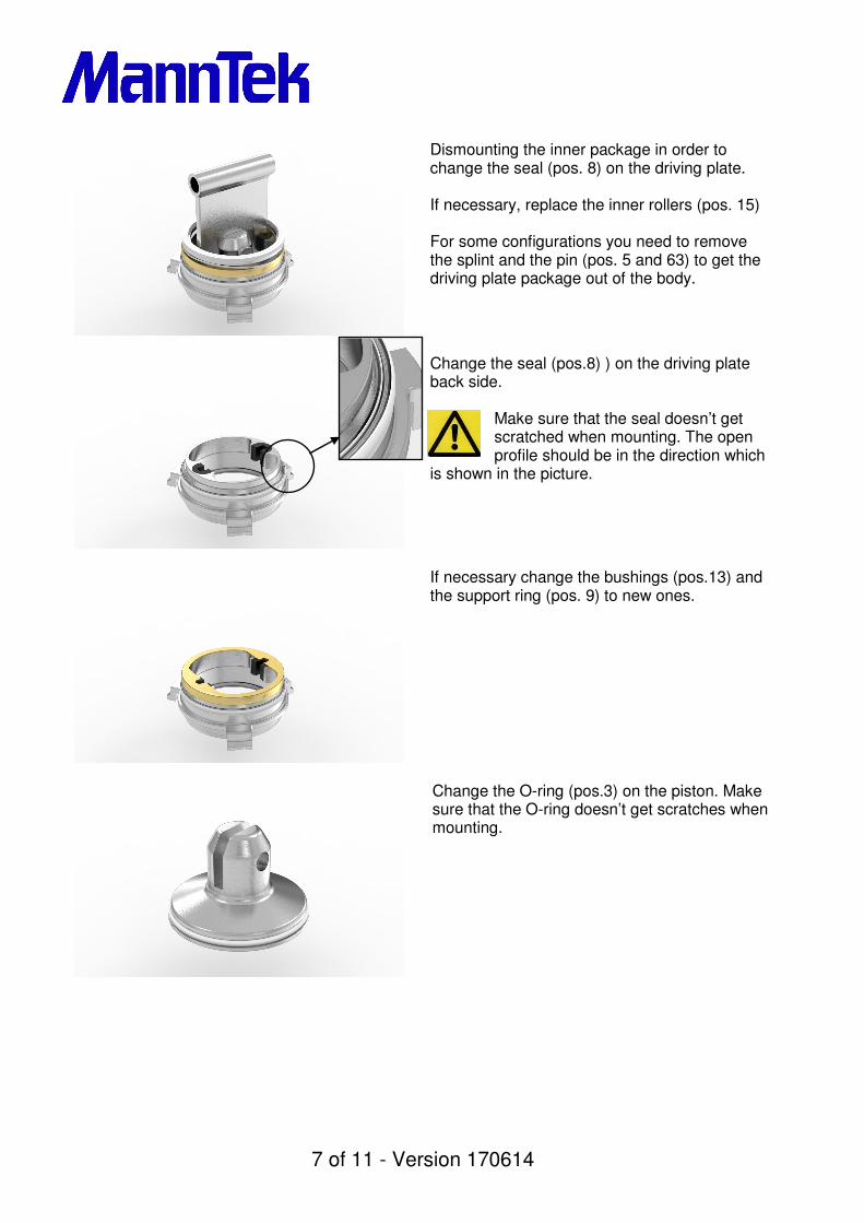
Dismounting the inner package in order to change the seal (pos. 8) on the driving plate. If necessary, replace the inner rollers (pos. 15) For some configurations you need to remove the splint and the pin (pos. 5 and 63) to get the driving plate package out of the body.
Change the seal (pos.8) ) on the driving plate back side.
Make sure that the seal doesn’t get scratched when mounting. The open profile should be in the direction which
is shown in the picture.
If necessary change the bushings (pos.13) and the support ring (pos. 9) to new ones.
Change the O-ring (pos.3) on the piston. Make sure that the O-ring doesn’t get scratches when mounting.

8 of 11 - Version 170614
If necessary change the three shafts (pos.18), locking nuts (pos.19) and rollers (pos.17) to new ones. Tool: Standard wrench 10 mm
Check the rollers for easy rotation.
Before the coupling body places on the driving plate package, make sure that the part where the upper cam curve ends, shall be placed exactly over one roll, and the heel on the driving plate package should be placed under the hole for the shaft. Place the coupling body over the driving plate package. Grab the piston guide and turn the unit upside down. (There are different ways to mount the driving plate package. If yours is not possible like this, ask your sales representative for an updated instruction)
Press down and turn the driving plate to the position where the driving plate heels are placed under the rollers.
The ring surface on the top of the driving plate is a sealing surface. Press down the piston only, the driving plate
will follow. Use a soft material for pressing it down.

9 of 11 - Version 170614
Assemble the shaft and two rollers for piston guide when applying pressure to the driving plate packet.
Do not apply too much pressure onto the inner package, only that the shaft and the rollers are easy to fit.
Assemble the swivel ring back onto the hose unit body.
Press down the Swivel ring (pos. 22) and drop the balls through the cutting space of the thread into the ball bearing. Mount the lip seal (pos.24) carefully into the groove.
Make sure that the seal doesn’t get scratched when mounting. The open profile should be in the direction which
is shown in the picture.
Replace the O-ring (pos. 78) before placing the swivel sleeve back on the body.

10 of 11 - Version 170614
Place the swivel sleeve over the coupling body and screw in the swivel sleeve. Take care that the markings you made in the beginning are aligning. If necessary apply anti seize lube on the threads.
Use Loctite® 243 and screw the lock screw into the swivel ring without any force! Risk to deform the ball bearing! Apply sealing wax on the lock screw to prevent misuse.
Finally, make a visual inspection that everything is in it’s place. Do also a test connection / disconnection with a tank unit that not has any fluid inside. If the coupling works alright you are ready to mount the hose unit on your hose again.
Loctite® is registered trademark of Henkel.

11 of 11 - Version 170614
TEST PROCEDURE
After each service a tightness test of each coupling is mandatory. The following test parameters are in accordance with EN12266 and EN14432: Test procedure Test pressure Acceptance criteria
Tightness test (liquid nitrogen)
6 bar +/- 1 bar No visually detectable leakage for the duration of the test
Table 1 – Test pressure Size Cooling down Keeping time DN 25 5 min 30 s DN 50 10 min 45 s DN 65 12 min 60 s DN 80 15 min 60 s DN 100 18 min 90 s DN 150 20 min 120 s Table 2 – Minimum test duration
TEST PROCEDURE:
• Connect the hose unit to the tank unit
• At the beginning the couplings shall be cooled down by opening the tank with liquid
nitrogen for the cooling down time specified in Table 2.
• Maintain the test pressure for the keeping time specified in Table 2.
• Determine the leakage rate.
• Disconnect the hose unit and the tank unit.
• Maintain a test pressure of 5 bar in the tested unit(s) for the keeping time specified in
Table 2
• Determine the leakage rate while depressurizing the Units.
STORAGE Store coupling in a dry, dust free, dark place, in ambient temperature.
© Copyright 2008 Mann Teknik AB. Mann Teknik AB reserves the right to make changes at any time in prices, materials, specifications and models and to discontinue models without notice or obligations.