
Operating Instruction
26
4XH35QB200907-360 220V level 0.4kW-3.0kW 400V level 0.4kW-7.5kW ■ Please read this manual carefully and understand the contents for correct installation and use. ■ Please give this manual to the final user and keep it properly. ■ The technical specifications of this product may change without notice. 2RI20200907-12.0 Version A English Start Date: September 07, 2020 Document Number: XM-H0126 V1.0 Small general frequency converter Operating Instruction
-
Upload
khangminh22 -
Category
Documents
-
view
7 -
download
0
Transcript of Operating Instruction

4XH35QB200907-360
220V level 0.4kW-3.0kW
400V level 0.4kW-7.5kW
■ Please read this manual carefully and understand the contents for correct
installation and use. ■ Please give this manual to the final user and keep it properly. ■ The technical specifications of this product may change without notice.
2RI20200907-12.0 Version A
English
Start Date: September 07, 2020
Document Number: XM-H0126
V1.0
Small general frequency converter
Operating Instruction

2 / 26
Solemn statement Thank you for using the frequency converter. Before use, must read this
manual carefully, and use it after you are familiar with the safety
precautions of this product.
Safety Precautions:
1. Before wiring, please confirm whether the input power is off.
2. For wiring work, please invite professional electrical engineer to work.
3. The ground terminal must be grounded.
4. After the wiring of the emergency stop circuit is completed, must check
whether the action is effective.
5. The output wire of the frequency converter must not be connected to the
housing, and the output wire should not be short-circuited.
6. Please confirm whether the voltage of the AC main circuit power supply
is consistent with the rated voltage of the frequency converter.
7. Do not perform voltage withstand test on the frequency converter.
8. Please connect the braking resistor according to the wiring diagram.
9. Do not connect the power cord to the output U, V, W terminals.
10. Do not connect the contactor to the output circuit.
11. Be sure to install the protective cover before powering on. When
removing the cover, must disconnect the power supply.
12. Select the frequency converter with the reset and retry function, please
do not approach the mechanical equipment. It will restart suddenly
when the alarm stops.
13. After confirming that the running signal is cut off, the alarm can be
reset. If the alarm is reset in the running signal state, the frequency
converter may start suddenly.
14. Do not touch the terminals of the frequency converter. There is high
voltage on the terminals, which is very dangerous.
15. Do not change the wiring and terminal disassembly during power-on.
16. Cut off the main circuit power supply before inspection and
maintenance.
17. Do not modify the frequency converter without authorization.

3 / 26
1.Parameters List Rated data of frequency converter
Model Power Power supply Output current (A)
0.75G1-220V 0.75KW Single phase
alternating
220V-240V
50Hz/60Hz
4
3.7
1.5G1-220V 1.5KW 7
6.4
2.2G1-220V 2.2KW 9.5
8.7
0.75G3-380V 0.75KW Three-phase
alternating
380V-440V
50Hz/60Hz
2.5
2.3
1.5G3-380V 1.5KW 4.1
3.8
2.2G3-380V 2.2KW 5.8
5.3
4.0G3-380V 4.0KW 9.4
8.6
5.5G3-380V 5.5KW 12.6
11.6
7.5G3-380V 7.5KW 16.1
14.8 2.Product Size

4 / 26
Product size of frequency converter H W D A B C
0.75G1-220V
170 78 135 60 160 150
1.5G1-220V 170 78 135 60 160 150
2.2G1-220V 170 78 135 60 160 150
0.75G3-380V
170 78 135 60 160 150
1.5G3-380V 170 78 135 60 160 150
2.2G3-380V 170 78 135 60 160 150
4.0G3-380V 212 95 151 78 200 180
5.5G3-380V 212 95 151 78 200 180
7.5G3-380V
3.Installation and wiring

5 / 26
Usage description of wire terminal
Terminal Usage Setting and Description
R、S、T
Power supply of
frequency converter:
380V model connects to
R, S, T
220V model connect to R,
S or R, T (determined
according to terminal
label)
The front end of the input power supply
of the frequency converter should use an
air switch as an overcurrent protection
device. If a leakage protection switch is
added, in order to prevent the leakage
switch from malfunctioning, please
choose a device with a sensitivity of
200mA and action time more than 100ms
U、V、W
Frequency converter
output which is connected
to the motor
In order to reduce the leakage current, the
motor connection line should not exceed
50 meters.
Grounding The frequency converter must be well
grounded.
X1 Digital input X1 Set by parameter F2.13, the factory default
is forward
X2 Digital input X2 Set by parameter F2.14, the factory default
is reverse
X3 Digital input X3 Set by parameter F2.15, the factory default
is the first stage of multi-speed
X4 Digital input X4 Set by parameter F2.16, the factory default
is the second stage of multi-speed
GND Signal common terminal Zero potential of analog input signal
+24V Open collector output
power supply +24V,10mA is the largest
+5V
Frequency set the
potentiometer power
supply
+5V,10mA is the largest
Y1 Open collector output 1 4-20 mA, input impedance: 100 Ω
AI1 Analog input signal Set by parameter F0.02
TA,TC Relay output
Set by parameter F0.06
Contact rating:AC 250V/3A
DC 24V/2A

6 / 26
① Operation panel and method
4. Commissioning
The frequency converter operation command mode is set by parameter
F0.02: there are three types: start and stop controlled by panel, terminal and
communication (optional):
Method of return to the original interface after setting the parameters: 1. After power off, power on again. 2. Select parameter d-00, then press PRG key. 3. Long press the SET button for 3 seconds
② Frequency converter running command method setting
Note: After the frequency converter is powered on, the running panel will display
50.0 (output frequency)

7 / 26
(1) Panel control start and stop: (factory default is panel start
and stop F0.02=0)
To use the panel to control the start and stop of the frequency
converter, press the green button on the panel to start and the red button to
stop. The frequency converter will start forward by default, and the forward
and reverse must be set through the input terminals X1-X5 (reverse set to
4).
(2) Terminal start and stop:
The frequency setting mode of the frequency converter is set by parameter
F0.02. When F0.02=0, the operating frequency is set by the potentiometer;
when F0.02=2, the operating frequency is inputted by AVI (0-5V can be
connected to the potentiometer, J1 line cap jumps to the upper position );
when F0.02=2, the operating frequency is inputted by ACI (4-20mA, J1 line
cap jumps to the lower position); when F0.02=3, which is controlled by
external terminals (the switch amount value is set to frequency
increase/decrease.
③ Selection of frequency converter setting
mode

8 / 26
5. Parameters List
Parameter
Name Factory Default
Predeter mined Area
Content
F0 Group- Basic operating parameters
F0.00 Motor control method
1 0~2 0: VF control 1: Advanced VF control 2: Simple vector control
F0.01
Run command channel selection
0 0~1 0: The panel runs the command 1: The terminal runs the command
F0.02 Frequency setting selection
0 0~5
0: Panel potentiometer 1: Digital setting 1, adjust by operating ▲/▼ keys on the panel 2: AVI simulation given (0~5 V/0~20 mA) 3: Digital setting 2, adjust by terminals UP/DOWN 4: Two-stage speed terminal is connected to the given and run, terminal UP/DO WN adjusts the frequency 5: The second-stage speed terminal triggers the setting and run
F0.03
Operation frequency digital setting
50.0 Hz
0.0~upper limit frequency
The set value is initial value of frequency digital setting
F0.04 Digital frequency control
00 0011
LED ones place: Store at power off 0: Store 1: Do not store LED tens place: Keep state at downtime 0: Keep 1: Do not keep LED hundreds place: reserve Thousands place: reserve
9 / 26
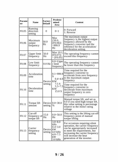
Parameter
Name Factory Default
Predeter mined
Area Content
F0.05 Running direction setting
0 0~1 0: Forward 1: Reverse
F0.06 Maximum output frequency
50.0 Hz
Max {50.0, [F0.06]} ~999.9 Hz
The maximum output frequency is the highest output frequency allowed by the frequency converter and the reference for the acceleration/ deceleration setting.
F0.07 Upper limit frequency
50.0 Hz
Max {0.1, [F0.07]} ~ [F0.05]
The operating frequency cannot exceed this frequency
F0.08 Low limit frequency
0.0 Hz 0.0~Upper limit frequency
The operating frequency cannot be lower than this frequency
F0.09 Acceleration time
Device setting
0.1~999.9 S
0.4~4.0 KW
7.5 S 5.5~7.5
KW 15.0 S
Time required for the frequency converter to accelerate from zero frequency to the maximum output frequency
F0.10 Deceleration time
Time required for the frequency converter to decelerate from maximum output frequency to zero frequency
F0.11 Torque lift amount
Device setting
0.0~30.0%
Manual torque lift, and set as 0.0 if you need high torque lift, this value setting is percentage relative to the motor rating voltage
F0.12 Cut-off frequency of torque lift
15.0 Hz
0.0~50.0 Hz
This setting is the lifting cut-off frequency point of manual torque lifting
F0.13 Carrier frequency setting
Device setting
3.0~8.0 kHz 0.4~3.0 kW 4.0 kHz 4.0~7.5 kW 3.0 kHz
For occasions requiring silent operation, the carrier frequency can be appropriately increased to meet the requirements, but increasing the carrier frequency will increase the heat generation of the inverter.

10 / 26
Parameter
Name Factory Default
Predeter mined Area
Content
F0.14 Stop mode 0 0~1 0: Slow down to stop 1: Stop freely
F0.15 Jog frequency setting
10.0 Hz
0.0~Upper limit frequency
Set the jog frequency
F0.16
AI1 input lower limit voltage
0.00V 0.00~5.00 V/0.00~20.00 mA Set upper and lower limits of
AI1 voltage or current
F0.17 AI1 input upper limit voltage
5.00V 0.0~5.0 V
F0.18
AI1 lower limit corresponding setting
0.0% -100.0%-100.0%
Set the AI1 upper and lower limits corresponding setting which is corresponding to the percentage of the upper limit frequency [F0.06]
F0.19
AI1 upper limit corresponding setting
100.0%
0.1~frequency value F2
0: Idle control terminal 1: Forward jog control 2: Reverse jog control 3: Forward control (FWD) 4: Reverse control (REV) 5: Three-wire operation control 6: Free stop control 7: External stop signal input (STOP) 8: External reset signal input (RST) 9: External fault normally open input 10: Frequency up command (UP) 11: Frequency down command (DOWN) 13: Multi-speed option S1 14: Multi-speed option S2 15: Multi-speed option S3 16: Run command channel forced to be terminal 17: Reserve 18: Reserve 19: Frequency switching to AVI 20: Frequency switching to digital frequency 1
F0.20
Input Terminal X1 function
3 0~23
F0.21
Input Terminal X2 function
4 0~23
F0.22
Input Terminal X3 function
7 0~23
F0.23
Input Terminal X4 function
0 0~23

11 / 26
Parameter
Name Factory Default
Predeter
mined Area
Content
F0.24 Reserve 0 -
21: Frequency switching to digital frequency 2 22: Reserve 23: Relay 24: Select speed 1 and run 25: Select speed 2 and run 26: Multi-speed shutdown (only valid for functions 24 and 25)
F0.25 Y1 output
setting 0 0~20
0: Idle 1: The frequency converter is running 2: Frequency converter failure 3: Input setting 23 is valid 4: Frequency/speed arrival signal (FAR) 5: Frequency/speed level detection signal (FDT) 6: Frequency converter overload pre-alarm level 7: Frequency converter overload pre-alarm delay ~20: reserved
F0.26 R output setting
2 0~20
F0.27 R Closing
delay 0.0s
0.0~255.0s
The delay between the relay R state has changes to output also has change F0.28
R Disconnection delay
F0.29
Frequency reaches the
FAR detection
range
5.0Hz 0.0Hz~15.0Hz
The output frequency is within the positive and negative detection width of the set frequency, and the terminal outputs a valid signal (low level)
F0.
30
FDT level
setting value
10.0 Hz
0.0Hz~
frequency upper limit
F0.31 FDT lagged value
1.0 Hz 0.0~30.0 Hz

12 / 26
Parameter Name
Factory Default
Predeter mined
Area Content
F0.32
UP/DOWN adjusting frequency
rate
10.0 0.0~
50.0Hz/S
Set the UP/DOWN Adjusting frequency rate
F0.33
Terminal electrical
level selection
0 0~1FH 0: Electrical level mode 1: Trigger mode
F0.34 Terminal
input filter coefficient
10 0~9999 Set the terminal input filter coefficient
F0.35 Terminal input logic
0 0~1FH Set terminal input logical
F0.36 FWD/REV
terminal control mode
0 0~3
0: Two-wire control mode 1 1: Two-wire control mode 2 2: Three-wire control mode 1 3: Three-wire control mode 2
F0.37
Terminal function detection
selection at power-on
0 0~1
0: Terminal run command is invalid at power-on 1: Terminal run command is valid at power-on
F0.38 Multi-speed frequency 1
5.0 Hz
Negative upper limit
frequency~
Upper limit
frequency
Set the frequency in velocity period 1
F0.39 Multi-speed frequency 2
10.0 Hz
Negative upper limit
frequency ~
Upper limit
frequency
Set the frequency in velocity period 2
F0.40 Multi-speed frequency 3
15.0 Hz
Negative upper limit
frequency ~
Upper limit
frequency
Set the frequency in velocity period 3
13 / 26
Parameter
Name Factory Defaul
t
Predeter mined Area
Content
F0.41 Multi-speed
frequency 4
25.0 Hz
Negative upper limit
frequency ~
Upper limit
frequency
Set the frequency in velocity period 4
F0.42 Multi-speed frequency 5
35.0 Hz
Negative upper limit
frequency ~
Upper limit
frequency
Set the frequency in velocity period 5
F0.43 Multi-speed frequency 6
45 Hz
Negative upper limit
frequency ~
Upper limit
frequency
Set the frequency in velocity period 6
F0.44 Multi-speed frequency 7
50.0 Hz
Negative upper limit
frequency ~
Upper limit
frequency
Set the frequency in velocity period 7
F0.45 Acceleration
time 2
10.0 s
0.1~999.9 s
0.4~4.0 kW
10.0 s 5.5~7.5
Kw 15.0 s
Set acceleration and deceleration time 2
F0.46 Deceleration
time 2

14 / 26
Parameter
Name Factory Defaul
t
Predeter mined Area
Content
F0.47 Jog
acceleration time Device
setting
0.1~255.0 s
0.4~4.0KW 10.0S 5.5~22KW 15.0S
Set the jog acceleration and deceleration time
F0.48 Jog
deceleration time
F0.49 Motor rated
voltage Device setting
0~500V: 380V
0~250V: 220V
Motor parameter setting
F0.50 Motor rated frequency
50.0 Hz
1.0~999.9 Hz
F0.51 Motor rated speed
Device setting
0~60000 rpm
F0.52 Motor
rated current
Device setting
0.1~999.9 A
F0.53 Motor
no-load current
Device setting
0.1~999.9 A
F0.54 Motor stator
resistance Device setting
0.001~20.000Ω
Set the motor stator resistance
F0.55 Slip
compensation selection
0 0~1 0:Invalid 1: Valid
F0.56
Motor overload protectio
n coefficie
nt
100% 0%
~200%
The motor overload protection coefficient is the percentage of the motor rated current value to the rated output current of the frequency converter.
F0.57
Undervoltage
protection level
180/ 360V
50-280/ 50-480V
This function code specifies the lower limit voltage allowed by the DC bus when the frequency converter is working normally

15 / 26
Parameter
Name Factory Defau
lt
Predeter mined Area
Content
F0.58
Deceleration voltage limiting
coefficient
1 0: shut down,
1~255
This parameter is used to adjust the ability of the frequency converter to suppress overvoltage during deceleration.
F0.59 Overvoltag
e limit level
375/790V
350-400/ 660-850V
The overvoltage limit level defines the operating voltage for overvoltage stall protection
F0.60
Acceleration current limiting
coefficient
10 0: shut down, 1~99
This parameter is used to adjust the ability of the frequency converter to suppress overcurrent during acceleration.
F0.61
Constant speed
current limiting coefficie
nt
0 0: shut down, 1~10
This parameter is used to adjust the ability of the frequency converter to suppress overcurrent during constant speed.
F0.62 Current limit
level 180%
50%~250%
The current limit level defines the current threshold for the automatic current limit action, and its set value is relative to the percentage of rated current of the frequency converter.
F0.63 Parameter
initialization 0 0~1
0: No operation The frequency converter is in normal parameter reading and writing status. Function code setting value.
F0.63 Parameter
initialization 0 0~1
Whether it can be changed is related to the setting status of the user password and the current working status of the frequency converter.
1: Restore factory settings All user parameters are
restored to factory settings according to the model.

16 / 26
Parameter
Name Factory Defaul
t
Predeter mined Area
Content
F0.64
Main interface display
selection
10 00~FFH
which means select the output current d-04, and the default display item of the main monitoring interface is the current output current value during operation.
LED's tens place: Selection of monitoring parameter during downtime.
You can change the monitoring items of main interface display
by changing the setting value of this function code. For example, set the tens place of F0.62 equal to 8, which means select the module temperature d-08, and the default display item of the main monitoring interface is the current module temperature during downtime.
LED hundreds place: Reserve LED thousands place:
Reserve
F0.65 Auxiliary display
selection 34 00~FFH
LED ones place: monitoring parameter selection at operating status
LED tens place: monitoring parameter selection at down state
Hundreds of LEDs: reserved LED Thousands: Reserved
F0.66 Voltage
compensation
0 0-1 0: Invalid 1: Valid

17 / 26
Parameter Name
Factory Defaul
t
Predeter mined Area
Content
F0.67
Output phase loss
protection detection
coefficient
2.00 0.00~20.0
0
When the ratio of the maximum value to the minimum value of the three-phase output current is greater than this coefficient, and the duration exceeds 6 seconds, the frequency converter reports the output current unbalance fault ETUN
F0.68
Frequency converter overload pre-alarm
level
120% 0~150%
The current threshold of the frequency converter overload pre-alarm action, the set value is relative to the rated current of the frequency converter.
F0.69
Frequency converter overload pre-alarm
delay
5.0 s 0.0~15.0s
The delay time between the output current of the frequency converter is continuously lager than the overload pre-alarm level (F0.68) and output overload pre-alarm signals.
F0.70 Motor tuning
0 0~1 0: Invalid 1: Statical tuning
F0.71 User
password 0 0~9999 Set any non-zero number and wait 3 minutes or power down before it takes effect
F0.72 JOG keys
setting 0 0~3
0: JOG 1: Forward and reverse switch 2: Clear ▲/▼ key frequency setting
3: Run in reverse (at this time, the default Run key is forward)
F0.73 PID
Functional Setting
0 00~12
LED one’s place: PID sleep mode 0:disabled 1: Normal hibernation 2:Disturbance sleep
Same as the parameter setting
18 / 26
Parameter
Name Factory Defaul
t
Predeter mined Area
Content
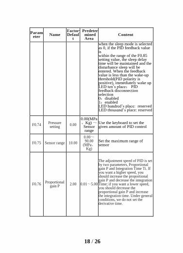
when the sleep mode is selected as 0, if the PID feedback value is within the range of the F0.85 setting value, the sleep delay time will be maintained and the disturbance sleep will be entered. When the feedback value is less than the wake-up threshold(PID polarity is positive), immediately wake up LED ten’s place: PID feedback disconnection selection 0:disabled 1:enabled LED hundred’s place: reserved LED thousand’s place: reserved
F0.74 Pressure setting
0.00
0.00(MPa、Kg) ~
Sensor range
Use the keyboard to set the given amount of PID control
F0.75 Sensor range 10.00
0.00~90.00
(MPa、Kg)
Set the maximum range of sensor
F0.76 Proportional
gain P 2.00 0.01~5.00
The adjustment speed of PID is set by two parameters, Proportional gain P and Integration Time Ti. If you want a higher speed, you should increase the proportional gain P and decrease the integration Time; if you want a lower speed, you should decrease the proportional gain P and increase the integration time. Under general conditions, we do not set the derivative time.

19 / 26
Parameter
Name Factory Defaul
t
Predeter mined Area
Content
F0.77 Integral time
Ti
6.0s 0.1~50.0s
F0.78
Threshold
value of
sleeping
100.0% 0.0~
150.0%
If the actual feedback value is
greater than the set value and the
inverter output frequency reaches
the sleep frequency, The
inverter will turn to sleeping state
after the delay time defined by
F0.79
(ie zero speed operation); The
value is the percentage of the PID
set value.
F0.79 Delay time of
sleep 100.0s 0.0~999.9s
Set the time-delay of sleeping
F0.80
Threshold
value of
awaking
90.0% 0.0~
150.0%
If the feedback value is less than
the set value, the inverter will turn
to sleeping state after waiting for
the delay time defined by F0.81;
This value is a percentage of the
PID set value.
F0.81 Delay time of
awaking 1.0s 0.0~999.9s
Set the time-delay of awaking
F0.82 Feedback cha
nnel gain 1.00 0.01~10.00
When the feedback channel is not
consistent with the setting channel,
the function can be used to adjust
the signal of feedback channel.

20 / 26
Parameter Name
Factory Default
Predeter mined Area
Content
F0.83
Feedback
disconnection
detection
value
0.0% 0.0~
100.0%
This value is percentage of PID given amount. When the PID
feedback value continues to be less than the feedback disconnection detection value.The inverter will
make the corresponding protection action. When F0.83=0.0%, this
value is invalid.
F0.84
Feedback
disconnection
detection time
10.0s 0.1~999.9S When the feedback disconnection occurs, the time-delay before the
protective action.
F0.85
Deviation
limit of
feedback
when entering
sleep state
compared
with set
pressure
0.5% 0.0~20.0% The function parameter is only
effective to the disturbance sleeping mode.
F0.86 Sleep
frequency 0.0
0.0~pper limit freq.
Set sleep frequency
F1 Group- Basic operating parameters
F1.00 Manufacture
r password 1~9999 System setting special password
Group d - Monitoring parameter group
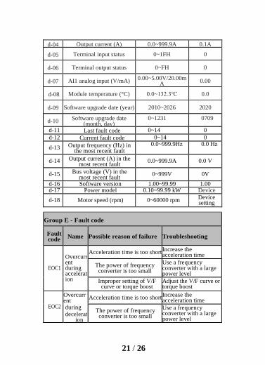
Parameter
Name Range Minimum unit
d-00 Output frequency (Hz)
setting 0.0~999.9Hz 0.1Hz
d-01 Set frequency
(Hz) 0.0~999.9Hz 0.1Hz
d-02 Output
voltage (V) 0~999V 1V
d-03 Bus voltage (V) 0~999V 1V
21 / 26
d-04 Output current (A) 0.0~999.9A 0.1A
d-05 Terminal input status 0~1FH 0
d-06 Terminal output status 0~FH 0
d-07 AI1 analog input (V/mA) 0.00~5.00V/20.00m
A 0.00
d-08 Module temperature (°C) 0.0~132.3℃ 0.0
d-09 Software upgrade date (year) 2010~2026 2020
d-10 Software upgrade date
(month, day) 0~1231 0709
d-11 Last fault code 0~14 0
d-12 Current fault code 0~14 0
d-13 Output frequency (Hz) in the most recent fault
0.0~999.9Hz 0.0 Hz
d-14 Output current (A) in the most recent fault
0.0~999.9A 0.0 V
d-15 Bus voltage (V) in the most recent fault
0~999V 0V
d-16 Software version 1.00~99.99 1.00 d-17 Power model 0.10~99.99 kW Device
setting d-18 Motor speed (rpm) 0~60000 rpm
Device setting
Group E - Fault code
Fault code
Name Possible reason of failure Troubleshooting
EOC1
Overcurrent during acceleration
Acceleration time is too short Increase the acceleration time
The power of frequency converter is too small
Use a frequency converter with a large power level
Improper setting of V/F curve or torque boost
Adjust the V/F curve or torque boost
EOC2
Overcurrent during decelerat
ion
Acceleration time is too short Increase the acceleration time
The power of frequency converter is too small
Use a frequency converter with a large power level
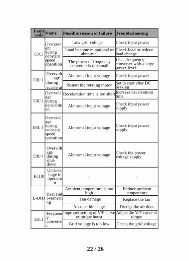
22 / 26
Fault code
Name Possible reason of failure Troubleshooting
EOC3
Overcurrent during constant speed operation
Low grid voltage Check input power
Load become mutational or abnormal
Check load or reduce load change
The power of frequency converter is too small
Use a frequency converter with a large power level
EHU 1
Overvoltage
during accelerat
ion
Abnormal input voltage Check input power
Restart the rotating motor Set to start after DC braking
EHU 2
Overvoltage during deceleration
Deceleration time is too short Increase deceleration time
Abnormal input voltage Check input power supply
EHU 3
Overvoltage during constant speed operation
Abnormal input voltage Check input power supply
EHU 4
Overvoltage during shut-down
Abnormal input voltage Check the power voltage supply
ELU0
Undervoltage in operatio
n
- -
E-OH1 Heat sink overheating
Ambient temperature is too high
Reduce ambient temperature
Fan damage Replace the fan
Air duct blockage Dredge the air duct
EOL1
Frequency converter
Improper setting of V/F curve or torque boost
Adjust the V/F curve or torque boost
Grid voltage is too low Check the grid voltage
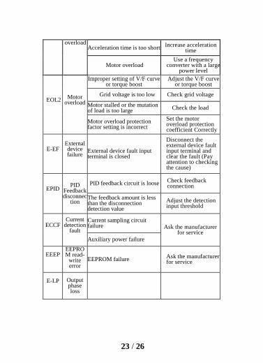
23 / 26
overload Acceleration time is too short
Increase acceleration time
Motor overload Use a frequency
converter with a large power level
EOL2 Motor
overload
Improper setting of V/F curve or torque boost
Adjust the V/F curve or torque boost
Grid voltage is too low Check grid voltage
Motor stalled or the mutation of load is too large
Check the load
Motor overload protection factor setting is incorrect
Set the motor overload protection coefficient Correctly
E-EF External device failure
External device fault input terminal is closed
Disconnect the external device fault input terminal and clear the fault (Pay attention to checking the cause)
EPID PID
Feedback disconnec
tion
PID feedback circuit is loose Check feedback connection
The feedback amount is less than the disconnection detection value
Adjust the detection input threshold
ECCF Current
detection fault
Current sampling circuit failure Ask the manufacturer
for service Auxiliary power failure
EEEP EEPROM read-
write error
EEPROM failure Ask the manufacturer for service
E-LP Output phase loss
24 / 26
6.Applications
(1) constant pressure water supply control by frequency converter
A: Electric contact pressure gauge control (the simplest control
method)
Use the electric contact pressure gauge to control the water pressure.
You only need to connect 2 wires, one from the green needle and the other
from the black needle, respectively connected to the upper 2 of the 3
terminals of the electric contact pressure gauge (some electric contact table
may be different). When the water pressure is low, the black needle is
underneath the green needle, and the frequency converter is in the
acceleration start state. When the water pressure is high, the black needle is
on the top of green needle, and the frequency converter is in the
deceleration stop state. Very simple and easy to maintain.
For this frequency converter, the debugging steps are as follows:
① Connect the two wires from the electric contact pressure gauge,
one wire of the start signals to X1, and the other wire to GND
(do not need to distinguish between positive and negative pole,
please connect the start signal after setting all parameters).
② Set parameter F0.01=1 to select external terminal to start
control.
③ Turn up the speed control knob on the panel to the maximum.
④ Frequency converter parameter setting: F0.20=3 (default
value), F0.09=60, F0.10=60, F0.37 =1
It can start automatically after power on. If it does not start, you can
use a wire to directly connect X1 and GND to see if it starts. If it still fails,
it means there is a problem with the internal settings of the frequency
converter. If it can be started, it means the external electric contact meter or
circuit problem. You can check whether the two wires on the electric
contact are connected. If the black needle is lower than the green needle, it
should be connected, and if the black needle is higher than the green needle,
it should be disconnected.

25 / 26
(2) Two speed setting mode control
Equipment requirements: use the potentiometer knob to adjust the
speed during forward rotation, and use multi-speed low-speed operation
during reverse rotation.
①Parameter setting: F0.02=1, F0.03=3, F1.17=10 (reverse running
speed 10HZ)
②Connection: 3 wires of the potentiometer are connected to GND, AVI,
+10V, the forward rotation signal is connected to X1 and GND, the reverse
signal is connected to X2, GND, and X2 and X3 are short-circuited (set the
frequency at the same time when reverse Select the setting value of multi-
speed 1).
(3) Jog control
Equipment that needs jog control:
① Parameter setting: F0.02=1, F2.15=1 (forward jog), F2.16=2
(reverse jog), forward jog frequency is given by parameter F1.09, reverse
point The dynamic frequency is given by parameter F1.10. The jog
acceleration time is set by parameter F1.11, and the jog deceleration time is
set by parameter F1.12.
② Wiring: the forward jog signal is connected to GND and X3, and the
reverse jog signal is connected to GND and X4.
(4) Torque is insufficient when running at low speed (rotation is
weak)
Adjust parameter F0.14, gradually adjust from small to large. Don't
adjust it too large at the beginning. If it is adjusted too large, it may report
OC overcurrent fault.
Adjust parameter F0.15, which is the cutoff frequency of torque boost.

26 / 26
Service delivers value, quality creates glory
To customers:
Thank you for using our products. In order to ensure that you get the
best after-sales service from our company, please read the following
terms carefully and do the relevant matters.
1. Product warranty scope
Any failures that occur under normal use according to the requirements
of use are covered by the warranty.
2. Product warranty period
The warranty period of this product is within twelve months from the
date of delivery. Long-term technical support services will be
implemented after the warranty period.
3. Non-warranty coverage
Any damage caused by human factors, natural disasters, water ingress,
external force damage, harsh environment, etc. that violate the
requirements of use, as well as unauthorized disassembly, modification
and maintenance of the frequency converter, shall be deemed to
automatically waive the warranty service.
4. Purchase products from middlemen
Anyone who purchases products from distributors or agents should
contact the distributor or agent if the product fails.
Please keep this manual properly in case you need it.


