Operating Instruction BA 200 EN - Edition 10/17 - Bauer Gear ...
80
Bauer Gear Motor GmbH Eberhard-Bauer-Straße 37 73734 Esslingen am Neckar Bauer Gear Motor GmbH Eberhard-Bauer-Str. 37 73734 Esslingen www.bauergears.com These documents must be kept with the unit. Further documentation can be found on the internet. Translation Operating Instruction BA 200 EN - Edition 10/17 Your driving power
-
Upload
khangminh22 -
Category
Documents
-
view
0 -
download
0
Transcript of Operating Instruction BA 200 EN - Edition 10/17 - Bauer Gear ...

Bauer Gear Motor GmbHEberhard-Bauer-Straße 3773734 Esslingen am Neckar
B a u e r G e a r M o t o r G m b H E b e r h a r d - B a u e r - S t r . 3 7 7 3 7 3 4 E s s l i n g e n w w w . b a u e r g e a r s . c o m
These documents must be kept with the unit.Further documentation can be found on the internet.
Translation
Operating Instruction BA 200 EN - Edition 10/17
Ihre treibende Kraft - Your driving power

P-7119-BGM-EN-A5 10/17Bauer Gear Motor +49 711 3518-02

P-7119-BGM-EN-A5 10/17
TABLE OF CONTENTS
EU-Declaration of Conformity 4
Safety information for the operation of geared motors 6
Geared motors with three-phase rotor 8
Lubricants 19Lubrication quantity series BG .................................................................................................................. 19Lubrication quantity for BG20-01R ........................................................................................................... 20Lubrication quantity series BF ................................................................................................................... 21Lubrication quantity series BK .................................................................................................................. 22Lubrication quantity series BS................................................................................................................... 23Lubrication quantity for gear design with free running input shaft ............................................................. 24Lubrication quantity for gear design with integral motor ............................................................................ 25Lubrication quantity for gear design with free running input shaft ............................................................. 26Lubrication quantity for coupling lantern ................................................................................................... 27Lubrication quantity for pre-stage ............................................................................................................. 28Lubrication quantity for intermediate gear ................................................................................................. 29
Brakes 30Spring-loaded brakes with direct current solenoid release Models E003B and E004B .............................. 30Spring-loaded brakes with DC solenoid release Models ES(X)010A ... ES(X)250A, ZS(X)300A, ZS(X)500A, EH(X)027A …EH(X)400A ................................. 35
Electrical brake connection ....................................................................................................................... 52Brake connection: special rectifier ESG 1.460A ........................................................................................ 56Brake connection: DC voltage supply ....................................................................................................... 58Brake connection: special rectifier MSG...I ................................................................................................ 59Brake connection: special rectifier MSG...U .............................................................................................. 61Brake connection: standard rectifier SG 3.575B ....................................................................................... 62Rectifier on motor terminal block or cage clamp ....................................................................................... 66Manual release for spring loaded brake with DC solenoid Model E003B and E004B ................................. 67Manual release for spring loaded brake with DC solenoid Model ES(X)010A ... ES(X)250A, ZS(X)300A, ZS(X)500A ........................................................................... 68
Gearmotors 71Gear units designed with torque arms and rubber buffers for series BF .................................................... 71Gear units designed with torque arms and rubber buffers for series BK .................................................... 72Gear units designed with torque arms and rubber buffers for series BS .................................................... 73Geared motors with backstop .................................................................................................................. 74Assembly of standard motor with C-Adapter (IEC and NEMA) .................................................................. 75Assembly and disassembly of the shrink-disc ........................................................................................... 76Information on the storage of geared motors with cage rotors .................................................................. 77
Bauer Gear Motor +49 711 3518-0 3

P-7119-BGM-EN-A5 10/17
EU-Declaration of Conformity
Ihre treibende Kraft - Your driving power An Altra Industrial Motion Company
Bauer Gear Motor GmbHPostfach 10 02 0873726 Esslingen (Germany)Eberhard-Bauer-Str. 3773734 Esslingen (Germany)Telephone: +49 (0)711 35 18 0Fax: +49 (0)711 35 18 381Email: [email protected]: www.bauergears.com
Bauer Gear Motor GmbHEberhard-Bauer-Str. 37, 73734 Esslingen (Germany)
declares on its sole responsibility the conformity of the following products:
Asynchronous motors from the seriesD..04, D..05, D..06, D..07; D..08, D..09, D..11, D..13, D..16, D..18, D..20, D..22, D..25, D..28 E..04, E..05, E..06, E..07, E..08, E..09
where necessary, in conjunction withgears from the series: BG.., BF.., BK.., BS.., BM..
with the requirements of the European Directives
DIRECTIVE 2014/35/EU OF THE EUROPEAN PARLIAMENT AND OF THE COUNCIL of 26 February 2014on the harmonisation of the laws of the Member States relating to the making available on the market of electrical equipment designed for use within certain voltage limits.Published on 29 March 2014 in the Offi cial Journal of the EU L96/357.
DIRECTIVE 2009/125/EC1) OF THE EUROPEAN PARLIAMENT AND OF THE COUNCIL of 21 October 2009establishing a framework for the setting of ecodesign requirements for energy-related products.Published on 31 October 2009 in the Offi cial Journal of the EU L285/10.
1) Where the products fall under the scope of this Directive, the requirements of COMMISSION REGULATION (EC) No 640/2009 - Establishing electric motor ecodesign requirements - of 22 July 2009 and 6 January 2014 are met.Additional product labels HE; PE (IE2: IE3 according to EN 60034-30-1)
The object of declaration described above is in conformity with the Union‘s relevant harmonization legislation, proven by the compliance with the following harmonised standards:
EN 60034-1:2010 + Cor.:2010 EN 60034-2-1:2014 EN 60034-5:2001/A1:2007EN 60034-8:2007/A1:2014 EN 60034-30-1:2014 EN 60529:1991/A1:2000/A2:2013
Additional information:Three-phase motors do not fall under the scope of the EMC Directive, since as passive elements they are neither suscep-tible for the purpose of interference resistance, nor do they affect the environment by emitting high-frequency interference. Operation of these motors in the case of power supply through switch-mode supplies (converter) and the associated EMC-relevant aspects are the responsibility of the user of this PDS (Power Drive System). The instructions in the con-verter‘s product documentation must be observed. The installer is responsible for the fi nal EMC properties of the device, system or installation.
Esslingen 20. April 2016
Bauer Gear Motor GmbH
K.P. Simon P. Cagan(Managing Director and President) (Quality Director)
This certifi cate does not contain any guarantee of features in terms of product liability. The technical documentation is produced and administered by Bauer Gear Motor GmbH.
Low Voltage Directive 2014/35/EU Ecodesign Directive 2009/125/EC
B 010.0800-02 Version: 04/2016 EE-geFile: 2016_KonfErkl_NSR_ErP_ASM_B_010_0800_02_EN
EU Declaration of Conformity
Bauer Gear Motor +49 711 3518-04

P-7119-BGM-EN-A5 10/17
Ihre treibende Kraft - Your driving power An Altra Industrial Motion Company
Bauer Gear Motor GmbHPostfach 10 02 0873726 Esslingen (Germany)Eberhard-Bauer-Str. 3773734 Esslingen (Germany)Telephone: +49 (0)711 35 18 0Fax: +49 (0)711 35 18 381Email: [email protected]: www.bauergears.com
Bauer Gear Motor GmbHEberhard-Bauer-Str. 37, 73734 Esslingen (Germany)
declares on its sole responsibility the conformity of the following products:
Permanent magnet three-phase synchronous motors in the series
S..04, S..05, S..06, S..07; S..08, S..09, S..11, S..13, S..16, S..18
where necessary, in conjunction with
gears from the series: BG.., BF.., BK.., BS.., BM..
with the requirements of the European Directives
DIRECTIVE 2014/35/EU OF THE EUROPEAN PARLIAMENT AND OF THE COUNCIL of 26 February 2014on the harmonisation of the laws of the Member States relating to the making available on the market of electrical equipment designed for use within certain voltage limits.Published on 29 March 2014 in the Offi cial Journal of the EU L96/357
The object of declaration described above is in conformity with the Union‘s relevant harmonisation legislation, proven by the compliance with the following harmonised standards:
EN 60034-1:2010/AC:2010EN 60034-5:2001/A1:2007EN 60034-8:2007/A1:2014EN 60529:1991/A1:2000/A2:2013
Additional information:Three-phase motors do not fall under the scope of the EMC Directive, since as passive elements they are neither suscep-tible for the purpose of interference resistance, nor do they affect the environment by emitting high-frequency interference. Operation of these motors in the case of power supply through switch-mode supplies (converter) and the associated EMC-relevant aspects are the responsibility of the user of this PDS (Power Drive System). The instructions in the con-verter‘s product documentation must be observed. The installer is responsible for the fi nal EMC properties of the device, system or installation.
Esslingen, 20 April 2016
Bauer Gear Motor GmbH
K.P. Simon P. Cagan(Managing Director and President) (Quality Director)
This certifi cate does not contain any guarantee of features in terms of product liability. The technical documentation is produced and administered by Bauer Gear Motor GmbH.
Low Voltage Directive 2014/35/EU
B 010.0800-03 Version: 04/2016 EE-geFile: 2016_KonfErkl_NSR_PMSM_B_010_0800_03_EN
EU Declaration of Conformity
Ihre treibende Kraft - Your driving power An Altra Industrial Motion Company
Bauer Gear Motor GmbHPostfach 10 02 0873726 Esslingen (Germany)Eberhard-Bauer-Str. 3773734 Esslingen (Germany)Telephone: +49 (0)711 35 18 0Fax: +49 (0)711 35 18 381Email: [email protected]: www.bauergears.com
Bauer Gear Motor GmbHEberhard-Bauer-Str. 37, 73734 Esslingen (Germany)
declares on its sole responsibility the conformity of the following products:
Asynchronous motors from the seriesD..04, D..05, D..06, D..07; D..08, D..09, D..11, D..13, D..16, D..18, D..20, D..22, D..25, D..28 E..04, E..05, E..06, E..07, E..08, E..09
where necessary, in conjunction withgears from the series: BG.., BF.., BK.., BS.., BM..
with the requirements of the European Directives
DIRECTIVE 2014/35/EU OF THE EUROPEAN PARLIAMENT AND OF THE COUNCIL of 26 February 2014on the harmonisation of the laws of the Member States relating to the making available on the market of electrical equipment designed for use within certain voltage limits.Published on 29 March 2014 in the Offi cial Journal of the EU L96/357.
DIRECTIVE 2009/125/EC1) OF THE EUROPEAN PARLIAMENT AND OF THE COUNCIL of 21 October 2009establishing a framework for the setting of ecodesign requirements for energy-related products.Published on 31 October 2009 in the Offi cial Journal of the EU L285/10.
1) Where the products fall under the scope of this Directive, the requirements of COMMISSION REGULATION (EC) No 640/2009 - Establishing electric motor ecodesign requirements - of 22 July 2009 and 6 January 2014 are met.Additional product labels HE; PE (IE2: IE3 according to EN 60034-30-1)
The object of declaration described above is in conformity with the Union‘s relevant harmonization legislation, proven by the compliance with the following harmonised standards:
EN 60034-1:2010 + Cor.:2010 EN 60034-2-1:2014 EN 60034-5:2001/A1:2007EN 60034-8:2007/A1:2014 EN 60034-30-1:2014 EN 60529:1991/A1:2000/A2:2013
Additional information:Three-phase motors do not fall under the scope of the EMC Directive, since as passive elements they are neither suscep-tible for the purpose of interference resistance, nor do they affect the environment by emitting high-frequency interference. Operation of these motors in the case of power supply through switch-mode supplies (converter) and the associated EMC-relevant aspects are the responsibility of the user of this PDS (Power Drive System). The instructions in the con-verter‘s product documentation must be observed. The installer is responsible for the fi nal EMC properties of the device, system or installation.
Esslingen 20. April 2016
Bauer Gear Motor GmbH
K.P. Simon P. Cagan(Managing Director and President) (Quality Director)
This certifi cate does not contain any guarantee of features in terms of product liability. The technical documentation is produced and administered by Bauer Gear Motor GmbH.
Low Voltage Directive 2014/35/EU Ecodesign Directive 2009/125/EC
B 010.0800-02 Version: 04/2016 EE-geFile: 2016_KonfErkl_NSR_ErP_ASM_B_010_0800_02_EN
EU Declaration of Conformity
Bauer Gear Motor +49 711 3518-0 5

P-7119-BGM-EN-A5 10/17
(in accordance with the Low Voltage Directive 2014/35/EU)
General This safety information applies in addition to the relevant product-specific operating instructions and for safety reasons must be taken into particular consideration in every case.This safety information is intended to protect persons and objects from injury and hazards which can arise from improper use, incorrect operation, inadequate maintenance or other incorrect handling of electric drive units in industrial installations. Low-voltage machines have rotating parts and may have parts that are live, even when the machine is at rest, and surfaces that may become hot in operation. Warning signs and information signs on the machine are to be observed without exception. Details may be found in our detailed operating instructions. They are provided with the machine when it is supplied and can be requested separately as required by stating the motor model.
1 PersonnelAll necessary work on electric drive units, in particular also planning work, transport, assembly, installation, commissioning, mainte-nance, repair, may only be performed by adequately qualified personnel (e.g. electrical engineers as specified in draft EN 50 110-1/DIN VDE 0105), who have the operating instructions provided and other product documentation available during any corresponding work and who are obliged to abide by the instructions contained therein. This work is to be monitored by a specialist supervisor. Qualified personnel are persons who are authorised due to training, experience and instruction as well as their knowledge of relevant standards, rules, accident prevention regulations and operating conditions by the person responsible for the safety of the installation to perform the activities required in each case and who are able to recognise and avoid possible hazard. Knowledge of first-aid measures and of the available lifesaving equipment is also required. Non-qualified personnel shall be forbidden to work on the geared motors.
2 Intended use taking into account the relevant technical regulationsThese machines are intended for commercial installations, unless otherwise expressly agreed. They comply with the standards of the series EN 60034/DIN VDE 0530. Use in a potentially explosive atmosphere is forbidden, if not expressly intended for this purpose (refer to additional information). If in a special case --use in non-commercial installations-- Increased safety precautions are required (e.g. protection against access by children’s fingers), these conditions are to be ensured when setting up the installation. The machines are designed for ambient temperatures between -20˚ C to +40˚ C as well as for installation heights up to 1000 m above sea level. Data for Units designed for differing ambient temperarures on the rating plate. Any deviations found on the rating plate must be taken into consideration. The conditions at the place of work must correspond to all rating plate data.
Low-voltage machines are components for installation in machines in the sense of the Machinery Directive 2006/42/EC. It is forbidden to use the machine until conformity of the final product with this directive is established (consult EN 60204-01).
3 Transportation, storage Only the attachment points provided by the factory may be used for transporting and installing the geared motors. When the electric drive units are being transported, the eye bolts -- where provided in the design-- must be firmly tightened down their bearing surface. They may be used only for transporting the drive unit and not for lifting both the drive unit and the driven machine. Damage sustained after delivery must be reported to the haulage company immediately. Commissioning may have to be suspended. If drive units are to be stored, ensure a dry, dust free and low vibration (veff < 0,2 mm/s) environment (damage sustained during storage). The life of the lubricants and seals is reduced with longer storage times. There is a risk of fracture at very low temperatures (under approximately - 20˚ C). If the transport eye bolts are replaced, drop forged eye bolts as specified in DIN 580 are to be used.
4 Mounting arrangement, assemblyThe drive unit is to be fastened by its flange or foot if an IM.. mounting arrangement is intended. Gear units with hollow shafts are to be attached on the driven shaft using the means provided.
Caution! Depending on the reduction ratio, geared motors develop substantially higher torques and forces than high-speed motors of similar power.
Mounts, substructure and torque restraint are to be rated for the high forces to be anticipated during operation and secured suf-ficiently against loosening. The output shaft(s) and any second motor shaft extension present as well as the transmission elements mounted on it (couplings, chain wheels etc.) are to be covered so that they cannot be touched.
5 Connection All work shall only be carried out by qualified technical personnel on a stationary machine which has been protected against re-starting. This applies also to auxiliary circuits (e.g. stationary heating). Remove any transportation blocks before start-up.
Safety information for the operation of geared motors
Bauer Gear Motor +49 711 3518-06

P-7119-BGM-EN-A5 10/17
Check to ensure safe isolation from the supply!The terminal box may only be opened once it has been ensured that the power is switched off. The information on voltage and frequency on the rating plate must correspond with the mains voltage under observance of the terminal circuit. Exceeding the toler-ances as in EN 60034 / DIN VDE 0530, i.e. voltages ± 5 %, frequency ± 2 %, cam form, symmetry, increases heating and reduces service life.Accompanying connection diagrams, particularly for special equipment (e.g. pole-changing, thermistor protection etc.), are to be observed. Type and cross-section of the main conductors as well the protective conductors and any potential equalization which may become necessary must correspond to the general and local installation regulations. With switching duty, the starting current is to be taken into account. The drive unit is to be protected against overloading and in dangerous situations against automatic restarting due to inadvertent starting. The terminal box is to be locked again to protect against contact with live components.
6 CommissioningBefore commissioning, protective films are to be removed, the mechanical connection to the driven machine disconnected as far as possible and the direction of rotation examined in the no-load state. Feather keys are to be removed or secured in such a way that they cannot be ejected as this is done. Ensure that the current draw in the loaded condition does not exceed the rated current indicated on the rating plate for any length of time. Observe the drive unit after first commissioning for at least one hour for any unusual heat or noise.
7 Operation With certain layouts (e.g. unventilated machines), relatively high temperatures can occur on the motor frame, which are however within the limits specified in the standard. If these drive units are located in a place where they are subject to intensive contact, measures must be taken by the installer or operator to provide protective shielding.
8 Spring-loaded brakesSpring-loaded brakes are safety brakes which continue to work in the event of power failure or usual wear. With a spring loaded brake with manual release option, the operator must ensure that the manual release of the brake cannot be actuated accidentally. If the operator removes the manual release lever for this purpose, then, in the case that the brake is built in under the fan cowl, he must allow for suitable contact protection at the emerging opening of the sheet metal fan cowl. Since other components could also fail, suitable safety precautions are to be taken to avoid any injury to persons or damage to objects cause by un-braked operation.
9 MaintenanceIn order to prevent breakdowns, danger and damage, the drive units must be examined at regular intervals depending on the operating conditions. The lubrication intervals for bearings and gear units specified in the respective operating instructions are to be observed. Worn or damaged parts are to be replaced using original spare parts or standard parts. In the event of heavy dust accumulation, clean airways regularly. For all inspection and maintenance work, observe Section 5 and the information provided in the detailed operating instructions.
10 Operating instructions For reasons of clarity, the operating instructions and safety information do not contain all information relating to all geared motors types and cannot take into account every conceivable case of installation, operation or maintenance. The information is essentially limited to that which is required for qualified personnel in normal working situations. Any unclear points can be clarified by contact-ing Bauer.
11 Faults Changes in relation to normal operation, such as higher temperatures, vibrations, noises etc. tend to indicate that the function is impaired. To avoid faults which could lead directly or indirectly to injury to persons or damage to property, the maintenance staff responsible must be informed. If in any doubt, the geared motors are to be switched off immediately.
12 Electromagnetic compatibilityThe operation of the low-voltage machine in its intended application must meet the protection requirements of the EMC (electro-magnetic compatibility) Directive 2014/30/EU.Correct installation (e.g. screened cables) is the responsibility of the system’s installers. Precise information can be taken from the operation instructions. For systems with frequency inverters and rectifiers, the manufacturer’s electromagnetic compatibility information is also to be taken into consideration. The electromagnetic compatibility directive in accordance with EN 61000-6-2 and EN 61000-6-4 is complied with given proper use and installation of BAUER geared motors. This is also true in combination with frequency inverters and rectifiers. The additional information provided in the operation instructions is to be taken into consid-eration when using the motors in the residential, commercial and trade sectors, as well as in small businesses in accordance with EN 61000-6-1 and EN 61000-6-3.
13 Warranty and liability The warranty obligations of Bauer arise out of the relevant supply contract, which is neither expanded nor restricted by this safety information or other instructions.
This safety information is to be kept in a safe place.
Safety information for the operation of geared motors
Bauer Gear Motor +49 711 3518-0 7

P-7119-BGM-EN-A5 10/17
Geared motors with three-phase rotor
In the standard version the drives are designed for an ambient temperature range of –20° C to +40° C and for installation elevations up to 1000 m above sea level; differing conditions are marked on the nameplate. Exposure to dirt, moisture and the usual outdoor conditions may not exceed the level cor-responding to the IP protection rating. The air inlet and outlet must be kept free of obstruction (for example, due to an acoustic cover).
Motor sizesMinimum clearance a at air inletUp to D .. 16 35 mmD .. 18 to D. 22 85 mmD .. 25 and above 125 mm
The operating instructions are an intergral element of the product and must be available in a readable form at all times. Employees responsible for the plant and operations together with all who have to work with the unit must have read and understood the operating instructions completely.
Observation of the operating instructions is a prerequisite for the safe use and the attainability of the product performance of the geared motor.Bauer does not accept liability for personal, material or economical damages caused by non-observation of the operating instructions. Liability for defects are excluded in such cases.
(Motor models D/E06... to D.28...) complying with EN 60529 and IEC 34-5/529 are totally enclosed and dust-tight as well as hose proof.
For outdoor installation, the geared motor must be coated with several lay-ers of durable paint to protect against corrosion. The condition of the paint must be checked and repaired at regular intervals, depending on ambient influences. The paint finish must be compatible with the other components. Paints with a synthetic resin base have proved well suited to this purpose.
(Motor models D/E04... and D/E05...) complying with EN 60034, part 5 and IEC 34-5 are protected against dust and occasional splashing water. Instal-lation outdoors or in wet areas is not permissible without special protective measures.
General Notes
Disclaimer
Geared motors in degree of protec-tion IP65
Geared motors in degree of protec-tion IP54
Bauer Gear Motor +49 711 3518-08

P-7119-BGM-EN-A5 10/17
It is recommended that drinking water, food, textiles etc. beneath the geared motor be covered.
The drive unit should be installed as free from vibration as possible.
Special instructions are to be observed in installation locations with abnor-mal operating conditions (e.g. prolonged exposure to dripping water, high ambient temperatures above 40° C, explosion hazards). The fresh air intake must not be restricted by unsuitable installation or by fouling.
Flexible couplings with zero play, if possible, are recommended for direct power transmission from the gear unit to the driven machine and commer-cially available slip clutches are recommended if there is a risk of blocking.
Care must be taken when fitting transmission elements onto the output shaft of the gear unit, which is finished to ISO k 6 or m 6, and the tapped end hole intended for this purpose according to DIN 332 should be used if pos-sible. Warming the machine part to be fitted onto the shaft to approximately 100° C has proved to be advantageous. The bore must be dimensioned in accordance with following table and must thus exhibit the following toler-ances:
Nominal size of bore (in mm)
k 6 or m 6 output shaft Bore H7 with tolerances (in 1/1000 mm)
over 6 to 10 0 to + 15over 10 to 18 0 to + 18over 18 to 30 0 to + 21over 30 to 50 0 to + 25over 50 to 80 0 to + 30over 80 to 120 0 to + 40
Where the gear units have a hollow shaft and keyway for high profile feather keys as specified in DIN 6885, Part 1 and hollow shaft for shrink-disc con-nection, the shafts intended to form the counterpart must be dimensioned to ISO h 6. They must, therefore, exhibit the following tolerances:
Shaft diameter (in mm) Nominal allowance (in 1/1000 mm)over 18 to 30 0 to - 13over 30 to 50 0 to - 16over 50 to 80 0 to - 19over 80 to 120 0 to - 22over 120 to 140 0 to - 25
Mounting arrangement
Geared motors with three-phase rotor
Bauer Gear Motor +49 711 3518-0 9

Direction of rotation I Direction of rotation II
Additional dimensiondrawing
Gear (Motors)
The actual gearbox design can vary from the geometry shown.
Additional Dimension Sheets
P-7119-BGM-EN-A5 10/17
In all cases, particular care shall be taken to ensure that any burring, swarf etc. is carefully removed before assembly. The keyways should be lightly greased to prevent seizing. Hollow shafts to be fitted with shrink-disc con-nections must not be greased. The following installation instructions are to be noted here.
The eye bolt is to be retightened firmly if it has worked loose during trans-portation.
When connecting the motor, take note of the rating plate information and the connection diagram as well as the relevant safety regulations and rules for the prevention of accidents.Unless a special design is concerned, the rating data refer to ± 5 % voltage tolerance, -20 to 40° C ambient temperature and altitudes up to 1000 m above sea level.Small motors can be connected directly (the regulations of the local electric-ity supply companies are to observed). The permissible switching frequency depends on the design of the motors, the load torque and the mass moment of inertia.The direction of rotation of single phase motors may generally only be changed after the motor has stopped and in accordance with the following diagram:
Electrical connection
Geared motors with three-phase rotor
Bauer Gear Motor +49 711 3518-010

P-7119-BGM-EN-A5 10/17
Unless otherwise stated, the three phase motor is connected for the higher of the two rated voltages specified. The motor may have to be connected from star to delta at the terminal board, if necessary, to ensure that it com-plies with the mains voltage.
Specially designed motors (e.g. for two rated voltages in the ratio 1:2 or with pole-changing windings) are to be connected in accordance with the relevant circuit diagram.
Two mains leads must be swapped in the event of incorrect direction of rotation. When closing the terminal box, particular attention must be given to obtaining a perfect seal. With motors in sizes D/E 04 to D/E 09 with moulded terminal boxes, two connection openings each on side A and C are possible.
The cable entry openings required depending on the installation position should carefully pierced with a suitable tool. Take care not to damage the terminal board.
Two lock nuts and seals are provided in the terminal box for the cable glands (metric). Plugs must be screwed into unused cable entry holes.The maximum spanner opening for the cable glands of the D04 is 24 mm and of the D05 to D09 is 29 mm.To guarantee electromagnetic compatibility (EMC) as defined in EMC Direc-tive 2014/30/EU, all signal lines must use shielded cables. The cable sheath is to be earthed at both ends. The frequency inverter operating instructions will indicate whether a shielded cable is necessary for the motor supply line. A shielded motor cable is not required when connecting to the low-voltage network or to a frequency inverter with an output filter. Signal cables and power cables should not be laid parallel over long distances.
A motor protection switch must be used to protect the winding against over-loading and against the consequences of operating on only 2 mains leads (e.g. when only one fuse blows or in the event of a wire breakage)
Example Motor winding for 230/400 V;Rated currents 5.7/3.3 ASetting of the motor protection switch atConnection for 230 V (delta): 5.7 AConnection for 400 V (star): 3.3 A
Overload protection
Geared motors with three-phase rotor
Bauer Gear Motor +49 711 3518-0 11

P-7119-BGM-EN-A5 10/17
The overcurrent relay of the motor protection switch is to be set to the cor-rect rated current intensity for the rated voltage concerned (see rating plate).Take note of the relevant circuit diagram for motors with thermally activated winding protection (e.g. thermostats or thermistors).
Automatic restarting after the winding has cooled must be avoided in most applications.The output of the motors is normally adequately rated, particularly in con-nection with four and multistage gear units. The rated current does not rep-resent a measure of gear unit utilization in these cases and cannot be used as overload protection for the gear unit. In some cases, the way in which the driven machine is loaded can exclude any overloading as a matter of course. In other cases it is prudent to protect the gear unit by mechanical means (e.g. slip clutch, sliding hub etc.). The maximum permissible limit torque M2 in continuous running duty specified on the rating plate is decisive here.
The rotors on the PMSM machines are fitted with embedded permanent magnets.
Caution: The magnetic field which is created may be harmful to health.
For this reason, it is imperative to observe the accident prevention regula-tions of the respective country in workplaces where people are exposed to magnetic fields. In Germany, the accident prevention regulations BVG B11 (VBG25) – Electromagnetic Fields must be observed. Please note that additional electromagnetic fields occur in operation.
Warning: Magnetic fields emanating from the permanent magnets exert a very strong pull on magnetisable materials.
Dismantlement of the motor must therefore only be carried out with spe-cial tools and auxiliary equipment. Once engine components, tools or other magnetisable materials are attracted to the rotor, it takes great effort to sepa-rate them again. In the event of dismantlement, the rotor must be removed in a guided and insulated manner.
Caution: The removed rotor must be protected from contamination such as metal shavings. Before reinsertion, the rotor must be thor-oughly cleaned.
Hazard: The attraction of other objects may lead to severe bruising and injuries from attracted tools, such as screwdrivers, wrenches etc.
Permanent-magnet synchronous motor (PMSM)
Geared motors with three-phase rotor
Bauer Gear Motor +49 711 3518-012

P-7119-BGM-EN-A5 10/17
Caution: Permanent-magnet synchronous motors can only be operated with a frequency converter. Direct connection to the mains is not possible.
The motor data listed on the nameplate for the motor parameterisation must be used for commissioning.
The values of the torque limit, limiting currents and limit speed on the name-plate must be observed.
Caution: Exceeding these limit values may lead to motor damage as a result of heating, centrifugal force and demagnetisation of the permanent magnets, to gear damage resulting from overstress-ing and to system damage.
In the event of application-related overloading, Bauer Gear Motor must be consulted.
In generator operation, a PMSM works like a dynamo and generates ten-sioning on the open motor clamps through the movement of the rotor shaft or the drive components.
Warning: Electric shock with slight personal injuries as a result of genera-tor operation at the open motor clamps.
The gear units are supplied with lubricant ready for operation.
In normal operating conditions and with a lubricant temperature of approxi-mately 80° C, the oil should be replaced after approximately 15000 operat-ing hours when using CLP 220, or after 25000 operating hours when using PGLP 220/PGLP 460. The lubrication interval must be reduced at higher temperatures (halve it for each 10 K increase in the lubricant temperature).
The lubricant must be changed after 2 or 3 years at the latest whatever the operating hours.
The medium and larger gear units have filling plugs and drain plugs. In the standard designs, these make it possible to change the lubricant without disassembly.With smaller gear units, the interior is accessed by unscrewing the connect-ing bolts. Alignment pins and centrings secure the precise assembly.
Worm-gear units are sliding gear units whose tooth flanks, contrary to rolled gear units, only become smooth once run in. They should therefore initially be run in under partial loading (about 2/3 of the rated load) until the full load capacity of the flanks and the optimal efficiency is achieved. After approxi-mately 200 operating hours, the lubricant should be changed and the gear unit enclosure thoroughly flushed, so that the minimal, but inevitable amount of material removed by smoothing abrasion is cleared.
Commissioning
Lubricant changes
Geared motors with three-phase rotor
Bauer Gear Motor +49 711 3518-0 13

P-7119-BGM-EN-A5 10/17
It is also necessary to flush the gear unit enclosure if the lubricant grade or lubricant type is changed.If the motor is only used briefly it is sufficient to drain off the original oil and use the original lubricant type to refill the maximum possible amount for the gear unit as defined in the lubricant volume table. Then operate the drive unit briefly under no load, drain this oil off again and refill with the new lubricant as defined on the rating plate. In special cases, refill up to the oil level mark.If necessary, drain off the original lubricant and flush out the gear unit with pe-troleum until all traces have been washed out. Then perform the procedure described above for short-term operation twice before filling with the speci-fied volume of new lubricant in accordance with the rating plate, in special cases up to the oil level mark.
It is advisable to inspect and if necessary replace the wear parts (bearings and seals) when changing the lubricant.
Oils CLP 220, PGLP 220 and PGLP 460 complying with DIN 51502 and DIN 51517 are suitable for lubricating the gear unit, or in special cases use soft flow grease GLP 00f with good EP properties.
The lubricant must permit low-friction, virtually wear-free continuous opera-tion. The damage load level on the FZG test as specified in DIN 51354 shall be in excess of load level 12, and the specific wear below 0.27 mg/kWh. The lubricant should not foam, should protect against corrosion and should not attack the interior paint, the rolling contact bearings, gearwheels and seals.
Lubricants of different types may not be mixed, as otherwise the lubrication characteristics may be impaired. A long service life is only ensured by the use of a lubricant listed below or which is demonstrably equivalent.
Should geared motors need to be stored for a longer period of time before installation, please observe the chapter „Information on the storage of geared motors with cage rotors“
Wear-protecting EP gear lubricant oils as listed in the lubricant table below have proved particularly suitable.
Lubricant grade
Storage
Geared motors with three-phase rotor
Bauer Gear Motor +49 711 3518-014

P-7119-BGM-EN-A5 10/17
ATTENTION! Synthetic gear oils with a polyglycol base (e.g. PGLP etc) must
be kept separate from mineral oils and disposed of as special waste.
As long as the ambient temperature does not fall below -20° C, ISO viscosity grade VG 220 (SAE 90) is recommended in accordance with the interna-tional definition of viscosity grades at 40° C in accordance with ISO 3448 and DIN 51519, and AGMA 5 EP in North America.
Geared motors with three-phase rotor
AGIP BLASIA 220[13 02 08]
BLASIA S 220[13 02 06]
BLASIA S 460[13 02 06]
BECHEM RHUS STAROIL G 220[13 02 08]
BERUSYNTH EP 68
[13 02 06]
BERUSYNTH EP 220[13 02 06]
BERUSYNTH EP 460[13 02 06]
BERUSYNTH EP 220 H1[13 02 06]
CASTROLALPHA EP 220
[13 02 08]ALPHA SP 220
[13 02 08]OPTIGEAR EP 220
[13 02 08]OPTIGEAR 1100/220
[13 02 08]
Alphasyn T68[13 02 06]
ALPHASYN PG 220[13 02 06]
OPTIGEAR 800/220[13 02 06]
OPTIGEAR 1300/220[13 02 06]
ALPHASYN GS 220[13 02 06]
ALPHASYN PG 460[13 02 06]
OPTIGEAR 800/460[13 02 06]
OPTIGEAR 1300/460[13 02 06]
ALPHASYN GS 460[13 02 06]
OPTILEB GT 220(CLP-HC)[13 02 06 ]
OPTILEB GT 1800/220(CLP-PG)[13 02 08]
CHEVRONMeropa 220[13 02 08]
GEARTEX EP-A SAE 85W-90
[13 02 06]
Meropa Synlu-be WS 68[13 02 06]
Meropa Synlube WS 220[13 02 06]
Meropa Synlube WS 460[13 02 06]
Chevron lubricating oils FM 220 (USA)
[13 02 06]
FUCHSRENOLIN CLP 220
[13 02 08]RENOLIN CLPF 220
SUPER[13 02 08]
RENOLIN CLP 220 PLUS[13 02 08]
RENOLIN UNI-SYN CLP 68[13 02 06]
RENOLIN PG 68
[13 02 06]
RENOLIN PG 220
[13 02 06]
RENOLIN PG 460
[13 02 06]
CASSIDA FLUID GL 220[13 02 06]
KLÜBER KLÜBEROIL GEM 1-220 N[13 02 08]
KLÜBER-SYNTH GH
6-80[13 02 06]
KLÜBERSYNTH GH 6-220[13 02 06]
KLÜBERSYNTH GH 6-460[13 02 06]
KLÜBEROIL 4UH1-220 N[13 02 06]
KLÜBERSYNTH UH1 6-220[13 02 06]
MOBIL MOBILGEAR 600 XP 220[13 02 08]
MOBIL SHC 626[13 02 06]
MOBIL SCH Gear 220[13 02 06]
MOBIL SCH 630[13 02 06]
MOBIL SCH Gear460[13 02 06]
MOBIL SCH 634[13 02 06]
MOBIL SHC CIBUS 220[13 02 06]
OEST Gearol 220[13 02 06]
SHELL OMALA S2 GX220[13 02 08]
OMALA S4 WE 220[13 02 06]
OMALA S4 WE 460[13 02 06]
TOTAL CARTER EP 220[13 02 08]
CARTER XEP 220[13 02 06]
CARTER SY 220[13 02 06]
CARTER SY 460[13 02 06]
NEVASTANE SL220[13 02 06]
NEVASTANE EP 220[13 02 06]
NEVASTANE SY 220[13 02 06]
WINTERSHALL SRS ERSOLAN 220[13 02 08]
Lubricant type
Mineral Oil Synthetic Oil USDA H1 Oil
ISO VG 220 ISO VG 68 ISO VG 220 ISO VG 460 ISO VG 220
Standard oil for gearboxes in the series
Low temperature oil for gearboxes
in the series
Standard oil for gearboxes
in the series
Standard oil for gearboxes in the series
Food and Beverage Industry Oil for gearboxes
in the series
LubricantManufacturer
BF06-BF90BG04-BG100BK60-BK90
BF06-BF90BG04-BG100
BK06-BK90BM09-BM40BS02-BS40
BS02-BS10BK06-BK10BM09-BM40
High temperature oil for gearboxes
in the seriesBS02-BS10BK06-BK10BF06-BF90
BG04-BG100BK60-BK90BM09-BM10
BS20-BS40BK17-BK50BM20-BM40
High temperature oil for gearboxes
BS20-BS40BK17-BK50BM20-BM40
BF06-BF90BG04-BG100BK06-BK90BM09-BM40BS02-BS40
[....] European Waste Catalogue Code (Decision 2001/118/CE)
Bauer Gear Motor +49 711 3518-0 15

P-7119-BGM-EN-A5 10/17
For lower ambient temperatures, oils of a lower nominal viscosity, with cor-respondingly better starting characteristics should be used, such as PGLP with a nominal viscosity of VG 68 (SAE 80) or AGMA 2 EP. These grades may also be required at temperatures around the freezing point if the drive unit‘s breakaway torque has been reduced with a view to achieving soft starting or if the motor has a relatively low power output.
The recommended lubricant quantity for the particular style is indicated on the rating plate of the motor (symbol ). When filling, make certain that the upper gear unit components, depending upon the installation position, are also well lubricated. The oil level mark should be taken into consideration in special cases. Information about the lubricant volume required for other styles construction can be obtained from the works.
The metallic parts of the gear unit and the geared motor can be disposed of as scrap, segregated into steel, iron, aluminium and copper.The lubricants used are to be disposed of as waste oil, and the synthetic oils are to disposed of as special waste.Information on this can be found on the lubrication chart or the rating plate.
Bearing lubrication
Gearbox bearings are usually open bearings. Open bearings in standard BAUER gearboxes are lubricated together with the gearing lubrication. Their maintenance therefore takes place as a part of the routine gearbox lubrica-tion change.
The bearings in special designs (Ex) can be in encapsulated design and equipped with their own grease reservoirs. In this case, the grease lubrica-tion is renewed by changing the bearings themselves in the course of a regular gearbox lubrication change. Cleaning and re-greasing the bearings is not recommended due to the risk of impurifying the lubrication.
Input assemblies of BAUER geared motors • with integrated motors, all gearbox sizes with all combinable motors• with free running input shaft (-SN) for the gearbox sizes 06 to 70 to-
gether with 10 to 100 with pre-stage• free running input shaft (-SN) the gearbox size BF80• for assembly with standard motors in sizes up to and including IEC180
or NEMA286
include factory-installed greased encapsulated bearings.
Lubricant volume
Disposal
Gearbox assemblies
Input assemblies
Geared motors with three-phase rotor
Bauer Gear Motor +49 711 3518-016

P-7119-BGM-EN-A5 10/17
Geared motors with three-phase rotor
When operated at an input speed of 1500 rpm, a grease change is required after 10,000 hours of operation. In specific cases a maximum allowable in-put rpm of 3600 is allowable. If the input rpm is doubled, the grease change interval is halved.
If the gearbox has encapsulated bearings in the input components, the grease change takes place by replacing the bearings while maintaining/in-specting the radial shaft seals. Cleaning and re-greasing the bearings is not recom- mended due to the risk of impurifying the lubrication..
Input assemblies of BAUER geared motors• free running input shaft (-SN) the gearbox sizes 80 and 90, however not
for BF80• for assembly with standard motors in sizes as from and including
IEC200 or NEMA324
are, in contrast to the encapsulated bearings described above, equipped with open, regreasable input bearings, an individual lubrication point or nip-ple is installed for each regreasable bearing.
The maximum speed is 1800 rpm. The grease change interval is 2500 hours of operation however, a maximum of 6 months. The grease filling in the bear-ing is to be renewed after every 800 hours of operation by topping up with fresh grease.
The entire grease filling is to be replaced after two grease top-ups at the lat-est. Approx. 40 g of additional grease is required to top up free running input shaft assemblies (-SN) and standard motor installation and three times as much (120 g) being required for a complete grease change. For integrated motor assemblies, 60 g of grease is required to top up and 180 g for a com-plete grease change.
The topping up or exchange of the grease filling should be performed while the motor shaft is rotating in order to effect an optimal distribution of the grease in the bearing.
When removing the grease, excess and used-up grease is to be removed from the grease discharge chamber. KLÜBER PETAMO GHY 133 N grease is to be used as lubricant.
The grease type for encapsulated and regreasable bearings may vary from the standard for special-purposes lubrication (food-compatible, biodegrad-able, etc.). Ask the geared motor manufacturer about the correct lubrication for specific special applications.
Bauer Gear Motor +49 711 3518-0 17

P-7119-BGM-EN-A5 10/17
Failure Possible causes RemedyOil leakage at:• output shaft sealing• motor shaft sealing• Gearbox cover• Motor flange
• Shaft seal defec-tive
• Excess pressure in gear unit
• Change shaft sealing• Excess pressure function
check breather valve• Contact Bauer Service
• Gear box output shaft does not turn although motor is switched on.
• Interruption of movement chain
• Contact Bauer Service
Failure Possible causes Remedy• Output shaft is
turning in the wrong direction
• Motor connection wrong
• Change 2 phases with each other
• Motor gets too hot • Bad ventilation of the motor
• Motor runs against a closed brake
• Check ventilation system• Clean surface of motor
(packing of dust)• Check brake function• Contact Bauer Service
• Brake failure • Brake is not lifting• Friction partner
worn out
• Check brake lift voltage• Change friction partner• Contact Bauer Service
Operating prob-lems: Gear unit
Operating prob-lems: Motor
Geared motors with three-phase rotor
Bauer Gear Motor +49 711 3518-018

0.08
0.15
0.05
1.05
13.5
22.5
66.0
40.0
10.9
1.0 2.41.62.41.71.0 1.01.0
BG70
BG80
BG100
BG90
BG50
BG40
BG30
BG60
6.59.013.58.06.5 6.56.5
11.011.0 11.0
50.0
19.0
35.0
19.0
55.0
19.0
11.0
35.0
19.0
11.015.022.5
50.0
26.0
66.0
40.0 19.0
35.0
4.5
2.5
3.0
1.7
5.5 7.0
3.0
1.7
3.0
1.7
5.5 5.5
4.5
2.5
1.7
3.0
1.7
1.0
3.0
1.7
1.0
3.0
1.7
1.0
5.5 5.55.5 7.0
-
-
3.3
2.1
6.4 -
5.5
3.5
10.9
-
-
-
3.0
1.7
5.5
3.5
--
3.3
2.1
1.7
5.5
3.5
2.3
10.9 6.4 5.5
BG06
BG05
BG20
BG10
BG04
- 0.050.05 0.05 -- 0.05
0.08
0.08
0.08
0.08
0.08
-
0.08
0.08
0.12 0.120.12 0.12
0.85
1.1
1.0
0.6
0.65
0.8
0.6
0.45
0.65
0.8
0.6
0.45
0.65
0.8
0.6
0.45
0.08
-
-
0.08
0.16
-
-
0.24 0.15 - -
0.65
-
-
0.8
-
-
1.4
0.85
1.1
0.9
0.6
1.05
1.4
1.15
0.75
0.05
0.03
0.05
0.03
0.05
-
0.05
0.03B7 B8B6B3
0.05
-
-
0.03
0.1
-
-
V6V5
H2 H3H1H4 V1H6 B5H5
1.6
9.0
15.0
50.0
26.0
-
-
-
3.3
2.1
-
6.4
0.08
-
0.15
-
0.85
1.1
-
-
-
0.05
V3
Lubrication quantity in l
BG04-BG100
Gearbox type
(gear-housing with flange or foot)
Flange (Code-2./Code-3./Code-4./Code-7.) Foot with clearance holes (Code-9.)Foot with threads (Code-6.) [Completely machined (Code -8.)]
BG04-BG100
(Gearbox
cast-on-foot with clearance holes (Code -1.)
Gearbox housingAttachment housing
housing)
Lubrication quantities for BG gear series
0.350.4 0.40.4 --0.550.62 -BG15
Gear (Motors)
The actual design can vary from the geometry shown.
Additional Dimension Sheets
P-7119-BGM-EN-A5 10/17
LubricantsLubrication quantity series BG
Bauer Gear Motor +49 711 3518-0 19

BG20R 0.8
H1H4
0.8 1.0
V5H3H2
1.4 1.65
V6
1.0
Gear type
Lubrication quantity in l
Lubricant quantities, BG20RGear (Motors)
The actual design can vary from the geometry shown.
Additional Dimension Sheets
P-7119-BGM-EN-A5 10/17
LubricantsLubrication quantity for BG20-01R
Bauer Gear Motor +49 711 3518-020

H2H1 V1H4H3 V2
BF50
BF40
BF30
BF06
BF20
BF10
0.25 0.25 0.370.25 0.30.35
1.450.850.85 0.85 1.1 1.5
1.7 2.21.31.31.3 2.25
1.71.7 1.7 3.22.2 3.0
2.72.7 2.7 3.5 4.9 4.8
3.83.8 3.8 5.0 6.7 6.7
BF90
BF80
BF70
BF60 9.0 12.36.76.76.7 12.0
12.212.2 12.2 24.216.0 21.8
17.017.0 17.0 21.0 32.2 27.5
32.032.0 32.0 41.0 62.0 53.0
Lubrication quantity in l
Gear type
Lubrication quantities for BF gear seriesGear (Motors)
The actual design can vary from the geometry shown.
Additional Dimension Sheets
P-7119-BGM-EN-A5 10/17
Lubricants Lubrication quantity series BF
Bauer Gear Motor +49 711 3518-0 21

Lubrication quantity in l
Gear box type
BK90 33.0
6.0BK60
BK70
BK80 18.0
10.2
BK50
BK40
5.8
3.5
48.0 36.0 69.0 48.045.0
12.06.98.7
25.5
15.0
19.0 37.0
11.5 20.5
5.8
3.5
5.8 11.5
3.5 6.7
8.6 8.6
14.5
25.523.5
13.5
3.7
6.06.0
3.7
BK30
BK20
2.2
1.5
BK10 0.83
2.2
1.5
2.3 4.4
1.6 2.9
0.83 0.92 1.75
1.65
2.42.4
1.65
0.920.92
H1 H2 H3 H4 V1 V2
BK06 0.15 0.23 0.29 0.18 0.230.31
Lubrication quantities for BK gear series
BK17 1.0 1.7 1.8 2.6 1.81.3
Gear (Motors)
The actual design can vary from the geometry shown.
Additional Dimension Sheets
P-7119-BGM-EN-A5 10/17
Lubricants Lubrication quantity series BK
Bauer Gear Motor +49 711 3518-022

BS40
BS30
3.5
2.2
BS10
BS20
BS06
0.9
1.5
0.24
3.54.7
3.0 2.2
3.56.0
3.8 2.2
0.91.3
2.1 1.5
0.36 0.24
0.91.6
2.7 1.5
0.45 0.24
3.5
2.2
0.9
1.5
0.24
BS04
BS03
BS02
0.11
0.17
0.06
0.17 0.11
0.17
0.06
0.17
0.06
0.2 0.11
0.17
0.06
0.17
0.06
0.11
0.17
0.06
H1 H2 H3 H4 V1 V2
Lubrication quantity in l
Gear type
Lubrication quantities for BS gear seriesGear (Motors)
The actual design can vary from the geometry shown.
Additional Dimension Sheets
P-7119-BGM-EN-A5 10/17
Lubricants Lubrication quantity series BS
Bauer Gear Motor +49 711 3518-0 23

V2
1.2
2.6
Caution: if * is shown the lubrication quantity of the pre-stage is filled into the main gear.
3.3*
*: Lubrication quantity for BM30Z/BM40Z
BM40/S2
on request
3.2*
3.2*
BM40
BM40/S1
2.5
2.5
1.8*
1.8*
1.9*
BM30
BM30/S11.2
1.3BM30/S2
0.65
0.7BM20
BM10
Gear type
0.5BM09
H1 H2 H4H3 V1
Lubrication quantity in l
Lubricant quantities, BM-series gearsGear (Motors)
The actual design can vary from the geometry shown.
Additional Dimension Sheets
P-7119-BGM-EN-A5 10/17
LubricantsLubrication quantity for gear design with free running input shaft
Bauer Gear Motor +49 711 3518-024

D..04; E..04
D..05; E..05
D..06; E..06
D..07
D..08; S..08
D..09; S..09
D..11; S..11
D..13
D..16
D..18
D..20; D..22
D..20; D..22
BF
BK / BS
H4
H4
H1
H2
H2
H1
H1
V2V1 H2
H3
H3
V3
V2
V1
V1
H3H4
BGB3/B5 B7B6 B8 V6/H6V5/H5
Lubrication quantity for execution with integral motors
Motor size
not regreasable
regreasablelubricant to be used: KLÜBER Petamo GHY133NAmount of grease for regreasing: approx. 60g (--> BA..)Amount of grease for renewal: approx 180g (--> BA..)
only at BG90; BK90
Exception: BG90; BK90not regreasable
Gear (Motors)
The actual design can vary from the geometry shown.
Additional Dimension Sheets
P-7119-BGM-EN-A5 10/17
Lubricants Lubrication quantity for gear design with integral motor
Bauer Gear Motor +49 711 3518-0 25

BK06-SN / BS06-SN
BG10-BG10Z-SNBF10-BF10Z-SNBK10-BK10Z-SNBS10-BS10Z-SN
BG20-BG20Z-SNBF20-BF20Z-SNBK20-BK20Z-SNBS20-BS20Z-SN
BG30-BG30Z-SNBF30-BF30Z-SNBK30-BK30Z-SNBS30-BS30Z-SN
BG40-BG40Z-SNBF40-BF40Z-SNBK40-BK40Z-SNBS40-BS40Z-SN
BG50-BG50Z-SNBF50-BF50Z-SNBK50-BK50Z-SN
BG60-BG60Z-SNBF60-BF60Z-SNBK60-BK60Z-SN
BG70Z-SNBG80Z-SN
BF70Z-SN BK70Z-SNBF80Z-SN BK80Z-SNBF90Z-SN
BG70-SN
BF70-SNBK70-SN
BG80-SNBK80-SNBG90-SN
BF90-SNBK90-SN
BG90Z-SN
BG100-SN
BK und BS
BG
H1
H4
H4
H3
H3
H2V1 V2
H1
H1
H2
H2
H4 H3
V1
V1
V2
V3
BF
B3/B5 B8B6 B7 V5/H5 V6/H6
BG100Z-SNBK90Z-SN
Gear type
regreasablelubricant to be used: KLÜBER Petamo GHY133NAmount of grease for regreasing: approx. 40g (--> BA..)
Not regreasable
Amount of grease for renewal: approx 120g (--> BA..)
Additional lubricant quantities, gear versions with input shaft - SN
Gear (Motors)
The actual design can vary from the geometry shown.
Additional Dimension Sheets
BF80-SN
P-7119-BGM-EN-A5 10/17
Lubricants Lubrication quantity for gear design with free running input shaft
Bauer Gear Motor +49 711 3518-026

BG20-BG20Z-CBG10-BG10Z-C
BF20-BF20Z-CBF10-BF10Z-C
BK06-C / BS06-C
BK90-BK90Z-CBF90-C
BG90-BG90Z-C
BG100-C
BK80-CBK70-C
BG80-C
BG100Z-C
BG100-C
BK90-BK90Z-C
BF90-C
BG90-BG90Z-C
BF90Z-CBK80Z-CBF80Z-CBK70Z-CBF70Z-C
BG80Z-CBG70Z-C
BK80-CBF80-C
BK70-CBF70-C
BG70-C
BF80-CBG80-C
BF70-CBG70-C
BK60-BK60Z-C
BF60-BF60Z-CBG60-BG60Z-C
BK50-BK50Z-C
BF50-BF50Z-CBG50-BG50Z-C
BS40-BS40Z-CBK40-BK40Z-C
BF40-BF40Z-C
BG40-BG40Z-C
BS30-BS30Z-CBK30-BK30Z-C
BF30-BF30Z-C
BG30-BG30Z-C
BS20-BS20Z-CBK20-BK20Z-C
BS10-BS10Z-CBK10-BK10Z-C
BF
BK / BS
H4
H4
H1
H2
H2
H1
H1
V2V1 H2
H3
H3
V3
V2
V1
V1
H3H4
BGB3/B5 B7B6 B8 V6/H6V5/H5
Lubrication quantity for execution with coupling - C
Gear type
only
from
IE
C20
0 up
only
from
Nem
a324
/326
TC u
p
up to
IEC
180
or u
p to
Nem
a284
/286
TC
regreasablelubricant to be used: KLÜBER Petamo GHY133NAmount of grease for regreasing: approx. 40g (--> BA..)
Not regreasable
Amount of grease for renewal: approx 120g (--> BA..)
Gear (Motors)
The actual design can vary from the geometry shown.
Additional Dimension Sheets
P-7119-BGM-EN-A5 10/17
Lubricants Lubrication quantity for coupling lantern
Bauer Gear Motor +49 711 3518-0 27

3.07.73.55.41.54.2BK90Z
0.070.160.070.120.050.10BF10ZBG10Z
0.30.5
0.61.2
BG90Z
BK80Z
BG80Z
BK70Z
BF90Z
BF80Z
1.33.1
BG70Z
BK60Z
BF70Z
BG60Z
BK50Z
BF60Z0.50.9
0.100.2*
BG50Z BF50Z
BK30Z BS30Z
0.170.32*
BF20ZBG20Z
BG30Z
BK20Z
BF30Z
BS20Z
BK10Z BS10Z
0.15 0.07
0.51.150.70.92
1.42.41.61.8
2.64.0 2.05.2
1.11.55 0.72.0
0.190.350.220.35
0.370.50 0.320.6
0.170.19 0.27 0.10
BG100Z
BM30Z
BS40ZBF40Z
BM40ZBK40ZBG40Z
Lubrication quantity in l
Gear type
*: The lubricant of the pre-stage for BM30Z/BM40Z is filled in the main gearbox.
Lubricant quantities, pre-stage gears (Z)
BF
BK undBS
BG
H1
H4
H4 H1
H1
V1 V2
H2
H2 H3
H3
H2 H4
V1
V1 V2
V3
H3
B3/B5 B6 B7 B8 V5/H5 V6/H6
Gear (Motors)
The actual design can vary from the geometry shown.
Additional Dimension Sheets
P-7119-BGM-EN-A5 10/17
Lubricants Lubrication quantity for pre-stage
Bauer Gear Motor +49 711 3518-028

B5
0.03
0.65
0.08
0.08
0.65
0.08
0.8
3.0
1.7
0.8
mou
ntin
g po
sitio
n H
1,H
2,H
3,S
tand
ard
posi
tion
of K
LK
B5,
V1,
V3
for m
ount
ing
with
scre
wed
resp
. cas
ted
flang
e
5.5
0.05
0.15
1.05
0.15
0.15
1.05
1.4
3.3
1.4
V1
1.1
2.5
4.5
1.1
0.08
0.85
0.08
0.08
0.85
0.03
H3H2
0.8
1.7
3.0
0.8
0.08
0.65
0.08
0.08
0.65
0.03
0.8
1.7
3.0
0.8
0.03
0.08
0.65
0.08
0.08
0.65
H1
Mou
ntin
g po
sitio
nof
mai
n ge
arbo
x
Type designation of double gearbox combination
0.05
V3
0.15
0.85
0.15
0.85
0.15
1.1
3.3
2.1
1.1
BG06G04BK06G04
BS06G04
BK10G06 BS10G06
BG40G10
BK50G10
BK40G10
BG50G10
BG30G06BK30G06
BG20G06BK20G06
BF40G10BS40G10
BF50G10
BF30G06BS30G06
BF20G06BS20G06
BG10G06 BF10G06
BG60G20 BF60G20
BG70G20
BK80G40
BG90G50BK90G50
BK70G20
BG80G40
BF70G20
BF90G50
BF80G40
BG100G50
BK60G20
-> intermediate gearbox terminal box pos. IIMain gearbox BK,BS terminal box pos. II-> intermediate gearbox terminal box pos. IMain gearbox BG,BF terminal box pos. Iis similar to the main gearbox that meansTerminal box position for intermediate gear
Definition of the terminal box position
Lubrication quantity in liquid pint
Libricant quantities, intermediate gears
BSBK und
BG
BF
H1
H4
H4
V1
H1
H1
V2
H2
H2
H2
H3
H3
H4
V1
V1
H3
V3
V2
B3/B5 B6 B7 B8 V5/H5 V6/H6
Gear (Motors)
The actual design can vary from the geometry shown.
Additional Dimension Sheets
P-7119-BGM-EN-A5 10/17
Lubricants Lubrication quantity for intermediate gear
Bauer Gear Motor +49 711 3518-0 29

P-7119-BGM-EN-A5 10/17
Connection, adjusting and maintenance work may only be carried out taking into account the safety information given on pages 4/5.
Caution: Brakes are safety-relevant components; therefore, only qualified
personnel with product-specific training may perform work on them. To find your nearest service partner, visit www.bauergears.com.
These spring loaded brakes are working brakes. The brakes perform fric-tional work in standard duty e.g. a braking function is performed.
In addition to holding loads in the idle state, the spring-loaded brake slows rotating and linear moving masses, thus reducing unwanted overtravel dis-tances and times.The brake is released electromagnetically. Under zero-load conditions, brak-ing force is applied by spring pressure. Because braking is still effective even if an accidental power failure occurs, it can be considered a safety brake within the context of accident prevention regulations.During the braking process, the kinetic energy of the mass moments of iner-tia is converted into heat via the brake disc. The brake disc, which consists of high-quality, asbestos-free material, is highly resistant to wear and heat. A certain amount of wear is unavoidable, however. For this reason, the limit values specified in paragraph MAINTENANCE regarding the working capac-ity and the minimum lining thickness are to be strictly observed.
The operating principle is described in Figure 1.
BrakesThe brake disc (1) is pressed axially through the retaining plate (2) against the friction plate (4) by springs (3). Radial movement of the retaining plate is prevented by the fillister screws (5). The braking torque is transferred to the rotor via gear teeth connecting the brake disc and the carrier (6) fixed to the shaft. The braking torque and the number of springs can be changed in stages (see paragraph 6).
Brake releaseSupplying the coil (7) with the correct DC voltage causes the retaining disc to be attracted by the magnetic field generated in the magnet housing (8) against the spring force. This relieves the brake disc and as a result allows the rotor to move freely.The increased air gap sL caused by the wear to the brake discs can be overcome thanks to the generous dimensioning of the electromagnets. No adjustment facility is hence provided. All brakes can be optionally fitted with either a latching or non-latching man-ual release, which may be used to release the brake manually e.g. in the event of a power failure.
Safety information
Operating principle
Brakes Spring-loaded brakes with direct current solenoid release Models E003B and E004B
Bauer Gear Motor +49 711 3518-030

P-7119-BGM-EN-A5 10/17
Figure 1: Spring-loaded brake from the series E003B and E004B
Generally, the spring-loaded brakes are mounted ready for operation on the motor. Proceed as follows for retrofitting (see Figure 1):• Fit carrier (6) to the shaft, pay attention to the total supporting length
of the keys and fix axially with a retaining ring.• Push friction plate (4) with both seals (9) and brake disc (1) onto the
carrier manually. Ensure that the gearing moves easily. Do not damage ! Observe the correct installation position of the friction plate (4):Side with engraved marking “Reibseite“ (friction side) facing toward brake disc (1).
• Secure the brake (4) using the fillister screws (5) and the USIT rings (10) over the friction plate and both seals (9) on the end shield of the motor. Observe starting torque, MA = 2.5 Nm.
• For motor types without a second shaft end, fit a closure cap (11) and for motor types with a second shaft end, fit a shaft sealing ring (12).
The brake is ready for operation once the electrical connection has been made.
Assembly
Brakes Spring-loaded brakes with direct current solenoid release Models E003B and E004B
Bauer Gear Motor +49 711 3518-0 31

P-7119-BGM-EN-A5 10/17
ATTENTION! Bauer asumes no liability when the springs are changed.
Different braking torques can be obtained with a different spring configura-tion in the magnet housing (see paragraph MAINTENANCE).Request the relevant set of springs from the factory, specifying the brake type and the required braking torque setting.
Procedure for changing the spring configuration (see Figure 1):6.1 Remove brake from the motor end shield.6.2 Remove fastening screws (5).6.3 Unscrew the shoulder screws (15) from the magnet housing (8)
and remove the retaining plate (2).
ATTENTION! The springs (3) press against the retaining plate. To remove the
shoulder screws, the retaining plate must be pressed against the magnet housing to avoid releasing the springs too quickly.
Observe the installation position of the retaining plate and make sure that no springs fall out.
6.4 Insert springs (3) according to desired braking torque (see paragraph MAINTENANCE).
ATTENTION! The springs should be arranged symmetrically.
6.5 Place the retaining plate (2) on the magnet housing (8) or springs (3) (observe installation position, if necessary use fastening screws (5) as centring assistance), press the retaining plate down against the spring force and screw in the shoulder screws (15) to the stop.
6.6 Secure the brake using the fastening screws (5) and USIT rings (10) above the friction plate (4) and both seals (9) on the end shield of the motor. Observe starting torque, MA = 2.5 Nm.
The E003B and E004B brakes are to a large extent maintenance-free, since a very long service life is obtained by the durable and wear resistant brake discs.However, if the brake disc becomes worn due to high total friction and the function of the brake is therefore no longer guaranteed, replacing the brake disc will restore the brake to its original condition.The state of wear of the brake disc should be checked regularly by measur-ing the brake disc thickness. This must not fall below the limit value.Procedure for checking the state of wear and for replacing the brake disc(see Figure 1):
Setting of the brake torque
Maintenance
Brakes Spring-loaded brakes with direct current solenoid release Models E003B and E004B
Bauer Gear Motor +49 711 3518-032

E003B9 3 4 1.5 36 55 35 150 15 5.85 20E003B7 2.2 3 1.8 36 90 28 210 20 5.75 20E003B4 1.5 2 2.1 36 140 21 275 30 5.6 20E004B9 5 2.5 60 50 37 125 15 5.87 30E004B8 4 3 60 100 30 160 18 5.75 30E004B6 2.8 3.6 60 180 23 230 26 5.55 30E004B4 2 4.1 60 235 18 290 37 5.4 30E004B2 1.4 4.8 60 310 15 340 47 5.2 30
P-7119-BGM-EN-A5 10/17
• Remove brake from the motor end shield.• Remove fastening screws (5).• Clean brake. Remove abrasion material using compressed air.• Remove brake disc (1) from the carrier (6).• Measure the thickness of the brake disc. At the latest, the brake disc
is to be replaced when it reaches the minimum thickness.• Check retaining plate (2) for wear and parallelism (there should be no
significant grooving). Replace retaining plate if necessary.• Push brake disc (1) onto carrier (6) and check for radial play. If there is
increased play in the gear teeth between the carrier and brake disc, the carrier must be removed from the shaft and replaced.
• Secure the brake using the fastening screws (5) and USIT rings (10) over the friction plate (4) and both seals (9) on the end shield of the motor. Observe starting torque MA = 2.5 Nm.
Technical data
Type MBr NS Wmax Wth WL tA tAC tDC dmin Pel
[Nm] [*10 3J] [*10 3J] [*10 6J] [ms] [ms] [ms] [mm] [W]
4x red4x grey4x yellow2x grey2x yellow
Brakes Spring-loaded brakes with direct current solenoid release Models E003B and E004B
Bauer Gear Motor +49 711 3518-0 33
P-7119-BGM-EN-A5 10/17
Explanation of abbreviationsMBr Nominal braking torque. Brake torque tolerance: -10 / +30 %
NS Number of springs Because different springs can be used for the E004B, the colour
of the relevant springs must also be specified here.
Wmax Maximum permissible switching energy for a single braking operation
Wth Maximum permissible switching energy per hourWL Maximum permissible switching until replacement of the brake
disc
The values given for WL are reference values which can vary considerably depending on the specific application. It is recom-mended to monitor the brake disc thickness regularly.
tA Response time when releasing with normal excitation. Overexcitation by the MSG special rectifier results in response
times that are approximately half as long.tAC Response time when braking with alternating current isola-
tion, i.e. by interruption of the power supply of a separately fed standard rectifier.
When the voltage supply of the rectifier results from the motor connection block, considerably higher response times are ex-pected due to the residual magnetism of the motor - dependent on motor size and winding design.
tDC Response time when braking with direct current interruption by mechanical circuit breaker.
Electronic direct-current interruption by a special rectifier (type ESG or MSG) results in response times that are approximately twice as long.
Dependent on the operating temperature and the state of wear of the brake disc, the actual response times (tA, tAC, tDC) can deviate from the guide values indicated here.
dmin Minimum permissible thickness of the brake disc
Pel Electrical power consumption of the solenoid at 20° C Depending on the voltage design of the coil, the actual power
can differ from the reference value given.
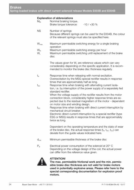
ATTENTION! The max. permissible frictional work and the min. permis-
sible brake disc thickness are not valid for brake motors used in potentially explosive areas. Please refer here to the special corresponding documentation for explosion proof motors.
Brakes Spring-loaded brakes with direct current solenoid release Models E003B and E004B
Bauer Gear Motor +49 711 3518-034

P-7119-BGM-EN-A5 10/17
Connection, adjusting and maintenance work may only be carried out taking into account the safety information on pages 4/5.
Caution: Brakes are safety-relevant components; therefore, only qualified
personnel with product-specific training may perform work on them. To find your nearest service partner, visit www.bauergears.com.
The brakes ES010A ... ES250A, ZS300A and ZS500A are holding brakes which do not perform frictional work in standard duty but are used princi-pally for holding a specifically reached position. In emergency situations a braking function may also be performed.
The brakes ESX010A ... ESX250A , ZSX300A and ZSX500A are working brakes which perform frictional work in standard duty e.g. a braking function is performed.
In addition to holding loads in the idle state, the spring-loaded brake slows rotating and linear moving masses, thus reducing unwanted overtravel dis-tances and times.The brake is released electromagnetically. In the de-energized state, braking force is applied by spring pressure. Because the retardation effect is still ef-fective even if an unforeseen power failure occurs, it can be considered to be a safety brake within the context of accident prevention regulations.During the braking process, the kinetic energy of the mass moments of in-ertia is transformed into heat via the brake discs. The brake discs consist of high-quality, asbestos-free material and are particularly resistant to abrasion and heat. A certain amount of wear is, however, unavoidable. For this rea-son, the limit values regarding the working capacity and the minimum lining thickness are to be strictly observed.
ES and ESX: Brake mounting is under the fan cover EH and EHX: Brake mounting is on the fan cover
Single disc brakes ES(X)...
The springs (Pos. 3) press the axial movable pressure plate (Pos. 6) and the brake disc (Pos. 2) which is mechanically connected to the rotor shaft against the friction disc or motor end shield. The brake torque is created.
Safety information
General information
Brake mounting
Operating principle
Brakes Spring-loaded brakes with DC solenoid release Models ES(X)010A ... ES(X)250A, ZS(X)300A, ZS(X)500A, EH(X)027A …EH(X)400A
Bauer Gear Motor +49 711 3518-0 35

P-7119-BGM-EN-A5 10/17
When a DC voltage is placed on the coil in the magnet housing (Pos. 1), a magnetic force is created whereby the pressure plate (Pos. 6) is pulled against the spring force against the magnet housing (Pos. 1). The brake disc is free to run and the brake is opened.
Caution!The air gap of the brake is not adjustable due to the construction prin-cipal of the magnet housing. When the wear limit or the max. permissi-ble air gap is reached, the brake disc must be replaced. The momentar-ily existing air gap of the brake can be determined by means of a feeler gauge after removing the plug (Pos. 13). The plug must be replaced and sealed with locking varnish.
Brakes Spring-loaded brakes with DC solenoid release Models ES(X)010A ... ES(X)250A, ZS(X)300A, ZS(X)500A, EH(X)027A …EH(X)400A
Bauer Gear Motor +49 711 3518-036

1515
17
16
13
9
7
6
2
10
11
12
14
3
4.1
1
8
4.2
5
P-7119-BGM-EN-A5 10/17
1 Magnet housing2 Brake disc3 Spring4.1 Sealing cap for encapsulated brakes4.2 Shaft seal for 2nd shaft extension5 Carrier6 Pressure Plate7 O-Ring8 Fastening bolts with copper washer9 Hollow bolt10 Circlip11 Key12 Circlip13 Plug for monitoring of the air gap14 Friction plate - only in motors with aluminium end shield15 Plug for monitoring of the micro switch setting16 Microswitch (Optional)17 Manual release (Optional)
Figure 1: Brake Models ES(X)010A ... ES(X)250A.
Air Gap
Brakes Spring-loaded brakes with DC solenoid release Models ES(X)010A ... ES(X)250A, ZS(X)300A, ZS(X)500A, EH(X)027A …EH(X)400A
Bauer Gear Motor +49 711 3518-0 37

7
1392.22.110
511
12
1
18
17
16
1514
4.1
3
8
4.2
6
P-7119-BGM-EN-A5 10/17
Double disc brakes ZS(X)...
The springs (Pos. 3) press the axial movable pressure plate (Pos. 6) and the brake disc (Pos. 2.1 and 2.2) which are mechanically connected to the rotor shaft against the motor end shield. The brake torque is created.
When a DC voltage is placed on the coil in the magnet housing (Pos. 1), a magnetic force is created whereby the pressure plate (Pos. 6) is pulled against the spring force against the magnet housing (Pos. 1). The brake discs (Pos. 2.1 and 2.2) are free to run and the brake is opened.
When the wear limit or the max. permissible air gap is reached, the brake can be adjusted. When worn, the brake can be adjusted. The momentarily existing air gap can be monitored after removal of the sealing ring (Pos. 13).
Figure 2: Brake models ZS(X)300A, ZS(X)500A.
Air Gap
Brakes Spring-loaded brakes with DC solenoid release Models ES(X)010A ... ES(X)250A, ZS(X)300A, ZS(X)500A, EH(X)027A …EH(X)400A
Bauer Gear Motor +49 711 3518-038

P-7119-BGM-EN-A5 10/17
1 Magnet housing2 Brake disc 2.1 and 2.23 Spring4.1 Sealing cap for encapsulated brakes4.2 Shaft seal for 2nd shaft extension5 Carrier6 Pressure Plate7 O-Ring8 Fastening bolts with copper washer9 Hollow bolt 10 Circlip11 Key12 Circlip13 Cover14 Fastening bolts15 Plate16 Assembly screw/Assembly help17 Microswitch (Optional)18 Manual release (Optional)
ATTENTION!• Brake disc and brake surface must be free from oil and grease• The carrier must be positioned so that the spline of the brake
disc is in full contact.• The contacting surface of the key should be along the full
length of the carrier.• Cleaning agents containing solvents may not be used as
these corrode the friction material.
The brakes are assembled ready-for-use on the motor.
The assembly of the single disc brakes results as follows:
• Insert the circlip (Pos. 10) in the shaft groove.• Insert the key (Pos. 11) in the rotor shaft.• Position the carrier (Pos. 5) on the rotor shaft and secure with the circlip
(Pos. 12).• Assembly friction plate (Pos. 14) (only motor sizes D08 and D09).• Push the brake disc (Pos. 2) onto the carrier (Pos. 5).• Assemble the magnet housing with 3 fastening bolts (Pos. 8). Tighten-
ing torques refer to Brake Technical Data.
Caution! Copper washers are found under the bolt heads. These may only
be used once.
• The air gap of the brake is defined by the brake design.
Assembly
BrakesSpring-loaded brakes with DC solenoid release Models ES(X)010A ... ES(X)250A, ZS(X)300A, ZS(X)500A, EH(X)027A …EH(X)400A
Bauer Gear Motor +49 711 3518-0 39

P-7119-BGM-EN-A5 10/17
The assembly of the double disc brakes results as follows:
• Insert circlip (Pos. 10) in the shaft groove.• Insert key (Pos. 11) in the motor shaft.• Position carrier (Pos. 5) on the shaft and secure with circlip (Pos. 12).• Push brake disc (Pos. 2.1) onto the carrier (Pos. 5).• Push the magnet housing with the intermediate flange and the brake
disc (Pos. 2.2.) onto the carrier.• Tighten the fastening bolts with the given torque. Tightening torque
refer to Brake Technical Data.• The brake air gap must be monitored. Values refer to Brake Technical
Data Caution! Should the air gap not correspond to the given values, it must be
set accordin to section Air Gap.• Place the O-Rings (Pos. 7 ) in the corresponding grooves.• Place the cover (Pos. 13) around the brake.• Place the plate (Pos. 15) on the lugs of the covering plate.• Press the cover plate with screws (Pos. 14) so far so that the cover
plate lies radially on the magnet housing and the motor end shield.
Caution!Copper washers are found under the bolt heads. These may only be used once.
Caution!The brakes without manual release are supplied with an assembly aid which is to be removed after assembly.
The open holes in the magnet housing must be sealed with the plastic plugs supplied along with the brake.
GeneralThe air gap must be monitored regularly. When the max. permissible air gap is reached (see technical data) the brake disc must be replaced or the air gap adjusted. Adjustment of the air gap is only possible for double disc brakes.
Monitoring the air gap of single disc brakesThe brake air gap (max. permissible air gap refer to Brake Technical Data) can be measured by means of a feeler gauge by removing the plug (Pos. 13). The plug must be replaced and sealed with locking varnish.
Caution!The max. tightening torque of the plug is 10 Nm.
Monitoring of the air gap of double disc brakesAfter removal of the cover (Pos. 13), the air gap can be measured my means of a feeler gauge.
Air Gap
Brakes Spring-loaded brakes with DC solenoid release Models ES(X)010A ... ES(X)250A, ZS(X)300A, ZS(X)500A, EH(X)027A …EH(X)400A
Bauer Gear Motor +49 711 3518-040

P-7119-BGM-EN-A5 10/17
Procedure:• When looking at the brake, the fastening bolts (Pos. 8) must be re-
leased by half a turn.• Now, the hollow bolts (Pos. 9), which enclose the fastening bolts
(Pos. 8) can be screwed into the magnet housing (Pos. 1) by turning anticlockwise.
• Turning the 3 fastening screws (Pos. 8), positioned 120° from another, clockwise, the magnet housing can be moved in the direction of the pressure plate (Pos. 6) so that the nominal air gap measured with a feeler gauge is reached. Nominal air gap refer to Brake Technical Data.
• The 3 hollow bolts are now screwed out clockwise until they sit against the magnet housing (Pos. 1).
• Finally the fastening screws (Pos. 8) are tightened wit the defined tight-ening torque given in the Brake Technical Data.
• The rest of the hollow bolts of the adjacent friction surface must be carefully tightened with the defined tightening torque.
• The brake air gap must now be rechecked. Values refer to Brake Tech-nical Data.
Caution!The manual release setting may not be changed.
ATTENTION! Bauer asumes no liability when the springs are changed.
Single disc brakes ES(X)...Diferent brakes torques (see Brake Technical Data) can be reached by means of differing spring placement (see figure 7.1) in the magnet housing (Pos. 1).
When the conversion of the brake must result through the user, the required springs (Pos. 3) are to be requested giving the brake size and the brake setting.
ATTENTION! The brake must be disassembled form the motor and under no-
load before the springs are chenged.
Disassembly• Release the fastening screws (Pos. 8) when present.• Remove the manual release (optional).• Unscrew the hollow bolts (Pos. 9) out of the magnet housing (Pos. 1).
ATTENTION! The springs (Pos. 3) press against the pressure plate (Pos. 6). The pressure plate (Pos. 6) must be pressed against the magnet
housing (Pos. 1) to avoid an abrupt relief of the springs (Pos. 3).
Setting of the brake torque
Brakes Spring-loaded brakes with DC solenoid release Models ES(X)010A ... ES(X)250A, ZS(X)300A, ZS(X)500A, EH(X)027A …EH(X)400A
Bauer Gear Motor +49 711 3518-0 41

P-7119-BGM-EN-A5 10/17
Figure 7.1 Positioning of the springs – Brakes ES(X)010A...ES(X)200A
Assembly• Remove the springs (Pos. 3).• Insert the new spring set– positioning see figure 7.1 and figure 7.2
Figure 7.2 Positoning of the springs - Brake ES(X)250A
Brakes Spring-loaded brakes with DC solenoid release Models ES(X)010A ... ES(X)250A, ZS(X)300A, ZS(X)500A, EH(X)027A …EH(X)400A
Bauer Gear Motor +49 711 3518-042

P-7119-BGM-EN-A5 10/17
ATTENTION!If a manual release was present, proceed with the assembly and setting according to the section Manual Release.• Place the pressure plate (Pos. 6) on the springs (Pos. 3).
ATTENTION!Observe the position of the bore for the manual release.• Screw in the hollow bolts (Pos. 9) against the spring force
until block.• Assemble the brake on the motor end shield.
ATTENTION! Refer to Brake Technical Data for the tightening torque of the
fastening screws (Pos. 8).
Brake checkChecking the air gap• Remove plug (Pos. 13).• Check the air gap by means of a feeler gauge. Air gap refer to Brake
Technical Data.• Replace the plug (Pos. 13).
Double disc brakes ZS(X)...The brakes ZS(X)300 and ZS(X)500 cannot be modified to other brake tor-ques.
• Remove the motor and brake from the mains supply. Disconnect the brake supply cable.
• Loosen the fastening screws (Pos. 8) and remove the brake from the motor end shield.
• Clean the brake. Remove brake dust by means of compressed air.• Remove the brake disc (Pos. 2) from the carrier (Pos. 5).• Place the new brake disc on the carrier and re-assemble the brake.
Replacing the brake disc
Brakes Spring-loaded brakes with DC solenoid release Models ES(X)010A ... ES(X)250A, ZS(X)300A, ZS(X)500A, EH(X)027A …EH(X)400A
Bauer Gear Motor +49 711 3518-0 43

P-7119-BGM-EN-A5 10/17
Technical Date of the Holding Brakes with Emergency Characteristics Models ES.../ZS...Frictional Work, Response Time, Power
* only permissible with MSG-Rectifier, over excitation is required
Type MBr Wmax Wth WL tA tAC tDC Pel
[Nm] [103 J] [103 J] [106 J] [ms] [ms] [ms] [W]
ES010AX 15* 3 - - 110 - 30
35
ES010A9 10 3 - - 60 100 15
ES010A8 8 3 - - 55 150 20
ES010A5 5 3 - - 45 220 20
ES010A4 4 3 - - 30 250 20
ES010A2 2.5 3 - - 25 350 25
ES027AX 32* 2.5 - - 80 - 30
50ES/EH027A9 27 2.5 - - 120 100 15
ES/EH027A7 20 2.5 - - 100 130 20
ES/EH027A6 16 2.5 - - 80 170 25
ES/EH040A9 40 3.5 - - 100 100 20
65ES/EH040A8 34 3.5 - - 80 200 25
ES/EH040A7 27 3.5 - - 70 250 30
ES070AX 90* 3.5 - - 120 - 40
85ES070A9 70 3.5 - - 120 150 18
ES070A8 63 3.5 - - 120 200 20
ES070A7 50 3.5 - - 90 220 25
ES/EH125A9 125 4.5 - - 170 220 25
105
ES/EH125A8 105 4.5 - - 150 320 28
ES/EH125A7 85 4.5 - - 135 350 30
ES/EH125A6 70 4.5 - - 120 440 35
ES125A5 57 4.5 - - 100 600 40
ES125A3 42 4.5 - - 90 700 45
ES/EH200A9 200 8 - - 400 150 22
105ES/EH200A8 150 8 - - 280 250 35
ES/EH200A7 140 8 - - 200 320 35
ES250A9 250 9 - - 300 500 45
135
ES250A8 200 9 - - 200 960 60
ES250A6 150 9 - - 160 1100 60
ES250A5 125 9 - - 150 1500 90
ES250A4 105 9 - - 130 1800 110
ZS300A9 300 8 - - 280 220 3575
ZS300A8 250 8 - - 210 380 45
EH400A9 400 10 - - 300 600 60
180EH400A7 300 10 - - 200 850 75
EH400A5 200 10 - - 150 1400 85
ZS500A9 500 9 - - 320 320 50100
ZS500A8 400 9 - - 260 600 60
ZS800A9 800 20 - - 400 550 65140ZS800A7 600 20 - - 320 920 80
ZS800A5 400 20 - - 250 1450 100
Brakes Spring-loaded brakes with DC solenoid release Models ES(X)010A ... ES(X)250A, ZS(X)300A, ZS(X)500A, EH(X)027A …EH(X)400A
Bauer Gear Motor +49 711 3518-044

P-7119-BGM-EN-A5 10/17
Explanation of abbreviationsMBr Nominal braking torque. Brake torque tolerance: -10 / +30 %Wmax Maximum permissible switching energy for a single braking op-
erationWth Maximum permissible switching energy per hourWL Maximum permissible switching until replacement of the brake
disc
No values given for Wth and WL as the holding brakes in stand-ard duty do not perform frictional work.
tA Response time when releasing with normal excitation. Overexcitation by the MSG special rectifier results in response
times that are approximately half as long.tAC Response time when braking with alternating current isolation, i.e. by interruption of the power supply of a separately fed
standard rectifier. When the voltage supply of the rectifier results from the motor
connection block, considerably higher response times are ex-pected due to the residual magnetism of the motor - dependent on motor size and winding design.
tDC Response time when braking with direct current interruption by mechanical circuit breaker.
Electronic direct-current interruption by a special rectifier (type ESG or MSG) results in response times that are approximately twice as long.
For the brake torque designs marked with *, which can only be reached by use of the MSG rectifier, the values for tA and tDC are already valid for use with the MSG rectifier i.e. tA for over excitation and tDC for electronical DC switching.
Depending on the operating temperature and the production tolerances, the actual response times can differ from the guidance values given here.
Pel Electrical power consumption of the solenoid at 20° C Depending on the voltage design of the coil, the actual power
can differ from the reference value given.
Brakes Spring-loaded brakes with DC solenoid release Models ES(X)010A ... ES(X)250A, ZS(X)300A, ZS(X)500A, EH(X)027A …EH(X)400A
Bauer Gear Motor +49 711 3518-0 45

P-7119-BGM-EN-A5 10/17
Spring placement, Air Gap, Tightening torque of the screws
* only permissible with MSG-Rectifier, over excitation is required1) Brake with special spring bore. Reworking to another brake torque is not possible.
Type MBr
[Nm]
Number and colour of the springs
sLN
[mm]
sLmax
[mm]MA
[Nm]outside inside w/o HL with HL
ES010AX 15*1) Special 0.2 0.6 0.6
6
ES010A9 10 4x yellow 3x turquoise 0.2 0.6 0.6ES010A8 8 4x yellow 3x yellow 0.2 0.7 0.7ES010A5 5 2x yellow 3x yellow 0.2 1.0 1.0ES010A4 4 4x yellow - 0.2 1.2 1.0ES010A2 2.5 4x silver 3x silver 0.2 1.5 1.0ES027AX 32*1) Special 0.3 0.6 0.6
10ES/EH027A9 27 4x turquoise 3x turquoise 0.3 0.6 0.6ES/EH027A7 20 4x yellow 3x turquoise 0.3 0.9 0.9ES/EH027A6 16 4x turquoise - 0.3 1.0 1.0ES/EH040A9 40 4x silver 3x silver 0.3 0.9 0.9
10ES/EH040A8 34 4x silver 2x silver 0.3 1.1 1.0ES/EH040A7 27 2x silver 3x silver 0.3 1.3 1.0ES070AX 90* 4x turquoise 3x turquoise 0.3 1.0 1.0
25ES070A9 70 2x turquoise 3x turquoise 0.3 0.8 0.8ES070A8 63 4x yellow 3x yellow 0.3 1.1 1.0ES070A7 50 4x yellow 2x yellow 0.3 1.5 1.0ES/EH125A9 125 4x yellow 3x turquoise 0.4 0.7 0.7
25
ES/EH125A8 105 2x yellow 3x turquoise 0.4 1.2 1.2ES/EH125A7 85 4x yellow 2x yellow 0.4 1.3 1.2ES/EH125A6 70 2x yellow 3x yellow 0.4 1.7 1.2ES125A5 57 4x yellow - 0.4 2.0 1.2ES125A3 42 - 3x yellow 0.4 2.0 1.2ES/EH200A9 2001) Special 0.4 0.6 0.6
25ES/EH200A8 150 4x yellow 3x yellow 0.4 0.9 0.9ES/EH200A7 140 4x yellow 2x yellow 0.4 1.2 1.2ES250A9 250 4x yellow 4x yellow 0.5 1.0 1.0
50ES250A8 200 4x yellow 2x yellow 0.5 1.7 1.5ES250A6 150 4x yellow 1x yellow 0.5 2.0 1.5ES250A5 125 4x yellow - 0.5 2.4 1.5ES250A4 105 4x silver 4x silver 0.5 2.4 1.5ZS300A9 300 4x yellow 3x yellow 0.5 0.9 0.9
25ZS300A8 250 2x yellow 3x yellow 0.5 1.1 1.1EH400A9 400 4x yellow 4x yellow 0.5 1.2 1.2
50EH400A7 300 4x yellow 2x yellow 0.5 1.5 1.5EH400A5 200 4x yellow - 0.5 1.7 1.5ZS500A9 500 4x yellow 4x yellow 0.5 1.0 1.0
50ZS500A8 400 4x yellow 2x yellow 0.5 1.2 1.2ZS800A9 800 4x yellow 4x yellow 0.6 1.2 1.2
50ZS800A7 600 4x yellow 2x yellow 0.6 1.2 1.2ZS800A5 400 4x yellow - 0.6 1.2 1.2
Brakes Spring-loaded brakes with DC solenoid release Models ES(X)010A ... ES(X)250A, ZS(X)300A, ZS(X)500A, EH(X)027A …EH(X)400A
Bauer Gear Motor +49 711 3518-046

P-7119-BGM-EN-A5 10/17
Explanation of abbreviationsMBr Nominal braking torque. Brake torque tolerance: -10 / +30 %
sLN Nominal air gap when new. Tolerance +0,15 mm, except at EH400 and ZS800 Tolerance: +0,20 mmsLmax Maximum permissible air gapHL Manual Release
MA Tightening torque of the fastening screws
ATTENTION! The max. permissible frictional work and the min. permis-
sible brake disc thickness are not valid for brake motors used in potentially explosive areas. Please refer here to the special corresponding documentation for explosion proof motors.
Brakes Spring-loaded brakes with DC solenoid release Models ES(X)010A ... ES(X)250A, ZS(X)300A, ZS(X)500A, EH(X)027A …EH(X)400A
Bauer Gear Motor +49 711 3518-0 47

P-7119-BGM-EN-A5 10/17
Technical Date of the Working Brakes Models ES(X).../ZS(X)...Frictional Work, Response Time, Power
* only permissible with MSG-Rectifier, over excitation is required
BrakesSpring-loaded brakes with DC solenoid release Models ES(X)010A ... ES(X)250A, ZS(X)300A, ZS(X)500A, EH(X)027A …EH(X)400A
Type MBr
[Nm]
Wmax
[103 J]
Wth
[103 J]
WL
[106 J]tA
[ms]
tAC
[ms]
tDC
[ms]
Pel
[W]without HL with HL
ESX010AX 15* 3 250 120 120 110 - 30
35
ESX010A9 10 3 250 120 120 60 100 15ESX010A8 8 3 250 150 150 55 150 20ESX010A5 5 3 250 240 240 45 220 20ESX010A4 4 3 250 300 240 30 250 20ESX010A2 2.5 3 250 390 240 25 350 25ESX027AX 27* 10 350 150 150 80 - 30
50ESX/EHX027A9 22 10 350 150 150 120 100 15ESX/EHX027A7 16 10 350 300 300 100 130 20ESX/EHX027A6 13 10 350 350 350 80 170 25ESX/EHX040A9 32 20 450 420 420 100 100 20
65ESX/EHX040A8 27 20 450 560 490 80 200 25ESX/EHX040A7 22 20 450 700 490 70 250 30ESX070AX 72* 28 550 700 700 120 - 40
85ESX070A9 58 28 550 500 500 120 150 18ESX070A8 50 28 550 800 700 120 200 20ESX070A7 40 28 550 1200 700 90 220 25ESX/EHX125AX 100* 40 700 1900 1900 100 - 70
105
ESX/EHX125A9 85 40 700 1700 1700 150 320 28ESX/EHX125A8 70 40 700 1900 1700 135 350 30ESX/EHX125A7 58 40 700 2700 1700 120 440 35ESX125A5 45 40 700 3300 1700 100 600 40ESX125A3 34 40 700 3300 1700 90 700 45ESX/EHX200AX 160* 60 850 2000 2000 105 - 70
105ESX/EHX200A9 120 60 850 1700 1700 280 250 35ESX/EHX200A8 110 60 850 2600 2600 200 320 35ESX250A9 200 84 1000 2800 2800 300 500 45
135ESX250A8 160 84 1000 6800 5700 200 960 60ESX250A6 120 84 1000 8500 5700 160 1100 60ESX250A5 100 84 1000 11000 5700 150 1500 90ESX250A4 85 84 1000 11000 5700 130 1800 110ZSX300A9 250 60 850 1300 1300 280 220 35
75ZSX300A8 200 60 850 2000 2000 210 380 45EHX400A9 320 120 1100 3000 3000 300 600 60
180EHX400A7 240 120 1100 4800 4800 200 850 75EHX400A5 160 120 1100 6000 4800 150 1400 85ZSX500A9 400 84 1000 2800 2800 320 320 50
100ZSX500A8 320 84 1000 4000 4000 260 600 60ZSX800A9 640 120 1150 1550 1550 400 550 65
140ZSX800A7 480 120 1150 1550 1550 320 920 80ZSX800A5 320 120 1150 1550 1550 250 1450 100
Bauer Gear Motor +49 711 3518-048

P-7119-BGM-EN-A5 10/17
Explanation of abbreviationsMBr Nominal braking torque. Brake torque tolerance: -20 / +30 % when worn in. In new state
up to -30 % possible
Wmax Maximum permissible switching energy for a single braking operation
Wth Maximum permissible switching energy per hourWL Maximum permissible switching until serviceing i.e. replacement
of the brake disc or air gap adjustment. Adjustment of the air gap only possible for ZS(X) brakes possible
HL Manual release
The values given for WL are reference values which can vary considerably depending on the specific application. It is recom-mended to monitor the brake disc thickness regularly.
ATTENTION! The max. permissible frictional work and the min. permis-
sible brake disc thickness are not valid for brake motors used in potentially explosive areas. Please refer here to the special corresponding documentation for explosion proof motors.
tA Response time when releasing with normal excitation. Overexcitation by the MSG special rectifier results in response
times that are approximately half as long.tAC Response time when braking with alternating current isola-
tion, i.e. by interruption of the power supply of a separately fed standard rectifier.
When the voltage supply of the rectifier results from the motor connection block, considerably higher response times are ex-pected due to the residual magnetism of the motor - dependent on motor size and winding design.
tDC Response time when braking with direct current interruption by mechanical circuit breaker.
Electronic direct-current interruption by a special rectifier (type ESG or MSG) results in response times that are approximately twice as long.
For the brake torque designs marked with *, which can only be reached by use of the MSG rectifier, the values for tA and tDC are already valid for use with the MSG rectifier i.e. tA for over excitation and tDC for electronical DC switching.
Depending on the operating temperature, wear of the brake disc and the production tolerances, the actual response times can differ from the guid-ance values given here.
Pel Electrical power consumption of the solenoid at 20° C Depending on the voltage design of the coil, the actual power
can differ from the reference value given.
Brakes Spring-loaded brakes with DC solenoid release Models ES(X)010A ... ES(X)250A, ZS(X)300A, ZS(X)500A, EH(X)027A …EH(X)400A
Bauer Gear Motor +49 711 3518-0 49

P-7119-BGM-EN-A5 10/17
Spring placement, Air Gap, Tightening torque of the screws
* only permissible with MSG-Rectifier, over excitation is required1) Brake with special spring bore. Reworking to another brake torque is not possible.
Type MBr
[Nm]
Number and colour of the springs
sLN
[mm]
sLmax
[mm]MA
[Nm]outside inside w/o HL with HL
ESX010AX 15* 1) Special 0.2 0.6 0.6
6
ESX010A9 10 4x yellow 3x turquoise 0.2 0.6 0.6ESX010A8 8 4x yellow 3x yellow 0.2 0.7 0.7ESX010A5 5 2x yellow 3x yellow 0.2 1.0 1.0ESX010A4 4 4x yellow - 0.2 1.2 1.0ESX010A2 2.5 4x silver 3x silver 0.2 1.5 1.0ESX027AX 27* 1) Special 0.3 0.6 0.6
10ESX/EHX027A9 22 4x turquoise 3x turquoise 0.3 0.6 0.6ESX/EHX027A7 16 4x yellow 3x turquoise 0.3 0.9 0.9ESX/EHX027A6 13 4x turquoise - 0.3 1.0 1.0ESX/EHX040A9 32 4x silver 3x silver 0.3 0.9 0.9
10ESX/EHX040A8 27 4x silver 2x silver 0.3 1.1 1.0ESX/EHX040A7 22 2x silver 3x silver 0.3 1.3 1.0ESX070AX 72* 4x turquoise 3x turquoise 0.3 1.0 1.0
25ESX070A9 58 2x turquoise 3x turquoise 0.3 0.8 0.8ESX070A8 50 4x yellow 3x yellow 0.3 1.1 1.0ESX070A7 40 4x yellow 2x yellow 0.3 1.5 1.0ESX/EHX125AX 100* 4x yellow 3x turquoise 0.4 1.3 1.3
25
ESX/EHX125A9 85 2x yellow 3x turquoise 0.4 1.2 1.2ESX/EHX125A8 70 4x yellow 2x yellow 0.4 1.3 1.2
ESX/EHX125A7 58 2x yellow 3x yellow 0.4 1.7 1.2ESX125A5 45 4x yellow - 0.4 2.0 1.2ESX125A3 34 - 3x yellow 0.4 2.0 1.2ESX/EHX200AX 160* 1) Special 0.4 1.0 1.0
25ESX/EHX200A9 120 4x yellow 3x yellow 0.4 0.9 0.9ESX/EHX200A8 110 4x yellow 2x yellow 0.4 1.2 1.2ESX250A9 200 4x yellow 4x yellow 0.5 1.0 1.0
50ESX250A8 160 4x yellow 2x yellow 0.5 1.7 1.5ESX250A6 120 4x yellow 1x yellow 0.5 2.0 1.5ESX250A5 100 4x yellow - 0.5 2.4 1.5ESX250A4 85 4x silver 4x silver 0.5 2.4 1.5ZSX300A9 250 4x yellow 3x yellow 0.5 0.9 0.9
25ZSX300A8 200 2x yellow 3x yellow 0.5 1.1 1.1EHX400A9 320 4x yellow 4x yellow 0.5 1.2 1.2
50EHX400A7 240 4x yellow 2x yellow 0.5 1.5 1.5EHX400A5 160 4x yellow - 0.5 1.7 1.5ZSX500A9 400 4x yellow 4x yellow 0.5 1.0 1.0
50ZSX500A8 320 4x yellow 2x yellow 0.5 1.2 1.2ZSX800A9 640 4x yellow 4x yellow 0.6 1.2 1.2
50ZSX800A7 480 4x yellow 2x yellow 0.6 1.2 1.2ZSX800A5 320 4x yellow - 0.6 1.2 1.2
BrakesSpring-loaded brakes with DC solenoid release Models ES(X)010A ... ES(X)250A, ZS(X)300A, ZS(X)500A, EH(X)027A …EH(X)400A
Bauer Gear Motor +49 711 3518-050

P-7119-BGM-EN-A5 10/17
Explanation of abbreviationsMBr Nominal braking torque. Brake torque tolerance: -20 / +30 % when worn in. In new state
up to -30 % possible
sLN Nominal air gap when new. Tolerance +0,15 mm, except at EHX400 and ZSX800 Tolerance: +0,20 mm
sLmax Maximum permissible air gapHL Manual Release
MA Tightening torque of the fastening screws
ATTENTION! The max. permissible frictional work and the min. permis-
sible brake disc thickness are not valid for brake motors used in potentially explosive areas. Please refer here to the special corresponding documentation for explosion proof motors.
Brakes Spring-loaded brakes with DC solenoid release Models ES(X)010A ... ES(X)250A, ZS(X)300A, ZS(X)500A, EH(X)027A …EH(X)400A
Bauer Gear Motor +49 711 3518-0 51

P-7119-BGM-EN-A5 10/17
There are 2 different options for the voltage supply of the DC solenoid:1. Externally from an existing DC control power supply, or from a rectifier in the control cabinet.2. From a rectifier built into the motor terminal box or brake terminal box.In this instance, the rectifier can be supplied either directly from the motor terminal board or from the mains.In the following instances, the rectifier must not however be connected to the motor terminal board:
• Pole-changing motors and wide range motors• Operation with frequency converter• Other designs in which the motor voltage is not constant, e.g. opera-
tion on smooth-start equipment, starting transformers, ...
If the solenoid is energised using nominal voltage, the coil current and the magnetic field build up follow an exponential function. Only when the power has achieved a specific value (lRel) is the spring force overcome and the brake begins to release.
Two different cases can occur during response time tA, assuming the power is supplied to the motor and the brake at the same time:
• Motor is blocked - condition: MA < ML + MBr The motor takes the inrush current and is thereby subjected to ad-ditional thermal loading. This scenario is shown in Figure 2.
• Motor tears away from brake - condition: MA > ML + MBr At the start, the brake is subject to thermal loading and wears more rapidly.
MA: starting torque of the motor, ML: load torque, MBr: braking torque
In both scenarios, the motor and brake are therefore subjected to additional loading. The response time becomes noticeably longer as the size of the brakes increases. A reduction in response time is therefore especially recom-mended for medium and large-sized brakes as well as with a high frequency of braking operations. A relatively simple electrical solution is possible using the principle of ‚overexcitation‘. In this instance, the solenoid is briefly sup-plied with twice the nominal voltage when switched on.The response time is decreased to approximately half by comparison with ‘normal excitation‘ as a result of the associated steeper rise of the current. This overexcitation function is integrated in the MSG special rectifier (see section brake connection).
General
Brake Release
Brakes Electrical brake connection
Bauer Gear Motor +49 711 3518-052

t
I
INÜN
UN
2UN
NÜ
t
nN
NÜ
tt tt
Solenoid voltage
Solenoid current
Motor speed
P-7119-BGM-EN-A5 10/17
Figure 2: Solenoid voltage, solenoid current and motor speed development at normal excitation (N) and overexcitation (Ü).tÜ: overexcitation period; tAN, tAÜ: response times at normal excitation and overexcitation
As the air gap gets larger, the release current and therefore the response time increase. As soon as the release current exceeds the nominal coil cur-rent, the brake no longer releases during normal excitation and the brake disc wear limit is reached.
BrakesElectrical brake connection
Bauer Gear Motor +49 711 3518-0 53

P-7119-BGM-EN-A5 10/17
The braking torque is not effective immediately after the power supply to the solenoid is switched off. Firstly, the magnetic energy has to reduce until the spring force can overcome the magnetic force. This occurs at holding ampe-rage IHold which is far smaller than the release current. Dependent on the circuit design, different response times result.
Switching off the AC supply of the standard rectifier SGa) Rectifier supply from the motor terminal board (Figure 3, graph 1)
Response time tA1: very long Cause: after the motor voltage is switched off, the remanence of the motor induces a slowly decaying voltage which continues to supply the rectifier and thus the brake. The magnetic energy of the brake solenoid declines relatively slowly through the freewheeling circuit of the rectifier.
b) Separate rectifier supply (Figure 3, graph 2) Response time tA2: long Cause: after the rectifier voltage is switched off, the magnetic energy of the brake solenoid declines relatively slowly through the freewheeling circuit of the rectifier.
No significant shut-off voltages arise on the solenoid during an AC interrup-tion.
Interruption in the DC switching circuit of the solenoid (Figure 3, graph 3)a) By mechanical switch
- for separate supply from a DC control network or - at the DC switching contacts (A2, A3) of the standard rectifier Response time tA3: very short Cause: The magnetic energy of the brake solenoid is rapidly reduced by the arc developing at the switch.
b) Electronically By use of a special rectifier, type ESG or MSG Response time tA3: short Cause: the magnetic energy of the brake solenoid is reduced rapidly by a varistor integrated in the rectifier.
Braking
Brakes Electrical brake connection
Bauer Gear Motor +49 711 3518-054

IN
t
t
Nn
tA2 tA3 A1 t
12
3I
0
Solenoid current
Motor speed
P-7119-BGM-EN-A5 10/17
With a DC interruption, voltage spikes u q are induced through the solenoid the height of which depends on the following relationship between the self-inductance L of the coil and the cut-off speed di/dt:
uq = L · didt
As a consequence of the winding design, inductivity L increases as the solenoid rated voltage increases. With higher solenoid voltages, the cut-off voltage spikes may therefore be dangerously high. All brakes for voltages in excess of 24 V are therefore connected with a varistor.The varistor serves only to protect the solenoid and not as protection for the surrounding electronic components and devices against electromagnetic compatibility interference.On request, brakes for voltages of less than or equal to 24 V can also be produced with varistors.
If the direct current interruption is produced by a mechanical switch, high levels of burn down are caused by the arc produced on the switch contacts. Only special DC direct current contactors or adapted AC alternating current contactors can be used with contacts of usage category AC3 as defined in EN 60947-4-1.
Brakes Electrical brake connection
Bauer Gear Motor +49 711 3518-0 55

KB
c1
L2
PEL3
L1
BD2 K
control cabinet
A1
~L~N
BD1
PE
UDC
UU
UE
SG
1
motor
3~M
blue
netnet
net
P-7119-BGM-EN-A5 10/17
Figure 8: Rectifier voltage supply from the motor terminal board Voltage connection for the rectifier from the motor terminal block or cage clamp (see Rectifier Connection on Motor Terminal Block or Cage Clamp)
Rectifier technical data
Operating principle Half-wave rectifier with electronic direct current interruption
Supply voltage U1 220 - 460 V AC ±5 %, 50/60 HzOutput voltage 0.45 * U1 V DC Maximum output current 1 A DCAmbient temperature -20° C to 40° CPossible conductorcross-sections maximum 1.5 mm2
The blue conductor routed out of the casing must be connected to PE to activate the integrated high-speed switch-off function.As this conductor is coupled to the supply voltage with high impedance, leakage currents of up to a maximum of 2 mA may flow, depending on the voltage level.
If the motor undergoes high-voltage testing, the blue wire of the rectifier must be disconnected from the PE beforehand.
When operating on unearthed networks, the blue conductor is to be con-nected with the right alternating current voltage contact (N) of the ESG. If the rectifier is supplied from the motor terminal board in this case, an increase in the response time on shut-down is to be anticipated.
Brakes Brake connection: special rectifier ESG 1.460A
Bauer Gear Motor +49 711 3518-056

V
3~M
U W
ES
G1
motor
L2L1
PEL3
control cabinetPE
c1
ACU
A1K
~L~N
BD2
BD1
blue
P-7119-BGM-EN-A5 10/17
Picture 8a: Separate voltage supply of the rectifier, e.g. for usage on fre-quency inverter
Brakes Brake connection: special rectifier ESG 1.460A
Bauer Gear Motor +49 711 3518-0 57

V
3~M
U W
motor
L2L1
PEL3
control cabinetPE
c2
BD2
BD1
c1
L+L-
P-7119-BGM-EN-A5 10/17
If the brake is supplied directly from a DC control power supply.
Figure 4: Direct DC power supply from a control network
Brakes Brake connection: DC voltage supply
Bauer Gear Motor +49 711 3518-058

PE
c1
PE
L1
L3L2
DCBD2
BD1U
K
MS
G ..
. I
~~
A1
motor
control cabinet
UUU
3~M
KB
netnet
net
P-7119-BGM-EN-A5 10/17
Figure 10: Voltage connection for the rectifier from the motor terminal block or cage clamp (see Rectifier Connection on Motor Terminal Block or Cage Clamp)
Rectifier technical data MSG 1.5.480I
Operating principle Half-wave rectifier with time-limited overexci tation and electronic direct current interruption
Quick switch-off due to absence of motor current in a phase.
Operating voltage U1 220 - 480 V AC +6/-10 %, 50/60 HzOutput voltage 0.9 * U1 V DC during overexcitation
0.45 * U1 V DC after overexcitation Overexcitation period 0.3 sMaximum output current 1,5 A DCAmbient temperature -20° C to 40° CPossible conductorcross-sections maximum 1.5 mm2
Brakes Brake connection: special rectifier MSG...I
Bauer Gear Motor +49 711 3518-0 59

P-7119-BGM-EN-A5 10/17
To enable the current monitoring, one of the leads of the supply cable must be passed through the current sensor on the side of the rectifier. As the current sensing has a lower threshold, the lead must be passed through the sensor twice if the motor no-load current is lower than 0,4A. In this case a sticker with the number “2” is on the rectifier underneath the sensor itself. The maximum constant current of the sensor is 64A.
Caution: It is imperative for the correct functioning of the rectifier that a
motor lead is passed through the sensor. If not, the rectifier will not switch on and in the worst case can be permenantly dama-ged.
The diameter of the sensor bore for passing the leads through is 7 mm. The diameter of the leads of the motor connection cable must therefore not exceed the following values:max. lead diameter: 6,7 mm for 1 passthrough 3,2 mm for 2 passthroughs
Brakes Brake connection: special rectifier MSG...I
Bauer Gear Motor +49 711 3518-060

V
3~M
U W
MS
G ..
. U
motor
L2L1
PEL3
control cabinetPE
c2
ACU
A1K
~~
BD2
BD1
c1
P-7119-BGM-EN-A5 10/17
Picture 9: Separate voltage supply of the rectifier
Rectifier technical data MSG 1.5.500U
Operating principle Half-wave rectifier with time-limited overexci tation and electronic direct current interruption
Quick shut-down due to absence of input voltage.
Operating voltage U1 220 - 500 V AC +/-10 %, 50/60 HzOutput voltage 0.9 * U1 V DC during overexcitation
0.45 * U1 V DC after overexcitation Overexcitation period 0.3 sMaximum output current 1,5 A DCAmbient temperature -20° C to 40° CPossible conductorcross-sections maximum 1.5 mm2
Brakes Brake connection: special rectifier MSG...U
Bauer Gear Motor +49 711 3518-0 61

c1
PE
SG
A1K
A2A3
~~
BD2
BD1KBDCU
UU UL2
L1
PEL3
motor
control cabinet
3~M
netnet
net
P-7119-BGM-EN-A5 10/17
Figure 5: AC disconnection Terminal A2 and A3 bridged
Rectifier technical data
Operating principle Half-wave rectifierSupply voltage U1 maximum 575 V AC +5 %, 50/60 HzOutput voltage 0.45 * U1 V DC Maximum output current 2 A DC Ambient temperature -40° C to 40° CPossible conductorcross-sections max. 1.5 mm2 without wire end ferrule max. 1.0 mm2 with wire end ferrule
1 Rectifier voltage supply from the motor terminal board Voltage connection for the rectifier from the motor terminal block or cage clamp (see Rectifier Connection on Motor Terminal Block or Cage Clamp)
Brakes Brake connection: standard rectifier SG 3.575B
Bauer Gear Motor +49 711 3518-062

UU U
SG
motor
L2L1
PEL3
control cabinetPE
c2
A1K
A2A3
~~
BD2
BD1
c1
KBDCU
3~M
netnetnet
P-7119-BGM-EN-A5 10/17
Figure 6: DC disconnection at terminals A2 and A3 e.g. via direction of rotation contactor via relay
Brakes Brake connection: standard rectifier SG 3.575B
Bauer Gear Motor +49 711 3518-0 63

U V W
BD2
BD1
L1
L3PE
L2
c1
PE
A1K
A2A3
~~
motor
control cabinet
UAC
SG
3~M
P-7119-BGM-EN-A5 10/17
2 Rectifier voltage supply via separate contactor
As described in paragraph 4.1, the rectifier may not be connected at the mo-tor terminal board on all models with variable motor voltage or on pole chan-ging motors. Instead, the input voltage of the rectifier must be connected through a separate contactor. The implementation principle when operating on the frequency inverter is shown in Figure 7 and 7a by way of example.
Figure 7: Separate voltage supply of the rectifier. Alternating current switch-off Terminals A2 and A3 bridged
BrakesBrake connection: standard rectifier SG 3.575B
Bauer Gear Motor +49 711 3518-064

V
3~M
U W
SG
motor
L2L1
PEL3
control cabinetPE
c1
ACU
A1K
A2A3
~~
BD2
BD1
P-7119-BGM-EN-A5 10/17
Picture 7a: Separate voltage supply of the rectifier. DC side switching on the terminals A2 and A3 via relay.
Brakes Brake connection: standard rectifier SG 3.575B
Bauer Gear Motor +49 711 3518-0 65

U4U4U4V1 V3
L2
V2 V1
L2
V2V3 V3V1
L2
V2
U ~ 0,45xUL1
DC
U2 W1V4
U3 W4U1
W3
W2
L3
U ~ 0,225xUU ~ 0,45xU
U2
U3
DCL1
W3
W2L3
W1V4
W4U1
L1DC
W1V4
W4U1
U2
U3
L3
W3
W2
W2 U2 V2
U ~ 0,45xU
L1
DC
L2
U1 V1
L3
W1
U1
L1
W2 V2U2
W1
L3
U ~ 0,45xU
V1
L2
DC
W2
U1 W1
U2 V2
V1
L1
U ~ 0,26xU
L2
DC
L3
Y
Y
L1 L2 L3
1
U1 V1 W1
Y PE
53426
W2 U2 V2
1 2 3
U1 V1 W1
1
Y PE 21
2
3
3
L1 L2 L3
4
U2
5
V2
6
W2
U1 V1 W1U2 V2
L1 L2 L3
1
W2
Y
6
4 5
PE
2
1 2
3
3
U1 V1W2 U2 V2W1
L1
U1PE V1W2 U2
L2
V2W1
L3
U1
U1
PE
U2
U2V1
V1
W2
W2
V2W1
V2W1
L1 L2 L3
U1 U2W2 V1 W1 V2
L1
U1PE U2
L2
W2 V1
L3
W1 V2(L)*
(N)*
(N)*
(N)*
(L)*
(L)*
net
net
net
net net net
P-7119-BGM-EN-A5 10/17
Brakes Rectifier on motor terminal block or cage clamp
Bauer Gear Motor +49 711 3518-066

P-7119-BGM-EN-A5 10/17
The manual release can only be assembled with the rake removed. Procedure (see Figures 1 and 12 in section spring loaded E003B and E004B):
1.1 Remove brake from the motor end shield.1.2 Remove stopper plugs from the manual-release holes in the
magnet housing (8).1.3 Push compression springs (16) onto the manual-release bolts
(17).1.4 Push manual-release bolts (17) with compression springs (16)
into the manual-release holes on the magnet housing (8) from the inside (in the direction of the coil (7)).
1.5 Push the O-rings (18) onto manual-release bolts (17) and push into the countersinks on the magnet housing (8).
1.6 Push spacer plates (19) onto the manual-release bolts (17).1.7 Locate manual release bracket (13), push on washer (20) and
screw on self-locking nut (21) loosely.1.8 Tighten both lock nuts (21) until the retaining plate (2) is flush
with the magnet housing (8).1.9 With non-lockable manual release:
Unscrew both lock nuts (21) by 1.5 turns, thereby creating the air gap between the retaining plate (2) and magnet housing (8) and the test dimension X = 0.9 mm. With latching manual release: Unscrew both lock nuts (21) by 3 turns, thereby creating the test dimension X = 2 mm.
1.10 After fitting the fan cowl, screw the manual-release rod (14) into manual-release bracket (13) and tighten.
Assembly
Fig 12: Assembly of the manual release
The manual release bracket (13) is pressed by the compression springs (16) into the neutral position. The brake can be released by axial manipulation.For the model with a latching manual release, the manual release bracket is fixed by screwing the manual release rod (14) into the appropriate bore in the brake housing with the brake released.To release the latch, turn the manual release rod back again.
Function
Brakes Manual release for spring loaded brake with DC solenoid Model E003B and E004B
Bauer Gear Motor +49 711 3518-0 67

31
33
32
P-7119-BGM-EN-A5 10/17
The hand release allows the manual release of the brake. By operating the manual release, the pressure plate (Pos. 6) is pulled against the magnet hous-ing (Pos. 1). An air gap between the brake disc (Pos. 2) and the pressure plate (Pos.6) results, the brake is open and the rotor shaft can rotate freely.
ATTENTION! The settings of the manual release may not be changed. The manual release lever and loacking arrangement are supplied separately as a by-pack kit.
Screw the manual release lever Pos. 31 and the locking arrangement Pos. 32 (if applicable) into the manual release. For brake types ES(X) and ZS(X) insert the protective guard Pos. 33 over the lever into the fan cowl slot. If the lock-ing arrangement is present, break out the perforation in the protective guard.
Assembly of the manual release lever
Brakes Manual release for spring loaded brake with DC solenoid Model ES(X)010A ... ES(X)250A, ZS(X)300A, ZS(X)500A
The assembly of the manual release is only possible when the brake was ordered specifically for this option.
When changing the brake torque, the manual release must be re-assembled as follows:
Caution! Before assembly of the manual release, the brake must be disassem-bled from the motor and electrically disconnected!
• Before the pressure plate is assembled, the O-Rings (Pos. 20) and the discs (Pos. 21) must be placed in the in the countersinks in the magnet housing.
• Assemble the pressure plate (Pos. 6) with the hollow bolts (Pos. 9).
Caution! The hollow bolts must lie under the sealing face of the magnet housing.
Assembly and disassembly of the manual release
ES(X)…A / EH(X)...A/ZS(X)…A Lever thread Driving torque reference value [Nm]010 M5 5
027/040 M6 8070/125/200/300 M8 18250/400/500/800 M12 25
Caution: Manual release lever and grip pro-tection in the accessory kit. If the manual release lever (Pos. 31) and grip protection (Pos. 33) are not in-stalled together, the operator must allow for suitable contact protection at the opening in the fan cowl pro-vided for movement of the manual release lever.
Bauer Gear Motor +49 711 3518-068

P-7119-BGM-EN-A5 10/17
• Push the washer (Pos. 24) and then the spring (Pos. 22) onto the bolt (Pos. 23). Then push all parts, from the inside looking at the sealed coil, into the bores in the pressure plate and magnet housing (Pos. 1).
• Push the O-Rings (Pos. 25) over the threads of the mounting bolts (Pos. 23) and press them into the countersink of the magnet housing
(Pos. 1).• Push the plate (Pos. 26) over the screw thread.• Push the bolts (Pos. 28) into the manual release lever.• Screw the screw (Pos. 23) into the bolt (Pos. 28).• Tighten both hexagon bolts (Pos. 23) until the pressure plate (Pos. 6) lies uniformly on the magent housing (Pos. 1).• Release both hexagonal bolts (Pos. 23) by X turns
(see Table Setting the Manual Release). The adjusting dimension „y“ for the manual release is set this way.
ATTENTION!: The adjusting dimension „y“ must be set uniformly and my not be readjusted later.
• Mark the setting using locking varnish on the hand release bolts (Pos. 28).
• After assembly of the fan cowl, screw the manual release lever in the manual release and tighten.
Setting of the manual release
Type Setting the Manual ReleaseAdjusting
Dimension Y
[mm]
"Unsrew bolts by X turns"
Wrench size Manual release
lever [mm]
ES(X)010 1 1.5 8ES(X)027/EH(X)027 1 1.5 10ES(X)040/EH(X)070 1 1.3 10ES(X)070 1 1 12ES(X)125/EH(X)125 1.2 1.2 12ES(X)200/EH(X)200 1.2 1.2 12ES(X)250 1.5 1.2 19ZS(X)300 1.2 1.2 12ZS(X)500 1.5 1.2 19EH(X)400 1.5 1.2 19ZS(X)800 1.5 1.2 19
Brakes Manual release for spring loaded brake with DC solenoid Model ES(X)010A ... ES(X)250A, ZS(X)300A, ZS(X)500A
Bauer Gear Motor +49 711 3518-0 69

33
31
3233
31
32
P-7119-BGM-EN-A5 10/17
After the manual release has been opersted, this can be locked by seizing the threaded bolt against the magnet housing.
Locking manual release
Assembly of the locking:The existing manual release of the brakes ES(X)010 to ES(X)250 and the ZS(X)300 bis ZS(X)500 can be converted to locking manual release through assembly of the plate (Pos. 32 ) and the threaded bolt (Pos. 33).
Brake Wrench size of the threaded boltES(X)010 to ES(X)027/EH(X)027 2.5ES(X)040/EH(X)040 2.5ES(X)070 to ES(X)200/EH(X)200 4ES(X)250 5ZS(X)300 4ZS(X)500 5EH(X)400 5ZS(X)800 5
Manual release
• Disassemble lever (Pos.31).
Caution!The existing spring ring on the lever thread must be removed
• Locate plate (Pos. 32) with threaded bolt (Pos. 33) between the hand release and the lever.
• Tighten lever (Pos. 31)
Brakes Manual release for spring loaded brake with DC solenoid Model ES(X)010A ... ES(X)250A, ZS(X)300A, ZS(X)500A
Bauer Gear Motor +49 711 3518-070

13.5
13
17
21.5
21
16.5
30
29.5
25.54.5 M20 30BF70 Pos.4 5200 377 13793
BF90
BF80
555Pos.5 16800
9500Pos.5 445
7.030270
21348 5.5
50M20
M20 40
BF40
BF60
BF50
BF30
BF20
242Pos.2 780
1200
2150Pos.3
Pos.3
340
270
350
500Pos.2
Pos.1
210
190
BF06
BF10 200
Pos.0
Pos.1 155
4.03223
6324
4444
4.5
4.0
2381
1842
2.5
3.0
20M10
M18
M18
28
24
M10
M10
18
18
1290 2.2 M10 16
162.5°
242.5°
2.5° 19
112.5°
2.5°
2.5°
15
12
2.5°
2.5° 9
8
2.5° 7
S
a
G
LL
H
K
91395 104 2.0 10M8 10 2.5° 5
shaft mounted gearboxsee dimension sheet of the respectiveDimensions of the transverse hole:
= pressing force on the rubber buffers= assigned gear torque2T
F
(mm)(Nm)2T K
(N)F
(mmG H
(mm)L
rubber buffer
Pre-tensioning per
(mm) (Not for rubber buffer)
(see
T 2
23)
Rubber buffers pretensioned
Gear
Rubber buffer for torque restraint
s (mm)
max. wayaPos. max.
Gear (Motors)
The actual design can vary from the geometry shown.
Additional Dimension Sheets
P-7119-BGM-EN-A5 10/17
1. Installation of the rubber buffer.The rubber buffers provided are to be fixed in accordance with the drawings N-BF-DST,N-BK-DST or N-BS-DST and tightened to the pretension required.
2. As part of the specified maintenance intervals, the correct tensioning and conditions of the rubber buffers is to be checked and the same changed should faults be apparent. For dynamic applications, this proceedure must be performed independent from the standard intervals, every 3.000 hours machine usage.
Note: Play in the rubber buffers can result in damage to the gearwheels and bearings.
Gearmotors Gear units designed with torque arms and rubber buffers for series BF
Bauer Gear Motor +49 711 3518-0 71

shaft mounted gearboxsee dimension sheet of the respective
2130 2.5°455.0 M2022340470Pos.5BK80 10500
BK90 Pos.5 16800 29474570 5.5 M20 45 29.5 2.5° 25
Pos.3BK50 950
BK70
BK60
Pos.4 5200
Pos.3 2150
BK40
BK30
Pos.2 680
Pos.2 400
BK10
BK06
BK20
Pos.1 170
Pos.1 280
Pos.0 80
363.5 M183800250 21.5
4.514054370
6324340 4.0
40M20 25.5
M18 2138
3.02720250
1951205 3.0
1730M10
M10 1730
112.5°
162.5°
2.5° 15
112.5°
2.5° 9
1.51063160
1556180 2.0
555144 1.5
19M10 13.5
M10 1319
M8 10 10.5
72.5°
2.5° 8
a
SL
H
Dimensions of the transverse hole:
K
L
G
62.5°
max. screw diameter
Rubber buffers pretensioned
= pressing force on the rubber buffers= assigned gear torque2T
F
(mm)(Nm)2T K
(N)F
(mm)G H
(mm)L
rubber buffer
Pre-tensioning per
(mm)
max. way
(Not for rubber buffer)
s (mm)
a
(see
T 2
23)
Gear
Rubber buffer for torque restraint
BK17 Pos.1 280 2.01556180 19M10 13 82.5°
Pos. max.
Gear (Motors)
The actual design can vary from the geometry shown.
Additional Dimension Sheets
P-7119-BGM-EN-A5 10/17
1. Installation of the rubber buffer.The rubber buffers provided are to be fixed in accordance with the draw-ings N-BF-DST, N-BK-DST or N-BS-DST and tightened to the pretension required.
2. As part of the specified maintenance intervals, the correct tensioning and conditions of the rubber buffers is to be checked and the same changed should faults be apparent. For dynamic applications, this proceedure must be performed independent from the standard intervals, every 3.000 hours machine usage.
Note: Play in the rubber buffers can result in damage to the gearwheels and bearings.
Gearmotors Gear units designed with torque arms and rubber buffers for series BK
Bauer Gear Motor +49 711 3518-072

510 10.5 2.5°M81.546611855Pos.0BS03
1.5
2.0
2.5
3.0
2.0
3.0
Pos.0
Pos.0
Pos.2
Pos.2
Pos.1
Pos.3BS40
BS10
BS20
BS30
BS04
BS06
340980 2882
121
144
205
250
160180
290
542
110
45
1125
1415
2096
372
764
2.5°
2.5°
2.5°
2.5°
2.5°
2.5°38M18 22
19
30
30
10
10
M10
M10
M10
M8
M10
13
17.5
17
10.5
10
15
7
9
11
5
6
s
Gear(mm)(Nm)
2T K(N)F
= pressing force on the rubber buffers= assigned gear torque
a
(mm)G H
(mm)L
max. screw diameter
Rubber buffers pretensioned
HL
LG
rubber buffer
Pre-tensioning per
(mm) (Not for rubber buffer)
s (mm)
The actual gearbox design can vary from the geometry shown.
K
2TF
shaft mounted gearboxsee dimension sheet of the respectiveDimensions of the transverse hole:
Rubber buffer for torque restraint
max. waya
(see
T 2
23)
Pos. max.
Gear (Motors)
The actual design can vary from the geometry shown.
Additional Dimension Sheets
P-7119-BGM-EN-A5 10/17
1. Installation of the rubber buffer.The rubber buffers provided are to be fixed in accordance with the draw-ings N-BF-DST, N-BK-DST or N-BS-DST and tightened to the pretension required.
2. As part of the specified maintenance intervals, the correct tensioning and conditions of the rubber buffers is to be checked and the same changed should faults be apparent. For dynamic applications, this proceedure must be performed independent from the standard intervals, every 3.000 hours machine usage.
Note: Play in the rubber buffers can result in damage to the gearwheels and bearings.
GearmotorsGear units designed with torque arms and rubber buffers for series BS
Bauer Gear Motor +49 711 3518-0 73

P-7119-BGM-EN-A5 10/17
The backstop locks the geared motor in a certain direction of rotation (indi-cation of direction with view of the mounted side of the gear unit).
The backstop is assembled on the end shield of the motor.The inner ring with mounted on clamping part insert is located on the ex-tended rotor shaft. This clamping part insert consists of caging in which the individually spring-loaded clamping parts are guided. The clamping parts lay flushon the outer ring. The end guard protects against contact and the penetra-tion of foreign objects.
When the geared motor is started, the clamping parts disengage and do not make contact until the speed of the motor drops below approximately 640/min (D..08), 740/min (D..09,D..11), 665/min (D..13 bis D..18) after discon-nection or a power failure. The clamping parts then slowly rise and lock a reversing movement at the moment of rest.The power transmission in locked state goes from the rotor shaft via the inner ring to the clamping parts and from there via the outer ring to the end shield and the housing of the geared motor.
The standard three phase current motors are normally connected for anti-clockwise rotation when looking at the front of the fan shaft end and with the phase sequence L1 - L2 - L3. The actual phase sequence of the mains is to be selected in such a way that the motor starts in the freewheeling direction. For the first test start, it is advisable to connect particularly larger motors in star connection to protect the backstop as far as possible.If a brief test connection finds that the motor is not connected in direction of rotation, but in the blocked direction, two mains leads are to be exchanged as with any normal change of direction of rotation. After a wrong connection, check fuses and motor protection switches and check for correct terminal board connection as indicated on the rating plate.
Safety information: Mounting, connection, adjusting and maintenance work may
only be carried out taking into account the safety information given on the accompanying information sheet No. 122 and of the operating instructions for the backstop.
Assembly of the freewheeling mechanisms may only be carried out by trained specialist personnel taking into account the instal-lation information!
The machinery must be secured against rollback before work is performed on the backstop!
Mounting
Operation
Supply connection
Gearmotors Geared motors with backstop
Bauer Gear Motor +49 711 3518-074

P-7119-BGM-EN-A5 10/17
Connection and maintenance work may only be carried out taking into ac-count the safety information on pages 4/5.
The assembly of standard motors in the size range IEC 56 to IEC 280 and NEMA 56 C to NEMA 405 TC using the C-Adapter is to be performed ac-cording to the following plan:
I. Remove assembly plug 1II. Arrange the clamping ring so that the clamping screw 2 is under
the assembly hole. Loosen the clamping screw 2 so much that the clamping ring 4 does not tighten on the intermediate shaft 3 anymore.
III. Arrange the motor ans rotor shaft to the gear side mounting face
IV. To make assembly easier, bring the motor and gearbox together in the vertical position (motor pointing upwards)
V. Insert motor shaft into the intermediate shaft without forcingVI. Tighten clamping screw 2VII. Tighten motor fitting screws 5VIII. Insert assembly plug 1
Tightening torques of screwsIEC NEMA Threads DIN 13 M [Nm]56 M6 12,363 M6 12,371 56 M6 12,380 M8 29,890 145 M8 29,8112 184 M8 29,8132 215 M12 102160 256 M12 102180 286 M12 102200 M16 252225 326 M16 252250 365 M16 252280 405 M16 252
Safety Information
Motor Attachment
Gearmotors Assembly of standard motor with C-Adapter (IEC and NEMA)
Bauer Gear Motor +49 711 3518-0 75

grease freeShaft
Hub
Inner Ring
Tightening Bolts
Outer Ring
Assembly and disassemblyof the shrink disc
Gear (Motors)
The actual gearbox design can vary from the geometry shown.
Additional Dimension Sheets
P-7119-BGM-EN-A5 10/17
The shrink-disc is supplied ready to be installed and should therefore not be dismantled. The shrink-disc may not be clamped without fitting the shaft.The shaft must be fitted or the hub pushed onto the shaft in the area of the shrink-disc seat.The tightening bolts must then be tightened evenly around the circumfer-ence until the front side face of the outer ring and inner rings is flush. The state of clamping can thus be monitored visually.To disassemble, loosen all screws evenly in sequence. If the outer ring does not automatically separate from the inner ring, a number of tightening bolts may be removed and screwed into the neighbouring forcing-off threads.Any rust on the shaft in front of the hub must be removed before the shaft is removed or the hub is taken from the shaft.Removed shrink-discs only need to be dismantled, cleaned, and regreased before refitting if they are very dirty. In this event, a solid lubricant with a coef-ficient of friction of µ = 0.04 or better is to be used.
Gearmotors Assembly and disassembly of the shrink-disc
Bauer Gear Motor +49 711 3518-076

P-7119-BGM-EN-A5 10/17
If geared motors are to be stored for an extended time before start-up, inc-reased protection against damage by corrosion or humidity can be achieved by observing the following information. Since the actual loading depends very strongly on local conditions, the time data can be regarded only as a guide value. It should also be noted that this data does not include any extension of the warranty term. If disassembly is necessary before start-up according to this information, it is recommended that the nearest BAUER franchised workshop or representatives be called in. The instructions contai-ned in the after-sales manual are to be observed in all cases.
The plugs supplied by the works in all entry holes on the terminal box are to be checked for damage caused during transportation and for correct posi-tioning and replaced if necessary.
Any vent valves which are present are to be removed and replaced with a suitable cover screw for the length of storage.
If any damage is caused in transit to the paintwork or if there are bare areas where the anti-rust paint has come away, such as on shafts or flanges, this should be repaired.
The storage space should be dry, well-ventilated and vibration-free. If the temperature in the space exceeds the normal range of approximately -20° C to +40° C for an extended period of time or varies strongly frequently, it could even become necessary to employ the measures before start-up specified in section “Measures before start-up” after shorter storage times.
The drives should be turned 180°, at intervals of approximately one year, so that lubricant covers the bearings in the gearing, previously located in an upper position, and the cog wheels. The levels of lubricant on the bearings must also be inspected at the same time. The lifespan of lubricant in the bearings will be reduced in the event of lengthy storage. If you see that the lubricant is contaminated, it must be changed.
Turning the drive unit does not have to be carried out if the gear unit enclo-sure is completely filled with lubricant as the result of a special agreement. In this case, the lubricant level before start-up is to be reduced to the desired value as defined in the operating instructions and the lubrication information plate.
Motor component• Insulation measurement
Measure the insulation resistance of the winding with commercially available measuring apparatus (e.g. with a magneto) between all winding parts and between the win-ding and the enclosure.
Geared motor con-dition and storage space
Measures during the storage period
Measures before start-up
Gearmotors Information on the storage of geared motors with cage rotors
Bauer Gear Motor +49 711 3518-0 77

P-7119-BGM-EN-A5 10/17
• Measured value above 50 megohm: no drying necessary, new condition Measured value under 5 megohm: drying advised Measured value approximately 1 megohm: lowest permissible thres-hold
• Drying the winding by standstill stator heating without disassembly Connection to stepless or tapped variable alternating current voltage up to approximately 20 % maximum of the rated voltage. Heating current max. 65 % of the rated current according to the rating plate.Observe heating up for first 2 to 5 hours; reduce heating voltage if necessary. Heating duration approximately 12 to 24 hours until insulation resis-tance rises to desired value.
• Dry the winding in the oven after disassembly Dismantle the motor in the appropriate manner Dry the stator winding in a well ventilated drying oven at between 80° C and 100° C for approximately 12 to 24 hours until the insulation resis-tance rises to the desired value.
• Lubricating the rotor position If the storage period exceeds approximately 2 to 3 years, or the temperatures were very unfavourable throughout a shorter storage period as described in “Geared motors with three phase cage rotors” paragraph 3, the lubricant in the rotor positions must be checked and refilled if necessary. For checking, a partial assembly on the fan side is sufficient, where the rolling contact bearing becomes visible after remo-val of the fan cowl, fan and bearing flange (end shield).
Gear unit component• Lubricant
If the storage period exceeds approximately 2 to 3 years, or the temperatures were very unfavourable throughout a shorter storage period as described in “Geared motors with three phase cage rotors” paragraph 3, the lubricant in the gear unit must be changed. For de-tailed instructions and lubricant recommendations please see chapter lubrication quantity.
• Shaft seals When changing the lubricant, the function of the shaft seals between the motor and gear unit as well as on the output shaft must also be checked. If a change in shape, colour, hardness or sealing effect is determined, the shaft seals must be replaced appropriately under observance of the after-sales manual.
• Gaskets If lubricant is draining out at the connecting points on the gear unit enclosure, the sealing compound must be replaced as described in the after-sales manual.
• Vent valve If a vent valve was replaced with a cover screw when storing, the vent valve must be refitted to the point of removal.
Gearmotors Information on the storage of geared motors with cage rotors
Bauer Gear Motor +49 711 3518-078

P-7119-BGM-EN-A5 10/17
Note
Bauer Gear Motor +49 711 3518-0 79

P-7119-BGM-EN-A5 10/17
Bauer Gear Motor GmbHEberhard-Bauer-Straße 3773734 EsslingenGermanyTel.: +49 711 3518-0Fax: +49 711 3518-381www.bauergears.com
Bauer does not make any representations, warranties or guarantees, expressed or implied, as to the accuracy or completeness of this manual or any statements, technical information and recommendations contained herein, or in any other documentation supplied by Bauer in connection with the use of the geared motor or gear unit (the “Product”). Before using the Product you should determine its suitability for your intended use. You bear all risk in connection with the use of the Product. You are reminded that all warranties as to merchantability and fitness for purpose are excluded from the contract under which the Product and this manual have been supplied to you. Bauer’s only obligation in this respect is, at its option, to repair or replace any product proven to be defective. Neither Bauer nor any of its affiliates or any of their respective directors, officers, employees or agents shall be liable in contract, tort or in any other manner whatsoever to any person for any direct or indirect loss, damage, injury, liability, cost or expense of any nature (whether loss of profit or otherwise), including without limitation incidental, special, direct or consequential damages arising out of or in connection with the use of this manual.Photos/Graphics: Altra- und Bauer-Archiv, Chr. Mayr, Precima
An Altra Industrial Motion CompanyIhre treibende Kraft - Your driving power