July/August 1995 Gear Technology
52
-
Upload
khangminh22 -
Category
Documents
-
view
0 -
download
0
Transcript of July/August 1995 Gear Technology


• Designed lOr IdlJ, The Pfauter PlOD is a true drycarbide hob bing machine, The horizontali worksplndle facilitates chip removal; and a work areacompletely enclosed in a stainless steel shrouddirects chips downward and completely awayffom the work. area. There's simply no place for"hot" chips to accumulate in a dry operation-the PWO Is thermally stable!I.H'exJbllllJlDr·· "IUIme" Wet .or dry. __carbideor HSS soft or hard gear flnishlng. ,.,almostanything's possible within PWO's remarkableperformance range:• Hob/tool speed range: .200-4,000 RPM• Workpiece/worktab.le max~ RPM.~3,.000• Max~Diametral Pilch: 10The Pfauter PlOO's unique direct drive hoband work spindle design makes it.possible-and affordable.
• Easy tol own and operate~Low cost, compactfootprint (only 2.3 cu. M), and 2 sec. auto loadsystem are a few more reasons to buy the PlOO.fall America.-n Pfautertodayat (SIS) 282-3000.
The enli~e work areais enclosed in astainless steel shroud(yellow) that preventshot chips from accu'mulaling and direclsthem downward intoa chip conveyor.Horizontal orientation
, ofwork spindle (red)1----' helps facililare
chip .removal.
Se'#!us at Booth #100
1351 Windsor RoadLoves Park, IL,61132·2698 U.S,A.
CIRCLE .1.-11on REAllER SE.FI.VIOE,CARD
Phone: 815-.282-3000Telefax: 815-282·3075
,GEAR MANUFACTURING ~CAN'T BE BUILT AROUND
You base your buying decisions on solid facts: prec."service and support. So separate promises from 01'01•••
demanding that your gear inspection system suppliero 1. Can the system's accuracy claims be traced?o 2. Does the system repeat (six sigma) to SUO-DBlca.
o 3. Can the system precisely measure involute met.4. Is it a PC-based system with networking capt"
o 5. Can the analysis software be tailored to UI'IWlI;" ......
06. Is an extended software warranty providedlo 7. Can the system's reliability track record be __D 8. Does the design, assembly, softwaret sales taG..
come from one dependable source?
SEND FOR FREE TECH REPORTGet our answers to the questions above, and see whymore professionals trust M&MPrecision Systems.Where you get proven results without the hype.Phone 513/859-8273 or fax 513/859-4452.
=- M&M PRECISION... SYSTEMS CurpaI__
"THE METROLOGY AND MOTION PEOPLE"CIRCLE A-5 on READER SERVICE CARD
---
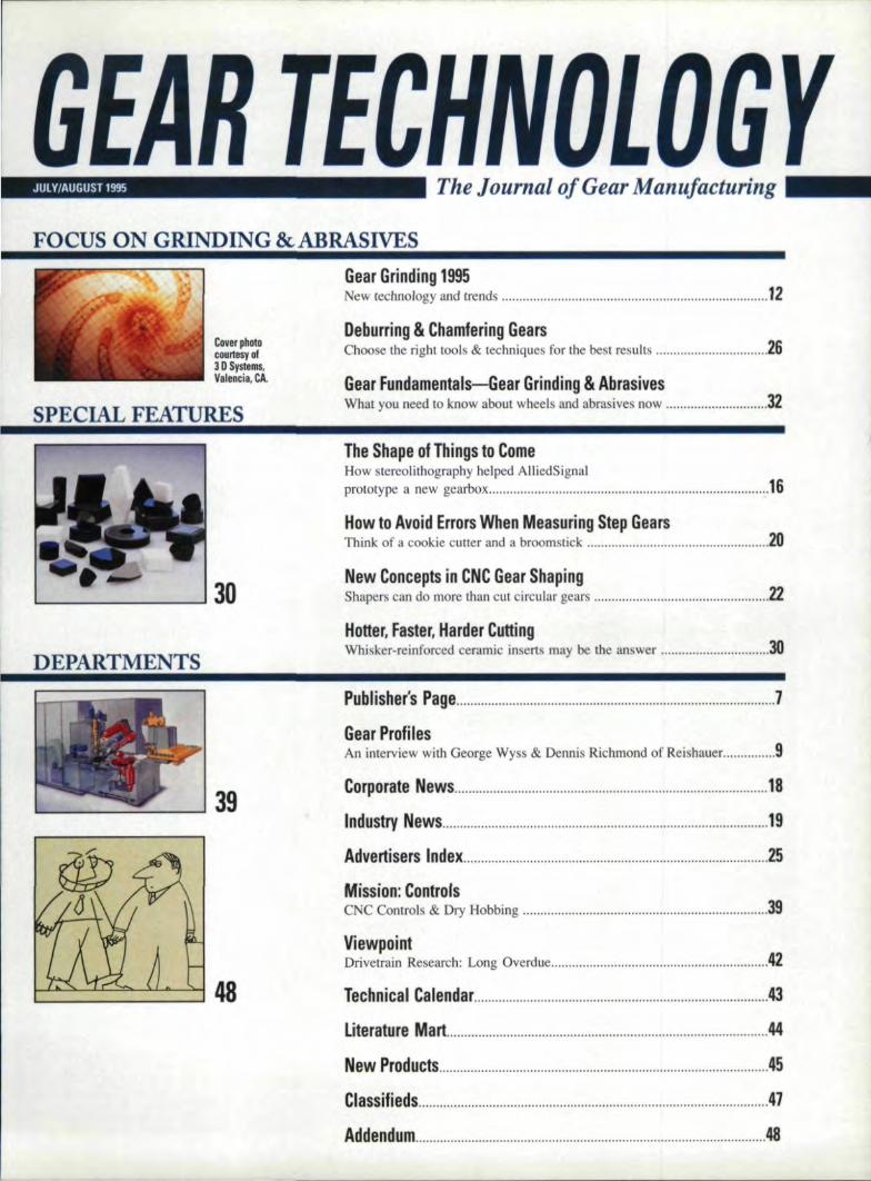
JULY/AUGUST 1995 I The Journal of Gear ManuJa,c.turing
FOCUS ,ON GRINDING &ABRASIVES
Cover Iphotocounesyol3 D Systems.,Valencia, CA.
SPECIAL FEATURES
IGear G,riinding1995ew technology and trends " " 1,2'
DebUlrlring & Chamfering GearsChoose the right tools & techniques for tile best results 26
G:ear IFundamentals-'Gear Grinding & AbrasinsWhat you need to, know about wheels and. abrasives now :32
DEPARTMENTS
TheSha:pe: 01 Thilngs to Come'How stereo lithography helped AlliedSignalprototype a. new gearbox ..,. " " 16
IHow to .Avoid E,rrolrs When Measur,ingl Step Gears __Think of a cookie cutter and a broomstick 2.0
INew Conce'pts in CNIC Gear Sha:pingShapers can do more than cut. circular gears "' 22
Hotter, ~aster, Harder CuttingWhisker-reinforced ceramic inserts may be the answer 30
48
Publlishe.(s; Pa,ge " 1
Gear IProfiliesAn interview with George Wyss & Dennis Richmond of Rei hauer 9,
C"o:rIPolrate! Ne,w.s, '18,
Industry News , 191
Advertisers lndex , , 25
Mission: C'ontrolsC _C Controls & Dry Bobbing " 39
Vli1ewpointDrivetrain Research: Long Overdue " 42
'lechnical Ca,l!endar 43:
Lit,erature M'art "." 44
New Products 45
'CI1assifieds, " ,41
Addendum " 48
Withthel available number of precisiong;ear cuttin,gltool .suppliers reduoed', ;5"1'1it good' to IkJloW that you
sti:1Iha,ve an ,o'ption?'
¥'our' alterns,tive so'urce....AMIER:IICA'N SVIKES ICOMPANYSOLUTIONS tor ,the Gear ,Manufacturer
Suppliers ,of Preoision:Hobs - All TypesShapers - Disc, Shank,. Deep COlJnterbore,
Herringbone, Rack TypeShavers - Conventional, Diagonal, lin-FeedHones - External & lntsmalAdjustable Floating IReamers
Phone: (511'31427 ..0507or Faa: 1513,1 427 - 96:53
A member 01 theI>B David Brown Group
- ,of Companies
ROTARY ~ PROFILE DISCSHONING TOOLS FOR HARDENED GEAR PROFILES
oWENDT DUNNINGTON939 Rt.l00, Chesler Springs. PA 19425 Tel 6101458-5181 Fax 6101458-8903
CIRCLE A-4lonIREADEFI REPLY CA-'RD
IGEAR TECHNOLOGY1"- ........... r_
"'BPA InternationallPub'llcatiuMembership AppLi d Irur
September 1994."
EDITORIALIJubli her & Edjtor-Ia- 'hid
Michael' Ooldslejn
ASS4"lCiate PubJsbet" & Managing EditorJames K. Spalding. ca
Senior Editor - ancy Bartels
ssodate EdilQr Wil!ium R. Slon
T, clmlcal Edil.or.Robert Ernchello
William L. JanninckDon McVittie
Robert. E. Smith
ARTArt Director Jean Bartz
ADVERTISING,Adnrtlsinll ~lanaller
Patricia Flam
CIRCULATiIONCircu1lation oordinator
Deborah Donigian
RANDAll PUBLliSHING STA1FFPre idem Michael Goldstein
Vice Presidenl Richard Gold I 'in
Vlice PI' 'den General Ma~ell"Jame K. Spalding, CBC
ontro'ller Patrick Nash
ccounling Laura Manion
Art. Consultanl Marsha Goldstein
VOL 12,. NO.4GI<:AR TEnl 01104-''11. 1bc JUW'IU!I ur ';.:arMlinuFlicluTling ((SS U743·6858)" pubhxhedbl!llonlbl) h) iRandaJI Pubh I1mll . Inc .. 1425LUnEAvenue, P.O, Box 1426. E.JkGrove \l11l·1!~.Il 60007. (70 I 437-b6!14. rmer pm-e U.IX!U.S. Seco!lId..clas~ PU>.31lC (laid al ArlingtonHeight». r , and at additional mailing oltice.Randall Publi<hlnl! make every dfOl1 10 en_un:lh31 the procc .. es described in GEAR TECH·NOlOGY conform W sound engineering II c-neeNeither the uuthors nor 'he publisher can beheld re,pon,ibl~ for injuries sllblllim:u .. hrl f....l·lowing the procedure» de,,;r,l1cd. P,"lmQ,ler;Send uddre, changes LO GEAR TECI·I OlO·GY. The Journal or Gear MllJlufu tunng, 1425Luni Avenue, P.O, Bo~ 142b. Elk Grove Villug.e,u., 60007. (lCOntc,,', copyrl8lm:o.I by RAD Ll PU8USHI G. INC .• 1995. Mlldes.appcanng ill GEAR T 'GL'IIOlJJ{jY m.ay 1101 bereproduced ill whale nr in pUrl .....nhnur shee pres~ roenni',ioo of Ihe p"bI~r or Ilte ullior.

A Winning Strategy InGe -rin - Technology.
L'i'e!bhIe r1lrLor,enz
Four leaders in gear manufacturing technologyhave combined technical expert nee to provide gearmakers an unparalleled resource for creating worldclass gear production capability.
We call it Sigma Pool. And the combined productrange includes bevel geaI cutting and grindingmachines, gear hobbing and shaping machines,parallel axis grinding machines, gear measuring
centers, and hob sharpening machines,as well asgeax cutting tools ..Plus automation of work han-dling, and even complete plant installations.
The result is a winning strategy for making ge~rsof virtually any type to the highest quality level's, inshorter cycles, and at lowest practical per-piece cost.Contact Liebherr, 1465Woodland Drive, 'Saline,MI,313.429.7225.
CIRCLE A-8 on, REA'DER :SERVICE. 'CARD

......-1Dr ... 1.-culling IDOls to
fit "" bevelgear cullingmachines.
....~....l.'.fJMf........... What1JllCNfayyou
artCllrran6y runniBo In __ with tneQMI tradition of offertng only the best In gearcutting, deburrlng and finishing machinery,the quality found in our line of cutting toolsequals or exceeds all competitors.
All GMI bevel gear tools offer the samehigh precision and high performance asOEM tools, only at a significant savings!Our tools use high-tensile steel to increasetheir resistance to wear and increase thevolume of material removed betweensharpening operations.
Strict manufacturing specifications onprocess and heat treatment guarantee highquality throughout the tool life. Excellenttooth finish is ensured by precisionmachining and superior control of surfacefinish. And to ensure that all tools meet GMIstandards, they are all tested using state-of-the-art control processes.
GMI bevel gear tools - the best valueavailable in modern high precision bevel gearcuning tools.
GMf offers a wide variety of modem high precision bevel gearcufting tools, with the GMI quality that exceeds our competitors.
--
GMI gives you the edge to emerge as a major player in a world economy.---- ---
GMI6708 Ivandale Rd.P.D.lBox 31038Independence, OH 44131Phone (216) 642-0230 FAX (216) 642-0231CIRCLE .A·S.7on REA'OER SERVICE CARD

Bfginnl11g whh thhis1;Uf, one of the last bits of the
"old" Gear Technology is gone. From now on we'll be running the new
picture of me you see on this page. It. was time, my art and editorial
staff explained to me, to move ahead with the rest of the updated art
and editorial in the magazine. (] emphatically deny that the real moti-
vation for the new picture was putting a stop to the ever-increasing
number of jabs from certain friends about my "Dorian Gray" look.)
In the overall scheme of things, this is hardly worth noting. Still,
when it's one's own photo, the change becomes a bit more personal.
Studying one's portrait proofs gives new meaning to the phrase "shock
of recognition." If nothing else, it's one more reminder that nothing
stays the same forever. Change is the default mode of existence.
Another, far more important change took place recently in the auto-
motive gearing business. Marcello Finateri, after nearly 50 years with
Ford Motor Company, has retired .. Since 1962, Marcello has been
involved in the development of the differentials for all Ford cars and
trucks sold i..n the U.S. market. He was instrumental in developing and
maintaining Ford's strong engineering capability .in differential gear-
ing. Many of the hot cars we lusted after in our younger (and not so
younger) days have had Marcello's design engineering fingerprints all
over their drivetrains,
BUI Marcello has been much more than a brilliant 'engineer. He s
never met a gear he didn't like, and his long hours and killer work
weeks were as much a result of his passion for what he was doing as a
function of his work ethic,

PUBLISHER'S PAGE _
IM~o;re'geair fo:r ~yourImoney 8'nd val'uethat lasts.,Niagara Gear has an affordablealternative for your high quality,close-tolerance g,ear requ irements,
As gear grindingspeoialists. we usethe latest grinding wheel technologiesand all ,electronic Reishauer gea rgrinders to deliver what: you need.On prioe. On 'Quality. On time'.Our ground spur and: helical gears are:• Lighter, ~tronger, faster and quieter• The answer to your indust,ry's
toughest tolerance and! finishstandards
• Manufactured to Mll-I-4S2·1)6 andinspected to calibration StandardMll·STD-45662A
• Aliailab'le to 14 inch diameter andto' AGMA Class t 5 with crowning
More than 80% of our customers areFortune 500 companies. let us quoteon your next gear req,uirement andfind out why.
FAX: 016)1 874-9003941 Military Road '.IBuffalo. N'YI14217'
TIEL: 016) 874-3131'
GROUND GEA_RSPECIALISTS
CIRCLE 11-09'on READER:REPl.Y CAIRO
8 GEAR TECHN,OLOGY

George Wyss &Dennis Richmond ofReishauer Corporation
For this interview, "'e spoke withGeorge Wyss, president, and DennisRichmond, vice president of ReishauerCorporation about gear grinding andits place in gear manufacturillg today.
GT: Where do you see Relshauee'splace in the fotal gear industry'!.DR: Reishauer is in a niche w.ithin aniche industry. Somewhere between 5%and 70/; of those iii! the industry grindgears. That means 93% to 95% of them
don't. That sets us apart, and we have to
do things a little differently,
GT: Can you characterize the 7 %you're t.a'lkingabout?DR: For the 1110s1 part, they are sub-con-tractors-people that supply to original
equipment manufacturers. Some Q, Msdon't see gear grinding as a technologythey want to invest in. They leave that. upto shop that have decades of experience
grinding gears. Most of our customersmake complete gears=everything from
cutting raw materials to heal treating.
GT: Which market. segments repre-sent most of your business'?DR: Roughly speaking. 7.0% of ourbusiness is gear grinding machinesunder 400 rnrn in capacity-that is, 16"or smaller; 10% is in gear grinders up 10
800 mrn, The remaining 2.0% is com-posed of gearhoning and thread grind-ing machines .. The gears show up in
printing presses, machine 100Is., materialhandling, off-road truck and vehicle
transmissions, industrial speed reducers
and increasers and cars.
GT: You mentlenedcars last .. Is that
the smalle t egment?
DR: III the U.S. it is. In Europe automo-tive represents approximately one-third
of our bu iness.
GT: Why such a small U.S..segment?DR: The machines sold to the Europeanautomotive 'industry are primarily used
11mfinishing manual transmission gears.
We don't make many manual tran mis-sions in this country.
GT: What about the Japanese auto-mutlve marll:.et?GW: The Japanese car makers buildtransmissions differently. They are splitinto two eel ions connected by a set oftransfer gears with approximately 50.teeth. Also the final drive gear createsquite a bit of noise. It' those gears that
are being hard finished. More and moreAmerican car makers arc also lookinginto hard gear finishing. They're chang-
ing their thinking, especially wherenoise is critical in the final drive gearset in a. transmission, In the last five or
six. years, some U.S. auto makers have
started. grinding the final drive set So, Iwouldn't count grinding out of the .J.S.automotive market.
GT: '0 YOIII ee grinding as sometbingthe American auto industry is begin-ning to pick up,on?(;W: The problem is actually multi-fold ..
A few years ago when you bought a car,it came with II 101. of noise, but you not
only had transmission noise, you alsohad wind noise. Today, most of the wind
noise is gone, but you hear the transmis-sion. You have 10 do something with the
transmission to make it more quiet.
GT: To meet customer demand?GW: Yes, and the alternatives (0 grind-
ing to control noise can be very costly.
GT: With the cutbacks in aerospace,what markets are taking thelrptace?DR:, New markets such as motorcycle
transmissions are a good example.Harley-Davidson is now grinding gears
to reduce the drive-by noisegeneratedby theengine and transmission in itsmotorcycles. Five years ago no onewould ever believe that you could buy aHarley-Davidson with a ground geartransmission. Another example is windpower generation. In order to efficientlyuse wind and water for power genera-tion, you have tohave some way to gen-erate electricity that uses very littleenergy or friction. The way you do that
is with precision ground gears.GW: During 'the Reagan build-up years,
we sold a 101 of machines worldwide,
bUI right now the demand for groundgears in the aerospace and the aircraftindustry is really diminished,
OR: There's a lot of excessive capacity
JULY/AUGUST 1995 91

SAVE WARRANTY COSTS WITH
DiamondBLACKeAm 0 r p hat e c· C era m I e I
BENEFITS:
93-95Rc HARDNESS
LOW TEMPERATUREApplied at under 250°F
AMORPHOUS STRUCTUREResists chipping,
cracking & Peeling
HIGH ADHESIONWill not transfer
AFFINITY FORLUBRICANTS
CHEMICAL RESISTANTImpervious to most harsh
chemicals, acids and bases
UNIFORMITYSurface replication with
no build up
TEMPERATURE RESISTANTTO 2282°F
EXTREMELY THIN(80 Millionths)
US & FOREIGN PATENTED
DiamondBLACK" coatedgean have provided 7 timesthe gear ute VI. uncoated.
,,\'"~ DiamondBLACKe
- Amorphat,eclCerainicl- -"",. ....fill". ,
4'".""P. O. Box 190
100 Somerset DriveConover, NC 28613-0190
1-800-368-9968FAX 704-322-4636
CIRCLE A·10 'on READER REPLY CARD
'10 GEAR TECHNOLOGY
GEAR PROF;llES _oul there. The machine thai were sold : to inve I more in order 10 produce
in the HOsare now 1010 1.5year old something at rca enable co I. You have
and certainly capable of still generating
the necessary quality, at lea I for the
time being.
GW: I don't see defense aerespacecoming back with all the efforts forworldwide peace. ~ al 0 don't think Olecommercial aircraft indu try will boom.There's increasing demand over the
next few years, but airplanes gel faster,bigger .•and you use fewer of them,DR: But if you look at the average ageof an airplane in an airline' fleet, it'snow nearing 20-25 years, old. So I thinkthere could be another cyclic demandfor commercial aircraft. and that might
coincide with the need to replace thegrinding equipment.
From a maintenance standpoint, themachines are going to be 15 or 20 yearsold, andthe new technology is so much
better that I think when the demanddocs come back. it won', lake as manymachines to satisfy it because the new
machines are so much more productive.
GT: How are Retsbauer machineschanging?GW: I think it will be difficult in thefuture to come up with machines thatare even faster or more productive thanthey are now, because if this could beaccomplished. it actually reduces thedemand for new machines. They will bemore expensive 10 build, and fewer
machines will be sold because they'remore productive.
You call only raise the technology ofthe equipment tothe level oflhe [001.
Thai i the key factor. ]f you look at
grinding wheels today, there's a limit onhow fast you can grind, Once you've
eliminated all the idle times in theprocess. you are down to the '[001.
What's the grinding capability or the
specific removal rate of Ihe wheel? Ithink we are almost at the limit unlessgrinding wheels are going [0 be a lot
more productive in the future.I think: the ultimate goal is to pro-
ducea gear for the least cost. Tooling
and equipment has to be affordable forthe customer. bUI [ think the investment
playa' econdary role. You may have
to look at the cost per piece.DR: The point is, if someone hasn'tinvested lin new gear grinding technelo-
gy in the last .ix years, they're not cur-rent, There' something 011 the market
that's a lot better, that will produce agear faster-up 10 200 to 300% fa uer,depending on the age of the technologythat they are using now-and make agear for a lower perishable tool cost.
GW: There's always a relation betweeninvestment and cost per piece. Today
you can produce a gear ar a quarter ofthe co t that you could w.ith old equip-menl, but the price of the equipment.hasn't quadrupled; it's probably onlytwice as much.
GT: Wilal about grinding wheel teeh-nDlogy? How lias it cllallged?
DR: Ten years ago there wa a lot ofinterest in CB . Some companies e tab-lished processes that specified CB.Recently all article published by the
University of Aachen concluded that.there wa noadvantage in compressive
stresses gained from usjng CB . Withthe new shift grinding machine technol-ogy we introduced several years ago,there is 110 produ livily advantageto thesingle-ribbed, plated, CBN single-indexgrinding machine over our generatingprocess. I:n fact, we now set the industry
standard as far as productivity for medi-um pitch gears 400 mm and smaller.
Seeded gel wheel's are also beillgused ucces fully, and we haven't aban-
doned aluminum oxide. That's been amainstay over the year . The wheel
composition has changed a little, and we
are starting to see more and moreinduced-porosity wheels. They've given
u orne huge productivity gain .IGW: The bs ic material has not changed,but (he ratios of composition have.DR: I think thaI in the pill I we wentwith the approach that aile wheel fits
all. Now each gear has to be looked at
individually, and we have to choose the
optimum process 'for each specific part.
GT: Are tbere any other j,mporlanltrend to take 11 tieor?
DR: Many manufacturers are investi-
gating honing, especially for high-vet-
ume application , becau e the machine1001 isle expen ive, but m think mosthoning machine manufacturer. are 5tH]
trying to perfect the process. In mostcases the gear i.. driven by the hone-ring. The machine doesn't require anelectronic generating module. Honingmachines are less expensive than grind-ing machines because they have fewer
axes. Commercially available controlcomponents make these machines moreeconomical to build, I think honing windefinilely have at future once you have'
the righttool. By right tool [ mean the
right hone-ring and the dre 'sing toolmarried toa rigid machine.
But honing won't eliminate grindmg ..If you waru to have constant quality andprocess stability without light control ofthe gear priorto heat treat, you can only
get it by grinding, Honing by itselfis notthe answer to all the problems, but acombination of grinding and honing maybe. In order 10 have honing accepted, wehave to change the way we think abouthow we make gear inthls country,
GW: Especial ly in the automotiveindustry. Eliminating having is quite'difficull. If you talk to some engineer ,especially in automotive. and tell themlhey don't have to shave any more, they. ay, then I have to roll. 011 the contrary,
you don', have to roll ehher, II is hard
to. fini h-hone a gear if you shape or rollit. You wan! 1.0 hob a gear, harden it and
hone il without removing more materialtitan you have to. But I don', thinkhon-
ing will replace gear rolling. That is byfar the fastest process there is.GT: How have the needs of your cus-tomers changed?GW: E Ihinkll'le key point is that themachine operator from the pas I.-theguy who had the expersise to know
exaetly what he was doing on themachine-is no longer available today.Now customers are looking for aprocess thai aUow· anybody to run the
machine with Iittle or no training. If
something break. down. the Cll lamer
expect us to be right there to keep the
equipment going.DR: We had a customer in Milwaukee
lell us he warns to lakes a guy off of the
street and train him to run a grinding cellworth more than a million dollars in fourhours, This individual is supposed to betotally respon ible for the machine,proce • quality and productivity,GW: That' what weare faced with ~today. That's the trend. It's not realistic, :bUI a lot of people expect this. They'repushing the envelope to come up withthe lowest trainingcost and highest effi-
ciency in terms of dollar and lime.
Customers assume CNC will lei youtrain quickly, but there' more to .a gear
grinder than 10 a C lathe or CCconventienal machine'. 0If you wou'ld Iliike more informationaliulUl R·eishauer Corp. plea e circle
Eeader Service Number A·IM.
lall Us WhatVou Think....lf you found thisarticle of interest and/or useful, pleasecircle ReaderService Number A-HIS.
I__ :OWIU IHIAVE
OTHIEIR CIHOICE
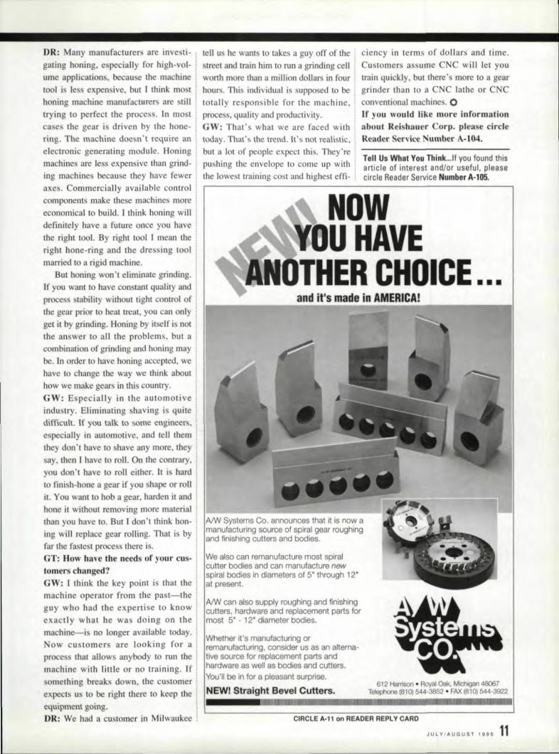
also can remanufacture most spiralbodies and can manufacture new
I bodies in diameters of 5" through 12"present.
can also supply roughing and finishinghardware and replacement parts for
5' ·12' diameter bodies.
IWlhptlhpr it's manufacturing orconsider us as an alterna-
source for replacement parts andhardware as well as bodies and cutters.
'II be in for a pleasant surprise.
NIEW! Straight Bevel 'Cutters.I I I
612 Harrison. Royal Oak, MlChgan 48067Telephone (B10) 544-3852 • FAX (810) 544-3922
II I
CIRCLE A-11 on IREADER REPLY CARD
JULY/AUGUST '995 11
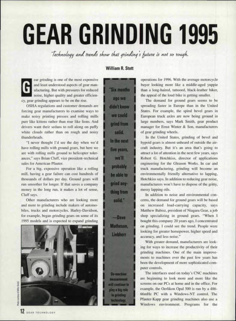
GEAR GRINDING 1995ear grinding is aile of lite most expensiveand leas! understood aspect of gear man-ufacturing. BUI with pressures for reducednoise. higher quality and. greater efficien-
cy, gear grinding appears to be on the rise.OSHA regulations and customer demands are
forcing gear manufacturer to examine ways 10
make noisy printing presses and rolling millispurr like kittens rather than roar like lions. Anddrivers wanttheir sedans to roll along on puffy
white clouds rather than 011 rough and noisythunderheads.
"I never thought rd see the day when we'd
have mlling mills with ground gears, but here weare with rolling mills ground to hehcopter toler-ances," says Brian Cluff, vice president-technicalsales for American Pfauter,
For a big, expensive operation like ,l rollingmilt having a gear failure can cost hundreds ofthousands of dollars per day. Ground gears willrun smoother for longer. If that saves a company
money in the long run, it makes a 101 of sense,
Cluff ay".Other manufacturers who are looking more
and more to grinding include makers of automo-biles, trucks and motorcycles. Harley-Davidson,for example, began grinding gears 011 some of its1995 models and is expected to expand grinding
12 GEAR TECHNOLOGY
operations for 1996. WilhtJle average motorcyclebuyer looking more like a middle-aged yuppiethan a long-haired, lattooed, black-leather biker.
the appeal of the loud bike is getting mailer."[he demand for ground gears seem to be
spreading faster in Europe than in the United
Stales. For example, the spiral bevel gears in
European truck axles are now being ground inlarge numbers, says Mark Smith, gear productmanager for Ernst Winter & Son. manufacturers
of geaJ grinding wheels.
Ie the United Stales. grinding of bevel andhypoid gears i almost unheard of outside the air-craft lndustry, BUI it' an area that' going to
attract a lot of attention in Lite next few years, aysRobert G. Hotchkiss. director of applicationsengineering for the Gleason Works. ]n car andtruck manufacturing, grinding wi.11 become:.menvironmentally friendly alternative to lapping,Hotchkiss. says. ln addition [0 reducing gear noise,manufacturers won't have 10 dispose of the gri'lly,
messy lapping oils.In addition '10 noise and environmental con-
cerns, the demand for ground gears will be based
on increa ed load-carrying capacity, saysMatthew Babisz, president of Niagara Gear, ajobshop specializing lin ground gears. "When Ibought this company 20 years ago, I concentratedon grinding. m could see the trend. People were
looking for greater horsepower, higher peed andaccuracy, and less noise."
Wilh greater demand, rnanutacturers are look-
ing for ways 10 increase the productivity of theirgrinding machines. One of the main improve-ments to machines over tile past few years hasbeen the development of more sophisticated com-puter controls.
The interfaces used on today's CNC machinesare beginning to. look more and more lik.e thescreens on our PCs al home and in the office, For
example.jhe Oerlikon Opal 500 is run by a 486-
Mmliz PC with a Windows-T control. ThePfauter-Kapp gear grinding machines also use aWindows environment. Programs for the
Rei hauer R2 820 machine can be prepared all a
detached PC and downloaded 10 the machine. TheHofler machines can be equipped w,itlt a modem,
which allows engineers in Germa_ny 10 '[rou-
ble hoot a machine without ending a service
technician. When problem can't be olved overthe phone, the technician will have a good idea fwhat needs fixing before he comes to the ire,
By making the mnchinesea ier to u e andcapable of toring more setup' and programs. themachine 100\ manufacturers have gone a long way
toward making gear grinding machines more pro-ductive. "Jn the old days, you could spend a wholeday Of days setting up index plates and sine bars,Today. with a CNC machine, it lakes 10 to. 15 min-ute far a preprogrammed part," says 0011 Ko al,
sales engineer for National Broach.
ln addition CNC controls improve the grinding
process. "Burning of the gear i the greatest factormal inhibits reducing tlte costs of gear grinding,"
ays Carl Eckberg. vice president for gear prod-ucts, Bourn & Koch. "Our customers want [0 beable 10 produce more parts in less time for lessmoney. They want 10 know how we can build
machines to reducethe bumLng of the part alld/orgrinding cracks when feeds and speeds are
increa ed." Advanced C controls allowmachines to grind faster and deeper by varying thegrinding cycle. "CN can allow the machine 1.0
alternate grinding areas so thaI one area wen'I gel100 hot while another area is sirnng cold.t' Eck-
berg say.At 0, CNC allow grinders to produce modifi-
cations to lead and profilethat previously wereeither impos ible or t.OO lime-consuming 10 be
economically practical. "The inl:roduction of CNCcontroltechnolegy has not only improved the effi-ciency, reliability and accuracy of ge..u grindingmachine , but it has also opened the door to awide variety of gear grinding process improve-ment ," ay Stephen Price, vice president of
Honer. Such improvement include workpiecemanagement programs, automatic start and finish
grindiog, special relief modifications and on-machine gear inspection, Price says.
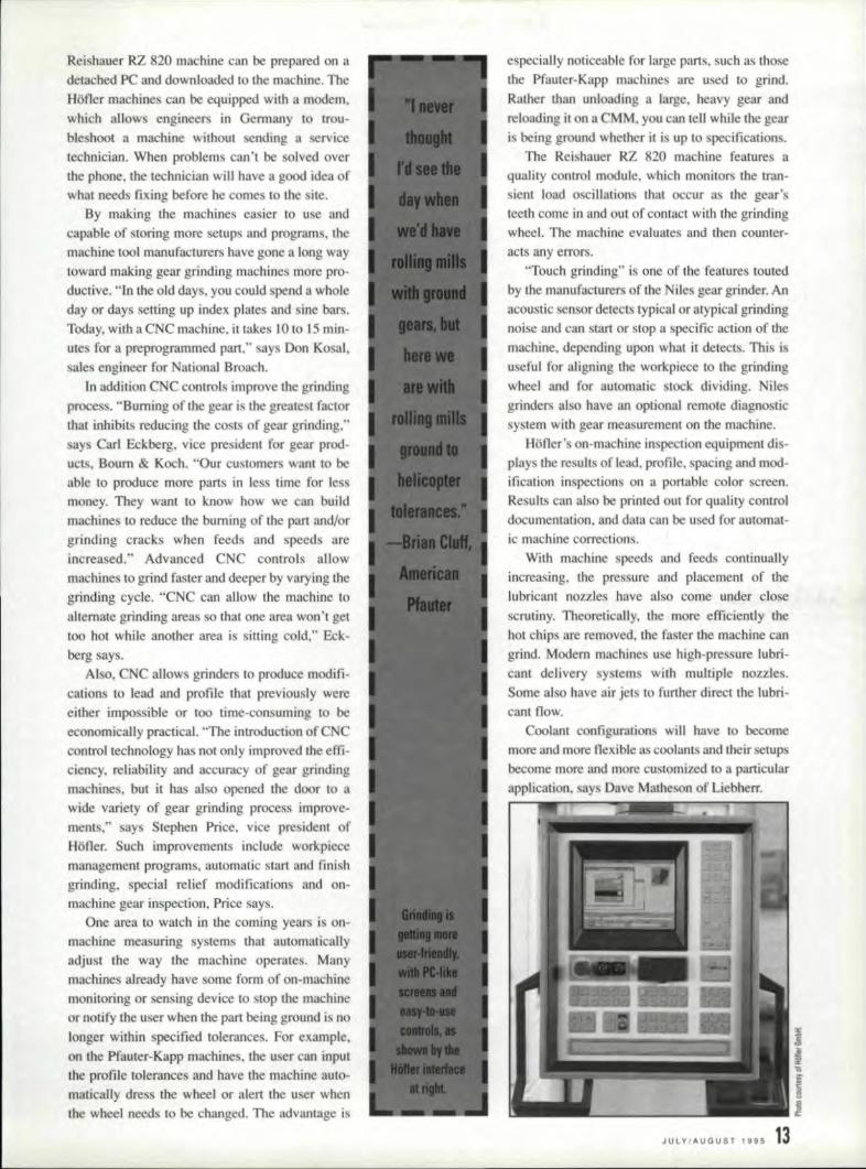
One area 1.0 watch in the coming years is on-machine measuring systems that autornatiealjyadjust the way the machine operates. Manymachines already have some ferrn of on-machine
monitoring or sensing device 10 stop the machineor notify the user when the part being ground is no
.Ionger within pecified tolerance. Fur example,
on the Pfauter-Kapp machines .. Ihe user can inputthe profile tolerance and have the machine auto-marically dress the wheel or alert the user when[he wheel needs to. be changed. The advantage is
especially noticeable for large paris, such as those
the Ptauter-Kapp machines 31e used to' grind.
Rather 'than unloading a large, heavy gear andreloading it oma CMM, you can tell white Lhe gear
is being ground whether it is up to. pecifications.
The Reishauer R2 82() machine features aquality central module, which monitors the fran-sienr load oscillations that occur asthegearteeth come in and out of contact with the grindingwheel. The machine evaluates and then counter-acts any errors,
"Touch grinding" is one of the features toutedby the manufacturer of the Niles gear grinder, Anacoustic sensor detects typical or atypical grind,ing
noise and can start or stop' a specifscacuon of the
machine. depending upon what it detects. This isuseful for aligning the workpiece [0 the grinding
wheel and for automatic stock dividing, Niles
grinders a,180 have an optional remote diagnostic
system withgear measurement on the machine,Hofler's on-machine in pection equipment dis-
play tile re uhs of lead, profile, pacing and mod-
ification inspections on a portable color screen.Results can also be printed out for quality controldocumentation, and data can be used for automat-ic machine corrections.
With machine speeds and feeds continually
increasing, the pressure and placement of thelubricant nozzles have also come under close
scrutiny. Theoretically, the more efficiently the
hot chips are removed. the faster tile machine cangrind. Modem machine use hjgh-pressure lubri-
cant. delivery system w.ith multiple 1II01.7.les.
Some also have air jets to further direct the lubri-cant flow..
Coolant configurations will have to becomemore and more flexible as coolant and their setups
become more and more customized '10 a. particularapplication. 8YS Dave Matheson of Liebherr,
JULY/AUGUST '995

In addition, "Gear manufacturers are just nowbeginning In understand the effectthe righe grind-ing fluid can have." say Carl Eckberg of Bourn &Koch. Advances in coolant materials will allowgear manufacturers 1:0 become more environmen-tally friendly. Despite the fact that synthetic andwater-soluble lubricant are now available andbeing developed every day, 90~ of all gear grind-ing is done with traight oil. say .. Kri. Kumar,application. engineer with GE uperabrasives,
lternative materials will probably be used moreand more. he says.
One of the areas where coolants are going toplay a more important role is in grinding partfrom olid, Matheson ays, Many of ihe machinetool manufacturers have been experimeming withami. louting their machines' abilities [Q grindthrough-hardened parts from solid, eliminatingthe hobbing or shaping process altogether.
Traditionally, it has been econ mically practi-calla grind from olid only the smallest, fine t-
pitch gears. Today that's changing. The SigmaPool companies have been doing exten ive te tson grinding from olid, An example is a 6DP,. 29-1001h, 11/2-il1chgear ground from solid in 14 min-utes, "Six months ago we didn't know we couldgrind from solid," Matheson says, "In the nextfive years, we'll probably be able \0 grind any-thing from solid."
American Pfauters Brian Cluff agrees, CBNtechnology has allowed grinding from solid toeliminate processes and save money. Despitecommon notions, il can be done with aerospacealloy steels .. and it can be done on gears larger
than 20", Cluff ays. "We can grind gears IDP andcoar er from solid. In some cases, there's no otherway to make the gear except to grind it fromsolid," Internal gears are a natura], Cluff ays.ThaI way, you don't have to have a ded.ic'lledshaping machine with specialized internal rooling.
Other companie have 31 a been experiment-ing with variou methods for rapid stockremoval. Hofler promotes it machines' ability tocombine deep feed grinding with double flankgrinding, which. according 'to the manufacturer ..
iIt:,.
il~ __~~~ ~14, GEAR TEC'i!\!OlOGV
---................--................
accomplishes in one grinding pass what wouldtake three or four passes using conventional gen-erating grinding.
Edgerek Machinery Co. is interested In apply-ing a technology called high efficiency deepgrinding 10 gearing. Edgetek produces a CNgrinding machine with a 35hp spindle that is
capable of up to 4().OOO fpm using electroplatedCB wheels.
Wes Lee. president of Edgetek, says high effi-ciency deep grinding could provide 4-5 limes theefficiency of creep-feed grinding with up [0 a 40':;';:reduction in cycle lime. Edgetek's technology iscurrently being used 10 produced spline. lots andother gear-like forms,
Although CBN technology has been around forabout 15 years, it remain one of the least agreed-upon topics in gear manufacturing. Pan of'theproblem is that every machine tool manufacturerha: trled to carve out its ownnichein the marker,Certain grinding machine are geared towardusing electroplated CBN wheels, while others tryto take advantage of vitrifi.ed aluminum oxidewheel. Because competition is 0 fierce. it's nosurprise that the manufacturers are reluctant totalk about their competitors' technologies,
There is no question that CBN is all out tand-ing rnuterial. Its metal cutting qualities have beenwell documented. It's hard-nearly a hard a dia-mond. lIS structure is such that is stays sharper forlonger than other materials, It sounds like a won-der-marerial. And for many applications, it is.
Bul there i a great deal of mi conceptionabout the best use for CB ; grinding. According10 Brian Cluff of American Pfauter, the miscon-ception is that CB is cost-effective only forhigh-volume production. "Plated CBN grinding iscost-effective both for large and small lots," Cluffsays. "It's cost-effecrive for one gear." Gulfpoints to a major gcar job shop that produces verylarge, very expensive gears with CBN grinding.
On the other hand, Gary Rackley, president ofPro-Gear Co., which specializes in gear toothgrinding, says the misconception is that electro-
plated B wheels are the way to go for everyapplication. Pro-Gear uses seeded gel wheels. AndMatthew Babi z, president of iagara gear, whichal 0 specialize ill ground gears, say, "Electro-plated CB is good tuff, but it's very expensive.We use ceramic-type wheel."
Each manufacturer of gears has his own prod-uct mix. and will have to choose his own optimumgrinding technology, It is difficulr to generalizeabout what is the state of the an ill gear grindingwhen it i different for each application. You canbuy an awful lot of virrified-bond aluminum oxide

wheel at $35 each before you can justify the$2,000 or more it might cost. for an electroplatedeBN wheel. But on the other hand. it may beimportant to finish a large. expensive part asquickly as possible. so the cost may be justified.
To make matter more confusing. a great dealof work has been done in recent years to improvethe bonds used with aluminum oxide and otherconventional materials. "The area that. we're get-ting some of the biggest surpri es in is in vitrifiedwheel technology," says Dave Matheson of Lieb-herr. "We've been able to increase aluminumoxide grinding cycle times to nearly as good asCBN cycle times by putting more air space in thegrinding wheel, We've been able to put so muchair space in the wheel that you could hold one upto your mouth and blowout a candle through it."
The air space allows for less material buildup.which in tum allows for greater stock removal.
"There is a definne trend back to the basics;'says Stephen Price of Hofler, "111al is, back todre sable aluminum oxide and corundum."
Because of the advances in vitrified-bond tech-nology, the movement in the industry also seemstoward dres able CBN. The advantages of thistechnology are a more stable finish, a more con-sistent level. of material. removal and a more con-sistent level. of heat generated, because the wheelis constantly being adjusted to present an accurateprofile. says John Ferriola .. product manager forErnst Winter & Son. In addition. with dre sablewheels, when a minor print change comes down.you don', have to order a new wheel. You canreprofile the one you have.
Most of the grinding machine manufacturerswill tell you that their machines are capable ofusing dressable eBN techaclogy, But capabledoesn't necessarily mean pracucal.In fact, the useof dressable eBN is not very widespread. Vitri-fied-bond CB- ,i dressable, but only to a certainextent. says Ronald Halama, sales manager forWMW Machinery Co., which represents the Nilesgrinder in America. Because eBN is so hard, itmust be dressed with diamond tools. Makingmajor adjustments to a dressable eBN wheelcauses great wear and tear on the dressing tool,and also result in throwing away large amountsof expensive CBN material, Halama says ..
The Sigma Pool has researched the use of vitorified-bond CBN wheels. "We got more partsthan with standard vitreous wheels, but it tooklonger to dress and it ate up Ihe dressing wheel.The technology is not there yet," says DaveMathe on of Liebherr,
However, there are companies using dressableCBN grinding with great success, says Brian
....poiIItolCOlI,.piece.
Irs liard toanuwntItt ..
".........
Cluff. Dressable CBN is applicable for a varietyof indu tries, he says.
Because there are so many different rechnolo-gies involved ill gear grinding, it's important formanufacturers to have a solid understanding ofthem all. Most of the machines on the markettoday are capable of using either electroplated ordressable wheels. In many cases, it's up to thegear manufacturer to decide what proce s is goingto be most co t-effeetive for a given application .
The cost of gear grinding is one of the key fac-tors that has prevented its widespread use. and it'snot always easy to justify. "Grinding has gOIto beeconomically viable from the viewpoint of costper piece," says Robert G. Hotchkiss of the Glea-son Works. "It's hard tonail down the value ofimproved quality or reduced noise. so it's not easyto justify in every case."
In fact, a number of alternative technologieshave been experimented with as replacements forhard finishing gears by grinding, but grinding'splace seems secure. "I've been in the gear bust-ness for 40 year and in the grinding part of thebusiness for 30 years," says Niagara Gear'sMatthew Babisz, "I've seen them try just abouteverything-from carbide hobbing or skive hob-bing to ausrolling ro trying to control the heattreating process-and it just doesn't work. Grind-ing is still the best solution," 0
For more :informalion about any of the compa-nies mentloned ill this article, plea e circle theappropr~a.te Reader Service number below.American Pfauter/Praut,er-K~pp A-I06Bourn &. Koch , , A-I07Edgetek Mach iner y , , A -1 08,Ernst Wint!er & Son A-I09'GE Superabrasives A-110Gleason Works A-ll1H,ofler A··Il2National Broach A·lHNiagara Gear A·l14Oerltkon/Ltebberr/Sfgma Pool.. A·1l5Pro-Gear, A·ll,6,Relshauer, A-l17WMW Machinery/NUes A.118
Telll IllsW,hat 'tou lhink ...IIf you found this article ofinterest and/or useful, please circle Reader Service!Number A-11!9.
JULY/AUGUST 1995 115

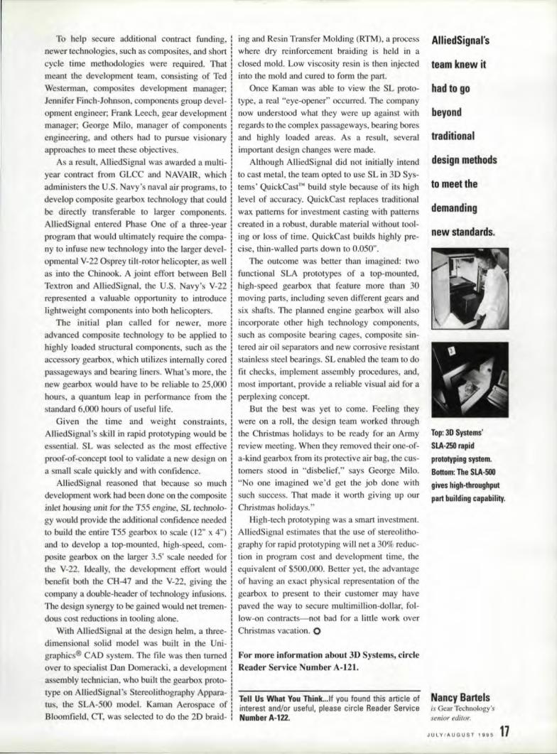
Top: Distinctives:quare·hiltc~h patten!
of Ihe O:uickCastTII1
buildlstyle. Middle:C'utaw.ay section of
AlliedSignalrsIllpgrad'ed gearbDx fDr
the 155 engine'. Bot·tom; De'I',phiHarrlison
Thel'lDal Systems' Slmasters fDr vaeuamsand casting tDols.,
16 GEAR TECHNOLOGV
The Shape ofThings to Come
/low ..f}/lieB'lfn.d tdeJjteteolitlr.ofltZPlr.r to :l(lvetime tLn.dmon.ey on a Ir.elic!('~ptetrea't60K. prototype.
u engineer's responsibility for verifying II
new design or product concept as manu-facmrable early in the development cycle
is a. lough challenge. What appears towork 011 a blueprint or in athree-dimensional CAnfile ona computer creen may nol work onthe fac-tory Iloor; and the downstream impact on the man-ufacturing process of an undetected design flawcan be eeorrnous, Co ts can run into the millions.
Increasingly. manufacturers are lUm.ing tostereolithography (SL) for rapid. prototyping ofncw or re-engineered products to fully visualize,verify., iterate. optimize and lest parts before rnak-ing any commitment to. hard productiontooling.
Developed by 3D Systems of Valencia, CA, theSL proce s enables rransformation of a 3-D com-puter model directly into a tangible part usmg thecombined technologies of computers. opticalscanning. lasers and photochemistry, Complicatedproduct concept • as semblles and systems are eas-ily verified and/Qr modified before co tly produc-tion is ever undertaken. Pans that would take
weeks to machine can now be produced in hourswith tereolithography.
tereolitho rapby-How ItWorksSL creates three-dimensional plastic parts
directly from CAD/CAM data. A Stereolithogra-phy Apparatu (SLA) receives design data from
the CAD file and "slices" it into thin cross sec-tions. Next. an ultraviolet laser traces each suc-cessive cross section of the object onto the surfaceof a vat of phctosensitive resin. The liquid plastichardens only where touched by the laser beam. A
plex propulsion systems 'to computer mice, gear
manufacturer have been slow to test its mettle.That may change as the gear industry learn .how
hundreds of companies, both small and large,throughout 'the U.S .... Europe and Asia report
reductions in tooling cOSL, improvements in prod-uct qualily and the ability to cut their productdevelopment lime by half or more using SL.
An excellent. example of how SL can make acritical difference in gear manufaclUrjng is offered
by AlhedSignal Engines (formerly TexrrenLycoming) of Stratford, CT. Like many companiesin the military sector. AllicdSignal, a leading man-ufacturer of miiitary/commercia] aerospace
I engines, sought ways to cope with fewer largegovernment contracts and Ihe business realities of
doing more with less ill a downsized economy. Thecompany re olved to create new markets throughtechnology infusion and the development of value-added component that would meet or exceed pro-gram objectives without running up costs.
AUied's Pilot ProgramOne of the first opportunities 10 exercise
AlliedSignal's new competitive posture tookplace whenthe company led II pilot program 10
upgrade its T55 gas turbine engine. which powersthe CH-47, twin-engine Chinook helicopter, theArmy's workhorse transport. In order Eo infusenew life Into this reliable, but aging helicopterengine. AlliedSignal offered a. technology pack-age to arrract the interest of the Great Lakes Com-posite Consortium (GLCC).
Among the parts lated fer improvement were
8,.........
new liquid layer is then spread over the solidified several external engine components, such as gear-layer. and the next contour is drawn 'by the laser. '1>0 e • acce series and oil lines. Priority was
The process repeats automatically and. unattended placed on weight reduction. mainl.ainability..until the part iscomplete, 10l1ger life cycle and lower cost. Due to the poten-
Good rOI" the Gear Business rial for high payback. pecial attention was paid toWhile SL has been in widespread use ln the (he top- and bonum-mounted gearbo e . A newer.
aerospace, automotive •. computer and consumer
electronic industries en every product from com-more compact, top-mounted design was formulat-ed to replace the existing gearbox, s",
To help secure additional COntract funding, :I
newer technologies, such as composites.and short !cycle time methodologies were required. Thatmeant the de ....eloprnent team, consisting of Ted
Westerman,. composites development manager;
ing and Resin Transfer Molding (RTM), a processwhere dry reinforcement braiding is held in a
closed mold. Low viscosity resin is then injected
intothe mold and cured to form the part.Once Kaman was able to ....iewthe SL proto-
Jennifer Finch-Johnson, components group devel- type,a real "eye-opener occurred. The company
opmeru engineer; Frank Leech, gear developmentmanager; George Milo, manager of components
engineering, and others had to pursue visionaryapproaches to meet these objectives.
As a result. AlliedSi.gnal. was awarded a multi-
year contract from GLCC and NAVArR, which
administer the U.S ..Navy's naval air programs. to
develop composite gearbox technology that couldbe directly transferable to larger components.
AlliedSignaJ entered Phase One of a three-year
program that would ultimately require the compa-ny to infuse new technology into the larger devel-opmental V-22 Osprey tilt-rotor helicopter, as wellas into the Chinook. A joint effort between Belli
Textron and AUiedSi.gnai., the U.S. Navy's V-22represented a valuable opportunity to introducelightweight components into both helicopters.
The initial. plan called for newer, moreadvanced composite 'technology to be applied tohighly loaded. structural components, suchas theaccessory gearbox, which utilizes internally cored
passageways and bearing liners. What's more, thenew gearbox would have to be reliable to 25,000
hours, a quantum leap' inperfonnance from the lstandard 6,000 hours of useful life.
Given the time and weight constraints,AlliedSignall's skiU in rapid prototyping would be
essential. SL was selected as the most effective
proof-of-concept tool to validate a new design ona small scale quickly and with confidence.
AlliedSignal reasoned that because so muchdevelopment work had been done 011 the compositeinJel housing unit for the T55 engine, SL .Iechn.ol.o- J
gy would provide the additional confidence needed
to build theentire T55 gearbox 1.0 scale < 12" x 4")and to de vclop a lop-mounted, high-speed, com-posite gearbox on the larger 3.5' scale needed forthe V-22. ~deally, the de veloprnem effort wouldbenefit. both the CH-47 and the V-22, givingthe ,company a double-header of technology infusions.
The design synergy to be gained would net tremen-dous cost reductions iatooling alone.
Wil.h AniedSignal al the design helm, a three-
dimensional solid. model was built in the Uni-graphics® CAD system. Tile file was then turnedover to specialist Dan Domeracki, a developmentassembly technician, who built the gearbox proto-type on AlliedS.ignal's Srereclithography Appara-IUs, the SLA-500 model. Kaman Aerospace ofBloomfield. CT. was selected to do the 20. bra:id-
now understood what they were up against withregards to the complex passageways. bearing boresand highly loaded areas. As a result, severalimportant de ign change were made ..
Although AlIiedSignal did nor. initi.ally intend
to cast metal, the team opted to use SL in 30. Sys-tems' QuickCast'M build style because of itsh:igh
level of accuracy .. QuickCast replaces traditionalwax patterns for investment casting with patterns.
created lin a robust, durable material without. tool-ing or loss of time. QuickCast builds highly pre-cise, thin-walled parts down 100.050".
The outcome was better than imagined: two.functional SLA prototype of a top-mounted.high- peed gearbox that feature more than 30moving paris, including seven different gears andsix. shafts ..The planned engine gearbox will alsoincorporate other bigh technology components,such as compo ire bearing cages, compoite in-tered air oil separators and new corrosive resi tantstainless steel bearings. SL enabled the team to do
fit checks, implement assembly procedures. and,most important, provide a reliable visual aidfor a
perplexing conceptBut the best was yet 10 come. Feeling 'they
were en a roll, the design team worked throughthe Christmas holidays 10 be ready for an Annyre ....iew meeting. WlJen they removed their one-of-
a-kind gearbox from its preteen ve air bag ..the cus-
tomers stood in "disbelief," says George Milo .."No one Lmagined we'd get the job done with
such success. That made it worth giving up ourChristmas holidays."
High-tech prototyping was a smart investment.AIHedSignal estimates that the use of stereolitho-
graphy for rapid prototyping will net a 30% reduc-tionin program cost and development time. theequivalent of $500,000. Beller yet. the advantageof having an exact physical representation of thegearbox to present to (heir customer may have
pa ....ed tile way to secure multimillion-dollar, fol-low-on contracts-c-not badfor a Iitl:le work o ....er
Christmas vacation. 0
For more information abol1t3D Systems. circleReader Service NU1I1ber A·Ill.
Tell Us What 'tau Think ...'lf you found this article ofinterest and/or useful. please circle' Reader ServiceNumber A.-122.
AllliedSig!nal's
team Iknew it
had 101 g;o
beondv- .traditional
design meth'ods
to meet the
dema.nding
new standards.
lop: 31J Systems'
SI.A-.2501 rapidprototypillgsrstem.IBottom: The SLA-500gives high·throughputpart building capability.
Nancv iBanelsis Gear Technology'ssenior edaor.
JULYIAUGIUSTI99·5 11

Swiss High Precision Worm and Thread Mililing Machine
UMREHT 124 and 124 CNC:...J • '"
> max. dia. 1¥.In>max. DP 12> max. rpm 2500>manual and
auto reeding
Distributors in USAEast coast Mid WestNVest
INDUSilRIES INC.
1650 Sycamore Ave., Bohemia, NY 11716511)./;67-1000 • fa.: 516-567-1355
TOOL.ING &. PRODUCTIONSYSTEMS, INC.P.O. 60': 143Sussex, Wisconsin 53089,141<11246·6110 • Fax (414) 246·4864
CIRCLE A-47on IREADER REPLY CARD
Process Industries, a leader in the manufacture of CustomGears, is now offering a gear and hob inspection service.Using our state-of-the-art M & Mil> Gear Analyzer allowsgeometrical analysis of gear characteristics as well as diagnosisand troubleshooting of gear problems.Gear ilnspection Iinclud'es:Profile (Involute) FormTooth Alignment (Lead)Tooth Spacing VariationPitch Li ne Run-outEvaluationOutside Diameter Run-outLet us help you prove the quality of your gears or hobs.2 day inspection standard.Rush Inspection provides. 24 hour turn around.We also Sharpen Hobs!3860 N. IRiver ;Road • Schiller Park,. IL 60176
IHobInspectionl Includes:Flute LeadThread LeadPressure AngleSharpening
-
For More Information Call
1 800 860 63 The Companies Of
• • '1 11 Process IndustriesCIRCLE ,60·48on READER REPL'If CARD
18 GEAR TECHNOlOGV'
... _1 CORPORATIE NEWS, _
Huddersfield, UK---,DavidBrown 'Group, PLC. has an-nounced the acquisition of the
gear businesses remaining inDavid Brown family owner-ship. The companies areDavid Brown, Austrajia,David Brown, Soutl1 Africa"David Brown, Zimbabweand Bos~.ock, & Bramley"U.K. David Brown Groupmanagement says the reunit-
ing of this group of comple-
mentary businesses will netseveral advantage , including
original offer was rebuffed by
Clark, but the sweetened
terms of the announced dealwon the unanimous approvalof both companies' boards.
Providence. RI-MadisonCulling Tools, Inc. hasmoved to an expandedproduc-
tion facility in Pawtucket, RLThe new facility offers 34,000sq. ft of manufacturing floor
space. The company's mailing
addre s, phone and fax num-bers remain the same.
AVOIl, MN-Columbiathe expansion of the Group's Gear Corporatlon. a custom
manufacturing capabilitiesand capaci ty, the broadeningof the acquired companies'activities 10 take advantage of
David Brown Group productdevelopments. and the maxi-mization of the David Brown
name and reputation for engi-neering excellence.
Waterloo, lA-AdvanceHeat Treat announced plansto open a new 12.000 sq. ft.facility in Monroe, MI,. which
is expected to employ 25 peo-ple. The new facility offers
five ion nitriding vessels totreat workpieces up 1.0 1.60" in
diameter and 360" in length.induction and duplex harden-ing capabilities, a 10- and 25-ton lifting capacity and a com-plete metallurgical lab. Also
included in the $2.4 millionfacility is a synthetic mediablasting system for steel,fiberglass. aluminum and
poly urethane.The facility is expected to
operate 241]01.11':<>a day. sevendays a week.
South Bend, IN-]nger-soli-Rand Co. has reachedagreement to buy its competi-tor, Clark Equi.pment COo.,for $L5 billion. Ingersoll's
gearing design and manufac-turing company, bas achieved
ISO-9OO2 certification for itsmanufacturing and assembly
operations ..The company, asubsidiary of Vesper Corpora-tion, was audited by DetNorske Veritas (DNV), an in-dependent auditing finn. Co-lumbia is a supplier of'customspur arid helical gearing andrelated services.
Prolll1otlons .... RodneyW. Howard has been named
sales engineering manager andlimited partner with WilliamC. Perrin. president ofPerrtnPreelsian Tool, Inc .. Denver,
NC ... Master ChemicalCorporat.i.on of Perrysburg,
OH, has named Paul E.Laura operations manager re-sponsible for the company's
domestic and. European fluiddivision ... Wayne H. Grosshas been named managing di-rector of the InternationalGas Turbine Institute ali
ASME International. where
he will oversee and help de-velop a wide range of techni-
cal and continuing educationprograms. expositions andconferences in support of gasturbine technology.

_-------------IIINDUSTRYNEWS ------- __experiment using paints and non- !cyanide 'based plating for : elective ':hardening. several ahernative "lop-off:methods performed well enough foraerospace application.
In another experiment, the Bark-hausen Effect, a magnetic effect wasstudied for po: sible use in gear manu-facturing inspection, especjally casedepth mea urementand grinding 'bums
detection. Results indicated tha! it mayhave use in case depth measurement,but testing still meeds 10 be done in thedetection of grinding 'bums.
For more informatiOD about theseex.periment • circle Reader rl'ic,e
,umber A·I01.
IINIFAIC REIPORTS ONI RE,ICIENT IHOBBINGANI 01 HIEAT TREATIINIG EXPERIMENTS
CflicQ8~ResullS of recent studieson residual stress in gear hobbing, hob..bing without lubrieants and heat treatingwere reported by representatives ofINFAC (Instrumented Factory for'Gears) at an indu try briefing in March
of this year.The results of four experiments on
residual stress in gear Ilobbing indicat-ed the fonowing: conventional hobbinggenerate lower re idual stress thanclimb bobbing: lower speed/feedmeans lower residual tresses; stressesin the roots of the gear teeth are gener-aUy higher than those in [he flanks; andthe leading ide of the gear tooth flankalway has higher tress 'than the trail-ing ide of the gear tooth flank.
Dryhobbing studie involving resid-ual stress depth profile analysis showedthai tile profile wa independent ofspeed, bUI dependent upon feed rate andhardness of the 'materials.
Heat treating is another importantre earch subject at [ FA . A maj r sta-tistlcnlly de igned experiment deter-mined the 'effect on part quality of thehealing cycle. the carbon diffusioncycle. the location of pan within Ihecarbunzarion furnaceand of incomingresidual tre in pans after carburizing.Result howed an unexpected trendtoward Ie distonion in index and run-out for pari with higher incomingstresses. Other conclusions are that theramp heating cycle produced lesserrorin index and runouj in gears after car-burizing; the boo t healing cycle causedslightly higher tensile l'esidual stressesin [he carburized areas; and the furnacelocal ion had no effect on re idual stres -e • but did influence distortion.
In another, preliminary heal trealingstudy. the possibility is being exploredthat dew probes may 'be used in place ofoxygen probes for anno phere controlin carburizing furnaces.
Another important focus for mFAChas been the use of alternative process-ing methods '1.0 reduce pollution. ]n an
T'ell t.!sWh I Y,IIU Think ..'!'f VOIl found thisarticle of interest and/or useful, pleasecircle Reader Service' INumber A·11Jc3.
CIRCLE A-31 en READER REPLY CARD'
JULVJ~UGUST Ins 191

How to Avoid Errors,When Measuring
Step Gears
here are problems in dimensional mea-surement that should be simple to solvewith standard measuring procedures, butaren't.In such cases, using accepted prac-
lice may result linerrors of hundreds of micronswithout any warning that something is wrong.
One such problem, is the accurate measure-ment of the dimensions of the three-dimensionaltrack" or the motion surface, around a cylindricalcam, or step gear (Fig. ,I). Step gears are used toindex a number of different devices such as tool
roller diameter = Hi -20 -
Fig. 1 - Three-dlmensional traek or cylindrical molion surfaee,
DIJD2 '" 0, .95, .9, .8, .7, .35)
F,ig. 2 - Effective roller cress secrlon,
201 GEAR TECHNOLOGY
Heinz IRohr
changers. transfer line mechanisms and parts han-dling systems=-virtually any apparatus that mustaccurately locate workpieces or tools for subse-quent operations.
The three-dimensional track forces a cylindri-cal roller to move parallel to theaxis of the cylin-der. The relationship between the track and theroller is critical to the operation of the step gear ..The challenge is to correctly measure the dimen-sions of the track with a coordinate measuringmachine 10 determine the axis position of theroller as it moves on the track around the circum-ference of the cylinder. The po ition of the rolleraxis is important since it determines where index-ing will begin and endfor each "stop."
The standard procedure to determine (he posi-tion of lite roller axis is to measure two parallellinesatthe top and bottom of the track around thecylinder at a predefined distance from its axis.This circular measurement is "unwrapped," and atrack radius correction is made to compensate forthe radius of the roller in order to determine theroller's "center" position.
The error in this procedure is hidden in theroller radius correction. To find the error, it isimportant to understand the comact characteristicsof the roller as it travels the length of the track.
Typically, the roller is tapered so that it fitssnugly mto the tapered open side of the tuck. A~the track "rises" during the rotation of the cylin-der, the curve of the track aroundthe cylinder pre-sents changing surface characteristics to the staticsurface of the roller ..Due to the taper of the track.the slope increases on the inside of the track, caus-ing the line of contact. ofthe roller to hift off axis.Whe.1rIthe track descends, the line of contact on.the roller swings back past perfect alignment w.iththe cylinder axis to the mirror image of what itwas on the ascent curve. The point of contactbetween the track and roller scribes an oval ratherthan a perfect circle.

Traditioaally, 10 find tile contact point of the I,roller/surface at a specific radius from the center :
of the cylinder, the roller and track would be imated and then "CUI" wi.th a phantom coaxial "
cylinder having a diameter sufficient to intersectthe roller at that specific radius from the center,
Thi results ill two, plotted curves on the coaxialcylinder which may be "unwrapped" into a plane.
One is a line created by the circumference of thecoaxial cylinder, which traces the fulJ path of thetrack, The second :is a point on the axis of the
roller where the coaxial cylinder cuts through the
cylindrical roller.The oval shape of the unwrapped, curved inter-
section plane of the roilier is determined by the
proportion ofthe roller and cutting diameters (Fig,2). As an example, B' a broom tick is ClI! with a
circular cookie cutter. the cut end may appear to
be a perfect circle. Because the cookie cutter isround. however, ilt creates an arc-shaped cut
through the broom handle which win appearovoid when viewed off-axis. The shape of the oval
depend' 011 the size of the broom handle andlorthe size o'f'the cookie cutter, In the case of a stepgear. the contact points on both unwrapped curves
represent the contact characteristics ofthe rolleron the Ira k at a specific radius, The center pointon the oval represents the roller axis.
When usinga coordinate measuring machine'10 find ihe roller axis position for all measuredpoints along the track. follow standard procedures10 create an unwrapped plane using the phantom
coaxial cylinder approach .. The resulting oval's
orientation on Ihat plane must then be mathemati-cally determined, The path ofthe axis center pointon the oval, not a circular cross section of the
roller, gives the true position of the roller axis,The difference in re ultant accuracy between
using the ovoid shape of the roller find the circularshape of the roller averages 200 microns., Slopecharacteristic a well as the relative diameters of
the coaxial cylinder (the cookie cutter) and theroller (the broom handle) will affect the total error,Maximum discrepancles w.ill appear at the area ofmaximum slope and at the inner diameter of themotion urtace (Fi.g. 3).
100
50
50 lOll' 150
i
-50 I
·100 I
Between the inner and outer radius of the track, tribution of areas with high pre sure as well as athe "oval effect" is different. Larger deviations I displacement of the whole shape. 0belong 10 the imler radius where measurementsare rarely carried out because of the limitationsimposed by the radius of tile CMM probe. Con-versely. measurements are not earned out al the
outside edge because of varying chamfer. whichonly adds to the problem, The rotaling roller may,
contact the track only at or near one edge. This !,lack of fulllength upport caused by faulty manu- :
·150
umber of lines e 3
Fig. " - flear.ing pattern 'rur cylinder (I!!"V, •
facturing proceduresresults in high surface pres-sure and possible catastrophic part failure.
The mathematical relationship between the
track and the roller is a complex one. The advan-tage of using a CMM in this type of measurementis that it can express thai complex relationship interms of X. Y. and Z coordinates. which makes the
measurement easier to perform. Special sonwarepackages such as tile STEPGR option for QUlLN-IDOS® metrology software from Leitz take the
problems out of step gear measurement. makingthe radius correction aUloroalicaUy and assuring
the correct calculation of the roller position. Abearing pattern can also be generated using thissoftware package it' more than one line .is mea-sured (Fig. 4). The bearing pattern shows the dis-
For more linformation about Leitz or BrownSharpe, please circle tile Reader Servlvce Num-ber A-lB ..
feU Us What Y'DU fnink ...lf you found this article ofinterest and/or usefull, please circle Reader ServiceNumber A·124.
o.ofline = 3Paste thickness = 0,010 mm
H'e;inzIRohris wlth Leit: Mess/ech·nik GmbHA. {I Brown& Sharpe Company.
JULY/AUGUST 1995 ,21

New Concepts in CNCGear Shaping
K,la!Us felitenMichael Johnston
On today's economy, when purchasing a new state-of-the-art gear shaper means a significant cap-
ital investment, common sense alone dictates that you develop strategies to get the most for your
money. One of the best ways to do this is to take advantage of the sophistication of the machine
10 make it. more than just a single-purpo e toot
With the right machine adjustments, euttiag tools and auxiliary attachments, a modem gear shaper
can produce a variety of parts beyond a simple circular gear. It can make variants of square external pro-
files, splines, spur couplings with straight-sided teeth, face gears with non-parallel axes, sector steering
one operation in a single setup.
gears and racks. parts for hydraulic motors and pumps and elliptical gear. It can also perform more than
Following are six example of the kinds of applications a modern gear shaper can do.
External Gear Machined in One SetupThe task is to machine an external gear with face width bigger than thestroking length of a given machine and specific runout conditions. This
is done with a gear simper with a sliding culler head and special SSMsoftware,
Requirements• Cutter head slide machine with high accuracy
• Special back-off cam• Special software• Dialogue programming
• Special cutler holder
Possible Applications• Production of extended stroking length• Shaping pam with limited -unout, dependent on pre-set stroking length• Shaping of parts without runout• Optimizing shaping conditions
Machill(, Datu
• According to customer requirements
22: GEAR TECHNOLOGY

Conveyor Units (Gate Parts)
Pump Gear for Conveying of Granulates
The task here is to shape all outer contours: no teeth. The required sur-
face finish is Rz= 16Jlm = 400 uinch (finish shaping).
The Specific CNC Programs Used
• Main Program: Positioning datu and signals for tool changerCUlling data with number of cuts
Stroking speed and radial infecdTrack data. turning direction• Sub-Program:
Machine Data• Two-cut operation (roughing/finishing)
• CUlling speed - 25 m/min• Total cycle time - 113 min
• Peripheral length - ROO min
CUlfillg ToolTwo disc-type cutter'. ASP 60 (different diameter. positioned on one cut-ter holder), one for concave and one for the convex. section.
HydromotorThe task is shaping of internal and external non-circular gears. Three
major steps are nec·e~sary to produce the a.m. components.
1. Calculation of the generating curves
2. Calculation of the geometry of the gear3. Calculation according 10 the collision diagram
Machine Requirements• Highly precise rotation fixes C and D• Highly precise X-Ilxis with extremely low backlash for forward andbackward movement
• High-speed CNC control and dialogue programming as well as soft-ware for manufacturing non-circular gears
The complex geometry of the internal involute gear requires that the cuttingtool will be mounted eccentrically and IIml a special back-off cum is available.
Pedal Arm for Bicycle Polygon Internal ProfileThe [ask here i:-. to cut a tapered internal square.
Machine Datu• Special back-off cam for taper cutting
• Face Width: 14.5 mm• Number of Cuts: 2• Feed Method: Generating
• Cycle Time: 1.05 min
Cutting Tool, Shank-type cutter, polygon, TiN-coated
IDr.Klaus FeUenis director of researchand development forLiebherrtl.orenz,Ettlinge», German)".
Michael Johnstonis product manager JOI"
Liebherr America.Saline, Mi.
JULYIAUGUST 1995 23,
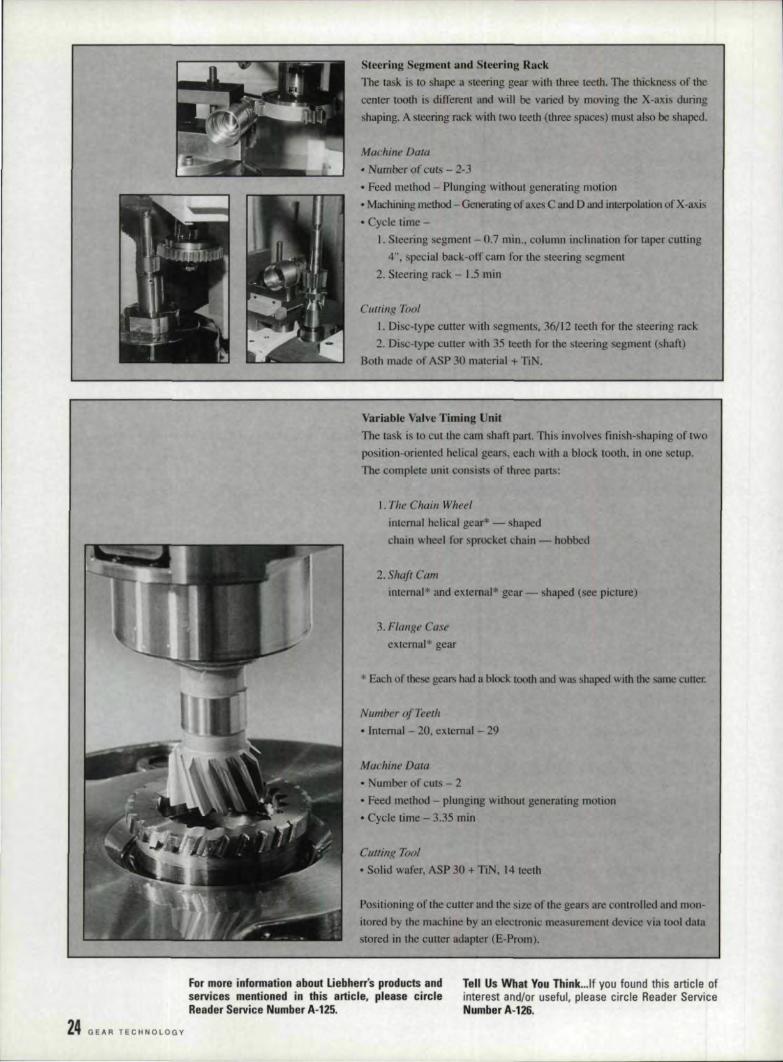
Steering Segment and Steering RackThe task. is to shape a steering gear with three teeth. The thickness of the
center tooth is different and will be varied by moving the X-axis during
shaping. A steering rack. with two teeth (three spaces) must also be shaped.
Machine Data
• Number of cuts - 2-3• Feed method - Plunging without generating motion• Machining method - Gener.uing of axes C and D and interpolation of X-axis
• Cycle time -I. Steering segment - 0.7 min .• column inclination for taper cutting
4", special back-off cam for the steering segment
2. Steering nick. - 1.5 min
Cutting TootI. Disc-type cutter with segments, 36/12 teeth for the steering rack2. Disc-type cutter with 35 teeth for the steering segment (shaft)
Both made of ASP 30 material + TiN.
Variable Valve Timing Unit
The task is 10 CUI the cam shaft part. This involves finish-shaping of twoposition-oriented helical gears, each with a block tooth. in one setup.The complete unit consists of three parts:
1. The Chain Wheelinternal helical gear* - shaped
chain wheel for sprocket chain - hobbed
2. Shaji Caminternal'" and external= gear - shaped (see picture)
3. Flange Caseexternal* gear
* Each of these gears had a block. tooth and was shaped with the same cuner.
Number of Teeth
• Internal - 20. external - 29
Machine Data
• Number of cuts - 2• Feed method - plunging without generating motion
• Cycle lime - 3.35 min
CUllil1,€? Tool• Solid wafer. ASP 30 + TiN, 14 teeth
Positioning of the culler and the size of the gears are controlled and mon-itored by the machine by an electronic measurement device via tool datastored in the culler adapter (E-Prom).
For more' information ,about Uellherr's products andservices mentioned in this art'icl'e, please circleReader Service Number.A·"2!i.
24 GE"'R TECHNOLOGY
TelIIUs Wh'st You Think .•.lf you found this article atinterest and/or useful, please circle Reader ServiceNumber A·126.
IG.EARMACHINES
SAlLES & S'ERVICE
CIRCLE A·1,2 on, READER REPlY CARD
21 44merican Gear
Manufaclurers Association 14 38 M & M Precision Systems 5 2
American Metal Treating Company 44 47 Midwcsi. Gear 17 41
American Pfauter, .1,•.P. Niagara Gear 9 t!
American Sykes Co. J 4 Parker lndusmes, Inc. 47,16 18,40
Basic lncorporuted Group 12 25 prallter-MWlg CUI.lingTools, l.P. 2,41 IF ,47
Bourn & Koch Machine Tool Co. 3~ 41 Pro-GearCempany, Inc. 40 47
Diugrind 23 44 Process Ind ustries, Inc. 48.20 111,44
Diamond Black Technologies, lnc. 10 10 Rota-Technology 42 47
Fairla.ne Gear, Inc. 13 38 Russell, lIolbrook & Henderson 39 46
orest Cit}' Gear 46 IRe Simon International 22 44
Glenson Works 6 Be Software Engineering Service 43 47
GMI 7 6 Starcut Sales. Inc. 37 lL)·
Hillla 37 Wendt Dunnin IDIl 4 4
ITW Heartland 15 40 Willler. Em~L& Son 19 43
Liebherr 8 5
JULV/AUGUST 1 s a s 25
A Basic Guide toDeburring and
Chamfering Gearsc?/z(}(}j(! .the tz'rht t(}(}htinl teC!hl'li$ueJ6(}t the beJt, 111.(}3tt!Mt-e66edlve te3ulfJ.
B,ruce Horst
I I n.tOday.'.s.in~ustri81m.arketp..18.-: d.e.bl.lrrin.gI and chamfering are no longer Just a matterI of cosmetics. The faster speeds at whichI transmissions run today demand that gearteeth mesh as smoothl.yand accurately as possibleto prevent premature failure. The dem~d for quiet-er gears also requires tighter tolerances. New heattreating practices and other secondary gear opera-tions have placed their own sets of demands onmanufacturers. Companies that can deburr orchamfer to these newer, more stringent specifica-tions-and still keep costs in line-frnd them-selves with a leg lip on their competition.
Wheels or Brushes?The choice of grinding wheels or power brush-
es for deburring depends on a number of factors:the type of gear, the material used, the part printrequirements, the gear configuration and. the cus-tomer's specifications. tooling co IS and produc-tion requirements. In general we prefer to usebrushes for deburring because:
1. They create les grit and dust and causefewer cleanup problems than grinding wheels.
2. They normally give better tool life.3. They do not require a precision setup,However, keep in mind that while a power
brush can deburr and provide a radius on the
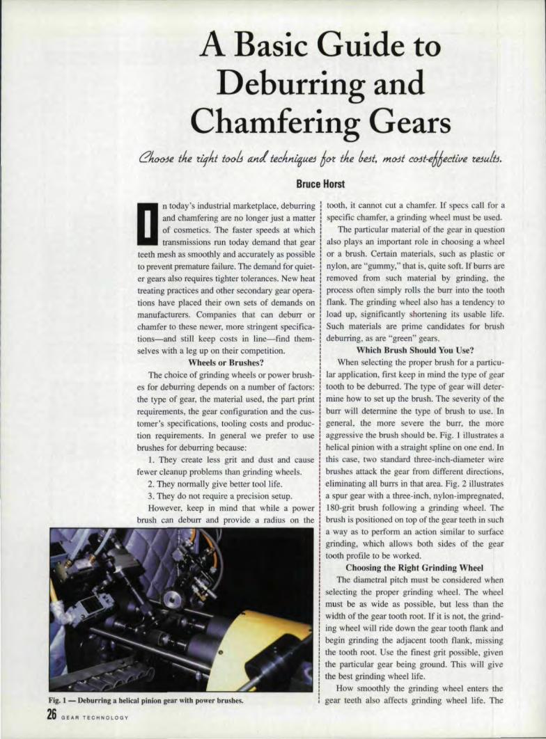
fig. 1 - Deburringa helical pinion gea.J"with power brushes.
26 GEAR TECHNO~OGY
tooth, it cannot cut a chamfer. If specs call for aspecific chamfer, a grinding wheel must be used.
The particular material of the gear in questionalso plays an important role in choosing a wheelora brush. Cerrain materials, such as plastic ornylon, are "gummy," that is, quite soft. If burrs areremoved from such material by grinding, theprocess often simply rolls the burr into the toothnanl<. The grinding wheel also has a tendency toload up, significantly shortening its usable life.Such materials are prime candidates for brushdeburring, as are "green" gears.
Which Bliush Should You Use?When selecting the proper brush for a particu-
lar application, first keep in mind the type of geartooth to be deburred. The type of gear will deter-mine how to set up the brush. The severity of theburr will determine the type of brush 1.0 use .. Ingeneral, the more severe the burr, the moreaggressive the brush should be. Fig .. I. illustrates ahelical pinion with a straight spline on one end. Inthis case, two standard three-inch-diameter wirebrushes attack the gear from different directions,eliminating all burrs in that area. Fig. 2 illustratesa spur gear with a three-inch, nylon-.impregnated.180-grit brush following a grinding wheel. Thebrush is positioned on top of the gear teeth in sucha way as to perform an action similar to, surfacegrinding, which allows both sides of the gearsooth profile to be worked.
Choosing the Right Grinding WibeelThe diametral pitch must be considered when
selecting the proper grinding wheel. The wheelmust. be as wide as possible, but less than thewidth of the gear tooth 1'00t. If it is not, the grind-ing wheel will ride down the gear tooth flank andbegin grinding the adjacent tooth flank, missingthe tooth root. Use the finest grit possible giventhe particular gear being ground. This will givethe best grinding wheel life.
How smoothly the grinding wheel enters thegear teethal a affects grinding wheel life. The
size of the chamfer required can be controlled by
grinding wheel grit size, speed of the work pindle
and. ail' balance control. An increase in 1001. lifecan be expected on wet grinding applications.
Helpful Gear Debllrring Hints
The closeness of the hub diameter of the tool to
the gear tooth root diameter has always been aproblem in gear grinding. The hub diameter tendsto interfere with the grinding wheel before it
reaches the gear tooth root diameter becau e thegrinding wheel will hit the hub first and not grind
the root diameter. This causes an interrupted,unacceptable chamfer.
Using power brushes can solve this problem.Brushes will remove most burrs, but, as stated
before .. they will not provide a chamfer. Bru hesdo, however, provide a radius, which offers addi-
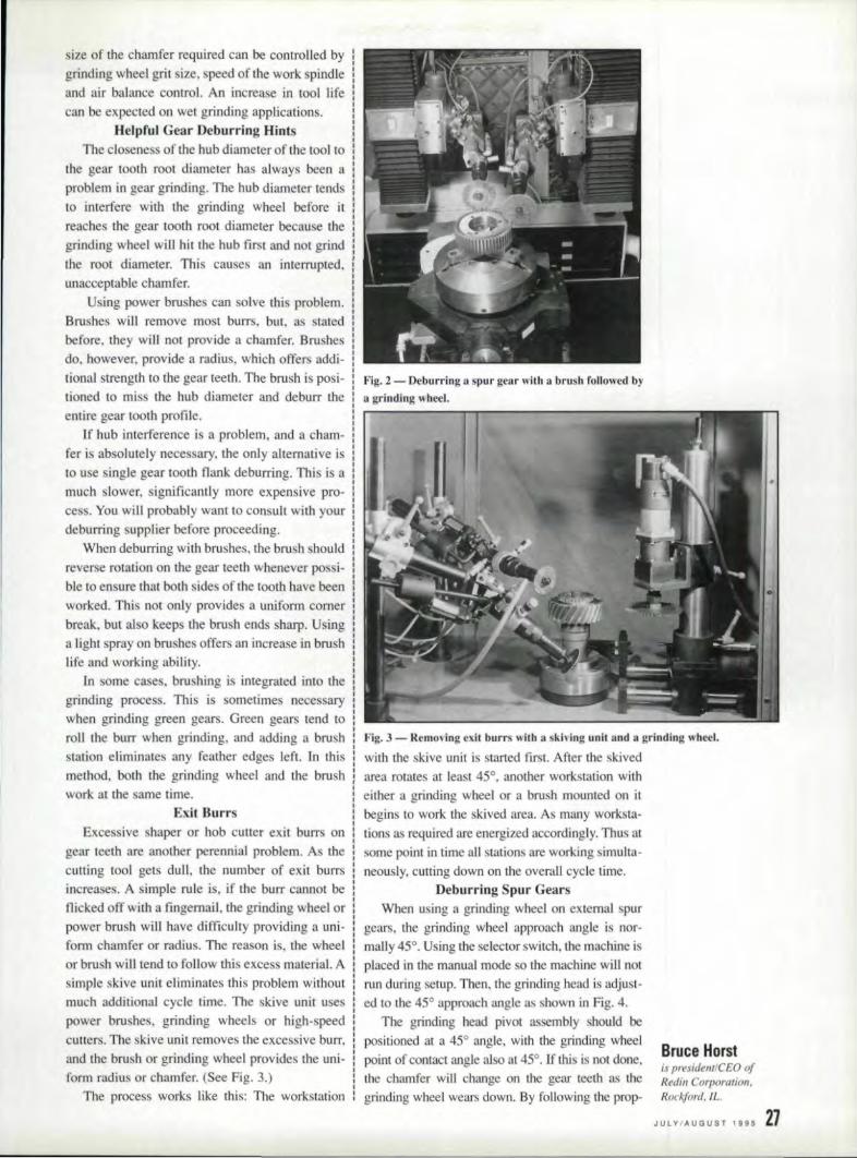
tional strength to the gear teeth. The brush is posi- Fig. 2 - Deburring a spur gear with a brush I'ollowedby
tioned to mi the hub diameter and deburr thea grinding wheel.entire gear tooth profile. .---------,r-r---------------
If hub interference is a problem, and a cham-fer is absolutely necessary, the only alternative is
to u e single gear tooth flank deburring, This is a
much slower, significantly more expen ive pro-ce s, You will probably want 10 consult with your
deburring supplier before proceeding.When deburring with brushes, the brush should
reverse rotation on the gear teeth whenever possi- I
ble to ensure that both sides of the toothhave beenworked. This not only provides a uniform comer
break, but al 0 keeps the brush ends sharp. Usinga Iight spray on brushes offers an increase in brushlife and working ability.
III some cases. brushing is integrated inlo the
grinding process .. This is sometimes necessarywhen grinding green gears. Green gears tend to
roll the burr when grinding, and adding a brushstation eliminates any feather edges left. In thismethod, both the grinding wheel and the brushwork at ohe arne time.
Exit BurrsExcessive haper or hob cutter exit burrs on
gear teeth are another perennial problem. As the
cutting tool gets dull, (he number of exit burrsincreases ..A simple rule is, if the bUIT cannot beflicked off with a fingernail, the grinding wheel orpower brush will have difficulty providing a uni-form chamfer or radius. The rea on is, the wheelor brush will tend to follow this excess material Asimple skive unit eliminates this problem withoutmuch additional cycle time. The skive unit uses
power brushes, grinding wheels or high-speedcutters, The kive unit removes the excessive burr,
and the brush or grinding wheel provides the uni-form radius or chamfer. (See Fig .. 3.)
TIle process works like this: TIle workstation
Fig, 3 -Removing exit burrs with a skiving unit and a grinding wheel.
with the skive unit is started first, After the skived
area rotates at least 45°, another workstation witheither a grinding wheel or a brush mounted on itbegins to work the skived area. As many worksta-
tions as required are energized accordingly. Thus atsome point in time all stations are working simulta-neously. cutting down on the overall. cycle time.
Deburrtng Spur GearsWhen using a grinding wheel on external spur
gears, the grinding wheel approach angle is nor-mally 45°. Using the selector switch. the machine is
placed in the manual mode so the machine will notrun during setup. Then. the grinding head is adjust-ed to the 45° approach angle as shown in Fig. 4.
The grinding head pivot assembly should bepositioned at a 45° angle, with the grinding wheel
point of contact angle also at 45°. If this is not done.the chamfer will change on the geaJ" teeth as thegrinding wheel wears down. By following the prop-
Brl.lce Herstis presidemlCEO ofRedin Corporation.Rockford. tt:
JULY/AUGUST 1995 2'1

er positioning, grinding wheel life will drasticallyimprove and chamler consi tency wil] also improve.
Align the grinding wheel. £0 the censer of thegear (see Fig ..5).. The grinding wheel can be oper-ated from either the right- or left-hand side of thegear. Remember that the gear rotation must beaway from the grinding wheeL .In some cases,positioning the grinding heads will allow debur-ring of both sides of the gear simultaneously whilerotating 1800
• This will increase production.Extreme concentricity ofthe gear is not required,
1-
Parallel
Movement (Float) of GrindingWheel Riding Up and Downon Gear Teeth
Fig..4 - Alignment of grindjng wheel.
Left-Hand I
,._/ Opcratio~
: III I,
'"T-:-':;" I~~.- ...._fIJ'---
\
I Right-Hand__ Operation
Centerline of Gear andGrinding Wheel
I<'ig.5 - Aligninglbe grinding wheel to the center of the gear.
Pivot45°
-~
15°_30°Point of Wheel Contact
Ii'ig. ,6 - Helical gear wheel contacl.
.Fig. 7 - Example of wheel set 100 deeply.
2.8, GEAR TECHNOLOGY
because the grinding or brushing head "floats." Thehead assembly is mounted on a fulcrum" and a col-umn of air provides the counterweight
After the valve is energized and! the grinding orbrushing head enters the workpiece, the air pres-sure i.sreduced. This allows freedom of the head.The head can be easily lifted by hand, dependingon the amount of air still supplied (normally 25
psi). ln this way anything rotated under the headraises or lowers the unit. So up to a certain range,the floating head follows whatever profile is Linderit. For additional ranges, we've added specialcams. These cams are integrated into the grindingor brushing heads •. allowing irregularly shapedparts lobe deburred,
Deburring Helical GearsHelical gears up to a maximum helixangle of
approximately 30° can be deburred, A rather flatchamfer can be expected. Setup for these modelsis similar to that for spur gears. The point of con-(act ohile wheel on helical gears must be reducedto prevent. scuffing one side of the gear nank (seeFigs. 6-:7).
When grinding helical gears, the grindingwheel angle must match the helix. angle of thegear tooth be.ilflgchamfered (see Fig. 8). If theangle i too flat, the grinding wheel will ride overthe top of the gear loath and will not properlychamfer the comer of the gear tooth flank. If thegrinding, wheel angle is too steep, it will drop offthe gear tooth and scuff the adjacent gear toothflank. The rotation of tile gear must be such thatthe whee] grinds up the acute angle and down theobtuse angle. This procedure' will produce a uni-form gear tooth chamfer. The proper procedureused to top- and bottom-grind a helical gearsimultaneously is to reverse the direction of thework spindle. This can be completed in one auto-matic cycle. If the gear teelh specifications are notstringent, both top and bottom grinding can beaccomplished simultaneously, increasing gearproduction. If customer specs allow it, powerbrushes can be used.
Deburring Spiral Bevel GearsThe alignment of the grinding wheel to spiral
bevel gears is similar to other gears with the foll-lowing exceptions;
•. Instead of aligning the grinding wheel withthe centerline of the gear, it should be positionedon the gear tooth root that is closest to being par-allel to' the grinding wheel (see Fig. 9, View A).
• The pivot angle "Z" should be approximately15° from the gear face being chamfered (see Fig.9, View B).
On spiral bevel gears, both the heel and toe canbe debarred simultaneously using two grinding

heads (see Fig. 9, View C).Deburriing Str.aight. Bevel. Gears
The alignment of the grinding wheel for debur-ring straight bevel gears is similar to that of exter-
nal spur gear (see Fig. ]0).
Delmrring Square Slots or SplinesDeburring square slots and splines, (either l.D.
Of O.D.) call be accomplished as illustrated in Fig,
11. With the grinding wheel positioned behind thecenterline, one ide of the slot and half of the root
is deburred, and with another grinding wheel posi-tioned ahead ofthecenterline, the other side of the
slot and the other half of the root is deburred. Thisoperation can be accomplished simultaneously.
The Cell Concept ,& Deburr.ingDeburring fits nicely into operations where
manufacturing cells are popuLar. Careful planningcan eliminate entire operations, saving both timeand money. We recently eliminated a customer'swash station by integrating the cleaning process
with the gear deburring, thus reducing production
times .. Using a wet machine will also drasticallyincrease grinding wheel tool life.
In another case, we are working with a cus-
tomer 10 integrate a de burring machine into hispresent work cell, which manufactures splined
pinion gears. Doing so will eliminate theneed to
handle the parts and move them to a separatedeburring station. The longest cycle time in thecell is three minutes ..The cycle time of our debur-
ring machine i. two minutes, thereby giving thecustomer "free" deburring.
Sample Gear DeburrfngI ustomer sample gear deburring tests prim to
machine quotationsare a good idea. They allow usto present (he customer with all the information heor she needs to make informed decisions. A com-puter printout showing tooling used, expected toollife.cycletime, etc., is returned with the samples.This procedure eliminates unnecessary problems
that may occur during a machine runoff. Choosingthe proper machinery for quality, long life, versa-
tility. ease of changeover, room for expansion at II
reasonable price is our goal.This kind of cooperative effort between cus-
tomers and supp.liers can make deburring opera-
tions efficient, accurate and cost-effective. allnecessary ingredients for success in today'sdemanding gear production market, 0
For more information about .Redin Corporation,please circle Reader Service Number A-127.
fig. 8- The grinding wheel ang,le must match the hcl1:l:angle urlhe gear looth.
ChamferingExternal and
Internal ProfilesSimultaneously
r'Z"
ChamferingExternal Profile
V1.ew A ViewB View C
~',ig.9 - Spiral bevel gear setup,
," ..... "\':'-,'-- ~ . '\ Optional'" ' .",,~ Underside
,,": Head
Work Holder
Fig. WO- Sll'aighl bevel gear setup.
Tell Us What You Ihink",(f you found this article ofinterest and/or useful. please circle Reader ServiceNumber A-128. Flg, n - Setup for deburring square slots or splines.
JU~VIAIJGUST I iS5 29

What Is Whisk,er·Re~nrorcedCeramic?Whisker-reinforced ceramic a applied. to cut-
ting tool inserts comprises a matrix of aluminumoxide into which approximately 50% by volumeof high-purity iliconcarbide "whiskers" are ran-domly dispersed. The "whiskers" are, in fact, sin-
gle crystals having dimensions of approximately
0.6 microns ill diameter x 10-80 microns inlength. These "whiskers" have II tensile rrengta00 the order of 1,000.000 p i. (690 MPa). Thecompo ite material that is the be t known andmost widely applied using thistechnology is des-
ignated WG·300 and manufactured by the Green-leaf Corporation of Saegertown, PA.
When reinforced with silicon carbide whiskers,the aluminum-oxide-based composite exhibit. anumber of highly desirable properties not found inany other material: namely. very high hot hardnes .(as high as 1400°C has been measured), 'excep-
tional resi ranee to thermal shock, high abrasionwear re i lance, excellent resistance to mechani-cal hock, chemical inertness and high hardnes .
I (94.5 Ra), Tliese propertiesenable cuningtool 10
perform reliably and repeatedly ill what mere-garded as very ho tile situation.
For example, nickel-base alloys such asJnconel can be readily machined at speeds as highas 2,000 S.F.M., which is 8 to 10 times the high-est peed achieved with lung ten carbide tools,
Hardened material up to 62 Rc can be machined.often a a sub titute forgrillding. It has been
shownjhat in bearing surface applications, amachined surface will often outwear a ground ur-face. This i .probably due to the elimination ofabrasive particle on the surface of the parts ..
In the gear indusl.ry. there are application. inthe facing of hardened gears where the cutting1001 is required to pass across theintermjttent sur-
face of the gear teeth, Provided that speed is main-rained and the feed rate kept within rea enable
boundaxies, this type of operation can be achievedwitll a very high rate of reliability, often al speedas high as 300 to 5(~] S.F.M.
Hotter, Faster,Harder Cutting
Keith H. Smith
fig. 1- A. election of popular ceramic inserts incl udingeomposire and wbisker·reinforced materials,
ApproximateHeal Generution
1-750/{2 - 20'*3 - 5%
Heat Dissipation in Ceramic Machining
WG·3tJOIn.sen
to H<llIIO m-en
/ApproximateHeal Dissipation ,.- ~.
3 - In'oCrl sliduig Oil
workpiece4 - 80'R-5-10%6-10%
F,ig. Z - Heal dissipation diagram.
30' GE.AR TE.CHNOLOGY

Whisker-reinforced ceramics owe their perfor-mance very largely to their ability to withstandvery high cutting temperatures without sacrificingstrength and hardness. Cutting tools are, therefore,programmed to achieve a temperature of approxi-mately ]200QC ahead of the tool in the shear zone.III this way, the velocity of the tool generales suf-ficient heat to pia ticize the material immediatelyahead of it. facilitating its removal. Therefore.whisker-reintorced ceramics cannot be u ed joform gear teeth because the short interrupted CUIS
required for that proce s will not generate therequired heat.
In the hardne s range of 4~2 Rc, in continu-ous engagement operating in turning, boring andgrooving. whiskered ceramics offer an alternativetechnique that can dramatically reduce floor-to-floor times and increase quality and profitability,
A nomogram has been developed that willindicate the approximate surface speed needed togenerate the desirable 1000- [200°C temperatureahead of the tool at a given hardness. If speedslower thanthe recommended speed are mandated.then a corresponding decrease in feed rate fromthe recommended will be necessary [0 maintainthe required heat.
To use the nomogram. go to the centered hori-zontal bar and IIocate the material hardness. Godirectly verticallyto the upper curve to find thestarting speed and then vertically to the lowercurve to find a starring feed rate,
In addition to whisker-reinforced ceramics.there are other materials available in the ceramicfamily that. will perform very well on hard ferrousmaterials, One of these is a material designatedGEM-6. which is a composite of titanium carbideand aluminum oxide with special additives. Whilelower in strength than WG-300 whiskered materi-als, GEM-6 is extremely wear-resistant and lowerin cost and can be expected to perform well ininterrupted operations.
It should be mentioned thai coolants are rec-ommended for lise with whiskered materialsbecause of extreme resistance to thermal shock.whereas the opposite can be said about compositeinserts, which are mostly run dry.
The same starting speeds and feeds chart canbe used for compo ite materials, 0
For more lafurmatlenabout Greenleaf Corpo-ration, please cirde Reader Service No. A-129.
lelll Us What Youllhink. .. lf you found this article ofinterest and/or useful, please circle Reader ServiceNumber A.-130.
..!: MPa PSIoilc1! 1380 200,000.n
: ~ 1035 150.0000.;;:I
e<: 690 100.000"~... 345 50.000~c~
Relative Strength al Elevated Temperatures
I I
1
II. I
'" r---I "X"'-- WG·300
I , --+1 C2 ( arbide <,I
(~-20l
200 400 600 gOO 1000 1200 1400 Co390 750 1110 1470 1830 2190 2550 F'
Temperature
Fig. 3 - Relative trength of carbides lind WG·300 al elevated temperatures.
WG-JOO Machining Recommendations For Hardened MaterialsMeters FeCI D.O.C. = .06U" ( 1.5 mm) I
2g0 800 1..---.......---,---..,...---,.-1 Starting Point II600 '----- Based on lnsert
I"-~-+-----f-"...::--t-----l RNGN-45
400 1-----1!------1f-----4~~...........j1 (R 'G -12.D8(0)I
... MM
'" c 0.0311:1. 0ss 0.064 .00250::0~ ~~e<: 0.127 .005
0.191 .oms I
.."C.
'tl 210&~140V) .S
" ::Eu.l'! 70...:0
til
200
Fig. " - Nomogram indicating ap,proximate surface speed needed 10 generalU)()()O-UOO° al a given hardness,
III
\ I jFor ing Scale onditionI I J
r-, 1\ I I I II<,r. I~! II
I
~Nr"Ir-I.I
31L II I
BHN .. 293 381 4291
RC=~O r 40 ~5
LIII
I
I "V.l...-"i.,V,Exam le: /
WG·300 Machining RecnmmendationsStarting Poin I Based on Insert
M I RNGN-45 (RNGN-120~OO)e ers 'eel D.O.C. ... 125" (3.175 mm)
1050 3000
~75 2500
~C
700 2000~~"CL.
il 525 1500~
tn.," 350 1000~3
tn
175 500
0
.§ MM Inch
~ 0.064 .0025s-..0::tE 0.127 .005
~ ,(.1075.." 0.191.."tl-
0.254 .010
o
P71 R lnconel 47 RC700 SFM (213 m/rnin.).0075 IPR (O.l91mm/rev)
Keith IH. Smithis manager of interna-tiona! sales at Green-leaf Corporation,Saegertown, PA.
JULY/AUGUST 1995 3,1Fiig..s: - Sample nomogram for nickel alloyain:raJli engines.
32 GEAR TECHr.lOLOGY
Gear GrindingComes of Age
Whtityou nee! fa knCtw a6Ctuf,wlzee~ ti.J1.1tt!ntBive3 now:
Noise reduction is achieved through theimproved overlap ratio and tooth contract control.Tooth flank curvature in both profileand length-
I, wise direction may be accurately controlled toI produce the low gear set motion -errors required
for quiet operation.While conventional cut/hardened/lapped gear
sets are not. interchangeable, grinding producesmore consistent tooth geometry, introducing the
possibility of interchangeable gear members of agiven design.
Finishing TechniquesGears can be finished before or after harden-
ing. When finishing is done before. distortioncaused by heat treatment reduces the accuracy ofthe part. Machining adjustments can compensatefor some of the anticipated distortion. but heattreating variables make highly accurate adjust-ments hard to achieve.
Grinding Methods:Spur and Helical Gears
Spur 3J1d helical gears are ground by threebasic methods: single index. generation, continu-ous generation or form grinding.
With the index generating method, the disc-shaped grinding wheel generate a single toothslot by feeding the wheel through the slot in aseries of passes. Each pass is preceded by a mallradial infeed, The wheel grinds a single flank onone tooth or both Hanks of adjacent teeth, thenindexes 1:0. the next tooth space.
Continuous generating uses a grinding wheelin the form of a threaded worn] or hob. As in thesingle index procedure, the grinding wheel is fedin the direction of the axis of rotation of the gearfor a number of passes .
During form grinding. II shaped abrasive wheelpasses between two teeth, grinding the entire sur-face of the adjacent tooth flanks. The gear is thenindexed to the next loath space.
Form grinding and. index generating grindingarc suitable for producing balch quantities of gearswith diarnetral pitches generally coarser than 3 or
IPhiUip Plainte
In the quest for ever more exacting and com-pact commercial gears, precision abrasives areplaying a key production role-a role that canshorten cycle lime, reduce machining costs andmeet growing market demand for such require-ments as light weights, high loads, high speed andquiet operation. Used in conjunction with high-quality grinding machines, abrasives can deliver alevel of accuracy unmatched by other manufactur-ing techniques, cost-effectively meeting AGMAgear quality levels in the 12 to 15 range. Thanks toadvances in grinding and abrasive technology,machining has become one of the most viablemeans to grind fast, strong and quiet gears.
The EVQlutiQn ,£If GrindingTraditional gear grinding was a. slow, expen-
sive process thai. required complex machines andhighly skilled operators. a process consideredappropriate for only the Closest-tolerance appli-cations, such as aerospace. Engineers woulddevelop performance-enhancing tooth geometrychanges using prototype ground gears, then pur-chase tooling for shaving production. Now suchchanges are made on the gear grinder and do notrequire shaving tooling. Similarly. manufacturernow rough-hob gear 'blanks, heat treat them.jhengrind them to specification on new CNC or com-pater-controlled gear grinders. Shaving is nolonger required for production either,
Benefits of Ground vs..Cut: GearsAs an alternative to cut gear sets, ground gears
offer many benefits. These include:• Uniform profile on allteeth of a ipeciflc gear
and on all gears of the same design;• Increased load capacity; .• Higher quality (up to AGMA class 15); and•,Elimtnatlon ofthe need for matched ets.Grinding corrects spacing errors caused by
prior machining and heat treatment. Thisimproves gear set strength by allowing greateroverlap ratios and evenly distributed 1.00lh-10-tooth loading, Root radius grinding also improvesthe bending strength of gear and pinion teeth,
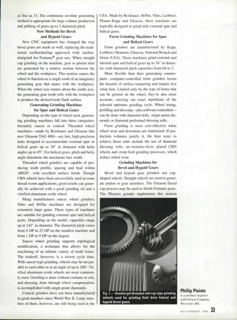
as :fine as 15..The continuous involute generatingmethod is appropriate for large volume productionand j bbing of gears up to 3 diametral pilCh.
New Methods for Bev,eland Hypoid Gears
New CNC equipment has changed the waybevel gearsare made as well, replacing the tradi-tional cut/harden/lap approach with cut/har-den/grind for Formate® gear sets. When straightcup grinding on the machine, gear or pinion slotare generated by a relative motion between thewheel and the workpiece. This motion causesthewheel to function as a single tooth of an imaginarygeneratinggear that mates wi.ththe workpiece.When the wheel axis rotates about the cradle axis,the generating gear tooth rolls with the workpieceto produce the desired tooth flank surface.
Generating Grinding Machinesfor Spur and "e~icamGear
Depending on the type of wheel used, generat-ing grinding machines fall into three categories:threaded, aucer or conical Threaded wheelmachines-made by Reishauer and Glea on (thenew Gleason TAG 400)-are fast, high-precisionunits designed to accommodate external spur orhelical gears up to 30" in diameter with helixangles up to 45°. For helical gears. pitch and helixangle determine the maximum face width.
Threaded wheel grinders are capable of pro-duc:ing tooth profile, spacing and lead within.000120", w.ith exceflent surface finish .. ThoughCBN wheels have been successfully used in somethread worm applications,good results can gener-ally be achieved with a good grinding oil and avitrified aluminum oxide wheel.
Maag manufactures saucer wheel grinders;Niles and Hofler machines are designed forextremely large gears. These types of machinesare suitable for grinding external spur and helicalgears. Depending on the model, capacities rangeup to :142" in diameter. The diametral pitch variesfrom 6 Df to 25 DP on the smallest machine andfrom I DF to 9 DP on the large I.
Saucer wheel.grilldi.ng supports topologicalmodiflcatien, a technique that allows for themachining of an infinite variety of tooth forms.The tradeoff, however •. is a slower cycle time.With saucer-type grinding. wheels may be set par-allel to each other or at an angle of I.Ipto IO{)°.Vit- 'ri:fied aluminum oxide wheels are most common-ly used. Grinding is done without coolants or oils,and dressing. done through wheel compensation.is accompli hed w.ithingle-point diamond .
onical grinder have not been manufacturedin great numbers since World War U. Large num-bers ofthem, however. are still being used in the
USA. Made by Reishauer, Hofler,· iles, Liebherr,Pfauter-Kapp and Gleason, the e machines aretypically designed 10 grind only external spur andhelical gears.
Form Grinding Machines tior Spurand Melkal Gears
Form grinders are manufactured by Kapp,Leibherr, Okamoto, Gleason. National Broach andOrion (USA). These machines grind external. andinternal spur and helical gears up to 36" in diarne-ter, with diamerral pitch capacities from 64 to 2.
More flexible than their generating counter-parts, computer-controlled fonn grinders lessenthe hazards of urface tempering and require lesssetup' time. Limited only bythe type of forms Ihalcan be ground on the wheel, they're also moreaccurate, carrying out exact repetitions of theselected optimum grinding cycle. Wheel truing,profiling and dressing-also softwarecontto.l1ed-can be done with diamond di ks ..single-point dia-monds or diamond preformed dressing rolls.
!Form grinding is most cost-effective whenwheel wear and downtime are minimized. If pro-duction volumes justify it, the best ways toachieve those ends include the lise of diamond.dressing rolls, no-wear/no-dress plated CBNwheels and creep-feed grinding processes, whichreduce wheel wear.
Grinding Machines forBevel and Hypoid Gears
Bevel and hypoid gear grinders use cup-shaped wheels. Straight wheels are used to gener-ale pinion or gear members. The Gleason flaredClipprocess may be used 1.0 flni, h Formate gears.The Phoenix grinder implements this motion
Philliip Plainteis a' product engineerwith Norton Company,Worc/';m~r.MA.
JU~V/AUGUST IS95 33

with coordinated X-, Y-...Z-. B- and A-axis move-ments whichare similar 1.0 generating motions,
Breakthrough Bond and Abrash',es
Though grinding equipment is expensive,advances ill grinding wheel technology enable
faster speeds and feeds, which shorten cycle time
and reduce costs. Such advances include thedevelopment of CBN. Seeded Gel. (SO®) andTAROAT" abrasive wheels.
Cub.ic 8oron Nitr;ide (CBN)
The hardness of BN (4700 Knoop scale) is
second only to diamond, Classified as a uperabra-
sive, CB wears more slowly than conventional
abrasives. It also conducts heal. away from theground surface, reducing (henna! damage.
In recent years, manufacturers of precisiongears (AcOMA classes 12 10 14) have adopted CBfinishing for miiitary ~U1daircraft applications.
Though the initial cost of CB is much higherthan that of conventional abrasive , CBN finish-ing ha been found 10 cui production time,improve quality and reduce manufacturing co t
by as much as 80%.Seeded Gel, (SG) Aluminum Oxide
SG abrasives are manufactured by a sintering
preces that results in abra ive grits consisting ofthous and of submicron-size aluminum oxidecrystals. During dressing or self-sharpening. the- -
Important Grinding Wheel Characlerislics
Wheels are classified according to a standard marking system (see
Fig.21that specifies the following characteristics: abrasive type; grain or grit
size; grade; structure; bond; wheel type; and bond type.
Manufacturers' abrasive type, the first element in the marking system,
specifies the class of a given abrasive. Norton, for example, offers several
classes of aluminum oxide which differ in purity. crystal structure and friability.
Grain or grit size indicates the degree to which abrasive grains are
rough or fine. In this system, the abrasive size increases as the grit size
becomes finer: Wheel grade or hardness refers to the bond strength, or the
torce required to break the grain from the wheel. In this case, alphabetic let-
ters are used to designate grades from saft to hard.
The structure of a grinding wheel refers to the spacing of the abrasive
grains in the band matrix. Grinding wheel structures from dense to open
(low to high porosity) are indicated by increasing structure number.
The bond system is normally a function af the selected abrasive type.
bond grade and structure; not an end-user variable. Wheel manufacturers
have their own designations for bond systems, and must therefore be con-
suited for bond system recommendations and information.
341
-, GEAR TECHNOLOGY
grains shed these very small particles. The resultsare higher. harpness and lower total wear limn for
conventional abra ives, Due to more uniform
micro tructure and increased chemical purity. SOis also harder (2100, Knoop scale) than conven-
tional aluminum oxide.Since SO grains fracture by bedding ubmi-
cron particles. wear flats do not develop al theworking urface of rhegrinding wheel. Instead.
sharp. relieved CUlling edges are produced. A_ 3.
result, eeded gel abrasives are sharper than con-
ventional aluminum oxide,Because of the increased hardness and the
structure of the SG grains, SO generelly wearslonger 'thall conventional aluminurst oxide. A
small particle break away 'from the grain due togrinding forces, only small portions of the total
grain volume are lost.SG functions best when aggressive metal
removal rate , are required and/or where the wheelwear conditions are . evere, SG may also be the
be I abrasive choice for hard-to-grind material,such as Waspalloy or other stainless steel alloytypically u ed in aerospace appljcaliolls.
The recommended abrasive for flared cup
grinding on Gleason machine. SG may offerimproved performance over conventional abra-sives forgenerated pinions and gears as well.
In use, self-sharpening sa has been foued 10
increase the number of parts ground betweendre ing and 10 reduce wheel dre sing by up to
80%. When tested, SG wheels finished 40 auto-motive gears per dress vs .. 12 gears with conven-
tional aluminum oxide wheels ..TARGA Abrasiives-
The Nexl Generation of SGTO abrasives, which perform in 11 more
focused environment. feature a grain lha.t isproce sed into elongated shapes with an aspectratio dependent on both the type of abrasive prod-
uct and the grinding application. The hape ofTARGA abrasives establi hes lightly moreporosity than. i shown in the typical pecifica-lions, a fact even more evident in higher tructure
TARGA wheels.TARGA users find. lower power draw produce
hlgher unlt forces per grain in higher structurewheel . TARGA user will gain benefits from the
grain shape which lends it elf to naturallyincreased pam ity, This pam ity increase unitpres tire on the grain, which yields lower powerdraw with the benefit of achieving near: uperabra-sive re ult in applications of creep-feed grindingof aero pace alloys.
Like S'O wheels, TAROA abrasives are COllsid-ered an alrernanve (0 the more costly varified
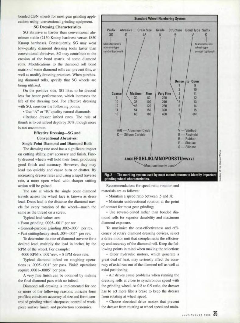
bonded CBN wheels for most gear grinding appli-
cations using conventional grinding eqcipment,SG Dressing Characteristics
SG abrasive is harder Ihan conventional alu- I
minum oxide (2150 Knoop hardness versus 1850Knoop hardness), Consequently, SG may wear
low-quality diamond dre sing tools fa tel" thanconventional abrasives. SG may contribute to the
erosion of the bond matrix of orne diamond
rolls. Modifications to the diamond roll bondmatrix; of some diamond rolls can prevent this. aswell as modify dre ing practices. When purchas-ing diamond roll , specify that SG wheels are
being utilized.On the positive side, SG likes to be dressed
less for better performance, which increa es thelife of the dressing tool. For effective dressingwith SO, consider the following points:
• Use "An or "8" quality natural diamonds
• Reduce dresser infeed rates. The rule ofthumb is to cut infeed depth by 50%, though more
is not uncommon.
Effecti.ve IJressing-8G andConventional Abrasive :
Single Point Diamond and Diamond RollsThe dres ing rate used has a significant impact
on cutting ability, part accuracy and finish, Fine-
ly dressed wheels will hold their form, producinggood fini h and accuracy. However, they mayload too quickly and cause bum or chatter. By
tncreasing dre ser rates and using a rapid traverserate a more open wheel. with sharper culling
action win be gained.The rate at which the single point diamond
travels across the wheel face is known as dress
lead. Dress lead is the distance the diamond trav-els for every rotation of the wheel=-rnuch the
same as the thread on a screw.Typical lead values are:
• Fonn grinding .0005-.001" per rev.
• General-purpose grinding .002-.003" per rev .• Fast cutting/heavy stock .004-.005" per rev.
To determine the rate of diamond traver e for adesired lead, multiply the lead in inches by theRPM of the wheel. For example:
4000 RPM x .002"/rev. = 8 !PM dress rate.Typical diamond infeed on roughing opera-
tions is .0005-.001" per pass. Finish operations
require .000'1-.'0005" per pass.A very fine finish can be obtained by making
the final diamond pass with no infeed,
Diamond mil dressing is implemented for one
or more of the following reasons: intricate formprofiles; consistent accuracy of size and form: con-trol of grinding wheel sharpness; control of work-piece surface fini h; and production economics.
Standard Wheel Numbering System
Prefix Abrasive3S GI
ManufaClUrer'sabrasive-typesymbol (optional)
Grain Sila46
GradaK
Structure Bond Type Suffix5 V S
IMe n ufacturar'swheel·typesymbol (oplIOnall
Dense Open1 92 10
Coarse Fine Very IFine 3 116 80 220 4 1210 100 240 5 1312 120 2BO 6 1414 150 320 7 1516 180 400 B etc .
A/G - Aluminum OxideC - Silicon Carbide
v - VitrifiedB -ResinoidR- RubberE - ShellacS - Silicate
ABCDEFGHIJKLMNOPQRSTUvwxyz~Most commonly used /
Fig. 2 - The marking svstem used bV most manufacturers to identify importantgrinding wheel characteristics.
Recommendations for speed. ratio, rotation andmaterial area follows:
• Maintain a speed ratio between .5 and .8;
• Maintain unidirectional rotation al. the pointof contact for mosl gear grinding;
• Use reverse-plated rather than bonded dia-mond rolls for superior durability and maximumdiamond exposure.
To maximize the co t-effeetiveness and effi-ciency of rotary diamond dressing devices, selecta drive motor unit. that complements the efficien-cy and. accuracy of the diamond roll. Keep the fol-lowing points in mind when milking the selection:
• Older hydraulic motors, which generate agreat deal. of heal, may seriously affect the accu-racy of axial run-out of the diamond roll a e well as
axial po itioning.• Air drives cause problems when running the
dressing rolls at close 1.0 synchronous speed with
the grinding wheel, AI 0.8 to 0.9 ratio, the dresser
has to act more like a brake to keep the dresserfrom rotating at wheel speed.
• Choose electrical drive motors that preventthe dresser from rotating at wheel speed and main-
JUlY,AUGUST j 995 35
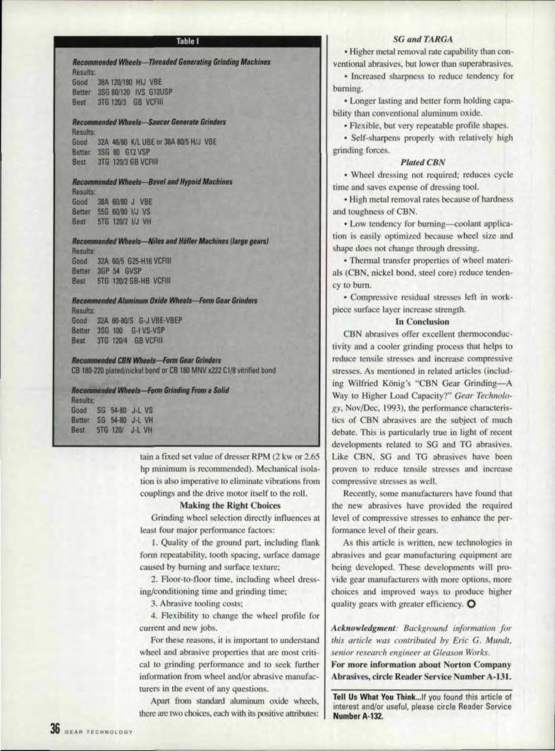
- ----------
Tahle I
RecDml1Jelltied WhBels-T1rrnded Sen".ting GrindingMllchinesResults:Good 38A 12011110HIJ VBEBetter 3SG 801120 IVS G12USPBest 3TG 121113GB VCRII
,.,...,.. WfIHII---S.Hw:eI6tmemrI Gri".,.Results:Good 32A 46/80 K/l UBE or 38A IlOl5 H/J VBEBetter 3SG 80 G12VSPBest 3TG 12013GB VCFtII
tlecMRlfIII. WhM ,.",II1II H",oid IfIIchinesResults:Good 38A 60IIl J VBEBetter 55G 60IIl I/J VSBest 5TG 12012VJ VH
RICO_lid. WfIHIs--Nila MIdHiiffer "';/Ift (IIIIP galS)Results:Good 32A 6015 G25-H16VCFIIIBettar 3GP 54 GVSPBest 5TG 12012GB-HB VCFIII
1IK_*"Ahai .. 011_ ~ 6HrGriltHrsResults:Good 32A 6O-80/S G-J VBE-VBEPBetter 3SG 100 G-I VS-VSPBast JTG 120{4 6B VCRII
R_.." CBNWfIrtIeII--FenI Gar Gri,."CB 180-220plated/nickelbond or CB 180MNV x222 Ctt8 vitrified bond
.. ~ .... ~ GrindlngFrom.SDlidResults:Good S6 54-80 J-L VSBetter S6 54-80 J-l VHBest 5T6 1201 J-l VH
rain a fixed et value of dresser RPM (2 kw or 2,65hp minimum is recommended). Mechanical isola-tion is also imperative toellminate vibration fromcouplings and the drive motor itself to the roll.
Making the Right ChoicesGrinding wheel selection directly influences at
least four major performance factors:I. QlJal'ily of the ground part, including flank
form repeatability, tooth spacing, surface damagecaused by 'bumLng and urface texture;
2. Floor-to-flo r lime, including whee IIdress-inglcolldiliOiling time and grinding time;
3,. Abrasive 'tooling costs;4, Flexibility to change the wheel profile for
current and new jobs,For these reasons, il is important to understand
wheel and abrasive properties thatare most criti-cal to grinding performance and to seek furtherinformation from wheel and/or abrasive manufac-turers in the event of any questions.
Apart from standard aluminum oxide wheels.there are two choices. each with its positive attributes:
,36, GEAR TECHNOLOGY
SG and TA.RGA• Higher metal removal, rate capability than COI1-
ventional abrasives. but lower than superabrasives,• Increased sharpness 10 reduce tendency for
burning.• Longer lasting and better form holding capa-
bility tI1an conventional aluminum oxide.• Flexible, but very repealable profile shapes..' Self-sharpens properly with relatively high
grinding forces.P{atedCBN
• Wheel dressing not required; reduces cycletime and aves expenseof dre sing 100L
• High metalremoval rates because of hardness'I I and toughness of CBN.
• Low tendency for buming--coolant applica-tion is easily optimized because wheel size andshape does not change through dressing.
• Thermal transfer properties of whee! rnateri-als ( B • nickel bond, steel core) reduce tenden-cy to bum.
• Compressive residual tresses left in work-piece surface layer increase sircngth,
[n ConclusionCO abrasives offer excellent jhertnocondue-
tivity and a cooler grindmg process that helps toreduce tensile stres es and increase compressivestresses. As mentioned ill related article (inelud-
,ing Wilfried Konig's "CON Gear Grinding-AWay to Higher Load Capacity?" ,GeclF Technalo-gy. Nov/Dec. )993). the performance characteris-tics of CB abrasives are the subject of muchdebate. This i particularly true in light of recentdevelopments related to SG 3J'1d TG abrasives.
Like BN. SG andG abrasives have 'beenproven to reduce tensile' stre ses and increasecompres ive Ires e a well.
Recently. some manufacturers have found thatthe new abrasives have provided the requiredlevel. of compressive stressesto enhance the per-forrnance level of their gears,
A this article i wr.itlen, new technologiesjnabrasives and gear manufacturing equipment arebeing developed. Th se developments will pro-
vide gear manufacturers with more options, morechoice' and improved ways 10 produce higherquality gears with greater efficiency. 0
Ack.nowledgm:e.nt: Backgroulld information forthis article was contrihuted by Eric' G. MUlldt.senior research engineer at Gleason Works.For more iinformatiol'l abeut Norton C'ompanyAbrasives, c:irde Reader Service Number A·Bl.
Tellt Us What You Think ...lf you found this article ofinterest and/or useful. please circle Reader ServiceNumber A·132.

-------~~--~--~~~-~-------------~--~
Ground in 13'9 Minutes26.2 II
Gear for wind turbine drive system.
,GEAR DATA:
Outside DiameterFace widthNo. of TeethD.~HeHx AngleGrinding Stock per flankProfile ModificationHardnessQuality
-~I
26.2 It
7.1 "803.18'8 0
0.018 II
0.0013 n
62 HRcAGMA 15
Total grinding time, including dressing time: IJ.9 min.
Ground on a Hofler Nova CNC 1000 gear grinder with a dressable, co-rundum grinding wheel and Hofler's deep teed grinding process - HDR
Hofler, the better way to grind gears,
For more information, can or write to one of the following addresses:
fllillCorp.
Honer Corp',P.D..Box 127Sky Manor Rd.Pittstown, N.J . .08867Phone: (908) 996-6922Telefax: .(908) 996-6977
IF:IIIIIMaschinenbau
Honer GmbHP.O. Box 045276258 EulingenGennallYPhone: - 49 - 7243 - 599 - 0Telefax: - 49 - 7243 - 599 - 165

------
Pl-
CL lHPlRIISL UUWHEN YOU N,EIED'lNITRICAlIE DESIGiNS AND METICULOUS CRAIfTSMANSHIP', IRELY ON fAIRLANE GEAR,IN,C.
NEW MA·CHI,N,ES JUST PURCHASED'... KAPP' CNC "-~RD FINISHER... AMERICAN P,FAUTiER CNC HOB
W,EOF,FER:I· Gear Noise Reduction Program
..Expert Technical Assistance·Gear Cutting, in a Wide Range
of Sizes, Types &. Quantities• Prototype & Emergency Re-
pair I Rebuild Service
Quality ge.arsup toAGMA 15, MIL-1-45208A,MIL·STD-45'662
SIZE IIAINGE -Smaller than aninch to 48·
TYiPU:Spur -Intemal & ExternalHelical-linternal & ExternalWorms, Worm GearsSerrations - ShaftsSplines .. Internal & ExtermalSprockets- ClustersSegments - SpindlesRatchets· Gear Boxes
CIRCL'EA-1S on REA.'OER REPLV CARl)
,COMMITIMENIT TO IOl.lAUTYReishauer Ground GearsM & M Precision Gear CheckerKapp CBN Hard Finished GearsAmerican Pfauter CNC HobCoordinate Measurement
Machine
FullV implemented SPG, and datacommunications capabilities.
!For the ultimate in Quality gears,call or send mquines to:
~ Failil'ane Gear,lnc.,
P. o. Box. 409 APlymouth, MI48170Phone (313),45.9-24401
(800.)837-1173Fax 13131459-2941
,38 GEAR TECHNOLOay
ILet'sfo[e it to k'eep IIp with fhe latest fechnol'ogy, you ,have 10 meel with
suppliers. But lhat can eot into your lime--lime you ton', spare. That's why GEAR
EX.PO'95 is the ~a(e fa be'tame N'ovember:There, under one roof, YOD,' find Ihe
lop suppliers fo the gear industry;
In foci, GElR IEXPO'9.5 is the only exlUbitia(J ,devofed exclusively to the gear
industry ..AI GW EXPO '95, y.ou choose, which suppliers you wonlfo see,,~when
you WlIntloseerhem ...'ond how much timeyou'll spend wilh,each. You also get to'
see live demonstrations of the 'eqlJipmenlyou'l(e been thinkjng of buy-,ing.
So, do yourseH ,cnd your suppliers 0 fllvof ...ond' len 'em wflere fo !go':
•
THE WORLD OF GEARINGI_ N'ovember12-1S,1995-Indianapolis,llndlana
Tefl'em 'hat~ ,wher;eall the smart suppJie.TS--lIl1d buym-wiJ/ be!

MISSIONI: CONTIROLS
Dry Gear Hobbing/low m(}rIe'lnma(!hin~ (!(}nt'{o~,ititleJ an'motot3 play
a pari in. thh ,emettp'n.f neto technoiCtf'f.
!2U2jtlon.~We are contemplating pur-
cha ing a hobbing machinewil.h dry hobbingcapabilii .•
ties. What do we need toknow about the special sys-tem requirements for thistechnology?'
4njut(!t:If you are cutting small gearsin high-volume production,
you should consider the dry
hobbing option. Dry hobbingoffers many advantages andvery few disadvantages overconventional hobbing. Cur-rently only certain sized gearsju tiJy the cost of cutting withthis method. The decision is
based on the pitch rating of thegears, which influences the
cost of the tools. Dry cutting
technology is generally used:for smaller automotive sizedgears. Largerpitch gears arenot manufactured in ufficient
quantities to justify the use ofcarbide hobs,
A additional dry hobbingmachines of various sizes areintroduced by the manufactur-ers andthe cost of the toolsgoes down, the dry hobbingmethod wil1 gain wider accep-tance in the industry. (SeeGear Technology, Novem-
ber/December 1994. "GearHobbing Without Coolant,"
for 3. basic introduction to this
technology.)There are two points that]
would Like to make regardingthi new technology. The fir t
E. Peter Kovar
one is that although the ad-vance in CNC technology was
not tile only cmalyst inthe de-velopment of the dry hobbing
technique, it is one ofthe keys
10 the functionality of thistechnology. Dry bobbing wouldnot have been possible with-
out the recent developmentsin CNC systems and motors.
The second point is that dryhobblng is very fast, so fastthat the CNC cannot correctinherent machinery problems(as it can in lower traditionalmethods). Therefore the dry
hobbing machine needs to bevery well designed.
Hand in hand with elec-tronics, two other forces ac-
celerated the development ofdry hobbing technology. Onewas the introduction of better
carbide tool materials. Signif-
icant increases in tool lifehave been achieved over thelast :few years. Further ad-
vances in carbide and ceramictool technology, along with
reductions in the cost of thesetools, will increase the appeal
of dry hobbingeven more.The second accelerating
factor was the total redesignof the dry cutting machinesthem elves for accuracy, ther-mal stability and fast chip re-
moval. The machines alsoneeded to. be built to more ex-
acting tolerances. Machines
cutting at these ultra-fast speeds
need to 'be more accurate.
The integration of the hoband table kinematics of these
fast machines tests the limitsof modem CNC controls,
Currently, CNC systems can
correct kinematic errors in the
magnitude of 160 Hz. depend-ing on the inertia ratio be-tween the servo motors and
the machine elements to be
controlled. The critical area isthe angular link between thetool. and the workpiece (the
mechanical element ill thehob head and the table), Er-rors in the kinematics of themachine cannot always becompensated for bythe con-
trols at such high speeds.
These errors need to be elimi-nated in the design of the ma-chines themselves.
Why Bother'?Dramatic new concepts are
usually met with resistance.
The poet Alexander Pope said."Be not the first by whom the
new are tried ... " Most of ustend to agree, especially when
the new involves big capitalexpenditures and the abandon-ment of old, comfortable wayof doing things ..However, drybobbing technology has beenproven in tests to. be faster,less expensive and more envi-ronmentally friendly than con-ventional hobbing for many
high speed applications and.therefore, should be given se-
rious consideration by gear
application engineers.The dry hobbing process
was developed primarily foreconomic reasons. _ ew cut-ting 100.1 technologies using
est ealemn willi answeryour questions about'gear machinery contro!lsand electrical svstems ..Send your questiansalbout. CNC,sofli.wareand ma1chinery elsetri-cid systems to M'ission:Contmls, IP: 0..180x 1!426,E,lk Grove, IL ,60009' or'ax them to 708-431-6618.
E. IP,eter Kovaris the \'Jrepresident ofu.s. Teclr Corporation,Chicago. ll., (JIll I a recog-nized authority Oil CNCapplications.
JULY/AUGUST 1995 3,91

I//Tnliln INSPECTION &1/1/. lJ'lJI·· BURNISHING SVSTIEMSl1Wpion.ee.r,ed the gear inspection .business oversixty yeats ago. Let ,ourexperience work for fOU.
We offer complete design. manufacturing. salesInd service to the gear inspection industry.
Products:manual gear rolling inspection devicesgear analyzerscomputerized gear rollerssemi-automatic gear inspection machineshigh speed fully automatic:
• gear inspection with automated part handling• gear burnishing equipment
Services:installation/training/serviceservice contractsdesign servicesengineered quality management
ITf}fWHeardandALEXANDRIA. MN
PHONE 6t2~162-5223 FAX 6.72·762·5260
CIRCLE ..0.·15 on READER REPLY ,CARD
SOLID CARB.,D,E AND ass (M42)Class AAA, AA or Aground form-24 to 250 DP. Standardand non -standard to all current U.S. and Europeanspecifications. TiN coating and stock hobs available. Writefor our free brochure.e il::lJ.:lI::I~:III!!!!!!IINDUSTRIES
~4{11r-1~~-~. INC.1650. SycamoreAve.,.Bohemia,NY 11716
516-567-1000· FAX- 516-567-1355AUG'MASTER GEARS AND SPLINE 'GAGES
CIRCLE .0.·116on, READER REPLY CARD
40 GEAR' TECHNOLOGY
••• _11 MISSmN: ICONTROilShigh-speed carbide cutters andceramic tools, along with thehigher peeds of modem ma-chines, made the dry cuttingprocess possible. One dry hob-bing machine can replace twoto six.conventional machines,depending upon the hardnessof the steel be:ing cut,
One tremendous side ben-efit oflhis technology is envi-ronmental friendliness. Notonly are coolant purchaseand disposal costs eliminated,but there is al a the addedbenefit of cleaner air on theproduction floor, Some of thechief proponents of this tech-nology arelhe operatorsthemselves, who can work ina cleaner environment whendry cutting. Shop personnel,floors and equipment. are notcovered with coolant at theend of the day. There is also areduced. fire hazard since
-
What's Involived?Dry hobbing is much more
complicated than simply"turning off the coolant" Inaddition to the CUlling tool,three design factors must becon idered, The machine it-self needs to carry away hotchips efficiently so the geom-etry of the workpiece is notaffected. Also, the machine'schip chute must not inhibit thechip. The chute design istherefore much steeper thanthat of a conventional ma-chine (see Fig. 1).
The machine des.ign mustensure thermal stability, sincethere lis no coolaru in the ma-
chine bed to carry away thegenerated heat. Dry bobbingmachines are designed withspecial internal ribbing forthermal stability. They aregenerally quite heavy and in-corporate special steep walls
flammable oils are no longer around the table. The rna-needed. Bacteria and corro-sion from water-soluble cool-ants are also eliminated. Afinal benefit of dry hobbing is
the simplification of theprocess, as parts do not re-quire wa hing,
Ceramic (lr Carbide?The cost-effectiveness of
ceramic hobs is still subject todebate, especially since cur-rently no domestic manufac-turer makes these hobs ..Mostof the testing and researchbeing done by the domesticautomotive industry is nowfocused on carbide hobs (al-though Fiat-Italy, and ZF inEurope are testing ceramichob capabilities). At the mo-ment, ceramic hobs are veryexpensive, more sensitive tocorrect setup and calibration
than carbide hobs and difficultto sharpen. However, newcoatings are being tested that.may significantlytheir performance.
chines also include an inte-grated chip conveyor to keepthe heat of the chips from. ac-cumulating in the machineand to maximize the speed atwhich the chips are removedfrom the machine for dis-posal. In some cases, themanufacturers of the ma-chines are using special vi-bration panels underneath theworkpiece to accelerate chipremoval, Finally, the machinemust be capable of high cut-ting speeds. The machine'seNe-controlled,. integratedautomation must support theshorter machining cycles ofthese machines.
The feeds and speeds ofthe machine, along wilh thenumber of starts in the cuttingtool, need to be optimized toobtain a chip thicknessthatcam carry tile heal. away fromthe part. The machine must becapable of a minimum hobspeed of 3,000 rpm and a

table speed of at least 500rpm, Engineers carefully se-lect the appropriate motorsizes for these machines inorder to ensure that sufficienttorque is available to cut theproper chip depth efficiently.As :new carbide compoundsare developed, the hob andtable speeds will be pushedeven higher.
Machines for dry hobbingneed to incorporate modem,preferably digitally controlledmotors capable of supportingthe dynamics in this high-speed application ..The speed
compensate for inherent ma-chine temperature instabilitywith special coolant muting orby using the CNC to performelectronic compensation, al-though neither method wasvery reliable. Dry cutting re-quires that the machines havean inherent thermostability,and, therefore, the machinedoes not need electronic com-pensation devices,
Most of the heat generatedin the dry hobbing process (asmuch as 80%) is carried awaywith the chips. Gears gener-ally come out of the machine
Fig" 11 - IConceplhobbing machine for dry bobbing. Courtes\l' ot LiebherrAmerica. Used wim pemissiDn. .of the application al a put a in the temperature range ofdemand on the synchroniza- lOS-115°F. Machines thatlion ofthe hob and table rota- i heat gears only to 115° gener-lions controlled by the C.c. ally do not require thermal
Without today's elec-tronic technology, dry hob-bing methods would not becost-competitive. The ma-chines and controls must. becapable of achieving al leasta 3,000 rpm hob speed forlong period of time withoutoverheating. The selection ofthe control and motor capac-ity is critical.
Another area controlled bythe CNC in the past is temper-ature compensation. The ther-mo lability of the conventionalmachine was not a critical areaof concern for :mach:ine de-signers. Most gear machinemanufacturers were able to
compensation devices,Conclusion
Modem controls, drivesand motors have set the pacefor technological advancesand a better environment. Dryhob bing technology is a giantstep toward lowering the totallong term co ts of gear manu-facturiag and oil disposal 0
leU Us What VOIIThink ...lf youfound this article of interestand/or useful, please circleReader Service NumllerA-13J.
Spiral 81Straight Beve~1Gear iManufacturing',Commercial toaircrah qua1lityIgearing.
Spur. helical. sp'lined shafts.lintema'l& externa!I•.shaved & Iground 'gears. Spirailibevel grinding',
Mil-I-4520S·Mil-STO-45662. SPC
MIIJWES.TG"'~WES,r . e'.NT...ACT.:& T'lUllINC. ~ ~ CIlAJGIIJ.ROSS:
26069 Groesbeck Hwy. - - '(810)nG-7580Warren, MI4B089 FAX(810) 716-2322
CIRCLE 11.-11 on IREADER REI'L Y CA_RD'
• OEM- Gear Hobbers,Shapers, Grinders andInspection Machines
• Re.... ufacture/Retrofit/RebuUdof Your Barber-Colman Machines
• IParls/Servlce/IRepel •• of YOU'T'Barber-Colman, Boufn& Koch Machinery
2500 Kishwa.ukee S1.Rockford, JL 61104Phone (815) 965-4013fax (815) 965·0019
J U L V I AUG US T '995 41
VIEWPOINIT _
o ivetrain Research.a; !Jlea WJuHeh'me fj Oveu/ue
he popular percep- rotorcraft have been steadily determined and unified imperative. Jobs, both civil-
lion today is thattechnological ad-vancement is an
engine running almost out ofcontrol. New products andproce se are developingfaster than we can keep upwith them, as anyone whohas had a new computer sys-tem era h into obsolescencepractically before it's out ofthe bOI( can tell you. BUI
that's not the case every-where .. Transmis ion tech-nology, for example.
The drivetrain, perhapsbecau e it doesn't lend itselfto exciting film footage 01'
glitzy electronic presenta-tion, has been neglected.
Yes, some exceptions doexist. Thanks in part toresearch done during the mil-itary buildup of the 80s, [hemain propulsion gears of theU.B. avy's surface andundersea fleet are now hard-ened and ground rather thanshaved and then hardened.The Advanced RmorcraftTransmission (ATR) pro-gram brought some develop-ments which were integratedinto the Comanche maintransmission at Sikorsky, andMcDonnell Douglas Heli-copter System s continuesorne oLils ATR research.
But the fact is that theperformance capabilities of
Dr. Suren B. Roois rill' director of /11,'I,la/irma/ ('efJIU [or :
Advanced DrivetrainTechnologies £I{
Perm Stall'Universtr;
42 GEAR TECHNOLOGY
and significantly upgradedwhile the basic power trans-missions remain relativelyunchanged, I wonder whether .we are not now approaching :the "ragged edge"-a limewhen power transmissionsare unable to cope adequatelywith the newly enhanced per-formance capabilities of therest of the rotorcrafr,
In one sense transmission
European helicopter industry.United Stales rotorcraft man-ufacturers will have to squareoff against the "Eurocoprer"consortium on every potentialsale in Europe and el ewhere.McDonnell Douglas recentlywon a significant contractagainst the "Eurocopter" withits pending ale of Apaches tothe Netherlands. On the otherhand, the government of Abu
technology has been the vic- : Dhabi has just ordered atim of its own success. dozen Eurocopters.Tran missions designed in the Aerospace is not the onlyprevious decades had such a . place where the technologicallarge safety factor built into status quo could hurt usthem that no major changes badly. The respite presentlywere believed necessary to ; enjoyed by the automotivecarry the increased load and and off-highway vehicle sec-enhanced performance specifi- tor becau e of the soaring yencations. It was easy to neglect: rate Cannot last forever. Whenthem because they grabbed Ihe yen comes back, say toattenti on only when they the 110 to the dollar level, canfailed. By building better- the Big Three or Caterpillarthan-required transmi sions, compete head-on with thedesigners and manufacturershave, unfortunately, deflectedall the limelight away fromtransmissions-leaving them-selves in the dark!
The problem now is, justat the moment when thatragged edge is on the hori-zon, political and economictimes have changed. If nomajor innovations were evi-dent when [he defense bud-get, which funded much of :
Toyotas and the Komatsus?Higher power density drive-trains that are quieter andmore reliable could be impor-tant to success in such a head-on competition.
Rest assured, someone isworking on developing light-er, quieter and more reliabletransmissions right now .. It'sjust that they're not workingon them in the, .S.
Unlike consumer electron-the research. was "fat," what ~ lcs, power train developmentis to happen during the cur- . is not an area we can leave torent and future "lean" years? : someone else. The implica-
Safety issues aside, neg- : lions for both our defense andlect in this area will co t us ci vilian economy are toodearly. For example, we face: important. Much more thanvigorous and renewed over- : national pride is at stake.sea competition from a very There is also an economic
ian and military, defense' pre-paredness and user safety areall under the gun if the staresquo continues.
The good news is we'renot starting fr-om quite groundzero. Several university-based centers, using govern-men! funds, are doing
research in this technologyector. The National Center
for Advanced DrivetrainTechnologies here at PennState, the InstrumentedFactory (]NFAC) for gearrnanufacturi ng at the liTResearch Institute (IITRI)and the Gear Center at OhioState University all have pro-grams in place.
BUI these are only thebeginning .. More work needs10 be done. Industry needs toaggressively irueract withthese research institutions toreap the most benefits fromtheir work. And we need 10
remind our legislators that inthe rush to downsize the mili-tary. we don't throw the babyout with the bath water.
The drivetrain indu try is
capable of overcoming years ofneglect. II. has the potential tobe the best and most advanced.
in the world. But if we want tobe leaders and not followers,now is the time 10 act. 0
For more information ahoutNCADT, pl,ease circleReader Service No. A·134.
Tell! Us W-hat Vou ihink ...lf youfound this article of interestand/or useful, pleess circle!Reader Service INumber A~135.

••••••••••••••• TECHNI'CAL. CAtIEIN!DA!R •••••••••••••• _
,JULY 1:O-AUG'US:r ,251ASM International Education Seminars.Jul,y 10-14. Metallurgy for the on-Metallurgist: July H-20, FractureMechanics & Damage Tolerance: Jully18-20, Tool Steel & II Heal Treatment:A.ugust 21-25, Fundamentals &Applications of Powder Metallurgy;Mechanical Testing of Metals. All semi-nar held at ASM Headquarter ,Materials Park, OR Call 21.6-338-51.51or fax 216-3384634.
SIEPTE~BER1-9National Screw Machine ProductAs ociation Metalworking SoftwareExpo '95. Chicago Marriou O'Hare.Showcasing the latest in software andcomputer technology serving the metal-working job hop indu try, For moreinformation, contact Gardner Mana-gement Services, 1-800-950-8977 01' fax51.3-527-8950.
SEIP'TEM!BIER 1i1~14ASM 2nd International onference onHeat-Resistant Materials, Focus on thedevelopmern, performance and end-useof heat-resi rant material . ContactASM at 216-338-5151, x. 703 or fax216-338-4634.
SEP:rEMBER 11-15AGMA Training School for GearManufacturing. Daley College, Chi-cago. ]L. Contact A,GMA Oil 703-684-021. 1 or fax 703-684-0242.
8IEP1EMBER'12-14Ohio State Univeraity, "Gear NoiseSeminar." Covers measurement,sources, transmission error, rattle,reduction techniques and more. ContactSusie YOWlg, 61.4-292-5860.
OCTOBER 116-18AGMA Fall TechnicalCharleston, Sc. Presentations on gearmanufacturing and research subjects.For more information, contact AGMAat 703-684-02~ 1 or fax 703-684-0242.
INOVE'MBER 12...:15AGMA Gear Expo '95. IndianaConvention Center, Indianapolis, IN.The one trade show devoted exclusivelyto the gear and gear-related productsand services industry . See the late t
machines. products and proces es, Formore information. contact AGMA at703-684-021 Lor fax 703-684-0242.
To announce all important technicalmeeting, exposition or seminar. pleasesend not.i/icali.o1I 1.0 Gear T:echnologyTech Calendar, P'. O. Box 1426, ElkGrove Village, IL 60009. Noticesshould arrive in our offices six weeksprior to the date of the issue in whichyou wish it to appeer. Items are used 011
a space-al'ailable basis.
lOur Gear Dressing Discs GiveYOIUI E,urope,a,n Qu!alility
Tired of holding up production ofyour high quality gears while you:wait for overseas quality diamonddressing discs? Wait no more.Winter's premier quality diamonddressing discs are manufactured righthere in America, in a state-of-the-artfacility in Travelers Rest,South Carolina. Thatmeans immediate accessto the world's finestquality dressing disc.sforyour Reishauer SPA,Fassler DSA, Okamoto orCsepel dressing units.
You won't have to 'go overseas whenyour dressing discs, need repa ir ,either. Our sets of dressing discsare offered two ways: sintered,r.andomly distributed diamond,or plated, single layer. randomlydistri buted dia mond. We offe r
a full range of standardmodules and diametralpitches. If you requirea non-standard moduleor a special tipmodification, we canhandle that, too. All inrecord U.S.A. time.
U.S.A. - South carolinaErnst Winter & Son, Inc.
P.O. Box 1006 .• TravelersRest,SC 29690(803) 834-4145· FAX (803) 8343730
CIRCLE A·19 en READER REPL'It CARD
JUlYIAUGUSTI995 ,43

Let Process Industries, a leader in the manufacture ofCustom Gears, do your gear grinding, for you!Using;Reishauer RZ-300and AlA's, Process Gear canfi nish-grind external gears per your specifications:Capabilitiies Inelude: 4 DP to 48 DP'
1 Tooth and UpUp to 12'" 00'
GNG Gear Analysis provides documentation of gearquality as well as in process control.Galiloday and leI Process Gear put their 50 years ofgear production experience to work for you.
Please call BOO,,860·t63t today, for more .information,or FAX your pnnts to 708 ..61t·6840',
3860 N. River Road • Schiller IPark, IL '60176-----
For More Information CallThe Compames Of118001860'1631 Process Industries
CIRCLE A-2D on READER IREPLY CARD
We can now manufacture Master Gears, SplineGages, and many other tooth-form products to yourspecifications (optionall design services are also avail-able). Accuracy levels required for master reference,QC inspection, or production grades are assuredthrough testing with our Model 3000 QC Systemthe industry standard for automated gear and splinetesl!ing. . .
For quotations or applications information, write orI call M &. M Precision Systems, 300 Progress Rd.,
West Carrollton, OH 45449',.513/859/8273. For FREiE.descr.iptive brochure, circle reader service number.
,M&M PRECISIONGi SYSTEMS CcmPORATlCN
.CARD'
44 GEAR TECHNOLOGY
ADVERTISING SECTION
LITERATURE MART
Superabrasive WheelsDiagrind's Catalog 300 coversinternal wheels from 0-.030-3" diameter. Informationincluded on wheel selection.speed. overhang, collet orarbor use and feed rates.Superabrasi ve profiles areillustrated ..
Diagrind., Inc.,10491 W. ]64111 PlaceOrland Park. IL 60462Phone: (708) 460·4333Fax: (708) 460-8842
CIRCLE. REA'DER SERVICE 123
The Com,plete IGear BookGear Geometry & AppliedTheory, by Faydor L. Litvin.covers the modern theory ofgearing. geometry. design andcomputerized simulation ofmeshi ng and contact foralmost all gears; the geometryfor face-gear drives, doublecircular-arc helical gears;CNC applications and newapproaches for tool design..Prentice-Hall, 1994. $72.00..To order call (800) 947-7700..
Scr,ew Machined PartsHerzog GmbH & Co. is amanufacturer of high qaalityscrew machined parls,includ-ing gears, armatures. spindles,connecting pins. elbows andcomplete assemblies. AJI partsare made according to cus-tomer-specific requirements.Herzog is the solution for yourapplications) For further infer-mation, please contact Simonat (502) 731-3983 or fax al(502) 769-1815.
Fr,ee INIASA LiteratureCOSMIC, NASA's ComputerSoftware Technology TransferCenter, offers a free brochuredescribing 15 computer pm-grams in the general area ofStructural Analysis that weredeveloped tor internal use byNASA. These programs aremade available in source codeform for reuse within the U.S.Contact COSM[C, 382 EastBroad Street, Athens. GA30602-4272. Ph: (706) 542-3265. Fax. (706) 542-4807 .
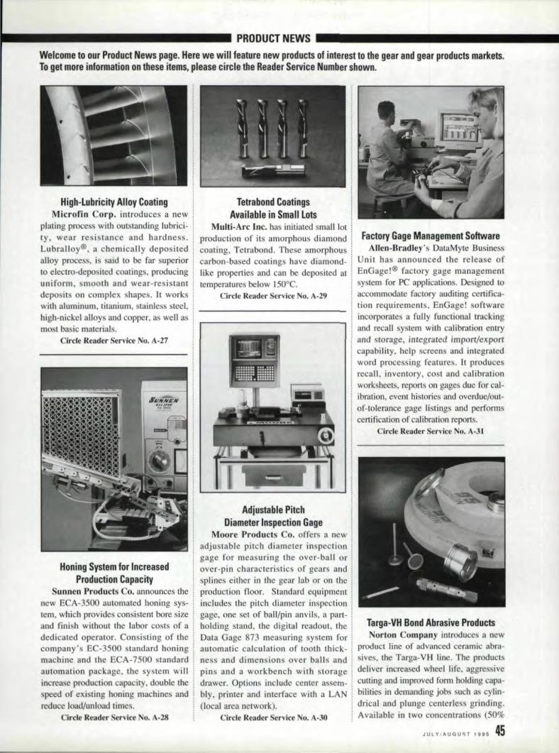
_------------1 PRO,DUCTNEWS _Welcome to our P,roduct News page. Here we will feature new pr,oducts 01 interest to the gear and gear IP;roducts;markets.101 Iget more, information on these items, please cirela the, Reader Service Number shown.
Hig,h-tubricity Aliloy CoatinglMicrofin. Corp. introduces a new
plating process with outstanding lubrici-ty, wear reaistance and hardness.LubraHoy®, a chemically depositedalloy process. is said 10 be far superiorto electro-depo ired coatings. producinguniform, mooth and wear-resistant.deposits on complex shapes .. h workswith aluminum, titanium. stainless steel,high-nickel! alloys and copper. as well asmost basic material.
Circle Reader ervlce No. A-27
Honing System'or IincreasedProduction Capacity
Sunnen Products Co. announces thenew ECA-3500 automated honing sys-tem, which provides consistent bore sizeand finish without the labor costs of adedicated operator .. Consisting of thecompany's EC-3500 srandardhoningmachine and the ECA-7500 standardautomation package, the system willincrease production capacity, double thespeed of existing honing machines andreduce load/unload limes.
Circle Reader Ser ice No. A-.l8
Tetrabond Coatings.Allail'able in Smalll tots
Mult:i-Arc Inc. has initiated small lotproducnon of its amorphous diamondcoaong, Tetrabond. These amorphouscarbon-based coatings have diamond-like properties and can be deposited attemperatures below 150°C.
Circle Reader Servlee No. A-29
.Adjustable PitchDiameter Inspection 'Gage!
Moore Products Co. offers a newadjustable pitch diameter inspectiongage for measuring the over-ball orover-pin characteristics of gears andsplines either in the gear lab or on theproduction floor. Standardequipmentincludes the pitch diameter inspectiongage. one set of ball/pin anvils. a part-holding stand, the digital. readout, theData Gage 873 measuring system forautomatic calculation of tooth thick-ness and dimensions over balls andpins and a workbench with storagedrawer. Options include center assem-bly, printer and interface with a LAN(local area network).
Circle Reader erviee No. ··30
Factory Gage Management Softwar,eAllen-Bradley's Dat.aMyle Business
Unit has announced the relea e ofEnGage!® factory gage managementsystem for PC applications. Designed toaccommodate factory auditing certifica-tion requirements, Em'Gage~!softwareincorporates a fully functiorraltrackingand recall system with cafibrationentryand storage, integrated imporr/exporrcapability, help screen and integratedword processing features. It producesrecall, inventory, cost and calibrationworksheets, reports on gages due for cal-ibration, event histories and overdue/out-of-tolerance gage listings and performscertification of calibration reports,
Clrele Reader Service No. A-31
Targa-VH Bond Abrasi,ve P',rod'ucts;Norton Company introduces a new
product line of advanced ceramic abra-sives, the Targa-VB line. The productsdeliver increased wheel. life. aggressiveculling and improved form holding capa-bilities in demanding job such as cylin-drical and plunge centerle s grinding.Available intwo concentrations (5()o/t
JUlVIAUGU~TI U5 ,45
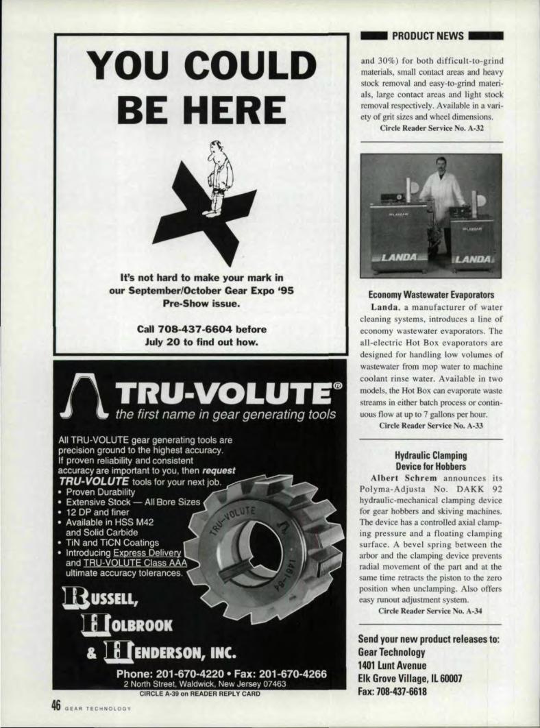
YOU COULDBE HERE
U's not Ihard to make' your mark .inlour Se,ptem'ber:-IOelober' Gear Expo '95
Pre-Show lssue,
'Call 7'08-437-6604 before.July 20 tofi'nd out ho'w.
46, GEAR TECHNOLOGY
IPiRODUCT NEWS; __
and 301?l) for both difficult-to-grindmaterials, small contact areas and heavystock removal and easy-ro-grind rnateri.also large contact areas and light IOc.kremoval respectively. Available in a vari-ety of grit sizes and wheel dimensiens.
ircle Reader Service No. .4.-32
Econom.y Wastewater IE.vaporatorsLanda, a manufacturer of water
cleaning systems •. introduces a line ofeconomy wastewater evaporators. Theall-electric Hot Box evaporators aredesigned for handling low volume ofwastewater from mop water to machinecoolant rinse water. Available in twomodels, Ihe Hot Box can evaporate wastestreams in either batch process or contin-uous flow at up to 7 gallons per hour.
, ircle Reader Service No. A-33
!Hvdraulic mampinglDevice for IHo'b'bers
Alber. Sclilrem announces itsPolyrna-Adjusta o. DAKK 92hydraulic-mechanical clamping devicefor gear hobbersand skiving machine.Tile device has a controlled axial clamp-ing pressure and a floating clampingsurface, A bevel spring between thearbor and the clamping device preventsradial movement of the pari. and at thesame lime retracts the piston '10 the zeroposition when unelamping. AI 0 offerseasy runout adjustment system.
Cirele Reader Service No. A-34
Send your new produ.ct releases to,:IGea.r Technoillogy114011Lunl Avenu'eElk Grove,Vll11age,1160007Fax: 708-437-6618,
SERVICE- -- - - --- -
GEAR TOOTHGRINDING SIERVI'CIES
• Cost effeCl,ive gea,r tooth grindingspecialists
.' Gear manufacturers are our onlycustomers
-Prototype and production quantities• Capacity to 27.5" P.O., 3.5 D. P.• Able to match delivery to your
requirements• All service to AGMA standards with
Certified Gear Inspection IEquipment
PRO-GEAR COMPANY,INC.23 Dick. Road Depew, NY 1'4043
Phone' (716) 684-3SHFax (716) 1684-7717
OIFiCI.'E A-40 on, RE.AOEfi REPL Y CA~FiD
FOR SALE
E.'!abli,hed Precision Gear Mfg. Facilit)'Specinlizing in Transmission and Engine Gearing56 Million + Sales in Strong Growth Markel~end Inquirh!s to: Box AI\.
'Gear TechnologyP.O ..Box 1426Elk G rove Village" n. 60009
HELP WANTED
MAN- FACTlIRER' REP'.GEAR SALES ENGINEER
J\ OMOTIVE--AEROSPACEE GINE- TRANSMISSIO .
PROl'OIfVPE-PRODl'CJIO:SHAVED-GRO NIl-HON II)
FJ\JR~ANE GEAR P.O. BOX 709PLYMO- H, MH8170
MANUFACTURING MANAGER: $80.000ENGINEERING MANAGER: Fine Pitch. $70,000PRODUCTiON MANAGER: $70,000/CarPRODUCTION CONTROL MA AGER: $60,000Coruncn Ann Hunsucker Godwin. Excel Assoc.PO Box 520. Cordova. TN 380 g Or call 501· 735·6352 or F X 501· 735·6860.
: 10 advertise on th~Classified pagecall (708) 437-6604 for details.
PFAUTER-MAAGCUTTING TOOLS
LIMITEDPARTNERSHIP
• HOB SHARPENING
• SHAVING CUTTER GRINDING
• T.I.N. COATING SERVICE
• CUSTOM HEAT TREAT SERVICE
PFA TER-MAAGC TfINGTOOLI .1351 Windsor Road, P.O. Box 2950I Loves Park, IL 61132-2950, Phone (815) 877-8900
I1 Fax (815) 877-0264I
II
SOFTWARE
GEAIR SOFTWARIEGEARPACK
Announcing Version 4.00 of our pop-ular Gearpack. software, Now a sin-gl'a source for geometry, meshgraphics and strength of spur andhelical gears.
Ch,eck out our other software forgear shaping, hobbing, grinding,gea,r tooling and setup. Many of yourcompetitors did.
ASK FOR A.I!lEMO DISK:SOFTW.A.RE ENGINEERING SERVICE
«J 2801 Ridg'B AvenueRockford,lllinois ,61103
Fax/Phone 18151963-1760
CIRCLE A·43 on READER REPLY CARD
G:EAR I~NS,PECTIONUIPGIRADE
If you are not using the latest IBMcompatible "user.friendl,y" ROT()-SMART pBckagefo'r your 'geartesters, composite testers, leadtesters, redliners, and other inspec-tion systems, you need us!
With this service, which meatsAGMA standards, you will have thelatest in gear technology,
We can also supply a new RC-400Gear Inspection System.
Call1!-800-815-ROI0or Fax us at (513) 865-0656
ROTO-TECI!INOLOGY, INC.351 Fame Road, Dayton,. OH
CIBCLE .A-42 on READER REPL'It'CARD
HEAT TREATING
IContour InductionHardenin,g Sp,ecial.ists
.Spur,helical and bevel gearsOur gear hardening equipmentincludes 3 NATC!) submergedprocess ma chines and 4 AJAXCNe-controlied gear scanninqmachines. We, can also tool tomeet any production need.Write for a free brochure.
Amelriean Metal Trea,ting Com,pany1043East 62nd StreetC'leveland,.OH 44103
,(216) 431-4492Fax: 1(21'6)431-1508
CIRCLE A·44 on READER IREPLY CAR D
Rilles: Line Classified--$30 per line, 8 lines per inch. $240 minimum. Cla<silied Display (3" mln.): IX.....:$525.3X-$495. '5X-S46S. Addi!ion~1 per inch: 11X-$ 175. 3X-$165. 6X-SI55. Gear t~chn"I"li)I will sci type \0
advertiser's layout or design a classi [jed ad ut no extra charge,Payment: Fulll payment must accompany classified ads. Send check or Visl\lMaslerCard/Amcrican Express num-ber and expiration date 10: Gear T~,·hnol(Jg.l'. P.O. Box 1426. Elk Grove Village. IL 60009. A'genc.v Commission:, to agency commission on clussified-. MillerwJs Deadline: Ads must be received by the 25th of the month. twomonths prior to publication. Acceptance: Publ isher reserves me right to accept or reject clnssi fied advertisementsat his discretion.
JULy/ ....UGUST 1995 41'

Gears in Congress & Other Odd Places
M'r: Gear Goes to WashingtonAs the authority on gears of all
sizes, shapes and political persuasions,Gear Technology tracks down informa-tion about the most. important gears inthe world. In this issue. a history les-son. John Henry Gear was a U.S. Sen-atorfrom Iowa from .1895-1900.
Gear was born April 7, 1825, inIthaca, NY, the son of an Episcopal cler-gyman. In 1843, he moved to Burling-ton, lA, where he began a successful.career as a Wholesale grocer. He alsobecame heavily involved in the railroadbusiness. He was the founding presidentof the Burlington, Cedar Rapids andMinnesota Railroad.
Gear's public career began when hewas elected mayor of Burlington in1863 .. In 1871 he was elected to theIowa General Assembly, where heserved three terms. In 1873 he waselected Speaker of the House after atwo-week debate. After two terms asSpeaker of the Iowa House, Gear waselected governor of Iowa, where heserved from 187810 1881.
From there, 'Gear moved 011 toWashington, serving in the House ofRepresentatives from 1887 until ]89 LAfter a brief stint as assistant secretaryto the Treasury in 1892 and 1893, hewas re-elected to the House.
Finally, Gear served the UnitedStates Senate from ] 895 until 1900,where he was chairman of the Commit-tee on Pacific Railroads. Although hewas re-elected for a second term, he died
.lulyl4. 1900, before the term began.Gears Online
With all the hoopla surrounding theInternet these days, it's no surprise thatnew web sites are opening every day.Gear Technology is pleased toannounce that there is now a homepage called HEARS. But before thehoopla gets out of hand at your office,let us warn you: it's not what you think.
The Hlobal Entomology AgrlcultaralResearch Server (GEARS) is a newweb site devoted to--you guessed it-bugs. The server is provided by theUSDA-ARS Laboratory and includes thelargest online coUection of bee- andpollination-related infonnation avail-able. You can browse the art gallery offascinating insect photographs, learnabout thelatest beekeeping techniquesor listen to live recording of bugs intheir native environments.
You can log on to GEARS atiutp.ttgears.tucson.ars.ag.govt, but ifyou leave a question on their bulletinboard about the involute modificationon your latest gear design, don't expectan answer any time SOOI1.
48 GEAR TECHNOLOGY
"That may be you/' doodle, Pembroke. but it's our intellectual properly."
next Wacky Widgets, gearmotor .
Assuming shelf A holds one spur
Answers to' Last Month's Puzzle IUse the chart below to help ~
determine the probabilities for the ~
~~Iand one helical gear, and shelf IB
holds two spur and one helical
gear, the 6 lines represent. the six
differ·ent combinations of gears that
are possible. S=Spurand H=Helical.
Shelf A Shelf B
II. S 51
2. 5 52
3. S H
4. H 51
5. H S26. H H
Thus we can see that the
chances of one spur and one helical
gear are 3 in ,6, or 50% (lines 3,4
and 5), and the chances of two
spur gears are 2 lin 6. or 331/3%
(lines I and 2). The chances of the
foreman throwing up are zero,
Aft~r ,all, he lsa trained pr~'e5.-~5iona~1I(don't try this at home).
lID
IPatriotic GearsIn celebration of U.S. Independence
day, patriotic gear manufacturers cantake heart in the fact that gears aredoing their part to protect the nation.
There are approximately 576,000gears in service as components of theU.S. Army's nee! of 7,775 helicopters,according to I FAC, the InsnumenredFactory for Gears, a research organiza-tion sponsored by the U.S. Army Avia-tion and Troop Command at the HTResearch Institute in Chicago. 0
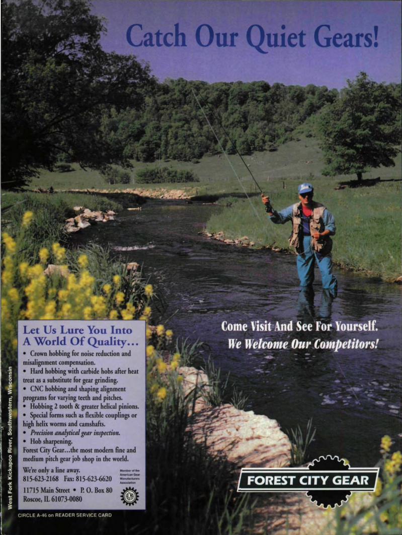
Catch Our Quiet Gears!
Let Us Lure You IntoA World Of Quality .....• Crown bobbing for noise rediuction andmisalignment. compensation.• Hard hobbing with carbide bobs after heattreat as a substitute for gear grinding.• CNC hobbing and shaping alipentprograms for varying teeth and pitches.• Hobbmg 2 tooth & greater helical pinions.• Special forms such. as flexible couplings orhigh helix worms and camshafts.• Precision analytical ge'llr inspection.• Hob sharpening.FOJlest City GeM ... the most modem 6ne andmedium pitch gear job shop, in the world.We're oo1y a line away.815·623·2168 Fax: 815·623·6620[1715 Main Stleet • P. O. 80x 80Roscoe, IL 6Hl73~0080

THIE WHIOiLE T'O'OTH •••,ANIID NOTH'ING ,BUT T,H:E T'O'OT'H".
"These teeth need high-speedhobbing with high accuracy;
Get a Gleason 125GH Hobber: "
'With this gear; automaticthreaded-wheel eNG grindingis the way to go. Get a GleasonTAG 400."
I
S,pur and Helica'l GearManufacturing Tiechno'iogy
If you hob and/or grindprecision gears, Glemon machinescan give you Fe'sterproductionresponse, higher quality assurance,lowerrooling costs, end more partsper hour per machine. for slcrters,there's our high-rigiidity CNChobbers.
High-Volume IHo'b'bing•••in Small Quantities,
'Now you can combine highspeed and high accuracy, withtoday's need for fast changeoverand versatility. All in one offord·able, Ihig'hly-rigid CNC hobber thatyou can run wet or dry. Use ofmult,i-gash hobs let you reduce cut"ting cyde times. And tool'-free hobchonge [in seconds) gives youhigh..upfime bafch run capabil;ity.
"Gleason's GNG chamfering!deburring machine is madefor this job. "
l"AG 400' 8~AXls ONO Gear GrindeI'
The Gleason Works, 1000 University Ave-., Rochesfer,NY 14692~2970(7161 473-1000 FAX; 17161 461-4348
CIRCLE A.ij on READER SE,RVICE ,CARD
'C'ompletely AutomaticDre.ssingandi Grinding
Gleason's eNC Spur andH'elical Gear Grinder providescompletel:y automatic dressing andgrinding, cycles, to maximizeproduction rates, wheel life, andgear quality whil'e eliminatingdressing guesswork. Utilizing thethreaded·wheel generatingl process,you get continuously variabl'ewheel speed's kom 0-2500 rpmfor process flexibility. 8-axis CNClets you minimize initial setup andsubseq,uent changeover time.
We also oFfer-a 5-axis CNCchamfering/deburdng machineand 01 CNC honinq machine, osweill as our 13Q.year leadership inmachines for bevell/hypoid gears.Backed with worldwide support.Calli l·800-643·2770or yourGI'eason reg:ional sales manager.
I
'I
'1
Gleason