technical manual - gear hub systems
110
technical manual (english) gear hub systems 2009
-
Upload
khangminh22 -
Category
Documents
-
view
0 -
download
0
Transcript of technical manual - gear hub systems

tec
hn
ica
l ma
nu
al
(e
ng
lish
) g
ea
r h
ub
sys
tem
s
20
09
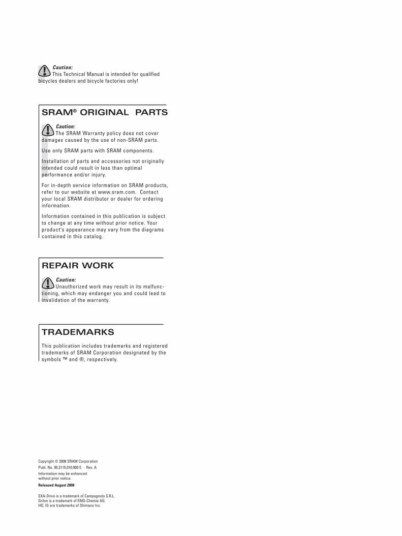
Caution:This Technical Manual is intended for qualified
bicycles dealers and bicycle factories only!
REPAIR WORK
Caution:Unauthorized work may result in its malfunc-
tioning, which may endanger you and could lead to
invalidation of the warranty.
SRAM® ORIGINAL PARTS
Caution:
The SRAM Warranty policy does not cover damages caused by the use of non-SRAM parts.
Use only SRAM parts with SRAM components.
Installation of parts and accessories not originally intended could result in less than optimal performance and/or injury.
For in-depth service information on SRAM products, refer to our website at www.sram.com. Contact your local SRAM distributor or dealer for ordering information.
Information contained in this publication is subject to change at any time without prior notice. Your product‘s appearance may vary from the diagrams contained in this catalog.
TRADEMARKS
This publication includes trademarks and registered trademarks of SRAM Corporation designated by the symbols ™ and ®, respectively.
Copyright © 2008 SRAM Corporation
Publ. No. 95.3115.010.000 E · Rev. A
Information may be enhanced
without prior notice.
Released August 2008
EXA-Drive is a trademark of Campagnolo S.R.L.
Grilon is a trademark of EMS-Chemie AG.
HG, IG are trademarks of Shimano Inc.

1Technical Manual Gear Hub Systems 2009 · Rev. A
TABLE OF CONTENTSGEAR HUB SYSTEMS
G E A R H U B S A N D S H I F T E R S
i-MOTION® 9 3
i-MOTION® 3 25
DualDrive™ 46
SRAM® S7 57
SRAM® P5 65
SRAM® P5 Cargo 73
SRAM® T3 80
Sparc® 89
G E A R H U B S Y S T E M C O M P O N E N T S
Brake Lever 96
i-LIGHT™ – Dynamo Hubs 98
Power Chain™ 102
SRAM Komfy™ – Hydraulic Disc BrakeSee Technical Manual AVID – „Juicy® 5“
S U P P O R T
Distributors / Spare Parts 106
CARGOCARGO
✆

2 Technical Manual Gear Hub Systems 2009 · Rev. A

3Technical Manual Gear Hub Systems 2009 · Rev. A
i-MOTION® 9 TECHNICAL DATA / ASSEMBLY REQUIREMENTS
i-MOTION 9 with back pedal brake i-MOTION 9 disc brake compatib. i-MOTION 9 without brake
Speeds 9 9a 9
Brake With back pedal brake Adaptor for disc brake without
Over Locknut Dim., OLD 135 mm 135 mm 135 mm
Length, L 186 mm 186 mm 186 mm
Ends Diameter M 10x1 M 10x1 M 10x1
Dropout Width Dim., A min. 4 mm / max. 10 mm min. 4 mm / max. 10 mm min. 4 mm / max. 10 mm
Holes 36 or 32 36 or 32 36 or 32
Hole Diameter, DS 2.8 mm 2.8 mm 2.8 mm
Hole Ref. ø, HR 93.6 mm 93.6 mm 93.6 mm
Flange Dist. to 1/2 OLD F1 = 26.5 mm / F
2 = 31.5 mm F
1 = 26.5 mm / F
2 = 31.5 mm F
1 = 26.5 mm / F
2 = 31.5 mm
Overall 340 %
1st gear 0,542
2nd gear 0,621
3rd gear 0,727
4th gear 0,853
5th gear 1,000
6th gear 1,172
7th gear 1,375
8th gear 1,611
9th gear 1,844
Chainline, CL 48.8 mm 48.8 mm 48.8 mm
Ratio 1.73 – 1.90 min. 1.73 min. 1.73
Dimensions 1/2" x 1/
8" and 1/
2" x 3/
32" 1/
2" x 1/
8" and 1/
2" x 3/
32" 1/
2" x 1/
8" and 1/
2" x 3/
32"
Sprocket 18 / 19 / 20 / 21 / 22 teeth 18 / 19 / 20 / 21 / 22 teeth 18 / 19 / 20 / 21 / 22 teeth
Shifter i-MOTION 9 IBS SL and i-MOTION 9 SL
Disc Brake — 6 holes —
Hand brake lever — Disc brake compatible —
Tandem Not suitable for tandems, transport bicycles or similar
Weight 2,400 g 1,960 g 1,960 g
Mat. Hub shell Aluminum Aluminum Aluminum
Surface Satin matt "Lux" anodized Satin matt "Lux" anodized Satin matt "Lux" anodized
Ø 7.6
DS
HR
103.6
56.3
94.8
M 1
0x1
M 1
0x1
CL
F1
F2
AA
3.5 3.5
2.2
3.23.2
OLD
L
1/2 OLDVersion with back pedal brake
GETRIEBENABEN
Ach
seSp
eich
enÜ
bers
etzu
ngKe
tteKo
mpa
tibili
tät
Fini
sh
Gangsprung
14 %
17 %
17 %
17 %
17 %
17 %
17 %
14 %

Technical Manual Gear Hub Systems 2009 · Rev. A4
i-MOTION® 9TECHNICAL DATA / ASSEMBLY REQUIREMENTS
77.3113.7
15
115.777.3
i-MOTION 9 IBS SL i-MOTION 9 SL
Version i-MOTION 9 IBS (integrated hand brake lever) i-MOTION 9 (single shifter)
Shift cable lengths 1400 mm / 1500 mm / 1600 mm / 1700 mm 1400 mm / 1500 mm / 1600 mm / 1700 mm
Shifter type SRS Twist shifter with integrated brake lever SRS Twist shifter
Mounting location right side of handlebar right side of handlebar
Compat. Gear hub i-MOTION 9 i-MOTION 9
Gear indicator Window Window
Barrel adjuster Indexed Indexed
Clamping diameter 22.1 – 22.3 mm 22.1 – 22.3 mm
Straight handlebar ends Minimum necessary length for shifter and handlebar grip = 150 mm
Cable routing Continuous cable housing (pre-assembled) Continuous cable housing (pre-assembled)
Compatibility Linear-Pull, Avid BB Disc —
Ratio 2.32 —
Cable path 24 mm —
Reach Adjust Yes —
Adjusting screw Yes —
Lever size 4-finger —
Material Aluminum, forged —
Weight 272 g 195 g
Shift cable Stainless steel Stainless steel
Housing Cast aluminum Cast aluminum
Grip cover Thermoplastic elastomer Thermoplastic elastomer
Frame clamp Aluminum Aluminum
Finish Mercury silver painted Mercury silver painted
Mat
eria
lH
and
brak
e le
ver
SHIFTERS
SRAM BL 60
Version SRAM BL 60, left SRAM BL 60, right
Mounting location left side of handlebar right side of handlebar
Clamping diameter 22.1 – 22.3 mm ➔
Compatibility Linear-Pull, Avid BB Disc ➔
Ratio 2.32 ➔
Cable path 24 mm ➔
Reach Adjust Yes ➔
Adjusting screw Yes ➔
Lever size 4-finger 4-finger
Weight 95 g 95 g
Housing Cast aluminum ➔
Lever Aluminum, forged ➔
Frame clamp Aluminum ➔
Finish Mercury silver painted ➔
Mat
eria
l
BRAKE
LEVER
Shifter i-MOTION 9 IBS SL Shifter i-MOTION 9 SL Brake lever SRAM BL 60
Ø 2
2.1
– 2
2.3
Ø 2
2.1
– 2
2.3
Ø 2
2.1
– 2
2.3

Technical Manual Gear Hub Systems 2009 · Rev. A 5
i-MOTION® 9TECHNICAL DATA / ASSEMBLY REQUIREMENTS
Type of dropout
Necessary
Retaining washer on
the left axle end
(non drive side) 15L – blue dot 30L – yellow dot 67L – dark brown 180L – orange dot 75L – ocher dot
Necessary
Retaining washer on
the right axle end
(drive side) 15R – red dot 30R – green dot 67R – pastel blue 180R – purple dot 75R – light purple dot
A B
C Y C L E F R A M EFrame strength must be such that, the
rear part of the frame does not undergo
any permanent deformation when a max.
braking torque of 250 Nm (2200 in.lbs.) is
applied to the rear wheel.
D R O P O U T SOnly flat and not off-set versions.
Dropout thickness: 4 – 10 mm.
The dropouts must be parallel.
Dropout dimensions: see figures on right.
R E T A I N I N G W A S H E R S The following table shows the permissible
combinations of dropout and retaining
washer.
C R A N K S E TThe crankset and bottom bracket speci-
fications must conform to the following
details.
A = 48.8 mm ± 5 mm
B = 48.8 mm (rear chainline)
Standard dropouts
Vertical dropout Dropout open towards rear
min. 19
10 mm
10 mm
15°
10 mm
30°
10 mm
15°30°
min. 19
180°
180°
30°
30°
15°
15°
15°
15°
75°
10 mm 75°
Rohloff dropout
75°
75°
67°
67°

6 Technical Manual Gear Hub Systems 2009 · Rev. A
i-MOTION® 9TECHNICAL DATA / ASSEMBLY REQUIREMENTS
165.
1
Ø 5
4.5
Ø 7
8.0
– 9
4.5
(18
Z –
22
T)
Ø 8
7.7
Ø 1
03.6
12.5
Ø 16
7.7
1
2
3
4
0° ± 5°
F R A M E A N D C H A I N G U A R D For the frame and chain guard layout,
the dimensions listed below have to be
considered.
S H I F T C A B L E R O U T I N GShift cable routing only along the chainstay
Only continuous cable housing (no open cable routing).
See the adjoining figure for attachment points.

7Technical Manual Gear Hub Systems 2009 · Rev. A
i-MOTION® 9ASSEMBLY
A S S E M B L Y T H E H U B
» Spoke the hub as normal.
1 Set the dust cap (1) onto the driver.
The curvature must point to the out-
side.
2 Set the sprocket (2)
onto the driver.
3 Mount the sprocket circlip (3) onto
the driver. Check for proper seating
of the circlip.
» Hub version for Disc Brake:Hu
Advice: Read and observe the corre-
sponding technical documentation for
assembling the disc of the disc brake.
Caution: Plane faces of the hub and disc
and the threaded holes of the hub must
be clean and free from oily and greasy
substances.
» Place the rear wheel into the rear
frame.
4 Slide one retaining washer each (4)
onto each axle end. The correct ver-
sion is shown in the table on page 5.
The serrated face of the retaining
washer must lie against the frame
dropout. Where retaining washers have
locating lugs, these must engage in the
frame dropouts.
5 First fit the axle nut on the drive side
and tighten to a torque of 40 Nm (350
in.lbs.).
Then fit the axle nut (5) on the non-drive
side and tighten to a torque of 40 Nm
(350 in.lbs.).
6 If applicable, mount the brake lever
(6) between the two straps of the
frame clamp (7).
Caution: The frame clamp must be fitted
tightly on the frame without any play.
Use a self-locking nut (M6)!
Tightening torque: 2 – 3 Nm (18 – 27 in.lbs.).
Caution: Before setting out on any ride,
always check the correct and trouble-free
operation of the shift system and brakes.
525
40 Nm350 in.lbs.
44
67
6
1
1
2
2
3
3

8 Technical Manual Gear Hub Systems 2009 · Rev. A
i-MOTION® 9ASSEMBLY
F I T T I N G T H E S H I F T E R
7 Slide the shifter (1) onto the han-
dlebar.
8 Slide the handlebar grip (2) onto the
handlebar.
Caution: Never use lubricants or solvents
when fitting handlebar grips. They have
a safety function and must not come
free from the handlebar.
9 Place the shifter on the handlebar grip
and position so that you can use it
comfortably. Tighten the clamping bolt (3).
3 mm Allen key, torque 3.5 – 4 Nm (31 –
35 in.lbs.).
Caution: Check that shifter and brake lever
can be easily operated (if necessary,
realign).
» Never ride without handlebar grips. The
turning grip of the twist shifter could
become loose. This can result in severe
injuries.
Caution: Before setting out on any ride,
always check the correct and trouble-free
operation of the shift system and brakes.
F I T T I N G T H E S H I F T C A B L E
Advice: Make sure that the cable housing
length is sufficient to permit turning of
the handlebar over its full range.
» Also bear in mind the effect of adjust-
able handlebars and stems on the cable
housing length.
» Always use new, high-quality cables
and compressionless cable housings
with end caps.
10 Secure the cable housing to the
frame.
Advice: The cable housing must be free to
move at the securing points.
» Avoid tight bends when routing the
shift cable.
11 Make sure that the shifter is set to
1st gear.
12 Slide the quick release fastener (4)
on the connecting tube to the right.
The opening (5) should now be visible.
13 Make the connection by sliding the
opening of the connecting tube onto
the catch (6) on the hub.
14 Slide the quick release fastener (7)
on the connecting tube to the left
until it snaps into place. The connection
is now locked.
Caution: Before setting out on any ride,
always check the correct and trouble-free
operation of the shift system and brakes.
F I T T I N G T H E B R A K E L E V E RS R A M B L 6 0
» Slide the brake lever onto the handlebar.
» Tighten the clamping bolt. 3 mm Allen
key, torque 2 – 2.5 Nm (18 – 22 in.lbs.).
6
13
4
512
17
28
3 mm3.5 – 4 Nm (31 – 35 in.lbs)
3
9
10
11
7
14

9Technical Manual Gear Hub Systems 2009 · Rev. A 9
i-MOTION® 9ASSEMBLY
G E A R A D J U S T M E N T
» Before adjusting the gears, shift several
times between 1st and 9th gears and
then back again, so that the shift cable
seats itself correctly.
15 Turn the twist shifter from 7th to 6th
gear.
16 To make adjustments, use the barrel
adjuster (1) on the shifter
17 or the barrel adjuster (2) on the con-
necting tube.
18 Turn the barrel adjuster until the
yellow / red marks (3) in the window
of the gear hub are aligned.
F I T T I N G T H E B R A K E C A B L E
Caution:The brake lever on the i-MOTION
IBS shifter and the brake lever i-BRAKE
60 BL is only compatible with the fol-
lowing brakes: Avid BB Disc and Linear-
Pull compatible brakes.
Advice:Make sure that the cable housing
length is sufficient to permit turning of
the handlebar over its full range.
» Also bear in mind the effect of adjust-
able handlebars and stems on the cable
housing length.
» Always use new, high-quality cables
and compressionless cable housings
with end caps.
19 Turn the cable adjustment screw (1)
and the counter nut (2) so that the
cable slot is aligned with the slot on the
bottom of the brake lever housing.
20 Pull the brake lever to the handlebar
and guide the inner cable into the
housing.
Hook the nipple (3) of the inner cable
into the recess (4) in the brake lever.
» Follow the brake manufacturer's in-
structions when fitting the brake cable
and adjusting the brakes.
Caution:Check that the brake is operating in
a correct and trouble-free manner.
Reach adjust of the hand brake lever:so that you can operate the brake lever on
the shifter comfortably, set the reach to
match your hand size.
21 Use a 2 mm Allen key to set the dis-
tance between the brake lever and
the handlebar.
Caution:Every time you adjust the reach,
check and correct the brake cable tension
to ensure good brake performance.
Advice:Read and observe the operating
manual and technical documentation of
the brake manufacturer.
34
20
15
1219
1
16
2
17
3
18
21

10 Technical Manual Gear Hub Systems 2009 · Rev. A
i-MOTION® 9OPERATION
S H I F T I N G
1 Shift gears by turning the twist
shifter on the right side of the han-
dlebar.
» You can shift gear while stationary or
when riding.
» Ensure you shift to a lower gear in
plenty of time before hills.
» The quickest and smoothest gear shifts
are achieved by shifting while pedaling
using only a low force.
B R A K I N G
When descending long and steep hills,
always use the second (front) brake as
well, to prevent overheating of the brakes.
Caution: Before setting out on any ride,
always check the correct and trouble-
free operation of the shift system and
brakes.
Caution: Excessive heating of the hub caused
by back pedal braking may result in loss
of lubricant and cause sharper braking.
Relubricating of the brake sleeve with
special grease is then necessary. See
"DISMANTLING/ ASSEMBLY OF THE HUB -
NOT DRIVE SIDE", page 16.
Reach adjust of the hand brake lever:so that you can operate the brake lever on
the shifter comfortably, set the reach to
match your hand size.
2 Use a 2 mm Allen key to set the dis-
tance between the brake lever and
the handlebar.
Caution:Every time you adjust the reach,
check and correct the brake cable tension
to ensure good brake performance.
Advice:Read and observe the operating
manual and technical documentation of
the brake manufacturer.
1
2

11Technical Manual Gear Hub Systems 2009 · Rev. A
i-MOTION® 9MAINTENANCE
Other topics Page
G E A R A D J U S T M E N T 12
R E M O V I N G T H E R E A R W H E E L 12
F I T T I N G T H E R E A R W H E E L 13
E X C H A N G I N G T H E G E A R U N I T 14
D I S M A N T L I N G A N D A S S E M B L I N G T H E H U B 16
C H A N G I N G T H E S H I F T C A B L E 20
C H A N G I N G T H E B R A K E C A B L E 22
T R O U B L E S H O O T I N G 23
C L E A N I N G
Your SRAM i-MOTION 9 components are
well protected against adverse environ-
mental effects.
» To prevent water ingress and any resul-
tant malfunctioning, do not use pressur-
ized water (e.g. pressure washers) for
cleaning.
» During winter use, you should clean
your bike more frequently to prevent salt
damage.
» Do not use any corrosive cleaning
agents.
» Clean dirty chains before oiling. Allow
cleaner to work for only a few minutes
before rinsing off with water. Do not oil
chain until completely dry.
L U B R I C A T I O N
» The rear wheel hub is provided with per-
manent lubrication and is maintenance-
free under normal conditions.
» When dismantling/assembling the gear
unit, observe the lubrication guidelines.
See "DISMANTLING / ASSEMBLY OF
THE HUB", from page 16.
» Regular lubrication will extend the
chain's service life.
R E P A I R W O R K
Caution: Unauthorized work on the i-MOTION 9
system may result in its malfunctioning,
which may endanger you and could lead
to invalidation of the warranty.
Back pedal brake If braking is too sharp, the brake sleeve
has to be re-lubricated with special
grease. See "DISMANTLING/ ASSEMBLY
OF THE HUB - NOT DRIVE SIDE", page 16.
W E A R P A R T S
Brake liners or brake sleeve, brake cables,
shift cables, handlebar grips, sprockets,
and bike chains are wear parts. Please
check these parts regularly and replace
them well before they are worn out.

12 Technical Manual Gear Hub Systems 2009 · Rev. A
i-MOTION® 9MAINTENANCE
G E A R A D J U S T M E N T
1 Turn the twist shifter from 7th to 6th
gear.
2 To make adjustments, use the barrel
adjuster (1) on the shifter
3 or the barrel adjuster (2) on the con-
necting tube.
4 Turn the barrel adjuster until the yel-
low / red marks (3) in the window of
the gear hub are aligned.
R E M O V I N G T H E R E A R W H E E L
5 Turn the twist shifter
to 1st gear.
6 Slide the quick release fastener (1)
on the connecting tube to the right.
7 Undo the connection by removing
the connecting tube in a downwards
direction.
8 Loosen the axle nuts (2) and take
these and the underlying retaining
washers (3) off. If fitted, unscrew (4) the
frame clamp of the brake lever.
» Remove the rear wheel.
7
1
6
1
5
2
1
3
2
4
3
8
4
2
3

13Technical Manual Gear Hub Systems 2009 · Rev. A
i-MOTION® 9MAINTENANCE
F I T T I N G T H E R E A R W H E E L
» Place the rear wheel into the rear
frame.
9 Place one retaining washer each (1)
onto each axle end. The serrated
face of the retaining washer must lie
against the frame dropout. Where re-
taining washers have locating lugs,
these must engage in the frame drop-
outs.
10 First fit the axle nut on the drive side
and tighten to a torque of 40 Nm (350
in.lbs.).
Then fit the axle nut (2) on the non-drive
side and tighten to a torque of 40 Nm
(350 in.lbs.).
11 If applicable, mount the brake lever
(3) between the two straps of the
frame clamp (4).
Caution:The frame clamp must be fitted
tightly on the frame without any play.
Use a self-locking nut (M6)!
Tightening torque: 2 – 3 Nm (18 – 27 in.lbs.).
12 Make sure that the shifter is set to
1st gear.
13 Slide the quick release fastener (5)
on the connecting tube to the right.
The opening (6) should now be visible.
14 Make the connection by sliding the
opening of the connecting tube onto
the catch (7) on the hub.
15 Slide the quick release fastener (8)
on the connecting tube to the left
until it snaps into place. The connection
is now locked.
Caution: Before setting out on any ride,
always check the correct and trouble-free
operation of the shift system and brakes.
8
15
7
14
5
613
1022
40 Nm350 in.lbs.
12
9 1
11
43

14 Technical Manual Gear Hub Systems 2009 · Rev. A
1
2
3
1
4
53
2
46
7
58
9
10
6
i-MOTION® 9MAINTENANCE
E X C H A N G I N G T H E G E A R U N I T
1 Detach the circlip (1).
Caution: The circlip is spring force loaded.
Take off the sprocket (2) and the small
outer dust cap (3).
2 Clamp the drive side of the axle with
the two flats of the axle in a vise.
3 Unscrew the nut (4) and the large axle
nut (5) from the axle. Wrench size
17 mm and 27 mm (SRAM tool part no. 00
0924 003 000 for wrench size 27 mm).
For the no-brake hub version and
disc brake, the axle nut (4) and the
underlying adjusting cone should be
unscrewed from the axle.
Wrench size 17 mm and 13 mm.
4 Hub version with back pedal brake:
Take off the lever cone (6) and the
ball retainer (7).
4 Hub versions without brake and Disc
Brake: take the ball retainer (7) out.
5 Hub version with back pedal brake:
Remove the brake sleeve (8).
6 Remove the hub shell (9) by jerking
upwards.
Advice: The outer large dust cap (10) is a
very tight fit. Its removal will result in it
being damaged. Replace with a new cap
during reassembly.
The gear unit can be removed by tap-
ping a rubber mallet on the axle on the
non-drive side of the shell. To do this,
remove the hub from the vise.
» Clamp the new gear unit on the drive
side of the axle in the vise.
Caution:Use only SRAM special grease, part
no. 0369 135 200 / ... 201.
Lubricate ball retainers and ball tracks
only with SRAM Ball Bearing Grease. Part
no. 0369.001.015
Lubrication:Lightly grease the ball tracks (11)
7 and the toothing (12) on the inside of
the hubshell.
Hub version with back pedal brake: Lightly
grease the brake cylinder (13).
7 Position the hub shell. Turning
slightly to the left/right eases posi-
tioning.
Ensure that the hub shell is correctly
seated on the ball retainer (14).
8 Hub version with back pedal brake:
Turn the shell in a clockwise direc-
tion until it reaches the stop. This en-
sures that the rollers (15) of the brake
can fall back and that the brake sleeve
can be mounted.
» Hub version with back pedal brake:
Lubrication:Clean the brake sleeve and com-
pletely coat its outer surface only with
grease.
Caution:Use only SRAM special grease,
part no. 0369 135 200 / ... 201.
9 Insert the brake sleeve. The side
with only one recess must point
downwards. The angled spring end (16)
must be positioned in this recess (17).
Advice:The brake sleeve must be
renewed, if, as a result of wear, the
pattern on its outer surface is scarcely
visible.
Lubrication:Clean the ball retainer (18) and
10 grease it using SRAM Ball Bearing
Grease (part no. 0369.001.015).
10 Insert the ball retainer (18). The side
with the balls must point down-
wards.

15Technical Manual Gear Hub Systems 2009 · Rev. A
711
12
13
14
22
23
2412
1018
815
9
16
17
12
21
20
19
11
2513
26
14
27
15
28
16
15–20 Nm
133 – 177 in.lbs.
i-MOTION® 9MAINTENANCE
11 Hub version with back pedal brake:
Fit the lever cone (19).
By turning to the left and right, bring the
lever cone (19) into its final position. The
locating lugs (20) of the lever cone will
then lie in the recesses (21) of the brake
sleeve.
12 Hub version with back pedal brake:
Screw the large axle nut (22) with
the projection (23) downwards onto the
axle. Wrench size 27 mm.
» Hub versions without brake and disc
brake:
screw the adjusting cone onto the axle.
Wrench size 13 mm.
12 Position the bearing in a play-free
manner and tighten using nut (24).
Wrench size 17 mm. Tightening torque
15 – 20 Nm (133 – 177 in.lbs.).
Caution: Test the play of the bearing and
correct if required.
» Clamp the hub with the other axle side
in the vise.
13 Press the large outer plastic dust cap
(25) onto the hub until it engages.
Advice: Use a new dust cap after each
dismantling.
14 Place the small inner dust cap (26)
onto the driver. The curvature must
point to the outside.
15 Set the sprocket (27)
onto the driver.
16 Mount the sprocket circlip (28) onto
the driver. Check for proper seating
of the circlip.
» Remove the hub from the vise.
» Fit the rear wheel into the rear frame as
described on page 13.
Adjust the gears as described on page
12.
Caution: Before setting out on any ride,
always check the correct and trouble-free
operation of the shift system and brakes.

16 Technical Manual Gear Hub Systems 2009 · Rev. A
i-MOTION® 9MAINTENANCE
D I S M A N T L I N G T H E H U BN O T D R I V E S I D E
Caution: During dismantling, one side of the
hub must always remain closed, to prevent
the gear unit from coming apart.
Advice:On the non-drive side of the hub,
1 work may only be carried out on the
following parts:
– lever cone / adjusting cone with ball re-
tainer (1)
– brake sleeve (2).
– Roller guide ring and rollers (3)
Work on the brake cone / adjusting cone and ball retainer:
2 Clamp the drive side of the axle with
the two flats of the axle in a vise.
3 Unscrew the nut (4) and the large axle
nut (5) from the axle. Wrench size
17 mm and 27 mm (SRAM tool part no.
00 0924 003 000 for wrench size 27 mm).
For the no-brake hub version and
disc brake, the axle nut (4) and the
underlying adjusting cone should be
unscrewed from the axle.
Wrench size 17 mm and 13 mm.
4 Hub version with back pedal brake:
Take off the lever cone (6) and the
ball retainer (7).
4 Hub versions without brake and Disc
Brake: take the ball retainer (7) out.
» Lubrication and assembly details can be
found on the following page.
Work on the brake sleeve: (Hub version with back pedal brake)
» Dismantle the hub as previously de-
scribed ("Work on brake cone / adjusting
cone and ball retainer")
5 Remove the
brake sleeve (8).
Advice: The brake sleeve must be
renewed, if, as a result of wear, the
pattern on its outer surface is scarcely
visible.
» Lubrication and assembly details can be
found on the following page.
Work on the roller guide ring and rollers:(Hub version with back pedal brake)
» Dismantle the hub as previously de-
scribed ("work on brake cone / adjusting
cone and ball retainer" and "work on
brake sleeve").
6 Remove the hub shell by jerking up-
wards.
Advice: The outer large dust cap (9) is a
very tight fit. Its removal will result in it
being damaged. Replace with a new cap
during reassembly.
The gear unit can be removed by tap-
ping a rubber mallet on the axle on the
non-drive side of the shell. To do this,
remove the hub from the vise.
7 Remove the
circlip (10).
8 Take off the washer (11) and take the
6 rollers (12) out of the roller guide
ring.
9 Take off the roller
guide ring (13).
Caution: Further dismantling is not per-
mitted, as otherwise the gear unit comes
apart. Reassembly could then only be
undertaken by SRAM.
» Lubrication and assembly details can be
found on the following page.
9
6
11
12
8
12
31
2
46
7
58
107
4
53
13
9

17Technical Manual Gear Hub Systems 2009 · Rev. A
i-MOTION® 9MAINTENANCE
A S S E M B L I N G T H E H U B N O T D R I V E S I D E
Work on the roller guide ring and rollers:
1 Seat the roller guide ring (1) on the
gear unit.
Advice:The two lugs (2) of the roller guide
ring must mesh in the long recesses (3).
2 Insert the 6 rollers (4) in the roller
guide ring.
Lubrication:Oil the 6 rollers and the two pawls (5)
of the roller guide ring.
Use only standard bicycle oil.
3 Place the washer (6) on the roller
guide ring and fit the circlip (7).
4 Position the hub shell. Turning
slightly to the left/right eases posi-
tioning.
Ensure that the hub shell is correctly
seated on the ball retainer (8).
5 Hub version with back pedal brake:
Turn the shell in a clockwise direc-
tion as far as it will go. This ensures that
the rollers (9) of the brake can fall back
and that the brake sleeve can be
mounted.
Work on the brake jacket:(Hub version with back pedal brake)
Lubrication:Clean the brake sleeve and com-
pletely coat its outer surface only with
grease.
Caution: Use only SRAM special grease,
part no. 0369 135 200 / ... 201.
6 Insert the brake sleeve. The side
with only one recess must point
downwards. The angled spring end (10)
must be positioned in this recess (11).
Advice: The brake sleeve must be
renewed, if, as a result of wear, the
pattern on its outer surface is scarcely
visible.
Work on the brake cone / adjusting cone and ball retainer:
Lubrication:Clean the ball retainer (12) and
10 grease it using SRAM Ball Bearing
Grease (part no. 0369.001.015).
7 Insert the ball retainer (12). The side
with the balls must point down-
wards.
8 Hub version with back pedal brake:
Fit the lever cone (13).
By turning to the left and right, bring the
lever cone (13) into its final position. The
locating lugs (14) of the lever cone will
then lie in the recesses (15) of the brake
sleeve.
9 Hub version with back pedal brake:
Screw the large axle nut (16) with
the projection (17) downwards onto the
axle. Wrench size 27 mm
» Hub versions without brake and disc
brake:
Screw the positioning cone onto the
axle. Wrench size 13 mm.
9 Position the bearing in a play-free
manner and tighten using nut (18).
Wrench size 17 mm. Tightening torque
15 – 20 Nm (133 – 177 in.lbs.).
Hub version i-BRAKE: Instead of the nut
mount the centering bushing with the
projection upwards onto the axle.
Wrench size 17 mm.
Caution: Test the play of the bearing and
correct if required.
» Remove the hub from the vise.
» Fit the rear wheel into the rear frame as
described on page 13.
Adjust the gears as described on page 12.
Caution: Before setting out on any ride,
always check the correct and trouble-free
operation of the shift system and brakes.
11
2
3
16
17
189
7
6
3
4
5
2
59
6
10
11
8
4
712
12
15
14
13
8
15–20 Nm
133 – 177 in.lbs.

18 Technical Manual Gear Hub Systems 2009 · Rev. A
4
12
1
6
3
3
4
5
2
75
9
8
610
7
i-MOTION® 9MAINTENANCE
D I S M A N T L I N G T H E H U B D R I V E S I D E
Caution: During dismantling, one side of the
hub must always remain closed, to prevent
the gear unit from coming apart.
Advice:On the drive side of the hub, work
1 may only be carried out on the fol-
lowing parts:
– fixed cone (1) with ball retainer (2)
Work on the fixed cone and ball retainer:
2 Detach the circlip (3), sprocket (4)
and the small outer dust cap (5).
Caution: The large outer plastic dust cap (6)
3 must remain fitted, to prevent the
gear unit from coming apart.
4 Clamp the non-drive side of the axle
with the two flats of the axle in a
vise.
5 Unscrew nut (7) from the axle.
Wrench size 17 mm.
6 Take off the fixed cone (8) together
the washer (9) above it.
7 Take off the
ball retainer (10).
Caution:Further dismantling is not per-
mitted, as otherwise the gear unit comes
apart. Reassembly could then only be
undertaken by SRAM.
» Lubrication and assembly details can be
found on the following page.

19Technical Manual Gear Hub Systems 2009 · Rev. A
7
4
8
5
9
6
11
63
2
4
3
2
5
i-MOTION® 9MAINTENANCE
15 – 20 Nm(133 – 177 in.lbs.)
A S S E M B L I N G T H E H U B D R I V E S I D E
Work on the fixed cone and ball retainer:
Lubrication:Clean the ball retainer (1) and
10 grease it using SRAM Ball Bearing
Grease (part no. 0369.001.015).
1 Insert the ball retainer (1). The side
with the balls must point down-
wards.
2 Push the fixed cone (2) onto
the axle.
Advice:The lug (3) of the fixed cone must
mesh in the axle recess (4).
2 Place the washer (5)
on top of it.
3 Screw the nut (6) onto the axle.
Wrench size 17 mm, tightening
torque 15 – 20 Nm (133 – 177 in.lbs.)
4 Place the small inner dust cap (7)
onto the driver. The curvature must
point to the outside.
5 Set the sprocket (8)
onto the driver.
6 Mount the sprocket circlip (9) onto
the driver. Check for proper seating
of the circlip.
» Remove the hub from the vise.
» Fit the rear wheel into the rear frame as
described on page 13.
Adjust the gears as described on page
12.
Caution: Before setting out on any ride,
always check the correct and trouble-free
operation of the shift system and brakes.

20 Technical Manual Gear Hub Systems 2009 · Rev. A
7
56
24
3
1
2
1
2 mm3
45
8
6
i-MOTION® 9MAINTENANCE
C H A N G I N G T H E S H I F T C A B L E
Advice:Always use new, high-quality cables
and compressionless cable housings with
end caps.
1 Turn the twist shifter
to 1st gear.
2 Slide the quick release fastener (1) on
the connecting tube to the right.
3 Undo the connection by removing
the connecting tube in a downwards
direction.
4 Unscrew the barrel adjuster (2) from
the connecting tube and pull the
connecting tube from the shift cable.
5 Use a 2 mm Allen key to loosen the
clamping screw (3) in the nipple and
pull this and the spring (4) behind it off
the inner cable.
1 Make sure that the shifter is set to
1st gear.
6 Remove the cap (5) from the shifter.
The nipple of the inner cable is now
visible.
7 Push or pull the old inner cable out
of the shifter, e.g. using a small
screwdriver.
» Guide the new inner cable into the cable
inlet, through the shifter and the new
cable housing. Pull the cable tight.
» Insert the cap in the shifter.
8 Screw in the shifter barrel adjuster (6)
as far as it will go.
Fitting the nipple without assembly tool:
9 Push the barrel adjuster (7) onto
the inner cable. Pull the inner
cable tight and shorten by 82 mm
(measured from the front edge of the
barrel adjuster).
10 Push the spring (8) onto the inner
cable. Guide the inner cable into
the nipple (9) and tighten the clamping
screw with a 2 mm Allen key. Tight-
ening torque 1.5 Nm (13 in.lbs.).
Fitting the nipple with assembly tool
(SRAM part no. 00.0991.002.000):
11 Clamp the assembly tool in the
vise.
12 Push the barrel adjuster (10) onto
the inner cable. Route the inner
cable through the assembly tool and
push the barrel adjuster onto the as-
sembly tool.
13 Thread the spring onto the inner
cable. The spring should, for ease
of mounting, be clamped, as shown in
the figure.
14 Pull the inner cable tight and cut it
off at the end of the assembly tool.
15 Lift the inner cable slightly from
the assembly tool and guide it into
the nipple.
16 Place the nipple in the tool and
and tighten the clamping screw
with a 2 mm Allen key. Tightening
torque: 1.5 Nm (13 in.lbs.).

21Technical Manual Gear Hub Systems 2009 · Rev. A
14
19
15
20
12
1318
14
82 mm
9
7
2 mm1,5 Nm(13 in.lbs.)
10
9
8
12
10
13
15
16
11
17
2 mm1,5 Nm(13 in.lbs.)
11 Artikel Nr.00.0991.002.000
i-MOTION® 9MAINTENANCE
17 Push the cable end with the nipple
into the connecting tube.
Advice:When doing this, ensure that the
flattened corner of the nipple matches
the corresponding shape in the con-
necting tube.
Screw the barrel adjuster (11) as far as
it will go onto the connecting tube.
1 Make sure that the shifter is set to
1st gear.
18 Slide the quick release fastener (12)
on the connecting tube to the right.
The opening (13) should now be visible.
19 Make the connection by sliding the
opening of the connecting tube onto
the catch (14) on the hub.
20 Slide the quick release fastener (15)
on the connecting tube to the left
until it snaps into place. The connection
is now locked.
» Adjust the gears as described on page
12.
Caution: Before setting out on any ride,
always check the correct and trouble-free
operation of the shift system and brakes.

22 Technical Manual Gear Hub Systems 2009 · Rev. A
i-MOTION® 9MAINTENANCE
C H A N G I N G T H E B R A K E C A B L E
Advice:Always use new, high-quality cables
and compressionless cable housings with
end caps.
» Loosen the inner cable from the brake.
1 Turn the cable adjustment screw (1)
and the counter nut (2) so that the
cable slot is aligned with the slot on the
bottom of the brake lever housing.
2 Pull the brake lever to the handlebar
and unhook the nipple (3) of the
inner cable from the recess (4) in the
brake lever.
Remove the old brake cable completely.
2 Pull the brake lever to the handlebar
and guide the new inner cable into
the housing.
Hook the nipple (3) of the inner cable
into the recess (4) in the brake lever.
» Follow the brake manufacturer's in-
structions when fitting the brake cable
and adjusting the brakes.
Caution: Check that the brake is operating in
a correct and trouble-free manner.
34
2
12
1

23Technical Manual Gear Hub Systems 2009 · Rev. A
i-MOTION® 9MAINTENANCE
T R O U B L E S H O O T I N G
Problem Cause Remedy
Shifting difficulties: Incorrect gear adjustment. Adjust the gears.
Page 12.
The shift cable for the cable housing is damaged. Renew the shift cable and cable housing.
Page 20.
The connecting tube is touching the bike frame
or is twisted.
The connecting tube must be freely connected to
the hub without being twisted.
Remove the cause of twisting (e.g. by correctly
aligning the rear wheel).
The connecting tube is twisted:
– Left and right retaining washers have been
interchanged.
– Incorrect retaining washers fitted.
The connecting tube must be freely connected to
the hub without being twisted.
Fit the correct retaining washers.
Page 5.
The pedals go forwards when freewheeling:
The chain tension is too tight. Slacken the chain tension.
The bearing adjustment is too tight. Readjust the bearing.
Page 15.
Locknut of the lever cone / adjusting cone is
loose.
Readjust the bearing and tighten the locknut.
Page 15, figure 12, no. 24.
The back pedal brake is too sharp or locked: The brake sleeve is no longer lubricated. Lubricate the brake cylinder of the hub shell and
the brake sleeve (if necessary renew).
Page 16 "Work on the brake sleeve".
Grinding noise: Dust cap incorrectly fitted or defective. Fit the dust cap correctly (if necessary renew).
Page 15, figure 13, no. 25.

24 Technical Manual Gear Hub Systems 2009 · Rev. A

25Technical Manual Gear Hub Systems 2009 · Rev. A
i-MOTION® 3TECHNICAL DATA / ASSEMBLY REQUIREMENTS
OLD 19
A
3
A
3
2.8 2.8
F1
F2
M 1
0x
1
10
0
M 1
0x
1
L
HR
78
124.5
CLstraight
CLoffset
1/2 OLD
Ø 3.0
Ø 7.3
Version with back pedal brake
C Y C L E F R A M EFrame strength must be such that, the rear
part of the frame does not undergo any
permanent deformation when a max. braking
torque of 250 Nm (2200 in.lbs.) is applied to
the rear wheel.
D R O P O U T S• Only flat and no off-set versions.
• Dropout thickness: 4 – 8 mm.
• Dropouts must be parallel.
• Slot width at rear dropout: max. 10+0.5 mm.
GEAR
HUBS
i-MOTION 3 w. back pedal brake i-MOTION 3 disc brake compatib. i-MOTION 3 without brake
Speeds 3 3 3
Brake With back pedal brake Adaptor for disc brake Without brake
Over Locknut Dim., OLD 130 mm 135 mm 130 mm
Length, L 178 mm (and 168 mm) 178 mm 178 mm (and 168 mm)
Ends diameter M 10x1 M 10x1 M 10x1 M 10x1
Dropout Width Dim, A min. 4 mm / max. 8 mm min. 4 mm / max. 8 mm min. 4 mm / max. 8 mm
Holes 28 / 32 / 36 32 / 36 32 / 36
Hole diameter 3.0 mm 3.0 mm 3.0 mm
Hole ref. ø, HR 70 mm 70 mm 70 mm
Flange Dist. to 1/2 OLD F1 = 27.3 mm / F
2 = 27.6 mm F
1 = 27.3 mm / F
2 = 27.6 mm F
1 = 27.3 mm / F
2 = 27.6 mm
Overall 186 %
1st gear 0,734
2nd gear 1,000
3rd gear 1,362
Chainline, CL 44.0 mm (straight sprocket) / 40.5 mm (offset sprocket)
Ratio 24", 26", 28" = 2,0 – 2,4 / 20" = 2,0 – 2,5 min. 2.0 min. 2.0
Dimensions 1/2" x 1/
8" and 1/
2" x 3/
32" 1/
2" x 1/
8" and 1/
2" x 3/
32" 1/
2" x 1/
8" and 1/
2" x 3/
32"
Sprocket 16 / 17 / 18 teeth (straight) / 19 / 20 / 21 teeth (offset)
Shifter SRAM i-MOTION 3 SRAM i-MOTION 3 SRAM i-MOTION 3
Disc Brake — 6 holes —
Hand brake lever — Disc brake compatible —
Tandem Not suitable for tandems, transport bicycles or similar
Weight 1,390 g 1,210 g 1,120 g
Mat. Hub shell Steel Steel Steel
Finish Pearl Nickel / Chrome Pearl Nickel / Chrome Pearl Nickel / Chrome
Axl
eSp
oke
Ratio
Chai
nCo
mpa
tibili
tyFi
nish
Gear steps
36 %
36 %
26 Technical Manual Gear Hub Systems 2009 · Rev. A
i-MOTION® 3TECHNICAL DATA / ASSEMBLY REQUIREMENTS
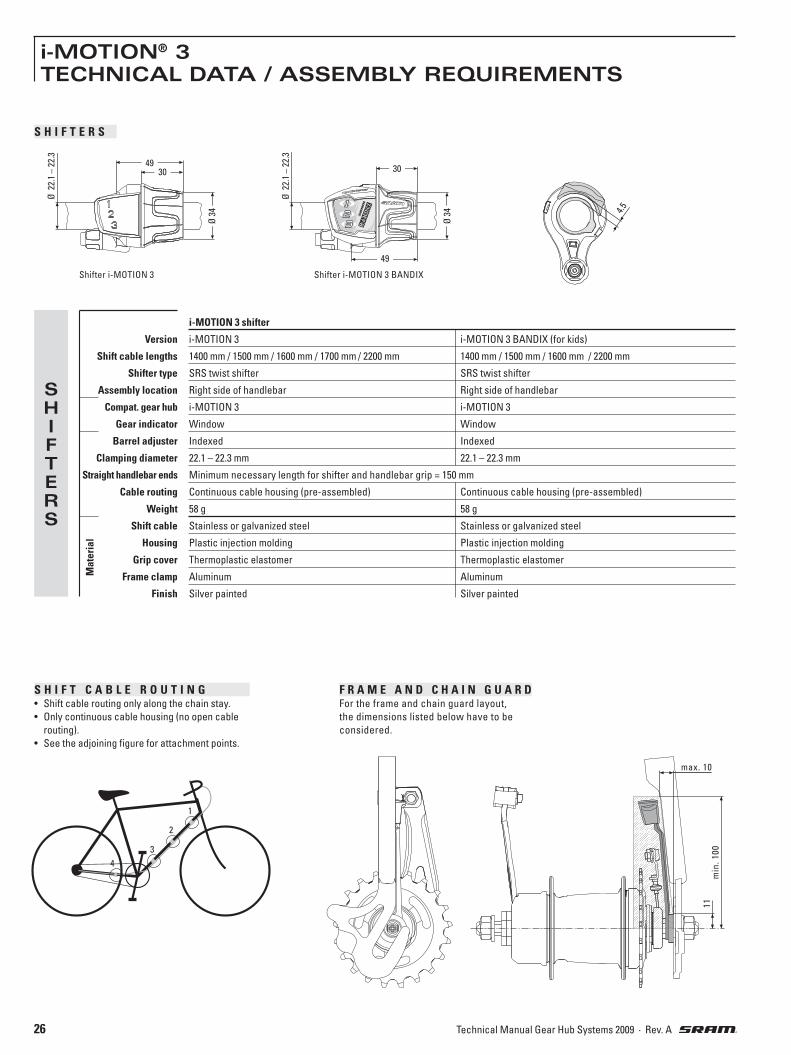
S H I F T C A B L E R O U T I N G• Shift cable routing only along the chain stay.
• Only continuous cable housing (no open cable
routing).
• See the adjoining figure for attachment points.
i-MOTION 3 shifter
Version i-MOTION 3 i-MOTION 3 BANDIX (for kids)
Shift cable lengths 1400 mm / 1500 mm / 1600 mm / 1700 mm / 2200 mm 1400 mm / 1500 mm / 1600 mm / 2200 mm
Shifter type SRS twist shifter SRS twist shifter
Assembly location Right side of handlebar Right side of handlebar
Compat. gear hub i-MOTION 3 i-MOTION 3
Gear indicator Window Window
Barrel adjuster Indexed Indexed
Clamping diameter 22.1 – 22.3 mm 22.1 – 22.3 mm
Straight handlebar ends Minimum necessary length for shifter and handlebar grip = 150 mm
Cable routing Continuous cable housing (pre-assembled) Continuous cable housing (pre-assembled)
Weight 58 g 58 g
Shift cable Stainless or galvanized steel Stainless or galvanized steel
Housing Plastic injection molding Plastic injection molding
Grip cover Thermoplastic elastomer Thermoplastic elastomer
Frame clamp Aluminum Aluminum
Finish Silver painted Silver painted
Mat
eria
l
SHIFTERS
S H I F T E R S
4.5
Shifter i-MOTION 3
4930
Ø 2
2.1
– 2
2.3
Ø 3
4
Shifter i-MOTION 3 BANDIX
49
30
Ø 3
4
Ø 2
2.1
– 2
2.3
F R A M E A N D C H A I N G U A R D For the frame and chain guard layout,
the dimensions listed below have to be
considered.
min
. 1
00
max. 10
11
4
3
2
1

27Technical Manual Gear Hub Systems 2009 · Rev. A
A S S E M B L I N G T H E H U B
» Lacing the hub:
– Lacing by hand: Place the cable stop
bracket (5, figure 4) and the locking
bush with the rubber insert (6) on the
axle, to permit an axial spoke arrange-
ment.
– Automatic lacing machine: Ensure an
offset of 5.5 mm.
Alternatively, a spacer sleeve (part
no. 0399.110.000) is mountable on the
drive side of the alxe.
1 Set the dust cap (1) onto the driver.
The curvature must point to the out-
side.
2 Place the sprocket (2) on the driver.
For offset, i.e. transversely displaced
sprockets, the sprocket should be
mounted with the toothing to the inside
(the curvature must point outwards).
3 Mount the sprocket circlip (3) onto
the driver.
Advice: Ensure that the plastic dust cap
(4) is not damaged.
Check for proper seating of the circlip.
» Hub version for Disc Brake:
Advice: Read and observe the corre-
sponding technical documentation for
assembling the disc of the disc brake.
Caution: Plane faces of the hub and the
disc and the threaded holes of the hub
must be clean and free from oily and
greasy substances.
4 Push the cable stop bracket (5) and
then the locking bush with the rub-
ber insert (6) onto the axle end on the
sprocket side.
» Place the rear wheel into the rear
frame.
5 Place one retaining washer (7) on
each axle end.
The serrated face of the retaining wash-
er must lie against the frame dropout.
6 Align the cable stop bracket (8) paral-
lel to the frame strut (9).
7 Fit the axle nuts (10) and tighten
these while alternating between
sides. Tightening torque 30 – 40 Nm
(266 – 350 in.lbs.).
8 If applicable, mount the brake lever (11)
between the two straps of the frame
clamp (12).
Caution: The frame clamp must be fitted
tightly on the frame without any play.
Use a self-locking nut (M6)!
Tightening torque: 2 – 3 Nm (18 – 27 in.lbs.).
Caution: Before setting out on any ride,
always check the correct and trouble-free
operation of the shift system and brakes.
107
1
1
22
33
5 6
4
75
8
9
6
1112
8
4
30 – 40 Nm(266 – 350 in.lbs.)
i-MOTION® 3ASSEMBLY

28 Technical Manual Gear Hub Systems 2009 · Rev. A
i-MOTION® 3ASSEMBLY
34
15
121
2
3
4
1
9
2
10
3 2,5 mm1,7 Nm (15 in.lbs.)
11
13
1
2
14
F I T T I N G T H E S H I F T E R
Caution: Because of a risk of fracturing,
following types of handlebars are not
suited:
– thin walled aluminum handlebars, e.g.
Hyperlite© handlebars
– carbon handlebars
9 Slide the shifter (1) onto the handle-
bar.
10 Slide the handlebar grip (8) onto the
handlebar.
Caution: Never use lubricants or solvents
when fitting handlebar grips. They have
a safety function and must not come
free from the handlebar.
11 Place the shifter on the handlebar grip
and position so that you can use it
comfortably. Tighten the clamping bolt (3).
2.5 mm Allen wrench, torque 2 Nm (15
in.lbs.).
Caution: Check that shifter and brake lever
can be easily operated (if necessary,
realign).
» Never ride without handlebar grips. The
turning grip of the twist shifter could
become loose. This can result in severe
injuries.
Caution: Before setting out on any ride,
always check the correct and trouble-free
operation of the shift system and brakes.
F I T T I N G T H E S H I F T C A B L E
Advice: Make sure that the cable housing
length is sufficient to permit turning of
the handlebar over its full range.
» Also consider the influence of adjust-
able handlebars and stems on the cable
housing length.
12 Fasten the cable housing on the
frame.
Advice: The cable housing must be free to
move at the securing points.
» Avoid tight bends when routing the
shift cable.
13 Make sure that the shifter is set to
1st gear.
14 Make the connection between shift-
er and rear wheel hub by hooking
the connection lug (1) onto the shift ca-
ble nipple (2).
15 Plug the plastic retainer (3) onto the
cable stop bracket (4).
Caution: Before setting out on any ride,
always check the correct and trouble-free
operation of the shift system and brakes.

29Technical Manual Gear Hub Systems 2009 · Rev. A
i-MOTION® 3ASSEMBLY
2
1
16
17
18
G E A R A D J U S T M E N T
» Before adjusting the gears, shift several
times between 1st and 3rd gears and
then back again, so that the shift cable
seats itself correctly.
16 Turn the twist shifter
to 3rd gear.
Advice: The shift cable should be adjusted
so that it is free from play when 3rd gear
is selected, i.e. it must be pulled out as far
as it will go.
17 It should not be possible to pull the
shift cable further out of the gear hub by
pulling on the plastic retainer (1).
– Shift cable has too much play:
Turn the twist shifter to 1st gear.
18 Reduce the shift cable play by
turning the barrel adjuster (2) on
the shifter.
– Shift cable is too tight/taut:
Either the shifter cannot select 3rd
gear or the gear hub does not shift to
1st gear or shifts constantly between
1st and 2nd gears.
Turn the twist shifter to 1st gear.
18 Reduce the shift cable tension
with the aid of the barrel adjust-
er (2) on the shifter.
» Turn the twist shifter to 3rd gear and
check once again that there is no play in
the shift cable.
30 Technical Manual Gear Hub Systems 2009 · Rev. A
i-MOTION® 3OPERATING
S H I F T I N G
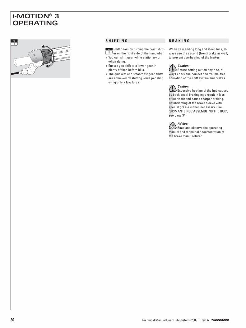
1 Shift gears by turning the twist shift-
er on the right side of the handlebar.
» You can shift gear while stationary or
when riding.
» Ensure you shift to a lower gear in
plenty of time before hills.
» The quickest and smoothest gear shifts
are achieved by shifting while pedaling
using only a low force.
B R A K I N G
When descending long and steep hills, al-
ways use the second (front) brake as well,
to prevent overheating of the brakes.
Caution: Before setting out on any ride, al-
ways check the correct and trouble-free
operation of the shift system and brakes.
Caution: Excessive heating of the hub caused
by back pedal braking may result in loss
of lubricant and cause sharper braking.
Relubricating of the brake sleeve with
special grease is then necessary. See
"DISMANTLING / ASSEMBLING THE HUB",
see page 34.
Advice: Read and observe the operating
manual and technical documentation of
the brake manufacturer.
1

31Technical Manual Gear Hub Systems 2009 · Rev. A
i-MOTION® 3MAINTENANCE
C L E A N I N G
» Your SRAM i-MOTION 3 components are
well protected against adverse envi-
ronmental effects. However, do not use
water under pressure (such as pressure
washers or water jets) for cleaning to
prevent malfunctions due to water pen-
etration.
» During winter use, you should clean
your bike more frequently to prevent salt
damage.
» Do not use any corrosive cleaning
agents.
» Clean dirty chains before oiling. Allow
cleaner to work for only a few minutes
before rinsing off with water. Do not oil
chain until completely dry.
L U B R I C A T I O N
» The rear wheel hub is provided with per-
manent lubrication and is maintenance-
free under normal conditions.
» When dismantling/assembling the gear
unit, observe the lubrication guidelines.
See "DISMANTLING/ ASSEMBLING THE
HUB", from page 34.
» Regular will extend the chain's service
life.
R E P A I R W O R K
Caution: Unauthorized work on the i-MOTION 3
system may result in its malfunctioning,
which may endanger you and could lead
to invalidation of the warranty.
Back pedal brake If braking is too sharp, the brake sleeve
has to be re-lubricated with special
grease. See "DISMANTLING / ASSEM-
BLING THE HUB", page 34.
W E A R P A R T S
Brake liners or brake segments, brake
cables, shift cables, handlebar grips,
sprockets, and bike chains are wear parts.
Please check these parts regularly and re-
place them well before they are worn out.
Other topics Page
G E A R A D J U S T M E N T 32
R E M O V I N G T H E R E A R W H E E L 32
F I T T I N G T H E R E A R W H E E L 33
E X C H A N G I N G T H E G E A R U N I T 34
D I S M A N T L I N G A N D A S S E M B L I N G T H E H U B 34
D I S M A N T L I N G A N D A S S E M B L I N G T H E G E A R U N I T 36
C H A N G I N G T H E S H I F T C A B L E 44
T R O U B L E S H O O T I N G 45

32 Technical Manual Gear Hub Systems 2009 · Rev. A
i-MOTION® 3MAINTENANCE
G E A R A D J U S T M E N T
1 Turn the twist shifter
to 3rd gear.
Advice: The shift cable should be adjusted
so that it is free from play when 3rd gear is
selected, i.e. it must be pulled out as far as
it will go.
2 It should not be possible to pull the
shift cable further out of the gear
hub by pulling on the plastic retainer (1).
– Shift cable has too much play:
Turn the twist shifter to 1st gear.
3 Reduce the shift cable play by
turning the barrel adjuster (2) on
the shifter.
– Shift cable is too tight/taut:
Either the shifter cannot select 3rd
gear or the gear hub does not shift to
1st gear or shifts constantly between
1st and 2nd gears.
Turn the twist shifter to 1st gear.
3 Reduce the shift cable tension
with the aid of the the barrel ad-
juster (2) on the shifter.
» Turn the twist shifter to 3rd gear and
check once again that there is no play in
the shift cable.
R E M O V I N G T H E R E A R W H E E L
4 Turn the twist shifter
to 1st gear.
5 Pull the plastic retainer (1) from the
cable stop bracket (2).
6 Break the connection between shift-
er and rear wheel hub by unhooking
the connection lug (3) from the shift ca-
ble nipple (4).
7 Loosen the axle nuts (5) before re-
moving them together with the un-
derlying retaining washers (6).
If applicable, remove the brake lever
screw (7) from the frame clip.
» Remove the rear wheel.
34
6
4
12
5
7
5
67
2
3
1
1
2

33Technical Manual Gear Hub Systems 2009 · Rev. A
i-MOTION® 3MAINTENANCE
F I T T I N G T H E R E A R W H E E L
8 If dismantled, push the cable stop
bracket (1) and then the locking bush
with the rubber insert (2) onto the axle
end on the sprocket side.
» Place the rear wheel into the rear
frame.
9 Place one retaining washer (3) on
each axle end.
The serrated face of the retaining wash-
er must lie against the frame dropout.
10 Align the cable stop bracket (4) paral-
lel to the frame strut (5).
11 Fit the axle nuts (6) and tighten these
while alternating between sides.
Tightening torque 30 – 40 Nm (266 – 350
in.lbs.).
12 If applicable, mount the brake lever (7)
between the two straps of the frame
clamp (8).
Caution: The frame clamp must be fitted
tightly on the frame without any play.
Use a self-locking nut (M6)!
Tightening torque: 2 – 3 Nm (18 – 27 in.lbs.).
13 Make sure that the shifter is set to
1st gear.
14 Make the connection between shift-
er and rear wheel hub by hooking
the connection lug (9) onto the shift ca-
ble nipple (10).
15 Plug the plastic retainer (11) onto the
cable stop bracket (12).
Caution: Before setting out on any ride,
always check the correct and trouble-free
operation of the shift system and brakes.
1 2
8
4
5
10
611
78
12
39
13
9
10
14
1112
15
30 – 40 Nm(266 – 350 in.lbs.)

34 Technical Manual Gear Hub Systems 2009 · Rev. A
3
4
5
2
5
9
10
11
3
7
6
8
4
2
1
1
i-MOTION® 3MAINTENANCE
E X C H A N G I N G T H E G E A R U N I T / W O R K I N G O N T H E B A C K P E D A L B R A K E
D I S M A N T L I N G T H E H U B Work on the brake cone / adjusting cone and ball retainer of the non-drive side:
1 Take off the locking bush (1) and the
cable stop bracket (2).
2 Detach the circlip (3).
Caution: The circlip is spring force loaded.
Take off the sprocket (4) and the dust
cap (5).
3 Clamp the drive side of the axle with
the two flats of the axle in a vise.
4 Unscrew both nuts (6) from the axle.
Wrench size 22 mm.
For the no-brake hub version, the locknut
and the underlying adjusting cone
should be unscrewed from the axle.
Wrench size 17 mm.
4 Hub version with back pedal brake:
Take off the lever cone (7) and the
ball retainer (8).
» Lubrication and assembly details can be
found in the following column.
Work on the brake segments (hub version
with back pedal brake) and ball retainer on the drive side:
» Dismantle the hub as previously de-
scribed ("Work on brake cone / adjusting
cone and ball retainer on non-drive
side").
5 Take the hub shell (9) off in an up-
wards direction. Take both brake
segments (10) out of the hub shell.
Take off the ball retainer (11) in an up-
wards direction.
Advice: When exchanging the gear unit,
removal of the ball retainer is not neces-
sary.
» Lubrication and assembly details can be
found in the following column.
A S S E M B L I N G T H E H U B For a gear unit change:Clamp the new gear unit on the drive side
of the axle in the vise.
Clean the parts after dismantling:The parts can be degreased in a cleaning
bath.
Lubricating the parts:Caution: Use only SRAM special grease, part
no. 0369 135 200 / ... 201 and commercially
available cycle oil.
Lubricate ball retainers and ball tracks
only with SRAM Ball Bearing Grease. Part
no. 0369.001.015
Work on the brake segments (hub version
with back pedal brake) and ball retainer on the drive side:
Lubrication:Grease the ball track (12) of the
6 driver and the ball retainer (13) with
SRAM Ball Bearing Grease (part no.
0369.001.015).
6 Insert the ball retainer (13) with the
balls pointing upwards towards the
driver (12).
Lubrication:Oil both pawls (15) of the planetary
6 gear carrier.
For the hub version with back pedal
brake, place a drop of oil on the 5 rollers
(14).
7 Lightly grease the inside of the
hubshell eith SRAM special
grease. Lightly grease the ball tracks
(17) with with SRAM Ball Bearing Grease
(part no. 0369.001.015).
For the hub version with back pedal
brake lightly grease the brake cylinder
(16).
Caution:Use only SRAM special grease,
part no. 0369 135 200 / ... 201.
7 Position the hub shell. Turning slight-
ly to the left/right eases positioning.
Ensure that the hub shell is correctly
seated on the ball retainer (18).

35Technical Manual Gear Hub Systems 2009 · Rev. A
3115
32
26
24
25
11
27
2812
2310
21
22
209
19
8
18
7
29
13
3014
12
6
15
14
13
17
16
15–20 Nm(133 – 177 in.lbs.)
i-MOTION® 3MAINTENANCE
8 Hub version with back pedal brake:
Turn the shell in a clockwise direc-
tion as far as it will go. This ensures that
the rollers (19) of the brake can fall back
and that the brake segments can be
mounted.
» Hub version with back pedal brake:
Lubrication:Clean the brake segments and
completely coat the outer surfaces with
grease.
Caution: Use only SRAM special grease,
part no. 0369 135 200 / ... 201.
9 Inserting the brake segments:
The recesses (20) must point up-
wards.
» At first insert the brake segment so
that the bevel (21) is visible from
above.
Advice: The brake segment lie against
the angled spring end (22).
» Insert the second brake segment.
Advice: The brake segments must be
renewed, if, as a result of wear, the
grooves on the outer surface are
scarcely visible.
Work on the brake cone / adjusting cone and ball retainer of the non-drive side:
Lubrication:Clean the ball retainer (23) and
10 grease it using SRAM Ball Bearing
Grease (part no. 0369.001.015).
10 Insert the ball retainer (23). The side
with the balls must point down-
wards.
11 Hub version with back pedal brake:
Fit the lever cone (24).
By turning to the left and right, bring the
lever cone (24) into its final position. The
locating lugs (25) of the lever cone will
then lie in the recesses (26) of the brake
segments.
12 Screw an axle nut (27) onto the axle.
Wrench size 22 mm.
» Hub versions without brakes and i-BRAKE:
screw the adjusting cone onto the axle.
Wrench size 17 mm.
12 Position the bearing in a play-free
manner and tighten using nut (28).
Wrench size 22 mm. Tightening torque
15 – 20 Nm (133 – 177 in.lbs.).
Test the play of the bearing and correct
if required.
» Clamp the hub with the other axle side
in the vise.
13 Set the dust cap (29) onto the driver.
The curvature must point to the out-
side.
14 Place the sprocket (30) on the driver.
For offset, i.e. transversely displaced
sprockets, the sprocket should be
mounted with the toothing to the inside
(the curvature must point outwards).
15 Mount the sprocket circlip (31) onto
the driver.
Advice: Ensure that the plastic protective
cap (32) is not damaged.
Check for proper seating of the circlip.
» Remove the hub from the vise.
» Fit the rear wheel into the rear frame as
described on page 33.
Adjust the gears as described on page
32.
Caution: Before setting out on any ride,
always check the correct and trouble-free
operation of the shift system and brakes.

36 Technical Manual Gear Hub Systems 2009 · Rev. A
11
3
2
2
4
5
3
6
7
4 8
9
510
11
12
13
14
15
16
6
177
18
19
20
21
i-MOTION® 3MAINTENANCE
D I S M A N T L I N G T H E G E A R U N I T Gear hubs until July 2007 (Gear
hubs as of August 2007 see page 40)
Remove the gear unit as described on
page 34.
1 Remove the retaining ring (1) and
take off the washer (2) and planetary
gear carrier (3) beneath it.
2 Take off the ring gear (4)
and washer (5).
3 Take off the
pawl carrier (6).
Advice: Press on the pawls (7) to make
removal easier.
» Clamp the hub with the other axle side
in the vise.
4 Take off the plastic protective cap (8).
Undo the shift cable (9) by turning in
an anticlockwise direction and pull it out
of the axle.
5 Unscrew the threaded bushing (10)
from the axle. Wrench size 13 mm.
Take off the fixed cone (11) and spring (12)
from the axle.
6 Hub version with back pedal brake:
Take off the driver (13) and the con-
trol washer (14) beneath it. Take off the
coupling piece (15) and shift bush (16).
Work on the thrust block:Advice: The thrust block only requires atten-
tion if the shift cable has torn off.
7 Unscrew the red grub screw (17)
from the axle.
Caution: The grub screw is spring force
loaded.
Take the spring (18) and spacer bolt (19)
out of the axle.
7 Turn the circlip (20) and take the
thrust block (21) out of the axle.
» Lubrication and assembly details can be
found on the following page.

37Technical Manual Gear Hub Systems 2009 · Rev. A
7
26
929
8
520
21 22
4 19
1718
314
15
16
212
10
11
139
6 25
24
23
71
6
5
4
3
2
1
28
27
8
15–20 Nm (133 – 177 in.lbs.)
i-MOTION® 3MAINTENANCE
A S S E M B L I N G T H E G E A R U N I T Gear hubs until July 2007 (Gear
hubs as of August 2007 see page 41)
Clean the parts after dismantling:Caution: The planetary gear carrier and the
driver should only be cleaned on the out-
side using a paint brush so that they are
not degreased. Cleaning in a cleaning bath
is not permitted.
The remaining parts can be degreased in
a cleaning bath.
Lubricating the parts:Caution: Use only SRAM special grease, part
no. 0369 135 200 / ... 201.
Lubricate ball retainers and ball tracks
only with SRAM Ball Bearing Grease. Part
no. 0369.001.015.
Work on the thrust block / assembly of the axle:
1 Place the thrust block in the shift
sleeve (1).
Advice:The tapped hole (2) of the thrust
block must be located on the axle side
with the long slit (3). This subsequently
allows the shift cable to run through the
long slit (4).
Turn the circlip through 90 degrees to
secure the thrust block.
1 Insert the spacer bolt (5) and spring (6)
in the axle. Turn the red grub screw (7)
so it is flush with the axle.
Assembling the gear unit: Lubrication:Lightly grease the axle and grease
2 the toothing (8). Use only SRAM spe-
cial grease, part no. 0369 135 200 /
... 201.
Place a drop of oil on the thrust block (9).
2 Fit the shift bush (10) with the crown
toothing (11) facing downwards to-
wards the axle. Place the coupling piece
(12) with the lugs (13) downwards on to
the shift bush.
3 Hub version with back pedal brake:
Place the control washer (14) (with
the bent up ends (15) facing upwards)
on the coupling piece (16).
» Hub version without brake:
Place the large washer on the coupling
piece.
Lubrication:Oil the 4 pockets for the pawls (17)
4 and the driver pawl spring (18).
Grease the ball retainer (19) with
SRAM Ball Bearing Grease (part no.
0369.001.015).
5 Seat the driver (20) on the control
washer (21). The pawls (22) must lie
in the recesses of the control washer.
6 Push the spring (23) and the fixed
cone (24) onto the axle. Fit the
threaded bushing (25) and tighten with a
torque of 15 – 20 Nm (133 – 177 in.lbs.).
Wrench size 13 mm.
Lubrication:On the axle side with the recess (26)
7 for the shift cable, the opening (27)
on the fixed cone must be filled with
grease. Use only SRAM special grease,
part no. 0369 135 200 / ... 201.
8 Push the shift cable on the side of
the recess (28) into the fixed cone
and secure it, by turning in a clockwise
direction (minimum of 7 full turns). Turn
only until hand-tight.
9 Fit the plastic
protective cap (29).
» Clamp the hub with the other axle side
in the vise.

38 Technical Manual Gear Hub Systems 2009 · Rev. A
i-MOTION® 3MAINTENANCE
Lubrication:Apply a drop of oil on both bearing
10 bolts (30) of the pawl carrier. Oil the
pawl spring (31).
11 Insert the pawl carrier (32) in the
shift bush. The leg (33) of the shift
bush lies in the two large recesses (34)
of the pawl carrier.
Advice: Press on the pawls (35) to make
insertion easier.
12 Place the washer (36) on the pawl
carrier.
Lubrication:Apply a drop of oil to both bearing
13 bolts (37) of the ring gear.
Apply a little grease to the pawl
teeth (38) and grease the ring gear teeth
(39). Use only SRAM special grease, part
no. 0369 135 200 / ... 201.
Lubrication:Apply a drop of oil on the three
14 bearing bolts (40) of the planetary
gear carrier and oil the contact sur-
face (41). Oil the pawl pockets (42) and the
pawl spring (43). Grease the seat of the
friction spring (44) with SRAM special
grease, part no. 0369 135 200 / ... 201.
Oil the end surface (45).
15 Match the profile of the pawl carrier
(46) to that of the coupling piece (47).
Press the pawl carrier down, pull on the
shift cable and hold the system in this
position for the next work step.
15
4647
14 45
43 4244
4041
13
37
38 39
12
10
30
31
11
32
35
34
33
36

39Technical Manual Gear Hub Systems 2009 · Rev. A
i-MOTION® 3MAINTENANCE
16 Fit, while holding the system in posi-
tion, the larger diameter ring gear (48)
downwards over the pawls (49) of the
driver.
Maintain the system in this position.
17 Mount the planetary
gear carrier (50).
By turning to the left and right, bring the
planetary gear carrier into its final posi-
tion.
Advice:The planetary gears (51) must be
flush with the ring gear teeth (52).
Maintain the system in this position.
18 Position the washer (53) and fit the
circlip (54).
Caution: The opening of the circlip must be
located over the axle flat (55).
» Complete hub assembly as described
on page 34 under “ASSEMBLING THE
HUB".
17
50
5251
54
53
16
48
49
18 55

40 Technical Manual Gear Hub Systems 2009 · Rev. A
i-MOTION® 3MAINTENANCE
D I S M A N T L I N G T H E G E A R U N I T Gear hubs as of August 2007
(Gear hubs until July 2007 see page 36)
Remove the gear unit as described on
page 34.
1 Remove the retaining ring (1) and
take off the washer (2) and planetary
gear carrier (3) beneath it.
2 Take off the ring gear (4)
and washer (5).
3 Take off the
pawl carrier (6).
Advice: Press on the pawls (7) to make
removal easier.
» Clamp the hub with the other axle side
in the vise.
4 Take off the plastic protective cap (8).
Undo the shift cable (9) by turning in
an anticlockwise direction and pull it out
of the axle.
5 Loosen the threaded bushing (10),
but leave it on the axle with a couple
of threads. Wrench size 13 mm.
Lift the driver off one time to release the
inboard spacer sleeve.
Take of the threaded bushing (10), the
cable guide bush (11), the spacer sleeve
(12), the fixed cone (13), and spring (14)
from the axle.
, 6 Hub version with back pedal brake:
Take off the driver (15) and the con-
trol washer (16) beneath it. Take off the
coupling piece (17) and shift bush (18).
, 6 Hub version without brake:
Take off the driver (15) and the con-
trol washer (16) beneath it. Take off the
coupling piece (17) and shift bush (18).
Work on the thrust block:Advice: The thrust block only requires atten-
tion if the shift cable has torn off.
7 Unscrew the red grub screw (19)
from the axle.
Caution: The grub screw is spring force
loaded.
Take the spring (20) and spacer bolt (21)
out of the axle.
7 Turn the circlip (22) and take the
thrust block (23) out of the axle.
» Lubrication and assembly details can be
found on the following page.
2
4
5
3
6
7
5
4 8
9
15
16
17
18
6
11
3
2
197
20
21
22
23
10
11
12
13
14

41Technical Manual Gear Hub Systems 2009 · Rev. A
i-MOTION® 3MAINTENANCE
A S S E M B L I N G T H E G E A R U N I T Gear hubs as of August 2007
(Gear hubs until July 2007 see page 37)
Clean the parts after dismantling:Caution: The planetary gear carrier and the
driver should only be cleaned on the out-
side using a paint brush so that they are
not degreased. Cleaning in a cleaning bath
is not permitted.
The remaining parts can be degreased in
a cleaning bath.
Lubricating the parts:Caution: Use only SRAM special grease, part
no. 0369 135 200 / ... 201.
Lubricate ball retainers and ball tracks
only with SRAM Ball Bearing Grease. Part
no. 0369.001.015.
Work on the thrust block / assembly of the axle:
1 Place the thrust block in the shift
sleeve (1).
Advice:The tapped hole (2) of the thrust
block must be located on the axle side
with the long slit (3). This subsequently
allows the shift cable to run through the
long slit.
Turn the circlip through 90 degrees to
secure the thrust block.
1 Insert the spacer bolt (4) and spring (5)
in the axle. Turn the red grub screw (6)
so it is flush with the axle.
Assembling the gear unit: Lubrication:Lightly grease the axle and grease
2 the toothing (7). Use only SRAM spe-
cial grease, part no. 0369 135 200 /
... 201.
Place a drop of oil on the thrust block (8).
2 Fit the shift bush (9) with the crown
toothing (10) facing downwards to-
wards the axle. Place the coupling piece
(11) with the lugs (12) downwards on to
the shift bush.
3 Hub version with back pedal brake:
Place the control washer (13) (with
the bent up ends (14) facing upwards)
on the coupling piece (15).
» Hub version without brake:
Place the large washer on the coupling
piece.
Lubrication:Oil the 4 pockets for the pawls (16)
4 and the driver pawl spring (17).
Grease the ball retainer (18) with
SRAM Ball Bearing Grease (part no.
0369.001.015).
5 Seat the driver (19) on the control
washer (20). The pawls (21) must lie
in the recesses of the control washer.
6 Push the spring (22), the fixed cone
(23), the spacer sleeve (24), and the
cable guide bush (25) onto the axle.
Advice:The slotted side (26) of the spacer
sleeve and the guide surface (27) of the
cable guide bush must be located on the
axle side with the slit (28) for the shift
cable.
Fit the threaded bushing (29) and tighten
with a torque of 15 – 20 Nm (133 – 177
in.lbs.). Wrench size 13 mm.
Lubrication:Fill the opening (30) for the shift
7 cable on the cable guide bush with
grease.
Use only SRAM special grease, part no.
0369 135 200 / ... 201.
8 Push the shift cable into the cable
guide bush and secure it, by turning
in a clockwise direction (minimum of 7
full turns). Turn only until hand-tight.
9 Fit the plastic
protective cap (31).
» Clamp the hub with the other axle side
in the vise.
519
20 21
313
14
15
931
8
4 18
1617
211
9
10
128
6
61
5
4
3
2
1
30
7
22
29
25
24
23
28
2726
7
15–20 Nm (133 – 177
in.lbs.)

42 Technical Manual Gear Hub Systems 2009 · Rev. A
i-MOTION® 3MAINTENANCE
Lubrication:Apply a drop of oil on both bearing
10 bolts (32) of the pawl carrier. Oil the
pawl spring (33).
11 Insert the pawl carrier (34) in the
shift bush. The leg (35) of the shift
bush lies in the two large recesses (36)
of the pawl carrier.
Advice: Press on the pawls (37) to make
insertion easier.
12 Place the washer (38) on the pawl
carrier.
Lubrication:Apply a drop of oil to both bearing
13 bolts (39) of the ring gear.
Apply a little grease to the pawl
teeth (40) and grease the ring gear teeth
(40). Use only SRAM special grease, part
no. 0369 135 200 / ... 201.
Lubrication:Apply a drop of oil on the three
14 bearing bolts (42) of the planetary
gear carrier and oil the contact sur-
face (43). Oil the pawl pockets (44) and the
pawl spring (45). Grease the seat of the
friction spring (46) with SRAM special
grease, part no. 0369 135 200 / ... 201.
Oil the end surface (47).
15 Match the profile of the pawl carrier
(48) to that of the coupling piece (49).
Press the pawl carrier down, pull on the
shift cable and hold the system in this
position for the next work step.
15
4849
14 47
45 4446
4243
13
39
40 41
12
10
32
33
11
34
37
36
35
38

43Technical Manual Gear Hub Systems 2009 · Rev. A
i-MOTION® 3MAINTENANCE
16 Fit, while holding the system in posi-
tion, the larger diameter ring gear (50)
downwards over the pawls (51) of the
driver.
Maintain the system in this position.
17 Mount the planetary
gear carrier (52).
By turning to the left and right, bring the
planetary gear carrier into its final posi-
tion.
Advice:The planetary gears (53) must be
flush with the ring gear teeth (54).
Maintain the system in this position.
18 Position the washer (55) and fit the
circlip (56).
Caution: The opening of the circlip must be
located over the axle flat (57).
» Complete hub assembly as described
on page 34 under “ASSEMBLING THE
HUB".
17
52
5453
16
50
51
18 56
55
57

44 Technical Manual Gear Hub Systems 2009 · Rev. A
i-MOTION® 3MAINTENANCE
C H A N G I N G T H E S H I F T C A B L E
Advice:Always use new, high-quality cables
and compressionless cable housings with
end caps.
1 Turn the twist shifter
to 1st gear.
2 Pull the plastic retainer (1) from the
cable stop bracket (2).
3 Break the connection between shift-
er and rear wheel hub by unhooking
the connection lug (3) from the shift ca-
ble nipple (4).
4 Place the plastic retainer and the
connection lug in the assembly tool
(SRAM part no. 00.0391.017.000).
Unscrew the nut (wrench size 8 mm).
Advice:You may want to clamp the as-
sembly tool in a vise.
5 Take the nut (5) and the underlying
washer (6) off. Take off the connec-
tion lug and the plastic retainer from the
shift cable.
1 Make sure that the shifter is set to
1st gear.
6 Remove the cap (7) from the shifter.
The nipple (8) of the inner cable is
now visible.
7 Push or pull the old inner cable out
of the shifter, e.g. using a small
screwdriver.
» Guide the new inner cable into the cable
inlet, through the shifter and the new
cable housing. Pull the cable tight.
» Insert the cap in the shifter.
8 Screw in the shifter barrel adjuster (9)
at the shifter in a clockwise direc-
tion as far as it will go, then turn coun-
terclockwise 2 full turns.
Fitting the connection lug with assembly
tool (SRAM part no. 00.0391.017.000):
Advice:You may want to clamp the as-
sembly tool in a vise.
9 Push the plastic retainer and the
connection lug with fitted washer
and nut onto the inner cable.
Place the plastic retainer and the con-
nection lug in the assembly tool.
10 Pull the inner cable tight and cut it
off directly at the connection lug.
11 Push the connection lug to the left
and tighten the nut. Tightening
torque: 3 – 4 Nm (27 – 35 in.lbs).
Wrench size 8 mm.
8 mm
4 Part no.00.0391.017.000
9
8
8 mm / 3 – 4 Nm
11
9
10
1
68
7
7
5 5
6
34
3
12
2

45Technical Manual Gear Hub Systems 2009 · Rev. A
12
8 mm / 3 – 4 Nm
39 mm
13
14
i-MOTION® 3MAINTENANCE
T R O U B L E S H O O T I N G
Problem Cause Remedy
Shifting difficulties: Incorrect gear adjustment. Adjust the gears.
Page 32.
The shift cable or the cable housing is damaged. Renew the shift cable and cable housing.
Page 44.
Shift cable of the hub is not screwed in com-
pletely.
Screw in completely the shift cable of the hub
(minimum of 7 full turns).
Page 37 or 41 figure 8. Turn only until hand-tight!
The pedals go forwards when freewheeling:
The chain tension is too tight. Slacken the chain tension.
The bearing adjustment is too tight. Readjust the bearing.
Page 35.
Locknut of the lever cone / adjusting cone is
loose.
Readjust the bearing and tighten the locknut.
Page 35, figure 12, no. 28.
The back pedal brake is too sharp or locked: The brake segments are no longer lubricated. Lubricate the brake cylinder of the hub shell and
the brake segments (if necessary renew).
Page 34, "Work on the brake segments".
Fitting the connection lug without an as-
sembly tool:
12 Push the plastic retainer and the
connection lug with fitted washer
and nut onto the inner cable.
Fit the plastic retainer on the cable stop
bracket. Hook the connection lug onto
the hub shift cable nipple.
Pull the inner cable tight and securely
tighten the nut of the connection lug.
Unhook the connection lug again and
cut off the projecting excess cable so it
is as short as possible.
13 Make the connection between shift-
er and rear wheel hub by hooking
the connection lug onto the shift cable
nipple.
14 Plug the plastic retainer onto the ca-
ble stop bracket.
» Adjust the gears as described on page
32.
Caution: Before setting out on any ride,
always check the correct and trouble-
free operation of the shift system and
brakes.
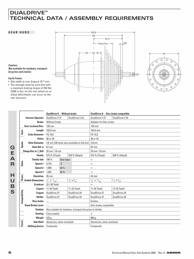
46 Technical Manual Gear Hub Systems 2009 · Rev. A
Caution: Not suitable for tandems, transport bicycles and similar.
Cycle frame:• Slot width at rear dropout 10+0.5 mm.
• The strength must be such that with
a maximum braking torque of 250 Nm
(2200 in.lbs.) on the rear wheel no re-
sidual deformation can occur on the
rear structure.
18
67.5
Chainline
135
182.6
4.6
33 67
GEAR
HUBS
DualDrive II · Without brake DualDrive II · Disc brake compatible
Version (Speeds) DualDrive II 27 DualDrive II 24 DualDrive II 27 DualDrive II 24
Brake Without brake Adaptor for Disc brake
Over Locknut Dim. 135 mm 135 mm
Length 182.6 mm 182.6 mm
Ends Diameter FG 10,5 FG 10,5
Holes 36 or 28 36 or 32
Hole Diameter 2.6 mm (28 holes also available in 2,8 mm) 2.6 mm
Hole Ref. ø 67 mm 67 mm
Flange Dist. to 1/2 OLD 33 mm / 18 mm 33 mm / 18 mm
Totally 573 % (27spd) 539 % (24spd) 573 % (27spd) 539 % (24spd)
Totally hub 186 %
Speed 1 0,734
Speed 2 1,000
Speed 3 1,362
Chainline 45 mm 42 mm
Usable Dimensions 1/2" x 11/
128" 1/
2" x 3/
32" 1/
2" x 11/
128" 1/
2" x 3/
32"
Crankset 33 / 38 Teeth
Cogset 11-34 Teeth 11-32 Teeth 11-34 Teeth 12-32 Teeth
Cogset DualDrive 27 DualDrive 24 DualDrive 27 DualDrive 24
Shifter DualDrive 27 DualDrive 24 DualDrive 27 DualDrive 24
Disc brake — 6 holes
Hand Brake Lever — Disc brake compatible
Tandem Not suitable for tandems, transport bicycles or similar
Sealing Extra sealed
Weight 970 g 985 g
Hub Shell Aluminum, silver anodized Aluminum, silver anodized
Shifting device Composite Composite
Axl
eSp
oke
Ratio
Fini
sh
Gear steps
36 %
36 %
Com
patib
ility
Chai
n
DUALDRIVE™
TECHNICAL DATA / ASSEMBLY REQUIREMENTS
G E A R H U B S

47Technical Manual Gear Hub Systems 2009 · Rev. A
DUALDRIVE™
TECHNICAL DATA / ASSEMBLY REQUIREMENTS
DualDrive single sided shifter
Version DualDrive 27 DualDrive 24
Clickbox Cable 1400 mm / 1500 mm / 1600 mm / 1700 mm / 2100 mm
Shifter Type SRS Twistring-Thumbshifter-Combo (2in1)
Arrangement Right side of handlebar
Gear Hub DualDrive 27 DualDrive 24
Derailleur DualDrive 27 DualDrive 24
Gear Indication Der. Window Printed
Riding Mode Indic. Printed Printed
Barrel Adj. Gear Hub None
Barrel Adj. Derailleur Indexing
Clamping Diameter 22.1 – 22.3 mm
Straight handlebar ends Minimum necessary length for shifter and handlebar grip = 150 mm
Cable Routing, Gear Hub Continuous housing (preassembled)
Cable Routing, Der. Open or continuous
Weight N/A
Cables Stainless steel
Housing Glass filled PA – Silver painted
Grip Cover Thermoplastic elastomer
Clamping Collar Aluminum
Clickbox Composite
Des
ign
Com
p-pa
t.
SHIFTERS
S H I F T E R S
49
84
Ø 2
2.1
– 2
2.3
Ø 4
0
69
16
49
84
Ø 2
2.1
– 2
2.3
Ø 4
0
69
5
Shifter DualDrive 27 Shifter DualDrive 24
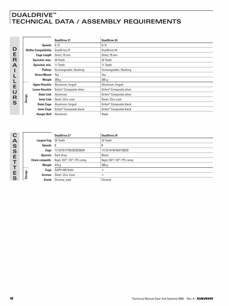
48 Technical Manual Gear Hub Systems 2009 · Rev. A
DUALDRIVE™
TECHNICAL DATA / ASSEMBLY REQUIREMENTS
CASSETTES
DualDrive 27 DualDrive 24
Largest Cog 34 Teeth 32 Teeth
Speeds 9 8
Cogs 11/13/15/17/20/23/26/30/34 11/12/14/16/18/21/26/32
Spacers Dark Gray Black
Chain compatib. 9spd, HG® / IG® / PC comp. 8spd, HG® / IG® / PC comp.
Weight 410 g 280 g
Cogs SAPH 440 Stahl
Screws Steel / Zinc Coat
Finish Chrome, matt Chrome
Des
ign
DERAILLEURS
DualDrive 27 DualDrive 24
Speeds 9 / 8 9 / 8
Shifter Compatibility DualDrive 27 DualDrive 24
Cage Length Short, 75 mm Short, 75 mm
Sprocket, max. 34 Teeth 32 Teeth
Sprocket, min. 11 Teeth 11 Teeth
Pulleys Exchangeable / Bushing Exchangeable / Bushing
Direct Mount Yes Yes
Weight 258 g 265 g
Upper Knuckle Aluminum, forged Aluminum, forged
Lower Knuckle Grilon® Composite silver Grilon® Composite silver
Outer Link Aluminum Grilon® Composite silver
Inner Link Steel / Zinc coat Steel / Zinc coat
Outer Cage Aluminum, forged Grilon® Composite black
Inner Cage Grilon® Composite black Grilon® Composite black
Hanger Bolt Aluminum Steel
Des
ign

49Technical Manual Gear Hub Systems 2009 · Rev. A
DUALDRIVE™
TECHNICAL DATA / ASSEMBLY REQUIREMENTS
1
2
3
4
C A B L E H O U S I N G • Use only new high quality cable and
com -pressionless cable housing with
end caps.
• When choosing cable housing lengths,
be sure to allow enough housing for an
extreme turn of the handlebars in both
directions.
• Note also, that different stem lengths
and cable stop positions effect cable
housing length.
D R O P O U TOnly flat and no off-set versions.
Dropout thickness: 7 – 8 mm.
Vertical or horizontal dropout slot.
Dropouts must be parallel.
Dropout dimensions: see Fig. 2 and 3.
C R A N K S E TBicycle without chain case:
Use a chain guard disc (at the outer
surface of chainring, material no resin)
Use only standard chainring version (non-
shifting teeth).
Number of teeth: 33 / 38
Chainline: 45 mm
C H A I N G U I D E F O R KIt prevents chain from jumping off front
chainring, is bolted inside the chain case
(1, Fig. 4).
H A N D L E B A RDiameter: 22.3 mm.
Minimum length of straight area for shifter:
150 mm.
Check the compatibility of intended
handlebars and brake levers.
1
ø max. 220 mm
L
28
30
X
6–10
7.5 –10
A
25˚–30˚
25˚–30˚
R1
8.5 max
8.5 max
R2
11.5 –13.5
11.5 –13.5
Cable routing DualDrive 27 / DualDrive 24
Hub cable Along chainstay only
Derailleur cable Along chainstay only
Cable attachementsiehe Bild 1 Cable housing Attachement points Cable stops
Hub Continuous 1 / 2 / 3 / 4 (see Fig. 1) —
Derailleur Continuous 1 / 2 / 3 / 4 / 5 (see Fig. 1) —
Open — 1 / 5 (Fig. 1)
32
60
25
45
15
14
13
1
2
3
45
Length X min. 90 mm.
Cable stop below or beside chainstay.
X (mm) 10 120 130
L (m
m)
200
180
160
140
120
100
C A B L E H O U S I N G F O R D E R A I L L E U R
Rear cable stop position Rear housing length
Example: Distance X = 100 mm cable
housing length L = 140 – 165 mm.
X
R2
R1
A X
L
90°

50 Technical Manual Gear Hub Systems 2009 · Rev. A
DUALDRIVE™
ASSEMBLY
A S S E M B L Y H U B• Lace the wheel as normal.
• Place spoke protector disc (1, Fig. 1) on shoulder of hub, fit cassette (2)
onto driver profile. Screw lock nut (3)
with cassette tool (Park Tool FR-5 or
SRAM Part No. 4624 411 010), tightening
torque: 40 Nm (350 in.lbs.).
• Screw shifting rod (1, Fig. 2) into the
hub axle and tighten it with 0.2 Nm (1.8
in.lbs.).
• Fit wheel in dropouts.
• Hub versions for i-BRAKE and Disc
Brake:
Advice: Read and observe the corresponding technical documentation for assem-bling the disc of the disc brake.Caution: Plane faces of the hub and the disc and the threaded holes of the hub must be clean and free from oily and greasy substances.
• Place one retaining washer without lug
(2, Fig. 2) on right axle end (drive side).
The serrations must bear against the
dropout.
• Place one retaining washer with lug (3,
Fig. 2) (new version, 3,5 mm thick) on
left axle end (non-drive side). The lug
must engage in the dropout slot.
On vertical dropouts, fit one retaining
washer without lug on each axle end.
The serrations must bear against the
dropout.
• Tighten up axle nuts. Tightening torque
30 – 40 Nm (266 – 350 in.lbs.).
A S S E M B L Y D E R A I L L E U RAdvice: Check the rear derailleur hanger alignment. A bent rear derailleur hanger will result in inaccurate index shifting. • Attach the rear derailleur to the frame’s
rear derailleur hanger using a 5 mm hex
head wrench (Fig. 3).• Check that the b-adjust washer tab
(b-adjust screw at DualDrive 24) is clear
of the rear derailleur dropout tab (Fig. 4).• Tighten the 5 mm hex hanger bolt to
8 – 10 Nm (70 – 85 in.lbs.).
C H A I N L E N G T H• Bypassing the rear derailleur, run the
chain around the largest cog/large
chainring combination (Fig. 5). – For rear suspension frames, position
the rear suspension for the greatest
chain length required.
• Add 4 LINKS or 3 link + Connecting Link
to this length for proper chain length.
A S S E M B L Y S H I F T E RCaution:• Never use lubricants or solvents to
install handlebar grips. Handlebar grips provide safety function. For this reason, they should be mounted in such a way as to make sure they do not slip off handlebar!
• Always check the front and rear brake levers for proper operation.
If there is interference between shifters and brake levers, re-adjust lever and shifter placement.
• Slide the shifter (1, Fig. 6) onto the
handlebar.
• Rotate the shifter until the barrel ad-
juster (4) is beneath (but out of the way
of) the brake lever.
• Tighten the 3 mm hex clamp bolt (2) to
1.9 – 2.5 Nm (17 – 22 in.lbs.).
• Slide the handlebar grip (3) onto the
handle bar.
I N S T A L L I N G C L I C K B O X• Fit the cable and avoid small radius.
• Cable attachment points see Page 49 / Fig. 1.
Cable housing must be movable inside attachment.
• Place shift lever in uphill riding mode /
gear position „1“ (Fig. 7).• Push Clickbox button down (Fig. 7).• Push on Clickbox to the stop on the hub
axle.
• Press button up.
• Place thumb shift lever in standard
riding mode / gear position „2“ (Fig. 8).• Match up the marks in the Clickbox
viewing window by twisting the barrel
adjuster (Fig. 8).
4
3
5
6
5 mm
8 – 10 Nm70 – 85 in.lbs.
(4 Links)
DualDrive 24
2
4
13
DualDrive 27
1
2
10,2 Nm
2
3
3
21

51Technical Manual Gear Hub Systems 2009 · Rev. A
DUALDRIVE™
ASSEMBLY
D E R A I L L E U R A D J U S T M E N TLimit screw adjustment:• View the rear derailleur and pulleys from
behind the rear of the bicycle (Fig. 9).• Using a small screwdriver, turn the limit
screw marked ’H’ on the outer link of
the derailleur to align the upper guide
pulley center with the outboard edge of
the smallest cog – clockwise moves the
guide pulley inboard towards the wheel.
• While turning the crank, push the rear
derailleur towards the larger cogs by
hand.
• Align the upper guide pulley under the
largest cog, center to center, by turning
the limit screw marked ’L’ on the outer
link – clockwise moves the guide pulley
outboard away from the spokes.
Chain gap adjustment:Chain gap is the distance between the upper
guide pulley and the cog the chain is riding
on. Optimal chain gap is small enough to
allow quick, efficient shifts to and from
any cog, but large enough to allow smooth
shifts to and from the largest cog.
• Shift chain to the small chain ring.
• While turning the crank, push the rear
derailleur inboard by hand to the largest
cog.
• Hold the derailleur in this position while
making the following adjustment.
• Use a 3 mm hex wrench, turn the b-
adjust screw until the chain gap equals
approximately 6 mm (1/4”) from tip of the
cog to tip of upper guide pulley (Fig. 10).
– Turn the b-adjust screw clockwise to
increase the chain gap.
– Turn the b-adjust screw counterclock-
wise to decrease the chain gap.
Advice: Do not use the b-adjust screw to adjust the rear derailleur to act as a chain-tensioning device or to prevent chain suck. This increases the chain gap causing poor shifting performance.
Index shifting adjustment:• Check that the chain and the rear derail-
leur are in the smallest cog position.
• Measure and cut the rear piece of cable
housing. Make sure that it is not too
short or long (see page 49 for figure and chart).
• Rotate the twist shifter until the largest
number and gear indication tab/dash
line up.
• Turn the twist shifter barrel adjuster (4,
Fig. 6) clockwise fully into the shifter,
then turn counterclockwise 1 full turn.
• Feed the shifter cable through the rear
derailleur cable housing, stops and
cable guides.
• Feed the rear derailleur cable through
the rear derailleur-housing stop and
through the cable guide on the fin.
• Pull the cable tight and position it under
the cable anchor washer (Fig. 11).• Tighten the 5 mm hex cable anchor bolt
to 4 – 5 Nm (35 – 45 in.lbs.).
• Rapidly shift the chain and derailleur
up and down the cassette several times.
If the cable slips repeat the two former
steps.
• Shift the chain to the smallest cog.
• While pedaling, move the shifter up one
detent.
– If the chain hesitates or does not shift
to the second cog, increase the cable
tension by turning the shifter barrel
adjuster counterclockwise.
– If the chain shifts beyond the second cog,
decrease the cable tension by turning
the shifter barrel adjuster clockwise.
• Repeat the two former steps until shift-
ing and cable tension is accurate.
• While turning the crank, shift the chain
up and down the cassette and chain
rings several times to ensure that your
derailleur is indexing smoothly.
5 mm
4 – 5 Nm35 – 45 in.lbs.
11
7
10
9
8
3 mm
6 mm(1/
4")
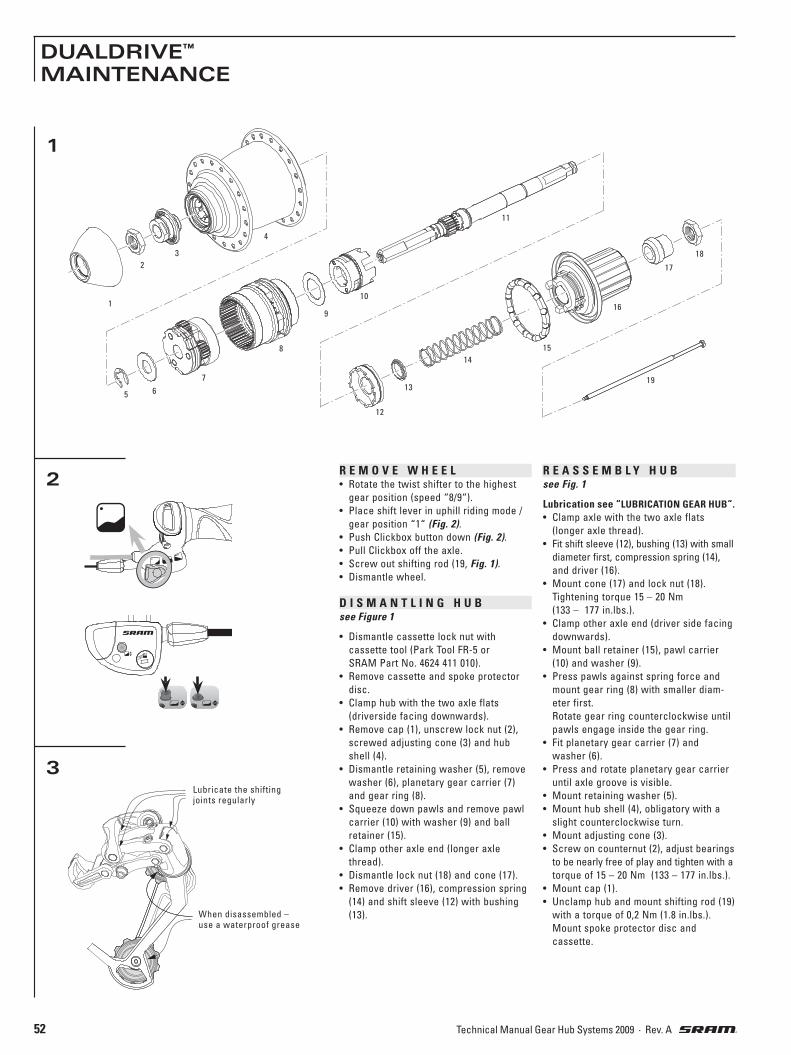
52 Technical Manual Gear Hub Systems 2009 · Rev. A
DUALDRIVE™
MAINTENANCE
1
2R E A S S E M B L Y H U Bsee Fig. 1
Lubrication see “LUBRICATION GEAR HUB“.• Clamp axle with the two axle flats
(longer axle thread).
• Fit shift sleeve (12), bushing (13) with small
diameter first, compression spring (14),
and driver (16).
• Mount cone (17) and lock nut (18).
Tightening torque 15 – 20 Nm
(133 – 177 in.lbs.).
• Clamp other axle end (driver side facing
downwards).
• Mount ball retainer (15), pawl carrier
(10) and washer (9).
• Press pawls against spring force and
mount gear ring (8) with smaller diam-
eter first.
Rotate gear ring counterclockwise until
pawls engage inside the gear ring.
• Fit planetary gear carrier (7) and
washer (6).
• Press and rotate planetary gear carrier
until axle groove is visible.
• Mount retaining washer (5).
• Mount hub shell (4), obligatory with a
slight counterclockwise turn.
• Mount adjusting cone (3).
• Screw on counternut (2), adjust bearings
to be nearly free of play and tighten with a
torque of 15 – 20 Nm (133 – 177 in.lbs.).
• Mount cap (1).
• Unclamp hub and mount shifting rod (19)
with a torque of 0,2 Nm (1.8 in.lbs.).
Mount spoke protector disc and
cassette.
R E M O V E W H E E L• Rotate the twist shifter to the highest
gear position (speed “8/9“).
• Place shift lever in uphill riding mode /
gear position “1“ (Fig. 2).• Push Clickbox button down (Fig. 2).• Pull Clickbox off the axle.
• Screw out shifting rod (19, Fig. 1).• Dismantle wheel.
D I S M A N T L I N G H U Bsee Figure 1
• Dismantle cassette lock nut with
cassette tool (Park Tool FR-5 or
SRAM Part No. 4624 411 010).
• Remove cassette and spoke protector
disc.
• Clamp hub with the two axle flats
(driverside facing downwards).
• Remove cap (1), unscrew lock nut (2),
screwed adjusting cone (3) and hub
shell (4).
• Dismantle retaining washer (5), remove
washer (6), planetary gear carrier (7)
and gear ring (8).
• Squeeze down pawls and remove pawl
carrier (10) with washer (9) and ball
retainer (15).
• Clamp other axle end (longer axle
thread).
• Dismantle lock nut (18) and cone (17).
• Remove driver (16), compression spring
(14) and shift sleeve (12) with bushing
(13).
3Lubricate the shifting joints regularly
When disassembled –use a waterproof grease
1
2
3
4
5 6
7
8
9
10
11
12
13
14
15
16
17
18
19

53Technical Manual Gear Hub Systems 2009 · Rev. A
DUALDRIVE™
MAINTENANCE
4
6
7
5
L U B R I C A T I O N G E A R H U BHubs are provided with permanent
lubrication and maintenance-free under
normal conditions.
Cleaning of parts:• All parts – except the planetary
gear carrier and the driver – can be
degreased in a cleaning bath.
• Planetary gear carrier and driver only
need to be cleaned on the outside with
a brush so as not to degrease the bear-
ings.
Lubrication of parts:Use only SRAM special grease, part no.
0369 135 200 / ... 201.
Lubricate ball retainers and ball tracks
only with SRAM Ball Bearing Grease. Part
no. 0369.001.015.
• To lubricate the bearing points on
the planetary gear sets, position the
planetary gear carrier pawls upside and
apply 2 – 3 drops of oil to the bearing
bolts – at the same time turning the
planetary gears so that the bearing
points are completely wet. Oil axle slot,
apply a thin coating of grease to the
outside.
• Grease the teeth of the axle (fill the
gaps).
• Apply grease to gear ring teeth but just
oil the pawls and pawl teeth.
• Oil pawl carrier pawls and pawl bear-
ings.
• Oil cartridge bearing.
• Regrease ball retainers, line ball bear-
ing running tracks with grease.
Caution:Do not use high-pressure water when cleaning the gear hub (e.g. strong water jets, high-pressure cleaners etc.) – if wa-ter penetrates it could lead to functional problems.
L U B R I C A T I O N R E A R D E R A I L L E U R• Do not use solvants or corrosive materi-
als to clean the components.
• Lubricate the shifting joints regularly
(Fig. 3).• Grease any cable guides (e.g. beneath
the bottom bracket).
C A B L E C H A N G EAdvice:Use only new high quality cable and compressionless cable housing with end caps.
Twist shifter (rear derailleur):• Detach the cable from the derailleur.
• Cut cable off 15 cm (6") from shifter bar-
rel adjuster. Discard old cable and cable
housing.
• Remove screw (1, Fig. 4) and pull open
the cable change sleeve (2).
• Rotate the shifter fully in the cable
release direction (gear position “8/9“).
• Look for cable head entry (3, Fig. 5).• Push cable up/out of the shifter and
discard.
• Feed the new cable through the cable
entry and out the barrel adjuster (4).
• Pull cable snug.
• Install cable change sleeve (2, Fig. 4).• Feed the cable through the new cable
housing and frame stops.
• Attach cable to the derailleur.
• Adjust indexing per derailleur instruction.
Thumb shift lever (gear hub):• Place thumb shift lever (5, Fig. 6) in
uphill riding mode / gear position “1“.
• Remove Clickbox from the axle (see page 52).
• Snap open Clickbox-cover (8, Fig. 7) as
shown.
• Unscrew clamping bolt (9).
• Remove the shifter escape hatch (6, Fig. 6).• Remove and discard the old cable.
• Feed the new cable through the cable
entry (7, Fig. 6), the new calbe housing
and pull the cable snug.
• Attach the escape hatch.
• Pull the cable tight and position it under
the cable anchor washer (10, Fig. 7).• Tighten the 4 mm hex cable anchor bolt
to 2.5 – 4 Nm (22 – 35 in.lbs.).
• Cut off cable end to 1 – 2 mm.
• Snap in Clickbox-cover (8).
• Install Clickbox (see page 50).• Place thumb shift lever in standard rid-
ing mode / gear position “2“.
• Match up the marks in the Clickbox
viewing window (11, Fig. 7) by turning
the barrel adjuster (12).
2
1
3
4
6
5
7
11 12
89
10
4 mm
2,5 – 4 Nm35 – 45 in.lbs.

54 Technical Manual Gear Hub Systems 2009 · Rev. A
DUALDRIVE™
MAINTENANCE
Problem
Hub: Shifting difficulties
Pedals are carried forward
when freewheeling
Derailleur: Chain jumps from smallest
sprocket to frame dropout.
Difficult or impossible to
shift chain onto smallest
sprocket.
Chain jumps over largest
sprocket and falls between
the spokes and largest
sprocket or inner cage
plate scrapes on spokes.
Delayed shifting.
Rough shifting behavior.
Shifts more gears onto small-
er sprockets as intented
Delayed shifting onto
larger sprocket
Delayed shifting onto
smaller sprocket
Cause
Incorrect gear setting
To much additional axle at-
tachments between hub and
axle nut on clickbox side.
Shifting rod is not screwed
completely into the axle.
Bearings set too tight
Loose lock nuts
Rear frame dropouts non
parallel
High gear limit screw is not
adjusted properly.
High gear limit screw is not
adjusted properly.
Low gear limit screw is not
adjusted properly.
Rear derailleur or derailleur
hanger is bent.
Clearance between guide
pulley / sprocket is too large.
Clearance between guide
pulley / sprocket is too small.
Shift cable insufficiently
tensioned.
Shift cable insufficiently
tensioned.
Shift cable is too tight.
Excessive cable friction,
pinched or poorly routed
cable.
Remedy
Adjust shifting system, oil
control cable, check that cable
stop is fastened correctly.
Reduce dimension of axle
attachments.
Screw in shifting rod com-
pletely and tighten it with a
torque of 0,2 Nm (1.8 in.lbs.).
Re-adjust bearing
Tighten lock nuts (15 – 20 Nm,
133 – 177 in.lbs.)
Bend / reorient dropouts
Turn in screw H until the
guide pulley is aligned with
the smallest sprocket.
Unscrew screw H until the
guide pulley is aligned with
the smallest sprocket.
Turn in screw L until the
guide pulley is aligned with
the largest sprocket.
Straighten or replace.
Adjust b-adjust screw by
rotating counterclockwise.
Adjust b-adjust screw by
rotating clockwise.
Turn barrel adjuster on the
shifter counterclockwise.
Turn barrel adjuster on the
shifter counterclockwise.
Turn barrel adjuster on the
shifter clockwise.
Lubricate or replace cable
and housing. Check for
excessive bending of cable
housing.
T R O U B L E S H O O T I N G

55Technical Manual Gear Hub Systems 2009 · Rev. A
DUALDRIVE™
MAINTENANCE

56 Technical Manual Gear Hub Systems 2009 · Rev. A

57Technical Manual Gear Hub Systems 2009 · Rev. A
SRAM S7 with coaster brake SRAM S7 without brake
Type MH 7215 MH 7205
Brake With coaster brake Without brake
Over Locknut Dim., OLD 130 mm 130 mm
Length, L 183.4 mm 183.4 mm
Ends Diameter, T FG 10.5 FG 10.5
Dropout Width Dim. A1 max. = 12.5 mm / A
2 max. = 12 mm A
1 max. = 12.5 mm / A
2 max. = 10 mm
Holes 36 36
Hole Diameter, DS 3.0 mm 3.0 mm
Hole Ref. ø, HR 75 mm 75 mm
Flange Dist. to 1/2 OLD F1 = 33 mm / F
2 = 34 mm F
1 = 33 mm / F
2 = 34 mm
Totally 303 %
Speed 1 0,574
Speed 2 0,677
Speed 3 0,809
Speed 4 1,000
Speed 5 1,236
Speed 6 1,476
Speed 7 1,742
Usable Dimensions 1/2" x 1/
8" or 1/
2" x 3/
32" 1/
2" x 1/
8" or 1/
2" x 3/
32"
Line, C/D/E C = 54 mm / D = 51 mm / E = 48 mm C = 54 mm / D = 51 mm / E = 48 mm
Ratio 24", 26", 28"= 1.83 – 1.90 / 20"= 1.83 – 2.00 min. 1.83
Sprocket 16 – 24 Teeth (outward offset - Chain Line C) / 18 Teeth (straight - CL D) / 19 – 24 Teeth (inward offset - CL E)
Shifter SRAM Grip 7
Clickbox Clickbox S7
Tandem Not suitable for tandems, transport bicycles or similar
Weight 1714 g 1556 g
Hub Shell Material Steel Steel
Finish Matt Chrome Plated or Black Matt Chrome Plated or Black
SRAM® S7TECHNICAL DATA / ASSEMBLY REQUIREMENTS
Caution: Not suitable for tandems, transport bicycles and similar.
Cycle frame:• Dropouts must be parallel.
• Slot width at rear dropout 10+0.5 mm.
• The strength must be such that with a
maxi mum braking torque of 250 Nm
(2200 in.lbs.) on the rear wheel no
residual deformation can occur on the
rear structure.
Com
patib
ility
Axl
eSp
oke
Gea
r Hub
Rat
ioCh
ain
Fini
sh
GEAR
HUBS
Gear steps
18 %
19 %
24 %
24 %
19 %
18 %
Version with Coaster Brake
R 100
Ø 7.3
HR
DS
A1 maxA
2 max
F2
F1
L
1/2 OLD
OLD
CD
E
7min. 13.5
83T
3.5

58 Technical Manual Gear Hub Systems 2009 · Rev. A
SRAM® S7TECHNICAL DATA / ASSEMBLY REQUIREMENTS
SRAM S7ASSEMBLY
SRAM Grip 7
Shifter Type Twist Shifter mit Clickbox
Cable Length Black housing: 1400 mm ❘ 1500 mm ❘ 1600 mm ❘ 1700 mm ❘ 1800 mm ❘ 1900 mm ❘ Grey housing: 1650 mm ❘ 1750 mm
Gear Indication Window
Clamping Diameter 22.1 – 22.3 mm
Straight handlebar ends Minimum necessary length for shifter and handlebar grip = 150 mm
Length of shifter 76 mm
Weight N/A
Housing Glass filled PA, black or grey
Grip PP
Grip Cover Thermoplastic elastomer, Overmolded
Clamping Collar Aluminum
Des
ign
SHIFTER
1
2
3
10
9
8 7
1 2
4 5
6
3
MontagewerkzeugArt.-Nr. 0582 104 000
Spoke lengths are approximate values. They must be checked through lacing attempts
and adjusted accordingly.
A S S E M B L Y H U B• Lace the wheel as normal. See spoke
length table.
• Place the dust cap (1, Fig. 1) and
sprocket (2) on the driver.
Advice: When fitting a straight sprocket (not an offset version), the beadings of the sprocket must lie against the dust cap.
• Push sprocket circlip (3, Fig. 2) onto the
cone of tool sleeve (4). Place tool sleeve
with large diameter on the driver.
• Push the spring end of sliding sleeve (5)
of the tool over the tool sleeve. Thrust
sliding sleeve in direction (6), this forces
circlip into the recess of the driver.
• Remove tool and check that the circlip
is seated correctly.
Tire Size Cross Length 47–406 20" x 1.75 x 2 3 x 181 mm
37–490 22" x 1 3/8 3 x 225 mm
47–507 24" x 1.75 x 2 3 x 232 mm
37–540 24" x 1 3/8 3 x 251 mm
47–559 26" x 1.75 x 2 3 x 259 mm
37–590 26" x 1 3/8 3 x 275 mm
47–622 28" x 1.75 3 x 289 mm
37–622 28" x 1 3/8 x 1 5/
8 3 x 289 mm
28–622 28" x 1 1/8 3 x 289 mm
32–622 28" x 1 5/8 x 1 1/
4 3 x 289 mm
28–630 27" x 1 1/4 fifty 3 x 294 mm
32–630 27" x 1 1/4 3 x 294 mm
Spoke length table
76
Ø 2
2.1
– 2
2.3
Ø 3
4.5
S H I F T E R

59Technical Manual Gear Hub Systems 2009 · Rev. A
SRAM® S7ASSEMBLY
• Turn dust cap (7, Fig. 3) until the three
lugs (8) are between the three beads (9)
on the sprocket (10).
• Position dust cap and push towards
sprocket until it is felt to lock into place.
• Placing the wheel in the rear frame.
• Fit new retaining washer (3,5 mm thick)
on left axle end (1, Fig. 4). The serrations must bear against the
dropout and the lug must engage in the
dropout slot.
• Fit the hoop guard (1, Fig. 5) on the right
axle side (drive side).
No additional washers or any acces-
sories are permitted.
Advice: If a different protective bracket is used the thickness of the attachment plate must be max. 3 mm. At least the beginning of the axle thread must be visible in front of the axle nut.
• Mount the axle nuts. Tightening torque
on axle nuts 30 – 40 Nm (266 – 350 in.lbs.)
• Version with coaster brake:
Mount the brake lever using a suitable
frame clamp (2, Fig. 4).Caution:Mount the brake lever between the two straps of the frame clamp.The clamp must be seated on the frame without play.Use a self-locking nut! Tightening torque: 2 – 3 Nm (18 – 27 in.lbs.).
Caution:Check that all the brake system components are functioning properly!
A S S E M B L Y S H I F T E RAdvice:• When choosing cable housing lengths,
be sure to allow enough housing for an extreme turn of the handlebars in both directions.
• Note also, that different stem lengths and handlebar positions effects cable housing length.
• Slide the shifter (1, Fig. 6) onto the
handlebar.
• Slide the handlebar grip (2) onto the
handlebar.
Caution: Never use lubricants or solvents when fitting handlebar grips. They have a safety function and must not come free from the handlebar.
• Place the shifter on the handlebar grip
and position so that you can use it com-
fortably. Tighten the clamping bolt (3). 3
mm Allen key, torque 3.5 – 4 Nm (31 – 35
in.lbs.).
Caution: • Check that shifter and brake lever
can be easily operated (if necessary, realign).
• Never ride without handlebar grips. The turning grip of the twist shifter could become loose. This can result in severe injuries.
• When fitting the cable avoid small radi-
us. Attach the cable 3 times to the down
tube (1, Fig. 7).• Last attachment point is on the lower
rear wheel fork (2, Fig. 7) immediately
behind the chain wheel.
Cable housing must be movable inside attachment.
I N S T A L L I N G C L I C K B O X• Insert shift rod (1, Fig. 8) in shift tube (2)
(oil parts lightly) and then push into axle
bore as far as the stop. Turn slot (6) in
shift tube to a position where it is easily
visible.
• Push locating sleeve (3) with guiding rib
(4) to the front onto the hub axle – mak-
ing sure that the internal lug (5) is guid-
ed in the slot (6) of the shift tube until it
can be felt – and heard – to engage.
• Turn locating sleeve on the axle until
the guiding rib (4) is facing roughly
upwards.
• Place shifter in gear position “1“.
• Push on Clickbox (2, Fig. 5) to the stop
on the hub axle. The guiding rib (4, Fig. 8) of the locating sleeve thereby engag-
es in the slot on the housing. In the end
position tighten up the knurled bolt (3, Fig. 5) by hand (0.3 Nm / 2.7 in.lbs.).
A D J U S T M E N T• Be sure to reset rotational shifter from
5th to 4th gear.
• Match up the marks in the Clickbox
viewing window (4, Fig. 6) by turning
the barrel adjuster (5).
Caution:Check that all the brake system components are functioning properly!
4
6
7
8
1
3 2
1
4
5
2
3
7
6 4
5
21 3
12
5
1
2

60 Technical Manual Gear Hub Systems 2009 · Rev. A
SRAM® S7MAINTENANCE
2
SRAM S7 mounting aidPart No. 65 0324 103 000
1
R E M O V E W H E E L• Place shifter in gear position “1“.
• Loosen the knurled screw (44, Fig. 1) and pull the Clickbox off the axle.
• Disengage the red location sleeve (43)
and pull it off.
• Remove shift rod (42) and shift tube (41)
out of the axle bore.
• Remove wheel.
D I S M A N T L I N G H U Bsee Fig. 1
• Remove circlip (39), sprocket (38) and
dust cap (37) as normal.
• Clamp hub by the axle between alu-
minum jaws with sprocket side facing
downwards.
• Unscrew both locknuts (1).
• While turning clockwise, remove lever
cone (2) with friction spring (3) and ball
retainer (4).
• Take out 3 brake segments (5).
• Withdraw hub sleeve (6) upwards.
• Remove brake cone (7).
• Take out retaining washer (8) and thrust
washer (9).
• Remove planetary gear carrier (10),
washer (11) compression spring (12) and
the three sun gears (13, 14, 15).
• Clamp other axle end.
• Unscrew fixed cone (36).
• Remove driver (35), compression spring
(33) with cover (32), large compression
spring (31), ball retainer (34), gear ring (30)
and coupling gear (29).
• Compress spring (26) and remove thrust
block (28).
• Remove cover (27), spring (26) and
cover (25).
• Dismantle retaining washer (24).
• Remove thrust washer (23) and plastic
profile washer (22).
• Unscrew grub screw (17) (Caution: It
is subject to spring pressure) – and
dismantle the long compression spring
(18) guide pin (19), thrust block (20) and
the short compression spring (21).
1
2
34
5
6
7
89
16
17
18
21
22
2324
25
26
15
1213
14
10
11
3132
33
42 43
40
41
39
38
3736
35
34
27
28
29
30
1920
X
44
3

61Technical Manual Gear Hub Systems 2009 · Rev. A
SRAM® S7MAINTENANCE
R E A S S E M B L Y H U Bsee Fig. 1
Lubrication see “MAINTENANCE / LUBRICATION“.• Insert into the axle (on the side with the
internal thread):
Short compression spring (21), thrust
block (20) – it is the same both sides, guide
rod (19) – it is the same both sides, long
compression spring (18).
• Compress spring and fit grub screw (17).
• Clamp axle, end with groove for
Clickbox facing upwards.
• Fit plastic profile washer (22) with its
large diameter upwards.
• Fit thrust washer (23) and retaining
washer (24).
• Locate cover (25), compression spring (26)
with 7 turns and cover (27, insides to the
spring).
• Compress spring and position thrust
block (28) – it is the same both sides
– centrally in the axle.
• Clamp other axle end (groove is facing
downwards).
• Fit large sun gear (15), with deflector
bevels upwards.
• Position medium sun gear (14), with
deflector bevels upwards.
• Fit small sun gear (13) – with recesses in
front, thrust block engages in the slots.
• Position smallest compression spring (12).
• Fit 1 mm thick washer (11).
• Fit planetary gear carrier (10):
Place the mounting aid(Fig. 2) on the
planetary gear carrier such that the
markings (X) on the 3 small planet gears
and the mounting aid match up.
• Turn planetary gear carrier and at the
same time push it downwards over the
sun gears.
• Fit thrust washer (9) and retaining
washer (8) in the undercut.
Now remove the mounting aid.
Advice:If the gears are not accurately assembled the hub may feel tight in use. This may lead to gear wheel damage during travel.
• Clamp other axle end (groove for
Clickbox facing upwards).
• Fit coupling gear (29) with carrier plate
downwards
• Push ring gear (30) over the coupling
gear.
• Locate large spring (31).
• Fit largest ball retainer (34) with balls
underneath.
• Fit cover (32, inside to the spring).
• Assemble the compression spring (33)
with 12 turns.
• Position driver (35) – push it down – and
screw on fixed cone (36) to the stop,
tightening torque 20 Nm (177 in.lbs.).
• Clamp other axle end (groove for
Clickbox is facing downwards).
• Assemble hub shell (6) with a slight
counter-clockwise movement.
In case the hub shell jams, position the
plastic ring (Fig. 3) correctly. The plastic
ring is only fitted to some hub versions.
• Screw brake cone (7) clockwise onto
the planetary gear carrier (10) until it
stops.
• Insert 3 brake segments (5).
• Turn in friction spring (3) counterclock-
wise into the lever cone (2) (inlying
winding of the spring has to lie against
the lever cone) (Fig. 4). • Insert ball retainer (4) (balls are facing
upwards) into lever cone (2): the 3 re-
cesses have to engage into the retaining
lugs of the lever cone. Slightly turn ball
retainer to prevent it from falling off.
• Fit lever cone onto hub shell: the
retaining lugs of the lever cone have to
engage into the openings between the
brake segments. Make sure that lever
cone engages while turning it back and
forth slightly.
• Screw on locknuts (1), adjust bearing
so that there is no play and lock nuts
together with 15 – 20 Nm (133 – 177in.lbs.).
Caution:Check that all the brake system components are functioning properly!
Advice:Dismantling and reassembly of hub ver-sion without brake should be carried out in the same way. Differences: Instead of brake segments / cone a click-and-pawl carrier is installed on the planetary gear carrier.
4

62 Technical Manual Gear Hub Systems 2009 · Rev. A
SRAM® S7MAINTENANCE
C H A N G I N G T H E S H I F T C A B L E Advice:Always use new, high-quality cables and compressionless cable housings with end caps.
• Turn the twist shifter to 1st gear.
Advice:Do not remove the Clickbox from the axle end.
• Unscrew the barrel adjuster (1, Fig. 5) completely. Unscrew the cover screw
(2), brush aside the barrel adjuster (1)
and remove the cover (3).
• Withdraw the shifter cable and clamping
bolt (1, Fig. 6) upwards, loosen the clamp
screw with a 2.5 mm Allen key and pull
the clamping piece from the cable.
• Remove and discard the old cable hou-
sing.
• Remove the cap (1, Fig. 7) from the
shifter. The nipple of the inner cable is
now visible.
• Push or pull the old inner cable (Fig. 7) out of the shifter, e.g. using a small
screwdriver.
• Guide the new inner cable into the cable
inlet, through the shifter and the new
cable housing. Pull the cable tight.
• Insert the cap in the shifter.
• Position clamping bolt (1, Fig. 8) at a
distance of 90 mm.
Advice:For positioning the clamping bolt use adjust gauge (Fig. 9) (Part. No. 65 0324 107 000).Tighten the clamping screw with a 2.5 mm
Allen key. Tightening torque 1.5 Nm (13
in.lbs.).
Cut off the cable end to 2 – 3 mm.
• Locate clamping bolt (1, Fig. 6) and
place shifter cable around the carrier
cylinder (counter-clockwise winding).
• Position the cover (3, Fig. 5) and tighten
up with the cover screw (2).
Torque 0.35 – 0.45 Nm (3.1 – 4.0 in.lbs.).
Screw in the barrel adjuster (1) com-
pletely.
Advice:• If you want to remove the Clickbox from
the axle end for changing the cable, do as follows:
– Place shifter in gear position “1“. – Loosen the knurled screw and pull
the Clickbox off the axle. – Now it’s essential to push the end (1,
Fig. 9) of the adjust gauge completely into the Clickbox and tighten up the knurled bolt (so that you maintain the initial tension of the spring inside the Clickbox).
– Change cable as per description above.• If you remove the Clickbox from the
axle and change the cable without using the end of the adjust gauge, then you will lose the initial tension of the spring inside the Clickbox. In this case you must assemble the cable by placing it around the carrier cylinder with an additional winding (Fig. 6).
• Adjust the gears as described on
page 59.
5
6
7
8
9
23
1
2
1
1
2 +1 mm 90±0,5 mm
1
1

63Technical Manual Gear Hub Systems 2009 · Rev. A
SRAM® S7MAINTENANCE
M A I N T E N A N C E / L U B R I C A T I O NCaution:The SARM hubs are provided with permanent lubrication and are mainte -nance-free under normal conditions. If the coaster brake is loaded excessively its effect can be too strong, the hub may lock. In such a case the 3 brake segments must be lubricated only with SRAM spe-cial grease (Part No. 0369 135 200/ ...201). Renew brake segments when rhombic pattern is worn out.
Cleaning of parts:• All parts – except for the planetary gear
carrier – can be degreased in a clean-
ing bath.
• The planetary gear carrier only needs to
be cleaned on the outside with a brush
so as not to degrease the planetary
gear bearing.
Caution:Do not use high-pressure water when cleaning the gear hub (e.g. strong water jets, high-pressure cleaners etc.) – if wa-ter penetrates it could lead to functional problems.
Lubrication of parts:Use only SRAM special grease, part no.
0369 135 200 / ... 201.
Lubricate ball retainers and ball tracks
only with SRAM Ball Bearing Grease. Part
no. 0369.001.015.
• To lubricate the bearing points on the
plan etary gear sets, position the plan-
etary gear carrier on its crown and ap-
ply 2 – 3 drops of oil to the bearing bolts
– at the same time turning the planetary
gears so that the bear ing points are
completely wet. Oil axle through the
axle bore and axle slot, apply a thin
coating of grease to the outside.
• Oil the inside of the sun gears, grease
the outside teeth (fill the gaps in the
teeth).
• Oil outside teeth and carrier plate on
the coupling gear and lightly grease the
borehole from right and left.
• Do not apply grease to ring gear but just
oil the pawl pockets.
• Slightly grease the actuation ramps of
the planetary gear carrier.
• Apply grease all around the seat area of
the friction spring. Oil the pawl pockets.
• Spread grease on the complete sur-
faces inside and outside of the 3 brake
segments.
• Regrease ball retainer and insert into
lever cone, slightly grease cone surface
of the lever cone.
• Line ball bearing running tracks and
brake cylinder in hub shell with grease.
Problem
Shifting
difficulties
Pedals are
carried
forward
when free-
wheeling
Hub locks
when
braking
(coaster
brake)
Coaster
brake
without
function
CauseDamaged
control cable
Incorrect
gear setting
To much ad-
ditional axle
attachments
between hub
and axle nut
Bearings
set too tight
Loose
lock nuts
Chain is over-
tensioned
Brake seg-
ments has
run dry
Incorrect
mounted fric-
tion spring (3,
Fig. 1 / Page 60)
RemedyReplace
control cable
Adjust shift.
system
Beginning of
axle thread
must be visib-
le in front of
the axle nut
Re-adjust
bearings
Tighten
lock nuts
(15 – 20 Nm)
Reduce
chain tension
Wash out
hub sleeve,
repolish and
relubricate
brake cylinder,
renew brake
segments
Fit friction
spring in
correct way
T R O U B L E S H O O T I N G

64 Technical Manual Gear Hub Systems 2009 · Rev. A

65Technical Manual Gear Hub Systems 2009 · Rev. A
SRAM® P5TECHNICAL DATA / ASSEMBLY REQUIREMENTS
SRAM P5 with coaster brake SRAM P5 without brake
Type MH 5215 MH 5205
Brake With coaster brake Without brake
Over Locknut Dim., OLD 122 mm 122 mm
Length, L 175 mm 175 mm
Ends Diameter, T FG 10.5 ❘ FG 10.5 toothed cone FG 10.5
Dropout Width Dim. A1 max. = 12.5 mm / A
2 max. = 11.5 mm A
1 max. = 12.5 mm / A
2 max. = 10.5 mm
Holes 36 36
Hole Diameter, DS 3,0 mm 3,0 mm
Hole Ref. ø, HR 75 mm 75 mm
Flange Dist. to 1/2 OLD F1 = 28.5 mm / F
2 = 29.5 mm F
1 = 29 mm / F
2 = 29 mm
Totally 251 %
Speed 1 0,633
Speed 2 0,781
Speed 3 1,000
Speed 4 1,281
Speed 5 1,579
Usable Dimensions 1/2" x 1/
8" or 1/
2" x 3/
32" 1/
2" x 1/
8" or 1/
2" x 3/
32"
Line, C/D/E C = 49 mm / D = 45.5 / E = 43 mm C = 49 mm / D = 45.5 mm / E = 43 mm
Ratio 24", 26", 28"= 1.8 – 1.9 / 20"= 1.8 – 2.0 min. 1.8
Sprocket 16 – 24 Teeth (outward offset - Chain Line C) / 16 – 18 Teeth (straight - Chain Line D) / 18 – 24 Teeth (inward offset - Chain Line E)
Shifter SRAM Grip 5
Clickbox Clickbox P5
Tandem Not suitable for tandems, transport bicycles or similar
Weight 1495 g 1330 g
Hub Shell Material Steel Steel
Finish Matt Chrome Plated Matt Chrome Plated
Version SRAM P5 Cargo:see page 73.
Caution: Not suitable for tandems, transport bicycles and similar.
Cycle frame:• Dropouts must be parallel.
• Slot width at rear dropout 10+0.5 mm.
• The strength must be such that with
a maxi mum braking torque of 250 Nm
(2200 in.lbs.) on the rear wheel no
residual deformation can occur on the
rear structure.
GEAR
HUBS
Com
patib
ility
Axl
eSp
oke
Gea
r Hub
Rat
ioCh
ain
Fini
sh
Gear steps
23 %
28 %
28 %
23 %
Version with coaster brake
R 100
Ø 7.3
HR
DS
A1 maxA
2 max
F2
F1
L
1/2 OLD
OLD
CD
E
7min. 13.5
83
T
3.5

66 Technical Manual Gear Hub Systems 2009 · Rev. A
SRAM® P5TECHNICAL DATA / ASSEMBLY REQUIREMENTS
SRAM P5ASSEMBLY
Spoke lengths are approximate values. They must be checked through lacing attempts
and adjusted accordingly.
A S S E M B L Y H U B• Lace the wheel as normal. See spoke
length table.
• Place the dust cap (1, Fig. 1) and
sprocket (2) on the driver.
Advice: When fitting a straight sprocket (not an offset version), the beadings of the sprocket must lie against the dust cap.
• Push sprocket circlip (3, Fig. 2) onto
the cone of tool sleeve (4). Pvlace tool
sleeve with large diameter on the driver.
• Push the spring end of sliding sleeve (5)
of the tool over the tool sleeve. Thrust
sliding sleeve in direction (6), this forces
circlip into the recess of the driver.
• Remove tool and check that the circlip
is seated correctly.
1
2
3
10
9
8 7
1 2
4 5
6
3
Mounting ToolPart No. 0582 104 000
SRAM Grip 5
Shifter Type Twist Shifter mit Clickbox
Cable Length 1500 mm ❘ 1600 mm ❘ 1700 mm ❘ 1800 mm ❘ 1900 mm
Gear Indication Window
Clamping Diameter 22.1 – 22.3 mm
Straight handlebar ends Minimum necessary length for shifter and handlebar grip = 150 mm
Length of shifter 76 mm
Weight N/A
Housing Glass filled PA
Grip PP
Grip Cover Thermoplastic elastomer, Overmolded
Clamping Collar Aluminum
Des
ign
SHIFTER
Tire Size Cross Length 47–406 20" x 1.75 x 2 3 x 181 mm
37–490 22" x 1 3/8 3 x 225 mm
47–507 24" x 1.75 x 2 3 x 232 mm
37–540 24" x 1 3/8 3 x 251 mm
47–559 26" x 1.75 x 2 3 x 259 mm
37–590 26" x 1 3/8 3 x 275 mm
47–622 28" x 1.75 3 x 289 mm
37–622 28" x 1 3/8 x 1 5/
8 3 x 289 mm
28–622 28" x 1 1/8 3 x 289 mm
32–622 28" x 1 5/8 x 1 1/
4 3 x 289 mm
28–630 27" x 1 1/4 fifty 3 x 294 mm
32–630 27" x 1 1/4 3 x 294 mm
Spoke length table:
76
Ø 2
2.1
– 2
2.3
Ø 3
4.5
S H I F T E R

67Technical Manual Gear Hub Systems 2009 · Rev. A
SRAM® P5ASSEMBLY
• Turn dust cap (7, Fig. 3) until the three
lugs (8) are between the three beads (9)
on the sprocket (10).
• Position dust cap and push towards
sprocket until it is felt to lock into place.
• Placing the wheel in the rear frame.
• Fit new retaining washer (3,5 mm thick)
on left axle end (1, Fig. 4). The serrations
must bear against the dropout and the
lug must engage in the dropout slot.
• On the sprocket side fit the protective
bracket (1, Fig. 5) directly below the
axle nut. Tightening torque on axle nuts
30 – 40 Nm (266 – 350 in.lbs.).
• Mount the brake lever using a suitable
frame clamp (2, Fig. 4).Caution:Mount the brake lever between the two straps of the frame clamp.The clamp must be seated on the frame without play.Use a self-locking nut! Tightening torque: 2 – 3 Nm (18 – 27 in.lbs.).
Advice:• If a different protective bracket (1, Fig. 5)
is used the thickness of the attachment plate must be max. 3 mm.
• Do not use additional washers. • At least the beginning of the axle thread
must be visible in front of the axle nut.
Caution:Check that all the brake system components are functioning properly!
A S S E M B L Y S H I F T E RAdvice:• When choosing cable housing lengths,
be sure to allow enough housing for an extreme turn of the handlebars in both directions.
• Note also, that different stem lengths and handlebar positions effects cable housing length.
• Slide the shifter (1, Fig. 6) onto the
handlebar.
• Slide the handlebar grip (2) onto the
handlebar.
Caution: Never use lubricants or solvents when fitting handlebar grips. They have a safety function and must not come free from the handlebar.
• Place the shifter on the handlebar grip and
position so that you can use it comfortably.
Tighten the clamping bolt (3). 3 mm Allen
key, torque 3.5 – 4 Nm (31 – 35 in.lbs.).
Caution: • Check that shifter and brake lever can be
easily operated (if necessary, realign).• Never ride without handlebar grips. The
turning grip of the twist shifter could become loose. This can result in severe injuries.
• When fitting the cable avoid small radius.
Attach the cable 3 times to the down
tube (1, Fig. 7).• Last attachment point is on the lower
rear wheel fork (2, Fig. 7) immediately
behind the chain wheel.
Cable housing must be movable inside attachment.
I N S T A L L I N G C L I C K B O X• Insert shift rod (1, Fig. 8) in shift tube (2)
(oil parts lightly) and then push into axle
bore as far as the stop. Turn slot (6) in
shift tube to a position where it is easily
visible.
• Push locating sleeve (3) with guiding rib
(4) to the front onto the hub axle – mak-
ing sure that the internal lug (5) is guid-
ed in the slot (6) of the shift tube until it
can be felt – and heard – to engage.
• Turn locating sleeve on the axle until
the guiding rib (4) is facing roughly
upwards.
• Place shifter in gear position “2“.
• Push on Clickbox (2, Fig. 5) to the stop
on the hub axle. The guiding rib (4, Fig. 8) of the locating sleeve thereby engages
in the slot on the housing. In the end posi-
tion tighten up the knurled bolt (3, Fig. 5) by hand (0.3 Nm / 2.7 in.lbs.).
A D J U S T M E N T• Be sure to reset rotational shifter from
4th to 3th gear.
• Match up the marks in the Clickbox
viewing window (4, Fig. 6) by turning
the barrel adjuster (5).
Caution:Check that all the brake system components are functioning properly!
4
6
7
8
1
3 2
1
4
5
2
3
7
6 4
5
21 3
12
5
1
2

68 Technical Manual Gear Hub Systems 2009 · Rev. A
SRAM® P5MAINTENANCE
1
R E M O V E W H E E L• Place shifter in gear position “2“.
• Loosen the knurled screw (41, Fig. 1) and pull the Clickbox off the axle.
• Disengage the red location sleeve (40)
and pull it off.
• Remove shift rod (39) and shift tube (38)
out of the axle bore.
• Remove wheel.
D I S M A N T L I N G H U Bsee Fig. 1
• Remove circlip (36), sprocket (35) and
dust cap (34).
• Clamp hub with sprocket side facing
downwards with the two axle flats.
• Unscrew both locknuts (1).
• While turning clockwise, remove lever
cone (2) with friction spring (3) and ball
retainer (4).
• Take out 3 brake segments (5).
• Withdraw hub sleeve (6) upwards.
• Remove brake cone (7).
• Remove retaining washer (8), thrust
washer (9).
• Remove planetary gear carrier (10) and
thrust washer (11).
• Clamp other axle end.
• Unscrew fixed cone (33).
• Remove driver (32), compression spring
(30), large compression spring (28) and ball
retainer (31).
• Withdraw gear ring (27) and coupling
gear (26) and then remove cover (29)
from the coupling gear.
• Take out thrust block (25), (to do this
compress the spring). Remove spring
(23) and the two covers (24/22).
• Dismantle retaining washer (21), washer
(20), conical compression spring (19),
and the large sun gear (13). Clamp other
axle end (thrust block visible).
• Unscrew grub screw (15) – Dismantle
spring (16), guide bolt (17) and thrust
block (18).
• Remove small sun sun gear (12).
1
2
34
5
6
7
89
14
15
16
18
1920
2122
23
13
10
1112
2829
30
40
39
38
37
35
36
3433
32
31
24
25
26
27
17
X
2
3
SRAM P5 mounting aidPart No. 65 0524 300 000
41

69Technical Manual Gear Hub Systems 2009 · Rev. A
SRAM® P5MAINTENANCE
R E A S S E M B L Y H U Bsee Fig. 1
Lubrication see “MAINTENANCE / LUBRICATION“.• Clamp axle with internal thread up-
wards.
• Position small sun gear (12) with crown
gears to the front.
• Position thrust block (18) in the slotted
hole (is laterally guided when the sun
gear is screwed in).
• Locate bolt (17), then spring (16) in the
axle and screw in grub screw (15) until
it is flush with the axle.
• Reclamp axle. Fit large sun gear (13)
(it is the same both sides). Position
conical compression spring (19), with
the large diameter first. Press spring
together and fit washer (20) and retain-
ing washer (21).
• Assemble cover (22), compression
spring with 7 turns (23) and the second
cover (24, insides to the spring).
• Compress spring and position thrust
block (25) (it is the same both sides) in
the center of the slotted hole.
• Position coupling gear (26) with carrier
plate facing downwards.
• Fit cover (29, inside to the spring) for
compression spring.
• Position gear ring (27) over the teeth of
the coupling gear.
• Place ball retainer (31), with balls below
on the gear ring.
• Position large compression spring (28)
on gear ring.
• Mount compression spring with 13 turns
(30) on the axle. (Is supported in the
coupling wheel by the cover).
• Locate driver (32), press it down and
screw on fixed cone (33) as far as the
stop. Tightening torque 20 Nm.
• Clamp other axle end.
• Push on thrust washer (11) and fit
planetary gear carrier (10). In doing this:
Position mounting aid (Fig. 2) on the
planetary gear carrier so that the (X)
markings on the three planetary gears
match with the mounting aid.
• Insert planetary gear carrier, place
thrust washer (8) on it and mount retain-
ing washer (9) in recess.
Now remove the mounting aid.
Advice:If the gears are not accurately installed the hub may be tight to move. This could lead to damage to the gear-wheels in operation.
• Assemble hub shell (6) with a slight
counter-clockwise movement.
In case the hub shell jams, position the
plastic ring (Fig. 3) correctly. The plastic
ring is only fitted to some hub versions.
• Screw brake cone (7) clockwise onto
the planetary gear carrier (10) until it
stops.
• Insert 3 brake segments (5).
• Turn in friction spring (3) counterclock-
wise into the lever cone (2) (inlying
winding of the spring has to lie against
the lever cone) (Fig. 4). • Insert ball retainer (4) (balls are facing
upwards) into lever cone (2): the 3 re-
cesses have to engage into the retaining
lugs of the lever cone. Slightly turn ball
retainer to prevent it from falling off.
• Fit lever cone onto hub shell: the
retaining lugs of the lever cone have to
engage into the openings between the
brake segments. Make sure that lever
cone engages while turning back and
forth slightly.
• Screw on locknuts (1), adjust bearing
so that there is no play and lock nuts
together with 15 – 20 Nm (133 – 177in.
lbs.).
Caution:Check that all the brake system components are functioning properly!
Advice:Dismantling and reassembly of hub ver-sion without brake should be carried out in the same way. Differences: Instead of brake segments / cone a click-and-pawl carrier is installed on the planetary gear carrier.
4

70 Technical Manual Gear Hub Systems 2009 · Rev. A
SRAM® P5MAINTENANCE
C H A N G I N G T H E S H I F T C A B L E Advice:Always use new, high-quality cables and compressionless cable housings with end caps.
• Turn the twist shifter to 1st gear.
Advice:Do not remove the Clickbox from the axle end.
• Unscrew the barrel adjuster (1, Fig. 5) completely. Unscrew the cover screw
(2), brush aside the barrel adjuster (1)
and remove the cover (3).
• Withdraw the shifter cable and clamping
bolt (1, Fig. 6) upwards, loosen the clamp
screw with a 2.5 mm Allen key and pull
the clamping piece from the cable.
• Remove and discard the old cable hou-
sing.
• Remove the cap (1, Fig. 7) from the
shifter. The nipple of the inner cable is
now visible.
• Push or pull the old inner cable (Fig. 7) out of the shifter, e.g. using a small
screwdriver.
• Guide the new inner cable into the cable
inlet, through the shifter and the new
cable housing. Pull the cable tight.
• Insert the cap in the shifter.
• Position clamping bolt (1, Fig. 8) at a
distance of 80 mm.
Advice:For positioning the clamping bolt use adjust gauge (Fig. 9) (Part. No. 65 0324 107 000).Tighten the clamping screw with a 2.5 mm
Allen key. Tightening torque 1.5 Nm (13
in.lbs.).
Cut off the cable end to 2 – 3 mm.
• Locate clamping bolt (1, Fig. 6) and
place shifter cable around the carrier
cylinder (counter-clockwise winding).
• Position the cover (3, Fig. 5) and tighten
up with the cover screw (2).
Torque 0.35 – 0.45 Nm (3.1 – 4.0 in.lbs.).
Screw in the barrel adjuster (1) com-
pletely.
Advice:• If you want to remove the Clickbox from
the axle end for changing the cable, do as follows:
– Place shifter in gear position “1“. – Loosen the knurled screw and pull
the Clickbox off the axle. – Now it’s essential to push the end (1,
Fig. 9) of the adjust gauge completely into the Clickbox and tighten up the knurled bolt (so that you maintain the initial tension of the spring inside the Clickbox).
– Change cable as per description above.• If you remove the Clickbox from the
axle and change the cable without using the end of the adjust gauge, then you will lose the initial tension of the spring inside the Clickbox. In this case you must assemble the cable by placing it around the carrier cylinder with an additional winding (Fig. 6).
• Adjust the gears as described on
page 67.
5
6
7
8
9
23
1
2
1
1
2 +1 mm 80±0,5 mm
1
1

71Technical Manual Gear Hub Systems 2009 · Rev. A
SRAM® P5MAINTENANCE
M A I N T E N A N C E / L U B R I C A T I O NCaution:The SARM hubs are provided with permanent lubrication and are mainte -nance-free under normal conditions. If the coaster brake is loaded excessively its effect can be too strong, the hub may lock. In such a case the 3 brake segments must be lubricated only with SRAM spe-cial grease (Part No. 0369 135 200/ ...201). Renew brake segments when rhombic pattern is worn out.
Cleaning of parts:• All parts – except for the planetary gear
carrier – can be degreased in a clean-
ing bath.
• The planetary gear carrier only needs to
be cleaned on the outside with a brush
so as not to degrease the planetary
gear bearing.
Caution:Do not use high-pressure water when cleaning the gear hub (e.g. strong water jets, high-pressure cleaners etc.) – if wa-ter penetrates it could lead to functional problems.
Lubrication of parts:Use only SRAM special grease, part no.
0369 135 200 / ... 201.
Lubricate ball retainers and ball tracks
only with SRAM Ball Bearing Grease. Part
no. 0369.001.015.
• To lubricate the bearing points on the
planetary gear sets, position the plan-
etary gear carrier on its crown and ap-
ply 2 – 3 drops of oil to the bearing bolts
– at the same time turning the planetary
gears so that the bearing points are
completely wet. Oil axle through the
axle bore and axle slot, apply a thin
coating of grease to the outside.
• Oil the inside of the sun gears, grease
the outside teeth (fill the gaps in the
teeth).
• Oil outside teeth and carrier plate on
the coupling gear and lightly grease the
borehole from right and left.
• Do not apply grease to ring gear but just
oil the pawl pockets.
• Slightly grease the actuation ramps of
the planetary gear carrier.
• Apply grease all around the seat area of
the friction spring. Oil the pawl pockets.
• Spread grease on the complete sur-
faces inside and outside of the 3 brake
segments.
• Regrease ball retainer and insert into
lever cone, slightly grease cone surface
of the lever cone.
• Line ball bearing running tracks and
brake cylinder in hub shell with grease.
Problem
Shifting
difficulties
Pedals are
carried
forward
when free-
wheeling
Hub locks
when
braking
(coaster
brake)
Coaster
brake
without
function
CauseDamaged
control cable
Incorrect
gear setting
To much ad-
ditional axle
attachments
between hub
and axle nut
Bearings
set too tight
Loose
lock nuts
Chain is over-
tensioned
Brake seg-
ments has
run dry
Incorrect
mounted fric-
tion spring (3,
Fig. 1 / Page 68)
RemedyReplace
control cable
Adjust shift.
system
Beginning of
axle thread
must be visib-
le in front of
the axle nut
Re-adjust
bearings
Tighten
lock nuts
(15 – 20 Nm)
Reduce
chain tension
Wash out
hub sleeve,
repolish and
relubricate
brake cylinder,
renew brake
segments
Fit friction
spring in
correct way
T R O U B L E S H O O T I N G

72 Technical Manual Gear Hub Systems 2009 · Rev. A

73Technical Manual Gear Hub Systems 2009 · Rev. A
SRAM P5 Cargo with coaster brake SRAM P5 Cargo with drum brake SRAM P5 Cargo disc brake compatible
Typ MH 5215 Cargo MH 5225 Cargo –
Brake With coaster brake With drum brake – Version „D“ Adaptor for disc brake
Over Locknut Dim., OLD 122 mm 126 mm 125 mm
Length, L 175 mm 179 mm 179 mm
Ends Diameter, T FG 10.5 toothed cone FG 10.5 FG 10.5
Dropout Width Dim. A1 max. = 12.5 mm / A
2 max. = 11.5 mm A
1 max. = 12.5 mm / A
2 max. = 12.5 mm A
1 max. = 12.5 mm / A
2 max. = 11.5 mm
Holes 36 36 36
Hole Diameter, DS 3.0 mm 2.9 mm 3,0 mm
Hole Ref. ø, HR 75 mm 89 mm 75 mm
Flange Dist. to 1/2 OLD F1 = 28.5 mm / F
2 = 29.5 mm F
1 = 30.5 mm / F
2 = 29.5 mm F
1 = 28.5 mm / F
2 = 29.5 mm
Totally 224 %
Speed 1 0,667
Speed 2 0,778
Speed 3 1,000
Speed 4 1,286
Speed 5 1,500
Usable Dimensions 1/2" x 1/
8" or 1/
2" x 3/
32" 1/
2" x 1/
8" or 1/
2" x 3/
32" 1/
2" x 1/
8" or 1/
2" x 3/
32"
Line, C/D/E C = 49 mm / D = 45.5 mm / E = 43 mm C = 51.5 mm / D = 48.5 mm / E = 45.5 mm C = 50 mm / D = 47 mm / E = 44 mm
Ratio 24", 26", 28"= 1.8 – 1.9 / 20"= 1.8 – 2.0 min. 1.8 min. 1.8
Sprocket 16 – 24 Teeth (outward offset - Chain Line C) / 16 – 18 Teeth (straight - Chain Line D) / 18 – 24 Teeth (inward offset - Chain Line E)
Shifter SRAM Grip 5
Clickbox Clickbox P5
Scheibenbremse — — 6 holes
Hand Brake Lever — see page 75 Disc brake compatible
Tandem Suitable for tandems, transport bicycles or similar
Weight 1495 g 1536 g 1390 g
Hub Shell Material Steel Aluminum Steel
Finish Matt Chrome Plated Clear Coat Matt Chrome Plated
SRAM® P5 CARGOTECHNICAL DATA / ASSEMBLY REQUIREMENTS CARGOCARGO
Caution: The SRAM P5 Cargo is suitable for tan-dems, transport bicycles and similar.An additional external rear brake is necessary due to the high load.
Tolerable stress:Axle load: max. 120 kilograms
Torque/driver body: max. 85 Nm (750 in.lbs.),
no continuous stress.
Identification SRAM P5 Cargo:Yellow grub screw inside the axle end.
Version SRAM P5 for normal bikes:see page 65.
Cycle frame:• Dropouts must be parallel.
• Slot width at rear dropout 10+0.5 mm.
• The strength must be such that with a maxi mum braking torque of 250 Nm (2200 in.lbs.) on the rear wheel no
residual deformation can occur on the rear structure.
GEAR
HUBS
Com
patib
ility
Axl
eSp
oke
Gea
r Hub
Rat
ioCh
ain
Fini
sh
Gear steps
17 %
29 %
29 %
17 %
Version with coaster brake
R 100
Ø 7.3
HR
DS
A1 maxA
2 max
F2
F1
L
1/2 OLD
OLD
CD
E
7min. 13.5
83
T
3.5

74 Technical Manual Gear Hub Systems 2009 · Rev. A
SRAM® P5 CARGOTECHNICAL DATA / ASSEMBLY REQUIREMENTS
Spoke lengths are approximate values. They must be checked through lacing attempts
and adjusted accordingly.
Tire Size Cross Length MH 5215 Length MH 5225 47–406 20" x 1.75 x 2 3 x 181 mm 179 mm
37–490 22" x 1 3/8 3 x 225 mm 222 mm
47–507 24" x 1.75 x 2 3 x 232 mm 229 mm
37–540 24" x 1 3/8 3 x 251 mm 248 mm
47–559 26" x 1.75 x 2 3 x 259 mm 256 mm
37–590 26" x 1 3/8 3 x 275 mm 272 mm
47–622 28" x 1.75 3 x 289 mm 286 mm
37–622 28" x 1 3/8 x 1 5/
8 3 x 289 mm 286 mm
28–622 28" x 1 1/8 3 x 289 mm 286 mm
32–622 28" x 1 5/8 x 1 1/
4 3 x 289 mm 286 mm
28–630 27" x 1 1/4 fifty 3 x 294 mm 291 mm
32–630 27" x 1 1/4 3 x 294 mm 291 mm
Spoke length table:
A S S E M B L Y H U B• Lace the wheel as normal. See spoke
length table.
• Place the dust cap (1, Fig. 1) and
sprocket (2) on the driver.
Advice: When fitting a straight sprocket (not an offset version), the beadings of the sprocket must lie against the dust cap.
• Push sprocket circlip (3, Fig. 2) onto the
cone of tool sleeve (4). Place tool sleeve
with large diameter on the driver.
• Push the spring end of sliding sleeve (5)
of the tool over the tool sleeve. Thrust
sliding sleeve in direction (6), this forces
circlip into the recess of the driver.
• Remove tool and check that the circlip
is seated correctly.
• Turn dust cap (7, Fig. 3) until the three
lugs (8) are between the three beads (9)
on the sprocket (10).
• Position dust cap and push towards
sprocket until it is felt to lock into place.
• Hub versions for Disc Brake:
Advice: Read and observe the corresponding technical documentation for assemb-ling the disc of the disc brake.Caution: Plane faces of the hub and the disc and the threaded holes of the hub must be clean and free from oily and greasy substances.
• Placing the wheel in the rear frame.
• Fit new retaining washer (3,5 mm thick)
on left axle end (1, Fig. 4). The serrations
must bear against the dropout and the
lug must engage in the dropout slot.
1
2
3
4
10
9
8 7
1 2
1
2
4 5
6
3
Mounting ToolPart No. 0582 104 000
SRAM P5 CARGOMONTAGE
SRAM Grip 5 (Drawing see Page 66)
Shifter Type Twist Shifter mit Clickbox
Cable Length 1500 mm ❘ 1600 mm ❘ 1700 mm ❘ 1800 mm ❘ 1900 mm
Gear Indication Window
Clamping Diameter 22.1 – 22.3 mm
Handlebar, Straight Area Minimum necessary length for shifter and handlebar grip = 150 mm
Length of shifter 76 mm
Weight N/A
Housing Glass filled PA
Grip PP
Grip Cover Thermoplastic elastomer, Overmolded
Clamping Collar Aluminum
Des
ign
SHIFTER

75Technical Manual Gear Hub Systems 2009 · Rev. A
SRAM® P5 CARGOASSEMBLY CARGOCARGO
• On the sprocket side fit the protective
bracket (1, Fig. 5) directly below the
axle nut. Tightening torque on axle nuts
30 – 40 Nm (266 – 350 in.lbs.).
• Mount the brake lever using a suitable
frame clamp (2, Fig. 4 resp. Fig. 10).Caution:Mount the brake lever between the two straps of the frame clamp.The clamp must be seated on the frame without play.Use a self-locking nut! Tightening torque: 2 – 3 Nm (18 – 27 in.lbs.).
Advice:• If a different protective bracket (1, Fig. 5)
is used the thickness of the attachment plate must be max. 3 mm.
• Do not use additional washers. • At least the beginning of the axle thread
must be visible in front of the axle nut.
Caution:Check that all the brake system compo-nents are functioning properly!
A S S E M B L Y S H I F T E RAdvice:• When choosing cable housing lengths,
be sure to allow enough housing for an extreme turn of the handlebars in both directions.
• Note also, that different stem lengths and handlebar positions effects cable housing length.
• Slide the shifter (1, Fig. 6) onto the
handlebar.
• Slide the handlebar grip (2) onto the
handlebar.
Caution: Never use lubricants or solvents when fitting handlebar grips. They have a safety function and must not come free from the handlebar.
• Place the shifter on the handlebar grip and
position so that you can use it comfortably.
Tighten the clamping bolt (3). 3 mm Allen
key, torque 3.5 – 4 Nm (31 – 35 in.lbs.).
Caution: • Check that shifter and brake lever can be
easily operated (if necessary, realign).• Never ride without handlebar grips. The
turning grip of the twist shifter could become loose. This can result in severe injuries.
• When fitting the cable avoid small radius.
Attach the cable 3 times to the down
tube (1, Fig. 7).• Last attachment point is on the lower
rear wheel fork (2, Fig. 7) immediately
behind the chain wheel.
Cable housing must be movable inside attachment.
I N S T A L L I N G C L I C K B O X• Insert shift rod (1, Fig. 8) in shift tube (2)
(oil parts lightly) and then push into axle
bore as far as the stop. If the shifting
rod is sticking up out of the axle end:
apply slight pressure on the shift rod
with its threaded section and screw
inwards in a clockwise direction until
it can again be moved axially (valid for
older hub versions). Turn slot (6) in shift
tube to a position where it is easily visible.
• Push locating sleeve (3) with guiding rib
(4) to the front onto the hub axle – making
sure that the internal lug (5) is guided in
the slot (6) of the shift tube until it can
be felt – and heard – to engage.
• Turn locating sleeve on the axle until the
guiding rib (4) is facing roughly upwards.
• Place shifter in gear position “2“.
• Push on Clickbox (2, Fig. 5) to the stop
on the hub axle. The guiding rib (4, Fig. 8) of the locating sleeve thereby engages
in the slot on the housing. In the end posi-
tion tighten up the knurled bolt (3, Fig. 5) by hand (0.3 Nm / 2.7 in.lbs.).
A D J U S T M E N T• Be sure to reset rotational shifter from
4th to 3rd gear.
• Match up the marks in the Clickbox
viewing window (4, Fig. 6) by turning the
barrel adjuster (5).
C O N N E C T I N G D R U M B R A K ECaution:Only use brake levers with a cable moving distance of at least 15 mm and a leverage of “i“ = 3.8 – 4.2 (Fig. 9). • Fit cable stop (1, Fig. 10) with adjusting
bolt (2) and nut (3) and insert into the
slot on the brake anchor plate.
• Turn adjusting bolt down by approx. 2/3 and
route the brake cable from the brake handle.
• Push lower brake cable end through
adjusting bolt (2) and insert lower cable
housing end into adjusting bolt.
• Thread brake cable end (4) into fork unit (5).
• Tighten screw (6) slightly.
• Attach fork unit to brake lever (7).
• Pull brake cable end taut with pliers so
that fork unit can still be attached and
removed (important for changing wheel).
• Tighten screw (6).
A D J U S T M E N T D R U M B R A K E• Unscrew adjusting screw (2, Fig. 10)
until the brake pads drag lightly.
• Actuate the hand brake lever forcefully
several times and then, if necessary,
turn the adjusting screw further in just
until the wheel starts spinning freely.
• Lock hex nut (3).
Caution:Check that all the brake system components are functioning properly!
5
6
7
8
9
1
3 2
5
7
64
132
10
i =l
—a
a
25
l
7
6 4
5
21 3
12
1
4
5
2
3

76 Technical Manual Gear Hub Systems 2009 · Rev. A
SRAM® P5 CARGOMAINTENANCE
1
1
2
34
5
6
7
89
14
15
16
18
1920
2122
23
13
10
1112
2829
30
4041
39
38
37
35
36
3433
32
31
24
25
26
27
17
X
2
SRAM P5 mounting aidPart No. 65 0524 300 000
R E M O V E W H E E L• Place shifter in gear position “2“.
• Loosen the knurled screw (41, Fig. 1) and pull the Clickbox off the axle.
• Disengage the red location sleeve (40)
and pull it off.
• Remove shift rod (39) and shift tube (38)
out of the axle bore.
• Remove wheel.
D I S M A N T L I N G H U Bsee Fig. 1
• Remove circlip (36), sprocket (35) and
dust cap (34).
• Clamp hub with sprocket side facing
downwards with the two axle flats.
• Unscrew both locknuts (1).
• While turning clockwise, remove lever
cone (2) with friction spring (3) and ball
retainer (4).
• Take out 3 brake segments (5).
• Withdraw hub sleeve (6) upwards.
• Remove brake cone (7).
• Remove retaining washer (8), thrust
washer (9).
• Remove planetary gear carrier (10) and
thrust washer (11).
• Clamp other axle end.
• Unscrew fixed cone (33).
• Remove driver (32), compression spring
(30), large compression spring (28) and ball
retainer (31).
• Withdraw gear ring (27) and coupling
gear (26) and then remove cover (29)
from the coupling gear.
• Take out thrust block (25), (to do this
compress the spring). Remove spring
(23) and the two covers (24/22).
• Dismantle retaining washer (21), washer
(20), conical compression spring (19),
and the large sun gear (13). Clamp other
axle end (thrust block visible).
• Unscrew grub screw (15) – Dismantle
spring (16), guide bolt (17) and thrust
block (18).
• Remove small sun sun gear (12).

77Technical Manual Gear Hub Systems 2009 · Rev. A
SRAM® P5 CARGOMAINTENANCE CARGOCARGO
R E A S S E M B L Y H U Bsee Fig. 1
Lubrication see “MAINTENANCE / LUBRICATION“.• Clamp axle with internal thread up-
wards.
• Position small sun gear (12) with crown
gears to the front.
• Position thrust block (18) in the slotted
hole (is laterally guided when the sun
gear is screwed in).
• Locate bolt (17), then spring (16) in the
axle and screw in grub screw (15) until
it is flush with the axle.
• Reclamp axle. Fit large sun gear (13) (it
is the same both sides). Position conical
compression spring (19), with the large
diameter first. Press spring together and
fit washer (20) and retaining washer (21).
• Assemble cover (22), compression
spring with 7 turns (23) and the second
cover (24, insides to the spring).
• Compress spring and position thrust
block (25) (it is the same both sides) in
the center of the slotted hole.
• Position coupling gear (26) with carrier
plate facing downwards.
• Fit cover (29, inside to the spring) for
compression spring.
• Position gear ring (27) over the teeth of
the coupling gear.
• Place ball retainer (31), with balls below
on the gear ring.
• Position large compression spring (28)
on gear ring.
• Mount compression spring with 13 turns
(30) on the axle. (Is supported in the
coupling wheel by the cover).
• Locate driver (32), press it down and
screw on fixed cone (33) as far as the
stop. Tightening torque 20 Nm.
• Clamp other axle end.
• Push on thrust washer (11) and fit
planetary gear carrier (10). In doing this:
Position mounting aid (Fig. 2) on the
planetary gear carrier so that the (X)
markings on the three planetary gears
match with the mounting aid.
• Insert planetary gear carrier, place
thrust washer (8) on it and mount
retaining washer (9) in recess.
Now remove the mounting aid.
Advice:If the gears are not accurately installed the hub may be tight to move. This could lead to damage to the gear-heels in operation.
• Assemble hub shell (6) with a slight
counter-clockwise movement.
• Screw brake cone (7) clockwise onto
the planetary gear carrier (10) until it
stops.
• Insert 3 brake segments (5).
• Turn in friction spring (3) counterclock-
wise into the lever cone (2) (inlying
winding of the spring has to lie against
the lever cone) (Fig. 3). • Insert ball retainer (4) (balls are facing
upwards) into lever cone (2): the 3 re-
cesses have to engage into the retaining
lugs of the lever cone. Slightly turn ball
retainer to prevent it from falling off.
• Fit lever cone onto hub shell: the
retaining lugs of the lever cone have to
engage into the openings between the
brake segments. Make sure that lever
cone engages while turning back and
forth slightly.
• Screw on locknuts (1), adjust bearing
so that there is no play and lock nuts
together with 15 – 20 Nm (133 – 177in.
lbs.).
Caution:Check that all the brake system compo-nents are functioning properly!
Advice:Dismantling and reassembly of hub types with drum brake and disc brake should be carried out in the same way. Differences: Instead of brake segments / cone a click-and-pawl carrier is installed on the planetary gear carrier.
3

78 Technical Manual Gear Hub Systems 2009 · Rev. A
SRAM® P5 CARGOMAINTENANCE
C H A N G I N G T H E S H I F T C A B L E Advice:Always use new, high-quality cables and compressionless cable housings with end caps.
• Turn the twist shifter to 1st gear.
Advice:Do not remove the Clickbox from the axle end.
• Unscrew the barrel adjuster (1, Fig. 4) completely. Unscrew the cover screw
(2), brush aside the barrel adjuster (1)
and remove the cover (3).
• Withdraw the shifter cable and clamping
bolt (1, Fig. 5 upwards, loosen the clamp
screw with a 2.5 mm Allen key and pull
the clamping piece from the cable.
• Remove and discard the old cable hou-
sing.
• Remove the cap (1, Fig. 6) from the
shifter. The nipple of the inner cable is
now visible.
• Push or pull the old inner cable (Fig. 6) out of the shifter, e.g. using a small
screwdriver.
• Guide the new inner cable into the cable
inlet, through the shifter and the new
cable housing. Pull the cable tight.
• Insert the cap in the shifter.
• Position clamping bolt (1, Fig. 7) at a
distance of 80 mm.
Advice:For positioning the clamping bolt use adjust gauge (Fig. 9) (Part. No. 65 0324 107 000).Tighten the clamping screw with a 2.5 mm
Allen key. Tightening torque 1.5 Nm (13
in.lbs.).
Cut off the cable end to 2 – 3 mm.
• Locate clamping bolt (1, Fig. 5) and
place shifter cable around the carrier
cylinder (counter-clockwise winding).
• Position the cover (3, Fig. 4) and tighten
up with the cover screw (2).
Torque 0.35 – 0.45 Nm (3.1 – 4.0 in.lbs.).
Screw in the barrel adjuster (1) com-
pletely.
Advice:• If you want to remove the Clickbox from
the axle end for changing the cable, do as follows:
– Place shifter in gear position “1“. – Loosen the knurled screw and pull
the Clickbox off the axle. – Now it’s essential to push the end (1,
Fig. 8) of the adjust gauge completely into the Clickbox and tighten up the knurled bolt (so that you maintain the initial tension of the spring inside the Clickbox).
– Change cable as per description above.• If you remove the Clickbox from the
axle and change the cable without using the end of the adjust gauge, then you will lose the initial tension of the spring inside the Clickbox. In this case you must assemble the cable by placing it around the carrier cylinder with an additional winding (Fig. 5).
• Adjust the gears as described on
page 67.
4
5
6
7
8
23
1
2
1
1
2 +1 mm 80±0,5 mm
1
1

79Technical Manual Gear Hub Systems 2009 · Rev. A
SRAM® P5 CARGOMAINTENANCE CARGOCARGO
D R U M B R A K EInstall brake anchor plate (or exchange it):• Place thrust washer (8, Fig. 9) over the
axle on the adjusting cone and fit com-
plete brake anchor plate. Position was-
her (9) distance sleeve (10) and screw
on lock nut (11).
• Push brake lever (7) to the stop and hold
it there to center the brake jaws in the
brake drum – tighten up locknut with a
torque of 15 – 20 Nm (133 – 177 in.lbs.).
A D J U S T M E N T D R U M B R A K E• Unscrew adjusting screw (2, Fig. 9) until
the brake pads drag lightly.
• Actuate the hand brake lever forcefully
several times and then, if necessary,
turn the adjusting screw further in just
until the wheel starts spinning freely.
• Lock hex nut (3).
Caution:Check that all the brake system compon-ents are functioning properly!
M A I N T E N A N C E / L U B R I C A T I O NCaution:The SARM hubs are provided with permanent lubrication and are mainte -nance-free under normal conditions. If the coaster brake is loaded excessively its effect can be too strong, the hub may lock. In such a case the 3 brake segments must be lubricated only with SRAM spe-cial grease (Part No. 0369 135 200/ ...201). Renew brake segments when rhombic pattern is worn out.
Cleaning of parts:• All parts – except for the planetary
gear carrier – can be degreased in a
cleaning bath.
• The planetary gear carrier only needs to
be cleaned on the outside with a brush
so as not to degrease the planetary
gear bearing.
Caution:Do not use high-pressure water when cleaning the gear hub (e.g. strong water jets, high-pressure cleaners etc.) – if wa-ter penetrates it could lead to functional problems.
Lubrication of parts:Use only SRAM special grease, part no.
0369 135 200 / ... 201.
Lubricate ball retainers and ball tracks
only with SRAM Ball Bearing Grease. Part
no. 0369.001.015.
• To lubricate the bearing points on the
planetary gear sets, position the plane-
tary gear carrier on its crown and apply
2 – 3 drops of oil to the bearing bolts –
at the same time turning the planetary
gears so that the bearing points are
completely wet. Oil axle through the
axle bore and axle slot, apply a thin
coating of grease to the outside.
• Oil the inside of the sun gears, grease
the outside teeth (fill the gaps in the
teeth).
• Oil outside teeth and carrier plate on
the coupling gear and lightly grease the
borehole from right and left.
• Do not apply grease to ring gear but just
oil the pawl pockets.
• Slightly grease the actuation ramps of
the planetary gear carrier.
• Apply grease all around the seat area of
the friction spring. Oil the pawl pockets.
• Spread grease on the complete sur-
faces inside and outside of the 3 brake
segments.
• Regrease ball retainer and insert into
lever cone, slightly grease cone surface
of the lever cone.
• Line ball bearing running tracks and
brake cylinder in hub shell with grease.
9
11 10
9
4
5
6
23
7
1
8
Problem
Shifting
difficulties
Pedals are
carried
forward
when free-
wheeling
Hub locks
when
braking
(coaster
brake)
Coaster
brake
without
function
CauseDamaged
control cable
Incorrect
gear setting
To much ad-
ditional axle
attachments
between hub
and axle nut
Bearings
set too tight
Loose
lock nuts
Chain is over-
tensioned
Brake seg-
ments has
run dry
Incorrect
mounted fric-
tion spring (3,
Fig. 1 / Page 76)
RemedyReplace
control cable
Adjust shift.
system
Beginning of
axle thread
must be visib-
le in front of
the axle nut
Re-adjust
bearings
Tighten
lock nuts
(15 – 20 Nm)
Reduce
chain tension
Wash out
hub sleeve,
repolish and
relubricate
brake cylinder,
renew brake
segments
Fit friction
spring in
correct way
T R O U B L E S H O O T I N G

80 Technical Manual Gear Hub Systems 2009 · Rev. A
SRAM T3 with coaster brake SRAM T3 without brake
Type MH 3115 MH 3105
Brake Coaster Without brake
Over Locknut Dim., OLD 118 mm ❘ 127 mm 117 mm
Length, L 155 or 166 mm ❘ 166 mm 155 mm or 166 mm
Ends Diameter, T FG 10.5 FG 10.5
Holes 36 or 28 ❘ 36 36 or 28
Hole Diameter, DS 3.0 mm 3.0 mm
Hole Ref. ø, HR 58 mm 58 mm
Flange Dist. to 1/2 OLD F1 = 24.5 mm / F
2 = 25.5 mm F
1 = 24.5 mm / F
2 = 25.5 mm
Totally 186 %
Speed 1 0,734
Speed 2 1,000
Speed 3 1,362
Line, C/D/E C = 44.5 mm / D = 41.5 mm / E = 38.5 mm C = 44 mm / D = 41 mm / E = 38 mm
Ratio 24", 26", 28"= 2.0 – 2.4 / 20"= 2.0 – 2.5 min. 2.0
Dimensions 1/2" x 1/
8" and 1/
2" x 3/
32" 1/
2" x 1/
8" and 1/
2" x 3/
32"
Sprocket 16 – 24 Teeth (outward offset - Chain Line C) / 16 – 18 Teeth (straight - Chain Line D) / 16 – 24 Teeth (inward offset - Chain Line E)
Shifter SRAM T3 / SRAM Bandix 3
Tandem Not suitable for tandems, transport bicycles or similar
Weight 1182 g 911 g
Hub Shell Material Steel Steel
Finish Matt Chrome Plated Matt Chrome Plated
GEAR
HUBS
Axl
eSp
oke
Gea
r Hub
Rat
ioCh
ain
Fini
sh
Gear steps
36 %
36 %
Com
pati-
bilit
y
Caution: Not suitable for tandems, transport bicycles and similar.
Cycle frame:• Dropouts must be parallel.
• Slot width at rear dropout 10+0.5 mm.
• The strength must be such that with a maxi -
mum braking torque of 250 Nm (2200 in.lbs.)
on the rear wheel no residual deformation
can occur on the rear structure. Version with Coaster Brake
SRAM® T3TECHNICAL DATA / ASSEMBLY REQUIREMENTS
G E A R H U B S
T
L
CD
OLD
1/2 OLD
E
HR
Ø 7.3
DS
R 100F2
F1
65

81Technical Manual Gear Hub Systems 2009 · Rev. A
SRAM® T3TECHNICAL DATA / ASSEMBLY REQUIREMENTS
SRAM T3 shifter
Version SRAM T3 SRAM T3 BANDIX (for kids)
Shift cable lengths 2200 mm 2158 mm
Comp. Cable Housing Capped, Compressionless with Resin Liner inside Capped, Compressionless with Resin Liner inside
Shifter type SRS twist shifter SRS twist shifter
Assembly location Right side of handlebar Right side of handlebar
Compat. gear hub SRAM T3 SRAM T3
Gear indicator Window Printed
Barrel adjuster None None
Clamping diameter 22.1 – 22.3 mm 22.1 – 22.3 mm
Straight handlebar ends Minim. necessary length for shifter and handlebar grip = 150 mm Minim. necessary length for shifter and handlebar grip = 155 mm
Weight 58 g 65 g
Shift cable Stainless or galvanized steel Stainless or galvanized steel
Housing Plastic injection molding PA
Grip cover Thermoplastic elastomer Thermoplastic elastomer
Frame clamp Aluminum Aluminum
Finish Black Black
Fini
sh
SHIFTERS
S H I F T E R S
4930
Ø 2
2.1
– 2
2.3
Ø 3
4 4.5
Shifter SRAM T3 Shifter SRAM T3 BANDIX
6747
Ø 3
2
Ø 2
2.1
– 2
2.3

82 Technical Manual Gear Hub Systems 2009 · Rev. A
SRAM® T3ASSEMBLY
• Guide tension chain (5, Fig. 5) through
return pulley (6).
• Position return pulley at axle nut (4, Fig. 5) and push until it is felt to lock into
place.
Turn return pulley until the circular area is at the top (7, Fig. 6).
Caution:• Only install additional axle attach-
ments (e.g. struts) between nut and retaining washer.
• Cable stop bracket: dimensions see Fig. 9.
• Axle end must protrude by min. 1 mm to max. 4 mm beyond the nut (4, Fig. 5).
• Hub version with coaster brake:
Mount the brake lever (3, Fig. 4) between the two straps of the frame
clamp (4).
Caution:Use a suitable frame clamp.The clamp must be seated on the frame without play.Use a self-locking nut! Tightening torque: 2 – 3 Nm (18 – 27 in.lbs.).
Caution:Check that all the brake system compo-nents are functioning properly!
A S S E M B L Y H U B• Lace the wheel as normal. See spoke
length table.
• Place the dust cap (1, Fig. 1) and
sprocket (2) on the driver.
Advice: When fitting a straight sprocket (not an offset version), the beadings of the sprocket must lie against the dust cap.
• Push sprocket circlip (3, Fig. 2) onto the
cone of tool sleeve (4). Place tool sleeve
with large diameter on the driver.
• Push the spring end of sliding sleeve (5)
of the tool over the tool sleeve. Thrust
sliding sleeve in direction (6), this forces
circlip into the recess of the driver.
• Remove tool and check that the circlip
is seated correctly.
• Turn dust cap (7, Fig. 3) until the three
lugs (8) are between the three beads (9)
on the sprocket (10).
• Position dust cap and push towards
sprocket until it is felt to lock into place.
• Screw tension chain (5, Fig. 5) into the
axle end.
• Placing the wheel in the rear frame.
• Mount the chain.
• Slide one retaining washer (3,5 mm
thick) (1, Fig. 4) each axle end.
The serrations must bear against the
dropout of the frame and the lug must
engage in the dropout of the frame.
• Mount the special type axle nut (4, Fig. 5) on the right axle side (drive side) and the
axle nut at the other axle end. Tightening
torque 30 – 40 Nm (266 – 350 in.lbs.).
Spoke lengths are approximate values. They must be checked through lacing attempts
and adjusted accordingly.
Tire Size Cross Length 28 / 36 Holes 28 / 36 Holes 47–406 20" x 1.75 x 2 2 x / 3 x 182 mm / 184 mm
37–490 22" x 1 3/8 — / 3 x — / 228 mm
47–507 24" x 1.75 x 2 2 x / 3 x 234 mm / 235 mm
37–540 24" x 1 3/8 — / 3 x — / 254 mm
47–559 26" x 1.75 x 2 2 x / 3 x 258 mm / 262 mm
37–590 26" x 1 3/8 — / 3 x — / 254 mm
47–622 28" x 1.75 2 x / 3 x 289 mm / 292 mm
28–622 28" x 1 1/8 — / 3 x — / 292 mm
32–622 28" x 1 5/8 x 1 1/
4 — / 3 x — / 292 mm
37–622 28" x 1 3/8 x 1 5/
8 — / 3 x — / 292 mm
28–630 27" x 1 1/4 fifty — / 3 x — / 297 mm
32–630 27" x 1 1/4 — / 3 x — / 297 mm
Spoke length table:
1
2
3
4
5
6
10
9
8 7
1 2
4
5
6
7
4 5
6
3
Mounting ToolPart No. 0582 104 000
3
2
1
30 – 40 Nm(266 – 350 in.lbs.)

83Technical Manual Gear Hub Systems 2009 · Rev. A
SRAM® T3ASSEMBLY
F I T T I N G T H E S H I F T E RCaution: Because of a risk of fracturing, following types of handlebars are not suited:– thin walled aluminum handlebars, e.g.
Hyperlite© handlebars– carbon handlebars
• Slide the shifter (1, Fig. 7) onto the
handlebar.
• Slide the handlebar grip (2, Fig. 7) onto
the handlebar.
Caution: Never use lubricants or solvents when fitting handlebar grips. They have a safety function and must not come free from the handlebar.
• Place the shifter on the handlebar grip
(Fig. 7) and position so that you can use
it comfortably. Tighten the clamping
bolt (3). 2.5 mm Allen wrench, torque 2
Nm (15 in.lbs.).
Caution: • Check that shifter and brake lever
can be easily operated (if necessary, realign).
• Never ride without handlebar grips. The turning grip of the twist shifter could become loose. This can result in severe injuries.
Caution: Before setting out on any ride, always check the correct and trouble-free opera-tion of the shift system and brakes.
F I T T I N G T H E S H I F T C A B L EAdvice:• Make sure that the cable housing
length is sufficient to permit turning of the handlebar over its full range.
• Also consider the influence of adjust-able handlebars and stems on the cable housing length.
• Fasten the cable housing on the frame.
Advice: • In case of continuous cable housing
the cable housing must be secured in equidistant intervals on the frame and must be free to move at the securing points.
• When fitting the cable avoid small radius.
• Use only compressionless cable housings with resin liner inside and capped.
Advice:To avoid malfunction the cable frictional force must not exceed 6 N (1.4 lbs.).
• Feed the shifter cable into the locating
sleeve (5, Fig. 9), fix at the appropriate
length (cable stop bracket: see Fig. 10) using the clamping bolt (1).
Allen key 2.5 mm, tightening torque
1.5 Nm (13 in.lbs.). Shorten any cable
which is sticking out.
• Connect to the hub: push locating
sleeve (2, Fig. 9) loosely onto small pull
rod (3).
Adjustment
• Place the shifter in gear position "3".
Move the crank to check that the gear
is engaged.
• To make the adjustment, the cable must
be taut in third gear to be able to transfer
a shift movement directly to the hub.
• Push locating sleeve (2, Fig. 9) onto the
small pull rod (3) until the control cable
is taut. Make sure that you don’t pull the
indicator chain out of the return pulley (4).
Check:
• Place shifter in gear position "1" while
moving the crank.
• Setting too loose: In gear position "1" the
tension chain can be pulled out of the
return pulley by hand.
• Setting too tight: It is difficult to place
the shift lever in gear position "1".
• If required, readjust the shift mechanism
(in third gear).
Caution:Before setting out on any ride, always check the correct and trouble-free opera-tion of the shift system and brakes
7
10min.
13 mm
min. 90 mm
min. 12 mm
max. 30°
21
3
4
5
3 2,5 mm1,7 Nm15 in.lbs.
8
9
1
2

84 Technical Manual Gear Hub Systems 2009 · Rev. A
SRAM® T3MAINTENANCE
R E M O V E W H E E L• Apply fingertip pressure onto the metal
key of locating sleeve to release it from
the pull rod.
• Remove return pulley.
• Screw off both axle nuts and remove
retaining washers.
• Remove wheel.
D I S M A N T L I N G H U Bsee Fig. 1
• Unscrew indicator chain (23), remove
circlip (21), sprocket (20), dust cap (19)
and clamp axle (10) on the driver side.
• Unlock hexagonal nuts (1) and unscrew.
• Remove brake arm (2), ball retainer (3)
and brake sleeve (4) and remove hub
shell (5).
• Remove safety washer (7), thrust
washer (8) and then the planet car-
rier (9) complete with brake cone (6).
Unscrew the brake cone from the planet
carrier.
• Clamp other axle end.
• Loosen the lock nut (22) and fixed cone
(18) and remove.
• Remove driver (17), compression springs
(14 and 13) and ball retainer (16).
• Push the sliding key (12) through the
large bore in the coupling wheel of
the ring gear (11) – the bore and thrust
block must be aligned.
• Remove the gear ring (11) from the axle.
Advice:The dismantly and reassembly of the hubs without brake should be carried out in the same way (Fig. 2).
Differences• There is no brake sleeve (4) and brake
cone (6).
• The planet carriers (a) have a cylindri-
cal shaft instead of a flat thread, which
houses a pawl carrier (b) held by a
safety washer instead of the brake
cone.
• Further differences: instead of a lever
cone (2) for type MH 3115, an adjusting
cone (d) with dust cap (e) for type
MH 3105 are fitted.
1Coaster brake / MH 3115
x
1
e
d
3
c
b
aWithout brake / MH 3105 2
1
69
78
10
11
13
1412
16
22
21
20
1918
17
23
5
4
3
2

85Technical Manual Gear Hub Systems 2009 · Rev. A
SRAM® T3MAINTENANCE
R E A S S E M B L Y H U Bsee Fig. 1 / 2
Lubrication see “MAINTENANCE / LUBRICATION“.• Clamp the hub axle (10) with the slot for
thrust block upwards), fit ring gear (11)
and align the large bore in the coupling
wheel with the slot. Position the radius
of the sliding key (12) facing downwards
and turn the coupling wheel slightly.
• Fit the compression springs (13 and 14).
• Place ball retainer with balls in (16) on
ring gear (11), mount driver (17), fit fixed
cone and lock with hexagonal nut (22),
tightening torque 15 – 20 Nm (133 – 177
in.lbs).
• Turn hub over and slide on planet car-
rier (9) – thrust washer (X) must first be
fitted for types MH 3105. (For type MH
3115, this washer is already integrated
in the planet carrier). Mount thrust
washer (8) and place safety washer (7)
in the recess of the axle.
• Screw brake cone (6, type MH 3115)
onto the flat thread – for types MH 3105
mount pawl carrier (b) and secure in
place using safety washer (c).
• Fit hub shell (5) – turning it counter-
clockwise slightly to get past the stop
notches – until the shell runs cleanly
onto the ball retainer.
• For type MH 3115, insert the brake
sleeve (4) so that the spring end of the
friction spring on the brake cone (6)
sits in one of the two slots on the brake
sleeve. Insert the ball retainer and fit
the lever cone – move the lever cone
lightly until the lugs on the brake lever
catch in the grooves on the adjusting
cone.
• Adjust the hub clearance by screwing
on hexagonal nut (1) until the hub shell
runs free of play but not under tension.
Lock with a second nut to a tightening
torque of 15 – 20 Nm (133 – 177 in.lbs.).
• For type MH 3105 insert ball retainer (3),
mount adjusting cone (d) with dust cap
(e) and hexagonal nuts (1). Adjust the
hub clearance as for type MH 3115.
• For type MH 3125, the ball retainer (f)
and dust cap (pressed in) normally
remain in the hub shell. The hub clear-
ance is set with adjusting cone (D) as
for type MH 3115.
Caution:Check that all the brake system compo-nents are functioning properly!
C H A N G I N G T H E S H I F T C A B L E Advice:Always use new, high-quality cables and compressionless cable housings with end caps.
• Turn the twist shifter to 3rd gear.
• Detach the cable from the locating
sleeve.
• Remove the cable housing. Cut the
cable off 15 cm (6") from the shifter bar-
rel adjuster. Discard the old cable and
cable housing.
• Remove the cap (1, Fig. 3) from the shifter.
The nipple (2) of the inner cable is now
visible.
• Push or pull the old inner cable out of
the shifter (Fig. 4), e.g. using a small
screwdriver.
• Guide the new inner cable into the cable
inlet, through the shifter and the new
cable housing.
• Insert the cap in the shifter.
• Feed the shifter cable into the locating
sleeve (5, Fig. 5), fix at the appropriate
length using the clamping bolt (1). Allan
key 2.5 mm, tightening torque 1.5 Nm
(13 in.lbs.). Shorten any cable which is
sticking out.
• Connect to the hub: push locating
sleeve (2, Fig. 5) loosely onto small pull
rod (3).
A D J U S T M E N T• Place the shifter in gear position "3".
Move the crank to check that the gear
is engaged.
• To make the adjustment, the cable must
be taut in third gear to be able to transfer
a shift movement directly to the hub.
• Push locating sleeve (2, Fig. 5) onto the
small pull rod (3) until the control cable
is taut. Make sure that you don’t pull the
indicator chain out of the return pulley (4).
Check:
• Place shifter in gear position "1" while
moving the crank.
• Setting too loose: In gear position "1" the
tension chain can be pulled out of the
return pulley by hand.
• Setting too tight: It is difficult to place
the shift lever in gear position "1".
• If required, readjust the shift mechanism
(in third gear).
5
21
3
4
5
3
2
1
4

86 Technical Manual Gear Hub Systems 2009 · Rev. A
SRAM® T3MAINTENANCE
T E C H N I C H A L C H A N G E SCoaster Brake:Improved braking in third gear after
production date CW 38/96
• In case of repair, older hub models (Fig. 6) can be converted with a repair set (Fig. 7).It is important that all three parts are
replaced at the same time – new,
reinforced compression springs, planet
carrier with 4 lugs and ring gear with 4
lugs on the driving plate.
• Feature of the new or converted hubs: When braking in third gear, the indicator
chain moves out of the return pulley by
approx. one chain link – after braking,
the tension chain returns immediately to
its normal position.
M A I N T E N A N C E /L U B R I C A T I O NCaution:The SARM hubs are provided with permanent lubrication and are mainte nance-free under normal conditions. If the coaster brake is loaded excessively its effect can be too strong, the hub may lock. In such a case the 3 brake segments must be lubricated only with SRAM special grease (Part No. 0369 135 200/ ...201). The brake shell must be renewed, if, as a result of wear, the grooves on the outer surface are scarcely visible.
Cleaning of parts:• All parts – except for the planetary gear
carrier – can be degreased in a clean-
ing bath.
• The planetary gear carrier only needs to
be cleaned on the outside with a brush
so as not to degrease the planetary
gear bearing.
Lubrication of parts:Use only SRAM special grease, part no.
0369 135 200 / ... 201.
Lubricate ball retainers and ball tracks
only with SRAM Ball Bearing Grease. Part
no. 0369.001.015.
• To lubricate the bearing points on the
planetary gear sets, position the plan-
etary gear carrier on its crown and ap-
ply 2 – 3 drops of oil to the bearing bolts
– at the same time turning the planetary
gears so that the bearing points are
completely wet. Oil axle through the
axle bore and axle slot, apply a thin
coating of grease to the outside.
• Oil the inside of the sun gears, grease
the outside teeth (fill the gaps in the
teeth).
• Oil outside teeth and carrier plate on
the coupling gear and lightly grease the
borehole from right and left.
• Do not apply grease to ring gear but just
oil the pawl pockets.
• Grease the brake cone in the borehole
and the friction spring.
• Spread grease on the inside and outside
of the brake shell.
• Fill lever cone with grease reserves for
brakes.
• Regrease ball retainer, line ball bearing
running tracks with grease.
Caution:Do not use high-pressure water when cleaning the gear hub (e.g. strong water jets, high-pressure cleaners etc.) – if wa-ter penetrates it could lead to functional problems.
6
7
Ø 1.1 mm
Ø 1.4 mm

87Technical Manual Gear Hub Systems 2009 · Rev. A
SRAM® T3MAINTENANCE
Problem
Shifting difficulties
Pedals are carried forward
when freewheeling
Ccoaster brake: Hub locks when braking
Pedals yield slowly during
braking (does not impair
safety).
CauseIncorrect gear setting
Bearings set too tight
Loose lock nuts
Chain is overtensioned
Brake shell has run dry
Brake cone / brake sleeve
RemedyAdjust shifting system, oil
control cable, check that cable
stop is fastened correctly.
Re-adjust bearing
Tighten lock nuts (15 – 20 Nm)
Reduce chain tension
Wash out hub sleeve, repo-
lish and relubricate brake
cylinder, renew brake shell
Replace brake cone and brake
sleeve
T R O U B L E S H O O T I N G

88 Technical Manual Gear Hub Systems 2009 · Rev. A

89Technical Manual Gear Hub Systems 2009 · Rev. A
Sparc Shifter (Drawing see Page 66)
Shifter Type Twist Shifter
Cable Length 1450 mm ❘ 1550 mm ❘ 1650 mm ❘ 1750 mm ❘ 1850 mm
1950 mm ❘ 2150 mm ❘ 2350 mm
Gear Indication Window
Clamping Diameter 22.1 – 22.3 mm
Straight handlebar ends Min. necessary length for shifter a. handlebar grip = 150 mm
Length of shifter 76 mm
Weight N/A
SPARC®
TECHNICAL DATA / ASSEMBLY REQUIREMENTS
REM.
CON.
Sparc Remote Control Unit
Cable Length (mm) 1500 ❘ 1600 ❘ 1700 ❘ 1800 ❘ 2000 ❘ 2200
Mode Selector Off / Econ / Speed
Mode Indication Printed
Clamping Diameter 22.1 – 22.3 mm
Cable Connection 3.5 mm stereo jack
Weight 45 g
B
A.
B
O
X
Sparc Battery Box 16,8 V
Cable Length (mm) 650 ❘ 750 ❘ 850 ❘ 1400 ❘ 1650 ❘ 1950
Battery 16,8 V / 8 Ah NiMH battery
Charger 16,8 V / 2 A
Charging time 4 hours 30 minutes
Luggage carrier comp. Struts: ø 8 mm / dist. 68 mm center to center / parallel
Weight 2400 g
SHIFTER
G
E
A
R
H
U
B
S
Sparc hub 16,8 V
Wheel ø 28" / 26" 20" 26" USA
Econ Mode 22 km/h 16 km/h 26 km/h
Speed Mode 25 km/h 23 km/h 32 km/h
Econ Mode ca. 35 km*
Speed Mode ca. 25 km*
Engine Type 2 x 16,8 V DC engines
Power 2 x 100 W max.
Assist Type Pedal controlled
Assist Ratio Econ / Speed
Brake None
Over Locknut Dim. 135 mm
Length 190 mm
Ends Diameter FG 10.5
Holes 36
Hole Diameter 2.9 mm
Hole Reference ø 194 mm
Totally 251 %
Speed 1 / 2 / 3 / 4 / 5 63 % / 78 % / 100 % / 128 % / 158 %
Usable Dimension 1/2" x 1/
8" or 1/
2" x 3/
32"
Line 49.5 mm (only off-set sprockets)
Ratio 1.7 – 2.6
Shifter Compatib. Sparc Shifter
Frame Compatib. Dropouts max. 7 mm
Over Locknut Dim. (OLD) 135 mm
Tandem Not suitable for tandems, transport
bicycles or similar
Weight 2450 g
Axl
eV
max
.Ra
nge
Elec
tric
Dri
veSp
oke
Ratio
Chai
n
Caution: Not suitable for tandems, transport bicycles and similar.
Cycle frame:• Dropouts must be parallel.
• Slot width at rear dropout 10+0.5 mm.
190
135 33,5
40 40
16 25
49.567.512.5
55
18
5
205
194
8.6
2.7
30
°
* Average speed 20 km/h in the plain using a 28-inch wheel and assuming 75-watt input by the rider. (US version: SPEED = 15 miles, ECON = 21 miles)
The range achieved by a single battery charge depends on various factors. These include drive mode, the condition of the battery, the road conditions and particularly the cyclist’s own effort.

90 Technical Manual Gear Hub Systems 2009 · Rev. A
SPARC®
ASSEMBLY
L A C I N G T H E W H E E LVersion 28" / 26":1-cross only.
All spoke heads must be posi tioned either
at the outside or the inside of the respec-
tive spoke flange.
Spoke tension about 1000 N recommended.
Version 20":• 1-cross:
Use only rim „Rigida 20x406 59 (L 01 12 E)“
(or contact SRAM).
All spoke heads must be posi tioned at
the outside of the spoke flange.
Spoke tension about 1000 N recommended.
• Radial lacing:
No restrictions.
Spoke tension about 1000 N recommended.
A S S E M B L Y H U B• Place the dust cap (1, Fig. 1) and
sprocket (2) on the driver. Toothing
close to the hub (only sprocket version
off-set).
• Push sprocket circlip (3, Fig. 2) onto the
cone of tool sleeve (4). Place tool sleeve
with large diameter on the driver.
• Push the spring end of sliding sleeve (5)
of-the tool over the tool sleeve. Thrust
sliding sleeve in direction (6), this forces
circlip into the recess of the driver.
• Remove tool and check that the circlip
is seated correctly.
• Turn dust cap (7, Fig. 3) until the three
lugs (8) are between the three beads (9)
on the sprocket (10).
• Position dust cap and push towards
sprocket until it is felt to lock into place.
• Placing the wheel in the rear frame.
Advice:Dropouts must be parallel.
• Fit new retaining washer (3,5 mm thick)
on left axle ends (1, Fig. 4). The serra-
tions must bear against the dropout and
the lug must engage in the dropout slot.
• On the sprocket side fit the protective
bracket (1, Fig. 5) directly below the
axle nut. Tightening torque on axle nuts
30 – 40 Nm (266 – 350 in.lbs.).
Advice:• If a different protective bracket is used
the thickness of the attachment plate must be max. 3 mm.
• Do not use additional washers. • At least the beginning of the axle thread
must be visible in front of the axle nut.
A S S E M B L Y S H I F T E RAdvice:• When choosing cable housing lengths,
be sure to allow enough housing for an extreme turn of the handlebars in both directions.
• Note also, that different stem lengths and handlebar positions effects cable housing length.
• Slide the shifter (1, Fig. 6) onto the
handlebar.
• Slide the handlebar grip (2) onto the
handlebar.
Caution: Never use lubricants or solvents when fitting handlebar grips. They have a safety function and must not come free from the handlebar.
• Place the shifter on the handlebar grip and
position so that you can use it comfortably.
Tighten the clamping bolt (3). 3 mm Allen
key, torque 3.5 – 4 Nm (31 – 35 in.lbs.).
Caution: • Check that shifter and brake lever can be
easily operated (if necessary, realign).• Never ride without handlebar grips. The
turning grip of the twist shifter could become loose. This can result in severe injuries.
• When fitting the cable (1, Fig. 7) avoid
small radius.
• Last attachment point is on the lower
rear wheel fork (2, Fig. 7) immediately
behind the chain wheel.
Cable housing must be movable inside attachment.
I N S T A L L I N G C L I C K B O X• Insert shift rod (1, Fig. 8) in shift tube (2)
(oil parts lightly) and then push into axle
bore as far as the stop. Turn slot (6) in
shift tube to a position where it is easily
visible.
• Push locating sleeve (3) with guiding rib
(4) to the front onto the hub axle – mak-
ing sure that the internal lug (5) is
guided in the slot (6) of the shift tube
until it can be felt – and heard – to
engage.
• Turn locating sleeve on the axle (7)
until the guiding rib (4) is facing roughly
upwards.
• Place shifter in gear position “2“.
• Push on clickbox (2, Fig. 5) to the stop
on the axle. The guiding rib (4, Fig. 8) of
the locating sleeve thereby engages in
the slot on the housing. In the end posi-
tion tighten up the knurled bolt (3, Fig. 5) by hand (0.3 Nm / 2.7 in.lbs.).
A D J U S T M E N T H U B• Be sure to reset rotational shifter
from 4th. to 3rd gear.
• Match up the arrow marks in the
Clickbox viewing window (4, Fig. 6) by
turning the barrel adjuster (5).
6
1
2
3
4
5
10
9
8 7
1 2
1
4 5
6
3
Mounting ToolPart No. 0582 104 000
1
3 2
1
4
5
2
3

91Technical Manual Gear Hub Systems 2009 · Rev. A
SPARC®
ASSEMBLY
A S S E M B L Y B A T T E R Y B O X• Pull both quick releases outward and
turn them to the „open“ position (Fig. 9).• Position battery box onto luggage car-
rier struts (3, Fig. 7).• Push quick releases inwards and turn
them to the „closed“ position (Fig. 9).• Slide plug of battery cable in the slot of
the battery box until it snaps in.
• Attach cable along the frame or luggage
carrier strut.
Advice:Last attachment point of the cable at the rear fork: approx. 8 cm away from the axle end.Do not jam the cable between frame and rear hub and keep it away from the rotating hub shell.
• Slide plug in the slot on the hub until it
snaps in.
Advice:Closed elements such as brazed-on eye bolts are not suitable because plug will not pass through.
S T O R I N G B A T T E R Y B O XThe battery box should be stored fully
charged in a dry and cool place. Remove
the plug of the battery cable from the box.
All batteries are shipped with an additional
documentation about the last charging
date within our SRAM facility. This docu-
mentation of battery charging also allows
you to fill in the dates of additional charge
actions that you would need to perform
if the batteries stay in your warehouse
over a longer period of time. You can
identify the next necessary charge date
at a glance (at least 3 months after last
charge).
A S S E M B L Y R E M O T E C O N -T R O L U N I T• Slide remote control unit (1, Fig. 10) onto
handlebar.
• Mount brake lever (2) and fixed grip (3).
• Adjust remote control unit on handlebar
and tighten the bolt (4) with a torque of
1.5 Nm (13 in.lbs.).
• Slide plug of remote control cable in the
slot (5) of the remote control unit until it
snaps in.
• Attach cable along the frame.
Advice:Last attachment point of the cable at the rear fork: approx. 8 cm away from the axle end.Do not jam the cable between frame and rear hub.Make a cable loop between plug and cable attachment point to avoid tensile load.
• Slide the plug straightly in the slot on
the hub until it snaps in.
Angular installation may damage the
slot.
Check:Switch remote control to „Speed“ position
and rotate the rear wheel (Battery has to
be fully charged).
At least 1 green and the red LED must
gleam. If not, assemble plugs again
completely / right.
7
8
9
10
1
7
2
35
46
31
2
openclosed
1
3
4
5
1
2

92 Technical Manual Gear Hub Systems 2009 · Rev. A
SPARC®
MAINTENANCE
1
2R E M O V E W H E E L• Pull the remote control cable plug off
the hub.
• Apply fingertip pressure onto the tap
and pull battery cable plug off the hub.
• Loosen the knurled screw (40, Fig. 1) and pull the Clickbox off the axle.
• Disengage the red locating sleeve (38)
and pull it off. Remove shift rod (37) and
shift tube (36) out of the axle bore.
• Remove wheel.
E L E C T R I C D R I V ERemove:• Unscrew resin nut (3, Fig. 1).• Remove electric drive (4).
Caution:Do not disassemble and do not lubricate the electric drive.
Reassembly:• Position electric drive onto hub.
• While rotating the electric drive push
it inside until the two small inside pins
engage in corresponding small holes (41).
Check: The thread (6) must be visible at
least 8 mm.
• Screw on resin nut (3) with a torque of
3 – 5 Nm (27 – 44 in.lbs.).
D I S M A N T L I N G G E A R H U Bsee Fig. 1
• Remove circlip (35), sprocket (34) and
dust cap (33).
• Clamp hub with the two axle flats
sprocket side facing downwards.
• Remove electric drive (4) (see left column).
• Unscrew the locknuts (1+2).
• Remove plate (6) and 2 washers (5).
• Remove hub shell (7).
• Remove circlip (8) and washer (9).
• Remove planetary gear carrier (10) and
circlip (11).
• Clamp other axle end.
• Unscrew fixed cone (32).
• Remove driver (31), compression spring
(29), large compression spring (27) and
ball retainer (30). – Withdraw gear ring
(26) and coupling gear (25) and remove
cover (28) from the coupling gear.
• Take out thrust block (24), (to do this
compress the spring). Remove spring
(22) and the two covers (23/21).
• Dismantle retaining washer (20), washer
(19), conical compression spring (18),
and-the large sun gear (13).
• Clamp other axle end.
• Unscrew grey grub screw (14) – dis-
mantle spring (15), guide bolt (16) and
thrust block (17).
• Remove small sun gear (12).
X
Sparc mounting aidPart No. 65 3024 001 000
1
2
3
4
56
41
7
89
10
1112
13
14
15
1617
1819
2021
22
2324
25
26
2728
29
30
3132
33
34 35
36
37
38
40
39

93Technical Manual Gear Hub Systems 2009 · Rev. A
1
SPARC®
MAINTENANCE
R E A S S E M B L Y H U Bsee Fig. 1
Lubrication see “LUBRICATION GEAR HUB“, next page.• Clamp axle with small internal thread
upwards.
• Position small sun gear (12) with crown
gears to the front.
• Position thrust block (17) in the slotted
hole (is laterally guided when the sun
gear-is mounted).
• Locate bolt (16), then spring (15) in the
axle-and screw in grey grub screw (14)
until it-is-flush with the axle end.
• Clamp other axle end. Fit large sun
gear (13). Position conical compression
spring (18), with the large diameter first.
Compress spring and fit washer (19) and
retaining washer (20).
• Assemble cover (21), compression
spring with 7 turns (22) and the second
cover (23, insides to the spring).
• Compress spring and position thrust
block (24) (it is the same both sides) in
the center of the slotted hole.
• Position coupling gear (25) with carrier
plate facing downwards.
• Fit cover (28, inside to the spring) for
compression spring.
• Position gear ring (26) over the teeth of
the-coupling gear.
• Place ball retainer (30), with balls below
on-the gear ring.
• Position large compression spring (27)
on-gear ring.
• Mount compression spring with 13 turns
(29) on the axle. (Is supported in the
coupling wheel by the cover.)
• Locate driver (31), press it down and
screw on fixed cone (32). Tightening
torque 20 Nm.
• Clamp other axle end.
• Push on thrust washer (11) and fit
planetary gear carrier (10). In doing this:
Position mounting aid (Fig. 2) on the
planetary gear carrier so that the (X)
markings on the three planetary gears
match with the mounting aid.
• Insert planetary gear carrier, place
thrust-washer (9) and mount circlip (8)
in recess.
Remove the mounting aid.
Advice:If the gears are not accurately installed the-hub may be tight to move. This could lead to-damage to the gear-wheels in operation.
• Mount hub shell (7), with a slight
counterclockwise turn.
• Fit plate (6) and 2 washers (5).
• Screw on counternuts (2+1), tightening
torque 15 – 20 Nm (133 – 177 in.lbs.).
• Reassemble electric drive.
C H A N G I N G T H E S H I F T C A B L E Advice:Always use new, high-quality cables and com-pressionless cable housings with end caps.
• Turn the twist shifter to 1st gear.
Advice:Do not remove the Clickbox from the axle end.
• Unscrew the barrel adjuster (1, Fig. 3) completely. Unscrew the cover screw
(2), brush aside the barrel adjuster (1)
and remove the cover (3).
• Withdraw the shifter cable and clamping
bolt (1, Fig. 4) upwards, loosen the clamp
screw with a 2.5 mm Allen key and pull
the clamping piece from the cable.
• Remove and discard the old cable housing.
• Remove the cap (1, Fig. 5) from the shifter.
• Push or pull the old inner cable (Fig. 5) out of the shifter, e.g. using a small
screwdriver.
• Guide the new inner cable into the cable inlet,
through the shifter and the new cable housing.
• Insert the cap in the shifter.
• Position clamping bolt (1, Fig. 6) at a
distance of 80 mm.
Advice:For positioning the clamping bolt use adjust gauge (Fig. 7) (Part. No. 65 0324 107 000).Tighten the clamping screw with a 2.5 mm
Allen key. Tightening torque 1.5 Nm (13 in.lbs.).
Cut off the cable end to 2 – 3 mm.
• Locate clamping bolt (1, Fig. 4) and
place shifter cable around the carrier
cylinder (counter-clockwise winding).
• Position the cover (3, Fig. 3) and tighten
up with the cover screw (2).
Torque 0.35 – 0.45 Nm (3.1 – 4.0 in.lbs.).
Screw in the barrel adjuster (1) completely.
Advice:• If you want to remove the Clickbox from the
axle end for changing the cable, do as follows: – Place shifter in gear position “1“. – Loosen the knurled screw and pull
the Clickbox off the axle. – Now it’s essential to push the end (1, Fig.
7) of the adjust gauge completely into the Clickbox and tighten up the knurled bolt (so that you maintain the initial tension of the spring inside the Clickbox).
– Change cable as per description above.• If you remove the Clickbox from the
axle and change the cable without using the end of the adjust gauge, then you will lose the initial tension of the spring inside the Clickbox. In this case you must assemble the cable by placing it around the carrier cylinder with an additional winding (Fig. 4).
A D J U S T M E N T• Be sure to reset rotational shifter from
4th to 3rd gear.
• Match up the marks in the Clickbox
viewing window (Fig. 3) by turning the
adjusting screw (1).
3
4
5
6
7
1
23
1
2
1
1
2 +1 mm 80±0,5 mm

94 Technical Manual Gear Hub Systems 2009 · Rev. A
SPARC®
MAINTENANCE
8L U B R I C A T I O N G E A R H U BCleaning of parts:• All parts – except for the planetary gear
carrier – can be degreased in a clean-
ing bath.
• The planetary gear carrier only needs to
be cleaned on the outside with a brush
so as not to degrease the planetary
gear bearing.
Lubrication of parts:Use only SRAM special grease, part no.
0369 135 200 / ... 201.
Lubricate ball retainers and ball tracks
only with SRAM Ball Bearing Grease. Part
no. 0369.001.015.
• To lubricate the bearing points on
the planetary gear sets, position the
planetary gear carrier on its crown and
apply 2 – 3 drops of oil to the bearing
bolts – at the same time turning the
planetary gears so that the bearing
points are completely wet.
• Oil axle through the axle bore and axle
slot, apply a thin coating of grease to
the
outside.
• Oil the inside of the sun gears, grease
the outside teeth (fill the gaps in the
teeth).
• Oil outside teeth and carrier plate on
the-coupling gear and lightly grease the
borehole from right and left.
• Do not apply grease to ring gear but just
oil the pawl pockets.
• Regrease ball retainer, line ball bearing
running tracks with grease.
Advice:Do not use high-pressure water when cleaning (e.g. strong water jets, high-pressure cleaners etc.) – if water penetrates it could lead to functional problems.
B A T T E R Y C H A N G E
16,8 V NiMH battery(see Fig. 8 and 9)Disassembly:• Apply fingertip pressure onto the tap
and pull battery cable plug off the bat-
tery box.
• Turn quick releases to the „open“ posi-
tion (Fig. 8) and pull them outward.
• Take off battery box from luggage car-
rier.
• Unscrew the 4 bottom screws (slotted
screwdriver / Torx T10) and take off
battery box cover.
• Hang out stirrup (3, Fig. 9).• Take out battery and pull off plug (1) and
cable shoe (2) from card modul.
Reassembly:• Connect plug and cable shoe of new
battery to card modul:
– white plug with red and black cable
(1, Fig. 9) – cable shoe with yellow cable (2)
and put battery inside.
• Assemble stirrup (3) (bulge downward).
Pay attention of correct cable routing
(Fig. 9).• Mount battery box cover by the 4 screws.
• Pull both Quick Releases outward and
turn them to the „open“ position (Fig. 8).• Position battery box onto luggage car-
rier struts.
• Push Quick Releases inwards and turn
them to the „closed“ position (Fig. 8).• Slide plug of battery cable in the slot of
the battery box until it snaps in.
Advice:Use only batteries as specified by SRAM.
12 V lead battery(see Fig. 10 and 11)Disassembly:• Apply fingertip pressure onto the tap
and pull battery cable plug off the bat-
tery box.
• Turn quick releases to the „open“ posi-
tion (Fig. 10) and pull them outward.
• Take off battery box from luggage
carrier.
• Unscrew the 4 bottom screws (slotted
screwdriver / Torx T10) and take off
battery box cover.
• Hang out stirrup (3, Fig. 11).• Take out battery and pull off plugs (1+2)
from battery.
Advice: Do not pull off any plug from card modul.
Reassembly:• Connect plugs to new battery:
– black cable: Negative Pole (1, Fig. 11) – red cable: Positive Pole (2) and put
battery inside.
• Assemble stirrup (3) (bulge downward).
Pay attention of correct cable routing
(Fig. 11).• Mount battery box cover by the 4
screws.
• Pull both Quick Releases outward and
turn them to the „open“ position (Fig. 10).• Position battery box onto luggage car-
rier struts.
• Push Quick Releases inwards and turn
them to the „closed“ position (Fig. 10).• Slide plug of battery cable in the slot of
the battery box until it snaps in.
Advice:Use only batteries as specified by SRAM.
openclosed
11
4
12
3
openclosed
4
1 2
3
16.8 V NiMH-battery
9 16.8 V NiMH-battery
10 12 V lead battery
12 V lead battery
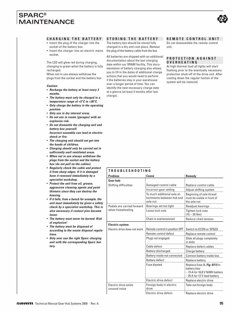
95Technical Manual Gear Hub Systems 2009 · Rev. A
SPARC®
MAINTENANCE
C H A R G I N G T H E B A T T E R Y• Insert the plug of the charger into the
socket of the battery box.
• Insert the charger into an electric mains
socket.
The LED will glow red during charging,
changing to green when the battery is fully
recharged.
When not in use always withdraw the
plugs from the socket and the battery box
Caution:• Recharge the battery at least every 3
months.• The battery must only be charged in a
temperature range of +5°C to +30°C.• Only charge the battery in the operating
position.• Only use in dry internal areas.• Do not use in rooms (garages) with an
explosion risk.• Do not dismantle the charging unit and
battery box yourself.Incorrect assembly can lead to electric shock or fire.
• The charging unit should not get into the hands of children.
• Charging should only be carried out in sufficiently well ventilated areas.
• When not in use always withdraw the plugs from the socket and the battery box (do not pull on the cables).
• Regularly check the cable and protect it from sharp edges. If it is damaged have it renewed immediately by a specialist workshop.
• Protect the unit from oil, grease, aggressive cleaning agents and paint thinners since they can destroy the housing.
• If it falls, from a bench for example, the unit must immediately be given a safety check by a specialist workshop. This is also necessary if contact pins become loose.
• The battery must never be burned. Risk of explosion!
• The battery must be disposed of according to the waste disposal regula-tions.
• Only ever use the right Sparc charging unit with the corresponding Sparc bat-tery.
S T O R I N G T H E B A T T E R YThe battery box should be stored fully
charged in a dry and cool place. Remove
the plug of the battery cable from the box.
All batteries are shipped with an additional
documentation about the last charging
date within our SRAM facility. This docu-
mentation of battery charging also allows
you to fill in the dates of additional charge
actions that you would need to perform
if the batteries stay in your warehouse
over a longer period of time. You can
identify the next necessary charge date
at a glance (at least 3 months after last
charge).
R E M O T E C O N T R O L U N I TDo not disassemble the remote control
unit.
P R O T E C T I O N A G A I N S T O V E R H E A T I N GAt high thermal load all lights will start
flashing prior to the eventually necessary
protection shutt-off of the drive unit. After
cooling down the regular funtion of the
system will be restored.
Problem
Gear hub: Shifting difficulties
Pedals are carried forward
when freewheeling
Electric system: Electric drive does not work
Electric drive emits
unusual noise
Cause
Damaged control cable
Incorrect gear setting
To much additional axle at-
tachments between hub and
axle nut
Bearings set too tight
Loose lock nuts
Chain is overtensioned
Remote control in position OFF
Remote control defect
Plugs not engaged
Cable defect
Battery discharged
Battery inside not connected
Battery defect
Fuse blasted
Electric drive defect
Foreign body in electric
drive
Electric drive defect
Remedy
Replace control cable
Adjust shifting system
Beginning of axle thread
must be visible in front of
the axle nut
Readjust bearings
Tighten lock nuts
(15 – 20 Nm)
Reduce chain tension
Switch to ECON or SPEED
Replace remote control
Slide all plugs completely
in slots
Replace defect cables
Charge battery
Connect battery inside box
Replace battery
Replace fuse (4, Fig. 9/11) in
battery box:
– 15 A for 16,8 V NiMH battery
– 25 A for 12 V lead battery
Replace electric drive
Take out foreign body
Replace electric drive
T R O U B L E S H O O T I N G

96 Technical Manual Gear Hub Systems 2009 · Rev. A
BRAKE LEVER SRAM® BL 60 TECHNICAL DATA / ASSEMBLY REQUIREMENTS
SRAM BL 60
Version SRAM BL 60, left SRAM BL 60, right
Mounting location left side of handlebar right side of handlebar
Clamping diameter 22.1 – 22.3 mm
Compatibility Linear-Pull, Avid BB Disc
Ratio 2.32
Cable path 24 mm
Reach Adjust Yes
Adjusting screw Yes
Lever size 4-finger 4-finger
Weight 95 g 95 g
Housing Cast aluminum
Lever Aluminum, forged
Frame clamp Aluminum
Finish Mercury silver painted
Mat
eria
l
BRAKE
LEVER
C A B L E A N D C A B L E H O U S I N G
Advice:Make sure that the cable housing
length is sufficient to permit turning of
the handlebar over its full range.
» Also bear in mind the effect of adjust-
able handlebars and stems on the cable
housing length.
» Always use new, high-quality cables
and compressionless cable housings
with end caps.
Caution:SRAM BL 60 brake levers are de-
signed for use with Avid BB Disc Brakes
and Linear-Pull compatible brakes.
Do not use SRAM Brake Levers with
conventionell cantilever brakes (those
with arms measuring less than 76 mm and
utilizing a non-linear straddle cable). Use
of SRAM Brake Levers with conventional
cantilever brakesets, drum brakes or
roller brakes will result in faulty braking
performance.
Designed for use with linear-pull brakes.
Do not use conventional cantilever brakes.
76
– 1
08
Nm
15
115.7
Ø 2
2.1
– 2
2.3

97Technical Manual Gear Hub Systems 2009 · Rev. A
BRAKE LEVER SRAM® BL 60 ASSEMBLY / MAINTENANCE
2
1 F I T T I N G T H E B R A K E L E V E R» Slide the brake lever onto the handlebar.
1 Tighten the clamping bolt.
3 mm Allen key, torque 2 – 2.5 Nm
(18 – 22 in.lbs.).
F I T T I N G T H E B R A K E C A B L E
Caution:The SRAM BL 60 brake lever is only
compatible with the following brakes:
Avid BB Disc and Linear-Pull compatible
brakes.
Advice:Make sure that the cable housing
length is sufficient to permit turning of
the handlebar over its full range.
» Also bear in mind the effect of adjust-
able handlebars and stems on the cable
housing length.
» Always use new, high-quality cables
and compressionless cable housings
with end caps.
2 Turn the cable adjustment screw (1)
and the counter nut (2) so that the
cable slot is aligned with the slot on the
bottom of the brake lever housing.
3 Pull the brake lever to the handlebar
and guide the inner cable into the
housing.
Hook the nipple (3) of the inner cable
into the recess (4) in the brake lever.
» Follow the brake manufacturer's in-
structions when fitting the brake cable
and adjusting the brakes.
Caution:Check that the brake is operating in
a correct and trouble-free manner.
Reach adjust of the hand brake lever:so that you can operate the brake lever on
the shifter comfortably, set the reach to
match your hand size.
4 Use a 2 mm Allen key to set the dis-
tance between the brake lever and
the handlebar.
Caution:Every time you adjust the reach,
check and correct the brake cable tension
to ensure good brake performance.
Advice:Read and observe the operating
manual and technical documentation of
the brake manufacturer.
U S ECaution:Before riding, always check that all
brake system components are function-
ing properly.
Advice:On your ride with your new bicycle,
actuate the hand brake lever carefully
to become familiar with the braking
performance.
M A I N T E N A N C EAdvice:Clean the brake lever using only
water and mild soap.
4 3
1 3 mm2 – 2.5 Nm18 – 22 in.lbs.
12
3
4

98 Technical Manual Gear Hub Systems 2009 · Rev. A
i-LIGHT™ – DYNAMO HUBS · D7 / D3-SERIESTECHNICAL DATA / ASSEMBLY REQUIREMENTS
Model D724-N D730-N D724-D D730-D
Version Standard ➔ Disc Brake compat. / 6 holes
Output 2.4 Watt 3.0 Watt 2.4 Watt 3.0 Watt
Voltage 6 V 6 V
Wheel ø 400 – 720 mm / 16” – 28” 400 – 720 mm / 16” – 28”
Over Locknut Dim., OLD 100 mm 100 mm
Length, L 140 mm 108 mm 140 mm 108 mm 140 mm 108 mm 140 mm 108 mm
Type Solid Hollow1 Solid Hollow1 Solid Hollow1 Solid Hollow1
Material Steel Steel
Ends Diameter M 9 x1 – M 9 x1 – M 9 x1 – M 9 x1 –
Holes 36 / 32 36 / 32
Hole Diameter 2.5 mm 2.5 mm
Hole Reference ø 71 mm 71 mm
Flange Width 3.4 mm 3.4 mm
Flange Distance, F1/F2 F1 = 28 mm / F
2 = 28 mm F
1 = 18 mm / F
2 = 31 mm
Offset 0 mm 6.5 mm
Bearing Cartridge Cartridge
Sealing Double Sealed Double Sealed
Homologation KBA homologation for versions with 3.0 Watt (KBA = Kraftfahrtbundesamt Germany)
Efficiency 70% at 15 km/h 70% at 15 km/h
Weight 557 g 525 g N/A 580 g 557 g 525 g N/A 580 g
Finish Hub Shell Aluminum, silver or black anodized
Axl
eSp
oke
D724
D730
1 Caution: Quick release braking load min. 10000 N (2250 lbs.)!
M 9
x1
F1
F2
100°
3,4
OLD
L
1/2 OLD
Ø 2
,5
Ø 71
Caution:The dynamo hub generates an
extremely high voltage. Never touch the
conntection terminal of the dynamo hub
while riding or while the wheel is spinning.
This may cause an electric shock.
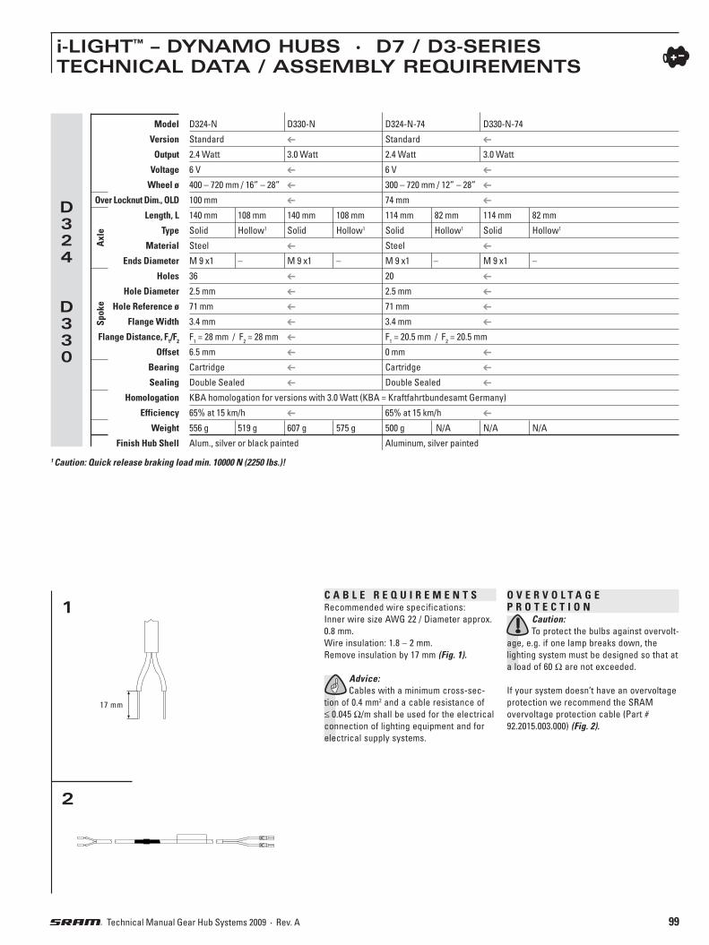
99Technical Manual Gear Hub Systems 2009 · Rev. A
i-LIGHT™ – DYNAMO HUBS · D7 / D3-SERIESTECHNICAL DATA / ASSEMBLY REQUIREMENTS
2
Model D324-N D330-N D324-N-74 D330-N-74
Version Standard Standard
Output 2.4 Watt 3.0 Watt 2.4 Watt 3.0 Watt
Voltage 6 V 6 V
Wheel ø 400 – 720 mm / 16” – 28” 300 – 720 mm / 12” – 28”
Over Locknut Dim., OLD 100 mm 74 mm
Length, L 140 mm 108 mm 140 mm 108 mm 114 mm 82 mm 114 mm 82 mm
Type Solid Hollow1 Solid Hollow1 Solid Hollow1 Solid Hollow1
Material Steel Steel
Ends Diameter M 9 x1 – M 9 x1 – M 9 x1 – M 9 x1 –
Holes 36 20
Hole Diameter 2.5 mm 2.5 mm
Hole Reference ø 71 mm 71 mm
Flange Width 3.4 mm 3.4 mm
Flange Distance, F1/F2 F1 = 28 mm / F
2 = 28 mm F
1 = 20.5 mm / F
2 = 20.5 mm
Offset 6.5 mm 0 mm
Bearing Cartridge Cartridge
Sealing Double Sealed Double Sealed
Homologation KBA homologation for versions with 3.0 Watt (KBA = Kraftfahrtbundesamt Germany)
Efficiency 65% at 15 km/h 65% at 15 km/h
Weight 556 g 519 g 607 g 575 g 500 g N/A N/A N/A
Finish Hub Shell Alum., silver or black painted Aluminum, silver painted
Axl
eSp
oke
D324
D330
1 Caution: Quick release braking load min. 10000 N (2250 lbs.)!
C A B L E R E Q U I R E M E N T SRecommended wire specifications:
Inner wire size AWG 22 / Diameter approx.
0.8 mm.
Wire insulation: 1.8 – 2 mm.
Remove insulation by 17 mm (Fig. 1).
Advice: Cables with a minimum cross-sec-
tion of 0.4 mm2 and a cable resistance of
≤ 0.045 Ω/m shall be used for the electrical
connection of lighting equipment and for
electrical supply systems.
1
17 mm
O V E R V O L T A G E P R O T E C T I O N
Caution: To protect the bulbs against overvolt-
age, e.g. if one lamp breaks down, the
lighting system must be designed so that at
a load of 60 Ω are not exceeded.
If your system doesn’t have an overvoltage
protection we recommend the SRAM
overvoltage protection cable (Part #
92.2015.003.000) (Fig. 2).

100 Technical Manual Gear Hub Systems 2009 · Rev. A
i-LIGHT™ – DYNAMO HUBS · D7 / D3-SERIESASSEMBLY
A S S E M B L I N G T H E H U BCaution: The dropouts of the fork must be
parallel.
• Lacing the hub as normal.
• Hub version for Disc Brake:
Advice: Read and observe the
corresponding technical documentation
for assembling the disc of the disc
brake.
Caution: Plane faces and threaded holes of
the hub must be clean and free from oily
and greasy substances.
• Place the front wheel into the front fork.
Advice:The connection terminal of the
1 dynamo hub should be on the
right side viewed from behind the
rear of the bicycle. The connection
terminal should tend upwards or
backwards.
Fastening wheel / solid axle:
2 Place one retaining washer (1) on
each axle end.
2 Fit the
axle nuts (2).
– Tighten the axle nuts while alternating
between sides, to course that the
dynamo hub connection terminal
do not turn away from the correct
orientation.
– The recommended axle nut tightening
torque is 20 Nm (177 in.lbs.).
Caution:If the axle nuts are screwed on too
tight, or if one or the other is screwed
tighter or looser than the other, the hub
axle may be forced to turn. Making the
axle nuts looser or too tight, this could
permanently damage the dynamo hub.
Fastening wheel / quick release:• Only use quick release devices with the
correct length.
• Position quick release opposite to the
brake (Disc Brake version).
• Turn release lever outwards until it
is at least at a right angle to the bike
(position “OPEN“).
• Tighten adjusting nut on the end of the
skewer as much as possible by hand.
3 Turn release lever to the “closed“
position (the word “CLOSE” is visible
from the outside).
• After closure, the release lever should
be parallel to the fork. If the release
lever can be closed relatively easily, the
tension force is inadequate.
In this case, open release lever again,
tighten adjusting nut slightly and close
release lever again.
• If considerable force is required to
close the lever, open the lever again,
undo the adjusting nut slightly and close
lever again.
Caution:
4 Do not tighten the wheel by
turning the release lever
clockwise.
• Only use hand force.
• By incorrectly mounting the skewer or
the wheel in the dropout, or by wrongly
adjusting the closing force, the wheel
may come loose and fall off during the
ride. This may lead to severe rider injury
or death.
N O !
4
1
1
2
2
3

101Technical Manual Gear Hub Systems 2009 · Rev. A
i-LIGHT™ – DYNAMO HUBS · D7 / D3-SERIESASSEMBLY / MAINTENANCE
C O N N E C T I N G T H E C A B L E S • Strip the insulation off of the wire
aproximately 17 mm.
5 Twist the cable wires before
connecting.
6 Stick the cables through the two
holes of the inner connecting piece.
Bend the cable wires and run them along
the grooves.
7 Push the inner piece with cable
wires into the outer piece.
Advice:When doing this, ensure that the
flattened corner of the inner peace
matches the corresponding shape in the
outer piece.
8 Connect the cable with the dynamo
hub. Push the connecting piece onto
the connection terminal of the dynamo
hub.
Caution:Make sure, that it is securely
connected before using the dynamo
hub.
Check: Rotate the front wheel and check the
lamp illumination.
Caution:The dynamo hub generates an
extremely high voltage. Never touch the
conntection terminal of the dynamo hub
while riding or while the wheel is spinning.
This may cause an electric shock.
Caution:Before setting out on any ride,
always check the correct and trouble-free
operation of the dynamo hub.
M A I N T E N A N C E• Do not disassemble the internal hub
mechanism.
• Do not apply any lubricant to the inside
of the hub, otherwise the grease will
come out and it may cause problems
with conductivity.
Caution:If the axle nuts are screwed on too
tight, or if one or the other is screwed
tighter or looser than the other, the hub
axle may be forced to turn. Making the
axle nuts looser or too tight, this could
permanently damage the dynamo hub.
5
6
7
8

102 Technical Manual Gear Hub Systems 2009 · Rev. A
POWER CHAIN™
TECHNICAL DATA / ASSEMBLY REQUIREMENTS
PC 10 Saltshaker PC 10
Application Gear Hubs / MTB Gear Hubs / MTB
Max. No. of sprockets max. 7 max. 7
Compatibility Front Single / HG® Single / HG®
Compatibility Rear Single / HG® Single / HG®
Dimension 1/2" x 3/
32" 1/
2" x 3/
32"
Length 6.92 mm 6.92 mm
Riveting Step Step
Chrome Hardened No No
Push Power 1000 N 1000 N
Min. Tensile Strength 9000 N 9000 N
Weight (114 links) 300 g 300 g
External Pin Plate Light Grey Brown
Internal Pin Plate Light Grey Brown
Connecting Method Power Link SS1 or Pin Power Link G or Pin
POWER
CHAIN
Desi
gnPi
n
PC 1 Saltshaker PC 1 Ni PC 1
Application Gear Hubs Gear Hubs Gear Hubs
Max. No. of sprockets 1 1 1
Compatibility Front Single Single Single
Compatibility Rear Single Single Single
Dimension 1/2" x 1/
8" 1/
2" x 1/
8" 1/
2" x 1/
8"
Length 7.8 mm 7.8 mm 8,98 mm
Riveting Step Step V shape
Chrome Hardened No No No
Push Power 800 N 800 N 800 N
Min. Tensile Strength 8000 N 8000 N 8000 N
Weight (114 links) 330 g 330 g 356 g
External Pin Plate Light Grey Silver / Nickel Plated Brown
Internal Pin Plate Light Grey Silver / Nickel Plated Brown
Connecting Method Snap Lock or Pin Snap Lock, 3pcs Connection Link or Pin
POWER
CHAIN
Desi
gnPi
n

103Technical Manual Gear Hub Systems 2009 · Rev. A
POWER CHAIN™
TECHNICAL DATA / ASSEMBLY REQUIREMENTS
PC 890 PC 870 PC 850 PC 830 Saltshaker PC 830
Application MTB / Road MTB / Road MTB / Road MTB / Road MTB / Road
Max. No. of sprockets max. 8 max. 8 max. 8 max. 8 max. 8
Compatibility Front HG® / IG® / PG / EXA-Drive® HG® / IG® / PG / EXA-Drive® HG® / IG® / PG / EXA-Drive® HG® / IG® / PG / EXA-Drive® HG® / IG® / PG / EXA-Drive®
Compatibility Rear HG® / IG® / PGII / EXA-Drive® HG® / IG® / PGII / EXA-Drive® HG® / IG® / PGII / EXA-Drive® HG® / IG® / PGII / EXA-Drive® HG® / IG® / PGII / EXA-Drive®
Dimension 1/2" x 3/
32" 1/
2" x 3/
32" 1/
2" x 3/
32" 1/
2" x 3/
32" 1/
2" x 3/
32"
Length 6,92 mm 6,92 mm 6,92 mm 6,92 mm 6,92 mm
Riveting Step Step Step Step Step
Chrome Hardened Yes Yes Yes No No
Push Power 2000 N 2000 N 2000 N 1300 N 1500 N
Min. Tensile Strength 9000 N 9000 N 9000 N 9000 N 9000 N
Weight (114 links) 310 g 310 g 310 g 310 g 310 g
External Pin Plate Silver / Nickel Plated Silver / Nickel Plated Grey / Polished Light Grey Grey / Polished
Internal Pin Plate Silver / Nickel Plated Grey / Polished Grey / Polished Light Grey Grey / Polished
Connecting Method Power Link S only Power Link S or Pin Power Link S or Pin Power Link SS2 or Pin Power Link S or Pin
POWER
CHAIN
Desi
gnPi
n
PC 991 PC 991 Hollow Pin PC 991 Cross Step PC 971 PC 951
Application MTB / Road MTB / Road MTB / Road MTB / Road MTB / Road
Max. No. of sprockets 9 only 9 only 9 only 9 only 9 only
Compatibility Front Truvativ® / HG® / EXA-Drive® Truvativ® / HG® / EXA-Drive® Truvativ® / HG® / EXA-Drive® Truvativ® / HG® / EXA-Drive® Truvativ® / HG® / EXA-Drive®
Compatibility Rear HG® / PG / EXA-Drive® HG® / PG / EXA-Drive® HG® / PG / EXA-Drive® HG® / PG / EXA-Drive® HG® / PG / EXA-Drive®
Dimension 1/2" x 11/
128" 1/
2" x 11/
128" 1/
2" x 11/
128" 1/
2" x 11/
128" 1/
2" x 11/
128"
Length 6.65 mm 6.35 mm 6.65 mm 6.65 mm 6.65 mm
Riveting Step Cylindrical Cross Step Step Step
Chrome Hardened Yes Yes Yes Yes Yes
Push Power 2000 N 2000 N 2500 N 2000 N 2000 N
Min. Tensile Strength 9000 N 9000 N 9000 N 9000 N 9000 N
Weight (114 links) 297 g 276 g 297 g 297 g 297 g
External Pin Plate Silver / Nickel Plated Silver / Nickel Plated Silver / Nickel Plated Silver / Nickel Plated Grey / Polished
Internal Pin Plate Silver / Nickel Plated Silver / Nickel Plated Silver / Nickel Plated Grey / Polished Grey / Polished
Connecting Method 1 Power Link 9spd or Pin Power Link 9spd only Power Link 9spd only Power Link 9spd or Pin Power Link 9spd or Pin
POWER
CHAIN
Desi
gnPi
n
1 Caution: Hollow Pin and Cross Step chains connecting method: with Power Link only (no pin)!

104 Technical Manual Gear Hub Systems 2009 · Rev. A
POWER CHAIN™
ASSEMBLY
1
2 3
4
1
2
3
4
5
6
Closing chain with 3pcs Connection Link:• Fit the shortened chain, bring the two
ends together and connect with the
chain lock. The chain lock consists of
an outer plate with pins (1, Fig. 4), an
outer plate (2) and a retaining spring (3).
• Insert outer plate with pins (1) into
the chain ends, attach outer plate (2)
and press chain lock together (1+2).
• Attach retaining spring (3) with the closed
end of the retaining ring pointing in the
direction of chain travel (Fig. 4). • Slide retaining spring in the direction
of arrow (4, Fig. 5) to engage it in the
grooves in the pins.
Closing standard version with clamping pin:Fit chain, bring the two ends together and
press pin (Fig. 6) through with assembly tool.
The pin must extend by the same amount at both outer plates. It must be possible to move the connecting link slightly.
P C 1 (1 /2" X 1 /8" )
Chain length:(A chain tool will be required to shorten the
chain.)
• Replacing a worn chain:
Measure the worn chain and shorten the
new to the same length.
• Initial assembly:
Shorten the chain to the length speci-
fied by the drivetrain manufacturer.
SRAM components:
Place the chain over front chainwheel and
rear sprocket (Fig. 1). For rear suspension
frame, position the rear suspension for the
greatest chain length required.
Closing chain with Snap Lock: • Fit the shortened chain, bring the ends
together and connect with the Snap Lock.
Place the outer plate on one pin (Fig. 2).• Gently flex the chain until the outside
connector plate snaps into position over
the second pin (Fig. 3).
Caution:• Make sure plate is fully seated in the
pin channel and plates are parallel to each other.
• If movement of the connector plate is noticed a new Snap Lock must be used.
• Snap Lock is for one-time use only!• Always use a new Snap Lock when
fitting a new chain.• Use Snap Lock only with SRAM chains!• Failure to shorten the chain properly or
to lock it exactly into place may cause damage to the chain and eventually total chain failure, material damage or the rider to fall off his bicycle resulting in injury.
• Worn sprockets should also be re-placed when a new chain is fitted.

105Technical Manual Gear Hub Systems 2009 · Rev. A
POWER CHAIN™
ASSEMBLY / MAINTENANCE
7
9
10
(2 links)
8
P C 9 9 1 / P C 9 7 1 / P C 9 5 1 / P C 8 9 0 / P C 8 7 0 / P C 8 5 0 /P C 8 3 0 / P C 1 0(1/2" X 3 /32" UND 1/2" X 11/128" )
Chain length:(A chain tool will be required to shorten
the chain.)
• Replacing a worn chain:
Measure the worn chain and shorten the
new to the same length.
• Initial assembly:
Shorten the chain to the length speci-
fied by the derailleur manufacturer.
SRAM derailleurs:
• Place the chain over largest front
chainwheel and largest rear sprocket
(Fig. 7). For rear suspension frame,
position the rear suspension for the
greatest chain length required.
• Add 2 links or 1 link + Power Link (Fig. 7).
Closing chain with Power Link:Caution:• Use Power Link only with SRAM
chains! • Use only Power Link to close Hollow
Pin chains and Cross Step chains (no Pin)!
• Use only as specified, to avoid mate-rial damage or the rider to fall off his bicycle resulting in injury:
Power Link G (gold coloured):
for PC 991 Hollow Pin, PC 991 Cross Step,
PC 991, PC 971, PC 951
Power Link S (silver coloured):
for PC 890, PC 870, PC 850, PC 830
Power Link SS2 (light grey coloured):
for PC 830 Saltshaker
Power Link SS1 (light grey coloured):
for PC 10 Saltshaker
Power Link G (grey coloured):
for PC 10
Closing:
• Fit chain, bring the ends together and
insert both halves of the Power Link into
the chain ends. (Fig. 8) • Press both halves of the Power Link
together (Fig. 9) and lock in place by pulling the chain apart. (Fig. 10)
Opening:
Press both plates of the Power Link
together (Fig. 9) while sliding the chain
ends together (unlock). Remove the two
halves of the link from the chain ends.
Caution: • Always use a new Power Link when
fitting a new chain.• Failure to shorten the chain properly or
to lock it exactly into place may cause damage to the chain and eventually total chain failure, material damage or the rider to fall off his bicycle resulting in injury.
• Worn sprockets should also be re-placed when a new chain is fitted.
Closing standard version with clamping pin:Fit chain, bring the two ends together
and press pin through with assembly tool
(Fig. 6). The pin must extend by the same amount at both outer plates. It must be possible to move the connecting link slightly.
M A I N T E N A N C E / C A R E• Clean dirty chains before oiling. Do not
use any acidic agents. Cleaning agent
must be rinsed off after a few minutes
with water. Apply oil after chain is com-
pletely dried.
• Regular lubrication will extend the
chain's service life. Apply oil to the
chain links rollers and allow to work in.

106 Technical Manual Gear Hub Systems 2009 · Rev. A
SUPPORTDISTRIBUTORS / SPARE PARTS ✆
D I S T R I B U T O R S
Please check
http://www.sram.com/en/locator/distributors.php
for full contact information.
S P A R E P A R T S
You can find an extensive spare parts
program in SRAM’s Spare Parts Catalog
for Gear Hub Systems Model Year 2009
Part Number 95.3115.009.000.
S R A M O R I G I N A L P A R T S
Caution:Installation of parts and accessories
not originally intended could result in less
than optimal performance and/or injury.


www.sram.com
world headquartersSRAM corporation
1333 n. kingsbury st., 4th fl chicago, il 60622
phone +1-312-664-8800fax +1-312-664-8826
european headquartersSRAM europebasicweg 12-d
3821 br amersfoortthe netherlands
phone +31-33-450-6060fax +31-33-457-0200
asian headquartersSRAM taiwan
no. 1598-8 chung shan rdshen kang hsiang, taichung
county 429 taiwan r.o.c.phone +886-4-2561-3678
fax +886-4-2561-3686