Gear 0 ptimization - CORE
65
NASA Contractor Report 420 1 Gear 0 ptimization G. N. Vanderplaats, Xiarig Chen, and Ning-tian Zhang GRANT NAG3483 DECEMRER 1988 NASA CORE Metadata, citation and similar papers at core.ac.uk Provided by NASA Technical Reports Server
-
Upload
khangminh22 -
Category
Documents
-
view
6 -
download
0
Transcript of Gear 0 ptimization - CORE
NASA Contractor Report 420 1
Gear 0 ptimization
G. N. Vanderplaats, Xiarig Chen, and Ning-tian Zhang
GRANT NAG3483 DECEMRER 1988
NASA
https://ntrs.nasa.gov/search.jsp?R=19890004422 2020-03-20T04:19:09+00:00ZCORE Metadata, citation and similar papers at core.ac.uk
Provided by NASA Technical Reports Server
*- I
NASA Contractor Report 4201
Gear Optimization
G. N. Vanderplaats, Xiang Chen, and Ning-tian Zhang University of California Santa Bar&ara, California
Prepared for Lewis Research Center under Grant NAG3-683
Nat i ona I Aeronautics and Space Administration
Scientific and Technical Information Division
I 1988
CONTENTS
I3-s
LIST OF SYMBOLS ....................................... iv
1 . 0 INTRODUCTION . . . . . . . . . . . . . . . . . . . . . . . . . . . . . . . . . . . . . . . . 2.0 NUMERICAL OPTIMIZATION CONCEPTS ..................... 3.0 THE COPES/ADS OPTIMIZATION PROGRAM . . . . . . . . . . . . . . . . . . . 4.0 SPUR GEAR ANALYSIS AND OPTIMIZATION . . . . . . . . . . . . . . . . . .
4.1 THE SPUR GEAR PROGRAM .......................... 4.2 PARAMETERS CONTAINED IN THE GLOBAL COMMON BLOCK
4.3 DESIGN EXAMPLES ................................ 5.0 SPIRAL BEVEL GEAR ANALYSIS AND OPTIMIZATION ...........
5.1 THE SPIRAL BEVEL GEAR PROGRAM . . . . . . . . . . . . . . . . . . . 5.2 PARAMETERS CONTAINED IN THE GLOBAL COMMON BLOCK
5.3 DESIGN EXAMPLES ................................ 6.0 SUMMARY ............................................ 7.0 REFERENCES ..........................................
1
2
4
5
20
21
27
31
44
44
48
53
55
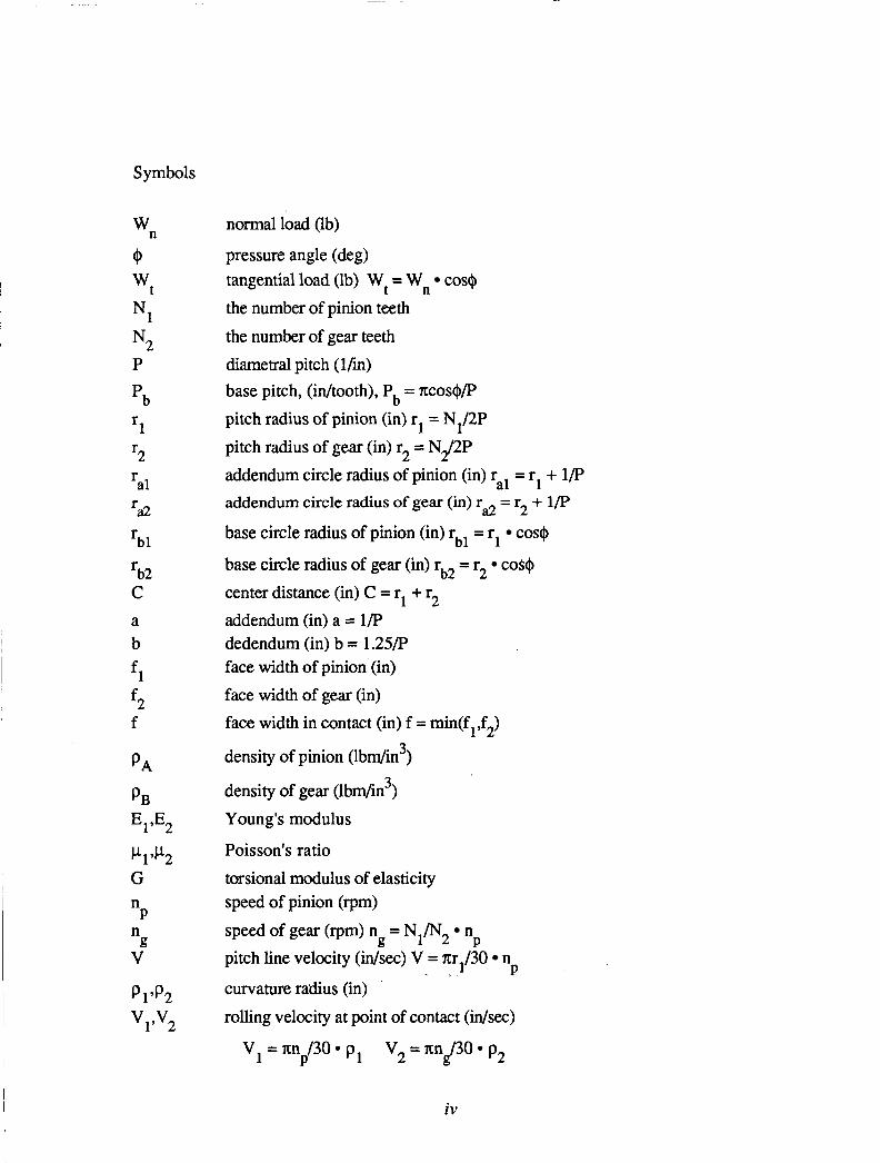
Symbols
W normal load (lb)
@ pressure angle (deg) n
tangential load (lb) Wt = Wn cos@ the number of pinion teeth
wt
Nl
N2 P
‘b
2 r r a1 r a2
‘bl r b2 C a b
f l
f2 f
PA
PB E1’E2
h’P2 G n P n
g V
the number of gear teeth diametral pitch (1Ti) base pitch, (idtooth), Pb = xcos@/P pitch radius of pinion (in) rl = N1/2P pitch radius of gear (in) r2 = Nd2P addendum circle radius of pinion (in) ral = r1 + 1/P addendum circle radius of gear (in) r
base circle radius of pinion (in) rbl = rl cos$
base circle radius of gear (in) rb2 = r2 COS@
center distance (in) C = rl + r2 addendum (in) a = 1/P dedendum (in) b = 1.25/P face width of pinion (in) face width of gear (in) face width in contact (in) f = min(fl,f2)
density of pinion (lbdin3)
density of gear (lbm/in3) Young’s modulus
Poisson’s ratio torsional modulus of elasticity speed of pinion (rpm) speed of gear (rpm) ng = N1/N2 n pitch line velocity (in/sec) V = xr1/30 n
= r2 + 1/P a2
P . > P
curvature radius (in) rolling velocity at point of contact (in/sec)
4 4 2
V 1 = m /30*p1 V 2 = m O * p 2 P $3
iv
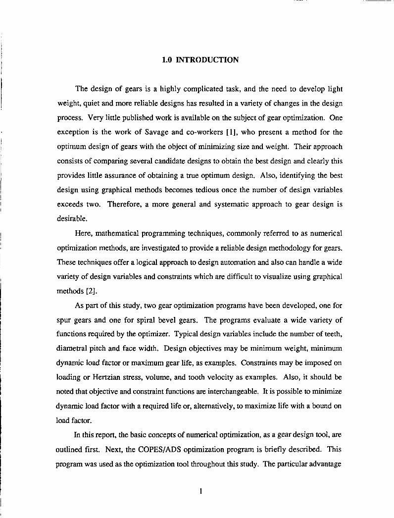
1.0 INTRODUCTION
The design of gears is a highly complicated task, and the need to develop light
weight, quiet and more reliable designs has resulted in a variety of changes in the design
process. Very little published work is available on the subject of gear optimization. One
exception is the work of Savage and co-workers [l], who present a method for the
optimum design of gears with the object of minimizing size and weight. Their approach
consists of comparing several candidate designs to obtain the best design and clearly this
provides little assurance of obtaining a true optimum design. Also, identifying the best
design using graphical methods becomes tedious once the number of design variables
exceeds two. Therefore, a more general and systematic approach to gear design is
desirable.
Here, mathematical programming techniques, commonly referred to as numerical
optimization methods, are investigated to provide a reliable design methodology for gears.
These techniques offer a logical approach to design automation and also can handle a wide
variety of design variables and constraints which are difficult to visualize using graphical
methods [2].
As part of this study, two gear optimization programs have been developed, one for
spur gears and one for spiral bevel gears. The programs evaluate a wide variety of
functions required by the optimizer. Typical design variables include the number of teeth,
diametral pitch and face width. Design objectives may be minimum weight, minimum
dynamic load factor or maximum gear life, as examples. Constraints may be imposed on
loading or Hertzian stress, volume, and tooth velocity as examples. Also, it should be
noted that objective and constraint functions are interchangeable. It is possible to minimize
dynamic load factor with a required life or, alternatively, to maximize life with a bound on
load factor.
In this report, the basic concepts of numerical optimization, as a gear design tool, are
outlined first. Next, the COPES/ADS optimization program is briefly described. This
program was used as the optimization tool throughout this study. The particular advantage
1

of this program is that the user is free to choose different design variables, objective
function and constraint functions using input data when the program is executed, without
modifying the program itself. The analysis capabilities developed here for spur gear and
spiral bevel gear design are described next. It is important to note that these programs
perform analysis only, and can be used for that purpose, without optimization. They have
been written in the form needed to couple them to the COPES/ADS program when
optimization is desired. When discussing each of these analyses capabilities, design
examples are given to demonstrate their application in the optimization mode. Finally, the
results of this project are summarized and continuing research efforts are described
2.0 NUMERICAL OPTIMIZATION CONCEPTS
The constrained optimization problem is mathematically stated as follows [ 11
Minimize (or maximize) F(X)
Subject to g j w 0 j = l,m
\(X) = 0 k = 1,1
i = l,n
Where, F(X) is referred to as the objective function. g.(X) are inequality constraint
functions and hk(X) are equality constraint functions. Xi' i=l,n, are design variables.
Equation (4) defines side constraints which impose limits on the region of search for the
optimum.
J
A typical optimization problem for spur gear design can be stated as
Subject to
limits on
Life
1) Dynamicload
2) Bending strength
2
Surface durability
Scoring
Weight
Gear size
Contact ratio
Involute interference
Width to diameter ratio
Alternatively, the dynamic load factor might be minimized with a lower bound
constraint on life. Using COPES [3] and ADS [4,5], only input data needs to be changed
for different problems.
Design Variables
The key element in formulating an optimization problem is the selection of the
independent design variables that are necessary to characterize the design of the system.
Normally, it is good to choose those variables that have a significant impact on the
objective function. Based on this criterion, the number of teeth on the pinion and gear, N1
and N2, the diametral pitch P and facewidth of the pinion and gear, fl and f2 are typically
chosen as the design variables. Since present optimization techniques do not deal well with
integer variables, N1 and N2 are treated as a continuous variables in the optimization. The
final answer can be rounded to the nearest integer value.
In principal, any input parameter to the gear analysis program can be taken as a
design variable. The input data to the COPEWADS program defines the number and
identity of the design variables at run time. Also, design variables may be "linked" so that,
for exampe N2 = 3 * N, would assure a 3 to 1 gear reduction.
Objective Functions
The surface pitting fatigue life of a gear set in mesh and the dynamic load on a gear
tooth are the objective functions in life maximization problem and dynamic load
3
minimization problem, respectively. Other objective functions may be size, weight, or
tooth velocity as examples.
Constraints
Just as any response quantity calculated by the gear analysis program can be treated
as the design objective, so can any quantity by treated as a constraint. As listed above,
typical constraints here include limits on bending strength, surface durability, scoring,
weight, size, contact ratio, interference and width-to-diameter ratio. Also, life and dynamic
load can be treated interchangeably as objective or constraint functions. All that is needed
to change the definition of the objective or constraint functions or the bounds on the
constraints, is to change the input data to the COPEWADS program.
3.0 THE COPESlADS OPTIMIZATION PROGRAM
The COPES/ADS optimization program [3-51 was used in this study as the design
tool, coupled with the spur gear or bevel gear analysis. The ADS program is a general
purpose optimization program containing a variety of modern nonlinear programming
algorithms. The COPES program is a control program which acts as the interface between
ADS and the user-supplied analysis.
The basic concept of using COPEWADS is that the user must supply an analysis
program in subroutine form, called ANALIZ. The analysis is separated into three parts,
being INPUT, EXECUTION, and OUTPUT. All parameters in the analysis that may be
design variables, objective functions or constraints are contained in a single labeled
common block called GLOBCM. The ordering of the information in GLOBCM is
arbitrary.
The entries into the GLOBCM common block are treated as a set of sequential
information to be accessed by COPES and the input data to COPES refers to these entries
by their location. For example, the input to COPES may tell the program to minimize the
value of entry number 3, while locations 1,6 and 21 define three design variables. Finally,
4
locations 30 through 35 and locations 7 and 2 can be constrained. The details of how the
data is input to the program are given in reference 3.
The key to using the COPES/ADS program is that it provides the designer a great deal
of flexibility in choosing the design variables, objective and constraints, and that no
program modifications are needed between design runs. It is only necessary to change the
input data. This allows the designer to compare a variety of optimized designs, as opposed
to the usual single variable trade-off studies. Also, the program is in no way limited to the
analysis of spur and bevel gears described here, but is applicable to any design problem for
which to ANALIZ subroutine is avialable.
4.0 SPUR GEAR ANALYSIS AND OPTIMIZATION
One of the design capabilities developed as part of this study is for spur gears. The
study began by converting the TELSGE program, provided by NASA Lewis Research
Center, to a subroutine ANALIZ and gaining experience in design for life maximization.
This gear program does not include many of the constraints that must be considered by
optimization, such as bending strength and scoring. However, TELSGE provided an
excellent starting point for development of a more detailed program for use in optimization.
The basic analysis capabilities of that program are described here and examples are given to
demonstrate its capabilities. The purpose here was not to develop new analytical models
for gears, but rather to identify and program good models into a general design program.
The program is written in modular form so that any of the component parts can be modified
and updated in the future.
Analytical Model for the Life of Spur Gears
The life of spur gears is calculated from an analytical model developed by NASA
Lewis Research Center, which is programmed in subroutine LIFESG [6-81. The basic
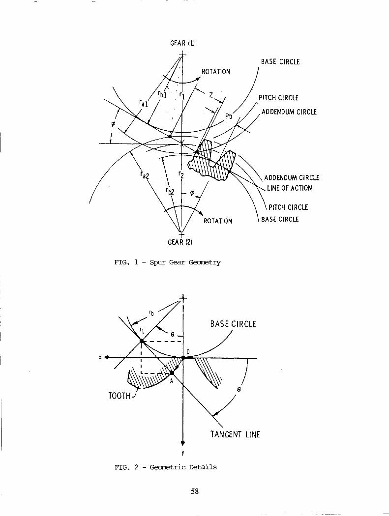
gear geometry with geometrical parameters is shown in figures 1 through 4
5

Here, it is assumed that the life of spur gears is mainly determined by the surface
pitting fatigue failure caused by repeated applications of high surface contact stress.
The life of a single pinion tooth in millions of pinion rotations with 90 percent
probability of survival is given as
L1 = KW, -4.3 f3.9 cp-5 q0.4
where Cp is the curvature radius (in), determined by
= r b l Q L 1 (Csin+'- rbl + L 1)
€ILI is the roll angle corresponding to the lowest point of single tooth contact on the pinion
where the maximum Hertzian stress is considered to occur
eL1 = 6l + PL1 (7)
and
c sin+ - Jr2 - r 2 a 2 b2
bl r 6, =
- Jr:l - r i l + ,/r22 - r i 2 - c sin + - P b
b l P L l - r
In equation (5),1, is the involute profile arc length of the pinion (in)
1 '1 = rbl pH1 ('1 + PL1' T p ~ l )
6
(9)

where,
Here, I, is calculated as the involute length across the heavy load zone as a justifiable
simplication.
For a single gear tooth, the life in millions of pinion rotations with 90 percent
probability of survival
where, e is the Weibull exponent which is taken as 2.5. I2 is the involute profile arc length
of the gear (in) which is calculated similarly to I,
2 c sin + - Jri1 - rbl 6 , = t
b2 L
Jr:l - r i l + ,/r,ZZ - r i 2 -,c sin + - pb
b2 PL2 = r
7
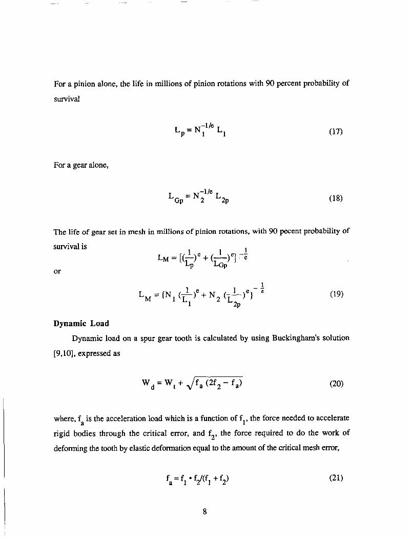
For a pinion alone, the life in millions of pinion rotations with 90 percent probability of
survival
-1 /e L p = N 1 Ll
For a gear alone,
-1 /e LGp = N 2 L2p
The life of gear set in mesh in millions of pinion rotations, with 90 pecent probability of
survival is
or
1 1 1
LP LGP LM = ((-)" + (-)"I -e
1 e 1 1 - - = (N ( - ) e + N ( - ) e }
Lh4 Ll L2p
Dynamic Load
Dynamic load on a spur gear tooth is calculated by using Buckingham's solution
[9,10], expressed as
w, = w, + Jfa (2f2 - fa) (20)
where, fa is the acceleration load which is a function of f,, the force needed to accelerate
rigid bodies through the critical error, and f2, the force required to do the work of
deforming the tooth by elastic deformation equal to the amount of the critical mesh error,
8

I
and m is the effective mass at pitch line of gears
e is the measured error on pair of mating teeth
d is the total deformation of mating teeth under applied load
For 20-deg full-depth form,
1 1 d = 9.00 (W, / f ) [- + q] El
In equation (22)
m2=m +md I3
Where, m1 and m2 are effective masses acting at pitch line of pinion and gear, respectively.
m and m are effective masses of pinion blank at r1 and gear blank at r2, P g
respectively.
9

m b = (4.: + 4A,C, - B,) /2A,
2 A , = H m , V 1
B, = (m + m2) A, + em Z P 2 1
c, = em, 1 m2Zl
m d = (JB; + 4A2C, - B2) /2A2
2 A 2 - H m a V 2
(32)
(33)
(34)
(35)
B 2 = (mg + ml) A2 + emlZ2 (36)
C, = em, 2 mlZ2 (37)
where, ma and ma are full effective masses of connected bodies ar r1 and r2, respectively. 1 2
Xp A m = m p + - 32 ' d: L l ,l 1
KpB 4 ma = m +- 2 g 32 df, ' L2 (39)
10
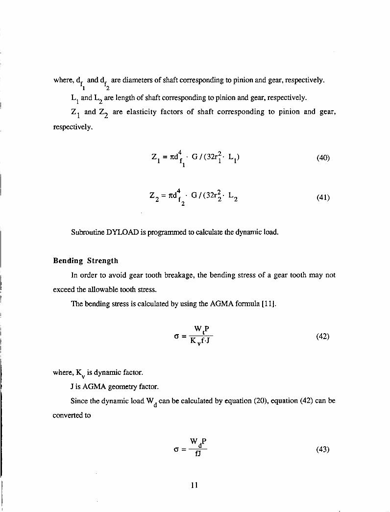
where, d and d are diameters of shaft corresponding to pinion and gear, respectively. fi f2
L, and Lz are length of shaft corresponding to pinion and gear, respectively.
Z1 and Z2 are elasticity factors of shaft corresponding to pinion and gear,
respectively.
Z, = xd4 - G/(32r t - L1) f l
Z2 = xd4 - G /(32ri- L2 f 2
Subroutine DYLOAD is programmed to calculate the dynamic load.
Bending Strength
In order to avoid gear tooth breakage, the bending stress of a gear tooth may not
exceed the allowable tooth stress.
The bending stress is calculated by using the AGMA formula [ 1 13.
tp o = K .f*J
where, KV is dynamic factor.
J is AGMA geometry factor.
Since the dynamic load Wd can be calculated by equation (20), equation (42) can be
converted to
dp o=- fJ
11
(43)
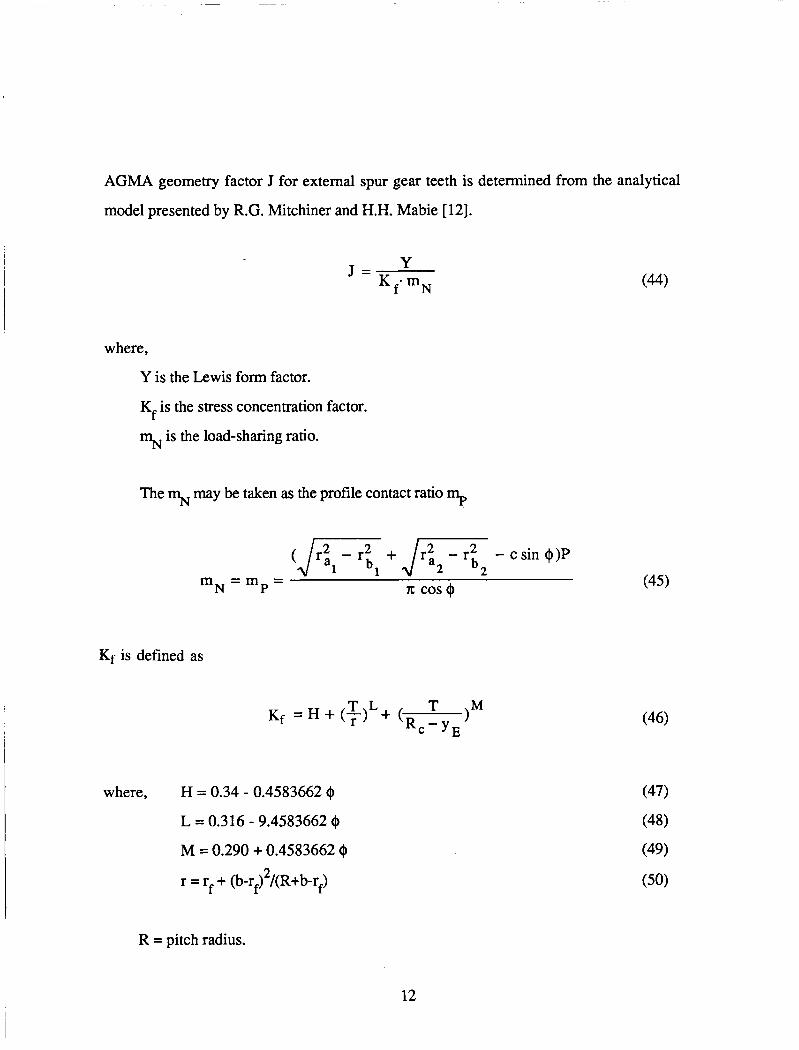
AGMA geometry factor J for external spur gear teeth is determined from the analytical
model presented by R.G. Mitchiner and H.H. Mabie [ 121.
Y J = m N (44)
where,
Y is the Lewis form factor.
Kf is the stress concentration factor.
% is the load-sharing ratio.
The % may be taken as the profile contact ratio mp
(Jm + J- - c sin @)P
(45) 1 1 2 b 2 m N = m =
P 71: cos@
Kf is defined as
where, H = 0.34 - 0.4583662 @
L = 0.316 - 9.4583662 $
M = 0.290 + 0.4583662 Q 2 r = rf + (b-r2 /(R+b-rf)
R = pitch radius.
12

I
rf = fiilet radius on hob tip.
T = tooth width between points of tangency of parabola and mot fillets.
R, = radius from center of gear to apex of parabola.
'It (- COS + - b sin +) 1 ' f = l - s i n + 4p
R cos + COS( + A - [ - + inv+ - inv+ AI I 7r R, =
2N
inv+ = tan@ - f
where, 8 is calculated by using Newton's method.
b - r R0 1+(- )tan@ + e>
-tan@ + 0) mJE = - b-r ,
(53)
(54)
(57)
13

X, = (R - b + rf) sin (p + 0) - Re cos(p+ 0) -
[(b - rf)sin(P + e) + Re cos@+ e)] (59)
= (R - b + rf) COS (p+ e) + Re sin@+ 0) + YE
[Re sin@ + e) - (b - rf) cos (p + e)] (60)
f (e) is calculated by using first-forward differential method. In equation (46),
T = 2X,
Y is defined as
P 1.5
Y = tan OL
cos$ [x - - T 1
where,
14

Q L = tan-1 ( R 1-m ’ - inv[tan-l ( 11 cos@ R + a ‘Os@ R + a
+ inv@ . AGMA geometry factor J is calculated in subroutine GEOFAC. The bending stresses
of pinion and gear tooth are calculated in subroutine BENDST.
The constraint condition for bending stress is
where, 0 is material allowable stress.
Surface Durability
The gears must be designed so that the dynamic surface stresses are within the
surface endurance limit of the material.
The surface contact stress (Hertzian stress) [ 1 13
where, p1 and p2 are calculated at pitch point. The surface fatigue strength for steels is
3 S , = (0.4 H, - 10) x 10 psi
H, is the Brinell hardness of the softer of the two contacting surfaces.
Modified by effective factors, the corrected fatigue strength
15
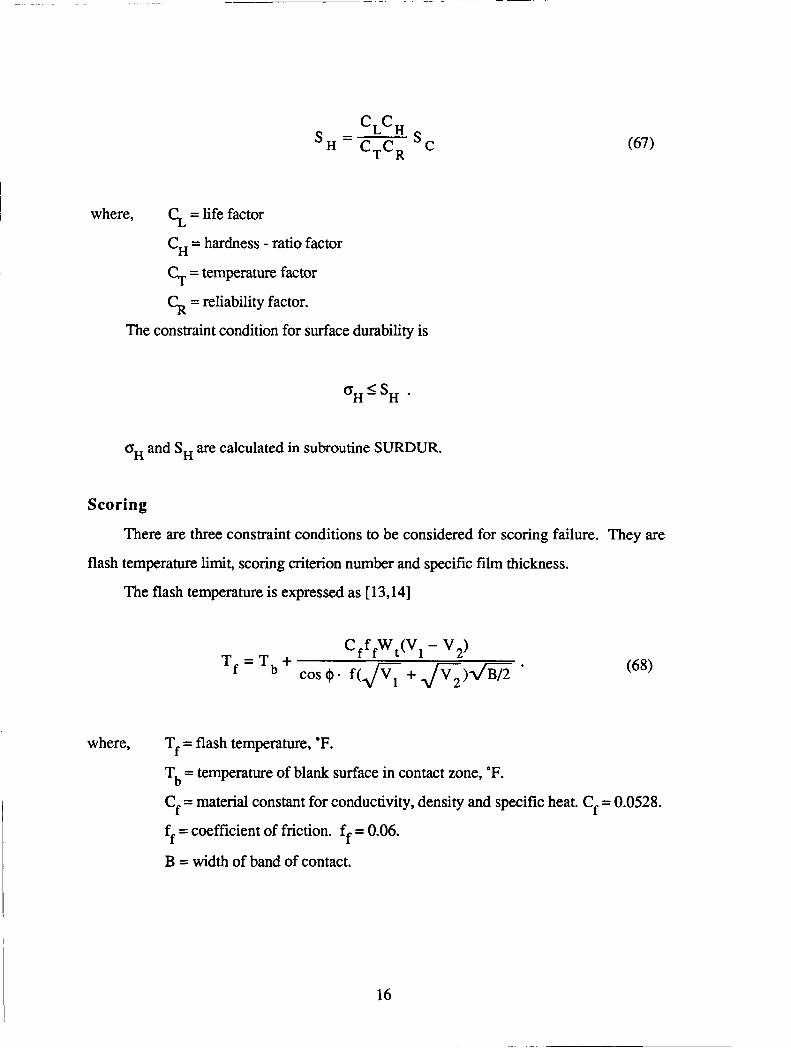
c, c,. - L H - C,C, 'C
where, = life factor
C, = hardness - ratio factor
C+ = temperature factor
= reliability factor.
The constraint condition for surface durability is
oH and S , are calculated in subroutine SURDUR.
Scoring
There are three constraint conditions to be considerec for scoring failure. They are
flash temperature limit, scoring criterion number and specific film thickness.
The flash temperature is expressed as [ 13,141
where, T, = flash temperature, OF.
Tb = temperature of blank surface in contact zone, OF.
C, = material constant for conductivity, density and specific heat. Cf = 0.0528.
f, = coefficient of friction. ff = 0.06.
B = width of band of contact.
16
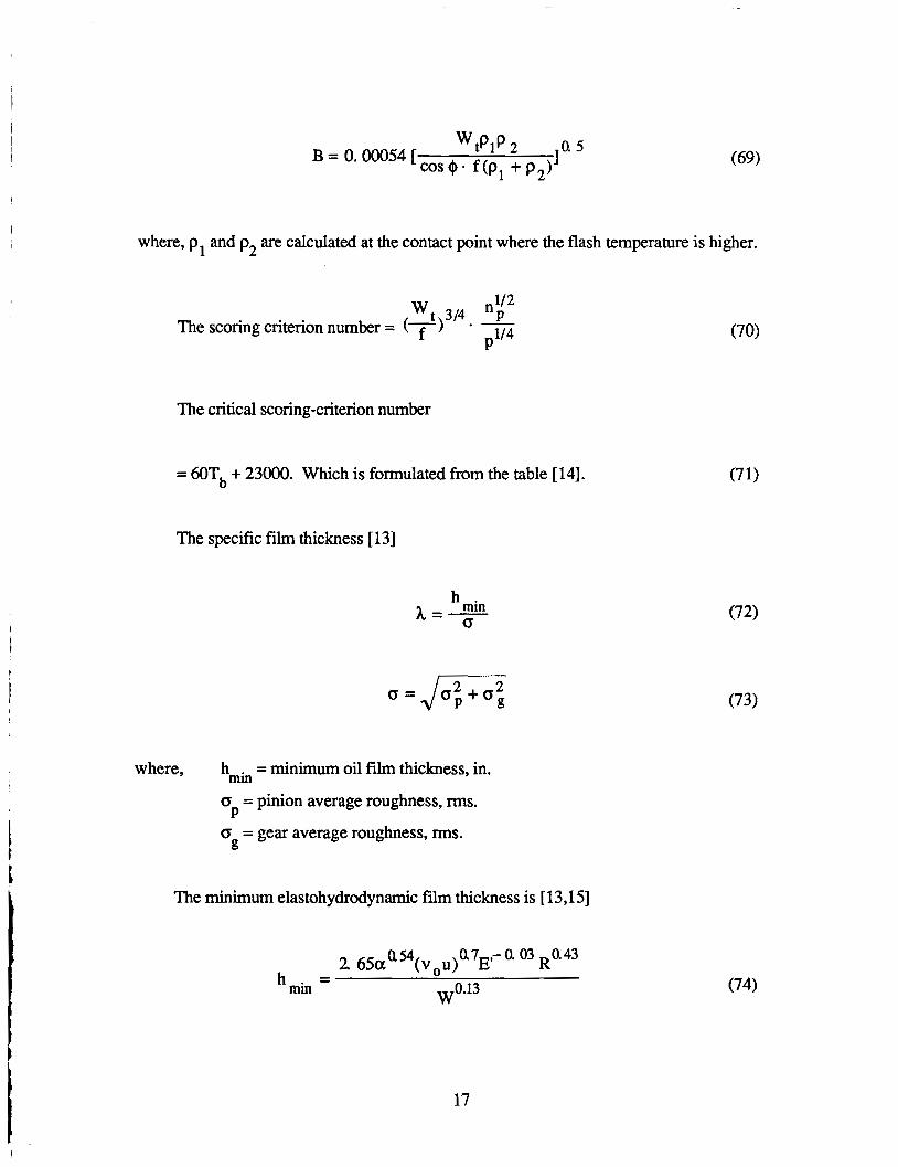
i where, p, and p2 are calculated at the contact point where the flash temperature is higher.
n 112 * -
p1/4 w t 314 P
The scoring criterion number =
The critical scoring-criterion number
= 60Tb + 23000. Which is formulated from the table [ 141.
The specific film thickness [ 131
min <T
h h = - -
where, h = minimum oil film thickness, in. min
P
g
CT = pinion average roughness, rms.
CT = gear average roughness, rms.
The minimum elastohydrodynamic film thickness is [ 13,151
0.7 ,- 0 03 R0.43 2 6 5 c ~ ~ ~ ( v ~ u ) E h =
min w0.13 (74)
17

where, a = pressure viscosity coefficient.
vo = absolute viscosity.
1 2 1 u =-(u + u2)
u1 and u2 are rolling velocities of pinion and gear at point of contact, respectively.
m P --. '1- 30 p i
(75)
(76)
(p, and p2 are calculated at the lowest point where the worst Hertzian stress is
considered to occur.)
, here. W = specific loading. It is taken as f w t
To avoid the scoring failure, the flash temperature should be below a certain limit, the
specific film thickness may not be less than 1.0, and the scoring number may not exceed
the critical number.
These functions are calculated in subroutine FLASH, SCORING, FILMTH,
18
FLMFC.
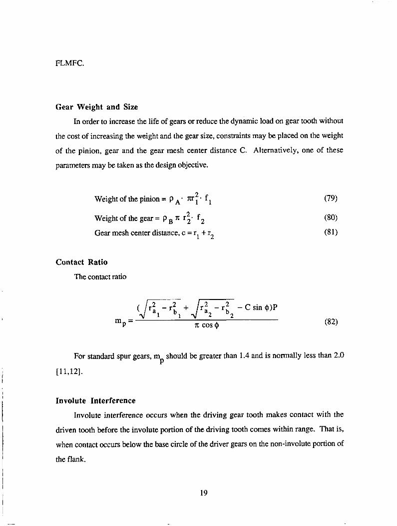
Gear Weight and Size
In order to increase the life of gears or reduce the dynamic load on gear tooth without
the cost of increasing the weight and the gear size, constraints may be placed on the weight
of the pinion, gear and the gear mesh center distance C. Alternatively, one of these
parameters may be taken as the design objective.
Weightofthepinion= P A * m:. f ,
Weight of the gear = p 2 n: r2* f 2
Gear mesh center distance, c = r1 + r2
Contact Ratio
The contact ratio
(Jr: - r i +Jr: 2 - r t 2 - c sin +)P 1 1 m = P n: cos0
(79)
For standard spur gears, m should be greater than 1.4 and is normally less than 2.0 P [ 11,121.
Involute Interference
Involute interference occurs when the driving gear tooth makes contact with the
driven tooth before the involute portion of the driving tooth comes within range. That is,
when contact occurs below the base circle of the driver gears on the non-involute portion of
the flank.
19
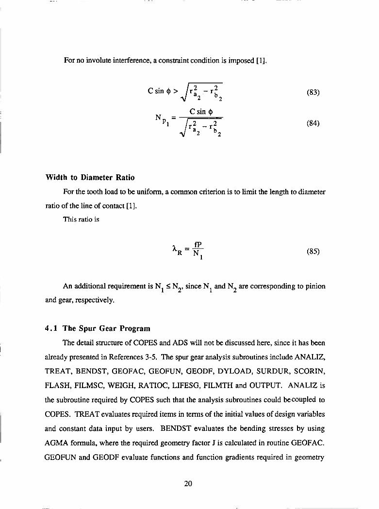
For no involute interference, a constraint condition is imposed [ 11.
c sin @ > J- 2 2
C sin @ N =
Width to Diameter Ratio
For the tooth load to be uniform, a common criterion is to limit the length to diameter
ratio of the line of contact [l]. I
This ratio is
I An additional requirement is N, I N2, since N, and N2 are corresponding to pinion
~ and gear, respectively.
4 . 1 The Spur Gear Program
The detail structure of COPES and ADS will not be discussed here, since it has been
already presented in References 3-5. The spur gear analysis subroutines include ANALIZ,
TREAT, BENDST, GEOFAC, GEOFUN, GEODF, DYLOAD, SURDUR, SCORIN,
FLASH, FILMSC, WEIGH, RATIOC, LIFESG, FILMTH and OUTPUT. ANALIZ is
the subroutine required by COPES such that the analysis subroutines could becoupled to
COPES. TREAT evaluates required items in terms of the initial values of design variables
and constant data input by users. BENDST evaluates the bending stresses by using
AGMA formula, where the required geometry factor J is calculated in routine GEOFAC.
I
~
1 GEOFUN and GEODF evaluate functions and function gradients required in geometry
I 20
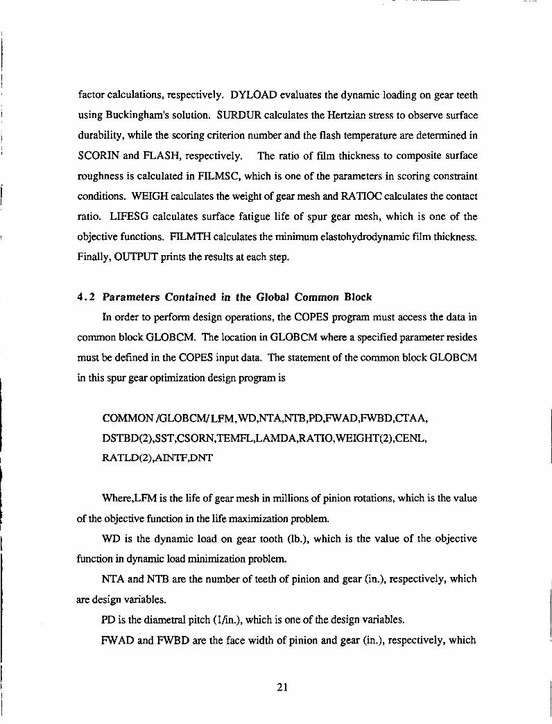
factor calculations, respectively. DYLOAD evaluates the dynamic loading on gear teeth
using Buckingham's solution. SURDUR calculates the Hertzian stress to observe surface
durability, while the scoring criterion number and the flash temperature are determined in
SCORIN and FLASH, respectively. The ratio of film thickness to composite surface
roughness is calculated in FILMSC, which is one of the parameters in scoring constraint
conditions. WEIGH calculates the weight of gear mesh and RATIOC calculates the contact
ratio. LIFESG calculates surface fatigue life of spur gear mesh, which is one of the
objective functions. FILMTH calculates the minimum elastohydrodynamic film thickness.
Finally, OUTPUT prints the results at each step.
4.2 Parameters Contained in the Global Common Block
In order to perform design operations, the COPES program must access the data in
common block GLOBCM. The location in GLOBCM where a specified parameter resides
must be defined in the COPES input data. The statement of the common block GLOBCM
in this spur gear optimization design program is
COMMON /GLOBCM/LFM,WD,NT.A,NTB,PD,FWAD,FWBD,CTAA, DSTBD(2),SST,CSORN,TMFL,LAMDA,RATIO,WEIGHT( 2),CENL,
RATLD(2),AINTF,DNT
Where,LFM is the life of gear mesh in millions of pinion rotations, which is the value
of the objective function in the life maximization problem.
WD is the dynamic load on gear tooth (lb.), which is the value of the objective
function in dynamic load minimization problem.
NTA and NTB are the number of teeth of pinion and gear (in.), respectively, which
are design variables.
PD is the diametral pitch (lhn.), which is one of the design variables.
W A D and FWBD are the face width of pinion and gear (in.), respectively, which
21
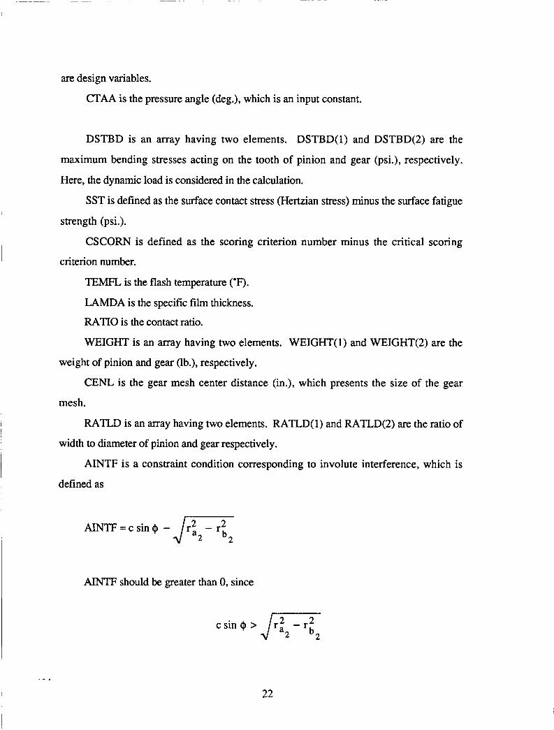
are design variables.
CTAA is the pressure angle (deg.), which is an input constant.
DSTBD is an array having two elements. DSTBD(1) and DSTBD(2) are the
maximum bending stresses acting on the tooth of pinion and gear (psi.), respectively.
Here, the dynamic load is considered in the calculation.
SST is defined as the surface contact stress (Hertzian stress) minus the surface fatigue
strength (psi.).
CSCORN is defined as the scoring criterion number minus the critical scoring
criterion number.
TEMFL, is the flash temperature (OF).
LAMDA is the specific film thickness.
RATIO is the contact ratio.
WEIGHT is an array having two elements. WEIGHT( 1) and WEIGHT(2) are the
weight of pinion and gear (lb.), respectively.
CENL is the gear mesh center distance (in.), which presents the size of the gear
mesh.
RATLD is an array having two elements. RATLD( 1) and RATLD(2) are the ratio of
width to diameter of pinion and gear respectively.
AINTF is a constraint condition corresponding to involute interference, which is
defined as
M m = c s i n + -J.’ - r 2 2 b2
AINTF should be greater than 0, since
c s in+>J , z - r 2 2 b2
22

I DNT is defined as NTE3 minus NTA. DNT should not be less than 0, since the gear
is always not less than the pinion.
DSTB, SST, CSCORN, TEMFL, LAMDA, RATIO, WEIGHT, CENL, RATLD,
AINTF and DNT are values of constraint functions. The definitions of some terms have
been explained previously.
Input Data Description
There are two parts of input data file. The first part corresponds to COPES; and the
second part corresponds to the spur gear analysis subroutines. The details of the COPES
input may be found in the COPES manual (3) and so are not described here.
Spur Gear Analysis Input Data
There are six rows of data in the second part input file. The form of the input data file
is as follows:
NTA,NTB ,PD,FWAD,FWBD,CTAA
'ITLD,CY CLP
DENS A,DENSB,YMAD,YMBD,EPS A,EPSB ,SRMS 1 ,SRMS2
ERR,SHLl ,SHL2,SHD 1 ,SHD2
HARDB,CL,CH,CT,CK
ALPHA,VIS D ,BETA ,TEMLUB
Where, NTA and NTB are the number of pinion and gear teeth, respectively.
PD is the diametral pitch (in. - l)
W A D and FWBD are the face widths of pinion and gear, respectively (in.).
CTAA is the pressure angle (deg.).
T E D is the normal load acting on gear tooth (lb.).
CYCLP is the pinion speed (r/s).
DENSA and DENSB are the material density of pinion and gear, respectively
(1brn/in3).
23
YMAD and YMBD are Young's modulus of pinion and gear, respectively (psi.).
EPSA and EPSB are Poisson's ratio of pinion and gear, respectively.
SRMS1 and SRMS2 are surface roughness corresponding to pinion and hear, '
respectively (microin. )
ERR is the measured error on pair of mating teeth (in.).
SHLl and SHL2 are the lengths of shaft corresponding to pinion and gear,
respectively (in.).
SHDl and SHD2 are the diameters of shaft corresponding to pinion and gear,
respectively (in.).
HARDB is the Brinell hardness, which is required in scoring observation.
CL, CH, CT, CK are the life factor, the hardness ratio factor, the temperature factor
and the reliability factor, respectively. These factors are required in surface durability
observation.
ALPHA is the pressure viscosity coefficient.
VISD is the viscosity (lb.s/in2) at ambient temperature.
BETA is the temperature viscosity coefficient.
TEMLLJB is the ambient temperature (deg. F).
ALPHA, VISD, BETA and TEMLUB are required input data in film thickness
calculation.
All of above input data are real number, including the number of teeth NTA and
NTB.
Input Data Example: Life Maximization
The input data for a design example of the life maximization problem is presented in
the following Table.
24
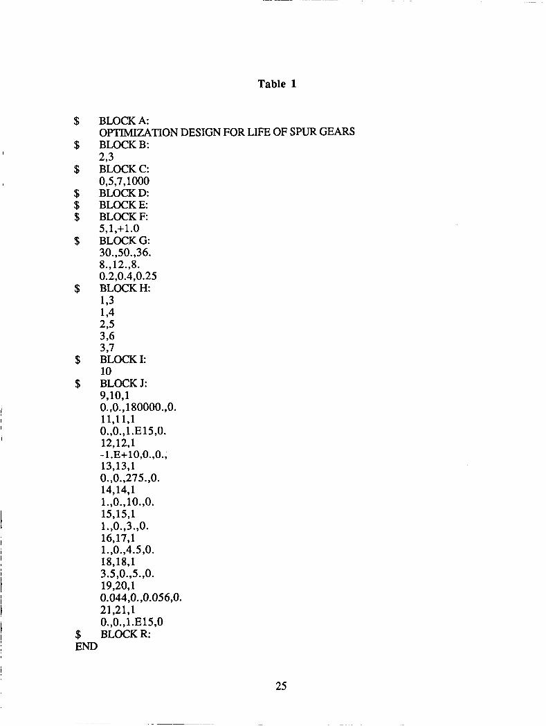
Table 1
BLOCKA: OPTIMIZATION DESIGN FOR LIFE OF SPUR GEARS BLOCK B: 293 BLOCK C: 0,s ,7,1000 BLOCK D: BLOCK E: BLOCK F 5,1,+1.0 BLOCK G: 30.,50.,36. 8.,12.,8. 0.2,0.4,0.25 BLOCK H 193 194 295 3,6 3 9 7
BLOCK I: 10 BLOCK J: 9,10,1 0.,0.,180000.,0. 11,11,1 0.,0.,1.E15,0. 12,12,1
13,13,1 0.,0.,275.,0. 14,14,1 l.,O.,lO.,O. 15,15,1 1.,0.,3.,0. 16,17,1 1.,0.,4.5,0. 18,18,1 3.5,0.,5.,0. 19,20,1 0.044,O. ,0.056,0. 21,21,1 0.,0.,1 .E15,0 BLOCK R:
- 1 .E+lO,O.,O.,
25
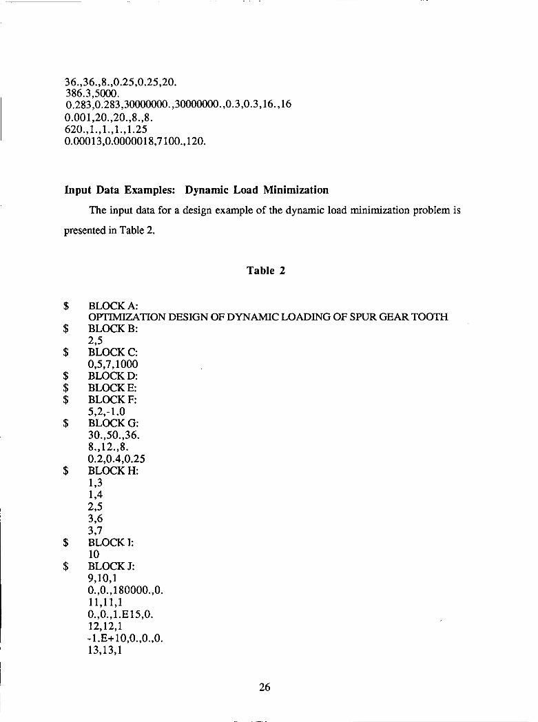
36.,36.,8.,0.25,0.25,20. 386.3,5000. 0.283,0.283,30000000. ,30000000. ,0.3,0.3,16., 16 0.001,20.,20.,8.,8. 620.,1.,1.,1.,1.25 0.0001 3,0.0000018,7 loo., 120.
Input Data Examples: Dynamic Load Minimization
The input data for a design example of the dynamic load minimization problem is
presented in Table 2.
Table 2
BLOCK A: OFTIMEATION DESIGN OF DYNAMIC LOADING OF SPUR GEAR TOOTH BLOCK B: 275 BLOCK C: 0,5,7,1000 BLOCK D: BLOCK E: BLOCK F:
BLOCK G: 30.,50.,36. 8., 12.3. 0.2,0.4,0.25 BLOCK H: 193 194 2 s 396 3 97 BLOCK I: 10 BLOCK J: 9,10,1 0.,0.,180000.,0. 11,11,1 0.,0.,1.E15,0. 12,12,1 - 1 .E+10,0.,0.,0. 13,13,1
5,2,-1.0
26
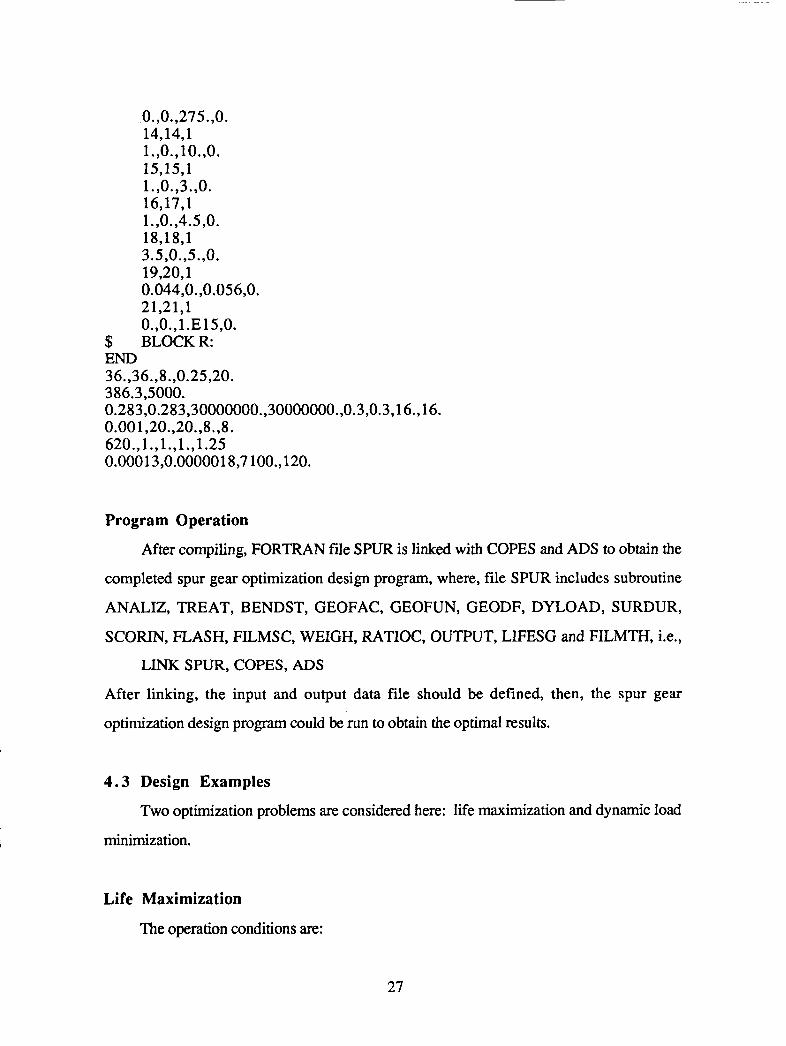
0.,0.,275.,0. 14,14,1 l.,O.,lO.,O. 15,15,1 1.,0.,3.,0. 16,17,1 1.,0.,4.5,0. 18,18,1 3.5,0.,5.,0. 19,20,1 0.044,O. ,0.056,0. 21,21,1 0.,0.,1.E15,0.
$ BLOCKR: END 36.,36.,8.,0.25,20. 386.3,5000. 0.283,0.283,30000000.,30000000.,0.3,0.3,16., 16. 0.00 1,20.,20. ,8. ,8. 620.,1.,1.,1., 1.25 0.00013,0.0000018,7 100.,120.
Program Operation
After compiling, FORTRAN file SPUR is linked with COPES and ADS to obtain the
completed spur gear optimization design program, where, file SPUR includes subroutine
ANALIZ, TREAT, BENDST, GEOFAC, GEOFUN, GEODF, DYLOAD, SURDUR,
SCORIN, FLASH, FILMSC, WEIGH, RATIOC, OUTPUT, LIFESG and FILMTH, i.e.,
LINK SPUR, COPES, ADS
After linking, the input and output data file should be defined, then, the spur gear
optimization design program could be run to obtain the optimal results.
4 . 3 Design Examples
Two optimization problems are considered here: life maximization and dynamic load
minimization.
Life Maximization
The operation conditions are:
27
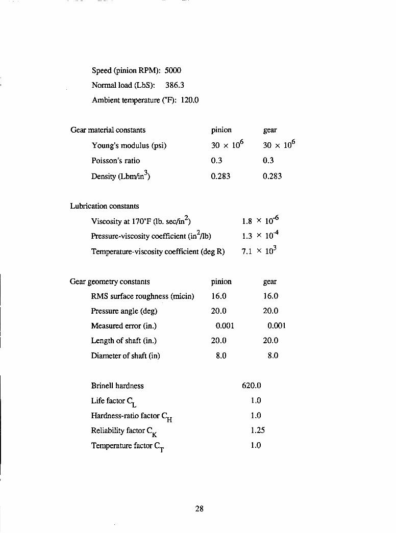
Speed (pinion RPM): 5000
Normal load (LbS): 386.3
Ambient temperature (OF): 120.0
Gear material constants
Young's modulus (psi)
Poisson's ratio n
Density (Lbdin')
pinion gear
30 x lo6
0.3 0.3
0.283 0.283
30 x lo6
Lubrication constants
Viscosity at 170°F (lb. sec/in2)
Pressure-viscosity coefficient (in Ab)
Temperature-viscosity coefficient (deg R)
2
Gear geometry constants
RMS surface roughness (micin)
Pressure angle (deg)
Measured error (in.)
Length of shaft (in.)
Diameter of shaft (in)
Brinell hardness
Life factor 5 Hardness-ratio factor C, Reliability factor C, Temperature factor C,
pinion
16.0
20.0
0.00 1
20.0
8.0
1.8 X
1.3 X lo4
7.1 x lo3
gear 16.0
20.0
0.001
20.0
8 .O
620.0
1 .o 1 .o 1.25
1 .o
28

The life maximization problem is
Maximize L(x) (Gear mesh life)
Subject to 1) 0 I (T (bending stress) I 18oooO
2) oH (Hertzian stress) I S, (fatigue strength)
3) Scoring number I critical scoring number
4) 0 I T, (Flash temperature) I 2 7 5
5) 1 5 h (specific film thickness) I 10
6) 1.4 I m (contact ratio) 52.0
7) 1.0 I W (pinion weight) I 4.5
8) 1.0 I W (gear weight) 14.5
9) 3.5 I C (center distance) 15.0
10) 0,044 I \ (length to diameter ratio) 20.056
1 1) Np, (for no involute interference) 2 1
12) N, I N 2
P
P
g
Side Constraints
1) 30 I X,, X2 (the number of teeth) I 60
2) 8 I Xg (diametral pitch) I 12.
3) 0.2 I X4, X5 (facewidth) I 0.4
the initial design was
N, = N2 = 36, P = 8, f, = f2 = 0.25 (in.)
has a mesh life of 666.1 million pinion rotations.
The optimization algorithm used was the Modified Feasible directions method with
polynomial interpolation with bounds for the one-dimensional search. After optimization,
the final design has a mesh life of 1963.6 million pinion rotations.
The fmal value of the design variables are
29

N, = N2 = 58.8 P = 11.774 f, = f2 = 0.28 (in.)
The initial and final dynamic loads, Wd, were 1141.1 and 1190.1, respectively.
Dynamic Load Minimization
For the dynamic load minimization problem, all the input constants, constraint
conditions, side constraints and initial values of design variables are the same as in life
maximization problem. Only the objective function becomes dynamic load Wd now.
That is
Minimize Wd
the initial design has a dynamic load of 1141.1 lb.
After optimization, where the same optimization method as in life maximization
problem is used, the final design has a dynamic load of 1089.2 lb.
The final value of the design variables are
N, N2 = 39.8 P = 8, f, = f2 = 0.219 (in.)
Summary
It is seen from the results of these examples that the mesh life of spur gears can be
increased significantly (195%) by increasing the number of teeth, diametral pitch and face
width without any significant change in the weight and size of the gears. Meanwhile, all
the constraints conditions considered here are satisfied.
On the other hand, the dynamic load on spur gear tooth is reduced only a little (4.6%)
by increasing the number of teeth and decreasing face width. The reason may be that the
dynamic load on gear tooth mainly depends on the dynamic parameters such as speed and
measured error on pair of mating teeth rather than the geometric parameters which are
design variables here.
30

The nature of the dynamic load optimization problem needs to be investigated further.
More reasonable design variables are expected to be chosen such that the dynamic load can
be minimized much more. Besides, the constraint conditions corresponding to new design
variables need to be developed.
5.0 SPIRAL BEVEL GEAR ANALYSIS AND OPTIMIZATION
Spiral bevel gears have advantages than other bevel gears. The mesh of spiral bevel
gears has a rolling contact. Since spiral bevel gears have curved oblique teeth, the contact
is smooth and continuous from end to end. Also as a result of their overlapping teeth
action, spiral bevel gears will transmit motion more smoothly than spur gears and other
bevel gears thereby reducing noise and vibration which become especially noticeable at
high loads and high speeds.
On the other hand, because of the complicated geometry of spiral bevel gear, the basic
mechanisms which govern the major modes of spiral bevel gears are still not fully~
understood. Thus the design and analysis of a spiral bevel gear set remains a difficult
problem.
The analysis presented is for the design of a set standard spiral bevel gear mesh. A
typical objective is to maximize gear life without increasing gear weight. The transmitted
horsepower, rpm of the pinion, and gear reduction ratio are given as input. A typical set of
constraints includes bending fatigue, surface pitting, and scoring failure. Kinematic limits
of face contact ratio, involute interference and other geometric limits are also considered.
The study here is based on a thorough study of the kinematics of the gear mesh, such
as those by Buckingham [9]. A Tregolds approximation to calculate spiral bevel gear
geometry is used. The study is also based on a standard spiral bevel gear set with
dimensions of the AGMA.
The purpose is to establish an optimal design procedure for a set of standard spiral
bevel gears which are given specified pinion speeds, input horsepower and gear reduction
ratio.
31
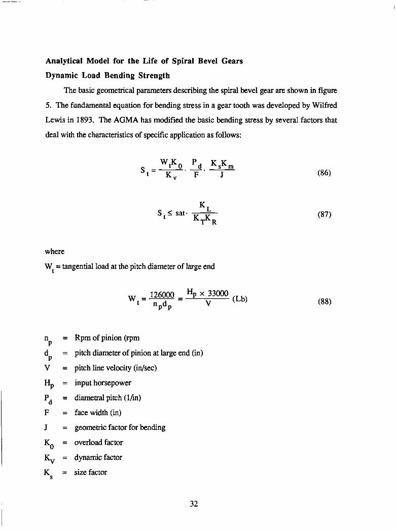
Analytical Model for the Life of Spiral Bevel Gears
Dynamic Load Bending Strength
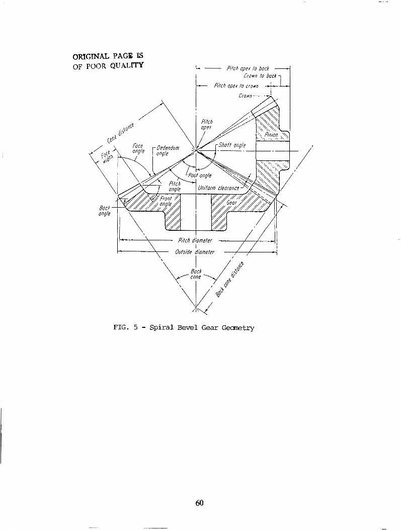
The basic geometrical parameters describing the spiral bevel gear are shown in figure
5. The fundamental equation for bending stress in a gear tooth was developed by Wilfred
Lewis in 1893. The AGMA has modified the basic bending stress by several factors that
deal with the characteristics of specific application as follows:
K . L S I sat-
where
Wt = tangential load at the pitch diameter of large end
n =
d =
v = Hp =
'd - F =
J =
P
P
-
- - - Kv -
K = S
Rpm of pinion (rpm
pitch diameter of pinion at large end (in)
pitch line velocity (idsec)
input horsepower
diametral pitch (lhn)
face width (in)
geometric factor for bending
overload factor
dynamic factor
size factor
32
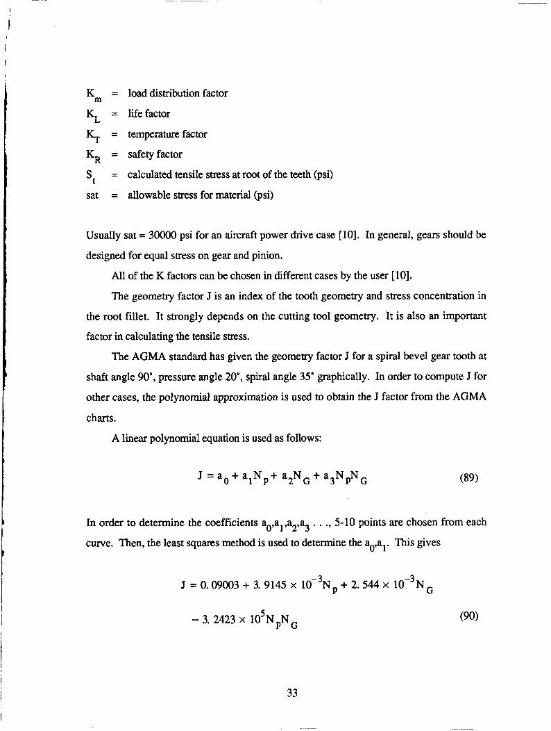
K = m
K L = KT -
- -
KR - - -
sat =
load distribution factor
life factor
temperature factor
safety factor
calculated tensile stress at root of the teeth (psi)
allowable stress for material (psi)
Usually sat = 3oooO psi for an aircraft power drive case [lo]. In general, gears should be
designed for equal stress on gear and pinion.
All of the K factors can be chosen in different cases by the user [lo].
The geometry factor J is an index of the tooth geometry and stress concentration in
the root fillet. It strongly depends on the cutting tool geometry. It is also an important
factor in calculating the tensile stress.
The AGMA standard has given the geometry factor J for a spiral bevel gear tooth at
shaft angle 90", pressure angle 20", spiral angle 35' graphically. In order to compute J for
other cases, the polynomial approximation is used to obtain the J factor from the AGMA
charts.
A linear polynomial equation is used as follows:
J = a. + a,Np+ a2NG + a3NpNG (89)
In order to determine the coefficients ao,al,a2,a3 . . ., 5-10 points are chosen from each
curve. Then, the least squares method is used to determine the ao,al. This gives
J = 0.09003 + 3.9145 x IO-~N, + 2.544 x I O - ~ N ~
- 3. 2423 x 105NpNG
33

( 1 2 I N I100 P
12 I NG I 100)
where Np = number of teeth on pinion
NG = number of teeth on gear
This equation is not only convenient for computer code, but also is quite accurate for
calculating geometry factor J.
Pitting
Another mode of failure is called "pitting" of the tooth surfaces. It is caused by too
high contact stress known as "Hertz stress" at the contact surface. Here we assume that the
magnitude of Hertz stress is a reasonable measure of the tendency of the surface to pit.
In the AGMA standard, the Hertz stress can be calculated by the following formula
S , I s CL.cH c,c,
where
Wt C = elasticcoefficient
P
= tangential load at the pitch diameter of large end (Lb)
cp = 1. 5
= Poisson's ratio for pinion
= Poisson's ratio for gear cLP
PG
34
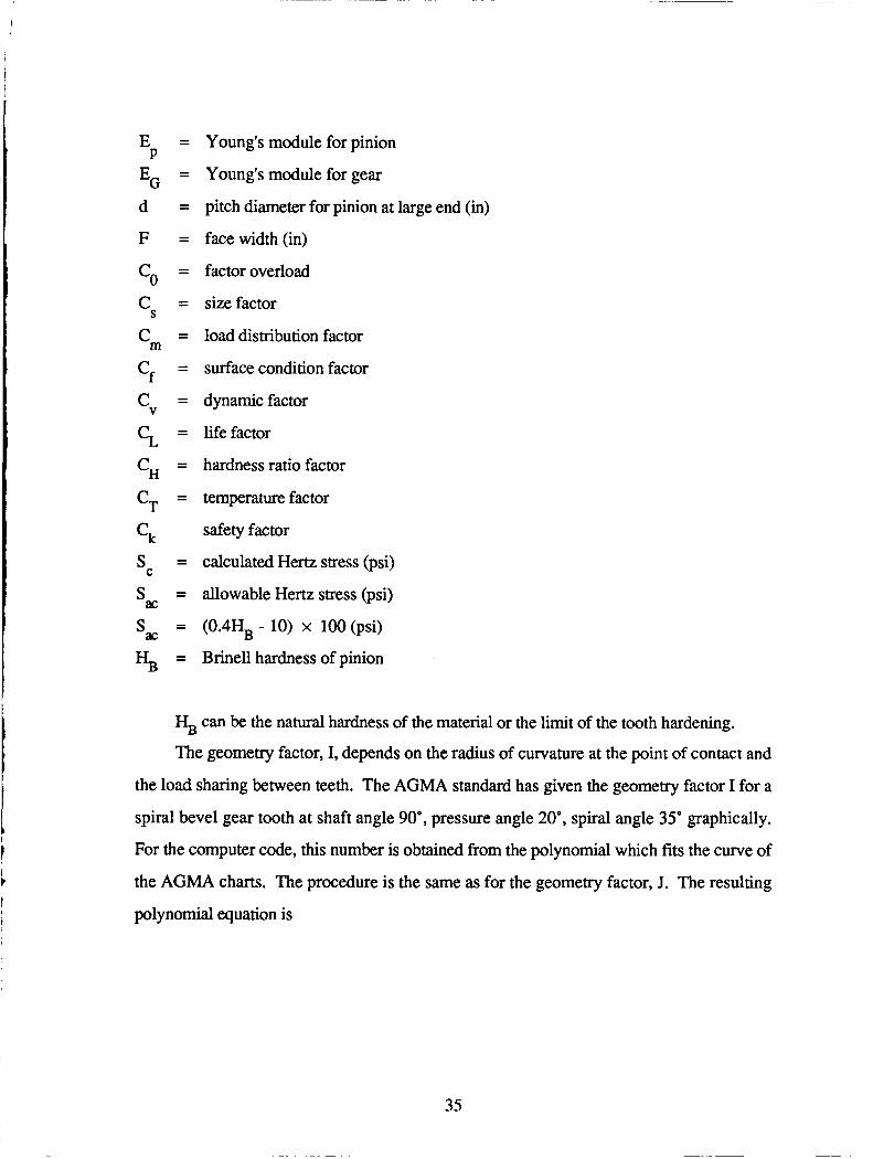
E =
EG - d =
F =
P -
- co - c = c = S
m -
cf -
% =
cT - ck
c = V
- - -
s = s = s =
C
ac
ac
% =
Young's module for pinion
Young's module for gear
pitch diameter for pinion at large end (in)
face width (in)
factor overload
size factor
load distribution factor
surface condition factor
dynamic factor
life factor
hardness ratio factor
temperature factor
safety factor
calculated Hertz stress (psi)
allowable Hertz stress (psi)
(0.4HB - 10) x 100 (psi)
Brinell hardness of pinion
HB can be the natural hardness of the material or the limit of the tooth hardening.
The geometry factor, I, depends on the radius of curvature at the point of contact and
the load sharing between teeth. The AGMA standard has given the geometry factor I for a
spiral bevel gear tooth at shaft angle 90", pressure angle 20', spiral angle 35' graphically.
For the computer code, this number is obtained from the polynomial which fits the curve of
the AGMA charts. The procedure is the same as for the geometry factor, J. The resulting
polynomial equation is
35

I = 0.0680 - 1.0736 x 10⁻³Np + 1. 399 x 10-3N,
- L 235 x 106NpNG (93)
(12 S Np I 5 0 151NG<100)
All of the c factors can be chosen by user [5].
Scoring
Besides breakage fatigue and pitting fatigue, the third mode of failure is scoring.
Recently more attention has been paid to this phenomena. It usually occurs in high speed
and high load conditions, with low viscosity lubricants when the overheating causes the oil
film breakdown and the gear is kept in operation after pitting starts. This phenomena is
also called metal-to-metal contact resulting in welding and tearing apart until the tooth
surface is deteriorated. Actually, scoring is a lubrication failure, and is hard to analyze and
predict. Research has reported that it is influenced by a combination of factors, such as
pressure, sliding velocity, viscosity of the oil, temperature of the oil bath, properties of
material and surface finish and treatment, etc.
There are many ways to predict scoring risk. Two design approaches will be given
here. The one efficient method is based on flash temperature (called hot scoring). The
other is based on oil-film thickness (called cold scoring).
The concept of flash temperature was first presented by Blok [ 16las follows:
Tf=Tb+AT (94)
Where: Tb is the temperature of gear blank in the contact zone. It is difficult to estimate,
Often the blank temperature is approximated as the average of the oil temperature entering
and leaving the gearbox [13]. In this paper, we choose Tb = 200°F. The increment of the
36
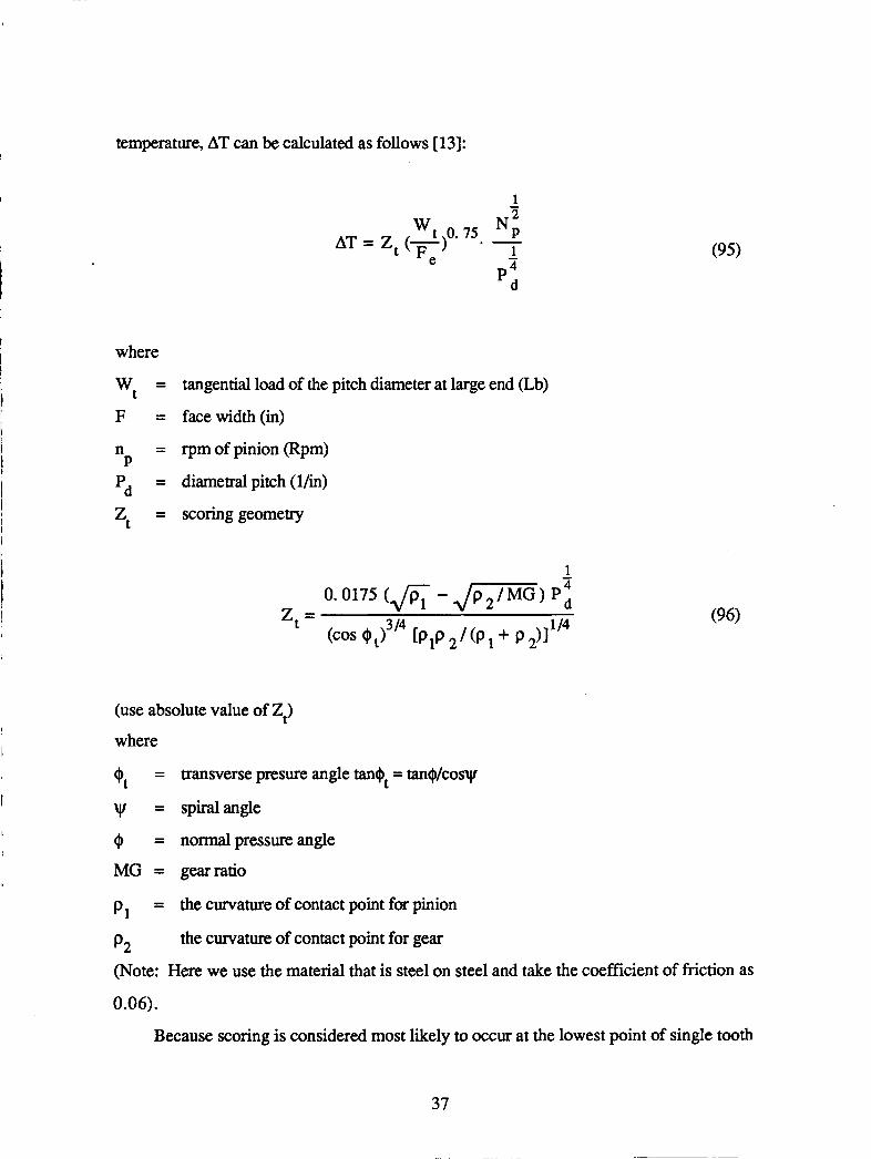
temperature, AT can be calculated as follows [13]:
w t 0.75 Ni AT = 2 (-) - - 1
D4 - Fe
' d
where
W, F = facewidth(in)
n = rpmofpinion (Rpm)
Pd = diametralpitch(l/in)
Z, = scoring geometry
= tangential load of the pitch diameter at large end (Lb)
P
(95)
(use absolute value of 22
where
0, = transverse presure angle tan+, = tan$/cosy
w = spiralangle
0 = normalpressureangle
MG = gearratio
p1 = the curvature of contact point for pinion
the curvature of contact point for gear p2 (Note: Here we use the material that is steel on steel and take the coefficient of friction as
0.06).
Because scoring is considered most likely to occur at the lowest point of single tooth
37
contact on the pinion or the highest point of single tooth contact on the pinion, these two
points are checked. Normally, scoring calculations are made for the pinion only and the
gear is handled indirectly. If the pinion is safe the gear should be safe.
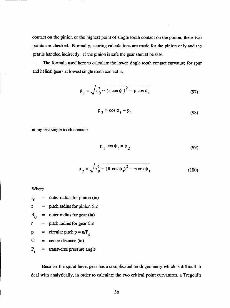
The formula used here to calculate the lower single tooth contact curvature for spur
and helical gears at lowest single tooth contact is,
p, =J~z,- (rcos+t ) 2 - pcosQt
at highest single tooth contact:
(97)
p 2 = , / r i - ( R c o s $ J 2 - P C O S + ~
Where
r = outer radius for pinion (in)
r = pitch radius for pinion (in)
Ro = outer radius for gear (in)
r = pitch radius for gear (in)
p = circularpitchp=7c/Pd
C = centerdistance(in)
Pt = transverse pressure angle
0
Because the spiral bevel gear has a complicated tooth geometry which is difficult to
deal with analytically, in order to calculate the two critical point curvatures, a Tregold’s
38
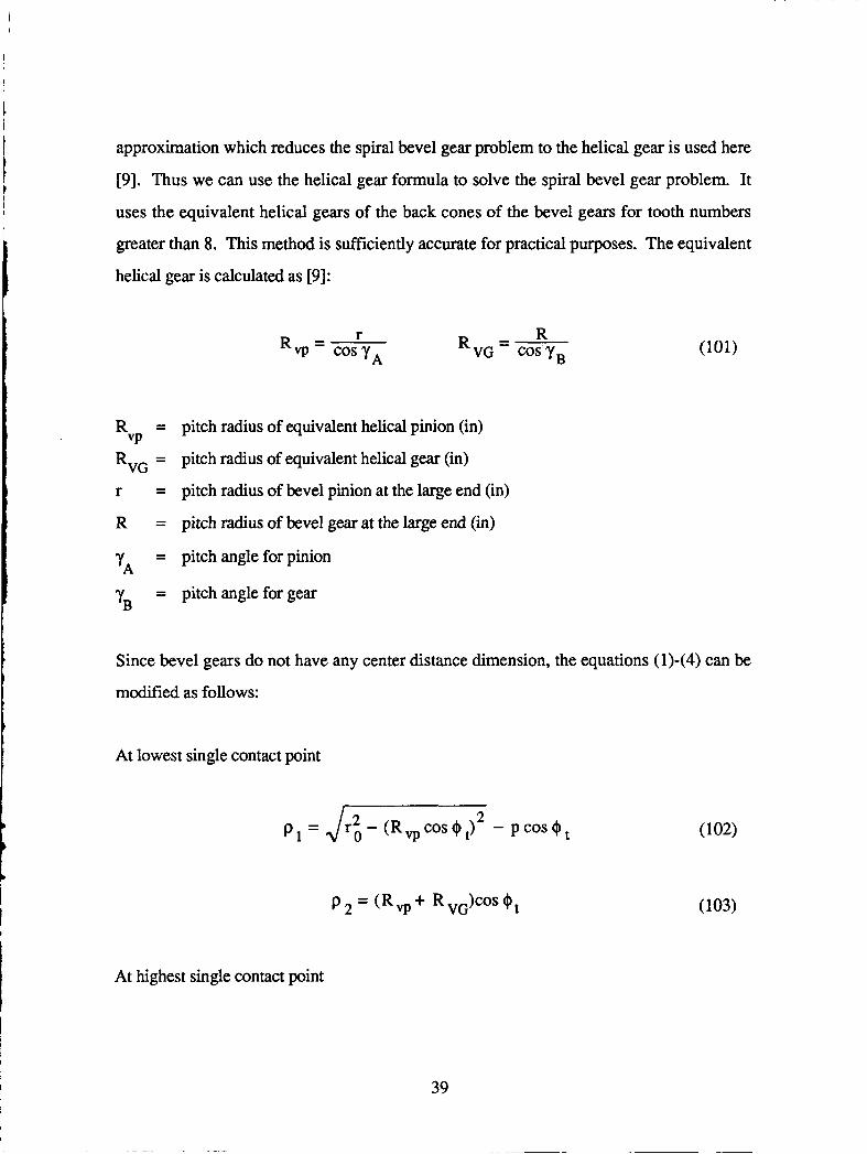
approximation which reduces the spiral bevel gear problem to the helical gear is used here
[9]. Thus we can use the helical gear formula to solve the spiral bevel gear problem. It
uses the equivalent helical gears of the back cones of the bevel gears for tooth numbers
greater than 8. This method is sufficiently accurate for practical purposes. The equivalent
helical gear is calculated as [9]:
r - Rvp - cosyA
R = pitch radius of equivalent helical pinion (in)
RVG = pitch radius of equivalent helical gear (in)
r
R
Vp
= pitch radius of bevel pinion at the large end (in)
= pitch radius of bevel gear at the large end (in)
= pitch angle for pinion
= pitch angle for gear yA
yB
Since bevel gears do not have any center distance dimension, the equations (1)-(4) can be
modified as follows:
At lowest single contact point
P 2 = (RV+ RVG)COSOt
At highest single contact point
39
where
r o = R q + l .O/Pd
R o = Rvg + 1. O/Pd
ro = outer radius of equivalent helical pinion
Ro = outer radius of equivalent helical gear
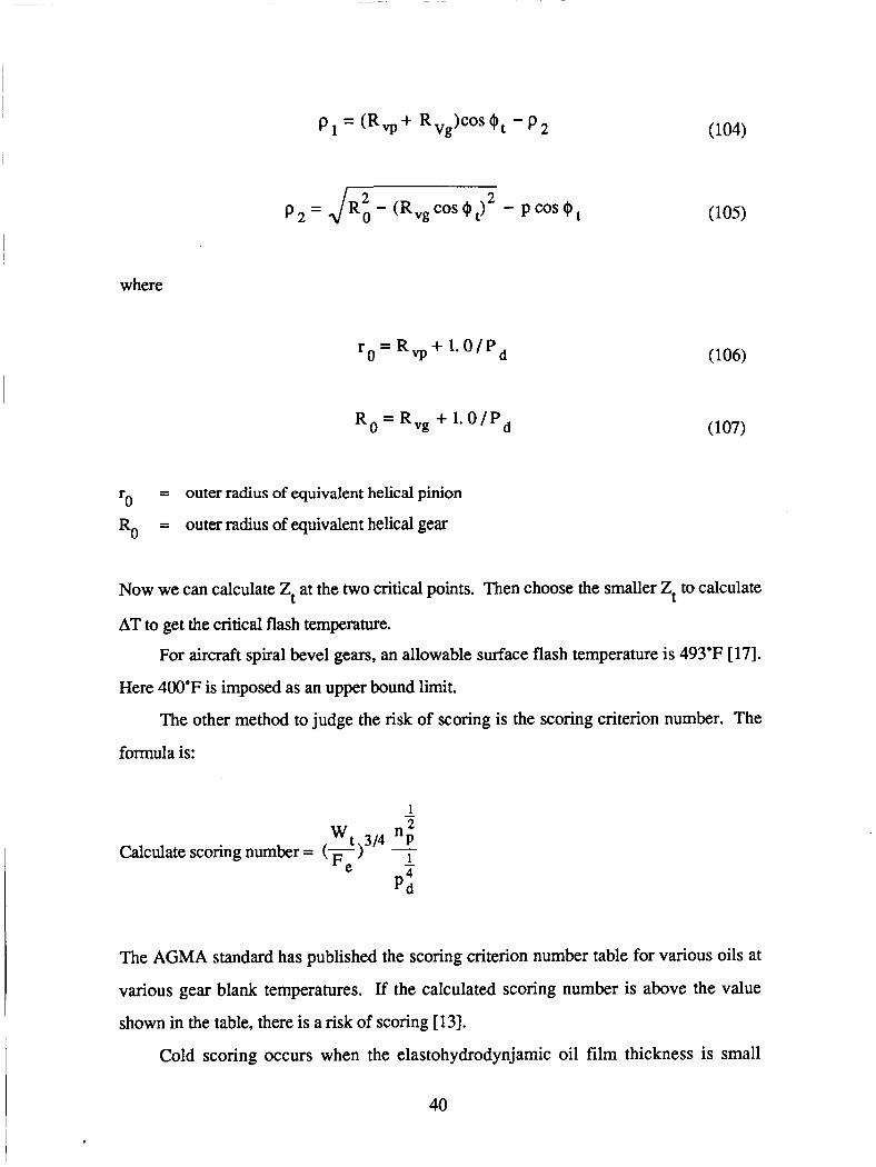
Now we can calculate Zt at the two critical points. Then choose the smaller Zt to calculate
AT to get the critical flash temperature.
For aircraft spiral bevel gears, an allowable surface flash temperature is 493°F [17].
Here 400°F is imposed as an upper bound limit.
The other method to judge the risk of scoring is the scoring criterion number. The
formula is:
w t 314 "p' Calculate scoring number = (K -
p4d
The AGMA standard has published the scoring criterion number table for various oils at
various gear blank temperatures. If the calculated scoring number is above the value
shown in the table, there is a risk of scoring [13].
Cold scoring occurs when the elastohydrodynjamic oil film thickness is small
40

compared with the surface roughness and the lubricant does not have enough additives to
prevent scoring on the contact tooth surfaces. A criterion used to determine the possibility
of surface distress is the ratio of film thickness to composite surface roughness [ 131:
min 0
h A = - 21
h = filmparameter
h = minimum oil film thickness (in)
CJ = surface roughness of pinion (rms)
0 = surface roughness of gear (rms)
min
P
f3
There is a risk of cold scoring if h is less than 1. Here the lower bound of 1 is used.
The calculation of hmin is a quite complicated problem. It requires special data about
the oil. A simple but approximate calculation for the minimum oil film thickness at the
pitch line is used here
44. 6 re (lubricant factor) (velocity factor) h = min (loading factor) (Pin) (109)
where
= effective radius of curvature at pitch diameter re
41

Spiral Bevel gears do not have any contact distance, so use c = (MG + l)r
- sin $n MG r e - cos 2 'VI ' MG+1
r = pitch diameter at large end for pinion
$n = normal pressureangle
y . ~ = spiralangle
MG = gearratio
Lubricant factor = (CXE')'.~ 2 a = lubricant pressure-viscosity coefficient in Ab
E' = effective elastic modulus for a steel gear set
6 - _ ' E = 51.7 x 10 psi. - (1-v2)
7 E = 3 x 10 psi V = 0.3
0.70 OU Velocity factor = (-i-)
E r e
po = lubricant viscosity at operating temperature (cp) and u = rolling velocity at the pitch
line
~ n , , d s i n t $ ~ 60 in / second u =
- )I '0 = p ' e r p + ( T + 4 6 0 T,+460 1
42
P = P = To -
-
T =
d = - 4 -
viscosity at temperature To
lube, temp-viscosity coefficient at lube ambient temperature (deg. R)
tooth bulk temperature
temperature (deg. F)
pinion pitch diameter at large end (in)
transverse pressure angle
0.13 Loading factor = (WPEI',)
Wt = tangential load (Lb)
F = facewidth(in)
Face Contact Ratio
In order to insure a quiet, smooth, reliable gear mesh, the face contact ratio must be
considered. The face contact ratio for a given spiral bevel gear is the ratio of face advance
to the circular pitch. It must be greater than a minimum number. The value 1.25 is
commonly used for spiral bevel gear.
Involute Intereference
Involute interference occurs when the addendum circle of one gear crosses the line of
action past its point of tangency with the base circle on its mating gear. That is, its contact
occurs below the base circle of the pinion on the non-involute portion. This phenomena
also is called "undercut" and this weakens the gear. There are many ways to avoid
undercut. The use of minimum pinion teeth to eliminate interference is imposed here.
The lower bound of teeth number for pinion is 12 for spiral bevel gears, when the
pressure angle is 20'. On the other side, in order to avoiC: undercut with low numbers of
teeth and balance the strength of gear and pinion teeth, there is a limit for gear and pinion
teeth:
43
N + N G 2 3 4 (for pressure angle equals 20") P
Ratio of Face Width to Cone Distance
The AGMA standard recommended the ratio of face width to
1/3 or PdlO, whichever is smaller.
one distance is equal to
5 .1 The Spiral Bevel Gear Program
The spiral bevel gear analysis program is written in the same general format as the
spur gear analysis program. That is, the main routine is a sub routine called ANALIZ
which can be directly coupled with the COPEWADS optimization program.
The analysis routines include ANALIZ, INPUT, OUTPUT, PITTING, BENDING,
SCORING, CONTR, WEIGHT, FLSHT, FMTH, LFAFBG, and LIFEBG. These are all
contained in a FORTRAN file called SPIRLB. Subroutine ANALIZ is the main analysis
control routine which is called by COPES for optimization. This routine contains the
GLOBCM common block which transfers data between the analysis and optimization.
Subroutine INPUT reads all analysis data and subroutine OUTPUT prints the analysis
results.
5.2 Parameters Contained in the Global Common Block
In subroutine ANALIZ, the labeled common block, GLOBCM, contains the
information that is transferred between the analysis and optimization routines. The
common block is as follows:
COMMON/GLOBCM/NTA,NTB,FWAD,FWBD,PR,SIGMA,PSI,PHI,SC,ST,SCORN, FLASHT,LAMDA,FCON,MF,WEIGHT,INTFl ,INTF2,LF,MG
These parameters are defined in the following table for convenient reference:
44

Fortran
Parameter Name Units Definition
1
2
3
4
5
6
7
8
9
10
11
12
13
14
15
16
17
18
19
20
NP
NG F
F
'd
C S
st
Tf
SCON
FCON
% WEIGHT
INF 1
INF2
LF
MG
NTA
NTB
W A D
FWBD
PR
SIGMA
PSI
PHI
sc ST
SCON
FLASHT
LAMDA
FCON
MF
WEIGHT
INF 1
INF2
LF
MG
in.
in.
l/in.
degrees
degrees
degrees
psi
psi
deg. F
Imb
lo6 rev.
Number of teeth in pinion
Number of teeth in gear
Face width of pinion
Face width of gear
Diametd pitch
Shaft angle
Spiral angle
Pressure angle
Hertzian stress
Bending stress
Scoring number
Flash temperature
Thicknesshoughness ratio
Ratio of face widtwcone dist.
Face contact ratio
Gear set weight
No involute inter. lower bound
Sum of gear mesh
Gear mesh life
Gear ratio
Input Data Description
As with the spur gear design, the data file consists of two parts. The first is the
COPES input data which defines the optimization problem and the second is the analysis
data for the spiral bevel gear.
45

Spiral Bevel Gear Input Data
There are seven lines of data as defined below.
Line 1
GEMATA, GEMATB, LUBNA
GEMATA - pinionmaterial
GEMATB - gearmaterialname
LUBNA - lubricantname
Line 2
RPMA,SC,ST,Y lESA,Y lESB,YMAD,YMBD
RPMA - RPMofpinion
sc - allowable contact stress (psi)
ST - allowable bending stress (psi)
YlESA - pinion material yield stress (psi)
YlESB - gear material yield stress (psi)
YMAD - pinion material Young's modulus (psi)
YMJ3D - gear material Young's modulus (psi)
Line 3
NTA,MG,HP,HB,SRMS 1 ,SRMS2,BETA,TEMLUB,SPHEA,SPHEB NTA - number of teeth in the pinion
MG - gearratio
HP - input horsepower
HB - minimumb h e l l hardness of the gear set
SRMS 1 - pinion rms surface roughness (micreinches)
SRMS2 - gear rms surface roughness (micro-inches)
BETA
TEMLUB - lube ambient temperature (deg. F)
- lube temp-viscosity coef. at lub ambient temp (deg. R)
46
t
1
SPHEA - specific heat of the pinion
SPHEB - specific heat of the gear
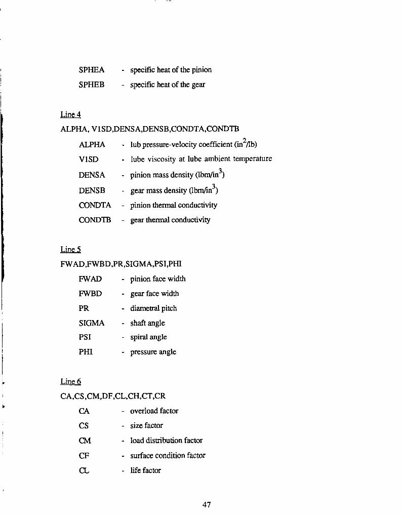
Line 4
ALPHA, V 1 SD,DENS A,DENSB,CONDTA,CONDTB 2 ALPHA - lub pressure-velocity coefficient (in Ab)
VlSD - lube viscosity at lube ambient temperature
DENSA - pinion mass density (lbdin”)
DENSB - gear mass density (lbdin’)
CONDTA - pinion thermal conductivity
CONDTF3 - gear thermal conductivity
Line 5
FWAD,FWBD,PR,SIGMA,PSI,PHI WAD - pinion face width
FWBD - gearfacewidth
PR - dimerralpitch
SIGMA - shaftangle
PSI - spiral angle
PHI - pressure angle
Line 6
CA,CS ,CM,DF,CL,CH,CT,CR
CA - overload factor
cs - size factor
CM - load distribution factor
CF - surface condition factor
CL - lifefactor
47
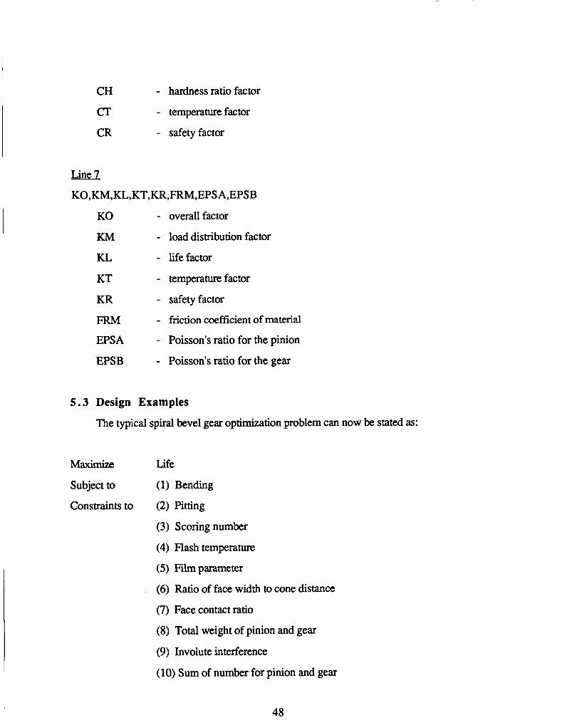
CH
a CR
- hardness ratio factor
- temperature factor
- safety factor
Line 1 KO,KM,KL,KT,KR,FRM,EPS A,EPSB
KO - overall factor
KM - load distribution factor
KL - lifefactor
KT - temperature factor
KR - safety factor
FRM - friction coefficient of material
EPSA - Poisson's ratio for the pinion
EPSB - Poisson's ratio for the gear
5.3 Design Examples
The typical spird bevel gear optimization problem can now be stated as:
Life
Subject to (1) Bending
Constraints to (2) Pitting
(3) Scoring number
(4) Flash temperature
(5) Filmparameter
(6) Ratio of face width to cone distance
(7) Face contact ratio
(8) Total weight of pinion and gear
(9) Involute interference
(10) Sum of number for pinion and gear
48

c
In the following example the initial design was assumed that a single reduction spiral bevel
gear set is to be designed for a 450 horsepower input from pinion shaft, the RPM of the
pinion is to be 15000 RPM.
The material AISI 93 10 is chosen here. The gears are assumed to be made from case
hardened alloy steel with ground tooth surfaces. Its hardness is 620 HB. A constant
pinion speed and gear ratio are maintained during the optimization.
Super-refined naphthenic mineral oil is used as the lubricant.
The initial values are described as follows:
Gear Dau:
Number of teeth for pinion
Number of teeth for gear
Gear ratio
Shaft angle
Pressure angle
Spiral angle
Diametral pitch
31
46.5
1.5
90 degrees
20 degrees
35 degrees
6/in
. . 1 Pinion 1500 Rpm
Gear lo00 Rpm
Ambient temperature 100'F
Gear Material Data
Material
Density
Young's modulus
Poisson's ratio
AISI 93 10
0.283 Lb/in3
30,000,000 psi
0.3
49
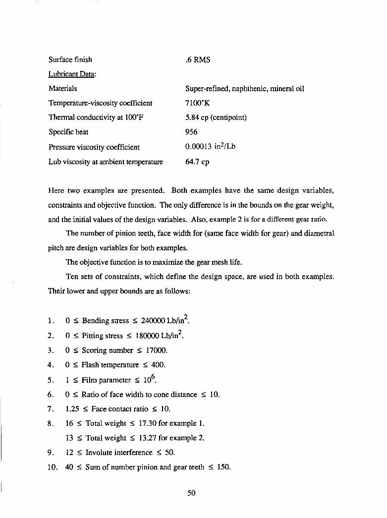
Surface finish .6 RMS
Lubricant Data:
Materials Super-refined, naphthenic, mineral oil
Temperature-viscosity coefficient 7 100'K
Thermal conductivity at 100°F
Specific heat 956
Pressure viscosity coefficient 0.00013 in2/Lb
5.84 cp (centipoint)
Lub viscosity at ambient temperature 64.7 cp I
Here two examples are presented. Both examples have the same design variables,
constraints and objective function. The only difference is in the bounds on the gear weight,
and the initial values of the design variables. Also, example 2 is for a different gear ratio.
The number of pinion teeth, face width for (same face width for gear) and diametral
pitch are design variables for both examples.
The objective function is to maximize the gear mesh life.
Ten sets of constraints, which define the design space, are used in both examples.
Their lower and upper bounds are as follows:
1.
2. I 3. I 4.
5 .
6.
7.
8.
9.
10.
0 I Bending stress I 240000Lb/in2.
0 I Pitting stress I 180000 Lb/in2.
0 I Scoringnumber I 17000.
0 I Flash temperature I 400. 6 1 I Film parameter I 10 .
0 I Ratio of face width to cone distance I 10.
1.25 I Facecontactratio I 10.
16 I Total weight I 17.30 for example 1.
13 I Total weight I 13.27 for example 2.
12 I Involuteinterference 5 50.
40 I Sum of number pinion and gear teeth I 150.
I 50

The optimization results for example 1 are listed in Table 1, where the initial number
of pinion teeth is 31. The gear ratio is 1.5 so the number of gear teeth is 46.5. The initial
value for face width is 2.5 in, the initial diametral pitch is 6/in. In Tables 1 and 2, the
parameters ISTRAT, IOPT and IONED refer to the strategy, optimizer and one-
dimensional search options in the ADS program [5].
The initial design is an infeasible design. The upper bound of ratio of face width to
cone distance is violated. The initial value for gear mesh life is 12958 x lo6 cycles. After
optimization, the optimizer brought the initial infeasible design to a feasible design. Here
four different combinations of strategies have been used on this example and none of the
constraints were violated. The gear mesh life is increased. Strategy 8 (Sequential
Quadratic Programming) failed to produce an optimum design.
In example 2, different initial values of design variables were used. The number of
the pinion teeth is 18, and the gear ratio is 3.5. The optimization results for example 2 are
shown in Table 2. It is seen that the initial design is also infeasible. Two constraints are
violated, one is the upper bound of flash temperature, the other is the upper bound on the
ratio of the face width to cone distance. The optimizer brought the initial infeasible design
to a feasible optimum design. At the optimum, none of the constraints were violated. The
life was reduced from its initial infeasible value, but is optimum for the constraints that
were imposed. Strategy 8 again failed to produce the optimum, although it came close.
I
b
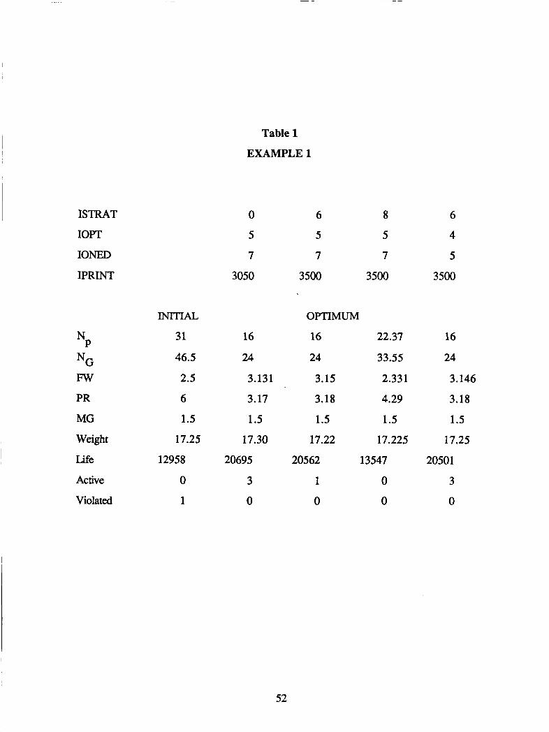
Table 1
EXAMPLE 1
ISTRAT
IOPT
IONED
IPRINT
N* NG Fw PR MG Weight
Life
Active
Violated
m A L
31
46.5
2.5
6
1.5
17.25
12958
0
1
0 6 8
5 5 5
7 7 7
3050 3500 3500
16
24
3.131
3.17
1.5
17.30
20695
3 0
OPTIMUM
16 22.37
24 33.55
3.15 2.33 1
3.18 4.29
1.5 1.5
17.22 17.225
20562 13547
1 0
0 0
6
4
5
3500
16
24
3.146
3.18
1.5
17.25
20501
3
0
52
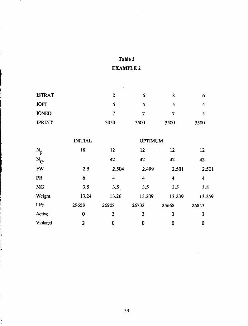
Table 2
EXAMPLE 2
ISTRAT
IOPT
IONED
IPRINT
P N
NG Fw PR MG
Weight
Life
Active
Violated
INITIAL
18
2.5
6
3.5
13.24
29658
0 2
0
5
7
3050
12
42
2.504
4
3.5
13.26
26908
3 0
6 8
5 5
7 7
3500 3500
OFTIMUM
12 12
42 42
2.499 2.501
4 4
3.5 3.5
13.209 13.239
26733 25668
3 3
0 0
6
4
5
3500
12
42
2.501
4
3.5
13.259
26847
3
0
I
t i
53

Summary
From the results of the examples that are presented here, it can be seen that the life
can be increased by decreasing the diametral pitch without increasing the weight. Also the
face width is another significant factor for life. The optimizer changes the design variables
until an acceptable design can be gained. In these two examples, the optimizer brought the
initial infeasible design to feasible (even though sometimes the life is reduced). In example
1, after optimization the final mesh life is roughly 59% more than the initial design. In
example 2 after optimization the final mesh life is roughly 9% less than the initial design,
but it is feasible design.
Further Work
This program is only used for a standard bevel gear set with shaft angle go', pressure
angle 20' and spiral angle 35' because of lack of some information. It may be expected that
the spiral angle also is a significant factor for the mesh life. Thus, if enough information is
available to modify the program and include this effect, the use of this program will be
broadened.
6.0 SUMMARY
Design of precision gears has been addressed as a numerical optimization task. The
principal objective here has been to investigate how optimization methods may be applied to
this design problem and to demonstrate the resulting technology. To achieve this, the
development of software that demonstrates the theoretical concepts is necessary. This is
consistent with the overall goal of research, which is to produce a usable tool for
engineering design.
Two gear design programs have been developed, one for spur gear design and one
for spiral bevel gear design. These codes have been demonstrated with test cases to
demonstrate their applicability to typical gear design problems. The key to successful
54
design optimization is that a wide variety of constraints must be considered. For example,
if a gear is designed for minimum noise without regard to bending or Hertzian stress
constraints, the resulting design will be of little practical use, since it will soon fail due to
insufficient strength. Thus, an essential part of this effort has been to consider many
constraints, something that is natural for the numerical optimization approach to design.
A basic gear design capability has been developed here. This effort has dealt only
with the gear itself, as opposed to the overall speed reduction system which includes
shafting, housing, powerplant, etc. Also, the analysis tools used here are relatively basic.
Continuing research is considering more detail in the analysis. This includes more
sophisticated models for noise generation as well as more detailed models of the gear teeth
themselves. In the later case, research is being undertaking to model the gear teeth using
finite element methods. An example of this effort is to design gear teeth which have an
involute profile under the deformed sm , as opposed to the design where the unloaded gear
is an involute shape.
The use of numerical optimization has been shown to significantly improve the life of
gears, reduce noise, and otherwise enhance the design process. Most importantly, this
technology provides the ability to investigate the tradeoffs between the competing
constraints in a rational way.
55

7. REFERENCES
1 .
2.
3.
4.
5 .
6 .
7.
8.
9.
10.
11 .
12.
13.
14.
Savage, M, J.J. Coy and D.P. Townsend: Optimal Tooth Numbers for Compact Standard Spur Gear Sets, ASME Journal of Mechanical Design, Vol. 104, Oct. 1982.
Vanderplaats, G.N.: Numerical Optimization Techniques for Engineering Design: With Applications, McGraw-Hill, 1984.
Vanderplaats, G.N., "COPES/ADS - A FORTRAN Program for Engineering Synthesis Using the ADS Optimization Program, Version 2.0, Engineering Design Optimization, Inc., Santa Barbara, CA 1988.
Vanderplaats, G.N. and Sugimoto, H., "A General-Purpose Optimization Program for Engineering Design," International Journal of Computers and Structures, Vol. 24, No. 1, 1986.
Vanderplaats, G.N., "ADS - A FORTRAN Program for Automated Design Synthesis, Version 3 .OO," Engineering Design Optimization, Inc., Santa Barbara, CA, 1988.
Coy, J.J., D.P. Townsend, and E.V. Zaretsky: An Update on the Life Analysis of Spur Gears, NASA, CP-2210,1982, pp. 421-434.
Townsend, D.P., J.J. Coy, and E.V. Zaretsky: Experimental and Analytical Load- Life Relation for AIS1 9310 Steel Spur Gears, NASA TM-X-73590, 1977.
Coy, J.J., D.P. Townsend, and E.V. Zaretsky: Analysis of Dynamic Capacity of Low-Contact-Ratio Spur Gears Using Lundberg-Palmgren Theory, NASA TND- 8029, 1975.
Buckingham, E.: Analytical Mechanics of Gears, McGraw-Hill, New York, 1949.
Dudley, D.W.: Gear Handbook, McGraw-Hill, 1962.
Shigley, J.E., and L.D. Mitchell: Mechanical Engineering Design, McGraw-Hill, 1983.
Mitchiner, R.G. and H.H. Mabie: The Determination of the Lewis Form Factor and the AGMA Geometry Factor J for External Spur Gar Teeth, ASME Journal of Mechanical Design, Vol. 104, Jan. 1982, pp. 148-158.
Lynwander, Peter: Gear Drive Systems, Marcel Dekker, Inc. 1983.
Dudley, D.W.: Handbook of Practical Gear Design, McGraw-Hill, 1984.
56
15 Dowson, D. and G.R. Higginson: Elasto-Hydrodynamic Lubrication, Pergamon Press, 1977.
16. Blok, H., Surface Temperatures Under Extreme Pressure Conditions, 2nd Work, Petroleum Congress, Paris, September 1937.
17. Coleman, W., Bevel and Hypoid Gear Surface Durability: Pitting and Scuffing, Roc. Inst. Mech. Engrs. 1967-68, Vol. 182 Pt3A.
57
GEAR
ADDENDUM CIRCLT
ADDENDUM C I R a E
GEAR (2)
FIG. 1 - Spur Gear Geametry
TANGNT LINE
Y
FIG. 2 - Geametric Details
58

Q
a2 NORMAL
LOAD
FIG. 3 - Loading
-L-
- +/- FIG. 4 - m e t r i c Details
PINION ROLL ANGLE I
59
ORIGTNAL PAGE IS OF POOR Q U A L m - Pitch apex lo back
- Pitch apex to crown
Crown lo back
Pitch d;bmeter
FIG. 5 - Spiral Bevel Gear GeQnetry
60
National Aeronautics and I Space AdminisIralion
1. Report No. 2. Government Accession No.
NASA CR-4201 4. Title and Subtitle
Gear Optimization
Report Documentation Page 3. Recipient's Catalog No.
5. Report Date
December 1988
7. Author(s)
!- 6. Performing Organization Code
8. Performing Organization Report No.
G.N. Vanderplaats, Xiang Chen, and Ning-tian Zhang
9. Performing Organization Name and Address
Department of Mechanical Engineering
Santa Barbara, California 93106 University of California
12. Sponsoring Agency Name and Address
National Aeronautics and Space Administration Lewis Research Center Cleveland, Ohio 44135-3191
I None (E-4459)
11. Contract or Grant No.
NAG3-683
13. Type of Report and Period Covered
Contractor Report Final
14. Sponsoring Agency Code
110. Work Unit No.
17. Key Words (Suggested by Author(s))
Spur gear Spiral bevel gear Fatigue life Weight
18. Distribution Statement
Unclassified - Unlimited Subject Category 37
15. Supplementary Notes
Project Manager, Harold H. Coe, Propulsion Systems Division, NASA Lewis Research Center.
16. Abstract
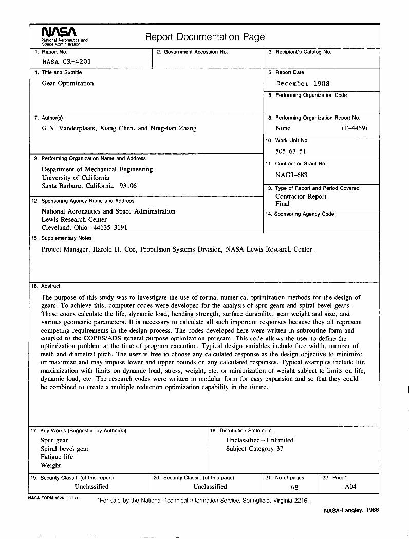
The purpose of this study was to investigate the use of formal numerical optimization methods for the design of gears. To achieve this, computer codes were developed for the analysis of spur gears and spiral bevel gears. These codes calculate the life, dynamic load, bending strength, surface durability, gear weight and size, and various geometric parameters. It is necessary to calculate all such important responses because they all represent competing requirements in the design process. The codes developed here were written in subroutine form and coupled to the COPEWADS general purpose optimization program. This code allows the user to define the optimization problem at the time of program execution. Typical design variables include face width, number of teeth and diametral pitch. The user is free to choose any calculated response as the design objective to minimize or maximize and may impose lower and upper bounds on any calculated responses. Typical examples include life maximization with limits on dynamic load, stress, weight, etc. or minimization of weight subject to limits on life, dynamic load, etc. The research codes were written in modular form for easy expansion and so that they could be combined to create a multiple reduction optimization capability in the future.
19. Security Classif. (of this report)
Unclassified 20. Security Classif. (of this page) 21. No of pages 22. Price'
Unclassified 68 A04
*For sale by the National Technical Information Service, Springfield, Virginia 221 61 NASA FORM 1626 OCT 86
NASA-Langley, 1988