
March/April 2005 Gear Technology
60
GEAR TECHNOLOGY The Journal of Gear Manufacturing MARCH/APRIL 2005 THE GEAR INDUSTRY’S INFORMATION SOURCE www.geartechnology.com HEAT TREATING • Advances in Quenching • The Heat Goes On: Gear Up for Induction Hardening • Hot Stuff FEATURES • Environmentally Friendly Cutting Fluids • Gear Data Exchange Format NEWS • Expanded Coverage of Products, Events and Industry News
-
Upload
khangminh22 -
Category
Documents
-
view
0 -
download
0
Transcript of March/April 2005 Gear Technology

GEAR TECHNOLOGYThe Journal of Gear ManufacturingMARCH/APRIL 2005
THE GEAR INDUSTRY’S INFORMATION SOURCE
www.geartechnology.com
HEAT TREATING• Advances in Quenching• The Heat Goes On: Gear Up for Induction Hardening• Hot Stuff
FEATURES • Environmentally Friendly Cutting Fluids • Gear Data Exchange Format
NEWS • Expanded Coverage of Products, Events and Industry News

KEEPING THE WORLD IN MOTION ™
Cylindrical Gear Production WorkholdingService & Training MetrologyCutting Tools
1000 University Ave., P.O. Box 22970 • Rochester, NY 14692-2970 U.S.A. Phone: 585/473-1000 • Fax: 585/461-4348 • [email protected]
www.gleason.com
GLEASON GEAR GRINDERSMAXIMIZE QUALITY & PRODUCTIVITY
The 245TWG Threaded Wheel Grinder:
� Cuts floor-to-floor times for grinding spur and helical gears to half that of conventional grinders.
� Uses Gleason multi-start threaded grindingwheels to improve production rates 5-10times over typical single-start wheels.
� Integrates patented master diamond dressinggear system to dress multi-start wheels in lessthan the time it takes to grind a gear.
� Features a fast, automated carousel loading system with spin station.
Gleason-Pfauter Profile Grinders:
� Eliminate hours of costly manual setup with powerfulnew alignment and compensation software.
� Dramatically reduce non-grinding time withAdaptive Process Control software.
� Deliver the flexibility to grind internal and external gears — from 400 mm to 4,000 mmdiameter — with Gleason high-performance plated CBN wheels.
Ready to finish first? Start with the latest in grinding technology from Gleason.
Gleason-Hurth ZH Gear Honing Machines
produce a high quality, low-noise tooth flank.

October 16-19, 2005 • Cobo Center Detroit, Michigan
www.gearexpo.com
Contact the American Gear Manufacturers Association, 703.684.0211 or e-mail [email protected].
• Acquire New Customers• Maximize Relationships
with Current Customers• Access New Markets• Improve Your Bottom Line• Learn new technologies• Network with your peers
Profit from the largest collection of gear experts in the world at one time in one place.
Exhibit at:
Document6 11/9/04 11:59 AM Page 1

HEAT TREATING ISSUE
Advances in Quenching: A Discussion of Present and Future TechnologiesThe causes of distortion and insight on ways to eliminate it……....................................20
Hot StuffThe latest news related to heat treating.............................................................................29
The Heat Goes On: Gear Up for Induction HardeningMaintaining—and getting the most out of—
your induction hardening equipment.................................................................................32FEATURES
Environmentally Friendly Cutting FluidsProducts that help gear manufacturers minimize waste and increase performance..........16
Gear Data Exchange Format
Efforts to standardize gear data formats from design to manufacturing to inspection….36
DEPARTMENTS
Publisher's PageSpring is in the air................................................................................................................7
Product NewsSolar Atmospheres’ high pressure gas quenching, a technology
for near frictionlessmotion, and other products for the gear industry.................................9
EventsA closer look at the AGMA and Gleason gear schools; previews of the SAE Congress and
Hannover Fair; plus our technical calendar and other event coverage.............................41
Industry News ASME honors Faydor Litvin, wind turbines and other recent gear-related news............48
Advertiser Index Use this directory to get information fast………………………………….....................52
Classifieds Services, Heat Treating, Websites, and Gear Manufacturing…………………………...53
Addendum Gear Tattoos…………..…………………………………………....................................56
GEAR TECHNOLOGYThe Journal of Gear ManufacturingMARCH/APRIL 2005
41 41
32
36
56 H
56 H H
2 MARCH/APRIL 2005 • GEAR TECHNOLOGY • www.geartechnology.com • www.powertransmission.com
Cover photo courtesy of Nachi Machining Technology Co. of
Machining Technology Co. of
Macomb, MI. Macomb, MI.

KAPP ) nilesKAPP Technologies 2870 Wilderness Place Boulder, CO 80301Ph: 303-447-1130 Fx: 303-447-1131 www.kapp-usa.com [email protected]
The best is versatile
The KAPP KX300P is a small-footprintmachine with huge capabilities.It featurestwo grinding processes, two tool concepts,on-board balancing, and on-board gearinspection. It uses both dressable vitrifiedtools and CBN tools. The KX300P has avertical workpiece orientation to facilitateeasy integration of a KAPP-designedautomation system. The best does it all.
48899_KAPP p03.qxp 2/15/05 10:44 AM Page 1

EDITORIAL
Publisher & Editor-in-ChiefMichael Goldstein
Managing Editor William R. Stott
Associate Editor Joseph L. Hazelton
Assistant Editor Robin Wright
Editorial Consultant Paul R. Goldstein
Technical EditorsRobert Errichello, Don McVittieRobert E. Smith, Dan Thurman
ART
Production Coordinator Kathleen O'Hara
ADVERTISING
Advertising Manager Patricia Flam
CIRCULATION
Circulation Coordinator Carol Tratar
INTERNET
Web Developer Dan MacKenzie
Gear Industry Home Page™ SalesPatricia Flam
powertransmission.com™ SalesClark Hopkins
RANDALL PUBLISHING STAFF
President Michael Goldstein Vice President Richard Goldstein Accounting Luann Harrold
Phone: 847-437-6604E-mail: [email protected]: www.geartechnology.com
www.powertransmission.com
GEAR TECHNOLOGY, The Journal of Gear Manufacturing(ISSN 0743-6858) is published bimonthly by Randall Publishing, Inc., 1425 Lunt Avenue, P.O. Box 1426, Elk Grove Village, IL 60007, (847) 437-6604. Cover price $5.00 U.S. Periodical post-age paid at Arlington Heights, IL, and at additional mailing office (USPS No. 749-290). Randall Publishing makes every effort to ensure that the processes described in GEAR TECHNOLOGY conform to sound engineering practice. Neither the authors nor the publisher can be held responsible for injuries sustained while fol-lowing the procedures described. Postmaster: Send address changes to GEAR TECHNOLOGY, The Journal of Gear Manufacturing, 1425 Lunt Avenue, P.O. Box 1426, Elk Grove Village, IL, 60007. ©Contents copyrighted by RANDALL PUBLISHING, INC., 2005. No part of this publication may be reproduced or transmitted in any form or by any means, electronic or mechanical, including pho-tocopying, recording, or by any information storage and retrieval system, without permission in writing from the publisher. Contents of ads are subject to Publisher’s approval.
VOL. 22, NO. 2
GEAR TECHNOLOGYThe Journal of Gear Manufacturing
��������������������������������������������������������
�������������������������������������������������������������������������������������������������������������������������������������������������������������������������������������������������������������������������������������������������������������������������������������������������������������������������������������
������������������������������������������������������������
��������������������������������������������������������
��������������� ��
��������������������������
�������������������������������������������������
������������������������������������
4 MARCH/APRIL 2005 • GEAR TECHNOLOGY • www.geartechnology.com • www.powertransmission.com

No matter how you need your gears machined,
LIEBHERR HAS A WAY!
As the pioneer of high-speed dry gearmachining, Liebherr is leading the way in gear cutting, offering machines withgear drives or direct drives in modular platforms from 80 mm to 4500 mm diameters.
Hobbing. Productivity: fast cycle timesover the full spectrum of external gears.
Shaping. Flexibility: CNC guide forinternal and external spur or helicalgears.
Grinding. Precision: generating or profile grinding, with dressable or CBNtools in one machine.
Liebherr gear machines are renowned for quality, productivity, reliability, main-tainability and low life-cycle cost.
Liebherr Gear Technology Co.1465 Woodland Drive
Saline, MI 48176-1259734.429.7225
The Gearing Partnership of Liebherr, Klingelnberg and Oerlikon
Gear Hobbing • Shaping • Grinding • Measuring

32251 N. Avis Dr., Madison Heights, MI 48071• Tel: 248/585-9393 • Fax: 248/589-1062 • E-mail: [email protected]
www.inductoheat.com
INDUCTOHEAT®
Simultaneous Dual Frequency Gear Heat Treating
Inductoheat’s gear hardening process
uses two frequencies to concurrently heat
gears inside and out, reducing stresses that
cause cracking and distortion. Simultaneous
Dual Frequency (SDF) technology improves
quality and efficiency while cutting costs,
yielding higher production rates
than conventional induction
heating processes.
SDF benefits include
shorter heating cycles,
reduced distortion and improved
mircostructure. It is also easily integrated
into new or existing manufacturing lines or as a
flexible workcell. Contact Inductoheat to learn how
SDF can improve your existing process.
Page 6 l 3/8/04 1:36 PM Page 1

PUBLISHER’S PAGE
Michael Goldstein, Publisher & Editor-in-Chief
www.powertransmission.com • www.geartechnology.com • GEAR TECHNOLOGY • MARCH/APRIL 2005 7
In Chicago, Spring is fi nally in the air. Yesterday, we had our fi rst truly balmy day, with temperatures in the 60s, the sun shining, a warm wind blowing, and birds chirping everywhere.
Over the past few weeks, conversations I’ve had with people in the gear industry make it seem that it’s not just the weather that’s warming up. The gear industry is also going through a healthy transition. Spring is fi nally coming to gear manufacturing.
Talking to both gear manufacturers and suppliers of gear cutting tools and machine tools, almost everyone in the industry seems to be extremely busy. Gear manufacturers are not only cutting gears, they’re adding capacity. Cutting tool manufacturers are posting record sales. Gear machine tool manufacturers are fi lling up their capacity and looking into 2006.
In short, there appears to be growth in the industry again.Roland Ramberg, president of The Gear Works—Seattle
Inc., says that 2005 sales are “robust,” that he expects to record his largest volume ever, by more than 10%. Ramberg says that a number of industries are driving demand, including most of the OEM heavy industries, material handling, conveyors, construction, mining, and printing. He also notes that the market for wind turbine gears has picked up considerably.
Cam Drecoll, president of Brad Foote Gear Works, says his business in 2005—and projected into 2006—is “booming,” and that demand for gears in a number of key industries is also “booming.” Those industries include wind turbines, locomo-tives, off-highway, steel and oil.
The story at Gear Motions Inc. is also extremely positive. Sam Haines, the company’s president, says that 2005 will be his company’s biggest year ever in terms of both sales and profits. Demand for hardened and ground gears is intense, especially in the automotive and motorcycle industries, Haines says.
Craig Ross, president of Midwest Gear & Tool, says that his sales were up 30% in 2004 and that he expects 2005 to be even better, with demand still strong among his machine tool, aero-space and military industry gear customers. In fact, Ross says, the only thing that might hold him back this year is the fact that he’s in the process of moving to a new building.
Overton Gear & Tool has experienced double-digit sales growth over the past three years, according to company presi-dent Lou Ertel, and demand for his company’s gears remains strong. Ertel expects that 2005 will be another growth year for Overton.
Forest City Gear is also building on a very strong 2004 and expecting a similar 2005, according to general manager Mike Goza. Forest City has picked up new customers since last year, and demand for gears in aerospace, motorcycles and fishing reels is keeping the company very busy.
I think you get the point. For many gear manufacturers, find-ing customers isn’t the problem it was a couple of years ago.
But I don’t want to give you the idea that everything is rosy, because it’s not. I’ve talked to some gear manufacturers who are still struggling. Even those who are experiencing growth right now face significant challenges. Most everyone I spoke to said that one of their biggest problems is the rising costs of health care.
Some of the biggest challenges facing gear manufacturers are on the supply side. Most of them told me they’re having a hard time getting their hands on raw materials, with delivery times for forgings as high as six months. More than one manu-facturer also told me he was having a hard time getting gear steels, irrespective of price.
I also know, from talking to machinery suppliers, that if you think you might need to add capacity and you haven’t already, you may have to wait in line.
Jeff Barnes, president of New England Gear, specializes in retrofitting gear machines. Barnes says he’s full to capacity
Gary Kimmet, VP of worldwide sales for Gleason Corp., says that both cutting tool and machine tool sales are “power-
that 2005 is already shaping up to be a “great” year and likely be “very good” for Gleason. According to
Kimmet, sales are strong both in the United States and Asia.David Goodfellow, president of Star SU LLC, says that
cutting tool sales were strong in 2004 and will be very strong in 2005 and that the demand is being driven by the automotive, construction and wind energy industries. Goodfellow also says that machine tool sales are expected to increase again this year.
The change of seasons is invigorating, especially when it seemed like the winter in the gear industry would never end. But now the gear industry appears to be poised for a period of needed growth. I’m really looking forward to the rest of 2005—and so should you!
Spring is in the airSpring is in the air
through a healthy transition. Spring is fi nally coming to gear
through a healthy transition. Spring is fi nally coming to gear
Talking to both gear manufacturers and suppliers of gear Talking to both gear manufacturers and suppliers of gear cutting tools and machine tools, almost everyone in the industry cutting tools and machine tools, almost everyone in the industry seems to be extremely busy. Gear manufacturers are not only seems to be extremely busy. Gear manufacturers are not only cutting gears, they’re adding capacity. Cutting tool manufacturers cutting gears, they’re adding capacity. Cutting tool manufacturers
a number of industries are driving demand, including most
a number of industries are driving demand, including most of the OEM heavy industries, material handling, conveyors,
of the OEM heavy industries, material handling, conveyors, construction, mining, and printing. He also notes that the market
construction, mining, and printing. He also notes that the market for wind turbine gears has picked up considerably.
for wind turbine gears has picked up considerably.
Cam Drecoll, president of Brad Foote Gear Works, says Cam Drecoll, president of Brad Foote Gear Works, says his business in 2005—and projected into 2006—is “booming,” his business in 2005—and projected into 2006—is “booming,” and that demand for gears in a number of key industries is also and that demand for gears in a number of key industries is also “booming.” Those industries include wind turbines, locomo- “booming.” Those industries include wind turbines, locomo-
The story at Gear Motions Inc. is also extremely positive. The story at Gear Motions Inc. is also extremely positive. Sam Haines, the company’s president, says that 2005 will be his Sam Haines, the company’s president, says that 2005 will be his company’s biggest year ever in terms of both sales and profits. company’s biggest year ever in terms of both sales and profits.
in retrofitting gear machines. Barnes says he’s full to capacity
in retrofitting gear machines. Barnes says he’s full to capacity right now.
right now.
Gary Kimmet, VP of worldwide sales for Gleason Corp.,
Gary Kimmet, VP of worldwide sales for Gleason Corp.,
says that both cutting tool and machine tool sales are “power-
says that both cutting tool and machine tool sales are “power-ful,” ful,” that 2005 is already shaping up to be a “great” year and that 2005 is already shaping up to be a “great” year and that 2006 will that 2006 will likely be “very good” for Gleason. According to likely be “very good” for Gleason. According to Kimmet, sales are strong both in the United States and Asia.Kimmet, sales are strong both in the United States and Asia.
David Goodfellow, president of Star SU LLC, says that David Goodfellow, president of Star SU LLC, says that cutting tool sales were strong in 2004 and will be very strong cutting tool sales were strong in 2004 and will be very strong in 2005 and that the demand is being driven by the automotive, in 2005 and that the demand is being driven by the automotive, construction and wind energy industries. Goodfellow also says construction and wind energy industries. Goodfellow also says that machine tool sales are expected that machine tool sales are expected

Power IntegratedPop-upTM
Lift/Rotate InductionHeat-Treating System
Radyne’s Power Integrated Pop-upTM
heat-treat center is a self-containedsystem for hardening and temperingcomponents in a lift/rotate, sub-merged quench method to meet thespecific needs of the heat treater. Auser-friendly machine interface paneland PLC control enable quick andeasy setup and operation. An integrated, modern, efficient, transistorized inverter power supplycan match a wide variety of heating coils with easy-to-change tuningcapacitors and a multitap output isolation transformer.
The lift actuator assembly includes a ball bearing linear way mountedunder a stainless steel sink throughdouble lip wave seals. A chrome-plated stainless steel spindle ismounted on a tapered roller bearing,enclosed in a steel housing. The liftmechanism allows load/unload, heat and quench positions.
The Perfect IntegrationThe combination of Radyne’s PowerIntegrated Pop-upTM and APEX QATMand APEX QATMand APEX QAQuality Assurance system represents the latest in inductionheat-treating technology.
Innovators in Induction Heating1-800-236-8360211 W. Boden Street211 W. Boden StreetMilwaukee, WI 53207, U.S.A.(414) 481-8360 • Fax: (414) 481-8303e-mail: [email protected]://www.radyne.com

PRODUCT NEWS
www.powertransmission.com • www.geartechnology.com • GEAR TECHNOLOGY • MARCH/APRIL 2005 9
When gas quenching, the mini-mizing of heat treat distortion in gears may be a matter of high pres-sure and high velocity. That’s what and high velocity. That’s what andSolar Atmospheres thinks, that’s why the heat treat company sends helium gas into its vacuum furnaces at more than 100 mph.
“The high pressure/high veloc-ity gas quenching technology enables the gear manufacturer to finish machine gears closer to final size,” says Robert Hill Jr., president of Solar Atmospheres of Western Pennsylvania, located in Hermitage. “This process has virtually elimi-nated post-heat treatment machin-ing, grinding, straightening or plat-ing to size for several types of gears, including many spiral bevel gears, worm gears, miter gears, and her-ringbone gears. Each of these types of gears has a propensity to severely distort during a traditional liquid quench.”
Typically, gears made of low-alloy, medium-carbon steel (e.g.
4140) or of low-alloy, car-burized steel (e.g. 8620) are hardened with hot oil as the quench medium. When liquid quenching is employed, three distinct phases occur. These phases produce large temperature differentials during the quenching process, so the roots, teeth, bores, shafts and webs cool at varying rates.
“These delta Ts cause tremen-dous internal stress on the gears, that will ultimately result in severe distortion,” Hill says.
Instead of extracting heat by quenching in a liquid (e.g. water, salt, polymer or oil), vacuum furnace quenching uses inert gas cooling that subjects the gears to one cooling phase: convective (see Fig. 1). Since gas cooling is less abrupt and more uniform, this processing achieves acceptable hardened microstructures
with considerably less distortion.
In the past, gas cooling wasn’t fast enough to attain the proper metal-lurgical results.
“Today, with increased pressure—10 bar—and increased velocity—pri-marily using helium, gas quenching is able to produce fully martensitic microstructures with much less dis-tortion,” Hill says. “However, there always exist certain limitations that may prevent a fully transformed phase. Therefore, for successful gas quenching, maximum cross sections and minimal percentages of elements within the alloy chemistry must be determined.”
According to Hill, the use of heli-um for quenching is ever increasing, and improved cooling rates aren’t only a function of pressure but also of gas velocity. By utilizing variable speed drives, Solar Atmospheres is now overspeeding its 300 hp blower
Adding High
Velocity to
High Pressure
Gas Quenching
Figure 1—Typical cooling curves for gas (red) and oil (blue) quenching.

PRODUCT NEWS
10 MARCH/APRIL 2005 • GEAR TECHNOLOGY • www.geartechnology.com • www.powertransmission.com
motors to 5,000 rpm. (Nominal speed is 3,600 rpm.) The exit gas velocity is now well over 100 mph. This quench gas impinges 360° around the workload and is then recirculated back through a heat exchanger.
“Since helium is a very light gas, the power required to recirculate it dur-ing quenching is far less than that used
for nitrogen or argon,” Hill says. “When cycle times—cooling times—are reduced by 40%, a substantial savings is realized.”
Shape change is a leading cause of scrap and rework in the gear industry, so the value of vacuum heat treating is less spoilage. Vacuum quenching in the hard-ening process much reduces the distortion
caused by residual stress.Another advantage of high pressure
gas quenching is its inert atmosphere. The heat-treated gears are bright, clean and oxide-free (see Fig. 2).
“There is a tremendous added value since gears no longer need to be pick-led, shot- or grit-blasted, or ground,” Hill says. “The surface condition of the gears remains the same as the pre-heat treated condition.”
Since high pressure gas quenching eliminates the need for liquid quenchants and the parts are processed in an inert environment, vacuum heat treating is an environmentally friendly process.
“This technique is becoming more and more popular worldwide,” Hill says, “especially when combined with the advantages of vacuum carburizing.”
Solar Atmospheres Inc., a commer-cial vacuum heat treater, is advancing this technology. “Precise temperature con-trols, development of vacuum furnace capabilities and the demand for manufac-turing efficiency are the driving forces,” Hill says.
Also located in Souderton, PA, Solar Atmospheres has more than 30 vacuum furnaces—from lab size to large produc-tion—that serve the gear industry.
For more information:Solar Atmospheres Inc.30 Industrial RoadHermitage, PA 16148Phone: (866) 982-0660Fax: (724) 982-0593E-mail: [email protected]: www.solaratm.com
Quality Spiral Bevel Tools
A/W Systems Co. is your quality alternative manufacturing source of spiral gear roughing and finishing cutters and bodies.We can also manufacture new spiral cutter bodies in diameters of 5" through 12" at present.
A/W can also supply roughing and finishing cutters for most 5"–12" diameter bodies.Whether it’s service or manufacturing, consider us as an alternative source for cutters and bodies.
You’ll be in for a pleasant surprise.
Royal Oak, MI 48067 Tel: (248) 544-3852 • Fax: (248) 544-3922
Figure 2—Sample of parts processed using Solar Atmosphere's process.

PRODUCT NEWS
www.powertransmission.com • www.geartechnology.com • GEAR TECHNOLOGY • MARCH/APRIL 2005 11
Company OffersTechnology for
“Near-Frictionless Motion of Machines”
Friction Control Solutions Ltd. has a technology to reduce friction and wear, a process the company described as allowing “near-frictionless motion of machines.”
The technology, called combined micro-relief (CMR), was designed to cope with extreme tribological condi-tions, including poor lubrication, high pressure, low-to-zero velocity and rapid directional changes.
CMR’s ability to reduce wear and friction was checked through independent testing, says Kostia Mandel, FriCSo’s vice president–R&D.
“These tests have been conducted by both FriCSo and by some of the leading manufacturers of various mechanical parts and systems, both in lab tests and in actual applications, including gear parts—like shafts and axles,” Mandel says.
He couldn’t discuss the manufacturers’ specific applications or their test methods, though, because of binding nondisclosure agreements.
According to a FriCSo press release, the technology creates a highly stable, dura-ble and uniform lubricant layer between moving surfaces. The process consists of
lapping and grooving. The lapping is done with tools made of a poly-meric compound with standard abrasive material. According to the company, the lapping creates a repelling force against the oil microlayer adherent to the coun-tersliding part. This hydrophobic effect keeps the part afloat, away from the other part—even at a standstill.
“The hydrophobic characteristic is intrinsic to the CMR process and is not the result of applying foreign material,” Mandel says.
The grooving, created with spe-cial software, is done through plastic deformation. The grooves are sinusoidal indents, with depths of a few microns. They aren’t lapped, so they don’t repel
For “Near-Frictionless Motion”—Combined micro-relief (CMR) laps a part surface, such as this spline shaft, to create a hydrophobic effect, which works to keep oil droplets from spreading out. CMR also creates non-lapped grooves, which serve as reservoirs. Filled with oil, the reservoirs act as oil bearings and provide lubrication.

New Bevel Gear CuttingMachine from Gleason
The new Phoenix II 600 HC CNC cutting machine from Gleason features a monolithic column design that optimizes dry machining , reduces fl oor space requirements and improves cycle times.
According to the company’s press release, this machine was designed for workpiece diameters as large as 600 mm. In addition, it can accommodate both wet and dry cutting processes as well as dry machining.
The need for a conventional machine bed is eliminated as this is the only machine in its class with a cast-iron monolithic column design. In addition, the cutter and work spindle are directly mounted to the column and the cutter spindle pivots to create the root angle rather than mounting the spindle on a rotating base. This enables hot dry chips to fall completely clear of the machine structure into a simple chip conveyor.
Other features include a direct-drive
PRODUCT NEWS
12 MARCH/APRIL 2005 • GEAR TECHNOLOGY • www.geartechnology.com • www.powertransmission.com
oil. They instead serve as reservoirs for oil repelled by the part’s lapped sur-face. Filled with oil, the reservoirs act as oil bearings and provide lubrication. According to the company, the groov-ing also strain hardens surface layers, increasing their hardness by 70–80%.
“FriCSo targets two major markets: automotive and heavy machinery,” says
Amir Guttman, managing partner at Aviv Venture Capital, which co-owns FriCSo. “The automotive market is huge, but penetration is slow. However, in the heavy machinery market—which includes shipping, oil drilling and mili-tary industries—we may generate sales during 2005.”
An Israeli company, FriCSo was
founded in 2003 and has offices in Farmington Hills, MI, near Detroit.
For more information:Friction Control Solutions Inc. 27260 Haggerty Road, Suite A–20Farmington Hills, MI 48331 Phone: (248) 489-0759Fax: (248) 489-0832E-mail: [email protected]: www.fricso.com

spindle motor, higher acceleration/deceleration rates, increased torque, and shorter and faster axis motions to reduce non-cutting between cycles.
For more information, contact Gleason Corp. of Rochester, NY, by telephone at (585) 473-1000 or on the Internet at www.gleason.com.
New Gear Roller from Marposs
The M62 DF from Marposs is designed for the dynamic inspection of ring gears with automatic part rotation.
The system can evaluate lead angle, lead variation and taper in addition to the usual double-flank parameters.
According to the company’s press release, additional features include a retoolable center distance from 25–200 mm; the ability to accommodate a tooth module up to 5, part height up to 60 mm, and weight up to 10 kg; low pressure measuring devices and an electric gear axis generated by dedicated transducers.
New Gearboxes from ZF
The new right-angle servoworm gearboxes from ZF are designed to meet the demands of servo drive applications.
PRODUCT NEWS
www.powertransmission.com • www.geartechnology.com • GEAR TECHNOLOGY • MARCH/APRIL 2005 13
www.comtorgage.com
®
Rugged,Reliable,Repeatable
...For 75 Years!
Internal orExternal SplineMeasurement
Made Easy!Still using
micrometers andpins method?
Comtor SplineGages make pitch
diameter measure-ment quick, easy
and accurate!
Comtorgage Corporation (since 1928)
Phone: (401) 765-0900 • Fax (401) 765-2846
PitchDiameter
MajorDiameter
MinorDiameter
• Applicable to Spur and Helical Gears!
• Gage the Part at the Machine!
COMTOR SPLINE GAGES
According to the company’s press release, the units are available with high precision, precision and standard levels of accuracy that offer backlash levels of less than 1, 3 and 10 arc-min. respectively. Units are sealed with a high-performance polyglycol lubricant.
Featuring a computer-optimized gear contact pattern that evenly spreads the stress throughout the teeth, these units
also can perform at less than 55 dB. The worm wheel is manufactured from a spe-cially developed bronze alloy.
The oversized taper roller bearings have a configuration that consists of two sets of roller bearings and an additional set of floating ball bearings. Bearings are preloaded for higher temperature varia-tions and loads.
Caption ?

14 MARCH/APRIL 2005 • GEAR TECHNOLOGY • www.geartechnology.com • www.powertransmission.com
Robin WrightGear TechnologyP.O. Box 1426Elk Grove Village, IL 60009, USAFax: (847) 437-6618E-mail: [email protected]
� � � � � � �
�����������������������
tooling up����������������������������������������
������������������������������������������������������������������
��������������������������������������������������������������������������
����������������������������������������������������������������������������������
�������������
SEND US YOUR NEWSDo you have a new product, technology or process for the gear industry?
Do you have corporate news you’d like to share?
Being included in a future issue is easy as 1-2-31.Come up with some ideas2.Gather your materials (text, photos, etc.)3.Send them to:
Connection to the drive shaft is accomplished through a keyless shrink disc, while a pinned and bound wheel ring design promotes a stiff and reliable interface.For more information, contact ZF Industrial of Nottingham, U.K., by e-mail at [email protected].
New Size 17 Gearhead from HD Systems
The Quantam Series from HD Systems is the highest torque capac-ity harmonic gearhead the company has produced.
According to the company’s press release, this gearhead delivers 50% more torque than the CSF Series. It can main-tain 1 arc-min. positional accuracy and +/–5 arc-sec. repeatability.
With an outer diameter of 79 mm and a length measurement of 45 mm, the gearhead is available in ratios of 50, 80, 100 and 120:1.
For more information, contact HD Systems of Hauppauge, NY, by telephone at (800) 231-HDSI or on the Internet at www.HDSI.net.www.HDSI.net.www.HDSI.net
New Thread Rolling Heads from LMT-Fette
The new tangential thread rolling heads from LMT-Fette are pre-
������������������������������������������������������������������������������������������������������������������������������������������������������
�������������������������������������������������������������������������������������������������������������������������������������������������������������������������������������������������������������������������������������������������
��������������������������������������������������������������������������������������������������������������������������������������������������������������������������
����������������������������������������������������
��������������
������������������������������������������������
PERRY JOHNSONREGISTRARS, INC. ���������������������������
������������������������������������������
������������������������������������

sychronized for effi cient set-up with no roll timing. According to the company’s press release, because symmetrical roller repositioning is performed with a central setting screw and away from the rolling systems, operators can expect a 10-minute cycle time.
The lengths of the rolling heads have also been decreased by 20% in order to be suitable for use in CNC lathes and screw machines. Available in T120F, T160F, T220F and T350F, these heads can accommodate thread diameters from 5/64–2”. Models can now thread 1/16–1” diameter NPT and NPTF pipe sizes.
For more information, contact LMT-Fette of Cleveland, OH, by telephone at (800) 225-0852 or on the Internet at www.lmtfette.com.
New Lab Oil from Heatbath
Lab Oil 100 100 is dry-to-the-touch over phosphate coating, low in toxic-ity, has improved emulsification and high corrosion resistance. The product is designed for manufacturers of metal products requiring rust or corrosion pro-tections.
PRODUCT NEWS
www.powertransmission.com • www.geartechnology.com • GEAR TECHNOLOGY • MARCH/APRIL 2005 15
POWER
TECHNOLOGY
PRECISION
MILWAUKEE
GEAR COMPANY
5150 N. PORT WASHINGTON RD.MILWAUKEE, WI 53217-0615
Phone: 414-962-3532
www.milwaukeegear.com
GEAR COMPANY
●Tight Specifi cations●In House Heat Treating●Design Capabilities●Ground Tooth to Q-14
MILWAUKEE GEARCOMPANY
According to the company’s press release, emulsions of oil can withstand 240+ hours of per ASTM B-01117 when applied over zinc phosphated steel panels. Maximum corrosion protection is achieved when concentration is main-tained at 20–30% by volume.
In addition, this oil is tolerant of alka-line or acid contamination when either is encountered in black oxide or phospating cycles.
Recommended operating temperature is 140–180° and concentration ranges from 5–30%. The typical immersion time is 1–2 minutes and tanks can be mild steel, heated with steam or gas and elec-tric heater.
For more information, contact Heatbath Corp. of Springfield, MA, by telephone at (413) 452-2000.
New Furnace from Grieve
The No. 943 pit furnace from Grieve is an electrically-heated top loading pit furnace capable of 2,000°F and is suitable for heat treating applications at a customer’s facility.
Additional features include 7” thick insulated walls, an air-operated vertical lift door and reinforced ½” steel top plate, a temperature controller and separate heating element control contactors.
For more information, contact The Grieve Corp. of Round Lake, IL, by telephone at (847) 546-9210 or on the Internet at www.grievecorp.com.

FRIENDLY CUTTING FLUIDS
16 MARCH/APRIL 2005 • GEAR TECHNOLOGY • www.geartechnology.com • www.powertransmission.com
“We were doing some hard skiv-ing, and tool life was a big issue,” says Kevin Lynch, business unit manager for gear manufacturer ITW Spiroid. The Glenview, IL-based company recently switched from a mineral oil-based cutting fluid to a vegetable oil-based fluid. “The cutting tools are really expensive, so we switched to it, and we actually saw about a 30% increase in tool life.”
ITW Spiroid, like many gear manu-facturers and other metalworking com-panies, is finding that many of today’s more environmentally friendly industrial fluids are actually making their biggest impact not in environmental terms, but in performance.
“We really didn’t do it for the envi-
ronmental aspects,” Lynch says. The key for them was increasing tool life, but the environmental benefits were an added bonus.
ITW Spiroid uses the vegetable oil-based Accu-Lube Flood 40 coolant from sister company ITW Rocol.
Tools for Reducing Environmental Impact
Today’s formulators of industrial chemicals have a wider array of tools than ever, from new types of synthetic esters to new breeds of genetically modified vegetable oil crops. This means a greater ability for manufacturers to tailor fluids to their exact metal cutting needs.
So manufacturers are able to increase
productivity, achieve a better surface finish, or—like ITW Spiroid—improve tool life, all while improving the work environment for their employees and reducing the costs associ-ated with disposing of waste fluids.
Many coolant suppliers offer some choices that are more environmentally friendly than others. In some cases, a more environmentally friendly product is simply one that can be recycled or that lasts longer. If you have to dispose of less waste fluid, you have less impact on the environment.
“A lot of people consider that even a mineral oil-based product can be environ-mentally friendly, through extended sump life or by formulating with chemistries
Environmentally
William R. Stott, Managing Editor
Photos courtesyof Blaser Swisslube(top left) and ITWRocol North America

www.powertransmission.com • www.geartechnology.com • GEAR TECHNOLOGY • MARCH/APRIL 2005 17
that aren’t hazardous to aquantic or plant life,” says Randy Templin, vice presi-dent of Blaser Swisslube. Blaser sup-plies both traditional mineral oil-based products and the Vasco line of vegetable oil-based products. But, Templin adds, “We consider ourselves to be a leader in marketing products based on natural and synthetic esters that are derived from a vegetable base.”
Vegetable OilsMetalworking fluids based on veg-
etable oils are available as straight oil (as in the case of the Accu-Lube Flood 40 fluid used by ITW Spiroid) or as water soluble products, where a concentrate is mixed with water to produce the cool-ant. But no matter which form the fluid comes in, vegetable oils have a number of performance benefits over straight mineral oils.
“In general, we can get better lubric-ity with a vegetable based-oil than we
can with a straight oil,” says Robert Myers, business unit manager for the Accu-Lube product line. The extra lubric-ity is what gives manufacturers better tool life, he adds.
Blaser has seen increased demand for its vegetable oil- based products, especially in Europe, where higher environ-mental concerns, regulations and disposal costs require manufacturers to use coolants without chlorine. “When you take the chlorinated additive out of a cutting fluid, you give up considerable performance, and with some materials, it
can be dramatic,” Templin says. “The vegetable oils offer much higher lubric-ity than mineral oils, so you’re able to machine chlorine free.”
In addition to greater lubricity, veg-etable-based products offer many advan-tages over traditional mineral oils, says Templin. Among those advantages are a higher flash point, which means less chance of fire; less misting than mineral oil; and better compatibility with skin.
Another company using vegetable-based products to push the performance envelope is Environmental Lubricants Manufacturing Inc. (ELM) of Plainfield,IA. ELM produces the SoyEasy line of industrial fluids, which are based on
genetically modified soybean oil. The modified soybean produces an oil that resists oxidation and lasts longer in the sump, according to Gene Tripp, director of sales and marketing.
Tripp has been working for several years with a number of well-known agri-cultural, off-highway, automotive and aerospace companies, testing his com-pany’s coolants for gear manufacturing operations.
“We’ve tested on a broach, on a shaper cutter, and on a finish shaving cutter operation,” Tripp says, “and we’ve done very well.”
Besides being biodegradable and recyclable, vegetable oil-based products, offer longer tool life, higher feeds and speeds and improved surface finish of parts, Tripp says.
“These products are environmentally friendly, and they’re extremely lubristic, without the harmful additives, he says.” “They offer less mist, less foam, less chance of fire. They’re high performance products that will exceed petroleum and are extremely stable.”
The company’s major gear customers are still in the proving stages, but ELM has a number of non-gear customers who have achieved significant tooling savings by switching to the SoyEasy, Tripp says.
Reduce, Reuse, RecycleIn addition to raising performance,
one of the goals among coolant suppli-ers is to help manufacturers reduce the amount of fluid that’s disposed.
“That’s our drive—our obsession—to produce a zero waste stream,” says Hank Limper, general manager of the metal cutting fluids division of Houghton International.
“What we felt was the golden fleece of this industry was metalworking fluids that would not go rancid, that would not sour, that basically would last ‘forever,’” Limper says.
Typically, a company disposes of metalworking fluids because of biologi-cal activity that breaks them down, causes odors and dramatically reduces the sump life of the fluids, Limper says.
So Houghton developed the HOCUT 795 line of metalworking fluids, a water soluble product, based on what Limper describes as a “bio-stable build-ing block,” a chemical ingredient that
helps the fluids last longer and also allows them to be used for a variety of allows them to be used for a variety of applications.
Starting with the bio-stable base material, Houghton can modify the for-mulation to suit a user’s needs. “We can add a lot of mineral oil and make it a soluble oil, we can use less mineral oil and make it a semi-synthetic, we can add synthetic components like polymers and make it a synthetic product offering, or we can add vegetable oil and make it a truly vegetable oil-based product,” Limper says.
But the key to being environmen-tally friendly is the ability of the water tally friendly is the ability of the water soluble products to be reused and recycled, Limper says. Houghton uses what they call a “congruent chemistry approach.” That means that a wide variety of indus-trial fluids, including quench oils, spray wash cleaners, rust inhibitors and cool-ants, are all based on the same bio-stable building block. The idea is that when certain fluids become too contaminated for further use, instead of dumping fluid into the waste stream, it gets filtered, processed and put back into a central coolant system.
“The theory is that you could tie all your process chemicals into the central coolant system,” Limper says.
Reducing waste can save a company a lot of money, he adds.
In fact, Houghton worked with a major U.S. manufacturer of aerospace gears to implement a rigorous fluids man-agement program that included replacing the company’s old coolants and processes with a central system using HOCUT 795. That facility reduced its hazardous waste disposal by 95%, saving the company $66,000 per year.
Okay, So Why Isn’t Everybody Going Green?
It would be easy to switch to moreenvironmentally friendly cutting fluids if all manufacturers had to think about if all manufacturers had to think about were the enhanced performance, environ-mental benefits and reduced waste. The main disadvantage of all these products is price.
The cost differences range depend-ing on what the customer is using, says Blaser’s Templin. Some of the refined mineral-based cutting oils, particularly recycled oils, can be as little as one-fifth the cost of Blaser’s vegetable-based

18 MARCH/APRIL 2005 • GEAR TECHNOLOGY • www.geartechnology.com • www.
products. In most cases, the price dis-parity isn’t that great, Templin says, but it’s not uncommon for the vegeta-ble based-products to cost as much as 50% more.
That price differential means that nobody is willing to pay just for the environmental benefits, Templin says. “Environmental concern might drive their interest, but they have to justify it by performance.”
Blaser has conducted a number of studies on gear manufacturing operations to demonstrate the performance and cost benefits of the vegetable-based cutting fluids. In one study, which involved hobbing transmission gears, tool life was measured in actual production runs over a two-month period. A variety of gears were cut using both a mineral-oil based coolant and Blaser’s Vascomill 42 veg-etable oil-based coolant. In all cases, the tool life achieved with the vegetable oil-based coolant was significantly higher (averaging 45% greater tool life over two months).
In another Blaser study involving transmission parts, tool life was increased by 40%, even while feeds were increased so that cycle time per piece was reduced by 30%.
Other customers have replaced min-eral oil with Vascomill for performance improvements in gear shaping, mill-ing, shaving and broaching operations, Templin says.
Although the additional price can’t always be justified, in many operations, the more expensive fluids offer a clear-cut advantage.
“Consistently, customers tell us that when you look at the whole picture, the price per gallon pales when compared to tool life savings and the reduced usage and consumption,” Limper says. “Those things are part of the total cost picture that the intelligent customer is measuring.”
Beyond price, there may also be some resistance in the marketplace due to early attempts to introduce vegetable-based products.
“Biological populations—bacteria—love vegetable oil,” Limper says. “It’s literally Thanksgiving dinner for them. People would move to this technology and find the product being waste treated right in the sump, because the bacteria
would tear it apart and have a field day with it.”
But the vendors all agree that the oxidation problem of the early vege-table products has largely been over-come through a combination of techno-logical improvements, including better logical improvements, including better basic materials, such as Houghton’s bio-stable building block or ELM’s geneti-cally modified soybean oil. Also, the fluids are now formulated with highly specialized additive packages that help reduce the biological activity.
“Some of our original custom-ers that are now seven years old still claim that most of their machines have never been dumped or discharged due to failure of the coolant,” Limper says.
The vendors also agree that demand for more and more environmentally friendly cutting tools will continue to grow.
“I believe it’s definitely a market “I believe it’s definitely a market that’s growing,” Templin says. “As people replace older equipment with newer tech-nology, they’re demanding more out of nology, they’re demanding more out of the fluids themselves, and they’re paying more attention to the oils they’re using. In addition to that, the environment, health and safety are becoming more and more important to the customers.”Courtesy of
EnvironmentalLubricantsManufacturing Inc.
Courtesy ofHoughton International
For more information:
Blaser Swisslube Inc.31 Hatfi eld Ln.Goshen, NY 10924Phone: (845) 294-3200Fax: (845) 294-3102Internet: www.blaser.com
Environmental Lubricants Manufacturing Inc.1307 Badger Ave.Plainfi eld, IA 50666Phone: (319) 276-4801Fax: (319) 276-4803Internet: www.elmusa.com
Houghton International Inc.P.O. Box 930Valley Forge, PA 19482-0930Phone: (610) 666-4000Fax: (610) 666-1376Internet: www.houghtonintl.com
ITW Rocol North America3624 W. Lake Ave.Glenview, IL 60026Phone: (800) 452-5823Fax: (847) 657-5278Internet: www.itwfpg.com
Courtesy ofHoughton International

State-of-the-art Atmosphere Technology.New to North America, Proven to the rest of the world.Technology benefits• Reduced labor cost• Unsurpassed reliability• Reproducible parts• Energy efficient• Cost effective• Higher quality parts• As automated as you like it
P.O.Box 6266 · Rockford, IL 61125-1266Tel. 815.332.4941 · Fax 815.332.3074
Ipsen International
www.ipsen-intl.com · e-mail: [email protected]

Advances in Quenching
A Discussion of Present and Future Technologies
D. Scott MacKenzie

IntroductionRegardless of the product, it is likely that
it is heat-treated and quenched. Engine com-ponents are heat treated for wear and durabil-ity. Aircraft components are heat treated for strength and fracture toughness. Even bicycle frames are heat treated for strength, lightness and durability. Furnaces are specially designed to heat treat products quickly and cost-effec-tively. To meet these needs, it is necessary to expand the knowledge of heat treating and quenching to consistently produce a quality product, capable of being manufactured in a cost-effective manner.
In metallurgy, the definition of quenching is “the controlled extraction of heat.” The most important word in this definition is “con-trolled.” The quenchant is any medium that extracts heat from the part. The quenchant can be a liquid, solid, or gas.
When a hot component comes in contact with a liquid quenchant, there are normally three stages of quenching (see Fig. 1): • Vapor Stage (Stage A or Vapor
Blanket Stage)• Boiling Stage (Stage B or Nucleate Boiling Stage)• Convection Stage (Stage C)
The vapor stage is encountered when the surface of the heated component first comes in contact with the liquid quenchant. The component becomes surrounded with a blanket of vapor.
In this stage, heat transfer is very slow and occurs primarily by radiation through the vapor blanket. Some conduction also occurs through the vapor phase. This blanket is very stable, and its removal can only be enhanced
by agitation or speed-improving additives. This stage is responsible for many of the surface soft spots encountered in quenching. High-pressure sprays and strong agitation eliminate this stage. If the surface spots are allowed to persist, undesirable microconstituents can form.
The second stage encountered in quenching is the boiling stage. This is where the vapor stage starts to collapse and all liquid in contact with the component surface erupts into boiling bubbles. This is the fastest stage of quench-ing. The high heat extraction rates are due to heat being carried away from the hot sur-face and transferring it further into the liquid quenchant, which allows cooled liquid to replace it at the surface. In many quenchants, additives have been utilized to enhance the maximum cooling rates obtained by a given fluid. The boiling stage stops when the temperature of the component’s surface falls below the boil-ing point of the liquid. For many distortion-prone components, high-boiling-temperature oils or liquid salts are used if the media is fast enough to harden the steel, but both of these quenchants have relatively little use in induction hardening.
The final stage of quenching is the convec-tion stage. This occurs when the component has reached a point below that of the quenchant’s
www.powertransmission.com • www.geartechnology.com • GEAR TECHNOLOGY • MARCH/APRIL 2005 21
Advances in Quenching
A Discussion of Present and Future Technologies
Figure 1—Schematic representation of the three stages of quenching for normal quench oil: 1) Left—vapor barrier formation; 2) Center—vapor barrier collapse and nucleate boiling; 3) Right—convection.
Management SummaryHeat treating and quenching are arguably the most critical operations in the manufacture of gears. It is
these processes that provide a gear with the proper mechanical and wear properties to withstand high contact stresses and have high longevity. Unfortunately, heat treating and quenching are often the least understood in the manufacturing stream. Parts are often distorted or stained after heat treatment. It is often the “black hole” on which all the ills of the manufacturing process are blamed.
It is the purpose of this article to examine the causes of distortion during the heat treatment and quenching of gears and provide some insight into proper action to correct distortion and high residual stresses during quenching.
D. Scott MacKenzie

boiling temperature. Heat is removed by convection. It is controlled by the quenchant’s specific heat and ther-mal conductivity, and the temperature differential between the component’s temperature and that of the quenchant. The convection stage is usually the lowest of the three. Typically, it is this stage where most distortion occurs.
Obtaining desired properties and achieving low distortion is usually a balancing act. Often, optimal properties are obtained at the expense of high residual stresses or high distortion. Low distortion or low residual stresses are usually obtained at a sacrifice in properties. Therefore, the optimum quench rate is one where properties are just met. This usually provides the minimum distortion.
To achieve proper strength and toughness, it is necessary to convert austenite to martensite, which is then altered to form the proper tempered martensitic microstructure. To achieve this conversion of austenite to martensite, a rapid quench rate is required. This quench rate must be fast enough to avoid the formation of upper transformation products, like bainite and pearlite, and convert all austenite to martensite. This critical quench rate just misses the “knee” of the time-temperature-transformation (TTT) curve (Fig. 2). The rate of the critical quench rate is dependent on the steel chemistry.
In practice, when a steel component is quenched, the surface cools much more rapidly than the center. This means that the surface could cool at the critical rate and be fully hardened, but the center cools more slowly and forms a soft pearlitic or bainitic microstructure.
Hardenability is the ability of steel to through-harden. It is not the ability of the steel to harden. In a sense, it is a measure of the critical cooling rate on the TTT curve.
Increasing the hardenability of steel is accomplished by increasing its alloying content. Manganese, chromium and molybdenum are all effective alloying elements that increase a steel’s hardenability. These elements cause a delay in transformation by shifting the transformation curve to the right. This reduces the critical cooling rate for martensitic transformation (Fig. 3). However, alloying elements may be expensive and not always benefi cial to other processes, such as machining or forging.
Increasing the alloying content is not a simple panacea. Increasing the carbon and alloying content can also have del-eterious effects by lowering the martensite-start transformation temperature (M
s). Increasing the carbon content, while shifting
the TTT curve to the right, significantly lowers the Ms tempera-
ture (Table 1). Alloying elements also increase the “effective carbon” content according to the following formula (Ref.1):
Ceq
= C + Mn/5 + Mo/5 + Cr/10 + Ni/10
Cracking and distortion increase along with the “effective carbon” content. Alloys become prone to distortion and cracking as the “effective carbon” content exceeds 0.52%. This tendency is decreased by the proper application of quenchants. A quenchant is used that is fast enough to achieve the desired properties, but slow enough that cracking or excessive distortion will not occur.
The cooling characteristics of a quenchant can be measured using probes instrumented with thermocouples. Various tech-niques have been used, including both cylindrical and spheri-cal probes manufactured from a variety of metals, including stainless steel, silver and nickel alloys. One of the most widely used and accepted methods is based upon the use of a 12.5 mm diameter cylindrical probe manufactured from Inconel 600® alloy, as specified by the Wolfson Heat Treatment Center (WHTC) Engineering Group, recommended by the International Federation for Heat Treatment (IFHT) and adopt-
22 MARCH/APRIL 2005 • GEAR TECHNOLOGY • www.geartechnology.com • www.powertransmission.com
Figure 2—A time-temperature-transformation (TTT) diagram illustrating the critical cooling rate for complete martensitic transformation.
Carbon Content Ms Temperature
0.2% 430°C
0.4% 360°C
1.0% 250°C
0.2% 430
0.4% 360
1.0% 250
Table 1—Martensite Start Transformation Temperature (Ms) as a Function of Carbon Content.
Figure 3—The effect of alloy content on steel hardenability.

ed by the International Standards Organization (ISO 9950).Results obtained by the different test methods vary
depending upon the material, geometry and surface condition of the probe. Cooling curves produced in this way illustrate well the three stages of quenching and demonstrate the influence that factors such as agitation, quenchant temperature, contamination and degradation have upon quenching performance.
The cooling characteristics can either be shown as a graph of temperature against time or as a graph of temperature against cooling rate, as shown in Figure 4 for both normal speed and high speed quenching oils.
The duration of the vapor phase and the temperature at which the maximum cooling rate occurs have a critical influence on the ability of the steel to harden fully. The rate of cooling in the convection phase is also important since it is generally within this temperature range that martensitic transformation occurs. Therefore, it can influence residual stress, distortion and cracking.
However, cooling curves produced under laboratory condi-tions must be interpreted carefully and should not be considered in isolation. Results on used quenchants should be compared with reference curves for the same fluid.
Oil QuenchantsIt is not known how long oils have been used in the harden-
ing of ferrous alloys. Many types of oils have been used, includ-ing vegetable, fish and animal oils, such as sperm whale oil. The first petroleum-based quenching oils were developed around 1880 by E.F. Houghton in Philadelphia. Since that time, much advancement has been made in the development of quenching oils to provide highly specialized products for specific applica-tions.
A wide range of quenching characteristics can be obtained through careful formulation and blending. High quality quenching oils are formulated from refined base stocks of high thermal stability. Selected wetting agents and accelerators are added to achieve specific quenching characteristics. Complex antioxidant packages are included to maintain performance for long periods of continued use, particularly at elevated tem-peratures. Emulsifiers may be added to enable easy cleaning after quenching.
Petroleum Oil-Based QuenchantsPetroleum-based quench oils can be divided into several
categories, depending on the operational requirements. These requirements include quenching speed, operating temperatures and ease of removal.
The quenching speed is important because it influences the hardness and the depth of hardening. This is probably the most common method of classifying quench oils. They can be classi-fied as normal, medium or high speed.
Normal speed quench oils have relatively low rates of heat extraction and are used in applications where the material being quenched has a high hardenability. Highly alloyed steels, such as AISI 4340, or tool steels are typical examples of steels quenched in normal speed oils.
Medium speed quench oils provide intermediate quenching characteristics and are widely used for medium to high hardenability applications where dependable, consistent metallurgical properties are required.
High speed quench oils are used for applications such as low hardenability alloys, carburized and carbonitrided components, or large cross-sections of medium hardenability steels where high rates of cooling are required to ensure maximum mechanical properties. A comparison of the quenching speeds of the different types of quench oil is shown in Figure 5.
Marquenching oilsare a special case where the part is quenched at elevated temperature, typically 100–200ºC. The workpiece is held in the quenchant until temperature equilibrium is established throughout the section, and then air-cooled to ambient temperature.
During marquenching,g marquenching,gcomponents are quenched to an intermediate temperature close to the M
stemperature
and held at this level. This eliminates the temperature gradients across the surface. Consequently, during subsequent slow cooling after removal from the hot oil, transformation to martensite occurs uniformly throughout the section. This minimizes the generation of internal stresses and reduces distortion.
Since marquenching oils are used at relatively high temperatures, their formulation and physical properties are different from cold quenching oils. They are formulated from very carefully selected base stocks with high oxidation resistance and thermal stability. They have high fl ash points and viscosities and
www.powertransmission.com • www.geartechnology.com • GEAR TECHNOLOGY • MARCH/APRIL 2005 23
Figure 4—Temperature-time cooling curve and the differential cooling rate curve.
Figure 5—Cooling curves for normal, Cooling curves for normal, medium and high speed quenching oils.

24 MARCH/APRIL 2005 • GEAR TECHNOLOGY • www.geartechnology.com • www.powertransmission.com
contain complex antioxidant packages to provide long life. Selection of the marquenching oil is based on the operating temperature and quenching characteristics. A minimum of 50ºC should be maintained between the operating temperature of the oil and its fl ash point.
However, the source of distortion and residual stresses is not limited to the martensite start temperature, the oil used, or the alloy content. There are a number of sources of residual stresses, and not all of them are heat treating-related. A schematic of some causes of distortion and residual stresses is illustrated in Figure 6.
Distortion and Residual StressesBy far the largest source of problems for heat treaters
is distortion of parts after heat treatment. Distortion causes excessive noise in the gear drive train and potentially early failure due to high residual stresses. It can be seen in Figure 6 that many of the sources of residual stress and distortion occur before heat treatment and quenching, yet it is often the heat treater that gets the blame for a distorted part.
Material.Material.Material The alloy chosen can play an important role in how sensitive a part is to distortion during quenching. If the equivalent carbon C
eq is greater than 0.52%, it is prone to
high residual stresses from transformation stresses and crack-ing (Ref. 1). If it has low hardenability, fast quench rates are required to meet properties. This can also cause residual stresses because of the development of thermal gradients during quenching that can cause some areas to transform to martensite earlier than other areas. Segregation in the raw material can cause local areas of high hardenability, which can also cause localized early transformation to martensite, creating metallurgical notches that are prone to cracking.
Design. Often the design of a part is responsible for cracking or distortion. For instance, if sharp radii are used or there is little transition between thick and thin sections, a high level of constraint forms. This can result in distortion or cracking. It is always a good idea to use generous transi-
tions between sections and minimize the use of thick and thin sections.
Prior to heat treatment. Many processes, such as forging and casting, create large residual stresses during the formation of the green shape. This is due to the elevated temperatures, the non-uniform deformation, and the subsequent non-uni-form cooling. Different microstructures are formed. This will cause non-uniform response to heat treatment. Also, because of the non-uniform deformation that occurs during forging, significant residual stresses are formed. To relieve these stresses, it is always recommended to normalize the forg-ings prior to machining. This serves two purposes—first to provide a semi-uniform microstructure (ferrite and pearlite) for machining and secondly to reduce the residual stresses occurring during forging.
One practice that is always recommended, but is rarely implemented, is to spheroidize anneal the parts after normalizing. This practice causes the carbides in the pearlite to form uniformly distributed carbide spheres. This makes a steel much easier to machine, and it forms chips readily. The material is softer, more uniform, and has a better surface fi nish. Tool life is improved. As an added benefi t, response to heat treatment is also much more uniform and consistent. Typical spheroidizing cycles are long (10+ hours) and at elevated temperatures (1,250–1,325°F). Because of the time involved and the cost of furnace time, this valuable step is often skipped.
In the case of castings, the solidification rate is non-uniform, meaning that there will be localized segregation and that the concentration of alloying elements will not be uniform throughout the part. During heat treatment, this non-uniformity will cause different hardness responses and vari-able distortion. Often the castings are homogenized to reduce the local chemical gradients. It is also recommended that a normalization anneal is performed to increase homogeneity of the microstructure.
Many of the processes prior to heat treatment involve the removal of material. These can include grinding, broach-ing, turning, and other machining operations. Because of the speed and feed rates at which these operations must operate to be profitable, a large amount of residual stresses can be created in the part. The stresses will be relieved during heat treatment, resulting in part distortion. To minimize the for-mation of residual stresses, it is often necessary to turn the part over several times during the machining operation. It is also often necessary to include several stress relief operations during the machining operations. The amount of residual stresses created in a shop is highly dependent on its various practices. This includes tool sharpening frequency, feeds and speeds, the coolant used, geometry of the tool, etc.
Heat treatment.Heat treatment.Heat treatment Parts containing residual stresses prior to heat treatment will relieve those stresses during heat treat-
Figure 6—Fishbone diagram of the potential causes of residual stress-es and distortion.

www.powertransmission.com • www.geartechnology.com • GEAR TECHNOLOGY • MARCH/APRIL 2005 25
ment. The relaxation of these stresses will cause distortion as the part finds a stress-free equilibrium. Heat-up rates in the furnace can also cause distortion, as thermal gradients are formed and the thinner sections reach temperature quicker. There will be differential thermal expansion, which can cause sizable thermal strains to be developed within the part. If these thermal strains are large enough, then plastic deformation and distortion can occur. The use of a preheat stage to allow thicker sections to “catch-up” to the thinner section will reduce distortion. The same thing can occur if the furnace has non-uniform tempera-ture within the work zone.
Racking of parts is an extremely important part of the heat-treating process. Proper racking minimizes part-to-part interac-tions and allows heat to reach all parts. It further allows the quenchant to evenly extract the heat from parts in a uniform fashion.
The role the atmosphere plays is often overlooked in the con-trol of distortion and residual stresses. Most gears are carburized to achieve a hard wearing surface. In non-wear critical areas, car-burizing is not needed. These regions are plated or coated with a carburizing stop-off to prevent the diffusion of carbon into the steel. As steel transforms from austenite to martensite, there is a volumetric expansion that increases as the carbon content increases:
∆V/V/V V x 100 = 1.68(100 V x 100 = 1.68(100 V – Vc– V
a) + V
a(2.21C – 4.64)
where ∆V is the change in volume; V is the change in volume; V Vc and V
a are the volume
fractions of carbon and austenite; and C is the concentration of C is the concentration of Ccarbon in the steel (Ref. 2). Typically this amount is between 3–5% for carburized steel. This volume change will cause dif-ferential transformational strains, which may cause distortion. While these strains may not cause distortion to occur immedi-ately after heat treat, distortion can appear immediately after any subsequent machining steps, as the part tries to achieve a new static equilibrium. These residual stresses can also manifest themselves by shortened fatigue life.
Proper atmosphere control is important. Excessive soot can be carried into the quench oil, creating dirty parts, and shorten-ing the life of the quench oil. Proper atmosphere control can also reduce the amount of retained austenite, which can also cause residual stresses and distortion.
Quenching. From Figure 6, it can be seen that there are many sources of residual stress and distortion. In quenching, the primary source of distortion and residual stresses is differential temperatures from the center of the part to the surface or from different locations on the surface. By reducing the thermal gra-dients and differential temperatures, large reductions in residual stresses and distortion can be achieved. The most significant factors that cause large thermal gradients in parts during quench-ing are temperature, agitation, the quenchant chosen and con-tamination of the quenchant.
Temperature. Increasing the oil temperature can reduce the distortion and residual stresses in a heat-treated compo-
nent. As the oil temperature is increased, the temperature gradi-ents in the part are decreased. This is the basic principle of mar-tempering. Using increased temperature can also reduce thermal gradients in cold oils, up to the recommended use temperature of cold oil (typically 180–200ºF). Interestingly, the speed of cold oil can be increased by warming to approximately 160ºF.
Agitation. Distortion occurs because of differen-tial (Ref. 3.) temperature gradients, whether from the center to the surface or from surface to surface.
Figure 7—Creation of non-uniform quenching by inadequate agitation (after Ref. 3).
Figure 8—The effect of agitation on the quenching characteristics of a normal speed oil.

26 MARCH/APRIL 2005 • GEAR TECHNOLOGY • www.geartechnology.com • www.powertransmission.com
All three phases of cooling occur in the piece at differ-ent times. At times, all three phases can be present—which means that some areas are cooled very slowly, while other parts are cooled rapidly. This has the effect of creating ther-mal gradients on the surface of the part, which can cause distortion (see Fig. 7). The purpose of agitation is to minimize these surface gradients.
Quenching characteristics are influenced significantly by the degree of agitation for a normal speed quench oil under varying degrees of propeller agitation, as shown in Figure 8. It can be seen that increasing the degree of agitation reduces the stability of the vapor phase and increases the maximum rate of cooling. This also minimizes any vapor pockets and ensures that the part has uniform heat transfer across the surface.
However, too much agitation can have the same effect as too little agitation. If the agitation rate is too excessive, then the parts are cooled too rapidly. Large internal thermal gradients occur, and distortion results from the creation of large thermal gradients center-to-surface.
Quenchant. As was discussed previously, there are many types of petroleum-based quenchants. For most gear heat-treating applications, the use of marquenching oils is applied almost exclusively because of the benefits of reducing distor-tion. However, there are certain applications where cold oils are used, specifically in very large sections, or where press quenching occurs.
Contamination and Oxidation. The condition of the quench oil can also contribute to distortion of gears. Contamination of quenching oils with water must be avoided at all cost. As little as 0.05% of water in quenching oil influences quenching char-acteristics significantly and may cause soft spots, distortion or cracking (see Fig. 9). At concentrations of 0.5% or more, foaming during quenching is likely, and this can give rise to fires and explosions. Other contaminants, such as hydraulic oil and fire-resistant hydraulic fluids, can also alter the quenching characteristics, resulting in increased distortion and residual stresses.
The oxidation of a quenching oil, measured by the
precipitation number or total acid number, is an indication of the level of oxidation of the quenching oil. As the oil oxidizes, it forms organic acids. As shown in Figure 9, the formation of oxidized constituents decreases the stability of the vapor phase and increases the maximum cooling rate. This can increase the risk of distortion and cracking. The use of stable, high quality quench oils will reduce the possibility of this occurring, as will the use of a proactive maintenance program of monthly or quarterly checks for contamination and oxidation.
Racking. Racking of gears is critical in minimizing the distortion. Parts must be located so that the applied agitation will ensure uniform heat transfer on all surfaces of the gear. Uniformity of heat transfer will minimize the formation of thermal gradients on the surface of the parts. The parts must be located so as not to create hot spots from adjacent parts or create mechanical damage from part-to-part interactions.
There are two primary methods for quenching parts. The fi rst method is the use of a press quench. This is a specialized technique involving the physical restraint of distortion-prone parts on close-tolerance fi xtures during the quenching operation. It minimizes distortion and movement and is used mainly during the quenching of bearing rings and automotive transmission ring gears. It is a highly manually-intensive operation, as each gear must be removed from the furnace manually and placed on a quench fi xture. The press is actuated, and a large fl ow of quenchant is passed through the fi xture. Highly accurate and low distortion parts can be achieved in this manner.
There are several disadvantages to this technique. As indi-cated above, it is manually intensive, although some robotic applications have been implemented. Because hydraulic fluids are used to actuate the dies, contamination of the quenchant is a problem. This can cause a change in the cooling rate and quenching characteristics, which can cause cracking or fires. If fire-resistant hydraulic fluids are used, then some spots or cracking can occur on the part or the close-tolerance fixture. The quenchant must be routinely checked for contamination and water content. The close-tolerance fixtures used in quench pressing are expensive to manufacture and must be designed for each gear configuration. Should the gear dimensions change, then a new fixture must be designed. Further, the life of the die is finite because of the thermal stresses experienced by the fixture. Distortion and cracking of the fixture can also cause its premature replacement. As a general rule, cold oils are used to harden the parts. This technique is generally lim-ited to flat and symmetrical parts, such as ring gears.
The second method of quenching gears is to place them on a grid or fixture. Many gears can be heat treated in this fashion, greatly improving production rates. However, there are many ways to rack a gear that often depend on the type of furnace, quenchant, and the preference of the metallurgist.
Typically, ring gears are either laid flat on a grid or stacked several high. They can be offset, or stacked directly on top of each other. They are often hung, with supports under the gear.
Figure 9—The effect of water and contamination on the characteristics of a normal speed quenching oil.

Either has benefits that depend on the configuration of the gear. If gears are laid flat, they will tend to bend, or “potato-chip,” with gears on the bottom and top of the load most prone to this type of distortion. This is due to differential cooling of the gears. In this case, the thermal mass of the grid retains heat, while the upper surface of the gear experiences the full quenching effect of the oil. The upper surface contracts due to thermal contrac-tion, while the lower surface cools slower and does not experi-ence as much thermal contraction. As the upper surface cools to a point where the martensitic transformation occurs, a volume change occurs, placing the upper surface in tension. When the lower surface cools, and its martensitic transformation occurs, a stress reversal places the upper surface in tension and the lower surface in compression. This is complicated by the round shape of the part, so that some areas bow up while other areas bow down, resulting in the “potato chip” shape. The degree of distortion is often dependent on how stiff the section is (polar moment of inertia). This can be overcome by the proper design of racking fixtures.
One thing that is important, when gears are laid flat on a grid, is that the grid itself is flat. Because the material being heat treated is hot and soft, it will conform to the shape of the grid. If the grid is in poor condition and badly warped, then parts laid on it will tend to be warped in a similar fashion. It is very important that proper care be taken with supporting grids, and to discard those grids that are warped or badly cracked. Grids and racks should be routinely stress-relieved to relieve the buildup of quenching stresses over time. This will also extend the life of expensive grids and help minimize cracking.
When parts are hung, the weight of the gear often causes the gear to distort, with the gear becoming the shape of an oval. The degree of ovality often depends on the quality of support and the weight of the part. Smaller parts, fully supported, will tend to distort less. Properly designed supports minimize distortion and provide for uniform heat transfer. One advantage of hang-ing gears, is that all sides will experience similar heat transfer, assuming no hot spots or proximity of other parts (creating hot oil spots).
Spiral bevel pinion gears are racked vertically. It is preferred that the heavy section is down and is the fi rst to quench. Often, the pinions are offset to allow uniform heat transfer and the minimization of hot spots. Spacers are usually used to maintain the pinions vertically and to prevent movement of the parts.
Modeling of QuenchingComputational fluid dynamics (CFD). Computational Fluid
Dynamics (CFD) is a computer model of the flow of fluid. It has been used extensively in the aerospace field to simulate the flow around airframes and structures. This enables the creation of a virtual model to avoid expensive wind tunnel testing and the design and creation of very expensive instrumented wind tunnel models.
CFD is very computationally intense. Previously, it required the use of specialized CRAY supercomputers or networked RISC workstations. However, because of the increase in com-puting capability and improved algorithms, fairly complex CFD
models can now be performed on everyday office computers or laptops. There are three major steps in creating a CFD simula-tion: preprocessing, solving the mesh, and post-processing.
Preprocessing. Preprocessing is the first step in building and analyzing a flow model. It includes building the model (or importing from a CAD package), applying a mesh, and enter-ing the data. A mesh is created using geometrical shapes, such as cubes, “bricks,” or tetrahedral shapes. Data is entered about the fluid, such as viscosity, temperature, inlet velocities, fluid density, etc.
Solving the mesh. After preprocessing, the CFD solver does the calculations and produces the results. The flow characteris-tics of the mesh are determined by solving the Navier-Stokes equations at each node or corner of the mesh. This is a very com-putationally intensive step and can consume many thousands of CPU cycles, depending on the complexity of the mesh.
Post-processing. Post-processing is the final step in CFD analysis and involves organization and interpretation of the data and images. An example of the results of a CFD analysis is shown in Figure 10.
The use of CFD allows designing “virtual” quench tanks to examine fluid flow within them and to simulate the interaction
of fluid flow with the parts. CFD is commonly used to design quenching systems and to evaluate the effect of changes to the quench tank. It can be used as an aid to understand distortion problems. It can also be used to examine the effect of different racking methods. Capable of looking at the “whole-picture,” CFD examines hot spots that occur because of part interactions. Because of this ability to examine the entire quench agitation system, it is extremely useful for modeling racking and thermal gradients in the quenchant.
Because of the availability of cost-effective software and improved user interfaces, CFD is a tool that will have increasing applications in solving heat-treating and quenching problems.
www.powertransmission.com • www.geartechnology.com • GEAR TECHNOLOGY • MARCH/APRIL 2005 27
Figure 10—Results of a CFD analysis of a quench tank, showing variations in agitation.

28 MARCH/APRIL 2005 • GEAR TECHNOLOGY • www.geartechnology.com • www.powertransmission.com
Finite element analysis (FEA) of part distortion.Determining the distortion of a part during heat-treating or predicting the microstructure of a part has been a long-held goal of the heat-treating industry. However, this goal has been elu-sive. Finite element analysis (FEA) has been used extensively to solve structural and performance issues of components. It has only recently been used in predicting part distortion or part microstructure.
To accurately predict distortion or the formation of residual stresses in a part requires an understanding of many factors. These factors include heat transfer, elastic-plastic stress and strain behavior, and microstructure.
Heat transfer is not a steady-state condition. It requires the determination of heat-transfer coefficients as a function of fluid properties, geometry, surface condition, and agitation. It is also time- and location-dependent.
Analyzing elastic-plastic stress and strain behavior requires detailed constitutive models of stress and strain as a function of strain rate, location and temperature.
Knowledge of the diffusion transformations (pearlite and bainite) occurring in the component, as well as the non-diffu-sion transformations (austenite to martensite transformation, recrystallization, grain growth, etc.) is necessary to accurately predict the microstructure development and its contribution to distortion and residual stresses.
All of these factors (heat transfer, microstructure and elas-tic-plastic strain) are necessary to effectively model the residual stresses and distortion occurring in a component.
Advantages of FEA modeling of part distortion are many. These include: • Enabling the distortion and residual stresses in a heattreated part to be quantified;
• Examining the effect of part geometry and racking on the development of distortion and residual stresses, includ ing alternative part geometries and racking techniques prior to part creation or heat treatment; and
• Examining causes of failure due to quench cracking or high residual stresses.
Disadvantages of this technique include:
• The technique is computationally intensive. Because of the complexities described above, the learning curve is steep. A skilled engineer is necessary for accurate results.
• Detailed heat transfer, elastic-plastic and microstructure constitutive models must be known. This may require extenive laboratory and field testing for the initial model and verification.
• There is difficulty in measuring and verifying residual stresses. In addition, previous processes play a critical role in the development of distortion and residual stresses. These previous processes are often beyond the scope of cur rent modeling capability.
• There is the limitation of modeling a single part. Since
the heat transfer conditions change from part to part depending on racking and agitation, it is very difficult to understand and model an entire quench load.
• The use of finite element modeling of microstructure development and the development of residual stresses and distortion is in its infancy. With the creation and applica tion of better constitutive models, this technique offers great potential in solving many distortion problems before the part enters the furnace.
ConclusionAn effort was made to explain the three phases of quench-
ing and the effect that the quench path has on the development of distortion and residual stresses. The formation of residual stresses from non-heat-treating sources was examined and dis-cussed. The variables affecting the distortion of gears during heat treatment and quenching were illustrated. Finally, meth-ods of characterizing the distortion and residual stresses using computer modeling were described. The limitations of different types of modeling (CFD and FEA) were examined.
References1.Kunitake, T. and S. Susigawa, Sumitomo Search, May 1971, p. 16–25.2.Thelning, K.E. Steel and Its Heat Treatment, Steel and Its Heat Treatment, Steel and Its Heat TreatmentButterworths Publishing, London, 1985, p. 584.3.MEI Course 6, Heat Processing Technology, “Quenching Media and Equipment,” ASM, 1977, p.2.
D. Scott MacKenzie is a technical specialist–heat treating products for Houghton International of Valley Forge, PA. His responsibilities include product and customer support for oil and polymer quenchants, salts and other heat treating products. Previously, MacKenzie was an associate technical fellow at Boeing and a manufacturing engineer for heat treating processes and equipment at McDonnell Aircraft Co.

www.powertransmission.com • www.geartechnology.com • GEAR TECHNOLOGY • MARCH/APRIL 2005 29
HEAT TREATING NEWS
HEAT TREATING NEWS
New Basketless Heat Treatment System from Can-Eng
The patent-pending basketless heat treatment systems from Can-Eng are designed for manufacturers of alumimum products requiring process heating or thermal processing.
This system is capable of providing process heating or thermal processing and T4, T5, T6 and T7 thermal processes for sand, permanent mold and thin-walled castings and wrought products.
According to the company’s press release, the re-structured airfl ow throughout the heating chambers facilitates improvements in product thermal profi les.
For more information, contact Can-Eng by telephone at (925) 356-1327 or by e-mail at [email protected].
Jore Corp. Orders Surface Combustion Furnace
The Jore Corp. of Ronan, MT, has ordered the Uni-Blue atmosphere furnace from Surface Combustion.
This furnace is the latest extension of the Uni-DRAW and MetaLined batch furnace product lines. The Uni-Blue furnace has an “inside-out” construction that consists of an internal stainless steel casing assembly with an external layer of insulation and light gauge steel/metal covering. According to the company’s press release, this design protects the insulation from contaminants which could impregnate the insulation lining of a conventionally designed furnace.
The furnace design provides for a circular wind fl ow along the inside of the furnace’s internal casing. It is electrically heated with sheathed-type heating elements that prevent the direct exposure of the actual heating elements to the furnace atmosphere. Also included in the furnace design are four specially designed water cooled fi n tubes for quickly cooling workloads.
Jore Corp. designs, manufactures and markets power tool accessories and hand tools.
New General Manager at Wall Colmonoy
Donald C. Hainley has been named general manager of Wall Colmonoy Corp.’s Dayton business unit.
According to the company’s press release, he will oversee thermal spraying, furnace brazing and thermal processing of all types of materials.
Hainley has 20 years’ experience in heat transfer technology and product development for the aerospace industry. His most recent position was technical director for an aerospace component manufacturer.
Wall Colmonoy manufactures metal coating and joining products and offers alloy manufacturing and contract servicesin prototype development, overhaul, brazing, heat treating and precision machining.
SECO/WARWICK Furnaces Installed Worldwide
SECO/WARWICK delivered a vacuum furnace with a convection heating and 10-bar gas quenching system to the Bodycote Heat Treatment Centre at Woodford, Cheshire,U.K.
According to the company’s press release, this furnace is capable of hardening, vacuum carburizing, annealing and tempering on a variety of loads.
This equipment is designed for the needs of commercial heat treaters. Convection heating enables a hardening and multi-stage tempering of the load in a single furnace cycle.
Bodycote’s Woodford facility was the fi rst heat treatment plant in the U.K. to specifi cally service the aerospace industry. Last year, it was the fi rst sub-contract heat treatment service in Europe to gain NADCAP approval.
In recent weeks, several other SECO/WARWICK furnaces have been installed at international companies. Cooper Power Systems has purchased a new transducer core annealing furnace system for its facility in Jalisco, Mexico. A semi-continuous, three chamber, electrically heated CuproBraze furnace system will be the seventh CuproBraze system installed at Suomen Jaahdytintehdas Oy, a Finnish-based radiator manufacturer.
Lastly, Metals Technology Corp. has purchased the 15-bar Universal High Pressure Quench Vacuum Furnace for its heat treat facility in Carol Stream, IL.
Donald C. Hainley

30 MARCH/APRIL 2005 • GEAR TECHNOLOGY • www.geartechnology.com • www.powertransmission.com
Surface Combustion and Air Products Introduce Joint Marketing Strategy
Surface Combustion Inc. and Air Products & Chemicals have entered into an agreement in which both companies will jointly market their product lines to the metals processing industry.
Industrial gases, services, and atmosphere generating equipment are among the technologies the two companies will promote.
Surface Combustion of Maumee, OH, manufactures thermal systems in the metals processing and heat treating industries.
Air Products & Chemicals supplies industrial gases to customers who use Surface Combustion’s PUREFIRE atmosphere systems.
“Many times, our customers require a combination of industrial gases and generated atmosphere for their specifi c metallurgic application for an economic reason,” says Daniel E. Goodman, Surface Combustion’s vice president of sales, in the company’s press release.
Brown Named Inductoheat’s Division President
Douglas R. Brown was named president of the forging division at Inductoheat’s Madison Heights, MI, offi ce.
According to the company’s press release, his new responsibilities
include the global sales, marketing and manufacturing of induction heating for forging products, including the recently released InductoForge line of billet heaters.
Brown has worked in the induction heating industry for the past 25 years and specialized in forging for the last 15 years. Most recently, he served as director of forging for Inductotherm’s North American operation as well as president of the Alpha 1 Induction Service Center.
New Sales Repat Vacuum Furnace
Stanley Zinn was hired as the New York sales rep for Vacuum Furnaces Corp. of Souderton, PA.
Zinn is the owner of Fettotherm Inc., a Rochester-based fi rm that specializes in providing process heat treating. With
this new contract, Zinn will cover the entire state with the exception of the New York City metropolitan area.
According to the company’s press release, Zinn has been involved in the thermal processing industry for the past 50 years. He holds memberships in the American Society of Engineers, the Society of Manufacturing Engineers (SME), and he is a founding member of the Heat Treat Institute.
Vacuum Furnace Sells Furnace to Bio-VacVacuum Furnace Corp. sold a vacuum furnace to Bio-Vac
Corp. for its Southfi eld, MI, orthopedic coatings plant. The new horizontal two-bar external quenching system will join four other VFS furnaces currently in operation at this plant, plus two at the Bio-Vic facility in Valencia, Spain.
According to the company’s press release, the Model HEQ03836-2 minimizes oxidation and enhances adhesion and luster of the coating. The furnace has a work zone of 24" wide by 24" high x 36" deep and a graphite-insulated hot zone and GraForm curved graphite heating elements that can be used in their proprietary coating process for orthopedic implants. In addition, the furnace’s programmer/controller contains an interactive touch-screen workstation.
Vacuum Furnace designs and manufactures high performance vacuum furnaces for thermal processing applications in the metal treating and brazing technologies industries.
Executive Appointments at Watlow
Watlow, a designer and manufacturer of heaters, control-lers and temperature sensors, has named Harvey Feldstein product manager for the company’s swagged/non-swagged (SNS) product line. He was most previously employed at Cooper Bussmann as senior product manager responsible for developing annual product line business plans, competitive product/market positions and dis-tribution channels.
Steve Rhoads was promoted to director of operations. Among his new responsibilities are swagged/non-swagged operations as well as overall facilities management.
Stanley Zinn
Harvey Feldstein
HEAT TREATING NEWS
Douglas Brown

www.powertransmission.com • www.geartechnology.com • GEAR TECHNOLOGY • MARCH/APRIL 2005 31
Rhoads has been with the company for the past 28 years, most recently as a senior operations manager.
Fran Fritz was hired as European marketing manager. Prior to joining Watlow, he was employed by Johnson Controls of Milwaukee, WI, as divisional products manager where he worked in both the United States and Germany.
Heatbath Acquires the Assets of
Chemtech FinishingHeatbath Corp. of Springfield, MA, has acquired the
assets of Chemtech Finishing Systems. According to a letter from Chemtech’s president, key
personnel with Chemtech will be retained, and production to their customers will not be interrupted due to their distribu-tion through Heatbath’s facilities.
Heatbath Corp. and its subsidiary Park Metallurgical manufacture heat treating salts and quenchants as well as metal finishing products.
New contact information for Chemtech orders and service are:Phone: (413) 452-2000Fax: (413) 543-2378
Latest Nitrex Installations and New Japanese Distributorship
Nitrex completed a turnkey installation of two NX-1025 systems at DaimlerChrysler do Brasil for treating automotive gears.
According to the company’s press release, the furnace has a work zone diameter and height of 1,000 mm x 2,500 mm (40"x 98"), a 5,000 kg load capacity, and are outfi tted with two closed-loop cooling systems as well as a neutralizing unit to eliminate effl uent gases.
Earlier, Hitachi Canadian Industries had started up a top-loading 2,000 kg load capacity, NX-820 system in Saskatoon, Saskatchewan for nitriding stainless steel generator components used in the power generation industries.
Finally, Nitrex Metal has contracted Correns Corp. to supply the complete line of Nitreg® nitriding and nitrocarburizing systems to the Japanese metal processing industry.
Alfe Heat Treating Celebrates 25th AnniversaryAlfe Heat Treating recently celebrated its
25th anniversary.The company currently has nine facilities throughout
the country.
Alfe Heat Treating is owned by Alfe Corp.
Ipsen Ships Furnace Line to TaiwanThe Ipsen I/O 3000 internal quench batch furnace line has
been sold and shipped to the Shenli heat treating facility in Taiwan to heat treat various components for automotive and tool and die manufacturers.
According to the company’s press release, this furnace has a rigid housing, durable door assembly and ceramic muf-fle providing tight atmosphere and temperature uniformity. In addition, both atmosphere furnaces operate electrically with an integral oil quench, two endothermic generators with air-cooled heat exchanges and two directional load cars for loading and unloading parts.
Ipsen International of Rockford, IL, manufactures atmo-sphere and vacuum heat treating furnaces and systems, pro-cess controls, automation and supervisory technology.
New Temperature Control Systems from Chromalox
The new HACS system from Chromalox provides temperature control and air handling capabilities for any large capacity temporary heating application.
According to the company’s press release, the unit does not produce emissions and is designed for the maximum combination of fl ow, control, construction and monitoring options.
Air handling units can be designed up to 150 kW and 7,000 SCM air at 5” WG.
For more information, contact Chromalox of Pittsburgh, PA, by telephone at (800) 443-2640 or on the Internet at www.chromalox.com.
HEAT TREATING NEWS
Send Your News Items to:
Robin WrightGear TechnologyP.O. Box 1426Elk Grove Village, IL 60009, USAFax: (847) 437-6618E-mail: [email protected]
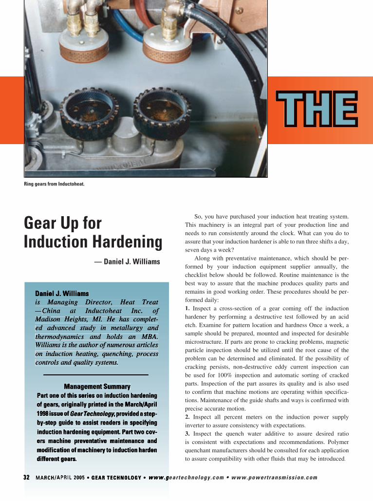
3232 MARCH/APRIL 2005 • GEAR TECHNOLOGY • www.geartechnology.comwww.geartechnology.com • www.powertransmission.com
Gear Up for Induction Hardening — Daniel J. Williams
So, you have purchased your induction heat treating system. This machinery is an integral part of your production line and needs to run consistently around the clock. What can you do to assure that your induction hardener is able to run three shifts a day, seven days a week?
Along with preventative maintenance, which should be per-formed by your induction equipment supplier annually, the checklist below should be followed. Routine maintenance is the best way to assure that the machine produces quality parts and remains in good working order. These procedures should be per-formed daily: 1. Inspect a cross-section of a gear coming off the induction hardener by performing a destructive test followed by an acid etch. Examine for pattern location and hardness Once a week, a sample should be prepared, mounted and inspected for desirable microstructure. If parts are prone to cracking problems, magnetic particle inspection should be utilized until the root cause of the problem can be determined and eliminated. If the possibility of cracking persists, non-destructive eddy current inspection can be used for 100% inspection and automatic sorting of cracked parts. Inspection of the part assures its quality and is also used to confirm that machine motions are operating within specifica-tions. Maintenance of the guide shafts and ways is confirmed with precise accurate motion. 2. Inspect all percent meters on the induction power supply inverter to assure consistency with expectations.3. Inspect the quench water additive to assure desired ratio is consistent with expectations and recommendations. Polymer quenchant manufacturers should be consulted for each applicaquenchant manufacturers should be consulted for each applicaquenchant tion to assure compatibility with other fluids that may be introduced.
Management SummaryPart one of this series on induction hardening of gears, originally printed in the March/April 1998 issue of Gear Technology, provided a step-Gear Technology, provided a step-Gear Technologyby-step guide to assist readers in specifying induction hardening equipment. Part two cov-ers machine preventative maintenance and modification of machinery to induction harden different gears.
THE HEAT GOES ON Ring gears from Inductoheat.
Daniel J. Williamsis Managing Director, Heat Treat —China at Inductoheat Inc. of Madison Heights, MI. He has complet-ed advanced study in metallurgy and thermodynamics and holds an MBA. Williams is the author of numerous articles on induction heating, quenching, process controls and quality systems.

www.powertransmission.com • www.geartechnology.com • GEAR TECHNOLOGY • MARCH/APRIL 2005 33
4. Check the quench temperature. If it’s too cold, the part will crack. With a quenchant that’s too warm, the required level of hardness will not be obtained. 5. Assure that the number of kilowatt-seconds is consistent with expectations.6. Inspect the quench filter and clean or replace as necessary. If the filter is plugged, quench flow will be restricted and proper hardening will not take place. On newer systems, pressure gauges across the filter should be checked. Older systems require that the canister be manu-ally opened and visually inspected. 7. Observe several machine cycles to assure that the part is properly rotating.8. Inspect the coil and bus connections for debris,and ensure the connections are tight. Field service tech-nicians frequently are called to plants when arcing occurs, only to discover that the coil and bus connections are loose.9. Assure that the isolation transformer connections are tight. 10. Check quench holes for obstruction and clean as needed. The quench ring often (unfortunately) acts as a quench filter and collects particles (scale), which eventually cause blockages in quench flow. This reduces the cooling effect of the quenchant, leading to inconsistent results. 11. Assure that the inductor coil is properly located with respect to the part. Check for concentricity between the coil and part in the known heat treat position.
Every six months, drain and clean the quench tank, then replace the fluid. Clean or replace all filters and check quench holes for obstructions. Then, inspect coil for crack-ing around quench holes.
Be sure to also check for loose hoses internal to the power supply.
Machine Modifi cation to Handle Various GearsAs a follow-up to these points, this article will discuss-
ways to modify induction hardening machinery to handle additional gear applications.
Can I use my induction system to process a different gear?
Gear #123 is being successfully processed on your induction hardening system. However, your company has just received a large contract to manufacture gear #789. Part prints show that gear #789 will require induction hardening. Rather than immediately deciding that new equipment is the order of the day, it may be possible to retool an existing system. The following factors must be considered:
Capacity. Is there open capacity on current induction machinery? If your answer is yes, continue considering a retool. If not, purchasing an additional piece of equipment may be your only option.
Machine’s frequency. Part prints will indicate the case depth required for gear #789. Frequency selec-tion is very important to obtain specified results.
THE HEAT GOES ON
Gears in the midst of one of Inductoheat's hardening processes.

Too low of a frequency will leave the tooth tips unheat-ed. On the other hand, heating with too high a frequen-cy will not heat the root area and will overheat the tips (see Fig. 1).
Even if the frequency does not match that used on the current equipment, it may still be functional by adding 25–50% to the “heat on” interval. If the frequency is far out of range, you may consider purchasing a more appro-priate power supply and having it installed in the existing machine platform.
Power. Power determination is calculated based on five major factors: prior microstructure of the part; mate-rial; case depth required; diametral pitch; and surface area to be hardened. Further experiments establish power lev-els for a thermally hardenable material with three differ-ent microstructures (annealed, normalized, and quenched and drawn). If the required power is equal to or less than that currently owned, move ahead. If not, consider buying a new, larger power supply to be installed in the current machine platform.
Part size. Will gear #789 fit into the machine? The existing induction equipment does have certain space limitations. The maximum diameter of gear #789 (or any gear) cannot exceed center-to-center machine constraints (approximately 10" in this example).
Both single- and dual-spindle machines offer options. If the major diameter of gear #789 exceeds 10” on a dual-spindle machine, a simple solution is to utilize only one spindle to allow for more space. In other words, a dual-spindle machine is modi-fied to become a single-spindle. If gear #789 does not exceed the 10" maximum, a dual-spindle machine can continue to operate as a dual-spindle.
Tooling. If your examination determines that this job can be processed on existing equipment (i.e., open capacity exists and the power and frequency are acceptable), then retooling the machine is the next step. An important tip: Locator tooling is best purchased from the same company designing and building the inductor coil. Proper locator tooling is essential to minimiz-ing or eliminating part distortion.
Perishable tooling includes locator tooling. Part touch tool-ing, as the name implies, touches the part. It is designed by looking for datum surfaces that are repeatable within 1/10 the tolerance of the heat treat specifications. The lateral position and height must also be established in the case of vertical machines. Concentricity of the gear within the coil must also be examined.
Ideally, tooling will be non-ferrous to avoid corrosion or inadvertent heating by the magnetic field of the inductors. Mild steel can be used in cases where the locator tooling is sufficient-ly spaced from the inductor coil. Zinc dichromate or electroless nickel coating will enable mild steel to weather the quenchant.
Inductor. Inductor coils are application-specific and, there-fore, gear #789—and most others—will require a new coil. An inductor coil will be designed nominally with an air gap that is no greater than 1.50 times the reference depth of heating for the given frequency. Quench holes will be selected to obtain 5–10% coverage on the coil heating face. Locator tooling and inductor coils are best developed by your induction equipment supplier before committing to a rebuild, a new power supply or even a new machine. Advance process development is completed to assure that metallurgical results obtained are satisfactory and acceptable. Quite often, results are not as hoped and part material, heat treat specifications and even product design may require modification. Locator tooling, inductors and process development are completed to establish satisfactory metal-lurgical results.
34 MARCH/APRIL 2005 • GEAR TECHNOLOGY • www.geartechnology.com • www.powertransmission.com
Figure 1—Proper frequency selection is needed to accomplish even heating across the part. It may be possible to have a new power supply installed in the current platform.
Sprocket gears are among those most suitable for inductionhardening.
Analysis Available vs. Required Action
Frequency The available frequency is greater than or equal to the required power supply
Use existing power supply
Frequency The available frequency is too low Buy new power supply
Power
Power The available power is too low Buy new power supply Buy new power supply
Table 1—Examination of Power Supply (Frequency and Power).
Use existing power supply The available power supply is greater than or equal to the required power supply

www.powertransmission.com • www.geartechnology.com • GEAR TECHNOLOGY • MARCH/APRIL 2005 35
Buying Locator Tooling and InductorsBuying Locator Tooling and Inductors
Although development of new part locator tooling may seem an easy task to a team of experienced engineers, it is actually best designed and built by an induction equipment supplier. Locator tooling is imperative to a successful induc-tion process, as it establishes the correct relative location between the part and tool.
Locator tooling can also affect distortion of the part and should be designed in a way that minimizes distortion of the gear itself (i.e. taper and runout). Proper or improper design can prevent or add to distortion. Furthermore, locator tooling must be validated to assure that the part is not being dis-torted.
Choosing a material able to survive the induction environ-ment is an important part of the design process. The selected material must be:
a) Able to withstand the proximity to the magnetic field and not intersect lines of flux;b) Impervious and not affected by repeat exposure to quench; andc) Self-cleaning.Unless the gear in question is already in production and
a suitable coil has been designed and built, a metallurgical laboratory is needed to test the coil and prove the process.
Inductor coil designs are difficult to predict. A design-build-develop (DBD) program, completed by an induction equipment supplier with an in-house metallurgical laboratory and a full-time metallurgist, is the best source for obtaining the proper coil. Repeated lab testing may reveal that the coil requires several slight modifications (e.g., air gaps and size specifications).
A quench barrel may be required in some cases. For instance, when the outer diameter of the gear requires quench-ing while the inner diameter is heated. Process development is required to assess whether a quench barrel is required.
Likewise, use of magnetic flux concentrators can only be confirmed via prior development.
The equipment supplier’s lab source will need guidance with respect to accomplishing desired results within the power supply size and power supply frequency constraints of the exist-ing machine. For example, avoid allowing your induction equip-ment supplier’s met lab to develop a gear hardening process at 200 kHz, if you have 30 kHz available. (Or until they prove that the 30 kHz just won’t do the job.)
Quench barrel. A quench barrel may be needed for quenching out of position.
Finally, after obtaining satisfactory metallurgical results, the supplier’s lab documentation is needed to confi rm plans for implementation at your existing facilities. Get a quotation from your supplier for production-worthy tooling and implementation. This would include inductor coils, quench rings, locator tooling and any necessary machine modifi cations for adapters for the existing equipment to accept the new tooling and process. This would be an ideal time to consider replacement of the induction power unit with a variable frequency induction heating power supply, which enables future fl exibility of the existing equipment. Field service may also be specifi ed to assist with initial setup and debugging of the gear heat treat process.
Competitive pressure forces management to consider how to make more gears, of the same and of different types, on the same or lesser equipment, with no or minimal capital outlay. Careful consideration needs to be given to existing equipment’s capability and fl exibility before investing more cash into production equipment.
Nominal Heat Times to get Carbon into Solution for Induction Hardening
(at 45 kWs/in2 Energy Density)
0
2
4
6
8
10
12
14
Powdered Metal Nodular Iron Steel Chromium AlloyedSteel
Grey Iron
Sec
onds
Figure 2—Typical power-on times for single-shot heating gener-ally range between 2–20 seconds. (For scan heating, assume 0.25–2.0” per second.)
Nominal Heat Times to Transfer Carbon Nominal Heat Times to Transfer Carbon into Solution For Induction Hardening
(at 45 kWS/in2 Energy Density)

36 MARCH/APRIL 2005 • GEAR TECHNOLOGY • www.geartechnology.com • www.powertransmission.com
gear data
Figure 1—Data exchange between different companies.
Management SummaryThe exchange of gear data between design, manufacturing and quality
inspection operations is a unique, or individual, solution in many companies, with no conformance between suppliers or customers. So manifold errors or misunderstandings can result when the companies send to each other data sheets printed on paper—especially when they’re faxed or when they’re photocopies of photocopies of photocopies. Errors or misunderstandings can also result when the sheets are transmitted electronically using nonstandardized file formats.
To improve this situation, the Association of German Engineers (VDI) created a data exchange format for gears in conjunction with the Association for Electrical, Electronic & Information Technologies (VDE). This format allows for the electronic exchange of all geometric parameters for cylindrical gears.

www.powertransmission.com • www.geartechnology.com • GEAR TECHNOLOGY • MARCH/APRIL 2005 37
IntroductionVDI/VDE Technical Committee
3.61 “Measurements of gears and gear-boxes” has defined a data exchange format for gears. This format appeared in Germany in September 2003 in a new guideline, supported by VDI and titled “Exchanging format for gearing data—Gear Data Exchange Format (GDE).” It contained the defi-nition of a data format suitable for exchanging electronically all geomet-ric parameters for cylindrical gears—including their modifications and toler-ances—between design, manufacturing and quality inspection personnel. This format is based on Extensible Markup Language (XML). It can easily be inte-grated into most database applications and Internet environments.
The advantages of a coordinated, uni-form (standardized) data exchange format are obvious. Additionally, the VDI com-mittee constantly works on a systematic extension of this format, including with regard to gear cutting tools and other processes.
This paper gives, on the one hand, an overview of the GDE format and its specific content and provides adescription of a practical application ofthis new development, which opens upnew possibilities. Moreover, it reflects the format’s current state of development and its new trends.
Motives and State of the Art
Information about a product today usually consists of large and com-plex amounts of data which describe
the manufacturing process, machines, instruments, semi-finished products and materials involved, as well as the envi-ronmental conditions. Modern, highly specialized multi-step manufacturing processes, quality tests and statistical evaluations generally are based on dif-ferent systems and data processing structures. Data exchange among the companies involved usually takes place through posting of drawings, by electronic mailing of scanned files, or via fax (see Fig. 1).
The data are then entered into a data-base system, usually by hand. Data trans-mission problems (arising, for exam-ple, in fax communication or during the scanning of model documents), errors made during entry of the data, and a limited readability or incorrect interpreta-tion of drawings may lead to consider-able misunderstandings and unnecessary delays.
Inside the companies, the situation is not much better. Data exchange between the individual systems usually takes place via specially developed, expensive conversion pro-grams or, likewise, by time-consuming manual data transmission susceptible to errors. Progressive enterprises have a central data administration system at their disposal. They require defined interfaces through which the interconnected instru-ments communicate.
Requirements for a Uniform Data Format
With these problems in mind, VDI/VDE Technical Committee 3.61
f o r m a tby
Günther Gravel and Anke Günther
“Measurement of gears and gearboxes” has specified a data exchange format for gears (GDE: Gear Data Exchange) which allows all data arising in the process of design, manufacture and quality testing to be described and exchanged. Several manufacturers of gears and measuring instruments, as well as members of research institutes, are cooperating to define the contents.
Dr. Günther Gravelis a professor for production engi-neering at the Hamburg University of Applied Sciences, located in Hamburg, Germany. He is also head of the university’s Laboratory of Production Engineering. A mechani-cal engineer, he has 18 years’ experi-ence in measuring gears, especially in high accuracy measurement, in software development and in analysis and correction of deviations. He is also chairman of the VDI commit-tee that creates VDI guidelines for measuring gears and gearboxes.
Anke Güntheris a scientific assistant with the Bremen Institute of Industrial Technology and Applied Work Science (BIBA), a part of the University of Bremen, locat-ed in Bremen, Germany. An elec-trical engineer, she works in the institute’s MAQ department (metrology, automation and quality science) developing software for measuring bevel gears. Günther is a nther is a nthermember of several DIN and VDI work groups that develop guidelines for gear tolerancing and coordinatemeasurement, including the group developing VDI’s gear data exchange format.

38 MARCH/APRIL 2005 • GEAR TECHNOLOGY • www.geartechnology.com • www.powertransmission.com
Likewise, the AGMA Data Exchange Protocol Committee is developing an information sheet on a system for digital storage and retrieval of gear metrology and related data for cylindrical gears. The committee is scheduled to publish its AGMA information sheet by the end of 2005. During its work, the committee reviewed the guideline on the VDI/VDE gear data exchange format. The AGMA format and its content are expected to undergo a formal ballot in which the committee members may comment.
In the VDI/VDE effort, broad agree-ment and acceptance are ensured by discussions among manufacturers of machine tools and cutting tools. The envisaged data format makes possible universal, rapid and—above all—safe communication between the different systems and databases. In addition, the format has a clear and extensible structure and may be mapped with readable ASCII characters. All users must, moreover, be given the possibility of representing their individual data in this format (Ref. 1).
When a new data format is designed, the essential questions are which structure is to be used for data description and which tools will make data processing possible. It is desirable and useful to fall back on established products which are widely used. They allow a wide spectrum of users to integrate the data format into their specific applications, with as little effort and outlay as possible. A mod-ern data exchange format which meets these requirements and which is, more-over, suitable for Internet applications is XML.
Characteristics and Advantages of XML
The data format is based on the XML format, a format standardized through-out the world, which is especially well out the world, which is especially well outsuited for Internet and database inter-facing. XML has been developed on the basis of the application of, and the experience gained with, SGML (Standard Generalized Markup Language) and HTML (Hypertext Markup Language). Moreover, XML is a data-oriented format
Figure 3—Example of a user interface.
Figure 2—Representation of a GDE file in Internet Explorer.
Figure 4—Flexible structure design of an XML file.

www.powertransmission.com • www.geartechnology.com • GEAR TECHNOLOGY • MARCH/APRIL 2005 39
and thus well suited for the description of complex data types. The structured data are filed as text files.
In addition to being easily readable (clearly structured ASCII text), the format has a structure which makes possible both flexible extensionand easy description of user-specific sections. Integration into a data-base is usually easy, and utilization does not require a license. Meanwhile, it is yet another advantage that all operating systems commonly used are equipped with standard software tools with which the format can be read and processed (see Fig. 2).
A large number of suitable programs is available with which attractive data sheets or user interfaces can be de-signed to simplify data input. These aids make the direct processing of ASCII files superfluous. Figure 3 shows an example of an interface for data input.
The outward form of such an input interface can be individually designed by every user.
XML permits nesting of the data to any depth. The number of single elements per nesting level can be freely defined. Lacking elements and blank elements are possible (see Fig. 4).
The XML specification allows for separate management of the data structure definition and of the data set proper. The situation in practice will be as follows: VDI makes available a “complete” struc-ture file (gde.dtd) without any data. This file is the definition file for all “valid” GDE data records. Taking this definition file as a basis, every user may design suit-able GDE files which he may require to describe his data (see Fig. 5).
If the structure file is extended (by VDI or by user supplements), the data records of a previous structure file will be “valid” even at a later date.
Integration of the Exchange Formats
Another data model for the exchange of gear data is at present being developed, with the emphasis placed on the design of gearings (Ref. 2). This model is based on
the CAD interface Step, and the aim is complete mapping of a gearing. Many modern programs for computation, simu-lation and construction are to be intercon-nected with its aid. The aspect of describ-ing the gearings in relation to the shaft, which is also highly fascinating with fascinating with fregard to manufacture, inevitably leads to a highly complex data structure.
The GDE format, however, is to make fast and simple data exchange possible and is to support gear manufacture in
Figure 7—Existing GDE format structure file.
particular. As the topics covered by thetwo formats supplement each other very well, there is close cooperation between the bodies concerned (see Fig. 6). After both formats have been introduced and established in the form of directives, it appears reasonable to combine in an ISO standard in the long run.
StructureGDE currently covers all geo-
metric characteristics of cylindrical gears,
Figure 6—Integration of the data formats.
Figure 5—Separation of structure and data.

40 MARCH/APRIL 2005 • GEAR TECHNOLOGY • www.geartechnology.com • www.powertransmission.com
Figure 8—Program for the analysis of gear deviations.
including their modifications and tol-erances. A large part of the measure-ment results has also been integrated (see Fig. 7). Still under preparation are sections describing bevel gears and splines and a section covering measure-ment and evaluation instructions for the automatic programming of gear meas-uring instruments. It has been planned to continue extending the areas already defined, in compliance with the users’ requests, an essential prerequisite for this being compatibility, because constant adapting of existing interface programs must be avoided.
The identifiers of the individual key-words are stated in English. The direc-tive will make available for the structure file a table with the German translations of the terms used. VDI/VDE Technical Committee 3.61 will be responsible for extensions of the GDE format in the future. Supplements proposed will be discussed at the committee meetings held every six months, and the programs will then be updated accordingly. Version numbers will be assigned to the different stages of development to ease manage-ment. Upward compatibility is to be guar-anteed. VDI Guideline 2610 is currently available as a white paper (Ref. 3).
Example of ApplicationThe following example demonstrates
the possibilities and perspectives offered by a generally valid exchange format. An evaluation program for the analysis of errors arising in manufacture accesses the data of a measuring instrument and rep-resents them (see Fig. 8). The effects of typical errors can then be simulated inter-actively and the real errors corrected. The correction values can be used in manufac-ture immediately and without further cal-culation. This powerful program consists of many tools for easy graphic compari-sion of measurements and for detection of systematic errors. Wearing of tools, hardening deformation or trends in pro-duction can be found with a click. The analysis program is now available with the GDE interface, so the program can be used with every gear measuring machine that supports the GDE format.
SummaryIn summary, the utilization of a
uniform exchange format allows soft-ware to be developed—independ-ent of the measuring instrument and its interfaces—that can later be run to analyze and optimize production. The GDE interface will make addi-
An earlier version of this paper was presented at two conferences: the International Conference on Gears, held March 13–15, 2002, in Munich, Germany, and Gear Measurement, held June 4–5, 2002, in Mannheim, Germany. The first presentation was pub-lished in VDI Report 1665, the conference’s proceedings, by VDI Verlag GmbH. The second was published in VDI Report 1673. At both conferences, the version was written by Anke Günther,Frank Härtig and Günther Gravel. Härtig’s contribu-tion was a planned application of the gear data exchange format, but the application wasn’t carried out as expected, so his contribution wasn‘t considered in the revised paper published here. This paper is republished with VDI’s permission.
References1. Gravel, G. and A. Pommer. “Einheitliches Format beim Austausch von Verzahnungsdaten,” Antriebstechnik, Vol. 38, No. 2, 1999, pp. 39–41.2. Höhn, B.-R., K. Steingröver and A. Dyla. “Integrierte Entwicklung von Getrieben: Praxisanwendung und Visionen,” VDI Report 1569, 2000, pp. 115–135.3. Verein Deutscher Ingenieure/Verband Der Elektrotechnik Elektronik Informationstechnik, VDI/VDE Guideline 2610, Gear Data Exchange Format (GDE), September 2003.
tional developments possible in the future. Until now, these developments have not been feasible for purely economic reasons.

www.powertransmission.com • www.geartechnology.com • GEAR TECHNOLOGY • MARCH/APRIL 2005 41
EVENTS
During April 11–15, Hannover, Germany, will host the largest international contingent of industrial automation technology professionals. Hannover Fair 2005 encompasses 11 trade fairs within a single venue. The Hannover Convention Center will welcome participants from 60 countries to the following pavilions:
Professionals in all of these disciplines will have the opportunity to hear German Chancellor Gerhard Schröder and Russian President Vladimir Putin offi cially open the exposition on April 10. The following day, the two will lead the Russian-German Business Symposium in Hall 13.
Gear buyers worldwide can browse
products from ATA Gears, Bonfi glioli
Riduttori, Brevini, Davall Gear, Flender,
Great Taiwan Gear, Hansen Transmis-
sions, IMS Gear, Metso Drives, Mijno
Precision Gearing, Ronson Gears, SEW
Eurodrive, Textron Power Transmission
and many more.
Mijno Precision Gearing is planning on
displaying two product lines at Hannover
Fair 2005. The precision rack and pinion
product line, which is now operating at
quality levels up to AGMA 12, and low
backlash planetary gearheads that can
bolt onto servomotors, will occupy most
of their programming.
“This show is always one of our better
forums as we sell worldwide. Hannover
always has a signifi cant European
presence, but there are a great deal of
Asian and South American customers
as well,” says Tom Provencher, Mijno’s
director of sales and marketing.
Leading power transmission man-
ufacturers include Animatics, Dana Corp.
Formsprag Clutch, Marland Clutch and
Pacifi c Bearing. The American Gear
Manufacturers Association will have a
booth to promote the activities of the U.S.
gear market.
For more information:Hannover MesseMessengeländeD-30521 Hannover, GermanyTelephone: +(49) 511-89-31146Fax: +(49) 511-89-31149Internet: www.hannovermesse.de
Hannover Fair Welcomes
World Leaders, Global Gear
Manufacturers
■ INTERKAMA—process automation■ Factory automation■ Motion, drive and automation■ Digital factory■ MicroTechnology■ Research & Technology■ Energy■ ComVac—compressed air and vacuum technology■ Surface Technology plus Powder Coating Europe■ Subcontracting■ Industrial Services & Repair
Thousands walk the halls at Hannover Fair.
International visitors discuss the latest technology.

42 MARCH/APRIL 2005 • GEAR TECHNOLOGY • www.geartechnology.com • www.powertransmission.com
EVENTS
The Society of Automotive Engineers will be celebrating its 100th anniverseary at the SAE 2005 World Congress and Exhibition, which will be held April 11-14 at Detroit’s Cobo Center. The annual event features a trade show with more than 500 auto industry manufacturers and suppliers, as well as a technical congress featuring presentations in more than 275 individual sessions.
Both the expo and the congress are organized into technology pavilions:
• Electronics Technology• Environment/Emissions• High Performance• Materials• Safety/Testing• Propulsion/PowertrainGear industry exhibitors will
include major OEM manufacturers, such as Getrag, Aisin Drivetrain and the transmission divisions of many leading automobile manufacturers. Other gear manufacturing companies exhibiting include Flywheel Ring Gears Pvt. Ltd., Gajra Gears Pvt. Ltd., GNA Axles Ltd., Graziano Trasmissioni SpA, Hi-Tech Gears Ltd., Hota Industrial Mfg. Co. Ltd., Jiangxi Jiangling Gear Co. Ltd., mG miniGears and Suhner Manufacturing.
“Our company decided to exhibit at the congress because we are looking to expand our business further into automotive,” says Arthur Pantelides, general manager of mG miniGears North America, located in Virginia Beach, VA. “Currently, we are supplying Tier 1 companies with precision gears and mechanisms. We feel we can expand on our unique capabilities of producing precision powdered metal gears, cut metal gears as well as assemblies, and provide customers with overall gearing and actuator solutions.”
Ted Karmazin,sales manager for Solo World Partners of Grosse Ile, MI, says his com-pany has exhib-ited at the SAE World Congress for the last 10 years. Solo repre-sents a number of medium- to large-volume manufac-turers in the Far East, including Hota Industrial Mfg. and Shanghai Automotive. Solo will display a variety of steel gears, shafts, CNC machined parts and powdered metal parts for engines, differ-entials, transmis-sions and other powertrain com-ponents. The company empha-sizes the low cost and high quality of the manufactur-ers it represents. Parts are manu-factured at ISO-9000 and ISO-16949 registered facilities, Karmazin says.
The technical presentations at the SAE Congress will also include many gear-related topics.
For example, Saul Herscovici, president of Power Engineering & Manufacturing (PEM) Ltd. of Waterloo, IA, will be presenting “Increased Power Density, Efficiency and Durability with Megagears and Unimegagears.”
Megagears and Unimegagears are trade names for gear designs developed by PEM Ltd. The company uses computersoftware to determine high pressure-angle designs that provide a larger area of
contact, Herscovici says. “Through many years of research, we have increased the power density of gears 35–45%.”
Complete information on attend-ing the SAE 2005 World Congress & Exhibition is available using the contact information below:
SAE International400 Commonwealth Dr.Warrendale, PA 15096-0001Phone: (877) SAE-CONG or (724) 772-4027E-mai l :CustomerServ [email protected]: www.sae.org/congress
SAE Marks 100th Anniversary
at the 2005 Congress

www.powertransmission.com • www.geartechnology.com • GEAR TECHNOLOGY • MARCH/APRIL 2005 43
EVENTS
������������������
���������������
��������������������������������
��������������������������������
������������������� ���������������������
������������������������ �������������
�����������������������������������������
���������������������������������������
����������������������������������������
����������������������������������������
��������������������������������
�� � � ���� � � ����� �
���� ��� � �� �
������������������������
�����������������������
���� ��������� � � ������������ �� �����������
������������� � � ����� �������������
�������������������������
To Retain Quality: Gear Training from AGMAYou’ve got a new salesman, two new machine operators,
and a 22-year-old engineer. They’ve been working for months, learning their jobs, but their training hasn’t been as systematic as you’d like. You’ve also got a manager returning to the shop fl oor after fi ve years in a front offi ce. He should have a refresher in gear manufacturing.
They all need formal training. The operators and manager especially need training in troubleshooting. But you don’t have the time.
AGMA does, though.“Our class recognizes that most people directly involved in
the gear manufacturing process have little or no formal educa-tion in the theory of gear geometry and its relationship with the process,” says Geoff Ashcroft. “We feel that this knowledge is fundamental to retaining a quality manufacturing process.”
Ashcroft, a gear manufacturing consultant, is an instructor for AGMA’s Training School for Gear Manufacturing. He teaches the school’s basic course through his company, Gear Consulting Group LLC, which is AGMA’s contractor for this and similar programs.
The course, to be held June 13–15, provides classroom train-ing in gears and their nomenclature, inspection principles, gear manufacturing processes—especially hobbing and shaping—and emphasizes troubleshooting.
“The emphasis is on the relationships between the three dis-tinct aspects of gear production: making the teeth, inspection of the result and relating these two aspects through the underlying geometry,” Ashcroft says. “This is essential for an understanding of why things go wrong and how to fix them.”
Past students included machinists, technicians, engineers, quality managers, sales reps, managers and executives. The course is usually taught at Richard J. Daley College in Chicago and provides classroom and hands-on training. The June course will be held at Liebherr Gear Technology Co., located in Saline, MI.

44 MARCH/APRIL 2005 • GEAR TECHNOLOGY • www.geartechnology.com • www.powertransmission.com
EVENTSFELLOWS
SPARES
Mechanical guides: spur/helicalHydrostatic guides: spur/helical
YOUR SOLE RELIABLE SOURCE
Send yourrequest for quote to
Former Licensee manufacturer
Via Cimarosa 17—40033 Casalecchio di Reno (BO) Italyph 011 39 051 6117811 fax 011 39 051 6117808
www.decimaspa.it
More Than the Fundamentals: Gleason’s Gear School
In a gear fundamentals course, students could expect to learn about spur and helical gears, the involute profile, and the mechan-ics of hobbing and shaping. But could they expect to learn what causes extreme amounts of lead variation in gears with fewer than 12 teeth and a helix angle of more than 60 degrees?
They might not expect to, but they did at the course held Feb. 7–10 at Gleason Cutting Tools Corp.
The gears with lead varia-tions were among several real-world manufacturing problems brought by attendees and discussed in class at Gleason Cutting Tools Corp., located in Loves Park, IL. Other problems involved tool wear, tool life, and catastrophic failures, with students asking how to troubleshoot the problems.
Called a gear fundamentals course, Gleason’s program goes beyond basic explanations of the various types of parallel-axis gears and their gear manufacturing processes. Attendees at the February course learned what aspects of the gear cutting tool affect what aspects of the gear and which features of machine control affect which gear features. They learned, for example, about AGMA hob specifications and their relationships to gear specifications.
The course costs $750 per person and covers classroom ses-sions, course manual and AGMA certificate of completion.
This course has been presented by Gear Consulting Group at other locations, including Gleason Corp.’s facil-ity in Novi, MI. Gear Consulting Group also plans to provide the course Sept. 14–16 at Contour Hardening Inc., located in Indianapolis, IN.
For more information:Gear Consulting Group LLCP.O. Box 647Richland, MI 49083Phone: (269) 623-4993Fax: (269) 623-2055E-mail: [email protected]: www.gearconsultinggroup.com
Leading calculation software
for efficient gear box design
�������
��������Dimensioning and design
optimization of machine elements
Various unique calculation tools
Rating according to
ISO, ANSI, DIN, AGMA,
VDI, FKM
KISSsoft AG
Frauwis 1
8634 Hombrechtikon
Switzerland SWISS
Quality
��������
Dimensioning and optimization
of gearboxes
Fast analysis of variants and
switched gears
Automatic documentation
Tel: +41 55 264 20 30
http://www.KISSsoft.ch
C O R P O R A T I O N

www.powertransmission.com • www.geartechnology.com • GEAR TECHNOLOGY • MARCH/APRIL 2005 45
EVENTSGiven throughout the year, the four-day course is designed
for people who are new to gear manufacturing and cov-ers gear types and ratios, gear tooth systems, general for-mulas, gear manufacturing methods, and inspection, both functional and analytical. It also covers high speed steels and the differences between tool tolerance and gear tolerance.The course is taught by Gleason employees involved in engi-neering, production and inspection. Moreover, students can tour the facility so they can see the practical applicability of their lessons.
The course costs $895 per person. The cost covers hand-book, all class materials, all lunches and one group dinner. It doesn’t include hotel room, though hotel arrangements are made for attendees by Gleason Cutting Tools. For the February course, students stayed at Cliffbreakers Hotel and took hotel shuttles between it and Gleason Cutting Tools’ nearby facility.
The class is kept small, no more than 15 people, so instruc-tors can address students’ individual concerns. In February, the class consisted of 11 attendees. They included machine opera-tors, engineers, managers and a quality control supervisor.
The course will be held again April 11–14. Gleason CuttingTools can also provide the course at gear factories and other facilities. The company also offers a second course on advanced gear process dynamics.
As for the gears with lead variations, John Lange recom-mended looking at three factors: face-to-bore clamping surface perpendicularity in the gear blank, wobble in the hobber’s fixture, and the fixturing in the inspection machine. An instruc-tor, Lange is product manager, regional products–Americas for Gleason Cutting Tools and has been in the gear industry since 1970.
Lange didn’t know whether one, two or all three factors were responsible, but he was sure that looking at them would solve the lead problem.
“One hundred percent,” he said. “Those are the things that cause it.”
For more information,contact the Gear School Coordinator:Gleason Cutting Tools Corp.1351 Windsor RoadLoves Park, IL 61111Phone: (815) 877-8900 Fax: (815) 282-0281 E-mail: [email protected]: www.gleason.com
(586) 754-8923(586) 754-8923(586) 754-8923FAX (586) 754-8926

46 MARCH/APRIL 2005 • GEAR TECHNOLOGY • www.geartechnology.com • www.powertransmission.com
EVENTS
����������������������������������������������������������
������������������������� ������������������������������������������������������������������
����������������������������������������
��������������������������
������������������������������������������
���������� �������������������������
�������������������������������������������
�������������������������������������������
��� ����� ���� ���������
630-543-9570 PHONE630-543-7440 FAX 530 Westgate DriveAddison, IL 60101
Overton Gear and Tool Corporation
www.overtongear.com
More than 100 abstracts have been selected to be devel-oped into technical papers for the 3rd International Conference on Gears, scheduled for Sept. 14–16 in Munich, Germany.
“The presentations are expected to emphasize future trends in the design, development and applications of gears and transmissions,” said Heyjo Jacobi, product manager–confer-ences for VDI Wissensforum (the VDI Center for Advanced Training). Jacobi, who holds a doctorate in mechanical engineering, is responsible for the conference.
The abstracts were selected among 220 submitted by authors from 25 countries in Europe, North America and Asia.
“The highest amount of abstracts we have ever gotten,” Jacobi said. “The high amount of potential presentations gives us again the opportunity to increase the scientific and techni-cal level of the conference.”
The center chose the best 110 abstracts, asking selected authors to develop their summaries into technical papers for presentation. The abstracts covered gear design, production, testing, industrial applications, and research and development.
The conference allows gear researchers to present the most recent results of their work, teaching attendees about the state of the art. “The conference will offer participants the opportunity to discuss these results in detail and share their experience,” Jacobi said.
The conference will be held in Munich, the capital of Bavaria. Jacobi described Bavaria as a center of the automo-tive industry in southern Germany.
Jacobi said he expects more than 300 people to take part in the conference, about 50 more than participated in the last conference, held in 2002. The conference’s program and registration form will be available by April 15.
For more information:Ursula ZinkeVDI Wissensforum IWB GmbHPostfach 10 11 39D-40002 DüsseldorfGermanyPhone: +(49) 211-6214-522Fax: +(49) 211-6214-575Internet: www.vdi.deE-mail: [email protected]
Papers Being Chosen for
International Gear
Conference
���������������
Get your Fellows machinesback in shape
1000 University Ave., P.O. Box 22970 Rochester, NY 14692-2970 U.S.A.
Phone: 585/473-1000 Fax: 585/461-4348 Web site: www.gleason.com E-mail: [email protected]
Your single source for Fellows 10-2, 10-4, 20-4 and 20-5 Gear Shaper Rebuild/Retrofit programs:� ���������������������������������������������������������������������������
� �����������������������������������������������������������
� ���������������������������������������������������������������������������
�������������������������������������������������������������������������������������������������������

www.powertransmission.com • www.geartechnology.com • GEAR TECHNOLOGY • MARCH/APRIL 2005 47
EVENTS
April 4–7—WESTEC ’05 Annual Exposition and Conference. LosAngeles Convention Center, Los Angeles, CA. The West Coast’s largest manufacturing and metalworking exhibit. Seminar top-ics include lean manufacturing, prototype deburring, and global manufacturing. Registration is free. For more information, con-tact the Society of Manufacturing Engineers on the Internet at www.sme.org.
April 26–27—Plastic Gear Technology Seminar. Universal Technical Systems facility, Rockford, IL. An introductory course in plastic gearing. Attendees will discuss case studies involving The Ohio State University’s Gear Lab, the engineering plastics material operations at Ticona, tooling and parts manufacturing at UFE, and plastic and metal gear design at Universal Technical Systems. $1,250. For more information, contact Universal Technical Systems by telephone at (800) 435-7887 or on the Internet at www.uts.com.
May 24–26—EASTEC Advanced Productvity Expo. Eastern States Expo Center, West Springfi eld, MA. An annual manufacturing event that will introduce the Smart Machining & Job Shop Center as well as the Lean Manufacturing and Quality Resource Center. Sponsored by the Society of Manufacturing Engineers. Registration is free. For more information, contact SME by telephone at (800) 733-3976 or on the Internet at www.sme.org.
The Pfister Hotel in Milwaukee, WI, hosted the “Old Goats’ Dinner” honoring past American Gear Manufacturers Association presidents on October 2–3.
Dan Bailey, Fred Sowinski, Marilyn Bergmann, Stan and Zdenska Sitta at AGMA’s Old Goats’ Dinner.
The dinner was held alongside the association’s fall technical meeting. Current AGMA chairman Fred Sowinski presented a posthumous award of excellence to former AGMA president Bob Bergmann. His widow, Marilyn, was present to accept the award on behalf of her late husband’s 35-year contribution to the gear industry.
Other former AGMA presidents in attendance were Stan Sitta and Dan Bailey.
AGMA Toasts Past Presidents
HIGH PRECISIONGROUND GEARS
• Bevel and Hypoid
• Spur and Helical
• Taper Rack and Pinion
• Worms & Wormwheels
• CURVIC® Couplings(registered trademark of The Gleason Works)
ISO-9001: 2000 CERTIFIEDISO-14001: 1996 CERTIFIED
Head Office: 119-1 KumaidenShimizu-cho, Sunto-gun, Shizuoka Japan Fax: +81-55-972-4553E-mail: [email protected]
SIGSUDA International Gear Works Ltd.
www.sudaintlgear.com
Est. 1944
Contact: (North America)P.O. Box 4, Pittsford, NY 14534 USAFax: (585) 385-8537E-mail: [email protected]
Gear Inspectionintroduces the Model 5823 Gear Inspection Machine
for automatic high speed inline gear inspection, offering greater flexibilitywith 6 axis robot loading and sorting of gears.
1104 Hwy 27 WestAlexandria, MN 56308 U.S.A.
Ph: (320) 762-8782Fax: (320) 762-5260
E-mail: [email protected]
For additional information on our fullline of Functional Gear Inspection,
and Gear Burnishing,visit our website at:www.itwgears.com
MACHINE FEATURES INCLUDE:• Greater flexibility in running
complete families of differentgears on the same machines.
• Part change over is done veryquickly requiring no tools orspecial skills.
• Setting masters are stored inquick change trays. The robotautomatically selects the settingmasters and returns them to thesame location after calibration.
• Production capability up to 600gears per hour depending on thestyle of the gear.
• Inspecting total composite, tooth-to-tooth action, runout, nicks,DOB size, lead, lead variation,taper along with other gear andpart geometry measurementscustom-ized to your particularn e e d s .
Gear InspectionHIGH SPEED
Manufactured in the USATURN-KEY SYSTEMS AVAILABLE
CUSTOMIZED TO YOUR APPLICATIONBURNISHING + WASHING + INSPECTION

INDUSTRY NEWS
In America, manufacturers of utility-scale wind turbines—and manufacturers of their gears—know the U.S. wind energy industry depends a lot on the federal government’s wind energy tax credit. Wind energy developers may even suspend their projects if they don’t have the credit.
In Norway, though, ScanWind Group AS is erecting 14 three-megawatt wind turbines to answer a question: If the company produced these turbines, could wind farms using them compete with other energy sources, without government subsidies?
The answer, whatever it is, will come from the company’s Hundhammerfjellet wind farm, located along Norway’s west coast, where the turbines are exposed to the winds of the Norwegian Sea, north of the Atlantic Ocean.
The key to a “Yes” answer is ScanWind’s ability to build wind turbines that last 20 years. According to Torolf Pettersen, the company’s managing director, turbines around the world operate at full load for an average of 2,300 hours each year. In Norway, the average is 3,900 hours. Given the country’s situa-tion, ScanWind figured if it could build turbines that lasted 20 years—and Pettersen maintains it can—then: “We can build wind power in Norway cheaper than any other type of new electricity—including gas power,” he says.
ScanWind is creating the Hundhammerfjellet wind farm with both geared and gearless wind turbines. The project consists of three phases: 1.) installing a 3000 DL demonstration turbine, completed during winter 2003, 2.) installing a 3000 GL demonstration turbine, completed during fall 2004, and 3.) installing 12 more three-megawatt turbines, creating a wind farm with a 42 megawatt capacity.
ScanWind’s 3000 DL is a three-megawatt turbine made for onshore use and equipped with a direct-drive generator. The 3000 GL is also a three-megawatt turbine for onshore use, but it’s built with a special gear assembly that lets the turbine use an asynchronous generator.
Pettersen says the project’s original two turbines have been performing very well and producing little noise. ScanWind expected to start producing the remaining 12 turbines this spring and start installing them in spring 2006, with all 14 tur-bines operational in fall 2006.
Wind Farms that Don’t Need
GovernmentSubsidies?
48 MARCH/APRIL 2005 • GEAR TECHNOLOGY • www.geartechnology.com • www.powertransmission.com
Faydor L. Litvin, professor of mechanical engineering and director of the Gear Research Center at the University of Illinois at Chicago, was 2004’s recipient of the American Society of Manufacturing Engineers’ Thomas A. Edison Patent Award.
Litvin’s patent, called the “Apparatus and Method for Precision Grinding Face Gears,” has provided a means of reducing the weight of helicopter transmissions by 40%, thereby promoting fuel savings and reduced emissions.
Litvin invented a process that grinds hardened face gears that can be manufactured with the same safety features as spiral bevel gears.
Mel Torres, media manager at ASME, says the Thomas Edison award is the most prestigious granted by the association in Litvin’s fi eld.
“In the area of patents, this is the highest ASME accomplishment,” he says. “Faydor Litvin was nominated by his peers because of the creativity in developing a process that enhances the fi eld of mechanical engineering.”
The Boeing Co. is currently working with Litvin’s patent. Face gears for an upgrade of the drive system for the Apache attack helicopter utilized by the U.S. Army were created with Litvin’s principles in mind.
Terrell Hansen, Boeing’s department manager for drive system design, says they make gears with the ideas outlined in Litvin’s patent on a daily basis.
“Because of Professor Litvin’s innovation in grinding face gears, we now have a higher reduction ratio in a gear set. This means we can get rid of hardware and some of the weight, which results in lower costs for designers, builders and operators of the system,” he says.
This is the third patent that Litvin holds, and his research is credited with 25 inventions. Mostly, his research focuses on mechanisms, manipulators, theory of gearing, computerized design and the simulation of meshing of gear drives.
Litvin has been at the University of Illinois at Chicago since 1979, when he arrived in the United States.
Much of his time was divided between teaching and writing, and he is credited with 300 publications, including 10 monographs.
The ASME was established in 1880 for the engineering and technology community. The assoc-iation’s honors and awards program is funded by the ASME Foundation.
ASMEPresentsPatent Award to Litvin
Faydor L. Litvin

www.powertransmission.com • www.geartechnology.com • GEAR TECHNOLOGY • MARCH/APRIL 2005 49
INDUSTRY NEWS
Star SU recently hired four new employees for its sales and technical efforts. Kit Pridmore has joined the company as a technical service manager. He has worked at Gleason in the same position for the past eight years and at American Pfauter for nine years prior to that. Pridmore will be based out of Detroit and will be responsible for technical support to customers in Detroit and parts of northern Ohio.
Rick Ruffi n was hired asa regional sales manager for the southeastern United States. He will operate out of Charlotte, NC. According to the company’s press release, Ruffi n has held similar positions at Gleason Cutting Tools and Perrin Precision Tools.
Mark W. Raby will manage the cutting tool sales operations in southeastern and south central Michigan. He has worked in powertrain manufacturing technical service sales for nine years at Mapal in Port Huron, MI. In addition, he has extensive experience inprototype R&D and as a journeyman apprentice.
Rick Mattingly joined Star SU as manager of tool services. He held similar positions at Pfauter Maag Cutting Tools, Barber Colman and Gleason since 1969. Mattingly will be based in the company’s Hoffman Estates, IL, facility.
Rick Ruffi n
Mark W. Raby
Star SUHires New Personnel
Rick Mattingly
Kit Pridmore
Magazine Subscription Request�� I want a free subscription to The Shot Peener.
Please send it to the address below.
Please print or attach your business card:
Name ______________________________________Title __________________
Company __________________________________________________________
Address __________________________________________________________
City _____________________State_______ Zip________Country ____________
Telephone ________________________ Fax ____________________________
Email Address ______________________________________________________
Fax: (574)256-5222Mail: The Shot Peener56790 Magnetic Drive, Mishawaka, Indiana 46545 USA
The Shot Peener: www.shotpeener.com/EI/tsp/index.html
Do your gears need:
More strength?Longer life?Shot peening is the answer.To learn more, subscribe to The Shot Peener. The Shot Peener is dedicated to raising the awareness and apprecia-tion for the shot peening process.
GT

50 MARCH/APRIL 2005 • GEAR TECHNOLOGY • www.geartechnology.com • www.powertransmission.com
INDUSTRY NEWS
Brian St. Denis was promoted to vice president of HD Systems from his previous position as engineering manager.
According to the company’s press release, he has been with HD Systems for 12 years.
HD Systems of Hauppauge, NY, is a manu-facturer of harmonic drive gearing and motion control products.
Ikona Gear Signs AgreementIkona Gear has entered into a development agreement with
StarRotor Corp. to provide patented Ikona Gear technology for the third generation of StarRotor’s proprietary design engine.
According to Ikona’s press release, both companies will develop and test the patented Ikona Gear tooth form and later negotiate a licensing agreement with royalties based on StarRotor’s net engine sales. Both companies will file separate patents to protect their intellectual properties.
Ikona has also entered into an unrelated non-disclosure agreement with Paccar-Winch Division of Paccar Inc., in which both companies will collaborate to assess the adequacy of Ikona’s slew ring and D-drive differential technologies in Paccar’s new winches and hoist drives.
If the results prove successful, Paccar will gain exclusive distribution rights within the winch industry.
Höfl er GmbH Celebrates Signifi cant Anniversaries With Hofmann
On February 1, Hagen Hofmann observed his 40th anniver-sary with Höfler GmbH and his 65th birthday.
According to the company’s press release, Hofmann started as a design engineer in 1965 and convinced the company’s founder, Dr. Ing. Höfler, to develop gear manufacturing equip-ment of all sizes and types. That same year, the first Höfler gear grinder was introduced. Hagen Hofmann was appointed president of Höfler Maschinenbau GmbH in 1990.
New Board Member at American AxleAmerican Axle & Manufacturing Holdings Inc. appointed
Larry K. Switzer to its board of directors.According to the company’s press release, Switzer has held
numerous positions in finance. Before his retirement in 2000, he was CEO of Danka PLC and led the company into a success-ful restructuring and turnaround.
American Axle & Manufacturing designs, engineers, manu-factures and validates driveline systems and related compo-nents for various automotive applications.
Brian St. Denis
St. Denis Promoted at HD Systems Estudio Piña Certifi ed to ISO 9001: 2000Estudio Piña received its ISO 9001: 2000 certifi cation for
the scope of technical assistance services in mechanical gear drives and applications.
According to the company’s press release, the certifi cation covers any service offered to customers in Argentina and Latin America.
Marposs President Receives Japanese Marketing AwardStefano Possati, president of Marposs S.p.A., received the
News Digest Marketing Award for 2004.The award was
presented to Possati at News Digest Publishing’s annual meeting in Nagoya, Japan. It was the second time in the award’s 22-yearhistory that a non-Japanese company has been so highly recognized.
Fifty Japanese operators representing the manufacturing community selected Possati on the basis of four criteria. According to the company’s press release, Marposs possesses the largest share of in-process measuring equipment, applies quality metrology technology to a variety of products, offers worldwide support for specifi c market integrations and solves in- and post-process measurement applications in workshops.
RoMaDyn Opens Rotating
Machinery Consultancy
RoMaDyn of Minden, NV, will offer global consultancy on rotating machinery dynamics.
According to a press release, the new company will offer machinery diagnostics, product services, and technical seminars on rotating machinery assets and other topics. Machinery diagnostic services include fi nding the root cause of malfunctions in turbines, compressors, motors, generators and pumps. Product services include installation, verifi cation, repair and maintenance of vibration instrumentation. Seminars will cover balancing, alignment, vibration monitoring system operations and maintenance and externally pressurized bearings. G. Richard Thomas will lead the operation as global services manager. Thomas authored a comprehensive textbook titled Fundamentals of Rotating Machinery Diagnostics and has extensive industry experience.
Stefano Possati (left) receives News Digest Marketing Award for 2004.

www.powertransmission.com • www.geartechnology.com • GEAR TECHNOLOGY • MARCH/APRIL 2005 51
INDUSTRY NEWS
POWER TRANSMISSION BUYERS GUIDE
FREE LISTINGSFor sellers of gears,
bearings, motors, clutches, couplings and other
power transmission components
SIGN UP TODAY!At
www.gearproductnews.com
In MemoriamGear Manufacturer Bennie L. Boxx: 1935–2005
Bennie L. Boxx, founder of B&R Machine and Gear Corp. of Sharon, TN, died Jan. 2 of blood cancer. He was 69 years old.
Mr. Boxx worked in the gear industry for more than 50 years, starting as a 15-year-old employee of Industrial Gear of Chicago.
Mr. Boxx was born March 28, 1935, in the small farming community of Sidonia, TN. Eight years later, his family moved to Chicago. Mr. Boxx attended high school in Chicago but dropped out to earn money. His first job in the gear business was at Industrial Gear.
He later left In-dustrial Gear to work at Arrow Gear Co. of Downers Grove, IL, where he learned about spiral bevel gears. Over the years, Mr. Boxx worked for a number of other gear-related companies, including Balfre Gear, Brad Foote Gear Works, and Cadillac Ma-chinery.
“He was an honest and honorable individual,” says Michael Goldstein, president of Cadillac Machinery, “and he was extremely talented in his bevel gear ability.” Mr. Boxx, however, was with the company only briefly, Goldstein explains. “He enjoyed making gears much more than selling gear machines.”
In the early ’70s, Mr. Boxx and two friends started their own gear company, Astron Gear in Hodgkins, IL. Within a few years, he sold his
share of the company and started B&R Bevel Gears and Machine, located in Addison, IL. The company had three employees during its first year; B&R has 30 today.
By late 1980, B&R Bevel Gears moved from Illinois to Tennessee. In ’77, Mr. Boxx was visiting his hometown of Sidonia when he noticed an empty building once used by Central Southern Trucking in Sharon, a nearby town. He decided to open a branch of B&R Bevel Gears in the building. In ’78, his eldest son, Bennie R. Jr., moved to Sharon and opened B&R Machine and Gear Corp. Within three years, Mr. Boxx merged the two operations.
The merged company started in a 7,000-square-foot building. Owned and operated by the Boxx family, B&R now consists of five buildings, more than 135,000 square feet, on 22 acres.
Mr. Boxx is survived by his wife, Doretta; two sons, Bennie R. and Terry; two daughters, Brenda Sudzum and Suzette Kelly; a brother, Danny; two sisters, Joan Rollins and Carolyn Burnett; 13 grandchildren and three great-grandchildren. He was preceded in death by a daughter, Doretta Denise Boxx.
B&R continues.
Bennie L. Boxx, Founder of B&R Machine and Gear Corp.

Use this index to contact any advertiser in this issue.
ADVERTISER INDEXADVERTISER PAGE # PHONE E-MAIL INTERNET
ALD Thermal Treatment Inc. 54 (803) 233-0660 54 (803) 233-0660 [email protected] [email protected] www.aldtt.net
Allen Adams Sharper Services Inc. 53 (802) 259-2937 Allen Adams Sharper Services Inc. 53 (802) 259-2937 Allen Adams Sharper Services Inc. 53 (802) 259-2937 Allen Adams Sharper Services Inc. 53 (802) 259-2937 [email protected]
American Gear Manufacturers Assoc. 1 (703) 684-0211 1 (703) 684-0211 1 (703) 684-0211 1 (703) 684-0211 [email protected] [email protected] www.gearexpo.com
American Metal Treating Co. 54 (216) 431-4492 American Metal Treating Co. 54 (216) 431-4492 American Metal Treating Co. 54 (216) 431-4492 American Metal Treating Co. 54 (216) 431-4492 [email protected] www.americanmetaltreating.com
Applied Process Inc. 4Applied Process Inc. 4 (734) 464-2030 [email protected] [email protected] www.appliedprocess.com
Arrow Gear Co. 14 (630) 969-7640 Arrow Gear Co. 14 (630) 969-7640 Arrow Gear Co. 14 (630) 969-7640 Arrow Gear Co. 14 (630) 969-7640 [email protected] [email protected] www.arrowgear.com
Atlas Gear 55 (248) 583-3000 Atlas Gear 55 (248) 583-3000 Atlas Gear 55 (248) 583-3000 Atlas Gear 55 (248) 583-3000 [email protected] [email protected] www.atlasgear.com
A/W Systems Co. 10 (248) 544-3852A/W Systems Co. 10 (248) 544-3852A/W Systems Co. 10 (248) 544-3852A/W Systems Co. 10 (248) 544-3852
Broaching Machine Specialties Co. 53 (248) 471-4500 Broaching Machine Specialties Co. 53 (248) 471-4500 Broaching Machine Specialties Co. 53 (248) 471-4500 Broaching Machine Specialties Co. 53 (248) 471-4500 [email protected] [email protected] www.broachingmachine.com
The Cincinnati Steel Treating Co. 54 (513) 271-3173 The Cincinnati Steel Treating Co. 54 (513) 271-3173 The Cincinnati Steel Treating Co. 54 (513) 271-3173 The Cincinnati Steel Treating Co. 54 (513) 271-3173 [email protected] [email protected] www.steeltreating.com
Clifford Jacobs Forging Co. 43 (217) 352-5172 43 (217) 352-5172 [email protected] [email protected] www.clifford-jacobs.com
Comtorgage Corp. 13 (401) 765-0900 13 (401) 765-0900 13 (401) 765-0900 www.comtorgage.com
De.Ci.Ma SpA 44 (39) (051) 611-7811 [email protected] [email protected] www.decimaspa.it
Donner + Pfi ster AG 45 (585) 586-5748 Donner + Pfi ster AG 45 (585) 586-5748 Donner + Pfi ster AG 45 (585) 586-5748 Donner + Pfi ster AG 45 (585) 586-5748 [email protected] [email protected] www.dpag.ch
Eldec Induction USA Inc. 54 (248) 364-4750 Eldec Induction USA Inc. 54 (248) 364-4750 Eldec Induction USA Inc. 54 (248) 364-4750 Eldec Induction USA Inc. 54 (248) 364-4750 [email protected] [email protected] www.eldec.de
Forest City Gear Co. IBC (815) 623-2168 Forest City Gear Co. IBC (815) 623-2168 Forest City Gear Co. IBC (815) 623-2168 Forest City Gear Co. IBC (815) 623-2168 Forest City Gear Co. IBC (815) 623-2168 www.fcgear.com
Formax Precision Gear Inc. 55 (586) 323-9067 ecision Gear Inc. 55 (586) 323-9067 ecision Gear Inc. 55 (586) 323-9067 ecision Gear Inc. 55 (586) 323-9067
Gear Motions Inc. 54Gear Motions Inc. 54 (315) 488-0100 (315) 488-0100 [email protected]@nixongear.com www.gearmotions.comwww.gearmotions.com
The Gear Works—Seattle Inc. 55 (206) 762-3333 Seattle Inc. 55 (206) 762-3333 Seattle Inc. 55 (206) 762-3333 Seattle Inc. 55 (206) 762-3333 [email protected] [email protected] www.thegearworks.com
Gleason Corp. IFC, 46, 53, 54 (585) 473-1000 Gleason Corp. IFC, 46, 53, 54 (585) 473-1000 Gleason Corp. IFC, 46, 53, 54 (585) 473-1000 Gleason Corp. IFC, 46, 53, 54 (585) 473-1000 [email protected] [email protected] www.gleason.com
Gleason Cutting Tools Corp. 53, 54 (815) 877-8900 Gleason Cutting Tools Corp. 53, 54 (815) 877-8900 Gleason Cutting Tools Corp. 53, 54 (815) 877-8900 Gleason Cutting Tools Corp. 53, 54 (815) 877-8900 [email protected] [email protected] www.gleason.com
Horsburgh & Scott 54 (216) 432-3784 54 (216) 432-3784 [email protected] [email protected] www.horsburgh-scott.com
Inductoheat 6 (248) 585-9393 Inductoheat 6 (248) 585-9393 Inductoheat 6 (248) 585-9393 Inductoheat 6 (248) 585-9393 [email protected] [email protected] www.inductoheat.com
Insco Corp. 43 (978) 448-6368Insco Corp. 43 (978) 448-6368Insco Corp. 43 (978) 448-6368Insco Corp. 43 (978) 448-6368 [email protected] [email protected] www.inscocorp.com
Ipsen International 19Ipsen International 19 (815) 332-4941 [email protected] [email protected] www.ipsen-intl.com
ITW Heartland 47 (320) 762-8782 ITW Heartland 47 (320) 762-8782 ITW Heartland 47 (320) 762-8782 ITW Heartland 47 (320) 762-8782 [email protected] [email protected] www.itwgears.com
Kapp Technologies 3 (303) 447-1130 3 (303) 447-1130 [email protected] [email protected] www.kapp-usa.com
KissSoft AG 44KissSoft AG 44 (41)(55) 264-2030 [email protected] [email protected] www.kisssoft.ch
Koro Sharpening Service 53 (763) 425-5247 53 (763) 425-5247 [email protected] [email protected] www.koroind.com
Liebherr Gear Technology Co. 5 (734) 429-7225 Liebherr Gear Technology Co. 5 (734) 429-7225 Liebherr Gear Technology Co. 5 (734) 429-7225 Liebherr Gear Technology Co. 5 (734) 429-7225 [email protected] [email protected] www.liebherr.com
Midwest Gear & Tool Inc. 45 (586) 754-8923 Midwest Gear & Tool Inc. 45 (586) 754-8923 Midwest Gear & Tool Inc. 45 (586) 754-8923 Midwest Gear & Tool Inc. 45 (586) 754-8923 [email protected]
Milwaukee Gear Co. 15 (414) 962-3532Milwaukee Gear Co. 15 (414) 962-3532Milwaukee Gear Co. 15 (414) 962-3532Milwaukee Gear Co. 15 (414) 962-3532 [email protected] [email protected] www.milwaukeegear.com
Niagara Gear Corp. 55 (800) 447-2392, (716) 874-9003 [email protected] [email protected] www.niagaragear.com
Overton Gear & Tool Corp. 46 (630) 543-9570Overton Gear & Tool Corp. 46 (630) 543-9570Overton Gear & Tool Corp. 46 (630) 543-9570 [email protected] [email protected] www.overtongear.com
Paulo Products 51 (314) 647-7500 Paulo Products 51 (314) 647-7500 Paulo Products 51 (314) 647-7500 [email protected] [email protected] www.paulo.com
Presrite Corp. 11 (216) 441-5990 Presrite Corp. 11 (216) 441-5990 Presrite Corp. 11 (216) 441-5990 Presrite Corp. 11 (216) 441-5990 www.presrite.com
The Purdy Corp. 12 (860) 649-000012 (860) 649-0000 [email protected] [email protected] www.purdytransmissions.com
Radyne 8 (414) 481-8360 [email protected] [email protected] www.radyne.com
RoMaDyn 49 (877) 766- 2396 (877) 766- 2396 [email protected] [email protected] www.romadyn.com
Schwartz Precision Gear Co. 55 (586) 754-4600 Schwartz Precision Gear Co. 55 (586) 754-4600 Schwartz Precision Gear Co. 55 (586) 754-4600 [email protected]
The Shot Peener magazine 49 magazine 49 (800) 832-5653, (574) 256-5001 www.shotpeener.com
Star SU LLC BOC, 53Star SU LLC BOC, 53 (847) 649-1450 [email protected] [email protected] www.star-su.com
SUDA International Gear Works Ltd. 47 (585) 385-8537 47 (585) 385-8537 47 (585) 385-8537 [email protected] [email protected] www.sudaintlgear.com
52 MARCH/APRIL 2005 • GEAR TECHNOLOGY • www.geartechnology.com • www.powertransmission.com

www.powertransmission.com • www.geartechnology.com • GEAR TECHNOLOGY • MARCH/APRIL 2005 53
CLASSIFIEDS
Rates—Line Classified: 1" minimum, $325. Additional lines $45 per line (8 lines per inch). Display Classified: 3" minimum: 1X—$540,
3X—$495 per insertion, 6X—$450 per insertion. Additional per inch: 1X—$255, 3X—$235 per insertion, 6X—$225 per insertion. Color
Classified: Add $135 per insertion for color. Gear Technology will set type to advertiser’s layout or design a classified ad at no extra charge.
Payment: Full payment must accompany classified ads. Send check drawn in U.S. funds on a U.S. bank or Visa/MasterCard number and
expiration date to Gear Technology, P.O. Box 1426, Elk Grove Village, IL 60009. Agency Commission: No agency commission on classified
ads. Materials Deadline: Ads must be received by the 15th of the month, two months prior to publication. Acceptance: Publisher reserves the
right to accept or reject advertisements at his discretion.
SERVICE
Broaching Requirements?• Eight standard lines ofnew broaching equipment
• New and remanufacturedturnkey broaching systems•Hydraulic and electro-mechanical drive availablavailabla e
• Broach ToolToolT s
• Production Broaching Services
• Parts and service for alltypes of broaching machines
25180 Seeley RoadNovi, MI 48375-2044Phone: (248) 471-4500Fax: (248) 471-0745
www.broachingmachine.com
Electro-mechanical internal table-up
E-mail: [email protected]
��������������������������������
�����������������������
�����������������
����������������������������All former Fellows Employees
Allen Adams Shaper Services, Inc.394 Stewart Rd N, Mount Holly, VT 05758Phone: 802-259-2937 Fax: 802-259-3937
e-mail: [email protected]
Sharpening Servicefor hobs, milling cutters
shaper cutters, shaving cutters.
5200 Prairie Stone Parkway, Suite 100Hoffman Estates, IL 60192
Tel.: (847) 649 -1450 - Fax: (847) 649-0112
2083 W.M-55, West Branch, MI 486611-888�Resharp 1-888-737-4277
Tel.: (989) 345 -2865 - Fax: (989) 345-5660
1580 Progress Dr., Richmond, IN 47374Tel.: (765) 935 -7424 - Fax: (765) 935-7631
[email protected] www.star-su.com
KORO SHARPENING SERVICE9530 - 85TH AVENUE NO.
MAPLE GROVE, MN [email protected]
HOB SHARPENING(763) 425-5247
THIN FILM COATINGS HSS & Carbide up to 5” Dia.
Straight Gash,Sharpened & InspectedPer AGMA STANDARDS
Quick Turnaround
www.gleason.com
PICK UP AND DELIVERY IN MANY AREAS
C O R P O R A T I O N1351 Windsor Road
Loves Park, IL 61111 U.S.A.Phone: 815/877-8900
Fax: 815/877-0264E-mail: [email protected]
• BROACH SHARPENING
• HOB SHARPENING
• SHAVING CUTTER GRINDING
• THIN FILM COATING
• CUSTOM HEAT TREAT SERVICE
• REPLACEMENT HELICAL GUIDES FOR SHAPERS, INCLUDING FELLOWS
• BROACH SHARPENING
• HOB SHARPENING
• SHAVING CUTTER GRINDING
• THIN FILM COATING
• CUSTOM HEAT TREAT SERVICE
• REPLACEMENT HELICAL GUIDES FOR SHAPERS, INCLUDING FELLOWS
SERVICE
www.gleason.com
SPECIALIZED GEAR SERVICES
1000 University Ave., P.O. Box 22970 Rochester, NY 14692-2970 U.S.A.
Phone: 585/473-1000Fax: 585/461-4348
E-mail: [email protected]
• CONTRACT METROLOGY SERVICES
• CURVIC COUPLING GRINDING& INSPECTION
• BEVEL & CYLINDRICALDEVELOPMENTS & PROTOTYPES
• APPLICATION ENGINEERINGSUPPORT & DESIGN SERVICES
• HEAT TREATMENT
• REPLACEMENT HELICAL GUIDES FORSHAPERS, INCLUDING FELLOWS
• CONTRACT METROLOGY SERVICES
• CURVIC COUPLING GRINDING& INSPECTION
• BEVEL & CYLINDRICALDEVELOPMENTS & PROTOTYPES
• APPLICATION ENGINEERINGSUPPORT & DESIGN SERVICES
• HEAT TREATMENT
• REPLACEMENT HELICAL GUIDES FORSHAPERS, INCLUDING FELLOWS
SERVICE

HEAT TREATINGWEBSITES
Induction Hardening Specialists in Tooth by Tooth Contour
Hardening of InternalSpur, helical and bevel gears
Our gear hardening equipment includes 5NATCO submerged process machines and 5AJAX CNC-controlled gear scanningmachines. Tooth by tooth gear hardeningfrom .5DP-10DP, up to 15 tons, 200" diameter.
American Metal Treating CompanyCleveland, Ohio
Phone: (216) 431-4492 • Fax: (216) 431-1508Web: www.americanmetaltreating.com
E-mail: [email protected]
BreakdownServiceAvailable
We Use Med. & High FrequencySimultaneous Dual Frequency
Induction Hardened
Aircraft Gear
If you need this, call us. We sellthe systems to make it for you!
Induction, USA, [email protected]@eldec-usa.com
248-364-4750 www.eldec.de
GLEASON CUTTING TOOLSCORPORATION
www.gleason.com
Learn about one of the most modernfleets of Gear Grinders, including thenew Höfler 700 at Oliver Gear. See thelatest Reishauer Gear Grinding technolo-gy, at ISO 9001-2000 registered NixonGear, as well as the latest in CNC GearHobbing and cellular manufacturing.
GEAR MOTIONS, INC.
www.gearmotions.comwww.gearmotions.comwww.gearmotions.comwww.gearmotions.comwww.gearmotions.comwww.gearmotions.comwww.gearmotions.comwww.gearmotions.comwww.gearmotions.comwww.gearmotions.com
GLEASON CUTTING TOOLSCORPORATION
Gleason Cutting Tools Corporation is theleading gear cutting tool manufacturer inNorth America. We offer a wide variety ofform-relieving milling cutters, hobs, shapercutters, shaving cutters and CBN-plated formgrinding wheels as well as our engineering,coating, heat treating, metallurgical, toolsharpening and reconditioning services.
www.gleason.com
GLEASON CORPORATION
www.gleason.com
Gleason is the world’s most comprehensiveresource for gear manufacturing technolo-gy. We offer a comprehensive gear cuttingmachine program for every gear hobbing,milling and grinding application for cylin-drical and bevel gears. To learn more aboutour products and services or to find keycontact information, see our Web site.
HORSBURGH & SCOTTLarge Part Heat Treating
HUSweb http://www.horsburgh-scott.com
5114 Hamilton Avenue, Cleveland, OH 44114-3985 5114 Hamilton Avenue, Cleveland, OH 44114-3985 • Phone: 216-431-3900 • Fax: 216-432-5850 HUS
Fax: 216-432-5850 HUS
Fax: 216-432-5850 • Toll Free: 888-772-3900
Contact: Horsburgh & Scott Heat Treat DepartmentPhone: 216-432-3784 • Fax: 216-432-5861 • Email: [email protected]
Equipment180” Deep x 75” Diameter – Deep Pit Furnaces
Large Batch Quench & Temper Furnace60” Deep x 48” Diameter – Pit Atmosphere Furnaces
Car Bottom Stress Relieving Furnaces
Treatments(Minimum Order Weight)
Carburizing – 500 lbs. 0.080”- 0.250” effective casedepthsQuench & Temper – 500 lbs.Annealing – 500 lbs.Normalizing – 500 lbs.Stress Relieving – 1,000 lbs.
H&S has a 30,000 square foot Heat Treat Facility, with Metallurgical Lab and over 25 years experience ready
to serve your large part heat treating needs.
54 MARCH/APRIL 2005 • GEAR TECHNOLOGY • www.geartechnology.com • www.powertransmission.com
Contact: Tony WuTel: (803) 233-0660 Ext 101Email: [email protected]
Website Contact:[email protected]
Be on the Cover of
Gear TechnologySend us your high-qualitygear-related images forour consideration. It's a
great chance forFREE publicity.
Contact:Kathy O'Hara
1425 Lunt AvenueElk Grove Village, IL 60007
Phone: (847) 437-6604
• Full Service • Efficient • Fast
● Carburizing, carbonitriding, hardening● Marquenching for Distortion Control● Nitriding/ Ferritic Nitrocarburizing● Induction Hardening● Gleason Press Quenching● Flame Hardening
Gear Heat Treating Services:
5701 Mariemont AvenueCincinnati OH 45227Phone (513) 271-3173Fax (513) 271-3510
www.steeltreating.com
Other Services Include:
Member of
Ford Q1 Approved
•
• Aluminum Processing• Neutral salt bath hardening• Stress relieving• Tool steel processing High temperature
alloy age hardening
• Long Parts • Stainless steel processing• Sub-zero treating• Metallurgical consulting• Annealing and
normalizing Additional Manufacturing Services Available
5701 Mariemont AvenueCincinnati OH 45227Phone (513) 271-3173Fax (513) 271-3510
www.steeltreating.com

GEAR MANUFACTURING
— Spur, Helical and Pump Gears to AGMA Class 15
— Featuring the latest grinding and CNC technology including:• Reishauer RZ300E Electronic
Gear Grinders• Gleason TAG 400 CNC, 8-axis
High Production Gear Grinder• Full CNC Multi-axis Cylindrical
Grinding (Internal and External)• High Performance CNC Hobbing
— Continuous Process ImprovementUtilizing SPC and Quality Planning
— JIT Delivery using InnovativeStocking Programs
PRECISION GROUND GEARS
800-447-2392Fax: 716-874-9003www.niagaragear.comemail:[email protected]
www.powertransmission.com • www.geartechnology.com • GEAR TECHNOLOGY • MARCH/APRIL 2005 55
Precision Spline Grinding-Service
Aerospace, Commercial, DefenseSplines & Gears / Int. & Ext.
�Small Wheel Jobs (3/8" Diameter)�1 Page Charting on Form, Lead, Index, R/O
� M&M Gear Analyzer�M&M Inspection Time
6047 18 Mile RoadSterling Heights, MI 48314
PH (586) 323-9067FAX (586) 323-9069
� Crowns � Sectors�Tapered Arbors � Timing/Loc.� Spline Gages �Master Gears� Spline Collets � Salvage/Repairs� Nital Etch � Weep-Outs
Join the thousands who visit every day. Log on to www.powertransmission.com to find suppliers of the components you need.
The Ultimate Shopping Mall for Power Transmission Components
powertransmission.com™
• Gears • Bearings • Motors • Speed Reducers • Sprockets • Actuators • Linear Motion… and more
WHEN IT HAS TO BE RIGHT
• Gear Grinding to 94"• Industrial Gears to 250"• Turbo Compressor Gears• Custom Drives• Spline Broaching• Gear Metrology • Stock Planetary Speed ReducersStock Planetary Speed Reducers
GGGGGGGGGGGGGGGGGGGGGGGGGGGGGGGGGGGGGGGGGGGGGGGGGGGEE
ISO-9001
www. theg. theg earworks .com
Custom Gear Services Since 1946
The Gear Works—Seattle, Inc.500 S. Portland StreetSeattle, WA 98108-0886Phone: (206) 762-3333Fax: (206) 762-3704E-mail: [email protected]
GEAR MANUFACTURING
PRECISION GROUND SPUR-HELICAL-GEARS-
SPLINES-WORMS-WORMGEARS-GROUND RACKS-
PROTOTYPE OR PRODUCTIONMAKE COMPLETE OR
OPERATIONAL INCLUDINGGEAR BOXES & ASSEMBLY-GEAR PUMPS-AEROSPACE-
MILITARY-COMMERCIAL-HOBBING-SHAPING-TURNING
JIG GRINDING-COMPLETEGRINDING FACILITIES
NITAL ETCH-MAGNAFLUX
24649 Mound Road, Warren, MI 48091Phone (586) 754-4600
Fax (586) 754-4603Email [email protected]
Want to Drive
Traffic to Your
Website?Advertise
on
www.geartechnology.com
Call (847) 437-6604

ADDENDUM
Tell Us What You Think . . . Send e-mail to [email protected] to• Rate this article• Make a suggestion Or call (847) 437-6604 to talk to one of our editors!
56 MARCH/APRIL 2005 • GEAR TECHNOLOGY • www.geartechnology.com • www.powertransmission.com
Imagine a shop supervisor with a three-gear drivetrain tat-tooed on his bicep or a saleswoman with a tiny spur gear silhou-etted just above her ankle.
Now imagine hundreds of gear people supporting their industry by getting Gear TattoosGear TattoosG . That’s a grassroots cam-paign the Addendum team could get excited about, and it would help us forget about our last campaign.
As readers will recall, we suggested in the September/October issue that the gear industry start a grassroots campaign to put the face of Edwin R. Fellows, inventor of the gear shaping machine, on the $10 bill. We kicked off the campaign by calling the United States Treasury with our idea. We even invited our gear comrades to join by calling us so we could give them the Treasury’s phone number.
Strangely, no one called.We assumed our gear fellows took the initiative and called
the Treasury themselves, so we phoned to see how many people joined our campaign. The department’s receptionist seemed a little confused about our request, but she said she’d ask around the office. We waited a month, then two, for a call back. We didn’t get one.
Eventually, we decided if we wanted responsiveness, we shouldn’t go to the federal government. We should go to the gear industry itself. After all, we’re all about short lead times and getting things done.
So the Addendum team started thinking: How else could gear people publicly show their support for their industry?
Then it hit us: Gear TattoosGear TattoosG .With this campaign, we don’t need to rely on the Treasury
to change the $10 bill. We can change our bodies our-
selves. Now the tattoo can be simple, the spur gear silhouette, or complicated, a mechanism’s gear assembly.
The Addendum team went the complicated route—well, one of us did. He was in a Jim Beam slumber that Friday night. That was just as well. It took the artist several hours to do the whole tattoo. After waking, our teammate was surprised by our decision. He later saw the usefulness of a gear tattoo, though. If we want to start a grassroots campaign, we have to be willing to take the first step.
Now our teammate’s tattoo (pictured above) is on his left forearm. To show it off, all he has to do is hold out his arm or, at most, roll up his sleeve. That’s important. The gear tattoo has to be on a body part that can be shown in public, in mixed company. This campaign is about publicly showing our support for our industry: No tattoos where zippers have to be undone or clasps unhooked.
Now it’s March. Gear Expo 2005 is in October. That gives us seven months. By the time we get to Detroit, we should all have our Gear TattoosGear TattoosG . The Addendum team has already called Cobo Center’s receptionist and asked to reserve a room so exhibitors and attendees could show off their tattoos. She wasn’t sure a room would be available, but said she’d ask around the office.
We’ll give her a month to call back.
Gear TattoosGear TattoosGear Tattoos

���������������������������������� ��� �� ��������� ����� ���� ������� ����� �����������������������
����� ���� ����� ������������� ������ ���� ��� ����������
��������������������������������������������������������
�����������������������������������������������������
����� ����� ������ ������������� ���� �������� ��������
��������������������������������������������������������
���������������������������������������������������������
����������� ��� �������� ������������ ������������ ��� ����
������ ����������������������������� �������������������
�������������������������������������������������������
��������������� ���������� �������� ���� ���������� ����
�������������������������������������������������������������������������������������������������������������������������������������������������������������������������������������������������������������������������������������������������������������������������������������������������
��������������������������������������������������
�����������������������������������������������������������������
����������������������������

GT
0803
Star SU LLC5200 Prairie Stone ParkwaySuite 100Hoffman Estates, IL 60192Tel.: (847) 649-1450Tel.: (847) 649-1450TFax: (847) [email protected]
We’reall abouttools
Choose from a comprehensive line of gear cuttingtools – including patented solutions you will find onlyat Star SU.
- HSS and carbide hobs, FELLO shaper cutters - Milling cutters, rack and saw cutters- Shaving cutters- Profile grinding wheels- Master gears- Chamfering and deburring tools (incl. sprocket wheels)- Gun drills and reamers
Creative and proven designs, excellent base materi-als, custom-made production machines and certifiedprocesses are bound together to form a final productof superior quality.To maintain the level of quality and to meet your requirements, we offer tool regrinding services forhobs, shaper cutters, milling cutters, shaving cuttersand master gears in our Service Centers in the USand all over the world.
Not only are we experts in gear cutting tool applica-tions but we also offer a complete range of gearroughing and finishing machines for various applica-tions including a variety of brands like Bourn &Koch/Fellows shaping technology as well as Koch/Fellows shaping technology as well as KSamputensili and Star machine technology.
Visit our website to download our complete program of products andfind out the match for yourparticular need.
Contact us today. We're closer than you may think.
AD_GT_0803 26.09.2003 16:20 Uhr Seite 1