
Miter Gear Box - Tsubaki Singapore
82
TSUBAKI Miter Gear Box TSUBAKIMOTO CHAIN CO. Miter Gear Box
-
Upload
khangminh22 -
Category
Documents
-
view
0 -
download
0
Transcript of Miter Gear Box - Tsubaki Singapore

TSU
BA
KI
Miter G
ear Box
TSU
BA
KIM
OTO
CH
AIN
CO
.
U.S. TSUBAKI POWER TRANSMISSION, LLC301 E. Marquardt Drive, Wheeling, IL 60090, U.S.A.Phone : +1-847-459-9500URL : http://ustsubaki.com/
TSUBAKI of CANADA LIMITED1630 Drew Road, Mississauga, Ontario, L5S 1J6, CanadaPhone : +1-905-676-0400URL : http://tsubaki.ca
TSUBAKI BRASIL EQUIPAMENTOS INDUSTRIAIS LTDA.R. Pamplona, 1018, CJ. 73/74, Jd. PaulistaCEP 01405-001, São Paulo, S.P.BrazilPhone : +55-11-3253-5656URL : http://tsubaki.ind.br
TAIWAN TSUBAKIMOTO CO.No. 33, Lane 17, Zihciang North RoadGueishan Township Taoyuan County Taiwan R.O.C.Phone : +886-3-3293827/8/9URL : http://tsubakimoto.com.tw
TSUBAKIMOTO CHAIN (SHANGHAI) CO. LTD.Room 601, Urban City Centre, 45 Nanchang Road Huangpu District, Shanghai 2000020, People's Republic of China Phone : +86-21-5396-6651/2 URL : http://tsubaki.cn/
TSUBAKIMOTO (THAILAND) CO. LTD.388 Exchange Tower, 19th Floor Unit 1902Sukhumvit Road, Klongtoey, Bangkok 10110, ThailandPhone : +66-2-262-0667/8/9URL : http://tsubaki.co.th
TSUBAKI INDIA POWER TRANSMISSION PVT. LTD.Chandrika Chambers No.4, 3rd Floor, Anthony StreetRoyapettah, Chennai, Tamil Nadu 600014, IndiaPhone : +91-44-4231-5251 URL : http://tsubaki.in/
PT. TSUBAKI INDONESIA TRADINGWisma 46 - Kota BNI, 24th Floor, Suite 24.15Jl. Jend. Sudirman, Kav. 1, Jakarta 10220, Indonesia Phone : +62-21-571-4230/31 URL : http://tsubakimoto.co.id/
TSUBAKI POWER TRANSMISSION (MALAYSIA) SDN. BHD.No. 22, Jalan Astaka U8/84A, Bukit Jelutong Industrial Park Section U8, 40150 Shah Alam, Selangor, Malaysia Phone : +60-3-7859-8585 URL : http://tsubaki.sg
TSUBAKIMOTO SINGAPORE PTE. LTD.25 Gul Lane, Jurong, Singapore 629419 Phone : +65-6861-0422/3/4URL : http://tsubaki.sg
TSUBAKI AUSTRALIA PTY. LTD.Unit E, 95-101 Silverwater Road Silverwater NSW 2128, AustraliaPhone : +61-02-9704-2500URL : http://tsubaki.com.au
TSUBAKIMOTO KOREA CO., LTD.#1004/1005 East Wing, Hanshin Intervalley 24, 707-34Yeoksam-dong, Gangnam-gu, Seoul, KoreaPhone : +82-02-2183-0311URL : http://tsubakimoto.com
TSUBAKI AUSTRALIA PTY. LTD.NEW ZEALAND BRANCH2 Kalmia Street, Ellerslie, Auckland 1051, New ZealandPhone : +64-275-082-726Phone : http://tsubaki.com.au
Group companies
ASIA and OCEANIA
TSUBAKIMOTO EUROPE B.V.Aventurijn 1200, 3316 LB Dordrecht, The NetherlandsPhone : +31-78-620-4000URL : http://tsubaki.eu
OOO "TSUBAKI KABELSCHLEPP"Prospekt Andropova 18, Building 6115432 Moscow, RussiaPhone : +7-499-418212URL : http://kabelschlepp.ru/
TSUBAKIMOTO U.K. LTDOsier Drive, Sherwood Park, Annesley, NottinghamNG15 0DX, United KingdomPhone : +44-1623-688-700URL : http://tsubaki.eu
TSUBAKI DEUTSCHLAND GmbHASTO Park Oberpfaffenhofen, Friedrichshafener Straße 1D-82205, Gilching, GermanyPhone : +49-8105-7307100URL : http://tsubaki.de/
EUROPE
NORTH and SOUTH AMERICA
HeadquartersNakanoshima Mitsui Building3-3-3 Nakanoshima, Kita-kuOsaka, 530-0005, JapanPhone : +81-6-6441-0011URL : http://tsubakimoto.com
Chain & Power Transmission Sales1-3 Kannabidai, 1-chomeKyotanabe,Kyoto, 610-0380, JapanPhone : +81-774-64-5022
TSUBAKIMOTO SINGAPORE PTE. LTD.VIETNAM REPRESENTATIVE OFFICEH&H Building 8F, 209 Hoàng Văn ThụPhú Nhuận District, Hồ Chí Minh City, VietnamPhone : +84-8-3999-0131/2URL : http://tsubaki.net.vn/
Catalog No.985K555-1 ©2015/2 TSUBAKIMOTO CHAIN CO.Printed in Japan (K) 1,000
Miter Gear Box

TSUBAKI’ s Miter Gear Box has been used for a wide range of applications and in various specifications since it was launched in 1966.The type ED and type ARA Gear Box are available in various special specifications besides the standard model.
TSUBAKI’s Miter Gear Box plays important roles around the world
No.1market share
Wide range of variationsSolution power
■ Type EDFeatures, structure, functionsModel list, Standard specificationIndication of model number(Shaft arrangement, rotational relationship, type of mounting)
Selection, Example of model selectionTransmission capacity tableDimensional drawing
■ Type ARAFeatures, Model list, Standard specificationIndication of model number, SelectionTransmission capacity table, Dimensional drawing
Top market share supported by reliability, results, and track record
We can propose the optimum speci�cation for every application including various special speci�cations.
Solution power
The type ED & type ARA are available in a wide range of standard models and semi-standard models. (Refer to the Model list in p.9.)
Wide variations
Type EDSpeed ratio:1:1, 1.5:1, 2:1, 2.5:1, 3:1 Size:10 sizes Shaft arrangement:42 types Casing material:FC (Gray cast iron) FCD (Ductile cast iron) * ED2 uses ADC (Aluminum die-casting)
Type ARASpeed ratio:1:1, 2:1 Size:3 sizes Shaft arrangement:3 types Casing material:ADC (Aluminum die-casting)
TSUBAKI’s Miter Gear Box TSUBAKI’s Miter Gear Box TSUBAKI’s Miter Gear Box TSUBAKI’s Miter Gear Box TSUBAKI’s Miter Gear Box TSUBAKI’s Miter Gear Box
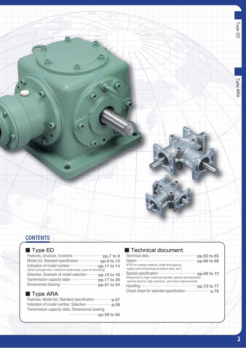
CONTENTS
TSUBAKI’s Miter Gear Box has received recognition for its reliability, results, and track record, from customers in various �elds, and has achieved top market share in the Gear Box �eld.
・・・・・・・・・・・・・・・・・・・・・・・・・・・・pp.7 to 8・・・・・・・・・・・・・・・・・・・・pp.9 to 10
・・・・・・・・・・・・・・・・・・・・・・・・・・・pp.11 to 14
・・・・・・・・・・・pp.15 to 16・・・・・・・・・・・・・・・・・・・・・・・・・・pp.17 to 20
・・・・・・・・・・・・・・・・・・・・・・・・・・・・・・・・・・・・pp.21 to 54
・・・・・・・・・・・・・・・・p.57・・・・・・・・・・・・・・・・・・・・・・・・p.58
・・・・・・・・・・・・・・・・・・・・・・・・・・・pp.59 to 60
■ Technical documentTechnical dataOption(FCD for casing material, shaft end tapping, spigot joint processing at bottom face, etc.)
Special specification(Responds to high rotational speeds, special atmospheres, special layouts, high precision, and other requirements)
HandlingCheck sheet for selected specification
・・・・・・・・・・・・・・・・・・・・・・・・・・・・・・・・・・・・・・・・・・・・・pp.63 to 65・・・・・・・・・・・・・・・・・・・・・・・・・・・・・・・・・・・・・・・・・・・・・・・・・・・・・・・・pp.66 to 68
・・・・・・・・・・・・・・・・・・・・・・・・・・・・・・・・・・・・pp.69 to 72
・・・・・・・・・・・・・・・・・・・・・・・・・・・・・・・・・・・・・・・・・・・・・・・・・・・・・pp.73 to 77・・・・・・・・・・・・・・・・・・・・・・・・p.78
1
TSUBAKI’ s Miter Gear Box has been used for a wide range of applications and in various specifications since it was launched in 1966.The type ED and type ARA Gear Box are available in various special specifications besides the standard model.
TSUBAKI’s Miter Gear Box plays important roles around the world
No.1market share
Wide range of variationsSolution power
■ Type EDFeatures, structure, functionsModel list, Standard specificationIndication of model number(Shaft arrangement, rotational relationship, type of mounting)
Selection, Example of model selectionTransmission capacity tableDimensional drawing
■ Type ARAFeatures, Model list, Standard specificationIndication of model number, SelectionTransmission capacity table, Dimensional drawing
Top market share supported by reliability, results, and track record
We can propose the optimum speci�cation for every application including various special speci�cations.
Solution power
The type ED & type ARA are available in a wide range of standard models and semi-standard models. (Refer to the Model list in p.9.)
Wide variations
Type EDSpeed ratio:1:1, 1.5:1, 2:1, 2.5:1, 3:1 Size:10 sizes Shaft arrangement:42 types Casing material:FC (Gray cast iron) FCD (Ductile cast iron) * ED2 uses ADC (Aluminum die-casting)
Type ARASpeed ratio:1:1, 2:1 Size:3 sizes Shaft arrangement:3 types Casing material:ADC (Aluminum die-casting)
CONTENTS
TSUBAKI’s Miter Gear Box has received recognition for its reliability, results, and track record, from customers in various �elds, and has achieved top market share in the Gear Box �eld.
・・・・・・・・・・・・・・・・・・・・・・・・・・・・pp.7 to 8・・・・・・・・・・・・・・・・・・・・pp.9 to 10
・・・・・・・・・・・・・・・・・・・・・・・・・・・pp.11 to 14
・・・・・・・・・・・pp.15 to 16・・・・・・・・・・・・・・・・・・・・・・・・・・pp.17 to 20
・・・・・・・・・・・・・・・・・・・・・・・・・・・・・・・・・・・・pp.21 to 54
・・・・・・・・・・・・・・・・p.57・・・・・・・・・・・・・・・・・・・・・・・・p.58
・・・・・・・・・・・・・・・・・・・・・・・・・・・pp.59 to 60
■ Technical documentTechnical dataOption(FCD for casing material, shaft end tapping, spigot joint processing at bottom face, etc.)
Special specification(Responds to high rotational speeds, special atmospheres, special layouts, high precision, and other requirements)
HandlingCheck sheet for selected specification
・・・・・・・・・・・・・・・・・・・・・・・・・・・・・・・・・・・・・・・・・・・・・pp.63 to 65・・・・・・・・・・・・・・・・・・・・・・・・・・・・・・・・・・・・・・・・・・・・・・・・・・・・・・・・pp.66 to 68
・・・・・・・・・・・・・・・・・・・・・・・・・・・・・・・・・・・・pp.69 to 72
・・・・・・・・・・・・・・・・・・・・・・・・・・・・・・・・・・・・・・・・・・・・・・・・・・・・・pp.73 to 77・・・・・・・・・・・・・・・・・・・・・・・・p.78
Type EDType A
RA
2

Type ARAType ED
Motive power is distributed to the right and left sides, and is input to the jack.
Hoisting equipment
Motive power is input from the cross shaft (orthogonal shaft), and the lateral shaft is set as the output shaft. Two units are coupled and synchronized.
Motive power is input from the cross shaft using the lateral dual shaft, and the opposing lateral shaft is rotated in the reverse direction.
Entertainment facility
Motive power is input to the cross shaft using a ceil ing-mounted construction, then motive power is distributed to the pulleys of another cross shaft and lateral shaft, and they are driven at the same time.
Paper folding machine
The screw in the water is driven by motive power from the unit on the ground.
Motive power is distributed to the right and left sides, as well as to plural shafts, and the line shaft is driven.
Iron- and steel-making machine
Packaging quantity is counted by linking the rotary cutter with the counter drive for the number of �lm sheets.
Food packaging machine
The ag i ta tor i s d r iven by distributing motive power to the right and left sides.
Agitator
We can propose the optimum speci�cation for every application.The type ED and type ARA are available in standard models with a wide range of variations in terms of size, shaft arrangement, speed ratio, and material. Furthermore, with various special specifications, they play important roles in a wide range of applications such as entertainment facilities, chemical plants, food machinery.
Scraper in water
Driven with one motor unit, synchronization is easy and hoisting is possible while keep-ing a horizontal state.
Driven with one motor unit, plural units can be synchro-nized.
Layout can be freely designed. (Please indicate type of mount-ing.)
It is possible to use the gear box in water. Harmonization with the environment can be promoted with water lubrica-tion.
Synchronized operation can be achieved easily by driving with one motor unit. A compact equ ipment des ign can be achieved.
Space savings are possible by linking with the compact ARA Gear Box. Besides, when using the ARA Gear Box, which has excellent corrosion resistance, it is possible to prevent the generation of rust.
One motor unit can drive two shafts. Using the ARA Gear Box, which has excellent corro-sion resistance, it is possible to prevent the generation of rust.
Using the lateral dual shaft, rotation is possible in different directions with one motor unit.
Type ED Type ARAMultistory parking structure for transporting pallets
Merit Merit Merit Merit Merit Merit Merit Merit
3

Type ARAType ED Type ARAType ARA
Motive power is distributed to the right and left sides, and is input to the jack.
Hoisting equipment
Motive power is input from the cross shaft (orthogonal shaft), and the lateral shaft is set as the output shaft. Two units are coupled and synchronized.
Motive power is input from the cross shaft using the lateral dual shaft, and the opposing lateral shaft is rotated in the reverse direction.
Entertainment facility
Motive power is input to the cross shaft using a ceil ing-mounted construction, then motive power is distributed to the pulleys of another cross shaft and lateral shaft, and they are driven at the same time.
Paper folding machine
The screw in the water is driven by motive power from the unit on the ground.
Motive power is distributed to the right and left sides, as well as to plural shafts, and the line shaft is driven.
Iron- and steel-making machine
Packaging quantity is counted by linking the rotary cutter with the counter drive for the number of �lm sheets.
Food packaging machine
The ag i ta tor i s d r iven by distributing motive power to the right and left sides.
Agitator
We can propose the optimum speci�cation for every application.The type ED and type ARA are available in standard models with a wide range of variations in terms of size, shaft arrangement, speed ratio, and material. Furthermore, with various special specifications, they play important roles in a wide range of applications such as entertainment facilities, chemical plants, food machinery.
Scraper in water
Driven with one motor unit, synchronization is easy and hoisting is possible while keep-ing a horizontal state.
Driven with one motor unit, plural units can be synchro-nized.
Layout can be freely designed. (Please indicate type of mount-ing.)
It is possible to use the gear box in water. Harmonization with the environment can be promoted with water lubrica-tion.
Synchronized operation can be achieved easily by driving with one motor unit. A compact equ ipment des ign can be achieved.
Space savings are possible by linking with the compact ARA Gear Box. Besides, when using the ARA Gear Box, which has excellent corrosion resistance, it is possible to prevent the generation of rust.
One motor unit can drive two shafts. Using the ARA Gear Box, which has excellent corro-sion resistance, it is possible to prevent the generation of rust.
Using the lateral dual shaft, rotation is possible in different directions with one motor unit.
Type ED Type ARAMultistory parking structure for transporting pallets
Merit Merit Merit Merit Merit Merit Merit Merit
Type EDType A
RA
4

5
MEMO

Type ED
C O N T E N T S
Features, structure, functions・ ・・・・・・・ p.7
Model list・・・・・・・・・・・・・・・・・・・・・・・・・・ p.9
Standard specification・ ・・・・・・・・・・・・ p.10
Indication of model number・・・・・・・・・ p.11Shaft arrangement, rotational relationship, type of mounting
Selection・ ・・・・・・・・・・・・・・・・・・・・・・・・ p.15
Transmission capacity table・・・・・・・・・ p.17
Dimensional drawing・・・・・・・・・・・・・・・ p.21
6

Type ED
7
Type ED
Features, structure, functions
ブラケット
ギヤ
ケース
クロス軸
ラテラル軸
ブラケットがある側の軸をラテラル軸とよびます。
ピニオン
FeaturesWide range of variationsThe optimum model can be selected from a wide range.We can also respond to various special specifications for all market needs.
High qualityBecause it adopts high-precision spiral bevel gears that comply with AGMA standards, many high-level
functions such as high efficiency and high transmission capacity can be obtained.
Prompt deliveryA wide range of standard and semi-standard models is available. (Refer to the Model list in p.9.)
StructureHorizontal shaft type
⑪
①
②
③
④
⑤⑥
⑦
⑧
⑨
⑨
⑨
⑩
⑩
ED6M-1-L-O-Y Internal structure
① Casing
② Bracket
③ Lateral shaft
④ Cross shaft
⑤ Pinion
⑥ Gear
⑦ Input seal support
⑧ Output bearing support
⑨ �Taper roller bearing (Sizes 2 & 4 use ball bearing.)
⑩ Oil seal
⑪ Oil gauge
Note 1) Sizes 2 & 4 are not provided with an oil gauge.
Cross shaft
Casing
Lateral shaftThe shaft at the bracket side is called the lateral shaft.
Gear
Bracket
Pinion
Type ED
8
FunctionAs a basic function…
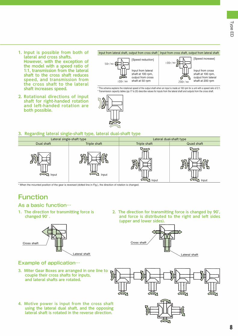
1. Input is possible frombothoflateralandcrossshafts.
However,with theexceptionofthemodelwithaspeedratioof1:1,transmissionfromthelateralshaft to thecrossshaft reducesspeed, and transmission fromthe cross shaft to the lateralshaftincreasesspeed.
2.Rotational directions of inputshaft for right-handed rotationand left-handed rotation arebothpossible.
Cross shaft
Lateral shaft Lateral shaft
Cross shaft
Example of application…
1.Thedirectionfortransmittingforceischanged90°.
3.MiterGearBoxesarearrangedinonelinetocoupletheircrossshaftsforinputs,andlateralshaftsarerotated.
2.Thedirectionfortransmittingforceischangedby90°,and force is distributed to the right and left sides(upperandlowersides).
4.Motive power is input from the cross shaftusing the lateraldualshaft,andtheopposinglateralshaftisrotatedinthereversedirection.
3.Regardinglateralsingle-shafttype,lateraldual-shafttypeLateral single-shaft type Lateral dual-shaft type
Dual shaft Triple shaft Triple shaft Quad shaft
入力 入力
入力 入力
* When the mounted position of the gear is reversed (dotted line in Fig.), the direction of rotation is changed.
Input from lateral shaft, output from cross shaft Input from cross shaft, output from lateral shaft
* This schema explains the rotational speed of the output shaft when an input is made at 100 rpm for a unit with a speed ratio of 2:1. * Transmission capacity tables (pp.17 to 20) describe values for inputs from the lateral shaft and outputs from the cross shaft.
[Speed reduction] [Speed increase]
Input from lateral shaft at 100 rpm, output from cross shaft at 50 rpm
Input Input
Input Input
Input from cross shaft at 100 rpm, output from lateral shaft at 200 rpm

Type ED
9
Type ED
Model list
1. Lateral single-shaft typeSpeed ratio M (1:1) B15 (1.5:1) B20 (2:1) B25 (2.5:1) B30 (3:1)
Size FC FCD FC FCD FC FCD FC FCD FC FCD
2 ●○(ADC)
— — — — — — — — —
4 ●●○ △ — — ●●○ △ — — — —
6 ●●○ ●●○ ●●○ ●●○ ●●○ ●●○ ●●○ ●●○ ●●○ ●●○
7 ●●○ ●●○ ●●○ ●●○ ●●○ ●●○ ●●○ ●●○ ●●○ ●●○
8 ●●○ ●●○ ●●○ ●●○ ●●○ ●●○ ●●○ ●●○ ●●○ ●●○
10 ●●○ ●●○ ●●○ ●●○ ●●○ ●●○ ●●○ ●●○ ●●○ ●●○
12 ●●○ ●●○ ●●○ ●●○ ●●○ ●●○ ●●○ ●●○ ●●○ ●●○
16 ●●○ △ — — ●●○ △ — — — —
20 ●●○ — — — ●●○ — — — — —
25 ●●○ — — — ●●○ — — — — —
Material
:Standard item △:Semi-standard item
2. Lateral dual-shaft typeSpeed ratio M (1:1) B15 (1.5:1) B20 (2:1) B25 (2.5:1) B30 (3:1)
Size FC
2 ※△(ADC)
— — — —
4 ●○ — ●○ — —
6 ●○ ●○ ●○ ●○ ●○
7 ●○ ●○ ●○ ●○ ●○
8 ●○ ●○ ●○ ●○ ●●●○
10 ●○ ●○ ●○ ●○ ●○
12 ●○ ●○ ●○ ●○ ●○
16 △ — △ — —
20 △ — △ — —
25 △ — △ — —
Material
Note 1) ADC (Aluminum die-casting), FC (Gray cast iron), FCD (Ductile cast iron)
Note 2) For the lateral dual-shaft type of size 2, shaft arrangements of 1-1-UD (-O), 1-1-U (-O), 1-1-D (-O), U-D-LR (-O), U-D-R (-O), and U-D-L (-O) can be manufactured.
Note 3) For FCD, shaft arrangements of 1-LR (-O), 1-R (-O), and 1-L (-O) of the size in the table above can be manufactured.
Model list

Type ED
10
Type ED
Standard specification
Gear box
Speed reduction method Spiral bevel gear
Lubrication method Sizes 2 & 4: Grease lubricationSizes 6 to 25: Oil lubrication
Specification of key New JIS regular class JIS B1301-1976 The key is attached at delivery.
Casing material Size 2: ADC Sizes 4 to 25: FC (FCD is optional.)
Sealing structure Single oil seal
Painting specificationPaint color: Munsell 2.5G6/3
Undercoat: Lacquer-type undercoat paint Finish coating: Acrylic lacquer-type paint
Corrosion-resistant specification
Corrosion-resistant period: six months under indoor storage conditions (after shipment from the factory)
Outside corrosion-resistant treatment: Application of corrosion-preventive oil Inside corrosion-resistant treatment: Sealing after enclosing lubrication oil
Ambient conditions
Installation site Indoor
Ambient temperature –10°C to 50°C
Humidity 95% or less
Altitude 1,000 m or lower
Atmosphere There shall be no corrosive or explosive gas, vapor, and dew condensation, and there shall be minimal dust.
Type of mounting Floor (Y), Ceiling (T), Wall (K1, K2, K3, K4)
Note 1) ADC (Aluminum die-casting), FC (Gray cast iron), FCD (Ductile cast iron)
Standard specification

Type ED
11
Type ED
Indication of model number Shaft arrangement • Rotational relationship
ED 6 M − 1−LR − Y ED 10 B20 − 1−1−UD − T
Size Speed ratio Shaft arrangement • Rotational relationship
2
4
6
7
8
10
12
16
20
25
M(1:1)
B15(1.5:1)
B20(2:1)
B25(2.5:1)
B30(3:1)
Lateral single-shaft type
1-LR 1-UD U-LR D-LR
Lateral dual-shaft type
1-1-LR 1-1-UD U-D-LR
1-LR-O 1-UD-O U-LR-O D-LR-O 1-1-LR-O 1-1-UD-O U-D-LR-O
1-R 1-U U-R D-R 1-1-R 1-1-U U-D-R
1-R-O 1-U-O U-R-O D-R-O 1-1-R-O 1-1-U-O U-D-R-O
1-L 1-D U-L D-L 1-1-L 1-1-D U-D-L
1-L-O 1-D-O U-L-O D-L-O 1-1-L-O 1-1-D-O U-D-L-O
1-D-O
1-U-O
1-LR-O
1-D
1-U
1-LR
1-L-O
1-L
1-UD-O
1-UD
1-R-O
1-R
U-L-O
U-R-O
U-L
U-R
U-LR-O
U-LR
・�The�shaft�arrangements�described�to�the�right�have�the�same�rotational�relationships.�However,�note�that�the�positions�of�plug,�oil�gauge,�and�name�plate�differ.U-LR=U-LR-O,�U-R=U-L-O,�U-L=U-R-O,�D-LR=D-LR-O,�D-R=D-L-O,�D-L=D-R-O,�1-1-LR=1-1-LR-O,�1-1-R=1-1-L-O,�1-1-L=1-1-R-O,�U-D-LR=U-D-LR-O,�U-D-R=U-D-L-O,�U-D-L=U-D-R-O
Lateral single-shaft type
Lateral dual-shaft type

Type ED
12
Size Speed ratio Shaft arrangement • Rotational relationship
2
4
6
7
8
10
12
16
20
25
M(1:1)
B15(1.5:1)
B20(2:1)
B25(2.5:1)
B30(3:1)
Lateral single-shaft type
1-LR 1-UD U-LR D-LR
Lateral dual-shaft type
1-1-LR 1-1-UD U-D-LR
1-LR-O 1-UD-O U-LR-O D-LR-O 1-1-LR-O 1-1-UD-O U-D-LR-O
1-R 1-U U-R D-R 1-1-R 1-1-U U-D-R
1-R-O 1-U-O U-R-O D-R-O 1-1-R-O 1-1-U-O U-D-R-O
1-L 1-D U-L D-L 1-1-L 1-1-D U-D-L
1-L-O 1-D-O U-L-O D-L-O 1-1-L-O 1-1-D-O U-D-L-O
1-1-D-O
1-1-U-O
1-1-LR-O
1-1-D
1-1-U
1-1-LR
1-1-L-O
1-1-L
1-1-UD-O
1-1-UD
1-1-R-O
1-1-R
U-D-L-O
U-D-R-O
U-D-L
U-D-R
U-D-LR-O
U-D-LR
D-L-O
D-R-O
D-L
D-R
D-LR-O
D-LR
Type of mounting For mounting by each shaft arrangement, refer to pp.13, 14.
・�The�shaft�arrangements�described�to�the�right�have�the�same�rotational�relationships.�However,�note�that�the�positions�of�plug,�oil�gauge,�and�name�plate�differ.U-LR=U-LR-O,�U-R=U-L-O,�U-L=U-R-O,�D-LR=D-LR-O,�D-R=D-L-O,�D-L=D-R-O,�1-1-LR=1-1-LR-O,�1-1-R=1-1-L-O,�1-1-L=1-1-R-O,�U-D-LR=U-D-LR-O,�U-D-R=U-D-L-O,�U-D-L=U-D-R-O
Floor mount Ceiling mount Wall mountY T K1 K2 K3 K4
Lateral dual-shaft type
Oil supply plug Grease nipple
Drain plug
Oil gaugeOil supply plugGrease nipple
Drain plugOil gauge
Oil supply plug
Drain plug
Oil gauge
Oil supply plug
Grease nipple
Drain plug
Oil gauge
Oil supply plug
Drain plug
Oil gauge (opposite face)
Oil supply plug
Grease nipple
Drain plug
Oil gauge (opposite face)
Shaft arrangement1-1-UD(-O)1-1-U(-O)1-1-D(-O)

Type ED
13
Lateral single-shaft typeType of mounting • Position of each plug
1-LR(-O)1-R(-O)1-L(-O)
1-UD(-O)1-U(-O)1-D(-O)
U-LR(-O)U-R(-O)U-L(-O)
D-LR(-O)D-R(-O)D-L(-O)
Floor mount
Y
Ceiling mount
T
Wall m
ount
K1
For 1-L (-O), the parts are at the opposite side of the cross shaft.
K2
For U-R (-O), the parts are at the opposite side of the cross shaft.
For D-R (-O), the parts are at the opposite side of the cross shaft.
K3
For 1-R (-O), the parts are at the opposite side of the cross shaft.
K4
For U-L (-O), the parts are at the opposite side of the cross shaft.
For D-L (-O), the parts are at the opposite side of the cross shaft.
Type ED
Indication of model numberType of mounting
Oil supply plug (opposite face)
Oil gauge (opposite face)
Drain plug (opposite face)
Oil supply plug (opposite face)
Drain plug(opposite face)
Oil gauge (opposite face)
Oil supply plug Grease nipple
Drain plug
Oil gauge
Oil supply plug
Grease nipple
Drain plug
Oil gauge
Oil supply plug (opposite face)
Grease nipple (opposite face)
Drain plug(opposite face)
Oil gauge (opposite face)
Oil supply plug (opposite face)
Drain plug(opposite face)
Oil gauge (opposite face)
Oil supply plug (opposite face)
Drain plug(opposite face)
Oil gauge (opposite face)
Oil supply plug (opposite face)
Grease nipple (opposite face)
Drain plug(opposite face)
Oil gauge (opposite face)
Oil supply plug
Grease nipple
Drain plug
Oil gauge
Oil supply plug
Grease nipple
Drain plug
Oil gauge
Oil supply plug
Drain plug
Oil gauge
Oil supply plug
Drain plug
Oil gauge
Oil supply plug
Drain plug
Oil gauge
Oil supply plug
Drain plug
Oil gauge
Oil supply plug
Drain plug
Oil gauge Oil supply plugGrease nipple
Drain plug
Oil gauge (opposite face)
Oil supply plug
Grease nipple
Drain plug
Oil gauge (opposite face)
Oil supply plugGrease nipple
Drain plug
Oil gauge (opposite face)
Oil supply plug
Drain plugOil gauge (opposite face)
Oil supply plug
Drain plug
Oil gauge
Oil supply plug
Drain plug
Oil gauge
Oil supply plug
Grease nipple
Drain plug
Oil gauge (opposite face)
Oil supply plug
Grease nipple
Drain plug
Oil gaugeOil supply plug
Grease nipple
Drain plug
Oil gauge
Note 1) Sizes 2 & 4 are not provided with oil gauge and grease nipple. They can be mounted in any direction.Note 2) For sizes 6 to 25, floor mount (Y) is the standard. In the cases of ceiling mount (T) and wall mount (K1, K2, K3, K4), the positions of the oil gauge, plug, and grease nipple differ.
Type of mounting
Shaft arrangement

Type ED
14
Lateral dual-shaft typeType of mounting • Position of each plug
1-1-LR(-O)1-1-R(-O)1-1-L(-O)
1-1-UD(-O)1-1-U(-O)1-1-D(-O)
U-D-LR(-O)U-D-R(-O)U-D-L(-O)
Floor mount
Y
Ceiling mount
T
Wall m
ount
K1
For 1-1-L (-O), the parts are at the opposite side of the cross shaft.
K2
For U-D-R (-O), the parts are at the opposite side of the cross shaft.
K3
For 1-1-R (-O), the parts are at the opposite side of the cross shaft.
K4
For U-D-L (-O), the parts are at the opposite side of the cross shaft.
Oil supply plug
Drain plug
Oil gauge (side face)
Oil supply plug
Drain plug
Oil gauge (side face)
Oil supply plug Grease nipple
Drain plug
Oil gauge
Oil supply plugGrease nipple
Drain plugOil gauge
Oil supply plug (opposite face)
Grease nipple (opposite face)
Drain plug(opposite face)
Oil gauge (opposite face)
Grease nipple
Oil supply plug (opposite face)
Drain plug(opposite face)
Oil gauge (opposite face)
Oil supply plug
Grease nipple
Drain plug
Oil gauge
Oil supply plug
Drain plug
Oil gauge
Oil supply plug
Drain plug
Oil gauge
Oil supply plug
Grease nipple
Drain plug
Oil gauge
Oil supply plug
Grease nipple
Drain plug
Oil gaugeOil supply plugGrease nipple
Drain plug
Oil gauge (opposite face)
Oil supply plugGrease nipple
Drain plug
Oil gauge
Oil supply plug
Drain plug
Oil gauge (opposite face)
Oil supply plug
Drain plug
Oil gauge (opposite face)
Oil supply plug
Grease nipple
Drain plug
Oil gauge
Oil supply plug
Grease nipple
Drain plug
Oil gauge (opposite face)
Oil supply plugGrease nipple
Drain plug
Oil gauge
Note 3) These are for sizes 6 to 16. The positions of the oil gauge and plug differ for sizes 20 & 25. Furthermore, a pressure vent is mounted for size 12 or larger. For the mounting position, refer to the dimensional drawings (pp.45 to 54).
Type of mounting
Shaft arrangement

Type ED
15
Make�the�selection�according�to�the�following�procedure,�considering�conditions.
1. Decision on service factorAll�transmission�capacity�tables�in�the�catalog�show�values�with�the�service� factor� set� at� 1.0.�Depending� on� service� conditions,� decide�the�service�factor�using�the�Service�factor�table�in�Table�1.
2.Decision on corrected torque or corrected kWDecide�corrected�torque�or�corrected�kW�considering�the�service�factor.�Corrected�torque�or�Corrected�kW�=(Load�torque�or�transmission�kW�applied�to�the�Miter�Gear�Box)��Service�factor�(Table�1)
3.Decision on sizeFor�the�rotational�speed�used,�select�the�size�that�satisfies�corrected�torque�or�corrected�kW�from�the�transmission�capacity�tables.Furthermore,�check�whether�the�peak�torque�at�starting�and�stopping�is�kept�to�within�200%�of�the�transmission�capacity�of�the�selected�size.
4.Confirmation of radial loadWhen�driving� is�performed�at�a�state�with�sprocket,�gear,�or�pulley,�etc.�mounted�on� the� lateral�shaft�and/or�cross�shaft,�confirm� the�radial�load�using�the�following�formula.■ Formula�for�confirming�radial�load
When� the� formula� at� the� left� side� is� not� satisfied� as� a� result� of�confirming�the�radial�load,�it�is�necessary�to�increase�“R,”�namely�the�pitch�circle�radius�of�the�sprocket,�pulley,�etc.
Table2 O.H.L. factor (f)Chain 1.00Gear 1.25
Toothed�belt 1.25V-belt�•�Strong�toothed�belt 1.50
5.Decision on shaft arrangement • rotational relationship, type of mounting – Decision on model number・�Shaft�arrangement�•�Rotational�relationshipSelect�from�Shaft�arrangement�•�Rotational�relationship�(pp.11�to�12).�(Pay�attention�to�rotational�direction�of�the�shaft.)
・�Type�of�mounting�Select�from�Type�of�mounting�(pp.13�to�14).�(Sizes�2�&�4�are�lubricated�with�grease,�and�there�is�no�limit�to�the�mounting�direction.)
Decide�model�number�on�the�basis�of�the�conditions�above.
6.Investigation/study of options, special specifications, etc.Because�we�also�manufacture� options� (pp.66� to�68)� as�well� as� standard� items�and� items�with� special� specifications� (pp.69� to�72),�please�consult�our�company.
Type ED
Selection
1.Machine and equipment used, layout2.Operating conditions3.Ambient atmosphere4.Others (option, special specification, etc.)
1. Machine and equipment used, layout2. Operating conditions ・Description�of�prime�mover ・Load�torque�N•m�{kgf•m}�or�transmission�kW ・Operating�time:�(������)�hrs/day�����Continuous�•�Intermittent ・Starting�and�stopping�frequency:�(������)�times/hr ・�Input�rotational�speed:��Regular�(������)�rpm�
�Max.�(������)�rpm ・Direction�of�input�shaft:�Lateral�shaft�•�Cross�shaft
・Speed�ratio:�1�:�1,��1.5�:�1,��2�:�1,��2.5�:�1,��3�:�1 ・�Characteristics�of�load�: Uniform�load�•�Load�with�some�shock�•�Load�with�large�shock3. Ambient atmosphere ・�Usage� environment� :� Indoors� •� Outdoors� •� Near� a� furnace� •��Inside�a�refrigerator�•�Others�(���������)
・�Ambient�temperature�:�Regular�(�����)�°C�•���High�temperature�(�����)�°C�•�Low�temperature�(�����)�°C�
・�Ambient�atmosphere:�Salt�damage�•�Dust�•�Acid�•��Others�(���������)
4. Others ・Option�(pp.66�to�68),�Special�specification�(pp.69�to�72),�etc.
* Also use the Check sheet for selecting the specification (p.78).
Q
ℓ
(Allowable�radial�load:�p.64)
Allowable�radial�load ≧ T × f × LfRT� = Corrected�torque N・m{kgf・m}f� = O.H.L.�factor�(Table�2)Lf� = Operating�position�factor�(Table�3)R� = ��Pitch�circle�radius�of�sprocket,�
�pulley,�etc.�m
Selection conditions
Selection procedure
Table 3 Operating position factor (Lf)When�load�is�applied�to�the��center�of�the�shaft�or�inside Lf = 1
When�load�is�applied�to�the�outside��rather�than�the�center�of�the�shaft
Q�=�Length�of�output�shaft�end ℓ=Operating�position�of�radial�load
Note)��If�radial�load�and�axial�load�are�to�be�applied�at�the�same�time,�please�consult��our�company.
ℓ≦ Q2
ℓ > Q2 Lf =2ℓ
Q
Table 1 Service factor Operating timeCharacteristics of load 2 hrs 10 hrs 24 hrsUniform load 1.00(1.00) 1.00(1.25) 1.25(1.50)
Load with some shock 1.00(1.25) 1.25(1.50) 1.50(1.75)
Load with large shock 1.25(1.50) 1.50(1.75) 1.75(2.00)
Note�1)�When�frequency�of�starting�and�stopping�is�not�less�than�10�times�an�hour,�or�the�prime�mover�is�a�multi-cylinder�engine,�use�the�values�in�(�����).Note�2)�The�service�factors�above�are�general�guidelines.�Make�a�decision�considering�service�conditions.
Type ED
16
①Decision on service factor �From�Table�1,�the�service�factor�is�1.0�under�the�operating�conditions�above�(uniform�load,�8�hrs/day).
②Selection of each Miter Gear Box (1) Miter Gear Box No.1・The�gear�drives�only�load�A.→�Transmission� capacity� of� 245�N•m�×�1.0� =� 245�N•m� or�more�is�required.
・�The�cross�shaft�drives�loads�A,�B,�and�C.��→Cross�shaft�torque�of�(245�N•m�+�245�N•m�+�245�N•m)�×�1.0�=�735�N•m�or�more�is�required.�So,�ED10M�is�selected�from�the�transmission�capacity�tables�and�allowable�torque�of�cross�shaft.
ED10M��Transmission�capacity:�513�N•m�>�245�N•m, � ���Allowable�torque�of�cross�shaft:�891�N•m�>�735�N•m� (2) Miter Gear Box No. 2・�The�gear�drives�only�load�B.→�Transmission� capacity� of� 245�N•m�×�1.0� =� 245�N•m� or�more�is�required.
・�The�cross�shaft�drives�loads�B�and�C.�→Cross� shaft� torque� of� (245�N•m�+� 245�N•m)�×�1.0� =� 490�N•m� or�more� is� required.� So,� ED8M� is� selected� from� the�transmission�capacity�tables�(pp.17�to�18)�and�allowable�torque�of�the�cross�shaft�(p.63).
ED8M��Transmission�capacity:�331�N•m�>�245�N•m, ��Allowable�torque�of�cross�shaft:�627�N•m�>�490�N•m
(3) Miter Gear Box No.3・Both�gear�and�cross�shaft�drive�only�load�C.�→Transmission�capacity�as�well�as�cross�shaft�torque�of�245�N•m�×�1.0�=�245�N•m�or�more�is�required.��So,� ED8M� is� selected� from� the� transmission� capacity� tables�(pp.17�to�18)�and�allowable�torque�of�cross�shaft�(p.63).
� ED8M���Transmission�capacity:�331�N•m�>�245�N•m, ���Allowable�torque�of�cross�shaft:�627�N•m�>�245�N•m
③Decision on model number �Decide�model� number� from� shaft� arrangement,� rotational�relationship,�and�type�of�mounting�for�usage�layout�(pp.11�to�14).
No.1 ED10M-1-LR-O-Y No.2 ED8M-1-LR-O-Y No.3 ED8M-1-R-O-Y can�be�selected. *�Check�direction�of�rotation.
Type ED
Example of selection
■ General selectionUsage layout
Operating conditions・�Motive�power�is�input�from�the�lateral�shaft�by�directly�coupling�a�general-purpose�motor�(15�kW�×�4P�×�60�Hz).
・�For�the�cross�shaft�side,�a�sprocket�with�a�Pitch�Circle�Diameter�(P.C.D.)�of�100�mm�is�mounted.
・�It�is�operated�at�a�load�transmission�in�kW�of�10�kW.・�Operating�time�is�10�hrs/day�under�a�load�with�some�shock.Start-stop:�Intermittent�operation�12�times/hr
・�Speed�ratio�is�1:1.Ambient atmosphere・Indoor,�30°C�constant,�ordinary�atmosphere�(no�dust,�etc.)Option・None�(The�standard�item�can�be�used.)
■ Line shaft driveUsage layout
①Decision on service factor �From� Table� 1,� the� service� factor� becomes� 1.50� under� the�operating� condition� above� (load�with� some� shock,� 10� hrs/day,�and�starting�and�stopping�12�times/hr).
②Decision on corrected kW �Corrected�kW�=�10�kW�(load�transmission�kW)�×�1.5.��(service�factor)�=�15�kW��So,�the�corrected�kW�becomes�15�kW.
③Decision on size �For� the� size� that� satisfies� the� corrected� kW�=�15� kW,� inputted�rotational� speed� of� 1,750� rpm,� ED6M� is� selected� from� the�transmission�capacity�tables.
④Confirmation of radial load� (�It�is�assumed�that�the�radial�load�is�applied�at�the�center�of�the�cross�shaft.)
�With�a�chain�transmission,�the�O.H.L.�factor�f�=1.0�from�Table�2,�and�the�operating�position�factor�Lf�=�1�because�the�radial�load�is�applied�to�the�shaft�center. �From�the�formula�for�confirming�radial�load�and�service�conditions,
Radial load=
9550 × 15× 1.0 × 1.0
=1637N1750
1002 × 1000
�From� the�Allowable� radial� load� of� the� ED6M’s� cross� shaft� =�2,303�N�>�1,637N,�it�can�be�used�within�the�allowable�value.
⑤Decision on model number �Decide� model� number� from� shaft� arrangement,� rotational�relationship,�and�type�of�mounting�for�usage�layout.
�ED6M-1-R-Y�can�be�selected. *�Check�direction�of�rotation.
* Precautions for selecting line shaft driveIn�the�case�of�line�shaft�drive,�the�load�applied�to�the�gear�and�the�load�applied�to�the�line�shaft�(cross�shaft)�differ.�Therefore,�it�is�necessary�to�select�each�individually.�For� the� allowable� torsional� transmission� capacity� of� the� cross� shaft�alone�(allowable�torque�of�the�cross�shaft),�refer�to�p.63.
Operating conditions・�All� loads� A,� B,� and�C� are� used� at� a� uniform� load� of� 245�N•m�(25�kgf•m),�and�operating�time�is�8�hrs/day.
・�Input�rotational�speed�is�300�rpm,�and�speed�ratio� is�1:1�for�all�loads.
Ambient atmosphere・Indoor,�30°C�constant,�ordinary�atmosphere�(no�dust,�etc.)Option・None�(The�standard�item�can�be�used.)
Load A
Load B
Load C
( )
( )
( )
Example 1 of selection Example 2 of selection

Type ED
17
Type ED
Lateral single-shaft type Transmission capacity tableSpeed ratio
Rotational speed of
lateral shaftr/min
ED2 ED4 ED6 ED7 ED8InputkW
Cross shaft torque InputkW
Cross shaft torque InputkW
Cross shaft torque InputkW
Cross shaft torque InputkW
Cross shaft torqueN・m {kgf・m} N・m {kgf・m} N・m {kgf・m} N・m {kgf・m} N・m {kgf・m}
1:1
3000 3.41 10.6 {1.08} 7.71 24.0 {2.45} 22.8 ��71.1 {��7.25} − − − − − −
2000 2.43 11.3 {1.16} 5.96 27.9 {2.84} 18.6 ��87.0 {��8.87} 27.1 105 {12.9} 57.3 268 {27.3}
1750 2.15 11.5 {1.17} 5.61 30.0 {3.06} 17.1 ��91.1 {��9.30} 24.8 132 {13.5} 52.3 279 {28.5}
1450 1.79 11.6 {1.18} 4.94 31.9 {3.25} 14.9 ��96.0 {��9.80} 22.0 142 {14.5} 45.6 294 {30.0}
1150 1.43 11.7 {1.19} 4.19 34.1 {3.48} 12.7 103 {10.5��} 18.4 150 {15.3} 37.5 305 {31.1}
870 1.12 12.1 {1.23} 3.46 37.2 {3.80} 10.5 113 {11.5��} 15.2 164 {16.7} 29.0 312 {31.8}
580 0.74 12.1 {1.23} 2.45 39.5 {4.03} ��7.35 119 {12.1��} 11.4 184 {18.8} 19.8 319 {32.6}
300 0.39 12.3 {1.26} 1.30 40.5 {4.13} ��3.93 123 {12.5��} ��6.35 198 {20.2} 10.6 331 {33.8}
100 0.13 12.7 {1.30} 0.44 41.9 {4.28} ��1.36 127 {13.0��} ��2.20 206 {21.0} ��3.70 346 {35.3}
10 0.01 13.0 {1.33} 0.04 43.0 {4.39} ��0.14 132 {13.5��} ��0.22 214 {21.8} ��0.38 361 {36.8}
1.5:1
3000 − − − − − − 19.7 92.1 {��9.39} − − − − − −
2000 − − − − − − 14.9 105 {10.7��} 19.2 135 {13.7} 25.8 181 {18.5}
1750 − − − − − − 13.7 110 {11.2��} 17.4 139 {14.2} 22.7 182 {18.6}
1450 − − − − − − 12.1 117 {11.9��} 15.0 145 {14.8} 19.1 185 {18.9}
1150 − − − − − − ��9.96 122 {12.4��} 12.0 147 {15.0} 15.4 188 {19.2}
870 − − − − − − ��7.66 123 {12.6��} ��9.30 150 {15.3} 11.8 191 {19.5}
580 − − − − − − ��5.23 126 {12.9��} ��6.32 153 {15.6} ��8.14 197 {20.1}
300 − − − − − − ��2.77 129 {13.2��} ��3.35 157 {16.0} ��4.34 203 {20.7}
100 − − − − − − ��0.95 134 {13.7��} ��1.16 163 {16.6} ��1.49 210 {21.4}
10 − − − − − − ��0.09 139 {14.2��} ��0.12 169 {17.2} ��0.15 218 {22.2}
2:1
3000 − − − 5.56 34.6 {3.53} 15.6 ��97.3 {��9.92} − − − − − −
2000 − − − 4.30 40.2 {4.10} 10.7 100 {10.2��} 14.2 133 {13.5} 18.9 176 {18.0}
1750 − − − 3.97 42.4 {4.33} ��9.44 101 {10.3��} 12.7 135 {13.8} 16.9 180 {18.4}
1450 − − − 3.32 42.8 {4.37} ��7.90 102 {10.4��} 10.6 137 {14.0} 14.0 180 {18.4}
1150 − − − 2.67 43.4 {4.43} ��6.39 104 {10.6��} ��8.55 139 {14.2} 11.3 183 {18.7}
870 − − − 2.04 43.8 {4.47} ��4.88 105 {10.7��} ��6.56 141 {14.4} ��8.70 187 {19.1}
580 − − − 1.38 44.4 {4.53} ��3.34 108 {11.0��} ��4.47 144 {14.7} ��5.92 191 {19.5}
300 − − − 0.72 45.5 {4.64} ��1.76 110 {11.2��} ��2.37 148 {15.1} ��3.14 196 {20.0}
100 − − − 0.24 46.6 {4.76} ��0.60 114 {11.6��} ��0.81 152 {15.5} ��1.08 202 {20.6}
10 − − − 0.02 48.5 {4.95} ��0.06 116 {11.8��} ��0.08 157 {16.0} ��0.11 209 {21.3}
2.5:1
3000 − − − − − − 11.7 ��91.1 {��9.29} − − − − − −
2000 − − − − − − ��8.00 ��93.5 {��9.53} ��9.40 110 {11.2} 15.2 177 {18.1}
1750 − − − − − − ��7.13 ��95.3 {��9.72} ��8.36 112 {11.4} 13.5 180 {18.4}
1450 − − − − − − ��5.97 ��96.2 {��9.82} ��6.99 113 {11.5} 11.4 184 {18.8}
1150 − − − − − − ��4.78 ��97.2 {��9.92} ��5.64 115 {11.7} ��9.11 185 {18.9}
870 − − − − − − ��3.68 ��99.0 {10.1��} ��4.30 116 {11.8} ��7.00 188 {19.2}
580 − − − − − − ��2.48 100 {10.2��} ��2.92 118 {12.0} ��4.76 192 {19.6}
300 − − − − − − ��1.32 102 {10.5��} ��1.55 121 {12.3} ��2.53 197 {20.1}
100 − − − − − − ��0.44 104 {10.7��} ��0.52 123 {12.6} ��0.86 203 {20.7}
10 − − − − − − ��0.04 107 {11.0��} ��0.05 126 {12.9} ��0.08 208 {21.2}
3:1
3000 − − − − − − ��9.59 ��89.7 {��9.14} − − − − − −
2000 − − − − − − ��6.56 ��92.0 {��9.38} ��7.30 102 {10.4} 10.9 152 {15.6}
1750 − − − − − − ��5.78 ��92.7 {��9.46} ��6.48 104 {10.6} ��9.78 157 {16.0}
1450 − − − − − − ��4.84 ��93.6 {��9.55} ��5.42 105 {10.7} ��8.20 159 {16.2}
1150 − − − − − − ��3.88 ��94.8 {��9.67} ��4.34 106 {10.8} ��6.55 160 {16.3}
870 − − − − − − ��2.97 ��95.9 {��9.79} ��3.34 108 {11.0} ��5.04 163 {16.6}
580 − − − − − − ��2.02 ��97.6 {��9.96} ��2.25 109 {11.1} ��3.42 166 {16.9}
300 − − − − − − ��1.07 100 {10.2��} ��1.18 111 {11.3} ��1.80 169 {17.2}
100 − − − − − − ��0.36 102 {10.4��} ��0.40 115 {11.7} ��0.61 173 {17.7}
10 − − − − − − ��0.03 104 {10.6��} ��0.04 118 {12.0} ��0.06 179 {18.3}
Note�1)�When�it�is�used�between�the�respective�rotational�speeds,�calculate�the�values�by�interpolation.Note�2)�When�rotational�speed�of�the�lateral�shaft�is�less�than�10�rpm,�use�it�with�the�torque�at�10�rpm.Note�3)�When�it�is�used�at�a�rotational�speed�of� �,�it�corresponds�to�the�specification�of�oil�lubrication.�Refer�to�the�item�on�special�specification.Note�4)��When�it�is�used�at�a�rotational�speed�of� �,�it�may�correspond�to�the�specification�of�forced�lubrication.�In�such�a�case,�please�consult�our�company.
�In�the�case�of�a�rotational�speed�between�a�rotational�speed�of� �and�a�lower�rotational�speed,�also�please�consult�our�company.
1
2
・・・・・・・

Type ED
18
Speed ratio
Rotational speed of
lateral shaftr/min
ED10 ED12 ED16 ED20 ED25InputkW
Cross shaft torque InputkW
Cross shaft torque InputkW
Cross shaft torque InputkW
Cross shaft torque InputkW
Cross shaft torqueN・m {kgf・m} N・m {kgf・m} N・m {kgf・m} N・m {kgf・m} N・m {kgf・m}
1:1
3000 − − − − − − − − − − − − − − −
2000 79.0 358 {36.5} − − − − − − − − − − − −
1750 74.6 399 {40.7} 109.6 586 {59.8} − − − − − − − − −
1450 65.3 421 {43.0} ��96.0 619 {63.2} 163 1019 {104���} − − − − − −
1150 55.7 453 {46.2} ��81.8 665 {67.9} 139 1098 {112���} 234 1842 {188} − − −
870 44.6 479 {48.9} ��67.5 726 {74.1} 114 1186 {121���} 193 2009 {205} 335 3489 {356}
580 30.6 493 {50.3} ��49.7 802 {81.8} ��85.9 1343 {137���} 145 2274 {232} 252 3940 {402}
300 16.4 513 {52.3} ��26.8 835 {85.2} ��54.1 1637 {167���} ��90.8 2744 {280} 159 4792 {489}
100 ��5.72 535 {54.6} ����9.36 875 {89.3} ��20.3 1842 {188���} ��35.3 3205 {327} ��60.0 5439 {555}
10 ��0.59 561 {57.2} ���0.98 919 {93.8} ����2.14 1940 {198���} ��3.53 3205 {327} ����6.30 5713 {583}
1.5:1
3000 − − − − − − − − − − − − − − −
2000 49.5 336 {34.3} − − − − − − − − − − − −
1750 46.0 368 {37.6} ��65.9 528 {53.9} − − − − − − − − −
1450 38.7 374 {38.2} ��58.3 564 {57.6} − − − − − − − − −
1150 31.2 380 {38.8} ��49.2 601 {61.3} − − − − − − − − −
870 24.1 389 {39.7} ��40.7 656 {66.9} − − − − − − − − −
580 16.4 396 {40.4} ��28.9 699 {71.3} − − − − − − − − −
300 ��8.78 411 {41.9} ��15.5 724 {73.9} − − − − − − − − −
100 ��3.04 426 {43.5} ��5.37 754 {76.9} − − − − − − − − −
10 ��0.31 443 {45.2} ��0.56 785 {80.1} − − − − − − − − −
2:1
3000 − − − − − − − − − − − − − − −
2000 32.0 290 {29.6} − − − − − − − − − − − −
1750 28.2 302 {30.8} ��48.3 516 {52.7} 87.7 908 {��92.7} − − − − − −
1450 23.6 305 {31.1} ��40.0 516 {52.7} 73.7 921 {��94.0} 126� 1578 {161} − − −
1150 19.0 309 {31.5} ��31.7 516 {52.7} 59.5 938 {��95.7} 102� 1607 {164} 199 3146 {321}
870 14.6 315 {32.1} ��24.0 516 {52.7} 46.0 958 {��97.8} ��79.0 1646 {168} 155 3224 {329}
580 10.0 322 {32.9} ��16.3 524 {53.5} 31.3 980 {100���} ��54.2 1695 {173} 107 3332 {340}
300 ��5.33 332 {33.9} ����8.71 543 {55.4} 16.7 1009 {103���} ��29.0 1754 {179} ��57.5 3479 {355}
100 ��1.84 344 {35.1} ����3.01 563 {57.4} ��5.84 1058 {108���} ��10.1 1833 {187} ��20.1 3646 {372}
10 ��0.19 357 {36.4} ���0.31 586 {59.8} ��0.60 1098 {112���} ����1.06 1921 {196} ����2.11 3822 {390}
2.5:1
3000 − − − − − − − − − − − − − − −
2000 24.3 275 {28.1} − − − − − − − − − − − −
1750 21.7 290 {29.6} ��37.4 500 {51.0} − − − − − − − − −
1450 18.2 293 {29.9} ��31.4 507 {51.7} − − − − − − − − −
1150 14.7 298 {30.4} ��25.3 514 {52.4} − − − − − − − − −
870 11.2 302 {30.8} ��19.5 523 {53.4} − − − − − − − − −
580 ��7.68 310 {31.6} ��13.3 535 {54.6} − − − − − − − − −
300 ��4.06 317 {32.3} ����7.08 552 {56.3} − − − − − − − − −
100 ��1.40 326 {33.3} ����2.43 568 {58.0} − − − − − − − − −
10 ��0.14 336 {34.3} ����0.25 588 {60.1} − − − − − − − − −
3:1
3000 − − − − − − − − − − − − − − −
2000 18.6 252 {25.8} − − − − − − − − − − − −
1750 16.8 270 {27.5} ��28.2 452 {46.1} − − − − − − − − −
1450 14.0 270 {27.6} ��23.6 458 {46.7} − − − − − − − − −
1150 11.3 275 {28.1} ��19.0 464 {47.3} − − − − − − − − −
870 ��8.66 279 {28.5} ��14.6 469 {47.9} − − − − − − − − −
580 ��5.89 285 {29.1} ����9.92 480 {49.0} − − − − − − − − −
300 ��3.11 291 {29.7} ����5.29 495 {50.5} − − − − − − − − −
100 ��1.07 300 {30.6} ����1.82 510 {52.0} − − − − − − − − −
10 ��0.11 308 {31.4} ���0.18 527 {53.8} − − − − − − − − −

Type ED
19
Type ED
Lateral dual-shaft typeTransmission capacity tableSpeed ratio
Rotational speed of
lateral shaftr/min
ED2 ED4 ED6 ED7 ED8InputkW
Cross shaft torque InputkW
Cross shaft torque InputkW
Cross shaft torque InputkW
Cross shaft torque InputkW
Cross shaft torqueN・m {kgf・m} N・m {kgf・m} N・m {kgf・m} N・m {kgf・m} N・m {kgf・m}
1:1
3000 2.38 7.42 {0.75} 5.39 16.8 {1.71} 15.9 49.7 {5.07} − − − − − −
2000 1.70 7.91 {0.81} 4.17 19.5 {1.99} 13.0 60.9 {6.21} 18.9 73.5 {��7.50} 40.1 187 {19.1}
1750 1.50 8.05 {0.81} 3.92 21.0 {2.14} 11.9 63.7 {6.50} 17.3 92.4 {��9.42} 36.6 195 {19.9}
1450 1.25 8.12 {0.82} 3.45 22.3 {2.27} 10.4 67.2 {6.85} 15.4 99.4 {10.1��} 31.9 205 {21.0}
1150 1.00 8.19 {0.83} 2.93 23.8 {2.43} 8.89 72.1 {7.35} 12.8 105 {10.7��} 26.2 213 {21.7}
870 0.78 8.47 {0.86} 2.42 26.0 {2.65} 7.35 79.1 {8.07} 10.6 114 {11.7��} 20.3 218 {22.2}
580 0.51 8.47 {0.86} 1.71 27.6 {2.82} 5.14 83.3 {8.50} 7.98 128 {13.1��} 13.8 223 {22.7}
300 0.27 8.61 {0.88} 0.91 28.3 {2.89} 2.75 86.1 {8.78} 4.44 138 {14.1��} 7.42 231 {23.6}
100 0.09 8.89 {0.91} 0.30 29.3 {2.99} 0.95 88.9 {9.07} 1.54 144 {14.7��} 2.59 242 {24.7}
10 0.01 9.10 {0.93} 0.02 30.1 {3.07} 0.09 92.4 {9.42} 0.15 149 {15.2��} 0.26 252 {25.7}
1.5:1
3000 − − − − − − 13.7 64.4 {6.57} − − − − − −
2000 − − − − − − 10.4 73.5 {7.50} 13.4 94.5 {��9.64} 18.0 126 {12.9}
1750 − − − − − − 9.59 77.0 {7.85} 12.1 97.3 {��9.92} 15.8 127 {13.0}
1450 − − − − − − 8.47 81.9 {8.35} 10.5 101 {10.3��} 13.3 129 {13.2}
1150 − − − − − − 6.97 85.4 {8.71} 8.4 102 {10.5��} 10.7 131 {13.4}
870 − − − − − − 5.36 86.1 {8.78} 6.51 105 {10.7��} 8.26 133 {13.6}
580 − − − − − − 3.66 88.2 {9.00} 4.42 107 {10.9��} 5.69 137 {14.0}
300 − − − − − − 1.93 90.3 {9.21} 2.34 109 {11.2��} 3.03 142 {14.5}
100 − − − − − − 0.66 93.8 {9.57} 0.81 114 {11.6��} 1.04 147 {15.0}
10 − − − − − − 0.06 97.3 {9.92} 0.08 118 {12.0��} 0.10 152 {15.5}
2:1
3000 − − − 3.89 24.2 {2.47} 10.9 68.1 {6.95} − − − − − −
2000 − − − 3.01 28.1 {2.87} 7.49 70.0 {7.14} 9.94 93.1 {��9.5��} 13.2 123 {12.5}
1750 − − − 2.77 29.6 {3.02} 6.60 70.7 {7.21} 8.89 94.5 {��9.64} 11.8 126 {12.8}
1450 − − − 2.32 29.9 {3.05} 5.53 71.4 {7.28} 7.42 95.9 {��9.78} 9.80 126 {12.8}
1150 − − − 1.86 30.3 {3.10} 4.47 72.8 {7.42} 5.98 97.3 {��9.92} 7.91 128 {13.0}
870 − − − 1.42 30.6 {3.12} 3.41 73.5 {7.5} 4.59 98.7 {10.0��} 6.09 130 {13.3}
580 − − − 0.96 31.0 {3.17} 2.33 75.6 {7.71} 3.12 100 {10.2��} 4.14 133 {13.6}
300 − − − 0.50 31.8 {3.25} 1.23 77.0 {7.85} 1.65 103 {10.5��} 2.19 137 {14.0}
100 − − − 0.16 32.6 {3.32} 0.42 79.8 {8.14} 0.56 106 {10.8��} 0.75 141 {14.4}
10 − − − 0.01 33.9 {3.46} 0.04 81.2 {8.28} 0.05 109 {11.2��} 0.07 146 {14.9}
2.5:1
3000 − − − − − − 8.19 63.7 {6.5} − − − − − −
2000 − − − − − − 5.60 65.4 {6.67} 6.58 77.0 {7.85} 10.6 123 {12.6}
1750 − − − − − − 4.99 66.7 {6.8} 5.85 78.4 {8.00} 9.45 126 {12.8}
1450 − − − − − − 4.17 67.3 {6.87} 4.89 79.1 {8.07} 7.98 128 {13.1}
1150 − − − − − − 3.34 68.0 {6.94} 3.94 80.5 {8.21} 6.37 129 {13.2}
870 − − − − − − 2.57 69.3 {7.07} 3.01 81.2 {8.28} 4.9 131 {13.4}
580 − − − − − − 1.73 70.0 {7.14} 2.04 82.6 {8.42} 3.33 134 {13.7}
300 − − − − − − 0.92 71.4 {7.28} 1.08 84.7 {8.64} 1.77 137 {14.0}
100 − − − − − − 0.30 72.8 {7.42} 0.36 86.1 {8.78} 0.60 142 {14.5}
10 − − − − − − 0.02 74.9 {7.64} 0.03 88.2 {9.00} 0.05 145 {14.8}
3:1
3000 − − − − − − 6.71 62.7 {6.4} − − − − − −
2000 − − − − − − 4.59 64.4 {6.57} 5.11 71.4 {7.28} 7.63 106 {10.8}
1750 − − − − − − 4.04 64.8 {6.62} 4.53 72.8 {7.42} 6.84 109 {11.2}
1450 − − − − − − 3.38 65.5 {6.68} 3.79 73.5 {7.50} 5.74 111 {11.3}
1150 − − − − − − 2.71 66.3 {6.77} 3.03 74.2 {7.57} 4.58 112 {11.4}
870 − − − − − − 2.07 67.1 {6.85} 2.33 75.6 {7.71} 3.52 114 {11.6}
580 − − − − − − 1.41 68.3 {6.97} 1.57 76.3 {7.78} 2.39 116 {11.8}
300 − − − − − − 0.74 70.0 {7.14} 0.82 77.7 {7.92} 1.26 118 {12.0}
100 − − − − − − 0.25 71.4 {7.28} 0.28 80.5 {8.21} 0.42 121 {12.3}
10 − − − − − − 0.02 72.8 {7.42} 0.02 82.6 {8.42} 0.04 125 {12.7}
Note�1)�When�it�is�used�between�respective�rotational�speeds,�calculate�the�values�by�interpolation.Note�2)�When�rotational�speed�of�the�lateral�shaft�is�less�than�10�rpm,�use�it�with�the�torque�at�10�rpm.Note�3)�When�it�is�used�at�a�rotational�speed�of� �,�it�corresponds�to�the�specification�of�oil�lubrication.�Refer�to�the�item�on�special�specification.Note�4)��When�it�is�used�at�a�rotational�speed�of� �,�it�may�correspond�to�the�specification�of�forced�lubrication.�In�such�a�case,�please�consult�our�company.
�In�the�case�of�a�rotational�speed�between�a�rotational�speed�of� �and�a�lower�rotational�speed,�also�please�consult�our�company.
1
2
・・・・・・・

Type ED
20
Speed ratio
Rotational speed of
lateral shaftr/min
ED10 ED12 ED16 ED20 ED25InputkW
Cross shaft torque InputkW
Cross shaft torque InputkW
Cross shaft torque InputkW
Cross shaft torque InputkW
Cross shaft torqueN・m {kgf・m} N・m {kgf・m} N・m {kgf・m} N・m {kgf・m} N・m {kgf・m}
1:1
3000 − − − − − − − − − − − − − − −
2000 55.3 250 {25.5} − − − − − − − − − − − −
1750 52.2 279 {28.5} 76.7 410 {41.8} − − − − − − − − −
1450 45.7 294 {30.0} 67.2 433 {44.2} 114 713 {72.8} − − − − − −
1150 38.9 317 {32.3} 57.2 465 {47.5} 97.3 769 {78.4} 164 1289 {132} − − −
870 31.2 335 {34.2} 47.2 508 {51.8} 79.8 830 {84.7} 135 1406 {144} 235� 2442 {249}
580 21.4 345 {35.2} 34.7 561 {57.2} 60.1 940 {95.9} 102 1592 {162} 176� 2758 {281}
300 11.4 359 {36.6} 18.7 584 {59.6} 37.9 1146 {117} 63.6 1921 {196} 111� 3354 {342}
100 4.00 374 {38.2} 6.55 612 {62.5} 14.2 1289 {132} 24.7 2244 {229} 42.0� 3807 {389}
10 0.41 392 {40.0} 0.68 643 {65.6} 1.50 1358 {139} 2.47 2244 {229} 4.41 3999 {408}
1.5:1
3000 − − − − − − − − − − − − − − −
2000 34.6 235 {24.0} − − − − − − − − − − − −
1750 32.2 257 {26.2} 46.1 369 {37.7} − − − − − − − − −
1450 27.0 261 {26.7} 40.8 394 {40.2} − − − − − − − − −
1150 21.8 266 {27.1} 34.4 420 {42.9} − − − − − − − − −
870 16.8 272 {27.7} 28.4 459 {46.8} − − − − − − − − −
580 11.4 277 {28.2} 20.2 489 {49.9} − − − − − − − − −
300 6.14 287 {29.3} 10.8 506 {51.7} − − − − − − − − −
100 2.12 298 {30.4} 3.75 527 {53.8} − − − − − − − − −
10 0.21 310 {31.6} 0.39 549 {56.0} − − − − − − − − −
2:1
3000 − − − − − − − − − − − − − − −
2000 22.4 203 {20.7} − − − − − − − − − − − −
1750 19.7 211 {21.5} 33.8 361 {36.8} 61.4 636 {64.9} − − − − − −
1450 16.5 213 {21.7} 28.0 361 {36.8} 51.6 645 {65.8} 88.2 1105 {113} − − −
1150 13.3 216 {22.0} 22.1 361 {36.8} 41.7 657 {67.0} 71.4 1125 {115} 139 2202 {225}
870 10.2 220 {22.5} 16.8 361 {36.8} 32.2 671 {68.5} 55.3 1152 {118} 109 2257 {230}
580 7.00 225 {23.0} 11.4 366 {37.4} 21.9 686 {70.0} 37.9 1187 {121} 74.9 2332 {238}
300 3.73 232 {23.7} 6.09 380 {38.7} 11.7 706 {72.1} 20.3 1228 {125} 40.3 2435 {249}
100 1.28 240 {24.5} 2.10 394 {40.2} 4.09 741 {75.6} 7.07 1283 {131} 14.1 2552 {260}
10 0.13 249 {25.5} 0.21 410 {41.8} 0.42 769 {78.4} 0.74� 1345 {137} 1.48 2675 {273}
2.5:1
3000 − − − − − − − − − − − − − − −
2000 17.0 192 {19.6} − − − − − − − − − − − −
1750 15.1 203 {20.7} 26.1 350 {35.7} − − − − − − − − −
1450 12.7 205 {20.9} 21.9 354 {36.2} − − − − − − − − −
1150 10.2 208 {21.2} 17.7 359 {36.7} − − − − − − − − −
870 7.84 211 {21.5} 13.6 366 {37.3} − − − − − − − − −
580 5.37 217 {22.1} 9.31 374 {38.2} − − − − − − − − −
300 2.84 221 {22.6} 4.95 386 {39.4} − − − − − − − − −
100 0.98 228 {23.2} 1.70 397 {40.5} − − − − − − − − −
10 0.09 235 {24���} 0.17 411 {42.0} − − − − − − − − −
3:1
3000 − − − − − − − − − − − − − − −
2000 13.0 176 {18.0} − − − − − − − − − − − −
1750 11.7 189 {19.2} 19.7 316 {32.2} − − − − − − − − −
1450 9.8 189 {19.2} 16.5 320 {32.7} − − − − − − − − −
1150 7.91 192 {19.6} 13.3 324 {33.1} − − − − − − − − −
870 6.06 195 {19.9} 10.2 328 {33.5} − − − − − − − − −
580 4.12 199 {20.3} 6.94 336 {34.2} − − − − − − − − −
300 2.17 203 {20.7} 3.70 346 {35.3} − − − − − − − − −
100 0.74 210 {21.4} 1.27 357 {36.4} − − − − − − − − −
10 0.07 215 {22.0} 0.12 368 {37.6} − − − − − − − − −

176124
89.25 34.7552
34.75
110.5
180
33
3334.75
331.75
3.25 52
1.75
1.75
20
20
Key5×5
φ15h7
φ15h7
Key5×5
82
Key5×5Key5×5
φ15h 78 84
100
φ15h 7φ15h 7
8 884100
10
20
4-φ9 holes
174124
89.25 34.7550
18034.75
1.75 3333
20
82848100
φ15H7
φ15H7
1.75
Key5×5
20
4884
5239φ15h7
91
8
10
100
Key5×5Key5×5Key5×5 φ15h7
φ15h7
20
3334.75
1.75110.5
4-φ9 holes
174124
89.25 34.7533
50 141.2590
55.25 34.7533
51.25
20
1.75
20
8284100
8
Key5×5
φ15h7
φ15h7
1.75
φ15h7
φ15h7
Key5×5
4884100
9152
39
8
10
4-φ9 holes
176124
89.25 34.7552
331.75
20
φ15h7
φ15h7
Key5×5
828 84100
φ15h 7φ15h 7
Key5×5Key5×5
141.25106.5
34.75
523.25
1.75 33
8 84100
8
20
10
4-φ9 holes
176124
89.25 34.7552
331.75
20
φ15h7
φ15h7
Key5×5
8284100
8
φ15h7φ15h7
142
107.25
34.75
5233
1.75
20
10
8 884100
Key5×5
4-φ9 holes
174124
89.25 34.7550 141.25
9055.2534.75
33 1.75
51.25
9152
39
848100
82
33
Key5×5
20
φ15h7
φ15h7
1.75
20
48 84100
8
φ15h7
10
Key5×5Key5×5
4-φ9 holes
Type ED
ED2
21
Transmission capacity table
Lateral single-shaft type
1-L, 1-L-O
1-R, 1-R-O
1-LR, 1-LR-O
1-D, 1-D-O
1-UD, 1-UD-O
1-U, 1-U-O
Approximate mass:2.0kg Grease lubrication:150g
* Phase of key groove does not always match.
■Speed ratio:M(1:1) ■Type of mounting:Y (Free mounting direction)
Dimensional drawing
Note 1) For a case between the respective rotational speeds of the lateral shaft, calculate the values by interpolation. Furthermore, when the rotational speed of the lateral shaft is less than 10 rpm, use it with the torque at 10 rpm.
Note 2) When it is used at a rotational speed of , it corresponds to the specification of oil lubrication. Refer to the item on special specification (p.69).Note 3) For the operating position of radial load, refer to the item on Selection (p.15).
Size
Rotational speed of lateral
shaft rpmr/min
M Speed ratio 1 : 1
Input kW
Cross shaft torque Allowable radial load N {kgf}
N・m {kgf・m} Lateral shaft Cross shaft
ED2
3000 3.41 10.6 {1.08} 127 { 13.0} 117 {12.0}
2000 2.43 11.3 {1.16} 186 { 19.0} 176 {18.0}
1750 2.15 11.5 {1.17} 216 { 22.0} 196 {20.0}
1450 1.79 11.6 {1.18} 265 { 27.0} 216 {22.0}
1150 1.43 11.7 {1.19} 323 { 33.0} 235 {24.0}
870 1.12 12.1 {1.23} 402 { 41.0} 255 {26.0}
580 0.74 12.1 {1.23} 549 { 56.0} 314 {32.0}
300 0.39 12.3 {1.26} 696 { 71.0} 392 {40.0}
100 0.13 12.7 {1.30} 980 {100 } 588 {60.0}
10 0.01 13.0 {1.33} 980 {100 } 588 {60.0}
Shaft end detail of lateral shaft, cross shaft
5
17
5
φ15h7

176
104
5252
7234.75
331.75
10
20
8 84100
8
180110.5 34.7534.75
331.751.75
20
33
20
φ15h7
φ15h7
φ15h7
Key5×5Key5×5Key5×5
84 48100
5 8
8
Key5×5
φ15h 7φ15h 7
4-φ9 holes
176
721.75
10452
5210
34.75
3320
8 84100
8
141.2551.25 90
55.25 34.75331.75
20
φ15h7
φ15h7
Key5×5Key5×5
Key5×5
8 84 48100
φ15h 7φ15h 7
58
4-φ9 holes
176
104
5252
72
1034.75
331.75
20
8 84100
8
141.2590 51.25
34.75 55.25
58
33 1.75
20
φ15h7
Key5×5Key5×5
φ15h 7φ15h 784100
48 8
Key5×5
4-φ9 holes
176
104
5252
72
1034.75
331.75
20
8 84100
8
141.2590 51.25
34.75 55.25
58
33 1.75
20
φ15h7
Key5×5Key5×5
φ15h 7φ15h 784100
48 8
Key5×5
4-φ9 holes
176124
34.75
89.25
52
331.75
20
10
8 84100
8
180110.5 34.7534.75
331.7533 1.75
2020
φ15h7
φ15h7
φ15h7
φ15h7
Key5×5Key5×5Key5×5
8 84 48100
Key5×5
φ15h7
4-φ9 holes
176124
89.25
34.75
52
331.75
20
10
8 84100
8
141.2590
34.7555.2551.25
331.75
20
φ15h7
φ15h7
Key5×5Key5×5
8 84100
48
Key5×5
φ15h7φ15h7
4-φ9 holes
176
124
34.75
89.25
52
331.75
20
10
8 84100
8
141.259055.2534.75
51.25
33 1.75
Key5×5
φ15h7φ15h7
20
Key5×5Key5×5
848 84100
φ15h7
φ15h7
4-φ9 holes
Type ED
22
Approximate mass:2.0kg Grease lubrication:150g
* Phase of key groove does not always match.
U-L, U-L-O
U-R, U-R-O
U-LR, U-LR-O
D-R, D-R-O
D-LR, D-LR-O
D-L, D-L-O

248
5210
18034.75110.5
33
34.75
33
20
φ15h7
20φ15h7
φ15h7884
φ15h7
48100
1.751.75
124
34.75
331.75
20
89.25
33 34.75 72
84100
8
20
1.75
8
Key5×5
Key5×5
Key5×5
Key5×5
4-φ9 holes
8
248124124
89.2534.75 89.25 34.75331.75
Key5×5
2020
33 1.75
8284100
8 84100
8
180
34.75
34.75
331.75
2020
10
523.25
110.5
331.75
φ15h7
φ15h7
φ15h7
Key5×5
Key5×5
Key5×5
φ15h 7
4-φ9 holes
248124
89.2589.25 34.7533
20
1.75
12434.75
20
82
141.25106.5
5233 34.75
3.25
1.75
100848
10
8
20
848100
33 1.75
φ15h7
φ15h7
φ15h 7
Key5×5Key5×5
Key5×54-φ9 holes
248124
89.2589.25 34.7533
20
1.75
12434.75
20
82
141.25106.5
5233 34.75
3.25
1.75
100848
10
8
20
848100
33 1.75
φ15h7
φ15h7
φ15h 7
Key5×5Key5×5
Key5×54-φ9 holes
248
124
89.25
5234.75
3320
1.75
124
72
84
141.259034.75
4884
1.75φ15h7
φ15h720
55.2551.25
8100
58
Key5×5Key5×5
Key5×5Key5×5
Key5×5
φ15h7
33
100
34.75
331.75
88
10
20
4-φ9 holes
248
124
89.25
5234.75
3320
1.75
124
72
84
141.259034.75
4884
1.75φ15h7
φ15h720
55.2551.25
8100
58
Key5×5Key5×5
Key5×5Key5×5
Key5×5
φ15h7
33
100
34.75
331.75
88
10
20
4-φ9 holes
141.2551.2590
55.251.75
34.7533
248
7234.75
3320
52124
34.75
3320
1.75
89.25
84100
101.75
8848 84
1008
20
Key5×5
Key5×5
Key5×5
φ15h7
φ15h7
φ15h7
4-φ9 holes
248124
34.7589.25331.75
124
φ15h7
φ15h7
Key5×5
89.25
34.75
33
142
107.25
52
20
1.75
84 8100
8
10
34.7533
2020
φ15h7
1.75
Key5×5Key5×5
8284100
8
4-φ9 holes
Type ED
ED2
23
Transmission capacity table
■Speed ratio:M(1:1) ■Type of mounting:Y (Free mounting direction)
Dimensional drawing
U-D-LR, U-D-LR-O1-1-UD, 1-1-UD-O
1-1-D, 1-1-D-O U-D-R, U-D-R-O
U-D-L, U-D-L-O1-1-U, 1-1-U-O
Approximate mass:2.6kgGrease lubrication:180g
* Phase of key groove does not always match.
Lateral dual-shaft type
Shaft end detail of lateral shaft, cross shaft
5
17
5
φ15h7
Size
Rotational speed of lateral
shaft rpmr/min
M Speed ratio 1 : 1
Input kW
Cross shaft torque Allowable radial load N {kgf}
N・m {kgf・m} Lateral shaft Cross shaft
ED2
3000 2.38 7.42 {0.75} 127 { 13.0} 117 {12.0}
2000 1.70 7.91 {0.81} 186 { 19.0} 176 {18.0}
1750 1.50 8.05 {0.81} 216 { 22.0} 196 {20.0}
1450 1.25 8.12 {0.82} 265 { 27.0} 216 {22.0}
1150 1.00 8.19 {0.83} 323 { 33.0} 235 {24.0}
870 0.78 8.47 {0.86} 402 { 41.0} 255 {26.0}
580 0.51 8.47 {0.86} 549 { 56.0} 314 {32.0}
300 0.27 8.61 {0.88} 696 { 71.0} 392 {40.0}
100 0.09 8.89 {0.91} 980 {100 } 588 {60.0}
10 0.01 9.10 {0.93} 980 {100 } 588 {60.0}
Note 1) For a case between the respective rotational speeds of the lateral shaft, calculate the values by interpolation. Furthermore, when the rotational speed of the lateral shaft is less than 10 rpm, use it with the torque at 10 rpm.
Note 2) When it is used at a rotational speed of , it corresponds to the specification of oil lubrication. Refer to the item on special specification (p.69).Note 3) For the operating position of radial load, refer to the item on Selection (p.15).

Type ED
24

257.518077.5
140.5 39.5381.5
232
152.5
7640
25
φ19h 7
381.5
39.5
382
Key 6×6
117.5125155
15
Key 6×6
Key 6×6 2525
17
φ19h7
φ19h7
125155
15 15
4-φ10.5 drilled holes
257.518077.5
140.5 39.538
25
1.5
232153
φ19h7
φ19h7
φ19h7
136
7660
Key 6×6
117.5125155
15 15
17
Key 6×6 Key 6×6
39.5381.5
39.538 1.5
2525
125 53.5155
4-φ10.5 drilled holes
257.518077.5
140.5 39.538
25
1.5
232153
φ19h7
φ19h7
φ19h7
136
7660
Key 6×6
117.5125155
15 15
17
Key 6×6 Key 6×6
39.5381.5
39.538 1.5
2525
125 53.5155
4-φ10.5 drilled holes
18077.5140.5 39.5
381.5
25
257.5 190.5116
76.574.5
φ19h7
117.5125155
15
39.5381.5
25
φ19h7
15 125 53.5155
17
136
7660
Key 6×6 Key 6×6
4-φ10.5 drilled holes
18077.5140.5 39.5
381.5
25
257.5 190.5116
76.574.5
φ19h7
117.5125155
15
39.5381.5
25
φ19h7
15 125 53.5155
17
136
7660
Key 6×6 Key 6×6
4-φ10.5 drilled holes
257.518077.5
140.5 39.5381.5
25
Key 6×6
117.5125155
Key 6×6
φ19h7
φ19h 7
15
190.5150.5
76
2
4038
125155
15 15
17
25
4-φ10.5 drilled holes
257.518077.5
140.5 39.5381.5
25
117.5125155
15
φ19h7
φ19 h7
192
152.5
7638
1.5
39.525
17
125155
15 15
Key 6×6
Key 6×6
4-φ10.5 drilled holes
4-φ10.5 drilled holes4-φ10.5 drilled holes
257.5 190.574.5116
76.518077.5
140.5 39.538
25
1.539.538
25
φ19h7
1.5
Key 6×6
117.5125155
15
φ19h7
136
7660
Key 6×6Key 6×6
15125155
53.517
Type ED
25
Transmission capacity table
1-L, 1-L-O
1-R, 1-R-O
1-LR, 1-LR-O
1-D, 1-D-O
1-UD, 1-UD-O
1-U, 1-U-O
Lateral single-shaft type
■Speed ratio:M(1:1), B20(2:1) ■Type of mounting:Y (Free mounting direction)
Dimensional drawing
ED4
Size
Rotational speed of lateral
shaft rpmr/min
M Speed ratio 1 : 1 B20 Speed ratio 2 : 1
Input kW
Cross shaft torque Allowable radial load N {kgf} Input kW
Cross shaft torque Allowable radial load N {kgf}
N・m {kgf・m} Lateral shaft Cross shaft N・m {kgf・m} Lateral shaft Cross shaft
ED4
3000 7.71 24.0 {2.45} 647 { 66.0} 764 { 78.0} 5.56 34.6 {3.53} 686 { 70.0} 1569 {160}
2000 5.96 27.9 {2.84} 745 { 76.0} 862 { 88.0} 4.30 40.2 {4.10} 833 { 85.0} 1765 {180}
1750 5.61 30.0 {3.06} 784 { 80.0} 902 { 92.0} 3.97 42.4 {4.33} 1078 {110 } 1960 {200}
1450 4.94 31.9 {3.25} 833 { 85.0} 951 { 97.0} 3.32 42.8 {4.37} 1078 {110 } 1960 {200}
1150 4.19 34.1 {3.48} 882 { 90.0} 1029 {105 } 2.67 43.4 {4.43} 1078 {110 } 1960 {200}
870 3.46 37.2 {3.80} 960 { 98.0} 1127 {115 } 2.04 43.8 {4.47} 1078 {110 } 1960 {200}
580 2.45 39.5 {4.03} 1078 {110 } 1323 {135 } 1.38 44.4 {4.53} 1078 {110 } 1960 {200}
300 1.30 40.5 {4.13} 1519 {155 } 1960 {200 } 0.72 45.5 {4.64} 1078 {110 } 1960 {200}
100 0.44 41.9 {4.28} 1911 {195 } 1960 {200 } 0.24 46.6 {4.76} 1078 {110 } 1960 {200}
10 0.04 43.0 {4.39} 1911 {195 } 1960 {200 } 0.02 48.5 {4.95} 1078 {110 } 1960 {200}
Note 1) For a case between the respective rotational speeds of the lateral shaft, calculate the values by interpolation. Furthermore, when the rotational speed of the lateral shaft is less than 10 rpm, use it with the torque at 10 rpm.
Note 2) When it is used at a rotational speed of , it corresponds to the specification of oil lubrication. Refer to the item on special specification (p.69).Note 3) For the operating position of radial load, refer to the item on Selection (p.15).

256
152
76104
7617
38 39.5
1.5
125
78
15515 15
25
39.5232153
38
78
39.538 1.51.5
2525
φ19h7
φ19h7
φ19h 753.5125
15515
Key 6×6
Key 6×6
Key 6×6
4-φ10.5 drilled holes
256
152
76104
7617
38 39.5
1.5
125
78
15515 15
25
39.5232153
38
78
39.538 1.51.5
2525
φ19h7
φ19h7
φ19h 753.5125
15515
Key 6×6
Key 6×6
Key 6×6
4-φ10.5 drilled holes
104
7676
258
152
38 39.5
171.5
125
78
15515 15
25
78
φ19h 753.5125
15515
25
φ19h7
39.576.5116
190.574.5
381.5
Key 6×6
Key 6×6
4-φ10.5 drilled holes
104
7676
258
152
38 39.5
171.5
125
78
15515 15
2578
φ19h 753.5125
15515
25
φ19h7
39.576.5116
190.574.5
381.5
Key 6×6
Key 6×6
4-φ10.5 drilled holes
256
152
7676
104
1738
1.5
39.5
25
125
7 8
15515 15
190.574.576.539.5
38 1.5
25
φ19h7
Key 6×6Key 6×6
φ19h 753.5 125
15515
78
Key 6×6
4-φ10.5 drilled holes
232153 39.5
381.539.538 1.5 φ19h 7
25
φ19h7
53.5125155
15
25
φ19h7
256
180
140.5
76
381.5
39.525
17
125155
15 15
Key 6×6
Key 6×6
Key 6×6
4-φ10.5 drilled holes
232153 39.5
381.539.538 1.5 φ19h 7
25
φ19h7
53.5125155
15
25
φ19h7
256
180
140.5
76
381.5
39.525
17
125155
15 15
Key 6×6
Key 6×6
Key 6×6
4-φ10.5 drilled holes
256
180
140.5
76
381.5
39.525
17
15512515 15
190.574.5 116
39.576.5381.5φ19 h7
Key 6×6
25
φ19h7
Key 6×6
53.5125155
154-φ10.5 drilled holes
256
180
140.5
76
381.5
39.525
17
15512515 15
190.574.5 116
39.576.5381.5φ19 h7
Key 6×6
25
φ19h7
Key 6×6
53.5125155
154-φ10.5 drilled holes
256
180
140.5
76
381.5
39.525
17
125155
15 15
190.5116 74.5
39.538 1.5
76.5φ19 h7
Key 6×6
25
φ19h7
53.5 125 15155
Key 6×6
4-φ10.5 drilled holes
Type ED
26
U-L, U-L-O
U-R, U-R-O
U-LR, U-LR-O
D-R, D-R-O
D-LR, D-LR-O
D-L, D-L-O
Shaft end detail of lateral shaft, cross shaft
6
21.5
φ19h7
6
4M Lateral shaft, Cross shaft, 4B Cross shaft
5
18
φ16h7
5
4B Lateral shaft
Approximate mass:10kg Grease lubrication:350g
* Dimensional drawings correspond to the shaft diameter size of the speed ratio: M (1:1). Because shaft diameter size differs depending on speed ratio, confirm with the following detail drawings.

180180360
140.5 140.5 39.538
39.538 1.51.5
25 25
φ19h7
117.5125155
15
φ19h7
φ19h7
φ19h7
232
152.5
4039.538
1.5
382 76
2525
17
125155
15 15
Key 6×6
Key 6×6
Key 6×6
Key 6×6
4-φ10.5 drilled holes
360180180
140.5 140.523215339.5
3839.538 1.51.5
25 25
φ19h7
φ19h7
117.5125155
15
39.538
39.538 1.51.5
2525
φ19h7φ19h7
6076136
53.5125155
15
17
Key 6×6 Key 6×6Key 6×6
Key 6×6
4-φ10.5 drilled holes
360180180
140.5 140.523215339.5
3839.538 1.51.5
25 25
φ19h7
φ19h7
117.5125155
15
39.538
39.538 1.51.5
2525
φ19h7φ19h7
6076136
53.5125155
15
17
Key 6×6 Key 6×6Key 6×6
Key 6×6
4-φ10.5 drilled holes
360180180
140.5 140.5 39.538
39.538 1.51.5
25 25
φ19h7
φ19h7
117.5125155
15
6076136
17
53.5125155
15
25
φ19h7
39.538
76.5116
190.574.5
1.5
Key 6×6 Key 6×6 Key 6×6
4-φ10.5 drilled holes
360180180
140.5 140.5 39.538
39.538 1.51.5
25 25
φ19h7
φ19h7
117.5125155
15
6076136
17
53.5125155
15
25
φ19h7
39.538
76.5116
190.574.5
1.5
Key 6×6 Key 6×6 Key 6×6
4-φ10.5 drilled holes
180180360
39.539.538 381.51.5
25 25
φ19h7
117.5125155
15
φ19h7
φ19h7
190.5150.574.5
764038
2
25
17
125155
15 15
Key 6×6
Key 6×6
Key 6×6
4-φ10.5 drilled holes
180180360
140.5 140.5 39.538
39.538 1.51.5
25 25
φ19h7
117.5125155
15
φ19h7
φ19h7
192
152.5
39.538
1.5
76
25
17
125155
15 15
Key 6×6Key 6×6
Key 6×6
4-φ10.5 drilled holes
180360
180140.5 140.5 39.5
3839.538 1.51.5
25 25
φ19h7
φ19h7
117.5125155
125155
15
25
φ19h7
6076136
53.5 15
17
39.5 76.5116 74.5
190.5
38 1.5
Key 6×6Key 6×6Key 6×6
Key 6×6
4-φ10.5 drilled holes
180360
180140.5 140.5 39.5
3839.538 1.51.5
25 25
φ19h7
φ19h7
117.5125155
125155
15
25
φ19h7
6076136
53.5 15
17
39.5 76.5116 74.5
190.5
38 1.5
Key 6×6Key 6×6Key 6×6
Key 6×6
4-φ10.5 drilled holes
Type ED
27
Transmission capacity table
1-1-U, 1-1-U-O
1-1-D, 1-1-D-O
1-1-UD, 1-1-UD-O1-1-LR, 1-1-LR-O
1-1-R, 1-1-R-O
1-1-L, 1-1-L-O
Lateral dual-shaft typeED4■Speed ratio:M(1:1), B20(2:1) ■Type of mounting:Y (Free mounting direction)
Dimensional drawing
Size
Rotational speed of lateral
shaft rpmr/min
M Speed ratio 1 : 1 B20 Speed ratio 2 : 1
Input kW
Cross shaft torque Allowable radial load N {kgf} Input kW
Cross shaft torque Allowable radial load N {kgf}
N・m {kgf・m} Lateral shaft Cross shaft N・m {kgf・m} Lateral shaft Cross shaft
ED4
3000 5.39 16.8 {1.71} 647 { 66.0} 764 { 78.0} 3.89 24.2 {2.47} 686 { 70.0} 1569 {160}
2000 4.17 19.5 {1.99} 745 { 76.0} 862 { 88.0} 3.01 28.1 {2.87} 833 { 85.0} 1765 {180}
1750 3.92 21.0 {2.14} 784 { 80.0} 902 { 92.0} 2.77 29.6 {3.02} 1078 {110 } 1960 {200}
1450 3.45 22.3 {2.27} 833 { 85.0} 951 { 97.0} 2.32 29.9 {3.05} 1078 {110 } 1960 {200}
1150 2.93 23.8 {2.43} 882 { 90.0} 1029 {105 } 1.86 30.3 {3.10} 1078 {110 } 1960 {200}
870 2.42 26.0 {2.65} 960 { 98.0} 1127 {115 } 1.42 30.6 {3.12} 1078 {110 } 1960 {200}
580 1.71 27.6 {2.82} 1078 {110 } 1323 {135 } 0.96 31.0 {3.17} 1078 {110 } 1960 {200}
300 0.91 28.3 {2.89} 1519 {155 } 1960 {200 } 0.50 31.8 {3.25} 1078 {110 } 1960 {200}
100 0.30 29.3 {2.99} 1911 {195 } 1960 {200 } 0.16 32.6 {3.32} 1078 {110 } 1960 {200}
10 0.02 30.1 {3.07} 1911 {195 } 1960 {200 } 0.01 33.9 {3.46} 1078 {110 } 1960 {200}
Note 1) For a case between the respective rotational speeds of the lateral shaft, calculate the values by interpolation. Furthermore, when the rotational speed of the lateral shaft is less than 10 rpm, use it with the torque at 10 rpm.
Note 2) When it is used at a rotational speed of , it corresponds to the specification of oil lubrication. Refer to the item on special specification (p.69).Note 3) For the operating position of radial load, refer to the item on Selection (p.15).

125
78
15515 15
2525
360
180
180
104
76140.5
39.538
1.5
1.5
39.538
17
23239.538
153 39.5381.5 1.5φ19h7
φ19h7
2525
φ19h7
φ19h7
125
78
53.5155
15
Key 6×6
Key 6×6Key 6×6
Key 6×6
Key 6×6
4-φ10.5 drilled holes
125155
15 15
2525
360
180
180
104
76140.5
39.538
1.5
1.5
39.538
17
190.576.574.5 39.5
381.5φ19h7
φ19h7
25
φ19h7
125
7878
53.5155
15
Key 6×6
Key 6×6
Key 6×6Key 6×6
4-φ10.5 drilled holes
125
78
15515 15
2525
360
180
180
104
76140.5
39.538
1.5
1.5
39.538
17
39.5 76.5190.5
74.538 1.5 φ19h7
25
φ19h7
φ19h7125
78
53.5155
15
Key 6×6
Key 6×6Key 6×6
Key 6×6Key 6×6
4-φ10.5 drilled holes
Type ED
28
U-D-LR, U-D-LR-O
U-D-R, U-D-R-O
U-D-L, U-D-L-O
Approximate mass:12.5kg Grease lubrication:450g
* Dimensional drawings correspond to the shaft diameter size of the speed ratio: M (1:1). Because shaft diameter size differs depending on speed ratio, confirm with the following detail drawings.
Shaft end detail of lateral shaft, cross shaft
6
21.5
φ19h7
6
4M Lateral shaft, Cross shaft, 4B Cross shaft
5
18
φ16h7
5
4B Lateral shaft

4-φ14 drilled holes
317222
168.595
53.5503.5
35
20
φ25h7
φ2 5h7
19014619 152
φ84
φ25h7
205
314
54.550
904.5
12.5
54.550
4.5
35
Drain plug
Oil gauge
19019 19152
35
Key 8×7
Key 8×7
Key 8×7
Oil supply plug
Grease nipple
4-φ14 drilled holes
31731420554.5
50 4.554.550
3535
4.5
22295168.5 53.5
50
35
3.5
φ25h7
19014619 152
1908119 152
166
9076
φ25h7
20
φ25h7
Oil supply plug
Oil gauge
Drain plug
Key 8×7Key 8×7
Key 8×7
31722295
168.5 53.550
35
3.5
φ25h7
19014619 152
Oil supply plug
1908119 152
166
9076
20
35
φ25h7
54.5504.5
102.5157102.5
259.5
Oil gauge
Drain plug
Key 8×7 Key 8×7
4-φ14 drilled holes
Grease nipple
317222
168.595
53.5503.5
35
φ25h7
19014619 152
φ84φ25h7
20
205
259.5
54.550
904.5
12.5
19019 19152
35
Key 8×7
Key 8×7
Oil supply plug
Oil gauge
Drain plug
4-φ14 drilled holes
317222
168.595
53.5503.5
35
φ25h7
φ2 5h7
Key 8×7
Key 8×7
19014619 152
φ84
205
2
259.5
9054.550
4.5
12.5
19019 19152
20
Grease nipple 35
Oil supply plug
Oil gauge
Drain plug
4-φ14 drilled holes
31722295
168.5 53.550
35
3.5
35
φ25h7
Key 8×7Key 8×7Key 8×7
19014619 152
Drain plug
Oil gauge
Oil supply plug
190152
166
9076
20
φ25h7
81 19
54.5
259.5157 102.5
50 4.5102.5
4-φ14 drilled holes
Type ED
29
Transmission capacity table
Lateral single-shaft type
1-L, 1-L-O
1-R, 1-R-O
1-LR, 1-LR-O
1-D, 1-D-O
1-UD, 1-UD-O
1-U, 1-U-O
■Speed ratio:M(1:1), B15(1.5:1), B20(2:1), B25(2.5:1), B30(3:1) ■Type of mounting:Y(T, K1, K2, K3, K4)
Dimensional drawing
ED6
Size
Rotational speed of lateral
shaft rpmr/min
M Speed ratio 1 : 1 B15 Speed ratio 1.5 : 1 B20 Speed ratio 2 : 1
Input kW
Cross shaft torque Allowable radial load N {kgf} Input kW
Cross shaft torque Allowable radial load N {kgf} Input kW
Cross shaft torque Allowable radial load N {kgf}
N・m {kgf・m} Lateral shaft Cross shaft N・m {kgf・m} Lateral shaft Cross shaft N・m {kgf・m} Lateral shaft Cross shaft
ED6
3000 22.8 71.1 { 7.25} 1520 {155} 1912 {195} 19.7 92.1 { 9.39} 1274 {130} 2255 {230} 15.6 97.3 { 9.92} 1274 {130} 2255 {230}
2000 18.6 87.0 { 8.87} 1716 {175} 2157 {220} 14.9 105 {10.7 } 1814 {185} 2500 {255} 10.7 100 {10.2 } 1814 {185} 2500 {255}
1750 17.1 91.1 { 9.30} 1813 {185} 2303 {235} 13.7 110 {11.2 } 2205 {225} 2744 {280} 9.44 101 {10.3 } 2205 {225} 2744 {280}
1450 14.9 96.0 { 9.80} 1911 {195} 2450 {250} 12.1 117 {11.9 } 2548 {260} 2842 {290} 7.90 102 {10.4 } 2548 {260} 2842 {290}
1150 12.7 103 {10.5 } 2058 {210} 2597 {265} 9.96 122 {12.4 } 3038 {310} 3087 {315} 6.39 104 {10.6 } 3038 {310} 3087 {315}
870 10.5 113 {11.5 } 2205 {225} 2842 {290} 7.66 123 {12.6 } 3430 {350} 3332 {340} 4.88 105 {10.7 } 3430 {350} 3332 {340}
580 7.35 119 {12.1 } 2499 {255} 3185 {325} 5.23 126 {12.9 } 3430 {350} 3528 {360} 3.34 108 {11.0 } 3430 {350} 3528 {360}
300 3.93 123 {12.5 } 3430 {350} 3528 {360} 2.77 129 {13.2 } 3430 {350} 3528 {360} 1.76 110 {11.2 } 3430 {350} 3528 {360}
100 1.36 127 {13.0 } 3430 {350} 3528 {360} 0.95 134 {13.7 } 3430 {350} 3528 {360} 0.60 114 {11.6 } 3430 {350} 3528 {360}
10 0.14 132 {13.5 } 3430 {350} 3528 {360} 0.09 139 {14.2 } 3430 {350} 3528 {360} 0.06 116 {11.8 } 3430 {350} 3528 {360}
Note 1) For a case between the respective rotational speeds of the lateral shaft, calculate the values by interpolation. Furthermore, when the rotational speed of the lateral shaft is less than 10 rpm, use it with the torque at 10 rpm.
Note 2) When it is used under conditions exceeding the rotational speed of , the specification with forced lubrication might be necessary. In such a case, please consult our company.Note 3) In the case of a rotational speed between a rotational speed of and a lower rotational speed, also please consult our company.Note 4) For the operating position of radial load, refer to the item on Selection (p.15).

311.5
179.589.5
90132
53.550
3.5
20
1901919 152
117φ122
35
19019 152
117
81
φ25h7
205314
54.554.5504.550 4.5
35 35
φ25h7
φ25h7
Oil supply plugOil supply plug
4-φ14 drilled holes4-φ14 drilled holes
Key 8×7Key 8×7 Key 8×7Key 8×7
Key 8×7Key 8×7
Drain plugDrain plug
Oil gaugeOil gauge
311.5
179.589.5
90132
53.550
3.5
20
1901919 152
35
19019 152 81
φ25h7
54.5102.5102.5
259.5157
504.5
35
φ25h7
117φ122
117
Oil supply plugOil supply plug
4-φ14 drilled holes4-φ14 drilled holes
Key 8×7Key 8×7
Key 8×7Key 8×7
Drain plugDrain plug
Oil gaugeOil gauge
311.5
179.589.5
90132
53.550
3.5
20
1901919 152
35
117φ122
19019152
117
81
φ25h7
54.5 102.5157 102.5
259.5
50 4.5
35
φ25h7
Oil supply plugOil supply plug
4-φ14 drilled holes4-φ14 drilled holes
Key 8×7Key 8×7
Key 8×7Key 8×7
Drain plugDrain plug
Oil gaugeOil gauge
312
222
168.5
53.550
3.5
9020
1901919 152
35
19019 152 81
φ25h7
35 35
205314
54.554.5504.550 4.5 φ2 5h7
φ25h7
Oil supply plugOil supply plug
4-φ14 drilled holes4-φ14 drilled holes
Grease nippleGrease nipple
Key 8×7Key 8×7 Key 8×7Key 8×7
Key 8×7Key 8×7
Drain plugDrain plug
Oil gaugeOil gauge
312
222
168.5
53.550
3.5
9020
1901919 152
35
54.5102.5102.5 157
259.5
504.5φ2 5h7
35
φ25h7
19019 152 81
Oil supply plugOil supply plug
4-φ14 drilled holes4-φ14 drilled holes
Grease nippleGrease nipple
Key 8×7Key 8×7
Key 8×7Key 8×7
Drain plugDrain plug
Oil gaugeOil gauge
222
90312168.5
53.550
3.5
20
1901919 152
35
1901915281
φ25h7
35
54.550 4.5
102.5102.5
157259.5
φ2 5h7
Oil supply plugOil supply plug
4-φ14 drilled holes4-φ14 drilled holes
Grease nippleGrease nipple
Key 8×7Key 8×7
Key 8×7Key 8×7
Drain plugDrain plug
Oil gaugeOil gauge
Type ED
30
U-L, U-L-O
U-R, U-R-O
U-LR, U-LR-O
D-R, D-R-O
D-LR, D-LR-O
D-L, D-L-O
B25 Speed ratio 2.5 : 1 B30 Speed ratio 3 : 1
Input kW
Cross shaft torque Allowable radial load N {kgf} Input kW
Cross shaft torque Allowable radial load N {kgf}
N・m {kgf・m} Lateral shaft Cross shaft N・m {kgf・m} Lateral shaft Cross shaft
11.7 91.1 { 9.29} 1274 {130} 2255 {230} 9.59 89.7 { 9.14} 1274 {130} 2255 {230}
8.00 93.5 { 9.53} 1814 {185} 2500 {255} 6.56 92.0 { 9.38} 1814 {185} 2500 {255}
7.13 95.3 { 9.72} 2205 {225} 2744 {280} 5.78 92.7 { 9.46} 2205 {225} 2744 {280}
5.97 96.2 { 9.82} 2548 {260} 2842 {290} 4.84 93.6 { 9.55} 2548 {260} 2842 {290}
4.78 97.2 { 9.92} 3038 {310} 3087 {315} 3.88 94.8 { 9.67} 3038 {310} 3087 {315}
3.68 99.0 {10.1 } 3430 {350} 3332 {340} 2.97 95.9 { 9.79} 3430 {350} 3332 {340}
2.48 100 {10.2 } 3430 {350} 3528 {360} 2.02 97.6 { 9.96} 3430 {350} 3528 {360}
1.32 102 {10.5 } 3430 {350} 3528 {360} 1.07 100 {10.2 } 3430 {350} 3528 {360}
0.44 104 {10.7 } 3430 {350} 3528 {360} 0.36 102 {10.4 } 3430 {350} 3528 {360}
0.04 107 {11.0 } 3430 {350} 3528 {360} 0.03 104 {10.6 } 3430 {350} 3528 {360}
Shaft end detail of lateral shaft, cross shaft
8
φ25h7
28
7
Approximate mass:21kg Approximate oil quantity:0.95L
* Positions of each plug, oil gauge, and grease nipple correspond to mounting type Y. * Phase of the key groove does not always match.

444
314
205
54.5
90
222222168.5168.553.5
50 3.553.5503.5φ25h7
φ25h7
φ84
3535
19015219 146
φ25h7
φ25h7
5054.550
4.5
3535 4.5
12.5
19015219 19
20
Oil supply plugOil supply plug
4-φ14 drilled holes4-φ14 drilled holes
Grease nippleGrease nippleKey 8×7Key 8×7
Key 8×7Key 8×7
Key 8×7Key 8×7 Key 8×7Key 8×7
Drain plugDrain plug
Oil gaugeOil gauge
444314205
222222168.5168.553.5
50
35
3.553.550
35
3.5
φ25h7
φ25h7
190152 14619
190152 8119
54.5 54.55050 4.5 4.5
35 35
φ25h7φ25h7
166
9076
20
Oil supply plugOil supply plug
4-φ14 drilled holes4-φ14 drilled holes
Key 8×7Key 8×7 Key 8×7Key 8×7Key 8×7Key 8×7
Key 8×7Key 8×7
Drain plugDrain plug
Oil gaugeOil gauge
Key 8×7Key 8×7
444222222
168.5168.553.550
35
3.553.550
35
3.5
φ25h7
φ25h7
190152 14619
166
9076
20
190152 8119
φ25h7
35
54.5102.50259.5
102.5504.5
Oil supply plugOil supply plug
4-φ14 drilled holes4-φ14 drilled holes
Key 8×7Key 8×7 Key 8×7Key 8×7
Drain plugDrain plug
Oil gaugeOil gauge
444222 222
168.5168.553.550 3.5
53.5503.5
φ25h7
φ84
3535
190152 14619
φ25h7
φ25h7
259.5205
54.5
90504.5
12.5
35
19015219 19
20
Oil supply plugOil supply plug
4-φ14 drilled holes4-φ14 drilled holes
Grease nippleGrease nipple
Key 8×7Key 8×7
Key 8×7Key 8×7Key 8×7Key 8×7
Drain plugDrain plug
Oil gaugeOil gauge
444222222
168.5168.553.550 3.5
53.5503.5φ25h7
φ84
3535
19015219 146
φ25h7
φ25h7 259.5
205
9054.550
4.5
12.5
19015219 19
20
35
Oil supply plugOil supply plug
4-φ14 drilled holes4-φ14 drilled holes
Grease nippleGrease nippleKey 8×7Key 8×7
Key 8×7Key 8×7Key 8×7Key 8×7
Drain plugDrain plug
Oil gaugeOil gauge
4-φ14 drilled holes4-φ14 drilled holes
Key 8×7Key 8×7
444222222
168.5168.553.550
35
3.553.550
35
3.5
φ25h7
φ25h7
190152 14619
φ25h7
166
9076
19015281 19
54.550
35
20
259.5102.5 102.54.5
Oil supply plugOil supply plug
Key 8×7Key 8×7Key 8×7Key 8×7
Drain plugDrain plug
Oil gaugeOil gauge
Type ED
31
Transmission capacity table
1-1-UD, 1-1-UD-O1-1-LR, 1-1-LR-O
1-1-D, 1-1-D-O1-1-R, 1-1-R-O
1-1-U, 1-1-U-O1-1-L, 1-1-L-O
ED6■Speed ratio:M(1:1), B15(1.5:1), B20(2:1), B25(2.5:1), B30(3:1) ■Type of mounting:Y(T, K1, K2, K3, K4)
Dimensional drawing
Lateral dual-shaft type
Size
Rotational speed of lateral
shaft rpmr/min
M Speed ratio 1 : 1 B15 Speed ratio 1.5 : 1 B20 Speed ratio 2 : 1
Input kW
Cross shaft torque Allowable radial load N {kgf} Input kW
Cross shaft torque Allowable radial load N {kgf} Input kW
Cross shaft torque Allowable radial load N {kgf}
N・m {kgf・m} Lateral shaft Cross shaft N・m {kgf・m} Lateral shaft Cross shaft N・m {kgf・m} Lateral shaft Cross shaft
ED6
3000 15.9 49.7 {5.07} 1520 {155} 1912 {195} 13.7 64.4 {6.57} 1274 {130} 2255 {230} 10.9 68.1 {6.95} 1274 {130} 2255 {230}
2000 13.0 60.9 {6.21} 1716 {175} 2157 {220} 10.4 73.5 {7.50} 1814 {185} 2500 {255} 7.49 70.0 {7.14} 1814 {185} 2500 {255}
1750 11.9 63.7 {6.50} 1813 {185} 2303 {235} 9.59 77.0 {7.85} 2205 {225} 2744 {280} 6.6 70.7 {7.21} 2205 {225} 2744 {280}
1450 10.4 67.2 {6.85} 1911 {195} 2450 {250} 8.47 81.9 {8.35} 2548 {260} 2842 {290} 5.53 71.4 {7.28} 2548 {260} 2842 {290}
1150 8.89 72.1 {7.35} 2058 {210} 2597 {265} 6.97 85.4 {8.71} 3038 {310} 3087 {315} 4.47 72.8 {7.42} 3038 {310} 3087 {315}
870 7.35 79.1 {8.07} 2205 {225} 2842 {290} 5.36 86.1 {8.78} 3430 {350} 3332 {340} 3.41 73.5 {7.50} 3430 {350} 3332 {340}
580 5.14 83.3 {8.50} 2499 {255} 3185 {325} 3.66 88.2 {9.00} 3430 {350} 3528 {360} 2.33 75.6 {7.71} 3430 {350} 3528 {360}
300 2.75 86.1 {8.78} 3430 {350} 3528 {360} 1.93 90.3 {9.21} 3430 {350} 3528 {360} 1.23 77.0 {7.85} 3430 {350} 3528 {360}
100 0.95 88.9 {9.07} 3430 {350} 3528 {360} 0.66 93.8 {9.57} 3430 {350} 3528 {360} 0.42 79.8 {8.14} 3430 {350} 3528 {360}
10 0.09 92.4 {9.42} 3430 {350} 3528 {360} 0.06 97.3 {9.92} 3430 {350} 3528 {360} 0.04 81.2 {8.28} 3430 {350} 3528 {360}
Note 1) For a case between the respective rotational speeds of the lateral shaft, calculate the values by interpolation. Furthermore, when the rotational speed of the lateral shaft is less than 10 rpm, use it with the torque at 10 rpm.
Note 2) When it is used under conditions exceeding the rotational speed of , the specification with forced lubrication might be necessary. In such a case, please consult our company.Note 3) In the case of a rotational speed between a rotational speed of and a lower rotational speed, also please consult our company.Note 4) For the operating position of radial load, refer to the item on Selection (p.15).

444
222
222
168.5
53.550
90132
53.550
3.5
3.5
3535
190152
117 117 φ122
19 19
20
314205 54.5
5054.550 4.54.5 φ25h7
φ25h7
35
φ25h7
35
φ25h7
190152 8119
Oil supply plugOil supply plug
4-φ14 drilled holes4-φ14 drilled holes
Grease nippleGrease nipple
Key 8×7Key 8×7
Key 8×7Key 8×7Key 8×7Key 8×7
Key 8×7Key 8×7
Drain plugDrain plug
Oil gaugeOil gauge
444
222
222
168.5
53.550
90132
53.550
3.5
3.5
3535
19015219 19
20
117 φ122
54.5259.5
102.5 102.550
φ25h7
35
4.5φ25h7
117
φ25h7
190152 8119
Oil supply plugOil supply plug
4-φ14 drilled holes4-φ14 drilled holes
Grease nippleGrease nipple
Key 8×7Key 8×7
Key 8×7Key 8×7
Key 8×7Key 8×7
Drain plugDrain plug
Oil gaugeOil gauge
444
222
222
168.5
53.550
90132
53.550
3.5
3.5
3535
19015219 19
20
54.550 4.5
259.5102.5 102.5
φ25h7
35
φ25h7
φ25h7
19015281 19
117 117 φ122
Oil supply plugOil supply plug
4-φ14 drilled holes4-φ14 drilled holes
Grease nippleGrease nipple
Key 8×7Key 8×7
Key 8×7Key 8×7
Key 8×7Key 8×7
Drain plugDrain plug
Oil gaugeOil gauge
Type ED
32
U-D-LR, U-D-LR-O
U-D-R, U-D-R-O
U-D-L, U-D-L-O
Shaft end detail of lateral shaft, cross shaft
8
φ25h7
28
7
Approximate mass:27kg Approximate oil quantity:1.0L
* Positions of each plug, oil gauge, and grease nipple correspond to mounting type Y. * Phase of the key groove does not always match.
B25 Speed ratio 2.5 : 1 B30 Speed ratio 3 : 1
Input kW
Cross shaft torque Allowable radial load N {kgf} Input kW
Cross shaft torque Allowable radial load N {kgf}
N・m {kgf・m} Lateral shaft Cross shaft N・m {kgf・m} Lateral shaft Cross shaft
8.19 63.7 {6.50} 1274 {130} 2255 {230} 6.71 62.7 {6.4 } 1274 {130} 2255 {230}
5.60 65.4 {6.67} 1814 {185} 2500 {255} 4.59 64.4 {6.57} 1814 {185} 2500 {255}
4.99 66.7 {6.80} 2205 {225} 2744 {280} 4.04 64.8 {6.62} 2205 {225} 2744 {280}
4.17 67.3 {6.87} 2548 {260} 2842 {290} 3.38 65.5 {6.68} 2548 {260} 2842 {290}
3.34 68.0 {6.94} 3038 {310} 3087 {315} 2.71 66.3 {6.77} 3038 {310} 3087 {315}
2.57 69.3 {7.07} 3430 {350} 3332 {340} 2.07 67.1 {6.85} 3430 {350} 3332 {340}
1.73 70.0 {7.14} 3430 {350} 3528 {360} 1.41 68.3 {6.97} 3430 {350} 3528 {360}
0.92 71.4 {7.28} 3430 {350} 3528 {360} 0.74 70.0 {7.14} 3430 {350} 3528 {360}
0.30 72.8 {7.42} 3430 {350} 3528 {360} 0.25 71.4 {7.28} 3430 {350} 3528 {360}
0.02 74.9 {7.64} 3430 {350} 3528 {360} 0.02 72.8 {7.42} 3430 {350} 3528 {360}

370265
200 65105
623
50
φ32h7
φ32h7
φ32h7φ32h7
φ32h7
178174φ133
21018
350
220
6565
625050 623
10 100
3
174210
1818
20
Oil supply plugOil supply plug
4-φ14 drilled holes4-φ14 drilled holes
Grease nippleGrease nippleKey 10×8Key 10×8
Key 10×8Key 10×8
Key 10×8Key 10×8
Drain plugDrain plug
Oil gaugeOil gauge
4-φ14 drilled holes4-φ14 drilled holes
Key 10×8Key 10×8 Key 10×8Key 10×8
370265105
200 6562
350220 6565
6262
50 5050
187
87100
88
20
17817418210
17418210
φ32h7
φ32h7
φ32h7
φ32h7
φ32h7
φ32h7
3 33
Oil supply plugOil supply plug
Key 10×8Key 10×8
Drain plugDrain plug
Oil gaugeOil gauge
4-φ14 drilled holes4-φ14 drilled holes
Key 10×8Key 10×8 Key 10×8Key 10×8
370265105
200 6562
350220 6565
6262
50 5050
187
87100
88
20
17817418210
17418210
φ32h7
φ32h7
φ32h7
φ32h7
φ32h7
φ32h7
3 33
Oil supply plugOil supply plug
Key 10×8Key 10×8
Drain plugDrain plug
Oil gaugeOil gauge
265370
105200 65
6250
3
φ32h7
φ32h7
17817418210
285110 175
6562
1103
50
88174210
18
2087
100187
φ32h7
φ32h7
Oil supply plugOil supply plug
4-φ14 drilled holes4-φ14 drilled holes
Key 10×8Key 10×8Key 10×8Key 10×8
Drain plugDrain plug
Oil gaugeOil gauge
370265105
200 65623
50
φ32h7
φ32h7
17817418φ133
210
φ32h7φ32h7
285220
110
100
6562310
17418210
18
50
20
Oil supply plugOil supply plug
4-φ14 drilled holes4-φ14 drilled holes
Grease nippleGrease nipple
Key 10×8Key 10×8
Key 10×8Key 10×8
Drain plugDrain plug
Oil gaugeOil gauge
265370
105200 65
62
50
3
φ32h7
φ32h7
17817418φ133
210
285
220
65100
623
10
50
17418210
18
20
φ32h7
Oil supply plugOil supply plug
4-φ14 drilled holes4-φ14 drilled holes
Grease nippleGrease nipple
Key 10×8Key 10×8
Key 10×8Key 10×8
Drain plugDrain plug
Oil gaugeOil gauge
Key 10×8Key 10×8
370265105
200 6562350
φ32h7
φ32h7
17817418210
285110
11065175
62 3
50
φ32h7
φ32h787
100187
88 174210 18
20
Oil supply plugOil supply plug
4-φ14 drilled holes
4-φ14 drilled holes
Drain plugDrain plug
Oil gaugeOil gauge
Key 10×8Key 10×8
Type ED
33
Transmission capacity table
Lateral single-shaft type
1-L, 1-L-O
1-R, 1-R-O
1-LR, 1-LR-O
1-D, 1-D-O
1-UD, 1-UD-O
1-U, 1-U-O
■Speed ratio:M(1:1), B15(1.5:1), B20(2:1), B25(2.5:1), B30(3:1) ■Type of mounting:Y(T, K1, K2, K3, K4)
Dimensional drawing
ED7
Size
Rotational speed of lateral
shaft rpmr/min
M Speed ratio 1 : 1 B15 Speed ratio 1.5 : 1 B20 Speed ratio 2 : 1
Input kW
Cross shaft torque Allowable radial load N {kgf} Input kW
Cross shaft torque Allowable radial load N {kgf} Input kW
Cross shaft torque Allowable radial load N {kgf}
N・m {kgf・m} Lateral shaft Cross shaft N・m {kgf・m} Lateral shaft Cross shaft N・m {kgf・m} Lateral shaft Cross shaft
ED7
3000 ─ ─ ─ ─ ─ ─ ─ ─ ─ ─ ─ ─ ─ ─ ─ ─ ─ ─ ─ ─ ─
2000 27.1 105 {12.9} 2010 {300} 2500 {310} 19.2 135 {13.7} 2696 {275} 4756 {485} 14.2 133 {13.5} 2696 {275} 4756 {485}
1750 24.8 132 {13.5} 2156 {220} 2842 {290} 17.4 139 {14.2} 3038 {310} 4998 {510} 12.7 135 {13.8} 3038 {310} 4998 {510}
1450 22.0 142 {14.5} 2450 {250} 3136 {320} 15.0 145 {14.8} 3430 {350} 5390 {550} 10.6 137 {14.0} 3430 {350} 5390 {550}
1150 18.4 150 {15.3} 2744 {280} 3234 {330} 12.0 147 {15.0} 4067 {415} 5978 {610} 8.55 139 {14.2} 4067 {415} 5978 {610}
870 15.2 164 {16.7} 2989 {305} 3381 {345} 9.30 150 {15.3} 4753 {485} 6076 {620} 6.56 141 {14.4} 4753 {485} 6076 {620}
580 11.4 184 {18.8} 3381 {345} 3822 {390} 6.32 153 {15.6} 5096 {520} 6174 {630} 4.47 144 {14.7} 5096 {520} 6174 {630}
300 6.35 198 {20.2} 4410 {450} 5537 {565} 3.35 157 {16.0} 5096 {520} 6272 {640} 2.37 148 {15.1} 5096 {520} 6272 {640}
100 2.20 206 {21.0} 5096 {520} 6272 {640} 1.16 163 {16.6} 5096 {520} 6272 {640} 0.81 152 {15.5} 5096 {520} 6272 {640}
10 0.22 214 {21.8} 5096 {520} 6272 {640} 0.12 169 {17.2} 5096 {520} 6272 {640} 0.08 157 {16.0} 5096 {520} 6272 {640}
Note 1) For a case between the respective rotational speeds of the lateral shaft, calculate the values by interpolation. Furthermore, when the rotational speed of the lateral shaft is less than 10 rpm, use it with the torque at 10 rpm.
Note 2) When it is used under conditions exceeding the rotational speed of , the specification with forced lubrication might be necessary. In such a case, please consult our company.Note 3) In the case of a rotational speed between a rotational speed of and a lower rotational speed, also please consult our company.Note 4) For the operating position of radial load, refer to the item on Selection (p.15).
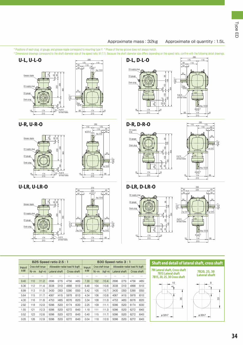
Key 10×8Key 10×836
419999
100
100
165
62 653
20
50
174210
1818
125φ133φ133
285110
110175
6562 3
φ32h7φ32h7
174210
88 18
φ32h7
50
125
Oil supply plugOil supply plug
4-φ14 drilled holes4-φ14 drilled holes
Key 10×8Key 10×8
Drain plugDrain plug
Oil gaugeOil gauge
19999
100
100
165
62 65
3
50
20 364
125φ133φ133
174210
1818
285110 175
110 65623
50
φ32h7
φ32h7
88174210
18φ32h7φ32h7
125
Oil supply plugOil supply plug
4-φ14 drilled holes4-φ14 drilled holes
Key 10×8Key 10×8
Key 10×8Key 10×8Drain plugDrain plug
Oil gaugeOil gauge
364
19999
100
100
165
62 65
3
50
20
174
125φ133φ133
2101818
35022065
62 365623
5050
φ32h7
φ32h7
φ32h7φ32h7
88174
125
21018
φ32h7
Oil supply plugOil supply plug
4-φ14 drilled holes4-φ14 drilled holes
Key 10×8Key 10×8
Key 10×8Key 10×8
Key 10×8Key 10×8
Drain plugDrain plug
Oil gaugeOil gauge
365
265
200
100
3656250
20
174210
1818
370220 65
6236562 3 φ32h7
5050
φ32h7
φ32h7
174 88210
18
φ32h7
Oil supply plugOil supply plug
4-φ14 drilled holes4-φ14 drilled holes
Grease nippleGrease nipple
Key 10×8Key 10×8 Key 10×8Key 10×8
Key 10×8Key 10×8
Drain plugDrain plug
Oil gaugeOil gauge
Key 10×8Key 10×8
Key 10×8Key 10×8
365265
6562
100
3200
50
20
174210
1818
285175110
110 65623φ32h7
50
φ32h7
φ32h7
174210
8818
Oil supply plugOil supply plug
4-φ14 drilled holes4-φ14 drilled holes
Grease nippleGrease nipple
Drain plugDrain plug
Oil gaugeOil gauge
Key 10×8Key 10×8
Key 10×8Key 10×8
365265
6562
100
3200
50
174210
1818
20285
175 11011065
62 3
174210
88 18
φ32h7
φ32h7φ32h7
50
Oil supply plugOil supply plug
4-φ14 drilled holes4-φ14 drilled holes
Grease nippleGrease nipple
Drain plugDrain plug
Oil gaugeOil gauge
Type ED
34
U-L, U-L-O
U-R, U-R-O
U-LR, U-LR-O
D-R, D-R-O
D-LR, D-LR-O
D-L, D-L-O
B25 Speed ratio 2.5 : 1 B30 Speed ratio 3 : 1
Input kW
Cross shaft torque Allowable radial load N {kgf} Input kW
Cross shaft torque Allowable radial load N {kgf}
N・m {kgf・m} Lateral shaft Cross shaft N・m {kgf・m} Lateral shaft Cross shaft
─ ─ ─ ─ ─ ─ ─ ─ ─ ─ ─ ─ ─ ─
9.40 110 {11.2} 2696 {275} 4756 {485} 7.30 102 {10.4} 2696 {275} 4756 {485}
8.36 112 {11.4} 3038 {310} 4998 {510} 6.48 104 {10.6} 3038 {310} 4998 {510}
6.99 113 {11.5} 3430 {350} 5390 {550} 5.42 105 {10.7} 3430 {350} 5390 {550}
5.64 115 {11.7} 4067 {415} 5978 {610} 4.34 106 {10.8} 4067 {415} 5978 {610}
4.30 116 {11.8} 4753 {485} 6076 {620} 3.34 108 {11.0} 4753 {485} 6076 {620}
2.92 118 {12.0} 5096 {520} 6174 {630} 2.25 109 {11.1} 5096 {520} 6174 {630}
1.55 121 {12.3} 5096 {520} 6272 {640} 1.18 111 {11.3} 5096 {520} 6272 {640}
0.52 123 {12.6} 5096 {520} 6272 {640} 0.40 115 {11.7} 5096 {520} 6272 {640}
0.05 126 {12.9} 5096 {520} 6272 {640} 0.04 118 {12.0} 5096 {520} 6272 {640}
Shaft end detail of lateral shaft, cross shaft
10
φ32h7
35
8
7M Lateral shaft, Cross shaft7B15 Lateral shaft
7B15, 20, 25, 30 Cross shaft8
φ30h7
33
7
7B20, 25, 30 Lateral shaft
Approximate mass:32kg Approximate oil quantity:1.5L
* Positions of each plug, oil gauge, and grease nipple correspond to mounting type Y. * Phase of the key groove does not always match.* Dimensional drawings correspond to the shaft diameter size of the speed ratio: M (1:1). Because the shaft diameter size differs depending on the speed ratio, confirm with the following detail drawings.

530265
200265200 65
626562 3 3
5050
φ32h7
φ32h7
174φ133
178210
18
φ32h7
φ32h7
350
220
100
65626562
33
10
174210
18 18
50
20
50Oil supply plugOil supply plug
4-φ14 drilled holes
4-φ14 drilled holes
Grease nippleGrease nippleKey 10×8Key 10×8
Key 10×8Key 10×8
Key 10×8Key 10×8
Key 10×8Key 10×8
Drain plugDrain plug
Oil gaugeOil gauge
4-φ14 drilled holes
4-φ14 drilled holes
530265
200265
350220
200 656250
656250
3 3
φ32h7
φ32h7
174 178210
174 88210
18 18
65623
6562 3
5050
φ32h7
φ32h7
87100187
20
Oil supply plugOil supply plug
Key 10×8Key 10×8 Key 10×8Key 10×8Key 10×8Key 10×8 Key 10×8Key 10×8
Drain plugDrain plugOil gaugeOil gauge
4-φ14 drilled holes
4-φ14 drilled holes
530265
200200265
656250
656250
3 3
φ32h7
174 178210
18
φ32h7
285110 110 65
62
50
3
φ32h7
20
174 88210
18
87100187
Oil supply plugOil supply plug
Key 10×8Key 10×8
Key 10×8Key 10×8Key 10×8Key 10×8
Drain plugDrain plugOil gaugeOil gauge
4-φ14 drilled holes
4-φ14 drilled holes
530265 265
6562
6562 3 3
5050
φ32h7
174 178210
18
φ32h7φ133
φ32h7
100 220
285
6562110
310
174210
18 18
50
20
Oil supply plugOil supply plug
Grease nippleGrease nipple
Key 10×8Key 10×8
Key 10×8Key 10×8
Key 10×8Key 10×8
Drain plugDrain plug
Oil gaugeOil gauge
530265
200265200 65
626562 3 3φ32h7
50
φ32h7
174φ133
178210
18
φ32h7 50
220 285
6562100
103
174210
18 18
20
50Oil supply plugOil supply plug
4-φ14 drilled holes
4-φ14 drilled holes
Grease nippleGrease nipple
Key 10×8Key 10×8
Key 10×8Key 10×8
Key 10×8Key 10×8
Drain plugDrain plug
Oil gaugeOil gauge
530265
200265200 65
6250
656250
3 3
φ32h7
174 178210
18
φ32h7
285110 11065
62 3
20174 1888210
φ32h7
87100187
50
Oil supply plugOil supply plug
4-φ14 drilled holes4-φ14 drilled holes
Key 10×8Key 10×8 Key 10×8Key 10×8
Key 10×8Key 10×8
Drain plugDrain plugOil gaugeOil gauge
Type ED
35
Transmission capacity table
■Speed ratio:M(1:1), B15(1.5:1), B20(2:1), B25(2.5:1), B30(3:1) ■Type of mounting:Y(T, K1, K2, K3, K4)
Dimensional drawing
ED7 Lateral dual-shaft type
1-1-UD, 1-1-UD-O1-1-LR, 1-1-LR-O
1-1-D, 1-1-D-O1-1-R, 1-1-R-O
1-1-U, 1-1-U-O1-1-L, 1-1-L-O
Size
Rotational speed of lateral
shaft rpmr/min
M Speed ratio 1 : 1 B15 Speed ratio 1.5 : 1 B20 Speed ratio 2 : 1
Input kW
Cross shaft torque Allowable radial load N {kgf} Input kW
Cross shaft torque Allowable radial load N {kgf} Input kW
Cross shaft torque Allowable radial load N {kgf}
N・m {kgf・m} Lateral shaft Cross shaft N・m {kgf・m} Lateral shaft Cross shaft N・m {kgf・m} Lateral shaft Cross shaft
ED7
3000 ─ ─ ─ ─ ─ ─ ─ ─ ─ ─ ─ ─ ─ ─ ─ ─ ─ ─ ─ ─ ─
2000 18.9 73.5 { 7.5 } 2010 {300} 2500 {310} 13.4 94.5 { 9.64} 2696 {275} 4756 {485} 9.94 93.1 { 9.5 } 2696 {275} 4756 {485}
1750 17.3 92.4 { 9.42} 2156 {220} 2842 {290} 12.1 97.3 { 9.92} 3038 {310} 4998 {510} 8.89 94.5 { 9.64} 3038 {310} 4998 {510}
1450 15.4 99.4 {10.1 } 2450 {250} 3136 {320} 10.5 101 {10.3 } 3430 {350} 5390 {550} 7.42 95.9 { 9.78} 3430 {350} 5390 {550}
1150 12.8 105 {10.7 } 2744 {280} 3234 {330} 8.4 102 {10.5 } 4067 {415} 5978 {610} 5.98 97.3 { 9.92} 4067 {415} 5978 {610}
870 10.6 114 {11.7 } 2989 {305} 3381 {345} 6.51 105 {10.7 } 4753 {485} 6076 {620} 4.59 98.7 {10.0 } 4753 {485} 6076 {620}
580 7.98 128 {13.1 } 3381 {345} 3822 {390} 4.42 107 {10.9 } 5096 {520} 6174 {630} 3.12 100 {10.2 } 5096 {520} 6174 {630}
300 4.44 138 {14.1 } 4410 {450} 5537 {565} 2.34 109 {11.2 } 5096 {520} 6272 {640} 1.65 103 {10.5 } 5096 {520} 6272 {640}
100 1.54 144 {14.7 } 5096 {520} 6272 {640} 0.81 114 {11.6 } 5096 {520} 6272 {640} 0.56 106 {10.8 } 5096 {520} 6272 {640}
10 0.15 149 {15.2 } 5096 {520} 6272 {640} 0.08 118 {12.0 } 5096 {520} 6272 {640} 0.05 109 {11.2 } 5096 {520} 6272 {640}
Note 1) For a case between the respective rotational speeds of the lateral shaft, calculate the values by interpolation. Furthermore, when the rotational speed of the lateral shaft is less than 10 rpm, use it with the torque at 10 rpm.
Note 2) When it is used under conditions exceeding the rotational speed of , the specification with forced lubrication might be necessary. In such a case, please consult our company.Note 3) In the case of a rotational speed between a rotational speed of and a lower rotational speed, also please consult our company.Note 4) For the operating position of radial load, refer to the item on Selection (p.15).

530
265
265
200
100
100
65626562
33
5050
174210
18 18
φ133125
20
350220 65
626562 3 3φ32h7
5050
φ32h7
φ 32h7174 88210
18
φ32h7
Oil supply plugOil supply plug
4-φ14 drilled holes4-φ14 drilled holes
Grease nippleGrease nipple
Key 10×8Key 10×8 Key 10×8Key 10×8
Key 10×8Key 10×8
Key 10×8Key 10×8
Drain plugDrain plug
Oil gaugeOil gauge
4-φ14 drilled holes
4-φ14 drilled holes
530
265
265
200
100
100
65626562
33
5050
174210
18 18
φ133125
20
285110 110 65
623φ32h7
50
φ32h7
φ 32h7174
125
88210
18
Oil supply plugOil supply plug
Grease nippleGrease nipple
Key 10×8Key 10×8
Key 10×8Key 10×8
Key 10×8Key 10×8
Drain plugDrain plug
Oil gaugeOil gauge
530
265
265
200
100
100
65626562
33
5050
174210
18 18
φ133125
20
285110 11065
62 3 φ32h7
125
φ32h7174210
88 18
φ32h7
50
Oil supply plugOil supply plug
4-φ14 drilled holes
4-φ14 drilled holes
Grease nippleGrease nipple
Key 10×8Key 10×8
Key 10×8Key 10×8
Key 10×8Key 10×8
Drain plugDrain plug
Oil gaugeOil gauge
Type ED
36
Shaft end detail of lateral shaft, cross shaft
10
φ32h7
35
8
7M Lateral shaft, Cross shaft7B15 Lateral shaft
7B15, 20, 25, 30 Cross shaft8
φ30h7
33
7
7B20, 25, 30 Lateral shaft
U-D-LR, U-D-LR-O
U-D-R, U-D-R-O
U-D-L, U-D-L-O
Approximate mass:41kg Approximate oil quantity:1.6L
* Positions of each plug, oil gauge, and grease nipple correspond to mounting type Y. * Phase of the key groove does not always match.* Dimensional drawings correspond to the shaft diameter size of the speed ratio: M (1:1). Because the shaft diameter size differs depending on the speed ratio, confirm with the following detail drawings.
B25 Speed ratio 2.5 : 1 B30 Speed ratio 3 : 1
Input kW
Cross shaft torque Allowable radial load N {kgf} Input kW
Cross shaft torque Allowable radial load N {kgf}
N・m {kgf・m} Lateral shaft Cross shaft N・m {kgf・m} Lateral shaft Cross shaft
─ ─ ─ ─ ─ ─ ─ ─ ─ ─ ─ ─ ─ ─
6.58 77.0 {7.85} 2696 {275} 4756 {485} 5.11 71.4 {7.28} 2696 {275} 4756 {485}
5.85 78.4 {8.00} 3038 {310} 4998 {510} 4.53 72.8 {7.42} 3038 {310} 4998 {510}
4.89 79.1 {8.07} 3430 {350} 5390 {550} 3.79 73.5 {7.50} 3430 {350} 5390 {550}
3.94 80.5 {8.21} 4067 {415} 5978 {610} 3.03 74.2 {7.57} 4067 {415} 5978 {610}
3.01 81.2 {8.28} 4753 {485} 6076 {620} 2.33 75.6 {7.71} 4753 {485} 6076 {620}
2.04 82.6 {8.42} 5096 {520} 6174 {630} 1.57 76.3 {7.78} 5096 {520} 6174 {630}
1.08 84.7 {8.64} 5096 {520} 6272 {640} 0.82 77.7 {7.92} 5096 {520} 6272 {640}
0.36 86.1 {8.78} 5096 {520} 6272 {640} 0.28 80.5 {8.21} 5096 {520} 6272 {640}
0.03 88.2 {9.00} 5096 {520} 6272 {640} 0.02 82.6 {8.42} 5096 {520} 6272 {640}

425.5308117.5
230 7875
55
3
φ40h7
φ40h7
φ40h7
210.5195φ120
20235
19520235
20
416
258
115
75 797975
4
144
5555
22
Oil supply plugOil supply plug
4-φ14 drilled holes4-φ14 drilled holes
Grease nippleGrease nipple
Key 12×8Key 12×8
Key 12×8Key 12×8
Key 12×8Key 12×8
Drain plugDrain plug
Oil gaugeOil gauge
425.5308117.5
230 7875
55
3
41625879
75 479754
55 55
φ40h7
φ40h7φ40h7
210.5 110.5195235
19520235
20
213
115
98
22
Oil supply plugOil supply plug
4-φ14 drilled holes4-φ14 drilled holes
Key 12×8Key 12×8Key 12×8Key 12×8
Key 12×8Key 12×8
Drain plugDrain plug
Oil gaugeOil gauge
20
425.5308117.5
230 7875
55
3
φ40h7
210.519520235
213
115
9822
195235
110.5
7975
129
129
55
φ40h7
4
337208
Oil supply plugOil supply plug
4-φ14 drilled holes4-φ14 drilled holes
Key 12×8Key 12×8 Key 12×8Key 12×8
Drain plugDrain plug
Oil gaugeOil gauge
425.5308117.5
230 7875
55
3
φ40h7
φ40h7
210.5195φ120
20235
195235
2020
55
22
337258
115
144 75 79
Oil supply plugOil supply plug
4-φ14 drilled holes4-φ14 drilled holes
Grease nippleGrease nipple
Key 12×8Key 12×8
Key 12×8Key 12×8
Drain plugDrain plug
Oil gaugeOil gauge
425.5308117.5
230 78753φ40h7
55
φ40h7
19520235
φ120210.5
195
337
258
7975115
20235
20
144
22
55
Oil supply plugOil supply plug
4-φ14 drilled holes4-φ14 drilled holes
Grease nippleGrease nippleKey 12×8Key 12×8
Key 12×8Key 12×8
Drain plugDrain plug
Oil gaugeOil gauge
425.5308117.5
230 7875
55
3
φ40h7
210.519520235
337208
7975 4
129129
φ40h7
110.5 195235
20
213
115
98
22
55
Oil supply plugOil supply plug
4-φ14 drilled holes4-φ14 drilled holes
Key 12×8Key 12×8Key 12×8Key 12×8
Drain plugDrain plug
Oil gaugeOil gauge
Type ED
37
Transmission capacity table
Lateral single-shaft type
1-L, 1-L-O
1-R, 1-R-O
1-LR, 1-LR-O
1-D, 1-D-O
1-UD, 1-UD-O
1-U, 1-U-O
■Speed ratio:M(1:1), B15(1.5:1), B20(2:1), B25(2.5:1), B30(3:1) ■Type of mounting:Y(T, K1, K2, K3, K4)
Dimensional drawing
ED8
Size
Rotational speed of lateral
shaft rpmr/min
M Speed ratio 1 : 1 B15 Speed ratio 1.5 : 1 B20 Speed ratio 2 : 1
Input kW
Cross shaft torque Allowable radial load N {kgf} Input kW
Cross shaft torque Allowable radial load N {kgf} Input kW
Cross shaft torque Allowable radial load N {kgf}
N・m {kgf・m} Lateral shaft Cross shaft N・m {kgf・m} Lateral shaft Cross shaft N・m {kgf・m} Lateral shaft Cross shaft
ED8
3000 ─ ─ ─ ─ ─ ─ ─ ─ ─ ─ ─ ─ ─ ─ ─ ─ ─ ─ ─ ─ ─
2000 57.3 268 {27.3} 2941 {300} 3040 {310} 25.8 181 {18.5} 3432 {350} 6864 {700} 18.9 176 {18.0} 3432 {350} 6864 {700}
1750 52.3 279 {28.5} 3087 {315} 3234 {330} 22.7 182 {18.6} 3822 {390} 7252 {740} 16.9 180 {18.4} 3822 {390} 7252 {740}
1450 45.6 294 {30.0} 3234 {330} 3381 {345} 19.1 185 {18.9} 4361 {445} 7987 {815} 14.0 180 {18.4} 4361 {445} 7987 {815}
1150 37.5 305 {31.1} 3479 {355} 3626 {370} 15.4 188 {19.2} 5096 {520} 8820 {900} 11.3 183 {18.7} 5096 {520} 8820 {900}
870 29.0 312 {31.8} 3773 {385} 3969 {405} 11.8 191 {19.5} 6076 {620} 8820 {900} 8.70 187 {19.1} 6076 {620} 8820 {900}
580 19.8 319 {32.6} 4263 {435} 4459 {455} 8.14 197 {20.1} 7644 {780} 8820 {900} 5.92 191 {19.5} 7644 {780} 8820 {900}
300 10.6 331 {33.8} 5243 {535} 6958 {710} 4.34 203 {20.7} 8428 {860} 8820 {900} 3.14 196 {20.0} 8428 {860} 8820 {900}
100 3.70 346 {35.3} 8428 {860} 8820 {900} 1.49 210 {21.4} 8428 {860} 8820 {900} 1.08 202 {20.6} 8428 {860} 8820 {900}
10 0.38 361 {36.8} 8428 {860} 8820 {900} 0.15 218 {22.2} 8428 {860} 8820 {900} 0.11 209 {21.3} 8428 {860} 8820 {900}
Note 1) For a case between the respective rotational speeds of the lateral shaft, calculate the values by interpolation. Furthermore, when the rotational speed of the lateral shaft is less than 10 rpm, use it with the torque at 10 rpm.
Note 2) When it is used under conditions exceeding the rotational speed of , the specification with forced lubrication might be necessary. In such a case, please consult our company.Note 3) In the case of a rotational speed between a rotational speed of and a lower rotational speed, also please consult our company.Note 4) For the operating position of radial load, refer to the item on Selection (p.15).

422.5
193
229.5114.5
115
322
787555
195
152φ162
20235
20110.5195
152
20235
φ40h7
φ40h7
41625879
75 479754
55 55
φ40h7
Oil supply plugOil supply plug
4-φ14 drilled holes4-φ14 drilled holes
Key 12×8Key 12×8 Key 12×8Key 12×8
Key 12×8Key 12×8
Drain plugDrain plug
Oil gaugeOil gauge
422.5
193
229.5114.5
115
322
787555
195
152φ162
20235
20110.5195
152
20235
φ40h7
φ40h7
337208
129129
79754
55
Oil supply plugOil supply plug
4-φ14 drilled holes4-φ14 drilled holes
Key 12×8Key 12×8
Key 12×8Key 12×8
Drain plugDrain plug
Oil gaugeOil gauge
422.5
193
229.5114.5
115
322
787555
195
152φ162
20235
20110.5 195 20
235
φ40h7
φ40h7
7975
1294
55
337208 129
152
Oil supply plugOil supply plug
4-φ14 drilled holes4-φ14 drilled holes
Key 12×8Key 12×8
Key 12×8Key 12×8
Drain plugDrain plug
Oil gaugeOil gauge
110.519520235
416258 79
757975 44
55
φ40h7
φ40h7
55
φ40h7
423308
115
230
78753
22
19520235
20
55
Oil supply plugOil supply plug
4-φ14 drilled holes4-φ14 drilled holes
Grease nippleGrease nipple
Key 12×8Key 12×8 Key 12×8Key 12×8
Key 12×8Key 12×8
Drain plugDrain plug
Oil gaugeOil gauge
423308
115
230
7875
19520235
20
223
55
110.519520235
55
φ40h7
337208129
7975
1294
φ40h7
Oil supply plugOil supply plug
4-φ14 drilled holes4-φ14 drilled holes
Grease nippleGrease nippleKey 12×8Key 12×8
Key 12×8Key 12×8
Drain plugDrain plug
Oil gaugeOil gauge
423308
115
230
78
19520235
20
2275
3
55
110.5 195 20235
55
φ40h7
φ40h7
337208 129
7975
1294
Oil supply plugOil supply plug
4-φ14 drilled holes4-φ14 drilled holes
Grease nippleGrease nipple
Key 12×8Key 12×8
Key 12×8Key 12×8
Drain plugDrain plug
Oil gaugeOil gauge
Type ED
38
U-L, U-L-O
U-R, U-R-O
U-LR, U-LR-O
D-R, D-R-O
D-LR, D-LR-O
D-L, D-L-O
Approximate mass:49kg Approximate oil quantity:1.9L
* Positions of each plug, oil gauge, and grease nipple correspond to mounting type Y. * Phase of the key groove does not always match.
Shaft end detail of lateral shaft, cross shaft
12
43
φ40h7
8
B25 Speed ratio 2.5 : 1 B30 Speed ratio 3 : 1
Input kW
Cross shaft torque Allowable radial load N {kgf} Input kW
Cross shaft torque Allowable radial load N {kgf}
N・m {kgf・m} Lateral shaft Cross shaft N・m {kgf・m} Lateral shaft Cross shaft
─ ─ ─ ─ ─ ─ ─ ─ ─ ─ ─ ─ ─ ─
15.2 177 {18.1} 3432 {350} 6864 {700} 10.9 152 {15.6} 3432 {350} 6864 {700}
13.5 180 {18.4} 3822 {390} 7252 {740} 9.78 157 {16.0} 3822 {390} 7252 {740}
11.4 184 {18.8} 4361 {445} 7987 {815} 8.20 159 {16.2} 4361 {445} 7987 {815}
9.11 185 {18.9} 5096 {520} 8820 {900} 6.55 160 {16.3} 5096 {520} 8820 {900}
7.00 188 {19.2} 6076 {620} 8820 {900} 5.04 163 {16.6} 6076 {620} 8820 {900}
4.76 192 {19.6} 7644 {780} 8820 {900} 3.42 166 {16.9} 7644 {780} 8820 {900}
2.53 197 {20.1} 8428 {860} 8820 {900} 1.80 169 {17.2} 8428 {860} 8820 {900}
0.86 203 {20.7} 8428 {860} 8820 {900} 0.61 173 {17.7} 8428 {860} 8820 {900}
0.08 208 {21.2} 8428 {860} 8820 {900} 0.06 179 {18.3} 8428 {860} 8820 {900}

195 210.5φ120
20235
φ40h7
φ40h7
φ40h7
55
616308308
230 230 7875
7875
416
258
797579754
14115
4
5555
33
55
φ40h7
195235
20 20
22
Oil supply plugOil supply plug
4-φ14 drilled holes4-φ14 drilled holes
Grease nippleGrease nipple
Key 12×8Key 12×8
Key 12×8Key 12×8
Key 12×8Key 12×8
Key 12×8Key 12×8
Drain plugDrain plug
Oil gaugeOil gauge
616416258
21398
115
308308230 230 78
75
210.5
7875
55
φ40h7
φ40h7
19520235
3379754
7975 4
φ40h7
φ40h7
110.519520235
55 5555
22
Oil supply plugOil supply plug
4-φ14 drilled holes4-φ14 drilled holes
Key 12×8Key 12×8 Key 12×8Key 12×8Key 12×8Key 12×8 Key 12×8Key 12×8
Drain plugDrain plugOil gaugeOil gauge
616308308
230 230 7875
210.5
7875
55
φ40h7
φ40h7
19520235
33
55
21398
115
22
195235
110.520
79129337
129754
φ40h7
55
Oil supply plugOil supply plug
4-φ14 drilled holes4-φ14 drilled holes
Key 12×8Key 12×8 Key 12×8Key 12×8 Key 12×8Key 12×8
Drain plugDrain plug
Oil gaugeOil gauge
4-φ14 drilled holes4-φ14 drilled holes
616308308
230 230 7875
7875 33
φ40h7
55
195 210.5φ120
20235
φ40h7
55
φ40h7
337258
7975414115
55
195235
20 20
22
Oil supply plugOil supply plug
Grease nippleGrease nipple
Key 12×8Key 12×8
Key 12×8Key 12×8
Key 12×8Key 12×8
Drain plugDrain plug
Oil gaugeOil gauge
φ40h7
φ40h7
55
616308308
230 230 7875
7875 33
55
φ40h7
195 210.5φ120
20235
79754
14115258 337
195235
20 20
22
55Oil supply plugOil supply plug
4-φ14 drilled holes4-φ14 drilled holes
Grease nippleGrease nippleKey 12×8Key 12×8
Key 12×8Key 12×8Key 12×8Key 12×8
Drain plugDrain plug
Oil gaugeOil gauge
616308308
230 230 7875
210.5
7875
55
φ40h7
φ40h7
19520235
33
55
21398
115 φ40h7
195235
22
110.5
79337
129 12975 4
55
20
Oil supply plugOil supply plug
4-φ14 drilled holes
4-φ14 drilled holes
Key 12×8Key 12×8 Key 12×8Key 12×8
Drain plugDrain plug
Oil gaugeOil gauge
Key 12×8Key 12×8
Type ED
39
Transmission capacity table
■Speed ratio:M(1:1), B15(1.5:1), B20(2:1), B25(2.5:1), B30(3:1) ■Type of mounting:Y(T, K1, K2, K3, K4)
Dimensional drawing
ED8 Lateral dual-shaft type
1-1-UD, 1-1-UD-O1-1-LR, 1-1-LR-O
1-1-D, 1-1-D-O1-1-R, 1-1-R-O
1-1-U, 1-1-U-O1-1-L, 1-1-L-O
Size
Rotational speed of lateral
shaft rpmr/min
M Speed ratio 1 : 1 B15 Speed ratio 1.5 : 1 B20 Speed ratio 2 : 1
Input kW
Cross shaft torque Allowable radial load N {kgf} Input kW
Cross shaft torque Allowable radial load N {kgf} Input kW
Cross shaft torque Allowable radial load N {kgf}
N・m {kgf・m} Lateral shaft Cross shaft N・m {kgf・m} Lateral shaft Cross shaft N・m {kgf・m} Lateral shaft Cross shaft
ED8
3000 ─ ─ ─ ─ ─ ─ ─ ─ ─ ─ ─ ─ ─ ─ ─ ─ ─ ─ ─ ─ ─
2000 40.1 187 {19.1} 2941 {300} 3040 {310} 18.0 126 {12.9} 3432 {350} 6864 {700} 13.2 123 {12.5} 3432 {350} 6864 {700}
1750 36.6 195 {19.9} 3087 {315} 3234 {330} 15.8 127 {13.0} 3822 {390} 7252 {740} 11.8 126 {12.8} 3822 {390} 7252 {740}
1450 31.9 205 {21 } 3234 {330} 3381 {345} 13.3 129 {13.2} 4361 {445} 7987 {815} 9.80 126 {12.8} 4361 {445} 7987 {815}
1150 26.2 213 {21.7} 3479 {355} 3626 {370} 10.7 131 {13.4} 5096 {520} 8820 {900} 7.91 128 {13.0} 5096 {520} 8820 {900}
870 20.3 218 {22.2} 3773 {385} 3969 {405} 8.26 133 {13.6} 6076 {620} 8820 {900} 6.09 130 {13.3} 6076 {620} 8820 {900}
580 13.8 223 {22.7} 4263 {435} 4459 {455} 5.69 137 {14.0} 7644 {780} 8820 {900} 4.14 133 {13.6} 7644 {780} 8820 {900}
300 7.42 231 {23.6} 5243 {535} 6958 {710} 3.03 142 {14.5} 8428 {860} 8820 {900} 2.19 137 {14.0} 8428 {860} 8820 {900}
100 2.59 242 {24.7} 8428 {860} 8820 {900} 1.04 147 {15 } 8428 {860} 8820 {900} 0.75 141 {14.4} 8428 {860} 8820 {900}
10 0.26 252 {25.7} 8428 {860} 8820 {900} 0.10 152 {15.5} 8428 {860} 8820 {900} 0.07 146 {14.9} 8428 {860} 8820 {900}
Note 1) For a case between the respective rotational speeds of the lateral shaft, calculate the values by interpolation. Furthermore, when the rotational speed of the lateral shaft is less than 10 rpm, use it with the torque at 10 rpm.
Note 2) When it is used under conditions exceeding the rotational speed of , the specification with forced lubrication might be necessary. In such a case, please consult our company.Note 3) In the case of a rotational speed between a rotational speed of and a lower rotational speed, also please consult our company.Note 4) For the operating position of radial load, refer to the item on Selection (p.15).

616
416258 79
757975 4 4
308
308
115
115
78230
7875
753
3
5555
195
152φ162
23520 20
22
φ40h7
φ40h7
5555
φ40h7
195
152
110.520235
φ40h7
Oil supply plugOil supply plug
4-φ14 drilled holes4-φ14 drilled holes
Grease nippleGrease nipple
Key 12×8Key 12×8
Key 12×8Key 12×8
Key 12×8Key 12×8
Key 12×8Key 12×8
Drain plugDrain plug
Oil gaugeOil gauge
616
308
230
308
115
115
78757875
5555
33
195
152φ162
20 20235 19520
235
22
110.5φ40h7
152
φ40h7
79129337
129754φ40h7
55
Oil supply plugOil supply plug
4-φ14 drilled holes4-φ14 drilled holes
Grease nippleGrease nippleKey 12×8Key 12×8
Key 12×8Key 12×8
Key 12×8Key 12×8
Drain plugDrain plug
Oil gaugeOil gauge
22
616
308
308
115
115
78230
7875
753
3
5555
195
337129 129
152φ162
23520 20
7975 4 φ40h7
55
φ40h7
195110.5
152
20235
φ40h7
Oil supply plugOil supply plug
4-φ14 drilled holes4-φ14 drilled holes
Grease nippleGrease nipple
Key 12×8Key 12×8
Key 12×8Key 12×8
Key 12×8Key 12×8
Drain plugDrain plug
Oil gaugeOil gauge
Type ED
40
Approximate mass:62kg Approximate oil quantity:2.1L
* Positions of each plug, oil gauge, and grease nipple correspond to mounting type Y. * Phase of the key groove does not always match.
Shaft end detail of lateral shaft, cross shaft
12
43
φ40h7
8
U-D-LR, U-D-LR-O
U-D-R, U-D-R-O
U-D-L, U-D-L-O
B25 Speed ratio 2.5 : 1 B30 Speed ratio 3 : 1
Input kW
Cross shaft torque Allowable radial load N {kgf} Input kW
Cross shaft torque Allowable radial load N {kgf}
N・m {kgf・m} Lateral shaft Cross shaft N・m {kgf・m} Lateral shaft Cross shaft
─ ─ ─ ─ ─ ─ ─ ─ ─ ─ ─ ─ ─ ─
10.6 123 {12.6} 3432 {350} 6864 {700} 7.63 106 {10.8} 3432 {350} 6864 {700}
9.45 126 {12.8} 3822 {390} 7252 {740} 6.84 109 {11.2} 3822 {390} 7252 {740}
7.98 128 {13.1} 4361 {445} 7987 {815} 5.74 111 {11.3} 4361 {445} 7987 {815}
6.37 129 {13.2} 5096 {520} 8820 {900} 4.58 112 {11.4} 5096 {520} 8820 {900}
4.9 131 {13.4} 6076 {620} 8820 {900} 3.52 114 {11.6} 6076 {620} 8820 {900}
3.33 134 {13.7} 7644 {780} 8820 {900} 2.39 116 {11.8} 7644 {780} 8820 {900}
1.77 137 {14.0} 8428 {860} 8820 {900} 1.26 118 {12.0} 8428 {860} 8820 {900}
0.6 142 {14.5} 8428 {860} 8820 {900} 0.42 121 {12.3} 8428 {860} 8820 {900}
0.05 145 {14.8} 8428 {860} 8820 {900} 0.04 125 {12.7} 8428 {860} 8820 {900}

502.5360142.5
265 9590
70
5
φ45h7
φ45h7
φ45h7
24024022.5285
φ183
480
290
95905
9590140
55
240285
22.5 22.5
25
7070
Oil supply plugOil supply plug
4-φ16 drilled holes4-φ16 drilled holes
Grease nippleGrease nippleKey 14×9Key 14×9
Key 14×9Key 14×9
Key 14×9Key 14×9
Drain plugDrain plug
Oil gaugeOil gauge
502.5360
265 9590
70
24024022.5285
5
142.5480290
258
140
118
95905
9590 5
70 70
φ45h7
25
120240285
22.5
φ45h7
φ45h7
Oil supply plugOil supply plug
4-φ16 drilled holes4-φ16 drilled holes
Key 14×9Key 14×9Key 14×9Key 14×9 Key 14×9Key 14×9
Drain plugDrain plug
Oil gaugeOil gauge
9590
70
24024022.5285
5
142.5
φ45h7
502.5360
265
258
140
118
120240285
22.5
70
φ45h7
240145385
145 95905
25
Oil supply plugOil supply plug
4-φ16 drilled holes4-φ16 drilled holes
Key 14×9Key 14×9Key 14×9Key 14×9
Drain plugDrain plug
Oil gaugeOil gauge
502.5360142.5
265 9590
70
5
φ45h7
φ45h7
24024022.5285
φ183
385290
9590140
55
240285
22.5 22.5
25
70
Oil supply plugOil supply plug
4-φ16 drilled holes4-φ16 drilled holes
Grease nippleGrease nipple
Key 14×9Key 14×9
Key 14×9Key 14×9
Drain plugDrain plug
Oil gaugeOil gauge
502.5360142.5
265 9590
70
5
φ45h7
φ45h7
24024022.5285
φ183
290385
95905
140
5
240285
22.5 22.5
25
70
Oil supply plugOil supply plug
4-φ16 drilled holes
4-φ16 drilled holes
Grease nippleGrease nipple
Key 14×9Key 14×9
Key 14×9Key 14×9
Drain plugDrain plug
Oil gaugeOil gauge
502.5360
265 9590
70
24024022.5285
5
142.5
φ45h7
258
140
118
95 145240 145
385
90 5
70
120 240285
22.5
φ45h7
25
Oil supply plugOil supply plug
4-φ16 drilled holes
4-φ16 drilled holes
Key 14×9Key 14×9Key 14×9Key 14×9
Drain plugDrain plug
Oil gaugeOil gauge
Type ED
41
Transmission capacity table
1-L, 1-L-O
1-R, 1-R-O
1-LR, 1-LR-O
1-D, 1-D-O
1-UD, 1-UD-O
1-U, 1-U-O
■Speed ratio:M(1:1), B15(1.5:1), B20(2:1), B25(2.5:1), B30(3:1) ■Type of mounting:Y(T, K1, K2, K3, K4)
Dimensional drawing
Lateral single-shaft typeED10
Size
Rotational speed of lateral
shaft rpmr/min
M Speed ratio 1 : 1 B15 Speed ratio 1.5 : 1 B20 Speed ratio 2 : 1
Input kW
Cross shaft torque Allowable radial load N {kgf} Input kW
Cross shaft torque Allowable radial load N {kgf} Input kW
Cross shaft torque Allowable radial load N {kgf}
N・m {kgf・m} Lateral shaft Cross shaft N・m {kgf・m} Lateral shaft Cross shaft N・m {kgf・m} Lateral shaft Cross shaft
ED10
3000 ─ ─ ─ ─ ─ ─ ─ ─ ─ ─ ─ ─ ─ ─ ─ ─ ─ ─ ─ ─ ─
2000 79.0 358 {36.5} 3677 { 375} 4069 { 415} 49.5 336 {34.3} 4167 { 425} 7845 { 800} 32.0 290 {29.6} 4167 { 425} 7845 { 800}
1750 74.6 399 {40.7} 3969 { 405} 4263 { 435} 46.0 368 {37.6} 4459 { 455} 8232 { 840} 28.2 302 {30.8} 4459 { 455} 8232 { 840}
1450 65.3 421 {43.0} 4165 { 425} 4508 { 460} 38.7 374 {38.2} 5194 { 530} 9212 { 940} 23.6 305 {31.1} 5194 { 530} 9212 { 940}
1150 55.7 453 {46.2} 4459 { 455} 4851 { 495} 31.2 380 {38.8} 6174 { 630} 10486 {1070} 19.0 309 {31.5} 6174 { 630} 10486 {1070}
870 44.6 479 {48.9} 4851 { 495} 5292 { 540} 24.1 389 {39.7} 7448 { 760} 11760 {1200} 14.6 315 {32.1} 7448 { 760} 11760 {1200}
580 30.6 493 {50.3} 5488 { 560} 5880 { 600} 16.4 396 {40.4} 9555 { 975} 11760 {1200} 10.0 322 {32.9} 9555 { 975} 11760 {1200}
300 16.4 513 {52.3} 9713 { 685} 7987 { 815} 8.78 411 {41.9} 9996 {1020} 11760 {1200} 5.33 332 {33.9} 9996 {1020} 11760 {1200}
100 5.72 535 {54.6} 9996 {1020} 11760 {1200} 3.04 426 {43.5} 9996 {1020} 11760 {1200} 1.84 344 {35.1} 9996 {1020} 11760 {1200}
10 0.59 561 {57.2} 9996 {1020} 11760 {1200} 0.31 443 {45.2} 9996 {1020} 11760 {1200} 0.19 357 {36.4} 9996 {102}0 11760 {1200}
Note 1) For a case between the respective rotational speeds of the lateral shaft, calculate the values by interpolation. Furthermore, when the rotational speed of the lateral shaft is less than 10 rpm, use it with the torque at 10 rpm.
Note 2) When it is used under conditions exceeding the rotational speed of , the specification with forced lubrication might be necessary. In such a case, please consult our company.Note 3) In the case of a rotational speed between a rotational speed of and a lower rotational speed, also please consult our company.Note 4) For the operating position of radial load, refer to the item on Selection (p.15).

240
155φ183
28522.5 22.5
70
278
138
140
220
498
95905 12
525
480290 95
9059590 5
70
φ45h7
φ45h7
φ45h7
70
240
155
120285
22.5
Oil supply plugOil supply plug
4-φ16 drilled holes4-φ16 drilled holes
Key 14×9Key 14×9 Key 14×9Key 14×9
Key 14×9Key 14×9
Drain plugDrain plug
Oil gaugeOil gauge
240
155φ183
28522.5 22.5
278
138
140
220
498
95905 12
525
240145385
145 95905
70
φ45h7
φ45h7
240 120285
22.5
15570
Oil supply plugOil supply plug
4-φ16 drilled holes4-φ16 drilled holes
Key 14×9Key 14×9
Key 14×9Key 14×9
Drain plugDrain plug
Oil gaugeOil gauge
240
155φ183
28522.5 22.5
70
278
138
140
220
498
95905 12
525
240 145385
1459590 5
φ45h7
70
155
φ45h7
240120285
22.5
Oil supply plugOil supply plug
4-φ16 drilled holes4-φ16 drilled holes
Key 14×9Key 14×9
Key 14×9Key 14×9
Drain plugDrain plug
Oil gaugeOil gauge
480290 95
9059590 5 φ45h7
70
φ45h7
φ45h7
70
240 120285
22.5
360
140
500
265
95905
240285
22.5 22.5
25
70
Oil supply plugOil supply plug
4-φ16 drilled holes4-φ16 drilled holes
Grease nippleGrease nipple
Key 14×9Key 14×9
Key 14×9Key 14×9
Key 14×9Key 14×9
Drain plugDrain plug
Oil gaugeOil gauge
140
500360
265
95905
240285
22.5 22.5
25
70
240385
145145 95
905φ45h7
70
φ45h7
240 120285
22.5
Oil supply plugOil supply plug
4-φ16 drilled holes4-φ16 drilled holes
Grease nippleGrease nipple
Key 14×9Key 14×9
Key 14×9Key 14×9
Drain plugDrain plug
Oil gaugeOil gauge
360
140
500
265
95905
240285
22.5 22.5
25
70
240120285
22.5
φ45h7
70
240 145385
1459590 5 φ45h7
Oil supply plugOil supply plug
4-φ16 drilled holes4-φ16 drilled holes
Grease nippleGrease nipple
Key 14×9Key 14×9
Key 14×9Key 14×9
Drain plugDrain plug
Oil gaugeOil gauge
Type ED
42
U-L, U-L-O
U-R, U-R-O
U-LR, U-LR-O
D-R, D-R-O
D-LR, D-LR-O
D-L, D-L-O
Approximate mass:78kg Approximate oil quantity:3.5L
* Positions of each plug, oil gauge, and grease nipple correspond to mounting type Y. * Phase of the key groove does not always match.
Shaft end detail of lateral shaft, cross shaft
14
48.5
φ45h7
9
B25 Speed ratio 2.5 : 1 B30 Speed ratio 3 : 1
Input kW
Cross shaft torque Allowable radial load N {kgf} Input kW
Cross shaft torque Allowable radial load N {kgf}
N・m {kgf・m} Lateral shaft Cross shaft N・m {kgf・m} Lateral shaft Cross shaft
─ ─ ─ ─ ─ ─ ─ ─ ─ ─ ─ ─ ─ ─
24.3 275 {28.1} 4167 { 425} 7845 { 800} 18.6 252 {25.8} 4167 { 425} 7845 { 800}
21.7 290 {29.6} 4459 { 455} 8232 { 840} 16.8 270 {27.5} 4459 { 455} 8232 { 840}
18.2 293 {29.9} 5194 { 530} 9212 { 940} 14.0 270 {27.6} 5194 { 530} 9212 { 940}
14.7 298 {30.4} 6174 { 630} 10486 {1070} 11.3 275 {28.1} 6174 { 630} 10486 {1070}
11.2 302 {30.8} 7448 { 760} 11760 {1200} 8.66 279 {28.5} 7448 { 760} 11760 {1200}
7.68 310 {31.6} 9555 { 975} 11760 {1200} 5.89 285 {29.1} 9555 { 975} 11760 {1200}
4.06 317 {32.3} 9996 {1020} 11760 {1200} 3.11 291 {29.7} 9996 {1020} 11760 {1200}
1.40 326 {33.3} 9996 {1020} 11760 {1200} 1.07 300 {30.6} 9996 {1020} 11760 {1200}
0.14 336 {34.3} 9996 {1020} 11760 {1200} 0.11 308 {31.4} 9996 {1020} 11760 {1200}

4-φ16 drilled holes4-φ16 drilled holes
720360
265 95905
36026595
90 5
φ45h7
φ45h7
φ45h7
70
φ45h7
70
24024022.5285
φ183
480
290
9595
905
590
140
5
7070
25
24022.5285
22.5
Oil supply plugOil supply plugGrease nippleGrease nipple
Key 14×9Key 14×9
Key 14×9Key 14×9
Key 14×9Key 14×9
Key 14×9Key 14×9
Drain plugDrain plug
Oil gaugeOil gauge
4-φ16 drilled holes4-φ16 drilled holes
720360
265 95905
36026595
90
480290 95
905559590
φ45h7
φ45h7
φ45h7
70 70
24024022.5285
12024022.5285
φ45h7
25
70
258
140
118 70
Oil supply plugOil supply plug
Key 14×9Key 14×9 Key 14×9Key 14×9Key 14×9Key 14×9 Key 14×9Key 14×9
Drain plugDrain plug
Oil gaugeOil gauge
4-φ16 drilled holes4-φ16 drilled holes
720360
265 95905
36026595
90 5
φ45h7
φ45h7
70 70
24024022.5285
24022.5285
25
258
140
118
120
φ45h7
70
385145 145 95
905Oil supply plugOil supply plug
Key 14×9Key 14×9 Key 14×9Key 14×9 Key 14×9Key 14×9
Drain plugDrain plug
Oil gaugeOil gauge
4-φ16 drilled holes4-φ16 drilled holes
720360
265 95905
36026595
90 5
φ45h7
φ45h7
70
φ45h7
70
24024022.5285
φ183
70
24022.5285
22.5
385290
95
590
140
145
5
25
Oil supply plugOil supply plugGrease nippleGrease nipple
Key 14×9Key 14×9
Key 14×9Key 14×9
Key 14×9Key 14×9
Drain plugDrain plug
Oil gaugeOil gauge
4-φ16 drilled holes4-φ16 drilled holes
720360
265 95905
36026595
90 5
φ45h7
φ45h7
70
φ45h7
70
24024022.5285
φ183
95385
290
140
905
5
70
25
24022.5285
22.5
Oil supply plugOil supply plugGrease nippleGrease nipple
Key 14×9Key 14×9
Key 14×9Key 14×9
Key 14×9Key 14×9
Drain plugDrain plug
Oil gaugeOil gauge
4-φ16 drilled holes4-φ16 drilled holes
720360
265 95905
36026595
90 5
φ45h7
φ45h7
70 70 70
24024022.5285
φ45h7
258
140
118
120 240 22.5285
25
385145 1455
9590Oil supply plugOil supply plug
Key 14×9Key 14×9 Key 14×9Key 14×9Key 14×9Key 14×9
Drain plugDrain plug
Oil gaugeOil gauge
Type ED
43
Transmission capacity table
■Speed ratio:M(1:1), B15(1.5:1), B20(2:1), B25(2.5:1), B30(3:1) ■Type of mounting:Y(T, K1, K2, K3, K4)
Dimensional drawing
ED10 Lateral dual-shaft type
1-1-UD, 1-1-UD-O1-1-LR, 1-1-LR-O
1-1-D, 1-1-D-O1-1-R, 1-1-R-O
1-1-U, 1-1-U-O1-1-L, 1-1-L-O
Size
Rotational speed of lateral
shaft rpmr/min
M Speed ratio 1 : 1 B15 Speed ratio 1.5 : 1 B20 Speed ratio 2 : 1
Input kW
Cross shaft torque Allowable radial load N {kgf} Input kW
Cross shaft torque Allowable radial load N {kgf} Input kW
Cross shaft torque Allowable radial load N {kgf}
N・m {kgf・m} Lateral shaft Cross shaft N・m {kgf・m} Lateral shaft Cross shaft N・m {kgf・m} Lateral shaft Cross shaft
ED10
3000 ─ ─ ─ ─ ─ ─ ─ ─ ─ ─ ─ ─ ─ ─ ─ ─ ─ ─ ─ ─ ─
2000 55.3 250 {25.5} 3677 { 375} 4069 { 415} 34.6 235 {24.0} 4167 { 425} 7845 { 800} 22.4 203 {20.7} 4167 { 425} 7845 { 800}
1750 52.2 279 {28.5} 3969 { 405} 4263 { 435} 32.2 257 {26.2} 4459 { 455} 8232 { 840} 19.7 211 {21.5} 4459 { 455} 8232 { 840}
1450 45.7 294 {30.0} 4165 { 425} 4508 { 460} 27.0 261 {26.7} 5194 { 530} 9212 { 940} 16.5 213 {21.7} 5194 { 530} 9212 { 940}
1150 38.9 317 {32.3} 4459 { 455} 4851 { 495} 21.8 266 {27.1} 6174 { 630} 10486 {1070} 13.3 216 {22.0} 6174 { 630} 10486 {1070}
870 31.2 335 {34.2} 4851 { 495} 5292 { 540} 16.8 272 {27.7} 7448 { 760} 11760 {1200} 10.2 220 {22.5} 7448 { 760} 11760 {1200}
580 21.4 345 {35.2} 5488 { 560} 5880 { 600} 11.4 277 {28.2} 9555 { 975} 11760 {1200} 7.00 225 {23.0} 9555 { 975} 11760 {1200}
300 11.4 359 {36.6} 9713 { 685} 7987 { 815} 6.14 287 {29.3} 9996 {1020} 11760 {1200} 3.73 232 {23.7} 9996 {1020} 11760 {1200}
100 4.00 374 {38.2} 9996 {1020} 11760 {1200} 2.12 298 {30.4} 9996 {1020} 11760 {1200} 1.28 240 {24.5} 9996 {1020} 11760 {1200}
10 0.41 392 {40.0} 9996 {1020} 11760 {1200} 0.21 310 {31.6} 9996 {1020} 11760 {1200} 0.13 249 {25.5} 9996 {102}0 11760 {1200}
Note 1) For a case between the respective rotational speeds of the lateral shaft, calculate the values by interpolation. Furthermore, when the rotational speed of the lateral shaft is less than 10 rpm, use it with the torque at 10 rpm.
Note 2) When it is used under conditions exceeding the rotational speed of , the specification with forced lubrication might be necessary. In such a case, please consult our company.Note 3) In the case of a rotational speed between a rotational speed of and a lower rotational speed, also please consult our company.Note 4) For the operating position of radial load, refer to the item on Selection (p.15).

4-φ16 drilled holes4-φ16 drilled holes
720
360
360
265
95905
140
125
95905
7070
24022.5285
155φ183
22.5
25
480290 95
9059590 5 φ45h7
70 70
120240285
22.5
φ45h7
φ45h7
φ45h7
155
Oil supply plugOil supply plug
Grease nippleGrease nipple
Key 14×9Key 14×9 Key 14×9Key 14×9
Key 14×9Key 14×9
Key 14×9Key 14×9
Drain plugDrain plug
Oil gaugeOil gauge
4-φ16 drilled holes4-φ16 drilled holes
720
360
360
265
95905
140
125
95905
7070
24022.5285
155φ183
22.5
25
385145145 95
905
70
φ45h7
φ45h7
120240285
22.5
φ45h7
155
Oil supply plugOil supply plug
Grease nippleGrease nipple
Key 14×9Key 14×9
Key 14×9Key 14×9
Key 14×9Key 14×9
Drain plugDrain plug
Oil gaugeOil gauge
4-φ16 drilled holes4-φ16 drilled holes
720
360
360
265
95905
140
125
95905
7070
24022.5285
22.5
25
38514514595
90 5
φ45h7
φ45h7
70
120 240285
22.5
φ45h7
155 155φ183
Oil supply plugOil supply plug
Grease nippleGrease nipple
Key 14×9Key 14×9
Key 14×9Key 14×9
Key 14×9Key 14×9
Drain plugDrain plug
Oil gaugeOil gauge
Type ED
44
Approximate mass:100kg Approximate oil quantity:3.7L
* Positions of each plug, oil gauge, and grease nipple correspond to mounting type Y. * Phase of the key groove does not always match.
Shaft end detail of lateral shaft, cross shaft
14
48.5
φ45h7
9
U-D-LR, U-D-LR-O
U-D-R, U-D-R-O
U-D-L, U-D-L-O
B25 Speed ratio 2.5 : 1 B30 Speed ratio 3 : 1
Input kW
Cross shaft torque Allowable radial load N {kgf} Input kW
Cross shaft torque Allowable radial load N {kgf}
N・m {kgf・m} Lateral shaft Cross shaft N・m {kgf・m} Lateral shaft Cross shaft
─ ─ ─ ─ ─ ─ ─ ─ ─ ─ ─ ─ ─ ─
17.0 192 {19.6} 4167 { 425} 7845 { 800} 13.0 176 {18.0} 4167 { 425} 7845 { 800}
15.1 203 {20.7} 4459 { 455} 8232 { 840} 11.7 189 {19.2} 4459 { 455} 8232 { 840}
12.7 205 {20.9} 5194 { 530} 9212 { 940} 9.80 189 {19.2} 5194 { 530} 9212 { 940}
10.2 208 {21.2} 6174 { 630} 10486 {1070} 7.91 192 {19.6} 6174 { 630} 10486 {1070}
7.84 211 {21.5} 7448 { 760} 11760 {1200} 6.06 195 {19.9} 7448 { 760} 11760 {1200}
5.37 217 {22.1} 9555 { 975} 11760 {1200} 4.12 199 {20.3} 9555 { 975} 11760 {1200}
2.84 221 {22.6} 9996 {1020} 11760 {1200} 2.17 203 {20.7} 9996 {1020} 11760 {1200}
0.98 228 {23.2} 9996 {1020} 11760 {1200} 0.74 210 {21.4} 9996 {1020} 11760 {1200}
0.09 235 {24.0} 9996 {1020} 11760 {1200} 0.07 215 {22.0} 9996 {1020} 11760 {1200}

4-φ21 drilled holes4-φ21 drilled holes
585415170
309.5 105.51005.5
75
φ50h7
27029025340
φ50h7
φ50h7
550
104.5
4.5
100
290340
25 25
75 100
100
75
32
345.5
175
Oil supply plugOil supply plug
Grease nippleGrease nipple
Pressure ventPressure vent
Key 14×9Key 14×9
Key 14×9Key 14×9
Key 14×9Key 14×9Drain plugDrain plug
Oil gaugeOil gauge
4-φ21 drilled holes4-φ21 drilled holes
585 550339 105.5105.5
100 5.5 5.5 100
130290
340
175
165
340
75
415170309.5 105.5
100
75
27029025340
5.5
φ50h7
75
32
φ50h7
φ50h7
25
Oil supply plugOil supply plug
Pressure ventPressure vent
Key 14×9Key 14×9 Key 14×9Key 14×9 Key 14×9Key 14×9Drain plugDrain plug
Oil gaugeOil gauge
4-φ21 drilled holes4-φ21 drilled holes
415585
170105.5309.5100
75
27029025340
5.5
φ50h7
444.5169.5
169.5275
105.51005.5
130290
340
175
165
340
32
φ50h7
25
75
Oil supply plugOil supply plug
Pressure ventPressure vent
Key 14×9Key 14×9 Key 14×9Key 14×9Drain plugDrain plug
Oil gaugeOil gauge
4-φ21 drilled holes4-φ21 drilled holes
585415170
309.5 105.51005.5
75
φ50h7
27029025340
φ50h7
444.5
345.5
175
290340
25 25
75 100
100
32
Oil supply plugOil supply plug
Grease nippleGrease nipple
Pressure ventPressure vent
Key 14×9Key 14×9
Key 14×9Key 14×9Drain plugDrain plug
Oil gaugeOil gauge
Oil gaugeOil gauge
4-φ21 drilled holes4-φ21 drilled holes
585415170
309.5 105.51005.5
75
φ50h7
27029025340
φ50h7
450
345.5
104.5
4.5
100
175
75
290340
25 25
32
Oil supply plugOil supply plug
Grease nippleGrease nipple
Pressure ventPressure vent
Key 14×9Key 14×9
Key 14×9Key 14×9Drain plugDrain plug
4-φ21 drilled holes4-φ21 drilled holes
585444.5
169.5169.5
275415170
309.5 105.5100
75
290 27025340
5.5
φ50h7
105.5100 5.5
130 290
340
175
165
340
75
32
φ50h7
25
Oil supply plugOil supply plugPressure ventPressure vent
Key 14×9Key 14×9 Key 14×9Key 14×9Drain plugDrain plug
Oil gaugeOil gauge
4-φ21 drilled holes4-φ21 drilled holes
585444.5
169.5169.5
275415170
309.5 105.5100
75
290 27025340
5.5
φ50h7
105.5100 5.5
130 290
340
175
165
340
7532
φ50h7
25
Oil supply plugOil supply plugPressure ventPressure vent
Key 14×9Key 14×9 Key 14×9Key 14×9Drain plugDrain plug
Oil gaugeOil gauge
Type ED
45
Transmission capacity table
1-L, 1-L-O
1-R, 1-R-O
1-LR, 1-LR-O
1-D, 1-D-O
1-UD, 1-UD-O
1-U, 1-U-O
■Speed ratio:M(1:1), B15(1.5:1), B20(2:1), B25(2.5:1), B30(3:1) ■Type of mounting:Y(T, K1, K2, K3, K4)
Dimensional drawing
ED12 Lateral single-shaft type
Size
Rotational speed of lateral
shaft rpmr/min
M Speed ratio 1 : 1 B15 Speed ratio 1.5 : 1 B20 Speed ratio 2 : 1
Input kW
Cross shaft torque Allowable radial load N {kgf} Input kW
Cross shaft torque Allowable radial load N {kgf} Input kW
Cross shaft torque Allowable radial load N {kgf}
N・m {kgf・m} Lateral shaft Cross shaft N・m {kgf・m} Lateral shaft Cross shaft N・m {kgf・m} Lateral shaft Cross shaft
ED12
3000 ─ ─ ─ ─ ─ ─ ─ ─ ─ ─ ─ ─ ─ ─ ─ ─ ─ ─ ─ ─ ─
2000 ─ ─ ─ ─ ─ ─ ─ ─ ─ ─ ─ ─ ─ ─ ─ ─ ─ ─ ─ ─ ─
1750 109.6 586 {59.8} 4851 { 495} 5341 { 545} 65.9 528 {53.9} 5096 { 520} 9212 { 940} 48.3 516 {52.7} 5096 { 520} 9212 { 940}
1450 96.0 619 {63.2} 5096 { 520} 5586 { 570} 58.3 564 {57.6} 5978 { 610} 10486 {1070} 40.0 516 {52.7} 5978 { 610} 10486 {1070}
1150 81.8 665 {67.9} 5488 { 560} 6076 { 620} 49.2 601 {61.3} 7252 { 740} 12151 {1240} 31.7 516 {52.7} 7252 { 740} 12151 {1240}
870 67.5 726 {74.1} 5880 { 600} 6566 { 670} 40.7 656 {66.9} 8869 { 905} 14504 {1480} 24.0 516 {52.7} 8869 { 905} 14504 {1480}
580 49.7 802 {81.8} 6713 { 685} 7301 { 745} 28.9 699 {71.3} 11466 {1170} 14504 {1480} 16.3 524 {53.5} 11466 {1170} 14504 {1480}
300 26.8 835 {85.2} 8232 { 840} 9065 { 925} 15.5 724 {73.9} 11858 {1210} 14504 {1480} 8.71 543 {55.4} 11858 {1210} 14504 {1480}
100 9.36 875 {89.3} 11368 {1160} 12593 {1285} 5.37 754 {76.9} 11858 {1210} 14504 {1480} 3.01 563 {57.4} 11858 {1210} 14504 {1480}
10 0.98 919 {93.8} 11858 {1210} 14504 {1480} 0.56 785 {80.1} 11858 {1210} 14504 {1480} 0.31 586 {59.8} 11858 {1210} 14504 {1480}
Note 1) For a case between the respective rotational speeds of the lateral shaft, calculate the values by interpolation. Furthermore, when the rotational speed of the lateral shaft is less than 10 rpm, use it with the torque at 10 rpm.
Note 2) When it is used under conditions exceeding the rotational speed of , the specification with forced lubrication might be necessary. In such a case, please consult our company.Note 3) In the case of a rotational speed between a rotational speed of and a lower rotational speed, also please consult our company.Note 4) For the operating position of radial load, refer to the item on Selection (p.15).

580
340
240
165
175
32105.55.5
100
75
29025 25340
550339 105.5
1005.5105.5100 5.5
7575
φ50h7
φ50h7
φ50h7
130290340
25
φ1684-φ21 drilled holes4-φ21 drilled holes
Pressure ventPressure vent
Key 14×9Key 14×9 Key 14×9Key 14×9
Key 14×9Key 14×9
Drain plugDrain plug
Oil gaugeOil gauge
580
340
240
165
175
105.55.5
100
75
29025 25340
275444.5
169.5169.5
105.51005.5
75
φ50h7
290340
25 130
φ50h7
φ168
32
4-φ21 drilled holes4-φ21 drilled holes
Pressure ventPressure vent
Key 14×9Key 14×9
Key 14×9Key 14×9Drain plugDrain plug
Oil gaugeOil gauge
580
340
240
165
175
32105.55.5
100
75
29025 25340
275444.5
169.5169.5
105.5100 5.5
75
φ50h7
φ50h7130 290
34025
φ1684-φ21 drilled holes4-φ21 drilled holes
Pressure ventPressure vent
Key 14×9Key 14×9
Key 14×9Key 14×9
Drain plugDrain plug
Oil gaugeOil gauge
4-φ21 drilled holes4-φ21 drilled holes
415
590
309.5
105.5
5.5
10075
175
32
29025340
25 130290340
25
550339 105.5
1005.5105.5100 5.5 φ50h7
7575
φ50h7
φ50h7
Oil supply plugOil supply plug
Grease nippleGrease nipple
Pressure ventPressure vent
Key 14×9Key 14×9 Key 14×9Key 14×9
Key 14×9Key 14×9
Drain plugDrain plug
Oil gaugeOil gauge
4-φ21 drilled holes4-φ21 drilled holes
415
590
309.5
105.5
5.5
10075
175
32
29025340
25
275444.5
169.5169.5
105.51005.5φ50h7
75
φ50h7
290340
25 130
Oil supply plugOil supply plug
Grease nippleGrease nipple
Pressure ventPressure vent
Key 14×9Key 14×9
Key 14×9Key 14×9Drain plugDrain plug
Oil gaugeOil gauge
4-φ21 drilled holes4-φ21 drilled holes
415
590
105.5
5.5
10075
175
32
29025 25340
309.5
130 290340
25
275444.5
169.5169.5
105.5100 5.5 φ50h7
75
φ50h7
Oil supply plugOil supply plug
Grease nippleGrease nipple
Pressure ventPressure vent
Key 14×9Key 14×9
Key 14×9Key 14×9Drain plugDrain plug
Oil gaugeOil gauge
Type ED
46
U-L, U-L-O
U-R, U-R-O
U-LR, U-LR-O
D-R, D-R-O
D-LR, D-LR-O
D-L, D-L-O
Approximate mass:124kg Approximate oil quantity:7.0L
* Positions of each plug, oil gauge, and grease nipple correspond to mounting type Y. * Phase of the key groove does not always match.
Shaft end detail of lateral shaft, cross shaft
14
53.5
φ50h7
9
B25 Speed ratio 2.5 : 1 B30 Speed ratio 3 : 1
Input kW
Cross shaft torque Allowable radial load N {kgf} Input kW
Cross shaft torque Allowable radial load N {kgf}
N・m {kgf・m} Lateral shaft Cross shaft N・m {kgf・m} Lateral shaft Cross shaft
─ ─ ─ ─ ─ ─ ─ ─ ─ ─ ─ ─ ─ ─
─ ─ ─ ─ ─ ─ ─ ─ ─ ─ ─ ─ ─ ─
37.4 500 {51.0} 5096 { 520} 9212 { 940} 28.2 452 {46.1} 5096 { 520} 9212 { 940}
31.4 507 {51.7} 5978 { 610} 10486 {1070} 23.6 458 {46.7} 5978 { 610} 10486 {1070}
25.3 514 {52.4} 7252 { 740} 12151 {1240} 19.0 464 {47.3} 7252 { 740} 12151 {1240}
19.5 523 {53.4} 8869 { 905} 14504 {1480} 14.6 469 {47.9} 8869 { 905} 14504 {1480}
13.3 535 {54.6} 11466 {1170} 14504 {1480} 9.92 480 {49.0} 11466 {1170} 14504 {1480}
7.08 552 {56.3} 11858 {1210} 14504 {1480} 5.29 495 {50.5} 11858 {1210} 14504 {1480}
2.43 568 {58.0} 11858 {1210} 14504 {1480} 1.82 510 {52.0} 11858 {1210} 14504 {1480}
0.25 588 {60.1} 11858 {1210} 14504 {1480} 0.18 527 {53.8} 11858 {1210} 14504 {1480}
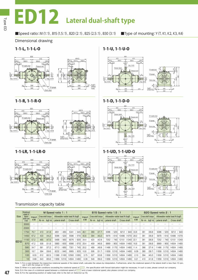
4-φ21 drilled holes4-φ21 drilled holes
830415415
309.5309.5105.5100 5.5
105.55.5 100
75
φ50h7
75
φ50h7
φ50h7
φ50h7
270290340
25
550
345.5
100
175
104.5
100
4.5
7575 100
290340
25 25
32
Oil supply plugOil supply plugGrease nippleGrease nipple
Pressure ventPressure vent
Key 14×9Key 14×9
Key 14×9Key 14×9 Key 14×9Key 14×9
Key 14×9Key 14×9
Drain plugDrain plug
Oil gaugeOil gauge
4-φ21 drilled holes4-φ21 drilled holes
830550
167.5 169.5415415
309.5309.5105.5100 5.5
105.55.5 100
Drain plug
Oil gauge
75
φ50h7
Key 14×9
φ50h7
Key 14×9
75
φ50h7
Key 14×9
75
φ50h7
Key 14×9
75
270290340
25 130290340
25
R91
107.5100 7.54.5
105.51005.5
32
340
175
165
Oil supply plugOil supply plug Pressure ventPressure vent
4-φ21 drilled holes4-φ21 drilled holes
830415415
309.5309.5105.5100 5.5
105.55.5 100
75
φ50h7
φ50h7
75
270290340
25
442.5167.5 169.5 105.5
1005.5
75
φ50h7
130290340
25
340
175
165
32
Oil supply plugOil supply plug Pressure ventPressure vent
Key 14×9Key 14×9 Key 14×9Key 14×9Key 14×9Key 14×9
Drain plugDrain plug
Oil gaugeOil gauge
4-φ21 drilled holes4-φ21 drilled holes
830415415
309.5309.5105.5100 5.5
105.55.5 100
75
φ50h7
75
φ50h7
270290340
25
φ50h7
445.5345.5
100
175
75 100
290340
25 25
32
Oil supply plugOil supply plugGrease nippleGrease nipple
Pressure ventPressure vent
Key 14×9Key 14×9 Key 14×9Key 14×9
Key 14×9Key 14×9
Drain plugDrain plug
Oil gaugeOil gauge
4-φ21 drilled holes4-φ21 drilled holes
830415415
309.5309.5105.5100 5.5
105.55.5 100
75
φ50h7
75
φ50h7
φ50h7
270290340
25
450
345.5
175
104.5
100
4.5
290340
25 25
32
75Oil supply plugOil supply plugGrease nippleGrease nipple
Pressure ventPressure vent
Key 14×9Key 14×9
Key 14×9Key 14×9
Key 14×9Key 14×9Drain plugDrain plug
Oil gaugeOil gauge
4-φ21 drilled holes
4-φ21 drilled holes
830415415
309.5309.5105.5100 5.5
105.55.5 100
75
φ50h7
φ50h7
75
270290340
25
R91
444.5167.5 169.5
φ50h7
290340
130 25
107.5100 7.54.5
32
340
175
165
75
Oil supply plugOil supply plug Pressure ventPressure vent
Key 14×9Key 14×9 Key 14×9Key 14×9 Key 14×9Key 14×9
Drain plugDrain plugOil gaugeOil gauge
Type ED
47
Transmission capacity table
■Speed ratio:M(1:1), B15(1.5:1), B20(2:1), B25(2.5:1), B30(3:1) ■Type of mounting:Y(T, K1, K2, K3, K4)
Dimensional drawing
ED12 Lateral dual-shaft type
1-1-UD, 1-1-UD-O1-1-LR, 1-1-LR-O
1-1-D, 1-1-D-O1-1-R, 1-1-R-O
1-1-U, 1-1-U-O1-1-L, 1-1-L-O
Size
Rotational speed of lateral
shaft rpmr/min
M Speed ratio 1 : 1 B15 Speed ratio 1.5 : 1 B20 Speed ratio 2 : 1
Input kW
Cross shaft torque Allowable radial load N {kgf} Input kW
Cross shaft torque Allowable radial load N {kgf} Input kW
Cross shaft torque Allowable radial load N {kgf}
N・m {kgf・m} Lateral shaft Cross shaft N・m {kgf・m} Lateral shaft Cross shaft N・m {kgf・m} Lateral shaft Cross shaft
ED12
3000 ─ ─ ─ ─ ─ ─ ─ ─ ─ ─ ─ ─ ─ ─ ─ ─ ─ ─ ─ ─ ─
2000 ─ ─ ─ ─ ─ ─ ─ ─ ─ ─ ─ ─ ─ ─ ─ ─ ─ ─ ─ ─ ─
1750 76.7 410 {41.8} 4851 { 495} 5341 { 545} 46.1 369 {37.7} 5096 { 520} 9212 { 940} 33.8 361 {36.8} 5096 { 520} 9212 { 940}
1450 67.2 433 {44.2} 5096 { 520} 5586 { 570} 40.8 394 {40.2} 5978 { 610} 10486 {1070} 28.0 361 {36.8} 5978 { 610} 10486 {1070}
1150 57.2 465 {47.5} 5488 { 560} 6076 { 620} 34.4 420 {42.9} 7252 { 740} 12151 {1240} 22.1 361 {36.8} 7252 { 740} 12151 {1240}
870 47.2 508 {51.8} 5880 { 600} 6566 { 670} 28.4 459 {46.8} 8869 { 905} 14504 {1480} 16.8 361 {36.8} 8869 { 905} 14504 {1480}
580 34.7 561 {57.2} 6713 { 685} 7301 { 745} 20.2 489 {49.9} 11466 {1170} 14504 {1480} 11.4 366 {37.4} 11466 {1170} 14504 {1480}
300 18.7 584 {59.6} 8232 { 840} 9065 { 925} 10.8 506 {51.7} 11858 {1210} 14504 {1480} 6.09 380 {38.7} 11858 {1210} 14504 {1480}
100 6.55 612 {62.5} 11368 {1160} 12593 {1285} 3.75 527 {53.8} 11858 {1210} 14504 {1480} 2.10 394 {40.2} 11858 {1210} 14504 {1480}
10 0.68 643 {65.6} 11858 {1210} 14504 {1480} 0.39 549 {56.0} 11858 {1210} 14504 {1480} 0.21 410 {41.8} 11858 {1210} 14504 {1480}
Note 1) For a case between the respective rotational speeds of the lateral shaft, calculate the values by interpolation. Furthermore, when the rotational speed of the lateral shaft is less than 10 rpm, use it with the torque at 10 rpm.
Note 2) When it is used under conditions exceeding the rotational speed of , the specification with forced lubrication might be necessary. In such a case, please consult our company.Note 3) In the case of a rotational speed between a rotational speed of and a lower rotational speed, also please consult our company.Note 4) For the operating position of radial load, refer to the item on Selection (p.15).

4-φ21 drilled holes4-φ21 drilled holes
415
830
415
175
134.5
309.5
105.5
105.5
100
100
5.5
5.5
7575
290340
25 25
32
105.5339550
5.5 100105.5
5.5100 φ50h7
φ50h7
75
φ50h7
75
φ50h7
130290340
25
φ168
Oil supply plugOil supply plug
Grease nippleGrease nipple
Pressure ventPressure vent
Key 14×9Key 14×9 Key 14×9Key 14×9
Key 14×9Key 14×9
Key 14×9Key 14×9
Drain plugDrain plug
Oil gaugeOil gauge
4-φ21 drilled holes4-φ21 drilled holes
415
830
415
175
134.5
309.5
105.5
105.5
100
100
5.5
5.5
7575
290340
25 25
32
105.5169.5169.5444.5
5.5 100φ50h7
φ50h7
130290340
25
75
φ50h7
φ168
Oil supply plugOil supply plug
Grease nippleGrease nipple
Pressure ventPressure vent
Key 14×9Key 14×9
Key 14×9Key 14×9
Key 14×9Key 14×9Drain plugDrain plug
Oil gaugeOil gauge
4-φ21 drilled holes4-φ21 drilled holes
415
830
415
175
134.5
309.5
105.5
105.5
100
100
5.5
5.5
7575
290340
25 25
32
169.5 169.5444.5
105.55.5100 φ50h7
75
φ50h7
φ50h7
130 290340
25
φ168
Oil supply plugOil supply plug
Grease nippleGrease nipple
Pressure ventPressure vent
Key 14×9Key 14×9
Key 14×9Key 14×9
Key 14×9Key 14×9
Drain plugDrain plug
Oil gaugeOil gauge
Type ED
48
Approximate mass:159kg Approximate oil quantity:7.4L
* Positions of each plug, oil gauge, and grease nipple correspond to mounting type Y. * Phase of the key groove does not always match.
Shaft end detail of lateral shaft, cross shaft
14
53.5
φ50h7
9
U-D-LR, U-D-LR-O
U-D-R, U-D-R-O
U-D-L, U-D-L-O
B25 Speed ratio 2.5 : 1 B30 Speed ratio 3 : 1
Input kW
Cross shaft torque Allowable radial load N {kgf} Input kW
Cross shaft torque Allowable radial load N {kgf}
N・m {kgf・m} Lateral shaft Cross shaft N・m {kgf・m} Lateral shaft Cross shaft
─ ─ ─ ─ ─ ─ ─ ─ ─ ─ ─ ─ ─ ─
─ ─ ─ ─ ─ ─ ─ ─ ─ ─ ─ ─ ─ ─
26.1 350 {35.7} 5096 { 520} 9212 { 940} 19.7 316 {32.2} 5096 { 520} 9212 { 940}
21.9 354 {36.2} 5978 { 610} 10486 {1070} 16.5 320 {32.7} 5978 { 610} 10486 {1070}
17.7 359 {36.7} 7252 { 740} 12151 {1240} 13.3 324 {33.1} 7252 { 740} 12151 {1240}
13.6 366 {37.3} 8869 { 905} 14504 {1480} 10.2 328 {33.5} 8869 { 905} 14504 {1480}
9.31 374 {38.2} 11466 {1170} 14504 {1480} 6.94 336 {34.2} 11466 {1170} 14504 {1480}
4.95 386 {39.4} 11858 {1210} 14504 {1480} 3.70 346 {35.3} 11858 {1210} 14504 {1480}
1.70 397 {40.5} 11858 {1210} 14504 {1480} 1.27 357 {36.4} 11858 {1210} 14504 {1480}
0.17 411 {42.0} 11858 {1210} 14504 {1480} 0.12 368 {37.6} 11858 {1210} 14504 {1480}

4-φ25 drilled holes4-φ25 drilled holes
650455195
345.5 109.5105
92.5
4.5
φ60h7
φ60h7
φ60h733030 290390
109.5
630
405.5
105
4.5
115
92.5
92.5
105
200
5.5
4.5
30390330 30
40
φ120
Oil supply plugOil supply plug
Grease nippleGrease nipple
Pressure ventPressure vent
Key 18×11Key 18×11
Key 18×11Key 18×11
Key 18×11Key 18×11
Drain plugDrain plug
Oil gaugeOil gauge
4-φ25 drilled holes4-φ25 drilled holes
650455195
345.5 109.5105
92.5
33030 290390
4.5
630411 109.5
1054.54.5
386
200
186
109.5105
φ60h7
φ60h7
92.592.5
φ60h7
33030 150390
40
Oil supply plugOil supply plug
Pressure ventPressure vent
Key 18×11Key 18×11 Key 18×11Key 18×11 Key 18×11Key 18×11Drain plugDrain plug
Oil gaugeOil gauge
4-φ25 drilled holes4-φ25 drilled holes
650455195
345.5 109.5105
92.5
33030 290390
4.5
386
φ60h7
184.5 315499.5
205.5 109.51054.5
200
186
92.5
φ60h7
33030 150390
40
Oil supply plugOil supply plug
Pressure ventPressure vent
Key 18×11Key 18×11 Key 18×11Key 18×11Drain plugDrain plug
Oil gaugeOil gauge
4-φ25 drilled holes4-φ25 drilled holes
650455195
345.5 109.51054.5
92.5
φ60h7
33030 290390
φ60h7
502.5387.5
115
92.5
105
200
5.5
4.5
30390330 30
40
φ120
Oil supply plugOil supply plug
Grease nippleGrease nipple
Pressure ventPressure vent
Key 18×11Key 18×11
Key 18×11Key 18×11Drain plugDrain plug
Oil gaugeOil gauge
4-φ25 drilled holes4-φ25 drilled holes33030 290
390
455195345.5 109.5
105
92.5
4.5
φ60h7
φ60h7
650
109.5
515
405.5
105
4.5
200
92.5
30390330 30
40
Oil supply plugOil supply plug
Grease nippleGrease nipple
Pressure ventPressure vent
Key 18×11Key 18×11
Key 18×11Key 18×11Drain plugDrain plug
Oil gaugeOil gauge
4-φ25 drilled holes4-φ25 drilled holes
455195345.5 109.5
105
92.5
33030 290390
4.5
φ60h7
315 184.5499.5
205.54.5
386
200
186
109.5105
φ60h7
92.5
330 30150390
40
650
Oil supply plugOil supply plug
Pressure ventPressure vent
Key 18×11Key 18×11 Key 18×11Key 18×11Drain plugDrain plug
Oil gaugeOil gauge
Type ED
49
Transmission capacity table
1-L, 1-L-O
1-R, 1-R-O
1-LR, 1-LR-O
1-D, 1-D-O
1-UD, 1-UD-O
1-U, 1-U-O
■Speed ratio:M(1:1), B20(2:1) ■Type of mounting:Y(T, K1, K2, K3, K4)
Dimensional drawing
ED16 Lateral single-shaft type
Size
Rotational speed of lateral
shaft rpmr/min
M Speed ratio 1 : 1 B20 Speed ratio 2 : 1
Input kW
Cross shaft torque Allowable radial load N {kgf} Input kW
Cross shaft torque Allowable radial load N {kgf}
N・m {kgf・m} Lateral shaft Cross shaft N・m {kgf・m} Lateral shaft Cross shaft
ED16
3000 ─ ─ ─ ─ ─ ─ ─ ─ ─ ─ ─ ─ ─ ─
2000 ─ ─ ─ ─ ─ ─ ─ ─ ─ ─ ─ ─ ─ ─
1750 ─ ─ ─ ─ ─ ─ ─ 87.7 908 { 92.7} 5439 { 555} 10339 {1055}
1450 163 1091 {104} 10633 {1085} 10976 {1120} 73.7 921 { 94.0} 5978 { 610} 12152 {1240}
1150 139 1098 {112} 11368 {1160} 11760 {1200} 59.5 938 { 95.7} 6419 { 655} 13083 {1335}
870 114 1186 {121} 12446 {1270} 12740 {1300} 46.0 958 { 97.8} 6958 { 710} 14210 {1450}
580 85.9 1343 {137} 14014 {1430} 14504 {1480} 31.3 980 {100 } 7840 { 800} 16072 {1640}
300 54.1 1637 {167} 17150 {1750} 17640 {1800} 16.7 1009 {103 } 9604 { 980} 19600 {2000}
100 20.3 1842 {188} 22540 {2300} 22540 {2300} 5.84 1058 {108 } 13328 {1360} 22540 {2300}
10 2.14 1940 {198} 22540 {2300} 22540 {2300} 0.60 1098 {112 } 22540 {2300} 22540 {2300}
Note 1) For a case between the respective rotational speeds of the lateral shaft, calculate the values by interpolation. Furthermore, when the rotational speed of the lateral shaft is less than 10 rpm, use it with the torque at 10 rpm.
Note 2) When it is used under conditions exceeding the rotational speed of , the specification with forced lubrication might be necessary. In such a case, please consult our company.Note 3) In the case of a rotational speed between a rotational speed of and a lower rotational speed, also please consult our company.Note 4) For the operating position of radial load, refer to the item on Selection (p.15).

641
386
255
186
200
40
φ210
109.5
105
4.5
92.5
30390330 30
630411 109.5
1054.5109.5105 4.5
92.592.5
φ60h7
φ60h7
33030 150390
φ60h7
φ1934-φ25 drilled holes4-φ25 drilled holes
Pressure ventPressure vent
Key 18×11Key 18×11 Key 18×11Key 18×11
Key 18×11Key 18×11
Drain plugDrain plug
Oil gaugeOil gauge
641
386
255
186
200
40
φ210
109.5
105
4.5
92.5
30 30390330
315499.5
184.5205.5 109.5
1054.5
92.5
φ60h7
33030 150390
φ60h7
φ1934-φ25 drilled holes4-φ25 drilled holes
Pressure ventPressure vent
Key 18×11Key 18×11
Key 18×11Key 18×11
Drain plugDrain plug
Oil gaugeOil gauge
641
386
255
186
200
40
φ210
109.5
105
4.5
92.5
30 30390330
315499.5
184.5205.5 109.5
1054.5
92.5
φ60h7
33030 150390
φ60h7
φ1934-φ25 drilled holes4-φ25 drilled holes
Pressure ventPressure vent
Key 18×11Key 18×11
Key 18×11Key 18×11
Drain plugDrain plug
Oil gaugeOil gauge
641
386
255
186
200
40
φ210
109.5
105
4.5
92.5
30390330 30
315499.5
184.5205.5109.5
105 4.5
92.5
φ60h7
330 30150390
φ60h7
φ1934-φ25 drilled holes4-φ25 drilled holes
Pressure ventPressure vent
Key 18×11Key 18×11
Key 18×11Key 18×11
Drain plugDrain plug
Oil gaugeOil gauge
4-φ25 drilled holes4-φ25 drilled holes
109.5
455
200
655345.5
105
4.5
40
30390330 30
92.5
33030 150390
630411 109.5
1054.54.5109.5105 φ60h7
92.592.5
φ60h7
φ60h7
Oil supply plugOil supply plug
Grease nippleGrease nipple
Pressure ventPressure vent
Key 18×11Key 18×11 Key 18×11Key 18×11
Key 18×11Key 18×11
Drain plugDrain plug
Oil gaugeOil gauge
4-φ25 drilled holes4-φ25 drilled holes
109.5
455
200
655345.5
105
40
390330 3030
92.5
4.5
499.5315.00
205.50184.5
109.51054.5 φ60h7
92.5
φ60h7
33030 150390
Oil supply plugOil supply plug
Grease nippleGrease nipple
Pressure ventPressure vent
Key 18×11Key 18×11
Key 18×11Key 18×11Drain plugDrain plug
Oil gaugeOil gauge
4-φ25 drilled holes4-φ25 drilled holes
109.5
655
455
345.5
200
105
4.5
40
30390330 30
92.5
499.5315205.5
184.5
4.5109.5105 φ60h7
330 30150390
φ60h7
92.5
Oil supply plugOil supply plug
Grease nippleGrease nipple
Pressure ventPressure vent
Key 18×11Key 18×11
Key 18×11Key 18×11
Drain plugDrain plug
Oil gaugeOil gauge
Type ED
50
U-L, U-L-O
U-R, U-R-O
U-LR, U-LR-O
D-R, D-R-O
D-LR, D-LR-O
D-L, D-L-O
Approximate mass:188kg Approximate oil quantity:10L
* Positions of each plug, oil gauge, and grease nipple correspond to mounting type Y. * Phase of the key groove does not always match.
Shaft end detail of lateral shaft, cross shaft
18
64
φ60h7
11

545790
430 11510510
245
720
501
109.5
105
4.5
245
105
4.5
5.5
109.5
434
90
φ72h7
φ72h7
φ72h7
430φ140
330490
30
40 110 110410
110 40
9090
32
Oil supply plugOil supply plug
Grease nippleGrease nipple
Pressure ventPressure vent
Drain plugDrain plug
Oil gaugeOil gauge
Key 20×12Key 20×12
Key 20×12Key 20×12
Key 20×12Key 20×12
8-φ21 drilled holes8-φ21 drilled holes
720501109.5
105 4.5109.5105
90
4.5545
790
430 11510510
90
245
90
462
245
217
φ72h7
φ72h7
φ72h7
43030 330490
40 110 110410
110 195
32
Oil supply plugOil supply plug
Pressure ventPressure vent
Drain plugDrain plug
Oil gaugeOil gauge
Key 20×12Key 20×12 Key 20×12Key 20×12 Key 20×12Key 20×12
8-φ21 drilled holes8-φ21 drilled holes
545790
582.5360222.5
250.5430 115
10510
90
245
φ72h7
430 330490
30
109.51054.5
90
φ72h7
462
245
217
40 110 110410
110 195
32
Oil supply plugOil supply plug
Pressure ventPressure vent
Drain plugDrain plug
Oil gaugeOil gauge
Key 20×12Key 20×12 Key 20×12Key 20×12
8-φ21 drilled holes8-φ21 drilled holes
790430 115
10510245
φ72h7
90
φ72h7
430φ140
330490
30
434
105
4.5
5.5
109.5
602492.5
245
90
40 110 110410
110 40
32
Oil supply plugOil supply plug
Grease nippleGrease nipple
Pressure ventPressure vent
Drain plugDrain plug
Oil gaugeOil gauge
Key 20×12Key 20×12
Key 20×12Key 20×12 8-φ21 drilled holes8-φ21 drilled holes
545790
430 11510510
245
90
φ72h7
φ72h7
430 330490
30
434
90 109.5
605
495.5
245
105
4.5
40 110 110410
110 40
32
Oil supply plugOil supply plug
Grease nippleGrease nipple
Pressure ventPressure vent
Drain plugDrain plug
Oil gaugeOil gauge
Key 20×12Key 20×12
Key 20×12Key 20×12
8-φ21 drilled holes8-φ21 drilled holes
545790
430 115
582.5222.5360
250.5109.5105 4.5
10510
245
43030 330490
90 90
462
245
217
φ72h7
110 110410
110 40195
32
φ72h7
Oil supply plugOil supply plug
Pressure ventPressure vent
Key 20×12Key 20×12 Key 20×12Key 20×12Drain plugDrain plug
Oil gaugeOil gauge
8-φ21 drilled holes8-φ21 drilled holes
Type ED
51
Transmission capacity table
1-L, 1-L-O
1-R, 1-R-O
1-LR, 1-LR-O
1-D, 1-D-O
1-UD, 1-UD-O
1-U, 1-U-O
■Speed ratio:M(1:1), B20(2:1) ■Type of mounting:Y(T, K1, K2, K3, K4)
Dimensional drawing
ED20 Lateral single-shaft type
Size
Rotational speed of lateral
shaft rpmr/min
M Speed ratio 1 : 1 B20 Speed ratio 2 : 1
Input kW
Cross shaft torque Allowable radial load N {kgf} Input kW
Cross shaft torque Allowable radial load N {kgf}
N・m {kgf・m} Lateral shaft Cross shaft N・m {kgf・m} Lateral shaft Cross shaft
ED20
3000 ─ ─ ─ ─ ─ ─ ─ ─ ─ ─ ─ ─ ─ ─
2000 ─ ─ ─ ─ ─ ─ ─ ─ ─ ─ ─ ─ ─ ─
1750 ─ ─ ─ ─ ─ ─ ─ ─ ─ ─ ─ ─ ─ ─
1450 ─ ─ ─ ─ ─ ─ ─ 126 1578 {161} 7693 { 785} 14602 {1490}
1150 234 1842 {188} 15386 {1570} 15680 {1600} 102 1607 {164} 8771 { 895} 17934 {1830}
870 193 2009 {205} 16660 {1700} 17150 {1750} 79.0 1646 {168} 9506 { 970} 19453 {1985}
580 145 2274 {232} 18816 {1920} 19404 {1980} 54.2 1695 {173} 10780 {1100} 22001 {2245}
300 90.8 2744 {280} 23422 {2390} 24108 {2460} 29.0 1754 {179} 13132 {1340} 27342 {2790}
100 35.3 3205 {327} 28420 {2900} 32928 {3360} 10.1 1833 {187} 18228 {1860} 33320 {3400}
10 3.53 3205 {327} 28420 {2900} 33320 {3400} 1.06 1921 {196} 28420 {2900} 33320 {3400}
Note 1) For a case between the respective rotational speeds of the lateral shaft, calculate the values by interpolation. Furthermore, when the rotational speed of the lateral shaft is less than 10 rpm, use it with the torque at 10 rpm.
Note 2) When it is used under conditions exceeding the rotational speed of , the specification with forced lubrication might be necessary. In such a case, please consult our company.Note 3) In the case of a rotational speed between a rotational speed of and a lower rotational speed, also please consult our company.Note 4) For the operating position of radial load, refer to the item on Selection (p.15).

762
462
217
245
115
10510 300
32
90
430
φ275
49030 30
720501 109.5109.5
105105 4.54.5
φ72h7
90
φ72h7
90
40 110 110410
110 195
φ72h7
Pressure vent(Oil supply port)
Pressure vent(Oil supply port)
Drain plugDrain plug
Oil gaugeOil gauge
Key 20×12Key 20×12 Key 20×12Key 20×12
Key 20×12Key 20×12
8-φ21 drilled holes8-φ21 drilled holes
762
462
217
245
115
10510 300
32
90
430
φ275
49030 30
360250.5 109.5
1054.5
222.5
φ72h7
90
40 110 110410
110 195
582.5
φ72h7
Pressure vent(Oil supply port)
Pressure vent(Oil supply port)
Drain plugDrain plug
Oil gaugeOil gauge
Key 20×12Key 20×12
Key 20×12Key 20×12
8-φ21 drilled holes8-φ21 drilled holes
Pressure vent(Oil supply port)Pressure vent(Oil supply port)
φ72h7
90
762
462
217
245
115
10510 300
32
90
430490
30 30
582.5222.5360
250.5109.5105 4.5
40 110 110410
110195
φ72h7
φ275
Drain plugDrain plug
Oil gaugeOil gauge
Key 20×12Key 20×12
Key 20×12Key 20×12
8-φ21 drilled holes8-φ21 drilled holes
245
545
430
115
10590
10
790
430
720501 109.5109.5
105105 4.54.5
49030 30
32
φ72h7
φ72h7
90
φ72h7
90
40 110 110410
110 195
Oil supply plugOil supply plug
Grease nippleGrease nipple
Pressure ventPressure vent
Drain plugDrain plug
Oil gaugeOil gauge
Key 20×12Key 20×12 Key 20×12Key 20×12
Key 20×12Key 20×12
8-φ21 drilled holes8-φ21 drilled holes
245
545
430
115
10590
10
790
430
582.5360
250.5 109.51054.5
222.5
49030 30
32
φ72h7
φ72h7
90
40 110 110410
110 195
Oil supply plugOil supply plug
Grease nippleGrease nipple
Pressure ventPressure vent
Drain plugDrain plug
Oil gaugeOil gauge
Key 20×12Key 20×12
Key 20×12Key 20×12
8-φ21 drilled holes8-φ21 drilled holes
245
545
430
115
10590
10
790
430490
30 30
582.5222.5360
250.5109.5105 4.5
32
φ72h7
40 110 110410
110195
φ72h7
90
Oil supply plugOil supply plug
Grease nippleGrease nipple
Pressure ventPressure vent
Drain plugDrain plug
Oil gaugeOil gauge
Key 20×12Key 20×12
Key 20×12Key 20×12
8-φ21 drilled holes8-φ21 drilled holes
Type ED
52
U-L, U-L-O
U-R, U-R-O
U-LR, U-LR-O
D-R, D-R-O
D-LR, D-LR-O
D-L, D-L-O
Approximate mass:297kg Approximate oil quantity:11L
* Positions of each plug, oil gauge, and grease nipple correspond to mounting type Y. * Phase of the key groove does not always match.
Shaft end detail of lateral shaft, cross shaft
20
76.5
φ72h7
12

8-φ24 drilled holes8-φ24 drilled holes
950
860
591
134.5
290
4.5
130
105
105
130
4.5
5.5
134.5
660290520 140
13010 510 φ85h7
φ85h7
105
φ85h7
40052030580
135130130 13045480
45
35
Oil supply plugOil supply plug
Grease nippleGrease nipple
Pressure ventPressure vent
Key 22×14Key 22×14
Key 22×14Key 22×14
Key 22×14Key 22×14
Drain plugDrain plug
Oil gaugeOil gauge
8-φ24 drilled holes8-φ24 drilled holes
950 860591 134.5134.5
130
105
130
545
255
290
4.54.5660290
520
40052030580
140130
105
10
φ85h7
φ85h7
φ85h7
130 130 130 23545480
105
35
Oil supply plugOil supply plug
Pressure ventPressure vent
Key 22×14Key 22×14 Key 22×14Key 22×14 Key 22×14Key 22×14Drain plugDrain plug
Oil gaugeOil gauge
8-φ24 drilled holes8-φ24 drilled holes
950660290
520
40052030580
140130
693.5430263.5
295.5 134.51304.5
105
10
φ85h7
545
255
290
130 130 130 23545480
105
φ85h7
35
Oil supply plugOil supply plug
Pressure ventPressure vent
Key 22×14Key 22×14 Key 22×14Key 22×14Drain plugDrain plug
Oil gaugeOil gauge
8-φ24 drilled holes8-φ24 drilled holes
950660290
520 14013010
φ85h7
105
φ85h7
40052030580
135
105
130130 13045480
45
35
693.5559
290
130
4.5
5.5
134.5
510Oil supply plugOil supply plug
Grease nippleGrease nipple
Pressure ventPressure vent
Key 22×14Key 22×14
Key 22×14Key 22×14
Drain plugDrain plug
Oil gaugeOil gauge
8-φ24 drilled holes8-φ24 drilled holes
950660290
520 14013010 φ85h7
105
φ85h7
40052030580
105
510
130130 13045480
45
35
720
585.5
134.5
4.5
130
290
Oil supply plugOil supply plug
Grease nippleGrease nipple
Pressure ventPressure vent
Key 22×14Key 22×14
Drain plugDrain plug
Oil gaugeOil gauge
Key 22×14Key 22×14
950660
693.5263.5430
295.5134.5130 4.5
290520
40052030580
140130
105
10
φ85h7
545
255
290 φ
85h7
105
35
130130 130235 45480
Oil supply plugOil supply plug
8-φ24 drilled holes8-φ24 drilled holes
Pressure ventPressure vent
Key 22×14Key 22×14Drain plugDrain plug
Oil gaugeOil gauge
Type ED
53
Transmission capacity table
1-L, 1-L-O
1-R, 1-R-O
1-LR, 1-LR-O
1-D, 1-D-O
1-UD, 1-UD-O
1-U, 1-U-O
■Speed ratio:M(1:1), B20(2:1) ■Type of mounting:Y(T, K1, K2, K3, K4)
Dimensional drawing
ED25 Lateral single-shaft type
Size
Rotational speed of lateral
shaft rpmr/min
M Speed ratio 1 : 1 B20 Speed ratio 2 : 1
Input kW
Cross shaft torque Allowable radial load N {kgf} Input kW
Cross shaft torque Allowable radial load N {kgf}
N・m {kgf・m} Lateral shaft Cross shaft N・m {kgf・m} Lateral shaft Cross shaft
ED25
3000 ─ ─ ─ ─ ─ ─ ─ ─ ─ ─ ─ ─ ─ ─
2000 ─ ─ ─ ─ ─ ─ ─ ─ ─ ─ ─ ─ ─ ─
1750 ─ ─ ─ ─ ─ ─ ─ ─ ─ ─ ─ ─ ─ ─
1450 ─ ─ ─ ─ ─ ─ ─ ─ ─ ─ ─ ─ ─ ─
1150 ─ ─ ─ ─ ─ ─ ─ 199 3146 {321} 12985 {1325} 24647 {2515}
870 335 3489 {356} 24794 {2530} 25480 {2600} 155 3224 {329} 13573 {1385} 29400 {3000}
580 252 3940 {402} 28028 {2860} 28910 {2950} 107 3332 {340} 15680 {1600} 33222 {3390}
300 159 4792 {489} 34300 {3500} 35280 {3600} 57.5 3479 {355} 19159 {1955} 40474 {4130}
100 60.0 5439 {555} 39200 {4000} 49000 {5000} 20.1 3646 {372} 26656 {2720} 49000 {5000}
10 6.30 5713 {583} 39200 {4000} 49000 {5000} 2.11 3822 {390} 39200 {4000} 49000 {5000}
Note 1) For a case between the respective rotational speeds of the lateral shaft, calculate the values by interpolation. Furthermore, when the rotational speed of the lateral shaft is less than 10 rpm, use it with the torque at 10 rpm.
Note 2) When it is used under conditions exceeding the rotational speed of , the specification with forced lubrication might be necessary. In such a case, please consult our company.Note 3) In the case of a rotational speed between a rotational speed of and a lower rotational speed, also please consult our company.Note 4) For the operating position of radial load, refer to the item on Selection (p.15).

915
545
370
255
290
140
130
105
1035
φ299
52030580
30
860591 134.5134.5
130130 4.54.5
105
φ85h7
105
φ85h7
130130 13045480
235
φ85h7
Pressure vent(Oil supply port)Pressure vent(Oil supply port)
Key 22×14Key 22×14
Key 22×14Key 22×14
Key 22×14Key 22×14Drain plugDrain plug
Oil gaugeOil gauge
8-φ24 drilled holes8-φ24 drilled holes
915
545
370
255
290
140
13010
35
105
φ299
52030580
30
134.5295.5430
693.5263.5
1304.5
105
φ85h7
130130 13045480
235
φ85h7
Pressure vent(Oil supply port)Pressure vent(Oil supply port)
Key 22×14Key 22×14
Key 22×14Key 22×14Drain plugDrain plug
Oil gaugeOil gauge
8-φ24 drilled holes8-φ24 drilled holes
915
545
370
255
290
140
130
105
1035
52030580
30
φ299
693.5430295.5134.5
130 4.5
263.5
105
φ85h7
130130 130 45480
235
φ85h7
Key 22×14Key 22×14
Key 22×14Key 22×14
Drain plugDrain plug
Oil gaugeOil gauge
8-φ24 drilled holes8-φ24 drilled holes
Pressure vent(Oil supply port)Pressure vent(Oil supply port)
8-φ24 drilled holes8-φ24 drilled holes
950
660
290
520
140
130
105
10
52030580
30
35
860591 134.5134.5
130130 4.54.5
105
φ85h7
105
φ85h7
130130 13045480
235
φ85h7
Oil supply plugOil supply plug
Grease nippleGrease nipple
Pressure ventPressure vent
Key 22×14Key 22×14 Key 22×14Key 22×14
Key 22×14Key 22×14
Drain plugDrain plug
Oil gaugeOil gauge
8-φ24 drilled holes8-φ24 drilled holes
950
660
290
520
140
130
105
10
52030580
30
35
134.5295.5430263.5
693.5
1304.5 φ85h7
105
φ85h7
130130 13045480
235
Oil supply plugOil supply plug
Grease nippleGrease nipple
Pressure ventPressure vent
Key 22×14Key 22×14
Key 22×14Key 22×14
Drain plugDrain plug
Oil gaugeOil gauge
8-φ24 drilled holes8-φ24 drilled holes
950
660
290
520
140
130
105
10
52030580
30
35
693.5430295.5134.5
130 4.5
263.5
φ85h7
105
φ85h7
130130 130 45480
235
Oil supply plugOil supply plug
Grease nippleGrease nipple
Pressure ventPressure vent
Key 22×14Key 22×14
Key 22×14Key 22×14
Drain plugDrain plug
Oil gaugeOil gauge
Type ED
54
U-L, U-L-O
U-R, U-R-O
U-LR, U-LR-O
D-R, D-R-O
D-LR, D-LR-O
D-L, D-L-O
Approximate mass:488kg Approximate oil quantity:18L
* Positions of each plug, oil gauge, and grease nipple correspond to mounting type Y. * Phase of the key groove does not always match.
Shaft end detail of lateral shaft, cross shaft
22
90
φ85h7
14

55
MEMO

56
技術資料
Type ARA
C O N T E N T S
Features, Model list, Standardspecification・ ・・・・・・・・・・・・・・・・・・・・・ p.57
Indication of model number, Selection・ ・・・・・・・・・・・・・・・・・・・・・・・・ p.58
Transmission capacity table, Dimensional drawing・・・・・・・・・・・・・・・ p.59

57
Type・ARA
FeaturesCompact, lightweight, fineAluminum die-casting (ADC) is adopted for the casing.
Corrosion resistanceStainless steel (SUS304) which has excellent corrosionresistance is adopted for the shaft material.
Universal mountingIt can be mounted in all directions, and mounting is also easy.
High efficiency, high transmission capacity, low noise, low vibratioBecause a high-precision spiral bevel gear is adopted, high performance can be obtained over a wide range.
Quick deliveryAll models are in stock.
Model list
Type ARA
Features, Model list, Standard specification
●○:Standard item Speed ratioARA 1:1 2:1
3 ●○ ●○5 ●○ ●○6 ●○ ●○
Standard specification
Gear box
Speed reduction system Spiral bevel gearLubrication system Grease lubricationSpecification of key New JIS regular class, JIS B1301-1976 Parallel key (Size 3 is D cut.)Material of casing ADC (Aluminum die-casting)Structure of seal Single oil seal
Painting specification No painting
Ambient conditions
Installation site IndoorAmbient temperature –10°C to 50°C
Humidity 95% or lessAltitude 1,000 m or lower
Atmosphere There shall be no corrosive or explosive gas, vapor, or dew condensation,and there shall be minimal dust.
Type of mounting Free mounting direction

58
Type・ARA
Type ARA
Indication of model number, Selection
Indication of model number
ARA 3 10 LRType Size Speed・ratio Shaft・arrangement・•・Rotational・relationship
Speed ratio 10 =1:120 =2:1
(Allowable radial load → p.64)
T = Corrected torque N•m {kgf•m} f = O.H.L. factor (Table 2)Lf = Operating position factor (Table 3)R = Pitch circle radius of sprocket, pulley, etc. m
Shaft arrangement • Rotational relationshipLR type SN type SF type 1. Input is possible from both
lateral shaft and cross shaft. Furthermore, rotational direction of the input shaft in both right and left directions is possible.
2. In the case of a speed ratio of 2:1, driving from the lateral shaft to cross shaft reduces speed , and when mot ive power is input from the cross shaft, it increases speed.
3. A and B are identical products.
Plug with hole in the rear face A
Cross shaft
Lateral shaft
Plug with hole (rear face)
Plug with hole in the front face B
Plug with hole (front face)
Cross shaft
Lateral shaft
SelectionSelection conditions
① Load torque or transmission kW ② Rotational speed at input ③ Speed ratio ④ Characteristics of load ⑤ Frequency of start-stopSelection procedureMake the selection according to the following procedure, considering conditions.1. Decision on service factorAll transmission capacity tables in the catalog show values with the service factor set at 1.0. Depending on service conditions, decide the service factor using the Service factor table on Table 1.Table 1 Service factor Operating timeCharacteristics of load 2 hrs 10 hrs 24 hrs
Uniform load 1.00(1.00) 1.00(1.25) 1.25(1.50)
Load with some shock 1.00(1.25) 1.25(1.50) 1.50(1.75)
Load with large shock 1.25(1.50) 1.50(1.75) 1.75(2.00)
Note 1) When frequency of starting and stopping is not less than 10 times an hour, or the prime mover is a multi-cylinder engine, use the values in ( ).Note 2) The service factors above are general guidelines. Make a decision considering service conditions.
2. Decision on corrected torque or corrected kW Decide corrected torque or corrected kW considering the service factor (Table 1). Corrected torque or Corrected kW = (Load torque or transmission kW applied to ARA Gear Box) × Service factor (Table 1)
3. Decision of model・ For the rotational speed used, select the size that satisfies corrected torque or corrected kW, from the transmission capacity table (P.59).
Furthermore, check whether the peak torque at starting and stopping is kept to within 200% of the transmission capacity of the selected size.・ For the shaft arrangement and rotational relationship, decide the suitable model number from the Shaft arrangement • Rotational relationship above.
4. Confirmation of radial loadWhen driving is performed in a state with sprocket, gear, or pulley, etc. mounted on the lateral shaft and/or cross shaft, confirm the radial load with the following formula.
■ Formula for confirming radial load
Note) If the formula above is not satisfied as a result of confirming the radial load, it is necessary to increase “R,” namely the pitch circle radius of the sprocket, pulley, etc.
Table 3 Operating position factor (Lf)When load is applied tothe centerof shaft or inside ℓ≦ Q
2 Lf = 1
When load is applied to outsiderather than the center of the shaft ℓ
∧ Q2 Lf =2ℓ
QQ=Length of output shaft end ℓ=Operating position of radial loadNote) I f radial load and axial load are applied at the
same time, please consult our company.
Table 2 O.H.L. factor (f)
Q
Chain 1.00
Gear 1.25
Toothed belt 1.25
V-belt, Strong toothed belt 1.50
Allowable radial load ≧ T × f × LfR

59
Type・ARA
Type ARA
Transmission capacity table, Dimensional drawing
8570
5515
709455
15φ22H7
21717φ22H7
52
xxφ10h 7
3848
74
23-φ5.5 holes
17171717φ10h7
x
74x
φ22H7
403828
38 48
3828
4-φ5.5 holes(Same for 3 faces)
14638 108
8 8
120.5
35155.582.5
φ35H7
55
58
3825
φ15h7
5470
Key 5 × 5
3-φ6.8 holes φ35h7
2424
242424φ35H7
Key 5 × 5
25
φ15h7
605640
7054
4-φ6.8 holes(Same for 3 faces)
5640
20215250
12 12
177
49226
127
50
φ42H7
55
125
38
3838
φ42H7
φ20h77698
Key 6 × 6
3-φ8.8 holes
Key 6 × 6
38
3838
φ42H7φ20h7
767454
9876
4-φ8.8 holes(Same for 3 faces)
7454
■Speed ratio: 10 (1 : 1) 20 (2 : 1) ■Type of mounting: Free mounting direction Approximate mass: 0.4 kg
■Speed ratio: 10 (1 : 1) 20 (2 : 1) ■Type of mounting: Free mounting direction Approximate mass: 1.3 kg
■Speed ratio: 10 (1 : 1) 20 (2 : 1) ■Type of mounting: Free mounting direction Approximate mass: 3.1 kg
Rotational speed of lateral
shaft rpmr/min
1:1 2:1
InputkW
Cross shaft torque InputkW
Cross shaft torqueN・m {kgf・m} N・m {kgf・m}
3600 0.52 1.37 {0.14} 0.28 1.37 {0.14}2750 0.45 1.47 {0.15} 0.24 1.56 {0.16}1900 0.37 1.76 {0.18} 0.18 1.66 {0.17}1750 0.36 1.96 {0.20} 0.17 1.76 {0.18}1450 0.31 1.96 {0.20} 0.14 1.76 {0.18}1150 0.28 2.25 {0.23} 0.11 1.76 {0.18}870 0.24 2.55 {0.26} 0.08 1.76 {0.18}580 0.18 2.94 {0.30} 0.05 1.76 {0.18}400 0.14 3.23 {0.33} 0.04 1.76 {0.18}300 0.12 3.72 {0.38} 0.03 1.76 {0.18}200 0.08 3.72 {0.38} 0.02 1.76 {0.18}150 0.06 3.72 {0.38} 0.014 1.76 {0.18}100 0.04 3.72 {0.38} 0.010 1.76 {0.18}50 0.02 3.72 {0.38} 0.005 1.76 {0.18}
Rotational speed of lateral
shaft rpmr/min
1:1 2:1
InputkW
Cross shaft torque InputkW
Cross shaft torqueN・m {kgf・m} N・m {kgf・m}
3600 2.11 5.49 {0.56} 1.35 6.95 {0.71}2750 1.82 6.17 {0.63} 1.03 6.95 {0.71}1900 1.45 7.15 {0.73} 0.71 6.95 {0.71}1750 1.34 7.15 {0.73} 0.66 6.95 {0.71}1450 1.11 7.15 {0.73} 0.55 6.95 {0.71}1150 0.88 7.15 {0.73} 0.43 6.95 {0.71}870 0.66 7.15 {0.73} 0.33 6.95 {0.71}580 0.44 7.15 {0.73} 0.22 6.95 {0.71}400 0.30 7.15 {0.73} 0.15 6.95 {0.71}300 0.23 7.15 {0.73} 0.11 6.95 {0.71}200 0.15 7.15 {0.73} 0.075 6.95 {0.71}150 0.11 7.15 {0.73} 0.056 6.95 {0.71}100 0.08 7.15 {0.73} 0.038 6.95 {0.71}50 0.04 7.15 {0.73} 0.018 6.95 {0.71}
Rotational speed of lateral
shaft rpmr/min
1:1 2:1
InputkW
Cross shaft torque InputkW
Cross shaft torqueN・m {kgf・m} N・m {kgf・m}
3600 3.15 8.13 {0.83} 1.81 9.41 {0.96}2750 2.75 9.31 {0.95} 1.58 10.78 {1.10}1900 2.26 11.07 {1.13} 1.22 11.96 {1.22}1750 2.19 11.66 {1.19} 1.12 11.96 {1.22}1450 1.92 12.25 {1.25} 0.94 11.96 {1.22}1150 1.73 14.01 {1.43} 0.74 11.96 {1.22}870 1.47 15.78 {1.61} 0.56 11.96 {1.22}580 1.10 17.74 {1.81} 0.37 11.96 {1.22}400 0.76 17.74 {1.81} 0.26 11.96 {1.22}300 0.57 17.74 {1.81} 0.19 11.96 {1.22}200 0.38 17.74 {1.81} 0.13 11.96 {1.22}150 0.28 17.74 {1.81} 0.10 11.96 {1.22}100 0.19 17.74 {1.81} 0.064 11.96 {1.22}50 0.095 17.74 {1.81} 0.032 11.96 {1.22}
SN
SN
SN
ARA3
ARA5
ARA6

60
Type・ARA
8570
515
5
709455
2415
52
22
x
x7 4
φ10h7
φ22H7
φ22H7
1717
1717φ22H7
xxφ10h 7
3848
74
3-φ5.5 holes
403828
38 484-φ5.5 holes
(Same for 3 faces)
3828
1510070
5
7 4
φ10h7
2470
945515
x
x
21717
52
515
403828
φ10h7 74
x
x
23-φ5.5 holes φ22H7
φ22H7
φ22H7
17171717
xxφ10h 7
3848
74
38 48
4-φ5.5 holes(Same for 3 faces)
3828
146108 38
8 8
120.5
35155.582.5
38φ15h7
Key 5 × 5
25
5
58
25
φ15h75470
Key 5 × 5
3-φ6.8 holes
5
φ35H7 24
2424 φ35H7
φ35h7
2424
605640
7054
4-φ6.8 holes(Same for 3 faces)
5640
18410838 38
8 8120.5
35155.582.5
38φ15h7
φ15h7 25
Key 5 × 5Key 5 × 5
Key 5 × 5
3-φ6.8 holes
25
φ35H7
φ35H7
φ35h7
242424
24245 5
525
8
φ15h75470
605640
7054
4-φ6.8 holes(Same for 3 faces)
5640
202152 50
12 12
177
49226
127
50
φ20h738
Key 6 × 6
125
38
φ20h77698
Key 6 × 6
φ42H7
3838
3838
3-φ8.8 holes
55
φ42H7
φ42H7
767454
9876
4-φ8.8 holes (Same for 3 faces)
7454
25215250
12 12
3838
φ20h7
φ20h7
Key 6 × 6Key 6 × 6
177
49226
127
50
55
125
38
φ42H738
38
3838
φ42H7
φ42H7
φ20h77698
Key 6 × 6
3-φ8.8 holes
767454
9876
4-φ8.8 holes(Same for 3 faces)
7454
■Speed ratio: 10 (1 : 1) 20 (2 : 1) ■Type of mounting: Free mounting direction Approximate mass: 0.4 kg
■Speed ratio: 10 (1 : 1) 20 (2 : 1) ■Type of mounting: Free mounting direction Approximate mass: 1.3 kg
■Speed ratio: 10 (1 : 1) 20 (2 : 1) ■Type of mounting: Free mounting direction Approximate mass: 3.1 kg
SF
SF
SF
LR
LR
LR

61
Technical document
MEMO

62
Technical document
C O N T E N T S
Technical data・・・・・・・・・・・・・・・・・・・・・ p.63
Option・ ・・・・・・・・・・・・・・・・・・・・・・・・・・p.66
Special specification・ ・・・・・・・・・・・・・・p.69
Handling・・・・・・・・・・・・・・・・・・・・・・・・・・p.73
Confirmation sheet forselected specification・ ・・・・・・・・・・・・・p.78

63
Technical document
1.Efficiency�The�type�ED�and�type�ARA�maintain�high�levels�of�efficiency�because�they�adopt�a�high-precision�spiral�bevel�gear.�①�ED2�to�ED12:�98%��②�ED16�to�ED25:�95%��③�ARA3�to�ARA6:�98%However,�it�varies�depending�on�rotational�speed,�ambient�temperature,�and�load�factor.
2.BacklashDenotes�the�total�value�of�the�mechanical�clearance�that�can�be�measured�in�the�rotational�direction�on�the�cross�shaft�when�the�lateral�shaft�is�fixed.
2-1. Type ED� Unit:Angle °Speed ratio
ED 1:1 1.5:1 2:1 2.5:1 3:1 Speed ratioED 1:1 1.5:1 2:1 2.5:1 3:1
2 0.20 〜 1.51 − − − − 10 0.18 〜 0.75 0.16 〜 0.65 0.11 〜 0.58 0.12 〜 0.42 0.12 〜 0.424 0.15 〜 1.16 − 0.12 〜 0.65 − − 12 0.16 〜 0.65 0.13 〜 0.57 0.12 〜 0.53 0.13 〜 0.40 0.10 〜 0.376 0.19 〜 1.00 0.17 〜 0.85 0.17 〜 0.59 0.09 〜 0.51 0.09 〜 0.51 16 0.16 〜 0.66 − 0.12 〜 0.51 − −7 0.24 〜 0.94 0.17 〜 0.79 0.15 〜 0.50 0.17 〜 0.53 0.08 〜 0.45 20 0.16 〜 0.60 − 0.09 〜 0.43 − −8 0.19 〜 0.82 0.14 〜 0.70 0.12 〜 0.45 0.14 〜 0.47 0.07 〜 0.40 25 0.15 〜 0.53 − 0.09 〜 0.38 − −
Note)�When�positional�accuracy�is�required,�a�product�with�a�“low-backlash�specification”�� ��can�be�manufactured.�(Refer�to�p.72.)
2-2. Type ARA Unit:Angle °Speed ratio
ARA 10(1:1) 20(2:1)3 0.31 〜 1.97 0.31 〜 1.755 0.24 〜 1.42 0.19 〜 1.156 0.18 〜 1.16 0.16 〜 0.94
3.Moment of inertia {GD2} converted to lateral shaft3-1. Type EDLateral single-shaft type Unit:kg•m2 {kgf•m2} Lateral dual-shaft type Unit:kg•m2 {kgf•m2}
Speed ratioED 1:1 1.5:1 2:1 2.5:1 3:1 Speedratio
ED 1:1 1.5:1 2:1 2.5:1 3:1
2 0.05 × 10⁻³ − − − − 2 0.08 × 10⁻³ − − − −{0.20 × 10⁻³} {0.32 × 10⁻³}
4 0.15 × 10⁻³ − 0.12 × 10⁻³ − − 4 0.23 × 10⁻³ − 0.18 × 10⁻³ − −{0.60 × 10⁻³} {0.48 × 10⁻³} {0.92 × 10⁻³} {0.72 × 10⁻³}
6 1.40 × 10⁻³ 0.90 × 10⁻³ 0.67 × 10⁻³ 0.58 × 10⁻³ 0.50 × 10⁻³ 6 2.00 × 10⁻³ 1.40 × 10⁻³ 1.10 × 10⁻³ 0.94 × 10⁻³ 0.83 × 10⁻³
{5.60 × 10⁻³} {3.60 × 10⁻³} {2.68 × 10⁻³} {2.32 × 10⁻³} {2.00 × 10⁻³} {8.00 × 10⁻³} {5.60 × 10⁻³} {4.40 × 10⁻³} {37.6 × 10⁻³} {3.32 × 10⁻³}
7 3.50 × 10⁻³ 1.70 × 10⁻³ 1.40 × 10⁻³ 1.10 × 10⁻³ 0.93 × 10⁻³ 7 5.30 × 10⁻³ 2.50 × 10⁻³ 2.20 × 10⁻³ 1.70 × 10⁻³ 1.60 × 10⁻³
{14.0 × 10⁻³} {6.80 × 10⁻³} {5.60 × 10⁻³} {4.40 × 10⁻³} {3.72 × 10⁻³} {21.2 × 10⁻³} {10.0 × 10⁻³} {8.80 × 10⁻³} {6.80 × 10⁻³} {6.40 × 10⁻³}
8 4.80 × 10⁻³ 4.30 × 10⁻³ 3.50 × 10⁻³ 3.20 × 10⁻³ 2.90 × 10⁻³ 8 7.10 × 10⁻³ 6.40 × 10⁻³ 5.50 × 10⁻³ 5.40 × 10⁻³ 5.00 × 10⁻³
{19.2 × 10⁻³} {17.2 × 10⁻³} {14.0 × 10⁻³} {12.8 × 10⁻³} {11.6 × 10⁻³} {28.4 × 10⁻³} {25.6 × 10⁻³} {22.0 × 10⁻³} {21.6 × 10⁻³} {20.0 × 10⁻³}
10 23.0 × 10⁻³ 9.60 × 10⁻³ 6.80 × 10⁻³ 5.70 × 10⁻³ 4.60 × 10⁻³ 10 38.0 × 10⁻³ 14.0 × 10⁻³ 11.0 × 10⁻³ 9.10 × 10⁻³ 7.80 × 10⁻³
{92.0 × 10⁻³} {38.4 × 10⁻³} {27.2 × 10⁻³} {22.8 × 10⁻³} {18.4 × 10⁻³} �{152 × 10−3} {56.0 × 10⁻³} {44.0 × 10⁻³} {36.4 × 10⁻³} {31.2 × 10⁻³}
12 25.0 × 10⁻³ 22.0 × 10⁻³ 14.0 × 10⁻³ 13.0 × 10⁻³ 11.0 × 10⁻³ 12 �130 × 10−3 33.0 × 10⁻³ 21.0 × 10⁻³ 20.0 × 10⁻³ 19.0 × 10⁻³
�{100 × 10−3} {88.0 × 10⁻³} {56.0 × 10⁻³} {52.0 × 10⁻³} {44.0 × 10⁻³} �{520 × 10−3} �{132 × 10−3} {84.0 × 10⁻³} {80.0 × 10⁻³} {76.0 × 10⁻³}
16 85.0 × 10⁻³ − 37.0 × 10⁻³ − − 16 − − − − −�{340 × 10−3} �{148 × 10−3}
20 �255 × 10−3 − 76.0 × 10⁻³ − − 20 − − − − −{1020 × 10−3} �{304 × 10−3}
25 �733 × 10−3 − �217 × 10−3 − − 25 − − − − −{2932 × 10−3} �{868 × 10−3}
3-2. Type ARA Unit:kg•m2 {kgf•m2}Speed ratio
ARA 10(1:1) 20(2:1)3 0.45 × 10⁻⁵ {1.80 × 10⁻⁵} 0.28 × 10⁻⁵ {1.10 × 10⁻⁵}5 3.70 × 10⁻⁵ {14.8 × 10⁻⁵} 2.10 × 10⁻⁵ {8.20 × 10⁻⁵}6 22.0 × 10⁻⁵ {87.0 × 10⁻⁵} �13.0 × 10⁻⁵ {51.0 × 10⁻⁵}
Technical data
4.Allowable torque of cross shaftDenotes�the�allowable�torsional�transmission�capacity�of�only�the�cross�shaft�(allowable�torque�of�cross�shaft).In�the�case�of�a�line�shaft�drive,�it�is�necessary�to�confirm�the�torque�applied�to�the�cross�shaft.�(Refer�to�Example�2�on�selection�on�p.16.)
Unit:N•m {kgf•m}
ED 2 4 6 7 8 10 12 16 20 25Allowable torque of only the cross shaft
32.0{3.30}
66.0{6.80}
152{15.6}
320{32.7}
627{64.0}
891{91.0}
1225{125}
2116{216}
3626{370}
6017{614}
Note)�By�adopting�a�special�material�for�the�shaft,�allowable�torque�can�increased.�(Refer�to�p.70.)

64
Technical document
5.Allowable radial loadRadial�load�denotes�the�load�in�the�vertical�direction�applied�to�the�shaft.�It�is�absolutely�necessary�for�this�to�be�confirmed�during�the�investigation/study�of�the�Miter�Gear�Box�and�ARA�Gear�Box.(Refer� to�P.15� for� the� type�ED,�and�P.58� for� type�ARA.)�When� it� exceeds� the�allowable� value,� please�consult� our�company.
5-1. Type ED Unit:N {kgf}
ED
Speed ratio
Rotational speed of lateral
shaft rpmr/min
2 4 6 7 8 10 12 16 20 25
Lateral shaft
Cross shaft
Lateral shaft
Cross shaft
Lateral shaft
Cross shaft
Lateral shaft
Cross shaft
Lateral shaft
Cross shaft
Lateral shaft
Cross shaft
Lateral shaft
Cross shaft
Lateral shaft
Cross shaft
Lateral shaft
Cross shaft
Lateral shaft
Cross shaft
1:1
3000��127 117 647 764 1520 1912 — — — — — — — — — — — — — —
{13.0} {12.0} {66.0} {78.0} {155} {195} — — — — — — — — — — — — — —
2000��186 ��176 ��745 862 1716 2157 2010 2500 2941 3040 3677 4069 — — — — — — — —
{19.0} {18.0} {76.0} {88.0} {175} {220} {300} {310} {300} {310} {375} {415} — — — — — — — —
1750��216 ��196 ��784 902 1813 2303 2156 2842 3087 3234 3969 4263 4851 5341 — — — — — —
{22.0} {20.0} {80.0} {92.0} {185} {235} {220} {290} {315} {330} {��405} {��435} {��495} {��545} — — — — — —
1450265 ��216 833 951 1911 2450 2450 3136 3234 3381 4165 4508 5096 5586 10633 10976 — — — —
{27.0} {22.0} {85.0} {97.0} {195} {250} {250} {320} {330} {345} {��425} {��460} {��520} {��570} {1085} {1120} — — — —
1150323 235 882 1029 2058 2597 2744 3234 3479 3626 4459 4851 5488 6076 11368 11760 15386 15680 — —
{33.0} {24.0} {90.0} {105} {210} {265} {280} {330} {355} {370} {��455} {��495} {��560} {��620} {1160} {1200} {1570} {1600} — —
870402 255 960 1127 2205 2842 2989 3381 3773 3969 4851 5292 5880 6566 12446 12740 16660 17150 24794 25480
{41.0} {26.0} {98.0} {115} {225} {290} {305} {345} {385} {405} {��495} {��540} {��600} {��670} {1270} {1300} {1700} {1750} {2530} {2600}
580549 314 1078 1323 2499 3185 3381 3822 4263 4459 5488 5880 6713 7301 14014 14504 18816 19404 28028 28910
{56.0} {32.0} {110} {135} {255} {325} {345} {390} {435} {455} {��560} {��600} {��685} {��745} {1430} {1480} {1920} {1980} {2860} {2950}
300696 392 1519 1960 3430 3528 4410 5537 5243 6958 9713 7987 8232 9065 17150 17640 23422 24108 34300 35280
{71.0} {40.0} {155} {200} {350} {360} {450} {565} {535} {710} {��685} {��815} {��840} {��925} {1750} {1800} {2390} {2460} {3500} {3600}
100980 588 1911 1960 3430 3528 5096 6272 8428 8820 9996 11760 11368 12593 22540 22540 28420 32928 39200 49000
{100} {60.0} {195} {200} {350} {360} {520} {640} {860} {900} {1020} {1200} {1160} {1285} {2300} {2300} {2900} {3360} {4000} {5000}
10980 588 1911 1960 3430 3528 5096 6272 8428 8820 9996 11760 11858 14504 22540 22540 28420 33320 39200 49000
{100} {60.0} {195} {200} {350} {360} {520} {640} {860} {900} {1020} {1200} {1210} {1480} {2300} {2300} {2900} {3400} {4000} {5000}
1.5:12:1
2.5:13:1
3000— — 686 1569 1274 2255 — — — — — — — — — — — — — —
— — {70.0} {160} {130} {230} — — — — — — — — — — — — — —
2000— — 833 1765 1814 2500 2696 4756 3432 6864 4167 7845 — — — — — — — —
— — {85.0} {180} {185} {255} {275} {485} {350} {700} {425} {800} — — — — — — — —
1750— — 1078 1960 2205 2744 3038 4998 3822 7252 4459 8232 5096 9212 5439 10339 — — — —
— — {110} {200} {225} {280} {310} {510} {390} {740} {��455} {��840} {��520} {��940} {��555} {1055} — — — —
1450— — 1078 1960 2548 2842 3430 5390 4361 7987 5194 9212 5978 10486 5978 12152 7693 14602 — —
— — {110} {200} {260} {290} {350} {550} {445} {815} {��530} {��940} {��610} {1070} {��610} {1240} {��785} {1490} — —
1150— — 1078 1960 3038 3087 4067 5978 5096 8820 6174 10486 7252 12151 6419 13083 8771 17934 12985 24647
— — {110} {200} {310} {315} {415} {610} {520} {900} {��630} {1070} {��740} {1240} {��655} {1335} {895} {1830} {1325} {2515}
870— — 1078 1960 3430 3332 4753 6076 6076 8820 7448 11760 8869 14504 6958 14210 9506 19453 13573 29400
— — {110} {200} {350} {340} {485} {620} {620} {900} {��760} {1200} {��905} {1480} {��710} {1450} {970} {1985} {1385} {3000}
580— — 1078 1960 3430 3528 5096 6174 7644 8820 9555 11760 11466 14504 7840 16072 10780 22001 15680 33222
— — {110} {200} {350} {360} {520} {630} {780} {900} {��975} {1200} {1170} {1480} {��800} {1640} {1100} {2245} {1600} {3390}
300— — 1078 1960 3430 3528 5096 6272 8428 8820 9996 11760 11858 14504 9604 19600 13132 27342 19159 40474
— — {110} {200} {350} {360} {520} {640} {860} {900} {1020} {1200} {1210} {1480} {��980} {2000} {1340} {2790} {1955} {4130}
100— — 1078 1960 3430 3528 5096 6272 8428 8820 9996 11760 11858 14504 13328 22540 18228 33320 26656 49000
— — {110} {200} {350} {360} {520} {640} {860} {900} {1020} {1200} {1210} {1480} {1360} {2300} {1860} {3400} {2720} {5000}
10— — 1078 1960 3430 3528 5096 6272 8428 8820 9996 11760 11858 14504 22540 22540 28420 33320 39200 49000
— — {110} {200} {350} {360} {520} {640} {860} {900} {1020} {1200} {1210} {1480} {2300} {2300} {2900} {3400} {4000} {5000}
Note�1)�These�are�the�values�at�shaft�center�of�the�lateral�shaft�and�cross�shaft.Note�2)�When�it�is�used�between�the�respective�rotational�speeds,�calculate�the�values�by�interpolation.
5-2. Type ARA Unit:N {kgf}
Speed ratio ARA 3 5 61:1、2:1 108�{11.0} 216�{22.0} 441�{45.0}
Note�1)�These�are�the�values�at�shaft�center�of�the�lateral�shaft�and�cross�shaft.Note�2)�When�it�is�used�between�the�respective�rotational�speeds,�calculate�the�values�by�interpolation.

65
Technical document
6.Detailed dimensions of bracket part
Technical data
ED2 〜 10
ED12 〜 16
ED20 〜 25
Unit:�mm
ED A B C D E F G H I J K
2 5 22 26 7 — 60 50 58 — 36
4-M4hex�socket�head�cap�bolts�PCD�48
4 8 34.5 31.5 8 — 82 60 78 — 50
4-M4hex�socket�head�cap�bolts�PCD�62
6 10 49 26 6 3 108 90 117 65 72
4-M8hex�socket�head�cap�bolts�PCD�95
7 12 57.5 35 8 3 125 100 124 70 80
4-M8hex�socket�head�cap�boltsPCD�100
8 15 78 29 8 4 145 120 152 85 105
4-M8hex�socket�head�cap�bolts�PCD�130
10 15 94.5 30 10 — 165 135 154 — 110
4-M8hex�socket�head�cap�bolts�PCD�130
12 18 73 58 16 3 232 150 168 100 120
6-M8hex�socket�head�cap�bolts�PCD�148
16 18 107 30 25 10 272 180 193 105 140
6-M10hex�socket�head�cap�bolts�PCD�170
20 17.5 152 32 41 2 325 215 230 125 155
6-M12hex�socket�head�cap�bolts�PCD�195
25 20 179.5 50 47 3 395 250 270 140 190
6-M14hex�socket�head�cap�bolts�PCD�230
A B CDE
F G H
K
I J
A B C
D
E
FG
H
K
I J
A B C
D
E
FG
H
K
I J
A B C
D
E
F G H
K
I J
A B C
D
E
F G H
K
I J

66
Technical document
1.Material of casing and bracket : FCD (ductile cast iron)Depending�on�service�conditions,�it�is�possible�to�change�the�material�of�the�casing�and�bracket�from�standard�FC�(gray�cast�iron)�to�FCD�(ductile�cast�iron).The�transmission�capacity,�dimensions,�and�shape�are�the�same�as�standard�items.For�applicable�models,�refer�to�the�Model�list�(p.9).Furthermore,�ED2M�is�aluminum�die-cast�(ADC).
2.Lateral shaft, cross shaft : Specification of former JIS keyWhen�the�former�JIS�key�(JIS�B�1301-1959�parallel�key,�class�2)�is�needed,�it�can�be�handled�by�manufacturing�a�new�shaft.
3.Changing individual plug positionsThe�position�of�each�plug�for�the�oil�gauge,�pressure�vent,�drain�plug,�etc.�can�be�changed�to�an�arbitrary�position�with�additional�processing�of�the�casing.
4.Tapping at shaft endWhen�the�end�plate�is�used�for�retaining�the�sprocket�or�gear�mounted�on�the�lateral�shaft�or�cross�shaft,�tapping�at�the�shaft�end�is�processed.�Dimensions�of�tapping�at�the�shaft�end�are�as�follows.
ED TYPE No. of taps Size Dept
(L)Pitch(P)
2 Ⅰ 1 M6 12 −4 Ⅰ 1 M6 12 −6 Ⅰ 1 M8 12 −7 Ⅰ 1 M8 12 −8※ Ⅱ(Ⅰ) 2(1) M8(M12) 12(22) 20(−)
10※ Ⅱ(Ⅰ) 2(1) M8(M12) 12(22) 22(−)
12※ Ⅱ(Ⅰ) 2(1) M10(M12) 15(22) 26(−)
16 Ⅱ 2 M10 15 3620 Ⅱ 2 M12 18 4425 Ⅱ 2 M12 18 54
5.Lateral shaft, cross shaft : Specification of hard chrome platingBy�applying�hard�chrome�plating�to�the�lateral�shaft�and�cross�shaft,�corrosion�resistance�and�abrasion�resistance�at�the�oil�seal�part�can�be�improved.(Partial�plating�specification�is�applied�to�the�oil�seal�part.)
Option
Note)� *Pay� attention� because� tapping� at� the� lateral�shaft� for� ED8B20/25,� 30,� ED10B25/30,�ED12B25/30�is�TYPE�I,�and�at�the�cross�shaft�is�TYPE�Ⅱ.

67
Technical document
6.Spigot joint processing at the bottom face of casingThis�applies�if�spigot�joint�processing�at�the�bottom�face�of�the�casing�is�necessary�to�perform�centering�with�the�mating�part�at�installation.The�Miter�Gear�Box�side�becomes�the�female�spigot�joint.
7.Various oil gaugesTo�check�the�oil�level,�a�rising-sun�(hinomaru)�type�gauge�is�mounted�as�standard.�However,�various�oil�gauges�are�available�upon�request.
7-1. Vertical type oil gaugeA�visible�gauge�is�mounted�for�confirming�the�oil�level�during�operation.�However,�it�is�for�indoor�use.
7-2. Metallic oil gaugeAn�oil�gauge�made�of�resin,�which�is�the�standard�specification,�can�be�changed�to�a�metallic�oil�gauge.
8.Drain valveA�drain�valve�is�attached�for�effectiveness�of�draining�oil�when�changing�oil�or�installing�piping,�etc.�
Option
Diameter of spigot joint
Diameter of spigot joint
Diameter of sp
igot joint
Unit:�mm
EDDimension of female spigot joint
Diameter of spigot joint Depth of spigot joint mm
2 φ 94H8 3
4 φ 155H8 5
6 φ 190H8 5
7 φ 220H8 5
8 φ 250H8 5
10 φ 305H8 5
12 φ 370H8 7
16 φ 420H8 7
20 φ 360H8 10
25 φ 430H8 10
ED2
ED4 〜 16
ED20 , 25
Drain plug
Oil level
Drain plug
Drain valve
Oil gauge

68
Technical document
Kind of painting Painting specificationW
eather resistance
Water
resistance
Acid resistance
Alkali resistance
UseClassifi-cation Painting system Common name
Standard
Indoorstandard
Under�coating Lacquer�system�primer
− − △ △ Standard�painting�specificationFinish�
coating Acryl�lacquer�system
Semi-standard
Outdoor standard
Under�coating Lacquer�system�primer
△ △ △ △ Outdoor�standard�painting�specificationFinish�
coatingPhthalic�acid�resin�system�paint�(Alkyd�resin�paint)
Waterproof standard
Under�coating Special�modified�epoxy
○ ◎ ○ ◎ Waterproof�standard�painting�specificationFinish�
coatingTwo-pack�type�urethane�resin�paint
Special painting
Long-oil phthalic acid resinsystem
Under�coating
Long-oil�alkyd�resin�system�anti-corrosive�paint
○ ○ △ △ Ships,�bridges,�coastal�zone,�outdoor�humid�atmosphereFinish�
coatingLong-oil�alkyd�resin�system�top�coat�paint
Phenol resin system
Under�coating
Anti-corrosive�paint��JIS�K�5623�class�2
○ ○ ◎ △Indoor�and�outdoor�chemical�plant�area�and�floating�parts�where�acid�is�usedFinish�
coatingPhenol�resin�system�acid�resistant�paint
Chlorinated rubber
Under�coating Epoxy�resin�system�primer
◎ ○ ○ ○Ships,�bridges,�coastal�zone,�outdoor�humid�atmosphere,�corrosive�gas
Intermediate�coating
Chlorinated�rubber�system�intermediate�coating�paint
Finish�coating
Chlorinated�rubber�system�top�coat�paint
Heat-resistant type
Under�coating
Heat-resistant�special�alkyd�resin�under�coating
○ × × ×
Painting�that�endures�a�constant�100°C,�and�an�instantaneous�maximum�temperature�of�150°C
Finish�coating
Heat-resistant�special�alkyd�resin�finish�coating
Epoxy resin system
Under�coating Epoxy�resin�system�primer
○ ◎ ○ ◎ Excellent�seawater�resistance�and�chemical�resistanceFinish�
coating Epoxy�resin�system�top�coat�paint
Tar epoxy
Under�coating Organic�zinc�rich�primer
× ◎ ◎ ◎
Excellent�chemical�resistance,�oil�resistance,�seawater�resistance,�and�water�resistance
Finish�coating
Tar�epoxy�resin�paint�JIS�K�5664�class�1
Note)�For�details�of�use,�please�consult�our�company.��◎…Suitable�(notably�excellent) ○…Suitable △…Pay�attention�for�selection ×…Not�suitable
11.Special corrosion-preventative specificationWhen�long-term�corrosion�prevention�that�is�superior�to�standard�corrosion�prevention�or�corrosion�prevention�for�export�products�is�necessary,�we�can�respond�to�requests.�So,�please�consult�our�company.(Period� of� standard� rust-preventative� specification� is� six�months� after� shipment� from� our� factory� under� indoor�storage�conditions.)
9.Inspection cover MountingIt�is�possible�to�mount�an�inspection�cover�for�easy�check�at�maintenance�and�inspection.Although� the�material�of� the� inspection�cover� is�FC� (gray�cast� iron),� a�cover�made�of� transparent�acryl�can�be�manufactured�upon�request.
10.Various painting specificationsWhen� non-standard� painting� is� required,� special� painting� in� accordance�with� the� ambient� atmosphere� can� be�provided�upon�request.

69
Technical document
Note)�For�high�rotational�speeds,�service�range�and�transmission�capacity�are�limited�depending�on�operating�time,�operation�cycle,�ambient�temperature,�and�load�condition.�Therefore,�please�consult�our�company.
Oil supply plug
Flow regulating valve
Drain plug (opposite face)
Special specification
Note)�For�detailed�specification�and�dimensions,�please�consult�our�company.
1-1.ED2 & 4 Oil lubricating specificationThe�standard�item�adopts�the�grease�lubrication�method.�However,�if�either�one�of�the�rotational�speed�of�input�shaft�or� rotational� speed� of� output� shaft� exceeds� 1,750� rpm� during� use,� the� temperature� of� the� gear� box� sometimes�exceeds�the�allowable�temperature,�depending�on�operating�time,�load,�etc.�In�such�a�case,�it�is�necessary�to�adopt�the�oil�lubrication�method.�By�adopting�the�oil�lubrication�method,�it�is�possible�to�have�an�input�rotational�speed�up�to�3,000�rpm.For�the�transmission�capacity,�refer�to�the�section�on� �in�the�transmission�capacity�tables�(pp.17�to�20).
1-2.ED6 to 25 Auxiliary cooling specificationWhen�the�gear�box�is�used�at�a�rotational�speed�of� �sections�of�the�transmission�capacity�tables�(pp.17�to�20),�the�temperature�of�the�gear�box�sometimes�exceeds�the�allowable�temperature�depending�on�operating�time,�load,�etc.� in� the� case� of� the� standard� specification� (oil� lubrication�method).�With� such� a� case,� an� auxiliary� cooling�specification,�such�as�forced�lubrication�method,�fan�mounting�method,�fin�attachment�method�is�necessary.
Auxiliary cooling specification 1 Forced lubrication methodTemperature�rise�is�suppressed�by�forcibly�lubricating�the�gear�and�bearings.In�the�transmission�capacity�table�(pp.17�to�20),�the�forced�lubrication�method�is�recommended�when�the�gearbox�is�used�at�a�rotational�speed�of� �.
(1)Approximate oiling quantity and tank capacity
EDOiling quantity (L/min)
Gear part Bearing part Total6 0.8 0.3 2
7 1 0.5 3
8 1 0.5 3
10 1.5 0.7 4.3
12 2 1 6
16 2.5 1 6.5
20 3 1.5 9
25 4 1.5 10
Note�1)�The�tank�capacity�above�is�a�rough�guideline,�and�it�should�be��decided�considering�pipe�length,�etc.
Note�2)�A� forced� lubrication� device�will� be� prepared� because� it� is�required�for�the�forced�lubrication�method.
(2)Outline drawing for reference
1.Responding to high rotational speedsWhen�the�type�ED�is�used�at�high�rotational�speeds,�our�company�applies�a�special�specification�to�prevent�heat�generation.

70
Technical document
2.Responding to a special atmosphereWhen�the�gear�box�is�used�in�a�special�environmental�atmosphere�outside�the�range�described�in�the�catalog,�it�is�necessary�to�adopt�special�specifications.�Respective�specifications�in�a�special�environmental�atmosphere�are�as�follows.
2-1.Heat-resistant, cold-resistant specificationWhen�ambient�temperature� is�below�–10°C�or�above�50°C,�the�service�range�is�sometimes�limited�depending�on�operating�time,�load,�operating�condition,�etc.�Oil�seal,�oil,�casing,�bracket,�shaft�material,�etc.�selected�are�changed�as�needed.
2-2.Special material specification of lateral shaft, cross shaftIt�is�possible�to�change�the�shaft�material�depending�on�service�conditions�and�ambient�atmosphere.�
(1)Shaft material SCM440 Specification with refined material�When� it� is� required� to� increase� torsional� strength� and/or� bending� strength� of� the� shaft� compared� to� the�standard�material�(S45C),�the�material�can�be�changed�to�the�refined�material�of�SCM440.For�models�ED4B20,�ED6B20/25/30,�ED7B20/25/30,�ED8B20/25/30,�ED10B25/30,�and�ED12B25/30,�the�standard�material�used�for�the�lateral�shaft�is�a�carburized�and�quenched�material�of�SCM415.
(2)Shaft material of stainless steel specificationWhen�the�usage�environment�is�a�poor�atmosphere�with�the�generation�of�corrosion,�rust�should�be�avoided,�so�it�is�possible�to�change�the�shaft�material�to�stainless�steel.However,�it�cannot�be�manufactured�for�models�ED4B20,�ED6B20/25/30,�ED7B20/25/30,�ED8B20/25/30,�ED10B25/30,�and�ED12B25/30.
2-3.Casing and bracket material with steel plate specificationThe�casing�and�bracket�can�be�manufactured�with�steel�plates�(SS400)�having�the�same�main�dimensions�(shaft�diameter,�shaft�length,�height�of�the�shaft�center,�mounting�pitch,�etc.)�as�the�standard�item.
Auxiliary cooling specification 2 Fan mounting methodMounting�a�cooling�fan�suppresses�heat�generation�in�the�gear�box.�However,�it�cannot�be�used�when�the�rotational�speed�is�low�and�with�the�dual-shaft�type�cross�shaft.
Auxiliary cooling specification 3 Fin attachment methodCooling�is�assisted�by�attaching�fins�to�the�surface�of�the�gear�box�casing.�However,�the�method�cannot�be�used�in�an�atmosphere�with�poor�ventilation�characteristics,�etc.
(3)Forced lubrication deviceIt�can�be�used�when�the�type�ED�is�operated�with�the�forced�lubrication�method.�Regarding�the�forced�lubrication�device,�please�consult�a�specialized�manufacturer.
Strainer
Pressure gauge
Oil supply port andline filter
Oil level gauge with thermometer
Trochoid pumpwith motor
Line filter
Basic oil level
(480)
(Rc1)
(335)
(Rc1/2)Discharge
(Within 550)
Return
Oil drain portRc1/2 withbull plug
Oil cooler
Oil tank
Strainer
Pressure gauge
Oil supply port andline filter
Oil level gauge with thermometer
Trochoid pumpwith motor
Line filter
Basic oil level
(480)
(Rc1)
(335)
(Rc1/2)Discharge
(Within 550)
Return
Oil drain portRc1/2 withbull plug
Oil cooler
Oil tank
*The�outline�drawing�above�is�a�representative�example�for�reference�purposes.
Front view Side view

71
Technical document
Special specification
3.Responding to special layout
3-1.Large sizeWhen�the�gear�box�is�used�under�conditions�exceeding�the�transmission�capacity�(pp.17�to�20),�a�larger�size�than�ED25� can� be�manufactured.� The� transmission� capacity� of� ED28M� is� described� below.� For� specification,�dimensions,�etc.,�please�consult�our�company.�Moreover,�as�an�even�larger�size�can�also�be�manufactured,�please�consult�our�company.
■ ED28M Transmission capacity (for reference)Rotational speed of lateral shaft
rpm r/minED28M(1:1)
870 580 300 100 10
Input kW — 563 308 109 11.8
Cross shaft torque
N・m — 8820 9314 9954 10689
{kgf・m} — {899} {949} {1015} {1089}
When�it�is�used�at�a�rotational�speed�of �,�it�becomes�the�auxiliary�cooling�specification�(refer�to�pp.69�to�70).
3-2.Underwater specificationIt�is�possible�to�use�it�under�water�(scraper�in�water,�low-speed�conveyer�in�water,�etc.).Although� oil� lubrication� is� usually� adopted,� harmony�with� the� environment� can� be� promoted� by� adopting�water�lubrication.Furthermore,�in�the�case�of�water�lubrication,�separate�piping,�pump,�valve,�etc.�are�required.For�detailed�specification,�dimensions,�etc.,�please�consult�our�company.
Air vent plug
Clean water pressurizing plug
Clean water drain plug
Reference drawing (specification of
water lubrication)Valve
Valve
Water supply pipe
Tank
ValveAtmosphere
Underwater
Water drain pipe
Reference installation
drawing

72
Technical document
4.Responding to high-precision specification
4-1.Specification with low backlashWhen�positional�accuracy�is�requested,�a�gear�box�with�a�low�backlash�specification�can�be�manufactured.(For�backlash�with�standard�items,�refer�to�Technical�data,�2.�Backlash�in�p.63.)It�denotes�the�total�value�of�the�mechanical�clearance�that�can�be�measured�in�the�rotational�direction�on�the�cross�shaft�when�the�lateral�shaft�is�fixed.
Unit:�Angle°
Speed ratioED
1 : 1 1.5 : 1 2 : 1 2.5 : 1 3 : 1
2 0.18 〜 0.42 — — — —
4 0.14 〜 0.32 — 0.11 〜 0.26 — —
6 0.17 〜 0.29 0.16 〜 0.27 0.15 〜 0.27 0.08 〜 0.19 0.08 〜 0.18
7 0.21 〜 0.34 0.15 〜 0.27 0.13 〜 0.23 0.15 〜 0.26 0.08 〜 0.18
8 0.17 〜 0.27 0.13 〜 0.23 0.11 〜 0.20 0.12 〜 0.21 0.06 〜 0.14
10 0.16 〜 0.25 0.15 〜 0.23 0.11 〜 0.20 0.11 〜 0.18 0.11 〜 0.19
12 0.14 〜 0.22 0.12 〜 0.19 0.11 〜 0.18 0.12 〜 0.19 0.09 〜 0.15
16 0.14 〜 0.24 — 0.11 〜 0.17 — —
20 0.14 〜 0.22 — 0.09 〜 0.13 — —
25 0.14 〜 0.21 — 0.08 〜 0.12 — —
4-2.Lateral shaft, cross shaft Specification of keyless shaftWhen�the�lateral�shaft�and�cross�shaft�are�used�with�a�fastener�other�than�key�fastening,�such�as�power�lock�fitting�(friction�fastener),�a�keyless�shaft�can�be�manufactured.The�basic�dimensions�are�same�as�those�of�the�outline�dimensional�drawings�in�the�catalog.
5.Others Special specification
5-1.ED6 or larger Specification of grease lubricationRegarding�a�gear�box�of�ED6�or�larger,�it�is�possible�to�change�the�lubrication�method�to�the�specification�of�grease�lubrication�(NIGTITE�LMS�No.000)�due�to�a�mounting�layout�issue,�etc.�Because� a� detailed� investigation/study� becomes� necessary� depending� on� size,� rotational� speed,� etc.,� please�consult�our�company.
5-2.Lateral shaft • Cross shaft Special dimensionsWhen�shaft�dimensions�other�than�the�standard�dimensions�are�necessary,�please�consult�our�company.
5-3.Special speed ratioWhen�a�speed�ratio�other�than�the�standard�speed�ratios�(1:1,�1.5:1,�2:1,�2.5:1,�3:1)�is�required,�please�consult�our�company.
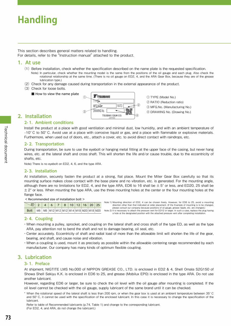
73
Technical document
Handling
This�section�describes�general�matters�related�to�handling.�For�details,�refer�to�the�“Instruction�manual”�attached�to�the�product.
1.At use(1)�Before�installation,�check�whether�the�specification�described�on�the�name�plate�is�the�requested�specification.
��Note)� �In�particular,�check�whether� the�mounting�model� is� the�same�from�the�positions�of� the�oil�gauge�and�each�plug.�Also�check�the�rotational�relationship�at�the�same�time.�(There�is�no�oil�gauge�on�ED2,�4,�and�the�ARA�Gear�Box,�because�they�are�of�the�grease�lubrication�type.)
(2)Check�for�any�damage�caused�during�transportation�in�the�external�appearance�of�the�product.(3)Check�for�loose�bolts.
2.Installation2-1.Ambient conditionsInstall�the�product�at�a�place�with�good�ventilation�and�minimal�dust,�low�humidity,�and�with�an�ambient�temperature�of�–10°C�to�50°C.�Avoid�use�at�a�place�with�corrosive�liquid�or�gas,�and�a�place�with�flammable�or�explosive�materials.��Furthermore,�when�used�out�of�doors,�etc.,�attach�a�cover,�etc.�to�avoid�direct�contact�with�raindrops,�etc.�
2-2.TransportationDuring�transportation,�be�sure�to�use�the�eyebolt�or�hanging�metal�fitting�at�the�upper�face�of�the�casing,�but�never�hang�wires,�etc.�at�the�lateral�shaft�and�cross�shaft.�This�will�shorten�the�life�and/or�cause�trouble,�due�to�the�eccentricity�of�shafts,�etc.Note)�There�is�no�eyebolt�on�ED2,�4,�6,�and�the�type�ARA.
2-3.InstallationAt� installation,� securely� fasten� the� product� at� a� strong,� flat� place.�Mount� the�Miter�Gear� Box� carefully� so� that� its�mounting�surface�makes�close�contact�with�the�base�plane�and�no�vibration,�etc.�is�generated.�For�the�mounting�angle,�although�there�are�no�limitations�for�ED2,�4,�and�the�type�ARA,�ED6�to�16�shall�be�±5°�or�less,�and�ED20,�25�shall�be�±2°�or�less.�When�mounting�the�type�ARA,�use�the�three�mounting�holes�at�the�center�or�the�four�mounting�holes�at�the�flange�face.< Recommended size of installation bolt >
ED 2 4 6 7 8 10 12 16 20 25
Bolt M8 M8 M12 M12 M12 M14 M18 M20 M18 M20
2-4.Coupling・�When�mounting�a�pulley,�sprocket,�and�coupling�on�the�lateral�shaft�and�cross�shaft�of�the�type�ED,�as�well�as�the�type�ARA,�pay�attention�not�to�bend�the�shaft�and�not�to�damage�bearing,�oil�seal,�etc.・�Center�accurately.�Eccentricity�of�shaft�and�radial�load�of�more�than�the�allowable�limit�will�shorten�the�life�of�the�gear,�bearing,�and�shaft,�and�cause�noise�and�vibration.・�When�a�coupling�is�used,�mount�it�as�precisely�as�possible�within�the�allowable�centering�range�recommended�by�each�manufacturer.�Our�company�has�many�kinds�of�optimum�flexible�coupling.
3.Lubrication3-1.PrefaceAt�shipment,�NIGTITE�LMS�No.000�of�NIPPON�GREASE�CO.,�LTD.�is�enclosed�in�ED2�&�4,�Shell�Omala�S2G150�of�Showa�Shell�Sekiyu�K.K.�is�enclosed�in�ED6�to�25,�and�grease�(Mobilux�EP0)�is�enclosed�in�the�type�ARA.�Do�not�use�another�lubricant.However,�regarding�ED6�or�larger,�be�sure�to�check�the�oil�level�with�the�oil�gauge�after�mounting�is�completed.�If�the�oil�level�cannot�be�checked�with�the�oil�gauge,�supply�lubricant�of�the�same�brand�until�it�can�be�checked.*��When�the�rotational�speed�of�the�lateral�shaft�is�less�than�200�rpm,�or�when�the�gear�box�is�used�at�an�ambient�temperature�between�35°C�and�50°C,�it�cannot�be�used�with�the�specification�of�the�enclosed�lubricant.�In�this�case�it�is�necessary�to�change�the�specification�of�the�lubricant.�� Refer�to�table�of�Recommended�lubricants�(p.74,�Table�1)�and�change�to�the�corresponding�lubricant.� (For�ED2,�4,�and�ARA,�do�not�change�the�lubricant.)
■ How to view the name plate① TYPE�(Model�No.)② RATIO�(Reduction�ratio)③ MFG.No.�(Manufacturing�No.)④ DRAWING�No.�(Drawing�No.)
①
③
②
④
Note�1)�Mounting� direction� of� ED2,� 4� can� be� chosen� freely.�However,� for� ED6� to� 25,� avoid� a�mounting�direction�other�than�that�indicated�at�order�placement.�(If�the�Example�of�mounting�is�to�be�changed,�please�consult�our�company�because�positions�of�oil�gauge,�grease�nipple,�etc.�are�changed.)
Note�2)�It�is�necessary�to�attach�the�pressure�vent�for�ED12�or�larger.�In�such�a�case,�replace�the�plug�having�a�hole�at�the�designated�position�with�the�attached�pressure�vent�after�completing�installation.

74
Technical document
3-2.Replacing lubricant・�For�ED2�&�4,�replacing�lubricant� is�basically�not�required�because�the�lubricant�used�is�grease.�However,� replacing�grease�at�the�target�of�20,000�hrs.�can�increase�life.�At�replacement,�use�the�grease�described�on�p.73�item�3-1,�in�an�amount�of�approx.�150�g�for�ED2,�and�approx.�350�g�for�ED4.�・�For�ED6�to�25,�replace�with�new�oil�500�hrs.�after�starting�operation�for�the�1st�time.�The�purpose�is�to�clean�initial�abrasion� powder,� etc.� generated�when� running� in� (warming� up)� each� part.� It� also� improves� performance� and� life.�At�the�second�time�and�thereafter,�replace�with�new�lubricant�at�the�target�of�after�2,500�hrs.�or�six�months,�whichever�is�earlier,�depending�on�operating�conditions.�(However,�if�the�product�is�operated�continuously�for�a�long�time�and/or�in�a�high-temperature�atmosphere,�or�in�an�environment�with�humidity�or�corrosive�gas,�it�is�necessary�to�shorten�the�oil�replacement�interval.)・�Select�from�recommended�lubricants�in�the�following�Table�1,�referring�to�rotational�speed�and�ambient�temperature.・�In�the�case�of�the�ARA�Gear�Box,�replacing�lubricant�is�basically�not�required�due�to�grease�lubrication.・�In�the�case�of�the�forced�lubrication�specification,�refer�to�the�special-purpose�“Instruction�manual.”
Table 1 Recommended lubricantRotational speed of lateral
shaft rpm r/min
Name of maker
Ambient temperature
–10°C to 35°C 35°C to 50°C
1750
〜
200
Industrial�gear�oil,�class�2 ISO�VG150� ISO�VG�220
Showa�Shell�Sekiyu Shell�Omala�S2G150 Shell�Omala�S2G220
Idemitsu�Kosan Daphne�Super�Gear�Oil�150 Daphne�Super�Gear�Oil�220
Exxon�Mobil Mobilgear�600XP-150 Mobilgear�600XP-220
COSMO�OIL Cosmo�Gear�Oil�SE150 Cosmo�Gear�Oil�SE220
JX�Nippon�Oil�&�Energy BONNOC�M150 BONNOC�M220
Rotational speed of lateral
shaft rpm r/min
Name of maker
Ambient temperature
− 10°C 〜 35°C 35°C 〜 50°C
Less than 200
Industrial�gear�oil,�class�2 ISO�VG�220 ISO�VG�320
Showa�Shell�Sekiyu Shell�Omala�S2G220 Shell�Omala�S2G320
Idemitsu�Kosan Daphne�Super�Gear�Oil�220 Daphne�Super�Gear�Oil�320
Exxon�Mobil Mobilgear�600XP-220 Mobilgear�600XP-320
COSMO�OIL Cosmo�Gear�Oil�SE220 Cosmo�Gear�Oil�SE320
JX�Nippon�Oil�&�Energy BONNOC�M220 BONNOC�M320
Table 2 Approximate oil quantity Unit:LED 6 7 8 10 12 16 20 25
Lateral single-shaft type 0.95 1.5 1.9 3.5 7 10 11 18
Lateral dual-shaft type 1.0 1.6 2.1 3.7 7.4 ー ー ー
3-4.Inspecting and replacing oil seal・��Oil�seals�also�wear�and�have�a�useful�life,�and�can�cause�an�oil�leakage.�When�they�are�used�under�notably�severe�conditions� (severe� environmental� conditions� such�as� high� temperature,� high� rotational� speeds,� outdoors),� there� is� a�possibility�of�life�being�shortened.�Perform�periodic�inspection,�and�if�there�is�an�oil�leakage,�promptly�replace�the�oil�seal.�When�replacing�an�oil�seal,�be�sure�to�use�an�oil�seal�of�same�type�and�material.�(Using�an�oil�seal�of�a�different�material�may� cause� an� oil� leakage.)� Furthermore,�when� replacing� oil� seals,� refer� to� the� catalogs� of� oil� seal�manufacturers.・�When�starting�operation�for�the�first�time,�surplus�grease�sometimes�exudes�that�has�been�filled�up�to�the�lip�of�the�oil�seal�at�assembly.�However,�this�does�not�indicate�that�the�functions�of�the�gear�box�are�impaired.
3-3. Supplying grease (For gear boxes with shaft arrangement of shaft oriented in the vertical direction, for ED6 or larger)
・�When�a�bearing�is�positioned�above�the�oil�level,�it�is�not�sufficiently�lubricated�by�splashes�of�oil�alone.�Therefore,�the�following�grease�is�enclosed�in�this�bearing�part�at�shipment.��Exxon�Mobil��Mobilux�EP2
・�Because�it�is�necessary�to�supply�grease�to�this�bearing�periodically�(approx.�every�1,000�hrs),�replace�the�stop�plug�with�the�attached�grease�nipple�at�the�designated�position�of�the�Type�of�mounting�(pp.13,�14),�and�supply�grease.Note)�A�grease�nipple�is�attached�to�products�with�all�kinds�of�shaft�arrangement�at�shipment.
Table 4 Recommended amount of grease Unit:gED 6 7 8 10 12 16 20 25
Lateral shaft 22 35 70 100 170 270 370 640
Output bearing support Ⅰ 3 7 12 17 20 55 90 150
Output bearing support Ⅱ 6 9 12 17 20 70 85 135
Table 3 Recommended grease
メーカ名 BrandShowa Shell Sekiyu Alvania�EP2
Idemitsu Kosan Daphne�Eponex�SR2
Exxon Mobil Mobilux�EP2
COSMO OIL Cosmo�Dynamax�No.2
JX Nippon Oil & Energy EPNOC�Grease�AP2

75
Technical document
Handling
4.Operation4-1.Prestart inspectionWhen�installation�is�completed,�inspect�the�following�points�before�starting�operation.•�Whether�rotational�relationships�are�correct.�•�Whether�coupling�with�the�driven�shaft�is�correct.�•�Whether�there�is�a�loose�mounting�bolt,�tightening�bolt,�etc.
4-2.Test operationBefore�starting�regular�operation,�carry�out�a�no-load�operation�to�check�whether�rotational�relationships�are�correct,�and�that�there�is�no�abnormal�vibration,�noise,�heat�generation,�etc.�Then,�apply�a�load�gradually.
4-3.Regular operationAfter�starting�operation,�check�the�following�items.•�Whether�there�is�abnormal�vibration,�noise,�heat�generation,�etc.�•�Whether�shock�and/or�overload�is�applied.Note)� �Slight�heat�generation�may�occur�during�the�first�two�or�three�days�after�starting�operation.�However,�if�the�surface�temperature�of�the�
casing�exceeds�93°C,�insufficient�or�too�much�lubricant,�installation�failure,�etc.�should�be�considered.�Therefore,�check�each�part.
5.Daily inspection, maintenance5-1.At maintenance・�For�maintenance,�wear�suitable�clothes�for�work�and�suitable�protective�gear�(safety�glasses,�gloves,�safety�shoes,�etc.).・�Tidy�up�the�surrounding�area�and�carry�out�work�so�as�not�to�cause�a�secondary�accident.・�Be�sure�to�turn�off�the�power�supply,�and�carry�out�work�with�the�machine�completely�stopped.�Also,�make�be�sure�that�the�power�supply�cannot�be�turned�on�accidentally.・�The�type�ED�and�type�ARA�are�hot�during�operation,�and�there�is�a�risk�of�a�burn�if�they�are�touched�directly.�So,�be�careful.�
5-2. Daily inspectionPerform� regular�maintenance�according� to� the� following�procedure,�while�paying�attention� to�operating�condition,�using�the�necessary�measuring�instruments.Be�sure�to�perform�daily�inspection�according�to�the�following�table.�If�daily�inspection�is�neglected,�trouble�may�be�caused.
Inspection item Contents of inspectionNoise Whether�noise�is�greater�than�usual.�Whether�abnormal�sound�is�generated.
Vibration Whether�there�is�abnormal�vibration.�Also,�whether�a�rapid�change�occurs.
Surface temperature Whether�it�is�abnormally�high.�Also,�whether�there�is�a�rapid�increase.
Oil level, In�a�stopped�state,�whether�oil�level�is�at�the�specified�position.
Installation bolt Whether�installation�bolts�are�loose.
Chain, belt Whether�anything�is�loose.
Dirtiness of lubricant Whether�there�is�any�dirt�due�to�abrasion�powder,�etc.
Leakage of lubricant Whether�an�oil�leakage�is�generated�at�each�joint,�oil�seal�part,�or�cover�of�reduction�gear.
Pressure vent Whether�the�air�vent�hole�is�choked.
If�any�trouble� is�observed�at�daily� inspection,� take�measures�according�to�“10.�Handling�method�at�generation�of�trouble.”�If�normal�operation�cannot�be�recovered�despite�taking�countermeasures,�please�inform�the�vendor.
6.Disassembling, assembling・�Never�disassemble�the�product.・�In�this�machine,�tooth�contact�adjustment�and�bearing�adjustment�are�carried�out�to�maximize�performance.・�If�disassembly�is�necessary,�please�inform�our�company.

76
Technical document
7.Parts list
EDBearing size and quantity
Oil seal and quantity
Plug size
Oil gauge
Grease nipple
26203R SHLateral� 2�pcsCross� 2�pcs
D16.28.7Lateral� 1�pcCross� 1/2�pc
1/8″ ー ー
46304R SHLateral� 2�pcsCross� 2�pcs
DM20.35.10(※ DM17.35.8)Lateral� 1�pcCross� 1/2�pc
1/4″ ー ー
630306Lateral� 2�pcsCross� 2�pcs
DM28.48.11(※ DM26.48.11)Lateral� 1�pcCross� 1/2�pc
3/8″3/8″
A-M6F(Bracket�part)
B-M6F7
30307Lateral� 2�pcsCross� 2�pcs
DM35.52.11(※ DM32.52.11)Lateral� 1�pcCross� 1/2�pc
3/8″3/8″
830309Lateral� 2�pcsCross� 2�pcs
DM42.65.12Lateral� 1�pcCross� 1/2�pc
3/8″3/8″
Note�1)� Quantity�of�bearings,�oil�seals� ・�Lateral�2�pcs�denotes�the�quantity�used�for�the�lateral�part.�So,�in�the�lateral�dual-shaft�type,�2�pcs�×�2�positions�=�4�pcs�are�necessary.� ・�Cross�1/2�pc�denotes�one�piece�at�a�single�shaft,�and�2�pcs�at�double�shafts.� ・�For�4B,�6B,�7B,�an�oil�seal�with�the�mark�*�is�used�for�the�lateral�shaft�side,�and�an�oil�seal�without�the�mark�*�is�used�for�the�cross�shaft�side.
Note�2)� Sizes�20,�25�for�the�oil�gauge�are�model�Nos.�of�Koho�Kosan.
8.Recombination of shaft arrangementModels�of�the�Miter�Gear�Box�that�can�be�recombined�with�common�parts�are�as�follows.�For�recombination�of�shaft�arrangement,�please�consult�our�company.
Basic shaft arrangement → Shaft arrangement that can be recombined
1-LR → 1-LR-O
1-R → 1-L-O
1-L → 1-R-O
Basic shaft arrangement → Shaft arrangement that can be recombined
1-UD → 1-UD-O, D-LR, D-LR-O, U-LR, U-LR-O
1-U → 1-D-O, D-R, D-L-O, U-L, U-R-O
1-D → 1-U-O, D-L, D-R-O, U-LR, U-L-O
9.StorageIf�reduction�gears�are�not�to�going�be�used�soon,�store�them�while�paying�attention�to�the�following�points.
9-1.Storage areaStore�them�at�a�clean,�dry�place�indoors.�Do�not�store�them�outdoors,�or�at�places�with�humidity,�dust,�sharp�temperature�changes,�corrosive�gas,�etc.
9-2.Posture during storagePacking�and�shipping�in�accordance�with�the�type�of�mounting�(mounting�form)�are�performed�at�shipment.�Store�products� by� keeping� the� same�mounting� arrangement� (relationship� of� top� &� bottom� sides,� etc.).� In� the� case� of�special�installation,�there�is�a�risk�that�grease�at�a�bearing�will�mix�with�lubricant�and�dissolve�out.
9-3.Storage period・The�storage�period�should�be�within�six�months.・If�the�storage�period�is�six�months�or�more,�a�special�rustproof�specification�is�required.� In�such�a�case,�please� consult�our�company.・In�the�case�of�export�items,�a�rustproof�specification�for�export�is�necessary.�In�such�a�case,�please�consult�our company.
9-4.Usage after storage・�Nonmetallic�portions�such�as�oil�seal,�oil�gauge,�oil�supply�plug�easily�deteriorate�under�environmental�influences�such�as� temperature,�ultraviolet� rays.� In�such�a�case,�after�storage� for�a� long� time,�check� them�before�starting�operation�and�replace�items�where�deterioration�is�observed�with�new�items.・�When�starting�operation,�check�for�abnormal�sound,�vibration,�and/or�heat�generation.�If�any�trouble�is�observed,�please�inform�the�vendor�promptly.
EDBearing size and quantity
Oil seal and quantity
Plug size
Oil gauge
Grease nipple
1030310Lateral� 2�pcsCross� 2�pcs
DM48.70.12Lateral� 1�pcCross� 1/2�pc
1/2″1/2″ A-M6F(Bracket�part)
B-M6F1230312Lateral� 2�pcs30311Cross� 2�pcs
DM52.75.12Lateral� 1�pcCross� 1/2�pc
1/2″1/2″
1632314Lateral� 2�pcsCross� 2�pcs
DM65.88.12Lateral� 1�pcCross� 1/2�pc
1/2″1/2″ A-PT�1/8″
2032316Lateral� 2�pcsCross� 2�pcs 個
DM75.100.13Lateral� 1�pcCross� 1/2�pc
1/2″VAB
A-PT�1/4″
2532319Lateral� 2�pcsCross� 2�pcs
DM90.115.13Lateral� 1�pcCross� 1/2�pc
1/2″VAB

77
Technical document
Handling
10.Method of handling troubleIf any trouble is caused, refer to the following table, and take suitable measures at an early stage.
Contents of trouble Cause Countermeasure
Temperature has increased.
Overload�operation Decrease�load�or�use�larger�gear�box.
Contamination,�deterioration�of�lubricant� Replace�with�new�lubricant.
Insufficient�or�excessive�lubricant Fill�with�the�correct�amount�of�lubricant.
Nonconformity�of�oil�type Replace�with�recommended�lubricant.
Ambient�temperature�is�high. Provide�a�cooling�device�or�change�the�position�of�the�gear�box.
Pressure�vent�is�not�attached. Attach�a�pressure�vent.
Nonconformity�of�centering Align�the�center�with�equipment�precisely.
Noise has increased.
Vibration has increased.
Overload�operation Decrease�load�or�use�larger�gear�box.
Contamination,�deterioration�of�lubricant� Replace�with�new�lubricant.
Insufficient�or�excessive�lubricant Fill�with�the�correct�amount�of�lubricant.
Nonconformity�of�oil�type Replace�with�recommended�lubricant.
Damage�to�bearing Replace�bearing�with�a�new�one.�
Loose�tightening�bolt Perform�retightening.
Nonconformity�of�centering Align�the�center�with�equipment�precisely.
Lubricant leaks.
Damaged,�deteriorated�oil�seal Replace�oil�seal�with�a�new�one.
Nonconformity�of�tightening�each�plug Retighten.
Pressure�vent�is�not�attached. Attach�a�pressure�vent.
Excessive�lubricant Fill�with�the�correct�amount�of�lubricant.
*�If�another�trouble�has�occurred,�please�consult�our�company.�

78
Technical document
When making an inquiry with regard to selection of Miter Gear Box, ARA Gear Box, please let us know the following.
Machine to be used
Name�of�equipment
Contents�of�equipment
Layout Please�enter�details�in�the�following�columns.�(Shaft�arrangement,�rotational�direction,�mounting�direction,�coupling�method�of�shaft,�and�others)
Operating conditions
Description�of�prime�mover Motor,�servomotor,�engine,�others( )
Load�torque�or�transmission�kW ( )kW�or( )N・m
Operating�time ( )hrs/day,�continuous�•�intermittent
Frequency�of�start-stop ( )times/hr
Rotational�speed�at�input Regular( )rpm�•�Maximum( )rpm
Direction�of�input�shaft Lateral�shaft�•�Cross�shaft
Speed�ratio�of�gear�box 1:1、1.5:1、2:1、2.5:1、3:1、( ):1
Load�characteristics Uniform�load�•�Load�with�extent�shock�•�Load�with�large�shock
Atmosphere where used
Usage�environment Indoor�•�Outdoor�•�Near�a�furnace�•�Inside�a�freezer�•�Others( )
Ambient�temperature Regular( ℃)・High�temperature( ℃)・Low�temperature( ℃)
Ambient�atmosphere Salt�damage�•�Dust�•�Acid�•�Others( )
OthersOption�(pp.66�to�68) Tapping�at�shaft�end�•�Material�of�casing�bracket:�FCD�•�Others( )
Special�specification�(pp.69�to�72)
Outline drawing of equipment
Confirmation sheet for selected specification

79
MEMO
80
Precautions for safety(General)●Complywithsafetyregulationsfortheplaceofinstallationandtheequipmentused.(“OrdinanceonIndustrialSafetyandHygiene,”“Guidebookofelectricalequipment,”“BuildingStandardsAct,”etc.)
●Beforeuse,readthe“Instructionmanual”thoroughly,andusetheproductscorrectly.Ifthe“Instructionmanual”isnotfound,requestthevendororourcompanytoprovideit.Besuretodeliverthe“Instructionmanual”totheenduser.
(Selection)●Selectaproductthatissuitablefortheusageenvironmentandapplication.●Whenourcompany’sproductsareusedforequipmentthattransportspeopleorhoistingequipment,provideasafetydeviceattheequipmentsideforsafetypurposes.
●Useanexplosion-proofmotor inanexplosiveatmosphere.Furthermore,useanexplosion-proofmotorwithaspecificationthatconformstohazardousplaces.
●Whenanexplosion-proofmotorisdrivenbyaninverter,theonlycombinationofmotorandinverterallowedisintheratioof1:1.Besuretooperateitwiththeindicatedspecializedinverter.Moreover,becausetheinverterhasanon-explosion-proofstructure,besuretoinstallitataplacewherethereisnoexplosivegas.
●Whenthemotorisdrivenbya400Vclassinverter,installasuppressionfilterorreactorattheinverterside,oruseamotorofareinforcedinsulationtype.
●Forequipmentinwhichoilcontaminationshouldnotoccur,suchasfood-processingmachinery,attacha losspreventiondevicesuchasanoilpanincaseofaccidentaloilleakagecausedbyfailure,endofusefullife,etc.
Warranty1. Warranty period, free of chargeOurcompany’swarrantyperiod,freeofcharge,is18monthsaftershipmentfromourfactory,or12monthsafterstartinguse(includingafter incorporatingourcompany’sproduct intothecustomer’sequipment),whichever isshorter.
2. Warranty rangeRegardingafailureofourcompany’sproductsduringthewarrantyperiod,freeofchargeincasecorrectinstallation,usage,maintenanceandcontrolaccordingtothe“Instructionmanual”areperformed,thefailedportionsshallbereplacedorrepairedfreeofcharge.However,thetargetofthewarrantyshallonlybeourcompany’sproducts;therefore,thefollowingexpensesshallbeoutsidethescopeofthewarranty.(1) Expensesrequiredfordismountingandmountingourcompany’sproductsfrom/tothecustomer’sequipment,
andexpensesforworkrelatedtothem.(2) Expensesrequiredfortransportingthecustomer’sequipmenttotherepairshop,etc.(3) Customer’slostprofitsassociatedwithfailureand/orrepair,aswellasotherlosses.
3. Warranty for a feeIfanytroubleiscausedduetothefollowingitems,inspiteofitoccurringduringthewarrantyperiod,freeofcharge,wewillundertakeinvestigationandrepairforafee.(1) Ifthecustomerhasnotcorrectlyinstalledourcompany’sproductsinaccordancewiththe“Instructionmanual”(2) Customer’smaintenanceandcontrolwasnotsufficient,andhandlingwasnotcorrect(3) Incaseafailureoccursduetodefectivecouplingofourcompany’sproductswithotherequipment(4) Ifthestructureofourcompany’sproductshasbeenchanged,suchasmodificationbythecustomer.(5) Iftheproductswererepairedbyafirm/factory,otherthanourcompanyorafactorydesignatedbyourcompany(6) If ourcompany’sproductswereusedunderconditionsother than thecorrectoperatingenvironment in
accordancewiththe“Instructionmanual”(7) Ifafailureisgeneratedduetoforcemajeuresuchasanaccidentorduetoanillegalactbyathirdparty(8) Ifafailureofourcompany’sproductsisgeneratedsecondarilyduetoanydefectinthecustomer’sequipment(9) Ifafailureisgeneratedduetoapart/componentsuppliedbythecustomerthatwasincorporatedinourproduct,
orduetoapart/componentusedasdesignatedbythecustomer,etc.(10) Ifconsumablepartssuchasbearings,oilsealsthatwere incorporatedinourcompany’sproductsrunout,
becomeworn,ordeteriorate(11) Inaddition,anydamagegeneratedduetoacausethatisoutsideourcompany’sresponsibility
This catalog mainly refers to the selection of models.For actual usage, read the “Instruction manual” thoroughly before use, and use products correctly.
Caution
The logos, brand names, or product names in this catalog are trademarks or registered trademarks of Tsubakimoto Chain Co. in Japan and other countries.

TSU
BA
KI
Miter G
ear Box
TSU
BA
KIM
OTO
CH
AIN
CO
.
U.S. TSUBAKI POWER TRANSMISSION, LLC301 E. Marquardt Drive, Wheeling, IL 60090, U.S.A.Phone : +1-847-459-9500URL : http://ustsubaki.com/
TSUBAKI of CANADA LIMITED1630 Drew Road, Mississauga, Ontario, L5S 1J6, CanadaPhone : +1-905-676-0400URL : http://tsubaki.ca
TSUBAKI BRASIL EQUIPAMENTOS INDUSTRIAIS LTDA.R. Pamplona, 1018, CJ. 73/74, Jd. PaulistaCEP 01405-001, São Paulo, S.P.BrazilPhone : +55-11-3253-5656URL : http://tsubaki.ind.br
TAIWAN TSUBAKIMOTO CO.No. 33, Lane 17, Zihciang North RoadGueishan Township Taoyuan County Taiwan R.O.C.Phone : +886-3-3293827/8/9URL : http://tsubakimoto.com.tw
TSUBAKIMOTO CHAIN (SHANGHAI) CO. LTD.Room 601, Urban City Centre, 45 Nanchang Road Huangpu District, Shanghai 2000020, People's Republic of China Phone : +86-21-5396-6651/2 URL : http://tsubaki.cn/
TSUBAKIMOTO (THAILAND) CO. LTD.388 Exchange Tower, 19th Floor Unit 1902Sukhumvit Road, Klongtoey, Bangkok 10110, ThailandPhone : +66-2-262-0667/8/9URL : http://tsubaki.co.th
TSUBAKI INDIA POWER TRANSMISSION PVT. LTD.Chandrika Chambers No.4, 3rd Floor, Anthony StreetRoyapettah, Chennai, Tamil Nadu 600014, IndiaPhone : +91-44-4231-5251 URL : http://tsubaki.in/
PT. TSUBAKI INDONESIA TRADINGWisma 46 - Kota BNI, 24th Floor, Suite 24.15Jl. Jend. Sudirman, Kav. 1, Jakarta 10220, Indonesia Phone : +62-21-571-4230/31 URL : http://tsubakimoto.co.id/
TSUBAKI POWER TRANSMISSION (MALAYSIA) SDN. BHD.No. 22, Jalan Astaka U8/84A, Bukit Jelutong Industrial Park Section U8, 40150 Shah Alam, Selangor, Malaysia Phone : +60-3-7859-8585 URL : http://tsubaki.sg
TSUBAKIMOTO SINGAPORE PTE. LTD.25 Gul Lane, Jurong, Singapore 629419 Phone : +65-6861-0422/3/4URL : http://tsubaki.sg
TSUBAKI AUSTRALIA PTY. LTD.Unit E, 95-101 Silverwater Road Silverwater NSW 2128, AustraliaPhone : +61-02-9704-2500URL : http://tsubaki.com.au
TSUBAKIMOTO KOREA CO., LTD.#1004/1005 East Wing, Hanshin Intervalley 24, 707-34Yeoksam-dong, Gangnam-gu, Seoul, KoreaPhone : +82-02-2183-0311URL : http://tsubakimoto.com
TSUBAKI AUSTRALIA PTY. LTD.NEW ZEALAND BRANCH2 Kalmia Street, Ellerslie, Auckland 1051, New ZealandPhone : +64-275-082-726Phone : http://tsubaki.com.au
Group companies
ASIA and OCEANIA
TSUBAKIMOTO EUROPE B.V.Aventurijn 1200, 3316 LB Dordrecht, The NetherlandsPhone : +31-78-620-4000URL : http://tsubaki.eu
OOO "TSUBAKI KABELSCHLEPP"Prospekt Andropova 18, Building 6115432 Moscow, RussiaPhone : +7-499-418212URL : http://kabelschlepp.ru/
TSUBAKIMOTO U.K. LTDOsier Drive, Sherwood Park, Annesley, NottinghamNG15 0DX, United KingdomPhone : +44-1623-688-700URL : http://tsubaki.eu
TSUBAKI DEUTSCHLAND GmbHASTO Park Oberpfaffenhofen, Friedrichshafener Straße 1D-82205, Gilching, GermanyPhone : +49-8105-7307100URL : http://tsubaki.de/
EUROPE
NORTH and SOUTH AMERICA
HeadquartersNakanoshima Mitsui Building3-3-3 Nakanoshima, Kita-kuOsaka, 530-0005, JapanPhone : +81-6-6441-0011URL : http://tsubakimoto.com
Chain & Power Transmission Sales1-3 Kannabidai, 1-chomeKyotanabe,Kyoto, 610-0380, JapanPhone : +81-774-64-5022
TSUBAKIMOTO SINGAPORE PTE. LTD.VIETNAM REPRESENTATIVE OFFICEH&H Building 8F, 209 Hoàng V�n Th�Phú Nhu�n District, H� Chí Minh City, VietnamPhone : +84-8-3999-0131/2URL : http://tsubaki.net.vn/
Catalog No.985K555-1 ©2015/2 TSUBAKIMOTO CHAIN CO.Printed in Japan (K) 1,000
Miter Gear Box