
Miter bend polarizers in CW ECRH systems - Research Square
15
Miter bend polarizers in CW ECRH systems: groove design, ohmic loss, and cooling in numerical analyses Jawad Taheri ( [email protected] ) Nuclear Science and Technology Research Institute Davoud Iraji Amirkabir University of Technology Research Article Keywords: grating polarizer, groove design, high-power ECRH system, ohmic loss, water cooling Posted Date: August 19th, 2022 DOI: https://doi.org/10.21203/rs.3.rs-1952720/v1 License: This work is licensed under a Creative Commons Attribution 4.0 International License. Read Full License
-
Upload
khangminh22 -
Category
Documents
-
view
1 -
download
0
Transcript of Miter bend polarizers in CW ECRH systems - Research Square

Miter bend polarizers in CW ECRH systems: groovedesign, ohmic loss, and cooling in numericalanalysesJawad Taheri ( [email protected] )
Nuclear Science and Technology Research InstituteDavoud Iraji
Amirkabir University of Technology
Research Article
Keywords: grating polarizer, groove design, high-power ECRH system, ohmic loss, water cooling
Posted Date: August 19th, 2022
DOI: https://doi.org/10.21203/rs.3.rs-1952720/v1
License: This work is licensed under a Creative Commons Attribution 4.0 International License. Read Full License

1
Miter bend polarizers in CW ECRH systems: groove design, ohmic loss, and
cooling in numerical analyses
Jawad Taheri1,*, Davoud Iraji2,*
1 School of Plasma Physics and Nuclear Fusion, Nuclear Science and Technology Research Institute, Tehran,
Iran.
2 Department of Energy Engineering and Physics, Amirkabir University of Technology, Tehran, Iran.
*corresponding authors: [email protected], [email protected]
Abstract
Polarizer miter bends are important components in the transmission lines of electron cyclotron
resonance heating systems, as they create a desired polarization for the electron cyclotron wave before
coupling in the fusion plasma. Normally, a pair of grooved mirrors with different groove depths is
enough to form a universal polarizer made of polarization twister and elliptical polarizer. The groove
shape, and how the grooved mirror tolerates in a modern high-power system with continuous wave
operation, can influence the entire operation of the system. This work contains various investigations
on the grooved mirror including the parametric groove design, low ohmic loss, and effective cooling
with an appropriate design of the cooling channel. Since the rounded trapezoidal grooves have some
advantages over rectangular and sinusoidal grooves, the study is mainly dedicated to the trapezoidal
grooves in both polarizer mirrors. The steady-state thermal analysis is carried out for 1 MW power at
110 GHz.
Keywords: grating polarizer, groove design, high-power ECRH system, ohmic loss, water cooling.
1. Introduction
To enhance the electron cyclotron resonance heating and current drive (ECRH & CD) of plasma at a
desired position, a particular elliptical polarization is required to be induced in the millimeter wave.
Normally this can be achieved by a pair of rotatable grooved mirrors as grating polarizers with different
groove depths installed into successive miter bends of the transmission line. One of them has the groove
depth that corresponds to λ/4 and the other has the grooved depth corresponding to λ/8 where λ is the
wavelength [1-3]. The former is referred to as polarization twister (PT) and the latter is referred to as
elliptical polarizer (EP) in this study.
The groove profile is also important when taking into account the arc discharge on the sharp edges of
the mirror corrugations, especially in high-power transmission lines. Therefore, it is recommended to

2
round the edges of the corrugations (or grooves). In high-power systems, the operation can be also
limited by the high ohmic loss on the grooved mirrors as the grooves and their orientation with respect
to the incident polarization can lead to a significantly higher loss than a plane mirror. So with the
development of high-power, long-pulse gyrotron in modern systems such as ITER ECRH/ECCD with
power up to 1 MW, the loss in the transmission line components cannot be neglected [4, 5]. In such
systems, active water cooling is imperative for the compact polarizer miter bends.
This paper not only investigates the groove profile on the polarizer mirrors but also studies the ohmic
loss on the mirrors and effective active cooling for the ohmic heat dissipation. Extensive work is done
to design optimum profiles that are parametric based on the wavelength and can create suitable
polarization for each polarizer. The parametric feature makes the profiles to be adopted for any single
frequency transmission line. The proposed groove profiles are in trapezoidal shapes with rounded edges.
Since a rectangular groove is a special case of trapezoidal grooves where the sidewalls are parallel, the
analysis also includes the rounded rectangular shapes. We used numerical simulations integrated with
vector theory for diffraction gratings. The simulation parts are performed in COMSOL and the vector
theory is developed in MATLAB. Then the loss on the mirrors with the suitable grooves is calculated
by the numerical simulation. This analysis together with water cooling analysis is done for a continuous
wave (CW) operation with 1 MW power at 110 GHz.
2. Groove design
2-1. Calculation method for polarization parameters
The geometry of a rotatable polarizer grooved mirror in a miter bend is shown in Fig. 1Error!
Reference source not found.. The incident angle is θ =45° to the mirror normal axis, and the mirror
rotation angle is denoted by ϕ. When the electric field of a linearly polarized incidence is perpendicular
to the incidence plane it is called the H-plane incidence, and the electric field parallel to the incidence
plane defines the E-plane incidence. The polarization states of the reflected wave can be characterized
by two parameters: the rotation angle, α, and the ellipticity, β, where −45° ≤ β ≤ 45°. Circularly
polarization is defined by |β| = 45°, while linear polarization is defined by β = 0°. At the grooved
surface, the incident wave field is divided into two orthogonal components where the component
parallel to the grooves reflects at the top surface of corrugations while the component perpendicular to
the grooves penetrates the groove and reflects at the bottom and therefore the phase shift, τ, is made.
The elliptical form of waves comes from the relative phase shift of the reflected field components. For
a normal incidence on a rectangular grooved surface, τ = 2kd = 4πd/λ where d is the groove depth
and k is the wavenumber. In a such case, the groove depth d = λ/4 corresponds to a linear polarization
with τ = π while d = λ/8 corresponds to a circular polarization with τ = π/2.

3
Fig. 1. Polarizer geometry in a miter bend (θ = 45°). When the orientation of the grooves
is perpendicular to the incidence plane, ϕ = 0°. kr is normal to the polarization ellipse.
In non-normal incidence on a non-rectangular grooved surface, obtaining τ is much more complicated.
By the numerical simulation (which solves Maxwell’s equations) the reflected field can be obtained and
then by the relation
[Er𝜃Erϕ] = [cos ξsin ξ −sin ξcos ξ ] [eiτ 2⁄0 0e−iτ 2⁄ ] [ cos ξ−sin ξ −sin ξ− cos ξ] [Ei𝜃Eiϕ] (1)
where ξ = atan (cosθ tanϕ) ≈ atan (0.7 × tan ϕ), and using the integral method in the vector theory
of diffraction gratings discussed in [1, 6-8] τ can be found. When τ is found then the polarization
parameters (α, β) of the reflected wave can be obtained by: 𝛼 = 12 atan(tan 2γ × cos δ) (2) β = 12 asin(sin 2γ × sin δ) (3)
where γ = atan(|Erϕ|/|Erθ|) , and δ = δϕ − δθ = arg (Erϕ) − arg (Erθ) is the phase difference
between the reflected field components, inducing the ellipticity.
4
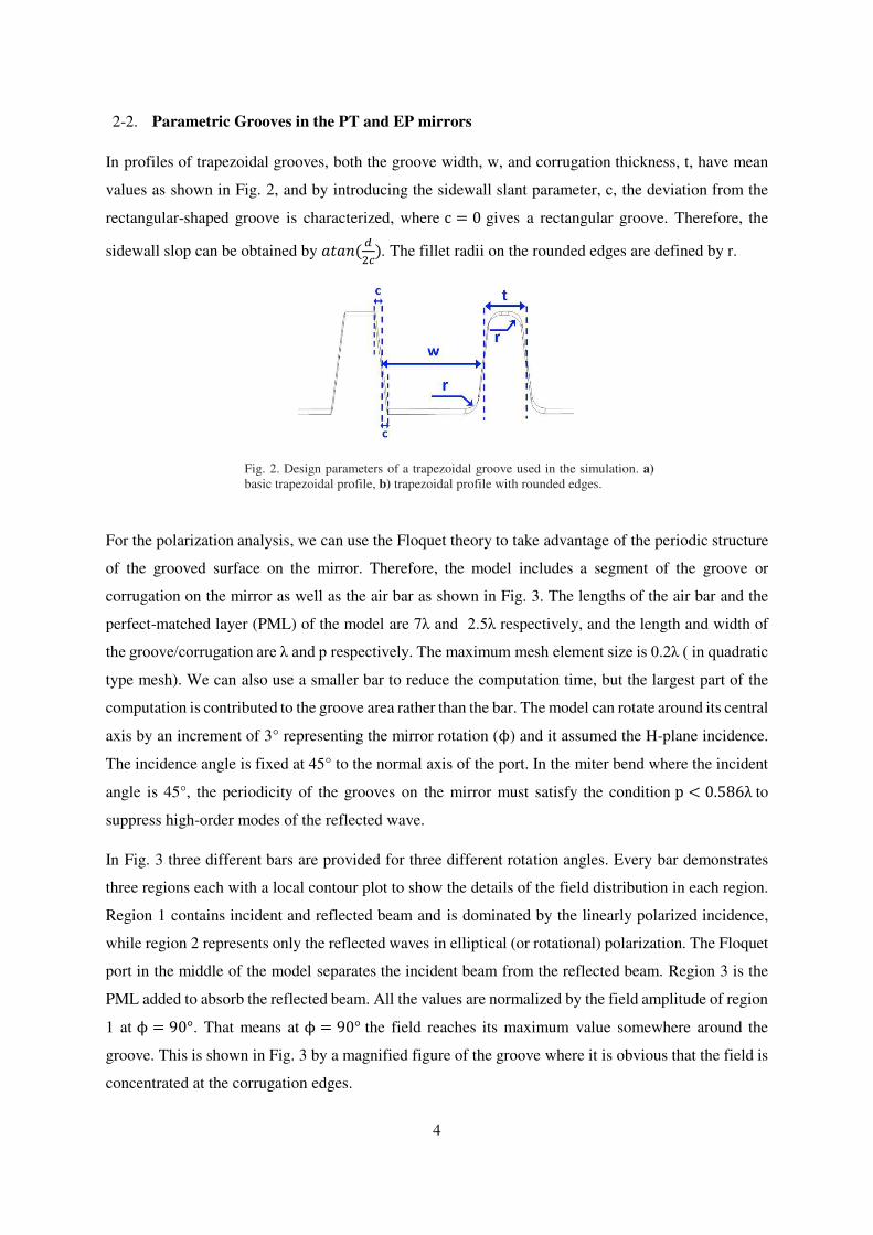
2-2. Parametric Grooves in the PT and EP mirrors
In profiles of trapezoidal grooves, both the groove width, w, and corrugation thickness, t, have mean
values as shown in Fig. 2, and by introducing the sidewall slant parameter, c, the deviation from the
rectangular-shaped groove is characterized, where c = 0 gives a rectangular groove. Therefore, the
sidewall slop can be obtained by 𝑎𝑡𝑎𝑛 ( 𝑑2𝑐). The fillet radii on the rounded edges are defined by r.
Fig. 2. Design parameters of a trapezoidal groove used in the simulation. a)
basic trapezoidal profile, b) trapezoidal profile with rounded edges.
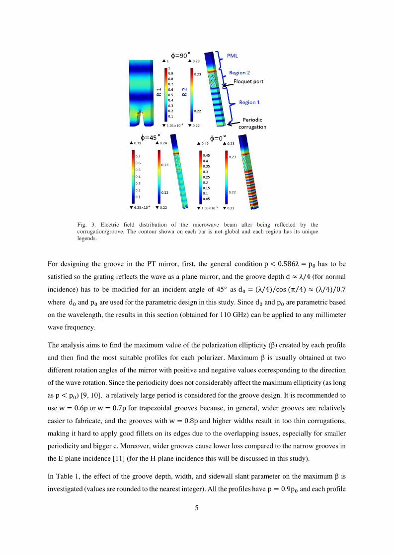
For the polarization analysis, we can use the Floquet theory to take advantage of the periodic structure
of the grooved surface on the mirror. Therefore, the model includes a segment of the groove or
corrugation on the mirror as well as the air bar as shown in Fig. 3. The lengths of the air bar and the
perfect-matched layer (PML) of the model are 7λ and 2.5λ respectively, and the length and width of
the groove/corrugation are λ and p respectively. The maximum mesh element size is 0.2λ ( in quadratic
type mesh). We can also use a smaller bar to reduce the computation time, but the largest part of the
computation is contributed to the groove area rather than the bar. The model can rotate around its central
axis by an increment of 3° representing the mirror rotation (ϕ) and it assumed the H-plane incidence.
The incidence angle is fixed at 45° to the normal axis of the port. In the miter bend where the incident
angle is 45°, the periodicity of the grooves on the mirror must satisfy the condition p < 0.586λ to
suppress high-order modes of the reflected wave.
In Fig. 3 three different bars are provided for three different rotation angles. Every bar demonstrates
three regions each with a local contour plot to show the details of the field distribution in each region.
Region 1 contains incident and reflected beam and is dominated by the linearly polarized incidence,
while region 2 represents only the reflected waves in elliptical (or rotational) polarization. The Floquet
port in the middle of the model separates the incident beam from the reflected beam. Region 3 is the
PML added to absorb the reflected beam. All the values are normalized by the field amplitude of region
1 at ϕ = 90°. That means at ϕ = 90° the field reaches its maximum value somewhere around the
groove. This is shown in Fig. 3 by a magnified figure of the groove where it is obvious that the field is
concentrated at the corrugation edges.
5
Fig. 3. Electric field distribution of the microwave beam after being reflected by the
corrugation/groove. The contour shown on each bar is not global and each region has its unique
legends.
For designing the groove in the PT mirror, first, the general condition p < 0.586λ = p0 has to be
satisfied so the grating reflects the wave as a plane mirror, and the groove depth d ≈ λ/4 (for normal
incidence) has to be modified for an incident angle of 45° as d0 = (λ/4)/cos (π 4⁄ ) ≈ (λ/4)/0.7
where d0 and p0 are used for the parametric design in this study. Since d0 and p0 are parametric based
on the wavelength, the results in this section (obtained for 110 GHz) can be applied to any millimeter
wave frequency.
The analysis aims to find the maximum value of the polarization ellipticity (β) created by each profile
and then find the most suitable profiles for each polarizer. Maximum β is usually obtained at two
different rotation angles of the mirror with positive and negative values corresponding to the direction
of the wave rotation. Since the periodicity does not considerably affect the maximum ellipticity (as long
as p < p0) [9, 10], a relatively large period is considered for the groove design. It is recommended to
use w = 0.6p or w = 0.7p for trapezoidal grooves because, in general, wider grooves are relatively
easier to fabricate, and the grooves with w = 0.8p and higher widths result in too thin corrugations,
making it hard to apply good fillets on its edges due to the overlapping issues, especially for smaller
periodicity and bigger c. Moreover, wider grooves cause lower loss compared to the narrow grooves in
the E-plane incidence [11] (for the H-plane incidence this will be discussed in this study).
In Table 1, the effect of the groove depth, width, and sidewall slant parameter on the maximum β is
investigated (values are rounded to the nearest integer). All the profiles have p = 0.9p0 and each profile

6
has two values of the maximum β corresponding to the two different widths: The first value is for w =0.6p while the second is for w = 0.7p. The fillet radius on the edges is set as follows: For c = 0
(rectangular) we used r = 0.07λ (for either w = 0.06p and w = 0.07p). In other profiles with non-
zero c, again for w = 0.06p we used r = 0.07λ and for w=0.7p we used r = 0.05λ. This is because
when w and c increase, applying the bigger fillet encounters overlapping issues. We observed that
changing the fillet radius from 0.05λ to 0.07λ does not change the result by more than three degrees.
The rounding effect on the maximum β is more or less similar to the effect of the sidewall slant
parameter.
Table 1. Maximum ellipticity during 180° rotation of the PT mirror having rounded trapezoidal grooves with p =0.9p0 and w = (0.6p, 0.7p) c = 0.25t c = 0.2t c = 0.15t c = 0.1t c = 0.05t c = 0
27, 25 24, 22 20, 20 17, 18 14, 15(IV) 12, 16 d = 0.9d0
18, 16 14, 13 11(II), 11(I) 14, 11 17, 13 20, 13(III) d = d0 13, 12 15, 13 18, 15 22, 18 24, 20 28, 20 d = 1.1d0 20, 18 23, 20 26, 23 32, 25 33, 28 37, 28 d = 1.2d0
In this study the lowest value of the maximum β during 180° of mirror rotation appeared to be ~10°,
therefore, the profiles that give a maximum β within 10°-15° can be candidates for PT. It can be seen
that, in each row or column, the maximum β goes to the lower or upper limit, 10°and 45° respectively,
with a routine and then comes back. By using the logical patterns between the data in each row or
column of Table 1 one can predict the value in the next cell or use interpolation to reach the desired
result. These logical patterns may be more important than the values themselves as they can provide a
helpful insight into groove design based on the previous results.
For designing the groove in the EP mirror, we now use d0 ≈ (λ/8)/0.7 and look for the groove shapes
that give a maximum β within 40°-45°. The effect of each groove parameter on the maximum β is
investigated for the EP and reported in Table 2 by using the approaches applied in the PT groove design.
Table 2. Maximum ellipticity during 180° rotation of the EP mirror having rounded trapezoidal
grooves with p = 0.9p0 and w = (0.6p, 0.7p) c = 0.25t c = 0.2t c = 0.15t c = 0.1t c = 0.05t c = 0
27, 28 28, 30 30, 31 31, 32 32, 34 33, 32 d = d0 31, 33 33, 35 35, 36 36, 37 38, 38 39, 37 d = 1.1d0 36, 37 38, 39 39, 41 41, 42 43, 44 45, 42 d = 1.2d0

7
40, 42 41,43 44 (VI), 44(V) 43, 42 41, 41 39, 42 d = 1.3d0
45, 43 43, 41 41, 39 38, 37 36, 35 33, 37 d = 1.4d0
Here again, the first result in each cell is for w = 0.6p while the second is for w = 0.7p and the
rounding of edges is similar to that of the PT grooves. In Table 2, some of the profiles give the maximum
β within 40°-45° which can be considered for the EP. The polarization parameters of all the profiles in
column c = 0.15t in Table 1 and a profile with c = 0.15t and d = 1.3d0 in Table 2, all with w = 0.7p
(second values in each cell) are shown in Fig. 4. By comparing the β graphs, it can be seen how the
graph changes when the maximum β goes near its lower limit, and then two other extrema (positive and
negative) appear at two different angles as the varying parameter (d) increases.
All the results obtained for both polarizers are valid for the smaller periodicity of the grooves. However,
shorter periods may increase the loss as the number of grooves increases. This can draw our attention
to an important advantage of the trapezoidal grooves with a larger duty cycle (w/p) over sinusoidal
grooves.
Fig. 4. The polarization parameters made by the PT and EP trapezoidal grooves. All
the grooves have w=0.7p and c=0.15t but different depths.
2-3. The field in the grooves
As a preliminary investigation of the ohmic loss analysis, the electric field strength in the suggested
grooves for PT and EP is calculated here to get an opinion on the loss created by each groove. If we
consider the loss mainly as a result of the wall current induced by the waves in the grooves, similar to
the standing wave between walls, so we can assume the higher field in the grooves induces higher loss.
In Fig. 5 the normalized field strength in the middle of the grooves with suggested profiles from Table
1 and Table 2 is depicted. The graphs are obtained using the Floquet model shown in Fig. 3. The

8
suggested groove profiles in Table 1 and Table 2 are denoted by the Latin numbers (Profile III is the
rounded rectangular groove).
Fig. 5. Electric field strength at the center of grooves (d/2, w/2) obtained by the simulation using the Floquet theory. Four
groove profiles are from Table 1 (PT) and two profiles are from Table 2 (EP)
By comparing the graphs shown in Fig. 5 some conclusions can be made:
At the H-plane incidence, the field in the grooves is maximum at ϕ = 90°, so in this position, the
ohmic loss is expected to be maximum.
For different grooves, the one with the strongest field in the groove at ϕ = 90° has the weakest
field at ϕ = 0°. This happens because when the electric field and the groove orientation are
perpendicular to the incidence plane, the field cannot penetrate much the grooves due to the cutoff
frequency condition, so the field in the groove is the weakest. Thus more penetration in the
situation where the grooves are parallel to the incidence plane means a higher cutoff when the
grooves are perpendicular to the incidence plane.
For identical grooves with different widths, the one with larger width causes a weaker field in the
groove (this is also examined for smaller widths to make sure).
For identical grooves with different sidewall slant parameters, the one with a higher slant (higher
c) causes a weaker field in the groove.
For identical grooves with different depths, the one with a smaller depth causes a weaker field in
the groove.
It is worth reminding that the above conclusions are made for the H-plane polarization and the field in
the groove is evaluated at the center of grooves (d/2, w/2). Different grooves also have different field
gradients in the grooves. Considering the first conclusion above, the following loss analysis has been
carried out just for the mirror rotation angle of 90°.

9
3. Ohmic loss and cooling considerations
The ohmic attenuation of a reflected microwave by a plane mirror at normal incidence can be obtained
by Pa = 4(Rs Z0⁄ ) where Rs = ρ/δ = √πρZ0/λ is the surface resistance, Z0 is the characteristic
impedance of free space (377 Ω), ρ is the resistivity, and δ is the skin depth. The incident angle of θ to
the mirror normal axis affects the absorbed power by 𝑃𝑎𝑐𝑜𝑠𝜃 for the H-plane configuration and 𝑃𝑎/𝑐𝑜𝑠𝜃 for the E-plane configuration [12]. In the case of a grooved mirror, the grooves and their
orientation with respect to the incident polarization can significantly increase the loss, especially when
the skin depth is smaller than the surface roughness.
The simulation here assumed a sawtooth model of the surface roughness with a root mean square value
of 1 µm (bigger than the skin depth, which is ~0.2 µm at room temperature). In a such model, the surface
resistance is increased by the surface roughness as [13, 14]: Rs.r = Rs.s [1 + 2π atan (1.4 (Δδ)²)] (4)
where Rs.r and Rs.s are the rough and smooth surface resistance respectively, Δ is the root mean square
value of the surface roughness and δ is the skin depth.
For thermal analysis related to the ohmic loss, the whole miter bend should be modeled with the inlet
and outlet waveguides (miter bend arms) as shown in Fig. 6. The waveguides are corrugated with a
37.75 mm diameter designed for 110 GHz. The power incident on the grooved mirror is ~1 MW in the
gaussian HE11 mode with the H-plane polarization. The polarizer mirror is a CuCrZr shaft with a re-
entrant cooling channel as shown in Fig. 7. In COMSOL, the selected material for the mirror has
temperature-dependent resistivity which counts for the ohmic loss calculation.
Fig. 6. The polarizer miter bend with the mirror rotation angle of 90˚.
10
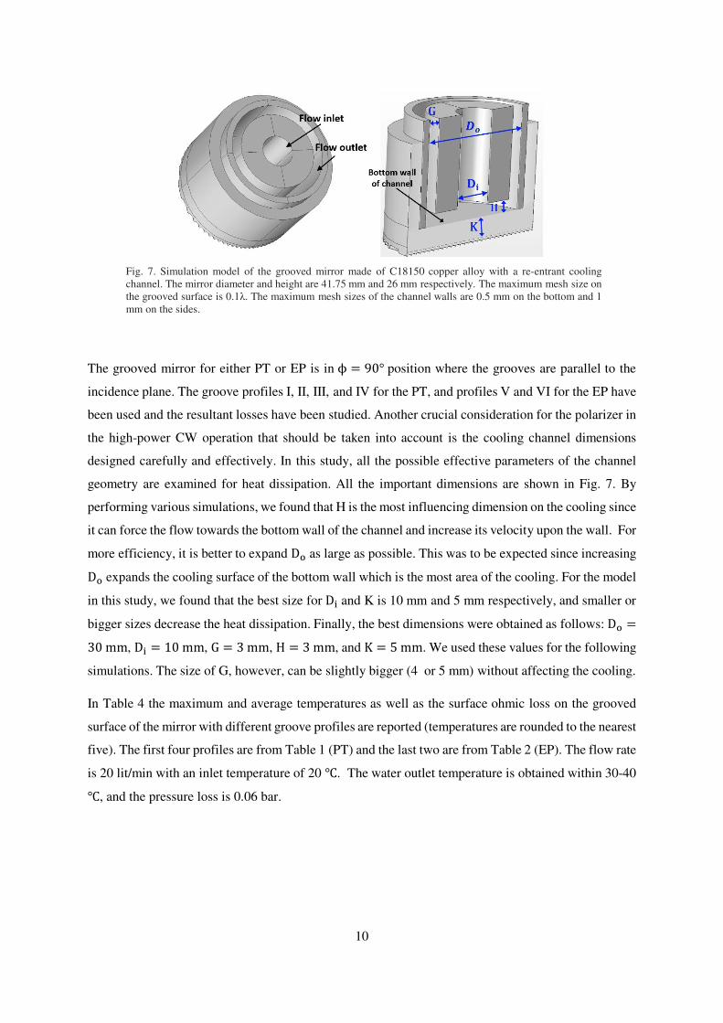
Fig. 7. Simulation model of the grooved mirror made of C18150 copper alloy with a re-entrant cooling
channel. The mirror diameter and height are 41.75 mm and 26 mm respectively. The maximum mesh size on
the grooved surface is 0.1λ. The maximum mesh sizes of the channel walls are 0.5 mm on the bottom and 1
mm on the sides.
The grooved mirror for either PT or EP is in ϕ = 90° position where the grooves are parallel to the
incidence plane. The groove profiles I, II, III, and IV for the PT, and profiles V and VI for the EP have
been used and the resultant losses have been studied. Another crucial consideration for the polarizer in
the high-power CW operation that should be taken into account is the cooling channel dimensions
designed carefully and effectively. In this study, all the possible effective parameters of the channel
geometry are examined for heat dissipation. All the important dimensions are shown in Fig. 7. By
performing various simulations, we found that H is the most influencing dimension on the cooling since
it can force the flow towards the bottom wall of the channel and increase its velocity upon the wall. For
more efficiency, it is better to expand Do as large as possible. This was to be expected since increasing Do expands the cooling surface of the bottom wall which is the most area of the cooling. For the model
in this study, we found that the best size for Di and K is 10 mm and 5 mm respectively, and smaller or
bigger sizes decrease the heat dissipation. Finally, the best dimensions were obtained as follows: Do =30 mm, Di = 10 mm, G = 3 mm, H = 3 mm, and K = 5 mm. We used these values for the following
simulations. The size of G, however, can be slightly bigger (4 or 5 mm) without affecting the cooling.
In Table 4 the maximum and average temperatures as well as the surface ohmic loss on the grooved
surface of the mirror with different groove profiles are reported (temperatures are rounded to the nearest
five). The first four profiles are from Table 1 (PT) and the last two are from Table 2 (EP). The flow rate
is 20 lit/min with an inlet temperature of 20 . The water outlet temperature is obtained within 30-40 , and the pressure loss is 0.06 bar.

11
Table 3. Ohmic loss, maximum and average temperature (in ) on the grooved
surface of polarizer mirrors with different groove profiles from Table 1 & Table 2,
radiated by 1 MW CW gaussian beam at 110 GHz
T (ave.) T (max.) Loss (%)
Profile I 325 765 1.14
Profile II 390 855 1.4
Profile III 355 850 1.26
Profile IV 325 760 1.14
Profile V (EP) 205 420 0.61
Profile VI (EP) 215 460 0.7
Table 3 shows that in the H-plane configuration, the wider grooves (w = 0.7p) produce less ohmic loss
compared to the narrower grooves (w = 0.6p) with the same other groove parameters, and consequently
experience lower temperature. The shorter groove depths can reduce the loss, and as was also expected
from the previous section, higher values of c produce a lower loss. This is why profile I produces lower
loss than profile III. As a general explanation, we can say that when the sidewall slant parameter c, is
higher, the field in the grooves can be reduced due to the outward reflection, and consequently, the
induced tangential current on the walls is smaller. A higher sidewall slant factor can also offer better
heat conduction from the corrugation ridge to the mirror interior region. It means that besides the higher
mechanical stability, the trapezoidal grooves are likely to have higher thermal tolerance than the
rectangular grooves. So, groove shapes I and IV for the PT, and V for the EP suggest very good thermal
stability in the high-power CW systems (profile I is shown in Fig. 3).
In Fig. 8 the loss and temperature distribution on the PT mirror are shown. It is noticeable that the
maximum temperature always occurs on the ridges of corrugations where the conductive heat transfer
is lower than the bottom part and therefore the loss on the rounded edges becomes higher due to the
increased resistivity. Rounding the corrugations can moderate the very high temperature on the edges
where the loss is concentrated. in Fig. 9, two cross-section contours are provided to show the mirror
interior temperature and water flow velocity. The peak velocity of flow occurs on the bottom wall of
the channel where the channel dimension H (shown in Fig. 7) plays a key role in adjusting this velocity
which affects the cooling of the wall.

12
Fig. 8. Temperature on the mirror (a), and the grooved surface ohmic loss (b).
Fig. 9. Cross-sectional view of the mirror interior temperature (a) and the flow velocity (b).
As a more investigation, the effects of dimension H and flow rate on the cooling of the mirror with
groove profile I are provided in Table 4. By increasing the flow rate from 20 lit/min to 30 lit/min, the
average cooling on the grooved surface enhances by about 17% while the cooling on the ridge of the
corrugations enhances by 10%. For H = 3 mm, the peak velocity of the 30 lit/min flow in the channel
(on the bottom wall) is near 10 m/s, and the pressure loss is still as low as 0.15 bar. For H = 4 mm, the
velocity on the channel bottom wall is lower compared to H = 3 mm, therefore, the cooling is less
efficient. The melting point of C18150 is within 1050-1100 . So the corrugations with profiles I and
IV while experiencing high temperature, are within the safe thermal limit.
Table 4. Temperature (in ) on the grooved surface of the PT with groove profile I from Table 1
20 lit/min 30 lit/min
H=3 mm 300 (ave.), 705 (max.) 250 (ave.), 630 (max.)
H=4 mm 340 (ave.), 790 (max.) 280 (ave.), 710 (max.)

13
4. Conclusion
In this study, the rounded trapezoidal grooves in the grating polarizers were designed based on the
wavelength, so they can be adapted for any frequency of high-power ECRH systems. The grooves are
studied for their output polarization, suitable for the PT and EP, using numerical simulation and vector
theory for diffraction gratings. Then we considered different groove profiles with desired polarization
for the ohmic loss analysis. The analysis is carried out for 1 MW power of CW at 110 GHz while the
incidence polarization was in the H-plane configuration and the orientation of the grooves was parallel
to the incidence plane. The main purposes of the analyses were to see how the groove width and sidewall
slant factor as well as the groove depth affect the ohmic loss and to what level the resultant temperature
on the grooved surface increases. The surface roughness on the grooved surface was assumed to be 1
µm. According to the results, to increase the safeness of a high-power CW operation, it is recommended
to consider wider grooves, with slanted sidewalls, shorter groove depths, as well as larger allowed
periodicity to significantly decrease the loss of the reflected beam on the mirrors. The mirrors had an
integrated water channel with optimum dimensions to dissipate the heat in the steady state operation.
Declarations
Ethical Approval: Not applicable.
Competing interests: The authors have no competing interests.
Authors' contributions: The manuscript is written by Jawad Taheri and reviewed by Davoud
Iraji.
Funding: There was no specific funding for this study.
Availability of data and materials: The authors confirm that the data supporting the findings
of this study are available within the article.
References
[1] T. Ii et al., "Design of polarizers for a mega-watt long-pulse millimeter-wave transmission line on the
large helical device," Review of Scientific Instruments, vol. 86, no. 2, p. 023502, 2015.
[2] J. L. Doane, "Grating polarizers in waveguide miter bends," International journal of infrared and
millimeter waves, vol. 13, no. 11, pp. 1727-1743, 1992.
[3] M. Saigusa et al., "Development of a high power wideband polarizer for electron cyclotron current drive
system in JT-60SA," Fusion Engineering and Design, vol. 96, pp. 577-582, 2015.
[4] D. Wagner, F. Leuterer, W. Kasparek, J. Stober, and A. U. Team, "Minimization of the ohmic loss of
grooved polarizer mirrors in high-power ECRH systems," Journal of infrared, millimeter, and terahertz
waves, vol. 38, no. 2, pp. 191-205, 2017.

14
[5] J. Doane, H. Grunloh, W. Martin, and W. Wu, "Polarizer miter bends for high-power microwave
transmission: Ohmic loss and cooling," Fusion Engineering and Design, vol. 102, pp. 99-107, 2016.
[6] F. Smits, "A polarizing mirror for electron cyclotron resonance heating on RTP," in Proc. EC, 1989, p.
10.
[7] K. Nagasaki, A. Isayama, and A. Ejiri, "Application of a grating polarizer to the 106.4 GHz ECH system
on Heliotron‐E," Review of scientific instruments, vol. 66, no. 6, pp. 3432-3437, 1995.
[8] Y.-L. Kok and N. C. Gallagher, "Relative phases of electromagnetic waves diffracted by a perfectly
conducting rectangular-grooved grating," JOSA A, vol. 5, no. 1, pp. 65-73, 1988.
[9] F. Zhang et al., "Study of the polarization strategy for electron cyclotron heating systems on HL-2M,"
Journal of Infrared, Millimeter, and Terahertz Waves, vol. 37, no. 6, pp. 572-581, 2016.
[10] J. Taheri and D. Iraji, "Optimum profiles of trapezoidal grooves in polarizer mirrors for high-power
ECRH systems, and the ohmic loss calculation," Fusion Engineering and Design, vol. 177, p. 113088,
2022.
[11] B. Plaum, E. Holzhauer, and C. Lechte, "Numerical calculation of reflection characteristics of grooved
surfaces with a 2D FDTD algorithm," Journal of Infrared, Millimeter, and Terahertz Waves, vol. 32, no.
4, pp. 482-495, 2011.
[12] J. Doane and C. Moeller, "HE11 mitre bends and gaps in a circular corrugated waveguide," International
Journal of Electronics, vol. 77, no. 4, pp. 489-509, 1994.
[13] E. Hammerstad and O. Jensen, "Accurate models for microstrip computer-aided design," in 1980 IEEE
MTT-S International Microwave Symposium Digest, 1980, pp. 407-409: IEEE.
[14] "Radio Frequency Module User's Guide, COMSOL Multiphysics® ", 5.5 ed: COMSOL AB.
https://doc.comsol.com/5.5/doc/com.comsol.help.rf/rf_ug_radio_frequency.07.32.html