Bend Track Manual
57
Bend Track: An “N”ovative Modular System Page: 1 of 57 Manual Table of Contents 1. Bend Track Concept 2. Advantages and Concerns 3. Standards a. Bench work b. Track work c. Wiring and Electrical 4. Curved Bench work 5. Combining Bend Track and N-Trak 6. Stilts for raising modules 7. Tips and Techniques
-
Upload
khangminh22 -
Category
Documents
-
view
5 -
download
0
Transcript of Bend Track Manual

Bend Track: An “N”ovative Modular System Page: 1 of 57
Manual
Table of Contents
1. Bend Track Concept 2. Advantages and Concerns 3. Standards
a. Bench work b. Track work c. Wiring and Electrical
4. Curved Bench work 5. Combining Bend Track and N-Trak 6. Stilts for raising modules 7. Tips and Techniques

Bend Track: An “N”ovative Modular System Page: 2 of 57
The Bend Track Concept
Introduction
We're sure that by now most model railroaders are at least somewhat familiar, if not very familiar, with the concept of modular model railroading. In case you're very new to the
hobby, allow us to briefly explain the basic concept behind modular railroading. Modular railroading is a means by which individual modelers can build a section of railroad and assemble them with other modelers units to form a complete working model railroad. If
you have ever been to a model railroad meet, chances are that you've seen this concept in action. So popular is this idea, that virtually every scale has made use of this concept, not
only for public shows but also for home or club layouts.
Bend Track is a new concept in modular model railroading. The idea was developed in 1986 after viewing an HOn3 display layout which had a single mainline that traversed a section of the layout bench work twice. Once on the front at ground zero and then across
the back side at a higher elevation in the opposite direction. It was the action of movement in both directions on the same 3 foot wide board that spawned the idea of
Bend Track.

Bend Track: An “N”ovative Modular System Page: 3 of 57
The Bend Track Concept
The Bend Track modular system is based on standard modules of varying lengths that are two feet in width at their abutting surfaces. N scale was selected as the size most
appropriate for the amount of space that would be available on the module surface.
The entire concept is based on a two sided module with a double mainline on both sides and an optional center divider which can serve as a scenery backdrop for both sides.
When a center divider is installed, it is like having two traditional modules assembled back to back with no space between the two.

Bend Track: An “N”ovative Modular System Page: 4 of 57
Balloon Module
Instead of having four corner modules to build and contend with as in other modular systems, Bend Track offers the convenience of just two modules which are referred to as
"Balloon" modules. These balloon modules provide a 180 degree turn around for the double mainlines allowing them to swing from one side of a module around to the other
side.

Bend Track: An “N”ovative Modular System Page: 5 of 57
Two Balloon Modules
For all practical purposes, the smallest and simplest Bend Track system includes just two balloon modules assembled together to form a small loop or oval setup. The train begins
on one side of a balloon, then traverses to the opposite side before traveling onto the second balloon and returning to the starting point.
Two Balloon and a Straight Module
With two balloons and some straight sections you have used the two most basic module designs to expand your layout.

Bend Track: An “N”ovative Modular System Page: 6 of 57
A Branching Layout
Unlike traditional modular systems where you usually have just straight sections and 90 degree corners making up 85% to 90% of modular layouts, Bend Track accommodates an
almost limitless variety of different shapes of modules to make up it's system. By using Bend Track modules you can quickly conjure up modular layouts with an appealing
variety of shapes. Layouts are possible with legs branching out in all directions as shown above and each "leg" can be as long, twisting, and branching as you want it to be. This

Bend Track: An “N”ovative Modular System Page: 7 of 57
has been a big advantage when setting up a display for a railroad show since you can bend the display out of the way of pillars and columns.
Straight Modules
Now that you have an idea of the concept, let's explore the Bend Track family of modules. We'll start with the basic straight module. Your "straight" module can actually be any length OR SHAPE you can think of, so in fact it need not even be "straight" at all! All
that is necessary is to have each module conform to the required joining standards. This will allow them to mate with any other Bend Track module. The Bend Track straight module differs from the traditional straight module in that it has tracks on both sides
instead of just one. When setting up a traditional module system you need to make sure that you have an equal length of modules on both sides of the setup. For example, if you
have two 6 foot modules on one side totaling 12 feet, you must maintain that 12 foot length on the opposite side with either two more 6 foot modules, three 4 foot modules or
a 4 and 8 foot module. With Bend Track that "need" is entirely eliminated. When you build a straight module to any length, its like building two modules at the same time that
will automatically total the same length.

Bend Track: An “N”ovative Modular System Page: 8 of 57
Balloon Modules
As mentioned earlier, Bend Track requires at least two balloon modules instead of the four modules required for the traditional modular setup. These balloon modules must retain the basic minimum standard radius, which we will discuss later. They can be of
any size or shape that you desire or which will fit your need. As long as the tracks return to the same 2 foot area at which they entered onto the balloon module.

Bend Track: An “N”ovative Modular System Page: 9 of 57
Curved Modules
Curved modules can be built with any amount of curvature that is desired or needed to fit a particular space or area. Traditional modular systems rely heavily on having four 90
degree corner modules in order to have a complete running layout. With Bend Track the need for corner modules does not exists. In fact, the Bend Track system has no "corner" module as such, but rather straight modules that have been bent to any desired amount of curvature or angle. The thing to remember about a curved Bend Track module is that the curve of the module is not itself necessary to make the system work. The reason to curve a Bend Track module is to create a more natural or pleasing appearance to the eye or to
better match what you want the track to be doing, such as an offset or "S" shaped module where the track follows a river or hillside.

Bend Track: An “N”ovative Modular System Page: 10 of 57
Branching Modules
Branching modules can add great variety and interest to the shape of a Bend Track layout. A "T" module is nothing more than a straight module with another 2 foot end coming off
of one of the sides where more modules can connect to, to form a branch off of the original route. Other modules can be built with the same idea in mind but in the shape of

Bend Track: An “N”ovative Modular System Page: 11 of 57
"Y"s, "+"s, "X"s, or any other arrangement you wish. One note to mention, for every branch in the layout, a balloon module must be used to cap off the branch.
Advantages and Concerns
Advantages
Advantage 1: Flexibility
With no fixed number of modules required (other than two balloons) and with countless different sizes, shapes, and configurations of modules being possible, there is an almost
limitless variety of possible permutations and combinations to layout design. In fact, each operating session or show can yield a new variation in the design of how the modules are arranged. (We've never set ours up the same way at a show twice.) Also, since you don't need to match lengths of one part of a display with lengths of other parts as in traditional modular systems, you won't have to leave out anyone's modules just because the lengths
don't work out to be equal.
Advantage 2: An Interactive Layout
The Bend Track system was created foremost with the idea that it could give a home or club layout the capacity for movement to a new or better location and second, that it
could be used for shows. With the proper use of stanchions or guard rails at shows, we've found that you can walk around the layout while keeping an eye on your train and at the same time interact with the people who are viewing the trains. From earlier experiences with traditional modular layouts, it seemed almost as if the modules acted as a barrier between the club members and the public. We were perceived as being inside a sound
proof control booth, not to be contacted unless we happened to stray outside the system.
Recalling our club's first Bend Track "show" setup, (see "A Branching Layout" diagram in the Bend Track Concept section) it seemed that the general public was more inclined
to visit with our members and ask questions about model railroading as a whole. We

Bend Track: An “N”ovative Modular System Page: 12 of 57
found our Bend Track layout to be an excellent way for our club members to reach out and interact with spectators and train enthusiasts who might be thinking of getting into
the hobby or perhaps joining a club.
Advantage 3: More Running Length in a Smaller Space
Since Bend Track does not have an operating pit, you can better make use of the space that the system occupies. Especially when using branching modules, the layout display
can place modules into locations that would normally be left vacant with nothing for the club members to run on or the public to see. More modules can be used in the same
square footage, meaning more mainline to run on and more trains running at once. This has allowed us not to have "running time" problems from lack of usable space in a given
area.
Advantage 4: Minimal Startup Expense
Bend Track offers the possibility of using just two minimum balloon modules to be able to have an operating layout. The lesser amount of modules will reduce the cost of
construction, so you might say that you get two for the price of one. For instance, a member who builds two balloon modules would accomplish the same end result as if they
had built four traditional 90 degree corner modules, but with one half the time and expense. This minimal amount of modules to start a small system would fit nicely with a
club who's membership is small but wishes to have a larger layout in the future.

Bend Track: An “N”ovative Modular System Page: 13 of 57
Concerns
Concern 1: No Operating Pit
The fact that the Bend Track system, in comparison with traditional modular layouts, has no enclosed operating pit might bring up the concern for adequate security during shows and ease of movement between different parts of the layout. Bend Track addresses these
issues by recommending that the layout be constructed with a working height in the neighborhood of 50 inches, rather than the 36 or 40 inch heights that are prevalent in
more traditional layouts. The use of an increased height results in not only the ability to move under the modules with ease, but also provides a much more realistic viewing angle for both operators and spectators. We have also found this height to be more comfortable in terms of working on scenery and rolling stock. As far as security goes, we have found that with shelving (which rests on the module leg cross pieces) and skirting (on each side of a module covering this shelving) there is ample room to store boxes and other rift raft
out of view of the public. Naturally, stanchions and rope around the layout provide protection from young arms and hands that may want to touch the trains.
Concern 2: Tighter Turning Radius
While Bend Track does have a tighter minimum track radius (14-1/2") than usually affiliated with other modular systems, this does not mean that all of your curved track must stay at this minimum. Curves can be as broad as you wish and branch lines that
curve off the two mainlines can be as tight as you find practical for the use of your branch line. On the original three modules that we built, the two balloons were built with the minimum radius allowed (a 29" diameter). We have consistently run trains with four
locomotives and 65 to 70 cars with minimal problems. We've found that for the most part the problems have been wheel or car related, rather than track radius related. An
occasional oblong or egg shaped wheel might be the culprit, or an old problem, a car with little or no weight or top heavy car was put in consist at the head of a long heavy train and would be more likely to tip over than if it was placed near the rear half where the
drag was reduced.

Bend Track: An “N”ovative Modular System Page: 14 of 57
Bench Work Standards Now we get into the nitty gritty of Bend Track. This is what sets the
system apart from all others. We'll discuss the construction of the modules which includes the bench work and legs, brands of track and turnouts, mainline placement, mainline radius, scenery track, and the electrical wiring.
Module Surface
Module frames should be made from nominal 1 x 4 pine lumber or plywood (the actual size of the board is 3/4" x 3 1/2"), #2 grade or better. For added strength, one might want to use a piece of hardwood such as oak in the frame on the module ends where they'll be clamped together. The hardwood will hold up better against the pressure of the clamps.
1/2" plywood is suggested to be secured to the top of the framework. Therefore the overall height would be a minimum standard of 4". While 1/2" plywood is recommended for rigidity, homosote, suspended ceiling tile, or rigid insulation foam can also be used to
reduce the weight of the module. If such material is used for the top, the framework should then be made more sturdy and the lightweight top material should sit down into
the frame so the soft edge will not be exposed to damage. Veneer plywood has also been successfully used for the framework. However, we recommend not using plywood that is
less than 1/2" thick (5 ply veneer).
Using this standard 4" height will allow all modules to fit against one another neatly. If however, you wish to build a module with a scenery profile that is NOT totally flat across
the end, you may of course do this, but you will have to allow a space under the mainlines in the bench work where C-clamps can go to attach to the next module. 2" to 3
1/2" C-clamps are required to connect and hold the modules together. Generally, 24" should be the standard width at the module end where it fits to the next module, although you may build modules with any width above this that you desire. This would provide as

Bend Track: An “N”ovative Modular System Page: 15 of 57
much extra room as needed for any purpose the modeler desires. Remember when designing your modules, that they will have to fit in your car, truck, or van for hauling
purposes.
Module Legs
Legs should be built to a length which allows the modules to adjust to a standard rail height of 50" on uneven floors. However, you may choose any height which fits your
needs. This height (50") was selected to give a more realistic vantage point for viewing the modules and has received quite a few compliments from the viewing public, some
people saying that they felt they became much more a part of the scene. We have found that legs built in an "L" shaped configuration made from 3/4" lumber seem to work best. See FIG #2. The "L" shape eliminates the warping effect that is a problem with legs that have been made by ripping a 2 x 4 in half. A block of hard wood cut to a size of 2 1/2"
long x 1 1/4" square with a hole drilled clear through the length will allow a carriage bolt to thread through for leveling. This block should then be glued and nailed flush with the bottom of the leg. Be careful not to drive a nail through the hole in the hardwood block.
A "T" nut with no less than a 1/4 x 20 thread (5/16" x 20 preferred) and no less than 9/16" threaded shaft should be driven into the hole.
If you prefer, a threaded brass insert may be used instead. 1/4 x 20 threaded carriage bolts with a length of 3" to 4" screwed into the bottom of the legs with 1 1/2" exposed will serve as the levelers for the module. We recommend not using a carriage bolt smaller

Bend Track: An “N”ovative Modular System Page: 16 of 57
than 1/4" diameter because it can bend if the modules are slid around a lot. Larger carriage bolts and "T" nuts such as 5/16" or 3/8" diameter will endure better in the long
run. Also the 5/16" and larger "T" nuts usually have holes for screws to hold them in place so they can't work loose. The 1/4" "T" nuts have only small spikes to hold them in
and can work loose over time, as has happened to our group several times.
Now take the two legs and glue and screw lateral bracing members (made of strips of solid wood or plywood) up from the bottom a distance of 6" and 36" (for modules with a 50" rail height). This will create a "paired leg" that can not wobble from side to side. See FIG. #3a. Do not attach the paired legs directly to the module end. The head of the bolt
used to attach the legs will protrude on the outer surface of the end and will not allow the modules to clamp together tightly. This will produce a gap that can not be easily spanned.
Instead, these paired legs will eventually bolt to "spandrels" within the module bench work. See FIG. #4.
If you plan to use 1/2" electrical wiring conduit to make the diagonal leg bracing as described below, you may want to raise the lower lateral brace somewhat. This will allow
you to use broom handle retaining clips (also called "C" clips or tension clips) on the lateral bracing to hold the diagonal bracing when the modules are transported. See FIG.
#3b. Broom handle retaining clips are available from most any hardware store.
Then simply clamp the two "paired leg" assemblies to the spandrels and drill a hole for a bolted connection. If 1/4" diameter bolts are to be used, be sure to use a 17/64" drill bit to

Bend Track: An “N”ovative Modular System Page: 17 of 57
make a hole that the bolts will slip through easily. One bolt at the top of each leg will be enough to secure the paired legs to the bench work.

Bend Track: An “N”ovative Modular System Page: 18 of 57
Module Braces
Now you produce and assemble diagonal braces from the legs to the bench work or from legs to legs. This final bracing will prevent the module from wobbling end to end (see
FIG. #6). This we have accomplished with the simple process of using 1/2" ID thin walled electrical conduit which can be acquired from your local hardware store or
commercial electrical warehouse. The price is about $1.50 per 10 foot length. For most modules, one 10' piece will be sufficient for all the braces needed. Cutting the conduit
into 4 equal lengths of 30" long and flattening about 4" of both ends of each piece creates a strong but lightweight brace (see FIG. #5).

Bend Track: An “N”ovative Modular System Page: 19 of 57
If a short module (about 4' or less) is to be built, then you may want to smash a 4' length in the middle of each piece and drill another hole so you can bolt the two pieces together
to form an "X" brace.

Bend Track: An “N”ovative Modular System Page: 20 of 57
Now bolt the conduit braces to the bench work and/or legs. Set the modules up and clamp the units together. You'll find that the more bends and branches you add to a layout the
more stable the layout will become, to say nothing of the greater appeal to the eye!

Bend Track: An “N”ovative Modular System Page: 21 of 57
Track Work Standards
Mainline Specifications
Track code
Both mainlines are required to use Flex or sectional Atlas, Peco, Shinohara, or Micro Engineering track, either (nominal) code 80, 70 or 55 rail. All of which are available through your local hobby dealer. All have been proven to work reliably in the past. Neither of the two mainlines shall be hand laid track, thus reducing the chance of
variation in the gauge and assuring more reliable operation for everyone in a group setup.
If you wish to use code 55 flex track, you will need to use a small stretch of Atlas sectional track approximately 1" to 2" in length at the ends of each mainline. Don't use a
piece of flex track for this as the rails will be loose. Sectional track will keep the rails held securely in place and in gauge even if it is only 1" to 2" long, 2" being recommended.
This short piece of Atlas track is needed because code 55 track is thinner overall and won't join properly with the connector tracks which are Atlas 5" straight sectional track (code 80). The use of this section will allow the joiner track between modules to mate
with track that has the exact same profile. By using cardboard shims to gradually raise the code 55 track, the rail heads can be made flush with that of the Atlas section at the ends
of each mainline. Also, Micro Engineering and Atlas will not join directly with a rail joiner without a noticeable mismatch in the elevation of the top of the railhead. This is
separate from, but in addition to, the tie thickness difference. Also refer to the "Tips and Techniques" page for joining code 55 to code 80 rails

Bend Track: An “N”ovative Modular System Page: 22 of 57
Mainline Placement
Position of the tracks is as follows: Mainline #1 is the main farther from the center of the bench work and Mainline #2 is the main closer to the center of the bench work. To
position the mains at each end you first find the center of the 2 foot wide module (if the module is built to the minimum 2 foot width) and measure out both directions 8 1/2" to the center line of main two and 10" out to the center of main one. This should leave 2" from the center of main one to the front edge of the module. If the end of the module is built wider than the 2 foot minimum, the common centerline does not need to be placed at the center of the wider module. It may be shifted to one side or the other as long as there is al least 2" between the edge of the bench work and the center of mainline #1.

Bend Track: An “N”ovative Modular System Page: 23 of 57
PLEASE RESIST THE TEMPTATION to measure 2" and 3 1/2" in from the outside edge of the module to locate the track centerlines. We have found the chance for error in
alignment of mainlines from one module to another is GREATLY REDUCED by measuring out from the centerline of the module. This is because the centerline, as a
common point to align all mainlines from, prevents slight module width variations from becoming mainline alignment errors. One module's centerline will match another
module's centerline even if the width of the two modules varies slightly. If this seems to be making a mountain out of a mole hill, please realize that you can't slide a module
sideways to improve track alignment on one side without creating a misalignment on the other side if the mainlines were not located properly to begin with. Just a little care in the track laying stage will prevent any significant shimmy as a train crosses from one module
to the next.
Mainline Clearance
The 1 1/2" of space between the two mainlines may be widened within the confines of the module to accommodate more track such as a yard or other scenery, but should not go below this minimum in order to insure proper clearance between equipment anywhere on
the system.
If tunnels, bridges or any structures extending over the mainline are to be used, make sure that there is easy access in order to retrieve any derailment which might occur. There
should be sufficient clearance for high or wide equipment such as double stack containers, long 90 foot "flats", 85 foot "hi-cubes" and passenger cars. Please note that double stack container cars are taller than passenger cars, hi-cube box cars and TOFC's (trailer on flat cars), and will need more height clearance than what is normally considered adequate,
keep this in mind if you have any members who model the modern era.
Joiner Track
The track starts 2-7/16" in from the end of the module to allow for an Atlas 5 " straight section as a joiner track between modules. An Atlas 5" straight section is actually a little less than 5" long. This is why your mainlines should come a little closer to the end of the
module than 2-1/2". That is why we have specified 2-7/16" from the end. After

Bend Track: An “N”ovative Modular System Page: 24 of 57
positioning the mainlines, nail in place at least 2" of straight track before any curvature of track begins. This will allow the track to remain straight, without a kink, when the joiner
tracks are installed between modules. See FIG. #8. Extra track nails used in additional holes that you can drill in the ties are a big help in keeping the 2" minimum straight track
in alignment if you use flex track all the way to the end. The best method though, is to use a short piece of rigid sectional track before the start of the use of flex track. Also
refer to the "Tips and Techniques" page for the tip on "break away tracks"

Bend Track: An “N”ovative Modular System Page: 25 of 57
Mainline Radius
Track radius of mainline one or two shall not be less than 14 1/2" anywhere. Note that for outside curves the minimum radius for Main #1 is 16", and Main #2 is 14 1/2" to keep 1 1/2" track centers. For inside curves, Main #2 is now 16" and Main #1 is 14 1/2" to keep
1 1/2" track centers. See FIG. #8
Cork Roadbed
The use of cork roadbed is recommended, starting the roadbed at the end of the module and continuing across to the other end so that the roadbed stretches clear across the entire
module. We have found that gluing at least the first 3" helps it stand up better to the increased ware and tear it will get from being at the end of the module.
Grades
Mainlines shall remain flat and level with no grades. No restrictions on any other tracks. If other tracks cross the mains, crossings should be level and true to the mainlines.
Turnouts
All turnouts that are a part of the mainlines or are used to diverge away from the mainlines shall be only Peco, Shinohara, Micro Engineering, or post 1994 Atlas Standard

Bend Track: An “N”ovative Modular System Page: 26 of 57
Line or Custom Line turnouts. The diverging route of the turnout should be a nominal #5, #6, or #8 for good rolling stock performance. Note: If a Peco #4 ("sharp") turnout is to be used on the mainline, then only the straight leg is to be on the mainline. Don't use the #4 Peco for crossovers between mainlines. The curved leg, being approximately 8" radius, is too tight to accept some equipment. All these turnouts are usually readily available. Peco, Micro Engineering, and Atlas Standard Line (with manual or powered switch machine)
have points which snap and hold in place, thus reducing the chance of wheels picking the points and derailing. Shinohara and Atlas Custom Line (no switch machine) require the
use of a ground throw or some kind of underground switch machine. Peco seem to be the preferred turnouts for most modular systems in N or HO that we have seen.
Crossings on Mainlines (Diamonds)
Atlas, Peco, or Shinohara crossings may be used. No hand laid Crossings.
Crossovers
Crossovers are not required on the mainlines, but we urge you to include at least one on one side of your module for future operational uses. Crossovers can use either a #8
(large), a #6 or #5 (medium), or a #6 Wye turnout (all are standard sizes in Peco brand), or equivalent sizes in the other brands. Do not use turnouts sharper than a #5 for
crossovers as they may not handle all equipment. After the track has left either main you can use any size radius or brand of turnout that you wish. Turnouts and crossovers on
mainlines may be powered if you desire, but are not required.
Scenery Track
Scenery tracks are defined as any track other than the mainlines, such as industrial spurs or yards.
Track Code
Scenery tracks may have any type of commercial track that is available. They may also be hand laid, if so inclined.

Bend Track: An “N”ovative Modular System Page: 27 of 57
Radius
There are no radius restrictions on scenery tracks.
Grades
There are no grade restrictions on scenery tracks.
Turnouts
Turnouts used on scenery tracks can be any type of commercial turnout that is available. Scenery track turnouts may also be hand laid, and may have any radius or size.
Wiring and Electrical Standards Wiring Specifications
Wire Sizes
As with N-Trak, Bend Track uses no smaller than 18 gauge lamp cord for mainline power and no smaller than 16 gauge lamp cord for the 12 volt white power line. Since the
modules are double sided, you will have six cords running across the underside of the module. At the ends of these cords, Bend Track uses the same two pin Cinch-Jones plugs
that N-Trak specifies. For the feeder wires, use 22 to 24 gauge solid core wire to tap power from the orange/blue mainline cords to the rails. See FIG #10a. Bend Track also uses the same method for observing the polarity of both mainline and white line cords. The ribbed wire is connected to the wide pin of the Cinch-Jones plug and to the
front rail of each mainline. 12 volts is carried by the wide pin of the Cinch-Jones plug and the ribbed wire and ground is carried by the small pin and smooth wire of the white
cord.
Wire Plug Color Minimum gauge
Mainline 1 Orange 18 Gauge
Mainline 2 Blue 18 Gauge
Centerline White 16 Gauge

Bend Track: An “N”ovative Modular System Page: 28 of 57
Position of Wires and Plugs
The orange/blue cables should approximately follow under the appropriate mainlines, much the same as they do on any N-Trak module. Since the Bend Track module is like having two N-Trak modules which are connected back to back, you will have six wires
hanging down on each end of the module instead of N-Trak's 4 wires. Refer to FIG. #10b.

Bend Track: An “N”ovative Modular System Page: 29 of 57
NOTE: The front rail should be soldered to the ribbed side of the lamp
cord which is then soldered to the wide pin of the CINCH JONES plug. Repeat this process for all mainline connector
plugs.

Bend Track: An “N”ovative Modular System Page: 30 of 57
If possible, at the ends of the module, the orange/blue cords should remain close to the outside edges under the appropriate mains. The white cords should remain close to the
center. This will keep them in line when the modules are clamped together and keep the white 12 volt lines away from the mainlines to reduce the chance of 12 volts getting
plugged into a mainline. Be sure to leave at least 6" of cord below the bench work on both ends. This will allow an adequate amount of cord to plug into the next module.
Referring to figures 9, 10, 11, and 12, note that an easy way to remember where the male and female Cinch-Jones plugs go is to notice that as you view a Bend Track module from the side (not from an end), the right hand end always has the male plug and the left hand end always has the female plug. A "T" module has three sides but the "right hand rule" still applies as you look at each side by itself. The right hand rule for the gender of the
Cinch-Jones plugs guarantees that any module can be rotated any way and still connect to other modules that have not been rotated.
Balloon Wiring

Bend Track: An “N”ovative Modular System Page: 31 of 57
Balloons have a small change to the required wiring. Since they only have one end to connect, they need less cords than a standard end. The only cords needed are the
orange/blue cords to feed the mains. The white cords are optional on balloon modules. This is because the white male/female Cinch-Jones plugs at the outer end of the last non-
balloon module of the branch can be plugged into each other to make the continuous connection for the white line. At this point the purpose of the white cords should be
mentioned. They serve the same purpose for Bend Track as they do in N-Trak in that they provide a 12 volt power supply which we can tap off of for use on mainline throttles, yard or local cabs or anything that needs 12 volts of power such as lights, signals, etc. A DPST (double pole, single throw) or DPDT (double pole, double throw) switch or some kind of disconnection must be included for BOTH CONDUCTORS of the white line if you are using power from it for your module so that if problems arise, the switch can be shut off
to isolate the problem from the rest of the white line. A properly sized fuse is also a must!
If thought of properly, Bend Track wiring is identical in concept to that of N-Trak with the exception of one less mainline and the use of different color codes

Bend Track: An “N”ovative Modular System Page: 32 of 57

Bend Track: An “N”ovative Modular System Page: 33 of 57
Curved Bench Work From: Allen Heimsoth
One Method to Create Curved Bench Work
Curved bench work is easier than it appears, honest!
Before I get started, I'd like to clear up a couple of misconceptions about curving the bench work.
1. You do not need to steam the wood 2. You do not soak the wood in vinegar for several days!
In fact you do not need any fancy or expensive tools. More than likely, if you own any woodworking power tools you'll have the new you'll need.
You'll need a circular saw or table saw, electric power drill with a screwdriver bit, "C" clamps, a belt sander or orbital sander or sanding block, glue, and a little time. If you
have a radial arm saw or table saw, the repetitive cuts will be a little simpler. Better yet if you know a finish carpenter or cabinet maker you'll have this project in the bag!
The main framework can be constructed from 1 x 4 lumber of 1/2" to 3/4" plywood as mentioned before. The curved section of the framework is made from multiple layers of
1/8" masonite (hardboard) which are cut to fit the area and glued and clamped to the existing framework. Each layer has to be glued and clamped individually and left to dry
thoroughly before adding another layer of masonite. After all the layers of masonite have been glued in place, several screws can be driven and countersunk for added protection.

Bend Track: An “N”ovative Modular System Page: 34 of 57
Lets start with the basic balloon module. Figure "A" shows a balloon that has all 90 and 45 degree corners.
Figure "B" shows the same balloon with two corners made with rounded framework.
Figure "C" shows how the basic frame is made from 90 and 45 degree joints and nothing more than three rectangular frameworks attached to one another with two spandrels and
two 45 degree fill pieces.
Figure "D" has the layers of masonite added to round off the corners.
Figure "E" shows a detailed view of the main framework and how the masonite is attached. You will need to add a piece of 1/2" wood to the outside of the framework
(called a scab) to match the thickness of the layers of masonite (4 layers). Most of the Bend Track modules that our group uses are made from good interior grade plywood for the main framework, so four layers of 1/8" masonite will equal the thickness of the 1/2"
plywood.

Bend Track: An “N”ovative Modular System Page: 35 of 57
You will need to rough cut the pieces of masonite a little longer than needed and then cut and fit them until they fit the radius that you desire. Once the first piece fits you will need to glue and clamp it until it dries. (NOTE: Use the YELLOW Carpenter's glue, it dries a
little faster and is a LOT stronger than Elmer's white glue).
After the first layer of masonite has dried THOROUGHLY, apply a second layer over the first one, applying a generous amount of glue so that you cover the entire surface of the
first piece. Then apply the "C" clamps along the entire curve. Wipe off any excess amount of glue that drips out with a ran dampened with warm water. The more glue you wipe off now means the less you may have to try and sand off later, which will save your
sanding belts.
Now just repeat the previous process until you match the thickness of the plywood scab. After the final piece has been applies, you may wish to run a couple of screws through the layers of masonite and into the framework. Now use a wood putty such as ROCK
HARD and fill any holes or uneven joints and sand smooth.
With this simple procedure you can build all kinds of curved bench work and make all kinds of interestingly shaped modules, even to the point of having NO straight portions of framework ANYWHERE AT ALL on the module outline! (except of course for the ends
to clamp to the next module).

Bend Track: An “N”ovative Modular System Page: 36 of 57
Figure "E" shows how to make two types of curved bench work. The top picture shows how to put in a 90 degree turn while the bottom shows an offset in a "straight" section.
Follow the same steps as above and you should end up with the same results. Then just let your imagination run wild and have fun.

Bend Track: An “N”ovative Modular System Page: 37 of 57
Combining Bend Track and N-Trak
Adaptor Modules
In this part of the manual we'll be taking a look at what we call "Adapter" or "Conversion" modules. With the use of these adapter modules the flexibility of both Bend
Track and N-Trak is increased above either system's flexibility by itself. As the name suggests these special modules will allow the use of both systems in the same layout. For example, this would permit a club who has an N-Trak system in use and who would be reluctant to pick up and start over, to simply decide on one or more of these conversion
modules. Therefore, with a little bit of construction and wiring, they would have increased the options to the members in the variety of modules that could be built. The biggest benefit of doing this is that the two systems each have certain strengths which
compliment each other very nicely.
As this chapter is being written, we have a total of three different types of adapters of which the third is currently in use with splendid results, the first (in the "corner version")
is being constructed, and the second is awaiting construction. Each type has it's own intended purpose although there are some functional similarities between the first two.
N-Trak to Bend Track Adaptor
The first type of adapter is ideally suited to a club who has an existing N-Trak system and would like to add Bend Track to it. It is similar to a Bend Track "T" in that the shank of the "T" ends with Bend Track standards but now the two wings of the "T" end with N-Trak standards. N-Trak mainlines 1 and 2 swing from the wings to the shank to become Bend Track mainlines 1 and 2. N-Trak's branch line (track 3) runs across from one wing to the other without diverting to the shank of the "T". Obviously this design requires all
trains on mainlines 1 and 2 to travel all of both types of modules. If desired, various arrangements of crossovers, diamonds, and sidings can allow all trains to remain on the N-Trak sections of the layout. Block controls may be needed to permit the crossing over
of the trains through these cutoffs depending on the particular arrangement. See FIG. #13,14.

Bend Track: An “N”ovative Modular System Page: 38 of 57

Bend Track: An “N”ovative Modular System Page: 39 of 57
The wiring for this adapter is very straight forward. Even though the module has connection points for two different sets of standards, the basic electrical conventions of the two systems are very similar. Just follow the appropriate wiring specifications that
each system (Bend Track or N-Trak) uses and apply them to the appropriate ends of the adapters. You'll notice in figure #15 that the zip cords feeding mainlines 1 and 2 will each
wind up having two differing color codes on the Cinch-Jones plugs. This happens because Bend Track uses different colors to identify it's mainlines 1 and 2 than what N-
Trak uses. Also take note of the gender of the plugs. Again, following the wiring specifications of the appropriate standard for each of the three ends of the module will
ensure the proper plugs are located correctly.

Bend Track: An “N”ovative Modular System Page: 40 of 57
The length between the N-Trak ends would most conveniently be built to 6 or 8 feet to work most easily in an N-Trak layout, again referring to FIG. #13. The shortest possible
length for this adapter would be 4 feet 10 inches if the minimum radius and other standards of Bend Track were used and no diamonds were used for bypassing trains. This
would require a "Bridge" module of equal length to be used on the opposite side of the layout to keep everything in balance since 4 feet 10 inches is not a standard length in N-
Trak. Main 2 could use medium turnouts to allow it to bypass the Bend Track section and still fit in the 4 foot 10 inch length. See FIG. #16

Bend Track: An “N”ovative Modular System Page: 41 of 57
One last point to mention about this adapter is that it could also be built to replace an N-Trak outside corner module instead of a straight. This is the "corner version" adapter
referred to at the start of the adapter section. In this case the shank and one wing of the "T" are made to N-Trak standards while the remaining wing is made to Bend Track
standards. See FIG #17. The wiring would follow the same principle of using each end's color codes and plug gender arrangement for the type of module that is to connect to it.
As pictured in FIG. #17, the adapter replaces a standard 4 foot N-Trak corner module but the same basic design could also replace the smaller 3 foot standard corner. If so, the
outline of the module will be shaped not straight like FIG #17, but like an N-Trak corner module superimposed on a Bend Track "offset straight" module (shown in the 'Branching
Layout' diagram in the 'Bend Track Concept' section). This is how the "under construction, corner version" adapter is being built, utilizing curved bench work to blend
the outline of the module between the three non-aligned ends.

Bend Track: An “N”ovative Modular System Page: 42 of 57
The Hybrid Balloon Adapter
The second type of adapter allows a portion of an N-Trak layout to be used as a replacement for a Bend Track balloon module. It is more involved to build because it
consists of at least three separate pieces. See FIG #18.
We'll call the center piece the "Wye" and the other two the "Wings". The two free ends of the Wings have the tracks and wiring installed to N-Trak standards while the free end of the Wye has it's tracks and wiring installed to Bend Track standards. The space between the ends of the Wings is such that two standard N-Trak four foot corners can complete
the loops of track and therefore the balloon. This gives you an "operating pit" inside the balloon of four foot by slightly more than four foot, enough room for up to two people to
stand if they aren't too sturdily constructed. Any number of N-Trak modules could be used, even extra outside and inside corners forming an "L" shaped balloon. If there is
enough room for the people operating the modules that form the pit plus a couple extra, the pit could serve as a place from which the entire layout could be run. Track can be laid on this adapter so that the N-Trak branch line forms either a continuous loop around the balloon or a long siding for mainline 2, or both if crossovers are used from main 2 to the
branch line. See FIG. #18.

Bend Track: An “N”ovative Modular System Page: 43 of 57
Now let's back up a bit. In describing this adapter it was mentioned that it consists of at least three pieces, so that means it could be made up of more than that. Let's say that you
wanted the pet to be wider than the four feet it would be when two standard corners complete the balloon. You could do this by putting a four foot straight N-Trak module between the two corners and thereby increase the pit to eight feet in width. But now the free ends of the Wings of the adapter don't line up with the rest of the N-Trak modules
forming the balloon. The easiest way to overcome this is to use a pair of bridge modules that will spread the Wings farther apart. They don't need their own legs as they can be
clamped to the other sections of the adapter. It would be economical to make these bridges 12 inches deep front to back instead of just deep enough to hold the two or three tracks that cross them. The reason why will be clear shortly. The length of the bridges
needs to be 5 feet 7 and 7/8 inches. This length, when inserted between the Wye and the Wings of the adapter, will increase the spread of the free ends of the Wings by exactly
four feet. See FIG. #19.
Bend Track: An “N”ovative Modular System Page: 44 of 57
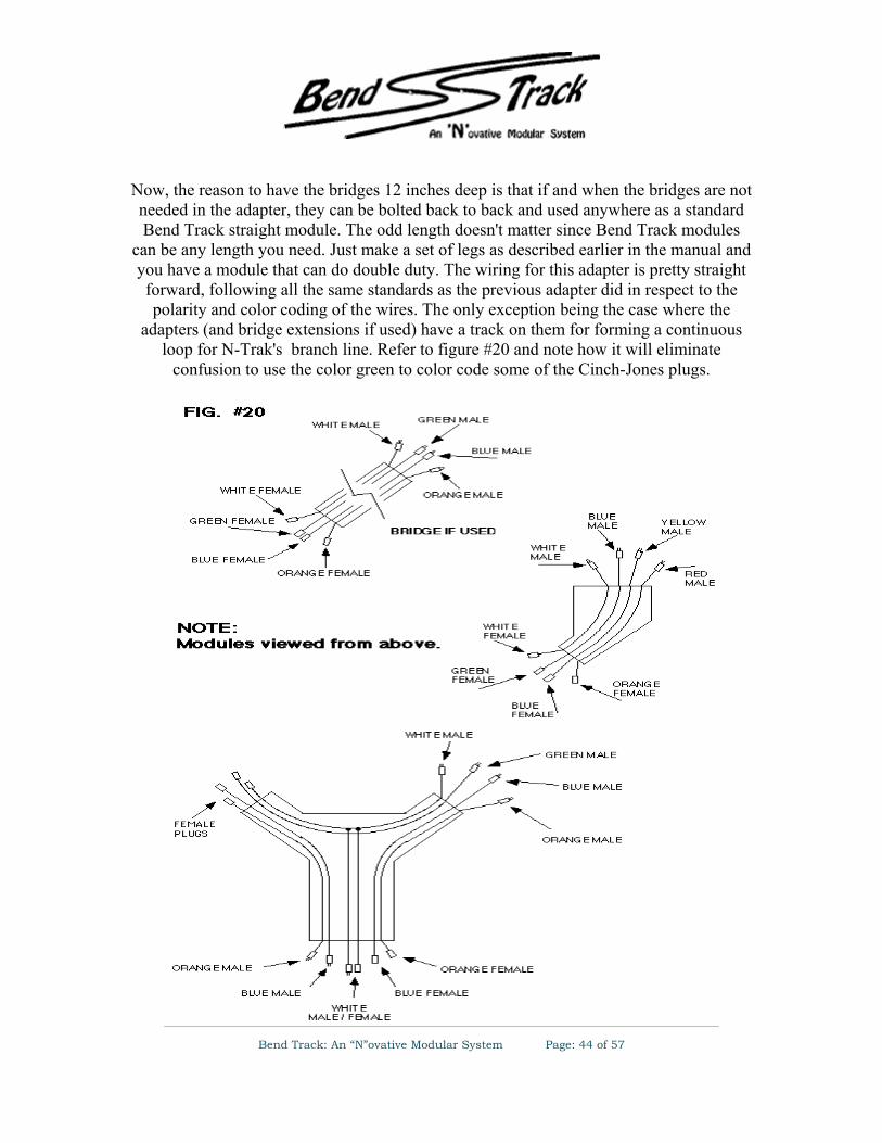
Now, the reason to have the bridges 12 inches deep is that if and when the bridges are not needed in the adapter, they can be bolted back to back and used anywhere as a standard Bend Track straight module. The odd length doesn't matter since Bend Track modules
can be any length you need. Just make a set of legs as described earlier in the manual and you have a module that can do double duty. The wiring for this adapter is pretty straight forward, following all the same standards as the previous adapter did in respect to the polarity and color coding of the wires. The only exception being the case where the
adapters (and bridge extensions if used) have a track on them for forming a continuous loop for N-Trak's branch line. Refer to figure #20 and note how it will eliminate
confusion to use the color green to color code some of the Cinch-Jones plugs.

Bend Track: An “N”ovative Modular System Page: 45 of 57
This will prevent the accidental connection of Bend Track mainline 2 with N-Trak mainline 3 (branch line) at the interface of an adapter Wing and adapter Wye or at the interface of either end of a bridge section and the Wings and Wye. If green is not used,
blue might get used instead since blue is the color code normally used for N-Trak's branch line and the track on the adapter is, after all, there for N-Trak's branch line. But if
blue were to be used, there could be confusion when plugging in the wiring under the modules. Bend Track main 2 is also blue and could get mixed up with the through track
for N-Trak's branch line.

Bend Track: An “N”ovative Modular System Page: 46 of 57
Bend Track to N-Trak Adaptor
The third adapter is well suited to a club who has mostly Bend Track modules but would also like to include N-Trak in the layout. It consists of a "T" and a balloon module. They
are designed so that any number of N-Trak modules can be connected between them. This adapter can't provide for a separate continuous run on N-Trak's branch line but does
allow it to be used as a large switching lead for industries on the modules or as a large passing siding for Bend Track's mainline 1. The "T" has the two wings laid to Bend
Track standards and the shank to N-Trak standards. The balloon has it's connecting end laid to N-Trak standards. Straights, outside corners, and inside corners can be connected between the N-Trak interfaces of the two adapter modules. You'll see in figure #21 that mainline 1 and 2 of the N-Trak modules are being used as an extension of Bend Track's
mainline 1.

Bend Track: An “N”ovative Modular System Page: 47 of 57
Also take note that on the short pieces of what would be N-Trak's branch line on the two adapter modules, there need to be insulators on both rails of the track before this branch
line track merges with the mainline track. See FIG #22 & #23.
This will allow the branch line track of all the N-Trak modules between the "T" and balloon to be kept electrically isolated from Bend Track's mainline 1. This way whole
trains on main 1 can pass each other and local switch engines can run on the branch line without having to use mainline power. This adapter is the only one of the three that has some modifications to the standard wiring practices of either Bend Track or N-Trak. If
you start at point A in figure #22 and move up and around in the diagram until you come to point B, you will see that the rail considered to be the "front" rail in an N-Trak module
becomes the "rear" rail in a Bend Track module. This is a problem because the wiring specifications of both modular systems require that the "front" rail of the track be
connected to the wide pin of the Cinch-Jones plugs. If the plugs at the N-Trak end of the "T" are wired the way it would at first seem they should be, with the front rail connected
to the wide pin, there will be a direct short from the front rail to the rear rail on Bend Track main 1 when an N-Trak module is plugged in. The same thing would happen when the adapter balloon is plugged in. The solution to this is to flip the polarity of the Cinch-Jones plugs for the yellow and blue plugs of the "T" and balloon which means the ribbed
wire of the zip cords connect to the narrow pin instead of the wide pin. This allows a standard N-Trak module (or modules) to operate with the yellow and blue track's polarity reversed with no short circuits. Figure #23 shows how the wiring on the "T" and balloon
is done.

Bend Track: An “N”ovative Modular System Page: 48 of 57
This finishes the section on the adapter modules, however they shouldn't be considered the only way to combine the two systems. Be creative and build whatever it is you need to, to accomplish whatever it is you want to do. If you have a system other than Bend
Track or N-Trak, use these adapter ideas as inspiration for creating a way to connect any type of system to any other!

Bend Track: An “N”ovative Modular System Page: 49 of 57
Tips and Techniques :
Stilts for Raising Modules Since the Bend Track standard design calls for a height of 50" and most of the traditional modules are a standard height of 40", there needs to be a way to match the two systems
when they are being interconnected. We've toyed with numerous options, most proved to be too outrageous or costly. What we finally came up with seems to be the easiest,
cheapest, and most practical solution. Actually, this method could be used anytime the height of two module systems are not equal and you want to use them together, not just
for raising N-Trak 40" modules to Bend Track's 50".
Since there is a 10" difference in the height, we have taken a 2 x 2 and cut it to 1 1/4" x 1 1/4" x 10", drilled a 4" deep hole in one end and inserted a "T" nut so the existing
carriage bolt from the shorter leg can be inserted for leveling. Then cut two pieces of 3/4" lumber, one at 2" wide x 16" long, the other at 1 1/4" wide x 16" long. Glue and screw
these two pieces to two adjoining edges of the 2 x 2 x 10, careful not to drive a screw so that it enters the hole where it will interfere with the carriage bolt. Repeat this process
until you have enough stilts for every leg. Now you have the option of clamping or bolting the stilts to your legs. For temporary uses, clamping would work just fine but if you plan on using them more than a few times I'd suggest going to the extra trouble of
buying a few bolts, washers, and wing nuts and bolt them to your legs if you don't mind having two extra cross-holes in your legs. The nuts and bolts would be cheaper than
buying four or more "C" clamps. If and when the need arises to lower your modules, just remove the stilts, unthread the carriage bolts from the stilts, and reinsert the bolts into
your original legs and you're ready for your next setup.
The total cost is somewhere around $5.00 (per four-legged module) for the hardware to bolt the stilts on with, which is a lot cheaper and easier than building all new legs for
each module that you want to raise.

Bend Track: An “N”ovative Modular System Page: 50 of 57
A Simple Solution for Using ME Flex Track
From: Damian Kostron
Atlas and many other brands of code 80 track has the unfortunate characteristic of appearing toy-like on close inspection. Micro Engineering Code 55 track is more realistic track but because of the joiner track standards, needs to be connected in some manner to a short length of Atlas code 80. One easy and fairly robust method of doing this is to use a rail joiner as a small shelf to solder the Micro Engineering flex track on to. Attach the rail joiner as you usually do to the section of Atlas track. Leave about half the joiner extended beyond the end of the track rails. Rest the Micro Engineering track on top of the extended rail joiner, butted up against the end of the Atlas rail. Then solder the lower part of the ME rail to the rail joiner. Simple as that.
The rail joiner acts as a small shelf that increases the surface area of the joint between the two sections of track. This adds both strength to the connection and allows for better electrical contact.

Bend Track: An “N”ovative Modular System Page: 51 of 57
Break Away Track - Protect Your
Track work. From: Allen Heimsoth
Break Away Tracks -- Have you ever had to replace the first few inches or (worse) feet of track from the edge of your module for reasons other than track relocation, or new track? What I'm trying to say is having to replace ripped up track that was caused by snagging it with your clothes or not removing the joiner tracks before unclamping the modules. Here's a simple solution to the problem. Instead of using flex track all the way to the end of the module, try using a piece of sectional track for the first inch or so, then start with your flex track.
This method has two purposes.
1. 1) By using a piece of sectional track, like both ends of an Atlas 5" straight section, the rails are both held firmly in place and are not likely to become loose after you attach the joiner track between two modules a number of times. You can also drill a few more holes to allow the placement of a few more nails if you prefer.
2. 2) The main purpose of these Break Away Tracks are to prevent you from replacing a long distance of mainline due to someone who gets over ambitious and tries to unclamp the modules before the joiner tracks are removed. Believe me, I'm talking from experience! This may sound like a lot of extra work in the beginning, but it's worth the time you spend if you have ever had to replace a section of track that has been completed with ballast and scenery.
After you have the piece of track cut and tacked in place, you just attach the flex track or turnout(s) to the Break Away Track with new rail joiners. This allows for a good tight fit. Now once you have all the tracks in place, your ready to solder on the feeder wires. At this point in time it's a good idea to add another pair of feeder wires to each of the Break Away Tracks and tie all the appropriate wires together and then attach them to the mainline power cables which run under the table. By doing this you are assured of getting power to the two pieces of Break Away Tracks on each end rather than relying on the rail joiners to do the job. This will prevent any DEAD spots between modules, or loss of hair!

Bend Track: An “N”ovative Modular System Page: 52 of 57
In fact, one of the most effective ways to use break away track is to use plastic insulated rail joiners where the break away track meets the flex track. These joiners have much more give and will let the break away track slip out easier, saving the flex track from almost any disaster. If you use insulated track joiners, then you definitely have to use feeder wires to power this small electrically isolated section.

Bend Track: An “N”ovative Modular System Page: 53 of 57
Sturdier Legs and Levelers By Allen Heimsoth
The most common way to have leg levelers are to make the legs from 2 x 2's and drill a hole large enough to except a "T" nut and 1/4" x 20 x 3" carriage bolt. This idea has several problems.
The first is that the 2 x 2's can warp or twist if the wood has not been properly cured and dried. Second, if the hole in the bottom of the 2x2 is not drilled perfectly perpendicular to the bottom of the leg then the carriage bolt will rub on the interior wall as the bolt gets turned in further. Third, as the modules get moved around, the drive-in "T" nut becomes loose and will eventually fall out, making the setup a virtual headache.
To overcome these problems we started out by making the legs in an "L" shape configuration, this "L" shape seems to resist the twisting and warping that's encountered with the 2x2 legs if the wood has not been properly dried or cured. From a common pine 1 x 4" (actual size 3/4" x 3 1/2"), rip two strips of wood, one 2" wide and the other 1 1/4" wide, then assemble these pieces together with glue and screws to form an "L" that measures 2" x 2" on the outer dimensions. Then we attach a piece of hard wood i.e.: oak or maple, to the bottom and inside of the of the legs. This block measures 2 1/2" tall by 1 1/4" square.
Being only 2 1/2" tall, this allows the block to set flat on a drill press base and ensures a straighter hole that is perpendicular to the bottom of the block. The hole should then be drilled completely through the block ( a bit larger than the diameter of the "T" nut ) so that the carriage bolt, when fully turned in, will protrude out of the top of the block. Then the block can be attached to the leg, the bottom of the block being flush with the bottom of the leg. When you attach the block it's a good idea to glue it and either nail or screw in place, being careful not to let the nails or screws enter the hole for the leveling bolt as this will hinder you from threading the bolt through completely. This might be a good time to make mention to offset the hole to one corner of the block. This just gives you a little more room to nail or screw it on.

Bend Track: An “N”ovative Modular System Page: 54 of 57
We use a 5/16" "T" nut and carriage bolt for our levelers. These seem to resist the bending that affects the thinner 1/4" bolts. The "T" nuts do not drive-in like the normal "T" nuts do, instead they have three holes in the plate which we use screws to attach them to the bottom of the blocks. Since the blocks are made from hardwood the screws will hold better than if attached to a softer wood . You may need to enlarge the holes to accept larger screws and may have to drill pilot holes in order to drive the screws in easily.
The completed legs can then be attached to the module framework in the same manner as the normal 2 x 2 legs are. With these simple modifications to your legs, you should experience years of trouble free leveling!

Bend Track: An “N”ovative Modular System Page: 55 of 57
Rubbing Alcohol Used as Wet Water From: Joe Muskin
A glue mixture is often used to attach scenery material to the layout or module. This glue mixture is usually some dilution of white glue with water. Unfortunately, water has a surface tension that tends to cause the water to form isolated drops rather then flow evenly into the scenery.
Wet water is often used to help break this surface tension. It is water mixed with a drop or two of dish soap. The soap assists in lowering the surface tension and moistening the scenery. This allows the glue mixture to flow more freely and form a bond with all of the material. However, this method is still not ideal. Often the wet water will only lower the surface tension, and not completely eliminate it. The problem of scenery material pulling together on a water drop will still occasionally occur, and the soap can make tiny bubbles itself.
Rubbing alcohol is an effective alternative to wet water that eliminates the problems. It has almost no surface tension so it flows readily into the ballast and other scenery material ready to accept the glue mixture without disrupting the shape or distribution of the scenery material. Bottles of Isopropanol Alcohol at 70% solution work great and can be purchased at major drug stores for about 30 or 40 cents a bottle. I use it at full strength.
The alcohol dries faster so you are ready for second and third coats much faster. I have used rubbing alcohol with a great deal of success. The material is firmly attached to the layout or module without the disruption and redistribution caused by surface tension. Be sure, however, to provide plenty of ventilation.

Bend Track: An “N”ovative Modular System Page: 56 of 57
A Cheaper Cork Roadbed From: Allen Heimsoth
An option to buying commercial cork roadbed is to make it yourself. This can be done by first buying what is called Roll Cork, which can be found at almost any hardware store in widths of 3' by 3/16" thick, the price is about $5 per foot. After getting it home lay a straight edge across the three foot width and with a sharp hobby or utility knife, began slicing off strips of the cork to your desired width.
Instead of having cork that is in two pieces like the commercial cork, we cut ours in one piece, 3/4" wide ( roughly the same width as the ties ). This we do for two reasons. One, this increases the amount of strips that can be cut from the roll cork and the more you cut the cheaper it becomes. Second, since the cork does not extend beyond the ties, this allows us to form a more natural slope of the ballast. This however is a personal opinion.
By not having the cork split in two pieces which can be laid one on each side of the track centerline as with the commercial cork, this becomes a little more difficult to get laid perfectly centered, so after the track has been laid on top of the cork, we go back and trim the excess cork off flush with the ends of the ties with a sharp hobby knife. If you wanted to, you could slice pieces at 3/8" wide and then tack one piece on each side the track center line. Now the track is ready to be painted, ballasted and run
The more strips that can be cut from the piece of cork, the cheaper it becomes. We average about 14 to 16, 3/4" wide strips from a 12" wide piece. This puts the price at roughly 50 cents each as compared to 85 to 90 cents for commercial cork roadbed.

Bend Track: An “N”ovative Modular System Page: 57 of 57
Visit Bend Track on the Web at: www.alltel.net/~ah50902/index.htm
or email us at [email protected]