Electrical Control Devices - Tsubaki EU
58
Electrical Control Devices
-
Upload
khangminh22 -
Category
Documents
-
view
5 -
download
0
Transcript of Electrical Control Devices - Tsubaki EU

Electrical ControlDevicesJapan Headquarters +81 6-6441-0011 http://tsubakimoto.com
Motion Control Division +81 75-956-8138
TSUBAKIMOTO CHAIN CO.
Note: In accordance with the policy of TSUBAKIMOTO CHAIN CO. to constantly improve its products, the speci�cations in this catalog are subject to change without notice.Catalog No. 985M002 ©2020/4 TSUBAKIMOTO CHAIN CO. Printed in Japan 1,000
The Tsubaki Eco Link logo is used only on products that satisfy the standards for environmental friendliness set by the Tsubaki Group.
Global Group Companies
AMERICAS
United States of America U.S. Tsubaki Power Transmission, LLC
Brazil Tsubaki Brasil Equipamentos Industriais Ltda.
Canada Tsubaki of Canada Limited
EUROPE
Netherlands Tsubakimoto Europe B.V.
France Kabelschlepp France S.A.R.L.
Germany Tsubaki Deutschland GmbH
Tsubaki Kabelschlepp GmbH
Italy Kabelschlepp Italia S.R.L.
Russia OOO Tsubaki Kabelschlepp
Spain Tsubaki Ibérica Power Transmission S.L.
United Kingdom Tsubakimoto U.K. Ltd.
INDIAN OCEAN RIM
Singapore Tsubakimoto Singapore Pte. Ltd.
Australia Tsubaki Australia Pty. Limited
India Tsubaki India Power Transmission Private Limited
Indonesia PT. Tsubaki Indonesia Trading
Malaysia Tsubaki Power Transmission (Malaysia) Sdn. Bhd.
New Zealand Tsubaki Australia Pty. Limited - New Zealand Branch
Philippines Tsubakimoto Philippines Corporation
Thailand Tsubakimoto (Thailand) Co., Ltd.
Vietnam Tsubakimoto Vietnam Co., Ltd.
EAST ASIA
Korea Tsubakimoto Korea Co., Ltd.
Taiwan Taiwan Tsubakimoto Co.
CHINA
China Tsubakimoto Chain (Shanghai) Co., Ltd.
+1 847-459-9500 https://www.ustsubaki.com/
+55 11-3253-5656 http://tsubaki.ind.br/
+1 905-676-0400 http://tsubaki.ca/
+31 78-6204000 https://tsubaki.eu/
+33 1-34846365 https://kabelschlepp.fr/
+49 89-2000-133-80 http://tsubaki.de/
+49 2762-4003-0 https://tsubaki-kabelschlepp.com/
+39 0331-350962 https://kabelschlepp.it/
+7 499-4180212 http://kabelschlepp.ru/
+44 1623-688-700 https://tsubaki.eu/
+65 6861-0422/3/4 http://tsubaki.sg/
+61 2-9704-2500 http://tsubaki.com.au/
+91 44-7101-2000 http://tsubaki.in/
+62 21-89458898 http://tsubakimoto.co.id/
+60 3-5888-8275 http://tsubaki.my/
+64 9-352-2085 http://tsubaki.com.au/
+63 2-8824-7519 http://tsubaki.ph/
+66 2-262-0667/8/9 http://tsubaki.co.th/
+84 24-6274-1449 http://tsubaki.net.vn/
+82 2-2183-0311 http://tsubakimoto-tck.co.kr/
+886 3-3293827 https://tsubakimoto.tw/
+86 21-53966651/2 http://tsubaki-sh.cn/
+34 911-873450 http://tsubaki.es/

LINEUP
Rapidly advancing IoT is raising productivity and quality in factories. Tsubaki plays a key role here, with electrical control devices that watch over factories by providing visualization of operational circumstances and detection of overload.
These current-monitoring control devices quickly detect overcurrent during motor overload and thus prevent equipment from damage. Their applications include lifting/lowering devices and conveyors.
Shock Relay
Quickly detects overcurrent
Tsubaki electrical control devices boost visualization and equipment management in factories
Features Easy to install onto existing equipmentSends emergency signal only when problems detected
SC Series ED Series
SB Series 150 Series
These electricity-monitoring control devices detect minimal load variations by monitoring motor input power. They can be used on machine tools to shorten processing times and detect broken drills.
Shock Monitor
Power detection to monitor minimal variations in load
Features Wide frequency range (5 to 120 Hz)
Quick response Records load conditions
Basic type Economy type (H1)
Contact detection type (M1) Tool breakage detection type (M3)
1 2
APPLICATIONS
Applications ideal for protecting machine/equipment from overload
Features
Hoisting system ShredderDetects overweight Stops the shredder when the load becomes heavy
Water treatment equipment Sewage collector
overload protection
Multi-spindle drilling machine Overload protection and
tool breakage detectionMultiple conveyors Online remote monitoring
Dishwasher
Grinding machine Lathe Drilling machine
Stops equipment when spoons or other utensils get jammed in the machine
Through contact detection of grindstone-workpiece, the grinding cycle can be reduced and grindstone processing starting points can be found
Chip wear detection
Tool breakage detection during continuous processing
Load value can be precisely set while verifying motor current on the digital display during operation
Features
Automatic reset suitable for frequent stops
Compact
Economical
Features
During machining, detects overload and tool breakage with high precision
Features
Thanks to the load-following function, the set value can be followed and abnormal load can be detected precisely even if there is a small ef�ciency change in the high-gear-ratio reducer
Selectable value for each tool (8 types)
Economical
Features
Loads on multiple conveyors can be monitored remotely with a connected PC
Parameter values can also be changed remotely
Features
Features
Compact
Economical
Can be installed inside the control box
Can offset the load factor at no-load operation before contact with the workpiece, allowing detection of only tiny contact loads
Features
Integrates power consumption during processing and detects minimal load variations due to wear, so users know the appropriate time to change the chips
Quickly detects tool breakage, thus preventing continuous output of defective processed items
Features
Shock RelayED Series
Shock RelaySB Series
Shock MonitorTSM4000
Shock MonitorTSM4000H2
Shock MonitorTSM4000M2
Shock MonitorTSM4000M3
Shock RelaySC Series
Shock RelaySB Series
Shock MonitorTSM4000M1
Power Sensors
Realize preventive device maintenance and automation by detecting minute overload variations in things like grindstone-workpiece contact, tool wear, and crusher automatic operation.
3 4
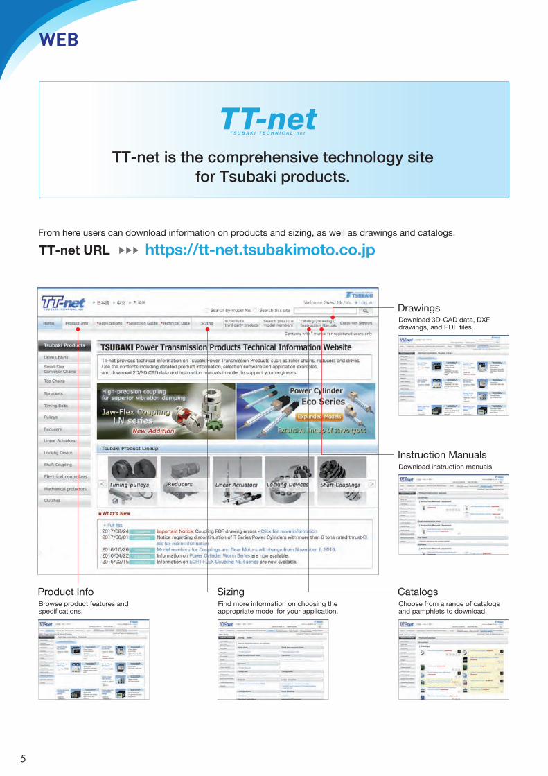
WEB
DrawingsDownload 3D-CAD data, DXF drawings, and PDF �les.
Instruction ManualsDownload instruction manuals.
CatalogsChoose from a range of catalogs and pamphlets to download.
Product InfoBrowse product features and speci�cations.
SizingFind more information on choosing the appropriate model for your application.
https://tt-net.tsubakimoto.co.jpTT-net URLFrom here users can download information on products and sizing, as well as drawings and catalogs.
TT-net is the comprehensive technology site for Tsubaki products.
5

Features p7
Applications p8
Seriesreferencechart p9
Noteswhenselecting: p10Specialmodelsandoptionalspecifications
ShockRelaySCSeries p11
ShockRelayEDSeries p22
ShockRelay150Series p25
ShockRelaySBSeries p29
ShockRelay50Series p32
SHOCK RELAY
6

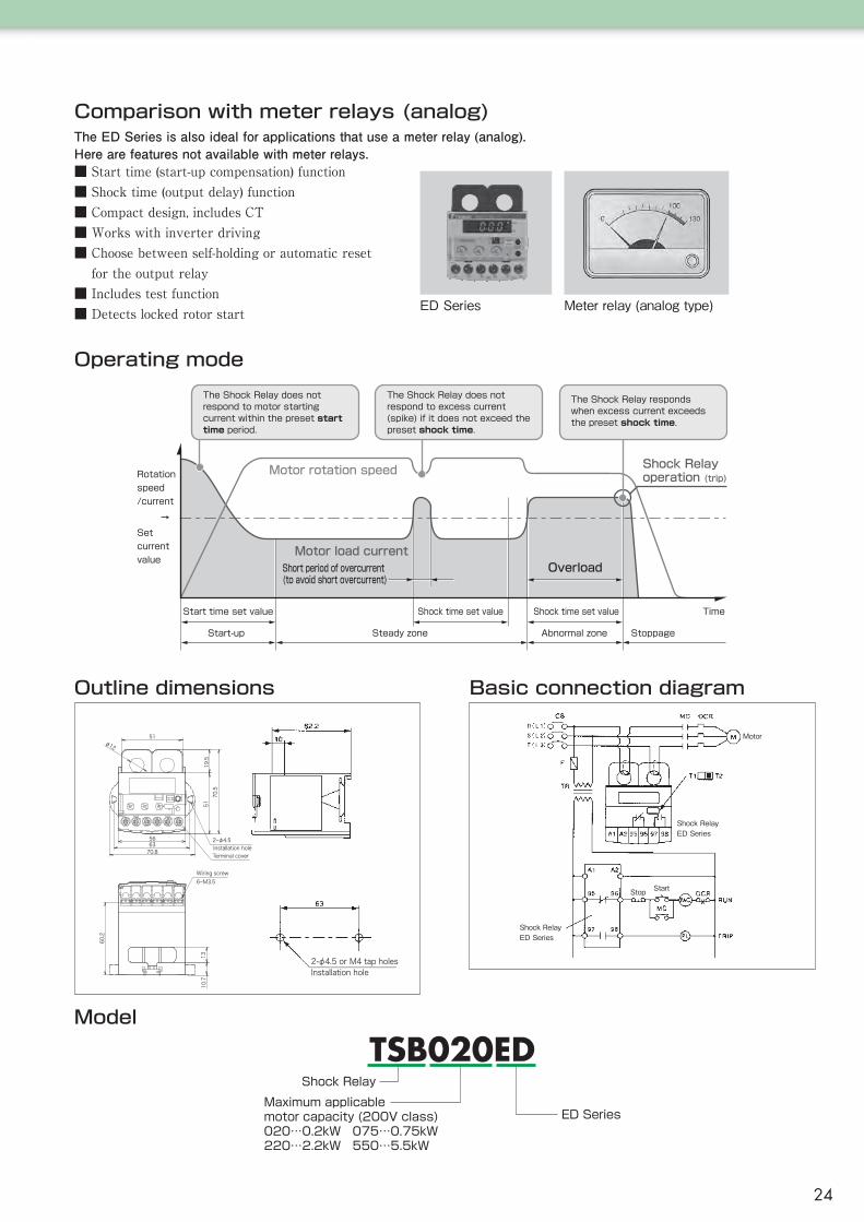
2. Easy to install on existing equipmentThe Shock Relay is an electrical protection device.When adding the Shock Relay to existing equipment, it is not necessary to make major modifications to the equipment as in the case of mechanical protection devices.Because the Shock Relay is installed inside the control panel, it canfunction outdoors or in harsh environments.
Quickly detects equipment overload!
1. Instantly detects overcurrentWhen the motor current exceeds the predetermined current value, therelay contact signal can be output after a preset time.For example, when a foreign object gets caught up in the conveyor, theShock Relay sends a signal causing an emergency stop, thus minimizingequipment damage.
It's not a thermal relayThe purpose of the thermal relay is to protect the motor from burnout.When the motor current continually exceeds the rated value for a certainperiod of time, an emergency signal is sent to protect the motor from burnout. Generally, it takes a long time for operation to begin, so it is not suitable for equipment/machine protection.
3. The emergency signal is only outputunder abnormal conditionsThe Shock Relay sends an emergency signal when overcurrent continues to exceed the preset period of time.Sometimes during normal operation, conveyors will experience insignificant short-term current overloads due to reasons such as the current pulsation of the equipment, or when packages are put on the conveyor. By using the shock time function these small overloads will not be recognized as overloads, therefore avoiding nuisance stoppages.
Short
Long
Load current
Operation time
The operation time ofthe Shock Relay isconsistent
The thermal relay's operation time is changed depending on load current
Operation time Protected object
Shock Relay
Thermal Relay
Short
Long*
* If the motor current slightly exceeds the preset value,the thermal relay will not work. Even if it does work, itwill do so slowly.
Equipment
Motor
Existing equipment Environment
Electrical
Mechanical
Easy to install later
Difficult to install later
Built inside the panel
Necessary environmental precautions
Operation time chart
0%
100%
Current value of motor
load factor
Set start time Shock time
Set shock time
Set current value
If the current continues to exceedthe set current value and setshock time…
The preset shock time hasnot been exceeded, so theShock Relay does not act
Equipmentstops
Starting current
The Shock Relay is a current monitoring device thatquickly detects motor overload, thus protecting yourequipment from unexpected damage.
Features
ShockRelay
7
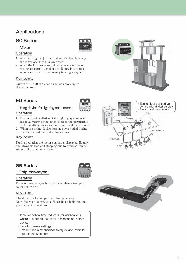
Applications
SC Series
MixerOperation1. When mixing has just started and the load is heavy,
the mixer operates at a low speed.2. When the load becomes lighter after some time of
mixing, an output signal of 4 to 20 mA is sent to a sequencer to switch the mixing to a higher speed.
Key pointsOutput of 4 to 20 mA enables action according tothe actual load.
SB SeriesChip conveyor
OperationProtects the conveyor from damage when a tool gets caught in its belt.
Key pointsThe drive can be compact and less expensive.Note: We can also provide a Shock Relay built into the gear motor terminal box.
・ Ideal for hollow type reducers (for applications where it is difficult to install a mechanical safety device)
• Easy to change settings• Smaller than a mechanical safety device, even for
large-capacity motors
ED Series
Lifting device for lighting and screensOperation1.Due to over-installation of the lighting system, when
the total weight of the baton exceeds the permissible load, the lifting device will be automatically shut down.
2.When the lifting device becomes overloaded during operation it automatically shuts down.
Key pointsDuring operation the motor current is displayed digitally,and allowable load and stopping due to overload can beset as a digital numeric value.
Control box
Motor
Winding drum
ReducerPulley
Steel wire
Ceiling
Baton
・ Economically priced yet comes with digital display
・Easy to set parameters
8
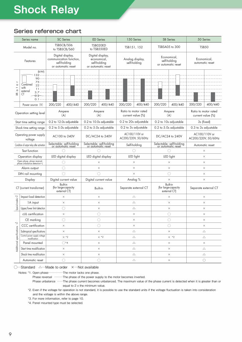
SC Series 50 SeriesSB Series150 SeriesED SeriesSeries name
Series reference chart
Power source(V) 200/220 200/220400/440 400/440
Mo
to
r
Operation setting level
Start time setting range
Shock time setting range
Operating power supply voltage
Condition of output relay after activation
Test function
Operation displayOpen phase, phase reversal, phase unbalance detection*1
Alarm output
DIN rail mounting
Display
CT (current transformer)
(kW)132
907522113.70.20.1
Ampere(A)
0.2 to 10.0s adjustable
0.2 to 5.0s adjustable
DC/AC24 to 240V
Selectable; self-holdingor automatic reset
◯
LED digital display
×
×
◯
Digital current value
Built-in
×
×
×
◯
◯
◯
×
×
×
×
×
◯
Spec
ial m
odels
Add
ition
al s
peci
ficat
ions
cUL certification
CE marking
CCC certification
Subtropical specificationsControl power supply voltage
modification
Panel mounted
Start time modification
Shock time modification
Automatic reset
Impact load detection
1A input
Upper/lower limit detection
200/220 400/440
Ratio to motor ratedcurrent value (%)
0.2 to 20s adjustable
0.2 to 3s adjustable
AC100/110V orAC200/220V, 50/60Hz
Self-holding
◯
LED light
×
×
×
Analog %
Separate external CT
△
△
△
×
×
×
△
△
△
△
△
△
200/220 400/440
Ampere(A)
0.2 to 10s adjustable
0.2 to 5.0s adjustable
DC/AC24 to 240V
Selectable; self-holdingor automatic reset
◯
LED light
×
×
◯
×Built-in
(for large-capacityexternal CT)
×
×
×
◯
◯
◯
×
×
×
×
×
×
*2 *2
200/220 400/440
Ratio to motor ratedcurrent value (%)
3s (fixed)
0.3 to 3s adjustable
AC100/110V orAC200/220V, 50/60Hz
Automatic reset
×
×
×
×
×
×
Separate external CT
×
×
×
×
×
×
△
△
×
△
△
○
*3
*3
TSB50
Economical,automatic reset
TSBSA05 to 300
Economical,self-holding
or automatic reset
TSB151, 152
Analog display,self-holding
TSB020ED to TSB550ED
Digital display,economical,self-holding
or automatic reset
TSBSCB/S06to TSBSCB/S60
Digital display,communication function,
self-holding or automatic reset
Model no.
Features
Ampere(A)
0.2 to 12.0s adjustable
0.2 to 5.0s adjustable
AC100 to 240V
Selectable; self-holdingor automatic reset
◯
LED digital display
◯
◯
◯
Digital current valueBuilt-in
(for large-capacityexternal CT)
×
×
◯
×
◯
×
×
×
◯
×
×
◯
*2
*4
CombinedwithexternalCT
)
)
◯…Standard △…Made to order ×…Not availableNotes: *1. Open phase ……………The motor lacks one phase.
Phase reversal ………The phase of the power supply to the motor becomes inverted.Phase unbalance ……The phase current becomes unbalanced. The maximum value of the phase current is detected when it is greater than or equal to 2 x the minimum value.
*2. Even if the voltage for operation is not standard, it is possible to use the standard units if the voltage fluctuation is taken into consideration and the voltage is within the above range.*3. For more information, refer to page 10.*4. Panel mounted type must be selected.
ShockRelay
9
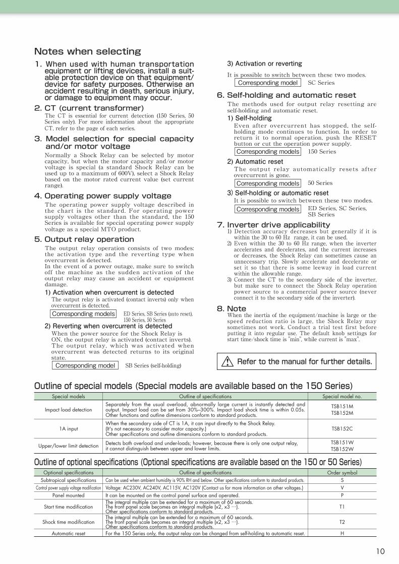
Notes when selecting
Outline of special models (Special models are available based on the 150 Series)
Outline of optional specifications (Optional specifications are available based on the 150 or 50 Series)Outline of specifications Order symbolOptional specifications
Subtropical specificationsControl power supply voltage modification
Panel mounted
Start time modification
Can be used when ambient humidity is 90% RH and below. Other specifications conform to standard products.Voltage: AC230V, AC240V, AC115V, AC120V (Contact us for more information on other voltages.)It can be mounted on the control panel surface and operated.The integral multiple can be extended for a maximum of 60 seconds.The front panel scale becomes an integral multiple (x2, x3 …).Other specifications conform to standard products.
SVP
T1
Shock time modification The integral multiple can be extended for a maximum of 60 seconds.The front panel scale becomes an integral multiple (x2, x3 …).Other specifications conform to standard products.
T2
Automatic reset For the 150 Series only, the output relay can be changed from self-holding to automatic reset. H
1. When used with human transportation equipment or lifting devices, install a suit-able protection device on that equipment/device for safety purposes. Otherwise an accident resulting in death, serious injury, or damage to equipment may occur.
2. CT (current transformer)The CT is essential for current detection (150 Series, 50 Series only). For more information about the appropriate CT, refer to the page of each series.
3. Model selection for special capacity and/or motor voltageNormally a Shock Relay can be selected by motor capacity, but when the motor capacity and/or motor voltage is special (a standard Shock Relay can be used up to a maximum of 600V), select a Shock Relay based on the motor rated current value (set current range).
4. Operating power supply voltageThe operating power supply voltage described in the chart is the standard. For operating power supply voltages other than the standard, the 150 Series is available for special operating power supply voltage as a special MTO product.
5. Output relay operationThe output relay operation consists of two modes: the activation type and the reverting type when overcurrent is detected.In the event of a power outage, make sure to switch off the machine as the sudden activation of the output relay may cause an accident or equipment damage.1) Activation when overcurrent is detected
The output relay is activated (contact inverts) only when overcurrent is detected.Corresponding models ED Series, SB Series (auto reset),
150 Series, 50 Series2) Reverting when overcurrent is detected
When the power source for the Shock Relay isON, the output relay is activated (contact inverts).The output relay, which was activated when overcurrent was detected returns to its original state.Corresponding model SB Series (self-holding)
3) Activation or revertingIt is possible to switch between these two modes.
Corresponding model SC Series
6. Self-holding and automatic resetThe methods used for output relay resetting are self-holding and automatic reset.1) Self-holding
Even after overcurrent has stopped, the self-holding mode continues to function. In order to return it to normal operation, push the RESET button or cut the operation power supply.Corresponding models 150 Series
2) Automatic resetThe output relay automatically resets after overcurrent is gone.Corresponding models 50 Series
3)Self-holding or automatic resetIt is possible to switch between these two modes.Corresponding models ED Series, SC Series,
SB Series
7. Inverter drive applicability1) Detection accuracy decreases but generally if it is
within the 30 to 60 Hz range, it can be used.2) Even within the 30 to 60 Hz range, when the inverter
accelerates and decelerates, and the current increases or decreases, the Shock Relay can sometimes cause an unnecessary trip. Slowly accelerate and decelerate or set it so that there is some leeway in load current within the allowable range.
3) Connect the CT to the secondary side of the inverter, but make sure to connect the Shock Relay operation power source to a commercial power source (never connect it to the secondary side of the inverter).
8. NoteWhen the inertia of the equipment/machine is large or the speed reduction ratio is large, the Shock Relay may sometimes not work. Conduct a trial test first before putting it into regular use. The default knob settings for start time/shock time is "min", while current is "max".
Outline of specifications Special model no.Special models
Impact load detection
1A input
Upper/lower limit detection
Separately from the usual overload, abnormally large current is instantly detected and output. Impact load can be set from 30%–300%. Impact load shock time is within 0.05s. Other functions and outline dimensions conform to standard products.
When the secondary side of CT is 1A, it can input directly to the Shock Relay.(It's not necessary to consider motor capacity.)Other specifications and outline dimensions conform to standard products.
Detects both overload and under-loads; however, because there is only one output relay,it cannot distinguish between upper and lower limits.
TSB151MTSB152M
TSB152C
TSB151WTSB152W
Refer to the manual for further details.
10
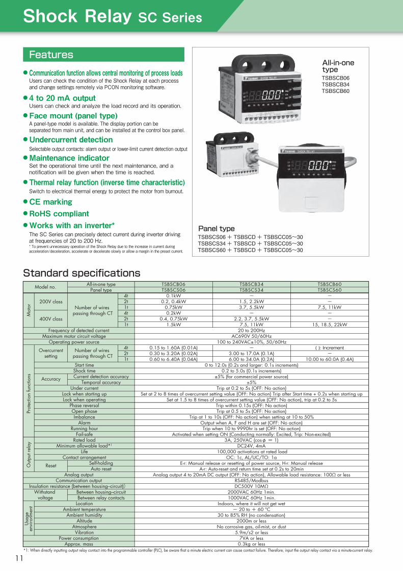
Features● Communication function allows central monitoring of process loadsUsers can check the condition of the Shock Relay at each process
and change settings remotely via PCON monitoring software.
● 4 to 20 mA outputUsers can check and analyze the load record and its operation.
● Face mount (panel type)A panel-type model is available. The display portion can be
separated from main unit, and can be installed at the control box panel.
●Undercurrent detectionSelectable output contacts: alarm output or lower-limit current detection output
●Maintenance indicator
● CE marking● RoHS compliant●Works with an inverter*
Set the operational time until the next maintenance, and a
notification will be given when the time is reached.
● Thermal relay function (inverse time characteristic)Switch to electrical thermal energy to protect the motor from burnout.
TSBSCS06 + TSBSCD + TSBSCC05~30TSBSCS34 + TSBSCD + TSBSCC05~30TSBSCS60 + TSBSCD + TSBSCC05~30
Panel type
TSBSCB06TSBSCB34TSBSCB60
All-in-onetype
The SC Series can precisely detect current during inverter driving
at frequencies of 20 to 200 Hz.
* To prevent unnecessary operation of the Shock Relay due to the increase in current during
acceleration/deceleration, accelerate or decelerate slowly or allow a margin in the preset current.
Standard specifications
*1: When directly inputting output relay contact into the programmable controller (PLC), be aware that a minute electric current can cause contact failure. Therefore, input the output relay contact via a minute-current relay.
TSBSCB34TSBSCS34
-
1.5, 2.2kW3.7, 5.5kW
-
2.2, 3.7, 5.5kW7.5, 11kW
20 to 200HzAC690V 50/60Hz
100 to 240VAC±10%, 50/60Hz-
3.00 to 17.0A (0.1A)6.00 to 34.0A (0.2A)
0 to 12.0s (0.2s and larger: 0.1s increments)0.2 to 5.0s (0.1s increments)
±5% (for commercial power source)±5%
Trip at 0.2 to 5s (OFF: No action)Set at 2 to 8 times of overcurrent setting value (OFF: No action) Trip after Start time + 0.2s when starting up
Set at 1.5 to 8 times of overcurrent setting value (OFF: No action), trip at 0.2 to 5sTrip within 0.15s (OFF: No action)Trip at 0.5 to 5s (OFF: No action)
Trip at 1 to 10s (OFF: No action) when setting at 10 to 50%Output when A, F and H are set (OFF: No action)Trip when 10 to 9990hr is set (OFF: No action)
Activated when setting ON (Conducting normally: Excited, Trip: Non-excited)3A, 250VAC (cosφ = 1)
DC24V, 4mA 100,000 activations at rated load
OC: 1c, AL/UC/TO: 1aE-r: Manual release or resetting of power source, H-r: Manual release
A-r: Auto-reset and return time set at 0.2s to 20minAnalog output 4 to 20mA DC output (OFF: No action), Allowable load resistance: 100Ω or less
RS485/ModbusDC500V 10MΩ
2000VAC 60Hz 1min.1000VAC 60Hz 1min.
Indoors, where it will not get wet- 20 to + 60 °C
30 to 85% RH (no condensation)2000m or less
No corrosive gas, oil-mist, or dust5.9m/s2 or less
7VA or less0.3kg or less
TSBSCB06TSBSCS06
All-in-one typePanel typeModel no.
Mot
orPr
otec
tion
func
tions
Out
put r
elay
Usa
geen
viro
nmen
t
0.1kW0.2, 0.4kW
0.75kW0.2kW
0.4, 0.75kW1.5kW
0.15 to 1.60A (0.01A)0.30 to 3.20A (0.02A)0.60 to 6.40A (0.04A)
Frequency of detected currentMaximum motor circuit voltage
Operating power source
Start timeShock time
Under currentLock when starting upLock when operating
Phase reversalOpen phaseImbalance
AlarmRunning hour
Fail-safeRated load
Minimum allowable load*1
LifeContact arrangement
Analog outputCommunication output
Insulation resistance (between housing–circuit))Between housing–circuitWithstand
voltage Between relay contactsLocation
Ambient temperatureAmbient humidity
AltitudeAtmosphereVibration
Power consumptionApprox. mass
Current detection accuracyTemporal accuracy
Self-holdingAuto reset
4t2t1t4t2t1t
4t2t1t
Number of wires passing through CT
Number of wires passing through CT
200V class
400V class
Overcurrentsetting
Accuracy
Reset
TSBSCB60TSBSCS60
-
-
7.5, 11kW-
-
15, 18.5, 22kW
( ): Increment
-
10.00 to 60.0A (0.4A)
ShockRelaySCSeries
11

Part names and functions
ESC button (reset)Releases the trip or returns the settings screen to the initial screen.Push the reset button after completing parameter settings to return to the initial screen.
UP/DN button (UP/DOWN)Switches to parameter mode and changes data settings.
SET button (set)Confirms and registers parameter setting data.
LED display
COMMOC OC AL/UC/TO4~20mA
A1 A2 95 96 98 08 + - V- D1 D0 S
All-in-one type Panel type
a. Phase display LED
b. Unit display LED
c. Load factor display bar graph
d. 7-segment LED
Displays the phase (L1 →L2 →L3) that shows the current. Changes every two seconds.
Indicates the unit.
Can be utilized as a guide when setting OC (overcurrent setting value).Displays the ratio of operational load current to OC current set value (load factor) in percentage (%).
Displays operating current, parameter set values, cause of trip, etc.
ESC button
SET button
4 LED display 4
UP/DNbutton
ESC button
SET button
LED display
UP/DNbutton
L1
L2
L3
65 70 75 80 85 90 95 100%
Amp
X10
sec
Phase L1 operating current
L1
L2
L3
65 70 75 80 85 90 95 100%
Amp
X10
sec
Phase L2 operating current
L1
L2
L3
65 70 75 80 85 90 95 100%
Amp
X10
sec
Phase L3 operating current
Automatically switching display
1) While in normal operation, users can change the displayed phase, and set it by pushing the SET button. Release by pushing the ESC button.
2) Trip records (3 most recent) can be viewed by pushing and holding the ESC button 5 sec. or longer. Push the UP/DN buttons to cycle through and confirm current values (phases L1 →L2→L3→L1→...) . The order of the trip record appears on a bar graph in the order of 100%, 95%, and 90% for easy confirmation. Release by pushing the ESC button.
●Digital ammeter functions
Connects AC100 to 240V commercial powersupply
Operationalpower supplyA1, A2
FunctionTerminal symbol Explanation
Terminal 96, 98, 08 common contanctCommon contact95
b contact: Normally closed, open during overcurrent(FS: When OFF)
OC output96
a contact: Normally open, closed during overcurrent(FS: When OFF)98
Alarm output, running hour output, undercurrentoutput
AL/TO/ULoutput08
Connect when using communication functionTerminal for communicationV−, D1, D0, S
Outputs analog current DC4 to 20mAAnalogoutput
+-
L1
L2
L3
65 70 75 80 85 90 95 100%
Amp
X10
sec
a Phase display LED b Unit display LED
c Load factor display bar graph d 7-segment LED display
1
2
3
4
Terminal arrangement
Applicable wire
5
2
3
1
2
3
1
Wire: ISO 1 to 2.5mm2, AWG#18 to 14, 75℃ copper wireStrip length: 8mmNo. of connectable wires: Up to 2 for one terminalTightening torque: 0.8 to 1.2N・m
12

Light-load operating (undercurrent detection) modeOnce the motor current falls below the preset level, it is detected and a signal is sent to stop the motor.
Rotation
speed/Current
Current set
value
Current set
value
Motor load current
Motor rotation speed
Time
Current
Time
Motor load current
Operating mode
Note: For lower-limit detection, the output contact is either alarm output.
Start time set value Shock time set value Shock time set value
Abnormal zoneNormal zone Motor stoppageMotor start-up
OverloadShort period of overcurrent(to avoid short overcurrent)
Shock Relayoperation (trip)
The Shock Relay does not respond to motor starting current within the preset start time period.
The Shock Relay does not respond to excess current (spike) if it does not exceed the preset shock time.
The Shock Relay responds when excess current exceeds the preset shock time.
Start time set value Shock time set value Shock time set value
Abnormal zoneNormal zone Motor stoppageMotor start-up
Current dropShort period of undercurrent(to avoid short undercurrent)
Shock Relayoperation (trip)
The Shock Relay does not respond to short-term current degradation if it does not exceed the preset shock time.
The Shock Relay responds when current degradation continues for longer than the preset shock time.
Model
T S B S C B 0 6
Shock Relay TypeB: All-in-one
SC Series Load current(Max. setcurrent value)06:6A34:34A60:60A
T S B S C S 0 6
Shock Relay TypeS: Panel
SC Series Load current(Max. set current value)06:6A34:34A60:60A
T S B S C C 0 5
Shock Relay Cable
SC SeriesCable length05:0.5m10:1.0m15:1.5m20:2.0m30:3.0m
Shock Relay Panel
SC Series
T S B S C DPanel
type
All-in-one
type T S B 3 C T C 1 0 0
Shock Relay For SC Series
3-phase CT Rated current100:100A200:200A300:300A
In case current setting range is over 60A, use with TSBSCB/S06 as a set.
Overload operating mode
Main unit
Main unit (for panel type) Cable (for panel type)Panel unit (for panel type)
External CT (for SC Series only)
ShockRelaySCSeries
13

A 4 to 20 mA analog signal is a standard instrumentation signal used around the world.Instrumentation signal:・Voltage signal: DC 0 to 5 V, DC 0 to 10 V, etc.・Current signal: DC 0 to 20 mA, DC 4 to 20 mA, etc.Current signals are less susceptible to influence from noise than voltage signals.In addition, DC 4 to 20 mA, when compared to DC 0 to 20 mA, is more precise in the event of wire disruption or breaks. Therefore, DC 4 to 20 mA is used frequently, specifically in the case of long transmission distances (several tens of meters) or for reducing noise influence.
①Automatic control of the input and viscosity depending on the load by inputting the load current of a crusher or mixer to the sequencer.②F igu r i n g ou t t h e ope r a t i o n and l o ad i ng conditions for the equipment by recording the load current of a trial unit, and using it as the basis for an optimal equipment design.
③, ④ Activation of a digital or analog meter with DC 4 to 20 mA signal for remote centralized monitoring of pumps, etc.
In the case of TSBSCB60 (max. 60A), it is possible to transmit DC 0 to 60 A as a DC 4 to 20 mA signal. In addition, output value correction is available due to the scaling adjustment function of the DC 4 to 20mA output of the TSBSC Series.
Unique functions of the SC Series
Remote control Displays the current of each phase L1, L2, and L3 on the PC screen by reading them from a specified Shock Relay address.
Current change display Plots the current value of each phase at specified intervals. Data for the last 159 times can be displayed.
Accumulated operation time display
What is a 4 to 20 mA analog signal?
Application examples
Can be used for maintenance such as lubrication and filter cleaning.
The three most recent trip records of a designated Shock Relay is displayed on the screen.
Cause of troublePhase that caused trouble
Maximum connection: up to 247 unitsMaximum total extension: up to 1200m
Specificationsof RS485
No.1
No.1
No.2 No.3
First time Second time Third time
No.4
Signal converterRS485/USB(Commercially available)
Three most recent trip records
12
1
2
1
1
3
2
2
3
Current value when trouble happenedSet value when trouble happened
3
4
3
4
19.2A 19.5A 19.7A
Reads in the set values from a specified Shock Relay address and displays them on the PC screen.
1) Set value read-in
Set values edited on the PC can be written to a specified Shock Relay address.
2) Set value writing
Set values edited on the PC can bebacked up to a text file.
3) Set value back-up
1 2
3 4
Input to sequencer Display the wavepattern with recorder
Display with digitalpanel meter
Display with analogmeter
130100
0
4 to 20 mA signal
USBPC
Communication function
4 to 20 mA analog signal
Shock Relay settings
Trip record
14

Set value
0
1
3Ph
1Ph
dE
th
In
no
1t, 2t, 4t
100, 200, 300
oFF
on
oFF
on
See right
Initial value
ParameterMenu
Parameter lock1
2
3
4
5
6
7
Fail-safe
Overcurrentsetting
Selection ofphase no.
Upper limit detection operating
characteristics
CT ratio
Phase reversaldetection
No. Explanation of function
All parameter settings are possible.
To lock parameter settings, input "1" for every parameter set.
To unlock the setting, input "1", then "0". When is displayed, the
setting is completed.
Monitors 3-phase motor.
Monitors single-phase motor.
Operates with definite time characteristics.
Operates with inverse time characteristics and is cumulative, similar to thermal
characteristics. (Refer to “Thermal characteristics” chart on page 18.)
Operates with inverse time characteristics. (Refer to “Inverse characteristics” chart on page 18.)
Disables upper limit detection.
Sets the number of motor wires that pass through the CT (1t: once, 2t: twice, 4t: 4 times)
Type 34: only 1t and 2t; Type 60: only 1t
Select when using an external CT (Type 06 only)
When a trip occurs, the relay turns ON (95-96: Open; 95-98: Closed).
After the power is turned on, the relay turns ON (95-96: Open; 95-98: Closed);
and when a trip occurs, the relay turns OFF (95-96: Closed; 95-98: Open).
This setting becomes effective after a power reset.
Set to "on" for when detecting phase reversal.
Sets the current value for overcurrent. For type 34 and 60, the current value cannot
be set over 32A for inverse time characteristics "th" and "In" .
1. Selection of parameter
2. Preparation for setting
3. Selection of setting
4. Registration of setting
5. Initial screen
Operation buttonItem Operation instruction
Press the UP/DN button to select the parameter to be set.
The set value begins blinking when the SET button is pressed after selecting a parameter.
Press the UP/DN button until the desired set value is shown.
Press the SET button after selecting the set value. The blinking value indication becomes lighted
and the set value is registered.
Press the ESC button to return to the initial display after completing the settings. If no button is
pressed, the display automatically returns to the initial screen after 50 seconds.
Normal mode
Fail-safe mode
Setup steps
Parameters
UP/DN
SET
UP/DN
SET
ESC
●Current setting table
06 type
Setting range Increment
0.60 to 6.40
0.30 to 3.20
0.15 to 1.60
12.0 to 128
24.0 to 256
36.0 to 384
0.04
0.02
0.01
1
1
1
34 type
Setting range Increment
6.00 to 34.0
3.00 to 17.0
0.2
0.1
60 type
Setting range
Unit: (A)
Increment
10.0 to 60.0 0.4
CTRatio
1t
2t
4t
100
200
300
ShockRelaySCSeries
15

Start time8
9
10
11
12
13
14
15
16
17
18
19
20
Overcurrentshock time
Under-currentsetting
Under-currentshock time
Open phase
Lock when starting
Analog outputrange
Alert
Open phaseoperating time
Imbalancesetting
Imbalanceoperating time
Lock when operating
Jam fault duration
Set value
0
0.2 to 12.0s
0.2 to 5.0s
1 to 30
oFF
See right
0.2 to 5.0s
oFF
on
0.5 to 5s
oFF
10 to 50%
1 to 10s
oFF
2 to 8 times
oFF
1.5 to 8 times
0.2 to 5s
See right
oFF
no
A
F
H
to
uc
oFF
50 to 100%
Initial value
ParameterMenuNo. Explanation of function
When set ting the inverse time characteristic "In", it operates in Cold curve characteristic from motor start-up until the current becomes lower than the OC setting. After that, it operates in Hot curve characteristic.
The relay is not output within the time setting, so as not to operate when the motor starts. When inverse time characteristic "In" is set, it operates in Hot characteristic after start time.
Sets current value for detecting lower limit. This cannot be set higher than the overcurrent value. Relay output for lower limit detection is as follows:Alarm ALo is set to "except uc": Outputs at OC contactAlarm ALo is set to "uc": Outputs at AL/UC/TO contacts
Selects the operation characteristic when inverse time characteristic "th" or "In" are set. (Refer to thermal and inverse characteristics charts.)
Sets continuous overload time of the overcurrent setting.
Sets operating time for when detecting open phase.When open phase detection is set to oFF, it is not displayed.
Sets operating time for when detecting imbalance. When imbalance detection is set to oFF, it is not displayed.
Sets the ratio against overcurrent setting for when detecting locked start-up.Setting range: Sc setting value ×OC ≦ 250A. When the start time is set to 0s, it is not displayed.
Sets the ratio against overcurrent setting for when detecting locked operation.Setting range: JA setting value ×OC ≦ 250A.
Sets the operating time for when detecting locked operation. When set to oFF, it is not displayed.
Sets the current value as analog current output scale for 20mA output. Refer to page 15 “Current setting table” for setting range.
Set when disabling analog current output.
Set when disabling alarm output.
Set when enabling alarm output. Refer to the table on page 17.
Triggers an output when the running hour is set.
Set for when detecting lower limit.
Set the ratio against the OC current for when outputting an alarm.
Set to 10 to 50% for when detecting imbalance.
Imbalance rate (%) = ×100
Set to "on" for when detecting open phase.
Set continuous lower limit detection time of under-current setting.
(Max. current–Min. current)
Max. current
Parameters
16
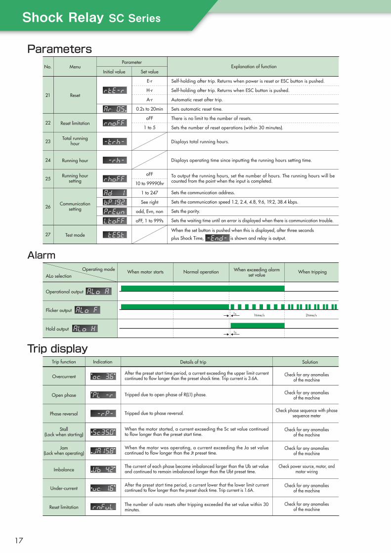
1s 1time/s 2time/s
1s
Reset
Reset limitation
Running hour
Test mode
21
22
24
23
25
26
27
Total runninghour
Running hoursetting
Communicationsetting
Set value
E-r
H-r
A-r
0.2s to 20min
oFF
1 to 5
oFF
10 to 99990hr
1 to 247
See right
odd, Evn, non
oFF, 1 to 999s
Initial value
ParameterMenuNo. Explanation of function
Self-holding after trip. Returns when power is reset or ESC button is pushed.
Self-holding after trip. Returns when ESC button is pushed.
Automatic reset after trip.
Sets automatic reset time.
There is no limit to the number of resets.
Sets the number of reset operations (within 30 minutes).
Displays total running hours.
Displays operating time since inputting the running hours setting time.
To output the running hours, set the number of hours. The running hours will be counted from the point when the input is completed.
When the set button is pushed when this is displayed, after three seconds
plus Shock Time, is shown and relay is output.
Sets the communication speed 1.2, 2.4, 4.8, 9.6, 19.2, 38.4 kbps.
Sets the communication address.
Sets the waiting time until an error is displayed when there is communication trouble.
Sets the parity.
Overcurrent
Open phase
Phase reversal
Imbalance
Under-current
Stall(Lock when starting)
Jam(Lock when operating)
Reset limitation
IndicationTrip function Details of trip Solution
After the preset start time period, a current exceeding the upper limit current continued to flow longer than the preset shock time. Trip current is 3.6A.
Check phase sequence with phasesequence meter
When the motor started, a current exceeding the Sc set value continued to flow longer than the preset start time.
When the motor was operating, a current exceeding the Ja set value continued to flow longer than the Jt preset time.
The current of each phase became imbalanced larger than the Ub set value and continued to remain imbalanced longer than the Ubt preset time.
After the preset start time period, a current lower that the lower limit current continued to flow longer than the preset shock time. Trip current is 1.6A.
Tripped due to open phase of R(L1) phase. Check for any anomalies of the machine
Check for any anomalies of the machine
Check power source, motor, andmotor wiring
Check for any anomalies of the machine
Check for any anomalies of the machine
Check for any anomalies of the machine
Check for any anomalies of the machine
Tripped due to phase reversal.
The number of auto resets after tripping exceeded the set value within 30 minutes.
Hold output
Flicker output
Operational output
Operating modeALo selection
When motor starts Normal operation When exceeding alarmset value
When tripping
Parameters
Trip display
Alarm
ShockRelaySCSeries
17

Inverse-time characteristics charts
Number of motor wires that pass through the CT (current transformer)
Current(Multiples of set value)
Time(s)10000
1000
100
10
1
0.1
HotCold
Current(Multiples of set value)
Time(s)10000
1000
100
10
1
0.11 2 3 5 7 94 6 8 10
303030202020101010
252525151515
555
111
kW Shock Relay model no.
3-phase AC 200V class motor
TSBSCB/S06TSBSCB/S06TSBSCB/S06TSBSCB/S06TSBSCB/S34TSBSCB/S34TSBSCB/S34TSBSCB/S34TSBSCB/S60TSBSCB/S60
---
Number of wirespassing through CT
4221221111---
0.10.20.40.751.52.23.75.57.511---
Model no.
Applicable main unit model no.
Exte
rnal
CT
For
ref.
TSB3CTC100
100A
15 to 18.5kW30 to 45kW
ClassRated primary current
Rated secondary currentRated burden
Rated frequencyMass
TSB3CTC200
Grade 3200A
5A5VA
50/60Hz0.9kg
TSBSCB/S06
22 to 37kW55 to 90kW
TSB3CTC300
300A
45 to 75kW110 to 132kW
kW Shock Relay model no.
3-phase AC 400V class motor
-TSBSCB/S06TSBSCB/S06TSBSCB/S06TSBSCB/S06TSBSCB/S34TSBSCB/S34TSBSCB/S34TSBSCB/S34TSBSCB/S34TSBSCB/S60TSBSCB/S60TSBSCB/S60
Number of wirespassing through CT
-422122211111
-0.20.40.751.52.23.75.57.51115
18.522
Refer to the table below for the number of motor wires that pass through the CT.The values in this table are just a guide for when the motor is used at load factors of 80 to 100%. If the motor load factor is low, increase the number of wires passing through to improve the setting accuracy.In addition, for motors not in the table below (small, single phase, different voltage, etc.), select and set an appropriate model and the number of wires passing through the CT based on the set current values.
Notes: 1) Set the parameter “CT ratio” based on the number of wires passing through the CT. 2) If motor capacity exceeds the above table, use an external CT.
303030
202020151515
252525
101010555
111
303030252525
151515202020
101010555
111
1 2 3 5 7 94 6 8 10
Motor200V class400V class
外 部 C T の 仕 様
Inverse characteristicsThermal characteristics
Specifications of external CT
18

M
CT
T(L3)S(L2)
TRIP
A2A1
OCR96
PL
RUN95 STOP RUN
MCMC
08
+
ー4-20mA OUTPUT
RS485communication
98
AL/UC/TO
OC
Fail-safe mode:OFF(FS:off)
Shock RelayTSBSC Series
TR
F
OCRR(L1)
Powersupply
Motor
MCCB
Single-phase motor
MC
M Motor
OCR
Shock RelayTSBSC Series
CT
Connection diagram
Communication function
Note: 1. If necessary, set a transformer (Tr) depending on the voltage on the Shock Relay and electromagnetic contactor (MC). Install an isolating transformer if there is any harmonic noise generating device, such as an inverter. 2. Output relay is not excited in normal condition and excited in trip condition. 3. The coil capacity of the MC connected with the output relay of the Shock Relay should be: Injection: less than 200VA; Holding: less than 20VA As a guide, for TSBSCB60/TSBSCS60, set an auxiliary relay, activate the auxiliary relay with the output relay of the Shock Relay, and open/close the MC with the contact of the auxiliary relay.
1) Prepare a signal converter to use the TSBSC PCON monitoring software .2) Use twisted-pair cables and connect as follows.
COMM
V- D1 D0 S
Signal
GND
Data(B)Data(A)Shield
Terminal
V−
D1
D0
S
RS485 terminal
GND
Tx+
Tx−
Shield
Details
RS-485
1200m (Depends on transmission speed)
Half-duplex bidirectional, Modbus protocol
1.2k to 38.4kbps
Item
Transmission standards
Max. transmission distance
Transmission system
Transmission speed
基 本 接 続 図
信 号 変 換 機 と の 接 続
Communication specifications
Basic connection diagram
Connection with signal converter
ShockRelaySCSeries
19

Communication function
PCON can be downloaded from the Tsubaki website.http://www.tsubakimoto.jp/products/reference/6/5/
The following can be done on the PC screen:◇ Set the parameters for the Shock Relay◇ Monitor changes in the motor current◇ View trip history
13
2
Communication setting at PCON side1
Select connected unit2
Start communication3
USB
① RS485/USB signal converter (commercially available)② USB cable (commercially available; should fit the size of slot ①)③ Twisted-pair cable with shield (commercially available)④ Terminating resistor (120Ω, 1/4W and larger)⑤ TSBSC PCON dedicated monitoring software
Set the address and the communication method for each Shock Relay in advance, before starting communication.Set the following items by calling up parameter 26 “Communication setting”.Address (1 to 247), Communication speed (1.2 to 38.4kbps), Parity (EVEN, ODD, non), Communication loss time (off, 1 to 999s)
First, install the monitoring software and signal converter software on the PC.
Connect terminals V-, D1, D0, and S with the cable.Connect the terminating resistor 120Ω between terminatingterminal D1 and D0.Connect the PC and the signal converter with a USB cable.
Note: If communication with a PLC (sequencer) is necessary without using PC monitoring software, consult Tsubaki.
1
2
3
Click the desktop icon to start up the software. The PCON operating display appears on the screen. On thecommunication settings for the PCON side, set the communication method to be the same as for the Shock Relay.For [ComPort], select the PC port number in which the USB cable is connected.Select the address of the connected Shock Relay.Click the link icon to begin communication.
1
2
3
PC 120Ω
1 1
2
3
ご 用 意 い た だ く 物
PCON monitoring softwareMonitoring software for PC is available.Users can connect a PC and a Shock Relay via a third-party signal converter(RS485/USB).
Things to prepare
Main functions
How to connect
Set the address of the Shock Relay main unit
Set TSBSC PCON software
Download the PCON monitoring software
20
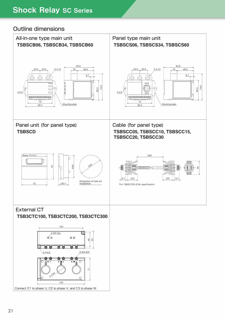
Outline dimensions
TSBSCB06, TSBSCB34, TSBSCB60 TSBSCS06, TSBSCS34, TSBSCS60
TSB3CTC100, TSB3CTC200, TSB3CTC300
TSBSCD TSBSCC05, TSBSCC10, TSBSCC15, TSBSCC20, TSBSCC30
Mounting plate7082.3
∅4.5
22.5 22.5 3-∅12
8.7
83.818
56.3 74.5
46.5
Mounting plate7082.3
22.5 22.5
∅4.5
3-∅12 46.5
56.3
1883.8
8.7
74.5
SHOCK RELAY
65 70 75 80 85 90 95 100%
SECx10AmpL1
L2L3
72
72
∅64
(28.1)Dimension of hole forinstallation
∅65
(23)
8
1
500*
30
(23)9.7 9.7
8
1
TSBSCC05(0.5m)TSBSCC05(0.5m)
4-M4 Nut
2-∅4.5
140
5546
3-∅24
6-M4 Bolt
150
71
*For TSBSCC05 (0.5m specification)
All-in-one type main unit Panel type main unit
External CT
Panel unit (for panel type) Cable (for panel type)
Connect C1 to phase U, C2 to phase V, and C3 to phase W.
ShockRelaySCSeries
21

TSB020ED TSB220EDTSB075ED TSB550ED
CT all-in-one model
CT(current transformer)
Model no. TSB020ED
0.1kW0.2kW
0.1, 0.2kW0.4, 0.75kW
TSB075ED
0.4kW0.75kW
—1.5kW
TSB220ED
1.5kW2.2kW
2.2, 3.7kW5.5kW
TSB550ED
3.7kW5.5kW7.5kW11kW
0.20 to 1.20A(0.01A increments)
0.40 to 2.40A(0.02A increments)
1.20 to 3.20A(0.02A increments)
1.80 to 5.80A(0.04A increments)
3.00 to 10.0A(0.1A increments)
4.00 to 14.0A(0.1A increments)
6.00 to 26.0A(0.2A increments)
9.00 to 34.0A(0.25A increments)*2
Applicablemotors
*1
200Vclass
T2T1T2T1
T2
T1
DIP switch to select no. of wires passing through CT*4
400Vclass
Frequency of detected currentMaximum motor circuit voltage
Operating power supply voltage
Mot
orPr
otec
tion
func
tions
Out
put r
elay
Usag
e env
ironm
entW
ithsta
ndvo
ltage
Insulati
on
Ove
rload
Accu
racy
Current settingrange
*3
Start time*3
Shock time*3
Current detection accuracyTemporal accuracy
Locked rotor startRated load
Minimum allowable loadLife
Contact arrangementOperation
Between housing–circuitBetween housing–circuit
Between relay contact electrodesLocation
Ambient temperatureAmbient humidity
AltitudePower consumption
Mass
DIP switch to select no. of wires passing through CT*4
DIP switch to select no. of wires
passing through CT
AM
ResetDIP switch for
selecting trip reset
20 to 200HzAC600V 50/60Hz
24 to 240VAC ±10%, 50/60Hz
*1. The applicable motors are just a rough indication for reference. Make your selection based upon actual electrical current value.Select by electrical current value for single-phase motors as well.
*2. Set values 10A and higher are displayed as follows due to the maximum number of display digits. 10.0A→10.2A→10.5A→10.7A→11.0A*3. A ±1 digit error can occur with the current and the set time in the range indicated.*4. Be sure to make one turn when selecting T1 and two turns when selecting T2.
● Digitally displays motor current and set values ● Economically priced● CT included in one compact unit● Works with inverter*
● Choose between self-holding or automatic reset for the output relay● CE marking● UL/cUL certification
Current can be precisely detected when inverter is operatingbetween 20 to 200 Hz.
* To prevent unnecessary operation of the Shock Relay due to the increase in current during acceleration/deceleration, accelerate or decelerate slowly or allow a margin in the preset current.
● CCC certification
0.2 to 10.0s (0.2s increments)0.2 to 5.0s (0.2s increments)
±5% ±1 digit or less (except when combined with the inverter, ±10% ±1 digit or less)±5% ±1 digit or less
It will trip if the set current value exceeds 200% when starting, after the set start time +0.2s has elapsed3A, 250VAC(cosφ=1)
DC24V, 4mA80,000 activations at rated load
1a1bEnergization/normal operation: no excitation; Trip: excitation
After returning to normal current value, automatically resets in 1 sec.Can be manually reset by pressing the "RESET" button
DC500V, 10MΩ2000VAC 60Hz: 1 minute1000VAC 60Hz: 1 minute
Indoors, where it will not get wet-20 to +60°C
30 to 85% RH (no condensation)2000m or less2.0W or less0.25kg or less
Standard specifications
Features
ShockRelayEDSeries
22
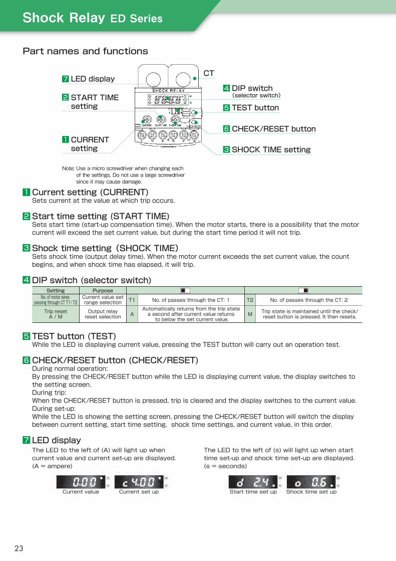
7
2
1
4
5
6
3
LED display
START TIMEsetting
CURRENTsetting
CT
DIP switch(selector switch)
TEST button
CHECK/RESET button
SHOCK TIME setting
Part names and functions
Current setting (CURRENT)Sets current at the value at which trip occurs.
Start time setting (START TIME)Sets start time (start-up compensation time). When the motor starts, there is a possibility that the motor current will exceed the set current value, but during the start time period it will not trip.
Shock time setting(SHOCK TIME)Sets shock time (output delay time). When the motor current exceeds the set current value, the count begins, and when shock time has elapsed, it will trip.
DIP switch (selector switch)
TEST button (TEST)While the LED is displaying current value, pressing the TEST button will carry out an operation test.
CHECK/RESET button (CHECK/RESET)During normal operation:By pressing the CHECK/RESET button while the LED is displaying current value, the display switches to the setting screen.During trip:When the CHECK/RESET button is pressed, trip is cleared and the display switches to the current value.During set-up:While the LED is showing the setting screen, pressing the CHECK/RESET button will switch the display between current setting, start time setting, shock time settings, and current value, in this order.
LED display
SettingNo. of motor wires
passing through CT T1/ T2
Trip resetA / M
Current value setrange selection
Output relayreset selection
T1
A
No. of passes through the CT: 1
Automatically returns from the trip statea second after current value returns to below the set current value.
T2
M
No. of passes through the CT: 2
Trip state is maintained until the check/reset button is pressed. It then resets.
Purpose
The LED to the left of (A) will light up when current value and current set-up are displayed. (A = ampere)
Current value Start time set upCurrent set up Shock time set up
The LED to the left of (s) will light up when start time set-up and shock time set-up are displayed. (s = seconds)
1
2
3
4
5
6
7
Note: Use a micro screwdriver when changing each of the settings. Do not use a large screwdriver since it may cause damage.
ShockRelayEDSeries
23
The Shock Relay does not respond to motor starting current within the preset start time period.
The Shock Relay does not respond to excess current (spike) if it does not exceed the preset shock time.
The Shock Relay responds when excess current exceeds the preset shock time.
Motor rotation speed
Motor load current
Shock Relayoperation (trip)
Short period of overcurrent(to avoid short overcurrent)
Overload
Rotationspeed/current
Setcurrentvalue
Start time set value Shock time set value Shock time set value Time
Start-up Steady zone Abnormal zone Stoppage
Comparison with meter relays (analog)The ED Series is also ideal for applications that use a meter relay (analog). Here are features not available with meter relays.■ Start time (start-up compensation) function■ Shock time (output delay) function■ Compact design, includes CT■ Works with inverter driving■ Choose between self-holding or automatic reset for the output relay■ Includes test function■ Detects locked rotor start
Operating mode
Outline dimensions
Model
51
56 2-φ4.5
6-M3.5
Installation hole
2-φ4.5 or M4 tap holes Installation hole
Terminal cover
Wiring screw
6370.8
51
60.2
10.7
1319.5
70.5
φ12
Basic connection diagram
TSB020EDShock Relay
ED SeriesMaximum applicablemotor capacity (200V class)020…0.2kW 075…0.75kW220…2.2kW 550…5.5kW
ED Series Meter relay (analog type)
Shock RelayED Series
Shock RelayED Series
Motor
StartStop
24

TSB151TSB152
TSB-COM
TSB AT
ModelFunction TSB151-COM
0.2 to 3.7kW*1
0.2 to 3.7kW-10°C to 50°C
45 to 85% RH; no condensation5.9m/s2 or less1000m or less
No corrosive gas or dust
±10% (full-scale)0.2 to 20s0.2 to 3s
AC100/110V or AC200/220V, 50/60Hz ±10%AC600V, 50/60Hz1-phase CT system
Self-holding availableOutput relay not excited
Output relay excited1c contact, AC250V 0.2A (inductive load cosφ=0.4)
DC24V, 4mA10,000,000 activations
100,000 activationsIncluded
AC1500V, 60Hz, 1 minute (power supply circuit and contact circuit)AC700V, 60Hz, 1 minute
AC1500V, 60Hz, 1 minute (power supply circuit and contact circuit)
1.2VA
TSB152, TSB AT*2
5.5 to 90kW5.5 to 90kW
TSB15130 to 130%(100%=5mA)
TSB15230 to 130%(100%=5A)
1.0kg 1.2kg
TSB-COM0.75A, 1.5A, 1.75A, 2.0A, 2.5A, 3.3A, 4.0A,
5.3A, 7.0A, 9.0A, 10.0A, 16.0A5mA
0.5VA0.5kg
TSB AT( …Rated input current value)100A, 120A, 150A,200A, 250A, 300A
5A5VA
0.6kg
Main unit model no.Load current (current setting range)*4
Current setting accuracy
Control power supply voltageMax. motor circuit voltageCurrent detecting system
Test function
MassPower consumption
Accessory external CT model
Rated input current
Rated output currentRated load
Mass
Motor
Usage environmentCom
mon
Mai
n un
itEx
tern
al C
T
200V class400V class
Ambient temperatureRelative humidity
VibrationAltitide
Atmosphere
Time setting rangeStart time*4
Shock time*4
Output relay
Output relay life
Self-holdingNormal state
Abnormal stateContact capacity
Min. applicable load*3
MechanicalElectric
Withstand voltageBetween circuit–housing
Between contactsBetween circuits
Notes: *1. If the TSB-COM-A (small-capacity CT) is used, a motor of 0.1kW or less can be used. *2. TSB152 and TSB AT (external CT) have different model numbers. *3. When directly inputting output relay contact into the programmable controller (PLC), be aware that a minute electric current can cause contact failure. Therefore, before inputting the output relay contact into the PLC, it is recommended that you drive the relay coil for a minute current via the relay signal. *4. Current and time setting ranges are settable ranges, not the upper and lower levels of setting volume.
Features● Analog meter
● Self-holding type
● Special MTO models and optional specifications are available
Standard specifications
ShockRelay150Series
25

Part names and functions
Operating mode
Load currentset value
Rotationspeed/current
Rotationspeed/current
Motor rotation speed
Motor current
Start time
Steady zone Overload zone Stop
TimeShock time Shock time
Momentary overload Overload
Shock Relay operation
Starting current
Starting current
Lower limitload currentset value
Motor rotation speed
Motor current
Start time
Steady zone Light load Stop
TimeShock time Shock time
Momentary light load Light load
Shock Relay operation
% Display meterThe meter displays the percentage of the motor current in operation vs. the motor rated current. (The rated current here is based on "Motor rated current" in the CT selection table on page 28.)
■ Overload operating mode
■ Light-load operating modeTSB151W, 152W(Lower/upper limit detector specifications)Note: Because there is only one output relay, it
is not possible to distinguish between over load operat ion and l ight- load operation.
TerminalsAll terminals are located on the upper portion of the Shock Relay, making wiring easy.
POWER indicatorLights up when the Shock Relay is turned on.
Activation indicatorLights up when the Shock Relay is operating.
TEST buttonShock Relay operation can be tested stand-alone or during motor operation.
RESET buttonAfter the Shock Relay activates, the RESET button is used to cancel the self-holding of the output contact.
SHOCK TIME knobShock time is the amount of time set until the Shock Relay activates whenoverload occurs. Within the set time, the Shock Relay will not activate, even if it is overloaded.
When testing the Shock Relay, continue to press and hold the TEST button longer than the set start time or shock time, whichever is longer.
LOAD CURRENT knobLoad current can be set to stop the motor at the desired level when overload occurs. When the motor current exceeds the preset current value (continues to exceed the preset shock time), the Shock Relay activates and stops the motor.
% Adjust knobIf the input from the CT is 5mA (TSB151) or 5A (TSB152), the meter can be modified in the 95 to 130% range. Also, after adjusting the % adjuster, the meter scale indicator and load current set scale are the same.
START TIME knobTo prevent the Shock Relay from operating due to the motor start-up current, set the start time a little bit longer than the time the motor settles into the steady zone.
( )
Test button
Reset button
% Display meter
Load current knobRange is 30 to 130%of motor rated current
Shock time knob0.2 to 3s range
Start time knob0.2 to 20s range% Adjust knob
Terminal Power indicatorActivation indicator
26
Auto-reset
H
Shock time modification
T2
Start time modification
T1
Optional specifications
Model
Outline dimensions Model
15 or less
Main unit TSB151/TSB152
CT (current transformer)■ Common CT For TSB151 TSB-COM/TSB-COM-A
■ For motors 3.7kW or smaller
■ Through-hole CT For TSB152 TSB AT
TSB151 -Additional specifications:S, V, P, T1, T2, H
Common CT(current transformer)
150 Series
…151
…151M 151WShock Relay
COM…For 0.2 to 3.7kWCOM-A…For 0.1kW
or less
Special model
Standard model
■ For motors 5.5kW or largerMain unit
TSB152 Additionalspecifications: S V P T1 T2 H
150 Series
Shock Relay
…152
…152M 152C 152W
Special model
Standard model
Through-hole CT
TSB ATCT size
Standard model and special models with optional specifications
The hunting mounting bracket's mounting location can be changed 90 degrees to match installation space.
Note: Use the main unit and CT as a set.
StandardImpact load detection
151/152151M/152M
152C
151W152W
1A input(motor capacity is not necessary
to consider)
Upper/lower limitdetection
Subtropical spec.
S
Control power supplyvoltage modification
V
Panel mounted
P◎◎
◎
◎◎
◎◎
◎
◎◎
◎◎
◎
◎◎
◎◎
◎
◎◎
◎◎
◎
◎◎
◎◎
◎
◎◎
Notes: 1. Refer to page 10 for detailed specifications 2. For optional specifications V, specify control power source 3. For optional specifications T1 and T2, indicate the start time and shock time modification time.
◎ : Multiple specifications available
Name plate forconnecting terminals
ShockRelay150Series
27

CT (current transformer)
・TSB-COM (standard) can be used with 0.2 to 3.7kW motors.
・TSB-COM-A (small capacity) can be used with motors up to and including 0.1kW.
・Select a CT size applicable to motor capacity.
■ TSB-COM (standard type)
Note: Common CT motor side L1–L2 or Shock Relay side ℓ 1– ℓ 2 can be combined with a 1A output CT.
Motors(kW)
0.20.40.751.52.23.7
1.75 2.5 4.0 7.0 10.0 16.0
K-L2
K-L2
K-L2
K-L1
K-L1
K-L1
k-ℓ1
k-ℓ2
k-ℓ3
k-ℓ1
k-ℓ2
k-ℓ3
0.75 1.5 2.0 3.3 5.3 9.0
K-L2
K-L2
L1-L2
L1-L2
L1-L2
K-L1
ℓ1-ℓ2
ℓ2-ℓ3
ℓ2-ℓ3
k-ℓ2
k-ℓ3
ℓ1-ℓ3
Power supply: AC400/ 440VMotor ratedcurrent (A)
Connecting terminalMotor side
Power supply: AC200/ 220VMotor ratedcurrent (A)
Connecting terminalMotor side Shock Relay side Shock Relay side
For single-phase motors or motor capacities not on the selection chart, use the following calculation to make your selection:
CT size ≧ Motor rated current x Numberof wire(s) passing through CT
Motor(kW)
5.5 7.5 11 15 19 22 30 37 45 55 75 90
2530506075
100120150170200250300
100AT120AT100AT120AT150AT100AT120AT150AT200AT200AT250AT300AT
442221111111
142025303750607585
100130150
100AT100AT100AT120AT150AT100AT120AT150AT100AT100AT150AT150AT
754442221111
Power supply: AC400/440VMotor ratedcurrent (A) CT size
No. of wirespassing through
CT (T)
Power supply: AC200/220VMotor ratedcurrent (A) CT size
No. of wirespassing through
CT (T)
■ TSB-COM-A (small-capacity type)
Note: Select by current value.
Motor ratedcurrent (A)
0.150.250.40.61.01.6
K-L2
K-L2
K-L2
K-L1
K-L1
K-L1
k-ℓ1
k-ℓ2
k-ℓ3
k-ℓ1
k-ℓ2
k-ℓ3
Connecting terminal
Motor side Shock Relay side
■ Common CT: for motors 3.7kW or smaller
■ Through-type CT for motors 5.5kW or larger
■ TSB151P, TSB152P (panel mounted type)outline dimensions
Basic connection diagram
Special models andoptional specifications
MotorMPowersource
MCCB
F
Tr
Shock Relay150 Series
0V 200 or100
cb
a
StopStart
MCOCR
MC
OCR
LK
L
Notes:1. If the voltage of the main circuit exceeds 220VAC, install a step-down
transformer Tr. As well, do not improperly wire the power source wires (AC100V or AC200V).
2. If the CT's secondary side is left open while the primary side is energized, it will cause damage to the CT. When the Shock Relay is not connected, short-circuit the CT's secondary side.
3. The coil capacity of the electromagnetic contactor MC which the TSB150 output contact opens and closes should be less than 200VA when injecting, and less than 20VA when holding.
■ Notes on CT (current transformer) selectionThe load current meter of the Shock Relay shows 100% when the motor rated current is as shown in the chart. When the actual motor rated current value is not on the chart, use a through-hole CT or common CT for which the motor rated current is within the 80% to 100% range of the Shock Relay load current.
Motor side
4 φ 4.5 orM4 tap holes
InstallationholeRubber bushing
Shock Relay side
Shock Relay side
(Example: Wires passing through the CT twice)
Powersourceside
Motorside
128 or less
28

CT all-in-one model
CT externally mounted model
Notes*1: Current and time setting ranges are settable ranges, not the upper and lower levels of setting volume. *2: Although the minimum value on the display is 1s, values smaller than 1s can be set with the dial.*3: When directly inputting output relay contact into the programmable controller (PLC), be aware that a minute electric current can cause contact failure. Therefore, before inputting the output relay contact into the PLC, it is recommended that you drive the relay coil for a minute current via the relay signal.
TSBSB05 TSBSB10 TSBSB30 TSBSB60 TSBSB100 TSBSB200
0.5 to 6A0.1 to 0.75kW0.2 to 2.2kW
1 to 12A1.5 to 2.2kW
3.7kW
3 to 30A3.7 to 5.5kW5.5 to 11kW
5 to 60A7.5 to 11kW15 to 22kW
10 to 100A15 to 18.5kW30 to 45kW
20 to 200A22 to 37kW55 to 90kW
TSBSB300
30 to 300A45 to 75kW
110 to 132kW0.20 to 10s*2 0.2 to 5s*2
±10% (full scale)AC100 to 240V AC / DC±10%, 50/60Hz
AC600V, 50/60Hz2-phase CT system
MON lamp on during normal monitoringOC lamp on during overcurrent monitoring
1a1b3A AC250V cosφ=1
0.2 A or less AC250V cosφ=0.4
DC10V, 10mADIP switch SS: Excitation during normal operation, self-holding after tripping
SA: Excitation during abnormal operation, auto reset after tripping80,000 activations at contact rating load
-20 to 60℃-30 to 70℃
45 to 85% RH; no condensation2,000 m or less
No dust or corrosive gas; To be installed inside control panel with pollution degree 3 or under
5.9m/s2 or less10 MΩ or higher (DC 500V megger)
AC 2000V, 60 Hz, 1 min.AC 1000V, 60 Hz, 1 min.AC 2000V, 60 Hz, 1 min.
IP20Upper housing: PA6; lower housing: PA66
PA62W or less
Mounted on 35 mm DIN rail or accessory mounting plate
0.2kg(0.5kg)
200V class400V classStart time
Shock time
Contact arrangementContact rating
Recommended current (during frequent operation)Min. applicable load*3
Operation selection
LifeOperating temperature rangeStorage temperature range
HumidityAltitude
Atmosphere
Applicablemotor capacity
Time setting range*1
Current setting accuracyOperating power source
Maximum motor circuit voltageCurrent detection system
Output relay
VibrationBetween circuit–housingBetween circuit–housing
Between contactsBetween circuit
HousingTerminal cover
Main unit (external CT only)
Usageenvironment
Insulation resistance
Protective structure
Withstandvoltage
Material
Power consumptionInstallation
Mass
Display
Current setting range*1
Model no.
TSBSB100(TSBSB05+TSB2CT100)TSBSB200(TSBSB05+TSB2CT200)TSBSB300(TSBSB05+TSB2CT300)
TSBSB05TSBSB10TSBSB30TSBSB60
Standard specifications
Features● Choose between self-holding or automatic reset for the output relay● Economically priced● Broad current setting range● High repeating accuracy● Includes TEST/RESET buttons● All-in-one unit with CT (current transformer)● CE marking● DIN rail (35 mm) mountable● Can be used with a single-phase motor● UL/cUL certification● CCC certification
CT(current transformer)
ShockRelaySBSeries
External CT(current transformer)
29

Operating mode
LOAD CURRENT settingLoad current can be set to stop the motor at the desired level when overload occurs. When the motor current exceeds the preset current value (continues to exceed the preset shock time), the Shock Relay activates and stops the motor.
START TIME settingTo prevent the Shock Relay from operating due to the motor start-up current, set the start time a little bit longer than the time the motor settles into the steady zone.
TEST buttonShock Relay operation can be tested stand-alone or during motor operation.(When testing the Shock Relay, continue to press and hold the TEST button longer than the set start time or shock time, whichever is longer.)
RESET buttonAfter the Shock Relay activates, the RESET button is used to cancel the self-holding of the output contact.
SHOCK TIME settingShock time is the amount of time set until the Shock Relay activates when overload occurs. Within the set time, the Shock Relay will not activate, even if it is overloaded.
Part names and functions
The lamp lights during normal monitoring conditions.When the shock time exceeds the preset time, the lamp turns off.
MON lamp
When the motor current exceeds preset current value, the lamp flickers.When shock time exceeds the preset time, the lamp lights.
OC lamp
Load current setting
Test button
DIP switch
Reset button
CT (current transformer)
0.2 to 5.0sShock time setting
0.2 to 10.0sStart time setting
Model
TSB SB 05Shock Relay
SB Series Size
Rotation speed/current
Current set value
Motor current
Motor rotation speed
TimeStart time set value Shock time set value Shock time set value
Abnormal zoneNormal zone Motor stoppageMotor start-up
OverloadShort period of overcurrent (to avoid short overcurrent)
Shock Relay operation (trip)
30
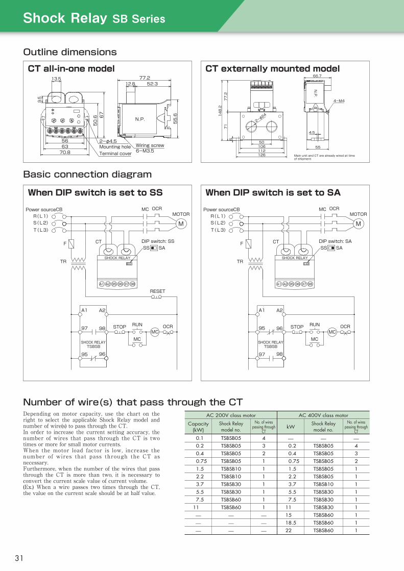
Outline dimensions
Number of wire(s) that pass through the CT
Basic connection diagram
Depending on motor capacity, use the chart on the right to select the applicable Shock Relay model and number of wire(s) to pass through the CT.In order to increase the current setting accuracy, the number of wires that pass through the CT is two times or more for small motor currents.When the motor load factor is low, increase the number of wires that pass through the CT as necessary.Furthermore, when the number of the wires that pass through the CT is more than two, it is necessary to convert the current scale value of current volume.(Ex.) When a wire passes two times through the CT, the value on the current scale should be at half value.
AC 200V class motor
Capacity (kW)
Shock Relay model no.
No. of wires passing through
CT00.1 TSBSB05 4
00.2 TSBSB05 3
00.4 TSBSB05 2
0.75 TSBSB05 1
01.5 TSBSB10 1
02.2 TSBSB10 1
03.7 TSBSB30 1
05.5 TSBSB30 1
07.5 TSBSB60 1
11.0 TSBSB60 1
— — —— — —— — —
AC 400V class motor
kWShock Relay model no.
No. of wires passing through
CT
— — —00.2 TSBSB05 4
00.4 TSBSB05 3
0.75 TSBSB05 2
01.5 TSBSB05 1
02.2 TSBSB05 1
03.7 TSBSB10 1
05.5 TSBSB30 1
07.5 TSBSB30 1
11.0 TSBSB30 1
15.0 TSBSB60 1
18.5 TSBSB60 1
22.0 TSBSB60 1
CT all-in-one model
When DIP switch is set to SS
CT externally mounted model
When DIP switch is set to SA
TSB50TSB-COMcurrent transformer
Starting currentMotor rotation speed
Motor currentMomentaryoverload Overload
Shock timeStart timeFixed at 3s Shock time
Overload zoneSteady zone
Load currentset value
Rotation speed/current
Time
Stop
Shock Relay operation
Model no.Function TSB50-COM
0.2 to 3.7kW*1
0.2 to 3.7kW–10°C to 50°C
45 to 85%RH; no condensation5.9m/s2 or less1000m or less
No corrosive gas or dustTSB50
50 to 130% (100%=5mA)±10% (full-scale)
Fixed at 3s0.3 to 3s
AC100/110V or AC200/220V, 50/60Hz ±10%AC600V, 50/60Hz1-phase CT system
No self-holding (automatic reset)Output relay is not excited
Output relay is excited1s contact, AC250V 0.1A (inductive load cosφ=0.4)
DC10V, 10mA10,000,000 activations
100,000 activationsNot available
AC1500V, 60Hz, 1minute (power supply circuit and contact circuit)AC500V, 60Hz, 1 minute
AC1500V, 60Hz, 1 minute (power supply circuit and contact circuit)0.3kg (not including external CT)
0.5VATSB COM
0.75A, 1.5A, 1.75A, 2.0A, 2.5A, 3.3A,4.0A, 5.3A, 7.0A, 9.0A, 10.0A, 16.0A
5mA0.5VA0.5kg
Main unit model no.Load current (current setting range)*3
Current setting accuracy
Control power supply voltageMax. motor circuit voltageCurrent detecting system
Test function
MassPower consumption
Accessory external CT model
Rated primary current
Rated secondary currentRated load
Mass
Motor
Com
mon
Mai
n un
itEx
tern
al C
T
Usage environment
200V class400V class
Ambient temperatureAmbient humidity
VibrationAltitude
Atmosphere
Time setting range Start timeShock time
Output relay
Output relay life
Self-holdingNormal state
Abnormal stateContact capacity
Min. applicable load*2
MechanicalElectrical
Withstand voltageBetween circuit–housing
Between contactsBetween circuits
Notes:*1. If the TSB-COM-A (small-capacity CT) is used, a motor of 0.1kW or less can be used.*2. When directly inputting output relay contact into the programmable controller (PLC), be aware that a minute electric current can cause contact failure. Therefore, before inputting the output relay contact into the PLC, it is recommended that you drive the relay coil for a minute current via the relay signal. *3. Current and time setting ranges are settable ranges, not the upper and lower levels of setting volume.
Standard specifications
Part names and functions Operating mode
● Economically priced
● Automatic reset
● Optional specifications available
Features
Load current settingSet to 50% to 130% of motor rated current
Power indicator lampLights up during normal operation and turns off during Shock Relay activation
Shock time settingSet range 0.3 to 3s
Wiring screw6-M3.5
N.P.
55.6
52.312.877.2
9.5
13.5
70.86356 2-φ4,5
Mounting holeTerminal cover
50.6 67 148.2
66.7
N.P.
77.2
Main unit and CT are already wired at time of shipment
106
4.5
50
671
126
55
2-φ24
4-M4
112
DIP switch: SS
RESET
SA
98A1 A2 95 96 97
SHOCK RELAY
A2A1
OCR
9695
9897 STOP RUN
MCMC
SHOCK RELAYTSBSB
CT
TR
F
OCR
T(L3)S(L2)R(L1) MOTOR
M
Power source MCCB
SS
MC
SS SADIP switch: SA
Power sourceCB MC
MR(L1)S(L2)T(L3)
OCR
F
TR
CT
SHOCK RELAYTSBSB
MC
RUNSTOP95 96
97 98
OCR
A1 A2
SHOCK RELAY
979695A2A1 98
MOTOR
ShockRelaySBSeries
31
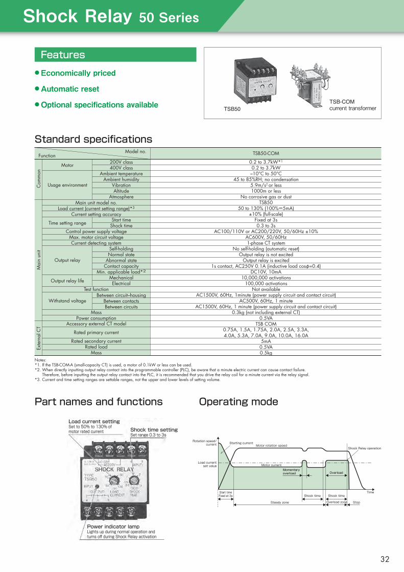
TSB50TSB-COMcurrent transformer
Starting currentMotor rotation speed
Motor currentMomentaryoverload Overload
Shock timeStart timeFixed at 3s Shock time
Overload zoneSteady zone
Load currentset value
Rotation speed/current
Time
Stop
Shock Relay operation
Model no.Function TSB50-COM
0.2 to 3.7kW*1
0.2 to 3.7kW–10°C to 50°C
45 to 85%RH; no condensation5.9m/s2 or less1000m or less
No corrosive gas or dustTSB50
50 to 130% (100%=5mA)±10% (full-scale)
Fixed at 3s0.3 to 3s
AC100/110V or AC200/220V, 50/60Hz ±10%AC600V, 50/60Hz1-phase CT system
No self-holding (automatic reset)Output relay is not excited
Output relay is excited1s contact, AC250V 0.1A (inductive load cosφ=0.4)
DC10V, 10mA10,000,000 activations
100,000 activationsNot available
AC1500V, 60Hz, 1minute (power supply circuit and contact circuit)AC500V, 60Hz, 1 minute
AC1500V, 60Hz, 1 minute (power supply circuit and contact circuit)0.3kg (not including external CT)
0.5VATSB COM
0.75A, 1.5A, 1.75A, 2.0A, 2.5A, 3.3A,4.0A, 5.3A, 7.0A, 9.0A, 10.0A, 16.0A
5mA0.5VA0.5kg
Main unit model no.Load current (current setting range)*3
Current setting accuracy
Control power supply voltageMax. motor circuit voltageCurrent detecting system
Test function
MassPower consumption
Accessory external CT model
Rated primary current
Rated secondary currentRated load
Mass
Motor
Com
mon
Mai
n un
itEx
tern
al C
T
Usage environment
200V class400V class
Ambient temperatureAmbient humidity
VibrationAltitude
Atmosphere
Time setting range Start timeShock time
Output relay
Output relay life
Self-holdingNormal state
Abnormal stateContact capacity
Min. applicable load*2
MechanicalElectrical
Withstand voltageBetween circuit–housing
Between contactsBetween circuits
Notes:*1. If the TSB-COM-A (small-capacity CT) is used, a motor of 0.1kW or less can be used.*2. When directly inputting output relay contact into the programmable controller (PLC), be aware that a minute electric current can cause contact failure. Therefore, before inputting the output relay contact into the PLC, it is recommended that you drive the relay coil for a minute current via the relay signal. *3. Current and time setting ranges are settable ranges, not the upper and lower levels of setting volume.
Standard specifications
Part names and functions Operating mode
● Economically priced
● Automatic reset
● Optional specifications available
Features
Load current settingSet to 50% to 130% of motor rated current
Power indicator lampLights up during normal operation and turns off during Shock Relay activation
Shock time settingSet range 0.3 to 3s
ShockRelay50Series
32
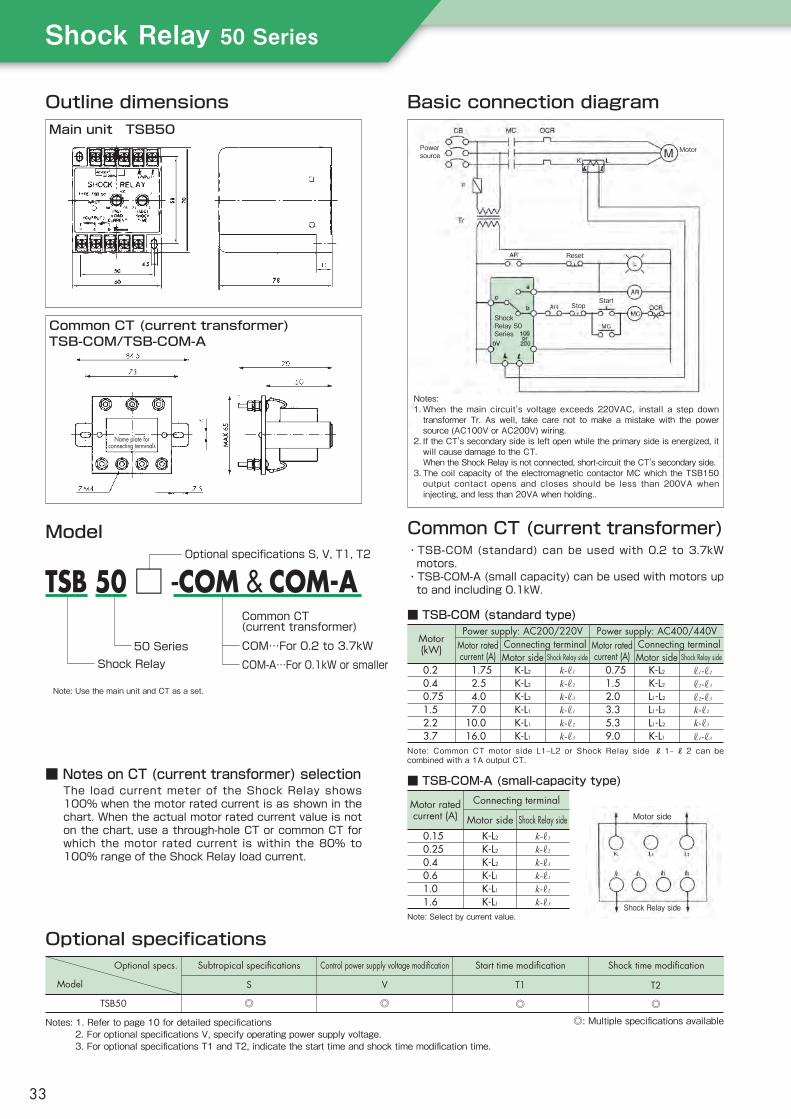
Outline dimensionsMain unit TSB50
Common CT (current transformer)TSB-COM/TSB-COM-A
Basic connection diagram
Common CT (current transformer)・TSB-COM (standard) can be used with 0.2 to 3.7kW
motors.・TSB-COM-A (small capacity) can be used with motors up
to and including 0.1kW.
Model
■ Notes on CT (current transformer) selectionThe load current meter of the Shock Relay shows 100% when the motor rated current is as shown in the chart. When the actual motor rated current value is not on the chart, use a through-hole CT or common CT for which the motor rated current is within the 80% to 100% range of the Shock Relay load current.
Optional specifications
Notes: 1. Refer to page 10 for detailed specifications 2. For optional specifications V, specify operating power supply voltage. 3. For optional specifications T1 and T2, indicate the start time and shock time modification time.
Subtropical specifications Control power supply voltage modification Start time modification Shock time modification
S
◎
V T1 T2
◎ ◎ ◎
Model
Optional specs.
TSB50
◎: Multiple specifications available
Name plate forconnecting terminals
Notes:1. When the main circuit's voltage exceeds 220VAC, install a step down
transformer Tr. As well, take care not to make a mistake with the power source (AC100V or AC200V) wiring.
2. If the CT's secondary side is left open while the primary side is energized, it will cause damage to the CT.
When the Shock Relay is not connected, short-circuit the CT's secondary side.3. The coil capacity of the electromagnetic contactor MC which the TSB150
output contact opens and closes should be less than 200VA when injecting, and less than 20VA when holding..
Powersource
Motor
Reset
StopStart
■ TSB-COM (standard type)
Note: Common CT motor side L1–L2 or Shock Relay side ℓ 1– ℓ 2 can be combined with a 1A output CT.
Motor(kW)
0.20.40.751.52.23.7
1.75 2.5 4.0 7.0 10.0 16.0
K-L2
K-L2
K-L2
K-L1
K-L1
K-L1
k-ℓ1
k-ℓ2
k-ℓ3
k-ℓ1
k-ℓ2
k-ℓ3
0.75 1.5 2.0 3.3 5.3 9.0
K-L2
K-L2
L1-L2
L1-L2
L1-L2
K-L1
ℓ1-ℓ2
ℓ2-ℓ3
ℓ2-ℓ3
k-ℓ2
k-ℓ3
ℓ1-ℓ3
Power supply: AC400/440VMotor ratedcurrent (A)
Connecting terminalMotor side
Power supply: AC200/220VMotor ratedcurrent (A)
Connecting terminalMotor side Shock Relay side Shock Relay side
■ TSB-COM-A (small-capacity type)
Note: Select by current value.
Motor ratedcurrent (A)
0.150.250.40.61.01.6
K-L2
K-L2
K-L2
K-L1
K-L1
K-L1
k-ℓ1
k-ℓ2
k-ℓ3
k-ℓ1
k-ℓ2
k-ℓ3
Connecting terminal
Motor side Shock Relay side Motor side
Shock Relay side
ShockRelay 50Series
Note: Use the main unit and CT as a set.
TSB 50 □ -COM & COM-A
COM-A…For 0.1kW or smaller50 Series COM…For 0.2 to 3.7kW
Common CT(current transformer)
Shock Relay
Optional specifications S, V, T1, T2
ShockRelay50Series
33
Features p35
Modelreferencechart p36
Applicationexamplesandbasicoperationsofeachtype
ShockMonitorTSM4000 p37
ShockMonitorTSM4000/TSM4000H1 p43
ShockMonitorTSM4000H2 p44
ShockMonitorTSM4000M1 p43
ShockMonitorTSM4000M2 p46
ShockMonitorTSM4000M3 p47
ShockMonitorTSM4000C1 p48
Externalconnection,parametersettings,terminalfunctions p49
SHOCK MONITOR
34

Motor load
Current variation small (difficult to detect)
Power variation large (easy to detect)
Loadvariation
Detection value
Power
Current
Variation at light load zone
Influence of power source voltage fluctuation
Example: Power and current variation corresponding to load variation
Current variation large (unstable)
Power variation small (stable)
Loadconstant
Detection value
Power (at 200/220V)Current (at 220V)Current (at 200V)
Motor load
0
50
100
Load factor (%)
Example: Power and current variation for load variation
Time
Motor: 0.75kW
Current variation
Power variation
Load variation
Load variation 10%
TSM4000 Series‒200 to +200% converted into 0 to 10V (basic type)0 to +200% converted into 0 to 10V (optional)0 to +200% converted into 4 to 20mA (optional)
Features
● Ideal for monitoring light loads
The Shock Monitor is an electricity-monitoring control device that detects minimal load variations by monitoring motor input power.
For a standard motor there are only minute current variations in the light load zone. For load monitoring of a device used in the light load zone, monitoring electric power variations in the proportional load is ideal.
● Almost completely unaffected by source voltage variationEven with a constant load, if the power supply voltage fluctuates then current will fluctuate largely, thus making accurate load detection impossible. The Shock Monitor monitors electricity so it is almost completely unaffected by voltage fluctuation, making stable load detection possible.
● Can be used with a wide range of frequencies (5 to 120Hz)Can be used with an inverter and a servomotor drive. (The inverter's electronic thermal relay is for burnout protection and is not suitable for device protection.)Note: If the power source frequency exceeds 120Hz,
such as a servomotor for a machine tool’s main spindle, consult Tsubaki.
● Quick responseMotor input power is measured every 0.02 seconds. Right after an emergency, the signal is output in a minimum of 0.05 seconds.
● Records load conditionsThe direct current voltage that is proportionate to motor input power is output, so the load condition can be recorded on the recorder.
● CE compliancy possibleFor details, contact Tsubaki.
(1)Power variation that is proportional to load variation can be seen.
(2)From the chart below we can see that with a load variation of about 10%, there is almost no change in current, while power makes a significant change.
ShockMonitor
35
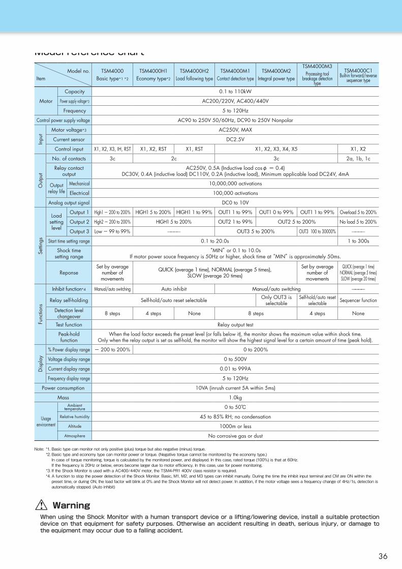
Model reference chart
Note: *1.Basictypecanmonitornotonlypositive(plus)torquebutalsonegative(minus)torque. *2.Basictypeandeconomytypecanmonitorpowerortorque.(Negativetorquecannotbemonitoredbytheeconomytype.) Incaseoftorquemonitoring,torqueiscalculatedbythemonitoredpower,anddisplayed.Inthiscase,ratedtorque(100%)isthatat60Hz. Ifthefrequencyis20Hzorbelow,errorsbecomelargerduetomotorefficiency.Inthiscase,useforpowermonitoring. *3.IftheShockMonitorisusedwithaAC400/440Vmotor,theTSM4-PR1400Vclassresistorisrequired. *4.AfunctiontostopthepowerdetectionoftheShockMonitor.Basic,M1,M2,andM3typescaninhibitmanually.DuringthetimetheinhibitinputterminalandCMareONwithinthe presettime,orduringON,theloadfactorwillblinkat0%andtheShockMonitorwillnotdetectpower.Inaddition,ifthemotorvoltageseesafrequencychangeof4Hz/1s,detectionis automaticallystopped.(Autoinhibit)
WarningWhen using the Shock Monitor with a human transport device or a lifting/lowering device, install a suitable protection device on that equipment for safety purposes. Otherwise an accident resulting in death, serious injury, or damage to the equipment may occur due to a falling accident.
Model no.Item
TSM4000Basic type*1 *2
TSM4000H1Economy type*2
TSM4000H2Load following type
TSM4000M1Contact detection type
TSM4000M2Integral power type
TSM4000M3Processing tool
breakage detection type
TSM4000C1Built-in forward/reverse
sequencer type
Motor
Capacity 0.1 to 110kW
Power supply voltage*3 AC200/220V, AC400/440V
Frequency 5 to 120Hz
Control power supply voltage AC90 to 250V 50/60Hz, DC90 to 250V Nonpolar
Motor voltage*3 AC250V, MAX
Current sensor DC2.5V
Control input X1, X2, X3, IH, RST X1, X2, RST X1, RST X1, X2, X3, X4, X5 X1, X2
No. of contacts 3c 2c 3c 2a, 1b, 1c
Relay contactoutput
AC250V, 0.5A (Inductive load cosφ = 0.4)DC30V, 0.4A (inductive load) DC110V, 0.2A (inductive load), Minimum applicable load DC24V, 4mA
Outputrelay life
Mechanical 10,000,000 activations
Electrical 100,000 activations
Analog output signal DC0 to 10V
Loadsettinglevel
Output 1 High1 - 200 to 200% HIGH1 5 to 200% HIGH1 1 to 99% OUT1 1 to 99% OUT1 0 to 99% OUT1 1 to 99% Overload 5 to 200%
Output 2 High2 - 200 to 200% HIGH1 5 to 200% OUT2 1 to 99% OUT2 5 to 200% No load 5 to 200%
Output 3 Low - 99 to 99% ———— OUT3 5 to 200% OUT3 100 to 30000% ————
Start time setting range 0.1 to 20.0s 1 to 300s
Shock timesetting range
“MIN” or 0.1 to 10.0sIf motor power souce frequency is 50Hz or higher, shock time at “MIN” is approximately 50ms.
ReponseSet by average
number of movements
QUICK (average 1 time), NORMAL (average 5 times), SLOW (average 20 times)
Set by average number of movements
QUICK (average 1 time) NORMAL (average 5 times) SLOW (average 20 times)
Inhibit function*4 Manual/auto switching Auto inhibit Manual/auto switching ————
Relay self-holding Self-hold/auto reset selectable Only OUT3 is selectable
Self-hold/auto reset selectable Sequencer function
Detection level changeover 8 steps 4 steps None 8 steps 4 steps None
Test function Relay output test
Peak-holdfunction
When the load factor exceeds the preset level (or falls below it), the monitor shows the maximum value within shock time.Only when the relay output is set as self-hold, the monitor will show the highest signal level for a certain amount of time (peak hold).
% Power display range - 200 to 200% 0 to 200%
Voltage display range 0 to 500V
Current display range 0.01 to 999A
Frequency display range 5 to 120Hz
Power consumption 10VA (inrush current 5A within 5ms)
Mass 1.0kg
Usageenvironment
Ambienttemperature 0 to 50℃
Relative humidity 45 to 85% RH; no condensation
Altitude 1000m or less
Atmosphere No corrosive gas or dust
Inpu
tO
utpu
tSe
tting
sFu
nctio
nsD
ispl
ay
36

Shock Monitor TSM4000Features
Safety designThe terminal block is equipped with a cover.This structure prevents dust from entering themain unit.
Quickly detects small load changes
Analog output0 to 10 V analog output comes standard, enabling action and monitoring according to the load. (0 to 5 V and 4 to 20 mA outputs are optionally available.)
Environmentally friendlyThe backlight automatically turns off, contributing to energy savings. This product also does not contain any RoHS restricted substances.Contributes to visualization in factories
(option)Combining a commercially available touchpanel display and a Shock Monitor having an optional communication function makes it possible to display the current readout of the Shock Monitor and a trend graph of the readout on a remote display. Also, you can change the parameters of the Shock Monitor through remote touchpanel operations.
Improved handleabilityThe panel-mount design has beem standardized to make connection to the terminal block easy whenmounting this product on a panel.Also, this product can be mounted on DIN rails.
Basic operations of TSM4000
ElectricityShockMonitor trip
High1 Shock timeHigh2 Shock time
Self-holdsetting
Auto reset settingRecovers onesecond later
Overload
Motor stop
Motor display
High1 display
High1 relay
High2 display
High2 relay
Momentary overload
Time
High1 Shock timeStart time
High2set valueHigh1
set value
■ Overload operating modeElectricity
Lowset value
Motor display
Low display
Low relay
Start time Low Shock time Low Shock time
Light load
Momentary light load
Motor stop
Self-holdsetting
Shock Monitortrip
Time
■ Light-load operating mode
1) The TSM4000 compares the load with the preset overload detection level, and presents an external notification of load abnormality when an overload state (or a light-load state) continues for a certain period of time (the shock time).
2)Two upper-limit emergency signals and one lower-limit emergency signal are available and can be used as advance notification signals or motor stop signals.
3)To prevent false output due to acceleration, the load detection is canceled for a preset time (the start time) when starting the motor.4)A torque monitoring function (20 to 120 Hz) is available, which is effective when an inverter is used. See Note *2 on page 36.
Note: The counting of both the start time and the shock time begins when the motor starts. Therefore, the one set to a longer time is valid.
ShockMonitor
37

● Usage examples
● Application examples of the optional communication function
Overload protection for machinetools, detection of drill breakage
In a drilling process using a machine tool, the Shock Monitor reliably detects not only overload but also any breakage of the drill, preventing defective products from being produced during unattended operation.Additionally, using a model that calculates integral power values enables detection of wear in the drill with high accuracy. Replacing the dri l l before breakage can contribute to better productivity.
Overload protection for suspension/hoisting devices
The Shock Monitor can be used with a hoisting device on a staging set or in a factory. When the load on the device exceeds the design load (allowable load), the drive system is stopped automatically to prevent accidents such as dropping.The power detection method ensures highly accurate load detection even for high-reduction operation using a worm gear reducer in the drive unit.
The optionally available communication function enables the combination of the Shock Monitor and a commercially available touchpanel display unit to be used in the following ways: Functions available with the display unit● Displaying of electrical power, current, and voltage data in graph form● Saving of the above data and transferring the data into memory● Reading/writing of setting values for a specified parameter
Shock MonitorTouchpanel display unit(third-party product)
Communication specifications
Item
Transmissionstandard
Communicationmethod
Transmissionspeed
Brief specifications
RS485
Half-duplex, bidirectional, Modbus protocol
Selectable from 2.4, 4.8, 9.6, 19.2, and 38.4kbps
Usage● The production process can be monitored using real-time displays of power and current waveforms.● Checking the waveform of abnormal events is effective in preventive measures or making improvements to
guard against device damage.
For details, contact Tsubaki.
38

● Model
● Outline dimensions (Basic type)
● Part names and functions① Liquid crystal display … Displays load factor, set values, and parameter data.
② LED indicators ……… Indicates the status in which the motor is running and
the output relay is activated.
③ Operation keys ……… Keys used to change the display mode or parameters.
④ Connector CN1 ……… Is connected when using signals such as control input and
analog output.
⑤ Terminal block for wiring … Terminals for connecting control power supply,
motor voltage, relay output, current sensor cable, etc.
● Outline dimensions (Panel mounted type)
Main unit section
Socket section
Note: Use as a set with a current sensor based on the motor capacity.
TSM4000 H1 P - □□□□ - A1Shock Monitor main unit
TypeBlank : BasicP : Panel-mountedH1 : EconomyH2 : Load following
M1 : Contact detectionM2 : Integral power typeM3 : Processing tool breakage detection typeC1 : Built-in forward/reverse sequencer
Current sensor(Example: )
Option codeBlank : Standard specificationT1 : With communication function
(consultation required)A1 : Analog output 4 to 20mAA2 : Analog output 0 to 5V
U 0 1 0Blank: Wall mountedP: Panel mounted
90
96
842-φ4.5(2-M4)
取付穴加工寸法
99.5
124
90
96
842-φ4.5(2-M4)
取付穴加工寸法
99.5
124
90
96
842-φ4.5(2-M4)
取付穴加工寸法
99.5
124
90
96
842-φ4.5(2-M4)
取付穴加工寸法
99.5
124
Mountingholedimension90
96
93±0.2
69±0.2
パネル取付穴寸法
90
124
90
96
93±0.2
69±0.2
パネル取付穴寸法
90
124
Panelmountingholedimension
90
96
93±0.2
69±0.2
パネル取付穴寸法
90
124
90
96
93±0.2
69±0.2
パネル取付穴寸法
90
124
ShockMonitor
39

Option■ Current sensor (sold separately)
The current sensor is needed to bring motor current into the Shock Monitor unit. Select a model from the chart below depending on the motor capacity and voltage.
Installation holes: 2-φ4
54
1 4
46
545
63.5
8 20
37
Current direction indicator
MOLEX5046-04AG
φ20
Motor capacity(kW)
Sensormodel no.
Number of wirespassing
through CTSensor
model no.Number of wires
passing through CT
AC 200/220V motor AC 400/440V motor
0.1
0.2
0.4
0.75
1.5
2.2
3.7
5.5
7.5
11
15
18.5
22
30
37
45
55
75
90
110
TSM-U010
TSM-U010
TSM-U010
TSM-U050
TSM-U050
TSM-U050
TSM-U050
TSM-U050
TSM-U100
TSM-U100
TSM-U150
TSM-U150
TSM-U200
TSM-M300
TSM-M300
TSM-M400
TSM-M600
TSM-M600
TSM-M800
TSM-M800
6
3
2
6
3
2
1
1
1
1
1
1
1
1
1
1
1
1
1
1
TSM-U010
TSM-U010
TSM-U010
TSM-U010
TSM-U050
TSM-U050
TSM-U050
TSM-U050
TSM-U050
TSM-U050
TSM-U100
TSM-U100
TSM-U100
TSM-U150
TSM-U150
TSM-U200
TSM-M300
TSM-M300
TSM-M400
TSM-M400
12
6
3
2
6
5
3
2
1
1
1
1
1
1
1
1
1
1
1
1
Sensor model no.TSM-U010, TSM-U050, TSM-U100, TSM-U150, TSM-U200
MOLEX5046-04AG
Installation holesφ4.6
Installation holesR2.3 Current direction indicator
24
6428
205
90
7840
4 1
7
4-φ460
2931.2
45
120
105
90
U2 V2 W2
U1 V1 W1
6-M4 screw
RESISTORFOR 380-460V
TSM4-PR1
Sensor model no.TSM-M300, TSM-M400, TSM-M600, TSM-M800
■ 400V class resistorThis is required if the motor voltage is400/440V. Please order separately.
TSM4-PR1
■ Sensor cableA sensor cable (TSM4-S01) comes standard toconnect the Shock Monitor and the current sensor.If a different cable is required, order a cable with connector as shown below .
L
■ I/O cableThis cable is required when you want to perform processchangeover from the outside, when resetting the Shock Monitor, and when connecting an externalmeter. It should be ordered as necessary.
121.5108.5 35
93±0.2
5
(81)
71.8
69±0.2
Rubber sheets
2-M4 nutPanel mounting hole
dimensionNote1. Included: M4 3-point SEMS screw x 15
2. Screw tightening torque: 0.12 to 0.16N・m
3. Panel mounting hole dimension: See the figure on the right.
■ Panel mounting bracketThis bracket is used tosecure the panel-mounted Shock Monitor.
L
Model No. Cable length (L)TSM4-S01 (attached)
TSM4-S03TSM4-S05TSM4-S10TSM4-S20TSM4-S30
1m3m5m10m20m30m
Model No. Cable length (L)TSM4-C01TSM4-C03
1m3m
TSM4-PL1
40

Current sensor
CB : Circuit breakerF : FuseMC : Electromagnetic contactor for motorOCR : Overcurrent relayCR1 : CR filterSTART : Start buttonSTOP : Stop button
METERRECORDER
*FOR ANALOG INPUT
*FOR COMMUNICATION
START
STOP
LAMP
LAMP
BUZZER
400V CLASS RESISTOR (OPTION)(ONLY WHEN USING 400/440V)
*The analog input and communication terminals are supported as optional functions.
SENSOR CABLE
SHOCK MONITOR
OUTPUT
OUTPUTCONNECTOR CN1
OUTPUT
Note:1. Select the current sensor from the Current Sensor Table based on motor capacity and voltage. Use the specified CT through number and current direction.
2. Make sure to put the current sensor into phase V, and use the sensor cable to connect with the Shock Monitor.
3. If using a 400/440V motor, use the 400V class resistor shown in dashed line.
4. Connect the motor voltage terminal of the Shock Monitor U [1], V [2], W [3] with the phase of [U], [V], [W] respectively.
5. Use relay for minute electric current for [X1], [X2], [X3], [IH], and [RST].
◎ In case of a wrong connection, load cannot be detected correctly and the Shock Monitor will not work properly.
When the operating electromagnetic coil capacity (electromagnetic capacity) of the electromagnetic contactor [MC] for the motor is less than 100 VA for injection and less than 10 VA for holding.
■ External connection
・Terminal block ・Connector CN1Current sensorHigh2output
Motorvoltageinput
GroundLowoutput
High1output
Powersupply
+
Note: Connection to pins No. 3 and 14 is prohibited.
Name
Control power supply
Ground
Current sensor
Motor voltage
Low output
High1 output
High2 output
POWER
E- 15+15C-C+FGUVWbacbaccab
IN
-OUTOUTININ-INININ
OUTOUTOUTOUTOUTOUTOUTOUTOUT
1112101617181920123789456131415
Connection of controlpower supply
Ground terminal
Sensor cable
Motor voltage inputterminal
Relay contact outputwhen lower limitoutput is activated
Relay contact output when upper limit 1 is output
Relay contact output when upper limit 2 is output
SymbolIN/OUT
Pinno.
Explanation
Name
Process changeover
Inhibit Common Reset
X1X2X3IH
CMRST
ININININININ
19210411
Power process terminal
Inhibit terminalX1,X2,X3,IH,RST common terminalResets self-hold status
SymbolIN/OUT
Pinno.
Explanation
■ Control input
■ Analog output
Analog output
Analog output
Load factor Load factor
■ Terminal functions
When the model supports the terminal function as standard, the analog outputcharacteristic can be selected with Parameter 21: OUTPUT SELECT.
ShockMonitor
41

■ Parameter settings
No.
1
2
3456
78
9
1011
12
1314
15161718
19
20
21
22
23
Parameter LockMotor Voltage
Motor kWStart TimeProcessHigh2 LevelProcess[1]Shock Time H2Output Relay H2
High1 LevelProcess[1]Shock Time H1Output Relay H1
Low LevelProcess[1]Shock Time LOutput Relay L
Motor EfficiencyResponseInhibit TimeAuto Inhibit
Power/Torque
H2Relay Logic
Output Select
LCD Backlight
Trip Test
(1)Unlocked(2)Locked(1)200-230V(2)380-460V0.1 to 110kW0.1 to 20.0s1 to 8−200 to −5%5 to 200%MIN,0.1 to 10s(1)Self-Hold(2)Auto-Reset−200 to −5%5 to 200%MIN,0.1 to 10s(1)Self-Hold(2)Auto-Reset−99 to 0 to 99%
MIN,0.1 to 10s(1)Self-Hold(2)Auto-Reset10 to 100%1 to 50timesIH,0.1 to 10s(1)On(2)Off(1)Power(2)Torque(1)Fail Safe(2)Nomal Logic(1)−200 to 200%(2)0 to 200%(1)Always(2)2min(1)Motor on/off(2)Motor off
(1)
(1)
0.753.0s
1100%
1.0s
(1)
80%
1.0s
(2)
0%
1.0s
(1)
100%5times
IH
(2)
(1)
(2)
(2)
(1)
(1)
All parameters can be changedParameters other than this parameter cannot be changedMotor voltage 3-phase 200V classMotor voltage 3-phase 400V classSet motor capacitySet start timeNumber of processesUpper limit 2 value of process 1
Upper limit 2 shock timeSelect upper limit 2output operation modeUpper limit 1 value of process 1
Upper limit 1 shock timeSelect upper limit 1output operation modeLower limit value of process 1
Lower limit shock timeSelect lower limit outputoperation modeMotor efficiencyNumber of moving average sampling operationsInhibit time*Set auto inhibit function
Monitor with motor input powerMonitor with torque calculated by powerSelect fail-safe operation
Select analog output
Keep backlight on at all timesBacklight turns off in 2 minutes after key operationSelect test mode duringmotor operation
Parameter Data Default settings Details
■ LCD contrast adjustment
If the LCD is hard to read, hold down the SET key and press ▲ or ▼ key to adjust it.(Note that excessively high contrast will shorten the LCD service life.)
* Inhibit time: Time during which power detection is temporarily stopped.
Hold down the SET key and press▲ to make the display darker.
Hold down the SET key and press▼ to make the display lighter.
42

Applications for the Shock Monitor
Application examples and basic operations of each type1. Basic type: TSM4000 For general industrial machines
Economy type: TSM4000H1The economy type has fewer functions than the basic type.Refer to the below chart for a comparison of Shock Monitor functions.
■ Damage prevention
Shock Monitor
Shock Monitor load factor 100%
Shock Monitor load factor 50%
Shock Monitor load factor 0%
Just pulling theconveyor by hand
These responseswere detected byShock Monitor
Seats for automobiles
1//1800 reducer
Motor
Low speed conveyor overload protection
Basic operations of TSM4000H1
Alarm output when motor powerexceeds HIGH1 level.
After elapsed HIGH2 shock time, outputs the abnormal condition of the equipment.
Setting time of Shock Monitoroutput after exceeding HIGH2 set value.
Setting time to prevent Shock Monitoroutput error due to start-up power.
0%
100%
Start time
ON
ON
HIGH2 Output relay
HIGH1 Output relay
HIGH2 setting
HIGH1 setting
Motor power
HIGH2 Shock time
HIGH1 Shock time
Simplified model with only the essential functions
Key pointThere is little current variation due to a high gear ratio,making it difficult for the Shock Relay to detect the overload,so a power-detecting Shock Monitor is the best option.ApplicationsAssembly conveyor, water and sewage treatment,garbage disposal conveyors, etc.
Note: Overload may be difficult to detect depending on the characteristics of the machine. Check your usage conditions and contact us if you are considering this type of application.
■ Preventive maintenance
Carryingbread dough
Fermentation lineMotor
Shock Monitor
Bread making line lubrication maintenance
Key pointThe Shock Monitor detects a minute load rise due to a lack of lubrication on the chain. It then sends analarm signal and operates the automatic lubricator.ApplicationsFood processing machines that operate 24 hours a day, etc.
Features1) Simplified functions means easy setting.2) Relay output has two outputs. It can
be used as an alarm signal (HIGH1) and an abnormal level output (HIGH2).
3) As a set, HIGH1 and HIGH2 can be switched externally for a maximum of 4 types. It is useful for changing the setting depending on the workpiece being carried.
4) It comes with an efficient torque* monitoring function (20 to 120Hz) for when using the inverter.
*Refer to page 36, Note: *2
Function Basic model Economy model
Load
detec
tion HIGH1
HIGH2LOW
Comparison of function: Basic model and Economy model
◯◯◯◯
◯◯×◯
48
◯ ×
Torque monitoring functionNo. of selection of detection level
(No. of process to monitor)Monitoring negative torque
● Economical load detection is possible: Economy type
Various application-specific types based on the TSM4000 basic modelOurline-upofShockMonitorsfitsallkindsofapplications.
ShockMonitor
43

Application examples and basic operations of each type2. Load following type: TSM4000H2…For general industrial machines
■ Protection for efficiency-varying equipment
ShockMonitor
Mud collecting chain
Basic operations of TSM4000H2
Because variation in machine efficiency does not affect the Shock Monitor,it makes the ideal overload protection device.
■ Protection for equipment on which load periodically changes
ShockMonitor
Features1)For equipment where
mechanical efficiency varies, by periodically following the operational level and minimizing the efficiency variation effect, the practical overload state can be detected.
2)The write cycle can be changed according to fluctuations in efficiency.
3)Because the operational level of HIGH2 is constant and has no variation, absolute value monitoring can be done by HIGH2.
● The set value automatically follows the variation in load: Load following
}}}}
0%
100%
+10%(HIGH1)
HIGH1 set value
Set value
Motor power
+10% operation level+10%
+10%
Set value
HIGH2 set value
HIGH1 set value
HIGH1 Output relay
Set value
Start time Write cycle Write cycle Write cycle Shock time
ONWriting interval can be changed between 1 sec. to 60 minutes.
Example: Once HIGH1 set value is set as"+ (plus )10%", the variation is read at everywriting cycle, and it resets the operationlevel within +10% as a new level.
HIGH2: No rewriting of the operation level allowsabsolute value monitoring.
Detects overload andoutputs abnormalcondition of equipment.
Key point The efficiency of the reducer varies according to operating time. As well, even for equipment where the load factor varies, it is possible to detect abnormals condition due to the load following function.ApplicationsWater treatment equipment, etc.
Key pointEven if the load of the equipment varies during 1 rotation, it is possible to detect abnormal conditions due to the load following function.ApplicationsMedical equipment, etc.
● Equipment driven by worm reducer ● Swivel
44

Application examples and basic operations of each type3. Contact detection type: TSM4000M1・・・・For machine tools (patent granted)
■ Tool and workpiece contact detection (Feed speed control, etc.)
ShockMonitor
Feed Workpiece
Basic operations of TSM4000M1
The idling position is automatically offset to a 0% load factor, and the ShockMonitor will detect only work volume.
Features1)Because the TSM4000M1 auto-
matically offsets power during idling to 0%, the minute power change during tool and workpiece contact can be detected with high precision. (There are two types of output: OUT1 and OUT2.)
2)OUT3 can do abosolute value monitoring with non-offset values.
3)In regard to detection levels, as a set, OUT1, OUT2, and OUT3 can be switched externally for a maximum of 8 types. It can deal with changes in grindstones and workpieces.
● Rapidly detects workpiece contact: Contact detection
FunctionUntil the grindstone makes contact with the workpiece, the feed speed is high. After the Shock Monitor has detected contact with the workpiece, the TSM4000M1 immediately switches to a low feed speed. (Shortens work time.)Key pointA minute load at the moment the grindstone contacts with the workpiece is quickly and accurately detected. Consequently, a substantial decrease in the finishing cycle time is realized.ApplicationsMetalworking, machine tools, etc.
0%
100%
Motor power
Start timeON OUT1 Output relay
OUT1 set value
OUT3 set valueMonitors at non-offset absolute value.
OUT1 Shock time
Minute load variation from offset value can be detected and output quickly and accurately.
Load factor at no-load operation can be offset to 0%.
● Grindstone contact detection
■ Tool and workpiece contact detection
ShockMonitor
High-speed rotationalbalance is measuredusing a vibrationsensor. When vibration is above the regulated amount, the crank shaft in question can be rendered defective.
In order to balance thedefective product, drill a hole to reduce the weight of the overweight portion, allowing the Shock Monitor to detect the moment the drill touches the workpiece.From there, the drill feed amount and the weight reduction quantity are kept constant.1.5kW
FunctionWhen drilling a hole, if the drill touches the workpiece, it will be detected and the Shock Monitor will immediately output. From there, by keeping feed time constant, the drilled quantity is managed uniformly.Key pointThe Shock Monitor ignores common changes to idling power. Because it detects only work volume, it can securely judge the moment contact is made with the drill (0.05s).ApplicationsMachine tools (drilling machine, grinding machine, etc.)
● Rotational balance corrector for auto parts (crank shaft)
Note:Ifthepowersourcefrequencyexceeds120Hz,suchasaservomotorforamachinetool'smainspindle,consultTsubaki.
ShockMonitor
45

0%
100%
Integration set time
Motor power/integrated power
Integration set time Integration set time
Self-holding
OUT3 Set value (Instantaneous)OUT2 Set value (Integrated)OUT1 Set value (Integrated)
1s One-shot outputOUT2 Output (wear)
OUT1 Output (breakage)
OUT3 Output (overload)
Integrated value proportional to the area
Within the set time of 1(one) cycle, detects the increase of integrated power due to tool wear, and outputs to OUT2
Monitoring time can be changed between 0.1 to 25 sec.
OUT1 is for light-load (drill breakage) detection
OUT3 monitors the current instantaneous load factor
1s One-shot output (automatic reset after 1s of output)
Motor
ShockMonitor
Jig to fix the workpiece
Turn the tap, then insert into the workpiece toinspect the thread machined condition.The Shock Monitor can detect the defectivecondition of the workpiece.
Workpiecewith thread
Application examples and basic operations of each type4. Integral power type: TSM4000M2・・・・ For machine toolsBy integrating one cycle of power from themanufacturing process, toolwear condition and breakage, aswell asoverloadcanbedetected.
■ Tool service life estimation
Basic operations of TSM4000M2
Machine tool wear can be detected by integrated power, and outputting the abnormal condition.
■ Check product quality
Features1)In a constant-pressure finishing
machine, the tool wears but the load factor does not increase while the machining time increases. Such an application is monitored by power consumption (area).
2)After machining is completed, the drill wear is detected by the upper limit of power integration (OUT2), while the drill breakage can be detected by the lower limit (OUT1).
3)OUT3 does absolute value monitoring of overload due to jams via instantaneous value.
4)As a set, OUT1, OUT2, and OUT3 can be switched externally for a maximum of 8 types. It can deal with changes in tools and workpieces.
5)The elapsed time setting can be changed easily.
●With total power consumption of one cycle, machine tool wear,breakage, and overload can be detected: Integral power
Constant-pressure feed
Workpiece
Drill (tool)
Motor
Shock Monitor
Key pointIn a constant-pressure finishing machine, the tool wears but the load variation is small. By taking advantage of the increase in machining time, the integral power type can precisely detect wear.ApplicationsMachine tools, etc.
Key pointSimilar to checking the quality of a tap hole, the integral power type is ideal for applications where instantaneous power is unstable and setting the detection level is difficult.ApplicationsInspection equipment, etc.
●Drill piece wear detection ● Screw thread quality inspection
Note:Ifthepowersourcefrequencyexceeds120Hzsuchasaservomotorforamachinetool'smainspindle,consultTsubaki.
46
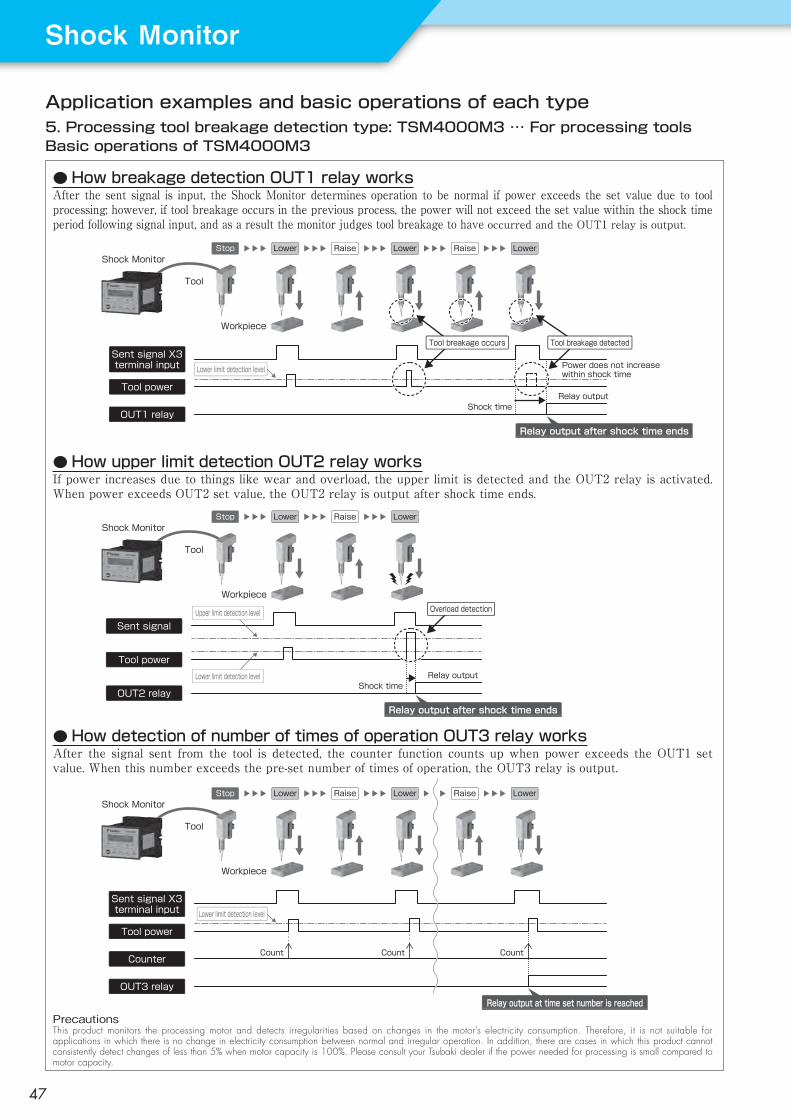
Application examples and basic operations of each type5. Processing tool breakage detection type: TSM4000M3 … For processing toolsBasic operations of TSM4000M3
● How breakage detection OUT1 relay worksAfter the sent signal is input, the Shock Monitor determines operation to be normal if power exceeds the set value due to tool processing; however, if tool breakage occurs in the previous process, the power will not exceed the set value within the shock time period following signal input, and as a result the monitor judges tool breakage to have occurred and the OUT1 relay is output.
● How upper limit detection OUT2 relay worksIf power increases due to things like wear and overload, the upper limit is detected and the OUT2 relay is activated. When power exceeds OUT2 set value, the OUT2 relay is output after shock time ends.
● How detection of number of times of operation OUT3 relay worksAfter the signal sent from the tool is detected, the counter function counts up when power exceeds the OUT1 set value. When this number exceeds the pre-set number of times of operation, the OUT3 relay is output.
PrecautionsThis product monitors the processing motor and detects irregularities based on changes in the motor’s electricity consumption. Therefore, it is not suitable for applications in which there is no change in electricity consumption between normal and irregular operation. In addition, there are cases in which this product cannot consistently detect changes of less than 5% when motor capacity is 100%. Please consult your Tsubaki dealer if the power needed for processing is small compared to motor capacity.
Shock timeRelay output
Sent signal X3 terminal input
Tool power
OUT1 relay
Workpiece
Tool
Shock Monitor
Power does not increase within shock time
Stop Lower Raise Lower Raise Lower
Relay output after shock time ends
Lower limit detection level
Tool breakage occurs Tool breakage detected
Shock time
Sent signal
Tool power
OUT2 relay
Relay output
Workpiece
Tool
Shock MonitorStop Lower Raise Lower
Relay output after shock time ends
Upper limit detection level
Lower limit detection level
Overload detection
Count Count Count
Sent signal X3 terminal input
Tool power
OUT3 relay
Counter
Workpiece
Tool
Shock MonitorStop Lower Raise Lower Raise Lower
Relay output at time set number is reached
Lower limit detection level
ShockMonitor
47
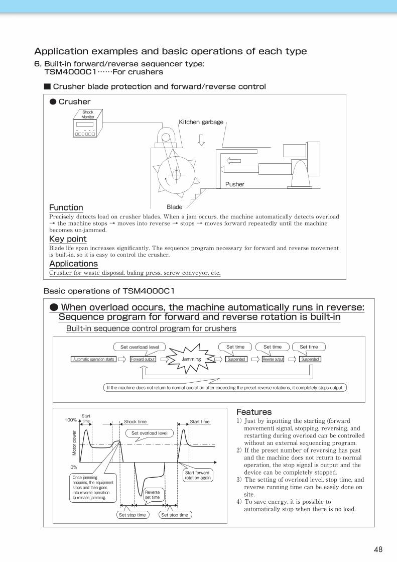
Application examples and basic operations of each type6. Built-in forward/reverse sequencer type:
TSM4000C1……For crushers
■ Crusher blade protection and forward/reverse control
ShockMonitor
Kitchen garbage
Pusher
Blade
Basic operations of TSM4000C1
Built-in sequence control program for crushers
Features1) Just by inputting the starting (forward
movement) signal, stopping, reversing, and restarting during overload can be controlled without an external sequencing program.
2) If the preset number of reversing has past and the machine does not return to normal operation, the stop signal is output and the device can be completely stopped.
3) The setting of overload level, stop time, and reverse running time can be easily done on site.
4) To save energy, it is possible to automatically stop when there is no load.
● When overload occurs, the machine automatically runs in reverse:Sequence program for forward and reverse rotation is built-in
FunctionPrecisely detects load on crusher blades. When a jam occurs, the machine automatically detects overload → the machine stops → moves into reverse → stops → moves forward repeatedly until the machine becomes un-jammed.Key pointBlade life span increases significantly. The sequence program necessary for forward and reverse movement is built-in, so it is easy to control the crusher.ApplicationsCrusher for waste disposal, baling press, screw conveyor, etc.
Automatic operation starts Forward output Suspended Reverse output SuspendedJamming
Set overload level Set time Set time Set time
If the machine does not return to normal operation after exceeding the preset reverse rotations, it completely stops output.
0%
100%Starttime Start timeShock time
Motor power Set overload level
Once jamming happens, the equipment stops and then goes into reverse operation to release jamming.
Set stop timeSet stop time
Reverseset time
Start forwardrotation again
● Crusher
48

Current sensorNo
connection
Motorvoltageinput
GroundHigh2output
High1output
Powersupply
OUTPUTHigh2
7V-8RS-
AC200/220VAC400/440V50/60Hz
AC100/200V50/60Hz
R0
S
T
0
0 T
S
RCB
CURRENT SENSOROCR
W
V
U
SHOCK MONITORTSM4000H1
POWER
CR1OCR
M
LAMP(High2)LP1
BUZZER(High1)
SENSORCABLE
400V CLASS RESISTOR (OPTION)(ONLY WHEN USING 400/440V)
MC
START
MCSTOP
MC
[7]b
[8]ac[9]
E[10]
c[6]
[11]
[12]
F
F
BZX2 [5]a
[4]bOUTPUTHigh1
X1 X1
METER RECORDER
CONNECTOR CN1
[3]W[2]V[1]U
[18]C-[17]+15[16]-15
[19]C+[20]FG
1X2 9
CM 4Aout 50V 12Ain 60V 13RS+ 15
N.C. 3N.C. 14
RST 11RST
U1V1
U2V2W2 W1
External connection, parameter settings, terminal functions1. Economy type TSM4000H1…… For general industrial machinery
Note:1.SelectthecurrentsensorfromtheCurrentSensorTablebasedonmotorcapacityandvoltage.UsethespecifiedCTthroughnumberandcurrentdirection.
2.MakesuretoputthecurrentsensorintophaseV,andusethesensorcabletoconnectwiththeShockMonitor.
3.Ifusinga400/440Vmotor,usethe400Vclassresistorshownindashedline.
4.ConnectthemotorvoltageterminaloftheShockMonitorU[1],V[2],W[3]withthephaseof[U],[V],[W]respectively.
5.Userelayforminuteelectriccurrentfor[X1],[X2],and[RST].
◎Incaseofawrongconnection,loadcannotbedetectedcorrectlyandtheShockMonitorwillnotworkproperly.
■ External connection
■ Terminal functions Default settings
■ Parameter settings
No.
1
2
345
6
7
8
9
10
11
12
13
14
Motor Voltage
Motor kW
Start TimeProcessHigh1 Level
Shock TimeH1
Output RelayH1
High2 Level
Shock Time H2
Output RelayH2
Response
Auto Inhibit
Power/Torque
LCD Backlight
(1)200-230V(2)380-460V(1)0.1kW(2)0.2kW(3)0.4kW(4)0.75kW(5)1.5kW(6)2.2kW(7)3.7kW(8)5.5kW(9)7.5kW(10)11kW0.1 to 20.0s1 to 45 to 200%MIN0.1 to 10.0s(1)Self-Hold(2)Auto-Reset5 to 200%MIN0.1 to 10.0s(1)Self-Hold(2)Auto-Reset(1)QUICK(2)NORMAL(3)SLOW(1)On(2)Off(1)Power(2)Torque(1)Always(2)2min
Motor voltage 3-phase 200V classMotor voltage 3-phase 400V class
Set motor capacity
Set start timeNumber of processesUpper limit 1 value of process 1
Set upper limit 1 shock time
Select output operationmode (High1)
Upper limit 2 value of process 1
Set upper limit 2 shock time
Select output operationmode (High2)
Average number of movements
Set auto inhibitfunction Monitor with motor input powerMonitor with torque calculated by power
Set backlightillumination time
Parameter Data Details
(1)
0.75kW
3.0180
1.0
(2)
100
1.0
(1)
(2)
(2)
(1)
(1)
(11)15kW(12)18.5kW(13)22kW(14)30kW(15)37kW(16)45kW(17)55kW(18)75kW(19)90kW(20)110kW
CB :CircuitbreakerF :FuseMC :Electromagneticcontactor formotorOCR :OvercurrentrelayCR1 :CRfilterSTART:StartbuttonSTOP :Stopbutton
When the operating electromagnetic coilcapacity(electromagneticcapacity)oftheelectromagnetic contactor [MC] for themotor is less than 100VA for injectionandlessthan10VAforholding.
Name
Control powersupply
Ground
Currentsensor
Motorvoltage
HIGH 1output
HIGH 2output
Noconnection
POWER
E−1515C−C+FGUVWbacbac
−
IN
−OUTOUTININ−INININ
OUTOUTOUTOUTOUTOUTN.CN.CN.C
1112101617181920123456789131415
Connection of controlpower supply
Ground terminal
Current sensor cable
Motor voltage inputterminal
Relay contact outputwhen upper limit 1 is output
Relay contact outputwhen upper limit 2 isoutput
Do not connect anything
SymbolIN/OUT
Pinno.
Explanation
Name Symbol IN/OUTPinno. Explanation
Processchangeover
X1 IN 1 ProcesschangeoverterminalsX2 IN 9
Common CM IN 4 CommonterminalsforX1,X2,andRST
Reset RST IN 11 Resetsself-holdstatus
ShockMonitor
49

Name Symbol IN/OUTPinno. Explanation
Referencewriting X1 IN 1 Setsreference
writing
Common CM IN 4 CommonterminalsforX1andRST
Reset RST IN 11 Resetsself-holdstatus
[9]c
7V-8RS-
AC200/220VAC400/440V50/60Hz
AC100/200V50/60Hz
R0
S
T
0
0 T
S
RCB
CURRENT SENSOROCR
W
V
U
SHOCK MONITORTSM4000H2POWER
CR1OCR
High2OUTPUT
M
LAMP(High2)LP1
BUZZER(High1)
SENSOR CABLE400V CLASS RESISTOR(OPTION)
(ONLY WHNE USING 400/440V)
MC
START
MCSTOP
MC
[7]b
[8]a
E[10]
c[6]
[11]
[12]
F
F
BZ[5]a
[4]bOUTPUTHigh1
X1 X1
METER RECORDER
CONNECTOR CN1
[3]W[2]V[1]U
[18]C-[17]+15[16]-15
[19]C+[20]FG
1
CM 4Aout 50V 12Ain 60V 13RS+ 15
N.C. 3N.C. 14
RST 11RST
U1V1
U2V2W2 W1
Default settings
■ Parameter settings
No.
1
2
34
5
6
7
8
9
10
11
12
13
14
Motor Voltage
Motor kW
Start TimeHigh1 Level
Shock TimeH1
Output RelayH1
High2 Level
Shock Time H2
Output RelayH2
Response
Auto Inhibit
Offset Mode
Interval Time
LCD Backlight
(1)200-230V(2)380-460V(1)0.1kW(2)0.2kW(3)0.4kW(4)0.75kW(5)1.5kW(6)2.2kW(7)3.7kW(8)5.5kW(9)7.5kW(10)11kW0.1 to 20.0s1 to 99%MIN0.1 to 10.0s(1)Self-Hold(2)Auto-Reset5 to 200%MIN0.1 to 10.0s(1)Self-Hold(2)Auto-Reset(1)QUICK(2)NORMAL(3)SLOW(1)On(2)Off(1)Interval(2)X11 to 60s1.1 to 60.0min(1)Always(2)2min
Motor voltage 3-phase 200V classMotor voltage 3-phase 400V class
Set motor capacity
Set start timeValue of upper limit 1
Set upper limit 1 shock time
Set output operation mode(High 1)
Value of upper limit 2
Set upper limit 2 shock time
Select output operation mode(High2)
Average number of movements
Set auto inhibit function
Set reference writing
Write cycle
Set backlightillumination time
Parameter Data Details
(1)
0.75kW
3.010
1.0
(2)
100
1.0
(1)
(2)
(2)
(2)
50s
(1)
(11)15kW(12)18.5kW(13)22kW(14)30kW(15)37kW(16)45kW(17)55kW(18)75kW(19)90kW(20)110kW
When the operating electromagnetic coilcapacity(electromagneticcapacity)oftheelectromagnetic contactor [MC] for themotor is less than 100VA for injectionandlessthan10VAforholding.
Name
Control powersupply
Ground
Currentsensor
Motorvoltage
HIGH 1output
HIGH 2output
Noconnection
POWER
E−1515C−C+FGUVWbacbac
−
IN
−OUTOUTININ−INININ
OUTOUTOUTOUTOUTOUTN.CN.CN.C
1112101617181920123456789131415
Connection of controlpower supply
Ground terminal
Current sensor cable
Motor voltage inputterminal
Relative value upper limitoutput 1
Absolute value upper limitoutput 2
Do not connect anything
SymbolIN/OUT
Pinno.
Explanation
External connection, parameter settings, terminal functions2. Load following type TSM4000H2…… For general industrial machinery
■ External connection
■ Terminal functions
Current sensorNo
connection
Motorvoltageinput
GroundHigh2output
High1output
Powersupply
Note:1.SelectthecurrentsensorfromtheCurrentSensorTablebasedonmotorcapacityandvoltage.UsethespecifiedCTthroughnumberandcurrentdirection.
2.MakesuretoputthecurrentsensorintophaseV,andusethesensorcabletoconnectwiththeShockMonitor.
3.Ifusinga400/440Vmotor,usethe400Vclassresistorshownindashedline.
4.ConnectthemotorvoltageterminaloftheShockMonitorU[1],V[2],W[3]withthephaseof[U],[V],[W]respectively.
5.Userelayforminuteelectriccurrentfor[X1]and[RST].
◎Incaseofawrongconnection,loadcannotbedetectedcorrectlyandtheShockMonitorwillnotworkproperly.
CB :CircuitbreakerF :FuseMC :Electromagneticcontactor formotorOCR :OvercurrentrelayCR1 :CRfilterSTART:StartbuttonSTOP :Stopbutton
50

(1)
0.75kW
3.0110
1.0
(2)
15
1.0
(2)
80
1.0
(1)
(2)
IH
(2)
(1)
Current sensorOUT3output
Motorvoltage input GroundOUT2
outputOUT1output
Powersupply
When the operating electromagnetic coilcapacity(electromagneticcapacity)oftheelectromagnetic contactor [MC] for themotor is less than 100VA for injectionandlessthan10VAforholding.
OUTPUTOUT3
AR2
AR3
AR1
c[6]
AR3
INVERTER
OUTPUTSTOP
CM
W
V
U
T
S
R
OCR
7V-8RS-
AC200/220VAC400/440V50/60Hz
AC100/200V50/60Hz
R0
S
T
0
0 T
S
RCB
CURRENT SENSOROCR
W
V
U
SHOCK MONITORTSM4000M1POWER
OUT1OUTPUT
M
SENSOR CABLE
400V CLASS RESISTOR(OPTION)(ONLY WHEN USING 400/440V)
[15]b
[14]a
[4]b
[5]a
c[13]
E[10]
c[9]
[11]
[12]
F
F
X2
X4X3
[8]a
[7]bOUTPUTOUT2
X1 X1
METER RECORDER
CONNECOTR CN1
[3]W[2]V[1]U
[18]C-[17]+15[16]-15
[19]C+[20]FG
1X2 9X3 2X4 10
CM 4Aout 50V 12Ain 60V 13RS+ 15
N.C. 3N.C. 14
X5 11X5
DETECTIONLEVELSELECTIONINHIBIT
OFFSET INPUT
U1V1
U2V2W2 W1
{
External connection, parameter settings, terminal functions3. Contact detection type TSM4000M1…… For machine tools
■ External connection
■ Terminal functions
Note:1.SelectthecurrentsensorfromtheCurrentSensorTablebasedonmotorcapacityandvoltage.UsethespecifiedCTthroughnumberandcurrentdirection.
2.MakesuretoputthecurrentsensorintophaseV,andusethesensorcabletoconnectwiththeShockMonitor.
3.Ifusinga400/440Vmotor,usethe400Vclassresistorshownindashedline.
4.ConnectthemotorvoltageterminaloftheShockMonitorU[1],V[2],W[3]withthephaseof[U],[V],[W]respectively.
5.Userelayforminuteelectriccurrentfor[X1],[X2],[X3],[X4],and[X5].
◎Incaseofawrongconnection,loadcannotbedetectedcorrectlyandtheShockMonitorwillnotworkproperly.
CB :CircuitbreakerF :FuseMC :Electromagneticcontactor formotorOCR :OvercurrentrelayCR1 :CRfilterSTART:StartbuttonSTOP :Stopbutton
Name Symbol IN/OUT Pinno. Explanation
Processchangeover
X1 IN 1 Processchangeoverterminals
X2 IN 9X3 IN 2
Inhibit X4 IN 10 StopsloaddetectionOffset X5 IN 11 Offsetscurrentlocationto0Common CM IN 4 CommonterminalsforX1toX5 Default
settings
■ Parameter settings
No.
1
2
3
456
7
8
9
10
11
12
13
14
15
16
17
18
Parameter Lock
Motor Voltage
Motor kW
Start TimeProcessOUT1 LevelShock TimeOUT1Output RelayOUT1OUT2 LevelShock TimeOUT2Output RelayOUT2OUT3 LevelShock TimeOUT3Output RelayOUT3
Response
Auto Inhibit
Power/Torque
LCD Backlight
(1)200-230V(2)380-460V(1)200-230V(2)380-460V(1)0.1kW(2)0.2kW(3)0.4kW(4)0.75kW(5)1.5kW(6)2.2kW(7)3.7kW(8)5.5kW(9)7.5kW(10)11kW0.1 to 20.0s1 to 81 to 99%MIN0.1 to 10.0s(1)Self-Hold(2)Auto-Reset5 to 200%MIN0.1 to 10.0s(1)Self-Hold(2)Auto-Reset(1)QUICK(2)NORMAL(3)SLOW(1)On(2)Off(1)QUICK(2)NORMAL(3)SLOWIH0.1 to 10.0s(1)On(2)Off(1)Always(2)2min
Parameters can be changed Parameters cannot be changedMotor voltage 3-phase 200V classMotor voltage 3-phase 400V class
Set motor capacity
Set start timeNumber of processesOUT1 value
OUT1 shock time
Select output operationmode (OUT1)OUT2 value
OUT2 shock time
Select output operationmode (OUT2)OUT3 value
OUT3 shock time
Select output operationmode (OUT3)
Average number of movements
Set inhibit time
Set auto inhibit function
Set backlightillumination time
Parameter Data Details
(11)15kW(12)18.5kW(13)22kW(14)30kW(15)37kW(16)45kW(17)55kW(18)75kW(19)90kW(20)110kW
Name
Control powersupply
Ground
Currentsensor
Motorvoltage
OUT 1output
OUT 2output
OUT 3output
POWER
E−1515C−C+FGUVWbacbaccab
IN
−OUTOUTININ−INININ
OUTOUTOUTOUTOUTOUTOUTOUTOUT
1112101617181920123456789131415
Connection of controlpower supply
Ground terminal
Current sensor cable
Motor voltage inputterminal
Relative value upper limitoutput 1 after offset
Relative value upper limitoutput 2 after offset
Non-offset absolute valueupper limit output
SymbolIN/OUT
Pinno.
Explanation
ShockMonitor
51

Parameters can be changedParameters cannot be changedSet time for rated value of integrated powerSet time for power value integrationMotor voltage 3-phase 200V classMotor voltage 3-phase 400V class
Set motor capacity
Set start timeNumber of processesValue of OUT1 integrated power lower limitValue of OUT2 integrated power upper limitValue of OUT3 instantaneous power upper limit
Set OUT3 shock time
Select outputoperation mode (OUT3)
Average number of movements
Set inhibit time
Set auto inhibitfunction
Set backlightillumination time
Current sensorOUT3output
Motorvoltage input GroundOUT2
outputOUT1output
Powersupply
DETECTIONLEVELSELECTION
U1V1
U2V2W2 W1
OUTPUTOUT3
OUT1
STOPMC
START
LAMPLP1
BUZZERBZ
OCRCR1
MC
c[6]
7V-8RS-
AC200/220VAC400/440V50/60Hz
AC100/200V50/60Hz
R0
S
T
0
0 T
S
RCB
CURRENT SENSOROCR
W
V
U
SHOCK MONITOR TSM4000M2POWER
OUTPUT
M
SENSOR CABLE
400V CLASS RESISTOR (OPTION)(ONLY WHEN USING 400/440V)
[15]b
[14]a
[4]b
[5]a
c[13]
E[10]
c[9]
[11]
[12]
F
F
X2
X4X3
[8]a
[7]bOUTPUTOUT2
X1 X1
METER RECORDER
CONNECTOR CN1
[3]W[2]V[1]U
[18]C-[17]+15[16]-15
[19]C+[20]FG
1X2 9X3 2X4 10
CM 4Aout 50V 12Ain 60V 13RS+ 15
N.C. 3N.C. 14
X5 11X5
{INHIBITORDER TO STARTINTEGRATION
External connection, parameter settings, terminal functions4. Integral power type TSM4000M2…… For machine tools
■ External connection
■ Terminal functions
■ Parameter settings
Note:1.SelectthecurrentsensorfromtheCurrentSensorTablebasedonmotorcapacityandvoltage.UsethespecifiedCTthroughnumberandcurrentdirection.
2.MakesuretoputthecurrentsensorintophaseV,andusethesensorcabletoconnectwiththeShockMonitor.
3.Ifusinga400/440Vmotor,usethe400Vclassresistorshownindashedline.
4.ConnectthemotorvoltageterminaloftheShockMonitorU[1],V[2],W[3]withthephaseof[U],[V],[W]respectively.
5.Userelayforminuteelectriccurrentfor[X1],[X2],[X3],[X4],and[X5].
◎Incaseofawrongconnection,loadcannotbedetectedcorrectlyandtheShockMonitorwillnotworkproperly.
CB :CircuitbreakerF :FuseMC :Electromagneticcontactor formotorOCR :OvercurrentrelayCR1 :CRfilterSTART:StartbuttonSTOP :Stopbutton
When the operating electromagnetic coilcapacity(electromagneticcapacity)oftheelectromagnetic contactor [MC] for themotor is less than 100VA for injectionandlessthan10VAforholding.
Name
Control powersupply
Ground
Currentsensor
Motorvoltage
OUT 1output
OUT 2output
OUT 3output
POWER
E−1515C−C+FGUVWbacbaccab
IN
−OUTOUTININ−INININ
OUTOUTOUTOUTOUTOUTOUTOUTOUT
1112101617181920123456789131415
Connection of powersource
Ground terminal
Current ensor cable
Motor voltage inputterminal
Lower limit output afterintegration
Upper limit output afterintegration
Upper limit output atinstantaneous electricpower
SymbolIN/OUT
Pinno.
Explanation
Name Symbol IN/OUT Pinno. Explanation
Processchangeover
X1 IN 1 Processchangeoverterminals
X2 IN 9X3 IN 2
Inhibit X4 IN 10 StopsloaddetectionStartintegration X5 IN 11 StartspowerintegrationCommon CM IN 4 CommonterminalsforX1toX5
Default settingsNo.
1
23
4
5
678910
11
12
13
14
15
16
Parameter Lock
Base TimeIntegration Time
Motor Voltage
Motor kW
Start TimeProcessOUT1 LevelOUT2 LevelOUT3 Level
Shock TimeOUT3
Output RelayOUT3
Response
Inhibit Time
Auto Inhibit
LCD Backlight
(1)Unlocked(2)Locked0.1 to 25sX5,0.1 to 25s(1)200-230V(2)380-460V(1)0.1kW(2)0.2kW(3)0.4kW(4)0.75kW(5)1.5kW(6)2.2kW(7)3.7kW(8)5.5kW(9)7.5kW(10)11kW0.1 to 20.0s1 to 80 to 99%5 to 200%5 to 200%MIN0.1 to 10.0s(1)Self-Hold(2)Auto-Reset(1)QUICK(2)NORMAL(3)SLOWIH0.1 to 10.0s(1)On(2)Off(1)Always(2)2min
Parameter Data Contents
(1)
2.55.0
(1)
0.75kW
3.01080100
1.0
(1)
(2)
IH
(2)
(1)
(11)15kW(12)18.5kW(13)22kW(14)30kW(15)37kW(16)45kW(17)55kW(18)75kW(19)90kW(20)110kW
52

Parameters can be changedParameters cannot be changedMotor voltage 3-phase 200V classMotor voltage 3-phase 400V class
Set motor capacity
Set start timeNumber of processesOUT1 value
OUT1 shock time
Select output operationmode (OUT1)OUT2 value
OUT2 shock time
Select output operationmode (OUT2)OUT3 valueSelect output operationmode (OUT3)Average number of movements
Set inhibit time
Set auto inhibitfunctionMonitor with motor input powerMonitor with torque calculated by powerSet backlightillumination time
Current sensorOUT3output
Motorvoltage input GroundOUT2
outputOUT1output
Powersupply
External connection, parameter settings, terminal functions5. Processing tool breakage detection type: TSM4000M3……For processing tools
■ External connection
■ Terminal functions
■ Parameter settings
Note:1.SelectthecurrentsensorfromtheCurrentSensorTablebasedonmotorcapacityandvoltage.UsethespecifiedCTthroughnumberandcurrentdirection.
2.MakesuretoputthecurrentsensorintophaseV,andusethesensorcabletoconnectwiththeShockMonitor.
3.Ifusinga400/440Vmotor,usethe400Vclassresistorshownindashedline.
4.ConnectthemotorvoltageterminaloftheShockMonitorU[1],V[2],W[3]withthephaseof[U],[V],[W]respectively.
5.Userelayforminuteelectriccurrentfor[X1],[X2],[X3],[X4],and[X5].
◎Incaseofawrongconnection,loadcannotbedetectedcorrectlyandtheShockMonitorwillnotworkproperly.
CB :CircuitbreakerF :FuseMC :Electromagneticcontactor formotorOCR :OvercurrentrelayCR1 :CRfilterSTART:StartbuttonSTOP :Stopbutton
When the operating electromagnetic coilcapacity(electromagneticcapacity)oftheelectromagnetic contactor [MC] for themotor is less than 100VA for injectionandlessthan10VAforholding.
Name
Control powersupply
Ground
Currentsensor
Motorvoltage
OUT 1output
OUT 2output
OUT 3output
POWER
E−1515C−C+FGUVWbacbaccab
IN
−OUTOUTININ−INININ
OUTOUTOUTOUTOUTOUTOUTOUTOUT
1112101617181920123456789131415
Connection of powersource
Ground terminal
Current ensor cable
Motor voltage inputterminal
Breakage detection output
Upper limit detection output
Output of detection of number of times of operation
SymbolIN/OUT
Pinno.
Explanation
Default settingsNo.
1
2
3
456
7
8
9
10
11
12
13
14
15
16
17
18
Parameter Lock
Motor Voltage
Motor kW
Start TimeProcessOUT1 LevelShock TimeOUT1Output RelayOUT1OUT2 LevelShock TimeOUT2Output RelayOUT2OUT3 CountOutput RelayOUT2Response
Inhibit Time
Auto Inhibit
Power/Torque
LCD Backlight
(1)Unlocked(2)Locked(1)200-230V(2)380-460V(1)0.1kW(2)0.2kW(3)0.4kW(4)0.75kW(5)1.5kW(6)2.2kW(7)3.7kW(8)5.5kW(9)7.5kW(10)11kW0.1 to 20.0s1 to 40 to 99%MIN0.1 to 30.0s(1)Self-Hold(2)Auto-Reset5 to 200%MIN0.1 to 10.0s(1)Self-Hold(2)Auto-Reset100 to 30000(1)Self-Hold(2)Auto-Reset1 to 50IH0.1 to 10.0s(1)On(2)Off(1)Power(2)Torque(1)Always(2)2min
Parameter Data Details
(1)
(1)
0.75kW
3.0110
1.0
(2)
100
1.0
(2)
10000
(1)
5
IH
(2)
(1)
(1)
(11)15kW(12)18.5kW(13)22kW(14)30kW(15)37kW(16)45kW(17)55kW(18)75kW(19)90kW(20)110kW
Name Symbol IN/OUT Pinno. Explanation
Processchangeover
X1 IN 1 ProcesschangeoverterminalsX2 IN 9
Sentsignal X3 IN 2 SentsignalterminalInhibit X4 IN 10 StopsloaddetectionOffset X5 IN 11 Resetsself-holdstatusCommon CM IN 4 CommonterminalsforX1toX5
CONNECTOR CN1c[6]
AR1 AR2 AR3 STOP
AR2
AR3
AR1X5 11X5
14N.C.3N.C.
15RS+130V6Ain120V5Aout4CM
10X42X39X21
[20]FG[19]C+
[16]-15[17]+15[18]C-
[1]U[2]V[3]W
IoT TERMINAL
X1X1OUT2OUTPUT
[7]b
[8]a
X3X4
X2
F
F
[11]
[12]
c[9]
E[10]
c[13]
[5]a
[4]b
[14]a
[15]b
MC
MC
START
MC
(ONLY WHEN USING 400/440V)400V CLASS RESISTOR (OPTION) SENSOR
CABLE
M
OUTPUTOUT1
OUTPUTOUT3
OCRCR1
POWER TSM4000M3SHOCK MONITOR
U
V
W
OCRCURRENT SENSOR
CBR
S
T0
0
T
S
0R
50/60HzAC100/200V
50/60HzAC400/440VAC200/220V
RS- 8V- 7
W1W2V2U2
V1U1
ShockMonitor
53
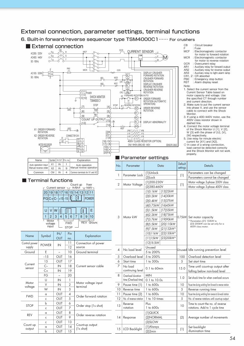
(1)
(1)
0.75kW
Unused
1005
15.0
1.0
105105
10
(2)
(1)
Current sensorCount upoutput
Motorvoltageinput
GroundREVFWDSTOP
Powersupply
[14][15][8]
[5]
[4]
[13]
[9]
[6]
[7]
[11][12]
AR3
METER RECORDERX2 9X2
120V5Aout4CM
1CONNECTOR CN1
X1X1
AR3
SENSOR CABLE
E[10]
[18]C-[17]+15
[19]C+[20]FG
[16]-15(ONLY WHEN USING 400/440V)
[3]W[2]V[1]U
400V CLASS RESISTOR (OPTION)
FGLMC
MC
PL
F
R
CRUSHER FORWARDROTATION
CRUSHER REVERSEROTATION
DISPLAY CRUSHERFORWARD ROTATION
DISPLAY CRUSHERREVERSE ROTATION
MCR
MCF
AR1
AR2
50/60HzCR1
AC200/220V R0S
T0
0 T
S
R CURRENT SENSOR
W
V
U
M
F MCR OCR
AC400/440V50/60Hz
MCF
PB0
OCRCB
AC100/200V
C1TSM4000FORWARD ROTATION(AUTO)SHOCK MONITOR
POWER
X1X1
ORDER FORWARDROTATION (AUTOMATICOPERATION)
X2
ORDER REVERSEROTATION
X2:
X1:ORDER FORWARDROTATION
DISPLAY ABNORMALITY
STOP REVERSE ROTATIONX1
FWDREV
STOPX2 ORDER REVERSE
ROTATIONAR1
AR2
PLCOUNT UP OUTPUT
AR3RST
CR2
A
A
U1V1W1W2
V2U2
External connection, parameter settings, terminal functions6. Built-in forward/reverse sequencer type TSM4000C1…… For crushers
■ External connection
■ Terminal functions
■ Parameter settings
Note:1.SelectthecurrentsensorfromtheCurrentSensorTablebasedonmotorcapacityandvoltage.UsethespecifiedCTthroughnumberandcurrentdirection.
2.MakesuretoputthecurrentsensorintophaseV,andusethesensorcabletoconnectwiththeShockMonitor.
3.Ifusinga400/440Vmotor,usethe400Vclassresistorshownindashedline.
4.ConnectthemotorvoltageterminaloftheShockMonitorU[1],V[2],W[3]withthephaseof[U],[V],[W]respectively.
5.Userelayforminuteelectriccurrentfor[X1]and[X2].
◎Incaseofawrongconnection,loadcannotbedetectedcorrectlyandtheShockMonitorwillnotworkproperly.
CB :CircuitbreakerF :FuseMCF :Electromagneticcontactor formotortoforwardrotationMCR :Electromagneticcontactor formotortoreverserotationOCR :OvercurrentrelayAR1 :AuxiliaryrelayforforwardoutputAR2 :AuxiliaryrelayforreverseoutputAR3 :AuxiliaryrelaytolightalarmlampCR1,2:CRabsorberPB0 :EmergencystopbuttonRST :Alarmdisplayreset
Parameters can be changedParameters cannot be changedMotor voltage 3-phase 200V classMotor voltage 3-phase 400V class
Set motor capacity
Idle running prevention level
Overload detection levelSet start time
Time until count-up output after falling below non-load level
Set shock time for when overload occurs
Pause time during switching from forward to reverse rotationReverse running timePause time during switching from reverse to forward rotationNo. of reverse rotations until count-up output
Time to count the no. of reverse rotations. Add to 1 cycle time
Average number of movements
Set backlightillumination time
Name
Control powersupply
Ground
Currentsensor
Motorvoltage
FWD
STOP
REV
Count upoutput
POWER
E−1515C−C+FGUVWacbcaccab
IN
−OUTOUTININ−INININ
OUTOUTOUTOUTOUTOUTOUTOUTOUT
1112101617181920123456789131415
Connection of powersource
Ground terminal
Current sensor cable
Motor voltage inputterminal
Order forward rotation
Order stop (1s shot)
Order reverse rotation
Count-up output(1s shot)
SymbolIN/OUT
Pinno.
Explanation
* Parameters (21) 132kW to(23) 200kW can be set only for a400V class motor.
Default settingsNo.
1
2
3
4
567
8
9101112
13
14
15
Parameter Lock
Motor Voltage
Motor kW
No load level
Overload levelStart time
No loadcontinuing level
Overload durationtime (Overload time)
Pause time (1)Reverse timePause time (2)No. of reverse rotation
Reverserotation
Response
LCD Backlight
(1)Unlock(2)Lock(1)200-230V(2)380-460V(1)0.1kW(2)0.2kW(3)0.4kW(4)0.75kW(5)1.5kW(6)2.2kW(7)3.7kW(8)5.5kW(9)7.5kW(10)11kW(11)15kW(12)18.5kWUnused5 to 200%5 to 200%1 to 300s
0.1 to 60min
MIN0.1 to 10.0s1 to 600s1 to 600s1 to 600s1 to 10 times
Plus1 to 600s
(1)QUICK(2)NORMAL(3)SLOW(1)Always(2)2min
Parameter Data Details
(13)22kW(14)30kW(15)37kW(16)45kW(17)55kW(18)75kW(19)90kW(20)110kW(21)132kW*(22)150kW*(23)200kW*
Name Symbol IN/OUT Pinno. Explanation
AutooperationinputManualreverseorder
X1 IN 1 AutooperationManualreverseoperationX2 IN 9
Common CM IN 4 CommonterminalsforX1andX2
54

M E M O
ShockMonitor
55

Safety Guide and Warranty
● When carrying out an operation test or making a periodic inspection, make sure to verify that it functions properly as a protection device.● Follow the instruction manual when carrying out megger testing because most electrical devices have certain requirements for megger testing.● Check the operation of the device periodically so that it can be sure to function properly when overloaded occurs.● Comply with the 2-1-1 General Standard of "Ordinance on Labor Safety and Hygiene".● When performing maintenance or inspections:
1) Wear proper work clothes and protective equipment (safety devices, gloves, shoes, etc.). To avoid an accident, make sure to perform maintenance and inspections in an appropriate environment.
2) Make sure the power is switched off, and the machine has stopped completely before carrying out maintenance and inspections. Take the necessary measures to ensure the power is not turned back on.
3) Follow the instruction manual.4) Wire according to the technical standards of Electrical Installation and company regulations. Take note of the cautions in this
manual which explain installation direction, clearance and environmental conditions. Make sure to ground the device to prevent electrical shock and to improve noise resistance.
● When using with lifting equipment, install a suitable protection device for safety purposes, otherwise an accident resulting in death, serious injury or damage to the equipment may occur due to a falling accident.
1. Warranty period without chargeEffective 18 months from the date of shipment or 12 months fromthe first use of Goods, including the installation of the Goods tothe Buyer's equipment or machine - whichever comes first.
2. Warranty coverageShould any damage or problem with the Goods arise within thewarranty period, given that the Goods were operated andmaintained according to the instructions provided in the manual,the Seller will repair and replace at no charge once the Goodsare returned to the Seller.This warranty does not include the following:1) Any costs related to removal of Goods from the Buyer's
equipment or machine to repair or replace parts.2) Cost to transport Buyer's equipment or machines to the
Buyer's repair shop.3) Costs to reimburse any profit loss due to any repair or
damage and consequential losses caused by the Buyer.
3. Warranty with chargeSeller will charge for any investigation and repair of Goods caused by:1) Improper installation by failing to follow the instruction manual.2) Insufficient maintenance or improper operation by the Buyer.3) Incorrect installation of the Goods to other equipment or
machines.4) Any modifications or alterations of Goods by the Buyer.5) Any repair by engineers other than the Seller or those designated
by the Seller.6) Operation in an environment not specified in the manual7) Force Majeure or forces beyond the Seller's control such as
natural disasters and injustices inflicted by a third party.8) Secondary damage or problems incurred by the Buyer's equipment
or machines.9) Defective parts supplied or specified by the Buyer.10) Incorrect wiring or parameter settings by the Buyer.11) The end of life cycle of the Goods under normal usage.12) Losses or damages not liable to the Seller.
4. Dispatch serviceThe service to dispatch a Seller's engineer to investigate, adjustor trial test the Seller's Goods is at the Buyer's expense.
Warranty:
WARNING Death or serious injury may result from product misuse due to not following the instructions.
● Consumable parts (tantalum electrolytic capacitors, relays, etc.) are built-in the products. Using the manual, periodically check the functions and operation of the device. If it is not functioning properly, contact the distributor for repair.
● Do not use the device in a corrosive gas environment. Sulphidizing gases (SO2, H2S) can especially corrode the copper and copper alloy used on PCBs and parts, and cause a malfunction.
● Read the instruction manual carefully, and use the product properly. In case the instruction manual is not available, request one from the distributor where you purchased the product, or our sales office with the product name and model number.
● Deliver this instruction manual to the final customer who uses the product.
The logos and product names used in this catalog are either trademarks or registered trademarks of TsubakimotoChain Co. or the Tsubaki Group in Japan and other countries.
CAUTION Minor or moderate injury, as well as damage to the product may result from product misuse due to not following the instructions.
Tsubakimoto Chain Co.: hereinafter referred to as "Seller"; Customer: hereinafter referred to as "Buyer"; Goods sold or supplied by Seller to Buyer: hereinafter referred to as "Goods"
CAUTION The contents of this catalog are mainly to aid in product selection.Read the instruction manual thoroughly before using the product in order to use it properly.

Electrical ControlDevicesJapan Headquarters +81 6-6441-0011 http://tsubakimoto.com
Motion Control Division +81 75-956-8138
TSUBAKIMOTO CHAIN CO.
Note: In accordance with the policy of TSUBAKIMOTO CHAIN CO. to constantly improve its products, the speci�cations in this catalog are subject to change without notice.Catalog No. 985M002 ©2020/4 TSUBAKIMOTO CHAIN CO. Printed in Japan 1,000
The Tsubaki Eco Link logo is used only on products that satisfy the standards for environmental friendliness set by the Tsubaki Group.
Global Group Companies
AMERICAS
United States of America U.S. Tsubaki Power Transmission, LLC
Brazil Tsubaki Brasil Equipamentos Industriais Ltda.
Canada Tsubaki of Canada Limited
EUROPE
Netherlands Tsubakimoto Europe B.V.
France Kabelschlepp France S.A.R.L.
Germany Tsubaki Deutschland GmbH
Tsubaki Kabelschlepp GmbH
Italy Kabelschlepp Italia S.R.L.
Russia OOO Tsubaki Kabelschlepp
Spain Tsubaki Ibérica Power Transmission S.L.
United Kingdom Tsubakimoto U.K. Ltd.
INDIAN OCEAN RIM
Singapore Tsubakimoto Singapore Pte. Ltd.
Australia Tsubaki Australia Pty. Limited
India Tsubaki India Power Transmission Private Limited
Indonesia PT. Tsubaki Indonesia Trading
Malaysia Tsubaki Power Transmission (Malaysia) Sdn. Bhd.
New Zealand Tsubaki Australia Pty. Limited - New Zealand Branch
Philippines Tsubakimoto Philippines Corporation
Thailand Tsubakimoto (Thailand) Co., Ltd.
Vietnam Tsubakimoto Vietnam Co., Ltd.
EAST ASIA
Korea Tsubakimoto Korea Co., Ltd.
Taiwan Taiwan Tsubakimoto Co.
CHINA
China Tsubakimoto Chain (Shanghai) Co., Ltd.
+1 847-459-9500 https://www.ustsubaki.com/
+55 11-3253-5656 http://tsubaki.ind.br/
+1 905-676-0400 http://tsubaki.ca/
+31 78-6204000 https://tsubaki.eu/
+33 1-34846365 https://kabelschlepp.fr/
+49 89-2000-133-80 http://tsubaki.de/
+49 2762-4003-0 https://tsubaki-kabelschlepp.com/
+39 0331-350962 https://kabelschlepp.it/
+7 499-4180212 http://kabelschlepp.ru/
+44 1623-688-700 https://tsubaki.eu/
+65 6861-0422/3/4 http://tsubaki.sg/
+61 2-9704-2500 http://tsubaki.com.au/
+91 44-7101-2000 http://tsubaki.in/
+62 21-89458898 http://tsubakimoto.co.id/
+60 3-5888-8275 http://tsubaki.my/
+64 9-352-2085 http://tsubaki.com.au/
+63 2-8824-7519 http://tsubaki.ph/
+66 2-262-0667/8/9 http://tsubaki.co.th/
+84 24-6274-1449 http://tsubaki.net.vn/
+82 2-2183-0311 http://tsubakimoto-tck.co.kr/
+886 3-3293827 https://tsubakimoto.tw/
+86 21-53966651/2 http://tsubaki-sh.cn/
+34 911-873450 http://tsubaki.es/