Energy Efficiency Best Operating Practices Guide for Foundries
Upload
khangminh22Category
view
3download
0
35
Operating GuideVersion 6
W1014HM6056 -YI VQT5K88A-6(E)

– 2 –
fSDXC logo is a trademark of SD-3C, LLC. fMMC (Multi Media Card) is a registered trademark of Infineon Technologies AG. fMicrosoft® and Windows® are registered trademarks or trademarks of Microsoft Corporation in the United States and/or other countries. fScreenshots are used according to Microsoft Corporation guidelines. fApple, Macintosh, Mac OS, QuickTime, iPad, iPhone, and ProRes are trademarks or registered trademarks of Apple Inc. in the United States and/or other countries. f Java and all Java-based trademarks are trademarks or registered trademarks of Sun Microsystems, Inc. in the United States. fAll other names, company names, product names, etc., contained in this document are trademarks or registered trademarks of their respective owners. f This product is licensed under the AVC Patent Portfolio License. All other acts are not licensed except private use for personal and non-profit purposes such as what are described below. - To record video in compliance with the AVC standard (AVC Video) - To play back AVC Video that was recorded by a consumer engaged in a personal and non-commercial activity - To play back AVC Video that was obtained from a video provider licensed to provide the videoVisit the MPEG LA, LLC website (http://www.mpegla.com/) for details.
fUse of DCF Technologies under license from Multi-Format, Inc. f The Apple ProRes codec module is used under license from Atomos. fAtomos is a trademark or registered trademark of Atomos Global Pty. Ltd.
How to read this document
r Illustrations fScreenshots or illustrations may differ from the actual product.
r Conventions used in this manual fWords and phrases in [ ] brackets indicate details and content displayed in the viewfinder or control panel. fWords and phrases in < > brackets indicate design text used on this camera, such as button names.
r Reference pages fReference pages in this document are indicated by (page 00).
r Terminology fSD memory card, SDHC memory card, and SDXC memory card are referred to as “SD memory card”. fA memory card with the “P2” logo such as AJ-P2E064FG memory card (optional) is referred to as a “P2 memory card”. fA memory card with the “microP2” logo such as AJ-P2M032AG memory card (optional) is referred to as a “microP2 memory card”. fA memory card with the “expressP2” logo such as AU-XP0256AG memory card (optional) is referred to as a “expressP2 memory card”. fP2 memory card, microP2 memory card, and expressP2 memory card are referred to only as “P2 card” unless distinguished otherwise. fVideo that is created during a single recording operation is referred to as a “clip”.

Contents
– 3 –
Contents
Chapter 1 Overview 5Before using the camera 6Accessories 7
Camera module 7Recording module 7Electronic HD color viewfinder 7Shoulder mount module 7
Use of the camera on a system 8Basic system devices 8Expansion system devices 8Accessories 8
Chapter 2 Description of Parts 9Camera module 10
Left side 10Right side 10Front 11Rear 12Top 12Bottom 12
Recording module 13Left side 13Right side 14Front 14Rear 15Top side 15Bottom 16
Electronic HD color viewfinder 17Left side 17Front 17Rear 17Top 18
Shoulder mount module 19Left side 19Right side 19Front 19Top 19
Chapter 3 Preparation 20Assembling modules 21
Assembling the camera module and recording module 21Mounting the Electronic HD color viewfinder 22Mounting the shoulder mount module 23
Attaching and removing accessories 24Eye cup/eye piece filter 24Attaching a tripod 24Attaching the rain cover 25
Power supply 26Using batteries 26Mounting and setting battery 26Using external DC power supply 27
Mounting and adjusting the lens 28Mounting the lens 28Flange lens back adjustment 28
Connecting to the DC output terminal 29Connecting the <DC OUT/RS> terminal to the external
recording start/stop switch 29Connecting to the <DC OUT> terminal 29
Charging the built-in battery 30Setting the date/time of the internal clock 31Inspections before shooting 32
Chapter 4 Video Recording and Color Grading 33Dual-recording 34
File name style 34Selecting the resolution, codec, and video format for
recording 37In-camera grading 40
Grading function 40Control combinations through settings 40
P2 card 42Inserting a P2 card 42Removing a P2 card 43Preventing accidental erasure 43Card access LEDs and P2 card status 43
P2 card recording time 44CPS (Content Protection System) 44How to handle data recorded on P2 cards 45Formatting a P2 card 46
Special recording functions 47Hot swap recording 47Shot mark recording function 47Text memo recording function 47Pre-recording 47Interval recording 48One-shot recording 48
Chapter 5 Control Panel 50Control panel operation 51
Camera status display 51Using the control panel extension unit 52
HOME screen 54PLAY screen 56TC screen 57INFO screen 58VIEW screen 59MENU screen 60
Chapter 6 Audio recording 61Preparing for audio input 62
Using front microphone 62Using audio devices 63
Selecting audio input and adjusting recording levels 64Selecting audio input signals 64Adjusting the recording levels 64Audio monitor (headphones) 65
Chapter 7 Viewfinder 66Adjusting and setting the viewfinder 67
Adjustment method 67Viewfinder status display 68
Lamp display 68Status display 68
Convenient shooting functions 71Zebra patterns display 71Displaying the center marker 71Displaying the safety zone marker 71Displaying frame marker 71Focus assist function 71
Chapter 8 Output and Screen Display 73SDI output 74
Output format list 74<MON OUT1> output 81
Output format list 81<MON OUT2> output 83
Output format list 83<VF SDI> output 87
Output format list 87Screen status display 88
Status display (STATUS) in the <MON OUT1>, <MON OUT2>, and <VF SDI> outputs. 88
Control panel status display (VIEW screen) 89
Chapter 9 Other Useful Functions 90Getting position information using the GPS 91Assigning functions to the USER buttons 92
Selectable functions 92Handling setting data 93
File types 93Handling SD memory cards 93Performing operations on SD memory cards 94
Setting the time data 95Definition of time data 95User bits settings 95How to input user bits 95Setting the time code 96Externally locking the time code 96Supplying the time code externally 97

Contents
– 4 –
Connection through the <USB DEVICE> terminal 99Connecting to a computer in the USB device mode 99
Chapter 10 Menu Operations 100Setting menu structure 101
Menu configuration 101Setting menu display 102
Setting menu basic operations 102Setting menu initialization 102
Menu list 103[SYSTEM SETTINGS] 103[CAMERA SETTINGS] 108[REC SETTINGS] 113[AUDIO SETTINGS] 116[OUTPUT SETTINGS] 117[FILE] 123[PERIPHERAL] 123
Menu operations 125[SYSTEM SETTINGS] 125[CAMERA SETTINGS] 126[REC SETTINGS] 128[AUDIO SETTINGS] 129[OUTPUT SETTINGS] 129[FILE] 131[PERIPHERAL] 132
Chapter 11 Network Connection 133Network connection 134
Available functions 134Preparing for connection 135
For wireless LAN 135For wired LAN 135
Network settings 136Wireless LAN settings 136Wired LAN settings 136Checking network setting 137Changing network setting 138
Connecting the remote operation panel (AK-HRP200G) 139Setting for connection with the remote operation panel
(AK-HRP200G) 139Limitation with the remote control 139
Chapter 12 Extension module 141Before using the extension module 142Description of parts 143
Left side 143Right side 143Front 143Rear 144
Assembling Extension Modules 145Removing the camera extension module and recording
extension module 145Assembling the camera module and the camera extension
module 145Assembling the recording module and the recording extension
module 146Mounting extension cables 147
Power supply 148Using batteries 148Battery attachment and setting 148Using the external DC power supply 149Displaying of the power supply condition 150
Connecting to the DC output terminal 151Connecting to the <DC OUT> terminal 151
Specifications 152Dimensions 152Specifications 152
Chapter 13 V-RAW recorder 153V-RAW recorder 154
Attaching the V-RAW recorder 154HOME screen on the control panel 155
Power supply 156Turning on the power 156
Operation with the control panel 157System setting and recording 157Playback 158Media 158
Version update 161
Chapter 14 Maintenance 162Warning system 163
Cases indicated by error codes 163Cases indicated by error messages 163
Updating the camera firmware 166Updating the firmware 166
Cleaning and storing 167Cleaning the camera recorder 167Cautions when storing the camera recorder 167
Chapter 15 Specification 168Specifications 169
Dimensions 169Specifications 169
Index 172

Before using the camera, read this chapter.
Chapter 1 Overview

– 6 –
Chapter 1 Overview — Before using the camera
Before using the camera
r Before using the camera, always check if the built-in battery is not consumed, and then set the date/time.The internal clock of the camera is reset when the built-in battery has been consumed. This may result in the metadata of the clip not recorded correctly, and it may not display correctly in the thumbnail screen.Check if the built-in battery is not consumed before using. (page 30)Also, set the correct date/time. (page 31)
r Cautions when throwing memory cards away or transferring them to othersFormatting memory cards or deleting data using the functions of the camera or a computer will merely change the file management information: it will not completely erase the data on the cards. When throwing these cards away or transferring them to others, either physically destroy them or use a data deletion program for computers (commercially available) to completely erase the data. Users are responsible for managing the data stored in their memory cards.
r Control panel and viewfinder f If the same image or letters are allowed to be displayed on the control panel for a long time, the image may be burned into the screen. It will return to normal after leaving the camera recorder turned off for several hours. fCondensation sometimes forms on the LCD of the control panel in locations subject to extreme temperature differences. If this happens, wipe with a soft, dry cloth. f If the camera recorder is very cold, the control panel will be slightly darker than normal immediately after the power is turned on. It will return to its regular brightness when the temperature inside increases. fSince the viewfinder uses organic EL, if the same image or letters are allowed to be displayed for a long time, the image may be burned into the screen. There is no problem with the recorded images.Switch the screen by turning off the screen or by using the eye sensor, etc. f The control panel and viewfinder monitor (organic EL) are highly-precisely managed so that at least 99.99% of the dots are effective pixels and 0.01% or less are invalid pixels and always lit. This is not a malfunction and it has no effect whatsoever on the recorded images.
r Do not point the eye piece of the lens and viewfinder at the sun.Doing so might damage the components inside.
r GPSGPS (Global Position System) satellite is managed by the United States Department of State and its precision is sometimes intentionally changed.Position it in a location where there is a good view of the sky and there is no influence of obstacles such as roofs and trees, etc.Depending upon the surrounding environment and the time, it may take a long time to position and errors may be larger.
r Caution regarding laser beamsThe MOS sensor may be damaged if the MOS sensor is subjected to light from a laser beam.Take sufficient care to prevent laser beams from striking the lens when shooting in an environment where laser devices are used.
r Note the following points. f If you prepare to record important images, always shoot some advance test footage to verify that both pictures and sound are being recorded normally. fShould video or audio recording fail due to a malfunction of the camera or the P2 cards used, we will not assume liability for such failure. fSet up or check the calendar and time zone before recording. (page 31) These settings have an effect on the management and playback order of the recorded contents.
r Software information about this product1 This product includes software licensed under GNU General Public License (GPL) and GNU Lesser General Public License (LGPL), and
customers are hereby notified that they have rights to obtain, re-engineer, and redistribute the source code of these software. 2 This product includes software licensed under MIT-License. 3 This product includes software developed by the OpenSSL Project for use in the OpenSSL Toolkit (http://www.openssl.org/).4 This product includes software licensed under OpenBSD License.5 This product includes PHP, freely available from <http://www.php.net/>.6 This software is based in part on the work of the Independent JPEG Group.7 This product includes software licensed under MOZILLA PUBLIC LICENSE. For details on these descriptions (originally provided in English) and how to obtain the source code, visit the following website.http://pro-av.panasonic.net/We do not accept inquiries about the details of the source code obtained by the customer.
r Precautions when installing USB driversFor the latest information on the driver, visit the following website.http://pro-av.panasonic.net/
f Install the required driver into your computer from the website. f For installation procedure of the driver, refer to the installation manual on the website.

– 7 –
Chapter 1 Overview — Accessories
Accessories
Camera module fMount cap (already attached to the camera module)
Recording module fControl panel extension unit fControl panel mounting part
Electronic HD color viewfinder fConnecting cable fSlider unit fSlider unit mounting screw (2 pcs.) fEye cup (already attached to the Electronic HD color viewfinder) fEye piece filter (already attached to the Electronic HD color viewfinder)
Shoulder mount module fSlide rail (already attached to the shoulder mount module)
@@ NOTE
t After unpacking the product, dispose of the packing material properly.

– 8 –
Chapter 1 Overview — Use of the camera on a system
Use of the camera on a systemUse the following recommended parts.
Basic system devicesThe following are required devices for shooting.
Product name Model No. Remark
VariCam 35 Camera module*1 AU-V35C1G “Assembling the camera module and recording module” (page 21)
Recording module*1 AU-VREC1G “Assembling the camera module and recording module” (page 21)
Shoulder mount module AU-VSHL1G “Mounting the shoulder mount module” (page 23)
Electronic HD color viewfinder AU-VCVF1G “Mounting the Electronic HD color viewfinder” (page 22)
Lens (35 mm, PL mount) ZEISS/COOKE/CANON/FUJINON, etc. “Mounting the lens” (page 28)
Stereo microphone kit AJ-MC900G “Using front microphone” (page 62)
Battery DIONIC HD*2
HYTRON140*2“Mounting and setting battery” (page 26)
expressP2 memory card AU-XP0256AG/AU-XP0256BG/AU-XP0512BG “P2 card” (page 42)
SD memory card*3
P2 memory card*3
microP2 memory card*3
Visit the support desk at the website*3 “P2 card” (page 42)
*1 The camera module and recording module are both required in this system. The system will not run with only one of those modules.*2 A battery holder is provided as standard on the recording module.*3 Refer to our support desk at the following website for the latest information not included in this document.
http://pro-av.panasonic.net/
Expansion system devicesYou can also use the following devices in addition to the basic system devices.
Product name Model No. Remark4K LCD monitor BT-4LH310 —
LCD monitor BT-LH910G, etc. —
Memory card drive AU-XPD1 —
External DC power supply — “Using external DC power supply” (page 27)
VariCam HS camera module AU-V23HS1G —
Wireless module AJ-WM30/AJ-WM50 “For wireless LAN” (page 135)
Remote operation panel AK-HRP200G “Connecting the remote operation panel (AK-HRP200G)” (page 139)
Extension module AU-VEXT1G “Extension module” (page 141)
Extension cable AU-VCBL05G “Extension module” (page 141)
Accessories
Product name Model No. RemarkTripod adaptor SHAN-TM700 “Attaching a tripod” (page 24)
Soft carrying case AJ-SC900 —
Rain cover SHAN-RC700 “Attaching the rain cover” (page 25)
Microphone holder AJ-MH800G “Using front microphone” (page 62)

This chapter describes the names, functions, and operations of parts on the camera.
Chapter 2 Description of Parts

– 10 –
Chapter 2 Description of Parts — Camera module
Camera module
Left side
2345
6
7
9
8
10
11
1
1 Lens flange back adjustment holeUsed when adjusting the lens flange back.
2 USER buttons (<1>/<2>/<3>)User-selected functions can be assigned to each button. Pressing a button performs the assigned function.
3 Focus hook/focus mark < >Indicate the focal plane of the MOS sensor.
4 <REC> buttonPress this button to start recording. Press this button again to stop recording. The button lights up in red during recording.
5 <SHUTTER> switchSwitch for changing the electronic shutter.
6 <EI> switchSwitch for changing the EXPOSURE INDEX (gain).
7 Accessory mounting holesFor attaching accessories.
fMounting hole size - 3/8-16 UNC
8 Handle9 <LOCK> switch
Disables the operation of the camera module buttons and switches. (except the <REC> button)Keep this in the <LOCK> position to prevent incorrect operation when moving the camera, etc.
10 <WB> switchSwitch for changing the white balance.
11 Fan inletFan inlet for dissipating heat. Do not block this when the camera is in use.
Right side
1
32
4
5
6
7
9
8
10
11
1 Accessory mounting holesFor attaching accessories.
fMounting hole size

– 11 –
Chapter 2 Description of Parts — Camera module
- 3/8-16 UNC
2 Fan outletFan outlet for dissipating heat. Do not block this when the camera is in use.
3 Recording module release leverLever for removing the recording module (optional) from the camera module.
4 Accessory mounting holesFor attaching accessories.
fMounting hole size - 1/4-20 UNC (screw length 5.5 mm or shorter)
5 USER button (<4>)User-selected functions can be assigned to this button. Pressing the button performs the assigned function.
6 Focus hookIndicate the focal plane of the MOS sensor. It provides a reference for measuring the accurate focal length from the subject.
7 <VF> terminalTerminal for connecting the HD viewfinder AU-VCVF1G (optional).
8 <VF SDI> terminalOutput terminal for 3G/HD SDI. Displays the video equal to the viewfinder display.For the cable to connect to this terminal, prepare a double-shielded cable equivalent to 5C-FB.
9 <DC OUT> terminalThis is the DC12 V output terminal. It provides a maximum current of 1 A.
10 <MIC IN> terminalTerminal for connecting a microphone.
11 <LENS> terminalTerminal for connecting a lens cable. For details, refer to the Operating Instructions for the lens.
Front
1
2
3
4
5
6
1 Accessory mounting holesFor attaching accessories.
fMounting hole size - 3/8-16 UNC (screw length 5.5 mm or shorter)
2 Lens cable /microphone cable clampClamp for securing the lens and microphone cables.
3 Lens mountHolds the lens.
4 <FILTER> dialSelects a filter which suits the illumination of the subject.<1><CLEAR>: Does not use the ND filter.<2><0.6ND>: Reduces the amount of light entering the MOS sensor to 1/4.<3><1.2ND>: Reduces the amount of light entering the MOS sensor to 1/16.<4><1.8ND>: Reduces the amount of light entering the MOS sensor to 1/64.
5 Lens leverAfter mounting the lens to the lens mount, tighten the lever to secure the lens.
6 Mount capAttach the cap when the lens is not mounted.

– 12 –
Chapter 2 Description of Parts — Camera module
Rear
1
2
1 Lock plateFitting which secures the recording module in place when connected.
2 Recording module connection terminalTerminal for connecting the recording module.
Top
1 4
5
1
2
3
1 Viewfinder mounting holesFor attaching the viewfinder.
2 Mounting hole for control panel mounting part3 Microphone holder mounting position4 GPS module position
This part has a built-in GPS module. Do not cover this part with metallic objects when the GPS is in use.
5 Accessory mounting holesFor attaching accessories.
fMounting hole size - 1/4-20 UNC - 3/8-16 UNC
Bottom
1
1 Shoulder mount module/tripod mounting holesFor attaching the shoulder mount module or a tripod.
fMounting hole size - 1/4-20 UNC (screw length 5.5 mm or shorter) - 3/8-16 UNC (screw length 5.5 mm or shorter)

– 13 –
Chapter 2 Description of Parts — Recording module
Recording module
Left side
1
23456
87 9 1011
12
13141516
1718 19 20 21 22
1 <HOME> buttonReturns to the HOME screen when pressed.
2 <PLAY> buttonShows the PLAY screen when pressed.
3 <TC> buttonShows the TC screen when pressed.
4 <INFO> buttonShows the INFO screen when pressed.
5 <VIEW> buttonDisplays the camera video in the control panel.
6 Main slot open/close switchOpens the main slot bay.
7 Control panel operation buttonsButtons for operating the control panel. User-selected functions can be assigned to each button to function as USER buttons.
8 Control panelUsed to perform tasks such as checking the device status and setting basic items.
9 <MENU> buttonDisplays the setting menu in the control panel screen.
10 <REC> buttonPress this button to start recording. Press this button again to stop recording. The button lights up in red during recording.
11 <EXIT> buttonRestores the display to the previous state while the setting menu or control panel operation is displayed.
12 <POWER> switchSwitch on/off the power.Even when the <POWER> switch is set to the <OFF> position, the camera is not shut off from the main power.
13 Jog dial buttonUsed for setting, moving items, and selecting menus on the control panel.
14 <LOCK> switchDisables the operation of the control panel buttons and switches. (except the <REC> button)Keep this in the <LOCK> position to prevent incorrect operation when moving the camera, etc.
15 Cable clampClamp for securing the control panel extension unit cable.
16 Open/close switch for sub slot and SD memory card slotOpens the sub slot / SD memory card slot bay.
17 Main slot lock switch 1/2Lock switch to prevent incorrect insertion and removal in the main slot.Recording is enabled when this is locked.Do not release the lock during recording.
18 Main slot 1/2 access LEDIndicates the access status of recording and playback of each card inserted in main slot 1/2.
19 Main slot 1/2Slot for expressP2 memory cards.
20 Sub slot 3/4 access LEDIndicates the access status of recording and playback of each card inserted in sub slot 3/4.
21 Sub slot 3/4Slot for microP2 memory cards.

– 14 –
Chapter 2 Description of Parts — Recording module
22 SD memory card slotSlot for SD memory cards (optional). SD memory cards are used for opening the camera setting menu, recording/opening lens files, or uploading metadata.
Right side
1
2
345
6 8
7
9
1 <SDI OUT1>/<SDI OUT2>/<SDI OUT3>/<SDI OUT4> terminalOutput terminal for 3G/HD SDI. This terminal outputs videos in SINGLE, DUAL, or QUAD mode.For the cable to connect to this terminal, prepare a double-shielded cable equivalent to 5C-FB.
2 Light output terminalPower supply terminal when light is connected.
3 <USB HOST> terminal (inside the cover, 5.0 V 0.5 A max)For mounting the wireless module AJ-WM30/AJ-WM50 (optional).For the cable to connect to this terminal, prepare a double-shielded cable.
4 <TC IN/OUT> terminalConnects to the time code input terminal of the external device when locking the time code of the external device to the time code on the camera.For the cable to connect to this terminal, prepare a double-shielded cable equivalent to 5C-FB.
5 <GENLOCK IN> terminalInputs reference signals when setting the genlock on the camera unit or when externally locking the time code. The input signal is 3G/HD-SDI.For the cable to connect to this terminal, prepare a double-shielded cable equivalent to 5C-FB.
6 <MON OUT1>/<MON OUT2> terminal3G/HD-SDI output terminal of videos for the monitor.For the cable to connect to this terminal, prepare a double-shielded cable equivalent to 5C-FB.
7 Fan outletFan outlet for dissipating heat. Do not block this when the camera is in use.
8 <USB DEVICE> terminalUSB device terminal for connecting a USB 2.0 cable.For the cable to connect to this terminal, prepare a double-shielded cable.
9 <LAN> terminalFor connecting a LAN (100BASE-TX) cable.For the cable to connect to this terminal, prepare a shielded cable.
Front
1
2
1 Lock angleFitting which secures the camera unit (optional) in place when connected.
2 Camera unit connection terminalTerminal for connecting the camera unit (optional).

– 15 –
Chapter 2 Description of Parts — Recording module
Rear
1
2
34
5
6
87
910
1 Battery holderFor mounting Anton/Bauer batteries.
2 Battery release leverPull this battery release lever down to release the battery.
3 Battery contact terminalsContact terminals for the battery.
4 SpeakerEE audio can be monitored during recording while playback audio can be monitored during playback.The alarm is output in sync with flashing/lighting of the warning indicator.Audio from the speaker automatically is turned off when headphones are connected to the <PHONES> terminal.
5 <AUDIO IN 1>/<AUDIO IN 2> terminalConnect the audio equipment or the microphone.
6 <LINE>/<MIC> switchSwitch for switching audio input signals connected to the <AUDIO IN 1>/<AUDIO IN 2> terminal.<LINE>: Select when audio equipment is connected by the line input.<MIC>: Select when a microphone is connected.
7 <PHONES> terminalConnecting terminal of headphones for audio monitor. (Stereo mini jack)
8 <DC OUT/RS> terminalTerminal for DC 12 V output and REC trigger input. The DC output provides a maximum current of 1.0 A.
9 <DC IN> terminalInput terminal for connecting an external DC power supply.
10 <LIGHT CONTROL> switchControl switch when light is connected to the light output terminal.
Top side
2
1
3
1 Mounting hole for control panel mounting part2 <RELEASE> switch
Switch for removing the control panel.
3 External unit connection terminalTerminal for future expansions. Keep the cover on during normal use.

– 16 –
Chapter 2 Description of Parts — Recording module
Bottom
1
1 Shoulder mount module/tripod mounting holesFor attaching the shoulder mount module or a tripod.
fMounting hole size - 1/4-20 UNC (screw length 5.5 mm or shorter) - 3/8-16 UNC (screw length 5.5 mm or shorter)

– 17 –
Chapter 2 Description of Parts — Electronic HD color viewfinder
Electronic HD color viewfinder
Left side
1234
5 6 7
1 <EVF USER 1>/<EVF USER 2> buttonsUser-selected functions can be assigned to each button. Pressing a button performs the assigned function. Functions are set on the viewfinder menu.
2 <CAM MENU> buttonDisplays the camera menu screen.
3 <EVF MENU> buttonDisplays the viewfinder menu screen.
4 Jog dialOperation dial.Used for setting, moving, and selecting in menus.
5 Zoom ringRing which enlarges/reduces the size of the viewfinder display screen.This is used to enlarge the display when adjusting the focus. When the display is enlarged, some parts of the video may be hidden.
6 Visibility adjustment ringRing which adjusts the visibility. Turn this ring while pressing and holding the upper button.
7 Eye cup
Front
1
2
1 Tally LEDLights up in red during recording. This can be disabled in the viewfinder menu.
2 Connection terminalTerminal for connecting the supplied cable. This connects to the camera module (optional).
Rear
1 2
3 4
1 Eye sensorScreen is displayed on the viewfinder when an eye is brought close.The eye sensor may not work properly depending on the shape of glasses in use, how you hold the camera, or the strong light hitting around the eye piece.
2 Lock leverSecures the viewfinder in place.
3 Eye piece filterProtective filter against dust, water, and moisture. Use the camera with this attached.

– 18 –
Chapter 2 Description of Parts — Electronic HD color viewfinder
4 StopperUsed when removing the viewfinder from the slider unit.
Top
1
2
1 Lock lever (left/right position)Adjusts the position of the viewfinder (left/right).
2 Lock lever (front/back position)Adjusts the position of the viewfinder (front/back).

– 19 –
Chapter 2 Description of Parts — Shoulder mount module
Shoulder mount module
Left side
2
3
1
1 Support rod lock knobSecures the rod in place.
: Release, : Lock
2 Accessory attachment (rosette)Attach accessories such as hand grip.
fMounting screw size - M6 (screw length 9 mm or shorter)
3 StopperPressed when removing the slide rail from the shoulder mount module.
Right side
2
1
3
1 Support rod lock knobSecures the rod in place.
: Release, : Lock
2 Accessory attachment (rosette)Attach accessories such as hand grip.
fMounting screw size - M6 (screw length 9 mm or shorter)
3 Slide rail lock knobSecures the slide rail in place.
Front
1
1 Support rod mounting holesHoles for connecting a rod with a diameter of 15 mm.
Top
1
1 Slide railAttaches to the camera.

Before you use the camera, assemble the unit following the procedures in this chapter. The mounting of accessories is also described in this chapter.
Chapter 3 Preparation

– 21 –
Chapter 3 Preparation — Assembling modules
Assembling modules
Assembling the camera module and recording module
Fig. 1 Fig. 2
Fig. 3 Fig. 4
1 Align the upper lock angle in front of the recording module with the upper lock plate at the rear of the camera module. (Fig. 1)
2 Firmly push in the recording module and connect the connection terminals of the camera module and recording module. (Fig. 2)
@@ NOTE
t The modules cannot be joined together if the V edge of the camera module is down. (Fig. 3) Push down the recording module release lever of the camera module to raise the V edge. (Fig. 4)
t Do not touch the mechanical parts near the V edge. The V edge will move quickly, which may cause injury.
Disassembling
Fig. 1 Fig. 2
1 Push down the recording module release lever (Fig. 2) while pulling up the lock knob (red) of the recording module release lever (Fig. 1).The rear part of the recording module will slightly come up.It will be difficult for the rear part to come up when heavy items such as batteries are mounted.
2 Lift the recording module.Do not hold the control panel part. Doing so may cause the control panel to detach and fall.
3 Remove the upper lock angle in front of the recording module from the upper lock plate at the rear of the camera module.

– 22 –
Chapter 3 Preparation — Assembling modules
Mounting the Electronic HD color viewfinder
Fig. 1 Fig. 2
Release
Lock
1 Attach the slider unit to the viewfinder mounting holes on top of the camera module using the two supplied screws. (Fig. 1)
2 Slide the viewfinder plate from above into the slider unit. (Fig. 2)Release the viewfinder lock lever by pushing it forward.
3 Push down the lock lever backwards to lock.
4 Connect the supplied connecting cable to the viewfinder connection terminal and the camera module’s <VF> terminal.Connect by aligning the red mark on the connector.
Disassembling
a
a: Stopper
1 Remove the connecting cable.
2 Push down the lock lever towards the front to release the lock.
3 Lift the viewfinder while pulling the stopper.
4 Remove the slider unit clamping screw.

– 23 –
Chapter 3 Preparation — Assembling modules
Mounting the shoulder mount moduleMount the shoulder mount module after mounting the camera module and recording module.
Fig. 1 Fig. 2
Fig. 3
Slide rail lock knobLock Release
Stopper
Slide rail lock knob
Stopper opening
1 Release the slide rail lock knob.
2 Remove the slide rail from the shoulder mount module while pressing the stopper. (Fig. 1)
3 Orient the stopper opening of the slide rail toward the front of the camera, and securely mount to the bottom of the camera with the supplied two screws on the screw holes indicated in the figure. (Fig. 2)
4 Slide the camera forward along the groove in the shoulder mount module from the rear until it clicks. (Fig. 3) Before mounting, confirm that the slide rail lock knob is released.
5 After adjusting the slide position of the camera considering its weight balance, lock by turning the slide rail lock knob clockwise.Confirm that the camera is securely locked. The camera may fall causing a malfunction or injury when the camera is off balance or the screws are not locked securely.
Disassembling
1 Release the slide rail lock knob.
2 Remove the camera from the shoulder mount module by sliding it toward rear while pressing the stopper.
3 Loosen the two screws and remove the slide rail from the bottom of the camera.If the shoulder mount is mounted on a tripod, lock the pan lock lever and the tilt lock lever of the tripod. It may lose balance and fall, causing a malfunction or injury.

– 24 –
Chapter 3 Preparation — Attaching and removing accessories
Attaching and removing accessories
Eye cup/eye piece filterThe eye cup and eye piece filter can be removed. Always use the camera with these attached.
b a
a: Eye cupb: Eye piece filter
Attaching a tripodWhen mounting the camera on a tripod, use the optional tripod adaptor (SHAN-TM700).
Fig. 1 Fig. 2
Tripod adaptor
Pan head
1 Mount the tripod adaptor on the tripod. (Fig. 1)
2 Mount the camera on the tripod adaptor. (Fig. 2)Slide the camera forward along the grooves until you hear a click.
@@ NOTE
t Select an appropriate hole in the adaptor, taking into account the center of gravity of the camera and tripod adaptor combined.Also, make sure that the diameter of the selected hole matches the diameter of the pan head screw.
Removing the camera from the tripod adaptor
While holding the red lever down, move the black lever in the direction of the arrow, and slide the camera backward to remove it.
Red lever Black lever
@@ NOTE
t If the tripod adaptor pin does not return to its original position after the camera has been removed, hold the red lever down and move the black lever in the direction of the arrow again, in order to return the pin to its original position.The camera cannot be mounted if the pin remains in the center. Be careful.

– 25 –
Chapter 3 Preparation — Attaching and removing accessories
Attaching the rain coverThe figure below shows an example of use of the rain cover SHAN-RC700 (optional).
Tighten the cord Secure with the surface fastener

– 26 –
Chapter 3 Preparation — Power supply
Power supplyA battery or an external DC power supply can be used as the power supply.
Using batteriesConnection of the following batteries to the camera has been verified.
r Anton/Bauer batteriesHYTRON140DIONIC HC/DIONIC HCX/DIONIC HD
r IDX batteriesENDURA HL9
@@ NOTE
t Other batteries can be supported by changing [BATTERY SELECT] in [MENU] → [SYSTEM SETTINGS] → [BATTERY]. Use of batteries that are already verified as connectable to the camera is recommended.
t Before you use a battery, charge it with a battery charger. (For details on charging, refer to each operating instructions.)
Mounting and setting battery
Using Anton/Bauer batteries
Anton/Bauer batteries
Release lever
1 Mount the Anton/Bauer battery.
2 Insert the battery terminal and slide in the direction of the arrow.
3 Set the battery type.From [MENU] → [SYSTEM SETTINGS] → [BATTERY] → [BATTERY SELECT], select the battery type.For details, refer to “Setting menu basic operations” (page 102).
@@ NOTE
t To remove the battery, keep the release lever of the battery holder completely down, slide the battery in the opposite direction when you mounted it.
Using V-mount type batteries
Mount the V-mount type battery plate. As shown in the illustration, insert and slide in the direction of the arrow.
Release lever
1 Mount the V-mount type battery plate.
2 Slide in the direction of the arrow.
3 Set the battery type. f From [MENU] → [SYSTEM SETTINGS] → [BATTERY] → [BATTERY SELECT], select the battery type.

– 27 –
Chapter 3 Preparation — Power supply
@@ NOTE
t Contact your dealer for information about the V-mount type battery plate. t When the V-mount type battery plate is used, % (percent) is not displayed even if batteries with a battery level indicator function are used. t When removing the plate, remove by sliding the release lever. t When using a battery that is not included in [BATTERY SELECT], set [other], then set [FULL Volt], [NEAR END Volt], or [END Volt] according to the characteristics of the battery.
Using external DC power supply
<DC IN> terminal
DC cable
External DC power supply
1 Connect the external DC power supply to the <DC IN> terminal of the camera.
2 Turn on the power switch of the external DC power supply (if the external DC power supply has a power switch).
3 Turn the <POWER> switch of the camera to <ON>.
r External DC power supplyConnect after making sure that the output voltage of the external DC power supply is compatible with the rated voltage of the camera.Select an output amperage for the external DC power supply with a margin above the total amperage of the connected devices.The total amperage of connected devices can be calculated with the following formula.Total power consumption ÷ VoltageWhen the power of the camera is turned on, inrush current is generated. Insufficient power supply when turning on the power may cause a malfunction. We recommend that you use an external DC power supply that can assure double the capacity of the total power consumption of the camera and connected devices that are turned on by interlock when the power of the camera is turned on (such as lenses). For the DC cable, use a dual-core shielded wire of AWG16 (nominal cross section area 1.309 mm2) or thicker.
f Make sure of the pin alignment of the DC output terminal of the external DC power supply and the camera <DC IN> terminal, and connect the polarity correctly.If the +12 V power supply is mistakenly connected to the GND terminal, it may cause fire or malfunction.
DC IN1 GND
2 NC
3 NC
4 +12 V
Panasonic Parts No.: K1AA104H0038Manufacturer Parts No.: HA16RX-4P (SW1) (76) (Hirose Electric Co.)
@@ NOTE
t When both the battery and the external DC power supply are connected, the power supply from the external DC power supply has priority. The battery may be removed while using the external DC power supply.
t When using an external DC power supply, always turn the power switch of the external DC power supply on before turning the <POWER> switch of the camera <ON>. If the operations are performed in reverse, the camera may malfunction because the external DC power supply output voltage rises too slowly.
t When switching the power supply from an external DC power supply to the battery, carefully remove the DC cable from the <DC IN> terminal. Removing the cable quickly may temporarily stop the camera’s operation.
t When power is supplied from the <DC IN> terminal, the light circuit does not function. The light circuit can be used only when power is supplied from the Anton/Bauer battery plate.
t When a battery is connected to the <DC IN> terminal, set [MENU] → [SYSTEM SETTINGS] → [BATTERY] → [EXT DC IN SELECT] to [BATTERY], then set [FULL Volt], [NEAR END Volt], or [END Volt] according to the characteristics of the battery. However, in this the case, the percent (%) display will not be available for batteries with a battery level indicator function.

– 28 –
Chapter 3 Preparation — Mounting and adjusting the lens
Mounting and adjusting the lens
Mounting the lens
Fig. 1 Fig. 2
Fig. 3
Lens lever
Mount cap
Fig. 4
Cable clamp
<LENS> terminal
1 Raise the lens lever and remove the mount cap. (Fig. 1)
2 Align the convex portion at the upper right of the lens mount with the concave portion at the lens mount to mount the lens. (Fig. 2)
3 Lower the lens lever to firmly clamp the lens. (Fig. 3)
4 If a cable is attached to the lens, secure the cable through the cable clamp and connect it to the <LENS> terminal. (Fig. 4)
@@ NOTE
t For handling the lens, refer to the lens operating instructions. t When the lens is removed, install the mount cap to protect the device.
Flange lens back adjustmentThe camera is equipped with the adjustment function of the flange back (distance from the lens mounting surface to the image formation surface). As the factory setting, it is adjusted with high accuracy. If you adjust the flange back, perform the adjustment in an well-equipped environment.
@@ NOTE
t Contact your dealer for information about the adjustment method.

– 29 –
Chapter 3 Preparation — Connecting to the DC output terminal
Connecting to the DC output terminal
Connecting the <DC OUT/RS> terminal to the external recording start/stop switchIt is possible to get a 1.0 A current from the <DC OUT/RS> terminal of the recording module.Recording start/stop can be controlled by connecting an external switch to this terminal.An LED connected to this terminal can also be used as a tally lamp. This is useful for shooting video when fixing the camera on a crane.
1
23
4
<DC OUT/RS> terminal
LED
Resistance
start/stop
(Connection example)
Cable connectorHR10A-7R-4SC (73)Hirose Electric Co.
Recording
1 GND2 TALLY OUT
Open collector output on the camera side
Tally lamp on Low impedance
Tally lamp off High impedance
3 Recording start/stop switchThis is connected in parallel to the <REC> button on the camera or the VTR button on the lens.
4 +12 V
@@ NOTE
t Make sure that polarity is correct before connecting an external device. Otherwise, it may result in a malfunction.
Connecting to the <DC OUT> terminalIt is possible to get a 1.0 A current from the <DC OUT> terminal of the camera module.
1
2
Cable connector0B.302LEMO1 GND2 +12 V
@@ NOTE
t Make sure that polarity is correct before connecting an external device. Otherwise, it may result in a malfunction.

– 30 –
Chapter 3 Preparation — Charging the built-in battery
Charging the built-in batteryThe date/time set in the camera is maintained by the built-in battery.The built-in battery may be consumed when the power of the camera is not turned on for approximately a half year.If [BACKUP BATT EMPTY] is displayed in the viewfinder for approximately five seconds when the <POWER> switch is set to <ON>, the built-in battery has been consumed.Charge the built-in battery with the following procedure.
1 Make sure that the <POWER> switch is <OFF>.
2 Connect the batteries or the external DC power supply to the camera.For details on the connection of batteries or external DC power supply, refer to “Power supply” (page 148).
3 Leave the camera for approx. four hours.The built-in battery will be charged.Make sure the settings for the date/time and timecode after the built-in battery has been charged. Set the date and time of the internal clock when the [SET DATE AND TIME] is displayed in the viewfinder.
4 Set the <POWER> switch to <ON>, and check that [BACKUP BATT EMPTY] is not displayed in the viewfinder screen.Replacement of the built-in battery is necessary when [BACKUP BATT EMPTY] is displayed even after the built-in battery has been charged. Consult your dealer.

– 31 –
Chapter 3 Preparation — Setting the date/time of the internal clock
Setting the date/time of the internal clockThe date/time and time zone are recorded as metadata in the content (clip) while shooting. The date/time metadata will affect the playback order by the thumbnail.Always check and set the date/time and time zone before using the camera for the first time.Do not change the setting of the date/time and time zone while shooting.
1 Press the <MENU> button. f The [MENU] screen is displayed on the control panel.
2 Select [MENU] → [SYSTEM SETTINGS] → [CLOCK] → [CLOCK SETTING] to set the year, month, day, and time.The year setting upper limit is 2037. For details on the settings menu, refer to “Setting menu basic operations” (page 102).
3 Select [MENU] → [SYSTEM SETTINGS] → [CLOCK] → [TIME ZONE] to set the time difference from Greenwich Mean Time.
@@ NOTE
t You can correct the date and time of the internal clock from GPS by enabling the GPS function. t The accuracy of the clock is approximately ±30 seconds per month. Check and reset the time when accurate time is required. t Note that if the time is received using the built-in GPS, the time of the internal clock (local date and time) is maintained accurately based on the time received (Greenwich mean time) and the time zone.Check the settings of the time zone again if the settings for the time zone is not correct, such as the wrong local date and time are displayed as the time of the internal clock (it is not necessary to reset the internal clock).
r Time zone table
Time difference Region Time difference Region00:00 Greenwich +01:00 Central Europe
−00:30 +01:30
−01:00 Azores +02:00 Eastern Europe
−01:30 +02:30
−02:00 Mid-Atlantic +03:00 Moscow
−02:30 +03:30 Tehran
−03:00 Buenos Aires +04:00 Abu Dhabi
−03:30 Newfoundland +04:30 Kabul
−04:00 Halifax +05:00 Islamabad
−04:30 Caracas +05:30 Mumbai
−05:00 New York +06:00 Dakar
−05:30 +06:30 Yangon
−06:00 Chicago +07:00 Bangkok
−06:30 +07:30
−07:00 Denver +08:00 Beijing
−07:30 +08:30
−08:00 Los Angeles +09:00 Tokyo
−08:30 +09:30 Darwin
−09:00 Alaska +10:00 Guam
−09:30 Marquesas Islands +10:30 Lord Howe Island
−10:00 Hawaii +11:00 Solomon Islands
−10:30 +11:30
−11:00 Midway Islands +12:00 New Zealand
−11:30 +12:45 Chatham Islands
−12:00 Kwajalein Atoll +13:00 Phoenix Islands
+00:30

– 32 –
Chapter 3 Preparation — Inspections before shooting
Inspections before shootingBefore shooting, perform the following inspections to ensure that the system operates properly.
1 Confirm that the assembled modules and the handles are fixed securely.
2 Insert an expressP2 memory card or P2 memory card into the main slot, and close the slot cover.
3 Set the <POWER> switch to <ON> and check the following items. f [BACKUP BATT EMPTY] is not displayed on the viewfinder screen. f The remaining battery level is adequate in the status display on the control panel. f The remaining space on the media is adequate in the status display on the control panel.
4 Press the <REC> button and check the following. f The main slot card access LED flashes in orange. f The <REC> button lights up in red. fNo system warning is displayed with the status display on the control panel.
5 Press the <REC> button again.Confirm that the main slot card access LED lights up in orange and the <REC> button does not light in red.
6 Press the <PLAY> button to switch to the PLAY screen, and play back the clip you just recorded.Confirm that the clip plays back properly on the control panel or viewfinder.

This chapter describes the video combinations that can be recorded and the color grading (in-camera color grading) that can be performed using the camera.
Chapter 4 Video Recording and Color Grading

– 34 –
Chapter 4 Video Recording and Color Grading — Dual-recording
Dual-recordingThe camera has two built-in recorders.
Main slot
Sub slot
r Main recorder
Card slot expressP2 memory card slot × 2
Compatible memory cards expressP2 memory cardP2 memory card (with some restrictions)
fP2 memory cards cannot be used when the 4K format, the ProRes format, [AVC-Intra2K 444] format, [AVC-Intra444] format, [AVC-Intra200] format, or the variable frame rate function is enabled. fP2 memory cards of 2 GB cannot be used. fR, A, and E series P2 memory cards cannot be used for 1080/59.94P and 1080/50P.
r Sub recorder
Card slot microP2 memory card slot × 2
Compatible memory cards microP2 memory card
fProxy data can be recorded simultaneously in the sub recorder (with some restrictions) fSub recorder has two types of operation modes. Set the mode using [MENU] → [SYSTEM SETTINGS] → [SYSTEM MODE] → [VFR SUB REC]. - [NORMAL+Audio]: Records in the frame of system frequency. Audio signal is also recorded. - [VFR up to 60p (50p)]: Records in a variable frame rate by synchronizing to the [VFR] setting of the main recorder. Audio signal is not recorded when [VFR] is set to [ON].
If either of the following is set, the operation mode is fixed to [NORMAL+Audio]. - [HIGH SPEED]: [ON (**-**fps)] (excluding when the [MAIN CODEC] setting is [ProRes 4444]) - [SUB CODEC]: [AVC-LongG50] or [AVC-LongG25]
fRecording using only the sub recorder is not possible.
File name styleThe file name style for recorded clips can be set in [MENU] → [REC SETTINGS] → [FILE NAME STYLE].
r [P2]
Split Clip1: 023QM200 Split Clip3: 023QM202
CLIP1: 451QM2UR
Split Clip2: 023QM201
4GB 4GB
File name with information split
[MAIN CODEC]
[SUB CODEC]
Example: [AVC-Intra4K 422]
Example: [AVC-Intra100]
Start recording Stop recording
Fig. 1
Fig. 2
If the file name style is set to [P2], the information split is included in the file name even if the file is separated by 4 GB. (Fig. 1)The file can be handled as a single clip in editing software, etc.

– 35 –
Chapter 4 Video Recording and Color Grading — Dual-recording
In the following cases, the file is split by 4 GB and it is recorded as the P2 file name style. fWhen the format of the recording media is FAT32
Recording media FormatP2 FAT32
microP2 (32 GB) FAT32
fWhen the recording format is OP-Atom format
[MAIN CODEC] Format[AVC-Intra200] OP-Atom
[AVC-Intra100] OP-Atom
In the following cases, “M” to indicate metadata is displayed next to the REEL number in the HOME screen and the clip number icon. (Fig. 2) fSet the [FILE NAME STYLE] to [P2] fSet the [User Clip Name] to [TYPE3]
r [CINE]
CLIP1:A005C031_151201_I40B
CLIP1:A005C031_151201_I40B
4GB 4GB
A 001C001_ yymmdd _ hhhh.mxf (A 001C001_ yymmdd _ hhhh.mov)
541 2 3
The file name is the same
[MAIN CODEC]
[SUB CODEC]
Example: [AVC-Intra4K 422]
Example: [AVC-Intra422]
Start recording Stop recording
Fig. 1
Fig. 2
1 CAM INDEX2 REEL No.3 Clip number4 Date5 Hashtag generated from the serial number of the recording moduleThe [CINE] setting of the file name style is enabled if the following conditions (where a clip is not split by 4 GB) are met.When these conditions are not met, the setting of the file name style is forcibly switched to [P2] even if [CINE] is set in [FILE NAME STYLE]. An alert is displayed. Check the alert.
fWhen the format of the recording media is exFAT
Recording media FormatexpressP2 exFAT
microP2 (64 GB) exFAT
fWhen the recording format is OP-1b format
[MAIN CODEC] Format[AVC-Intra4K 444] OP-1b
[AVC-Intra4K 422] OP-1b
[AVC-Intra4K-LT] OP-1b
[AVC-Intra2K 444] OP-1b
[AVC-Intra2K 422] OP-1b
[AVC-Intra444] OP-1b
[AVC-Intra422] OP-1b
[AVC-LongG25] OP-1b
[ProRes 422 HQ] OP-1b

– 36 –
Chapter 4 Video Recording and Color Grading — Dual-recording
[MAIN CODEC] Format[ProRes 4444] OP-1b
The following happens when [CINE] is enabled. f The file name of the main recorder and sub recorder is the same. (Fig. 1) fRecording across slots cannot be performed. fRecording stops if there is no more space on the sub recorder card even if space remains on the main recorder card. f “F” to indicate the file is displayed next to the REEL number of the HOME screen and the clip number icon. (Fig. 2)
Even when [P2] is set, the [CINE] file name style (1-5) is recorded in the metadata as [USER CLIP NAME] if [USER CLIP NAME] is set to [TYPE3].

– 37 –
Chapter 4 Video Recording and Color Grading — Selecting the resolution, codec, and video format for recording
Selecting the resolution, codec, and video format for recordingYou can select the recording resolution, recording codec, and recording frame rate.
f [MAIN PIXEL]: Resolution f [MAIN CODEC]: Recording format f [FREQUENCY]: System frequency f [HIGH SPEED]: High speed mode fVFR: Variable frame rate function (variable frame rate range) f [SUB CODEC]: Sub recording format f [PROXY]: Proxy data recording (Proxy data recording does not function when the variable frame rate function is enabled.)
Recording format fOP-1b format: [AVC-Intra4K 444]/[AVC-Intra4K-LT]/[AVC-Intra4K 422]/[AVC-Intra2K 444]/[AVC-Intra2K 422]/[AVC-Intra444]/[AVC-Intra422]/[AVC-LongG50]/[AVC-LongG25]/[ProRes 422 HQ]/[ProRes 4444] fOP-Atom format: [AVC-Intra200]/[AVC-Intra100]
The recording will stop in six hours for the following cases: f [MAIN CODEC] is set to [ProRes 4444] or [ProRes 422 HQ]. f [FILE NAME STYLE] is set to [CINE], and the [CINE] function is enabled.
r When [MAIN PIXEL] is set to [4096×2160]
[MAIN CODEC] [FREQUENCY] [HIGH SPEED] VFR Variable range
[SUB CODEC] [PROXY]
[AVC-Intra4K 444] [23.98p] — — [AVC-Intra2K 422] [G3.5(1024×540)][24.00p] — —
[25.00p] — —
[29.97p] — —
[AVC-Intra4K 422] [23.98p] [OFF (1-60fps)] 1fps - 60fps [AVC-Intra2K 422] [G3.5(1024×540)][24.00p] [OFF (1-60fps)] 1fps - 60fps
[25.00p] [OFF (1-50fps)] 1fps - 50fps
[29.97p] [OFF (1-60fps)] 1fps - 60fps
[50.00p] [OFF (1-50fps)] 1fps - 50fps —
[59.94p] [OFF (1-60fps)] 1fps - 60fps —
[AVC-Intra4K-LT] [23.98p] [OFF (1-60fps)] 1fps - 60fps [AVC-Intra2K 422] [G3.5(1024×540)]
[ON (60-120fps)] 60fps - 120fps —
[24.00p] [OFF (1-60fps)] 1fps - 60fps [G3.5(1024×540)]
[ON (60-120fps)] 60fps - 120fps —
[25.00p] [OFF (1-50fps)] 1fps - 50fps [G3.5(1024×540)]
[ON (50-100fps)] 50fps - 100fps —
[29.97p] [OFF (1-60fps)] 1fps - 60fps [G3.5(1024×540)]
[ON (60-120fps)] 60fps - 120fps —
[50.00p] [OFF (1-50fps)] 1fps - 50fps —
[ON (50-100fps)] 50fps - 100fps
[59.94p] [OFF (1-60fps)] 1fps - 60fps —
[ON (60-120fps)] 60fps - 120fps
r When [MAIN PIXEL] is set to [3840×2160]
[MAIN CODEC] [FREQUENCY] [HIGH SPEED] VFR Variable range
[SUB CODEC] [PROXY]
[AVC-Intra4K 444] [23.98p] — — [AVC-Intra422][AVC-Intra100] [AVC-LongG50] [AVC-LongG25]
[G3.5(960×540)][25.00p] — —
[29.97p] — —
[AVC-Intra4K 422] [23.98p] [OFF (1-60fps)] 1fps - 60fps [AVC-Intra422][AVC-Intra100] [AVC-LongG50] [AVC-LongG25]
[G3.5(960×540)][25.00p] [OFF (1-50fps)] 1fps - 50fps
[29.97p] [OFF (1-60fps)] 1fps - 60fps
[50.00p] [OFF (1-50fps)] 1fps - 50fps [AVC-Intra422][AVC-Intra100] [AVC-LongG25]
—
[59.94p] [OFF (1-60fps)] 1fps - 60fps —

– 38 –
Chapter 4 Video Recording and Color Grading — Selecting the resolution, codec, and video format for recording
[MAIN CODEC] [FREQUENCY] [HIGH SPEED] VFR Variable range
[SUB CODEC] [PROXY]
[AVC-Intra4K-LT] [23.98p] [OFF (1-60fps)] 1fps - 60fps [AVC-Intra422][AVC-Intra100] [AVC-LongG50] [AVC-LongG25]
[G3.5(960×540)]
[ON (60-120fps)] 60fps - 120fps —
[25.00p] [OFF (1-50fps)] 1fps - 50fps [G3.5(960×540)]
[ON (50-100fps)] 50fps - 100fps —
[29.97p] [OFF (1-60fps)] 1fps - 60fps [G3.5(960×540)]
[ON (60-120fps)] 60fps - 120fps —
[50.00p] [OFF (1-50fps)] 1fps - 50fps [AVC-Intra422][AVC-Intra100] [AVC-LongG25]
—
[ON (50-100fps)] 50fps - 100fps
[59.94p] [OFF (1-60fps)] 1fps - 60fps —
[ON (60-120fps)] 60fps - 120fps
r When [MAIN PIXEL] is set to 2048×1080
[MAIN CODEC] [FREQUENCY] [HIGH SPEED] VFR Variable range
[SUB CODEC] [PROXY]
[AVC-Intra2K 444] [23.98p] — — [AVC-Intra2K 422] [G3.5(960×540)][24.00p] — —
[25.00p] — —
[29.97p] — —
[AVC-Intra2K 422] [23.98p] [OFF (1-60fps)] 1fps - 60fps [AVC-Intra2K 422] [G3.5(1024×540)]
[ON (60-120fps)] 60fps - 120fps —
[24.00p] [OFF (1-60fps)] 1fps - 60fps [G3.5(1024×540)]
[ON (60-120fps)] 60fps - 120fps —
[25.00p] [OFF (1-50fps)] 1fps - 50fps [G3.5(1024×540)]
[ON (50-100fps)] 50fps - 100fps —
[29.97p] [OFF (1-60fps)] 1fps - 60fps [G3.5(1024×540)]
[ON (60-120fps)] 60fps - 120fps —
[50.00p] [OFF (1-50fps)] 1fps - 50fps —
[ON (50-100fps)] 50fps - 100fps
[59.94p] [OFF (1-60fps)] 1fps - 60fps —
[ON (60-120fps)] 60fps - 120fps
r When [MAIN PIXEL] is set to 1920×1080
[MAIN CODEC] [FREQUENCY] [HIGH SPEED] VFR Variable range
[SUB CODEC] [PROXY]
[AVC-Intra444] [23.98p] — — [AVC-Intra422][AVC-Intra100][AVC-LongG50][AVC-LongG25]
[G3.5(960×540)][25.00p] — —
[29.97p] — —
[AVC-Intra200] [23.98p] [OFF (1-60fps)] 1fps - 60fps [AVC-Intra422][AVC-Intra100][AVC-LongG50][AVC-LongG25]
[G3.5(960×540)][25.00p] [OFF (1-50fps)] 1fps - 50fps
[29.97p] [OFF (1-60fps)] 1fps - 60fps
[AVC-Intra422] [23.98p] [OFF (1-60fps)] 1fps - 60fps [AVC-Intra422][AVC-Intra100][AVC-LongG50][AVC-LongG25]
[G3.5(960×540)]
[ON (60-120fps)] 60fps - 120fps —
[25.00p] [OFF (1-50fps)] 1fps - 50fps [G3.5(960×540)]
[ON (50-100fps)] 50fps - 100fps —
[29.97p] [OFF (1-60fps)] 1fps - 60fps [G3.5(960×540)]
[ON (60-120fps)] 50fps - 100fps —
[50.00p] [OFF (1-50fps)] 1fps - 50fps [AVC-Intra422][AVC-Intra100][AVC-LongG25]
—
[ON (50-100fps)] 50fps - 100fps
[59.94p] [OFF (1-60fps)] 1fps - 60fps —
[ON (60-120fps)] 60fps - 120fps

– 39 –
Chapter 4 Video Recording and Color Grading — Selecting the resolution, codec, and video format for recording
[MAIN CODEC] [FREQUENCY] [HIGH SPEED] VFR Variable range
[SUB CODEC] [PROXY]
[AVC-Intra100] [23.98p] [OFF (1-60fps)] 1fps - 60fps [AVC-Intra422][AVC-Intra100] [AVC-LongG50] [AVC-LongG25]
[G3.5(960×540)]
[ON (60-120fps)] 60fps - 120fps —
[25.00p] [OFF (1-50fps)] 1fps - 50fps [G3.5(960×540)]
[ON (50-100fps)] 50fps - 100fps —
[29.97p] [OFF (1-60fps)] 1fps - 60fps [G3.5(960×540)]
[ON (60-120fps)] 60fps - 120fps —
[50.00p] [OFF (1-50fps)] 1fps - 50fps [AVC-Intra422][AVC-Intra100] [AVC-LongG25]
—
[ON (50-100fps)] 50fps - 100fps
[50.00i] — — [AVC-Intra100] [G3.5(960×540)]
[59.94p] [OFF (1-60fps)] 1fps - 60fps [AVC-Intra422][AVC-Intra100][AVC-LongG25]
—
[ON (60-120fps)] 60fps - 120fps
[59.94i] — — [AVC-Intra100] [G3.5(960×540)]
[ProRes 4444] [23.98p] [OFF (1-30fps)] 1fps - 30fps [AVC-Intra422][AVC-Intra100][AVC-LongG50][AVC-LongG25]
[G3.5(960×540)][ON (30-60fps)]* 30fps - 60fps
[25.00p] [OFF (1-25fps)] 1fps - 25fps
[ON (25-50fps)]* 25fps - 50fps
[29.97p] [OFF (1-30fps)] 1fps - 30fps
[ON (30-60fps)]* 30fps - 60fps
[ProRes 422 HQ] [23.98p] [OFF (1-60fps)] 1fps - 60fps [AVC-Intra422][AVC-Intra100] [AVC-LongG50] [AVC-LongG25]
[G3.5(960×540)][ON (60-120fps)]* 60fps - 120fps
[25.00p] [OFF (1-50fps)] 1fps - 50fps
[ON (50-100fps)]* 50fps - 100fps
[29.97p] [OFF (1-60fps)] 1fps - 60fps
[ON (60-120fps)]* 60fps - 120fps
[50.00p] [OFF (1-50fps)] 1fps - 50fps [AVC-Intra422][AVC-Intra100] [AVC-LongG25]
—
[ON (50-100fps)]* 50fps - 100fps
[59.94p] [OFF (1-60fps)] 1fps - 60fps —
[ON (60-120fps)]* 60fps - 120fps
[50.00i] — — [AVC-Intra100] [G3.5(960×540)][59.94i] — —
* Cannot be played back. To playback, set [HIGH SPEED] to [OFF].
@@ NOTE
t Operation mode of the image sensor and signal processing will change depending on selection of [MAIN CODEC]. t When [ON] is selected in [HIGH SPEED], the performance will degrade partially, compared to when other items are selected. t Recording on multiple cards cannot be performed with ProRes format.

– 40 –
Chapter 4 Video Recording and Color Grading — In-camera grading
In-camera gradingThis chapter describes the camera’s grading function. You can record V-Log (master video) in the main recorder and grading video in the sub recorder simultaneously.
Grading function
[CDL]: fControlled using [Slope], [Offset], [Power] (RGB stand-alone), and [Saturation] (RGB common). fCan be controlled in real-time using the camera’s control panel. fControl parameters are saved to a file and stored in a P2 card together with videos, etc.It can also be saved to the SD memory card. f The file extension is .cdl.
[3D LUT]: fControlled in a 17-grid [3D LUT] file. fUploads data within the camera through an SD memory card.It can also be saved to the SD memory card. fControl parameters are saved to a file and stored in a P2 card together with videos, etc. f The file extension is .vlt.
Control combinations through settings
[MAIN COLOR] [Grading SEL] [SUB COLOR] [3D LUT] [CDL]Output Picture Adjustment
[MON 1][MON 2] [EVF] [VF SDI]
[V-Log]
[External App]/[Internal]
[V-Log][OFF]/[V-709]/[Loaded File] [ON]/[OFF] V-Log
Grading
V-LogGradingV-709LCC Same As VF/
V-Log
[Grading]
[OFF][V-Log]
[OFF] [OFF] V-LogV-709
V-LogV-709LCC[V-709]
[V-709] [OFF] [V-709] [OFF] [OFF] V-709 V-709Same As VF
[3D LUT] [OFF] [3D LUT] [OFF] [OFF] 3D LUT 3D LUT
When [MAIN COLOR] is set to [V-Log] or [3D LUT], the setting in [MENU] → [CAMERA SETTINGS] → [Enhanced] → [Enhanced SW] is fixed to [OFF].When [Grading SEL] is set to [External App], the function is controlled from the color grading application of the computer connected via network. When [Grading SEL] is set to [Internal], the function is controlled from the control panel.Color grading operations can be performed using CDL even while recording is in operation. The CDL parameter value to record as the .cdl file becomes the value when recording stops.The control parameter recorded in the file and the control parameter applied to the video may not match when an operation for color grading is performed right before stopping the recording.Picture adjustment matching the settings of the output picture adjustment is output when playing the recorded V-Log video.The .vlt and CDL parameters that is currently set in the camera is applied rather than the .vlt or .cdl that is saved at the same time as the clip to play when set to Grading.
r When playing back the recorded V-Log videoWhen outputting in output picture adjustment
fSelect [OFF] in [MENU] → [SYSTEM SETTINGS] → [COLOR SETTING] → [PLAYBACK GRADING]. f This is reflected to the output with [MON 1]/[MON 2]/[VF]/[VF SDI] setting is set to [Grading].
When outputting with the control parameter recorded in the P2 card fSelect [ON] in [MENU] → [SYSTEM SETTINGS] → [COLOR SETTING] → [PLAYBACK GRADING]. f This is reflected to all output regardless of [MON 1]/[MON 2]/[VF]/[VF SDI] setting.

– 41 –
Chapter 4 Video Recording and Color Grading — In-camera grading
@@ NOTE
t When playing back V-RAW recorder with VariCam 35The picture adjustment by the control parameter is not performed even when [PLAYBACK GRADING] is set to [ON].
t The V-Log video with the [3D LUT] file other than the [V-709] setting recorded by VariCam 35 attachedVariCam HS will not perform the picture adjustment by the saved control parameter even when [PLAYBACK GRADING] is set to [ON].

– 42 –
Chapter 4 Video Recording and Color Grading — P2 card
P2 card
Inserting a P2 cardWhen using the camera for the first time, be sure to set the time data beforehand. (page 31)Insert the expressP2 memory card into the main slot and the microP2 memory card into the sub slot.
Main slot card access LEDSub slot 4
Main slot 1
Main slot 2
Sub slot card access LED
Sub slot 3
Card slot cover
Fig. 1 Fig. 2 Fig. 3
Main slot lock switch
Eject button
1 Open the card slot cover. (Fig. 1)
2 Insert a card into the card slot. (Fig. 2) f expressP2 memory cards (main slot)- Slide the main slot lock switch to the left to release the lock.- Insert the card with the logo facing up until the eject button pops out.- Press the eject button that pops up to the right.- Slide the main slot lock switch to the right to lock. fmicroP2 memory cards (sub slot)- Insert with the label facing up.
3 Make sure that the card access LED is lit in orange or green. (Fig. 3) (page 43)When two P2 cards are inserted in the card slots, the P2 card with the smaller slot number will be recorded to first. Note, however, that regardless of the slot number, if a P2 card is inserted later, that P2 card will not be accessed until the previously inserted P2 card has been recorded to.
fExample: When expressP2 memory cards are inserted in two slotsIf expressP2 memory cards are inserted into the two slots, the cards are used as expressP2 memory cards in the order of the slot number 1 → 2. However, if you remove the expressP2 memory card from slot 1 and then insert it again, recording to the expressP2 memory cards will take place in the order slot 2 → 1.
The P2 memory card number to be recorded to is maintained even if the camera is turned off. When the camera is next turned on, recording can be continued to the same P2 memory card as before the camera was turned off.
4 Close the cover of the main slot or sub slot.
@@ NOTE
t The topmost slot on the sub slot side is for the SD memory card used for configuration, etc. Videos and other forms of data cannot be recorded. t Be sure to close the card slot cover in order to prevent dropping, dust, and static electricity. t Be sure to format P2 cards only on the camera. t Operation is not guaranteed if SDHC/SDXC memory cards other than microP2 memory cards are used in the sub slot. t If a microP2 memory card is inserted slowly, [FORMAT ERROR!] or [NOT SUPPORTED!] may be displayed. In such a case, insert the card again. t In the ProRes format, recording across the cards.

– 43 –
Chapter 4 Video Recording and Color Grading — P2 card
Removing a P2 card
Fig. 1 Fig. 2
1 Open the card slot cover.
2 Remove the card. f expressP2 memory cards- Slide the main slot lock switch to the left to release the lock.- Lift the eject button (Fig. 1), and press in. (Fig. 2) fmicroP2 memory cards- Press in the microP2 card further into the camera and let go.- The microP2 memory card is released from the card slot, and the microP2 memory card can be removed.
@@ NOTE
t Do not remove the P2 card after inserting it, while it is being accessed, or being detected (card access LED flashing in orange). Otherwise, it may result in a malfunction.
t If the P2 card is removed while being accessed, [TURN POWER OFF] is displayed on the viewfinder screen, and the camera gives out a warning indication by a warning lamp, etc. Also, all card access LEDs flash rapidly in orange. Turn off the power. (page 163)
t If the P2 card is removed while being accessed, clips on it may become irregular. Check the clips and restore them, if required. t If the P2 card being formatted is removed, formatting of the P2 card is not guaranteed. In this case, [TURN POWER OFF] is displayed on the viewfinder screen displays. Turn off the power and then back on again, and reformat the P2 card.
t If a P2 card is inserted into another slot during playback, the inserted card is not recognized and the card access LED does not light up. The P2 card will start to be recognized when playback ends.
t Even if a P2 card is inserted in a vacant card slot during recording, the P2 card may not be recognized immediately in the following instance:- Immediately after a recording slot is switched
Preventing accidental erasureIn order to prevent erasing the recorded contents of the P2 card by mistake, turn the write protect switch on the P2 card to the Protect side (or the LOCK side).
Write-protect switch Write-protect switch
@@ NOTE
t Write-protect switch can be switched while the card is being accessed (during recording or playback), but does not take effect until accessing of the card stops.
Card access LEDs and P2 card status
Card access LED P2 card statusIlluminated in green Recording possible Reading/writing are both possible.
Illuminated in orange Recording target Reading/writing are both possible. The card is currently the recording target (including loop recording).
Flashing in orange Accessing card Reading/writing are currently being performed.
Flashing in orange rapidly The card is being recognized. The P2 card is being recognized.

– 44 –
Chapter 4 Video Recording and Color Grading — P2 card
Card access LED P2 card status
Flashing in green slowly
Card full There is no free space on the P2 card. Reading only is possible.
Write protect The write-protect switch on the P2 card is at the Protect position. Reading only is possible.
Unrecordable cardRecording is not possible by the currently set recording format since the SD memory card, etc. is inserted. To record the card, change the recording format or use a P2 card.
Off
Card not supported This card cannot be used on the camera. Replace the card.
Illegal format The P2 card is not properly formatted. Reformat the card.
No card The P2 card is not inserted. The card is waiting to be recognized.
Unauthenticated cardAn expressP2 memory card or microP2 memory card that cannot be authenticated. Select [MENU] → [SYSTEM SETTINGS] → [CARDS/MEDIA] → [CPS PASSWORD], and enter the password.
P2 card recording time
r P2 cards supported on the cameraThe optional expressP2, P2, and microP2 memory cards can be used with the camera.
@@ NOTE
t AJ-P2C002SG (2 GB) cards cannot be used. t Refer to our support desk at the following website for the latest information not included in this document.http://pro-av.panasonic.net/
r Main recorder
Main recording format([MAIN CODEC]) Setting conditions Recording time when using a 256 GB expressP2
memory card
[AVC-Intra4K 422][25.00p]/[29.97p]VFR: [OFF] Approx. 72 min
VFR: [ON], [50fps]/[60fps] Approx. 36 min
[AVC-Intra100][25.00p]/[29.97p]VFR: [OFF] Approx. 256 min
VFR: [ON], [50fps]/[60fps] Approx. 128 min
r Sub recorder
Sub recording format([SUB CODEC]) Setting conditions Recording time when using a 64 GB microP2
memory card[AVC-Intra2K 422] [25.00p]/[29.97p] Approx. 64 min
[AVC-Intra100] [25.00p]/[29.97p] Approx. 64 min
[AVC-LongG50] [25.00p]/[29.97p] Approx. 128 min
[AVC-LongG25] [25.00p]/[29.97p] Approx. 256 min
@@ NOTE
t Indicated capacities include management and other area, so the space available for recording is less than the values in the table above.
Dividing clips recorded on P2 cards
If a P2 card with a capacity of 8 GB or more are used with the camera, recording is automatically continued as another clip when a single continuous recording time exceeds the following time. The thumbnail operation (display, delete, restore, etc.) for a clip on the P2 devices can be performed as a operation for a single clip. Clips may be displayed as separate clips in nonlinear editing software and on a computer. When using an expressP2 card in AVC-Intra 4K 422, and if the recording is performed on a microP2 memory card that exceeds 32 GB in AVC-LongG 50 or AVC-LongG 25, the recording can be continued as a same clip by selecting [ONE FILE] from [MENU] → [REC SETTINGS] → [FILE SPLIT].
Recording format (excluding native recording) Continuous recording timeAVC-Intra 4K 422 (25P/29.97P) Approx. 1 min
AVC-Intra 100 (1080/50P, 1080/59.94P) Approx. 3 min
AVC-Intra 100 (1080/25P, 1080/29.97P) Approx. 5 min
AVC-LongG 50 Approx. 10 min
AVC-LongG 25 Approx. 20 min
CPS (Content Protection System)The expressP2 memory card (excluding B series) and the microP2 memory card support the security function “Content Protection System” that allows encryption formatting to prevent data leakage to third party.To use the CPS function, set a CPS password for the camera, and enable the expressP2 or microP2 memory card authentication and encryption formatting functions. Encrypted memory cards will be automatically recognized between devices where the same CPS password is set, and recording and playback of the memory cards will be enabled. For details, refer to “Setting CPS password” (page 45).

– 45 –
Chapter 4 Video Recording and Color Grading — P2 card
@@ NOTE
t From [MENU] → [SYSTEM SETTINGS] → [CARDS/MEDIA] → [CPS PASSWORD], set or delete the CPS. t Up to 16 characters can be input. t The encrypted memory card is not recognized in the SD card slot in a computer. t If the card is unable to be recognized, authenticate with the correct password or format and use the card as recording media. Recording data on the card failed to be recognized cannot be checked. Do not perform any operation other than manual authentication and formatting with the failed card inserted.
Setting CPS password
To set a CPS password, either load the password from the SD memory card or use the menu of the camera to enter the password.Only one CPS password can be set on the camera. Loading the CPS password again overwrites the previously saved password.
Loading CPS password from SD memory card
1 Download and install the latest P2 Viewer Plus into a computer.
2 With P2 Viewer Plus, generate a CPS password and write it to the SD memory card.
3 Load the CPS password file.
1) Start the camera, and insert the SD memory card into the SD card slot.
2) Open the thumbnail screen, and select [LOAD] from [MENU] → [SYSTEM SETTINGS] → [CARDS/MEDIA] → [CPS PASSWORD].
The password file list is displayed.
3) Select a file to be used and press the jog dial button.
fWhen loading of the CPS password has succeeded, the message [LOADING PASSWORD COMPLETED!] is displayed. fWhen loading of the CPS password has failed, a warning message is displayed. For an explanation of warnings, refer to “Warning system” (page 163).
@@ NOTE
t The CPS password file generated on the SD memory card is encrypted. When it is not necessary any more, format the SD memory card, etc., for security risk management.
Setting CPS password using the menu of the camera
1 Open the thumbnail screen, and select [SET] from [MENU] → [SYSTEM SETTINGS] → [CARDS/MEDIA] → [CPS PASSWORD].The software keyboard to enter the CPS password is displayed.
2 Enter the CPS password with the keyboard.Enter [PASSWORD] and [RETRY PASSWORD] for verification, and select [OK] to set the CPS password.
fWhen entry of the CPS password has succeeded, the message [SETTING PASSWORD COMPLETED!] is displayed. fWhen entry of the CPS password has failed, the warning message is displayed. For warnings description, refer to “During thumbnail and menu operation” (page 164).
@@ NOTE
t Up to 16 characters can be input. t The entered password cannot be displayed on the device. Do not forget the password.
Deleting CPS password
When the CPS function is no longer used, delete the CPS password.
1 Open the thumbnail screen, and select [DELETE] from [MENU] → [SYSTEM SETTINGS] → [CARDS/MEDIA] → [CPS PASSWORD].[DELETING PASSWORD COMPLETED!] is displayed and the CPS password is deleted.
@@ NOTE
t When the CPS password is deleted and becomes unset, the encryption format function and the automatic authentication of the encrypted memory cards are disabled.
How to handle data recorded on P2 cardsP2 cards are semiconductor memory cards that are used as the recording medium in the professional video production and broadcasting devices that make up the DVCPRO P2 series.
fSince data recorded in the P2 format is in a file format, they have excellent compatibility with computers. The file structure is a unique format, which in addition to video and audio data in MXF files contains various other important information items. The folder structure links data recorded in the P2 format as shown below.

– 46 –
Chapter 4 Video Recording and Color Grading — P2 card
LASTCLIP.TXT*
AUDIOAVCLIP
CLIPICONPROXYVIDEOVOICE
CONTENTS
Drive:\
All these folders are required.If even part of this information is modified or deleted, the data may no longer be recognized as P2 data, or the card may no longer be able to be used with P2 devices.This is the file to which the information of the final clip that was recorded with the P2 device is written.
@@ NOTE
t P2 cards formatted on devices other than microP2 memory card compatible devices do not have the AVCLIP folder. For P2 cards without the AVCLIP folder, the folder will automatically be created when recording is performed on microP2 memory card compatible devices.
t When transferring data from a P2 card to a computer, or when rewriting data saved on a computer back to a P2 card, to prevent data loss be sure to download the special “P2 Viewer Plus” software. For details on downloading P2 Viewer Plus and the operating environment, visit the support desk at the following website:http://pro-av.panasonic.net/
t Follow the steps below to use general IT tools such as Microsoft Windows Explorer or Apple Finder to transfer the data to a computer. Be sure to use P2 Viewer Plus to write data back to a P2 card.- Transfer the corresponding CONTENTS folder and LASTCLIP.TXT file together as a set.- Do not transfer individual files from the CONTENTS folder.- When copying, copy the LASTCLIP.TXT file at the same time as the CONTENTS folder.- When transferring the data in multiple P2 cards to a computer, create a folder for each P2 card to prevent clips with the same name from being
overwritten.- Do not delete data from the P2 card.- Be sure to format P2 cards on the camera or the latest P2 Viewer Plus.
Formatting a P2 card
1 Select the slot of the memory card you want to format from [MENU] → [SYSTEM SETTINGS] → [CARDS/MEDIA] → [FORMAT CARD].
fSelect [EXIT] when you do not wish to format the card.
2 Select [YES] using the jog dial button.The selected P2 card is formatted.
@@ NOTE
t Data deleted as a result of formatting cannot be restored. Always check the data before formatting. t If the CPS password has been set, the confirmation message whether to select the encrypted format [CPS(ENCRYPT)] or normal format [NORMAL] is displayed when selecting a slot. When the encrypted format is selected, the memory card is encrypted.

– 47 –
Chapter 4 Video Recording and Color Grading — Special recording functions
Special recording functions
Hot swap recordingWhen P2 cards are inserted into two card slots, recording can be performed continuously across two cards.Also, the card other than the one currently being recorded to can be swapped and recording can be continued on three or more cards (hot swap recording).However, P2 card recognition might slow down depending on the timing (before and after continuous recording across two card slots) that the P2 card is inserted into the vacant card slot. When inserting a P2 card, make sure that there is at least one minute of free space on the card to be recorded to.
@@ NOTE
t Hot swap playback is not supported. t The hot swap recording is not possible with the ProRes format. t The hot swap recording cannot be performed when [CINE] is selected for file name style.
Shot mark recording functionShot mark is the mark added to the thumbnail of each clip to distinguish that clip from others.Only clips with shot marks attached can be displayed or played back.
Adding shot marks
1 From [MENU] → [SYSTEM SETTINGS] → [USER SWITCHES], set [SHOT MARK] for any setting from [USER1] to [USER4].
2 During recording or while a clip is selected in the PLAY screen, press the button to which the shot mark is assigned. f [MARK ON] is displayed, and the short mark is added to the recorded clip. fAnother press of the button displays [MARK OFF] and the shot mark disappears.
@@ NOTE
t To add shot marks to combined clips, such as those recorded over multiple P2 cards, or delete them, there are following restrictions.- All P2 cards constituting clips must be inserted into the slots.- A shot mark is added only to the top clip among combined clips.
Text memo recording functionText memos can be added to any video point.
Adding text memos
1 From [MENU] → [SYSTEM SETTINGS] → [USER SWITCHES], set [TEXT MEMO] for any setting from [USER1] to [USER4].
2 During a pause or while a clip is selected in the PLAY screen, press the button to which the text memo is assigned.[TEXT MEMO] is displayed, and the text memo is added to the video clip that was displayed when the button was pressed.
@@ NOTE
t Up to 100 text memos can be recorded to a single clip.
Pre-recordingThis function enables recording of video and audio from a fixed amount of time (approximately three seconds) before the operation to start recording is performed.
Operation to start recording Operation to stop recording
Actual recording time
Pre-recording time
(Time)
1 Set [MENU] → [REC SETTINGS] → [REC FUNCTION] → [PRE REC MODE] to [ON]. f [P-REC] is displayed on the [HOME] screen.
2 Press the <REC> button. f [P-REC] lights up in red on the [HOME] screen.
@@ NOTE
t Video and audio according to the preset time may not be recorded in the following cases:- Immediately after the power is turned on- After recording-related settings have been altered in the setting menu- Immediately after the P2 card is inserted- After playback- When the [VFR] setting has been changed (When [ON]/[OFF] for [VFR] has been switched or the [FPS] setting has been changed)

– 48 –
Chapter 4 Video Recording and Color Grading — Special recording functions
- Immediately after [WINDOW BURN] has been set and [PREVIEW] has been performed- During the time from recording stop until completion of writing to a card
t The pre-recording function does not work in the following cases:- When [SUB CODEC] is set to [AVC-LongG50] or [AVC-LongG25], or when the proxy data recording is selected- When the interval recording or one-shot recording is set- When [MAIN CODEC] setting is ProRes format and [HIGH SPEED] setting is [ON].- When the V-RAW recorder is connected.
Interval recordingPerform recording at the set time intervals. One frame is recorded at a single recording.
Recording (1 frame) Recording (1 frame) Recording (1 frame)
(Time)
Time set in [INTERVAL TIME] Time set in [INTERVAL TIME]
1 Set [MENU] → [REC SETTINGS] → [REC FUNCTION] → [REC MODE] to [INTERVAL].
2 Set the following related items from [MENU] → [REC SETTINGS] → [REC FUNCTION]. f [INTERVAL TIME]: Intermittent time (minimum 2 frames, maximum 1 hour) f [START DELAY]: Delay time from the time when the <REC> button is pressed until the time when the first recording starts
3 Press the <REC> button.Interval recording starts according to the set intermittent time.
fWhen [INTERVAL TIME] is set to two minutes or longer, the tally lamp flashes every five seconds to indicate that the camera is on standby. f To stop recording, press the <REC> button. f To clear settings, set [MENU] → [REC SETTINGS] → [REC FUNCTION] → [REC MODE] to [NORMAL]. f The followings are displayed on the [HOME] screen.- During recording: [i REC] lights up in red- During pause: [i REC] is inverted in red and white
When [INTERVAL TIME] is set to less than two seconds, [i REC] lights up in red.- During stop: [i REC] in black character
@@ NOTE
t During operation in the interval recording mode, the card access LED of the recording slot flashes in orange. Do not remove this P2 card. If you remove the card, restore the clips. Note that even when the clips are restored, the last three to four seconds of the recording may still be lost (maximum ten seconds in case that the card was removed during recording on multiple P2 cards).
t Pre-recording does not function. t Audio is not recorded. t Recorded data (data recorded until the recording was stopped) is included in one file.
One-shot recordingRecording takes place once for the set amount of time.
1 Set [MENU] → [REC SETTINGS] → [REC FUNCTION] → [REC MODE] to [ONE SHOT]. fWhen [SUB CODEC] is set to [AVC-LongG50] or [AVC-LongG25], or when the proxy data recording is selected, one-shot recording is not available. fWhen [VFR] is set, one-shot recording is not available.
2 Set the following related items from [MENU] → [REC SETTINGS] → [REC FUNCTION]. f [REC TIME]: Duration of each recording f [START DELAY]: Delay time from the time when the <REC> button is pressed until the time the first recording starts
3 Press the <REC> button. fRecording is performed for the time set in step 2, and then pauses. f To stop recording, perform one of the following operations.- Press and hold the <REC> button for at least two seconds. After recording operation is performed once, recording stops.- Press and hold the <HOME> button for at least two seconds. f To clear settings, set [MENU] → [REC SETTINGS] → [REC FUNCTION] → [REC MODE] to [NORMAL]. f The followings are displayed on the top right in the display window and the right side in the viewfinder or LCD monitor.- During recording: [i REC] lights up in red- During pause: [i REC] is inverted in red and white- During stop: [i] in black character
@@ NOTE
t During operation in the one-shot recording mode, the card access LED of the recording slot flashes in orange. Do not remove this P2 card. If you remove the card, restore the clips. Note that even when the clips are restored, the last three to four seconds of the recording may still be lost (maximum 10 seconds in case that the card was removed during recording on multiple P2 cards).
t Pre-recording does not function. t Audio is not recorded.

– 49 –
Chapter 4 Video Recording and Color Grading — Special recording functions
t Recorded data (data recorded until the recording was stopped) is included in one file. t When one-shot recording is continuously performed, the recording operation may be slower.

This chapter describes how to change each setting and check the setting status using the control panel.
Chapter 5 Control Panel

– 51 –
Chapter 5 Control Panel — Control panel operation
Control panel operationBasic camera operations can be performed using the control panel.When the setting is changed in the control panel, the setting in the [MENU] is also changed in conjunction.
j
j
a
b
c
d
e
g
h
f
i
a: <HOME> buttonb: <PLAY> buttonc: <TC> buttond: <INFO> buttone: <VIEW> buttonf: <EXIT> buttong: <MENU> buttonh: Jog dial buttoni: <LOCK> switchj: Control panel operation buttons
Camera status display
1 2 3 4 5
6 7 8 9
1 Recording status displayTop: Main slot recording status display
f [REC]: Currently recording: When audio is not being recorded
Bottom: Sub slot recording status display f [REC]: Currently recording
2 Media free space displayTop: Main slot media remaining capacity displayBottom: Sub slot media remaining capacity display
f [***min]: Remaining capacity (0 to 599 minutes) f [**h]: Remaining capacity (more than 10 hours) f [END]: No remaining free space f [WP]: Write protected f [OFF]: When [SUB CODEC] is [OFF]
3 Codec displayTop: Main slot codec display ([MAIN CODEC] setting value)Bottom: Sub slot codec display ([SUB CODEC] setting value)
4 Battery display fChanges to → → → as the battery charge level gets lower. f (yellow): Battery charge level is low. f (red): Battery charge has run out. f [**.*V]: Displays the battery charge level in units of 0.1 V. f [***%]: Displays the battery charge level with charge level information in %.
5 Audio level meter display

– 52 –
Chapter 5 Control Panel — Control panel operation
fChannel display[1]/[2] or [3]/[4] f Level meter displayDisplays the level represented by 19 bars. (2 dB increments) fStandard level barAt the −18 dB position or the −20 dB positionThe standard is in [MENU] → [SYSTEM SETTINGS] → [AUDIO LEVEL] → [HEADROOM]
6 Warning/error displays: Warning (details are displayed on the time code display in the following cases)
f [SYSTEM ERROR !] f [TURN POWER OFF !] f [REC WARING !] f [CARD ERROR !] (when recording has stopped) f [LOW BATTERY !] f [MEDIA END !] : Alert
7 Time code display f [TCG 12:59:59:20]: Displays the time code generator value. f [TCR 12:59:59:20]: Displays the time code reader value. f [UBG AB CD EF 98]: Displays the user bits generator value. f [UBR AB CD EF 98]: Indicates the user bits reader value. f [Dur.00:59:59:23]: Displays the duration.
8 [USER CLIP NAME]/[TYPE3] displayDisplays the CAM INDEX, REEL number, and clip number.
9 Lock display/network status displayDisplayed when button operations are disabled due to the <LOCK> switch.
: Displays the network connection status.
Using the control panel extension unitThe control panel can still be used after it is removed. To remove the control panel, set the <POWER> button to <OFF>.
Fig. 1 Fig. 2
Fig. 3
1 Press the <RELEASE> switch while lifting up the control panel. (Fig. 1)The control panel will come off.
2 Attach the control panel extension unit. (Fig. 2)
3 Connect the control panel extension unit cable to the control panel. (Fig. 3)

– 53 –
Chapter 5 Control Panel — Control panel operation
Securing the control panel using the control panel mounting part
The removed control panel can be secured using the control panel mounting part.
Fig. 1
Fig. 3
Fig. 2
1 Mount the control panel mounting part. (Fig. 1)
2 Mount the control panel onto the control panel mounting part. (Fig. 2)
3 Secure the control panel using screws. (Fig. 3)
@@ NOTE
t Use the cable clamp to prevent the cable from getting snagged.

– 54 –
Chapter 5 Control Panel — HOME screen
HOME screenThe Home screen displays the basic camera settings and is used to change those settings.
[FPS] Sets the frame rate.
[VFR] Toggles the variable frame rate.When this is [OFF], the frame rate become 1x the rate set in [MENU] → [SYSTEM SETTING] → [FREQUENCY].
f When this is [ON], audio cannot be recorded. Audio is recorded at the sub recorder.
[PRESET] Mode for selecting preset frame rates.Up to 12 presets can be stored in memory.Presets can be added/deleted using [ADD]/[DEL].
[VARIABLE] Mode for selecting from the overall variable range.The variable step changes through [FINE]/[NORMAL]/[COARSE].
[SHUTTER] Sets the shutter speed.
[ON]/[OFF] [OFF] means shutter off (open angle 360 deg).
[PRESET] Mode for selecting preset shutter speeds.Up to 12 can be registered.Presets can be added/deleted using [ADD]/[DEL].
[SYNCHRO] Mode for selecting from the overall variable range.The variable step changes through [FINE]/[COARSE].
[deg/sec] Determines the shutter setting unit.[deg]: Open angle[sec]: Second
[EI] Sets the EXPOSURE INDEX (gain).
[ISO/dB] Selects the setting method.
[NATIVE ONLY] Only the native ISO can be selected. (when [ISO] is set)
[800BASE] The ISO800 standard value can be selected. (when [ISO] is set)
[5000BASE] The ISO5000 standard value can be selected. (when [ISO] is set)
[WB] Sets the color temperature (white balance).
[AWB] Executes automatic white balancing.
[PRESET] Mode for selecting preset white balance values.Up to 12 can be registered.Presets can be added/deleted using [ADD]/[DEL].If [AWB] is performed, the results are automatically added to the choices.
[TEMP SHIFT] Mode for making adjustments from the overall variable range.
[GMg] Shifts to the Green-Magenta axis.
[COLOR] Sets the video colors (gamma and gamut).
[MAIN COLOR] Sets the output colors of videos from terminals <SDI OUT1> to <SDI OUT4> as well as videos recorded in the main recorder.
[SUB COLOR] Sets the colors of videos recorded in the sub recorder.
[Grading SEL] Sets the grading function.[MAIN COLOR] is only enabled in [V-Log] mode.
[3D LUT] Sets the grading in the [3D LUT].[Grading SEL] is disabled when this is [OFF].When [Grading SEL] is set to [Internal] or [External App]
f Loads from the SD memory card using [LOAD]. f Saves the setting value to the SD memory card with [SAVE AS].
[CDL] Sets the grading in [CDL].[Grading SEL] is disabled when this is [OFF].When [Grading SEL] is set to [Internal] or [External App]
f Sets [Slope]/[Offset]/[Power]/[Saturation] on the control panel. f Loads from the SD memory card using [LOAD]. f Saves the setting value to the SD memory card with [SAVE AS].

– 55 –
Chapter 5 Control Panel — HOME screen
[MON SET] Sets the display color for [MON OUT]/[VF]/[VF SDI].
[SYSTEM MODE] Sets the camera’s system.
[FREQUENCY] Sets the system frequency.
[PIXEL] Sets the camera’s main resolution (number of pixels).
[MAIN CODEC] Sets the main recorder’s codec.The camera’s basic system is determined by four settings: [FREQUENCY], [PIXEL], [MAIN CODEC], and [HIGH SPEED]. Restarting the system may be necessary if basic system settings are changed.After confirming the four settings, restart in accordance with the guide.
[SUB CODEC] [SUB CODEC]: Sets the codec of the sub recorder.[VFR SUB REC]: Selects either [NORMAL+Audio] or [VFR up to 60p (50p)].
f [NORMAL+Audio]: Records in the frame of system frequency. Audio signal is also recorded. f [VFR up to 60p (50p)]: Records in a variable frame rate by synchronizing to the [VFR] setting of the main recorder. Audio signal is not recorded when [VFR] is set to [ON]. Recording is not available when the frame rate is 60p (50p) display or higher.
[HIGH SPEED] Sets the high speed mode. Playback operation is not possible when [MAIN CODEC] is set to [ProRes 422 HQ]/[ProRes 4444] and [HIGH SPEED] is set to [ON].
[AUDIO] [AUDIO] Sets the audio input and recording.[VOL]: Sets the input volume.[IN]: Sets input channel switching and level control.[OUT]: Sets the output to a speaker or headphone.
[DAILIES] Sets the data to superimpose on the video to be recorded in the sub recorder.
[WATER MARK] Superimposes the set character string.
[FRAME MARK] Superimposes the frame mark.
[WINDOW BURN] Sets [WINDOW BURN].
[BURN DATA] Sets [BURN DATA] used in [WINDOW BURN].
[PREVIEW] Checks the setting status of [WINDOW BURN].
[USER CLIP NAME] Sets [USER CLIP NAME].
[CAM INDEX] Sets the [CAM INDEX] applicable when the [USER CLIP NAME] is set to [TYPE3].
[NEXT REEL COUNT] Sets the [NEXT REEL COUNT] applicable when the [USER CLIP NAME] is set to [TYPE3].
[TYPE] Sets [TYPE] of [USER CLIP NAME].

– 56 –
Chapter 5 Control Panel — PLAY screen
PLAY screenThe Play screen is the screen for playing recorded videos.
You can select clips by turning the jog dial button.Play the clip selected in the middle by pressing the jog dial button.At the end of the clip, the display will return to the list display.Playback is paused by pressing the jog dial button.Fast-forward/cue is performed by turning the jog dial button during playback.
[SLOT] Switches between the main recorder and sub recorder.Displays the selected recorder on the upper left.[M]: Main recorder[S]: Sub recorder
[DEL/FORMAT] Deletes the selected clip or formats the card.
[COPY] Copies the selected clips.
[SORT] Sets the conditions for displaying clips in a list.
[REPAIR] Selects and repairs the target clip (file).
[PROPERTY] Displays the properties of the clip selected in the middle.
Playback operation is not possible when [MAIN CODEC] is set to [ProRes 422 HQ]/[ProRes 4444] and [HIGH SPEED] is set to [ON].The list will display first 15 characters of [USER CLIP NAME] when the [USER CLIP NAME] setting is set to [TYPE3].

– 57 –
Chapter 5 Control Panel — TC screen
TC screenThe TC screen is the screen for setting the time code.
[TC/UB/Dur.] Switches between the HOME screen and status display.[TC]: Time code[UB]: User bits[Dur.]: Duration
[FREE/REC RUN] Switches between free run and recording run.This is fixed to recording run when the variable frame rate function is enabled.
[DF/NDF] Switches between drop frame and non-drop frame.
[SET] Sets the time code generator.

– 58 –
Chapter 5 Control Panel — INFO screen
INFO screenThe INFO screen displays information about the camera.
[DIAGNOSTICS] Displays camera statuses such as warnings.
[SWITCHES] The switch information assigned to each USER switch is displayed as list with [MENU] → [SYSTEM SETTINGS] → [USER SWITCHES].
[VERSION] Displays the firmware version.[UPDATE]: Performs an update of the firmware.
[PERIPHERAL] Displays information about peripheral devices (USB, network, etc).
[HISTORY] Performs operations related to services.[USB]: Enters the support mode using the USB.[TRACE LOG]: Writes the trace log to an SD memory card.
[MEDIA] Performs operations related to recording media such as formatting, etc.[CPS PASSWORD]: Moves to the screen for performing CPS (Content Protection System) operations.[FORMAT]: Moves to the screen for performing card formatting operations.

– 59 –
Chapter 5 Control Panel — VIEW screen
VIEW screenDisplays video. For status display contents, configure [MENU].

– 60 –
Chapter 5 Control Panel — MENU screen
MENU screenDisplays the [MENU].Depending on the [MENU] → [SYSTEM SETTINGS] → [MON OUT] → [MENU DISP] setting, [MENU] is displayed for the output from the <MON OUT1> terminal and <MON OUT2> terminal.

This chapter describes how to prepare and adjust audio recorded at the time of shooting.
Chapter 6 Audio recording

– 62 –
Chapter 6 Audio recording — Preparing for audio input
Preparing for audio inputPrepare the camera for connecting audio input devices.
Using front microphoneMicrophones such as the stereo microphone kit AJ-MC900G (optional) can be mounted.
a
b
Fig. 1 Fig. 2
Fig. 3 Fig. 4
1 Remove the screws at the microphone holder mounting position and attach the microphone holder AJ-MH800G (optional). (Fig. 1)
2 Attach the microphone and tighten the clamping screw (a). (Fig. 2) Mount with the UP indication on the microphone facing up.
3 Loosen the lock lever (b), adjust the angle of the microphone, and tighten the lock lever. (Fig. 3)
4 Connect the microphone cable to the <MIC IN> terminal on the camera module. (Fig. 4)
5 According to the audio channel to be recorded, select [FRONT] in control panel audio input.
Setting the audio input using the control panel
1 Press the <HOME> button to display the HOME screen.
2 From [SYSTEM] → [AUDIO], select [AUDIO IN].
3 Select [FRONT] in [CH1/2 IN].[CH3/4 IN] is automatically set to [REAR].

– 63 –
Chapter 6 Audio recording — Preparing for audio input
Using audio devices
a
c
b
a: <AUDIO IN 1> terminalb: <AUDIO IN 2> terminalc: <LINE>/<MIC> switch
1 Connect the audio device to the <AUDIO IN 1> or <AUDIO IN 2> terminal of the recording module using the XLR cable.
2 According to the channel to which the XLR cable is connected, select [REAR] in control panel audio input.
3 Switch the <LINE>/<MIC> switch on the <AUDIO IN 1> terminal or <AUDIO IN 2> terminal to <LINE>.
Setting the control panel
1 Press the <HOME> button to display the HOME screen.
2 From [SYSTEM] → [AUDIO], select [AUDIO IN].
3 Select [REAR] in [CH1/2 IN].[CH3/4 IN] is automatically set to [FRONT].
@@ NOTE
t When the input signal is digital audio (AES/EBU format), set [MENU] → [SYSTEM SETTINGS] → [AUDIO INPUT] → [AES/EBU IN] to [ON]. All 4 channels become digital inputs, and audio input setting and level adjustment are disabled.

– 64 –
Chapter 6 Audio recording — Selecting audio input and adjusting recording levels
Selecting audio input and adjusting recording levelsThe camera supports independent 4-channel sound recording in all recording formats.
Selecting audio input signals
1 Press the <HOME> button to display the HOME screen.
2 From [SYSTEM] → [AUDIO], select [AUDIO IN].
3 Select [FRONT] in [CH1/2 IN].[CH3/4 IN] is automatically set to [REAR].
@@ NOTE
t When the input signal is in AES/EBU format, all 4 channels become AES/EBU input, and audio input signal setting is disabled. t The audio signal to be recorded is output straight as SDI signal. The details regarding audio is set in [MENU] → [SYSTEM SETTINGS] → [AUDIO INPUT], [AUDIO LEVEL], and [AUDIO OUTPUT].
Adjusting the recording levelsThe camera performs manual adjustment and automatic adjustment of recording levels.
Automatic adjustment
The recording levels in audio channel 1/2 can be automatically adjusted. When audio channels 1/2 are set to [FRONT], audio channels 3/4 can be set in the same manner.
1 Press the <HOME> button to display the HOME screen.
2 From [SYSTEM] → [AUDIO], select [AUDIO IN].
3 Select [AUTO] in [FRONT1 LEVEL] or [FRONT2 LEVEL].
Manual adjustment
Recording levels in audio channel 1/2 can be manually adjusted. When audio channels 1/2 are set to [FRONT], audio channels 3/4 can be set in the same manner.
1 Press the <HOME> button to display the HOME screen.

– 65 –
Chapter 6 Audio recording — Selecting audio input and adjusting recording levels
2 From [SYSTEM] → [AUDIO], set [AUDIO IN].For [CH3/4], switch to [CH1/2] in [to CH1/2].
3 Select [MANUAL] in [FRONT1 LEVEL] or [FRONT2 LEVEL].If [AUTO] is selected, [A] is displayed on the [VOL] screen and manual adjustment is not possible.
4 Select [AUDIO VOL] in [SYSTEM] → [AUDIO].
5 Adjust with [FRONT1+]/[FRONT1−] or [FRONT2+]/[FRONT2−] or turning the jog dial while viewing the display of the audio channel level meter.When the topmost bar (0 dB) is exceeded, the red bar display lights up to indicate that input volume is excessive. Adjust the maximum level so that the display does not reach 0 dB.The levels for both channels will increase or decrease with the jog dial operation. It will not increase or decrease in case of [AUTO].
r Recording standard levelIn [MENU] → [SYSTEM SETTINGS] → [AUDIO LEVEL] → [HEADROOM], [18dB] or [20dB] can be selected.Common settings for channels 1 through 4.
@@ NOTE
t When the level adjustment is set to [MANUAL], set whether to enable [FRONT1 LIMITER]/[FRONT2 LIMITER]/[REAR1 LIMITER]/[REAR2 LIMITER] in [MENU] → [SYSTEM SETTING] → [SYSTEM MODE] → [AUDIO LEVEL]. This is set to [OFF] in the factory settings.
Audio monitor (headphones)You can listen to the camera’s audio using headphones.
1 Press the <HOME> button to display the HOME screen.
2 From [SYSTEM] → [AUDIO], select [AUDIO OUT].
r Setting the headphones output audio
1 Select the output signal (mono, stereo, mix) in [MONITOR].
r Adjusting the headphones output audio level
1 Adjust with [MON+]/[MON−] or turning the jog dial.

This chapter describes the viewfinder screen display and how to make adjustments.
Chapter 7 Viewfinder

– 67 –
Chapter 7 Viewfinder — Adjusting and setting the viewfinder
Adjusting and setting the viewfinderThe camera’s panel is OLED (organic EL).Positioning your eye near the viewfinder will trigger the eye sensor to automatically display the image.
Adjustment method
b c d
a
a: Lock lever (left/right position)b: Lock lever (front/back position)c: Visibility adjustment ringd: Zoom ring
r Left/right position adjustment
1 Loosen the lock lever (left/right positions).
2 Slide the viewfinder from side to side.Adjust to a comfortable position.
3 Lock the lock lever (left/right position).
r Front/back position adjustment
1 Loosen the lock lever (front/rear positions).
2 Slide the viewfinder back and forth.Adjust to a comfortable position.
3 Lock the lock lever (front/back position).
r Visibility adjustment
1 Turn the visibility adjustment ring while pressing holding the upper button.Visibility adjustment range: −3.6 D - +1.4 D
r Zoom adjustment
1 Adjust by turning the zoom ring.Adjust to a comfortable view angle while checking the video.Perform adjustment when adjusting the focus.Vignetting may occur around the screen of the enlarged image.

– 68 –
Chapter 7 Viewfinder — Viewfinder status display
Viewfinder status displayIn addition to video, the viewfinder displays messages, a center marker, safety zone marker, zebra patterns, and other information that indicate the camera settings and operation status.
Lamp display
1 2
3 4
1 Green tally lampLights up in green when green tally signals are received.
2 Red tally/recording lampLights up in red during recording or when red tally signals are received.
3 Warning lampFlashes or lights up when a warning occurs with the camera.
4 Battery lampStarts flashing when the remaining battery level is low. It is illuminated after the battery is completely flat.
Status displayRefer to “Status display (STATUS) in the <MON OUT1>, <MON OUT2>, and <VF SDI> outputs.”.
Adjusting the screen
1 Press the <EVF MENU> button.Screen adjustment items are displayed on the upper part of the screen.
2 Turn the jog dial button to select the items you want to adjust.
3 Press the jog dial button.
4 Turn the jog dial button to make adjustments.
5 Press the jog dial button.
6 Press the <EVF MENU> button.The screen adjustment items display disappears.This can also be done in [EVF MENU] → [DISPLAY SETUP].
Direct camera settings
The following camera settings can be set directly through viewfinder operation.[FPS]/[SHUTTER]/[EI]/[WB]
1 Press the <CAM MENU> button of the viewfinder.Setting items are displayed on the lower part of the screen.
2 Turn the jog dial button to select the items you want to set.
3 Press the jog dial button.
4 Turn the jog dial button to select setting details.
5 Press the <CAM MENU> button.
[MENU] settings from the viewfinder
The camera’s [MENU] can be directly configured through viewfinder operation.
1 Press and hold the <CAM MENU> button of the viewfinder for at least two seconds.The camera [MENU] is displayed.

– 69 –
Chapter 7 Viewfinder — Viewfinder status display
[MENU] is also displayed on the camera’s operation panel.
[EVF MENU] operation
1 Press and hold the <EVF MENU> button for at least two seconds.[EVF MENU] is displayed.
[EVF MENU] list
r [DISPLAY SETUP]
Item Description of settings[CONTRAST] Adjusts the contrast.
[−32]…[31] f Factory setting: [0]
[BRIGHT] Adjusts the brightness.[−32]…[31]
f Factory setting: [0]
[COLOR] Adjusts the color level.[−32]…[31]
f Factory setting: [0]
[-- PEAKING VALUE] Adjusts the outline of the image in the viewfinder.[0]…[9]
f Factory setting: [0]
[R BRT] Adjusts the red color brightness.[−32]…[31]
f Factory setting: [0]
[G BRT] Adjusts the green color brightness.[−32]…[31]
f Factory setting: [0]
[B BRT] Adjusts the blue color brightness.[−32]…[31]
f Factory setting: [0]
r [SW MODE]
Item Description of settings[FRONT TALLY] Enables/disables the front tally lamp function.
[ON]/[OFF][EYE SENSOR] Sets sensitivity of eye sensor.
[NORMAL]: Displays the viewfinder screen according to the eye sensor.[1min]: Keeps the viewfinder screen display for one minute after the eye sensor is released.[5min]: Keeps the viewfinder screen display for five minutes after the eye sensor is released.
[B/W] Switches to monochrome mode.[ON]: Display will be all black and white.[OFF]: Disables the monochrome mode.
[SCAN] Reverses the display.[NORMAL]/[REVERSE]
r [USER SW 1]/[USER SW 2]Selects the function assigned to the <EVF USER 1>/<EVF USER 2> button.The setting will be common with the contents displayed and set in the VF related item in [MENU] → [OUTPUT SETTINGS] of the camera.(excluding [FALSE COLOR])
Description of settings[MARKER]: Displays/hides markers.[CENTER MARKER]: Displays/hides the center marker.[SAFETY MARKER]: Switches the display/hide of the safety marker.[FRAME MARK]: Displays/hides the frame marker.[USER BOX]: Displays/hides the user box.[ZEBRA]: Displays/hides the zebra display.[EXPAND]: Enables/disables the display enlargement function.[FOCUS ASSIST]: Enables/disables the focus assist function.[IN COLOR/SQ./MONO]: Enables/disables the advanced assist (focus assist) function.[FALSE COLOR]: Enables/disables false color mode.[SURROUND VIEW]: Enables/disables the surround view function.[SURROUND VIEW LINE]: Displays/hides the surround view area marker display.[SMOOTH MODE]: Enables/disables the smooth mode.[WFM]: Displays/hides waveform monitor.
r [INFORMATION]
Item Description of settings[OPERATION TIME] Displays the total display time of the organic EL panel of the viewfinder.

– 70 –
Chapter 7 Viewfinder — Viewfinder status display
Item Description of settings[VERSION] Displays the firmware version of the viewfinder.
False color mode
Check the exposure using the false color.Image will be displayed with colors sored by luminosity signals. Images of other levels are displayed in black and white.The false color can be displayed in the viewfinder and the output image from the <VF SDI> terminal.
Display patterns
r When [MAIN COLOR] is [V-Log]
Color Level Description
(Red) (White clip −3%) or more* White-level clip
(Yellow) (White clip −6%) to (White clip −3%)* Lower area of the white-level clip
(Pink) 48.7% - 51.8% One-stopover color from neutral gray
(Green) 40.5% - 43.6% 18% gray neutral color
(Blue) 10.3% - 13.2% Upper area of the black-level clip
(Purple) 7.3% - 10.3% Black-level clip
* The white clip level will differ depending on the [ON]/[OFF] of [EI] and [HIGH SPEED].
r When [MAIN COLOR] is not [V-Log]
Color Level Description
(Red) (White clip −1%) or more* White-level clip
(Yellow) 98% - 100% 100% level of video output
(Blue) 2.5% - 4.0% Upper area of the black-level clip
(Purple) 0% - 2.5% Black-level clip
* The white clip level will differ depending on the [ON]/[OFF] of [EI] and [HIGH SPEED]. The white clip level for [3D LUT] will be the same level as for [V-709].

– 71 –
Chapter 7 Viewfinder — Convenient shooting functions
Convenient shooting functions
Zebra patterns displayThe camera can display two types of zebra patterns.The level to display the zebra pattern can be set in [MENU] → [OUTPUT SETTINGS] → [VF EI ASSIST] → [ZEBRA].
Item Description of settings[ZEBRA SW] Sets whether to superimpose the zebra signal on the output from the <VF> terminal and <VF SDI>
terminal.[ON], [OFF]
f Factory setting: [OFF]
[ZEBRA1 DETECT] Sets the detection level of zebra pattern 1.[0%]…[109%]
f Factory setting: [80%]
[ZEBRA2 DETECT] Sets the detection level of zebra pattern 2.[0%]…[109%]
f Factory setting: [100%]
[ZEBRA2 MODE] Enables/disables zebra pattern 2 and selects [SPOT].[ON], [SPOT], [OFF]
f Factory setting: [OFF]
[SPOT]: The image level from the setting value of [ZEBRA1 DETECT] to the setting value of [ZEBRA2 DETECT] is displayed in the zebra pattern.
[ZEBRA2]Image level[ON] [OFF] [SPOT]
[109%]
[ZEBRA2 DETECT]
[ZEBRA1 DETECT]
[0%]
Displaying the center markerDisplayed when [MENU] → [OUTPUT SETTINGS] → [VF MARKER] → [CENTER MARKER] is set to anything other than [OFF].
Displaying the safety zone markerThe item selected in [MENU] → [VF & VF SDI SETTINGS] → [VF MARKER] → [SAFETY MARKER] is displayed.The size of the safety zone marker can be changed in [MENU] → [VF & VF SDI SETTINGS] → [VF MARKER] → [SAFETY AREA].
Displaying frame markerDisplayed when [MENU] → [OUTPUT SETTINGS] → [VF MARKER] → [FRAME MARK] is set to [ON].Set the view angle in [MENU] → [OUTPUT SETTINGS] → [VF MARKER] → [FRAME SIG].Set the color of the frame marker in [MENU] → [OUTPUT SETTINGS] → [VF MARKER] → [FRAME COLOR].Set the level for outside in [MENU] → [OUTPUT SETTINGS] → [VF MARKER] → [FRAME LEVEL].
Focus assist functionThe focus assist function enables you to focus the target easily.Enlarged display in the output image from the viewfinder or <VF SDI> terminal, peaking display (display with the contours of the image in red), focus square display (display in the size of a square displayed in each area), and focus bar display are available.

– 72 –
Chapter 7 Viewfinder — Convenient shooting functions
Expanded display
Set [MENU] → [OUTPUT SETTINGS] → [VF FOCUS ASSIST] → [EXPAND SW] to [ON].
f In the expanded display, the status display and zebra pattern disappear. f The display mode can be set in [MENU] → [OUTPUT SETTINGS] → [VF FOCUS ASSIST] → [- POS]/[- VALUE]/[- MODE].
@@ NOTE
t The output video from the viewfinder screen and <VF SDI> terminal are enlarged. t Images output from the <SDI OUT1>/<SDI OUT2>/<SDI OUT3>/<SDI OUT4> terminals and the <MON OUT1> terminal are not expanded. t The output from the <MON OUT2> terminal will be the same output as the <VF SDI> terminal when [VF] is selected in [MENU] → [OUTPUT SETTINGS] → [MON OUT] → [MON OUT2 SIGNAL SEL].
t A marker is displayed to see which area is expanded during the expanded display.
Advanced assist function
Peaking display (focus in red)Set [MENU] → [OUTPUT SETTINGS] → [VF FOCUS ASSIST] → [IN COLOR/SQ./MONO SW] to [ON].Set [MENU] → [OUTPUT SETTINGS] → [VF FOCUS ASSIST] → [- FOCUS IN COLOR SW] to [ON].Set [MENU] → [OUTPUT SETTINGS] → [VF FOCUS ASSIST] → [-- COLOR SEL] to [RED].Adjust the focus so that the contours of the subject you want to focus on turn red.[GREEN] or [WHITE] can also be selected in [MENU] → [OUTPUT SETTINGS] → [VF FOCUS ASSIST] → [-- COLOR SEL].
@@ NOTE
t Only the output video from the viewfinder screen and <VF SDI> terminal are displayed.
Focus square displaySet [MENU] → [OUTPUT SETTINGS] → [VF FOCUS ASSIST] → [IN COLOR/SQ./MONO SW] to [ON].Set [MENU] → [OUTPUT SETTINGS] → [VF FOCUS ASSIST] → [- FOCUS SQUARES SW] to [ON].Adjust the focus so that the square size displayed in the area of the subject to be focused becomes the largest.
When focused on the doll When focused on the panel
@@ NOTE
t Only the output video from the viewfinder screen and <VF SDI> terminal are displayed.
Focus bar display
The focus bar can be displayed by setting [MENU] → [OUTPUT SETTINGS] → [VF FOCUS ASSIST] → [FOCUS BAR SW] to [ON].The degree of focus is indicated by the length of the bar.
fWhite bar: Focus bar display fGreen line: Peak display
Not in focus The bar extends to the right when the viewfinder is in-focus.
@@ NOTE
t Only the output video from the viewfinder screen and <VF SDI> terminal are displayed.

This chapter describes video output.
Chapter 8 Output and Screen Display

– 74 –
Chapter 8 Output and Screen Display — SDI output
SDI outputOutput format is set in [MENU] → [SYSTEM SETTINGS] → [SDI OUT].One type of image is output from the four BNC terminals: <SDI OUT1> to <SDI OUT4>.If the setting does not require all four terminals, there may be terminals that do not provide output. If the output format is 3G × 2, images are output from the <SDI OUT1> and <SDI OUT2> terminals, and are not output from the <SDI OUT3> and <SDI OUT4> terminals.Status, markers, etc. cannot be displayed.During playback with the sub recorder, output is muted and the screen becomes black.
Output format list— indicates that the item is not affected by the settings.**P becomes the setting value of [SYSTEM MODE] → [FREQUENCY].
[SYSTEM MODE] [VFR SW]
[SDI OUT] Output Format[FREQUENCY] [PIXEL] [MAIN CODEC] [HIGH SPEED] [P to
PsF][4K OUT TYPE] Signal Format
[23.98p][29.97p]
[4096×2160] [AVC-Intra4K 444] — — — [SQUARE] 4096×2160**P*4:4:4
3G×4
— [2 SAMPLE INT] 4096×2160**P*4:4:4
3G×4
[AVC-Intra4K 422] — [OFF] — [SQUARE] 4096×2160**P4:2:2
1.5G×4
— [2 SAMPLE INT] 4096×2160**P4:2:2
3G×2
— [ON] — [SQUARE] 4096×216059.94P4:2:2
3G×4
— [2 SAMPLE INT] 4096×216059.94P4:2:2
3G×4
[AVC-Intra4K-LT] [OFF (1-60fps)] [OFF] — [SQUARE] 4096×2160**P4:2:2
1.5G×4
— [2 SAMPLE INT] 4096×2160**P4:2:2
3G×2
[ON] — [SQUARE] 4096×216059.94P4:2:2
3G×4
— [2 SAMPLE INT] 4096×216059.94P4:2:2
3G×4
[ON (60-120fps)] [ON] — [SQUARE] 4096×216059.94P4:2:2
3G×4
— [2 SAMPLE INT] 4096×216059.94P4:2:2
3G×4
[24.00p] [4096×2160] [AVC-Intra4K 444] — — — [SQUARE] 4096×216024.00P*
4:4:4
3G×4
— [2 SAMPLE INT] 4096×216024.00P*
4:4:4
3G×4
[AVC-Intra4K 422] — [OFF] — [SQUARE] 4096×216024.00P4:2:2
1.5G×4
— [2 SAMPLE INT] 4096×216024.00P4:2:2
3G×2
— [ON] — [SQUARE] 4096×216060.00P4:2:2
3G×4
— [2 SAMPLE INT] 4096×216060.00P4:2:2
3G×4

– 75 –
Chapter 8 Output and Screen Display — SDI output
[SYSTEM MODE] [VFR SW]
[SDI OUT] Output Format[FREQUENCY] [PIXEL] [MAIN CODEC] [HIGH SPEED] [P to
PsF][4K OUT TYPE] Signal Format
[AVC-Intra4K-LT] [OFF (1-60fps)] [OFF] — [SQUARE] 4096×216024.00P4:2:2
1.5G×4
— [2 SAMPLE INT] 4096×216024.00P4:2:2
3G×2
[ON] — [SQUARE] 4096×216060.00P4:2:2
3G×4
— [2 SAMPLE INT] 4096×216060.00P4:2:2
3G×4
[ON (60-120fps)] [ON] — [SQUARE] 4096×216060.00P4:2:2
3G×4
— [2 SAMPLE INT] 4096×216060.00P4:2:2
3G×4
[59.94p] [4096×2160] [AVC-Intra4K 422] — [OFF] — [SQUARE] 4096×216059.94P4:2:2
3G×4
— [2 SAMPLE INT] 4096×216059.94P4:2:2
3G×4
— [ON] — [SQUARE] 4096×216059.94P4:2:2
3G×4
— [2 SAMPLE INT] 4096×216059.94P4:2:2
3G×4
[AVC-Intra4K-LT] [OFF (1-60fps)] [OFF] — [SQUARE] 4096×216059.94P4:2:2
3G×4
— [2 SAMPLE INT] 4096×216059.94P4:2:2
3G×4
[ON] — [SQUARE] 4096×216059.94P4:2:2
3G×4
— [2 SAMPLE INT] 4096×216059.94P4:2:2
3G×4
[ON (60-120fps)] [ON] — [SQUARE] 4096×216059.94P4:2:2
3G×4
— [2 SAMPLE INT] 4096×216059.94P4:2:2
3G×4
[25.00p] [4096×2160] [AVC-Intra4K 444] — — — [SQUARE] 4096×216025.00P*
4:4:4
3G×4
— [2 SAMPLE INT] 4096×216025.00P*
4:4:4
3G×4
[AVC-Intra4K 422] — [OFF] — [SQUARE] 4096×216025.00P4:2:2
1.5G×4
— [2 SAMPLE INT] 4096×216025.00P4:2:2
3G×2
— [ON] — [SQUARE] 4096×216050.00P4:2:2
3G×4
— [2 SAMPLE INT] 4096×216050.00P4:2:2
3G×4

– 76 –
Chapter 8 Output and Screen Display — SDI output
[SYSTEM MODE] [VFR SW]
[SDI OUT] Output Format[FREQUENCY] [PIXEL] [MAIN CODEC] [HIGH SPEED] [P to
PsF][4K OUT TYPE] Signal Format
[AVC-Intra4K-LT] [OFF (1-50fps)] [OFF] — [SQUARE] 4096×216025.00P4:2:2
1.5G×4
— [2 SAMPLE INT] 4096×216025.00P4:2:2
3G×2
[ON] — [SQUARE] 4096×216050.00P4:2:2
3G×4
— [2 SAMPLE INT] 4096×216050.00P4:2:2
3G×4
[ON (50-100fps)] [ON] — [SQUARE] 4096×216050.00P4:2:2
3G×4
— [2 SAMPLE INT] 4096×216050.00P4:2:2
3G×4
[50.00p] [4096×2160] [AVC-Intra4K 422] — [OFF] — [SQUARE] 4096×216050.00P4:2:2
3G×4
— [2 SAMPLE INT] 4096×216050.00P4:2:2
3G×4
— [ON] — [SQUARE] 4096×216050.00P4:2:2
3G×4
— [2 SAMPLE INT] 4096×216050.00P4:2:2
3G×4
[AVC-Intra4K-LT] [OFF (1-50fps)] [OFF] — [SQUARE] 4096×216050.00P4:2:2
3G×4
— [2 SAMPLE INT] 4096×216050.00P4:2:2
3G×4
[ON] — [SQUARE] 4096×216050.00P4:2:2
3G×4
— [2 SAMPLE INT] 4096×216050.00P4:2:2
3G×4
[ON (50-100fps)] [ON] — [SQUARE] 4096×216050.00P4:2:2
3G×4
— [2 SAMPLE INT] 4096×216050.00P4:2:2
3G×4
[23.98p][29.97p]
[3840×2160] [AVC-Intra4K 444] — — — [SQUARE] 3840×2160**P*4:4:4
3G×4
— [2 SAMPLE INT] 3840×2160**P*4:4:4
3G×4
[AVC-Intra4K 422] — [OFF] — [SQUARE] 3840×2160**P4:2:2
1.5G×4
— [2 SAMPLE INT] 3840×2160**P4:2:2
3G×2
— [ON] — [SQUARE] 3840×216059.94P4:2:2
3G×4
— [2 SAMPLE INT] 3840×216059.94P4:2:2
3G×4

– 77 –
Chapter 8 Output and Screen Display — SDI output
[SYSTEM MODE] [VFR SW]
[SDI OUT] Output Format[FREQUENCY] [PIXEL] [MAIN CODEC] [HIGH SPEED] [P to
PsF][4K OUT TYPE] Signal Format
[AVC-Intra4K-LT] [OFF (1-60fps)] [OFF] — [SQUARE] 3840×2160**P4:2:2
1.5G×4
— [2 SAMPLE INT] 3840×2160**P4:2:2
3G×2
[ON] — [SQUARE] 3840×216059.94P4:2:2
3G×4
— [2 SAMPLE INT] 3840×216059.94P4:2:2
3G×4
[ON (60-120fps)] [ON] — [SQUARE] 3840×216059.94P4:2:2
3G×4
— [2 SAMPLE INT] 3840×216059.94P4:2:2
3G×4
[59.94p] [3840×2160] [AVC-Intra4K 422] — [OFF] — [SQUARE] 3840×216059.94P4:2:2
3G×4
— [2 SAMPLE INT] 3840×216059.94P4:2:2
3G×4
— [ON] — [SQUARE] 3840×216059.94P4:2:2
3G×4
— [2 SAMPLE INT] 3840×216059.94P4:2:2
3G×4
[AVC-Intra4K-LT] [OFF (1-60fps)] [OFF] — [SQUARE] 3840×216059.94P4:2:2
3G×4
— [2 SAMPLE INT] 3840×216059.94P4:2:2
3G×4
[ON] — [SQUARE] 3840×216059.94P4:2:2
3G×4
— [2 SAMPLE INT] 3840×216059.94P4:2:2
3G×4
[ON (60-120fps)] [ON] — [SQUARE] 3840×216059.94P4:2:2
3G×4
— [2 SAMPLE INT] 3840×216059.94P4:2:2
3G×4
[25.00p] [3840×2160] [AVC-Intra4K 444] — — — [SQUARE] 3840×216025.00P*
4:4:4
3G×4
— [2 SAMPLE INT] 3840×216025.00P*
4:4:4
3G×4
[AVC-Intra4K 422] — [OFF] — [SQUARE] 3840×216025.00P4:2:2
1.5G×4
— [2 SAMPLE INT] 3840×216025.00P4:2:2
3G×2
— [ON] — [SQUARE] 3840×216050.00P4:2:2
3G×4
— [2 SAMPLE INT] 3840×216050.00P4:2:2
3G×4

– 78 –
Chapter 8 Output and Screen Display — SDI output
[SYSTEM MODE] [VFR SW]
[SDI OUT] Output Format[FREQUENCY] [PIXEL] [MAIN CODEC] [HIGH SPEED] [P to
PsF][4K OUT TYPE] Signal Format
[AVC-Intra4K-LT] [OFF (1-50fps)] [OFF] — [SQUARE] 3840×216025.00P4:2:2
1.5G×4
— [2 SAMPLE INT] 3840×216025.00P4:2:2
3G×2
[ON] — [SQUARE] 3840×216050.00P4:2:2
3G×4
— [2 SAMPLE INT] 3840×216050.00P4:2:2
3G×4
[ON (50-100fps)] [ON] — [SQUARE] 3840×216050.00P4:2:2
3G×4
— [2 SAMPLE INT] 3840×216050.00P4:2:2
3G×4
[50.00p] [3840×2160] [AVC-Intra4K 422] — [OFF] — [SQUARE] 3840×216050.00P4:2:2
3G×4
— [2 SAMPLE INT] 3840×216050.00P4:2:2
3G×4
— [ON] — [SQUARE] 3840×216050.00P4:2:2
3G×4
— [2 SAMPLE INT] 3840×216050.00P4:2:2
3G×4
[AVC-Intra4K-LT] [OFF (1-50fps)] [OFF] — [SQUARE] 3840×216050.00P4:2:2
3G×4
— [2 SAMPLE INT] 3840×216050.00P4:2:2
3G×4
[ON] — [SQUARE] 3840×216050.00P4:2:2
3G×4
— [2 SAMPLE INT] 3840×216050.00P4:2:2
3G×4
[ON (50-100fps)] [ON] — [SQUARE] 3840×216050.00P4:2:2
3G×4
— [2 SAMPLE INT] 3840×216050.00P4:2:2
3G×4
[23.98p][29.97p]
[2048×1080] [AVC-Intra2K 444] — — [OFF] — 2048×1080**P*4:4:4
3G×1
[ON] — 2048×1080**Psf*
4:4:4
3G×1
[AVC-Intra2K 422] [OFF (1-60fps)] [OFF] [OFF] — 2048×1080**P4:2:2
1.5G×1
[ON] — 2048×1080**Psf4:2:2
1.5G×1
[ON] — — 2048×108059.94P4:2:2
3G×1
[ON (60-120fps)] [ON] — — 2048×1080119.9P4:2:2
3G×2
[24.00p] [2048×1080] [AVC-Intra2K 444] — — [OFF] — 2048×108024.00P*
4:4:4
3G×1
[ON] — 2048×108024.00Psf*
4:4:4
3G×1

– 79 –
Chapter 8 Output and Screen Display — SDI output
[SYSTEM MODE] [VFR SW]
[SDI OUT] Output Format[FREQUENCY] [PIXEL] [MAIN CODEC] [HIGH SPEED] [P to
PsF][4K OUT TYPE] Signal Format
[AVC-Intra2K 422] [OFF (1-60fps)] [OFF] [OFF] — 2048×108024.00P4:2:2
1.5G×1
[ON] — 2048×108024.00Psf
4:2:2
1.5G×1
[ON] — — 2048×108060.00P4:2:2
3G×1
[ON (60-120fps)] [ON] — — 2048×1080120.00P
4:2:2
3G×2
[59.94p] [2048×1080] [AVC-Intra2K 422] [OFF (1-60fps)] [OFF] — — 2048×108059.94P4:2:2
3G×1
[ON] — — 2048×108059.94P4:2:2
3G×1
[ON (60-120fps)] [ON] — — 2048×1080119.9P4:2:2
3G×2
[25.00p] [2048×1080] [AVC-Intra2K 444] — — [OFF] — 2048×108025.00P*
4:4:4
3G×1
[ON] — 2048×108025.00Psf*
4:4:4
3G×1
[AVC-Intra2K 422] [OFF (1-50fps)] [OFF] [OFF] — 2048×108025.00P4:2:2
1.5G×1
[ON] — 2048×108025.00Psf
4:2:2
1.5G×1
[ON] — — 2048×108050.00P4:2:2
3G×1
[ON (50-100fps)] [ON] — — 2048×1080100.00P
4:2:2
3G×2
[50.00p] [2048×1080] [AVC-Intra2K 422] [OFF (1-50fps)] [OFF] — — 2048×108050.00P4:2:2
3G×1
[ON] — — 2048×108050.00P4:2:2
3G×1
[ON (50-100fps)] [ON] — — 2048×1080100.00P
4:2:2
3G×2
[23.98p][29.97p]
[1920×1080] [AVC-Intra444] — — [OFF] — 1920×1080**P*4:4:4
3G×1
[ON] — 1920×1080**Psf*
4:4:4
3G×1
[ProRes 4444] [OFF (1-30fps)] [OFF] [OFF] — 1920×1080 **P* 4:4:4
3G×1
[ON] — 1920×1080 **Psf*
4:4:4
[ON] [OFF] — 1920×1080 29.97P×2*
4:4:4
3G×2
[ON] — 1920×1080 29.97Psf×2*
4:4:4
[ON (30-60fps)] [ON] [OFF] — 1920×1080 29.97P×2*
4:4:4
3G×2
[ON] — 1920×1080 29.97Psf×2*
4:4:4

– 80 –
Chapter 8 Output and Screen Display — SDI output
[SYSTEM MODE] [VFR SW]
[SDI OUT] Output Format[FREQUENCY] [PIXEL] [MAIN CODEC] [HIGH SPEED] [P to
PsF][4K OUT TYPE] Signal Format
[AVC-Intra200][AVC-Intra422][AVC-Intra100]
[ProRes 422 HQ]
[OFF (1-60fps)] [OFF] [OFF] — 1920×1080**P4:2:2
1.5G×1
[ON] — 1920×1080**Psf4:2:2
1.5G×1
[ON] — — 1920×108059.94P4:2:2
3G×1
[AVC-Intra422][AVC-Intra100]
[ProRes 422 HQ]
[ON (60-120fps)] [ON] — — 1920×1080119.9P4:2:2
3G×2
[59.94p] [1920×1080] [AVC-Intra422][AVC-Intra100]
[ProRes 422 HQ]
[OFF (1-60fps)] [OFF] — — 1920×108059.94P4:2:2
3G×1
[ON] — — 1920×108059.94P4:2:2
3G×1
[AVC-Intra422][AVC-Intra100]
[ProRes 422 HQ]
[ON (60-120fps)] [ON] — — 1920×1080119.9P4:2:2
3G×2
[25.00p] [1920×1080] [AVC-Intra444] — — [OFF] — 1920×108025.00P*
4:4:4
3G×1
[ON] — 1920×108025.00Psf*
4:4:4
3G×1
[ProRes 4444] [OFF (1-25fps)] [OFF] [OFF] — 1920×1080 25.00P*
4:4:4
3G×1
[ON] — 1920×1080 25.00Psf*
4:4:4
[ON] [OFF] — 1920×1080 25.00P×2*
4:4:4
3G×2
[ON] — 1920×1080 25.00Psf×2*
4:4:4
[ON (25-50fps)] [ON] [OFF] — 1920×1080 25.00P×2*
4:4:4
3G×2
[ON] — 1920×1080 25.00Psf×2*
4:4:4
[AVC-Intra200][AVC-Intra422][AVC-Intra100]
[ProRes 422 HQ]
[OFF (1-50fps)] [OFF] [OFF] — 1920×108025.00P4:2:2
1.5G×1
[ON] — 1920×108025.00Psf
4:2:2
1.5G×1
[ON] — — 1920×108050.00P4:2:2
3G×1
[AVC-Intra422][AVC-Intra100]
[ProRes 422 HQ]
[ON (50-100fps)] [ON] — — 1920×1080100.00P
4:2:2
3G×2
[50.00p] 1920×1080 [AVC-Intra422][AVC-Intra100]
[ProRes 422 HQ]
[OFF (1-50fps)] [OFF] — — 1920×108050.00P4:2:2
3G×1
[ON] — — 1920×108050.00P4:2:2
3G×1
[AVC-Intra422][AVC-Intra100]
[ProRes 422 HQ]
[ON (50-100fps)] [ON] — — 1920×1080100.00P
4:2:2
3G×2
* 12 bit

– 81 –
Chapter 8 Output and Screen Display — <MON OUT1> output
<MON OUT1> outputOutput format is set in [MENU] → [SYSTEM SETTINGS] → [MON OUT].Status display is set in [MENU] → [SYSTEM SETTINGS] → [MON OUT INDICATOR].Marker display is set in [MENU] → [SYSTEM SETTINGS] → [MON OUT MARKER].
Output format list
[SYSTEM MODE] [MON OUT1] Output Format[FREQUENCY] [PIXEL] [MAIN CODEC] [MON OUT FORMAT] Signal Format
[23.98p][29.97p]
[4096×2160][2048×2160]
[AVC-Intra4K 444][AVC-Intra2K 444]
[2048/**PsF] 2048×1080**Psf4:2:2
1.5G
[1920 (SQUEEZE)/**PsF]
1920×1080**Psf4:2:2
1.5G*1
[1920 (SIDE CROP) over **i]
1920×1080**Psf4:2:2
1.5G*2
[AVC-Intra4K 422][AVC-Intra4K-LT][AVC-Intra2K 422]
[2048 over 59.94p] 2048×108059.94P4:2:2
3G
[1920 (SIDE CROP) over 59.94i]
1920×108059.94i4:2:2
1.5G*1
[1920 (SIDE CROP) over 59.94i]
1920×108059.94i4:2:2
1.5G*2
[24.00p] [4096×2160][2048×2160]
[AVC-Intra4K 444][AVC-Intra2K 444]
[2048/24PsF] 2048×108024.00Psf
4:2:2
1.5G
[1920 (SIDE CROP) /24PsF]
1920×108024.00Psf
4:2:2
1.5G*1
[1920 (SIDE CROP) /24PsF]
1920×108024Psf4:2:2
1.5G*2
[AVC-Intra4K 422][AVC-Intra4K-LT][AVC-Intra2K 422]
[2048 over 60p] 2048×108060.00P4:2:2
3G
[1920 (SIDE CROP) over 60i]
1920×108060.00i4:2:2
1.5G*1
[1920 (SIDE CROP) over 60i]
1920×108060.00i4:2:2
1.5G*2
[59.94p] [4096×2160][2048×2160]
[AVC-Intra4K 422][AVC-Intra4K-LT][AVC-Intra2K 422]
[2048 over 59.94p] 2048×108059.94P4:2:2
3G
[1920 (SIDE CROP) over 59.94i]
1920×108059.94i4:2:2
1.5G*1
[1920 (SIDE CROP) over 59.94i]
1920×108059.94i4:2:2
1.5G*2
[25.00p] [4096×2160] [AVC-Intra4K 444][AVC-Intra2K 444]
[2048/24PsF] 2048×108025.00Psf
4:2:2
1.5G
[1920 (SIDE CROP) /25PsF]
1920×108025.00Psf
4:2:2
1.5G*1
[1920 (SIDE CROP) /25PsF]
1920×108025Psf4:2:2
1.5G*2
[AVC-Intra4K 422][AVC-Intra4K-LT][AVC-Intra2K 422]
[2048 over 50p] 2048×108050.00P4:2:2
3G
[1920 (SIDE CROP) over 50i]
1920×108050.00i4:2:2
1.5G*1
[1920 (SIDE CROP) over 50i]
1920×108050.00i4:2:2
1.5G*2

– 82 –
Chapter 8 Output and Screen Display — <MON OUT1> output
[SYSTEM MODE] [MON OUT1] Output Format[FREQUENCY] [PIXEL] [MAIN CODEC] [MON OUT FORMAT] Signal Format
[50.00p] [4096×2160][2048×2160]
[AVC-Intra4K 422][AVC-Intra4K-LT][AVC-Intra2K 422]
[2048 over 50p] 2048×108050.00P4:2:2
3G
[1920 (SQUEEZE) over 50i]
1920×108050.00i4:2:2
1.5G*1
[1920 (SIDE CROP) over 50i]
1920×108050.00i4:2:2
1.5G*2
[23.98p][29.97p]
[3840×2160][1920×1080]
[AVC-Intra4K 444][AVC-Intra444]
[1920/**PsF] 1920×1080**Psf4:2:2
1.5G
[AVC-Intra4K 422][AVC-Intra4K-LT][AVC-Intra200][AVC-Intra422][AVC-Intra100][ProRes 4444]
[ProRes 422 HQ]
[1920 over 59.94p] 1920×108059.94P4:2:2
3G
[1920 over 59.94i] 1920×108059.94i4:2:2
1.5G
[59.94p] [3840×2160][1920×1080]
[AVC-Intra4K 422][AVC-Intra4K-LT][AVC-Intra422][AVC-Intra100]
[ProRes 422 HQ]
[1920 over 59.94p] 1920×108059.94P4:2:2
3G
[1920 over 59.94i] 1920×108059.94i4:2:2
1.5G
[25.00p] [3840×2160][1920×1080]
[AVC-Intra4K 444][AVC-Intra444]
[1920/25PsF] 1920×108025.00Psf
4:2:2
1.5G
[AVC-Intra4K 422][AVC-Intra4K-LT][AVC-Intra200][AVC-Intra422][AVC-Intra100][ProRes 4444]
[ProRes 422 HQ]
[1920 over 50p] 1920×108050.00P4:2:2
3G
[1920 over 50i] 1920×108050.00i4:2:2
1.5G
[50.00p] [3840×2160][1920×1080]
[AVC-Intra4K 422][AVC-Intra4K-LT][AVC-Intra422][AVC-Intra100]
[ProRes 422 HQ]
[1920 over 50p] 1920×108050.00P4:2:2
3G
[1920 over 50i] 1920×108050.00i4:2:2
1.5G
*1 The horizontal effective pixels are converted from 2048 pixels to 1920 pixels to squeeze the image.*2 It will be the side-crop display with 64 pixels cropped from left and right from the 2048 horizontal valid pixels.

– 83 –
Chapter 8 Output and Screen Display — <MON OUT2> output
<MON OUT2> outputOutput format is set in [MENU] → [SYSTEM SETTINGS] → [MON OUT].The setting details of the status display and marker display are the same as the details for the <MON OUT1> terminal. Each can be set to be displayed or hidden.
fOutput signal can be switched in [MENU] → [SYSTEM SETTINGS] → [MON OUT] → [MON OUT2 SIGNAL SEL].[MON OUT1]: The image (output image, etc.) becomes the same image as the output from the <MON OUT1> terminal.[VF (1080p)]/[VF (1080i)]: The image (output image, marker, status, enlargement, etc.) will be the same as the output from the <VF SDI> terminal. Regardless of the [MON OUT FORMAT] setting, it is output in the selected format (1080P or 1080i), and it will be LEVEL-A signal when 1080P is selected.
Output format list
[SYSTEM MODE] [MON OUT2] Output Format[FREQUENCY] [PIXEL] [MAIN CODEC] [MON OUT2
SIGNAL SEL][MON OUT FORMAT]
Signal Format
[23.98p][29.97p]
[4096×2160][2048×1080]
[AVC-Intra4K 444][AVC-Intra2K 444]
[MON OUT1] [2048/**PsF] 2048×1080**Psf4:2:2
1.5G
[1920 (SQUEEZE) over **i]
1920×1080**Psf4:2:2
1.5G*1
[1920 (SIDE CROP) over **i]
1920×1080**Psf4:2:2
1.5G*2
[VF (1080p)] — 1920×108059.94P4:2:2
3G
[VF (1080i)] — 1920×108059.94i4:2:2
1.5G
[AVC-Intra4K 422][AVC-Intra4K-LT][AVC-Intra2K 422]
[MON OUT1] [2048 over 59.94p] 2048×108059.94P4:2:2
3G
[1920 (SQUEEZE) over 59.94i]
1920×108059.94i4:2:2
1.5G*1
[1920 (SIDE CROP) over 59.94i]
1920×108059.94i4:2:2
1.5G*2
[VF (1080p)] — 1920×108059.94P4:2:2
3G
[VF (1080i)] — 1920×108059.94i4:2:2
1.5G
[24.00p] [4096×2160][2048×1080]
[AVC-Intra4K 444][AVC-Intra2K 444]
[MON OUT1] [2048/24PsF] 2048×108024.00Psf
4:2:2
1.5G
[1920 (SQUEEZE) /24PsF]
1920×108024.00Psf
4:2:2
1.5G*1
[1920 (SIDE CROP) /24PsF]
1920×108024Psf4:2:2
1.5G*2
[VF (1080p)] — 1920×108060.00P4:2:2
3G
[VF (1080i)] — 1920×108060.00i4:2:2
1.5G

– 84 –
Chapter 8 Output and Screen Display — <MON OUT2> output
[SYSTEM MODE] [MON OUT2] Output Format[FREQUENCY] [PIXEL] [MAIN CODEC] [MON OUT2
SIGNAL SEL][MON OUT FORMAT]
Signal Format
[AVC-Intra4K 422][AVC-Intra4K-LT][AVC-Intra2K 422]
[MON OUT1] [2048 over 60p] 2048×108060.00P4:2:2
3G
[1920 (SQUEEZE) over 60i]
1920×108060.00i4:2:2
1.5G*1
[1920 (SIDE CROP) over 60i]
1920×108060.00i4:2:2
1.5G*2
[VF (1080p)] — 1920×108060.00P4:2:2
3G
[VF (1080i)] — 1920×108060.00i4:2:2
1.5G
[59.94p] [4096×2160][2048×1080]
[AVC-Intra4K 422][AVC-Intra4K-LT][AVC-Intra2K 422]
[MON OUT1] [2048 over 59.94p] 2048×108059.94P4:2:2
3G
[1920 (SQUEEZE) over 59.94i]
1920×108059.94i4:2:2
1.5G*1
[1920 (SIDE CROP) over 59.94i]
1920×108059.94i4:2:2
1.5G*2
[VF (1080p)] — 1920×108059.94P4:2:2
3G
[VF (1080i)] — 1920×108059.94i4:2:2
1.5G
[25.00p] [4096×2160] [AVC-Intra4K 444][AVC-Intra2K 444]
[MON OUT1] [2048/25PsF] 2048×108025.00Psf
4:2:2
1.5G
[1920 (SQUEEZE) /25PsF]
1920×108025.00Psf
4:2:2
1.5G*1
[1920 (SIDE CROP) over 60i]
1920×108060.00i4:2:2
1.5G*2
[VF (1080p)] — 1920×108050.00P4:2:2
3G
[VF (1080i)] — 1920×108050.00i4:2:2
1.5G
[AVC-Intra4K 422][AVC-Intra4K-LT][AVC-Intra2K 422]
[MON OUT1] [2048 over 50p] 2048×108050.00P4:2:2
3G
[1920 (SQUEEZE) over 50i]
1920×108050.00i4:2:2
1.5G*1
[1920 (SIDE CROP) /25PsF]
1920×108025Psf4:2:2
1.5G*2
[VF (1080p)] — 1920×108050.00P4:2:2
3G
[VF (1080i)] — 1920×108050.00i4:2:2
1.5G
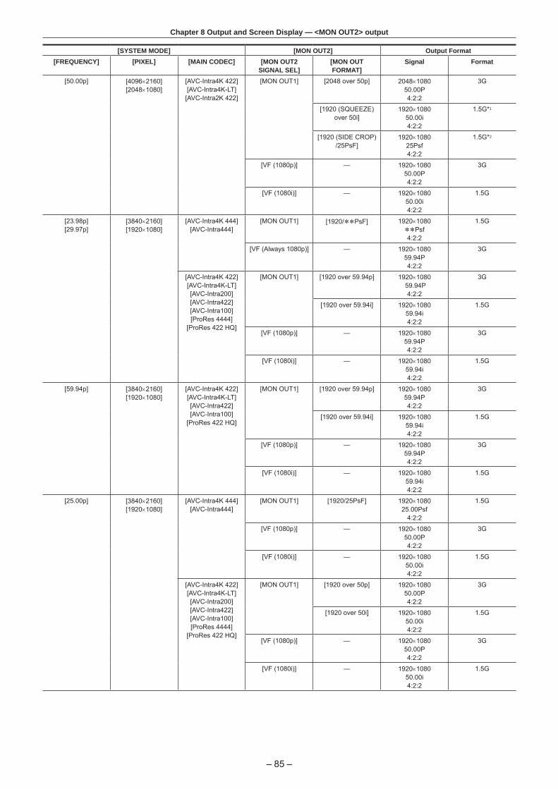
– 85 –
Chapter 8 Output and Screen Display — <MON OUT2> output
[SYSTEM MODE] [MON OUT2] Output Format[FREQUENCY] [PIXEL] [MAIN CODEC] [MON OUT2
SIGNAL SEL][MON OUT FORMAT]
Signal Format
[50.00p] [4096×2160][2048×1080]
[AVC-Intra4K 422][AVC-Intra4K-LT][AVC-Intra2K 422]
[MON OUT1] [2048 over 50p] 2048×108050.00P4:2:2
3G
[1920 (SQUEEZE) over 50i]
1920×108050.00i4:2:2
1.5G*1
[1920 (SIDE CROP) /25PsF]
1920×108025Psf4:2:2
1.5G*2
[VF (1080p)] — 1920×108050.00P4:2:2
3G
[VF (1080i)] — 1920×108050.00i4:2:2
1.5G
[23.98p][29.97p]
[3840×2160][1920×1080]
[AVC-Intra4K 444][AVC-Intra444]
[MON OUT1] [1920/**PsF] 1920×1080**Psf4:2:2
1.5G
[VF (Always 1080p)] — 1920×108059.94P4:2:2
3G
[AVC-Intra4K 422][AVC-Intra4K-LT][AVC-Intra200][AVC-Intra422][AVC-Intra100][ProRes 4444]
[ProRes 422 HQ]
[MON OUT1] [1920 over 59.94p] 1920×1080 59.94P
4:2:2
3G
[1920 over 59.94i] 1920×108059.94i4:2:2
1.5G
[VF (1080p)] — 1920×108059.94P4:2:2
3G
[VF (1080i)] — 1920×108059.94i4:2:2
1.5G
[59.94p] [3840×2160][1920×1080]
[AVC-Intra4K 422][AVC-Intra4K-LT][AVC-Intra422][AVC-Intra100]
[ProRes 422 HQ]
[MON OUT1] [1920 over 59.94p] 1920×108059.94P4:2:2
3G
[1920 over 59.94i] 1920×108059.94i4:2:2
1.5G
[VF (1080p)] — 1920×108059.94P4:2:2
3G
[VF (1080i)] — 1920×108059.94i4:2:2
1.5G
[25.00p] [3840×2160][1920×1080]
[AVC-Intra4K 444][AVC-Intra444]
[MON OUT1] [1920/25PsF] 1920×108025.00Psf
4:2:2
1.5G
[VF (1080p)] — 1920×108050.00P4:2:2
3G
[VF (1080i)] — 1920×108050.00i4:2:2
1.5G
[AVC-Intra4K 422][AVC-Intra4K-LT][AVC-Intra200][AVC-Intra422][AVC-Intra100][ProRes 4444]
[ProRes 422 HQ]
[MON OUT1] [1920 over 50p] 1920×108050.00P4:2:2
3G
[1920 over 50i] 1920×108050.00i4:2:2
1.5G
[VF (1080p)] — 1920×108050.00P4:2:2
3G
[VF (1080i)] — 1920×108050.00i4:2:2
1.5G

– 86 –
Chapter 8 Output and Screen Display — <MON OUT2> output
[SYSTEM MODE] [MON OUT2] Output Format[FREQUENCY] [PIXEL] [MAIN CODEC] [MON OUT2
SIGNAL SEL][MON OUT FORMAT]
Signal Format
[50.00p] [3840×2160][1920×1080]
[AVC-Intra4K 422][AVC-Intra4K-LT][AVC-Intra422][AVC-Intra100]
[ProRes 422 HQ]
[MON OUT1] [1920 over 50p] 1920×108050.00P4:2:2
3G
[1920 over 50i] 1920×108050.00i4:2:2
1.5G
[VF (1080p)] — 1920×108050.00P4:2:2
3G
[VF (1080i)] — 1920×108050.00i4:2:2
1.5G
*1 The horizontal effective pixels are converted from 2048 pixels to 1920 pixels to squeeze the image.*2 It will be the side-crop display with 64 pixels cropped from left and right from the 2048 horizontal valid pixels.
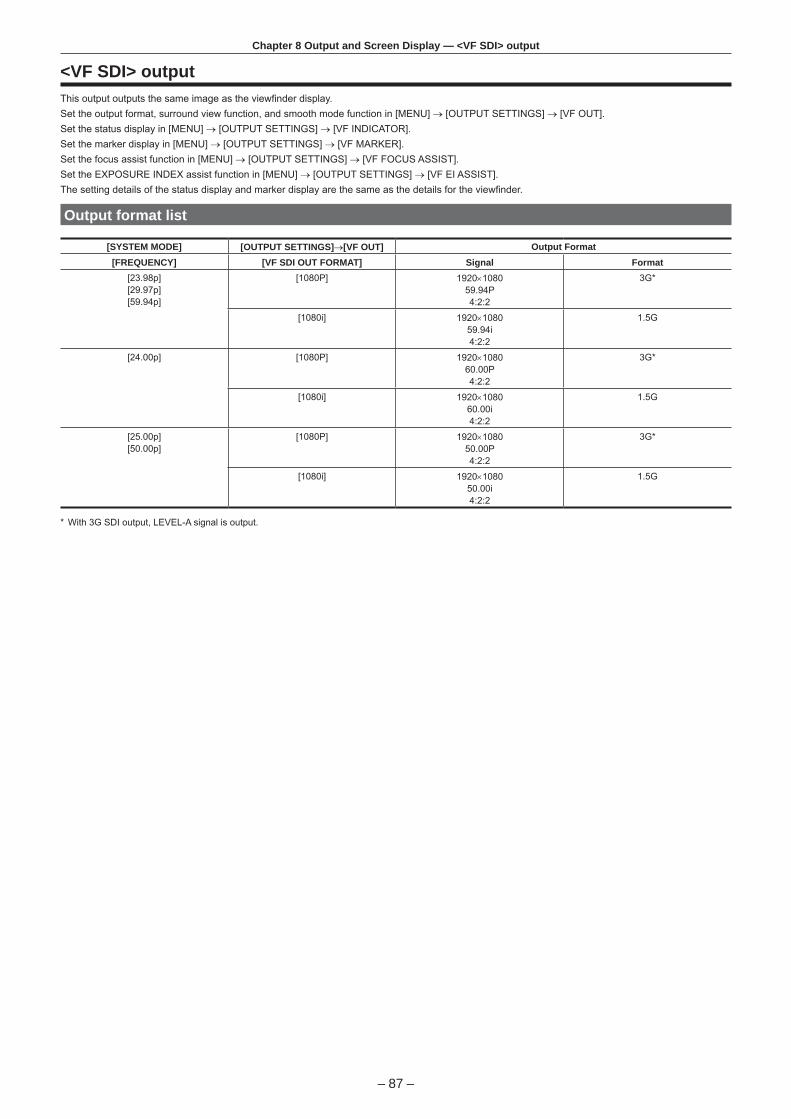
– 87 –
Chapter 8 Output and Screen Display — <VF SDI> output
<VF SDI> outputThis output outputs the same image as the viewfinder display.Set the output format, surround view function, and smooth mode function in [MENU] → [OUTPUT SETTINGS] → [VF OUT].Set the status display in [MENU] → [OUTPUT SETTINGS] → [VF INDICATOR].Set the marker display in [MENU] → [OUTPUT SETTINGS] → [VF MARKER].Set the focus assist function in [MENU] → [OUTPUT SETTINGS] → [VF FOCUS ASSIST].Set the EXPOSURE INDEX assist function in [MENU] → [OUTPUT SETTINGS] → [VF EI ASSIST].The setting details of the status display and marker display are the same as the details for the viewfinder.
Output format list
[SYSTEM MODE] [OUTPUT SETTINGS]→[VF OUT] Output Format[FREQUENCY] [VF SDI OUT FORMAT] Signal Format
[23.98p][29.97p][59.94p]
[1080P] 1920×108059.94P4:2:2
3G*
[1080i] 1920×108059.94i4:2:2
1.5G
[24.00p] [1080P] 1920×108060.00P4:2:2
3G*
[1080i] 1920×108060.00i4:2:2
1.5G
[25.00p][50.00p]
[1080P] 1920×108050.00P4:2:2
3G*
[1080i] 1920×108050.00i4:2:2
1.5G
* With 3G SDI output, LEVEL-A signal is output.

– 88 –
Chapter 8 Output and Screen Display — Screen status display
Screen status display
Status display (STATUS) in the <MON OUT1>, <MON OUT2>, and <VF SDI> outputs.
WRN4096 x 2160 23.98p I-2K422-200M I-2K422-100M M 999 S 999min TC 12:59:59:2380.5%
120fps
0010AA
180deg ISO12800 CC-15000K+10 99.9ft 1000.0mm ND 1.8 EX i-SHOT
GPS+7STOP
T11.0
PXY
1
15 17 1916
2 43 5 6 7 8 10 11
13 14
9
21 22 2418 2012 23 25
1 System pixel2 System frequency3 Main recorder recording status4 Main codec5 Sub recorder recording status6 Sub codec7 Card remaining free space8 Battery charge level9 Time code10 Warning11 Proxy12 Clip name13 Focus bar (only output from <VF SDI> terminal)14 FPS 15 Shutter16 EXPOSURE INDEX 17 White balance18 Y GET 19 Iris20 Focus position21 Zoom22 ND filter23 Extender24 Recording mode (to be supported)25 GPS status

– 89 –
Chapter 8 Output and Screen Display — Screen status display
Control panel status display (VIEW screen)
4096 x 2160 23.98p I-2K422-200M I-2K422-100M
M 999 S 999min TC 12:59:59:23
120fps 180deg ISO12800 CC-15000K+10
99.9ft 1000.0mmND 1.8
EX
i-SHOT
GPS
+7STOP 0010AAT11.0
PXYFULL
21
14 17 1915
3 105 116 7 8
12 13 2316 21
94
18 20 22
1 Card remaining free space2 System pixel3 System frequency4 Battery charge level5 Main recorder recording status6 Main codec7 Sub recorder recording status8 Sub codec9 Proxy10 Time code11 Recording mode (to be supported)12 Iris13 FPS 14 ND filter15 Shutter16 Y GET 17 EXPOSURE INDEX 18 Clip name19 White balance20 Focus position21 GPS status22 Zoom23 Extender

This chapter describes other useful features such as function buttons, etc.
Chapter 9 Other Useful Functions

– 91 –
Chapter 9 Other Useful Functions — Getting position information using the GPS
Getting position information using the GPSThe camera has a built-in GPS. Positioning information can be recorded through GPS.The GPS antenna is placed on top of the camera module.When using the GPS function, do not cover the top of the camera module with metallic objects.
f [GPS] flashes in the viewfinder screen when positioning preparation is being performed. fWhen positioning is complete, [GPS] lights up and GPS signal reception strength is indicated by 4-level bars. f If the time is received using GPS, the time of the internal clock is maintained accurately based on the time received (Greenwich mean time) and the time zone. f If the date and time display is different from the local time, the time zone setting may be incorrect. Recheck the time zone settings.
@@ NOTE
t If it cannot position even after waiting several minutes, it means that the GPS signals are weak and difficult to receive. t Position in the open space with a clear view of the sky. t Detecting altitude may take more time than detecting latitude and longitude. t The followings are locations where the signals from the GPS satellite cannot be properly received. Thus, you may not be able to position or you have large margin of errors.- Indoors- Near buildings or a canyon of buildings- In underground shopping areas- In forests- While moving in trains or automobiles- Inside tunnels

– 92 –
Chapter 9 Other Useful Functions — Assigning functions to the USER buttons
Assigning functions to the USER buttonsSelected functions can be assigned to the USER buttons <1> to <4> and the control panel operation buttons.Set each function to be assigned to [USER1] to [USER10] in [MENU] → [SYSTEM SETTINGS] → [USER SWITCHES].There are no functions assigned to the USER button in the factory settings.
USER2
USER5
USER6
USER8 USER10USER1 USER3
USER4
USER7
USER9
Selectable functions
Item Description[INHIBIT] Disables assignment of functions.
[SIX USER BUTTONS] Sets against the USER <1> to <4> buttons, when the control panel operation button is used as the USER button.
[AWB] Assigns the automatic white balance function.
[ABB] Assigns the automatic black balance function.
[Y GET] Assigns the function for displaying the luminance level of the image at the position indicated by the square marker displayed near the center.
[EXPAND] Assigns the enlargement function.
[IN COLOR/SQ./MONO] Switches ON/OFF of the focus in color function, the focus square function, and the monochrome display function.
[WFM] Enables/disables the viewfinder wave form display.
[BARS] Assigns the color bars display function.
[FRAME LINE] Displays/hides the frame line display function.
[FALSE COLOR] Enables/disables the false color mode.
[VF COLOR] Switches output images from the viewfinder and the <VF SDI> terminal.
[MON1 COLOR] Switches output images from the <MON OUT1> terminal.
[MON2 COLOR] Switches output images from the <MON OUT2> terminal.
[VF DESQUEEZE] Switches ON/OFF of the de-squeeze function against the viewfinder and the output from the <VF SDI> terminal.
[VF IMAGE INVERT] Switches ON/OFF of the invert display function against the viewfinder and the output from the <VF SDI> terminal.
[SMOOTH MODE] Assigns the smooth mode function.
[TEXT MEMO] Assigns the text memo function.
[SHOT MARK] Assigns the shot mark function.
[MAIN SLOT SEL] Assigns the function for switching the card for recording when two or more cards are inserted in the main slot.
[SUB SLOT SEL] Assigns the function for switching the card for recording when two or more cards are inserted in the sub slot.
[REC SW] Assigns the function of the <REC> button.
[AUDIO MON VOL] Calls out the screen to adjust the monitor output of audio to the control panel.
[AUDIO IN VOL] Calls out the screen to adjust the input of audio to the control panel.
@@ NOTE
t Only the following functions can be assigned to [USER5] to [USER10].[INHIBIT], [EXPAND], [IN COLOR/SQ./MONO], [FRAME LINE], [VF COLOR], [MON1 COLOR], [MON2 COLOR], [SMOOTH MODE]

– 93 –
Chapter 9 Other Useful Functions — Handling setting data
Handling setting dataEach setting data can be saved to and read from an SD memory card.
File types
r Setup fileAll menu data
f Target settingAll [MENU] (except the following)
[SYSTEM SETTINGS] [CARDS/MEDIA] [CPS PASSWORD]
[CLOCK] [CLOCK SETTING]
[TIME ZONE]
[REC SETTINGS] [TC] [SET TC]
[SET UB]
[TC/UB/Dur.]
[OUTPUT SETTINGS] [VF FOCUS ASSIST] [EXPAND SW]
f File extension.p2s
r Lens fileIndividual lens correction data
fNumber of files that can be saved in the camera64 f File extension.ins
r 3D LUT file3D LUT data for in-camera grading
f File extension.vlt
r CDL fileCDL data for in-camera grading
f File extension.cdl
r MetafileMetadata for setting [REC META DATA] (only reading from the SD memory card)
f File extension.p2
Handling SD memory cardsThe SD memory card can be removed and inserted, either before or after the power is turned on.
Inserting SD memory cards
Fig. 1 Fig. 2
1 Open the slot cover. (Fig. 1)
2 Insert the SD memory card into the SD memory card slot with the label side of the card upward, and close the slot cover. (Fig. 2)
@@ NOTE
t The SD memory card must be inserted with the correct side facing the SD card slot. If the SD memory card is hard to insert, it may be reversed or upside-down. Do not force it into the slot. Check the orientation of the card before reinserting it.
t Cautions when using SD memory cards- On the camera, use SD memory cards that conform to the SD standard, SDHC standard, or the SDXC standard.

– 94 –
Chapter 9 Other Useful Functions — Handling setting data
- MMC (Multi Media Card) cannot be used. (Bear in mind that taking pictures may no longer be possible if you use them.)- When using miniSD/microSD cards with the camera, always install the adaptor specially designed for miniSD/microSD cards. (The camera will not
work properly if only the miniSD/microSD adaptor is installed. Make sure that the card has been inserted into the adaptor before use.)- Use of Panasonic SD memory cards and miniSD/microSD cards is recommended. Be sure to format cards on the camera before use.- Refer to our support desk at the following website for the latest information not included in this document.
http://pro-av.panasonic.net/- SDHC memory cards are a standard that was established in 2006 by the SD Association for large-capacity memory cards that exceed 2 GB.- SDXC memory cards are a standard that was established in 2009 by the SD Association for large-capacity memory cards that exceed 32 GB.
Removing SD memory cards
After opening the slot cover and making sure that the busy lamp is not illuminated, push the SD memory card further into the camera and then release. This releases the SD memory card from the card slot. Remove the SD memory card and close the slot cover.
Note the following points when using or storing memory cards. fAvoid high temperature and humidity. fAvoid water droplets. fAvoid charging with electricity.
Store the SD memory card with the card still inserted into the camera and with the slot cover closed.
Performing operations on SD memory cardsIf the SD memory card that was formatted in a standard other than the SD/SDHC/SDXC standards on a device other than the camera is inserted, [LOAD] or [SAVE] operation of the file cannot be performed. Format the SD memory card again.
Formatting SD memory cards
1 From [MENU] → [SYSTEM SETTINGS] → [CARDS/MEDIA] → [FORMAT CARD], select [SD CARD], and press the jog dial button.The confirmation screen is displayed.
2 Select [YES] on the confirmation screen, and press the jog dial button.When not formatting, select [NO], and press the jog dial button.
3 When the completion message is displayed, select [OK], and press the jog dial button.For details on error messages, refer to “During thumbnail and menu operation” (page 164).
@@ NOTE
t Data deleted as a result of formatting cannot be restored. Always check the data before formatting.

– 95 –
Chapter 9 Other Useful Functions — Setting the time data
Setting the time dataThe camera provides time codes, user bits, and date and time (real time) data as time data, and they are recorded in the frame in sync with video. They are also recorded as data for clip metadata files.
Definition of time data
r Time codeYou can switch to [REC RUN] and [FREE RUN] with the control panel.
f [FREE RUN]: The time code always advances even when the power is turned off, and it can be handled in the same way as time. It can also be recorded slaved to the time code input to the <TC IN/OUT> terminal. f [REC RUN]: Can be regenerated and recorded into the time code of clips recorded to P2 cards as a continuous value.
@@ NOTE
t In the following case, the values are not continuous.- When deleting recorded clips- When switching to 24PN and 30PN (25PN)- When recording is interrupted due to a malfunction of [REC WARNING], etc. during recording.
r User bitsTwo types of user bits are built in.
f LTC UB: Recorded as LTC and output from the <TC IN/OUT> terminal. It is also output as LTC of the SDI signal. fVITC UB: Recorded as VITC. It is also output as VITC of the SDI signal.
LTC UB can select and record user set values, time, year/month/day, the same value as time codes, camera frame rate information, and input value of external signals from the <TC IN/OUT> terminal, etc.VITC UB records the camera frame rate information.The LTC UB value of the recording start time can be recorded on the user bits of the clip metadata.
r Duration (clip length) counterThis counter counts from 0 each time recording starts.The duration of the recorded clip is displayed after recording.
r Date/time (real time) fBased on the internal clock, year, month, day, and time can be displayed on the viewfinder/LCD monitor and on the image output from the <VF SDI> terminal, etc. f The internal clock is used for measuring the free run time code while the power is off and as time and year/month/day data of the user bits. It is also used as the reference for file generation times during clip recording, which determine the sorting order of thumbnails and the order of playback. f It is also used to generate clip metadata and UMID (Unique Material Identifier).For details, refer to “Setting the date/time of the internal clock” (page 31).
User bits settingsSets the user bits to be recorded in the sub code area with the control panel.
Item Description[USER] Records internal user values. The user value can be set from [MENU] → [REC SETTINGS] → [TC] → [SET UB], the user value
can be set. Setting values are held even when the power is turned off.For details, refer to “How to input user bits” (page 95).
[TIME] Records the time measured by the internal clock.
[DATE] Records the hour digit of year/month/day/date-time measured by the internal clock.
[EXT INPUT] Records the user bits values currently entered to the <TC IN/OUT> terminal.
[TCG] Records the time code value.
[FRAME RATE] Records the camera photo frame rate information.When playing back clips recorded in native format, the same frame rate information as VITC UB is output regardless of the recorded value. Use at this setting when the editing device such as a computer uses the frame rate information of the user bits.
How to input user bitsBy setting user bits, information such as memos (date, time) up to eight digits long (hexadecimal) can be recorded.
1 Press the <TC> button to display the TC screen.
2 From the user bits display, select [User] in [UB MODE].
3 Select [SET].The [TC SET] screen is displayed.
4 Set the user bits using the jog dial button.
5 Press the jog dial button to confirm the user bits setting value.
@@ NOTE
t If you exit the user bits setting screen without pressing the jog dial button, the set values will be disabled.

– 96 –
Chapter 9 Other Useful Functions — Setting the time data
Retention of user bits in memory
User bit settings are automatically recorded and are retained even if the power is turned off.
Frame rate information
The relationship between frame rates, image pull-down, and time codes/user bits is as follows.
・60i:600 ・60P:608 ・30P:308 ・24P:248 ・24PN:24C ・50i:502 ・50P:50A ・25P:25A ・ **P:**9 ・ **P:**1 ・ **P:**D ・ **P:**B
・ ・
Verification information on the right-hand six digitsFixed values
Sequence No.24P: 0-4
Other than above: F-fixed
Media management informationUpdated frame flags and valid frame flagsREC mark
Camera image modeExample)
(During shooting)
(VFR 30PN or over 60P) (VFR over 60P) (VFR 24PN during shooting) (VFR 25PN or over 50P)
Setting the time code
1 Press the <TC> button to display the TC screen.
2 From the time code display, select [DF] or [NDF] in [DF/NDF].Set [DF] to advance the time code in the drop frame mode, and set [NDF] to advance it in the non-drop frame mode. Note, however, that the time code always runs in [NDF] in the 24p (23.98P) mode.
3 Select [SET].The [TC SET] screen is displayed.
4 Set the time code using the jog dial button.
5 Press the jog dial button to confirm the time code setting value.
Settable time code range
59.94P, 29.97P 00:00:00:00 to 23:59:59:29
23.98P 00:00:00:00 to 23:59:59:23
50P, 25P 00:00:00:00 to 23:59:59:24
@@ NOTE
t If you exit the time code setting screen without pressing the jog dial button, the set values will be disabled.
Time code function during battery replacement
Even during battery replacement, the backup mechanism functions, allowing the time code generator to continue operating.When each item of the system mode has been changed, the time code of free run may shift. Turn on the power again, check the time code, and reset it, if necessary.
Time codes in variable frame rate
f In 24PN, recording is 24 frames, output is 30 frames, which matches 2:3 pull-down images. f The advance rate of the recording and output time code matches real time only when the image frame rate is 24P. When 60P, recording advance rate is 60/24 times. In this case, the camera switches to [REC RUN] fixed operation and the time code value that is output when recording starts matches the recording time code. f It is the same when shooting in modes other than 30P when in 30PN and shooting in modes other than 25P when in 25PN.
Externally locking the time codeThe internal time code generator of the camera can be locked to an external generator.
Example of connections for external locking
As shown in the figure, connect both the reference video signal and the reference time code.

– 97 –
Chapter 9 Other Useful Functions — Setting the time data
Reference time code
<GENLOCK IN> terminal
<TC IN/OUT> terminal
Reference video signal
External lock operation procedure
To externally lock the time code, follow the steps below.
1 Press the <TC> button to display the TC screen.
2 From the time code display, select [Free Run] in [Free/Rec].
3 From [MENU] → [REC SETTINGS] → [TC] → [TC IN/OUT SEL], select [TC IN].
4 Enter the external time code from the <TC IN/OUT> terminal.[SLAVE] is displayed on the TC screen.The [TCG] characters on the HOME screen are displayed in black and white inversion.
f For the reference video signal, enter the SDI signal which is the same format as the system signal format ([FREQUENCY], [PIXEL]). fWhen the system frequency is 59.94p or 50p, the time code may be out of sync by one field. fWhen the input reference signal of generator lock is disrupted, recording cannot be performed normally. [TEMPORARY PAUSE IRREGULAR SIG] is displayed in the viewfinder screen, and the clip is divided. The synchronization with the time code is also not guaranteed. Recording will resume when the signal returns to normal. fWhen the time code is externally locked, the time code is instantaneously locked to the external time code, the same value as the value of the external time code is output to the counter display area. Do not set to the recording mode for several seconds until the sync generator has stabilized. Furthermore, lock the time code to the <TC IN/OUT> terminal signal. f If you execute the slave once, even if there is no longer <TC IN/OUT> terminal and <GENLOCK IN> terminal input, the slave status is maintained. However, in the following cases, the slave status will be released.- When [TC SET] is executed- When the power is turned off- When switched [DF]/[NDF]- When set to [Rec Run]- When a variable frame rate is applied f The SDI input time code cannot be slave-locked (synchronized). f If [EXT INPUT] is selected in [UB MODE] of the UB screen, regardless of the time code slave status, the user bits can be matched with the user bits input in the <TC IN/OUT> terminal. In this case, [UBG] characters are black and white inverted.
Cautions when switching the power supply from the battery to the external power supply while an external lock is active
To keep on the time code generator power supply continuously, connect an external power supply to the <DC IN> terminal and then remove the battery pack. If the battery pack is removed first, there is no guarantee that the time code will stay externally locked.
Supplying the time code externallyYou can supply the output time codes to an external recording device from the camera by matching the camera images or the replayed images.

– 98 –
Chapter 9 Other Useful Functions — Setting the time data
Connection example for supplying to external device
r When locking external devices to the camera
<TC IN/OUT> terminal
<SDI OUT1>/<SDI OUT2>/<SDI OUT3>/<SDI OUT4> terminal
VIDEO IN terminalSDI IN terminalHD SDI IN terminal
TC IN terminal
VTR, etc.
r When two cameras are connected and one is used as a reference cameraWhen using two cameras in which one is used as a reference camera to slave the time code, make the connection as follows.
<TC IN/OUT> terminal
Reference camera Slave camera
<TC IN/OUT> terminal
<SDI OUT1> terminal<GENLOCK IN> terminal
@@ NOTE
t Sets the <TC IN/OUT> terminal to output or input in [MENU] → [REC SETTINGS] → [TC] → [TC IN/OUT SEL]. t By setting [MENU] → [REC SETTINGS] → [TC] → [TC OUT REF] to [RECORDING] on both cameras, the two cameras will be able to record with the same time code on the video at the same time.
Operating procedure
1 From [MENU] → [REC SETTINGS] → [TC] → [TC IN/OUT SEL], set [TC OUT]. f To match the time code output from the <TC IN/OUT> terminal to the SDI output and monitor output image, set [MENU] → [REC SETTINGS] → [TC] → [TC OUT REF] to [SDI OUT]. f To output TCR during playback, set [MENU] → [REC SETTINGS] → [TC] → [TC OUT] to [TCG/TCR].These settings are not required, if the internal device uses LTC or VITC output multiplexed to the SDI output.

– 99 –
Chapter 9 Other Useful Functions — Connection through the <USB DEVICE> terminal
Connection through the <USB DEVICE> terminal
Connecting to a computer in the USB device mode
Connecting to a computer
Fig. 1
1 Connect the USB cable to the <USB DEVICE> terminal (device). (Fig. 1)
2 Set the [MENU] → [SYSTEM SETTINGS] → [INFORMATION] to [USB].For details, refer to “Setting menu basic operations” (page 102).During USB connection, [USB DEVICE CONNECTED] is displayed in the center of the control panel.If it is not connected properly, [USB DEVICE DISCONNECTED] is displayed.
3 Exit the USB device mode.There are following two methods:
f Turn the power switch of the camera to <OFF>. fPress the <HOME> button.
@@ NOTE
t The USB 2.0 cable is not supplied with the camera. Prepare a commercial USB 2.0 cable (double-shielded for noise suppression). t A USB connection cable of up to 5 m is supported, however, a cable of 3 m or shorter is recommended as preferable. t When the camera is operating in the USB device mode, no camera shooting, recording/playback operation or clip thumbnail operation is allowed. t When the camera is operating in the USB device mode, the P2 card remaining capacity and status are not displayed. Also, video/audio cannot be output or displayed.

This chapter describes how to operate the camera menus, the structure, and details of the setting menu.
Chapter 10 Menu Operations

– 101 –
Chapter 10 Menu Operations — Setting menu structure
Setting menu structure
Menu configurationThe setting menu is configured as follows.
[SYSTEM SETTINGS] Sets the system in general.Sets the system frequency, the number of lines, recording format, and recording method.
[CAMERA SETTINGS] Sets the fine quality adjustment of camera videos and sets camera operation. This item is also handled as a scene file.There are a limited number of fine image quality adjustment items in the factory settings. If [MENU] → [CAMERA SETTINGS] → [Enhanced] → [Enhanced SW] is set to [ON], operation of all items can be performed.
[REC SETTINGS] The various setting items of the recording function of the camera.
[AUDIO SETTINGS] Various setting items for audio recording.
[OUTPUT SETTINGS] Sets the content of displaying output video from the video output terminal.
[FILE] Performs file-related operations such as reading/writing menu settings data from/to an SD memory card, and handling lens files. This item will be available in future version upgrade.
[PERIPHERAL] Applies settings related to functions used in conjunction with peripheral devices, such as network and GPS devices.
[Enhanced] menu
The camera has an extended ([Enhanced]) menu that can be used to perform fine image quality adjustment for camera videos.The extended menu is not displayed by default in the factory settings. To display extended menu items, set [MENU] → [CAMERA SETTINGS] → [Enhanced] → [Enhanced SW] to [ON].The presence of items marked with in the menu list indicates that you are viewing the extended menu.When [MAIN COLOR] is set to [V-Log] or [3D LUT], the setting in [MENU] → [CAMERA SETTINGS] → [Enhanced] → [Enhanced SW] is fixed to [OFF].

– 102 –
Chapter 10 Menu Operations — Setting menu display
Setting menu display
Setting menu basic operationsYou can change camera settings using the setting menu according to the shooting scene and recording details.Set data are written and saved in the internal memory of the camera.
b
a
c
a: <MENU> buttonb: <EXIT> buttonc: Jog dial button
1 Press the <MENU> button when not recording. f The [MENU] screen is displayed on the control panel.
2 Turn the jog dial button to place the cursor on the desired menu item. f Turn the jog dial button to move the cursor vertically.
3 Press the jog dial button. f The next level of screen is displayed.If there is another level, press the jog dial button again to display it. f The current setting value of the item selected on the right is displayed.
4 Turn the jog dial button to place the cursor on the desired item.
5 Press the jog dial button.The item is in the setting status.If there are two items, the setting value selection frame may be displayed on the right.
6 Turn the jog dial button to place the cursor on the desired item.
7 Press the jog dial button.Setting is completed.
8 Press the <EXIT> button to close the menu.
Setting menu initializationThe values set in the setting menu can be reset to the factory setting.
1 Select [LOAD FACTORY DATA] from [MENU] → [SYSTEM SETTINGS] → [INITIALIZE].[MENU] setting values are reset to factory settings.

– 103 –
Chapter 10 Menu Operations — Menu list
Menu list
[SYSTEM SETTINGS]Sets the system in general.
f is the extended menu. Set [MENU] → [CAMERA SETTINGS] → [Enhanced] → [Enhanced SW] to [ON] to display the extended menu.
Item Description of settings[SYSTEM MODE] [FREQUENCY] Sets the system frequency.
If the setting of this item is changed, the device must be restarted. If a restart is required, a confirmation dialog will be shown.The camera’s system operation are determined by four settings: [FREQUENCY], [PIXEL], [MAIN CODEC], and [HIGH SPEED]. Check the four settings.[23.98p], [24.00p], [25.00p], [29.97p], [50.00p], [50.00i], [59.94p], [59.94i]
f Factory setting: [23.98p]
[V-RAW] Sets the V-RAW format.Displayed only when the V-RAW recorder is connected.[4K/12bit], [4K/10bit], [UHD/12bit], [UHD/10bit]
f Factory setting: [4K/12bit]
[MAIN PIXEL] Sets the main recorder’s number of recording pixels.[4096×2160], [3840×2160], [2048×1080], [1920×1080]
f Factory setting: [4096×2160]
[MAIN CODEC] Sets the main recorder’s recording codec. Selectable items vary depending on the [FREQUENCY]/[PIXEL] setting.[AVC-Intra4K 444], [AVC-Intra4K 422], [AVC-Intra4K-LT], [AVC-Intra2K 444], [AVC-Intra2K 422], [AVC-Intra444], [AVC-Intra200], [AVC-Intra422], [AVC-Intra100], [ProRes 422 HQ], [ProRes 4444], [OFF][OFF] is displayed only when the V-RAW recorder is connected.
f Factory setting: [AVC-Intra4K 422]
[SUB CODEC] Sets the sub recorder’s recording codec. Selectable items vary depending on the [FREQUENCY]/[PIXEL] setting.At the same time, this enables/disables proxy data recording.[AVC-Intra2K 422], [AVC-Intra422], [AVC-Intra100], [AVC-LongG50], [AVC-LongG25], [AVC-Intra2K 422 & Pxy], [AVC-Intra100 & Pxy], [AVC-LongG50 & Pxy], [AVC-LongG25 & Pxy], [OFF]
f Factory setting: [AVC-Intra2K 422]
[VFR SUB REC] Sets the operation of the sub recorder during the variable frame rate operation.[VFR up to 60p (50p)], [NORMAL+Audio]
f Factory setting: [VFR up to 60p]
[HIGH SPEED] Sets the high speed mode.[ON (**-**fps)], [OFF (1-**fps)]The variable frame rate recording is not possible when the variable range of the variable frame rate is exceeding 60 fps, and it is displayed with [(NO SUB VFR)].** represents the variable range of VFR. This will change depending on the [MAIN CODEC] setting. Depending on the [MAIN CODEC] setting, when [HIGH SPEED] is set to [ON (**-**fps)], [CAMERA SETTINGS] → [FPS] → [VFR SW] is fixed to [ON].
f Factory setting: [OFF (1-60fps)]
[COLOR SETTING] [MAIN] Sets the colors of videos (entire camera system) recorded in the main recorder.[V-Log]/[V-709]/[3D LUT]It is fixed to [V-Log] when connected to the V-RAW recorder.
f Factory setting: [V-Log]
[GRADING] Sets whether to apply the grading process.This only enabled when [V-Log] is set in [MAIN].[Internal]: Sets grading with the control panel.[OFF]: Disables the grading process.[External App]: Sets the grading using an external application.
f Factory setting: [OFF]
[SUB] Sets the colors of videos (entire camera system) recorded in the sub recorder.Selectable items vary depending on the [MAIN] setting.When [MAIN] is set to [V-Log] and [GRADING] is set to [Internal] or [External App][V-Log]/[GRADING]When [MAIN] is set to [V-Log] and [GRADING] is set to [OFF][V-Log]/[V-709]When [MAIN] is set to [V-709][V-709]When [MAIN] is set to [3D LUT][3D LUT]
f Factory setting: [V-Log]
[3D LUT] Sets the grading process method when [GRADING] is set to [Internal] or [External App].When [GRADING] is set to [Internal] or [External App][OFF]/[V-709]/[LOADED FILE]/[FILE SEL]/[SAVE AS(SD CARD)]When [GRADING] is set to [OFF][OFF]
f Factory setting: [OFF]

– 104 –
Chapter 10 Menu Operations — Menu list
Item Description of settings[PLAYBACK GRADING] Sets the grading method during the playback.
[ON]: Applies grading process to the playback video based on the grading information of the recording.[OFF]: Performs grading process to the playback video based on the setting in [SYSTEM SETTINGS] → [COLOR SETTING] → [MON 1]/[MON 2]/[VF]/[VF SDI]. The grading process is applied only to video recording V-Log.The grading process is not performed to the video from the SDI output terminal.
f Factory setting: [OFF]
[CDL] Sets the grading process method when [GRADING] is set to [Internal] or [External App].When [GRADING] is set to [Internal] or [External App][ON]/[OFF]/[SAVE AS(SD CARD)]When [GRADING] is set to [OFF][OFF]
f Factory setting: [OFF]
[MON 1] Sets the output image from the <MON OUT1> terminal.Selectable items vary depending on the [MAIN] setting.When [MAIN] is set to [V-Log] and [GRADING] is set to [Internal] or [External App][V-Log]/[GRADING]When [MAIN] is set to [V-Log] and [GRADING] is set to [OFF][V-Log]/[V-709]When [MAIN] is set to [V-709][V-709]When [MAIN] is set to [3D LUT][3D LUT]
f Factory setting: [V-Log]
[MON 2] Sets the output image from the <MON OUT2> terminal.Selectable items vary depending on the [MAIN] setting.When [MAIN] is set to [V-Log] and [GRADING] is set to [Internal] or [External App][V-Log]/[GRADING]When [MAIN] is set to [V-Log] and [GRADING] is set to [OFF][V-Log]/[V-709]When [MAIN] is set to [V-709][V-709]When [MAIN] is set to [3D LUT][3D LUT]
f Factory setting: [V-Log]
[VF] Sets the output image from the <VF> terminal and the <VF SDI> terminal.Selectable items vary depending on the [MAIN] setting.When [MAIN] is set to [V-Log] and [GRADING] is set to [Internal] or [External App][V-Log]/[GRADING]/[V-709]/[LCC]When [MAIN] is set to [V-Log] and [GRADING] is set to [OFF][V-Log]/[V-709]/[LCC]When [MAIN] is set to [V-709][V-709]When [MAIN] is set to [3D LUT][3D LUT]
f Factory setting: [V-Log]
[VF SDI] Sets the output image from the <VF SDI> terminal.Selectable items vary depending on the [MAIN] setting.When [MAIN] is set to [V-Log][Same As VF]/[V-Log]When [MAIN] is set to anything other than [V-Log][Same As VF]
f Factory setting: [Same As VF]
[ANAMORPHIC DESQUEEZE]
[SUB REC & MON OUT] Sets if the image to be recorded in the sub recorder and the monitor output image is to be de-squeezed.[ON], [OFF]
f Factory setting: [OFF]
[VF & VF SDI] Sets if the output image from the <VF> terminal and the <VF SDI> terminal is to be de-squeezed.[ON], [OFF]
f Factory setting: [OFF]
[DESQUEEZE RATIO] Sets the de-squeeze ratio.[1.3x]: De-squeeze 1.3 times in horizontal direction.[1.3xmag]: It will be in aspect ratio of 2.39:1 for mastering generated from the image de-squeezed 1.3 times in horizontal direction.[2.0x]: De-squeeze 2.0 times in horizontal direction.[2.0xmag]: It will be in aspect ratio of 2.39:1 for mastering generated from the image de-squeezed 2.0 times in horizontal direction.
f Factory setting: [1.3x]
[IMAGE INVERT] [SUB REC & MON OUT] Sets if the image to be recorded in the sub recorder and the monitor output image is to be inverted.[ON], [OFF]
f Factory setting: [OFF]
[VF & VF SDI] Sets if the output image from the <VF> terminal and the <VF SDI> terminal is to be inverted.[ON], [OFF]
f Factory setting: [OFF]

– 105 –
Chapter 10 Menu Operations — Menu list
Item Description of settings[INVERT SELECT] Sets the type of inversion.
[VERTICAL]: Invert vertically[HORIZONTAL]: Invert horizontally[180° ROTATE]: Invert vertically and horizontally
f Factory setting: [HORIZONTAL]
[USER SWITCHES] [USER1] Sets the function to be assigned to the USER <1> button.[INHIBIT], [SIX USER BUTTONS], [AWB], [ABB], [Y GET], [EXPAND], [IN COLOR/SQ./MONO], [WFM], [BARS], [FRAME LINE], [FALSE COLOR], [VF COLOR], [MON1 COLOR], [MON2 COLOR], [VF DESQUEEZE], [VF IMAGE INVERT], [SMOOTH MODE], [TEXT MEMO], [SHOT MARK], [MAIN SLOT SEL], [SUB SLOT SEL], [REC SW], [AUDIO MON VOL], [AUDIO IN VOL]
f Factory setting: [INHIBIT]
[USER2] Sets the function to be assigned to the USER <2> button.[INHIBIT], [SIX USER BUTTONS], [AWB], [ABB], [Y GET], [EXPAND], [IN COLOR/SQ./MONO], [WFM], [BARS], [FRAME LINE], [FALSE COLOR], [VF COLOR], [MON1 COLOR], [MON2 COLOR], [VF DESQUEEZE], [VF IMAGE INVERT], [SMOOTH MODE], [TEXT MEMO], [SHOT MARK], [MAIN SLOT SEL], [SUB SLOT SEL], [REC SW], [AUDIO MON VOL], [AUDIO IN VOL]
f Factory setting: [INHIBIT]
[USER3] Sets the function to be assigned to the USER <3> button.[INHIBIT], [SIX USER BUTTONS], [AWB], [ABB], [Y GET], [EXPAND], [IN COLOR/SQ./MONO], [WFM], [BARS], [FRAME LINE], [FALSE COLOR], [VF COLOR], [MON1 COLOR], [MON2 COLOR], [VF DESQUEEZE], [VF IMAGE INVERT], [SMOOTH MODE], [TEXT MEMO], [SHOT MARK], [MAIN SLOT SEL], [SUB SLOT SEL], [REC SW], [AUDIO MON VOL], [AUDIO IN VOL]
f Factory setting: [INHIBIT]
[USER4] Sets the function to be assigned to the USER <4> button.[INHIBIT], [SIX USER BUTTONS], [AWB], [ABB], [Y GET], [EXPAND], [IN COLOR/SQ./MONO], [WFM], [BARS], [FRAME LINE], [FALSE COLOR], [VF COLOR], [MON1 COLOR], [MON2 COLOR], [VF DESQUEEZE], [VF IMAGE INVERT], [SMOOTH MODE], [TEXT MEMO], [SHOT MARK], [MAIN SLOT SEL], [SUB SLOT SEL], [REC SW], [AUDIO MON VOL], [AUDIO IN VOL]
f Factory setting: [INHIBIT]
[USER5] Sets the function to be assigned to the control panel operation button. The control panel operation button functions as a USER button.Assign [SIX USER BUTTONS] to USER buttons <1> to <4>.[INHIBIT], [EXPAND], [IN COLOR/SQ./MONO], [FRAME LINE], [FALSE COLOR], [VF COLOR], [MON1 COLOR], [MON2 COLOR], [SMOOTH MODE]
f Factory setting: [INHIBIT]
[USER6] Sets the function to be assigned to the control panel operation button. The control panel operation button functions as a USER button.Assign [SIX USER BUTTONS] to USER buttons <1> to <4>.[INHIBIT], [EXPAND], [IN COLOR/SQ./MONO], [FRAME LINE], [FALSE COLOR], [VF COLOR], [MON1 COLOR], [MON2 COLOR], [SMOOTH MODE]
f Factory setting: [INHIBIT]
[USER7] Sets the function to be assigned to the control panel operation button. The control panel operation button functions as a USER button.Assign [SIX USER BUTTONS] to USER buttons <1> to <4>.[INHIBIT], [EXPAND], [IN COLOR/SQ./MONO], [FRAME LINE], [FALSE COLOR], [VF COLOR], [MON1 COLOR], [MON2 COLOR], [SMOOTH MODE]
f Factory setting: [INHIBIT]
[USER8] Sets the function to be assigned to the control panel operation button. The control panel operation button functions as a USER button.Assign [SIX USER BUTTONS] to USER buttons <1> to <4>.[INHIBIT], [EXPAND], [IN COLOR/SQ./MONO], [FRAME LINE], [FALSE COLOR], [VF COLOR], [MON1 COLOR], [MON2 COLOR], [SMOOTH MODE]
f Factory setting: [INHIBIT]
[USER9] Sets the function to be assigned to the control panel operation button. The control panel operation button functions as a USER button.Assign [SIX USER BUTTONS] to USER buttons <1> to <4>.[INHIBIT], [EXPAND], [IN COLOR/SQ./MONO], [FRAME LINE], [FALSE COLOR], [VF COLOR], [MON1 COLOR], [MON2 COLOR], [SMOOTH MODE]
f Factory setting: [INHIBIT]
[USER10] Sets the function to be assigned to the control panel operation button. The control panel operation button functions as a USER button.Assign [SIX USER BUTTONS] to USER buttons <1> to <4>.[INHIBIT], [EXPAND], [IN COLOR/SQ./MONO], [FRAME LINE], [FALSE COLOR], [VF COLOR], [MON1 COLOR], [MON2 COLOR], [SMOOTH MODE]
f Factory setting: [INHIBIT]
[CARDS/MEDIA] [CPS PASSWORD] Sets the CPS encryption password for the expressP2 memory card and the microP2 memory card.[LOAD]: Loads CPS password from an SD memory card.[SET]: Enters the CPS password.[DELETE]: Deletes the password saved to the device, and disables encrypted formats.

– 106 –
Chapter 10 Menu Operations — Menu list
Item Description of settings[FORMAT MEDIA] Formats the card in the specified slot after the format menu is selected.
[V-RAW], [MAIN SLOT1], [MAIN SLOT2], [SUB SLOT1], [SUB SLOT2], [SD CARD]When a CPS password is set, you can select [NORMAL] (normal unencrypted format) or [CPS(ENCRYPT)] (encrypted format).Data deleted as a result of formatting cannot be restored. Always check the data before formatting.[V-RAW] is displayed only when the V-RAW recorder is connected.
[MEDIA END ALARM] Sets whether to generate an alarm sound when there is no remaining free space in the expressP2 memory card or the microP2 memory card.[ON], [OFF]
f Factory setting: [ON]
[POWER MANAGEMENT]
[DC IN SOURCE] Sets the type of the external power supply input into the <DC IN> terminal.[DC POWER SUPPLY]: Selected when connecting an AC adaptor. In this case, the remaining battery charge level is not displayed.[BATTERY]: Selected when connecting a battery to the <DC IN> terminal. Remaining charge level is detected from the voltage level.
f Factory setting: [DC POWER SUPPLY]
[DC IN BATTERY SETTINGS]
(Display only)
[- FULL VOLT] Sets the voltage to be displayed in the remaining charge level full display when an external battery is input from the <DC IN> terminal.[13.0V] - [17.0V] (0.1 V step)
f Factory setting: [15.5V]
[- NEAR END VOLT] Sets the remaining charge level near end voltage when an external battery is input from the <DC IN> terminal.[11.0V] - [15.0V] (0.1 V step)
f Factory setting: [13.2V]
[- END VOLT] Sets the remaining charge level end voltage when an external battery is input from the <DC IN> terminal.[11.0V] - [15.0V] (0.1 V step)
f Factory setting: [12.5V]
[ONBORD BATTERY SETTINGS]
(Display only)
[- BATTERY SELECT] Selected according to the battery used.[DIONIC], [HyTRON], [ENDURA], [PAG]: The remaining charge level is detected and a warning is displayed according to the [NEAR END Info] and [END Info] settings. When there is no remaining charge level information, the remaining charge level is detected from the voltage level.[other]: Remaining charge level is detected from the voltage level.
f Factory setting: [DIONIC]
[- FULL VOLT] Sets the voltage in the remaining charge level full display when the battery remaining charge level is detected from the voltage level.[13.0V] - [17.0V] (0.1 V step)
f Factory setting: [15.5V]
[- NEAR END VOLT] Sets the remaining charge level near end voltage when the battery remaining charge level is detected from the voltage level.[11.0V] - [15.0V] (0.1 V step)
f Factory setting: [13.2V]
[- END VOLT] Sets the remaining charge level end voltage when the battery remaining charge level is detected from the voltage level.[11.0V] - [15.0V] (0.1 V step)
f Factory setting: [12.5V]
[- NEAR END INFO] Sets the percentage value of the remaining charge level near end when remaining charge level information is acquired from the battery.[4%], [5%], [6%], [7%], [8%], [9%], [10%], [12%], [14%], [16%], [18%], [20%]
f Factory setting: [5%]
[- END INFO] Sets the percentage value of the remaining charge level end when remaining charge level information is acquired from the battery.[1%] - [10%] (1% step)
f Factory setting: [1%]
[EXT-REC DC IN SOURCE]
Sets the type of the external power supply connected to the DC input terminal of the V-RAW recorder when V-RAW shooting is performed connected to the V-RAW recorder.Displayed only when the V-RAW recorder is connected.[DC POWER SUPPLY]: Select when connecting the AC adaptor. The remaining battery charge level is not displayed in this case.[BATTERY]: Select when connecting a battery to the DC input terminal. The remaining battery level of the V-RAW recorder is detected in accordance with [EXT-REC BATT FULL], [EXT-REC BATT NEAR END], and [EXT-REC BATT END].
f Factory setting: [DC POWER SUPPLY]
[EXT-REC BATTERY SETTINGS]
(Display only)
[- FULL VOLT] Sets the voltage to fully charge when the remaining charge of the battery for the V-RAW recorder is detected with the voltage level.Displayed only when the V-RAW recorder is connected.[13.0V] - [17.0V] (0.1 V step)
f Factory setting: [15.5V]

– 107 –
Chapter 10 Menu Operations — Menu list
Item Description of settings[- NEAR END VOLT] Sets the near end voltage when the remaining charge of the battery for the V-RAW recorder is detected
with the voltage level.Displayed only when the V-RAW recorder is connected.[11.0V] - [15.0V] (0.1 V step)
f Factory setting: [13.2V]
[- END VOLT] Sets the end voltage when the remaining charge of the battery for the V-RAW recorder is detected with the voltage level.Displayed only when the V-RAW recorder is connected.[11.0V] - [15.0V] (0.1 V step)
f Factory setting: [12.5V]
[CAM DC IN SOURCE] Sets the type of the external power source input to the <DC IN> terminal of the camera extension module when the camera module and the recording module is separated and they are used connected with an extension cable.Displayed only when the extension module is attached.[DC POWER SUPPLY]: Selected when connecting an AC adaptor. In this case, the remaining battery charge level is not displayed.[BATTERY]: Selected when a battery is connected to the <DC IN> terminal. The remaining battery level of the camera extension module is detected in accordance with [CAM BATT FULL], [CAM BATT NEAR END], or [CAM BATT END].
f Factory setting: [DC POWER SUPPLY]
[CAM BATTERY SETTINGS]
(Display only)
[- FULL VOLT] Sets the voltage to display the remaining battery level of the camera extension module as full when the camera module and the recording module is separated and used by connecting them with a extension cable.Displayed only when the extension module is attached.[13.0V] - [17.0V] (0.1 V step)
f Factory setting: [15.5V]
[- NEAR END VOLT] Sets the near end voltage for the remaining battery level of the camera extension module when the camera module and the recording module is separated and used by connecting them with a extension cable.Displayed only when the extension module is attached.[11.0V] - [15.0V] (0.1 V step)
f The maximum value is the value set in [FULL Volt]. (However, the maximum is [15.0V]) f Factory setting: [13.2V]
[- END VOLT] Sets the end voltage for the remaining battery level of the camera extension module when the camera module and the recording module is separated and used by connecting them with a extension cable.Displayed only when the extension module is attached.[11.0V] - [15.0V] (0.1 V step)
f The maximum value is the value set in [NEAR END Volt]. f Factory setting: [12.5V]
[END ALARM] Sets whether to sound an alarm at battery remaining charge level end.[ON], [OFF]
f Factory setting: [ON]
[FAN] [FAN SPEED] Select the rotation speed of the fan.[REC AUTO]: The rotation speed is lowered simultaneously with start of recording. However, the fan will rotate in maximum speed when it reaches the specified temperature.[MATCH CODEC]: The fan will operate in rotation speed appropriate for each in accordance with [MAIN CODEC].[ALWAYS FULL]: The fan will always rotate at the maximum speed.
f Factory setting: [REC AUTO]
[GENLOCK] [GENLOCK MODE] Switches the synchronization signal of the camera signal.[INT]: Synchronizes to the internal standard signal.[EXT]: Synchronizes to the entered external standard signal.
f Factory setting: [INT]
[H PHASE COARSE] Roughly adjusts to match horizontal synchronization phase when building a system.[−100]…[100]
f Factory setting: [0]
[H PHASE FINE] Minutely adjusts to match horizontal synchronization phase when building a system.[−100]…[100]
f Factory setting: [0]
[SENSOR SYNCHRO] Sets the operation to synchronize the sensors for creating 3D video, etc.[MASTER]: Outputs with the synchronization signal superimposed to the output from the <SDI OUT1> terminal.[SLAVE]: Shoots with the sensor synchronized to the synchronization signal from the master. It is necessary to set [GENLOCK MODE] to [EXT] to perform slave operation. The synchronization signal is output from <SDI OUT1>.[OFF]: Output or receiving of the synchronization signal is not performed.
f Factory setting: [OFF]
[CONTROL DISPLAY] [BRIGHTNESS] Adjusts the brightness of the control panel.[−15]…[15]
f Factory setting: [0]
[COLOR LEVEL] Adjusts the color levels of the control panel.[−15]…[15]
f Factory setting: [0]

– 108 –
Chapter 10 Menu Operations — Menu list
Item Description of settings[CONTRAST] Adjusts the contrast of the control panel.
[−30]…[30] f Factory setting: [0]
[BACK LIGHT] Sets the brightness of the control panel backlight.[−1]: Darkens the display more than normal.[0]: Normal brightness.[1]: Brightens the display more than normal.
f Factory setting: [0]
[BUTTON LED] Illuminates each button of the control panel and camera module.[ON], [OFF]
f Factory setting: [ON]
[STATUS] Press the <VIEW> button to set whether to show the status display when a camera video is displayed on the control panel.[ON], [OFF]
f Factory setting: [ON]
[CLOCK] [CLOCK SETTING] Sets the built-in calendar (year/month/day) and time.[YEAR]: [2014] - [2037][MONTH]: [JAN]…[DEC] ([1]…[12])[DAY]: [1] - [31] ([28], [29], [30])[HOUR]: [0] - [23][MINUTE]: [0] - [59]
[TIME ZONE] Set the time zone. After setting the time, when changing the time zone setting, the displayed and registered times switch to the time with the time difference.[−12:00] - [+13:00](30-minute interval, without [+12:30] and with [+12:45])
[DATE FORMAT] Sets the display order of year/month/day.This is also applied to the recording date displayed in the clip properties.[Y-M-D]/[M-D-Y]/[D-M-Y]
f Factory setting: [Y-M-D]
[INFORMATION] [OPERATION TIME] Displays the operation time of the camera.
[VERSION] Displays the information of the camera.[VERSION]: Displays the version.[MODEL NAME]: Displays the product name.[SERIAL NO.]: Displays the serial number.
[UPDATE] Performs an update of the camera firmware. (Enabled only when there is a dedicated update file on the SD memory card.)
[USB] Switches the camera to mode for USB device function.
[TRACE LOG] Reads the camera’s execution log from an SD memory card.
[SENSOR TEMP] Displays the ambient temperature detected by the camera module’s sensor.
[INITIALIZE] [LOAD FACTORY DATA] Returns the menu values to their factory settings.[YES], [NO]
[CAMERA SETTINGS]Sets the fine quality adjustment of camera videos and camera operation.
is the extended menu. Set [MENU] → [CAMERA SETTINGS] → [Enhanced] → [Enhanced SW] to [ON] to display the extended menu.
Item Description of settings[Enhanced] [Enhanced SW] Enables/disables the [Enhanced] function.
[ON]: Enables the [Enhanced] function and shows the menu related to the [Enhanced] function.[OFF]: Disables the [Enhanced] function and hides the menu related to the [Enhanced] function.
f Factory setting: [OFF]
[FPS] [VFR SW] Enables/disables variable frame rate.[ON]: Enables the variable frame rate function. The desired frame rate can be set using [PRESET VALUE]/[VARIABLE VALUE]. Audio cannot be recorded.[OFF]: Disables the variable frame rate function. [VFR SW] is fixed to [ON] when [SYSTEM SETTINGS] → [SYSTEM MODE] → [HIGH SPEED] is set to [ON (**-**fps)].
f Factory setting: [OFF]
[FPS MODE] Selects the frame rate setting method.[PRESET]: Selects the frame rate from preset frame rates (maximum of 12).Registration is done from the control panel.[VARIABLE]: Selects the frame rate from all available frame rates.
f Factory setting: [PRESET]
[PRESET VALUE] Selects a value from a maximum of 12 values set from the control panel. f Factory setting: [24fps]
[VARIABLE VALUE] Selects the frame rate from all available frame rates. Selectable values vary depending on [SYSTEM MODE] settings.
f Factory setting: [24fps]
[WHITE] [AWB] Executes automatic white balancing.[EXECUTE], [CANCEL]
f Factory setting: [CANCEL]

– 109 –
Chapter 10 Menu Operations — Menu list
Item Description of settings[MODE] Selects the white balance mode.
[PRESET]: Selects the color temperature from preset color temperatures. Registration is done from the control panel.[TEMP SHIFT]: Selects the color temperature from all configurable color temperatures.
f Factory setting: [PRESET]
[PRESET VALUE] Selects a value from a maximum of 12 values set from the control panel.Preset values that can be selected in the factory setting are [3200K+0GMg], [4300K+0GMg], [5600(5500)K+0GMg], and [6300K+0GMg].
f Factory setting: [3200K+0GMg]
[TEMP SHIFT] Selects the color temperature from all configurable color temperatures.[2300K]…[15000K]
f Factory setting: [3200K]
[GMg] Adjusts the balance between green and magenta.+: Adjusts toward green.−: Adjusts toward magenta.[−10]…[10]
f Factory setting: [0]
[R GAIN] Adjusts the Rch gain.[−200]…[200]
f Factory setting: [0]
[B GAIN] Adjusts the Bch gain.[−200]…[200]
f Factory setting: [0]
[AWB OFFSET] Sets the Rch gain and Bch gain value when performing automatic white balancing.[ON]: Maintains and adds the values of [R GAIN] and [B GAIN] after performing automatic white balancing.[OFF]: Resets the value of [R GAIN] and [B GAIN] after performing automatic white balancing.
f Factory setting: [OFF]
[SHOCKLESS WHITE] Sets the transition time when switching preset values.[OFF]: Values are immediately switched.[1]: Switches in approximately one second.[2]: Switches in approximately two seconds.[3]: Switches in approximately five seconds.
f Factory setting: [OFF]
[BLACK] [ABB] Executes automatic black balancing. When executing automatic black balancing, put the cap on the lens to keep any light from entering the image sensor.[EXECUTE], [CANCEL]
f Factory setting: [CANCEL]
[M.PED] Sets the master pedestal level.[−100]…[100]
f Factory setting: [0]
[R PED] Adjusts the Rch pedestal level.[−100]…[100]
f Factory setting: [0]
[G PED] Adjusts the Gch pedestal level.[−100]…[100]
f Factory setting: [0]
[B PED] Adjusts the Bch pedestal level.[−100]…[100]
f Factory setting: [0]
[ABB OFFSET] Sets the pedestal levels for Rch, Gch, and Bch after performing the adjustment of the automatic black balance.[ON]: The values of [R PED], [G PED], and [B PED] are maintained and added even after performing the automatic black balance.[OFF]: The values of [R PED], [G PED], and [B PED] are reset after performing the automatic black balance.
f Factory setting: [OFF]
[INITIAL ABB] Executes the initialization of the sensor at the same time the automatic black balance is executed.This can be selected only when [HIGH SPEED] is set to [ON].Keep the light away from the image sensor by placing a cap on the lens, etc., when executing the automatic black balance.[EXECUTE], [CANCEL]
f Factory setting: [CANCEL]
[NR] [ISO800] Switches the noise reduction effect in the range of ISO200 to ISO4000.[ON], [OFF]The range will be ISO200 to ISO2000 when [HIGH SPEED] is set to [ON].The range will be 0 dB to 15 dB when [MODE] in [EI] is set to [dB].
f Factory setting: [OFF]
[ISO5000] Switches the noise reduction effect in the range of ISO5000 to ISO12800.[ON], [OFF]The range will be ISO2500 to ISO6400 when [HIGH SPEED] is set to [ON].The range will be 18 dB to 24 dB when [MODE] in [EI] is set to [dB].
f Factory setting: [OFF]
[EI] [MODE] Switches the EXPOSURE INDEX control unit.[ISO], [dB]
f Factory setting: [ISO]

– 110 –
Chapter 10 Menu Operations — Menu list
Item Description of settings[ISO SELECT] Selects the operation of ISO.
[NATIVE ONLY], [800BASE], [5000BASE] f Factory setting: [NATIVE ONLY]
[NATIVE ISO] Sets the value when [NATIVE ONLY] is selected.[800], [5000]The value will be [400] and [2500] when [HIGH SPEED] is set to [ON].
f Factory setting: [800]
[800BASE ISO] Sets the value when [800BASE] is selected.[200], [250], [320], [400], [500], [640], [800], [1000], [1250], [1600], [2000], [2500], [3200], [4000], [5000], [6400], [8000], [10000], [12800]It will be [200], [250], [320], [400], [500], [640], [800], [1000], [1250], [1600], [2000], [2500], [3200], [4000], [5000], and [6400] when the setting of [HIGH SPEED] is [ON].
f Factory setting: [800]
[5000BASE ISO] Sets the value when [5000BASE] is selected.[1250], [1600], [2000], [2500], [3200], [4000], [5000], [6400], [8000], [10000], [12800]It will be [1250], [1600], [2000], [2500], [3200], [4000], [5000], and [6400] when [HIGH SPEED] is set to [ON].
f Factory setting: [5000]
[SETTING(GAIN)] Sets the value when [dB] is selected.[0dB], [3dB], [6dB], [9dB], [12dB], [15dB], [18dB], [21dB], [24dB]
f Factory setting: [0dB]
[GAIN OFFSET SW] Sets whether to perform fine adjustment of control when [dB] is selected.[ON], [OFF]
f Factory setting: [OFF]
[OFFSET LEVEL] Sets the fine adjustment level.[0.0dB] - [0.9dB] (0.1 dB step)
f Factory setting: [0dB]
[SHUTTER] [SW] Enables/disables the shutter function.[ON], [OFF]
f Factory setting: [ON]
[DISPLAY MODE] Sets the shutter display unit.[sec]: Displays in time.[deg]: Displays at shutter open angle.
f Factory setting: [deg]
[MODE] Switches the shutter control mode.[PRESET]: Selects the mode from 12 modes inside the memory.[SYNCHRO]: Selects the mode from the operable range.
f Factory setting: [PRESET]
[SYNCHRO deg] Sets the value of angle control ([deg]).[1.0]…[358.0]
f Factory setting: [180.0]
[SYNCHRO sec] Sets the value of time control ([sec]). The lowest value changes depending on the frame rate ([FPS]) value.[1/60] - [1/250]
f Factory setting: [1/48]
[PRESET VALUE deg] Selects the angle control ([deg]) value from the maximum of 12 values set in the control panel.Preset values that can be selected in the factory setting are [11.5], [22.5], [45.0], [90.0], [120.0], [144.0], [172.8], [180.0], [270.0], and [358.0].
f Factory setting: [180.0]
[PRESET VALUE sec] Selects the time control ([sec]) value from the maximum of 12 values set in the control panel.Preset values that can be selected in the factory setting are [1/60], [1/100], [1/120], [1/250], [1/500], [1/1000], and [1/2000].
f Factory setting: [1/60]
[TEST SIG] [TEST SIG SEL] Sets the test signal output.[OFF]: Does not output a test signal.[BARS]: Outputs the color bar set in [COLOR BARS TYPE].
f Factory setting: [OFF]
[COLOR BARS TYPE] Set the color bar to be used.[SMPTE]: Uses the color bar in the SMPTE standard.[FULL]: Uses full color bars.
f Factory setting: [SMPTE]
[DETAIL] [SW] Enables/disables the detail function.[ON], [OFF]
f Factory setting: [OFF]
[CORING] Sets the coring amount for the detail signal.[0] - [60]
f Factory setting: [1]
[MASTER LEVEL] Sets the effect level for the detail signal.[−31]…[31]
f Factory setting: [0]
[SKIN DETAIL] [SW] Enables/disables the skin tone detail function.[OFF], [ON]
f Factory setting: [OFF]
[TABLE SELECT] Selects the table for the skin tone detail.[A], [B], [C], [A+B], [A+C], [B+C], [A+B+C]
f Factory setting: [A]

– 111 –
Chapter 10 Menu Operations — Menu list
Item Description of settings[GET] Sets whether to register the screen center color as the color by which the skin tone detail is applied.
[EXECUTE], [CANCEL][ZEBRA SW] Sets whether to superimpose the zebra signal to the color by which the skin tone detail is applied.
[ON], [OFF] f Factory setting: [OFF]
[EFFECT LEVEL] Sets the effective level of the skin tone detail. The higher the value, the more significant the effect.[0] - [31]
f Factory setting: [16]
[DETECT TABLE] Selects the skin tone table of the subject that displays the skin tone detail.[A], [B], [C]
f Factory setting: [A]
[I CENTER] Sets the center position of the upper I axis (setting the area that displays the skin tone).[0]…[255]
f Factory setting: [35]
[I WIDTH] Sets the width of the area that displays the skin tone of the upper I axis that focus on [I CENTER].[0]…[255]
f Factory setting: [55]
[Q WIDTH] Sets the width of the area that displays the skin tone of the upper Q axis that focus on [I CENTER].[0]…[127]
f Factory setting: [22]
[Q PHASE] Sets the phase of the area that displays the skin tone regarding to the Q axis.[0]…[255]
f Factory setting: [0]
[MATRIX] [SW] Enables/disables the matrix function.[ON], [OFF]
f Factory setting: [OFF]
[(R-G)_N] Adjusts the linear matrix.[−127]…[127]
f Factory setting: [0]
[(R-G)_P] Adjusts the linear matrix.[−127]…[127]
f Factory setting: [0]
[(R-B)_N] Adjusts the linear matrix.[−127]…[127]
f Factory setting: [0]
[(R-B)_P] Adjusts the linear matrix.[−127]…[127]
f Factory setting: [0]
[(G-R)_N] Adjusts the linear matrix.[−127]…[127]
f Factory setting: [0]
[(G-R)_P] Adjusts the linear matrix.[−127]…[127]
f Factory setting: [0]
[(G-B)_N] Adjusts the linear matrix.[−127]…[127]
f Factory setting: [0]
[(G-B)_P] Adjusts the linear matrix.[−127]…[127]
f Factory setting: [0]
[(B-R)_N] Adjusts the linear matrix.[−127]…[127]
f Factory setting: [0]
[(B-R)_P] Adjusts the linear matrix.[−127]…[127]
f Factory setting: [0]
[(B-G)_N] Adjusts the linear matrix.[−127]…[127]
f Factory setting: [0]
[(B-G)_P] Adjusts the linear matrix.[−127]…[127]
f Factory setting: [0]
[COLOR CORRECTION] [SW] Enables/disables the color correction function.[ON], [OFF]
f Factory setting: [OFF]
[R (SAT)] Corrects red color saturation.[−63]…[63]
f Factory setting: [0]
[R (PHASE)] Corrects the red hue.[−63]…[63]
f Factory setting: [0]
[R-Mg (SAT)] Corrects the color saturation between red and magenta.[−63]…[63]
f Factory setting: [0]

– 112 –
Chapter 10 Menu Operations — Menu list
Item Description of settings[R-Mg (PHASE)] Corrects the hue between red and magenta.
[−63]…[63] f Factory setting: [0]
[Mg (SAT)] Corrects magenta color saturation.[−63]…[63]
f Factory setting: [0]
[Mg (PHASE)] Corrects the magenta hue.[−63]…[63]
f Factory setting: [0]
[Mg-B (SAT)] Corrects the color saturation between magenta and blue.[−63]…[63]
f Factory setting: [0]
[Mg-B (PHASE)] Corrects the hue between magenta and blue.[−63]…[63]
f Factory setting: [0]
[B (SAT)] Corrects blue color saturation.[−63]…[63]
f Factory setting: [0]
[B (PHASE)] Corrects the blue hue.[−63]…[63]
f Factory setting: [0]
[B-Cy (SAT)] Corrects the color saturation between blue and cyan.[−63]…[63]
f Factory setting: [0]
[B-Cy (PHASE)] Corrects the hue between blue and cyan.[−63]…[63]
f Factory setting: [0]
[Cy (SAT)] Corrects cyan color saturation.[−63]…[63]
f Factory setting: [0]
[Cy (PHASE)] Corrects the cyan hue.[−63]…[63]
f Factory setting: [0]
[Cy-G (SAT)] Corrects the color saturation between cyan and green.[−63]…[63]
f Factory setting: [0]
[Cy-G (PHASE)] Corrects the hue between cyan and green.[−63]…[63]
f Factory setting: [0]
[G (SAT)] Corrects green color saturation.[−63]…[63]
f Factory setting: [0]
[G (PHASE)] Corrects the green hue.[−63]…[63]
f Factory setting: [0]
[G-Yl (SAT)] Corrects the color saturation between green and yellow.[−63]…[63]
f Factory setting: [0]
[G-Yl (PHASE)] Corrects the hue between green and yellow.[−63]…[63]
f Factory setting: [0]
[Yl (SAT)] Corrects yellow color saturation.[−63]…[63]
f Factory setting: [0]
[Yl (PHASE)] Corrects the yellow hue.[−63]…[63]
f Factory setting: [0]
[Yl-R (SAT)] Corrects the color saturation between yellow and red.[−63]…[63]
f Factory setting: [0]
[Yl-R (PHASE)] Corrects the hue between yellow and red.[−63]…[63]
f Factory setting: [0]
[SKIN CORRECTION] [SKIN AREA SW] Enables/disables the function which makes fine adjustments of near skin tone colors.[ON], [OFF]
f Factory setting: [OFF]
[SKIN AREA HUE] Makes fine adjustments in hue.[−63]…[63]
f Factory setting: [0]
[SKIN AREA TONE] Makes fine adjustments in tone.[−63]…[63]
f Factory setting: [0]

– 113 –
Chapter 10 Menu Operations — Menu list
Item Description of settings[EXT.FUNC] [FOCUS DISP] Sets the unit that displays the focus distance.
[Meter], [Feet] f Factory setting: [Feet]
[LENS SETTING] [A.IRIS TYPE] Determines whether to set the speed control to the lens volume and use the value set in the menu.[LENS], [CAM]
f Factory setting: [LENS]
[A.IRIS LEVEL EFFECT] Sets the target value during auto iris operation.[0] - [100]
f Factory setting: [30]
[A.IRIS SPEED] Sets the speed when the [A.IRIS TYPE] is set to [CAM].[1] - [20]
f Factory setting: [10]
[A.IRIS WINDOW] Selects the auto iris detection window.[NORMAL1]: Window that is near screen center.[NORMAL2]: Window that is near screen bottom.[CENTER]: Window that is a spot in the screen center.
f Factory setting: [NORMAL1]
[A.IRIS PEAK/AVE] Sets the ratio included in the peak for auto iris standard.[0] - [100]
f Factory setting: [30]
[LENS CONNECT TYPE]
Sets the type of lens to be connected.[TYPE A]: Lens controlled with LDS (Lens Data System). (ULTRA PRIME lens not supported)[TYPE B]: Lens controlled with 12-pin connector[TYPE C]: Lens controlled with cooke/i communication[OFF]: Other lenses
f Factory setting: [OFF]
[REC SETTINGS]The various setting items of the recording function of the camera.
Item Description of settings[FILE NAME STYLE] Sets the file name style.
[CINE]: Records a file as a file name of cinema style.For details, refer to “File name style” (page 34).[P2]: Records a file as a file name style unique to P2.
f Factory setting: [P2]
[REC FUNCTION] [REC MODE] Selects the special recording function.[NORMAL]: Normal recording[INTERVAL]: Interval recording (function to perform intermittent recording in constant interval)[ONE SHOT]: One-shot recording (function to perform recording of specified duration every time the REC button is pressed)The setting is fixed to [NORMAL] when [SYSTEM SETTINGS] → [MON OUT INDICATOR] → [VFR] is set to [ON].
f Factory setting: [NORMAL]
[REC TIME] Sets the recording duration of single one-shot recording.[00s01f]…[59s23f]
f The maximum value of the frame digit differs depending on the system frequency. f Factory setting: [00s01f]
[INTERVAL TIME] Sets the intermittent recording frequency of single interval recording.[0h00min00s02f]…[1h00min00s00f]
f Factory setting: [0h05min00s00f]
[START DELAY] Sets the delay time to start recording for the interval recording and the one-shot recording.[0s]…[10s]
f Factory setting: [0s]
[PRE REC MODE] Selects the pre-recording (function to record few seconds earlier than when the REC button is pressed by accumulation into the internal memory).[ON], [OFF]The setting is fixed to [OFF] when [REC MODE] is set to [INTERVAL] or [ONE SHOT].
f Factory setting: [OFF]
[FILE SPLIT] Sets whether to split the recording file by units of 4 GB or just maintain one file, when the following two conditions are met:
f When OP-1b format codec is selected in [MENU] → [SYSTEM SETTINGS] → [SYSTEM MODE] → [MAIN CODEC]/[SUB CODEC]. f When the recording size exceeds 4 GB
[ONE FILE]: Records in one file.[SPLIT]: Splits the clip every 4 GB.
f Factory setting: [ONE FILE]When [MAIN CODEC] is set to OP-Atom format, [SUB CODEC] will also be fixed to [SPLIT]. When [MAIN CODEC] is set to [ProRes 422 HQ] or [ProRes 4444], it will be [ONE FILE] regardless of the setting.

– 114 –
Chapter 10 Menu Operations — Menu list
Item Description of settings[TC] [SET TC] Sets the default value of the time code to record.
Hour: [00] - [23]Minute: [00] - [59]Second: [00] - [59]Frame: [00]…[23] (for [24p], [23.98p]), [00]…[23] (for [50i], [50p], [25p]), [00]…[29] (for [59.94i], [59.94p], [29.97p])
f Factory setting: [00] (various items)
[SET UB] Sets user bits. Enabled only when [USER] is selected in [UB MODE].This can be set by each digit from [00] to [FF].
f Factory setting: [00]
[TC/UB/Dur.] Switches the time code display to the user bits and duration counter display.[TC], [UB], [Dur.]
f Factory setting: [TC]
[FREE/REC RUN] Sets the operation mode to advance the built-in time code generator. It will be fixed to [REC RUN] when [VFR] is set to [ON].[FREE RUN]: Advances regardless of the operation mode.[REC RUN]: Advances when recording is in process.
f Factory setting: [FREE RUN]
[DF/NDF] Sets count method for the built-in time code generator of the camera.[DF]: Uses the drop frame mode.[NDF]: Uses the non-drop frame mode.
f Factory setting: [NDF]Enabled only when [59.94i], [59.94p], or [29.97p] is selected in [MENU] → [SYSTEM SETTINGS] → [SYSTEM MODE] → [FREQUENCY].
[UB MODE] Selects the user bits mode.[FRAME RATE]: Selects camera imaging information (such as frame rate).[USER]: Selects the user bits value that has been set.[EXT INPUT]: Records the user bits values currently input to the <TC IN/OUT> terminal.[TIME]: Selects the local time. (hh, mm, ss)[DATE]: Selects the local date and time. (YY, MM, DD, hh)[USER CLIP NAME (TYPE3)]: CAM INDEX (A-Z) in ASCII character code will go into MSB. Also, the REEL number in ASCII character code will go into LSB 3 digits.Example: A123=0x41 0x31 0x32 0x330XFFFF is recorded if [USER CLIP NAME] is set to anything other than [TYPE3].
f Factory setting: [FRAME RATE]
[TC IN/OUT SEL] Sets the input/output of the <TC IN/OUT> terminal.[TC IN], [TC OUT]
f Factory setting: [TC IN]
[TC OUT] Selects the time code output to the <TC IN/OUT> terminal.[TCG], [TCG/TCR]
f Factory setting: [TCG]
[TC OUT REF] Sets the output delay of the time code output from the <TC IN/OUT> terminal.[RECORDING], [SDI OUT]
f Factory setting: [RECORDING]
[REC METADATA] [LOAD] Loads the metadata upload file saved to the SD memory card.
[RECORD] Sets whether to add loaded metadata at a recording.[ON]: Adds metadata.[OFF]: Does not add metadata.
f Factory setting: [OFF]
[USER CLIP NAME] Sets data to be recorded to [USER CLIP NAME].It is fixed to [TYPE3] when connected to the V-RAW recorder. (When [RECORD] is [ON])[TYPE1]: Records setting values of the loaded data.[TYPE2]: Records the loaded data and counter value.[TYPE3]: Records the setting value prescribed with CAM INDEX or REEL number. (When [RECORD] is [OFF])[TYPE1]: Records the same value as [GLOBAL CLIP ID].[TYPE2]: Records the same value as [CLIP NAME].[TYPE3]: Records the setting value prescribed with CAM INDEX or REEL number.
f Factory setting: [TYPE3]
[CAM INDEX] Sets CAM INDEX used in [TYPE3] of [USER CLIP NAME].[A]…[Z]
f Factory setting: [A]
[NEXT REEL COUNT] Sets REEL used in [TYPE3] of [USER CLIP NAME]. The REEL number for the card that the REEL number is already assigned would not change.[001]…[999]
f Factory setting: [001]
[COUNTER RESET] Resets the counter value when [USER CLIP NAME] is set to [TYPE2].
[PROPERTY] Checks loaded metadata. This cannot be modified.
[REC BEEP SOUND] [MODE] Sets if the beep sound is output at the time when the recording is started or stopped.[OFF]: It is not output for both starting and stopping of the recording.[START]: It is output at the start of recording.[STOP]: It is output at the stop of recording.[START & STOP]: It is output for both starting and stopping of the recording.
f Factory setting: [OFF]

– 115 –
Chapter 10 Menu Operations — Menu list
Item Description of settings[VOLUME] Sets the volume of the beep sound that is output at the time when the recording is started or stopped.
[LOUD], [MEDIUM], [SMALL] f Factory setting: [MEDIUM]
[WINDOW BURN SW] Text display is written to the image to be recorded in the sub recorder.[ON], [OFF]
f Factory setting: [OFF]
[WINDOW BURN SETTINGS]
[UPPER LEFT] Selects the display at top left.[NONE]/ [CUSTOM BURN DATA1]/ [CUSTOM BURN DATA2]/ [CUSTOM BURN DATA3]/ [CAM INDEX]/ [REEL COUNT]/[CLIP NAME]/ [USER CLIP NAME (TYPE3)]/ [SHOOT DATE]/ [SENSOR FPS]/[SHUTTER]/[EI]/[COLOR TEMP]
f Factory setting: [NONE]
[UPPER CENTER] Selects the display at top center.[NONE]/ [CUSTOM BURN DATA1]/ [CUSTOM BURN DATA2]/ [CUSTOM BURN DATA3]/ [CAM INDEX]/ [REEL COUNT]/[CLIP NAME]/ [USER CLIP NAME (TYPE3)]/ [SHOOT DATE]/ [SENSOR FPS]/[SHUTTER]/[EI]/[COLOR TEMP]
f Factory setting: [NONE]
[UPPER RIGHT] Selects the display at top right.[NONE]/ [CUSTOM BURN DATA1]/ [CUSTOM BURN DATA2]/ [CUSTOM BURN DATA3]/ [CAM INDEX]/ [REEL COUNT]/[CLIP NAME]/ [USER CLIP NAME (TYPE3)]/ [SHOOT DATE]/ [SENSOR FPS]/[SHUTTER]/[EI]/[COLOR TEMP]
f Factory setting: [NONE]
[LOWER LEFT] Selects the display at bottom left.[NONE]/ [CUSTOM BURN DATA1]/ [CUSTOM BURN DATA2]/ [CUSTOM BURN DATA3]/ [CAM INDEX]/ [REEL COUNT]/[CLIP NAME]/ [USER CLIP NAME (TYPE3)]/ [SHOOT DATE]/ [SENSOR FPS]/[SHUTTER]/[EI]/[COLOR TEMP]
f Factory setting: [NONE]
[LOWER CENTER] Selects the display at bottom center.[NONE]/ [CUSTOM BURN DATA1]/ [CUSTOM BURN DATA2]/ [CUSTOM BURN DATA3]/ [CAM INDEX]/ [REEL COUNT]/[CLIP NAME]/ [USER CLIP NAME (TYPE3)]/ [SHOOT DATE]/ [SENSOR FPS]/[SHUTTER]/[EI]/[COLOR TEMP]
f Factory setting: [NONE]
[LOWER RIGHT] Selects the display at bottom right.[NONE]/ [CUSTOM BURN DATA1]/ [CUSTOM BURN DATA2]/ [CUSTOM BURN DATA3]/ [CAM INDEX]/ [REEL COUNT]/[CLIP NAME]/ [USER CLIP NAME (TYPE3)]/ [SHOOT DATE]/ [SENSOR FPS]/[SHUTTER]/[EI]/[COLOR TEMP]/[TC]
f Factory setting: [NONE]
[CUSTOM BURN DATA1]
Sets [CUSTOM BURN DATA1] of the [WINDOW BURN] function. (20 characters or less) f Factory setting: (blank)
[CUSTOM BURN DATA2]
Sets [CUSTOM BURN DATA2] of the [WINDOW BURN] function. (20 characters or less) f Factory setting: (blank)
[CUSTOM BURN DATA3]
Sets [CUSTOM BURN DATA3] of the [WINDOW BURN] function. (20 characters or less) f Factory setting: (blank)
[WATER MARK SW] Selects the watermark (transparent characters inserted to video to be recorded in the sub recorder).[ON], [OFF]
f Factory setting: [OFF]
[WATER MARK SETTINGS]
[MARK POSITION] Selects the position to superimpose the watermark.[UPPER LEFT], [UPPER CENTER], [UPPER RIGHT], [CENTER LEFT], [CENTER], [CENTER RIGHT], [LOWER LEFT], [LOWER CENTER], [LOWER RIGHT]
f Factory setting: [CENTER]
[MARK LEVEL] Selects the transparency of the watermark. It becomes more transparent when the value is larger. It is not transparent when [0%] is selected.[0%], [25%], [50%], [75%]
f Factory setting: [0%]
[CHAR EDIT] Edits the characters of the watermark. (32 characters or less) f Factory setting: (blank)
[CHAR SIZE] Selects the character size of the watermark.[SMALL], [LARGE]
f Factory setting: [LARGE]
[FRAME MARK SW] Selects the frame mark (frame mark inserted to video to be recorded in the sub recorder).[ON], [OFF]
f Factory setting: [OFF]
[FRAME MARK SETTINGS]
[FRAME ASPECT] Selects the aspect ratio of the frame mark.[1.33:1], [1.44:1], [1.56:1], [1.78:1], [1.85:1], [2.201:1], [2.35:1], [2.39:1]
f Factory setting: [2.39:1]
[FRAME LEVEL] Sets the level outside the frame mark. Image becomes more transparent when the value is larger. It is not transparent and becomes black when [0%] is selected.[0%], [25%], [50%], [75%]
f Factory setting: [0%]

– 116 –
Chapter 10 Menu Operations — Menu list
[AUDIO SETTINGS]Various setting items for audio recording.
Item Description of settings[AUDIO RECORD] Sets whether to record the audio.
The audio data itself is not recorded when set to [OFF]. (Audio data will not appear in the timeline of editing software)[ON], [OFF]
f Factory setting: [ON]
[AUDIO INPUT] [AES/EBU IN] If this is set to [ON], the digital audio (AES/EBU standard-compliant) input from the <AUDIO IN 1> terminal and <AUDIO IN 2> terminal is recorded in 4 channels.In this case, analog input selection and volume adjustment is not possible.[ON], [OFF]
f Factory setting: [OFF]
[FRONT MIC POWER] Enables/disables the front microphone phantom power.[ON], [OFF]
f Factory setting: [ON]
[FRONT MIC LEVEL] Sets the front microphone input level.[−40dB], [−50dB]
f Factory setting: [−40dB]
[REAR1 MIC POWER] Enables/disables the phantom power of the rear microphone connected to the <AUDIO IN 1> terminal.[ON], [OFF]
f Factory setting: [OFF]
[REAR2 MIC POWER] Enables/disables the phantom power of the rear microphone connected to the <AUDIO IN 2> terminal.[ON], [OFF]
f Factory setting: [OFF]
[REAR MIC LEVEL] Sets the input level of the rear microphone connected to the <AUDIO IN 1> and <AUDIO IN 2> terminals.[−40dB], [−50dB], [−60dB]
f Factory setting: [−60dB]
[REAR LINE LEVEL] Sets the line input level from the <AUDIO IN 1> terminal and <AUDIO IN 2> terminal.[4dB], [0dB], [−3dB]
f Factory setting: [4dB]
[FRONT1 MIC LOWCUT]
Enables/disables the low-cut filter of front microphone 1.[ON], [OFF]
f Factory setting: [OFF]
[FRONT2 MIC LOWCUT]
Enables/disables the low-cut filter of front microphone 2.[ON], [OFF]
f Factory setting: [OFF]
[REAR1 MIC LOWCUT] Enables/disables the low-cut filter of rear microphone 1.[ON], [OFF]
f Factory setting: [OFF]
[REAR2 MIC LOWCUT] Enables/disables the low-cut filter of rear microphone 2.[ON], [OFF]
f Factory setting: [OFF]
[CH IN SEL] Sets the input of audio channels 1 to 4.[1t2FRONT 3t4REAR], [1t2REAR 3t4FRONT]
f Factory setting: [1t2FRONT 3t4REAR]
[TEST TONE] Sets whether to output a test signal when the video is made to a color bar.[ON]: Outputs a test tone.[OFF]: Does not output a test tone.
f Factory setting: [ON]
[AUDIO LEVEL] [FRONT1 LEVEL] Sets the level adjustment method of the front microphone 1 to manual or automatic.[AUTO]: Adjust automatically.[MANUAL]: Enables manual adjustment.
f Factory setting: [AUTO]
[FRONT2 LEVEL] Sets the level adjustment method of the front microphone 2 to manual or automatic.[AUTO]: Adjust automatically.[MANUAL]: Enables manual adjustment.
f Factory setting: [AUTO]
[REAR1 LEVEL] Sets the level adjustment method of the rear microphone 1 to manual or automatic.[AUTO]: Adjust automatically.[MANUAL]: Enables manual adjustment.
f Factory setting: [AUTO]
[REAR2 LEVEL] Sets the level adjustment method of the rear microphone 2 to manual or automatic.[AUTO]: Adjust automatically.[MANUAL]: Enables manual adjustment.
f Factory setting: [AUTO]
[FRONT1 VOL] Performs adjustments in this item when the level adjustment method of the front microphone 1 is set to [MANUAL].[0]…[100]
f Factory setting: [70]
[FRONT2 VOL] Performs adjustments in this item when the level adjustment method of the front microphone 2 is set to [MANUAL].[0]…[100]
f Factory setting: [70]

– 117 –
Chapter 10 Menu Operations — Menu list
Item Description of settings[REAR1 VOL] Performs adjustments in this item when the level adjustment method of the rear microphone 1 is set to
[MANUAL].[0]…[100]
f Factory setting: [70]
[REAR2 VOL] Performs adjustments in this item when the level adjustment method of the rear microphone 2 is set to [MANUAL].[0]…[100]
f Factory setting: [70]
[FRONT1 LIMITER] Enables/disables the limiter of front microphone 1.[ON], [OFF]
f Factory setting: [OFF]
[FRONT2 LIMITER] Enables/disables the limiter of front microphone 2.[ON], [OFF]
f Factory setting: [OFF]
[REAR1 LIMITER] Enables/disables the limiter of rear microphone 1.[ON], [OFF]
f Factory setting: [OFF]
[REAR2 LIMITER] Enables/disables the limiter of rear microphone 2.[ON], [OFF]
f Factory setting: [OFF]
[HEADROOM] Sets the headroom (standard level).[18dB], [20dB]
f Factory setting: [20dB]
[AUDIO OUTPUT] [MONITOR SEL1] Sets the audio channel to be output from the <PHONES> terminal.[CH1/2]: Outputs audio channel 1/2.[CH3/4]: Outputs audio channel 3/4.
f Factory setting: [CH1/2]
[MONITOR SEL2] Sets the audio format (mono, stereo, mix) to be output from the <PHONES> terminal.When [MONITOR SEL1] is set to [CH1/2]:[MONO CH1], [MONO CH2], [STEREO CH1/2], [MIX CH1/2]When [MONITOR SEL1] is set to [CH3/4]:[MONO CH3], [MONO CH4], [STEREO CH3/4], [MIX CH3/4]
f Factory setting: [STEREO CH1/2] or [STEREO CH3/4]
[MONITOR DELAY] Sets whether to delay the audio from the <PHONES> terminal to match the monitor output.[ON], [OFF]
f Factory setting: [OFF]
[MONITOR VOL] Adjusts the level of audio to be output from the <PHONES> terminal.[0]…[100]
f Factory setting: [70]
[ALARM] Sets the volume of the warning sound to be output from the <PHONES> terminal.[LOUD], [MEDIUM], [SMALL], [OFF]
f Factory setting: [MEDIUM]
[OUTPUT SETTINGS]Sets the display content of the output video from the viewfinder and <VF SDI> terminal.
Item Description of settings[SDI OUT] [P to PsF] Sets the segment frame for the output from terminals <SDI OUT1> to <SDI OUT4>.
This is enabled only when both of the following items are set. f When [MENU] → [SYSTEM SETTINGS] → [SYSTEM MODE] → [FREQUENCY] is set to [29.97p], [23.98p], or [25.00p]. f When [MENU] → [SYSTEM SETTINGS] → [SYSTEM MODE] → [PIXEL] is set to [1920×1080].
[ON], [OFF] f Factory setting: [OFF]
[4K OUT TYPE] Sets the 4K signal format to be output from terminals <SDI OUT1> to <SDI OUT4>.[SQUARE], [2 SAMPLE INT]
f Factory setting: [SQUARE]
[3G-SDI OUT] Sets the 3G SDI signal format to be output from terminals <SDI OUT1> to <SDI OUT4>.[LEVEL-A]: Selects the LEVEL-A method.[LEVEL-B]: Selects the LEVEL-B DL method.
f Factory setting: [LEVEL-B]
[SDI REC REMOTE] Sets whether to use the control function of recording operation for an external device (such as a recorder) connected to the <SDI OUT> terminal, the <MON OUT1> terminal, and the <MON OUT2> terminal. It can be output from the <MON OUT2> terminal only when [MON OUT2 SIGNAL SEL] is set to [MON OUT1].[ON]: Controls the recording operation of the external device.[OFF]: Does not control the recording operation of the external device.
f Factory setting: [OFF]

– 118 –
Chapter 10 Menu Operations — Menu list
Item Description of settings[MON OUT] [MON OUT FORMAT] Select the signal output from the <MON OUT1> terminal and <MON OUT2> terminal.
4096×2160, 2048×1080: [2048 over **p], [1920 (SQUEEZE) over **i], [1920 (SIDE CROP) over **i], [2048/**PsF], [1920 (SQUEEZE)/**PsF], [1920 (SIDE CROP)/**PsF] 3840×2160, 1920×1080: [1920 over **p], [1920 over **i], [1920/**PsF]** represents the frequency of the output signal. The signal that can be selected is limited depending on the [SYSTEM MODE] setting. The setting value will automatically change when the [SYSTEM MODE] setting is changed.
f Factory setting: [2048/24PsF]
[3G-SDI OUT] Sets the 3G SDI signal format to be output from the <MON OUT1> terminal and <MON OUT2> terminal.[LEVEL-A]: Selects the LEVEL-A method.[LEVEL-B]: Selects the LEVEL-B DL method.
f Factory setting: [LEVEL-B]
[MON OUT2 SIGNAL SEL]
Sets the output from the <MON OUT2> terminal.[VF (1080p)]: Selects the same output as the <VF SDI> terminal. The signal format will always be 1920×1080p.[VF (1080i)]: Selects the same output as the <VF SDI> terminal. The signal format will always be 1920×1080i.[MON OUT1]: Selects the same output as the <MON OUT1> terminal.
f Factory setting: [VF (1080p)]
[MON OUT1 STATUS] Sets whether to show the status display on the output from the <MON OUT1> terminal.[ON], [OFF]
f Factory setting: [OFF]
[MON OUT2 STATUS] Sets whether to show the status display on the output from the <MON OUT2> terminal.[ON], [OFF]
f Factory setting: [OFF]
[MENU DISP] Sets whether to display [MENU] in the output from the <MON OUT1> terminal and <MON OUT2> terminal.[ON], [OFF]
f Factory setting: [ON]
[PLAY DISP & CTRL] Sets whether to display the PLAY screen in the output from the <MON OUT1> terminal and the <MON OUT2> terminal.[ON], [OFF]
f Factory setting: [OFF]
[VF OUT] [VF SDI OUT FORMAT] Selects the signal to output from the <VF SDI> terminal.[1080P], [1080i]
f Factory setting: [1080P]
[SURROUND VIEW SW] Enables/disables the surround view function (the function to display the image outside the effective range on the viewfinder).[ON], [OFF]
f Factory setting: [OFF]
[SURROUND VIEW AREA]
Selects the range of the surround view.[UPPER (NORMAL)], [LOWER]The image to be recorded will shift approximately 396 µm upwards from the center of the lens when [LOWER] is selected. Take care when the zoom lens is used.
f Factory setting: [UPPER (NORMAL)]
[SURROUND VIEW LINE SW]
Enables/disables the effective area line mark display function.[ON], [OFF]
f Factory setting: [ON]
[SURROUND VIEW COLOR]
Sets the effective area line mark color.[WHITE], [BLACK], [RED], [GREEN], [BLUE], [YELLOW]
f Factory setting: [WHITE]
[SURROUND VIEW LEVEL]
Sets the microphone level for the surround signal.[OFF], [75%], [50%], [25%]
f Factory setting: [OFF]
[SMOOTH MODE] Enables/disables the smooth mode (function which smoothens the viewfinder image when 24P and half shutter function is running).[ON], [OFF]
f Factory setting: [OFF]
[MON OUT INDICATOR] [SYSTEM PIXEL] Displays/hides system pixels.[ON], [OFF]
f Factory setting: [ON]
[SYSTEM FREQ] Displays/hides system frequency.[ON], [OFF]
f Factory setting: [ON]
[REC FORMAT] Displays/hides recording format display.[ON], [OFF]
f Factory setting: [ON]
[REC MODE] Displays/hides the status for the interval recording or the pre-recording.[ON], [OFF]
f Factory setting: [ON]
[VFR] Displays/hides the variable frame rate status.[ON], [OFF]
f Factory setting: [ON]

– 119 –
Chapter 10 Menu Operations — Menu list
Item Description of settings[FPS] Displays/hides frame rate.
[ON], [OFF] f Factory setting: [ON]
[SHUTTER] Displays/hides shutter speed.[ON], [OFF]
f Factory setting: [ON]
[EI] Displays/hides EXPOSURE INDEX.[ON], [OFF]
f Factory setting: [ON]
[WHITE] Displays/hides color temperature.[ON], [OFF]
f Factory setting: [ON]
[IRIS] Displays/hides iris value.[ON], [OFF]
f Factory setting: [ON]
[FOCUS] Displays/hides focus distance.[ON], [OFF]
f Factory setting: [ON]
[ZOOM] Displays/hides zoom value.[ON], [OFF]
f Factory setting: [ON]
[FILTER] Displays/hides the optical filter transmittance.[ON], [OFF]
f Factory setting: [ON]
[EXTENDER] Displays/hides the extender.[ON], [OFF]
f Factory setting: [ON]
[Y GET] Displays/hides brightness of Y GET.[ON], [OFF]
f Factory setting: [ON]
[TC] Displays/hides the time code, user bits, and duration counter displays.[TCG/TCR], [TCG], [OFF]
f Factory setting: [TCG/TCR]
[P2 CARD REMAIN] Displays/hides the display of the remaining recording free space of a P2 card.[ON], [OFF]
f Factory setting: [ON]
[BATTERY REMAIN] Displays/hides the estimated remaining battery charge level.[ON], [OFF]
f Factory setting: [ON]
[PROXY] Displays/hides proxy information.[ON], [OFF]
f Factory setting: [ON]
[GPS] Displays/hides GPS signal reception status.[ON], [OFF]
f Factory setting: [OFF]
[CLIP NAME] Displays/hides clip names.[ON], [OFF]
f Factory setting: [ON]
[USER CLIP NAME (TYPE3)]
Displays/hides the user clip name when [REC SETTINGS] → [REC METADATA] → [USER CLIP NAME] is set to [TYPE3].[ON], [OFF]
f Factory setting: [ON]
[MON OUT MARKER] [MON OUT1 SW] Displays/hides markers for the output from the <MON OUT1>.[ON], [OFF]
f Factory setting: [OFF]
[MON OUT2 SW] Displays/hides markers for the output from the <MON OUT2>.[ON], [OFF]
f Factory setting: [ON]
[LCD SW] Displays/hides markers for the control panel.[ON], [OFF]
f Factory setting: [ON]
[PB MARKER SW] Sets whether to superimpose markers to the playback images.The markers to superimpose are the same markers to superimpose to the camera video that is set in [MON OUT MARKER].[ON], [OFF]
f Factory setting: [OFF]
[MARKER & CHAR LVL] Sets the frame marker and character luminance.Enabled for [FRAME MARK] only when [FRAME COLOR] is set to [WHITE].[50%]…[100%] (10% step)
f Factory setting: [70%]

– 120 –
Chapter 10 Menu Operations — Menu list
Item Description of settings[CENTER MARKER] Controls the center mark.
[1]: + (large)[2]: Open center (large)[3]: + (medium)[4]: Open center (medium)[5]: + (small)[6]: Open center (small)[7]: + (very small)[OFF]: Does not display.
f Factory setting: [1]
[SAFETY MARKER] Selects the type of frame for the safety zone marker.[1]: Box[2]: Corners[OFF]: Does not display.
f Factory setting: [OFF]
[SAFETY AREA] Sets the size of the safety zone marker.[80%] - [100%] (1% step, fixed aspect ratio)
f Factory setting: [90%]
[FRAME MARK] Enables/disables frame marker.[ON], [OFF]
f Factory setting: [OFF]
[FRAME SIG] Sets frame marker aspect ratio.[1.33:1], [1.44:1], [1.56:1], [1.78:1], [1.85:1], [2.201:1], [2.35:1], [2.39:1]
f Factory setting: [2.39:1]
[FRAME COLOR] Sets the color of the frame marker.[WHITE], [BLACK], [RED], [GREEN], [BLUE], [YELLOW]
f Factory setting: [WHITE]
[FRAME LEVEL] Sets the level of the outside of the frame marker.[0%] - [100%] (10% step)
f Factory setting: [100%]
[USER BOX] Displays/hides the user box.[ON], [OFF]
f Factory setting: [OFF]
[USER BOX WIDTH] Sets the width of the user box.[1]…[100]
f Factory setting: [13]
[USER BOX HEIGHT] Sets the height of the user box.[1]…[100]
f Factory setting: [13]
[USER BOX H POS] Sets the horizontal position of the center of the user box.[−50]…[50]
f Factory setting: [0]
[USER BOX V POS] Sets the vertical position of the center of the user box.[−50]…[50]
f Factory setting: [0]
[VF INDICATOR] [INDICATOR SW] Sets whether to display items that will be set by [INDICATOR] in the output from the <VF> terminal and <VF SDI> terminal.[ON]: Items are individually displayed/hidden.[OFF]: Hides all.
f Factory setting: [ON]
[SYSTEM PIXEL] Displays/hides system pixels.[ON], [OFF]
f Factory setting: [ON]
[SYSTEM FREQ] Displays/hides system frequency.[ON], [OFF]
f Factory setting: [ON]
[REC FORMAT] Displays/hides recording format display.[ON], [OFF]
f Factory setting: [ON]
[REC MODE] Displays/hides the status for the interval recording or the pre-recording.[ON], [OFF]
f Factory setting: [OFF]
[VFR] Displays/hides the variable frame rate status.[ON], [OFF]
f Factory setting: [OFF]
[FPS] Displays/hides [FPS].[ON], [OFF]
f Factory setting: [ON]
[SHUTTER] Displays/hides shutter speed.[ON], [OFF]
f Factory setting: [ON]
[EI] Displays/hides EXPOSURE INDEX.[ON], [OFF]
f Factory setting: [ON]

– 121 –
Chapter 10 Menu Operations — Menu list
Item Description of settings[WHITE] Displays/hides color temperature.
[ON], [OFF] f Factory setting: [ON]
[IRIS] Displays/hides iris value.[ON], [OFF]
f Factory setting: [ON]
[FOCUS] Displays/hides focus distance.[ON], [OFF]
f Factory setting: [ON]
[ZOOM] Displays/hides zoom value.[ON], [OFF]
f Factory setting: [ON]
[FILTER] Displays/hides the optical filter transmittance.[ON], [OFF]
f Factory setting: [ON]
[EXTENDER] Displays/hides the extender.[ON], [OFF]
f Factory setting: [ON]
[Y GET] Displays/hides brightness of Y GET.[ON], [OFF]
f Factory setting: [ON]
[TC] Displays/hides the time code, user bits, and duration counter displays.[TCG/TCR], [TCG], [OFF]
f Factory setting: [TCG/TCR]
[P2 CARD REMAIN] Displays/hides the display of the remaining recording free space of a P2 card.[ON], [OFF]
f Factory setting: [ON]
[BATTERY REMAIN] Displays/hides the estimated remaining battery charge level.[ON], [OFF]
f Factory setting: [ON]
[PROXY] Displays/hides proxy information.[ON], [OFF]
f Factory setting: [ON]
[GPS] Displays/hides GPS signal reception status.[ON], [OFF]
f Factory setting: [OFF]
[REC TALLY] Displays/hides the method of displaying the recording status.[RED]: The red tally lamp lights up.[GREEN]: The green tally lamp lights up.[CHAR]: The characters [REC] are displayed in the viewfinder.
f Factory setting: [RED]
[CLIP NAME] Displays/hides clip names.[ON], [OFF]
f Factory setting: [OFF]
[USER CLIP NAME (TYPE3)]
Switches the display/hide of user clip name when [REC SETTINGS] → [REC METADATA] → [USER CLIP NAME] is set to [TYPE3].[ON], [OFF]
f Factory setting: [OFF]
[INDICATOR OUT SEL] Selects the output destination of the item to set in the [INDICATOR] page.[VF], [VF SDI], [VF & VF SDI]
f Factory setting: [VF & VF SDI]
[VF MARKER] [MARKER SW] Sets whether to display markers in the output from the <VF> terminal and <VF SDI> terminal.[ON], [OFF]
f Factory setting: [ON]
[PB MARKER SW] Sets whether to superimpose markers to the playback images.The markers to superimpose are the same markers to superimpose to the camera video that is set in [MON OUT MARKER].[ON], [OFF]
f Factory setting: [OFF]
[MARKER & CHAR LVL] Sets the frame marker and character luminance.Enabled for [FRAME MARK]/[SURROUND VIEW] only when [FRAME COLOR]/[-- COLOR SEL] is set to [WHITE].[50%], [60%], [70%]
f Factory setting: [50%]
[CENTER MARKER] Switches the center marker.[1]: + (large)[2]: Open center (large)[3]: + (medium)[4]: Open center (medium)[5]: + (small)[6]: Open center (small)[7]: + (very small)[OFF]: Does not display.
f Factory setting: [1]
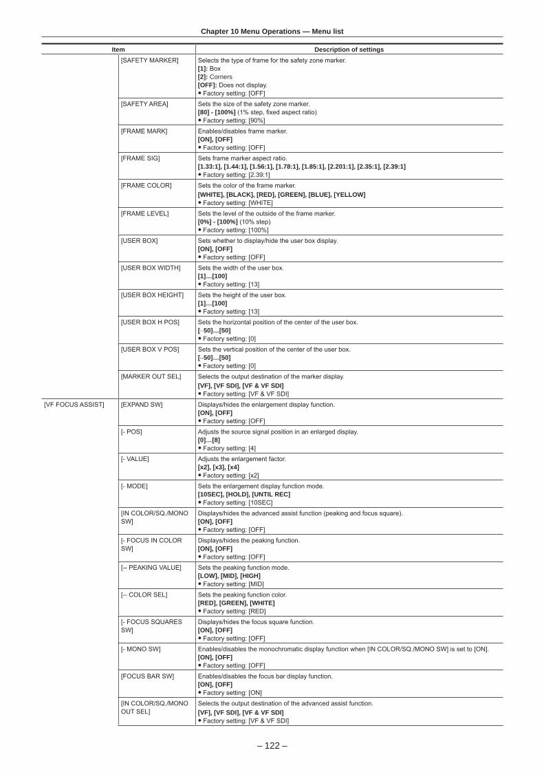
– 122 –
Chapter 10 Menu Operations — Menu list
Item Description of settings[SAFETY MARKER] Selects the type of frame for the safety zone marker.
[1]: Box[2]: Corners[OFF]: Does not display.
f Factory setting: [OFF]
[SAFETY AREA] Sets the size of the safety zone marker.[80] - [100%] (1% step, fixed aspect ratio)
f Factory setting: [90%]
[FRAME MARK] Enables/disables frame marker.[ON], [OFF]
f Factory setting: [OFF]
[FRAME SIG] Sets frame marker aspect ratio.[1.33:1], [1.44:1], [1.56:1], [1.78:1], [1.85:1], [2.201:1], [2.35:1], [2.39:1]
f Factory setting: [2.39:1]
[FRAME COLOR] Sets the color of the frame marker.[WHITE], [BLACK], [RED], [GREEN], [BLUE], [YELLOW]
f Factory setting: [WHITE]
[FRAME LEVEL] Sets the level of the outside of the frame marker.[0%] - [100%] (10% step)
f Factory setting: [100%]
[USER BOX] Sets whether to display/hide the user box display.[ON], [OFF]
f Factory setting: [OFF]
[USER BOX WIDTH] Sets the width of the user box.[1]…[100]
f Factory setting: [13]
[USER BOX HEIGHT] Sets the height of the user box.[1]…[100]
f Factory setting: [13]
[USER BOX H POS] Sets the horizontal position of the center of the user box.[−50]…[50]
f Factory setting: [0]
[USER BOX V POS] Sets the vertical position of the center of the user box.[−50]…[50]
f Factory setting: [0]
[MARKER OUT SEL] Selects the output destination of the marker display.[VF], [VF SDI], [VF & VF SDI]
f Factory setting: [VF & VF SDI]
[VF FOCUS ASSIST] [EXPAND SW] Displays/hides the enlargement display function.[ON], [OFF]
f Factory setting: [OFF]
[- POS] Adjusts the source signal position in an enlarged display.[0]…[8]
f Factory setting: [4]
[- VALUE] Adjusts the enlargement factor.[x2], [x3], [x4]
f Factory setting: [x2]
[- MODE] Sets the enlargement display function mode.[10SEC], [HOLD], [UNTIL REC]
f Factory setting: [10SEC]
[IN COLOR/SQ./MONO SW]
Displays/hides the advanced assist function (peaking and focus square).[ON], [OFF]
f Factory setting: [OFF]
[- FOCUS IN COLOR SW]
Displays/hides the peaking function.[ON], [OFF]
f Factory setting: [OFF]
[-- PEAKING VALUE] Sets the peaking function mode.[LOW], [MID], [HIGH]
f Factory setting: [MID]
[-- COLOR SEL] Sets the peaking function color.[RED], [GREEN], [WHITE]
f Factory setting: [RED]
[- FOCUS SQUARES SW]
Displays/hides the focus square function.[ON], [OFF]
f Factory setting: [OFF]
[- MONO SW] Enables/disables the monochromatic display function when [IN COLOR/SQ./MONO SW] is set to [ON].[ON], [OFF]
f Factory setting: [OFF]
[FOCUS BAR SW] Enables/disables the focus bar display function.[ON], [OFF]
f Factory setting: [ON]
[IN COLOR/SQ./MONO OUT SEL]
Selects the output destination of the advanced assist function.[VF], [VF SDI], [VF & VF SDI]
f Factory setting: [VF & VF SDI]

– 123 –
Chapter 10 Menu Operations — Menu list
Item Description of settings[FOCUS BAR OUT SEL] Selects the output destination of the focus bar display.
[VF], [VF SDI], [VF & VF SDI] f Factory setting: [VF & VF SDI]
[VF EI ASSIST] [ZEBRA SW] Sets whether to superimpose the zebra signal on the output from the <VF> terminal and <VF SDI> terminal.[ON], [OFF]
f Factory setting: [OFF]
[ZEBRA1 DETECT] Sets the detection level of zebra pattern 1.[0%] - [109%]
f Factory setting: [80%]
[ZEBRA2 DETECT] Sets the extraction level of zebra pattern 2.[0%] - [109%]
f Factory setting: [100%]
[ZEBRA2 MODE] Enables/disables zebra pattern 2 and selects [SPOT].[ON], [SPOT], [OFF]
f Factory setting: [OFF]
[ZEBRA OUT SEL] Selects the output destination of the zebra display.[VF], [VF SDI], [VF & VF SDI]
f Factory setting: [VF & VF SDI]
[WFM SW] Displays/hides waveform monitor.[ON]/[OFF]
f Factory setting: [OFF]
[- TYPE] Sets the display format of the waveform monitor.[Y], [YGBR]
f Factory setting: [Y]
[- TRANSPARENCE] Sets the transparency of the waveform monitor display.[0%], [25%], [50%], [75%]
f Factory setting: [50%]
[Y GET SW] Enables/disables the Y GET display function.The user box function will not operate when [Y GET SW] is set to [ON].[ON], [OFF]
f Factory setting: [OFF]
[UNIT] Sets the [Y GET] display unit when [MAIN COLOR] is set to [V-Log].[STOP], [%]
f Factory setting: [STOP]
[- AREA SIZE] Sets the size of area to detect with the Y GET display function.[S], [M], [L]
f Factory setting: [M]
[FALSE COLOR SW] Sets the display of the false color.[ON], [OFF]
f Factory setting: [OFF]
[WFM OUT SEL] Selects the output destination of the waveform monitor display.[VF], [VF SDI], [VF & VF SDI]
f Factory setting: [VF & VF SDI]
[FALSE COLOR OUT SEL]
Selects the output destination of the false color display.[VF], [VF SDI], [VF & VF SDI]
f Factory setting: [VF & VF SDI]
[FILE]Performs file-related operations such as reading/writing menu settings data from/to an SD memory card.
Item Description of settings[SETUP FILE] [LOAD(SD CARD)] Selects the setup file saved to the SD memory card and to be read in the camera.
[SAVE(SD CARD)] Overwrites the current setting values in the camera to the file selected from the setup file file list saved to the SD memory card.
[SAVE AS(SD CARD)] Enters a file name or title name for the file containing the current setting values of the camera and saves it in the SD memory card as a new setup file.
[PERIPHERAL]Applies settings related to functions used in conjunction with peripheral devices, such as network and GPS devices.
Item Description of settings[GPS] Configures internal GPS settings.
[ON]: Activates the GPS operation. Outputs the location information as a signal to the <SDI OUT> terminal and records it as clip metadata.[OFF]: Does not activate the GPS operation. Does not output and record the location information.
f Factory setting: [OFF]

– 124 –
Chapter 10 Menu Operations — Menu list
Item Description of settings[NETWORK SEL] Sets the connection method when connecting the camera with an external device (such as a computer) via
network.[LAN]: Connects via the <LAN> terminal.[WLAN]: Connects via wireless LAN.[OFF]: Does not connect.
f Factory setting: [OFF]
[NETWORK FUNC] [USER ACCOUNT] Sets the user account to be used for authentication in the network function of the camera.
[ACCOUNT LIST] Displays the currently set account name. Also registers new accounts and deletes accounts.
[LAN PROPERTY] [MAC ADDRESS] Displays the MAC address of the <LAN> terminal on the camera. (Cannot be changed.)
[DHCP] Sets whether to use automatic acquisition via DHCP. (Mutually exclusive with [DHCP SERVER] setting)[ENABLE]: Uses automatic acquisition.[DISABLE]: Does not use automatic acquisition. Set [IP ADDRESS], [SUBNET MASK], [DEFAULT GATEWAY], [PRIMARY DNS], and [SECONDARY DNS].
f Factory setting: [ENABLE]
[IP ADDRESS] Sets the IP address when [DISABLE] is selected in [DHCP]. f Factory setting: [192.168.0.1]
[SUBNET MASK] Sets the subnet mask when [DISABLE] is selected in [DHCP]. f Factory setting: [255.255.255.0]
[DEFAULT GATEWAY] Sets the default gateway when [DISABLE] is selected in [DHCP]. f Factory setting: [192.168.0.254]
[PRIMARY DNS] Sets the primary DNS server when [DISABLE] is selected in [DHCP]. f Factory setting: [0.0.0.0]
[SECONDARY DNS] Sets the secondary DNS server when [DISABLE] is selected in [DHCP]. f Factory setting: [0.0.0.0]
[DHCP SERVER] Sets whether to use the DHCP SERVER function when connected via wired LAN. (Mutually exclusive with [DHCP] setting)[ENABLE]: Uses the DHCP SERVER function.[DISABLE]: Does not use the DHCP SERVER function.
f Factory setting: [DISABLE]
[WIRELESS PROPERTY]
[MAC ADDRESS] Displays the MAC address of the wireless LAN adaptor connected to the camera. (Cannot be changed.)
[SSID] Displays network name (SSID).Factory setting: [AU-VREC1]
[BAND] Switches between two transmission methods (2.4 GHz or 5 GHz).[2.4GHz], [5GHz]
f Factory setting: [2.4GHz]
[CHANNEL(2.4GHz)] Sets the channel to be used when [2.4GHz] is selected in [BAND] and connected with the wireless LAN.[AUTO], [CH1], [CH6], [CH11]
f Factory setting: [AUTO]
[CHANNEL(5GHz)] Sets the channel to be used when [5GHz] is selected in [BAND] and connected with the wireless LAN.The selection differs depending on the installed wireless module.[AUTO], [CH36], [CH40], [CH44], [CH48], [CH149], [CH153], [CH157], [CH161], [CH165]
f Factory setting: [AUTO]
[ENCRYPT KEY] Sets the encryption key. Set the key using a string of 8 to 63 characters or a hexadecimal number with 64 digits.
f Factory setting: [01234567890123456789abcdef]
[IP ADDRESS] Sets the IP address when [DISABLE] is selected in [DHCP]. f Factory setting: [192.168.0.1]
[SUBNET MASK] Sets the subnet mask when [DISABLE] is selected in [DHCP]. f Factory setting: [255.255.255.0]
[DHCP SERVER] Sets whether to use the DHCP SERVER function when connected via wireless LAN.[ENABLE]: Uses the DHCP SERVER function.[DISABLE]: Does not use the DHCP SERVER function.
f Factory setting: [ENABLE]
[NETWORK TOOLS] [STATUS DISPLAY] Displays the network status.
[INITIALIZE] Restores the network setting status to the factory settings.

– 125 –
Chapter 10 Menu Operations — Menu operations
Menu operations
r Operation fUI: Settings can be performed using the control panel fSW: Settings can be performed using switches and buttons fVF: Settings can be performed using viewfinder menu and buttons. fl: Items for operation. f—: Non-operation items.
[SYSTEM SETTINGS]
ItemOperation
UI SW VF[SYSTEM MODE] [FREQUENCY] l — —
[V-RAW] l — —
[MAIN PIXEL] l — —
[MAIN CODEC] l — —
[SUB CODEC] l — —
[VFR SUB REC] l — —
[HIGH SPEED] l — —
[COLOR SETTING] [MAIN] l — —
[GRADING] l — —
[SUB] l — —
[3D LUT] l — —
[PLAYBACK GRADING] — — —
[CDL] l — —
[MON 1] l l —
[MON 2] l l —
[VF] l l —
[VF SDI] l — —
[ANAMORPHIC DESQUEEZE] [SUB REC & MON OUT] — — —
[VF & VF SDI] — l —
[DESQUEEZE RATIO] — — —
[IMAGE INVERT] [SUB REC & MON OUT] — — —
[VF & VF SDI] — l —
[INVERT SELECT] — — —
[USER SWITCHES] [USER1] — l —
[USER2] — l —
[USER3] — l —
[USER4] — l —
[USER5] l l —
[USER6] l l —
[USER7] l l —
[USER8] l l —
[USER9] l l —
[USER10] l l —
[CARDS/MEDIA] [CPS PASSWORD] l — —
[FORMAT MEDIA] l — —
[MEDIA END ALARM] — — —
[POWER MANAGEMENT] [DC IN SOURCE] — — —
[DC IN BATTERY SETTINGS] — — —
[- FULL VOLT] — — —
[- NEAR END VOLT] — — —
[- END VOLT] — — —
[ONBORD BATTERY SETTINGS] — — —
[- BATTERY SELECT] — — —
[- FULL VOLT] — — —
[- NEAR END VOLT] — — —
[- END VOLT] — — —
[- NEAR END INFO] — — —
[- END INFO] — — —
[EXT-REC DC IN SOURCE] — — —

– 126 –
Chapter 10 Menu Operations — Menu operations
ItemOperation
UI SW VF[EXT-REC BATTERY SETTINGS] — — —
[- FULL VOLT] — — —
[- NEAR END VOLT] — — —
[- END VOLT] — — —
[CAM DC IN SOURCE] — — —
[CAM BATTERY SETTINGS] — — —
[- FULL VOLT] — — —
[- NEAR END VOLT] — — —
[- END VOLT] — — —
[END ALARM] — — —
[FAN] [FAN SPEED] — — —
[GENLOCK] [GENLOCK MODE] — — —
[H PHASE COARSE] — — —
[H PHASE FINE] — — —
[SENSOR SYNCHRO] — — —
[CONTROL DISPLAY] [BRIGHTNESS] — — —
[COLOR LEVEL] — — —
[CONTRAST] — — —
[BACK LIGHT] — — —
[BUTTON LED] — — —
[STATUS] — — —
[CLOCK] [CLOCK SETTING] — — —
[TIME ZONE] — — —
[DATE FORMAT] — — —
[INFORMATION] [OPERATION TIME] l — —
[VERSION] l — —
[UPDATE] l — —
[USB] l — —
[TRACE LOG] l — —
[SENSOR TEMP] l — —
[INITIALIZE] [LOAD FACTORY DATA] — — —
[CAMERA SETTINGS]
ItemOperation
UI SW VF[Enhanced] [Enhanced SW] — — —
[FPS] [VFR SW] l — —
[FPS MODE] l — —
[PRESET VALUE] l — l
[VARIABLE VALUE] l l l
[WHITE] [AWB] l — —
[MODE] l — —
[PRESET VALUE] l l l
[TEMP SHIFT] l l l
[GMg] l — —
[R GAIN] — — —
[B GAIN] — — —
[AWB OFFSET] — — —
[SHOCKLESS WHITE] — — —
[BLACK] [ABB] — — —
[M.PED] — — —
[R PED] — — —
[G PED] — — —
[B PED] — — —
[ABB OFFSET] — — —
[NR] [ISO800] — — —
[ISO5000] — — —
[EI] [MODE] l — —
[ISO SELECT] l — —

– 127 –
Chapter 10 Menu Operations — Menu operations
ItemOperation
UI SW VF[Native ISO] l l l
[800BASE ISO] l l l
[5000BASE ISO] l l l
[SETTING(GAIN)] l l l
[GAIN OFFSET SW] — — —
[OFFSET LEVEL] — — —
[SHUTTER] [SW] l — —
[DISPLAY MODE] l — —
[MODE] l — —
[SYNCHRO deg] l l l
[SYNCHRO sec] l l l
[PRESET VALUE deg] l l l
[PRESET VALUE sec] l l l
[TEST SIG] [TEST SIG SEL] — — —
[COLOR BARS TYPE] — — —
[DETAIL] [SW] — — —
[CORING] — — —
[MASTER LEVEL] — — —
[SKIN DETAIL] [SW] — — —
[TABLE SELECT] — — —
[GET] — — —
[ZEBRA SW] — — —
[EFFECT LEVEL] — — —
[DETECT TABLE] — — —
[I CENTER] — — —
[I WIDTH] — — —
[Q WIDTH] — — —
[Q PHASE] — — —
[MATRIX] [SW] — — —
[(R-G)_N] — — —
[(R-G)_P] — — —
[(R-B)_N] — — —
[(R-B)_P] — — —
[(G-R)_N] — — —
[(G-R)_P] — — —
[(G-B)_N] — — —
[(G-B)_P] — — —
[(B-R)_N] — — —
[(B-R)_P] — — —
[(B-G)_N] — — —
[(B-G)_P] — — —
[COLOR CORRECTION] [SW] — — —
[R (SAT)] — — —
[R (PHASE)] — — —
[R-Mg (SAT)] — — —
[R-Mg (PHASE)] — — —
[Mg (SAT)] — — —
[Mg (PHASE)] — — —
[Mg-B (SAT)] — — —
[Mg-B (PHASE)] — — —
[B (SAT)] — — —
[B (PHASE)] — — —
[B-Cy (SAT)] — — —
[B-Cy (PHASE)] — — —
[Cy (SAT)] — — —
[Cy (PHASE)] — — —
[Cy-G (SAT)] — — —
[Cy-G (PHASE)] — — —
[G (SAT)] — — —
[G (PHASE)] — — —

– 128 –
Chapter 10 Menu Operations — Menu operations
ItemOperation
UI SW VF[G-Yl (SAT)] — — —
[G-Yl (PHASE)] — — —
[Yl (SAT)] — — —
[Yl (PHASE)] — — —
[Yl-R (SAT)] — — —
[Yl-R (PHASE)] — — —
[SKIN CORRECTION] [SKIN AREA SW] — — —
[SKIN AREA HUE] — — —
[SKIN AREA TONE] — — —
[EXT.FUNC] [FOCUS DISP] — — —
[LENS SETTING] [A.IRIS TYPE] — — —
[A.IRIS LEVEL EFFECT] — — —
[A.IRIS SPEED] — — —
[A.IRIS WINDOW] — — —
[A.IRIS PEAK/AVE] — — —
[LENS CONNECT TYPE] — — —
[REC SETTINGS]
ItemOperation
UI SW VF[FILE NAME STYLE] — — —
[REC FUNCTION] [REC MODE] — — —
[REC TIME] — — —
[INTERVAL TIME] — — —
[START DELAY] — — —
[PRE REC MODE] — — —
[FILE SPLIT] — — —
[TC] [SET TC] l — —
[SET UB] — — —
[TC/UB/Dur.] l — —
[FREE/REC RUN] l — —
[DF/NDF] l — —
[UB MODE] — — —
[TC IN/OUT SEL] — — —
[TC OUT] — — —
[TC OUT REF] — — —
[REC METADATA] [LOAD] — — —
[RECORD] — — —
[USER CLIP NAME] l — —
[CAM INDEX] l — —
[NEXT REEL COUNT] l — —
[COUNTER RESET] — — —
[PROPERTY] — — —
[REC BEEP SOUND] [MODE] — — —
[VOLUME] — — —
[WINDOW BURN SW] l — —
[WINDOW BURN SETTINGS] [UPPER LEFT] l — —
[UPPER CENTER] l — —
[UPPER RIGHT] l — —
[LOWER LEFT] l — —
[LOWER CENTER] l — —
[LOWER RIGHT] l — —
[CUSTOM BURN DATA1] l — —
[CUSTOM BURN DATA2] l — —
[CUSTOM BURN DATA3] l — —
[WATER MARK SW] l — —
[WATER MARK SETTINGS] [MARK POSITION] l — —
[MARK LEVEL] l — —
[CHAR EDIT] l — —

– 129 –
Chapter 10 Menu Operations — Menu operations
ItemOperation
UI SW VF[CHAR SIZE] l — —
[FRAME MARK SW] l — —
[FRAME MARK SETTINGS] [FRAME ASPECT] l — —
[FRAME LEVEL] l — —
[AUDIO SETTINGS]
ItemOperation
UI SW VF[AUDIO RECORD] — — —
[AUDIO INPUT] [AES/EBU IN] — — —
[FRONT MIC POWER] — — —
[FRONT MIC LEVEL] — — —
[REAR1 MIC POWER] — — —
[REAR2 MIC POWER] — — —
[REAR MIC LEVEL] — — —
[REAR LINE LEVEL] — — —
[FRONT1 MIC LOWCUT] — — —
[FRONT2 MIC LOWCUT] — — —
[REAR1 MIC LOWCUT] — — —
[REAR2 MIC LOWCUT] — — —
[CH IN SEL] l — —
[TEST TONE] — — —
[AUDIO LEVEL] [FRONT1 LEVEL] l — —
[FRONT2 LEVEL] l — —
[REAR1 LEVEL] l — —
[REAR2 LEVEL] l — —
[FRONT1 VOL] l — —
[FRONT2 VOL] l — —
[REAR1 VOL] l — —
[REAR2 VOL] l — —
[FRONT1 LIMITER] — — —
[FRONT2 LIMITER] — — —
[REAR1 LIMITER] — — —
[REAR2 LIMITER] — — —
[HEADROOM] — — —
[AUDIO OUTPUT] [MONITOR SEL1] l — —
[MONITOR SEL2] l — —
[MONITOR DELAY] — — —
[MONITOR VOL] l — —
[ALARM] l — —
[OUTPUT SETTINGS]
ItemOperation
UI SW VF[SDI OUT] [P to PsF] — — —
[4K OUT TYPE] — — —
[3G-SDI OUT] — — —
[SDI REC REMOTE] — — —
[MON OUT] [MON OUT FORMAT] — — —
[3G-SDI OUT] — — —
[MON OUT2 SIGNAL SEL] — — —
[MON OUT1 STATUS] — — —
[MON OUT2 STATUS] — — —
[MENU DISP] — — —
[PLAY DISP & CTRL] — — —
[VF OUT] [VF SDI OUT FORMAT] — — —
[SURROUND VIEW SW] — — l
[SURROUND VIEW AREA] — — —

– 130 –
Chapter 10 Menu Operations — Menu operations
ItemOperation
UI SW VF[SURROUND VIEW LINE SW] — l l
[SURROUND VIEW COLOR] — — —
[SURROUND VIEW LEVEL] — — —
[SMOOTH MODE] — l l
[MON OUT INDICATOR] [SYSTEM PIXEL] — — —
[SYSTEM FREQ] — — —
[REC FORMAT] — — —
[REC MODE] — — —
[VFR] — — —
[FPS] — — —
[SHUTTER] — — —
[EI] — — —
[WHITE] — — —
[IRIS] — — —
[FOCUS] — — —
[ZOOM] — — —
[FILTER] — — —
[EXTENDER] — — —
[Y GET] — — —
[TC] — — —
[P2 CARD REMAIN] — — —
[BATTERY REMAIN] — — —
[PROXY] — — —
[GPS] — — —
[CLIP NAME] — — —
[USER CLIP NAME (TYPE3)] — — —
[MON OUT MARKER] [MON OUT1 SW] — — —
[MON OUT2 SW] — — —
[LCD SW] — — —
[PB MARKER SW] — — —
[MARKER & CHAR LVL] — — —
[CENTER MARKER] — — —
[SAFETY MARKER] — — —
[SAFETY AREA] — — —
[FRAME MARK] — — —
[FRAME SIG] — — —
[FRAME COLOR] — — —
[FRAME LEVEL] — — —
[USER BOX] — — —
[USER BOX WIDTH] — — —
[USER BOX HEIGHT] — — —
[USER BOX H POS] — — —
[USER BOX V POS] — — —
[VF INDICATOR] [INDICATOR SW] — — —
[SYSTEM PIXEL] — — —
[SYSTEM FREQ] — — —
[REC FORMAT] — — —
[REC MODE] — — —
[VFR] — — —
[FPS] — — —
[SHUTTER] — — —
[EI] — — —
[WHITE] — — —
[IRIS] — — —
[FOCUS] — — —
[ZOOM] — — —
[FILTER] — — —
[EXTENDER] — — —
[Y GET] — — —
[TC] — — —

– 131 –
Chapter 10 Menu Operations — Menu operations
ItemOperation
UI SW VF[P2 CARD REMAIN] — — —
[BATTERY REMAIN] — — —
[PROXY] — — —
[GPS] — — —
[REC TALLY] — — —
[CLIP NAME] — — —
[USER CLIP NAME (TYPE3)] — — —
[INDICATOR OUT SEL] — — —
[VF MARKER] [MARKER SW] — — l
[PB MARKER SW] — — —
[MARKER & CHAR LVL] — — —
[CENTER MARKER] — — l
[SAFETY MARKER] — — l
[SAFETY AREA] — — —
[FRAME MARK] — — l
[FRAME SIG] — — —
[FRAME COLOR] — — —
[FRAME LEVEL] — — —
[USER BOX] — — l
[USER BOX WIDTH] — — —
[USER BOX HEIGHT] — — —
[USER BOX H POS] — — —
[USER BOX V POS] — — —
[MARKER OUT SEL] — — —
[VF FOCUS ASSIST] [EXPAND SW] — l l
[- POS] — — —
[- VALUE] — — —
[- MODE] — — —
[IN COLOR/SQ./MONO SW] — l l
[- FOCUS IN COLOR SW] — — —
[-- PEAKING VALUE] — — —
[-- COLOR SEL] — — —
[- FOCUS SQUARES SW] — — —
[- MONO SW] — — —
[FOCUS BAR SW] — — —
[IN COLOR/SQ./MONO OUT SEL] — — —
[FOCUS BAR OUT SEL] — — —
[VF EI ASSIST] [ZEBRA SW] — — l
[ZEBRA1 DETECT] — — —
[ZEBRA2 DETECT] — — —
[ZEBRA2 MODE] — — —
[ZEBRA OUT SEL] — — —
[WFM SW] — l l
[- TYPE] — — —
[- TRANSPARENCE] — — —
[Y GET SW] — l —
[UNIT] — — —
[- AREA SIZE] — — —
[FALSE COLOR SW] — l l
[WFM OUT SEL] — — —
[FALSE COLOR OUT SEL] — — —
[FILE]
ItemOperation
UI SW VF[SETUP FILE] [LOAD(SD CARD)] — — —
[SAVE(SD CARD)] — — —
[SAVE AS(SD CARD)] — — —

– 132 –
Chapter 10 Menu Operations — Menu operations
[PERIPHERAL]
ItemOperation
UI SW VF[GPS] l — —
[NETWORK SEL] l — —
[NETWORK FUNC] [USER ACCOUNT] — — —
[ACCOUNT LIST] l — —
[LAN PROPERTY] [MAC ADDRESS] — — —
[DHCP] — — —
[IP ADDRESS] — — —
[SUBNET MASK] — — —
[DEFAULT GATEWAY] — — —
[PRIMARY DNS] — — —
[SECONDARY DNS] — — —
[DHCP SERVER] — — —
[WIRELESS PROPERTY] [MAC ADDRESS] — — —
[SSID] — — —
[BAND] — — —
[CHANNEL(2.4GHz)] — — —
[CHANNEL(5GHz)] — — —
[ENCRYPT KEY] — — —
[IP ADDRESS] — — —
[SUBNET MASK] — — —
[DHCP SERVER] — — —
[NETWORK TOOLS] [STATUS DISPLAY] — — —
[INITIALIZE] — — —

This chapter describes how to use the camera by connecting to network.
Chapter 11 Network Connection

– 134 –
Chapter 11 Network Connection — Network connection
Network connectionThe camera can be connected to the network via wireless LAN or wired LAN.To use wireless LAN, attach AJ-WM30/AJ-WM50 (optional) to the <USB HOST> terminal.To use wired LAN, connect a LAN cable to the <LAN> terminal on the right side.
100BASE-TX/10BASE-T
IEEE802.11g/n
Available functionsWhen the camera is connected to network, the following functions are available.
f Third party color grading application fRemote control with the remote operation panel AK-HRP200G (optional)
@@ NOTE
t For the latest information, visit the following website.http://pro-av.panasonic.net/

– 135 –
Chapter 11 Network Connection — Preparing for connection
Preparing for connection
For wireless LANAttach the wireless module AJ-WM30/AJ-WM50 (optional) to the camera.
Fig. 1 Fig. 2 Fig. 3
1 Push the lever down, and open the cover. (Fig. 1, Fig. 2)
2 Connect the wireless module to the <USB HOST> terminal. (Fig. 3)Insert it all the way.
3 Close the cover.
@@ NOTE
t When removing the wireless module, pull it down straight. t When connected with the wireless LAN, attach the wireless module securely and close the cover.
Cautions when using wireless module AJ-WM30/AJ-WM50
Read the operating manual of the wireless module thoroughly and understand it before using.For the latest information, visit the following website:http://pro-av.panasonic.net/
For wired LANConnect a LAN cable (optional).
1 Connect the LAN cable to the <LAN> terminal on the right side.
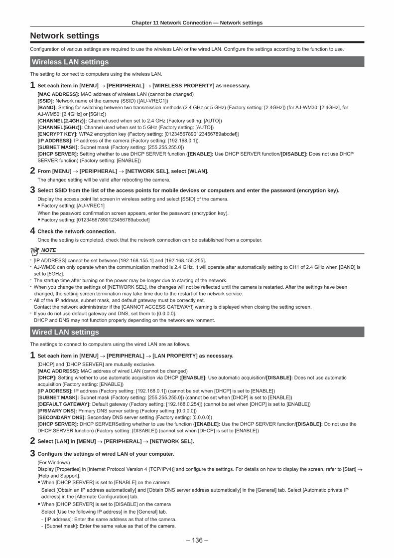
– 136 –
Chapter 11 Network Connection — Network settings
Network settingsConfiguration of various settings are required to use the wireless LAN or the wired LAN. Configure the settings according to the function to use.
Wireless LAN settingsThe setting to connect to computers using the wireless LAN.
1 Set each item in [MENU] → [PERIPHERAL] → [WIRELESS PROPERTY] as necessary.[MAC ADDRESS]: MAC address of wireless LAN (cannot be changed)[SSID]: Network name of the camera (SSID) ([AU-VREC1])[BAND]: Setting for switching between two transmission methods (2.4 GHz or 5 GHz) (Factory setting: [2.4GHz]) (for AJ-WM30: [2.4GHz], for AJ-WM50: [2.4GHz] or [5GHz])[CHANNEL(2.4GHz)]: Channel used when set to 2.4 GHz (Factory setting: [AUTO])[CHANNEL(5GHz)]: Channel used when set to 5 GHz (Factory setting: [AUTO])[ENCRYPT KEY]: WPA2 encryption key (Factory setting: [01234567890123456789abcdef])[IP ADDRESS]: IP address of the camera (Factory setting: [192.168.0.1]).[SUBNET MASK]: Subnet mask (Factory setting: [255.255.255.0])[DHCP SERVER]: Setting whether to use DHCP SERVER function ([ENABLE]: Use DHCP SERVER function/[DISABLE]: Does not use DHCP SERVER function) (Factory setting: [ENABLE])
2 From [MENU] → [PERIPHERAL] → [NETWORK SEL], select [WLAN].The changed setting will be valid after rebooting the camera.
3 Select SSID from the list of the access points for mobile devices or computers and enter the password (encryption key).Display the access point list screen in wireless setting and select [SSID] of the camera.
f Factory setting: [AU-VREC1]When the password confirmation screen appears, enter the password (encryption key).
f Factory setting: [01234567890123456789abcdef]
4 Check the network connection.Once the setting is completed, check that the network connection can be established from a computer.
@@ NOTE
t [IP ADDRESS] cannot be set between [192.168.155.1] and [192.168.155.255]. t AJ-WM30 can only operate when the communication method is 2.4 GHz. It will operate after automatically setting to CH1 of 2.4 GHz when [BAND] is set to [5GHz].
t The startup time after turning on the power may be longer due to starting of the network. t When you change the settings of [NETWORK SEL], the changes will not be reflected until the camera is restarted. After the settings have been changed, the setting screen termination may take time due to the restart of the network service.
t All of the IP address, subnet mask, and default gateway must be correctly set.Contact the network administrator if the [CANNOT ACCESS GATEWAY!] warning is displayed when closing the setting screen.
t If you do not use default gateway and DNS, set them to [0.0.0.0].DHCP and DNS may not function properly depending on the network environment.
Wired LAN settingsThe settings to connect to computers using the wired LAN are as follows.
1 Set each item in [MENU] → [PERIPHERAL] → [LAN PROPERTY] as necessary.[DHCP] and [DHCP SERVER] are mutually exclusive.[MAC ADDRESS]: MAC address of wired LAN (cannot be changed)[DHCP]: Setting whether to use automatic acquisition via DHCP ([ENABLE]: Use automatic acquisition/[DISABLE]: Does not use automatic acquisition (Factory setting: [ENABLE])[IP ADDRESS]: IP address (Factory setting: [192.168.0.1]) (cannot be set when [DHCP] is set to [ENABLE])[SUBNET MASK]: Subnet mask (Factory setting: [255.255.255.0]) (cannot be set when [DHCP] is set to [ENABLE])[DEFAULT GATEWAY]: Default gateway (Factory setting: [192.168.0.254]) (cannot be set when [DHCP] is set to [ENABLE])[PRIMARY DNS]: Primary DNS server setting (Factory setting: [0.0.0.0])[SECONDARY DNS]: Secondary DNS server setting (Factory setting: [0.0.0.0])[DHCP SERVER]: DHCP SERVERSetting whether to use the function ([ENABLE]: Use the DHCP SERVER function/[DISABLE]: Do not use the DHCP SERVER function) (Factory setting: [DISABLE]) (cannot set when [DHCP] is set to [ENABLE])
2 Select [LAN] in [MENU] → [PERIPHERAL] → [NETWORK SEL].
3 Configure the settings of wired LAN of your computer.(For Windows)Display [Properties] in [Internet Protocol Version 4 (TCP/IPv4)] and configure the settings. For details on how to display the screen, refer to [Start] → [Help and Support].
fWhen [DHCP SERVER] is set to [ENABLE] on the cameraSelect [Obtain an IP address automatically] and [Obtain DNS server address automatically] in the [General] tab. Select [Automatic private IP address] in the [Alternate Configuration] tab. fWhen [DHCP SERVER] is set to [DISABLE] on the cameraSelect [Use the following IP address] in the [General] tab.- [IP address]: Enter the same address as that of the camera.- [Subnet mask]: Enter the same value as that of the camera.

– 137 –
Chapter 11 Network Connection — Network settings
- [Default gateway]: Enter the same address as that of the camera.- [Preferred DNS server]/[Alternate DNS server]: Not necessarily to be entered.
(For Mac OS) fWhen [DHCP SERVER] is set to [ENABLE] on the camera[Configure IPv4]: Select [Using DHCP].[Configure IPv6]: Select [Automatically]. fWhen [DHCP SERVER] is set to [DISABLE] on the camera[Configure IPv4]: Select [Manually] and enter the following items.- [IP Address]- [Subnet Mask]- Entering [Router] is not required. Leave it blank.[Configure IPv6]: Select [Automatically].
@@ NOTE
t [IP ADDRESS] cannot be set between [192.168.155.1] and [192.168.155.255], inclusive.
Checking network setting
Check in the MENU screen
Fig. 1
1 Select [STATUS DISPLAY] in [MENU] → [PERIPHERAL] → [NETWORK TOOLS].Displays the current status of the network device. (Fig. 1)
Check in the INFO screen
Fig. 1
1 Press the <INFO> button to display the INFO screen.
2 Select [PERIPHERAL].Displays the current status of the network device. (Fig. 1)

– 138 –
Chapter 11 Network Connection — Network settings
Changing network setting
Switching network
Switches wireless LAN and wired LAN.
Fig. 1
1 Press the <INFO> button to display the INFO screen.
2 Select [NETWORK] in [PERIPHERAL].
3 Select [LAN], [WLAN], or [OFF].The setting is switched. (Fig. 1)[LAN]: Wired LAN[WLAN]: Wireless LAN[OFF]: The network function is not used.
Operating user account
Registration of user account can be performed.
r Setting user account
1 Select [MENU] → [PERIPHERAL] → [NETWORK FUNC] → [USER ACCOUNT].
r Checking user account
1 Select [MENU] → [PERIPHERAL] → [NETWORK FUNC] → [ACCOUNT LIST].Checking and deleting of the user account list can be performed.To delete, place the cursor above the user account to delete, and press the <SET> button.
@@ NOTE
t [guest] for [USER ACCOUNT] and [p2guest] for [User Password] are initial setting values. t Password cannot be changed. To change, delete the account once and perform new register again. t The upper limit for user account registration is 3.
r Initializing network settings
1 Select [INITIALIZE] in [MENU] → [PERIPHERAL] → [NETWORK TOOLS].Initialize is completed.

– 139 –
Chapter 11 Network Connection — Connecting the remote operation panel (AK-HRP200G)
Connecting the remote operation panel (AK-HRP200G)Part of the function can be remotely controlled by connecting the remote operation panel AK-HRP200G (optional) via IP connection.Playback operation is not possible from the remote operation panel AK-HRP200G. Playback can only be performed from the camera.
LAN cable (optional)
AK-HRP200G
Setting for connection with the remote operation panel (AK-HRP200G)To connect AK-HRP200G via network to set the camera to the remote control mode, configure the settings in the following procedure.
1 Set each item in [MENU] → [PERIPHERAL] → [LAN PROPERTY] in the camera.[IP ADDRESS]: Sets the address set at AK-HRP200G.[DHCP]: Sets to [DISABLE].
2 Set each item in [MENU] → [PERIPHERAL] → [NETWORK FUNC] → [USER ACCOUNT] in the camera.[USER NAME]: Sets the user account name. (Factory setting: [guest])[PASSWORD]: Sets the password. (Factory setting: [p2guest])Enter up to 31 characters for a user account, and characters between 6 and 15 for a password.
3 Configure the network settings of AK-HRP200G.For the network settings, use the ROP setup software application supplied with AK-HRP200G.
Limitation with the remote controlThere are following limitations when controlling from the remote operation panel.
r When the [MENU] → [CAMERA SETTINGS] → [Enhanced] → [Enhanced SW] is set to [ON] fCamera power button <HEAD POWER>: Control is not possible fAutomatic white balance button <WHITE>: Aborting during adjustment is not possible fAutomatic black balance button <BLACK>: Aborting during adjustment is not possible fAutomatic setup button <SETUP>: Not used f 5600 K button <5600 K>: Not used fKnee off button <KNEE OFF>: Disabled fScene/user file switching button <SHIFT>: Disabled fScene/user file selection buttons <SCENE1/USER1> - <SCENE3/USER3>/<SCENE4>: Disabled fScene/user file registration button<STORE>: Disabled fVolume lock button <VR LOCK>: Enabled fR flare/pedestal volume <FLARE/PED R>: Disabled fB flare/pedestal volume <FLARE/PED B>: Disabled fDataset buttons <UP>/<DOWN>: Enabled fAdjusted value display area (4 digits): Enabled fCamera number display area <No.>: Enabled fCamera selection button <SELECT>: Enabled fMemory card slot: Disabled fRed/green tally display area, call button <TALLY/CALL>: Disabled f Iris/master pedestal lock button <IRIS/M.PED LOCK>: Enabled f Iris lever <IRIS>: Enabled when the lens can operate fSense volume <SENSE>: Disabled fCoarse volume <COARSE>: Disabled fAuto iris button <AUTO>: Enabled when the lens can operate f Iris close button <CLOSE>: Enabled when the lens can operate f Fader full button <FULL>: Disabled fAlarm display area <ALM>: Warning is displayed f Light alarm display area <OPT>: Disabled f Lens extender display <EXT>: Enabled when the lens can operate

– 140 –
Chapter 11 Network Connection — Connecting the remote operation panel (AK-HRP200G)
fDigital extender display <D.EXT>: Disabled
r When the [MENU] → [CAMERA SETTINGS] → [Enhanced] → [Enhanced SW] is set to [OFF]Following buttons are disabled in addition to limitation when [Enhanced SW] is set to [ON].
fMatrix button <MATRIX> fSkin tone detail button <SKINDTL> fDetail off button <DTL OFF> fDetail volume <DTL> fRGain volume <GAIN R> fBGain volume <GAIN B> fRFlare/pedestal volume <FLARE/PED R> fBFlare/pedestal volume <FLARE/PED B> fMaster pedestal volume <M.PED>
About adjusted value display area (4 digits)
Zoom, focus, and auto focus are not supported.When the VFR is set to [ON], it is displayed as [***P] (*** is the frame rate value).When the VFR is set to [OFF], it is displayed as [FroF].When the setting of the camera is set to [Native ISO] or [ISO], it is displayed as [iSo].
@@ NOTE
t To connect the camera and AK-HRP200G directly, use a crossover LAN cable. t For details, refer to the Operating Instructions of AK-HRP200G. t The following information is required to connect to AK-HRP200G.- User account name- Password- IP address- Port number: 49152
t For AK-HRP200G, use Ver4.01.00 or later versions. t For details on the operations of ROP setup software application, refer to the Operating Instructions of AK-HRP200G. t For the ROP setup software application, use Ver3.0.0.0 or later versions.

This chapter describes how to connect the extension module and the names, functions, and operations of each of its parts.
Chapter 12 Extension module

– 142 –
Chapter 12 Extension module — Before using the extension module
Before using the extension module
r This device is a module that extends the distance between the camera module (optional) and the recording module (optional).The distance between the camera module and the recording module can be extended by using the extension cable (optional).
r A power supply to the camera extension module and recording module (optional) is required.When using the device, a power supply to both the camera extension module and recording module is required.
r To use the extension module, update to the latest firmware that is compatible with the extension module.Update the firmware of the camera module (optional) and recording module (optional) before using the device. An error will be displayed if an incompatible firmware is used. For details on how to update the firmware of the camera module and recording module, refer to “Updating the camera firmware” (page 166).
r You cannot update the firmware of the camera module (optional) and recording module (optional) if the extension module is connected.
To update the firmware, remove the extension module and perform the update with the camera module directly connected to the recording module.

– 143 –
Chapter 12 Extension module — Description of parts
Description of parts
Left side: Camera extension module: Recording extension module
1
2
1 <DC OUT> terminalThis is the DC12 V output terminal. The DC output provides a maximum current of 1.0 A.
2 <SIX USER BUTTONS> buttonThis button sets the control panel operation buttons of the recording module (optional) to be used as USER buttons. You can operate the functions allocated from [USER5] to [USER10] in [MENU] → [SYSTEM SETTINGS] → [USER SWITCHES].
Right side: Camera extension module: Recording extension module
15
3
2
4
1 Light output terminalPower supply terminal for connecting a light.
2 <EXT> terminalThis is the terminal to connect the extension cable (optional). This connects to the recording extension module.
3 Extension cable securing fittingSecures the extension cable connected to the <EXT> terminal.
4 <DC IN> terminalInput terminal for connecting an external DC power supply.
5 Recording extension module release leverLever for removing the recording module (optional) from the recording extension module.
Front: Camera extension module: Recording extension module
1
2
3
4

– 144 –
Chapter 12 Extension module — Description of parts
1 Lock angleFitting which secures the camera module (optional) in place when connected.
2 Camera module connection terminalTerminal for connecting the camera module (optional).
3 <EXT> terminalThis is the terminal to connect the extension cable (optional). This connects to the camera extension module.
4 Extension cable securing fittingSecures the extension cable connected to the <EXT> terminal.
Rear: Camera extension module: Recording extension module
1
4
3
2
6
5
1 Battery holderFor mounting Anton/Bauer batteries.
2 Battery release leverPull this lever down to release the battery.
3 Battery contact terminalsContact terminals for the battery.
4 <LIGHT CONTROL> switchControl switch when light is connected to the light output terminal.
5 Lock plateFitting which secures the recording module (optional) in place when connected.
6 Recording module connection terminalTerminal for connecting the recording module (optional).

– 145 –
Chapter 12 Extension module — Assembling Extension Modules
Assembling Extension Modules
Removing the camera extension module and recording extension moduleBefore assembly, remove the 2 modules.
Fig. 1 Fig. 2
1 While raising the lock knob (red) of the recording extension module release lever (Fig. 1), pull the recording extension module release lever. (Fig. 2)The rear part of the recording extension module will slightly come up.
2 Lift the recording extension module.
3 Remove the lock angle of the camera extension module from the lock plate of the recording extension module.
Assembling the camera module and the camera extension module
Fig. 1 Fig. 2
Fig. 3 Fig. 4
1 Align the upper lock angle at the front of the camera extension module with the upper lock plate at the rear of the camera module.(Fig. 1)
2 Firmly push in the camera extension module and connect the connection terminals of the camera module and camera extension module. (Fig. 2)
@@ NOTE
t You cannot join the modules together if the V edge of the camera module is down. (Fig. 3) Push down the recording module release lever of the camera module to raise the V edge. (Fig. 4)
t Do not touch the mechanical parts near the V edge. The V edge will move quickly, which may cause injury.

– 146 –
Chapter 12 Extension module — Assembling Extension Modules
Disassembling
Fig. 1 Fig. 2
1 Push down the recording module release lever (Fig. 2) while pulling up the lock knob (red) of the recording module release lever (Fig. 1).The rear part of the camera extension module will come up.It will be difficult for the rear part to come up when heavy items such as batteries are mounted.
2 Lift the camera extension module.
3 Remove the upper lock angle in front of the camera extension module from the upper lock plate at the rear of the camera module.
Assembling the recording module and the recording extension module
Fig. 1 Fig. 2
Fig. 3 Fig. 4
1 Align the upper lock angle at the front of the recording module with the upper lock plate at the rear of the recording extension module. (Fig. 1)
2 Firmly push in the recording module and connect the connection terminals of the recording extension module and recording module. (Fig. 2)
@@ NOTE
t You cannot join the modules together if the V edge of the recording extension module is down. (Fig. 3) Push down the recording extension module release lever of the recording extension module to raise the V edge. (Fig. 4)
t Do not touch the mechanical parts near the V edge. The V edge will move quickly, which may cause injury.

– 147 –
Chapter 12 Extension module — Assembling Extension Modules
Disassembling
Fig. 1 Fig. 2
1 Push down the recording extension module release lever (Fig. 2) while pulling up the lock knob (red) of the recording extension module release lever. (Fig. 1)The rear part of the recording module will slightly come up.It will be difficult for the rear part to come up when heavy items such as batteries are mounted.
2 Lift the recording module.Do not hold the control panel part. Doing so may cause the control panel to detach and fall.
3 Remove the upper lock angle at the front of the recording module from the upper lock plate at the rear of the recording extension module.
Mounting extension cablesHow the extension cable is connected is the same for the camera extension module and the recording extension module.
Fig. 1 Fig. 2 Fig. 3
1 Loosen the screw on the extension cable securing fitting. (Fig. 1)
2 Connect the extension cable to the <EXT> terminal. (Fig. 2)Confirm the shape of the connector and insert the extension cable.Securely tighten the screw on the extension cable after inserting.
3 Tighten the screw on the extension cable securing fitting. (Fig. 3)

– 148 –
Chapter 12 Extension module — Power supply
Power supplyA battery or external DC power supply can be used as the camera extension module's power supply.This section describes the power supply to the camera extension module.For details on the power supply of the recording module, refer to “Power supply” (page 26). After supplying power to the camera extension module and recording module, set the <POWER> switch of the recording module to <ON>. After setting the <POWER> switch to <ON> to supply power to the recording module, an error may occur if power is supplied to the camera extension module.
Using batteriesConnection of the following batteries to the device has been verified.
r Anton/Bauer batteriesHYTRON140DIONIC HC/DIONIC HCX/DIONIC HD
r IDX batteriesENDURA HL9
@@ NOTE
t You can also use other batteries. Use of batteries that are already verified as connectable to the device is recommended. t Before you use a battery, charge it with a battery charger. (For details on charging, refer to each operating instructions.) t The percent (%) display will not be available for batteries with a battery level indicator function.
Battery attachment and setting
Using Anton/Bauer batteries
Anton/Bauer batteries
Release lever
1 Mount the Anton/Bauer battery.
2 Insert the battery terminal and slide in the direction of the arrow.
3 Set the battery features.Select [CAM BATT FULL]/[CAM BATT NEAR END]/[CAM BATT END] in [MENU] → [SYSTEM SETTINGS] → [BATTERY] to set the voltage at which the battery level and warning will be displayed.
@@ NOTE
t To remove the battery, keep the release lever of the battery holder completely down, slide the battery in the opposite direction when you mounted it.
Using V-mount type batteries
Mount the V-mount type battery plate. As shown in the illustration, insert and slide in the direction of the arrow.
Release lever
1 Mount the V-mount type battery plate.
2 Slide in the direction of the arrow.

– 149 –
Chapter 12 Extension module — Power supply
3 Set the battery features. fSelect [CAM BATT FULL]/[CAM BATT NEAR END]/[CAM BATT END] in [MENU] → [SYSTEM SETTINGS] → [BATTERY] to set the voltage at which the battery level and warning will be displayed.
@@ NOTE
t Contact your dealer for information about the V-mount type battery plate. t When removing the plate, remove by sliding the release lever.
Using the external DC power supply
<DC IN> terminal
DC cable
External DC power supply
1 Connect the external DC power supply to the <DC IN> terminal of the camera extension module.
2 Turn on the power switch of the external DC power supply (if the external DC power supply has a power switch).
3 Supply power to the recording module.
4 Set the <POWER> of the recording module to <ON>.
r Regarding external DC power supplyConnect after making sure that the output voltage of the external DC power supply is compatible with the rated voltage of the device.Select an output amperage for the external DC power supply with a margin above the total amperage of the connected devices.The total amperage of connected devices can be calculated with the following formula.Total power consumption ÷ voltageWhen the power of the camera is turned on, inrush current is generated. Insufficient power supply when turning on the power may cause a malfunction. We recommend that you use an external DC power supply that can assure double the capacity of the total power consumption of this device and connected devices that are turned on by interlock when the power of the device is turned on (such as lenses). For the DC cable, use a dual-core shielded wire of AWG16 (nominal cross section area 1.309 mm2) or thicker.
f Make sure of the pin alignment of the DC output terminal of the external DC power supply and the <DC IN> terminal of the device, and connect the polarity correctly.Making the mistake of connecting a +12 V power supply to the GND terminal may cause fire or malfunction.
DC IN1 GND
2 NC
3 NC
4 +12 V
Panasonic Part No.: K1AA104H0038Manufacturer Part No.: HA16RX-4P (SW1) (76) (Hirose Electric Co.)
@@ NOTE
t When both the battery and the external DC power supply are connected, the power supply from the external DC power supply has priority. The battery may be removed while using the external DC power supply.
t When using an external DC power supply, always turn the power switch of the external DC power supply on before setting the <POWER> switch of the recording module to <ON>. If the operations are performed in reverse, the camera may malfunction because the external DC power supply output voltage rises too slowly.
t When switching the power supply from an external DC power supply to the battery, carefully remove the DC cable from the <DC IN> terminal. Removing the cable quickly may temporarily stop the operation of the device.
t When power is supplied from the <DC IN> terminal, the light circuit does not function. The light circuit can be used only when power is supplied from the Anton/Bauer battery plate.

– 150 –
Chapter 12 Extension module — Power supply
t When a battery is connected to the <DC IN> terminal, set [MENU] → [SYSTEM SETTINGS] → [BATTERY] → [CAM EXT DC IN SEL] to [BATTERY], then set [CAM BATT END], [CAM BATT NEAR END], and [CAM BATT FULL] according to the features of the battery. The percent (%) display will not be available for batteries with a battery level indicator function.
Displaying of the power supply condition
Extension module The module with lowest power supply level Battery charge level indicatorNo — —
Yes Recording module
Yes Camera module

– 151 –
Chapter 12 Extension module — Connecting to the DC output terminal
Connecting to the DC output terminal
Connecting to the <DC OUT> terminalIt is possible to get a 1.0 A current from the <DC OUT> terminal of the camera extension module.
1
2
Cable connector0B.302LEMO1 GND2 +12 V
@@ NOTE
t Make sure that polarity is correct before connecting an external device. Otherwise, it may result in a malfunction.

– 152 –
Chapter 12 Extension module — Specifications
Specifications
Dimensions
73 mm (2-7/8 inches) 121 mm (4-25/32 inches)
143
mm
(5-2
1/32
inch
es)
61 mm (2-13/32 inches) 106 mm (4-3/16 inches)
143
mm
(5-2
1/32
inch
es)
Specifications
General
PowerDC 12 V (11.0 V - 17.0 V)Power consumption33 W (body only)63 W (with all optional accessories connected and maximum power supplied from each output terminal)
indicates safety items.
Ambient operating temperature 0 °C - 40 °C (32 °F - 104 °F)
Ambient operating humidity 10% - 85% (no condensation)
Storage temperature −20 °C - 60 °C (−4 °F - 140 °F)
Weight Camera extension module: Approx. 0.95 k] (2.09 lbs.)Recording extension module: Approx. 0.65 k] (1.43 lbs.)
Dimensions (W×H×D) Camera extension module:121 mm×143 mm×73 mm(4-25/32 inches×5-21/32 inches×2-7/8 inches)Recording extension module:106 mm×143 mm×61 mm(4-3/16 inches×5-21/32 inches×2-13/32 inches)
fMake sure that the total current from the <DC OUT> terminal, <VF> terminal, and <LENS> terminal of the camera module (optional), and the <DC OUT> terminal of the camera extension module does not exceed 30 W.

This chapter describes how to use the camera by connecting to the Codex V-RAW recorder.
Chapter 13 V-RAW recorder

– 154 –
Chapter 13 V-RAW recorder — V-RAW recorder
V-RAW recorderThe V-RAW (VariCam RAW) recording is possible when connected to the Codex V-RAW recorder.
Attaching the V-RAW recorderV-RAW recorder is attached to the battery holder and the external unit connection terminal of the recording module.
Fig. 1 Fig. 2
Fig. 3
Cover
Fig. 4
1 Loosen the screw on the external unit connection terminal at the rear of the recording module and remove the cover. (Fig. 1)
2 Attach the V-RAW recorder. (Fig. 2)
3 Slide the V-RAW recorder downward. (Fig. 3)
4 Fold down the release lever of the V-RAW recorder. (Fig. 4)
Disassembling
Fig. 1 Fig. 2 Fig. 3
Stopper
1 Slide the stopper on the release lever on the V-RAW recorder, and pull up the release lever. (Fig. 1, Fig. 2)The V-RAW recorder will lift.

– 155 –
Chapter 13 V-RAW recorder — V-RAW recorder
2 Remove the V-RAW recorder. (Fig. 3)
HOME screen on the control panelThe HOME screen in the control panel will be as follows when the V-RAW recorder is connected.
a b c
d
a: Recording condition display and media remaining space indicator for the V-RAW recorder and the main slot.b: Color space for the V-RAW recorder and the main slot.
It is fixed to [V-Log] when connected to the V-RAW recorder.
c: Recording format for the V-RAW recorder and the main slot.d: Battery charge level indicator for the V-RAW recorder.

– 156 –
Chapter 13 V-RAW recorder — Power supply
Power supplyThe power can be supplied to the camera main unit from the V-RAW recorder. The DC power supply for the V-RAW recorder is 24 V. A separate power supply can be supplied to the camera simultaneously. The DC power supply for the camera main unit is 12 V. A power cannot be supplied from the camera main unit to the V-RAW recorder.The power is not automatically supplied to the camera main unit from the V-RAW recorder when the power supply from the external DC power supply to the camera main unit is disconnected. Disconnect the connector for the external DC power supply to the camera main unit once.
Turning on the power
r When turning on the power
1 Connect the V-RAW recorder.
2 Connect the battery or the external DC power supply to the V-RAW recorder.
3 Set the <POWER> switch of the recording module to <ON>.
r When removing the V-RAW recorder
1 Set the <POWER> switch of the recording module to <OFF>.
2 Remove the V-RAW recorder.
@@ NOTE
t When attaching or removing the V-RAW recorder, always turn off the power of the camera main unit before performing. It will cause a system error when the V-RAW recorder is removed with the power turned on.
r Displaying of the power supply condition
V-RAW recorder Extension module The module with lowest power supply level
Battery charge level indicator
No No — —
No Yes Recording module
No Yes Camera module
Yes No Recording module
Yes No V-RAW recorder
Yes Yes Recording module
Yes Yes Camera module
Yes Yes V-RAW recorder

– 157 –
Chapter 13 V-RAW recorder — Operation with the control panel
Operation with the control panel
System setting and recordingThe camera main unit and the V-RAW recorder will operate as a single system. All the operations of the V-RAW recorder can be operated on the control panel of the recording module. The recording can also be started/stopped with the <REC> button on the recording module.
r [SYSTEM] setting screen
r [V-RAW] format setting screen
Priority of the setting is as follows.1 [FREQUENCY]2 [V-RAW]3 [MAIN PIXEL]4 [MAIN CODEC]5 [SUB CODEC]The setting value for lower order is also changed when the setting value of higher order is changed.Example)
fWhen [FREQUENCY] is set to 30p or less, all [V-RAW] ([4K/12bit], [UHD/12bit], [4K/10bit], and [UHD/10bit]) can be selected. fWhen [FREQUENCY] is set higher than 30p, the setting that can be selected will be restricted to [4K/10bit] and [UHD/10bit].
[MAIN CODEC] can be set to [OFF] when the V-RAW recorder is connected. It is also not possible to record in the main slot or sub slot when [HIGH SPEED] is set to [ON].The Look file (.cdl/.vlt) linked to the clip will also be recorded with the same name as the V-RAW in accordance to the in-camera color grading function in the camera main unit.
@@ NOTE
t UHD cannot be selected when [FREQUENCY] is set to 24p.

– 158 –
Chapter 13 V-RAW recorder — Operation with the control panel
r Recordable setting
[FREQUENCY] [V-RAW] [MAIN PIXEL] [MAIN CODEC] [SUB CODEC] [HIGH SPEED]
Up to 30p
[4K/12bit][4096×2160] [AVC-Intra4K 444]
[AVC-Intra422 & Pxy][AVC-Intra100 & Pxy][AVC-LongG50 & Pxy][AVC-LongG25 & Pxy]
—[2048×1080] [AVC-Intra2K 444]
[4K/10bit][4096×2160]
[AVC-Intra4K 422]
[AVC-Intra4K-LT][OFF]/[ON]
[2048×1080] [AVC-Intra2K 422]
[UHD/12bit](excluding 24p)
[3840×2160] [AVC-Intra4K 444]
—[1920×1080] [AVC-Intra444]
[UHD/10bit](excluding 24p)
[3840×2160][AVC-Intra4K 422]
[AVC-Intra4K-LT] [OFF]/[ON]
[1920×1080]
[AVC-Intra200] —
[AVC-Intra422]
[OFF]/[ON][AVC-Intra100]
[ProRes 4444]
[ProRes 422 HQ]
Up to 60p
[4K/10bit][4096×2160]
[AVC-Intra4K 422] —
[AVC-Intra4K-LT][OFF]/[ON]
[2048×1080] [AVC-Intra2K 422]
[UHD/10bit]
[3840×2160][AVC-Intra4K 422] —
[AVC-Intra4K-LT]
[OFF]/[ON][1920×1080]
[AVC-Intra422]
[AVC-Intra100]
[ProRes 422 HQ]
PlaybackThe V-RAW that is recorded to Capture Drive can be played in the control panel of the recording module.There are no functions for [DELETE], [COPY], and [REPAIR].
1 Select [RAW] in [SLOT] from the PLAY screen.The thumbnail screen is displayed.
2 Select a clip.The selected clip is played.
MediaThe Codex media (Capture Drive) is used for the V-RAW recording. Displaying of the various information from the HOME screen, and confirmation of the media status and media format from the INFO screen can be executed from the control panel of the recording module.

– 159 –
Chapter 13 V-RAW recorder — Operation with the control panel
Insertion method of the Capture Drive
Fig. 1 Fig. 2
Fig. 3 Fig. 4 Fig. 5
1 Open the drive slot cover. (Fig. 1, Fig. 2)
2 Insert the Capture Drive. (Fig. 3, Fig. 4)
3 Close the drive slot cover. (Fig. 5)
r To remove
Fig. 1 Fig. 2 Fig. 3
1 Open the drive slot cover. (Fig. 1, Fig. 2)
2 Remove the Capture Drive. (Fig. 3)
@@ NOTE
t Do not remove the Capture Drive while the Capture Drive is being accessed or when the Capture Drive is inserted and being recognized (access LED flashing in blue). Otherwise, it may result in a malfunction.
Access LED
There is a access LED on the V-RAW recorder and the Capture Drive.

– 160 –
Chapter 13 V-RAW recorder — Operation with the control panel
LED status V-RAW recorder Capture DriveGreen (illuminated) Power can be supplied from the V-RAW recorder/
camera is powered off—
Blue (illuminated) Recording possible Removing possible
Blue (flashing) Recording not possible (Capture Drive is being recognized, drive slot cover is opened, etc.)
Capture Drive is being recognized/removing not possible
Red (illuminated) Recording —
Red (flashing) Error has occurred Capture Drive recognition failed
@@ NOTE
t It may take some time until the access LED for the Capture Drive starts to flash when the Capture Drive is inserted. t Do not remove the Capture Drive when the access LED is flashing in blue. Otherwise, it may result in a malfunction. The Capture Drive can be removed when the blue flashing turns into blue illumination.
Recording time of the Capture Drive
The recording time of single Codex Capture Drive 2.0 (82 TB) is as follows.
Resolution Number of bits Frame rate Recording time (minutes)3840×2160 10 bits 23.98 119
3840×2160 10 bits 25 114
3840×2160 10 bits 29.97/30 95
3840×2160 10 bits 48 59
3840×2160 10 bits 50 57
3840×2160 10 bits 59.94/60 47
3840×2160 10 bits 96 29
3840×2160 10 bits 120 23
3840×2160 12 bits 23.98 106
3840×2160 12 bits 25 101
3840×2160 12 bits 29.97/30 84
4096×2160 10 bits 23.98/24 112
4096×2160 10 bits 25 107
4096×2160 10 bits 29.97/30 89
4096×2160 10 bits 48 56
4096×2160 10 bits 50 53
4096×2160 10 bits 59.94/60 44
4096×2160 10 bits 96 28
4096×2160 10 bits 120 22
4096×2160 12 bits 23.98/24 100
4096×2160 12 bits 25 96
4096×2160 12 bits 29.97/30 80
Formatting of the Capture Drive
Perform from the INFO screen in the control panel.

– 161 –
Chapter 13 V-RAW recorder — Operation with the control panel
r To operate from MENU
1 Select [V-RAW] in [MENU] → [SYSTEM SETTINGS] → [CARDS/MEDIA] → [FORMAT MEDIA].
2 Select [YES] using the jog dial button.
@@ NOTE
t Data deleted as a result of formatting cannot be restored. Always check the data before formatting.
Version updateThe update of the firmware for the V-RAW recorder is performed from the control panel using a SD memory card in the same manner as the camera main unit.The firmware for version update for the V-RAW recorder is released from Codex or from Panasonic integrated with the firmware for the camera main unit. Visit the support desk at the following website.http://pro-av.panasonic.net/

Maintenance and warning system of the camera are described.
Chapter 14 Maintenance

– 163 –
Chapter 14 Maintenance — Warning system
Warning systemIf an error is detected immediately after the camera is turned on or during operation, the viewfinder and warning lamp indicate the error. Deal with the error by following the indications.
Cases indicated by error codes
Error code Display Description Behavior and cause
[E-30] [TURN POWER OFF]An error occurred in the camera built-in memory because the P2 card being accessed was ejected.
f Warning lamp flashes four times per second.
f Cannot operate. f Follow the message to turn off the power once and turn on the power again. f Ensure that there is no error in the clips on the ejected card, and restore the clips as necessary.
[E-31] [TURN POWER OFF] System mode error occurred. f Warning lamp flashes four times per second.
f Cannot operate. f Follow the message to turn off the power once, turn on the power again, and check that there is no error display.
[E-33] [SYSTEM ERROR] Camera unit error occurred. f Warning lamp flashes four times per second.
f The operation stops. f Contact your dealer.
[E-35] [SYSTEM ERROR] Codec control error occurred. f Warning lamp flashes four times per second.
f The operation stops. f Contact your dealer.
[E-36] [SYSTEM ERROR] P2 system error occurred. f Warning lamp flashes four times per second.
f The operation stops. f When it occurs right after the power is turned on after connecting the V-RAW recorder, and the LED of the V-RAW recorder stays illuminated in greenTurn off the power of the V-RAW recorder once, and then turn on the power again after removing the Capture Drive. f Contact your dealer.
[E-37] [SYSTEM ERROR] P2CS microcomputer error occurred. f Warning lamp flashes four times per second.
f The operation stops. f Contact your dealer.
[E-39] [SYSTEM ERROR] Video initialization error occurred. f Warning lamp flashes four times per second.
f The operation stops. f Contact your dealer.
[E-64] [SYSTEM ERROR](or no display)
Reference signal error occurred. f Warning lamp flashes four times per second.
f The operation stops. f Contact your dealer.
[E-65] [No Camera Module Detected]
The camera module cannot be recognized. f Warning lamp flashes four times per second.
f The operation will stop. f Contact your dealer.
[E-67] [Check Camera Module Connection]
There is a connection error between the camera module and the recording module.
f Warning lamp flashes four times per second.
f The operation will stop. f Confirm if the cable connectors are connected correctly when the extension module is used. f Contact your dealer.
Cases indicated by error messages
During recording/playback
Display Description Behavior and cause
[AUTH NG CARD] (slot number)CPS authentication of microP2 memory card has failed. The microP2 memory card whose CPS authentication failed cannot be recorded or played back.
f The current operation will continue.
[BACKUP BATT EMPTY]Displays any reduced voltage detected on the backup battery in the internal clock when the power is turned on.
f The current operation will continue. f Charge the built-in battery.
[CARD ERROR] (slot number)
Displayed when an data error caused by the P2 card occurs during recording.Displayed after recording stops until the next operation. Also displayed for three seconds during playback when a P2 card error causes playback to stop.
f If the error occurs during recording, the warning lamp flashes four times per second for approx. three seconds after recording stops. f Warning lamp does not light up when an error occurs during playback.
f The operation will stop. f After it stops, the P2 card on which the error occurred is write-protected. Replace the P2 card of the slot where the error occurred.
[DIR NG CARD] (slot number) The directory position is not correct. f The current operation will continue. f Make a card backup immediately and format the card to use it again.
[FAN STOPPED] Displayed when the fan motor is stopped.
f The current operation will continue. f If the fan has stopped with error, stop using the camera immediately and consult your dealer. f If the fan has stopped, temperature of the camera will rise. Therefore, do not use the camera for a long period of time.

– 164 –
Chapter 14 Maintenance — Warning system
Display Description Behavior and cause
[HIGH TEMPERATURE] The temperature inside the camera is higher than that of the normal conditions.
f The current operation will continue. f Turn off the power of the camera, turn it on again, and check recording and playback operations. If the problem persists, consult your dealer.
[PB INTERMITTENT] (slot number)Playback is interrupted on the SDHC/SDXC memory card. A card whose playback performance cannot be assured is inserted.
f The current operation will continue. f Use of microP2 or P2 memory card is recommended.
[PROXY ERROR] An error occurred in the internal proxy module.
f The current operation will continue. f Turn off the camera and turn on it again to check the recording and playback. If the error continues to occur, please consult your dealer.
[PROXY REC WARNING] A proxy data recording error occurred.
f The current operation will continue. f Turn off the camera and turn on it again to check the recording and playback. If the error continues to occur, please consult your dealer.
[REC IMPOSSIBLE] (slot number)An SDHC/SDXC memory card is inserted into the microP2 memory card slot.Recording to the SDHC/SDXC memory card is disabled.
f The current operation will continue. f Record to microP2 or P2 memory cards.
[REC WARNING][FRAME SIGNAL]
Displayed when a video or audio error occurs during recording.
f Warning lamp flashes four times per second during continuous recording.
f The current operation will continue. When input signals are disrupted, recording continues while disrupted images are recorded. Check the signal to be input to the camera. f Turn off the power and on before using it again.
[REC WARNING][OVER MAX# CLIPS]
Displayed when attempting to record in excess of the maximum total number of clips allowed for one P2 card.
f Warning lamp flashes four times per second during continuous recording.
f The operation will stop. f Replace the P2 card or delete unnecessary clips.
[REC WARNING][PULL DOWN]
(Occurs during recording)The video pull-down sequence and time code values are not synchronized.
f Warning lamp flashes four times per second during continuous recording.
f The current operation will continue. f Check the signal.
[REC WARNING][PULL DOWN ERROR]
(Occurs at times other than during recording)The video pull-down sequence and time code values are not synchronized.
f The current operation will continue. f Check the signal.
[REC WARNING] [REC DATA]
Displayed when an error occurs in recorded data during recording.
f Warning lamp flashes four times per second during continuous recording.
f The operation will continue or stop. f Turn off the power and on before using it again.
[RUN DOWN CARD] (slot number) The maximum number of overwrites has been exceeded.
f The current operation will continue. f Replacement of the P2 card is recommended.
[SD CARD] (slot number) An SDHC/SDXC memory card is inserted into the microP2 memory card slot.
f The current operation will continue. f Use of microP2 or P2 memory card is recommended.
[TEMPORARY PAUSE][IRREGULAR SIG]
Recording is temporary suspended due to correct recording not possible because of the disruption of input signal from the <GENLOCK IN> terminal. The clip will be divided.
f Warning lamp flashes four times per second during continuous recording.
f The operation will pause. f Recording will resume when the signal returns to normal.
During thumbnail and menu operation
Display Description Behavior and cause[AUTHENTICATION ERROR!] Manual authentication failed. Enter the correct password.
[CANNOT ACCESS!] Data cannot be accessed due to a content defect or some other reason. Ensure the health of the media and the clips.
[CANNOT CHANGE!]For a clip with the mark, where a thumbnail cannot be generated, the thumbnail cannot be modified in the text memo position.
Correct the settings and content to enable display of the thumbnail.
[CANNOT DELETE!] The content versions do not match. Cannot delete. Match the device and contents version.
[CANNOT FORMAT!] A P2 card problem or some other reason prevents formatting. Check the P2 card.
[CANNOT RE-CONNECT!]Clips cannot be remerged because either clips not recorded across multiple P2 cards are selected or other reasons.
Check the selected content.
[CANNOT REPAIR IN SELECTION!] Some of the selected clips cannot be repaired. Check the selected content.
[CANNOT REPAIR!] Content that cannot be repaired is selected. Check the selected content.
[CANNOT SAVE! FILE NAME IN USE] A settings file of the same name exists on the SD memory card. Use another name to save the file.
[CARD FULL!] The P2 card or SD memory card is full. Insert a card with free space available.

– 165 –
Chapter 14 Maintenance — Warning system
Display Description Behavior and cause
[COPY IMPOSSIBLE. TOO LARGE CLIP CONTAINED! (CLIP NAME: XXXXXX)]
Files exceeding 4 GB cannot be copied to P2 memory card or microP2 memory card with 32 GB or smaller capacity.
Copy to a microP2 memory card with 32 GB or larger capacity.
[INVALID VALUE!] The data value you entered is invalid. Enter data within the normal range.
[LACK OF CAPACITY!] There is not enough recording capacity left on the card. Insert a card with sufficient recording capacity.
[MISSING CLIP!] Shot marks cannot be attached to the clips unless all clips recorded over multiple P2 cards are present. Insert all P2 cards over which recording extended.
[NO CARD!] No P2 or SD memory card is inserted. Insert the relevant media.
[NO COPY TO SAME CARD!] A clip cannot be copied to the card storing the original clip.
Copy the selected clip to a card that does not contain the original clip.
[NO FILE!] The specified file does not exist. Check the file.
[NO INPUT!] No data is entered. Enter data and then set.
[NO SD CARD!] No SD memory card. Insert an SD memory card.
[NOT SELECTED!] Attempted to delete without selecting clips. Select clips to delete.
[SAME CLIP IS SELECTED!] Multiple instances of the same clip (copies) are included in the clips selected.
Multiple instances of the same clip (copies) cannot be copied simultaneously. Remove instances of the same clip from selected items.
[TOO MANY CLIPS!] Too many clips are selected. Reduce the number of selected clips.
[UNKNOWN CONTENTS FORMAT!] This is a warning of the contents for the version that is not supported by the camera. Match the device and content versions.
[UNKNOWN DATA!]The metadata character code is invalid. The metadata character code is UTF-8. Enter valid
characters using a viewer.
There is a problem with data in the file. Create the file again.
[USER CLIP NAME MODIFIED!] When adding a counter value to the clip name, characters must be deleted.
For the counter addition setting, the user clip name plus the counter value can only contain up to 100 bytes. Characters in the clip name are automatically deleted when the total number of characters exceeds this limit.
[WRITE PROTECTED!] The P2 card or SD memory card is write-protected. Insert write-accessible media.
During soft keyboard operation
Display Description Behavior and cause[AUTHENTICATION ERROR!] Manual authentication failed. Enter the correct password.
[CANNOT CHANGE!] An attempt is made to enter the [PERSON] item (user who enters the memo) when there is no text memo. Enter the [TEXT] (text information) first.
[CANNOT SET!][INVALID VALUE!] The entered value is invalid. Change the input value.
[CANNOT SET!][NO INPUT!] There is not input to the software keyboard. Enter the password.
[CANNOT SET!][RETRY PASSWORD IS DIFFERENT!] The re-entered password is different. Enter the correct reference password.

– 166 –
Chapter 14 Maintenance — Updating the camera firmware
Updating the camera firmwareThe firmware versions of the camera module and the recording module must match to operate this system.If they do not match, update the firmware before using the camera. Firmware of the camera module can be updated only when the recording module is connected.
Updating the firmwareTo update the firmware, an SD memory card is required.Use the camera or P2 Viewer Plus to format the SD memory card.
Fig. 1
1 Download the firmware from the website.http://pro-av.panasonic.net/
2 Save the downloaded firmware to an SD memory card.
3 Insert the SD memory card containing the firmware into the SD memory card slot of the recording module.
4 Turn the power on.
5 Press the <INFO> button to display the INFO screen. (Fig. 1)
6 Select [VERSION].
7 Press the jog dial button.
8 When [UPDATE] appears, select [UPDATE] → [OK].This starts the firmware update. Do not turn the power off until the update is completed.
@@ NOTE
t The time required for update is approximately 60 minutes. It is necessary to supply power without interruption during the update. Use the external DC power supply instead of battery.
t Do not remove the SD memory card during the update (while the card access LED is flashing). The communication with the camera may be discontinued, which may cause malfunction to the camera.
t Disconnect the connection cable of the viewfinder when updating the camera module and the recording module.

– 167 –
Chapter 14 Maintenance — Cleaning and storing
Cleaning and storing
Cleaning the camera recorder fEither remove the battery or disconnect the DC cable from the power outlet before cleaning. fDo not use benzine or thinner to clean the camera. Using benzine or thinner may cause deformation or peeling off of the paint of the camera recorder body. fWipe the camera recorder with a soft and clean cloth. If there is heavy dirt attached, wipe the camera recorder using a cloth soaked in kitchen detergent diluted with water, and then wipe it with a dry cloth.
Cautions when storing the camera recorderRemove the battery when storing the camera recorder. Store them in a place where humidity is low and temperature is relatively constant.
r Camera body fWrap the camera recorder with a soft cloth so that dust does not get into it.
r Battery f The battery life shortens where the temperature is extremely high or low. fStoring in a place where there is heavy oil smoke or dust may lead to malfunctions due to rust on terminal connectors, etc. fDo not let the battery terminal contact a metal object (such as a necklace or hairpin). Short circuit may occur between terminals and it may lead to heat generation. Touching on a heated part may cause severe burns. fStore the battery with electrically discharged. If you store it for a long period of time, it is recommended that you charge it once a year, use the camera recorder until the battery runs out, and then storing it again.
r expressP2 memory card, P2 memory card f If you remove it from the camera recorder, be sure to attach the dedicated cap so that sand and dust do not adhere to the connector part. Also, put it in the dedicated case when storing or carrying it. fDo not place it in a place where there is corrosive gas.
r microP2 memory card, SD memory card f If you remove it from the camera recorder, be sure to put it in its case. fDo not place it in a place where there is corrosive gas. fDo not place it in a place where temperature gets high, such as in a car or under direct sunlight. fDo not place it in a dusty place or where humidity is high.

This chapter describes the specifications of this product.
Chapter 15 Specification

– 169 –
Chapter 15 Specification — Specifications
Specifications
Dimensions
REC
1 2 3
SHUTTER EI WB
Optical Center
179 mm (7-1/16 inches)61 m
m (2
-13/
32 in
ches
)
127.2 mm (5-1/32 inches)
287.7 mm (11-11/32 inches)
347 mm (13-11/16 inches)
230.
5 m
m (9
-3/3
2 in
ches
)
143
mm
(5-2
1/32
inch
es)
88 m
m (3
-15/
32 in
ches
)
94 mm (3-23/32 inches) 111 mm (4-3/8 inches)
65 m
m (2
-9/1
6 in
ches
)
110 mm (4-11/32 inches) 254 mm (10 inches)
60 mm (2-3/8 inches)
Specifications
General
PowerDC e 12 V (11.0 V - 17.0 V)Power consumption99 W (with all optional accessories connected and maximum power supplied from each output terminal)
indicates safety information.
Ambient operating temperature 0 °C - 40 °C (32 °F - 104 °F)
Ambient operating humidity 10% - 85% (relative humidity)
Storage temperature −20 °C - 60 °C (−4 °F - 140 °F)
Weight Approx. 5.0 k] (11.02 lbs.) (excluding accessories)
Dimensions (W×H×D) Body only179.0 mm×230.5 mm×347.0 mm (7-1/16 inches×9-3/32 inches×13-11/32 inches)(excluding protrusions and accessories)
fEnsure that the total current from the <DC OUT> terminal, <VF> terminal, and <LENS> terminal of the camera module, and the <DC OUT/RS> terminal and <USB HOST> terminal of the recording module does not exceed 30 W.

– 170 –
Chapter 15 Specification — Specifications
Camera unit
Pickup device Super 35 mm, MOS, 8.9 megapixels
Number of pixels f Total number of pixelsApprox. 10.3 million pixels f Number of effective pixelsApprox. 8.9 million pixels
Lens mount 35 mm, PL mount
Optical filter f ND filter<1>: <CLEAR>, <2>: <0.6ND>, <3>: <1.2ND>, <4>: <1.8ND>
Gain setting f [ISO] modeISO200 - ISO12800 f [dB] mode0 dB - 24 dB (3 dBstep)
Shutter speed f [deg] mode1.0 deg - 358 deg (0.5 deg step) f [sec] mode1/24 seconds - 1/250 seconds (for 24p)
Memory card recorder
Recording media expressP2 memory card, P2 memory card, microP2 memory card
Number of recording pixels 4096×2160, 3840×2160, 2048×1080, 1920×1080
Recording frame rate (max) f 4K100p/120p f HD100p/120p
System frequency 59.94p, 50p, 29.97p, 25p, 24p, 23.98p, 59.94i, 50i
Recording format (main recorder) AVC-Intra 4K 444/AVC-Intra 4K 422/AVC-Intra 4K-LT/AVC-Intra 2K 444/AVC-Intra 2K 422/AVC-Intra 444/AVC-Intra 200/AVC-Intra 422/AVC-Intra 100/ProRes 422 HQ/ProRes 4444
Recording format (sub recorder) AVC-Intra 2K 422/AVC-Intra 422/AVC-Intra 100/AVC-LongG 50/AVC-LongG 25
Recording video signal 4096×2160/59.94p, 50p, 29.97p, 25p, 24p, 23.98p3840×2160/59.94p, 50p, 29.97p, 25p, 23.98p2048×1080/59.94p, 50p, 29.97p, 25p, 24p, 23.98p1920×1080/59.94p, 50p, 29.97p, 25p, 23.98p, 59.94i, 50i
Recording and playback time ([MAIN CODEC]) When using a 256 GB expressP2 memory card f AVC-Intra 4K 444, 24pApprox. 45 min f AVC-Intra 4K 422, [VFR]: [ON], 50 fps/60 fpsApprox. 36 min f AVC-Intra 4K 422, [VFR]: [OFF], 24pApprox. 90 min f AVC-Intra 4K-LT, [VFR]: [ON], 100 fps/120 fpsApprox. 32 min f AVC-Intra 100, [VFR]: [ON], 100 fps/120 fpsApprox. 64 min f ProRes 422 HQ, [VFR]: [ON], 60 fpsApprox. 60 min
Figures are for continuous recording as one clip. Depending on the number of clips, the overall recording time may be shorter than the above.
Recording and playback time ([SUB CODEC]) When using a 64 GB microP2 memory card f AVC-Intra 2K 422, 25.00p/29.97pApprox. 64 min f AVC-Intra 100, 25.00p/29.97pApprox. 64 min f AVC-LongG 50, 25.00p/29.97pApprox. 128 min f AVC-LongG 25, 25.00p/29.97pApprox. 256 min
Figures are for continuous recording as one clip. Depending on the number of clips, the overall recording time may be shorter than the above.
Digital video
Number of quantizing bits 12 bit (AVC-Intra 4K 444/AVC-Intra 2K 444/AVC-Intra 444), 10 bit (others)

– 171 –
Chapter 15 Specification — Specifications
Video compression format f AVC-Intra 4K 444/AVC-Intra 4K 422/AVC-Intra 4K-LT/AVC-Intra 2K 444/AVC-Intra 2K 422/AVC-Intra 444/AVC-Intra 200/AVC-Intra 422/AVC-Intra 100MPEG-4 AVC/H.264 Intra Profile f AVC-LongG 50/AVC-LongG 25MPEG-4 AVC/H.264 f ProRes 422 HQ/ProRes 4444Apple ProRes
Digital audio
Recording audio signal 48 kHz/24 bits, 4CH
Headroom 18 dB/20 dB switchable menu
Proxy
File format MOV
Video compression format H.264/AVC High Profile
Audio compression format LPCM
Approximate recording time (1 GB) Approx. 25 min
Reference value for continuous recording.The recording time may differ depending on the scene or the number of clips.
Video input/output
<SDI OUT1>/<SDI OUT2>/<SDI OUT3>/<SDI OUT4> terminal
HD (1.5G)/3G-SDI: 0.8 V [p-p], 75 Ω (1 set, 4 pieces)
<MON OUT1> terminal HD (1.5G)/3G-SDI: 0.8 V [p-p], 75 Ω
<MON OUT2> terminal HD (1.5G)/3G-SDI: 0.8 V [p-p], 75 Ω
<VF SDI> terminal HD (1.5G)/3G-SDI: 0.8 V [p-p], 75 Ω
Audio input/output
<AUDIO IN 1>/<AUDIO IN 2> terminal XLR×2, 3-pin<LINE>/<MIC>/<MIC+48V>/<AES> switchable type
<MIC IN> terminal XLR×1, 5-pin
<PHONES> terminal Stereo mini jack
Speaker 20 mm diameter, round ×1
Viewfinder
Display panel OLED (organic EL) 0.7 type, 2760000 dots
Video input method 1080/59.94p, 1080/50p, 1080/60p
Other input/output
<GENLOCK IN> terminal HD (1.5G)/3G-SDI: 0.8 V [p-p], 75 Ω
<TC IN/OUT> terminal BNC×1Input/output switching
f Input: 0.5 V - 8 V [p-p], 10 kΩ f Output: 2.0 V±0.5 V [p-p], low impedance
<DC IN> terminal XLR×1, 4-pin, DC 12 V (DC 11.0 V - 17.0 V)
<DC OUT/RS> terminal 4-pin, DC 12 V (DC 11.0 V - 17.0 V), maximum output current 1.0 A
<DC OUT> terminal 2-pin, DC 12 V (DC 11.0 V - 17.0 V), maximum output current 1.0 A
<LENS> terminal 12-pin, 4-pin×2
<VF> terminal 14-pin
<LAN> terminal 100BASE-TX/10BASE-T
<USB2.0> terminal (device) Type B connector, 4-pin
<USB2.0> terminal (host) Type A connector, 4-pin
<EXT> terminal 50-pin, exclusive for external recording (to be supported)
Control panel (LCD) 3.5-type QHD color monitor (approx. 1.56 million dots)

Index
– 172 –
Index
AAssembly
Camera extension module 145Camera module 21, 145Recording extension module 146Recording module 21, 146Shoulder mount module 23Viewfinder 22
Audio inputAudio devices 63Front microphone 62Recording level adjustment 64Signal selection 64
[AUDIO SETTINGS] 116
BBattery 26, 148
Mounting 26, 148Setting 26, 148
Built-in battery 30
C[CAMERA SETTINGS] 108Center marker 71Clock 31Control panel 51
HOME screen 54INFO screen 58MENU screen 60PLAY screen 56TC screen 57VIEW screen 59
Control panel extension unit 52CPS 44
DDate/Time 31DC power supply 27, 149Dual-recording 34
EError code 163Error message 163Expanded display 72expressP2 memory card 42
Inserting 42Removing 43Write protect 43
External DC power supply 27, 149External power supply 27, 149Eye cup 24Eye piece filter 24
F[FILE] 123Firmware
Update 166Flange lens back adjustment 28Focus assist 71Focus bar display 72Formatting
P2 card 46SD memory card 94
Frame marker 71
GGPS 91
HHeadphones 65Hot swap recording 47
IIn-camera grading 40
Internal clock 31Interval recording 48
LLens 28
Adjustment 28Mounting 28
MMenu
Setting menu 102microP2 memory card 42
Inserting 42Removing 43Write protect 43
NNetwork 134
Settings 136Wired LAN 135Wireless LAN 135
OOne-shot recording 48Output format
<MON OUT1> output 81<MON OUT2> output 83SDI output 74<VF SDI> output 87
PP2 card 42
Formatting 46Recording time 44Status 43
Peaking display (focus in red) 72[PERIPHERAL] 123Pre-recording 47
RRain cover 25Recording functions 47Recording levels 64[REC SETTINGS] 113Remote operation panel 139
SSafety zone marker 71SD memory card 14
Formatting 94Handling 93Inserting 93Operation 94Removing 94
Setting dataLens file 93Setup file 93
Setting menu 102Basic operations 102Initializing 102
Shot mark 47Shot mark recording 47Specifications 169Status display
Control panel 89<MON OUT1> output 88<MON OUT2> output 88<VF SDI> output 88
[SYSTEM SETTINGS] 103
TText memo recording 47Thumbnail 54Time code 96

Index
– 173 –
Time data 95Time zone 31Tripod 24
UUSB 99
Device mode 99User bits 95USER button 92
V[VF & VF SDI SETTINGS] 117Viewfinder 67
Adjustment 67Lamp display 68Status display 68
WWarning system 163
ZZebra patterns 71

Web Site: http://www.panasonic.com
©Panasonic Corporation 2014
Copyright © 2022 FDOKUMEN