Operating Guide VLT® AutomationDrive FC 302 - HOS BV
158
ENGINEERING TOMORROW Operating Guide VLT® AutomationDrive FC 302 90–315 kW, Enclosure Size D1h–D8h vlt-drives.danfoss.com
-
Upload
khangminh22 -
Category
Documents
-
view
0 -
download
0
Transcript of Operating Guide VLT® AutomationDrive FC 302 - HOS BV

ENGINEERING TOMORROW
Operating GuideVLT® AutomationDrive FC 30290–315 kW, Enclosure Size D1h–D8h
vlt-drives.danfoss.com


Contents
1 Introduction 4
1.1 Purpose of the Manual 4
1.2 Additional Resources 4
1.3 Manual and Software Version 4
1.4 Approvals and Certifications 4
1.5 Disposal 4
2 Safety 5
2.1 Safety Symbols 5
2.2 Qualified Personnel 5
2.3 Safety Precautions 5
3 Product Overview 7
3.1 Intended Use 7
3.2 Power Ratings, Weight, and Dimensions 7
3.3 Interior View of D1h Drive 9
3.4 Interior View of D2h Drive 10
3.5 View of Control Shelf in D1h–D8h Drives 11
3.6 Extended Options Cabinets 12
3.7 Local Control Panel (LCP) 13
3.8 LCP Menus 15
4 Mechanical Installation 16
4.1 Items Supplied 16
4.2 Tools Needed 17
4.3 Storage 17
4.4 Operating Environment 17
4.5 Installation and Cooling Requirements 18
4.6 Lifting the Drive 19
4.7 Mounting the Drive 20
5 Electrical Installation 23
5.1 Safety Instructions 23
5.2 EMC-compliant Installation 23
5.3 Wiring Schematic 26
5.4 Connecting to Ground 27
5.5 Connecting the Motor 29
5.6 Connecting the AC Mains 31
5.7 Connecting Regen/Load Share Terminals 33
5.8 Terminal Dimensions 35
Contents Operating Guide
MG34U502 Danfoss A/S © 09/2018 All rights reserved. 1

5.9 Control Wiring 63
6 Pre-start Check List 67
7 Commissioning 68
7.1 Applying Power 68
7.2 Programming the Drive 68
7.3 Testing Before System Start-up 70
7.4 System Start-up 70
7.5 Parameter Setting 71
8 Wiring Configuration Examples 72
8.1 Programming a Closed-loop Drive System 72
8.2 Wiring Configurations for Automatic Motor Adaptation (AMA) 72
8.3 Wiring Configurations for Analog Speed Reference 73
8.4 Wiring Configurations for Start/Stop 73
8.5 Wiring Configuration for an External Alarm Reset 75
8.6 Wiring Configuration for Speed Reference Using a Manual Potentiometer 75
8.7 Wiring Configuration for Speed Up/Speed Down 75
8.8 Wiring Configuration for RS485 Network Connection 76
8.9 Wiring Configuration for a Motor Thermistor 76
8.10 Wiring Configuration for a Relay Set-up with Smart Logic Control 77
8.11 Wiring Configuration for Mechanical Brake Control 77
8.12 Wiring Configuration for the Encoder 78
8.13 Wiring Configuration for Torque and Stop Limit 79
9 Maintenance, Diagnostics, and Troubleshooting 80
9.1 Maintenance and Service 80
9.2 Heat Sink Access Panel 80
9.3 Status Messages 81
9.4 Warning and Alarm Types 83
9.5 List of Warnings and Alarms 84
9.6 Troubleshooting 94
10 Specifications 96
10.1 Electrical Data 96
10.2 Mains Supply 102
10.3 Motor Output and Torque Data 102
10.4 Ambient Conditions 102
10.5 Cable Specifications 103
10.6 Control Input/Output and Control Data 103
10.7 Fuses and Circuit Breakers 106
Contents VLT® AutomationDrive FC 302
2 Danfoss A/S © 09/2018 All rights reserved. MG34U502

10.8 Fastener Tightening Torques 108
10.9 Enclosure Dimensions 109
11 Appendix 144
11.1 Abbreviations and Conventions 144
11.2 International/North American Default Parameter Settings 145
11.3 Parameter Menu Structure 145
Index 151
Contents Operating Guide
MG34U502 Danfoss A/S © 09/2018 All rights reserved. 3

1 Introduction
1.1 Purpose of the Manual
This operating guide provides information for safe instal-lation and commissioning of the VLT® drives.
The operating guide is intended for use by qualifiedpersonnel. To use the unit safely and professionally, readand follow this operating guide. Pay particular attention tothe safety instructions and general warnings. Always keepthe operating guide with the drive.
VLT® is a registered trademark.
1.2 Additional Resources
Other resources are available to understand advanceddrive functions and programming.
• The programming guide provides greater detail onworking with parameters and many applicationexamples.
• The design guide provides detailed informationabout capabilities and functionality to designmotor control systems.
• Instructions provide information for operationwith optional equipment.
Supplementary publications and manuals are availablefrom Danfoss. See drives.danfoss.com/knowledge-center/technical-documentation/ for listings.
1.3 Manual and Software Version
This manual is regularly reviewed and updated. Allsuggestions for improvement are welcome. Table 1.1 showsthe version of the manual and the corresponding softwareversion.
Manual version Remarks Software version
MG34U5xx Replaces MG34U4xx 8.12
Table 1.1 Manual and Software Version
1.4 Approvals and Certifications
Table 1.2 Approvals and Certifications
More approvals and certifications are available. Contact thelocal Danfoss office or partner. Drives of voltage 525–690 Vare UL certified for only 525–600 V.
The drive complies with UL 61800-5-1 thermal memoryretention requirements. For more information, refer to thesection Motor Thermal Protection in the product-specificdesign guide.
NOTICEOUTPUT FREQUENCY LIMITDue to export control regulations, the output frequencyof the drive is limited to 590 Hz. For demands exceeding590 Hz, contact Danfoss.
1.4.1 Compliance with ADN
For compliance with the European Agreement concerningInternational Carriage of Dangerous Goods by InlandWaterways (ADN), refer to ADN-compliant Installation in thedesign guide.
1.5 Disposal
Do not dispose of equipment containingelectrical components together withdomestic waste.Collect it separately in accordance withlocal and currently valid legislation.
Introduction VLT® AutomationDrive FC 302
4 Danfoss A/S © 09/2018 All rights reserved. MG34U502
11

2 Safety
2.1 Safety Symbols
The following symbols are used in this guide:
WARNINGIndicates a potentially hazardous situation that couldresult in death or serious injury.
CAUTIONIndicates a potentially hazardous situation that couldresult in minor or moderate injury. It can also be used toalert against unsafe practices.
NOTICEIndicates important information, including situations thatcan result in damage to equipment or property.
2.2 Qualified Personnel
Correct and reliable transport, storage, installation,operation, and maintenance are required for the trouble-free and safe operation of the drive. Only qualifiedpersonnel are allowed to install or operate this equipment.
Qualified personnel are defined as trained staff, who areauthorized to install, commission, and maintain equipment,systems, and circuits in accordance with pertinent laws andregulations. Also, the personnel must be familiar with theinstructions and safety measures described in this manual.
2.3 Safety Precautions
WARNINGHIGH VOLTAGEDrives contain high voltage when connected to AC mainsinput, DC supply, load sharing, or permanent motors.Failure to use qualified personnel to install, start up, andmaintain the drive can result in death or serious injury.
• Only qualified personnel must install, start up,and maintain the drive.
WARNINGUNINTENDED STARTWhen the drive is connected to the AC mains, DC supply,or load sharing, the motor can start at any time.Unintended start during programming, service, or repairwork can result in death, serious injury, or propertydamage. The motor can start with an external switch, afieldbus command, an input reference signal from theLCP or LOP, via remote operation using MCT 10 Set-upSoftware, or after a cleared fault condition.
To prevent unintended motor start:• Press [Off/Reset] on the LCP before
programming parameters.
• Disconnect the drive from the mains.
• Completely wire and assemble the drive, motor,and any driven equipment before connectingthe drive to the AC mains, DC supply, or loadsharing.
WARNINGDISCHARGE TIMEThe drive contains DC-link capacitors, which can remaincharged even when the drive is not powered. Highvoltage can be present even when the warning LEDindicator lights are off. Failure to wait the specified timeafter power has been removed before performing serviceor repair work can result in death or serious injury.
• Stop the motor.
• Disconnect AC mains and remote DC-link powersupplies, including battery back-ups, UPS, andDC-link connections to other drives.
• Disconnect or lock PM motor.
• Wait for the capacitors to discharge fully. Theminimum waiting time is 20 minutes.
• Before performing any service or repair work,use an appropriate voltage measuring device tomake sure that the capacitors are fullydischarged.
WARNINGLEAKAGE CURRENT HAZARDLeakage currents exceed 3.5 mA. Failure to ground thedrive properly can result in death or serious injury.
• Ensure the correct grounding of the equipmentby a certified electrical installer.
Safety Operating Guide
MG34U502 Danfoss A/S © 09/2018 All rights reserved. 5
2 2

WARNINGEQUIPMENT HAZARDContact with rotating shafts and electrical equipmentcan result in death or serious injury.
• Ensure that only trained and qualified personnelinstall, start up, and maintain the drive.
• Ensure that electrical work conforms to nationaland local electrical codes.
• Follow the procedures in this guide.
WARNINGUNINTENDED MOTOR ROTATIONWINDMILLINGUnintended rotation of permanent magnet motorscreates voltage and can charge the unit, resulting indeath, serious injury, or equipment damage.
• Ensure that permanent magnet motors areblocked to prevent unintended rotation.
WARNINGINTERNAL FAILURE HAZARDUnder certain circumstances, an internal failure cancause a component to explode. Failure to keep theenclosure closed and properly secured can cause deathor serious injury.
• Do not operate the drive with the door open orpanels off.
• Ensure that the enclosure is properly closed andsecured during operation.
CAUTIONHOT SURFACESThe drive contains metal components that are still hoteven after the drive has been powered off. Failure toobserve the high temperature symbol (yellow triangle)on the drive can result in serious burns.
• Be aware that internal components, such asbusbars, can be extremely hot even after thedrive has been powered off.
• Exterior areas marked by the high-temperaturesymbol (yellow triangle) are hot while the driveis in use and immediately after being poweredoff.
NOTICEMAINS SHIELD SAFETY OPTIONA mains shield option is available for enclosures with aprotection rating of IP21/IP54 (Type 1/Type 12). Themains shield is a cover installed inside the enclosure toprotect against the unintended touch of the powerterminals, according to BGV A2, VBG 4.
Safety VLT® AutomationDrive FC 302
6 Danfoss A/S © 09/2018 All rights reserved. MG34U502
22

3 Product Overview
3.1 Intended Use
The drive is an electronic motor controller that converts AC mains input into a variable AC waveform output. The frequencyand voltage of the output are regulated to control the motor speed or torque. The drive is designed to:
• Regulate motor speed in response to system feedback or to remote commands from external controllers.
• Monitor system and motor status.
• Provide motor overload protection.
The drive is designed for industrial and commercial environments in accordance with local laws and standards. Dependingon configuration, the drive can be used in standalone applications or form part of a larger system or installation.
NOTICEIn a residential environment, this product can cause radio interference, in which case supplementary mitigationmeasures can be required.
Foreseeable misuseDo not use the drive in applications which are non-compliant with specified operating conditions and environments. Ensurecompliance with the conditions specified in chapter 10 Specifications.
3.2 Power Ratings, Weight, and Dimensions
For enclosure sizes and power ratings of the drives, refer to Table 3.1. For more dimensions, see chapter 10.9 EnclosureDimensions.
Enclosure size D1h D2h D3h D4h D3h D4h
Rated power [kW]
45–55 kW(200–240 V)90–132 kW(380–500 V)90–132 kW(525–690 V)
75–150 kW(200–240 V)160–250 kW(380–500 V)160–315 kW(525–690 V)
45–55 kW(200–240 V)90–132 kW(380–500 V)37–132 kW(525–690 V)
75–150 kW(200–240 V)160–250 kW(380–500 V)160–315 kW(525–690 V)
With regen or load share terminals1)
IPNEMA
21/54Type 1/12
21/54Type 1/12
20Chassis
20Chassis
20Chassis
20Chassis
Shippingdimensions [mm(inch)]
Height 587 (23) 587 (23) 587 (23) 587 (23) 587 (23) 587 (23)
Width 997 (39) 1170 (46) 997 (39) 1170 (46) 1230 (48) 1430 (56)
Depth 460 (18) 535 (21) 460 (18) 535 (21) 460 (18) 535 (21)
Drivedimensions [mm(inch)]
Height 893 (35) 1099 (43) 909 (36) 1122 (44) 1004 (40) 1268 (50)
Width 325 (13) 420 (17) 250 (10) 350 (14) 250 (10) 350 (14)
Depth 378 (15) 378 (15) 375 (15) 375 (15) 375 (15) 375 (15)
Maximum weight [kg (lb)] 98 (216) 164 (362) 98 (216) 164 (362) 108 (238) 179 (395)
Table 3.1 Power Ratings, Weight, and Dimensions, Enclosure Sizes D1h–D4h
1) Regen, load share, and brake terminal options are not available for 200–240 V drives.
Product Overview Operating Guide
MG34U502 Danfoss A/S © 09/2018 All rights reserved. 7
3 3

Enclosure size D5h D6h D7h D8h
Rated power [kW]
90–132 kW(380–500 V)90–132 kW(525–690 V)
90–132 kW(380–500 V)90–132 kW(525–690 V)
160–250 kW(380–500 V)160–315 kW(525–690 V)
160–250 kW(380–500 V)160–315 kW(525–690 V)
IPNEMA
21/54Type 1/12
21/54Type 1/12
21/54Type 1/12
21/54Type 1/12
Shipping dimensions[mm (inch)]
Height 1805 (71) 1805 (71) 2490 (98) 2490 (98)
Width 510 (20) 510 (20) 585 (23) 585 (23)
Depth 635 (25) 635 (25) 640 (25) 640 (25)
Drive dimensions [mm(inch)]
Height 1324 (52) 1665 (66) 1978 (78) 2284 (90)
Width 325 (13) 325 (13) 420 (17) 420 (17)
Depth 381 (15) 381 (15) 386 (15) 406 (16)
Maximum weight [kg (lb)] 449 (990) 449 (990) 530 (1168) 530 (1168)
Table 3.2 Power Ratings, Weight, and Dimensions, Enclosure Size D5h-D8h
Product Overview VLT® AutomationDrive FC 302
8 Danfoss A/S © 09/2018 All rights reserved. MG34U502
33

3.3 Interior View of D1h Drive
Illustration 3.1 shows the D1h components relevant to installation and commissioning. The D1h drive interior is similar tothat of the D3h, D5h, and D6h drives. Drives with the contactor option also contain a contactor terminal block (TB6). For thelocation of TB6, see chapter 5.8 Terminal Dimensions.
e30b
g269
.10
1
3 8
4
6
7
2
5
9
10
1 LCP (local control panel) 6 Mounting holes
2 Control terminals 7 Relays 1 and 2
3 Mains input terminals 91 (L1), 92 (L2), 93 (L3) 8 Motor output terminals 96 (U), 97 (V), 98 (W)
4 Ground terminals for IP21/54 (Type 1/12) 9 Cable clamps
5 Lifting ring 10 Ground terminals for IP20 (Chassis)
Illustration 3.1 Interior View of D1h Drive (similar to D3h/D5h/D6h)
Product Overview Operating Guide
MG34U502 Danfoss A/S © 09/2018 All rights reserved. 9
3 3

3.4 Interior View of D2h Drive
Illustration 3.2 shows the D2h components relevant to installation and commissioning. The D2h drive interior is similar tothat of the D4h, D7h, and D8h drives. Drives with the contactor option also contain a contactor terminal block (TB6). For thelocation of TB6, see chapter 5.8 Terminal Dimensions.
2
4 10
5
12
e30b
g271
.10
6
7
3
11
8
9
1
1 Fieldbus top entry kit (optional) 7 Mounting hole
2 LCP (local control panel) 8 Relays 1 and 2
3 Control terminals 9 Terminal block for anti-condensation heater (optional)
4 Mains input terminals 91 (L1), 92 (L2), 93 (L3) 10 Motor output terminals 96 (U), 97 (V), 98 (W)
5 Cable clamps 11 Ground terminals for IP21/54 (Type 1/12)
6 Lifting ring 12 Ground terminals for IP20 (Chassis)
Illustration 3.2 Interior View of D2h Drive (Similar to D4h/D7h/D8h)
Product Overview VLT® AutomationDrive FC 302
10 Danfoss A/S © 09/2018 All rights reserved. MG34U502
33

3.5 View of Control Shelf in D1h–D8h Drives
The control shelf holds the keypad, known as the local control panel or LCP. The control shelf also includes the controlterminals, relays, and various connectors.
2
4
103
9
11
12
6
7
e30b
g270
.10
5
1
8
1 Local control panel (LCP) 7 Mounting holes
2 RS485 termination switch 8 LCP connector
3 USB connector 9 Analog switches (A53, A54)
4 RS485 fieldbus connector 10 Analog I/O connector
5 Digital I/O and 24 V supply 11 Relay 1 (01, 02, 03) on power card
6 Lifting rings 12 Relay 2 (04, 05, 06) on power card
Illustration 3.3 View of Control Shelf
Product Overview Operating Guide
MG34U502 Danfoss A/S © 09/2018 All rights reserved. 11
3 3

3.6 Extended Options Cabinets
If a drive is ordered with any of the following options, it issupplied with an extended options cabinet to contain theoptional components.
• Brake chopper.
• Mains disconnect.
• Contactor.
• Mains disconnect with contactor.
• Circuit breaker.
• Regeneration terminals.
• Load sharing terminals.
• Oversized wiring cabinet.
• Multiwire kit.
Illustration 3.4 shows an example of a drive with an optionscabinet. Table 3.3 lists the variants of the drive that includethese options.
Drive model Possible options
D5h Brake, disconnect
D6h Contactor, contactor with disconnect, circuitbreaker
D7h Brake, disconnect, multiwire kit
D8h Contactor, contactor with disconnect, circuitbreaker, multiwire kit
Table 3.3 Overview of Extended Options
The D7h and D8h drives include a 200 mm (7.9 in)pedestal for floor mounting.
There is a safety latch on the front cover of the optionscabinet. If the drive includes a mains disconnect or circuitbreaker, the safety latch locks the cabinet door while thedrive is energized. Before opening the door, open thedisconnect or circuit breaker to de-energize the drive, andremove the cover of the options cabinet.
For drives purchased with a disconnect, contactor or circuitbreaker, the nameplate label includes a type code for areplacement drive that does not include the options. If thedrive is replaced, it can be replaced independently of theoptions cabinet.
e30b
g830
.10
1
2
3
1 Drive enclosure
2 Extended options cabinet
3 Pedestal
Illustration 3.4 Drive with Extended Options Cabinet (D7h)
Product Overview VLT® AutomationDrive FC 302
12 Danfoss A/S © 09/2018 All rights reserved. MG34U502
33

3.7 Local Control Panel (LCP)
The local control panel (LCP) is the combined display and keypad on the front of the drive.
The LCP is used to:
• Control the drive and motor.
• Access drive parameters and program the drive.
• Display operational data, drive status, and warnings.
A numeric local control panel (NLCP) is available as an option. The NLCP operates in a manner similar to the LCP, but thereare differences. For details on how to use the NLCP, see the product-specific programming guide.
130B
F155
.11
AutoOn
ResetHandOn
Off
StatusQuickMenu
MainMenu
AlarmLog
BackCancel
InfoOK
Status 1(1)
0.00 kW
Off Remote Stop
0.0 Hz
On
Alarm
Warn.
0.00 A0 RPM
0.0 %
A1.1
A1.2
A1.3
A2
A3
B1
B2
B4
B3
C1
C2
C3
C4C5
D1
D2
D3
E1
E2
E3
E4
Illustration 3.5 Local Control Panel (LCP)
A. Display areaEach display readout has a parameter associated with it. See Table 3.4. The information shown on the LCP can becustomized for specific applications. Refer to chapter 3.8.1.2 Q1 My Personal Menu.
Callout Parameter Default setting
A1.1 Parameter 0-20 Display Line 1.1 Small Speed [RPM]
A1.2 Parameter 0-21 Display Line 1.2 Small Motor current [A]
A1.3 Parameter 0-22 Display Line 1.3 Small Power [kW]
A2 Parameter 0-23 Display Line 2 Large Frequency [Hz]
A3 Parameter 0-24 Display Line 3 Large Reference [%]
Table 3.4 LCP Display Area
Product Overview Operating Guide
MG34U502 Danfoss A/S © 09/2018 All rights reserved. 13
3 3

B. Menu keysMenu keys are used to access the menus for setting upparameters, toggling through status display modes duringnormal operation, and viewing fault log data.
Callout Key Function
B1 Status Shows operational information.
B2 Quick Menu Allows access to parameters for initialset-up instructions. Also providesdetailed application steps. Referto chapter 3.8.1.1 Quick Menus.
B3 Main Menu Allows access to all parameters. Refer tochapter 3.8.1.8 Main Menu Mode.
B4 Alarm Log Shows a list of current warnings and thelast 10 alarms.
Table 3.5 LCP Menu Keys
C. Navigation keysNavigation keys are used for programming functions andmoving the display cursor. The navigation keys alsoprovide speed control in local (hand) operation. Thedisplay brightness can be adjusted by pressing [Status] and[]/[] keys.
Callout Key Function
C1 Back Reverts to the previous step or list in themenu structure.
C2 Cancel Cancels the last change or command aslong as the display mode has not changed.
C3 Info Shows a definition of the selected function.
C4 OK Accesses parameter groups or enables anoption.
C5 Moves between items in the menu.
Table 3.6 LCP Navigation Keys
D. Indicator lightsIndicator lights are used to identify the drive status and toprovide a visual notification of warning or fault conditions.
Callout Indicator Indicatorlight
Function
D1 On Green Lights when the drive receivespower from the mains voltage ora 24 V external supply.
D2 Warn. Yellow Lights when warning conditionsare active. Text appears in thedisplay area identifying theproblem.
D3 Alarm Red Lights during a fault condition.Text appears in the display areaidentifying the problem.
Table 3.7 LCP Indicator Lights
E. Operation keys and reset keyThe operation keys and reset key are found toward thebottom of the local control panel.
Callout Key Function
E1 Hand on Starts the drive in local control. Anexternal stop signal by control input orserial communication overrides the local[Hand On].
E2 Off Stops the motor but does not removepower to the drive.
E3 Reset Resets the drive manually after a fault hasbeen cleared.
E4 Auto on Puts the system in remote operationalmode so it can respond to an externalstart command by control terminals orserial communication.
Table 3.8 LCP Operation Keys and Reset
Product Overview VLT® AutomationDrive FC 302
14 Danfoss A/S © 09/2018 All rights reserved. MG34U502
33

3.8 LCP Menus
3.8.1.1 Quick Menus
The Quick Menus mode provides a list of menus used toconfigure and operate the drive. Select Quick Menus bypressing the [Quick Menu] key. The resulting readoutappears on the LCP display.
e30b
f243
.11
Q1 My Personal MenuQ2 Quick SetupQ4 Smart SetupQ5 Changes Made
0 RPM 0.00 AQuick Menus
1(1)
Illustration 3.6 Quick Menu View
3.8.1.2 Q1 My Personal Menu
Use My Personal Menu to determine what is shown in thedisplay area. Refer to chapter 3.7 Local Control Panel (LCP).This menu can also show up to 50 pre-programmedparameters. These 50 parameters are manually enteredusing parameter 0-25 My Personal Menu.
3.8.1.3 Q2 Quick Setup
The parameters found in Q2 Quick Setup contain basicsystem and motor data that are always necessary forconfiguring the drive. See chapter 7.2.3 Entering SystemInformation for the set-up procedures.
3.8.1.4 Q4 Smart Setup
Q4 Smart Setup guides the user through typical parametersettings used to configure 1 of the following 3applications:
• Mechanical brake.
• Conveyor.
• Pump/fan.
The [Info] key can be used to display help information forvarious selections, settings, and messages.
3.8.1.5 Q5 Changes Made
Select Q5 Changes Made for information about:• The 10 most recent changes.
• Changes made from default setting.
3.8.1.6 Q6 Loggings
Use Q6 Loggings for fault finding. To get information aboutthe display line readout, select Loggings. The information isshown as graphs. Only parameters selected inparameter 0-20 Display Line 1.1 Small throughparameter 0-24 Display Line 3 Large can be viewed. It ispossible to store up to 120 samples in the memory forlater reference.
Q6 Loggings
Parameter 0-20 Display Line 1.1 Small Speed [RPM]
Parameter 0-21 Display Line 1.2 Small Motor Current
Parameter 0-22 Display Line 1.3 Small Power [kW]
Parameter 0-23 Display Line 2 Large Frequency
Parameter 0-24 Display Line 3 Large Reference %
Table 3.9 Logging Parameter Examples
3.8.1.7 Q7 Motor Setup
The parameters found in Q7 Motor Setup contain basic andadvanced motor data that are always necessary forconfiguring the drive. This option also includes parametersfor encoder set-up.
3.8.1.8 Main Menu Mode
The Main Menu mode lists all the parameter groupsavailable to the drive. Select the Main Menu mode bypressing the [Main Menu] key. The resulting readoutappears on the LCP display.
e30b
g272
.10
O-** Operation / Display1-** Load and Motor2-** Brakes3-** Reference / Ramps
0 RPM 0.00 AMain Menu
1(1)
Illustration 3.7 Main Menu View
All parameters can be changed in the main menu. Optioncards added to the unit enable extra parameters associatedwith the option device.
Product Overview Operating Guide
MG34U502 Danfoss A/S © 09/2018 All rights reserved. 15
3 3

4 Mechanical Installation
4.1 Items Supplied
Items supplied can vary according to product configu-ration.
• Make sure the items supplied and the informationon the nameplate correspond to the order confir-mation. Illustration 4.1 and Illustration 4.2 showsample nameplates for a D-sized drive either withor without an extended options cabinet.
• Check the packaging and the drive visually fordamage caused by inappropriate handling duringshipment. File any claim for damage with thecarrier. Retain damaged parts for clarification.
OUT: 3x0-Vin 0-590Hz 480/443 AIN: 3x380-500V 50/60Hz 463/427 A
250 kW / 350 HP, High Overload
OUT: 3x0-Vin 0-590Hz 588/535 A
315 kW / 450 HP, Normal Overload
VLTT/C: FC-302N250T5E20H2XGCXXXSXXXXAXBPCXXXXDXP/N: 136G0205 S/N: 123456H058
R AutomationDrivewww.danfoss.com
e30b
g28
2.10
IN: 3x380-500V 50/60Hz 567/516 A
ASSEMBLED IN USA
Tamb. 45 C/113 F at Full Output Current CHASSIS/IP20
SCCR 100 kA at UL Voltage range 380-500 V
Listed 36U0 E70524 IND. CONT. EQ.UL Voltage range 380-500 V
CAUTION - ATTENTION:
Stored charge, wait 20 min.Charge residuelle, attendez 20 min.
See manual for special condition / mains fuseVoir manuel de conditions speciales / fusibles
WARNING - AVERTISSEMENT:`
`
12
345
6
Danfoss A/S6430 NordborgDenmark
089
1 Type code
2 Part number and serial number
3 Power rating
4 Input voltage, frequency, and current
5 Output voltage, frequency, and current
6 Discharge time
Illustration 4.1 Example Nameplate for Drive Only (D1h–D4h)
OUT: 3x0-Vin 0-590Hz 480/443 AIN: 3x380-500V 50/60Hz 463/427 A
250 kW / 350 HP, High Overload
OUT: 3x0-Vin 0-590Hz 588/535 A
315 kW / 450 HP, Normal Overload
VLTT/C: FC-302N250T5E54H2XGC3XXSXXXXALBXCXXXXDXP/N: 134L8251 S/N: 123456H123
R AutomationDrivewww.danfoss.com
e30b
g28
1.10
IN: 3x380-500V 50/60Hz 567/516 A
ASSEMBLED IN USA
Tamb. 45 C/113 F at Full Output Current Type 12 / IP54
SCCR 100 kA at UL Voltage range 380-500 V
Listed 36U0 E70524 IND. CONT. EQ.UL Voltage range 380-500 V
CAUTION - ATTENTION:
Stored charge, wait 20 min.Charge residuelle, attendez 20 min.
See manual for special condition / mains fuseVoir manuel de conditions speciales / fusibles
WARNING - AVERTISSEMENT:`
`
12
345
6
Danfoss A/S6430 NordborgDenmark
Use the following Typecode to order Drive-only replacement:T/C: FC-302N250T5E54H2XGC7XXSXXXXALBXCXXXXDX
1 Type code
2 Part number and serial number
3 Power rating
4 Input voltage, frequency, and current
5 Output voltage, frequency, and current
6 Discharge time
Illustration 4.2 Example Nameplate for Drive with ExtendedOptions Cabinet (D5h–D8h)
NOTICELOSS OF WARRANTYDo not remove the nameplate from the drive. Removingthe nameplate can result in loss of warranty.
Mechanical Installation VLT® AutomationDrive FC 302
16 Danfoss A/S © 09/2018 All rights reserved. MG34U502
44

4.2 Tools Needed
Receiving/unloading
• I-beam and hooks rated to lift the weight of thedrive. Refer to chapter 3.2 Power Ratings, Weight,and Dimensions.
• Crane or other lifting aid to place the unit intoposition.
Installation
• Drill with 10 mm (0.39 in) or 12 mm (0.47 in) drillbits.
• Tape measurer.
• Various sizes of Phillips and flat bladedscrewdrivers.
• Wrench with relevant metric sockets (7–17 mm/0.28–0.67 in).
• Wrench extensions.
• Torx drives (T25 and T50).
• Sheet metal punch for conduits or cable glands.
• I-beam and hooks to lift the weight of the drive.Refer to chapter 3.2 Power Ratings, Weight, andDimensions.
• Crane or other lifting aid to place the drive ontopedestal and into position.
4.3 Storage
Store the drive in a dry location. Keep the equipmentsealed in its packaging until installation. Refer tochapter 10.4 Ambient Conditions for recommended ambienttemperature.
Periodic forming (capacitor charging) is not necessaryduring storage unless storage exceeds 12 months.
4.4 Operating Environment
NOTICEIn environments with airborne liquids, particles, orcorrosive gases, ensure that the IP/type rating of theequipment matches the installation environment. Failureto meet requirements for ambient conditions can reducethe lifetime of the drive. Ensure that requirements for airhumidity, temperature, and altitude are met.
Voltage [V] Altitude restrictions
200–240 At altitudes above 3000 m (9842 ft), contactDanfoss regarding PELV.
380–500 At altitudes above 3000 m (9842 ft), contactDanfoss regarding PELV.
525–690 At altitudes above 2000 m (6562 ft), contactDanfoss regarding PELV.
Table 4.1 Installation at High Altitudes
For detailed ambient conditions specifications, refer tochapter 10.4 Ambient Conditions.
NOTICECONDENSATIONMoisture can condense on the electronic componentsand cause short circuits. Avoid installation in areassubject to frost. Install an optional space heater whenthe drive is colder than the ambient air. Operating instandby mode reduces the risk of condensation as longas the power dissipation keeps the circuitry free ofmoisture.
NOTICEEXTREME AMBIENT CONDITIONSHot or cold temperatures compromise unit performanceand longevity.
• Do not operate in environments where theambient temperature exceeds 55 °C (131 °F).
• The drive can operate at temperatures down to-10 °C (14 °F). However, proper operation atrated load is only guaranteed at 0 °C (32 °F) orhigher.
• If temperature exceeds ambient temperaturelimits, extra air conditioning of the cabinet orinstallation site is required.
4.4.1 Gases
Aggressive gases, such as hydrogen sulfide, chlorine, orammonia can damage the electrical and mechanicalcomponents. The unit uses conformal-coated circuit boardsto reduce the effects of aggressive gases. For conformal-coating class specifications and ratings, seechapter 10.4 Ambient Conditions.
4.4.2 Dust
When installing the drive in dusty environments, payattention to the following:
Periodic maintenanceWhen dust accumulates on electronic components, it actsas a layer of insulation. This layer reduces the coolingcapacity of the components, and the components becomewarmer. The hotter environment decreases the life of theelectronic components.
Keep the heat sink and fans free from dust buildup. Formore service and maintenance information, refer tochapter 9 Maintenance, Diagnostics, and Troubleshooting.
Cooling fansFans provide airflow to cool the drive. When fans areexposed to dusty environments, the dust can damage thefan bearings and cause premature fan failure. Also, dust
Mechanical Installation Operating Guide
MG34U502 Danfoss A/S © 09/2018 All rights reserved. 17
4 4
can accumulate on fan blades causing an imbalance whichprevents the fans from properly cooling the unit.
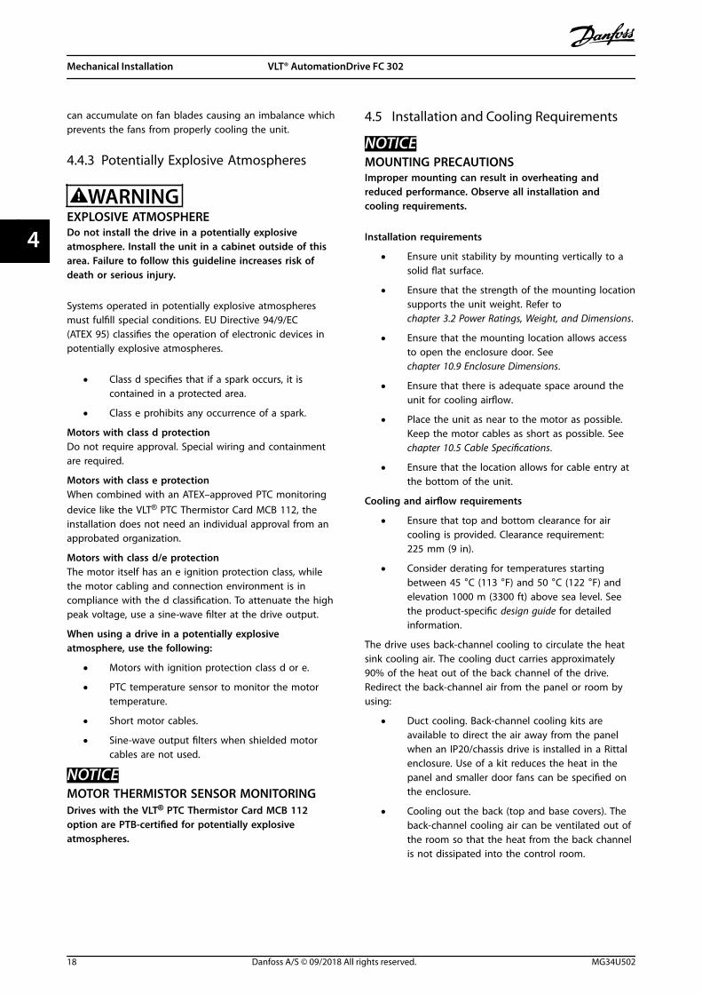
4.4.3 Potentially Explosive Atmospheres
WARNINGEXPLOSIVE ATMOSPHEREDo not install the drive in a potentially explosiveatmosphere. Install the unit in a cabinet outside of thisarea. Failure to follow this guideline increases risk ofdeath or serious injury.
Systems operated in potentially explosive atmospheresmust fulfill special conditions. EU Directive 94/9/EC(ATEX 95) classifies the operation of electronic devices inpotentially explosive atmospheres.
• Class d specifies that if a spark occurs, it iscontained in a protected area.
• Class e prohibits any occurrence of a spark.
Motors with class d protectionDo not require approval. Special wiring and containmentare required.
Motors with class e protectionWhen combined with an ATEX–approved PTC monitoringdevice like the VLT® PTC Thermistor Card MCB 112, theinstallation does not need an individual approval from anapprobated organization.
Motors with class d/e protectionThe motor itself has an e ignition protection class, whilethe motor cabling and connection environment is incompliance with the d classification. To attenuate the highpeak voltage, use a sine-wave filter at the drive output.
When using a drive in a potentially explosiveatmosphere, use the following:
• Motors with ignition protection class d or e.
• PTC temperature sensor to monitor the motortemperature.
• Short motor cables.
• Sine-wave output filters when shielded motorcables are not used.
NOTICEMOTOR THERMISTOR SENSOR MONITORINGDrives with the VLT® PTC Thermistor Card MCB 112option are PTB-certified for potentially explosiveatmospheres.
4.5 Installation and Cooling Requirements
NOTICEMOUNTING PRECAUTIONSImproper mounting can result in overheating andreduced performance. Observe all installation andcooling requirements.
Installation requirements
• Ensure unit stability by mounting vertically to asolid flat surface.
• Ensure that the strength of the mounting locationsupports the unit weight. Refer tochapter 3.2 Power Ratings, Weight, and Dimensions.
• Ensure that the mounting location allows accessto open the enclosure door. Seechapter 10.9 Enclosure Dimensions.
• Ensure that there is adequate space around theunit for cooling airflow.
• Place the unit as near to the motor as possible.Keep the motor cables as short as possible. Seechapter 10.5 Cable Specifications.
• Ensure that the location allows for cable entry atthe bottom of the unit.
Cooling and airflow requirements
• Ensure that top and bottom clearance for aircooling is provided. Clearance requirement:225 mm (9 in).
• Consider derating for temperatures startingbetween 45 °C (113 °F) and 50 °C (122 °F) andelevation 1000 m (3300 ft) above sea level. Seethe product-specific design guide for detailedinformation.
The drive uses back-channel cooling to circulate the heatsink cooling air. The cooling duct carries approximately90% of the heat out of the back channel of the drive.Redirect the back-channel air from the panel or room byusing:
• Duct cooling. Back-channel cooling kits areavailable to direct the air away from the panelwhen an IP20/chassis drive is installed in a Rittalenclosure. Use of a kit reduces the heat in thepanel and smaller door fans can be specified onthe enclosure.
• Cooling out the back (top and base covers). Theback-channel cooling air can be ventilated out ofthe room so that the heat from the back channelis not dissipated into the control room.
Mechanical Installation VLT® AutomationDrive FC 302
18 Danfoss A/S © 09/2018 All rights reserved. MG34U502
44

NOTICEOne or more door fans are required on the enclosure toremove heat not contained in the back channel of thedrive. The fans also remove any additional lossesgenerated by other components inside the drive.
Ensure that the fans supply adequate airflow over the heatsink. To select the appropriate number of fans, calculatethe total required airflow. The flow rate is shown inTable 4.2.
Enclosure size Door fan/top fan
Power size Heat sink fan
D1h/D3h/D5h/D6h
102 m3/hr(60 CFM)
90–110 kW,380–500 V
420 m3/hr(250 CFM)
75–132 kW,525–690 V
420 m3/hr(250 CFM)
132 kW,380–500 V
840 m3/hr(500 CFM)
All, 200–240 V 840 m3/hr(500 CFM)
D2h/D4h/D7h/D8h
204 m3/hr(120 CFM)
160 kW,380–500 V
420 m3/hr(250 CFM)
160 kW,525–690 V
420 m3/hr(250 CFM)
All, 200–240 V 840 m3/hr(500 CFM)
Table 4.2 D1h–D8h Airflow Rates
4.6 Lifting the Drive
Always lift the drive using the dedicated eye bolts at thetop of the drive. See Illustration 4.3.
WARNINGHEAVY LOADUnbalanced loads can fall or tip over. Failure to takeproper lifting precautions increases risk of death, seriousinjury, or equipment damage.
• Move the unit using a hoist, crane, forklift, orother lifting device with the appropriate weightrating. See chapter 3.2 Power Ratings, Weight,and Dimensions for the weight of the drive.
• Failure to locate the center of gravity andcorrectly position the load can causeunexpected shifting during lifting andtransport. For measurements and center ofgravity, see chapter 10.9 Enclosure Dimensions.
• The angle from the top of the drive module tothe lifting cables affects the maximum loadforce on the cable. This angle must be 65° orgreater. Refer to Illustration 4.3. Attach anddimension the lifting cables properly.
• Never walk under suspended loads.
• To guard against injury, wear personalprotective equipment such as gloves, safetyglasses, and safety shoes.
130B
E566
.11
65° min
Illustration 4.3 Lifting the Drive
Mechanical Installation Operating Guide
MG34U502 Danfoss A/S © 09/2018 All rights reserved. 19
4 4

4.7 Mounting the Drive
Depending on the drive model and configuration, thedrive can floor-mounted or wall-mounted.
Drive models D1h–D2h and D5h–D8h can be floormounted. Floor-mounted drives require space below thedrive for airflow. To provide this space, the drives can bemounted on a pedestal. The D7h and D8h drives comewith a standard pedestal. Optional pedestal kits areavailable for other D-sized drives.
Drives in enclosure sizes D1h–D6h can be wall-mounted.Drive models D3h and D4h are P20/Chassis drives, whichcan be mounted on a wall or on a mounting plate within acabinet.
Creating cable openingsBefore attaching the pedestal or mounting the drive,create cable openings in the gland plate and install it atthe bottom of the drive. The gland plate provides accessfor AC mains and motor cable entry while maintainingIP21/IP54 (Type 1/Type 12) protection ratings. For glandplate dimensions, see chapter 10.9 Enclosure Dimensions.
• If the gland plate is a metal plate, punch cableentry holes in the plate with a sheet metalpunch. Insert cable fittings into the holes. SeeIllustration 4.4.
• If the gland plate is plastic, punch out plastic tabsto accommodate the cables. See Illustration 4.5.
1
2
e30b
g284
.10
1 Cable entry hole
2 Metal gland plate
Illustration 4.4 Cable Openings in Sheet Metal Gland Plate
1
130B
F662
.10
2
1 Plastic tabs
2 Tabs removed for cable access
Illustration 4.5 Cable Openings in Plastic Gland Plate
Attaching the drive to the pedestalTo install a standard pedestal, use the following steps. Toinstall an optional pedestal kit, refer to the instructionsthat shipped with the kit. See Illustration 4.6.
1. Unfasten 4 M5 screws, and remove the pedestalfront cover plate.
2. Secure 2 M10 nuts over the threaded studs at theback of the pedestal, securing it to the drive backchannel.
3. Fasten 2 M5 screws through the back flange ofthe pedestal into the pedestal mounting bracketon the drive.
4. Fasten 4 M5 screws through the front flange ofthe pedestal and into the gland plate mountingholes.
Mechanical Installation VLT® AutomationDrive FC 302
20 Danfoss A/S © 09/2018 All rights reserved. MG34U502
44

e30b
g484
.10
1
3
4
5
6
7
8
9
10
2
200 (7.9)
1 Pedestal wall spacer 6 Back flange of pedestal
2 Fastener slots 7 M5 screw (fasten through back flange)
3 Mounting flange at drive top 8 Front flange of pedestal
4 Mounting holes 9 Front cover plate of pedestal
5 M10 nuts (fasten to threaded posts) 10 M5 screw (fasten through front flange)
Illustration 4.6 Pedestal Installation in D7h/D8h Drives
Mechanical Installation Operating Guide
MG34U502 Danfoss A/S © 09/2018 All rights reserved. 21
4 4

Floor mounting the driveTo secure the pedestal to the floor (after attaching thedrive to the pedestal), use the following steps.
1. Fasten 4 M10 bolts in the mounting holes at thebottom of the pedestal, securing it to the floor.See Illustration 4.7.
2. Reposition the pedestal front cover plate, andfasten with 4 M5 screws. See Illustration 4.6.
3. Slide the pedestal wall spacer behind themounting flange at the top of the drive. SeeIllustration 4.6.
4. Fasten 2–4 M10 bolts in the mounting holes atthe top of the drive, securing it to the wall. Use 1bolt for each mounting hole. The number varieswith enclosure size. See Illustration 4.6.
1
2
e30b
g289
.10
1 Mounting holes
2 Bottom of pedestal
Illustration 4.7 Pedestal-to-floor Mounting Holes
Wall mounting the driveTo wall mount a drive, use the following steps. Refer toIllustration 4.8.
1. Fasten 2 M10 bolts in the wall to align with thefastener slots at the bottom of drive.
2. Slide the fastener slots over the M10 bolts.
3. Tip the drive against the wall, and secure the topwith 2 M10 bolts in the mounting holes.
1
2
e30b
g288
.10
1 Top mounting holes
2 Lower fastener slots
Illustration 4.8 Drive-to-wall Mounting Holes
Mechanical Installation VLT® AutomationDrive FC 302
22 Danfoss A/S © 09/2018 All rights reserved. MG34U502
44

5 Electrical Installation
5.1 Safety Instructions
See chapter 2 Safety for general safety instructions.
WARNINGINDUCED VOLTAGEInduced voltage from output motor cables from differentdrives that are run together can charge equipmentcapacitors even with the equipment turned off andlocked out. Failure to run output motor cables separatelyor use shielded cables could result in death or seriousinjury.
• Run output motor cables separately or useshielded cables.
• Simultaneously lock out all the drives.
WARNINGSHOCK HAZARDThe drive can cause a DC current in the groundconductor and thus result in death or serious injury.
• When a residual current-operated protectivedevice (RCD) is used for protection againstelectrical shock, only an RCD of Type B isallowed on the supply side.
Failure to follow the recommendation means that theRCD cannot provide the intended protection.
Overcurrent protection• Additional protective equipment such as short-
circuit protection or motor thermal protectionbetween drive and motor is required forapplications with multiple motors.
• Input fusing is required to provide short circuitand overcurrent protection. If fuses are notfactory-supplied, the installer must provide them.See maximum fuse ratings in chapter 10.7 Fusesand Circuit Breakers.
Wire type and ratings• All wiring must comply with local and national
regulations regarding cross-section and ambienttemperature requirements.
• Power connection wire recommendation:Minimum 75 °C (167 °F) rated copper wire.
See chapter 10.5 Cable Specifications for recommended wiresizes and types.
CAUTIONPROPERTY DAMAGEProtection against motor overload is not included in thedefault setting. To add this function, setparameter 1-90 Motor Thermal Protection to [ETR trip] or[ETR warning]. For the North American market, the ETRfunction provides class 20 motor overload protection inaccordance with NEC. Failure to set parameter 1-90 MotorThermal Protection to [ETR trip] or [ETR warning] meansthat motor overload protection is not provided and, ifthe motor overheats, property damage can occur.
5.2 EMC-compliant Installation
To obtain an EMC-compliant installation, follow theinstructions provided in:
• Chapter 5.3 Wiring Schematic.
• Chapter 5.4 Connecting to Ground.
• Chapter 5.5 Connecting the Motor.
• Chapter 5.6 Connecting the AC Mains.
NOTICETWISTED SHIELD ENDS (PIGTAILS)Twisted shield ends (pigtails) increase the shieldimpedance at higher frequencies, reducing the shieldeffect and increasing the leakage current. To avoidtwisted shield ends, use integrated shield clamps.
• For use with relays, control cables, a signalinterface, fieldbus, or brake, connect the shield tothe enclosure at both ends. If the ground pathhas high impedance, is noisy, or is carryingcurrent, break the shield connection on 1 end toavoid ground current loops.
• Convey the currents back to the unit using ametal mounting plate. Ensure good electricalcontact from the mounting plate through themounting screws to the drive chassis.
• Use shielded cables for motor output cables. Analternative is unshielded motor cables withinmetal conduit.
NOTICESHIELDED CABLESIf shielded cables or metal conduits are not used, theunit and the installation do not meet regulatory limitson radio frequency (RF) emission levels.
Electrical Installation Operating Guide
MG34U502 Danfoss A/S © 09/2018 All rights reserved. 23
5 5

• Ensure that motor and brake cables are as shortas possible to reduce the interference level fromthe entire system.
• Avoid placing cables with a sensitive signal levelalongside motor and brake cables.
• For communication and command/control lines,follow the particular communication protocolstandards. Danfoss recommends use of shieldedcables.
• Ensure that all control terminal connections arePELV.
NOTICEEMC INTERFERENCEUse separate shielded cables for motor and controlwiring, and separate cables for mains wiring, motorwiring, and control wiring. Failure to isolate power,motor, and control cables can result in unintendedbehavior or reduced performance. Minimum 200 mm (7.9in) clearance between mains, motor, and control cables isrequired.
NOTICEINSTALLATION AT HIGH ALTITUDEThere is a risk of overvoltage. Isolation betweencomponents and critical parts could be insufficient, andnot comply with PELV requirements. Reduce the risk ofovervoltage by using external protective devices orgalvanic isolation.For installations above 2000 m (6500 ft) altitude, contactDanfoss regarding PELV compliance.
NOTICEPELV COMPLIANCEPrevent electric shock by using protective extra lowvoltage (PELV) electrical supply and complying with localand national PELV regulations.
Electrical Installation VLT® AutomationDrive FC 302
24 Danfoss A/S © 09/2018 All rights reserved. MG34U502
55

e30b
f228
.11
L1L2L3PE
PE
u
v
w
2
1
3
5
16
17
18
14
12
8
7
10
9
4
11
13
4
6
15
90
4
1 PLC 10 Mains cable (unshielded)
2 Minimum 16 mm2 (6 AWG) equalizing cable 11 Output contactor and similar options
3 Control cables 12 Cable insulation stripped
4 Required minimum separation of 200 mm (7.9 in) betweencontrol cables, motor cables, and mains cables
13 Common ground busbar (Follow local and nationalrequirements for enclosure grounding)
5 Mains supply 14 Brake resistor
6 Bare (unpainted) surface 15 Metal box
7 Star washers 16 Connection to motor
8 Brake cable (shielded) 17 Motor
9 Motor cable (shielded) 18 EMC cable gland
Illustration 5.1 Example of Proper EMC Installation
Electrical Installation Operating Guide
MG34U502 Danfoss A/S © 09/2018 All rights reserved. 25
5 5

5.3 Wiring Schematic
e30b
f111
.12
230 V AC50/60 Hz
TB5R1
Regen +
Regen -83
Regen (optional)
1
2
Brake temperature (NC)
Space heater (optional)
91 (L1)92 (L2)93 (L3)
PE
88 (-)89 (+)
50 (+10 V OUT)
53 (A IN)
54 (A IN)
55 (COM A IN)
0/4-20 mA
12 (+24 V OUT)
13 (+24 V OUT)
18 (D IN)
20 (COM D IN)
15 mA 200 mA
(U) 96(V) 97
(W) 98(PE) 99
(COM A OUT) 39
(A OUT) 420/4-20 mA
03
+10 V DC
-10 V DC to +10 V DC
0/4-20 mA
24 V DC
02
01
05
04
06240 V AC, 2A
24 V (NPN) 0 V (PNP)
0 V (PNP)24 V (NPN)
19 (D IN)
24 V (NPN) 0 V (PNP)27
24V
0V
(D IN/OUT)
0 V (PNP)24 V (NPN)
(D IN/OUT)
0V
24V29
24 V (NPN) 0 V (PNP)
0 V (PNP)24 V (NPN)
33 (D IN)
32 (D IN)
12
ON
A53 U-I (S201)
ON2
1A54 U-I (S202)ON=0/4-20 mAOFF=0 to ±10 V
95
400 V AC, 2AP 5-00
(R+) 82
(R-) 81
37 (D IN)2)
+ - + -
(P RS485) 68
(N RS485) 69
(COM RS485) 61
0V
5V
S801
RS485RS485
21 O
N
S801/Bus Term.OFF-ON
3-phasepowerinput
Load share Switch modepower supply
Motor
Analog output
interface
Relay1
Relay2
ON=TerminatedOFF=Open
Brakeresistor
(NPN) = Sink(PNP) = Source
==
=
240 V AC, 2A
400 V AC, 2A-10 V DC to +10 V DC
10 V DC(optional)
(optional)
TB6 Contactor 1)
Illustration 5.2 Basic Wiring Schematic
1) TB6 contactor is found only in D6h and D8h drives with a contactor option.2) Terminal 37 (optional) is used for Safe Torque Off. Refer to the VLT® FC Series - Safe Torque Off Operating Guide for installationinstructions.
Electrical Installation VLT® AutomationDrive FC 302
26 Danfoss A/S © 09/2018 All rights reserved. MG34U502
55

5.4 Connecting to Ground
WARNINGLEAKAGE CURRENT HAZARDLeakage currents exceed 3.5 mA. Failure to ground the drive properly can result in death or serious injury.
• Ensure the correct grounding of the equipment by a certified electrical installer.
For electrical safety• Ground the drive in accordance with applicable standards and directives.
• Use a dedicated ground wire for input power, motor power, and control wiring.
• Do not ground 1 drive to another in a daisy chain fashion.
• Keep the ground wire connections as short as possible.
• Follow motor manufacturer wiring requirements.
• Minimum cable cross-section: 10 mm2 (6 AWG) (or 2 rated ground wires terminated separately).
• Tighten the terminals in accordance with the information provided in chapter 10.8.1 Fastener Torque Ratings.
For EMC-compliant installation• Establish electrical contact between the cable shield and the drive enclosure by using metal cable glands or by
using the clamps provided on the equipment.
• Reduce burst transient by using high-strand wire.
• Do not use twisted shield ends (pigtails).
NOTICEPOTENTIAL EQUALIZATIONThere is a risk of burst transient when the ground potential between the drive and the control system is different.Install equalizing cables between the system components. Recommended cable cross-section: 16 mm2 (5 AWG).
Electrical Installation Operating Guide
MG34U502 Danfoss A/S © 09/2018 All rights reserved. 27
5 5

e30b
g266
.10
Illustration 5.3 Ground Terminals (D1h shown)
Electrical Installation VLT® AutomationDrive FC 302
28 Danfoss A/S © 09/2018 All rights reserved. MG34U502
55

5.5 Connecting the Motor
WARNINGINDUCED VOLTAGEInduced voltage from output motor cables that run together can charge equipment capacitors, even with theequipment turned off and locked out. Failure to run output motor cables separately or use shielded cables could resultin death or serious injury.
• Comply with local and national electrical codes for cable sizes. For maximum wire sizes, see chapter 10.5 CableSpecifications.
• Follow motor manufacturer wiring requirements.
• Motor wiring knockouts or access panels are provided at the base of IP21 (NEMA1/12) and higher units.
• Do not wire a starting or pole-changing device (for example Dahlander motor or slip ring asynchronous motor)between the drive and the motor.
Procedure1. Strip a section of the outer cable insulation.
2. Position the stripped wire under the cable clamp, establishing mechanical fixation and electrical contact betweenthe cable shield and ground.
3. Connect the ground wire to the nearest grounding terminal in accordance with the grounding instructionsprovided in chapter 5.4 Connecting to Ground. See Illustration 5.4.
4. Connect the 3-phase motor wiring to terminals 96 (U), 97 (V), and 98 (W). See Illustration 5.4.
5. Tighten the terminals in accordance with the information provided in chapter 10.8.1 Fastener Torque Ratings.
Electrical Installation Operating Guide
MG34U502 Danfoss A/S © 09/2018 All rights reserved. 29
5 5

e30b
g268
.10
Illustration 5.4 Motor Terminals (D1h shown)
Electrical Installation VLT® AutomationDrive FC 302
30 Danfoss A/S © 09/2018 All rights reserved. MG34U502
55

5.6 Connecting the AC Mains
• Size the wiring according to the input current of the drive. For maximum wire sizes, see chapter 10.1 Electrical Data.
• Comply with local and national electrical codes for cable sizes.
Procedure1. Strip a section of the outer cable insulation.
2. Position the stripped wire under the cable clamp, establishing mechanical fixation and electrical contact betweenthe cable shield and ground.
3. Connect the ground wire to the nearest grounding terminal in accordance with the grounding instructionsprovided in chapter 5.4 Connecting to Ground.
4. Connect the 3-phase AC input power wiring to terminals R, S, and T. See Illustration 5.5.
5. Tighten the terminals in accordance with the information provided in chapter 10.8.1 Fastener Torque Ratings.
6. When supplied from an isolated mains source (IT mains or floating delta) or TT/TN-S mains with a grounded leg(grounded delta), ensure that parameter 14-50 RFI Filter is set to [0] Off to avoid damage to the DC link and toreduce ground capacity currents.
NOTICEOUTPUT CONTACTORDanfoss does not recommend using an output contactor on 525–690 V drives that are connected to an IT mainsnetwork.
Electrical Installation Operating Guide
MG34U502 Danfoss A/S © 09/2018 All rights reserved. 31
5 5

e30b
g267
.10
Illustration 5.5 AC Mains Terminals (D1h shown). For a detailed view of terminals, see chapter 5.8 Terminal Dimensions.
Electrical Installation VLT® AutomationDrive FC 302
32 Danfoss A/S © 09/2018 All rights reserved. MG34U502
55

5.7 Connecting Regen/Load Share Terminals
The optional regeneration/load share terminals are found at the top of the drive. For drives with IP21/IP54 enclosures, thewiring is routed through a cover surrounding the terminals. Refer to Illustration 5.5.
• Size the wiring according to the current of the drive. For maximum wire sizes, see chapter 10.1 Electrical Data.
• Comply with local and national electrical codes for cable sizes.
Procedure1. Remove 2 plugs (for either top entry or side entry) from the terminal cover.
2. Insert cable fittings into the terminal cover holes.
3. Strip a section of the outer cable insulation.
4. Position the stripped cable through the fittings.
5. Connect the DC(+) cable to the DC(+) terminal, and secure with 1 M10 fastener.
6. Connect the DC(-) cable to the DC(-) terminal, and secure with 1 M10 fastener.
7. Tighten the terminals in accordance with chapter 10.8.1 Fastener Torque Ratings.
Electrical Installation Operating Guide
MG34U502 Danfoss A/S © 09/2018 All rights reserved. 33
5 5

e30b
g485
.10
244 (9.6)
101 (4.0) 125 (4.9)
14 (0.6)
32 (1.3)
16 (0.6)
125 (4.9)95 (3.7)236 (9.3)
87 (3.4)
1
2
3
6
7
8
9
11
4
5
10
12
1 Top openings for regen/load share terminals 7 DC(+) terminal
2 Terminal cover 8 DC(-) terminal
3 Side opening for regen/load share terminals 9 Hole for M10 fastener
4 Top view 10 Close-up view
5 Side view 11 Regen/load share terminals
6 View without cover 12 Front view
Illustration 5.6 Regen/Load Share Terminals in Enclosure Size D
Electrical Installation VLT® AutomationDrive FC 302
34 Danfoss A/S © 09/2018 All rights reserved. MG34U502
55

5.8 Terminal Dimensions
5.8.1 D1h Terminal Dimensions
88 (3.5)
0.0
200 (7.9)
130B
F342
.10
0.0
94 (3.7)29
3 (1
1.5)
263
(10.
4)
33 (1
.3)
62 (2
.4)
101
(4.0
)
140
(5.5
)
163
(6.4
)
185
(7.3
)
224
(8.8
)
2
1
3
1 Mains terminals 3 Motor terminals
2 Ground terminals – –
Illustration 5.7 D1h Terminal Dimensions (Front View)
Electrical Installation Operating Guide
MG34U502 Danfoss A/S © 09/2018 All rights reserved. 35
5 5

130B
F343
.10
244
(9.6
)
272
(10.
7)0.0
0.0
1 2
M10M10
32(1.3)
13(0.5)
32(1.3)
13(0.5)
1 Mains terminals 2 Motor terminals
Illustration 5.8 D1h Terminal Dimensions (Side Views)
Electrical Installation VLT® AutomationDrive FC 302
36 Danfoss A/S © 09/2018 All rights reserved. MG34U502
55

5.8.2 D2h Terminal Dimensions
130B
F345
.10
143 (5.6)
168 (6.6)
331 (13.0)
211 (8.3)
168 (6.6)
143 (5.6)
42 (1
.6)
68 (2
.7)
126
(5.0
)
184
(7.2
)
246
(9.7
)
300
(11.
8)
354
(13.
9)
378
(14.
9)
0.0
0.0
2
13
1 Mains terminals 3 Motor terminals
2 Ground terminals – –
Illustration 5.9 D2h Terminal Dimensions (Front View)
Electrical Installation Operating Guide
MG34U502 Danfoss A/S © 09/2018 All rights reserved. 37
5 5
130B
F346
.10
0.0
0.0
1 2
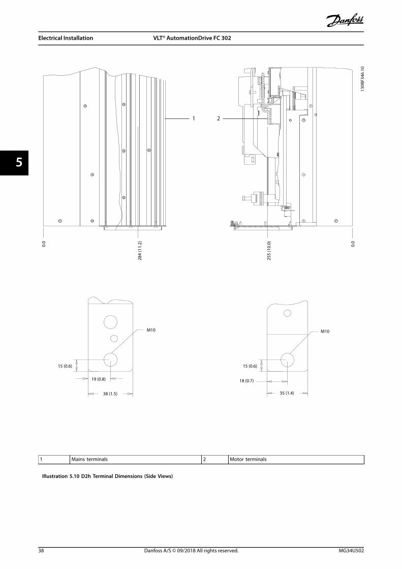
255
(10.
0)
284
(11.
2)
M10
15 (0.6)
38 (1.5)
19 (0.8)
15 (0.6)
18 (0.7)
35 (1.4)
M10
1 Mains terminals 2 Motor terminals
Illustration 5.10 D2h Terminal Dimensions (Side Views)
Electrical Installation VLT® AutomationDrive FC 302
38 Danfoss A/S © 09/2018 All rights reserved. MG34U502
55

5.8.3 D3h Terminal Dimensions
130B
F341
.10
83 (3.3)
0.0
188 (7.4)
22 (0
.9)
62 (2
.4)
101
(4.0
)
145
(5.7
)
184
(7.2
)
223
(8.8
)
152
(6.0
)
217
(8.5
)
292 (11.5)
0.0
2
13
4
1 Mains terminals 3 Motor terminals
2 Brake terminals 4 Ground terminals
Illustration 5.11 D3h Terminal Dimensions (Front View)
Electrical Installation Operating Guide
MG34U502 Danfoss A/S © 09/2018 All rights reserved. 39
5 5

M10
13 (0.5)
32 (1.3)
59 (2
.3)
12 (0.5)
10 (0.4) 38 (1.5)
M10
244
(9.6
)
290
(11.
4)
272
(10.
7)
130B
F344
.10
0.0
0.0
3 2
1
5
4 6
7
M10
13 (0.5)
32 (1.3)
145
(5.7
)
182
(7.2
) 3X M8x18
0
0
1 and 6 Bottom brake/regen terminals 3 and 5 Mains terminals
2 and 7 Motor terminals 4 Ground terminals
Illustration 5.12 D3h Terminal Dimensions (Side Views)
Electrical Installation VLT® AutomationDrive FC 302
40 Danfoss A/S © 09/2018 All rights reserved. MG34U502
55

5.8.4 D4h Terminal Dimensions
33 (1
.3)
91 (3
.6)
149
(5.8
)
211
(8.3
)
265
(10.
4)
319
(12.
6)
200 (7.9)
319 (12.6)
376 (14.8)
293
(11.
5)
237
(9.3
)
130B
F347
.10
0.0
o.o
1
3
2
4
1 Mains terminals 3 Motor terminals
2 Brake terminals 4 Ground terminals
Illustration 5.13 D4h Terminal Dimensions (Front View)
Electrical Installation Operating Guide
MG34U502 Danfoss A/S © 09/2018 All rights reserved. 41
5 5

5
4
6
7
91 (3
.6)
13 (0.5)
200
(7.9
)
259
(10.
2) 3X M10X20
0
0
M10
19 (0.8)38 (1.5)
255
(10.
0)
306
(12.
1)
284
(11.
2)
130B
F348
.10
0.0
0.0
3 2
1
M10
22 (0.9)
35 (1.4)
15 (0.6)
18 (0.7)
M10
16 (0.6)
32 (1.3)
19 (0.7)
1 and 6 Brake/regen terminals 3 and 5 Mains terminals
2 and 7 Motor terminals 4 Ground terminals
Illustration 5.14 D4h Terminal Dimensions (Side Views)
Electrical Installation VLT® AutomationDrive FC 302
42 Danfoss A/S © 09/2018 All rights reserved. MG34U502
55

5.8.5 D5h Terminal Dimensions
130B
F349
.10
0.0
0.0
45 (1
.8)
46 (1
.8)
99 (3
.9)
153
(6.0
)14
6 (5
.8)
182
(7.2
)19
3 (7
.6)
249
(9.8
)
221
(8.7
)
260
(10.
2)
118 (4.6)
148 (5.8)
90 (3.6)
196 (7.7)
227 (9.0)221 (8.7)
3
42
1
1 Mains terminals 3 Brake terminals
2 Ground terminals 4 Motor terminals
Illustration 5.15 D5h Terminal Dimensions with Disconnect Option (Front View)
Electrical Installation Operating Guide
MG34U502 Danfoss A/S © 09/2018 All rights reserved. 43
5 5

0.0
0.0
113
(4.4
)
206
(8.1
)
130B
F350
.10
1
3
2
1 Mains terminals 3 Motor terminals
2 Brake terminals – –
Illustration 5.16 D5h Terminal Dimensions with Disconnect Option (Side Views)
Electrical Installation VLT® AutomationDrive FC 302
44 Danfoss A/S © 09/2018 All rights reserved. MG34U502
55

130B
F351
.10
1
2
0.0
33 (1
.3)
0.0
62 (2
.4)
101
(4.0
)
140
(5.5
)
163
(6.4
)
185
(7.3
)19
1 (7
.5)
224
(8.8
)
256
(10.
1)26
3 (1
0.4)
293
(11.
5)
511 (20.1)
517 (20.4)
623 (24.5)
727 (28.6)
3
4
1 Mains terminals 3 Motor terminals
2 Brake terminals 4 Ground terminals
Illustration 5.17 D5h Terminal Dimensions with Brake Option (Front View)
Electrical Installation Operating Guide
MG34U502 Danfoss A/S © 09/2018 All rights reserved. 45
5 5

130B
F352
.10
246
(9.7
)
293
(11.
5)
274
(10.
8)0.0
0.0
2
1
3
1 Brake terminals 3 Motor terminals
2 Mains terminals – –
Illustration 5.18 D5h Terminal Dimensions with Brake Option (Side Views)
Electrical Installation VLT® AutomationDrive FC 302
46 Danfoss A/S © 09/2018 All rights reserved. MG34U502
55

5.8.6 D6h Terminal Dimensions
130B
F353
.10
0.0
96 (3.8)
195 (7.7)
227 (8.9)
123 (4.8)
153 (6.0)
458 (18.0)
0.0
46 (1
.8)
50 (2
.0)
99 (3
.9)
147
(5.8
)
182
(7.2
)19
3 (7
.6)
221
(8.7
)
249
(9.8
)26
0 (1
0.2)
146
(5.8
)
3
2
1
4
5
1 Mains terminals 4 Brake terminals
2 Ground terminals 5 Motor terminals
3 TB6 terminal block for contactor – –
Illustration 5.19 D6h Terminal Dimensions with Contactor Option (Front View)
Electrical Installation Operating Guide
MG34U502 Danfoss A/S © 09/2018 All rights reserved. 47
5 5

e30b
f354
.10
0.0
0.0
1
2
3
286
(11.
2)
113
(4.4
)
206
(8.1
)
1 Mains terminals 3 Motor terminals
2 Brake terminals – –
Illustration 5.20 D6h Terminal Dimensions with Contactor Option (Side Views)
Electrical Installation VLT® AutomationDrive FC 302
48 Danfoss A/S © 09/2018 All rights reserved. MG34U502
55

130B
F355
.10
99 (3
.9)
153
(6.0
)
0.0
225 (8.9)
45 (1
.8)
0.0
4
1
2
5
3
1 Mains terminals 4 Brake terminals
2 Ground terminals 5 Motor terminals
3 TB6 terminal block for contactor – –
Illustration 5.21 D6h Terminal Dimensions with Contactor and Disconnect Options (Front View)
Electrical Installation Operating Guide
MG34U502 Danfoss A/S © 09/2018 All rights reserved. 49
5 5

130B
F356
.10
0.0
286
(11.
2)
1
2
3
1 Brake terminals 3 Motor terminals
2 Mains terminals – –
Illustration 5.22 D6h Terminal Dimensions with Contactor and Disconnect Options (Side Views)
Electrical Installation VLT® AutomationDrive FC 302
50 Danfoss A/S © 09/2018 All rights reserved. MG34U502
55

130B
F357
.10
467 (18.4)
0.0
52 (2
.1)
0.0
99 (3
.9)
145
(5.7
)
1
2
3
4
1 Mains terminals 3 Brake terminals
2 Ground terminals 4 Motor terminals
Illustration 5.23 D6h Terminal Dimensions with Circuit Breaker Option (Front View)
Electrical Installation Operating Guide
MG34U502 Danfoss A/S © 09/2018 All rights reserved. 51
5 5

130B
F358
.10
163
(6.4
)
0.0
1
2
3
1 Mains terminals 3 Motor terminals
2 Brake terminals – –
Illustration 5.24 D6h Terminal Dimensions with Circuit Breaker Option (Side Views)
Electrical Installation VLT® AutomationDrive FC 302
52 Danfoss A/S © 09/2018 All rights reserved. MG34U502
55

5.8.7 D7h Terminal Dimensions
130B
F359
.10
0.0
0.0
2
1
372 (14.7)
412 (16.2)
395 (15.6)
515 (20.3)
66 (2
.6)
95 (3
.7)
131
(5.1
)
151
(5.9
)
195
(7.7
)
238
(9.4
)
292
(11.
5)
346
(13.
6)
49 (1
.9)
198
(7.8
)
368
(14.
5)
545 (21.4)
3
4
1 Mains terminals 3 Motor terminals
2 Brake terminals 4 Ground terminals
Illustration 5.25 D7h Terminal Dimensions with Disconnect Option (Front View)
Electrical Installation Operating Guide
MG34U502 Danfoss A/S © 09/2018 All rights reserved. 53
5 5

0.0
130B
F360
.10
119
(4.7
)
276
(10.
9)
12
3
1 Mains terminals 3 Motor terminals
2 Brake terminals – –
Illustration 5.26 D7h Terminal Dimensions with Disconnect Option (Side Views)
Electrical Installation VLT® AutomationDrive FC 302
54 Danfoss A/S © 09/2018 All rights reserved. MG34U502
55

130B
F361
.10
0.0
66 (2
.6)
123
(4.9
)
181
(7.1
)
243
(9.6
)26
9 (1
0.6)
297
(11.
7)32
5 (1
2.8)
351
(13.
8)
40 (1
.6)
0.0
1009 (39.7)1034 (40.7)
1082 (42.6)
1202 (47.3)
1260 (49.6)
375
(14.
8)
2
1 34
1 Mains terminals 3 Brake terminals
2 Ground terminals 4 Motor terminals
Illustration 5.27 D7h Terminal Dimensions with Brake Option (Front View)
Electrical Installation Operating Guide
MG34U502 Danfoss A/S © 09/2018 All rights reserved. 55
5 5
130B
F362
.10
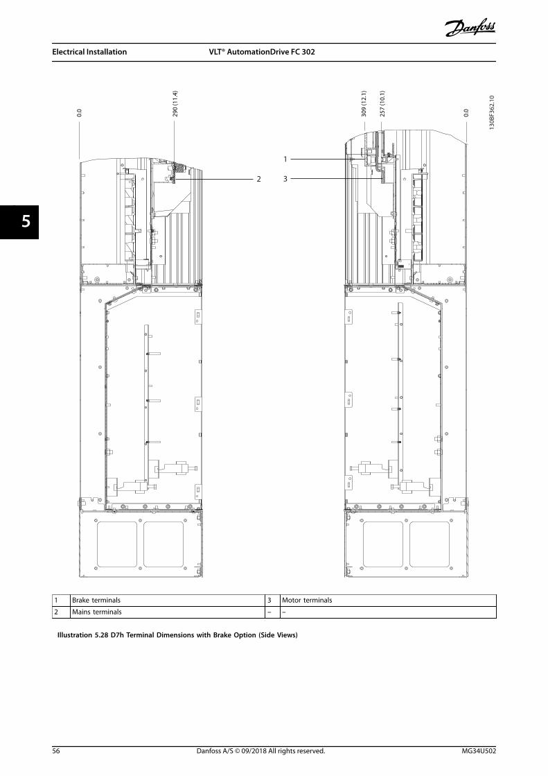
290
(11.
4)
0.0
257
(10.
1)
309
(12.
1)
0.0
2
1
3
1 Brake terminals 3 Motor terminals
2 Mains terminals – –
Illustration 5.28 D7h Terminal Dimensions with Brake Option (Side Views)
Electrical Installation VLT® AutomationDrive FC 302
56 Danfoss A/S © 09/2018 All rights reserved. MG34U502
55

5.8.8 D8h Terminal Dimensions
69 (2
.7)
0.0
123
(4.9
)
177
(7.0
)
238
(9.4
)
292
(11.
5)
346
(13.
6)
49 (1
.9)
378
(14.
9)
198
(7.8
)
378 (14.9)
0.0
418 (16.5)
898 (35.3)
401 (15.8)
521 (20.5)
95 (3
.7)
151
(5.9
)
130B
F367
.10
1
2
3
4
5
1 Mains terminals 4 TB6 terminal block for contactor
2 Brake terminals 5 Motor terminals
3 Ground terminals – –
Illustration 5.29 D8h Terminal Dimensions with Contactor Option (Front View)
Electrical Installation Operating Guide
MG34U502 Danfoss A/S © 09/2018 All rights reserved. 57
5 5

130B
F368
.10
119
(4.7
)
0.0
252
(9.9
)
127
(5.0
)
0.0
1
32
1 Mains terminals 3 Motor terminals
2 Brake terminals – –
Illustration 5.30 D8h Terminal Dimensions with Contactor Option (Side Views)
Electrical Installation VLT® AutomationDrive FC 302
58 Danfoss A/S © 09/2018 All rights reserved. MG34U502
55

130B
F369
.10
567 (22.3)
0.0
58 (2
.3)
0.0
123
(4.9
)
188
(7.4
)1
2
3
4
5
1 Mains terminals 4 TB6 terminal block for contactor
2 Brake terminals 5 Motor terminals
3 Ground terminals – –
Illustration 5.31 D8h Terminal Dimensions with Contactor and Disconnect Options (Front View)
Electrical Installation Operating Guide
MG34U502 Danfoss A/S © 09/2018 All rights reserved. 59
5 5

130B
F370
.10
246
(9.7
)
0.0
1
2
3
1 Mains terminals 3 Motor terminals
2 Brake terminals – –
Illustration 5.32 D8h Terminal Dimensions with Contactor and Disconnect Options (Side View)
Electrical Installation VLT® AutomationDrive FC 302
60 Danfoss A/S © 09/2018 All rights reserved. MG34U502
55

1
2
3
4
605(23.8)
85 (3
.3)
154
(6.1
)
224
(8.8
)
0
0
130B
F371
.10
1 Mains terminals 3 Ground terminals
2 Brake terminals 4 Motor terminals
Illustration 5.33 D8h Terminal Dimensions with Circuit Breaker Option (Front View)
Electrical Installation Operating Guide
MG34U502 Danfoss A/S © 09/2018 All rights reserved. 61
5 5

202
(8.0
)
130B
F372
.10
0.0
1
2
3
1
3
2
M10
20 (0.8) 15 (0.6)
40 (1.6)
M10
15 (0.6)
16 (0.6) 32 (1.3)
M1020
14 (0.5)
18 (0.7)
(0.8)
35 (1.4)
1 Mains terminals 3 Motor terminals
2 Brake terminals – –
Illustration 5.34 D8h Terminal Dimensions with Circuit Breaker Option (Side View)
Electrical Installation VLT® AutomationDrive FC 302
62 Danfoss A/S © 09/2018 All rights reserved. MG34U502
55

5.9 Control Wiring
All terminals to the control cables are inside the drivebelow the LCP. To access the control terminals, either openthe door (D1h/D2h/D5h/D6h/D7h/D8h) or remove the frontpanel (D3h/D4h).
5.9.1 Control Cable Routing
• Isolate control wiring from high-powercomponents in the drive.
• Tie down all control wires after routing them.
• Connect shields to ensure optimum electricalimmunity.
• When the drive is connected to a thermistor,ensure that the thermistor control wiring isshielded and reinforced/double insulated. A 24 VDC supply voltage is recommended.
Fieldbus connectionConnections are made to the relevant options on thecontrol card. For more detail, see the relevant fieldbusinstruction. The cable must be tied down and routed alongwith other control wires inside the unit.
5.9.2 Control Terminal Types
Illustration 5.35 shows the removable drive connectors.Terminal functions and default settings are summarized inTable 5.1 – Table 5.3.
130B
F144
.10
Illustration 5.35 Control Terminal Locations
12 13 18 19 27 29 32 33 20 37
39696861 42 50 53 54 55
130B
F145
.10
1
2
3
1 Serial communication terminals
2 Digital input/output terminals
3 Analog input/output terminals
Illustration 5.36 Terminal Numbers Located on the Connectors
Terminal Parameter Defaultsetting
Description
61 – – Integrated RC-filter forcable shield. ONLY forconnecting the shieldto correct EMCproblems.
68 (+) Parametergroup 8-3* FCPort Settings
– RS485 interface. Aswitch (BUS TER.) isprovided on thecontrol card for busterminationresistance. SeeIllustration 5.40.
69 (-) Parametergroup 8-3* FCPort Settings
–
Table 5.1 Serial Communication Terminal Descriptions
Digital input/output terminals
Terminal Parameter Defaultsetting
Description
12, 13 – +24 V DC 24 V DC supplyvoltage for digitalinputs and externaltransducers.Maximum outputcurrent 200 mA for all24 V loads.
18 Parameter 5-10 Terminal 18Digital Input
[8] Start Digital inputs.
19 Parameter 5-11 Terminal 19Digital Input
[10]Reversing
32 Parameter 5-14 Terminal 32Digital Input
[0] Nooperation
33 Parameter 5-15 Terminal 33Digital Input
[0] Nooperation
Electrical Installation Operating Guide
MG34U502 Danfoss A/S © 09/2018 All rights reserved. 63
5 5

Digital input/output terminals
Terminal Parameter Defaultsetting
Description
27 Parameter 5-12 Terminal 27Digital Input
[2] Coastinverse
For digital input oroutput. Defaultsetting is input.
29 Parameter 5-13 Terminal 29Digital Input
[14] JOG
20 – – Common for digitalinputs and 0 Vpotential for 24 Vsupply.
37 – STO When not using theoptional STO feature,a jumper wire isrequired betweenterminal 12 (or 13)and terminal 37. Thisset-up allows thedrive to operate withfactory defaultprogramming values.
Table 5.2 Digital Input/Output Terminal Descriptions
Analog input/output terminals
Terminal Parameter Defaultsetting
Description
39 – – Common for analogoutput.
42 Parameter 6-50 Terminal 42
Output
[0] Nooperation
Programmable analogoutput. 0–20 mA or4–20 mA at a
maximum of 500 Ω.
50 – +10 V DC 10 V DC analogsupply voltage forpotentiometer orthermistor. 15 mAmaximum.
53 Parametergroup 6-1*
Analog Input 1
Reference Analog input. Forvoltage or current.Switches A53 andA54 select mA or V.54 Parameter
group 6-2*Analog Input 2
Feedback
55 – – Common for analoginput.
Table 5.3 Analog Input/Output Terminal Descriptions
5.9.3 Wiring to Control Terminals
The control terminals are located near the LCP. The controlterminal connectors can be unplugged from the drive forconvenience when wiring, as shown in Illustration 5.35.
Either solid or flexible wire can be connected to thecontrol terminals. Use the following procedures to connector disconnect the control wires.
NOTICEMinimize interference by keeping control wires as shortas possible and separate from high-power cables.
Connecting wire to control terminals
1. Strip 10 mm (0.4 in) of the outer plastic layerfrom the end of the wire.
2. Insert the control wire into the terminal.
• For a solid wire, push the bare wire intothe contact. See Illustration 5.37.
• For a flexible wire, open the contact byinserting a small screwdriver into theslot between the terminal holes andpush the screwdriver inward. SeeIllustration 5.38. Then, insert the strippedwire into the contact, and remove thescrewdriver.
3. Pull gently on the wire to ensure that the contactis firmly established. Loose control wiring can bethe source of equipment faults or reducedperformance.
e30b
g283
.10
10 m
m (0
.4)
12 13 18 19 27 29 32 33
Illustration 5.37 Connecting Solid Control Wires
130B
D54
6.11
21
12 13 18 19 27 29 32 33
10 m
m (0
.4)
Illustration 5.38 Connecting Flexible Control Wires
Electrical Installation VLT® AutomationDrive FC 302
64 Danfoss A/S © 09/2018 All rights reserved. MG34U502
55

Disconnecting wires from the control terminals
1. To open the contact, insert a small screwdriverinto the slot between the terminal holes andpush the screwdriver inward.
2. Pull gently on the wire to free it from the controlterminal contact.
See chapter 10.5 Cable Specifications for control terminalwiring sizes and chapter 8 Wiring Configuration Examples fortypical control wiring connections.
5.9.4 Enabling Motor Operation(Terminal 27)
A jumper wire is required between terminal 12 (or 13) andterminal 27 for the drive to operate when using factorydefault programming values.
• Digital input terminal 27 is designed to receive24 V DC external interlock command.
• When no interlock device is used, wire a jumperbetween control terminal 12 (recommended) or13 to terminal 27. This wire provides an internal24 V signal on terminal 27.
• When the status line at the bottom of the LCPreads AUTO REMOTE COAST, the unit is ready tooperate, but is missing an input signal onterminal 27.
• When factory-installed optional equipment iswired to terminal 27, do not remove that wiring.
NOTICEThe drive cannot operate without a signal on terminal27, unless terminal 27 is reprogrammed usingparameter 5-12 Terminal 27 Digital Input.
5.9.5 Configuring RS485 SerialCommunication
RS485 is a 2-wire bus interface compatible with multi-dropnetwork topology, and it contains the following features:
• Either Danfoss FC or Modbus RTU communicationprotocol, which are internal to the drive, can beused.
• Functions can be programmed remotely usingthe protocol software and RS485 connection or inparameter group 8-** Communications andOptions.
• Selecting a specific communication protocolchanges various default parameter settings tomatch the specifications of the protocol, makingmore protocol-specific parameters available.
• Option cards for the drive are available to providemore communication protocols. See the option
card documentation for installation and operationinstructions.
• A switch (BUS TER) is provided on the controlcard for bus termination resistance. SeeIllustration 5.40.
For basic serial communication set-up, perform thefollowing steps:
1. Connect RS485 serial communication wiring toterminals (+)68 and (-)69.
1a Use shielded serial communication cable(recommended).
1b See chapter 5.4 Connecting to Ground forproper grounding.
2. Select the following parameter settings:
2a Protocol type in parameter 8-30 Protocol.
2b Drive address in parameter 8-31 Address.
2c Baud rate in parameter 8-32 Baud Rate.
61
68
69
+
130B
B489
.10
RS485
Illustration 5.39 Serial Communication Wiring Diagram
5.9.6 Wiring Safe Torque Off (STO)
The Safe Torque Off (STO) function is a component in asafety control system. STO prevents the unit fromgenerating the voltage required to rotate the motor.
To run STO, more wiring for the drive is required. Refer toSafe Torque Off Operating Guide for further information.
5.9.7 Wiring the Space Heater
The space heater is an option used to prevent conden-sation from forming inside the enclosure when the unit isturned off. It is designed to be field wired and controlledby an external system.
Specifications• Nominal voltage: 100–240
• Wire size: 12–24 AWG
Electrical Installation Operating Guide
MG34U502 Danfoss A/S © 09/2018 All rights reserved. 65
5 5

5.9.8 Wiring the Auxiliary Contacts to theDisconnect
The disconnect is an option that is installed at the factory.The auxiliary contacts, which are signal accessories usedwith the disconnect, are not installed at the factory toallow more flexibility during installation. The contacts snapinto place without the need for tools.
Contacts must be installed in specific locations on thedisconnect depending on their functions. Refer to thedatasheet included in the accessory bag that comes withthe drive.
Specifications• Ui/[V]: 690
• Uimp/[kV]: 4
• Pollution degree: 3
• Ith/[A]: 16
• Cable size: 1...2x0.75...2.5 mm2
• Maximum fuse: 16 A/gG
• NEMA: A600, R300, wire size: 18–14 AWG, 1(2)
5.9.9 Wiring the Brake Resistor TemperatureSwitch
The brake resistor terminal block is found on the powercard and allows for the connection of an external brakeresistor temperature switch. The switch can be configuredas normally closed or normally open. If the input changes,a signal trips the drive and shows alarm 27, Brake chopperfault on the LCP display. At the same time, the drive stopsbraking and the motor coasts.
1. Locate the brake resistor terminal block (terminals104–106) on the power card. See Illustration 3.3.
2. Remove the M3 screws that hold the jumper tothe power card.
3. Remove the jumper and wire the brake resistortemperature switch in 1 of the following configu-rations:
3a Normally closed. Connect to terminals104 and 106.
3b Normally open. Connect to terminals104 and 105.
4. Secure the switch wires with the M3 screws.Torque to 0.5–0.6 Nm (5 in-lb).
5.9.10 Selecting Voltage/Current InputSignal
The analog input terminals 53 and 54 allow setting ofinput signal to voltage (0–10 V) or current (0/4–20 mA).
Default parameter setting:• Terminal 53: Speed reference signal in open loop
(see parameter 16-61 Terminal 53 Switch Setting).
• Terminal 54: Feedback signal in closed loop (seeparameter 16-63 Terminal 54 Switch Setting).
NOTICEDisconnect power to the drive before changing switchpositions.
1. Remove the LCP. See Illustration 5.40.
2. Remove any optional equipment covering theswitches.
3. Set switches A53 and A54 to select the signaltype (U = voltage, I = current).
130B
F146
.10
BUS TER.OFF-ONA53 A54U- I U- I
12
N
O
12
N
O
12
N
O
12
N
O
Illustration 5.40 Location of Terminal 53 and 54 Switches
Electrical Installation VLT® AutomationDrive FC 302
66 Danfoss A/S © 09/2018 All rights reserved. MG34U502
55

6 Pre-start Check List
Before completing installation of the unit, inspect the entire installation as detailed in Table 6.1. Check and mark the itemswhen completed.
Inspect for Description Motor • Confirm continuity of the motor by measuring ohm values on U–V (96–97), V–W (97–98), and W–U (98–96).
• Confirm that the supply voltage matches the voltage of the drive and the motor.
Switches • Ensure that all switch and disconnect settings are in the proper positions.
Auxiliary equipment • Look for auxiliary equipment, switches, disconnects, or input fuses/circuit breakers that reside on the inputpower side of the drive or output side to the motor. Ensure that they are ready for full-speed operation.
• Check function and installation of any sensors used for feedback to the drive.
• Remove any power factor correction caps on motor.
• Adjust any power factor correction caps on the mains side and ensure that they are dampened.
Cable routing • Ensure that motor wiring, brake wiring (if equipped), and control wiring are separated or shielded, or in 3separate metallic conduits for high-frequency interference isolation.
Control wiring • Check for broken or damaged wires and loose connections.
• Check that control wiring is isolated from high-power wiring for noise immunity.
• Check the voltage source of the signals, if necessary.
• Use shielded cable or twisted pair and ensure that the shield is terminated correctly.
Input and outputpower wiring
• Check for loose connections.
• Check that motor and mains are in separate conduit or separated shielded cables.
Grounding • Check for good ground connections that are tight and free of oxidation.
• Grounding to conduit, or mounting the back panel to a metal surface, is not a suitable grounding.
Fuses and circuitbreakers
• Check for proper fusing or circuit breakers.
• Check that all fuses are inserted firmly and are in operational condition and that all circuit breakers (ifused) are in the open position.
Cooling clearance • Look for any obstructions in the airflow path.
• Measure top and bottom clearance of the drive to verify adequate airflow for cooling, seechapter 4.5 Installation and Cooling Requirements.
Ambient conditions • Check that requirements for ambient conditions are met. See chapter 10.4 Ambient Conditions.
Interior of the drive • Inspect that the unit interior is free of dirt, metal chips, moisture, and corrosion.
• Verify that all installation tools have been removed from unit interior.
• For D3h and D4h enclosures, ensure that the unit is mounted on an unpainted, metal surface.
Vibration • Check that the unit is mounted solidly, or that shock mounts are used, if necessary.
• Check for an unusual amount of vibration.
Table 6.1 Pre-start Check List
Pre-start Check List Operating Guide
MG34U502 Danfoss A/S © 09/2018 All rights reserved. 67
6 6

7 Commissioning
7.1 Applying Power
WARNINGUNINTENDED STARTWhen the drive is connected to AC mains, DC supply, orload sharing, the motor can start at any time, causingrisk of death, serious injury, and equipment, or propertydamage. The motor can start by activation of an externalswitch, a fieldbus command, an input reference signalfrom the LCP or LOP, via remote operation using MCT 10Set-up software, or after a cleared fault.
To prevent unintended motor start:• Press [Off] on the LCP before programming
parameters.
• Disconnect the drive from mains wheneverpersonal safety considerations make itnecessary to avoid unintended motor start.
• Check that the drive, motor, and any drivenequipment are in operational readiness.
NOTICEMISSING SIGNALIf the status at the bottom of the LCP reads AUTOREMOTE COASTING, or alarm 60, External interlock isshown, it indicates that the unit is ready to operate butis missing an input signal on, for example, terminal 27.See chapter 5.9.4 Enabling Motor Operation (Terminal 27).
Apply power to the drive using the following steps:1. Confirm that the input voltage is balanced within
3%. If not, correct the input voltage imbalancebefore proceeding. Repeat this procedure afterthe voltage correction.
2. Ensure that any optional equipment wiringmatches the installation requirements.
3. Ensure that all operator devices are in the OFFposition.
4. Close and securely fasten all covers and doors onthe drive.
5. Apply power to the unit, but do not start thedrive. For units with a disconnect switch, turn theswitch to the ON position to apply power to thedrive.
7.2 Programming the Drive
7.2.1 Parameter Overview
Parameters contain various settings that are used toconfigure and operate the drive and motor. Theseparameter settings are programmed into the local controlpanel (LCP) through the different LCP menus. For moredetail on parameters, see the product-specific programmingguide.
Parameter settings are assigned a default value at thefactory, but can be configured for their unique application.Each parameter has a name and number that remain thesame regardless of the programming mode.
In the Main Menu mode, the parameters are divided intogroups. The 1st digit of the parameter number (from theleft) indicates the parameter group number. The parametergroup is then broken down into sub-groups, if necessary.For example:
0-** Operation/Display Parameter group
0-0* Basic Settings Parameter sub-group
Parameter 0-01 Language Parameter
Parameter 0-02 Motor Speed Unit Parameter
Parameter 0-03 Regional Settings Parameter
Table 7.1 Example of Parameter Group Hierarchy
7.2.2 Parameter Navigation
Use the following LCP keys to navigate through theparameters:
• Press [] [] to scroll up or down.
• Press [] [] to shift a space to the left or right ofa decimal point while editing a decimalparameter value.
• Press [OK] to accept the change.
• Press [Cancel] to disregard the change and exitedit mode.
• Press [Back] twice to show the status view.
• Press [Main Menu] once to go back to the mainmenu.
Commissioning VLT® AutomationDrive FC 302
68 Danfoss A/S © 09/2018 All rights reserved. MG34U502
77

7.2.3 Entering System Information
NOTICESOFTWARE DOWNLOADFor commissioning via PC, install MCT 10 Set-upSoftware. The software is available for download (basicversion) or for ordering (advanced version, code number130B1000). For more information and downloads, seewww.danfoss.com/en/service-and-support/downloads/dds/vlt-motion-control-tool-mct-10/.
The following steps are used to enter basic systeminformation into the drive. Recommended parametersettings are intended for start-up and checkout purposes.Application settings vary.
NOTICEAlthough these steps assume that an asynchronousmotor is used, a permanent magnet motor can be used.For more information on specific motor types, see theproduct-specific programming guide.
1. Press [Main Menu] on the LCP.
2. Select 0-** Operation/Display and press [OK].
3. Select 0-0* Basic Settings and press [OK].
4. Select parameter 0-03 Regional Settings andpress [OK].
5. Select [0] International or [1] North America asappropriate and press [OK]. (This action changesthe default settings for some basic parameters).
6. Press [Quick Menus] on the LCP and then select02 Quick Setup.
7. Change the following parameters settings listedin Table 7.2 if necessary. The motor data is foundon the motor nameplate.
Parameter Default setting
Parameter 0-01 Language English
Parameter 1-20 Motor Power [kW] 4.00 kW
Parameter 1-22 Motor Voltage 400 V
Parameter 1-23 Motor Frequency 50 Hz
Parameter 1-24 Motor Current 9.00 A
Parameter 1-25 Motor Nominal Speed 1420 RPM
Parameter 5-12 Terminal 27 Digital Input Coast inverse
Parameter 3-02 Minimum Reference 0.000 RPM
Parameter 3-03 Maximum Reference 1500.000 RPM
Parameter 3-41 Ramp 1 Ramp Up Time 3.00 s
Parameter 3-42 Ramp 1 Ramp Down Time 3.00 s
Parameter 3-13 Reference Site Linked to Hand/Auto
Parameter 1-29 Automatic Motor Adaptation(AMA)
Off
Table 7.2 Quick Set-up Settings
NOTICEMISSING INPUT SIGNALWhen the LCP shows AUTO REMOTE COASTING or alarm60, External Interlock, the unit is ready to operate but ismissing an input signal. See chapter 5.9.4 Enabling MotorOperation (Terminal 27) for details.
7.2.4 Configuring Automatic EnergyOptimization
Automatic energy optimization (AEO) is a procedure thatminimizes voltage to the motor, reducing energyconsumption, heat, and noise.
1. Press [Main Menu].
2. Select 1-** Load and Motor and press [OK].
3. Select 1-0* General Settings and press [OK].
4. Select parameter 1-03 Torque Characteristics andpress [OK].
5. Select either [2] Auto Energy Optim CT or [3] AutoEnergy Optim VT and press [OK].
7.2.5 Configuring Automatic MotorAdaptation
Automatic motor adaptation is a procedure that optimizescompatibility between the drive and the motor.
The drive builds a mathematical model of the motor forregulating output motor current. The procedure also teststhe input phase balance of electrical power. It comparesthe motor characteristics with the data entered inparameters 1-20 to 1-25.
NOTICEIf warnings or alarms occur, see chapter 9.5 List ofWarnings and Alarms. Some motors are unable to run thecomplete version of the test. In that case, or if an outputfilter is connected to the motor, select [2] Enable reducedAMA.
Run this procedure on a cold motor for best results.1. Press [Main Menu].
2. Select 1-** Load and Motor and press [OK].
3. Select 1-2* Motor Data and press [OK].
4. Select parameter 1-29 Automatic Motor Adaptation(AMA) and press [OK].
5. Select [1] Enable complete AMA and press [OK].
6. Press [Hand On] and then [OK].The test runs automatically and indicates when itis complete.
Commissioning Operating Guide
MG34U502 Danfoss A/S © 09/2018 All rights reserved. 69
7 7

7.3 Testing Before System Start-up
WARNINGMOTOR STARTFailure to ensure that the motor, system, and anyattached equipment are ready for start can result inpersonal injury or equipment damage. Before start,
• Ensure that equipment is safe to operate underany condition.
• Ensure that the motor, system, and anyattached equipment are ready for start.
7.3.1 Motor Rotation
NOTICEIf the motor runs in the wrong direction, it can damageequipment. Before running the unit, check the motorrotation by briefly running the motor. The motor runsbriefly at either 5 Hz or the minimum frequency set inparameter 4-12 Motor Speed Low Limit [Hz].
1. Press [Hand On].
2. Move the left cursor to the left of the decimalpoint by using the left arrow key, and enter anRPM that slowly rotates the motor.
3. Press [OK].
4. If the motor rotation is wrong, setparameter 1-06 Clockwise Direction to [1] Inverse.
7.3.2 Encoder Rotation
If encoder feedback is used, perform the following steps:1. Select [0] Open Loop in parameter 1-00 Configu-
ration Mode.
2. Select [1] 24 V encoder in parameter 7-00 SpeedPID Feedback Source.
3. Press [Hand On].
4. Press [] for positive speed reference(parameter 1-06 Clockwise Direction at [0] Normal).
5. In parameter 16-57 Feedback [RPM], check that thefeedback is positive.
For more information on the encoder option, refer to theoption manual.
NOTICENEGATIVE FEEDBACKIf the feedback is negative, the encoder connection iswrong. Use either parameter 5-71 Term 32/33 EncoderDirection or parameter 17-60 Feedback Direction toinverse the direction, or reverse the encoder cables.Parameter 17-60 Feedback Direction is only available withthe VLT® Encoder Input MCB 102 option.
7.4 System Start-up
WARNINGMOTOR STARTFailure to ensure that the motor, system, and anyattached equipment are ready for start can result inpersonal injury or equipment damage. Before start,
• Ensure that equipment is safe to operate underany condition.
• Ensure that the motor, system, and anyattached equipment are ready for start.
The procedure in this section requires user-wiring andapplication programming to be completed. The followingprocedure is recommended after application set-up iscompleted.
1. Press [Auto On].
2. Apply an external run command.Examples of external run commands are a switch,key, or programmable logic controller (PLC).
3. Adjust the speed reference throughout the speedrange.
4. Ensure that the system is working as intended bychecking sound and vibration level of the motor.
5. Remove the external run command.
If warnings or alarms occur, see chapter 9.5 List of Warningsand Alarms.
Commissioning VLT® AutomationDrive FC 302
70 Danfoss A/S © 09/2018 All rights reserved. MG34U502
77

7.5 Parameter Setting
NOTICEREGIONAL SETTINGSSome parameters have different default settings forinternational or North America. For a list of the differentdefault values, see chapter 11.2 International/NorthAmerican Default Parameter Settings.
Establishing the correct programming for applicationsrequires setting several parameter functions. Details forparameters are provided in the programming guide.
Parameter settings are stored internally in the drive,allowing the following advantages:
• Parameter settings can be uploaded into the LCPmemory and stored as a back-up.
• Multiple units can be programmed quickly byconnecting the LCP to the unit and downloadingthe stored parameter settings.
• Settings that are stored in the LCP are notchanged when restoring factory default settings.
• Changes made to default settings as well as anyprogramming entered into parameters are storedand available for viewing in the quick menu. See chapter 3.8 LCP Menus.
7.5.1 Uploading and DownloadingParameter Settings
The drive operates using parameters stored on the controlcard, which is located within the drive. The upload anddownload functions move the parameters between thecontrol card and the LCP.
1. Press [Off].
2. Go to parameter 0-50 LCP Copy and press [OK].
3. Select 1 of the following:
3a To upload data from the control card tothe LCP, select [1] All to LCP.
3b To download data from the LCP to thecontrol card, select [2] All from LCP.
4. Press [OK]. A progress bar shows the uploading ordownloading process.
5. Press [Hand On] or [Auto On].
7.5.2 Restoring Factory Default Settings
NOTICELOSS OF DATALoss of programming, motor data, localization, andmonitoring records occurs when restoring defaultsettings. To create a back-up, upload data to the LCPbefore initialization. Refer to chapter 7.5.1 Uploading andDownloading Parameter Settings.
Restore the default parameter settings by initializing theunit. Initialization is carried out throughparameter 14-22 Operation Mode or manually.
Parameter 14-22 Operation Mode does not reset settingssuch as the following:
• Running hours.
• Serial communication options.
• Personal menu settings.
• Fault log, alarm log, and other monitoringfunctions.
Recommended initialization1. Press [Main Menu] twice to access parameters.
2. Go to parameter 14-22 Operation Mode andpress [OK].
3. Scroll to Initialization and press [OK].
4. Remove power to the unit and wait for thedisplay to turn off.
5. Apply power to the unit. Default parametersettings are restored during start-up. Start-uptakes slightly longer than normal.
6. After alarm 80, Drive initialized to default valueappears, press [Reset].
Manual initializationManual initialization resets all factory settings except forthe following:
• Parameter 15-00 Operating hours.
• Parameter 15-03 Power Up's.
• Parameter 15-04 Over Temp's.
• Parameter 15-05 Over Volt's.
To perform manual initialization:1. Remove power to the unit and wait for the
display to turn off.
2. Press and hold [Status], [Main Menu], and [OK]simultaneously while applying power to the unit(approximately 5 s or until an audible clicksounds and the fan starts). Start-up takes slightlylonger than normal.
Commissioning Operating Guide
MG34U502 Danfoss A/S © 09/2018 All rights reserved. 71
7 7

8 Wiring Configuration Examples
The examples in this section are intended as a quickreference for common applications.
• Parameter settings are the regional default valuesunless otherwise indicated (selected inparameter 0-03 Regional Settings).
• Parameters associated with the terminals andtheir settings are shown next to the drawings.
• Switch settings for analog terminals A53 or A54are shown where required.
• For STO, a jumper wire may be required betweenterminal 12 and terminal 37 when using factorydefault programming values.
8.1 Programming a Closed-loop DriveSystem
A closed-loop drive system usually consists of thefollowing:
• Motor
• Drive
• Encoder as feedback system
• Mechanical brake
• Brake resistor for dynamic braking
• Transmission
• Gear box
• Load
Applications demanding mechanical brake control typicallyneed a brake resistor.
130B
T865
.10
EncoderMechanical brake
Motor Gearbox
Load
Transmission
Brake resistor
Illustration 8.1 Basic Set-up for FC 302 Closed-loop SpeedControl
8.2 Wiring Configurations for AutomaticMotor Adaptation (AMA)
Parameters
FC
+24 V
+24 V
D IN
D IN
D IN
COM
D IN
D IN
D IN
D IN
+10 V
A IN
A IN
COM
A OUT
COM
12
13
18
19
20
27
29
32
33
37
50
53
54
55
42
39
130B
B929
.10 Function Setting
Parameter 1-29 Automatic MotorAdaptation(AMA)
[1] Enablecomplete AMA
Parameter 5-12 Terminal 27Digital Input
[2]* Coastinverse
*=Default value
Notes/comments: Setparameter group 1-2* MotorData according to motornameplate.
Table 8.1 Wiring Configuration for AMA with T27 Connected
Wiring Configuration Exampl... VLT® AutomationDrive FC 302
72 Danfoss A/S © 09/2018 All rights reserved. MG34U502
88

Parameters
FC
+24 V
+24 V
D IN
D IN
D IN
COM
D IN
D IN
D IN
D IN
+10 V
A IN
A IN
COM
A OUT
COM
12
13
18
19
20
27
29
32
33
37
50
53
54
55
42
39
130B
B930
.10 Function Setting
Parameter 1-29 Automatic MotorAdaptation(AMA)
[1] Enablecomplete AMA
Parameter 5-12 Terminal 27Digital Input
[0] Nooperation
*=Default value
Notes/comments: Setparameter group 1-2* MotorData according to motornameplate.
Table 8.2 Wiring Configuration for AMA withoutT27 Connected
8.3 Wiring Configurations for Analog SpeedReference
Parameters
+10 V
A IN
A IN
COM
A OUT
COM
50
53
54
55
42
39
A53
U - I
0 – 10 V
+
-
e30b
b92
6.11FC
Function Setting
Parameter 6-10 Terminal 53 LowVoltage
0.07 V*
Parameter 6-11 Terminal 53High Voltage
10 V*
Parameter 6-14 Terminal 53 LowRef./Feedb.Value
0 RPM
Parameter 6-15 Terminal 53High Ref./Feedb.Value
1500 RPM
*=Default value
Notes/comments:
Table 8.3 Wiring Configuration for Analog Speed Reference(Voltage)
Parameters
+10 V
A IN
A IN
COM
A OUT
COM
50
53
54
55
42
39
+
-
FC
e30b
b92
7.11
A53
U - I
4 - 20mA
Function Setting
Parameter 6-12 Terminal 53 LowCurrent
4 mA*
Parameter 6-13 Terminal 53 HighCurrent
20 mA*
Parameter 6-14 Terminal 53 LowRef./Feedb. Value
0 RPM
Parameter 6-15 Terminal 53 HighRef./Feedb. Value
1500 RPM
*=Default value
Notes/comments:
Table 8.4 Wiring Configuration for Analog Speed Reference(Current)
8.4 Wiring Configurations for Start/Stop
Parameters
FC
+24 V
+24 V
D IN
D IN
D IN
COM
D IN
D IN
D IN
D IN
+10
A IN
A IN
COM
A OUT
COM
12
13
18
19
20
27
29
32
33
37
50
53
54
55
42
39
130B
B802
.10 Function Setting
Parameter 5-10 Terminal 18Digital Input
[8] Start*
Parameter 5-12 Terminal 27Digital Input
[0] Nooperation
Parameter 5-19 Terminal 37 SafeStop
[1] SafeTorque OffAlarm
*=Default value
Notes/comments:If parameter 5-12 Terminal 27Digital Input is set to [0] Nooperation, a jumper wire toterminal 27 is not needed.
Table 8.5 Wiring Configuration for Start/Stop Command withSafe Torque Off
Wiring Configuration Exampl... Operating Guide
MG34U502 Danfoss A/S © 09/2018 All rights reserved. 73
8 8

130B
B805
.12
Speed
Start/Stop (18)
Illustration 8.2 Start/Stop with Safe Torque Off
Parameters
FC
+24 V
+24 V
D IN
D IN
D IN
COM
D IN
D IN
D IN
D IN
+10 V
A IN
A IN
COM
A OUT
COM
12
13
18
19
20
27
29
32
33
37
50
53
54
55
42
39
130B
B803
.10
Function Setting
Parameter 5-10 Terminal 18Digital Input
[9] LatchedStart
Parameter 5-12 Terminal 27Digital Input
[6] Stop Inverse
*=Default value
Notes/comments:If parameter 5-12 Terminal 27Digital Input is set to [0] Nooperation, a jumper wire toterminal 27 is not needed.
Table 8.6 Wiring Configuration for Pulse Start/Stop
Speed
130B
B806
.10
Latched Start (18)
Stop Inverse (27)
Illustration 8.3 Latched Start/Stop Inverse
Parameters
FC
+24 V
+24 V
D IN
D IN
D IN
COM
D IN
D IN
D IN
+10 VA IN
A IN
COM
A OUT
COM
12
13
18
19
20
27
29
32
33
50
53
54
55
42
39
130B
B934
.11
Function Setting
Parameter 5-10 Terminal 18Digital Input
[8] Start
Parameter 5-11 Terminal 19Digital Input
[10] Reversing*
Parameter 5-12 Terminal 27Digital Input
[0] Nooperation
Parameter 5-14 Terminal 32Digital Input
[16] Preset refbit 0
Parameter 5-15 Terminal 33Digital Input
[17] Preset refbit 1
Parameter 3-10 Preset Reference
Preset ref. 0Preset ref. 1Preset ref. 2Preset ref. 3
25%50%75%100%
*=Default value
Notes/comments:
Table 8.7 Wiring Configuration for Start/Stop with Reversingand 4 Preset Speeds
Wiring Configuration Exampl... VLT® AutomationDrive FC 302
74 Danfoss A/S © 09/2018 All rights reserved. MG34U502
88

8.5 Wiring Configuration for an ExternalAlarm Reset
Parameters
FC
+24 V
+24 V
D IN
D IN
D IN
COM
D IN
D IN
D IN
D IN
+10 VA IN
A IN
COM
A OUT
COM
12
13
18
19
20
27
29
32
33
37
50
53
54
55
42
39
130B
B928
.11
Function Setting
Parameter E-02 Terminal 19Digital Input
[1] Reset
*=Default value
Notes/comments:
Table 8.8 Wiring Configuration for an External Alarm Reset
8.6 Wiring Configuration for SpeedReference Using a ManualPotentiometer
Parameters
+10 V
A IN
A IN
COM
A OUT
COM
50
53
54
55
42
39
A53
U - I
≈ 5kΩ
e30b
b68
3.11FC
Function Setting
Parameter 6-10 Terminal 53Low Voltage
0.07 V*
Parameter 6-11 Terminal 53High Voltage
10 V*
Parameter 6-14 Terminal 53Low Ref./Feedb.Value
0 RPM
Parameter 6-15 Terminal 53High Ref./Feedb.Value
1500 RPM
*=Default value
Notes/comments:
Table 8.9 Wiring Configuration for Speed Reference
(Using a Manual Potentiometer)
8.7 Wiring Configuration for Speed Up/Speed Down
Parameters
FC
+24 V
+24 V
D IN
D IN
D IN
COM
D IN
D IN
D IN
D IN
12
13
18
19
20
27
29
32
33
37
e30b
b80
4.12
Function Setting
Parameter 5-10 Terminal 18Digital Input
[8] Start*
Parameter 5-12 Terminal 27Digital Input
[19] FreezeReference
Parameter 5-13 Terminal 29Digital Input
[21] Speed Up
Parameter 5-14 Terminal 32Digital Input
[22] SpeedDown
*=Default value
Notes/comments:
Table 8.10 Wiring Configuration for Speed Up/Speed Down
130B
B840
.12Speed
Reference
Start (18)
Freeze ref (27)
Speed up (29)
Speed down (32)
Illustration 8.4 Speed Up/Speed Down
Wiring Configuration Exampl... Operating Guide
MG34U502 Danfoss A/S © 09/2018 All rights reserved. 75
8 8
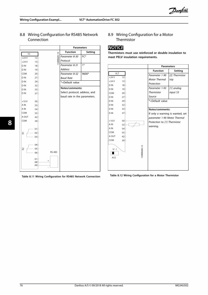
8.8 Wiring Configuration for RS485 NetworkConnection
Parameters
FC
+24 V
+24 V
D IN
D IN
D IN
COM
D IN
D IN
D IN
D IN
+10 V
A IN
A IN
COM
A OUT
COM
R1R2
12
13
18
19
20
27
29
32
33
37
50
53
54
55
42
39
01
02
03
04
05
06
-
616869
RS-485
+
130B
B685
.10 Function Setting
Parameter 8-30 Protocol
FC*
Parameter 8-31 Address
1*
Parameter 8-32 Baud Rate
9600*
*=Default value
Notes/comments:Select protocol, address, andbaud rate in the parameters.
Table 8.11 Wiring Configuration for RS485 Network Connection
8.9 Wiring Configuration for a MotorThermistor
NOTICEThermistors must use reinforced or double insulation tomeet PELV insulation requirements.
Parameters
130B
B686
.12
VLT
+24 V
+24 V
D IN
D IN
D IN
COM
D IN
D IN
D IN
+10 VA IN
A IN
COM
A OUT
COM
12
13
18
19
20
27
29
32
33
50
53
54
55
42
39
A53
U - I
D IN 37
Function Setting
Parameter 1-90 Motor ThermalProtection
[2] Thermistortrip
Parameter 1-93 ThermistorSource
[1] analoginput 53
*=Default value
Notes/comments:If only a warning is wanted, setparameter 1-90 Motor ThermalProtection to [1] Thermistorwarning.
Table 8.12 Wiring Configuration for a Motor Thermistor
Wiring Configuration Exampl... VLT® AutomationDrive FC 302
76 Danfoss A/S © 09/2018 All rights reserved. MG34U502
88
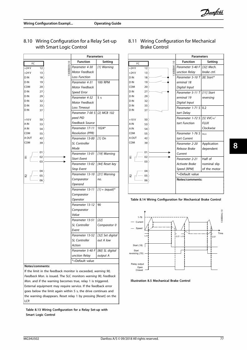
8.10 Wiring Configuration for a Relay Set-upwith Smart Logic Control
Parameters
FC
+24 V
+24 V
D IN
D IN
D IN
COM
D IN
D IN
D IN
D IN
+10 V
A IN
A IN
COM
A OUT
COM
R1R2
12
13
18
19
20
27
29
32
33
37
50
53
54
55
42
39
01
02
03
04
05
06
130B
B839
.10 Function Setting
Parameter 4-30 Motor FeedbackLoss Function
[1] Warning
Parameter 4-31 Motor FeedbackSpeed Error
100 RPM
Parameter 4-32 Motor FeedbackLoss Timeout
5 s
Parameter 7-00 Speed PIDFeedback Source
[2] MCB 102
Parameter 17-11 Resolution (PPR)
1024*
Parameter 13-00 SL ControllerMode
[1] On
Parameter 13-01 Start Event
[19] Warning
Parameter 13-02 Stop Event
[44] Reset key
Parameter 13-10 ComparatorOperand
[21] Warningno.
Parameter 13-11 ComparatorOperator
[1] ≈ (equal)*
Parameter 13-12 ComparatorValue
90
Parameter 13-51 SL ControllerEvent
[22]Comparator 0
Parameter 13-52 SL ControllerAction
[32] Set digitalout A low
Parameter 5-40 Function Relay
[80] SL digitaloutput A
*=Default value
Notes/comments:If the limit in the feedback monitor is exceeded, warning 90,Feedback Mon. is issued. The SLC monitors warning 90, FeedbackMon. and if the warning becomes true, relay 1 is triggered.External equipment may require service. If the feedback errorgoes below the limit again within 5 s, the drive continues andthe warning disappears. Reset relay 1 by pressing [Reset] on theLCP.
Table 8.13 Wiring Configuration for a Relay Set-up withSmart Logic Control
8.11 Wiring Configuration for MechanicalBrake Control
Parameters
FC
+24 V
+24 V
D IN
D IN
D IN
COM
D IN
D IN
D IN
D IN
+10 V
A IN
A IN
COM
A OUT
COM
R1R2
12
13
18
19
20
27
29
32
33
37
50
53
54
55
42
39
01
02
03
04
05
06
130B
B841
.10 Function Setting
Parameter 5-40 Function Relay
[32] Mech.brake ctrl.
Parameter 5-10 Terminal 18Digital Input
[8] Start*
Parameter 5-11 Terminal 19Digital Input
[11] Startreversing
Parameter 1-71 Start Delay
0.2
Parameter 1-72 Start Function
[5] VVC+/FLUXClockwise
Parameter 1-76 Start Current
Im,n
Parameter 2-20 Release BrakeCurrent
Applicationdependent
Parameter 2-21 Activate BrakeSpeed [RPM]
Half ofnominal slipof the motor
*=Default value
Notes/comments:
Table 8.14 Wiring Configuration for Mechanical Brake Control
Start (18)
Start reversing (19)
Relay output
Speed
Time
Current
1-71 1-712-21 2-21
1-76
OpenClosed
130B
B842
.10
Illustration 8.5 Mechanical Brake Control
Wiring Configuration Exampl... Operating Guide
MG34U502 Danfoss A/S © 09/2018 All rights reserved. 77
8 8

8.12 Wiring Configuration for the Encoder
The direction of the encoder, identified by looking into theshaft end, is determined by which order the pulses enterthe drive. See Illustration 8.6.
• Clockwise (CW) direction means channel A is 90electrical degrees before channel B.
• Counterclockwise (CCW) direction means channelB is 90 electrical degrees before A.
B
A
B
A
130B
A64
6.10
CW
CCW
Illustration 8.6 Determining Encoder Direction
NOTICEMaximum cable length 5 m (16 ft).
130B
A09
0.12
+24
V D
C
A B GN
D
1312 18 37322719 29 33 20
24 V or 10–30 V encoder
Illustration 8.7 Wire Configuration for the Encoder
Wiring Configuration Exampl... VLT® AutomationDrive FC 302
78 Danfoss A/S © 09/2018 All rights reserved. MG34U502
88

8.13 Wiring Configuration for Torque andStop Limit
In applications with an external electro-mechanical brake,such as hoisting applications, it is possible to stop thedrive via a standard stop command and simultaneouslyactivate the external electro-mechanical brake.Illustration 8.8 shows the programming of these driveconnections.
If a stop command is active via terminal 18 and the driveis not at the torque limit, the motor ramps down to 0 Hz.If the drive is at the torque limit and a stop command isactivated, the system activates terminal 29 output(programmed to [27] Torque limit & stop). The signal toterminal 27 changes from logic 1 to logic 0 and the motorstarts to coast. This process ensures that the hoist stopseven if the drive itself cannot handle the required torque,for example due to excessive overload.
To program the stop and torque limit, connect to thefollowing terminals:
• Start/stop via terminal 18(Parameter 5-10 Terminal 18 Digital Input [8] Start).
• Quick stop via terminal 27(Parameter 5-12 Terminal 27 Digital Input [2]Coasting Stop, Inverse).
• Terminal 29 output(Parameter 5-02 Terminal 29 Mode [1] Terminal 29Mode Output and parameter 5-31 Terminal 29Digital Output [27] Torque limit & stop).
• Relay output [0] (Relay 1)(Parameter 5-40 Function Relay [32] MechanicalBrake Control).
12 13 18 37322719 29 33 20
+24
V
P 5-
10 [8
]
P 5-
12 [2
]
P 5-
02 [1
]
P 5-
31 [2
7]
GN
D
P 5-40 [0] [32]
Relay 1 01 02 03
-
+
130B
A19
4.11
External
24 V DC
Mechanical brake
connection
Start
Imax 0.1 Amp
Illustration 8.8 Wire Configuration for Torque and Stop Limit
Wiring Configuration Exampl... Operating Guide
MG34U502 Danfoss A/S © 09/2018 All rights reserved. 79
8 8

9 Maintenance, Diagnostics, and Troubleshooting
This chapter includes:• Maintenance and service guidelines.
• Status messages.
• Warnings and alarms.
• Basic troubleshooting.
9.1 Maintenance and Service
Under normal operating conditions and load profiles, thedrive is maintenance-free throughout its designed lifetime.To prevent breakdown, danger, and damage, examine thedrive at regular intervals depending on the operatingconditions. Replace worn or damaged parts with originalspare parts or standard parts. For service and support, referto www.danfoss.com/en/contact-us/contacts-list/?filter=type%3Adanfoss-sales-service-center%2Csegments%3ADDS.
WARNINGUNINTENDED STARTWhen the drive is connected to AC mains, DC supply, orload sharing, the motor can start at any time.Unintended start during programming, service, or repairwork can result in death, serious injury, or propertydamage. The motor can start with an external switch, afieldbus command, an input reference signal from theLCP or LOP, via remote operation using MCT 10 Set-upSoftware, or after a cleared fault condition.
To prevent unintended motor start:• Press [Off/Reset] on the LCP before
programming parameters.
• Disconnect the drive from the mains.
• Completely wire and assemble the drive, motor,and any driven equipment before connectingthe drive to AC mains, DC supply, or loadsharing.
9.2 Heat Sink Access Panel
9.2.1 Removing the Heat Sink Access Panel
The drive can be ordered with an optional access panel inthe back of the unit. This panel provides access to the heatsink and allows the heat sink to be cleaned of any dustbuildup.
130B
D43
0.10
Illustration 9.1 Heat Sink Access Panel
NOTICEDAMAGE TO HEAT SINKUsing fasteners that are longer than those originallysupplied with the heat sink panel can damage the heatsink cooling fins.
1. Remove power from the drive and wait 20minutes for the capacitors to dischargecompletely. Refer to chapter 2 Safety.
2. Position the drive so that the back of the drive isaccessible.
3. Remove the screws (3 mm [0.12 in] internal hex)connecting the access panel to the back of theenclosure. There are 5 or 9 screws depending onthe size of the drive.
4. Inspect the heat sink for damage or dust buildup.
5. Remove dust and debris with a vacuum.
6. Replace the panel and secure it to the back ofthe enclosure with the screws previouslyremoved. Tighten the fasteners according to chapter 10.8 Fastener Tightening Torques.
Maintenance, Diagnostics, a... VLT® AutomationDrive FC 302
80 Danfoss A/S © 09/2018 All rights reserved. MG34U502
99

9.3 Status Messages
When the drive is in status mode, status messagesautomatically appear in the lowest line of the LCP display.Refer to Illustration 9.2. Status messages are defined inTable 9.1 – Table 9.3.
Status799RPM 7.83A 36.4kW
0.000
53.2%
1(1)
AutoHandO
RemoteLocal
RampingStopRunningJogging...Stand-by
130B
B037
.11
1
2
3
1 Where the stop/start command originates. Refer to Table 9.1.
2 Where the speed control originates. Refer to Table 9.2.
3 Provides the drive status. Refer to Table 9.3.
Illustration 9.2 Status Display
NOTICEIn auto/remote mode, the drive requires externalcommands to execute functions.
Table 9.1 to Table 9.3 define the meaning of the shownstatus messages.
Off The drive does not react to any control signaluntil [Auto On] or [Hand On] is pressed.
Auto The start/stop commands are sent via thecontrol terminals and/or the serial communi-cation.
Hand The navigation keys on the LCP can be usedto control the drive. Stop commands, reset,reversing, DC brake, and other signals appliedto the control terminals override local control.
Table 9.1 Operating Mode
Remote The speed reference is given from:
• External signals.
• Serial communication.
• Internal preset references.
Local The drive uses reference values from the LCP.
Table 9.2 Reference Site
AC brake AC brake was selected in parameter 2-10 BrakeFunction. The AC brake overmagnetizes themotor to achieve a controlled slow-down.
AMA finish OK Automatic motor adaptation (AMA) wascarried out successfully.
AMA ready AMA is ready to start. To start, press [HandOn].
AMA running AMA process is in progress.
Braking The brake chopper is in operation. The brakeresistor absorbs the generative energy.
Braking max. The brake chopper is in operation. The powerlimit for the brake resistor defined inparameter 2-12 Brake Power Limit (kW) hasbeen reached.
Coast • [2] Coast inverse was selected as a functionfor a digital input (parameter group 5-1*Digital Inputs). The corresponding terminalis not connected.
• Coast activated by serial communication.
Ctrl. ramp-down [1] Ctrl. ramp-down was selected inparameter 14-10 Mains Failure.
• The mains voltage is below the value setin parameter 14-11 Mains Fault Voltage Levelat mains fault.
• The drive ramps down the motor using acontrolled ramp-down.
Current high The drive output current is above the limit setin parameter 4-51 Warning Current High.
Current low The drive output current is below the limit setin parameter 4-52 Warning Speed Low.
DC hold DC hold is selected in parameter 1-80 Functionat Stop and a stop command is active. Themotor is held by a DC current set inparameter 2-00 DC Hold Current.
DC stop The motor is held with a DC current(parameter 2-01 DC Brake Current) for aspecified time (parameter 2-02 DC BrakingTime).
• DC brake is activated in parameter 2-03 DCBrake Cut In Speed [RPM] and a stopcommand is active.
• DC brake (inverse) is selected as a functionfor a digital input (parameter group 5-1*Digital Inputs). The corresponding terminalis not active.
• The DC brake is activated via serialcommunication.
Feedback high The sum of all active feedbacks is above thefeedback limit set in parameter 4-57 WarningFeedback High.
Feedback low The sum of all active feedbacks is below thefeedback limit set in parameter 4-56 WarningFeedback Low.
Maintenance, Diagnostics, a... Operating Guide
MG34U502 Danfoss A/S © 09/2018 All rights reserved. 81
9 9

Freeze output The remote reference, which holds the presentspeed, is active.
• [20] Freeze Output was selected as afunction for a digital input (parametergroup 5-1* Digital Inputs). Thecorresponding terminal is active. Speedcontrol is only possible via the terminalfunctions speed up and speed down.
• Hold ramp is activated via serial communi-cation.
Freeze outputrequest
A freeze output command has been given, butthe motor remains stopped until a runpermissive signal is received.
Freeze ref. [19] Freeze Reference was selected as afunction for a digital input (parameter group5-1* Digital Inputs). The corresponding terminalis active. The drive saves the actual reference.Changing the reference is now only possiblevia terminal functions speed up and speeddown.
Jog request A jog command has been given, but themotor is stopped until a run permissive signalis received via a digital input.
Jogging The motor is running as programmed inparameter 3-19 Jog Speed [RPM].
• [14] Jog was selected as function for adigital input (parameter group 5-1* DigitalInputs). The corresponding terminal (forexample, terminal 29) is active.
• The jog function is activated via the serialcommunication.
• The jog function was selected as a reactionfor a monitoring function (for example, Nosignal). The monitoring function is active.
Motor check In parameter 1-80 Function at Stop, [2] MotorCheck was selected. A stop command is active.To ensure that a motor is connected to thedrive, a permanent test current is applied tothe motor.
OVC control Overvoltage control was activated inparameter 2-17 Over-voltage Control, [2]Enabled. The connected motor is supplyingthe drive with generative energy. Theovervoltage control adjusts the V/Hz ratio torun the motor in controlled mode and toprevent the drive from tripping.
Power unit off (For drives with a 24 V DC external supplyinstalled only.) Mains supply to the drive isremoved, but the control card is supplied bythe 24 V DC external supply.
Protection md Protection mode is active. The unit hasdetected a critical status (an overcurrent orovervoltage).
• To avoid tripping, the switching frequencyis reduced to 1500 kHz ifparameter 14-55 Output Filter is set to [2]Sine-Wave Filter Fixed. Otherwise, theswitching frequency is reduced to 1000 Hz.
• If possible, protection mode ends afterapproximately 10 s.
• Protection mode can be restricted inparameter 14-26 Trip Delay at Inverter Fault.
QStop The motor is decelerating usingparameter 3-81 Quick Stop Ramp Time.
• [4] Quick stop inverse was selected as afunction for a digital input (parametergroup 5-1* Digital Inputs). Thecorresponding terminal is not active.
• The quick stop function was activated viaserial communication.
Ramping The motor is accelerating/decelerating usingthe active ramp up/down. The reference, alimit value, or a standstill is not yet reached.
Ref. high The sum of all active references is above thereference limit set in parameter 4-55 WarningReference High.
Ref. low The sum of all active references is below thereference limit set in parameter 4-54 WarningReference Low.
Run on ref. The drive is running in the reference range.The feedback value matches the setpointvalue.
Run request A start command has been given, but themotor is stopped until a run permissive signalis received via digital input.
Running The drive is driving the motor.
Sleep mode The energy saving function is enabled. Thisfunction being enabled means that the motorhas stopped, but that it restarts automaticallywhen required.
Speed high The motor speed is above the value set inparameter 4-53 Warning Speed High.
Speed low The motor speed is below the value set inparameter 4-52 Warning Speed Low.
Standby In auto-on mode, the drive starts the motorwith a start signal from a digital input or serialcommunication.
Start delay In parameter 1-71 Start Delay, a delay startingtime was set. A start command is activatedand the motor starts after the start delay timeexpires.
Maintenance, Diagnostics, a... VLT® AutomationDrive FC 302
82 Danfoss A/S © 09/2018 All rights reserved. MG34U502
99

Start fwd/rev [12] Enable Start Forward and [13] Enable StartReverse were selected as functions for 2different digital inputs (parameter group 5-1*Digital Inputs). The motor starts in forward orreverse depending on which correspondingterminal is activated.
Stop The drive has received a stop command from1 of the following:
• LCP.
• Digital input.
• Serial communication.
Trip An alarm occurred and the motor is stopped.Once the cause of the alarm is cleared, resetthe drive using 1 of the following:
• Pressing [Reset].
• Remotely by control terminals.
• Via serial communication.
Pressing [Reset] or remotely by controlterminals or via serial communication.
Trip lock An alarm occurred and the motor is stopped.Once the cause of the alarm is cleared, cyclepower to the drive. Reset the drive manuallyby 1 of the following:
• Pressing [Reset].
• Remotely by control terminals.
• Via serial communication.
Table 9.3 Operation Status
9.4 Warning and Alarm Types
The drive software issues warnings and alarms to helpdiagnose issues. The warning or alarm number appears inthe LCP.
WarningA warning indicates that the drive has encountered anabnormal operating condition that leads to an alarm. Awarning stops when the abnormal condition is removed orresolved.
AlarmAn alarm indicates a fault that requires immediateattention. The fault always triggers a trip or trip lock. Resetthe drive after an alarm.Reset the drive in any of 4 ways:
• Press [Reset]/[Off/Reset].
• Digital reset input command.
• Serial communication reset input command.
• Auto reset.
TripWhen tripping, the drive suspends operation to preventdamage to the drive and other equipment. When a tripoccurs, the motor coasts to a stop. The drive logiccontinues to operate and monitor the drive status. Afterthe fault condition is remedied, the drive is ready for areset.
Trip lockWhen trip locking, the drive suspends operation to preventdamage to the drive and other equipment. When a triplock occurs, the motor coasts to a stop. The drive logiccontinues to operate and monitor the drive status. Thedrive starts a trip lock only when serious faults occur thatcan damage the drive or other equipment. After the faultsare fixed, cycle the input power before resetting the drive.
Warning and alarm displays
• A warning is shown in the LCP along with thewarning number.
• An alarm flashes along with the alarm number.
130B
P086
.12
Status0.0Hz 0.000kW 0.00A
0.0Hz0
Earth Fault [A14]Auto Remote Trip
1(1)
Illustration 9.3 Alarm Example
In addition to the text and alarm code in the LCP, there are3 status indicator lights.
Back
CancelInfoOKOn
Alarm
Warn.
130B
B467
.11
Warning indicator light Alarm indicator light
Warning On Off
Alarm Off On (flashing)
Trip lock On On (flashing)
Illustration 9.4 Status Indicator Lights
Maintenance, Diagnostics, a... Operating Guide
MG34U502 Danfoss A/S © 09/2018 All rights reserved. 83
9 9

9.5 List of Warnings and Alarms
The following warning and alarm information defines eachwarning or alarm condition, provides the probable causefor the condition, and details a remedy or troubleshootingprocedure.
WARNING 1, 10 Volts lowThe control card voltage is less than 10 V from terminal 50.Remove some of the load from terminal 50, as the 10 Vsupply is overloaded. Maximum 15 mA or minimum 590 Ω.
A short circuit in a connected potentiometer or incorrectwiring of the potentiometer can cause this condition.
Troubleshooting• Remove the wiring from terminal 50. If the
warning clears, the problem is with the wiring. Ifthe warning does not clear, replace the controlcard.
WARNING/ALARM 2, Live zero errorThis warning or alarm only appears if programmed inparameter 6-01 Live Zero Timeout Function. The signal on 1of the analog inputs is less than 50% of the minimumvalue programmed for that input. Broken wiring or a faultydevice sending the signal can cause this condition.
Troubleshooting• Check connections on all analog mains terminals.
- Control card terminals 53 and 54 forsignals, terminal 55 common.
- VLT® General Purpose I/O MCB 101terminals 11 and 12 for signals, terminal10 common.
- VLT® Analog I/O Option MCB 109terminals 1, 3, and 5 for signals,terminals 2, 4, and 6 common.
• Check that the drive programming and switchsettings match the analog signal type.
• Perform an input terminal signal test.
WARNING/ALARM 3, No motorNo motor has been connected to the output of the drive.This warning or alarm appears only if programmed inparameter 1-80 Function at Stop.
Troubleshooting
• Check the connection between the drive and themotor.
WARNING/ALARM 4, Mains phase lossA phase is missing on the supply side, or the mainsvoltage imbalance is too high. This message also appearsfor a fault in the input rectifier. Options are programmed inparameter 14-12 Response to Mains Imbalance.
Troubleshooting• Check the supply voltage and supply currents to
the drive.
WARNING 5, DC link voltage highThe DC-link voltage (DC) is higher than the high-voltagewarning limit. The limit depends on the drive voltagerating. The unit is still active.
WARNING 6, DC link voltage lowThe DC-link voltage (DC) is lower than the low-voltagewarning limit. The limit depends on the drive voltagerating. The unit is still active.
WARNING/ALARM 7, DC overvoltageIf the DC-link voltage exceeds the limit, the drive trips aftera certain time.
Troubleshooting• Connect a brake resistor.
• Extend the ramp time.
• Change the ramp type.
• Activate the functions in parameter 2-10 BrakeFunction.
• Increase parameter 14-26 Trip Delay at InverterFault.
• If the alarm/warning occurs during a power sag,use kinetic back-up (parameter 14-10 MainsFailure).
WARNING/ALARM 8, DC under voltageIf the DC-link voltage drops below the undervoltage limit,the drive checks for 24 V DC back-up supply. If no 24 V DCback-up supply is connected, the drive trips after a fixedtime delay. The time delay varies with unit size.
Troubleshooting• Check that the supply voltage matches the drive
voltage.
• Perform an input voltage test.
• Perform a soft-charge circuit test.
WARNING/ALARM 9, Inverter overloadThe drive has run with more than 100% overload for toolong and is about to cut out. The counter for electronicthermal inverter protection issues a warning at 98% andtrips at 100% with an alarm. The drive cannot be resetuntil the counter is below 90%.
Troubleshooting• Compare the output current shown on the LCP
with the drive rated current.
• Compare the output current shown on the LCPwith the measured motor current.
• Show the thermal drive load on the LCP andmonitor the value. When running above the drivecontinuous current rating, the counter increases.When running below the drive continuouscurrent rating, the counter decreases.
WARNING/ALARM 10, Motor overload temperatureAccording to the electronic thermal protection (ETR), themotor is too hot.
Maintenance, Diagnostics, a... VLT® AutomationDrive FC 302
84 Danfoss A/S © 09/2018 All rights reserved. MG34U502
99

Select 1 of these options:• The drive issues a warning or an alarm when the
counter is >90% if parameter 1-90 Motor ThermalProtection is set to warning options.
• The drive trips when the counter reaches 100% ifparameter 1-90 Motor Thermal Protection is set totrip options.
The fault occurs when the motor runs with more than100% overload for too long.
Troubleshooting• Check for motor overheating.
• Check if the motor is mechanically overloaded.
• Check that the motor current set inparameter 1-24 Motor Current is correct.
• Ensure that the motor data in parameters 1-20 to1-25 is set correctly.
• If an external fan is in use, check that it isselected in parameter 1-91 Motor External Fan.
• Running AMA in parameter 1-29 Automatic MotorAdaptation (AMA) tunes the drive to the motormore accurately and reduces thermal loading.
WARNING/ALARM 11, Motor thermistor overtempCheck whether the thermistor is disconnected. Selectwhether the drive issues a warning or an alarm inparameter 1-90 Motor Thermal Protection.
Troubleshooting• Check for motor overheating.
• Check if the motor is mechanically overloaded.
• When using terminal 53 or 54, check that thethermistor is connected correctly between eitherterminal 53 or 54 (analog voltage input) andterminal 50 (+10 V supply). Also check that theterminal switch for 53 or 54 is set for voltage.Check that parameter 1-93 Thermistor Resourceselects terminal 53 or 54.
• When using terminal 18, 19, 31, 32, or 33 (digitalinputs), check that the thermistor is connectedcorrectly between the digital input terminal used(digital input PNP only) and terminal 50. Selectthe terminal to use in parameter 1-93 ThermistorResource.
WARNING/ALARM 12, Torque limitThe torque has exceeded the value inparameter 4-16 Torque Limit Motor Mode or the value inparameter 4-17 Torque Limit Generator Mode.Parameter 14-25 Trip Delay at Torque Limit can change thiswarning from a warning-only condition to a warningfollowed by an alarm.
Troubleshooting• If the motor torque limit is exceeded during
ramp-up, extend the ramp-up time.
• If the generator torque limit is exceeded duringramp-down, extend the ramp-down time.
• If torque limit occurs while running, increase thetorque limit. Make sure that the system canoperate safely at a higher torque.
• Check the application for excessive current drawon the motor.
WARNING/ALARM 13, Over currentThe inverter peak current limit (approximately 200% of therated current) is exceeded. The warning lasts approximately1.5 s, then the drive trips and issues an alarm. Shockloading or quick acceleration with high-inertia loads cancause this fault. If the acceleration during ramp-up is quick,the fault can also appear after kinetic back-up.If extended mechanical brake control is selected, a trip canbe reset externally.
Troubleshooting• Remove power to the drive.
• Check that the motor shaft can be turned.
• Check that the motor size matches the drive.
• Check that the motor data is correct inparameters 1-20 to 1-25.
• For parallel drive systems, check for output cableimbalances in size and length between phasesand between drive modules.
ALARM 14, Earth (ground) faultThere is current from the output phase to ground, either inthe cable between the drive and the motor, or in themotor itself. The current transducers detect the groundfault by measuring current going out from the drive andcurrent going into the drive from the motor. Ground faultis issued if the deviation of the 2 currents is too large. Thecurrent going out of the drive must be the same as thecurrent going into the drive.
Troubleshooting• Remove power to the drive and repair the ground
fault.
• Check for ground faults in the motor bymeasuring the resistance to ground of the motorcables and the motor with a megohmmeter.
• Reset any potential individual offset in the 3current transducers in the drive. Perform themanual initialization or perform a complete AMA.This method is most relevant after changing thepower card.
ALARM 15, Hardware mismatchA fitted option is not operational with the present controlcard hardware or software.
Maintenance, Diagnostics, a... Operating Guide
MG34U502 Danfoss A/S © 09/2018 All rights reserved. 85
9 9

Record the value of the following parameters and contactDanfoss.
• Parameter 15-40 FC Type.
• Parameter 15-41 Power Section.
• Parameter 15-42 Voltage.
• Parameter 15-43 Software Version.
• Parameter 15-45 Actual Typecode String.
• Parameter 15-49 SW ID Control Card.
• Parameter 15-50 SW ID Power Card.
• Parameter 15-60 Option Mounted.
• Parameter 15-61 Option SW Version (for eachoption slot).
There is short-circuiting in the motor or motor wiring.
WARNINGHIGH VOLTAGEDrives contain high voltage when connected to AC mainsinput, DC supply, or load sharing. Failure to performinstallation, start-up, and maintenance by qualifiedpersonnel can result in death or serious injury.
ALARM 16, Short circuit
Troubleshooting• Remove the power to the drive and repair the
short circuit.
• Check that the drive contains the correct currentscaling card and the correct number of currentscaling cards for the system.
WARNING/ALARM 17, Control word timeoutThere is no communication to the drive.The warning is only active when parameter 8-04 ControlWord Timeout Function is NOT set to [0] Off.If parameter 8-04 Control Word Timeout Function is set to [5]Stop and trip, a warning appears, and the drive rampsdown to a stop and shows an alarm.
Troubleshooting• Check the connections on the serial communi-
cation cable.
• Increase parameter 8-03 Control Word TimeoutTime.
• Check the operation of the communicationequipment.
• Verify that proper EMC installation wasperformed.
WARNING/ALARM 20, Temp. input errorThe temperature sensor is not connected.
WARNING/ALARM 21, Parameter errorThe parameter is out of range. The parameter number isshown in the display.
Troubleshooting• Set the affected parameter to a valid value.
WARNING/ALARM 22, Hoist mechanical brakeThe value of this warning/alarm indicates the cause:.0 = The torque reference was not reached before timeout(parameter 2-27 Torque Ramp Up Time).1 = Expected brake feedback was not received beforetimeout (parameter 2-23 Activate Brake Delay,parameter 2-25 Brake Release Time).
WARNING 23, Internal fan faultThe fan warning function is a protective function thatchecks if the fan is running/mounted. The fan warning canbe disabled in parameter 14-53 Fan Monitor ([0] Disabled).
There is a feedback sensor mounted in the fan. If the fan iscommanded to run and there is no feedback from thesensor, this alarm appears. This alarm also shows if there isa communication error between the fan power card andthe control card.
Check the alarm log for the report value associated withthis warning.
If the report value is 2, there is a hardware problem with 1of the fans. If the report value is 12, there is a communi-cation problem between the fan power card and thecontrol card.
Fan troubleshooting• Cycle power to the drive and check that the fan
operates briefly at start-up.
• Check for proper fan operation. Use parametergroup 43-** Unit Readouts to show the speed ofeach fan.
Fan power card troubleshooting• Check the wiring between the fan power card
and the control card.
• Fan power card may need to be replaced.
• Control card may need to be replaced.
WARNING 24, External fan faultThe fan warning function is a protective function thatchecks if the fan is running/mounted. The fan warning canbe disabled in parameter 14-53 Fan Monitor ([0] Disabled).
A feedback sensor is mounted in the fan. If the fan iscommanded to run and there is no feedback from thesensor, this alarm appears. This alarm also shows if there isa communication error between the power card and thecontrol card.
Check the alarm log for the report value associated withthis warning.
If the report value is 1, there is a hardware problem with 1of the fans. If the report value is 11, there is a communi-cation problem between the power card and the controlcard.
Maintenance, Diagnostics, a... VLT® AutomationDrive FC 302
86 Danfoss A/S © 09/2018 All rights reserved. MG34U502
99

Fan troubleshooting• Cycle power to the drive and check that the fan
operates briefly at start-up.
• Check for proper fan operation. Use parametergroup 43-** Unit Readouts to show the speed ofeach fan.
Power card troubleshooting• Check the wiring between the power card and
the control card.
• Power card may need to be replaced.
• Control card may need to be replaced.
WARNING 25, Brake resistor short circuitThe brake resistor is monitored during operation. If a shortcircuit occurs, the brake function is disabled and thewarning appears. The drive is still operational, but withoutthe brake function.
Troubleshooting• Remove the power to the drive and replace the
brake resistor (refer to parameter 2-15 BrakeCheck).
• In parallel drive systems, check the brake parallelconnections.
WARNING/ALARM 26, Brake resistor power limitThe power transmitted to the brake resistor is calculated asa mean value over the last 120 s of run-time. Thecalculation is based on the DC-link voltage and the brakeresistor value set in parameter 2-16 AC brake Max. Current.The warning is active when the dissipated braking poweris higher than 90% of the brake resistor power. If option [2]Trip is selected in parameter 2-13 Brake Power Monitoring,the drive trips when the dissipated braking power reaches100%.
The brake transistor is monitored during operation, and if ashort circuit occurs, the brake function is disabled, and awarning is issued. The drive is still operational, but sincethe brake transistor has short-circuited, substantial poweris transmitted to the brake resistor, even if it is inactive.
WARNINGOVERHEATING RISKA surge in power can cause the brake resistor tooverheat and possibly catch fire. Failure to remove powerto the drive and remove the brake resistor can causeequipment damage.
Troubleshooting• Remove power to the drive.
• Remove the brake resistor.
• Troubleshoot the short circuit.
WARNING/ALARM 28, Brake check failedThe brake resistor is not connected or not working.
Troubleshooting• Check parameter 2-15 Brake Check.
ALARM 29, Heat sink tempThe maximum temperature of the heat sink has beenexceeded. The temperature fault does not reset until thetemperature drops below a defined heat sink temperature.The trip and reset points are different based on the drivepower size.
TroubleshootingCheck for the following conditions:
• Ambient temperature too high.
• Motor cable too long.
• Incorrect airflow clearance above and below thedrive.
• Blocked airflow around the drive.
• Damaged heat sink fan.
• Dirty heat sink.
For drives in enclosure sizes D and E, this alarm is basedon the temperature measured by the heat sink sensormounted inside the IGBT modules.
Troubleshooting• Check fan resistance.
• Check soft charge fuses.
• Check IGBT thermal.
ALARM 30, Motor phase U missingMotor phase U between the drive and the motor ismissing.
WARNINGHIGH VOLTAGEDrives contain high voltage when connected to AC mainsinput, DC supply, or load sharing. Failure to performinstallation, start-up, and maintenance by qualifiedpersonnel can result in death or serious injury.
• Only qualified personnel must perform instal-lation, start-up, and maintenance.
• Before performing any service or repair work,use an appropriate voltage measuring device tomake sure that there is no remaining voltage onthe drive.
Troubleshooting• Remove the power from the drive and check
motor phase U.
ALARM 31, Motor phase V missingMotor phase V between the drive and the motor ismissing.
Maintenance, Diagnostics, a... Operating Guide
MG34U502 Danfoss A/S © 09/2018 All rights reserved. 87
9 9

WARNINGHIGH VOLTAGEDrives contain high voltage when connected to AC mainsinput, DC supply, or load sharing. Failure to performinstallation, start-up, and maintenance by qualifiedpersonnel can result in death or serious injury.
• Only qualified personnel must perform instal-lation, start-up, and maintenance.
• Before performing any service or repair work,use an appropriate voltage measuring device tomake sure that there is no remaining voltage onthe drive.
Troubleshooting• Remove the power from the drive and check
motor phase V.
ALARM 32, Motor phase W missingMotor phase W between the drive and the motor ismissing.
WARNINGHIGH VOLTAGEDrives contain high voltage when connected to AC mainsinput, DC supply, or load sharing. Failure to performinstallation, start-up, and maintenance by qualifiedpersonnel can result in death or serious injury.
• Only qualified personnel must perform instal-lation, start-up, and maintenance.
• Before performing any service or repair work,use an appropriate voltage measuring device tomake sure that there is no remaining voltage onthe drive.
Troubleshooting• Remove the power from the drive and check
motor phase W.
ALARM 33, Inrush faultToo many power-ups have occurred within a short timeperiod.
Troubleshooting• Let the unit cool to operating temperature.
• Check potential DC-link fault to ground.
WARNING/ALARM 34, Fieldbus communication faultThe fieldbus on the communication option card is notworking.
WARNING/ALARM 35, Option faultAn option alarm is received. The alarm is option-specific.The most likely cause is a power-up or a communicationfault.
WARNING/ALARM 36, Mains failureThis warning/alarm is only active if the supply voltage tothe drive system is lost and parameter 14-10 Mains Failureis not set to option [0] No Function.
• Check the fuses to the drive system and themains supply to the unit.
• Check that mains voltage conforms to productspecifications.
• Check that the following conditions are notpresent:Alarm 307, Excessive THD(V), alarm 321, Voltageimbalance, warning 417, Mains undervoltage, orwarning 418, Mains overvoltage is reported if anyof the listed conditions are true:
- The 3-phase voltage magnitude dropsbelow 25% of the nominal mainsvoltage.
- Any single-phase voltage exceeds 10%of the nominal mains voltage.
- Percent of phase or magnitudeimbalance exceeds 8%.
- Voltage THD exceeds 10%.
ALARM 37, Phase imbalanceThere is a current imbalance between the power units.
ALARM 38, Internal faultWhen an internal fault occurs, a code number defined inTable 9.4 is shown.
Troubleshooting• Cycle power.
• Check that the option is properly installed.
• Check for loose or missing wiring.
It may be necessary to contact the Danfoss supplier orservice department. Note the code number for furthertroubleshooting directions.
Number Text
0 The serial port cannot be initialized. Contact theDanfoss supplier or Danfoss Service Department.
256–259,266, 268
The power EEPROM data is defective or too old.Replace the power card.
512–519 Internal fault. Contact the Danfoss supplier orDanfoss Service Department.
783 Parameter value outside of minimum/maximumlimits.
1024–1284 Internal fault. Contact the Danfoss supplier orDanfoss Service Department.
1299 The option SW in slot A is too old.
1300 The option SW in slot B is too old.
1301 The option SW in slot C0 is too old.
1302 The option SW in slot C1 is too old.
1315 The option SW in slot A is not supported (notallowed).
Maintenance, Diagnostics, a... VLT® AutomationDrive FC 302
88 Danfoss A/S © 09/2018 All rights reserved. MG34U502
99

Number Text
1316 The option SW in slot B is not supported (notallowed).
1317 The option SW in slot C0 is not supported (notallowed).
1318 The option SW in slot C1 is not supported (notallowed).
1360–2819 Internal fault. Contact the Danfoss supplier orDanfoss Service Department.
2561 Replace control card.
2820 LCP stack overflow.
2821 Serial port overflow.
2822 USB port overflow.
3072–5122 Parameter value is outside its limits.
5123 Option in slot A: Hardware incompatible withcontrol board hardware.
5124 Option in slot B: Hardware incompatible withcontrol board hardware.
5125 Option in slot C0: Hardware incompatible withcontrol board hardware.
5126 Option in slot C1: Hardware incompatible withcontrol board hardware.
5127 Illegal option combination (2 options of the samekind mounted, or encoder in E0 and resolver in E1or similar).
5168 Safe stop/safe torque off was detected on acontrol card that does not have safe stop/safetorque off.
5376–65535 Internal fault. Contact the Danfoss supplier orDanfoss Service Department.
Table 9.4 Internal Fault Codes
ALARM 39, Heat sink sensorNo feedback from the heat sink temperature sensor.
The signal from the IGBT thermal sensor is not available onthe power card.
Troubleshooting• Check the ribbon cable between the power card
and gatedrive card.
• Check for a defective power card.
• Check for a defective gatedrive card.
WARNING 40, Overload of digital output terminal 27Check the load connected to terminal 27 or remove theshort-circuit connection. Check parameter 5-00 Digital I/OMode and parameter 5-01 Terminal 27 Mode.
WARNING 41, Overload of digital output terminal 29Check the load connected to terminal 29 or remove theshort-circuit connection. Also check parameter 5-00 DigitalI/O Mode and parameter 5-02 Terminal 29 Mode.
WARNING 42, Overload of digital output on X30/6 oroverload of digital output on X30/7For terminal X30/6, check the load connected to terminalX30/6 or remove the short-circuit connection. Also checkparameter 5-32 Term X30/6 Digi Out (MCB 101) (VLT®
General Purpose I/O MCB 101).
For terminal X30/7, check the load connected to terminalX30/7 or remove the short-circuit connection. Checkparameter 5-33 Term X30/7 Digi Out (MCB 101) (VLT®
General Purpose I/O MCB 101).
ALARM 43, Ext. supplyVLT® Extended Relay Option MCB 113 is mounted withoutexternal 24 V DC. Either connect a 24 V DC external supplyor specify that no external supply is used viaparameter 14-80 Option Supplied by External 24VDC, [0] No.A change in parameter 14-80 Option Supplied by External24VDC requires a power cycle.
ALARM 45, Earth fault 2Ground fault.
Troubleshooting• Check for proper grounding and loose
connections.
• Check for proper wire size.
• Check the motor cables for short circuits orleakage currents.
ALARM 46, Power card supplyThe supply on the power card is out of range.
There are 4 supplies generated by the switch mode powersupply on the power card:
• 48 V.
• 24 V.
• 5 V.
• ±18 V.
When powered with VLT® 24 V DC Supply MCB 107, onlythe 24 V and 5 V supplies are monitored. When poweredwith 3-phase mains voltage, all 4 supplies are monitored.
Troubleshooting• Check for a defective power card.
• Check for a defective control card.
• Check for a defective option card.
• If a 24 V DC supply is used, verify proper supplypower.
• Check D-sized drives for a defective heat sink fan,top fan, or door fan.
• Check E-sized drives for a defective mixing fan.
WARNING 47, 24 V supply lowThe supply on the power card is out of range.
There are 4 supplies generated by the switch mode supply(SMPS) on the power card:
Maintenance, Diagnostics, a... Operating Guide
MG34U502 Danfoss A/S © 09/2018 All rights reserved. 89
9 9

• 48 V.
• 24 V.
• 5 V.
• ±18 V.
Troubleshooting• Check for a defective power card.
WARNING 48, 1.8 V supply lowThe 1.8 V DC supply used on the control card is outside ofthe allowable limits. The supply is measured on the controlcard.
Troubleshooting• Check for a defective control card.
• If an option card is present, check forovervoltage.
WARNING 49, Speed limitThe warning is shown when the speed is outside of thespecified range in parameter 4-11 Motor Speed Low Limit[RPM] and parameter 4-13 Motor Speed High Limit [RPM].When the speed is below the specified limit inparameter 1-86 Trip Speed Low [RPM] (except when startingor stopping), the drive trips.
ALARM 50, AMA calibration failedContact the Danfoss supplier or Danfoss servicedepartment.
ALARM 51, AMA check Unom and Inom
The settings for motor voltage, motor current, and motorpower are wrong.
Troubleshooting• Check the settings in parameters 1-20 to 1-25.
ALARM 52, AMA low Inom
The motor current is too low.
Troubleshooting• Check the settings in parameter 1-24 Motor
Current.
ALARM 53, AMA motor too bigThe motor is too large for the AMA to operate.
ALARM 54, AMA motor too smallThe motor is too small for the AMA to operate.
ALARM 55, AMA parameter out of rangeThe AMA cannot run because the parameter values of themotor are outside of the acceptable range.
ALARM 56, AMA interrupted by userThe AMA is manually interrupted.
ALARM 57, AMA internal faultTry to restart the AMA. Repeated restarts can overheat themotor.
ALARM 58, AMA Internal faultContact the Danfoss supplier.
WARNING 59, Current limitThe current is higher than the value inparameter 4-18 Current Limit. Ensure that the motor data inparameters 1-20 to 1-25 is set correctly. Increase the currentlimit if necessary. Ensure that the system can operate safelyat a higher limit.
WARNING 60, External interlockA digital input signal indicates a fault condition external tothe drive. An external interlock has commanded the driveto trip. Clear the external fault condition. To resumenormal operation, apply 24 V DC to the terminalprogrammed for external interlock, and reset the drive.
WARNING/ALARM 61, Feedback errorAn error is detected between calculated speed and speedmeasurement from feedback device.
Troubleshooting• Check the settings for warning/alarm/disabling in
parameter 4-30 Motor Feedback Loss Function.
• Set the tolerable error in parameter 4-31 MotorFeedback Speed Error.
• Set the tolerable feedback loss time inparameter 4-32 Motor Feedback Loss Timeout.
WARNING 62, Output frequency at maximum limitIf the output frequency reaches the value set inparameter 4-19 Max Output Frequency, the drive issues awarning. The warning ceases when the output dropsbelow the maximum limit. If the drive is unable to limitthe frequency, it trips and issues an alarm. The latter mayhappen in the flux mode if the drive loses control of themotor.
Troubleshooting• Check the application for possible causes.
• Increase the output frequency limit. Ensure thatthe system can operate safely at a higher outputfrequency.
ALARM 63, Mechanical brake lowThe actual motor current has not exceeded the releasebrake current within the start delay time window.
WARNING 64, Voltage limitThe combination of load and speed requires a motorvoltage higher than the actual DC-link voltage.
WARNING/ALARM 65, Control card over temperatureThe cutout temperature of the control card is 85 °C(185 °F).
Troubleshooting• Check that the ambient operating temperature is
within the limits.
• Check for clogged filters.
• Check the fan operation.
• Check the control card.
Maintenance, Diagnostics, a... VLT® AutomationDrive FC 302
90 Danfoss A/S © 09/2018 All rights reserved. MG34U502
99

WARNING 66, Heat sink temperature lowThe drive is too cold to operate. This warning is based onthe temperature sensor in the IGBT module. Increase theambient temperature of the unit. Also, a trickle amount ofcurrent can be supplied to the drive whenever the motoris stopped by setting parameter 2-00 DC Hold/PreheatCurrent to 5% and parameter 1-80 Function at Stop.
ALARM 67, Option module configuration has changedOne or more options have either been added or removedsince the last power-down. Check that the configurationchange is intentional and reset the unit.
ALARM 68, Safe Stop activatedSafe Torque Off (STO) has been activated. To resumenormal operation, apply 24 V DC to terminal 37, then senda reset signal (via bus, digital I/O, or by pressing [Reset]).
ALARM 69, Power card temperatureThe temperature sensor on the power card is either toohot or too cold.
Troubleshooting• Check that the ambient operating temperature is
within limits.
• Check for clogged filters.
• Check fan operation.
• Check the power card.
ALARM 70, Illegal FC configurationThe control card and power card are incompatible. Tocheck compatibility, contact the Danfoss supplier with thetype code from the unit nameplate and the part numbersof the cards.
WARNING/ALARM 71, PTC 1 Safe StopSafe Torque Off (STO) has been activated from the VLT®
PTC Thermistor Card MCB 112 because the motor is toowarm. Once the motor cools and the digital input from theMCB 112 is deactivated, normal operation can resumewhen the MCB 112 applies 24 V DC to terminal 37 again.When the motor is ready for normal operation, a resetsignal is sent (via serial communication, digital I/O, or bypressing [Reset] on the LCP). If automatic restart isenabled, the motor can start when the fault is cleared.
ALARM 72, Dangerous failure
STO with trip lock. An unexpected combination of STOcommands has occurred:
• VLT® PTC Thermistor Card MCB 112 enablesX44/10, but STO is not enabled.
• MCB 112 is the only device using STO (specifiedthrough selection [4] PTC 1 alarm or [5] PTC 1warning in parameter 5-19 Terminal 37 Safe Stop),STO is activated, and X44/10 is not activated.
WARNING 73, Safe Stop auto restartSafe Torque Off (STO) activated. With automatic restartenabled, the motor can start when the fault is cleared.
ALARM 74, PTC ThermistorAlarm related to VLT® PTC Thermistor Card MCB 112. ThePTC is not working.
ALARM 75, Illegal profile sel.Do not write the parameter value while the motor isrunning. Stop the motor before writing the MCO profile toparameter 8-10 Control Word Profile.
WARNING 76, Power unit setupThe required number of power units does not match thedetected number of active power units. If the power cardconnection is lost, the unit also triggers this warning.
Troubleshooting• Confirm that the spare part and its power card
are the correct part number.
• Ensure that the 44-pin cables between the MDCICand power cards are mounted properly.
WARNING 77, Reduced power modeThis alarm applies to only multi-drive systems. The systemis operating in reduced power mode (fewer than theallowed number of drive modules). This warning isgenerated on power cycle when the system is set to runwith fewer drive modules and remains on.
ALARM 78, Tracking errorThe difference between setpoint value and actual valueexceeds the value in parameter 4-35 Tracking Error.
Troubleshooting• Disable the function or select an alarm/warning
in parameter 4-34 Tracking Error Function.
• Investigate the mechanics around the load andmotor. Check feedback connections from motorencoder to drive.
• Select motor feedback function inparameter 4-30 Motor Feedback Loss Function.
• Adjust the tracking error band inparameter 4-35 Tracking Error andparameter 4-37 Tracking Error Ramping.
ALARM 79, Illegal power section configurationThe scaling card has an incorrect part number or is notinstalled. Also, the MK101 connector on the power cardcould not be installed.
ALARM 80, Drive initialised to default valueParameter settings are initialized to default settings after amanual reset. To clear the alarm, reset the unit.
ALARM 81, CSIV corruptCSIV file has syntax errors.
ALARM 82, CSIV parameter errorCSIV failed to initialize a parameter.
ALARM 83, Illegal option combinationThe mounted options are incompatible.
ALARM 84, No safety optionThe safety option was removed without applying a generalreset. Reconnect the safety option.
Maintenance, Diagnostics, a... Operating Guide
MG34U502 Danfoss A/S © 09/2018 All rights reserved. 91
9 9

ALARM 88, Option detectionA change in the option layout is detected.Parameter 14-89 Option Detection is set to [0] Frozen config-uration and the option layout has been changed.
• To apply the change, enable option layoutchanges in parameter 14-89 Option Detection.
• Alternatively, restore the correct option configu-ration.
WARNING 89, Mechanical brake slidingThe hoist brake monitor detects a motor speed exceeding10 RPM.
ALARM 90, Feedback monitorCheck the connection to encoder/resolver option and, ifnecessary, replace VLT® Encoder Input MCB 102 or VLT®
Resolver Input MCB 103.
ALARM 91, Analog input 54 wrong settingsSet switch S202 in position OFF (voltage input) when aKTY sensor is connected to analog input terminal 54.
ALARM 96, Start delayedThe motor start has been delayed due to short-cycleprotection. Parameter 22-76 Interval between Starts isenabled.
Troubleshooting• Troubleshoot the system and reset the drive after
clearing the fault.
WARNING 97, Stop delayedStopping the motor has been delayed because the motorhas been running for less than the minimum time specifiedin parameter 22-77 Minimum Run Time.
WARNING 98, Clock faultTime is not set, or the RTC clock has failed. Reset the clockin parameter 0-70 Date and Time.
ALARM 99, Locked rotorThe rotor is blocked.
WARNING/ALARM 104, Mixing fan faultThe fan is not operating. The fan monitor checks that thefan is spinning at power-up or whenever the mixing fan isturned on. The mixing-fan fault can be configured as awarning or an alarm trip in parameter 14-53 Fan Monitor.
Troubleshooting• Cycle power to the drive to determine if the
warning/alarm returns.
WARNING/ALARM 122, Mot. rotat. unexp.The drive performs a function that requires the motor tobe at standstill, for example DC hold for PM motors.
ALARM 144, Inrush SupplyA supply voltage on the inrush card is out of range. Seethe bit field result report value for more details.
• Bit 2: Vcc high.
• Bit 3: Vcc low.
• Bit 4: Vdd high.
• Bit 5: Vdd low.
ALARM 145, External SCR disableThe alarm indicates a series DC-link capacitor voltageimbalance.
WARNING/ALARM 146, Mains voltageMains voltage is outside valid operating range. Thefollowing report values provide more details.
• Voltage too low: 0=R-S, 1=S-T, 2=T-R
• Voltage too high: 3=R-S, 4=S-T, 5=T-R
WARNING/ALARM 147, Mains frequencyMains frequency is outside valid operating range. Reportvalue provides more details.
• 0: frequency too low.
• 1: frequency too high.
WARNING/ALARM 148, System tempOne or more of the system temperature measurements istoo high.
WARNING 163, ATEX ETR cur.lim.warningThe drive has run above the characteristic curve for morethan 50 s. The warning is activated at 83% and deactivatedat 65% of the allowed thermal overload.
ALARM 164, ATEX ETR cur.lim.alarmOperating above the characteristic curve for more than60 s within a period of 600 s activates the alarm, and thedrive trips.
WARNING 165, ATEX ETR freq.lim.warningThe drive is running for more than 50 s below the allowedminimum frequency (parameter 1-98 ATEX ETR interpol.points freq.).
ALARM 166, ATEX ETR freq.lim.alarmThe drive has operated for more than 60 s (in a period of600 s) below the allowed minimum frequency(parameter 1-98 ATEX ETR interpol. points freq.).
WARNING 200, Fire modeThe drive is operating in fire mode. The warning clearswhen fire mode is removed. Refer to the fire mode data inthe alarm log.
WARNING 201, Fire mode was activeThe drive has entered fire mode. Cycle power to the unitto remove the warning. Refer to the fire mode data in thealarm log.
WARNING 202, Fire mode limits exceededWhile operating in fire mode, 1 or more alarm conditionsthat would normally trip the unit have been ignored.Operating in this condition voids unit warranty. Cyclepower to the unit to remove the warning. Refer to the firemode data in the alarm log.
Maintenance, Diagnostics, a... VLT® AutomationDrive FC 302
92 Danfoss A/S © 09/2018 All rights reserved. MG34U502
99

WARNING 203, Missing motorWith a drive operating multi-motors, an underloadcondition was detected. This condition can indicate amissing motor. Inspect the system for proper operation.
WARNING 204, Locked rotorWith a drive operating multi-motors, an overload conditionwas detected. This condition can indicate a locked rotor.Inspect the motor for proper operation.
WARNING 219, Compressor interlockAt least 1 compressor is inversely interlocked via a digitalinput. The interlocked compressors can be viewed inparameter 25-87 Inverse Interlock.
ALARM 243, Brake IGBTThis alarm is only for multi-drive systems. It is equivalent toalarm 27, Brake chopper fault. The report value in the alarmlog indicates which drive module generated the alarm. ThisIGBT fault can be caused by any of the following:
• The DC fuse is blown.
• The brake jumper is not in position.
• The Klixon switch opened due to an overtem-perature condition in the brake resistor.
The report value in the alarm log indicates which drivemodule generated the alarm:
1 = Left drive module.
2 = Second drive module from left.
3 = Third drive module from left (in 4-modulemodule systems).
4 = Fourth drive module from left (in 4-modulemodule systems).
ALARM 245, Heat sink sensorNo feedback from the heat sink temperature sensor. Thesignal from the IGBT thermal sensor is not available on thepower card. This alarm is equivalent to alarm 39, Heat sinksensor. The report value in the alarm log indicates whichdrive module generated the alarm:
1 = Left drive module.
2 = Second drive module from left.
3 = Third drive module from left (in 4-modulemodule systems).
4 = Fourth drive module from left (in 4-modulemodule systems).
TroubleshootingCheck the following:
• Power card.
• Gatedrive card.
• Ribbon cable between the power card and thegatedrive card.
ALARM 246, Power card supplyThis alarm is only for multi-drive systems. It is equivalent toalarm 46, Power card supply. The report value in the alarmlog indicates which drive module generated the alarm:
1 = Left drive module.
2 = Second drive module from left.
3 = Third drive module from left (in 4-modulemodule systems).
4 = Fourth drive module from left (in 4-modulemodule systems).
ALARM 247, Power card temperatureThis alarm is only for multi-drive systems. It is equivalent toalarm 69, Power card temperature. The report value in thealarm log indicates which drive module generated thealarm:
1 = Left drive module.
2 = Second drive module from left.
3 = Third drive module from left (in 4-modulemodule systems).
4 = Fourth drive module from left (in 4-modulemodule systems).
ALARM 248, Illegal power section configurationThis alarm is only for multi-drive systems. It is equivalent toalarm 79, Illegal power section configuration. The reportvalue in the alarm log indicates which drive modulegenerated the alarm:
1 = Left drive module.
2 = Second drive module from left.
3 = Third drive module from left (in 4-modulemodule systems).
4 = Fourth drive module from left (in 4-modulemodule systems).
TroubleshootingCheck the following:
• The current scaling cards on the MDCIC.
WARNING 250, New spare partThe power or switch mode supply has been exchanged.Restore the drive type code in the EEPROM. Select thecorrect type code in parameter 14-23 Typecode Settingaccording to the label on the drive. Remember to selectSave to EEPROM at the end.
WARNING 251, New type codeThe power card or other components have been replacedand the type code has been changed.
Troubleshooting• Reset to remove the warning and to resume
normal operation.
Maintenance, Diagnostics, a... Operating Guide
MG34U502 Danfoss A/S © 09/2018 All rights reserved. 93
9 9

9.6 Troubleshooting
Symptom Possible cause Test Solution
Displaydark/Nofunction
Missing input power. See Table 6.1. Check the input power source.
Missing or open fuses. See Open power fuses in this table for possiblecauses.
Follow the recommendations provided.
No power to the LCP. Check the LCP cable for proper connection ordamage.
Replace the faulty LCP or connectioncable.
Shortcut on control voltage(terminal 12 or 50) or at controlterminals.
Check the 24 V control voltage supply forterminal 12/13 to 20–39, or 10 V supply forterminals 50–55.
Wire the terminals properly.
Incompatible LCP (LCP from
VLT® 2800 or 5000/6000/8000/FCD or FCM).
– Use only LCP 101 (P/N 130B1124) or LCP102 (P/N 130B1107).
Wrong contrast setting. – Press [Status] + []/[] to adjust the
contrast.
Display (LCP) is defective. Test using a different LCP. Replace the faulty LCP or connectioncable.
Internal voltage supply fault orSMPS is defective.
– Contact supplier.
Intermittentdisplay
Overloaded supply (SMPS) dueto improper control wiring or afault within the AC drive.
To rule out a problem in the control wiring,disconnect all control wiring by removing theterminal blocks.
If the display stays lit, the problem is inthe control wiring. Check the wiring forshorts or incorrect connections. If thedisplay continues to cut out, follow theprocedure for Display dark/No function.
Motor notrunning
Service switch open or missingmotor connection.
Check if the motor is connected and theconnection is not interrupted by a serviceswitch or other device.
Connect the motor and check the serviceswitch.
No mains power with 24 V DCoption card.
If the display is functioning, but there is nooutput, check that mains power is applied tothe AC drive.
Apply mains power.
LCP Stop. Check if [Off] has been pressed. Press [Auto On] or [Hand On] (dependingon operating mode).
Missing start signal (Standby). Check parameter 5-10 Terminal 18 Digital Inputfor correct setting for terminal 18. Use defaultsetting.
Apply a valid start signal.
Motor coast signal active(Coasting).
Check parameter 5-12 Terminal 27 Digital Inputfor correct setting for terminal 27 (use defaultsetting).
Apply 24 V on terminal 27 or programthis terminal to [0] No operation.
Wrong reference signal source. Check reference signal:
• Local.
• Remote or bus reference?
• Preset reference active?
• Terminal connection correct?
• Scaling of terminals correct?
• Reference signal available?
Program correct settings. Checkparameter 3-13 Reference Site. Set presetreference active in parameter group 3-1*References. Check for correct wiring. Checkscaling of terminals. Check referencesignal.
Motorrunning inwrongdirection
Motor rotation limit. Check that parameter 4-10 Motor SpeedDirection is programmed correctly.
Program correct settings.
Active reversing signal. Check if a reversing command is programmedfor the terminal in parameter group 5-1*Digital inputs.
Deactivate reversing signal.
Wrong motor phaseconnection.
– See chapter 7.3.1 Warning - Motor Start.
Maintenance, Diagnostics, a... VLT® AutomationDrive FC 302
94 Danfoss A/S © 09/2018 All rights reserved. MG34U502
99

Symptom Possible cause Test Solution
Motor is notreachingmaximumspeed
Frequency limits set wrong. Check output limits in parameter 4-13 MotorSpeed High Limit [RPM], parameter 4-14 MotorSpeed High Limit [Hz], and parameter 4-19 MaxOutput Frequency.
Program correct limits.
Reference input signal notscaled correctly.
Check reference input signal scaling inparameter group 6-0* Analog I/O mode andparameter group 3-1* References.
Program correct settings.
Motor speedunstable
Possible incorrect parametersettings.
Check the settings of all motor parameters,including all motor compensation settings.For closed-loop operation, check PID settings.
Check settings in parameter group 1-6*Load Depen. Setting. For closed-loopoperation, check settings in parametergroup 20-0* Feedback.
Motor runsrough
Possible overmagnetization. Check for incorrect motor settings in allmotor parameters.
Check motor settings in parameter groups1-2* Motor data, 1-3* Adv Motor Data, and1-5* Load Indep. Setting.
Motor doesnot brake
Possible incorrect settings inthe brake parameters. Ramp-down times may be too short.
Check brake parameters. Check ramp timesettings.
Check parameter groups 2-0* DC Brake and3-0* Reference Limits.
Open powerfuses
Phase-to-phase short. Motor or panel has a short phase-to-phase.Check motor and panel phases for shorts.
Eliminate any shorts detected.
Motor overload. Motor is overloaded for the application. Perform start-up test and verify thatmotor current is within specifications. Ifmotor current is exceeding the nameplatefull load current, the motor can run onlywith reduced load. Review the specifi-cations for the application.
Loose connections. Perform pre-start-up check for looseconnections.
Tighten loose connections.
Mains currentimbalancegreater than3%
Problem with mains power (seealarm 4, Mains phase lossdescription).
Rotate input power leads into the 1 position:A to B, B to C, C to A.
If imbalanced leg follows the wire, it is apower problem. Check the mains supply.
Problem with the AC drive. Rotate input power leads into the AC drive 1position: A to B, B to C, C to A.
If the imbalanced leg stays on same inputterminal, it is a problem with the ACdrive. Contact supplier.
Motor currentimbalancegreater than3%
Problem with motor or motorwiring.
Rotate output motor cables 1 position: U to V,V to W, W to U.
If the imbalanced leg follows the wire, theproblem is in the motor or motor wiring.Check motor and motor wiring.
Problem with AC drive. Rotate output motor cables 1 position: U to V,V to W, W to U.
If the imbalanced leg stays on sameoutput terminal, it is a problem with theunit. Contact supplier.
AC driveaccelerationproblems
Motor data are enteredincorrectly.
If warnings or alarms occur, see chapter 9.5 List of Warnings and Alarms.Check that motor data are entered correctly.
Increase the ramp-up time inparameter 3-41 Ramp 1 Ramp Up Time.Increase current limit inparameter 4-18 Current Limit. Increasetorque limit in parameter 4-16 Torque LimitMotor Mode.
AC drivedecelerationproblems
Motor data are enteredincorrectly.
If warnings or alarms occur, see chapter 9.5 List of Warnings and Alarms.Check that motor data are entered correctly.
Increase the ramp-down time inparameter 3-42 Ramp 1 Ramp Down Time.Enable overvoltage control inparameter 2-17 Over-voltage Control.
Table 9.5 Troubleshooting
Maintenance, Diagnostics, a... Operating Guide
MG34U502 Danfoss A/S © 09/2018 All rights reserved. 95
9 9

10 Specifications
10.1 Electrical Data
10.1.1 Electrical Data for Enclosures D1h–D4h, 3x200–240 V
VLT® AutomationDrive FC 302 N45K N55K
High/normal overload HO NO HO NO(High overload=150% current during 60 s.Normal overload=110% current during 60 s)
Typical shaft output at 230 V [kW] 45 55 55 75
Typical shaft output at 230 V [hp] 60 75 75 100
Enclosure size D1h/D3h
Output current (3-phase)
Continuous (at 230 V) [A] 160 190 190 240
Intermittent (60 s overload) (at 230 V) [A] 240 209 285 264
Continuous kVA (at 230 V) [kVA] 64 76 76 96
Maximum input current
Continuous (at 230V) [A] 154 183 183 231
Maximum number and size of cables per phase
Mains, motor, brake, and load share [mm2 (AWG)] 2x95 (2x3/0) 2x95 (2x3/0)
Maximum external mains fuses [A]1) 315 350
Estimated power loss at 230 V [W]2), 3) 1482 1505 1794 2398
Efficiency3) 0.97 0.97
Output frequency [Hz] 0–590 0–590
Heat sink overtemperature trip [°C (°F)] 110 (230) 110 (230)
Control card overtemperature trip [°C (°F)] 75 (167) 75 (167)
Table 10.1 Electrical Data for Enclosures D1h/D3h, Mains Supply 3x200–240 V AC
1) For fuse ratings, see chapter 10.7 Fuses and Circuit Breakers.
2) Typical power loss is at normal conditions and expected to be within ±15% (tolerance relates to variety in voltage and cable conditions). Thesevalues are based on a typical motor efficiency (IE/IE3 border line). Lower efficiency motors add to the power loss in the drive. Applies fordimensioning of drive cooling. If the switching frequency is higher than the default setting, the power losses can increase. LCP and typical controlcard power consumptions are included. For power loss data according to EN 50598-2, refer to www.danfoss.com/vltenergyefficiency. Options andcustomer load can add up to 30 W to the losses, though usually a fully loaded control card and options for slots A and B each add only 4 W.3) Measured using 5 m (16.4 ft) shielded motor cables at rated load and rated frequency. Efficiency measured at nominal current. For energyefficiency class, see chapter 10.4 Ambient Conditions. For part load losses, see www.danfoss.com/vltenergyefficiency.
Specifications VLT® AutomationDrive FC 302
96 Danfoss A/S © 09/2018 All rights reserved. MG34U502
1010

VLT® AutomationDrive FC 302 N75K N90K N110 N150
High/normal overload HO NO HO NO HO NO HO NO(High overload=150% current during 60 s.Normal overload=110% current during 60 s)
Typical shaft output at 230 V [kW] 75 90 90 110 110 150 150 160
Typical shaft output at 230 V [hp] 100 120 120 150 150 200 200 215
Enclosure size D2h/D4h
Output current (3-phase)
Continuous (at 230 V) [A] 240 302 302 361 361 443 443 535
Intermittent (60 s overload) (at 230 V) [A] 360 332 453 397 542 487 665 589
Continuous kVA (at 230 V) [kVA] 96 120 120 144 144 176 176 213
Maximum input current
Continuous (at 230 V) [A] 231 291 291 348 348 427 427 516
Maximum number and size of cables per phase
Mains, motor, brake, and load share [mm2 (AWG)] 2x185 (2x400 mcm) 2x185 (2x400 mcm) 2x185 (2x400 mcm) 2x185 (2x400 mcm)
Maximum external mains fuses [A]1) 400 550 630 800
Estimated power loss at 230 V [W]2), 3) 1990 2623 2613 3284 3195 4117 4103 5209
Efficiency3) 0.97 0.97 0.97 0.97
Output frequency [Hz] 0–590 0–590 0–590 0–590
Heat sink overtemperature trip [°C (°F)] 110 (230) 110 (230) 110 (230) 110 (230)
Control card overtemperature trip [°C (°F)] 80 (176) 80 (176) 80 (176) 80 (176)
Table 10.2 Electrical Data for Enclosures D2h/D4h, Mains Supply 3x200–240 V AC
1) For fuse ratings, see chapter 10.7 Fuses and Circuit Breakers.
2) Typical power loss is at normal conditions and expected to be within ±15% (tolerance relates to variety in voltage and cable conditions). Thesevalues are based on a typical motor efficiency (IE/IE3 border line). Lower efficiency motors add to the power loss in the drive. Applies fordimensioning of drive cooling. If the switching frequency is higher than the default setting, the power losses can increase. LCP and typical controlcard power consumptions are included. For power loss data according to EN 50598-2, refer to www.danfoss.com/vltenergyefficiency. Options andcustomer load can add up to 30 W to the losses, though usually a fully loaded control card and options for slots A and B each add only 4 W.3) Measured using 5 m (16.4 ft) shielded motor cables at rated load and rated frequency. Efficiency measured at nominal current. For energyefficiency class, see chapter 10.4 Ambient Conditions. For part load losses, see www.danfoss.com/vltenergyefficiency.
Specifications Operating Guide
MG34U502 Danfoss A/S © 09/2018 All rights reserved. 97
10 10
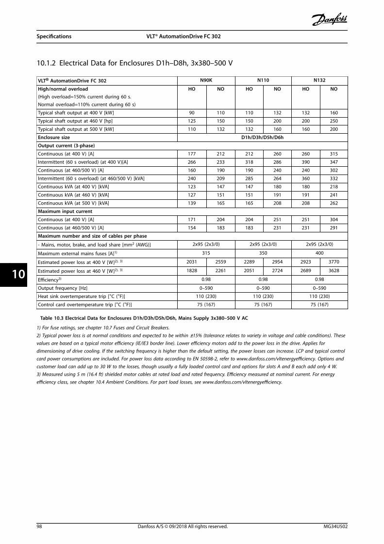
10.1.2 Electrical Data for Enclosures D1h–D8h, 3x380–500 V
VLT® AutomationDrive FC 302 N90K N110 N132
High/normal overload HO NO HO NO HO NO(High overload=150% current during 60 s.Normal overload=110% current during 60 s)
Typical shaft output at 400 V [kW] 90 110 110 132 132 160
Typical shaft output at 460 V [hp] 125 150 150 200 200 250
Typical shaft output at 500 V [kW] 110 132 132 160 160 200
Enclosure size D1h/D3h/D5h/D6h
Output current (3-phase)
Continuous (at 400 V) [A] 177 212 212 260 260 315
Intermittent (60 s overload) (at 400 V)[A] 266 233 318 286 390 347
Continuous (at 460/500 V) [A] 160 190 190 240 240 302
Intermittent (60 s overload) (at 460/500 V) [kVA] 240 209 285 264 360 332
Continuous kVA (at 400 V) [kVA] 123 147 147 180 180 218
Continuous kVA (at 460 V) [kVA] 127 151 151 191 191 241
Continuous kVA (at 500 V) [kVA] 139 165 165 208 208 262
Maximum input current
Continuous (at 400 V) [A] 171 204 204 251 251 304
Continuous (at 460/500 V) [A] 154 183 183 231 231 291
Maximum number and size of cables per phase
- Mains, motor, brake, and load share [mm2 (AWG)] 2x95 (2x3/0) 2x95 (2x3/0) 2x95 (2x3/0)
Maximum external mains fuses [A]1) 315 350 400
Estimated power loss at 400 V [W]2), 3) 2031 2559 2289 2954 2923 3770
Estimated power loss at 460 V [W]2), 3) 1828 2261 2051 2724 2689 3628
Efficiency3) 0.98 0.98 0.98
Output frequency [Hz] 0–590 0–590 0–590
Heat sink overtemperature trip [°C (°F)] 110 (230) 110 (230) 110 (230)
Control card overtemperature trip [°C (°F)] 75 (167) 75 (167) 75 (167)
Table 10.3 Electrical Data for Enclosures D1h/D3h/D5h/D6h, Mains Supply 3x380–500 V AC
1) For fuse ratings, see chapter 10.7 Fuses and Circuit Breakers.
2) Typical power loss is at normal conditions and expected to be within ±15% (tolerance relates to variety in voltage and cable conditions). Thesevalues are based on a typical motor efficiency (IE/IE3 border line). Lower efficiency motors add to the power loss in the drive. Applies fordimensioning of drive cooling. If the switching frequency is higher than the default setting, the power losses can increase. LCP and typical controlcard power consumptions are included. For power loss data according to EN 50598-2, refer to www.danfoss.com/vltenergyefficiency. Options andcustomer load can add up to 30 W to the losses, though usually a fully loaded control card and options for slots A and B each add only 4 W.3) Measured using 5 m (16.4 ft) shielded motor cables at rated load and rated frequency. Efficiency measured at nominal current. For energyefficiency class, see chapter 10.4 Ambient Conditions. For part load losses, see www.danfoss.com/vltenergyefficiency.
Specifications VLT® AutomationDrive FC 302
98 Danfoss A/S © 09/2018 All rights reserved. MG34U502
1010

VLT® AutomationDrive FC 302 N160 N200 N250
High/normal overload HO NO HO NO HO NO(High overload=150% current during 60 s.Normal overload=110% current during 60 s)
Typical shaft output at 400 V [kW] 160 200 200 250 250 315
Typical shaft output at 460 V [hp] 250 300 300 350 350 450
Typical shaft output at 500 V [kW] 200 250 250 315 315 355
Enclosure size D2h/D4h/D7h/D8h
Output current (3-phase)
Continuous (at 400 V) [A] 315 395 395 480 480 588
Intermittent (60 s overload) (at 400 V)[A] 473 435 593 528 720 647
Continuous (at 460/500 V) [A] 302 361 361 443 443 535
Intermittent (60 s overload) (at 460/500 V) [kVA] 453 397 542 487 665 589
Continuous kVA (at 400 V) [kVA] 218 274 274 333 333 407
Continuous kVA (at 460 V) [kVA] 241 288 288 353 353 426
Continuous kVA (at 500 V) [kVA] 262 313 313 384 384 463
Maximum input current
Continuous (at 400 V) [A] 304 381 381 463 463 567
Continuous (at 460/500 V) [A] 291 348 348 427 427 516
Maximum number and size of cables per phase
- Mains, motor, brake, and load share [mm2 (AWG)] 2x185 (2x400 mcm) 2x185 (2x400 mcm) 2x185 (2x400 mcm)
Maximum external mains fuses [A]1) 550 630 800
Estimated power loss at 400 V [W]2), 3) 3093 4116 4039 5137 5004 6674
Estimated power loss at 460 V [W]2), 3) 2872 3569 3575 4566 4458 5714
Efficiency3) 0.98 0.98 0.98
Output frequency [Hz] 0–590 0–590 0–590
Heat sink overtemperature trip [°C (°F)] 110 (230) 110 (230) 110 (230)
Control card overtemperature trip [°C (°F)] 80 (176) 80 (176) 80 (176)
Table 10.4 Electrical Data for Enclosures D2h/D4h/D7h/D8h, Mains Supply 3x380–500 V AC
1) For fuse ratings, see chapter 10.7 Fuses and Circuit Breakers.
2) Typical power loss is at normal conditions and expected to be within ±15% (tolerance relates to variety in voltage and cable conditions). Thesevalues are based on a typical motor efficiency (IE/IE3 border line). Lower efficiency motors add to the power loss in the drive. Applies fordimensioning of drive cooling. If the switching frequency is higher than the default setting, the power losses can increase. LCP and typical controlcard power consumptions are included. For power loss data according to EN 50598-2, refer to www.danfoss.com/vltenergyefficiency. Options andcustomer load can add up to 30 W to the losses, though usually a fully loaded control card and options for slots A and B each add only 4 W.3) Measured using 5 m (16.4 ft) shielded motor cables at rated load and rated frequency. Efficiency measured at nominal current. For energyefficiency class, see chapter 10.4 Ambient Conditions. For part load losses, see www.danfoss.com/vltenergyefficiency.
Specifications Operating Guide
MG34U502 Danfoss A/S © 09/2018 All rights reserved. 99
10 10

10.1.3 Electrical Data for Enclosures D1h–D8h, 3x525–690 V
VLT® AutomationDrive FC 302 N55K N75K N90K N110 N132
High/normal overload HO NO HO NO HO NO HO NO HO NO(High overload=150% current during60 s.Normal overload=110% current during60 s)
Typical shaft output at 525 V [kW] 45 55 55 75 75 90 90 110 110 132
Typical shaft output at 575 V [hp] 60 75 75 100 100 125 125 150 150 200
Typical shaft output at 690 V [kW] 55 75 75 90 90 110 110 132 132 160
Enclosure size D1h/D3h/D5h/D6h
Output current (3-phase)
Continuous (at 525 V) [A] 76 90 90 113 113 137 137 162 162 201
Intermittent (60 s overload)(at 525 V) [A]
114 99 135 124 170 151 206 178 243 221
Continuous (at 575/690 V) [A] 73 86 86 108 108 131 131 155 155 192
Intermittent (60 s overload)(at 575/690 V) [A]
110 95 129 119 162 144 197 171 233 211
Continuous kVA (at 525 V) [kVA] 69 82 82 103 103 125 125 147 147 183
Continuous kVA (at 575 V) [kVA] 73 86 86 108 108 131 131 154 154 191
Continuous kVA (at 690 V) [kVA] 87 103 103 129 129 157 157 185 185 230
Maximum input current
Continuous (at 525 V) [A] 74 87 87 109 109 132 132 156 156 193
Continuous (at 575/690 V) 70 83 83 104 104 126 126 149 149 185
Maximum number and size of cables per phase
- Mains, motor, brake, and load share
[mm2 (AWG)]
2x95 (2x3/0) 2x95 (2x3/0) 2x95 (2x3/0) 2x95 (2x3/0) 2x95 (2x3/0)
Maximum external mains fuses [A]1) 160 315 315 315 315
Estimated power loss at 575 V [W]2), 3) 1098 1162 1162 1428 1430 1740 1742 2101 2080 2649
Estimated power loss at 690 V [W]2), 3) 1057 1204 1205 1477 1480 1798 1800 2167 2159 2740
Efficiency3) 0.98 0.98 0.98 0.98 0.98
Output frequency [Hz] 0–590 0–590 0–590 0–590 0–590
Heat sink overtemperature trip [°C (°F)] 110 (230) 110 (230) 110 (230) 110 (230) 110 (230)
Control card overtemperature trip [°C
(°F)]
75 (167) 75 (167) 75 (167) 75 (167) 75 (167)
Table 10.5 Electrical Data for Enclosures D1h/D3h/D5h/D6h, Mains Supply 3x525–690 V AC
1) For fuse ratings, see chapter 10.7 Fuses and Circuit Breakers.
2) Typical power loss is at normal conditions and expected to be within ±15% (tolerance relates to variety in voltage and cable conditions). Thesevalues are based on a typical motor efficiency (IE/IE3 border line). Lower efficiency motors add to the power loss in the drive. Applies fordimensioning of drive cooling. If the switching frequency is higher than the default setting, the power losses can increase. LCP and typical controlcard power consumptions are included. For power loss data according to EN 50598-2, refer to www.danfoss.com/vltenergyefficiency. Options andcustomer load can add up to 30 W to the losses, though usually a fully loaded control card and options for slots A and B each add only 4 W.3) Measured using 5 m (16.4 ft) shielded motor cables at rated load and rated frequency. Efficiency measured at nominal current. For energyefficiency class, see chapter 10.4 Ambient Conditions. For part load losses, see www.danfoss.com/vltenergyefficiency.
Specifications VLT® AutomationDrive FC 302
100 Danfoss A/S © 09/2018 All rights reserved. MG34U502
1010

VLT® AutomationDrive FC 302 N160 N200 N250 N315
High/normal overload HO NO HO NO HO NO HO NO(High overload=150% current during 60 s.Normal overload=110% current during 60 s)
Typical Shaft output at 525 V [kW] 132 160 160 200 200 250 250 315
Typical Shaft output at 575 V [hp] 200 250 250 300 300 350 350 400
Typical Shaft output at 690 V [kW] 160 200 200 250 250 315 315 400
Enclosure size D2h/D4h/D7h/D8h
Output current (3-phase)
Continuous (at 525 V) [A] 201 253 253 303 303 360 360 418
Intermittent (60 s overload) (at 525 V)[A] 301 278 380 333 455 396 540 460
Continuous (at 575/690 V) [A] 192 242 242 290 290 344 344 400
Intermittent (60 s overload) (at 575/690 V) [A] 288 266 363 319 435 378 516 440
Continuous kVA (at 525 V) [kVA] 183 230 230 276 276 327 327 380
Continuous kVA (at 575 V) [kVA] 191 241 241 289 289 343 343 398
Continuous kVA (at 575/690 V) [kVA] 229 289 289 347 347 411 411 478
Maximum input current
Continuous (at 525 V) [A] 193 244 244 292 292 347 347 403
Continuous (at 575/690 V) 185 233 233 279 279 332 332 385
Maximum number and size of cables per phase
- Mains, motor, brake, and load share
[mm2 (AWG)]
2x185 (2x400) 2x185 (2x400) 2x185 (2x400) 2x185 (2x400)
Maximum external mains fuses [A]1) 550 550 550 550
Estimated power loss at 575 V [W]2), 3) 2361 3074 3012 3723 3642 4465 4146 5028
Estimated power loss at 690 V [W]2), 3) 2446 3175 3123 3851 3771 4614 4258 5155
Efficiency3) 0.98 0.98 0.98 0.98
Output frequency [Hz] 0–590 0–590 0–590 0–590
Heat sink overtemperature trip [°C (°F)] 110 (230) 110 (230) 110 (230) 110 (230)
Control card overtemperature trip [°C (°F)] 80 (176) 80 (176) 80 (176) 80 (176)
Table 10.6 Electrical Data for Enclosures D2h/D4h/D7h/D8h, Mains Supply 3x525–690 V AC
1) For fuse ratings, see chapter 10.7 Fuses and Circuit Breakers.
2) Typical power loss is at normal conditions and expected to be within ±15% (tolerance relates to variety in voltage and cable conditions). Thesevalues are based on a typical motor efficiency (IE/IE3 border line). Lower efficiency motors add to the power loss in the drive. Applies fordimensioning of drive cooling. If the switching frequency is higher than the default setting, the power losses can increase. LCP and typical controlcard power consumptions are included. For power loss data according to EN 50598-2, refer to www.danfoss.com/vltenergyefficiency. Options andcustomer load can add up to 30 W to the losses, though usually a fully loaded control card and options for slots A and B each add only 4 W.3) Measured using 5 m (16.4 ft) shielded motor cables at rated load and rated frequency. Efficiency measured at nominal current. For energyefficiency class, see chapter 10.4 Ambient Conditions. For part load losses, see www.danfoss.com/vltenergyefficiency.
Specifications Operating Guide
MG34U502 Danfoss A/S © 09/2018 All rights reserved. 101
10 10

10.2 Mains Supply
Mains supply (L1, L2, L3)Supply voltage 200–240 V, 380–500 V ±10%, 525–690 V ±10%
Mains voltage low/mains voltage drop-out (for 380–500 V and 525–690 V only):During low mains voltage or a mains drop-out, the drive continues until the DC-link voltage drops below the minimum stoplevel, which corresponds typically to 15% below the lowest rated supply voltage of the drive. Power-up and full torque cannot beexpected at mains voltage lower than 10% below the lowest rated supply voltage of the drive.
Supply frequency 50/60 Hz ±5%Maximum imbalance temporary between mains phases 3.0% of rated supply voltage1)
True power factor (λ) ≥0.9 nominal at rated loadDisplacement power factor (cos Φ) near unity (>0.98)Switching on input supply L1, L2, L3 (power-ups) Maximum 1 time/2 minuteEnvironment according to EN60664-1 Overvoltage category III/pollution degree 2
The drive is suitable for use on a circuit capable of delivering up to 100 kA short circuit current rating (SCCR) at 240/480/600 V.1) Calculations based on UL/IEC61800-3.
10.3 Motor Output and Torque Data
Motor output (U, V, W)Output voltage 0–100% of supply voltageOutput frequency 0–590 Hz1)
Output frequency in flux mode 0–300 HzSwitching on output UnlimitedRamp times 0.01–3600 s
1) Dependent on voltage and power.
Torque characteristicsStarting torque (constant torque) Maximum 150% for 60 s1), 2)
Overload torque (constant torque) Maximum 150% for 60 s1), 2)
1) Percentage relates to the nominal current of the drive.2) Once every 10 minutes.
10.4 Ambient Conditions
EnvironmentD1h/D2h/D5h/D6h/D7h/D8h enclosure IP21/Type 1, IP54/Type 12D3h/D4h enclosure IP20/ChassisVibration test (standard/ruggedized) 0.7 g/1.0 gRelative humidity 5–95% (IEC 721-3-3; Class 3K3 (non-condensing) during operation)Aggressive environment (IEC 60068-2-43) H2S test Class KdAggressive gases (IEC 60721-3-3) Class 3C3Test method according to IEC 60068-2-43 H2S (10 days)Ambient temperature (at SFAVM switching mode)- with derating Maximum 55 °C (131 °F)1)
- with full output power of typical EFF2 motors (up to 90% output current) Maximum 50 °C (122 °F)1)
- at full continuous FC output current Maximum 45 °C (113 °F)1)
Minimum ambient temperature during full-scale operation 0 °C (32 °F)Minimum ambient temperature at reduced performance -10 °C (14 °F)Temperature during storage/transport -25 to +65/70 °C (13 to 149/158 °F)Maximum altitude above sea level without derating 1000 m (3281 ft)Maximum altitude above sea level with derating 3000 m (9842 ft)
1) For more information on derating, see the design guide.
Specifications VLT® AutomationDrive FC 302
102 Danfoss A/S © 09/2018 All rights reserved. MG34U502
1010

EMC standards, Emission EN 61800-3EMC standards, Immunity EN 61800-3Energy efficiency class1) IE2
1) Determined according to EN 50598-2 at:
• Rated load.
• 90% rated frequency.
• Switching frequency factory setting.
• Switching pattern factory setting.
10.5 Cable Specifications
Cable lengths and cross-sections for control cables1)
Maximum motor cable length, shielded/armored 150 m (492 ft)Maximum motor cable length, unshielded/unarmored 300 m (984 ft)Maximum cross-section to motor, mains, load sharing, and brake See chapter 10.1 Electrical DataMaximum cross-section to control terminals, rigid wire 1.5 mm2/16 AWG (2x0.75 mm2)Maximum cross-section to control terminals, flexible cable 1 mm2/18 AWGMaximum cross-section to control terminals, cable with enclosed core 0.5 mm2/20 AWGMinimum cross-section to control terminals. 0.25 mm2/23 AWG
1) For power cables, see electrical data tables in chapter 10.1 Electrical Data.
10.6 Control Input/Output and Control Data
Digital inputsProgrammable digital inputs 4 (6)Terminal number 18, 19, 271), 291), 32, 33Logic PNP or NPNVoltage level 0–24 V DCVoltage level, logic 0 PNP <5 V DCVoltage level, logic 1 PNP >10 V DCVoltage level, logic 0 NPN >19 V DCVoltage level, logic 1 NPN <14 V DCMaximum voltage on input 28 V DCInput resistance, Ri Approximately 4 kΩ
All digital inputs are galvanically isolated from the supply voltage (PELV) and other high-voltage terminals.1) Terminals 27 and 29 can also be programmed as outputs.
Analog inputsNumber of analog inputs 2Terminal number 53, 54Modes Voltage or currentMode select Switches A53 and A54Voltage mode Switch A53/A54=(U)Voltage level -10 V to +10 V (scaleable)Input resistance, Ri Approximately 10 kΩMaximum voltage ±20 VCurrent mode Switch A53/A54=(I)Current level 0/4 to 20 mA (scaleable)Input resistance, Ri Approximately 200 ΩMaximum current 30 mAResolution for analog inputs 10 bit (+ sign)Accuracy of analog inputs Maximum error 0.5% of full scale
Specifications Operating Guide
MG34U502 Danfoss A/S © 09/2018 All rights reserved. 103
10 10

Bandwidth 100 Hz
The analog inputs are galvanically isolated from the supply voltage (PELV) and other high-voltage terminals.
Mains
Functionalisolation
PELV isolation
Motor
DC-bus
Highvoltage
Control+24 V
RS485
18
37
130B
A11
7.10
Illustration 10.1 PELV Isolation
Pulse inputsProgrammable pulse inputs 2Terminal number pulse 29, 33Maximum frequency at terminal 29, 33 (push-pull driven) 110 kHzMaximum frequency at terminal 29, 33 (open collector) 5 kHzMinimum frequency at terminal 29, 33 4 HzVoltage level See Digital Inputs in chapter 10.6 Control Input/Output and Control DataMaximum voltage on input 28 V DCInput resistance, Ri Approximately 4 kΩPulse input accuracy (0.1–1 kHz) Maximum error: 0.1% of full scale
Analog outputNumber of programmable analog outputs 1Terminal number 42Current range at analog output 0/4–20 mAMaximum resistor load to common at analog output 500 ΩAccuracy on analog output Maximum error: 0.8% of full scaleResolution on analog output 8 bit
The analog output is galvanically isolated from the supply voltage (PELV) and other high-voltage terminals.
Control card, RS485 serial communicationTerminal number 68 (P, TX+, RX+), 69 (N, TX-, RX-)Terminal number 61 Common for terminals 68 and 69
The RS485 serial communication circuit is functionally separated from other central circuits and galvanically isolated from thesupply voltage (PELV).
Digital outputProgrammable digital/pulse outputs 2Terminal number 27, 291)
Voltage level at digital/frequency output 0–24 VMaximum output current (sink or source) 40 mAMaximum load at frequency output 1 kΩMaximum capacitive load at frequency output 10 nFMinimum output frequency at frequency output 0 HzMaximum output frequency at frequency output 32 kHzAccuracy of frequency output Maximum error: 0.1% of full scaleResolution of frequency outputs 12 bit
1) Terminals 27 and 29 can also be programmed as inputs.
The digital output is galvanically isolated from the supply voltage (PELV) and other high-voltage terminals.
Specifications VLT® AutomationDrive FC 302
104 Danfoss A/S © 09/2018 All rights reserved. MG34U502
1010

Control card, 24 V DC outputTerminal number 12, 13Maximum load 200 mA
The 24 V DC supply is galvanically isolated from the supply voltage (PELV), but has the same potential as the analog and digitalinputs and outputs.
Relay outputsProgrammable relay outputs 2Maximum cross-section to relay terminals 2.5 mm2 (12 AWG)Minimum cross-section to relay terminals 0.2 mm2 (30 AWG)Length of stripped wire 8 mm (0.3 in)Relay 01 terminal number 1–3 (break), 1–2 (make)Maximum terminal load (AC-1)1) on 1–2 (NO) (Resistive load)2), 3) 400 V AC, 2 AMaximum terminal load (AC-15)1) on 1–2 (NO) (Inductive load @ cosφ 0.4) 240 V AC, 0.2 AMaximum terminal load (DC-1)1) on 1–2 (NO) (Resistive load) 80 V DC, 2 AMaximum terminal load (DC-13)1) on 1–2 (NO) (Inductive load) 24 V DC, 0.1 AMaximum terminal load (AC-1)1) on 1–3 (NC) (Resistive load) 240 V AC, 2 AMaximum terminal load (AC-15)1) on 1–3 (NC) (Inductive load @ cosφ 0.4) 240 V AC, 0.2 AMaximum terminal load (DC-1)1) on 1–3 (NC) (Resistive load) 50 V DC, 2 AMaximum terminal load (DC-13)1) on 1–3 (NC) (Inductive load) 24 V DC, 0.1 AMinimum terminal load on 1–3 (NC), 1–2 (NO) 24 V DC 10 mA, 24 V AC 2 mAEnvironment according to EN 60664-1 Overvoltage category III/pollution degree 2Relay 02 terminal number 4–6 (break), 4–5 (make)Maximum terminal load (AC-1)1) on 4–5 (NO) (Resistive load)2), 3) 400 V AC, 2 AMaximum terminal load (AC-15)1) on 4–5 (NO) (Inductive load @ cosφ 0.4) 240 V AC, 0.2 AMaximum terminal load (DC-1)1) on 4–5 (NO) (Resistive load) 80 V DC, 2 AMaximum terminal load (DC-13)1) on 4–5 (NO) (Inductive load) 24 V DC, 0.1 AMaximum terminal load (AC-1)1) on 4–6 (NC) (Resistive load) 240 V AC, 2 AMaximum terminal load (AC-15)1) on 4–6 (NC) (Inductive load @ cosφ 0.4) 240 V AC, 0.2 AMaximum terminal load (DC-1)1) on 4–6 (NC) (Resistive load) 50 V DC, 2 AMaximum terminal load (DC-13)1) on 4–6 (NC) (Inductive load) 24 V DC, 0.1 AMinimum terminal load on 4–6 (NC), 4–5 (NO) 24 V DC 10 mA, 24 V AC 2 mAEnvironment according to EN 60664-1 Overvoltage category III/pollution degree 2
The relay contacts are galvanically isolated from the rest of the circuit by reinforced isolation (PELV).1) IEC 60947 part 4 and 5.2) Overvoltage Category II.3) UL applications 300 V AC 2 A.
Control card, +10 V DC outputTerminal number 50Output voltage 10.5 V ±0.5 VMaximum load 25 mA
The 10 V DC supply is galvanically isolated from the supply voltage (PELV) and other high-voltage terminals.
Control characteristicsResolution of output frequency at 0–1000 Hz ±0.003 HzSystem response time (terminals 18, 19, 27, 29, 32, 33) ≤2 m/sSpeed control range (open loop) 1:100 of synchronous speedSpeed accuracy (open loop) 30–4000 RPM: Maximum error of ±8 RPM
All control characteristics are based on a 4-pole asynchronous motor.
Control card performanceScan interval 5 M/S
Specifications Operating Guide
MG34U502 Danfoss A/S © 09/2018 All rights reserved. 105
10 10

Control card, USB serial communicationUSB standard 1.1 (full speed)USB plug USB type B device plug
NOTICEConnection to PC is carried out via a standard host/device USB cable.The USB connection is galvanically isolated from the supply voltage (PELV) and other high-voltage terminals.The USB connection is not galvanically isolated from ground. Use only isolated laptop/PC as connection to the USBconnector on the drive or an isolated USB cable/converter.
10.7 Fuses and Circuit Breakers
10.7.1 Fuse Selection
Installing fuses on the supply side ensures that potential damage is contained inside the drive enclosure if a componentbreakdown (first fault) occurs inside the drive. Use the recommended fuses to ensure compliance with EN 50178, refer toTable 10.7, Table 10.8, and Table 10.9.
NOTICEUse of fuses on the supply side is mandatory for IEC 60364 (CE) and NEC 2009 (UL) compliant installations.
D1h–D8h recommended fuses
Model Bussmann part number
N45K 170M2620
N55K 170M2621
N75K 170M4015
N90K 170M4015
N110 170M4016
N150 170M4018
Table 10.7 D1h–D8h Power/Semiconductor Fuse Options, 200–240 V
Model Bussmann part number
N90K 170M2619
N110 170M2620
N132 170M2621
N160 170M4015
N200 170M4016
N250 170M4018
Table 10.8 D1h–D8h Power/Semiconductor Fuse Options, 380–500 V
Model Bussmann part number
N55K 170M2616
N75K 170M2619
N90K 170M2619
N110 170M2619
N132 170M2619
N160 170M4015
N200 170M4015
N250 170M4015
N315 170M4015
Table 10.9 D1h–D8h Power/Semiconductor Fuse Options, 525–690 V
Specifications VLT® AutomationDrive FC 302
106 Danfoss A/S © 09/2018 All rights reserved. MG34U502
1010

Type aR fuses are recommended for drives in enclosure sizes D3h–D4h. See Table 10.10.
Model 200–240 V 380–500 V 525–690 V
N45K ar-350 – –
N55K ar-400 – ar-160
N75K ar-500 – ar-315
N90K ar-500 ar-315 ar-315
N110 ar-630 ar-350 ar-315
N132 – ar-400 ar-315
N150 ar-800 – –
N160 – ar-500 ar-550
N200 – ar-630 ar-550
N250 – ar-800 ar-550
N315 – – ar-550
Table 10.10 D3h–D4h Power/Semiconductor Fuse Sizes
Bussmann Rating
LPJ-21/2SP 2.5 A, 600 V
Table 10.11 D1h–D8h Space Heater Fuse Recommendation
For UL compliance, use the Bussmann 170M series fuses for units supplied without a disconnect, contactor, or circuit breakeroption. If a disconnect, contactor, or circuit breaker option is supplied with the drive, see Table 10.12 to Table 10.15 for SCCRratings and UL fuse criteria.
10.7.2 Short-circuit Current Rating (SCCR)
The short-circuit current rating (SCCR) represents the maximum level of short-circuit current that the drive can safelywithstand. If the drive is not supplied with a mains disconnect, contactor, or circuit breaker, the SCCR of the drive is 100000A at all voltages (200–690 V).
If the drive is supplied with a mains disconnect only, the SCCR of the drive is 100000 amps at all voltages (200–600 V). SeeTable 10.12. If the drive is supplied with a contactor only, refer to Table 10.13 for the SCCR. If the drive contains both acontactor and disconnect, see Table 10.14.
If the drive is supplied with a circuit breaker only, the SCCR depends on the voltage. Refer to Table 10.15.
Enclosure size ≤ 600 V IEC/UL
D5h 100000 A1)
D7h 100000 A2)
Table 10.12 D5h and D7h Drives Supplied with a Disconnect Only
1) With an upstream branch protection Class J fuse with maximum rating of 600 A.2) With an upstream branch protection Class J fuse with maximum rating of 800 A.
Enclosure size 415 V
IEC1)
480 V
UL2)
600 V
UL2)
690 V
IEC1)
D6h 100000 A 100000 A 100000 A 100000 A
D8h (excluding N250 380-500V model) 100000 A 100000 A 100000 A 100000 A
D8h (N250 380-500V model only) 100000 A Contact Danfoss Not applicable Not applicable
Table 10.13 D6h and D8h Drives Supplied with a Contactor Only
1) With gL/gG fuses: 425 A maximum fuse size for D6h, and 630 A maximum fuse size for D8h.2) With external upstream Class J fuses: 450 A maximum fuse size for D6h, and 600 A maximum fuse size for D8h.
Specifications Operating Guide
MG34U502 Danfoss A/S © 09/2018 All rights reserved. 107
10 10

Enclosure size 415 V
IEC1)
480 V
UL2)
600 V
UL2)
D6h 100000 A 100000 A 100000 A
D8h (excluding N250 380-500V model) 100000 A 100000 A 100000 A
D8h (N250 380-500V model only) 100000 A Contact Danfoss Not applicable
Table 10.14 D6h and D8h Drives Supplied with a Disconnect and Contactor
1) With gL/gG fuses: 425A maximum fuse size for D6h, and 630A maximum fuse size for D8h.2) With external upstream Class J fuses: 450 A maximum fuse size for D6h, and 600 A maximum fuse size for D8h.
Enclosure size 415 V 480 V 600 V 690 V
D6h 120000 A 100000 A 65000 A 70000 A
D8h 100000 A 100000 A 42000 A 30000 A
Table 10.15 D6h and D8h Drives Supplied with a Circuit Breaker Only
10.8 Fastener Tightening Torques
Apply the correct torque when tightening fasteners in the locations that are listed in Table 10.16. Too low or too high torquewhen fastening an electrical connection results in a bad electrical connection. To ensure correct torque, use a torquewrench.
Location Bolt size Torque [Nm (in-lb)]
Mains terminals M10/M12 19 (168)/37 (335)
Motor terminals M10/M12 19 (168)/37 (335)
Ground terminals M8/M10 9.6 (84)/19.1 (169)
Brake terminals M8 9.6 (84)
Load sharing terminals M10/M12 19 (168)/37 (335)
Regeneration terminals (Enclosures D1h/D2h) M8 9.6 (84)
Relay terminals _ 0.5 (4)
Door/panel cover M5 2.3 (20)
Gland plate M5 2.3 (20)
Heat sink access panel M5 3.9 (35)
Serial communication cover M5 2.3 (20)
Table 10.16 Fastener Torque Ratings
Specifications VLT® AutomationDrive FC 302
108 Danfoss A/S © 09/2018 All rights reserved. MG34U502
1010

10.9 Enclosure Dimensions
10.9.1 D1h Exterior Dimensions
130B
E982
.10
667 (26.3) 500 (19.7)
164 (6.5)
99 (3.9)
Illustration 10.2 Front View of D1h
Specifications Operating Guide
MG34U502 Danfoss A/S © 09/2018 All rights reserved. 109
10 10

378 (14.9)
82 (3.2)
148 (5.8)
20 (0.8)
844 (33.2)
561 (22.1)
18 (0.7)
130B
F797
.10
Illustration 10.3 Side View of D1h
Specifications VLT® AutomationDrive FC 302
110 Danfoss A/S © 09/2018 All rights reserved. MG34U502
1010

200 (7.9)
246 (9.7)
893(35.2)
656(25.8)
200 (7.9)
844(33.2)
130 (5.1)
180 (7.1)
325 (12.8)
123(4.8)
78(3.1)
63 (2.5)
11(0.4)
20(0.8)
9(0.3)
24(0.9)
33(1.3)
25(1.0)
11 (0.4)
130B
F798
.10
A
A
B
B
Illustration 10.4 Back View of D1h
Specifications Operating Guide
MG34U502 Danfoss A/S © 09/2018 All rights reserved. 111
10 10

130B
F669
.10
404 (15.9)
298 (11.7)
105
Illustration 10.5 Door Clearance for D1h
130B
F607
.10
205 (8.1)
138 (5.4)
274 (10.8)27 (1.0)
137 (5.4)1 2
1 Mains side 2 Motor side
Illustration 10.6 Gland Plate Dimensions for D1h
Specifications VLT® AutomationDrive FC 302
112 Danfoss A/S © 09/2018 All rights reserved. MG34U502
1010

10.9.2 D2h Exterior Dimensions
130B
F321
.10
96 (3.8)
211 (8.3)
602 (23.7)
871 (34.3)
Illustration 10.7 Front View of D2h
Specifications Operating Guide
MG34U502 Danfoss A/S © 09/2018 All rights reserved. 113
10 10

130B
F799
.10
1050 (41.3)
718 (28.3)
148 (5.8)
18 (0.7)
378 (14.9)
142 (5.6)
20 (0.8)
Illustration 10.8 Side View of D2h
Specifications VLT® AutomationDrive FC 302
114 Danfoss A/S © 09/2018 All rights reserved. MG34U502
1010

1099 (43.3)
1051 (41.4)
107 (4.2)
320 (12.6)
213 (8.4)
857 (33.7)
130 (5.1)
420 (16.5)
346 (13.6)
280 (11.0)
271 (10.7)
A
A
B
B
9 (0.3)
20 (0.8)
11 (0.4)
75 (2.9)
24 (0.9)
11 (0.4)
33 (1.3)
130B
F800
.10
Illustration 10.9 Back View of D2h
Specifications Operating Guide
MG34U502 Danfoss A/S © 09/2018 All rights reserved. 115
10 10

395 (15.6)
523 (20.6)
105
130B
F670
.10
Illustration 10.10 Door Clearance for D2h
130B
F608
.10
27 (1.0) 185 (7.3)
1 2
369 (14.5)
196 (7.7)
145 (5.7)
1 Mains side 2 Motor side
Illustration 10.11 Gland Plate Dimensions for D2h
Specifications VLT® AutomationDrive FC 302
116 Danfoss A/S © 09/2018 All rights reserved. MG34U502
1010

10.9.3 D3h Exterior Dimensions
130B
F322
.10
61 (2.4)
128 (5.0)
495 (19.5)
660 (26.0)
Illustration 10.12 Front View of D3h
Specifications Operating Guide
MG34U502 Danfoss A/S © 09/2018 All rights reserved. 117
10 10

148 (5.8)
20 (0.8)
130B
F801
.10
844 (33.2)
39 (1.5)
375 (14.8)
82 (3.2)
18 (0.7)
Illustration 10.13 Side View of D3h
Specifications VLT® AutomationDrive FC 302
118 Danfoss A/S © 09/2018 All rights reserved. MG34U502
1010

656 (25.8)
200 (7.9)
200 (7.9)
130 (5.1)
889 (35.0)
909 (35.8)
844 (33.2)
78 (3.1)
123 (4.8)
250 (9.8)
180 (7.1)
A
B
A
B
33 (1.3)
11 (0.4)
25 (1.0)
11 (0.4)
20 (0.8)
9 (0.3)
24 (0.9)
25 (1.0)
M10
M10
130B
F802
.10
Illustration 10.14 Back View of D3h
Specifications Operating Guide
MG34U502 Danfoss A/S © 09/2018 All rights reserved. 119
10 10

10.9.4 D4h Enclosure Dimensions
130B
F323
.10
176 (6.9)
611 (24.1)
59 (2.3)
868 (34.2)
Illustration 10.15 Front View of D4h
Specifications VLT® AutomationDrive FC 302
120 Danfoss A/S © 09/2018 All rights reserved. MG34U502
1010
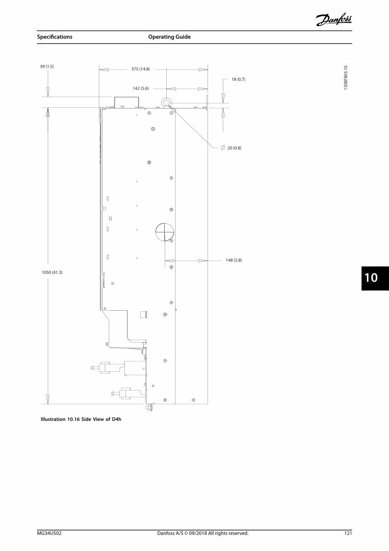
130B
F803
.10
20 (0.8)
148 (5.8)
18 (0.7)
1050 (41.3)
39 (1.5) 375 (14.8)
142 (5.6)
Illustration 10.16 Side View of D4h
Specifications Operating Guide
MG34U502 Danfoss A/S © 09/2018 All rights reserved. 121
10 10

B
130B
F804
.10
B
857 (33.7)
A
A
320 (12.6)
280 (11.0)
350 (13.8)
107 (4.2)
213 (8.4)1122 (44.2)
1096 (43.1)
1051 (41.4)
271 (10.7)
130 (5.1) 25 (1.0)
33 (1.3)
11 (0.4)
40 (1.6)
11 (0.4)
9 (0.3)
20 (0.8)24 (0.9)
Illustration 10.17 Back View of D4h
Specifications VLT® AutomationDrive FC 302
122 Danfoss A/S © 09/2018 All rights reserved. MG34U502
1010

10.9.5 D5h Exterior Dimensions
149 (5.9)
733 (28.9)
1107 (43.6)
130B
F324
.10
Illustration 10.18 Front View of D5h
Specifications Operating Guide
MG34U502 Danfoss A/S © 09/2018 All rights reserved. 123
10 10

130B
F805
.10
161 (6.3)
23 (0.9)
115 (4.5)
381 (15.0)
1277 (50.3)
Illustration 10.19 Side View of D5h
Specifications VLT® AutomationDrive FC 302
124 Danfoss A/S © 09/2018 All rights reserved. MG34U502
1010

130B
F806
.10
B
B
1276 (50.2)
64 (2.5)
AA
M10
M10
325 (12.8)
306 (12.1)
276 (10.9)
180 (7.1)
130 (5.1)
123 (4.8)
78 (3.1)
200 (7.9)
1324 (52.1)
1111 (43.7)
130 (5.1)
123 (4.8)
78 (3.1
200 (7.9)
200 (7.9)
220 (8.7)
25 (1)
4X 11 (0.4)
63 (2.5)
15 (0.6)
11 (0.4)
24 (0.9) 20 (0.8)
9 (0.3)
Illustration 10.20 Back View of D5h
Specifications Operating Guide
MG34U502 Danfoss A/S © 09/2018 All rights reserved. 125
10 10

130B
F828
.10
433 (17.0)
670 (26.4)
218 (8.6)
Illustration 10.21 Heat Sink Access Dimensions for D5h
Specifications VLT® AutomationDrive FC 302
126 Danfoss A/S © 09/2018 All rights reserved. MG34U502
1010

130B
F669
.10
404 (15.9)
298 (11.7)
105
Illustration 10.22 Door Clearance for D5h
111 (4.4)
224 (8.8)
242 (9.5)
121 (4.8)
43 (1.7)
1 2
130B
F609
.10
1 Mains side 2 Motor side
Illustration 10.23 Gland Plate Dimensions for D5h
Specifications Operating Guide
MG34U502 Danfoss A/S © 09/2018 All rights reserved. 127
10 10
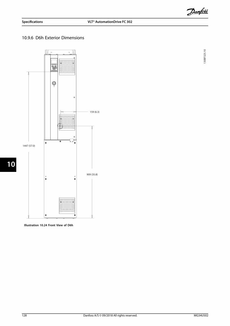
10.9.6 D6h Exterior Dimensions
159 (6.3)
130B
F325
.10
909 (35.8)
1447 (57.0)
Illustration 10.24 Front View of D6h
Specifications VLT® AutomationDrive FC 302
128 Danfoss A/S © 09/2018 All rights reserved. MG34U502
1010

130B
F807
.10
1617 (63.7)
181 (7.1)
23 (0.9)
115 (4.5)
381 (15.0)
Illustration 10.25 Side View of D6h
Specifications Operating Guide
MG34U502 Danfoss A/S © 09/2018 All rights reserved. 129
10 10

A
M10
25 (1)
4X 11 (0.4)
63 (2.5)
15 (0.6)
A
B
B
130B
F808
.10
325 (12.8)
306 (12.1)
276 (10.9)
180 (7.1)
130 (5.1)
1452 (57.2)
200 (7.9)
559 (22.0)
130 (5.1)
200 (7.9)
78 (3.1)
123 (4.8)
1615 (63.6)
1663 (65.5)
200 (7.9)
78 (3.1)
123 (4.8)
24 (0.9)20 (0.8) 9 (0.1)
64 (3.0)
11 (0.4)
M10
Illustration 10.26 Back View of D6h
Specifications VLT® AutomationDrive FC 302
130 Danfoss A/S © 09/2018 All rights reserved. MG34U502
1010

130B
F829
.10
433 (17.0)
1009 (39.7)
218 (8.6)
Illustration 10.27 Heat Sink Access Dimensions for D6h
Specifications Operating Guide
MG34U502 Danfoss A/S © 09/2018 All rights reserved. 131
10 10

130B
F669
.10
404 (15.9)
298 (11.7)
105
Illustration 10.28 Door Clearance for D6h
111 (4.4)
224 (8.8)
242 (9.5)
121 (4.8)
43 (1.7)
1 2
130B
F609
.10
1 Mains side 2 Motor side
Illustration 10.29 Gland Plate Dimensions for D6h
Specifications VLT® AutomationDrive FC 302
132 Danfoss A/S © 09/2018 All rights reserved. MG34U502
1010

10.9.7 D7h Exterior Dimensions
130B
F326
.10
209 (8.2)
1282 (50.5)
1754 (69.1)
Illustration 10.30 Front View of D7h
Specifications Operating Guide
MG34U502 Danfoss A/S © 09/2018 All rights reserved. 133
10 10

25 (1.0)
130B
F809
.10
23 (0.9)
156 (6.2)
386 (15.2)
161 (6.3)
193 (76.0)
Illustration 10.31 Side View of D7h
Specifications VLT® AutomationDrive FC 302
134 Danfoss A/S © 09/2018 All rights reserved. MG34U502
1010

235 (9.3)
71 (2.8)
AA
130 (5.1) 4X 11 (0.4)
130B
F810
.10
420 (16.5)
411 (16.2)
374 (14.7)
280 (11.0)
25 (1.0)
14 (0.6)
1760 (69.3)
130 (5.1)
70 (2.8)
385 (15.2)
25 (1.0)
M10
668 (26.3)
107 (4.2)
213 (8.4)
320 (12.6)
978 (77.9)
1953 (76.9)
107 (4.2)
213 (8.4)
320 (12.6)
B
B
23 (0.9)
Illustration 10.32 Back View of D7h
Specifications Operating Guide
MG34U502 Danfoss A/S © 09/2018 All rights reserved. 135
10 10

316 (12.4)
130B
F830
.10
591 (23.3)
1168 (46.0)
Illustration 10.33 Heat Sink Access Dimensions for D7h
Specifications VLT® AutomationDrive FC 302
136 Danfoss A/S © 09/2018 All rights reserved. MG34U502
1010

2X 11 (0.4)13
0BF8
32.1
0
1731 (68.1)
23 (0.9)
468 (18.4)
271 (10.7)
1537 (60.5)
Illustration 10.34 Wall Mount Dimensions for D7h
Specifications Operating Guide
MG34U502 Danfoss A/S © 09/2018 All rights reserved. 137
10 10

395 (15.6)
523 (20.6)
105
130B
F670
.10
Illustration 10.35 Door Clearance for D7h
130B
F610
.10
222 (8.7)
115 (4.5)
337 (13.3)
169 (6.6)
43 (1.7)-A-
1 2
1 Mains side 2 Motor side
Illustration 10.36 Gland Plate Dimensions for D7h
Specifications VLT® AutomationDrive FC 302
138 Danfoss A/S © 09/2018 All rights reserved. MG34U502
1010

10.9.8 D8h Exterior Dimensions
130B
F327
.10
215 (8.5)
1400 (55.1)
1699 (66.9)
767 (30.2)
112 (4.4)
Illustration 10.37 Front View of D8h
Specifications Operating Guide
MG34U502 Danfoss A/S © 09/2018 All rights reserved. 139
10 10

2236 (88.0)
23 (0.9)
406 (16.0)
156 (6.2)
162 (6.4)
25 (1.0)
130B
F811
.10
Illustration 10.38 Side View of D8h
Specifications VLT® AutomationDrive FC 302
140 Danfoss A/S © 09/2018 All rights reserved. MG34U502
1010

130B
F812
.10
A
4X 11 (0.4)
70 (2.8)
25 (1.0)
B
23 (0.9)
B
A
420 (16.5)
411 (16.2)
374 (14.7)
280 (11.0)
107 (4.2)
213 (8.4)
320 (12.6)
107 (4.2)
213 (8.4)
320 (12.6)
130 (5.1)
130 (5.1)
973 (38.3)
2065 (81.3)
2259 (88.9)
2284 (89.9)
72 (2.8)
25 (1.0)
M10
385 (15.2)
235 (9.3)
14 (0.6)
Illustration 10.39 Back View of D8h
Specifications Operating Guide
MG34U502 Danfoss A/S © 09/2018 All rights reserved. 141
10 10
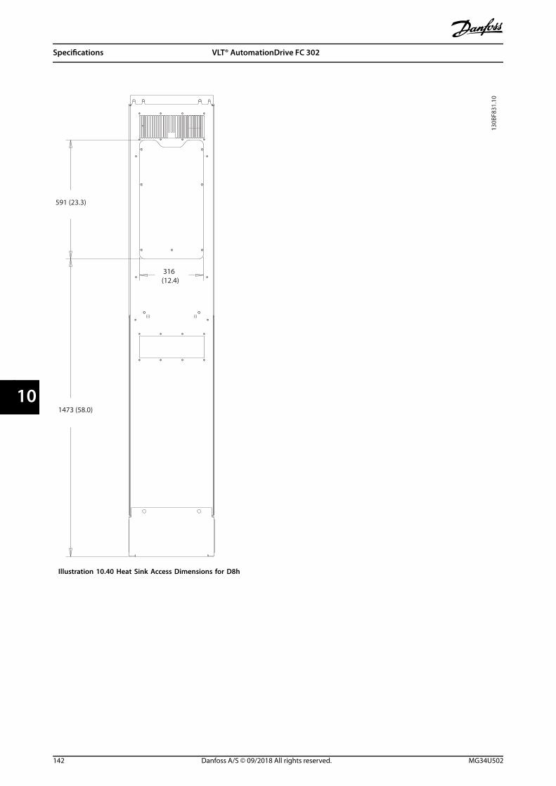
130B
F831
.10
1473 (58.0)
316 (12.4)
591 (23.3)
Illustration 10.40 Heat Sink Access Dimensions for D8h
Specifications VLT® AutomationDrive FC 302
142 Danfoss A/S © 09/2018 All rights reserved. MG34U502
1010

395 (15.6)
523 (20.6)
105
130B
F670
.10
Illustration 10.41 Door Clearance for D8h
130B
F610
.10
222 (8.7)
115 (4.5)
337 (13.3)
169 (6.6)
43 (1.7)-A-
1 2
1 Mains side 2 Motor side
Illustration 10.42 Gland Plate Dimensions for D8h
Specifications Operating Guide
MG34U502 Danfoss A/S © 09/2018 All rights reserved. 143
10 10

11 Appendix
11.1 Abbreviations and Conventions°C Degrees Celsius
°F Degrees Fahrenheit
Ω Ohm
AC Alternating current
AEO Automatic energy optimization
ACP Application control processor
AMA Automatic motor adaptation
AWG American wire gauge
CPU Central processing unit
CSIV Customer-specific initialization values
CT Current transformer
DC Direct current
DVM Digital voltmeter
EEPROMElectrically erasable programmable read-onlymemory
EMC Electromagnetic compatibility
EMI Electromagnetic interference
ESD Electrostatic discharge
ETR Electronic thermal relay
fM,N Nominal motor frequency
HF High frequency
HVAC Heating, ventilation, and air conditioning
Hz Hertz
ILIM Current limit
IINV Rated inverter output current
IM,N Nominal motor current
IVLT,MAX Maximum output current
IVLT,N Rated output current supplied by the drive
IEC International electrotechnical commission
IGBT Insulated-gate bipolar transistor
I/O Input/output
IP Ingress protection
kHz Kilohertz
kW Kilowatt
Ld Motor d-axis inductance
Lq Motor q-axis inductance
LC Inductor-capacitor
LCP Local control panel
LED Light-emitting diode
LOP Local operation pad
mA Milliamp
MCB Miniature circuit breakers
MCO Motion control option
MCP Motor control processor
MCT Motion control tool
MDCIC Multi-drive control interface card
mV Millivolts
NEMA National Electrical Manufacturers Association
NTC Negative temperature coefficient
PM,N Nominal motor power
PCB Printed circuit board
PE Protective earth
PELV Protective extra low voltage
PID Proportional integral derivative
PLC Programmable logic controller
P/N Part number
PROM Programmable read-only memory
PS Power section
PTC Positive temperature coefficient
PWM Pulse width modulation
Rs Stator resistance
RAM Random-access memory
RCD Residual current device
Regen Regeneration terminals
RFI Radio frequency interference
RMSRoot means square (cyclically alternating electriccurrent)
RPM Revolutions per minute
SCR Silicon controlled rectifier
SMPS Switch mode power supply
S/N Serial number
STO Safe Torque Off
TLIM Torque limit
UM,N Nominal motor voltage
V Volt
VVC Voltage vector control
Xh Motor main reactance
Table 11.1 Abbreviations, Acronyms, and Symbols
Conventions• Numbered lists indicate procedures.
• Bullet lists indicate other information anddescription of illustrations.
• Italicized text indicates:
- Cross reference
- Link
- Footnote
- Parameter name
- Parameter group name
- Parameter option
• All dimensions are in mm (inch).
Appendix VLT® AutomationDrive FC 302
144 Danfoss A/S © 09/2018 All rights reserved. MG34U502
1111

11.2 International/North American Default Parameter Settings
Setting parameter 0-03 Regional Settings to [0] International or [1] North America changes the default settings for someparameters. Table 11.2 lists those parameters that are affected.
Parameter International default parameter value North American default parameter value
Parameter 0-03 Regional Settings International North America
Parameter 0-71 Date Format DD-MM-YYYY MM/DD/YYYY
Parameter 0-72 Time Format 24 h 12 h
Parameter 1-20 Motor Power [kW] 1) 1)
Parameter 1-21 Motor Power [HP] 2) 2)
Parameter 1-22 Motor Voltage 230 V/400 V/575 V 208 V/460 V/575 V
Parameter 1-23 Motor Frequency 50 Hz 60 Hz
Parameter 3-03 Maximum Reference 50 Hz 60 Hz
Parameter 3-04 Reference Function Sum External/Preset
Parameter 4-13 Motor Speed High Limit
[RPM]3)
1500 RPM 1800 RPM
Parameter 4-14 Motor Speed High Limit [Hz]4) 50 Hz 60 Hz
Parameter 4-19 Max Output Frequency 100 Hz 120 Hz
Parameter 4-53 Warning Speed High 1500 RPM 1800 RPM
Parameter 5-12 Terminal 27 Digital Input Coast inverse External interlock
Parameter 5-40 Function Relay Alarm No alarm
Parameter 6-15 Terminal 53 High Ref./Feedb.Value
50 60
Parameter 6-50 Terminal 42 Output Speed 0-HighLim Speed 4-20 mA
Parameter 14-20 Reset Mode Manual reset Infinite auto reset
Parameter 22-85 Speed at Design Point
[RPM]3)
1500 RPM 1800 RPM
Parameter 22-86 Speed at Design Point [Hz] 50 Hz 60 Hz
Parameter 24-04 Fire Mode Max Reference 50 Hz 60 Hz
Table 11.2 International/North American Default Parameter Settings
1) Parameter 1-20 Motor Power [kW] is only visible when parameter 0-03 Regional Settings is set to [0] International.2) Parameter 1-21 Motor Power [HP] is only visible when parameter 0-03 Regional Settings is set to [1] North America.3) This parameter is only visible when parameter 0-02 Motor Speed Unit is set to [0] RPM.4) This parameter is only visible when parameter 0-02 Motor Speed Unit is set to [1] Hz.
11.3 Parameter Menu Structure
Appendix Operating Guide
MG34U502 Danfoss A/S © 09/2018 All rights reserved. 145
11 11

11.3
.1So
ftw
are
8.12
0-**
Ope
ratio
n /
Dis
play
0-0*
Basi
c Se
ttin
gs0-
01La
ngua
ge0-
02M
otor
Spe
ed U
nit
0-03
Regi
onal
Set
tings
0-04
Ope
ratin
g S
tate
at
Pow
er-u
p (H
and)
0-09
Perf
orm
ance
Mon
itor
0-1*
Set-
up O
pera
tions
0-10
Activ
e Se
t-up
0-11
Edit
Set
-up
0-12
This
Set
-up
Lin
ked
to
0-13
Read
out:
Lin
ked
Set
-ups
0-14
Read
out:
Edi
t Se
t-up
s /
Chan
nel
0-15
Read
out:
act
ual s
etup
0-2*
LCP
Dis
play
0-20
Dis
play
Lin
e 1.
1 Sm
all
0-21
Dis
play
Lin
e 1.
2 Sm
all
0-22
Dis
play
Lin
e 1.
3 Sm
all
0-23
Dis
play
Lin
e 2
Larg
e0-
24D
ispl
ay L
ine
3 La
rge
0-25
My
Pers
onal
Men
u0-
3*LC
P C
usto
m R
eado
ut0-
30U
nit
for
Use
r-de
fined
Rea
dout
0-31
Min
Val
ue o
f U
ser-
defin
ed R
eado
ut0-
32M
ax V
alue
of
Use
r-de
fined
Rea
dout
0-33
Sour
ce fo
r U
ser-
defin
ed R
eado
ut0-
37D
ispl
ay T
ext
10-
38D
ispl
ay T
ext
20-
39D
ispl
ay T
ext
30-
4*LC
P K
eypa
d0-
40[H
and
on]
Key
on
LCP
0-41
[Off]
Key
on
LCP
0-42
[Aut
o o
n] K
ey o
n L
CP0-
43[R
eset
] Ke
y on
LCP
0-44
[Off/
Rese
t] K
ey o
n L
CP0-
45[D
rive
Bypa
ss]
Key
on L
CP0-
5*Co
py/S
ave
0-50
LCP
Cop
y0-
51Se
t-up
Cop
y0-
6*Pa
ssw
ord
0-60
Mai
n M
enu
Pas
swor
d0-
61Ac
cess
to
Mai
n M
enu
w/o
Pas
swor
d0-
65Q
uick
Men
u P
assw
ord
0-66
Acce
ss t
o Q
uick
Men
u w
/o P
assw
ord
0-67
Bus
Pass
wor
d A
cces
s0-
68Sa
fety
Par
amet
ers
Pass
wor
d0-
69Pa
ssw
ord
Pro
tect
ion
of
Safe
tyPa
ram
eter
s0-
7*Cl
ock
Sett
ings
0-70
Dat
e an
d T
ime
0-71
Dat
e Fo
rmat
0-72
Tim
e Fo
rmat
0-73
Tim
e Zo
ne O
ffset
0-74
DST
/Sum
mer
time
0-76
DST
/Sum
mer
time
Star
t0-
77D
ST/S
umm
ertim
e En
d
0-79
Cloc
k Fa
ult
0-81
Wor
king
Day
s0-
82Ad
ditio
nal W
orki
ng D
ays
0-83
Addi
tiona
l Non
-Wor
king
Day
s0-
84Ti
me
for
Fiel
dbus
0-85
Sum
mer
Tim
e St
art
for
Fiel
dbus
0-86
Sum
mer
Tim
e En
d fo
r Fi
eldb
us0-
89D
ate
and
Tim
e Re
adou
t1-
**Lo
ad a
nd M
otor
1-0*
Gen
eral
Set
tings
1-00
Confi
gura
tion
Mod
e1-
01M
otor
Con
trol
Prin
cipl
e1-
02Fl
ux M
otor
Fee
dbac
k So
urce
1-03
Torq
ue C
hara
cter
istic
s1-
04O
verlo
ad M
ode
1-05
Loca
l Mod
e Co
nfigu
ratio
n1-
06Cl
ockw
ise
Dire
ctio
n1-
07M
otor
Ang
le O
ffset
Adj
ust
1-1*
Spec
ial S
ettin
gs1-
10M
otor
Con
stru
ctio
n1-
11M
otor
Mod
el1-
14D
ampi
ng G
ain
1-15
Low
Spe
ed F
ilter
Tim
e Co
nst.
1-16
Hig
h S
peed
Filt
er T
ime
Cons
t.1-
17Vo
ltage
filte
r tim
e co
nst.
1-18
Min
. Cur
rent
at
No
Loa
d1-
2*M
otor
Dat
a1-
20M
otor
Pow
er [k
W]
1-21
Mot
or P
ower
[HP]
1-22
Mot
or V
olta
ge1-
23M
otor
Fre
quen
cy1-
24M
otor
Cur
rent
1-25
Mot
or N
omin
al S
peed
1-26
Mot
or C
ont.
Rat
ed T
orqu
e1-
29Au
tom
atic
Mot
or A
dapt
atio
n (A
MA
)1-
3*A
dv. M
otor
Dat
a1-
30St
ator
Res
ista
nce
(Rs)
1-31
Roto
r Re
sist
ance
(Rr)
1-33
Stat
or L
eaka
ge R
eact
ance
(X1)
1-34
Roto
r Le
akag
e Re
acta
nce
(X2)
1-35
Mai
n R
eact
ance
(Xh)
1-36
Iron
Los
s Re
sist
ance
(Rfe
)1-
37d-
axis
Indu
ctan
ce (L
d)1-
38q-
axis
Indu
ctan
ce (L
q)1-
39M
otor
Pol
es1-
40Ba
ck E
MF
at 1
000
RPM
1-41
Mot
or A
ngle
Offs
et1-
44d-
axis
Indu
ctan
ce S
at. (
LdSa
t)1-
45q-
axis
Indu
ctan
ce S
at. (
LqSa
t)1-
46Po
sitio
n D
etec
tion
Gai
n1-
47To
rque
Cal
ibra
tion
1-48
Indu
ctan
ce S
at. P
oint
1-49
q-A
xis
Indu
ctan
ce S
atur
atio
n P
oint
1-5*
Load
Inde
p. S
ettin
g1-
50M
otor
Mag
netis
atio
n a
t Ze
ro S
peed
1-51
Min
Spe
ed N
orm
al M
agne
tisin
g [R
PM]
1-52
Min
Spe
ed N
orm
al M
agne
tisin
g [H
z]1-
53M
odel
Shi
ft F
requ
ency
1-54
Volta
ge re
duct
ion
in fi
eldw
eake
ning
1-55
U/f
Cha
ract
eris
tic -
U1-
56U
/f C
hara
cter
istic
- F
1-58
Flyi
ng S
tart
Tes
t Pu
lses
Cur
rent
1-59
Flyi
ng S
tart
Tes
t Pu
lses
Fre
quen
cy1-
6*Lo
ad D
epen
. Set
ting
1-60
Low
Spe
ed L
oad
Com
pens
atio
n1-
61H
igh
Spe
ed L
oad
Com
pens
atio
n1-
62Sl
ip C
ompe
nsat
ion
1-63
Slip
Com
pens
atio
n T
ime
Cons
tant
1-64
Reso
nanc
e D
ampi
ng1-
65Re
sona
nce
Dam
ping
Tim
e Co
nsta
nt1-
66M
in. C
urre
nt a
t Lo
w S
peed
1-67
Load
Typ
e1-
68M
otor
Iner
tia1-
69Sy
stem
Iner
tia1-
7*St
art
Adj
ustm
ents
1-70
Star
t M
ode
1-71
Star
t D
elay
1-72
Star
t Fu
nctio
n1-
73Fl
ying
Sta
rt1-
74St
art
Spee
d [R
PM]
1-75
Star
t Sp
eed
[Hz]
1-76
Star
t Cu
rren
t1-
8*St
op A
djus
tmen
ts1-
80Fu
nctio
n a
t St
op1-
81M
in S
peed
for
Func
tion
at
Stop
[RPM
]1-
82M
in S
peed
for
Func
tion
at
Stop
[Hz]
1-83
Prec
ise
Stop
Fun
ctio
n1-
84Pr
ecis
e St
op C
ount
er V
alue
1-85
Prec
ise
Stop
Spe
ed C
ompe
nsat
ion
Del
ay1-
9*M
otor
Tem
pera
ture
1-90
Mot
or T
herm
al P
rote
ctio
n1-
91M
otor
Ext
erna
l Fan
1-93
Ther
mis
tor
Reso
urce
1-94
ATEX
ETR
cur
.lim
. spe
ed re
duct
ion
1-95
Ther
mis
tor
Sens
or T
ype
1-96
Ther
mis
tor
Sens
or R
esou
rce
1-97
Ther
mis
tor
Thre
shol
d le
vel
1-98
ATEX
ETR
inte
rpol
. poi
nts
freq
.1-
99AT
EX E
TR in
terp
ol p
oint
s cu
rren
t2-
**Br
akes
2-0*
DC-
Brak
e2-
00D
C H
old
Cur
rent
2-01
DC
Bra
ke C
urre
nt2-
02D
C B
raki
ng T
ime
2-03
DC
Bra
ke C
ut In
Spe
ed [R
PM]
2-04
DC
Bra
ke C
ut In
Spe
ed [H
z]2-
05M
axim
um R
efer
ence
2-06
Park
ing
Cur
rent
2-07
Park
ing
Tim
e2-
1*Br
ake
Ener
gy F
unct
.2-
10Br
ake
Func
tion
2-11
Brak
e Re
sist
or (o
hm)
2-12
Brak
e Po
wer
Lim
it (k
W)
2-13
Brak
e Po
wer
Mon
itorin
g2-
15Br
ake
Chec
k2-
16AC
bra
ke M
ax. C
urre
nt2-
17O
ver-
volta
ge C
ontr
ol
2-18
Brak
e Ch
eck
Cond
ition
2-19
Ove
r-vo
ltage
Gai
n2-
2*M
echa
nica
l Bra
ke2-
20Re
leas
e Br
ake
Curr
ent
2-21
Activ
ate
Brak
e Sp
eed
[RPM
]2-
22Ac
tivat
e Br
ake
Spee
d [H
z]2-
23Ac
tivat
e Br
ake
Del
ay2-
24St
op D
elay
2-25
Brak
e Re
leas
e Ti
me
2-26
Torq
ue R
ef2-
27To
rque
Ram
p U
p T
ime
2-28
Gai
n B
oost
Fac
tor
2-29
Torq
ue R
amp
Dow
n T
ime
2-3*
Adv
. Mec
h B
rake
2-30
Posi
tion
P S
tart
Pro
port
iona
l Gai
n2-
31Sp
eed
PID
Sta
rt P
ropo
rtio
nal G
ain
2-32
Spee
d P
ID S
tart
Inte
gral
Tim
e2-
33Sp
eed
PID
Sta
rt L
owpa
ss F
ilter
Tim
e3-
**Re
fere
nce
/ Ra
mps
3-0*
Refe
renc
e Li
mits
3-00
Refe
renc
e Ra
nge
3-01
Refe
renc
e/Fe
edba
ck U
nit
3-02
Min
imum
Ref
eren
ce3-
03M
axim
um R
efer
ence
3-04
Refe
renc
e Fu
nctio
n3-
1*Re
fere
nces
3-10
Pres
et R
efer
ence
3-11
Jog
Spe
ed [H
z]3-
12Ca
tch
up/
slow
Dow
n V
alue
3-13
Refe
renc
e Si
te3-
14Pr
eset
Rel
ativ
e Re
fere
nce
3-15
Refe
renc
e Re
sour
ce 1
3-16
Refe
renc
e Re
sour
ce 2
3-17
Refe
renc
e Re
sour
ce 3
3-18
Rela
tive
Scal
ing
Ref
eren
ce R
esou
rce
3-19
Jog
Spe
ed [R
PM]
3-4*
Ram
p 1
3-40
Ram
p 1
Typ
e3-
41Ra
mp
1 R
amp
Up
Tim
e3-
42Ra
mp
1 R
amp
Dow
n T
ime
3-45
Ram
p 1
S-r
amp
Rat
io a
t Ac
cel.
Star
t3-
46Ra
mp
1 S
-ram
p R
atio
at
Acce
l. En
d3-
47Ra
mp
1 S
-ram
p R
atio
at
Dec
el. S
tart
3-48
Ram
p 1
S-r
amp
Rat
io a
t D
ecel
. End
3-5*
Ram
p 2
3-50
Ram
p 2
Typ
e3-
51Ra
mp
2 R
amp
Up
Tim
e3-
52Ra
mp
2 R
amp
Dow
n T
ime
3-55
Ram
p 2
S-r
amp
Rat
io a
t Ac
cel.
Star
t3-
56Ra
mp
2 S
-ram
p R
atio
at
Acce
l. En
d3-
57Ra
mp
2 S
-ram
p R
atio
at
Dec
el. S
tart
3-58
Ram
p 2
S-r
amp
Rat
io a
t D
ecel
. End
3-6*
Ram
p 3
3-60
Ram
p 3
Typ
e3-
61Ra
mp
3 R
amp
up
Tim
e3-
62Ra
mp
3 R
amp
dow
n T
ime
3-65
Ram
p 3
S-r
amp
Rat
io a
t Ac
cel.
Star
t3-
66Ra
mp
3 S
-ram
p R
atio
at
Acce
l. En
d3-
67Ra
mp
3 S
-ram
p R
atio
at
Dec
el. S
tart
3-68
Ram
p 3
S-r
amp
Rat
io a
t D
ecel
. End
3-7*
Ram
p 4
3-70
Ram
p 4
Typ
e3-
71Ra
mp
4 R
amp
up
Tim
e3-
72Ra
mp
4 R
amp
Dow
n T
ime
3-75
Ram
p 4
S-r
amp
Rat
io a
t Ac
cel.
Star
t3-
76Ra
mp
4 S
-ram
p R
atio
at
Acce
l. En
d3-
77Ra
mp
4 S
-ram
p R
atio
at
Dec
el. S
tart
3-78
Ram
p 4
S-r
amp
Rat
io a
t D
ecel
. End
3-8*
Oth
er R
amps
3-80
Jog
Ram
p T
ime
3-81
Qui
ck S
top
Ram
p T
ime
3-82
Qui
ck S
top
Ram
p T
ype
3-83
Qui
ck S
top
S-r
amp
Rat
io a
t D
ecel
. Sta
rt3-
84Q
uick
Sto
p S
-ram
p R
atio
at
Dec
el. E
nd3-
89Ra
mp
Low
pass
Filt
er T
ime
3-9*
Dig
ital P
ot.M
eter
3-90
Step
Siz
e3-
91Ra
mp
Tim
e3-
92Po
wer
Res
tore
3-93
Max
imum
Lim
it3-
94M
inim
um L
imit
3-95
Ram
p D
elay
4-**
Lim
its /
War
ning
s4-
1*M
otor
Lim
its4-
10M
otor
Spe
ed D
irect
ion
4-11
Mot
or S
peed
Low
Lim
it [R
PM]
4-12
Mot
or S
peed
Low
Lim
it [H
z]4-
13M
otor
Spe
ed H
igh
Lim
it [R
PM]
4-14
Mot
or S
peed
Hig
h L
imit
[Hz]
4-16
Torq
ue L
imit
Mot
or M
ode
4-17
Torq
ue L
imit
Gen
erat
or M
ode
4-18
Curr
ent
Lim
it4-
19M
ax O
utpu
t Fr
eque
ncy
4-2*
Lim
it F
acto
rs4-
20To
rque
Lim
it F
acto
r So
urce
4-21
Spee
d L
imit
Fac
tor
Sour
ce4-
23Br
ake
Chec
k Li
mit
Fac
tor
Sour
ce4-
24Br
ake
Chec
k Li
mit
Fac
tor
4-25
Pow
er L
imit
Mot
or F
acto
r So
urce
4-26
Pow
er L
imit
Gen
er. F
acto
r So
urce
4-3*
Mot
or S
peed
Mon
.4-
30M
otor
Fee
dbac
k Lo
ss F
unct
ion
4-31
Mot
or F
eedb
ack
Spee
d E
rror
4-32
Mot
or F
eedb
ack
Loss
Tim
eout
4-34
Trac
king
Err
or F
unct
ion
4-35
Trac
king
Err
or4-
36Tr
acki
ng E
rror
Tim
eout
4-37
Trac
king
Err
or R
ampi
ng4-
38Tr
acki
ng E
rror
Ram
ping
Tim
eout
4-39
Trac
king
Err
or A
fter
Ram
ping
Tim
eout
4-4*
Spee
d M
onito
r4-
43M
otor
Spe
ed M
onito
r Fu
nctio
n4-
44M
otor
Spe
ed M
onito
r M
ax4-
45M
otor
Spe
ed M
onito
r Ti
meo
ut4-
5*A
dj. W
arni
ngs
4-50
War
ning
Cur
rent
Low
4-51
War
ning
Cur
rent
Hig
h4-
52W
arni
ng S
peed
Low
Appendix VLT® AutomationDrive FC 302
146 Danfoss A/S © 09/2018 All rights reserved. MG34U502
1111

4-53
War
ning
Spe
ed H
igh
4-54
War
ning
Ref
eren
ce L
ow4-
55W
arni
ng R
efer
ence
Hig
h4-
56W
arni
ng F
eedb
ack
Low
4-57
War
ning
Fee
dbac
k H
igh
4-58
Mis
sing
Mot
or P
hase
Fun
ctio
n4-
59M
otor
Che
ck A
t St
art
4-6*
Spee
d B
ypas
s4-
60By
pass
Spe
ed F
rom
[RPM
]4-
61By
pass
Spe
ed F
rom
[Hz]
4-62
Bypa
ss S
peed
To
[RPM
]4-
63By
pass
Spe
ed T
o [H
z]4-
8*Po
wer
Lim
it4-
80Po
wer
Lim
it F
unc.
Mot
or M
ode
4-81
Pow
er L
imit
Fun
c. G
ener
ator
Mod
e4-
82Po
wer
Lim
it M
otor
Mod
e4-
83Po
wer
Lim
it G
ener
ator
Mod
e4-
9*D
irect
iona
l Lim
its4-
90D
irect
iona
l Lim
it M
ode
4-91
Posi
tive
Spee
d L
imit
[RPM
]4-
92Po
sitiv
e Sp
eed
Lim
it [H
z]4-
93N
egat
ive
Spee
d L
imit
[RPM
]4-
94N
egat
ive
Spee
d L
imit
[Hz]
4-95
Posi
tive
Torq
ue li
mit
4-96
Neg
ativ
e To
rque
lim
it5-
**D
igita
l In/
Out
5-0*
Dig
ital I
/O m
ode
5-00
Dig
ital I
/O M
ode
5-01
Term
inal
27
Mod
e5-
02Te
rmin
al 2
9 M
ode
5-1*
Dig
ital I
nput
s5-
10Te
rmin
al 1
8 D
igita
l Inp
ut5-
11Te
rmin
al 1
9 D
igita
l Inp
ut5-
12Te
rmin
al 2
7 D
igita
l Inp
ut5-
13Te
rmin
al 2
9 D
igita
l Inp
ut5-
14Te
rmin
al 3
2 D
igita
l Inp
ut5-
15Te
rmin
al 3
3 D
igita
l Inp
ut5-
16Te
rmin
al X
30/2
Dig
ital I
nput
5-17
Term
inal
X30
/3 D
igita
l Inp
ut5-
18Te
rmin
al X
30/4
Dig
ital I
nput
5-19
Term
inal
37
Safe
Sto
p5-
20Te
rmin
al X
46/1
Dig
ital I
nput
5-21
Term
inal
X46
/3 D
igita
l Inp
ut5-
22Te
rmin
al X
46/5
Dig
ital I
nput
5-23
Term
inal
X46
/7 D
igita
l Inp
ut5-
24Te
rmin
al X
46/9
Dig
ital I
nput
5-25
Term
inal
X46
/11
Dig
ital I
nput
5-26
Term
inal
X46
/13
Dig
ital I
nput
5-3*
Dig
ital O
utpu
ts5-
30Te
rmin
al 2
7 D
igita
l Out
put
5-31
Term
inal
29
Dig
ital O
utpu
t5-
32Te
rm X
30/6
Dig
i Out
(MCB
101
)5-
33Te
rm X
30/7
Dig
i Out
(MCB
101
)5-
4*Re
lays
5-40
Func
tion
Rel
ay5-
41O
n D
elay
, Rel
ay5-
42O
ff D
elay
, Rel
ay5-
5*Pu
lse
Inpu
t5-
50Te
rm. 2
9 Lo
w F
requ
ency
5-51
Term
. 29
Hig
h F
requ
ency
5-52
Term
. 29
Low
Ref
./Fee
db. V
alue
5-53
Term
. 29
Hig
h R
ef./F
eedb
. Val
ue5-
54Pu
lse
Filte
r Ti
me
Cons
tant
#29
5-55
Term
. 33
Low
Fre
quen
cy5-
56Te
rm. 3
3 H
igh
Fre
quen
cy5-
57Te
rm. 3
3 Lo
w R
ef./F
eedb
. Val
ue5-
58Te
rm. 3
3 H
igh
Ref
./Fee
db. V
alue
5-59
Puls
e Fi
lter
Tim
e Co
nsta
nt #
335-
6*Pu
lse
Out
put
5-60
Term
inal
27
Puls
e O
utpu
t Va
riabl
e5-
62Pu
lse
Out
put
Max
Fre
q #
275-
63Te
rmin
al 2
9 Pu
lse
Out
put
Varia
ble
5-65
Puls
e O
utpu
t M
ax F
req
#29
5-66
Term
inal
X30
/6 P
ulse
Out
put
Varia
ble
5-68
Puls
e O
utpu
t M
ax F
req
#X3
0/6
5-7*
24V
Enc
oder
Inpu
t5-
70Te
rm 3
2/33
Pul
ses
Per
Revo
lutio
n5-
71Te
rm 3
2/33
Enc
oder
Dire
ctio
n5-
8*I/O
Opt
ions
5-80
AH
F Ca
p R
econ
nect
Del
ay5-
9*Bu
s Co
ntro
lled
5-90
Dig
ital &
Rel
ay B
us C
ontr
ol5-
93Pu
lse
Out
#27
Bus
Con
trol
5-94
Puls
e O
ut #
27 T
imeo
ut P
rese
t5-
95Pu
lse
Out
#29
Bus
Con
trol
5-96
Puls
e O
ut #
29 T
imeo
ut P
rese
t5-
97Pu
lse
Out
#X3
0/6
Bus
Cont
rol
5-98
Puls
e O
ut #
X30/
6 Ti
meo
ut P
rese
t6-
**A
nalo
g In
/Out
6-0*
Ana
log
I/O
Mod
e6-
00Li
ve Z
ero
Tim
eout
Tim
e6-
01Li
ve Z
ero
Tim
eout
Fun
ctio
n6-
1*A
nalo
g In
put
16-
10Te
rmin
al 5
3 Lo
w V
olta
ge6-
11Te
rmin
al 5
3 H
igh
Vol
tage
6-12
Term
inal
53
Low
Cur
rent
6-13
Term
inal
53
Hig
h C
urre
nt6-
14Te
rmin
al 5
3 Lo
w R
ef./F
eedb
. Val
ue6-
15Te
rmin
al 5
3 H
igh
Ref
./Fee
db. V
alue
6-16
Term
inal
53
Filte
r Ti
me
Cons
tant
6-2*
Ana
log
Inpu
t 2
6-20
Term
inal
54
Low
Vol
tage
6-21
Term
inal
54
Hig
h V
olta
ge6-
22Te
rmin
al 5
4 Lo
w C
urre
nt6-
23Te
rmin
al 5
4 H
igh
Cur
rent
6-24
Term
inal
54
Low
Ref
./Fee
db. V
alue
6-25
Term
inal
54
Hig
h R
ef./F
eedb
. Val
ue6-
26Te
rmin
al 5
4 Fi
lter
Tim
e Co
nsta
nt6-
3*A
nalo
g In
put
36-
30Te
rmin
al X
30/1
1 Lo
w V
olta
ge6-
31Te
rmin
al X
30/1
1 H
igh
Vol
tage
6-34
Term
. X30
/11
Low
Ref
./Fee
db. V
alue
6-35
Term
. X30
/11
Hig
h R
ef./F
eedb
. Val
ue6-
36Te
rm. X
30/1
1 Fi
lter
Tim
e Co
nsta
nt6-
4*A
nalo
g In
put
46-
40Te
rmin
al X
30/1
2 Lo
w V
olta
ge6-
41Te
rmin
al X
30/1
2 H
igh
Vol
tage
6-44
Term
. X30
/12
Low
Ref
./Fee
db. V
alue
6-45
Term
. X30
/12
Hig
h R
ef./F
eedb
. Val
ue6-
46Te
rm. X
30/1
2 Fi
lter
Tim
e Co
nsta
nt6-
5*A
nalo
g O
utpu
t 1
6-50
Term
inal
42
Out
put
6-51
Term
inal
42
Out
put
Min
Sca
le6-
52Te
rmin
al 4
2 O
utpu
t M
ax S
cale
6-53
Term
42
Out
put
Bus
Ctrl
6-54
Term
inal
42
Out
put
Tim
eout
Pre
set
6-55
Ana
log
Out
put
Filte
r6-
6*A
nalo
g O
utpu
t 2
6-60
Term
inal
X30
/8 O
utpu
t6-
61Te
rmin
al X
30/8
Min
. Sca
le6-
62Te
rmin
al X
30/8
Max
. Sca
le6-
63Te
rmin
al X
30/8
Bus
Con
trol
6-64
Term
inal
X30
/8 O
utpu
t Ti
meo
ut P
rese
t6-
7*A
nalo
g O
utpu
t 3
6-70
Term
inal
X45
/1 O
utpu
t6-
71Te
rmin
al X
45/1
Min
. Sca
le6-
72Te
rmin
al X
45/1
Max
. Sca
le6-
73Te
rmin
al X
45/1
Bus
Con
trol
6-74
Term
inal
X45
/1 O
utpu
t Ti
meo
ut P
rese
t6-
8*A
nalo
g O
utpu
t 4
6-80
Term
inal
X45
/3 O
utpu
t6-
81Te
rmin
al X
45/3
Min
. Sca
le6-
82Te
rmin
al X
45/3
Max
. Sca
le6-
83Te
rmin
al X
45/3
Bus
Con
trol
6-84
Term
inal
X45
/3 O
utpu
t Ti
meo
ut P
rese
t7-
**Co
ntro
llers
7-0*
Spee
d P
ID C
trl.
7-00
Spee
d P
ID F
eedb
ack
Sour
ce7-
01Sp
eed
PID
Dro
op7-
02Sp
eed
PID
Pro
port
iona
l Gai
n7-
03Sp
eed
PID
Inte
gral
Tim
e7-
04Sp
eed
PID
Diff
eren
tiatio
n T
ime
7-05
Spee
d P
ID D
iff. G
ain
Lim
it7-
06Sp
eed
PID
Low
pass
Filt
er T
ime
7-07
Spee
d P
ID F
eedb
ack
Gea
r Ra
tio7-
08Sp
eed
PID
Fee
d F
orw
ard
Fac
tor
7-09
Spee
d P
ID E
rror
Cor
rect
ion
w/
Ram
p7-
1*To
rque
PI
Ctrl.
7-10
Torq
ue P
I Fee
dbac
k So
urce
7-12
Torq
ue P
I Pro
port
iona
l Gai
n7-
13To
rque
PI I
nteg
ratio
n T
ime
7-16
Torq
ue P
I Low
pass
Filt
er T
ime
7-18
Torq
ue P
I Fee
d F
orw
ard
Fac
tor
7-19
Curr
ent
Cont
rolle
r Ri
se T
ime
7-2*
Proc
ess
Ctrl.
Fee
db7-
20Pr
oces
s CL
Fee
dbac
k 1
Reso
urce
7-22
Proc
ess
CL F
eedb
ack
2 Re
sour
ce7-
3*Pr
oces
s PI
D C
trl.
7-30
Proc
ess
PID
Nor
mal
/ In
vers
e Co
ntro
l7-
31Pr
oces
s PI
D A
nti W
indu
p7-
32Pr
oces
s PI
D S
tart
Spe
ed7-
33Pr
oces
s PI
D P
ropo
rtio
nal G
ain
7-34
Proc
ess
PID
Inte
gral
Tim
e7-
35Pr
oces
s PI
D D
iffer
entia
tion
Tim
e7-
36Pr
oces
s PI
D D
iff. G
ain
Lim
it7-
38Pr
oces
s PI
D F
eed
For
war
d F
acto
r7-
39O
n R
efer
ence
Ban
dwid
th
7-4*
Adv
. Pro
cess
PID
I7-
40Pr
oces
s PI
D I-
part
Res
et7-
41Pr
oces
s PI
D O
utpu
t N
eg. C
lam
p7-
42Pr
oces
s PI
D O
utpu
t Po
s. C
lam
p7-
43Pr
oces
s PI
D G
ain
Sca
le a
t M
in. R
ef.
7-44
Proc
ess
PID
Gai
n S
cale
at
Max
. Ref
.7-
45Pr
oces
s PI
D F
eed
Fw
d R
esou
rce
7-46
Proc
ess
PID
Fee
d F
wd
Nor
mal
/ In
v.Ct
rl.7-
48PC
D F
eed
For
war
d7-
49Pr
oces
s PI
D O
utpu
t N
orm
al/
Inv.
Ctr
l.7-
5*A
dv. P
roce
ss P
ID II
7-50
Proc
ess
PID
Ext
ende
d P
ID7-
51Pr
oces
s PI
D F
eed
Fw
d G
ain
7-52
Proc
ess
PID
Fee
d F
wd
Ram
p u
p7-
53Pr
oces
s PI
D F
eed
Fw
d R
amp
dow
n7-
56Pr
oces
s PI
D R
ef. F
ilter
Tim
e7-
57Pr
oces
s PI
D F
b. F
ilter
Tim
e8-
**Co
mm
. and
Opt
ions
8-0*
Gen
eral
Set
tings
8-01
Cont
rol S
ite8-
02Co
ntro
l Wor
d S
ourc
e8-
03Co
ntro
l Wor
d T
imeo
ut T
ime
8-04
Cont
rol W
ord
Tim
eout
Fun
ctio
n8-
05En
d-of
-Tim
eout
Fun
ctio
n8-
06Re
set
Cont
rol W
ord
Tim
eout
8-07
Dia
gnos
is T
rigge
r8-
08Re
adou
t Fi
lterin
g8-
1*Ct
rl. W
ord
Set
tings
8-10
Cont
rol W
ord
Pro
file
8-13
Confi
gura
ble
Stat
us W
ord
STW
8-14
Confi
gura
ble
Cont
rol W
ord
CTW
8-17
Confi
gura
ble
Ala
rm a
nd W
arni
ngw
ord
8-19
Prod
uct
Code
8-3*
FC P
ort
Sett
ings
8-30
Prot
ocol
8-31
Addr
ess
8-32
FC P
ort
Baud
Rat
e8-
33Pa
rity
/ St
op B
its8-
34Es
timat
ed c
ycle
tim
e8-
35M
inim
um R
espo
nse
Del
ay8-
36M
ax R
espo
nse
Del
ay8-
37M
ax In
ter-
Char
Del
ay8-
4*FC
MC
pro
toco
l set
8-40
Tele
gram
Sel
ectio
n8-
41Pa
ram
eter
s fo
r Si
gnal
s8-
42PC
D W
rite
Confi
gura
tion
8-43
PCD
Rea
d C
onfig
urat
ion
8-45
BTM
Tra
nsac
tion
Com
man
d8-
46BT
M T
rans
actio
n S
tatu
s8-
47BT
M T
imeo
ut8-
48BT
M M
axim
um E
rror
s8-
49BT
M E
rror
Log
8-5*
Dig
ital/B
us8-
50Co
astin
g S
elec
t8-
51Q
uick
Sto
p S
elec
t8-
52D
C B
rake
Sel
ect
8-53
Star
t Se
lect
8-54
Reve
rsin
g S
elec
t
8-55
Set-
up S
elec
t8-
56Pr
eset
Ref
eren
ce S
elec
t8-
57Pr
ofidr
ive
OFF
2 Se
lect
8-58
Profi
driv
e O
FF3
Sele
ct8-
8*FC
Por
t D
iagn
ostic
s8-
80Bu
s M
essa
ge C
ount
8-81
Bus
Erro
r Co
unt
8-82
Slav
e M
essa
ges
Rcvd
8-83
Slav
e Er
ror
Coun
t8-
9*Bu
s Jo
g8-
90Bu
s Jo
g 1
Spe
ed8-
91Bu
s Jo
g 2
Spe
ed9-
**PR
OFI
driv
e9-
00Se
tpoi
nt9-
07Ac
tual
Val
ue9-
15PC
D W
rite
Confi
gura
tion
9-16
PCD
Rea
d C
onfig
urat
ion
9-18
Nod
e Ad
dres
s9-
19D
rive
Uni
t Sy
stem
Num
ber
9-22
Tele
gram
Sel
ectio
n9-
23Pa
ram
eter
s fo
r Si
gnal
s9-
27Pa
ram
eter
Edi
t9-
28Pr
oces
s Co
ntro
l9-
44Fa
ult
Mes
sage
Cou
nter
9-45
Faul
t Co
de9-
47Fa
ult
Num
ber
9-52
Faul
t Si
tuat
ion
Cou
nter
9-53
Profi
bus
War
ning
Wor
d9-
63Ac
tual
Bau
d R
ate
9-64
Dev
ice
Iden
tifica
tion
9-65
Profi
le N
umbe
r9-
67Co
ntro
l Wor
d 1
9-68
Stat
us W
ord
19-
70Ed
it S
et-u
p9-
71Pr
ofibu
s Sa
ve D
ata
Valu
es9-
72Pr
ofibu
sDriv
eRes
et9-
75D
O Id
entifi
catio
n9-
80D
efine
d P
aram
eter
s (1
)9-
81D
efine
d P
aram
eter
s (2
)9-
82D
efine
d P
aram
eter
s (3
)9-
83D
efine
d P
aram
eter
s (4
)9-
84D
efine
d P
aram
eter
s (5
)9-
85D
efine
d P
aram
eter
s (6
)9-
90Ch
ange
d P
aram
eter
s (1
)9-
91Ch
ange
d P
aram
eter
s (2
)9-
92Ch
ange
d P
aram
eter
s (3
)9-
93Ch
ange
d P
aram
eter
s (4
)9-
94Ch
ange
d P
aram
eter
s (5
)9-
99Pr
ofibu
s Re
visi
on C
ount
er10
-**
CAN
Fie
ldbu
s10
-0*
Com
mon
Set
tings
10-0
0CA
N P
roto
col
10-0
1Ba
ud R
ate
Sele
ct10
-02
MAC
ID10
-05
Read
out
Tran
smit
Err
or C
ount
er10
-06
Read
out
Rece
ive
Erro
r Co
unte
r10
-07
Read
out
Bus
Off
Cou
nter
10-1
*D
evic
eNet
10-1
0Pr
oces
s D
ata
Type
Sel
ectio
n
Appendix Operating Guide
MG34U502 Danfoss A/S © 09/2018 All rights reserved. 147
11 11

10-1
1Pr
oces
s D
ata
Confi
g W
rite
10-1
2Pr
oces
s D
ata
Confi
g R
ead
10-1
3W
arni
ng P
aram
eter
10-1
4N
et R
efer
ence
10-1
5N
et C
ontr
ol10
-2*
COS
Filte
rs10
-20
COS
Filte
r 1
10-2
1CO
S Fi
lter
210
-22
COS
Filte
r 3
10-2
3CO
S Fi
lter
410
-3*
Para
met
er A
cces
s10
-30
Arr
ay In
dex
10-3
1St
ore
Dat
a Va
lues
10-3
2D
evic
enet
Rev
isio
n10
-33
Stor
e A
lway
s10
-34
Dev
iceN
et P
rodu
ct C
ode
10-3
9D
evic
enet
F P
aram
eter
s10
-5*
CAN
open
10-5
0Pr
oces
s D
ata
Confi
g W
rite.
10-5
1Pr
oces
s D
ata
Confi
g R
ead.
12-*
*Et
hern
et12
-0*
IP S
ettin
gs12
-00
IP A
ddre
ss A
ssig
nmen
t12
-01
IP A
ddre
ss12
-02
Subn
et M
ask
12-0
3D
efau
lt G
atew
ay12
-04
DH
CP S
erve
r12
-05
Leas
e Ex
pire
s12
-06
Nam
e Se
rver
s12
-07
Dom
ain
Nam
e12
-08
Hos
t N
ame
12-0
9Ph
ysic
al A
ddre
ss12
-1*
Ethe
rnet
Lin
k Pa
ram
eter
s12
-10
Link
Sta
tus
12-1
1Li
nk D
urat
ion
12-1
2Au
to N
egot
iatio
n12
-13
Link
Spe
ed12
-14
Link
Dup
lex
12-1
8Su
perv
isor
MAC
12-1
9Su
perv
isor
IP A
ddr.
12-2
*Pr
oces
s D
ata
12-2
0Co
ntro
l Ins
tanc
e12
-21
Proc
ess
Dat
a Co
nfig
Writ
e12
-22
Proc
ess
Dat
a Co
nfig
Rea
d12
-23
Proc
ess
Dat
a Co
nfig
Writ
e Si
ze12
-24
Proc
ess
Dat
a Co
nfig
Rea
d S
ize
12-2
7M
aste
r Ad
dres
s12
-28
Stor
e D
ata
Valu
es12
-29
Stor
e A
lway
s12
-3*
Ethe
rNet
/IP12
-30
War
ning
Par
amet
er12
-31
Net
Ref
eren
ce12
-32
Net
Con
trol
12-3
3CI
P R
evis
ion
12-3
4CI
P P
rodu
ct C
ode
12-3
5ED
S Pa
ram
eter
12-3
7CO
S In
hibi
t Ti
mer
12-3
8CO
S Fi
lter
12-4
*M
odbu
s TC
P
12-4
0St
atus
Par
amet
er12
-41
Slav
e M
essa
ge C
ount
12-4
2Sl
ave
Exce
ptio
n M
essa
ge C
ount
12-5
*Et
herC
AT12
-50
Confi
gure
d S
tatio
n A
lias
12-5
1Co
nfigu
red
Sta
tion
Add
ress
12-5
9Et
herC
AT S
tatu
s12
-6*
Ethe
rnet
Pow
erLi
nk12
-60
Nod
e ID
12-6
2SD
O T
imeo
ut12
-63
Basi
c Et
hern
et T
imeo
ut12
-66
Thre
shol
d12
-67
Thre
shol
d C
ount
ers
12-6
8Cu
mul
ativ
e Co
unte
rs12
-69
Ethe
rnet
Pow
erLi
nk S
tatu
s12
-8*
Oth
er E
ther
net
Serv
ices
12-8
0FT
P S
erve
r12
-81
HTT
P S
erve
r12
-82
SMTP
Ser
vice
12-8
3SN
MP
Age
nt12
-84
Addr
ess
Confl
ict
Det
ectio
n12
-85
ACD
Las
t Co
nflic
t12
-89
Tran
spar
ent
Sock
et C
hann
el P
ort
12-9
*A
dvan
ced
Eth
erne
t Se
rvic
es12
-90
Cabl
e D
iagn
ostic
12-9
1Au
to C
ross
Ove
r12
-92
IGM
P S
noop
ing
12-9
3Ca
ble
Erro
r Le
ngth
12-9
4Br
oadc
ast
Stor
m P
rote
ctio
n12
-95
Inac
tivity
tim
eout
12-9
6Po
rt C
onfig
12-9
7Q
oS P
riorit
y12
-98
Inte
rfac
e Co
unte
rs12
-99
Med
ia C
ount
ers
13-*
*Sm
art
Logi
c13
-0*
SLC
Set
tings
13-0
0SL
Con
trol
ler
Mod
e13
-01
Star
t Ev
ent
13-0
2St
op E
vent
13-0
3Re
set
SLC
13-1
*Co
mpa
rato
rs13
-10
Com
para
tor
Ope
rand
13-1
1Co
mpa
rato
r O
pera
tor
13-1
2Co
mpa
rato
r Va
lue
13-1
*RS
Flip
Flo
ps13
-15
RS-F
F O
pera
nd S
13-1
6RS
-FF
Ope
rand
R13
-2*
Tim
ers
13-2
0SL
Con
trol
ler
Tim
er13
-4*
Logi
c Ru
les
13-4
0Lo
gic
Rule
Boo
lean
113
-41
Logi
c Ru
le O
pera
tor
113
-42
Logi
c Ru
le B
oole
an 2
13-4
3Lo
gic
Rule
Ope
rato
r 2
13-4
4Lo
gic
Rule
Boo
lean
313
-5*
Stat
es13
-51
SL C
ontr
olle
r Ev
ent
13-5
2SL
Con
trol
ler
Actio
n13
-9*
Use
r D
efine
d A
lert
s
13-9
0A
lert
Trig
ger
13-9
1A
lert
Act
ion
13-9
2A
lert
Tex
t13
-9*
Use
r D
efine
d R
eado
uts
13-9
7A
lert
Ala
rm W
ord
13-9
8A
lert
War
ning
Wor
d13
-99
Ale
rt S
tatu
s W
ord
14-*
*Sp
ecia
l Fun
ctio
ns14
-0*
Inve
rter
Sw
itchi
ng14
-00
Switc
hing
Pat
tern
14-0
1Sw
itchi
ng F
requ
ency
14-0
3O
verm
odul
atio
n14
-04
Acou
stic
Noi
se R
educ
tion
14-0
6D
ead
Tim
e Co
mpe
nsat
ion
14-1
*M
ains
Fai
lure
14-1
0M
ains
Fai
lure
14-1
1M
ains
Fau
lt V
olta
ge L
evel
14-1
2Re
spon
se t
o M
ains
Imba
lanc
e14
-14
Kin.
Bac
k-up
Tim
e-ou
t14
-15
Kin.
Bac
k-up
Trip
Rec
over
y Le
vel
14-1
6Ki
n. B
ack-
up G
ain
14-2
*Tr
ip R
eset
14-2
0Re
set
Mod
e14
-21
Auto
mat
ic R
esta
rt T
ime
14-2
2O
pera
tion
Mod
e14
-23
Type
code
Set
ting
14-2
4Tr
ip D
elay
at
Curr
ent
Lim
it14
-25
Trip
Del
ay a
t To
rque
Lim
it14
-26
Trip
Del
ay a
t In
vert
er F
ault
14-2
8Pr
oduc
tion
Set
tings
14-2
9Se
rvic
e Co
de14
-3*
Curr
ent
Lim
it C
trl.
14-3
0Cu
rren
t Li
m C
trl,
Prop
ortio
nal G
ain
14-3
1Cu
rren
t Li
m C
trl,
Inte
grat
ion
Tim
e14
-32
Curr
ent
Lim
Ctr
l, Fi
lter
Tim
e14
-35
Stal
l Pro
tect
ion
14-3
6Fi
eld-
wea
keni
ng F
unct
ion
14-3
7Fi
eldw
eake
ning
Spe
ed14
-4*
Ener
gy O
ptim
isin
g14
-40
VT L
evel
14-4
1A
EO M
inim
um M
agne
tisat
ion
14-4
2M
inim
um A
EO F
requ
ency
14-4
3M
otor
Cos
phi
14-5
*En
viro
nmen
t14
-50
RFI F
ilter
14-5
1D
C-Li
nk C
ompe
nsat
ion
14-5
2Fa
n C
ontr
ol14
-53
Fan
Mon
itor
14-5
5O
utpu
t Fi
lter
14-5
6Ca
paci
tanc
e O
utpu
t Fi
lter
14-5
7In
duct
ance
Out
put
Filte
r14
-59
Actu
al N
umbe
r of
Inve
rter
Uni
ts14
-6*
Aut
o D
erat
e14
-60
Func
tion
at
Ove
r Te
mpe
ratu
re14
-61
Func
tion
at
Inve
rter
Ove
rload
14-6
2In
v. O
verlo
ad D
erat
e Cu
rren
t14
-7*
Com
patib
ility
14-7
2Le
gacy
Ala
rm W
ord
14-7
3Le
gacy
War
ning
Wor
d
14-7
4Le
g. E
xt. S
tatu
s W
ord
14-8
*O
ptio
ns14
-80
Opt
ion
Sup
plie
d b
y Ex
tern
al 2
4VD
C14
-88
Opt
ion
Dat
a St
orag
e14
-89
Opt
ion
Det
ectio
n14
-9*
Faul
t Se
ttin
gs14
-90
Faul
t Le
vel
15-*
*D
rive
Info
rmat
ion
15-0
*O
pera
ting
Dat
a15
-00
Ope
ratin
g h
ours
15-0
1Ru
nnin
g H
ours
15-0
2kW
h C
ount
er15
-03
Pow
er U
p's
15-0
4O
ver
Tem
p's
15-0
5O
ver
Volt'
s15
-06
Rese
t kW
h C
ount
er15
-07
Rese
t Ru
nnin
g H
ours
Cou
nter
15-1
*D
ata
Log
Set
tings
15-1
0Lo
ggin
g S
ourc
e15
-11
Logg
ing
Inte
rval
15-1
2Tr
igge
r Ev
ent
15-1
3Lo
ggin
g M
ode
15-1
4Sa
mpl
es B
efor
e Tr
igge
r15
-2*
His
tori
c Lo
g15
-20
His
toric
Log
: Eve
nt15
-21
His
toric
Log
: Val
ue15
-22
His
toric
Log
: Tim
e15
-3*
Faul
t Lo
g15
-30
Faul
t Lo
g: E
rror
Cod
e15
-31
Faul
t Lo
g: V
alue
15-3
2Fa
ult
Log:
Tim
e15
-33
Faul
t lo
g: D
ate
and
Tim
e15
-4*
Dri
ve Id
entifi
catio
n15
-40
FC T
ype
15-4
1Po
wer
Sec
tion
15-4
2Vo
ltage
15-4
3So
ftw
are
Vers
ion
15-4
4O
rder
ed T
ypec
ode
Strin
g15
-45
Actu
al T
ypec
ode
Strin
g15
-46
Freq
uenc
y Co
nver
ter
Ord
erin
g N
o15
-47
Pow
er C
ard
Ord
erin
g N
o15
-48
LCP
Id N
o15
-49
SW ID
Con
trol
Car
d15
-50
SW ID
Pow
er C
ard
15-5
1Fr
eque
ncy
Conv
erte
r Se
rial N
umbe
r15
-53
Pow
er C
ard
Ser
ial N
umbe
r15
-54
Confi
g F
ile N
ame
15-5
8Sm
art
Setu
p F
ilena
me
15-5
9Fi
lena
me
15-6
*O
ptio
n Id
ent
15-6
0O
ptio
n M
ount
ed15
-61
Opt
ion
SW
Ver
sion
15-6
2O
ptio
n O
rder
ing
No
15-6
3O
ptio
n S
eria
l No
15-7
0O
ptio
n in
Slo
t A
15-7
1Sl
ot A
Opt
ion
SW
Ver
sion
15-7
2O
ptio
n in
Slo
t B
15-7
3Sl
ot B
Opt
ion
SW
Ver
sion
15-7
4O
ptio
n in
Slo
t C0
/E0
15-7
5Sl
ot C
0/E0
Opt
ion
SW
Ver
sion
15-7
6O
ptio
n in
Slo
t C1
/E1
15-7
7Sl
ot C
1/E1
Opt
ion
SW
Ver
sion
15-8
*O
pera
ting
Dat
a II
15-8
0Fa
n R
unni
ng H
ours
15-8
1Pr
eset
Fan
Run
ning
Hou
rs15
-89
Confi
gura
tion
Cha
nge
Coun
ter
15-9
*Pa
ram
eter
Info
15-9
2D
efine
d P
aram
eter
s15
-93
Mod
ified
Par
amet
ers
15-9
8D
rive
Iden
tifica
tion
15-9
9Pa
ram
eter
Met
adat
a16
-**
Dat
a Re
adou
ts16
-0*
Gen
eral
Sta
tus
16-0
0Co
ntro
l Wor
d16
-01
Refe
renc
e [U
nit]
16-0
2Re
fere
nce
%16
-03
Stat
us W
ord
16-0
5M
ain
Act
ual V
alue
[%]
16-0
6Ac
tual
Pos
ition
16-0
9Cu
stom
Rea
dout
16-1
*M
otor
Sta
tus
16-1
0Po
wer
[kW
]16
-11
Pow
er [h
p]16
-12
Mot
or V
olta
ge16
-13
Freq
uenc
y16
-14
Mot
or c
urre
nt16
-15
Freq
uenc
y [%
]16
-16
Torq
ue [N
m]
16-1
7Sp
eed
[RPM
]16
-18
Mot
or T
herm
al16
-19
Ther
mis
tor
Sens
or T
empe
ratu
re16
-20
Mot
or A
ngle
16-2
1To
rque
[%]
Hig
h R
es.
16-2
2To
rque
[%]
16-2
3M
otor
Sha
ft P
ower
[kW
]16
-24
Calib
rate
d S
tato
r Re
sist
ance
16-2
5To
rque
[Nm
] H
igh
16-3
*D
rive
Sta
tus
16-3
0D
C L
ink
Volta
ge16
-31
Syst
em T
emp.
16-3
2Br
ake
Ener
gy /
s16
-33
Brak
e En
ergy
Ave
rage
16-3
4H
eats
ink
Tem
p.16
-35
Inve
rter
The
rmal
16-3
6In
v. N
om. C
urre
nt16
-37
Inv.
Max
. Cur
rent
16-3
8SL
Con
trol
ler
Stat
e16
-39
Cont
rol C
ard
Tem
p.16
-40
Logg
ing
Buff
er F
ull
16-4
1Pe
rfor
man
ce M
easu
rem
ents
16-4
2Se
rvic
e Lo
g C
ount
er16
-43
Tim
ed A
ctio
ns S
tatu
s16
-45
Mot
or P
hase
U C
urre
nt16
-46
Mot
or P
hase
V C
urre
nt16
-47
Mot
or P
hase
W C
urre
nt16
-48
Spee
d R
ef. A
fter
Ram
p [R
PM]
16-4
9Cu
rren
t Fa
ult
Sour
ce
Appendix VLT® AutomationDrive FC 302
148 Danfoss A/S © 09/2018 All rights reserved. MG34U502
1111
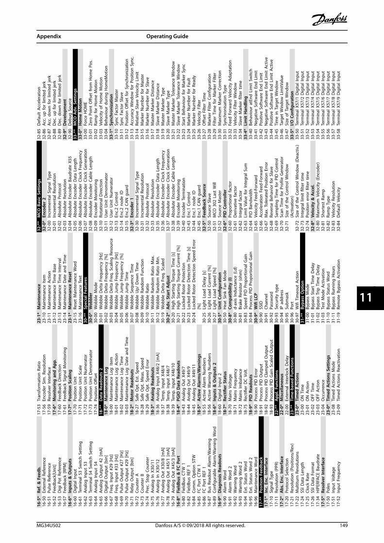
16-5
*Re
f. &
Fee
db.
16-5
0Ex
tern
al R
efer
ence
16-5
1Pu
lse
Refe
renc
e16
-52
Feed
back
[Uni
t]16
-53
Dig
i Pot
Ref
eren
ce16
-57
Feed
back
[RPM
]16
-6*
Inpu
ts &
Out
puts
16-6
0D
igita
l Inp
ut16
-61
Term
inal
53
Switc
h S
ettin
g16
-62
Ana
log
Inpu
t 53
16-6
3Te
rmin
al 5
4 Sw
itch
Set
ting
16-6
4A
nalo
g In
put
5416
-65
Ana
log
Out
put
42 [m
A]
16-6
6D
igita
l Out
put
[bin
]16
-67
Freq
. Inp
ut #
29 [H
z]16
-68
Freq
. Inp
ut #
33 [H
z]16
-69
Puls
e O
utpu
t #2
7 [H
z]16
-70
Puls
e O
utpu
t #2
9 [H
z]16
-71
Rela
y O
utpu
t [b
in]
16-7
2Co
unte
r A
16-7
3Co
unte
r B
16-7
4Pr
ec. S
top
Cou
nter
16-7
5A
nalo
g In
X30
/11
16-7
6A
nalo
g In
X30
/12
16-7
7A
nalo
g O
ut X
30/8
[mA
]16
-78
Ana
log
Out
X45
/1 [m
A]
16-7
9A
nalo
g O
ut X
45/3
[mA
]16
-8*
Fiel
dbus
& F
C P
ort
16-8
0Fi
eldb
us C
TW 1
16-8
2Fi
eldb
us R
EF 1
16-8
4Co
mm
. Opt
ion
STW
16-8
5FC
Por
t C
TW 1
16-8
6FC
Por
t RE
F 1
16-8
7Bu
s Re
adou
t A
larm
/War
ning
16-8
9Co
nfigu
rabl
e A
larm
/War
ning
Wor
d16
-9*
Dia
gnos
is R
eado
uts
16-9
0A
larm
Wor
d16
-91
Ala
rm W
ord
216
-92
War
ning
Wor
d16
-93
War
ning
Wor
d 2
16-9
4Ex
t. S
tatu
s W
ord
16-9
5Ex
t. S
tatu
s W
ord
216
-96
Mai
nten
ance
Wor
d17
-**
Posi
tion
Fee
dbac
k17
-1*
Inc.
Enc
. Int
erfa
ce17
-10
Sign
al T
ype
17-1
1Re
solu
tion
(PPR
)17
-2*
Abs
. Enc
. Int
erfa
ce17
-20
Prot
ocol
Sel
ectio
n17
-21
Reso
lutio
n (P
ositi
ons/
Rev)
17-2
2M
ultit
urn
Rev
olut
ions
17-2
4SS
I Dat
a Le
ngth
17-2
5Cl
ock
Rate
17-2
6SS
I Dat
a Fo
rmat
17-3
4H
IPER
FACE
Bau
drat
e17
-5*
Reso
lver
Inte
rfac
e17
-50
Pole
s17
-51
Inpu
t Vo
ltage
17-5
2In
put
Freq
uenc
y
17-5
3Tr
ansf
orm
atio
n R
atio
17-5
6En
code
r Si
m. R
esol
utio
n17
-59
Reso
lver
Inte
rfac
e17
-6*
Mon
itori
ng a
nd A
pp.
17-6
0Fe
edba
ck D
irect
ion
17-6
1Fe
edba
ck S
igna
l Mon
itorin
g17
-7*
Posi
tion
Sca
ling
17-7
0Po
sitio
n U
nit
17-7
1Po
sitio
n U
nit
Scal
e17
-72
Posi
tion
Uni
t N
umer
ator
17-7
3Po
sitio
n U
nit
Den
omin
ator
17-7
4Po
sitio
n O
ffset
18-*
*D
ata
Read
outs
218
-0*
Mai
nten
ance
Log
18-0
0M
aint
enan
ce L
og: I
tem
18-0
1M
aint
enan
ce L
og: A
ctio
n18
-02
Mai
nten
ance
Log
: Tim
e18
-03
Mai
nten
ance
Log
: Dat
e an
d T
ime
18-2
*M
otor
Rea
dout
s18
-27
Safe
Opt
. Est
. Spe
ed18
-28
Safe
Opt
. Mea
s. S
peed
18-2
9Sa
fe O
pt. S
peed
Err
or18
-3*
Ana
log
Rea
dout
s18
-36
Ana
log
Inpu
t X4
8/2
[mA
]18
-37
Tem
p. In
put
X48/
418
-38
Tem
p. In
put
X48/
718
-39
Tem
p. In
put
X48/
1018
-4*
PGIO
Dat
a Re
adou
ts18
-43
Ana
log
Out
X49
/718
-44
Ana
log
Out
X49
/918
-45
Ana
log
Out
X49
/11
18-5
*A
ctiv
e A
larm
s/W
arni
ngs
18-5
5Ac
tive
Ala
rm N
umbe
rs18
-56
Activ
e W
arni
ng N
umbe
rs18
-6*
Inpu
ts &
Out
puts
218
-60
Dig
ital I
nput
218
-7*
Rect
ifier
Sta
tus
18-7
0M
ains
Vol
tage
18-7
1M
ains
Fre
quen
cy18
-72
Mai
ns Im
bala
nce
18-7
5Re
ctifi
er D
C V
olt.
18-9
*PI
D R
eado
uts
18-9
0Pr
oces
s PI
D E
rror
18-9
1Pr
oces
s PI
D O
utpu
t18
-92
Proc
ess
PID
Cla
mpe
d O
utpu
t18
-93
Proc
ess
PID
Gai
n S
cale
d O
utpu
t22
-**
App
l. Fu
nctio
ns22
-0*
Mis
cella
neou
s22
-00
Exte
rnal
Inte
rlock
Del
ay23
-**
Tim
e-ba
sed
Fun
ctio
ns23
-0*
Tim
ed A
ctio
ns23
-00
ON
Tim
e23
-01
ON
Act
ion
23-0
2O
FF T
ime
23-0
3O
FF A
ctio
n23
-04
Occ
urre
nce
23-0
*Ti
med
Act
ions
Set
tings
23-0
8Ti
med
Act
ions
Mod
e23
-09
Tim
ed A
ctio
ns R
eact
ivat
ion
23-1
*M
aint
enan
ce23
-10
Mai
nten
ance
Item
23-1
1M
aint
enan
ce A
ctio
n23
-12
Mai
nten
ance
Tim
e Ba
se23
-13
Mai
nten
ance
Tim
e In
terv
al23
-14
Mai
nten
ance
Dat
e an
d T
ime
23-1
*M
aint
enan
ce R
eset
23-1
5Re
set
Mai
nten
ance
Wor
d23
-16
Mai
nten
ance
Tex
t30
-**
Spec
ial F
eatu
res
30-0
*W
obbl
er30
-00
Wob
ble
Mod
e30
-01
Wob
ble
Del
ta F
requ
ency
[Hz]
30-0
2W
obbl
e D
elta
Fre
quen
cy [%
]30
-03
Wob
ble
Del
ta F
req.
Sca
ling
Res
ourc
e30
-04
Wob
ble
Jum
p F
requ
ency
[Hz]
30-0
5W
obbl
e Ju
mp
Fre
quen
cy [%
]30
-06
Wob
ble
Jum
p T
ime
30-0
7W
obbl
e Se
quen
ce T
ime
30-0
8W
obbl
e U
p/ D
own
Tim
e30
-09
Wob
ble
Rand
om F
unct
ion
30-1
0W
obbl
e Ra
tio30
-11
Wob
ble
Rand
om R
atio
Max
.30
-12
Wob
ble
Rand
om R
atio
Min
.30
-19
Wob
ble
Del
ta F
req.
Sca
led
30-2
*A
dv. S
tart
Adj
ust
30-2
0H
igh
Sta
rtin
g T
orqu
e Ti
me
[s]
30-2
1H
igh
Sta
rtin
g T
orqu
e Cu
rren
t [%
]30
-22
Lock
ed R
otor
Pro
tect
ion
30-2
3Lo
cked
Rot
or D
etec
tion
Tim
e [s
]30
-24
Lock
ed R
otor
Det
ectio
n S
peed
Err
or[%
]30
-25
Ligh
t Lo
ad D
elay
[s]
30-2
6Li
ght
Load
Cur
rent
[%]
30-2
7Li
ght
Load
Spe
ed [%
]30
-5*
Uni
t Co
nfigu
ratio
n30
-50
Hea
t Si
nk F
an M
ode
30-8
*Co
mpa
tibili
ty (I
)30
-80
d-ax
is In
duct
ance
(Ld)
30-8
1Br
ake
Resi
stor
(ohm
)30
-83
Spee
d P
ID P
ropo
rtio
nal G
ain
30-8
4Pr
oces
s PI
D P
ropo
rtio
nal G
ain
30-9
*W
ifi L
CP30
-90
SSID
30-9
1Ch
anne
l30
-92
Pass
wor
d30
-93
Secu
rity
type
30-9
4IP
add
ress
30-9
5Su
bmas
k30
-96
Port
30-9
7W
ifi T
imeo
ut A
ctio
n31
-**
Bypa
ss O
ptio
n31
-00
Bypa
ss M
ode
31-0
1By
pass
Sta
rt T
ime
Del
ay31
-02
Bypa
ss T
rip T
ime
Del
ay31
-03
Test
Mod
e Ac
tivat
ion
31-1
0By
pass
Sta
tus
Wor
d31
-11
Bypa
ss R
unni
ng H
ours
31-1
9Re
mot
e By
pass
Act
ivat
ion
32-*
*M
CO B
asic
Set
tings
32-0
*En
code
r 2
32-0
0In
crem
enta
l Sig
nal T
ype
32-0
1In
crem
enta
l Res
olut
ion
32-0
2A
bsol
ute
Prot
ocol
32-0
3A
bsol
ute
Reso
lutio
n32
-04
Abs
olut
e En
code
r Ba
udra
te X
5532
-05
Abs
olut
e En
code
r D
ata
Leng
th32
-06
Abs
olut
e En
code
r Cl
ock
Freq
uenc
y32
-07
Abs
olut
e En
code
r Cl
ock
Gen
erat
ion
32-0
8A
bsol
ute
Enco
der
Cabl
e Le
ngth
32-0
9En
code
r M
onito
ring
32-1
0Ro
tatio
nal D
irect
ion
32-1
1U
ser
Uni
t D
enom
inat
or32
-12
Use
r U
nit
Num
erat
or32
-13
Enc.
2 Co
ntro
l32
-14
Enc.
2 no
de ID
32-1
5En
c.2
CAN
gua
rd32
-3*
Enco
der
132
-30
Incr
emen
tal S
igna
l Typ
e32
-31
Incr
emen
tal R
esol
utio
n32
-32
Abs
olut
e Pr
otoc
ol32
-33
Abs
olut
e Re
solu
tion
32-3
5A
bsol
ute
Enco
der
Dat
a Le
ngth
32-3
6A
bsol
ute
Enco
der
Cloc
k Fr
eque
ncy
32-3
7A
bsol
ute
Enco
der
Cloc
k G
ener
atio
n32
-38
Abs
olut
e En
code
r Ca
ble
Leng
th32
-39
Enco
der
Mon
itorin
g32
-40
Enco
der
Term
inat
ion
32-4
3En
c.1
Cont
rol
32-4
4En
c.1
node
ID32
-45
Enc.
1 CA
N g
uard
32-5
*Fe
edba
ck S
ourc
e32
-50
Sour
ce S
lave
32-5
1M
CO 3
02 L
ast
Will
32-5
2So
urce
Mas
ter
32-6
*PI
D C
ontr
olle
r32
-60
Prop
ortio
nal f
acto
r32
-61
Der
ivat
ive
fact
or32
-62
Inte
gral
fact
or32
-63
Lim
it V
alue
for
Inte
gral
Sum
32-6
4PI
D B
andw
idth
32-6
5Ve
loci
ty F
eed-
Forw
ard
32-6
6Ac
cele
ratio
n F
eed-
Forw
ard
32-6
7M
ax. T
oler
ated
Pos
ition
Err
or32
-68
Reve
rse
Beha
vior
for
Slav
e32
-69
Sam
plin
g T
ime
for
PID
Con
trol
32-7
0Sc
an T
ime
for
Profi
le G
ener
ator
32-7
1Si
ze o
f th
e Co
ntro
l Win
dow
(Act
ivat
ion)
32-7
2Si
ze o
f th
e Co
ntro
l Win
dow
(Dea
ctiv
.)32
-73
Inte
gral
lim
it fi
lter
time
32-7
4Po
sitio
n e
rror
filte
r tim
e32
-8*
Velo
city
& A
ccel
.32
-80
Max
imum
Vel
ocity
(Enc
oder
)32
-81
Shor
test
Ram
p32
-82
Ram
p T
ype
32-8
3Ve
loci
ty R
esol
utio
n32
-84
Def
ault
Vel
ocity
32-8
5D
efau
lt A
ccel
erat
ion
32-8
6Ac
c. u
p fo
r lim
ited
jerk
32-8
7Ac
c. d
own
for
limite
d je
rk32
-88
Dec
. up
for
limite
d je
rk32
-89
Dec
. dow
n fo
r lim
ited
jerk
32-9
*D
evel
opm
ent
32-9
0D
ebug
Sou
rce
33-*
*M
CO A
dv. S
ettin
gs33
-0*
Hom
e M
otio
n33
-00
Forc
e H
OM
E33
-01
Zero
Poi
nt O
ffset
from
Hom
e Po
s.33
-02
Ram
p fo
r H
ome
Mot
ion
33-0
3Ve
loci
ty o
f H
ome
Mot
ion
33-0
4Be
havi
our
durin
g H
omeM
otio
n33
-1*
Sync
hron
izat
ion
33-1
0Sy
nc F
acto
r M
aste
r33
-11
Sync
Fac
tor
Slav
e33
-12
Posi
tion
Offs
et fo
r Sy
nchr
oniz
atio
n33
-13
Accu
racy
Win
dow
for
Posi
tion
Syn
c.33
-14
Rela
tive
Slav
e Ve
loci
ty L
imit
33-1
5M
arke
r N
umbe
r fo
r M
aste
r33
-16
Mar
ker
Num
ber
for
Slav
e33
-17
Mas
ter
Mar
ker
Dis
tanc
e33
-18
Slav
e M
arke
r D
ista
nce
33-1
9M
aste
r M
arke
r Ty
pe33
-20
Slav
e M
arke
r Ty
pe33
-21
Mas
ter
Mar
ker
Tole
ranc
e W
indo
w33
-22
Slav
e M
arke
r To
lera
nce
Win
dow
33-2
3St
art
Beha
viou
r fo
r M
arke
r Sy
nc33
-24
Mar
ker
Num
ber
for
Faul
t33
-25
Mar
ker
Num
ber
for
Read
y33
-26
Velo
city
Filt
er33
-27
Offs
et F
ilter
Tim
e33
-28
Mar
ker
Filte
r Co
nfigu
ratio
n33
-29
Filte
r Ti
me
for
Mar
ker
Filte
r33
-30
Max
imum
Mar
ker
Corr
ectio
n33
-31
Sync
hron
isat
ion
Typ
e33
-32
Feed
For
war
d V
eloc
ity A
dapt
atio
n33
-33
Velo
city
Filt
er W
indo
w33
-34
Slav
e M
arke
r fil
ter
time
33-4
*Li
mit
Han
dlin
g33
-40
Beha
viou
r at
End
Lim
it S
witc
h33
-41
Neg
ativ
e So
ftw
are
End
Lim
it33
-42
Posi
tive
Soft
war
e En
d L
imit
33-4
3N
egat
ive
Soft
war
e En
d L
imit
Act
ive
33-4
4Po
sitiv
e So
ftw
are
End
Lim
it A
ctiv
e33
-45
Tim
e in
Tar
get
Win
dow
33-4
6Ta
rget
Win
dow
Lim
itVal
ue33
-47
Size
of
Targ
et W
indo
w33
-5*
I/O C
onfig
urat
ion
33-5
0Te
rmin
al X
57/1
Dig
ital I
nput
33-5
1Te
rmin
al X
57/2
Dig
ital I
nput
33-5
2Te
rmin
al X
57/3
Dig
ital I
nput
33-5
3Te
rmin
al X
57/4
Dig
ital I
nput
33-5
4Te
rmin
al X
57/5
Dig
ital I
nput
33-5
5Te
rmin
al X
57/6
Dig
ital I
nput
33-5
6Te
rmin
al X
57/7
Dig
ital I
nput
33-5
7Te
rmin
al X
57/8
Dig
ital I
nput
33-5
8Te
rmin
al X
57/9
Dig
ital I
nput
Appendix Operating Guide
MG34U502 Danfoss A/S © 09/2018 All rights reserved. 149
11 11
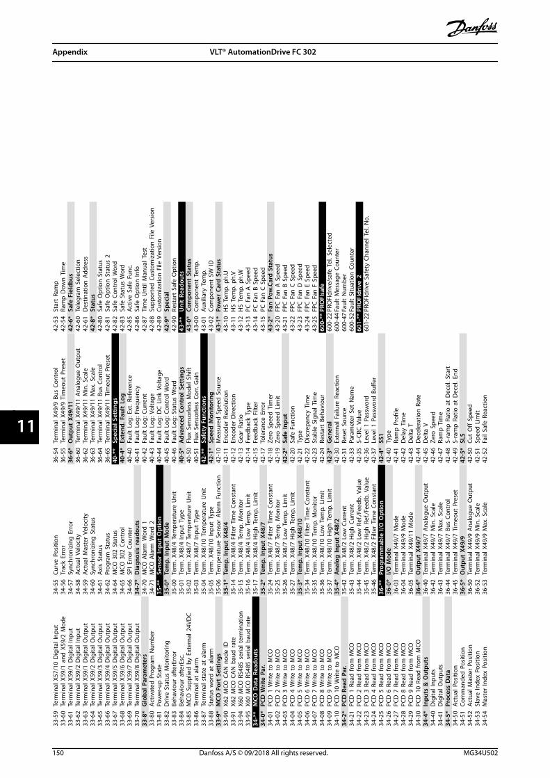
33-5
9Te
rmin
al X
57/1
0 D
igita
l Inp
ut33
-60
Term
inal
X59
/1 a
nd X
59/2
Mod
e33
-61
Term
inal
X59
/1 D
igita
l Inp
ut33
-62
Term
inal
X59
/2 D
igita
l Inp
ut33
-63
Term
inal
X59
/1 D
igita
l Out
put
33-6
4Te
rmin
al X
59/2
Dig
ital O
utpu
t33
-65
Term
inal
X59
/3 D
igita
l Out
put
33-6
6Te
rmin
al X
59/4
Dig
ital O
utpu
t33
-67
Term
inal
X59
/5 D
igita
l Out
put
33-6
8Te
rmin
al X
59/6
Dig
ital O
utpu
t33
-69
Term
inal
X59
/7 D
igita
l Out
put
33-7
0Te
rmin
al X
59/8
Dig
ital O
utpu
t33
-8*
Glo
bal P
aram
eter
s33
-80
Activ
ated
Pro
gram
Num
ber
33-8
1Po
wer
-up
Sta
te33
-82
Driv
e St
atus
Mon
itorin
g33
-83
Beha
viou
r af
terE
rror
33-8
4Be
havi
our
afte
rEsc
.33
-85
MCO
Sup
plie
d b
y Ex
tern
al 2
4VD
C33
-86
Term
inal
at
alar
m33
-87
Term
inal
sta
te a
t al
arm
33-8
8St
atus
wor
d a
t al
arm
33-9
*M
CO P
ort
Sett
ings
33-9
0X6
2 M
CO C
AN
nod
e ID
33-9
1X6
2 M
CO C
AN
bau
d r
ate
33-9
4X6
0 M
CO R
S485
ser
ial t
erm
inat
ion
33-9
5X6
0 M
CO R
S485
ser
ial b
aud
rat
e34
-**
MCO
Dat
a Re
adou
ts34
-0*
PCD
Wri
te P
ar.
34-0
1PC
D 1
Writ
e to
MCO
34-0
2PC
D 2
Writ
e to
MCO
34-0
3PC
D 3
Writ
e to
MCO
34-0
4PC
D 4
Writ
e to
MCO
34-0
5PC
D 5
Writ
e to
MCO
34-0
6PC
D 6
Writ
e to
MCO
34-0
7PC
D 7
Writ
e to
MCO
34-0
8PC
D 8
Writ
e to
MCO
34-0
9PC
D 9
Writ
e to
MCO
34-1
0PC
D 1
0 W
rite
to M
CO34
-2*
PCD
Rea
d P
ar.
34-2
1PC
D 1
Rea
d fr
om M
CO34
-22
PCD
2 R
ead
from
MCO
34-2
3PC
D 3
Rea
d fr
om M
CO34
-24
PCD
4 R
ead
from
MCO
34-2
5PC
D 5
Rea
d fr
om M
CO34
-26
PCD
6 R
ead
from
MCO
34-2
7PC
D 7
Rea
d fr
om M
CO34
-28
PCD
8 R
ead
from
MCO
34-2
9PC
D 9
Rea
d fr
om M
CO34
-30
PCD
10
Read
from
MCO
34-4
*In
puts
& O
utpu
ts34
-40
Dig
ital I
nput
s34
-41
Dig
ital O
utpu
ts34
-5*
Proc
ess
Dat
a34
-50
Actu
al P
ositi
on34
-51
Com
man
ded
Pos
ition
34-5
2Ac
tual
Mas
ter
Posi
tion
34-5
3Sl
ave
Inde
x Po
sitio
n34
-54
Mas
ter
Inde
x Po
sitio
n
34-5
5Cu
rve
Posi
tion
34-5
6Tr
ack
Erro
r34
-57
Sync
hron
izin
g E
rror
34-5
8Ac
tual
Vel
ocity
34-5
9Ac
tual
Mas
ter
Velo
city
34-6
0Sy
nchr
oniz
ing
Sta
tus
34-6
1A
xis
Stat
us34
-62
Prog
ram
Sta
tus
34-6
4M
CO 3
02 S
tatu
s34
-65
MCO
302
Con
trol
34-6
6SP
I Err
or C
ount
er34
-7*
Dia
gnos
is r
eado
uts
34-7
0M
CO A
larm
Wor
d 1
34-7
1M
CO A
larm
Wor
d 2
35-*
*Se
nsor
Inpu
t O
ptio
n35
-0*
Tem
p. In
put
Mod
e35
-00
Term
. X48
/4 T
empe
ratu
re U
nit
35-0
1Te
rm. X
48/4
Inpu
t Ty
pe35
-02
Term
. X48
/7 T
empe
ratu
re U
nit
35-0
3Te
rm. X
48/7
Inpu
t Ty
pe35
-04
Term
. X48
/10
Tem
pera
ture
Uni
t35
-05
Term
. X48
/10
Inpu
t Ty
pe35
-06
Tem
pera
ture
Sen
sor
Ala
rm F
unct
ion
35-1
*Te
mp.
Inpu
t X4
8/4
35-1
4Te
rm. X
48/4
Filt
er T
ime
Cons
tant
35-1
5Te
rm. X
48/4
Tem
p. M
onito
r35
-16
Term
. X48
/4 L
ow T
emp.
Lim
it35
-17
Term
. X48
/4 H
igh
Tem
p. L
imit
35-2
*Te
mp.
Inpu
t X4
8/7
35-2
4Te
rm. X
48/7
Filt
er T
ime
Cons
tant
35-2
5Te
rm. X
48/7
Tem
p. M
onito
r35
-26
Term
. X48
/7 L
ow T
emp.
Lim
it35
-27
Term
. X48
/7 H
igh
Tem
p. L
imit
35-3
*Te
mp.
Inpu
t X4
8/10
35-3
4Te
rm. X
48/1
0 Fi
lter
Tim
e Co
nsta
nt35
-35
Term
. X48
/10
Tem
p. M
onito
r35
-36
Term
. X48
/10
Low
Tem
p. L
imit
35-3
7Te
rm. X
48/1
0 H
igh
Tem
p. L
imit
35-4
*A
nalo
g In
put
X48/
235
-42
Term
. X48
/2 L
ow C
urre
nt35
-43
Term
. X48
/2 H
igh
Cur
rent
35-4
4Te
rm. X
48/2
Low
Ref
./Fee
db. V
alue
35-4
5Te
rm. X
48/2
Hig
h R
ef./F
eedb
. Val
ue35
-46
Term
. X48
/2 F
ilter
Tim
e Co
nsta
nt36
-**
Prog
ram
mab
le I/
O O
ptio
n36
-0*
I/O M
ode
36-0
3Te
rmin
al X
49/7
Mod
e36
-04
Term
inal
X49
/9 M
ode
36-0
5Te
rmin
al X
49/1
1 M
ode
36-4
*O
utpu
t X4
9/7
36-4
0Te
rmin
al X
49/7
Ana
logu
e O
utpu
t36
-42
Term
inal
X49
/7 M
in. S
cale
36-4
3Te
rmin
al X
49/7
Max
. Sca
le36
-44
Term
inal
X49
/7 B
us C
ontr
ol36
-45
Term
inal
X49
/7 T
imeo
ut P
rese
t36
-5*
Out
put
X49/
936
-50
Term
inal
X49
/9 A
nalo
gue
Out
put
36-5
2Te
rmin
al X
49/9
Min
. Sca
le36
-53
Term
inal
X49
/9 M
ax. S
cale
36-5
4Te
rmin
al X
49/9
Bus
Con
trol
36-5
5Te
rmin
al X
49/9
Tim
eout
Pre
set
36-6
*O
utpu
t X4
9/11
36-6
0Te
rmin
al X
49/1
1 A
nalo
gue
Out
put
36-6
2Te
rmin
al X
49/1
1 M
in. S
cale
36-6
3Te
rmin
al X
49/1
1 M
ax. S
cale
36-6
4Te
rmin
al X
49/1
1 Bu
s Co
ntro
l36
-65
Term
inal
X49
/11
Tim
eout
Pre
set
40-*
*Sp
ecia
l Set
tings
40-4
*Ex
tend
. Fau
lt L
og40
-40
Faul
t Lo
g: E
xt. R
efer
ence
40-4
1Fa
ult
Log:
Fre
quen
cy40
-42
Faul
t Lo
g: C
urre
nt40
-43
Faul
t Lo
g: V
olta
ge40
-44
Faul
t Lo
g: D
C L
ink
Volta
ge40
-45
Faul
t Lo
g: C
ontr
ol W
ord
40-4
6Fa
ult
Log:
Sta
tus
Wor
d40
-5*
Adv
ance
d C
ontr
ol S
ettin
gs40
-50
Flux
Sen
sorle
ss M
odel
Shi
ft40
-51
Flux
Sen
sorle
ss C
orr.
Gai
n42
-**
Safe
ty F
unct
ions
42-1
*Sp
eed
Mon
itori
ng42
-10
Mea
sure
d S
peed
Sou
rce
42-1
1En
code
r Re
solu
tion
42-1
2En
code
r D
irect
ion
42-1
3G
ear
Ratio
42-1
4Fe
edba
ck T
ype
42-1
5Fe
edba
ck F
ilter
42-1
7To
lera
nce
Erro
r42
-18
Zero
Spe
ed T
imer
42-1
9Ze
ro S
peed
Lim
it42
-2*
Safe
Inpu
t42
-20
Safe
Fun
ctio
n42
-21
Type
42-2
2D
iscr
epan
cy T
ime
42-2
3St
able
Sig
nal T
ime
42-2
4Re
star
t Be
havi
our
42-3
*G
ener
al42
-30
Exte
rnal
Fai
lure
Rea
ctio
n42
-31
Rese
t So
urce
42-3
3Pa
ram
eter
Set
Nam
e42
-35
S-CR
C V
alue
42-3
6Le
vel 1
Pas
swor
d42
-37
Leve
l 1 P
assw
ord
Buff
er42
-4*
SS1
42-4
0Ty
pe42
-41
Ram
p P
rofil
e42
-42
Del
ay T
ime
42-4
3D
elta
T42
-44
Dec
eler
atio
n R
ate
42-4
5D
elta
V42
-46
Zero
Spe
ed42
-47
Ram
p T
ime
42-4
8S-
ram
p R
atio
at
Dec
el. S
tart
42-4
9S-
ram
p R
atio
at
Dec
el. E
nd42
-5*
SLS
42-5
0Cu
t O
ff S
peed
42-5
1Sp
eed
Lim
it42
-52
Fail
Safe
Rea
ctio
n
42-5
3St
art
Ram
p42
-54
Ram
p D
own
Tim
e42
-6*
Safe
Fie
ldbu
s42
-60
Tele
gram
Sel
ectio
n42
-61
Des
tinat
ion
Add
ress
42-8
*St
atus
42-8
0Sa
fe O
ptio
n S
tatu
s42
-81
Safe
Opt
ion
Sta
tus
242
-82
Safe
Con
trol
Wor
d42
-83
Safe
Sta
tus
Wor
d42
-85
Activ
e Sa
fe F
unc.
42-8
6Sa
fe O
ptio
n In
fo42
-87
Tim
e U
ntil
Man
ual T
est
42-8
8Su
ppor
ted
Cus
tom
izat
ion
File
Ver
sion
42-8
9Cu
stom
izat
ion
File
Ver
sion
42-9
*Sp
ecia
l42
-90
Rest
art
Safe
Opt
ion
43-*
*U
nit
Read
outs
43-0
*Co
mpo
nent
Sta
tus
43-0
0Co
mpo
nent
Tem
p.43
-01
Auxi
liary
Tem
p.43
-02
Com
pone
nt S
W ID
43-1
*Po
wer
Car
d S
tatu
s43
-10
HS
Tem
p. p
h.U
43-1
1H
S Te
mp.
ph.
V43
-12
HS
Tem
p. p
h.W
43-1
3PC
Fan
A S
peed
43-1
4PC
Fan
B S
peed
43-1
5PC
Fan
C S
peed
43-2
*Fa
n P
ow.C
ard
Sta
tus
43-2
0FP
C F
an A
Spe
ed43
-21
FPC
Fan
B S
peed
43-2
2FP
C F
an C
Spe
ed43
-23
FPC
Fan
D S
peed
43-2
4FP
C F
an E
Spe
ed43
-25
FPC
Fan
F S
peed
600-
**PR
OFI
safe
600-
22PR
OFI
driv
e/sa
fe T
el. S
elec
ted
600-
44Fa
ult
Mes
sage
Cou
nter
600-
47Fa
ult
Num
ber
600-
52Fa
ult
Situ
atio
n C
ount
er60
1-**
PRO
FIdr
ive
260
1-22
PRO
FIdr
ive
Safe
ty C
hann
el T
el. N
o.
Appendix VLT® AutomationDrive FC 302
150 Danfoss A/S © 09/2018 All rights reserved. MG34U502
1111
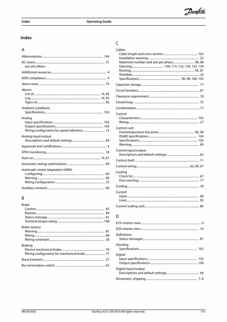
Index
AAbbreviations...................................................................................... 144
AC mains.................................................................................................. 31see also Mains
Additional resources.............................................................................. 4
ADN compliance..................................................................................... 4
Alarm reset.............................................................................................. 75
AlarmsList of............................................................................................. 14, 84Log.................................................................................................. 14, 93Types of................................................................................................ 83
Ambient conditionsSpecifications.................................................................................. 102
AnalogInput specifications...................................................................... 103Output specifications................................................................... 104Wiring configuration for speed reference............................... 73
Analog input/outputDescriptions and default settings.............................................. 64
Approvals and certifications............................................................... 4
ATEX monitoring................................................................................... 18
Auto on.............................................................................................. 14, 81
Automatic energy optimization...................................................... 69
Automatic motor adaptation (AMA)Configuring........................................................................................ 69Warning............................................................................................... 90Wiring configuration....................................................................... 72
Auxiliary contacts................................................................................. 66
BBrake
Control................................................................................................. 85Resistor................................................................................................ 84Status message................................................................................. 81Terminal torque rating................................................................. 108
Brake resistorWarning............................................................................................... 87Wiring................................................................................................... 66Wiring schematic............................................................................. 26
BrakingElectro-mechanical brake............................................................. 79Wiring configuration for mechanical brake............................ 77
Burst transient....................................................................................... 27
Bus termination switch....................................................................... 65
CCables
Cable length and cross-section................................................ 103Installation warning........................................................................ 23Maximum number and size per phase.............................. 96, 98Opening............................................. 109, 113, 123, 128, 133, 139Routing......................................................................................... 63, 67Shielded............................................................................................... 23Specifications.......................................................... 96, 98, 100, 103
Capacitor storage................................................................................. 17
Circuit breakers...................................................................................... 67
Clearance requirement....................................................................... 18
Closed loop............................................................................................. 72
Condensation......................................................................................... 17
ControlCharacteristics................................................................................ 105Wiring................................................................................................... 27
Control cardOvertemperature trip point.................................................. 96, 98RS485 specifications..................................................................... 104Specifications.................................................................................. 105Warning............................................................................................... 90
Control input/outputDescriptions and default settings.............................................. 63
Control shelf........................................................................................... 11
Control wiring.......................................................................... 63, 64, 67
CoolingCheck list............................................................................................. 67Dust warning..................................................................................... 17
Cooling..................................................................................................... 18
CurrentInput..................................................................................................... 66Limit...................................................................................................... 95
Current scaling card............................................................................. 86
DD1h interior view..................................................................................... 9
D2h interior view.................................................................................. 10
DefinitionsStatus messages............................................................................... 81
DeratingSpecifications.................................................................................. 102
DigitalInput specifications...................................................................... 103Output specifications................................................................... 104
Digital input/outputDescriptions and default settings.............................................. 64
Dimension, shipping......................................................................... 7, 8
Index Operating Guide
MG34U502 Danfoss A/S © 09/2018 All rights reserved. 151

DimensionsD1h exterior..................................................................................... 109D1h terminal...................................................................................... 35D2h exterior..................................................................................... 113D2h terminal...................................................................................... 37D3h exterior..................................................................................... 117D3h terminal...................................................................................... 39D4h exterior..................................................................................... 120D4h terminal...................................................................................... 41D5h exterior..................................................................................... 123D5h terminal...................................................................................... 43D6h exterior..................................................................................... 128D6h terminal...................................................................................... 47D7h exterior..................................................................................... 133D7h terminal...................................................................................... 53D8h exterior..................................................................................... 139D8h terminal...................................................................................... 57
Discharge time......................................................................................... 5
Disconnect.............................................................................................. 66
Disconnect switch................................................................................ 68
Disposal instruction............................................................................... 4
Door clearance..................................... 112, 116, 127, 132, 138, 143
Door/panel coverTorque rating................................................................................... 108
DriveDefinition............................................................................................... 7Initialization....................................................................................... 71Lifting................................................................................................... 19Status.................................................................................................... 81
EEfficiency
Specifications.................................................................... 96, 98, 100
Electrical specifications 200–240 V................................................ 97
Electrical specifications 380–500 V................................................ 99
Electrical Specifications 525–690 V............................................. 100
Electro-mechanical brake.................................................................. 79
Electronic thermal relay (ETR).......................................................... 23
EMC.............................................................................................. 23, 24, 25
Encoder.................................................................................................... 70
EncoderConfiguration.................................................................................... 78Determining encoder direction.................................................. 78
Energy efficiency class...................................................................... 102
Environment........................................................................................ 102
Explosive atmosphere......................................................................... 18
Exterior dimensionsD1h..................................................................................................... 109D2h..................................................................................................... 113D3h..................................................................................................... 117D4h..................................................................................................... 120D5h..................................................................................................... 123D6h..................................................................................................... 128D7h..................................................................................................... 133D8h..................................................................................................... 139
External alarm reset wiring configuration................................... 75
FFactory default settings...................................................................... 71
Fan power cardTroubleshooting............................................................................... 86
FansServicing.............................................................................................. 17Warning........................................................................................ 86, 92
Fault log................................................................................................... 14
Fieldbus.................................................................................................... 63
Filter........................................................................................................... 17
Fire mode................................................................................................. 92
FusesOvercurrent protection.................................................................. 23Pre-start check list........................................................................... 67Specifications.................................................................................. 106Troubleshooting............................................................................... 95
GGalvanic isolation............................................................................... 104
Gases......................................................................................................... 17
Gland plateD1h dimensions............................................................................. 112D2h dimensions............................................................................. 116D5h dimensions............................................................................. 127D6h dimensions............................................................................. 132D7h dimensions............................................................................. 138D8h dimensions............................................................................. 143Torque rating................................................................................... 108
GroundCheck list............................................................................................. 67Floating delta.................................................................................... 31Grounded delta................................................................................ 31Grounding.......................................................................................... 29Isolated main..................................................................................... 31Terminal torque rating................................................................. 108Warning............................................................................................... 89
Ground wire............................................................................................ 27
HHand on............................................................................................. 14, 81
Heat sinkAccess.................................................................... 126, 131, 136, 142Access panel torque rating........................................................ 108Alarm.................................................................................................... 89Cleaning.............................................................................................. 17Overtemperature trip point.................................................. 96, 98Warning............................................................................................... 91
HeaterUsage.................................................................................................... 17Wiring of.............................................................................................. 65Wiring schematic............................................................................. 26
High voltage.................................................................................... 87, 88
High voltage warning............................................................................ 5
Index VLT® AutomationDrive FC 302
152 Danfoss A/S © 09/2018 All rights reserved. MG34U502

Humidity.................................................................................................. 17
IIndicator lights....................................................................................... 83
InputPower.................................................................................................... 27Voltage................................................................................................. 68
Input specifications........................................................................... 103
InstallationCheck list............................................................................................. 67Electrical.............................................................................................. 23EMC-compliant................................................................................. 25Initialization....................................................................................... 71Qualified personnel........................................................................... 5Quick set-up....................................................................................... 69Start up................................................................................................ 70Tools needed..................................................................................... 17
Installation................................................................................ 18, 20, 22
Installation environment................................................................... 17
InterferenceEMC....................................................................................................... 24Radio....................................................................................................... 7
Interlock device..................................................................................... 65
Internal fault........................................................................................... 89
LLCP
Display................................................................................................. 13Indicator lights.................................................................................. 14Menu..................................................................................................... 15Troubleshooting............................................................................... 94
Leakage current................................................................................ 5, 27
Lifting................................................................................................. 17, 19
Load shareTerminal dimensions....................................................................... 34Terminal torque rating................................................................. 108Terminals...................................................................................... 12, 33Warning........................................................................................... 5, 88Wiring schematic............................................................................. 26
Load share.......................................................................................... 7, 33
Local control panel (LCP)................................................................... 13
MMain menu.............................................................................................. 15
MainsShield...................................................................................................... 6Supply specifications................................................................... 102Terminal torque rating................................................................. 108Warning............................................................................................... 88
Maintenance.................................................................................... 17, 80
ManualVersion number................................................................................... 4
MCT 10...................................................................................................... 69
MCT 10 Set-up Software.................................................................... 69
Mechanical brakeWiring configuration....................................................................... 77
MenuDescriptions of.................................................................................. 15Keys....................................................................................................... 14
MotorCable.............................................................................................. 23, 29Class protection................................................................................ 18Connection......................................................................................... 29Data....................................................................................................... 95Output specifications................................................................... 102Overheating....................................................................................... 85Power.................................................................................................... 27Rotation............................................................................................... 70Setup.................................................................................................... 15Terminal torque rating................................................................. 108Thermistor wiring configuration................................................ 76Troubleshooting........................................................................ 94, 95Unintended motor rotation............................................................ 6Warning................................................................................. 84, 85, 87Wiring schematic............................................................................. 26
Mounting................................................................................... 18, 20, 22
NNameplate............................................................................................... 16
Navigation keys.............................................................................. 14, 68
OOptional equipment..................................................................... 65, 68
OutputSpecifications.................................................................................. 104
Overcurrent............................................................................................. 85
Overcurrent protection...................................................................... 23
Overvoltage............................................................................................ 95
PParameters.............................................................................. 15, 71, 145
Pedestal.................................................................................................... 20
PELV......................................................................................................... 104
Periodic forming................................................................................... 17
Phase loss................................................................................................ 84
Pigtails...................................................................................................... 23
Potential equalization......................................................................... 27
Potentiometer................................................................................. 64, 75
PowerConnection......................................................................................... 23Leakage............................................................................................... 27Losses................................................................................... 96, 98, 100Ratings................................................................................. 96, 98, 100
Power cardWarning............................................................................................... 91
Programming......................................................................................... 14
Index Operating Guide
MG34U502 Danfoss A/S © 09/2018 All rights reserved. 153

PulseInput specifications...................................................................... 104Wiring configuration for start/stop........................................... 74
QQualified personnel................................................................................ 5
Quick menu..................................................................................... 14, 15
RRamp-down time.................................................................................. 95
Ramp-up time........................................................................................ 95
Recycling.................................................................................................... 4
ReferenceSpeed input........................................................................................ 73
Regen................................................................................................... 7, 33
RegenTerminal dimensions....................................................................... 34Terminals........................................................................ 12, 33, 40, 42
RegenerationTerminal torque rating................................................................. 108
Regional settings......................................................................... 71, 145
RelaySpecifications.................................................................................. 105
Reset..................................................................................... 14, 83, 85, 91
RFI............................................................................................................... 31
RotorWarning............................................................................................... 92
RS485Configuring........................................................................................ 65Terminal description....................................................................... 63Wiring configuration....................................................................... 76Wiring schematic............................................................................. 26
SSafe Torque Off
Terminal location............................................................................. 64Warning............................................................................................... 91Wiring configuration....................................................................... 73Wiring of.............................................................................................. 65Wiring schematic............................................................................. 26
Safety instructions................................................................................ 23
Serial communicationCover torque rating...................................................................... 108Descriptions and default settings.............................................. 63
Service...................................................................................................... 80
Set-up....................................................................................................... 14
ShieldingClamps................................................................................................. 23Mains....................................................................................................... 6Twisted ends...................................................................................... 23
Shipping dimension.......................................................................... 7, 8
Short circuit............................................................................................ 86
Short-circuit current rating............................................................. 107
Sleep mode............................................................................................. 82
Smart logic controlWiring configuration....................................................................... 77
Software version number.................................................................... 4
Specifications electrical..................................................... 96, 98, 100
SpeedWiring configuration for speed reference............................... 75Wiring configuration for speed up/down............................... 75
Start/stop wiring configuration............................................... 73, 74
Status message definitions............................................................... 81
Storage..................................................................................................... 17
SwitchesA53 and A54.................................................................................... 103A53/A54............................................................................................... 66Brake resistor temperature........................................................... 66Bus termination................................................................................ 65
TTemperature........................................................................................... 17
Terminal dimensionsD1h........................................................................................................ 35D2h........................................................................................................ 37D3h........................................................................................................ 39D4h........................................................................................................ 41D5h........................................................................................................ 43D6h........................................................................................................ 47D7h........................................................................................................ 53D8h........................................................................................................ 57
TerminalsAnalog input/output...................................................................... 64Control locations.............................................................................. 63Digital input/output........................................................................ 64Serial communication.................................................................... 63Terminal 37.................................................................................. 64, 65
Thermal protection................................................................................ 4
ThermistorCable routing..................................................................................... 63Terminal location............................................................................. 64Warning............................................................................................... 91Wiring configuration....................................................................... 76
Tools.......................................................................................................... 17
TorqueCharacteristic.................................................................................. 102Fastener rating................................................................................ 108Limit............................................................................................... 85, 95Wiring configuration for torque and stop limit..................... 79
Transducer............................................................................................... 63
TripPoints for 200–240 V drives.......................................................... 96Points for 380–500 V drives.......................................................... 98Points for 525–690 V drives........................................................ 100
Index VLT® AutomationDrive FC 302
154 Danfoss A/S © 09/2018 All rights reserved. MG34U502

TroubleshootingFuses..................................................................................................... 95LCP......................................................................................................... 94Mains.................................................................................................... 95Motor............................................................................................. 94, 95Warnings and alarms...................................................................... 84
UUL certification......................................................................................... 4
Unintended start.............................................................................. 5, 80
USBSpecifications.................................................................................. 106
VVoltage
Imbalance........................................................................................... 84Input..................................................................................................... 66
WWarnings
List of............................................................................................. 14, 84Types of................................................................................................ 83
Weight.................................................................................................... 7, 8
Windmilling............................................................................................... 6
Wire size................................................................................................... 29
Wiring control terminals.................................................................... 64
Wiring schematicDrive...................................................................................................... 26Typical application examples...................................................... 72
Index Operating Guide
MG34U502 Danfoss A/S © 09/2018 All rights reserved. 155

Danfoss can accept no responsibility for possible errors in catalogues, brochures and other printed material. Danfoss reserves the right to alter its products without notice. This also applies toproducts already on order provided that such alterations can be made without subsequential changes being necessary in specifications already agreed. All trademarks in this material are propertyof the respective companies. Danfoss and the Danfoss logotype are trademarks of Danfoss A/S. All rights reserved.
Danfoss A/SUlsnaes 1DK-6300 Graastenvlt-drives.danfoss.com
*MG34U502*130R0291 MG34U502 09/2018