VLT® HVAC Drive FC 131 - Danfoss
110
Design Guide VLT® HVAC Drive FC 131 vlt-drives.danfoss.com
-
Upload
khangminh22 -
Category
Documents
-
view
5 -
download
0
Transcript of VLT® HVAC Drive FC 131 - Danfoss

Design Guide
VLT® HVAC Drive FC 131
vlt-drives.danfoss.com


11.1
1.2
1.2.1
1.2.2
1.3
1.4
1.4.1
1.4.2
1.4.3
1.4.4
1.4.5
22.1
2.2
2.3
33.1
3.1.1
3.1.1.1
3.1.1.2
3.1.1.3
3.1.1.4
3.1.1.5
3.1.1.6
3.1.1.7
3.1.1.8
3.1.1.9
3.1.2
3.1.2.1
3.1.2.2
3.1.2.3
3.1.2.4
3.1.2.5
3.1.2.6
ContentsIntroduction 9
Purpose of this Design Guide 9
Additional Resources 9
Other Resources 9
MCT 10 Setup Software Support 9
Document and Software Version 9
Regulatory Compliance 9
Introduction 9
CE Mark 9
RCM Mark Compliance 10
EAC 10
UkrSEPRO 11
Safety 12Safety Symbols 12
Qualified Personnel 12
Safety Precautions 12
Product Overview 15Advantages 15
Why Use a Drive for Controlling Fans and Pumps? 15
The Clear Advantage - Energy Savings 15
Example of Energy Savings 16
Comparison of Energy Savings 16
Example with Varying Flow over 1 Year 18
Better Control 19
Star/Delta Starter or Soft Starter not Required 19
Using a Drive Saves Money 19
Traditional Fan System without a Drive 20
Fan System Controlled by Drives 21
Application Examples 21
Variable Air Volume 21
Constant Air Volume 22
Cooling Tower Fan 23
Condenser Pumps 24
Primary Pumps 25
Secondary Pumps 26
AJ370727701888en-000101/130R0995 | 3Danfoss A/S © 2022.04
Contents
VLT® HVAC Drive FC 131
Design Guide

3.2
3.2.1
3.2.2
3.2.3
3.2.4
3.2.5
3.2.6
3.2.7
3.2.8
3.2.9
3.3
3.3.1
3.3.2
3.3.3
3.3.3.1
3.3.3.2
3.3.4
3.4
3.4.1
3.4.2
3.4.3
3.4.4
3.4.4.1
3.4.4.2
3.4.5
3.5
3.6
3.6.1
3.7
3.7.1
3.7.2
3.7.3
3.7.3.1
3.7.3.2
44.1
4.2
Control Structures 27
Introduction 27
Control Structure Open Loop 27
PM/EC+ Motor Control 27
Local (Hand On) and Remote (Auto On) Control 28
Control Structure Closed Loop 28
Feedback Conversion 29
Reference Handling 29
Tuning the Drive Closed-loop 30
Adjusting the Manual PI 30
Ambient Running Conditions 30
Air Humidity 30
Derating 30
Acoustic Noise or Vibration 32
Acoustic Noise 32
Vibration and Shock 32
Aggressive Environments 33
General Aspects of EMC 33
Overview of EMC Emissions 33
Emission Requirements 34
EMC Emission Test Results 35
Harmonics Emission 36
Harmonics Emission Requirements 36
Harmonics Test Results (Emission) 36
Immunity Requirements 37
Galvanic Isolation (PELV) 37
Ground Leakage Current 38
Using a Residual Current Device (RCD) 40
Extreme Running Conditions 41
Introduction 41
Motor Thermal Protection (ETR) 42
Thermistor Inputs 42
Example with Digital Input and 10 V Power Supply 43
Example with Analog Input and 10 V Power Supply 43
Selection and Ordering 45Type Code 45
Options and Accessories 46
AJ370727701888en-000101/130R09954 | Danfoss A/S © 2022.04
Contents
VLT® HVAC Drive FC 131
Design Guide

4.2.1
55.1
5.1.1
5.1.2
5.1.3
5.2
5.2.1
5.2.2
5.2.3
5.2.4
5.2.4.1
5.2.4.2
5.2.4.3
5.2.4.4
5.2.4.5
5.2.4.6
5.2.4.7
5.2.4.8
5.2.5
5.2.6
66.1
6.1.1
6.1.2
6.1.3
6.1.4
6.1.5
6.2
6.2.1
6.2.2
6.3
6.4
6.4.1
6.4.2
6.4.3
6.4.4
Local Control Panel (LCP) 46
Installation 47Mechanical Installation 47
Side-by-side Installation 47
Drive Dimensions 47
Shipping Dimensions 48
Electrical Installation 48
Electrical Wiring 48
Electrical Installation in General 49
IT Mains 50
Mains and Motor Connection 51
Introduction 51
Connecting to Mains and Motor 52
Enclosure Size I2 52
Enclosure Size I3 53
Enclosure Size I4 54
IP54 Enclosure Sizes I2, I3, I4 55
Enclosure size I6 55
Enclosure size I7, I8 57
EMC-compliant Electrical Installation 57
Control Terminals 58
RS485 Installation and Set-up 60RS485 60
Overview 60
Connecting the Drive to the RS485 Network 60
Hardware Setup 61
Parameter Settings for Modbus Communication 62
EMC Precautions 62
FC Protocol 63
Overview 63
FC with Modbus RTU 63
Network Configuration 64
FC Protocol Message Framing Structure 64
Content of a Character (byte) 64
Telegram Structure 64
Telegram Length (LGE) 64
Drive Address (ADR) 65
AJ370727701888en-000101/130R0995 | 5Danfoss A/S © 2022.04
Contents
VLT® HVAC Drive FC 131
Design Guide

6.4.5
6.4.6
6.4.7
6.4.8
6.4.9
6.4.10
6.4.11
6.4.12
6.4.13
6.5
6.5.1
6.5.2
6.6
6.6.1
6.6.2
6.6.3
6.7
6.8
6.8.1
6.8.2
6.8.3
6.8.4
6.8.5
6.8.6
6.8.7
6.8.8
6.8.8.1
6.8.8.2
6.8.8.3
6.8.8.4
6.8.8.5
6.8.9
6.8.10
6.8.10.1
6.8.10.2
6.8.10.3
6.9
6.9.1
Data Control Byte (BCC) 65
The Data Field 65
The PKE Field 66
Parameter Number (PNU) 67
Index (IND) 68
Parameter Value (PWE) 68
Data Types Supported by the Drive 68
Conversion 68
Process Words (PCD) 69
Examples 69
Writing a Parameter Value 69
Reading a Parameter Value 70
Modbus RTU 70
Prerequisite Knowledge 70
Modbus RTU Overview 70
Drive with Modbus RTU 71
Network Configuration 71
Modbus RTU Message Framing Structure 71
Modbus RTU Message Byte Format 71
Modbus RTU Telegram Structure 72
Start/Stop Field 72
Address Field 72
Function Field 72
Data Field 72
CRC Check Field 73
Coil Register Addressing 73
Introduction 73
Coil Register 73
Drive Control Word (FC Profile) 73
Drive Status Word (FC Profile) 74
Address/Registers 75
Access via PCD Write/read 75
How to Control the Drive 76
Introduction 76
Function Codes Supported by Modbus RTU 76
Modbus Exception Codes 77
How to Access Parameters 77
Parameter Handling 77
AJ370727701888en-000101/130R09956 | Danfoss A/S © 2022.04
Contents
VLT® HVAC Drive FC 131
Design Guide

6.9.2
6.9.3
6.9.4
6.9.5
6.9.6
6.10
6.10.1
6.10.2
6.10.3
6.10.4
6.10.5
6.10.6
6.10.7
6.10.8
6.11
6.11.1
6.11.2
6.11.3
6.11.4
6.11.5
77.1
7.1.1
7.2
7.2.1
7.2.2
7.2.3
7.2.4
7.2.5
7.3
7.3.1
7.3.2
7.3.3
7.3.4
7.3.5
7.3.6
7.3.7
Storage of Data 77
IND (Index) 78
Text Blocks 78
Conversion Factor 78
Parameter Values 78
Examples 78
Introduction 78
Read Coil Status (01 hex) 78
Force/Write Single Coil (05 hex) 79
Force/Write Multiple Coils (0F hex) 80
Read Holding Registers (03 hex) 81
Preset Single Register (06 hex) 81
Preset Multiple Registers (10 hex) 82
Read/Write Multiple Registers (17 hex) 83
Danfoss FC Control Profile 84
Control Word According to FC Profile (8-10 Protocol = FC Profile) 84
Explanation of Each Control Bit 85
Status Word According to FC Profile (STW) 87
Explanation of Each Status Bit 88
Bus Speed Reference Value 89
General Specifications 91Mains Supply 91
3x380–480 V AC 91
Fuses and Circuit Breakers 93
Branch Circuit Protection 93
Short-circuit Protection 93
Overcurrent Protection 93
UL/Non-UL Compliance 93
Recommendation of Fuses and Circuit Breakers 93
General Technical Data 94
Protection and Features 94
Mains Supply (L1, L2, L3) 94
Motor Output (U, V, W) 94
Cable Length and Cross-section 95
Digital Inputs 95
Analog Inputs 95
Analog Outputs 95
AJ370727701888en-000101/130R0995 | 7Danfoss A/S © 2022.04
Contents
VLT® HVAC Drive FC 131
Design Guide

7.3.8
7.3.9
7.3.10
7.3.11
7.3.12
7.3.13
7.4
88.1
8.2
8.2.1
8.2.2
8.2.3
8.2.4
8.2.5
Digital Output 96
Control Card, RS485 Serial Communication 96
Control Card, 24 V DC Output 96
Relay Output 96
Control Card, 10 V DC Output 97
Ambient Conditions 97
dU/Dt 98
Appendix 101Abbreviations 101
Definitions 102
AC Drive 102
Input 102
Motor 102
References 103
Miscellaneous 104
AJ370727701888en-000101/130R09958 | Danfoss A/S © 2022.04
Contents
VLT® HVAC Drive FC 131
Design Guide

•
•
•
•
•
•
1 Introduction
1.1 Purpose of this Design GuideThis design guide is intended for qualified personnel, such as:
Project and systems engineers.
Design consultants.
Application and product specialists.
The design guide provides technical information to understand the capabilities of the VLT® HVAC Drive FC 131 for integration intomotor control and monitoring systems. Its purpose is to provide design considerations and planning data for integration of thedrive into a system. It caters for selection of drives and options for a diversity of applications and installations. Reviewing the de-tailed product information in the design stage enables developing a well-conceived system with optimal functionality and efficien-cy.This manual is targeted at a worldwide audience. Therefore, wherever occurring, both SI and imperial units are shown.VLT® is a registered trademark for Danfoss A/S.
1.2 Additional Resources
1.2.1 Other ResourcesOther resources are available to understand advanced drive functions and programming.
VLT® HVAC Drive FC 131 Operating Guide provides basic information on mechanical dimensions, installation, and basic commis-sioning.
VLT® HVAC Drive FC 131 Programming Guide provides information on how to program, and includes complete parameter de-scriptions.
Danfoss VLT® Energy Box software. Select PC Software Download at www.danfoss.com.
VLT® Energy Box software allows energy consumption comparisons of HVAC fans and pumps driven by Danfoss drives and alterna-tive methods of flow control. Use this tool to accurately project the costs, savings, and payback of using Danfoss drives on HVACfans, pumps, and cooling towers.Supplementary publications and manuals are available from Danfoss website www.danfoss.com.
1.2.2 MCT 10 Setup Software SupportDownload the software from the service and support section on www.danfoss.com.During the installation process of the software, enter access code 81463800 to activate the VLT® HVAC Drive FC 131 functionality. Alicense key is not required for using the VLT® HVAC Drive FC 131 functionality.The latest software does not always contain the latest updates for drives. Contact the local sales office for the latest drive updates (inthe form of *.upd files), or download the drive updates from the service and support section on www.danfoss.com.
1.3 Document and Software VersionThis guide is regularly reviewed and updated. All suggestions for improvement are welcome.The original language of this manual is English.
Table 1: Document and Software Version
Edition Remarks Software version
AJ370727701888, version 0101 First edition. 4.60
1.4 Regulatory Compliance
1.4.1 IntroductionAC drives are designed in compliance with the directives described in this section.
1.4.2 CE MarkThe CE mark (Communauté Européenne) indicates that the product manufacturer conforms to all applicable EU directives. The EUdirectives applicable to the design and manufacture of drives are listed in the following table.
AJ370727701888en-000101 / 130R0995 | 9Danfoss A/S © 2022.04
Introduction
VLT® HVAC Drive FC 131
Design Guide

N O T I C EThe CE mark does not regulate the quality of the product. Technical specifications cannot be deduced from the CE mark.
N O T I C EDrives with an integrated safety function must comply with the machinery directive.
Table 2: EU Directives Applicable to Drives
EU directive Version
Low Voltage Directive 2014/35/EU
EMC Directive 2014/30/EU
ErP Directive
Declarations of conformity are available on request.
1.4.2.1 Low Voltage DirectiveThe aim of the Low Voltage Directive is to protect persons, domestic animals and property against dangers caused by the electricalequipment, when operating electrical equipment that is installed and maintained correctly, in its intended application. The directiveapplies to all electrical equipment in the 50–1000 V AC and the 75–1500 V DC voltage ranges.
1.4.2.2 EMC DirectiveThe purpose of the EMC (electromagnetic compatibility) Directive is to reduce electromagnetic interference and enhance immunityof electrical equipment and installations. The basic protection requirement of the EMC Directive states that devices that generateelectromagnetic interference (EMI), or whose operation could be affected by EMI, must be designed to limit the generation of elec-tromagnetic interference and shall have a suitable degree of immunity to EMI when properly installed, maintained, and used asintended. Electrical equipment devices used alone or as part of a system must bear the CE mark. Systems do not require the CEmark, but must comply with the basic protection requirements of the EMC Directive.
1.4.2.3 ErP DirectiveThe ErP Directive is the European Ecodesign Directive for energy-related products. The directive sets ecodesign requirements forenergy-related products, including drives, and aims at reducing the energy consumption and environmental impact of products byestablishing minimum energy-efficiency standards.
1.4.3 RCM Mark Compliance
Illustration 1: RCM Mark
The RCM Mark label indicates compliance with the applicable technical standards for Electromagnetic Compatibility (EMC). An RCMMark label is required for placing electrical and electronic devices on the market in Australia and New Zealand. The RCM Mark regu-latory arrangements only deal with conducted and radiated emission. For drives, the emission limits specified in EN/IEC 61800-3apply. A declaration of conformity can be provided on request.
1.4.4 EAC
Illustration 2: EAC Mark
The EurAsian Conformity (EAC) Mark indicates that the product conforms to all requirements and technical regulations applicable tothe product per the EurAsian Customs Union, which is composed of the member states of the EurAsian Economic Union.The EAC logo must be both on the product label and on the packaging label. All products used within the EAC area must be boughtat Danfoss inside the EAC area.
AJ370727701888en-000101 / 130R099510 | Danfoss A/S © 2022.04
Introduction
VLT® HVAC Drive FC 131
Design Guide

1.4.5 UkrSEPRO
089
Illustration 3: UkrSEPRO Mark
The UkrSEPRO certificate indicates quality and safety of both products and services, in addition to manufacturing stability accordingto Ukrainian regulatory standards. The UkrSEPRO certificate is a required document to clear customs for any products coming intoand out of the territory of Ukraine.
AJ370727701888en-000101 / 130R0995 | 11Danfoss A/S © 2022.04
Introduction
VLT® HVAC Drive FC 131
Design Guide

•
•
•
•
-
---
2 Safety
2.1 Safety SymbolsThe following symbols are used in this guide:
D A N G E RIndicates a hazardous situation which, if not avoided, will result in death or serious injury.
W A R N I N GIndicates a hazardous situation which, if not avoided, could result in death or serious injury.
C A U T I O NIndicates a hazardous situation which, if not avoided, could result in minor or moderate injury.
N O T I C EIndicates information considered important, but not hazard-related (for example, messages relating to property damage).
2.2 Qualified PersonnelTo allow trouble-free and safe operation of the unit, only qualified personnel with proven skills are allowed to transport, store, as-semble, install, program, commission, maintain, and decommission this equipment.Persons with proven skills:
Are qualified electrical engineers, or persons who have received training from qualified electrical engineers and are suitablyexperienced to operate devices, systems, plant, and machinery in accordance with pertinent laws and regulations.
Are familiar with the basic regulations concerning health and safety/accident prevention.
Have read and understood the safety guidelines given in all guides provided with the unit, especially the instructions given inthe installation guide and safety guide.
Have good knowledge of the generic and specialist standards applicable to the specific application.
2.3 Safety Precautions
W A R N I N GHAZARDOUS VOLTAGEAC drives contain hazardous voltage when connected to the AC mains or connected on the DC terminals. Failure to performinstallation, start-up, and maintenance by skilled personnel can result in death or serious injury.
Only skilled personnel must perform installation, start-up, and maintenance.
W A R N I N GUNINTENDED STARTWhen the drive is connected to AC mains, DC supply, or load sharing, the motor may start at any time. Unintended start duringprogramming, service, or repair work can result in death, serious injury, or property damage. Start the motor with an externalswitch, a fieldbus command, an input reference signal from the local control panel (LCP), via remote operation using MCT 10software, or after a cleared fault condition.
Disconnect the drive from the mains.
Press [Off/Reset] on the LCP before programming parameters.
Ensure that the drive is fully wired and assembled when it is connected to AC mains, DC supply, or load sharing.
AJ370727701888en-000101 / 130R099512 | Danfoss A/S © 2022.04
Safety
VLT® HVAC Drive FC 131
Design Guide

--
-
-
-
--
-
-
-
---
W A R N I N GDISCHARGE TIMEThe drive contains DC-link capacitors, which can remain charged even when the drive is not powered. High voltage can bepresent even when the warning indicator lights are off.Failure to wait the specified time after power has been removed before performing service or repair work could result in death orserious injury.
Stop the motor.
Disconnect AC mains, permanent magnet type motors, and remote DC-link supplies, including battery back-ups, UPS, andDC-link connections to other drives.
Wait for the capacitors to discharge fully. The minimum waiting time is specified in the table Discharge time and is also visibleon the nameplate on the top of the drive.
Before performing any service or repair work, use an appropriate voltage measuring device to make sure that the capacitorsare fully discharged.
Table 3: Discharge Time
Voltage [V] Power range [kW (hp)] Minimum waiting time (minutes)
3x400 0.75–7.5 (1.0–10) 4
3x400 11–90 (15–125) 15
W A R N I N GELECTRICAL SHOCK HAZARD - LEAKAGE CURRENT HAZARDLeakage currents exceed 3.5 mA. Failure to connect the drive properly to protective earth (PE) can result in death or serious in-jury.
Ensure reinforced protective earthing conductor according to IEC 60364-5-54 cl. 543.7 or according to local safety regula-tions for high touch current equipment. The reinforced protective earthing of the drive can be done with:
a PE conductor with a cross-section of at least 10 mm2 (8 AWG) Cu or 16 mm2 (6 AWG) Al.
an extra PE conductor of the same cross-sectional area as the original PE conductor as specified by IEC 60364-5-54 with aminimum cross-sectional area of 2.5 mm2 (14 AWG) (mechanical protected) or 4 mm2 (12 AWG) (not mechanical protected).
a PE conductor completely enclosed with an enclosure or otherwise protected throughout its length against mechanicaldamage.
a PE conductor part of a multi-conductor power cable with a minimum PE conductor cross-section of 2.5 mm2 (14 AWG)(permanently connected or pluggable by an industrial connector. The multi-conductor power cable shall be installed with anappropriate strain relief).
NOTE: In IEC/EN 60364-5-54 cl. 543.7 and some application standards (for example IEC/EN 60204-1), the limit for requiringreinforced protective earthing conductor is 10 mA leakage current.
W A R N I N GEQUIPMENT HAZARDContact with rotating shafts and electrical equipment can result in death or serious injury.
Ensure that only trained and qualified personnel perform installation, start-up, and maintenance.
Ensure that electrical work conforms to national and local electrical codes.
Follow the procedures in this manual.
AJ370727701888en-000101 / 130R0995 | 13Danfoss A/S © 2022.04
Safety
VLT® HVAC Drive FC 131
Design Guide

-
C A U T I O NINTERNAL FAILURE HAZARDAn internal failure in the drive can result in serious injury when the drive is not properly closed.
Ensure that all safety covers are in place and securely fastened before applying power.
AJ370727701888en-000101 / 130R099514 | Danfoss A/S © 2022.04
Safety
VLT® HVAC Drive FC 131
Design Guide

3 Product Overview
3.1 Advantages
3.1.1 Why Use a Drive for Controlling Fans and Pumps?A drive takes advantage of the fact that centrifugal fans and pumps follow the laws of proportionality for such fans and pumps. Forfurther information, see 3.1.1.2 Example of Energy Savings.
3.1.1.1 The Clear Advantage - Energy SavingsThe clear advantage of using a drive for controlling the speed of fans or pumps lies in the electricity savings.When comparing with alternative control systems and technologies, a drive is the optimum energy control system for controllingfan and pump systems.
e30b
a780
.11
SYSTEM CURVE
FAN CURVE
PR
ES
SU
RE
%
A
B
C
0
20
40
60
80
100
120
20 40 60 80 100 120 140 160 180VOLUME%
Illustration 4: Fan Curves (A, B, and C) for Reduced Fan Volumes
120
100
80
60
40
20
0 20 40 60 80 100 120 140 160 180
120
100
80
60
40
20
0 20 40 60 80 100 120 140 160 180
Volume %
Volume %
INP
UT
PO
WE
R %
PR
ES
SU
RE
%
SYSTEM CURVE
FAN CURVE
A
B
C
e30b
a781
.11
ENERGYCONSUMED
Illustration 5: Energy Savings with Drive Solution
AJ370727701888en-000101 / 130R0995 | 15Danfoss A/S © 2022.04
Product Overview
VLT® HVAC Drive FC 131
Design Guide

When using a drive to reduce fan capacity to 60% - more than 50% energy savings may be obtained in typical applications.
3.1.1.2 Example of Energy SavingsAs shown in the following illustration, the flow is controlled by changing the RPM. By reducing the speed by only 20% from therated speed, the flow is also reduced by 20%. This is because the flow is directly proportional to the RPM. The consumption of elec-tricity, however, is reduced by 50%.If the system in question only needs to be able to supply a flow that corresponds to 100% a few days in a year, while the average isbelow 80% of the rated flow for the remainder of the year, the amount of energy saved is even more than 50%.The following illustration describes the dependence of flow, pressure, and power consumption on RPM.
n
100%
50%
25%
12,5%
50% 100%
80%
80%
e75h
a208
.10
P o w er ~n 3
P r essur e ~n 2
Fl o w ~n
Illustration 6: Laws of Proportionally
Flow : Q1
Q2 =
n1
n2
Pressure : H1
H2 =
n1
n2
2
Power : P1
P2 =
n1
n2
3
Table 4: The Laws of Proportionality
Q = Flow P = Power
Q1 = Rated flow P1 = Rated power
Q2 = Reduced flow P2 = Reduced power
H = Pressure n = Speed control
H1 = Rated pressure n1 = Rated speed
H2 = Reduced pressure n2 = Reduced speed
3.1.1.3 Comparison of Energy SavingsThe Danfoss drive solution offers major savings compared with traditional energy saving solutions such as discharge damper solu-tion and inlet guide vanes (IGV) solution. This is because the drive is able to control fan speed according to thermal load on thesystem, and the drive has a built-in facility that enables the drive to function as a building management system, BMS.The illustration in 3.1.1.2 Example of Energy Savings shows typical energy savings obtainable with 3 well-known solutions when fanvolume is reduced to 60%. As the graph shows, more than 50% energy savings can be achieved in typical applications.
AJ370727701888en-000101 / 130R099516 | Danfoss A/S © 2022.04
Product Overview
VLT® HVAC Drive FC 131
Design Guide

e30b
a782
.10
1
2
3
4
5
Illustration 7: The 3 Common Energy Saving Systems
1 Discharge damper
2 Less energy savings
3 Maximum energy savings
4 IGV
5 Costlier installation
e30b
a779
.12
0 60 0 60 0 600
20
40
60
80
100Discharge Damper Solution
IGV Solution
VLT Solution
Ene
rgy
cons
umed
Ene
rgy
cons
umed
Ene
rgy
cons
umed
Inpu
t pow
er %
Volume %
Illustration 8: Energy Savings
Discharge dampers reduce power consumption. Inlet guide vanes offer a 40% reduction, but are expensive to install. The Danfossdrive solution reduces energy consumption with more than 50% and is easy to install. It also reduces noise, mechanical stress, andwear-and-tear, and extends the life span of the entire application.
AJ370727701888en-000101 / 130R0995 | 17Danfoss A/S © 2022.04
Product Overview
VLT® HVAC Drive FC 131
Design Guide

3.1.1.4 Example with Varying Flow over 1 YearThis example is calculated based on pump characteristics obtained from a pump datasheet. The result obtained shows energy sav-ings of more than 50% at the given flow distribution over a year. The payback period depends on the price per kWh and the price ofdrive. In this example, it is less than a year when compared with valves and constant speed.
Energy savingsPshaft = Pshaft output
500
[h] t
1000
1500
2000
200100 300 [m3 /h]400Q
e75h
a210
.11
Illustration 9: Flow Distribution over 1 Year
e75h
a209
.11
60
50
40
30
20
10
H s
0 100 200 300 400
(m w g)
B
C
A
750r pm
1050r pm
1350r pm
1650r pm
0
10
20
30
(kW )
40
50
60
200 100 300 ( m 3 /h )
( m 3 /h )
400
750r pm
1050r pm
1350r pm
1650r pm
P shaf t
C 1
B 1
A 1
Illustration 10: Energy
Table 5: Result
m3/h Distribution Valve regulation Drive control
% Hours Power Consumption Power Consumption
A1 - B1 kWh A1 - C1 kWh
AJ370727701888en-000101 / 130R099518 | Danfoss A/S © 2022.04
Product Overview
VLT® HVAC Drive FC 131
Design Guide

350 5 438 42.5 18.615 42.5 18.615
300 15 1314 38.5 50.589 29.0 38.106
250 20 1752 35.0 61.320 18.5 32.412
200 20 1752 31.5 55.188 11.5 20.148
150 20 1752 28.0 49.056 6.5 11.388
100 20 1752 23.0 40.296 3.5 6.132
Σ 100 8760 – 275.064 – 26.801
3.1.1.5 Better ControlIf a drive is used for controlling the flow or pressure of a system, improved control is obtained.A drive can vary the speed of the fan or pump, obtaining variable control of flow and pressure. Furthermore, a drive can quicklyadapt the speed of the fan or pump to new flow or pressure conditions in the system.Simple control of process (flow, level, or pressure) utilizing the built-in PI control.
3.1.1.6 Star/Delta Starter or Soft Starter not RequiredWhen larger motors are started, it is necessary in many countries to use equipment that limits the start-up current. In more tradi-tional systems, a star/delta starter or soft starter is widely used. Such motor starters are not required if a drive is used.As shown in the following illustration, a drive does not consume more than rated current.
F ull load
% F
ull l
oad
cur r e
n t
& speed
500
100
0 0 12,5 25 37,5 50H z
200
300
400
600
700
800
4
3
2
1
e75h
a227
.10
Illustration 11: Start-up Current
1 VLT® HVAC Drive FC 131
2 Star/delta starter
3 Soft starter
4 Start directly on mains
3.1.1.7 Using a Drive Saves MoneyThe example in 3.1.1.8 Traditional Fan System without a Drive and 3.1.1.9 Fan System Controlled by Drives shows that a drive repla-ces other equipment. It is possible to calculate the cost of installing the 2 different systems. In the example, the 2 systems can beestablished at roughly the same price.
Use the VLT® Energy Box software that is introduced in chapter Additional Resources to calculate the cost savings that can be ach-ieved by using a drive.
AJ370727701888en-000101 / 130R0995 | 19Danfoss A/S © 2022.04
Product Overview
VLT® HVAC Drive FC 131
Design Guide

3.1.1.8 Traditional Fan System without a Drive
M
- +
M
M
x6 x6
x6
e75h
a205
.12
Valveposi-tion
Starter
Fuses
LVsupply
P.F.C
Flow3-Portvalve
Bypass
Return Control
Supplyair
V.A.V
outlets
Duct
P.F.C
Mains
Fuses
Starter
Bypass
supplyLV
Return
valve3-Port
Flow Control
Valveposi-tion
Starter
PowerFactorCorrection
Mains
IGV
Mechanicallinkageand vanes
Fan
Motororactuator
MainB.M.S
LocalD.D.C.control
SensorsPT
Pressurecontrolsignal0/10V
Temperaturecontrolsignal0/10V
Control
Mains
Cooling section Heating section Fan sectionInlet guide vane
Pump Pump
Illustration 12: Traditional Fan System without a Drive
D.D.C. Direct digital control
E.M.S. Energy management system
V.A.V. Variable air volume
SensorP
Pressure
SensorT
Temperature
AJ370727701888en-000101 / 130R099520 | Danfoss A/S © 2022.04
Product Overview
VLT® HVAC Drive FC 131
Design Guide

3.1.1.9 Fan System Controlled by Drives
e75h
a206
.11
Pump
FlowReturn
Supplyair
V.A.V
outlets
Duct
Mains
Pump
Return Flow
Mains
Fan
MainB.M.S
LocalD.D.C.control
Sensors
Mains
Cooling section Heating section Fan section
Pressurecontrol0-10Vor0/4-20mA
Controltemperature0-10Vor0/4-20mA
Controltemperature0-10Vor0/4-20mA
VLT
M
- +
VLT
M
MPT
VLT
x3 x3
x3
Illustration 13: Fan System Controlled by Drives
D.D.C. Direct digital control
E.M.S. Energy management system
V.A.V. Variable air volume
SensorP
Pressure
SensorT
Temperature
3.1.2 Application ExamplesThe following sections give typical examples of applications.
3.1.2.1 Variable Air VolumeVAV, or variable air volume systems, control both the ventilation and temperature to satisfy the requirements of a building. CentralVAV systems are considered to be the most energy-efficient method to air condition buildings. By designing central systems insteadof distributed systems, a greater efficiency can be obtained.The efficiency comes from utilizing larger fans and larger chillers which have much higher efficiencies than small motors and distrib-uted air-cooled chillers. Savings are also seen from the decreased maintenance requirements.
The VLT SolutionWhile dampers and IGVs work to maintain a constant pressure in the ductwork, a drive solution saves much more energy and re-duces the complexity of the installation. Instead of creating an artificial pressure drop or causing a decrease in fan efficiency, thedrive decreases the speed of the fan to provide the flow and pressure required by the system.Centrifugal devices such as fans behave according to the centrifugal laws. This means that the fans decrease the pressure and flowthey produce as their speed is reduced. Their power consumption is thereby significantly reduced. The PI controller of the drive canbe used to eliminate the need for additional controllers.
AJ370727701888en-000101 / 130R0995 | 21Danfoss A/S © 2022.04
Product Overview
VLT® HVAC Drive FC 131
Design Guide

D1
D2
D3
C ooling c oil Hea ting c oil F ilt er
P r essur e sig nal
Supply fan
V A V bo x es
Fl o w
Fl o w
P r essur e tr ansmitt er
R etur n fan
3
3 T
e30b
b455
.10
Drive
Drive
Illustration 14: Variable Air Volume
3.1.2.2 Constant Air VolumeCAV, or constant air volume systems, are central ventilation systems usually used to supply large common zones with the minimumamounts of fresh tempered air. They preceded VAV systems and are therefore found in older multi-zoned commercial buildings aswell. These systems preheat amounts of fresh air utilizing air handling units (AHUs) with a heating coil, and many are also used to aircondition buildings and have a cooling coil. Fan coil units are frequently used to assist in the heating and cooling requirements inthe individual zones.
The VLT SolutionWith a drive, significant energy savings can be obtained while maintaining decent control of the building. Temperature sensors orCO2 sensors can be used as feedback signals to drives. Whether controlling temperature, air quality, or both, a CAV system can becontrolled to operate based on actual building conditions. As the number of people in the controlled area decreases, the need forfresh air decreases. The CO2 sensor detects lower levels and decreases the supply fans speed. The return fan modulates to maintaina static pressure setpoint or fixed difference between the supply and return airflows.With temperature control, especially used in air conditioning systems, as the outside temperature varies as well as the number ofpeople in the controlled zone changes, different cooling requirements exist. As the temperature decreases below the setpoint, thesupply fan can decrease its speed. The return fan modulates to maintain a static pressure setpoint. By decreasing the air flow, ener-gy used to heat or cool the fresh air is also reduced, adding further savings.Several features of the Danfoss dedicated drive can be utilized to improve the performance of the CAV system. One concern ofcontrolling a ventilation system is poor air quality. The programmable minimum frequency can be set to maintain a minimumamount of supply air regardless of the feedback or reference signal. The drive also includes a PI controller, which allows monitoringboth temperature and air quality. Even if the temperature requirement is fulfilled, the drive maintains enough supply air to satisfythe air quality sensor. The controller is capable of monitoring and comparing 2 feedback signals to control the return fan by main-taining a fixed differential airflow between the supply and return ducts as well.
AJ370727701888en-000101 / 130R099522 | Danfoss A/S © 2022.04
Product Overview
VLT® HVAC Drive FC 131
Design Guide

P r essur e sig nal
C ooling c oil Hea ting c oil
D1
D2
D3
F ilt er
P r essur e tr ansmitt er
Supply fan
R etur n fan
T emper a tur e sig nal
T emper a tur e tr ansmitt er
e30b
b451
.10
Drive
Drive
Illustration 15: Constant Air Volume
3.1.2.3 Cooling Tower FanCooling tower fans cool condenser-water in water-cooled chiller systems. Water-cooled chillers provide the most efficient means ofcreating chilled water. They are as much as 20% more efficient than air-cooled chillers. Depending on climate, cooling towers areoften the most energy efficient method of cooling the condenser-water from chillers.They cool the condenser water by evaporation. The condenser water is sprayed into the cooling tower until the cooling towers fill toincrease its surface area. The tower fan blows air through the fill and sprayed water to aid in the evaporation. Evaporation removesenergy from the water dropping its temperature. The cooled water collects in the cooling towers basin where it is pumped backinto the chillers condenser and the cycle is repeated.
The VLT SolutionWith a drive, the cooling towers fans can be controlled to the required speed to maintain the condenser-water temperature. Thedrives can also be used to turn the fan on and off as needed.Several features of the Danfoss dedicated drive can be utilized to improve the performance of cooling tower fans applications. Asthe cooling tower fans drop below a certain speed, the effect the fan has on cooling the water becomes small. Also, when utilizing agearbox to frequency control the tower fan, a minimum speed of 40–50% is required.The customer-programmable minimum frequency setting is available to maintain this minimum frequency even as the feedback orspeed reference calls for lower speeds.Also as a standard feature, the drive can be programmed to enter a sleep mode and stop the fan until a higher speed is required.Additionally, some cooling tower fans have undesirable frequencies that may cause vibrations. These frequencies can easily be avoi-ded by programming the bypass frequency ranges in the drive.
AJ370727701888en-000101 / 130R0995 | 23Danfoss A/S © 2022.04
Product Overview
VLT® HVAC Drive FC 131
Design Guide

W a t er I nlet
W a t er Outlet
CHIL
LER
T emper a tur e S ensor
BASIN C onderser W a t er pump
Supply
e30b
b453
.10
Drive
Illustration 16: Cooling Tower Fan
3.1.2.4 Condenser PumpsCondenser water pumps are primarily used to circulate water through the condenser section of water-cooled chillers and their asso-ciated cooling tower. The condenser water absorbs the heat from the chiller's condenser section and releases it into the atmospherein the cooling tower. These systems are used to provide the most efficient means of creating chilled water, they are as much as 20%more efficient than air-cooled chillers.
The VLT SolutionDrives can be added to condenser water pumps instead of balancing the pumps with a throttling valve or trimming the pump im-peller.Using a drive instead of a throttling valve simply saves the energy that would have been absorbed by the valve. This can amount tosavings of 15–20% or more. Trimming the pump impeller is irreversible, thus if the conditions change and higher flow is requiredthe impeller must be replaced.
AJ370727701888en-000101 / 130R099524 | Danfoss A/S © 2022.04
Product Overview
VLT® HVAC Drive FC 131
Design Guide

Wa t e r I nlet
Wa t e r Outlet
BASIN
F lo w or pr essur e sensor
C ondenser W a t er pump
T hr ottling v alv e
Supply
CHIL
LER
e30b
b452
.10
Drive
Illustration 17: Condenser Pumps
3.1.2.5 Primary PumpsPrimary pumps in a primary/secondary pumping system can be used to maintain a constant flow through devices that encounteroperation or control difficulties when exposed to variable flow. The primary/secondary pumping technique decouples the primaryproduction loop from the secondary distribution loop. This allows devices such as chillers to obtain constant design flow and oper-ate properly while allowing the rest of the system to vary in flow.As the evaporator flow rate decreases in a chiller, the chilled water begins to become overchilled. As this happens, the chiller at-tempts to decrease its cooling capacity. If the flow rate drops far enough, or too quickly, the chiller cannot shed its load sufficientlyand the chiller’s safety trips the chiller requiring a manual reset. This situation is common in large installations especially when 2 ormore chillers in parallel are installed if primary/secondary pumping is not utilized.
The VLT SolutionDepending on the size of the system and the size of the primary loop, the energy consumption of the primary loop can becomesubstantial.A drive can be added to the primary system to replace the throttling valve and/or trimming of the impellers, leading to reducedoperating expenses. 2 control methods are common:
Flow meterBecause the desired flow rate is known and is constant, a flow meter installed at the discharge of each chiller, can be used to controlthe pump directly. Using the built-in PI controller, the drive always maintains the appropriate flow rate, even compensating for thechanging resistance in the primary piping loop as chillers and their pumps are staged on and off.
Local speed determinationThe operator simply decreases the output frequency until the design flow rate is achieved.Using a drive to decrease the pump speed is very similar to trimming the pump impeller, except it does not require any labor, andthe pump efficiency remains higher. The balancing contractor simply decreases the speed of the pump until the proper flow rate isachieved and leaves the speed fixed. The pump operates at this speed any time the chiller is staged on. Because the primary loopdoes not have control valves or other devices that can cause the system curve to change, and the variance due to staging pumpsand chillers on and off is usually small, this fixed speed remains appropriate. If the flow rate needs to be increased later in the sys-tem’s life, the drive can simply increase the pump speed instead of requiring a new pump impeller.
AJ370727701888en-000101 / 130R0995 | 25Danfoss A/S © 2022.04
Product Overview
VLT® HVAC Drive FC 131
Design Guide

CH
ILLE
R
CH
ILLE
R
F lo wmet er F lo wmet er
F F
e30b
b456
.10
DriveDrive
Illustration 18: Primary Pumps
3.1.2.6 Secondary PumpsSecondary pumps in a primary/secondary chilled water pumping system distribute the chilled water to the loads from the primaryproduction loop. The primary/secondary pumping system is used to hydronically de-couple 1 piping loop from another. In this case,the primary pump is used to maintain a constant flow through the chillers while allowing the secondary pumps to vary in flow,increase control and save energy.If the primary/secondary concept is not used in the design of a variable volume system when the flow rate drops far enough or tooquickly, the chiller cannot shed its load properly. The chiller’s low evaporator temperature safety then trips the chiller requiring amanual reset. This situation is common in large installations especially when 2 or more chillers in parallel are installed.
The VLT SolutionWhile the primary-secondary system with 2-way valves improves energy savings and eases system control problems, the true ener-gy savings and control potential is realized by adding drives.With the proper sensor location, the addition of drives allows the pumps to vary their speed to follow the system curve instead ofthe pump curve. This results in the elimination of wasted energy and eliminates most of the overpressurization that 2-way valvescan be subjected to.As the monitored loads are reached, the 2-way valves close down. This increases the differential pressure measured across the loadand the 2-way valve. As this differential pressure starts to rise, the pump is slowed to maintain the control head also called setpointvalue. This setpoint value is calculated by summing the pressure drop of the load and the 2-way valve together under design condi-tions.
N O T I C EWhen running multiple pumps in parallel, they must run at the same speed to maximize energy savings, either with individualdedicated drives or 1 drive running multiple pumps in parallel.
AJ370727701888en-000101 / 130R099526 | Danfoss A/S © 2022.04
Product Overview
VLT® HVAC Drive FC 131
Design Guide
•
•
CH
ILLE
R
CH
ILLE
R
3
3
P
e30b
b454
.10
Drive
Drive
Illustration 19: Secondary Pumps
3.2 Control Structures
3.2.1 IntroductionThere are 2 control modes for the drive:
Open loop.
Closed loop.
Select [0] Open loop or [1] Closed loop in parameter 1-00 Configuration Mode.
3.2.2 Control Structure Open Loop
100%
0%
-100%
100%
A ut o mode
Hand mode L ocal
P 4-10 M ot or speed dir ec tion
P 4-14 M ot or speed high limit [H z]
P 4-12 M ot or speed lo w limit [H z]
ReferencehandlingRemotereference
Localreferencescaled toHz
LCP Hand on,off and autoon keys
Remote
Reference
P 3-4* Ramp 1P 3-5* Ramp 2
Ramp
To motorcontrol
e30b
b892
.11
Illustration 20: Open-loop Structure
In the configuration shown in the above illustration, parameter 1-00 Configuration Mode is set to [0] Open loop. The resulting refer-ence from the reference handling system or the local reference is received and fed through the ramp limitation and speed limitationbefore being sent to the motor control. The output from the motor control is then limited by the maximum frequency limit.
3.2.3 PM/EC+ Motor ControlThe Danfoss EC+ concept provides the possibility for using high-efficient PM motors (permanent magnet motors) in IEC standardenclosure sizes operated by Danfoss drives.
AJ370727701888en-000101 / 130R0995 | 27Danfoss A/S © 2022.04
Product Overview
VLT® HVAC Drive FC 131
Design Guide

•
•
•
•
•
•
•
•
•
•
•
The commissioning procedure is comparable to the existing one for asynchronous (induction) motors by utilizing the Danfoss VVC+PM control strategy.Customer advantages:
Free choice of motor technology (permanent magnet or induction motor).
Installation and operation as know on induction motors.
Manufacturer independent when selecting system components (for example, motors).
Best system efficiency by selecting best components.
Possible retrofit of existing installations.
Power range: 0.75–90 kW (1.0–125 hp) (400 V) for induction motors and 0.75–22 kW (1.0–30 hp) (400 V) for PM motors.
Current limitations for PM motors:
Currently only supported up to 90 kW (125 hp).
LC filters are not supported with PM motors.
Kinetic back-up algorithm is not supported with PM motors.
Support only complete AMA of the stator resistance Rs in the system.
No stall detection (supported from software version 2.80).
3.2.4 Local (Hand On) and Remote (Auto On) ControlThe drive can be operated manually via the local control panel (LCP) or remotely via analog/digital inputs or serial bus. If allowed inparameter 0-40 [Hand on] Key on LCP, parameter 0-44 [Off/Reset] Key on LCP, and parameter 0-42 [Auto on] Key on LCP, it is possible tostart and stop the drive via LCP by pressing [Hand On] and [Off/Reset]. Alarms can be reset via the [Off/Reset] key.
Hand On On e3
0bb8
93.1
1
Off AutoReset
Illustration 21: LCP Keys
Local reference forces the configuration mode to open loop, independent on the setting of parameter 1-00 Configuration Mode.Local reference is restored at power-down.
3.2.5 Control Structure Closed LoopThe internal controller allows the drive to become a part of the controlled system. The drive receives a feedback signal from a sensorin the system. It then compares this feedback to a setpoint reference value and determines the error, if any, between these 2 signals.It then adjusts the speed of the motor to correct this error.For example, consider a compressor application where the speed of the compressor is to be controlled to ensure a constant suctionpressure in an evaporator. The suction pressure value is supplied to the drive as the setpoint reference. A pressure sensor measuresthe actual suction pressure in the evaporator and supplies the data to the drive as a feedback signal. If the feedback signal is greaterthan the setpoint reference, the drive speeds up the compressor to reduce the pressure. In a similar way, if the suction pressure islower than the setpoint reference, the drive automatically slows down the compressor to increase the pressure.
7-30 PI Nor mal/I n v erse
C on tr ol
PI
F eedback
P 4-10 M ot or speed
dir ec tion
T o mot or c on tr ol
e30b
b894
.11
S
100%
0%
-100%
100% *[-1]
_
+ Reference
Scale tospeed
Illustration 22: Control Structure Closed Loop
AJ370727701888en-000101 / 130R099528 | Danfoss A/S © 2022.04
Product Overview
VLT® HVAC Drive FC 131
Design Guide
While the default values for the closed-loop controller of the drive often provide satisfactory performance, the control of the systemcan often be optimized by adjusting parameters.
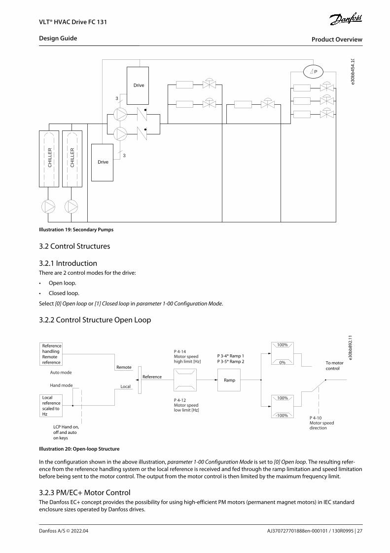
3.2.6 Feedback ConversionIn some applications, it may be useful to convert the feedback signal. One example of this is using a pressure signal to provide flowfeedback. Since the square root of pressure is proportional to flow, the square root of the pressure signal yields a value proportionalto the flow. See the following illustration.
e30b
b895
.10
+-
PI
P
P
P
Ref.signal
Desiredflow FB conversion
Ref.
FB
Flow
FBsignal
Flow
P 20-01
Illustration 23: Feedback Signal Conversion
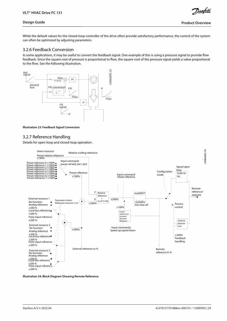
3.2.7 Reference HandlingDetails for open-loop and closed-loop operation.
Speed open loop
modeInput command:freeze reference
Processcontrol
Scale toHz
Scale toprocessunit
Remotereference/setpoint
±200%Feedbackhandling
Remote reference in %
maxRefPCT
minRefPctmin-max ref
Freezereference &increase/decreasereference
±100%
Input commands:Speed up/speed down
±200%
Relativereference =X+X*Y/100
±200%
External reference in %
±200%
Parameter choise:Reference resource 1,2,3
±100%Preset reference
Input command:preset ref bit0, bit1, bit2
+
+
Relative scalling referenceIntern resource
Preset relative reference±100%
Preset reference 0 ±100%Preset reference 1 ±100%Preset reference 2 ±100%Preset reference 3 ±100%Preset reference 4 ±100%Preset reference 5 ±100%Preset reference 6 ±100%Preset reference 7 ±100%
External resource 1No functionAnalog reference ±200 %Local bus reference ±200 %Pulse input reference ±200 %
Pulse input reference ±200 %
Pulse input reference ±200 %
External resource 2No functionAnalog reference ±200 %Local bus reference ±200 %
External resource 3No function Analog reference ±200 %Local bus reference ±200 %
Y
X
e30b
e842
.10
Illustration 24: Block Diagram Showing Remote Reference
AJ370727701888en-000101 / 130R0995 | 29Danfoss A/S © 2022.04
Product Overview
VLT® HVAC Drive FC 131
Design Guide

•
•
•
•
1.2.
3.4.5.
6.7.
The remote reference consists of:
Preset references.
External references (analog inputs and serial communication bus references).
The preset relative reference.
Feedback-controlled setpoint.
Up to 8 preset references can be programmed in the drive. The active preset reference can be selected using digital inputs or theserial communications bus. The reference can also be supplied externally, most commonly from an analog input. This externalsource is selected by 1 of the 3 reference source parameters (parameter 3-15 Reference 1 Source, parameter 3-16 Reference 2 Source,and parameter 3-17 Reference 3 Source). All reference resources and the bus reference are added to produce the total external refer-ence. The external reference, the preset reference, or the sum of the 2 can be selected to be the active reference. Finally, this refer-ence can by be scaled using parameter 3-14 Preset Relative Reference.The scaled reference is calculated as follows:
Reference = X + X × Y100
Where X is the external reference, the preset reference or the sum of these and Y is parameter 3-14 Preset Relative Reference in [%].
If Y, parameter 3-14 Preset Relative Reference, is set to 0%, the reference is not affected by the scaling.
3.2.8 Tuning the Drive Closed-loopOnce the drive's closed-loop controller has been set up, test the performance of the controller. Often, its performance may be ac-ceptable using the default values of parameter 20-93 PI Proportional Gain and parameter 20-94 PI Integral Time. However, sometimesit may be helpful to optimize these parameter values to provide faster system response while still controlling speed overshoot.
3.2.9 Adjusting the Manual PIProcedure
Start the motor.
Set parameter 20-93 PI Proportional Gain to 0.3 and increase it until the feedback signal begins to oscillate. If necessary, startand stop the drive or make step changes in the setpoint reference to attempt to cause oscillation.Reduce the PI proportional gain until the feedback signal stabilizes.Reduce the proportional gain by 40–60%.
Set parameter 20-94 PI Integral Time to 20 s and reduce it until the feedback signal begins to oscillate. If necessary, start andstop the drive or make step changes in the setpoint reference to attempt to cause oscillation.Increase the PI integral time until the feedback signal stabilizes.Increase the integral time by 15–50%.
3.3 Ambient Running Conditions
3.3.1 Air HumidityThe drive has been designed to meet the IEC/EN 60068-2-3 standard, EN 50178 9.4.2.2 at 50 °C (122 °F).
3.3.2 DeratingThe ambient temperature measured over 24 hours should be at least 5 °C (9 °F) lower than the maximum ambient temperature. Ifthe drive is operated at high ambient temperature, decrease the continuous output current.
AJ370727701888en-000101 / 130R099530 | Danfoss A/S © 2022.04
Product Overview
VLT® HVAC Drive FC 131
Design Guide

e30b
c255
.10
fsw[kHz]
20 100
10%
20%30%
40%50%60%70%80%90%
100%110%
Iout[%]
165
40 C104 F
。。
45 C113 F
。。
50 C122 F
。。
Illustration 25: 0.75–4.0 kW (1.0–5.4 hp), 400 V, Enclosure Size I2,IP54
e30b
c256
.10
fsw[kHz]
20 100
10%
20%
30%
40%
50%60%70%
80%
90%100%110%
Iout[%]
165
40 C 104 F。 。
50 C 122 F。 。
45 C 113 F。 。
Illustration 26: 5.5–7.5 kW (7.4–10 hp), 400 V, Enclosure Size I3, IP54
e30b
d012
.10
40 C104 F
。。
50 C122 F
。。
70%
80%
90%
0
60%
100%110%
2 84 106
50%
40%
30%
20%
10%
012 14 16
fsw[kHz]
Iout[%]
Illustration 27: 11–18.5 kW (15–25 hp), 400 V, Enclosure Size I4, IP54
e30b
c240
.10
Iout [%]
fsw [kHz]
20%
2 4 6 8 10 12
40%
60%
80%
100%110%
40 C 104 F。 。
50 C 122 F。 。45 C 113 F。 。
Illustration 28: 22–30 kW (30–40 hp), 400 V, Enclosure Size I6, IP54
e30b
c241
.10Iout [%]
fsw [kHz]
20%
2 4 6 8 10 12
40%
60%
80%
100%110%
40 C 104 F。 。
50 C 122 F。 。45 C 113 F。 。
Illustration 29: 37 kW (50 hp), 400 V, Enclosure Size I6, IP54
e30b
c242
.10Iout [%]
fsw [kHz]
20%
2 4 6 8 10 12
40%
60%
80%
100%110%
40 C 104 F。 。
50 C 122 F。 。
45 C 113 F。 。
Illustration 30: 45–55 kW (60–74 hp), 400 V, Enclosure Size I7, IP54
AJ370727701888en-000101 / 130R0995 | 31Danfoss A/S © 2022.04
Product Overview
VLT® HVAC Drive FC 131
Design Guide

•
•
•
•
•
•
•
•
•
e30b
c243
.10
Iout [%]
fsw [kHz]
20%
2 4 6 8 10 12
40%
60%
80%
100%110%
40 C 104 F。 。
50 C 122 F。 。
45 C 113 F。 。
Illustration 31: 75–90 kW (100–120 hp), 400 V, Enclosure Size I8, IP54
3.3.3 Acoustic Noise or VibrationIf the motor or the equipment driven by the motor - for example, a fan - makes noise or vibrations at certain frequencies, configurethe following parameters or parameter groups to reduce or eliminate the noise or vibrations:
Parameter group 4-6* Speed Bypass.
Set parameter 14-03 Overmodulation to [0] Off.
Switching pattern and switching frequency parameter group 14-0* Inverter Switching.
Parameter 1-64 Resonance Dampening.
3.3.3.1 Acoustic NoiseThe acoustic noise from the drive comes from 3 sources:
DC-link coils.
Integral fan.
RFI filter choke.
Table 6: Typical Values Measured at a Distance of 1 m (3.28 ft) from the Unit
Enclosure size Level [dBA](1)
I2 50.2
I3 54
I4 67.4
I6 70
I7 62
I8 65.6
1 The values are measured under the background of 35 dBA noise and the fan running with full speed.
3.3.3.2 Vibration and ShockThe drive has been tested according to the following standards:
IEC/EN 60068-2-6: Vibration (sinusoidal) - 1970
IEC/EN 60068-2-64: Vibration, broad-band random
The drive complies with the requirements that exist for units mounted on the walls and floors of production premises, and in panelsbolted to walls or floors.
AJ370727701888en-000101 / 130R099532 | Danfoss A/S © 2022.04
Product Overview
VLT® HVAC Drive FC 131
Design Guide

-
3.3.4 Aggressive EnvironmentsA drive contains many mechanical and electronic components. All are to some extent vulnerable to environmental effects.
C A U T I O NINSTALLATION ENVIRONMENTSFailure to take necessary protective measures increases the risk of stoppages, potentially causing equipment damage and per-sonnel injury.
Do not install the drive in environments with airborne liquids, particles, or gases that may affect or damage the electroniccomponents.
Liquids can be carried through the air and condense in the drive and may cause corrosion of components and metal parts. Steam,oil, and salt water may cause corrosion of components and metal parts. In such environments, use equipment with enclosure ratingIP54. As an extra protection, coated printed circuit boards can be ordered as an option (standard on some power sizes).Airborne particles such as dust may cause mechanical, electrical, or thermal failure in the drive. A typical indicator of excessive levelsof airborne particles is dust particles around the drive fan. In dusty environments, use equipment with enclosure rating IP54 or acabinet for IP20/TYPE 1 equipment.In environments with high temperatures and humidity, corrosive gases such as sulphur, nitrogen, and chlorine compounds causechemical processes on the drive components.Such chemical reactions rapidly affect and damage the electronic components. In such environments, mount the equipment in acabinet with fresh air ventilation, keeping aggressive gases away from the drive. An extra protection in such areas is a coating of theprinted circuit boards, which can be ordered as an option.Before installing the drive, check the ambient air for liquids, particles, and gases. This is done by observing existing installations inthis environment. Typical indicators of harmful airborne liquids are water or oil on metal parts, or corrosion of metal parts.Excessive dust particle levels are often found on installation cabinets and existing electrical installations. One indicator of aggressiveairborne gases is blackening of copper rails and cable ends on existing installations.
3.4 General Aspects of EMC
3.4.1 Overview of EMC EmissionsDrives (and other electrical devices) generate electronic or magnetic fields that may interfere with their environment. The electro-magnetic compatibility (EMC) of these effects depends on the power and the harmonic characteristics of the devices.Uncontrolled interaction between electrical devices in a system can degrade compatibility and impair reliable operation. Interfer-ence may take the form of mains harmonics distortion, electrostatic discharges, rapid voltage fluctuations, or high-frequency inter-ference. Electrical devices generate interference along with being affected by interference from other generated sources.Electrical interference usually occur at frequencies in the range 150 kHz to 30 MHz. Airborne interference from the drive system inthe range 30 MHz to 1 GHz is generated from the inverter, the motor cable, and the motor.Capacitive currents in the motor cable coupled with a high dU/dt from the motor voltage generate leakage currents, as shown inthe following illustration.The use of a shielded motor cable increases the leakage current (see the following illustration) because shielded cables have highercapacitance to ground than unshielded cables. If the leakage current is not filtered, it causes greater interference on the mains inthe radio frequency range below approximately 5 MHz. Since the leakage current (I1) is carried back to the unit through the shield(I3), there is only a small electromagnetic field (I4) from the shielded motor cable according to the following illustration.
AJ370727701888en-000101 / 130R0995 | 33Danfoss A/S © 2022.04
Product Overview
VLT® HVAC Drive FC 131
Design Guide

1
2
z
z
z
L1
L2
L3
PE
U
V
W
CS
I2
I1
I3
I4
CS CS CS
CS
I4
CSz PE
3 4 5 6
e75z
a062
.12
Illustration 32: Generation of Leakage Currents
1 Ground wire
2 Shield
3 AC mains supply
4 Drive
5 Shielded motor cable
6 Motor
The shield reduces the radiated interference, but increases the low-frequency interference on the mains. Connect the motor cableshield to the drive enclosure and on the motor enclosure. This is best done by using integrated shield clamps to avoid twisted shieldends (pigtails). Pigtails increase the shield impedance at higher frequencies, which reduces the shield effect and increases the leak-age current (I4).
If a shielded cable is used for relay, control cable, signal interface, and brake, mount the shield on the enclosure at both ends. Insome situations, however, it is necessary to break the shield to avoid current loops.If the shield is to be placed on a mounting plate for the drive, the mounting plate must be made of metal to convey the shieldcurrents back to the unit. Moreover, ensure good electrical contact from the mounting plate through the mounting screws to thedrive chassis.When using unshielded cables, some emission requirements are not complied with, although most immunity requirements are ob-served.To reduce the interference level from the entire system (unit+installation), make motor and brake cables as short as possible. Avoidplacing cables with a sensitive signal level alongside motor and brake cables. Radio interference higher than 50 MHz (airborne) isespecially generated by the control electronics.
3.4.2 Emission RequirementsThe EMC product standard for drives defines 4 categories (C1, C2, C3, and C4) with specified requirements for emission and immuni-ty. The following table states the definition of the 4 categories and the equivalent classification from EN 55011.Table 7: Correlation between IEC 61800-3 and EN 55011
EN/IEC61800-3 Cat-egory
Definition Equivalent emissionclass in EN 55011
C1 Drives installed in the 1st environment (home and office) with a supply voltage less than1000 V.
Class B
C2 Drives installed in the 1st environment (home and office) with a supply voltage less than1000 V, which are neither plug-in nor movable and are intended to be installed and com-missioned by a professional.
Class A Group 1
C3 Drives installed in the 2nd environment (industrial) with a supply voltage lower than1000 V.
Class A Group 2
C4 Drives installed in the 2nd environment with a supply voltage equal to or above 1000 V orrated current equal to or above 400 A or intended for use in complex systems.
No limit line. Makean EMC plan.
AJ370727701888en-000101 / 130R099534 | Danfoss A/S © 2022.04
Product Overview
VLT® HVAC Drive FC 131
Design Guide

When the generic (conducted) emission standards are used, the drives are required to comply with the limits in the following table.
Table 8: Correlation between Generic Emission Standards and EN 55011
Environment Generic emission standard Equivalent emissionclass in EN 55011
First environment (home and office) EN/IEC 61000-6-3 Emission standard for residential, commercialand light industrial environments.
Class B
Second environment (industrial en-vironment)
EN/IEC 61000-6-4 Emission standard for industrial environ-ments.
Class A Group 1
3.4.3 EMC Emission Test ResultsThe following test results have been obtained using a system with a drive, a shielded control cable, a control box with potentiome-ter, and a shielded motor cable.
Table 9: EMC Emission Test Results
RFI filtertype
Conduct emission. Maximum shielded cable length [m (ft)] Radiated emission
Industrial environment
EN 55011 Class A Group 2Industrial environ-ment
Class A Group 1Industrial environ-ment
Class BHousing, trades, andlight industries
Class A Group 1Industrial environ-ment
Class BHousing, trades,and light industries
EN/IEC61800-3
Category C3Second environmentIndustrial
Category C2First environmentHome and office
Category C1First environmentHome and office
Category C2First environmentHome and office
Category C1First environmentHome and office
Withoutexternalfilter
With ex-ternalfilter
Withoutexternalfilter
With ex-ternalfilter
Withoutexternalfilter
Withexternalfilter
Withoutexternalfilter
Withexter-nal fil-ter
Withoutexternalfilter
Withexter-nal fil-ter
H2 RFI filter (EN 55011 A2, EN/IEC 61800-3 C3)
0.75–18.5kW (1.0–25hp) 3x380–480 V IP54
25 (82) – – – – – Yes – – –
22–90 kW(30–120 hp)3x380–480V IP54
25 (82) – – – – – No – No –
H3 RFI filter (EN55011 A1/B, EN/IEC 61800-3 C2/C1)
0.75–18.5kW (1.0–25hp) 3x380–480 V IP54
– – 25 (82) – 10 (33) – Yes – – –
22–90 kW(30–120 hp)3x380–480V IP54
– – 25 (82) – 10 (33) – Yes – No –
AJ370727701888en-000101 / 130R0995 | 35Danfoss A/S © 2022.04
Product Overview
VLT® HVAC Drive FC 131
Design Guide

3.4.4 Harmonics EmissionA drive takes up a non-sinusoidal current from mains, which increases the input current IRMS. A non-sinusoidal current is trans-formed with a Fourier analysis and split into sine-wave currents with different frequencies, that is, different harmonic currents Inwith 50 Hz basic frequency:
Table 10: Harmonic Currents
I1 I5 I7
Hz 50 250 350
The harmonics do not affect the power consumption directly, but increase the heat losses in the installation (transformer, cables).So, in plants with a high percentage of rectifier load, maintain harmonic currents at a low level to avoid overload of the transformerand high temperature in the cables.
e75h
a034
.10
Illustration 33: DC-link Coils
N O T I C ESome of the harmonic currents might disturb communication equipment connected to the same transformer or cause resonancewith power factor correction batteries.
To ensure low harmonic currents, the drive is equipped with DC-link coils as standard. This normally reduces the input current IRMSby 40%.The voltage distortion on the mains supply voltage depends on the size of the harmonic currents multiplied by the mains impe-dance for the frequency in question. The total voltage distortion THDv is calculated based on the individual voltage harmonics us-ing this formula:
THD % = U 25 + U 2
7 + ... + U 2N
(UN% of U)
3.4.4.1 Harmonics Emission RequirementsEquipment is connected to the public supply network.Table 11: Connected Equipment
Options Definition
1 IEC/EN 61000-3-2 Class A for 3-phase balanced equipment (for professional equipment only up to 1 kW (1.3 hp) totalpower).
2 IEC/EN 61000-3-12 Equipment 16–75 A and professional equipment as from 1 kW (1.3 hp) up to 16 A phase current.
3.4.4.2 Harmonics Test Results (Emission)Power sizes up to PK75 in T4 complies with IEC/EN 61000-3-2 Class A. Power sizes from P1K1 and up to P90K in T4 complies withIEC/EN 61000-3-12, Table 4.
Table 12: Harmonic Current 0.75–18.5 kW (1.0–25 hp), 380–480 V
Individual harmonic current In/I1 (%)
I5 I7 I11 I13
Actual 0.75–18.5 kW (1.0–25 hp), IP54, 380-480 V (typical) 36.7 20.8 7.6 6.4
AJ370727701888en-000101 / 130R099536 | Danfoss A/S © 2022.04
Product Overview
VLT® HVAC Drive FC 131
Design Guide

Limit for Rsce≥120 40 25 15 10
Harmonic current distortion factor (%)
THDi PWHD
Actual 0.75–18.5 kW (1.0–25 hp), 380-480 V (typical) 44.4 40.8
Limit for Rsce≥120 48 46
Table 13: Harmonic Current 22–90 kW (30–120 hp), 400 V
Individual harmonic current In/I1 (%)
I5 I7 I11 I13
Actual 22–90 kW (30–120 hp), IP54, 400 V (typical) 36.3 14 7 4.3
Limit for Rsce≥120 40 25 15 10
Harmonic current distortion factor (%)
THDi PWHD
Actual 22–90 kW (30–120 hp), IP54 400 V (typical) 40.1 27.1
Limit for Rsce≥120 48 46
Provided that the short-circuit power of the supply Ssc is greater than or equal to:
SSC = 3 × RSCE × Umains × Iequ = 3 × 120 × 400 × Iequ
at the interface point between the user’s supply and the public system (Rsce).
It is the responsibility of the installer or user of the equipment to ensure, by consultation with the distribution network operator ifnecessary, that the equipment is connected only to a supply with a short-circuit power Ssc greater than or equal to specified above.Other power sizes can be connected to the public supply network by consultation with the distribution network operator.Compliance with various system level guidelines: The harmonic current data in the above tables are given in accordance withIEC/EN 61000-3-12 with reference to the Power Drive Systems product standard. They may be used as the basis for calculation of theharmonic currents' influence on the power supply system and for the documentation of compliance with relevant regional guide-lines: IEEE 519 -1992; G5/4.
3.4.5 Immunity RequirementsThe immunity requirements for drives depend on the environment in which they are installed. The requirements for the industrialenvironment are higher than the requirements for the home and office environment. All Danfoss drives comply with the require-ments for the industrial environment and therefore comply also with the lower requirements for home and office environment witha large safety margin.
3.5 Galvanic Isolation (PELV)PELV offers protection through extra low voltage. Protection against electric shock is ensured when the electrical supply is of thePELV type and the installation is made as described in local/national regulations on PELV supplies.All control terminals and relay terminals 01-03/04-06 comply with PELV (protective extra low voltage) (does not apply to groundeddelta leg above 440 V).Galvanic (ensured) isolation is obtained by fulfilling requirements for higher isolation and by providing the relevant creepage/clear-ance distances. These requirements are described in the EN 61800-5-1 standard.The components that make up the electrical isolation, as described, also comply with the requirements for higher isolation and therelevant test as described in EN 61800-5-1. The PELV galvanic isolation can be shown in Illustration 35.To maintain PELV, all connections made to the control terminals must be PELV, for example, thermistors must be reinforced/doubleinsulated.
AJ370727701888en-000101 / 130R0995 | 37Danfoss A/S © 2022.04
Product Overview
VLT® HVAC Drive FC 131
Design Guide

•
•
•
•
SMPS
e30b
b896
.10
1 2
3
a
M
Illustration 34: Galvanic Isolation 0.75–22 kW (1.0–30 hp)
1 Supply (SMPS)
2 Optocouplers, communication between AOC andBOC
3 Custom relays
a Control card terminals
e30b
b901
.10
1
3
2 4 5
a
M
Illustration 35: Galvanic Isolation 30–90 kW (40–125 hp)
1 Supply (SMPS) including signal isolation of UDC, in-dicating the intermediate current voltage
2 Gate drive that runs the IGBTs (trigger transformers/optocouplers)
3 Current transducers
4 Internal soft-charge, RFI, and temperature measure-ment circuits
5 Custom relays
a Control card terminals
The functional galvanic isolation (see Illustration 34) is for the RS485 standard bus interface.
C A U T I O NINSTALLATION AT HIGH ALTITUDEAt altitudes above 2000 m (6500 ft), contact Danfoss regarding PELV.
3.6 Ground Leakage CurrentFollow national and local codes regarding protective earthing of equipment where leakage current exceeds 3.5 mA.Drive technology implies high frequency switching at high power. This generates a leakage current in the ground connection.The ground leakage current is made up of several contributions and depends on various system configurations, including:
RFI filtering.
Motor cable length.
Motor cable shielding.
Drive power.
AJ370727701888en-000101 / 130R099538 | Danfoss A/S © 2022.04
Product Overview
VLT® HVAC Drive FC 131
Design Guide

•
•
e30b
b955
.12
a
b
Motor cable length
Leakage current
Illustration 36: Influence of the Cable Length and Power Size on Leakage Current, Power Size a > Power Size B
The leakage current also depends on the line distortion.
e30b
b956
.12
THDv=0%
THDv=5%
Leakage current
Illustration 37: Influence of Line Distortion on Leakage Current
If the leakage current exceeds 3.5 mA, compliance with EN/IEC 61800-5-1 (power drive system product standard) requires specialcare.Reinforce grounding with the following protective earth connection requirements:
Ground wire (terminal 95) of at least 10 mm2 (8 AWG) cross-section.
Two separate ground wires both complying with the dimensioning rules.
See EN/IEC 61800-5-1 and IEC EN 62477-1 for further information.
AJ370727701888en-000101 / 130R0995 | 39Danfoss A/S © 2022.04
Product Overview
VLT® HVAC Drive FC 131
Design Guide

•
•
•
-
-
-
W A R N I N GDISCHARGE TIMETouching the electrical parts, even after the equipment has been disconnected from mains, could be fatal.
Make sure that other voltage inputs have been disconnected, such as load sharing (linkage of DC-link), and the motor con-nection for kinetic back-up.
Before touching any electrical parts, wait at least the amount of time indicated in the safety chapter. Shorter time is allowedonly if indicated on the nameplate for the specific unit.
W A R N I N GLEAKAGE CURRENT HAZARDLeakage currents exceed 3.5 mA. Failure to ground the drive properly can result in death or serious injury.
Ensure the correct grounding of the equipment by a certified electrical installer.
3.6.1 Using a Residual Current Device (RCD)Where residual current devices (RCDs), also known as earth leakage circuit breakers (ELCBs), are used, comply with the following:
Use RCDs of type B only, which are capable of detecting AC and DC currents.
Use RCDs with an inrush delay to prevent faults caused by transient ground currents.
Dimension RCDs according to the system configuration and environmental considerations.
The leakage current includes several frequencies originating from both the mains frequency and the switching frequency. Whetherthe switching frequency is detected depends on the type of RCD used.
e30b
b958
.12
Leakage current
Frequency
3rd harmonicsMains Cable
RCD with low f cut-off
RCD with high f cut-off
50 Hz 150 Hz fsw
Illustration 38: Mains Contributions to Leakage Current
The amount of leakage current detected by the RCD depends on the cut-off frequency of the RCD.
AJ370727701888en-000101 / 130R099540 | Danfoss A/S © 2022.04
Product Overview
VLT® HVAC Drive FC 131
Design Guide

•
•
•
-
e30b
b957
.12
Leakage current [mA]
100 Hz
2 kHz
100 kHz
Illustration 39: Influence of Cut-off Frequency of the RCD on what is Responded to/Measured
For more details, refer to the RCD Application Note.
W A R N I N GRESIDUAL CURRENT DEVICE PROTECTIONThis product can cause a DC current in the protective conductor. Where a residual current device (RCD) is used for protection incase of direct or indirect contact, only an RCD of Type B is allowed on the supply side of this product. Otherwise, apply anotherprotective measure, such as separation from the environment by double or reinforced insulation, or isolation from the supplysystem by a transformer. See also application note Protection against Electrical Hazards.
Protective grounding of the drive and the use of RCDs must always follow national and local regulations.
3.7 Extreme Running Conditions
3.7.1 IntroductionShort circuit (motor phase-phase)Current measurement in each of the 3 motor phases or in the DC-link, protects the drive against short circuits. A short circuit be-tween 2 output phases causes an overcurrent in the inverter. The inverter is turned off individually when the short-circuit currentexceeds the allowed value (alarm 16, Trip Lock).
For information about protecting the drive against a short circuit at the load sharing and brake outputs, see chapter Fuses and CircuitBreakers.
Switching on the outputSwitching on the output between the motor and the drive is allowed. The drive is not damaged in any way by switching on theoutput. However, fault messages may appear.
Motor-generated overvoltageThe voltage in the DC link is increased when the motor acts as a generator. This occurs in following cases:
The load drives the motor (at constant output frequency from the drive), that is the load generates energy.
During deceleration (ramp-down) if the inertia moment is high, the friction is low, and the ramp-down time is too short for theenergy to be dissipated as a loss in the drive, the motor, and the installation.
Incorrect slip compensation setting (parameter 1-62 Slip Compensation) may cause higher DC-link voltage.
The control unit may attempt to correct the ramp if parameter 2-17 Over-voltage Control is enabled. The drive turns off to protect thetransistors and the DC-link capacitors when a certain voltage level is reached.
Mains drop-out
AJ370727701888en-000101 / 130R0995 | 41Danfoss A/S © 2022.04
Product Overview
VLT® HVAC Drive FC 131
Design Guide

•
•
•
During a mains dropout, the drive keeps running until the DC-link voltage drops below the minimum stop level, which is typically15% below the drive's lowest rated supply voltage. The mains voltage before the drop-out and the motor load determines how longit takes for the drive to coast.
3.7.2 Motor Thermal Protection (ETR)Danfoss uses ETR to protect the motor from being overheated. It is an electronic feature that simulates a bimetal relay based oninternal measurements. The characteristic is shown in the following illustration.
1.21.0 1.4
30
1020
10060
4050
1.81.6 2.0
2000
500
200
400300
1000600
t [s]
e75z
a052
.13
IM,N (parameter 1-24)
IM
f OUT = 2 x f M,N (parameter 1-23)
f OUT = 1 x f M,N
f OUT = 0.2 x f M,N
Illustration 40: Motor Thermal Protection Characteristic
The X-axis shows the ratio between Imotor and Imotor nominal. The Y-axis shows the time in seconds before the ETR cuts off and tripsthe drive. The curves show the characteristic nominal speed at twice the nominal speed and at 0.2x the nominal speed.It is clear that at lower speed, the ETR cuts off at lower heat due to less cooling of the motor. In that way, the motor is protectedfrom being overheated even at low speed. The ETR feature calculates the motor temperature based on actual current and speed.
3.7.3 Thermistor InputsThe thermistor cutout value is >3 kΩ.Integrate a thermistor (PTC sensor) in the motor for winding protection.Motor protection can be implemented using a range of techniques:
PTC sensor in motor windings.
Mechanical thermal switch (Klixon type).
Electronic thermal relay (ETR).
AJ370727701888en-000101 / 130R099542 | Danfoss A/S © 2022.04
Product Overview
VLT® HVAC Drive FC 131
Design Guide

•
•
1330
550
250
-20°C
e75h
a183
.10
4000
3000
R (W)
nominel nominel -5°C nominel + 5°C
[°C ]
Illustration 41: Trip due to High Motor Temperature
3.7.3.1 Example with Digital Input and 10 V Power SupplyThe drive trips when the motor temperature is too high.Parameter set-up:
Set parameter 1-90 Motor Thermal Protection to [2] Thermistor Trip.
Set parameter 1-93 Thermistor Source to [6] Digital Input 29.
R
OFF
ON
<800 Ω >2.9 κΩ
18 19
12 20 55
27 29 42 45 50 53 54
DIG
I IN
DIG
I IN
DIG
I IN
DIG
I IN
61 68 69
N
P C OM
M. G
ND
+24V
0/4-20mA A OUT / DIG OUT 0/4-20mA A OUT / DIG OUT
C OM A IN
C OM DIG IN
10V/20mA
IN
10V/20mA
IN
10V OU
T
BUS TER. OFF ON
e30b
b898
.10
Illustration 42: Digital Input/10 V Power Supply
3.7.3.2 Example with Analog Input and 10 V Power SupplyThe drive trips when the motor temperature is too high.
AJ370727701888en-000101 / 130R0995 | 43Danfoss A/S © 2022.04
Product Overview
VLT® HVAC Drive FC 131
Design Guide
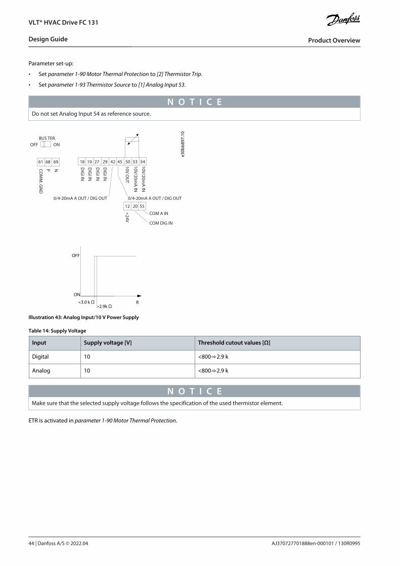
•
•
Parameter set-up:
Set parameter 1-90 Motor Thermal Protection to [2] Thermistor Trip.
Set parameter 1-93 Thermistor Source to [1] Analog Input 53.
N O T I C EDo not set Analog Input 54 as reference source.
18 19
12 20 55
27 29 42 45 50 53 54
DIG
I IN
DIG
I IN
DIG
I IN
DIG
I IN
61 68 69
N
P C OM
M. G
ND
+24V
0/4-20mA A OUT / DIG OUT 0/4-20mA A OUT / DIG OUT
C OM A IN
C OM DIG IN
10V/20mA
IN
10V/20mA
IN
10V OU
T
BUS TER. OFF ON
e30b
b897
.10
R <3.0 k Ω >2.9k Ω
OFF
ON
Illustration 43: Analog Input/10 V Power Supply
Table 14: Supply Voltage
Input Supply voltage [V] Threshold cutout values [Ω]
Digital 10 <800⇒2.9 k
Analog 10 <800⇒2.9 k
N O T I C EMake sure that the selected supply voltage follows the specification of the used thermistor element.
ETR is activated in parameter 1-90 Motor Thermal Protection.
AJ370727701888en-000101 / 130R099544 | Danfoss A/S © 2022.04
Product Overview
VLT® HVAC Drive FC 131
Design Guide

4 Selection and Ordering
4.1 Type CodeA type code defines a specific configuration of the drive. Use the following illustration to create a type code string for the desiredconfiguration.
F C - P T H
e30b
u825
.10
X S A B C X X X X
1 2 3 4 5 6 7 8 9 10 11 12 13 14 15 16 17 18 19 20 30 22 21 23 27 25 24 26 28 29 31 37 36 35 34 33 32 38 39
X 3 D 1 1 X X X X X X X X X
Illustration 44: Type Code
Table 15: Type Code Description
Description Position Possible choice
Product group & FC series 1–6 FC 131
Power rating 7–10 0.75–90 kW (1.0–125 hp) (PK75-P90K)
Number of phases 11 3 phases (T)
Mains voltage 11–12 T4: 380-480 V AC
Enclosure 13–15 E5A: IP54P5A: IP54 with back plate
RFI filter 16–17 H1: RFI filter class A1/BH2: RFI filter class A2H3: RFI filter class A1/B (reduced cable length)H4: RFI filter class A1
Brake 18 X: No brake chopper included
Display 19 A: Alpha numeric local control panelX: No local control panel
Coating PCB 20 X: No coated PCBC: Coated PCB
Mains option 21 X: No mains option
Adaptation 22 X: No adaptation
Adaptation 23 X: No adaptation
Software release 24–27 SXXXX: Latest release - standard software
Software language 28 X: Standard
A options 29–30 AX: No A options
B options 31–32 BX: No B options
C0 options MCO 33–34 CX: No C options
AJ370727701888en-000101 / 130R0995 | 45Danfoss A/S © 2022.04
Selection and Ordering
VLT® HVAC Drive FC 131
Design Guide

C1 options 35 X: No C1 options
C option software 36–37 XX: No options
D options 38–39 DX: No D0 options
4.2 Options and Accessories
4.2.1 Local Control Panel (LCP)
Table 16: Ordering Number of LCP
Ordering number Description
132B9221 LCP 32
Table 17: Technical Data of LCP
Enclosure Front-mounted
Maximum cable length to unit 3 m (10 ft)
Communication standard RS485
AJ370727701888en-000101 / 130R099546 | Danfoss A/S © 2022.04
Selection and Ordering
VLT® HVAC Drive FC 131
Design Guide

5 Installation
5.1 Mechanical Installation
5.1.1 Side-by-side InstallationThe drive can be mounted side by side but requires the clearance above and below for cooling. Table 18: Clearance Required for Cooling
Size IP class Power [kW (hp)] Clearance above/below [mm (in)]
I2 IP54 0.75–4.0 (1.0–5.0) 100 (4.0)
I3 IP54 5.5–7.5 (7.5–10) 100 (4.0)
I4 IP54 11–18.5 (15–25) 100 (4.0)
I6 IP54 22–37 (30–50) 200 (7.9)
I7 IP54 45–55 (60–70) 200 (7.9)
I8 IP54 75–90 (100–125) 225 (8.9)
N O T I C EThe drives are not suitable for outdoor mounting.
5.1.2 Drive Dimensions
e
fa
ee
fa
d
e
A
a
b B
C
D
e30b
f984
.10
Illustration 45: Dimensions
Table 19: Dimensions, Enclosure Sizes I2–I8
Enclosure Size I2 I3 I4 I6 I7 I8
IP class IP54 IP54 IP54 IP54 IP54 IP54
Power [kW (hp)] 3x380–480 V 0.75–4.0(1.0–5.0)
5.5–7.5(7.5–10)
11–18.5(15–25)
22–37(30–50)
45–55(60–70)
75–90(100–125)
Height [mm (in)] A 332 (13.1) 368 (14.5) 476 (18.7) 650 (25.6) 680 (26.8) 770 (30)
a 318.5 (12.53) 354 (13.9) 460 (18.1) 624 (24.6) 648 (25.5) 739 (29.1)
Width [mm (in)] B 115 (4.5) 135 (5.3) 180 (7.0) 242 (9.5) 308 (12.1) 370 (14.6)
b 74 (2.9) 89 (3.5) 133 (5.2) 210 (8.3) 272 (10.7) 334 (13.2)
AJ370727701888en-000101 / 130R0995 | 47Danfoss A/S © 2022.04
Installation
VLT® HVAC Drive FC 131
Design Guide

Enclosure Size I2 I3 I4 I6 I7 I8
Depth [mm (in)] C 225 (8.9) 237 (9.3) 290 (11.4) 260 (10.2) 310 (12.2) 335 (13.2)
Mounting hole [mm (in)] d 11 (0.43) 12 (0.47) 12 (0.47) 19 (0.75) 19 (0.75) 19 (0.75)
e 5.5 (0.22) 6.5 (0.26) 6.5 (0.26) 9 (0.35) 9 (0.35) 9 (0.35)
f 9 (0.35) 9.5 (0.37) 9.5 (0.37) 9 (0.35) 9.8 (0.39) 9.8 (0.39)
Maximum weight kg (lb) 5.3 (11.7) 7.2 (15.9) 13.8 (30.42) 27 (59.5) 45 (99.2) 65 (143.3)
The dimensions are only for the physical units. When installing in an application, allow space above and below the units for cooling.The amount of space for free air passage is listed in 5.1.1 Side-by-side Installation.
5.1.3 Shipping Dimensions
Table 20: Shipping Dimensions
Enclosureframe size
T4 (380–480 V AC) [kW(hp)]
IP frame Maximum weight[kg (lb)]
Height [mm(in)]
Width [mm(in)]
Depth [mm(in)]
I2 0.75–4.0 (1–5) IP54 6.1 (13.4) 310 (12.2) 205 (8.1) 435 (17.1)
I3 5.5–7.5 (7.5–10) IP54 7.8 (17.2) 325 (12.8) 230 (9.1) 480 (18.9)
I4 11–18.5 (15–25) IP54 13.8 (30.4) 390 (15.4) 295 (11.6) 635 (25.0)
I5 11–18.5 (15–25) IP54 23.3 (51.4) 850 (33.5) 370 (15.6) 460 (18.1)
I6 22–37 (30–50) IP54 28.3 (62.4) 850 (33.5) 370 (15.6) 460 (18.1)
I7 45–55 (60–70) IP54 41.5 (91.5) 850 (33.5) 410 (16.1) 540 (21.3)
I8 75–90 (100–125) IP54 60.5 (133.4) 950 (37.4) 490 (19.3) 490 (19.3)
5.2 Electrical Installation
5.2.1 Electrical Wiring
AJ370727701888en-000101 / 130R099548 | Danfoss A/S © 2022.04
Installation
VLT® HVAC Drive FC 131
Design Guide

-
L1L2L3
3-phasepowerinput
PE PE
+10 V DC
0-10 V DC-
0-10 V DC-
50 (+10 V OUT)
54 (A IN)
53 (A IN)
55 (COM A IN/OUT)
0/4-20 mA
0/4-20 mA
42 0/4-20 mA A OUT / D OUT
45 0/4-20 mA A OUT / D OUT
18 (D IN)
19 (D IN)
27 (D IN/OUT)
29 (D IN/OUT)
12 (+24 V OUT)
24 V (NPN)
20 (COM D IN)
O V (PNP)
24 V (NPN)O V (PNP)
24 V (NPN)O V (PNP)
24 V (NPN)O V (PNP)
Bus ter.
Bus ter.
RS485Interface RS485(N RS485) 69
(P RS485) 68
(Com RS485 ) 61
(PNP)-Source(NPN)-Sink
ON=TerminatedOFF=Unterminated
ON
12
240 V AC 3 A
Not present on all power sizes
Do not connect shield to 61
01
02
03relay 1
relay 2
UDC+
UDC-
Motor
UV
W e30b
d467
.13
06
05
04
240 V AC 3 A
Illustration 46: Basic Wiring Schematic Drawing
N O T I C EThere is no access to UDC- and UDC+ on the following units:
IP54, 380–480 V, 22–90 kW (30–125 hp)
5.2.2 Electrical Installation in GeneralAll cabling must comply with national and local regulations on cable cross-sections and ambient temperature. Copper conductorsare required. 75 °C (167 °F) is recommended.
Table 21: Tightening Torques for Enclosure Sizes I2–I8
Power [kW (hp)] Torque [Nm (in-lb)]
Enclosuresize
IP class 3x380–480 V Mains Motor DC connec-tion
Control ter-minals
Ground Relay
I2 IP54 0.75–4.0 (1.0–5.0) 0.8 (7.0) 0.8 (7.0) 0.8 (7.0) 0.5 (4.0) 0.8 (7.0) 0.5 (4.0)
I3 IP54 5.5–7.5 (7.5–10) 0.8 (7.0) 0.8 (7.0) 0.8 (7.0) 0.5 (4.0) 0.8 (7.0) 0.5 (4.0)
I4 IP54 11–18.5 (15–25) 1.2 (11) 1.2 (11) 0.8 (7.0) 0.5 (4.0) 0.8 (7.0) 0.5 (4.0)
AJ370727701888en-000101 / 130R0995 | 49Danfoss A/S © 2022.04
Installation
VLT® HVAC Drive FC 131
Design Guide

-
Power [kW (hp)] Torque [Nm (in-lb)]
I6 IP54 22–37 (30–50) 4.5 (40) 4.5 (40) – 0.5 (4.0) 3 (27) 0.6 (5.0)
I7 IP54 45–55 (60–70) 10 (89) 10 (89) – 0.5 (4.0) 3 (27) 0.6 (5.0)
I8 IP54 75–90 (100–125) 14 (124)/24(212)(1)
14 (124)/24(212)(1)
– 0.5 (4.0) 3 (27) 0.6 (5.0)
1 Cable dimensions ≤95 mm2.
5.2.3 IT Mains
C A U T I O NIT MAINSInstallation on isolated mains source, that is, IT mains.
Ensure that the supply voltage does not exceed 440 V (3x380–480 V units) when connected to mains.
For IP54, 400 V, 0.75–18.5 kW (1.0–25 hp) units, open the RFI switch by removing the EMC screw inside the drive when at IT grid. TheEMC screw is shown in the the following illustration.
AJ370727701888en-000101 / 130R099550 | Danfoss A/S © 2022.04
Installation
VLT® HVAC Drive FC 131
Design Guide

•
•
•
e30b
c251
.10
Illustration 47: IP54, 400 V, 0.75–18.5 kW (1–25 hp)
1 EMC screw
For IP54, 400 V, 22-90 kW (30–125 hp) units, the RFI switch can be opened in parameter 14-50 RFI Filter. Select [1] On to turn the RFIfilter on. The RFI filter ensures that the drive complies with EMC standards. Select [0] Off only when the drive is connected to ITmains.
N O T I C EIf reinserted, use only M3x12 screw.
5.2.4 Mains and Motor Connection
5.2.4.1 IntroductionThe drive is designed to operate all standard 3-phase induction motors.
Use a shielded/armored motor cable to comply with EMC emission specifications and connect this cable to the motor.
Keep the motor cable as short as possible to reduce the noise level and leakage currents.
Also see EMC-Correct Installation in the 5.2.5 EMC-compliant Electrical Installation.
AJ370727701888en-000101 / 130R0995 | 51Danfoss A/S © 2022.04
Installation
VLT® HVAC Drive FC 131
Design Guide

1.2.3.
5.2.4.2 Connecting to Mains and MotorMount the ground cables to the ground terminal.Connect the motor to terminals U, V, and W, and then tighten the screws according to the torques.Connect the mains supply to terminals L1, L2, and L3, and then tighten the screws according to the torques described in5.2.2 Electrical Installation in General.
5.2.4.3 Enclosure Size I2
e30b
c299
.10
7
3
2
5
1
8
4
6
Illustration 48: Enclosure Size I2, IP54, 380–480 V, 0.75–4.0 kW (1.0–5.0 hp)
1 RS485
2 Mains
3 Ground
4 Cable clamps
5 Motor
6 UDC
7 Relays
8 I/O
AJ370727701888en-000101 / 130R099552 | Danfoss A/S © 2022.04
Installation
VLT® HVAC Drive FC 131
Design Guide

5.2.4.4 Enclosure Size I3
e30b
c201
.10
Illustration 49: Enclosure Size I3, IP54, 380–480 V, 5.5–7.5 kW (7.5–10 hp)
1 RS485
2 Mains
3 Ground
4 Cable clamps
5 Motor
6 UDC
7 Relays
8 I/O
AJ370727701888en-000101 / 130R0995 | 53Danfoss A/S © 2022.04
Installation
VLT® HVAC Drive FC 131
Design Guide

5.2.4.5 Enclosure Size I4
e30b
d011
.10
Illustration 50: Enclosure Size I4, IP54, 380–480 V, 11–18.5 kW (15–25 hp)
1 RS485
2 Mains
3 Ground
4 Cable clamps
5 Motor
6 UDC
7 Relays
8 I/O
AJ370727701888en-000101 / 130R099554 | Danfoss A/S © 2022.04
Installation
VLT® HVAC Drive FC 131
Design Guide

5.2.4.6 IP54 Enclosure Sizes I2, I3, I4
e30b
c203
.10
Illustration 51: IP54 Enclosure Sizes I2, I3, I4
5.2.4.7 Enclosure size I6
e30b
t326
.10
Illustration 52: Connecting to Mains for Enclosure Size I6, IP54, 380–480 V, 22–37 kW (30–50 hp)
AJ370727701888en-000101 / 130R0995 | 55Danfoss A/S © 2022.04
Installation
VLT® HVAC Drive FC 131
Design Guide

e30b
t325
.10
Illustration 53: Connecting to Motor for Enclosure Size I6, IP54, 380–480 V, 22–37 kW (30–50 hp)
311
e30b
a215
.10
RELA Y 1 RELA Y 2 03 02 01
90
05 04
Illustration 54: Relays on Enclosure Size I6, IP54, 380–480 V, 22–37 kW (30–50 hp)
AJ370727701888en-000101 / 130R099556 | Danfoss A/S © 2022.04
Installation
VLT® HVAC Drive FC 131
Design Guide

•
•
•
•
•
5.2.4.8 Enclosure size I7, I8
91L1
92L2
93L3
96U
97V
98W
88DC-
9995
e30b
c248
.10
Illustration 55: Enclosure Sizes I7, I8, IP54, 380–480 V, 45–55 kW (60–70 hp), IP54, 380–480 V, 75–90 kW (100–125 hp)
5.2.5 EMC-compliant Electrical InstallationTo ensure EMC-correct electrical installation, observe the following:
Use only shielded/armored motor cables and shielded/armored control cables.
Ground the shield at both ends.
Avoid installation with twisted shield ends (pigtails), because it reduces the shielding effect at high frequencies. Use the cableclamps provided.
Ensure the same potential between the drive and the ground potential of PLC.
Use star washers and galvanically conductive installation plates.
AJ370727701888en-000101 / 130R0995 | 57Danfoss A/S © 2022.04
Installation
VLT® HVAC Drive FC 131
Design Guide

Back
OK
Com.
On
Warn.
Alarm
HandOn Reset
AutoOn
Menu Status QuickMenu
MainMenu
L1
L2L3
PE
Minimum 16 mm2
equalizing cable
Control cables
All cable entries in
one side of the panel
Grounding rail
Cable insula-tion stripped
Output con-tactor
Motor cable
Motor, 3 phases and
PLC Panel
Mains-supply
Minimum 200 mm (7.87 in)between control cable, mains cable, and between mains motor cable
PLC
protective earthReinforced protective earth
e30b
b761
.13
(6 AWG)
Illustration 56: EMC-compliant Installation
5.2.6 Control TerminalsRemove the terminal cover to access the control terminals.Use a flat-edged screwdriver to push down the lock lever of the terminal cover under the LCP, then remove the terminal cover asshown in the following illustration.For IP54 units, control terminals can be accessed after removing the front cover.
AJ370727701888en-000101 / 130R099558 | Danfoss A/S © 2022.04
Installation
VLT® HVAC Drive FC 131
Design Guide

e30b
d331
.10
Illustration 57: Removing the Terminal Cover
The following illustration shows all the drive control terminals. Applying start (terminal 18), connection between terminals 12-27,and an analog reference (terminal 53 or 54, and 55) make the drive run.
The digital input mode of terminal 18, 19, and 27 is set in parameter 5-00 Digital Input Mode (PNP is default value). Digital input 29mode is set in parameter 5-03 Digital Input 29 Mode (PNP is default value).
e30b
f892
.10
12 20 55
18 19 27 29 42 5445 50 53
DIG
I IN
61 68 69
NPCOM
M. G
ND
+24 V
GN
D
GN
D
10 V OU
T
10 V/20 mA
IN
0/4-20 mA
A O
UT/D
IG O
UT
BUS TER.OFF ON
DIG
I IN
DIG
I IN
DIG
I IN
0/4-20 mA
A O
UT/D
IG O
UT
10 V/20 mA
IN
Illustration 58: Control Terminals
AJ370727701888en-000101 / 130R0995 | 59Danfoss A/S © 2022.04
Installation
VLT® HVAC Drive FC 131
Design Guide

6 RS485 Installation and Set-up
6.1 RS485
6.1.1 OverviewRS485 is a 2-wire bus interface compatible with multi-drop network topology. The nodes can be connected as a bus, or via dropcables from a common trunk line. A total of 32 nodes can be connected to 1 network segment. Repeaters divide network segments,see the following illustration.
e75za145
.12R+
R+
R+
R+ R+
R+
R+
R+
Repeater
Repeater
Repeater
Master 1
1
1
1 2
2
2
2 3
3
3
3
30
30
30 31
31
Illustration 59: RS485 Bus Interface
N O T I C EEach repeater functions as a node within the segment in which it is installed. Each node connected within a given network musthave a unique node address across all segments.
Terminate each segment at both ends, using either the termination switch (S801) of the drives or a biased termination resistor net-work. Always use shielded twisted pair (STP) cable for bus cabling and follow good common installation practice.Low-impedance ground connection of the shield at every node is important, including at high frequencies. Thus, connect a largesurface of the shield to ground, for example with a cable clamp or a conductive cable gland. Sometimes, it is necessary to applypotential-equalizing cables to maintain the same ground potential throughout the network, particularly in installations with longcables.To prevent impedance mismatch, use the same type of cable throughout the entire network. When connecting a motor to the drive,always use shielded motor cable.
Table 22: Cable Specifications
Cable Shielded twisted pair (STP)
Impedance [Ω] 120
Cable length [m (ft)] Maximum 1200 (3937) (including drop lines).Maximum 500 (1640) station-to-station.
6.1.2 Connecting the Drive to the RS485 NetworkProcedure
AJ370727701888en-000101 / 130R099560 | Danfoss A/S © 2022.04
RS485 Installation and Set-up
VLT® HVAC Drive FC 131
Design Guide

1.
2.
Connect signal wires to terminal 68 (P+) and terminal 69 (N-) on the main control board of the drive.
61 68 69
N
P
C O
MM
. GN
D
e30b
b795
.10
Illustration 60: Network Connection
Connect the cable shield to the cable clamps.
N O T I C ETo reduce noise between conductors, use shielded, twisted-pair cables.
6.1.3 Hardware SetupTo terminate the RS485 bus, use the terminator switch on the main control board of the drive.
e30b
g049
.10
Illustration 61: Terminator Switch Factory Setting
The factory setting for the switch is OFF.
AJ370727701888en-000101 / 130R0995 | 61Danfoss A/S © 2022.04
RS485 Installation and Set-up
VLT® HVAC Drive FC 131
Design Guide

6.1.4 Parameter Settings for Modbus Communication
Table 23: Modbus Communication Parameter Settings
Parameter Function
Parameter 8-30 Protocol Select the application protocol to run for the RS485 interface.
Parameter 8-31 Address Set the node address.
N O T I C EThe address range depends on the protocol selected in parameter 8-30 Protocol.
Parameter 8-32 Baud Rate Set the baud rate.
N O T I C EThe default baud rate depends on the protocol selected in parameter 8-30 Protocol.
Parameter 8-33 Parity / StopBits
Set the parity and number of stop bits.
N O T I C EThe default selection depends on the protocol selected in parameter 8-30 Protocol.
Parameter 8-35 Minimum Re-sponse Delay
Specify a minimum delay time between receiving a request and transmitting a response. Thisfunction is for overcoming modem turnaround delays.
Parameter 8-36 Maximum Re-sponse Delay
Specify a maximum delay time between transmitting a request and receiving a response.
Parameter 8-37 Maximum In-ter-char delay
If transmission is interrupted, specify a maximum delay time between 2 received bytes to ensuretimeout.
N O T I C EThe default selection depends on the protocol selected in parameter 8-30 Protocol.
6.1.5 EMC PrecautionsTo achieve interference-free operation of the RS485 network, Danfoss recommends the following EMC precautions.
N O T I C EObserve relevant national and local regulations, for example regarding protective earth connection. Failure to ground the cablesproperly can result in communication degradation and equipment damage. To avoid coupling of high-frequency noise betweenthe cables, keep the RS485 communication cable away from motor and brake resistor cables. Normally, a distance of 200 mm(8 in) is sufficient. Maintain the greatest possible distance between the cables, especially where cables run in parallel over longdistances. When crossing is unavoidable, the RS485 cable must cross motor and brake resistor cables at an angle of 90°.
AJ370727701888en-000101 / 130R099562 | Danfoss A/S © 2022.04
RS485 Installation and Set-up
VLT® HVAC Drive FC 131
Design Guide

•
•
•
•
•
-
-
-
-
•
e95n
a493
.11
1
2
90°
Illustration 62: Minimum Distance between Communication and Power Cables
1 Fieldbus cable
2 Minimum 200 mm (8 in) distance
6.2 FC Protocol
6.2.1 OverviewThe FC protocol, also referred to as FC bus or standard bus, is the Danfoss standard fieldbus. It defines an access technique accord-ing to the master/follower principle for communications via a fieldbus.One master and a maximum of 126 followers can be connected to the bus. The master selects the individual followers via an ad-dress character in the telegram. A follower itself can never transmit without first being requested to do so, and direct telegramtransfer between the individual followers is not possible. Communications occur in the halfduplex mode.The master function cannot be transferred to another node (single-master system).The physical layer is RS485, thus utilizing the RS485 port built into the drive. The FC protocol supports different telegram formats:
A short format of 8 bytes for process data.
A long format of 16 bytes that also includes a parameter channel.
A format used for texts.
6.2.2 FC with Modbus RTUThe FC protocol provides access to the control word and bus reference of the drive.The control word allows the Modbus master to control several important functions of the drive:
Start.
Stop of the drive in various ways:
Coast stop.
Quick stop.
DC brake stop.
Normal (ramp) stop.
Reset after a fault trip.
AJ370727701888en-000101 / 130R0995 | 63Danfoss A/S © 2022.04
RS485 Installation and Set-up
VLT® HVAC Drive FC 131
Design Guide

•
•
•
•
•
•
•
Run at various preset speeds.
Run in reverse.
Change of the active set-up.
Control of the 2 relays built into the drive.
The bus reference is commonly used for speed control. It is also possible to access the parameters, read their values, and wherepossible, write values to them. Accessing the parameters offers a range of control options, including controlling the setpoint of thedrive when its internal PI controller is used.
6.3 Network ConfigurationTo enable the FC protocol for the drive, set the following parameters.
Table 24: Parameters to Enable the Protocol
Parameter Setting
Parameter 8-30 Protocol FC
Parameter 8-31 Address 1–126
Parameter 8-32 Baud Rate 2400–115200
Parameter 8-33 Parity/Stop Bits Even parity, 1 stop bit (default)
6.4 FC Protocol Message Framing Structure
6.4.1 Content of a Character (byte)Each character transferred begins with a start bit. Then 8 data bits are transferred, corresponding to a byte. Each character is securedvia a parity bit. This bit is set at 1 when it reaches parity. Parity is when there are an equal number of 1s in the 8 data bits and theparity bit in total. A stop bit completes a character, consisting of 11 bits in all.
Startbit
Evenparity
Stopbit
0 1 2 3 4 5 6 7
e95n
a036
.10
Illustration 63: Content of a Character
6.4.2 Telegram StructureEach telegram has the following structure:
Start character (STX) = 02 hex.
A byte denoting the telegram length (LGE).
A byte denoting the drive address (ADR).
Several data bytes (variable, depending on the type of telegram) follow.A data control byte (BCC) completes the telegram.
ST X L GE ADR D AT A BC C e95n
a099
.10
Illustration 64: Telegram Structure
6.4.3 Telegram Length (LGE)The telegram length is the number of data bytes plus the address byte ADR and the data control byte BCC.
AJ370727701888en-000101 / 130R099564 | Danfoss A/S © 2022.04
RS485 Installation and Set-up
VLT® HVAC Drive FC 131
Design Guide

•
•
•
•
•
•
•
•
Table 25: Length of Telegrams
4 data bytes LGE=4+1+1=6 bytes
12 data bytes LGE=12+1+1=14 bytes
Telegrams containing texts 10(1)+n bytes
1 The 10 represents the fixed characters, while the n is variable (depending on the length of the text).
6.4.4 Drive Address (ADR)Address format 1–126:
Bit 7 = 1 (address format 1–126 active).
Bit 0–6 = drive address 1–126.
Bit 0–6 = 0 broadcast.
The follower returns the address byte unchanged to the master in the response telegram.
6.4.5 Data Control Byte (BCC)The checksum is calculated as an XOR-function. Before the first byte in the telegram is received, the calculated checksum is 0.
6.4.6 The Data FieldThe structure of data blocks depends on the type of telegram. There are 3 telegram types, and the type applies for both controltelegrams (master->follower) and response telegrams (follower->master).The 3 types of telegram are:
Process block (PCD).
Parameter block.
Text block.
Process block (PCD)The PCD is made up of a data block of 4 bytes (2 words) and contains:
Control word and reference value (from master to follower).
Status word and present output frequency (from follower to master).
STX LGE ADR PCD1 PCD2 BCC
e30b
a269
.10
Illustration 65: Process Block
Parameter blockThe parameter block is used to transfer parameters between master and follower. The data block is made up of 12 bytes (6 words)and also contains the process block.
e30b
a271
.10
STX LGE ADR PCD1 PCD2 BCCPKE IND PWEPWEhigh low
Illustration 66: Parameter Block
Text blockThe text block is used to read or write texts via the data block.
AJ370727701888en-000101 / 130R0995 | 65Danfoss A/S © 2022.04
RS485 Installation and Set-up
VLT® HVAC Drive FC 131
Design Guide

•
•
e30b
a270
.10
STX LGE ADR PCD1 PCD2 BCCPKE IND Ch1 Ch2 Chn
Illustration 67: Text Block
6.4.7 The PKE FieldThe PKE field contains 2 subfields:
Parameter command and response (AK)
Parameter number (PNU)
15 14 13 12 11 10 9 8 7 6 5 4 3 2 1 0
e30b
b918
.10
PKE IND PWE high PWE l ow
AK PNU
P ar a
met
er
c om
man
ds
and
r epl
ies
P ar a
met
er
num
ber
Illustration 68: PKE Field
Bits 12–15 transfer parameter commands from master to follower and return processed follower responses to the master.
Table 26: Parameter Commands
Parameter commands master->follower
Bit number Parameter command
15 14 13 12
0 0 0 0 No command.
0 0 0 1 Read parameter value.
0 0 1 0 Write parameter value in RAM (word).
0 0 1 1 Write parameter value in RAM (double word).
1 1 0 1 Write parameter value in RAM and EEPROM (double word).
1 1 1 0 Write parameter value in RAM and EEPROM (word).
1 1 1 1 Read text.
Table 27: Response
Response follower->master
Bit number Response
15 14 13 12
0 0 0 0 No response.
AJ370727701888en-000101 / 130R099566 | Danfoss A/S © 2022.04
RS485 Installation and Set-up
VLT® HVAC Drive FC 131
Design Guide

0 0 0 1 Parameter value transferred (word).
0 0 1 0 Parameter value transferred (double word).
0 1 1 1 Command cannot be performed.
1 1 1 1 Text transferred.
If the command cannot be performed, the follower sends 0111 Command cannot be performed response and issues the followingfault reports in the following table.
Table 28: Follower Report
Fault code FC specification
0 Illegal parameter number.
1 Parameter cannot be changed
2 Upper or lower limit is exceeded.
3 Subindex is corrupted.
4 No array.
5 Wrong data type.
6 Not used.
7 Not used.
9 Description element is not available.
11 No parameter write access.
15 No text available.
17 Not applicable while running.
18 Other errors.
100 –
>100 –
130 No bus access for this parameter.
131 Write to factory set-up is not possible.
132 No LCP access.
252 Unknown viewer.
253 Request is not supported.
254 Unknown attribute.
255 No error.
6.4.8 Parameter Number (PNU)Bits 0–11 transfer parameter numbers. The function of the relevant parameter is defined in the parameter description in the VLT®HVAC Drive FC 131 Programming Guide.
AJ370727701888en-000101 / 130R0995 | 67Danfoss A/S © 2022.04
RS485 Installation and Set-up
VLT® HVAC Drive FC 131
Design Guide

6.4.9 Index (IND)The index is used with the parameter number to read/ write access parameters with an index, for example, parameter 15-30 AlarmLog: Error Code. The index consists of 2 bytes: a low byte and a high byte. Only the low byte is used as an index.
6.4.10 Parameter Value (PWE)The parameter value block consists of 2 words (4 bytes), and the value depends on the defined command (AK). The master promptsfor a parameter value when the PWE block contains no value. To change a parameter value (write), write the new value in the PWEblock and send from the master to the follower.When a follower responds to a parameter request (read command), the present parameter value in the PWE block is transferred andreturned to the master. If a parameter contains several data options, for example parameter 0-01 Language, select the data value byentering the value in the PWE block. Serial communication is only capable of reading parameters containing data type 9 (textstring).
Parameter 15-40 FC Type to parameter 15-53 Power Card Serial Number contain data type 9. For example, read the unit size and mainsvoltage range in parameter 15-40 FC Type. When a text string is transferred (read), the length of the telegram is variable, and thetexts are of different lengths. The telegram length is defined in the 2nd byte of the telegram (LGE). When using text transfer, theindex character indicates whether it is a read or a write command.To read a text via the PWE block, set the parameter command (AK) to F hex. The index character high-byte must be 4.
6.4.11 Data Types Supported by the Drive
Table 29: Data Types
Data types Description
3 Integer 16
4 Integer 32
5 Unsigned 8(1)
6 Unsigned 16(1)
7 Unsigned 32(1)
9 Text string
10 Byte string
13 Time difference
33 Reserved
35 Bit sequence
1 Unsigned means that there is no operational sign in the telegram.
6.4.12 ConversionThe Programming Guide contains the descriptions of attributes of each parameter. Parameter values are transferred as whole num-bers only. Conversion factors are used to transfer decimals.
Parameter 4-12 Motor Speed Low Limit [Hz] has a conversion factor of 0.1. To preset the minimum frequency to 10 Hz, transfer thevalue 100. A conversion factor of 0.1 means that the value transferred is multiplied by 0.1. The value 100 is thus perceived as 10.0.
Table 30: Conversion
Conversion index Conversion factor
74 3600
2 100
1 10
AJ370727701888en-000101 / 130R099568 | Danfoss A/S © 2022.04
RS485 Installation and Set-up
VLT® HVAC Drive FC 131
Design Guide

•
•
•
Conversion index Conversion factor
0 1
-1 0.1
-2 0.01
-3 0.001
-4 0.0001
-5 0.00001
6.4.13 Process Words (PCD)The block of process words is divided into 2 blocks of 16 bits, which always occur in the defined sequence.
Table 31: Process Words (PCD)
PCD 1 PCD 2
Control telegram (master->follower control word) Reference value
Control telegram (follower->master) status word Present output frequency
6.5 Examples
6.5.1 Writing a Parameter ValueChange parameter 4-14 Motor Speed High Limit [Hz] to 100 Hz.Write the data in EEPROM.
PKE = E19E hex - Write single word in parameter 4-14 Motor Speed High Limit [Hz]:
IND = 0000 hex.
PWEHIGH = 0000 hex.
PWELOW = 03E8 hex.
Data value 1000, corresponding to 100 Hz, see 6.4.12 Conversion.The telegram looks like the following illustration.
e30b
a092
.10
E19E 0000 0000 03E8H H H H
PKE IND PWEPWEhigh low
Illustration 69: Telegram
N O T I C EParameter 4-14 Motor Speed High Limit [Hz] is a single word, and the parameter command for write in EEPROM is E. Parameter 4-14
Motor Speed High Limit [Hz] is 19E in hexadecimal.
The response from the follower to the master is shown in the following illustration.
e30b
a093
.10
119E 0000 0000 03E8H H H H
PKE IND PWEPWEhigh low
Illustration 70: Response from Master
AJ370727701888en-000101 / 130R0995 | 69Danfoss A/S © 2022.04
RS485 Installation and Set-up
VLT® HVAC Drive FC 131
Design Guide

•
•
•
•
•
•
•
•
•
•
•
6.5.2 Reading a Parameter ValueRead the value in parameter 3-41 Ramp 1 Ramp Up Time.
PKE = 1155 hex - Read parameter value in parameter 3-41 Ramp 1 Ramp Up Time:
IND = 0000 hex.
PWEHIGH = 0000 hex.
PWELOW = 0000 hex.
e30b
a094
.10
1155 0000 0000 0000H H H H
PKE IND PWEPWEhigh low
Illustration 71: Telegram
If the value in parameter 3-41 Ramp 1 Ramp Up Time is 10 s, the response from the follower to the master is shown in the followingillustration.
e30b
a267
.10
1155 0000 0000 03E8H H H H
PKE IND PWEPWEhigh low
Illustration 72: Response
3E8 hex corresponds to 1000 decimal. The conversion index for parameter 3-41 Ramp 1 Ramp Up Time is -2, that is, 0.01.
Parameter 3-41 Ramp 1 Ramp Up Time is of the type Unsigned 32.
6.6 Modbus RTU
6.6.1 Prerequisite KnowledgeDanfoss assumes that the installed controller supports the interfaces in this manual, and strictly observes all requirements and limi-tations stipulated in the controller and drive.The built-in Modbus RTU (remote terminal unit) is designed to communicate with any controller that supports the interfaces de-fined in this manual. It is assumed that the user has full knowledge of the capabilities and limitations of the controller.
6.6.2 Modbus RTU OverviewRegardless of the type of physical communication networks, this section describes the process that a controller uses to request ac-cess to another device. This process includes how the Modbus RTU responds to requests from another device, and how errors aredetected and reported. It also establishes a common format for the layout and contents of telegram fields.During communications over a Modbus RTU network, the protocol:
Determines how each controller learns its device address.
Recognizes a telegram addressed to it.
Determines which actions to take.
Extracts any data or other information contained in the telegram.
If a reply is required, the controller constructs the reply telegram and sends it. Controllers communicate using a master/followertechnique in which only the master can initiate transactions (called queries). Followers respond by supplying the requested data tothe master, or by acting as requested in the query. The master can address individual followers, or initiate a broadcast telegram toall followers. Followers return a response to queries that are addressed to them individually. No responses are returned to broadcastqueries from the master.The Modbus RTU protocol establishes the format for the master query by providing the following information:
The device (or broadcast) address.
A function code defining the requested action.
Any data to be sent.
An error-checking field.
AJ370727701888en-000101 / 130R099570 | Danfoss A/S © 2022.04
RS485 Installation and Set-up
VLT® HVAC Drive FC 131
Design Guide

•
•
-
-
-
-
•
•
•
•
•
The response telegram of the follower device is also constructed using Modbus protocol. It contains fields confirming the actiontaken, any data to be returned, and an error-checking field. If an error occurs in receipt of the telegram, or if the follower is unable toperform the requested action, the follower constructs and sends an error message. Alternatively, a timeout occurs.
6.6.3 Drive with Modbus RTUThe drive communicates in Modbus RTU format over the built-in RS485 interface. Modbus RTU provides access to the control wordand bus reference of the drive.The control word allows the Modbus master to control several important functions of the drive:
Start.
Various stops:
Coast stop.
Quick stop.
DC brake stop.
Normal (ramp) stop.
Reset after a fault trip.
Run at various preset speeds.
Run in reverse.
Change the active set-up.
Control built-in relay of the drive.
The bus reference is commonly used for speed control. It is also possible to access the parameters, read their values, and, wherepossible, write values to them. Accessing the parameters offers a range of control options, including controlling the setpoint of thedrive when its internal PI controller is used.
6.7 Network ConfigurationTo enable Modbus RTU on the drive, set the following parameters:
Table 32: Network Configuration
Parameter Setting
Parameter 8-30 Protocol Modbus RTU
Parameter 8-31 Address 1–247
Parameter 8-32 Baud Rate 2400–115200
Parameter 8-33 Parity/Stop Bits Even parity, 1 stop bit (default)
6.8 Modbus RTU Message Framing Structure
6.8.1 Modbus RTU Message Byte FormatThe controllers are set up to communicate on the Modbus network using RTU (remote terminal unit) mode, with each byte in atelegram containing 2 4-bit hexadecimal characters. The format for each byte is shown in the following tables.
Table 33: Format for Each Byte
Start bit Data byte Stop/ parity Stop
Table 34: Byte Details
Coding system 8-bit binary, hexadecimal 0–9, A–F.
AJ370727701888en-000101 / 130R0995 | 71Danfoss A/S © 2022.04
RS485 Installation and Set-up
VLT® HVAC Drive FC 131
Design Guide

•
•
•
•
2 hexadecimal characters contained in each 8-bit field of the telegram.
Bits per byte 1 start bit.
8 data bits, least significant bit sent first.
1 bit for even/odd parity; no bit for no parity.
1 stop bit if parity is used; 2 bits if no parity.
Error check field Cyclic redundancy check (CRC).
6.8.2 Modbus RTU Telegram StructureThe transmitting device places a Modbus RTU telegram into a frame with a known beginning and ending point. This allows receiv-ing devices to begin at the start of the telegram, read the address portion, determine which device is addressed (or all devices, if thetelegram is broadcast), and to recognize when the telegram is completed. Partial telegrams are detected and errors set as a result.Characters for transmission must be in hexadecimal 00–FF format in each field. The drive continuously monitors the network bus,also during silent intervals. When the 1st field (the address field) is received, each drive or device decodes it to determine whichdevice is being addressed. Modbus RTU telegrams addressed to 0 are broadcast telegrams. No response is allowed for broadcasttelegrams. A typical telegram frame is shown in the following table.
Table 35: Typical Modbus RTU Telegram Structure
Start Address Function Data CRC check End
T1-T2-T3- T4 8 bits 8 bits N x 8 bits 16 bits T1-T2-T3- T4
6.8.3 Start/Stop FieldTelegrams start with a silent period of at least 3.5 character intervals. The silent period is implemented as a multiple of characterintervals at the selected network baud rate (shown as Start T1-T2-T3-T4). The 1st field to be transmitted is the device address. Fol-lowing the last transmitted character, a similar period of at least 3.5 character intervals marks the end of the telegram. A new tele-gram can begin after this period.Transmit the entire telegram frame as a continuous stream. If a silent period of more than 1.5 character intervals occurs before com-pletion of the frame, the receiving device flushes the incomplete telegram and assumes that the next byte is the address field of anew telegram. Similarly, if a new telegram begins before 3.5 character intervals after a previous telegram, the receiving device con-siders it a continuation of the previous telegram. This behavior causes a timeout (no response from the follower), since the value inthe final CRC field is not valid for the combined telegrams.
6.8.4 Address FieldThe address field of a telegram frame contains 8 bits. Valid follower device addresses are in the range of 0–247 decimal. The individ-ual follower devices are assigned addresses in the range of 1–247. 0 is reserved for broadcast mode, which all followers recognize. Amaster addresses a follower by placing the follower address in the address field of the telegram. When the follower sends its re-sponse, it places its own address in this address field to let the master know which follower is responding.
6.8.5 Function FieldThe function field of a telegram frame contains 8 bits. Valid codes are in the range of 1–FF. Function fields are used to send tele-grams between master and follower. When a telegram is sent from a master to a follower device, the function code field tells thefollower what kind of action to perform. When the follower responds to the master, it uses the function code field to indicate eithera normal (errorfree) response, or that some kind of error occurred (called an exception response).For a normal response, the follower simply echoes the original function code. For an exception response, the follower returns acode that is equivalent to the original function code with its most significant bit set to logic 1. In addition, the follower places aunique code into the data field of the response telegram. This code tells the master what kind of error occurred, or the reason forthe exception. Also refer to 6.8.10.2 Function Codes Supported by Modbus RTU and 6.8.10.3 Modbus Exception Codes.
6.8.6 Data FieldThe data field is constructed using sets of 2 hexadecimal digits, in the range of 00–FF hexadecimal. These digits are made up of 1RTU character. The data field of telegrams sent from a master to a follower device contains additional information which the follow-er must use to perform accordingly.
AJ370727701888en-000101 / 130R099572 | Danfoss A/S © 2022.04
RS485 Installation and Set-up
VLT® HVAC Drive FC 131
Design Guide

•
•
•
The information can include items such as:
Coil or register addresses.
The quantity of items to be handled.
The count of actual data bytes in the field.
6.8.7 CRC Check FieldTelegrams include an error-checking field, operating based on a cyclic redundancy check (CRC) method. The CRC field checks thecontents of the entire telegram. It is applied regardless of any parity check method used for the individual characters of the tele-gram. The transmitting device calculates the CRC value and appends the CRC as the last field in the telegram. The receiving devicerecalculates a CRC during receipt of the telegram and compares the calculated value to the actual value received in the CRC field. 2unequal values result in bus timeout. The error-checking field contains a 16-bit binary value implemented as 2 8-bit bytes. After theimplementation, the low-order byte of the field is appended first, followed by the high-order byte. The CRC high-order byte is thelast byte sent in the telegram.
6.8.8 Coil Register Addressing
6.8.8.1 IntroductionIn Modbus, all data is organized in coils and holding registers. Coils hold a single bit, whereas holding registers hold a 2 byte word(that is 16 bits). All data addresses in Modbus telegrams are referenced to 0. The 1st occurrence of a data item is addressed as itemnumber 0. For example: The coil known as coil 1 in a programmable controller is addressed as coil 0000 in the data address field of aModbus telegram. Coil 127 decimal is addressed as coil 007Ehex (126 decimal).Holding register 40001 is addressed as register 0000 in the data address field of the telegram. The function code field already speci-fies a holding register operation. Therefore, the 4XXXX reference is implicit. Holding register 40108 is addressed as register 006Bhex(107 decimal).
6.8.8.2 Coil Register
Table 36: Coil Register
Coil number Description Signal direction
1–16 Drive control word. Master to follower
17–32 Drive speed or setpoint reference range 0x0– 0xFFFF (-200% ... ~200%). Master to follower
33–48 Drive status word. Follower to master
49–64 Open-loop mode: Drive output frequency.Closed-loop mode: Drive feedback signal.
Follower to master
65 Parameter write control (master to follower). Master to follower
0 = Parameter changes are written to the RAM of the drive.
1 = Parameter changes are written to the RAM and EEPROM of the drive.
66–65536 Reserved. –
6.8.8.3 Drive Control Word (FC Profile)
Table 37: Drive Control Word (FC Profile)
Coil 0 1
01 Preset reference lsb
02 Preset reference msb
03 DC brake No DC brake
04 Coast stop No coast stop
AJ370727701888en-000101 / 130R0995 | 73Danfoss A/S © 2022.04
RS485 Installation and Set-up
VLT® HVAC Drive FC 131
Design Guide

Coil 0 1
05 Quick stop No quick stop
06 Freeze frequency No freeze frequency
07 Ramp stop Start
08 No reset Reset
09 No jog Jog
10 Ramp 1 Ramp 2
11 Data not valid Data valid
12 Relay 1 off Relay 1 on
13 Relay 2 off Relay 2 on
14 Set up LSB
15 –
16 No reversing Reversing
6.8.8.4 Drive Status Word (FC Profile)
Table 38: Drive Status Word (FC Profile)
Coil 0 1
33 Control not ready Control ready
34 Drive not ready Drive ready
35 Coast stop Safety closed
36 No alarm Alarm
37 Not used Not used
38 Not used Not used
39 Not used Not used
40 No warning Warning
41 Not at reference At reference
42 Hand mode Auto mode
43 Out of frequency range In frequency range
44 Stopped Running
45 Not used Not used
46 No voltage warning Voltage warning
47 Not in current limit Current limit
48 No thermal warning Thermal warning
AJ370727701888en-000101 / 130R099574 | Danfoss A/S © 2022.04
RS485 Installation and Set-up
VLT® HVAC Drive FC 131
Design Guide

6.8.8.5 Address/Registers
Table 39: Address/Registers
Bus ad-dress
Busregis-ter(1)
PLC reg-ister
Content Access Description
0 1 40001 Reserved – Reserved for legacy drives VLT® 5000 and VLT® 2800.
1 2 40002 Reserved – Reserved for legacy drives VLT® 5000 and VLT® 2800.
2 3 40003 Reserved – Reserved for legacy drives VLT® 5000 and VLT® 2800.
3 4 40004 Free – –
4 5 40005 Free – –
5 6 40006 Modbus configu-ration
Read/Write TCP only. Reserved for Modbus TCP (parameter 12-28Store Data Values and parameter 12-29 Store Always -stored in, for example, EEPROM).
6 7 40007 Last fault code Read only Fault code received from parameter database, refer toWHAT 38295 for details.
7 8 40008 Last error register Read only Address of register with which last error occurred, referto WHAT 38296 for details.
8 9 40009 Index pointer Read/Write Subindex of parameter to be accessed. Refer to WHAT38297 for details.
9 10 40010 Parameter 0-01Language
Dependent onparameter ac-cess
Parameter 0-01 Language (Modbus register = 10 param-eter number) 20 bytes space reserved for parameter inModbus map.
19 20 40020 Free – –
29 30 40030 Parameter 0-03Regional Settings
Dependent onparameter ac-cess
Parameter 0-03 Regional Settings 20 bytes space re-served for parameter in Modbus map.
1 Value written in the Modbus RTU telegram must be 1 or less than the register number. For example, Read Modbus Register 1 by writing value 0 inthe telegram.
6.8.9 Access via PCD Write/readThe advantage of using the PCD write/read configuration is that the controller can write or read more data in 1 telegram. Up to 63registers can be read or written to via the function code read holding register or write multiple registers in 1 telegram. The structureis also flexible so that only 2 registers can be written to and 10 registers can be read from the controller.The PCD write list is data sent from the controller to the drive, the data includes control word, reference, and application dependentdata like minimum reference and ramp times, and so on.
N O T I C EThe control word and reference is always sent in the list from the controller to the drive.
The PCD write list is set up in parameter 8-42 PCD Write Configuration.The PCD read list is data sent from the drive to the controller like status word, main actual value, and application dependent datalike running hours, motor current, and alarm word.
N O T I C EThe status word and main actual value is always sent in the list from the drive to the controller.
AJ370727701888en-000101 / 130R0995 | 75Danfoss A/S © 2022.04
RS485 Installation and Set-up
VLT® HVAC Drive FC 131
Design Guide

CTW
HoldingRegister
2810
WriteMaster Drive
ReadDrive Master
Controlled byParameter
HoldingRegister
Controlled byParameter
8-42 [0]
REF2811 8-42 [1]
2812 8-42 [2]PCD 2write
2813 8-42 [3]PCD 3write
2814 8-42 [4]PCD 4write
2815 8-42 [5]PCD 5write
... ... ...write
2873 8-42 [63]PCD 63write
STW2910 8-43 [0]
MAV2911 8-43 [1]
2912 8-43 [2]PCD 2read
2913 8-43 [3]PCD 3read
2914 8-43 [4]PCD 4read
2915 8-43 [5]PCD 5read
... ... ...read
2919 8-43 [63]PCD 63read
e30b
c048
.10
Illustration 73: Accessing via PCD write/read
N O T I C EThe boxes marked in gray are not changeable, they are default values.
N O T I C EThe 32-bit parameters must be mapped inside the 32-bit boundaries (PCD2 & PCD3 or PCD4 & PCD5, and so on), where the pa-
rameter number is mapped twice to parameter 8-42 PCD Write Configuration or parameter 8-43 PCD Read Configuration.
6.8.10 How to Control the Drive
6.8.10.1 IntroductionThis section describes codes which can be used in the function and data fields of a Modbus RTU telegram.
6.8.10.2 Function Codes Supported by Modbus RTUModbus RTU supports use of the following function codes in the function field of a telegram:
Table 40: Function Codes
Function Function code (hex)
Read coils 1
Read holding registers 3
Write single coil 5
Write single register 6
Write multiple coils F
Write multiple registers 10
Get comm. event counter B
Report follower ID 11
Read write multiple registers 17
AJ370727701888en-000101 / 130R099576 | Danfoss A/S © 2022.04
RS485 Installation and Set-up
VLT® HVAC Drive FC 131
Design Guide

Table 41: Function Codes
Function Function code Subfunction code Subfunction
Diagnostics 8 1 Restart communication.
2 Return diagnostic register.
10 Clear counters and diagnostic register.
11 Return bus message count.
12 Return bus communication error count.
13 Return follower error count.
14 Return follower message count.
6.8.10.3 Modbus Exception CodesFor a full explanation of the structure of an exception code response, refer to 6.8.5 Function Field.
Table 42: Modbus Exception Codes
Code Name Meaning
1 Illegal func-tion
The function code received in the query is not an allowable action for the server (or follower). This maybe because the function code is only applicable to newer devices and was not implemented in the unitselected. It could also indicate that the server (or follower) is in the wrong state to process a request ofthis type, for example because it is not configured and is being asked to return register values.
2 Illegal dataaddress
The data address received in the query is not an allowable address for the server (or follower). More spe-cifically, the combination of reference number and transfer length is invalid. For a controller with 100registers, a request with offset 96 and length 4 succeeds, while a request with offset 96 and length 5 gen-erates exception 02.
3 Illegal datavalue
A value contained in the query data field is not an allowable value for server (or follower). This indicates afault in the structure of the remainder of a complex request, such as that the implied length is incorrect.It does NOT mean that a data item submitted for storage in a register has a value outside the expectationof the application program, since the Modbus protocol is unaware of the significance of any value of anyregister.
4 Follower de-vice failure
An unrecoverable error occurred while the server (or follower) was attempting to perform the requestedaction.
6.9 How to Access Parameters
6.9.1 Parameter HandlingThe PNU (parameter number) is translated from the register address contained in the Modbus read or write telegram. The parame-ter number is translated to Modbus as (10 x parameter number) decimal.
ExamplesReading parameter 3-12 Catch up/slow Down Value (16 bit): The holding register 3120 holds the parameters value. A value of 1352(decimal), means that the parameter is set to 12.52%.
Reading parameter 3-14 Preset Relative Reference (32 bit): The holding registers 3410 and 3411 hold the parameters values. A value of11300 (decimal), means that the parameter is set to 1113.00.For information on the parameters, size, and conversion index, see the drive's programming guide.
6.9.2 Storage of DataThe coil 65 decimal determines whether data written to the drive is stored in EEPROM and RAM (coil 65 = 1), or only in RAM (coil 65= 0).
AJ370727701888en-000101 / 130R0995 | 77Danfoss A/S © 2022.04
RS485 Installation and Set-up
VLT® HVAC Drive FC 131
Design Guide

6.9.3 IND (Index)Some parameters in the drive are array parameters, for example parameter 3-10 Preset Reference. Since the Modbus does not supportarrays in the holding registers, the drive has reserved the holding register 9 as pointer to the array. Before reading or writing anarray parameter, set the holding register 9. Setting holding register to the value of 2 causes all following read/write to array parame-ters to be to the index 2.
6.9.4 Text BlocksParameters stored as text strings are accessed in the same way as the other parameters. The maximum text block size is 20 charac-ters. If a read request for a parameter is for more characters than the parameter stores, the response is truncated. If the read requestfor a parameter is for fewer characters than the parameter stores, the response is space filled.
6.9.5 Conversion FactorA parameter value can only be transferred as a whole number. To transfer decimals, use a conversion factor.
6.9.6 Parameter ValuesStandard data typesStandard data types are int 16, int 32, uint 8, uint 16, and uint 32. They are stored as 4x registers (40001–4FFFF). The parameters areread using function 03 hex read holding registers. Parameters are written using the function 6 hex preset single register for 1 regis-ter (16 bits), and the function 10 hex preset multiple registers for 2 registers (32 bits). Readable sizes range from 1 register (16 bits)up to 10 registers (20 characters).
Non-standard data typesNon-standard data types are text strings and are stored as 4x registers (40001–4FFFF). The parameters are read using function 03hex read holding registers and written using function 10 hex preset multiple registers. Readable sizes range from 1 register (2 char-acters) up to 10 registers (20 characters).
6.10 Examples
6.10.1 IntroductionThe following examples show various Modbus RTU commands.
6.10.2 Read Coil Status (01 hex)DescriptionThis function reads the ON/OFF status of discrete outputs (coils) in the drive. Broadcast is never supported for reads.
QueryThe query telegram specifies the starting coil and quantity of coils to be read. Coil addresses start at 0, that is, coil 33 is addressed as32. Example of a request to read coils 33–48 (status word) from follower device 01.
Table 43: Query
Field name Example (hex)
Follower address 01 (drive address)
Function 01 (read coils)
Starting address HI 00
Starting address LO 20 (32 decimals) coil 33
Number of points HI 00
Number of points LO 10 (16 decimals)
Error check (CRC) –
ResponseThe coil status in the response telegram is packed as 1 coil per bit of the data field. Status is indicated as: 1 = ON; 0 = OFF. The lsb ofthe 1st data byte contains the coil addressed in the query. The other coils follow toward the high-order end of this byte, and fromlow order to high order in subsequent bytes.
AJ370727701888en-000101 / 130R099578 | Danfoss A/S © 2022.04
RS485 Installation and Set-up
VLT® HVAC Drive FC 131
Design Guide

If the returned coil quantity is not a multiple of 8, the remaining bits in the final data byte are padded with values 0 (toward thehigh-order end of the byte). The byte count field specifies the number of complete bytes of data.
Table 44: Response
Field name Example (hex)
Follower address 01 (drive address)
Function 01 (read coils)
Byte count 02 (2 bytes of data)
Data (coils 40–33) 07
Data (coils 48–41) 06 (STW = 0607hex)
Error check (CRC) –
N O T I C ECoils and registers are addressed explicitly with an offset of -1 in Modbus. For example, coil 33 is addressed as coil 32.
6.10.3 Force/Write Single Coil (05 hex)DescriptionThis function forces the coil to either ON or OFF. When broadcast, the function forces the same coil references in all attached follow-ers.
QueryThe query telegram specifies the coil 65 (parameter write control) to be forced. Coil addresses start at 0, that is, coil 65 is addressedas 64. Force data = 00 00 hex (OFF) or FF 00 hex (ON).
Table 45: Query
Field name Example (hex)
Follower address 01 (drive address)
Function 05 (write single coil)
Coil address HI 00
Coil address LO 40 (64 decimal) Coil 65
Force data HI FF
Force data LO 00 (FF 00 = ON)
Error check (CRC) –
ResponseThe normal response is an echo of the query, returned after the coil state has been forced.
Table 46: Response
Field name Example (hex)
Follower address 01
Function 05
Force data HI FF
Force data LO 00
AJ370727701888en-000101 / 130R0995 | 79Danfoss A/S © 2022.04
RS485 Installation and Set-up
VLT® HVAC Drive FC 131
Design Guide

Field name Example (hex)
Quantity of coils HI 00
Quantity of coils LO 01
Error check (CRC) –
6.10.4 Force/Write Multiple Coils (0F hex)DescriptionThis function forces each coil in a sequence of coils to either on or off. When broadcasting, the function forces the same coil referen-ces in all attached followers.
QueryThe query telegram specifies the coils 17–32 (speed setpoint) to be forced.
N O T I C ECoil addresses start at 0, that is, coil 17 is addressed as 16.
Table 47: Query
Field name Example (hex)
Follower address 01 (drive address)
Function 0F (write multiple coils)
Coil address HI 00
Coil address LO 10 (coil address 17)
Quantity of coils HI 00
Quantity of coils LO 10 (16 coils)
Byte count 02
Force data HI (Coils 8–1) 20
Force data LO (Coils 16–9) 00 (reference = 2000 hex)
Error check (CRC) –
ResponseThe normal response returns the follower address, function code, starting address, and quantity of coils forced.
Table 48: Response
Field name Example (hex)
Follower address 01 (drive address)
Function 0F (write multiple coils)
Coil address HI 00
Coil address LO 10 (coil address 17)
AJ370727701888en-000101 / 130R099580 | Danfoss A/S © 2022.04
RS485 Installation and Set-up
VLT® HVAC Drive FC 131
Design Guide

Field name Example (hex)
Quantity of coils HI 00
Quantity of coils LO 10 (16 coils)
Error check (CRC) –
6.10.5 Read Holding Registers (03 hex)DescriptionThis function reads the contents of holding registers in the follower.
QueryThe query telegram specifies the starting register and quantity of registers to be read. Register addresses start at 0, that is, registers1–4 are addressed as 0–3.
Example: Read parameter 3-03 Maximum Reference, register 03030.
Table 49: Query
Field name Example (hex)
Follower address 01
Function 03 (Read holding registers)
Starting address HI 0B (Register address 3029)
Starting address LO D5 (Register address 3029)
Number of points HI 00
Number of points LO 02 – (parameter 3-03 Maximum Reference is 32 bits long, that is, 2 registers)
Error check (CRC) –
ResponseThe register data in the response telegram is packed as 2 bytes per register, with the binary contents right justified within each byte.For each register, the 1st byte contains the high-order bits, and the 2nd contains the low-order bits.
Example: hex 000088B8 = 35.000 = 35 Hz.
Table 50: Response
Field name Example (hex)
Follower address 01
Function 03
Byte count 04
Data HI (register 3030) 00
Data LO (register 3030) 16
Data HI (register 3031) E3
Data LO (register 3031) 60
Error check (CRC) –
6.10.6 Preset Single Register (06 hex)DescriptionThis function presets a value into a single holding register.
AJ370727701888en-000101 / 130R0995 | 81Danfoss A/S © 2022.04
RS485 Installation and Set-up
VLT® HVAC Drive FC 131
Design Guide

QueryThe query telegram specifies the register reference to be preset. Register addresses start at 0, that is, register 1 is addressed as 0.
Example: Write to parameter 1-00 Configuration Mode, register 1000.
Table 51: Query
Field name Example (hex)
Follower address 01
Function 06
Starting address HI 03 (register address 999)
Starting address LO E7 (register address 999)
Preset data HI 00
Preset data LO 01
Error check (CRC) –
ResponseThe normal response is an echo of the query, returned after the register contents have been passed.
Table 52: Response
Field name Example (hex)
Follower address 01
Function 06
Register address HI 03
Register address LO E7
Preset data HI 00
Preset data LO 01
Error check (CRC) –
6.10.7 Preset Multiple Registers (10 hex)DescriptionThis function presets values into a sequence of holding registers.
QueryThe query telegram specifies the register references to be preset. Register addresses start at 0, that is, register 1 is addressed as 0.Example of a request to preset 2 registers (set parameter 1-24 Motor Current to 738 (7.38 A)):
Table 53: Query
Field name Example (hex)
Follower address 01
Function 10
Starting address HI 04
Starting address LO 07
Number of registers HI 00
AJ370727701888en-000101 / 130R099582 | Danfoss A/S © 2022.04
RS485 Installation and Set-up
VLT® HVAC Drive FC 131
Design Guide

Field name Example (hex)
Number of registers LO 02
Byte count 04
Write data HI (Register 4: 1049) 00
Write data LO (Register 4: 1049) 00
Write data HI (Register 4: 1050) 02
Write data LO (Register 4: 1050) E2
Error check (CRC) –
ResponseThe normal response returns the follower address, function code, starting address, and quantity of registers preset.
Table 54: Response
Field name Example (hex)
Follower address 01
Function 10
Starting address HI 04
Starting address LO 19
Number of registers HI 00
Number of registers LO 02
Error check (CRC) –
6.10.8 Read/Write Multiple Registers (17 hex)DescriptionThis function code performs a combination of 1 read operation and 1 write operation in a single MODBUS transaction. The writeoperation is performed before read.
QueryThe query message specifies the starting address and number of holding registers to be read as well as the starting address, numberof holding registers, and the data to be written. Holding registers are addressed starting at 0. Example of a request to set parameter1-24 Motor Current to 738 (7.38 A) and read parameter 3-03 Maximum Reference which has value 50000 (50,000 Hz):
Table 55: Query
Field name Example (hex)
Follower address 01
Function 17
Reading starting address HI 0B (Register address 3029)
Read starting address LO D5 (Register address 3029)
Quantity to read HI 00
Quantity to read LO 02 (Parameter 3-03 Maximum Reference is 32 bits long, that is, 2 registers)
Write starting address HI 04 (Register address 1239)
AJ370727701888en-000101 / 130R0995 | 83Danfoss A/S © 2022.04
RS485 Installation and Set-up
VLT® HVAC Drive FC 131
Design Guide

Field name Example (hex)
Write starting address LO D7 (Register address 1239)
Quantity to write HI 00
Quantity to write LO 02
Write byte count 04
Write registers value HI 00
Write registers value LO 00
Write registers value HI 02
Write registers value LO 0E
Error check (CRC) –
ResponseThe normal response contains the data from the group of registers that were read. The byte count field specifies the quantity ofbytes to follow in the read data field.
Table 56: Response
Field name Example (hex)
Follower address 01
Function 17
Byte count 04
Read registers value HI 00
Read registers value LO 00
Read registers value HI C3
Read registers value LO 50
Error check (CRC) –
6.11 Danfoss FC Control Profile
6.11.1 Control Word According to FC Profile (8-10 Protocol = FC Profile)
Speed ref.CTW
Master-follower
e30b
a274
.11
15 14 13 12 11 10 9 8 7 6 5 4 3 2 1 0Bitno.:
Illustration 74: Control Word According to FC Profile
Table 57: Control Word According to FC Profile
Bit Bit value = 0 Bit value = 1
00 Reference value External selection lsb
01 Reference value External selection msb
AJ370727701888en-000101 / 130R099584 | Danfoss A/S © 2022.04
RS485 Installation and Set-up
VLT® HVAC Drive FC 131
Design Guide

Bit Bit value = 0 Bit value = 1
02 DC brake Ramp
03 Coasting No coasting
04 Quick stop Ramp
05 Hold output frequency Use ramp
06 Ramp stop Start
07 No function Reset
08 No function Jog
09 Ramp 1 Ramp 2
10 Data invalid Data valid
11 Relay 01 open Relay 01 active
12 Relay 02 open Relay 02 active
13 Parameter set-up Selection lsb
14 Parameter set-up Selection msb
15 No function Reverse
6.11.2 Explanation of Each Control Bit
6.11.2.1 Bits 00/01Bits 00 and 01 are used to select among the 4 reference values, which are preprogrammed in parameter 3-10 Preset Reference ac-cording to the following table.
Table 58: Control Bits
Programmed reference value Parameter Bit 01 Bit 00
1 Parameter 3-10 Preset Reference [0] 0 0
2 Parameter 3-10 Preset Reference [1] 0 1
3 Parameter 3-10 Preset Reference [2] 1 0
4 Parameter 3-10 Preset Reference [3] 1 1
N O T I C EIn parameter 8-56 Preset Reference Select, define how bit 00/01 gates with the corresponding function on the digital inputs.
6.11.2.2 Bit 02, DC BrakeBit 02 = 0: Leads to DC braking and stop. Set braking current and duration in parameter 2-01 DC Brake Current and parameter 2-02 DCBraking Time.Bit 02 = 1: Leads to ramping.
6.11.2.3 Bit 03, CoastingBit 03 = 0: The drive immediately releases the motor (the output transistors are shut off), and it coasts to a standstill.Bit 03 = 1: If the other starting conditions are met, the drive starts the motor.
In parameter 8-50 Coasting Select, define how bit 03 gates with the corresponding function on a digital input.
AJ370727701888en-000101 / 130R0995 | 85Danfoss A/S © 2022.04
RS485 Installation and Set-up
VLT® HVAC Drive FC 131
Design Guide

---
6.11.2.4 Bit 04, Quick StopBit 04 = 0: Makes the motor speed ramp down to stop (set in parameter 3-81 Quick Stop Ramp Time).
6.11.2.5 Bit 05, Hold Output FrequencyBit 05 = 0: The present output frequency (in Hz) freezes. Change the frozen output frequency only with the digital inputs program-med to [21] Speed up and [22] Speed down (parameter 5-10 Terminal 18 Digital Input to parameter 5-13 Terminal 29 Digital Input).
N O T I C EIf freeze output is active, the drive can only be stopped in 1 of the following ways:
Bit 03 coast stop.
Bit 02 DC brake.
Digital input programmed to [5] DC brake inverse, [2] Coast inverse, or [3] Coast and reset inv (parameter 5-10 Terminal 18 DigitalInput to parameter 5-13 Terminal 29 Digital Input).
6.11.2.6 Bit 06, Ramp Stop/StartBit 06 = 0: Causes a stop and makes the motor speed ramp down to stop via the selected ramp-down parameter.Bit 06 = 1: Allows the drive to start the motor if the other starting conditions are met.
In parameter 8-53 Start Select, define how bit 06 ramp stop/start gates with the corresponding function on a digital input.
6.11.2.7 Bit 07, ResetBit 07 = 0: No reset.Bit 07 = 1: Resets a trip. Reset is activated on the leading signal edge, that is, when changing from logic 0 to logic 1.
6.11.2.8 Bit 08, JogBit 08 = 1: Parameter 3-11 Jog Speed [Hz] determines the output frequency.
6.11.2.9 Bit 09, Selection of Ramp 1/2Bit 09 = 0: Ramp 1 is active (parameter 3-41 Ramp 1 Ramp Up Time to parameter 3-42 Ramp 1 Ramp Down Time).
Bit 09 = 1: Ramp 2 (parameter 3-51 Ramp 2 Ramp Up Time to parameter 3-52 Ramp 2 Ramp Down Time) is active.
6.11.2.10 Bit 10, Data Not Valid/Data ValidTell the drive whether to use or ignore the control word.Bit 10 = 0: The control word is ignored.Bit 10 = 1: The control word is used. This function is relevant because the telegram always contains the control word, regardless ofthe telegram type. If the control word is not needed when updating or reading parameter, turn it off.
6.11.2.11 Bit 11, Relay 01Bit 11 = 0: Relay 01 not activated.
Bit 11 = 1: Relay 01 activated if [36] Control word bit 11 is selected in parameter 5-40 Function Relay.
6.11.2.12 Bit 12, Relay 02Bit 12 = 0: Relay 02 is not activated.
Bit 12 = 1: Relay 02 is activated if [37] Control word bit 12 is selected in parameter 5-40 Function Relay.
6.11.2.13 Bit 13, Set-up SelectionUse bit 13 to select from the 2 set-ups according to the following table.
The function is only possible when [9] Multi set-ups is selected in parameter 0-10 Active Set-up.
AJ370727701888en-000101 / 130R099586 | Danfoss A/S © 2022.04
RS485 Installation and Set-up
VLT® HVAC Drive FC 131
Design Guide

Table 59: Set-up selection
Setup Bit 13
1 0
2 1
N O T I C ETo define how bit 13 gates with the corresponding function on the digital inputs, use parameter 8-55 Set-up Select.
6.11.2.14 Bit 15, ReverseBit 15 = 0: No reversing.
Bit 15 = 1: Reversing. In the default setting, reversing is set to [0] Digital input in parameter 8-54 Reversing Select. Bit 15 causes revers-ing only when [1] Bus, [2] Logic AND or [3] Logic OR is selected.
6.11.3 Status Word According to FC Profile (STW)Set parameter 8-30 Protocol to [0] FC.
Output freq.STW
Follower-master
e30b
a273
.11
15 14 13 12 11 10 9 8 7 6 5 4 3 2 1 0Bitno.:
Illustration 75: Status Word
Table 60: Status Word According to FC Profile
Bit Bit = 0 Bit = 1
00 Control not ready Control ready
01 Drive not ready Drive ready
02 Coasting Enable
03 No error Trip
04 No error Error (no trip)
05 Reserved –
06 No error Triplock
07 No warning Warning
08 Speed≠reference Speed=reference
09 Local operation Bus control
10 Out of frequency limit Frequency limit OK
11 No operation In operation
12 Drive OK Stopped, auto start
AJ370727701888en-000101 / 130R0995 | 87Danfoss A/S © 2022.04
RS485 Installation and Set-up
VLT® HVAC Drive FC 131
Design Guide

Bit Bit = 0 Bit = 1
13 Voltage OK Voltage exceeded
14 Torque OK Torque exceeded
15 Timer OK Timer exceeded
6.11.4 Explanation of Each Status Bit
6.11.4.1 Bit 00, Control Not Ready/ReadyBit 00=0: The drive trips.Bit 00=1: The drive controls are ready but the power component does not necessarily receive any supply (if there is 24 V externalsupply to controls).
6.11.4.2 Bit 01, Drive ReadyBit 01=0: The drive is not ready.Bit 01=1: The drive is ready for operation, but the coasting command is active via the digital inputs or via serial communication.
6.11.4.3 Bit 02, Coast StopBit 02=0: The drive releases the motor.Bit 02=1: The drive starts the motor with a start command.
6.11.4.4 Bit 03, No Error/TripBit 03=0: The drive is not in fault mode.Bit 03=1: The drive trips. To re-establish operation, press [Reset].
6.11.4.5 Bit 04, No Error/Error (No Trip)Bit 04=0: The drive is not in fault mode.Bit 04=1: The drive shows an error but does not trip.
6.11.4.6 Bit 05, Not UsedBit 05 is not used in the status word.
6.11.4.7 Bit 06, No Error/TriplockBit 06=0: The drive is not in fault mode.Bit 06=1: The drive is tripped and locked.
6.11.4.8 Bit 07, No Warning/WarningBit 07=0: There are no warnings.Bit 07=1: A warning has occurred.
6.11.4.9 Bit 08, Speed ≠ Reference/Speed=ReferenceBit 08=0: The motor runs, but the present speed is different from the preset speed reference. It might happen when the speedramps up/down during start/stop.Bit 08=1: The motor speed matches the preset speed reference.
6.11.4.10 Bit 09, Local Operation/Bus ControlBit 09=0: [Off/Reset] is activated on the control unit or [2] Local in parameter 3-13 Reference Site is selected. It is not possible to con-trol the drive via serial communication.Bit 09=1: It is possible to control the drive via the fieldbus/serial communication.
AJ370727701888en-000101 / 130R099588 | Danfoss A/S © 2022.04
RS485 Installation and Set-up
VLT® HVAC Drive FC 131
Design Guide
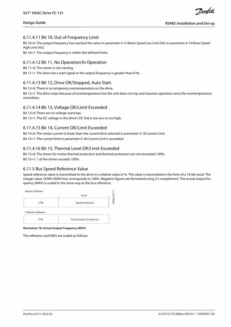
6.11.4.11 Bit 10, Out of Frequency LimitBit 10=0: The output frequency has reached the value in parameter 4-12 Motor Speed Low Limit [Hz] or parameter 4-14 Motor SpeedHigh Limit [Hz].Bit 10=1: The output frequency is within the defined limits.
6.11.4.12 Bit 11, No Operation/In OperationBit 11=0: The motor is not running.Bit 11=1: The drive has a start signal or the output frequency is greater than 0 Hz.
6.11.4.13 Bit 12, Drive OK/Stopped, Auto StartBit 12=0: There is no temporary overtemperature on the drive.Bit 12=1: The drive stops because of overtemperature but the unit does not trip and resumes operation once the overtemperaturenormalizes.
6.11.4.14 Bit 13, Voltage OK/Limit ExceededBit 13=0: There are no voltage warnings.Bit 13=1: The DC voltage in the drive’s DC link is too low or too high.
6.11.4.15 Bit 14, Current OK/Limit ExceededBit 14=0: The motor current is lower than the current limit selected in parameter 4-18 Current Limit.
Bit 14=1: The current limit in parameter 4-18 Current Limit is exceeded.
6.11.4.16 Bit 15, Thermal Level OK/Limit ExceededBit 15=0: The timers for motor thermal protection and thermal protection are not exceeded 100%. Bit 15=1: 1 of the timers exceeds 100%.
6.11.5 Bus Speed Reference ValueSpeed reference value is transmitted to the drive in a relative value in %. The value is transmitted in the form of a 16-bit word. Theinteger value 16384 (4000 hex) corresponds to 100%. Negative figures are formatted using 2’s complement. The actual output fre-quency (MAV) is scaled in the same way as the bus reference.
Actual output frequencySTW
Follower-follower
Speed referenceCTW
Master-follower
16 bit
e30b
a276
.11
Illustration 76: Actual Output Frequency (MAV)
The reference and MAV are scaled as follows:
AJ370727701888en-000101 / 130R0995 | 89Danfoss A/S © 2022.04
RS485 Installation and Set-up
VLT® HVAC Drive FC 131
Design Guide

Reverse ForwardPar.3-00 set to
(1) -max- +max
Max reference Max reference
Par.3-00 set to
(0) min-max
Max reference
Forward
Min reference
100%
(4000hex)
-100%
(C000hex)
0%
(0hex)
Par.3-03 0 Par.3-03
Par.3-03
(4000hex)(0hex)
0% 100%
Par.3-02
e30b
a277
.11
Illustration 77: Reference and MAV
AJ370727701888en-000101 / 130R099590 | Danfoss A/S © 2022.04
RS485 Installation and Set-up
VLT® HVAC Drive FC 131
Design Guide

7 General Specifications
7.1 Mains Supply
7.1.1 3x380–480 V AC
Table 61: 3x380–480 V AC, 0.75–18.5 kW (1.0–25 hp), Enclosure Sizes I2–I4
Drive PK75 P1K5 P2K2 P3K0 P4KO P5K5 P7K5 P11K P15K P18K
Typical shaft output [kW] 0.75 1.5 2.2 3.0 4.0 5.5 7.5 11 15 18.5
Typical shaft output [hp] 1.0 2.0 3.0 4.0 5.0 7.5 10.0 15 20 25
Protection rating IP54 I2 I2 I2 I2 I2 I3 I3 I4 I4 I4
Maximum cable size in terminals(mains, motor) [mm2 (AWG)]
4 (10) 4 (10) 4 (10) 4 (10) 4 (10) 4 (10) 4 (10) 16 (6) 16 (6) 16 (6)
Output current at 40 °C (104 °F) ambient temperature
Continuous (3x380–440 V) [A] 2.2 3.7 5.3 7.2 9.0 12 15.5 23 31 37
Intermittent (3x380–440 V) [A] 2.4 4.1 5.8 7.9 9.9 13.2 17.1 25.3 34 40.7
Continuous (3x441–480 V) [A] 2.1 3.4 4.8 6.3 8.2 11 14 21 27 34
Intermittent (3x441–480 V) [A] 2.3 3.7 5.3 6.9 9.0 12.1 15.4 23.1 29.7 37.4
Maximum input current
Continuous (3x380–440 V) [A] 2.1 3.5 4.7 6.3 8.3 11.2 15.1 22.1 29.9 35.2
Intermittent (3x380–440 V) [A] 2.3 3.9 5.2 6.9 9.1 12.3 16.6 24.3 32.9 38.7
Continuous (3x441–480 V) [A] 1.8 2.9 3.9 5.3 6.8 9.4 12.6 18.4 24.7 29.3
Intermittent (3x441–480 V) [A] 2.0 3.2 4.3 5.8 7.5 10.3 13.9 20.2 27.2 32.2
Maximum mains fuses See 7.2.5 Recommendation of Fuses and Circuit Breakers.
Estimated power loss [W], bestcase/typical(1)
21/16
46/57
46/58
66/83
95/118
104/131
159/198
248/274
353/379
412/456
Weight enclosure protection rat-ing IP54 [kg (lb)]
5.3(11.7)
5.3(11.7)
5.3(11.7)
5.3(11.7)
5.3(11.7)
7.2(15.9)
7.2(15.9)
13.8(30.4)
13.8(30.4)
13.8(30.4)
Efficiency [%], best case/typical(2) 98/97.6
97.7/97.2
98.3/97.9
98.2/97.8
98/97.6
98.4/98
98.2/97.8
98.1/97.9
98/97.8
98.1/97.9
Output current at 50 °C (122 °F) ambient temperature
Continuous (3x380–440 V) [A] 1.93 3.7 4.85 6.3 7.5 10.9 14 20.9 28 33
AJ370727701888en-000101 / 130R0995 | 91Danfoss A/S © 2022.04
General Specifications
VLT® HVAC Drive FC 131
Design Guide

Drive PK75 P1K5 P2K2 P3K0 P4KO P5K5 P7K5 P11K P15K P18K
Intermittent (3x380–440 V) [A] 2.1 4.07 5.4 6.9 9.2 12 15.4 23 30.8 36.3
Continuous (3x441–480 V) [A] 1.8 3.4 4.4 5.5 6.8 10 12.6 19.1 24 30
Intermittent (3x441–480 V) [A] 2.0 3.7 4.8 6.1 8.3 11 13.9 21 26.4 33
1 Applies for dimensioning of drive cooling. If the switching frequency is higher than the default setting, the power losses may increase. LCP andtypical control card power consumptions are included. For power loss data according to EN 50598-2, refer to Danfoss MyDrive® ecoSmart website.2 Efficiency measured at nominal current. For energy efficiency class, see 7.3.13 Ambient Conditions. For part load losses, see Danfoss MyDrive®ecoSmart website.
Table 62: 3x380–480 V AC, 22–90 kW (30–125 hp), Enclosure Sizes I6–I8
Drive P22K P30K P37K P45K P55K P75K P90K
Typical shaft output [kW] 22 30 37 45 55 75 90
Typical shaft output [hp] 30 40 50 60 70 100 125
Protection rating IP54 I6 I6 I6 I7 I7 I8 I8
Maximum cable size in terminals(mains, motor) [mm2 (AWG)]
35 (2) 35 (2) 35 (2) 50 (1) 50 (1) 95 (3/0) 120 (4/0)
Output current at 40 °C (104 °F) ambient temperature
Continuous (3x380–440 V) [A] 44 61 73 90 106 147 177
Intermittent (3x380–440 V) [A] 48.4 67.1 80.3 99 116.6 161.7 194.7
Continuous (3x441–480 V) [A] 40 52 65 80 105 130 160
Intermittent (3x441–480 V) [A] 44 57.2 71.5 88 115.5 143 176
Maximum input current
Continuous (3x380–440 V) [A] 41.8 57 70.3 84.2 102.9 140.3 165.6
Intermittent (3x380–440 V) [A] 46 62.7 77.4 92.6 113.1 154.3 182.2
Continuous (3x441–480 V) [A] 36 49.2 60.6 72.5 88.6 120.9 142.7
Intermittent (3x441–480 V) [A] 39.6 54.1 66.7 79.8 97.5 132.9 157
Maximum mains fuses See 7.2.5 Recommendation of Fuses and Circuit Breakers.
Estimated power loss [W], bestcase/typical(1)
496 734 995 840 1099 1520 1781
Weight enclosure protection rat-ing IP54 [kg (lb)]
27 (59.5) 27 (59.5) 27 (59.5) 45 (99.2) 45 (99.2) 65 (143.3) 65 (143.3)
Efficiency [%], best case/typical(2) 98 97.8 97.6 98.3 98.2 98.1 98.3
Output current at 50 °C (122 °F) ambient temperature
Continuous (3x380–440 V) [A] 35.2 48.8 58.4 63 74.2 102.9 123.9
AJ370727701888en-000101 / 130R099592 | Danfoss A/S © 2022.04
General Specifications
VLT® HVAC Drive FC 131
Design Guide

Drive P22K P30K P37K P45K P55K P75K P90K
Intermittent (3x380–440 V) [A] 38.7 53.9 64.2 69.3 81.6 113.2 136.3
Continuous (3x441–480 V) [A] 32 41.6 52 56 73.5 91 112
Intermittent (3x441–480 V) [A] 35.2 45.8 57.2 61.6 80.9 100.1 123.2
1 Applies for dimensioning of drive cooling. If the switching frequency is higher than the default setting, the power losses may increase. LCP andtypical control card power consumptions are included. For power loss data according to EN 50598-2, refer to Danfoss MyDrive® ecoSmart website.2 Efficiency measured at nominal current. For energy efficiency class, see 7.3.13 Ambient Conditions. For part load losses, see Danfoss MyDrive®ecoSmart website.
7.2 Fuses and Circuit Breakers
7.2.1 Branch Circuit ProtectionTo prevent fire hazards, protect the branch circuits in an installation - switch gear, machines, and so on - against short circuits andovercurrent. Follow national and local regulations.
7.2.2 Short-circuit ProtectionDanfoss recommends using the fuses and circuit breakers listed in this chapter to protect service personnel or other equipment incase of an internal failure in the unit or a short circuit on the DC link. The drive provides full short-circuit protection in case of a shortcircuit on the motor.
7.2.3 Overcurrent ProtectionProvide overload protection to avoid overheating of the cables in the installation. Overcurrent protection must always be carriedout according to local and national regulations. Design circuit breakers and fuses for protection in a circuit capable of supplying amaximum of 100000 Arms (symmetrical), 480 V maximum.
7.2.4 UL/Non-UL ComplianceTo ensure compliance with UL or IEC 61800-5-1, use the circuit breakers or fuses listed in this chapter. Circuit breakers must bedesigned for protection in a circuit capable of supplying a maximum of 10000 Arms (symmetrical), 480 V maximum.
7.2.5 Recommendation of Fuses and Circuit Breakers
N O T I C EIf a malfunction occurs, failure to follow the protection recommendation may result in damage to the drive.
Table 63: Fuses and Circuit Breakers
Circuit breaker Fuse
UL Non-UL UL Non-UL
Bussmann Bussmann Bussmann Bussmann Maximum fuse
Power [kW (hp)] Type RK5 Type RK1 Type J Type T Type G
3x380–480 V IP54
0.75 (1.0)
–
PKZM0-16 FRS-R-10 KTS-R-10 JKS-10 JJS-10 16
1.5 (2.0) PKZM0-16 FRS-R-10 KTS-R-10 JKS-10 JJS-10 16
2.2 (3.0) PKZM0-16 FRS-R-15 KTS-R-15 JKS-15 JJS-15 16
3.0 (4.0) PKZM0-16 FRS-R-15 KTS-R-15 JKS-15 JJS-15 16
4.0 (5.0) PKZM0-16 FRS-R-15 KTS-R-15 JKS-15 JJS-15 16
AJ370727701888en-000101 / 130R0995 | 93Danfoss A/S © 2022.04
General Specifications
VLT® HVAC Drive FC 131
Design Guide
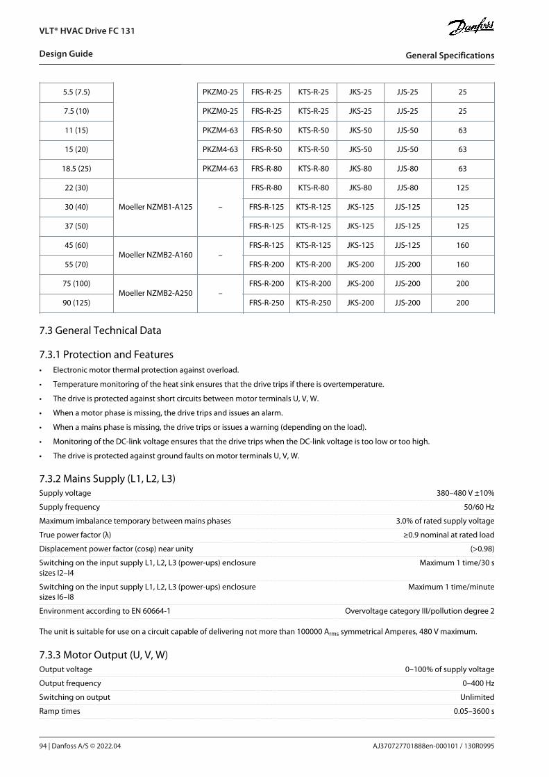
•
•
•
•
•
•
•
5.5 (7.5) PKZM0-25 FRS-R-25 KTS-R-25 JKS-25 JJS-25 25
7.5 (10) PKZM0-25 FRS-R-25 KTS-R-25 JKS-25 JJS-25 25
11 (15) PKZM4-63 FRS-R-50 KTS-R-50 JKS-50 JJS-50 63
15 (20) PKZM4-63 FRS-R-50 KTS-R-50 JKS-50 JJS-50 63
18.5 (25) PKZM4-63 FRS-R-80 KTS-R-80 JKS-80 JJS-80 63
22 (30)
Moeller NZMB1-A125 –
FRS-R-80 KTS-R-80 JKS-80 JJS-80 125
30 (40) FRS-R-125 KTS-R-125 JKS-125 JJS-125 125
37 (50) FRS-R-125 KTS-R-125 JKS-125 JJS-125 125
45 (60)Moeller NZMB2-A160 –
FRS-R-125 KTS-R-125 JKS-125 JJS-125 160
55 (70) FRS-R-200 KTS-R-200 JKS-200 JJS-200 160
75 (100)Moeller NZMB2-A250 –
FRS-R-200 KTS-R-200 JKS-200 JJS-200 200
90 (125) FRS-R-250 KTS-R-250 JKS-200 JJS-200 200
7.3 General Technical Data
7.3.1 Protection and FeaturesElectronic motor thermal protection against overload.
Temperature monitoring of the heat sink ensures that the drive trips if there is overtemperature.
The drive is protected against short circuits between motor terminals U, V, W.
When a motor phase is missing, the drive trips and issues an alarm.
When a mains phase is missing, the drive trips or issues a warning (depending on the load).
Monitoring of the DC-link voltage ensures that the drive trips when the DC-link voltage is too low or too high.
The drive is protected against ground faults on motor terminals U, V, W.
7.3.2 Mains Supply (L1, L2, L3)Supply voltage 380–480 V ±10%
Supply frequency 50/60 Hz
Maximum imbalance temporary between mains phases 3.0% of rated supply voltage
True power factor (λ) ≥0.9 nominal at rated load
Displacement power factor (cosφ) near unity (>0.98)
Switching on the input supply L1, L2, L3 (power-ups) enclosuresizes I2–I4
Maximum 1 time/30 s
Switching on the input supply L1, L2, L3 (power-ups) enclosuresizes I6–I8
Maximum 1 time/minute
Environment according to EN 60664-1 Overvoltage category III/pollution degree 2
The unit is suitable for use on a circuit capable of delivering not more than 100000 Arms symmetrical Amperes, 480 V maximum.
7.3.3 Motor Output (U, V, W)Output voltage 0–100% of supply voltage
Output frequency 0–400 Hz
Switching on output Unlimited
Ramp times 0.05–3600 s
AJ370727701888en-000101 / 130R099594 | Danfoss A/S © 2022.04
General Specifications
VLT® HVAC Drive FC 131
Design Guide

7.3.4 Cable Length and Cross-sectionMaximum motor cable length, shielded/armored (EMC-correct in-stallation)
See 3.4.3 EMC Emission Test Results.
Maximum motor cable length, unshielded/unarmoured 50 m (164 ft)
Maximum cross-section to motor, mains See 7.1.1 3x380–480 V AC for more information
Cross-section DC terminals for filter feedback on enclosure sizesI2–I4
4 mm2/11 AWG
Maximum cross-section to control terminals, rigid wire 2.5 mm2/14 AWG
Maximum cross-section to control terminals, flexible cable 2.5 mm2/14 AWG
Minimum cross-section to control terminals 0.05 mm2/30 AWG
7.3.5 Digital InputsProgrammable digital inputs 4
Terminal number 18, 19, 27, 29
Logic PNP or NPN
Voltage level 0–24 V DC
Voltage level, logic 0 PNP <5 V DC
Voltage level, logic 1 PNP >10 V DC
Voltage level, logic 0 NPN >19 V DC
Voltage level, logic 1 NPN <14 V DC
Maximum voltage on input 28 V DC
Input resistance, Ri Approximately 4 kΩ
Digital input 29 as thermistor input Fault: >2.9 kΩ and no fault: <800 Ω
Digital input 29 as pulse input Maximum frequency 32 kHz push-pull-driven & 5 kHz (O.C.)
The digital inputs are galvanically isolated from the supply voltage (PELV) and other high-voltage terminals.
7.3.6 Analog InputsNumber of analog inputs 2
Terminal number 53, 54
Terminal 53 mode Parameter 16-61 Terminal 53 Setting: 1 = voltage, 0 = current
Terminal 54 mode Parameter 16-63 Terminal 54 Setting: 1 = voltage, 0 = current
Voltage level 0–10 V
Input resistance, Ri Approximately 10 kΩ
Maximum voltage 20 V
Current level 0/4–20 mA (scalable)
Input resistance, Ri <500 Ω
Maximum current 29 mA
Resolution on analog input 10 bit
7.3.7 Analog OutputsNumber of programmable analog outputs 2
Terminal number 42, 45(1)
Current range at analog output 0/4–20 mA
Maximum load to common at analog output 500 Ω
Maximum voltage at analog output 17 V
Accuracy on analog output Maximum error: 0.4% of full scale
AJ370727701888en-000101 / 130R0995 | 95Danfoss A/S © 2022.04
General Specifications
VLT® HVAC Drive FC 131
Design Guide

Resolution on analog output 10 bit
1 Terminals 42 and 45 can also be programmed as digital outputs.
7.3.8 Digital OutputNumber of digital outputs 4
Terminals 27 and 29
Terminal number 27, 29(1)
Voltage level at digital output 0–24 V
Maximum output current (sink and source) 40 mA
Terminals 42 and 45
Terminal number 42, 45(2)
Voltage level at digital output 17 V
Maximum output current at digital output 20 mA
Maximum load at digital output 1 kΩ
1 Terminals 27 and 29 can also be programmed as input.2 Terminals 42 and 45 can also be programmed as analog output.
The digital outputs are galvanically isolated from the supply voltage (PELV) and other high-voltage terminals.
7.3.9 Control Card, RS485 Serial CommunicationTerminal number 68 (P, TX+, RX+), 69 (N, TX-, RX-)
Terminal number 61 common for terminals 68 and 69
7.3.10 Control Card, 24 V DC OutputTerminal number 12
Maximum load 80 mA
7.3.11 Relay OutputProgrammable relay outputs 2
Relay 01 and 02 (enclosure size I2–I4) 01–03 (NC), 01–02 (NO), 04–06 (NC), 04–05 (NO)
Maximum terminal load (AC-1)(1) on 01–02/04–05 (NO) (resistiveload)
250 V AC, 3 A
Maximum terminal load (AC-15)(1) on 01–02/04–05 (NO) (induc-tive load @ cosφ 0.4)
250 V AC, 0.2 A
Maximum terminal load (DC-1)(1) on 01–02/04–05 (NO) (resistiveload)
30 V DC, 2 A
Maximum terminal load (DC-13)(1) on 01–02/04–05 (NO) (induc-tive load)
24 V DC, 0.1 A
Maximum terminal load (AC-1)(1) on 01–03/04–06 (NC) (resistiveload)
250 V AC, 3 A
Maximum terminal load (AC-15)(1) on 01–03/04–06 (NC) (inductiveload @ cosφ 0.4)
250 V AC, 0.2 A
Maximum terminal load (DC-1)(1) on 01–03/04–06 (NC) (resistiveload)
30 V DC, 2 A
Minimum terminal load on 01–03 (NC), 01–02 (NO) 24 V DC 10 mA, 24 V AC 20 mA
Environment according to EN 60664-1 Overvoltage category III/pollution degree 2
1 IEC 60947 parts 4 and 5. Endurance of the relay varies with different load type, switching current, ambient temperature, driving configuration,working profile, and so forth. It is recommended to mount a snubber circuit when connecting inductive loads to the relays.
AJ370727701888en-000101 / 130R099596 | Danfoss A/S © 2022.04
General Specifications
VLT® HVAC Drive FC 131
Design Guide

Programmable relay outputs
Maximum terminal load (AC-1)(1) on 01–03 (NC), 01–02 (NO) (resis-tive load)
240 V AC, 2 A
Maximum terminal load (AC-15)(1) (inductive load @ cosφ 0.4) 240 V AC, 0.2 A
Maximum terminal load (DC-1)(1) on 01–02 (NO), 01–03 (NC) (resis-tive load)
60 V DC, 1 A
Maximum terminal load (DC-13)(1) (inductive load) 24 V DC, 0.1 A
Relay 01 and 02 terminal number (enclosure size I6–I8) 01–03 (NC), 01–02 (NO), 04–06 (NC), 04– 05 (NO)
Maximum terminal load (AC-1)(1) on 04–05 (NO) (resistive load)(2)(3) 400 V AC, 2 A
Maximum terminal load (AC-15)(1) on 04–05 (NO) (inductive load@ cosφ 0.4)
240 V AC, 0.2 A
Maximum terminal load (DC-1)(1) on 04–05 (NO) (resistive load) 80 V DC, 2 A
Maximum terminal load (DC-13)(1) on 04–05 (NO) (inductive load) 24 V DC, 0.1 A
Maximum terminal load (AC-1)(1) on 04–06 (NC) (resistive load) 240 V AC, 2 A
Maximum terminal load (AC-15)(1) on 04–06 (NC) (inductive load@ cosφ 0.4)
240 V AC, 0.2 A
Maximum terminal load (DC-1)(1) on 04–06 (NC) (resistive load) 50 V DC, 2 A
Maximum terminal load (DC-13)(1) on 04–06 (NC) (inductive load) 24 V DC, 0.1 A
Minimum terminal load on 01–03 (NC), 01–02 (NO), 04–06 (NC),04–05 (NO)
24 V DC 10 mA, 24 V AC 20 mA
Environment according to EN 60664-1 Overvoltage category III/pollution degree 2
1 IEC 60947 parts 4 and 5. Endurance of the relay varies with different load type, switching current, ambient temperature, driving configuration,working profile, and so forth. It is recommended to mount a snubber circuit when connecting inductive loads to the relays.2 Overvoltage Category II.3 UL applications 300 V AC 2 A.
7.3.12 Control Card, 10 V DC OutputTerminal number 50
Output voltage 10.5 V ±0.5 V
Maximum load 25 mA
7.3.13 Ambient ConditionsEnclosure protection rating IP54 (not for outdoor installation)
Vibration test 1.0 g
Maximum relative humidity 5–95% (IEC 60721-3-3; Class 3K3 (non-condensing)) during opera-tion
Aggressive environment (IEC 60721-3-3), non-coated enclosuresizes I2–I8
Class 3C2
Test method according to IEC 60068-2-43 H2S (10 days)
Ambient temperature(1) See maximum output current at 40/50 °C (104/122 °F) in 7.1.13x380–480 V AC.
Minimum ambient temperature during full-scale operation 0 °C (32 °F)
Minimum ambient temperature at reduced performance, enclo-sure sizes I2–I4
-20 °C (-4 °F)
Minimum ambient temperature at reduced performance, enclo-sure sizes I6–I8
-10 °C (14 °F)
Temperature during storage/transport -30 to +65/70 °C (-22 to +149/158 °F)
Maximum altitude above sea level without derating 1000 m (3281 ft)
Maximum altitude above sea level with derating 3000 m (9843 ft)
AJ370727701888en-000101 / 130R0995 | 97Danfoss A/S © 2022.04
General Specifications
VLT® HVAC Drive FC 131
Design Guide

•
•
•
•
•
•
Safety standards EN/IEC 61800-5-1
EMC standards, Emission EN 61800-3, EN 61000-6-3/4, EN 55011, IEC 61800-3
EMC standards, Immunity EN 61800-3, EN 61000-3-12, EN 61000-6-1/2, EN 61000-4-2, EN61000-4-3, EN 61000-4-4, EN 61000-4-5, EN 61000-4-6
Energy efficiency class(2) IE2
1 Refer to chapter Special Conditions in the operating guide for:
Derating for high ambient temperature.
Derating for high altitude.2 Determined according to EN 50598-2 at:
Rated load.
90% rated frequency.
Switching frequency factory setting.
Switching pattern factory setting.
7.4 dU/Dt
Table 64: dU/Dt Data
Cable length [m (ft)] AC line voltage [V] Rise time [μsec] V peak [kV] dU/dt [kV/μsec]
400 V 0.75 kW (1 hp) 5 (16) 400 0.160 0.808 4.050
25 (82) 400 0.240 1.026 3.420
50 (164) 400 0.340 1.056 2.517
400 V 1.5 kW (2 hp) 5 (16) 400 0.160 0.808 4.050
25 (82) 400 0.240 1.026 3.420
50 (164) 400 0.340 1.056 2.517
400 V 2.2 kW (3 hp) 5 (16) 400 0.190 0.760 3.200
25 (82) 400 0.293 1.026 2.801
50 (164) 400 0.422 1.040 1.971
400 V 3.0 kW (4 hp) 5 (16) 400 0.190 0.760 3.200
25 (82) 400 0.293 1.026 2.801
50 (164) 400 0.422 1.040 1.971
400 V 4.0 kW (5.4 hp) 5 (16) 400 0.190 0.760 3.200
25 (82) 400 0.293 1.026 2.801
50 (164) 400 0.422 1.040 1.971
400 V 5.5 kW (7.4 hp) 5 (16) 400 0.168 0.81 3.857
25 (82) 400 0.239 1.026 3.434
50 (164) 400 0.328 1.05 2.560
400 V 7.5 kW (10 hp) 5 (16) 400 0.168 0.81 3.857
25 (82) 400 0.239 1.026 3.434
50 (164) 400 0.328 1.05 2.560
AJ370727701888en-000101 / 130R099598 | Danfoss A/S © 2022.04
General Specifications
VLT® HVAC Drive FC 131
Design Guide

Cable length [m (ft)] AC line voltage [V] Rise time [μsec] V peak [kV] dU/dt [kV/μsec]
400 V 11 kW (15 hp) 5 (16) 400 0.116 0.69 4.871
25 (82) 400 0.204 0.985 3.799
50 (164) 400 0.316 1.01 2.563
400 V 15 kW (20 hp) 5 (16) 400 0.139 0.864 4.955
50 (82) 400 0.338 1.008 2.365
400 V 18.5 kW (25 hp) 5 (16) 400 0.132 0.88 5.220
25 (82) 400 0.172 1.026 4.772
50 (164) 400 0.222 1.00 3.603
400 V 22 kW (30 hp) 5 (16) 400 0.132 0.88 5.220
25 (82) 400 0.172 1.026 4.772
50 (164) 400 0.222 1.00 3.603
400 V 30 kW (40 hp) 10 (33) 400 0.376 0.92 1.957
50 (164) 400 0.536 0.97 1.448
100 (328) 400 0.696 0.95 1.092
150 (492) 400 0.8 0.965 0.965
10 (33) 480 0.384 1.2 2.5
50 (164) 480 0.632 1.18 1.494
100 (328) 480 0.712 1.2 1.348
150 (492) 480 0.832 1.17 1.125
10 (33) 500 0.408 1.24 2.431
50 (164) 500 0.592 1.29 1.743
100 (328) 500 0.656 1.28 1.561
150 (492) 500 0.84 1.26 1.2
400 V 37 kW (50 hp) 10 (33) 400 0.276 0.928 2.69
50 (164) 400 0.432 1.02 1.889
10 (33) 480 0.272 1.17 3.441
50 (164) 480 0.384 1.21 2.521
10 (33) 500 0.288 1.2 3.333
50 (164) 500 0.384 1.27 2.646
400 V 45 kW (60 hp) 10 (33) 400 0.3 0.936 2.496
50 (164) 400 0.44 0.924 1.68
100 (328) 400 0.56 0.92 1.314
AJ370727701888en-000101 / 130R0995 | 99Danfoss A/S © 2022.04
General Specifications
VLT® HVAC Drive FC 131
Design Guide

Cable length [m (ft)] AC line voltage [V] Rise time [μsec] V peak [kV] dU/dt [kV/μsec]
150 (492) 400 0.8 0.92 0.92
10 (33) 480 0.3 1.19 3.173
50 (164) 480 0.4 1.15 2.3
100 (328) 480 0.48 1.14 1.9
150 (492) 480 0.72 1.14 1.267
10 (33) 500 0.3 1.22 3.253
50 (164) 500 0.38 1.2 2.526
100 (328) 500 0.56 1.16 1.657
150 (492) 500 0.74 1.16 1.254
400 V 55 kW (74 hp) 10 (33) 400 0.46 1.12 1.948
480 0.468 1.3 2.222
400 V 75 kW (100 hp) 10 (33) 400 0.502 1.048 1.673
480 0.52 1.212 1.869
500 0.51 1.272 1.992
400 V 90 kW (125 hp) 10 (33) 400 0.402 1.108 2.155
400 0.408 1.288 2.529
400 0.424 1.368 2.585
AJ370727701888en-000101 / 130R0995100 | Danfoss A/S © 2022.04
General Specifications
VLT® HVAC Drive FC 131
Design Guide

8 Appendix
8.1 Abbreviations
°C Degrees Celsius
°F Degrees Fahrenheit
A Ampere/AMP
AC Alternating current
AWG American wire gauge
AMA Automatic motor adaptation
DC Direct current
D-TYPE Drive dependent
EMC Electro-magnetic compatibility
ETR Electronic thermal relay
fM,N Nominal motor frequency
g Gram
Hz Hertz
hp Horsepower
ILIM Current limit
IINV Rated inverter output current
IM,N Nominal motor current
IVLT,MAX Maximum output current
IVLT,N Rated output current supplied by the drive
kg Kilogram
kHz Kilohertz
LCP Local control panel
m Meter
mH Millihenry inductance
mA Milliampere
ms Millisecond
min Minute
MCT Motion control tool
nF Nanofarad
Nm Newton meter
ns Synchronous motor speed
AJ370727701888en-000101 / 130R0995 | 101Danfoss A/S © 2022.04
Appendix
VLT® HVAC Drive FC 131
Design Guide

PM,N Nominal motor power
PELV Protective extra low voltage
PCB Printed circuit board
PM motor Permanent magnet motor
Regen Regenerative terminals
RPM Revolutions per minute
s Second
TLIM Torque limit
UM,N Nominal motor voltage
V Volts
8.2 Definitions
8.2.1 AC DriveCoastThe motor shaft is in free mode. No torque on the motor.
IVLT,MAX
Maximum output current.
IVLT,N
Rated output current supplied by the drive.
UVLT,MAX
Maximum output voltage.
8.2.2 InputControl commandsStart and stop the connected motor with LCP and digital inputs.Functions are divided into 2 groups.Functions in group 1 have higher priority than functions in group 2.
Table 65: Function Groups
Group 1 Reset, coast stop, reset and coast stop, quick stop, DC brake, stop, and [Off].
Group 2 Start, pulse start, reversing, start reversing, jog, and freeze output.
8.2.3 MotorMotor runningTorque generated on the output shaft and speed from 0 RPM to maximum speed on the motor.
fJOG
Motor frequency when the jog function is activated (via digital terminals or bus).
fM
Motor frequency.
fMAX
Maximum motor frequency.
fMIN
Minimum motor frequency.
fM,N
AJ370727701888en-000101 / 130R0995102 | Danfoss A/S © 2022.04
Appendix
VLT® HVAC Drive FC 131
Design Guide

Rated motor frequency (nameplate data).
IM
Motor current (actual).
IM,N
Nominal motor current (nameplate data).
nM,N
Nominal motor speed (nameplate data).
ns
Synchronous motor speed.
ns = 2 × Parameter 1−23 × 60 sParameter 1−39
nslip
Motor slip.
PM,N
Rated motor power (nameplate data in kW or hp).
TM,N
Rated torque (motor).
UM
Instantaneous motor voltage.
UM,N
Rated motor voltage (nameplate data).
Break-away torque
e75z
a078
.10
(1)
(2)
(3)
Illustration 78: Break-away Torque
1 Torque
2 RPM
3 Pull-out
ηVLT
The efficiency of the drive is defined as the ratio between the power output and the power input.
Start-disable commandA start-disable command belonging to the control commands in group 1. See the table in chapter Input for more details.
Stop commandA stop command belonging to the control commands in group 1. See the table in chapter Input for more details.
8.2.4 ReferencesAnalog reference
AJ370727701888en-000101 / 130R0995 | 103Danfoss A/S © 2022.04
Appendix
VLT® HVAC Drive FC 131
Design Guide

•
•
•
•
A signal transmitted to the analog inputs 53 or 54 can be voltage or current.
Current input: 0–20 mA and 4–20 mA
Voltage input: 0–10 V DC
Bus referenceA signal transmitted to the serial communication port (FC port).
Binary referenceA signal transmitted via the serial communication port.
Preset referenceA defined preset reference to be set from -100% to +100% of the reference range. Selection of 8 preset references via the digitalterminals. Selection of 4 preset references via the bus.
RefMAX
Determines the relationship between the reference input at 100% full scale value (typically 10 V, 20 mA) and the resulting reference.The maximum reference value is set in parameter 3-03 Maximum Reference.
RefMIN
Determines the relationship between the reference input at 0% value (typically 0 V, 0 mA, 4 mA) and the resulting reference. Theminimum reference value is set in parameter 3-02 Minimum Reference.
8.2.5 MiscellaneousAnalog inputsThe analog inputs are used for controlling various functions of the drive.There are 2 types of analog inputs:
Current input: 0–20 mA and 4–20 mA.
Voltage input: 0–10 V DC.
Analog outputsThe analog outputs can supply a signal of 0–20 mA, 4– 20 mA, or a digital signal.
Automatic motor adaptation, AMAThe AMA algorithm determines the electrical parameters for the connected motor at standstill and compensates for the resistancebased on the length of the motor cable.
Digital inputsThe digital inputs can be used for controlling various functions of the drive.
Digital outputsThe drive features 2 solid-state outputs that can supply a 24 V DC (maximum 40 mA) signal.
DSPDigital signal processor.
Relay outputsThe drive provides 2 programmable relay outputs.
ETRElectronic thermal relay is a thermal load calculation based on present load and time. Its purpose is to estimate the motor tempera-ture and prevent overheating of the motor.
InitializingIf initializing is carried out (parameter 14-22 Operation Mode), the drive returns to the default setting.
Parameter 14-22 Operation Mode does not initialize communication parameters, fault log, or fire mode log.
Intermittent duty cycleAn intermittent duty rating refers to a sequence of duty cycles. Each cycle consists of an on-load and an off-load period. The opera-tion can be either periodic duty or nonperiodic duty.
LCPThe local control panel makes up a complete interface for control and programming of the drive. The LCP is detachable. With theinstallation kit option, the LCP can be installed up to 3 m (9.8 ft) from the drive in a front panel.
NLCPThe numerical local control panel interface for control and programming of the drive. The display is numerical and the panel is usedto show process values. The NLCP has storing and copy functions.
GLCP
AJ370727701888en-000101 / 130R0995104 | Danfoss A/S © 2022.04
Appendix
VLT® HVAC Drive FC 131
Design Guide

The graphic local control panel interface for control and programming of the drive. The display is graphic and the panel is used toshow process values. The GLCP has storing and copy functions.
lsbLeast significant bit.
msbMost significant bit.
MCMShort for mille circular mil, an American measuring unit for cable cross-section. 1 MCM = 0.5067 mm2.
On-line/off-line parametersChanges to on-line parameters are activated immediately after the data value is changed. To activate changes to offline parameters,press [OK].
PI controllerThe PI controller maintains the desired speed, pressure, temperature, and so on, by adjusting the output frequency to match thevarying load.
Process PIDThe PID control maintains speed, pressure, and temperature by adjusting the output frequency to match the varying load.
PCDProcess control data.
PFCPower factor correction.
Power cycleSwitch off the mains until the display (LCP) is dark, then turn power on again.
Power factorThe power factor is the relation between I1 and IRMS, where I1 is the fundamental current, and IRMS is the total RMS current includingharmonic currents.
Power factor = 3 × U × I1cosϕ1
3 × U × IRMS
For VLT® HVAC Drive FC 131 drives, cosϕ1 = 1, therefore:
Power factor = I1 × cosϕ1IRMS
= I1
IRMS
The power factor indicates to which extent the drive imposes a load on the mains supply. The lower the power factor, the higher theIRMS for the same kW performance.
IRMS = I12 + I5
2 + I72 + .. + In
2
In addition, a high power factor indicates that the different harmonic currents are low.The built-in DC coils produce a high-power factor, minimizing the imposed load on the mains supply.
Pulse input/incremental encoderAn external, digital pulse transmitter used for feeding back information on motor speed. The encoder is used in applications wheregreat accuracy in speed control is required.
RCDResidual current device.
SetupSave parameter settings in 2 setups. Change between the 2 parameter setups and edit 1 setup while another setup is active.
SFAVMAcronym describing the switching pattern stator fluxoriented asynchronous vector modulation.
Slip compensationThe drive compensates for the motor slip by giving the frequency a supplement that follows the measured motor load, keeping themotor speed almost constant.
Smart logic control (SLC)The SLC is a sequence of user-defined actions executed when the smart logic controller evaluates the associated user-definedevents as true.
STW
AJ370727701888en-000101 / 130R0995 | 105Danfoss A/S © 2022.04
Appendix
VLT® HVAC Drive FC 131
Design Guide

•
•
Status word.
THDTotal harmonic distortion states the total contribution of harmonic distortion.
ThermistorA temperature-dependent resistor placed where the temperature is monitored (drive or motor).
TripTrip is a state entered in fault situations. Examples of fault situations:
The drive is subject to an over voltage.
The drive protects the motor, process, or mechanism.
Restart is prevented until the cause of the fault has disappeared, and the trip state is canceled by activating reset or, in some cases,by being programmed to reset automatically. Do not use trip for personal safety.
Trip lockTrip lock is a state entered in fault situations when the drive is protecting itself and requiring physical intervention. For example, ashort circuit on the output triggers a trip lock. A locked trip can only be canceled by cutting off mains, removing the cause of thefault, and reconnecting the drive. Restart is prevented until the trip state is canceled by activating reset or, sometimes, by beingprogrammed to reset automatically. Do not use trip lock for personal safety.
VT characteristicsVariable torque characteristics used for pumps and fans.
VVC+If compared with standard voltage/frequency ratio control, voltage vector control (VVC+) improves the dynamics and stability, bothwhen the speed reference is changed and in relation to the load torque.
60° AVMRefer to the switching pattern 60° asynchronous vector modulation.
AJ370727701888en-000101 / 130R0995106 | Danfoss A/S © 2022.04
Appendix
VLT® HVAC Drive FC 131
Design Guide

Index110 V DC output..............................................................................................97
224 V DC output..............................................................................................96
AAbbreviations..............................................................................................101Acoustic noise................................................................................................32Additional resource........................................................................................9ADR....................................................................................................................65Aggressive environments......................................................................... 33Air humidity....................................................................................................30AK................................................................................................................ 66, 68AMA................................................................................................................ 104Ambient condition.......................................................................................97Analog input............................................................................... 95, 103, 104Analog output.............................................................................................104Application examples................................................................................. 21
BBalancing contractor...................................................................................25BCC.................................................................................................................... 65Better control.................................................................................................19Branch circuit protection...........................................................................93Break-away torque.................................................................................... 103Building management system, BMS......................................................16Bypass frequency range.............................................................................23
CCables
Leakage current................................................................................... 38CAV.................................................................................................................... 22CE mark...............................................................................................................9Central VAV system......................................................................................21Circuit breaker............................................................................................... 93Coast........................................................................................................85, 102Comparison, energy saving......................................................................16Condenser pump..........................................................................................24Constant air volume.................................................................................... 22Control card......................................................................................96, 96, 97Control potential.......................................................................................... 26Control structure closed loop.................................................................. 28Control structure open loop.....................................................................27Control word..................................................................................................84Controlling fan.............................................................................................. 15Controlling pump.........................................................................................15Conversion......................................................................................................68Conversion factor......................................................................................... 68Conversion index..........................................................................................68Cooling tower fan.........................................................................................23Current
Leakage current................................................................................... 38Transient ground.................................................................................40
Current loop................................................................................................... 34
DDamper............................................................................................................ 21Data control byte..........................................................................................65
Data field......................................................................................................... 65Data types....................................................................................................... 68DC brake.......................................................................................................... 85DC link.............................................................................................................. 41Definition of EMC categories................................................................... 34Derating...........................................................................................................30Differential pressure....................................................................................26Digital input....................................................................................................95Digital output................................................................................................ 96Document version..........................................................................................9Drive address................................................................................................. 65Drive closed-loop controller, tuning..................................................... 30
EEAC.....................................................................................................................10Earth leakage circuit breaker....................................................................40
See Residual current deviceElectrical installation................................................................................... 49Electronic thermal relay...........................................................................104EMC
Directive..................................................................................................10EMC plan..........................................................................................................34EMC-compliant installation...................................................................... 57Emission...........................................................................................................33Emission requirement..........................................................................34, 34Energy efficiency class................................................................................98Energy saving...................................................................................15, 16, 18Environment
Industrial.................................................................................................34Residential............................................................................................. 34
ErP directive....................................................................................................10ETR............................................................................................................42, 104Evaporator flow rate....................................................................................25Extreme running condition...................................................................... 41
FFeedback conversion..................................................................................29Flow meter......................................................................................................25Force/write multiple coil (0F hex)...........................................................80Force/write single coil (05 hex)............................................................... 79Freeze output..............................................................................................102Function Codes............................................................................................. 76Fuse................................................................................................................... 93
GGalvanic isolation......................................................................................... 37GLCP............................................................................................................... 104Ground
Leakage protection.............................................................................33Leakage current................................................................................... 39
HHardware setup.............................................................................................61Harmonic current......................................................................................... 36Harmonics distortion.................................................................................. 33Harmonics emission.................................................................................... 36Harmonics emission requirement..........................................................36Harmonics test result (emission)............................................................ 36Hold output frequency...............................................................................86
AJ370727701888en-000101/130R0995 | 107Danfoss A/S © 2022.04
Index
VLT® HVAC Drive FC 131
Design Guide

IIGV......................................................................................................................21Immunity requirement........................................................................34, 37IND..................................................................................................................... 68Index................................................................................................................. 68Industrial environment........................................................................34, 35Installation
Qualified personnel............................................................................12Intermittent duty cycle............................................................................ 104
JJog............................................................................................................ 86, 102
LLCP.................................................................................................. 28, 102, 104Leakage current.............................................................................. 13, 33, 38LGE.....................................................................................................................64Local (hand on) control.............................................................................. 28Local speed determination.......................................................................25Low evaporator temperature...................................................................25Low voltage directive................................................................................. 10
MMains drop-out..............................................................................................41Mains supply (L1, L2, L3)............................................................................ 94Manual PI adjustment.................................................................................30MCT 10 setup software................................................................................. 9Modbus communication........................................................................... 62Modbus exception codes.......................................................................... 77Modbus RTU..............................................................................63, 70, 71, 76Modbus RTU commands........................................................................... 78Modbus RTU protocol.................................................................................70Moment of inertia........................................................................................ 41Motor
Cable........................................................................................................ 33Leakage current................................................................................... 38Thermal protection.......................................................................42,89
Motor output (U, V, W)................................................................................94Motor-generated overvoltage.................................................................41Multiple pump...............................................................................................26
NNetwork configuration...............................................................................71Network connection....................................................................................61NLCP............................................................................................................... 104Nominal motor current............................................................................103Nominal motor speed.............................................................................. 103
OOvercurrent protection.............................................................................. 93Overload protection....................................................................................94
PParameter block............................................................................................65Parameter number.......................................................................................67Parameter value............................................................................................68Payback period..............................................................................................18PCD............................................................................................................. 65, 69PELV...................................................................................................................37PKE field........................................................................................................... 66
PNU......................................................................................................66, 67, 77Power cycle.................................................................................................. 105Preset multiple register (10 hex).............................................................82Preset single register (06 hex)..................................................................81Primary pump................................................................................................25Process block................................................................................................. 65Process words................................................................................................69Programmable minimum frequency setting..................................... 23Protective extra low voltage.................................................................... 37Public supply network................................................................................36Pump impeller...............................................................................................24Purpose of the manual..................................................................................9PWE....................................................................................................................68
QQualified personnel..................................................................................... 12
RRated current................................................................................................. 34RCD..................................................................................................................105RCM mark compliance................................................................................10Read coil status (01 hex)............................................................................ 78Read holding registers (03 hex).............................................................. 81Read/write multiple registers (17 hex)................................................. 83Reference handling..................................................................................... 29Relay output...................................................................................................96Remote (auto on) control.......................................................................... 28Remote terminal unit..................................................................................70Residential environment.................................................................... 34, 35Residual current device..............................................................................40RS485......................................................................................................... 60, 63RS485 serial communication....................................................................96
SSecondary pump.......................................................................................... 26Serial communication.............................................................................. 104Shock................................................................................................................ 32Short circuit (motor phase-phase)......................................................... 41Short-circuit protection..............................................................................93Side-by-side installation............................................................................ 47Slip compensation.....................................................................................105Soft starter.......................................................................................................19Software version............................................................................................. 9Star/delta starter...........................................................................................19Status word.....................................................................................................87Switching frequency
Use with RCDs.......................................................................................40Switching on the output............................................................................41Symbols........................................................................................................... 12Synchronous motor speed..................................................................... 103
TTelegram length........................................................................................... 64Telegram structure...................................................................................... 64Text block........................................................................................................65THD....................................................................................................................36Throttling valve.............................................................................................24Total voltage distortion..............................................................................36Trip.................................................................................................................. 106Trip lock......................................................................................................... 106Type code........................................................................................................45
AJ370727701888en-000101/130R0995108 | Danfoss A/S © 2022.04
Index
VLT® HVAC Drive FC 131
Design Guide

UUkrSEPRO certificate................................................................................... 11UL/Non-UL compliance..............................................................................93
VVariable air volume......................................................................................21Variable control, flow and pressure.......................................................19Varying flow (1 year)....................................................................................18
VAV.................................................................................................................... 21Vibration................................................................................................... 23, 32Voltage
Safety warning..................................................................................... 12Voltage distortion........................................................................................ 36
WWiring schematic..........................................................................................48
AJ370727701888en-000101/130R0995 | 109Danfoss A/S © 2022.04
Index
VLT® HVAC Drive FC 131
Design Guide

AJ370727701888en-000101 / 130R0995
*M0030901*Danfoss A/S © 2022.04
Danfoss A/SUlsnaes 1DK-6300 Graastenvlt-drives.danfoss.com
Danfoss can accept no responsibility for possible errors in catalogs, brochures, and other printed material. Danfoss reserves the right to alter its products without notice. Thisalso applies to products already on order provided that such alterations can be made without subsequential changes being necessary in specifications already agreed. Alltrademarks in this material are property of the respective companies. Danfoss and the Danfoss logotype are trademarks of Danfoss A/S. All rights reserved.
*130R0995*

![6WUDQD 6EmUND ]gNRQÖ ³ 131 ²gVWND](https://static.fdokumen.com/doc/165x107/6328bf8f051fac18490ee0a6/6wudqd-6emund-gnrqoe-131-gvwnd.jpg)