VLT® AutomationDrive FC 360 Quick Guide - Danfoss
50
MAKING MODERN LIVING POSSIBLE Quick Guide VLT ® AutomationDrive FC 360 www.danfoss.com/drives
-
Upload
khangminh22 -
Category
Documents
-
view
0 -
download
0
Transcript of VLT® AutomationDrive FC 360 Quick Guide - Danfoss

MAKING MODERN LIVING POSSIBLE
Quick GuideVLT® AutomationDrive FC 360
www.danfoss.com/drives


Safety
WARNINGHIGH VOLTAGEFrequency converters contain high voltage whenconnected to AC mains input power. Installation, startup, and maintenance should be performed by qualifiedpersonnel only. Failure to perform installation, start up,and maintenance by qualified personnel could result indeath or serious injury.
WARNINGUNINTENDED STARTWhen the frequency converter is connected to AC mains,the motor may start at any time. The frequencyconverter, motor, and any driven equipment must be inoperational readiness. Failure to be in operationalreadiness when the frequency converter is connected toAC mains could result in death, serious injury,equipment, or property damage.
WARNINGDISCHARGE TIMEFrequency converters contain DC-link capacitors that canremain charged even when the frequency converter isnot powered. To avoid electrical hazards, disconnect ACmains, any permanent magnet type motors, and anyremote DC-link power supplies, including batterybackups, UPS and DC-link connections to otherfrequency converters. Wait for the capacitors to fullydischarge before performing any service or repair work.The amount of wait time is listed in the Discharge Timetable. Failure to wait the specified time after power hasbeen removed before doing service or repair could resultin death or serious injury.
Voltage [V] Minimum waiting time [minutes]
4 15
380-480 0.37-7.5 kW 11-75 kW
High voltage may be present even when the warning LEDs areoff!
Discharge Time
SymbolsThe following symbols are used in this manual.
WARNINGIndicates a potentially hazardous situation which, if notavoided, could result in death or serious injury.
CAUTIONIndicates a potentially hazardous situation which, if notavoided, may result in minor or moderate injury. It mayalso be used to alert against unsafe practices.
CAUTIONIndicates a situation that may result in equipmentor property-damage-only accidents.
NOTICEIndicates highlighted information that should beregarded with attention to avoid mistakes or operateequipment at less than optimal performance.
Approval
Safety VLT® AutomationDrive FC 360 Quick Guide
MG06A302 - VLT® is a registered Danfoss trademark

Safety VLT® AutomationDrive FC 360 Quick Guide
MG06A302 - VLT® is a registered Danfoss trademark

Contents
1 Quick Start 3
1.1 Identification and Variants 3
1.2 Hand On/Auto On Mode 4
1.3 Application Selections 4
1.4 Jumper Terminal 12 and 27 7
1.5 Automatic Motor Adaptation (AMA) 7
2 Introduction 8
2.1 Exploded Views 8
2.2 Product Overview 9
2.3 Additional Resources 9
2.4 Frame Sizes and Power Ratings 9
3 Installation 10
3.1 Mechanical Installation 10
3.2 Electrical Installation 11
3.2.1 General Requirements 13
3.2.2 Earth (Grounding) Requirements 13
3.2.2.1 Leakage Current (>3.5 mA) 13
3.2.3 Mains, Motor and Earth Connections 14
3.2.4 Control Wiring 14
3.2.4.1 Access 14
3.2.4.2 Control Terminal Types 15
3.2.4.3 Control Terminal Functions 15
3.2.4.4 Using Screened Control Cables 16
3.3 Serial Communication 16
4 User Interface and Programming 18
4.1 Programming 18
4.1.1 Programming with the Numerical Local Control Panel (LCP 21) 18
4.1.2 LCP 21 18
4.1.3 The Right-Key Function 19
4.2 Quick Menu 19
4.3 Main Menu 21
4.4 PM Motor Setup 22
4.5 Parameter List 23
4.5.1 Main Menu Structure 24
5 Wiring Examples 28
6 Warnings and Alarms 31
Contents VLT® AutomationDrive FC 360 Quick Guide
MG06A302 - VLT® is a registered Danfoss trademark 1

6.1 System Monitoring 31
6.2 Warning and Alarm Types 31
6.2.1 Warnings 31
6.2.2 Alarm Trip vs. Alarm Trip Lock 31
6.3 Warning and Alarm Displays 31
6.4 Warning and Alarm Definitions 32
7 Basic Troubleshooting and FAQs 34
7.1 Start Up and Operation 34
8 Specifications 36
8.1 Power-dependent Specifications 36
8.1.1 Mains Supply 3 x 380-480 V AC 36
8.2 General Technical Data 38
8.3 Fuse Specifications 42
8.3.1 Fuses 42
8.3.2 Recommendations 42
8.3.3 CE Compliance 42
8.4 Connection Tightening Torques 43
Index 44
Contents VLT® AutomationDrive FC 360 Quick Guide
2 MG06A302 - VLT® is a registered Danfoss trademark

1 Quick Start
WARNINGImproper use could result in death, serious injury,equipment, or property damage. Before installing orusing the equipment, carefully read 1 Safety and 3 Instal-lation!
1.1 Identification and Variants
Confirm that the equipment matches the requirementsand ordering information by checking power size, voltageand overload data on the name plate of the frequencyconverter.
130B
C435
.11
CHASSIS/IP20
VLT
MADE BY DANFOSS IN CHINA
AutomationDrivewww.danfoss.com
R
T/C: FC-360HK37T4E20H2BXCDXXSXXXXAXBXP/N: 134F2970 S/N: 691950A2400.37 kW 0.5HP High OverloadIN: 3x380-480V 50/60Hz 1.24/0.99A
OUT: 3x0-Vin 0-500Hz 1.2/1.1A(Tamb. 45 C)o
1
2
3
CAUTION:SEE MANUAL
WARNING:
AND LAODSHARING BEFORE SERVICE
STORED CHARGE DO NOT TOUCH UNTIL 4 MIN. AFTER DISCONNECTIONRISK OF ELECTRIC SHOCK-DUAL SUPPLY DISCONNECT MAINS
Illustration 1.1 Name Plate 1 and 2
1 Typecode
2 Ordering number
3 Specifications
Table 1.1 Legend to Illustration 1.1
1-6: Product Name
7: OverloadH: Heavy Duty
Q: Normal Duty1)
8-10: Power Size
0.37-75 kW e.g.
K37: 0.37 kW2)
1K1: 1.1 kW11K: 11 kW etc.
11-12: Voltage Class T4: 380-480 V three phases
13-15: IP Class E20: IP20
16-17: RFI H2: C3 Class
18: Brake chopperX: No
B: Built-in4)
19: LCP X: No
20: PCB Coating C: 3C3
21: Mains terminals D: Load sharing
29-30: Embedded Fieldbus
AX: No
A0: Profibus3)
AL: Profinet3)
Table 1.2 Type Code: Selection of Different Features and Options
See for options and accessories.1) Only 11-75 kW for normal duty variants. Fieldbus unavailable fornormal duty.2) For all power sizes see 2.4 Frame Sizes and Power Ratings3) Not available yet.4) 0.37-22 kW with built-in brake chopper. 30-75 kW external brakechopper only.
130B
C437
.10
1 2 3 4 5 6 7 8 9 10 11 12 13 14 15 16 17 18 19 20 21 22 23 24 25 26 27 28 29 30 31 32
F C - 3 6 0 H T 4 E 2 0 H 2 X X C D X X S X X X X A X B X
Q B 0
L
A
A
Illustration 1.2 Typecode String
Quick Start VLT® AutomationDrive FC 360 Quick Guide
MG06A302 - VLT® is a registered Danfoss trademark 3
1 1

1.2 Hand On/Auto On Mode
After installation (see 3 Installation), there are two simpleways to start up the frequency converter, Hand On andAuto On mode. At the first power-up it is in auto on mode.
130B
D06
2.10
D HandOn Reset
AutoOn
OKOn
Warn
Alarm
Illustration 1.3 Location of Hand On, Off/Reset and Auto Onkeys on the NLCP
• Press [Hand On] to provide a local start commandto the frequency converter. Press [] and [] toincrease and decrease speed.
• Press [Off/Reset] to stop the frequency converter.
• Press [Auto On] to control the frequencyconverter either via control terminals or serialcommunication.
CAUTIONSince the frequency converter is in auto on mode at firstpower up, the frequency converter may start the motordirectly.
NOTICE5-12 Terminal 27 Digital Input has coast inverse as defaultsetting. Connect terminals 12 and 27 to test Hand On/Auto On running.
For LCP operation, see 4 User Interface and Programming.
1.3 Application Selections
Use the selections for quick application set-up of the mostcommon applications by setting 0-16 Application Selections.When necessary, the selections can be modified forindividual needs. All selections are for Auto On mode.
NOTICEWhen an application is selected, relevant parameters areautomatically set. Customer specific configuration of allparameters based on specific requirements is stillpossible.
CAUTIONIf any of the applications below are selected, relay 1 willbe set to [Running] and relay 2 will be set to [Alarm]
ApplicationPumps, fans, compressors
130B
C43
0.10
+24V 12
DI1 18
DI2 19
DI3 27
DI4 29
DI5 32
DI6 33
DI7 31
COM 20
+10V 50
AI1 53 - +
AI2 54
COM 55
AO1 45
AO2 42
1
2
3
4
5
6
R1
R2
FC 360
Start
Coast inverse
Jog
4-20mA
DescriptionFor applications where avalue (e.g. pressure,temperature) must bekept at a desired level bysensor feedback
Parameter settings
1-00 (Configuration Mode): [3] Process Close Loop1-03 (Torque Characteristics): [1] Variable Torque3-00 (Ref Range): [0] Min- Max3-15 (Ref Source 1): [0] No Function4-12 (Motor Low Limit): 30.0 Hz4-14 (Motor High Limit): 50.0 Hz5-10 (DI 18 Selection): [8] Start5-12 (DI 27 Selection): [2] Coast Inverse5-14 (DI 32 Selection): [14] Jog5-40 (Relay 1 Selection): Running5-40 (Relay 2 Selection): Alarm6-22 (AI 54 Low): 4.0 mA6-23 (AI 54 High): 20.0 mA6-29 (AI 54 Mode): [0] Current Mode6-70 (Term 45 Mode): [0] 0-20 mA6-71 (AO45): [100] Output freq6-90 (Term 42 Mode): [0] 0-20 mA6-91 (AO42): [103] Motor current7-20 (Process CL feedback source): [2] Analog input 54
Table 1.3 [1] Process Closed Loop
Quick Start VLT® AutomationDrive FC 360 Quick Guide
4 MG06A302 - VLT® is a registered Danfoss trademark
11

ApplicationLocal/Remote
130B
C43
1.10
+24V 12
DI1 18
DI2 19
DI3 27
DI4 29
DI5 32
DI6 33
DI7 31
COM 20
+10V 50
AI1 53
- +AI2 54
COM 55
AO1 45
AO2 42
1
2
3
4
5
6
R1
R2
FC 360
Start
Coast inverse
Setup select
4-20mA
DescriptionFor applicationswhere the speedreference can beswitched betweenlocal potentiometerand remote currentsignal
Parameter settings Setup 1 Setup 2
0-10 (Active Set-up)
[9] Multi Set-up [9] Multi Set-up
0-12 (Link Set-up) [20] Linked [20] Linked
1-00 (ConfigurationMode)
[0] Speed Open Loop [0] Speed Open Loop
3-00 (Ref Range) [0] Min- Max [0] Min- Max
3-15 (Ref Source 1) [1] AI 53 [2] AI 54
3-16 (Ref Source 2)
4-12 (Motor LowLimit)
25.0 Hz 25.0 Hz
4-14 (Motor HighLimit)
50.0 Hz 50.0 Hz
5-10 (DI 18Selection)
[8] Start [8] Start
5-12 (DI 27Selection)
[2] Coast Inverse [2] Coast Inverse
5-14 (DI 32Selection)
[23] Set-up select [23] Set-up select
5-40 (Relay 1Selection)
Running Running
5-40 (Relay 2Selection)
Alarm Alarm
6-10 (AI 53 Low) 0.07 V
6-11 (AI 53 High) 10 V
6-19 (AI 53 Mode) [1] Voltage Mode
6-22 (AI 54 Low) 4.0 mA
6-23 (AI 54 High) 20.0 mA
6-29 (AI 54 Mode) [0] Current Mode
6-70 (Term 45Mode)
[0] 0-20 mA [0] 0-20 mA
6-71 (AO45) [100] Output freq [100] Output freq
6-90 (Term 42Mode)
[0] 0-20 mA [0] 0-20 mA
6-91 (AO42) [103] Motor current [103] Motor current
Table 1.4 [2] Local/Remote
ApplicationConveyors, extruders
130B
C43
2.10
+24V 12
DI1 18
DI2 19
DI3 27
DI4 29
DI5 32
DI6 33
DI7 31
COM 20
+10V 50
AI1 53
AI2 54
COM 55
AO1 45
AO2 42
1
2
3
4
5
6
R1
R2
FC 360
Start
Coast inverse
DescriptionFor running at a stablespeed by a voltagereference signal.
Parameter settings
1-00 (Configuration Mode): [0] Speed Open Loop3-00 (Ref Range): [0] Min- Max3-15 (Ref Source 1): [1] AI 534-12 (Motor Low Limit): 25.0 Hz4-14 (Motor High Limit): 50.0 Hz5-10 (DI 18 Selection): [8] Start5-12 (DI 27 Selection): [2] Coast Inverse5-40 (Relay 1 Selection): Running5-40 (Relay 2 Selection): Alarm6-10 (AI 53 Low): 0.07 V6-11 (AI 53 High): 10 V6-19 (AI 53 Mode): [1] Voltage Mode6-70 (Term 45 Mode): [0] 0-20 mA6-71 (AO45): [100] Output freq6-90 (Term 42 Mode): [0] 0-20 mA6-91 (AO42): [103] Motor current
Table 1.5 [3] Speed Open Loop
Quick Start VLT® AutomationDrive FC 360 Quick Guide
MG06A302 - VLT® is a registered Danfoss trademark 5
1 1

ApplicationMachine tools, texturizers
130B
C433
.11
+24 V 12
DI1 18
DI2 19
DI3 27
DI4 29
DI5 32A
DI6 33B
DI7 31
COM 20
50
AI1 53
AI2 54
COM 55
AO1 45
AO2 42
1
2
3
4
5
6
R1
R2
FC 360
Start
Coast inverse
+10 V
DescriptionFor precise speedapplications with 24 Vencoder feedback
Parameter settings
1-00 (Configuration Mode): [1] Speed Close Loop3-00 (Ref Range): [0] Min- Max3-15 (Ref Source 1): [1] AI 533-16 (Ref Source 2): [11] Local Bus Ref4-12 (Motor Low Limit): 20.0 Hz4-14 (Motor High Limit): 50.0 Hz5-10 (DI 18 Selection): [8] Start5-12 (DI 27Selection): [2] Coast Inverse5-14 (DI 32 Selection): [82] Encoder input B5-15 (DI 33 Selection): [81] Encoder input A5-40 (Relay 1 Selection): Running5-40 (Relay 2 Selection): Alarm6-10 (AI 53 Low): 0.07 V6-11 (AI 53 High): 10 V6-19 (AI 53 Mode): [1] Voltage Mode6-70 (Term 45 Mode): [0] 0-20 mA6-71 (AO45): [100] Output freq6-90 (Term 42 Mode): [0] 0-20 mA6-91 (AO42): [103] Motor current7-00 (Speed PID Feedback Source): [1] 24 V encoder
Table 1.6 [4] Speed Close Loop
ApplicationIndustrial washingmachines, conveyors
130B
C43
4.10
+24V 12
DI1 18
DI2 19
DI3 27
DI4 29
DI5 32
DI6 33
DI7 31
COM 20
+10V 50
AI1 53
AI2 54
COM 55
AO1 45
AO2 42
1
2
3
4
5
6
R1
R2
FC 360
Start
Coast inverse
Pre set ref bit 0
Pre set ref bit 1
Pre set ref bit 2
DescriptionFor applications with8 different speeds bydigital input. By usinganother digital input,16 speeds arepossible.
Parameter settings
1-00 (Configuration Mode): [0] Speed Open Loop3-00 (Ref Range): [0] Min- Max3-15 (Ref Source 1): [0] No Function4-14 (Motor High Limit): 50.0 Hz5-10 (DI 18 Selection): [8] Start5-12 (DI 27 Selection): [2] Coast Inverse5-13 (DI 29 Selection): [16] Preset ref bit 05-14 (DI 32 Selection): [17] Preset ref bit 15-15 (DI 23 Selection): [18] Preset ref bit 26-70 (Term 45 Mode): [0] 0-20 mA6-71 (AO45): [100] Output freq6-90 (Term 42 Mode): [0] 0-20 mA6-91 (AO42): [103] Motor current
Table 1.7 [5] Multi-speed
NOTICEFor further examples, refer to 5 Wiring Examples.
Quick Start VLT® AutomationDrive FC 360 Quick Guide
6 MG06A302 - VLT® is a registered Danfoss trademark
11

1.4 Jumper Terminal 12 and 27
When using factory default programming values, jumperwire may be required between terminal 12 and terminal 27for the frequency converter to operate.
• Digital input terminal 27 is designed to receive an24 V DC external interlock command. In manyapplications, the user wires an external interlockdevice to terminal 27
• When no interlock device is used, wire a jumperbetween control terminal 12 to terminal 27. Thisprovides internal 24 V signal on terminal 27
• No signal present prevents the unit fromoperating
1.5 Automatic Motor Adaptation (AMA)
Automatic motor adaptation (AMA)It is highly recommended to run AMA because it measuresthe electrical characteristics of the motor to optimizecompatibility between the frequency converter and themotor under VVCplus mode.
• The frequency converter builds a mathematicalmodel of the motor for regulating output motorcurrent thus enhancing motor performance.
• Some motors may be unable to run the completeversion of the test. In that case, select Enablereduced AMA
• If warnings or alarms occur, see 6 Warnings andAlarms
• Run this procedure on a cold motor for bestresults
To run AMA using the numeric LCP (NLCP)1. By default parameter setting, connect terminal 12
and 27 before running AMA.
2. Enter the main menu.
3. Go to parameter group 1-** Load and Motor.
4. Press [OK].
5. Set motor parameters using name plate data forparameter group J1-1-2* Motor Data.
6. Set motor cable length in 1-42 Motor Cable Length
7. Go to 1-29 Automatic Motor Adaptation (AMA).
8. Press [OK].
9. Select [1] Enable complete AMA.
10. Press [OK].
11. The test will run automatically and indicate whenit is complete.
NOTICEAMA function in FC 360 does not cause the motorto run and it does not harm the motor.
Quick Start VLT® AutomationDrive FC 360 Quick Guide
MG06A302 - VLT® is a registered Danfoss trademark 7
1 1

2 Introduction
2.1 Exploded Views
130B
C439
.10
17
16
15
14
13
12
11
10
9
8
7
65
4
3
2
1
0302
01
0504
Illustration 2.1 Exploded View J1-J5 (0.37-22 kW), IP20
1 NLCP (accessory) 10 2-Pole Relay 2 (0.37-7.5 kW)3-Pole Relay 2 (11-22 kW)
2 Control cassette 11 Mains terminal
3 RFI switch (screw M3x12 only) 12 Cable strain relief (0.37-2.2 kW: accessory)
4 Removable fan assembly 13 RS-485 com pluggable terminal
5 Grounding clamp (accessory) 14 Fixed I/O terminals
6 Shielded cable grounding clamp and strain relief(accessory)
15 Fixed I/O terminals
7 Motor terminal (U V W) and brake and load sharingterminal
16 Terminal cover
8 PE ground 17 Option-B (MCB102/103 accessories)
9 3-Pole relay 1
Table 2.1 Legend to Illustration 2.1
Introduction VLT® AutomationDrive FC 360 Quick Guide
8 MG06A302 - VLT® is a registered Danfoss trademark
22

2.2 Product Overview
A frequency converter is an electronic motor controllerthat converts AC mains input into a variable AC waveformoutput. The frequency and voltage of the output areregulated to control the motor speed or torque. Thefrequency converter can vary the speed of the motor inresponse to system feedback, such as changingtemperature or pressure for controlling fan, compressor, orpump motors. The frequency converter can also regulatethe motor by responding to remote commands fromexternal controllers.
In addition, the frequency converter monitors the systemand motor status, issues warnings or alarms for faultconditions, starts and stops the motor, optimizes energyefficiency, and offers many more control, monitoring, andefficiency functions. Operation and monitoring functionsare available as status indications to an outside controlsystem or serial communication network.
2.3 Additional Resources
Other resources are available to understand advancedfrequency converter functions and programming.
• The Programming Guide provides greater detailon working with parameters.
• The Design Guide is intended to provide detailedcapabilities and functionality to design motorcontrol systems.
• Optional equipment is available that may changesome of the procedures described. Be sure to seethe instructions supplied with those options forspecific requirements.
Contact the local Danfoss supplier or go towww.danfoss.com/Products/Literature/VLT+Technical+Documentation.htm for downloads.
2.4 Frame Sizes and Power Ratings
Frame size380-480 V
J1 J2 J3 J4 J5 J6 J7
Power size[kW]
0.37-2.2 3.0-5.5 7.5 11-15 18.5-22 30-45 55-75
Dimensions[mm]
A a D
CBb
130B
C449
.10
Height A 210 272.5 272.5 317.5 410 520 550
Width B 75 90 115 133 150 233 308
Depth C(with option B)
168 (181) 168 (181) 168 (181) 245 (258) 245 (258) 242 332
Mounting holes
a 198 260 260 297.5 390
b 60 70 90 105 120
Mounting screw M4 M5 M5 M6 M6
Table 2.2 Frames Sizes, Power Ratings and Dimensions
Introduction VLT® AutomationDrive FC 360 Quick Guide
MG06A302 - VLT® is a registered Danfoss trademark 9
2 2

3 Installation
3.1 Mechanical Installation
Select the best possible operation site by considering:• Ambient operating temperature
• Installation method
• How to cool the unit
• Position of the frequency converter
• Cable routing
• Power source supplying correct voltage andnecessary current
• Motor current rating within the maximum currentfrom the frequency converter
• Correct rating of external fuses and circuitbreakers
Cooling and Mounting:• Top and bottom clearance for air cooling must be
provided, see Table 3.1 for clearance requirements
• Derating for temperatures starting from 45 °Cand elevation 1000 m above sea level must beconsidered. See the equipment Design Guide fordetailed information.
Enclosure J1-J5 J6/J7
Clearance above and below theunit [mm]
100 100-200
Table 3.1 Minimum Airflow Clearance Requirements
• Mount the unit vertically
• IP20 units (but NOT IP21 units) allow side-by-sideinstallation
• Improper mounting can result in over heatingand reduced performance
• Use the slotted mounting holes on the unit forwall mounting, when provided
• See 8.4 Connection Tightening Torques for propertightening specifications.
Installation VLT® AutomationDrive FC 360 Quick Guide
10 MG06A302 - VLT® is a registered Danfoss trademark
33

3.2 Electrical Installation
This section contains detailed instructions for wiring the frequency converter.
130B
C438
.12
3 Phasepowerinput
Switch ModePower Supply
Motor
Analog Output
Interface
(PNP) = Source(NPN) = Sink
ON=TerminatedOFF=Open
Brakeresistor
91 (L1)92 (L2)93 (L3)
PE
50 (+10 V OUT)
53 (A IN)
54 (A IN)
55 (COM A IN)
0/4-20 mA
12 (+24 V OUT)
31 (D IN)
18 (D IN)
20 (COM D IN)
10 V DC15 mA 100 mA
+ - + -
(U) 96(V) 97
(W) 98(PE) 99
(A OUT) 45
(A OUT) 42
(P RS-485) 68
(N RS-485) 69
(COM RS-485) 61
0V
5V
S801
0/4-20 mA
RS-485RS-485
03
+10 V DC
0/4-20 mA0-10 V DC
24 V DC
02
01
05
04
240 V AC, 2 A
24 V (NPN) 0 V (PNP)
0 V (PNP)24 V (NPN)
19 (D IN)
24 V (NPN) 0 V (PNP)27
24 V
0 V
(D IN/OUT)
0 V (PNP)24 V (NPN)
(D IN/OUT)
0 V
24 V29
24 V (NPN) 0 V (PNP)
0 V (PNP)24 V (NPN)
33 (D IN)
32 (D IN)
95
P 5-00
21 O
N
(+UDC) 82
(BR) 81
24 V (NPN) 0 V (PNP)
0-10 V DC
(-UDC) 88
RFI
3)
0 V
240 V AC, 2 A
Relay 1
1)
Relay 2 2)
4)
06
Illustration 3.1 Basic Wiring Schematic Drawing
A=Analog, D=Digital1) Built-in brake chopper available from 0.37-22 kW2) Relay 2 is 2-pole for J1-J3 and 3-pole for J4-J7. Relay 2 of J4-J7 with terminals 4, 5 and 6 same NO/NC logic as Relay 1.3) Dual DC choke in 30-75 kW4) Switch S801 (bus terminal) can be used to enable termination on the RS-485 port (terminals 68 and 69).
Installation VLT® AutomationDrive FC 360 Quick Guide
MG06A302 - VLT® is a registered Danfoss trademark 11
3 3

130B
D39
1.11
1
23
4
5
6
78
9 10
ResetAuto
OnHand
On
OK
Back
Menu
Status QuickMenu
MainMenu
PE
UVW
L1L2L3PE
Illustration 3.2 Typical Electrical Connection
1 PLC 6 Min. 200 mm (7.9 in) between control cables, motor and mains
2 Frequency converter 7 Motor, 3-phase and PE
3 Output contactor (Generally not recommended) 8 Mains, 3-phase and reinforced PE
4 Earth (grounding) rail (PE) 9 Control wiring
5 Cable insulation (stripped) 10 Equalising min. 16 mm2 (0.025 in)
Table 3.2 Legend to Illustration 3.2
Installation VLT® AutomationDrive FC 360 Quick Guide
12 MG06A302 - VLT® is a registered Danfoss trademark
33

3.2.1 General Requirements
WARNINGEQUIPMENT HAZARD!Rotating shafts and electrical equipment can behazardous. Extreme care should be taken to protectagainst electrical hazards when applying power to theunit. All electrical work must conform to national andlocal electrical codes and installation, start up, andmaintenance should only be performed by trained andqualified personnel. Failure to follow these guidelinescould result in death or serious injury.
CAUTIONWIRING ISOLATION!Run input power, motor wiring and control wiring inthree separate metallic conduits or use separatedshielded cable for high frequency noise isolation. Failureto isolate power, motor and control wiring could resultin less than optimum frequency converter and associatedequipment performance.Run motor cables from multiple frequency convertersseparately. Induced voltage from output motor cablesrun together can charge equipment capacitors even withthe equipment turned off and locked out.
• An electronically activated function within thefrequency converter provides overload protectionfor the motor. The overload provides Class 20motor protection. See 6 Warnings and Alarms fordetails on the trip function.
Wire Type and Ratings
• All wiring must comply with local and nationalregulations regarding cross-section and ambienttemperature requirements.
• Danfoss recommends that all power connectionsbe made with a minimum 75 °C rated copperwire.
• See 8 Specifications for recommended wire sizes.
3.2.2 Earth (Grounding) Requirements
WARNINGGROUNDING HAZARD!For operator safety, it is important to ground thefrequency converter properly by a certified electricalinstaller in accordance with national and local electricalcodes as well as instructions contained within thisdocument. Ground currents are higher than 3.5 mA.Failure to ground the frequency converter properly couldresult in death or serious injury.
• Proper protective grounding for equipment withground currents higher than 3.5 mA must beestablished, see 3.2.2.1 Leakage Current (>3.5 mA)
• A dedicated ground wire is required for inputpower, motor power and control wiring
• Use the clamps provided with the equipment forproper ground connections
• Do not ground one frequency converter toanother in a “daisy chain” fashion (seeIllustration 3.3)
• Keep the ground wire connections as short aspossible
• Using high-strand wire to reduce electrical noiseis recommended
• Follow motor manufacturer wiring requirements
130B
C500
.10
FC 1
FC 1
FC 2
FC 2
FC 3
FC 3
PE
PE
Illustration 3.3 Grounding Principle
3.2.2.1 Leakage Current (>3.5 mA)
Follow national and local codes regarding protectiveearthing of equipment with a leakage current > 3.5 mA.The earth leakage current depends on various systemconfigurations including RFI filtering, screened motorcables, and frequency converter power.
EN/IEC61800-5-1 (Power Drive System Product Standard)requires special care if the leakage current exceeds 3.5 mA.Earth grounding must be reinforced in one of thefollowing ways:
Installation VLT® AutomationDrive FC 360 Quick Guide
MG06A302 - VLT® is a registered Danfoss trademark 13
3 3

• Earth ground wire of at least 10 mm2 (copperwire)
• Two separate earth ground wires both complyingwith the dimensioning rules
See EN 60364-5-54 § 543.7 for further information.
Using RCDsWhere residual current devices (RCDs), also known as earthleakage circuit breakers (ELCBs), are used, comply with thefollowing:
• Use RCDs of type B only which are capable ofdetecting AC and DC currents
• Use RCDs with an inrush delay to prevent faultsdue to transient earth currents
• Dimension RCDs according to the system configu-ration and environmental considerations
3.2.3 Mains, Motor and Earth Connections
WARNINGINDUCED VOLTAGE!Run output motor cables from multiple frequencyconverters separately. Induced voltage from outputmotor cables run together can charge equipmentcapacitors even with the equipment turned off andlocked out. Failure to run output motor cables separatelycould result in death or serious injury.
Earthing (grounding) clamps are provided for motor wiring(see Illustration 3.4).
• Do not install power factor correction capacitorsbetween the frequency converter and the motor
• Do not wire a starting or pole-changing devicebetween the frequency converter and the motor
• Follow motor manufacturer wiring requirements
• All frequency converters may be used with anisolated input source as well as with groundreference power lines. When supplied from anisolated mains source (IT mains or floating delta)or TT/TN-S mains with a grounded leg (groundeddelta), set 14-50 RFI Filter to OFF (size J6-J7) orremove the RFI screw (J1-J5). When off, theinternal RFI filter capacitors between the chassisand the intermediate circuit are isolated to avoiddamage to the intermediate circuit and to reduceearth capacity currents in accordance with IEC61800-3.
• Do not install switch between the frequencyconverter and the motor in IT mains.
130B
C501
.10
0102
0304
05
Illustration 3.4 Mains, Motor and Earth Connections
Illustration 3.4 represents mains input, motor, and earthgrounding for basic frequency converters. Actual configu-rations vary with unit types and optional equipment.
3.2.4 Control Wiring
3.2.4.1 Access
• Remove access cover plate with a screw driver.See Illustration 3.5.
130B
C504
.10
Illustration 3.5 Control Wiring Access for J1-J7 Enclosures
Installation VLT® AutomationDrive FC 360 Quick Guide
14 MG06A302 - VLT® is a registered Danfoss trademark
33
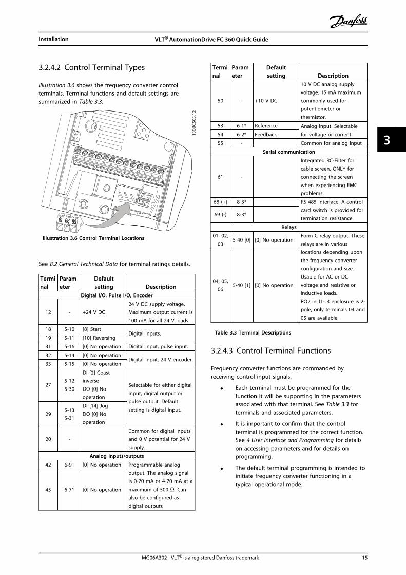
3.2.4.2 Control Terminal Types
Illustration 3.6 shows the frequency converter controlterminals. Terminal functions and default settings aresummarized in Table 3.3.
42 45
12 18 19 27 29 31 32 33 20 50 53 54 55
130B
C505
.12
Illustration 3.6 Control Terminal Locations
See 8.2 General Technical Data for terminal ratings details.
Terminal
Parameter
Defaultsetting Description
Digital I/O, Pulse I/O, Encoder
12 - +24 V DC24 V DC supply voltage.Maximum output current is100 mA for all 24 V loads.
18 5-10 [8] StartDigital inputs.
19 5-11 [10] Reversing
31 5-16 [0] No operation Digital input, pulse input.
32 5-14 [0] No operationDigital input, 24 V encoder.
33 5-15 [0] No operation
275-125-30
DI [2] CoastinverseDO [0] Nooperation
Selectable for either digitalinput, digital output orpulse output. Defaultsetting is digital input.
295-135-31
DI [14] JogDO [0] Nooperation
20 - Common for digital inputs
and 0 V potential for 24 Vsupply.
Analog inputs/outputs
42 6-91 [0] No operation Programmable analogoutput. The analog signalis 0-20 mA or 4-20 mA at a
maximum of 500 Ω. Canalso be configured asdigital outputs
45 6-71 [0] No operation
Terminal
Parameter
Defaultsetting Description
50 - +10 V DC
10 V DC analog supplyvoltage. 15 mA maximumcommonly used forpotentiometer orthermistor.
53 6-1* Reference Analog input. Selectablefor voltage or current.54 6-2* Feedback
55 - Common for analog input
Serial communication
61 -
Integrated RC-Filter forcable screen. ONLY forconnecting the screenwhen experiencing EMCproblems.
68 (+) 8-3* RS-485 Interface. A controlcard switch is provided fortermination resistance.
69 (-) 8-3*
Relays
01, 02,03
5-40 [0] [0] No operationForm C relay output. Theserelays are in variouslocations depending uponthe frequency converterconfiguration and size.Usable for AC or DCvoltage and resistive orinductive loads.RO2 in J1-J3 enclosure is 2-pole, only terminals 04 and05 are available
04, 05,06
5-40 [1] [0] No operation
Table 3.3 Terminal Descriptions
3.2.4.3 Control Terminal Functions
Frequency converter functions are commanded byreceiving control input signals.
• Each terminal must be programmed for thefunction it will be supporting in the parametersassociated with that terminal. See Table 3.3 forterminals and associated parameters.
• It is important to confirm that the controlterminal is programmed for the correct function.See 4 User Interface and Programming for detailson accessing parameters and for details onprogramming.
• The default terminal programming is intended toinitiate frequency converter functioning in atypical operational mode.
Installation VLT® AutomationDrive FC 360 Quick Guide
MG06A302 - VLT® is a registered Danfoss trademark 15
3 3

3.2.4.4 Using Screened Control Cables
Correct screeningThe preferred method in most cases is to secure controland serial communication cables with screening clampsprovided at both ends to ensure best possible highfrequency cable contact.If the earth potential between the frequency converter andthe PLC is different, electric noise may occur that willdisturb the entire system. Solve this problem by fitting anequalizing cable as close as possible to the control cable.Minimum cable cross section: 16 mm2.
12
PE
FC
PE
PLC
130B
B922
.12
PE PE<10 mm
Illustration 3.7 Screening Clamps at Both Ends
1 Min. 16 mm2
2 Equalizing cable
Table 3.4 Legend to Illustration 3.7
50/60 Hz ground loopsWith very long control cables, ground loops may occur. Toeliminate ground loops, connect one end of the screen-to-ground with a 100 nF capacitor (keeping leads short).
100nF
FC
PEPE
PLC
<10 mm 130B
B609
.12
Illustration 3.8 Connection with a 100 nF Capacitor
Avoid EMC noise on serial communicationThis terminal is connected to earth via an internal RC link.Use twisted-pair cables to reduce interference betweenconductors. The recommended method is in Illustration 3.9:
PE
FC
PE
FC
130B
B923
.12
PE PE
696861
696861
12
<10 mm
Illustration 3.9 Twisted-pair Cables
1 Min. 16 mm2
2 Equalizing cable
Table 3.5 Legend to Illustration 3.9
Alternatively, the connection to terminal 61 can beomitted:
PE
FC
PE
FC
130B
B924
.12
PE PE
69696868
12
<10 mm
Illustration 3.10 Twisted-pair Cables without Terminal 61
1 Min. 16 mm2
2 Equalizing cable
Table 3.6 Legend to Illustration 3.10
3.3 Serial Communication
Connect RS-485 serial communication wiring to terminals(+)68 and (-)69.
• Screened serial communication cable isrecommended
• See 3.2.2 Earth (Grounding) Requirements forproper grounding
61
68
69
+
130B
B489
.10
RS-485
Illustration 3.11 Serial Communication Wiring Diagram
Installation VLT® AutomationDrive FC 360 Quick Guide
16 MG06A302 - VLT® is a registered Danfoss trademark
33

For basic serial communication set-up, select the following:
1. Protocol type in 8-30 Protocol.
2. Frequency converter address in 8-31 Address.
3. Baud rate in 8-32 Baud Rate.
• Two communication protocols are internal to thefrequency converter. Follow motor manufacturerwiring requirements.
Danfoss FC
Modbus RTU
• Functions can be programmed remotely usingthe protocol software and RS-485 connection orin parameter group 8-** Communications andOptions
• Selecting a specific communication protocolchanges various default parameter settings tomatch that protocol’s specifications along withmaking additional protocol-specific parametersavailable
Installation VLT® AutomationDrive FC 360 Quick Guide
MG06A302 - VLT® is a registered Danfoss trademark 17
3 3

4 User Interface and Programming
4.1 Programming
4.1.1 Programming with the NumericalLocal Control Panel (LCP 21)
The FC 360 supports graphic and numerical local controlpanels as well as blind covers. This chapter coversprogramming with LCP 21. For programming with theGLCP, see the VLT® AutomationDrive FC 360 ProgrammingGuide.
NOTICEThe frequency converter can also be programmed from aPC via RS-485 com-port by installing the MCT-10 Setupsoftware. This software can either be ordered using codenumber 130B1000 or downloaded from the Danfoss Website: www.danfoss.com/BusinessAreas/DrivesSolutions/softwaredownload
4.1.2 LCP 21
The LCP 21 is divided into four functional sections.
A. Numeric display
B. Menu key
C. Navigation keys and indicator lights (LEDs)
D. Operation keys and indicator lights (LEDs)
130B
C506
.10
Setup 1A
B
C
D
5
12
13 14 15
10
11
10
9
6
7
8
4
1
2
3
Menu
Status QuickMenu
MainMenu
HandOn
OReset
AutoOn
Back
OKOn
Warn
Alarm
Illustration 4.1 View of the LCP 21
A. Numeric DisplayThe LCD-display is back-lit with 1 numeric line. All data isdisplayed in the LCP.
1 Set-up number shows the active set-up and the edit set-up. If the same set-up acts as both active and edit set-up,only that set-up number is shown (factory setting). Whenactive and edit set-up differ, both numbers are shown inthe display (Setup 12). The number flashing, indicates theedit set-up.
2 Parameter number.
3 Parameter value.
4 Motor direction is shown to the bottom left of the display– indicated by a small arrow pointing either clockwise orcounterclockwise.
5 The triangle indicates if the LCP is in status, quick menu ormain menu.
Table 4.1 Legend to Illustration 4.1
130B
D13
5.10
Setup 12
INDEX
AHPVkWsrpmHz%n2n1 n3
p5 p4p3 p2 p1
Illustration 4.2 Display Information
B. Menu KeyPress [Menu] to select between status, quick menu or mainmenu.
C. Navigation keys and indicator lights (LEDs)
6 Green LED/On: Control section is working.
7 Yellow LED/Warn.: Indicates a warning.
8 Flashing Red LED/Alarm: Indicates an alarm.
9 [Back]: For moving to the previous step or layer in thenavigation structure
10 Arrows [] []: For maneuvering between parameter groups,
parameters and within parameters or increasing/decreasingparameter values. Can also be used for setting localreference.
11 [OK]: For selecting a parameter and for accepting changes toparameter settings
12 []: For moving from left to right within the parameter valuein order to change each digit individually. See description in4.1.3 The Right-Key Function.
Table 4.2 Legend to Illustration 4.1
User Interface and Programm... VLT® AutomationDrive FC 360 Quick Guide
18 MG06A302 - VLT® is a registered Danfoss trademark
44

D. Operation keys and indicator lights (LEDs)
13 [Hand On]: Starts the motor and enables control of thefrequency converter via the LCP.
NOTICE5-12 Terminal 27 Digital Input has coast inverse asdefault setting. This means that [Hand On] will notstart the motor if there is no 24 V to terminal 27.
14 [Off/Reset]: stops the motor (off). If in alarm mode thealarm will be reset.
15 [Auto On]: frequency converter is controlled either viacontrol terminals or serial communication.
Table 4.3 Legend to Illustration 4.1
4.1.3 The Right-Key Function
WARNINGThe [Off/Reset] key is not a safety switch. It does notdisconnect the frequency converter from mains.
Press [] to edit any of the four digits on the displayindividually. When pressing [] once, the cursor moves tothe first digit and the digit starts flashing as shown inIllustration 4.3. Press the [] [] to change the value.Pressing [] will not change the value of the digits ormove the decimal point.
130B
C440
.10
Setup 1
Setup 1
Setup 1
Setup 1
Setup 1
Illustration 4.3 Right Key Function
[] can also be used for moving between parametergroups: when in main menu, press the right key to moveto the first parameter in the next parameter group (e.g.move from 0-03 Regional Settings [0] International to1-00 Configuration Mode [0] Open loop).
4.2 Quick Menu
The Quick Menu gives easy access to the most frequentlyused parameters.
1. To enter the Quick Menu, press [Menu] untilindicator in display is placed above Quick Menu.
2. Press [] [] to select either QM1 or QM2, thenpress [OK].
3. Press [] [] to browse through the parametersin the Quick Menu.
4. Press [OK] to select a parameter.
5. Press [] [] to change the value of a parametersetting.
6. Press [OK] to accept the change.
7. To exit, press either [Back] twice (or three times ifin QM” and QM3) to enter Status, or press [Menu]once to enter Main Menu.
User Interface and Programm... VLT® AutomationDrive FC 360 Quick Guide
MG06A302 - VLT® is a registered Danfoss trademark 19
4 4

130BC445.11
1-22
XXX
X V
Mot
or
nom
inal
sp
eed
QM
1
0-01
[0]
1-10
[0]
1-24
XXX
X A
Lang
uage
Mot
or Ty
pe
PM M
otor
Asyn
chro
nous
Mot
or
1-20
XXX
X kW
Mot
or p
ower
Mot
or vo
ltage
Mot
or C
ont.
Rat
ed To
rque
1-26
XXX
X1-
23 X
XXX
Hz
Stat
or
Resis
tanc
e
Mot
or fr
eque
ncy
1-25
XXX
X rp
m
(Rs)
1-30
XXX
X
1-39
XXX
X
1-40
XXX
X
30-8
0 XX
XX
1-25
XXX
X rp
m
1-24
XXX
X A
Mot
or C
urre
nt
3-02
XXX
X Hz
3-03
XXX
X Hz
3-41
XXX
X S
3-42
XXX
X S
5-12
[2]
1-29
[1]
Min
imum
Ref
eren
ce
Max
imum
Ref
eren
ce
Ram
p 1
Ram
p up
Tim
e
Ram
p 1
Ram
p Do
wn
Tim
e
Term
inal
27
Digi
tal in
put
AMA
Mot
or P
oles
Back
EM
F at
10
00 R
PM
d-ax
is In
duct
ance
(Ld)
Basic
Mot
or S
etup
Adv.
Mot
or S
etup
Enco
der S
etup
QM
2
BMS
AMS
ES
5-70
XXX
X
5-71
[0]
1-30
XXX
X
1-39
XXX
X
1-90
[0]
2-10
[0]
4-16
XXX
X %
4-17
XXX
X %
4-18
XXX
X %
1-00
[0]
1-01
[1]
1-10
[0]
1-24
XXX
X A
1-20
XXX
X kW
1-22
XXX
X V
Mot
or
nom
inal
sp
eed
PM M
otor
Asyn
chro
nous
Mot
or
Mot
or p
ower
Mot
or vo
ltage
Mot
or C
ont.
Rate
d To
rque
1-26
XXX
X1-
23 X
XXX
Hz
Stat
or
Resis
tanc
e
Mot
or fr
eque
ncy
1-25
XXX
X rp
m
(Rs)
1-30
XXX
X
1-40
XXX
X
30-8
0 XX
XX
1-25
XXX
X rp
m
1-24
XXX
X A
Mot
or C
urre
nt
Mot
or P
oles
Back
EM
F at
10
00 R
PM
d-ax
is In
duct
ance
(Ld)
1-39
XXX
X 4-19
XXX
X Hz
4-14
XXX
X Hz
Stat
or
Resis
tanc
e (R
s)
Mot
or P
oles
Mot
or
Ther
mal
Pro
tect
ion
Brak
e Fu
nctio
n
Torq
ue Li
mit
Mot
or M
ode
Torq
ue Li
mit
Gene
rato
r Mod
e
Curre
nt Li
mit
Term
32/
33 P
ulse
s pe
r Rev
olut
ion
Term
32/
33
Enco
der D
irect
ion
QM 3
QM
4Q
M 5
L10C
SFS
Last
10
Chan
ges
Sinc
e Fa
ctor
y Set
ting
Chan
ges M
ade
Alar
m Lo
gTB
D
Mot
or C
urre
nt
Mot
or
nom
inal
sp
eed
Mot
or
nom
inal
sp
eed
Mot
or
Curre
nt M
ode
Mot
or C
ontro
l Pr
incip
le
Mot
or Ty
pe
Mot
or S
peed
Hig
h Li
mit
[Hz]
Max
Out
put F
requ
ency
Illus
trat
ion
4.4
Qui
ck M
enu
Str
uctu
re
User Interface and Programm... VLT® AutomationDrive FC 360 Quick Guide
20 MG06A302 - VLT® is a registered Danfoss trademark
44

4.3 Main Menu
The Main Menu gives access to all parameters.
1. To enter the Main Menu, press [Menu] untilindicator in display is placed above Main Menu.
2. [] []: browse through the parameter groups.
3. Press [OK] to select a parameter group.
4. [] []: browse through the parameters in thespecific group.
5. Press [OK] to select the parameter.
6. [] and [] []: set/change the parameter value.
7. Press [OK] to accept the value.
8. To exit, press either [Back] twice (or three timesfor array parameters) to enter Main Menu, orpress [Menu] once to enter Status.
See Illustration 4.5 for the principles of changing the valueof continuous, enumerated and array parameters.
130B
C446
.10
Setup 1
Setup 1
Setup 1
Setup 1
Setup 1
Setup 1
Setup 1
Setup 1
1
2
3
4
5
6
7
10
11
12
OK
OK
Back
8
Back
Setup 1
2 x
+ OK
9
OK
Illustration 4.5 Main Menu Interactions - ContinuousParameters
User Interface and Programm... VLT® AutomationDrive FC 360 Quick Guide
MG06A302 - VLT® is a registered Danfoss trademark 21
4 4

1 [OK]: The first parameter in the group is shown.
2 Press [] repeatedly to move down to the desired
parameter.
3 Press [OK] to start editing.
4 []: First digit flashing (can be edited).
5 []: Second digit flashing (can be edited).
6 []: Third digit flashing (can be edited).
7 []: Decreases the parameter value, the decimal point
changes automatically
8 []: Increases the parameter value.
9 [Back]: Cancel changes, return to 2)[OK]: Accept changes, return to 2)
10 [][]: Select parameter within the group.
11 [Back]: Removes the value and shows the parameter group.
12 [][]: Select group.
Table 4.4 Changing Values in Continuous Parameters
For enumerated parameters the interaction is similar butthe parameter value is shown in brackets, because of theLCP 21 digits limitation (4 large digits) and the enum canbe greater than 99. When the enum value is greater than99, the LCP 21 can only display the first part of thebracket.
130B
C447
.11
Setup 1
Setup 1
Setup 1
1
2
3
4
5
6OK
OK
Back
7
OKBack
Illustration 4.6 Main Menu Interactions - EnumeratedParameters
1 [OK]: The first parameter in the group is shown.
2 Press [OK] to start editing.
3 [][]: Change parameter value (flashing).
4 Press [Back] to cancel changes or [OK] to accept changes(return to screen 2).
5 [][]: Select parameter within the group.
6 [Back]: Removes the value and shows the parameter group.
7 [][]: Select group.
Table 4.5 Changing Values in Enumerated Parameters
Array parameters function as follows:
130B
C448
.10
1
2
4
5
6
7
8
9
10
OK
Back
Back
Back
5 x
Setup 1
Setup 1
Setup 1
Setup 1
%INDEX
%INDEX
%INDEX
Setup 1
INDEX%
OK
OK
OK
Illustration 4.7 Main Menu Interactions - Array Parameters
1 [OK]: Shows parameter numbers and the value in the firstindex.
2 [OK]: Index can be selected.
3 [][]: Select index.
4 [OK]: Value can be edited.
5 [][]: Change parameter value (flashing).
6 [Back]: Cancels changes[OK]: Accepts changes
7 [Back]: Cancels editing index, a new parameter can beselected.
8 [][]: Select parameter within the group.
9 [Back]: Removes parameter index value and shows theparameter group.
10 [][]: Select group.
Table 4.6 Changing Values in Array Parameters
4.4 PM Motor Setup
Initial Programming Steps
1. Activate PM motor operation 1-10 MotorConstruction, select [1) PM, non salient SPM
Programming motor dataAfter selecting PM motor in 1-10 Motor Construction, thePM motor-related parameters in parameter groups 1-2*Motor Data, 1-3* Adv. Motor Data and 1-4* are active.The information can be found on the motor nameplateand in the motor data sheet.
User Interface and Programm... VLT® AutomationDrive FC 360 Quick Guide
22 MG06A302 - VLT® is a registered Danfoss trademark
44
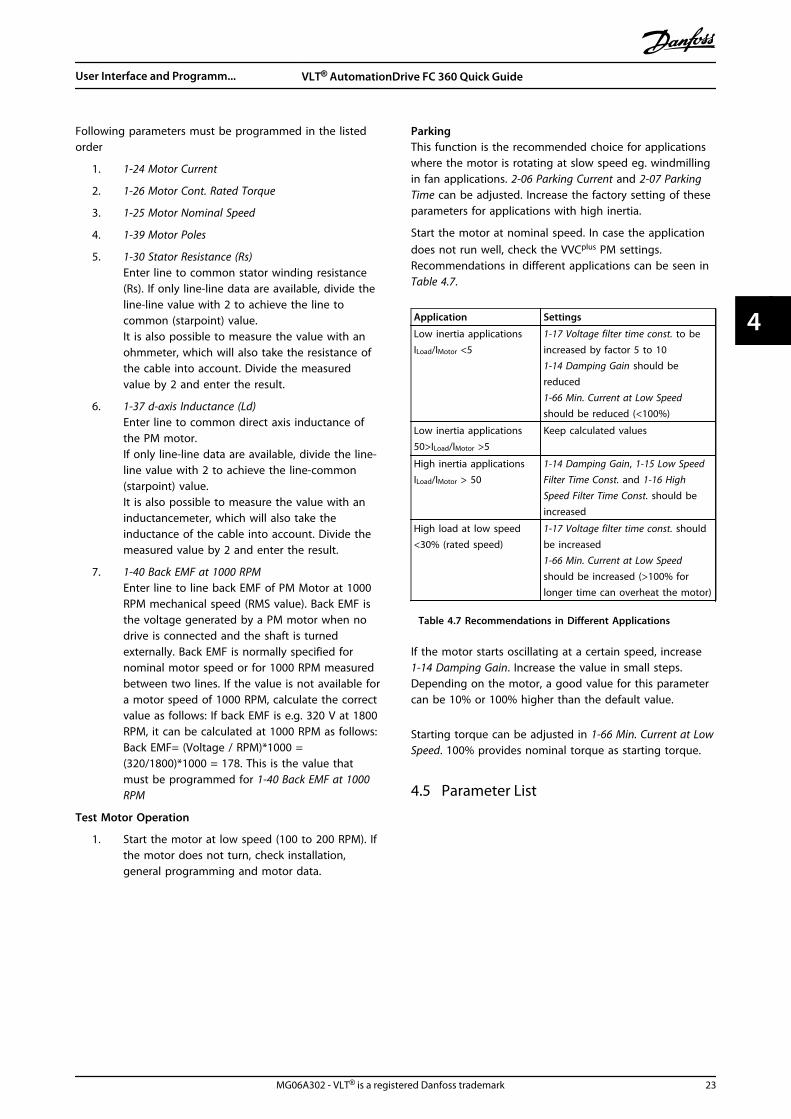
Following parameters must be programmed in the listedorder
1. 1-24 Motor Current
2. 1-26 Motor Cont. Rated Torque
3. 1-25 Motor Nominal Speed
4. 1-39 Motor Poles
5. 1-30 Stator Resistance (Rs)Enter line to common stator winding resistance(Rs). If only line-line data are available, divide theline-line value with 2 to achieve the line tocommon (starpoint) value.It is also possible to measure the value with anohmmeter, which will also take the resistance ofthe cable into account. Divide the measuredvalue by 2 and enter the result.
6. 1-37 d-axis Inductance (Ld)Enter line to common direct axis inductance ofthe PM motor.If only line-line data are available, divide the line-line value with 2 to achieve the line-common(starpoint) value.It is also possible to measure the value with aninductancemeter, which will also take theinductance of the cable into account. Divide themeasured value by 2 and enter the result.
7. 1-40 Back EMF at 1000 RPMEnter line to line back EMF of PM Motor at 1000RPM mechanical speed (RMS value). Back EMF isthe voltage generated by a PM motor when nodrive is connected and the shaft is turnedexternally. Back EMF is normally specified fornominal motor speed or for 1000 RPM measuredbetween two lines. If the value is not available fora motor speed of 1000 RPM, calculate the correctvalue as follows: If back EMF is e.g. 320 V at 1800RPM, it can be calculated at 1000 RPM as follows:Back EMF= (Voltage / RPM)*1000 =(320/1800)*1000 = 178. This is the value thatmust be programmed for 1-40 Back EMF at 1000RPM
Test Motor Operation
1. Start the motor at low speed (100 to 200 RPM). Ifthe motor does not turn, check installation,general programming and motor data.
ParkingThis function is the recommended choice for applicationswhere the motor is rotating at slow speed eg. windmillingin fan applications. 2-06 Parking Current and 2-07 ParkingTime can be adjusted. Increase the factory setting of theseparameters for applications with high inertia.
Start the motor at nominal speed. In case the applicationdoes not run well, check the VVCplus PM settings.Recommendations in different applications can be seen inTable 4.7.
Application Settings
Low inertia applicationsILoad/IMotor <5
1-17 Voltage filter time const. to beincreased by factor 5 to 101-14 Damping Gain should bereduced1-66 Min. Current at Low Speedshould be reduced (<100%)
Low inertia applications50>ILoad/IMotor >5
Keep calculated values
High inertia applicationsILoad/IMotor > 50
1-14 Damping Gain, 1-15 Low SpeedFilter Time Const. and 1-16 HighSpeed Filter Time Const. should beincreased
High load at low speed<30% (rated speed)
1-17 Voltage filter time const. shouldbe increased1-66 Min. Current at Low Speedshould be increased (>100% forlonger time can overheat the motor)
Table 4.7 Recommendations in Different Applications
If the motor starts oscillating at a certain speed, increase1-14 Damping Gain. Increase the value in small steps.Depending on the motor, a good value for this parametercan be 10% or 100% higher than the default value.
Starting torque can be adjusted in 1-66 Min. Current at LowSpeed. 100% provides nominal torque as starting torque.
4.5 Parameter List
User Interface and Programm... VLT® AutomationDrive FC 360 Quick Guide
MG06A302 - VLT® is a registered Danfoss trademark 23
4 4

4.5.
1M
ain
Men
uSt
ruct
ure
0-**
Ope
ratio
n /
Dis
play
0-0*
Basi
c Se
ttin
gs0-
01La
ngua
ge0-
03Re
gion
al S
ettin
gs0-
04O
pera
ting
Sta
te a
t Po
wer
-up
0-06
Grid
Type
[10]
>380
-440
V/50
Hz/
IT-g
rid<
[11]
>380
-440
V/50
Hz/
Del
ta<
[12]
>380
-440
V/50
Hz<
[20]
>440
-480
V/50
Hz/
IT-g
rid<
[21]
>440
-480
V/50
Hz/
Del
ta<
[22]
>440
-480
V/50
Hz<
[110
]>3
80-4
40V/
60H
z/IT
-grid
<[1
11]
>380
-440
V/60
Hz/
Del
ta<
[112
]>3
80-4
40V/
60H
z<[1
20]
>440
-480
V/60
Hz/
IT-g
rid<
[121
]>4
40-4
80V/
60H
z/D
elta
<[1
22]
>440
-480
V/60
Hz<
0-07
Aut
o D
C B
raki
ng0-
1*Se
t-up
Ope
ratio
ns0-
10A
ctiv
e Se
t-up
*[1]
>Set
-up
1<
[2]
>Set
-up
2<
[9]
>Mul
ti S
et-u
p<0-
11Pr
ogra
mm
ing
Set
-up
0-12
Link
Set
ups
0-16
App
licat
ion
Sel
ectio
n*[
0]N
one
[1]
>Pro
cess
Clo
se L
oop<
[2]
>Loc
al/R
emot
e<[3
]>S
peed
Ope
n L
oop<
[4]
>Spe
ed C
lose
Loo
p<[5
]>M
ulti
Spe
ed<
0-2*
LCP
Dis
play
0-20
Dis
play
Lin
e 1.
1 Sm
all
0-21
Dis
play
Lin
e 1.
2 Sm
all
0-22
Dis
play
Lin
e 1.
3 Sm
all
0-23
Dis
play
Lin
e 2
Larg
e0-
24D
ispl
ay L
ine
3 La
rge
0-3*
LCP
Cus
tom
Rea
dout
0-30
Cust
om R
eado
ut U
nit
0-31
Cust
om R
eado
ut M
in V
alue
0-32
Cust
om R
eado
ut M
ax V
alue
0-37
Dis
play
Tex
t 1
0-38
Dis
play
Tex
t 2
0-39
Dis
play
Tex
t 3
0-4*
LCP
Key
pad
0-40
[Han
d o
n] K
ey o
n L
CP0-
42[A
uto
on]
Key
on
LCP
0-44
[Off/
Rese
t] K
ey o
n L
CP0-
5*Co
py/S
ave
0-50
LCP
Cop
y*[
0]>N
o c
opy<
[1]
>All
to L
CP<
[2]
>All
from
LCP
<
[3]
>Siz
e in
dep.
from
LCP
<0-
51Se
t-up
Cop
y*[
0]>N
o c
opy
[1]
>Cop
y fr
om s
etup
1<
[2]
>Cop
y fr
om s
etup
2<
[9]
>Cop
y fr
om F
acto
ry s
etup
<0-
6*Pa
ssw
ord
0-60
Mai
n M
enu
Pas
swor
d1-
**Lo
ad a
nd M
otor
1-0*
Gen
eral
Set
tings
1-00
Conf
igur
atio
n M
ode
[0]*
>Ope
n L
oop<
[1]
>Spe
ed c
lose
d lo
op<
[3]
>Pro
cess
Clo
sed
Loo
p<[4
]>T
orqu
e op
en lo
op<
[6]
>Sur
face
Win
der<
[7]
>Ext
ende
d P
ID S
peed
OL<
[9]
>Cen
tral
Win
der<
[10]
>Pos
ition
ing<
[11]
>Syn
chro
nisa
tion<
1-01
Mot
or C
ontr
ol P
rinci
ple
[0]
>U/f
<*[
1]>V
VC+<
1-03
Torq
ue C
hara
cter
istic
s*[
0]>C
onst
ant
torq
ue<
[1]
>Var
iabl
e To
rque
<[2
]>A
uto
Ene
rgy
Opt
im. C
T<1-
06Cl
ockw
ise
Dire
ctio
n1-
08M
otor
Con
trol
Ban
dwid
th1-
1*M
otor
Sel
ectio
n1-
10M
otor
Con
stru
ctio
n1-
14D
ampi
ng G
ain
1-15
Low
Spe
ed F
ilter
Tim
e Co
nst.
1-16
Hig
h S
peed
Filt
er T
ime
Cons
t.1-
17Vo
ltage
filte
r tim
e co
nst.
1-2*
Mot
or D
ata
1-20
Mot
or P
ower
[2]
>0.1
2 kW
- 0
.16
hp<
[3]
>0.1
8 kW
- 0
.25
hp<
[4]
>0.2
5 kW
- 0
.33
hp<
[5]
>0.3
7 kW
- 0
.5 h
p<[6
]>0
.55
kW -
0.7
5 hp
<[7
]>0
.75
kW -
1 h
p<[8
]>1
.1 k
W -
1 h
p<[9
]>1
.5 k
W -
2 h
p<[1
0]>2
.2 k
W -
3 h
p<[1
1]>3
kW
- 4
hp<
[12]
>3.7
kW
- 5
hp<
[13]
>4 k
W -
5.4
hp<
[14]
>5.5
kW
- 7
.5 h
p<[1
5]>7
.5 k
W -
10
hp<
[16]
>11
kW -
15
hp<
[17]
>15
kW -
20
hp<
[18]
>18.
5 kW
- 2
5 hp
<[1
9]>2
2 kW
- 3
0 hp
<[2
0]>3
0 kW
- 4
0 hp
<[2
1]>3
7 kW
- 5
0 hp
<[2
2]>4
5 kW
- 6
0 hp
<[2
3]>5
5 kW
- 7
5 hp
<
[24]
>75
kW -
100
hp<
[25]
>90
kW -
120
hp<
[26]
>110
kW
- 1
50 h
p<1-
22M
otor
Vol
tage
1-23
Mot
or F
requ
ency
1-24
Mot
or C
urre
nt1-
25M
otor
Nom
inal
Spe
ed1-
26M
otor
Con
t. R
ated
Tor
que
1-29
Aut
omat
ic M
otor
Ada
ptio
n (A
MA
)*[
0]>O
ff<[1
]>E
nabl
e Co
mpl
ete
AM
A<
[2]
>Ena
ble
Redu
ced
AM
A<
1-3*
Adv
. Mot
or D
ata
I1-
30St
ator
Res
ista
nce
(Rs)
1-33
Stat
or L
eaka
ge R
eact
ance
(X1)
1-35
Mai
n R
eact
ance
(Xh)
1-37
d-ax
is In
duct
ance
(Ld)
1-39
Mot
or P
oles
1-4*
Adv
. Mot
or D
ata
II1-
40Ba
ck E
MF
at 1
000
RPM
1-42
Mot
or C
able
Len
gth
1-43
Mot
or C
able
Len
gth
Fee
t1-
5*Lo
ad In
dep.
Set
ting
1-50
Mot
or M
agne
tisat
ion
at
Zero
Spe
ed1-
52M
in S
peed
Nor
mal
Mag
netis
ing
[Hz]
1-55
U/f
Cha
ract
eris
tic -
U1-
56U
/f C
hara
cter
istic
- F
1-6*
Load
Dep
en. S
ettin
g1-
60Lo
w S
peed
Loa
d C
ompe
nsat
ion
1-61
Hig
h S
peed
Loa
d C
ompe
nsat
ion
1-62
Slip
Com
pens
atio
n1-
63Sl
ip C
ompe
nsat
ion
Tim
e Co
nsta
nt1-
64Re
sona
nce
Dam
peni
ng1-
65Re
sona
nce
Dam
peni
ng T
ime
Cons
tant
1-66
Min
. Cur
rent
at
Low
Spe
ed1-
7*St
art
Adj
ustm
ents
1-71
Star
t D
elay
1-72
Star
t Fu
nctio
n[0
]>D
C H
old/
dela
y tim
e<*[
2]>C
oast
/del
ay t
ime<
[3]
>Sta
rt s
peed
cw
<[4
]>H
oriz
onta
l ope
ratio
n<[5
]>V
VC+
clo
ckw
ise<
1-73
Flyi
ng S
tart
*[0]
>Dis
able
d<[1
]>E
nabl
ed<
[2]
>Ena
bled
Alw
ays<
[3]
>Ena
bled
Ref
. Dir.
<[4
]>E
nab.
Alw
ays
Ref.
Dir.
<1-
75St
art
Spee
d [H
z]1-
76St
art
Curr
ent
1-78
Com
pres
sor
Star
t M
ax S
peed
[Hz]
1-79
Com
pres
sor
Star
t M
ax T
ime
to T
rip1-
8*St
op A
djus
tmen
ts1-
80Fu
nctio
n a
t St
op*[
0]>C
oast
<[1
]>D
C h
old
/ M
otor
Pre
heat
<[3
]>P
re-m
agne
tizin
g<1-
82M
in S
peed
for
Func
tion
at
Stop
[Hz]
1-9*
Mot
or T
empe
ratu
re1-
90M
otor
The
rmal
Pro
tect
ion
*[0]
>No
pro
tect
ion<
[1]
>The
rmis
tor
war
ning
<[2
]>T
herm
isto
r tr
ip<
[3]
>ETR
war
ning
1<
[4]
>ETR
trip
1<
1-93
Ther
mis
tor
Sour
ce2-
**Br
akes
2-0*
DC-
Brak
e2-
00D
C H
old/
Mot
or P
rehe
at C
urre
nt2-
01D
C B
rake
Cur
rent
2-02
DC
Bra
king
Tim
e2-
04D
C B
rake
Cut
In S
peed
2-06
Park
ing
Cur
rent
2-07
Park
ing
Tim
e2-
1*Br
ake
Ener
gy F
unct
.2-
10Br
ake
Func
tion
*[0]
>Off<
[1]
>Res
isto
r br
ake<
[2]
>AC
bra
ke<
2-11
Brak
e Re
sist
or (o
hm)
2-12
Brak
e Po
wer
Lim
it (k
W)
2-14
Brak
e vo
ltage
red
uce
2-16
AC
Bra
ke, M
ax c
urre
nt2-
17O
ver-
volta
ge C
ontr
ol*[
0]>D
isab
led<
[1]
>Ena
bled
(not
at
stop
)<[2
]>E
nabl
ed<
2-19
Ove
r-vo
ltage
Gai
n2-
2*M
echa
nica
l Bra
ke2-
20Re
leas
e Br
ake
Curr
ent
2-22
Act
ivat
e Br
ake
Spee
d [H
z]3-
**Re
fere
nce
/ Ra
mps
3-0*
Refe
renc
e Li
mits
3-00
Refe
renc
e Ra
nge
*[0]
>Min
- M
ax<
[1]
>-M
ax -
+M
ax<
3-01
Refe
renc
e/Fe
edba
ck U
nit
3-02
Min
imum
Ref
eren
ce3-
03M
axim
um R
efer
ence
3-04
Refe
renc
e Fu
nctio
n*[
0]>S
um<
[1]
>Ext
erna
l/Pre
set<
3-1*
Refe
renc
es3-
10Pr
eset
Ref
eren
ce>-
100-
100%
< *
0%3-
11Jo
g S
peed
[Hz]
3-12
Catc
h u
p/sl
ow D
own
Val
ue3-
14Pr
eset
Rel
ativ
e Re
fere
nce
3-15
Refe
renc
e 1
Sour
ce[0
]>N
o fu
nctio
n<*[
1]>A
nalo
g In
put
53<
[2]
>Ana
log
Inpu
t 54
<[7
]>F
requ
ency
inpu
t 29
<[8
]>F
requ
ency
inpu
t 33
<[1
1]>L
ocal
bus
ref
eren
ce<
[32]
>Bus
PCD
<3-
16Re
fere
nce
2 So
urce
3-17
Refe
renc
e 3
Sour
ce3-
18Re
lativ
e Sc
alin
g R
efer
ence
Res
ourc
e3-
4*Ra
mp
13-
40Ra
mp
1 T
ype
*[0]
>Lin
ear<
[2]
>S-r
amp
Con
st T
ime<
3-41
Ram
p 1
Ram
p U
p T
ime
>0.0
5-36
00 s
< *
Siz
e re
late
d3-
42Ra
mp
1 R
amp
Dow
n T
ime
>0.0
5-36
00 s
< *
Siz
e re
late
d3-
5*Ra
mp
23-
50Ra
mp
2 T
ype
3-51
Ram
p 2
Ram
p U
p T
ime
3-52
Ram
p 2
Ram
p D
own
Tim
e3-
6*Ra
mp
33-
60Ra
mp
3 T
ype
3-61
Ram
p 3
Ram
p u
p T
ime
3-7*
Ram
p 4
3-70
Ram
p 4
Typ
e3-
71Ra
mp
4 R
amp
up
Tim
e3-
72Ra
mp
4 R
amp
Dow
n T
ime
3-8*
Oth
er R
amps
3-80
Jog
Ram
p T
ime
3-81
Qui
ck S
top
Ram
p T
ime
4-**
Lim
its /
War
ning
s4-
1*M
otor
Lim
its4-
10M
otor
Spe
ed D
irect
ion
[0]
>Clo
ckw
ise<
*[2]
>Bot
h d
irect
ions
<4-
12M
otor
Spe
ed L
ow L
imit
[Hz]
4-14
Mot
or S
peed
Hig
h L
imit
[Hz]
4-16
Torq
ue L
imit
Mot
or M
ode
4-17
Torq
ue L
imit
Gen
erat
or M
ode
4-18
Curr
ent
Lim
it4-
19M
ax O
utpu
t Fr
eque
ncy
4-2*
Lim
it F
acto
rs4-
22Br
eak
Aw
ay B
oost
4-3*
Mot
or F
b M
onito
r4-
30M
otor
Fee
dbac
k Lo
ss F
unct
ion
4-31
Mot
or F
eedb
ack
Spee
d E
rror
4-32
Mot
or F
eedb
ack
Loss
Tim
eout
4-4*
Adj
. War
ning
s 2
4-40
War
ning
Fre
q. L
ow4-
41W
arni
ng F
req.
Hig
h4-
42A
djus
tabl
e Te
mpe
ratu
re W
arni
ng4-
5*A
dj. W
arni
ngs
4-50
War
ning
Cur
rent
Low
4-51
War
ning
Cur
rent
Hig
h4-
54W
arni
ng R
efer
ence
Low
4-55
War
ning
Ref
eren
ce H
igh
4-56
War
ning
Fee
dbac
k Lo
w4-
57W
arni
ng F
eedb
ack
Hig
h4-
58M
issi
ng M
otor
Pha
se F
unct
ion
4-6*
Spee
d B
ypas
s4-
61By
pass
Spe
ed F
rom
[Hz]
4-63
Bypa
ss S
peed
To
[Hz]
4-64
Sem
i-Aut
o B
ypas
s Se
t-up
User Interface and Programm... VLT® AutomationDrive FC 360 Quick Guide
24 MG06A302 - VLT® is a registered Danfoss trademark
44

5-**
Dig
ital I
n/O
ut5-
0*D
igita
l I/O
mod
e5-
00D
igita
l I/O
Mod
e*[
0]>P
NP<
[1]
>NPN
<5-
01Te
rmin
al 2
7 M
ode
5-02
Term
inal
29
Mod
e5-
1*D
igita
l Inp
uts
5-10
Term
inal
18
Dig
ital I
nput
[0]
>No
ope
ratio
n<[1
]>R
eset
<[2
]>C
oast
inve
rse<
[3]
>Coa
st a
nd r
eset
inv<
[4]
>Qui
ck s
top
inve
rse<
[5]
>DC-
brak
e in
vers
e<[6
]>S
top
inve
rse<
*[8]
>Sta
rt<
[9]
>Lat
ched
sta
rt<
[10]
>Rev
ersi
ng<
[11]
>Sta
rt r
ever
sing
<[1
2]>E
nabl
e st
art
forw
ard<
[13]
>Ena
ble
star
t re
vers
e<[1
4]>J
og<
[15]
>Pre
set
refe
renc
e on
<[1
6]>P
rese
t re
f bi
t 0<
[17]
>Pre
set
ref
bit
1<[1
8]>P
rese
t re
f bi
t 2<
[19]
>Fre
eze
refe
renc
e<[2
0]>F
reez
e ou
tput
<[2
1]>S
peed
up<
[22]
>Spe
ed d
own<
[23]
>Set
-up
sel
ect
bit
0<[2
6]>P
reci
se s
top
inve
rse<
[28]
>Cat
ch u
p<[2
9]>S
low
dow
n<[3
4]>R
amp
bit
0<
35>R
amp
bit
1<
51>E
xter
nal I
nter
lock
<[6
0]>C
ount
er A
(up)
<[6
1]>C
ount
er A
(dow
n)<
[62]
>Res
et C
ount
er A
<[6
3]>C
ount
er B
(up)
<[6
4]>C
ount
er B
(dow
n)<
[65]
>Res
et C
ount
er B
<[7
2]>P
ID e
rror
inve
rse<
[73]
>PID
res
et I
part
<[7
4]>P
ID e
nabl
e<15
0>G
o T
o H
ome<
151
>Hom
e Re
f. Sw
tich<
155
>HW
Lim
it P
ositi
ve<
156
>HW
Lim
it N
egat
ive<
157
>Pos
. Qui
ck S
top<
160
>Go
To
Tar
get
Pos<
162
>Pos
. Idx
Bit0
<16
3>P
os. I
dx B
it1<
164
>Pos
. Idx
Bit2
<5-
11Te
rmin
al 1
9 D
igita
l Inp
ut5-
12Te
rmin
al 2
7 D
igita
l Inp
ut5-
13Te
rmin
al 2
9 D
igita
l Inp
ut
[32]
Puls
e tim
e ba
sed
5-14
Term
inal
32
Dig
ital I
nput
[82]
Enco
der
inpu
t B
5-15
Term
inal
33
Dig
ital I
nput
[32]
Puls
e tim
e ba
sed
[81]
Enco
der
inpu
t A
5-16
Term
inal
31
Dig
ital I
nput
5-3*
Dig
ital O
utpu
ts5-
30Te
rmin
al 2
7 D
igita
l Out
put
*[0]
>No
ope
ratio
n<[1
]>C
ontr
ol R
eady
<[2
]>D
rive
read
y<[3
]>D
rive
rdy/
rem
ctr
l<[4
]>S
tand
-by/
no w
arni
ng<
[5]
>Run
ning
<[6
]>R
unni
ng/n
o w
arni
ng<
[7]
>Run
in r
ange
/no
war
n<[8
]>R
un o
n r
ef/n
o w
arn<
[9]
>Ala
rm<
[10]
>Ala
rm o
r w
arni
ng<
[11]
>At
torq
ue li
mit<
[12]
>Out
of
curr
ent
rang
e<[1
3]>B
elow
cur
rent
, low
<[1
4]>A
bove
cur
rent
, hig
h<[1
5]>O
ut o
f fr
eque
ncy
rang
e<[1
6]>B
elow
freq
uenc
y, lo
w<
[17]
>Abo
ve fr
eque
ncy,
hig
h<[1
8]>O
ut o
f fe
edb.
ran
ge<
[19]
>Bel
ow fe
edba
ck, l
ow<
[20]
>Abo
ve fe
edba
ck, h
igh<
[21]
>The
rmal
war
ning
<[2
2]>R
eady
, no
the
rmal
war
ning
<[2
3]>R
emot
e,re
ady,
no T
W<
[24]
>Rea
dy, n
o o
ver/
unde
r vo
ltage
<[2
5]>R
ever
se<
[26]
>Bus
OK<
[27]
>Tor
que
limit
& s
top<
[28]
>Bra
ke, n
o b
rake
war
ning
<[2
9]>B
rake
rea
dy, n
o fa
ult<
[30]
>Bra
ke fa
ult
(IGBT
)<[3
1]>R
elay
123
<[3
2]>M
ech
bra
ke c
trl<
[36]
>Con
trol
wor
d b
it 1
1<[3
7]>C
ontr
ol w
ord
bit
12<
[40]
>Out
of
ref
rang
e<[4
1]>B
elow
ref
eren
ce, l
ow<
[42]
>Abo
ve r
ef, h
igh<
43>E
xten
ded
PID
Lim
it<[4
5]>B
us c
trl.<
[46]
>Bus
con
trol
, tim
eout
: On<
[47]
>Bus
con
trol
, tim
eout
: Off<
[55]
>Pul
se o
utpu
t <
[56]
>Hea
t si
nk c
lean
ing
war
ning
, hig
h<[6
0]>C
ompa
rato
r 0<
[61]
>Com
para
tor
1<[6
2]>C
ompa
rato
r 2<
[63]
>Com
para
tor
3<[6
4]>C
ompa
rato
r 4<
[65]
>Com
para
tor
5<
[70]
>Log
ic r
ule
0<[7
1]>L
ogic
rul
e 1<
[72]
>Log
ic r
ule
2<[7
3]>L
ogic
rul
e 3<
[74]
>Log
ic r
ule
4<[7
5]>L
ogic
rul
e 5<
[80]
>SL
digi
tal o
utpu
t A
<[8
1]>S
L di
gita
l out
put
B<[8
2]>S
L di
gita
l out
put
C<[8
3]>S
L di
gita
l out
put
D<
[91]
>Enc
oder
em
ulat
e ou
tput
A<
[160
]>N
o a
larm
<[1
61]
>Run
ning
rev
erse
<[1
65]
>Loc
al r
ef a
ctiv
e <
[166
]>R
emot
e re
f ac
tive<
[167
]>S
tart
com
man
d a
ctiv
<[1
68]
>Driv
e in
han
d m
ode<
[169
]>D
rive
in a
uto
mod
e<17
0>H
omin
g C
ompl
eted
<17
1>T
arge
t Po
sitio
n R
each
ed<
172
>Pos
ition
Con
trol
Fau
lt<[1
93]
>Sle
ep M
ode<
[194
]>B
roke
n B
elt
Func
tion<
5-31
Term
inal
29
Dig
ital O
utpu
t5-
34O
n D
elay
, Dig
ital O
utpu
t5-
35O
ff D
elay
, Dig
ital O
utpu
t5-
4*Re
lays
5-40
Func
tion
Rel
ay[0
]>N
o o
pera
tion<
[1]
>Con
trol
Rea
dy<
[2]
>Driv
e re
ady<
[3]
>Driv
e rd
y/re
m c
trl<
[4]
>Sta
nd-b
y/no
war
ning
<[5
]>R
unni
ng<
[6]
>Run
ning
/no
war
ning
<[7
]>R
un in
ran
ge/n
o w
arn<
[8]
>Run
on
ref
/no
war
n<*[
9]>A
larm
<[1
0]>A
larm
or
war
ning
<[1
1]>A
t to
rque
lim
it<[1
2]>O
ut o
f cu
rren
t ra
nge<
[13]
>Bel
ow c
urre
nt, l
ow<
[14]
>Abo
ve c
urre
nt, h
igh<
[15]
>Out
of
freq
uenc
y ra
nge<
[16]
>Bel
ow fr
eque
ncy,
low
<[1
7]>A
bove
freq
uenc
y, h
igh<
[18]
>Out
of
feed
b. r
ange
<[1
9]>B
elow
feed
back
, low
<[2
0]>A
bove
feed
back
, hig
h<[2
1]>T
herm
al w
arni
ng<
[22]
>Rea
dy, n
o t
herm
al w
arni
ng<
[23]
>Rem
ote,
read
y,no
TW
<[2
4]>R
eady
, no
ove
r/un
der
volta
ge<
[25]
>Rev
erse
<[2
6]>B
us O
K<[2
7]>T
orqu
e lim
it &
sto
p<[2
8]>B
rake
, no
bra
ke w
arni
ng<
[29]
>Bra
ke r
eady
, no
faul
t<[3
0]>B
rake
faul
t (IG
BT)<
[31]
>Rel
ay 1
23<
[32]
>Mec
h b
rake
ctr
l<[3
6]>C
ontr
ol w
ord
bit
11<
[37]
>Con
trol
wor
d b
it 1
2<[4
0]>O
ut o
f re
f ra
nge<
[41]
>Bel
ow r
efer
ence
, low
<[4
2]>A
bove
ref
, hig
h<[4
5]>B
us c
trl.<
[46]
>Bus
con
trol
, tim
eout
: On<
[47]
>Bus
con
trol
, tim
eout
: Off<
[56]
>Hea
t si
nk c
lean
ing
war
ning
, hig
h<[6
0]>C
ompa
rato
r 0<
[61]
>Com
para
tor
1<[6
2]>C
ompa
rato
r 2<
[63]
>Com
para
tor
3<[6
4]>C
ompa
rato
r 4<
[65]
>Com
para
tor
5<[7
0]>L
ogic
rul
e 0<
[71]
>Log
ic r
ule
1<[7
2]>L
ogic
rul
e 2<
[73]
>Log
ic r
ule
3<[7
4]>L
ogic
rul
e 4<
[75]
>Log
ic r
ule
5<[8
0]>S
L di
gita
l out
put
A<
[81]
>SL
digi
tal o
utpu
t B<
[82]
>SL
digi
tal o
utpu
t C<
[83]
>SL
digi
tal o
utpu
t D
<[1
60]
>No
ala
rm<
[161
]>R
unni
ng r
ever
se <
[165
]>L
ocal
ref
act
ive
<[1
66]
>Rem
ote
ref
activ
e<[1
67]
>Sta
rt c
omm
and
act
iv<
[168
]>D
rive
in h
and
mod
e<[1
69]
>Driv
e in
aut
o m
ode<
170
>Hom
ing
Com
plet
ed<
171
>Tar
get
Posi
tion
Rea
ched
<17
2>P
ositi
on C
ontr
ol F
ault<
[193
]>S
leep
Mod
e<[1
94]
>Bro
ken
Bel
t Fu
nctio
n<5-
41O
n D
elay
, Rel
ay5-
42O
ff D
elay
, Rel
ay5-
5*Pu
lse
Inpu
t5-
50Te
rm. 2
9 Lo
w F
requ
ency
5-51
Term
. 29
Hig
h F
requ
ency
5-52
Term
. 29
Low
Ref
./Fee
db. V
alue
5-53
Term
. 29
Hig
h R
ef./F
eedb
. Val
ue5-
55Te
rm. 3
3 Lo
w F
requ
ency
5-56
Term
. 33
Hig
h F
requ
ency
5-57
Term
. 33
Low
Ref
./Fee
db. V
alue
5-58
Term
. 33
Hig
h R
ef./F
eedb
. Val
ue5-
6*Pu
lse
Out
put
5-60
Term
inal
27
Puls
e O
utpu
t Va
riabl
e*[
0]>N
o o
pera
tion<
[45]
>Bus
ctr
l.<[4
8]>B
us c
trl.,
tim
eout
<[1
00]
>Out
put
freq
uenc
y<[1
01]
>Ref
eren
ce<
[102
]>P
roce
ss F
eedb
ack<
[103
]>M
otor
Cur
rent
<
[104
]>T
orqu
e re
l to
lim
it<[1
05]
>Tor
q r
elat
e to
rat
ed<
[106
]>P
ower
<[1
07]
>Spe
ed<
[109
]>M
ax O
ut F
req<
5-62
Puls
e O
utpu
t M
ax F
req
27
5-63
Term
inal
29
Puls
e O
utpu
t Va
riabl
e5-
65Pu
lse
Out
put
Max
Fre
q 2
95-
7*24
V E
ncod
er In
put
5-70
Term
32/
33 P
ulse
s Pe
r Re
volu
tion
5-71
Term
32/
33 E
ncod
er D
irect
ion
5-9*
Bus
Cont
rolle
d5-
90D
igita
l & R
elay
Bus
Con
trol
5-93
Puls
e O
ut 2
7 Bu
s Co
ntro
l5-
94Pu
lse
Out
27
Tim
eout
Pre
set
5-95
Puls
e O
ut 2
9 Bu
s Co
ntro
l5-
96Pu
lse
Out
29
Tim
eout
Pre
set
6-**
Ana
log
In/O
ut6-
0*A
nalo
g I/
O M
ode
6-00
Live
Zer
o T
imeo
ut T
ime
6-01
Live
Zer
o T
imeo
ut F
unct
ion
*[0]
>Off<
[1]
>Fre
eze
outp
ut<
[2]
>Sto
p<[3
]>J
oggi
ng<
[4]
>Max
. spe
ed<
[5]
>Sto
p a
nd t
rip<
6-1*
Ana
log
Inpu
t 53
6-10
Term
inal
53
Low
Vol
tage
>0-1
0 V<
*0.
07 V
6-11
Term
inal
53
Hig
h V
olta
ge>0
-10
V< *
10 V
6-12
Term
inal
53
Low
Cur
rent
>0-2
0 m
A<
*4
mA
6-13
Term
inal
53
Hig
h C
urre
nt>0
-20
mA
< *
20 m
A6-
14Te
rmin
al 5
3 Lo
w R
ef./F
eedb
. Val
ue6-
15Te
rmin
al 5
3 H
igh
Ref
./Fee
db. V
alue
6-16
Term
inal
53
Filte
r Ti
me
Cons
tant
6-19
Term
inal
53
mod
e[0
]>C
urre
nt m
ode<
*[1]
>Vol
tage
mod
e<6-
2*A
nalo
g In
put
546-
20Te
rmin
al 5
4 Lo
w V
olta
ge6-
21Te
rmin
al 5
4 H
igh
Vol
tage
6-22
Term
inal
54
Low
Cur
rent
6-23
Term
inal
54
Hig
h C
urre
nt6-
24Te
rmin
al 5
4 Lo
w R
ef./F
eedb
. Val
ue6-
25Te
rmin
al 5
4 H
igh
Ref
./Fee
db. V
alue
6-26
Term
inal
54
Filte
r Ti
me
Cons
tant
6-29
Term
inal
54
mod
e[0
]>C
urre
nt m
ode<
*[1]
>Vol
tage
mod
e<6-
7*A
nalo
g/D
igita
l Out
put
456-
70Te
rmin
al 4
5 M
ode
*[0]
>0-2
0 m
A<
[1]
>4-2
0 m
A<
[2]
>Dig
ital O
utpu
t<6-
71Te
rmin
al 4
5 A
nalo
g O
utpu
t
User Interface and Programm... VLT® AutomationDrive FC 360 Quick Guide
MG06A302 - VLT® is a registered Danfoss trademark 25
4 4

*[0]
>No
ope
ratio
n<[1
00]
>Out
put
freq
uenc
y<[1
01]
>Ref
eren
ce<
[102
]>P
roce
ss F
eedb
ack<
[103
]>M
otor
Cur
rent
<[1
04]
>Tor
que
rel t
o li
mit<
[105
]>T
orq
rel
ate
to r
ated
<[1
06]
>Pow
er<
[107
]>S
peed
<[1
11]
>Spe
ed F
eedb
ack<
[113
]PI
D C
lam
ped
Out
put
[139
]>B
us C
ontr
ol<
6-72
Term
inal
45
Dig
ital O
utpu
t6-
73Te
rmin
al 4
5 O
utpu
t M
in S
cale
6-74
Term
inal
45
Out
put
Max
Sca
le6-
76Te
rmin
al 4
5 O
utpu
t Bu
s Co
ntro
l6-
9*A
nalo
g/D
igita
l Out
put
426-
90Te
rmin
al 4
2 M
ode
6-91
Term
inal
42
Ana
log
Out
put
6-92
Term
inal
42
Dig
ital O
utpu
t6-
93Te
rmin
al 4
2 O
utpu
t M
in S
cale
6-94
Term
inal
42
Out
put
Max
Sca
le6-
96Te
rmin
al 4
2 O
utpu
t Bu
s Co
ntro
l6-
98D
rive
Type
7-**
Cont
rolle
rs7-
0*Sp
eed
PID
Ctr
l.7-
00Sp
eed
PID
Fee
dbac
k So
urce
[1]
>24V
enc
oder
<[2
]>M
CB 1
02<
[3]
>MCB
103
<[6
]>A
nalo
g In
put
53<
[7]
>Ana
log
Inpu
t 54
<[8
]>F
requ
ency
inpu
t 29
<[9
]>F
requ
ency
inpu
t 33
<*[
20]
>Non
e<7-
02Sp
eed
PID
Pro
port
iona
l Gai
n>0
.000
-1.0
00<
*0.
015
7-03
Spee
d P
ID In
tegr
al T
ime
>2.0
-200
00.0
ms<
*8.
0 m
s7-
04Sp
eed
PID
Diff
eren
tiatio
n T
ime
>0.0
-200
.0 m
s< *
30.0
ms
7-05
Spee
d P
ID D
iff. G
ain
Lim
it>1
.0-2
0.0<
*5.
07-
06Sp
eed
PID
Low
pass
Filt
er T
ime
>1.0
-100
.0 m
s< *
10.0
ms
7-07
Spee
d P
ID F
eedb
ack
Gea
r Ra
tio7-
08Sp
eed
PID
Fee
d F
orw
ard
Fac
tor
7-1*
Torq
ue P
ID C
trl.
7-12
Torq
ue P
ID P
ropo
rtio
nal G
ain
7-13
Torq
ue P
ID In
tegr
atio
n T
ime
7-2*
Proc
ess
Ctrl
. Fee
db7-
20Pr
oces
s CL
Fee
dbac
k 1
Reso
urce
*[0]
>No
func
tion<
[1]
>Ana
log
Inpu
t 53
<[2
]>A
nalo
g In
put
54<
[3]
>Fre
quen
cy in
put
29<
[4]
>Fre
quen
cy in
put
33<
7-22
Proc
ess
CL F
eedb
ack
2 Re
sour
ce7-
3*Pr
oces
s PI
D C
trl.
7-30
Proc
ess
PID
Nor
mal
/ In
vers
e Co
ntro
l*[
0]>N
orm
al<
[1]
>Inv
erse
<7-
31Pr
oces
s PI
D A
nti W
indu
p[0
]>O
ff<*[
1]>O
n<7-
32Pr
oces
s PI
D S
tart
Spe
ed>0
- 6
000
rpm
< *
0 rp
m7-
33Pr
oces
s PI
D P
ropo
rtio
nal G
ain
>0.0
0 -
10.0
0< *
0.01
7-34
Proc
ess
PID
Inte
gral
Tim
e>0
.10-
9999
.00
s< *
9999
.00
s7-
35Pr
oces
s PI
D D
iffer
entia
tion
Tim
e>0
.00-
20.0
0 s<
*0.
00 s
7-36
Proc
ess
PID
Diff
. Gai
n L
imit
7-38
Proc
ess
PID
Fee
d F
orw
ard
Fac
tor
>0-2
00%
< *
0%7-
39O
n R
efer
ence
Ban
dwid
th7-
4*A
dv. P
roce
ss P
ID I
7-40
Proc
ess
PID
I-pa
rt R
eset
7-41
Proc
ess
PID
Out
put
Neg
. Cla
mp
7-42
Proc
ess
PID
Out
put
Pos.
Cla
mp
7-43
Proc
ess
PID
Gai
n S
cale
at
Min
. Ref
.7-
44Pr
oces
s PI
D G
ain
Sca
le a
t M
ax. R
ef.
7-45
Proc
ess
PID
Fee
d F
wd
Res
ourc
e*[
0]>N
o fu
nctio
n<[1
]>A
nalo
g In
put
53<
[2]
>Ana
log
Inpu
t 54
<[7
]>F
requ
ency
inpu
t 29
<[8
]>F
requ
ency
inpu
t 33
<[1
1]>L
ocal
bus
ref
eren
ce<
[32]
>Bus
PCD
<7-
46Pr
oces
s PI
D F
eed
Fw
d N
orm
al/
Inv.
Ctrl.
7-48
PCD
Fee
d F
orw
ard
7-49
Proc
ess
PID
Out
put
Nor
mal
/ In
v. C
trl.
7-5*
Adv
. Pro
cess
PID
II7-
50Pr
oces
s PI
D E
xten
ded
PID
7-51
Proc
ess
PID
Fee
d F
wd
Gai
n7-
52Pr
oces
s PI
D F
eed
Fw
d R
amp
up
7-53
Proc
ess
PID
Fee
d F
wd
Ram
p d
own
7-56
Proc
ess
PID
Ref
. Filt
er T
ime
7-57
Proc
ess
PID
Fb.
Filt
er T
ime
7-6*
Feed
back
Con
vers
ion
7-60
Feed
back
1 C
onve
rsio
n*[
0]>L
inea
r<[1
]>S
quar
e ro
ot<
7-62
Feed
back
2 C
onve
rsio
n8-
**Co
mm
. and
Opt
ions
8-0*
Gen
eral
Set
tings
8-01
Cont
rol S
ite8-
02Co
ntro
l Sou
rce
8-03
Cont
rol T
imeo
ut T
ime
8-04
Cont
rol T
imeo
ut F
unct
ion
8-07
Dia
gnos
is T
rigge
r8-
1*Ct
rl. W
ord
Set
tings
8-10
Cont
rol W
ord
Pro
file
8-14
Conf
igur
able
Con
trol
Wor
d C
TW8-
19Pr
oduc
t Co
de
8-3*
FC P
ort
Sett
ings
8-30
Prot
ocol
*[0]
>FC<
[2]
>Mod
bus
RTU
<8-
31A
ddre
ss8-
32Ba
ud R
ate
[0]
>240
0 Ba
ud<
[1]
>480
0 Ba
ud<
*[2]
>960
0 Ba
ud<
[3]
>192
00 B
aud<
[4]
>384
00 B
aud<
[5]
>576
00 B
aud<
[6]
>768
00 B
aud<
[7]
>115
200
Baud
<8-
33Pa
rity
/ St
op B
its*[
0]>E
ven
Par
ity, 1
Sto
p B
it<[1
]>O
dd P
arity
, 1 S
top
Bit<
[2]
>No
Par
ity, 1
Sto
p B
it<[3
]>N
o P
arity
, 2 S
top
Bits
<8-
35M
inim
um R
espo
nse
Del
ay8-
36M
axim
um R
espo
nse
Del
ay8-
37M
axim
um In
ter-
char
del
ay8-
4*FC
MC
pro
toco
l set
8-43
PCD
Rea
d C
onfig
urat
ion
8-5*
Dig
ital/B
us8-
50Co
astin
g S
elec
t8-
51Q
uick
Sto
p S
elec
t8-
52D
C B
rake
Sel
ect
8-53
Star
t Se
lect
8-54
Reve
rsin
g S
elec
t8-
55Se
t-up
Sel
ect
8-56
Pres
et R
efer
ence
Sel
ect
8-57
Prof
idriv
e O
FF2
Sele
ct8-
58Pr
ofid
rive
OFF
3 Se
lect
8-7*
BACn
et8-
79Pr
otoc
ol F
irmw
are
Vers
ion
8-8*
FC P
ort
Dia
gnos
tics
8-80
Bus
Mes
sage
Cou
nt8-
81Bu
s Er
ror
Coun
t8-
82Sl
ave
Mes
sage
s Rc
vd8-
83Sl
ave
Erro
r Co
unt
8-84
Slav
e M
essa
ges
Sent
8-85
Slav
e Ti
meo
ut E
rror
s8-
88Re
set
FC p
ort
Dia
gnos
tics
8-9*
Bus
Feed
back
8-90
Bus
Jog
1 S
peed
8-91
Bus
Jog
2 S
peed
9-**
PRO
FIdr
ive
9-00
Setp
oint
9-07
Act
ual V
alue
9-15
PCD
Writ
e Co
nfig
urat
ion
9-16
PCD
Rea
d C
onfig
urar
iont
9-18
Nod
e A
ddre
ss9-
19D
rive
Uni
t Sy
stem
Num
ber
9-22
Tele
gram
Sel
ectio
n9-
23Pa
ram
eter
s fo
r Si
gnal
s9-
27Pa
ram
eter
Edi
t9-
28Fa
ult
Mes
sage
Cou
nter
9-45
Faul
t Co
de
9-47
Faul
t N
umbe
r9-
52Fa
ult
Situ
atio
n C
ount
er9-
53Pr
ofib
us W
arni
ng W
ord
9-63
Act
ual B
aud
Rat
e9-
64D
evic
e Id
entif
icat
ion
9-65
Prof
ile N
umbe
r9-
67Co
ntro
l Wor
d 1
9-68
Stat
us W
ord
19-
70Pr
ogra
mm
ing
Set
-up
9-71
Prof
ibus
Sav
e D
ata
Valu
es9-
72Pr
ofib
usD
riveR
eset
9-75
DO
Iden
tific
atio
n9-
80D
efin
ed P
aram
eter
s (1
)9-
81D
efin
ed P
aram
eter
s (2
)9-
82D
efin
ed P
aram
eter
s (3
)9-
83D
efin
ed P
aram
eter
s (4
)9-
84D
efin
ed P
aram
eter
s (5
)9-
90Ch
ange
d P
aram
eter
s (1
)9-
91Ch
ange
d P
aram
eter
s (2
)9-
92Ch
ange
d P
aram
eter
s (3
)9-
93Ch
ange
d P
aram
eter
s (4
)9-
94Ch
ange
d P
aram
eter
s (5
)9-
99Pr
ofib
us R
evis
ion
Cou
nter
12-*
*Et
hern
et12
-0*
IP S
ettin
gs12
-00
IP A
ddre
ss A
ssig
nmen
t12
-01
IP A
ddre
ss12
-02
Subn
et M
ask
12-0
3D
efau
lt G
atew
ay12
-04
DH
CP S
erve
r12
-05
Leas
e Ex
pire
s12
-06
Nam
e Se
rver
s12
-07
Dom
ain
Nam
e12
-08
Hos
t N
ame
12-0
9Ph
ysic
al A
ddre
ss12
-1*
Ethe
rnet
Lin
k Pa
ram
eter
s12
-10
Link
Sta
tus
12-1
1Li
nk D
urat
ion
12-1
2A
uto
Neg
otia
tion
12-1
3Li
nk S
peed
12-1
4Li
nk D
uple
x12
-8*
Oth
er E
ther
net
Serv
ices
12-8
0FT
P S
erve
r12
-81
HTT
P S
erve
r12
-82
SMTP
Ser
vice
12-8
9Tr
ansp
aren
t So
cket
Cha
nnel
Por
t12
-9*
Adv
ance
d E
ther
net
Serv
ices
12-9
0Ca
ble
Dia
gnos
tics
12-9
1A
uto
Cro
ss O
ver
12-9
2IG
MP
Sno
opin
g12
-93
Cabl
e Er
ror
Leng
th12
-94
Broa
dcas
t St
orm
Filt
er12
-96
Port
Con
fig12
-98
Inte
rfac
e Co
unte
rs12
-99
Med
ia C
ount
ers
13-*
*Sm
art
Logi
c13
-0*
SLC
Set
tings
13-0
0SL
Con
trol
ler
Mod
e*[
0]>O
ff<
[1]
>On<
13-0
1St
art
Even
t[0
]>F
alse
<[1
]>T
rue<
[2]
>Run
ning
<[3
]>I
n r
ange
<[4
]>O
n r
efer
ence
<[7
]>O
ut o
f cu
rren
t ra
nge<
[8]
>Bel
ow I
low
<[9
]>A
bove
I hi
gh<
[16]
>The
rmal
war
ning
<[1
7]>M
ains
out
of
rang
e<[1
8]>R
ever
sing
<[1
9]>W
arni
ng<
[20]
>Ala
rm (t
rip)<
[21]
>Ala
rm (t
rip lo
ck)<
[22]
>Com
para
tor
0<[2
3]>C
ompa
rato
r 1<
[24]
>Com
para
tor
2<[2
5]>C
ompa
rato
r 3<
[26]
>Log
ic r
ule
0<[2
7]>L
ogic
rul
e 1<
[28]
>Log
ic r
ule
2<[2
9]>L
ogic
rul
e 3<
[33]
>Dig
ital i
nput
DI1
8<[3
4]>D
igita
l inp
ut D
I19<
[35]
>Dig
ital i
nput
DI2
7<[3
6]>D
igita
l inp
ut D
I29<
*[39
]>S
tart
com
man
d<[4
0]>D
rive
stop
ped<
[42]
>Aut
o R
eset
Trip
<[5
0]>C
ompa
rato
r 4<
[51]
>Com
para
tor
5<[6
0]>L
ogic
rul
e 4<
[61]
>Log
ic r
ule
5<[8
3]>B
roke
n B
elt<
13-0
2St
op E
vent
*[0]
>Off<
[1]
>On<
13-0
3Re
set
SLC
*[0]
>Do
not
res
et S
LC<
[1]
>Res
et S
LC<
13-1
*Co
mpa
rato
rs13
-10
Com
para
tor
Ope
rand
13-1
1Co
mpa
rato
r O
pera
tor
13-1
2Co
mpa
rato
r Va
lue
13-2
*Ti
mer
s13
-20
SL C
ontr
olle
r Ti
mer
13-4
*Lo
gic
Rule
s13
-40
Logi
c Ru
le B
oole
an 1
13-4
1Lo
gic
Rule
Ope
rato
r 1
13-4
2Lo
gic
Rule
Boo
lean
213
-43
Logi
c Ru
le O
pera
tor
213
-44
Logi
c Ru
le B
oole
an 3
13-5
*St
ates
13-5
1SL
Con
trol
ler
Even
t13
-52
SL C
ontr
olle
r A
ctio
n
User Interface and Programm... VLT® AutomationDrive FC 360 Quick Guide
26 MG06A302 - VLT® is a registered Danfoss trademark
44

14-*
*Sp
ecia
l Fun
ctio
ns14
-0*
Inve
rter
Sw
itchi
ng14
-01
Switc
hing
Fre
quen
cy[0
]>R
an3<
[1]
>Ran
5<[2
]>2
.0 k
Hz<
[3]
>3.0
kH
z<[4
]>4
.0 k
Hz<
*[5]
>5.0
kH
z<[6
]>6
.0 k
Hz<
[7]
>8.0
kH
z<[8
]>1
0.0
kHz<
[9]
>12.
0kH
z<[1
0]>1
6.0k
Hz<
14-0
3O
verm
odul
atio
n[0
]>O
ff<*[
1]>O
n<14
-07
Dea
d T
ime
Com
pens
atio
n L
evel
14-0
8D
ampi
ng G
ain
Fac
tor
14-1
*M
ains
On/
Off
14-1
0M
ains
Fai
lure
*[0]
>No
func
tion<
[1]
>Ctr
l. ra
mp-
dow
n<[2
]>C
trl.
ram
p-do
wn,
trip
<[3
]>C
oast
ing<
[4]
>Kin
etic
bac
k-up
<[5
]>K
inet
ic b
ack-
up, t
rip<
[6]
>Ala
rm<
14-1
1M
ains
Vol
tage
at
Mai
ns F
ault
14-1
2Fu
nctio
n a
t M
ains
Imba
lanc
e*[
0]>T
rip<
[1]
>War
ning
<[2
]>D
isab
led<
[3]
>Der
ate<
14-2
*Re
set
Func
tions
14-2
0Re
set
Mod
e*[
0]>M
anua
l res
et<
[1]
>Aut
omat
ic r
eset
x 1
<[2
]>A
utom
atic
res
et x
2<
[3]
>Aut
omat
ic r
eset
x 3
<[4
]>A
utom
atic
res
et x
4<
[5]
>Aut
omat
ic r
eset
x 5
<[6
]>A
utom
atic
res
et x
6<
[7]
>Aut
omat
ic r
eset
x 7
<[8
]>A
utom
atic
res
et x
8<
[9]
>Aut
omat
ic r
eset
x 9
<[1
0]>A
utom
atic
res
et x
10<
[11]
>Aut
omat
ic r
eset
x 1
5<[1
2]>A
utom
atic
res
et x
20<
[13]
>Inf
inite
aut
o r
eset
<[1
4]>R
eset
at
pow
er-u
p<14
-21
Aut
omat
ic R
esta
rt T
ime
>0-6
00 s
< *
10 s
14-2
2O
pera
tion
Mod
e*[
0]>N
orm
al o
pera
tion<
[2]
>Ini
tialis
atio
n<14
-24
Trip
Del
ay a
t Cu
rren
t Li
mit
14-2
5Tr
ip D
elay
at
Torq
ue L
imit
14-2
7A
ctio
n A
t In
vert
er F
ault
[0]
>Trip
<*[
1]>W
arni
ng o
r tr
ip a
fter
war
ning
<14
-28
Prod
uctio
n S
ettin
gs14
-29
Serv
ice
Code
14-3
*Cu
rren
t Li
mit
Ctr
l.14
-30
Curr
ent
Lim
Ctr
l, Pr
opor
tiona
l Gai
n14
-31
Curr
ent
Lim
Ctr
l, In
tegr
atio
n T
ime
14-3
2Cu
rren
t Li
m C
trl,
Filte
r Ti
me
14-4
*En
ergy
Opt
imis
ing
14-4
0VT
Lev
el14
-41
AEO
Min
imum
Mag
netis
atio
n>4
0-75
%<
*66
%14
-5*
Envi
ronm
ent
14-5
0RF
I Filt
er14
-51
DC-
Link
Vol
tage
Com
pens
atio
n14
-52
Fan
Con
trol
*[5]
>Con
stan
t-on
mod
e<[6
]>C
onst
ant-
off
mod
e<[7
]>O
n-w
hen-
Inve
rter
-is-o
n-el
se-o
ffM
ode<
[8]
>Var
iabl
e-sp
eed
mod
e<14
-55
Out
put
Filte
r14
-6*
Aut
o D
erat
e14
-63
Min
Sw
itch
Fre
quen
cy*[
2]>2
.0 k
Hz<
[3]
>3.0
kH
z<[4
]>4
.0 k
Hz<
[5]
>5.0
kH
z<[6
]>6
.0 k
Hz<
[7]
>8.0
kH
z<[8
]>1
0.0
kHz<
[9]
>12.
0 kH
z<[1
0]>1
6.0
kHz<
14-6
4D
ead
Tim
e Co
mpe
nsat
ion
Zer
o C
urre
ntLe
vel
14-6
5Sp
eed
Der
ate
Dea
d T
ime
Com
pen-
satio
n14
-89
Opt
ion
Det
ectio
n14
-90
Faul
t Le
vel
15-*
*D
rive
Info
rmat
ion
15-6
1O
ptio
n S
W V
ersi
on15
-62
Opt
ion
Ord
erin
g N
o15
-63
Opt
ion
Ser
ial N
o15
-70
Opt
ion
in S
lot
A15
-71
Slot
A O
ptio
n S
W V
ersi
on15
-0*
Ope
ratin
g D
ata
15-0
0O
pera
ting
hou
rs15
-01
Runn
ing
Hou
rs15
-02
kWh
Cou
nter
15-0
3Po
wer
Up'
s15
-04
Ove
r Te
mp'
s15
-05
Ove
r Vo
lt's
15-0
6Re
set
kWh
Cou
nter
15-0
7Re
set
Runn
ing
Hou
rs C
ount
er15
-3*
Ala
rm L
og15
-30
Ala
rm L
og: E
rror
Cod
e15
-31
Inte
rnal
Faul
tRea
son
15-4
*D
rive
Iden
tific
atio
n15
-40
FC T
ype
15-4
1Po
wer
Sec
tion
15-4
2Vo
ltage
15-4
3So
ftw
are
Vers
ion
15-4
4O
rder
ed T
ypeC
ode
15-4
5A
ctua
l Typ
ecod
e St
ring
15-4
6D
rive
Ord
erin
g N
o15
-48
LCP
Id N
o15
-49
SW ID
Con
trol
Car
d15
-50
SW ID
Pow
er C
ard
15-5
1D
rive
Seria
l Num
ber
15-5
3Po
wer
Car
d S
eria
l Num
ber
15-6
*O
ptio
n Id
ent
15-6
0O
ptio
n M
ount
ed15
-9*
Para
met
er In
fo15
-92
Def
ined
Par
amet
ers
15-9
7A
pplic
atio
n T
ype
15-9
8D
rive
Iden
tific
atio
n15
-99
Para
met
er M
etad
ata
16-*
*D
ata
Read
outs
16-0
*G
ener
al S
tatu
s16
-00
Cont
rol W
ord
16-0
1Re
fere
nce
[Uni
t]16
-02
Refe
renc
e [%
]16
-03
Stat
us W
ord
16-0
5M
ain
Act
ual V
alue
[%]
16-0
9Cu
stom
Rea
dout
16-1
*M
otor
Sta
tus
16-1
0Po
wer
[kW
]16
-11
Pow
er [h
p]16
-12
Mot
or V
olta
ge16
-13
Freq
uenc
y16
-14
Mot
or c
urre
nt16
-15
Freq
uenc
y [%
]16
-18
Mot
or T
herm
al16
-3*
Dri
ve S
tatu
s16
-30
DC
Lin
k Vo
ltage
16-3
3Br
ake
Ener
gy /
2 m
in16
-34
Hea
tsin
k Te
mp.
16-3
5In
vert
er T
herm
al16
-36
Inv.
Nom
. Cur
rent
16-3
7In
v. M
ax. C
urre
nt16
-38
SL C
ontr
olle
r St
ate
16-3
9Co
ntro
l Car
d T
emp.
16-5
*Re
f. &
Fee
db.
16-5
0Ex
tern
al R
efer
ence
16-5
2Fe
edba
ck[U
nit]
16-5
7Fe
edba
ck [R
PM]
16-6
*In
puts
& O
utpu
ts16
-60
Dig
ital I
nput
16-6
1Te
rmin
al 5
3 Se
ttin
g16
-62
Ana
log
Inpu
t 53
16-6
3Te
rmin
al 5
4 Se
ttin
g16
-64
Ana
log
Inpu
t A
I54
16-6
5A
nalo
g O
utpu
t 42
[mA
]16
-66
Dig
ital O
utpu
t16
-67
Puls
e In
put
29[H
z]16
-68
Puls
e In
put
33 [H
z]16
-69
Puls
e O
utpu
t 27
[Hz]
16-7
0Pu
lse
Out
put
29 [H
z]
16-7
1Re
lay
Out
put
[bin
]16
-72
Coun
ter
A16
-73
Coun
ter
B16
-79
Ana
log
Out
put
AO
4516
-8*
Fiel
dbus
& F
C P
ort
16-8
0Fi
eldb
us C
TW 1
16-8
2Fi
eldb
us R
EF 1
16-8
4Co
mm
. Opt
ion
STW
16-8
5FC
Por
t CT
W 1
16-8
6FC
Por
t RE
F 1
16-9
*D
iagn
osis
Rea
dout
s16
-90
Ala
rm W
ord
16-9
1A
larm
Wor
d 2
16-9
2W
arni
ng W
ord
16-9
3W
arni
ng W
ord
216
-94
Ext.
Sta
tus
Wor
d16
-95
Ext.
Sta
tus
Wor
d 2
17-*
*Fe
edba
ck O
ptio
ns17
-60
Feed
back
Dire
ctio
n17
-61
Feed
back
Sig
nal M
onito
ring
17-1
*In
c.En
c.In
terf
ac17
-10
Sign
al T
ype
17-1
1Re
solu
tion
(PPR
)17
-5*
Reso
lver
Inte
rfac
e17
-50
Pole
s17
-51
Inpu
t Vo
ltage
17-5
2In
put
Freq
uenc
y17
-53
Tran
sfor
mat
ion
Rat
io17
-56
Enco
cer
Sim
. Res
olut
ion
17-5
9Re
solv
er In
terf
ace
17-6
*M
onito
ring
and
App
l18
-**
Dat
a Re
adou
ts 2
18-9
*PI
D R
eado
uts
18-9
0Pr
oces
s PI
D E
rror
18-9
1Pr
oces
s PI
D O
utpu
t18
-92
Proc
ess
PID
Cla
mpe
d O
utpu
t18
-93
Proc
ess
PID
Gai
n S
cale
d O
utpu
t22
-**
App
l. Fu
nctio
ns22
-4*
Slee
p M
ode
22-4
0M
inim
um R
un T
ime
22-4
1M
inim
um S
leep
Tim
e22
-43
Wak
e-U
p S
peed
[Hz]
22-4
4W
ake-
Up
Ref
./FB
Diff
22-4
5Se
tpoi
nt B
oost
22-4
6M
axim
um B
oost
Tim
e22
-47
Slee
p S
peed
[Hz]
22-6
*Br
oken
Bel
t D
etec
tion
22-6
0Br
oken
Bel
t Fu
nctio
n22
-61
Brok
en B
elt
Torq
ue22
-62
Brok
en B
elt
Del
ay30
-**
Spec
ial F
eatu
res
30-2
*A
dv. S
tart
Adj
ust
30-2
0H
igh
Sta
rtin
g T
orqu
e Ti
me
[s]
30-2
1H
igh
Sta
rtin
g T
orqu
e Cu
rren
t [%
]30
-22
Lock
ed R
otor
Pro
tect
ion
30-2
3Lo
cked
Rot
or D
etec
tion
Tim
e [s
]32
-**
Mot
ion
Con
trol
Bas
ic S
ettin
gs31
-11
Use
r U
nit
Den
omin
ator
32-1
2U
ser
Uni
t N
umer
ator
32-6
9PI
D S
ampl
e Ti
me
32-8
0M
axim
um A
llow
ed V
eloc
ity32
-81
Mot
ion
Ctr
l Qui
ck S
top
Ram
p33
-99
Mot
ion
Con
trol
Adv
. Set
tings
33-0
0Fo
rce
Hom
e33
-01
Hom
e O
ffset
33-0
2H
ome
Ram
p T
ime
33-0
3H
omin
g V
eloc
ity33
-04
Hom
ing
Typ
e33
-41
Neg
ativ
e So
ftw
are
Lim
it33
-42
Posi
tive
Soft
war
e Li
mit
33-4
3N
egat
ive
Soft
war
e Li
mit
Act
ive
33-4
4Po
sitiv
e So
ftw
are
Lim
it A
ctiv
e33
-47
Targ
et P
ositi
on W
indo
w
User Interface and Programm... VLT® AutomationDrive FC 360 Quick Guide
MG06A302 - VLT® is a registered Danfoss trademark 27
4 4

5 Wiring Examples
The examples in this section are intended as a quickreference for common functionalities.
Parameters
FC
+24 V
D IN
D IN
D IN
COM
D IN
D IN
D IN
D IN
+10 VA IN
A IN
COM
A OUT
12
18
19
20
27
29
32
33
31
50
53
54
55
42
130B
D06
3.11
45
A OUT
Function Setting
1-29 AutomaticMotorAdaptation(AMA)
[1] EnablecompleteAMA
5-12 Terminal 27Digital Input
[2]* Coastinverse
* = Default Value
Notes/comments: Parametergroup 1-2* Motor Data must beset according to motor
NOTICEIf terminal 12 and 27 arenot connected, set 5-12 to[0]
Table 5.1 AMA with T27 Connected
Parameters
130B
D06
4.11
+24 V
D IN
D IN
D IN
COM
D IN
D IN
D IN
D IN
+10 VA IN
A IN
COM
A OUT
12
18
19
20
27
29
32
33
31
50
53
54
55
42 0 ~10 V
+
-
FC
45A OUT
Function Setting
6-10 Terminal 53Low Voltage
0.07 V*
6-11 Terminal 53High Voltage
10 V*
6-14 Terminal 53Low Ref./Feedb.Value
0
6-15 Terminal 53High Ref./Feedb.Value
1500
6-19 Terminal 53Mode
[1] Voltage
* = Default Value
Notes/comments:
Table 5.2 Analog Speed Reference (Voltage)
Parameters
130B
D06
5.11
+24 V
D IN
D IN
D IN
COM
D IN
D IN
D IN
D IN
+10 VA IN
A IN
COM
A OUT
12
18
19
20
27
29
32
33
31
50
53
54
55
424 - 20mA
+
-
FC
A OUT 45
Function Setting
6-12 Terminal 53Low Current
4 mA*
6-13 Terminal 53High Current
20 mA*
6-14 Terminal 53Low Ref./Feedb.Value
0
6-15 Terminal 53High Ref./Feedb.Value
1500
6-19 Terminal 53Mode
[0] current
* = Default Value
Notes/comments:
Table 5.3 Analog Speed Reference (Current)
Parameters13
0BD
066.
11FC
+24 V
D IN
D IN
D IN
COM
D IN
D IN
D IN
D IN
+10 VA IN
A IN
COM
A OUT
12
18
19
20
27
29
32
33
31
50
53
54
55
42
45A OUT
Function Setting
5-10 Terminal 18Digital Input
[8] Start
5-11 Terminal 19Digital Input
[10]Reversing*
5-12 Terminal 27Digital Input
[0] Nooperation
5-14 Terminal 32Digital Input
[16] Presetref bit 0
5-15 Terminal 33Digital Input
[17] Presetref bit 1
3-10 PresetReference
Preset ref. 0Preset ref. 1Preset ref. 2Preset ref. 3
25%50%75%100%
* = Default Value
Notes/comments:
Table 5.4 Start/Stop with Reversing and 4 Preset Speeds
Wiring Examples VLT® AutomationDrive FC 360 Quick Guide
28 MG06A302 - VLT® is a registered Danfoss trademark
55

Parameters
130B
D06
7.11FC
+24 V
D IN
D IN
D IN
COM
D IN
D IN
D IN
D IN
+10 VA IN
A IN
COM
A OUT
12
18
19
20
27
29
32
33
31
50
53
54
55
42
45A OUT
Function Setting
5-11 Terminal 19Digital Input
[1] Reset
* = Default Value
Notes/comments:
Table 5.5 External Alarm Reset
Parameters
130B
B068
.11
+24 V
D IN
D IN
D IN
COM
D IN
D IN
D IN
D IN
+10 VA IN
A IN
COM
A OUT
12
18
19
20
27
29
32
33
31
50
53
54
55
42
≈ 5kΩ
FC
45A OUT
Function Setting
6-10 Terminal 53Low Voltage
0.07 V*
6-11 Terminal 53High Voltage
10 V*
6-14 Terminal 53Low Ref./Feedb.Value
0
6-15 Terminal 53High Ref./Feedb.Value
1500
6-19 Terminal 53Mode
[1] voltage
* = Default Value
Notes/comments:
Table 5.6 Speed Reference (Using a Manual Potentiometer)
Parameters
FC
+24 V
D IN
D IN
COM
D IN
D IN
D IN
D IN
D IN
+10 VA IN
A IN
COM
A OUT
R1R2
12
18
19
20
27
29
32
33
31
50
53
54
55
42
01
02
03
04
05
06
130B
D15
0.11
45A OUT
Function Setting
4-30 MotorFeedback LossFunction
[1] Warning
4-31 MotorFeedback SpeedError
100
4-32 MotorFeedback LossTimeout
5 s
7-00 Speed PIDFeedback Source
[2] MCB 102
17-11 Resolution(PPR)
1024*
13-00 SLController Mode
[1] On
13-01 Start Event [19] Warning
13-02 Stop Event [44] Resetkey
13-10 Comparator Operand
[21] Warningno.
13-11 Comparator Operator
[1] ≈*
13-12 Comparator Value
90
13-51 SLController Event
[22]Comparator 0
13-52 SLController Action
[32] Setdigital out Alow
5-40 FunctionRelay
[80] SL digitaloutput A
* = Default Value
Notes/comments:If the limit in the feedbackmonitor is exceeded, Warning90 will be issued. The SLCmonitors Warning 90 and inthe case that Warning 90becomes TRUE then Relay 1 istriggered.External equipment may thenindicate that service may berequired. If the feedback errorgoes below the limit againwithin 5 s, the frequencyconverter continues and thewarning disappears. But Relay 1will still be triggered untilpressing [Off/Reset].
Table 5.7 Using SLC to Set a Relay
Wiring Examples VLT® AutomationDrive FC 360 Quick Guide
MG06A302 - VLT® is a registered Danfoss trademark 29
5 5

Parameters
FC
+24 V
D IN
D IN
D IN
COM
D IN
D IN
D IN
D IN
+10 VA IN
A IN
COM
A OUT
12
18
19
20
27
29
32
33
31
50
53
54
55
42
130B
D06
9.11
45A OUT
Function Setting
5-10 Terminal 18Digital Input
[8] Start*
5-12 Terminal 27Digital Input
[19] FreezeReference
5-13 Terminal 29Digital Input
[21] SpeedUp
5-14 Terminal 32Digital Input
[22] SpeedDown
* = Default Value
Notes/comments:
Table 5.8 Speed Up/Down
S t a r t ( 1 8 )
F r e e z e r e f ( 2 7 )
S p e e d u p ( 2 9 )
S p e e d d o w n ( 3 2 )
S p e e d
R e f e r e n c e
130B
B840
.10
Illustration 5.1 Speed Up/DownIllustration for Table 5.8
CAUTIONThermistors must use reinforced or double insulationto meet PELV insulation requirements.
Parameters
130B
D07
0.11
+24 V
D IN
D IN
D IN
COM
D IN
D IN
D IN
D IN
+10 VA IN
A IN
COM
A OUT
12
18
19
20
27
29
32
33
31
50
53
54
55
42
FC
45A OUT
Function Setting
1-90 MotorThermalProtection
[2]Thermistortrip
1-93 ThermistorSource
[1] Analoginput 53
6-19 Terminal 53Mode [1] Voltage
* = Default Value
Notes/comments:If only a warning is desired,1-90 Motor Thermal Protectionshould be set to [1] Thermistorwarning.
Table 5.9 Motor Thermistor
Wiring Examples VLT® AutomationDrive FC 360 Quick Guide
30 MG06A302 - VLT® is a registered Danfoss trademark
55

6 Warnings and Alarms
6.1 System Monitoring
The frequency converter monitors the condition of itsinput power, output, and motor factors as well as othersystem performance indicators. A warning or alarm maynot necessarily indicate a problem internal to thefrequency converter itself. In many cases, it indicates failureconditions from input voltage, motor load or temperature,external signals, or other areas monitored by the frequencyconverter’s internal logic. Be sure to investigate those areasexterior to the frequency converter as indicated in thealarm or warning.
6.2 Warning and Alarm Types
6.2.1 Warnings
A warning is issued when an alarm condition is impendingor when an abnormal operating condition is present andmay result in the frequency converter issuing an alarm. Awarning clears by itself when the abnormal condition isremoved.
6.2.2 Alarm Trip vs. Alarm Trip Lock
An alarm is issued when the frequency converter istripped, that is, the frequency converter suspendsoperation to prevent frequency converter or systemdamage. The motor will coast to a stop. The frequencyconverter logic will continue to operate and monitor thefrequency converter status. After the fault condition isremedied, the frequency converter can be reset. It willthen be ready to start operation again.
A trip can be reset in any of 4 ways:
• Press [Reset]
• Digital reset input command
• Serial communication reset input command
• Auto reset
Very serious faults cause alarms with trip lock whichrequire that input power be cycled before resetting thealarm in any of the 4 ways described above.
6.3 Warning and Alarm Displays
Setup 1
Status Quick Menu
MainMenu
130B
D11
1.10
Illustration 6.1 Warning and Alarm Displays
An alarm or trip-lock alarm will flash on display along withthe alarm number.
Setup 1
Status Quick Menu
MainMenu
130B
D11
2.10
Illustration 6.2 Alarm/Trip Lock Alarm
In addition to the text and alarm code on the frequencyconverter display, there are three status indicator lights.
130B
D11
3.10
OReset
AutoOn
HandOn
OK
Back
Illustration 6.3 Status Indicator Lights
Warnings and Alarms VLT® AutomationDrive FC 360 Quick Guide
MG06A302 - VLT® is a registered Danfoss trademark 31
6 6

6.4 Warning and Alarm Definitions
No. Description Warning Alarm TripLock
Cause of Problem
2 Live zero error X X
Signal on terminal 53 or 54 is less than 50% ofvalue set in 6-10 Terminal 53 Low Voltage,6-12 Terminal 53 Low Current, 6-20 Terminal 54 LowVoltage and 6-22 Terminal 54 Low Current.
3 No motor X No motor has been connected to the output of the
frequency converter.
4 Mains phase loss1) X X XMissing phase on supply side, or too high voltageimbalance. Check supply voltage.
7 DC over voltage1) X X Intermediate circuit voltage exceeds limit.
8 DC under voltage1) X X Intermediate circuit voltage drops below “voltagewarning low” limit.
9 Inverter overloaded X X More than 100% load for too long.
10 Motor ETR over temperature X X Motor is too hot due to more than 100% load for
too long.
11 Motor thermistor over temperature X X Thermistor or thermistor connection is discon-
nected.
12 Torque limit X X Torque exceeds value set in either 4-16 Torque Limit
Motor Mode or 4-17 Torque Limit Generator Mode.
13 Over Current X X X Inverter peak current limit is exceeded.
14 Earth fault X X X Discharge from output phases to ground.
16 Short Circuit X X Short-circuit in motor or on motor terminals.
17 Control word timeout X X No communication to frequency converter.
25 Brake resistor short-circuited X X XBrake resistor is short-circuited, thus brake functionis disconnected.
26 Brake overload X X
The power transmitted to the brake resistor overthe last 120 s. exceeds the limit. Possiblecorrections: decrease brake energy (lower speed orlonger ramp time).
27Brake IGBT/Brake chopper short-circuited
X X XBrake transistor is short-circuited, thus brakefunction is disconnected.
28 Brake check X X Brake resistor is not connected/working
30 U phase loss X X Motor phase U is missing. Check the phase.
31 V phase loss X X Motor phase V is missing. Check the phase.
32 W phase loss X X Motor phase W is missing. Check the phase.
36 Mains failure X X This warning/alarm is only active if the supply
voltage to the frequency converter is lost and14-10 Mains Failure is NOT set to [0] No Function.
38 Internal fault X X Contact local Danfoss supplier.
40 Overload T27 X Check the load connected to terminal 27 or remove
short-circuit connection.
41 Overload T29 X Check the load connected to terminal 29 or remove
short-circuit connection.
46 Gate drive voltage fault X X
47 24 V supply low X X X 24 V DC may be overloaded.
51 AMA check Unom and Inom X Wrong setting for motor voltage and/or motor
current.
52 AMA low Inom X Motor current is too low. Check settings.
53 AMA big motor X The motor is too big for the AMA to operate.
54 AMA small motor X The motor is too small for the AMA to operate.
55 AMA parameter range X The parameter values of the motor are outside of
the acceptable range. AMA will not run.
Warnings and Alarms VLT® AutomationDrive FC 360 Quick Guide
32 MG06A302 - VLT® is a registered Danfoss trademark
66

No. Description Warning Alarm TripLock
Cause of Problem
56 AMA interrupt X The user has interrupted the AMA.
57 AMA timeout X
58 AMA internal X Contact your Danfoss supplier.
59 Current limit X X Frequency converter overload.
61 Encoder loss X X
63 Mechanical brake low X Actual motor current has not exceeded “release
brake” current within “start delay” time window.
65 Control card temp X X X The cutout temperature of the control card is 80 °C.
79 Undefined X X
80 Drive initialised to default value X All parameter settings are initialized to default
settings.
87 Auto DC braking X
Occurs in IT mains when the frequency convertercoasts and V DC is higher than 830 V. Energy onDC link is consumed by the motor. This functioncan be enabled/disabled in 0-07 Auto DC Braking.
95 Broken belt X X
101 Flow/pressure info missing X X
nwrun
Not While RUNning Parameter can only be changed when the motor is
stopped.
Err. A wrong password was entered Occurs when using a wrong password for changing
a password-protected parameter.
Table 6.1 Warnings and Alarms Code List
1) These faults may be caused by mains distortions. Installing Danfoss Line Filter may rectify this problem.
Warnings and Alarms VLT® AutomationDrive FC 360 Quick Guide
MG06A302 - VLT® is a registered Danfoss trademark 33
6 6

7 Basic Troubleshooting and FAQs
7.1 Start Up and Operation
Symptom Possible Cause Test Solution
Motor not running
LCP Stop Check if [Off] has been pressed.Press [Auto On] or [Hand On](depending on operation mode) torun the motor.
Missing start signal (Standby)Check 5-10 Terminal 18 Digital Inputfor correct setting for terminal 18(use default setting).
Apply a valid start signal to startthe motor.
Motor coast signal active(Coasting)
Check 5-12 Coast inv. for correctsetting for terminal 27 (use defaultsetting).
Apply 24 V on terminal 27 orprogram this terminal to Nooperation.
Wrong reference signal source
Check reference signal: Local,remote or bus reference? Presetreference active? Terminalconnection correct? Scaling ofterminals correct? Reference signalavailable?
Program correct settings. Check3-13 Reference Site. Set presetreference active in parametergroup 3-1* References. Check forcorrect wiring. Check scaling ofterminals. Check reference signal.
Motor running in wrongdirection
Motor rotation limitCheck that 4-10 Motor SpeedDirection is programmed correctly.
Program correct settings.
Active reversing signalCheck if a reversing command isprogrammed for the terminal inparameter group 5-1* Digital inputs.
Deactivate reversing signal.
Wrong motor phase connection
Motor is not reachingmaximum speed
Frequency limits set wrongCheck output limits in 4-14 MotorSpeed High Limit [Hz] and 4-19 MaxOutput Frequency
Program correct limits.
Reference input signal not scaledcorrectly
Check reference input signalscaling in 6-* Analog I/O mode andparameter group 3-1* References.
Program correct settings.
Motor speed unstablePossible incorrect parametersettings
Check the settings of all motorparameters, including all motorcompensation settings. For closedloop operation, check PID settings.
Check settings in parameter group1-6* Analog I/O mode.
Motor runs rough Possible over-magnetizationCheck for incorrect motor settingsin all motor parameters.
Check motor settings in parametergroups 1-2* Motor data, 1-3* Advmotor data, and 1-5* Load indep.setting.
Motor will not brakePossible incorrect settings in thebrake parameters. Possible tooshort ramp down times.
Check brake parameters. Checkramp time settings.
Check parameter group 2-0* DCbrake and 3-0* Reference limits.
Basic Troubleshooting and F... VLT® AutomationDrive FC 360 Quick Guide
34 MG06A302 - VLT® is a registered Danfoss trademark
77

Symptom Possible Cause Test Solution
Open power fuses or circuitbreaker trip
Phase to phase shortMotor or panel has a short phaseto phase. Check motor and panelphase for shorts.
Eliminate any shorts detected.
Motor overloadMotor is overloaded for theapplication.
Perform startup test and verifymotor current is within specifi-cations. If motor current isexceeding nameplate full loadcurrent, motor may run only withreduced load. Review the specifi-cations for the application.
Loose connectionsPerform pre-startup check for looseconnections.
Tighten loose connections.
Mains current imbalancegreater than 3%
Problem with mains power (SeeAlarm 4 Mains phase lossdescription)
Rotate input power leads into thedrive one position: A to B, B to C, Cto A.
If imbalanced leg follows the wire,it is a power problem. Check mainspower supply.
Problem with the frequencyconverter unit
Rotate input power leads into thefrequency converter one position: Ato B, B to C, C to A.
If imbalance leg stays on sameinput terminal, it is a problem withthe unit. Contact the supplier.
Motor current imbalancegreater than 3%
Problem with motor or motorwiring
Rotate output motor leads oneposition: U to V, V to W, W to U.
If imbalanced leg follows the wire,the problem is in the motor ormotor wiring. Check motor andmotor wiring.
Problem with the drive unitRotate output motor leads oneposition: U to V, V to W, W to U.
If imbalance leg stays on sameoutput terminal, it is a problemwith the unit. Contact the supplier.
Acoustic noise or vibration(e.g. a fan blade is makingnoise or vibrations atcertain frequencies)
Resonances, e.g. in the motor/fansystem
Bypass critical frequencies by usingparameters in parameter group4-6* Speed Bypass.
Check if noise and/or vibrationhave been reduced to anacceptable limit.
Turn off over-modulation in14-03 Overmodulation.
Change switching pattern andfrequency in parameter group14-0* Inverter Switching.
Increase Resonance Dampening in1-64 Resonance Dampening.
Table 7.1 Troubleshooting
Basic Troubleshooting and F... VLT® AutomationDrive FC 360 Quick Guide
MG06A302 - VLT® is a registered Danfoss trademark 35
7 7

8 Specifications
8.1 Power-dependent Specifications
8.1.1 Mains Supply 3 x 380-480 V AC
Frequency converterTypical Shaft Output [kW]
HK 370.37
HK 550.55
HK750.75
H1K11.1
H1K51.5
H2K22.2
H3K03
H4K04
H5K55.5
H7K57.5
Enclosure IP20 J1 J1 J1 J1 J1 J1 J2 J2 J2 J3Output currentShaft output [kW] 0.37 0.55 0.75 1.1 1.5 2.2 3 4 5.5 7.5Continuous (3 x 380-439 V) [A] 1.2 1.7 2.2 3 3.7 5.3 7.2 9 12 15.5Continuous (3 x 440-480 V) [A] 1.1 1.6 2.1 2.8 3.4 4.8 6.3 8.2 11 14Intermittent (60 s overload) [A] 1.9 2.7 3.5 4.8 5.9 8.5 11.5 14.4 19.2 24.8Continuous kVA (400 V AC) [kVA] 0.84 1.18 1.53 2.08 2.57 3.68 4.99 6.24 8.32 10.74Continuous kVA (480 V AC) [kVA] 0.9 1.3 1.7 2.5 2.8 4.0 5.2 6.8 9.1 11.6Max. input currentContinuous (3 x 380-439 V) [A] 1.2 1.6 2.1 2.6 3.5 4.7 6.3 8.3 11.2 15.1Continuous (3 x 440-480 V) [A] 1.0 1.2 1.8 2.0 2.9 3.9 4.3 6.8 9.4 12.6Intermittent (60 s overload) [A] 1.9 2.6 3.4 4.2 5.6 7.5 10.1 13.3 17.9 24.2Additional specificationsMax. cable cross section (mains,motor, brake and load sharing) [mm2/AWG]2)
4 mm2
Estimated power lossat rated max. load [W] 3) 20.88 25.16 30.01 40.01 52.91 73.97 94.81 115.5 157.54 192.83
Weight, enclosure IP20 2.3 2.3 2.3 2.3 2.3 2.5 3.6 3.6 3.6 4.1Efficiency [%]4) 96.2 97.0 97.2 97.4 97.4 97.6 97.5 97.6 97.7 98.0
Table 8.1 Mains Supply 3 x 380-480 V AC - Heavy Duty 1)
Frequency converterTypical Shaft Output [kW]
H11K11
H15K15
H18K18.5
H22K22
H30K30
H37K37
H45K45
H55K55
H75K75
IP20 J4 J4 J5 J5 J6 J6 J6 J7 J7Output currentContinuous (3 x 380-439 V) [A] 23 31 37 42.5 Continuous (3 x 440-480 V) [A] 21 27 34 40 Intermittent (60 s overload) [A] 34.5 46.5 55.5 63.8 Continuous kVA (400 V AC) [kVA] 15.94 21.48 25.64 29.45 Continuous kVA 480 V AC) [kVA] 17.5 22.4 28.3 33.3 Max. input currentContinuous (3 x 380-439 V ) [A] 22.1 29.9 35.2 41.5 Continuous (3 x 440-480 V) [A] 18.4 24.7 29.3 34.6 Intermittent (60 s overload) [A] 33.2 44.9 52.8 62.3 Additional specificationsMax. cable size (mains, motor, brake)[mm2/AWG] 2) 16 mm2 16 mm2 16 mm2 16 mm2 50 mm2 50 mm2 50 mm2 50 mm2 85 mm2
Estimated power loss at rated max.load [W] 3) 289.53 393.36 402.83 467.52
Weight enclosure IP20 [kg] 9.4 9.5 12.3 12.5 Efficiency [%]4) 97.8 97.8 98.1 97.9
Table 8.2 Mains Supply 3x380-480 V AC - Heavy Duty1)
Specifications VLT® AutomationDrive FC 360 Quick Guide
36 MG06A302 - VLT® is a registered Danfoss trademark
88

Frequency converterTypical Shaft Output [kW]
Q11K11
Q15K15
Q18K18.5
Q22K22
Q30K30
Q37K37
Q45K45
Q55K55
Q75K75
IP20 J4 J4 J5 J5 J6 J6 J6 J7 J7Output currentContinuous (3x380-439 V) [A] 23 31 37 42.5 Continuous (3x440-480 V) [A] 21 27 34 40 Intermittent (60 s overload) [A] 25.3 34.1 40.7 46.8 Continuous kVA (400 V AC) [kVA] Continuous kVA 460 V AC) [kVA] Max. input currentContinuous (3x380-439 V) [A] 22.1 29.9 35.2 41.5 Continuous (3x440-480 V) [A] 18.4 24.7 29.3 34.6 Intermittent (60 s overload) [A] 24.3 32.9 38.7 45.7 Additional specificationsMax. cable size (mains, motor, brake)[mm2/AWG] 2) 16 mm2 50 mm2 85 mm2
Estimated power loss at rated max.load [W] 3) 289.53 393.36 402.83 467.52
Weight enclosure IP20 [kg] 9.4 9.5 12.3 12.5 Efficiency [%]4) 97.8 97.8 98.1 97.9
Table 8.3 Mains Supply 3x380-480 V AC - Normal Duty1)
1) Heavy duty = 150~160% current during 60 s, Normal duty = 110% current during 60 s.
2) American Wire Gauge.
3) The typical power loss is at nominal load conditions and expected to be within ±15% (tolerence relates to variety in voltage andcable conditions).Values are based on a typical motor efficiency (eff2/eff3 border line). Motors with lower efficiency will also add to the power loss in thefrequency converter and opposite.If the switching frequency is increased compared to the default setting, the power losses may rise significantly.LCP and typical control card power consumptions are included. Further options and customer load may add up to 30 W to the losses.(Though typical only 4 W extra for a fully loaded control card, or fieldbus, or options for slot B).
Although measurements are made with state of the art equipment, some measurement inaccuracy must be allowed for (±5%).
4) Measured using 5 m screened motor cables at rated load and rated frequency.
Specifications VLT® AutomationDrive FC 360 Quick Guide
MG06A302 - VLT® is a registered Danfoss trademark 37
8 8

8.2 General Technical Data
Mains supply (L1, L2, L3)Supply Terminals L1, L2, L3Supply voltage 380-480 V:-15% (-25%)1) to +10%
1) The frequency converter can run at -25% input voltage with reduced performance. The maximum output power of thefrequency converter is 75% in case of -25% input voltage and 85% in case of -15% input voltage.Mains voltage low/mains drop-out:During low mains voltage or a mains drop-out, the frequency converter continues until the intermediate circuit voltage dropsbelow the minimum stop level, which corresponds typically to 15% below the frequency converter's lowest rated supply voltage.Full torque cannot be expected at mains voltage lower than 10% below the frequency converter's lowest rated supply voltage.
Supply frequency 50/60 Hz ±5%Max. imbalance temporary between mains phases 3.0 % of rated supply voltageTrue Power Factor (λ) ≥ 0.9 nominal at rated loadDisplacement Power Factor (cos ϕ) near unity (> 0.98)Switching on input supply L1, L2, L3 (power-ups) ≤ 7.5 kW maximum 2 times/min.Switching on input supply L1, L2, L3 (power-ups) 11-75 kW maximum 1 time/min.
The unit is suitable for use on a circuit capable of delivering not more than 100,000 RMS symmetrical Amperes, 480 V maximum.
Motor output (U, V, W)Output voltage 0-100% of supply voltageOutput frequency (0.37-75 kW) 0-500 HzOutput frequency in VVCplus Mode 0-200 HzSwitching on output UnlimitedRamp times 0.01-3600 s
Torque characteristicsStarting torque (constant torque) maximum 160% for 60 s1)
Overload torque (constant torque) maximum 160% for 60 s1)
Starting torque (variable torque) maximum 110% for 60 s1)
Overload torque (variable torque) maximum 110% for 60 sStarting current maximum 200% for 1 sTorque rise time in VVCplus (independent of fsw) 10 ms
1) Percentage relates to the nominal torque.2) The torque response time depends on application and load but as a general rule, the torque step from 0 to reference is 4-5 xtorque rise time.
Control cable lengths and cross sections1)
Max. motor cable length, screened 50 mMax. motor cable length, unscreened 100 mMaximum cross section to control terminals, flexible/rigid wire 2.5 mm2/14 AWGMinimum cross section to control terminals 0.55 mm2/ 30 AWG
1) For power cables, see Table 8.1 to Table 8.3.
Digital inputsProgrammable digital inputs 7Terminal number 18, 19, 271), 291), 32, 33, 31Logic PNP or NPNVoltage level 0-24 V DC Voltage level, logic'0' PNP < 5 V DCVoltage level, logic'1' PNP > 10 V DCVoltage level, logic '0' NPN2) > 19 V DCVoltage level, logic '1' NPN2) < 14 V DCMaximum voltage on input 28 V DCPulse frequency range 4 Hz-32 kHz
Specifications VLT® AutomationDrive FC 360 Quick Guide
38 MG06A302 - VLT® is a registered Danfoss trademark
88

(Duty cycle) Min. pulse width 4.5 msInput resistance, Ri approx. 4 kΩ
Analog inputsNumber of analog inputs 2Terminal number 53, 54Modes Voltage or currentMode select softwareVoltage level 0-10 VInput resistance, Ri approx. 10 kΩMax. voltage -15 to +20 VCurrent level 0/4 to 20 mA (scaleable)Input resistance, Ri approx. 200 ΩMax. current 30 mAResolution for analog inputs 11 bit (+ sign)Accuracy of analog inputs Max. error 0.5% of full scaleBandwidth 100 Hz
The analog inputs are galvanically isolated from the supply voltage (PELV) and other high-voltage terminals.
Mains
Functionalisolation
PELV isolation
Motor
DC Bus
Highvoltage
Control+24 V
RS-485
18
31
130B
D31
0.10
Illustration 8.1 Analog Inputs
Pulse inputsProgrammable pulse inputs 2Terminal number pulse 29, 33Max. frequency at terminal, 29, 33 32 kHz (Push-pull driven)Max. frequency at terminal, 29, 33 5 kHz (open collector)Min. frequency at terminal 29, 33 4 HzVoltage level see section on Digital inputMaximum voltage on input 28 V DCInput resistance, Ri approx. 4 kΩPulse input accuracy (0.1-1 kHz) Max. error: 0.1% of full scalePulse input accuracy (1-32 kHz) Max. error: 0.05% of full scale
Analog outputsNumber of programmable analog outputs 2Terminal number 45, 42Current range at analog output 0/4-20 mAMax. resistor load to common at analog output 500 ΩAccuracy on analog output Max. error: 0.8 % of full scaleResolution on analog output 10 bit
The analog output is galvanically isolated from the supply voltage (PELV) and other high-voltage terminals.
Control card, RS-485 serial communicationTerminal number 68 (P,TX+, RX+), 69 (N,TX-, RX-)Terminal number 61 Common for terminals 68 and 69
The RS-485 serial communication circuit is functionally seated from other central circuits and galvanically isolated from thesupply voltage (PELV).
Specifications VLT® AutomationDrive FC 360 Quick Guide
MG06A302 - VLT® is a registered Danfoss trademark 39
8 8

Digital outputsProgrammable digital/pulse outputs 2Terminal number 27, 29 1)
Voltage level at digital/frequency output 0-24 VMax. output current (sink or source) 40 mAMax. load at frequency output 1 kΩMax. capacitive load at frequency output 10 nFMinimum output frequency at frequency output 4 HzMaximum output frequency at frequency output 32 kHzAccuracy of frequency output Max. error: 0.1 % of full scaleResolution of frequency outputs 10 bit
1) Terminal 27 and 29 can also be programmed as input.
The digital output is galvanically isolated from the supply voltage (PELV) and other high-voltage terminals.
Control card, 24 V DC outputTerminal number 12Max. load 100 mA
The 24 V DC supply is galvanically isolated from the supply voltage (PELV), but has the same potential as the analog and digitalinputs and outputs.
Relay outputsProgrammable relay outputs 2Relay 01 and 02 01-03 (NC), 01-02 (NO), 04-06 (NC), 04-05 (NO)Max. terminal load (AC-1)1) on 01-02/04-05 (NO) (Resistive load) 250 V AC, 3 AMax. terminal load (AC-15)1) on 01-02/04-05 (NO) (Inductive load @ cosφ 0.4) 250 V AC, 0.2 AMax. terminal load (DC-1)1) on 01-02/04-05 (NO) (Resistive load) 30 V DC, 2 AMax. terminal load (DC-13)1) on 01-02/04-05 (NO) (Inductive load) 24 V DC, 0.1 AMax. terminal load (AC-1)1) on 01-03/04-06 (NC) (Resistive load) 250 V AC, 3 AMax. terminal load (AC-15)1)on 01-03/04-06 (NC) (Inductive load @ cosφ 0.4) 250 V AC, 0.2 AMax. terminal load (DC-1)1) on 01-03/04-06 (NC) (Resistive load) 30 V DC, 2 AMin. terminal load on 01-03 (NC), 01-02 (NO) 24 V DC 10 mA, 24 V AC 20 mA
1) IEC 60947 t 4 and 5The relay contacts are galvanically isolated from the rest of the circuit by reinforced isolation (PELV).
Control card, +10 V DC outputTerminal number 50Output voltage 10.5 V ±0.5 VMax. load 15 mA
The 10 V DC supply is galvanically isolated from the supply voltage (PELV) and other high-voltage terminals.
Control characteristicsResolution of output frequency at 0-500 Hz ± 0.003 HzSystem response time (terminals 18, 19, 27, 29, 32, 33) ≤ 2 msSpeed control range (open loop) 1:100 of synchronous speedSpeed accuracy (open loop) 30-4000 RPM: Maximum error of ±8 RPM
All control characteristics are based on a 4-pole asynchronous motor
Specifications VLT® AutomationDrive FC 360 Quick Guide
40 MG06A302 - VLT® is a registered Danfoss trademark
88

SurroundingsEnclosure type J1-J7 IP20, IP21/Type 1Vibration test all enclosure types 1.0 gRelative humidity 5-95% (IEC 721-3-3; Class 3K3 (non-condensing) during operationAggressive environment (IEC 60068-2-43) H2S test class KdTest method according to IEC 60068-2-43 H2S (10 days)Ambient temperature (at 60 AVM switching mode)- with derating max. 55 °C1)
- at full continuous output current with some power size max. 50 °C1)
- at full continuous output current max. 45 °C1)
Minimum ambient temperature during full-scale operation 0 °CMinimum ambient temperature at reduced performance - 10 °CTemperature during storage/transport -25 to +65/70 °CMaximum altitude above sea level without derating 1000 mMaximum altitude above sea level with derating 3000 mEMC standards, Emission EN 61800-3, EN 61000-6-3/4, EN 55011, IEC 61800-3
EMC standards, ImmunityEN 61800-3, EN 61000-6-1/2,
EN 61000-4-2, EN 61000-4-3, EN 61000-4-4, EN 61000-4-5, EN 61000-4-6
Control card performanceScan interval 1 ms
Protection and features• Electronic thermal motor protection against overload.
• Temperature monitoring of the heatsink ensures that the frequency converter trips if the temperature reaches apredefined level. An overload temperature cannot be reset until the temperature of the heatsink is below thetemperature limit. For details of these limits and level, refer to the VLT® AutomationDrive FC 360 Design Guide. Thefrequency converter has an auto derating function to avoid its heatsink reaching 95 °C.
• The frequency converter is protected against short-circuits on motor terminals U, V, W.
• If a mains phase is missing, the frequency converter trips or issues a warning (depending on the load andparameter setting).
• Monitoring of the intermediate circuit voltage ensures that the frequency converter trips if the intermediate circuitvoltage is too low or too high.
• The frequency converter is protected against earth faults on motor terminals U, V, W.
Specifications VLT® AutomationDrive FC 360 Quick Guide
MG06A302 - VLT® is a registered Danfoss trademark 41
8 8

8.3 Fuse Specifications
8.3.1 Fuses
It is recommended to use fuses and/or circuit breakers onthe supply side as protection in case of component break-down inside the frequency converter (first fault).
NOTICEThis is mandatory in order to ensure compliancewith IEC 60364 for CE or NEC 70 for UL.
WARNINGPersonnel and property must be protected against theconsequence of component break-down internally in thefrequency converter.
Branch circuit protectionTo protect the installation against electrical and fire hazard,all branch circuits in an installation, switch gear, machinesetc., must be protected against short-circuit and over-current according to national/international regulations.
NOTICEThe recommendations given do not coverBranch circuit protection for UL.
Short-circuit protectionDanfoss recommends using the fuses/circuit breakersmentioned below to protect service personnel andproperty in case of component break-down in thefrequency converter.
8.3.2 Recommendations
WARNINGIn case of malfunction, not following the recommen-dation may result in personnel risk and damage to thefrequency converter and other equipment.
Table 8.4 and Table 8.5 list the recommended fuses andcircuit breakers which have been tested.
If fuses/circuit breakers according to recommendations arechosen, possible damages on the frequency converter willmainly be limited to damages inside the unit.
8.3.3 CE Compliance
Fuses or circuit breakers are mandatory to comply with IEC60364. Danfoss recommend using a selection of thefollowing.
The fuses in Table 8.4 and Table 8.5 are suitable for use ona circuit capable of delivering 100,000 Arms (symmetrical),480 V depending on the frequency converter voltagerating. With the proper fusing the frequency convertershort circuit current rating (SCCR) is 100,000 Arms.
Frame Size Power [kW] gG
J1
0.37-1.1
101.5
2.2
J2
3.0
254.0
5.5
J3 7.5 32
J4 11-15 50
J518.5
8022
J6
30
16037
45
J755
25075
Table 8.4 CE Fuse, 380-480 V, Frame Sizes J1-J7
The circuit breakers in Table 8.5 are suitable for use on acircuit capable of delivering 35,000 Arms (symmetrical), 480V depending on the frequency converter voltage rating.With the proper fusing the frequency converter shortcircuit current rating (SCCR) is 35,000 Arms.
Frame Size Power [kW] EATON
J10.37-2.2 Moller
PKZM0-16
J2 3.0-5.5 NZMN-1-A-25
J3 7.5 NZMN-1-A-32
J4 11-15 NZMN-1-A-50
J5 18.5-22 NZMN-1-A-80
J6 30-45 NZMN-1-A-160
J7 55-75 NZMN-1-A-250
Table 8.5 CE Circuit Breakers, 380-480 V, Frame Sizes J1-J7
Specifications VLT® AutomationDrive FC 360 Quick Guide
42 MG06A302 - VLT® is a registered Danfoss trademark
88

8.4 Connection Tightening Torques
When tightening all electrical connections, it is very important to tighten with the correct torque. Too low or too hightorque results in a bad electrical connection. Use a torque wrench to ensure correct torque.
Torque [Nm]
Framesize
Power [kW] Mains MotorDC
connectionBrake Earth Relay
J1 0.37-2.2 1.4 0,8 0,8 0,8 3 0,5
J2 3.0 -55 1.4 0,8 0,8 0,8 3 0,5
J3 7.5 1.4 0,8 0,8 0,8 3 0,5
J4 11-15 1,2 1,2 1,2 1,2 1,6 0,5
J5 18.5-22 1,2 1,2 1,2 1,2 1,6 0,5
J6 30-45 2 2 2 - 2 0.5
J7 55 12 12 12 - 2 0.5
J7 75 14 14 14 - 2 0.5
Table 8.6 Tightening of Terminals
Specifications VLT® AutomationDrive FC 360 Quick Guide
MG06A302 - VLT® is a registered Danfoss trademark 43
8 8

Index
AAC
Mains....................................................................................................... 9Waveform.............................................................................................. 9
AMA With T27 Connected............................................................... 28
AnalogInputs................................................................................................... 39Outputs................................................................................................ 39
Automatic Motor Adaptation........................................................... 7
BBranch Circuit Protection................................................................. 42
CClearance Requirements.................................................................. 10
ControlCable Lengths And Cross Sections............................................ 38Cables................................................................................................... 16Card Performance............................................................................ 41Card, 24 V DC Output..................................................................... 40Card, RS-485 Serial Communication......................................... 39Characteristics................................................................................... 40System.................................................................................................... 9Wiring................................................................................................... 13
DDanfoss FC.............................................................................................. 17
Derating........................................................................................... 41, 10
DigitalInput........................................................................................................ 7Inputs................................................................................................... 38Outputs................................................................................................ 40
EElectrical Noise..................................................................................... 13
EMC........................................................................................................... 41
ExternalControllers............................................................................................. 9Interlock................................................................................................. 7
FFloating Delta....................................................................................... 14
Fuses......................................................................................................... 42
GGround
Connections....................................................................................... 13Loops.................................................................................................... 16Wire................................................................................................ 13, 14
Grounded Delta................................................................................... 14
Grounding....................................................................................... 13, 14
IIEC 61800-3..................................................................................... 14, 41
Induced Voltage.................................................................................. 13
InputPower............................................................................................ 13, 31Signals.................................................................................................. 15Voltage................................................................................................. 31
Installation............................................................................................. 10
Isolated Mains....................................................................................... 14
LLeakage Current (>3.5 MA)............................................................. 13
MMain Menu............................................................................................. 21
MainsSupply (L1, L2, L3)............................................................................ 38Supply 3 X 380-480 V AC............................................................... 36
Menu Key................................................................................................ 18
Modbus RTU.......................................................................................... 17
MotorCables............................................................................................ 13, 14Current................................................................................................... 7Data......................................................................................................... 7Output.................................................................................................. 38Power................................................................................................... 13Protection.................................................................................... 13, 41Status...................................................................................................... 9Wiring............................................................................................ 13, 14
Multiple Frequency Converters............................................. 13, 14
NNavigation Keys And Indicator Lights (LEDs).......................... 18
Noise Isolation...................................................................................... 13
Numeric Display................................................................................... 18
OOpen Loop.............................................................................................. 40
Operation Keys And Indicator Lights (LEDs)........................... 18
Optional Equipment...................................................................... 14, 9
Output Current..................................................................................... 40
Overload Protection........................................................................... 13
PPELV................................................................................................... 30, 40
PowerConnections....................................................................................... 13Factor.................................................................................................... 14
Power-dependent............................................................................... 36
Index VLT® AutomationDrive FC 360 Quick Guide
44 MG06A302 - VLT® is a registered Danfoss trademark

Programming.......................................................................................... 7
Protection And Features.................................................................. 41
Pulse Inputs........................................................................................... 39
QQuick Menu............................................................................................ 19
RRCD............................................................................................................ 14
Relay Outputs....................................................................................... 40
Remote Commands.............................................................................. 9
Reset.................................................................................................. 31, 41
RFI Filter.................................................................................................. 14
SScreened Control Cables.................................................................. 16
Serial Communication.................................................... 9, 16, 31, 16
Shielded Cable...................................................................................... 13
Specifications.......................................................................... 10, 17, 36
Speed Reference.................................................................................. 28
Start Up.................................................................................................... 34
Supply Voltage..................................................................................... 39
Surroundings........................................................................................ 41
Symbols..................................................................................................... iii
System Feedback................................................................................... 9
TTechnical Data...................................................................................... 38
Terminal Programming.................................................................... 15
Thermistor.............................................................................................. 30
Tightening Of Terminals.................................................................. 43
Torque Characteristics...................................................................... 38
Trip Function......................................................................................... 13
Troubleshooting.................................................................................. 34
VVoltage Level........................................................................................ 38
WWarnings And Alarms................................................................. 32, 33
Wire Sizes................................................................................................ 13
Wiring Examples.................................................................................. 28
Index VLT® AutomationDrive FC 360 Quick Guide
MG06A302 - VLT® is a registered Danfoss trademark 45

www.danfoss.com/drives
*MG06A302*130R0413 MG06A302 Rev. 2013-07-05