ffffijlvlRGl - LIGO DCC
455
lv\ CNRS Ceilrre Naliotnl de la Recherche Scientilique INFN lstiluto li6zbnale di Fisica Nucleare ffffijlvlRGl FII{AL DESIGN REPORT Code: VIR-TRE-1000-13 Issue:1 Date:0llo5l97 vIRGO 'A joint cNRs-INFN Plqject Project Office: INFN-Sezione di Pisr*Via Livornese, l29l'56010 San Secr-etariat: Telephone.(39) 50 880352 * FAX.(39) 50 880 350 | e-mail Piero a Crado, Pisa.ltalY. c laud i a @gal ileo.pi.in f n.it
-
Upload
khangminh22 -
Category
Documents
-
view
1 -
download
0
Transcript of ffffijlvlRGl - LIGO DCC
l v \
CNRSCei l r re Nal iotn l de la Recherche Scient i l ique
INFNl s t i l u t o l i 6 zbna le d i F i s i ca Nuc lea re
ffffijlvlRGl
FII{AL DESIGN REPORT
Code: VIR-TRE-1000-13
I s s u e : 1
Date:0 l lo5 l97
v I R G O ' A j o i n t c N R s - I N F N P l q j e c tP r o j e c t O f f i c e : I N F N - S e z i o n e d i P i s r * V i a L i v o r n e s e , l 2 9 l ' 5 6 0 1 0 S a n
S e c r - e t a r i a t : T e l e p h o n e . ( 3 9 ) 5 0 8 8 0 3 5 2 * F A X . ( 3 9 ) 5 0 8 8 0 3 5 0 | e - m a i lP i e r o a C r a d o , P i s a . l t a l Y .c l a u d i a @ g a l i l e o . p i . i n f n . i t
FINAL DESIGN REPORTDoc: VIR-TRE-1000-13Issue: IDate:01/05/97Page: 2
CHANGE RECORD
Issue/Rev Date Section affected Reason/ remarks19 t06 t97 A l l Upda te o f June 95 -Ve rs ion 0

rINAL DESIGN REPORTDoc: ViR-TRE-DIR- I 000- I 3Issue: I Date: 0l/05/97S/Sy: 1000 Page: I
1.0. INTRODUCTION
This document is an updated version of the technical part of the <Final Design, version 0>,issued in October 1995. Since then, the goals of the project, the expected perfonnance, and thecost have only very slightly evolved, but the planning has drifted and many technical detailshave been fixed or have evolved, so that an update of the technical design report wasconsidered as necessary.
ThE pioject organization is desdribed separatbly in theNovember 1996.
Management plan, isiued in
Programmatic aspects have been initially given in the second part of the <Final Design,version 0> and are regularly updated ib several documents: Council reports, Staff Distribution,Work Breakdown Structure, Work Package Description.
1"0. L Forelvord
Virgo is a project of construction of a large laser interferometer aiming at the direct detectionof gravitational waves emitted by various astrophysical sources. The initial discovery phasewill open the road to the new field of gravitational rvave astrophysics: Virgo must beconsidered both as an experiment and as a step torvards a future observatory.
Virgo is being designed and built by physicists and technicians from INFN in Italy andCNRS in France.
1,0.2 llistorical background
The scientific goals and the principles of the project were described in the Virgo proposal,submitted to both institutions in May 1989. This led to the signature of a declaration ofcommon interest between CNRS and INFN, in September 1991.
Costs arid planning estimates provided in the Final Conceptual Design document in March1992, were the basis for the final approval of the project and for the cooperation agreementsigned by CNRS and INFN in June 1994.
10.3 Collaboration CNRS, INFN
The collaboration agreement between INFN and CNRS concerning the realization of Virgorvas signed in June 1994. It defines the general rules of the collaboration and the role of theVirgo Council. This document concerns exclusively the construction of Virgo.
L0.4 Scientific objectives
Virgo has three levels of scientific objectives :- to realize or to participate in the first direct detections of gravitational radiation- to test the dynamical aspects of the theory of General Relativity through the
measurement of the properties of gravitational waves- to initiate the new field of gravitational waves astrophysics
L0.5 Project Description
The Virgo facilities will be erected in Cascina (Tuscany). They consist mainly in a larg_evacuum vessel containing the interferometer, and a few buildings. The vacuum vessel is Lshaped, with two, 3 km long, orthogonal arms (the tubes). The tubes have an internal diameter
FINAL DESIGN REPORTDoc: VIR-TRE-DIR- 1000-13Issue: I Date: 0l/05/97S/Syr 1000 Page: 2
of 1.2m. lhey house a number of baffles designed to trap the scattered light, rvhich leave a freeaperture of 1m in diameter
Ttt.y are connected to vertical tanks (the torvers), rvhich house the lorv frequency seismicisolation systems (the superattenuators) suspending each optical element of the interferometer.
The initial interferometer.is a recycled Michelson interferometer, containing a 3 km Fabry-Perot cavity in each arm. The vertex area contains the suspended input benih and detectionbench, the beamspl.itter, the input minors of the cavities, and a recycling mirror, each elementbeing associated rvith a superattenuator and a tower.
The tubes are protected by light concrete/metal structures (the tunnels) at ground level. At allthe extremities small buildings house the towers and associated equipment and maintain properenvironmental conditions (temperature, cleanliness, vibrations,...). fne largest one (abbut1000 m2 ) is the central building which contains seven towers. In the central area, ttueeadditional smaller buildings house the computing system (control-command building), sometechnical_facjlities (technical building), and the extremiry of the mode-cleaner (a L44 m longoptical-filtering cavity). The facilities are designed for a minimal lifetime of 20 years. Theyallow for some modifications of the interferometer geometry, and for the future addition of itleast a second interferometer.
These constructions are described below. The document is solit in five chapterscone-sponding to five << systems > (infrastructure, vacuum, interferometer oftics,interferometer suspensions, and electronics). Each system is split in subsystems, and finallyitems. Most subsystems, and all items, are under the responsibiliry of one single group.
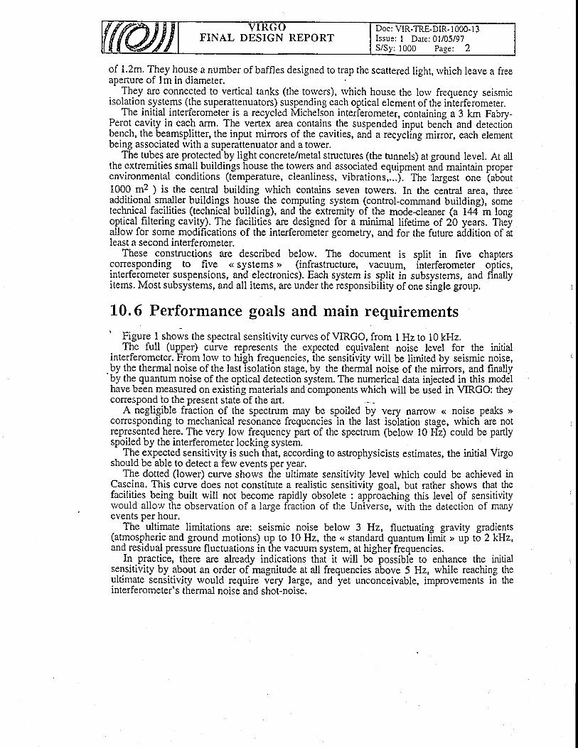
1"0.6 Performance goals and main requirements'
Figure 1 shows the spectral sensitivity curves of VIRGO, from I Hz to l0 kHz.The full (upper) curve represents the expected equivalent noise level for the initial
interferometer. From low to high frequencies, the sensitivity rvill be limited by seismic noise,. by the thermal noise of the last isolation stage, by the thermal noise of the mirrors, and finallyPy tne quantum noise of the optical detection system. The numerical data injected in this modelhave been measured on existing materials and components which will be uied in VIRGO: theycorrespond to the present state of the art.
A negligible fraction of the spectrum may be spoiledcoresponding to mechanical resonance frequencies in the
bylas
very naITow <( nolse peaKs >>t isolation stase. rvhich are not
ise peaks >isolation stage,
represented here. The very low frequency part of the spectrum (below 10 Hz) could be partlyspoiled by the interferometer locking system.
The expected sensitivity is such that, according to astrophysicists estimates, the initial VirgoThe expected sensitivity is such that, accordiluld be able to detect a ferv events Der vear.should be able to detect a ferv events peryear.The dotted (lower) curve shows the ultimultimate sensitiviry level which could be achieved inThe dotted (lower) curve shows
Cascina. This curve does not consdrute a realistic sensitivity goal, but rather shows that thefacilities being built rvill not become rapidly obsolete : approaching this level of sensitivityrvould allow the observation of a large fraction of the Universe, rvilh the detection of manyevents per hour.
The ultimate limitations are: seismic noise below 3 Hz, fluctuating gravity gradients(atmospheric and ground motions) up to 10 Hz, the << standard quantum limit > up to 2 kHz,and residual pressure fluctuations in the vacuum system, at highef frequencies.
In practice, there are already indications that it rvill be possibl-e to enhance the initialsensitivity by about an order of magnitude at all frequencies above 5 Hz, while reaching theultim-ate sensitivity rvould require very large, and yet unconceivable, improvements in theinterf'erometer' s thermal noise and shot-noise.
I
1 E - 1 8
1 E - 1 9
1 E - 2 0
1 E - 2 1
1E-22
1 E - 2 3
1e-24
1E-25
1 E - 2 61 0 2
frequency (Hz)
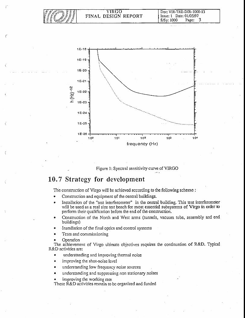
Figure 1: Spectral sensitivity curvcof VIRGO
L0.7 Strategy for clevelopment
The constnrction of Virgo will be achieved according to the following scherne :. Constmction and equipment of the central buildings.c Installation of the "test interferometer" in the cenral building. This test interferometer
rvill be used as a real size tost bench for most essential subsystems of Virgo in order toperform their qualification before the end of the conscruction.
o Construction of the North and lVest arms (tunnels, vacuum tube, assembly and endbuildings)
. Installation of the final optics and conrol systemso Tests and commissioning' OperationThe achievement of Virgo ultimate objectives requires the continuation of R&D. Typical
R&D activities are:. understanding and improving thermal noisec improving the shot-noise levelo understanding low frequency noise sourceso understanding and suppressing non stationary noiseso improving the working rateThese R&D activities remain to be organized and funded
c!
N--c
FINAL DESIGN REPORTDoc: VIR-TRE-DIR- 1000- I 3Issue: 1 Date:01/05D7S/Sy:1000 Page: 3
FINAL DESIGN REPORTDoc: VIR-TRE-DIR- I 000- I 3Issue: I Date: 0l/05/97
: 1300 Paee: I
L 3. System Studies
Table of Contents
13. System Studies
13.1 Model l ing
13.2 Locking13.2.1 Locking function and conceptI 3.2.2 Locking requirements
13.2.2.1Fabry-Perot cavities lengths 1L, and L2 )13.2.2.2 - 2. Recycling cavity equivalent length13.2.2.3 - 3. Dark fringe offset
I 3.2.3 Locking interfaces13.2.4 Selection of solutions
13.2.4.1 Llengths recovery13.2.4.2 Control of mirrors13.2.4.3 Remarks
13.3 Faci l i ty Geometry13.3.1 Scope:r a ? a c , . - - ^ - . , ^ c D ^ ^ , . : - ^ - ^ - . ^r J . J . z o u l r r r i l A r J u r A E q u r r E l l l g i l t s
13.3.2.1 Angle between the two arms:, 13.3.2.2 Angle between arms plane and Mode Cleaner beam
13.3.2.3 Distance input to terminal towersI 3.3.2.4..Tubes positioning:13.3.2.5 Towers positioning:
13.3.2.5.1 Separating roof, global tuning allowed:13.3.2.5.2 Towers Center:13.3.2.5.3 Towers positioning error.
13.3.2.6 Mode Cleaner reouirements13.3.3 Interfaces:13.3.4 Principles.I 3.3.5 Instrument accuracy
13.3.5.1 GPS Measurement.13.3.5.2 Theodoli te measurements
13.4 Electro-Magnet ic Compat ib i l i ty (EMC)13.4.1 E.M.C. GeneralI 3.4.2 External disturbances.I 3.4.3 Internal disturbancesI 3.4.4 Grounding conceprs13.4.5 Cabling
.,
3J
J
4A
)5)66
8886a
8886
89999
l 0l 0l 0
1 01 0l ll ll 21 2

I
{
L3. L Modell ing
Modelling refers to the physical studies and the corresponding.numerical estimates necessary formatriing technological decisions, or compromises, on- a quantitative basis. This kind of activiry issoine 6n in all thE laboratories of the collaboration, and a minimal coordination is necessary to avoidilseliss duplication of efforts, as rvell as to trigger some studies which otherwise could.be missing.The resulti of these studies may or may not be used as inputs for the general simulation program(srESTA).-
Following studies have been so far performed (non exhaustive list).
- Thermal effects in Laser optics (Orsay)Study of the tentperatuie indticed itresses in the YAG crystal, optimization of the optical path
- Interferometer configurations (Orsay)Analy t i c aI fo nrud a s fo r re cy clin g int e rfe r o m e t e rs
- Non-linear effects in cavities (Orsay)Stability of Virgo under dynamiial temperature gradients in the mirrors, and radiation pressureeffects
- Optics studies for specifying optical elements (Cooperation Orsay-Paris)' Static simula.tioi of rZsoiait Fabry-Perot cavitiei in a recycling configuration, involving
' imperfect mirrors
- Scattered light noise evaluation (Cooperation Pisa-Orsay-Lyo.n)Emissioi, propagation, rnodulation and recontbination of light scattered by-1he nirrors,' analytical'sndylMonte Carlo estimates, physical measurements, design of bffies
- Electrostatic actuators for moving mirrors (Cooperation Orsay--Napoli)Calculation of the force generated by electrodes on a silica blank
- Magnetic effects in Bechers (Cooperation Orsay-Annqcy) -Floise clue to interaction of the marionettu c;ils vvith a thin metallic wall : seismic excitation ofthe waII, Foucault clrrents, dissipation.
- Modulation studies (Orsay)M o dulat io n/D e mo dulat ion s cheme sNoise due to a jitter in the modulationfrequency
- Alignment (Frascati, Orsay, Annecy)Representation of weaily misaligned mirrors by modal expansion
- Interferometer simulation (Annecy, Orsay)Dynarnical models of interferometersfor global control
- Thermal noise (Orsay, Perugia)Models of cylindrical acottstic resonators for mirror thermal noise estimates
- Dynamics of superattenuator (Pisa, Orsay)" Model of the'chain of coupied o,scillaiors involved in a SA with all relevant degrees of freedont
Doc: VIR-TRE-DIR- I 300- I 3Issue: I Date:01/05/97FINAL DESIGN REPORT

FINAL DESIGN REPORTDoc: VIR-TRE-DIR- I 300- I 3Issue: I Dare:O1/05/97
L3.2 Locking
13,2,I Locking funct ion and concept
Virgo is a complex system rvhich final performance depends of the interaction betrveen all sub-systems. As an example, the- effect- of the various souices of noise of the laser light source(frequency, power, pointing fluctuations) is proportional to the asymmetry of the intjrferometeroptics, which is the result of optical components imperfections and of their misalignments. It is thetask of the control sys.tem to manage these interactions. The task of the locking activlty is to define themost adequate contiol.strategy for"ensuring that the position oittre i"-t!rr.it"i3t;;;;;$";nts and thelaser parameters remain lntj* a range of valueswhich provides the optimal sensitivity for Virgo.
Locking is then a typical System ac-tivity, ry.high involves a coordination betrveen iubsysteris.The control strategy. must be based on realistic performance achievable by each subsystem. Each
sub--system has to provide information and shall contribute to the definition of the strategy.Most of the effects to be expected as rvell as most of the transfer functions can bJ computed or
derived-from.experimental tesis, so the locking studies are principally based on simulations. It isbelieved that there is less to learn from the experimental study-of sniall moct-up interferometers thanfrom piecewise study of elementary, but real ilems.
The main simulation tools are MATLAB for the design of solutions and SIESTA for the tesr ofsolutions.
' The locking is also the place where the need for nerv or more accurate models arises.. After a satisfying strategy has been developed and (partially) tested on the test interferometer, thelog$-nq activity will naturally evolve- towardi the definition bf the << h reconstruction > straregy,which is in some way the inv-ersion of the locking strategy.
t3.2.2 Locking requirements
The main requ-irement of the locking is to bring and maintain the interferometer in a regime thatpermits to reactrthe nominal sensitivityl
Thi_s main,requirement can be split in three points:1. The locking has to limit the r-esidual motion of the mirrors below a certain value2. The Iocking has to be robust against:e Various resonances (violin modes, vertical thermal modes of the suspensions). Coupling due to the alignment. Inaccuracy of the mechanical and optical models3. Moreover this has to be done undeithe follorving constraint: the forces needed on the marionette
and the reference mass, in order to maintain the residual motion within acceptable range, shall notintroduce noise due to the electronic of the actuators.
. The first point of the requirements is the consequence of the power needed in the cavities and isalso the consequence of:
o The dynamic range of the photodiodes electronic and the ADC. The power fluctuation of the laser
The.se last requirements can be expressed in term of length variations (see Figure 2).The lockinggroup has shown that we have to maintain the four following lengths :
13.2.2.1 Fabr ] ' -Perot cav i t ies lengths (L, and Lr I
In order to keep the two Fabry-Perot at resonance rve have:r 1
a L , a n d & 2 . * # = s 1 0 4 1 .

rvhere :F = 5C is the finesse of the Fabry-Perotl, = I .064 10-6 m is the laser rvavelength
13.2.2.2 Recycl ing cav i t l , equiva lent length
This length is :
AL,=a1! ' * l ' 13p l - l l zy2 n 2
We have to keep.the recycling cavity at resonance
A I , ( + + = 1 . 6 l 0 { } .' t0 4F;where:F, = 150 is the finesse of the recycling
!3.2.2.3 Dark f r inge of fset
This length is : ,)ALo = A(lt - I , +:F(L, - Lt))
Ft'li:ffi#:Jffi :Y3,ft'#iii3l'n;,"0.0., .,,.,,onics, rhe n the phase nuctu ation has to be :
'Or equivalently in term of length:,1
aL, < --:.! A *T / L
because the phase variation divided by the dynamic range has to be less than the shot noise.
Fni/ttt, .fio-rt = 3.3.l.Q*I
rvhere :Pu = lkW is the porver on the beam splitter
I = 0.85 is the efficiency2hv = 3.7 10-reJDp6=16 is the number of photodiodes
r = 5 10?Hz'rn is the dynamic range of one photodiodeW ,
_ I _ is the shot noise spectral density in phase unitsl tiPo
The second condition is due to the laser power fluctuation, in that case we have :
AQo <" /4 r *l n P P
Because the length varaition has to be less than the shot noise devided by the laser fluctuation.
Or equivalently in term of length:
nr, <! Ertr=1.6 lo{} ." 4nl riP P
rvhere :
FINAL DESIGN REPORTDoc: VIR-TRE-DIR- I 300- I 3Issue: I Date:01/05/97
FINAL DESIGN REPORTDoc: VIR-TRE-DIR-l 300- I 3Issue: I Date:01/05/97S/Sv 1300 Paee:5
E = 19* 11r''o is the laser Dorver fluctuationP
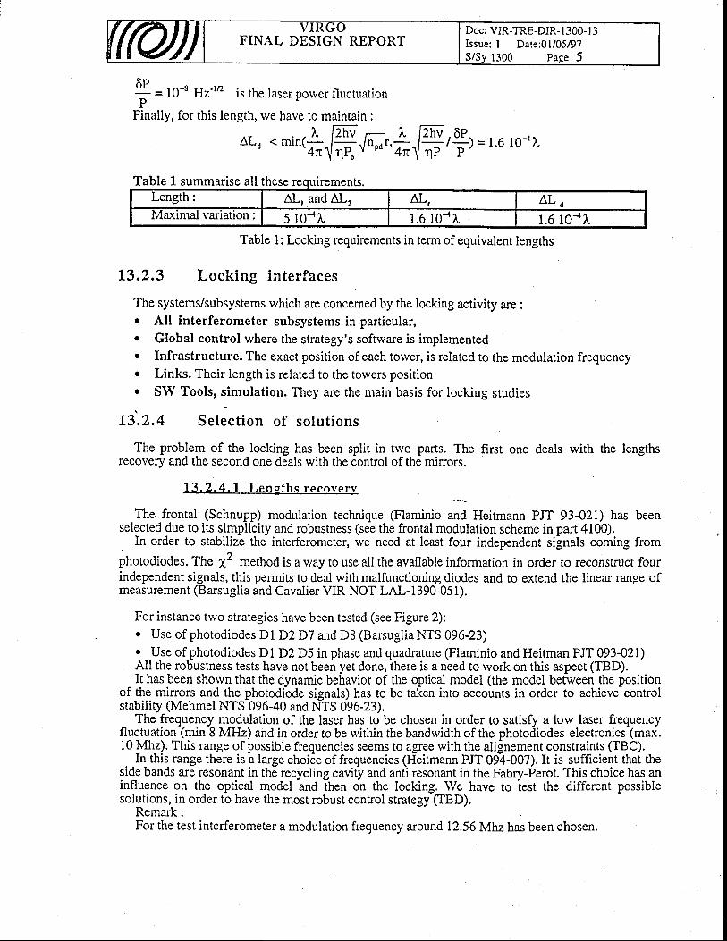
Finally, for this length, rve have to maintain :
aL, < minr! @-.- l' lzrrv . oP- '4n!
nR Jn"'';{ * 'i) = l'6 1o-{}'
Table 1su ll these Lllre 1 5 .mmarrse a menLength: A T , a n d A I , AL, A L oMaxrmal vanatlon: 5 10-41, 1.6 10-41, 1.6 10-1I
Table l: Locking requirements in term of equivalent lengths
L3,2.3 Locking interfaces
The systems/subsystems which are concerned by the locking activity are :. All interferometer subsystems in particular,. Global control where the strategy's software is implementedo Infrastructure. The exact position of each torver, is related to the modulation frequencyo Links. Their length is related to the towers position. SW Tools, simulation. They are the main basis for locking studies
L3.2.4 Select ion of solut ions
The problem of the locking has been split in two parts. The first one deals with the lengthsrecovery and the second one deals with the control of the minors.
13 .2 .4 . 1 Leng ths recove ry
The frontal (Schnupp) modulation technique (Flaminio and Heitmann PJT 93-021) has beenselected due to its simplicity and robustness (see the frontal modulation scheme in part 4100).
In order to stabilize the interferometer, rve need at least four independent signals coming from^
photodiodes .The a" method is a way to use all the available information in order to reconstruct fourindependent signals, this permits to deal with malfunctioning diodes and to extend the linear range ofmeasurement (B arsuglia and Cavalier VIR-NOT-LAL- 1 390-05 I ).
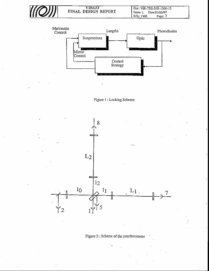
For instance two strategies have been tested (see Figure 2):. Use of photodiodes Dl D2D7 and D8 (BarsugliaNTS 096-23). {Jse of photodiodes D1 D2 D5 in phase and quadrature (Flaminio and Heitman PJT 093-02i)All the robustness tests have not been yet done, there is a need to work on this aspect (TBD).It has been shorvn that the dynamic behavior of the optical model (the model between the position
of the mirrors and the photodiode signals) has to be taken into accounts in order to achieve controlstability (Mehmel NTS 096-40 and NTS 096-23).
The frequency modulation of the laser has to be chosen in order to satisfy a low laser frequencyfluctuation (min 8 MHz) and in order to be rvithin the bandwidth of the photodiodes electronics (max.10 ]\Anz). This range of possible frequencies seems to agree with the alignement constraints (TBC).
In this range thare is i large choi6e of frequencies (Fieitmann PJT 09?-007). It is sufficient thai theside bands are resonant in the recycling cavity and anti resonant in the Fabry-Perot. This choice has aninfluence on the optical model anO itren on the locking. We have to iest the different possiblesolutions, in order to have the most robust control strategy (TBD).
Remark:For the test interferometer a modulation frequency around 12.56Mhzhas been chosen.

FINAL DESIGN REPORTDoc: VIR-TRE-DIR- I 300- I 3Issue: I Date:01/05/97S/Sv 1300 Paee:6
13. 2.4. 2 Contro l o f mir rors
An important problem is the bandrvidth of the control. For instance due to requirements and due to
the expected open loop displacement of the minors rve need at least an open loop gain of 106 (TBC)around 5 Hz.
If we assume a full decoupled technique (inversion of the optical model and the same compensatoron each minor, Mehmel NTS 096-23) and if rve call L(ja) the open loop transfer function from onelength to the same length, then the closed loop transfer function is given by :
1
I. Lfi,t)The needed accuracy tor L(ja) depends on the bandrvidth of the control. If the unity gain
frequency is lorv (around 10 Hz) then the controller is difficult to realize because the gain has todecrease rapidly. But in that case, it is not necessary to have a good knowledge of L(ja) above thisfrequency. On the contrary, if the unity gain is high (around lkHz) the controller is much more easyto realize, but we have to know the high frequency behavior of L(ja), which includes the optical andthe mechanical models.
13 .2 .4 .3 Remarks
1. Even if rve do not use a decoupled technique, rve have to know precisely L(jol) quite above theunity gain frequency.
2. We have decided to use a sampling frequency of 10 kHz for the control, so the maximal valuefor the unity gain frequency is around 1kHz.
3. The bandwidth- has 'an
influence on the transfer function between gravitational waves anddetection. In any case, this transfer function (rvhich may include the control strategy if the bandwidthis large) has to be known for the detection of gravitational rvaves.All tests have been done with a unitygain frequency of 30 Hz.
The second problem is the maximal forces available on both the marionette and the reference mass.Most of the simulation tests have been done with the only control on the reference mass. However,some studies have shown that it is not possible to act only on thb reference mass. A solution has beenproposed that permits to lower the force needed on the reference mass (Flaminio NTS096-06) but weneed informations on the maximal forces delivered by the actuators (TBD).
The third problem is the acquisition of the locking (TBD). SIESTA seems to be the tool thatpermits to tes[ the acquisition of ihe locking by using fast simulation. For the acquisition strategy, the
12 method could be useful.
FINAL DESIGN REPORTDoc: VIR-TRE-DIR-1300- l3Issue: I Date:01/05/97S/Sy 1300 Pasez7
Suspensions
ControlStrategy
MarioneneControl Lengths
Figure I : Locking Scheme
Figure 2 : Scheme of the interferometer
Photodiodes
l s/A
. Y I I \ I ' \J
FINAL DESIGN REPORTDoc: VIR-TRE-DIR- I 300- I 3Issue: I Date:01/05/97
L 3 . 3 Facility Geometry
1 3 . 3 . 1 S c o p e
- The alignment of the optical and mechanical elements on the 3 km arms requires the developmentof sp,ecific -methodologies. By facility geometry we understand all the meani necessary to piovidephysical references necessary during the assembly to achieve the required positioning tolerances.
13.3.2 Summary of Requirements
13.3.2.1 Angle betrveen the t rvo arms
The angle must be about 90o. There is no. precise requirement on tbis angle which will anyrvay beknown within the accuarcy of the GPS absolute measurements (< 10cm over 3 Km).
13.3.2.2 Angle betrveen arms p lane and Mode Cleaner beam
The mode cleaner needs to be in the same plane as the tlvo a-rms rvithin 1 mrd.(reminded that the North arm is horizontal but the west arm has a slope of 2 meters over 3
13.3.2.3 Dis tance input to terminal torvers
The absolute distance must be set rvithin + 0.25 meter.This precision is defined by the modulation wavelength (clL2MHz) divided by 100.
It isKm).
to be
13 .3 .2 .4 Tubes pos i t i on ine
Tube axisThe tutie axis must stay inside a cylinder of 50 mm radius centered on the line defined by thebeam splitter and the end mirror.
Longitudinal distance precision:The supports of the tube lay on the concrete slab on top of pillars.Each tube section must be positionned within * 5 mm with respect to the neighbouring one.
Straightness of the tube .The tube does not follow the earth curyature which would give a sag of about 20 cm over3 km but is straight. Local measurements must therefore be corrected.
13 .3 .2 .5 Towers pos i t i on ing
13.3.2.5.1 Separat ing roof , g lobal tuning a l lowed
The mirror position is defined by the center of the sepa.rating roof. All errors added the separatingroof must be positioned with an absolute accuracy of + 25 mm which is the range of movement of theseparating roof.
13,3.2,5.2 Torvers Center
The reference surface is the square upper flange.The position of the real center of the tower ( crossing of the axis ) is not materially defined (It can
be deduced indirectly within about one cm precision from the manufacturing tolerances).So and by definition the Center of the toiver is at 1630 mm below the crdssing of ttr! marks on the
upper flangeOnce the totver is in place, its deformations may be, during the baking or with time, up to lmm.
FINAL DESIGN REPORTDoc: VIR-TRE-DIR- I 300- I 3Issue: I Date:01/05/97
.. During the baking the torver expands-and quy noJ come.back exactly to the initial position. Thedisplacement of the tower "center t' would be abirut 7 mm during the biking. It is estirirated that thecenter may come back rvithin t 2 mm from its initial position.
The movements of the torvers can be measured rvith the targets on the upper flange.
f3 .3.2.5.3 Torvers posi t ion ing error
It is es-timated thatthe- towers may be position within * 5mm ( better if possible ). TBCIt can be distinghished between:
the absolute position of all the towers,and the relative precision of the torvers respective one to another.
13.3.2.6 Mode Cleaner reoui rements
The Mode Cleaner tower longirudinal position has to be set within * lcm from the theoreticalposition .
Mode cleaner Tubeaxis- precision. : The rube axis must stay inside a cylinder of 50 mm diametercentered on the line defined by the Injection tower and the Mode cleaner tower axis.
13.3.3 In ter faces:
The definition of geometrical references is needed for the installation of the follorving parts:Infrastructures WBS 2000
. Towers lower parts wBS 3310Tests interferometer Assemblv WBS 6100Modules realizationMode Cleaner tube
. Tube assembly
L3.3.4 Pr inc ip les.
provides positions on the geoid referred to several satellites emittirrg radiobe done onlv in ooen air-
The basic idea is to make use of the high absolute accuracy of GlobalPositioning Systems. GPSsignals. Measurements can
only in open air.;t network of re{A first network of reference points to be measured by this GPS method will be installed: at least
fiv.e points outside- the- buildings, permanently accessible and measurable, and several points inside thebuildings measurable before the rbofs are pui in place.Lqmgs measurable before the roofs are put in place.
This network will be linked to the locafgeodetic network. It will give the reference from which allthe other distances will be measured.
A second reference-points network rvill be installed inside the central building and the tunnels. Thepositions of the secondary reference points rvill be measured relative to the firslreference netrvork byclassical topographic method. (with aclassic-al topographic method. (with a special theodolite equipped with a telemeter ). It is from thissecsnd-ary network that the positions ofthe towers lower parts or the tube will be measured.run(.l,afy nelworK rnat tne posltlons oI u
Each tower or tube modules rvill beEach tower or tube modules rvill be equipped rvith targets. The mechanical references anddimensions of each elements rvill be measureil relative to the targets, before assembly on site.
So from the measurement of the tragets one knorvs the position of the element. Pbssible long termevolution can also be monitored with t[e same system.
The central buildings are rather full of equipment and hence obstruction of lines of sight must beavoided.. FiY. points inside the central building rvill be installed and their position measured before the roofins.tallation . Some points rvill be visiblJ from the outside. By this way it will be possible to link thepoints inside to the external references.
wBS 3110wBS 3130wBS 6300

FINAL DESIGN REPORTDoc: VIR-TRE-DIR- I 300- I 3Issue: I Date:01/05/97
1300 Paee: l0
13.3.5 Instrument accuracy
13 .3 .5 .1 GPS Measuremen t .
The expected precision of the GPS measurements for each point are :in planimetry : standard deviation o = 5 mmIn altimetry : standard deviation o = l0 mm
13.3.5.2 Theodol i te measurements
. The leveling of the buildings and the tunnel can be done by leveling theodolites which can cunenrlygive an accuracy ofabout I arcsecond.
L3lgths cal be meas.ured with specially equipped theodolites. The accuracy is:0.8 mm +1 ppm xDistance(mm)
13.4 Electro-Magnetic Compatibility (EMC)
t3.4.1 E.M.C. General
The useful detection-frequency range of Virgo is from 0 to about 20 Mhz The main frequenciesuse.d are shown on the figure below.
,G.W.FB COILS
L.V.D.T.ACC.
ADC & DAC
1 0 0
k H z
LASER MOD.
1 2
M H z
_ .]t-it important that undesired signals coming from outside or from other instruments inside thebuildings are kept at asufficiently low level not to interfere with the useful signals.
For this reason, electromagnetic interference suppression methods thal at least reduce, if notcompletely eliminate, unwanted effects must be used.
-
E.M.C. means to_study, to foresee, and (possibly) to solve problems that can arise by thecoexistence of such a lot of instruments into a nolsy arei.
Potential interference sources are:Al "Outside" sources:
Al) Interference from external sources (e.g. radio transmitter, lightning, etc.)A2) Interference existing on rhe 220Yac m-ains supply (ENEL)
Bl "lntemal" sources
B 1) Interference produced from instruments in the building

FINAL DESIGN REPORTDoc: VIR-TRE-DIR- I 300- I 3Issue: I Date:O1/05/97
B 1.1) Propagated by the 220Vac mains supplyB 1.2) Propagated magnetically and/or electricallyB2) Voltage differences due to an imperfect grounding of instruments
Let us see, for each item, details and possible solutions.
13.4.2 External disturbances.
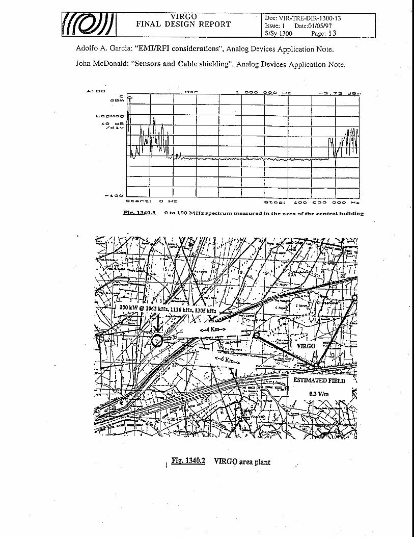
Some measurements have been performed in the area of the central building, in the frequency rangefrom 40 kHz to 100 MHz (Fig. 1340.1). It seems that the most relevant source of E. M. noise is the100 kW I MHz "COLTANO" AM transmitter, about 6 km from the building (Fig.1340.2).
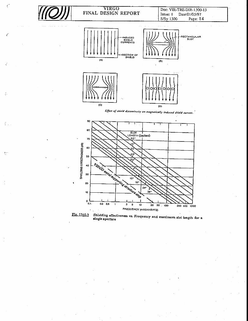
To reduce the impact of this and anv other sienal that could be present in the future (ainTo reduce the impact of this and any other signal that could be present in the future (aiqport radar,Monte Sena TV and Radio transmitters, etc.), it's convenient to shield the buildings. The shieldingMonte Sena TV and Radio transmitters, etc.), it's convenient to shield the buildings. The shieldingeffectiveness is inversely proportional to the longest dimension (not the total area) of an opening in theshieldine net (because the ooenines behave as slot antennas). and to the freouencv (Fie 1340.3).etlectlveness ts lnversely proportlonal to me longest olmenslon (not me total area) oI an openlngshielding net (because the openings behave as slot antennas), and to the frequency (Fig 1340.3).
Equalion 1340. 1 can be used io calculate the shielding effectiveness, oi the susceptibility to EMIleakage or penetration of an opening in an enclosure:
SHIELDING EFFECTIVENESS (dB) = @q. 13a0.1)20l"s,,[#)
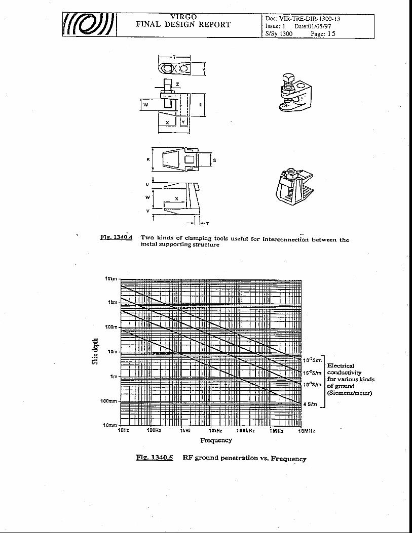
In our case, with l"=300m and L=4m, at least 30 dB of attenuation @ I MHz can be expectedusing only the metal supporting structure. In case it's necessary to increase this attenuation, it rvill beuse'firl to interconnect iG structure rvith a narrower rveb, using clamping tools (Fig. 1340.4) andcopper strips. No shieiding is necessary on the floor, because ittenuaiion-is u"ry'hfth through theground (Fig. 1340.5).
For the same problem it could be useful to ground theavbiding resonance problems.
13.4.3 Internal disturbances
vacuum tubes every 15 meters (TBC),
We will probably have no problems arising from the mains supply, because all the electronics willbe porvered- from an insulated Unintemrpted Porver Supply; we-must only be careful not to leavemains cables "after" and "before" the UPS running together for long distinces. If this will not bepossible, it could be necessary to use shielded cables with the "clean" power supply (TBC).-
This precaution will not b6 sufficient if our orvn electronics disrurbs the mains, spreading loise onthe cables. Simple rules to avoid this are: use (whenever possible) linear porver supplies,- notsrvitching; ask the manufacturers which EMC directive instruments comply to, and use only.thoseinstruments (crates, power supply, P.C., etc.) declaring compliance to FCC, VDE, IEC or similardirectives; in case tha instrumenti are home made the pioject must follow EMC criteria. Other rulescan be found in the bibliography at the end of the chapter.
The same guidelines aie fo 6e followed for the n6ise radiated magnetically and/or electrically; thefollowing approach shall be follorved :
a) thJ"ihotodiode and mixet'' system could detect the laser modulating sigl-d also; it will benecessary to shield the source (signil generator + power amplifier + Pockels celll and the receiver(photodiode + mixer) correctly.'^
b) position sensois (LVDT) and accelerometers, working at close frequencies (10 kHz to 50 kHz),could interact with each other, generating unwanted beat effects and/or cross/talk; moreover, some oIthese high frequency signals J* go thr:ough (for grounding problems) the anti-aliasing filters at theinput of every ADC system, with unpredictable results.^c)
all sigials at the output of tnL sensors are of very low level (near the noise limi|, and theconnections between these sensors and the instruments must be reliable.
For all these reasons, it is absolutely necessary to use, as much as possible, differential inputs. andoutputs, rvith the aid of trvisted anil shielded cables. This system rvill also avoid ground-looporoblems.

FINAL DESIGN REPORTDoc: VIR-TRE-DIR- I 300- I 3Issue: I Date:01i05/97
Likervise on the airplanes, no RF transmission will be allorved into the buildines: a lW hand-heldradio at a distance of I meter can generate an electric field of 5.5V/m, as in equatio"n. 1340.2:
(Eq. 1340.2)
That means no cellular phones, no cordless, etc. in critical areas during normal operation.
L3.4,4 Grounding concepts
The safety ground is not able to assure an equipotential ground system, especially at highfrequencies: a wire length of )J4 and its odd multiple is like an "open" connection; it's necessary touse connections as short as possible in Virgo.
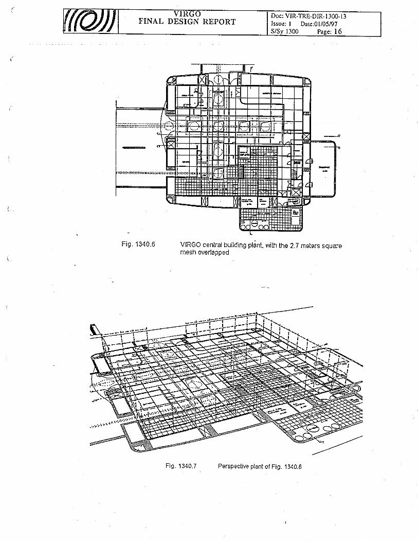
For this.reason, during the construction of the main building, a net (8 mm iron rods) has beenembedded into the concrete floor, rvith a square mesh of auoii z.z di";t-aFi!. :,34nJ6).In-thismanner it's easy to have very short ground connections if desired, because eviw1.l meteis. a shortl}ll:11t-.:,.jtyto have very short grgu.nd connections if desired,-because erity1.l mereis, a shorr
ELECTRIC FIELD INTENSITY, in V/m, = ,rfq[ ' )
manner-lt s,e,asy to nave very short ground connections if desired, beiron rod welded at every- crois point of the mesh comes out vertically.
On the walls, the rods are jbined to the metal supporting structurr
shield grounded at the receiver end only.Holever, these configurations leads to a high number
connection from the vacuum tower to the out.This is an "open point" to be discussed with other groups,
Electronics.
to the metal supporting structure of the building (Fig. i340.7);somewhere (in more than one iloint) there will be conirectiois with the safety gtounA.
13 .4 .5 Cab l i ng
As.stated before, very lorv level signals are cted in VIRGO; it's important to have high noise_r.\s.rr.llsLr usrefe, very row tevel slgnals are expected m vrKUU; tt's importanrej999i9n on the cables connecting the iensors inside the towers to rheii electrbnics.
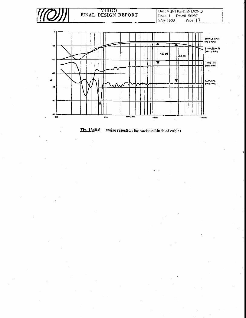
With a simple test set-u. .wlth a slmD-le test set-up, some measurements have been made that show how an extemal field islndu.ced at the inputsof a differential amplifier (Fig. 1340.8); it's clear that the best choice is the use oflnou.ceo ar tne rnputs of a difl-erential amplifier (Fig. 1340.8); it's clear that the best choice is the use ofa sileldecl twlsted pair cable, or the use of a special kind of coaxial cable (e.g. shielded coaxial), rvitha sileldecl twlsted pair cable, or the use of a special kind of coaxial cable (e.g. shielded coaxial), rviththe inner conductor connected to one input (i), the inner shield to the otireiinput (-), and the'outerinput (-), and the outer
oT cables, and to a high number of
particularly with Cabling, Vacuum and
Finally, it's almost impossible to fores_ee the EMC problems that will arise in Virgo; every decisionmustbe a trade-off betw-een the costs of the current ihoice (and its efficiency), an-cl ittosebf amoreeffective but more costly (and perhaps unnecessary) solution.
Bib l iography:
IJgltV W. Ott: "Noise reduction techniques in electronic systems", second edition, JohnWiley & Sons,Inc., New york.
ItugLY. Denny: _"Grounding for the control of EMI", Interference Control Technologies,Inc., Gainesville, Virginia.
$]qtt Monison: "Grounding and shielding techniques in instrumentation", thirdedition, John Wiley & Sons,Inc., New york.
Paul Brokaw: "An I.C. amplifier user's guide to decoupling, grounding, and makingthings go right for a changel', Analog Deviies Application Noti.
"
WaltJung. an-d Jo_hn McDonald: "Noise reduction and filtering for srvitching porversupply", Analog Devices Application Note.
FINAL DESIGN REPORTDoc: VIR-TRE-DIR- I 300- I 3Issue: I Dare:O1/05/97
Paee: I 3
Adolfo A. Garcia: "EMURFI considerations", Analog Devices Application Note.
John McDonald: "Sensors and Cable shielding", Analog Devices Application Note.
a : c t eo
d E l m
L - o 0 M 6 g
, . o d E l/ d t v
- t . o oS i t E r e :
F l p , 1 3 4 0 . 1
o H z s c a p : 1 o o o o o o o o H =
O to IOO A4rIz sp<trurn rnesured in ttre qra of thc central brri lding
f,;,i;'i t
*{/',/*
I
it'ill2{.-z
ESTI]VTATED FIELD
03Y/m
. < t ' \ - l
s ; t a p : 1 o o o o o o O O H =
, FIe. 130.2 \mcg area ptant
FINAL DESIGN REPORTDoc: VIR-TRE-DIR- l -100- I 3Issue: I Date:01/05/97
1300 Pase: 14
lllllltl(Al
- - tNoucEosfirELo
CURNENTS
. R E C I A N G U L A RS L O T
- -sEcnoN oFSHIELO
rffit(ct
l1s o l.,1: i
II
. to.t.
6@UzU
UU4ru
zaUJ
q
Elfect ol shicld discontiauitlt on matncricalbt iaduc<d shicld currcnt.
300 500 roooFFEOUENCY (MEGAHEAT4
FiE' 1340.3 Shietding efrecliveness vs. Frequency and rnaximurn stot tength for asingle aperfure
( 8 t
Hlil(l{i(ol
NPz;\ '"'ls3 5 r 0 3 0 5 0 .
T'INAL DESIGN REPORTDoc: VIR-TRE-DIR- l -300- I 3Issue: I Date:01/05/97S/Sv 1300 Pase: 15
ffi:
Fie. 1340.4 Two kinds of ctamping toolsmeta! supporting structure
F.().trl
.l{a4
1 Olrn
1km
1 00m
l0m
1 m
100mm
1Ornm
useful for interconnection Uetween the
t o-tsir'ri
1 o'2s/rn
1o{s/m
4s /m _
Eccuicufcsdnc{il/iryfor various kirdsof grcurd(Sicocnsloctcr)
tl
Fig. 1340.5 RF ground penetration vs. Frequency
FINAL DESIGN REPORTDoc: VIR-TRE-DIR- I 300- I 3Issue: I Dare:01/05/97S/Sv 1300 Paee; 16
F ig . 1340.6 VIRGO central building plant, with the 21 meters squaremesh overlapped
Fig. 1340.7 Perspective plant of Fig. 1340.6
FINAL DESIGN REPORTDoc: VIR-TRE-DIR- I 300- I 3Issue: I Date:01/05/97
.t)
.|
4
SIUPLE PAIR(m sH.rt
SIUPLE PAIR(Y/rh &!Cd)
TViTSTEO(rc Ed.ld)
co^xl L{r€ El*rtt}
Fig. 1340.8 Noise rejection for various kinds of cables
FINAL DESIGN REPORTDoc: VIR-TRE-DIR- 1000- I 3Issue: I Date: 0l/05/97Sy:2000 Page: 1
20. INFRASTRUCTURE
Table of Contents
20. INFRASTRUCTURE
20.1 Infrastructure function and concept
20.2 Infrastructure requirements20.2. I General requirements20.2.2 Site requirements
20.3 Infrastructure description20.3. I Ceneral description20.3.2 Access roads20.3.3 The site
20.3.3.1 Site choice20.3.3.2 Site morphology20.3.3.3 Site geology and stabil ity20.3.3.4 Seismic measurements
21,. Central Area Buildings
21.1 t 'Centra l ' .area bui ld ings" funct ion and concept
2L.2 Central area buildings requirements21.2.1 Central and M.C. building requirements21.2.2 Control building requirements
21.3 Bui ld ings and Equipment Descr ipt ion21.3.1 The central building21.3.2Tt.e mode cleaner building21.3.3 The mode cleaner tunnel21.3.4 The control building21.3.5 The technical building21.3.6 Electric power supply21.3.7 Service fluids21.3.8 Control cables
21.4 Inter face
22. Clean Areas
22.1 Clean areas function and concept
22.2 Clean areas requirements
22.3 Clean areas descr ipt ion22.3.1 The laboratories in the central building22.3.2The towers and gallery plant in the central building22.3.3 The torvers and gallery plant in the mode cleaner building223.4The towers and gallery plant in the terminal buildings
22.4 Clean areas interface
3
J
J
4A
4A
4))5
1
I
1I2
7
2J
J
44a
4
A
1
1
1')
2
2
J

FINAL DESIGN REPORTDoc: VIR-TRE-DIR- I 000- I 3Issue: I Date: 0l/05/97Sy:2000 Page: 2
23. Arms & terminal buildings
23.1 "Arms & terminal buidingst' function and concept
23.2 Arms and terminal bui ld ings requi rements23.2.1 Tunnel requirements23.2.2 T erminal bu ildi n g requirements23.2.3 Assembly building requirements
23.3 Arms & Terminal Bui ld ings Descr ipt ion23.3.I The interferometer tunnels23.3,2 The terminal buildings23.3.3 The pipe assembly halls23.3.4 Electric power supply23.3.5 Service fluids23.3.6 Control cables23.3.7 Service road23.3.8 Bridges
23.4 Inter face
24. Miscellaneous equipment24. I . l Set of electrical equipment24.1.2 Ourer l ighting plant24.1.3 Security system
I
2)
1
2
33
34A
A
tI
II
FINAL DESIGN REPORTDoc: VIR-TRE-DIR- I 000- l3Issue: I Date: 0l/05/97Sy:2000 Page: 3
20.t Infrastructure function and concept
The infrastructure for the VIRGO Project consists of the buildings and the tunnels, rviththeir equipment, necessary to the interfero-meter installation on the Casiina site.
In the next paragraphs the infrastructures designed to accept the VIRGO interferometer (thetunnels hiding the long vacuum pipes and the relative assembly halls, the experimental halls andthe laboratories) rvill be described together with the chosen site, its characteristics andarrangement (roads, bridges, fence, drain channels).
The executive design of the "central area buildings" has been completed; for this set ofbuildings the shown drarvings correspond to rvhat is really being built. On the contrary thedrawings of the "arms and terminal buildings", rvhen shorvn, correspond to the preliminarydesign.
20.2 Infrastructure requirements
20.2,1 General requirements
The installation of the VIRGO interferometer has to satisfy the follorving requirements :- build a detector and an infrastructure frame capable of a 20 years operation time;- keep the performances of the detector at the limits of present technologies;
build the"apparatus on a flat, controlled area, as far as possible arvay from mechanicalvibration sburces, as roads, trains, etc., within a reasonably short distance from one ofthe collaborating laboratories ;
- give a minimum perturbation to the geological, biological and economical equilibrium ofthe surrounding region.
The stability requirements for a safe VIRGO operation are summarized in rvhat follows.- The foundaiions of the experimental halli have to gridrantee the stability of the Super
Attenuators suspension points, located at the top of the vacuum tanks. (The suspensionpoints shall nof move more than 1 mm per day and, in a 20 year period, the overalldisplacement must stay well within the adjustment range of a ferv cm in all directions.Tidal effects and thermal dilatation are expected to produce movements up to 0.2 mmwith 6, 12,24 hour periods.)
- The foundations of the tunnels have to guarantee the stability of the tube. (it is requiredto have the center of any pipe cross-section always inside an ideal 5 cm radius cylinder.The realignment of the supports shall not occur more than once in a year.
20.2.2 Site requirements
To satisfy the requirements listed before, the site has been selected according to thefollowing mles :
- keep the distance of the tube from farm houses above a minimum of 50 m- keep the distance of the mirrors above a minimum of 500 m from main roads and of
200m from electrical power lines.- reduce to a minimum the number of crossed lanes and irrigation channels- keep the expenses for the acquisition of the land muc[ lower than the cost of the
apparatus itself;- allorv to build the halls and the tunnels rvith standard foundation.
FINAL DESIGN REPORTDoc: VIR-TRE-DIR- I 000- I 3Issue: I Date: 0l/05/97Sy:2000 Page: 4
20.3 Infrastructure description
20.3,t General descript ion
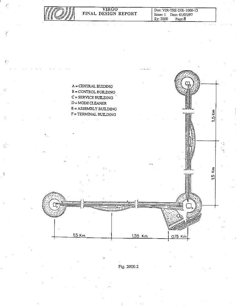
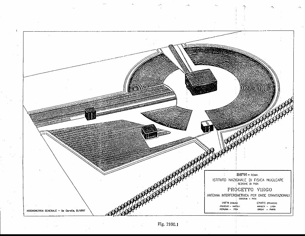
The area needed for VIRGO in Cascina (fig. 2000.2) consists of five laboratory areas, about40000 m2 each, connected by two orthogonal land strips 30 m rvide and 3 km long. Anadditional area, consisting of a small land strips along each side of the main trvo, is needed torealize country roads and the drain channels outside the fence, to satisfy the requirement of"Comune diCascina".
The tunnels, placed on the main land strips, make two orthogonal arms in the North andWest direction. Each tunnel hides the 3 km vacuum pipe.
There are four experimental halls : at the crossing point of the arms there is the "central
building" containing, under vacuum inside the towers (vacuum tanks), the pendulum chains,called Super Attenuators (SA), that supports the various optical parts; at the other ends of thetunnels there are the "terminal buildings" where are installed the chains supporting the othertrvo mirrors of the interferometer; a fourth hall, containing the mode-cleaner mirror, is locatedat 140 m from the central one, along the West arm, .
At 100 m from the central hall there are the 'tontrol building" and a "technical building" forelectricity and thermal plants.
At half way of the arms there are the "assembly buildings" for the vacuum pipe assembly.A service road, running along the arms, connects all the buildings.Apart the service road and a round zone around the central building, the remaining area will-be arranged with trees and grass.
20.3.2 Access roads
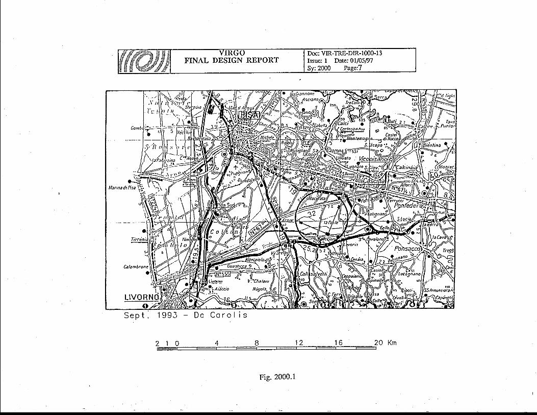
The access to the site is good, through already existing paved roads, linked to the Pisa-Firenze motor-way. The most relevant distances are : 15 km from Pisa, 8 km from Cascina, 21km from INFN laboratory in San Piero a Grado (fig. 2000.1). The Pisa-Firenze raihvay has astop in Cas6ina and an almost dismissed railway runs at about 5 km West of the central zone;it could be useful for tube elements delivery, during the installation phase.
The VIRGO area will be closed bv a f6nce. Cdntrolled access i: ttre VIRGO area will beonly through the central zone, even ii it could be possible also through the terminal zones. Infact all three zones are rvithin a distance of 0 - 100 m from already existing roads.
20.3.3 The s i te
2 0 . 3 . 3 . 1 S i t e c h o i c e
A very accurate search has been performed in a 100 km radius region around Pisa. Muchmore distant sites have also been investieated : the INFN National Laboratories at GranSassoand Legnaro and a site in the South of Italy, that was being considered to install largg airshower detectors. All morphological, technical and administrative aspects have beeninvestigated, including detailed seismic noise measurements. A site has been selected as verysuitable for the installation in the Comune di Cascina (fig. 2000.1); the Mayor assures ftillcollaboration to solve administrative problems in the land acquisition procedure. Outstandingcharacteristics of this site are the perf6ct flatness (+/-0.5 m) and the low population density.
The relevance of the noises lenerated by sources as roads and electiical lines has beeninvestigated theoretically and eiperimentally and possible screening methods have beensuggested, while not necessary in the chosen situation.

FINAL DESIGN REPORTDoc: VIR-TRE-DIR- I 000- I 3Issue: I Date: 0l/05/97Sy:2000 Page: 5
! ! . 3 . 3 . 2 S i t e m o r p h o l o g y
The vertical profiles of the two a-rms have been carefully measured and they turn out to beflat rvithin +/- 0.5 m. Only in a 100 m radius zone, around the arm crossing, the ground level is2 m higher; a clever architectural design uses this characteristics to allorv to circulate freelyaround the central area, despite the presence of the tunnels, and to use more efficiently thecentral building volume, entering at the first floor.
The plane of the interferometer rvill be horizontal in the North - South direction, butinclined by 2 m over 3 km, in the East - West direction. Being this slope perfectly tolerable forthe apparatus operation, it rvill not be corrected.
Only a few crossings have to be foreseen : a few inigation channels and one paved road oneach arm. The channels are only a few meters rvide and do not represent a problem. The smallroads rvill get bridges to allow the crossing of the VIRGO tunnels. Three smaller bridges willbe built for unpaved country roads.
2 0 . 3 . 3 . 3.S i t e pen losv and s tah i l i t v
The site geological survey, performed along the trvo whole arms, included penetrometrictests, core borings and rvater table height measurements. The study reached a depth of 50-60 mand, at few locations, 180 m. Undisturbed core samples have been collected at different depthsand laboratory analyzed. The complete srudy is contained in detailed reports, rvhere all the dataare collected and possible foundation types are envisaged, to meet the stability requirements.
Main feature of the ground is a surface clay layer, 4 m thick, with a lorv load capability,follorved by a sequence of softer and stronger clay and sand layers, extending down to a gravellayer situated at a depth variable betrveen 30 m and 60 m. Beyond the gravel layer (5 m thickminimum), there is consolidated clay extending ferv hundred meter deep.
Given the tight reguirements, a study of the ground motion expected in the next 20 years hasbeen performed. The study included:
precision measurements of the ground level up to 20 km away from the site- collection of historical data on the ground level- measurements of the water height in existing and on purpose drilled wells- collection of historical data on the water height- use of the ground knowledge acquired through the quoted geological measurements- development of a computer program for the dynamical iimulation of the interaction
between solid and liquid phases in the ground- tuning of the simulation program on the available historical data- computing of the ground level evolution in the next 20 years.The comfortable result is that, despite an overall subsidence (ground lowering) reaching 15
cm at some point, the differential subsidence will be less than 5 cm. This means that theplanarity of the site is expected to be preserved to better than +/-2.5 cm. This could even allorvio do not readjust the vaCuum tube alignment in the 20 year lifetime of the apparatus. It has tobe remarked that also the gravel layer suffers of most of the subsidence, due to the underlyingdeep clay layer.
20 .3 .3 .4 Se ism ic measuremen ts
Seismic measurements have been performed on the chosen site, showing that it isnormaVgood from his point of view, the seism intensity being belorv I0-61n2 s1l{2-ll2 in 6"whole relevant frequency range (0.5 Hz < n < 3000 Hz ).
Ground vibrati6n m6asurJments have also been performed at different distances fromploughing tractors; the result is that, in the VIRGO sife ground type, the effect reduces at thenaruial seism level at about 80 m distance from an operating machine. This does not give alyproblem for the mirrors, since their suspensions arb located at the center of 100 m radiusiaboratory areas. Also the vibrations iniluced on the vacuum tube are not expected to bedangerous, even if ploughing tractors could go as close as 15 m to the tube axis; the baffle

FINAL DESIGN REPORTDoc: VIR-TRE-DIR- I 000- l 3Issue: I Date: 0l/05/97Sy:2000 Page: 6
system designed to stop the diffused light is, in fact, performing well enough to get rid also ofthis problem. Moreover ploughing and other heavy agriculrural works lasi ferv days per yearand can be brought to coincide rvith apparatus maintenance periods, when data taking is,anyway, stopped.
FIGURE CAPTIONS
2000.1 Geographical location of the site2000.2 Soil area needed for VIRGO
C.l
bolr
.2ot-oOoIno_oa
r-ooc.l
U)
cal
Or
-8
SrO
Xo
Iu
t-
n
i:..
o8
AFr-l
z(nrY'lI
z
FINAL DESIGN REPORTDoc: VIR-TRE-DIR- 1000- l3Issue: I Date:01/05/97
A = CENTRAL BUIDINGB =CONTROLBUILDING
C = SERVICE BUILDINGD=MQ!!Ql{ffipE = ASSEMBLY BUILDINGF = TERMINAL BUILDING
Fig. 2000.2
FINAL DESIGN REPORTDoc: VIR-TRE-DIR- I 000- l 3Issue: I Dare: 0l/05/97Sy:2100 Page: 1
21. Central Area Buildings
2L.L "Central area buildings" function and conceptThe "central area buildings" shall accommodate the torvers, the pumping systems, the data
acquisition tYstg.m an{ !h9 related equipment at the cross of ihe -arris, -
providing twoexperimental -halls, .gp.tic laboratories, assembly laboratories, data acquisition-room, 6fficesfrom rvhich Virgowill be driven and data will be analyzed.
The "central building", a.t tle -crossing point of the two arms contains the main opticallomponents, suspended to six independent AS chains, inside six large vertical vacuum tinks.Only the bottom part of a seventh tank rvill be installed, to have the po-ssibility, in the future, touse the dual recyclir-rg. technique; the installation of such an heavy i,U;ect rvould be impossiblelater. A smaller building (mode cleaner building) contains the fai miiror of the mode ileaner,also suspended in vacuum to a shorter suspension chain. In the "central building", insideappropriate rooms, are installed the lasers and part of the acquisition and control electionics.
The experimental halls are equipped rvith cranes to ass-emble or disassemble the vacuumtanks and _the pendulum chains. They are controlled in temperature and humidity; the innervolume is kept in -overpressure rvith respect to the outside and iupplied only rvith filiered air, inorder to be free of dust.
To avoid mechanical vibrations all equipment containing motors or moving parts (pumps, airconditioning,.laS'er power supplies and Cooling, etc. ) rvill 6e mechanically is6lited oi coifinedrvell outside the experimental halls.- To avoid noises produced by human activity, the control room of the whole interferometer islocated in a separate building (control building), 100 m apart from the central one, connected by'a bunch ofcables to the apparatus.
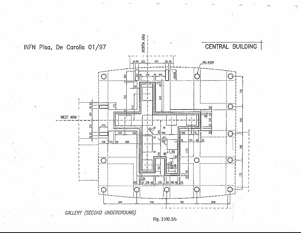
The foundations of the experimental halls (fig. 2100.2/a) consist of large drilled piles (Q1200 and-30 m long) resting on the gravel layer. Such deep piles are necessary to guarantee therequested stability t_o inclination and not to avoid subsidence lowering. The piles support astrong concrete platform; on this platform rest the vacuum tanks. Under the main level there is abasement level, the "gallery", allowing to access the tanks bottom, rvhere an aperture is locatedfgr. gptical_ equipment introduction; the gallery stru*ure further contributes to the platformrigidity..-Thep)atform supports also the upper part of the experimental halls, composed by avery stiff and light steel ttructure enclosed between two rvalls, made of a metal slieet/theriralinsulation sandrvich. The hall structure has been designed in order to be free of high Q-factormechanical resonance, belorv 7.5 Hz, since in thii frequency range the SA peiformancesbecome poor.
Most of the volume of the experimental halls is fully open, only a fraction of it, close to theouter walls, is subdivided in laboratories of standard height.
2I.2 Central area buildings requirements
2t.2,1 Central and M.C. buitding requirements
. Jlt. experimental halls of the "central area buildings" (central building and mode cleanerbuilding) have to satisfy the requirements figured our fr6m the indications 6f the involved sub-system. They shall be characterized by :
- absence of high Q-factor mechanical resonance- seismic noise less than 10'6/vz mHz-tn
FINAL DESIGN REPORTDoc: VIR-TRE-DIR-t 000-13Issue: I Date: 0l/05/97Sy:2100 Page: 2
- controlled temperature inside the experimental halls :22_2oC C|BC)- controlled humidity inside the experimental halls : 55 !5Vo- low dust level (overpressure 0.3 mbar)
In addition they shall provide :
"Clean rooms" for Laser and Optic Laboratoriesa gallery for mirror installationa crane 5t (13000 mm minimum free distance from the floor)distance from the floor to the tube axis : 1100 mmrelative displacement of super attenuator suspension points : less than 1 cm in 20 years(rBc)emergency generator unitUPS
2L.2,2 Control bui lding requirements
The control building has to satisfy the following requirements :
contain a data acquisition room with cooling air and double floorcontain a computer roomcontain a meeting room for minimum 50 peoplecontain some officeshave an e_mergency generator unithave UPS
2L,3 Buildings and Equipment Description
21.3.1 The central building
This building covers an area of 26x30 m2 and has a useful height of 15 m, to allow to lift upthe upper parts of the vacuum tanks and to make accessible the pendulum chains. (figs.2100.2).
The platform on which rest the vacuum tanks is stiffened by the double concrete wallconstituting the perimeter of the main level (the level containing the axes of the interferometer).
Inside there are the gallery, in the basement (fig. 2100.21a), and laboratories organized inthree levels. Following the description of the site vertical profile, the gallery and the first levelare underground; the first level is also called "main level" since it contains the plane defined bythe interferometer bearns, running at 1.1 m above the floor.
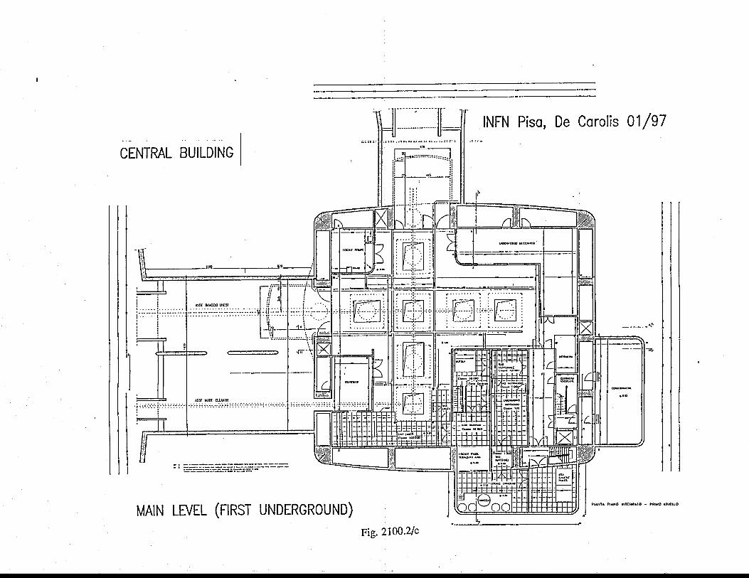
At the main level of the central building (fig. 2100.2/c) there are seven towers arranged as across, with the beam splitter tower at the center. In the South part of this floor, there are theclean rooms, one for-the laser installation and the other for the optical parts assembly. Astaircase and an aperture in the floor allow to bring to the gallery (tig. 21,00.2/b) clean opticalparts, rvhich will be installed, from below, in the towers. For thii purpose, also the gallery is aclean room, supplied with clean air through the towers.
At the mainl6vel there will be also : the large valves connecting the towers to the arm tubes,the large primary pumps for the arm tubes andthe laboratory to as-semble the SA chains. Insidetlvo volumes prbtrudiirg out of the rectangular shape of the building, there are the clean airgenerators, anbptical and mechanical parts washing chain and the air cbnditioning machinery. --
In the floor, -along
both sides of tfie tower crois, there are cable passages for porver andservice cables. Signal cables, coming out from the towers at 2.5 m hbight, reach the read outelectronics, at the upper floor, on aerial cable trays.
FINAL DESIGN REPORTDoc: VIR-TRE-DIR- I 000- I 3Issue: I Date: 0l/05/97Sy:2100 Page: 3
At the large valves location, suitable apertures are available for tower bases and valvesinstallation. The connection betrveen the central building and the tunnels is made throughtransition rooms containing auxiliary equipment for the large valves; the transition room torvaidthe West arm makes the connection also to the mode cleaner tunnel; it is therefore quite largeand rvill be used for storage.
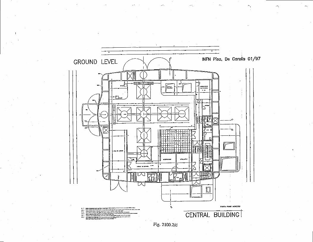
The personnel and truck entrances are located at the upper level (fig. 2100.2/d), coincidentwith the outer ground level. The truck entrance is closed and its removable roof will be openedto access the load with the crane, only after stopping the truck engine and waiting foi dustdepos.ition. People coming in through the personnel entrance rvill either stay in the receptionand visiting gallery zone or enter the laboratory zone after changing shoes and dress.
The data acquisition room is located at this level; in this rvay the signal cables come out ofthe tolvers at about the same height of the double floor of this room. Through the double floorcomes also the cooling air flow for the electronics racks. On this level there are also theelectronic workshop and the toilets.
The upper and last level of the central building has a surface of about 150 m2, divided inseven offices.
Five ton cranes rvill be available to-assemble or disassemble the vacuum tanks and thependulum chains; movable rented cranes will be used for the installation of the base of the tanksince these pieces have a weight much larger (up to 20 ton) than atl other pieces. All the innersurfaces accessible by the crane rvill be used as storage space for parts of the towers and otherequipment.
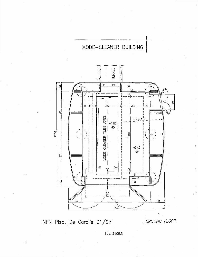
2L,3.2 The mode cleaner bui lding
. This building covers an area of 8x10 m2 (fig. 2100.3). It is only 10 m high since it containsa small tower with a simpler SA. The tower position can be adjusted by +l-2.0 m along themode cleaner beam.
Very little assembly space is required, since this hall is located only 140 m apart from the. central hall, where the necessary technical facilities are available.
Five ton cranes will be available to assemble or disassemble the vacuum tanks and thependulum ehains; movable rented cranes will be used for the-installation of the base of the tank.
21.3.3 The mode cleaner tunnel
This tunnel (fig. 2100.4) is parallel to theWest arm and has a smaller cross-section withrespect to that of the interferometer tunnel, since it contains a much smaller vacuum pipe (0.3 mdiameter) and , being only 140 m long, does not contain pumps.
It is founded on piles, 32 cmin diameter and 26 m long, driven in the ground. Every 15 mthere are two piles joined by a rectangular cap. The tunnel floor and rvalls are realized rvith asingle concrete beam resting on the caps. The tunnel cover is a light one, made of sandwichplates (metaVinsulation/metal).
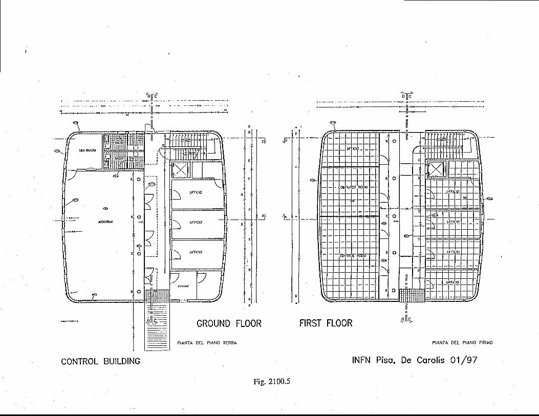
21..3,4 The control building
This building (fig, 2100.5),located in the central zone, has a surface of 280 m2 and is trvofloor high.
At grbund floor there are : a 50 people meeting room, the guardian room, some offices and asmall cafeteria. At first floor there are : the control room of the rvhole experiment, the computerroom and some office space for people in shift.
Control and computel room aie equipped with a double floor for cable passage and coolingair flowing to the elictronics racks.
' ' '

FINAL DESIGN REPORTDoc: VIR-TRE-DIR- 1000-t 3Issue: I Dare: 0l/05/97Sy:2100 Page: 4
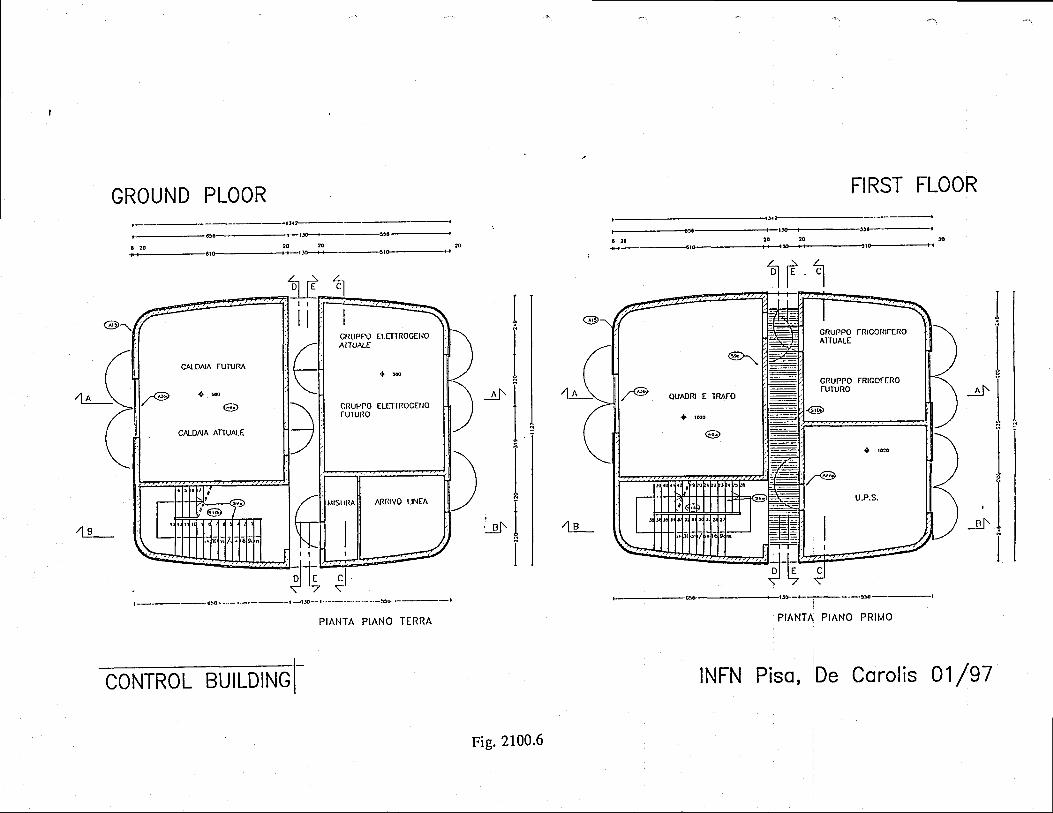
2L.3.5 The technical buitding
The technical building (fig: 2100.6) contains the electrical power station and rheclimatisation plant for the central buildings. It is siruated at the borde? of the cenrral zone, inorder to be easily reached for inspection and fuel supply. The building is divided in trvo halves,rvith two floors each. It contains : at the ground floor, the connection to the 15 kV porver line,the. diesel generator and the hot rvatei generator; at the first floor, the transf6rmers, theUnintemrpted Power Supply (UPS) and the water pumping units; on the roof, the chilled watergenerators. The water at the.proper te-mter.qt_qre, agto.q{lng to the season, is brought viainsglqqedpiping to the heat exchangers of the different bu[{ing5_of ttre central zone.
21.3.6 Electric po\yer supply
All the Virgo electrical network rvill be connected to the italian electricity company (ENEL)pedi.gm- voltage ggt-woik (tf kV) by a station located in the technical buildi-ng.'The totalinstalled power will be 1100 kW and includes : illumination (inner and outer), air c-onditioning,rvhite rooms, cranes, rvo_rkshops, vacunm pumps, electronics and compuiers. A distributio-nline will deliver ttuough five local transformbrs low voltage power (3801220 VAC) to rhe finalpanels.
In the central area rvill be installed a 600 kW transformer. Audliary porver supply areforeseen for short and long break-downs. The Uninterrupted Porver Suppiy ruPS)'ioi fastinterventions to keep- w_orking computers and electronics-(l50 kW, lasting-15 minutes) anddiesel generators (IPS) for long term emergency power supply (250 kW).. __Only.the totvers (TBC) rvill be connected to the generaf power supply to be baked-out (30JcW each).
2L.3.7 Service f luids
' There is one water circuit, for bathrooms, cleaning and general purposes. Bathrooms withshowers will be sufficient for a 20 working persons bccupancy in ihe central and the controlbuilding; fgl -t-O persons in all other buildings. During coistruction phase, auxiliary serviceswill be available in trailers.. .Cooling vater,.for laser and vacuum pumps, will be produced locally in the experimentalhalls with closed circuit cooling systems.
. Compressed air will be available only for vacuum vaives actuation and for tool powering. Inprinciple-compressed air for cleaning purposes will not be allowed, to avoid dust-propagation.Suitably large air reservoirs rvill be piovided, in order to provide buffers for emeigeicils andto let the compressors work at long intervals and at controiled times.
An integrate vacuum cleaner system could be installed in each experimental halls (TBC).
21.3.8 Control cables
. .Signals coming from every part of the set-up will converge, along the tunnels, in the centralbuilding for local use and/or to be sent to the control building. It-is foreseen to have a fewhundred cables or fiber optics from each arm, demanding for a cross-section of the order of100-200 cm2 on the cable travs.
The infrastructure_will provide the dedicated cable trays located at the right distance from thepowgl cable ones. In addition, the trvisted pair cabl-es, but not theirlnstallation, will beprovided.
2L.4 Interface
The "central area buildings" sub-system interfaces with many other sub-systems, due to itsfunction to accommodate many experimental facilities of Virgo.
In particular it interfaces rviih : '
FINAL DESIGN REPORTDoc: VIR-TRE-DIR- I 000- l3Issue: I Date: 0l/05/97
:2100 Page : 5
building.
FIGURE CAPTIONS
totver sub-system mainly for the torver installation, the hall temperature, totver
installation, theoperation (porver supply, cooling water, compressed air);super-attenuator sub-system for the filters washing machine, thestability of the suspension point, the S.A. operation;pumping sub-system for the installation and operation of tower pumplng units, tuberough pumping and venting (power supply, cooling water, compressed air);tube sub-system for tube terminal parts and related large vacuum valves;electronics sub-system, for the accommodation of computers and cabling necessary todrive Virgo and to record the experimental data (two different areas); in particular thetwisted pair cables will be furnished by infrastructure but the installation is in charge ofthe electronic sub-system;clean areas sub-system for the clean areas rvhich will be lodged in the central building;tunnels and terminal buldings sub-system, regarding the tunnel linking to the central
2 1 0 0 . 12t00.2
2100 .32t00.42100 .52100 .6
Arrangement of central area on Cascina siteCentril experimental hall; a - vertical cross-section; b - gallery (second underground);c - main level (first underground); d - ground levelMode-cleaner buildineMode cleaner tunnel iross-sectionControl building; a - ground floor; b - first floorTechnical buildTng; a'- ground floor; b - first floor
=tr
JO
ct
-.<
, s
:3
o*
3
!K
Z.
rh
-9
',
O
-
Z
=Y
A-
60
7
0
6z
E=
.- i2
r.6;
/
-
=c
:
65
)
- *
,u
-
F
-
(o
# 2
6 F
: E6
=
<.
N
F
!-
V
46
4 P
E"
-F*
N
=V
.
?3
8>
^t
!v
ll
li
E
z
=a
g
f,58
=
2
zz
dl
-
SH
F=2
.a
frz
c\fr
roo.doLouUIuJEU=uIJuFU-ozoqq
\I\\\\\\\

II-
lIlIr\o)o.9ooC
)c)oc,.ao-z.l.l.
=
c\l
otbolr
| !l
t;
tt r
tt
lt
tt
tt
t
c)z.oJ=co&FzLdc)
(Jz.o5mEFzIJc)
6l
ol
*i "r*
EOtffi==I\s{I
6
r\o)c).9ot-oOa)o(f
.9o_z.l!z.
r\O)
O.9ot-(fOc)o('.9
,o-z.t-t-z.
oorNlr.
az.=O(9IJoz.FU)
E.
GJIJLIJ
z.
(J:
2,
:6J=
:G
t
<E.
,Fz.
, lJ.J
:(j)
s
oeooc)c)c)oct,(Lez.
C\
C\bo
fr
IIII!,iiiii!iillrlrti!i!iililri IIIIIIItIIi
iiriiiiliii
iiiiiiiiilliillltliriiril:l
iliiiililtIliltiililt
JLdIJJOz.:)oEc)r
ltll
MODE-CLFANER BUILDING
Il l
l r l
z.l z .l : )
F
- - - i
II
III- l
Iol
II
III
E2:,+-IIIIl /
i /I tt rt \IIIII
+ 5 4 n I
/ d l
' |tI
I
I
I
I
aI
- - - l - - - - J /
8l /
Iau J l> < l
[ d l( D lf 'F-
o < lL J Iz.f i rJ IC)
L J Io lo
II
|---r---------- ',;----.----,-" "l
INFN Piso, De Corol is 01 /97
I
GROUND FLOOR
Fig. 2100.3

I
MODE-CLFANER TUNNEL
Fig. 2100.4
I------=rN T
l l| 1 R 0 || ------------:::-------;t - l
-]-l o 0
II
ot^ - | ' )<L L V - I L J
oN
?o
rd
\
ts
oi
@
tot-oO0)ooao-z.L.z.
\nC\l
bI)?
i .
E.
oOJL.F(/')EtLE
,ooJb-o
fi
LJZ
OF
E,
C)
Ets
o, .ii-*t,--E-*.--;;-..----1;--f
il+..-.:-----;*
r,,-.--r
,<.+
.-*#l..<
.-.,+..*o
-;;j-r,q,-.,-
6
to
a
oz.6J)TD
Jot'-zoO
r\O)
\\.
Oeo
O
FOC)
ozLO
Fzso
o-
.9,
o-z.t-t-z.
E.
oob-FaE.
E
oNc0
t!
OJmJOuFzOO
E.
OOJo-oz=OE(9
I+o
-
go
YY
LL
9q
9
0s
a
L=
2/
:=o
<
ou
/A\,,Y
\y
9FT
A-
pv
E!+
r},t?
i\
z=
UU
=x
5s
=;
.F
j+
d
?L
.t 9
0F
<
IE
tF
i<iJ
<
sL
3u
r i:\
--
L-
i5
<F
.+
=
f<

FINAL DESIGN REPORTDoc: VIR-TRE-DIR- I 000- I 3Issue: I Date: 0l/05/97Sy: 2200 Page: I
22. Clean Areas
22,L Clean areas function and concept
The clean areas of Virgo are the rooms, plants and all the necessary equipment rvhich shallallow to assembly and to install the cleah optics in the correct 6nvironment. The cleaninstallations can be roughly divided in tw_o types : the clean laboratories and the systems topro.vjde. filtered.air to the.towers during the installation of the clean optics. Both aie locatedinside the buildings.containing_th_e towers and rvill be realized following the results obtained inthe p.rototype installed in^LAPP. During.integration and operation the c-leanliness, temperature,fumidity and pressure of each room rvill be strictly controlled. The laboratories accesi will belimited to the personnel in-char.ge of specific opeiations. During scientific operation the cleanrooms may be shut down if no intervention on the payloads is foreseen.
22,2 Clean areas requirementsThe clean areas have to satisfy the requirements schematically listed below.
o General requirements :-avoid mechanical vibration sources-avoid acoustic noise sources
o Class of cleanliness :- Galleries :- Optic laboratory :- Laser laboratory- Benches laboratory- Towers
o Temperature
- Galleries :- Optic laboratory:- Laser laboratory- Benches laboratory- Torvers
. Humidiry
- Galleries :- laboratories- towers
not classified100 ooerational100.0'00 at rest10.000 at rest (below the filter)100
not classified20" c22" C22" C20'c
not classified52+ 3Vo
52+ 3Vo
22.3 Clean areas descriptionThe "clean areas" consist of 5 plants, complete of filters, conditioning system, electrical
power, etc. They are :- the laboratories plant in the central building
FINAL DESIGN REPORTDoc: VIR-TRE-DIR-1000- l3Issue: I Date: 0l/05/97Sy:2200 Page: 2
- the towers and gallery plant in the central building- the mode cleaner tower and gallery plant- the North terminal torver and gallery plant- the West terminal torver and gallery plantEach of them has the cleanliness class listed in the requirements part. The adopted
technology to realize them is a standard one consisting of lining the rvalls with proper materials,using double floor and roof, filtering and recycling air, controlling temperature, humidity andoverpressure.
The accessories as dresses, special shoes, gloves, etc. are part of the sub-system.
22.3.1 The laboratories in the central bui lding
This plant includes the clean optics assembly laboratories, the laser laboratory, the benchespreparation laboratory, the washing faciliry room (fig. 2200.1). The laboratories rvill beaccessed through trvo different intermediate rooms (SAS) respectively for people and materials.The laser laboratory rvill be accessed from the tower hall; an additional door is foreseen incorrespondence of the benches laboratory. The optic laboratory has an additional SAS forpersonnel. The torver gallery is accessed through a staircase and a rapdoor, respectively for thepersonnel and the materials, located in the central zone of this group. A crane to lift up andbown the materials is located near to the trapdoor. Next to malerial SAS there is a washingfacility room. The rvater cooling and heating units are installed in the technical building, inorder to avoid the mechanical vibrations and acoustic noise in the central building. Only the airtreatment unit is located in the central building, next to the laboratories.
22.3.2 The-towers and gallery plant in the central building
This plant provides the clean air to the towers and the belorv gallery. An air flow of 1200
m3ht will be provided to each torver via a Q 200 rnm port. In the gallery, an additional air flow'of 1200 m3h'r rvill be fed horizontally to each tank access. The gallery will be equipped as aclean area but not classified. During tlie optics installation, the tan[ access will be c-onfihed witha tent. Not more than two towers witt Ue fed contemporary.
The water cooling and heating units are the same used foi the clean laboratories plant. Theair treatment unit is locate insidelhe tower hall, upon the "pumping storage room". Both flowswill be extracted at the end of gallery and than recycled.
22,3.3 The tolvers and gallery plant in the mode cleaner building
This plant will be used only for the mode cleaner tower and is completely independent. It
will provide only an air flow of 1200 m3h't to the torver via a Q 200 mm port. The air florv willbe extracted via the gallery and then recycled. Since this equipment is small, it will completelyinstalled in the mode cleiner building. The gallery rvill be equipped as a clean area but notclassified and accessed via a movable SAS, located on the ghllery, to allow the towerdisplacement.
22.3.4 The tolvers and gallery plant in the terminal buildings
Thisplant is essentially of the same type described in2200.3.2, but rvill provide only onetower.
In addition only one small clean laboratory in each terminal building is foreseen (TBC). Insuch small installation the same water cooling and heating units rvill supply the air treatmentunits for the tower and the clean laboratorv.

FINAL DESIGN REPORTDoc: VIR-TRE-DIR- I 000-13Issue: I Date: 0l/05/97Sy:2200 Page: 3
22,4 Clean areas interfaceThe interfaces essentially concerns the central area building, in rvhich the clean areas rvill be
Iocated, the laser sub-system -for the laser .operation, torvei sub-system for the clean opticsinstallation and the netrvork sub-system for the communication.
FIGURE CAPTIONS
2200.1 Clean laboratories in the Central Building
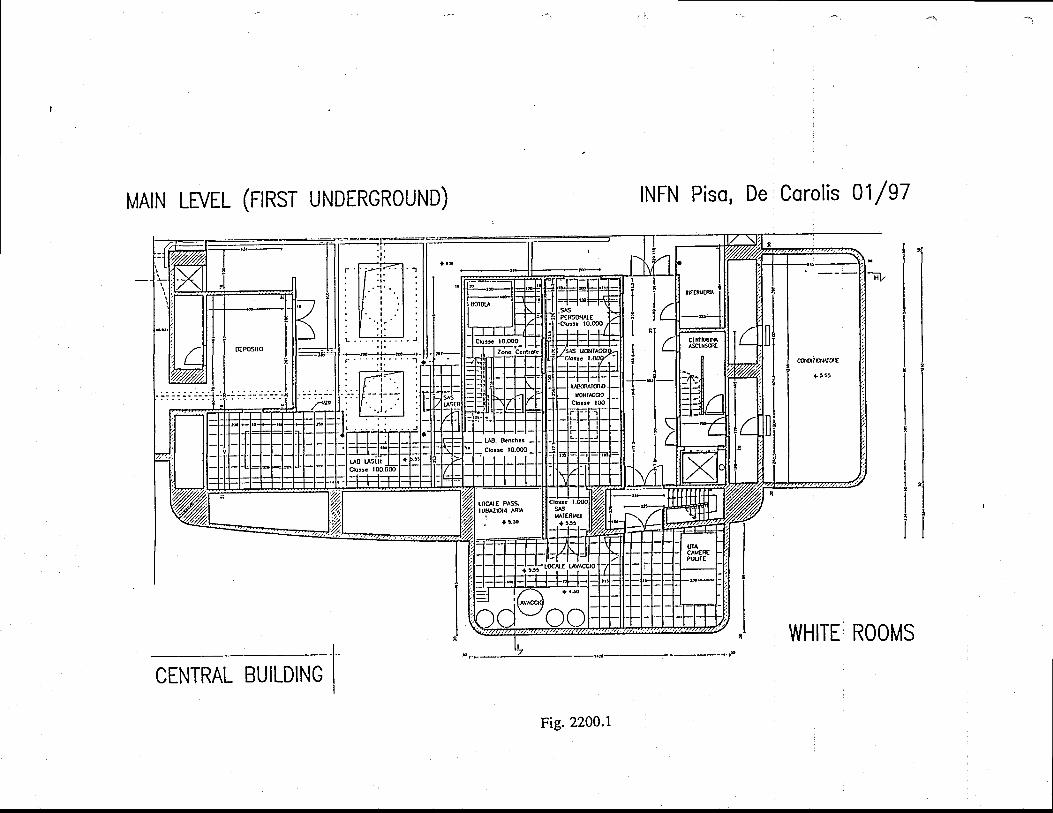
c.lNbol
t.
(,z.OJ=mJuFztJ'J(J
aOOEIJF=
O)
O.9,
oC)
c)c.)oC
)@Liz.u-z.Oz.=OE
.(9E
.LrJOz.=aE
.c;l!LLI
z.

FINAL DESIGN REPORTDoc: VIR-TRE-DIR- I 000- I 3Issue: I Date: 0l/05/97Sy:2300 Page: I
23. Arms & terminal buildings
23.l "Arms & terminal buidings" function andconcept
The 1.2 m diameter vacuum pipes, containing the beams of the interferometer, will beinstalled igti9" a protection structure, the "tunnel", containing also all the cables connecting thecentral building rvith the terminal ones. The beam tube axis is at 1.45 m above tunnel floor.
Tq$ng into account the nature of the ground, as described in the geology section, the tunnelcould lay directly on the ground, since the expected subsidence iitowei than the marimumtolerable displacement. In order to obtain perfectly straight arms and the correct slopes from thetunnel toward the sides of the land strip (this is necessary to collect water into the-lateral drainchannels a-nqlq improve the environmental aspect),,the top ground layer, l-2 m thick, will berearanged. This could producelocal ground disuniformity or compression, demanding deeperf.oundation resting o-n undisturbed grould layers. All the tube supports will be positioneddirectly ol lhe tunnel foundation.points. The movements of several pbints of the tunn-els will bemonitored in order to plan, if necessary, the re-alignment of the tube. Global rigiddisplacements preserving the complanarity of the apparatus will be neglected. The position-ofthree points, necessary to define the directions and the lengths of the interferometeiarms, can.be easily determined with "standard" techniques, rvith a I cm error in three coordinates; this islargely sufficient for VIRGO. GPS systems, allorving relative precision below 1 cm, will beused for all alignment and positioning purposes.
The tunnels connect the central building with the terminal buildings, rvhich are located at the. end of each arm and contain the terminal towers. They are similar to the central building, butreduced in surface, since each of them contains only one tower. To avoid mechanical vibrationsall equipme-nt containing motors or moving parts (pumps, air conditioning, laser powersupplies and cooling, etc. ) rvill be mechanically isolated or confined rvell outside the buildings.The foundations have to guarantee the requested stability to inclination and not to avoidsubsidence lowering.
At the middle of each arm a building dedicated to the tube assembly is located.
23.2 Arms and terminal buildings requirements
23,2,L Tunnel requirements
The tunnel requirements, figured out from the indications of the involved sub-system, areschematically listed below :
- location as far as possible arvay from main roads, trains, etc.;- distance from farm houses more than 50 m- vertical displacement of any pipe cross section :
less than 0.5 cm Der monthless than 1 cmpeiyearless than 15 cm (relative) in 20 years
- lateral displacement less than * 5 cm total (in 20 years)- correction of earth curvature- alignment of tunnel floor better than I cm on 15 m- minimum inner width 5m (TBC)- minimum inner height 3.0 m (TBC)- foundations every 15 m

FINAL DESIGN REPORTDoc: VIR-TRE-DIR- I 000- I 3Issue: I Date: 0l/05/97Sy:2300 Page: 2
- doors to enter every 300 m (TBC) in correspondence of the pumping stations (TBC)- tube axis distance from the floor 1450 mm;- aerators to evacuate 0.4 kW per meter of pipe (TBC)- supply of 10 kW - 380 Vac each 300m- supply of 10 kW -220Yac each 300m- service road along the tunnels- minimum height of bridges 3500 mm (TBC)
23.2.2 Terminal building requirements
The terminal building requirements, figured out from the indications of the involved sub-systems, are schematically listed belorv :
. Same general requirements as the Central Buildingr Independent emergency electrical generator unit. IndependentUPS
23,2.3 Assembly building requirements
The assembly building requirements, figured out from the indications of the involved sub-system, are schematically listed below :
- allorv the storage of some insulated tube modules ready for installation;- accorrmodate a test bench for the tube modules;- be connected to the tunnel;
r - provide for the tube modules an easy access to the tunnel;- allow the storage of tube supports, vacullm pumps and accessories;- lodge an emergency electrical generator- have an emergency generator unit
23.3 Arms & Terminal Buildings Description
23.3.L The interferometer tunnels
The tunnel, designed above ground, has the cross-section shorvn in figure 2300.1, with-aninner height of 3.0 m (fgC) and an inner width of 5.0 m (TBC). These dimensions are neededfor instafation and replacement of the vacuum pipe elements (as described in the relevantsection), of the relative pumps and of the tools necessary for baffle installation. The passage fora man has to be easily allorved at any moment, for survey and maintenance purposes.
Hence, every 15 m, there are trvo piles, 32 cm in diarireter and24 m deep, joined by a singlerectangular capital. The tunnel flooi and wails are made by a single contrete beam, pouredcontinuously on site, resting on the capitals.
The desilned structure does not suifer resonance problems, due to the great dumping effectof the grouid. This avoids vibrations that, transferrbd to the pipe, could:modulate the cavirybeams,-through the diffused light phenomenon. Residual os-cillations of the structure have,anyway, linlJrelevance, since itre tirbe supports rest on the capitals, directly connected to thepiles, hence to the ground.-
The tunnel floor-will be aligned to better than 1 cm on 15 m, correcting for earth curvature'The floor rvill be smooth enorigh to allow the displacement of pipe elements from the assemblyhalls to the installation point, using suitable trolleys, guided by rails.
Doors to enter the'tunnel are-foreseen every 3b0 m ITBC;, in conespondence of thepumping stations. On the wall opposite to doors-there are cable trays for power and controlcables and fluids.
The tunnel cover is a light one, made of curved sandrvich plates (metaVinsulation/metal)similar to those used for the outer walls of the buildings.

FINAL DESIGN REPORTDoc: VIR-TRE-DIR- | 000- 13Issue: I Dare: 0l/05/97Sy: 2300 Page: 3
Aerators rvill be installed on tunnels roof, to evacuate the heat produced during vacuum pipebake-out.
23.3.2 The terminal bui ldings
At the far ends of the trvo arms, trvo smaller experimental halls contain the end minors ofthe interferometer inside their vertical vacuum tanks.
The terminal buildings (ftg. 2300.2) have a structure very similar to the central one, butreduced in surface (15x22 m2) becalse they contain only one tower; the height is the samesince the terminal torvers contain a full size SA chain. Inside there is one innerhoor, equippedwith a clean laboratory, and a gallery. The temperature is controlled to +/-2 oC and frumiOily iskept .?t 55 +l-S%o, The inner volume is kept in overpressure rvith respect to the outside
-and
supplied only rvith filtered air, in order to be free of dust.Five ton cranes will be available to assemble or disassemble the vacuum tanks and the
pendulum chains; movable rented cranes rvill be used for the installation of the base of the tank.
23,3.3 The pipe assembly t "it,
A vacuum pipe assembly hall will be built in the middle of each arm of the interferometer.The covered area rvill be 20x50 m2 (TBC), rvith an useful height of 8 m. Trucks coming fromthe p-ipe factory will be unloaded in the delivery zone and the incoming vacuum pipe el6mentsrvill be stored in the storage area (fig. 2300.3).
The preparation zone is a clean area where the pipe elements rvill be prepared for installationand mounted on suitable trolleys to be brought in position, along the turinei.' One 5 ton craire rvill serve the delivery and preparation zones.
23.3.4 Electric poryer supply
The electrical porver distribution along the arms will be achieved rvith trvo separate netrvorks: one for installation and normal operation and one for bake-out of the vacuum Eystem (TBD).
The medium voltage network (15 kV) rvill be connected. to the technical building in thecentral area. A distribution line rvill deliver, through local transfonners, 100 kW in eaCh of thetube assembly zones and 150 kW in each of the terminal zones.
The total installed power includes : illumination (inner and outer), air conditioning, rvhiterooms, cranes, rvorkshops, vacuum pumps, electronics and computers._ - +" emergency generator unit (IPS) is foreseen for terminal and assembly buildings. TheUninterrupted ^Power Supply (UPS), for fast interventions to keep rvorkin! computars andelectronics, is foreseen only in the terminal buildings.
23.3.5 Serv ice f lu ids
From the central arca the water will be sent to the assembly building and to the terminalbuildings. There rvill be one water circuit for bathrooms and Cleanin.s pumoses. Toilets andshowers will be sufficient for 20 people for the assembly hall and 5 peofte in the terminalbuildings. During construction phase,'auxiliary services tiray be made'avaitable in trailers ifnecessary.
Cooling water, for vacuum pumps, will be produced locally in the terminal buildings andtunnels with closed circuit cooling systems.
In the terminal buildings compleised air will be available only for vacuum valves actuationand for tool porvering. In the teiminal buildings a suitable air r6servoirs rvill be provided, inorder to provide buffers for emergencies and to-let the compressors work at long intervals andat controlled times.
In the assembly building compressed air will be available for many purposes.
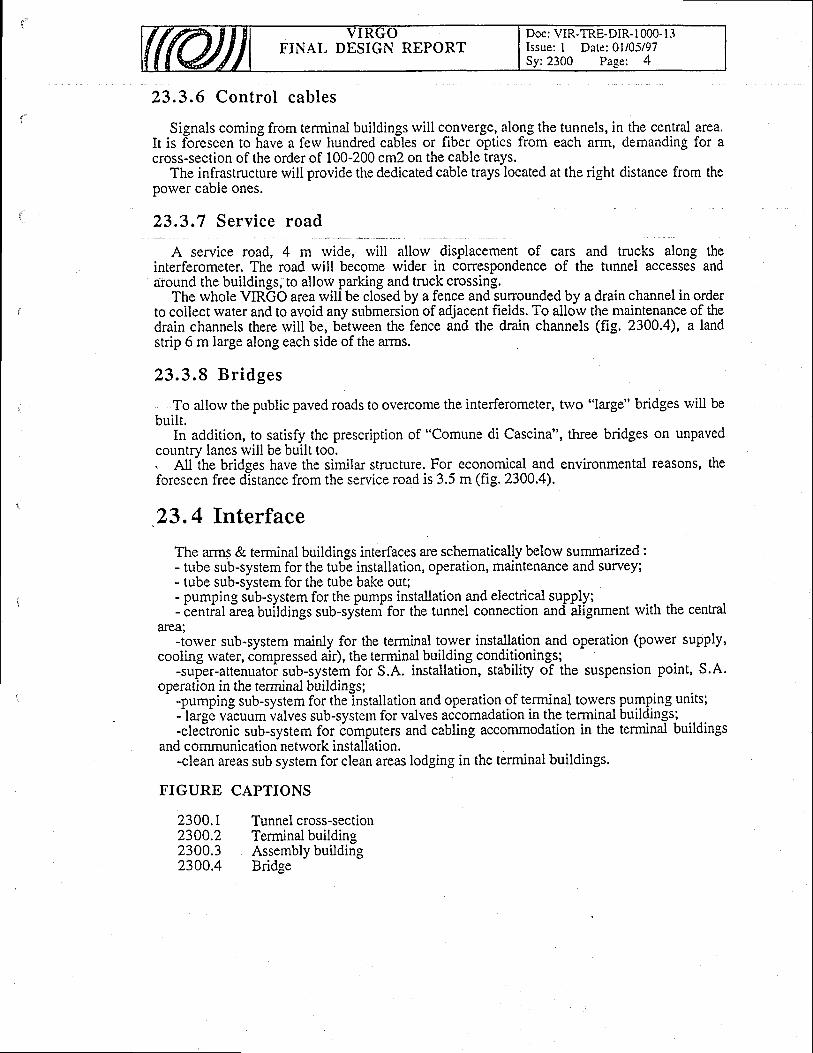
FINAL DESIGN REPORTDoc: VIR-TRE-DIR- I 000- I 3Issue: I Date: 0l/05/97Sy:2300 Page: 4
23.3.6 Control cables
Signals coming from terminal buildings rvill converge, along the tunnels, in the central area.It is foreseen to have a few hundred cables or fiber optics from each arm, demanding for across-section of the order of 100-200 cm2 on the cable trays.
The infrastructure will provide the dedicated cable trays located at the right distance from theporver cable ones.
23,3,7 Service roacl
A service road, 4 m rvide, rvill allow displacement of cars and trucks along theinterferometer. The road rvill become wider in correspondence of the runnel accesses andaround the buildings, to allorv parking and truck crossing.
The whole VIRGO area will be closed by a fence and sunounded by a drain channel in orderto collect rvater and to avoid any submersion of adjacent fields. To allorv the maintenance of thedrain channels there will be, betrveen the fence and the drain channels (fig. 2300.4), a landstrip 6 m large along each side of the arms.
23.3.8 Br idges
To allorv the public paved roads to overcome the interferometer,two "large" bridges will be
, three bridges on unpaved
environmental reasons, the
of "Comune di Cascina"
. Atl the bridges have the similar structure. Forforeseen free distance from the service road is 3.5
23.4 Interface
The arms & terminal buildings interfaces are schematically below summarized :- tube sub-system for the tube installation, operation, maintenance and survey;- tube sub-system for the tube bake out;- pumping sub-system for the pumps installation and electrical supply;- central area buildings sub-system for the tunnel connection and alignment
area;-tower sub-system mainly for the terminal tower installation and operation
buil t .In addition, to satisfy the prescription
country lanes will be built too.economical andm (fis. 2300.4).
and communication netrvork installation.-clean areas sub system for clean areas lodging in the terminal buildings.
FIGURE CAPTIONS
2300.1 Tunnelcross-section2300.2 Terminalbuilding2300.3 Assembly building2300.4 Bridge
with the central
(power supply,cooling water, compressed air), the terminal building conditioninqs;
-super-attenuatoi sub-system for S.A. installation, stability of the suspensionoperation in the terminal buildings;
-pumping sub-system for thelnstallation and operation of terminal torvers pumping units;-pumplng sub-system tor the rnstallatlon and operatlon or terrrunal towers pumpll--large vacuum valves sub-system for valves accomadation in the terminal buildin- large vacuum valves sub-system tbr valves accomadatton m tne termrnal bullomgs;-eleJtronic sub-system for iomputers and cabling accommodation in the terminal buildingsI communication netrvork installation.
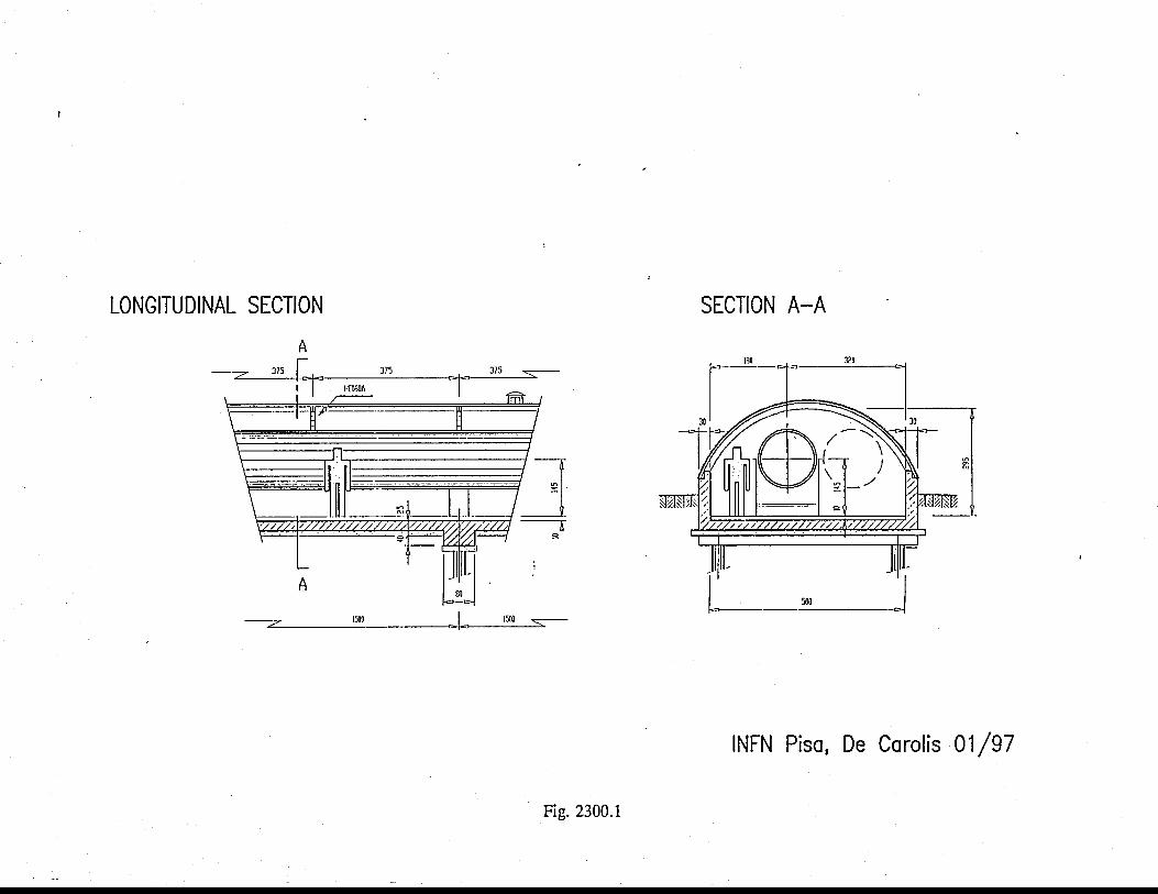
r\CD
Oeot-c'C
)c)ao.9
.o-z.L-z.
coc\lbofa
!
z.oFC)
l!U)
Jz.o=F(9z.O-t
\ j,,t"
or
\J
y''-:
I l\\
t\
\=
l \\
=l
\t
Iz.OF(-)LdC
J)

on{,d
o
o-
-o
abo
10
tLo
7-o
c\l
coC!bo
lf
#idlr
'.|.
I \. l'rlr
\|
' t\
|"
.t
'L
-' \.1
.. i'..l| \l
1..
:/El
(,-l P N
:.llll l{J
| \
'/trl=tt
\15
t\H
\I \F
RI
. ..
1
t'. \
r " .l'\
l
\
lr
1., i _
'i
t]5Fi\5
l-{j'l€
iLl+\u
ul,
.l ''.t,
f.
i t
'.i\r
('tgo
>
oo
rE
g6
k
tr, o('|<<
J
Ir'..
\l \,
t.\t
.Ll'-
N-
rl '.l
r%%
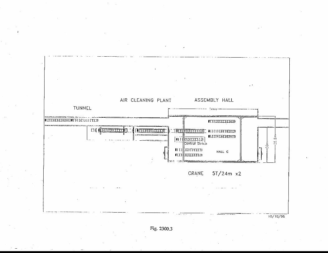
II
c\xE!'NFLO
t.
t
z.ECJ
JJ-Jmtrl(nv1
cfl
c.lc{co
Fz.Jn()z.zlJJJOfYa
Itst tT
t t5
U
l+l U
lh+
l,'{ }il
qlhl
li.i l.i.i 4
L.l i-.1
l.ll':I
- r:
h
Fr
-?
r: :-r 5
tr
I
I-l
tHl
tEsl
tHl
tffiltH
lrE
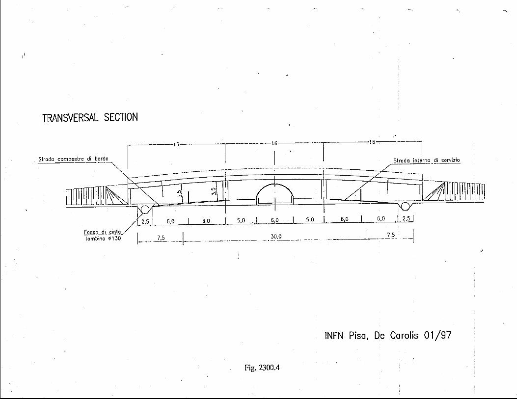
r\O)
Oaot-C'
Oc)oo.9
,o-z.b-z.
c!
IIIIIIIt-
$eocrlbo
!l
ll
it
tl
IiII.
tIIIIIItIIi
- |
-;t-
lr
-l
- I
':1FtF:
z.OFCJ
t!U)
JV)
]-rJ
azE

FINAL DESIGN REPORTDoc: VIR-TRE-DIR- I 000- l-3Issue: I Date: 0l/05/97Sy:2400 Page: I
24. Miscellaneous equipmentTo complete_ the infrastructure of Virgo, some additional equipments are needed. They are
summarized below.
24.L.L Set of electr ical equipment
The terminal and assembly buildings will.be-porvered with the medium voltage (15 kV) byan underground line connected to the technical building in the central area. Tfus installatioirinvolves the following set of electrical equipments :
- two terminal power stations- two middle power stations- 15 kV porver line along the arms .
24.1.2 Outer l ight ing plant
The central area and arms of Virgo rvill be provided by an outer lighting plant. Theconsistence of such plant has to be defined (TBD).
24,1,3 Security system
The buldings and the tunnels of Virgo rvill be provided rvith a security system. Theorganization of this system has still to be defined.
{ftu) V I R G UFINAL DESIGN REPORT
Doc: VIR-TRE-DIR- I 000- I 3Issue: I Date: 0l/05/97S/Sy: 3000 Page: I
30. VACUUM
Table of Contents
30. VACUUM
i0. i Vocuum system deicr ipt ion30.1 .1Tubes30.1.2 Baffles30.1.3 Torvers30.1.4 Pumping system
30.2 Vacuum system requirements30.2.1 Bursts of molecules30.2.2 Fluctuations of the tube volume
30.3 References
30.4 Figures
. 31. Tubes "
31.1 Tube function and concept
31.2 Requirements appl icable to the tube31.2.1 Physics requirements31.2.2 Design constraints
31.3 Tube inter faces31.3.1 Tunnel31.3.2 Pumping system31.3.3 Input and terminal towers31.3.4 Light beams
31.4 Select ion of so lut ions3 1.4. I Historical background31.4.2 Final choice
31.5 Tube moi lu les31.5.1Int roduct ion31.5.2 The modules31.5.3 L ip jo ints31.5.4 Bel lows3 L5.5 Other components31.5.6 Rarv material31.5.7 Cleaning3 1.5.8 Thermal treatment3 1.5.9 Leak detection31.5.10 Connections to supports
31.6 Tube assembly31.6.1 Assembly strategy31.6.2 Interfaces and attachments31.6.3 Transport to Site
3 0 0 0 - I
3 1 0 0 - 1
1
A
A-A
5)
67
7
7
J
4i?
A
Aa
5)
71
71
6
888899
99
l0l0

FINAL DESIGN REPORTDoc: VIR-TRE-DIR- 1000- I 3Issue: I Date: 0l/05/97
31.6.4 Supports31.6.5 Bake out3 1.6.6 Thermal insulation31.6.7 Assembly31.6.8 Test of 300 m sect ions31.6.9 Leak and vacuum test of3 km tubes
31.7 Mode Cleaner Tube
31.8 Large valves
l i .g Rur" . . . , . . ,
31 .10 F igu res
32. Baf f les
32.1 Int roduct ion
32.2 Scattered l ight in the long cavities32.2.1 Position of the baffles - Number of baffles32.2.2 Stainless steel baffles32.2.3 Class baffles betrveen minors and large valves32.2.4 Diff r acti on effects
32.3 Scattered l ight and baffles in Central Area
32.4 References
32,5 Figures
33. Toryers
33.1 Speci f icat ion33. L l Experimental requirements33. 1.2 Technical requirements33.1.3 Contingencies and flexibil i t ies33.1.4 Summary and design guidelines
33.2 Vacuum towers design33.2.1 Rarv material and surface treatment33.2.2 Vacuum towers compartment structure33.2.3 Tower mechanical structure
33.3 Vacuum system real isat ion33.3.1 Lower torver33.3.2 Upper torver33.3.3 Central building vacuum tank33.3.4 Beam compartment baking33.3.5 Lower torver ground floor anchoring
33.4 Vacuum system clean access33.4.1 A continuous clean processing l ine33.4.2 Payload transfer system33.4.3 Component handling tools33.4.4 Optics installation scenario
l lI J
l 5l )
l 8l 9
t 9
2 0
2 0
2 0
3 2 0 0 - 1
3 3 0 0 - 1
7
z2J
J
Aa
66
6671
78
l ll lt2t3
1 3l 3I Al a
1 A
l 5
FINAL DESIGN REPORTDocr VIR-TRE-DIR- 1000- l3Issue: I Date: 0l/05/97S/Sy:3000 Page: 3
33.4.5 Cleanness monitoring33.4.6 Safety
33.5 Assembly sequences33.5.1 Lower tower reception33.5.2 Lower torver installation and linking33.5.3 Intermediate vacuum chamber installation33.5.4 Suspension installation33.5.5 About cleaning
33.6 Guidelines for space allocation around the torvers
33.7 References
34. Pumping system
34.1 Pumping system funct ion and concept
34.2 Pumping system requirements34.2.1 Cas pressure34.2.2 Pumping and venting time and speed34.2.3 Measurement instrumentation34.2.4 Dust cleanliness34.2.5 Life time
34.3 Pumping system inter faces34.3.1 Sources ofgases in the vacuum volumes34.3.2 Bake-out34.3.3 Connection ports of pumping system34.3.4 Pumping stations locations34.3.5 Environmental Constraint34.3.6 Pumping system control
34.4 Pumping system descr ipt ion34.4.1 Pumping system for tubes34.4.2 Pumping system for mirror tower34.4.3 Pumping system for single volume towers34.4.4 Pumping system for Mode Cleaner tube34.4.5 Pumping sers for multiduty34.4.6 Summary of the pumping system
34.5 Operat ion of pumping system34.5.1 Final pressure estimation in UHV volumes34.5.2 Search for leaks34.5.3 Running efficiency of the installation
34.6 Vacuum compat ib i l i ty34.6. I Approved components34.6.2 Temporarily approved components34.6.3 Rejected components34.6.4 Motors
34.7 Pumping system contro l
l 6l 6
l 6l 6l 6t t
t 7l 1
l 8
1 8
3 4 0 0 - 1
3
A
A
4)
556I
77R
8e
l 4l 8202 l
1I
2J
A
^5)
Doc: VIR-TRE-DIR- 1000-l 3Issue: I Date: 0l/05/97S/Sy:3000 Page: 4
FINAL DESIGN REPORT
30 . L Vacuum system description
The entire interferometer is put in vacuum in order to suppress several sources of noise,each one of them being strong enough at atmospheric pressure to prevent the observation ofgravitational waves. They are :
othe transmission of acoustical noise to the mirrors,. . the damping of the minor suspension and the corresponding increase of its thermal noise,
rthe excitation of minor motion by gas molecules brownian motion,.the scattering of light by residual gas molecules,rthe random fluctuations of the refractive index.This last one is by far the largest one related to vacuum. If one finds satisfactory conditions
for it, then all the other ones rvill be fulfilled. The fluctuations of the number of moleculescontained inside the volume of the light beam is the source of variations of the optical pathlength. These fluctuations may be produced either by the poissonian distribution of themoiecules in steady vacuum or-by the occunence of sudden bursts of molecules. In both cases,the effect is proportional to the polarizabilily of the molecules. In practice one expects tfledominant residual gas to be hydrogen which has a lorv polarizability.
In a steady vacuum, the poissonian fluctuations of the number of molecules within the beamare evaluated as if the ratio of the volume of the tube to the volume of the beam rvas infinity.The basic correlalion time corresponds to the time for evacuating the molecules thr-ough theboundaries of the beam (or to th-e reverse). It is 60 ps for hydrogen and 180 ps for watervapour. This is to be compared to 10 ps for the light transit time betrveen two minors andabout 500 ps for the light storage time.
The vacuum system consists basically of trvo tubes, each 3 km long, joined in an_Ir !!ry9,.containing the Udht beams and of ten t6rvers disposed as shown in fig. 3000.1 and 3000.2,containin! the aitiseismic suspensions of the optical elements. All the vacuum vessels are madein stainless..steel. Each tube and torver can be isolated from the connected elements by largegate valves (fig. 3000.2). The full volume can be divided in trvo parts: a ultra high.vacuu.m(UHV) volum-e, where itre tight beams run, and a high vacuum (HV) volume, where thesuspensions and other less demanding equipments are contained.
30 .1 .1 Tubes
The tubes, containing the Fabry-Perot cavities, hence most of the interferemeter optical path,will be in ultra high vacuum. This will be achieved by a relatively modest permanent pu_ryPtEspeed, thanks to iir firing of the tube modules, adequate surface cleaning, subsequent 150 tbake out.
Each 3 km tube has a diameter of 1.2 m. It is made of ten 300 m long sections. Everysection rvill be built and tested separately for leaks and for ultimate vacuum after bake out,when ready the sections rvill be linked to build the full tubes.
30.L.2 Baff les
The baffles are necessary to stop the diffused light propagation inside the tubes and in thetowers; they are distributedin the tdbe so as to coveicoinpfetily its inner surface, as seen fromthe mirrors.
The baffles installed inside the tubes are made of stainless steel; the baffles installed in thetowers and in the links (tower-torver and torver-large valve) are made of absorbing glass.
FINAL DESIGN REPORTDoc: VIR-TRE-DIR- 1000- I 3Issue: I Date: 0l/05/97S/Sy: 3000 Page: 5
30.1.3 Toryers
Seven of the ten towers (minor towers) rvill be built in two parts, the so-called "uppertoler" (torver upper part) and "loler torveC' (tower lower part), connected by a smallconductance. The lower torvers which contain only clean optics, rvill be in UHV, as the 3 kmtubes. This rvill be achieved rvith a relatively modest permanent pumping speed thanks to airfiring of the vacuum vessels, adequate surface cleaning, subsequent t506C-bake out. Duringoperation, lower towers and 3 km tubes will be in open communication, constituting one singlevacuum vessel.
In contrast, the upper compartment of the mirror towers, which contain the superattenuatorsand the actuators (large outgassing rates) and the three other towers consisting of a singlecompartment, will require only HV, i.e. a pressure around 10'6 mbar.
30.1.4 Pumping system
The pumping system has been designed to allow for a high running efficiency of theantenna.
The tubes and the towers will be evacuated by dry pumps, starting from atmosphericpressure, in order to avoid oil back-streaming and air pollution in the environment; the trvocompartments of the minor totvers will be evacuated by the same dry pump.
Turbo pumps will be used for the permanent pumping of the high vacuum volumes and,during bake out, on the ultra-high vacuum volumes; in the end the permanent pumping of theultra-high vaculrm volumes rvill be achieved with large Ti sublimaiion pumps and small ionpumps.. The vacuum monitoring is done by separate instrumentation boxes.
All the pumps and the instrumentation boxes are connected to the large vacuum chambersthrough gate valves.
'30.2 Vacuum system requirementsIt is reqdired the gas pressure noise not to be a limiting factor for the antenna sensitivity, that
is, at least, one order of magnitude lower than the shot noise level. The relationship betweenthe sensitivity of the antenna and the average pressure on the optical path has been derived inthe 1990 Virgo proposal (Ref.3000.1, see fig. 2-154 herein).
The target sensitivity of the antenna has been set to be fr = tr-zty1r-%. A pressure ofhydrogen, in the absence of other gases of 2. 10-7 mbar (2. 10-5 Pa) would give a
corresponding noise level of fr = 10-2aHz-%,inagreement with the above requirement. Due totheir higher polarizability, a total pressure of 2. 10-8 mbar (2. 10-6 Pa) for most other gases, inthe absence of hydrogen, rvould give the same noise level.
Having in mind future improvements of the antenna sensitivify by one order of magnitude,the ultimate pressure should be 100 times lower (the two quantities are related by a squarelaw). This could be achieved either by a higher pumping speed or alternatively by a loweroutgassing rate, far easier to perform. Virgo aims from the sta-rt to reach the ultimate hydrogenoutgassing rate through an air firing treatment of the stainless steel at 400'C. This choice, whilemandatory for future improvements, allows from the beginning considerable savings in thepumplng system cost.
Furthermore, the residual gas must be free of hydrocarbons, in order to keep the opticalsurfacesclean.Apartialpresiureof less than 1O'ta mbar (i0''' Pa) is required if 6ne wants toavoid the cumulative deposition of a single layer of hydrocarbon molecules on the optics in 4years. This value has been calculated using rather conservative (while not fully verified)hypotheses:
sticking probability of hydrocarbons on mirrors = 1; private communications suggest a morelikely value of 0.1;
FINAL DESIGN REPORTDoc: VIR-TRE-DIR- 1000- l3Issue: I Date: 0l/05/97S/Sy:3000 Page: 6
one monolayer of hydrocarbon molecules is harmful for Virgo operation; this
so as it is not knorvn the hydrocarbons cross-section for infrared light (1,depending on this cross-section the deposited hydrocarbons could eithereventually be photodesorbed, under the intense (10 kW) Fabry-Perot beam.
The reiained target values for the average partial pressures on the optical path of the Virgobeams are:
Gas species Partial pressure
H2 1. 10'e mbar (i. 10-7 Pa)I other gases t. l0-10 mbar 0. l0-8 pa)tlydrocarbons 1. 10-14 mbar (1. t0-12 pa)
is not proven,= 1.06 pm);
polymerise or
30.2.1 Bursts of molecules
The release of bursts of molecules inside the vacuum system can produce variations of therefractive index along the Iight beams, hence fake gravitational wave signals.
These phenomeni are u-ery difficult to assessf let us first descri'5-e the various possiblesources and then try to develop their consequences on the behaviour of the antenna.
30 .2 .1 .1 The poss ib le sou rces
Mechanical motions of the inner part of the vacuum system isbe produced by. vibrations. By far, the most dangerous, fromIriciion between metallic surfaies (actuation of vacuum valves)'
Ion pumps have been found responsible for molecular bursts. This could originate from:ro-fragnients of titanium being bxftacted either from the cathode or sometimes from therde. T-hese obiects. which hive absorbed many molecules, bounce between the two
a rvell knorvn source;;^;;iJ';;perience,'
It canis the
IIucro-anode. objects, which hive absorbed many molecules, bounce between the twoelectrodes and can release molecules bursts at some stage.
At the present time, the only possible policy is to try to observe these effects in laboratoryconditions,'and to minimize their consequences on the antenna.
30.2. 1 .2 The burst character is t ics .
30 ,2 .1 .2 .1 The t ime dependence
If the burst emission time is short, then the rise time of the pressure pulse is of the order ofD/V, (about 700 ps for hydrogen), where D is the rube diameier and V, the molecule velocity.Othenvise, the rise time is longer.
The decay time is of the oider of v/S rvhere v is the volume pumped by each pumpingstation, having a pumping speed S; v/S is above 100 s for hydrogenl with 11 pumping stationson each 3 km tube.
This asymmetry between rise time and decay time gives a possible way of recognizing thesignature of a pressure burst.
30.2,1.2.2 The dangerous level
Both statistical fluctuations of the number of molecules in the light beam and molecule
bursts produce optical index variations. In consequence, the safe noise level (i=L0-21Hl-.%lis the same and il is equivalent to the statistical fluctuations for a hydrogen pressure of 2 10''mbar.
At this Dressure. the number of molecules in the beam volume of diameter d, 10 cm, is 1'310r? and tire variance 3.5 108. Assuming the burst of molecules to fill up the.rvhole crosssection of the tube, the number of relealed molecules having the same effect rvill be a factor

FINAL DESIGN REPORTDoc: VIR-TRE-DIR- 1000- I 3Issue: I Date: 0l/05/97S/Sy:3000 Page: 7
@/d)2 higher, that is- 3.5 l0r-0. Distributed over I m length of tube, it rvould produce a localpresslrre variation of 1.5 10'r2 mbar.
only the interferometer is capable of detecting such a small variation.
During interferometer operation, no part in motion rvill be present inside the UHVcompartment of the..vacuum system. In the HV compartments, very limited motions ofmech-anical.parts rvill be necessary to conllgl the.-suspensio,ns; great care has been put inavoiding frictions. A1Y molecule burst in HV will be-transfened'to the UHV compartmentattenuated by a large factor, thanks to the double differential vacuum.
It is knorvn that turbomolecular pumps and ion pumps can be themselves sources ofmolecule bursts. Studies on this subject has been-perfbrmed in collaboration with G.!gn^sc]t^u^s9 (rom P: T. B. - Berlin. Germany) and are reported in some Virgo internal reports(Ref. 3000.2); no definite conclusion has been reached sb far, further studiEs are plannei forthe future.. Th. follorving precautions have been adopted so far in the pennanent pumping sysremdesign:. turbomolecular.pumps rvill be present only on the HV compartments; hence bursts generatedby them, if any, rvill be attenuated by the differential vacuun system;
ion pumps will be located at one end of the titanium sublimation pots, hence the number ofmolecules reaching the tube rvould roughly be reduced by a factor bf t0, for a fresh layer oftltanrum.
Furthermore, giv_e_ir the very lorv outgassing rates and the very lorv pressure foreseen for thevac-uum system.of Virgo, turbomolecular and ion pumps will ivork in very good conditions'and one can expect burst events to be rare.
In.data analysis,-fake signals due to moleCules bursts will be recognized through theirpeculiar time dependence.'30,2,2
Fluctuations of the tube volume
- ̂ "At the pi'essure of 2 10-7 mbar (see 3000.2.L2.2.), a relative change of volume of 1/(3.510") in a time shorter than the time constant of the vacuum system, i.e.1OO s, would produie achange of refractive ind-ex at the level of the antenna sensitivity 1fr=10-2{Hr-%1. Such avolume change, 8.6 cm3, could be generated by a longitudinal diipiacement of one face of abellows convolution by 30 pm. Taking into account the large number of such objects, evenrvhen combining their actions statistically, these adiabatic changes could be a serious concernfor the antenna. It is now foreseen that th-e pressure in the tube witt Ue reduced by 2 and mostprobably 3 orders of magnitude, thus making such events unlikely.
30.3 References
3 0 . 2 . 1 . 3Stratesies asainst bur.sts
Virgo Proposal - 1990Ru_p_schus et al. - 40th AVS Symposium, abstr. 256, program # VT-WEMI1993
3000.13000.2
30.4 Figures
3000.1 Vacuum system artists view3000.2 Vacuum system schematic lay-out

rt1c!J
3oat>
.9(gEo@aE:Jo(6ciooCDc;
LL
:c
J
II!IIIII
=1
':l-,-
l
-l
JI
I
tl
\I-
l:
!
l
;ilr
l;
l
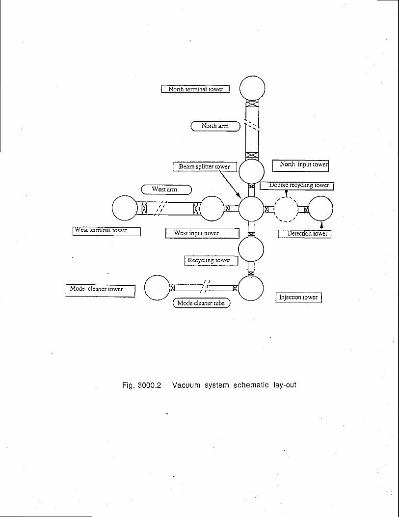
lower
Nonh arm
West arm
Norfi inpur
est terTru.nal tower
Mode cleaner tower
\Yest input tower
Rccycling tower
Mode cleaner rube
Fig. 3000.2 Vacuum system schematic lay-out
recyctng tower
Doc: VIR-TRE-DIR- I 000- l3Issue: I Date:01/05D7S/Sy:3100 Page: 1
FINAL DESIGN REPORT
31 . Tub es
Table of Contents
31. Tubes
31.1 Tube funct ion and concePt
31.2 Requirements applicable to the tube3 1.2. I Physics requirements31.2.2 Design constraints
31.3 Tube interfaces31.3.1 Tunnel31.3.2 Pumping system31.3.3 Input and terminal towers31.3.4 Light beams
31.4 Select ion of solut ions3 I 3.1 Historical background31.4.2 Final choice
31.5 Tubd' modules31.5.1 Inroduction31.5.2 The modules
3 I.5.2.1 Standard Module31.5.2.2 Pumping modules31.5 2.3 Special modules
31.5.3 Lip joins31.5.4 Bellows31.5.5 Other components31.5.6 Raw material31.5.7 Cleaning31.5.8 Thermal treatment31.5.9 Leak detection31.5.10 Connections to suPPorts
31.6 Tube assembly31.6.1 Assembly strategy31.6.2 Interfaces and attachments
3L.6.2.1 Supports and Supporting Feet31.6.2.2 Elecuical connections for baking
31.6.3 Transport to Site31.6.3.1 Transport31.6.3.zThe Saddles31.6.3.3 Site Internal Transport
31.6.4 Suppors3 1.6.4. 1 Elecrical Insulation31.6.4.2 Performances31.6.4.3 Adjustrnents31.6.4.4 Support interfaces31.6.4.5 Installation
31.6.5 Bake out31.6.6 Thermal insulation31.6.7 Assembly
31.6.7.1 Modules and Supports preparation
J
3J
3
A
A
Aa
44
55
771
77778888899
99
101010l01 11 11 1l 11 t
12121212r3l 5l515

FINAL DESIGN REPORTDoc: VIR-TRE-DIR- I 000- I 3Issue: I Date:01/05/97S/Sy:3100 Page:2
31.6.7.2 Section assembly and welding31.6.7.3 Section testing31.6.7.4 Tube assemblY31.6.7.5 Tube acceptance testing
31.6.8 Test of 300 m sections31.6.8.1 Introduction3l.6.8.2 Leak and Vacuum test
31.6.9 Leak and vacuum test of 3 km tubes31.6.9.1 Tube AssemblY31.6.9.2 Leak and Vacuum test
31.7 Mode Cleaner Tube
31.8 Large valves
31.9 References
31.10 F igures
1 6I I
t71 1
l 818l819l9l9
1 9
2 0
2 0
2 0
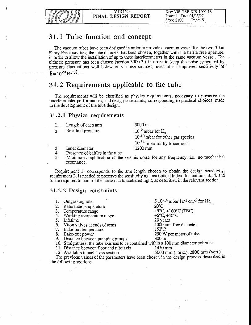
Doc: VIR-TRE-DIR- I 000- I 3Issue: I Date:01i05D7S/Sy:3100 Pagc:3
FINAL DESIGN REPORT
31.1" Tube function and concept
The vacuum tubes have been designed in order to provide a vacuum vessel for the trvo 3 kmFabry-Perot cavities; the tube diameter has been chosen, together rvith the baffle free aperture,in order to allow the installation of up to tlree interferometers in the same vacuum vessel. Theultimate pressure has been chosen (section 3000.2.) in order to keep the noise generated bypressure flucruations well below other noise sources, even at an improved sensitivity of
f i=1g-uyy-%.
3L.2 Requirements applicable to the tube
The requirements will be classified as physics requirements, necessary to preserve theinterferometer performances, and design consfraints, corresponding to practical choices, madein the development of the tube design.
3L.2.L Physics requirements
3000 m10-9 mbar for I!10-10 mbar for other gas species10-14 mbar for hydrocarbons1200 mm
Presence of baffles in the tubeMinimum amplification of the seismic noise for any frequency, i.e. no mechanicalIesonance.
J .A
f .
Requirement 1. corresponds to the ann length chosen to obtain the design se_nsitiviry;requiremerit 2. is needed t6 preserve the sensitiviry against optical index fluctuations; 3., 4. and5. lre required to contol the noise due to scattereA [ght, as described in the relevant section.
3I.2.2 Design constraints
1. Irngth of each armZ. Residual pressure
Inner diameter
1. Outgassing rate2. Reference temperatue3. Temperature range4. Working temperatue range5. Lifetime6. Viton valves at ends of arms
5 10-14 mbar I s-l cm-2 for H2200c+5oC, +160oC (TBC)+5oC, +40oC20 years1000 mm free diameter
7. Bake-out temperature 150oC8. Bake-outpower 250wpermeteroftube9. Distance between pumping groups 300 m10. Sraighhess: the tube axis-has to be contained within a 100 mm diameter cylinder11. Distance between floor and tube axis 1450 mm12. Available tunnel cross-section 5000 mm (horiz.),2800 mm (vert.) ,The previous values of the parameters have been chosen in the design process described in
the following sections.
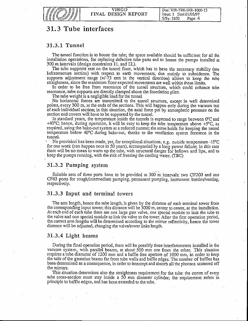
FINAL DESIGN REPORTDoc: VIR-TRE-DIR-1000-l 3Issue: 1 Date:01/05/97S/Sy: 3100 Page:4
31.3 Tube interfaces
3L .3 .1 Tunne l
The tunnel function is to house the tube; the space available should be sufficient for all thein_stallation operations, for replacing defective tube parts and to house the pumps installed at300 m intervals (design constraints 11. and 12.)._ ,The tube supports rest on the tunnel floor, which has to have the necessary stability $eeInfrastructure section) with respect to earth movements, due mainly to subsidence. Thesupports adjustrnent range (+/-75 mm in the vertical direction) allorvs to keep the tubestraightness, since the maximum floor expected movements are well within these limits.
In order to be free from resonance of the tunnel structure, which could enhance tuberesonance, tube- supports are directly clamped above the foundation piles.
The tube weight is a negligible load for the tunnelNo horizontal forces are transmitted to the tunnel structure, except in rvell determined
pQints, gvqry.J00 m, at the ends of the sections. This will.happen only during rhe vacuum tesrof eachindividual section; in this situation, the a-rial force put by atrnospherii pressure on thesection end covers will have to be supported by the tunnel.
In_standard years, the temperature inside the tunnels is expected to range benveen ffC and+40t; hence, during operation, it rvill be easy to keep the rube temperature above +5oC, asrequired, using the bake-out system at a reduced current; the same holds for keeping the tunneltemperature belorv 40"C during bake-out, thanks to the ventilation system fbreleen in thetunnel.
No provisiorf has been made, yet, for exceptional situations, e.g. outside temperature -15oCfor one.week (can happen once in 50 years), accompanied by a long porver failurre; in this casethere rvill be no mean to warm gp the tube, with structural danger foi beilows and lips, and tokeep the pumps running, with the risk of freezing the cooling rvater. (TBC)
3L.3.2 Pumping system
Suitable sets of three ports have to be provided at 300 m intervals: two CF200 and oneCF63 ports for rough/intermediate pumping, permanent pumping, instrument bottles/venting,respectively.
31.3.3 Input and terminal toryers
The arm length, hence the tube length, is given by the distance of each terminal tower fromthe corresponding input tower; this distance rvill be 3000 m, center to center, at the installation.At each end of each tube there are one large gate valve, one special module to link the tube tothe vaive and one special module to link the valve to the tower. After the fust operation period,the correct arm lengths rvill be determined according to the mi:ror reflectiviry, hence the towerdistance will be adjusted, changing the valve/torver links length.
31.3.4 L ight beams
During the final operation period, there rvill be possibly three interferometers installed in thevacuum system, with parallel beams, at about 500 mm one from the other. This situationrgquires a tube diameter of 1200 mm and a baffle free aperrure of 1000 mm, in order to keepthe tails of the g-aussian beams far from tube walls and baffle edges. The number of baffles hasbeen determined as a consequence, in order to intercept and absorb all the photons scattered offthe mirrors.
This situation determines also the straightness requirement for the tube: the cenre of everytube cross-section must stay inside a 50 mm diameter cylinder; the requirement refers inprinciple to baffle edges, and has been extended to the tube.
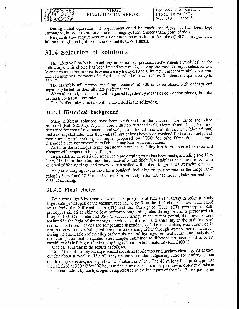
Doc: VIR-TRE-DlR-1000-13Issue: I Date:01/05D7S/Sy:3100 Page;5
FINAL DESIGN REPORT
During initial operation this requirement could be much less tight, but .has been keptunchangJd, in ordei to preserve the iube integrity, from q mechanical point of view.
No q-uantitative requ'irement exists on dust contamination in the tubes (TBD); dust particles,falling ihrough the light beam could simulate G'W. signals.
3L.4 Selection of solutions
The tubes will be built assembling in the tunnels prefabricated elements ("modules" in thefollowing). This choice has been immediately made, le-aving the module length selection to alaier siag-e as a compromiSe betrveeh a easy transpor-t and a limited number of modules per alm.Each e!#nenr will be made of a rigid parr and a-bellows to allorv for thermal expansion up to160'C.
The assembly will proceed installing "sections" of 300 m to be closed with endcaps endseparately tested for their ultimate performances.^Wheial
Fsted, the sections rviil be joined together by means of connection pieces, in orderto constitute a full 3 km tube.
The detailed tube structure will be described in the following.
31.4.L Historical background
Manv different solutions have been considered for the vacuum tube, since the Virgoproposil (Ref. 3000.1). A plain tube, rvith non stiffened wall, about 10 mmLhi.k, has beenhisiataeOior cost of raiv material and rveight; a stiffened tube with thinner wall (about 5 mm)and a comrgated tube rvith thin walls (2 mm or less) have^been retained for further study..The.continuous-spiial rvelding technique, proposed by LIGO for tube fabrication, has beendiscarded since not promptly availabie among European companies.
As far as rhe tecliniqu6 t6 join on site the irodules, welding has been preferred as safer andcheaper with respect to bolted flanges.
. ftiparallel, sdme relatively smai-l scale prototyping work has been made, including two 12.mtong,iO00 mm diameter,nrbdules, made of 3 rim-thick 304 stainless steel, reinforced rvitttLiiJ*ui Jtiff"ning rings; end covers were installed with bolp$ flanges and silver w{re gaskets.
Very encouraging results have been obtained, including'outgassing rates in the range 1Q-12
mbar I s-l cm-2 and L0-14 mbar I s-i cm-2 respectively, after 150 oC vacuum bake-out and after400 "C air fuing.
3L.4.2 Final choice
Four years ago Virgo started two parallel programs at Pisa gnq a! Q'sayll order to studylarge scaie proto"types
"of tite vacuurn
^tube and tJperform the final choice. These rvere called
reslectively the Stiffened Tube (ST) and the tomrgated Tube _ (CT) prototypes. Bothprototypes"aimed at ultimate lorv irydrogen outgassing rates through either.a.prolonged airhting
"al 400 'C or a classical 950 oC vaduum fiiilg. fn the recent- p.-eriod, their results rvere
analized in the Iight of the theory of hydrogen diffusion -and solubjlity in the stainless steel-attix. The latter] besides the timpera'ture Eependence of the mechanism, was exalnined inconnection with the existing hydrogen pressute arising either through water vapor dissociationOuting tne elaboration of thE ailoy 6r fr6m the natural-hydrogen coitent in air. The analysis ofthe niOrogen content in stainless'steel samples submitted to-different Eeatments confirmed thecapa5ility"of air firing to eliminate hydrogen from the bulk material (Ref. 3100.1).
One can summarize the results as follows.g;rh kinds of prototypes experienced indusrial fabrication and surface cleaning..After bake
out for about a week -a't
150 ^oC,
they presented similar outgassing rates for hydrogen' the
dominant gas species, namely a ferv 10'12 mbar I cm-2 s-1. The 48 m long.Pisa-prototype.wasthen air nriO aigSO ob for t00 hours maintaining a constant inner gas flow in order to eliminatethe contamination by the hydrogen being release-d in the inner part6f the tube. Subsequently an
FINAL DESIGN REPORTDoc: VIR-TRE-DIR- I m0- I 3Issue: I Date:O1/05D7S/Sy:3100 Page:6
outgassing rate around 5 10-15 mbar I cm-2 s-l rvas obtained after a standard bake out andpumping as described above.
At Orsay (Ref. 3100.2) a second com:gated prototype made of stainless sreel sheets, 950 tvacuum fired for 2 hours, gave an outgassing rate of 2.5 10-14 mbar I cm'2 s-1. The differencewith the rate obtained on the stiffened tube was atributed to the weld contamination by tracesofrvater vapor dissociated by the argon arc discharge. In order to test this hypothesis, the frstOrsay prototype was split into three elements. Each of these was air fired at 400 oC for about38 hours, respecting the necessary precaution to evacuate the hydrogen released from themetal. After reconstituting the prototype and a standard bake out and pumping, an tdtimateoutgassing rate of hydrogen of 1.5 10-15 mbar I cm-2 s-l rvas obtained. The improvemenrfactor is sensibly in agreement rvith the reduction of the length of the rvelds, rvhen comparingthe second and the third test.
For an indusrial construction of the tubes, Virgo took a conservative value of 5 10'14 mbar Icm-2 s-l as the design hydrogen outgassing rate. This is more than an order of magnitude largerthan the ultimate rate achieved. It is still compatible with a process involving a 400 oC air fuingof the metal sheets rvhich would exclude the treatment of the welds.
Other developments were made on bake out (heating tapes and current flowing in the tubewall, called IHS = impedance heating system), on thermal insulation, on pumping aspects (drypumping for evacuation, permanent pumping rvith titanium sublimators and NEG, cryogenicpumping for the tolver upper parts) and finally on instrumentation.
Hydrocarbon contamination after a normal cycle of bake out and pumping using a TMP anda mechanical forepump separated bv a zeolite frap. was found to be close to the level reouiredrequireda mechanical forepump separated by a zeolite frap, was found to be close toby Virgo.
All these efforts confirmed the feasibility of vacuum performances'presently needed for Virgo, thus allorving ior increased performancesthe antenna sensitivitv.
far better than the onesin other fields limitine
In order to make a choice betrveen the CT and the ST solutions, a group of external experts(TTAG, i.e. Tube Technical Advisory Group) has been asked to advice the Virgo Direction.Although both solutions could meet the final requirements of Virgo, based on financial andpractical considerations the ST solution was selected. It horvever incorporates some of the CTideas, concerning essentially bellorvs, IHS and the techniqug to join m6dules.
Following the recommendations of the TTAG, the maiir choices for the stiffened tubeconstruction are summarized below:
o module length 15 m, as a realistic approach to several problems such as transport,surface cleaning, etc.;wall thickness of 4 mm, together with the number of reinforcing rings was found to beadequate, thus lowering substantially the weight of steel needed without endangeringthe welding of the sub elements;the bellows were designed to work in the elastic regime in order to bring the safenumber of cycles in accordance rvith the large number of modules and that of the ba.ke-outs foreseen;modules will be joined welding together thin (2 mm) lips, thus allowing defectingmodules removal by automatic and clean lip cutting;the different parts of the module rvere toleranced to achieve smooth and preciseconditions for welding the lips;the heat treatrnent will be performed on the full module (including its bellows) thusallowing for extreme outgissing performances; the smallei thicknjss of the tube hasalso the advantage of reducing by one third the duration of the process;the bake out temperature was set to 150 oC, thus lorvering the cost of this operation butcalling for more stringent conditions so as to avoid accidental pollution;IHS was adopted.

Doc: VIR-TRE-DIR- I 000- I 3Issue: I Date:01105/97S/Sy:3100 Page:7
FINAL DESIGN REPORT
3L.5 Tube modules
31.5 .L In t roduc t ion
The modules consist in stainless steel stiffened tubes, 15 meter long, with a i200 mmdiameter, welded to each other through lips (Ref. 3100.3). Each 15 m-long tube.is equippedwith a bellows to allow for dilatation.l{ost of the modules are "standard modules", one out o.f20 is a pumpjag module, and in sevbral places there is need for different "specill modules".i-d;;a;i.i onE utt theircomponents have been modeled and optimized with lhe finite elementDrosram Systus. In particular-, the size and spacing of stiffening rings have been designed to'auoid
uny iisk of buitting of the tube (Ref. 3100.4).
3L.5.2 The modules
31 .5 . 2 . 1 S tandard Modu le
This module is shown in Fig. 3100.1. The rvall is 4 mm thick, and the qqffelgl rings are70 mm high and 8 mm thick, wlth a 1200 mm spacing. The tube is terminated-by zlips (one ateach end)?escribed in 3100.5.3., which allorv the rveldingto the adjac^ent modules. At one endoi the *odol", a 10 convolution bellorvs allorvs for dilatation (see 3100.5.4.). These 2 items,*oO. of Z -m thick stainless steel, are assembled to the tube ends by rvelding.. The module isl;ppo;;a through the two rings (t6 mm thick ) closer to the ends;-on these "terminal rings"
'different accessories are fixed :. feet for fixing the modules on support. .targets for alignment. pieces for handling. conr_rectors to feed-in bake-out current.
i 1 5 - ? . - 2 P r r m n i n g m o d u l e s
They are identical to standard modules, with three por:s., tyglol.respeccively intermediateand peimanent pumping, one for measuring instruments Fig. 3100.2).
3 1 . 5 . 2 . 3 S p e c i a l m o d u l e s
l.Modules without bellorvs : at the extemity of every 300 m section, the Est module hasno'@ngandhasfeetd is tar rce isstandardmodu1es.Thisa l lorvst t re;;;;ii;g of all the sections sepfrately, one after the other. Later on, the "missing beflows" arep"iiti""EO-""0 *itA"O iot*o da3u."ni lO0 meter sections, insuring the continuity of the 3 kmiong tube.--
i.iints at the end of arms : special modules identical to standard modules but rvith differenttengtff ixubmitytowerStothe1argeva1ves(theselinksaredismounting)and the large valves to the normal mo'dules.
31, .5 .3 L ip jo in ts
Modules wili be joined together by means of 2 mm thick lips (Fig. 3i00.1), follorving.atectrnique devetoped for the ioinr fuiopean Thorus. The ends
^CtipO 5f adjacent modules rvill
6;;iig;d;"a p,it ir .ont..t; *trin perfbctly coincident (within 0.3 mm), the edges of the lips*ifiU? weldedby urr.uuto.uti. -"^.hinr, developed on purpose. Greai care hai to be put inavoiding pulling or transverse stresses on the lip rvelds.
FINAL DESIGN REPORTDoc: VIR-TRE-DIR-lm0-13Issue: I Date:01/05D7S/Sy:3100 Page: 8
In case of necessity, modules rvill be dismounted simply cutting out the lip rvelds; theautomatic nibbling machine essentially removes an outer ring of the welded lips, reducing theirradius by 3 mm and making them free from each other. Later on the module will berepositioned and re-welded at a smaller radius. The radial width of the lips is such as to allorvthiee successive cut and rveld seouences.
31 .5 .4 Be l l o rvs
Necessary for absorbing the dilatation of the tube - rvhich rests on rigid supports fixed to theground every 15 m - the bellorvs @ig. 3100.3) are designed to operate in the elastic domain, inorder to reduce the stresses on themselves and on the lip welds. They are made out of 2 mmthick stainless steel, rvittr 10 convolutions. The bellows total extension range is 42 mm,allowing the tube to be operated from +5oC to +160oC. In case of very low outsidetemperature, the + 5oC minimum tube temperarure rvill be obtained by the bake-out system.
31.5.5 Other components
In order to test individually each 300 m section, end caps have to be made, with 1 lip jointfor their rvelding to the section terminal modules. When all the sections of one arm will betested, the end caps will be removed by nibbling their lip welds, and replaced by "missing
bellorvs" (3 100.5.2.3.).
31.5.6 Rarv material
All parts are lnade of stainless steel 1.4307/EN 10088 (X2CrNi 18-9). The thicknesses are2 mm for lips and bellorvs, 4 mm for the tube walls, 8 and 16 mm for the stiffening rings.There is a special requirement for the elastic limit of the 2 mm sheets :
'Rpo.z > 29 daN/mm2 at 20oCoRpo.z ) 20 daN/mm2 at L50oCFor 2 mm and 4 mm sheets a limit on inclusions content is also required.More precise specifications about the material (- 800 tons) can be found in the cali for tender
documents (Ref. 3100.3).
31 .5 .7 C lean ing
A careful cleaning of each module must be done at the end of itsorder to get rid of all possible contamination.
For the washing a2Vo concentration alkaline lye is used at 60oC.
complete assembly, in
Rinsing is done rvith tap water. The washing-rinsing cycle is done threerinsing rvith demineralized water is done at 60oC. Finally, the whole moduleradiant panels.
times. A lastis dried with
31.5.8 Thermal treatment
All the surfaces rvhich are part of the UHV tank rvill be heated at 400oC in air, for desorbinghydrogen out of stainless sieel, in order to get the outgassing rate as mentioned in thespecifications (Q < 5 10-14 mbar I s-l cm'2 for H2).
A clean oven with stainless steel walls and elecrrical heating is required.The typical heating cycle rvill be :oT increasing from 20oC to 400oC in at least 24 hoursoconstant 1= (400 + 10"C) for72 hoursoDecrease to T = 20oC in at least 24 hours.

Doc: VIR-TRE-DIR- I 000- 1 3Issue: 1 Dere:O1/05P7S/Sy:3100 Page:9
FINAL DESIGN REPORT
During the whole cycle an air florv rvill srveep the module for exracting the desorbedhydrogen.
31.5.9 Leak detect ion
The test must be performed in an air-conrolled area. The vessels are closed by end caps andput on a test bench, flat Viton gaskets insure tightness''
The tesr must be done by quatified people in the presence of Virgo inspectors. The total leakmust be smaller than 3 10'10 mbar I s'l (He).
31.5.10 Connect ions to supports
The modules rest on supporrs through 2 feet welded to each terminal ring (Fig. 3100.4). Inaverage the standard feet'(bn the rigfr't side in_the itg_"tt) should not be submitted to. anylongiiudinal stress (if two adjacent modules ar_e identical), besides the force necessa-ry- to bendthe-elastic supports'(see the ielevant section). Only the eventual diffe-rences_among modules caninduce funhdisresies; but the total force is always smaller than 700 daN on each foot. Theconstraint induced on the tube wall is always smaller than the elastic limit.
For the 300 meter section tests, the loigitudinal force due to aunospheric pressure on theend caps is 12 tons. Special feet have been designed and are welded on a doubled stiffened ring(on the left side in fig. 3100.4).
3L.6 Tube assembly'
The activities of receiving, storing, unpacking, preparing for instaliations of all the itemsbefore being entered into tlie tunnel-areia:riedon iri dedicated yard service areas properlyequipped. Trvo different locations are assigned for these areas.,^
One location is close to the cengal Uultding zone and is dedicated to modules reception,storage and thermal insulation equipping (fig. 5100.5). This area_is unique for both tubes; it isa hatt"equipped rvith bridge crand foimdOulds handling_ and.fixed supports for. m.o{glqs laying..
The othbi location is aiide each tunnel, at mid-lengih, where a woikshop is bui]t i.1t-qgratgdrvirh G tunnel (fig. 3100.6). In this worksho! (called Tube As_sem-bly Building .nInfrastmcture sectibn") each thermally insulated modlule can be prepared lelorg entering-thetunnel. Prior to entet this clean area tvorkshop the modules are to be 6leaned. A dedicated plantinstalled externatly to this workshop providei for the outside cleaning of modules. Inside thisworkshop a separite area is dedicatid for minor item and accessory: bellows sections, valves,pumping and instrumentation groups, supports. Here the minor items can be stored, completedbefoie issembly and receive
"Urief inspiction before bging qiyen to their frnal position. In
parricular supp6rts shall be cleaned wilth the same facilitiei of the modules. The halls of theservtce areas are equipped witir bridge cranes, transport boogies, electrical mains and rvater.
The thermal insritaiibn srorage is iocated in the mbdule storing alea, close to one of the trvomain walls.
The covered service areas layout, their ecluipment distribution and characteristics have still tobe revised (TBD).
3L.6.1- Assembly strategy
The fabrication of the tube is conceived to be executed in steps. For being fabricated the tubeis subd.ivided into modules, G majority of which is 15 m long; other components are alsofabricated. for completion, ai descriSed 6elorv. Each standard mo-dule includes a stiffened tube
to;do;;d u U"Uo'*r. The modules are manufactured in rvorkshop and arrive_ complete to site.i{ere they are equipped with thermal insulation prior to be erected in the tunnel onto the relevantiupports, previciufty installed. Modules are coinected toge^ther b^y welding. The connection isreit'ized 6y a coupt,i of facing lips, each belonging to one
-of ttre ficing modules. The lip edges

FINAL DESIGN REPORTDoc: VIR-TRE-DIR-1000-l 3Issue: I Date:01i05D7S/Sy: 3100 Page: 10
are fit-up and rvelded together. Major non destructive inspection on the rvelded joints is Heleak test.
Due to the need of verifying on a step-by-step basis the vacuum quality rcachable by therealized assembly, a number of adjacent assembled modules are made to constitute a "section".End caps are foreseen at one end of the extreme modules of each section for performing the sitetest. The tests are both He leak onto lip-welds executed on site (between adjacent modules andend caps) and the vacuum quality, measured by RGA (residual gas analyzer). First test requires10'o mbar pressure inside the section, second test requires 10't mbar, thus trough bakingprocess. The space needed for the end caps volume is made available delaying the installationof the bellorvs from a special module (see 3100.5.2.3.) at one end of the testing secrion. Themodule at the other end of the testing section has pumping and vacuum measuring pofts.
Once the sections are testes they are kept under vacuum (TBC) until there is the need ofconnecting them together to complete the tube. This operation is done by inserting the missingbellows in between each adjacent sections. The connection is realized via Iip joints similarlywelded and tested to those between modules. Other sections complete the tube at its ends.Thermal insulation continuity along the tube is restored after these itelms are erected.
Each completed tube is vacuum tested full length.To be noted that the temporary removal of tube splice for baffles relocation is relatively easy
by cutting out the lip weld at both ends of a module. The lips are dimensioned in order to allowa number of cutting and re-rvelding operations. It is also to be noted that lip welding is ttre lastoperation performed before clo.sing.the tube, i.e. confining its inside from the outside: to avoidcontamination any activity inside the tube after the rveld is completed is to be done undercomplete cleanness conEol.
,3L.6.2 Interfaces and attachments
To control the alignment of moduies and link sections one target holder can be installed ontoeach foot. The holders are to be erected on site onto the proper positions predisposed on theitems' feet. The correct positioning of target holders is made through mechanical coupling,' compatible with the alignment tolerance value.
To facilitate the items handling one lifting lug is mounted in manufacruring rvorkshop ontoeach terminal nng of each module and link section. The lugs may remain installed onto theterminal rings also during service (TBC).
31 . 6 . 2 . I Sunpor t s and Supnor t i ng Fee t
The Modules lay onto supports by means of built-in feet. The feet are in number of four permodule; the bellows have no feet. No other supporting points are foreseen, either allowed, forthe Module.
Feet are connected to the supporting rings in the manufacturing workshop. Their lowersurface is located rvithin the tolerances indicated in construction documents.
31 .6 .2 .2 E lec t r i ca l connec t i ons fo r bak ing
To allorv the baking operation for UHV by means of Joule effect, elecu'ical connectors arebolted onto a number of tube terminal rings in selected locations along the tube itself, after themodules are installed in their final destination. Selected locations ire the extreme rings ofsections. The connectors arc cabled to heating current power supplies installed along thetunnel.
31.6.3 Transpor t to S i te
The Modules, the Links, the Bellows sections and the end caps are collected frommanufacturing facilities completely assembled, mechanically complete and cleaned as ready tobe installed.

Doc: VIR-TRE-DIR- 1 000- 1 3Issue: I Darc:AUASl91S/Sy: 3100 Page: 1 1
FINAL DESIGN REPORT
3 1 . 6 . 3 . 1 T r a n s p o r t
Modules are transported to site onto adecluate saddles. Mod-ules are provided rvith temporaryprotecrive caps to kebp the inside clean; each item is singulgrly and entirely rwapped-up withplastic sheat6s, which horvever do not form a rvater-proof barrier. Module transport trip to^Cascina
rvill easily have to be across mountains. Due to aunospheric,pressure, function ofheight above sea ldvel and rveathqr conditions, total load onto covers and bellows can raise uqto i t (TBC). Fixing of covers onto lips and srength of covers themselves need not to standsuch load if a conrrolled air feeding device is connected to modules covers. Discharge ofintemal ovetpressure can be through non rerurn valves and air filter for safety. Inlet air williiiue to Ue fr6m a battery of clean air bottles activated by an automatic pressure sensitive valve.
Modules can be trairsported in groups: it is envisaged that if trucks are used then threemodules can be loaded per trip.
Packed modules loaded orito trucks or wagons are also to be covered by an heavy plasticcanvas of the type normally used for this kind of nansport.^
Bellows se6tions are fransported to site by means of rvooden boxes. Inside the boxesbellorvs sections are wrapped-up with plastic sheaths, forming a sealed water-proof barrier.Temporary protective cafs are iristalled
-to keep the inside surfaces clean.
fiansp6rimeans can be trucks as well as iailroad ryago?-l,.but it has to be considered thatthe site 6f Cascina is not equipped with inside railroad facilities. The closest railroad stationadequate for performing the tririsfer of modules onto u'ucks is Pisa. Sea transport.can also bedon6 being tlie harbour-of Livorno quite close to site and connected by highway. The transportsystem, with its details, is subject to the approval of Virgo.
3 1 . 6 . 3 . 2 T h e S a d d l e s
The saddles are designed for protecting modules (their bellows in P.arti.cuJar) from alldynamic loading due to-transport causing sresses beyond_an.acceptable iimit in any-point.
saddles.A number of saddles are foreseen for constantly feeding assembly site rvith the needed
quantity of items.
31 .6 .3 .3 S i te In te rna l T ranspor t
The top of the modules onto truck in ransportation asset, is higher than 3.5-m from roadtevel. This precludes from the possibiliry of dischargilg 49 modules close to the mid-Iengthworkshops bf each tunnel becar]se the piesence of road-Urieges with a maximum clearance of3.5 m.
Therefore the transportation from the stocking area and the mid-length rvorkshops is to bedone by other means.
fhii is in agreement with the strategy of unloading -molJules at the thennal insulationequipping building, which is unique for both arms (fig. 3100.5).
31.6 .4 Suppor ts
Supports are to stand mechanical loading, to allow thermal expansi-on of modules, withinthe loihs acceptable by bellows and lips, aiO to give the possibility of realigning the ttrbe incase of movements of the tunnel due to ground subsidence.
The mobile support is ecluipped with ipring elements which allorv the module to yield underIongirudinal dilatation caus-dby bake out and daily temperatue-chang.es.
in order to avoid latge tranivirsal srresses onio the lip welded jJints, the fixed.support ofone module and the modile support of the adjacent one are mounted-onto the same rigid ftflSg:In this way they can be moved verticaily together in case the tube realignment is needed' This
They should ac&mmodate at lbast *ree midules (Standard,Initial, oi-Pumping, or a selectionnf tire.m) for ontimizins rhe numher of transoort trios. Links can also be transported onto'of them) for optimizing the number of transport trips. Links can also transported onto

FINAL DESIGN REPORTDoc: VIR-TRE-DIR-1000-l 3Issue: I Date:01/05D7S/Sy:3100 Page: 12
frame is flanged to four posts, rvhich at their tum, are bolted to the concrete floor (fig.3100 .7 ) .
31 .6 .4 . 1 E lec t r i ca l I nsu la t i on
Betrveen modules feet and support top an elecuical insulation joint is inserted. It provideseiectrical and thermal insulation rvhen parts of the tube arc put to different voltages to bake thetube by current flowing in its wall.
31 .6 .4 .2 Pe r fo rmances
The fixed support (fig. 3100.7) is designed to stand an axial load of 3,200 kg C[BC) in bothdirections and a vertical load (ll2 the module weight) of about 2,000 kg.
The fixed supports of the trvo end modules of each section, called "superfixed", BrEdesigned to stand an a-xial load of 13,000 kg in both directions; other characteristics are thesame as for fixed support.
The mobile support is designed to displace +20 mm in the a,xial direction (with 0.5 mmmaximum vertical displacement) under the load of 2,000 kg C[BC); other characteristics are asper fixed support.
The displacement range of mobile support is dictated by thermai expansion of modules u160'C: range from of 5"C (minimum tube temperature) to 160oC is 38 mm. Such range is to beequally distributed from -19 to +19 mm to reduce the vertical displacement of top part ofmobile support. Due to its design rvhile running from -19 to +19 mm the support top pa$describes a curve which sagitta is 0.5 mm. Therefore the mobile support once installed is to bepre^-bent of -19 mm at 5oC, or in a proportional position if pre-bending regulation is done at a
' drtterent temDerarure.
The possibility of adjusrment of the three support types are for assembly needs and for tuberealignment
For alsembly needs the adjustments are specific of the support type. Fixed and mobilesupport frame cin be regulatedin height and trinsversai poiitiori Leforithe module is put on it.N{obile support can in addition be fine adjusted vertica-lly by +t0 mm and horizontally byt5 mm in order to perform a careful lip joint fit-up before welding.
Fortuberealignmenttheadjustmentof the support block (fixed support of one module andmobile support of the adjacent one) is made by the displacement of the entire frame, rvhich canbe moved along the vertical axis by t75 mm.
31 .6 .4 .4 Suppor t i n te r faces
Civil rvorksSupport bases are installed onto floor concrete slab by means of "fisher type" bolts. In the
area of supports floor surface is flat and horizontal rvithin a few mm every 2m in all directions.Support base plates should be installed onto leveled steel plates and grouted undemeath beforefinal bolts tiehtenine.
ModulesMoffi rest onto supports just through the feet attached to the terminal rings. The
boundary between supports and module is defined as the lower surface of the module feet.
3 1 . 6 . 4 . 5 I n s t a l l a t i o n
Supports are to be completely assembled in their final position in the tunnel prior the propermodule is laid on them.
Supports arc to be completely cieaned prior to entering into the tunnel. The use oflubricants, liquid or solid or spray, is stictly forbidden. Any dirty or greasy or rusted area of
Doc: VIR-TRE-DIR- 1000' I 3Issue: I Date;01/05D7S/Sy:3100 Page: 13
FINAL DESIGN REPORT
supporrs srrucrure rs to be properly cleaned and the surface is to be ieconditioned outside thetunnel.
31-.6.5 Bake out
Each tube has to be heated up to 150oC under vacuum (bake out),- at.least each time it is.u*uut.O, in order to eliminate^the ruater molecule layers present on its inner surface and toreduce thswater partial pressure to a negligible value. Furthermore, also during the assemblyon.t.. iach 300 * ,..tion of tube will6e-baked. The tube temperature must follow a cycle;i;i;a io itr" *unt.d residual pressue and gas co_mposition; i00 h- at 150oC is the ty^pical value.Moreover vacuum and mechinical resistatce add-constraints on temperaiurb uniformity and
increasing rate: a variation range of +10oC and a rate of rise of 2-4oC h't (limited by the power
ofthe installation) are taken as reference values.- Temperature in different points of the tube and its rate of change have to be monitored and
monitoring and control system, and the necessary
fffi;;ilg p"*iiis s.uppried t-o th9 tubes taking advantage of the fr9, *tp.yg-? ry9.t1:^"d ;;;teliy'r'i.ii;dirhii;*t..gl*t .g"guct6rs): an elicric current,will lqry Pt1gl,-..*
automalically conrolled.The power suPPlY, the temPerature
instailations are described below.
and Complgtgly WgIOgO (mgy afe gIgCInCaf COnUuUtUls,r; all trlcuu.tu uullcrrl-w.trJ' Iruw uvsSrr wcwr'
;;G-h;;'1i.ng ii by Joule effect. Another solution, implying $e use of e'lecuical tape resistorsrvound to the tuUe wali. frui U.rn iaken into accouni, ies6O anO then discarded for economic! ! . v v . . v s ! . . . D
rvound to tle tube wall, has been taken into accouni, tested and then discarded for economic;;;;;;ilpartiiutar tnl poriiOitribution to the heating tapes has been found remarkablyexpensive.- 'Conpquently
to the chosen te-chni-qJe a proper voltage difference must be applied to the
.t,rUei *& " retu* conao.toi of sufficientiy iotl impedance is necessa{y to complete the'elecuical
circuit. The main palameters in dimensioning the system arc:
porver losses through tube thermal insulationper meter of tube (see 3100.6.4.)
ohmic.resistance per meter of the 4 mm thick 304Lstainless steel tubes
175 Wattrn'(measured valus , at20"Croom temperature)50 pCl m-t-" (measured value, at 150oCtube temperarure)
The current effective value turns out to be I = 1870 A.Caicutations and experimenral rcsults obtained in Pisa and in LAL-Orsay clearly-show that
AC current is not suii'"Lf" rinii G t.t"u*t increase of circuit impedanc-e at 50Hz; in factbeiides its small absoiute value it results about 3 times highei ttran ohmic resistance.Furthermore AC current florvs not uniformly throughout thJ tube causing unacceptableremDerature sradients. ihen bC .urr"n t (lOVo maximum-residual oscillation) has been selected.'-'li-h;5-1g_f;"
t..*t-a iitoith"porver'density OY *t) supplied to each bellows is about 6
ti.nestrigter than the one supplie^d to the 4 mm itrict tube,-due.to itshigher ottmicresistance
ijb4t;;ui"less steel, ihi;il;fft *rn, iengttt 0.5-T, developed length I.g. rn); then to avoidover range t"rnp"rutur" gtiOO;Cl bellows ihermal iniulation has beei specially designed, both
for steady and rvarm-up conditions. < .A _-- ., 1 . ,The riturn conductdr shall be a99.5Vo Al bar with a cross section of 15 x 160 mm', whrch
dissipates a power oi;bo"r 4twil *i. Other solutions as copper cables or steel rails have
been found more expensive and not advantageous.Takine into account all the contributioni-fi.. uu"tuge power density turns out to be about 270
w;";';?a'i;;;;h arm the needed power figures 5ut'as{.8.MW, rvhile the correspongilqvoltage drop is 430 V (70 V on rerurn-bar, 360 V on tube). Tuking into. account extreme valuesof turinel t"^rlperuture "nd difi"t"nt efficiencies and lossei,- the pdwer installation for each armwill be capable of 1.2Ir{W. ffrii po*.t rvill heat the tunnel (400 W m'r, see Virgo report VIR-TRE-PIS j3100-103), hence requiring some ventilation.

FINAL DESIGN REPORTDoc: VIR-TRE-DIR- I 000- I 3Issue: 1 Date:01/05/97S/Sy:3100 Page: 14
A fine dimensioning of the necessary power and current will be achieved by testing the frst300 m tube section. The relevant parts of the bake out apparatus will be ordered only after suchtests.
The elecrical design must take into account the human safety: proper rules (CEI 64-8, Italy)allow at maximum 60 V DC if elecrical insulation is not present. To limit the max tube voltageto 60 V the power must be supplied in at least five points distributed along each arm. Theactual design foresees 5 suitable AC/DC converters (55 V, 4600 A) located at Z positions 300m,900 m, 1500 m,2100 m,2700 m; each one will supply two 300 m tube sections in parallel.The tube will be insulated from ground excluding 6 points, where it will be expresslygrounded, at 0 m,600 m, 1200 m, 1800 m,2400 m,3000 m.
Such arrangement is still to be confirmed, since some possible compatibiliry problem withother instruments in elecrical contact with the tube could exist. In fact, during bake out,pumping stations and vacuum devices, in addition to ttre ones located in the 6 groundedpositions, could have to be used in correspondence of the 5 supply positions ( at 55 V respectto ground).
Experimentation on this matter is a*ually in progress in Pisa.An alternative design with 10 supply points per arm located at each 300 m section center (27
V, 4600 A) and 11 ground points at each 300 m section end, will allow a more standardoperation of 11 pumping stations during bake out (see VIR-TRE-PIS-3100-104).
No risks for human safety arise from the magnetic field originated by the DC current, sinceit is far from the limit (2 T at 0 Hz frequency) imposed by CEI EN code.
About human safery it has to be remarked that bake out shall be stopped in case of peopleoperation on the tube.
Since the tube arms will be baked not contemporary the AC/DC converters will be movable. from one ann to another. Thev shall be placed outside the and the elecrical connections shall berealized by 6 x 630 mm2 copper cables.
The AC/DC converters rvill be supplied at 380 V, three phases, in part by dedicated dieselgenerators and, for the remaining quote (TBD), by the fixed Virgo installations.
. Beyond the tube, other parts have to be heated: vacuum devices and tube links. Eachseparable UIIV vacuum volume shall have its independent heating system.'The
heating system of vacuum pumps, valves and instrumentaEon (see 3400 chapter) will berealized with electical tape resistors.
Tlne L.2 m diameter tube links, connecting the large valves to the mirror towers and to thetube, will be also heated by electrical tape resistors._ During b4. 9gt the tube Jemperarure has to be monitored yth a precision of a few oC.
Thermocouples (K or T type) have been selected among the various sensors since their widediffusion, easiness of use'and low cost. Order of 10 elecrical insulated thermocouples shall beemployed for each 300m tube section. The conrol of temperature wiil be achieved using onelocal cbnroller unit for each power supply unit (AC/DC converters essentially, but also heatingtapes on tube links and pumping stations).
A1i the thermocouples and the controllers will be connected by a serial bus line to a remotocomputer, from whiCh it will be possible to drive the bake out changing temperarure set pointsand control parameters. The temperarure control system shall be used also during normaloPeration.-
Many additional thermocouples, not necessarily connected to the remote computer, rvill bepresent essentialiy on the first 300 m tube section, to allow occasionally detailed measurements.'
The bake out 6f each 300 m tube section during the installation phase will be performed by aACyDC converter supplied by a diesel generator movable along the tunnel.
Another function iequireil to the b-alce out system is to h.eat the tube in winter to avoidtemperanres below +5oC. It shall be futfilled by a single A9DC converter placed in the centerof tube (TBC) supplying 1100 A at 60 V, when tunnel temperature will be -5oC.
In this situation s6me equipment will be kept at a voltage with respect to ground. This is nota problem (IBC), since the permanent pumps in operaiion Cfi sublimatois and ion pumps)should not suffer ground problems; vacuum gauges, on the contrary, will have to be operatedswitching off the heating system for a while.

FINAL DESIGN REPORTDoc: ViR-TRE-DIR- I 000- I 3Issue: I Date:O1/05D7
3100 Page: 15
31.6.6 Thennal insu la t ion
A good thermal insulation will be installed on the tube extemal surface, about 24000 m2, toachieve acceptable potver losses during bake out. The principal technical requirements are:
rvorking temperature = 200oCindoor environment employmentlimited dust emission in tunnel.
This last requirements needs explanations: the tunnel will be not a pafiicularly dust freeenvironment (ai airborne dust concelnration of lmg m'3 typical of clean rvorkshops'or coun!ryenvironment can be taken as reference), and in order to avoid its pollution (significant increaseof dustiness) exraordinary precautions are not necessary (see also VIR-NOT-PIS-6300-100).
Felts of fibrous materials (rockwool, glassrvool) have been selected for their low cost andgood performances in the specified temperarure range, despite their high fiber emission (6*9
pm diameter, 1Gr50 pm length; typical'airborno concentration during installation less than 1fiber cm-').
To avoid pollution of tunnel by such dust the thermal insulation will be installed on themodules in a-ded.icated hall, and a proper sealing sheet will be used as final layer covering thefibrous material. Then each module outer surface will be cleaned from dust with a proper plant(see 3100.6.1.) before introduction in the tunnel .
What up to now described concems the insulation of tube stiffened paft. In fact beingbellorvs (and other minor pafls as end caps, pumping stations, links) insulated only after thatmodules are assembled inside the tunnel, their insulation has to allorv a "clean installation". The
'trvo kinds of insi:lation are belorv separately described.The tube stiffened part will have a very thick insulation, realized with two overlapping
layers to achieve high efficiency and good temperature uniformiry: a power dissipation of 150Watt per linear meter of tube (room temp. of 20oC) has been used in dimensioning.' Thls reference solution, well explained in a draft insulatiori technical specification (VIR-TRE-PIS-3100-105), includes twoiayers of rock rvool felt (density ?0-100 kdmt, thennalconductivity 0.045 Watt m-r oC at 100t) for a total thickness of 15O mm. The finishing layerwill be realized by a thin fek(2a-25 mm ) of glass rvool treaied with thermo-hardening resinsand faced on the 6uter layer with a foilskrim-laaft paper. Then a foilskim lcraft adhesive tapewill be used to seat the joints and a zinc plated (TBD) net mesh will be used as final layer formechanical support.
The above described solution has been experimentally tested; slightly higher power lossesthan estimated have been found. Hence the safe value of 175 W m'I (at 20oC room temp.) hasbeen assumed as requirement for the insulation effectiveness.
Insulation of bellorvs (and minor parts) rvill be realized with mattresses of glass-rvoolenveloped and quilted in an opportune cloth (Aluminum-glass cloth). The insulation of bellowsrvill be dimensioned taking into account the higher dissipated power.
31.6.7 Assembly
The assembly activities are subdivided into Stages. Each stage includes a set of activitieswhich result in a defined condition of the items involved. The Stases are subsecluent one toeach other, but only from the logical point of vierv and not from tfie planning point of vierv.The Stages described belorv are relevant to all items.
31 .6 .7 .1 Modu les a r i d Suppor t s p repa ra t i on
This Stage includes all the rvorks to be done prior the modules, the bellorvs sections and thesupports are entered into the tunnel for being installed in their assigned positions.
Handling of Modules in this phase shall be done rvith bridge cranes equipping the yardservice area (fig. 3100.5); mobile crane can be used only outside or, in case of need, inside
a
a
a
FINAL DESIGN REPORTDoc: ViR-TRE-DIR-1000-i3Issue: I Date:01/05/97S/Sy: 3100 Page: I 6
Hall A, after approval and under direct conrrol of Virgo supervisor. Modules arc to be handledonly from the indicated lifting points and to be rested only onto their built-in feet: no other partsof the items shall be in contact rvith hard bodies.
Handling of Bellows Sections shall be done through lifting rings or hears equipping theprorecting caps, rvhen bellorvs axis is vertical; rvhen axis is horizontal the same rings or hearsmay be used or the bellorvs can be hang by fabric slings.
Modules after an'ival to site are removed from truck and stored in Hall A. Care shall betaken rvhen removing outer canvas in order to avoid heavy contamination of modules outersheathing.
Unpacking of modules from packing sheaths is done before bringing them in Hall B forbeing €quipped rvith thermal insulation panels. Major debris from thermal insulation installationshall be removed from ecluipped modules prior to be fransported to ttre "module cleaning" plant(f ig. 3100.6).
Modules are then driven into Assembly building for a final overall check, mainly averification of not having received knocks and be free of indents. The protective cover wrappedaround caps are here removed, but the metallic covers are still left in place.
In the same Assembly building modules shall cue for entering into the tunnel.
31 . 6 .7 .2 Suppor t s i ns ta l l a t i on and a l i gnmen t
Supports are installed prior to modules. Their position is defined rvith reference to the axistraced in each tunnel by the geometers. The axis is defined by means of monuments locatedevery 300 m in correspondence to the superf,r.xed support position of pumping modules(Fig.3100.9). They are refened to the GPS (global positioning system) and theodolitemeasured monuments of rvhole olant.
' From the "300 m" monumerus i9 inter-points equatly spaced at 15 m are located: they arefor identifying the fixed support location of each support block modules @ig 3100.10).Therefore the position of first support is the one of "link section" module located on tube sideafter the large valve DN1000. To be noted that first monument will not be 300m distant from
' next, but 15 m closer; more, its exact location will be defined from design position of beamsplitter tower center reference. The reference marks and the axis will be used to locate the actualtibe axis, in terms of ldteral sraightness and level (Fig 3100.10). The expected precision oftaced axis from references marks is better than *1 mm in all directions.
Support will then be installed based on such references. Base plates will first be bolted toconcriie floor, then posts will be laid on them and finaily the sup'port block wiil be installed.The fine positioning of supports will then be executed in all three orthogonal direction: alongtube axis, transversally and vertically. Precision of positioning with respect to marks on flooris expected to be better than *1 mm in all directions. (Fig 3 100.1 1)
Once supports are aligned the mobile part rvill be pre-bent. Value rvill be the onecorresponding to average temperature of module being installed. Three supports blocks at leastare expected to be installed in advance of modules.
31 .6 .7 .3 Sec t i on assemb lv anc l r ve ld ing
Modules are set down onto a dedicated trolley by the bridge cranes and are driven in thetunnel to their final destination.
Before the a:rivai of the module the area around its final destination is to be cleaned fromminor dust by means of industrial vacuum cleaners: no brooms are allorved for this oqeration.
Oncearrivedin face of the final destination the module's bellows is compressed by meansof the proper device for allowing easy assembly and fit-up.
The module is thus erected onto ihe supports by means of the proper device. The moduleEnment relies upon its manufacturine toGiances lnd the support'aliinment precision for thealignment relies upon its manufacturing support-alignment precision for the
vertical and the tr-ansversal directions'-The module axial direciion precision Can be improvedadjusting the module final position with respect to the tunnel reference marks Sig. 3100.12).adJusnng the module tlnai posltion with respect to the tunnel reterence marks (ts19. J Iuu. r.4).After this operation, the erection device is removed from the area, and the alignment of themodule can be checked installine the ootical tarsets and relevant tarset holder onto the foreseenmodule can be checked installing the optical ta-rgets and relevant target holder onto the foreseen
FINAL DESIGN REPORTDoc: VIR-TRE-DF.- I 000- I 3Issue: I Date:O1/05P7S/Sy;3100 Page: 17
locations onto feet. The tolerances for alignment and the operating procedure aro to be defined(rBD).'
Onie the alignment is checked a protective tent is_positioned around the fit-up area. Thefacing covers oT the already installed module.andof the.one just a:rived are disman4ed onlyrvhen-the two lips are facin! and before releasing. the bellorvs holder. Tolerances for fit-up areof the order ofb.3 mm mlsmatch, for performing a sound rveld. The correct fit-up can beachieved operating onto the bellows compressing device and onto the scrervs and slidesprovided oir *re rnoUite support; the fxed stpport position shall not be modified in any case'Gig. g iOO.13, !4, 15 and-f6).-
After the fit--up operation is completed and the lips evenrually tack rveldedJhe rvglding rypotis iniiatteO and bpdrated. The rveiding is done uhder the protective tent. The iobot is thenremoved and laid ilown into its proper protection against dust; the protective tent may remain inoosition rvaitins for the next module.'
Initiul and Fumping Modul-es of each section receive welded End caps for section leakpsiing. The installatioiand rvelding of the caps are to be done under the protective tent and thetestrng.'I'ne mstauatlon ano welcung ot rno ca-ps afifit-up procedure is to follorv the indicatign-s abgve,
Pirrirps and instrumentation are installed as the Pumping Module is set in place and welded.
3 I . 6 . 7 . 4 Sec t i on tes t i ng
Once the se*ion is completed all rvelded lips are prepared forindividual He testing.The leaks found in th-e lip rvelds shall be repaired and the weld tested once more to
demonstrate adequacy to UHV.The section teitinj alorvs to verify the qualiry of the overall internal cleaning and the UHV
level that can be reached., After testingi the section is left under vacuum conditions (TBC).
3 1 . 6 . 7 . 5 T u h e a s s e m b l y
Once all 10 sections of the tube are tested they can be connected together.Bellows sections are brought to final destinition by means of thE module uolley.. B.fo.*
canying each of them to the-final position, t!. !y-o iections to which the bellows is to bervelded-shali be vented and the end iaps nibbled off from bcitir facing ends. Nibbling is caniedout with the robot. The opened tube ii thus covered by a cleur transport cover. The end capsare recovered.
Once each Bellorvs section is brought face to its final position it is handled by means of theinstallation device and it is compresled by means of :the proper device_for allowing easyassembly and fit-up. The hard mdtaUlc cove$ are now removedfrom the Bellows section butthe aluminium protection sheets are left in position. The bellows is then driven in betrveen thetwo facing se6tions, the protective tent is put in place and the fit-up operatio-ns may beperfonnedlOne lip couple iis initiatty fit-up, trimmed-and welded; the other is similarlY trea.tedifter the operatioris on ihe first is completdd. Trimming is done by means of the nibbling robotto the standard welding diameter.
A1l the 11 bellows slections are to be installed to complete the Tube.
31 . 6 .7 . 6 Tube accep tance tes t i ng
Once completed the Tube, all welded iips of the bellows sections are to be prepared forindividual He testing.
The leaks found- in the lip welds shall be repaired and the weld tested once more todemonstrate adequacy to UHV.-
tn" testing atio aitorus to verify the qualiry of the overall intemal cleaning and the IJHVlevei that can be reached.
After testing the entire Tube is left under vacuum conditions.
FINAL DESIGN REPORTDoc: VIR-TRE-DF.-1000-l 3Issue: 1 Date:01/05197S/Sy: 3100 Page: 18
31.6.8 Test of 300 m sect ions
3 1 . 6 . 8 . 1 I n t r o d u c t i o n
The strategy of the assembly foresees a development section-by-section in order to stafi rhevacuum operations as soon as possible all along the period of the rvhole installation, almosttwo years.
Once assembled, the first 300 m section is prepared for the leak search and the vacuum rest.For this it is equipped with trvo vacuum-tight covers, lip-welded by the robot at both ends, andthe proper pumping system rvhich-consists of an instrumentation group, an intermediate and apelmanent pumping group, all of them connected to the section through all metal gate valves.
Given the large volume of the section, =340 m3, it is convenient to establish 2 days to bringthe pressure from^the atmosphere down to 10't mbar. For this a movable roughing group iiloieqgen (see 3400.4.5.i.) to be connected to the section through a valve placed'on-thE coiersCF 63 port.
Every section is prepared for the tests in the same way as soon as assembled.
31 .6 .8 .2 Leak and Vacuum tes t
The intermediate pumping group is realized by means of a hybrid 1000+1500 I s-tturbopump backed by a mechanical oil free pump, 25+30 m3h'r. Berween the two pumps, aleak detector that can detect a lolest leak rate of 5 10'tt mbar I s'r is connected through a vatve.
.This arrangement allorvs the leak detector to provide sufficient sensitivity leaving -the
sectionprotected by its own vacuum system against any contamination from the l6ak deteCtor, if any.
The evacuation starts rvith the movable roughing group. It is important to prevent any riskof contaminants, srvitching-on the hybrid turUopu-m! ar6und t0{
^mbar before the rou'ghing
. gl'oup rvorks close to its ultimate pressure ( i0-'mbar). Due to high pumping speed now, thepressure should decrease in brief time in ttre range 10-5+10'6 mbar rvith the typical profile thatdepends- upon the gas evolution from the inner surface of the chamber, essentially water,unless the leakage of one or more big leaks in the sectioh determines a stop at a higherconstant value of the pressue proportional to the leakage.
Anyway at. this stage the leak detector vacuum -system can be operated through its ownvacuum pumping and the valve of connection opened.
The inspection wittr a Helium spray probe starts step by step from the first to the last lip-weld of the section, all of them performed during the assembly and then never tested befoie.Each circumferential weld is properly bagged and the individual bags are sequentially filledwith Helium during the test.
If a leak is found in one lip weld, it is necessary to localize at which point of its 3.8 m lengththe leak is, and this can be done rvith the help of the He spray probe rvhile removing thecirconferential bae step bv steo.
Leaks from 10:r mLar-l s-t^ dorvn to possible minimum values can be found and repairedafter a full section venting and a new ev:acuation. Smaller leaks down to 10'rt mbar I 3-t aremore difficult to be evidentiated due to the high ievel of the total pressure in the limit ofsensitivity of the leak detector.
When thepressure reaches the range of 10'6 mbar the system has to be heated via Jouleeffect at 150 trC according to the bake-6ut specifications.
The inspection with He is repeated when the bake-out cycle is over. Leaks down till thelorvest detectable leak rate of 5 10'tr mbar I s-t can be found. Eventual leaks can be repairedonly after afull section venting and a new vacuum cycle including bake-out.
The test is finally over when the pressure and the determination of the outgassing-rate matchthe project requirements, namely p<10'e mbar and Q<5 10't4 mbar I s'l cm-2 for hydrogen. Theinstrumentation group contains a RGA rvhich rvill be switched-on to check the actual gascomposition. Without any leak, the non H, components of the residual gas (essentially
Drc: VIR-TRE-DIR-1000-l 3Issue: 1 Date:01/05D7S/Sy:3100 Page: 19
FINAL DESIGN REPORT
CO,CO2, and CHo) has not to overcome partial pressures of 10't0mbar, to match the projectrequirement.
31.6.9 Leak and vacuum test of 3 km tubes
31 .6 .9 . 1 T t rbe I I nde r Tes t
At this moment, the trvo large valves and the relative link-sections toward the torvers ( input-output) and torvard the end-sections ( first and tenth ) are akeady assembled and tested as rvell.Th€refore it will be sufficient tovent atl the sections and to proceed with the insertion of theeleven bellorvs-sections, after cutting the iip-rvelds to remove the end-covers, and weldingagain the lip joints.
31 .6 .9 .2 Leak and Vac t t t tm tes t
The distance of 3 Km is betrveen the nvo mirrors positioned in the input and in the outputtowers of one tube. The leak and vacuum test is performed between the trvo large gate valves in"gLqssd" state, excluding the linl<-sections toward the torvers and the towers themselves.
The evacuation starts rvith a movable roughing group connected to the tube-Iarge valve linkmodule (see 3400-4-1-1). As a matter of fact, forrough pumping, regular spacing of pumpsalong the tube is of no importance, and so a single movable unit, located in the central building,can operate to pump dorvn each tube, one after the other.
Ai for the 300 m sections, it is important to prevent any risk of contaminants, switching-onall the hybrid rurbo-pumps of the tub-e around 10'' mbar before the roughing grouP works close
'toits ultimatepiessure. The time should be again around 2 days, and again the pressure very
quickly should decrease in the range 10-s+10-6 mbar unless leakage be present somervhere.This time the leak detector is connected tluough the proper valve betrveen the hybrid pump andthe relative mechanical forepump of the section presenting the highest pressrrre.
The inspection rvith Helium is timited to the new lip-welds ol the bellorvs sections startingfrom the ciosest one to the leak detector itself with the iame method and sequence for sections.
On." th6 average pressure reaches the range of 10'6 mbar a complete bake-out at 1500C (see3100.6.3.) has to be ferfonned. Before to start the heating, it is mandatory to evacuate also thetlo toweis and the small link sections that connect the towers to the large valves. In fact this isthe condition to heat the valves rvithout any damage.
When the bake-out is over and the temperature decreased, the leak research can be pushed tofind any iowest possible leak.
In the coursebf borh pre- and post-bake outgassing rate determination, the beamtube is alsotested for leakage by mlans of the residual gas analysis as measured by the RGA's in thesections. As soon as the total pressure measured by Penning or Bayard Alpert gauges reachesthe range of 10'6 mbar in on-e section, also the ielative RGA can be srvitched-on and thespecrum pealis can help to determine the approximate iocation of leakage, if any.-
The tu6e vacuum test is over rvhen the average pressure matches the values required by theproject : p",510-e mbar and Q<5 i0'14 mbar I s'r cm'' for hydrogen, and the residual gascomposition in agreement with requirements.
3L.7 Mocle Cleaner Tube
The mode cleaner tube, the mode cleaner tower and the input tower constitute a specialvacuum chamber isolated from the Virgo tubes and mirror towers by a windol.
Putting the optical mode clean.. sfste. into vacuum has roughly the same effect as theVirgo Vacuum system, i.e. to reduce the souces of noise rvhich are :
. the acoustical waves,
. the thermal gradients on the optical path,
FINAL DESIGN REPORTDoc: VIR-TRE-DIR-1000-13Issue: I Date:O1i05D7S/Sy:3100 Page:20
. the motion of dusts.Vacuum contributes also to keep the optics clean.The residual pressure allorved in the tube is 10-6 mbar.The distance betrveen torver axes is 144 m (Fig. 3i00.8), the tube has a 300 mm diamerer,
and is composed of 24 standard modules (5.7 m long), one pumping module and 5 dilaadonbellorvs.
One @ 250 valve isolates the tube from the input tower.Modules and bellorvs are Tig welded on site. The valves are linked to the tube by means of
CF flanges rvith Viton gaskets. For inroducing the tooling for the payload in the gallery of themode cleaner tube there is a 5 m long dismountable tube.
The tube conductance is 23 l.s-l for air. The mode cleaner fube is pumped through the modecleaner tower.
31.8 Large valves
Four large valves, at the extremities of each arm tube, allorv to isolate 5 different volumes ofthe overall UHV system : the central part torvers, the two long tubes and the two end towers.Work on every part can thus be done independently.
The nominal diameter of the valve is 1000 mm. The valve is a UHV gate valve rvith vitongasket for the flat. The link between valves and tube parts will be made rvith flanges rvith metalgaskets. They have to stand a 12 tons rvall effect while keeping the recluired tightness. All theparts in contact with vacuum have to be made of stainless steel, and rvill have to be heated at a400"C for the H2 desorption, in order to reach 1.10-9 mbar for H2.
. Glass windows will be implemented at the center of the flats, to allorv for light beampassage.
31. 9 References
3 100.1
3100.23100.33100.4
M. Bernardini et al. - Virgo int. rep. VAC 0i0 D - i994, Rev. 1995M. Bernardini et al. - "Air bake-out ....", to be published on VacuumM. Dialinas et a1. - Virgo int. rep. - 1994Module tender documents. VIR-CFT-LAI-3100-1 13 and i i5M. Dialinas - Tube calculation reDoft - 1996
31.10 F igures
3100.1 Standard module3100.2 Pumpine module3100.3 Beliorvs-3 i00.4 Feet and support conceptual scheme3100.5 Building for tube modules reception and thermai insulation3100.6 Tube assembly building3100.7 Tube supports, fixed and mobile3 i00.8 Mode Cleaner tube3100.9 Referencea-xisidentification3100.10 Supportblocksposition identification3 100. 1 1 Suirirort alignmint refeernce3100.i2 Supports and modules positioning references3 100. 13-1 6 Modules connection seouence
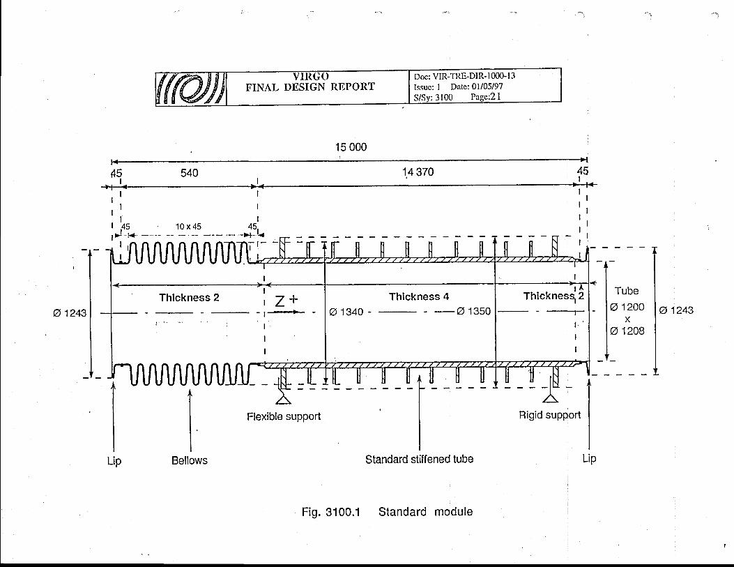
<o
l |
'.-u
r f
.t, I
ol
_s
l
Ic!rao@
oo
o-o
c! -N
JT
AN
II
:Eoo-a:otf
_c)3rooErol-(6EcC
g
ardoCDc;
iI
arCd
Ec(6
U)
I
IIIIIIIIIIIIIIII
o)-c)3
rE
rq
:'
G)
.i
+
<!-E
I\r(\Ira
o-=
ol-cf)s ro.(l_
to-
.E o.qrr)
oootr)r
olCJ
co
ca;(nU)
caTQF
-IrJ
O\
=m
r-
O
fforrl
C)
XE
,F
H
c...
o
8;Frz(n.'t
z
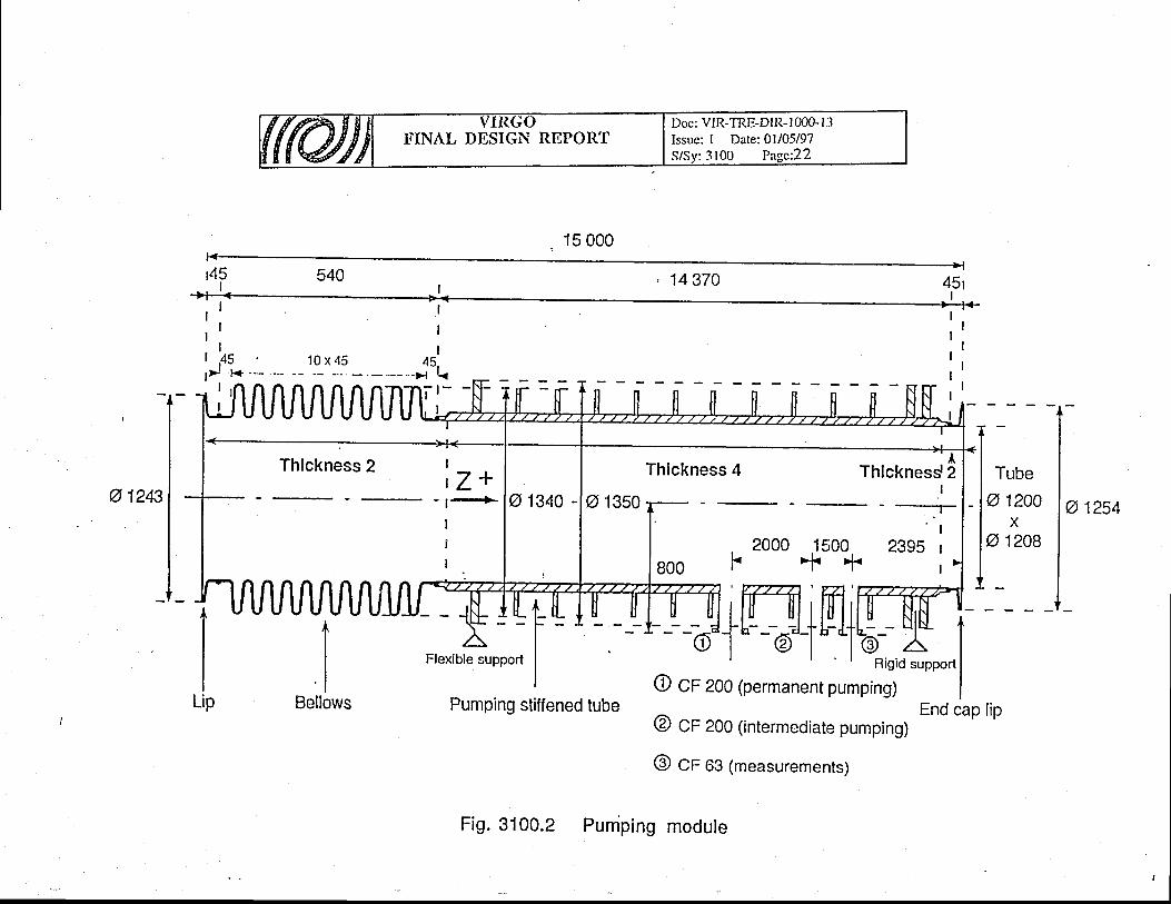
oOoror
=O-
ae
\=
h
6o
,"t ii
yx
rH
8A
e.lc\lC
.,
cnCN
FFI
z(ntt.'
t
z
ro-
soNcr)sOri|.
roro-
s
$lr)C
\J
a
o8
I€
S *
II
F
N
N
I
-t-II
ol-ttoocJC
)
F
--
fi ,
R
EE
w
<;
'rC
Dt'j N
l,^:FF
g'.'@
" 5 P
a lf-
"t\7 g
EJ
o^
=
o
- G
o
l+-l
ro-
hr-'q
3
g
E
9
Ft--r
o-
a)
#P
r=f-
F
E
Ef-
;, ---T-
0
ro
E
sF
To
EE
$5
N
'r
E
b
2
cv
fP
t. g
-q
U
VT
vt
?E
oo
r-r' O
O
C
);rg
=,"1
2r
cN
o
l @
c)J
EoEg)c.Efo-otooC
Dc;iI
tL T
L LL
OO
O
o@
@II
otoCD
ra
lf(tooceF
c)-o=]J(l)
-YrO=tr
.qxo
(n3<
-- o
'6(D
_o
.-=
cr)rqrC
\|
N
IIIr)
l'
:,
o_
'i+-tq
E
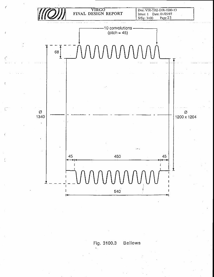
FINAL DESIGN REPORTDoc: VIR-TRE-DIR- I 000- I 3Issue; I Date: 0l/05/97S/Sv: 3100 Pas,e:23
a1200 x 1204
F i g . 3 1 0 0 . 3 B e l l o w s

FINAL DESIGN REPORTDoc: VIR-TRE-DIR- I 000- I 3Issue: I Date:01/05/97S/Sy: 3100 Pase:24
1827
F i 9 . 3 1 0 0 . 4Feet and support conceptual scheme
SPECIAL
STIFFENEDPUMPING
MODULE
Specialfoot
Figid
TUBE
tandard foot
-_)b
Pd,r r
Flexible
part
SPECIAL Z +- - + -
BELLOWS
:.:.:.:.: ' :. i :.:.:.:.: ' :.:.:. ' . ' . . ' ." ' . ' : ' : ' : ' : ' : ' : ' : .. ' : ' : ' . .......... ' i1.j. i ... ' ;r i:;:; i ; i ; i ;:; l ; i ; i ; i ; i ; i ; i ; i ; l ; l ;:; i ; i ; l ; i ; i : i ' i . i . i . l . l . i i . i . l . i . i . i . i ' i . l : i : l : i : i : i : i :;:;; i
,;,;'i,i,l,i'l',,i,.'l;lil,l,,i:::::i:.:i:i S UPPORT ::;i.i:i::. : . : . : . i : ' : . ! ! !1: . : . : . : ' : .' : ' : ' : ' l . i . i . i . i ; l . l . i . i . i ; i ' i . i ; i . i ; i - : . i ' : ' i ; : ; i ; i ; l ; i ;1. i . : ; i . : . i ; i ; : . : .1; :1: ; i . : ; : ; : ' i ; i :
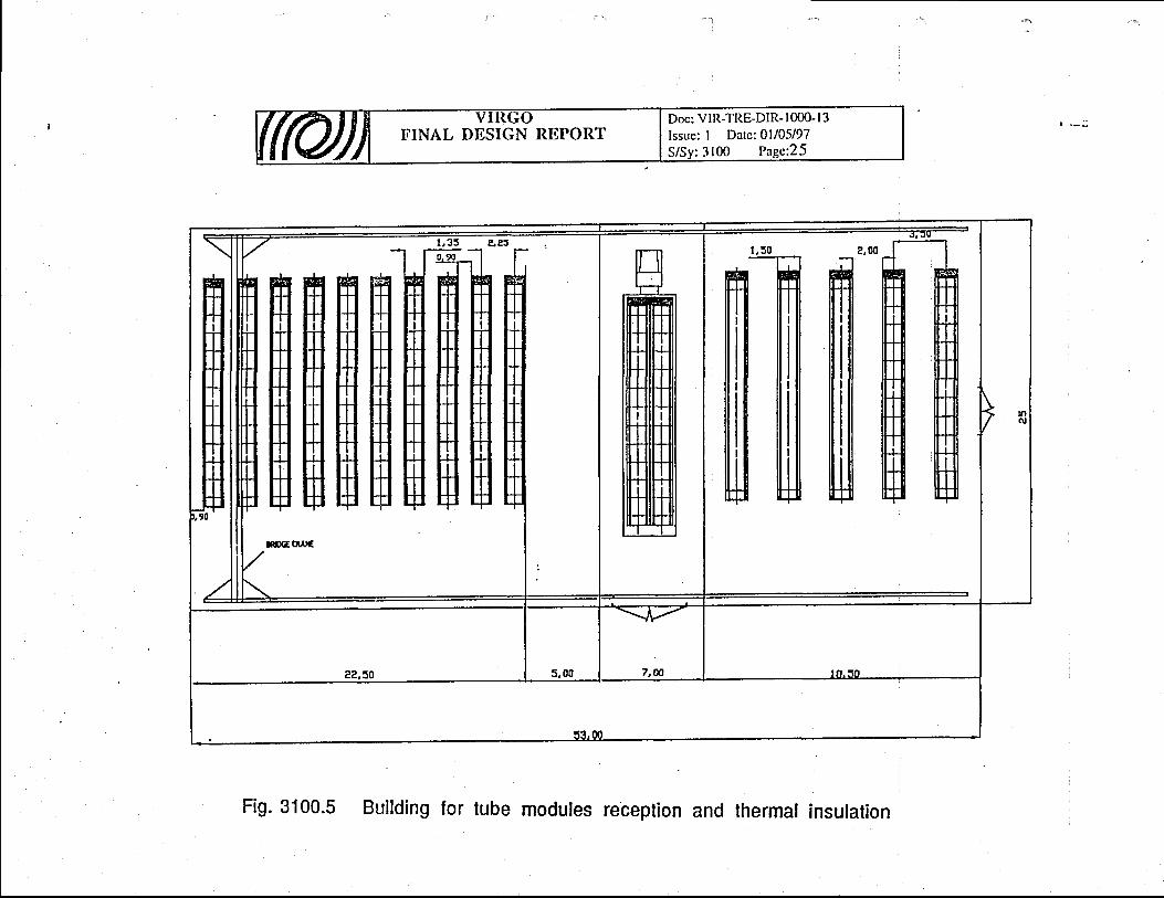
o.-(UJU)
.cCd
L.o-'o(It'
coIo-o.c)0)L.oo=.tfoEc)
-o:f,-t-oFo)
€corOoo(D(t)iE
Bru't !_
j__
_
g-r---rrr-r---r-r-r-I-T-F
sE
g._* H
rnc.tc-l
(t)
T9F
-qr
o\=
hr
.O
Io
d!i
ea
d5:
., c
)
8aEr
zV)
FIFf
z
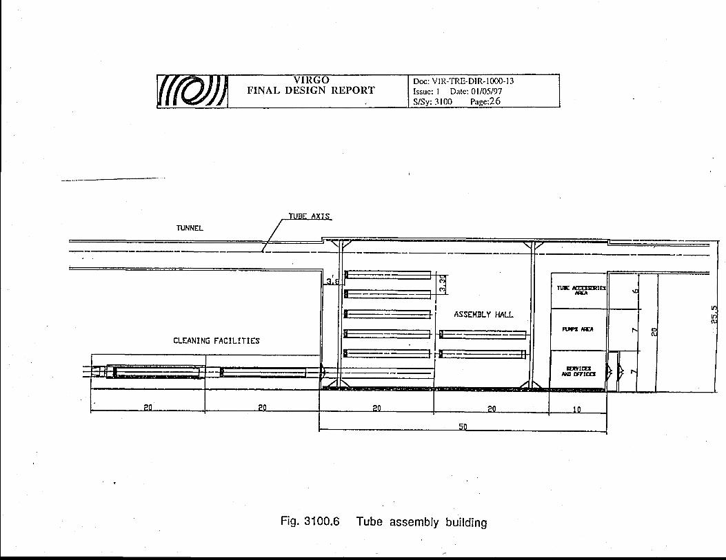
ct)
FE0)oU)
(o'
q)
-oF-
@oocr)c;iI
\oC-l
c.,
Rtr
5<
=h
ro
nc
dg
Nd
rd
H
I.. c
)E
;
E<
zrrl
U)
tlFl
zr-.v1trlFJtJt!t:z,z,LJJ(J
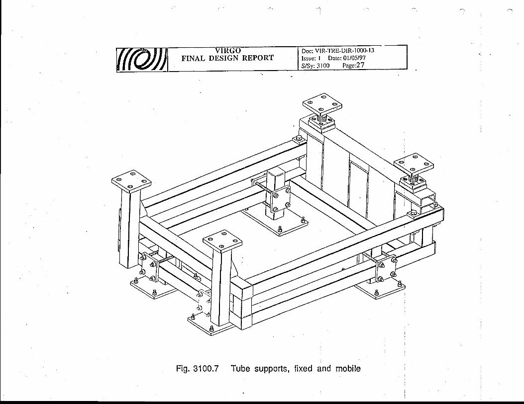
oEoE'oE(Uo)x,;Loo-ofo(I)-o=t--
\oococ;iI
f-cilU)
v)
c.i
Q
r-.q)
o\=
;
6o
rir c)
ea
FH
"c
)8
;Fzri(t).l
z
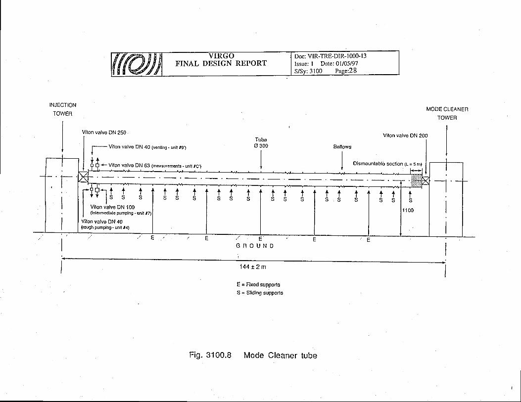
o-o3o)c(U_q)OoEoqOoC
Oc;iI
qo
E
tr
)a
C\t
o
E'
rx
.=
rr tr6
ri
li
l
LU (/)
CE
TU
z<c
Et!,
ui
i3
oo
c!z:
EIJ.ooo@iEo@39
-
AO
=c
t+
FO
it' '
r9
=c
.o
th
>E
oc
)=
(o
zz
^
6cl
cc
1.
=.
=o
ozn(,
sl
IS
l<
-c
-c
L+
-*-O-
.=)-
ziJ
=
-=
vz
@C.loca.
v)
c.)TQ
t--
QO
\=
hr
O
EO
,"t ii
tv cJ
FF
f
t:E
E
,FI
zCh
FI
Fl
zr-,
<-o
E
YO
:s*
?<
-c/) z
E
^!
g +
+E
<-(,) €i
A;
[-!E €
EH
>
€
c€
r s
gIII:
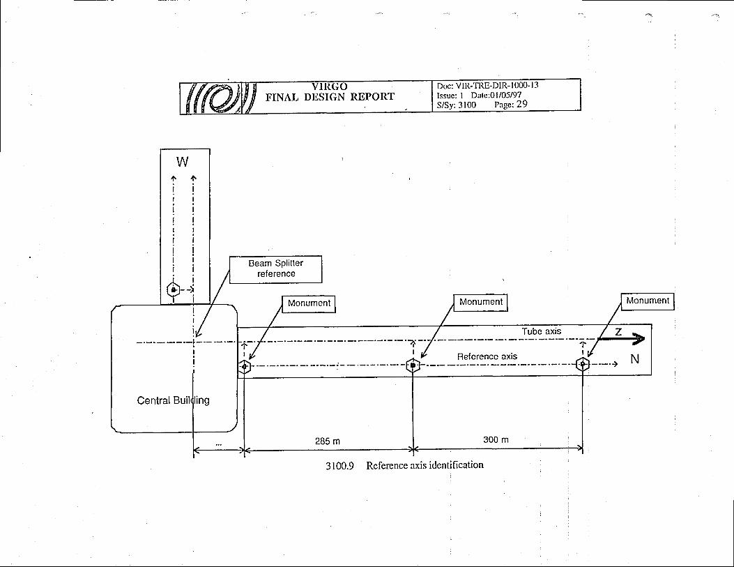
C)
c)6x(.)()g,c)a
E
{axF
\z1I
\iF-qthx0)0)tr\
-r
(--tl
i>( >l
+il
q)Eo
Eocf)Eroc\Iq)Eo
L0)=
o:
C)
o-c
CD
Ec
o)
(s
pc
)-
(n
c-+
-rh
=m
L0)O
-\v-
T><
a'- (\
JB
$a
r;
O.
r-.1 o
-G
)o
;r
9l
pi?
Q;
.(
N
E-'r
tl
?-z
.?O
=,
1-<
A>
r{Ffz
bNtru \;1
qV
ff,.L1*E1
%
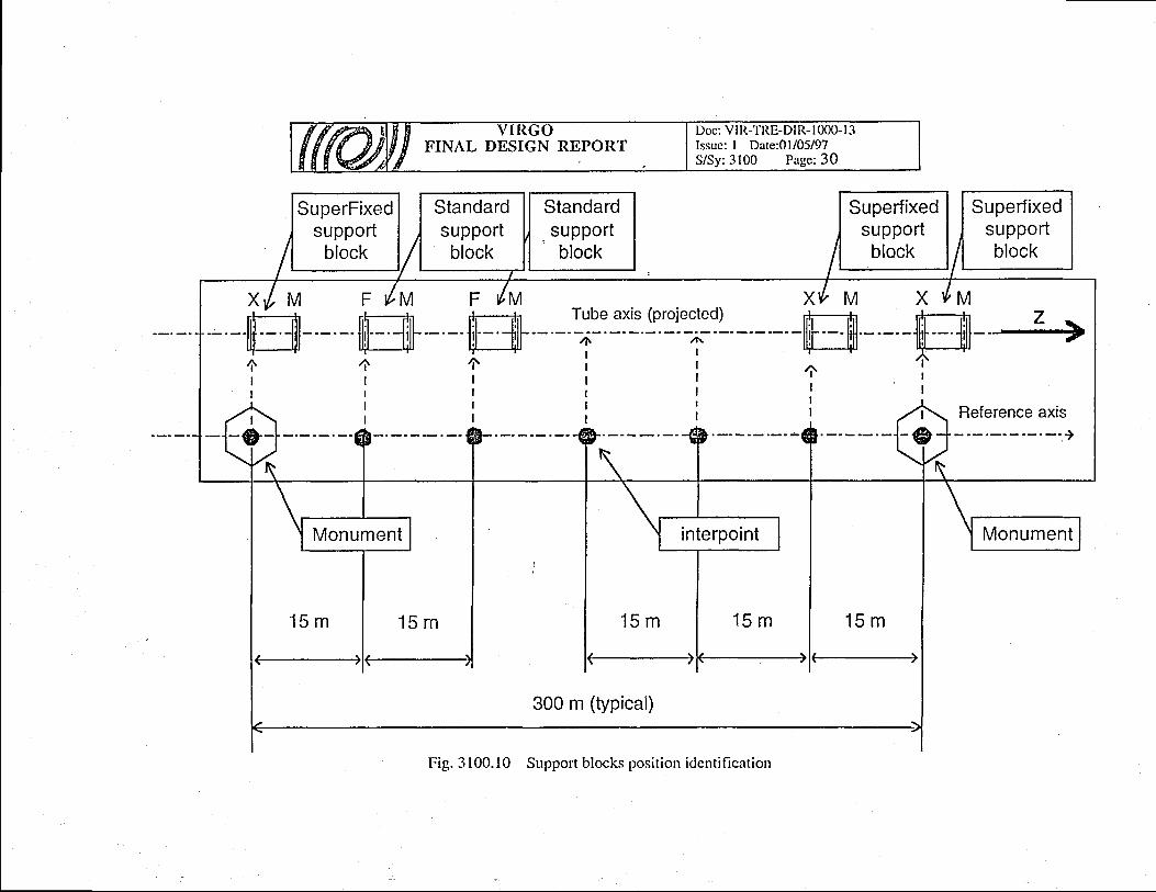
A"l>
F"
lx
+=
=F
sl
lx
+d0)oax0)a't
F
>F
:\
l
'rL
>F
>\lI
t I
l-
=F
:sl
X+
=
,=il
le
!-
l
Hi
bl
rf
:I
rr/ t*,
nUc
)r-X
Xv
.F
^(
)
6 d
oo
-f-
o=
aa
La)Eco
ioO .r-
XX
rz
F X
Eo
o
_tl
o- :f
-o=
aa
=ili
\YELO
!II
li
Ir
+ <
----€IIiIIIiII
(--- --sI
i!
!l
=rf
il
!l
r+
<-----@
ll
lr
L-
lHt
tl
tl
ii+
<- - -- -€
t!
ll
!-
lF
Ti
il r
T'-J
, /
A
EroEro
c'5o-Lo-
E.9o-(s
ol<
E+
Ea
v)
Eooa)
Li
-
-8 ei
c
o-lJ
a =
-o6
u)
Etr)r
-(JC
)-
.x k
r<L
LX
O
Hg
:=
aU
)Elr)
Jt-o
\Y
()(.)
t4at
(nt7
coc.)
(nU)
c?r-
)A
r! ii
-G
g'.
o
8AFrh
ct)F
I
z
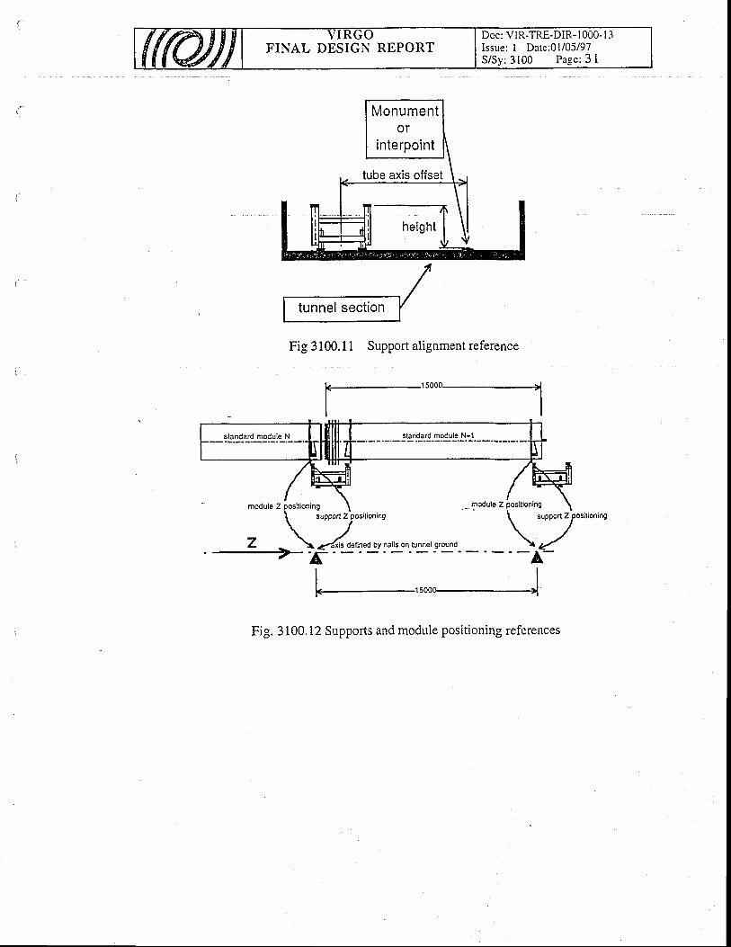
FINAL DESIGN REPORTDoc: VIR-TRE-DIR- I 000- I -1Issue: I Date:01/05/97S/Sy: 3100 Page: 3 I
Monumentor
interpoint
Fig 3100.1 1 Support alignment reference
Fig. 3100.12 Supports and module positioning references
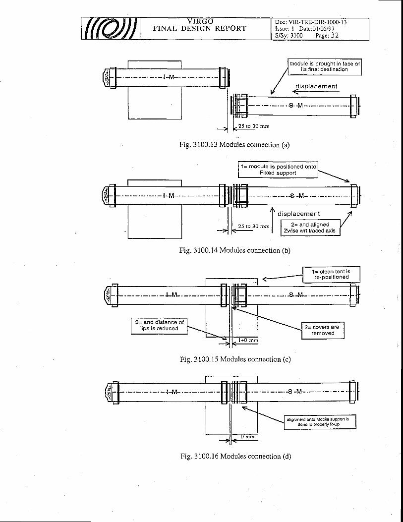
FINAL DESIGN REPORTDoc: VIR-TRE-DIR- 1000- I 3Issue: I Date:01/05/97S /Sy :3100 Page :32
#r l-nrl {ilIilE IIt-I- l l -
f o i sp tacementI I zs to go mm I I ,= ""d.1''s
-Z l- | lZwisewrttrac€
Fig. 3100.13 Modules connection (a)
Fig. 3100.14 Modules connection (b)
Fig. 3100.15 Modules connection (c)
3= and distance ofl ips is reduced
$t- +ttltilF\
alignment onto Mobile supPo( isdone to ProPerly lit-uP
mrn
Fig. 3 100.16 Modules connection (d)
FINAL DESIGN REPORTDoc: VIR.TRE-DIR.1 COO- 1 3Issue: Draft Date: 0l/05/97S/Sy:3200 Page: 1
32. B a f f les
Table of contents
32. Baff les
32.1 Int roduct ion
32.2 Scattered l igtrt in the long cavities32.2.1 Position of the baffles - Number of baffles32.2.2 St:l'nless steel baffles32.2.3 Glass baffles between mirrors and large valves32.2.4 D'tf fr action e f fects
32.3 Scattered l ight and bafftes in Central Area
32.4 References
32.5 Figures
a
7
22J
J
3
4
4
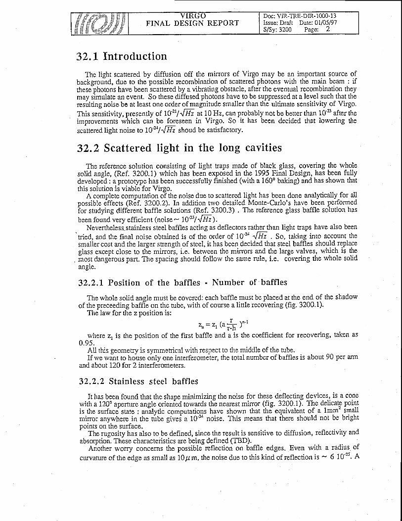
FINAL DESIGN REPORTDoc: VIR-TRE-DIR-1m0-1 3Issue: Drafr Date: 0l/05/97S/Sy:3200 Page: 2
32.L Introduction
The light scatrered by diffusion off the mirrors of Virgo may be an important source ofbackground, due to the possible recombination of scattered photons with the main beam : ifthese photons have been scattered by a vibrating obstacle, after the eventual recombination theymay simulate an event. So these diffused photons have to be suppressed at a level such that theresulting noise be at least one order of magnitude smaller than the ultimate sensitivity of Virgo.This sensitiviry, presen tly of 70'2t/48 at 10 Hz, can probably not be better than 10 B after theimprovements which can be foreseen in Virgo. So it has been decided that lowering thescattered light noise ,o t}'zt1',!E shoud be satisfactory.
32.2 Scattered light in the long cavities
The reference solution consisting of light traps made of black glass, covering the wholesolid angle, (Ref. 3200.1) which has been exposed in the 1995 Final Design, has been fullydeveloped : a protorype has been successfully finished (with a 1600 baking) and has shorvn thatthis solution is viable for Virgo.
A complete computation o-f the noise due to scattered light has been done analytically for al]possible effects Gef. 3200.2).In addition trvo detailed Monte-Carlo's have been performedior studying different baffle solutions (Ref. 3200.3) . The reference glass baffle solution hasbeen found very efficient (noise - I}'s/"[H).
Nevertheless.stainless steel baffles acting as deflectors rather than light traps have also been'tried, and the final noise obtained is of the order of lo'24 "[Hz . So, talcing into account the
smaller cost and the larger strength of steel, it has been decided that steel baffles should- re.placeglass except close to the mirrois, i.e. benveen the mirrors and the large valves, which is themost dangErous pafl. The spacing should follorv the same rule, i.e. covering the rvhole solidangre.
32.2.L Position of the baffles - Number of 'baffles
The whole solid angle must be covered: each baffle must be placed at the end of the shadowof the preceeding baffle on the tube, with of course a little recovering (fig. 3200.1).
The law for the z position is:
zn= zL (u # )"-t
rvhere z, is the position of the first baffle and a is the coefficient for recovering, taken as0.95.
All this geometry is symmerical rvith respect to the middle of the tube.If rve rvant to house only one interferometer, the total number of baffles is about 90 per arm
and about 120 for 2 interferometers.
32.2.2 Stainless steel baffles
It has been found ttrat the shape minimizing the noise for these deflecting devices, is a conewith a 1200 apernre angle orienied towards th-e nearest mirror (fig. 3200.1). Tle delicate pointis the surface state : anilytic computations have shown that the equivalent of a lmm' smallmirror anywhere in the ruUe givei a 70-u noise. This means that fhere should nol be brightpoints on the surface.'
The rugosity has also to be defined, since the result is sensitive to diffusion, reflectivity andabsorption. These characteristics are being defined (TBD).
Ariother worry concerns the possible-reflection on baffle edges. Even rvith a radius of
curvatureof theedgeassmallas lOpm,thenoiseduetothiskindof reflectionis - 610'25. A
FINAL DESIGN REPORTDoc: VIR-TRE-DIR-1m0-l 3Issue: Draft Date: 0l/05/97S/Sy:3200 Page: 3
ituAy is presentiy being performed in order to see rvhether cuiting on the innei edge
baffles at the module factory is presentlybe rvelded to the tube, possibly with the
of the baftles rvould solve the problem.The possibility of mounting the stainless steel
being investigated. In that case, the baffles shouldshape shown in fig. 3200.2.
32.2.3 Glass baffles betrveen mirrors and large Yalves
The link berween the mirrors and the large valves (the distance varies from 5 to 10 m) canbe a dangerous part, since :
--the hrle valve diameter is only 1 meter and must be hidden to the scattered light.- a bellolws and vacuum ports hive also to be hidden.- the zone is close to theinirrors and the first 10 meters are quite ha1mfu.l.- in addition, if the disribution of scattered light at the emission is very peaked
forward, the iunction between tower and tube has to be protected., the junction between tower and tube has to be protected.ward, the;unctlon between tower ano ru0e nas Io oe Proteclecr.-So, tivobiackglasslighttraps (fig.3?p0.i)1 as described in.lhg 192.5 Fiq?lJ)esign for theSO, tWO black glass llgnt tlaps (tlg. J.ZUU.J), aS Oescnoeu ur Ine IvvJ rllrill lresrBrl lut urs
reference solution] will bE instailed ii each of the mirror-tower links. These light traps can bedescribed as follows:
A glass cone (45o) inserted in a glass cylinder allows the incoming ph.otons to bereflected 3lmes if they come from the lefi(on the figure), and more than 5 timqs if thepr come
from the right. T\e reflectiviry R of the glass surface has to be such that (R)3 < 10'u which
gives <R> < 10-'. Geomerically, the baffle is oriented as shown in fig. 3200.1.for the first[Uof tle tube (near the input minor), and symmetrically rvith,respect to a verdcal plane I tothe tube axis in the middte bf the tube, for the end part of the tube.
A full protot)?e has been built and the manufacturing is norv mastered.
32.2.4 Diffraction effects
The noise introduced by diffraction on the baffle edges can be quite small, provided tiratcoherence effects due to i perfect radial geomeury are
-broken : the beam must bo slightly
displaced off the tube axis (but the result-is not very -sensitive lg -the.displacement) an-d theb#fle should be slightly tilted with respect to the vertiiai plahb, which will be done naturally bythe construction imperfe'ctions.
For about 100 baffles in a arm, the noise is then 5 rc'x/"lHz.
32.3 Scattered light and baffles in Central Area
Due to the number of optical componentsanalytically the noise due to scattered light.
in the central area, it is impossible to compute
A Monte Carlo has been especially developed,different optical components in all their interactions
follorving the photons impiging on th-ervith all the obstacles (tower body, link
tubes between towers etc).The results are exposed in ref. 3200.4.For the construcd6n of the interferometer, the constraints following from this study are:
- The diameter of the link tubes should be at least equal to 40 cm.- In the 3 main towers: beam splitter, west and no:rh input mirrop., the A L0A-0.
windows ieei"g ih" b"u- should be coveied Ui A i2OO coated glasicircles with a centered @200 hole (fig. 3200.4).
- fn iOOition, in cusr a6 250 valve is used in the middle of the links, ab 400 coatedglass circle, with a O 250 centercd hole, should be inserted on each side o! the valve.
Under these conditions, the noise in the central area is also betrveen 1Ou and 10'5 m/'lllz at10 Hz.
FINAL DESIGN REPORTDoc: VIR-TRE-DtR-1000-l 3Issue: Draft Date: 01105/97S/Sy:3200 Page: 4
3200.1
3200.2
32.4 References
3200.3
V. Brisson - A solution for removing the scattered light, Virgo note 9211V. Brisson - Feasability of glass baffles, Vkgo note 9212J.Y. Vinet, V. Brisson, S. Braccini - Scattered light evaluation and calculation ofthe induced phase noise, Virgo note 95126J.Y. vinet, v. Brisson, s. Braccini - Scattered light noise in G.w. interferomericdetector : coherent effecrs, Phys. Rev. D54-2, Lsn /96 (lZ7 6-1286)a) I. Fenante, S. Braccini - A Monte-Carlo for the calculation of noise bv diffusedlight in the Virgo vacuum pipeVirgo nore 96/18.b) F. Bondu et E. Tourni6 - A Monte-Carlo for the calculation of the noise due todiffused light Virgo note (in preparation).S. Braccini - PhD thesis, 1996.3200.4
32.5 Figures
3200.1 Working principle of baffles3200.2 Stainless steel baffle3200.3 Glass light traps3200.4 Glass baffles in central and terminal torvers

/\
q\ ac.)
(g^c)oQaaq)
.trU
)
cr)0)
(d-ooc).gC
)'co-
O)
co=c;oNcoo,LL
<notuU'
(t(g
oc)a)aL ---------------+
-=a
tnoC.l
CN
cn
TOr
ab
.=
;,
O
EO
rn !itv
aJ
l<
H
e.. c
.)8
Ao
,EHr-'l
zaF)
zr-,

FINAL DESIGN REPORTDoc: VIR-TRE-DIR- I 000- I 3Issue: I Dare: 0l/05/97S/Sy: 3200 Page:6
4180
Fig. 3200.2 Sta in less s tee l baf f le
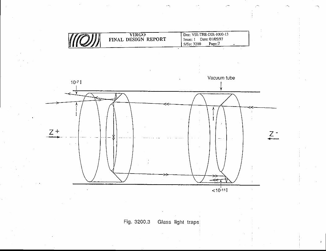
tul
l,t
c)V
o6JEfO(g
al_t
L-goNCI
qooC\l
c)c;ir
tr-e.lc.]
(n(n
Ot
so
b,
=h
JQ
6o
,''r ii
f/ cJ
t<
HIo
3,aor-l
zcnr-'l
.'r
z
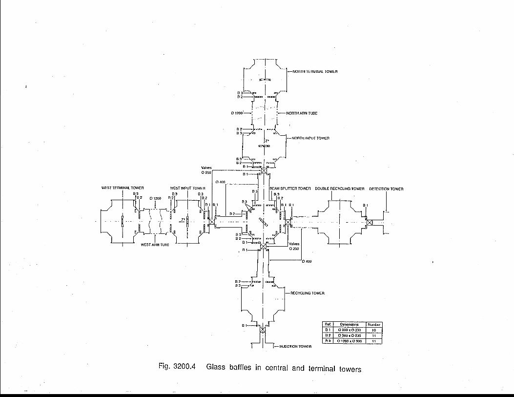
(/)Lc)3oG'-oEcE
Lc)().;(I)
(!-ou)ag(taoont
CD.-ir
l5zE
oE
5
E
U3ItroUFg=oqUloU==g
U3FzF2I
cg=zI
.-l ,'
t__
_if
!
I i
'. n
ff-s
tf
t;
FINAL DESIGN REPORTDoc: VIR-TRE-DIR- I 000- I 3Issue: I Date: 0l/05/97S/Sy: 3300 Page: I
33 . Towers
Table of Contents
33. Tolvers
33 .1 Spec i f i ca t i on33. l. I Experimental requirements
33.1.1.1 Torver posi t ion ing33.1.1.2 Decoupling from environmental noise
33.1. 1.2.1 Seismic noise33.1 .1.2.2 Light losses
33. I . l .3 Implementation of a calibration system33. 1.2 Technical requirements
33.1.2.1 Suspensions33.1.2.2 Payloads
33.l.2.2.l "Mirror" payloads33.1.2.2.2 Mode cleaner payload33.1.2.2.3 Input and detection benches payloads
33. 1.3 Contingencies and flexibil i t ies33.1.4 Summary and design guidelines
' 33.2 Vacudm torvers design33.2.1 Rarv material and surface treatment33.2.2 Vacuum towers compartment structure33.2.3 Torver mechanical structure
33.3 Vacuum system real isat ion33.3..1 Lorver to"ver
33.3.1.1 Lorver compartment functionalit ies33.3.1.1.1 Latera l beam f langes33.3.1.1.2 Access for payload installation33.3. 1. 1.3 Technical access33.3.1.1.4 Lorver tower/ gallery l inkage33.3.1. 1.5 Optical ports
3
4A
Aa
4At
4J
)6666
67I.I
888999999
l 0l 0l0l 0l ll ll ll t
l ll l
l tt 2t 2t 21 2l 3
33.3.1.1.6 Clean air supply, venting, roughing and intermediate pumping33.3.1.2 Intermediate vacuum chamber
33.3.1.2.1 Access for pumping33.3.1.2.2 Access for translations33.3.1.2.3 Visual control of the suspension wire position33.3,1.2.4 Thermal screening of the upper compartment
33.3. 1.3 Upper compartment functionalit ies33.3. 1.3.1 Technical access33.3.1.3.2 Pumping ports for the upper compartment
33.3.2 Upper tower33.3.3 Central building vacuum tank
33.3.3. I Lateral windorv interfaces33.3.3.2 Detailed l ink structure
33.3.3.2.1 Access for permanent pumping and instrumentation33.3.3.2.2 Sectioning valves33.3.3.2.3 Test interferometer configuration
33.3.4 Beam compartment baking
FINAL DESIGN REPORTDoc: VIR-TRE-DIR- l 000- I 3Issue: I Date: 0l/05/97S/Sv:3300 Paee: 2
33.3.4.1 Lorver torver baking33.3.4.2 Upper torver thermal insulation33.3.4.3 L ink baking
33.3.5 Lorver torver ground floor anchoring
33.4 Vacuum system c lean access33.4. I A continuous clean processing l ine33.4.2 Payload transfer system33.4.3 Component handling tools33.4.4 Optics installation scenario
33.4.4.1 Assembly on transfer system33.4.4.2 Transfer to the tolver access tent33.4.4.3 Introduction33.4.4.4 Fixation to the suspension rvire and tool extraction33.4.4.5 Fine tuning of the payload in the tower33.4.4.6 Baffle installation in the optics vicinity33.4.4.7 Tower closing
33.4.5 Cleanness monitorins33.4.6 Safety
33.5 Assembly sequences33.5.1 Lorver tower reception33.5.2 Lower torver installation and linking33.5.3 Intermediate vacuum chamber installation33.5.4 Suspension installation33.5.5 About cleaning
33.6 Guidei ines for space a l locat ion around the torvers
33.7 References
l - 1
l 3,t -1
t -1
t 4t 4I At -
l 5l 5l 5l )
l 5l 6l 6l 6t 6r6l 6
t 7l 7t 7t 7t 7l 8
1 8
1 8
IntroductionMultistage suspensions are implemented in towers of various heights [fig.3300.1],
depending on the locally requested seismic noise attenuation. The tower basement houses thesuspended payload. It interconnects the interferometer arms, provides optical access for thecomponent alignment and allorvs for the human access needed by the payload installation.
Seven towers are interlinked in the central building, three towers are linked at a distance fromthe central building. Towers are named according to their payload functionaliry [see table 3300-Il: input and detection, beam splitter, north / rvest input, polver and signal recycling in thecentral building, north / rvest end and mode-cleaner in dedicated buildings.
In the follorving rve review the construction design of the towers and of the central buildingvacuum system. The vacuum system assembly sequences are defined and a scenario for theclean installation of the interferometer components is described. The implementation of theservices requested by the totver operation is sketched.
FINAL DESIGN REPORTDoc: VIR-TRE-DIR- 1000- I -1Issue: I Date: 0l/05/97S/Sy: 3300 Page: 3
33. L Specif ication
33.1.1 Experimental requirements
33 . 1 . 1 . 1 To rve r pos i t i on ing
The respective locations of the torvers in the central building are determined by the details ofthe selected Iocking scheme. Provision has been made to allorv for an asymmetry of up to 1600mm between the two arms, allorving the displacement of the trvo input towers rvithin +l- 400mm. The porver recycling tower can also be translated rvithin +600 and -1000 mm.
Similarly the terminal torvers positions can be adjusted within rvithin +/- 1500 mm and theMode Cleaner tower within +/- 2000 mm.
The beam height is set at 1100 mm rdlative to the building ground floor. Throughout thissection, vertical coordinates (z) ue given with respect to the horizontal plane which contains thebeam.
As a consequence of the details of the beam propagation scheme and of the finite range of thesuspension displacement mechanisms it has been decided to position the torvers as shown onfig. 3300.2:
a
. a
Injection and recycling towers are translated rvith their links by 20 mm West with respectto the North Fabry Perot arm axis.Beam splitter and signal recycling torvers are translated rvith their links by 20 mm Northrvith reipect to the West Fabry Perot arm axis. The link betiveen signal recycling anddetection towers is translated by 10 mrn more, i.e. 30 mm. Detection torver is on theFabry-Perot West arm axis.
These particular locations are accounted in the vacuum chamber design rvith off axed linkconnections as shorvn on table 3300-il.
The final positioning of the interferometer components is obtained in several steps:1. Lorver towers a-re aligned in the laboratory system uSing the lower torver squqg flangeLOWer towers are allgned rn me laDoratory system usrng me lower tower squq9 uangc
already taken as a reference for its realization at factory [fig. 3300. 4]. They-arepositi6ned within a ferv mm in the laboratory reference system. The horizontality of titepositioned within a ferv mm in the laboratory reference system. horizontality of titeflange is defined to.lmrad.
2. A tower is built with two vacuum compartments separated by a wall fedthrough bY theis contolled accross thissuspension wire. The marionetta, hence the minor position,
rvall. It's geometry defines the first order position of theconsequence, the rvall is designed to allorv for a fine tuning
suspended paYload. As ain iosition inil angle rvith
respect to the beam line.3. Each suspension allorvs for the positioning of its optical component up to a ferv mm or
mrad rvithin the separating wall geometry.4. The ultimate alignment iipermanently ripdated by the control system which steers the
interferometer components to a fraction of a rvavelength acting on them via marionettaand reference mass.
The effective local position of a component is determined from outside the vacuum tankmeasuring the deflection of a rvell knowri additional laser beam. The implementation of thesemeasurements requires the realization of optical ports pointing to the opiicat component. [seetable 3300.II1.

FINAL DESIGN REPORTDoc: VIR-TRE-DIR- 1000- I 3Issue: I Date: 0l/05/97S/Sy:3300 Page: 4
33 .1 .1 .2 Decoup l i ng f rom env i ronmen ta l no i fg
3 3 . 1 . 1 . 2 . 1 S e i s m i c n o i s e
One of the most remarkable and unique feature of VIRGO rvill be its high sensitivity forgravitational rvaves in a frequency band starting as lorv as a ferv Hz. This fEature is achievedwith the multi-stage suspensions, also called superattenuators. They reduce the seismic noise onthe interferometer test mass in all the six degrees of freedom. As a consequence, the resonancefrequency of the mechanical structure supporting the suspension has been ilushed above l5 Hz,i.e. rvell above the superattenuator cutoff frequency.
33 ,1 .1 ,2 ,2 L igh t l osses
. The light scatterg{ of{ by the vacuum chamber walls or by the mirrors themselves may be animportant source of background, due to possible recombination of scattered photons rvith themain beam. Absorbing baffles are thus foreseen inside the long arms and in t'he neighborhoodof optical components.
lhlspgcifications on Fabry Perot optics limit diffusion losses on the coatings at the ppmlevel. To.keep this performance, losses due to dust deposits have to be mastered aia comparablelevel. This consideration limits the mirror obscurancy factor ( i.e. the ratio to the active surface,of the sr.rrface covered by dust particles) at the ppm level for a mirror set in operation.
Stability ̂requirements on the index of refraction of the beam propagating medium andanness of the optics impose strong specifications on the vacuum chamber resldual Dressure.residual pressure.cleanness of the optics impose strong specifications on the vacuum
Partial Dressures'as lorv at 10'mbar fbr H". 10't0 mbar for othefartial pr€ssures'as lorv as 10'mbar fbr H2, l0'r0 mbar for other gases, and 10'r'inbar forl - - - J - - - - t - - - - , l ! r i
3 3 . 1 . 1 . 3 Implementat ion of a cal ibrat ion svstem
The global operation of the interferometer is monitored with an independent calibrationsystem. It is performed using the radiation pressure.produced b.y an a4ditibnal-laser beam tomove a given mirror according to a rvell known displacement scheme. The implementation ofsuch a.sYstem requires a set of dedicated [see table 3300-II] optical ports pointing on theselected mirrors.
33,L.2 Technical requirements
\{any cgmponents are implemented in the vacuum system. Suspensions and payloads haveto be installed and operated in vacuum and in clean conditioni. Here we surnmarize thecomponent properties to be accounted in the design of the vacuum system
3 1 . 1 . 2 . 1 S u s p e n s i o n s
The suspensions and the inner structures supporting them are described in the relevantsections. The suspensions contain many mechanical and electrical components, hence, in thevacuLlm.compartment rvhere they are indtalled, it will not be possible to ieach a pressure lorverthan 10-" mbar.
hydrocarbons are required in the laser beam compartment. Such partial pressures can only berdached respecting strict cleaning procedures follorved by a 1500'C baking. Requirements areless stringent in the input,..detection and Mode Cleaner tube and tanks, rvhere partial pressures.near l0'' mbar are admissible.

FINAL DESIGN REPORTDoc: VIR-TRE-DIR- I 000- I 3Issue: I Date: 0l/05/97S/Sy: 3300 Page: 5
Suspensions rvill be installed on top of the lorver tower; once adjusted an tested, they will beenclosed in the upper tower, sliding on the modular cylinders and the top cap.
Given the recent developments of the suspension design, the interfaces rvith the torvers havestill to be agreed (TBD).
3 3 . 1 . 2 . 2 P a y l o a d s
The payload is the interferometer optical element associated to its steering devices. Theoptical element is a mirror, an input or a detection bench. The 1998 opticai elements beingtemporary, they rvill be adapted to their final steering devices using adhoc interfaces.
Payloads will be installed in the lorver towers through the bottom port, which is accessiblevia the "gallery" situated in the basement of the buildings, just under the floor supporting thetowers (f igs. 3300.1, 3300.5).
Table 3300-I : Torver specificitiesI npu t
&D e tec t i on
N Iodecleaner
S i g n a lrecyc l i ng
Porverrecyc l i ng
Beamsp l i t t e r
I npu tNorth
& IVest
EndNorth
& lYest
) i s p l a c e m e n t:ange (mm) fixed +2000 fixed +600
-1000
fixed +400 fixed
\ umberrf f i l ters J J 0 5 5 5 5
t lumberof rings t I
I 0 5 JaJ
a
ln termediate:hamber no no no yes yes yes yes
!Veight& size (mm)r f opt ics
750g
Qr20
x30
>3.5kg
anax>50
2l l42kg
a3so
x100
2r l42kg
a3s0
x100
Referencenass no yes no yes yes yes yes
Vlar ionet ta yes yes no yes yes yes yes
33 .1 ,2 .2 .1 " i \ I i r r o r " pay loads
The minor (input/end North/West, beam splitter, porver recycling) hangs -on a marionettawhich allows for iotations around the trvo axei perpendicular to the beam, and fo1 translationsalong the beam line. The acting forces are geniraGd by the current circulating through coilsfixed'to the last suspension stale and surro[nding magnets fixed to the marionetta. A motorallorvs for the balaniing of the marionetta. Six rvires arcnecessary for its control. -
The reference mass firovides u *or" sensitive control on the mirror longitudinal position. It issuspended to the marionetta. It has the same mass and center of gravity as th€ mirror. Itscylindrical shape, rvhich surrounds the mirror, provides also proteciion alainst dust d-eposits.fhe longitudinil correction is generated by eithefmagnetic or electrostatic forces acting between
FINAL DESIGN REPORTDoc: VIR-TRE-DIR- I 000- I 3Issue: I Date: 0l/05/97S/Sy: 3300 Page: 6
reference mass and mirror. The necessary power is fed rvith 8 rvires running dorvn thesuspension.
. The minor payloads being in the beam line, they fgllgrv the beam tube specificarions: UHV,low outgassing rate, good mechanical behavior at 1500C, cleanness.
To respect the above mentioned specifications on optics cleanness, payloads are assembled ina gle$.laboratory. Accordingly, their set Lrp in the beam line is perfoirned in lorver torvers fedwith filtered air.
33.1.2,2.2 l l lode c leaner payload
The Mode Cleaner gllTor has, in general, the same requirements as the other mirrors,will be installed in a single compartment torver, since the Mode Cleaner cavity can run in(pressure =10'6 mbar).
-
Detailed requirements have srill to be defined (TBD),
33.1.2.2.3 Input and detect ion benches payloads
The benches, being larger and heavier than mirors, require special marionetta's; no referencemass is.req_uired. They rvill be operated in HV, in single cbmpaitment towers.
Detailed requirements have still to be defined (TBD).
33.1.3 Contingencies and f lexibi l i t ies
The beam tube diameter (01200mm) has been chosen to accomodate a possible secondinterferometer. This is not the case for the diameter of the tubes linking the toivers, which has
butHV
beer fixed, for the first operation period, to accomodate only one interf#ometer.,. To simplify the.design and to provide some freedom it assembly, the lorverlinling elements will be standardiz6d and symmetrized.
For setting yq ?nd maintenance any tower has to be accessibre independentlystatus of its neighbouring towers, hence valves are present on the link'tubes.
33.L.4 Summary and design guidei ines
The above described experimental requirements and technical choices dehne the maincharacteristics of the vacuum tank design. The different outgassing rates expected from thesuspensions, optical paylaods, input and detection benches d'ictate thd tank vacuumcgmqTtlnelt structure. The cleanness requirements on optics dictate the implementation ofclassified clean infrastructures inside and dilectly connected to the vacuum tank. The suspensionweight and dimension defines the mechanical structure of the lower tower basement.
33.2 Yacuum tolyers design
Having made a choice for the raw material, one determines the vacuum svsrem comDartmentarrangement. This defines the lower tower as the basic building module-rvhose m6chanicaistructure is computed according to a modelisation with the SYSTUS code. The lorver torverbasement and its upper torver compartment are described. The functionalities of the differenttowers are detailed in table 3300-I and 3300-[. The different lorver totver vacuumcompartments are linked together and to the 3 km arm tubes to form the beam vacuum chamber,which needs to be baked io reach its specified outgassing rate. Finally, the tower groundanchoring is described
tower beam
of the pressure

FINAL DESIGN REPORTDoc: VIR-TRE-DIR- 1000- I 3Issue: I Date: 0l/05/97S/Sy:3300 Page: 7
i
33.2.1 Rarv material and surface treatment
The vacuum specifications defined above and the size of the vacuum chamber favourstainless steel for the choice of the chamber raw material. The 300 series of austenitic steels isthe most frequently used in vacuum and cryogenic wor\ be-cause it is conosion resistant, easyto rvork and non magnetic. The US 304L or NF Z2CN18-10 variety has been chosen.
The inner surface state of the tank is processed to iimit outgassing rate and dust adhesionabrasion and electropolishing an RA smaller than 1.6 micrometer is realized. On the other handhigh vacuum and cleanness specifications impose to fear hydrocarbons and dust particles in therealisation.
Tensions are relieved, hydrocarbons and hydrogen are removed by a thermal processing ofthe vacuum chamber. A 3 step thorough thermal processing [ref. 3300-l] of the lorver tower isthus defined:
- Tension relieving: Stainless steel sheetings are air fired-at 4500C- Hydrogen outguising: Components are a'ir fired at 4000C- D'egreising: L-orver iorver is UateO under vacuum at 2000C
After proiessing, the chamber is sealed and stays sealed until connection with its sus.pension.All vacurlm components are conditioned at high temperature before being assembled in an oilfree ambience. Dirst particles are only tracked after reception of the complete vacuum tank, justbefore payload installation.
Al flairges of diameter < 250 rrrm are of the CONFLAT type made with 304LN stainlesssteel. Flanges > 250 rrm can be sealed rvith either VITON or METAL gaskets.
33.2.2 Vacuum torvers compartment structure
The highly different outgassing rates expected from suspensions, mirror paylaods, input.anddetection Eenches dictate itJ compartimentation. The beam-compartment containing. the payloadis thus isolated from its corresponding suspension compartment by an intermediate vacuum.chamber. Input and detection benches are-isolated from the rest of the. beam propagationcompartmenf with appropriate optical rvindorvs. As the bench and suspension outg-assings. areexpected to be comparable, fhey are confined in single compartments. Each of thesecompartments is pumped for its orvn.
33.2.3 Torver mechanical structure
The vacuum if,rcations require the construction of a tark with 15mm wall thiickness fitI ne vacuum speclllcatrons requfe tne constructronrvith metallic sealings in its UHV (baked) compartment.
A more elaborate modellins usins the SYSTUS codeA more elaborate modelling using the SYrcture, The simulation oroduced distribdistributions of static deformations and stresses under
code has been used to define the lorver torverstructure. The simulationvarious loading conditions'(tank under its proper rveight at normal temperature, tank undervacuLlm at noriral temperattire, tank under vacuum at 150 "C). The model taken for b{.ngassumes a uniform heating betrveen the protection plate and the top of the square pelestal_ [fJg.3300.41. Results of the m"odeUing have
^been verified on the lorvei tower prototype [ref. 3300-
2) .- The details of the lorver torver geometry have been optimized to rise the torver fundamental
frequency to 27 Hz tf,rg 3300.31. -A
collapse factor of 12.8 during baking under vacuum wasobtained.
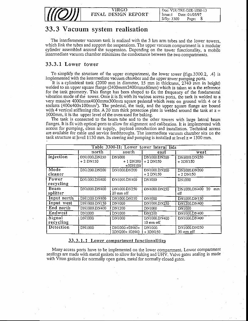
ffffijJ Y I K U UFINAL DESIGN REPORT
Doc: VIR-TRE-DIR- 1000- I 3Issue: I Date: 0UA5/97S/Sy: 3300 Pa-qe: 8
33.3 Vacuum system realisation
The interferometer vacuum tank is realized rvith the 3 km arm tubes and the lorver towers,rvhich link the tubes and support the suspensions. The upper vacuum compartment is a modularcylinder assembled around the suspension. Depending on the torver functionality, a mobileintermediate vacullm chamber minimizes the conductance betrveen the trvo comDartments.
33.3.L Lo lver to lyer
To simplify $e structLlre of the upper compartment, the lower torver [figs.3300.2, .4] isimplemented rvith the intermediate vacuum chamber and the upper tower pumping ports.-It
is a cylindrical tank (2000 mm in diameter, 15 mm iriihickness',2740 i,m in height)rvelded to an upper square flange (2400mmx2400mmx60mm) rvhich is taken as a the referencefo1 th9 tank geometry. This flange has been shaped to fix the frequency of the fundamentalvibration mode of the tower. Once it is fit with its various access ports, the tank is welded to avery massiv-e 4000mmx4000mrn"r300mrn square pedestal which rests on ground lvith 4 or 6sockets (400x400x100mm3). The pedestal,-the tink, and the upper squaie flange are boundrvith 4 vertical stiffening ribs. A 20 mm thick protection plate is rvelded-around the tank at z =1000mm, it is the upper level of the oven used for baking.
The tank is connected to the beam tube and to the other toivers rvith large lateral beamflanges. It is fit rvith optical ports to allorv for alignment and calibration. It is implemented withaccess for pr"rmping, clean air supply, payload introduction and installation. Technical accessare available for cable and service feedthroughs. The intermediate vacuum chamber sits on thetank structure at level 1130 mm. Its steering and pumping is installed at level z = 1300 mm.
33.3. 1 . 1 Lorver compartment funct ional i t ies
Many access ports have to be implemented on the lower compartment. Lorver compartmentsealings are made rvith metal gaskets to allorv for baking and UHV. Valve gates sealing is madervith Viton gaskets for normally open gates, metal for normally closed gates.
Iable JJUU-U: Lolver toryer lateral l idsnorth sou th east lves t
in jec t ion DNl000.DN250+ 2 DNl50
DN1000+ I DN200+3DNl00
DNl000.DN200+ 2 DNl50
DNl000.DN250+ 2DNl50
i\1l'o clecleaner
DNl200.DN200 DNl000.DN200 DNl000.DN200+ 2 DNl50
DNl000.DN200+ 2 DNl50
ro \verrecyc l ing
DNr000.DN400 DNl000.DN400 DN1000 DN1000
lJeamsp l i t te r
DNl000.DN400 DNr000.DN25020 mm off
DNl000.DN250 DNI000.DN400 20 mmoff
Input north DNl200.DN400 DNl000.DN250 DN1000 DN 000.DN150Input n'est DNl000.DNl50 DNl000 DNl000.DN250 DN 200.DN400Irnd north DNl000.DN400 DNr200 DNl000 DN 000l rndwest DN1000 DNr000 DN1200 DN 000.DN400D l g n a lr e c y c l i n g
DN1000 DNl000 DNl000.DN40010 mm off
DNl000.DN400
Detec t i on DNl000 DNl000.+DN63+2DN200+ 1DN40
DNr000.+ 3DNl50
DNl000.DN25030 mm off
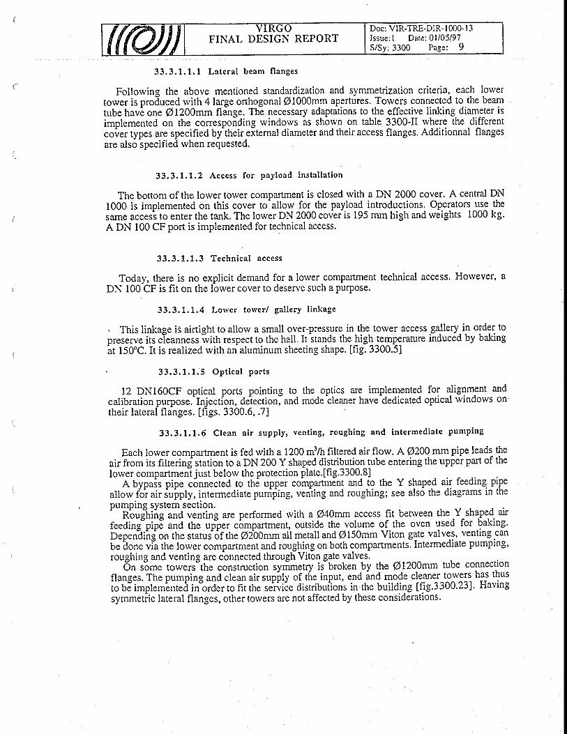
Doc: VIR-TRE-DIR- I 000- I 3Issue: I Date: 0l/05/97S/Sy:3300 Page: 9
FINAL DESIGN REPORT
33 .3 .1 .1 .1 La te ra l beam f l anges
Follorving the above mentioned standardization and symmetrization criteria, each lowertower is produced rvith 4large orthogonal @l000mm apertures. Torvers connected to the beamtube havl one @Lz}}mm flinge. Th! necessary adaptalions to the effective linking diameter isimplemented on the. corresponding rvindorvs as shorvn on table 3300-[ rvhere the differentcover types are specified batheir eitemal diameter and their access flanges. Additionnal flangesare also specified rvhen requested.
33 .3 .1 .1 .2 Access fo r pay load i ns ta l l a t i on
The bottom of the lorver tower compartment is closed rvith a DN 2000 cover. A central DN1000 is implemented on this cover to-allowJor_the payload_introductions. Operators use thesame access to enter the tank. The lower DN 2000 covtris 195 mm high and weights 1000 kg.A DN 100 CF port is implemented for technical access.
33 .3 .1 .1 .3 Techn i ca l access
Today, there is no explicit demand for a lorver compartment technical access. Holever, aDN 100 CF is fit on the lower cover to deserve such a purpose.
33.3.1.1.4 Lorver torver / gal lery l inkage
. This linkage iS airtight to allorv a small over-pressure in the tower access gallery.in order topreserve its ileanness ivith respect to the hall. it stands the high temperature induced by bakingit t50"C. It is realized rvith an aluminum sheeting shape. lfig. 3300.5]
33 .3 .1 .1 .5 Op t i ca l po r t s
12 DN160CF optical ports pointing to the optics are implemented for alignment andcalibration purpose.^Injection, detectionland mode cleaner have-dedicated optical rvindows ontheir lateral flanges. [figs. 3300.6, .7]
33.3.1.1.6 Clean a i r supply, vent ing, roughing and intermediate pumping
Each lorver comparrment is fed with a 1200 m3/h filtered air flow. A@200 mm pipe leads theair from its filtering station to a DN 200 Y shaped distribution_tube entering the upper part of thelower compartment just below the protection plate.[fig.3300.8]
A bypais pipe c6nnected to th6 upper coinparthen! a"d Jg the Y sfrape.d air feeding. pipeallorv fo'r air iuiply, intermediate punifing, veniing and ror.rghing; see also the diagrams in thepumping system section.'
nbuftriig and venring are performed rvith a Q40mm access fit betrveen the Y.shaped airfeeding"pipE and the upper compartment, outside thero_lume of the oven used for baking.b.p.niiitj on the stotui6f th. @tOOmmali metall and @150mm Viton gate valves,.venting.canbe'done via the fo*eiio*p-tment and roughing on both compartments.Intermediate pumping'roughing and venting are cbnnected through Viton gate valves.
6n s-ome torvers"the construction sytf;rn.try is"broken by the @LZO}mm rube connectionflanges. The pumping unA.f"un uiirupf,fy of tfie input, end ind mode cleaner towers has thusto UE imptembntei iriorder ro fir the servi6e distributlions in the buildilg tfig.3300.231. Havingsymmedic lateral flanges, other towers are not affected by these considerations.
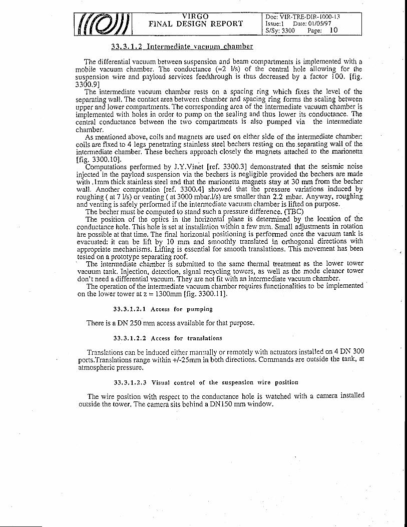
FINAL DESIGN REPORTDoc: VIR-TRE-DIR- I 000- I 3Issue: I Date: 0l/05/97S/Sy: 3300 Page: I 0
3 3 . 3 . 1 . 2I n te rmed ia te vac r r r rm chamber
The differential vacuum betrveen suspension and beam compartments is implemented with amobile vacuum chamber. The conductance (=! l/s) of the central hole allorving for thesuspension wire and payload services feedthrough is thus decreased by a factor 100. [fig.3300.91
The intermediate vacuum chamber rests on a spacing ring rvhich fixes the level of theseparating rvall. The contact area betrveen chamber and spacing ring forms the sealing betrveenupper and lorver compartments. The corresponding area of the intermediate vacuum chamber isimplemented rvith holes in order to plrmp on the sealing and thus lorver its conductance. Thecentral conductance between the trvo compartments is also pumped via the intermediatechamber.
As mentioned above, coils and magnets are used on either side of the intermediate chamber:coils are fixed to 4 legs penetrating stainless steel bechers resting on the separating rvall of theintermediate chamber. These bechers approach closely the magnets attached to the marionettalf ie. 3300.101.
Computations performed by J.Y.Vinet [ref. 3300.3] demonstrated that the seismic noiseinjected in the payload suspension via the bechers is negligible provided the bechers are madewith.lmm thick stainless steel and that the marionetta magnets stay at 30 mm from the becherwall. Another computation [ref. 3300.4] shorved that the pressure variations induced byroughing ( at 7 Vs) or venting ( at 3000 mbar.Vs) are smaller than 2.2 mbar. Anyrvay, roughingand venting is safely performed if the intermediate vacLlLrm chamber is lifted on purpose.
The becher must be computed to stand such a pressure difference. (TBC)The position of the oplics in the horizontal plane is determined by the location of the
conductance hole. This hole is set at installation rvithin a ferv mm. Small adjustments in rotationbre possible at that time. The final horizontal positioning is performed once the vacuum tank isevacuated: it can be lift bv 10 mm and smoothlv translated in orthosonal directions rvithappropriate mechanisms. Llfting is essential for smboth translations. Ttli movement has beentested on a prototype separating roof.'
The intermediate chamber is submitted to the same thermai teatment as the lolver torvervacuum tank. Injection, detection, signal recycling torvers, as rvell as the mode cleaner torverdon't need a differential vacLlum. They are not fit rvith an intermediate vacuum chamber.
The operation of the intermediate vacuum chamber requires functionalities to be implementedon the lower tower at z = 1300mm lfig. 3300.1 1].
33 ,3 ,1 .2 .1 Access fo r pump ing
There is a DN 250 mm access available for that purpose.
33.3.L,2,2 Access for t ranslat ions
Translations can be indr-rced either mannally or remotely w'ith actuators installed on 4 DN 300ports.Translations range rvithin +/-25mm in bbth directions. Commands are outside the tank, atatmospheric pressure.
33 .3 .1 .2 .3 V i sua l con t ro l o f t he suspens ion r v i r e pos i t i on
The wire position rvith respect to the conductance hole is rvatched with a camera installedoutside the torver. The camera sits behind a DN150 mm rvindorv.

Doc: VIR-TRE-DIR- I 000- I 3Issue: I Date: 0l/05/97S/Sy:3300 Page: I I
FINAL DESIGN REPORT
33,3.1.2.4 Thernra l screening of the upper compartment
A simulation has been made to define a thermal screening rvhich rvould minimize the heatradiated from the lorver tower towards filter # 7 during baking.
The exact requirements for this screen have still to be defined (TBD).
33.3. 1 .3 Upper compartment funct ional i t ies
These functionalities are implemeted on the lower tower at z = 1300 mm, i.e.at the samelevel as those of the intermediaie vacuum chamber, horvever they are in communication rvith thesuspension compartment.Ifig. 3300.1 11. Sealibakins temDeratures of 150"C.
ings are realiZed rvith metal gaskets. Valves standbaking temperatures of 15
33 .3 .1 .3 .1 Techn i ca l access
One DN250 port is available for technical services.
33.3.1.3.2 Pumping por ts for the upper compartment
Two axial DN250 ports are available for the uPper compartment permanent pumping.Moreover, a DN 150 port is fit to accomodate some upper toweiemergenCy pumping rfing thelower compartment intermediate pumping. The upper totver vacuum instrumentation is fit on theDN250 flaige opposite to the upper t6rver pumping flange.
Torvers riittr itingte compartment like input, detection and mode cleaner.have only anpumping station. Tu6ing is the same as for-other towers, but the intermediate pumpingnot connected.
33.3.2 Upper tolver
upperunit is
Its lunctlonalrtles are tmplementeo orheaded by a cupola.[fig. 3300.12]. Seali made with Viton gaskets.rded by a cupola.lttg. JJUU.Izl. Seallngs arc maog w-ltn vlton gasKets.
Standird rings ar6 ibout 200O mm hig-h with a 2000 mm inner diameter' They have forged
flanges and receive either metallic or "viton" gaskets.fhe exact height of the rings have still to be agqgqd. (TEP):The cupola r.its on ti,e upi"r last ring. it is FOO mm irigh and weights 1000 kg. It is also
used to head directly a lower tower.
33.3.3 Central building vacuum tank
In its first version, Virgo will accomodate a single interferometer. Main building torvers rvillthus be linked accordingl!. Light loss computatiorifavor a li{<ing with @400rnm tubes fit rvith@250mmvah,es. Diffuie'd ligfit is trappedivith glass baffles fit in the- straight links or inside thelower tower vacuum compartment. Sealings are made rvith metal gaskets.
Vqnrrrrrn nnnrrnlc qnrl-ITFIV .l"rrn".l"ni nrrmning stations arJimolemgnted on the l inksVacuum controls and-UHV permanent pumping stations are implemented on the lrnKswepn rhe fnwerq F.ach tnwer hrrt the- iniection. detection and mode cleaner towers,betrveen the towers. Each torv6r, but the-inje-ction, detection and mode
implemented rvith UHV pumping station.
3 3 . 3 . 3 . L f ,ateral rv indolv interfaces
Its functionalities are implemented on the lorver tower. It is built rvith a set of standardrings
t n
ls
Towers linked in the central building are connected tfuough 12 lateral flanges. Given the offaxis position of rhe in;"ction anO O.t..t'lon1inis At flanges ie produced with-a central DN 400
FINAL DESIGN REPORTDoc: VIR-TRE-DIR- I 000- I 3Issue: I Date: 0l/05/97S/Sy:3300 Page: 12
CF but the beam.splitter south and rvest, signal recycling east rvhich are off by 20 mm and thedetection west which is off bv 30 mm.
The 4 towers connectld to the 3km long-tube_are linked rvith flanges produced rvith anouter DN 1200. The 2 mode cleaner tube inteiface flanges have a cenffA DN 250 /400 CF.These features are specified on table 3300-II for each torver [fig. 3300.2].
33 .3 .3 .2 De ta i l ed l i nk s t ruc tu re
A connection between two totvers has to account for:the oven geometry,dilatations generated by balcing at -150"c: 6mm for a 3000mm long tube.misalignment betrveen totvers: +/-5mmmechanical tolerances on DN1000 flanges: +/-5mm in beam direction and +/-5mmperpendicular to the beam.mechanical tolerances on the links : +/-5mm in the beam direction,implementation of sectioning valves, glass baffles.installation of a permanent.oi an inteffiediate torver (beamsplitter) pumping systeminstallation of the vacuum instrumentation of each loiver toiver comparime-nt.-
A link is thus build up with a bellow connected to a straight section associated to a O250mmsectioning valve. The valve is inside the oven. If necessary-for pumping, a DN200CF port is nigl tl,e straight s-ections, in betrveen lgiglbouring oyens. me Uetiorv-J ailorv for lorigitudinaldisplacements of t40 mm and lateral displacements of +15 mm. The end flange near thivalve isfree-ly rotating to allow an assembly rvith upright valves.. . Ih. outgassipg of the equipmehts s-et fp in the input and detection torvers may prevent thehchievement of the expected UHV performances in the beam line. To assert the iirt6rferometerbeam vacuum chamber perfo.rman-ce, these torvers are linked across optical rvindorvs.. Inconclusion, there are six different links in the central buildingifig. :fOo.13l. The small
size and rveight of their components allorvs for an in situ assembly.' ' "
33.3.3.2.1 Access for permanent pumping and inst rumentat ion
. Three permanent (UHV) Ti pumping stations (unit #3) are implemented on straight sectionsbetrveen north input-beam spiittei, b?am splitter-porver recyciing, and beam silitter-signalrecYcling towers. A measurement port DN63 is fii on each link itraight section. A diam-eter250mm access is provided for permanent pumping.
33 .3 .3 .2 .2 Sec t i on ing va l ves
. Assembly sealings are metallic, gate sealings arc Viton and valve feedthroughs are realisedrvith bellorvs.
33 .3 .3 .2 .3 Tes t i n te r fe rome te r con f i gu ra t i on
For the test interferometer configuration, the permanent pumping station is fit on linksattached on the trvo inpr"rt tolers, tube side. The standard vacuum in^stnfmentation is fit on thoselinks. An gPtical rvindow is implemented on the end lid to allorv for alignment and locking.
In the final interferometer cbnfiguration, these links are removed ind replace d by 6 1200mm links connecting the input torvers to the large valves controlling the beam tube access.
FINAL DESIGI\i REPORTDoc: VIR-TRE-DIR- 1000- I 3Issue: I Date: 0l/05/97S/Sy: 3300 Page: I 3
33.3.4 Beam compartment baking
33.3.4. 1 Lorver torver bak ing
The lorver tower vacllum compartment is uniformly baked at 150"C surrounding it rvith anisolating structure blorvn rvith ho[ air. With the reduced space available in the torver vicinity itrvas found difficult to implement a dismountable structure as was done for the prototype oven.On the other hand, the suspension setting up needs the installation of an appropriate scaffoldingrvhich is also difficult to move around the towers. As a compromise, the scaffolding basementis taken as the supporting structure of the oven insulator. [fig. 3300.14]
This structure- ivill be permanently installed. Only the insulating malerial and the heatingelements will be moved from place to place. (TBD).
The prototype oven was operated with a florv of 2000 m'/h heated on 20 kW resistors. Thepayload access cover, accessed from the gallery, is heated for its orvn rvith a 3 kW resistor.
33.3.4.2 Upper torver thermal insulat ion
The suspension components do not stand the baking temperature. The 50 gm (TBD) thickrock rvool insulation rvhich is part of the oven is stopped at the middle of the first ring. It mayhappen that the suspension needs a more efficient heat screening. (TBD).
3 3 . 3 . 4 . 3 L i n k b a k i n g
. Balcing is performed by rvrapping discrete heating elements around the links and theassociated instrumentation. For a rvall thickness smaller than 5 rTrm a 16 Wdm2 polverdistribution rvill be implemented.
33.3.5 Lorver torver ground f loor anchoring
The assembled lorver tower, with its 4 lateral DN 1000 covers and its cupola, weights about16540 kg.
Any lower has to be accessed or baked independently of the pressure status of itsneigh6ouring totvers. A torver is thus screwed to grbund to stand presiure differences or freervith respect to ground to allorv for baking.
Holei are driJled in the ground after tower fine positioning and the torver is fixed to groundusing those holes.
hi our configuration, end towers stand the highest pressure difference. Their siruation istaken as a reference for computations.
Input and end towers stand 11310 DaN induced by the beam tube vacuum.They-are scrervedtogr5undandbearonmetallic plates a-nchored on the beam tube side [fig. 3300.15]. They geunicrewed for baking. When the tube is under vacuum, an input torvei expands towards thebeamsplitter tower. When it is at atmospheric pressure, i.e. the test interferometer situation, themetalG plate is removed to allow fof dilatatrions towards the tube, bearing on spacing rodsinserted betrveen input and beamsplitter tower pedestals.
Other totvers are also unscrerved for bakine. Torvers sandwiched betrveen two neighbours ata different pressure are balanced rvith spicing rods introduced betrveen processed andevacuated towers.
FINAL DESIGN REPORTDoc: VIR-TRE-DIR- I 000- I 3Issue: I Date: 0l/05/97S/Sy: 3300 Pa-se: 14
33.4 Vacuum system clean access
_. fh. payload.is installed by an operator rvhich enters the lorver torver vacullm compartment.This access is implemented via an underground gallery rvhich deserves the lorver torversinstalled in the main building. Mode cleaner and end towers are accessed through localgalleries. The vacuum tank clean access infrastructures and the payload installation scenario isrevierved.
33,4.L A continuous clean processing l ine
We propose to build acontinuous clean processing line [fig. 3300.16, .17] to prepare thesensi.live components before their installation in the tank. The line consisti of
-a lleaning
installation, an assembly laboratory, a transfer gallery, and a tent which protects the tank acceslhole. Materials enter the line through a cleaning installation, people entef it via an airlock rvhereclean clothes are rveared.
After high vacuum degreasing, the requested components enter a tunnel and passsuccessively a rvashing machine follorved by * oven. This devices, which can be confinedwith valves, are flushed rvith clean air or rvith nitrogen. Components to be cleaned areforrvarded on a rolling caniage. The rvashing machine is a box fit with handgloves allorving fora cleaning rvith_high pressLrre streams (less than 30bars). Currently used fluiEs are DI rvatEr ora mixture of DI rvater + ultra pure alcohol. The oven is able t6 heat at 150"C. Marionettas,reference mass, baffles, are processed through that line.
The assembly laboratory ihould provide i2000mm*2000mm laminar class 100 air florv. Airis^extrac.ted tloggh a false floor. Loads of 50 kg are handled and assembled to form payloadsof 700 kg.. The available height in the laminaiflorv is 2900 mm. Significant storage spacearound the laminar flow is available.
The staff airlock, the transit area betrveen assembly laboratory and the gallery elevator arecontrolled class 1000 areas.'-
The gallery is fit rvith clean air piping supplying each tank access rvith 1200m3fir of airfiltered at 99.99Vo DOP. During optics installation, the tank access is confined rvith polyanv 9 I 1 5 .
The tank itself is supplied rvith a 1200 m3ft air florv filtered at 99.9997Vo DOP. Duringpayload installation, the tank access is ahvays kept free to allorv for an optimal air florv throughthe introduction hole._ .Ti-ttimplementationof thetank cleanairpipingin the hall is shorvn on [fig. 3300.18, .19].It is located on the pumping side. It's heiglitls determined by the free spice required by themovements of the crane. In the gallery, the tank access tent clean air piping is located on thesame side wall, i.e. opposite to the elevator corner. The extraction of th6 air blowed throughthe tank and its access fent can be done either locally, belorv each tank, or globally at the galleryend. Unless otherlvise stated it's matter of convenience. Let's recall her! that ihe installationscenario requires a qualified cleanness only in the tank access volume in order to protect it u'ithrespect to the gallery.
33.4.2 Payload transfer system
The transfer system is a rigid gibbet made with four pillars resting on a telescopic cage. Theupper part of the gibbet can thus be lorvered and raised at introduction. Tfris function is useful tolimit the height of the system, specially during transport. The payload protection box slidesalong those pillars. The protection box is also [sed to'block the ilayload buring transport [fig.3300.201.
Doc: VIR-TRE-DIR- | 000- I 3Issue: I Daie: 0l/05/97S/Sy: 3300 Page: I 5
FINAL DESIGN REPORT
It is clear ttrai the payloiO fine tuning is made in the clean room at mounting. Then it istranspofted to the toGr. Once hanged tJ the suspension, there is no more access either to themarionetta nor to the mirror.
33,4.3 Component handl ing tools
Special tools are needed to.bring the components from the cleaning b,95tcit,91 tllTPott-tJillbox iminor) to their final position-on the payloa{ transfer system. Handling has alrvays to bebox (minor) to thelr tlnal Posltlon on tne payloag transret sperformed from belorv: one uses elevators rather than c-ranls..
The mirror transportation box has still to be agreed (TBD).'l he rrurror transportatlon Dox nas stlu to oe agreeq \l DYl. ^ ̂ ̂The marionetta 6as to go from the cleaning bench (level 1000The marionetta lias to go from the cleaning bench (level 1000 ry1) t9 the payload transfer
system (level l500mm). The mirror has to go from its transportation box to the suspensionrvires.
The reference mass has to go from the cleaning bench to its.-suspension wirg:. Ij has to fitcarefully the already suspende-d minor. The handling tool has still to be defrned (TBD).
33,4.4 Optics instal lat ion scenario
The experience gained rvith the tests [ref. 3300.5, .6] allows now to prop.ose confidently anew scenirio for tfe optical component installation. With the a-b_ove_p1o^p91ed transfer system,any payload but the infut or detedtion benches can be installed.[fig. 3300.17.]. .
thjop.tutor rvorking inside the tank is assisted !y * operator resting in the gallery. Bgtltare folloived by a third"operator sitting in the control-room.-He rvatches tankand gallery rvithTV monitors. They are linked rvith a fiee hand radio communication system.
The marionetta is hanged to the hook anchored in the laminar ceiling' The. mirror andreference mass suspensio'n rvires are set final. The transfer cradle.is presented.below the-rion.ttu sitting dn itr" assembly chariot The mirror, protected.!y itt handling lids..ispresented ro the" us"*Uty charioi. It is fixed to the trahsfer cr.a{!e using the front lid.Suspension wires are put in place. They are pretensioned. The rear lid is removed to introducethe ieference mass. The reference masi is transfered from the cleaning bench to.the-assemblychariot using a special crane. Pushing the chariot, the reference mass reaches its final placervhere its suspension rvires are put in place.
io p.rfo"i these operations, the it6ms to be assembled are presented at their final he.ight, inorder io minimize their handlings under clean conditions. Once the payload. is assembled, thepiotection Uoi is raised. This b'iocks the payload. A veil is wrapped around the box. Settingsand tunines are now final.
re. c. a. r Assemhlv on t rans fer svs tem
3 3 . 4 . 4 . 2Transfer to the torr'€r ailJss-len!
The protected box is rolled to the elevator on the assembly chariot fig.3300.17]: A movablearm all6ws its transfer from the chariot to the elevator platiorm fit rvith a telescopic cage. Theelevator is lorvered and rolled into the tower access teirt. There, after some settling time, thepayload is unveiled [fig.3300.21, step 1].
! ! . 4 .4 .3 In t roduc t i on
The operator which will enter the tank dresses himself in the tank access tent. Once in therank, heivaits for the payload [fig. 3300.21 step 2]. Belorv the introduction hole, his partnerrises the protected paytou'a to thl figh position of the transfer system and actions the elevator to
FINAL DESIGN REPORTDoc: VIR-TRE-DIR- 1000- I 3Issue: l Date: 0 l /05/97S/Sy:3-100 Page: 16
bring it to its final position. In this position, the tanli aperture has to be clear to allorv for anoptimum air feedthrough. The smooth approach and guiding of the payload in betrveen thebechers is achieved with an X.Y. rot Z positioning table. This table is qiialified to operare in aclass l0 clean room. The finalvertical positioning is achieved by a smooth vertical movemementimplemented on the introdr.rction cage.
33.4.4.4 F ixat ion to the suspension rv i re and too l ext ract ion
The acrual height of the suspension point is to be defined (TBD). We just knorv that theinless steel bechers limit oossible excursions to a few mm. For thaf reason it's mandatorv rostainless steel bechers limit possible excursions to a few mm. For thatstainless steel bechers limit possible excursions to a few mm. For that reason it's mandatory to
lock the suspension ponit at its final height. It is unlocked only once the payload is in its finalthe payload is in itsshape.
The operator attaches the marionetta to its suspension wire. He lets the cylindrical protectionbox glide along the pillars of the transfer system. The air which flushes the torver is ahvaysextracted through the introduction aperture. The transfer system can now be completelyremoved [fig. 3300.21, srep 3, 4].
3 3 . 4 . 4 . 5Fine tunins of the oavload in the torver
Only a visual check is possible. There is no access neither to the marionetta nor to the minor.
3 3 . 4 . 4 . 6 Baf f le ins ta l la t ion in the on t ics v ic in i tv
The operator installs the baffles [fig.3300.21, step 5] around the minor and leave the tank.
33 .4 .4 .7 To rve r c los ing
The transfer system is contracted to its transport position and returned to the assembly room.It comes back with the flange used to close the introduction hole [fig. 3300.21, step 6].
? ? d i ( - l o q - n o o c - ^ - i * n r i n nJ J . a . 9 V l V q l l l r w J J l l r v r r l l t , I I t t S
The final cleanness of the installed component has to be guaranteed. Of course, the bestguarantee is only provided by a nearly impossible in situ measurement. In the acfual scenario,the ultimate cleannes is guaranteed by:
1. an oversizing of the clean room installations. The measured safety margin is near 100.2. a permanent monitoring of the clean installations with the particle counters.3.the installation of witness samples on the payload. These samples are placed at the most
exposed locations. They are easy to install. They are also easy to remove after installation in thetank.
33.4.6 Safetv
Work in closed cavities is generally hazardous. Use of solvants in closed is reallydangerous. Strong safety rules apply" Acetone is prohibited.
The use of alcohol in- small cbncentrations cannot be avoided: it is a good dust remover to beemployed at the very end of the cleaning process.
The air in the tank and in the assembly room rvill thus be permanently monitored for itscontent in alcohol. Tank and gallery are alio watched for their oxyg.n content. Operators neverrvork alone. They are pennanently in audiovideo relation rvith a control room.
Doc: VIR-TRE-DIR- I 000- I 3Issue: I Date: 0l/05/97FINAL DESIGN REPORT
33.5 Assembly sequences
High vacuum and classified infrastructures require some planification and care for properimplementation. Guidelines are enumerated.
33.5.1 Lorver torver recePtion
After transportation the reception of a lorver tower is made on a vacuum test (TBD).
33.5.2 Lolver torYer instal lat ion and l inking
Once on the experimental site, the towers are p..ut in plac-e with lgi.!f+g sogkets and alignedrvith respect to 3 markers located on theirupper
-flange. After.positioning-, they.arethermally
isolated iiom ground and tightly linked rvith the g_al]ery. These links allow-for baking. The ovenstmcture is aslembled around the lower tower and the torver insulation is fit.
Once linked to the clean air generators, a tower is equipped with its pumping and links. Thenit is evacuated and baked for-its own. This allorvs foi its vacuum ciuacteization beforesuspension installation. Once linked, the central .building racuum. .cham-ber is put incorimunication and its overall vacuum performance is checked. Repetitive high temperaturebakings are intended to stabilise the geometry and hydrocarbon Cleanness of the vacuumchamber.
33.5.3 Intermediate vacuum chamber instal lat ion
The first stage permanent scaffolding is implemented_to allorv for the suspension cable trayand cable layin"g.
^Cables have to be pr6paredlvhen the lorver towers are closed, so when the
bare suspeniion-arrive, infrastructurei are ready for-tests in clean conditions.. The il.ann"r, of the central building is noiv under strict control. The access to the centralbuilding is reserved to authorized people.
Aftei the.. cabling, lower torveis aie opened and one proceeds to the intermediate vacuumchamber initaltatio"n. The associated meihanisms are m5unted and the bechers are carefullyuiign.O. firi op"rution is dust protected by a tent supported by the first stage scaffolding. TheIoier compart-ment is fed withtlean air to produce a small o.verpressure.
The recbption of the vacuum chamber'needs a mechanical-test and a vacuum test beforesuspension iiitallation. The effective conductance of the intermediate chamber is measured'
33.5.4 Suspension instal lat ion
The suspension installation follorvs.A temforary scaffolding is set Lrp, !1s trlo_ parts are. assembled in plac.e. They provide
access to tlie suJpension and iis related iabling. Rit gt are piled up. A functibnality test precedesthe cupola installation.
An'overall int".f"io-eter alignment is still possible at this.stage of.the assembly. To.thatpurpose, afignmeniofli.i *""i*talled and iuned to.operating positions. The^intermediatevaclum chariber instailed on the mirror torvers is moved using its associated mechantsms'
After a new baking and thorough vacuum test follorved by a suspension test, one proceeosrvith the installation of the final optics.
FINAL DESIGN REPORTDoc: VIR-TRE-DIR- t000- I 3Issue: l Date:01/05/97S/Sy: 3300 Page: I 8
33.5.5 About c leaning
Clean conditions can only be met rvhen all necessary material conditions are fulfilledand rvhen all concerned people agree to work "clean".
Lets recall that the specifications on hydrocarbon (oil vapors) and dust contaminations haveto be taken seriously and that it is rvell knorvn that the easiest pollution to remove is the onervhich has not been made !
The building construction has to proceed as a normal construction. As a rule, one does notstart any clean operation before its final reception. Any simple construction rvork becomescomplicate once _cleanness has been decided. The application of the rule requires theimplementation of restricted access to the clean places. The operation of any oil vapor or dustgenerating device is prohibited in the controlled areas. Vacuum components are assembled insuch conditions. Their assembly is not dustfree(rvhite ambience) but oilfree(clean ambience).
The rvhite ambience is only effective inside the lorver vacuum tank compartments and in theirdedicated access galeries. It can only be created when:
l.The vacuum tank is thoroughly tested for leaks.- ? fll the components connected to the vacuum tank are operational (suspensions, valves,feedthroughs,..). The maintenance of the less liable parts shoulil not breakthe cleanness.
l,.fh. clean processing line is fed rvith clean air and overpressurized.When these conditions are met, a thorough wet cleaning is undertaken, starting in the tank
and ending in the cleaning installations at the beginning of the continuous clean proiessing line.After reception rvith the particle counters, the infrastmctures are ready to operate the proposedpayload installation scenario.
33.6 Guidelines for space allocation around the tolvers
As seen alove (i.e. 3300.3.4.1), the roof of the oven supports the tower pumping unitsconnected at level z = 1300 mm. Most of the cables exit the towers at the level
-of iti technical
port [fig.3300.12]. As space around the towers is really scarce, another platform isimplemented at the level of this technical port: it rvill support the cable trays being- compatiblelmplementeo at me level oI tnts techrucal port: lt rvlll support the cable trays berng compaublewiih the tower insulation, the access to ihe technical dirt.and to pumping uniti A ditailedlavout of the comDonents and cable travs fit on these levels is sho'wn
^on Tfis. 3300.231. Oflayout of the components and cable trays fit on these bvels is shoivn
^on Tfig. 3300.231. Of
course, all that allows still the displacement of the suspensions rvith the crane and the additionof the last stage scaffolding [fig. 3300.2a].
Racks for the pumping hardrvare are located on the pumping side on the ground floor at800mm from the 6ven rvill.
33.7 References
3300.13300.23300.33300.4
3300.s
3300.6
P.lr{arin, Note on stainless steel processing by air firing.Franck Cadoux, rapport de stage LAPP, sept.1995J.Y. Vinet. Iniection of noise throueh the bechers -J.Y. Vinet, Injection of noise gh the bechers - NTS96-030R. Morand, A. Pasqualetti,Z.Zhang, Pressure differences in mirror towerduring rough pumping and venting - VIR-TRE-PIS-3400-105.R. Morand, A summary of the cleanness tests performed on the lower totverprototype at LAPP - VIR-SPE-LAPP-2200-101R" Morand and P. Mugnier, Clean optics installation, final proposal - VIR-SPE-LAPP-2200-102
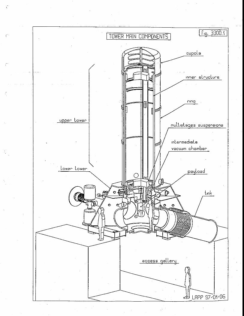
TOWER MRIN COMPONENTS
IL O
rnnec sLnucLune
mulLrs laoes s r o n s
rnLenmedraLe
vacuum ch"rb""
oad
L'nk
Lo*." Lowen
LRPP 37,01'0-o
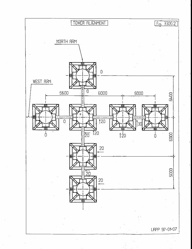
NORTH RRM
WTST flRM
TOWTR RLIGNMENT t'q. 33C0.2
LRPP 37,04'07
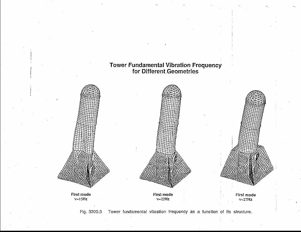
oE+
a
;E
F
i-
$
=a.,'
ll C
)I
>a
tt
Lv).t)EhooocJs(Uo(tr
()co)Jg
op
:N
F-
EN
=
*Q
l .g
E>
6
EE't'i6Pc')E\9vJ
h
La)oF
oFocro-L
g)
LL
o,-
tl-
65
{-
,l-
E6
-o
o5
(5-
=
HF
EP
F
raE
co
'Fr=
L-
=e
LLLo=oF
o?o
.ocr)
o c,?
YN
P :E
.9''
EIN
L
L
OJ
tT
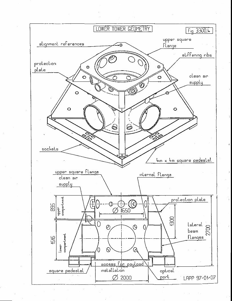
LOWER TOWTR CEOMTTRY f 'q 3100.t*
enL ""F""encesuPPer squar 'e
ttsL'IF" r ' 'bs
proLecLronLaL"
sockeLs
l+-* " [i.'m s esLaL
, """ FL,nLe"naL FLa
cLr=n a,"
L
LecLron aLeLtlm@
LaL"r'"1be- t
(fOIr\c!
L J , ,
Lf')ILano"s
\J
;
tv
oE
JL
C X} E
_ 9 8
I
III--r--
III
'nsLaLLaL'dndesLaL opL'c.L
LRPP 37,01,07
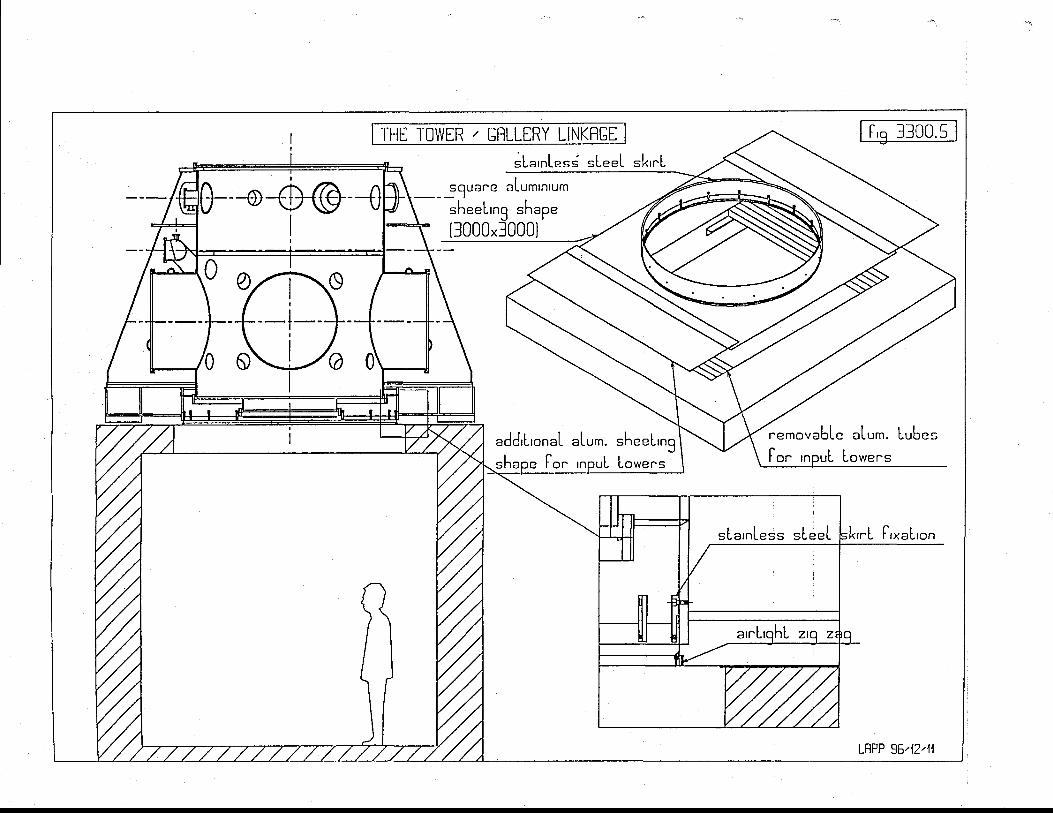
LO
o_o-ctrJ
joXc:--rJ
--Y
oL0)=U--J
-_^JfogLo(+
oL3-J--rJf,ogLna
0)oo-
al
:l-Jc0)-)rrooEULg--"Jn
l
_fU}
EocI-1J--o-!
II
nj
ooOO
=.
t.
I
ux
-:
O9
lo-b rn
E=sE0):)o-O1III
-Jg-Ytt)0)OJ
.-Jut'otn0)_cm-.J'
o
J()J0)
-.Jooa_c+
)o
N
-!)
+)
?I??
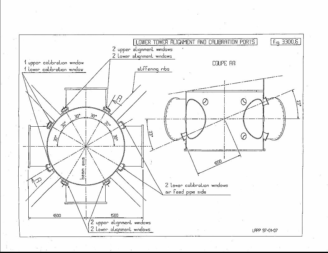
trot'\o_c_J
T
!'l;o-!c=cI..J
-9CJ
a)
Ectrl_lJ
o_=OLJ
Ya
r5
.
v
JL
c\
(D
9g
-E _E
3=
LL
oo
)o
-3
cL
o3
t
o-gC!
t:-.J
B=
-R -e
EE
==
C-
qo
--.J :'i
(u
oL
r-
&J(u
-tO
(J
3_
9s_
e
99
_E
_E=
t
LL
8_
9+
_e
"r, i ,/ ./
\. \',. | /' --t'\\lzl,/vj.-i,';\;-t_
=Jxe
urea
qt
,'' |
'\.'-'--tt
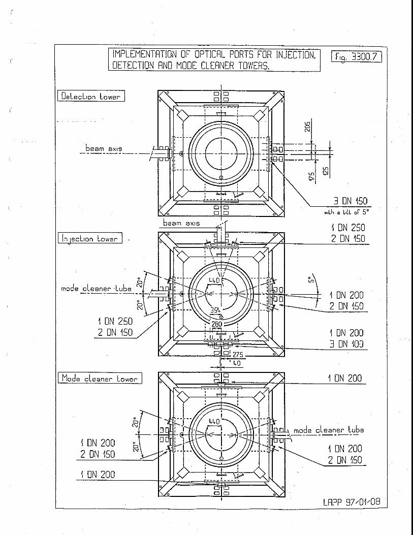
IMPLTMENTfiTION OF OPTICRL PORTS FOR INJECTION,DTTETTION RND MOOE CLERNTR TOu/ERS.
f'o. 3300.7
OeLecL'on Lo*e"
beam a* ' s
I DN 450
[n recL'on Lower-
*'Lh a L,LL ol 5o
1 DN 2502 DN ,r50
Imooe ,l DN 2002 DN ,150
,l DN 2502 DN ,150 4 DN 200
3 DN ,100
Mod" .1""n"" Lower
rod" "Lt "ne" Lrbt,1 DN 2002 DN 150
,l DN 2002 DN ,150
,1 DN 200
LRPP 97,04'03
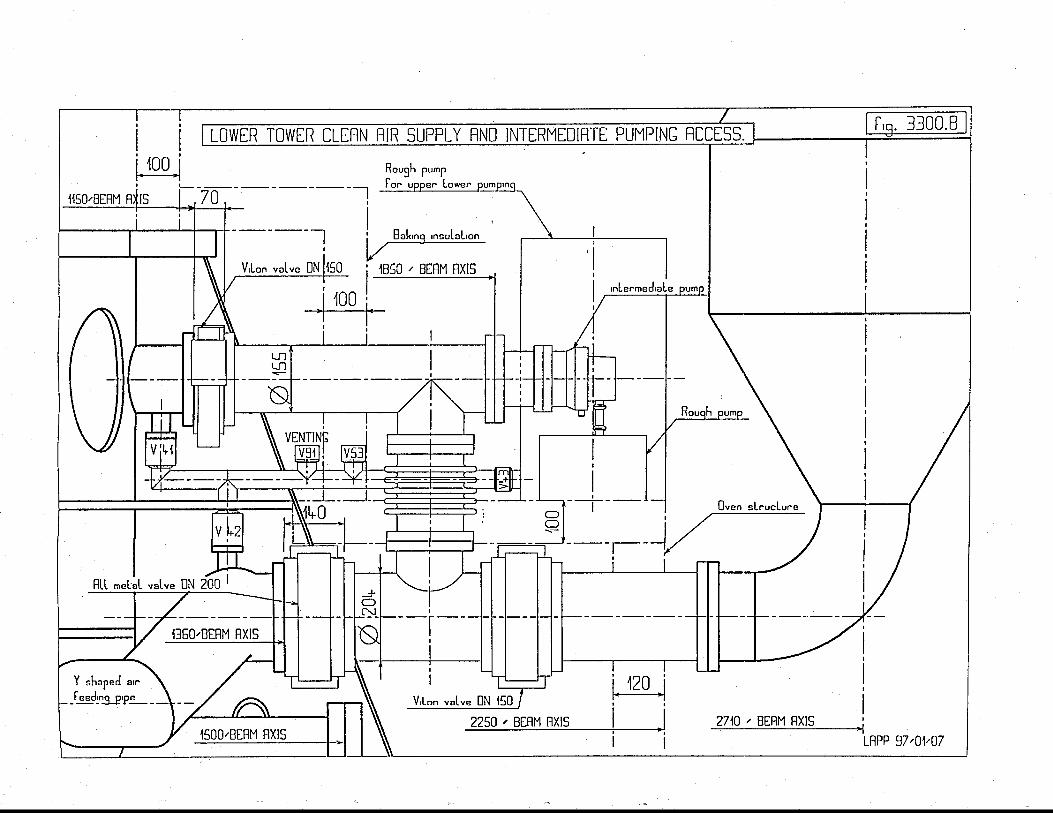
XCT
tLIoNc{
clOtr
l
rn
tflft1
LJr1
('-]C
I
L54o_T=a_trlFC
E-LI=E
.LdF4C
]z.GJo_ryCz.C
Ikl
I(-]
E.
LJ=OF_
t.IJ=OI
'o
L
xff=ctrf
,l
mj
x=ft,
lm
9xG=GtiJcc)oLO
orftz.oc.)
.oJef
I*
c,l
!J'
g- "Jo
g
:
o
ol
>-
Ll
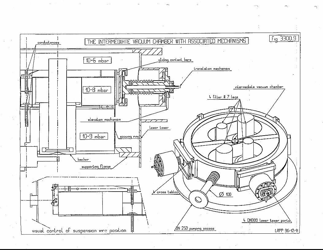
c\o_o_5
Loo'oc0),omz.+
LqJ0,
L==
_9r\L0,--!GJ
o--oEJooJ-f,0)ELg
Eoco()Ec;
cL
J
cc
c);cU6Co(,')aa
c-Lc,
o'
(l
Eooc)Ejo
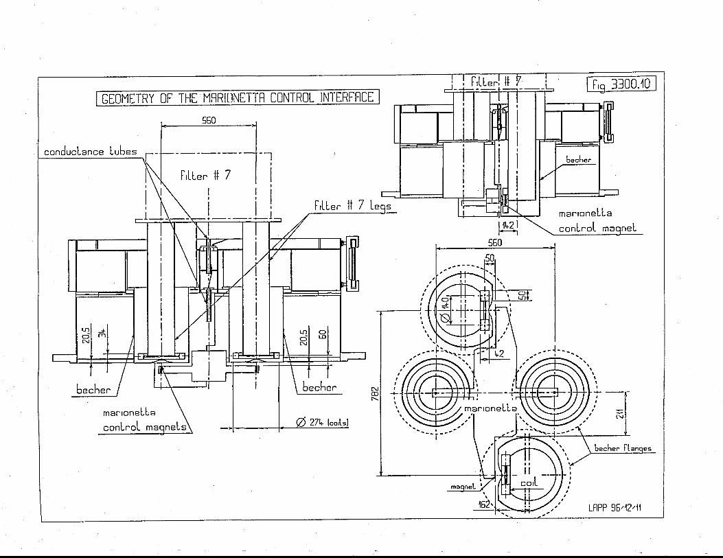
c\tn
o-nGJ
--J-Jn
r
C-oC
mG
)
-^Jo-
cu
nL
LC
qo
bO
:f+ |
-bl=
!:l
tt-4oo!
t\c\J-J0)co(DEoL.Jco
m
J
nl
C
nt
r0)nLr
==
IIIIIIII
-l
t-\+(_*)--=
(L
tr\L
-_.J-LL
oo_of.J0)o.JO-oco
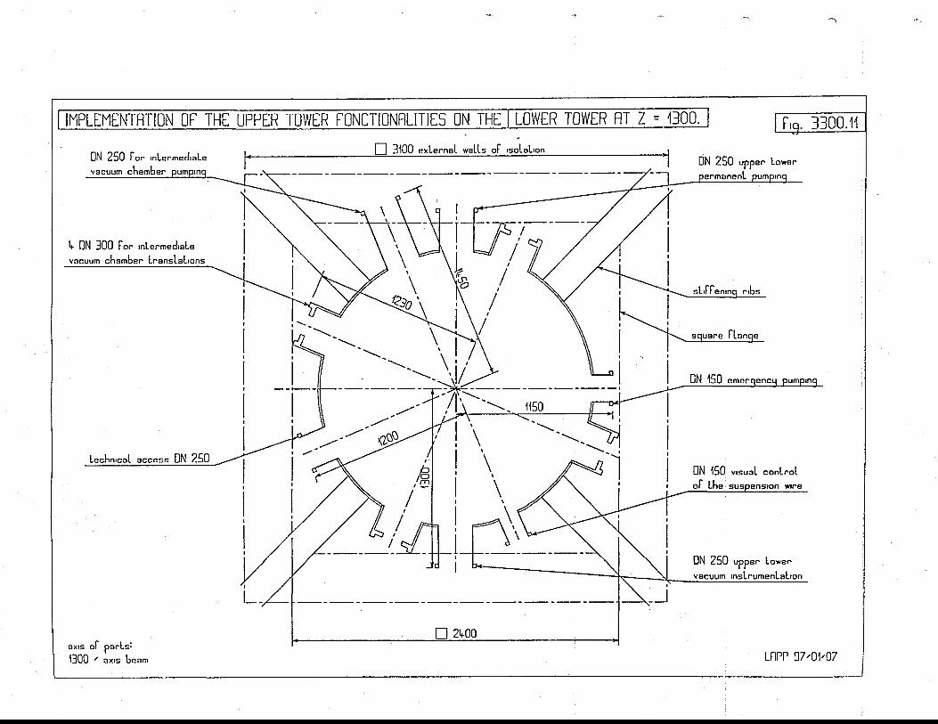
l.\ool.\glo_ffJ
E
'h
--ot
oL
5s
6\
eB
6s
o!
ii_
so
qJ
0t
EE
i3
fi;N
5z
HE
>
0,L!tl
t-
ocoIclrnz.o
r/
C)
mtr
l
oC\J
z.ul0)
|neoccc,Lq
!1
oo
q-
6R
-d
:c
:-
oj
J
:L
b+
L6
al
mE
aao
J>
L30,o-o-
oLNC\t
z.cl
EoEo
ooo=
OJ
JoOJ
E;GoLnc\tz.O
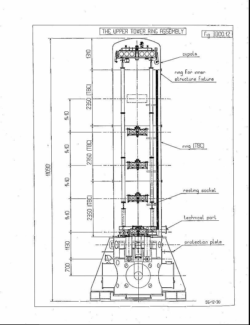
THT UPPER TO\/VER RINC RSSIMBLY f''q 3300.'12
" ,ng [o " Innen
sLnucLure l , xLune
(.-JmFOLN
c!
roLecLron
;-TCDFO
t t l
C{
i]cnt--OLNTn(\
36,12,30

HtilH
t-;tl-
l
l8l
l1L3ral=l
tcl
EI
t=l
E
0=+5FzveU
-€
-l
EiL
g
+
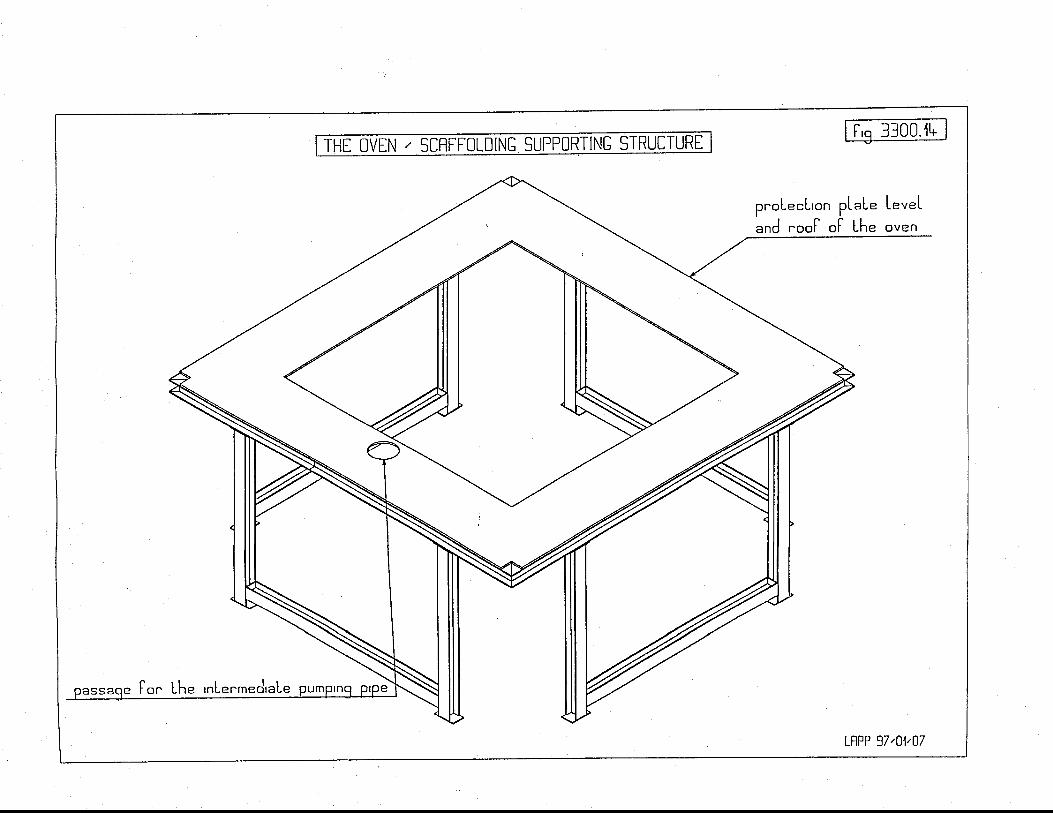
l-\oF\
cnn_J
-J
--oUent
.Jg0)(---)
(..-o
cnl
o--)L-C&c
-Eco
0)oJ.J
mo_Cn
J
U-^JLo_
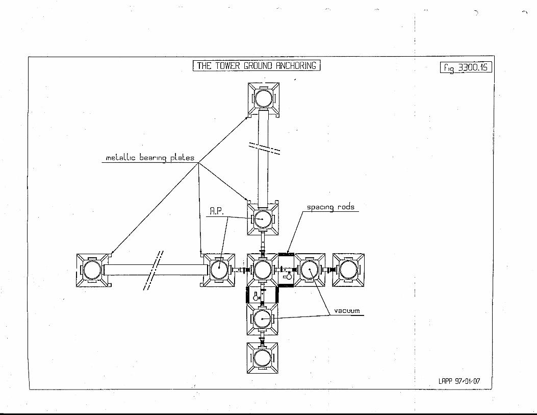
l.\r.-
o-o_G.J
Efoo
o-o
Ul
J)(IlJ
m.reJJ.J0)
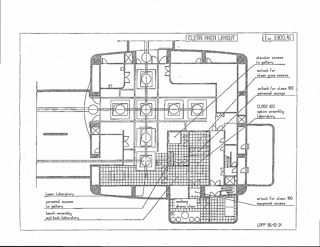
rnc!tn
o_J
_? i:
do
61
@-
6-
0,
tJ
ooo
L
o
E0,c
lo
-(
D
(n
(n
(n ct
GJ
utLnCJ
ooo
O
oL
Io;
ooo
LO
O0
,
-:
oa
)?
o6
io
)o
o
o0)(!oo
lFl
l=l
t=t
tu
llJ
lt
llrr
IlL
llt
Lt
lcl
tl
lz.l
lctr |It-l|l
Jl
EII
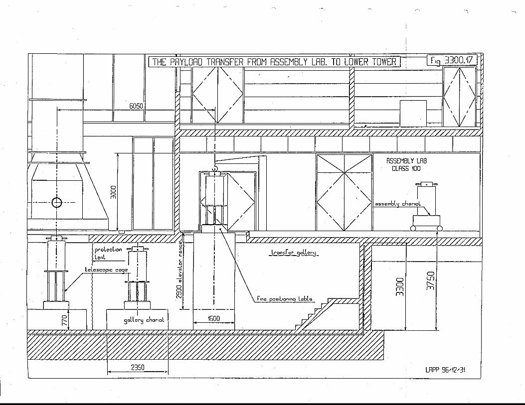
mc\o-o-ctrJ
E.
td=EFE.
td=cl-JOFEi
GJ
tmrLrJLNac=OE
.LLE
.tdtLaz.cE
.Fc=C
Tc3
I
CE
n_Ld-F
Jas4oocc,
L
J J
ole
^ala
00
62
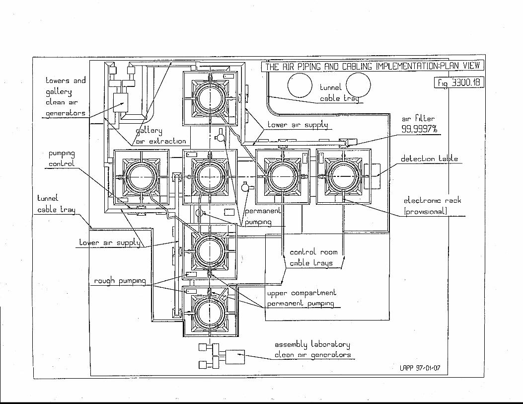
rnciOrnrn
=l
LL
'I
=l
z-CI
Jo_2O=ctrFz.LlJ
TIJJo_=L9z.:lmctr(JFz.EIL
Jlz
.lo
_t--t-ITtn
-t-l
r,
l
| --l-
ll-
m*)a
j
nl
-L)o--o
bN
-.r C
D-
m,,
o-l
!m-
oC
n
t.\OF\
cncJ
(,Lo--JLnl
c
J)
Lj
oE
-o
l=
6i
la
-:
J-)
oJ
Lom
Eof,r'l
-JccE
--JC
*,nOaOJ
o_)
U)
=L.Jm
eooLo--JcoO,=o-r)
,L
+)nm
cjLx0)g
:DL
octLa]
_YooEo-,o0)
L-J
-6 o)
-!
=o
-J
O
a)=
E}
'+
j,
-
oUJ
mL0)cOJ
TC!n
il6L
nr
C0
)i
(D
7-
=
oi
$-d
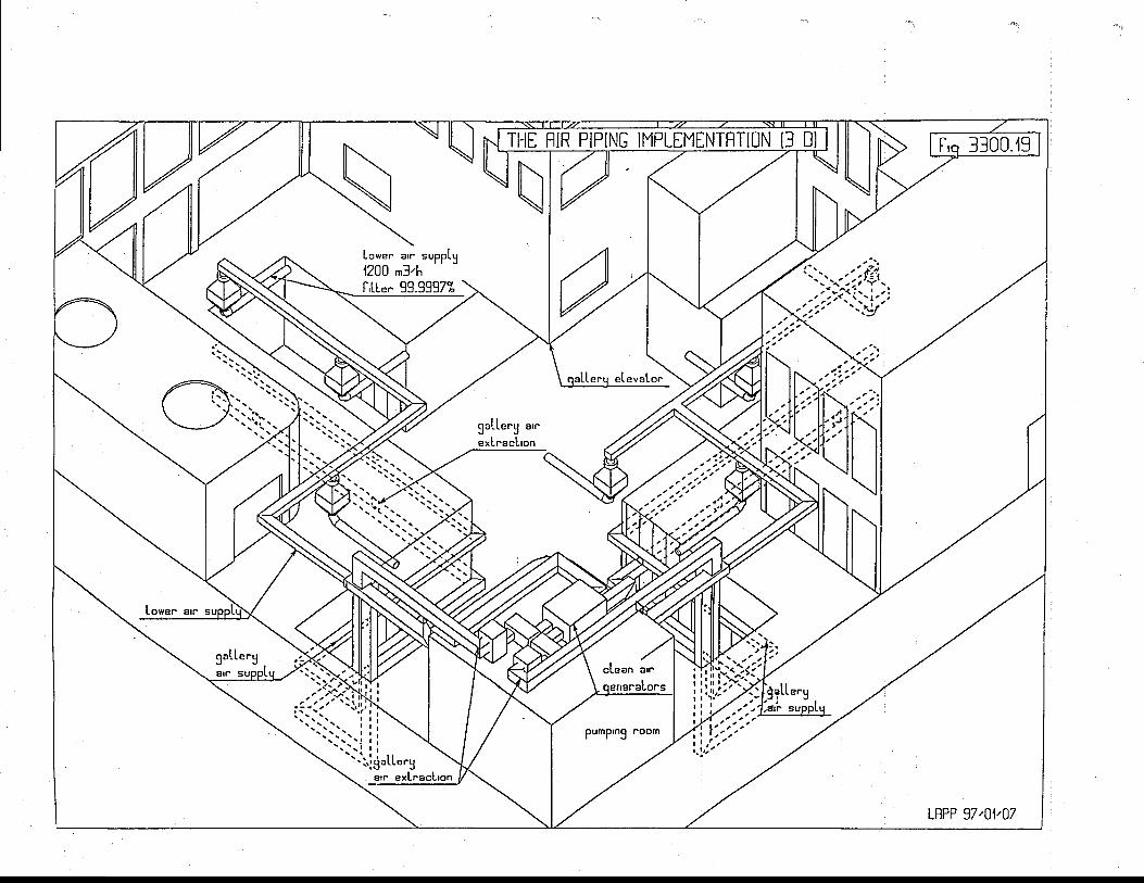

c\OF\
UI
no_ctr.J
oo
oJU
_c.cjItf
rcoc-.)s
OOO
OJ
=
OLN
ul
cOc0)Lnl
(+oL
Y
C)
ta
l
xncU
J
0).Joc
LnL!E
(/lL6
J-=oclj
nolLr)
oo.)o
mo
oo
vt
Emo
_oft
0)
c
-J
L
b%
(+
L
On
rc
F0
J=
oL
-(
J0
f,
r)-Jocalcn
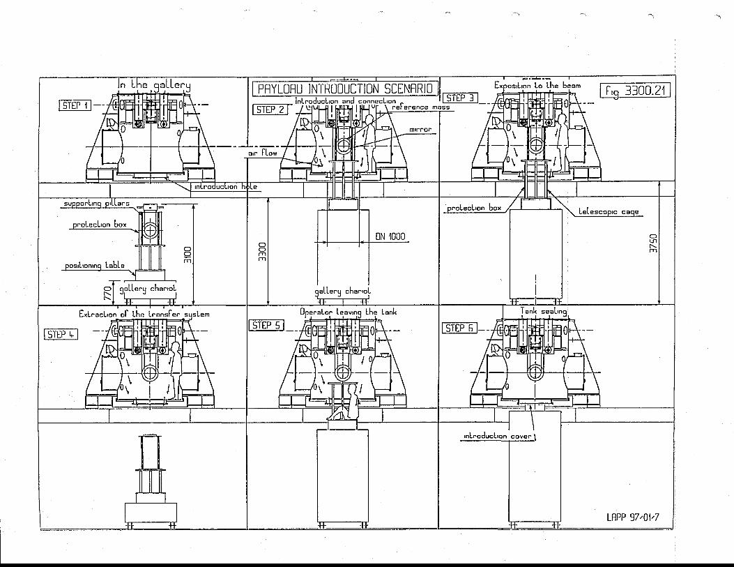
Uooc9.(,t
ocg
xJ
OEEz.td|tUJ
z.OF=clcft'aFFGOI
Go_
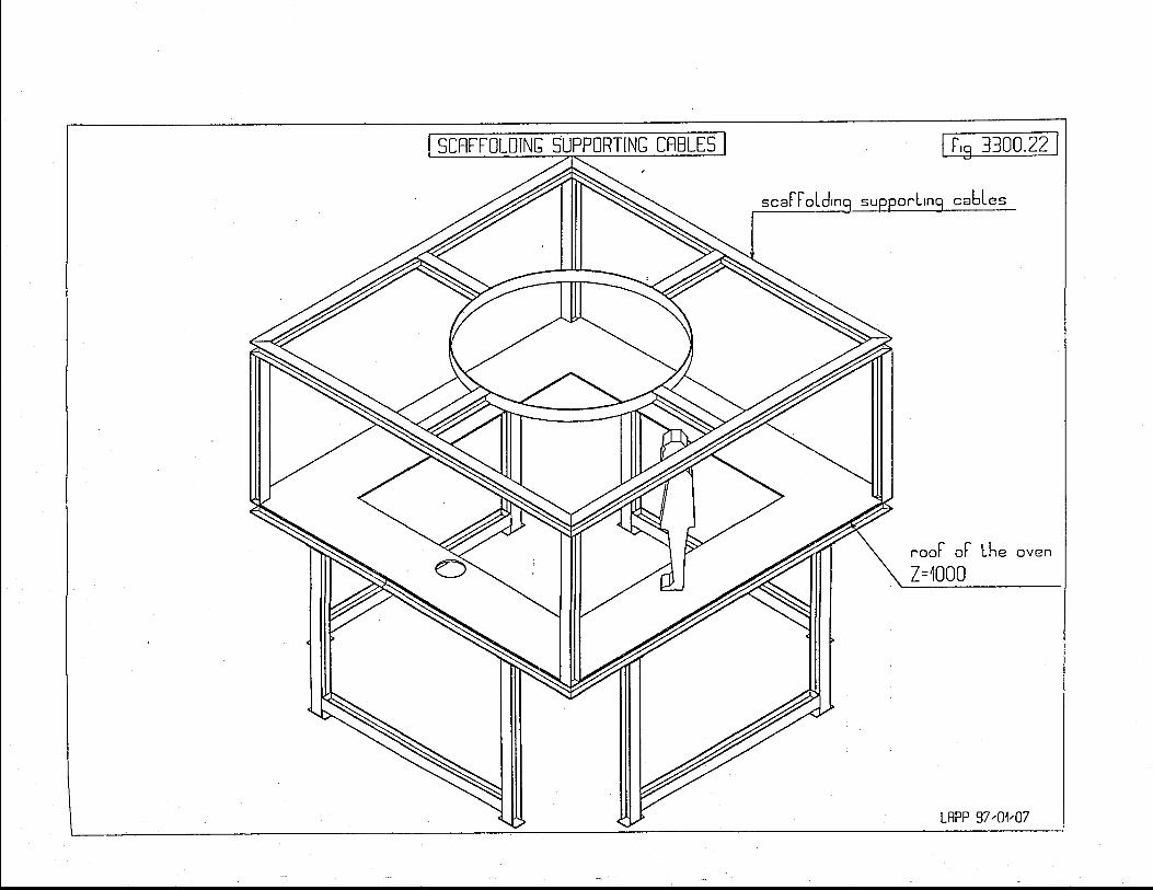
l-\Ot\o_nGJ
co0)_s.-.J
%c
>C)
qO
ot
lL
N!
o_-oooEJ)grco(-L.mo
U'
Lrl-JcoGf
l
t_9z.=E
.Oo_o_=L9z.-JcfLrL!G(.Jl
n
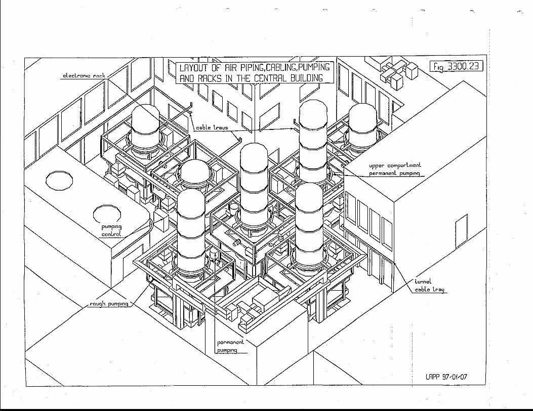
Ht8l
lnlHc-5z'
(JQ
- Z
.z
i-=
--
at
:r
ri
*=
-l:
:[
I-
|t
rr
l-
"-z-
('__! Llz. ()A
t uto
--F
-t.=
2.
u-aC
Jr-
L_
t_--'l
n-O>
-EE
z.
JG
UU
c(.) NL*
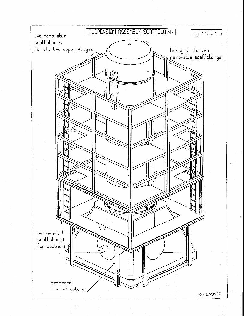
L*o ,^emouableSUSPTNSION RSSTMBLY SCRFFOLDING l,q 1300.2h
=."FIoLd'ngs[o" Lhe Lwo u L'nk,ng o[ Lhe Lwo
""r"u"bl" . "" [ [oL
penmanenL
s."FFoLd'ngFo" ""b1"=
per -manenL
oven sLnucLu ' -eLAPP 97,01'07
ff(a il V I R G OFINAL DESIGN REPORT
Doc: VIRTRE-DIR- 1000- I 3Issue: I Date: 0l/05/97S/Sy:3400 Page: 1
34. Pumping system
Table of contents
34. Pumping system
34.1 Pumping system funct ion and concept
34.2 Pumping system requirements34.2.1 Gas pressure34.2.2 Pumping and venting time and speed34.2.3 Measurement instrumentation34.2.4 Dust cleanliness34.2.5 Life time
34.3 Pumping system inter faces34.3.1 Sources ofgases in the vacuum volumes34,3.2 Bake-out34.3.3 Connection ports of pumping system34.3.4 Pumping stations locations34.3.5 Environmenral Constraint34.3.6 Pu.mping sysrem control
34.4 Pumping system descr ipt ion34.4.1 Pumping sysrem for tubes
34.4.1.I Rough pumping of the tubes: unit #l34.4.l.2Intermediate pumping of the tubes: unit #234.4.1.3 Permanent pumping of the tubes: units #334.4.1.4 Instrumenration bottle for the tube: unit a.34.4.1.5 Instrumentation bottle for the tube: unir b.34.4.1.6 Venting of rube: unir #9.
34.4.2 Pumping system for minor tower34.4.2.1 Rough pumping of the minor torver: unir #434.4.2.2 Permanenr pumping of the upper part: unir #5.
34.4.2.5 Differential Pumping in conductance tube: unit #8.34.4.2.6 Permanent pumping of the lower parts: unit #3.34.4.2.7 Venting and air shorver: unit #9.34.4.2.8 Insrrumentation bottle for the upper parts: unit c.34.4.2,9 Instrumentation bottle for the lorver part: unit d.
34.4.3 Pumping system for single volume torvers34.4.4 Pumping system for Mode Cleaner tube34.4.5 Pumping sers for multiduty
34.4.5.1Muhidury rough pumping: unit #1034.4.5.2 Pumping ser for intervention on small volumes: unit #l I
34.4.6 Summary of the pumping system
34.5 Operat ion of pumping system34.5.1 Final pressure estimation in UHV volumes34.5.2 Search for leaks34.5.3 Running efficiency of the installation
34.6 Vacuum compat ib i l i ty34.6. I Approved components
3
3JAI
At
))
5
67778
888
l 0l lt 2t 2I J
I 4I 6l o
14..4..?'3 _Fore pumping for upper turbo and emergency for lower bake-out lore pumping: unit #6. l634,4.2.4Intermediate pumping of minor tower lorver part and emergency pumping of rii.rot to*..
upper part: unit #7 l7t 7t 7t 7l 8l 8l 8202 la l
22z)
) <252627
2 7z 6

FINAL DESIGN REPORTDoc: VIRTRE-DIR- I 00G I 3Issue: 1 Date:0U05/97S/Sy:3400 Page: 2
34.6.2 Temporarily approvcd components34.6.3 Rejected components34.6.4 Motors
34.7 Pumping system control
c a?0
zt
2 9
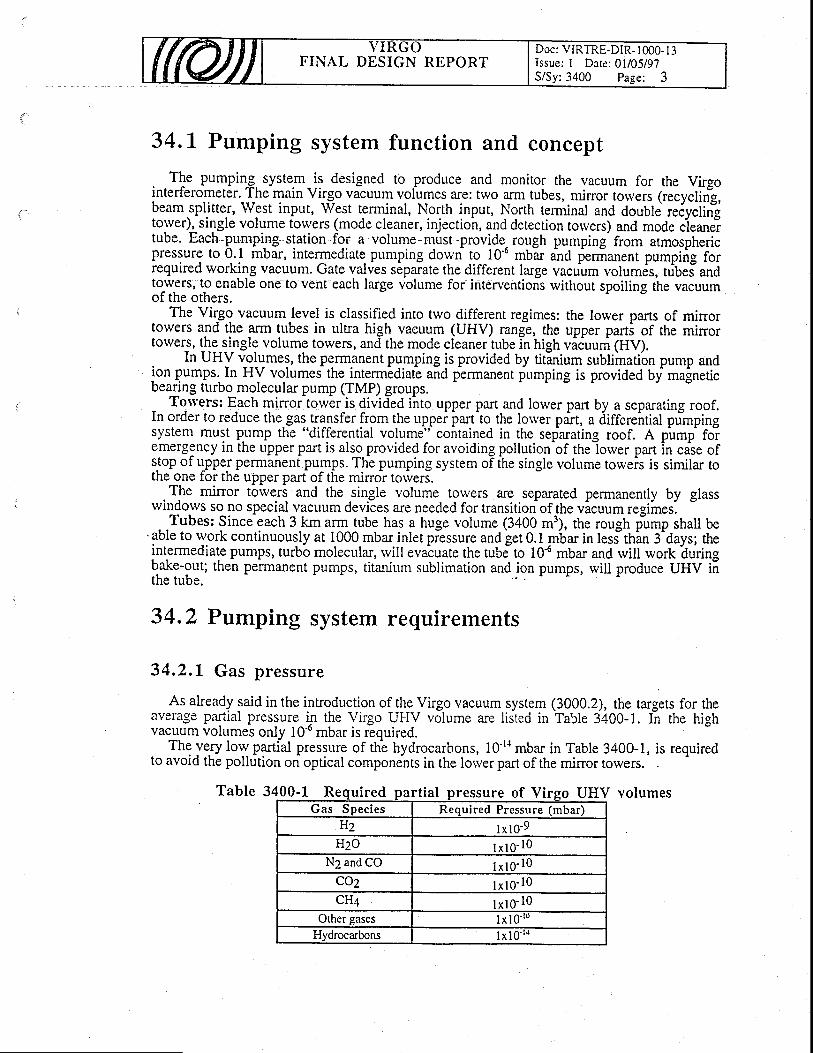
FINAL DESIGN REPORTDoc: VIRTRE-DIR- t000- I 3Issue: I Dare: 01105/97S/Sy:3400 Page: 3
34.t Pumping system function and concept
. .Tl. pumping, system_is designed to produce and monitor the vacuum for the Virgointerf-erometer. The main Virgo vacuum volumes are: ttvo arm-tubes, minor totvers (recyclirig,beam.spljtter, West input, West terminal, North input, North terminal and double re6yclin"gtorver), single volume tolvers (mode cleaner, injection, and detection torvers) and mode cieaneitube. Each lu.mping station for a volume must provide. rough pumping: from atmosphericpressure to q.l mbar, intermediate pumping down !g--10'u mUar ana fenianent pumpirig forrequired working vacuum. Gate valves separate the different large vacuum volumes, tribei anOtorvers, to enable one to vent each large volume for interventions without spoiling the vacuumof the others.
The Vi{go vacuum level is classified into two different regimes: the lorver parts of mirrortowers and the arm tubes in ultra high vacuum (UHV) range, the upper paft! of the mirrortowers, l\g_lingtq volume torvers, and the mode cleaner rube in high viiuum (HV).
In UHV volumes, the permanent pumping is provided by titlnium sublimation pump andion pumps. In HV volumei the intermediaG and permanent fumping is provided by magneticbearing turbo molecular pump (TMP) groups.
Torvers: Fach mirroitoiver is divided into upper part and lower part by a separating roof.In order to reduce the.gas.transfer from the uppei irart^to the lorver polt, a tiitfereitiat primpingsystem must pump the "differential volume" contained in the separating roof. A pump foiemergency in the upper pafl is also provided for avoiding pollution-of thelorver part in case ofstop of gpper permanent pllmps. The pumping system of the single volume torveis is similar tothe one for the upper part of the mirror totvers.
The mirror tbivers and the single volume towers arc separated permanently by glasswindorvs so no special vacuum devices are needed for transition of the vicuum regimes.
Tubes: Since each 3 km arm tube has a huge volume (3400 m3), the rough p-ump shall be'able to rvork continuously at 1000 mbar inlet piessure and get 0.1 mbar in less"thin 3^days; theintermediate pumps, turbb molecular, rvill evaluate the tubJto 10'6 mbar and rvill rvork'duringbake-out; then permanent pumps, titanium sublimation and ion pumps, rvill produce UHV i;the tube.
34.2 Pumping system requirements
34.2.L Gas pressure
As already said in the introduction of the Virgo vacuum system (3000.2), the targets for theaverage partial pressure i.n the Virgo UHV volume are listed in Table 3400-1. tn tire frigttvacuum volumes only l0'o mbar is required.
Thq ye.ry loY partial pressure of th-e hydrocarbons, 10'r{ mbar in Table 3400-1, is requiredto avoid the pollution on optical components in the lorver part of the minor towers.
Table 3400-l Required part ial pressure of Vireo UGas Species Required Pressure (mbar)
H2 lx l0-9Hzo I x l0- l0
N2 and CO lx l0 -10Coz l x l0 -10cHa l x l0 -10
Other gases I x l0 ' ' "Hydrocarbons I x l0- 'o
IIV volumes
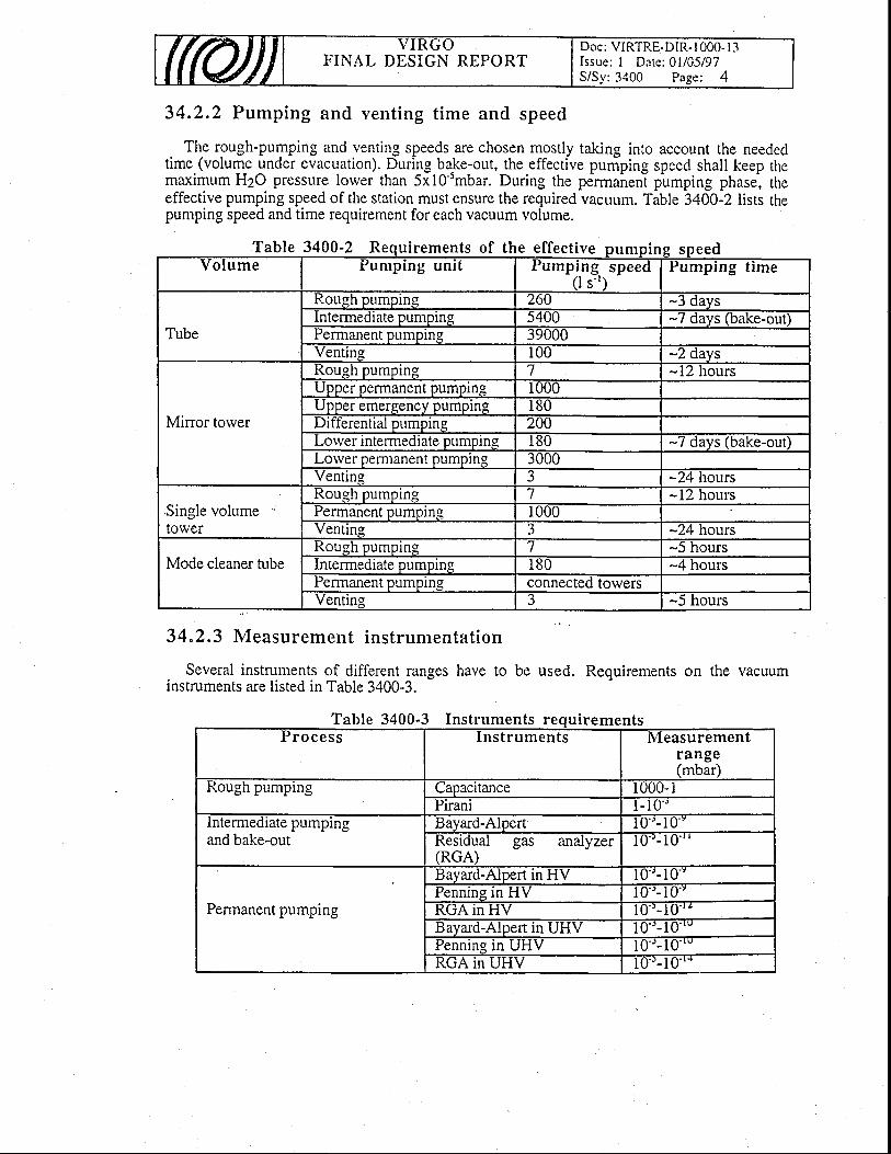
FINAL DESIGN REPORTDoc: VIRTRE-DIR- I 00O- I 3lssue: I Date:01/05/97S/Sy:3400 Page: 4
34.2.2 Pumping and vent ing t ime and speed
The rough-pumping and venting speeds are chosen mostly taking into account the neededtime (volume under evacuation). During bake-out, the effective pumping speed shall keep themaximum H2O pressure lorver than 5i1O'smbar. During the pe'nna^n"ni pumping phase, theeffective pumping speed of the station must ensure the required vacuum. Table 3400-2 lists thepumping speed and time requirement for each vacuum volume.
34.2.3 Measurement instrumentat ion
Several instruments of different ranges have to be used. Requirements on the vacuuminstruments are listed in Table 3400-3.
Table 3400-2 R f t h ff,
Table 3400-3 Inst ts entsa rumen urremr rocess Inst ruments iVleasurement
range(mbar)
Rough pumping CaDacltance 1000-1Plranr l -10 ' '
lntermediate pumpingand bake-out
lJayard-A]pen l0'' - l uResidual gas analyzer(RGA)
l0' '-10' '
Permanent pumping
Bayard-Alpert in HV 10"-10' '.t'ennlng tn H V l0 ' ' -10' 'KUA IN IlV 10"- I0 ' 'Bavard-Alpert in UHV 10' '- 10-'Pennlng rn UllV l0 ' ' -10 ' 'K(JA IN UtlV I0--10' '
a uirements ol- the ett-ect ive pumpin s eedvo lume Pumping unit rumr,ffilsPeedPumping t ime
Tube
Roush oumoins 26t) -3 dayslntermediate pumping 5400 -7 days (bake-outPermanent pumptnq 3900i)Ventine 100 -2 days
Minor torver
Rough pumping 7 -IZ nOLlrSU pper permanent pumplng I000UDDer emereencv DumDlng 180Differential pumping 200Lorver rntermedrate pumpln.q I 8 0 -7 davs (bake-out)Lorver Dermanent pumoin g 3000vent lng 3 -24 nours
Single volumetolver
Rongh pumplng I -12 hoursPermanent pumping 1000Venting 3 -24 hours
Mode cleaner tubeRough pumping 7 -) nourslntermediate pumping I 8 0 -4 hoursPermanent pumping connected towersventms 3 -5 hours

FINAL DESIGN REPORTDoc: VIRTRE-DIR- I 000- I 3Issue: I Date: 0l/05/97
:3400 Page: 5
34.2.4 Dust cleanl iness
All pumps must not induce dust pollution in vacuum volumes
34.2.5 Life time
Running time of the pumping installation: 20 years
34.3 Pumping system interfaces
34.3.L Sources of gases in the vacuum volumes
From the tests on the prototypes, values lorver than 5 10-15 mbar I s'l.cm-2 were obtainedfor the outgassing rate of hydrogen from stainless steel. With a safety factor of at least 10, thefigure of 5 10-la mbar I s-l.cm-2 is taken as basis for the vacuum requirement to the UHVvolume inner surface. This implies that all the relevant stainless steel components of the lowerparts of mirror towers and tubes have to be fired in air or vacuum.
. OOtls^siltS rytgs-a_nd gqs fluxes in permanent pumping phase used for design are listed intable 3400-4 and Table 3400-5, respecrively
materialsOutgassing rate
(mbar I s'l cm'2)Stainless steel air-fired and vacuum bakedStainless steel not-air-fired and vacuum baked
steel not-air-fired, not vacuum bakedViton baked in vacuumViton not-bdked in vGlass baffle in tubes
Super attenuation filters in towerslx l0 'mbar I s ' r / f i l ter
mbar I s''/filterI x l0-7 mbar I

FINAL DESIGN REPORTDoc: VIRTRE-DIR- 1000- I 3Issue: I Date: 0l/05/97S/Sy: 3.100 Page: 6
ta lT3400T bIa D l e o ux arm tuDeC o m p o n e n t Area
( " -2 )
number total f lux H2
(mbar I s ' 1 )
total f lux other gas
(mbar I s ' 1 )
I UDe L2x 1 08 I 6xl0-6
Baffies 3.3x 10⁶ -100 l x l 0 -6
Tower (lower part)
empty system
4x10⁵ J 6xl0-8
Tower
(upper to Iower)
5 3xl0-8 9x I 0-8
Yalve6 = 1000
(body)I .5x 105 2 6xl0'7
Viton gasket (O = 1000) l . 8x l0 r 2 8xl0-7
YalveQ =200
Oody)
28 8x l0-7
Viton gasket
6 =200
20 3x l0-7
Valve O = 150
Oody)
6 2x10'8
Viton gasket
@ = 1 5 0
6 3xl0-8
Ya lve@=63 . .
(Body)5x10³
. AL + 2.4x10⁻⁷
Viton gasket
@ = 6 3
t v t 8 2.5x10'7
To ta l <8.5x10 ' " < 1 . 5 x 1 0 ' 6
34.3.2 Bake-out
The batrce-out for the lorver part of the minor torvers and arm tubes rvill be carried out at150'C for about 100 hours, in order to speed up the degassing of water from the chambersurface. Bake-out operation rvill produce high gas load for the intermediate pumping sY!!eTs:.
Thetubesrvillbe-heated by J6ule effectby applying electrical voltage to it (See 3100.6.4).The intermediate pumping system (TMP) ind iome- instruments of the tubes shall rvorkelectrically connecied tb tfe tubes, tlien thby could be at different potential respect to ground(TBC).'*oper expedients will be adopte& to ensure reliable operation of the pumps. andinstruments. tn patticular, more precise measurements have to be taken rvith a few minuteintemrption of the bake-out.
The pumping stations (connections, intermediate pumps, permanent puPps anomeasureitent-chambers on the lower part of the towers and tubes) are baked by heating tapes.The bake-out is controlled toeether with the bake-out of the volume.

FINAL DESIGN REPORTDoc: VIRTRE-DIR- I 000- I 3Issue: I Dare: 0l/05/97S/Sy: 3100 Page: 7
Table Connection
Mirror towers
lnstrumentS
Single volumetowers
34.3.3 Connection ports of pumping system
The ,connection port types and sizes for the pumping system to the volumes underevacuation are listed in Table 3400-6).
34.3,4 Pumping stat ions locations
The pumpingstations for the tube shall be mounted near the fixed supports of the pumpingmodules to avoid large displacement induced by bake-out. The pumpin!iysrem for the ModECleaner tube is located neai the Injection tower. The pumping syitem toc-ati6n for the towers isdescribed in section 3300.
Temperature range of the environment is Iisted belo*':Temperature in the towers location: 20fr"CMaximum temperature in the tube tunnel:40'C (TBC)Minimum temperature in the tube tunnel: -5"C (TBC)
. - The gJectrical powe! supply for the pumping system will be provided in the infrastructure.About l0 kW 220vAC is ihe-needea poweifoieach pumping stition.
If needed a small cooling unit will 6e installed for dach pumping station.. Pumping stationlocation and operation conditions.
34.3.5 Environmental Constraint
No polluting smokes should be rejected to outside environment from any pump.
FINAL DESIGN REPORTDoc: VIRTRE-DIR- I 000- I 3Issue: I Date: 0l/05/97S/Sy;3400 Page: 8
34.3,6 Puntping system control
All the operations for the control of the tower pumping system and partially of tube pumpingsystem, including safety and data acquisition, are computer controlled. The rvhole system iidescribed in section 5000.2
34.4 Pumping system description
In order to increase the running efficiency of the antenna a ferv main choices were decided "apriori":
- gate valves must separate the different large vacuum volumes, tubes and towers, toenable one to vent each large volume for interventions without spoiling the vacuum of theothers.
- gate valves must separate the pumping sets and the instrumentation boxes from thelarge vacuum volumes to allow for interventions.
- the valves to UHV volumes will have:a viton gasket if normally open;a viton gasket if normally closed and protected by vacuum in other side;a metal gasket if normally closed and not protected in other side.
In order to reduce possible hydrocarbons pollution, rough pumps, for both roughing ofthe chamber and backing of the turbo molecular pumps (TMP), must be oil free at least in theprocess chamber, and the lubricant in the bearing box shall be protected properly; ceramic ormagnetic bearing TMPs are acceptable.
The pumping system consists of several modular units of different types: 8 for pumping,4 for vacuum measurements (called "bottles") and 2 for venting (it includes-also the venting andair shower connections to towers).
'34.4.1 Pumping system for tubes
Pressur'ti stability: During the permanent pumping, the ion pumps are the only source ofmolecule bursts in the unit. There are many evidences that micro-obje-ts may be expelled fromion pump electrodes. In order to minimize this effect, the ion pump is shielded from the tube byplacing it after one of the Ti sublimator.
Absence of pollution: All the rough pumps rvill be oil-free pumps and the turbo pumpswill be equipped with ceramic or magnetic bearings.
Titanium migration, if any, during a sublimation will be avoided by closing the gate valves.The absence of Ti dusts or peeling rvas demonstrated for typical layers, 0.1 pm thick. Thisfigure would correspond to a 20 year pumping rvithout venting.
Absence of mechanical vibrations: During the permanent pumping phase, the systemdoes not generate internai vibrations.
Flexibility and easy maintenance: The gate valves insure a maximum flexibiliry andeasy maintenance in all respects.
Pumping capacity: With one 15 g Ti ball per sublimator and 2 sublimators per 300 m oftube, the lifetime of the permanent pumping is insured for hundreds of years.
34.4.1, .1 . Rough numping of the tubes: un i t #1
The main specification for rough pumping concerns the absence of pollution, neither intemalnor extemal. Intemal pollution refers to hydrocarbons. For the rough pumping, regular spacingof the pumps along thb tube is of no importance. A single unit, "PIm'ping Uriit #I", loclted inthe central building, rvill be used to pump down each tube, one after the other. The roughpumping must evacuate the tube from atmospheric pressure to O.lmbar at which theintermediate turbo pumps of hybrid type can start to work. To avoid any back-stream from therough pump system, its ultimate pressure must be 0.01mbar.
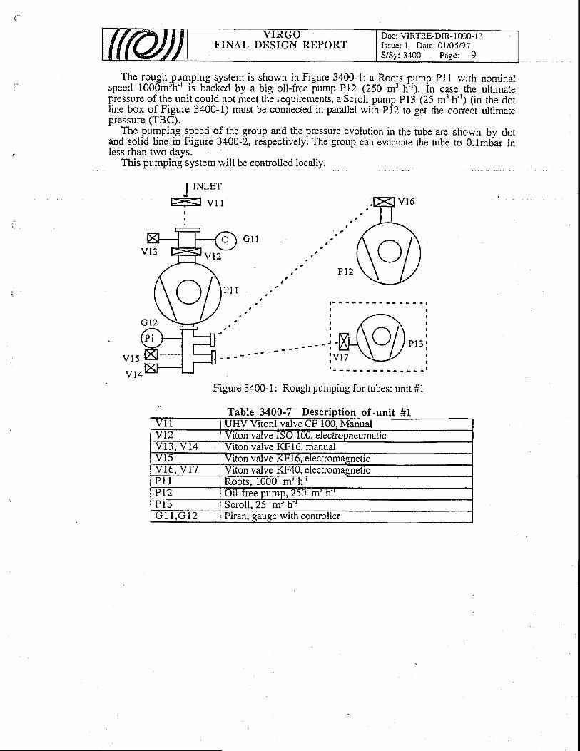
FINAL DESIGN REPORTDoc: VIRTRE-DiR- | 000- I 3Issue: I Date: 0l/05/97S/Sy:3400 Page: 9
The roughpu.mping system is shorvn in Figure 3400-t: a Roots pump Pll rvith nominalspeed 1000m'h'' is backed by a big oil-free pump Pl2 (250 m3 hr). in case the ultimatepressure of the unit could not meet the requirements, a Scroll pump Pl3 (25 mi n'r; 1in the dotline box of Frgure 3400-1) must be connected in parallel rvith Pl2 ro ger rhe correct ultimatepressure (TBC).
The.pumpifg speed o^f J!t9 group and.the pressure evolution in the tube are shown by dotand solid line in Figure 3400-2, respectively. The group can evacuate the tube to 0.lmbar inless than two days.
This pumping system rvill be controlled locally.
J n{LEr
I : v l l
v l 5
v l 4
G l l
Pt2
Figure 3400-1: Rough pumping for tubes: unit #1
Table 3400-7 Desc tio
I
I
I
t
I
I
I
I
t
I
I
P l 3
#1n o I - u nv l 1 UHV Vltonl valve uf IUU. Manualvt2 Vrton valve ISO 1Ul, electropneumaticv t 3 , v 1 4 Viton valve KFl6, manualv15 vlton valve Kt 10, electromagnetlcv 1 6 , v 1 7 Vrton valve Kt'4U, elecuomagneticP I Roots, i000 m'h-'PL2 Oil-fiee pump, 250 m' h''P i 3 Scrol l .25 m' hJ I I , L i I Z Prranr gauge wlth controller

FINAL DESIGN REPORTDoc: VIRTRE-DIR- l 000- I 3Issue: I Date:01/05/9'7S/Sy: 3400 Page: I 0
1 000
100
6
3 r ooo
o-
25 30
Tlme(h)
600 E
oo
9VV 6'a
300 E=o-
{ t1 0
Figure 3400-2: Pumping curve for 3 km tube rviththe rough pumping system.
34.4.1.2 In termediate pumping of the tubes: un i t #2
' The intermediate pumping system, shown in Figure 3400-3, is a rypicat TMP group. TMP. , r < n n n r - t
'
PZI rvith 1000l.s'' nominal numoins soeed is connected to the tube via a sate valve V2l and. , r < n n n r - t
'
PZI rvith 1000l.s'' nominal pumpi4g speed is connected to the tube via a gate valve V2l andbacked by a oil-free pump (25 mth-'Ip2t. A valve V23 provides a leak testiort. A Pirani G22backed by a oil-free pump (25 m'h'') P?l. A valve V23 provides a leak test port. A Pirani G22gauge monitors the fore-line pressure, a Bayard-Alpert gauge in the front of the TMP is used to' test the group itself when V2 I is closed and to test the pressqre in tube rvhen V2 1 is opened.
backed by a oil-free pump (25 mth'') Pzl. Avalve V23 provides a leak testgauge monitors the fore-line pressure, a Bayard-Alpert gauge in the front of
t the group itself when V2lis closed and to test the pressure in tube rvhen V21 is opened.In order to keep maximum water partial pressure <5x10'5 mbar during bake-out, 6 pumping
stations are chosen, they are located each 600m.Hybrid TMP will be chosen, so the pumping group
pressure.start to work at 0.i mbar inlet
Tube
Figure 3400-3: Intermediate pumping of the tubes: unit #2.
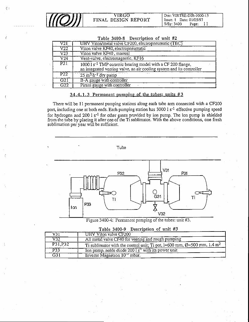
FINAL DESIGN REPORTDoc: VIRTRE-DIR- I 000- l -1Issue: I Date: 0l/05/97S/Sy:3400 Page: I I
Table 3400-8 Descr of unit #2Y2l UHV Viton/metal valve Ch'200, electropneumatlc ('l BC)v2z Viton valve KF40, electropneumaticv 2 3 vlton valve Kt4u. manualv24 vent-valve, electromagnetlc, l\.t' I oP2L 10001s-l TMP ceramic bearing model rvith a CF 200 flange,
an integrated venting valve, an air cooling system and its controllerP22 25 m3'h-l dry pumpGZI B-A gauge wlth controllerc22 Pirani gauge with controller
34.4.1.3 Permanent pumping of the tubes: un i ts #J
There rvill be 11 permanent pumping stations along each tube arm connected rvith a CF200port, including one at both ends. Each pumping station has 3000 I s-l effective pumping speedfor hydrogen and 200 I s-l for other gases provided by ion pump. The ion pump is shieldedfrom the tube by placing it after one of the Ti sublimator. With the above conditions, one freshsublimation per year rvill be sufficient.
Tube
Figure 3400-4: Permanent pumping of the tubes: unit #3.
Table 3400-9 Descript ion of unit #3e uv3l UHV Viton valve CF200v32 AII metal valve CF40 for venting and rough pumpin.gy S L , P J Z Ti sublimator with the control unit; Ti pot, l=600 mm, O=500 rym.14 m'�P33 Ion pump, noble diode 200 I s'' with its porver unitG 3 t Inverse Masnetron l0'" mbar.
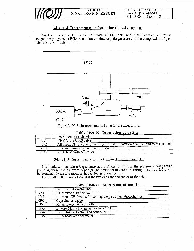
FINAL DESIGN REPORTDoc: VIRTRE-DIR- I 000- I 3Issue: I Date: 01i05/97S/Sy:3400 Page: 12
3 4 . 4 . 1 . 4Tnstrumentat ion bott le for the tube: unit a "
This bottle is connected to the tube rvith a CF63 port, and it rvill contain an inversemagnetron gallge and a RGA to monitor continuously the pressure and the composition of gas.There rvill be 8 units per tube.
Tube
Gfl.Fieure 3400-5: Instrumentation bottle for the tube: unit a.
3 4 . 4 . L . sf nstrumentat ion bott le for the tube: unit b.
rtD
This bottle will contain a Capacitance and a Pirani to measure the pressure during_ roughpumping phase, and a Bayard-Aipert gauge to monitor the pressure duririg bake-out. RGA rvillbe permanently used to monitor the residual gas composition.
There rvill be tfuee units located at the two ends and the center of the tube.
Table 3400-1L Descript ion of unit baDlelnstmrnentaiion chamber
vbl-nEfvirori
CF63 valvevb2 ffiini the initmmentation chamberG b l Capacitance gaugecb2 Pirani sause with controllerGb3 ffiwithcontrollerGb4 Bayard-Alpert gauge and controllerGb5
-RGA head with controller
ab le 3400- lU esc on of un A
Instrumentation chamberVal UHV Viton CF63 valveVa2 All metal CF40 valve for venting the instrumentation chamber and re-evacuatlon.ua l
--Everse rnasnetron eause with controller
lrA:2 RGA head with controller
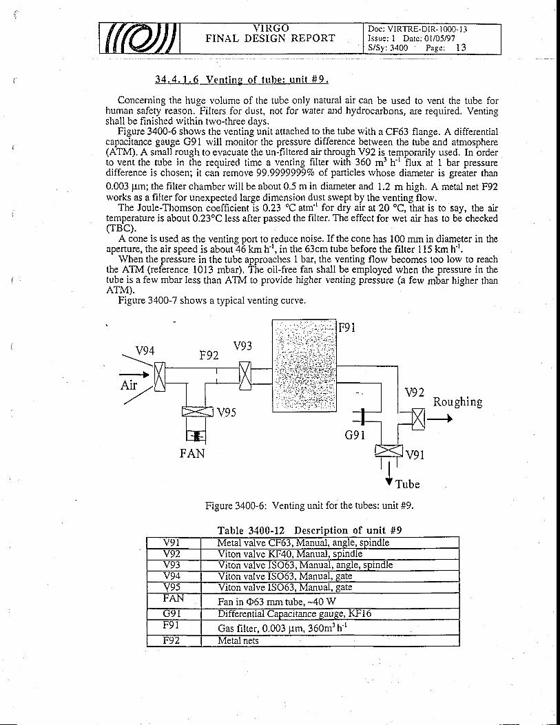
FINAL DESIGN REPORTDoc: VIRTRE-DIR- I 000- I -3Issue: I Date: 0l/05/97S/Sy: 3400 Page: I 3
3 4 . 4 . 1 . 6 V e n t i n g o f t u b e : u n i t # 9 .
Concerning the huge volume of the tube only natural air can be used to vent the tube forhuman safety reason. Filters for dust, not for rvater and hydrocarbons, are required. Ventingshall be finished rvithin trvo-three days.
Figure 3400-6 shows the venting unit attached to the tube rvith a CF63 flange. A differentialcapac'itance gauge G91 rvill monit5r the pressure difference betrveen the tubiand atmosphere(ATM). A small rough to evacuate the un-filtered air through V92 is temporarily used. In orderio venl the tube in t-he required time a venting filter rvit[ 360 m3 h't hux a[ I bar pressuredifference is chosen; it can remove99.9999999Vo of particles rvhose diameter is greater than0.003 pm; the filter chamber rvill be about 0.5 m in diameter and 1.2 m high. A metal net F92rvorks as a filter for unexpected large dimension dust swept by the venting flow.
The Joule-Thomson coefficient is 0.23 oC atrn' for dry air at 20 oC, that is to say, the airtemperature is about 0.23'C less after passed the filter. The effect for rvet air has to be checked(rBc).
A cone is used as the ventins Dort to reduce noise. If the cone has 100 mm in diameter in theaperture, the air speed is about?ii km h-r, in the 63cm tube before the filter I l5 km h''.
the ATM (reWhen the pressure in the tube aATM (reference l0l3 mbar). ' shall be employed when the pressure in the
: in the tube approaches I bar, the venting flow becomes too low to reachl0l3 mbar). The oil-free fan shall be employed when the pressure in the
tube is a ferv mbar Iess than ATM to provide higher venting pressure (a ferv mbar higher thanATM).
Figure 3400-7 shorvs a typical venting curve.
Roughing--+
G 9 1
v91
Figure 3400-6: Venting unit for the tubes: unit #9.
Table 3400-12 Description of unit #9
\
v
ITube
v9t Metal valve CF63, Manual, angle, sprndlev92 Viton valve KI'40, Manual, spmcllev93 Viton valve IS063, Manual, angle, spindleY94 Viton valve IS063, Manual, gate
Y95 Viton valve IS063, Manual, gateFAN Fan in (D63 mm tube, -40 WG91 Differential Capacitance gauge, KFI 6F91 Gas filter, 0.003 pm, 360m3 h'rF92 Metal nets

FINAL DESIGN REPORTDoc: VIRTRE-DIR- 1000- I 3Issue: I Date: 0l/05/97S/Sy: 3400 Page: 14
oL
oooL
0.
700600500
12 t o 20 24T ime I
40 4428 4Bo o32
'Figure 3400-7: Venting up to ATM (1013 mbar) for 3 km tube rvith 360 m3 hr filter. The fanprovides 1020 mbar venting pressure at 1000 mbar in tube.
34,4.2 Pumping system for mirror tolyer
The connection between the two parts of the mirror torvers is done by two cylinders, I cmdiameter 20 cm long, rvith a central chamber 10 cm high for the differential pumping. Thischamber is connected to a pumping group, external to the tower, via a 10 cm diameter pipe.This arrangement rvill reduce to less than 0.01 I s-l the gas flow into the torver lower pafithrough the central hole. The contribution from the joint of the separating roof is not measuredat the moment and has.been assumed to be zero, because the roof will be strictly connected tothe tower rvall (TBC). A value of 0.1 I s-r for H2 and 0.03 I s'r for H2O is assumed to have asafety factor of 10.
The pressure in the upper part is supposed to be 10-6 mbar and the residual gases to be waterfor 90 Vo and hydrogen for L0 Vo.
The problem of the hydrocarbon outgassing of the various components contained in theupper pirt of the towers ii of utmost impirtanc-e. Presently, it is coniidered from the point ofview of minimizing the outgassing of the specific components. Ways to reduce its impact onthe mirrors part are also investigated.
Figure 3400-8 shorvs the synopsis of the pumping for the mirror towers.
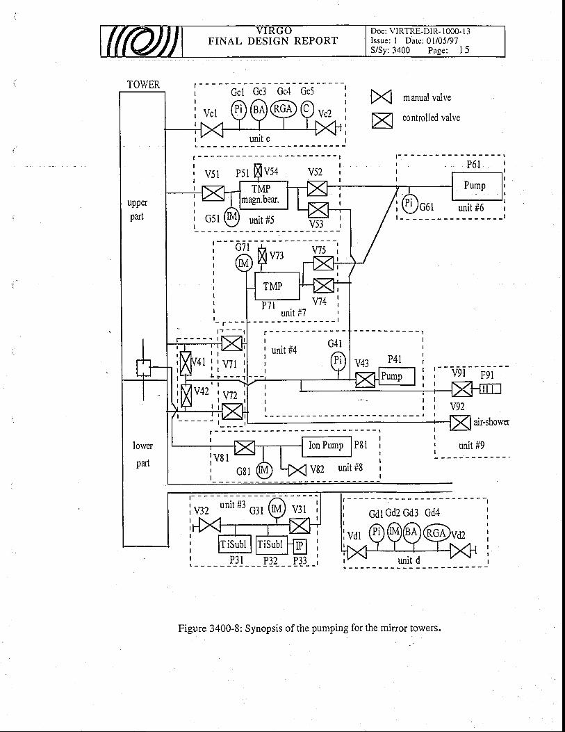
FINAL DESIGN REPORTDoc: VIRTRE-DIR- 1000- I 3Issue: I Date: 0l/05/97S/Sy:3400 Page: 15
P4l
TOWER
lower
pad
| | G -
I
t ' - -I
>< manualvalve
X] controlledvalve
unit c
P8 l
V82 unit #8
catGd2 Gd3 Gd4
Figure 3400-8: Synopsis of the pumping for the mirror towers.
, ' . ; ;
4l i lv i l i
FINAL DESIGN REPORTDoc: VIRTRE-DIR- I 000- I 3Issue: I Date: 0l/05/97S/Sy: 3400 Page: I 6
34.4.2.1 Rough numping of the nr i r ror torver : un i t #4
During the rough pumping the tr.vo parts of thetube to the dry plrnp. The valve V4l and V42difference betrveen two parts of the torver.
tolver are connected bv a 40 mm extemalare controlled together to avoid pressure
Several non turbulent cycles of pumping and venting between atmospheric pressure and Imbar are required in order to eliminate dusts. Such a time consuming process requires onerough pump unit per torver.
Table 3400-13 Descript ion of unit #4v4l ton valve uf4uv42 V ton valve CF40Y43 ton valve utzuuP4 i 25 m3.h-l dry pump and its venting valveG 4 l Plranr gauge wlth conlroller
34.4.2.2 Permanent pumnine of the upper nar t : un i t #5.
The upper part of the tower contains many electronic components, mechanical devices andthe associated rviring, the outgassing flow of which is not completely known. For this reason itis connected to the lorver part tfuough a differential pumping system [see later] with an effectiveconductance lorver than 10-2 I s-r for water vapor.
To have a large safety factor about the gas flux toward the lorver pafi a pressure of 10-6hbar is required on the upper part. One assumes at the moment a total outgassing rate of 10-3mbar I t'1, so an effective pumping speed of 1000 I s-r is therefore required. This pumpingspeed can be obtained using a turbo rvith a pumping speed higher than 1500 I s'' horizontally
.mounted 400 mm far from the tower and connected through a 250 mm valve.For reliabiliry reasons (mean time before failure larger than 10 years), a magnetic bearing
TMP is chosen.The dry pump of unit #4 is also connected to the TMP outlet and it will be used as fore
pump of unit #5 during the intermediate pumping. In permanent pumping conditions the unit #6[see later] can be used as fore pump.
Table 3400-L4 Description of unit #5P 5 1 1500 I s'' 'I'MP ivhit magnetlc beanng, lntegrated venting valve, alr
cooling system and controllerv51 Viton valve CF250G52 Inverse Magnetron gauge with controllerv52 Viton valve KF40 betr.veen the TMP and the unit #4v53 Viton valve KF40 between the TMP and the unit #6
14.4.2.3 Fore pumping for upper turbo and emergency for lorverbake-out fore numping: unit #6.
A small pump.is provided for the fore pumpjng of the.upper turbo.pump dedicated to theemergency pumping bf the tower upper part an-d to the bake--out pumping o-f the lower part; itcan also be used for the fore pumping of the large magnetic-TMP [unit #5], during thepermanent pumping.
This group consists of a small oil-free roughing pump and a Pirani gauge.
(ftu) VIRGOFINAL DESIGN REPORT
Doc: VIRTRE-DIR- I 000- I 3Issue: I Date: 0l/05/97S/Sy: 3400 Page: l7
Tablel-free backing punl
34.4.2.4 Intermediate pumping of mirror torver lorver part andemergency pumping of mirror tolver upper part: unit #7
In case of emergency (failure ofndatorv to be able to immediatelvmandatory to be able to immediately
upper part not too high. Furthermoretower lower part.tower lorver part.
the upper TMP)' unit #5 must be srvitched off. It issrvitch on a temporary unit to keep the pressure in thean intermediate and bake-out pumping is needed for the
Both functions can be supplied by a 200 I s-' Hybrid TMP model connected to the largepass betrveen the two parts of the tower. Unit #4 or #6 will provide the fore pumping for .
by-
ble 3400-16 Desc tion ofa uv7l Viton valve CFl60Y72 Metal valve CF200v 7 J Viton valve KFl6v74 Viton valve KF25 betrveen the TMP and unit #4v75 Viton valve KF25 betrveen the'l.MP and untt #6P 7 l 200 l.s-' TMP rvhit magnetic or ceramic bearing, integrated venting
valve, air cooling system and controllerg t2. Lnverse Magnetron gau.qe with controller
34.4.2.5 Di f ferent ia l Pumpiq in conductance tube: un i t #8.
To reduce the gas transfer to the lower part of the torver a differential pumping system mustbe used. It consisiof a vacuum chamber oir the small conductance tube, a 100 mm tube throughthe torver wall, an external 100 mm valve and an ion pump 2001 s-t. An Inverse Magnetrongauge to measure the pressure before srvitching on thd ion pump and a valve for venting andexternal pumping completes the group.
Table 3400-I.7 Descript ion of unit #Ev81 ff iF100P 8 l Ion pr:mp, noble diode 200Vs rvith its controllerG82 Inverse Masnetron gauge with controllerv82
--Iletal \ralvetFZ0 for venting the ion pump
34.4.2.6 Permanent pumping of the lorver par ts : un i t #3.
This permanent pumping unit is identical to the one used on the tubes; it rvill be installed onone of the links between the totvers.
34.4.2.7 Vent ing and a i r shorver : un i t #9.
Valves and filters, connected to the roughing line betrveen the two parts of the tower, rvillprovide rhe venting, and will allorv the air Jhowlr via the-b-lg by-pass. An appropriate venting
ilrocedure will be-set up, in order to prevent pressure differenc6s betrveen lower and uppertower (TBD).
#7nitT

FINAL DESIGN REPORTDoc: VIRTRE.DIR- I 000- I 3Issue: I Date:01/05197S/Sy: 3400 Page: I 8
T 34001 8 Descft 0 n o I u nv9 l vlton uf4u valvev92 UHV Viton CF200 valveF 9 l Dust Filter
34,4 .2 .8 Ins t rumenta t ion bo t t le fo r the uDDer nar ts : un i t c .
This bottle rvill contain a Capacitance and a Pirani to follow the tower pressure during therough pumping, a Bayard-Alpert to measure the pressure, and a RGA will be permanently usedto monitor the main gas composition.
Table 3400-19 Descri f unia r lp t lon o I un i t cInstrumentation chamber
vc l Viton CF63 valve for connecting to the towerYc2 Vlton CF40 valve tor ventlng the lnstrumentation chamberG c l Pirani gauge rvith controllerGc2 Capacitance gauge with controllerGc3 .ts ayard-Alpert gau ge wlth controllerGc4 RGA head with controller
bl
3z[ .4 .2.9 Inst rumentat ion bot t le for the lorver par t : un i t d .
This bottle rvill contain an Inverse Magnetron and a Bayard-Alpert to measure the totalpre.s_sur-e in a reliable rvay in the vessel; and a RGA to be permanently used to monitor theiesidual gas composition on the mirror and to check the efficiency of the differential pumpingc \ r c t F m
Table 3400-20 DescraD le on of unit dlnstrumentatl0n cnamber
vdt UHV Vlton CF63 valve tor the instrumentation chambervd2 All metal CF40 valve for venting the instrumentation chamberGd l Plranl gauge wlth controlierGd2 Inverse Magnetron qauge with controllerGd3 Bayard-Alpert gauge rvith controllerGd4 RGA head rvith controlier
34.4.3 Pumping system for single volume torvers
torvers, FigureThe pumping system for single volume towers is simplified respect to the system of minorvers. Figure 3400-9 shows the svnoosis of the oumoine svstern-Rough pumping unit #4':
9 shows the synopsis of the pumping systern.unit #4': The rough pumping is similar to the one used on the minorRough pumping unit #4': The rough pumping is similar to the one used on the minor
to_w^er: lh"_dry pump is connected directly to the torver for roughing and to the turbo pump unit#5 for backine.
Permaneri't pumping unit #5:the mirror tower upper parts.
Emergency foii pdmping unitused on the mirror tower.
Venting unit #9': A valve andventing.
Instrumentation bottle for the tolyer uniton the mirror tower upper parts. The RGA willcomposition on the optics.
The permanent pumping is identical to the one used on
#6: The emergency fore pumping is identical to the one
filter, directly connected to the towers, are provided for
This bottle is identical to the one usedpermanently used to monitor the gas
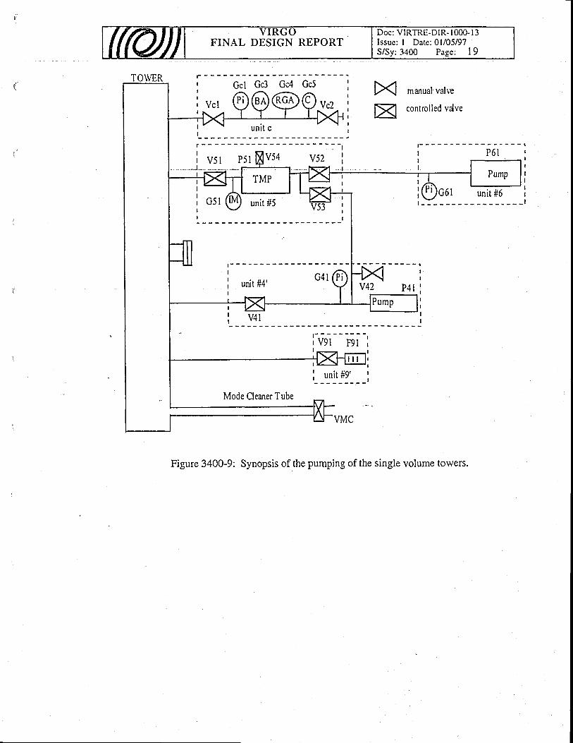
(ftU)J YIRGOFINAL DESIGN REPORT
Doc: VIRTRE-DIR- I 000- I 3Issue: I Date: 0l/05/97S/Syr 3400 Page; I 9
' Gcl Gc3 Gc4 Gc5 :| ^ X manual valre
|SZl controlled valve
Mode Cleaner Tube
Figure 3400-9: Synopsis of the pumping of the single volume towers.
I . . . . c 4 li unit #4'I
t -I
l .v52
unit #9't lI'-
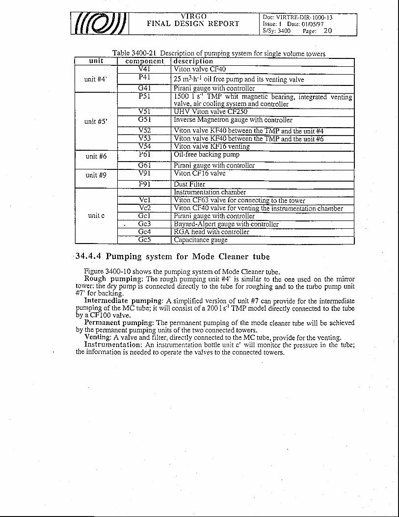
FINAL DESIGN REPORTDoc: VIRTRE-DIR- 1000- l3Issue: I Dare: 0l/05/97S/Sy:3400 Page: 20
Table 3400-21Desc Ie vola nptton oI pumptng system lor s lngle volume towersun i t componen t d e s c r i p t i o n
unit #4'v4l Vlton valve CF40P4l 25 m3.h'l oil free pump and its venting valveG 4 l Pirani gauge rvith controller
unit #5'
P 5 l 1500 I s'' f'MP whit magnetic bearing, integrated ventingvalve, air cooling system and controller
v5l UHV Viton valve CF250G 5 l lnverse Magnetron gauge with controller
Y52 Vrton valve K-h40 betrveen the TMP and the unit #4v53 Vtton valve lth4u between the'I'MP and the unit #6v54 Viton valve Kl.-l6 ventine
unit #6 P61 Orl-tree backrng pump
G 6 l Pirani gauge with controller
unit #9 v91 Vrton CFI6 valve
F 9 l Dust Filter
unit c
lnstrumentation chamberVcl Vlton CF63 valve tor connecting to the towerYc2 Viton CF40 valve for venting the instrumentation chamberG c l l ' lranl gau.ge wlth controllerGc3 Bayard-Alpert gauge rvtth controllerGc4 RGA head rvith controllerGc5 uapacltance gau.ge
34.4.4 Pumping system for Mode Cleaner tube
Figure 3400-10 shows the pumping system of Mode Cleaner tube.Rough pumping: The rough pumping unit #4' is simildr to the one used on the minor
!o_lye-r: the dry pump is connected directly to the tube for roughing and to the turbo pump unit#7' for backing.
Intermediate pumping: A simplified version of unit #7 can provide for the intermediatePumpiqg of the MC tube; it rvill consist of a 200 I s't TMP model directly connected to the tubeby a CFl00 valve.
Permanent pumping: The permanent pumping of the mode cleaner tube rvill be achievedby the pennanent pumping units of the trvo connected towers.
Venting: A valve and filter, directly connected to the MC tube, provide for the venting.Instrumentation: An instnrmentation bottle unit c' rvill monitor the pressure in the fube;
the information is needed to operate the valves to the connected towers.
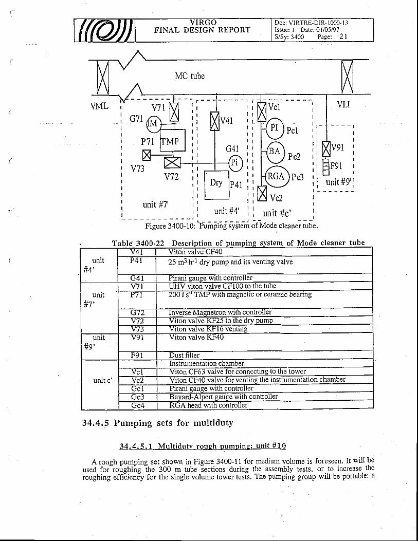
FINAL DESIGN REPORTDoc: VIRTRE-DIR- 1000- I 3Issue: I Date: 0l/05/97S/Sv: 3400 Pase: 2 l
MC tube
I r - -, l, ll ,
r l. l
l '
t l
; l
' r h/lVclI rG71 /ff i4 t; Mlv+r ;ii : 1 1 n ) P c t 'l l l \ J L e L ; l
P 7 1 I M P l i ' I l , l > < i lG1r . i l l { se ) " ^ " : ;i l l f - / P c 2 : l| __I_\_/ I I l,^. I
v j z l i L l l - : : l { n ca )p . l l ;i l l o o l r + t i ii i r I i i t a v c zu n i t # 7 ' r ' r r -, l u n i t # 4 ' r l
- - - , r u r u t l ' ' i t r u r i t # c '
- I - -
Figure 3400-10: RaFng;VstJm of fUoae cleaner tube.
stem of Mode clron be
34,4.5 Pumping sets for multiduty
34.4.5.1 Mul t iduty rough pumping: un i t #1 '0
A rough pumping set shown in Figure 3400-11 for medium volume is foreseen. It rvill beused for'roughing itre gOO m tube lections during the assembly tests, or to increase theroughing efficieniy for the single volume tower tesis. The pumpirig group rvill be portable: a
l 'able 34UO-ZZ Descript ion oI pumpl cleaner tu
unitl l t ttt+
V4I Viton valve CF40P4t 25 m3'h-I dry pump and its venting valve
G 4 I-Piiani
eauee with controller
unit#7'
v7 l UHV viton valve CFl00 to the tubeP 7 l 200 I s-' TMP with magnetic or ceramic bearing
G72 Inverse Magnetron rvith controllerY72
---Yiion@ KF25 to the dry pump
v73 Viton valve KFl6 ventineuilt
Jln rtt>
v9t Viton valve KF40
F91 Dust filter
unit c'
---lnstmrnentation chamber
VcI f f iectingtothetowerYc2 Viton CF40 valve for venting the instrumentation chamberGcl
--TiianfEause with controller
Gc3 Bayaid-{pert g auge with control lerGc4 RGA head with controller
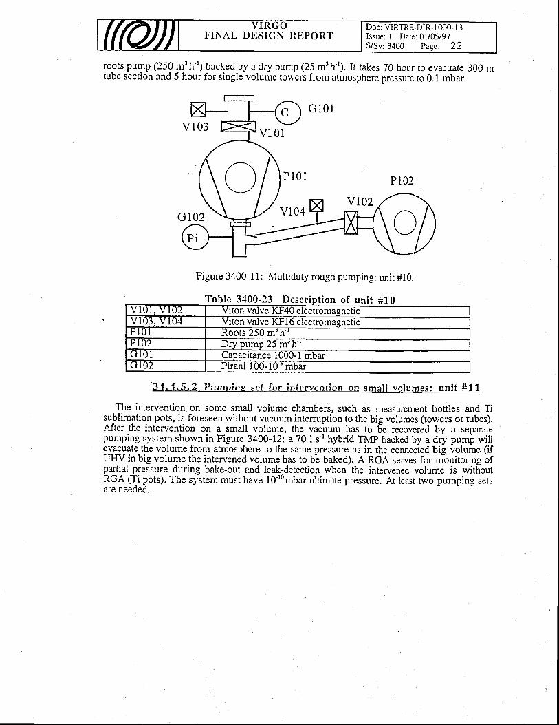
(rcil V T R G OFINAL DESIGN REPORT
Doc: VIRTRE-DIR- I 000- I 3Issue: I Date: 0l/05/97S/Sy:3400 Page: 22
roots pump (250 m3h'') backed by a dry pump (25 m'h-'). It takes 70 hour ro eyacuate 300 mtube section and 5 hour for single volume tow€rs from atmosphere pressure to 0.1 mbar.
Figure 3400-11: Multiduty rough pumping: unit #10.
able 3400-23 Descript ion of unit #10V I O I , V I O 2 Vrton valve K1.40 electromaeneticv103, v l04 Viton valve KFl6 electromasneticP i 0 l Roots 250 m'�h''PIIJZ Dry pump 25 m'h''G 1 0 1 Capacitance 1000-1 mbarG l02 Pirani 100-10'' mbar
"34.4.5.2 Pumping set for in tervent ion on smal l vo lumes: un i t #11
The intervention on some small volume chambers, such as measurement bottles and Tisublimatio.n pots, is foreseen without vacuum intemrption to the big volumes (torvers or tubes).After the intervention on a small volume, the vacuum has to 5e recovered by a separatepumping lystem shown in Figure 3400-12: a 70 Ls-r hybrid TMP backed by a dry pumi willevacuate the volume from atmosphere to the same pressure as in the connecied big volume (ifUHV-in big volume the intervened volume has to bb batea;. A RGA serves for monitoring ofpartial pressure during bake-out and leak-detection when the intervened volume is withoutRGA (Ti pots). The system must have 10'r0mbar ultimate pressure. At least two pumping setsare needed.
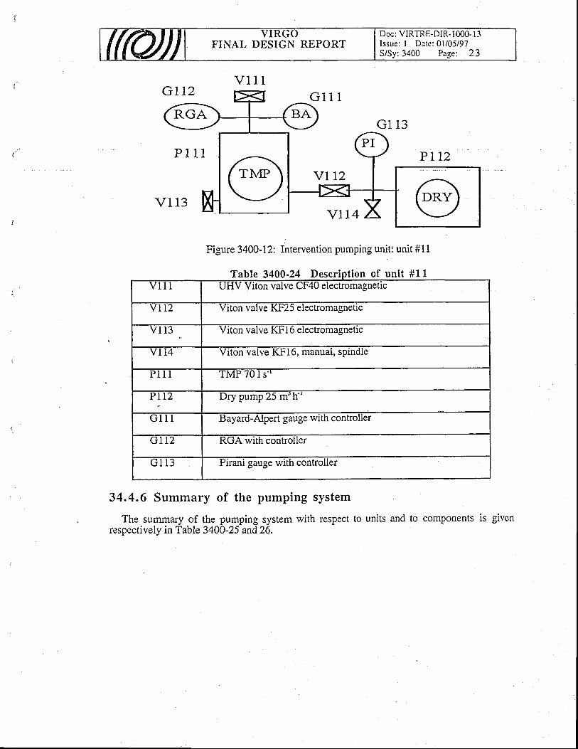
FINAL DESIGN REPORTDoc: VIRTRE-DIR- I 000- I 3Issue: I Datc: 0l/05/97S/Sy:3400 Page: 23
Figure 3400-12: Intervention pumping unit: unit #11
Table 3400-24 Descript ion of unit #11aDte r lp l lon or unv l l I UHV Viton vaive CF40 electromagnetlc
v l 1 2 Viton valve KF25 electromagnetic
/ I I J Viton valve l(h'16 elec[omagnetlc
v 1 1 4 Viton valve KFl6, manual, splndle
P 1 1 1 TMP 701s ' '
Y L L Z Dry pump 25 m'h
G u B ayard-Alpert gauge with controller
Gtt2 RGA with conuoller
G I 1 3 Pirani gauge with controller
34.4.6 Summary of the pumping system
The summary of the pumping system with respect to units and to comPonents is givenrespectively in Table 3400-25 and26.
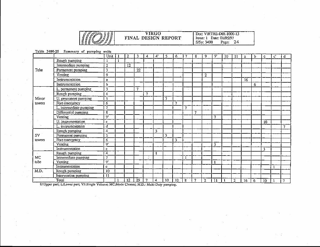
9'
+J
.-.Nq)
o\9
,; :r
JE
Fx
5d
:Iii
iv
o
>:
co
:i
=>
l
82
3
Fl-\
zU)
Fl
z
bTaEo
raalan
F
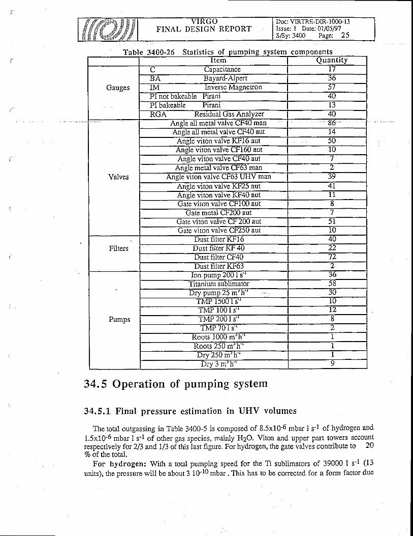
FINAL DESIGN REPORTDoc: VIRTRE-DIR- I 00G I 3Issue: 1 Date:0U05/97S/Sy:3400 Pagc 25
a tat ist ics m n s comDonenI tem Quantity
Gauges
C Capacitance L7BA Baya-rd-Alpert 36IM Inverse MagneEon 57PI not bakeable Prant 40PI bakeable Pirani 13RGA Residual Gas Analyzer 40
Valves
Anele all metal valve CF4U man 66Ansle all metal valve CF40 aut t4
Angle viton valve KFi6 aut 50Ansle viton valve Ctsl6U aut 10Angle vrton valve Ct'4U aut 7
Anele metal valve CF63 man 2Angle vlton valve ut,oJ u.hIV man 39
Anele viton valve Kt'25 aut 4LAnele viton valve Kl'4U aut t 1uate uton valve Lt'lw aut 8
Gate metal ct200 aut 7Gate viton vaive CF 200 aut 5 IGate viton valve CF250 aut 10
FiltersDust hlter KFl6 40Dust filter KF 40 22Dust frlter CF40 72Dust ll lter K|OJ z
Pumps
Ion pump 2001 s'^ 36'Iltaruum subllmator 58Dry pump 25 m'h 30
TMP 15001s ' ' 10TMP IUO I s.. lzTMP 2001s 8TMP 701s '^ z
Roots i000 m'h 1Roots 25U m"h 1Drv 250 m'h-' 1Dry 3 m'h' ' 9
34.5 Operation of pumping system
34.5.1 Final pressure estimation in UHV volumes
The total outgassing in Table 3400-5 is composed of 8.5x10⁻⁶ mbar I s-l of hydrogen and
1.5x10⁻⁶ mbar I s'l of other gas species, mainly HZO. Viton and upper part towers accountrespectively for 2R and 1/3 of this last figure. For hydrogen, the gate valves contribute to 207o of the total.
For hydrogen: Wi*r a total pumping speed for the Ti sublimators of 39000 I s'1 (13
units), the pressure wili be about 3 10-10 mbar . This has to be corrected for a form factor due
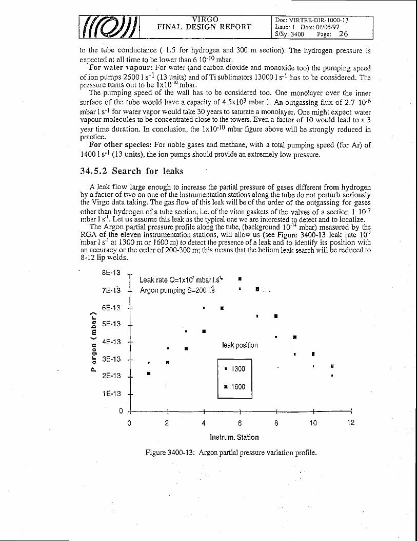
FINAL DESIGN REPORTDoc: VIRTRE-DIR- I 000- I 3Issue: I Date: 0l/05/97S/Sy: 3400 Page: 26
to the tube conductance ( 1.5 for hydrogen and 300 m section). The hydrogen pressure isexpected at all time to be lorver than 6 10-10 mbar.
For u'ater vapour: For rvater (and carbon dioxide and monoxide too) the pumping speedof ion pumps 25001r-l 1t3 units) and of Ti sublimators 130001s-l has to be considered. TheDressure turns out to be 1x10''u mbar.-
The pumping speed of the wall has to be considered too. One monolayer over the innersurface of the tube rvould have a capacity of 4.5x10³ mbar l. An outgassing flux of 2.7 10'6mbar I s-l for water vapor rvould take 30 years to saturate a monolayer. One might expect watervapour molecules to be concentrated close to the towers. Even a factor of l0 would lead to a 3year time duration. In conclusion, the 1x10⁻¹⁰ mbar figure above rvill be strongly reduced inpractlce.
For other species: For noble gases and methane, with a total pumping speed (for Ar) of1400 I s-l (13 units), the ion pumps should provide an extremely low pressure.
34.5.2 Search for leaks
A leak florv large enough to increase the pafiial pressure of gases different from hydrogenby a factor of trvo on one of the instrumentation stations along the tube do not perturb seriouslythe Virgo data taliing. The gas florv of this leak will be of the order of the outgassing for gasesother tha.n hydrogen of a tube section, i.e. of the viton gaskets of the valves of a section 1 10-7mbar I s-'. Let us assume this leak as the typical one we are interested to detect and to localize.
The Argon partial pressure profile along the tube, (background 10'r{ mbar) measured by thgRGA of the eleven instrumentation stations, will allorv us (see Figure 3400-13 lealc rate 10''inbar I s't at 1300 m or 1600 m) to detect the presence of a leik and"to identify its position rvithan accuracy or the order of 200-300 m; this means that the helium leak search rviil be reduced to8-12 lip rvelds.
L
L
8E-13
7E-13
6E-13
5E-13
4E-13
o t r - t o
2E-13
1 E - 1 3
0
Instrum. Station
Figure 3400-13: Argon partial pressure variation profile.
Leak rate Q=1x10⁷ mbai.l.S1'Argon pumping 5=200li
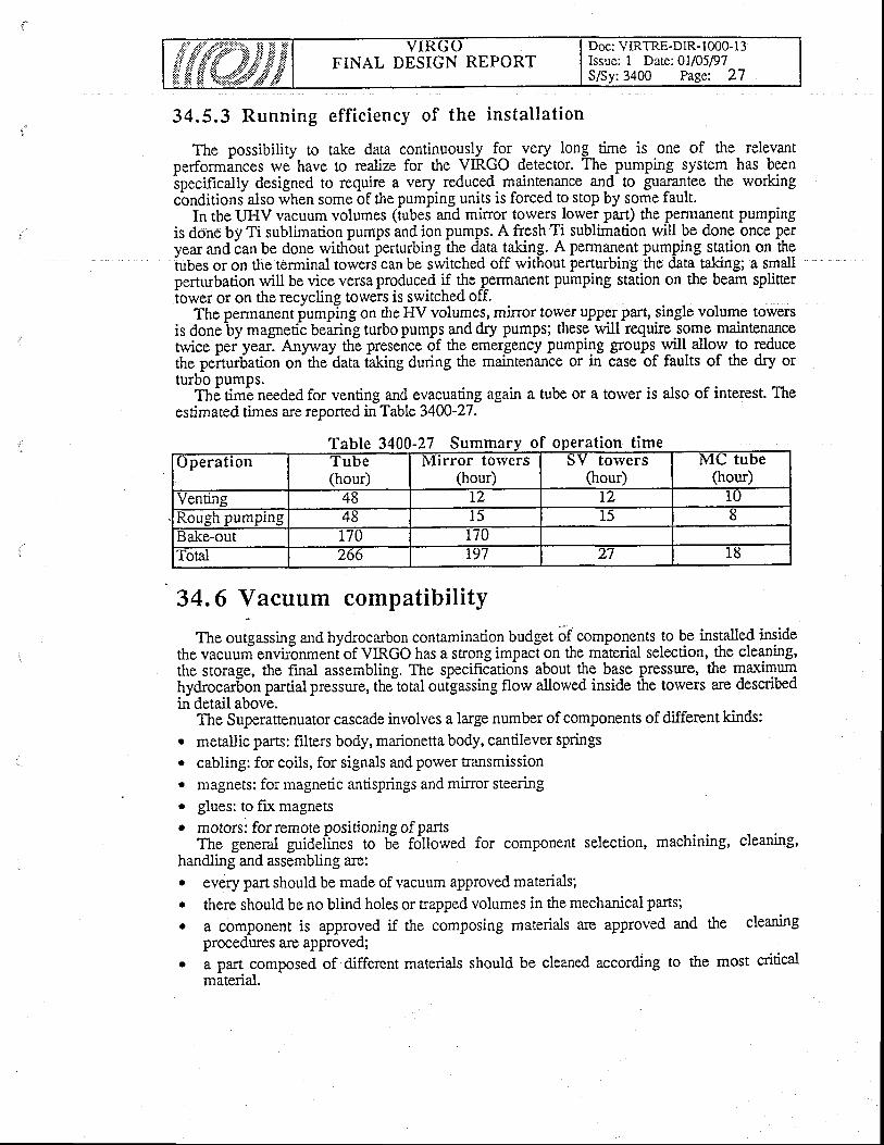
FINAL DESIGN REPORTDoc: VIRTRE-DIR- 1000- I 3Issue: I Date: 0l/05/97S/Sy:3400 Page: 27
34.5.3 Running eff ic iency of the instal lat ion
The possibility to take dara continuously _fgr yery long time is one of the relevantperforminces we, have to realize for the VIRGO detector. The pumping system has beenSpecifically designed to require a very reduced maintenance a1d to guaftm-tee the workingcbnditiond also when some of the pumping units is forced to stop by some fault.
In the UHV vacuum volumes (tubes and mirror towers lower part) the permanent pumpingis done by Ti sublimation pumps and ion pumps. A fresh Ti sublimation will be done once p€ryear and i:an be done widrbut perturbing thg qta tgnlg. A permanent pumping station on the-tubes
or on the terminal towers can be switched off without perturbing the data taking; a smallperturbation will be vice versa produced if the ̂ permanent pumping station on the beam spliner-tower
or on the recycling towers is switched off.The permanent iumpTng on the HV volumes, mirror tower upper part, single volume towers
is doneby magnetic bearing turbo pumps and dry pumps; these will require.ggqe maintenancetwice pei yearl Anpuay th! preseice of tfrg em'erlency pumping groups-11l! allow to reducethe pe-rrurbation on-the data taking during the maintenance or in case of faults of the dry orturbo pumps.
Th,; dma needed for venting and evacuating again a tube or a tower is also of interest. Theestimated times are reported in Table 34W-27.
Table 3400-27 Summa eration
34.6 Vacuum compatibility
The outgassing and hydrocarbon contamination budget of components to be installed insidethe vacuuri envir6nmeni of VIRGO has a srong impaci on the miterial selection, the cleaning,the storage, the final assembling. The specificatiohs about the base pressure, the maximumhydrocarSon partial pressure, the-total outgassing flow allowed inside ihe towers are describedin detail above.
The Superattenuator cascade involves a large number of components of different kinds:o pstallis parts: frlters body, marionena body, cantilever springs. cabling: for coils, for signals and power Eansmission. magnets: for magnetic antisprings and mirror steeringo glues: to fix magnetso motors: forremote positionine of parts
The general guidefines to b-e fd[owed for component selection, machining, cleaning,handling and assembling are:I evory part should be made of vacuum approved materials;. there should be no blind holes or trapped volumes in the mechanical parts;o I component is approved if the composing materials are approved and the cleaning
procedures are approved;. a part composed of different materials should be cleaned according to the most critical
material.
peration
FINAL DESIGN REPORTDoc: VIRTRE-DIR-10@13Issue: I Date: Oll05/97S/Sy:3400 Page: 28
An extensiv-e plgggp of outgassing melrsurement has been starred to qualify thecomponents at the VIRGO contamination level. Both GEO600 and LIGO have agreed to-sharedata and join efforts about this problem.
The measurements perfonned to date in the Pisa vacuum laboratory allow to assemble aSuperattenuator cq cade with an outgassing florv one order of magniiude below the formerFinal Design specifications (see note VACPISA 049).
f. lisl -of -components "approved" (for UHV or HV use), "temporarily approved" and"rejected" follows, together with the reference describing the details of the m-easurement of the
outgassing rate and composition.
34.6.1. Approved components
Approved components are the ones which are recommended for VIRGO due to their lowoutgassing rate and negligible hydrocarbon contamination.o Metals (as deduced from tube measuremens and literature)
o stainless steel (304,304L)o aluminium series 6000. OFFIC coppero steel for cantilever blades (chromium plated, if necessary)
o Cable insulations:Kapton, note VACPISA 036; sqggested cleaning is ulrasonic bath in isopropylalcohol for 15 minutes, then 120 uC baking in vacuum; FEP layer should be absenialuririna, note VACPISA 037; as supplied from the factoryGore+ex+PTFE: suggested cleaning is lrlrasonic bath in isopropyl alcohol for 20minutes, then a few days baking at 100 0C
Pyre-ML: suggested cleaning as the preceding onevacuum sealants (to be used as glues to fix the magnets): these materials should be used inthe upper part of the tower only, since there is no real way to ciean them and the two basecomponents undergo ageing.
" VAC-SEAL, note VACPISA 048, with several days curing at room temperatue;avoid contact with alcohol as suggested by LIGO experienie. Moreover,-there ishydrocarbon contamination above some tens degrees-. It should not be used forparts baked in situ. The possibiliry of mechanical fixing of magnets should beconsidered.
magnets, for antispring and for mirror steering. samarium cobalt, note VACPISA 047; suggested cleaning is baking at 150 0C.
there is hyd:ccarbon coniarnination above a fevr tens degrees thus they should notbe used on parts which must be baked in situ
a
a
34.6.2 Temporari ly approyed components
lgmporarily approved components include either equipment builr by UHV industries (e. g.feedthroughs) rvhich is known to be good for UHV environments but has not yet explicitlytested for VIRGO contamination level or materials wittr good vacuum properties but notmatching VIRGO requirements, thus waiting for a beuer cleaning merhod oi aieplacement. Inthe fust category there are: ceramic anE glass ceramic feidtroughs (CaBurn/ICI andCeramaseal under consideration) as supplied from factories; crimp contacts for elecuicalconnections as supplied from factories;-Viton for blades and cross dampers. In the secondgatggory there are the antispring magnets (fenite Phillips Ferroxdure 330, iee notes VACPISA046 and VACPISA 050). The suggested method for cleaning is baking ar 150 oC. The magnets
FINAL DESIGN REPORTDoc: VIRTRE-DIR- 1000-13Issue: I Date:0U05/97S/Sy:3400 Page: 29
exhibit slight hydrocarbon contamination at room temperatue which becomes stronger rvithincreasing temperarures.
34.6.3 Rejected components
The rejected components are the ones not matching VIRGO requirements, e.g. Tonseal andKrytox.
34.6.4 Motors
Motors suitable for use in UHV have been investigated. The tested samples from AML andOriental Motors generally have a good outgassing behavior after vacuum baking but ttrey emitsome organic fragments during baking, which precludes their baking in situ. Studies are beingperformed to check the reproducibility of performances.
34.7 Pumping system control
It concerns the control of the whole pumping system of Virgo: Valves, pumps, gauges,RGA, and temperature during baking. It also manages all the securities.
For each pumping bench (torver or tube pumping station), there is a diskless G96 crateIinked to the Slow Monitoring Network -Ethernet- figure 3400.14). There is one more cratervith a hard dis-k which is used to boot all ttre stations. The operating System is OS9. All the
' Standard Sofware tools of Virgo are used and especially the Sequencial Language.A tocal Supervisor gives the state of the vacuum of Virgo. It runs on ttre vacuum global
workstation, in the concrol room. This workstation allows the access any particular pumpingbench or instrument. It is also possible to link a terminal close to any bench in order to conEol' it locally.
Each pumping sequence may be done automatically or with separate manual operations.To s&ure thE vacuum (eslecially acting on gaie valygs) a separate control system is
foreseen; it wilI be able to reiet ths vacuum system in a safe stata, even in case of powerfailure.
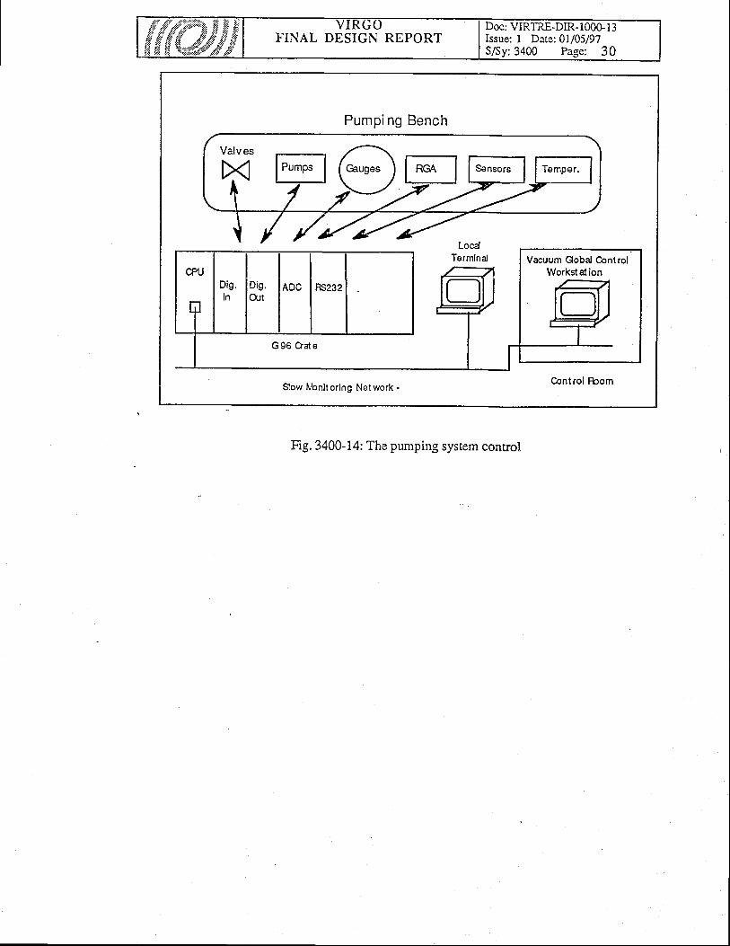
FINAL DESIGN REPORTDoc: VIRTRE-DIR-100G13Issue: I Date:01/05/97S/Sy:3400 Page: 30
Pumping Bench
Vacuum Gobal ControlWorkstat ion
Slow ltbnit oring Net work -
Fig. 3400-14: The pumping system control
FINAL DESIGN REPORTDoc: VIR-TRE-DIR- 1000- I 3Issue: I Date: 0l/05/97
40. INTERFEROMETER
Table of Contents
40. INTERFERONIETER
40.1 Inter ferometer descr ipt ion40.1.1 The test interferometer
40.2 Opt ica l scheme and detect ion pr inc ip les40.2.1 Optical scheme40.2.2 GW derecrion basis40.2.3 Virgo sensitivity limitation by optical components flarvs -
40.3 The suspension of the test masses
40.4 Inter ferometer regui rements
41. Laser and input bench
41.1 Funct ions and Concept
41.2 Requirements41.2.1 Laser Porver4 1.2.2 F r equency S tabil ity4 1.2.3 Forver Stabil ity41.2.4 Beam stabil ity41.2.5 Summary of requirements
41.3 Inter faces41.3.1 Interface with sub-system 2100 (Central area building)41.3.2 Interface with sub-system 2200 (Clean rooms)41.3.3 Interface with sub-system 3100 (MC tube)41.3.4 Interface rvirh sub-system 3300 (Towers)41.3.5 Interface rvith sub-system 31CI (Pumping)41.3.6 Interface ri,irh sub-system 4200 (Detection bench)41.3.7 Interface with sub-system 4300 (Minors)41.3.8 Interface with sub-system 4400 (Alignment)41.3.9 Interface with sub-system 4700 (Last stage suspensions)41.3.10 Interface with sub-system 4900 (Suspensions electronics)4l.3. I I Interface with sub-system 5 100 (Global control)
41.4 Select ion of so lut ions
41.5 Deta i led descr ipt ion41.5.1 Laser bench4l .5.2Input bench41.5.3 Local controls
41.6 Separat ion ry indorvs
simulations.
4 0 0 0 - 1
4 1 0 0 - 1
66
71
8
8
9
2J
J
A-4
4)))J
56666.|.f
89
t 4ZJ
2 9
FINAL DESIGN REPORTDoc: VIR-TRE-DIR- I 000- I 3Issue: I Date: 0l/05/97Sy:4000 Page: 2
41.6.1 Funct ion and conceDt
41,7 Laser and Input Bench assembly4 1.7. I Laser Bench assembly41.7.2 Input Bench assembly41.7.3 Sub-system assembly
42. Detection bench
42.1 Detect ion bench funct ion and concept
42.2 Requirements appl icable to the detect ion
42,3 Detect ion bench inter faces42.3.1 List of interfaces
42.4 Select ion of so lut ions
42,5 Deta i led descr ipt ion42.5.1 Output Opr ics42.5.2 Photodiodes42.5.3 Signal read-out
42.6 Detecl ion bench assembly42.6. I Output optics assembly and installation42.6.2 Photodiodes assembly and installation42.6.3 Signal read-out assembly and installation
43. Large mirrors
43.1 lVlirrors requirements43. l. I Test interferometer43.1.2 T\e Virgo interferometer43.1.3 Present results
43.2 General Descr ipt ion43.2. I Virgo optical components43.2.2 Deposition process43.2.3 State of the art43.2.4 Coater : Technical description43.2.5 Wavefront correction
43,3 Metro logy43.3.1 Goals43.3.2 B lanks lvletrology
43.3.3 Coated Optics Metrology
3 0303030
bench
4200-l'
4
5
669
I J
1 3l 3I A
1 At ?
4 3 0 0 - 1
.,
t
A
A
6789
1 0l 0l 0l l
5
FINAL DESIGN REPORTDoc: VIR-TRE-DIR-1000-l 3Issue: I Date: 0l/05/97
44. Al ignment
44.1 Al ignment funct ions and concept
44.2 Requirements appl icable to a l ignment
44,3 Al ignment in ter faces44.3.1 List of alignment interfaces4 4.3.2 lnterface with sub-system 330044.3.3 Interface with sub-system 410044.3.4 Interface rvith sub-system 420044.3.5 Interface with sub-system 430044.3.6 Interface with sub-system 510044.3.7 InLerface with sub-system 5400
44.4 Non l inear a l ignment44.4.1 Non linear Alignment function and concept44.4.2 Non linear Alignment detailed description44.4.3 Procedure
44.5 L inear Al ignment44.5.1 Linear-Alignment function and concept44.5.2 Linear Alignment detailed description
44.6 Posi t ion memor ies.44.6.1 Position memories function and concept.44.6.2 Position memory detailed description
45. Calibration
45.1 Calibration function and concept
45.2 Requirements
45.3 Select ion of so lut ions
45.4 Deta i led descr ipt ion45.4.1 The signal generator45.4.2The coils driver45.4.3 The laser diodes45.4.4 Calibration software45.4.5 Reconstruction software (TBC)
45.5 Cal ibrat ion in ter faces
46. Suspension System
46.1 Int roduct ion
4 4 0 0 . 1
888
1 8l 8l 8
4 5 0 0 - 1
A
4 6 0 0 - 1
I
27
23J
J
3J
A
6
35
3J
44
46.2 Suspension system requirements

F'INAL DESIGN REPORTDoc: VIR-TRE-DIR- I 000- I 3Issue: I Date: 0l/05/97
46.2.1 Functionality and payload46.2.2 Temperature stabil isation46.2.3 Vacuum compatibil i ty46.2.4 Bakeabil ity
46.3 Suspension in ter faces46.3.1 Interface with torvers46.3.2 Interface with local electronics
46.4 Deta i led descr ipt ion46.4.1 Mechanical filters46.4.2 Inertial Damping46.4.3 Filter 7 (or steering filter)46.4,4 Top Stage46.4.5 Cabling46.4.6 Tools46.4.7 Storage and transport46.4.8 Transfer function measurement
47. LAST STAGE SUSPENSION
47.7 Last stage function and concept
' 47,2 Requirerirents for tast stage elernents47.2.1 Last stage interfaces
47.3 Deta i led descr ipt ion47.3.1 Marionetta for Minors47.3.2 Reference masses47.3.3 Marionettas for inout and detection benches
48. Clamps and lyires
48.1 Overvierv48.1.1 Requirements for clamps and wires
48.2 lYires48.2.1 Overview48.2.2 Description48.2.3 Specifications48.2.4 Marionetta-Wire clamps48.2.5 Overview48.2.6 Specifications
48.3 Mirror - lVires spacers48.3.1 Overview48.3.2 Specifications
48.4 Interfaces
48,5 Future developments
A
A
5)
666
77
T2I J
t 4l 5L 7t 7l 8
47 00-1
1
t
2
J
4 8 0 0 . 1
3J
A
))
J
666
FINAL DESIGN REPORTDoc: VIR-TRE-DIR-l 000- l3Issue: I Date: 0l/05/97
49. Suspension e lect ronics
49.1 General Descr ipt ion49. L I Active damping of suspensions49.1.2 Suspended masses position control49.1.3 Super Attenuators internal status monitoring and conection49. 1.4 Interface betrveen the S.A. control system and other VIRGO sub-systems
49.2 Hardlvare Description49.2;l Digital Signal Processor Board49.2.2 ADC6r6b49.2.3 DAC820c
49.3 Sof tware Descr ipt ion49.3.1 Advanced Damping Toolkit (ADT).49,3.2The graphical user interface :49.3.3 The internal structure of adt softrvare
4 9 0 0 - 1
I
222
)-'l
J
)
6677
FINAL DESIGN REPORTDoc: VIR-TRE-DIR- I 000- I 3Issue: I Date: 0l/05/97
4A.t Interferometer descriptionThe interferometer is the sensitive part of VIRGO. It consists in a laser system,-the input
bench, which contains optics and optionics for adapting the laser beam to thi inteiteromerer,the.large interferometer (minors and suspensions),-the detection bench, which also containsoptics and optronics for monitoring, cleaning and-detecting the main interierence signal, and allthe ancillary equipment (secondary detectori_for the locking and alignment servosy"stems, localcontrol stations), and the calibration device(s), A major f&ture otitre Virgo intefoerometer isthe ensemble of " superattenuators ", the lorv frequency seismic isolation slystems from whicheach sensitive component is suspended.
The main characieristics of ttre optical system are the follorving :- The t$gl tY-tt_?T consists_in.a higii power Nd:YAG ring-laser, injection-locked from amonolithic I Watt laser. It is actively stabilized, in frequency a;d in amplitude. Thebeam is p.hase modulated, to allow fbr a shot-noise limited detection, and filtered bytransmission through a reson_ant (mode-cleaner) cavity. The power will be about 25W.
"- The large interferometer is a Michelson interferbmetei, with I tm tong arms. Each arm' contains a Fabry-Perot cavity of length L= 3 km. The light poiver is increased through
the use of a standard recycling technique. The nominal vituei are a finesse of 50 for tfieFabry-Perot's, and a recycling coefficient of 50 (conesponding to a finesse of 150 forthe recycling cavity).
- These performances are obtained through the realization of very lorv loss mirrors,having typical surface qualities of l,/300, rvhose fabrication and tests are performed by
. the VIRGO teams.The main interference beam, rvhich carries the gravitational signals, is filtereroutput mode-cleaner, and detected rvith an a mulriple InGaAs &tector of hieh
ignals, is filtered with anquanrum
efficiency.- All the secondary beams lealiing through, or reflected by, the interferometer, are split
onto two quadrant detectors and one InGaAs detector. This orovides redund-antinformation for the alignment and locking servosystem
- We use a set of computerized CCD cameras l5oking inside each tower, in order tomonitor the preliminary (nonlinear) alignment and to ineasure precisely the position ofeach mirror relative to its own tower and to the laser beam
- The calibration rvill be done by applying time-dependent forces on the mirrors, in trvodifferent ways.: a magnetic foice onio f set of mignets glued to the mirrors, and laserinduced radiation pressure.
40.L.1 The test interferometer
. By mid-98 (or about trvo -years after the site acquisition), rve rvill start installing a shortinterferometer in the central building. We catl it th6 test interferometer. It will diifer fromVn'GO.gr_tJI Uy t-tt-" absence of the iar mirrors of the 3 km Fabry-Perot's, by a lower laserpower (l0W), and by the choice of the radius of curvatures and of the reflectiviiies of the otherminors. The interferometer geometry will be simpler than in VIRGO, and the mirrors will be ofsmaller diameter. Except foithat, it will provide a complete, full size, test of all the critical partsof.VIRGO.( suspensions, laser, benchds, data manalement, control and alignment systems,mlfor quallty, data management, ...), and give some hint about the presenct of unexpectednolse sources.. The presence of this test bench rvill accelerate the commissioning of VIRGO after the end of
the construction, since all the functions and components, except the"final large mirrors, and thefinal locking and alignment procedures will have been tested.
^
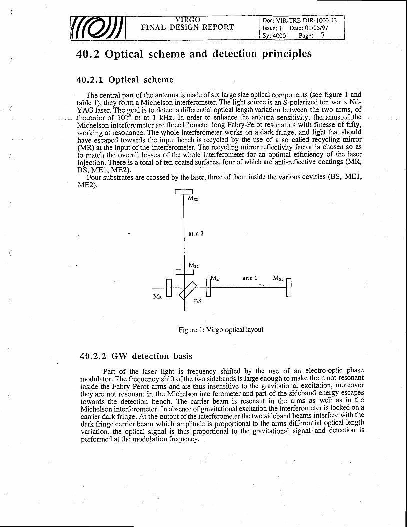
t
4A.2 Optical scheme and detection principles
40.2.L Optical scheme
The central part of the antenna is made of six large size optical components (see figure I andtable 1), they form a Michelson interferometer. The light source is an S-polarized ten watts Nd-YAG laser. The goal is to detect a differential optical length variation between the two arms, ofthe order of 10-b m at 1 kHz. In order to eirhance the antenna sensitivity, the arms of theMichelson interferometer are three kilometer long Fabry-Perot resonators with finesse of fifty,rvorking at resonance. The whole interferometer works on a dark fringe, and light that shouldhave escaped torvards the input bench is recycled by the use of 3 ss sellsd recycling mirror(MR) at the input of the interferometer. The recycling minor reflectivity fa9t9r is chosen so asto match the overall losses of the whole interferometer for an optimal efficiency of the laserinjection. There is a total of ten coated surfaces, four of which are- anti-reflective coatings (MR,BS, MEI, ME2).
Four substrates are crossed by the laser, three of them inside the various cavities (BS, MEl,ME2).
Figure 1: Virgo optical laYout
40.2.2 GIY detection basis
Part of the laser light is frequency shifted by the use of an- electro-optic phasemodulator. The frequency shift of the tivo sidebands is large enough to make them not resonantinside the Fabry-Pdrot aims and are thus insensitive to tf,e gravltational excitation, moreoverthey are not resonant in the Michelson interferometer and part gf the sideband ene-rgy escapestowards the detection bench. The canier beam is resonint in the arms as well as in theMichelson interferometer. In absence of gravitational excitation the interferometer is locked on acarrier dark fringe. At the output of the iiterferometer the two sideband beams interfere with thedark fringe carrilr beam which amplitude is proportional to the arms differential optical fengqhvariation] the optical signal is thui proportionil to the gravitational signal and detection isperformed at the modulation frequency.
Doc: VIR-TRE-DIR- I 000- I 3Issue: I Date: 0l/05/97FINAL DESIGN REPORT

FINAL DESIGN REPORTDoc: VIR-TRE-DIR- I 000- I 3Issue: I Date: 0l/05/97
40.2"3 Virgo sensitivity limitation by optical components flaryss imulat ions.
At frequencies above 5Q0 I{2. tirgo sensitivity is limited by shot noise. Any defect in theoptical components-rvill raise this limit, either by-decreasing the amount of stoied light insidethe interferometer, by degrading the q-uality of the canier dark fringe, or by maki-ng Virgosensitive to laser frequency noise.In order to-quantitatively express thjeffect df geom#ical
"or
other characteristics of the optical parts of Virgo a co0d hai been written, in -which
real orsimulated defects can be introduced, which piovided the signal to noise degradation withreference to the shot noise limit of the antenna. This code iibased on the fie-Id distributionprojection -o1 H.ermite-Gauss basis. Thes-e functions are propagated betrveen the varioussurfaces of the interferometer. Each interface is representeci by ilatrices which acts on thevarious function of the Hermite-Gauss basis. This piogram allows to simulate various kind ofdefects :
o Laser defects (alignment, modes, noise...)o Coating defects (geometrical imperfections, absorption, transmission, local defects...)r Blank defects (absorption, local defects, geometrical distortions...)r Thermal effects (e.g. in entrance mirrors)This code is reliable and fast enough to be used for statistical simulations.This.last point has to be underlined because we have based our simulation programs on
artificial mirrors rvavefront figures based on the statistical distributions -Dower tawi- 5f defectsthat we have experienced on test mirrors during the R and D period.
40.3 The suspension of the test massesGravitational waves can be detected by measuring the distance between test masses. These'masses,
the interferometer mirrors, need to be suspended to be as free as possible. Thesuspension system must:
- isolate the test mass from seismic motion- keep low the thermal noise motion in the detection band- allow for cbntrol and steering of the test masses to keep the best optical conditions for
detection without introducing additional noise- be compatible with the level of vacuum neededA complete suspension chain consists, from top to bottom, of the following elements:
a movable suspension point, a chain of several seismic filters and a marionettesuspending the mirror.
. An inverted pendulum provides the mean to adjust the position of the suspension pointrelative to the supporting structure. The settings for this device are determined from thealtgnment enor signals an-d the lo_rv frequency component of the locking en'or signals.
Then there is a cha_in of up to-5 seismic fifters, tliat perform a passiv6 mechan-ical attenuationin all six.degrees of freedom of a rigid body. Normai motion of the filter chain can result inlarge oscillations bringing th.e interferometefaway from its working point.gs uscurarrons onnglng tne tnterlerometer away lrom lts worlQng point.
At the level of the marionette, mirror positioning is achiev6d by forces acting from aerence mass, itself suspended to the marionette. Larie ranse lonsitud'inal motion anE aneulalAt me level ot the marionette, mirror positioning is achieved by forces ac
reference mass, itself suspended to the marionette. Larle range longitud'inal motiondisplacements arc achiev-ed by acting on the marioneite froir coiis suspended to
angulardisplacements arc achievia uy acting on the marioneiie rto,h "oiis ;;;p.;d.d ro the seienthfilter.
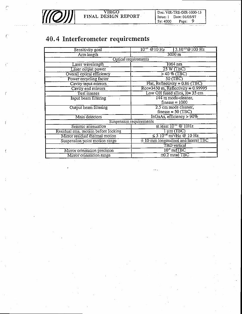
FINAL DESIGN REPORTDoc: VIR-TRE-DIR-l 000- I 3Issue: I Date: 0l/05/97
40 .4 Interferometer requirements
Sensitivitv eoal l0 ' ' ' @ l0 Hz | 3 .10 ' "@ 100 HzArm leneth 3UUU rn
uptlcal requrrementsLaser wavelength 1064 nm
Laser output power 2s w (TBC)Overall optical ef ticiencv > 40 Vo (TBC)Power recvclrng tactor s0 (Ttsc)Cavrty lnput nurrors Flat, Retlectivlty = 0.86 ('lBU)Cavitv end mirrors Rcc=3450 m. Reflectivitv = O.99995
I'est masses Lorv OH fused siltca, R= 35 cmInput beam tiltenng 144 m mode-cleaner,
finesse = 1000Output beam tiltenng 2.5 cm mode cleaner,
finesse = 50 (TBC)Main detectors InGaAs, etticiency ) 90"/o
Suspenston requlrementsseismrc attenuatlon at least 10'" @ IOHz
Residual rrns. motion betbre lockins I trm (TBC)Mirror residual thermal motlon ( I 1g'tu m/.JHz @ 10 HzSuspensron pornt motton range + l0 rnrn lonsitudinal and lateral'I uU
TBD verticalMirror onentation prectsion 10-'radTBC
Mlrror onentatlon range +0.2 mrad TBC
FINAL DESIGN REPORTDoc: VIR-TRE-DIR- I 000- l -jIssue: I Date: 0l/05/97S/Sy:4100 Page: I
4t. Laser and Input Bench
Table of Contents
41. Laser and Input Bench
41.1 Funct ions and Concept
41.2 Requirements4l .2. I Laser Power4 1.2.2 Frequency S tability41.2.3 Power Stability41.2.4 Beam stabil ity4l.2.5 Summary of requirements
41.3 Inter faces41.3.1 Interface with sub-system 2100 (Central area building)4l.3.2Interface rvith sub-system 2200 (Clean rooms)41.3.3 Interface with sub-system 3100 (MC tube)41.3.4 Interface rvith sub-system 3300 (Torvers)41.3.5 Interface with sub-system 3400 (Pumping)4 1.3.6 Interface with sub-system 4200 (Detection bench)
' 41.3.7 Interface with sub-system 4300 (Minors)41.3.8 Interface with sub-system 4400 (Alignment)41.3.9 Interface with sub-system 4700 (Last stage suspensions)41.3.10 Interface with sub-system 4900 (Suspensions electronics)4l.3.l l Interface with sub-system 5100 (Global control)
41.4 Select ion of so lut ions
41.5 Deta i led descr ipt ion41.5.1 Laser bench
41.5.1.1 Laser bench function and concept4l.5.1.2 Laser bench detailed description
41.5.2 Input bench41,5.2.1 Input bench function and concept41.5.2.2 Input bench detailed description
41.5.3 Local controls41.5.3.1 Function and concept41.5.3.2 Detailed description
41.6 Separation ryindorvs41.6.1 Function and concept
41.6.1.1 Requirements of Input window4 1.6.1.2 Selected solution
41.7 Laser and Input. Bench assembly41.7. I Laser Bench assembly41.7.2 Input Bench assembly4 1.7.3 Sub-system assembly
',
7
2
3A
4
4)5
55566667
7
8999
l4l4l 523z). A
2 9292929
3 0303030
FINAL DESIGN REPORTDoc: VIR-TRE-DIR- I 000- I 3Issue: I Date: 0l/05/97S/Sy:4100 Page: 2
The sub-system is located at the input of the interferometer, it includes the realization of thelaser source with its stabilizations and the input optics used to direct and to enlarge the beam tomatch it to the interferometer's beam size.
The laser source and stabilizations are located on at least 2 tables forming rvhat is called herethe Laser Bench, the input optics are located on a table named Input Bench, suspended undervacuum inside the injection tower.
The 3 items that will be described below are :- the Laser Bench where the laser light is provided and located in the laser laboratory- the Input Bench located inside the Injection torver (sometimes also called Input tower)- the Local Controls that gather all the monitoring and controls necessary in the sub-
system.
4!,! Functions and Concept
The Laser and Input Bench Subsystem is designed to produce the light power n_ecessary forthe interferometer with the stabilizations required for the expected sensitiviry of Virgo as rvellas the beam geometry matched to that of the caviry arms. Besides that, it provides also all themonitorings-and controls of the beam parameters and the automatic alignments of thecavitiesibeams used to achieve the different stability goals.
The requirement of high power and stability of the light source is achieved by using diode-pumped Nd:YAG lasers, and the technique of injection locking. A low power si-ngle flequencyi maitero laser controls a high power ., ilave >> laser. One slave laser, or two coherently addedslave lasers (TBC), will be used, depending on the necessary power and on the state of the artof high power l4sers.' Tfr'e ichievement of laser beam stability is performed through the prestabilization and finalfrequency stabilization, and the power stabilization. The prestabilization of the laser is the firststef of ninowing the laser linewidth using an ultra-stable short te-rm reference cavity. The finalstabilization is th? one that locks the laser frequency and the interferometer resonance one to the
'other.
The beam jittering of the laser is cured via a passive filtering done by a_ M9_{e Cleaner,which is a res6nant c-avity used in transmission on fhe fundamental mode TEM*. With a goodchoice of that Fabry-Per6t's geometry, all the high order modes will be far ayay- enough fromthe TEM* one, to be reflected by this cavity, ensuring then a spatial "cleaningl' of the beam.Besides tfr'at, the Fabry-Perot acti, in transmission, as a lorv pass filter for all the fluctuationsof the laser in frequency and amplitude.
To operate alt itre clvities iniesonance, a number. of servo-loops will be unavoidable, aswell as automatic alignments servo-loops of these cavities.
The SS has also tlie task of directing the beam to the interferometer and enlarging it from thelaser's size to the interferometer's sizE via a number of mirrors and telescopes, each of themdesigned for low losses and and lorv extra noise.
4t,2 Requirements
The requirements on the physical parameters originate from 2 sources :- the spictral sensitivity iuries of Virgo (initial aid ultimate) -eiu9n by the ligqre 4 10 0. 1 , forrvhicti we will quote iSC (curve a)-anit USC (curve b) (for initial sensitivity and ultimatesensitivity curves).- the techirical limitations linked to the realization and mainly as a consequence of one chosensolution in another Sub-System, for which we will quote TLS (for technical limitations of thesolution).
41.2.L Laser Polver
The accuracy of the phase measurement at the output of the interferometer is limited bystatistical fluctuations br shot noise in the detection.-This noise is rvhite, but as the signal
FINAL DESIGN REPORTDoc: VIR-TRE-DIR- 1000- I 3Issue: 1 Dare: 0l/05/97S/Sy:4100 Page: 3
decreases rvith the Fourier-frequencyJ the phase sensitivity-then varies proportionally withJand in the case of Virg-o, it becomes dominant only above 500 Hz, rvhile belorv that, tLe otheisources of noise are of various thermal origin.To reach a strain sensitivity of 3x10'23 y17'1t2, 1 kW (ISC) of light should be incident on rheBeamsplitter. The requirement on the,laser output porver dependl on the recycling factor, i.e.on the.quality of f1e. lqqe mi5r.ors. We are plesently-worliing with the asiumpiion thai therecycling factor rvill be 50, rvhich requires an effective laser poiver of 20 w.
4L,2.2 Frequency Stabi l i ty
For a given.strain sensitivity goal, the frequency stability (at,the entrance of the beamsplitter) isrelated to the expected asymmetry between the 2 arms of the Michelson. There ivil b6 acompromise-bgt*_.9n the.requirements on asymmetryand o-n frequency stability, that dependsupon the technical feasibiliry in one case or the other. The relationbetw6en these paramet&s is :
. d v _ hv p
rvhere B is the asyrnmetry factor of the Michelson arms and I t, the requested laser
[equency stability a!.the level of the input port of the interferometer lteamsplitter).Then for a given Virgo sensitiviry gdal (curve I of Managemeni Plan), rve plot now therequirements fordifferent asymmetries (figure 4100.2): the upper and lower sets of curves arcrespectively for ISC and USC. For instance with 17o asymmetry, the lowest level to beachievedisarouiid tO'6Hzt',ltlzforthe lst generation (ISC) and this is our goal today forthelaser stabilization .
.4L.2,3 Power Stabi l i ty
The main channel through which the laser power noise may affect the Virgo's sensitivity isthe finite gPen loop gain, _oi the offset, of the hark fringe contiol ryit"* Agfin here there is agompromise b^etween the laser stability that can be achieved and ihe possiSle residual offset.The product of the two parameters are related by :
Xr,n.@off*s Dovi,so = TL,"o,. f r1f ;
A reasonable order of magnitude for this residual offset can be estimated to be @s6gs.t S 0.1mrdcorrespondingtoapattr lengthdifferenceattheoutputportof 5offrrt = 1.6 10'51,= l .?l0-rrm. The curve a of the Figure 4100.3 gives the level of amplirude stabiliry requirementfollorving the level of strain sensitivity expected for Virgo and rve ian see that the lorvest levelrequired is 6P/P = 3.10-7 t.'llFrz at a frequency @ 500 Hz.. Jh. other p-ossible cause is due to the beam impinging on a mirror causing a displacementinduced by radiation pressure, which is transformed into an equivalent strain iensitivity whenthere is.an asymmetry B between the arms: with an intracavity laser porver of 15 kW, anasymmetry of 10-2, tests mass of 30 kg, we get
Tf r l . 7x to r3 f ' � f r ( f )P . -
(TLS),representedby the curve D of the Figure 4100.3 : this effect is less stringent thanthe noise mentioned above, then the overall level of amplitude stabiliry is dictated by the curvea at all frequencies.
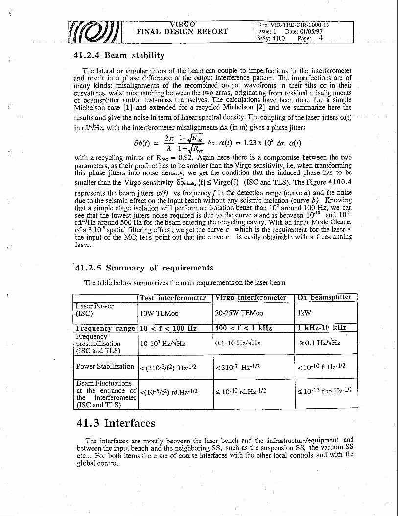
FINAL DESIGN REPORTDoc: VIR-TRE-DIR- I 000- I 3Issue: I Datel0l/05/97S/Sy:4100 Page: 4
41.2.4 Beam stability
The lateral or angular jitters of the beam can couple to imperfections in the interferometerand result in a phase difference at the output interference pattern. The imperfections are ofmany kinds: misalignments of the recombined output wavefronts in their tilts or in theircurvatures, waist mismatching between the two arms, originating from residual misalignmentsof beamsplitter and/or test-mass themselves. The calculations have been done for a simpleMichelson case [1] and extended for a recycled Michelson [2] and we summarize here theresults and give the noise in term of linear spectral density. The coupling of the laser jitters cr(t)
in rddHz, with the interferometer misalignments Ax (in m) gives a phase jitters
6QQ) = '{ lfy Lr. a(t) = 1.23x 10⁵ a.r. d(r)r\- / )" 1+J4*
with a recycling mirror of Rre" = 0.92. Again here there is a compromise betrveen the twoparameters, as their product has to be smaller than the Virgo sensitivity, i.e. when transformingthis phase jitters into noise density, we get the condition that the induced phase has to be
smaller than the Virgo sensitivity 6[,,r*rig"(f) S Virgo(f) (ISC and TLS). The Figure 4100.4
represents the beam jitters d(f) vs frequency/in the detection range (curve a) and the noisedue to the seismic effect on the input bench without any seismic isolation (curve D). Knowingthat a simple stage isolation will perform an isolation better than 10' around 100 Hz, we cansee Jhat th! lorve-st jitters noise required is due to the curye a and is betrveen 10'10 and 10'trrO/{Uz alound 500 Hz for the bearn entering the recycling cavity. With an input Mode Cleanerof a 3.10'3 spatial filtering effect , we get the curve c rvhich is ihe requirement for the laser atihe input of the MC; lett point out that the curye c is easily obtainable with a free-runninglaser.
4L,2.5 Summary of requirements
The tabl6 below summarizes the main requirements on the laser beam
4I.3 Interfaces
The interfaces are mostly between the laser bench and the infrastructure/equipment, qlqbetrveentheinputbenchan<itheneighboringSS, suchasthesuspensionSS, t l ievacuumSSetc... For both items there are of co-urse iniirfaces with the other local controls and with theglobal control.
'l 'est interterometer Virgo interferometer On beamsPli t terLaser rower(rsc) 10W TEMoo 20-25W TEMoo lkw
! ' requency range L 0 < f < 1 0 0 H 2 l u u < t < r K t l z f-IFz-lO kHzfrequencyprestabilisationfiSC and TLS)
1o-103 Hzl.lHz 0.1-10 Hzl"lHz > O.lHzltlHz
Power Stabilization< (310-3/P) 11v'rt2 < 310-7 g7-rt2 < 10-10 f Hz-rtz
.Beam t luctuatlonsat the entrance ofthe interferometer(ISC and TLS)
<(10-s/P) 76.117'rt2 < t0-10 6.117-rt2 < 10-13 1r6.Y17-rt2

FINAL DESIGN REPORTDoc: VIR-TRE-DIR- t 000- l -1Issue: I Date: 0l/05/97S/Sy:4100 Page: 5
4L,3.1 Interface \vith sub-system 2100 (Central area building)
The requirements given to the central building are:- electrical power :10 kW in continuous in the lab + 2 kW for the injection torver+ 1,5
kW around the mode cleaner tower.- 2 access doors to the laser lab are reouired to have
access, for security reasons.some safety lock and limited
- a double floor will be convenient to hide all the cables running around the laser bench.
41.3.2 Interface lvith sub-system 2200 (Clean rooms)
The requirements given to the clean areas SS concern:- a clean laser lab (100 000 class) with an overpressure relative to the outside part.- a "bench alignment room" in a class 1 000 or at least 10 000 if there is a local laminar
flow for the alignment check of the input bench.
41.3.3 Interface with sub-system 3100 (MC tube)
The input flange of the MC tube (on the injection tower side) will be 250 mm in diameter(see Memo). The MC tube of 300 mm diameter rvill be evacuated via the pumping system ofthe MC torver.
4L.3.4 Interface lyith sub-system 3300 (Torvers)
The hanging of the input bench to the marionette is realized by the injection bench group.As the input bench diameter does not exceed 900 mm in diameter, the installation of the
input bench and mode cleaner payload in the torver needs the same lower cover of I m.diameter, as in the standard case. The hanging of this system to the suspension inside the towercan follow the same process as the standard test-mass: the Figure 4100.9 shows the overallminimum height required for a possible protection box for the bench and its marionetta duringthe transportation in the gallery. (See also ref l4): the protection box and the installation insidethe torver are not planned by us norv (TBC).
Due to the position of the Reference Caviry at the bottom of the Input Bench, the humanaccess from the 1m lower cover is unfeasible so a lateral access through the 1 m East flange hasbeen requested, giving a connection between the input tower and the sas of the laser laboratory(rBC).
In the same order, the hanging of the end mirror of the modeplanned by us. The procedure for hanging large minors should(rBD).
For local control usins the cameras andneeded as shown in theiig.4100.5 .
for auxiliary HeNe laser beams, windorvs are
As far as the windows are concerned, the distribution is the following:- 3300 provides rvith all the windows in the input and mode clearier towers, windows no
3,4,5 and 6 of the Figure 4100 5.- we provide the windows of the main input flange in the input torver (South side): these
windows and their oosition have still to be defined.We also provide the separation window in the link (1 on Figure 4100.5) between the input
and recycling towers as rvell as the tube section containing this rvindorv, length TBD as soonas possible.
4L.3"5 Interface rvith sub-system 3400 (Pumping)
The vacuum required in the injection tower and mode cleaner tower is the following:- clean vacuum rvithout hydrocarbons (TBD) and a residual pressureof < 10'6 mbar.
cleaner inside the torver is notbe applicable completely here
FINAL DESIGN REPORTDoc: VIR-TRE-DIR- I 000- I 3Issue: I Date: 0l/05/97S/Sy:4100 Page: 6
41.3.6 Interface lvith sub-system 4200 (Detection bench)
We provide the detection bench SS with the modulation signal as a reference signal with thefollorving hardware's :
- BNC output connector delivering 0 dBm of RF signal at l0 MHz (TBC), available at thelevel of the laser bench.
- rve do not provide the cable to transport this signal outside our SS (for the demodulation ofother photodiodes than D2) or to the 3 km arms.
Tha SS 4200 is in charge of providing the D2 photodiode for the signal detection, as thisphotodiode sits on the laser bench, we have to decide together the oveiall dimensions (TBD).
41.3.7 Interface with sub-system 4300 (Mirrors)
Mirrors of the input rnode cleaner (and the spares) are coated by IPN-Lyon (seerequirements in parag MC below) as well as the optical contacting of the 2 plane mirrors on thecorner-cube (the mirrors substrates and the corner-cube are provided by us).
41.3.8 Interface with sub-system 4400 (Alignment)
The pointing of the laser beam into the interferometer is made in two steps:- during the VIRGO prealignment phase (non-linear alignment SS), the Input Bench as a
rvhole cannot be moved, as it is resonant rvith the Mode Cleaner cavity, but signals toorientate the beam can be applied to the picomotors carrying the input telescope, rvithout anyharm for the Mode Cleaner lock (which allorvs the transmission of the beam to thetnterferometer )."
- during the interferometer autoalignment (linear alignemnt SS), where it is a matter ofsmaller dynamic range, correction signals coming from automatic alignment can be applied(TBD), if necessary, to orientate the Input Bench through its marionetta coils (within a small
'dynamic range the lock and the autoalignment of the Mode Cleaner can be kept locked).This is the interfacing we propose to the SS 4400 and we need to check out together if the
resolution and dynamic range of our transducers match the alignments request (TBD).
A "screen" is planned after the last mirror of the IB at the 4400 SS request. There is roomfor such a device on the IB, but nevertheless rve will need to have more details on that screen(beginning of 97) in order to finalize the clamping of it on the bench.
4L,3.9 Interface ryith sub-system 4700 (Last stage suspensions)
Mechanical interface: the SS 4700 will provide the marionettas for input bench and modecleaner: it is different from other marionettas, since the input bench must be controllable in allsix degrees of freedom, which necessitates 8 coils each.
SS 4700 provides the coils and the magnets (TBC).The coil drivers are furnished by 4100 (TBC).It would be convenient if the foice of one coil onto a magnet (@ rc mm, thick 4 mm) with
23 mm pmetal extensions on both sides (who provides them? TBD) can be around 0.6 N/A(tils is the number obtained for the MC prototype coils defined in [3]).
The marionetta serves at the same time as a shield against dust coming from the uppersuspension, which might spoil the cleanliness of the suspended optics. The wires betrveenmaiionetta and suspend-ed mass (3 for IB and 2 for MC) are also piovided by 4700, they aremade out of Marval 18 alloy in I mm diameter and 827 mm in tot-al length (821 mm betweenthe nail heads). The clamps of these wires on the IB are designed and provided by us.
Electrical interface: there will be about 25 cables running from the input bench to themarionette and to the top. The clamp position of the wires have to be on the bench (TBD by us)and somewhere on the suspension (TBD by 4700).
FINAL DESIGN REPORTDoc: VIR-TRE-DIR-l 000- I 3Issue: I Dare: 0l/05/97S/Sy:4100 Page: 7
4t.3.L0 Interface lvith sub-system 4900 (Suspensions electronics)
The MC local mass control system will mainly act on the marionetta, but due to the limiteddynamic range (< I mm) for translations, slol drifts need to be corrected by acting on theupper suspension point (available degrees of freedom: x,!,2,0v). This necessitates aninteraction with the Suspension electronics SS. An offset for moving the suspension point by +10 mm in x and z and a ferv mm in y directions can be added Io the l&al contiol of ihesuspension point; moreover, a rotation around 0, can be done. For this purpose, the action ofthe local control is transparent for the user. The bandwidth is 10 Hz.
Hardware: there rvill be two separate VME crates for each of the trvo masses (IB and MC farminor); the first controls the coil currents on mass and marionette and reads the camera image(item 4140 below). The second one controls the movements of the upper suspension point.
The conection signals will be calculated by a local or "global" (within the MC context)control system (item4140); all signals below a certain limit frequency (e.g. 100 mHz) rvill goto the mass suspension point. In practice, the whole correction signal will be sent to crate 2 bya digital optical link (x,y,z,0y=4 signals), but only the low frequency part rvill contribute to thesuspension point movement; the trvo cutoff frequencies for marione$a (high pass) andsuspension point (low pass) must of course agree. Trigger signals conesponding to thesampling moments rvill be provided to crate 2 by cable.
41.3.1L Interface with sub-system 5100 (Global control)' A global erroi signal for the beam linear alignment is needed, since the local control shortand long term precision ir'ight not be sufficient for the VIRGO data taking phase (see alsointerface 4400).
Data of the control svstem are sent to the slow control frame builder throueh the standard. LJdLd UI LIItr L;UIIU(JT 5Y5T(i
Fb...Cm messages requ6sts.The foreseen sisnals tranThe foreseen signals transmitted are: DpsDc (DC power of the laser), mod 2 (modulation
index for the signal detection).ex for the signal detection).Servos-status and status of components giving an alarm if out of range value.
- Data of the fast acquisition (10 kHz) will be obtained in a specific VME crate under theLAPP responsibility. Analog signals to be read are delivered by the subsystem : DpsAc (noisepower of the laser), SphEr (frequency noise of the laser), D2 (a or b) (error signal fromrecycling cavity).
- Precise signals exchange rvith subsystems marionette, suspension, interferometer a.redefined
above in paragraphs 4100.3.4, 4100.3.5, 4100.3.7,
- Error reporting is done via the error-logger system. The list of signals giving Alarm (withthe severity level) is exposed in detail in the note [4].
4t.4 Selection of solutions- Choice of laser: the light will be generated by high porver Nd:YAG lasers, this choice has
been dictated by the expected efficiency, stability, and reliabiliry of this kind of lasers, mostlywhen pumped by laser diodes.
- Choice of multistage frequency stabilization: the final stability required is about 107 belorvthe level of usual laser including Yag lasers. Knowing that it is impossible nowadays tolevel of usual laser including Yag lasers. Knowing that it is impossible nowadays to
brm servo-loops rvith such hilgh ga'in at 500 Hz, we c-hoose to achieve the stabilizatiori in 2perform servo-loops rvith such high gain at 500 Hz,steps; the lst is the prestabilisation which reduces thsteps; the lst is the prestabilisation which reduces the laser fluctuations to those of a short term
FINAL DESIGN REPORTDoc: VIR-TRE-DIR- I 000- l3Issue: I Date: 0l/05/97
:4100 Pase : 8
.i
rigid reference cavity; the 2nd is the final stage which locks the laser to the interferometer andbrings it at the required level.
- Choice of using input mode cleaner: the beam geometry required is about 103 times betterthan the normal jitters presented by any stable laser beam, and the best way to reach the desiredbeam stability in position and geometry is to pass it through a resonant cavity, named as modecleaner. Then it is known that a mode cleaner with the adequate characteristics, rvill filter outthe residual beam jitters and bring it down to the required level. Furtheffnore it could helpfiltering the F{F noise of the laser, anyway we will take it into account when estimating for th-eprestabilization level required.
4!.5 Detailed description
For feasibility, maintenance and cost reasons, the components which are not due to stay invacuum and/or seismically isolated will be located on the laser bench which consists on 2tables or more (TBC) in the laser laboratory (Figures 4100.6 and 4100.7). They are :
- the lasers- the necessary phase modulators (there will be 2 at minimum). We provide the cable and
the demodulation electronics for the signal of photodiode D2 as it is used by us for thelocking of the laser on the interferometer.
- the optical isolators between lasers and interferometer.- the heom mnni tnr ino l rv ( - ( -T) ncrnerqsthe beam monitoring by CCD cameras
the photodetectors for active frequenc\- the photodetectors for active frequency stabilization including D2- the quadrant photodiodes for the auto-alignments to reference cavity and mode cleaner
the matching optics between the laser bench and the input bench.The components that should be under vacuum for cleanliness and acoustic noise reasons
will then be sitting on the input bench (Figure 4100.8) that will be suspended inside theinjection tower:
- the reference cavity- the mode cleaner (input mirrors on the input bench suspended inside injection tower and
curved end minor suspended inside mode cleaner tower)- the input matching optics (laser beam to interferometer-beam)- the power stabilization photodetectorIf we anticipate and state that the input bench is carrying also the reference cavity (\C) a.sll as the mode cleaner (MC), the alignment of the laser beam coming from the laser benchIl we antlclpate and state mat tne rnput bencn ls carryf
well as the mode cleaner (MC), the alignment of the laserwell as the mode cleaner (MC), the alignment of the laser beam coming from the laser benchto the input bench (IB), carrying one of these critical cavities, is due to match their alignmentrequirements. We have then trvo choices which are whether to align to the RC cavltY or to theMC cavity. If rve also state that there is another system to realign the beam on the input _bench
laser bench is aligned to the RC by some automatic beam positioning sitting on the laser bench(named ABP 1) and the beam on the IB is aligned relative to the MC by another ABP namedAPB 2 sitting on the IB. Then finally the beam coming out from the IB is aligned relative to theVirgo interferometer by another ABP named APB 3 positioned after the MC.'1he
subsequent mode nrutching for the mode clZaner is done by a telescope siuing o-n th-elaser bench. ihe mode cleaner miriors themselves are controlled only IocaIIy, and steered onlyduring the phase of initial alignment. The input matching optics matches the beam exiting fromthe MC.to-the intirferometei. Its mirrors canbe steerid,-too, for automatic align-ment of thebeam to the interferometer if necessary QBC). Their distancei can be controlled in order tochoose the waist position.
The power stabilization of the laser will use a photodiode sitting on the Input Bench hit by asmall fraction of the main beam transmitted by the Mode Cleaner (io take advantage of its low-pass filtering) through a leak of a HR minor for instance. The feedback will be done on theiaser diode cunent directly either on the power supplies or on the diodes directly. We have
MC cavity. If rve also state that there is another system to realign the beam on the input _benchto match ihe MC, then it is simple to decide that the RC is reference for the input bench. So thelaser bench is alisned to the RC bv some automatic beam positionine sittins on the laser bench
iaser diode cunent directly either on the power supplies or on the diodes directly. We havechosen not to feedback on the laser beam in order to avoid extra optical transducer.
FINAL DESIGN REPORTDoc: VIR-TRE-DIR-l 000- I 3Issue: I Date: 0l/05/97S/Sy:4100 Page: 9
41.5.1 Laser bench
41. 5. 1 . 1 Laser bench funct ion and concept
The laser bench includes the followins functions :- to produce a 10!V power laser with-2 or more lasers (for test interferometer) in a TEM00
polarized mode- active stabilization
stabilization)of laser in frequency and in power (prestabilisation and final stage
- phase modulate the laser for the signal detectionAll the components including the lasers. will be sitting physically on a laser table, rigidly
connected to it. To avoid optical feedback into the high bower laier we will use ai fi aipossible, interfaces at Brewster angle and reflective optics instead of refractive optics.
41.5.1.2 Laser bench deta i led descr ip t ion
. .- Powe-r : the requirement of power.combined with the level of stabiliry needed is verystrinq.ent for one s_i1gle laser as no such laser does exist today. But thanics to the use ofrecycling cavity-in Virgo which allows us to expect a recycling gain of the order of 50-100, thedemandonincident laser power is now l0-20-W. Besides tlialthe recvclins sain is inveiselvdemand on incident laier power is now l0-20'W. that the recycling gain is inversely
ional to the total losses so the mirrors technology rvill rvill be possible. Meanrvhile our strategy for thi: laser
proportional to the total losses so the mirrors technology rvill determine jaterbn what recyclingpctol witt be possible..Meanrvhile ou.r strategV rfl tii: laser porver is the following: wb rviluLrur- wru us Pussrultr. lvrcilrtvrule our s[aregy ror Ine laser po]ver ls me tollowrng: we tvillfirst develop a laser of 10W for the 98's test inierferometer and exneriences its refiai'ilitv. Thatexperience and the mirors state-of-art will determine then rvhat will be the final laser powerrequired.
; Injection log$?g : to solve the problem of compatibility rvith frequency stabilizing a laseri keeping its high output power, ive use the follorving pr5cess whicfi is Rist to inieciion lockand keeping its high outputand keeping its high_output power, we use the follorving pr6cess which is fiist to inject'ion lock
a high power laser (called slave laser) by a lorv powei liser (called master laser) -and
then toby a lorv power laser (called master laser) -and
then tofrequency stabilize the beam of the high fower laser by acting bn both the master laser and theslave laser._.
- The master laser is a diode-pumped commercial laser with an output power of 700 mW forthe test interferometer.
The slave laser is a slab laser pumped by fiber-coupled diodes chosen for their easyco'imating u.,* unaii'i{"iily'iffi#*XTo3{"nf;il"("""3i'^Xr:':?T":T:?: :hf;,J ;tr:rvithout stopping the whole laier).
- Prestabilisation: the 10W lasr- Prestabilisation: the 10W laser will be- Prestabilisation: the 10W laser will be frequency stabilized on the reference caviry RC(rvhich is sitting on the input bench and described belorv; rvith a feedback onto the mastei laser) rvith a feedback onto the master laserpzt and to the extemal phase corrector EO2 sitting on the laser bench.,_:Igdulution.frequency for.signal detection: ?-modulation frequency atF2 = 6.25 [&Iz(TBD) is applied onlhe same phaie modulator EO2.
41.5.1.2.1 l l laster laser
It is a commercial Nd:YAG diode-pumped built in the technology of monolithic piece(MISER), single frequency operating and delivering more than 70d"mW. The monoiithic
the Nd:the Nd:YAG insures the contithe_other one keeps operating)
ing and delivering more than 700 mW. The monolithically ultrastable and the use of two laser diodes for pumping
requency operaung and deltv(he laser intrinsically ultrastabletechn_o1ogy makes the laserlntrinsically ultrastable andthe use of two laser diodes for pumping
the Nd:YAG insures the continuous operation (the failed laser diode might be replac'ed whitE
The power^is ade_quate for injection locking of a high power laser of a few tens of Watts.The caviry is formed-by the cryit-al.itself and-the-freqieniy tuning of the laser is done in ther-ne caYlry rs rofinec Dy me cryst-al ttselt ancl tne trequency tuning of the laser is done rn the
3t-ow,r1nee.!y a thermfl-control of the crystal while thl {u_ripttt (uF to 30 kHz) is done by a pztbo*led on the crystal (-first resonance fr6quency around sO t<ttz, iinsiti"ity -+ MHz/Vdl|
'
The laser beam is ellipti4ly. polarized, ther6 is a need of a quarrer wive plate and a'halfrvaveplate to malch its polarization to that of the phase modulator'and of the high power laser.
The delivered beam is slightly asymmetric, sothe matching optics between t-he lasers have to
FINAL DESIGN REPORTDoc: VIR-TRE-DIR- | 000- l3Issue: I Date: 0l/05/97
:4100 Page: 10
take it into account.A servo-loop (named SOr) using 25 mW of light on photodiode Dro is used to
relaxation oscillation of the laser at 600 kHz.
41 ,5 ,1 ,2 .2 S lave l ase r
The 10W laser is the result of a collaboration betrveen B.M.I. company and SPI Orsaygroup and is running in Orsay since October 96. The details on the mechanical construction can6e found in the laser technical doc., B.M.I. 19104195. The main features sketched on Figure4120.1 are:
- Nd:YAG Xtal: 5x5x76 mm Nd:Yag zigzag slab with end faces cut at Brewster angle inorder to minimize thermal induced birefringence effect (10 internal reflections)
- transverse pumped on one side pumped by 10 {iber coupled diodes- collimation from the fibers beam by a cylindrical lens of 2.5 mm in diameter giving a
horizontal gain profile of 1.5 mm (FWHM ) in width.- presence ofinduced thermal focal length in the ve- presence of mcluced merrnal local lengm rn tl
in thb horizontal plane (for 68W of pump power)in the vertical plane of more than lm and 0.24m
the
- heat is evacu-ated via the upper and lower faces in contact rvith a gold coated copper blocrvhich temperature is controlled by 4 Peltier elements and servoed by gne PID servo element
mp powerr.d lower fac
(PID: Propbrdonal Integrator Deriiator), the Peltier elements are cooldd by a close circuit waterflow.
- Cavity: it is a X-shaped ring cavity, 3 flat mirrors, one concave of 0.75 m focal lengqf,- uavlty: lt rs a x-shaped rlng cavrty, J llat [urTors, one concave oI u. /J m rociit lenglfl,this insures a radius mod6 in the slab o-f +a0 microns (horizontal) and 860 microns (vertical),for the optimum stable mode. One of the plane mirror serves as output coupler with 107otransmrsslon.
circuit water
- mechanics of the caviry: all the mirrors are clamped on Zerodur in order to get rid of thenrrcn.v rlr ifr drre to the-rmal exnansion of the cavirv (reduced in this wav down to 2-3frequency drift due to thermal expansion of the caviry (reduced in this way down to 2-3
MHz/'C).- pzt iransducers: 2 flat mirrors are glued on apiezo actuators for frequency control, a slow'one (Physik Instrument) with a sensitiiity of 33 A/V or 3.6 MHZ/V (-1000V/+2pQ! 314 a !a1
r"sponsL up to 28 kHz (+6 dB amplituie), and a fast one with a sLnsitivity of 3 AA/ or 0.4MHzA/ and a flat response up to 200 kHz. .- r _
pimping biodes: the ten diodes lie on Peltier elements cooled. by a close- Fiber coupled pumping Diodes: the ten diodes lie on Peltier elements coolecl_ by a close:uit water ilow,'the- Peltier are fed by a PID servo element (Proportional Integrator
Derivator), which allows to set the temperature of the diode digitally via the loc?l _controls. Thecharacteristics of the diodes are siven'hereafter: output power of-10W for 23.5A under 1.8characteristics of the diodes are givenVolt (nominal current is 28A, i.e. 12W output),
: output Power ot low lor ZJ.JA unoer r.6), spdctral linewidth IIWHM 3 3 nm, run$ng
temperature according the diode ranges from 17 tb 30oC, at 808 nm for optimum Nd:YAG
absorption, dUdT= 0.3 nm/degree, output fiber NA= 0.2 and fiber diameter is 500 pm. Th?diodes are coupled with secondary fibers (numerical aperture of 0.2, diameter of 600 microns)which are connected to the laser head.
- thermal control of the laser is done via Peltier elements, the sensitivity is 500 MH/.C, thedynamic is larger than 10 GHz, the bandwidth is smaller than 1 Hz.'
- performarices: TEM* mode operation is achieved by using.a diqphragm iryide the cavity,howiver a slight contribriiion of TiiMo, remains; by using a.spatial filter the TEM*rco_mponentcan be extiaci'ed, giving then 9W outprit power foi a effEctiG pumped power of 60W (opticaleffrciency of l57i); bo'ih vertical and hoiizontal waists are loc-ated'on [he output coupler and
equals 515 microns and 233 microns respectively (radius at lle2). The M2 parameter is lowerthan 1.2 for both directions.
The strategy of our high power laser is quite clear: we use an efficient laser at 60Vo of thenominal po*ii (reached 'iitti tZO W of diodi pumping) to prevent maintenance-problems. Thismeans thit we can afford to have up to 4laser'diodls fliledbefore stopping the-laser operation,besides the fact that using the lasei diodes far from their nominal cunent will lengthen therrlifetime.
FINAL DESIGN REPORTDoc: VIR-TRE-DIR- t000- I 3Issue: I Date: 0l/05/97S/Sy:4100 Page: I I
4 1 . 5 . 1 . 2 . 3 I n j e c t i o n l o c k i n g
The principle of this servo named SLi has been described in the FD v.0 (1995). Herewithare the characteristics of the main components:
- Electronic: the photodiode Dil used is a InGaAs cell which feeds lkQ in DC and 7 kQ inAC, it is shot noise limited at less than lmW incident (photodiode Dil on the scheme). Theservotransferfunction is I/f fromDC!o 8kHz, and l/fabove 8 kHz; the error signal LSPzis feedback to the 3 transducers described above. Photodiode Dbrv monitors the injectionlocked status and acts as a trigger to relock automatically the servo SLi.. _The incident porver needed_on the photodiode Dil is determined according to the level of the
sidebands used and the specifications in terms of frequency stability. From the developmentstudies [5], we need 4.10-aW, and a modulation index of 0.024 radians to achieve the stability
of a standard Lightwave laser t lOlHt
Jnr ). The expected locking range is i-2MHz(output. F
c-oupler transmission of IIVo, free spectral range of 5I7 MHz, ratio of master laser power toslave laser power is 0.06).
4L .5 .1 .2 ,4 Op t i ca l componen ts
Waveplates at the output of the master laser converts and adjdjust the elliptical polarization to athe relaxation oscillation servo oflinear one in order to send 25 mW into thelinear one in order to send 25 mW into the photodiode Dro (the relaxation oscillation servo of
the master laser) from the input polarizer of Faraday 1 (Figure 4100.6).. Faraday isolator 1 is a TGG crystal surrounded by Brewster dielectric filters forming thepolarizers; it protects the master laser against the feedback of the slave laser when it ii notinjection locked.- Details. on th9 specifications for the Faraday (1 and 2) and their measured performances canbe found in the internal note [6].
The lenses in front of the EO1 are cylindrical (0.25m and 0.34 m focal length) and achievethe matching between master and slave laser.
EOI is the electro-optic crystal which generates the Fl sidebands used in the Pound-Dreverscheme of the injection, the prestabilization, and the mode cleaner lockings; it is made of a pairof LNO at Breister angles and the modulation frequency is around it'Vni, such that^thesidebands are reflected by all the cavities involved in the above mentioned servo-loops.
EO2 is the same kind of electro-optic used for the phase correction of the preslabilizationlogp !!r and used simultaneously (TBC) to generate the sidebands of the signal modulationcalled F2.
ABP1 is the auto beam positioning serving to realign the beam from the laser bench to theReference cavity sitting on the input bench (see also alignment shategy belorv) and is fed backby the error signal coming from the autoalignment of the RC, namedhere ARc.
An off-axis mirrors telescope (3 mirors TBC) of magnirude 10 will be used to match thelaser beam to the MC waist.
41.5. 1.2.5 Frequency prestabi l isat ion
The level required for the prestabilisation depends upon the final stage Ioop gain and thefiltering encouniered by the b-eam transmitted by the mode cleaners and the ricicling cavityb.-fot" reaching the beamsplitter. Starting from an average asymmetry of l%, rve havecalculated the level required for the prestabilisation stage (see d'etails in note PJT 93-009),which is at the same time the level of absolute stability iequired for the reference cavity (seereference cavity below).
Th. Figure 4L20.2 gives the requirement of prestabilization (see also note PJT 94-036) fordifferent asymmetries in the initial and ultimate sensitivity requirements (see results in PJT 95-02s).
FINAL DESIGN REPORTDoc: VIR-TRE-DIR- I 000- I 3Issue: I Date: 0l/05/97S/Sy:4100 Page: 12
41 .5 ,1 .2 .6 Po rve r s tab i l i za t i on
The power stabilisation servo loop SPo reduces the amplitude noise of the light as far aspossible in the frequency region of interest of the Virgo experiment, that is 1OHz - 1OkHz. Thegoal for this noise reduction is shown in Fig 4100.2. At present this loop has a unity gainfrequency of around 38kHz. It also is responsible for maintdging the average power level oftheilave laser as seen after the modecleaner, to a level specified by the user.
The loop consists of a detector (Detector Dps) operating under vacuum mounted on theinput bench, a PID or Servo Unit, and a control unit (I,aserdiode Controller) rvhich is aninierface between the Servo Unit and one of the laser diode arrays of the slave laser (Figure4120 .3 ) :
- The detector Dps.samples a small proportion of the light after the modecleaner(30mW), using a photodiode of type RMP 164-030 (equivalent to Hamamatsu G5832-03) .
- The Servo uses the outputs of Dps to produce control signals which are then applied tothe slave laser via the laserdiodes to regulate the average output power as seen after themodecleaner, and to reduce the amplitude noise down to or below the specified levels.
- The Laserdiode Controller is an interface betrveen the Servo Unit and one array of fivelaserdiodes rvhich drive the slave laser. Its mode of operation is to bypass a smallamount of cunent arvay from the laserdiodes and in this way to change the laserdiodecurrent. While this task is in fact achieved by a simple Darlington transistorarrangement, it is extremely important to ensure that no dammage results to thelaserdiodes, as they are very sensitive to reverse voltages. Consequently tit"-
' Laserdiode Controller includes a safety netrvork which prevents the application ofreverse voltages to the laserdiodes, and short-circuits any applied signals in the event oflaserdiode power supply shutdown.
' Operation :
The DC output of Dps is directly compared rvith a refer.ence signal in order to give a DCenor signal (Signal Sp6fr) whichis late? used to regulate the avJrage power of the laser aswell as to provide general stabilisation at frequenciei belorv 10H2. The AC output of PPtrvithout any processing, is literally the AC erroi signal. These two error signals are then addedtogether atihe input ofa high gain amplifier. Q.{ote that it is at this stage where the simulationof the modecleaner two low pass filters rvith poles at 500H2 takes place, at the input of the highgain amplifier. For operation with the real m-odecleaner, the capacitors of these filters must bedisconnected using the on-board switches provided).
Following this-are several stages of filtering giving the necessary roll-offs in order tomaintain higl gains in the lowerTrequencies oiiitereit, while allowing the gains.at higherfrequencies to be reduced to manageible levels. There is also an integrator operating in theregion belorv 50Hz to give precise locking to the external reference signai.-Finally
the output stage! produce trvo correction signals for the Laserdiode Controller andlaserdiode powei supply respectively: the Fast and Slow Correction Siganls. The SlowCorrection Signal is lioituced by integrating the Fast. This has three important adv,antages.Firstly, the avErage level of the Fast C6neciion Signal is maintained at zeio (the middle of itsrange)'thus insuring that the Laserdiode Controilef suys at the centre_of its operating regimeund-ei normal operaiion. Secondly, the Slorv Signal contains all the DC correction informationand is thus an indication of the DC adjustmeni performed by the power stabilisation system(Signal LDsPI). Thirdly, this arrangeirent allows a convienl way bf predictingtn immanentiel6ck by sensing whenihe Fast Coriection Signal moves away from zero volts @elock signalSPoSt ) .
Vacuum compatible photodetector Dps :
FINAL DESIGN REPORTDoc: VIR-TRE-DIR- I 000- I 3Issue: I Date: 0l/05/97S /Sy :4100 Page : 13
For a more detailed description of the design and function of the electronics of this detector,see ref [13]. To facilitate the use of this detector under vacuum, the circuit board containing thephotodiode is mounted in a specially made stainless-steel box (Figure 4120.4), rvith anIndium jount to render it air-tight, the photodiode being accessed via a sealed rvindorv. Normalatmospheric pressure is maintained inside the box to faciliate the cooling of the electroniccomponents.
The detector is mounted on the Input Bench, and receives light from the mirror M4 via amatching lens of 22.5 cm focal length, inserted 20 cm in front of the detector. The detector hasan active area of diameter 3mm. In order to allow for alignment error or small fluctuations inthe beam position, the beam is focussed down to roughly half the size, being 1.6mm.
Design Strategy:Since the polver stabilisation loop will be the last loop conceming the laser control to be
activated in any normal activation sequence, it is important that this unit remains "transparent"
until the time of activation, to avoid interference with the laser or other servo units. Also in thepossibility of computer or hardware failure, the resulting ramihcations should to be kept to aminimum. To these ends, the following design strategy has been adopted :
- when the servo unit is deactivated, either locally or by local controls, or disconnected fromits porver supply, all outputs return to zero volts, returning it to its normal bias level of 50V0,and thus leaving the laser power at the level predetermined by the main laserdiode porversupply, be that locally or remotely selected.
- the reference level for the laser porver is not taken uniquely from local controls, but isgiven by a combination of a multi-tum potentiometer found on the front panel of the Servo Unitrvhich sets the average power (nominal level 10W) and an external signal derived from control.command allorving an adjustment of lW either side of the average level. In this way, if thisextemal signal is disconnected or there is a computer failure, the laser continues to function,and its output power returns automatically to ihe predetenained average level, dictated by thelocal potentiometer.
41.5.1.2.7 Laser Table lv lechanics
The requirements on the laser table (TLS) are the following :- mechanical induced tilts on the beam smaller than 3.10-8 rddHz around 100 Hz- mechanical induced distortions on the optics should not misalign the beam- minimum of seismic isolation (see below)- some rigidity of the table and the optical mountings but no stringent conditions on thermal
stability (induced beam waist displacements are small compared to the Rayleigh range of theMC cavity).
Description of the laser table :- it is a TMC optical table:0.2mx0.9mx1.5m, 216 kg. The first and main mechanical
resonance is located around 200H2, the damping for this resonance provides an amplificationfactor Q smaller than 14 for the deformation of the table (14 is a typical value given by themanufacturer).
- the power spectrum density (psd) of the table deformation {fl expresses like
Q(D.y(0. * ,\LILJ )
rvhere / is the Fourier frequency, t(fl the psd of the perturbation expressed in m.s-2l{Hz(mainly seismic or acoustic noise). The associated tilt is then 6(f) /0.75 radians, and since rve
consider the first resonance flfl, the maximum deformation raises at half length of the table.- Seismic noise induced tilts: in the Orsay laboratory {f has been found to be less than
5.10-5 m.s-ZdHz [7], so the induced tilt is 0.4 nrd/{Hz. This is anyway belorv thespecification on the whole frequency range.' - Acoustical noise inducediilts: iet's issume a level of 50 dBadHi (standard lab normal

Doc: VIR-TRE-DIR- I 000- I 3Issue: I Date: 0l/05/97S/Sy:4100 Page: 14
FINAL DESIGN REPORT
level), this means a pressure of 0.0085NdH2 on the surface of the table; it leads to an
acceleration of the table of =ro,oo!i\,, llttz incase of a table lying on rigid feet and of216kg.(2nf)'
y# /{Hz if the table is lying on a piston isolators (free mass). At 200 Hz, for the rigid
feet we obtain a tilt of 10-16 radiansdHz;and a tilt of 0.46 nrddHz for the spring feet. In bothcases we are well below the specifications for the allowed tilt at the input bench entrance.
41.5.1.2,8 Al ignment & matching LB/RC
Alignment: the beam leaving the laser bench will be automatically aligned tg tlp referencecavity sitting on the input bench (servo ARc) viarhe pzt-mounted-minors named ABP 1 sittingon the laser bench. The misalignment of the RC due to slorv drifts can be critical as it canchange the prestabilization level.
Matctring: of the beam to the RC achieved via a two fixed lenses-telescope placed in front ofthe RC (see Figure 4100.8). This matching of the RC is not very critical as the level of lightneeded in the RC is less than 5 mW.
This strategy implies that seen from the laser bench, the RC is used as reference position forthe input bench.
41,5.1.2.9. Last s tage of f requency stabi l izat ion
The signal coming from the reflection of the rvhole interferometer, is seen by photodiode D2and rvill be demodulated before amplification, filtered and added to the error signal .*iggfrom the reference cavity (prestabiliiation loop). Then the rvidth of the reference cav-iry is theallorved dynamical rangi: of the detuning betrveen the laser frequency and the interferometerfrequency. This range"is today around-l2 kHz rvhich is mucli moie than rvhat any. ptrasecoriectoi could have. Of course the transfer function of this last stage has to be defined
'coherently with the locking group and the global control SS U6l. This loop can have amaximum bandrvidth of
-15 kHz (about one third of the free spectral range of the
interferometer). An analog servo-loop is planned and being developed today in the SS, but adigital servo-loop which cin be demcinstrated to have this bandwidtli should be more flexible interm of adaptation of transfer function compatible with the locking purposes. An agreementwith Virgo-Napoli is undenvay which resufts in an implementation and iest of such a digitalfilter in the laser system built in Orsay.
4L.5.2 Input bench
41.5.2.1. Input bench funct ion ancl concept
The input optics are sitting under vacuum on the suspended Input Bench-(IB) and serve 2purposes i ntter spatially theleam and stabilize its position with the Mode Cleaner (MC) andyield the necessary movements to align the beam to the axis of the interferometer.'
The IB suppoits the Reference Cavity (RC) rvhich acts as- a mechanical reference for thefrequency pre-siabilization and the input-output plane minors of the mode cleaner.
The MC is a three-mirror cavity used in transmission, in a ring shape conf,rguration, and hasits two input-output plane minors?orming a corner-cube and sitting on the Input Bench, whilethe far cuived minoi is suspended alone ibout 144 m away on an ixis perpendicular to that ofthe corner-cube.
The IB and the Mode Cleaner far mirror (Mmc) are 2 masses suspended in 2 separatetowers connected together by the Mode Cleaner tube which is 144 m l-ong. For-each mass,Iocal controls based-on posiiion memory readouts are implemented and are used for dampingthe pendulum oscillation and making the pre-alignment of the MC cavity by moving the mass
FINAL DESIGN REPORTDoc: VIR-TRE-DIR- I 000- l3Issue: I Date: 01i05/97S/Sy:4100 Page: l5
in all degrees of freedom. Both of them rvill be done by action on the 8 coils implemenredaround the marionetta of the IB and the Mmc (TBC) or on coils implemented on the ibrver partof the torvers (TBD).
Once the cavity aligned, the MC is brought into resonance with the arial position of Mmc(a Pound-Drever elror signal is used) by feedback possibly on some coils (TBD) locatedbehind the minor (TBD).
Then the automatic alignment (based on H.Ward's technique) of the MC starts to run rvith acorrection signal applied to the Mmc marionetta 8-coils, in order to avoid reintroduction ofseismic noise during operation..
41.5.2.2 Input bench deta i led descr ip t ion
It is a table suspended inside the injection tower where we can find the following optics:- I transmitting plane mirror giving 10'3 of the light to the RC- 2 plane mirrors oiAPB 2 serve to fold the beam to the MC comer cube and mounted
on pzt in order to do the auto-alignment of the beam to the MC caviry and fed back byenor signals from servo AMc
- the corner-cube carrying the two input mirrors of the MC- one plane minor to fold the output beam of the MC to the telescope and transmitting
3.10'' of the Iight to the power stabilization photodiode Dps- the final telescope formed by two off-axis curved mirrors used to match the beam to
the interferometer; they are mounted on pzt and can serve for the pre-alignment of thebeam (APB 3) to the interferometer as rvell as auto-alignment if necessary and if theydon't bring extra noise
- not seen on the IB is the end curved mirror of the mode cleaner Mmc to which we' will refer when talking about MC alignment, controls, etc...
41.5.2.2.L Reference cavi ty : opt ica l par ts
The stability of the caviry is coming from the thermal noise considerations and the inducedseismic noise on the internal modes. A detailed discussion can be found in the Virgo note PJT93-009 and summarized hereafter. To keep the thermal noise low, the intemal mode resonantfrequencies must be above the detection range as well as its intemal Q sufficiently high (Q >19+;. The first condition can be fulfilled with a judicious shape, while the second one isperformed with a high Q (and good thermal stabiliry for long term operation) material (seeFigure in FD 95).
To avoid acoustic noise and dust pollution of the mirrors, the cavity sits in a clean vacuumchamber so the mounting should be designed in order not to increased the rms. motion of thecavity.
Besides that there is an optical consideration concerning the finesse of the RC which shouldbe high as far as possible to lorver the shot noise limit of the prestabilization aroundrc-4Hzf l :Hz rvirh 1-2mWof l ight.
The beam entering the IB is matched to the MC waist of 4.9 mm, then a-2-lenses telescopeis used on the beam derived to the RC to reduce its size to of that of the 0.286 mm waist of theR C .
The constraint for this telescope are mainlv mechanics for distances "laser-first lens" andsecond lens- mirror" and optical fbr the distan;e LrL2
The optical parameters are:RC rvaist = 0.286 mmMC waist = 4.9 mmLrLr-- 437,7 mmL, focal length = -70 mmLrfocal length = 500 mm
Near the input mirrors cavity, 2 mirrors have been installed in order to take thecoming from the reflection and transmission of the cavity outside the.injection torverdetectors table.
beamson the
FINAL DESTGN REPORTDoc: VIR-TRE-DIR- I 000- I 3Issue: I Date: 0l/05/97S /Sy :4100 Page : 16
41.5.2,2,2 Reference cavi ty : mechanical par ts
The cavity is put inside a vacuum housing, evacuated by a small ion pump, This housing.isnecessary to-keeir the cavity clean from dust contamination on mirrors. The ion pump will bemantained to evacuate separately the RC during the first tests, to keep the mirrors of the cavityclean in case of possible contamination of the input torver. Figure 4130.L shor,vs themechanical drawings.
71.5.2:2:3 Modg cleaner: optical parts
The MC should fulfill the follorving criteria:- sparial filtering efficiency meaning a transmission ratio between the high order and the
fundamental modes smaller than l0'3- frequency filtering efficiency as a low pass filter for the laser noises, we can choose a pole
S 500 Hz giving an attenuation of at least 10 at 5 kHz- used with the rvhole laser porver; it should avoid thermal effects, meaning that the
absorbed light should not exceed a ferv tens of mW; of course this rvill depend on the coatingtechnology and on the laser power planned in the future
- as a cavity used in transmission, its efficiency should be more than95Vo- used to p-ass the signal modulation, its free spectral range has to be a sub-multiple of the
modulation frequency F2- furthermor'e to dvoid light feedback into the laser, it should be a tfuee-mirror ring-shape
cavity.
. With all these conditions taken into account (see [8]), the solution adopted today is:length L": I44m, free spectral range =beim wiist at inout miirors: 4.9 fim 2 Ltbeam size at end mirror: 11 mm
. minors diameter:80 mm (TBC)end mirror curvature: 18lmcorner cube angle: 90"-1'
The 2 pldne mirrorJare optically contacted on the corner.cube (Figure 4L30.2) sitting onthe IB anil the concave min6r susirended inside the mode cleaner tower 144 m away (t2m).;IB and the concave mirror suspended inside the mode cleaner tower I44 m away (t zm|
Because the mode cleaner is a lbw pass filter at 500 Hz (fp) for laser noises, the finesse Fof the MC will be around 1000 meaning a high reflective enil mirror (r,) and a reflectivity of0.997 (rr, rr) on <s > polarization for input mirrors
P =f r^ ' l f ' r ' r tL- r r r r r t
The figure 4130.3 gives the drarving of the corner cube, which is made of Siiica. A sparepiece exiits in Zerodur. The mechanical support of the corner cube is a simple plate.clamped tothe IB, the corner cube is sitting on top ol three thin cylindrical rods used as a simple stageisolation for the MC (see mechaiical isblation of IB). A cover will be put around to protect itfrom contamination during the prealignment phase.
The far-minor mass M-mc cin be dlamped in some ways (TBD) to a larger mass in order touse for it the same marionette as the stanciard test-mass. Iir the same way ttie use of a referencemass is also possible (TBC), mostly rvhen it can help controlling the position of the MC lengthin the locking purpose.
FINAL DESIGN REPORTDoc: ViR-TRE-DIR-1O00- I 3Issue: I Date: 0l/05/97S/Sy: 4100 Pa-qe: 17
41.5.2.2,4 l l la tch ing opt ics for the in ter feronreter
The waist of the beam entering the interferometer (matched to the FP cavities) should belocated at the input minor of the FP rvith a size of about 20 mm. Due to the large confocalparameter of 2310 m in Virgo, the tolerance in position of this waist is about * 100 m for a losslevel compatible rvith the estimated optical losses of the recycling cavity.
To match the beam coming out of the MC and entering into the interferometer, an InputTelescope (ITC) should be designed that match the follorving requirements. To avoid spuriousreflection backrvard into the laser, the telescope is a reflective type, dealing with off-axismirrors; it should introduce low beam distortion i.e" the induced abenation loss should besmaller than 10-3.
The following 2-mirrors off-axis telescope has been designed for the test interferometer :length of telescope = 549 mmfirst mirror radius of curvature = 3380 rnm at incidence angle 4osecond mirror radius of curvature .= - 2300 mm at incidence angle 4.9o
The two incidence angles ensure a compensation of astigmatism; the tolerances on the radiusof curvature is around l0'3 corresponding to a deviationprobably easy to achieve; the tolerance on the length of theloss smaller than 10'o in the matchine.
between l/10 to l/20 which istelescope is + I mm which gives
These two mirrors will be mounted on 3-axis pzt motors (APB 3) servingalignment and auto-alignment of the interferometer if necessary.
for their fine
41.5,2.2.5 Input Bench lVlechanics
The mechanical design of the IB and its components is governed by the mechanical andthermal induced fluctuations of the bench. These are translated in terms of phase fluctuations atthe input of the interferometer. This phase noise has to be compared to the requirements of the
.laser phase noise given in the Figure 4120.2. Knowing that any path length fluctuation
6L (F) isequivalenttoalaser frequency fluctuation 6v (F) as 6i, (F) = '| f .6L (F).,
let's examine the noise encountered by the IB and each component sitting on it.^When the usual seismic noise on I0-6/f 2 mdHz impinges on the Reference Cavity, we get
the curve n of the Figure 4130.4, which is rvell below the requirement (curve c). So there isno need for seismic isolation of the RC except to avoid excitation of mechanical resonances ofits support.
For the Mode Cleaner, any length fluctuation is enhanced by a factor which is equal to thenumber of round trips of the beam multiplied by the low pass transfer function of the MC. Fora finesse of 1 000 and a pole frequency of 500 Hz, the 10-6/f 2 mdHz seismic noise inducedfluctuation is given by the curve D of the same Figure. One can see that above 100 Hz there isa need of some seismic isolation for the MC, for instance a simple pendulum at L Hz will beenough for the suspension of the IB, even for the ultimate Virgo (curve e ).
The Figure 4130.5 shorvs the drawings of the IB as it has been realized today in Alplanchosen for its low Q value, the mechanical resonances have been found between 500 Hz andfew kHz with measured Q smaller than 500.
If the MC input mirrors block is rigidly connected to the bench, it will add its thermal noiseto that of the bench and the resulting noise is plotted on the Figure 4130.6 in comparison withthe laser requirement at the output of the mode cleaner. The straightfonvard conclusion is eitherto have a low Q material (Q<100) or a block's shape giving a mechanical resonance outside thedetection range (> 10 kHz). This is the reason rvhy the trvo plane mirrors of the MC is rigidlyclamped (optical contact) to a comer cube of Silica (Zerodur is better in terms of low Q) with ashape designed to have the lowest resonance around 9 Wlz. Furthermore to lower the influenceof this thermal noise, the corner cube sits on 3 rods designed to act as isolation above 50 Hz.Then the calculation shorvs that norv the equivalent frequency noise plotted on Figure 4L30.7is well below the reouirement.
Doc: VIR-TRE-DIR- I 000- I 3Issue: I Date: 0l/05/97S/Sy:4100 Page: 18
FINAL DESIGN REPORT
ModeCleaner
cavity
.Frequency role500 Hz
ferv ppm lossoDtics
Length = Ntimes 12m
l-stagesuspension
cleanvacuum ( 10-6mbar
MC Inputcorner-cube
Ist resonance210kHz
additionalisolation on theIB
rnputtelescope
retlective optrcs moucecl lowloss aberration
low beamdistorsionoDtics
lnput bench amechanics
IUOO I-stagesuspension
cleanvacuum S6mbar
l0-
Ret'erenceCavity RC
hlgh fmesse Z 3U000
t-ew ppm lossoptics
RCmechanics
lst resonance >10kHz
Q > I 0 0 0 0 zeroexpansionmaterial
cleanvacuum S 10-6mbar
Table 4100.2: Specifications of the main components of the Input Bench.
' 4 l .5 ' .2 ,2.6 Auto-a l ignment of cavi t ies
The automatic alignment of the 2 cavities used in the SS will be achieved using a differentialphase sensing technique, which yas proposed and experimentally de-monstrated- Ly th.
'^Glasgow graiitational wave groupo . ttre-technique is an extension of the Pound-Drevermod[lation scheme for locking the length of a cavity to the frequency of a laser. In both cases,(Figure 4130.8) the incident laser beim is phase modulated at a high frequency (e.g. aroundiO IaUz), and tire light reflected from the caiity is observed ivith a photodiode; the informationcontained in the ph6tocunent is extracted by demodulating with the modulation frequency. Inthe first case a- simple photodiode is uied, rvhile the, second one needs two quadrantphotodiodes, one in the near field, and the other one in the far field (witha tens). .'
The principle of this technique can be understood as follows (for simpliclty, olly one lateraldimensional is considered). In ihe case of simple frequency locking, the light reflected directlyat the caviry entrance mirror (including the modulation sidebands) interferes with the lighthaving ent6red the cavity and being transmitted back through tlre c-avity entrance mirror(indirlct reflection, containing only the canier); the demodulated signal contains informationibout the frequency error, coming from the dephasing betrveen the two interferin-ecomponents, which depends on the detuning. In the case of a misalignment, the beam incidenton the cavity can be decomposed rvith resplct to the cavity referenCe_ system. in terms of theHermite-Gai:ssian cavity eigen modes
^ Ur. Especialiy, an only- slightly misaligned
(mismatched) beam can be represented as a simple superposition of low-order modes:- beai error eigdn mode decomposition (phase)lateral misalignment (shift) Uo & U t Q")angular misalignment (tilt) Uo & U I(90")waist size mismatch Us & U2Q')waist position mismatch Uo & Uz00')
In general, the U,, will have different resonant frequencies, so only the Uo rvill enter thecavity-and resonate; the other modes are reflected off the entrance mirror. So the direct
0E. Morrison, B. J. Meers, D. I. Robertson, H. Ward, "Automatic alignment of optical interferometers", Appl.Opt. 33, 504i (1994); E. Monison, B. J. Meers, D. I. Robertson, H. Ward, "Exp-erimental demonstration of an
automatic alignment system for optical interferometers", Appl' Opt. 33, 5037 (1994)
FINAL DESIGN REPORTDoc: VIR-TRE-DIR- I 000- I 3Issue: I Dare: 0l/05/97S/Sy:4100 Page: 19
reflection off the cavity entrance minor (R1) contains the original Uo and U 1p contributions,including the modulation sidebands, rvhereas the part transmitted back through the cavityentrance mirror (the "indirect reflection", R2) contains only the LIo part. The iotal reflectedbeam will thus consist of trvo beams: the unaltered (misaligned) incident beam plus afundamental beam Up aligned rvith the cavity axis. The beat of both gives:
1. The beat of the fundamental part (U) of R1 rvith R2 gives the information about thefrequency error betrveen laser and cavity
2.The beat of the first order contribution U1 of R1 ("misaligned part") rvith R2 gives a two-lobed beat signal, rvhich can be detected rvith a symmetrically split photodiode (for both lateraldimensions: quadrant photodiode) to- yield information about the nrisalignment. According tothe type of misalignment (lateral shift or tilt, which determines the relative phase between U,and U1), the beat note occurs in the near field or in the far field of the reflected light.
Thus, in order to obtain the required informations, 3 photodiodes are necessary:1. A-quadrant diode looking at the light reflected from the caviry ior obtaining
informations about the beam tilts2. A quadrant diode in the focus of ii lens collecting the light reflected from the caviry for
obtaining informations about the lateral beam shifts3. An ordinary photodiode for obtaining informations about the frequency deviation of the
laser (this might be replaced by the sum of the 4 quadrants of photodiode 1).
41.5,2.2.7 : : j j :T l
measurements of IB and Mmc masses: posi t ion memory
The reading of the mass position/orientation of the IB and the Mmc uses the position.m€mory based on CCD cameras [9], read out by computer (Arrnecy camera IVIRGO nbte PJT92-0321).
The Fig.4130.9 shows the lst scheme rvhere one CCD is used to image the mass carrying.4 reference marks: during the phase of initial alignment, when the mass is still stronglymisaligned, if the mass moves in x or y direction, or tums around the z axis, the images of themarks 1 and 2 move accordingly on the camera, which gives informations on these 3 degreesof freedom. For measuring z, the perspectivic change in the distance between the images ofmark 3 and 4 is used, which leads to a small precision for this variable. The uncertainty in zwill be partially transferred to the measurement of x due to the angle Tunder which the mass isseen. Then an appropriate combination of the position of the 4 images on the CCD allorvs todetermine the 6 degrees of freedom of the mass position rvith a high dynamic range in fu anden'
Then a finer alignment can be done rvith additional two lasers andshown in Figure 4130.10: they are ananged in such a way as to createcamera. The beam of laser 1 is folded, so its spot on the camera does notgives a precise information on 0, and gy. For measuring 4, laser 2 is used. Due to the cameralens, laser 2 is not sensitive to mass rotitions.
It might be useful to srvitch betrveen the trvo modes of measurement according to the state of
an auxiliary minor astwo light spots on thechange rvith z. It thus
alignment and the desired precision.The following tables shorv the theoretical and
measurement system. The position was measurednoise is the variance of 30 consecutive points.
experimental performanceat 30 Hz, integrating over
of the position1/60 s; the rms.
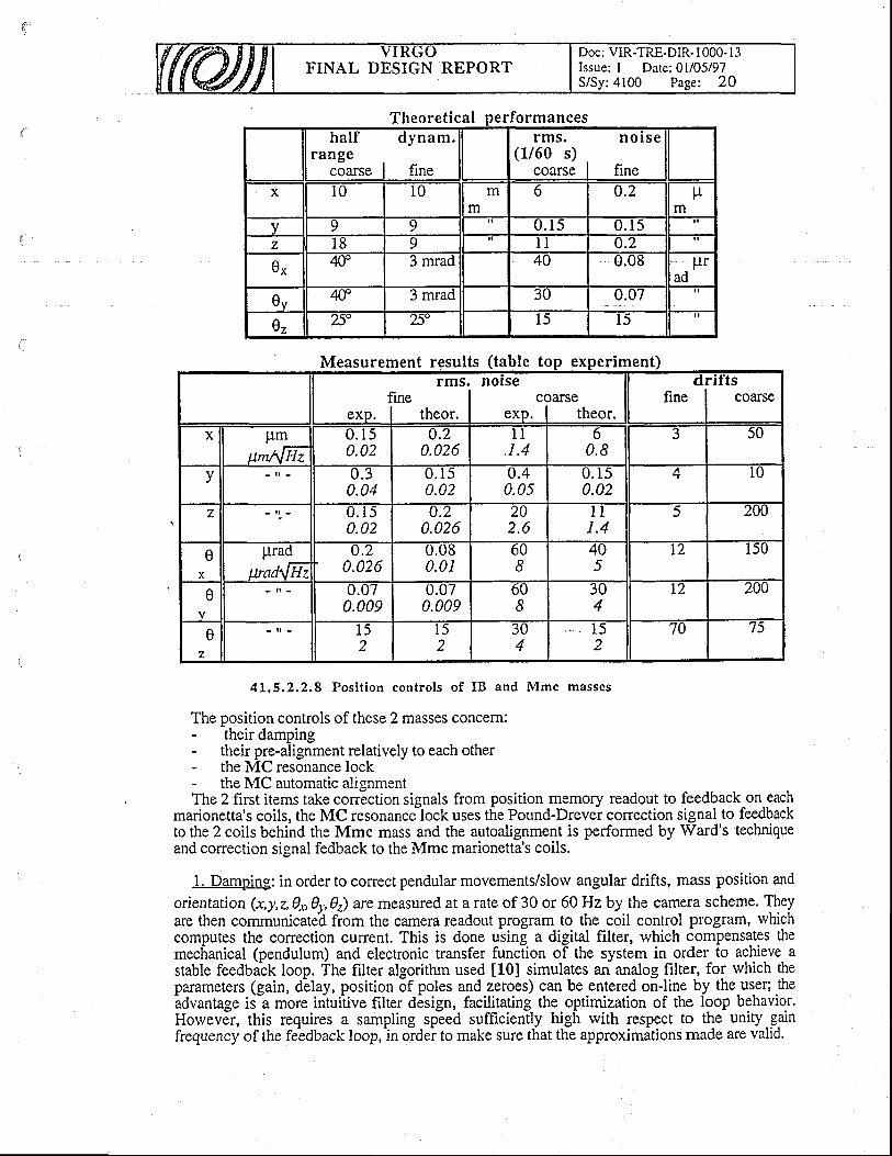
FINAL DESIGN REPORTDoc: VIR-TRE-DIR- t 000- I 3Issue: I Date: 0l/05/97S/Sy:4100 Page: 20
ha l f dynam.(1/60 s)
Theoretical erformances
Measurement results (table to imenrms
fineexp. I theor.
norsecoarse
eKp. I theor.
clfine
u l tscoarse
x pmum\l Hz
0 . 1 )0.02
u.'20.026
I I, r .4
o0.8
3 50
v - I - 0 . 30.04
0 . 1 50.02
u.40.05
0 . 1 50.02
AT l 0
z U . I )0.02
tJ.2
0.0262U2 . 6
1 l1 .4
5 20{)
eX
prad
wad\tHz0.'z
0.026U.U60.01
bU8
4U5
12 I50
e 0 . 0 /0.009
U.U /0.009
OU8
JU4
T2 200
ez
- i l - l )2
I 52
3U4
I )2
70 75
4L.5.2.2,8 Posi t ion contro ls of IB and Mmc masses
The position controls of these 2 masses concem:- their damping- their pre-alignment relatively to each other- the MC resonance lock- the MC automatic alignmentThe 2 first items take correction signals from position memory readout to feedback on each
marionetta's coils, the MC resonancelock uses the Pound-Drever correction signal to feedbackto the 2 coils behind the Mmc mass and the autoalignment is performed by Ward's techniqueand correction signal fedback to the Mmc marionetta's coils.
1. Damoing: in order to conect pendular movements/slow angular drifts, mass position and
orientation (x,y,z,gx,0r,,e) are measured at a rate of 30 or 6OHz by the cam€ra scheme. Theyare then communicated from the camera readout program to the coil control program, whichcomputes the correction current. This is done using a digital filter, which compensates themechanical (pendulum) and electronic transfer function of the system in order_ to achieve astable feedba-ck loop. The filter algorithm used [10] simulates an analog filter, for which theparameters (gain, delay, position of poles and zeroes) can be entered on-line by the user; the-advantage
is a more intuitive filter design, facilitating the optimization of the loop behavior.Horvevdr, this requires a sampling speed sufhciently high rvith respect to the unity_gainfrequency of the feldback loop,in oidei to make sure that the approximations made are valid.
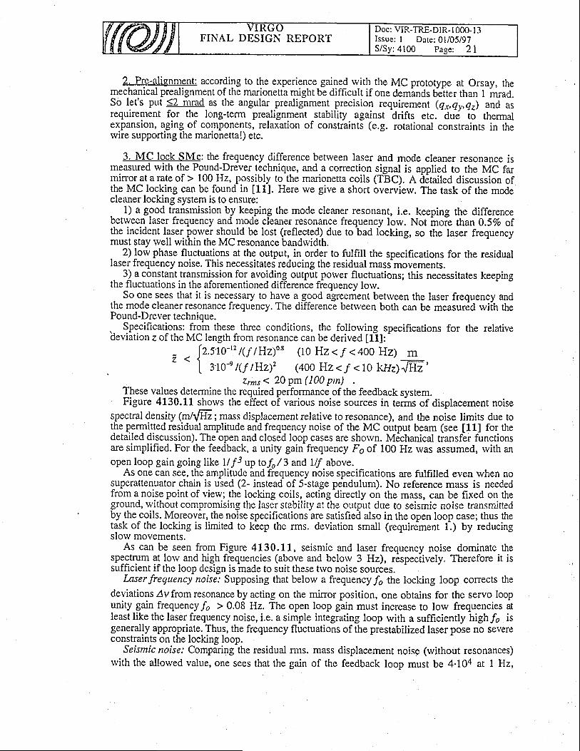
FINAL DESIGN REPORTDoc: VIR-TRE-DIR- I 000- I 3Issue: I Date: 0l/05/97S/Sy: 4100 Page: 2 l
2. Ple-alignrygnt: according to the experience gained rvith-the MC prototype at Orsay, themechanical prealignment of the marionetta might be difficult if one deminds better than 1 i*ad.So let's put 52 mrad-as the angular prealignment precision requirement (qr,qr-,qz) and asrequirement for the long-term prealignment stabiliry against drifts etc.
-duei lo thermal
expansion, aging of components, relaxation of constiainti (e.g. rotational constraints in thervire supporting the marionetta!) etc.
3. MC lock SMc: the frequency difference betrveen laser and mode cleaner resonance ismeasured rvith the Pound-Drever technique, and a conection signal is applied to the MC farminor at a rate of > 100 Hz, possibly to the marionetta coils (TBC). A derailed discussion ofthe MC locking can be found in [11J. Here we give a short overview. The task of the modecleaner locking system is to ensure:- 1) a good transmission by keeping the mode cleaner resonant, i.e. keeping the differencebetween laser frequency and mode cleaner resonance frequency lorv. Not hoie than O.SVo ofthe incident l.qser. power sh_ould be lost (reflected) due to bad locking, so the laser frequencymust stay well within the MC resonance bandrvidth.. 2) low phase fluctualions at the output, in order to fulfrll the specifications for the residuallaser frequency noise. This necessitates reducing the residual mass movements.
3) a constant transmi-ssion for avoidin-g output-porver fluctuations; this necessitates keepingthe fluctuations in the aforementioned differenie frequency lorv.
So one sees that it is necessary to have a good agreement betrveen the laser frequency andthe mode cleaner resonance frequency. The difference bettveen both can be measur6d rvilh thePound-Drever technioue.\- Specifications:_from these three conditions, the following specifications for the relativedeviation z of the MC length from resonance can be derived [fl]:
- . [z.stc-,z t1y /H210, (10 Hz < / < 400 Hz)
I a ro' t(f tlHz.;t'� (4oo Hz < / < 1o kfiz)mm
zrnts 1 20 pm (100 pm)These values determine the required performance of the feedback system.Figure 4130.11 shows the effect of various noise sources in terms of displacement noise
spectral density (n/{Hz; mass displacement relative to resonance), and the noise limits due tothe permitted residual amplitude and frequency noise of the MC output beam (see [LL] for thedetailed discussion). The open and closed loop cases are shorvn. M6chanical transfer functionsare simplified. For the feedback, a unity gainfrequency Fo of 100 Hz rvas assumed, rvith anopen loop gain going l\ke 1l f 3 up bfo/ 3 and Ilf above.
As one can see, the amplitude and frequency noise specifications are fulfilled even rvhen nosuperattenuator chain is used (2- instead of 5-stage pendulum). No reference mass is neededfrom a noise point of view; the locking coils, acting directly on the mass, can be fixed on theground, rvithout compromising the laser stability at the output due to seismic noise transmittedbylhe^coils. Moteover, the noise specifications are satisfied also in the open loop case; thus thetask of the locking is limited to keep the rms. deviation small (requirement 1-.) by reducingslorv movements.
As can be seen from Figure 4130.11, seismic and laser frequency noise dominate thespectrum ?! l_ow and high frequencies (above and belorv 3 Hz), respeciively. Therefore it issufficient if the loop design is made to suit these trvo noise sources.
Inserfrequency noise: Supposing that below a frequency/, the locking loop corrects thedeviationsdvfromresonancebyacting on the mirror position, one obtains for the servo loopunity gain frequency /, > 0.08 Hz. The open loop gain must increase to low frequencies atIeast like the laser frequency noise, i.e. a simple integrating loop with a sufficiently high/o isgenerally appropriate. Thus, the frequency fluctuations of the prestabilized laser pose no severeconstraints on the locking loop.
Seismic noise: Comparing the residual rms. mass displacement noise (without resonances)rvith the allowed value, one sees that the gain of the feedback loop must be 4'104 at I Hz,
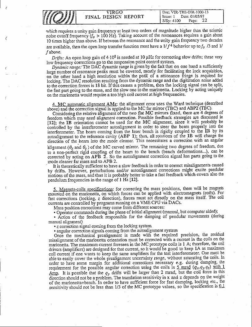
Doc: VIR-TRE-DIR- I 000- l -1Issue: I Date: 0l/05/97S/Sy:4100 Page: 22
FINAL DESIGN REPORT
rvhich requircs a unity gain frequency at least trvo orders^of magnitude higher.than the seismicnoise cut6ff frequeniy-(/, > 100 Hz). Taking account of the resonances requires a gain about10 times higher ihan above. If between the resonance and the unity gain frequency two decades
are available, then the open loop transfer function must have a U f 4 behavior up to/4 13 and ll
f above.Drifts: An open loop gain of 4.108 is needed at 10 pHz for correcting slorv drifts; these very
lorv frequency iorrectibns go to the suspension point-control system.Dyndnic iange: The DAC dynamic range is given by the fact that on one hand a sufficiently
laree number of resonance peaks must be covered, mostly for facilitating the lock acquisition,on-the other hand a high iesolution rvithih the peak of a resonance fringe is required forlocking. The DAC resolution resulting from the dynamic range and the_digitization noise addedto the Iorrection forces is 18 bit.If this causes a problem, then the locking signal can be split,the fast part going to the mass, and the slorv one to the marionetta. Locking by acting uniquelyon the niarionettiwould require a too high coil cunent at high frequencies.
4. MC automatic alignment AMc: thO alignment error uses the Ward teclr{r-que-(d-escribedaUovO anA ttre conection signal is applied to the MC far minor (TPC) and ABP2 (TqC).
Considering the relative itignmenibf the two flat MC mirrors fixed, there are 4_degrees offreedom whicfi may need alig-nment correction. Possible feedback strategies ar-e discussed in[12]; the IB orieniation caniot be used for the MC alignment,. since it will probably beionliolled by the interferometer autoalignment in order to steer the beam. properly-inlo t!r.inrerferomet6r. The beam coming frorn-the laser bench is rigidly coupled_io tllg IB by itsautoalignmenr to the reference civity (ABP 1); thus, all rotatloni of the IB rvill change thedirecdjn of the beam into the mocie cleaner. This necessitates a colrection with an angular
blignment 10rana 9y) of the MC curved mirror. The remaining trvo de_grees of freedom, dueto i non-p.rfect rigiO coupling of the beam to the bench (bench deformations...), can beconected'by acting-on AP'B 2-. So the autoalignment correction signal has parts going to themode cleaner far mass and to APB 2.'
It is itrioreticatty sufficient to have a slow feedback in order to correct misalignments causedby drifts. HowevLr, perturbations and/gr -autoalignment colrections _might. excite pendularniotions of the *uss,'und thus it is probably better to take a fast feedback which covers also thependulum frequencies in the range of I Hz [12].
5. Magnets-coils specifications: for correcting the mass. positions, there will be .$lSrytsm�ichforcescanbeappliedwithelectromagnets(9o{9).Fo.1fast corrections (locking, z direction), forces must aif directly_on the mass itself. The coilcurrents are controlled by programs running on a VME CPU via DACs.
Mass position corrections may come from different sources:. Opeiator commands during ihe phase of initial alignment (manual, but computer aided);.. Action of the feedback iespo'nsible for the damping of pendular movements (during
manual alignment). e correction signal coming from the locking system. angular correction signals coming from the autoalignment systemOncE the mechanict' prealignmjnt is made rvitli the re{uired precision-, the residual
misalignment of the mariorietta orientation must be corrected with a current in the coils on themarioietta. The maximum current foreseen in the MC prototype coils is I A; therefore, the coildrivers (amplifiers) are designed for that current, so it ivould6e go.od to keep 1A as maximumcoil cunent'if one'wants to-keep the same amplifiers for the test interferometer. One must beableto easily cover the rvhole prealignment uricertainty range, rvithout saturating.the coils. Inorder to have some margin f6r additional corections necessary e.g. during damping,.theiequirement for the posslble angular correction using the coils is S-mrad (qr,qy-,qz) With.l4-j,p It is possible that the c/y-drifts will be larger than 2 mrad, but the coil iorce in this
direition should not be a problein. The translation sensitivity- in 1 and z depends on the rveightof the marionetta+bench.'In order to have sufficient forceior fast damping, locking etc', !h9sensitivity should not be less than ll3 of the MC prototype values, so the specification is 0'l
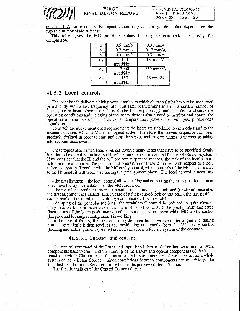
FINAL DESIGN REPORTDoc: VIR-TRE-DIR- 1000- l3Issue: I Date: 0l/05/97S /Sy :4100 Page : 23
mm for I A for x and z. No specification is given for y, since that depends on thesuDerattenuator blade stiffness.^This
table gives the MC prototype values for displacement/rotation sensitivity forcompanson.
x u.) mm/N 0.3 mm/Av u.2 mm/N 0.12 mmiAz 0.5 mm/N 0.3 mm/A
9x 150mradA{m
18 mrad/A
9y JUUUmradA,lm
360 mrad/A
9z 150mrad/Nm
l8 mrad/A
41.5.3 Local controls
The laser bench delivers a high porver laser beam which characteristics have to be monitoredpermanently rvith a lorv frequency rate. This laser beam originates from a certain number oflasers (master laser, slave lasers, laser diodes for the pumping), and in order to observe theoperation conditions and the aging of the lasers, there is also a need to monitor and control theoperation of parameters such as currents, temperatures, powers, pzt voltages, photodiodessignals, etc...
To match the above mentioned requirements the lasers are stabilized to each other and to theresonant cavities RC and MC in a'logical order. Therefore the servos sequence has beenlrecisely defined in order to start and itop the servos and to give alarms to prevent to takinginto account false events.
These topics also named local controls involve many items that have to be specified clearlyin order to be sure that the laser stability's reguirements are matched for the whole sub-system.If we consider that the IB and the MC are trvo suspended masses, the task of the local controlis to measuie and conect the position and orientatibn of these.2 masses with respect to a localreference system. Together with the MC cavity control, which controls of the MC mass relativeto the IB mass, it will work also during the prealignment phase. The local control is necessaryfor:
- the prealignment : the local control allows reading and correcting the mass position in orderto achieve the right orientation for the MC resonance.
- the mass local readout: the mass position is continuously monitored (or stored once afterthe first alignment is finished) and, in case of a fault (out-of-lock condition...), the last positioncan be read and restored, thus avoiding a complete start from scratch.
- damping of the pendular motions : the pendulum Q should be reduced to quite close tounity in order to avoid excessive mass movements, rvhich disturb the prealignment and causefluctuations of the beam position/angle after the mode cleaner, even while MC caviry control(longitudinal locking/autoalignment) is working.
In the case of the IB, the locai control system can be active even after alignment (duringnormal operation); it then receives the positioning commands from the MC caviry control(locking and autoalignment systems) either from a local reference system or the operator.
41 .5 .3 .L Func t i on and concep t
The control command of the Laser and Input bench has to define hardware and softwarecomponents used to command the running of the Lasers and optical components of the input-benCh and Mode-Cleaner to get the beam-to the Interferometer. All these-tasks act as a rvholesystem called << Beam Sourct >> since correlations between components are mandatory. Thefinal task resides in the Servo-control rvhich is the purpose of Beam Source.
The functionnalities of the Control Command are :
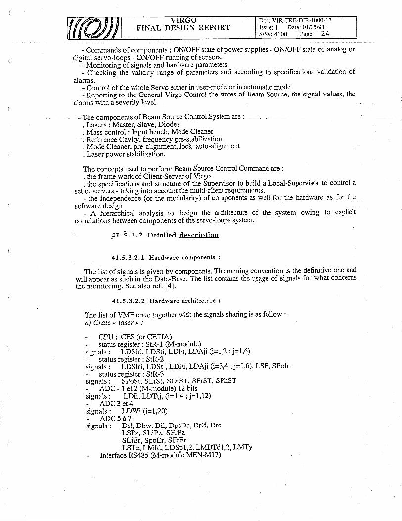
FINAL DESIGN REPORTDoc: VIR-TRE-DIR- I 000- l3Issue: I Date:01/05/97S/Sy:4100 Page: 24
- Commands of components : ONiOFF state of porver supplies - ON/OFF state of analog ordigital servo-loops - ON/OFF running of sensors.
- Monitoring of signals and hardrvare parameters- Checking 1ne vatidiry range of parameters and according to specifications validation of
alarms.- Control of the whole Servo either in user-mode or in automatic mode- Reporting to the General Virgo Control the states of Beam Source, the signal values, the
alarms rvith a severity level.
The components of Beam Source Control System are :. Lasers : Master, Slave, Diodes. Mass control : Input bench, Mode Cleaner. Reference Cavity-, fre quency pre-stab il ization. Mode Cleaner, pre-alignment, lock, auto-alignment. Laser power stabilization.
The concepts used to perform Beam Source Control Command are :. the frame work of Client-Server of Virgo. the specifications and structure of the Supervisor to build a Local-Supervisor to control a
set of servers - taking into account the multi-client requirements.- the independende (or the modularity) of components as well for the hardrvare as for the
softrvare design- A hieraichical analysis to design the architecture of the system owing to explicit
correlations betrveen components of the servo-loops system.
' 41 .5 .3 .2 De ta i l ed desc r ip t i on
1.5.3.2.1 Hardrvare comPonents :
The list of signals is given by components. The namigs convention is the definitive one andwill appear as slch in tlie Data-Base.-The list contains the u-sage of signals for what concernsthe monitoring. See also ref. [4].
41.5.3.2.2 Hardrvare archi tecture :
The list of VME crate together with the signals sharing is as follow :a) Crate << Iaser >, :
- CPU : CES (or CETIA)- status register: StR-l (M-module)signals : LDSlri, LDSti, LDFi, LDAji (i=L,2; j=1,6)- status register: StR-2signals : I-OSlri, LDSti, LDFi, LDAji (i=3,4; j=l,6), LSF, SPolr- status register: StR-3signals: SPoSt, SLiSt, SOTST, SFTST, SPhST- ADC -Let2 (M-module) 12bitssignals : LDIi, LDT{, (i=1,4 ; j=1,12)- ADC 3 et4signals: LDWi ( i=1,20)- A D C 5 e 7signals : Dsl, Dbrv, Dil, DpsDc, Dr@,Drc
LSPz, SLiPz, SFrPzSLiEr, SpoEr, SFrErLSTe, LMId, LDSp1,2, LMDTdl,2, LMTy
- Interface RS485 (M-module MEN-Ml7)
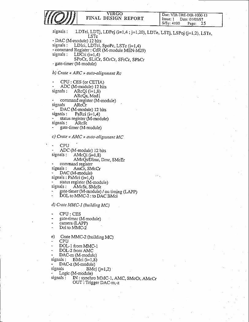
FINAL DESIGN REPORTDoc: VIR-TRE-DIR- l 000- I 3Issue: I Date:01105197S/Sy:4100 Pa-qe: 25
signals : LDTei, LPl, LDPej (i=1,4 ; j=l,20), LDTe, LSTj, LSpoj (J=1,2),LSTe,LSTc
- DAC (M-module) l2 bitssignals : I-DIci, LDTci, SpoPc, LSTc (i=1,4)-command
B9glster: CdR (M-module MEN-N{Z9)signals : LDCri (i=1,4)
SPoCr, SLiCr, SOrCr, SFrCr, SphCr- gate-timer (M-module)
b) Crate < ARC > auto-aligrttttent Rc
- CPU: CES (or CETIA)- ADC (M-module) 12 bitssignals : ARcQi (i=1,8)
ARcQs, Modlcommand register (M-module)
signals ARcCr- DAC (M-module) 12 bitssignals : PaRci (i=1,4)
status register (M-module)signals : ARcSt- gate-timer(M-module)
c) Crate < AMC > auto-aligrunent MC
- CPU- ADC (M-module) 12 bitssignals: AMcQi ( i=1,8)
AMcQs/Dlmc, Dmc, SMcEr- command registersignals : AmCr, SMcCr- DAC (M-module)signals : PaMci (i=1,4)
status register (M-module)signals : AMcSt, SMcSt
gate_-timer (M-module) / ou timing (LAPP)DOL to MMC-2 : to DAC BMci
-
d) Crate MMC-L (building MC)
- CPU: CES- gate-timer(M-module)- carnera (LAPP)- Dol to MMC-2
e) Crate MMC-2 (building MC). CPU- DOL-I from MMC-I- DOL-2 fromAMC- DAC-n (M-module)signals : BMci (i=1,8)- DAC-z (M-module)signals BMcj Q=1,2)- Logic (M-module)signals : IN: syncfuo MMC-I, AMC, SMcCr, AMcCr
OUT : Trigger DAC-m,-z
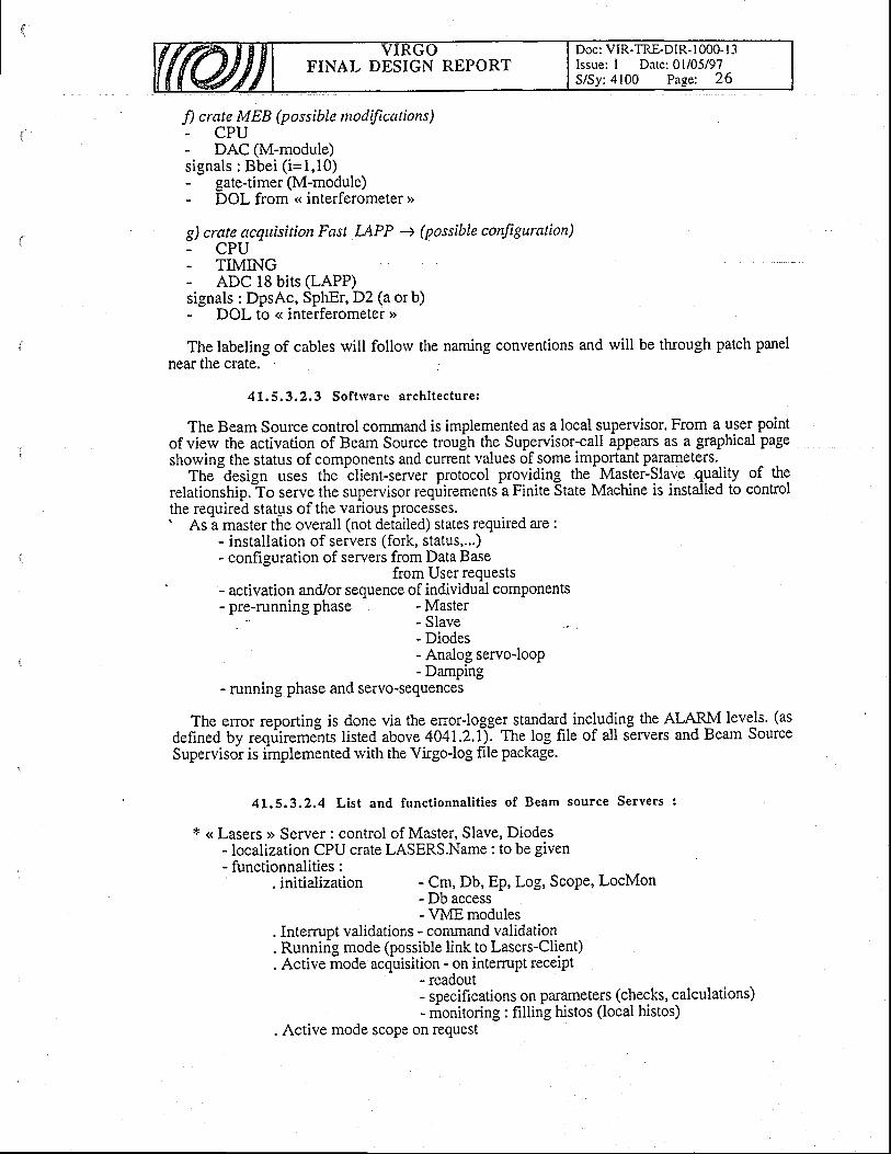
FINAL DESIGN REPORTDoc: VIR-TRE-DIR- I 000- I 3Issue: I Date: 0l/05/97S/Sy: 4100 Pa-se; 26
fl crate MEB (possible ntodifications)- CPU- DAC (M-module)signals : Bbei ( i=1,10)- gate-timer(M-module)- DOL from .< interferometer >
g) crate acquisition Fast I-APP + (possible conJiguration)- CPU- TMING- ADC 18 bits (LAPP)signals : DpsAc, SphEr, D2 (a or b)- DOL to < interferometer >>
The labeling of cables will follorv the naming conventions and will be through patch panelnear the crate.
41.5.3.2.3 Sof t tvare archi tecture:
The Beam Source control command is implemented as a local supervisor. From a user pointof view the activation of Beam Source trough the Supervisor-call appears as a graphical pageshowing the status of components and cunent values of some important parameters._.
The -design
uses rhe tlient-server protocol providing the- Mastei-Slave quality of therelationship."To serve the supervisor requirements-a Finite State Machine is installed to controlthe required status ofthe various processes.' As a master the overall (not detailed) states required are :
- installation of servers (fork, status,...)- configuration of servers from Data Base
from User requests- activation and/or sequence of individual components- pre-running phase - Master
- Slave- Diodes- Analog servo-looP- Damping
- running phase and servo-sequences
The error reporting is done via the enor-loggelstandard. including the ALARM levels. (asdefined by reqriiremeits listed above 404t.2.1\ The log file of all servers and Beam SourceSupervisor is implemented rvith the Virgo-log file package.
4t.5,3.2.4 List and funct ionnal i t ies of Beam source Servers :
t << Lasers >> Server : control of Master, Slave, Diodes- localization CPU crate LASERS.Name : to be given- functionnalities :
. initialization - Cm, Db, Ep, Loei, Scope, LocMon
:?Rfffi3'."'.,. Interrupt validations - command validation. Running mode (possible link to Lasers-Client). Active mode acquisition - on intemrpt receipt
- readout- specifications on pammeters (checks, calculations)- monitoring: filling histos (local histos)
. Active mode scope on request
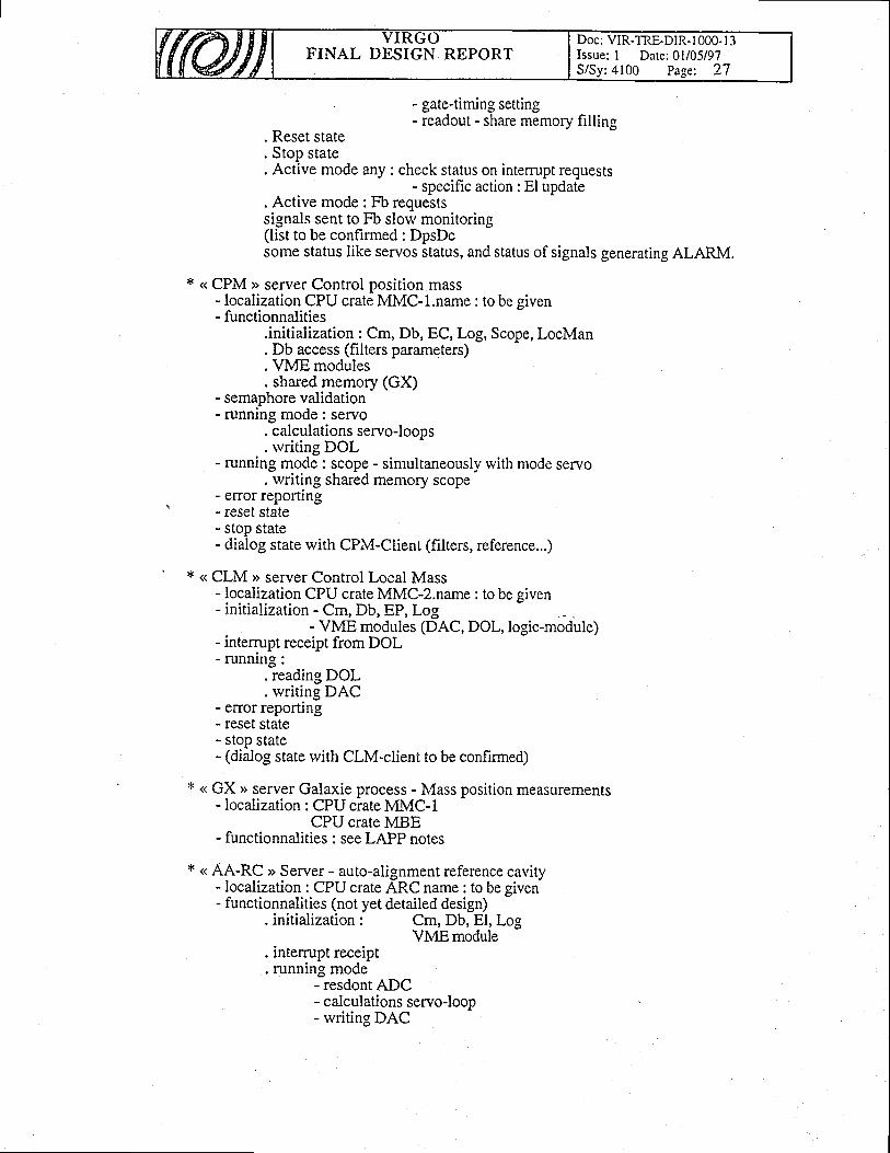
FINAL DESIGN REPORTDoc: VIR-TRE-DIR-l 000- l3Issue: I Dare: 0l/05/97S/Sy:4100 Page: 27
- gatetiming setting- readout - share memory filling
Reset state. stop state. Active mode any : check status on intemrpt reqllests
- specifrc action: Elupdate. Active mode: Fb reouestssignals sent to Fb slori monitoring(list to be confirmed : DpsDcsome status like servos status, and status of signals generating ALARM.
< CPM )> server Control position mass- localization CPU crate MMC-1.name : to be given- functionnalities
.initialization : Cm, Db, EC, Log, Scope, Loclr4an
. Db access (filters paramqters)
. VME modules
. shared memory (GX)- semaphore validation- running mode : servo
. calculations servo-looos
. rvriting DOL- running mode : scope - simultaneously with mode servo
. writing shared memory scope- error reporting- reset state- stop state- dialog state with CPM-CIient (filters, reference...)
< CLM >> server Control Local Mass- localization CPU crate MMC-2.name : to be given- initialization - Cm, Db, EP, Log
- VME modules (DAC, DOL,logic-module)- intemrpt receipt from DOL- runrung:
. reading DOL
. writing DAC- error reporung- reset state- stop state- (dialog state with ClM-client to be confirmed)
<( GX > server Galaxie process - Mass position measurements- localization: CPU crate MMC-1
CPU crate MBE- functionnalities : see LAPP notes
* ( AA-RC >> Seryer - auto-alignment reference cavity- Iocalization : CPU crate ARC name : to be given- functionnalities (not yet detailed design)
. initialization:
. intem.rpt receipt
. running mode- resdont ADC
Cm, Db, El, LogVMEmodule
- calculations servo-loop- writing DAC
Doc: VIR-TRE-DIR- I 000- I 3Issue: I Date: 0l/05/97S/Sy:4100 Page: 28
FINAL DESIGN REPORT
. status and command control
. reset state
. stop state
. error reporting
. dialog state with AA-RC client
* < AL-MC )> server - alignment and lock mode cleaner- localization: CPU crate AMC nalne: to be given- functionnalities :
. initialization Cm, Db, EP, Log, ScopeVME modulesDb access
. dialog state with AAMC client: - filters parameters- calibration- command
. intemrpt receiPt : .
. running mode (frequency - 400 Hz)- reading ABC- calculations servo-looP- writing DAC (ABP) and DOL (BMci)
. error reporting
. reset state
. stop state
* < CPBE >> server - control position input bench- localization : CPU crate MBE name : to be given- functionnalities:
Cm, Db, El, Log, ScopeDb accessVMEmodules
. dialog rvith CPBE client (like CPM)" . intemrpt and semaphore validation
. runnins mode : servo--calculation servo-loop- writing DAC
. running mode : scope
. elror reporung
. reset state
. stopstate
. running mode : interferometer to be designed
x << Beam Source Fast Acquisition >> to be designed by LAPP.
41.5.3.2.5 Sof t rvare implementat ions Beam source Superv isor :
The figures 4100.6-8 shorvs the implementation of sensors and active components alongthe beam] A tentative design of a graphibal-page to control Beam Source is shorvn in Figure4t40.2. The definitive c6ntrol-pigj wiU ben-efit from the Mode-Cleaner test (30m length)done at LAL-Orsay. In this page ?rtiboxes are << actives > click to.get informations concerningihe chosen compo'nent. Some'otactive boxes will be able to activate the specific- client of aS"*"r providin! the Master-delegation if requested by USER. Such client process have to linktoFSMif either-iscalledthroughihe Supervisor or abtivated as stand aloneduring a.phaseoftests of the main Virgo Superiisor. nyiire way the implementation of partitioning has to bedone through a shell-like piocess as foreseen for the Supervisor.
41.5,3.2.6 Sof t rvare implementat ions Beam Source Servos :
FINAL DESIGN REPORTDoc: VIR-TRE-DIR- 1000- l -1Issue: I Date: 0l/05/97S/Sy:4100 Page: 29
The control of the different servos of Beam Source follor,vs the requirements of sequenceanalysis. Some of servos such as SOr, SLi, SFr and SPo are performed in analog electronicdevices and one has only to knorv their status. The others servos : ARc, SMc, AMc and theMBe, MMc dampings (called SDM) are done by computer via a digital conversion of enorsignal and an analog conversion of the signal correction. The sequencing rvill be done by a<< smooth > user choice of automate from the graphical interface. In a later step someautomatic modes could be implemented specially for SOr, SLi and ARc, SMc, AMc. Theuser's inputs cannot be avoid for the so-called < Pre-alignment >) rvhich requires a visualobservation of the beam by video-camera.
The fig 4140.3 shows a tentative presentation of the active graphical page of the Servo-Control.
It is foreseen to implement Servos-Control as a super-server able to access directly the statusRegister and command Register needed to control the system and requesting informationsuseful to the user.
The definitive implementation rvill benefit from the Mode Cleaner test done at LAL-ORSAY.
41.6 Separation lvindows
41,6,L Function and concept
A separation rvindow is used to differentiate the ultra-high vacuum (l0a mbar)part of the interferometer from the normal vacuum (10'" mbar) of the IB andcleaner. It is inserted in the links localized close to the input and recycling torvers,tube sections mechanically compatible with the links.
ln order to get lorv insertion loss it rvill be made out of Silica, rvith the optical specificationsmatching the requirements of induced low noise in the laser beam .
. .41.6.L.1 Requi rements of Input rv indorY
The Input Beam Windorv is inserted just at the output port of the injection tower and rvill becrossed by the full laser beam having the stability requirements described above. So theconstraints on that IBW come from the fact that it should induce no degradation of theprestabilized laser frequency after the mode cleaner (meaning we can tolerate additionalfluctuations up to 10'z HzJHz in the low frequency range up to 100 Hz) see also ref[15].
The requirements of the output rvindow has TBD taking into account the possible noiseinduced by the scattering effects (ref Ligo),
41 .6 . 1 , .2 Se lec ted so lu t i on
The solution takes into account the studies described in ref [L7] of all the possible lossesinduced by mechanical as well as optical effects. The typical critiria is insertionloss S 10'3'
The Figure 4l30.l2 shows a drawing of the tube portion including the window : it iswithout AR coating near the Brervster angle (53+1"), the residual reflected beam from thatrvindow position is of the order of 0.0005-0.001 and can be used either to monitor the beam atthe input or to send an extra beam for the bench alignment purposes.
Th-e window will be clamped on both sides by viton o-rings, thus can stand vacuum on bothsides of it in case of opening of the tower benches or the recycling towers.
The window will be screrved on an intemal tube cut at BrJwster angle, which is itselfclamped on a small portion of link which length is 560 mm from the SS 33d0. Besides that duell portlon ot llnK whlch lengt
viton o-rings we would liketo the presence of viton o-rings we would like this rvindow-link to be as far as possible fromthe baking system, so as close as possible to the towers (TBC).
in the centmlinput modemounted on
Windorv size: Q 200mm x 20mm
FINAL DESIGN REPORTDoc: VIR-TRE-DIR-1000- I 3Issue: I Date: 0l/05/97S/Sy:4100 Page: 30
The input beam for the test interferometer rvill be around 7 mm in diameter and l5 mmthe Virgo interferometer. The rvindorv can fit more than 8 times the final beam size invertical direction and more 12 times the same beam size in the horizontal direction.
4t.7 Laser and Input Bench assembly
41.7.L Laser Bench assembly
The laser bench assembly will be mostly done in the lab before -ouing on iir". For thetransport, the most fragile oitical components will be removed, as well as the laser head whichwill 5e dismounted in orderio avoid damaging of the laser crystal. All the mechanical mounting-will be clamped on the table and the laser 6eam axis will be referenced by a certain number ofiris. The optical parts will be transported in a clean airtight box.
AII the deteclors localized on the laser bench shouldbe removed in order to avoid cablingfractures.
On site the re-positioning of all the removed optics rvill be done with an auxilliary lorvpower Yag laser, as well as the detectors.
41.7.2 Input Bench assembly
The IB rvill be prealigned mechanically in the labo before moving on site. Al-uit tight boxhas been designedipecifically for the transportation of the IB, whictiwill sit on 4 legs rvith the-
$C screrved -intern^ally
and externalty, in order to avoid strong mis.alignments. in case ofhrechanical schocks. The optics of the MC will be transported separately to the other mrlrors;all of them in a clean box .
On site the repositioning of the optics on the IB will be done also with qn au1lllarY laser in a. clean room (class 1000) oiunder a liminar flow to avoid contamination of the MC op.tics. .
The introductiOn Of'the IB and 1'tr r"? auruq6itr[ "Kt'ril 'qtelP6'i 'ru tut r ut''91' "1'9,
lvith these .components protected in a housing -w-hich rvill be removed after the completeinstallation"of tlie IB. Fifure 4L30.L4 is a vierv of the IB inside the injection torver.
41,7.3 Sub-system assembly
As soon as the laser beam rvill be available from the laser bench, it will be sent into the inputtower to match the axes defined by the interferometer and MC axes. The axes are defined onthe IB relaltive to some local re-ference of the torver itself which has TBD with the SSGeometry facility. The beams reflected by the IB will help the positioning of the outsidephotodetectors and cameras.
forthe
FINAL DESIGN REPORTDoc: VIR-TRE-DIR- I 000- I 3Issue: I Date: 0l/05/97S/Sy:4100 Pa-se: 3l
t l l
tzJ
t3l
List of References
A.Rudiger et al. Optica Acta (1981)
P.Hello, E.Calloni, meeting Virgo 1995
H. fleltqann, "D6tails sur les bobines du Mode cleaner", intemal note orsay,
(29.06.1994) (about the MC prototype coils)
t4l C.N.Man, Ph.Heusse: Control-Command of the SS Laser and lnput Bench (v.5),20t2/97
Orsay.,intemll-note, F. Cleva:"Evaluation of ultimate performances of the slave caviryservo", 20/ILl94
Orsay jntemal note, F. Cleva:"Isolateurs de Faraday VIRGO 97&99 - Solutions",25/07/95
t7J VIRGO NTS95-011, "Acousto-optic effects in air", F. Cleva, J.p. Coulon
tSl Orsay internal note: C.N.Man : "Mode cleaner specifications (1) and (2)",8-28/3/95.
i9] H. Heitmaffi,_ "Measurgment of position and orientation of the input mode cleanermasses", VIRGO note NTS96038 (18.6.1996)
[10] R. Ch-iche, "Note d propos de la technique d'implantation du correcteur numdriqueq$iy4tlt d partir de la ddfinition d'un correcteur analogique", internal note Oriay(07/199s)
t11] H. Htiitmann, "Longitudinal control of the VIRGO mode cleaner", intemal note Orsay(10.07.1996)
tl2] H. Heitmar,rn, "Some points on mode cleaner lock & autoalignment", intemal note Orsay(4.10.1996)
[13] M.Taubman, Orsay intemal note,3/97
tl4l C.N.Man, VIR-MEM-LAS-4100-105
115] A.Brillet, "Action of a rvindorv on a laser beam" 1994
[6] M.Barsuglia, Locking meeting minutes, Pisa 1995.
[17] F.Cleva, P"Mugnier, 301I0/96
t5l
I6l

FINAL DESIGN REPORTDoc: VIR-TRE-DIR- 1000- I 3Issue: I Date: 0l/05/97S/Sy:4100 Page: 32
10-1ere
1 o - 2 0
10 '21
10 '22
1 0 ' 2 3
10 '241 0 3 1 0 41 0 0 1 0 2
Figure 4 100. 1 : Initial (curve a) and r.rltitnate (curve b) sensitivity curves of Virgo vs frequency
1 0 1
1 o ' 3
1 o - 4
1 0 ' s
1 o - 6
1 o - 7
1 o - 81 1 0 10 0 1 0 3
Figure 4100.2: Requirements for laser frequency stability at_the input of the,diiferent asymmetries (LVo,3Vo,6Vo) and fbr the trvo cases ISC (upper sets)sets).
1 0 4
interferometer forand USC (lorver
Hz/^/Hz
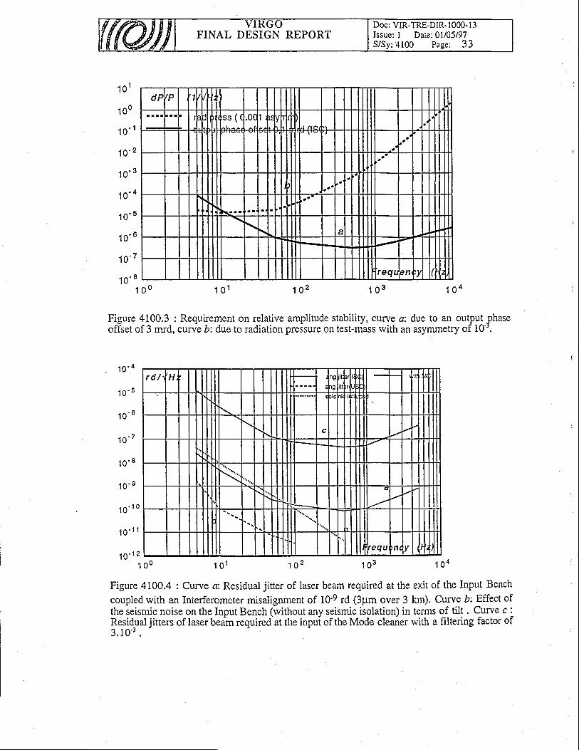
FINAL DESIGN REPORTDoc: VIR-TRE-DIR- 1000- I 3Issue: I Date: 0l/05/97S/Sy:4100 Page: 33
dF ,P 'lS S ( 0(
^ 1
{I t' J / r a
I
I TI+
rll !
I1+j
aTI
-I
IT
IreqL ,n I
1 0 1
1 0 0
1 o ' t
1 0 ' 2
1 0 ' 3
1 0 - 4
1 o ' 5
r n ' 6
fi-7
1 0 ' I1 g 0 1 0 1 1 0 2 1 0 3 1 0 4
Figure 4100.3 : Requirement on relative amplitude stability, curve c: due to an output phaseoffset of 3 mrd, curve b: due to radiation pressure on test-mass rvith an asymmetry of 10'.
< n ' 4
1 o ' s
1 o ' 6
1 0 ' 7
1 o ' 8
< n - 9l v
1 0 ' ' "
1 o ' 1 1
r d / H
c
\
t_ l;
requ n1 0 ' 1 2
1 0 0 1 o l 1 0 2 1 0 3 1 0 4
Figure 4100.4 : Curve a: Residual jitter of laser beam required at the exit of the Input Bench
coupled with an Interferometer misalignment of 10-9 rd (3pm over 3 km). Curve b: Effect ofthe seismic noise on the Input Bench (without any seismic isolation) in terms of tilt . Curve c :ResirlIal jitters of laser beim required at the inpul of the Mode cleaner rvith a f,rltering factor of3 .10 ' ' .

FINAL DESIGN REPORTDoc: VIR-TRE-DIR- I 000- I 3Issue: I Date: 0l/05/97S/Sy:4100 Page: 34
Mode cleaner tower
t-l
Figure 4100. 5 : Position of windorvs required on the injection and mode cleaner towers:1:-link betrveen injection and recycling towers; 2: MC tube; 3: Windorvs @ L50 for camerasetc., tl5o from axis, 5o additional tilt fbr avoiding perpendicularity (AR coated; in the flange);4: Windorv @ 100 for auxiliary HeNe beam (AR coated) (MC axis; in the flange); 5: Windowsin the lorver tower itself (ab6ve/belorv paper planeX diam.). Not all of these openings willpontain windorvs; 6: Lateral windorvs g 204.
to Detector Table
Figure 4100.6:schematic of the laser table containing the lasers, the modulators, and thetelEscope to match the beam to the input bench. This table is part of the Laser Bench .
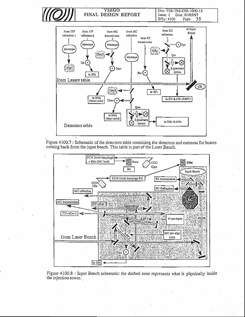
FINAL DESIGN REPORTDoc: VIR-TRE-DIR- I 000-13Issue: I Date: 01105197S/Sy:4100 Page: 35
from ITF
rcflcaion I
II
rdlcction 2I
frcrn MCtnnsmission
r i
from MC frcm RCreflection
fom RC ii**T"'i-..-- {.:Qaril 'r','J'i;ti-<-jl
to lnputFraah
riJ,r#
l ' , : : r : , . .
+ ;':J:ij'+io'q
, tI tosn' I
from Lasers table
Decectors table
to RMc(Mmcoils) !o sFr &ARc (ABPI)
to SMc(Mmecoils)
to SMc &AMc
Figure 4100.7 : Schematic of the detectors table containing the detectors and cameras for beamscoming back from the input bench. This table is part of the Laser Bench.
@| * r*",rr'."u, -
l-*€-illYr.oI M"l - t*"-
from Laser Bench
Figure 4100.8 : Input Bench schematic: the dashed zone represents what is physically insidethe iniection tower.
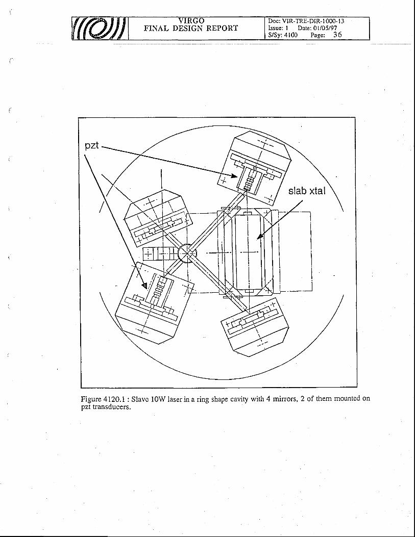
FINAL DESIGN REPORTDoc: VIR-TRE-DIR-l 0O0- l3Issue: I Date: 0l/05/97SlSy:4100 Page: 36
Figure 4I2O.l: Slave 10W laser in a ring shape cavity rvith 4 mirors, 2 of them mounted onpzt transducers.
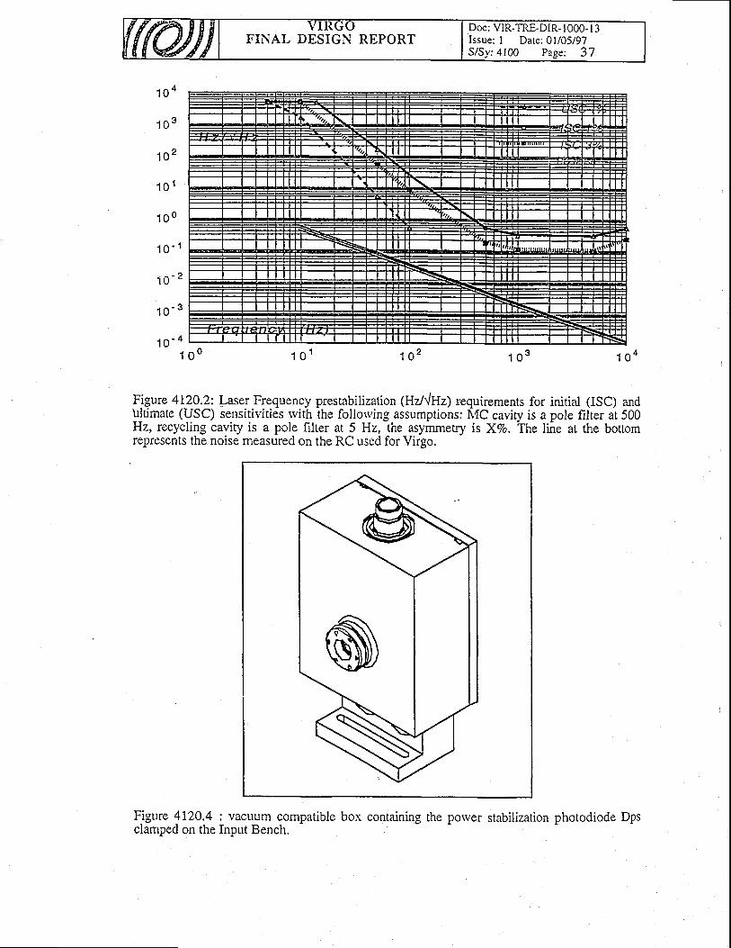
FINAL DESIGN REPORTDoc: VIR-TRE-DIR- I 000- I 3Issue: I Date: 0l/05/97S/Sy:4100 Page: 37
1 0 4
1 0 3
102
1 o l
1 0 0
r n ' 1
1 o - 2
1 o - 3
1 O - 4I 1 o l 1 0 2 1 0 3o o
Figure 4120.2: I aser Frequency prestabilization (Hzl{Hz) requirements for initial (ISC) andtrltimate (USC) sensitivities rvith the follorving assumptions: MC caviry is a pole filter at 500Hz, recycling cavity is a pole filter at 5 Hz, the asymmetry is XVo" The line at the bottomrepresents the noise measured on the RC used for Virgo.
1 0 4
Figure 4L20.4 : vacuum compatible box containing the powerclamped on the Input Bench.
photodiode Dps
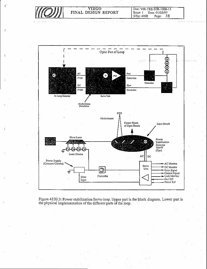
FINAL DESIGN REPORTDoc: VIR-TRE-DIR- I 000- I 3Issue: I Dare: 0l/05/97S/Sy:4100 Page: 38
IttodecleanerSimulation
Output Beamof Input Bench
PorverStabilisationDe!ector30mW(Dps)
Power Supply(Constant Cunent) AC Monitor
DC MonitorEnor SignalControl SignalLock NtonitorOa l O f fPorver Ref
Figure 4120.3: Power stabilization Servo-loop. Upper part is the block diagram. Lower part isthe physical implementation of the different parts of the loop.
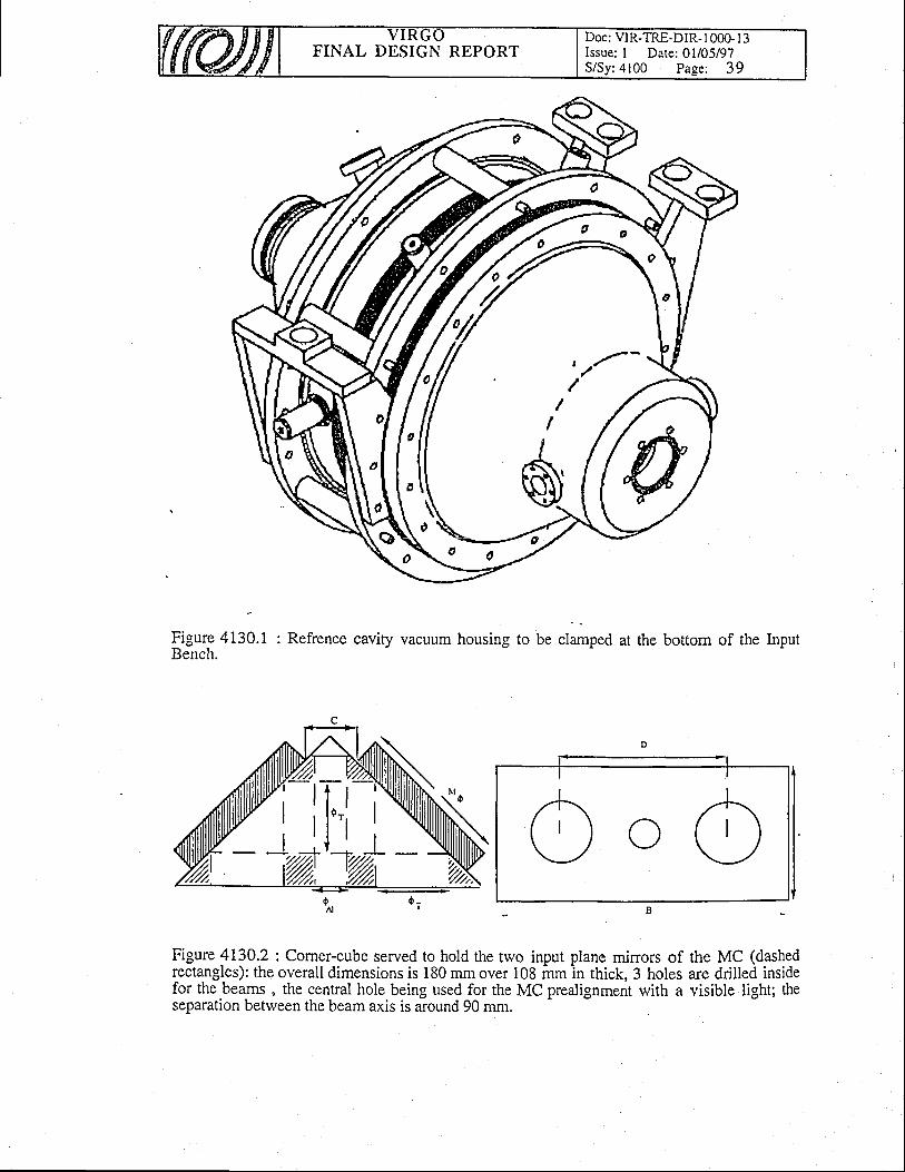
FINAL DESIGN REPORTDoc: VIR-TRE-DIR- I 000- I 3Issue; I Date: 0l/05/97S/Sy:4100 Page: 39
\0
ligur-e 4i30.1 : Refrence caviry vacuum housing to be clamped at the bottom of the InputBench.
O o OFigure !L?02 : Corner-cube served to hold the two input plane minors of the MC (dashedrectangles): theoveralldimensionsis lS0rrmover 108 mmin thick,3 holes are drilled insidefor the beams , the central hole being used for the MC prealignment with a visible light; theseparation between the beam axis is around 90 mm.
ili-i
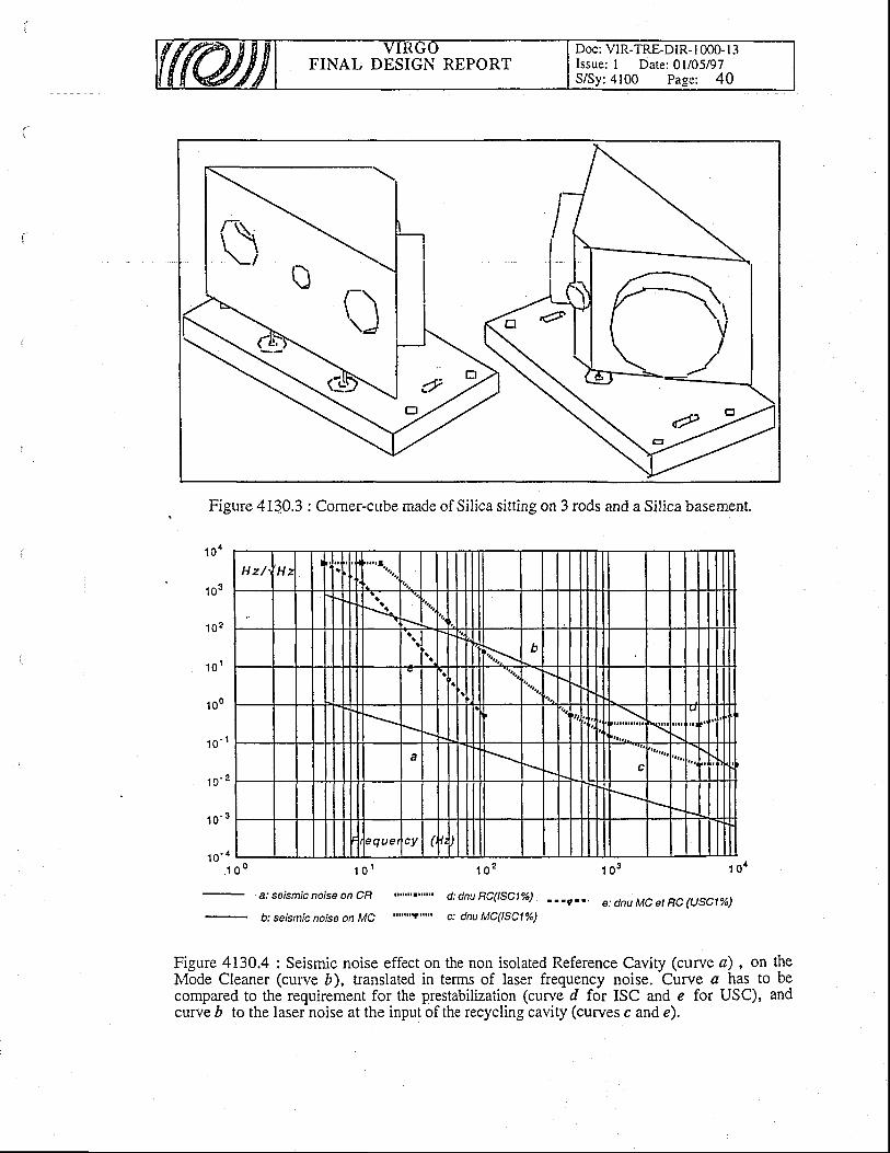
FINAL DESIGN REPORTDoc: ViR-TRE-DIR- I 000- I 3Issue: I Date: 0l/05/97S/Sy:4100 Page: 40
t
Figure 4110.3: Corner-cube made of Silica sitting on 3 rods and a Silica basement.
1 o o
1 0 3
1 0 2
1 o r
1oo
1 o ' I
Hz/ H ;*,4.r.
II
\\g
i.x b
ac
7 que cy
1o '2
1 o - 3
1 o ' 4_ l i o I
a: seismic noise on CR
1 0 2
"'.'n]n"' d: dnu RC(lsclo/")
t"""Y'r'.. c: dnu MC(lsclo/")
1 o s 1 o a
e: dnu MC et RC (USC|%)b: seismic noise on MC
Figure 4130.4 : Seismic noise effect on the non isolated Reference Cavity (curve a) , on theMode Cleaner (curve D), translated in terms of laser frequency noise. Curve a has to becompared to the requirement for the prestabilization (curve d for ISC and e for USC), andcurv-e D to the laseinoise at the input of the recycling cavity (curves c and e).
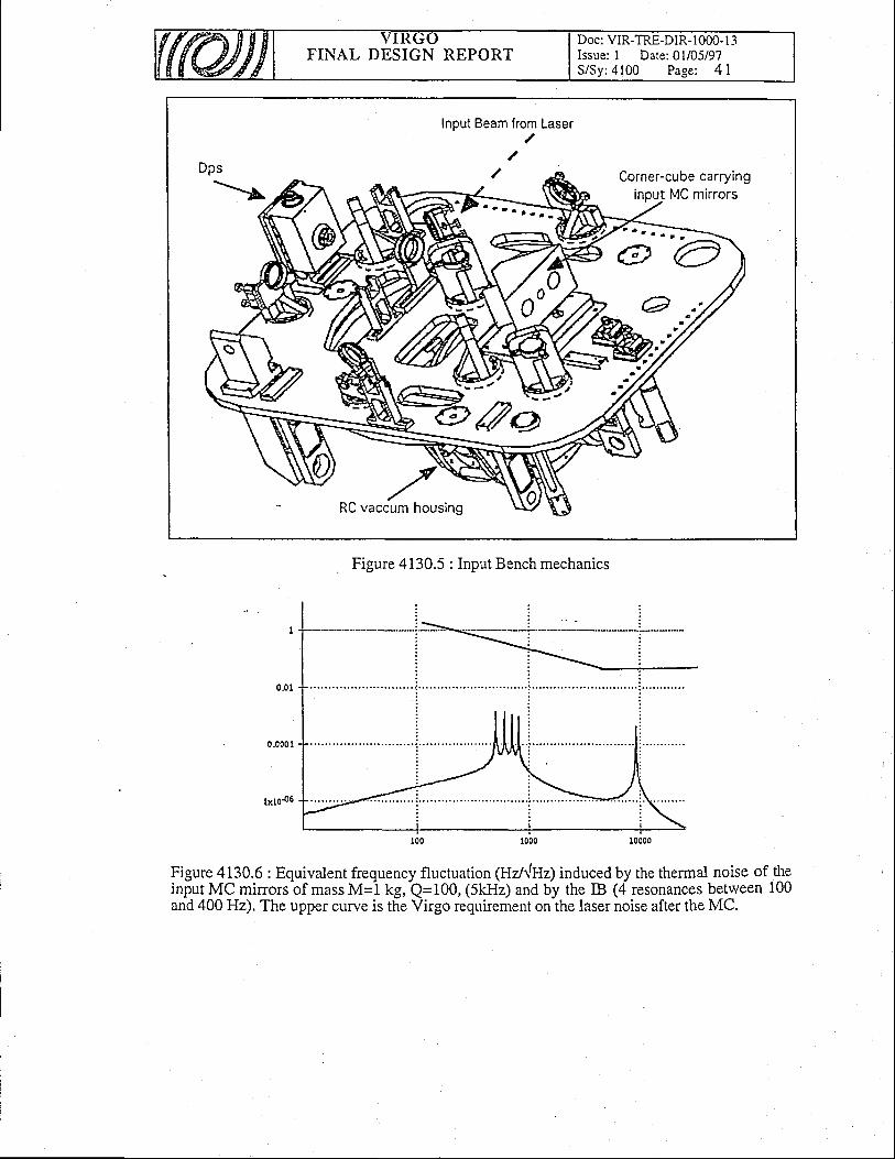
FINAL DESIGN REPORTDoc: VIR-TRE-DIR- 1000- I 3Issue: I Date: 0l/05/97S/Sy:4100 Page: 4 I
Input Beam lrom Laser/
Dps
>LCorner-cube carrying
Figure 4130.5 : Input Bench mechanics
Figure 4130.6: Equivalent frequency fluctuation (Uzllhlz) induced by the thermal noise of theinput MC mirrors of mass M=l kg, Q=100, (5kHz) and by the IB (4 resonances betrveen 100and 400 Hz). The upper curve is the Virgo requirement on the laser noise after the MC.
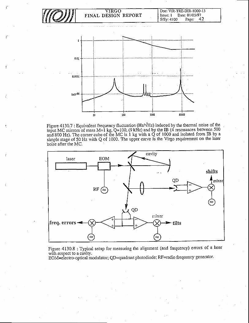
FINAL DESIGN REPORTDoc: VIR-TRE-DIR- I 000- l3Issue: I Date: 0l/05/97S/Sy:4100 Page: 42
Figure 413Q.7 : Equivalent frequency fluctuation_(Hzl^|ry4 induggd by the thermal-noise of theiniurMCminorsbf massM=i kg,Q=100,(9-kHz).?ndb^yt!e_p^(a resonances between 500ana 8OO Hz). The corner cube of Itre MC is 1 kg rvith a Q of 1000 and isolated from IB by asimple stage of 50 Hz rvith Q of 1000. The upper curve is the Virgo requirement on the laserhoise after the MC.
Figure 4130.8 : Typical setup for measuring the alignment (and frequency) elrors of a laserrvith respect to a cavity.EOM=eiectro-optical inodulator; QD=quadrant photodiode; RF=radio frequency generator'
shifts
freq. errors
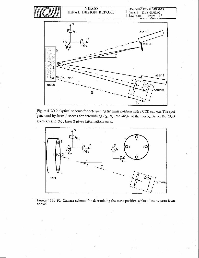
FINAL DESIGN REPORTDoc: VIR-TRE-DIR- 1000- I 3Issue: I Date: 0l/05/97S/Sy:4100 Page; 43
Figure 4130.9: Qptical scheme for determining the mass position with a CCD camera. The sporgenerated by laser I serves for determining g1, 0y; the image of the trvo points on the CCDgives x,y and 03i , laser 2 gives informations on e..
Figure 4130.10: Camera scheme for determining the mass position rvithout lasers, seenabove.
l x
$..I
usr-Oy
__.=.._
'--1--
2
J
^ zI i+Vo,'
.*l .l-""mass

FINAL DESIGN REPORTDoc: VIR-TRE-DIR- I 000- I 3Issue: I Date: 0l/05/97S/Sy:4100 Page: 44
MCl44, open loop10-+
NFF
10-z
10-10
10-13
10- te
10-tslGz 101
Frequ. (Hz)
MC144,closed loop1O+
1Oz
lOto
lOts
lOro
lOrsl0-z
Frequ. (Hz)n/WIz
Figure 4130.11: Noise sources acting on the mode cleaner in terms of equivalent relative
mass displacement spectral density (n/JHz). Dotted: shot noise (lower). and DACdigitization noise (upper). Dash-dotted: laser frequency noise. Solid: seismic noisetrirsmitted by the susir6nsion (upper), seismic noise tiansmitted by locking-coils fixed to theground actinj on the inass (loivii;. Dasfred: current noise of the coil a[nlifler (lower) andsuspension seismic noise rvithout 3-stages superattenuator (upper). Double lines: massdisilacement noise limits coming from the rLquired frequen-cy (upper) and amplitudestability (lower) of the MC output beam.
100 102
I NIBIHIE
1D1D10t1b10-r
- - - . - " - - \- u ' '
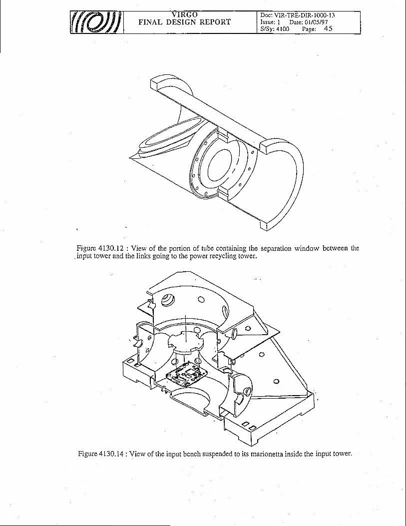
FINAL DESIGN REPORTDoc: VIR-TRE-DIR- I 000- I 3Issue: I Date: 0l/05/97S/Sy:4100 Page: 45
Figure 4130.12 : Vierv of the portion of tube containing the separation rvindow betrveen the. input tower and the links going to the power recycling torver.
Figure 4 130. 14 : View of the input bench suspended to its marionetta inside the input tower.

FINAL DESIGN REPORTDoc: VIR-TRE-DIR- I 000- I 3Issue: I Date: 0l/05/97S/Sy:4100 Page: 46
ffilDb'q
DIODES -s LAVE.-----L-----
I
SERVOS
t*.dl I5'o-- -T
J_ _!l--O----@--lr',rnsrnnl
I
I
I
/+i-o
I IJeaInMoOeAnal\rsts -I
' lo xerPcuon tu I Fig. 4140.2
ABP-Mc
Fig.4140.2

FINAL DESIGN REPORTDoc; VIR.TRE.DIR- I OOO. I 3Issue: I Date: 0l/05/97S/Sy:4100 Page: 47
Graphical ooo" ffimrgTf or Beam Source- ) SO€r= I ffiplFffiil
I
t---{'-s:@6'or------
-
l ornrij6k i.-> SorCr = 0 -.+ (modif Lltttd)
=E-I auto ) '+l j 'Go:; lL:--_./ sricr=o_@ _{rr* _{Tffi; l*O
@*
D*
@ *
D*
@ *-@=
Fig.4140.3
Fig. 4140.3
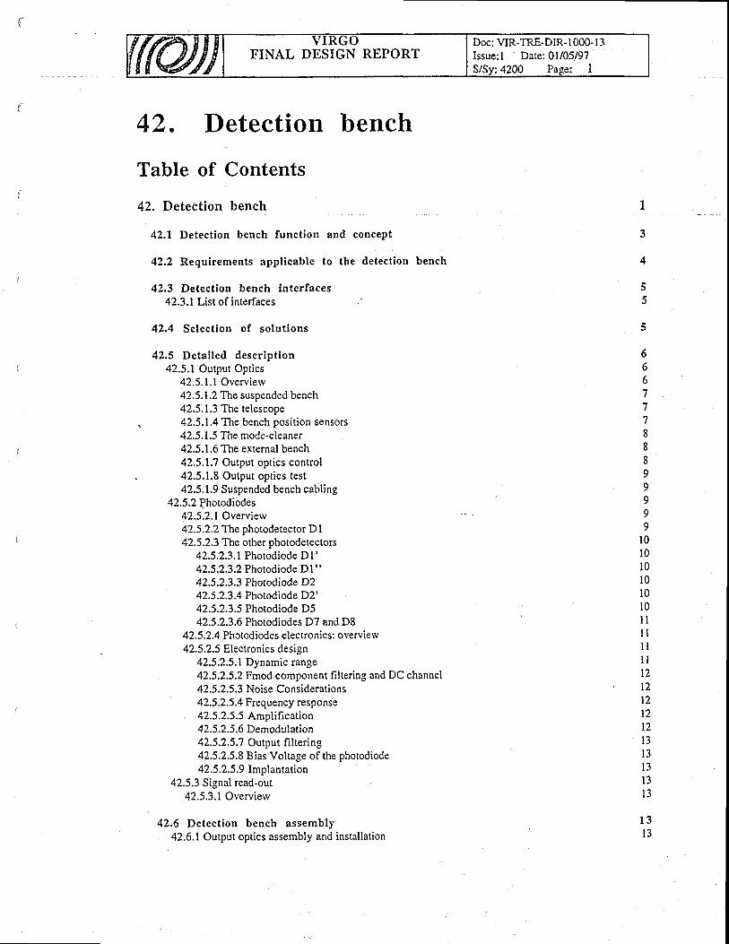
FINAL DESIGN REPORTDoc: VIR-TRE-DIR- 1000-l 3Issue: I Date: 0l/05/97S/Sv:4200 Pase: I
42 . Detection bench
Table of Contents
42. Detection bench
42.1 Detect ion bench funct ion and concept
42.2 Requirements appl icable to the detect ion bench
42,3 Detection bench interfaces42.3.1 List of interfaces
42.4 Select ion of so lut ions
42.5 Deta i led descr ipt ion42.5.1 Output Optics
42.5.1.1 Overvierv42.5.1.2 The suspended bench42.5.1.3 The telescope
, 42.5.1.4 The bench position sensors42.5.1.5 The mode-cleaner42.5.1.6 The external bench42.5.1.7 Output optics control42.5,1.8 Output optics test42.5.1.9 Suspended bench cabling
42.5.2 Photodiodes42.5.2.1 Overview42.5.2.2 The photodetector D I42.5.2.3 The other photodetectors
42.5.2.3.1 Photodiode D1'42.5.2.3.2 Photodiode D 1 "
42.5.2.3.3 Photodiode D242.5.2.3.4 Photodiode D2'42.5.2.3.5 Photodiode D542.5.2.3.6 Photodiodes D7 and D8
42.5.2.4 Photodiodes electronics: overvierv42.5.2.5 Electronics design
42.5.2.5.1 Dynamic range42.5.2.5.2 Fmod component filtering and DC channel42.5.2.5.3 Noise Considerations42.5.2.5.4 Frequency response
. 42.5.2.5.5 Amplification42.5.2.5.6 Demod ul ation42.5.2.5.7 Output frltering42.5.2.5.8 Bias Voltage of the photodiode42.5.2.5.9 Implantation
42.5.3 Signal read-out42.5.3.1 Overvierv
42.6 Detect ion bench assembly42.6.1 Output optics assembly and installation
5
6661
1
1
oo
II99999
10l 0l 0l 0l0l 0ilt lI I
l l
l l12t 2t2
1 2l 3I J
l 3l 3I J
1 3l 3

FINAL DESIGN REPORTDoc: VIR-TRE-DIR. I 000- I -jIssue: I Date: 0l/05/97S/Sv:4200 Page: 2
42.6.2 Photodiodes assembly and installation42.6.3 Signal read-our assembly and installation
The detection bench sub-system is divided in the follorving three items Il]:o 42IO Output Opticso 4220 Photodiodeso 4230 Signal read-out
FINAL DESIGN REPORTDoc: VIR-TRE-DIR- 1000- I 3Issue: I Date: 0l/05/97S/Sv:4200 Pase: 3
42.t Detection bench function and concept
The detection bench main functions are the follorving:o 'Dark fringe' beam extraction: it consist in providing all the optics required to extract
and filter the 'dark fringe' beam at the interferometer anti-symmetric port;o 'Dark fringe' signal detection: it concerns the detection of the gravitational wave signal
which is carriedby the 'dark fringe beam' at the interferometer main output;. T ocking signals detection: it consists in the detection of all the beams corying out of the
interfer-ometer and used to control the longitudinal position of the suspended mirrors.The 'dark fringe' beam is the beam obtained from the interference between the trvo beams
reflected from the trvo arms of the interferometer and traveling from the beam-splitter tolvardsthe so called detection tor,ver. This is the beam carrying the interferometer main output signali.e. the one directly related to the gravitational wave signal.
Figure 42OOJ ihorvs the 'dark-fringe' beam as well as the beam coming from the north armand r!flected from the beam splitter
-second face torvard the detection torver. Due to their
relatively big size (19.8 mm) an? to the beam-splitter geometry t2l the two beams are partiallysuperpoled and they form an angle of 3.6 mrad.'Sc,ine
optics (ouiput optics) is required in order to spatially separate the trvo beams. Onceseparated ftre trvo blams'have to b6 detected by som-e appiopriate photodetectors. To thisprirpos" the output optics should reduce the beams size to-a dimensi,cn comPatible with thephotodetectors size.'
The detection of the 'dark fringe' beam requires some signal-to-noise ratio considerations.As explained in the 4000 ciiapter the interferometer phase difference is measured by
detectingihe power amplitr"rde at the frequency of modulation. The best phase sensitivity one
.can reacl witi a Michelion interferometei is given.by the follorving expression:
oq = '/4 Hz-tt2l q P
where P is the amount of light impinging on the beam spliitd{.(t kW for VIRGO), hv is thephoton energy (0.85 eV foi i,=t.OO4 pm) and 11 the-photodiode quantum.-e-ffici-ency..As aionsequence-ltre photodiodes quantum bffrbiency should be as high as- possible. Neverthelesssince the VlRGOiensitiviry is 3hot-noise limited only above a few hundreds hertz its impact onthe overall sensitivity is limited to this part of the spectrum.
The previous expression assumes a-perfect fringe contrast.at the interferometer output port.In practice the exait shot noise level and so the. phase sensitivity will depend on the averageambunt of light impinging on the photodetector i.e. on the fringe contrast C.
Figure qfOO.Zrhofs ihe phase sensitivity normalized to the best sensitiviry as^a function ofthe riodulation depth m. The various cllryes correspond to different values of the contrastdefect (1-C).The'graphs shows that it ahvays exisis an optimum modulation depth rvhichma.ximizes ihe sensitivity but, as the contrast defect increased, the SAI at the maximum getsmaller. In addition to ihis, as the contrast defect increases, the required modulation depthincreased.
The exact value of the interferometer contrast is unknorvn at present since it will depe^nd.onthe amount of wave front deformation introduced by the various optical components' Opticalsoecifications for the mirrors have been calculated iri order to obtain a contrast of the order oflb''� t3l. This level of contrast rvill reduce the phase sensitivity by about 50Vo.
ii ii possible to improve the contrast by spatially filte-ring the output .bry" before thephotodio'des. To this purpor. the optics at the int6rferoi-reter outfut should include some spatialfiltering of the 'dark fringe' beam.
Thidetection of the d"ark fringe beam and of the beam reflected from the second face of thebeam splitter do not provides en"ough signals to lock the whole interferometer. The locking ofthe interferometer requires the detectionbf the following beams (see figure 4200.3):
FINAL DESIGN REPORTDoc: VIR-TRE-DIR- 1000- I 3Issue:l Date:01/05/97
4200 Pase: 4
o the 'dark fringe' beam (beam I in figure 4200.3)o the beam reflected from the north arm and deflected by the beam-splitter second face
torvards the interferometer output port (beam 5 in figure 4200.3)o the beam reflected from the recycling minor and extracted at the input bench (beam 2 in
figure 4200.3). the beam transmitted from the end mirror of the North caviry and extracted at the North
end bench (beam 7 in figure 4200.3). the beam transmitted from the end minor of the West cavity and extracted at the West
end bench (beam 8 in figure 4240$.For all these beams trvo (for redundancy) or more photodetectors have to be used in order to
measure the signal amplitude at the modulation frequency (in phase and in quadrature with themodulation signal) as rvell as the DC power impinging on the photodetector.
Once amplified all this signals have to be digitized rvith a system of ADC's. The digitizedsignals are then provided to the global control and to the data acquisition sub-systems.
42,2 Requirements applicable to the detection bench
The main requirements for the detection bench sub-system concern the detection of the darkfringe beam: it is required that the read-out system allows to measure the signal at themodulation frequency rvith a shot noise limited sensitivity.
r The output optics should separate the trvo beams at the interferometer output port. Thenit should reduce their sizes to about I mm so that the trvo beams will fit in the' photodiodes area.
o The requirements for the 'dark fringe' beam filtering is to reduce the total amount oflight on the 'dark fringe' below 1 Watt (carrier + sidebands). This value corresponds to
. a contrast defect of the order of 10'* (assuming a power of 1 kW impinging on thebeam-splitter)
o In order to maximize the phase sensitivity, the photodiode quantum efficiency should bea high as possible. A vilue of 0.85 (already meaidred)'rvill allorv to maintain thespectral sensitivity at927o of the optimum one.
. The photodetectors should measure the signal at the modulation frequency with a shot-noise limited sensitivity. The signal-to-noise ratio (shorvn in the previous figure) as wellas all the AC and DC signals amplitude have been evaluated assuming 6.27 }l4}Iz asmodulation frequency and 0.8 m as interferometer asymmetry. Nevertheless thephotodiodes should be able to measure signals up to a frequency of the order of 10MHz (TBC).
. The total DC potver impinging on the photodiodes should also be measured. Thismeasurement should be done on a 0 to 10 kHz frequency span.
o The photodiodes electronics front-end should have a high dynamic range in order todeal with the big dynamic range of the input signal. A rvell defined requirements ismissing since a-higher gain oF the lockinj loop gain can,reduce the signal dynamicrange. The expected order of magnitude is from 10' to 10o '/Hz.
For all the photodiodes the in-phase signal, the in-quadrature signal and the DC signalshould be sampled with a 20WIz sampling rate and sent to the DAQ sub-system.All these signal have to be sent to the global control at a 10 kHz rate in real time,
FINAL DESIG}{ REPORTDoc: VIR-TRE-DIR- I 000- I 3Issue: I Date: 0l/05/97S/Sv:4200 Paee: 5
42.3 Detection bench interfaces
42.3,1 List of interfaces
Interfacename Concemedsub-system
Detection tower input rvindorv:Detection tower output windorvs:Suspended bench wires:Beam-splitter geometry:Bench position control:Mode-cleaner coating:External bench opticai implementation:Beams profile monitoring:Suspended bench cabling:Photodiodes D2 and D2':Photodiodes D7 and D8:Digitized signals for locking:Digitized signals for DAQ:
Interface description
wBS 4100\,VBS 33OOwBS 4700lvBS 4300wBS 4900wBS 4300VIBS 44OOwBS s200wBS 4700wBS 4100wBS 4400wBS 5100wBS s400
(see $ 4200.5.1.1)(see $ 4200.5.1.1)(see $ 4200.5.1.2)(see $ 4200.5.1.3)(see $ 4200.5.1.4)(see $ 4200.5.1.5)(see $ 4200.5.1.6)(see $ 4200.5.1.8)(see $ 4200.5.1.9)(see $ 4200.5.2.3)(see $ 4200.5.2.3)(see $ 4200.5.3.1)(see $ 4200.5.3.1)
42.4 Selection of solutions'
InGaAs phottdiodes are knorvn for being the most sensitive photodetectors at 1.06- p.p.They have lieen proposed for the ViRGO detection system since the first VIRGO propoqJ [4],
Several commerCial InGaAs Photodiodes have been tested at LAPP in the past years [5,6,7].As the dimension of the photodiodes is increased the capacitance also increases thus decreasing'the
bandwidth. On the olher hand greater dimensions allows to deal with more light porver. Theuse of 3 mm diameter photodetectors is a good compromise. Test done at LAPP shows thatthese photodetectors are able to detect a power of 100 mW.(this level of power is above theconsti:ctors specifications). To deal wiih more power, more photodetectors can be used inparallel.
bandwidth (10 MHz) and quantum efficiency (85Vo). To guaranteeThe 3 mm diameter Hamamatsu photodetectors fulfill the VIRGO requirements in terms ofrdwidth (10 MHz) and ouanturn efficiencv 85Vo\. To suarantee this quantum efficiencyquantum efficiency
Hamamatsu is able to provide the photodetectors with antireflection coating on both thenamama$u ls aDte to provrqe me pnotooerecrors wrtn anu-fcrrecuon coaung uurvindorv and the detector. The possibility of using these photodetectors at higher frequency hasnot been demonstrated yet.
For the test interferometer all the photodetectors will be placed outside the vacuum tank [8].If needed the photodiodes used to detect the 'dark fringe' beam will be placed inside thedetection tower.
Each photodiode output signal will be digitizedsystem rvill be based on a VME architecture.
a 16 bits ADC. The ADC's read-out
The design of the 'dark fringe' beam filtering has not been frozen yet. The use of a shortlne deslgn oI the 'darK tnnge' Deam nltenng nas not Deen rrozen yet. ln€ use toptical cavity is the_solution offering-the best performancg.-A ugry short cavity is required,ifo?re wants to transmit the canier and-the trvo mbdulation sidebands'in the same Airy peak. Themain critical drawback is the great sensiti.viry of the interferometer output signal to the cavirylength vibrations (at the level"of tO't6 ny{Hi @ 100 Hz). One prototyp6 havJbeen built and isunder test since one year in Annecy [7].
The use of a system made by oriebi two diaphragm may be a possible backup solution. Thecomparison betrveen the trvo system depends 6n th-e origin of tiie contrast defdct. If the rvavefronl deformations eive mainlv rise to lbrv order transverse modes in the 'dark fringe' beam,ive mainly rise to lbrv order transverse modes in the 'dark fringe' beam,Iront oelorTnatrons glve mamly nse to low oroer tranthe optical cavity solution seems the more appropriate.
The use of i fabry-Perot cavity as spitial filter requires that the output optics used toseparate and filter the iwo beams atihe int-erferometer output port, will be isolated from seismic

FINAL DESIGN REPORTDoc: VIR-TRE-DIR-l 000- l-3Issue: I Date: 0l /05/97S/Sv:4200 Pase: 6
and acoustic perturbations. To this purpose these opticsplaced inside the detection tower.
be fixed on a suspended bench
The amount of seismic isolation required depends on the transmission of vibrations from thetop of the suspension to the suspended bench and from the bench to the Fabry-Perot cavity. Ifl%o of the bench residual vibrations is transmitted to the Fabry-Perot than a two stages super-attenuator rvill guarantee the required isolation. The use of a three stages suspension iinctudngthe filter #0) will allows to have a larger security factor for future development.
42.5 Detailed description
The detection bench sub-system has been divided in the following three items [1]:o 4220 Output Optics:
It includes the optics required to extract the two beams at the interferometer outputport. The output optics main function is to separate the two beams and to reduce theirsizes. In addition the dark fringe beam has to be spatially filtered.
c 4220 Photodiodes:It concerns all the photodetectors required for the detection of the beams used to lockthe interferometer.It includes the analog electronics required to demodulate and filterthe signal at the modulation frequency. It also includes the electronics necessary toread the DC porver impinging on the photodetectors.
o 4230 Signal read-out:It includes the system required to digitized all the photodiode signals. It also takes care
. of providing them to the DAQ and to the global control.
42.5.t Output Optics
42 .5 . 1 . 1 Overv ie l v
The output optics is located inside and behind the detection tower.AII the optics inside the tower is fixed on a suspended optical bench. The;pended to a marionette throush tfuee wires (figure 4200.4\. The marionettsuspended to a marionette through tfuee wires (
bench isis itselfsuspended to a marionette through tfuee wires (figure 4200.4). The marionette
suspended to a three or two stages suspension (TBD). The rvhole system is kept undekept undervacuumat [0'6 mbar.
All the optics outside the torver is located on a cornmercial optical bench (0.9x2 m2) placedbehind the detection tower (figure 4200.5). The beams go from the suspended bench to theextemal bench passing through 3 CFi50 windorvs placed on one of the tower lateral cover.
The optics general implementation on the benches is shown in figure 4200.6. The twobeams coming from the beam-splitter goes through a telescope that separate the trvo beams andthat reduce the beam rvaist to about 1 mm. lVe rvili refer to the 'dark fringe' beam as beam #land to the beam-splitter secondary beam as beam #5.
After the telescope the Beam #1 is separated by a splitter in two parts.Most of the Beam #L (98Vo TBC) is ieflected iowards the mode'-cleaner system. The beams
transmitted and reflected by the mode-cleaner arc sent outside the tower torvards the Dl andDl" photodiodes. These photodiodes are both placed on the extemal bench. A very smallfraction of these beams are sent to two CCD cameras for control purposes.
A small fraction (z%oTBC) is transmitted by the splitter and th-en ieflected by a small minortorvards the external bench. This part of the'beamieach the Dl' photodiodes placed on theexternal bench and it is used for loik acquisition purpose. A small fraction of the beam is sentto a CCD camera for control purposes.
The Beam #5 is also separated in tnThe Beam #5 is also separated in trvo parts by a splitter.Most of the Beam #5 00Vo TBO is transmitted bv the r by a small
placed onMost of the Beam #5 (90Vo TBC) is transmitted by the splitter and then reflected
minor torvards the extemal bench. This part of the beam reaches the D5 photodiodes
FINAL DESIGN REPORTDoc: VIR-TRE-DIR- I 000- I 3Issue: I Date: 0l/05/97S/Sv:4200 Pase: 7
the extemal bench and it is used for locking purpose. A small fraction of the beam is sent to aCCD camera for control purpose.
About l07o (TBC) of the light is reflected towards the bench position sensors. This systemuses two quadrants placed on the suspended bench to align the bench rvith the interferometeroutput beam.
All the optics rvill be mounted at a height of 100 mm respect to the bench. As a consequencethe bench rvill be located 100 mm below the VIRGO beam axis.
42 .5 .1 .2 The suspended bench
The suspended bench (see figure 4200.7) ii made from a piece of aluminum alloy (Alplan)machined in an octagonal shape (950 mm external diameter). The top plate is 10 mm thick.Several ribs 50 mm high and l0 mm thick are machined below the top plate. An aluminum plate10 mm thick is screwed belorv the ribs in order to add mass and rigidity to the bench. The totalbench mass is 60 kg (optics not included).
The possibility of placing the Dl photodiodes on the suspended bench is kept for the future.In this case the additional mass rvill be compensated by replacing the lorver plate with a smaller(and so lighter) plate.
A grid of M6 holes are machined on the top plate in order to fix the optical components.Three larger holes are also machined on the top plate in order to add (if necessary) some opticalelements belorv the table.
4 2 . 5 . 1 . 3 T h e t e l e s c o p e
. Due to the different beam geometry (the beam waist is 3.25 mm for the test interferometerind 19.8 mm for VIRGO), tli'e telescbpe used for the test interferometer cannot be the sameused for the complete interferometer. Nevertheless the beam dimension after the telescope willbe the same (1 mm) so that the follorving optics can also be the same.. The design of the VIRGO telescope has not been definitely frozen yet. The present solutionforeseen the use of a confocal doublet formed by two lenses [9,14] with focal lengths equal to2m and 10 cm respectively. The use of lenses eliminate any astigmatism effects. A small prismplaced on the first^lens fo6al point separates the two beami. DuJto the long focal length 6f thefirst lens, trvo folding mirrors rvill be necessary to fit the telescope on the suspended bench.
The use of mirrors instead of lenses allorvs to reduce the number of optical surfaces butinvolve some not negligible astigmatism and spherical aberrations [0] on the output beam. Thepossibility of using astigmatic optics remains to be investigated.-
The telescope [11] for the test interferometer (see figure 4200.8) will also be a confocaldoublet. The reduced dimension of the beam waist at the telescope input (3.25 mm) allows theuse of two spherical mirrors in this case. The trvo focal lengths will be 1 m and 0.3 mrespectively. This solution reduces the number of optical surfaces since no folding mirror isneeded. The two beams will be separated by a prism placed about 77 cm after the secondmiror.
42.5.1.4 The bench posi t ion sensors
A smalt fraction of the Beam #5 is used to align the suspended bench on the interferometeroutput beam [12]. The Beam #5 position and angle rvill be read by trvo quadrants placed at twodiffirent distinces from the teleicope (see figuri 4200.8). fne ECG YAG 44444 quadrantshave been selected to this purpose.
In order to maintain thi dirk fringe beam aligned rvith the output mode-cleaner the benchposition has to be controlled with ai rms. pr.cision of the ordei of 600 prn and the benchalignment has to be controlled with an rms. precision of 0.5 prad [7]. These requirements arerelated to mode-cleaner alignment.
For the test interferometer the input beam waist is smaller by a factor of 6. As a consequencethese requirements are a factor of six more strict for what concerns the position, but they are afactor of six less strict for what concerns the angles
FINAL DESIGN REPORTDoc: VIR-TRE-DIR- 1000- I 3Issue: I Date: 0l/05/97S/Sv:4200 Paee: 8
In both cases (VIRGO or test interferometer) the beam #5 displacement at the level of thequadrants should be controlled rvith a precision of the order of 1Opm [12].
The EGG quadrants rvill be placed on the bench under vacuum. Only four resistors (one foreach element of the quadrant) rvill be placed under vacuum. The- remaining part of theelectronics read-out will be outside of the vacuum system near the detection torvei.
-
The quadrants output signals will be digitized by a system of ADC's located in rhesuspension control crate. These digitized signals rvill be used to control the bench position rviththe digital control system developed by the Pisa group (interface with WBS 4900).
42.5. ! - ,5 The mode-c leaner
As already said in the 4200.4 section of this chapter, the mode-cleaner system is still in anR&D phase. This section describes the present solution.
The mode-cleaner is a short (25 mm) monolithic triangular caviry (see figure 4200.9). Thecaviry is a small piece of silica having three faces polished and coated. One of the faces isspherical with a radius of curvature equal to 0.3 m. Tfuee prototypes have been built. Theyhave all been coated (at IPN Lyon, interface with WBS 4300) in order to have a finesse of 50.
As a consequence of the difference between the silica index of refraction and the vacuum,the mode-cleaner input and output beam are affected by a strong astigmatism. Two solutionshave been studied to match the cavity waist. The first one consists in using cylindrical lensesrvhile the second one foreseen the uie of trvo small prisms. The solution"using trvo 10 mmprisms is shorvn in the figure 420Q.9 and will be soon tested at LAPP.
This solution corespond to the bench implementation shorvn on figure 4200.8. A lens isused to focus the beam on the mode-cleaner rvith the right dimension.. Two small mirrors, mounted on remotely adjustable optical mountings, are placed betweenihe lens and the mode cleaner in order to tret! th6 mode-cleaner alignmeni.
'
The mode-cleaner length is controlled tfuough a thermal actuator made by a Peitier ceils [7].The error signal is obtained by modulating the caviry length with a small piezoelectric pushing.on the top of the cavity. The signal at the modulation frequency (of the order of 10 kHz) will beextracted by looking at the DC outputs of trvo or more of the Dl photodetectors. The feedbackrvill be operated using a digital control system.
42 .5 .1 .6 The ex te rna l bench
The external bench will be a commercial 0.9x2 m2 optical bench. In order to keep enoughspace betrveen the extemal bench and the wall of the suspension assembly hall, the bench willbe partially mounted on the tower base (see figure 4200.5).
All the photodiodes and cameras required to detect and monitor the beams #l and #5 rvill befixed on the extemal bench.
Some space is kept free in order to accommodate the quadrants used by the linear alignmentsystem (interface rvith WBS 4400). The exact locations of the quadrants as well as the requiredoptics still remain to be defined in agreement rvith the WBS 4400 sub-system.
42.5. 1 .7 Output opt ics contro l
It consists of one VME crate containing the digital electronics required to control the modecleaner as well as the pico-motors used to- remotJly align some of ihe minors placed on thesuspended bench. This same crate may be used to accornmodate the boards used to read theCCD cameras (interface with WBS 5200) placed on the extemal bench.
A second crate is required to accommodate the analog electronics used to amplify thequadrants outputs. This same crate will accommodate the analog electronics needed to detect themode-cleaner output signal.
FINAL DESIGN REPORTDoc: VIR-TRE-DIR- I 000- l -1Issue:l Date: 0l/05/9?
:4200 Paee: 9
suspended bench inside the detection tower.The laser output beam is separated in tuThe laser output beam is separated in two parts (see figure 4200.10). One is sent torvards
the mode-cleanei system in order to test the conect functioning of the mode-cleaner controlsystem. In order to have enough power impinging on th€ mode-cleaner, one of the sp.littersunder vacuum rvill have to be rotated. The second part of the beam is sent towards the bench
42 .5 .1 .8 Ou tpu t op t i cs tes t
A laser rvill be placed on the external bench in order to test the component located on the
under vacuum rvill have to be rotated. The part of the beam is sent towards the bench
42,5.2 Photodiodes
posi t ionsensors inorder toteSt thecor � rect funct ion ing.of thetwoquadrants. � �- The laser test placed on the external bench will not allow to test the entire bench but only trvo
of the main elements. The possibility of a complete test done by injecting trvo light beams at thetelescope input is currently being studied.
The cabling has not been definitely frozen yet. This section describes the present solution.It is foreseen to have six remotely controlled optical mounts. Two of them are equipped witlt
3 pico-motors rvhile the other fouri uses only 2 pico-motors. One short pulse (few ms) with300 volts amplitude is provided to the pico-motor to make one step. One should remark thatthese motors ivill only be used for the initiat alignment and to comp6nsate some slow drift. Novoltage need to Ue appnea when the motor is airest. The total number of cables required to thispurpose is around 28. Two l6 rvires flat cables are foreseen at present.-
Ttre trvo quadrants need 5 rvires each. The use of one shielded 16 wires flat cable if foreseen3t present.
The mode cleaner system will need at least 6 rvires: 2 for the piezoelectric ,2 for the Peltiercells and two for a thermometer. One additional shielded 16 wires flat cable may guamntee therequired flexibility for future upgrades.
. The present soiution foresees to clamp the cables to the suspersion wires of the bench andattach tliem to the marionette (interface with WBS 4700). The cables will then travel along thesuspension.up to the top of the tower.
42 .5 .2 .1 Overv ie rv
The photodiodes location is shown in the figure 4200.t1. Photodiodes Dl, D1', D1", andD5 are iocated on the bench behind the detection tower. Photodiodes D2 and D2' ue located onthe laser bench near the injection tower (interface rvith WBS 4100). Finally photodiodes D7and D8 are located behind ihe North end torver and the West end tower respectively (interfacervith WBS 4400).
Since the totai amount of power is limited to 100 mW per photodiode, a different number ofphotodetectors will be needdd for each beam. In order to ieduce the impact of failures it isforeseen to use at least two photodetectors on each beam.
The amount of porver impinging on each photodetector depends on the light interferencerdition and will'be drasti6alli dlfferent duiing the lock acquisition process and once_ thecondition and will be drasticallv during
interferometer is locked. Since tfie locking acquisi-tion process has not been completely definedyet, the exact amount of power impinging on each phoiodetector are only very roughly knorvn-l.levertheless for constniction purlosis Ihe total number of photodeteciors has been evaluatedand the foreseen solution is described in this section.
42.5.2.2 The photodetector D1
Assuming 1 kW of power stored inside the recycling p-otYe.r, an asymmetty -9f 0.8 m, amodulationTrequency of A.ZS MHz and a contrast defect of 10-1 (after the beam filtering), the

FINAL DESIGN REPORTDoc: VIR-TRE-DIR- I 000- I 3Issue: I Date: 0l /05/97S /Sy :4200 P
optimum modulation depth turns out to be around 0.4 (see figure 4200.2). In these conditionsthe amount of DC polver impinging on the Dl photodetector is of the order of 0.7 W. Theamount of power at twice the modulation frequency (12.5 MHz) rvill be around 0.65 W. Thepeak porver approaches 1.4 W. The use of 16 photodetectors rvill allow to deal with thispower.
The detector arrangement is shown in figure 4200.12. Fifteen 5070 splitters are used todivide the beam in sixteen parts. The photodiodes are placed in order to be all at the samedistance from the first splitter. In this configuration, the use of only one lens in front of the firstbeam-splitter allorvs to focus the beam on all the photodetectors at the same time.
AII the photodetectors are mounted on an individual support which allorvs to center thephotodiode on the light beam and that places the photodiodes at about 10 cm above the bench(see figure 4200.13).
42.5.2.3 The other photodetectors
42 .5 ,2 ,3 .1 Pho tod iode D1 '
The amount of porver carried by the 'dark fringe' beam during the lock acquisition process(rvhen the interferometer is not locked on the 'dark fringe' yet) will not be the same one haswhen the interferometer is locked. In addition to this the output mode-cleaner is not expected tobe locked during the lock acquisition process. To deal rvith the locking acquisition process asmall fraction of the 'dark fringe' beam is extracted before the mode-cleaner and is sent towardsthe D1' photodetectors. Trvo photodiodes rvill be used to this purpose.
42 .5 .2 .3 .2 Pho tod iode D1"
Abig fraction of the 'dark fringe' beam is reflected by the mode-cleaner. The exact amountrvill depend on the fringe contrast before the mode-cleaner. The reflected light is detected by the'D1"
pfrotodetectors. T"his beam rvill be used only from mode-cleaner monitoring purpose. Twophotodiodes will be used.
42 .5 ,2 .3 .3 Pho tod iode D2
When all the interferometer is locked, the light is resonant in the recycling cavity. If therecycling cavity gain is optimized (TBC), only a very small fraction of the light coming fromthe laser (10 W for the iest interferometer and 20 W for VIRGO) will be reflected by therecycling minor towards the D2 photodiodes. In practice the exact amount of light impingingon the D2 photodetectors will depend on the fringe contrast of the recycling cavity i.e. on thebeam matching and on the matching betrveen the recycling mirror transmission and theinterferometer losses one rvill be able to achieve. From this point of vierv the situation is similarto rvhat happen on the Dl photodetector.
The difference is that-this beam will mainly be used for laser frequency stabilization(interface with WBS 4100 and Locking group) in 5 Hz to l5 kHz range (TBC) and the requiredsensitivity is belorv [13] the one requiied for the Dl photodetector. As a consequenc:_thedetection of all the tight witt not be re{uired. The fraction of light used to this purpose is TBD'The present solution foreseen the use of two photodiodes.
42 .5 ,2 .3 .4 Pho tod iode D2 '
The amount of light on the D2 photodetector will increase during the lock acquisitionprocess as it happenTor Dl. As for ihe Dl' photodetector the D2' will be used for lockingacquisition purposes. The fraction of light used is TBD. The present solution is to use trvophotodiodes to this purpose.
FINAL DESIGN R,EPORTDoc: VIR-TRE-DIR- 1000- I 3Issue: I Date: 0l/05/97
:4200 Pase: I I
4 2 . 5 . 2 . 3 . 5 P h o t o d i o d e D 5
The expected amount of light impinging on the D5 photodetector is of the order of 50 mW.This valul asslrme 1 kW of porv6r insiile the recy-ling cavity and 10'{ [l4J as reflectioncoefficient for the beam-splitter second face. It is foreseen to use trvo photodiodes.
42 .5 .2 ,3 .6 Pho tod iodes D7 and D8
The expected amount of light transmitted through the Fabry-Perot end mirrors is of the orderof 0.75 W. This value is calculated assuming 1 kW inside the recycling cavity, 50 for theFabry-Perot finesse and 50 ppm for the end minor transmission [14]. To deal with such aporver 8 photodetectors rvould be required. The sensitivity required on these signal has not beipecified-yet (interface with Locking group). As a consequence it is not clear rvhat fraction ofiight will be used (TBD). The present solution foreseen the use of 2 (TBC) photodiodes.-
If required these photodeteclors will be delivered for the test interferometer. In this case thetotal amount of power rvill be about 30 times lower. The use of trvo photodiodes will be morethan enough to detect such a power.
42.5.2.4 Photodiodes e lect ronics: overv ie lv
This section and the following two are dedicated to the analogue electronics and cablingwhich will be implemented in order to transform the photodiodes current into a suitable signalready to be digitized. The modulation frequency, envisaged in this reference solution, is 6.27MHz it might-be increased to 12 or 18 MHz, note that a change of frequency.imply somehardware *ork on this system and therefore is an important operation rvhich canr\ot beenvisaged without some preparation.
. The dark fringe beam is expected to contain the follorving power distribution :
- 0 . 7 w @ D C- 0 . 6 W p e a k @ 2 F m o d- 0.1 W peak @ Fmod [i5]
The interferometer's beams to be detected are used either for the signal detection or for theinterferometer locking. The general principle is to organize the beams geometry in order not toexceed 100 mW of tfunt peik porvir peidiode. Taking into account a quantum.efficiency of0.85 for the photodiodes, i.e. a conversion factor of 0.73 AAV, this implies a maximum cunentof 75 mA peak per channel, the number of channels depending of the beam power.
Each electronics channel associated with one photodiode contains :- one DC channel with a bandwidth of about 50 kHz- two AC channels with demodulated and filtered outputs in phase and in quadrature with
respect to the frontal modulation- one AC test output- one DC bias for the photodiode
42 .5 .2 .5 E lec t ron i cs des ign
The schematic diagram of one electronics channel described below is given in figure4200.t4.
42 .5 .2 ,5 ,1 Dynamic range
For each photodiode, the peak currqnt is 80 mA and the average current 40 mA. Thisinduces a sho^t noise current of t tO pe/{Hz. The useful signal at Fm6d corresponds to a peakcurrent of about 4.5 r4A. The usefuJ dynamic range is then given by :
4 .5 mA / 110 pA/ ' r lHz= 4.10 ' {Hz
FINAL DESIGN REPORTDoc: VIR-TRE-DIR- I 000- I 3Issue: I Dare: 0l/05/97S/Sy:4200 P
42.5.2,5,2 Fn' rod component f i l ter ing and DC channel
In order to reduce the dynamic range to its useful value, the 2 Fmod component must befiltered and brought to a value belorv the Fmod component.
To achieve this filtering, tve use a short-circuited cable tuned to the modulation frequency(L =)'^*14) so that the cable presents a high impedance at Fmod and a short circuit at 2 Fmod.This cable is terminated.by a capacitorensuring the high frequency short circuit in parallel rvitha current amplifier rvhich provides the DC output
To ensure a safetv factor on the attenuation of the 2frequency is placed
'at the input of the amplifier.
Fmod component, a notch filter at this
42 .5 .2 .5 .3 No i se Cons ide ra t i ons
A 50 Q resistor is placed at the input of the amplification stage to match the 50 Q cabletransporting the signal from the photodiode. The ele6tronics comp-onents should not add noiseF old^.J to keep the shot noise limited detection. The voltage indiced by the shot noise acrossthe 50Q resistor is about 5 nli{Hz. Measurements have sliown that thi input equivalent noiseof the electronics is 1.6 nV/r/Hz [01.
The equivalent circuit of the photodiode is a parallel capacitor and a series resistor. Thequency limitation of the system is made by the photodiode itself and the input impedance offrequency limitation.of the system is made by the photodiode itself and the input impedance of
the readout- circuit (500). Holever, the detection channel could be used -even
al a higherfrequency than the photodiode culoff frequency. The signal and shot noise will be reduced by
42 .5 .2 .5 .4 F requency response
input impedance of
frequency than the photodiode cut-off frequency. The signal and shot noise will be red bythe same amount, so the signal to noise ratio rvill noi be affected, provided the shot nois-eremains above the electronics' noise.
4 2 . 5 . 2 . 5 . 5 A m p l i f i c a t i o n
. An amplification is necessary to bring the Fmod signal at the maximum level allorved by themixer (0.9 V peak).We have chosen a CLC 425 operational amplifier for its low noise and-highspeed characteristics :
noise voltageGBW productDC offsetgainpower supply
1.05 nVdHz1.7 GHz100 pV typ.10 to 1000+/- 5V
4 2 . 5 , 2 . 5 . 6 D e m o d u l a t i o n
The output of _the amplifier feeds the mixer's RF inputs through a 3 way power divider :one way for the r'rr'-prraJb&i:t{dnunone way for the quadrature detectionone way for the test channel
The demodulation reference is supplied by the modulator. It is divided by a 90' splitter inorder to achieve the in-phase and quadrature demodulation's. The absolute-phase of the LOsignal can be adjusted tb take into iccount all the phase lags between the mbdulator and themlxer.
The demodulators are double balanced mixers with a LO level of +13 dBm and a madmumRF level of +9 dBm. Their dynamic range have been measured to 4.107 {Hz and just matchesthe specifications.
FINAL DESIGN REPORTDoc: VIR-TRE-DIR- 1000- I 3Issue: l Date:01/05/97S/Sv:4200 Pase: l3
42,5,2.5,7 Output f i l ter ing
The IF outputs of the mixers are connected to a low pass filter which eliminates all thefrequency components above 20Wlz.
ihen,-a second order lead compensator filter is placed to compress the dynamic range of thesignal and makes it fit into a 16 bits ADC. This filter has a low cutoff frequency at 0.25 Hz'anda high cutoff frequency at25 Hz.
Finally, the gain of ihe stage is adjusted to match the full scale input level of the ADC's.
The reverse bias voltage is driven by an external DAC. The DC current and the applied biasvoltage are measured by iwo dedicated circuits, the output ports of these circuits are connectedto a riultiplexing systeri which allows a channel by chdnnel visualization of cunent and voltageand to direct these information's towards the acquisition system ADCs. The bias voltage isapplied to the photodiode by a triaxial cable..This system:llows to apply the re.verse biasvbitage and to- transport the signal with a single cable. TNs same system rvill allow toautomatically turn the bias voltage off if the current florving tfuough the photodetector increasesabove a given threshold.
42,5,2.5.8 Bias Vol tage of the photodioJe
42 .5 .2 .5 .9 Imp lan ta t i on
All the electronics described above for one channel, is implanted on a VME like printedbircuit board. No processor or fast digital electonics rvill be installed on these analog crates.
42.5.3 Signal read-out
42 .5 .3 . 1 Overv ie rv
The photodiodes signals are converted using lorv noise ADCIs (ADC5020 from. Analogic)sampled at 20 kHz. fhese ADC's are installed on VME boards which provide-.the readoutfacility. They include an inboard FIFO and a private bus which allows to read a full VME cratein a sihgle bloc transfer at a user defined frequency (10 kp in our case).
Givei the size of the AID converter a ma;iimum of 32 channels could be fitted in one VMEcrate. Therefore, three crates are foreseen for the readout of the in-phase, quadrature and DCsignals for all the photodiodes in the central building. One crate wiil be enough for each endminor building.
There rvill6e one CPU per VME crate reading at 10 kHz, all the channels, doing calibration,unrvhitening and summing the twin channels, sEnding the result to the glolal- control (at l0kHz) and t"o the Dala Acluisition through Digital OpticA Links. The detailed crate/channelsassignment is TBC
42.6 Detection bench assembly
42,6,L Output opt ics assembly and instal lat ion
The suspended bench will be clean, assembled and pre-aligned at LAPP. During this phasethe bench is also suspended and balanced by adding some-small masses at the appropriateplaces. The bench rvillbe then shipped to Casiina inside a protection box ensuring a minimumlevel of cleanness (TBD).
FINAL DESIGN REPORTDoc: VIR-TRE-DIR- I 000- I 3Issue: I Date: 0l/05/97S/Sy:4200 Pa
Once received in Cascina, the bench will be installed in the benches lab using a chariot. Herethe precise alignment rvill be done using a Nd:YAG laser and some movable diaphragms. Thelaser rvill be located on another small bench placed near the first one and the liglit rvill be sentfrom one bench to the other using a fiber (TBC).
The marionette rvill be then assembled on the bench using some specific support attached tobench edge. It i"s assumed that the marionette has been previously suspend-ed and balancedseparately (interface with WBS 4700). The cables coming from the-bench are then clamped tothe three suspension rvires and connected to the connectors fixed on the marionette.
Once the cabling i9 completed, the correct functioning of the electrical components locatedon the Lgq.h (piezoelectric, thermometer, Peltier cell, quadrants and the pico-motors) rvill betested. This operation will need some electrical equipment like one oscilloscope and one crate(rBC).
The marionette will be then suspended to a small clean forklift through a wire similar to theone used to hang it to the last stage of the super-attenuator and the supports attached to thebench edge are removed. The balancing of the whole payload is checked by rising it rvith theforklift.
The marionette is then placed again on the support and the payload is ready to be installedinside the tower. Using the chariot and the elevator the payload is transported in the gallerybelow the detection tower and placed on the I m diameter tower lower cbver. An elevator isthen used to transport the payload inside the tower (see figure 4200.15).
The bench supporting feet are then installed inside the tower (see figure 4200.15). Themarionette is hanged to the super-attenuator and the cables coming from the top are connectedto the connectors attached on the marionette. The elevator goes down sl,owly until themarionette suspension rvires is under tension. The supports attached to the bench edge are5emoved (protection against the falling of the marionette remains to be defined).
The first test of the bench rvill be done by resting it upon the supporting foots. To thispuryose each foot is equipped rvith some adjustable screw. Test beams are then injected fromthe external bench (already installed) and the correct functioning of the elements placed on the
. bench and of the cabling is checked.The bench is then suspended again and the conect functioning of the position control system
using the cameras and the quadrants is checked. The bench is then ready to be used underY q v q u l l t .
42,6,2 Photodiodes assembly and install-ation
The photodiodes rvill be tested together with their electronics at LAPP.Once shipped to Cascina the photodiodes will be installed on the appropriate benches. For
what concern D2, D2' , D7, and D8 the installation will be done together with the peopleresponsible of the input bench (interface WBS 4100) and of the end benches (interface rvithwBS 4400).
The exact location of the analog electronics remains TBD.
42,6,3 Signal read-out assembly and installation
The VME crates with their ADC's, CPU and DOL will be set up and tested at LAPP. Thenthey will be shipped at Cascina installed in their assigned rack (in the data acquisition room forthe central building TBC) and connected to the photodiodes signal outputs.
, Y I A \ J V
FINAL DESIGN REPORTDoc : VIR-TRE-DIR- I 000- I -jIssue: l Date:01/05/97S/Sv: 4200 Paee: I 5
t4l
tsl
List of References
11l VIRGO WPD Work Package Description (unpublished)
tT] J.Y.Vinet; 'splitter', VIRGO note PJT94-16 (1994)
l3l P.Hello; 'Modele physiQUe et Simulation de I'antenne interferometrique gravitationelleVIRCO' PhD thesis, Orsay (1990)
The VIRGO collaboration; VIRGO proposal ( 1 989)
B.Caron et al.; Photodiodes selection for VIRGO detector, the first step', NuclearInstruments & Methods in Physics Research A 360 (1995) 379-384
t6l A.Dominjon et al.; Detection diodes: the second step', VIRGO note NTS95-009 (1995)
t7) A.Dominjon; 'Recherche des ondes gravitationelles: etude et conception de I'ensemblede detection du signal', PhD thesis, Annecy (1996)
t8l R.Flaminio; 'Do we really need to put the photodiodes in vacuum ?', VIRGO note
. NTS96-Q35 (1996)
l9l A. Dominjon et al.; 'Detection bench telescope', VIRGO note NTS95-020 (1995)
ti0l R.Flaminio, V.Sannibale; 'spherical aberrations of a gaussian beam produced by minorand lenses', VIRGO note NTS96-029 (1996)
t11l V.Sannibale; 'The VIRGO 1998 Detection Bench telescope', VIR-NOT-LAP-1390-069(1ee6)
Uzl V.Sannibale; 'The VIRGO detection bench position sensor' (in preparation)
tl3l see chapter 4100 of this document
t14l The VIRGO collaboration; 'VIRGO final design version 0' (1995)
t15l B.Caron et al.; 'A preliminary study of the locking of an interferometer for gravitationalrvave derection', L-APP-EXP'-96.04 (996) (to be published on Astroparticle Physics)
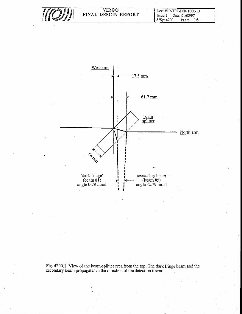
FINAL DESIGN REPORTDoc: VIR-TRE-DIR- I 000-l 3Issue: I Date: 0l/05/97S/Sy: 4200 Page: I 6
IIII
IIIIIIII
17.5 mm
,..ond* O.u*@eam#5)
angle -2.79 mrad
North arm
'dark fringe'(beam #1)
angle 0.79 mrad
IlIIIl
-)lIIl
IIIk_II!
Fig. 4200.1 View of the beam-splitter area from the top. The dark fringe beam and thesecondary beam propagates in the direction of the detection tower.
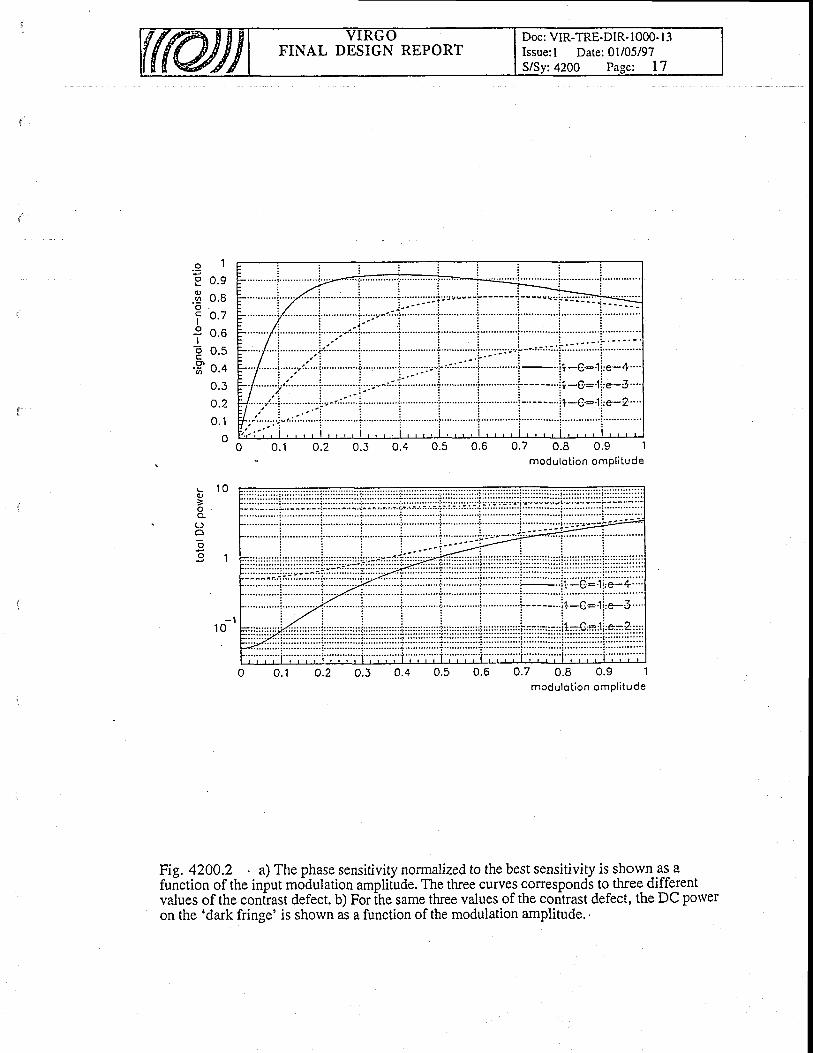
FINAL DESIGN REPORTDoc: VIR-TRE-DIR- 1000- I 3Issue:l Date:01i05/97
:4200 Pase: L7
.9 1o n o
.E o.aI o .7Io ^ ^
J tJ . O
t o.t'H 'o .e
n a
o.2
=
o
O l
u . l
oo.7 0.8 0.9 1
modulot ion ompl i tude
0.7 0.8 0.9 1modulot ion ompl i tude
- l1 0
u.z 0.50 . 1 0.6
Fig. 4200.2 . a) The phase sensitivity normalized to the best sensitivity is shorvn as- afuiction of the input mo'dulation ampli[ude. The three curves corresponds to three differentvalues of the conirast defect. b) For ih" same three values of the con'trast defect, the DC poweron the 'dark fringe' is shown as a function of the modulation amplitude. '
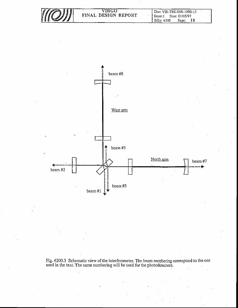
FINAL DESIGN REPORTDoc: VIR.TRE.DIR. I OOO. I3Issue: l Date:01/05/97S/Sy: 4200 Page: I 8
{ . . . . . . . . . . .beam #2
Fig. 4200.3 Schematic view of the interferometer. The beam numbering correspond to the oneused in the text. The same numbering rvill be used for the photodetectors.
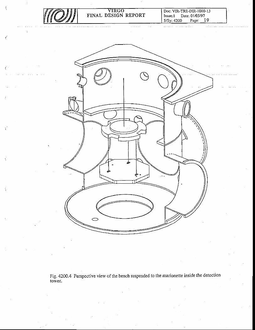
FINAL DESIGN REPORTDoc: VIR-TRE-DIR- 1000- l3Issue: l Date:01/05/97S/Sy: 4200 Page: I 9
Fig.420Q.4 Perspective vierv of the bench suspended to the marionette inside the detectiontower.
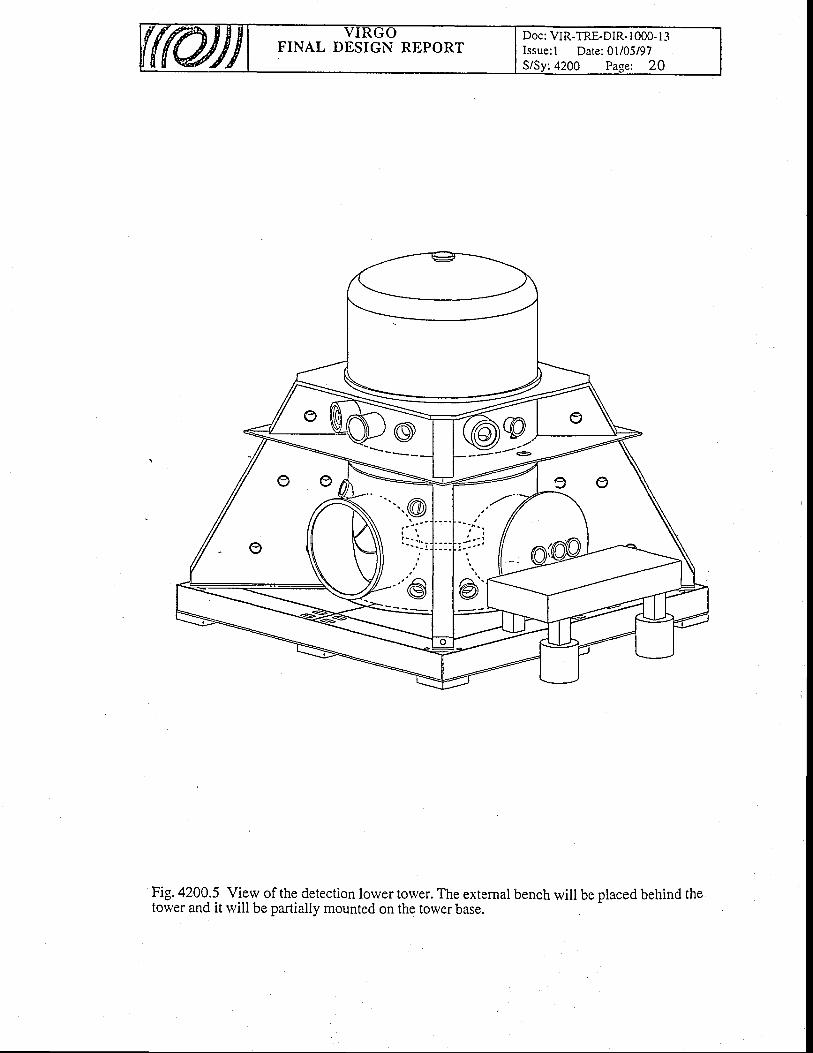
FINAL DESIGN REPORTDoc: VIR-TRE.DIR. IOOO. I 3Issue:1 Date: 0l/05/97
Fig. 4200.5 View of the detection lorver torver. The external bench will be placed behind thetorver and it will be partially mounted on the torver base.
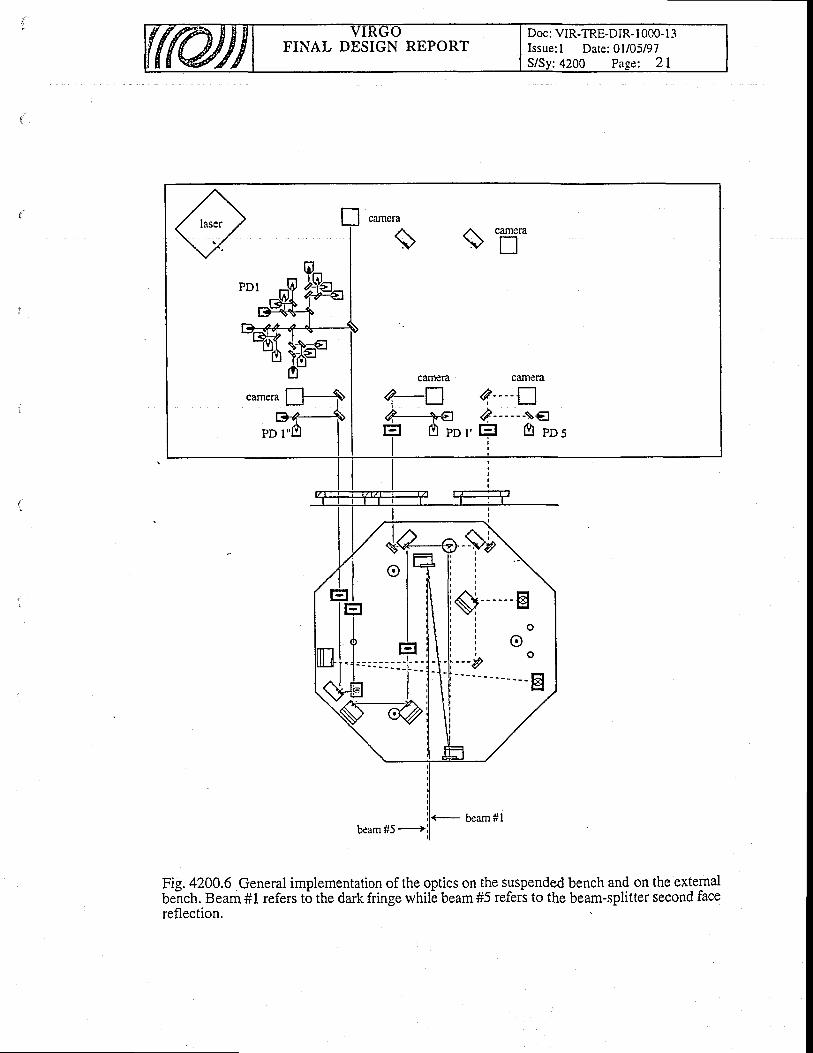
FINAL DESIGN REPORTDoc: VIR-TRE-DIR-1000-l 3Issue: l Date:01/05/97
: 4200 Pase: 2L
Fig. 4200.6 General implementation of the optics on the suspended bench and on the externalbe-nch. Beam #1 refers t6 the dark fringe rvhilb beam #5 refers to the beam-splitter second facereflection.
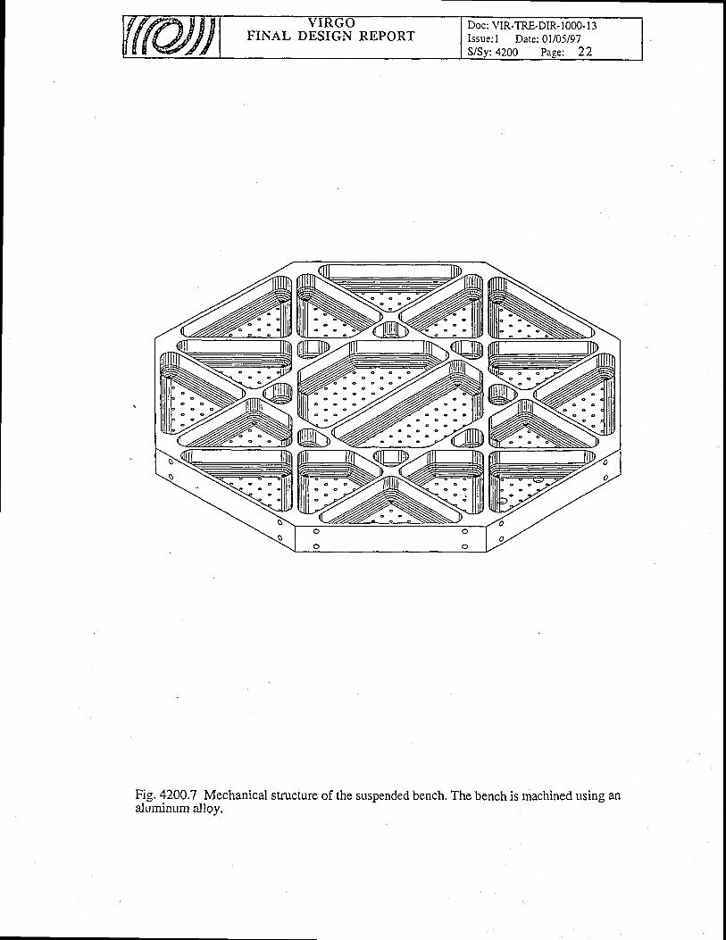
FINAL DESIGN REPORTDoc: VIR-TRE-DIR- 1000- I 3Issue: I Date:01105197
:4200 Pase: 22
NffiWK:-:--N-)
W
%ffi%=N
Fig. 4200.7 Mechanical structure of the suspended bench. The bench is machined using analuminum alloy.

FINAL DESIGN REPORTDoc: VIR-TRE-DIR-1000-13Issue: I Date: 0l/05/97S/Sv:4200 Page: 23
i
7 \ i -./ \ ! lr=11
14, \1. tl(},ll
\>--**---tEl
Fig. 4200.8 Optics implementation on the suspended bench. Some of the mirrors are mountedon remotely adjustable support.
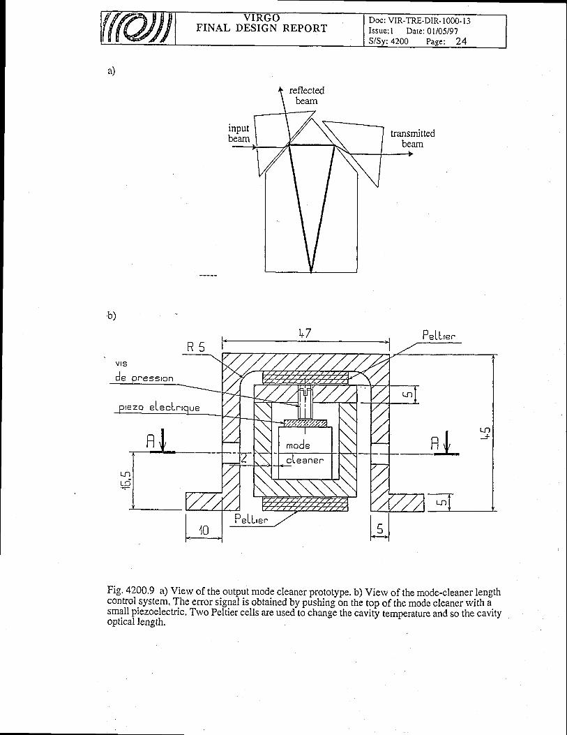
FINAL DESIGN REPORTDoc: VIR-TRE-DIR- I 000- I 3Issue; I Date: 0l/05/97S/Sy:4200 Page: 24
a)
'b)
PeLL'."
Fig' 4200.9 a) !!erv of the output mode cleaner prototype. b) View of the mode-cleaner lengthcontrol system. The error signal is obtained bv oushine on the toD of the morle cleaner rvith acontrol system. The errorcontrol.syste_m.The error_signal is obtained by pushing on the top of the mode cleaner rvith asmall piezoelectric. Two Peltier cells are usedt6 chang! the cavity temperature and so the cavoptical leneth.
temDerature and so the cavitv
P"LL'""
optical length.

FINAL DESIGN REPORTDoc: VIR-TRE-DIR- I 000- I 3Issue: I Date: 01/05/97S/Sv:4200 Page: 25
Fig. 4200.10 Test of the suspended bench: using a laser located on the extemal bench, twobeams are injected inside the tower through the tower lateral windorvs.
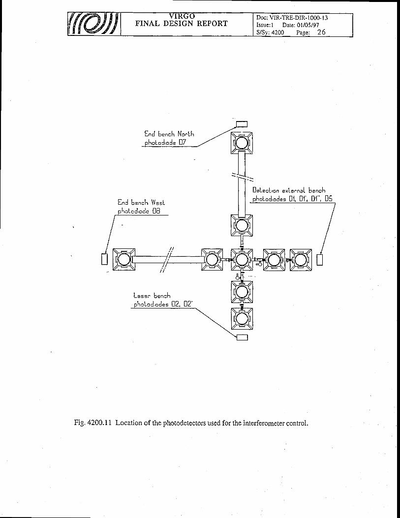
FINAL DESIGN REPORTDoc: VIR-TRE-DIR- 1000- I 3Issue: l Date:01/05/97
:4200 Page: 26
End bench NorLh
DeLecL'on e*Lernal b"n.hr D'1, D'l', D'1", D5End b"nch !V"rL
Lase. bench
Fig. 4200.11 Location of the photodetectors used for the interferometer control.
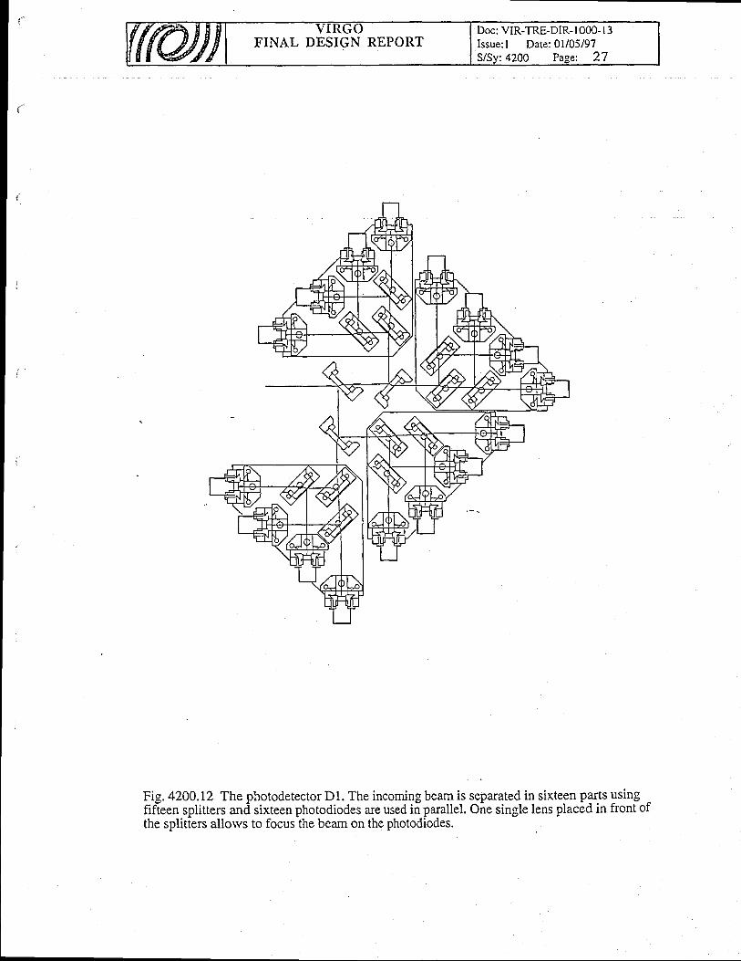
FINAL DESIGN REPORTDoc: VIR-TRE-DIR-1000- I 3Issue: l Date:01/05/97S/Sv:4200 Page: 27
Fig. 4200.12 The photodetector D1. The incoming beam is separated in sixteen parts using ̂fifleen splitters and sixteen photodiodes are used ii parallel. One single lens placed in front ofthe splitters allorvs to focus the beam on the photodiodes.
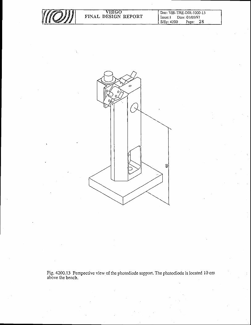
FINAL DESIGN REPORTDoc: VIR-TRE-DIR- I 000- l -1Issue:1 Date: 0l/05/97
:4200 Pase: 28
Fig.4200.13 Perspective view of the photodiode support. The photodiode is located 10 cmabove the bench.
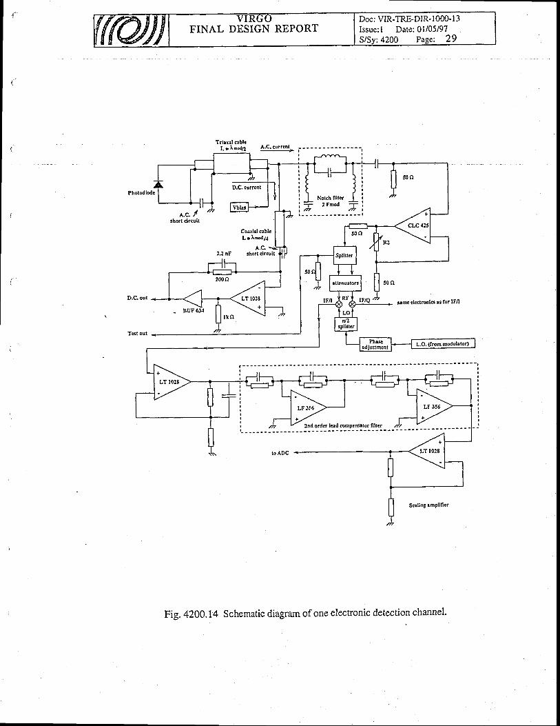
Doc: VIR-TRE-DIR- 1000- l3Issue: I Date:01/05/97
:4200 Pase: 29FINAL DESIGN REPORT
Trlrrll oblcL = lh"d/2 A.C. currrnf
tt.c. /short clrcuil
Coarlel crblc
L = Imoap
A.C.2.2 nF short clrcult
same electronls s for IFA
2nd order lead compeNator nltcr
S€ling rmPlifier
Fig. 4200.14 Schematic diagram of one electronic detection channel.
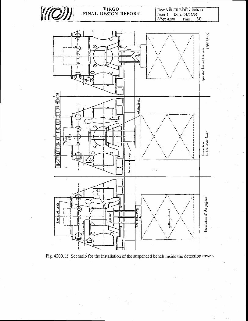
IFINAL DESIGN REPORT
Doc: VIR-TRE-DIR- 1000- l3Issue: I Date: 0l/05/97S/Sv:4200 Pase: 30
N
cctr
J Jco
o
otoo
o
oGo
L
ac t
-o
o
Fig. 4200.15 Scenario for the installation of the suspended bench inside the detection toiver.
t
43, I-arge Mirrors
Table of Contents
43. Large Mirrors
43.1 Ilt irrors requirements43.1. I Test interferometer43.1.2 The Virgo interferometer43.1.3 Present results
43.2 General Descr ipt ion43.2.1 Virgo optical components
43.2.1.1 Substrates43.2.1.2 Coatings
43.2.2 Deposition process43.2.2.1 D.I.B.S. deposition process43.2.2.2 D.I.B.S; process justif i cation
43.2.3 State of the art43.2,3.1 The scattering level43.2.3.2 Tfte absorption level' 43.2.3.3 Centering of minors and AR coatings43.2.3.4 The thickness uniformity
43.2.4 Coater : Technical description
. 43.2.5 Wavefront correction
43 .3 N le t ro logy43.3.1 Goals43.3.2 Blanks Metrology
43.3.2.1 Sil ica Absorption43.3.2.2 Bubbles and Local Defects43.3.2.3 B irefringence43.3.2.4 Wavefront control in transmission43.3,2.5 Surface polishing and scattering
43.3.3 Coated Optics Metrology43.3.3.1 Absorption43.3.3.2 Reflection coefficients homogeneity and equality43.3.3.3 Wavefront in reflection43.3.3.4 Roughness and local defects
)234
44
)66677776
89
1 0l0l010t0l ll ll lI tl l
I It ?i aI L
t 2
FINAL DESIGN REPORTDoc: VIR-TRE-DIR- 1000- I 3Issue: I Date: 0l/05/97
4300 Paee: I

43,L Mirrors requirements
43.1.1 Test interferometer
It has been decided to build a short interferometer in 1998 to test all the sub-svstems ofVirgo. The interferometer is a simple Michelson formed by the recycling minor Mo, the beamsplitter and the input minors Mr. Different solutions concerning the size and the shape of theoptical components have been studied; the chosen solution uses small substrates of 2 inchesdiameter (except for the beam splitter) instead of large substrates. Thus, the components can bemade in the present D.I.B.S. coater in Lyon.
The requirements of the test interferometer components are summarized in the table I belol.The substrate quality must be the same to the one we are using at the moment. The losses(absorption + scattering + wavefront losses) should be lower than 10 ppm.
The coating of the curved substrate (input minor) is in fact not a technical problem. Theproblem is the feasibility for the polisher to obtain a substrate with the desired curyarure R andrvith a good accuracy (the accuracy on the radius of curvature is t 2-3Vo).
Table 1 : Vi test interferometer ukementsComnonent Mo lv IF' ' M", B . S .
SUtsSTRATESMaterial SUPRASIL 312 SUPRASIL 312 S U Y K A S T L J I I S V
Diameter (mm) 5 0 5 0 230I'hickness (mm) 2 0 2 0 5 5
Dnape Dloe l FIat UoncaveR = 9 3 m
Flat
Dnape ulde / Flat Flat Flat
.. vYedge 0.3 +/- 0.075mrad
l+/- 0.075 mrad
Lncldent angle 00 0" 45"Losses (abs.= scat.) I ppm!uDstrate SurtaceDeformation compatible rvith coated surfaces requirements
COA'I ' INGSUoatlng diameter
( m m )40 4 0 5 0
Losses (abs. = scat.) I ppmCoat ing Side I
(S polarization)/\J(
R<10'3HR.
l0'5<T<10'*T = R = 0 . 5
+/- 0.005Coating Side 2
(S polarization)R - 0.985 AR
R<10'3Surlace Detormation
Side 1TBD TBD l./70 rms.
o n A = 7 c m *Uurtace l)etormation
Side 2TBD TBD
* assuming a roughness power larv z(f)".f ''?:rvhere z is the height [m] and f the spatialfrequency [m-r]
FINAL DESIGN REPORTDoc: VIR-TRE-DIR- I 000-l 3Issue: I Date: 0l/05/97
: 4300 Pag.e:2
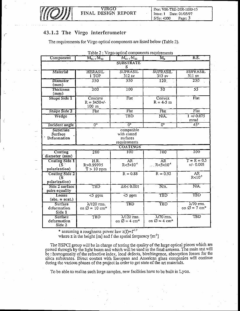
FINAL DESIGN REPORTDoc: VIR-TRE-DIR-1000-l 3Issue: I Date:01/05/97S/Sy:4300 Page:3
Table 2: Vi ntsComponent Ivlxl , Mx: lvlEl , lvlE! ftI* B.S.
SUtsS'IKA'I'.UJs
ivlaterial HERASILI TOP
SUPKASIL312 sv
sUPRASIL312 sv
SUYKASTL3 l l s v
Diameter(mm)
350 3 5 0 120 230
I hrcKness(mm)
200 100 3 0 5 5
Shape Side 1 uoncaveR = 3450+/-
100 m
Flat ConvexR = 4 - 5 m
Flat
Dnape Droe.z Flat FIat Flat Flat\Yeoge TBD NiA. 1 +/-0.075
mradlncident angle 0o 0o 00 / < o
SubstrateSurface
Deformation
compatiblervith coated
surfacesrequirements
COATINGSCoating
diameter (mm)280 1 0 0 I 0 0 200
uoating side I( s '
polarization)
H.R.R>0.99995T > 1 0 o o m
AKR<5x10'4
AR-. - R<5x10{
T = R = 0 . 5+/- 0.005
Coating Side Z( S
polarization)
R = 0.88 R = 0.92 ARR<l0'3
Droe z surtacepairs equalitv
TBD AR< U.UUI N/A.. N/A.
LOSSeS(abs. = scat.)
<5 PPm <5 ppm TBD TBD
SurIacedeformation
Side I
i"/120 rms.o n A = 1 0 c m *
TBD TBD L/70 rms.o n @ = 7 c m *
surtacedeformation
Side 2
TBD i"/I20 rms.o n A = 4 c m *
/,/70 rms.o n A = 4 c m *
TBD
43.1.2 The Virgo interferometer
The requirements for Virgo optical components are listed below (Table 2).
x assuming a roughness power law z(f)*f t
where z is the height [m] and f the spatial frequency [rn']
The ESPCI group will be in charge of testing the quality of the large optical pieces rvhich arepassed throughly the light beam an"d rvhich wiit Ue dsed i-n the final inte^nna. The main test rvillbe : homogeneityof theiefractive index, local defects, birefringence, absorption losses for thesilica subslrates. Direct contact with European and American glass companies will continueduring the various phases of the project in order to get state of the art materials.
To be able to realize such large samples, nerv facilities have to be built in Lyon.
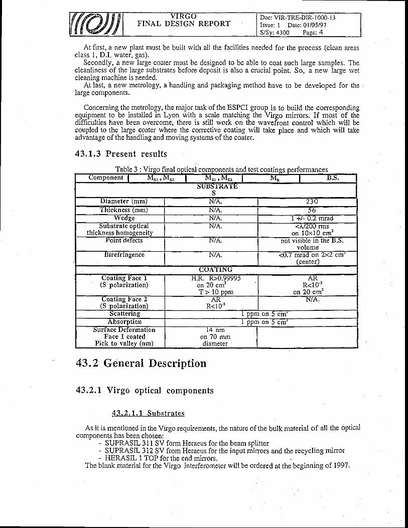
Y I . I \ \ JV
FINAL DESIGN REPORTDoc: VIR-TRE-DIR- 1000- l3Issue: I Date:01/05/97
:4300 Paee: 4
At first, a new plant must be built rvith all the facilities needed for the process (clean areasclass 1, D.I. watef, gas).
Secondly, a new large coater must be designed to be able to coat such large samples. Thecleanliness of the large substrates before deposit is also a crucial point. So, a new large rvetcleaning machine is needed.
At last, a new metrology, a handling and packaging method have to be developed for thelarge components.
Concerning the metrology, the major task of the ESPCI group is to build the correspondingequipment to be installed in Lyon with a scale matching the Virgo mirrors. If most of thedifficulties have been overcome, there is still work on the wavefront control rvhich will becoupled to the large coater where the corrective coating will take place and which will takeadvantage of the handling and moving systems of the coater.
43.L.3 Present results
able 3 : Vi inal ical com ts and test coatiuomponent I IvIxD Ntx! | MEr r NlE: | &l* IJ.S.
SUI'D Il(A'Its;S
Diameter (mm) N/A. 230I nrcKness (mmj N/A. 5 6
!Vedge t\/4. I +/- U.Z mraoSubstrate optical
thickness hoiirogeneitvN/4. <A/ZUU rrns
on 10x10 cm2Point def'ects N/4. not vlslDle !n tne
volumet'rrelrlngence N/A. <0.7 mrad on Zxz cm'
(center)COATING
Coating !'ace I(S polarization)
H.R. K>U.9999)on 20 cm2T > 1 0 o o m
At<R<I0'3
on 20 cm'�uoatlng .t iace z(S polarization)
At(R<10 '3
N/A.
Scattering I ppm on 5 cm'Absorption I ppm on 5 cm'
DUrIace .|JeIormatlonFace 1 coated
Pick to valley (nm)
14 nmon 70 mmdiameter
43.2 General Description
43.2.L Virgo optical components
43 .2 .1 .1 Subs t ra tes
As it is mentioned in the Virgo requirements, the nature of the bulk material of all the opticalcomponents has been chosen:
- SUPRASIL 311 SV form Heraeus for the beam splitter- SUPRASI-3I2 SV from Heraeus for the input mirrors and the recycling minor- HERASIL I TOP for the end mirrors
The blank material for the Virgo interferometer rvill be ordered at the beginning of 1997.

FINAL DESIGN REPORTDoc: VIR-TRE-DiR-l 000- I 3Issue: I Date:01105/97
: 4300 Pa-ee: 5
The beam splitter has already been purchased because it will be used in the 1998 testinterferometer. The polishing rvas made by Research Electro-Optics (R.E.O.). This silicasubstrate has been tested at ESPCI : the requirements on the birefringence, on the flatnessseem to be satisfied.
Except for the beam splitter, the choice of the polisher has not yet been done. A list of themanufacturers capable of doing micropolished substrates can be performed : the Frenchcompanies REOS^C, SFIM anO-SaCEM, R.E.O., PERKIN-ELMEH, ITEK OPTICAL fromthe Litton group, ZEISS. For this part, a call for tender rvill be done.
Because the polishing quality has a strong influence on the scattering level, we have fixedvery strict requirements on the poli-shed surfaces :' * nMS roughness : < 0'.4 A l measured with the "Micromap" system )
x Surface deformation : < 10 nm nns.
We have tested the polishing qualiry of 1 inch silica substrates coming from thefrench companies mentioned above.
Some ofthem are able to obtain on 1 inch diameter the requirements on the microroughness.But, unfortunately, there is still some big defects (scratches) rvhich are detrimental to thescattering level. These defects are totally absent on the REO substrates up to a diameter of 80mm.
Moreover, there is always an interrogation point conceming the polishing delay. We do notknorv at the present moment if it can be respected.
The ESPCI group is in charge of the large polished substrates control to see if thespecifications and tlie requirements are respected : homogeneiry of the refractive index,birefringence, absorption lbsses of the silica but also control of the microroughness and theflatness.
To avoid problems of manipulation by too many people, it rvill be easier and safer in thefuture to do these controls in Lyon, near the large coater and the cleaning station, because allthe infrastructure ( essentially the rvhite rooms ) will be in place.' If the polishing requirements are not satisfied, a nelv polishing will be asked.
' 4 3 . 2 . 1 . 2 C o a t i n g s
After having checked that the substrates have the good specifications, rve have to preparethem for the coatings.
* Because of their weight, new tools have to be developed to handle them the right rvay. Todo so, we rvill get informations from people who are used to manipulate large telescopecomponents (REOSC, MATRA, SESO).
x Concerning the cleaning, a prototype of a wet cleaning station is under test. A lot oftechnical probleirs have occriired^leadin! to a waste of time. Thus, we are still rvaiting -toperform sbme tests to validate the process. Nevertheless, we have leamed a lot and it will beeasy to avoid these problems for thd future large cleaning system rvhich is the only way to cleanbig substrates.-
The cleaning station needs ultra pure water which is heated during one part of theprocess. A special Iare should be talcen for a high porver Une of the ultra pure water heater;indeed, this equipment will need about 200 kW for a very short time.
* The optical losses (Absorption + Scattering + Wavefront losses) of each Virgo componentmust be lorver than 10 ppm..
The scattering will be measured on the real pieces (a nerv sample holder rvill be purchasedfor the CASI).
The absorption rvill be measured on small test samples which will be put.on several place.sof the coateriample holder. A reflection and transmission measurement wi[ also be performed.
* A large oven rvill be purchased to stabilize thermally the mirrors.
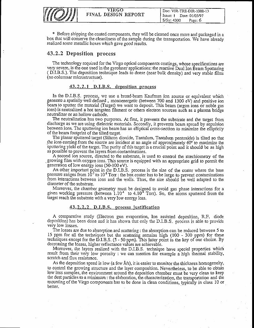
FINAL DESIGN REPORTDoc: VIR-TRE-DIR- 1000- 1.1Issue: I Date: 0I/05/97
:4300 Paee : 6
x Before shipping the coated components, they will be cleaned once more andbox that will conserve the cleanliness of the sample during the transportation. Werealized some metallic boxes rvhich gave good results.
43.2,2 Deposit ion process
packaged in ahave already
The technology required for the Virgo optical components coatings, whose specifications areY!rY_s3v_e1e, t thg one used in the gyrolaser applications: the reactive Dual Ion Beam Sputtering( D.I.B.S.). The.deposition technique leads to dense (near bulk density) and very stable films(no columnar microstructure).
43 .2 .2 . 1 D . I .B .S . depos i t i on p rocess
In the D.I.q.!. process, we use a broad-beam Kaufman ion source or equivalent rvhichgenerate a spatially rvell defined , monoenergetic (between 700 and 1300 eV) and positive ionP.aTJo sputter the material (Target) we want to deposit. This beam (argon ions or noble gasions) is neutralized a hot tungsten filament or others elec[on sources suih as a plasma bridgeneutralizer or an hollorv cathode.
The neurtralization has two purposes. At first, it prevents the substrate and the target fromdischarge as we are using dielectric materials. Secondly, it prevents beam spread by repulsionbetrveen ions. The sputtering ion beam has an elliptical cross-section to mininnize the eliipticiryof the beam footprint of the iilted target." Th" planar spr.rttered target (Silicon dioxide, Tantalum, Tantalum pentoxide) is tilted so that
the ions coming from the source are incident at an angle of approxiniately 60o to maximize thesputterlng yield of the target. The purity of this ta.rget is a cruclal point anil it should be as highas possible to prevent the layers from contaminations.
A second ion source, directed to the substrate, is used to control the stcechiometry of the. grorving film^rvith oxygen ions. This source is equipped rvith an appropriate grid to pdrmit ttregeneration of low energy ions (50-100 eV).
An other important pgint in -the D.LB.S. process is the size of the coater where the basepressure rarigeffrom 10-7 to l0-8 Torr : the bol coater has to be large to prevent contaminationsfrom interactions betrveen ions and the walls. Thus, the size should be well adapted to thediameter of the substrate.. Moreover, the chamber geometry mrrlt be desi-qned to avoid gas phase interactions for a
given working pressure ftdtween i.tO" to 4.10x Ton). So, th! atiomt sputtered from thetarget reach the substrate with a very lorv energy loss.
43 .2 .2 .2 D . I .B .S . p rocess j us t i f i ca t i on
. A ggmparative study (Electron gun evaporation, Ion assisted deposition, R.F. diodedeposition) has been done and it has shorvn that only the D.LB.S. proiess is able to providevery lorv losses.
The losses are due to absorption and scattering : the absorption can be reduced between 5 to15 -ppm for all the techniques but the scattering remains high (100 - 300 ppm) for thesetechniques except for the D.I.B.S. (5 - 50 ppm). This latter point is the key of-our choice. Bydecreasing the losses, higher reflectance values are achievable.
Moreover, the layers realized rvith the D.I.B.S. technique have special properties whichresult from their veiy low porosity : we can mention for exampl" a trigtr thennal stability,scratch and flrrx resistance.
As the deposition speed is low (a ferv A,/s), it is easier to monitor the thickness homogeneity,to control the grorving structure and the layer composition. Nevertheless, to be able to obtainlow loss samples, the environment around ihe deposition chamber must be very clean to keepthe dust part_ic,les !o a minimum : the elaboration, the characterization, the transp6rtation and themounting of the Virgo components has to be done in clean conditions, typicaily in class 10 orbetter.

Doc: VIR-TRE-DIR- 1000' I 3Issue: I Date: 0l/05/97S/Sv:4300 Page: 7
FINAL DESIGN REPORT
43.2.3 State of the art
Until now, rve have undertook a R&D study to improve all the performances of our.oaiingr. Moreover, the ESPCI g.roqp developi tools
-to allorv optimizing the coatings
fabrication in order to reach the required goals'- -io U. able to do that, some equipment; have been built or developed to characrerize ;
o the scattering and the transmission value (CASI scatterometer @ 1064 nm from TMA).
o With this system, mappings are . also -possible. To do accurate and sensitivemeasurements, a clean environment (class 1) has been required.
o The absorption (photothermal absorption measurement system @ 1064 nm)
r The cleanliness (particle counter); this point can also be evaluated rvith a scatteringmeasurement. ih; two methods are totaliy complementary and very sensitive.
43.2.3. 1 The scat ter ing- level
Over the entire surface of the sample, we have reached @ 1064 nm an average scatteringlevel close to I ppm on 80 mm diameier mirrors (0.6 +1.0.1 qpm). Thus, all the eventual poinl
defects are incldO'ed 6;;d;;nd, this is a very realistic val-ue.-This improvernent (about 20
times compared to the best available performance.5.years ago) is due to several tactors.-- ift. firri on" is tfre use oi nJ* *i.:ropolished sili6a substrates from REO (Research Electro-
Optics) rvhich have neither scratches nor digs (the RMS microroughness is lolu.": than 0.3 A)''The
second factor of improvement is linked to a new cleaning technique whic!. guarantees a
verv low particles *nt-ofinution ieuet. But, to preserve the cleaniiness, all the sample-iii*f^ri,i* murt U" Oone under class 10 or better 6nvironment : this is a crucial point.
43.2.3.2 The absorpt ion level
' The mirror absorotion level @1064 nm is norv Q.5 +l- 0.1 ppm on 80-mrn diameter' To
reach this low valuel *'i*pi"".rn.nrof tt. deposition procesihas been done to reduce the
laver contaminationl ;hi;ii-;";iioti G absorption level. To converge and find the best
r?ir"irJi,'rffi; S.i.M.S.lS""ono lon Vrasi Spiitrometry) drio g.o.s. (Energy Dispersive X-ray Spectrometry) analyses have been done routinely.
43.2.3.3 Center ing of mir rors and AR coat ings
A multidielectric minor only reflects the light 9! a lq4l-domain of rvavelength (rypically
200-250 nm wide) ,uith u high efficien.y. itt""*iddle of this band corresponds..to the centering
;;;J;;sih *i'i.tr ffiilb;"ib64nm il our case. The centerils.oi.tni,gorjllg_at the goodtuuuii.nlttt CfOO+ n*iit unorter important point we have studijd. It is dir-ectly related to the
absolute thickness oi'.u.i, ioyer. Ii.onttoit the optical performances of thi: coating and,
oarticularlv. the transmission loss of the minor.t*4;;'a;"ii-tii!*lttod ho, been devil,oped rvhich allows us to- guarantee now a difference
U.tru..n tt" "ip.ri'm.ntuf *O ttr" aesireOiJntering wavelength of less than 5 nm' Thus, the
transmission variation is quite negligible.-^-ih+;di"n, of ."ntenng ls more cntical for AR coatings, because the number of layers is
less and the useful bandrvidth is smaller.---Th;"d t" "Lw f"* "Ur"rptio" ."4 iCattering losses, high reflectance values can be achieved
(b99.995 Vo) and,for antireflective coating, rve can ufto nuut gi-oi'opit.l tin.iency (R<103)
if we monitor precisely each monolayer.
FINAL DESIGN REPORTDoc: VIR-TRE-DIR-l 000- I 3Issue: I Date: 0l/05/97
43 .2 .3 .4 The th i ckness un i fo rm i t y
The coating homogeneity is critical for the wavefront preservation in the interferometer. Thispoint is evaluated rvith a ZYGO Mark IV xp (1" = 633 nm) rvhich is now in Lyon. This sysremhas been tested prelimi. narily at ES_PCI. It has been demonstrated that the reproducibility of themeasurement is 4 nm if gre_at care is taken in the positioning of the optical pi6ce.
A simulation program has been developed to optimize the thi-cknes-s distribution of thecoatings by changing the sample holder and the target angles. Moreover, a new sample holder,rvhich has a planetary motion, has been built. This leads to an homogeneity on monolayers of8.10'3 on 2 inches. On B0 mm diameter minors, a uniformity of 1/40 (1, = 633 nm) peak tovalley on 25 mm and l/10 peak to valley on 70 mm has been reached (note : this value has notbeen obtained with the best angle conditions).
Moreover, rvith the ZYGO Mark IV, rve have evaluated the mechanical stress of ourcoatings which has an important role on the. wavefront shape.
43,2,4 Coater : Technical description
In order to minimize the asymmetry betrveen the arms of Virgo, the large coater must be ableto coat two 350 mm diameter silica substrates at the same time. The two components must havethe same optical properties which satisfy the Virgo requirements.
We have defined the needs and the technical specifications concerning the ttvofollowing parts :, - Sample holder, target holder
- Vacuum chamberAfter a first call for companies able to do the rvork (September 1996), a first choice has been
made. Then the definitive call for tender will be done for these two parts. We will follorv up the. realization of each part.
In the following paragraphs, we make a technical description of the main parts whichcompose the large coater.
a) The shape of the coater has not yet been frozen : it can be a cylinder or aparallelepiped (2.5 - 3 m).The first solution is the best to reduce the weight of the system : itcan be decreased by a factor of 30 Vo. Nevertheless, rve are used to work with parallelepipediccoaters and we have a great skill on this kind of systems. Moreover, it is easier io install all thecoater parts in such a vacuum chamber.
b) Presently, we are using an ion source rvith hot filaments. It cannot be the same in thefuturecoaterbecauseof the short filament lifetime ( = 30 hours ). Indeed, in the large coater,the process rvill last at least one hundred hours.
The solution of this problem is to use a Radio-Frequency (RF) ion source. But our maininterrogation is to know if this source is able to work hundreds of hours without any drop out.Thanks to R.E.O. informations, we know that, on the one hand, the Oxford source does notrvork well9rying a long time and that, on the other hand, REO people Ne very satisfied withthe IonTech RF ion source.
Moreover, people from Ion Tech told us that they solved that by putting a thjrd grid on theirsource to protect the trvo active grids.
There is another alternative to the RF source : this is the Hollow Cathode. It has beendemonstrated ( R.E.O. ) that the couple Hollorv Cathode (to sputter) and the Plasma Bridge-Neu,trallzer (qo neutralize the beam) ii rvorking well during very long runs. The drarvback ofthe Hollorv Cathode is that the spare parts are very expensive and ttrat they must be changedvery often.
Then. it seems reasonable to choose the IonTech RF ion source.
FINAL DESIGN REPORTDoc: VIR-TRE-DIR- 1000-l 3Issue: I Date: 0l/05/97S/Sv:4300 Paee: 9
The sources size rvill be quite Small (about 20 cm) because larger souices (40-50 cm) are notenough reliable and also because they are only used for etching. These sources will be watercooled.
We are developing a new coating simulation program to determine the number of ionsources in the large coater. A real coating in the future large coater can be simulated; thus, if thedeposition rate rvith one source is too small, trvo sources will be eventually used in parallel toobtain process time rvhich are acceptable.
c) Concerning the targets, their size should be the double of the source size (about 40 cm).In our small coater, high purity targets are used (99.99 Vo). It should be the samequality for the larger ones. We have to check if the target manufacturer can provide highpurity materials, whatever the size we rvill choose, to minimize the layerscontamination.
d) The prim4ry vacuum (up to 10'2 Ton) will be achieved in 30 minutes with trvo oil free' grodps (robts + dry i,i*p); the base pressure (about 10t Ton) will be obtained in 4houri rvith two cryopumps. These calculations have been done for a 2.5 meters cubicchamber.The chamber walls are electropolished; the coater will also have double walls to makethe cleaning of the system easier. At last, to suppress water vapor in the chamber, a
PolycoldrNr rvill be used in vacuum.e) To control the process in-situ, rve will only use a quartz balance which is a very reliable
system. In our present chamber, we are using only one quartz. Probably, in the futurecoater, several quartz, put at different places of the coater, will be used to increase theaccuracy of the control.
. 0 A generai control command system, which controls in real time the entire depositionprocess, rvill be pr,rrchased. This kind of system is already manufactured by somecompanies and it is rvorking rvell.
. g) On one door of the coater will be placed the robot rvhich rvill suppo-rt the silica- substrates. It will have an "intelligent" iobotic motion. The final scheme of this sy-s!-qmrvill depend on the result that we will get with the small robot and also on the capabilifywe will have to transpose the technology used for the.small robot to the large one.
The procedure that will be used to achieve to the wavefront specifications is this one :* Tlie multilayer coating will be realized and rvill be stopped at the right moment before the
end ((HB)n H 0.78).* Then, the sample will be annealed before making the wavefront metrology (indeed, the
major part of the layer stress rvill be relaxed).1 Then a small torrection will be done to planarize the surface by adding a very thin SiO,
layenAt this moment of the deposit, it will not be necessary
compensate the absorption inciease due to the corrective layer.
43,2,5 Wavefront correct ion
to anneal again the samPle to
The wavefront preservation is a priority at the moment because the Virgo requirements onthe maximum wau^efront deformation are not yet satisfied. A simple planEtary inotion is notenough.
Tliat is why a small robot has been built. To pilot this system, a softrvare. has beendeveloped to illoru any movement of the substrate. Moreovei, the maximum size of thesubstrates that can be coated is 100 mm diameter.
An other advantage of this system is that the distance betrveen the substrate and the ta.rget isgreater. This is a more favorable case to homogenize the layer thickness.-
Nevertheless, this system alone is not sufficient to reach VIRGO requirements. The useof masks betrveen the substrate and the target is a solution : it gives good hornogeneity results

FINAL DESIGN REPORTDoc: VIR-TRE-DIR- I 000- l3Issue: I Date: 0l/05/97S/Sy: +l0O Paee: I 0
on monolaye{s (f9.r example, homogeneity of 6.10'3 on 80 mm diameter for SiO, monolayers).But to reach the Virgo requirements, a planarization method must be used.
The principle of this method, called"'Corrective Coating Treatment', is to add a smallamount of SiO, (maximal thickness 900 A) ttgo.ugfr a hole (square, circle) on the last SiO, layerof the multilayer stack. This treatment is possible thanks to our small robot.
The addition of silica produces a ptrasd retardation . We follorv the phase variation ivith theZygo interferometer to find a wavefront shape a-s plane as possible.-The conection is fullyautomated thanks to a software we have develooed.
The first results obtained. are hopeful : on a 80 mm diameter mirror, the rvavefront goes from40 nm to 14 nm peak to valley.
To validate this method,'we checked that the absorption and the scattering losses are notlocally deteriorated by the deposition of a small amount of SiO, on rhe last layer. It has to beemphasized that the conection must come after the thermal treatment of the sample : indeed, itstabilizes the optical performances and relaxes the constraints which modify the rvavefront.
The addition of silica also modifies the residual transmission of the minbr. The transmissionincrease can be.compensated by increasing the number of doublets of the multilayer stack.
The same principle will be used for the large mirrors in the future large coater"
43,3 Metrology
43.3.1 Goals'
The aim of Virgo metrology is:.
x To help to improve the fabrication process during the R and D period of the project (forlnstance to reduce scattering and absorption losses, residual stresses in the coating, etc...) ;I To settle a set of -mostly new- set ups for measuring with the required
-high level of
accuracy the)99cy the performances of the mirrors (See table 1 and 2: substrates and -coated
optics) ;* To establish a simulation code able to provide the signal to noise degradation level withthe signal to noise degradation levelreference to shot noise by taking into accounl the actual minors characterisiics.
43.3.2 Blanks Metrology
43 .3 .2 .1 S i l i ca Abso rp t i on
In order to avoid thermally induced rvavefront distortions in Silica the absorption level mustbe maintained to a level of the order of 10-6 cm-t. A quasi collinear Mirage bench (photothennaldeflection) have been constmcted and coupled to a powerful (30 S{) cw Nd-YAG Laser.
The noise of this set-up corresponds to a absorption level of 10i'cm'r and reach the requiredVirgo goals.
Herasil 31lSV and 3t2SV ( Special Virgo) were found to be in the range lppm/cm, themain factor of absorption in silica is due to OH content which has been reduced to aconcentration level lorver than 50 ppm by atmosphere controlled preparation and probably byfurther annealing.
43 .3 .2 .2 Bubb les and Loca l De fec ts
. {ft9r polishing there is_ a need to explore the full volume of the optics which will be crossedby the laser beam in the Virgo interferometer.
The scanning system uses two non parallel split laser beams, balanced in power, rvhichcross the optical pieg_es and are alternatively set on and off. The scanered light associated withone beam at a sfecific point is recorded rvith a photomultiplier and conelaied with the signalconesponding to the second beam.

FINAL DESIGN REPORTDoc: VIR-TRE-DIR- I 000- I 3Issue: I Date: 0l/05/97S/Sv:4300 Paee: I 1
toct-in detection provides a clear "signatuie" of such conelated signals ivith eihibits equalamplitude and opposite sign. The spatial shift betrveen these signals provides the information ofthe scatterer position in depth. The magnitude of the signal provides the order of magnirude ofthe scatterer cross section.
43 .3 . 2 . 3 B i re f r i ngence
The birefringence of the optical pieces crossed by the beam is responsible of losses rvhichaffects the sensitivity of the antenna rvhen its level is larger that l0'* rd/cm.
It is worth underlining that the companies which provides silica can only guarantee abirefringende "lower than 10'r rd/cm" becauSO they do not have inStruments SensitiVe enough tocharacterize it at a lower level.
The bench we have built uses the same scanning system of the minor (horizontal) and of themeasuring bench (vertical) which is used for local defects and wavefront distortion. Theprinciple of the measurement is to add to the static birefringence which has to be measured, abontrolled periodic birefringence induced by a photoelastic modulator. Between crosspolarizersDC and AC signals (lock-in detected) allorv a precise measurement of the phase shift benveenthe two orthogonal polarisations associated to the polarizer and analyzer.
lVe perform two measurements by rotating (45') the bench in order to get a map of thebirefringence value and of the directions of the principal axes. The sensitiviry is better than 10''rd./cm.
43.3.2.4 lVavefront contro l in t ransmiss ion
' The opd;al pieces which must be controlled in transmission (beam sp-litter and inputminors) being paral-lel plates, their translation do not introduce any rotation of a probe beamcrossing them. So the piobe beam deflection can only be due to the gradient of the optical pathdistribution.' Usually in order to reconstruct the wavefront one has to integrate the measurementalong e.g. a diimeter. This integration introduces cumulative errors rvhich reduce the accuracyof the measurement.
Because such measurement carries more informatibn than required for a simpleintegration, it is possible to use an iterative algorithm (close to the ond used in the Shack-Hartman and adaptive optic control interferometers) which does not propagate the errors.
The accuracy over 100 cm2 is U65 pv rvhich is enough for the optical pieces mentionedabove.
43.3.2.5 Sur face pol ish ing and scat ter ing
The scattering rvill be controlled either by a direct measurement of the scattered light angulardistribution or b--y direct measurement of the roughness the coresponding instruments rvill bedescribed in the next part (coated optics).
43.3.3 Coated Optics Metrology
43 .3 .3 . 1 Abso rp t i on
Since the beginning of the R & D of Virgo, ferv "mirage benches" have been used to controlthe absorption lEvel oFvarious coatings mad'e either by the best companies in the field or by theVirgo group in Lyon (SMA). For ciated silica the sLnsitivity rvith one watt of P9.Yer on &ecoited'surfice is of th! order of aferv (rypically 5 to 8) tO'e 1a few parts perbiilion of theincident power left in the coating) which is-enough not only for measuring the required losses(l ppm) but also to check the homogeneity of such absorption losses.
FINAL DESIGN REPORTDoc: VIR-TRE-DIR- 1000- I 3Issue: I Date:01/05/97
:4300 Pase: 12
43.3.3.2 Ref lect ion coef f ic ients homogenei ty anc l equal i ty
As mentioned before in.the description of the interferometer, the symmetry of the trvoarms is an important goal for Virgo.
Moreover rvorking. at .th9 dar\ fringe imposes a good homogeneity of the reflectioncoefficients of the minors (mainly the input minois). The r-equired senlitivity is of the order ofl0'4, which excludes any kind of ilirect photoelectric meosurdm"nt.
For this reason, rve have built a differential measurement bench in rvhich a beam strikesaltematively the surface under examination and a reference surface rvhose reflection coefficientsare close. The differential signal re.flects the-difference between the two coefficients (typicallyless than IVo) and a measurement in the 10'2 range is enough to reach the required siiiitiuity(rve have reached 5 10 5 with a small scale set-up during the F. & D period).
I
43.3.3.3 lYavefront in re f lect ion
During the R & D period two systems.rvere used :I A commercial Fizeau interferometer @0-633 pm has been extensively used to improve
the.fabric.ation process (mai.nly in term of residual stresses which distort the surface) a'nd tovalidate the "corrective coating" approach for the Virgo minors.
^ . A slope based system working by scanning the minor surface and using a reference beamfor.compensation of the tilt of the scanning system gave the required sensitivity for the smalloptics of the test interferometer (less than 10 nm oveil0 cm).
For the large mirrors of Virgo trvo solutions are currently explored in parallel in order toavoid any risk in such a crucial measurement :-Commercial.Fizeau (or equivalent system) @1.06 pm exists and can handle(rvithout expanders) 15 cm diameters optics. With suih systems and a careful calibration of thereference surface (using e.g. multiple 3-flats methods) we can achieve the required l/100 pv
- sensitivity. Such slstem, providing a fast control will be used for finalizing the corrective'coating procedure @1.06 pm.- A slope based system which is an improved version of the one describe above,
rvill be used with a new improved algorithm which- does -not propagate the errors. I-et usunderline that for a system working in reflection only onb siop6 Eirection can be madeindependent of the scanning system ana the Shack-Hartinan algorilhms are no longer able toprovide the proper results.
43.3.3.4 Roughness and local defects
. Thg qu.ality of the coating has been improved so much during the R&D period that structuraltmpertections-are now at undetectable levels, so the scattering is norv only due to local defectswhich can be induced dlring the polishing period or during the coating deposition period.
For this reason VIRGO needs a tool rvhich allorvs a complete mappingbf the substrates andcoated optics with a ferv picometers in sensitivity.
Such instruments start to be commercially available and rvill be used in VIRGO in 1997.
44. A l ignment
Table of Contents
44. Al ignment
44.1 Al ignment funct ions and concept
44.2 Requirements appl icable to a l ignment
44.3 Al ignment in ter faces44.3.1 List of alignment interfaces44.3.2 Interface with sub-system 330044.3.3 Interface with sub-system 410044.3.4 Interface rvith sub-system 420044.3.5 Interface rvith sub-system 430044.3.6 Interface with sub-system 510044.3.7 interface rvith sub-system 5400
44.4 Non l inear a l ignment44.4.1 Non linear Alignment function and concept44.4.2 Non liSrear Alignment detailed description
' 44.4.3 Procedure
44.5 L inear Al ignment44.5.1 Linear Alignment function and concept
' 44.5.2 Linear Alignment detailed description4 4.5.2.1 Geometrical Considerations44.5.2.2 Sensitivity Requirements44.5.2.3 The Fabry-Perot Alignment '- -
44.5.2.4 Alignment of the Full Interferometer with the Anderson Method44.5.2.5 Achievable Accuracies44.5.2.6 Conclusions
44.6 Posi t ion memor ies.44.6.1 Position memories function and concept.44.6.2 Position memory detailed description
I
2
t
7
?
22
J
5
J
?
JA
6
8888
l0l lt215t 7
1 8l 8l8
Doc: VIR-TRE-DIR-1000- I 3Issue: l Date:01/05/97S/Sy:4400 Page: I
FINAL DESIGI{ REPORT

FINAL DESIGN REPORTDoc: VIR-TRE-DiR-l 000- l3Issue: l Date:01/05/97S/Sy:4400 Page: 2
alignment errors of each mirror down at the nanoradian level.The system of position memories, based on the use of small auxiliaries lasers and
calneras, rvill continuously monitor tle position of the mirrors in six degrees of freedoman accuracy-sufficient tg.bring back the interferometer, if for any reason the locking is lost,state where longitudinal locking and linear alignment can be started again.
44,2 Requirements applicable to alignmentRequirements for the Non linear alignment and related position memory
system:
44.1 Alignment functions and conceptThe non-linear alignment, starting from a mechanical
millimeter), has to bring the interferometer mirrors in a coarseferv microradians), sufficient to start the longitudinal locking.
After this is achieved, the linear alignment can start and
The requirements concerning the position of the opticalthe non linear alignment phase are the follorving: 0*,y,r=2z= 1 10-6 m.
Requirements for Linear Alignment :The system shall be able to detect misalignments of any
.rad/!Hz.
pre-aligned state (order of aaligned state (at the level of a
should be able to reduce the
elements of the interferometer after10-7rad, x andy = 1 10-4m and
Virgo minor of the order of 10-lo
bench, rve will look at theset in vacuum on the inPut
CCDrvith
, i n a
44.3 Alignment interfaces
44.3.L List of aiignment interfaces
_ -fh. alignment sub-system will have physical interfaces and/or interactions rvith thefollorving sub-systems :
1- Towers (3300)2- Laser & input bench (4100)3- Detection bench (4200)4- Minors (4300)5- Global control (5100)6- Data acquisition (5400)
44"3.2 Interface \yith sub-system 3300
The towers rvill be equipped rvith the specific optical benches of the position memories. Theinstallation rvill be perfornie,J in Cascina just afterihe tower delivery on site. For the non linearallgnment proce.dure_one auxiliary window for each end torver is re{uested to monitor thedirection of the interferometer beam transmitted by the end mirrors.
44,3.3 Interface \yi th sub-system 4L00
_Follorving the proposed non linear alignment procedure of thereflected light from the recycling mirror onto a diaphragm screenbench.

FINAL DESIGN REPORTDoc: VIR-TRE-DIR- 1000- I 3Issue: I Date: 0l/05/97S/Sy:4400 Pager 3
The set-up foreseen for the linear alignment requires the use of a pair of quadrantphotodiodes on the beam reflected by the recycling mirror. These photodiodes, together withihe associated telescopes, rvill be placed on the laser bench, on the beam from theinterferometer transmitted by one of the minors constituting the input telescope.
44.3.4 Interface lyith sub-system 4200
A pair of quadrant photodiodes rvill be placed on the bench located in air after the detectionbencli on the beam reflected by the second surface of the beam-splitter.
44.3,5 Interface \vith sub-system 4300
The minors rvill be equipped rvith four spots on the border out of the coated surface. Thesespots rvill be used for the position memories.
44.3.6 Interface tyith sub-system 5100
The global control rvill receive the digitised data of the quadrant photodiodes through thedata acq-uisition, and has to reconstruct from them the misalignments of the minors. The linearalignment groLlp rvill provide all the informations required to perform this reconstruction.
44,3.7 Interface tvith sub-system 5400
Each of the 8- quadrant photodiodes (4 pairs ) used for linear alignment, will produce 8butput signals to be read by ADCs :
- one per each quadrant directly,- vertical and horizontal differences, demodulated in-phase and in-quadrature.For all these signals, a reasonable sampling rate can be = 100 Hz.' The data acquiiition group will be responsible for the acquisition of these signals.
44.4 Non linear alignment
44.4.L Non linear Alignment function and concept
The pre alignment (initial alignment or non-linear alignment) is the procedure through y*itthe Virfo intefrerometer is set ii the range of operation-of ttre control- feedback ( line.ar). ThenonlinEar alignment is likely to be a ciucial irocedure which must be carefully designed todrive the interferometer set-rip to the operating point. Then the occulrence of the. pre alignmentprocedure in the sequence of-passes oi'the Virgo setting-up is just in the middle betrveen the
leometric positioning and th^e automatic operition. Othei it-ems are closely related to thedesign of the pre alignment of the interferometer as follows:
--aspect rdtio, siie and design of minors (lr{; i=0,...,4) and reference masses (RIvt;i=0r , . . ,4)
- control system of the marionette- position monitoring and memory- UHV compatibility.The proposed procedure has to match all the requirements related to the above mement'ion-ed items. The goal of the non-linear alignment is to bring the Interferometer to a
level good enough to allo# the linear alignment to ltart. This means ihat the angular errors of
the mirrors have to be smaller than the angular divergence of the beam 0=17 prad.
IThis requires vacuum windorv having the same diameter as the ion of the back side of theI rrls rcqullcs vasuum wlnoow navlng tne salne olameter as tne portlon Ot the bacl( slde of thefar mirror that can be seen through its reference mass (minilmurn diameter 20 cm). It is
- 4 blue lamps.- 7 CCD cameras.Trvo screens should be placed after the far mirrors of each FP, outside the vacuum. A
camera will look at the spo-t on this screen due to the beam transmitted by the FP end mirrorwith respect to suitable reference markers. This requires that the far min6r of each FP has tohave some finite transmittivity-(for example l0'4) constant over the mirror useful apenure.
44.4.2 Non l inear Al ignment detai led descript ion
The following hardware rvill be required in order to perform the pre alignment procedure- 2 screens outside the vacuum.
I screen/diaphragm on the injection bench.4 sets of scattering spots on the FP mirrors.
important to design a rigid stand for the these screens, steady rvith respect to the vacuumchambers (and then to the towers).
A sqreen (with a carnera to-look at it) on the injection bench rvith an aperture for the beam.This will detect the position of the beam reflected 6y the interferometer and' will also protect theinjection bench- from the reflected beam when thi: misalignment is large. The design of thescreen and the definition of the material is still matter of discussion. The-screen surfaie will bemachined in such a way to form a net which rvill be used to localise the spot from the data ofthe camera imageg. It has been proposed also to spray the surface of the screen rvith a materialthat re-emits the Nd-Yag laser light.
The four spot detection scheme developed at LAPP and tested by H. Heitmann is suitable toimplemented.in the pre alignment hardrvare equipment. A sooa contrast must be reachedbe.implemented.in the pre alignment hardrvare equipment. e gooa contrast must be reached
using lamps equipped rvith infrared filters that nermit to detect the nosirion of the snots rrsinqDe-tmplemented..ln tne pre allgnment hardrvare equipment. A good contrast must be reachedusing lamps equipped rvith infrared filters that permit to detect the position of the spots usingthe cameras.
- Cpto mounted on the recycling mirror tower, pointing at the rear face of the referencemass of M0;
- Cut mounted on the nearqnd.monitoring M,;
- Cu: mounted on ihe near
mirror torver along FPI (see figure), equipped rvith a lens
min"or torver along FP2 (see figure), equipped with a lens
figure), equipped with a lens and
and monitoring Mr;e;;;;;il'il';il far mirror tower along Fpl (see figure),equipped rvith a lens andmonitoring Mr;
- Cu+ mounted on the far mirror tower along FP2 (seemonitoring M4;C56 mounted on the injection bench tower, pointing at the diaphragm screen So;Cg 1 pointing at the screen outside the torver of FP I's far minor;Cg2 pointing at the screen outside the tower of FP2's far minor.It has been said that the angular divergence of the beam is 0* = 17 ;-rrad.
Then, the CCDprecision:
- cMo, cso =- cMl, CM2,
cameras have to monitor the spots of scattered light with the following
l m mC U : , C U + = 1 c m
FINAL DESIGN REPORTDoc: VIR-TRE-DIR- 1000- l 3Issue: l Date:01/05/97S/Sy:4400 Page: 4
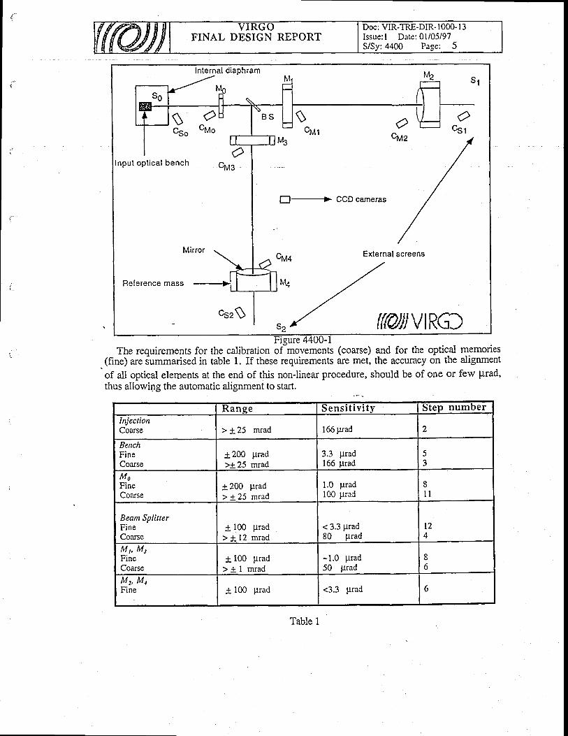
FINAL DESIGN REPORTDoc: VIR-TRE-DIR- 1000- I 3Issue: l Date:0 i /05/97S/Sy:4400 Page: 5
Internal diaphram
Input opt ica l bench
Reference mass
$cut
El--> GCD cameras
$ 9CSo vMo O
cuza
csr
Ocug
Ctr,,'t+ External screens
t l
{w}}vtRG)Figure 4400-1
The requirements for the calibration ofmovements (coarse) and for the optic-al memories(fine) are s-ummarised in table 1. If these requirements arc met, the accuracy on the alignment
of all optical elements at the end of this non-linear procedure, should be of one or ferv prad,thus allowing the automatic alignment to start.
I (anse S e n s i t i v i t y Step numberInjectionCoarse > t 25 mrad 166 prad 2
BenchFineCoarse
4200 prad>1 25 mrad
3.3 prad166 prad
MoFineCoarse
1 200> + 2 5
pradmrad
1.0 prad100 prad
8l l
Beam SplitterFineCoarse
t 100 ltrad> i 12 mrad
< 3.3 Prad80 prad
t2A
lvI h MrFineCoarse
+ 100 prad> + l m r a d
-1.0 Prad50 prad
8o
Mn MnFine + 100 prad <3.3 prad 6
Table 1
FINAL DESIGN REPORTDoc: VIR-TRE-DIR- 1000- I -jIssue:l Date: 0l/05/97S/Sy;4400 Page: 6
44.4.3 Procedure
_ Th.e frrst operation is the alignment of the injection bench. To do this it is important to centrefirst the beam onto the porver recycling mirror Mo. This mirror is supposed to be surroundedby a reference mass RMo which has the same shape and size as the FPs' RMs. Suitablemarkers applied on the side of RMo facing the injection bench (rear) must diffuse 2"=1.06 pmlight or detect by screen remission in order to detect the injected beam rvhen the bench is rotatedabout 0* 0, axes.
. STEP 1: Scan with_the input bench centring the beam onto Mo referring the beam spotto suitable markers on RMo.
+ INPUT BEAM CENTRED ON MoIn order to perform the alignment of the bench the reflected light from Mo can be detected;o the diaphragm screen So and to discriminate among the spotirvhich are ilisplayed there itonto the fiaphrqgm screen So and to discriminate among the spots which are
is crucial to misalien the FPs' mirrors avoidins sourious reflections fromis crucial to misalign the FPs' avoiding spurious reflections from the ofher opticalelements of the interferometer.-, Taking into accounts the distance between Mo and each near mirror NM (M,,M2) and the fulldiameter (coated + uncoated) of Mo we get the- following request about the'needed angle ofmisalignment:
OmisNM>5 10-3radthis angle must be compared rvith the largest mechanical rotation allorved by the coil-magnet
configuration on the marionette and rvith the room available between the marionette itself andthe roof that separates the UHV from the HV spaces. We have:
0 max. = 2 10'2 radAccording to the specifications of the electromagnetic actuators which act on the arms at the
top of the marionette, in order to avoid the thermal noise due to the current driven into the coils,'few t um coils have been designed (coils with a number of turns N=400, a mean radius of thecoil r =80 mm and made with a cooper rvire of a diameter of 1 mm).
Then, considering the momentum of inertia of the marionefte (for the torsional mode), anunreasonably high current should be applied to the coils (- 20 A). There are trvo solutions toovercome this problem:
_ a) use of the motorised rotation stage which acts on clamping point of the marionette's cableof suspension.
b) use-of another couple (at least one per marionefte arm) magnet-coil actuators exerting astro_ngqr force. According to the design ofthe UHV roof hypothesis b) seems more feasible.
Similarly we can deduce the misalignment required for the far mirror FM (Mz,Mr), getting0rirFM > 20 prad. In this case the constraint is not crucial first because the FPs of theinterferometers elements at this stage are supposed to be rather far from the aligned position,second being the required misalignment (20 prad) anainable rvithin the dynamics of thedesigned magnet-coil actuators.
. STEP 2 Misalign near and far mirrors.The first element which reaches a rough alignment is M0. This can be done by
monitoring with camera C56 C1 the spot on screen So, due to the beam reflected by Mo, whichmust be driven into the diaphragm. The angular scan of Mo is obtained by moving Mo'smarionette.
. STEP 3 Scan Mo looking with Cso at the spot on Ss, find the right position, leave itmisaligned.
=+ RIGHT POSiTION OF Mo STORED

FINAL DESIGN REPORTDoc: VIR-TRE-DIR- 1000- I 3Issue: l Date:01/05/97S/Sy:4400 Page: 7
At this point a rough aiignment of M, is reached follorving the spot of the reflected beamonto S0. Since Ml haibeen-previously sirongly misaligned, Its posiiion must be followed bymeans of the position memory system in the four-spot configuration of monitoring (seeT{.Heitmann). The system measures the position of the minor rvith respect to the torver. Thefollorving trvo situations c an take place:
a) at the beginning of the procedure M, is already very misaligned and the reflected beam arealready laying outside the field of Mo and then it do not appe-ared onto screen So;
b) during ihe misalignment of M,, driving the spot outside 56, the position memory system(camera Csl (Ca)) records the angular scan path and then the position can be recovered.
We remark that it is supposed ihat the actuators of the marionette must be calibrated allowingto drive the marionettes to the rvanted positions.
. STBP 4 Angular scan of Ml monitoring the reflected beam on screen So by means ofC5g, find the aligned position and leave it misaligned.
=+ RIGHT POSITION OF M, STOREDThe lens system in the injection bench can be used for the fine alignment of .the injected
light once the-beam is found-onto screen S,. Since S, is supposed to be steady with respect-toth! tower where the far mirror M" is housbd, the position of the beam onto the mirror can bededuced by correlating the imagei of screen S, and to those from the front face of M2.
. STEP .5 Fine angular scan (telescope) of the injected beam monitoring the spot onscreen S, by means of camera CSr (Cq)
=+ BEAM CENTRED ON M",INJECTION BENCH ALIGNED
. STEP 6 Angular scan of M, to monitor and record the aligned position on screen So.Leave M, misaligned.. =+ RIGHT POSITION OF M2 STORED
The FP cavity Mo-M, driven t-o the resonance and the transmitted light spot on screen.S, ismonitored. Thiiteclinique allorvs to optimise the alignment of lr4o (and M1) 4ong. the injectedlight. These movements can be obtaintd using the weak magnet-coil pair's installed onto themarionette of the NM.
o STEP 7 Drive M, (and Mo) to the stored position, look at the spot due to thetransmitted light from cavity Mo-M, on screen S, and oPtimise the alignment.
=+ RIGHT POSITION OF Mo, Mr STORED
. STEP 8 Misalign Mo, Mp M2.An angular scan of ifie BS is lequired to reach a rough centring of the beam on Sr. In this
case sinc6 the beam is supposed to be already centred along the line Mo-M, and the correctposition of Mo is supposed to be knorvn.
. STEP 9 Angular scan of BS monitoring the spot on screen S, with camera C52
=+ BEAM CENTRED ON M4
Then, similarly to STEP 6,
. STEP L0. Angular scan of M4 monitoring the spot on So. Leave it misaligned.=+ RIGHT POSITION OF M4 STORED
. STEP 11 Angular scan with M, to monitor the spot on So.
FINAL DESIGN REPORTDoc: VIR-TRE.DIR- IOOO. I 3Issue: I Date: 0l/05/97S/Sy:4400 Page: 8
Ag_a-t!, the light transmitted from the short FP (M'-Mr) can be used to optimise theposition of M, (Mo is norv fixed).
. STEP L2 Restore the conect position of M0. Align finely M, monitoring the spot ons 2 .
=+ RIGHT POSITION OF M, STORED
. STEP 13 Restore aligned position of M1, Ml Mu.+ RECYCLED FP-INTERFEROMETER ALIGNED
44.5 Linear Alignment
44.5.1 Linear Alignment funetion and concept
The linearalignment rvill make use of 8 quadrant photodiodes placed in pairs on the beamstransmitted by- the labry-Per9t's, on the beam reflected by the recycling minor, and on thebeam. reflectedby the second surface of the beam-splitter. The trvo-photodiodes of each pairrvill be located at values of the "Guoy phase" different by 90'. To achieve this, eachphotodiode will use a telescope of 2 lenses with adjustable positions.Each photodiode rvill provide directly coupled signals from each ofEach photodiode_rvill provide directly coupled signals from each of the 4 quadrants : they wille used as a check of its correct functioning. as a measurement of the averaqe Dower and to
determine the aVerage position of the beam. In particular, from the quadianf photodiodesplaced og the beam transmitted by the trvo Fabry-Perot's, it rvill be possible to extract the"av€rage'' alignment of the tlvo arms of the interferometer and thus to ait on the beam-splitterand on the direction of the beam leaving the injection bench, in order to maintain fixe-d theaverage position of the interferometer.
For the detection of the misalignments of the mirrors one with respect to the other and withthe direction of the input beam,-we will make use of the left-right Lnd up-down differencesbetrveen the quadrants, demodulated in-phase and in-quadrature. The 8 quadrant photodiodesrvill thus provide a total of32 ofsuch diflerences (16 in horizontal and 16 in vertical). For eachdirection, the angular positions of the 5 minors of the interferometer, can be deduced from the16 signals with a 72 minimisation procedure. In order to optimise this reconstruction of themirrors angles, the laser beam has to be modulated at a frequency such that both sidebandsresonate in the recycling cavity and one of them resonates in the FP's as TEM,'.
44.5.2 Linear Al ignment detai led descript ion
be used as a check of its co ioning, as a measurement of the average power and to
44 .5 .2 .1 Geomet r i ca l Cons ide ra t i ons
In ref.[l] it is shorvn that the effective optical length of a FP-cavity depends on the deviationangles 0y2of the two terminal mirrors M1.2 from the conditions of perfect alignment. This canbe seen in a greater detail by considering both the finite size of the mirrors and the positions oftheir rotation centres. Let us consider fig. (4400-2), where:
I r c are the mirror deviation angles;ai',t' are the mirror half thickneies;L 'is the separation betrveen the trvo centres of masses;I is the actual length of the cavity;R is the curvature radius of the minor Mr (3450 m);lo = L - af azis the optical length in condition of perfect alignment (2988 m).
o
a
a
o
a
a
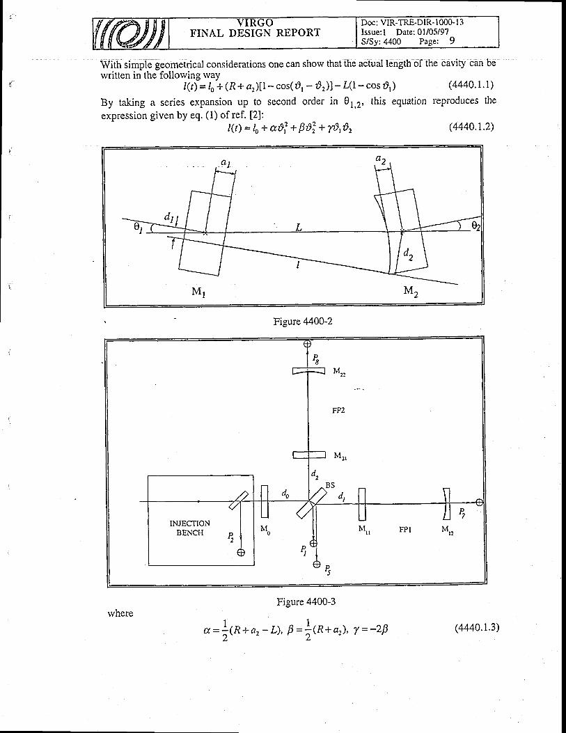
I fVith simple geometriCal coniiderationi one can shorv that the actual length of the Cavity can bervritten in the follorving rvay
l(t)= 1o+ (R + ar)[ - cos(r] ' - dr) l - L0- cos r]1) (4440. 1. l )
By taking a series expansion up to second order in Ot,r, this equation reproduces the
expression given by eq.(1) ofref. [2]:l(t) = 1o+ a*i + ps: + 78,8, (4440.r.2)
Figure 4400-2
Figure 4400-3
l - ld= : (R*az -L ) , 9= i fn+ a2 ) , T - -2p
FINAL DESIGN REPORTDoc: VIR-TRE-DIR- 1000-l 3Issue:l Date:01/05/97S/Sy:4400 Page: 9
M,,
FPz
M I
M,, Fpl M,,INJECTION
BENCH P2
rvhere(4440.1.3)
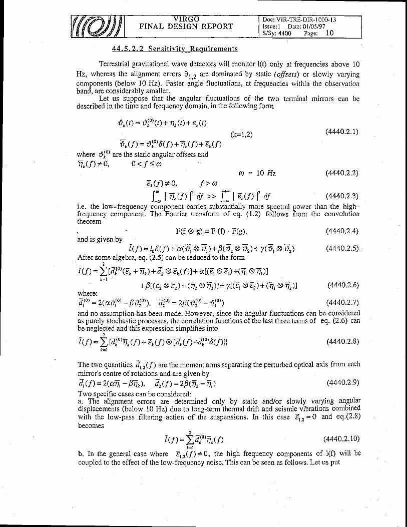
FINAL DESIGN REPORTDoc: VIR-TRE-DIR- I 000- l3Issue: I Date:01/05/97S/Sy:4400 Page: 10
44 .5 .2 .2 Sens i t i v i t y Requ i remen ts
Tenestrial gravitational rvave detectors will monitor l(t) only at frequencies above l0Hz, whereas the alignment errors 01,2 ile dominated by static (offsets) or slorvly varyingcomponents (belorv 10 Hz). Faster angle fluctuations, at fi€quencies rvithin the observationband, are considerably smaller.
Irt us suppose that the angular fluctuations of the trvo terminal mirrors can bedescribed in the time and frequency domain, in the following form
rlo(r) = tlfu'(r) + \Jt)+ e/t)(k=1,2)
4cn = olo)6(,f) + n(,f) + ErU)rvhere d,[o) are the static angular offsets andnk f f ) *0 , Oc fSco
a = L Q H zEk( f ) *0 , f> ro
Il. I n_rt> l, af ,, l_] | e_O> 1, ati.e. the lorv-frequency component carries substantially more spectral porver than the high-frequency component. The Fourier transform of eq. (1.2) follows from the convolutiontheorem
(4440.2.1)
(4440.2.2)
(4440.2.3)
(4440.2.4)
(4440.2.s)
(4440.2.6)
(4440.2.7)
(4440.2.8)
and is given byF ( f @ 8 ) = F ( f ) ' F ( g ) '
IU)= L6(/)+ cv(dr @ E,)+p(4 e D,l+ y(D, s DrlAfter some algebra, eq. (2.5) can be reduced to the form
2i (f) = ) t7*'o' {e* + 4 ) + 4 e e- <nt + a[(E,@ E, ) +(T, @ ?-, lt
K = l
BL(E.@Er)+(4r8 r f ) l+ T[G,@ Er)+ (4 @4)Jwnere:7,to'= 2(a810) -f , l lo'), 7:o'=z\@tot -,)lo')
and no assumption has been made. However, since the angular fluctuations can be consideredas purely stochastic processes, the conelation functions of the last tfuee terms of eq. (2.6) canbe neglected and this expression simplifies into
2
I u) =\tll"iln + E{f ) @ @rU) +r/r(0)6f)l}
(4440.2.e)
(4440.2.r0)
& = l
The two quantities Zr'(f) are the moment anns separating the perturbed optical axis from eachmirror's centre of rotations and are given by7,(f) =z(fr, - Fi), 7rff) =28(n.-n,)Trvo specific cases can be considered:a. The alignment errors are determined only by static and/or slorvly varying algllafdisplacements (belorv 10 Hz) due to long+ermiherind arift and seismic vjbrations combinedrvith the low-pass filtering action of the suspensions. In this case 4,2 = 0 and eq.(2.8)becomes
2
Iu)=I4"4'_ulb. In the general case where Er,r(f) # 0, the high frequency components of l(f) rvill becoupled to the effect of the lorv-frequency noise. This can be seen as follows. Let us put

FINAL DESIGN REPORTDoc; VIR-TRE-DIR- I 000- l3Issue: I Date: 0l/05/97S/Sy:4400 Page: I I
TrU) = 4,0,6("f) +7nff) (k=1,2)and let us take the square of eq.(2.8) for f >> 10 Hz (4'.2 =0). The expressions of the trvodiagonal terms become (k=1,2)
tEo @4(rf' = I_- e off)A*(f - f )ctf J__ r-fs' )Ar(f - C)ctd= J*- eo(f )Er(f +x)dx I::TrU
- f )ArU - f -x)ctf (4440.2.12)where x=g'-f. In absence of any conelations among the values of A(f) calculated at differentfrequencies, one has
I:dru-f )Tru-f -x)df =tf (Tt)6(x) =af (Z*tor'* ol) 6G)rvhere odk are the RMS-values of the 4f) of eq.(2.9).
For the sarne reason, the trvo non-diagonal terms vanish and the expression of ,2(/) reduces to
(4440.2.1t)
(4440.2.13)
(4440.2.14)
rvhere the contributions of the trvo mirrors can be assumed to be approximately equal. Thisexpression can be compared with eq.(14) of ref.[2] and it's worthwhile to notice that the d*RMS-values entering the latter, appears to be multiplied by an extra factor 2, which,apparently, is unjustifiable.-
The firlt case -shorvs
that, at least in principle, the offset contributions appearing in eqs.(2.8)can be trimmed down to zeraby applying a periodic torque to the minor and by monitoring theconesponding variations of tha optical length of the cavity. Moreover, measurementsperformed on thO superattenuators and estimates of the thermal noise indicate that:'-
the low frequency angular noise is dominated by the suspension noise, that is concentrated in
the region belorv 1 Hz and has a total RMS-value of about 2.5'10-s rad;- the Eigh frequency (> 10 Hz) component of the spectrum is dominated by the thermal noise
'that is estimated to be 2 .!O-t7 rad | 'J Hz at 10 Hz and 3 ' 10-20 rad I \[Hz at 100 Hz.
The RMS-value of the angular noise at lorv frequency would caused,tt" = 9 cm dln" = L2 cm'
in each direction. Following (z.t|),this rvould give a limit of h=1.4.10-2t l"lnz at 10 Hz.For the sensitivity limits of
h <!O-22 | -,llk ar 10 Hz (4440.2.15)
h <L0-23 t "lHz ar 100 Hzthe 10 Hz region is the most demanding and the dfuts comes out to be about 1 cm. To achieve
this, the RMS-value of the low-frequency angular noise must be reduced down to 10{ rad.
44.5.2.3 The Fabry-Perot A l ignment
The methods of D.Z.Anderson and H.Ward [3,4] have been originally suggested for thealignment of one single Fabry-Perot (FP) and no attempt has evei been made to extend thisprdcedure to the case-of a coniplete Michblson Interferometer (MI). In both these methods thetleam is frequency modulated and, in the Anderson scheme, the modulation equals Lhefrequency difference between the IEM* and TEMrc modes {ll2n=19.1 KHz . The
alignment information is related to the detection of the TEMrc components, in pbase or in
quadrature, with the mun TEM*. AII these details have been widely discussed elsewhere
[1 ,3 ,4 ] .
-ry=i rtrr, 1rlo,, +oj,.1
Af &=r

FINAL DESIGN REPORTDoc: VIR-TRE-DIR- I 000- I 3Issue: l Date:01/05/97S/Sy:4400 Page: L2
In the case of a single FP, the knowledge of a tilt and/or displacement of the optical axis, issufficient to identify the minor that caused it. But this is not true for a complete MI, where amisalignment signal measured behind one FP, rvill not be sufficient to single out the minor(s)that caused it. In order to disentangle the information, more measurements are needed. Inref.[1] we initiated to consider the complete Michelson Interferometer rvhere the beam splitterand the recycling mirror remained perfectly aligned. With the Anderson method and undersome simplifying assumptions, rve reached the follorving conclusions :
t . the left/right or up/down asynmetries, measured behind the terminal mirrors of one of thetwo FP's, yields direct information of the tilt of the FP-cavity axis, but its displacementappears always in a linear combination with the displacement of the other FP-cavity; ,t[ls cross-talk betrveen the two arms couples the two displacements only. Neitherangle/angle nor angle/displacement couplings are predicted;the coupling effect for the displacements is very close to one;with a molimum polver of 10 mlV impinging on the quadrant photodiodes, the limisimposed by the shot-noise would be :
t=''''Lo-l t ̂ lHz
(4440.3.r)
L = 3.lo-8 1",[Hzlvo
a and a refer to the optical axis of the FP-cavities.
44.5.2.4 Alignment of the Full Interferometer lvith the Anderson
2.
4.
rvhere
Method
In order to obtain a better approximation, we removed trvo of the limitations that affected the. results of ref.[1], i.e. :1. the recycling minor was kept "fixed" in a perfectly aligned condition;
2. the FP-reflectivities for the resonant (F) and non-resonant (1) frequencies
(4440.4.1)R , + &^ / = -' 1 + & &rvere both assumed to be equal to I (T2 = Q).With the values
R i = 0 . S S z , T ? = 0 . 1 1 8
4 =0.999g , T: = 10{taken from ref.[4], one has instead:F=Q.9984t , T=0.999997
(4440.4.2)
(4440.4.3)
and even if tiny, this difference can play a significant role. By timiting ourselves to consideronly the horizontal plane, we havelo measure the 2-displacements (a,,r) and the 2-angles( a,,r) of the FP-cavity axes and the angle of the recycling minor ( rlo) : in total five unknownquantities. Three quadrant photodiode rvill be sufficient to disentangle the problem: twolbcated right behind the two terminal mirrors, and a third on the injection _b_ench, to measurethe comp-onent reflected back from the recycling mirror (see fig.44d0-3). However a furtherfourth ptiotodiode can be used to measure ihe c-omponeni refle-cted from the uncoate{ putt ofthe beam splitter: this is not necessary but can add dn important extra piece of information.Given a c6mplete set of mirror miialignments, the equilibrium condition qmong the tfueeelectric fieldslmpinging upon the recycling minor, imposes the follorving relation :Et =ToE,+ iRoEz G440.4.4)where:
1 - & &
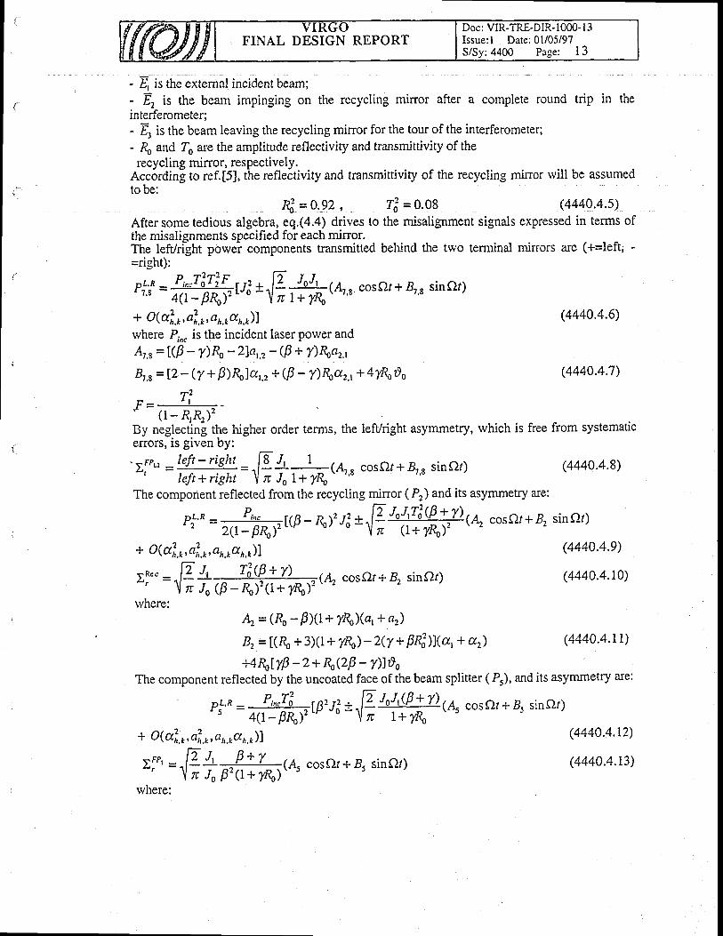
FINAL DESIGN REPORTDoc: VIR-TRE-DIR- 1000- I -3Issue: l Date:01/05i97S/Sy: 4400 Page: 1 3
- E ir tne Jxtemal incident beam;- 4 ir the beam impinging on the recycling minor after a complete round trip in theinterferometer;- 4 ir the beam leaving the recycling mirror for the tour of the interferometer;- {o and To are the amplitude reflectivity and transmittivity of therecycling mirror, respectively.
Acc6rding to ref.[5], the refleitivity and transmittiviry of the recycling min'or rvill be assumedto be:
4 =o-92 , Tot = o,o8 (4440.4.s)After some tedious algebra, eq.(4.4) drives to the misalignment signals expressed in terms ofthe misalignments specified for each mirror.The lefVri-ght powei components transmitted behind the two terminal minors are (+=left, -=right):
P,1;* = ffirs, Fr&(A,., coset+ 8,., sinot)
+ O (al.o, af, ,p, a 1,.1d 1,,p))where P,n" is the incident laser power andAt,e=l(F - /)& -2)a,,2-$ + T)Roar'
4 s = 12 - (y +F)&la'.t + (F - T)&az,t+ 4y8odo
ri." = n- RfJt
By neglectin! the higher order terms, the leff/right asymmetry, which is free from systematicerrors, is given by:'EFP', -','f! ."!!',=.,19 {' , ,t = (Ar., coser+e,, siner) (4440.4.8)' left*right \ n Jo 1+ y& ' ""
The component reflected from the recycling minor ( Pr) and its asymmetry are:
p!'^ = =r. P,-.rlg� - R), J: t ^p JoJ,liQ. +.y)(A, cosor+ B, siner)
2(I- pnr -1il
zt (l+ Y&)' \
(4440.4.6)
(4440.4.7)
(4440.4.e)
(4440.4.10)
(4440.4.tr)
(4440.4.r2)
(4440.4.r3)
+ O (al,r, al,, 1,, a 63d 1,.2))
rl." = ̂ Elt ,3\Pr: r) = rr(.4, cosc2r+ B, siner)ur - 1il o Jo (F -&)'(1+ y&)t
rvhere:4 = (& - BXl+ fio)(a, + nr)
4 = t(& +3X1+ /&)- z(y+ FPilJ(a,+ a.,)+4&ty| -2+ R,QB - Dlso
The component reflected by the uncoated face of the beam splitter ( P5), and its asymmetry are:
P,''^ = d#w'rl
t F"W(* cosQr+ 4 sinQt)+ O @1,r, a20.1,, a 6'd. o. o)f
sFP. E l, 0*t-r^cosf)r+8, sinctr)L ' ' = \ l ;T$c t *? ,&) t ' -s vvJr&& ' s r
where:
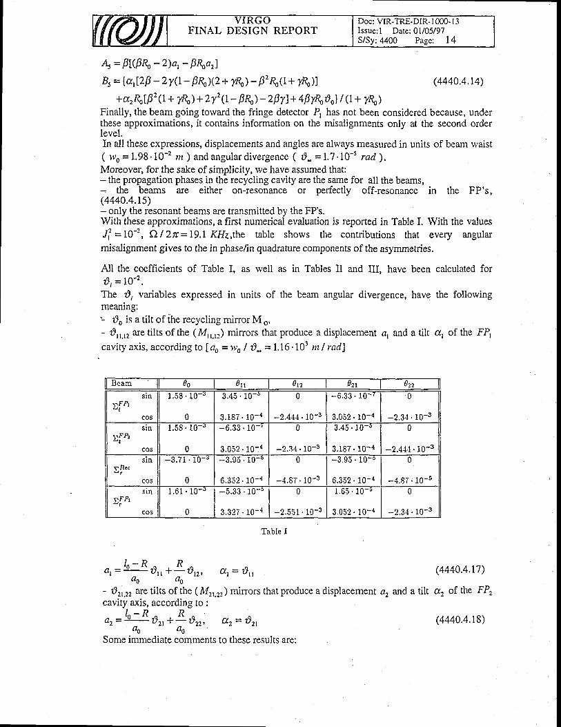
FINAL DESIGN REPORTDoc: VIR-TRE-DiR- I 000- | 3Issue: l Date:01/05/97
;4400 Page: 14
4= FL(F\-2)a,- F\nrlB, = la,[2p - zy(t- B&X2 + I&) - p'&(l + y&)]
+ arRolp2 (r+ ?,& ) + 2 T2 (I- B& ) - 2 FyJ + 4 ByRoS ol I Q + y\)Finally, the beam going torvard the fringe detector P, has not been considered because, underthese approximations, it contains information on the misalignments only at the second orderlevel.In all these expressions, displacements and angles are always measured in units of beam rvaist( ruo=1.98.10-2 n ) andangulard ivergence ( d-=1.?.10-5 rad) .Moreover, for the sake of simplicity, rve have assumed that;- the propagation phases in the recycling cavity are the same for all the beams,
the beams are either on-resonance or perfectly off-resonance in the FP's,(4440.4.rs)- only the resonant beams are transmitted by the FP's.With these approximations, a first numerical evaluation is reported in Table I. With the valuesJ,t =10-t, ttl2n=19.1 KHz,the table shows the contributions that every angularmisalignment gives to the in phase/in quadrafure components of the asymmetries.
Ail the coefficients of Table I, as rvell as in Tables II and III, have been calculated fordi = 10-2'The d, variables expressed in units of the beam angular divergence, have the follorvingmeaning:'- rlo is a tilt of ihe recycling mirror M o,- d,,,,, are tilts of the (Mrr.rr) mirrors that produce a displacement dr and a tilt a, of the FP,cavity axis, according to f ao =wo | 8* = 1.16.103 m I rad)
Beam Ao utt otz flzr ozz
s.FPrsln
cos
1 .58 ' 10 - "
0
3.45 . 10- '
3 .187. 10- {
0
-2.444 . 10-3
l 0 -.33 .6
3.052 . 10-{
0
-2.34 . 10-3sln
lFPzu t
cos
1.58 . 10-"
0
-6.33 . 10- ' �
3 .052. 10-4
0
-2.34 . 10-3
3 .45 . 10 -s
3 .187 . 10 -4
0
-2.444. 10-3s tn
gRcc
cos
-3.71 . 10-r
0
-3.95 . 10-o
6.3.52 . 10-{
0
-4 .87 ' 10-3
-3.95 . 10-5
6 .352 . 10 -4
0
-4.87 ; t0-5
tFPrsrn
cos 0
- JI . O I I U -5.33 . 10- '
3 .327. 10-4
0
*2.551 . 10-3
1.65 ' 10- .
3 .052 . 10 -4
0
-2.34 . l0-3
Table I
(4440.4.14)
(4440.4.r7)
and a tilt a., of. the FP.,
l n - R ^ RC t r = r d , , + - - : d 1 2 , & t = : B r t' a o " ( t o
- 8r,,r, are tilts of the (Mrr.rr) mirrors that produce a displacement ctzcavity axis, according to:
/ " - R ^ Re2 = r t)r, +:: t}r, dz = Ozt
Ao 4o
Some immediate comments to these results are:
(4440.4.18)
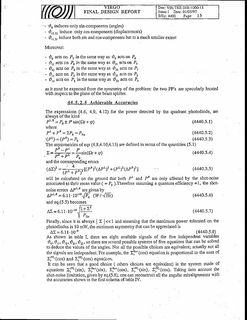
FINAL DESIGN REPORTDoc: VIR-TRE-DIR-l 000-13Issue: I Date: 0l/05/97S/Sy:4400 Page: l5
- r9o induces only sin-components (angles)- 8rr.r, induce only cos-components (displacements)- d,,.r, induce both sin and cos-components but to a much smaller extent
Moreover:
- do acts on P? in the same way as zlo acts on P,- 29,, acts on P8 in the same way as dr, acts on P,- r9,, acts on P8 in the same way as t}r, acts on P,- d,, acts on P, in the same way as d2r acts on P2- d,, acts on P2 in the same rvay as d, acts on P,
as it must be expected from the syrnmetry of the problem: the two FP's are specularly locatedwith respect to the plane of the beam splitter.
44 .5 .2 .5 Ach ievab le Accu rac ies
The expressions (4.6, 4.9, 4.12) for the power detected byalways of the kindPt'R = Po t Psin(or+ g)rvhereP L + P R - 2 P o = P r o ,
. ( P t ) = ( P ^ ) = P o
the quadrant photodiode, are
The asymmetries of eqs (4.8,4.10,4.13) are defined in terms of the quantities (5.1)
(4440.s.4)
(4440.s.s)
rvill be calculated on the ground that both PL and PR ue only affected by the shot-noiseassociated to their mean value ( = Po ).Therefore assuming a quantum efficiency =1, the shot-
noise enors APL'R are given byarr 'R - 6.11.10-'o{& (w | {Hz)and eq.(5.5) becomes
F;FA E = 6 . 1 1 . 1 0 - r o . l t
-
I Pro,Finally, since it is always I t 1..1 and assuming that the maximum power tolerated on thephotodiodes is 10 mW, the minimum asymmetry that can be appreciated is
AE = 6 .11 .10 -e (4440.s.8)As shown in table I, there are eight available signals of the five independent variablesds, d11, :812,821,8rr, so there are several possible systems of five equations that can be solvedto deduce the values of the angles. Not atl the possible choices are equivalent; acrually not allthe signals are independent. For example, the >l'"(cos) equation is proportional to the sum of
If"' (cos) and IfP'(cos) equations.It can be seen that a good choice ( others choices are equivalent) is the system made of
equations >f&1sin;, Ef""1sin1, Ef""1cos), Ij"(sin), EfP'(cos). Taking into account theshot-noise limitation, given by eq.(5.8), one can reconstruct all the angular misalignments lviththe accuracies shown in the first column of table ry.
p R - p L PI = * = : - s i n ( Q r + g ), P " + P " P ,and the corresponding enors
4r A r . ) 2 = , - , [ ( p R ) 2 ( A p L ; 2 + 1 r t ; 2 1 a r R ; 2 1\- /
lPt + PR;4
(4440.s.1)
(4440.s.2)(4440.s.3)
(4440.s.6)
(4440.5.7)
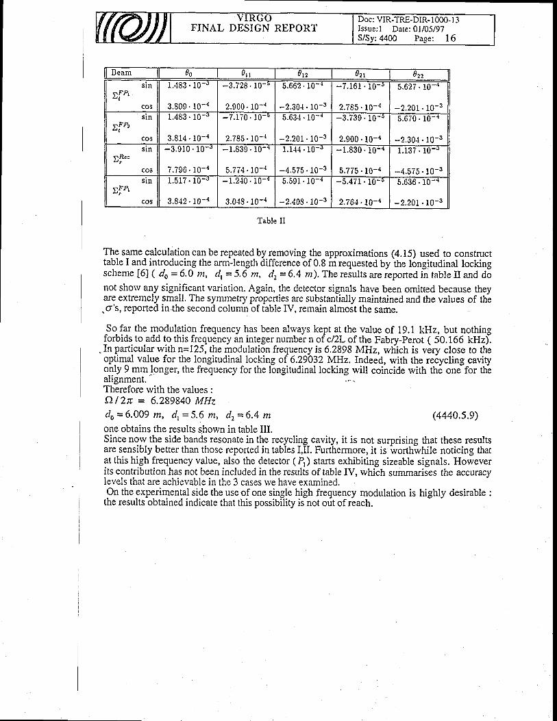
FINAL DESIGN REPORTDoc : VIR-TRE-DIR- I 000- I -3Issue: I Date: 0l/05/97S/Sy: 4400 Pa-se: 16
Beam 0s o t t 0n ozr ozz
rFrts tn
cos
1 .483 ' 10 - r
3.809. l0- ' t
-3 .729 . 10-o
2.900. 10- ' l
0. 15.662 {
-2.30{ . 10-3
-7 .161 . 10 -5
2.785 . 10-'{
5.627 . 10-"
-2.201 . 10-3
s.FPra t
s ln
cos
1.483 . 10-o
3 .814 . l 0 -4
-7 .170 . 10 -
2.785. 10- ' t
5 .63- l . 10-{
-2.201 . 10-3
-3 .739 . 10 -5
2.900 . 10-4
5.670 . l0-*
-2.30{ . 10-3
cos
slns.Rcc
-3 .910 . 10 -J
7.796' 10- ' � t
-1 .839 ' 10- {
5.774. 10- ' r
1 . 1 4 4 . 1 0 - 3
-4.575 . 10-3
-1 .830.10- ' '
5,775 . 10-4
1 .137 . 10- '
-4.575 . 10-3
TF&a t n
cos
1 .517 . 10 -J
3 .842 . 10 -4 3.018. 10- ' l
{9ln I 0- l 5.591 . 10-{
-2.408. 10-3
-5.471 . 10-5
2.764. 10-{ -2.201.10-3
D . . 1 0636
Table II
The same calculation can be repeated by removing the approximations (4.15) used to constructtable I and introducing the arm-length difference of 0.8 m requested by ifre longitudinal lockingscheme [6] ( do = 6.0 m, dr = 5.6 m, dz = 6.4 n). The results are reported in table tr and donot shorv any significant variation. Again, the detector signals have been omitted because theyare extremely small. The symmetry properties are substantially maintained and the values of th-e.o's, reported in the second column of table IV, remain almoit the same.
So far the modulation frequency has been always kept at the value of 19.1 kHz, but nothingforbids to add to this fre_quency an integer number n of clZL of the Fabry-Perot ( 50.166 kHz).
.In particular with \=125, the modulation frequency is 6.2898 MHz, wliich is very close to theoplim-al value for the longitudinal locking of 6.29032 MHz. Indeed, with the reiyctng cavityo.1ly 9 mm.longer, the frequency for the longitudinal locking will coincide with th6 one for th-eallgnment.Therefore with the values :dl | 2tr = 6.289840 MHzdo=6 .009 m, d r=5 .6 m, dz=6 .4 m (4440.s.9)one obtains the results shown in table III.Since now the side bands resonate in the recycling cavity, it is not surprising that these resultsare sensibly better than those reported in tables I,II. Furthermore, it is worthwhile noticing thatat this high frequency value, also the detector (P,) starts exhibiting sizeable signals. Howeverits contribution has not been included in the results of table IV, which summarises the accuracylevels that are achievable in the 3 cases rve have examined.On the experimental side the use of one single high frequency modulation is highly desirable :
the results obtained indicate that this possibility is not out of reach.
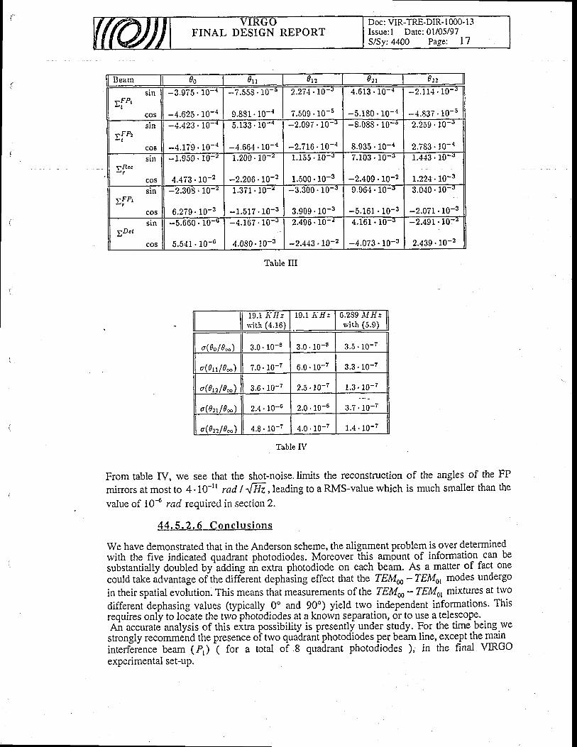
FINAL DESIGN REPORTDoc: VIR-TRE-DIR- I 000- I 3Issue: I Date: 0l/05/97S/Sy:4400 Page: L7
Beam 0s 0n 0n ozt 0n
rFPrsln
cos
-3.975 . 10- '
-4.625 . 10- ' t
- 7 .558 . 10 - i
9.831 . l0-4
2.274.L0-"
7 .509 ' 10-5
4.6 i3 . 10- ' t
-5.180 . 10- ' l
- 2 . 1 1 4 . 1 0 - J
-4.837 . 10-5stn
co5
sFPza t
-4.423 . 10- '
-4.179 . 10-4
5 .133. 10- "
-4.664 . 10-'r
-2 .097. 10- '
-2.?16 . 10-4
-8.088 . 10- !
8.935 . 10-{
2.259 . 10-"
2.?83 . 10-{stll
yRce
cos
-1 .959 . 10 -z
4 .473 ' 10 -2
1 . 2 0 0 ' L j - t
-2.206 . 10-2
1.155 . 10-"
1.500 . 10-3
7.103 . 10-3
-2.409 . 10-2 1.22+. 10-3
- J. l u31 . { . 1
rr&sin
cos
-2.308 ; 10-z
6 .279 . 10 -3
1.371 . 10- ' �
- 1 . 5 1 ? . 1 0 - 3
-3.300 . 10-J
3.909 . 10-3
9.964 . 10-3
-5.161 . 10-3
3.040. 10- '
-2.071 . 10-3
yDctl n5
cos
-5 0-o
5.541 . 10-6
' 1.600 -4 .167 . 10-J
4 .080. 10-3
2.496 . 10-z
-2.443 .70-?
4.161 . 10-J
-4 .073 . 10-3
-2.491 . 10-
2.439 .70-2
Table III
19. l . I f r / :with (4.16)
19.1 -IrI/: 6.259 il/l/:rvi th (5.9)
o(0o / 0-l, 3 . 0 ' 1 0 - 8 3.0 . 10-8 3.5 . 10- '
o(?rr l0n) ?.0 . 10-7 6 . 0 ' 1 0 - 7 9.3 . 1o-7
o(0n/0* 3.6 . 10-7 2.5.rc-? 1.3 . 10-7
o(021/0n) 2 .4 . 10-6 2 .0 . 10-6 r.t. io-'
o(0221 0*) 4 . 8 . l 0 - 7 4.0 . 10-7 1.4 . 10-7
Table IV
From table IV, we see that the shot-noise.limits the reconstruction of the angles of the FP
mirrors at most to 4'10-rr rad | ^[E ,leading to a RMS-value rvhich is much smaller than the
value of lAa rad required in section 2.
421 .5 .2 .6 Conc lus ions
We have demonstrated that in the Anderson scheme, the alignment problem is over determinedwith the five indicated quadrant photodiodes. Moreover this am6unt of information can besubstantially doubled by'adding an extra photodiode on each beam. As a matter of fact onecould take advantage of the aiffErent dephising effect that the TEMffi - TEMot modes undergo
in their spatial evolution. This means that measurements of the TEM@ - TEMot mixrures at hvo
different dephasing values (typically 0" and 90") yield two.independent informations. Thisrequires only to locate the two photodiodes at a knorvn separation, or to use a telescope. .An accuratd analysis of this eitra possibility is presently under sludy. For the timebeing.wettrongty recommind the presence oi two quadrani photodiodes per beim line, exce,pt the maininterfirlnce beam (P,) i fo, a total of 8 quadrant photodiodes ), in the final \TIRGOexperimental set-up.
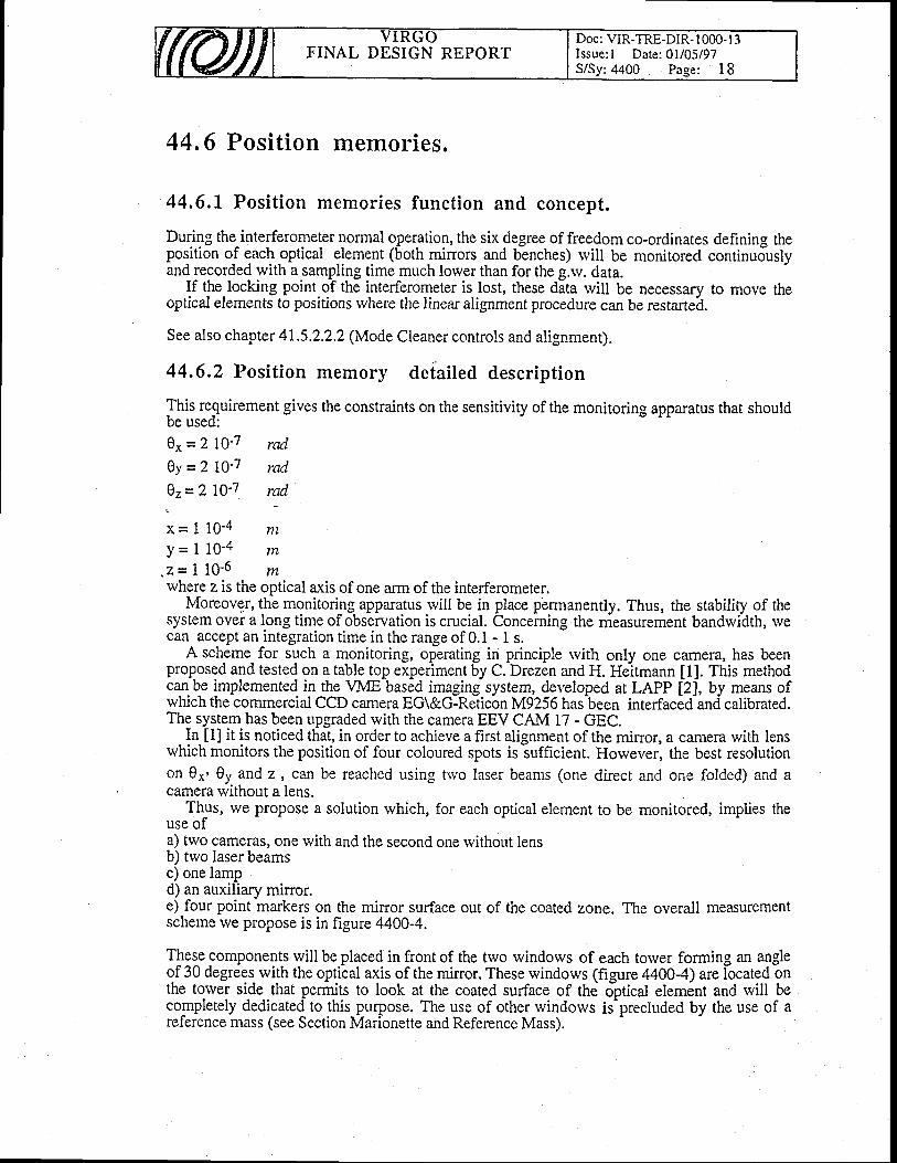
FINAL DESIGN REPORTDoc: VIR-TRE-DIR- 1000- I 3Issue: I Date: 0l/05/97S/Sy:4400 Page: 18
44,6 Position memories"
44,6.1 Posit ion memories funct ion and concept.
During the^interferometer normal operation, the six degree of freedom co-ordinates defining theposition of gacf optical element (both minors and benches) rvill be monitored continuouslyand recorded with a sampling time much lower than for the g.rv. data.
If the.locking point of the interferometer is lost, these data rvill be necessary to move theoptical elements to positions rvhere the linear alignment procedure can be restarted.
See also chapter 41.5.2.2,2 (Mode Cleaner controls and alignment).
44.6.2 Position memory detailed description
This requirement gives the constraints on the sensitivity of the monitoring apparatus that shouldbe used:0x=/ lQ-7 rcul0y =/ !g-7 rad07=/ lQ-7 rad
x= I 10-4 ntY= i 10 -4 mz= i 10 -6 mwhere z is the optical axis of one arm of the interferometer.
Moreover, the monitoring apparatus will be in place pbrmanently. Thus, the stabiliry of thesystem over a long time of observation is crucial. Concerning.the measurement bandwidth, rvecan accept an integration time in the range of 0.1 - 1 s.
A scheme for such a monitoring, operating in principle rvith only one camera, has beenproposed and tested on a table top experiment by C. Drezen and H. Heitmann [1]. This methodcqn !e implemented in the VME based imaging system, developed at LAPP [2j, by means ofwhich the commercial CCD camera EG\&G-Relicon M9256 hasbeen interfacedand catbrated.The system has been upgraded rvith the camera EEV CAM 17 - GEC.
In tll it is noticed that, in order to achieve a first alignment of the mirror, a camera with lensrvhich monitors the position of four coloured spots is sufficient. However, the best resolutionon 0*' 0t and z , can be reached usin-9 nvo laser beams (one direct and one folded) and acamera without a lens.
Th_us, we propose a solution rvhich, for each optical element to be monitored, implies theuse ofa) trvo cameras, one rvith and the second one rvithout lensb) two laser beamsc) one lampd) an auxiliary mirror.e) four point markers on the mirror surface out of the coated zone. The overall measurementscheme we propose is in figure 4400-4.
Tles,e components will be placed in front of the two rvindows of each torver forming an angleof 30 degrees- with the optical axis of the mirror. These windows (frgure 44004) are located onthe torver s'fle-.that permits to look at the coated surface of the optical element and will becompletely dedicated_ to this-purpose. The use of other windows is-precluded by the use of areference mass (see Section Marionette and Reference Mass).

Doc: VIR-TRE-DIR- I 000- I 3Issue: l Date:01/05/97S/Sy:4400 Page: 19
FINAL DESIGN REPORT
spot
Figure propo terTrurung mass posltlon.
4 oot ica I win do ws
Figure 4400-5
In the case of the beam splitter we plan to look still to the coated side of the element usingthe two rvindows at 15 degrees.

FINAL DESIGN REPORTDoc: VIR-TRE-DIR- I 000- l3Issue: l Dare:01/05/97S/Sy:4400 Page: 20
The overall scheme of the cameras used to monitor the positions ofYFGO is in figure 4400-6 rvhere also the positions of the iamera usedalignment are shown.
Each measu.nng s!.stem (lasers and cameras) rvill be attached to the structure of the torvers bysupports rvhich rvill comply to the following specifications:- The.supports must not have mechanical iesbnances at frequencies lorver than 100 Hz- Their design should insure the possibility to remove the elements from the torvers before outgasslng
the sixfor the
mirrors ofnon linear
- Th.e positionino of each element should be reproducible within 0.1mm, in order to facilitatere calibration of the measuringratron ot the measuring. apparatus after every assembly.
Care rvill_be taken to isolate all measuring apparaiurapparatus from the acoLlstic noise in theenvironment and from the fluctuations of air r6fra&ion index which could limit theirsensitivity.
References section 44,5tll Diabusci'H.lulg,^9.G!9-r!q1o, G.Marone, v.sannibale, LNF-94/027(IR),
Virgo note PJT 94-0t7 (1994)12) S.Kawamura and M.E.Zucker, Appl. Opt., 33 (1994),3912t3l D.Z.Anderson, Appt. opr.,23 0984),2g+q aiaN.lvl.Sanand N.M.Sampas and D.Z.Anderson,t3l D.Z.Anderson, Appl. Opt.,23 (1984),
Appl. Opt.l 29 (1990),394it] E. Monison, B.J. Meeri, D.J. Roberts-on and H. ward, Appl. opt., 33 (1994), 5041tll 9.N,Man, Virgo note PJT 94-AZ4 e994).t6l R. Flaminio and H. Heirmann, Virgo nore pJT 93-021 (1993)References section 44.6l1l H. Heitmann, Virgo Nores, 21.4.1994, 1 1.8.1994, 9.1.1995.
'l2l A.Bazan et al., Astroparticle phys. 2,ZZg (i994).
t3l H.Heitmann, Virgo Nore NTS 96038
t4l C. Drezen, H. Heitmann, F. Ricci, Virgo Note NTS 96072
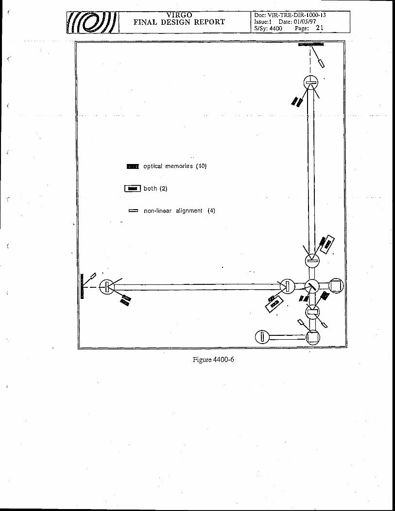
ld oPt ical memories (10)
l E I b o t h ( 2 )
r- non-linear alignment
Figure 4400-6
FINAL DESIGN REPORTDoc: VIR-TRE-DIR- 1000- I 3Issue: I Date: 0l/05/97S/Sy:4500 Page: I
45. Cal ibrat ion
Table of Contents
45. Calibration
45.1 Cal ibrat ion funct ion and concept
45.2 Requirements
45.3 Select ion of so lut ions
45.4 Deta i led descr ipt ion45.4.1 The signal generator45.4.2The coils driver45.4.3 The laser diodes
45.4.3.1 Laser rvavelengrh45.4.3.2 Laser power45,4.3.3 Optical layout and laser monitoring
45.4.4 Calibration software45.4.5 Reconstruction sofrware (TBC)
' 45.5 Calibration interfaces
I
7
7
7
1
J
J
J
JAI
^A
A

FINAL DESIGN REPORTDoc: VIR-TRE-DIR- | 000-l 3lssue: I Date: 0l/05/97S/Sy:4500 Page: 2
45.1- Calibration function and concept
The purpose of the calibration of an apparatus is to provide the tools needed to convert ther&sur€d data to a ohvsical ouantitv rvhich is in our case the metric Dertllrbation h induced bv ameasured data to a physical quantity rvhich is in o
eravitational rvave. The first obvious rvav to do it ithe metric pertllrbation h induced by a
gravitational rvave. first obvious wav to do it is to use our detailed knorvledge of the variouscomponents of the interferometer (laser power, conversion factors for the photodetectors,interferometer transfer function,...). This process relies on a precise determinat.ion of the detector,...). This process relies on a precise determinat.ion of the detectorcalibration constants and on a detailed deconvolution rvhich, taking into account optical transferfunction and the locking system of the interferometer, is a non-trivial operation. Therefore, to gainconfidence in our data we will use an independent system to calibrate the interferometer. Bycalibration, we mean the injection of a signal of knorvn amplitude and phase, which mimics, aswell as possible, the effect of a gravitational wave by moving one mirror and the study of thecoresponding signal in our recorded data.
The calibration will be used for at least two different goals. The first one is a general study ofthe VIRGO sensitivity. In this mode rve should be able to apply periodic or non periodic signalsrvith an amplitude and a frequency rvhich could be changed by ferv orders of magnirude in orderto study the full bandrvidth of VIRGO. The other mode of operation is a permanent monitoring ofthe VIRGO interferometer. In this case, rve will apply a set of periodic signals of well knorvnamplitudes and very stable frequency. In this mode, we will check the stability of theinterferometer and of the data acouisition svstem.
To move the minors rve will use trvo iifferent methods. One is to push the mirrors rvith thestandard coils located on the reference masse but driven by an external signal. The other one is the.push the mirror'rvith the radiation pressure from an additional laser beam driven also by anExternal signal. In addition to the softrvare used to operate these calibration devices we need thesoftrvare used to extract the calibration constant and the softrvare needed to use this information torecompute h (h reconstruction). Therefore, the calibration is subdivided in the following items:
. a stand alone signal generator of arbitrary waveform, rvith an accurate timing
. two light generators to push the inpuf cavity mirrors including the electronics and themechanical supports
. all the needed VME electronics and software to run the Calibrators.
. the software to extract the calibration constants
. the WRGO reconstruction softrvare, i.e. the software to compute h from the rarv data(rBc).
45.2 Requirements
The signal generator should be able to provide a signal at 20 kHz with an absolute timingbetter than 5 pts (a fraction of the sampling frequency).
The transducer should have enough power to produce a visible signal on the VIRGO output.Its fluctuations should not introduce noise in the VIRGO sensitivity.
The control softlvare should provide any shape.
45.3 Selection of solutions
This calibration signal should produce a miror displacement of rvell known amplirude andtime dependence. Tf,is means rie should kno.'v the force applied on the minor and themechanical transfer function. The calibration signals will be dfplied to the two input cavityminors located in the central building. This choic-e gives us the opportunity to already-install onthe test interferometer the final soluiion. We could also send thi calibrition signals on botharms with a single signal generator.
The principle of ihe calibration is to have a system as independent as possible from theVIRGO contiol system. Of course, the calibration iignal should nbt induce additional noise like
FINAL DESIGN REPORTDocr VIR-TRE-DIR- I 000- l3Issue: I Date: 0l/05/97S/Sy:4500 Page: 3
seismic noise or electromagnetic noise. Two different ways of pushing the nirrors have beenselected :
. Forces using the locking actuators
. The radiation pressure from an additional laser beam
45.4 Detailed description
45.4.1 The signal generator
The signal is gelerated by.a.D.Ap triggered bygn QPS clock. The DAC (ADAS 204) has 4ggtp-jqgttgnnels of 16 bits rvith ind^e_penqent FIFO of 32 krvords. The dati are provid6a uy ay.MESP_U running.in real time the SIESTA environment in order to provide any'signal Jtraie.The MvIE crate rvill be located in the data acquisition room in the cintral buildinglfhe cldckrvill be independent of the VIRGO timing sysiem in order to check its validiry (h"ardware andsoftware).
A summary of the status of the signal generator which includes the definition of thegenerated signal and the signal phase at some rvell defined time will be sent to the slowmorutonng system.
45,4.2 The coi ls dr iver
The calibration signals used to drive the coils of the reference masses be sent to theThen they will be
increases, the area
rvill.susp-ension control using. coaxial cables with BNC connectors (t10v rBC).locally added to the locking signals.
45,4.3 The Iaser diodes
f!9 princ.iple of this method is to move the minor by the pressure of radiation of asource of light with a modulated power. This method is able to prodrice any kind of waveformvery easily. The implantation ii presented by figure 4500.f. Let's ndw review the lightpa_rameters.
{1.4.3. I Laser rvavelength
Given our mirror coating, the choice of the wavelength is connected with the choice of theangle of incidence. As firvith large re
igure 4500.2 shows it, when the angle of incidence ishifted to smaller wavelensth (0o is for normal ineirwi.th Jargg re{lectivity is shifted to smaller wavelength (0" iJ for normal incidence). The easier
solution for the mechanical point of view is to use angleof incidence of 30" or 60". In order toavoid any confusion with the main laser beam rve riill use a rvavelength of 860 nm for thecalibration laser and therefore we will use the 60. optical port.
45.4.3.2 Laser porver
If we take a laser of porver P = Pocos(cot), hitting a minor of mass M of reflection R with anangle of incidence i, the mirror motion is, above the pendulum frequency (a ferv Hz given thesuspension design) :
x(0 - Pscos(rot)R cos(i)/(Mcro2)
. At^ul example, if we want a displacement of x = [Q-1?6, at 100 Hz, rvith M=2lkg, R=.95,1=oz- tne needed laser porver is: P = 1 10 mw (taking into account a factor 2 to generate a 55mW cosine wave).
.To.get a better determination of the needed powe-r, we compute the needed power to producea displacement equal.to the noise for one secc'ird of integ-ration. The resuh is'presented by the!_gy{ .4500.3assumingamassof2 l KgandanangleoTinc idence of 62. OiecanseethatalW laser is enough to cover most of th! frequency-range. This conespond to a typical laser
FINAL DESIGN REPORTDoc: VIR-TRE-DIR- I 000- l3Issue: I Date:01/05/97S/Sy:4500 Page: 4
diode. It is also interesting to notice that a 1 W laser would provide a large signal in the 10-lO0Hz rvhere we could have problem to reach our design sensitivity in the beginning of theVIRGO running.
This low power compared to the main beam porver (about 10 kW in the cavity) shorvs thatno thermal problem on the mirror surface is to be expected. This lorv power combined rvith thefact that the calibration light has a different wavelength and is not modulated at high frequencyremoves any concern about diffused light going into the main beam.
The selected laser diode is a 5W diode from Spectra Physics with an 5 m long optical fiberconnected to a beam expander. The resulting beam as a2 cm diameter.
45.4.3.3 Opt ica l layout and laser moni tor ing
Tfuee small optical tables will be aftached to the towers to hold the optical components.They rvill be the same as the ones used for the position memories. During the totver bakeout,the components installed on these tables will be removed.
The laser power will be monitored by.two photodiodes collecting the input and the reflectedbeam. One of these signals will be recorded by the standard data acquisition system. The beamalignment will be chebked by a quadrant photodiode looking at tlie transmitted beam. A 16channels ADC will be used to collect these signals. The calibrator control CPU will performthese monitoring.
45.4.4 Calibration softlvare
During special runs, we rvill srveep a sine rvave or introduce a white noise to measure thetransfer function. The calibration software will use these data to extract and parametrize thisiransfer function (TBC). A ferv permanent sine rvaves of small amplitude ivill be used tomonitor this transfer function. The resulting value rvill be archived in a database.
.45.4,5 Reconstruction softlvare (TBC)
The reconstruction softrvare will use the parametrized transfer function to compute in thetime domain the h reconstructed values starting from the photodiodes signal. This software hasto be studied in collaboration with the locking group.
45.5 Calibration interfaces
The interfaces are the following:With the suspension control (WBS 4900): two coaxial cables with BNC connector arc
provided for the coils calibration signals.With the torver (W-BS 3200) : the calibration optical tables are attached on the tower. Three
windows are needed on each input torver with the corresponding space.With the Data Acquisition system (W"BS 5400) : the four analog sign.als sent to each
calibrator are recordeil by the igeneral DAQ. The status information rvhich includes theparameters of the generated signals is sent to the slow monitoring frame builder.'
With the VIRGb softrvare ithe reconstruction program will -work
on frames and rvill havethe standard (SIESTA like) interface to the main program.
List of FiguresFigure 4500.1Figure 4500.2
Figure 4500.3
The laser calibration imolantationCoefficient of reflection for a mirror rvith various angle of incidence (60ofor the right curve, 65o middle, 70'left)Needed porver to produce a displacement equal to the nose observed forone second of integration time.
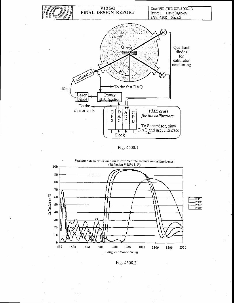
FINAL DESIGN REPORTDoc: VIR-TRE-DIR-I 00G I 3Issue: 1 Date:0V05197S/Sv:4500 Pase:5
Quadrantdiodes
forcalibrator
monitoring
To themirror coils
100
90
80
70
: 6 0
.E so6E 4 0
30
20
1 0
Fig. 4500.1
700 800 900 1000Longueur d'onde en nm
Fig.4500.2
Veriation de !a reflexion d'un miroir d'entr€e en fonctlon de I'incidence(R6 f l ex ion#88%40" )
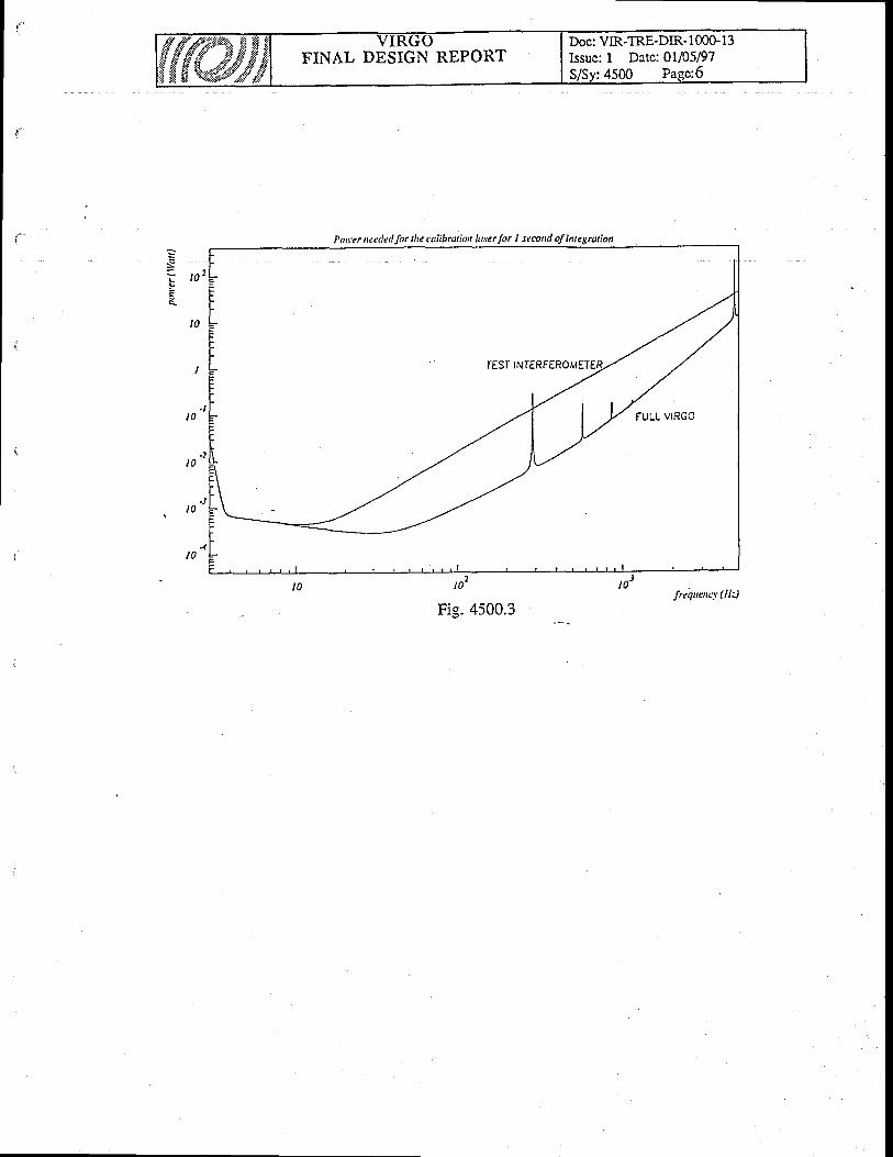
FINAL DESIGN REPORTDoc: VIR-TRE-DIR- I 00G, 13Issue: I Date: 01/05/97
Pou,er neetledJor the culibration krcrlor I secod of iuegraliot
sl o 2
IO
I
.tl 0
t 0
.JIO
4t0
frcquency (Hz)
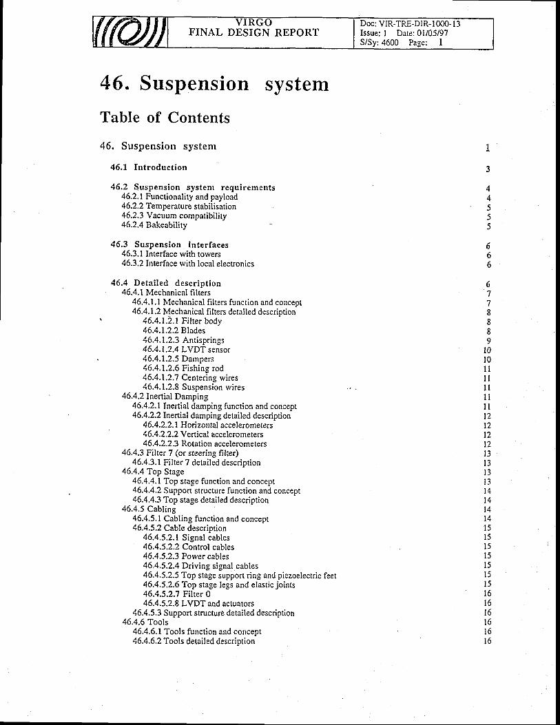
FINAL DESIGN REPORTDoc: VIR-TRE-DIR- I 000- I 3Issue: I Date: 0l/05/97S/Sy:4600 Page: I
46. Suspension system
Table of Contents
46. Suspension system
46.1 Int roduct ion
46.2 Suspension system requirements46.2.1 Functionality and payload46.2.2 Temperature stabilisarion46.2.3 Y acuum compatibili ty46.2.4 Bakeabil ity
46,3 Suspension in ter faces46.3.1 Interface rvith torvers46.3.2 Interface rvith local electronics
46.4 Deta i led descr ipt ion46.4.1 Mechanical frlters
46.4.1.1 Mechanical f i l ters function and concept46.4.1.2 Mechanical filters detailed description
\ 4 6.4.1.2. t F i t ter body46.4.1.2.2 Blades46.4.1.2.3 Antisprings46.4.1.2.4 LVDT sensor46.4.1.2.5 Dampers46.4.1.2.6 Fishing rod46.4.1.2.7 Centering wires46.4.1.2.8 Suspension wires
46.4.2 Inertial Dampin-e46.4.2.1 Inertial damping function and concepr46.4.2.2 Inertial damping detailed description
46.4.2.2.1 Horizontal accelerometers4 6.4.2.2.2 Y e*ical accelero meters46.4.2.2.3 Rotation accelerometers
46.4.3 Filter 7 (or steering filter)46.4.3.1 Filter 7 detailed descriotion
46.4.4 Top Stage46.4.4.1Top sta_se function and concept46.4.4.2 Support structure function and concept46,4.4.3 Top stage detailed description
46.4.5 Cabling46.4.5.1 Cabling function and concept46.4.5.2 Cable description
46.4.5.2.1 Signal cables46.4.5.2.2 Control cables4 6.4.5.2.3 Porver cables46.4.5.2.4 Driving signal cables46.4.5.2.5 Top stage support ring and piezoelectric feet46.4.5.2.6 Top stage legs and elastic joints46.4.5.2.7 Filter 046.4.5.2.8 LVDT and actuators
46.4.5.3 Support structure detailed description46.4.6 Tools
46.4.6.1 Tools function and concept46.4.6.2 Tools detailed description
3
4A
5))
666
67788a
9l0l 01 1l ll ll l
l l12t2t2t2l 3l 3I J
1 A
1 A
t 41 Al 1
l 5l 5l 5l 5l 5t i
l 5l o
l o
l 6l 6l 6l 6
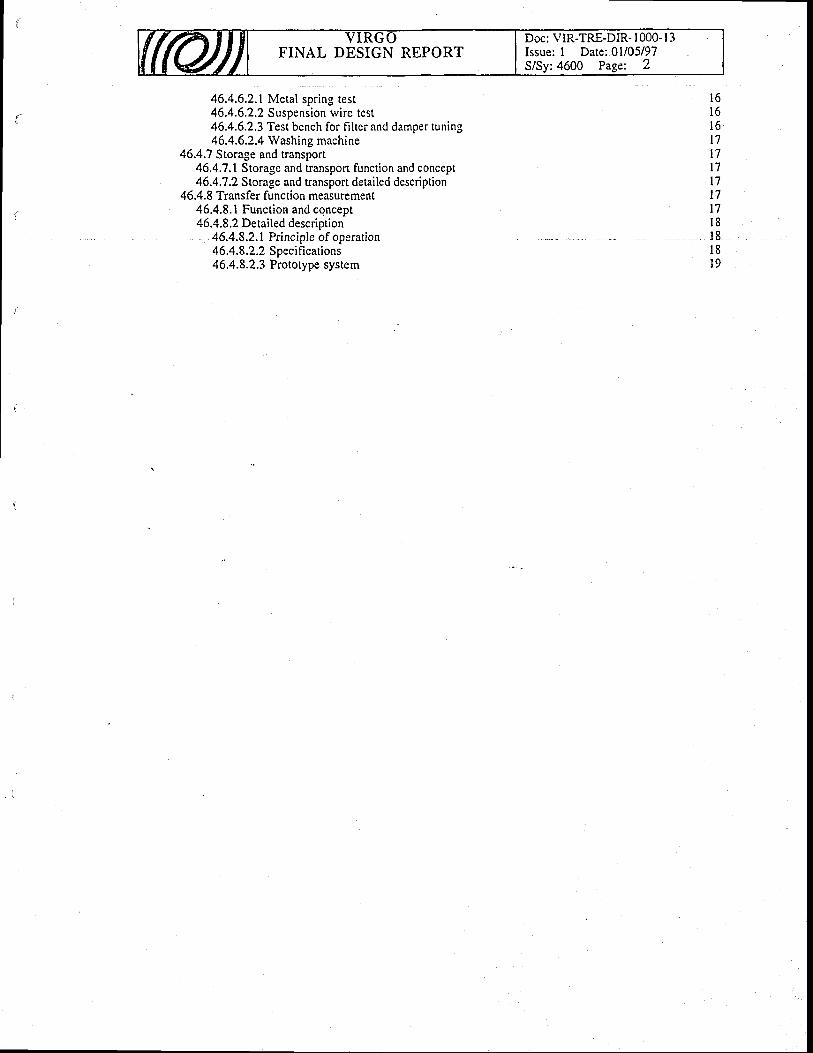
Doc: \'IR-TRE-DIR- | 000- I 3Issue: I Date:01/05/97
:4600 Page: 2FINAL DESIGN REPORT
46.4.6.2.1 Metal spring test46.4.6.2.2 Suspension ivire test46.4.6.2.3 Test bench for filter and damper tuning46.4.6.2.4 Washing machine
46.4.7 Storage and transport46.4.7.1 Storage and transport function and concept46.4,7.2 Storage and transport detailed description
46.4.8 Transfer function measurement46.4.8.1 Function and concept46.4.8.2 Detailed description
46.4.8.2.1 Principle of operation4 6.4.8.2.2 Specifications46.4.8.2.3 Prototype system
l 6l o
t 7t'lt 7t 7t7t7l 8t 8l 8l9
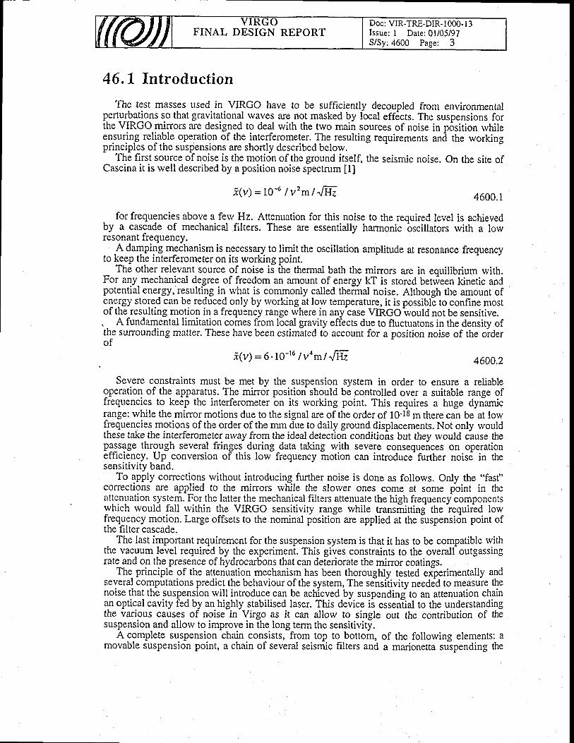
FINAL DESIGN REPORTDoc: VIR-TRE-DIR- I 000- I 3Issue: I Date: 0l/05/97S/Sy:4600 Page: 3
46.1. Introduction
The test masses used in VIRGO have to be sufficiently decoupled from environmentalgert_u$_a!o^ns so that gravitational waves ar9-no_t masked by local eff6cts. The sr-rspensions forthe VIRGO mirrors are designed to deal with the trvo main sources of noise in p6sition rvhileenpuring reliable operation of the interferomelgr. fhe resulting requiremenrs and the workingprinciples of the suspensions are shortly described belorv.
The first source of noise is the motion of the ground itself, the seismic noise. On the site ofCascina it is rvell described by a position noise spectrum [1]
i (v )=10-6/v 'ml" l f r . 4600.1
. for frequencie_s above a ferv Hz. Attenuation for this noise to the required level is achievedby a cascade of mechanical filters. These are essentially harmonic
-oscillators with a low
resonant frequency.A damping mechanism is necessary to limit the oscillation amplitude at resonance frequency
to Eep the interferometer on its working point.The other relevant source of noise is Che thermal bath the mirrors are in eouilibrium with.
For any mechanical degree of freedom an amount of energy kT is stored between kinetic andpotential energy, resulting in wh.at is commonly called thermal noise. Although the amount ofenergy stored can be reduced only by rvorking at lorv temperature, it is possiblE to confine mostof the resulting motion in a frequency range rvhere in any case VIRGO ivould not be sensitive.. A fundamental limitation comes from local graviry effects due to fluctuatons in the density ofth^e surrounding matter. These have been estimated to account for a position noise of the oiderof
i (v) =6. 1o- t6 | voml " l :Hz 4600,2
Severe constraints must be met by the suspension system in order to ensure a reliablelPeration of the apparatus. The mirror position should be controlled over a suitable range offrequencies to keep the interferometer on its rvorking point. This requires a huge dynamicrange: while the mirror motions due to the signal are of the order of 10-18 m there can be at lowfrequencies motion_s of the order of the mm due to daily ground displacements. Not only rvouldthese take the interferometer arvay {rom the ideal detection conditions but they would cause thep1:sage thro_ugh several fringes during data taking with severe consequences on operationefficiency. Up conversion of this lorv frequency motion can introduce- further noisd in thesensitivity band.
To apply corrections without introducing further noise is done as follorvs. Only the "fast"corrections are appfied to the mirors rvhile the slorver ones come at some pbint in theattenuation -s)'s!em. For the latter the mechanical filters attenuate the high frequency componentsrvhich rvould fali rvithin the VIRGO sensitivity range rvhile transititting the iequiied lorvfrequency motion. Large offsets to the nominal position are applied at the iuspension point ofthe filter cascade.
The last important requirement for the suspension system is that it has to be compatible withthe vacuum level required by the experiment. This gives constraints to the overalf outgassingratland ol the presence of hydrocarbons that can deGriorate the mirror coatings.
The. principle of the attenuation mechanism has been thoroughly tested eiperimentally andseveral computations predict the behaviour of the system, The sensiiivity needed to measure thenoise that the suspension rvill introduce can be achieved by suspending to an attenuation chainan optical cavity fed by an highly stabilised laser. This deiice ii essenlial to the understandingthe various causes of noise in Virgo as it can allow to single out the contribution of thesuspension and allow to improve in the long term the sensitivity.
A complete suspension chain consists, from top to bottom, of the following elements: amovable suspension point, a chain of several seismic filters and a madonetta suipending the
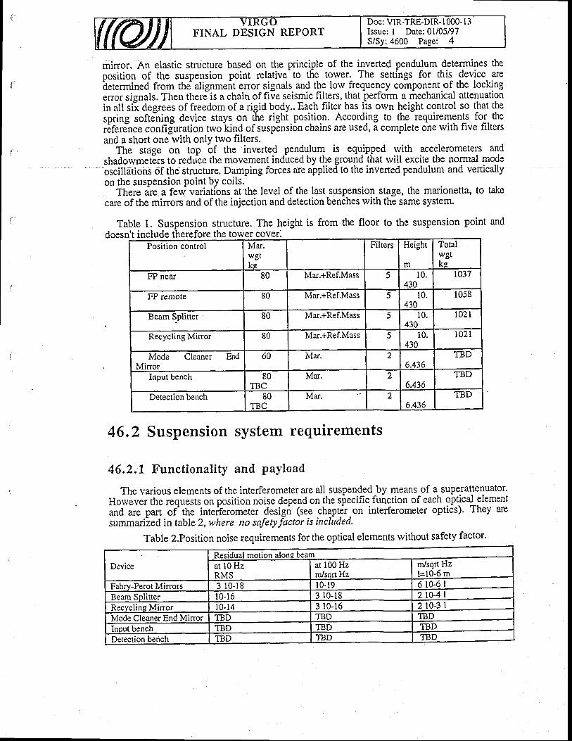
FINAL DESIGN REPORTDoc: VIR-TRE-DIR- I 000- I 3Issue: I Date: 0l/05/97S/Sy:4600 Page: 4
minor. An elastic structure based on the principle of the inverted pendulum determines theposition of the suspension point relative to the tower. The settings for this device areiletermined from the alignment error signals and the low frequency component of the lockingenor signals. Then therJis a chain of five seismic-filters, that.perform a mechanical attenuationin all sil degrees of freedom of a rigid body.. Each filter has its orvn height control so that thespring softJning device stays on the righi position. According to the requirements for therifrrjn.e confifuration trvo kind of suspension chains are used, a complete one rvith five filtersand a short one with only two filters.
The stage on top bf the inverted pendulum is equipped rvith accelerometers andshadorvmetErs to reduce the movement ind-uced by the ground that will excite the normal modeoscillations of the structure. Damping forces are applied to the inverted pendulum and verticallyon the suspension Point bY coils.
There are a few variations at the level of the last suspension stage, the marionetta, to takecare of the mirrors and of the injection and detection benches with the same system.
Table 1. Suspension structure. The height is from the floor to the suspension point anddoesn't include therefore the tower cover.
Position control Mar.wgtke
Filters Height
m
Totalwgtke
FP near 80 Mar.+Ref.Mass 5 10.430
r037
FP remote 80 lvlar.+Ref.Mass ) 10.430
1058
Beam Splitter 80 Mar.+Ref.Mass f, 10.430
l02 l
Recycling Minor 80 Mar.+Ref.Mass ) 10.430
l02 l
Mode Cleaner EndMinor
60 lvlar. 26.436
TBD
Input bench 80TBC
Mar. )6.436
TBD
Detection bench 80TBC
Mar. 26.436
TBD
46.2 Suspension system requirements
46,2.1 Functional i ty and payload
The various elements of the interferometer are all suspended by means of a superattenuator.Horvever the requests on position noise depend on the specific. function of each optical elementand are part of'the interferometer design (see chapt&.on interferometer optics). They aresummari-zed in table 2, where no safetyfactor is included.
Table 2.Position noise requirements for the optical elements rvithout safety factor.
DeviceResidual motion along beamat l0 HzRMS
at 100 Hzm/sort Hz
m/sqrt Hzl=10-6 m
Fabrv-Perot Mirrors 3 r0-18 l0-r9 6 10-6 IBeam Splitter l0-16 3 r0-18 2 t0-4 |Recycline Mirror l0-14 3 r0-16 2 l0-3 |Mode Cleaner End Minor TBD TBD TBDInput bench TBD TBD TBDDetection bench TBD TBD TBD
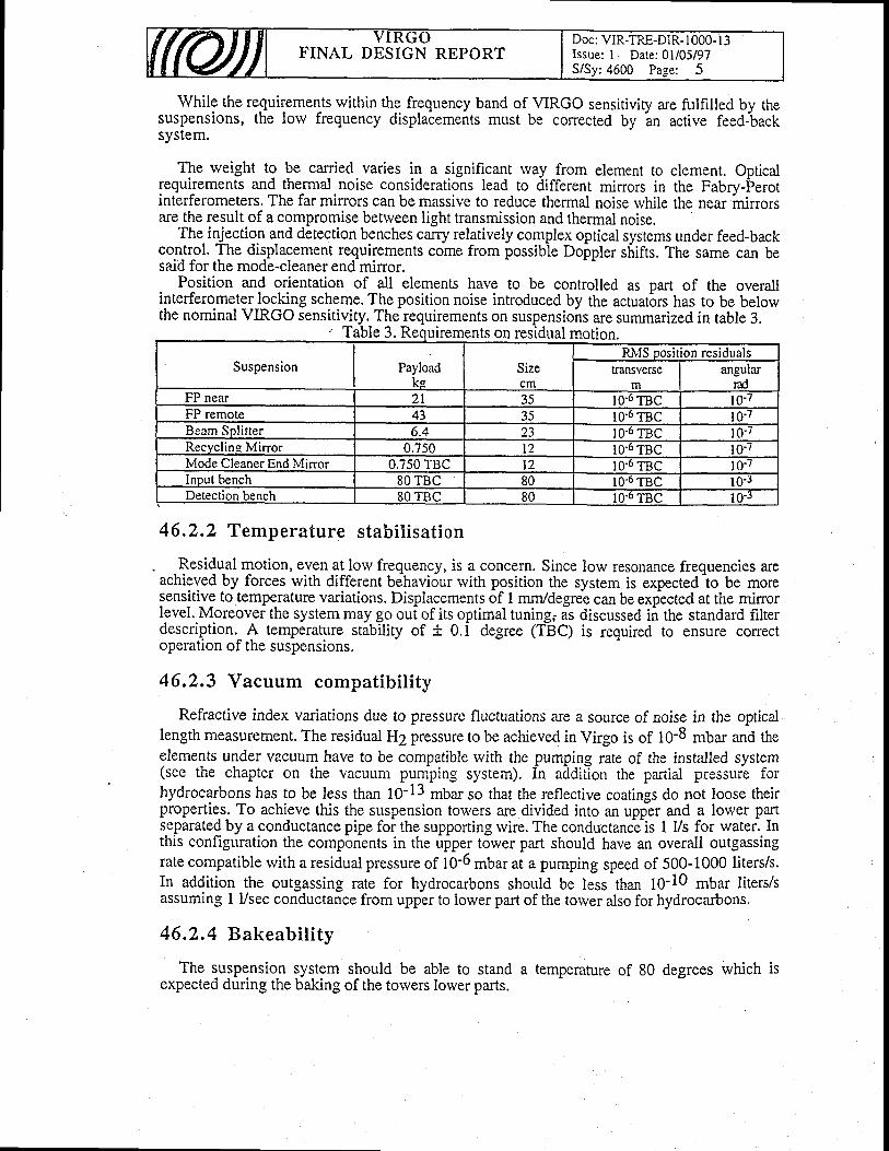
FINAL DESIGN REPORTDoc: VIR-TRE-DIR- 1000- l3Issue: I Date:01/05/97
: 4600 Pa-se: 5
While the requiremerus rvithin the frequency band of VIRGO sensitiviry are flilfilled by thesuspensions, the lorv frequency displa6ements must be conected by
'an active feed-back
system.
The rveight to be carried varies in a significant way from element to element. Opticalrequirements and thermal noise considerations lead to different minors in the Fabrv-Ferotinterferometers. The far mirrors can be massive to reduce thermal noise rvhile the near minorsare the result of a compromise betrveen light transmission and thermal noise.
The injection and detection benches carry relatively complex optical systems under feed-backco.ryr-ol. The displacenent requirements come from possibie Doppler s[ifts. The same can besaid for the mode-cleaner end minor.
Position and orientation of all elements have to be controlled as part of the overallinterferometer locking scheme. The position noise introduced by the actuatbrs has to be belowthe nominaMRco sensitivity. The requirements on suspensions are summarized in table 3.
Table 3. Requi residual moti
46,2.7 Temperature stabi l isat ion
-Residual motion, eygna!lorv frequency, is a concern. Since low resonance freguencies areachieved by forces with different behaviour rvith position the system is expected io be moresensitive to temperature variations. Displacements of I mm/degree can be expected at the mirrorlevel. Moreover the system may go oul of its optimal tuning; as discussed in the stan<iard fiiterdescription.-A temperarure stability of + 0.1 degree (TBC) is required to ensure correctoperation of the suspensions.
46.2.3 Vacuum compatibility
Refractive index variations due to pressure fluctuations a.re a source of noise in the opticallength measurement. The residual H2 pressure to be achieved in Virgo is of 10-8 mbar and theelements under vacuum have to be compatible rvith the pumping rate of the installed system(see the chapter on the vacuum pumping system). In addition the partial pressure forhydrocarbons has to be less than 10-13 mbar so that the reflective coatings do not loose theirproperties. To achieve this the suspension towers are divided into an upper and a lower partseparated by a conductance pipe foi the supporting rvire. The conductance'is I Vs for water. Inthis configuration the components in the upper tower part should have an overall outgassingrate compatible with a residual pressure of 10-6 mbar at a pumping speed of 500-1000 liters/s.In addition the outgassing rate for hydrocarbons should be less than 10-10 mbar liters/sassuming I Vsec conductance from upper to lower part of the torver also for hydrocarbons.
46.2,4 Bakeabi l i ty
The suspension system should be able to stand a temperature of 80 degrees which isexpected during the baking of the towers lower parts.
rements on motion.
Suspension Payloadks
Sizecm
fu\{S position residualsransverse
mangular
radFP near 2 l 35 10'6 TBC l 0 - /FP remote 43 35 l0'6 TBC l0 - /Beam Solitter 6.4 23 l0-o TBc l0- /Recvcline Mirror 0.750 t2 IO.O TBC l0-7Mode Cleaner End lvlinor 0.750 TBC t2 1O.O TBC l0 ' /Inout bench 80 TBC 80 10-o TBC l0-rDetection bench 80 TBC 80 l0'6 TBc 10-r

lI
{
46.3 Suspension interfaces
The suspension system has a number of sensors to monitor its state and a number ofactuators to achieve, directly indirectly, minor positioning. External information needed toposition mirrors comes from the interferometer elror signals, local postition monitors andiommands to define the behaviour of the digital filters that synthetize force signals. Suspensionelectronics (4900) takes care of this, producing cunents that feed the control coils and steppingmotors.
46.3.L Interface tYith torvers
The intemal suppoft structure must fit the torver basis and must hook to the torver rings.Baking of the tower lower part causes high temperarures to be achieved in the upper part,
where some elements cannot reach high temperatures.
46.3.2 Interface \yith local electronics
Cables for LVDT, stepping motors and control coils must be connected to the localelectronics. Since in the present design no active element stays inside the vacuum lYstemconnections will mostly lie analog and have to be noise-free. This is true in particular forsignals acting on mirrois, rvhere soldering is mandatory. The detailed description of the signalsis available in the cabling sub-subsytem description.
.46.4 Detailed description
The solution adopted for the VIRGO suspensions is a sophisticated mechanical structure,called Superattenuaior, able to filter the seiimic noise down to frequencies of a few Hertz' ( f ig . 4600.1) .'
ine suspension consists in a cascade of massiv,e pendula 1.2 m each connected one to theother. The working principle relies on the fact that foi frequencies above the resonances of thesystem each stage can be ieen as a filter attenuating a signal by a factor
4600.4A@)*4a -
as is well knorvn from the behaviour of a driven harmonic oscillator. In this way the use ofpendulum properties results in an attenuation of the position noise from the suspension point tothe swinging mass.
It turn-s oit that due to uncontrollable couplings between the pendular and other degrees offreedom it is necessary to attenuate also r6tatlons and the m6tion in the vertical direction.Rotational degrees of freedom are tal<en care of with high moments of inertia and short leverarms for torqrie application. This is achieved by having the connections at the filter level veryclose one to ihe oiher. The resulting resonance frequencies are of the order of I Hz.
In the vertical direction a simili result is achieved by suspending the next element of thechain through springs. Horvever the resonant frequency o-f the system i9 U9 {S} if theSuperattenuitor i's tibe sustained with an acceptabl6 elongation. To-reach also in this case aioi r"ronunt frequency these springs are "softened" aroun-d the rvorking position by means ofa force increasing locally with displacement.
The solution "uaopt".i
for the siismic filters uses magnets in a repulsive configuration thatmove transversaily to their magnetic field.
The attenuatioi of the seisitic noise has been studied experimentally. This result doesn'ttake into account further attenuation that can be achieved using the systam designed to dampnormal mode oscillations.
FINAL DESIGN REPORTDoc: VIR-TRE-DIR- I 000- I 3Issue: I Date: 0l/05/97S/Sy:4600 Page: 6
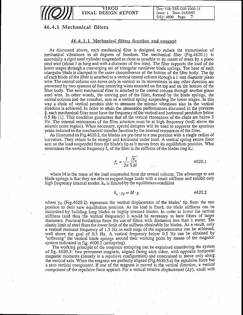
FINAL DESIGN REPORTDoc: VIR-TRE-DIR-l 000- I 3Issue: I Date; 0l/05/97SiSy:4600 Page: 7
46"4.1 Mechanica l f i l ters
46.4.1.1 Mechanica l f i l ters funct ion and concept
As discussed above, each mechanical filter is designed to reduce the transmission ofmechanical vibrations in all degrees of freedom. The mechanical filter (Fig.4620.1) isessentially a rigid steel cylinder suspended as close as possible to its center of mass by a pianosteel wire (about I m long and rvith a diameter of ferv mm). The filter supports the load of thelower stages through a converging set of triangular cantilever blade springs. The base of eachtriangular blade is clamped to the outer circumference of the bottom of the filter body. The tipof eaih blade of the filt6r is attached to a vertical central column through a I mm dianr'eter pianbwire. The central column can move only in vertical as its movements-in any other direction areprevented by trvo systems of four centering rvires mounted on the top and 6n the bottom of thefilter body. The next mechanical filter is attached to the central column through another pianosteel rvire. In other words, the moving part of the filter, formed by the blade springs, thecentral column and the crossbar, acts as a vertical spring suspending the lorver stages. In thisway a chain of vertical pendula able to attenuate the seismic vibrations also in the verticaldirection is achieved.In order to attain the attenuation performances discussed in the previous$, each mechanical filter must have the frequency of the vertical and horizontal pendulum below0.5 Hz [1]. This condition guarantees that all the vertical resonances of the chain are belorv 3Hz. The intemal resonances of the fllter structure must be at high frequency (rvell above theseismic noise region). When necessary, special dampers will be used to suppress the spuriouspeaks induced in the mechanical transfer function by the internal resonances of the filter.. As illustrated in Fig.4620.2, the blades are pre-bent to a rest position with a single radius ofcurvature. They return to be straight and horizontal under load. A vertical spring rerurn forceacts on the load suspended from the blade's tip as !t moves from its equilibrium position. Whatdetermines the vertical frequency fu of the filter is the stiffness of the blades ring ku:
€ -J v -
I W2r\ I,I
4620.1
where M is the mass of the load suspended from the central column. The advantage to useblade springs is that they are able to support large loads with a small stiffness and exhibit onlyhigh frequency internal modes. k" is limited by the equilibrium condition
k r ' ) ' o = M ' 8 462Q.2
rvhere yo Gig.4620.2) represents the vertical displacement of the blades' tip from the restposition to their new equilibrium position. As the load is fixed, the blade stiffness can beininimized by building lbng bladei or highly stressed blades. In order to lorver the verticalstiffness (and thus tlie vertical frequency) it would be necessary to have filters of largerdiameters. Practical limitations force the rise of filters with diameiers less than 1 meter. Theelastic limit of steel fixes the lower limit of the stiffness obtainable for blades. As a result, onlya vertical resonant frequency of 1.5 Hz in each stage of the superattenuator can be achieved,rvell above the goal of 0.5 Hz. A vertical frequincy below 0.5 Hz can be obtained by"softening" the virtical blade springs around their rvoiking point by means of the magneticsystem indicated in fig. 4600.2 (antispring).
The rvorking princlple of the magnetic antispring can be explained considering the systemof fig. 462A3: two permanent magnets, aligned facing each other, with opposite honzontalmagietic moments (n-amely in a refulsive configuration) and constrained to-move on^ly alongthe vertical axis. When the magnets- are perfectly aligned (Fig.4620.3.a) the repulsive force hasa zero vertical component. If 5ne of th6 magnets iimoved in the vertical dir-ection, a verticalcomponent of the r6pulsive force appears. For a vertical relative displacement (Ay), small with
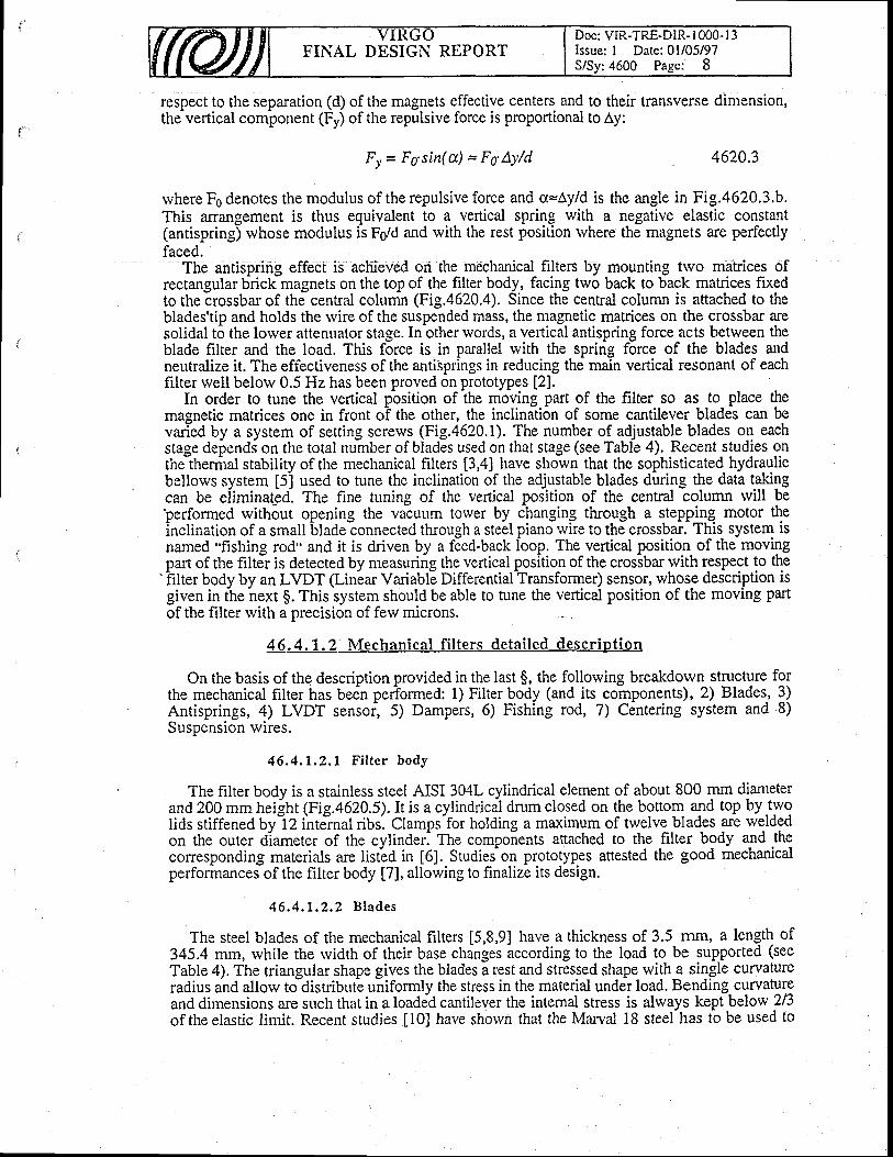
FINAL DESIGN REPORTDoc: VIR-TRE-DIR- 1000- I 3Issue: I Date:01/05/97S/Sy:4600 Page: 8
respect to the separation (d) of the magnets effective centers and to their transverse dimension,the vertical component (Fy) of the repulsive force is proportional to ly:
F r* = F o'sitt( a) = F o' AY/d 4620.3
rvhere Fe denotes the modulus of the repulsive force and s=Ay/d is the angle in Fig.4620.3.b.This anangement is thus equivalent to a vertical spring with a negative elastic constant(antispring) whose modulus is Fs/d and rvith the rest position rvhere the magnets are perfectlyfaced.
The antispring effect is achieved on the mechanical filters by mounting trvo matrices ofrectangular brick magnets on the top of the filter bodyr facing two back to back matrices fixedto the crossbar of the central column (Fig. 620.q. Since the central column is attached to theblades'tip and holds the rvire of the suspended mass, the magnetic matrices on the crossbar aresolidal to the lorver attenuator stage. In other words, a vertical antispring force acts between theblade filter and the load. This force is in parallel with the spring force of the blades andneutralize it. The effectiveness of the antisprings in reducing the main vertical resonant of eachfilter well below 0.5 Hz has been proved on prototypes [2].
In order to tune the vertical pbsition of the moving part of the filter so as to place themagnetic matrices one in front o-f the other, the inclination of some cantilever blades can bevaried by a system of setting screws (Fig.4620.1). The number of adjustable blades on eachstage depends on the total number of blades used on that stage (see Table 4). Recent studies onthelhermat stability of the mechanical filters [3,4] have shown that the sophisticated hydraulicbellows system [5] used to tune the inclination of the adjustable blades during the data tukilgcan be eliminated. The fine tuning of the veftical position of the central column rvill beperformed rvithout opening the vacuum torver by changing through a stepping motor theinclination of a small
-blade connected through a stei:l piano rvire to the crossbar, This system is
named "fishing rod" and it is driven by a f-ed-back lbop. The vertical position of the movingpart of the filtJr is detected by measuring the vertical position of the crossbar with respect to the
'hlter body by an LVDT (Linbar Variable Differential Transformer) sensor, whose description isgiven in the hext g. This system should be able to tune the vertical position of the moving partof the filter with a precision of few microns.
46.4.1.2 lV lechanica l f i l ters deta i led descr ip t ion
On the basis of the description provided in the last $, the follorving breakdown structure forthe mechanical filter has bedn pertormed: 1) Filter body (and its components), 2) Blades-, 3)Antisprings, 4) LVDT sensoi 5) Dampers, 6) Fishing rod, 7) Centering system and 8)Suspension wires.
46 .4 .1 .2 .1 F i l t e r bodY
The filter body is a stainless steel AISI 304L cylindrical element of about 800 mm diameterand 200 mm heilht Fig.4620.5). Ir is a cylindrical drum closed on the bottom and top by.tY9lids stiffened by-l2 intirnal ribs. Clamps-for holding a maximum of twelve blades are weldedon the outer diameter of the cylinder. The compoients anached to the filter body a1d Jhgconesponding materials are listed in t6l. Studieion prototypes attested the good mechanicalperformances of the filter body [7], allorving to finalize its design.
4 6 . 4 . 1 . 2 , 2 B l a d e s
The steel blades of the mechanical filters [5,8,9] have a thickness of 3.5 mm, a length of345,4 mm, while the rvidth of theirbase changes according to the load to be supported (seeTable 4). The triangular shape gives the blades a rest and stressed shape with a single curvarureradius and allorv to distribute uniformly the stress in the material under load. Bending curvatureand dimensions are such that in a loaded cantilever the internal stress is always kept below 2/3of theelastic limit. Recent studies [0] have shorvn that the Marval 18 steel has to be used to

FINAL DESIGN REPORTDoc: VIR-TRE-DIR- 1000- I 3Issue: I Dare: 01i05/97S/Sv: 4600 Page: 9
avoid creep in the blades. This material rvill replace the C70 stainless steel, used in the firstprototypes. The follorving thermal treatment of the Marval 18 has provided the best results intermsof creep: solubilization at 825'C for I hour under vacuum (or in neutral environment),natural cooling at room temperature and aging at 480 oC for 16 hour. Starting from this raivmaterial, the blades rvill be constructed following the design of Fig.4620.2. All the blades rvillbe protected from rust formation rvith a thin layer of nickel. The blades under load exhibit a 1.5Hz pendulum mode and the first flexural mode at about 100 Hz.
In Table 4 the main characteristics of the blades mounted on each filter of the chain arereported. A full characterization of the mechanical perfonnances of the cantilever blades hasbeen given in [5,8,9]. The blades have been heated under load at 800C rvithout significanteffects in their mechanical performances. Future tests should allorv to identify the maximumbaking temperature tolerated by the blades under stress.
46.4.1.2.3 Ant ispr ings
Each of the four magnetic matrix mounted on the filter (Fig.4620.4) is made of two or fourlines of Philips ferroxdure (FXD 330) magnets (6 x 2 x 1.5 cm3) producing a nominal magneticfield of 0.36 Tesla in the direction parallel to the 1.5 cm dimension [l 1]. Each line of magnetsin the matrix has the sense of the magnetic field opposite both to that of the neighboring line, inthe same matrix, and to that of the line facing on the opposite matrix. This configuration allowsto minimize the total magnetic dipole of the system, reducing the coupling with the extemalmagnetic field [2]. The number of magnets in each line is decreased from the top to the bottomfilter to match roughly the need of antispring elastic constant. 24 magnets per matrix rvill beused on the first filter, 20 on the second one, 16 on the third one and 12 on the fourth one. Finetuning of the antispring force is obtained by setting the horizontal separation of the magnetic'matrices. A vertical frequency of 0.4 Hz on the filter can be attained with a separation betweenthe magnetic matrices of about 1 cm. The supports (Fig.4620.4) will be made of Titanium, amaterial shorving the same thermal dilation coefficient of the magnets. A full characterization ofthe antispring system (dependence on the positioning, on the temperature and on the number ofmagnets) has been given in l2,l3l. This rvork has shown that large tolerances are allowed inthe assemblv of the antisDrins matrices. The main problem arises from the strong dependence
'magnets) has been given in l2,l3l. This rvork has shown thatthe assembly of the antispring matrices. The main problem arises from the strong dependenceof the permanent magnetic field on temperature. In order to keep the magnetic matrices alignedof the permanent magnetit field on temperature. In order to keep the magnetic matrices alignedrvithin the vertical working range (about one hundred of midlons), it is nlcessary to reduce thefilter thermal swinss. stabilizine the temperature of the VIRGO towers. A thermal stabilizationfilter thermal swings, izing the temperature of the VIRGO towers. A thermal stabilizationof few tenths of degree peak to peak is necessary [14].
Both the magnets and the titanium supports exhibit good vacuum performances. The glueproposed for attaching the magnets on the supports is VAC-SEAL [15]. This glue has shown avery low outgassing rate. The mechanical performances of this glue have not been still certifiedand other cheaper glues are also under test.
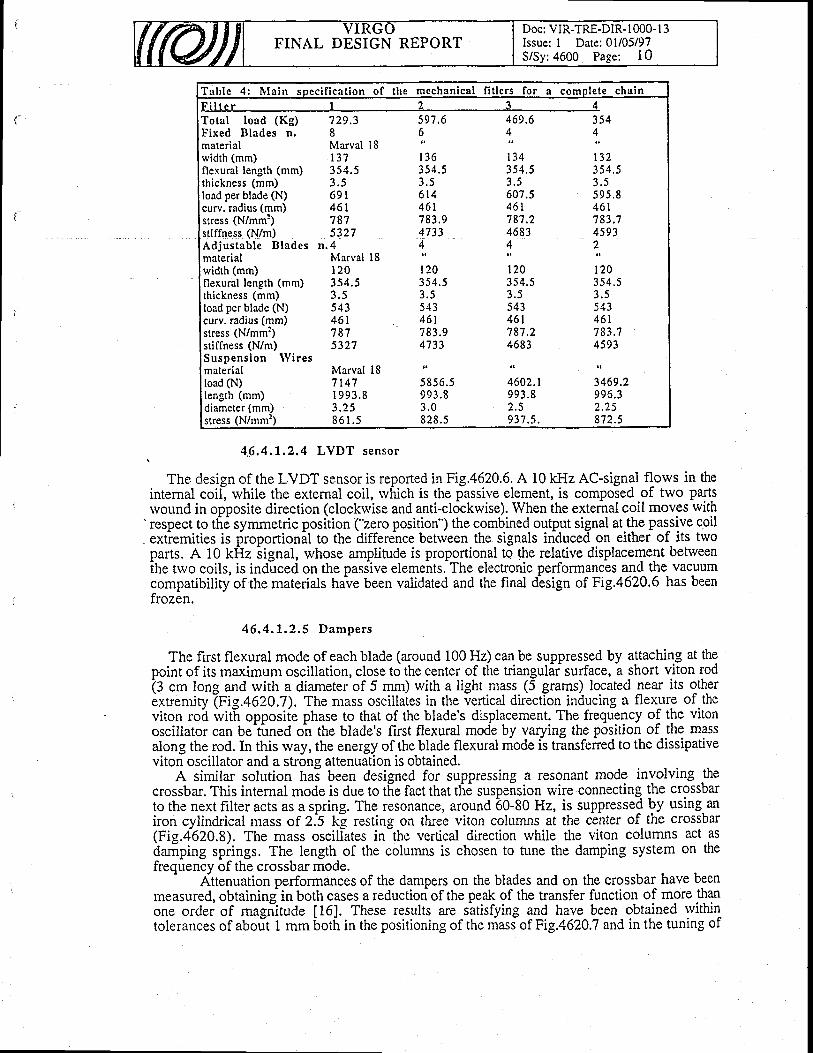
FINAL DESIGN REPORTDoc: VIR-TRE-DIR- I 000- I 3Issue: I Date: 0l/05/97S/Sy:4600 Page: 10
Tab le 4 : I l l a in soec i f i ca t ion o f the me al f i t lers a complF i l t e r | 2
Total load (Kg)F ixed B lades n .materialwidth (mm)flexural length (mm)thickness (mm)load per blade (N)curv. radius (mm)stress (N/mm:)stiffness (N/m)Adjustable Bladesmaterialwidth (mm)tlexural len-eth (mm)thickness (mm)load per blade (N)curv. radius (mm)stress (N/mm:)stiffness (N/m)Suspens ion Wi resmaterialload (N)length (mm)diameter (mm)stress (N/mm:)
729.38Marval I8r37354 .5? s6 9 r4 6 17875327
n . 4lvtarval 181 2 03s4 .53 . 55434 6 t7815327
Marval 187 147r 993 .83 . 2 58 6 1 . 5
597.6
1,1 3 6354 .53 . 56r4461783.94733
1,r203s4.53 . 5543461t 65 . v4733
5 85 6 .59 9 3 . 83 . 0828 .5
469.6
;;-354.5J . )
607.54 6 1787.24683A
i ,o354 .53 . 5543461187.24683
4602.r9 9 3 . 82 .5937 .5.
354
1,t32354.53 . 5< o < R461783.14593
7,t 2 0354.53 . 5< ̂ ' ,
461183.14593
3469.2996 .32 .25872.5
.6 .4.1.2.4 LVDT sensor
The design of the LVDT sensor is reported in Fig.4620.6. A 10 kllz AC-signal fl_ows in theinternal coil, while the external coil, rvhich is the passive element, is composed of two partsrvound in opposite direction (clockrvise and anti-clockwise). When the extemal coil moves with
'respect to th6 symmetric position ("zero position') the combined output signal at the passive coilextiemities is lSroportionil to the difference betrveen the signals induced on eithef of its tivoparts. A 10 kHz iignal, whose amplitude is proportional to the relative displacement betweenihe trvo coils, is induced on the passive elements. The electronic performances and the vacuumcompatibilityof thematerials have been validated and the final dbsign of Fig.4620.6 has beenfrozen.
46 .4 .1 .2 .5 Dampers
The first flexural mode of each blade (around 100 Hz) can be suppressed by attaching at thepoint of its maximum oscillation, close to the center of the triangular surface, a short viton rod(g cm long and with a diameter of 5 mm) with a light mass (5 grams) located near its otherextremity \Vig.+AZO.l). The mass oscillates in the vertical direction inducing a flexure of theviton rob ivit[ opposiie phase to that of the blade's displacement, The frequency of the vitonoscillator can be-tirned on the blade's first flexural mode by varying the position of the massalong the rod. In this rvay, the energy of the blade flexural mode is transfened to the dissipativeviton oscillator and a strong attenuation is obtained.
A similar solution hal been designed for suppressing a resonant mode involving rhecrossbar. This internal mode is due to the fact that the suspension wire connecting the crossbarto the next filter acts as a spring. The resonance, around 60-80 Hz, is suppresse{ by using. aniron cylindrical mass of 2.5 k! resting on three viton columns at the center of the crossbar(Fig.4620.8). The mass oscillates in-the vertical direction while the viton columns act asilamping spiings. The length of the columns is chosen to tune the damping system on thefrequency of the crossbar mode.'
Attenuation performances of the dampers on the blades and on the crossbar have beenmeasured, obtaining in both cases a reduction of the peak of the transfer function of more thanone ordei of magiirude t161. These results are satisfying and have been obtained rvithintolerances of aboit I mm both in the positioning of the niass of Fig.4620.7 and in the tuning of
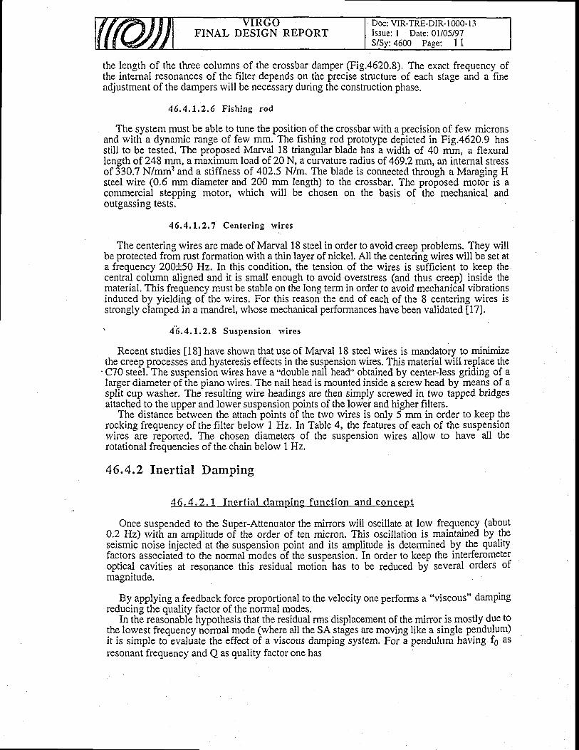
the length of the three columns of the crossbar damper (Fig.a620.8). The exact frequency ofthe internal resonances of the filter depends on the precise structure of each stage and a fineadjustment of the dampers rvill be necessaly during the construction phase.
46 .4 .1 .2 ,6 F i sh ing rod
The system must be able to tune the position of the crossbar with a precision of ferv micronsand rvith a dynamic range of few mm. The fishing rod prototype depicted in Fig.4620.9 hasstill to be tested. The proposed Marval 18 triangular blade has a rvidth of 40 rnm, a flexurallength of 248 rnm, a maximum load of 20 N, a curyature radius of 469.2 mrn, an internal stressof 330.7 N/mm' and a stiffness of 402.5 N/m. The blade is connected through a Maraging Hsteel wire (0.6 mm diameter and 200 mm length) to the crossbar. The proposed motor is acommercial stepping motor, rvhich rvill be chosen on the basis of the mechanical andoutgassing tests.
46.4, t .2 ,7 Center ing rv i res
The centering wires are made of Marval 18 steel in order to avoid creep problems. They willbe protected from rust formation rvith a thin layer of nickel. All the centering wires rvill be set ata frequency 200+50 Hz. In this condition, the tension of the wires is sufficient to keep thecentral column aligned and it is small enough to avoid overstress (and thus creep) inside thematerial. This frequency must be stable on the long term in order to avoid mechanical vibrationsinduced by yielding of the rvires. For this reason the end of each of the 8 centering wires isstrongly clamped in a mandrel, rvhose mechanical performances have been validated [17].
' 4 ' 6 .4 ,1 .2 .8 Suspens ion r v i r es
Recent studies [18] have shorvn that use of Marval 18 steel rvires is mandatory to minimizethe creep processes and hysteresis effects in the suspension wires. This material rvill replace the
'C70 steel. The suspension wires have a "double nail head" obtained by center-less griding of alarger diameter of the piano rvires. The nail head is mounted inside a screw head by means of asplit cup washer. The resulting rvire headings are then simply screrved in two tapped bridgesattached to the upper and lower suspension points of the lower and higher filters.
The distance between the attach points of the two rvires is only 5 mm in order to keep therocking frequency of the filter belorv 1 Hz. In Table 4, the features of each of the suspensionrvires are reported. The chosen diameters of the suspension wires allow to have all therotational frequencies of the chain below 1 Hz.
46,4,2 Inert ial Damping
46.4.2.1 Iner t ia l c lamping funct ion ant l concept
Once suspended to the Super-Attenuator the minors will oscillate at low frequency (abo.ut0.2 Hz) rvith an amplitude of the order of ten micron. This oscillation is maintained Uy j.heseismic noise injected at the suspension point and its amplitude is determined by th-e qualityfactors associated to the normal modes oT the suspension. In order to keep the interferometeroptical cavities at resonance this residual motioir has to be reduced by several orders ofmagnitude.
By applying a feedback force proportional to the velocity one performs a "viscous" dampingreducing the quality factor of the normal modes.
In the reasonable hypothesis that the residual rms displacement of the minor is mostlydue tothe lowest frequency rirjrmal mode (where all the SA stages are moving like a single pendulum)it is simple to-evaluate the effect of a viscous darnping system. For a pendulum having fg asresonant frequency and Q as quality factor one has
FINAL DESIGN REPORTDoc: VIR-TRE-DIR-l 000- I 3Issue: I Date: 0l/05/97S/Sy: 4600 Page: I 1
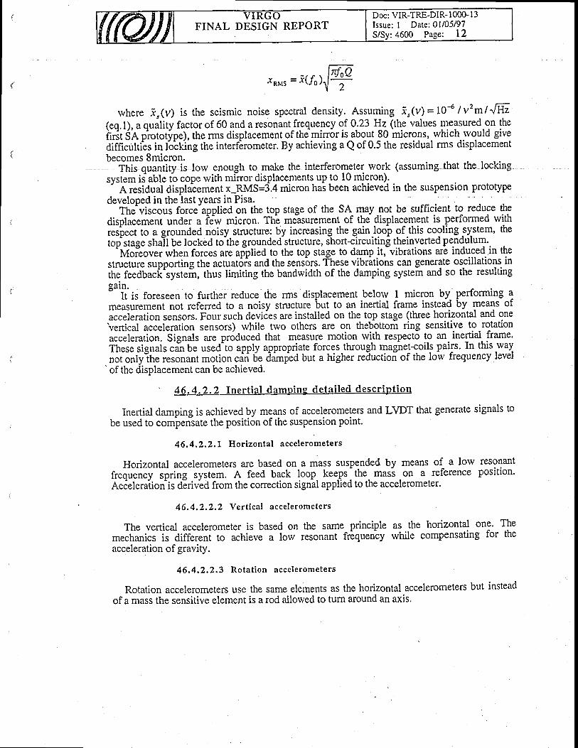
* - ; / f \a gr15 - ^ \J 0 , f
becomes 8micron.This quantity is lorv enough to.mqke the interferometer work
rvhere i"(v) is the seismic noise spectral density. Assuming i,(v)= LO4 tvzmlJfr.(eo.l). a quilitv factor of 60 and a resonant frequency of 0.23 Hz (the values measured on theiitit SA p'rototype), the rms displacement of the mirror is about 80 microns, which-rvould giveaifficutties in lircking the interfirometer. By achieving a Q of 0.5 the residual rms displacement
system is able to cope rvith minordi
developed in the last years.in Pisa.The^viscous force-applied on the top stage of the SA- ryay -not be sufficient to reduce theoiu"".n"nt under a idw micron. The measurement of the displacement is performed rvithOispiaiement under a ii* micron. Tht me-asurer-nent of the displacement is,perform.d tu]j!
respect to a grounded noisy structure:totstase shall be locked to the ground
rded noisy structure: by increasing the gainJoo-p of .this cooling system, theIocked to the grounded structure, short-Circuiting theinverted pendulum.top stage iting theinverted pe.nd_ulum.
;tem ii able io cope rvith minor displacements upto 10 micron)-A residual displacement x-RMS=3.4 micron has been achievedrelooed in the last vears in Pisa.
(assuming that the locking
in the suspension PrototYPe
go--'fufoi"ouii
*tt"n foic"s are afplied to the top stage to damp it,-vibrations are induced in thert*.tut" tupporting the actuat6rs and the sensors. These vibrltions can generate oscillations initre ieeOUact^iyst"i-t, thus limiting the bandwidth of the damping system and so the resultinggain.
measurement not referred to a noisy structure3ment belorv 1 micron by performing ato an inertial frame instead by means of
It is foreseen to further reduce the rms displacement belorv 1 micron bynsrrrement not referred to a noisv structure but to an inertial frame insteai
acceleration sensors. Four such deviies are installed on the top stage (three horilontal and one'vertical acceleration sensors) rvhile trvo others are on thebbttom ring sensitive to rotationu...f.ruiion. Sign^fs are produced that measure motion rvith respecto to an. inertiai, Iu*::ih.;; ;i$tfsifi be uied^to apply appropriate forces.through magiret-coils pairs. In this waynor onlv rhe resonant motion citi 6e ddmpleA but a higher reductioi of the lorv frequency levelnorontyih" resonant 1notLn .u^ti f5. ,idmpi.rA but a higher reductioi of the loiv frequency levelnot onlv tne resonan[ mouon can ocof the ciisplacement can be achieved.
4 6.4 -2 .2 Iner t ia l dampins de ta i led descr ip t ion
Inertial damping is achieved by mgans of accelerometers and LVDT that generate signals tobe used to cornpensate the positi6n of the suspension point'
46,4.2,2,1 Hor izonta l accelerometers
Horizontal accelerometers ale based on a mass suspended by means of a lorv resonantfreouency spring system. A feed back loop keeps
- the mas-s on a reference position.
Acieleraiion is OEriv'eA from the conection signal applied to the accelerometer.
46.4.2,2.2 Vert ica l accelerometers
The vertical accelerometer is based on the same principle as the horizontal one. Themechanics is different to achieve a lorv resonant frbqueniy while compensating for theacceleration of graviry.
46,4.2.2.3 Rotat ion accelerometers
Rotation accelerometers use the same elements as the horizontal accelerometers but insteadof a mass the sensitive element is a rod allorved to turn around an axis.
Doc: VIR-TRE-DIR- 1000- I 3Issue: I Date: All05l97S/Sy:4600 Page: 12
FINAL DESIGN REPORT
rfoQ2
FINAL DESIGN REPORTDoc: VIR.TRE-DIR- I OOO- I 3Issue: I Date: 0l/05/97S/Sy: 4600 Page: I 3
46.4.3 Fi l ter 7 (or steering f i l ter)
The last filter of the chain, historically called filter 7, holds the coils that steer the marionettaand the injection and detection benches. It must be able to exert forces and torques on themarionetta to set the minor longitudinal and angular position. Such an action rvill cause a recoilof the filter and the system filter7+marionetta rvill have a dynamics similar to the one of trvomasses held by a sprint and must be taken into account rvhendesigning the feedback control.
To reduce lhe power dissipateed in the steering coils mechanical offsets of the filter positionhave been included. The rest angular position of filter 7 with respect to the conductance bechersandtheangularpositionof the marionetta have to be adjusted. Furthermore the angle the filtermakes rvith the vertical has to be adjusted as rvell.
During the baking process of the tower lorver part the legs will be heated as rvell. The filtermust be designed to resist to the temperarure it rvill reach during baking. Calculations are inprogress to determine the temperature distribution in the whole chain.
f [ .4 .3.1 F i l ter 7 deta i led descr ip t ion
Filter 7 consists in a modified standard filter body to allow for vertical rotation of the filteritselfrvith respect to the suspension and of the wire suspending the marionetta. Two vacuumcompatible ceramics ball bearings allorv for rotation, steered by trvo stepping motors.
Balancing of the filter is achieved by means of a plate that acts as countenveight on the topthe filter body. The position of the plate can be adjusted in the x-y direction by steppingof the filter
. The legs and.coils have to be connected in a sufficiently rigid way not to introduce furtherresonances in the system. This is achieved rvith an additional plate bolted to the filter body.
A drawing of filter ) is shorvn in figure 4640.I
.46.4.4 Top Stage
46.4.4.1 Top stage funct ion and concep!
The motion at frequencies belorv the first resonance frequency of the superattenuator have tobe achieved by moving the suspension point. The top stage lays at the top of the metal supportstructure of the torvers. It defines the average position of the whole SA at the level of a fewmicron while carrying the whole rveight (about 1 ton)
The requirement for smooth motion with a large load over a large range leads to a systemmoving in elastic regime. This is achieved by building a structure hereby called Filter 0 thatrests on three beams. These beams 6 meter high are fixed to a ring by means of elastic joints. Alarge motion at the top results in a small deformation of the joint. A ielevant consequence is thatthe elastic recaliing force on Fiiter 0 can be small, leading to lorv resonance frequencies of thesystem.
The ring is itself supported by piezoelectric feet that maintain it horizontal. Noise in themotion comes in priciple only from internal friction in the metal of the joints. This allows to
The position of the plate can be adjusted in the x-y direction by steppingen to perfonn these adjustments quite unfreqr.rently and outside data taking
. r r t l t v 4 -J uuvv t rv
motors. It is foreseen to perfonn these adjustments quite unfreqr.rently-and outside data takiperiods.
move the ion p-oint smoothly during data taking to compensate for slow ground motion.rve tne Suspenslon polnt Smoothly dunng data taxrng to Compensate IOr SlOw grounq motlon.Horizontal motion-is obtained rvith stepping motors workiig under vacuum that push and
pull Filter 0 supporting the suspension -point.
Finally a mechanism raises and lower thesuperattenuator by means of a screw.
A drawing of the whole system is shown in fig 4.All these motions are rem6tely controlled but an offset can be applied at assembly time to the
position around the vertical axis. All stepping motors have an absotute position readout to allorvfor reliable operation rvhen the torver is closed.
The vertical lift contains a recirculating ceramicball bearing that can rvork under vacuum.

FINAL DESIGN REPORTDoc: VIR-TRE-DIR- I 000- I 3Issue: I Date: 0l/05/97S/Sy:4600 Page: 14
46.4.4.2 Suppor t s t ructure funct ion and concept
The support structure holds the safety rings for the seismic filters. In addition they hold thecoils and-siepping motors of the top itage. Finally they bring the cables to the top of thesuspension chain.
46.4.4.3 Top stage deta i led .descr ip t ion
The top srage consists in an elastic structure lqsting_on- q rigid ring, The ring !1self is kep!horizontai by * active feedback on angular position. By keeping the res-onance freQuency o.fthe structure belorv 100 mHz a significant atlenuation in the horizontal direction is achieved.This results also in lorv forces tliat need to be applied to compensate for the ground slorvmotion.
A simple inverted pendulum is made of a light vertical- stick frxed on ground by means of anelastic joint. A rveightat the top of the stick is source of a vertical force. For small angles therestoring moment is given by
M = -(k-mgl)0where m is the mass at the top of the stick, I is the length, k is the elastic constant of the joint
and 0 is the angle of the inverted pendulum with respect to the vertical. The resonancefrequency can be brought to zero by increasing the rveight.
Practii:al realisation requires to tirlie into account the stick moment of inertia and to allow fortolerances in the joint elaltic constant. A system made of three inverted pendula supporting.atable is more corirplex and prototypes havd been developed to understand the dyynamics indetail and to measure seismic attenuation.
The resulting design consists in a support ring that is kept horizontal by means of ttfeepiezoelectric feets. Tliis ring supports the elastic joints, that apply their restoring momenfum at'th. "per"ussion point" of eich itick, using rotati5n inertia to impiove seismic- attenuation. With
. a rigid connectio^n of the top table to the tfuee sticks the torsional resonance frequency is muchhigfier than the pendulumbnes. The top table is therefore suspended by means of rvires: atoision of the sy-stem is achieved by inclination of the sticks only rvithout torsion of the elastic10tnt."
To achieve attenuation in the vertical direction too the top table has metal springs to supportthe suspension point, the resulting structure being similarlo- a standard filter, but of a largersize (Fiiter 0). This fiiter is suspetided at the top extremity of Jl,t legs by wires. The reason isthat a rigid structure at the top would make the system more stiff.
LVDT provide a position-measurement of filter 0 rvith respect to the safety.structure (see4650) rvhiih supports also coils and stepping motors for positioning the suspension point.
46.4,5 Cabl ing
46.4.5.1 Cabl ing funct ion and concept
The cables are used for the electrical connection between the equipment inside the towersand the one outside. Inside the tower these cables go down along ih6 suspe-nsion to reach allfilt.rs, the marionetta and the reference mass, or ihe optical tabJe . Theiefore they must.ber.f..i,ia taking into account their vacuum tompatibiliry, seismic isolation compatibility,.fi.iti"uf "o.frutiUiiity (cumeni intensity, impedante, crosi talk, etc.). Besides they should notintroduce additional noise, for example by rubbing one against the other.
Table 5 gives the number of cabies n6eded foi a full'tower before any optimization. Thesecables have a typical length of about 10 m.
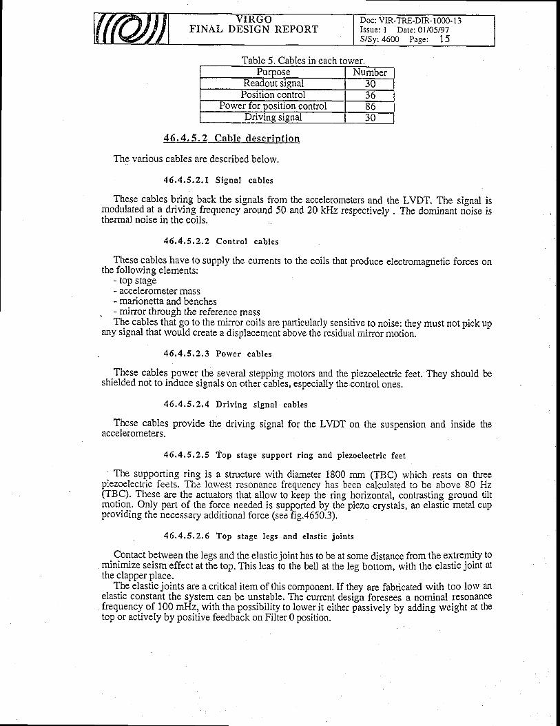
FINAL DESIGN REPORTDoc: VIR-TRE-DIR- 1000- I 3Issue: I Date: 0l/05/97S/Sy: 4600 Page: I 5
Table 5. Cables in each torver.
lon contror lor posltlon con
{6 .4 .5 .2 Cab le desc r ip t i on
The various cables are described belorv.
46 .4 .5 .2 .1 S igna l cab les
Jhgse cables-b.ring b-ack the signals from the accelerometers and the LVDT. The signalmodulatedat a driving.frequency around 50 and 2AkHz respectively. The donrinant n-oisethermal noise in the coils.
isis
46 .4 .5 .2 ,2 Con t ro l cab les
These cables have to supply the currents to the coils that produce electromagnetic forces onthe follorving elements:
- top stage- accelerometer mass- marionetta and benches
. - mirror through the reference massThe cables that g-o to the min'or coils are particularly sensitive to noise: they must not pick up
any signal that rvould create a displacement above the residual mirror motion.
46.4,5,2.3 Poryer cables
- .fh-ese cables power the several stepping motors and the piezoelectric feet. They should beshielded not to induce signals on other-iabFs, especially the iontror ones.
46 .4 .5 .2 ,4 D r i v i ng s i gna l cab les
These cables provide the driving signal for the LVDT on the suspension and inside theaccelerometers.
46.4.5,2.5 Top stage support r ing and p iezoelectr ic feet
The supporting ring is a structure rvith diameter 1800 mm (TBC) rvhich rests on threepiezo_electric feets. The lor','est resonance frequency has been calculated to be above 80 Hz(TBC). These a-re the actuators that allow to kbep the ring horizontal, contrasting ground tiltmotion. Only part of the force needed is supported by the piezo crystals, an elasiic metal cupprovrding the necessary additional force (see fig.4650.3).
. 46,4.5.2.6 Top stage legs and e last ic jo ints
Contact between the legs and the elastic joint has to be at some distance from the extremiry tominimize seism effect at the top. This leas fo the bell at the leg bottom, with the elastic joint atthe clapper place.
The elastic joints are a critical item of this component. If they are fabricated with too lorv anelastic constant the system can be unstable. The cunent design foresees a nominal resonancefrequency of 100 mFIz, with the possibility to lorver it either passively by adding weight at thetop or actively by positive feedback on Filter 0 position.
FINAL DESIGN REPORTDoc: VIR-TRE-DIR- 1000- I 3Issue: I Date: 0l/05/97SiSy:4600 Page: 16
46 .4 .5 .2 .7 F i l t e r 0
Filter 0 isbased on a standardbody structure, but rvith a larger diameter. In addition the filteris suspended by the sides to the legsby short wires that don't introduce any unrvanted rigidiryin the system.
Fig. 4650.4 shorvs a drarving of filter 0 inside the tower cap.
46,4.5.2.8 LVDT and actuators
Position rvith respect to a structure connected to the ground is measured by means of LVDT.This infoqmation, together rvith the low frequency component coming from the lockirrg andlocal alignment is used to compensate long term ground ryotion..The LVDT have a diameter of50 mm (-TBC) and a useful range of +/-20 mm (TBC). The position noise is 10-10 m/sqrthz.
To avoid high dissipation in vacuum there are trvo kinds of actuators. For AC motion coilsare used togenlrate a hagnetic field gradient causing a force on perrnanent mag-nets. For slwand DC offsets a stepping motor pushes or pulls a rvire connected to the filter 0, displacing thusthe equilibrium position of the system.
4.[.4.5.3 Support structure detai led descript ion
The support structure is made of three beams rvith a C prolle connected by rings. Thestructure i-s-modular so that assembly of the superattenuator can be performed by working atground level. Suitable bolts connect the structure to the viroles.
46.4,6 Tools
46.4.6.1, Tools funct ion and concept
Special tools have been developed to allow te production and check of the suspensionelements.
4 6 . 4 . 6 . 2 Tools detai led descrint ion
Tooling is required for the mass production of the suspension elements.-In..particular toolsfor testin{ ans aisembling the filter
-elements are required, together with a facility that allorvs
cleaning for vaccum compatibility the assembled elements.
46.4.6,2.7 lv le ta l spr ing test
Each metal spring rrndergoes mechanical and thermal treatment. The resulting elasticconstant has to !e mEasut."d Ind the uniformity of strain has to be verified by an hydraulicmachine capable of applying a known stress. MLtal springs can be also cycled to check furthertheir mechanical properties.
46.4.6.2.2 SusPension rv i re test
The suspension wires must be checked by plotting stress-strain curve that allorv toextrapolate'to the yield and breaking points. eU wir6s have to be checked, since they undergo atreatment to produce nail-heads at theit extremities.
. 46.4.6.2.3 Test bench for f i l ter and damper tuning
A test setup with two filters and a runable mass must be available to tune a seismic filter rvithits real load. fhis will allow to tune the metal spring and crossbar dampers and to measure forreference purposes the filter to filter transfer function.
FINAL DESIGN REPORTDoc: VIR-TRE-DIR- I 000- I 3Issue: I Date: 0l/05/97
:4600 Page: I7
The setup must allow to rvork without soiling the filter,the last operations before storage for assembly.
such a tuning rvill be one of
46 .4 .6 .2 ,4 Wash ing mach ine
An ultrasonic cleaning machine rvith a vessel diameter of 1250 mm is being purchased. Itrvill allorv cleaning of a rvhole assembled seismic filter and of several other parts-(for examplemetal baffles). The procedure is bieng defined, rvith the purpose that cleaning must aimtoremove grease residuals that rvould otherwise influence the vacuum quality.
46;4.7 Storage and transport
46.4.7.1 Storage and t ranspor t funct ion and concept
The prodcution of the suspension. elements is a complex pipeline. Local storage andtransport facilities are needed to synchronize production with asembly on site.
46.4.7.2 Storage and t ranspor t deta i led descr ip t ion
It is intended to store tested clean elements in protection cases to allow for transportation toCascina and direct assembly on site.
46.4.8 Transfer function measurement
4 6 . 4 " 8 . 1 Func t ion and concept
The problem of the measurement of the transfer function (TF) of the last stages of theSuperattenuator (SA) was discussed in a workshop dedicated to this subject [19].The idea is tosend a light beam on the suspended mirror from the outside of the vacuum tank and to recoverthe minor displacement (when subjected to a known excitation) by looking at the reflected lightrvith a suitable optical device. The first motivation for buiiding such a device is thecharacterization of the final stages of the suspension, including the iransduction effrciency ofthe magnetic coils used for the locking and alignement servoloops. This is necessary in order todesign the loop filters itself. In particular it is necessary to measure the mechanical transferfunction of the system for forces applyed on the marionetta or directly on the mirror from thereference mass; what is actually measured is the displacement induced on a suspended Virgotest mass, when exited with a knorvn force with the loop coils (or better when a given signal isfeed to the coil driver).
For this measurement a dedicated interferometric device rvill be used. The main requests onthe characreristics of this device can be summarized as follorvs:
1) It must be operating outside the vacuum tower to avoid any interferenceoperation of VIRGO.
the
2) It must be "portable" in the sense that it could be necessary to dismount it sometimesince it will use some rvindows that could be used also for'other purpose (calibration,optical memories,...).
The measurement of the transfer function will be performed in on site in Cascina for all thesuspension chains before the operation of the centrai interferometer to verify that the systemsbehaves according to the design and to defyne the acrual location of mechanical poles andzeroes in order to design the-proper loop hlters to lock the interferometer. During Viin order to design the proper loop filters to lock the interferometer. During V{go
ion in principle an indipendent TF miasurement in not necessary because Virgo itself isoperatlon tn pnnciple an indipendent'IF measurement in not necessary because Virgo rtsell $of course sensitive enough to measure the transfer function of the suspensions, but the devic.eshould be ready to repeaithe measurement all the time that it will be riecessary, in particular iffor some reason the interferometer gets unlocked and the TF of some of the suspension need tobe veryfied.
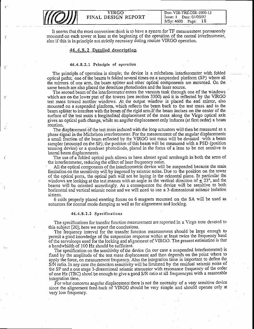
FINAL DESIGN REPORTDoc: VIR-TRE-DIR- 1000- I 3Issue: I Date: 0l/05/97S/Sy: 4600 Page: I 8
It seems that the most convenient think is to have a system for TF measurement permanentlymollnted on each tower at least at the beginning of the operation of the central interferometer,also if this is in principle not strictly necessary duting routine VIRGO operation.
4 6.4 .8 .2 De ta i l ed desc r ip t i on
vity rvill by imposed by seismic noise. Due to the position on the-tolver
46.4.8.2.1 Pr inc ip le of operat ion
The principle of operation is simple; the device is a michelson interferometer rvith foldedoptical paths; one of the beams is folded several times on a suspended platform (SP) rvhere alltlie minors of one arm, the beam splitter and other optical components are mounted. On thesame bench are also placed the detection photodiodes and the laser source.
The second beambf the interferometer enters the vacuum tank through one of the rvindowswhich are on the lorver part of the towers (see section 3300) and it is reflected by the VIRGOtest mass torvard anotfier windows. At. the output window is placed the end mirror, alsomounted on a suspended platform, rvhich reflects the beam back to the test mass and to thebeam splitter to interfere with the beam of the rigid arm.If the beam incises on the center of thesurface of the test mass a longitudinal displacement of the mass along the Virgo optical axisgives an optical path change, while an angular displacement only induces (at first order) a beamrotation.
The displacement of the test mass induced rvith the loop actuators rvill then be measured as aphase signal in the Michelson interferometer. For the measurement of the angular displacementsa small fraction of the beam reflected by the VIRGO test mass rvill be deviated rvith a beamsampler (mounted on the SP); the positi6n of this beam rvill be measured with a PSD (positionsensing device)'br a quadrant photodiode, placed in the focus of a lens to be not sensitve tolateral beam displacements.
The use of a folded optical path allows to have almost egual armlength in both the arms ofthe interferometer, reducing the effect of laser frequency noise.the interferometer, reducing the effect of laser frequency noise.
' All the opticai componeits of the interferometric device will be suspended because the mainlimitation on the sensitivitv rvill by imposed by seismic noise. Due to the position on the tolverof the optical ports, the oltical pltfr rvitt not be laying in tfe orizontal plane. !n particular thewindowi are l6oking at thi test irasses rvith an angie in the verticai direction of ! 23", an{ thgbeams rvill be oriented accordingly. As a consequence the device rvill be sensitive to bothhorizontal and vertical seismic nols6 and lve rvill nbed to use a 3-dimensional seismic isolationsistem.
6 coils properly placed exerting forces on 6 magnets mounted on the SA will be used asactuators for normalmode damping as well as for alignement and locking.
4 6 . 4 . 8 . 2 , 2 S p e c i f i c a t i o n s
The specifications for transfer function measurement are reported in a Virgo note devoted tos subject [20]; here we report the conclusions.The ?requeniy interval fbr the transfer function measurement should be large enoug-h to
this subject [20]; here we rel r r w I r v Y q v l I U J r r r L v r Y a l v t l l I v L l q l l J l w l l u I l v l l v l ! � � � � � � � u u � � � � � � � � � � � � � � � � � � � � � � � � � � � � � � � �
permit a gobd knowledge of the suspension response yrJlrn 3t_legt twice the frequency. bandpelTrut a good Knowledge ot me suspenslon response wrtllln at leasl twlutr tlre rrEgusrruJ uqrru
bf tf,e serioloops used ior the locking and alignement of VIRGO. The present estimation is thata bandrvhidth of 100 Hz should be sufficient.
The specification on the sensitivity of the device (in our case a suspended- interferometer) isfixed by'the amplitude of the test rnass displacement and then depends on the point rvhere toapply the force, bn measurement frequency. Also the integration time is important to define theS^A{ iatio. In any case the detection s6nsitivity will be limi'lated by the residiral seismic noise ofthe SP and a onL stage 3-dimentional seismi6 attenuator with resonance frequency of the orderof one Hz (TBC) sh5ul be enough to give a good SIR ratio at all frequencyei with a reasonableintesration time.
Fir rvhat concerns angular displacement there is not the necessity of a very sensitive device-t or wnat concerns angular olsplacement rnere rs nor rrtc necessrly or a vety ssusrr.since the alignement feed-back oi VTRCO should be very simple and should operate only atvery low frequency.
FINAL DBSIGN REPORTDoc: VIR-TRE-DIR- I 000- I 3Issue: I Date: 0l/05/97S/Sy: 4600 Page: I 9
46 .4 ,8 ,2 ,3 P ro to t ype sys tem
A.prototype.suspended interferometric device has been realized at the Napoli INFN sectionand is prelgnll.y.under tes.t. In.figure 4690.1 is shorvn the optical serup bn the sr.rspendedgl3{o5p. The light source is asingle mode He-Ne laser and thebptical paiil of the rigid arm isfolded in order to have q toJal length of trvo meters. The platforni is suspended to ab.5 meterlong pendulum and vertical isolation is provided by rubbei springs.- . A very simple DC detection scheme is used rvith the interlbrometer locked on the slope of afringe; . the enor signal is. provid^ed by- the difference of the currents of the trvo outputphotodiodes. Oneof the minors of the rigid arm is mounted on a PZT transducer that rvill'beused for calibration. The interferometer is locked on the fringe by reacting on the SP, in thisrvay the SP is forced to follow the SA motion. The measurement of thtsA motion is thenprovied by the actuating signal of the servoloop.. The prototype rvill be tested by measuring the transfer function of the tlvo stage suspensn ofthe 3 m interferometer operationg in Napoli. It rvill also be used to measure th-e TF bf a Seprototype when it rvill be mounted in Pisa.
The main difference betrveen the prototype suspended interferometer and the final ones thattvill be used for the actual sr.spensions in Cascina-is the fact that the prototype operates just infront of the test mass and thbn the beam is reflected normally. As'a consequdnce a iecondsuspended mirror is not necessary and the whole optical path is in the horizontaj olane. For thissuspended Tlnor is not necessary and the whole optical path isreason the final suspension rvill be different and piobablv btadr
plane. For thisreason the^final-susp,
FINAL DESIGN REPORTDoc: VIR-TRE-DIR- I 000- I 3Issue: I Date: 0l/05/97S/Sy:4600 Page: 20
t t l
t2l
List of References
R.Del Fabbro: 1994, "Superattenuator dynamics" (VIRGO Internal Report, NTS 006 - 1991).
S.Braccini et al.: 1996, "Extending the VIRGO detection band dorvn to a ferv Hz: metal bladesprings and magnetic antisprings" (VIRCO Internal Note, VIR-NOT-PIS-1390-068), submitted toNucl.Instr.Meth.
t3l S.Braccini, C.Casciano, R.De Salvo, F.Fidecaro: 1996, "On the stability of the superattenuatoC'(VIRCO Internal Note, NTS 031 - 1996).
S.Braccini, C.Casciano, R.De Salvo, F.Fidecaro: 1996, "Elimination of the hydraulic adjustment ofthe filter suspension offset" (VIRGO Internal Note, NTS 026 - 1996).
S.Braccini et al., Rev. Sci. Instrum.., 67 (8) (1996) 2899.
A.Gaddi , F.Raffaelli: 1996, "Standard filters specifications" (VIRGO Internal Note, VIR-SPE-PIS-4600-10s).
S.Braccini, C.Casciano, R.De Salvo, F.Paoletti, F.Fidecaro: 1996, "Evidence of creep in thesuperattenuator mechanical fi lters" (VIRGO Internal Note, NTS044 1 199 6).
Pisa VIRGO group: 1994, "seismic isolation: the use of blade springs" (VIRGO Internal Note, PJT094/008).
t9l Pisa VIRGO group: 1994, "Blade springs: transfer function measurement performed on a two stagesuspension" (VIRCO Internal note PJT094/0C9).
ll0l S.Braccini, C.Casciano, R.De Salvo, F.Paoletti, F.Fidecaro: 1996, "The microcreep problem in theVIRGO mechanical attenuators" (VIRGO Internal Note, in preparation), to be submitted toNucl.Instr.Meth.
I I 1l Datasheet o[ Ferroxdure 330 (FXD 330) in the "Handbook of Philips Components", 199 1.
|2) "Electromagnetic Noise", Appendix to the VIRGO Final Conceptual Design, 1992.
tl3l S.Braccini, Thesis, Scuola Normale Superiore, 1996, Pisa, Italy (To be published in the"Collections of the Scuola Normale Superiore")'
tl4l S.Braccini, C.Casciano, R.De Salvo, F.Fidecaro: 1996, "Temperature stabilization requirement ofthe VIRGO towers" (VIRGO Internal Note, NTS 032' 1996).
t15l lv{.Bernardini, C.Bradaschia, H.B.Pan, A.Pasqualetti, R.Poggiani, Z.Zhang: 1996, "Outgassing
measurement of VAC-SEAL vacuum epoxy" (VIRGO Internal Note, VACPISA 048 P).
t16l S.Braccini, C.Casciano, R.De Salvo: 1996, "Blades and crossbar dampers" (VIRCO Internal Note,vrR-NoT-Prs-4600- l 08).
tlTl S.Braccini, S.Malik: 1997, "Role of the centering rvires in determining the main resonant frequencyof the mechanical filters" (VIRCO Internal Note, VIR-NOT-PIS-4600- I l2).
Itsl S.Braccini, R.De Salvo, G.T.Feng: 1997, "Mechanical properties of the mechanical hlterssuspension rvires" (VIRGO Internal Note, in preparation).
tlgl Minutes of the rvorkshp on Transfer function measurement; Orsay March 23th 1995.
t20l virgo noteVIR-NOT-NAP-4600-....
t4l
tsl
t6l
t7l
t8l
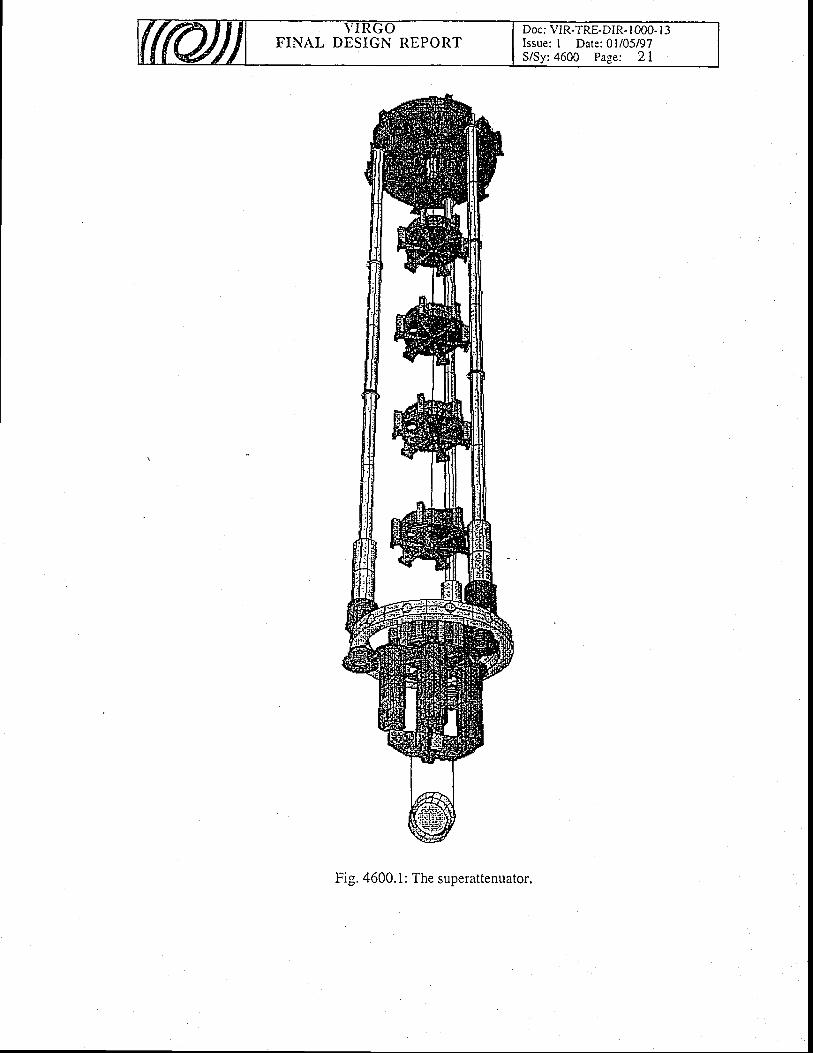
Fig. 4600. 1: The superattenuator.

tu3
9'8
IF
r----------r--t
Lc)(Jok()c)v)a)c.)
c)
c/)I
e.r\o\rl
f
oc\
t<v)ano
C)
v)
aoLro
F-o\ho
ta
q!
-c
)
gE\t
:>
'n
?i
a
r-,I
r-o
Fr-'t
z(nF'
.t
z
.Er
0) r-r
B=
C)
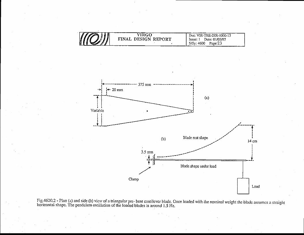
bo
zq'a()coC)
C)
at
()
o;
cJ
*
E u't
!c)
C
C)
o
E
v'to
s4
so
)
CJ
6J
fJ 'ox
c)
*,1J
L. cJ
€o
=-
tog
bo
a!
'-
v=
>-=
cr -?
'od
ats
vr<
Ec
i
,E
c\-
c.l tr\o
oi
fN
.:" o
ra)-
.cA
ociI
-L-rf
F
r)tr-caIIIIII-
kCJ
C)
C)
cnTON
g*-
"i Qq
lX
o
Eb
ileff
*d
lT
-o
*o
l:€;
:9
>'
EZ
3
l.rr-'l
zCN
r-'t
Fl
z
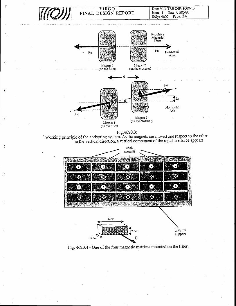
Doc: VIR-TRE-DIR- I 000- I 3Issue: I Date:01/05/97S/Sy:4600 Page:24
FINAL DESIGN REPORT
Repulsivelvtagnetic
Force
HorizontalAxis
Fi9.4620.3:' Working princiile of the antispring system.as. the magnets are moved one rcsp-ect to the other'
in the verticaidir;cdon, a verticai component of the repulsive force appears.
lvlagnet I tvlagnet2(on the filter) (on the crossbar)
<-d -)>
Fo
lvlagnet I(on the filter)
Nlagnet 2(on the crossbar)
brickmagnets
6 c m-t
tinniumsupPort
r.s cnrS
Al z c m
Y
Fig. 4620.4 - One of the four magnetic matrices mounted on the filter.
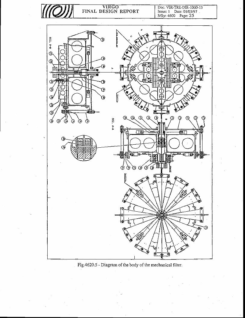
FINAL DESIGN REPORTDoc: VIR-TRE-DIR- 1000- l3Issue: I Date: 0l/05/97S/Sy: 4600 Page:25
Fig.4620.5 - Diagram of the body of the mechanical filter.
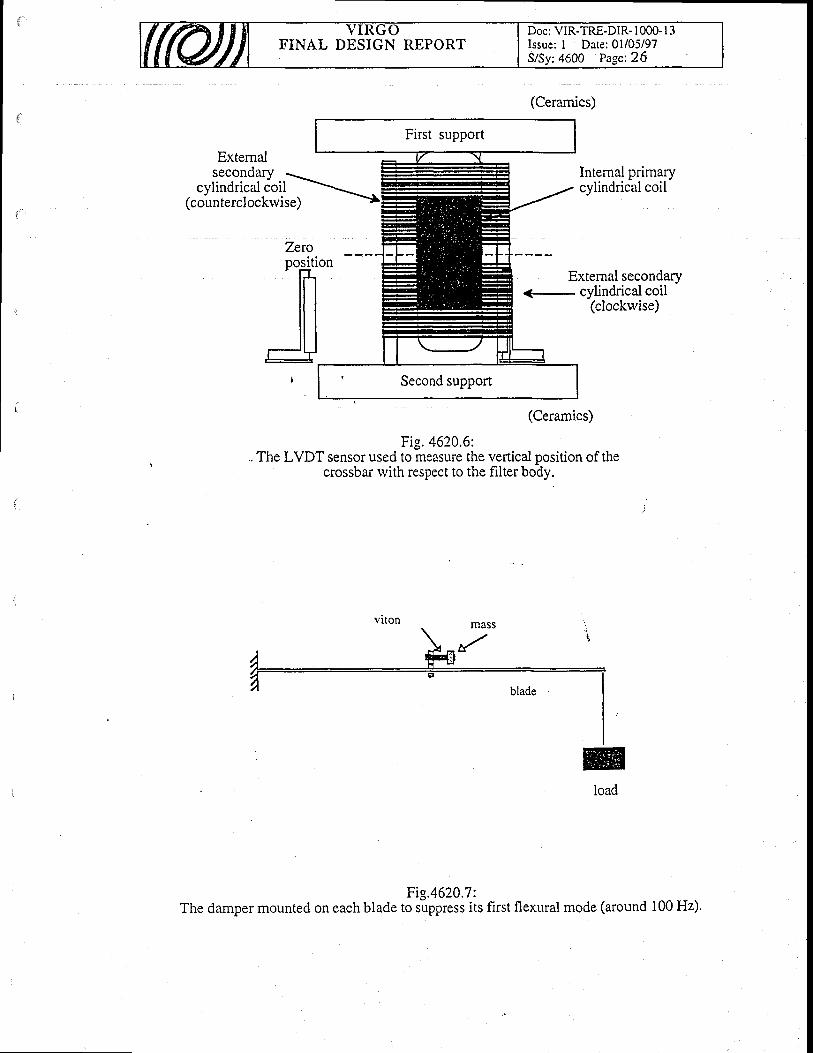
FINAL DESIGN REPORTDoc: VIR-TRE-DIR- 1000- l3Issue: I Date: 0l/05/97S/Sy: 4600 Page:26
Extemalsecondary
cylindrical coil(counterclockrvise)
(Ceramics)
Internal primarycylindrical coil
External secondary<- cylindrical coil
(clockrvise)
7*roposition
flJ
(Ceramics)
Fig. 4620.6:.. The LVDT sensor used to measure the vertical position of the
crossbar rvith respect to the filter body.
Fig/620.7:The damper mounted on each blade to suppress its first flexural mode (around 100 Hz).
viton
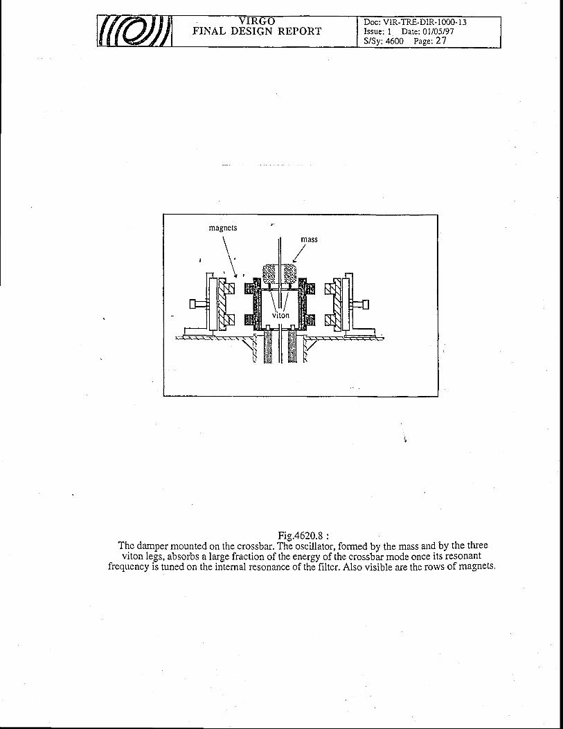
' f I I \ V V
FINAL DESIGN REPORTDoc: VIR-TRE-DIR- I 000- I 3Issue: I Date: 0l/05/97S/Sy:4600 Page:27
Fig.4620.8 :The damper mounted on the crossbar. The oscillator, formed by the mass and by the tfueeviton legs, absorbs a large fraction of the energy of the crossbar mode once its resonant
frequency is tuned on the internal resonance of the filter. Also visible arc the rows of magnets.
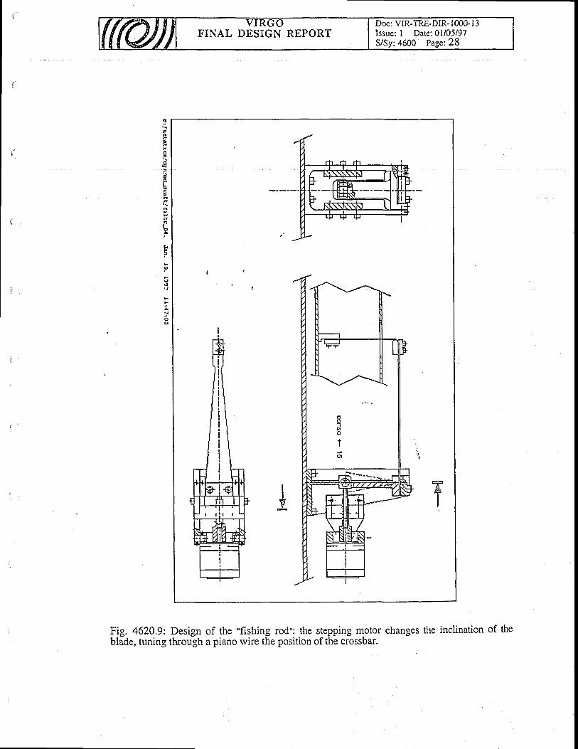
Doc: VIR-TRE-DIR- I 000- l -jIssue: I Date: 0l/05/97S/Sy:4600 Page:28
FINAL DESIGN REPORT
g
{
;:J
Fig. 4620.9: Design of the "fishing rod": the stepping motor changes the inclination of theblade, tuning through a piano rvire the position of the crossbar.
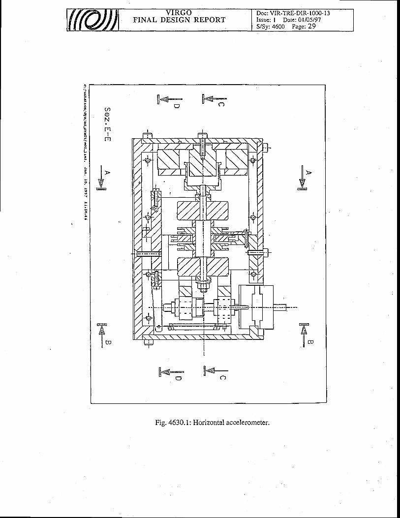
FINAL DESIGN REPORTDoc: VIR-TRE-DIR- 1000- l3Issue: I Date: 0l/05/97S/Sy:4600 Page:29
ll1*€- ll€-" o - c - )
flll >w
--T-
/g-r
l m
lil.€- ll€-' o - c )
Fig. 4630. 1 : Horizontal accelerometer.
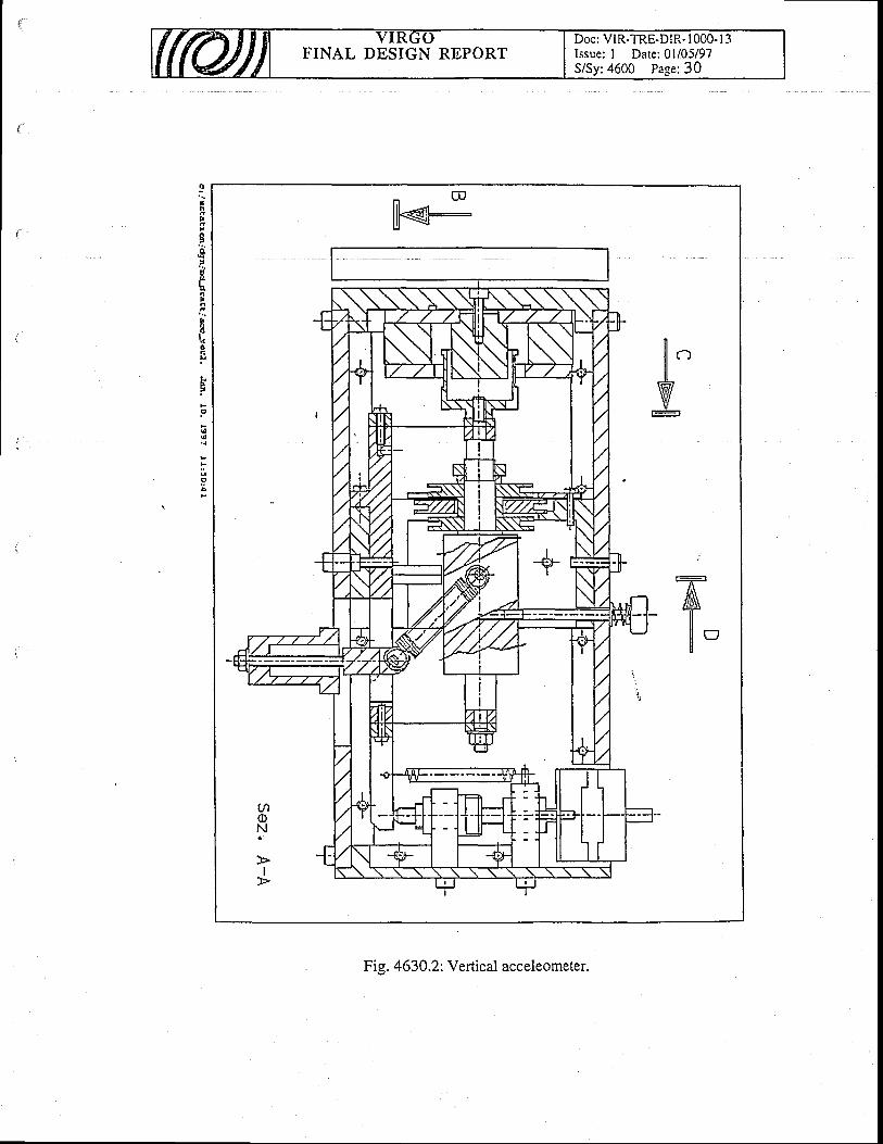
t?nF
a
.:a
F6nF
h
Bt:oq
^ E
llK-
FINAL DESIGN REPORTDoc: VIR-TRE-DIR- 1000- I 3Issue; I Date: 0l/05/97S/Sy:4600 Page:30
Fis. 4630.2: Vertical acceleometer.
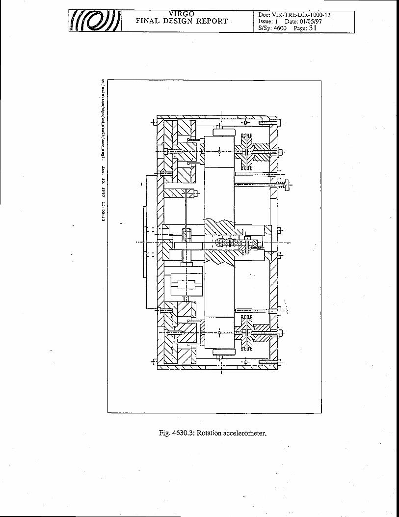
Fig. 4630.3: Rotation accelerometer.
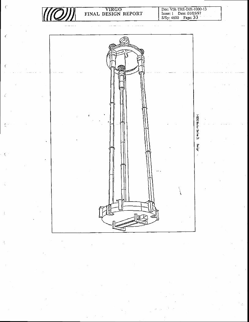
Doc: VIR-TRE-DIR- I 000-13Issue: 1 Darc: AU05/97S/Sy:4600 Page: 33
FINAL DESIGN REPORT
EE.
Kf .
!+
I
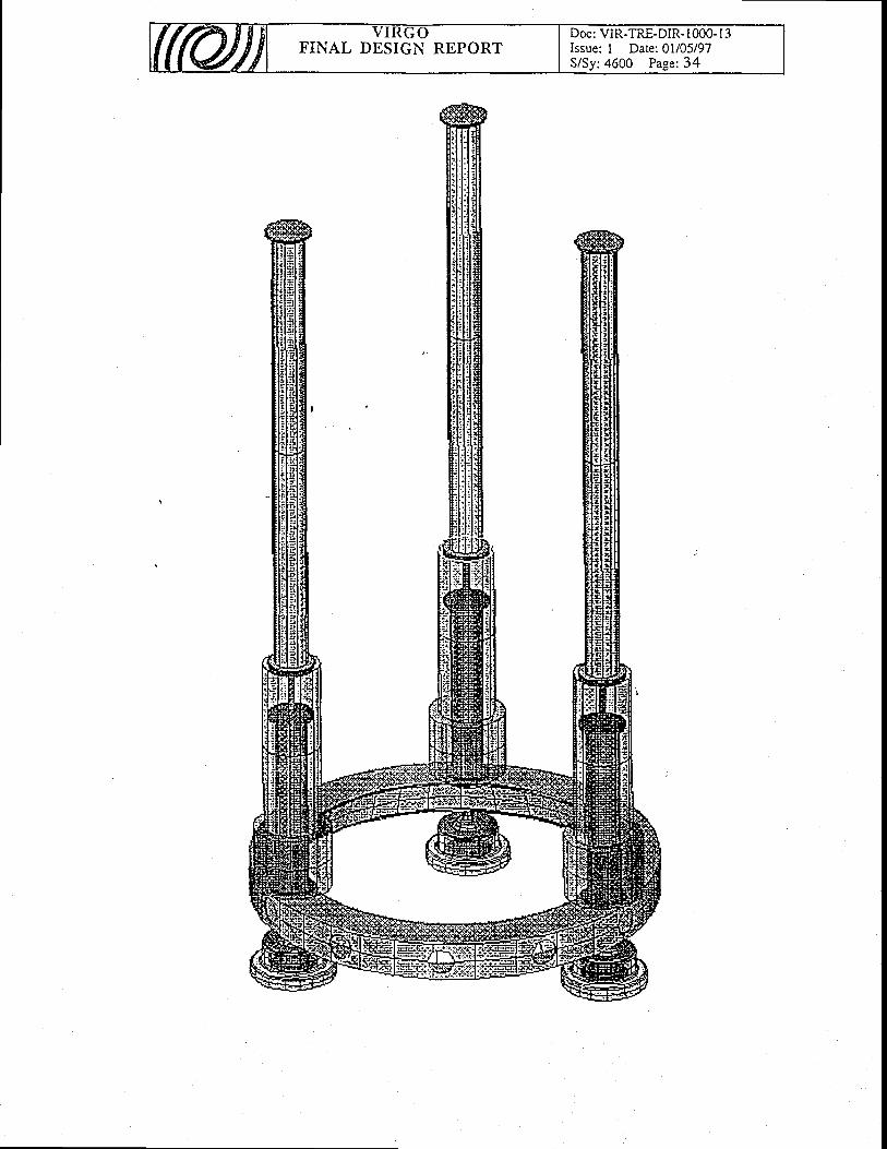
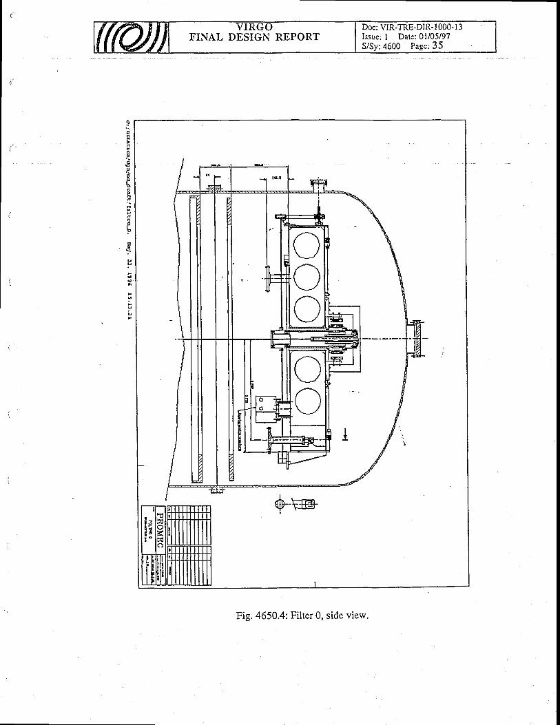
I/es ]-fl:ivy Fr_-r
Doc: VIR-TRE-DIR- I 000- l3Issue: I Date: 0l/05/97S/Sy:4600 Page; 35
FINAL DESIGN REPORT
Fig. 4650.4: Filter 0, side view.
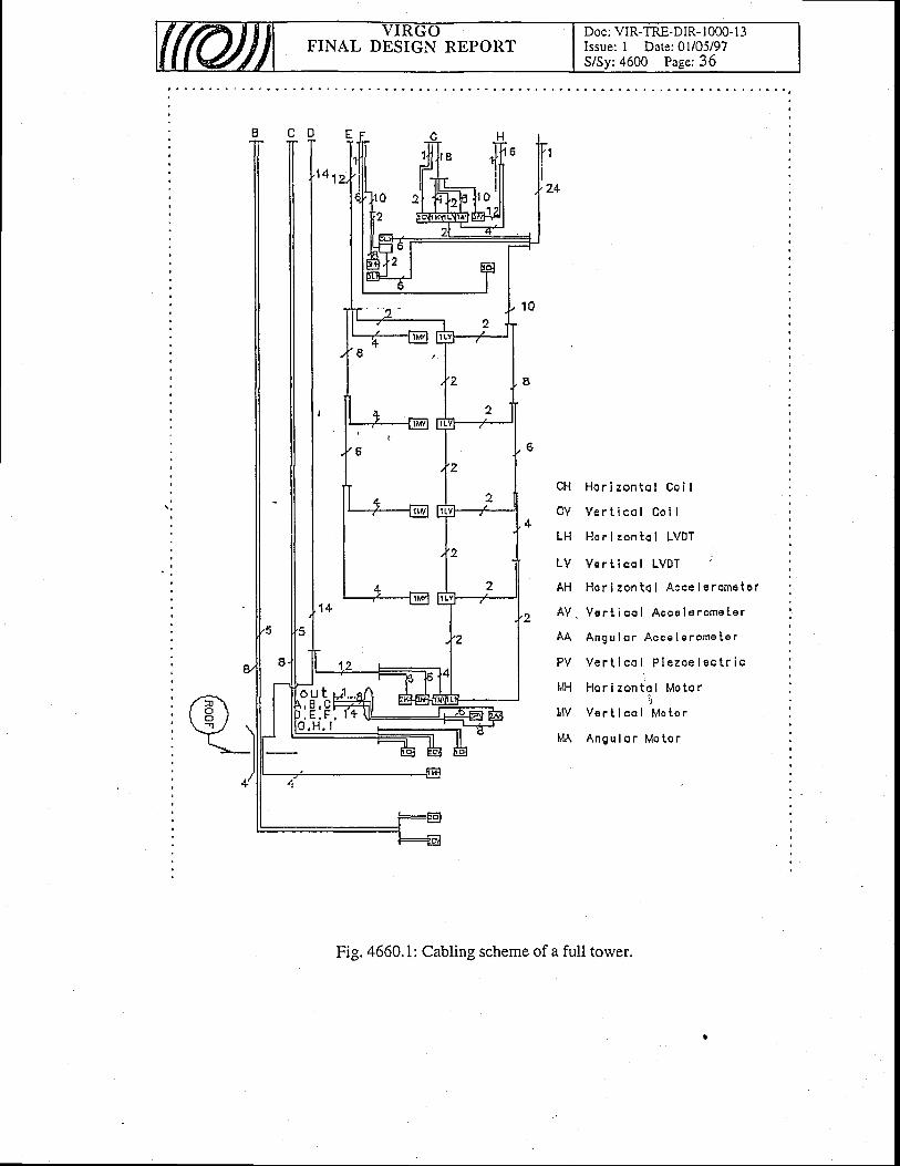
ff(uj) VIRGOFINAL DESIGN REPORT
Doc: VIR-TRE-DIR- I 000- I 3Issue: I Date: 0l/05/97S/Sy:4600 Page: 36
C H H o r i z o n t o t C o i I
C V V e r t i c o l C o i I
LH Ho r i zon to I LVDT
L V V e r t i c o l L V O T
AH Hor i zon to l Acce l e rome te r
A Y . V e r t i c o l A c c e l E r o m e t e r
A A A n g u l o r A c c e l e r o m e L e r
P V V e r t i c o l P i e z o e l e c t r i c!
h l H H o r i z o n t o l M o t o r,'l
t l V V a r t i c o l h l o t o r
I ' lA Angu lor l " lo to r
Fig. 4660.1: Cabling scheme of a full tower.
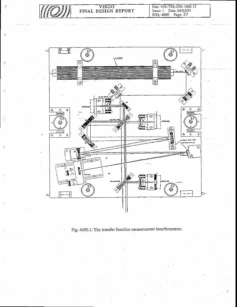
Doc: VIR-TRE-DIR- I 000- l3Issue: I Date: 0l/05/97S/Sy:4600 Page:37
FINAL DESIGN REPORT
i!r=ifi#I li i 'S.,:-lt e'o
)-'E1ryYoo-a,------- : -----( i l i l
t . _ + - : r . ; i _ - - i \ l r I
l--- 1-tlr- $:.----i\ ft.i'-i t!'ili*.,- II
-- \ \i1:::-;.!i?-\
r':=iri{TiL-iK
ri, '.q-i iel
. r t i c l
a4 tg l€ . ,|:
Fig. 4690.i: The transfer function measurement interferometer.

Doc: VIR-TRE-DIR- 1000-13Issue: I Date: 0l/05/97FINAL DBSIGN RBPORT
47 . Last stage suspension
Table of Contents
47. Last stage suspension
47,1 Last stage function anrl r concept
47.2 Requirements for last ,t"g" .1.-unt.4'1.2.1 Last stage interfaces
47.3 Dcta i led descr ipt ion47.3.1 Marionetta for Minors47 .3.2 Reference masses47.3.3 Marionettas for input and detection benches
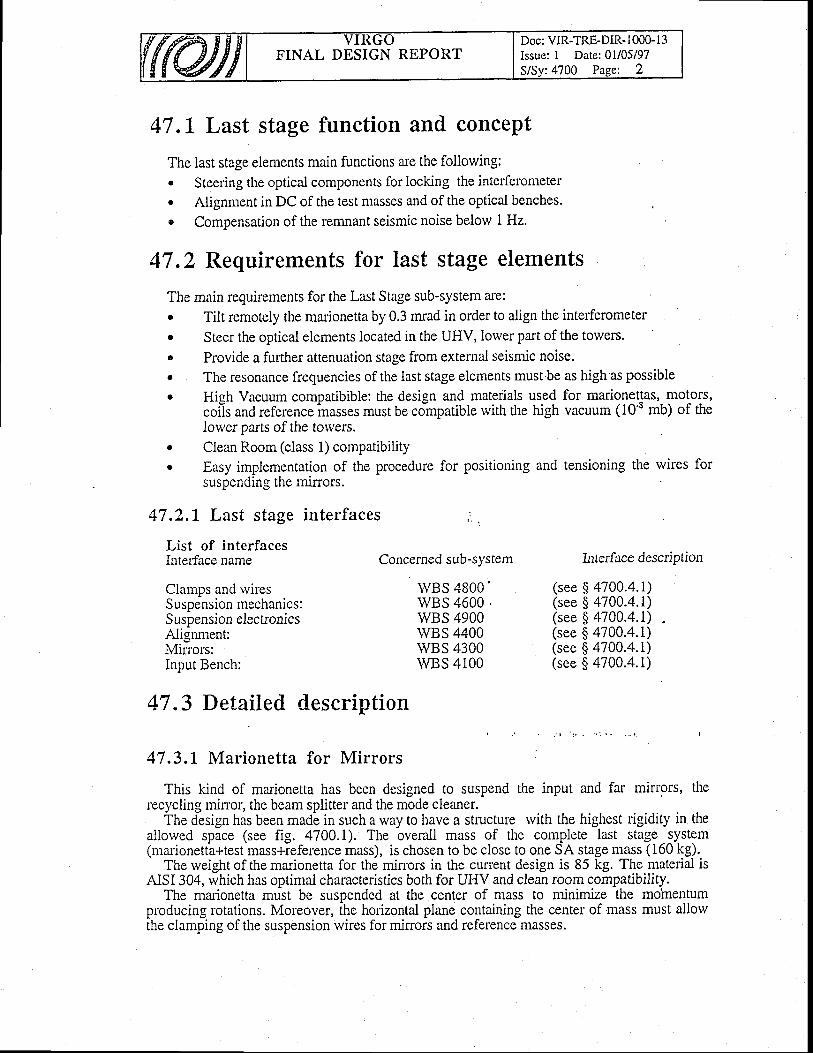
Doc: VIR-TRE-DIR-1000-13Issue: I Date:01105197FINAL DESIGN RBPORT
47 .L Last stage function and concept
The last stage elements main functions are the following:" Steering the optical components for locking the interferometer. Alignment in DC of the test masses and of the optical benches.o Compensation of the remnant seismic noise below I Hz.
47 .2 Requirements for last stage elements
The main requirements for the Last Stage sub-system ale:. Tilt remotely the marionetta by 0.3 mrad in order to align the interferometer. Steer the optical elements located in the UHV, lower part of the towem.. Provide a further attenuation stage from external seismic noise.. The resonance fiequencies of the last stage elements must be as high as possible. High Vacuum compatibible: the design and materials used for marionettas, motors,
coi'is and reference inoss.s must be co-mpatible with the high vacuum (10'8 mb) of theIorver parts of the towers.
. Clean Room (class 1) compatibilityc Easy implementation of the procedure for positioning and tensioning the wires for
. ' i c n a n n i n d t h o m i . r n r cD U J P v r r g r r r s L l r v l r u l l v l o r
47.2,1 Last stage interfaces ,' .
List of interfacesInteiface name
Clamps and rvircsSuspension mechanics:Suspension elecilonicsAlignment:Mirrors:Input Bench:
Concerned sub-sYsten
wBS 4800'wBS 4600 .wBS 4900wBS 4400wBS 4300wBS 4100
Interface description
(see $ 4700.4.1)(see $ 4700.4.1)(see $ 4700.4.1)(see $ 4700.4.1)(see $ 4700.4.1)(see $ 4700.4.1)
47 .3 Detailed description
47.3,1 Marionetta for Mirrors
This kind of marionetta has been designed to suspend the input and far mirrors, therecycling minor, the beam splitter and the mode cleaner.
The design has been madb in such a way to have a structure rvith the highest ligidity in theallowed space (see fig. 4700.1). The overall mass of the complete last stage system(marionetta+test mass+ieference mass), is chosen to be close to one SA stage mass (160 kg).
The weight of the marionetta for the mirors in the current design is 85 kg. The material isAISI 304, which lias optimal characteristics both for UHV and clean room compatibility.
The marionetta mutt be suspended at the center of mass to minimize the momentumproducing rotations. Moreover, the horizontal plane containing the center of mass must allowthe clamping of the suspension wires for mimors and reference masses.
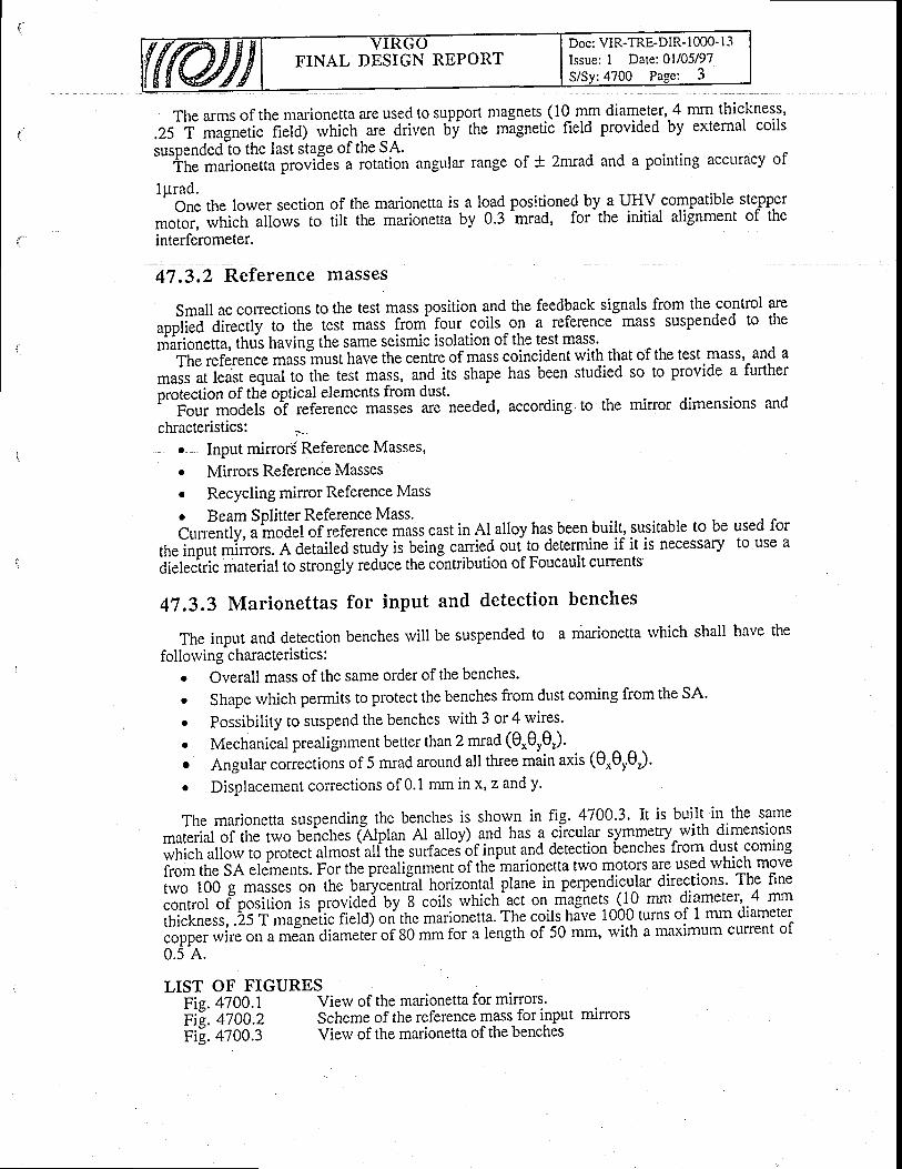
Doc: VIR-TRE-DIR-1000- I 3Issue: I Date: 0l/05/97S/Sv:4700 Pase: 3
FINAL DESIGN REPORT
The arms of the marionetta are used to support25 T magnetic field) rvhich are driven by the
magnets (10 mm diameter, 4 mrn thic.kness,mignetic field provided by external coils
' " - - ' 9 - - '
suspended to the last stage of the SA.lpgnoec to [nc lasL Sl irBc ur Ltrs r.r .
The marionetta provides a rotation angular rangeof + 2mrad and a pointing accuracy of
1prad.One the lower section of the marionetta is a load positioned UV.u tl{YcomPatible stepper
*oioi, *ti.fr alfows io rilt the marionetta by 0.3 -mrad,
for the initial alignment of the
interferometer.
4l. l ,z Reference masses
Small ac corrections to the test mass position and the feedback signals from the control
oppiitJ'oii.;it,i;.th" i.it rnuts {roqr foy 9oi!"9,1 l itlt::lt" mass suspended toniarionetta, thtis having the same seismic isolation of the test mas.s.
ffi;f#ri"e'rioii'*urrhavethecentreofmasscoincidentwiththatof thetest mass, and a! - r - - ^ - - - ^ - . : J ^ ^ f , , # L ^ -
#;;i;;;^A;;i1; rh. t.rt masi, and its shape has been studied so to provide a furtherprotection of the optical elements from dust.'
For,, models of reference masses are needed, to the minor dimensions and
chracteristics: t - .
. Input mirror( Reference Masses,
. Mirrors Reference Masses
. Recycling mirror Reference Mass
. Beam Splitter Reference Mass'C,rn=ntiy, ainoOef of reference mass cast in Al-alloy has been built, susitable to be
tit.lnput o,lnott. A detailed study is being canie{ out^tg determine if it is necessary
dielectric material to strongly reduce the contribution of Foucault curents
47.3.3 Marionettas for input and detection benches
The input and detection benches will be suspended to a marionetta rvhich shall have the
following characteristics :o Overall mass of the same order of the benches'
Shape which permits to protect the benches from dust coming from the SA'
Possibility to suspend the benches with 3 or 4 wires'
Mechanical prealignment better than 2 mrad (0*0r0r)'
Angular coriections of 5 mrad around all three miin axis (e.Oyer)'
Displacement corections of 0.1 mm in x, z and y.
arethe
used forto use a
a
o
a
a
a
The marionetta suspending the benches is shown in fig. 4700.3. It is buiit in the same
,nrLiiot of the t*o U.'n.ii.i f"Afpfan Al alloy) and has a circular symmetry with dimensions
which alow to prot""i oi-osi all'the ru.fu.Ll6f inpnt a.nO detection 6enchei frorn dust coming
from the SA elementr. Foi the prealignment of the'marionetta two motors are used rvhich move
two 100 g masses o" tfr" Uutycential horizontal plane in perpendicular directions' The fine
.o"troi ofposirion ir'pio"iO.d UV S .oilt which^act on m-ag?rets (trO * diameter, 4 mm
tf,i"[n"rr, .25 T mognetic field) on the marionetta. The coils hive 1000 turns of 1 mm diameter
copper wire on a mean diameter of 80 mm ioi u i"ngttt of 50 mm, with a maximum curent of
0.5 A.
LIST OF FIGURESFig.4700.1Fig.4700.2Fig. 4700.3
View of the marionetta for mirrors.Scheme of the reference mass for input mirrorsView of the marionetta of the benches
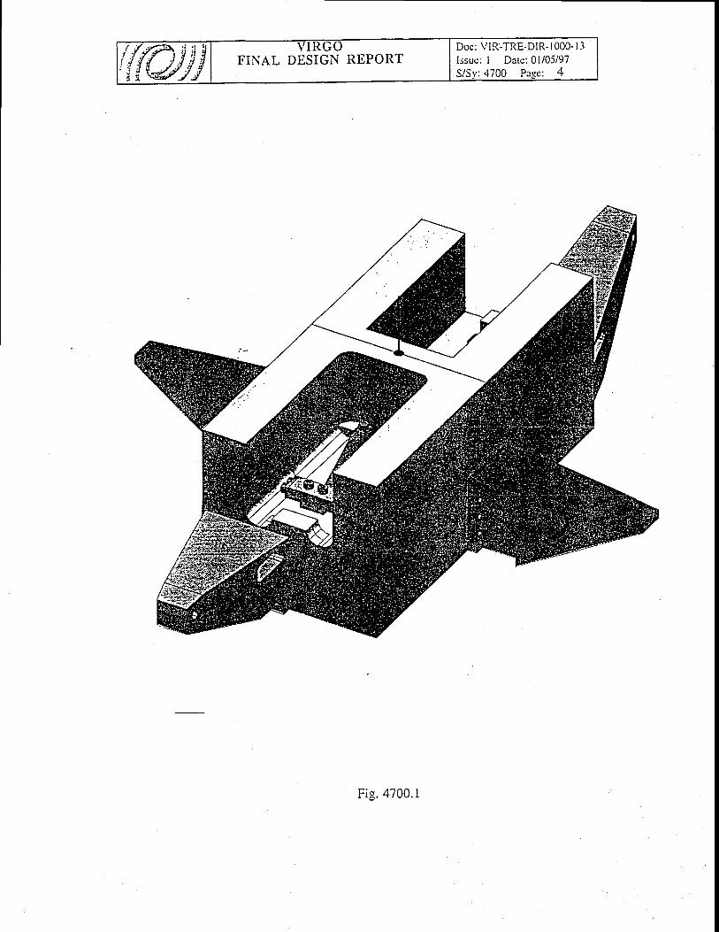
Doc: VIR-TRE-DIR- | 000- 1.1Issue: I Date: 0l/05/97S/Sv:4700 Pase: 4
FINAL DESIGN REPORT/ l f i ; l ' lr{{wif
F ig .4700 .1
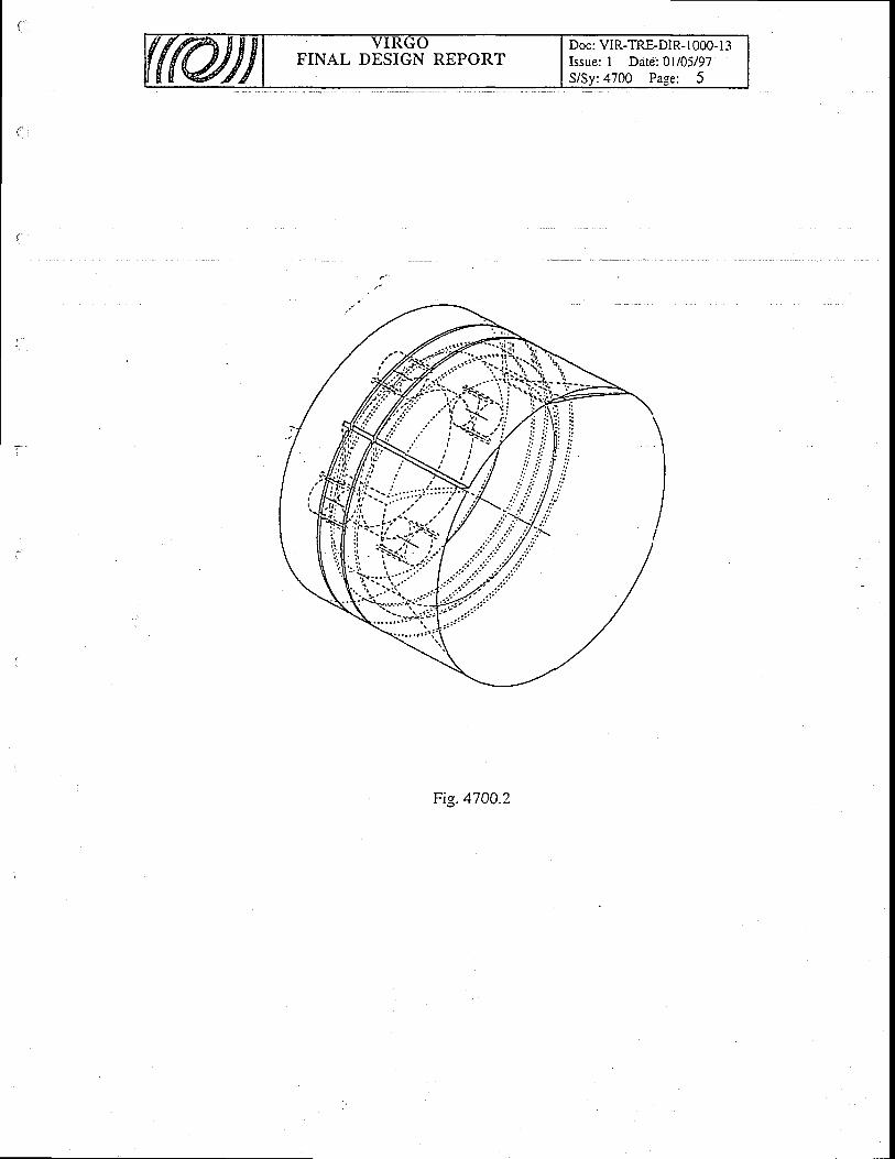
FINAL DESIGN REPORTDoc: VIR-TRE-DIR- 1000- I 3Issue: I Date: 01/05/97S/Sv:4700 Page; 5
Fi9.4700.2
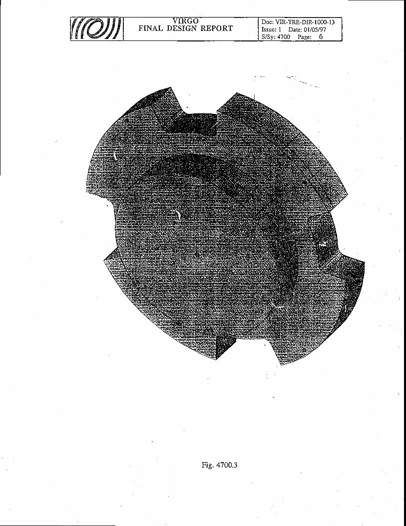
FINAL DESIGN REPORTDoc: VIR-TRE-DIR-1000- l3Issue: I Date: 0l/05/97S/Sy:4?00 Pase: 6
Fig.4700.3

Doc: VIR-TRE-DIR- I 000- I 3Issue: I Date:01/05/97
:4800 Paee: IFINAL DESIGN REPORT
48. Clamps and wires
Table of Contents
48. Clamps and rvires
48.1 Oferv ierv48.1.1 Requirements for clamps and wires
48.2 Wires48.2.1 Overview48.2.2 Description48.2.3 Specifications48.2.4 Marionetta-Wire clamPs48.2.5 Overview48.2.6 Specifications
48.3 lvl irror - lYires spacers48.3.1 Overv ierv48.3.2 Specifications
a "
48.4 Inter faces
48.5 Future developments
1
7
3
J
J
4)))
666
6
6

FINAL DESIGN REPORTDoc: VIR-TRE-DIR-1000-13Issue: I Date: 0l/05/97S/Sy:4800 Paee: 2
48. L Overview
The test mass or end mirror of the gravity wave interferometer is a monolithic piece of fusedquartz that is suspended as a pendulum. The design of this pendulum must allorv the positiondf the minor to be controlled io a high accuracy. The mechanical losses of the pendulum mustalso be small so that the resultant off-resonance displacement thermal noise is small too. Thefinal design must take into account the actual suspension of the minor, the type of material thatsuspends the mirror and the manner in which these pieces are fastened.
the Virgo mirrors rvill be suspended from the Marionefta by two wires_forming .eac! 1single loop around the mirror lorver surface. This avoids the. use- of any fixed mechanicalcoritact oi the mirror rvhich might reduce the mirror quality factor by post-productionmachining. With this solution, the true contactpoints betrveen the wires and the mirror surfacewill be fifrited to a short part of the wire louching the minor itself. The rest of the wire will notplay an important role fr6m the point of vjew of wire-mirror friction.'
Ttre usd of trvo rvires allorvs the tilt of the mirror about the horizontal axis perpendicular tothe optic axis to be controlled by the suspension point of the pendulum-hence, the telmrnariinefta. One drawback of thls s6heme is that it rais-es the frequen-cy of the tilt motion aboutthis axis. This can couple vertical motion into horizontal motion and add noise to the graviryrvave signal.
The 6ff-resonance thermal noise displacement is proportional to the square root of thependulum loss angle
4g00. I
{'-(,.)T * JQGIThe loss angle is related to the pendulum quality factor Q by:
4800. 2
q= j=QtooJ
Therefore, we must reduce 4a) (or increase the q) to reduce the thermal noise effect. The
actual loss angle 4Xa) canbe expressed as the sum of three different contributions:
l. the effective pendulum loss angle @r(al)
2. the energy loss @",n,0 due to a stick-and-slrp process between the suspension wire and
the clamp
3. the residual gas damping @*,
The measured Q can be expressed as4800. 3
Oo(to)* Q"u.p * 0e*
A maximisation of p requires the minimisation of the three different contributions.
For the pressure maintained in the virgo vacuum system (= loo Pn)' the residual gas
contribution to the quality factor Q is negligible (Q,*=IA) and the main process limiting the p
of pendulum will be given by Qr(coJ and Q.r*.
o = # =
FINAL DESIGN REPORTDoc: VIR-TRE-DIR- I OOO.I3Issue: I Date: 0l/05/97S/Sy:4800 Page: 3
48.1.1 Requirements for clamps and \yires
The requirements for the last stage, from the point of vierv of the mirror suspensionperformance and thermal noise reduction, are quickly summarised in the follorving list
. the pendulum quality factor must be high: Q5xld
o the mass normal mode quality factor should be Q^,,,opIxld
o the suspension rvire violin frequency mode as high as possible
o the mirror should hang safely
r the suspension rvire properties must be stable in time
o the suspension wires should stretch as Litttle as possible during the initial Virgo bakingtreatment (TBQ.
48"2 WiresI
48.2,1 Overv ie ly
. The suspension rvires are an important consideration in the final design since they play acrucial role in determining the thermal noise performance of the pendulum. The contribution ofthe loss angle Q"(co) to the effective pendulum 0 is given by
, 4g00. 4
Qo(co) = O-(r)i
where Q* is the loss that characterises the material and is independent of the geometry of thependulum suspension wire, L is the length of the pendulum rvire, E is the Young's modulus, /is the moment of inertia of the rvire cross section and K describes the dependence of the loss onthe pendulum geometry. i
The lowest violin mode frequency (which should be maximised) is girien by4800. 5
= Q*(co)K
r = I2L
where p is the mass density of the wire material.Since the mass of the minor is fixed from other design considerations, the only parameters
to be optimised are the wire material (0*(ol), Q and thickness (I=nr4/4).It is clear that a thinwire with a low loss is the best choice. The diameter of the rvire can only be made as thin as the*Tilffi':il"t'$tll"#t;.rerial,
from the poinr of view of the inherenr loss, is a bir moredifficult. If the wire is carefully prepared in a rvay that eliminates imperfections such asimpurities and structural irregul#ities,'the inherent lois in the material itseif can be bound by^using thermo-elastic damping as a lower limit. In this case, a thinner wire reduces the effect ofthermoelastic damping in the frequency band below 100H2.
EIMg
W

Doc: VIR-TRE-DIR-1000-13Issue: I Date: 0l/05/97S/Sy:4800 Page: 4
FINAL DESIGN REPORT
48.2,2 Descr ip t ion
From the reasons described previously, the best choice is a rvire rvith a high breaking loadand lorv loss angle.
Table 4800. 1 presents a list of material characteristics tested in Perugia. From this table, itis evident that C85 piano rvire is the best current solution for Virgo mirror wire suspensions.
A rvire diameter bf 0.20mm has been chosen for the 2l Kg mirror and 0.30mm for the 42Kg minor. This gives a safety factgr of 65Vo rvhich is_ adequatg_ given the results of testspelformed. The lowest violin mode frequency is greater than 300 Hz.
Another important considefation is the anelastic stretching of the rvire rvhen it is loaded withthe mirror masi and thermalised at the Virgo baking temperature for a long time period. A C850.2 mnt diameter wire, loaded with a 5 Kg mass and maintained at 150'C in vacuum for oneweek, shows 2.3 mm of permanent elongation. The elongation shorvs a logarithmicdependence in time (creep effect). Because of this stretching effegt, it is necessary to use, forthd mirror suspensions,^only pre-heated wires. A wire heated for one week, shows, afteranotherweek6f baking, a reiidual elonfhtion less than 0.3 mm. No residual creep effect hasbeen detected in that wire after twenty days at 35"C with a sensor having a resolution better than0.0005rnm.
a '
Table 4800. 1
lVire Material Q'"(10 'o)
diameter(mm)
lJreaKlngLoad (Kg)
Normal isedBreak. Load(Ke/mm')
AISI3O2Ge/Cr18A.{i8)
33 0.25 8.5+9.5 170+210
AISI 316Fe/Cr18A{i8Av1o3)
20 u./) 8.5+9.5 170+2lO
INVAKGe64A{i36)
29 u.'2.) < ) < t02
ALULJHKUM(Fe10/Cr25/Al5)
8 0.25 < ) < 102
UhTKUMALU Y(Fe75lCr20lAl5)
u.2) < 5 < toz
c75 .5.4+1 U . ) U 6.5+7.8 134+160CE5 (r = U.Imm) 6.0+
1v. / .u 8 . 5 + 9 . 5
' 270+300
Straight Prano Wre(Goodfellow, AISI3 16)
20+/J
0.30 L2 170
I ltan 20 u.'2.JTungsten L4 0.25 Ll+12 224+244
WireI
loss angle and breaking load test results
FINAL DESIGN REPORTDoc: VIR-TRE-DIR- I 000-13Issue: I Date: 0l/05/97
48.2.3 Speci f icat ions
. Considering that C85 piano wire is an easy material to find and to handle, it has beenchosen as the reference solution (tw-o piano wire loops, rvith length 2.2 m and diameterd=0.2 mm and d=0.30 nun.^for the light and he-avy mirror, respeciively); horvever, severalstudies are in progress to verify some interesting alternatives.
Table 4800.2 Wire Specifications
Material C85 Piano lYireBreaking Load (Kg/mm?) 250+300wrre dlameter tor the 2IKs mirror U.2ntmWrre drameter fbr the 42Ks mirror U,JMMWire leneth (one looo) 2,2mwre restdual elongation in baking
(150"C per 1 week)U.Jmnt
Wrre residual creep effect at 35"CI dnf,!1
"to"'" (<o'ooolmm Per 2o
Wire loss angle ' r 6xt0a. Pendulum Q in a full scale prototyte
with spacers 5xld
48.2.4 Marionetta-Wire clamps
.48,2.5 Overv ierv
To minimise the clamp e-nergy loss, it is very important to decrease the stick-ancl-sllp frictionbetrveen the suspension-wire ahd the clamp ltseli. The easiest way to reach this joal is tolncrease the squeezjng pressure exerted by the clamp on the suspension wire.
From several tests performed by the P6rugia gloup and reported in Figure 4800. 1, it is clearthat by increasing the clamping pressure, we oUtain an inirement of ;he pendulum Q and,consequently, a decrement of the energy loss @. In Figure 4800. 1, the p and the { of a smallpendulum pr-ot^oly-pe, made by a 0.4 mm djameter piano wire rvith a lehgth ranging between200 mrn and 300 mm and with a mass of 762 g attached to the lower'end oitfre wire, isplotted versus the sq.ueezing torque applied to a group of four screws on the clamping head ofthe pendulum. By increasing the torque, rve increase the clamping pressure. The-differentthe pendulum..By.increasjng the tolque, rve increise the clampicurves shown in Figure 4800. 1 refeito different clamp materiais
he torque, rve increase the clamping pressure. The different1 refeito different clamp materiais. Alirnriniu*, stainless steelfhere seem to be no evident differences between the behaviour
curyes shown inand tool steel have bten tested. There seem to be no ev differences between the behaviourof the different materials tested. Tool steel has been chosen to build the part of the clamp wherethe suspension.wire touches the clamp surface. This avoids surface dahrage to the clair-rp afterseveral squeezing and dismounting procedures.
48,2,6 Specif icat ions
The reference technical drawing for the mirror and reference mass clamps is shorvedFigure 4800. 2. This clamp is desighed to be directly mounted on the marionetia and to hostmirror and reference mass rvires. It is completely made in steel with four tool steel inserts.
If the reference solution for the marionZfta is modified to include two blades to suspend theminor (in order to lower the vertical resonant frequency), a backup solution for the ciamps isready (Figure 4800. 3). In this case, any mass attached to the bladei on the nnrionetta muit bekeptsmall so that the internal normal modes of the blade are at high frequencies outside of thegravity rvave detection band. For this reason, the clamp will be ma-de of iuminium.
inthe
Doc: VIR-TRE-DIR- 1000- I 3Issue: I Date: 0l/05/97S/Sy:4800 Pase: 6
FINAL DESIGN REPORT
48.3 Mirror - Wires spacers
48 .3 .1 Overv ie l v
The marionetta-wtre clamps test showed the importance of decreasing the stick-and-slipprocess to improve the quality factor of the pendulum. A similar process is foreseen in the pointof contact of the suspension wires rvith the lateral mirror surface. In fact, several test performedon a ful! scale prototype with trvo rvire loops simply cradling the mirror shorved a very poor Q(10'r-105) and a strong amplitude dependence. To reduce this effect different solution have beentested.
The solution that gives very good results rvith a minimal change to the configuration isshown in Figure 4800. a G); two cylindrical spacers, located in the equatorial plane of the
mirror, kept in position by the rvire tension give a Q of about Sxld for the pendulum modewith a very small amplitude dependence.'
48.3.2 Specif icat ions
The spacer.huru.t.rlrti., ,*. to be confirmed after their effect on the mirror internal Q hasbeen tested. The current solution is listed here:
( cylindrical spacers( r = 0.25 mm (TBC)
' ( h = l 0 d m ( T B C )( in aluminium or qua.rtz (TBC)( kept in position by the wire tension. !
48.4 Interfaces
o Mirror construction
o Position control
r Marionetta and reference mass
48.5 Future developments
4300
4920
4720
A high pressure locking of the suspension wire is the easiest way to reduce the stick-and-s/rp proies! inside the clamp, but not the most efficient. We are inveitigating the possibility ofprbducing a new generation of "monolithic" suspensions rvhere the wire and the clamp arefroduce in a single piece, without the use of any mechanical connection or sold-ering procedure'in fact, by constiucting a wire with a large cyliidrical head, it is possible to lock the suspensionto the support frame iir a very rigid mannei that almost complelely removes any_clamp-loss.This has-6een tested in Perulia irittt a small "monolithic" pr6torype made by a short 80 mmsteel strip linked to two big cilinCrical heads. The "monolitliic" proiotype Qb-ehaviour has beencompared rvith a strip pendirlum with the "usual" clamp and thus, the usual _clamp 91er$Ydissipation. The suspiniion strip also has been squeezed by using small-cylinders.inside.thedissipation. The suspiniion strip also has been squeezed by using small cylinders inside theclamir to localise th6 pressure tb the contact linei between the sirip and the small. cylindersthemselves. This coniiguration decreases the effect of the stick-aid-slrp process inside the
compared rvith a strip pendulum with the "usual" cl
clamp to localise the
clamp. The results obtained show a much lower f for the "monolithic" pendulum at all the
squeezing torques tested Q,,onu$,ar,=3Xf 01, q,,,,,=l.5xl0-t. The technological problem that must
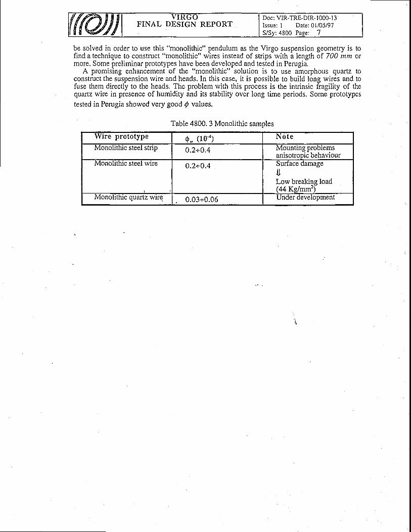
FINAL DESIGN REPORTDoc: VIR-TRE-DiR- 1000- I 3Issue: I Date: 0l/05/97S/Sv:4800 Paee: 7
be solved in order to Lrse this "monolithic" pendulum as the Virgo suspension geometry is tofind a technique to construct "monolithic" wires instead of strips rvith a length of 700 nxm ormore. Some preliminar prototypes have been developed and tested in Perugia.
A promising enhancement of the "monolithic" solution is to use amojconstruct the su
enhancement of the "monolithic" solution is to use amorphous qLlartz toire and heads. In this case, it is possible to build long wires and toconstruct me suspenslon wlre anq neaos. ln tnls case, lt rs posslDle to bullo long wlres ano to
fuse them directly to the heads. The problem rvith this process is the intrinsic fragility of thequartz rvire in presence of humidity and its stability over long time periods. Some prototypestested in Perugia shorved very good p values.
Table 4800. 3 Monolithic samples
Wire prototype 0.. (10'o) N o t e
Monolithic steel strip 0.2+0.4 Mountrng problemsanisotrooic behaviour
Monolrthic steel wire 0.2+0.4 sufface damage.t,Low breaking load(44 Kg/mm')
Monolithic quartz rvire 0.03+0.06 under development
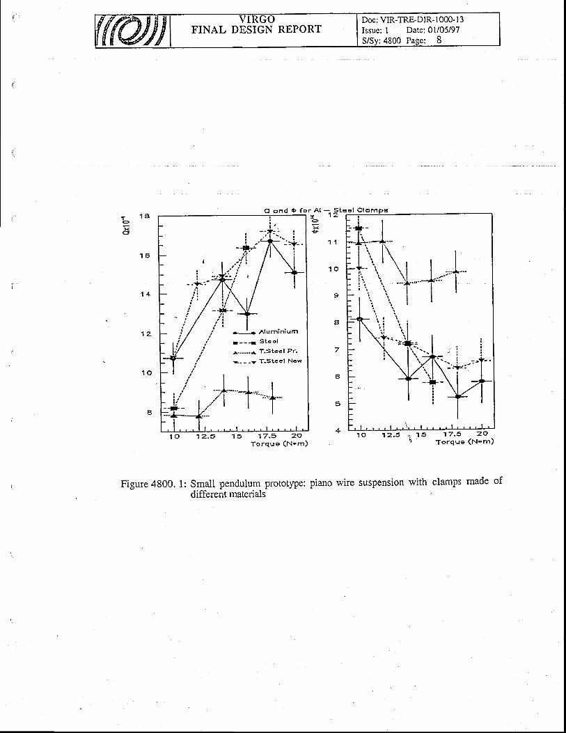
FINAL DESIGN REPORTDoc; VIR-TRE-DIR-1000-l 3Issue: I Date: 0l/05/97S/Sy:4800 Page: 8
t 1 8oxa
Cl ond tF fo r A l ;
x
+--l- Aluminiurn
1 - - q S t e e l
^.-.-.-{ T.Stccl Pr.
- - - -7 T .Stee l New
I
11 5 1 7 . 5 2 9
To rque (N 'm)
' A l - S t e e l C l € m D s- 1 2o F ! l
1 1
1 0
9
a
7
6
5
+, i ' l 5
'17 .5 ZOr') Torque (ru-m)
1 6
1 0
Figure 4800. 1: Small pendulum prototype: piano wire suspension with clamps made ofdifferent materials
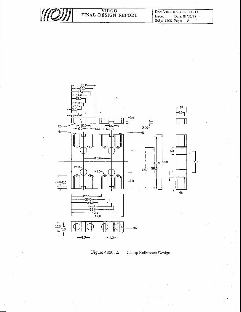
FINAL DESIGN REPORTDoc: VIR-TRE-DIR- 1000- I 3Issue: I Date: 01/05/97S/Sy:4800 Pase: 9
2 n '
ffit]Htf'n*J F1e.fr r-1?,&--r I- 6,0 - *-13,0- 6,0 -
FilE
ilLJ
t lt lH6
I''1*F
,f;r| 5,0- f
-q,o- --r4,0-
Figure 4800. 2: Clamp Reference Design
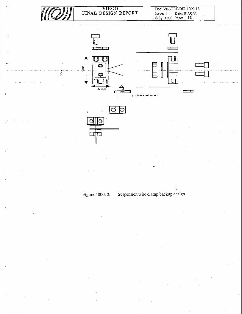
FINAL DESIGN REPORTDoc: VIR-TRE-DIR- 1000- I 3Issue: I Date: 0l/05/97S/Sv: 4800 Pase: 1 0
mEEE
r:1lj_]r
rr-ErTl
t[rilill;*-il/l i e l l -lrrur-rl<-> A
! ! a o Il..:-?-t
Figure 4800. 3:
r:il-il
- i l
Suspension wire clamp backup design
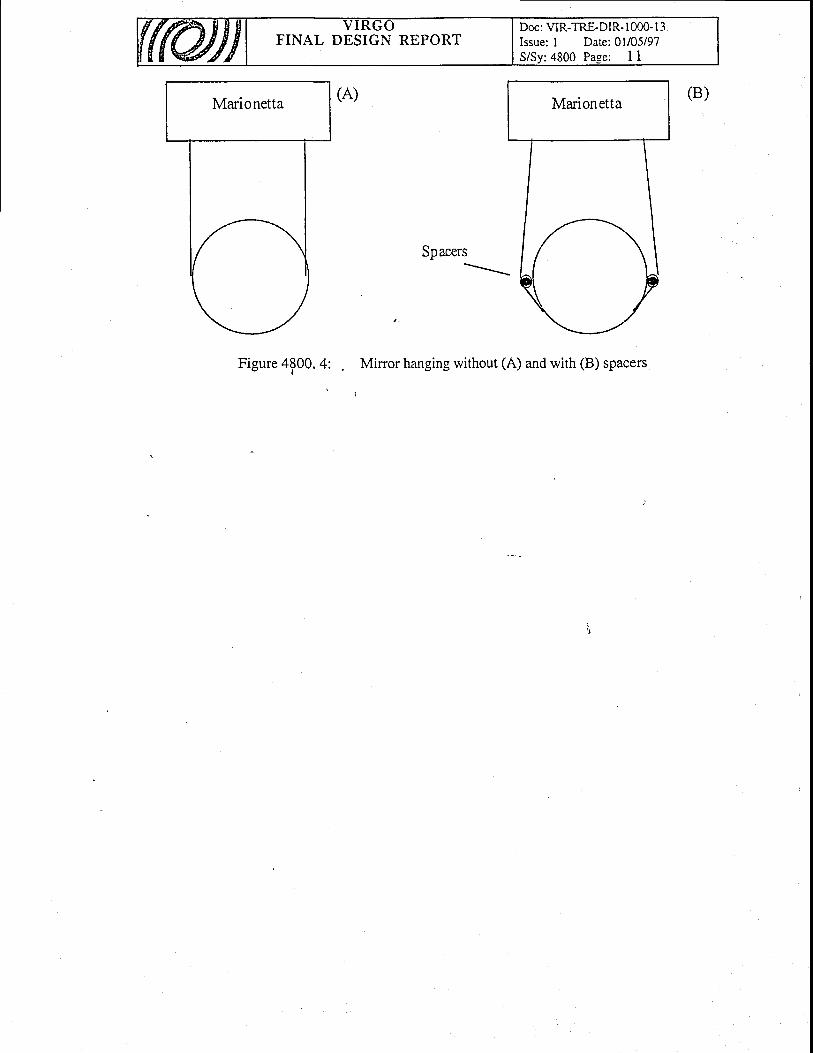
FINAL DESIGN REPORTDoc: VIR-TRE-DIR- 1000- I 3Issue: I Date: 0l/05/97S/Sy:4800 Page: I I
Marionetta Marionetta
Spacers\
Figure 4p00. 4: Mirror hanging rvithout (A) and with (B) spacers
FINAL DESIGN REPORTDoc: VIR-TRE-DIR- I 000- I 3Issue: I Date: 0l/05/97S/Sv:4900 Pase: 1
49. Suspension
Table of Contents
Electronics
49, Suspension Electronics
49.1 General Descr ipt ion49.1.1 Active damping of suspensions49.1.2 Suspended masses position control49.1.3 Super Attenuators internal status monitoring and conection49.1.4 Interface betrveen the S.A. controls.ystem and other VIRGO sub-systems
49.2 Hardrvare Description49.2.1 Digital Signal Processor Board49.2.2 ADC6l6b | .49.2.3 DAC820c
i
49.3 Sof t rvare Descr ipt ion49.3.1 Advanced Damping Toolkit (ADT).49.3.2 The graphical user interface
. 49.3.3 The internal structure of adt software
7
22J
J
J
4A
6
667I
FINAL DESIGN REPORTDoc: VIR-TRE-DIR- 1000- l-3Issue: l Date:01/05197
:4900 Pase: 2
49.1, General DescriptionThe suspension control system can be divided into four main parts:
1. Active damping of suspensions.2. Suspended masses position control.1. 9up.I Attenuators intemal status monitoring and correction.4. Interface bettveen the S.A. control system and other VIRGO sub-systems.
Fig. 4900.1 shows the schematic structure of the control system for a generic suspension.
49.1,1 Active damping of su.spensions
The S.A. has bee-n designed to reduce the suspended masses specual displacement in theYT99 ::lsitivity frequency .range. An active ieduction or trre-inasses
-ttii-aiipru...n.nt,
located at the S.A. normal mode; fr9-q3e1c1,.is necessary in order to reduce the dynimic rangiand the {lguired bandwidth,of the VIRGO locking sysiem. The specificati;; ;6;;";ing tfiemirrors displacement are the follo'wing:
r Spectral displacement lorver than 10'rs mHz'tn at frequencies higher than 3 Hz.o Rms displacement lorver than I pm on a time scale of 100 seconds.
. To achieve the rms displacement requirement a sophisticated digital control system has beendesigned and built. A Digital Signal Frocessor, under controt "of
a \ ,c a'pu, elaboratessignals gominq from p-osition and acceleration sensors, located cin top oi tfre S.e. and tiltsensors located on the bottom of the pr+stabilization stage. Then the DSp drives coil-magnet!,11tt on,top,alg piezo actuators locdted under.the pre-s-tabilization stage legs. fig. +ldO.Zthoivs a block diagram of the damping strategy implernented rvith the OSp. f"ne DS-p devotedto tne damprng system reads signals coming from sensors located on Filter Zero. plF.�l, pHZand PH3 are tvbr.position se"nsors_ whicli measure the relat'i've diii.;;;*r 6etiveen FiterZeroand Torver. AIil, AH2 and AH3 are acceleration sensors wtribtr measure the absoluteacceleration of Filter Zerc. The DSP combines these signals making a projection towards thethre^e main.longitudinal modes (x, y and 9r) of the pre-Isolation syitem (Iiverred pendulum),perlorms !L"_:-"gqtg9 compensatio_n and firylly feeds_back to th-e IP using magnet-coil pairacttrators (C.Hl,CH? t4CH3). Sensors !!1 and AVl provide signdls p"ropoftional to'thevertical motion of Filter Zero crossbar. The DSP computes 6orrectioniand abts bn the crossbarwithCVl.Tl andT2ue tiltsensorslocated on the lorver ring supporting the Ip legs. Signalscoming from Tl andT2 are used to reduce the tower tilt ;irh';.oniroi l*p-ritricn"usespiezoelectric actuators located under the ring
49,L.2 Suspended masses posit ion control
. ̂ ,Tlt: T!!.ilied d.y.namig range for the suspended masses position control is very large (aboutt9_" Hz"'). 'I'o achieve_this requirement the correct minors position rvill be set acting on threedifferent points in the S.A chain.:
r the suspension point (pre-stabilization stage),. marionetta (from,,filter Z")
_ _: mirror (from "reference mass").In Fig. 4900.1 the subdivision of conirol forces is shorvn. Three independent filters acting
on the three control stages are implemented in the DSP devoted. to rht pdrition control. Eigf,resolution digital to analog conferters and lorv noise coil duvers are necessarv. A DSPprocessor under control of a MvIE CPU computes the forces to be applied on ea6h point inorder to obtain the desired displacement.
FINAL DESIGN REPORTDoc: VIR-TRE-DIR- I 000- I 3Issue: I Date: 0l/05/97
:4900 Pase: 3
49.L.3 Super Attenuators internal status monitor ing and correct ion
Each filter in the S.A. chain needs a very lorv frequency control of the anti-spring magnetsposition. This control is achieved reading the relative displacement betrveen filter and cross bar.Stepping motors located on the filter itself will eventually correct the position. A similaradjustment system is foreseen on the marionetta stage. These lo',v frequency controls areprovided directly by the VME CPU.
49.7.4 Interface betlveen the S.A. control system and other VIRGOsub-systems
The Suspension Electronics has direct interfaces with the Global Control, Alignment, DataAcquisition and Monitoring sub-systems. The Suspension Electronics system ieceives datafrom Global Control and Alignment through fast optical links read by the DSP board; the S.A.status is sent to the Data Acquisition 4nd Monitoring through both fast links and Ethernetconnections. The Suspensior Electronics system is in charge for the development of thesoftrvare for the data exchange running on its hardrvare.
49.2 Hardware Description
The typical hardrvare configuration for the SA damping is shorvn in Fig. 4900.3. It iscomposed by a NIM crate conttining sensors and actuators conditioning and driving electronicmod-ules (coil drivers, accelerometeis, position sensors and lorv frequency modulation carier'sources) and a VME crate where the processing units are located.
The DSP board interfaces to the VME bus, to the VSB bus and to another local VOextension bus named VBeX. The VBgX bus is used for communications betrveen the DSPboard and ADC/DAC boards and it is mapped on VME P2 connector. The bus connected to P2'can
be software selected. Any conflict beiween VBeX and VSB modules is avoided_dtvldingthe address space into two different regions. ADC and DAC boards interface to the VME bus,used for initill boards setup, and to thtVBeX bus. The single connection with the timing boardis the trigger signal (the [igger signal starts the data conversion. and generates- an interntptrequest on ttre \BeX bus). A-Digital to Optical conversion board can be addressed by both theDSP and the CPU in order to allow fast data transfer tolfrom the VIRGO frame builder.
Two different mechanisms are foreseen for the communication between CPU and VME' Thefirst one is an access to the DSP memory through the VME bus using, the DSP board HostInterface. This fast intem.rpt mechanism (bnly trvo instruction are inserted in the program flux)allorvs the CPU to write irito the DSP memory and it is used for the program downloading, tostarVstop the program itself and for the "on the fly" upgrade of computationai parameters. Thesecond co.-uni.ation mechanism is mainly usLO firi monitoring purpose. Tire OSp boardrvrites the signal to be monitored into a duai port memory board using the VSB bus in blocktransfer modE. The CPU reads those data usin! the VME bus in order not to generate conflictswith the DSP.
Timing summary600 -+ 800 ns to read 6 channel on the VBeX bus.
600 -+ 800 ns to write 6 channel on the VBeX bus.
I -+ 2 ms to rvrite data on the DOL board (VSB Block Transfer).
| + 2 ms to write data on the RAM board (VSB Block Transfer).
L -+ 2 ms to read data from the RAM board rvith the CPU (VME Block Transfer).5 ms ADCs conversion time.1.2 ms DACs conversion time.
FINAL DESIGN REPORTDoc: VIR-TRE-DIR- I 000- I 3Issue: l Date:01/05/97S/Sv:4900 Pase: 4
About 40 ms available for DSP operations (800 instruction) rvith a sampling rate of 20 kHz(single sample delay betrveen input and output).
49.2.1 Digital Signal Processor Board
The VME Digital Signal Processor board, fully developed in the I.N.F.N. Labs in Pisa, hasbeen designed for the Virgo payloads position control and for the S.A. normal modes damping.The main features of this board are the follorving:
o One Motorola DSP96002 processor running at up to 40MHz giving a peak processingrate of 60MFLOPs (30 MFLOPs sustained).
o Large high speed memory anay. Up to 256kWord of local SRAM Zero lVait State.r Standard V\\IE A24 D32 Master/Slave interface supporting VME Block Transfer (DMA)
for rapid MdE data transfers. Direct access to the DSP Host lnterface to efficientlytransfer data at high speed.
r Standard VSB master interface. ''
o Local VO expansion bus VBEx (24 data bits, 6 address bits) providing a real timecommunication path rvith ADC and DAC boards.
r OnCE port for bSpgOOOZ debugging compatible rvith Motorola software tools.. RS232 serial port.
49 .2 .2 AD C616b'
The ADC6l6t is a 6 channels 16 bit ADC board that interfaces both to the VME bus and tothe VBeX local VC bus. The card has been fully designed and developed in the I.N.F.N.Iaboratories in Pisa.
The ADC616b uses the ANALOG DEVICES AD7885 analogue to digital converter, whichis a 16-bit monolithic converter rvith intemal sample-and-hold. The maximum throughput rateis i66 k-,SPS achieved using a two pass flash architecture. The power supplies required fromthe backplane are +12 V, -12 V and +5 V.
ANALOGUE INPUTS
Each ADC input has its own anti-aliasing filter module. The input impedance is 100 kC2 and
the input voltage range is 10 Vpp (-5 V -+ +5V).
BOARD PROGRAMMING
The ADC616b board is programmed only through the VMEbus. The following features canbe programmed.
Sample Clock Source RegisterIntemal (Clock Master) or External (Slave)
Sample Clock Rate RegisterThe lnternal 2+ Mn- crysta frequency is divided by the 16 bit number rvritten in the
sampling frequency on board register.
ADC Channel Enable Mask RegisterEach channel can be enabled uslng an 8 bits register. Even if the channel is not enabled, the
conversion talie place anyway. This register is used only when the board is read in BT.
FIFO Enable Reeister
Doc: VIR-TRE-DIR- I 000- I 3Issue: l Date:01/05/97
:4900 Page: 5FINAL DESIGN REPORT
The FIFO memories can be enabled or not depending on the status of a mode register (8 bi|'
Dorvnscaling Set Registerf f ieprograrnmedusingan8bi t reg is ter .Theregis terconta insthe
number of samples to be averageri'1-t => 2r, io divide.by 256) (the maximum number ofaveraged sampl^es is 256). The outpui of the adder is a 24 bits data (s_ig1 e_xtended.to 32 bits forthe VX4Ebus)'and can be read both from the VME bus and from the VBeX bus. Since the resultof an averageot 416 bits samples is on 18 bits, when FIFOs are enabled and the number ofaveraged sa-mples is greater than 4 only the 18 most significative bits are available.
Intemrpt Request Generationf f i ie lectedanintemlpt requestcanbegeneratedonIRQ1. .7.Whenthe
VBeX bus is selected only one level of int-errupi request is available. The intemrpt request isgenerated:
When the programmed number of averages has been made.
When the 6 ADC channels coniersion starts.
When the FIFO is "almost full" (programmable).
DAO Synchronizatidnff ianperformasynchronizedsamplesaveraging.Theadderresult isfed
to the output (or to the FIFO memories) in c-orrespondence rvith a double width clock pulse.When cloik master the ADC616b board.supplies tliis sync pulse every lAvI clock pulse, rvh91eM iq the. nrnorAmmerl nrrmber of samoles io be averaied. When slave the board automaticallyM is the progralnmed number of samples to be averaged. Iave the board automaticallY
o
a
a
po*p,,t"i thE number of averages in oider to, be synchionized rvith the master card. This featureproduce an uniform signals sampling other than a synchronized data acquisirion'
BLOCK TRANSFER .
The ADC616b board supports standard block transfer from the VMEbus. When the FIFOmemories are enabled,it is ibssiUle to transfer 256 by_te from the addressed channel otherwise,rvhen the FIFO memori.r ui. not enabled, the 6 ADC channels (or only the enabled channels)are riaO starting from ttre niit on.. Using ttr. gf daisy chain cabied on it2 it is possible to readmore than one board in block transfer.
ADC NOISB ', ,
In a sampling AD converter the noise is made^gp of sample-and-hold noise and a./d converternoG. Tire iamife-unO-trofd r..iion contributes 85'uV rms ind the ADC section contributes 98uV rms. These adO uo to a total rms noise of 120 uV rms. Fig. 4900.4 shows a histogram plotfor 5000 conversions^of a dc input using the AD7885 in the t5 V input range. The analog inp.utwas set close to tf," ..ni"r of a 6ode trarisition. All code other than the centei code are due to theADC noise. In this ;;;iil tpr*a is six codes. The noise rms value can be calculated from thestandard deviation estimation. We obtain:
VD*, = o#= 120 PV
Dynamic Performance And Effective Number of Bits - ^ - -9'8 Volt peak to peak sine,waveform'
Before "nt.iing in" ADC this signal has been filtered with a 3rd brder Butterworth lorv pass
nttir wittr a "u?iriqu*"y oi+i6, where i06 th. sine wave frequency, in order,to reduce the
source noise. The disiri signal'has been .tuUorut.A by a nuinericil notch filter and then
.onu.it.O UV-^ 1-O UiiSAb io"pitfo* the_ noise analysis wittr a spectrum analyzer. There is nota signifrcatiiechange of the n6ise level changilg the sine waveTrequency until this fre9ue3,clreaJhes about 200 Hz. Above this limit, the noist increase with the sine rvave fiequency. rtg'4900.6 shorvs the measurement result for a 120 Hz sine wave. The straight line is the average

FINAL DESIGN REPORTDoc: VIR-TRE-DIR- I 000- I 3Issue: l Date:01/05/97
:4900 Pase: 6
noise spectrum density used in the follorving calculations (1.6 uV Hz't'').The Signal to(Noise+Distorsion) Ratio is about 89.89 dB. This ADC is equivalent to an ideal ADC having
N = ros,[V*,]=,"*,[ff.]=,"r.[-- t/f ]= ra.a3 bits.
In* ,J " ' [ N{B /
- ' \1 .6 .10- .V10000. /
Note: a standard way to compute the effective number ofN = (SNR- 1J6) | 6.02= 14.64
49.2.3 DAC820c
The DAC820c is an 8 channels 20 bit DAC board that interfaces both to the VME bus and tothe VBeX bus. The card has been fully designed and developed in the I.N.F.N. laboratories inPISA. The DAC820c board uses the ANALOG DEVICES AD1862 dieital to analogueconverter which is a low-noise, low-distortion 20 bit audio converter] The maxim-umthroughput rate of this chip is about 800 kHz.
ANALOGUE OUTPUTS
Each DAC output has its own filter module. The cutvoltage range is 10 Vpp (-5 V + 5 V).
kHz. The output
DAC NOISE. Harmonic Distorsion and Signal to Noise Ratio
. Total Harmonic Distorsion (THD) can be measured using the technique shorvn in Fig.4900]. The 20 bit DAC is driven rvith a 20 bit digital sine rvave having a frequency of 156.25Hz. The DAC update rate is 20 kHz. The FFT Spectrum Analyzer (Ono Sokki CF-6_400)performs a4096 point FFI of the filtered signal and computes THD and Signal to.Noise Ratio
. (SNR), The Signal to (Noise+Distorsion) Ratio is about i06 dB. This DAC is eqiivalent to anideal DAC having
N = roe"[Y^'] = ,o*"[ur+/f \= ror,( fu,) = r7.a3 uits.- ' \ . n* /
- ' \ N{B /
- ' \2 '10- 'a /10000 /
49.3 Software Descriptiont
49.3.L Advanced Damping Toolki t (ADT).
The ADT softrvare has been developed to produce an highly optimized code for the DSP'scontrol system rvithout requiring a dedp knowledge of the
-naiAw'are implementation. In fact,
the user of tne existing sofiware-is, in ^general,
a Ipeciaiized one who kriorvs exactly the DSPhardrvare, furthermore the software is frequently designed for a set of configurations and notfor all.
ADT software solves all this problems. ADT's users can produce, essentially without anaccurate knowledge on how his'digital filter is implemented'into the DSP's system, higllyoptimized code using a graphical de-scription of whit the DSP have to do. Furthermore, thisiriplementation is no*moie ionelated to lhe particular hardware choice, so it is possible to usethe same user program with different hardware configurations.
This software- satisfies the follorving general -requirements:
portability; user friendlyinterface, a ClienVServer structure and finally a "protected" interface to the hardware system.The protected access to the processes that are-running on the DSP's system plays a fundamentalrole during the setup phase when it rvill be necessary to fix the control loops parameters.
To assure nice GUI (Graphical User Interface), easy portabiliry and Client/Server structurerve have chosen:
FINAL DESIGN REPORTDoc: VIR-TRE-DIR- t000- I 3Issue: I Date: 0l/05/97
:4900 Pa.se: 7
. ANSI C.a
a
UNIX-Like OS rvith XWINDOWS SYSTEM MANAGER.TCP/IP as transmission protocol.
The GUI is based on a public domain library, XFORMS, that runs on at most all the UNIX-Like systems including the Lynx-OS system. It is based on XIVINDOIVS and is rvritten instandard ANSI C language. At the moment the ADT softrvare can run on the followingplatforms:
. LynxOS 2.2 /m68ko IBM-RS6000. PowerPC /AIXo Linuxo Linux/i386. Linux/alphao Linux/m68ko Linux./sparco Mklinux/PowerMac XllR6.1o Suno SUnOS
. . Solaris -
o Dec-Alpha (OSFI VZ &Y3)r HP/HP-UX
. . OpenVMS /Alpha
49.3.2 The graphical user interface
Unfortunately, the implementation of a GUI for programs is in general a time consumingprocess. In the l'ait tew yiats a number of packages liavJ appeared th-at help build up .graphicalirser interfaces in a simfle way. ADT softrvare uses a public domain library (Forms Library) tobuild the GUI. The F6rms Library contains a large-number of pre-defined objects, such asbuttons, menus, sliders etc. The inieractive GUI buitder bundled wittr ttris library can be usedto generate all the geometry and C code needed, and in general it is not necessary to writeadditional C code t5 make i nice{ooking GUI. The applicaiion program has a large amount ofcontroloverhowobjectsare drawn on ihe forms. Ittan set color,-shape, text-style, text size,text color, etc. In thii rvay forms can be fine tuned to programmer's liKng, furthermore specialgoodies are built-in to peiform common task in the application program, like select a file name,Isk questions etc. In this way, the application progiammer can concentrate his orvn w_ork onask questions etc. In thi the application progiammer can concentrate his orvn w-oLk ondesiglning the handler functioni and on the real iorJof the softrvare project. The Forms .I=ibrarycan 5e uied both in C and in C++ programs. The library uses only the services provided by theXLIB and should run on all rvorkslations that have X installed on them.
49.3.3 The internal structure of adt softryare
The ADT software rvas designed to use its orvn library and to be easily scaleable for futureneeded, i.e. change in the hard'rvare setup, etc. For thii reascln we hav6 maintained an lighlevel of modularii-v in writine the code. fhe internal structure of this tool is sketched in Fig.4900.10.
The Design unit takes its graphical input from a schematic entry and performs the enorcheck, the eitraction of the NEttiit file, and the simulation of the control l6ops using externaldata (simulated or real).
FINAL DESIGN REPORTDoc: VIR-TRE-DIR- I 000- I 3Issue: I Date: 0l/05/97S/Sv:4900 Pase: 8
The Kernel unit is the core of the ADT software. It performsdorvnloading tasks. The compilation translates the Netlist informationdorvnload module send to the VME CPU trough the netrvork. Thiscommunications betrveen the other units and DSP's control svstem
the compilation and theinto bindrry code that theunit also coordinates thebuilding up the required
protected access to hardrvare system.The third unit is the Monitor. The tasks are the probe positioning on the schematic and the
analysis of the information to make graphics, FFT and Transfer Function of the signals takenfrom the DSP's control system.
The Tool unit is an advanced area in rvhich the user can build its orvn ADT library using theLibrary Designer tool, or design his orvn special digital filter using the Digital Filtei Desilner.Finally, ADT software has provided, also, of the Bitmap Vector Creator tool that can be used tobuild a vectorial description of the library object's icon.
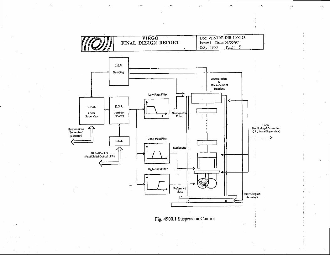
Eh
E'E
88
. 4E
sa
IY
06
|
-.E I
Io
J
I=
)l
su
tI
ktuC)
.4
(t)
Oo\sboH
Hl
.9EO
o!
o,!
.d&
:o
oiex
q5
0o
d
-9.9
tC
}ou
o\.f</)
v)
II
R*
=<
j*
a=
-H
O
qo
>::
8et-{i-i
'
Cn
PFlz

tvooLCh
c)()C)
ov)oC)
voan.nLCN
calr
LI
HE
Ol
!f
I
R*
TA
*o
=F
rq
o
'r
H
>:
..
oo
:'
l-(r-'t -
zCN
tlFlz
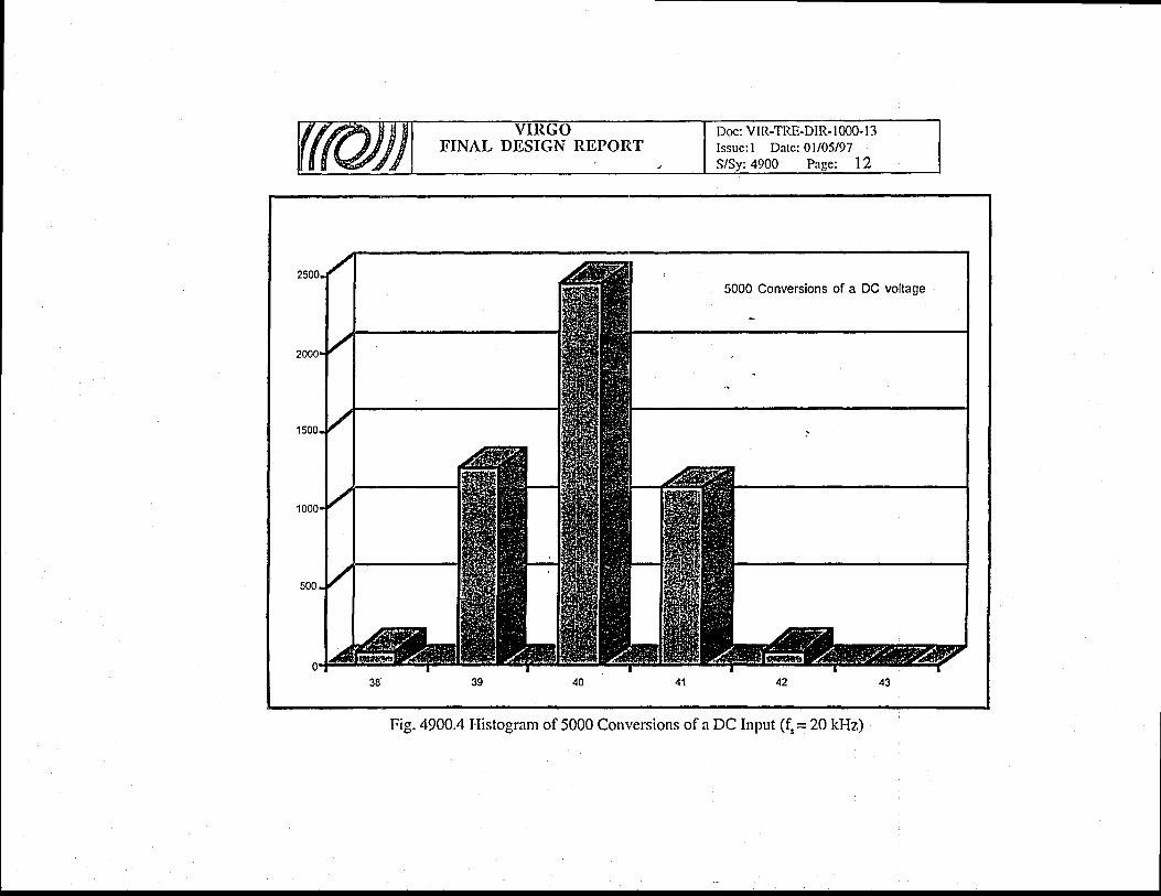
Or
-=
<.r'O=
\u
oH
O
FN
.. c
)
6dFf-.l
'
zrhaI-'l
.t
zr-,
(l)o)=ooo(go.9aiL{l,coOO
loo|r)
Ntsc.ttl
C)ahIAq)
Urn!e
!i<0\$bolr
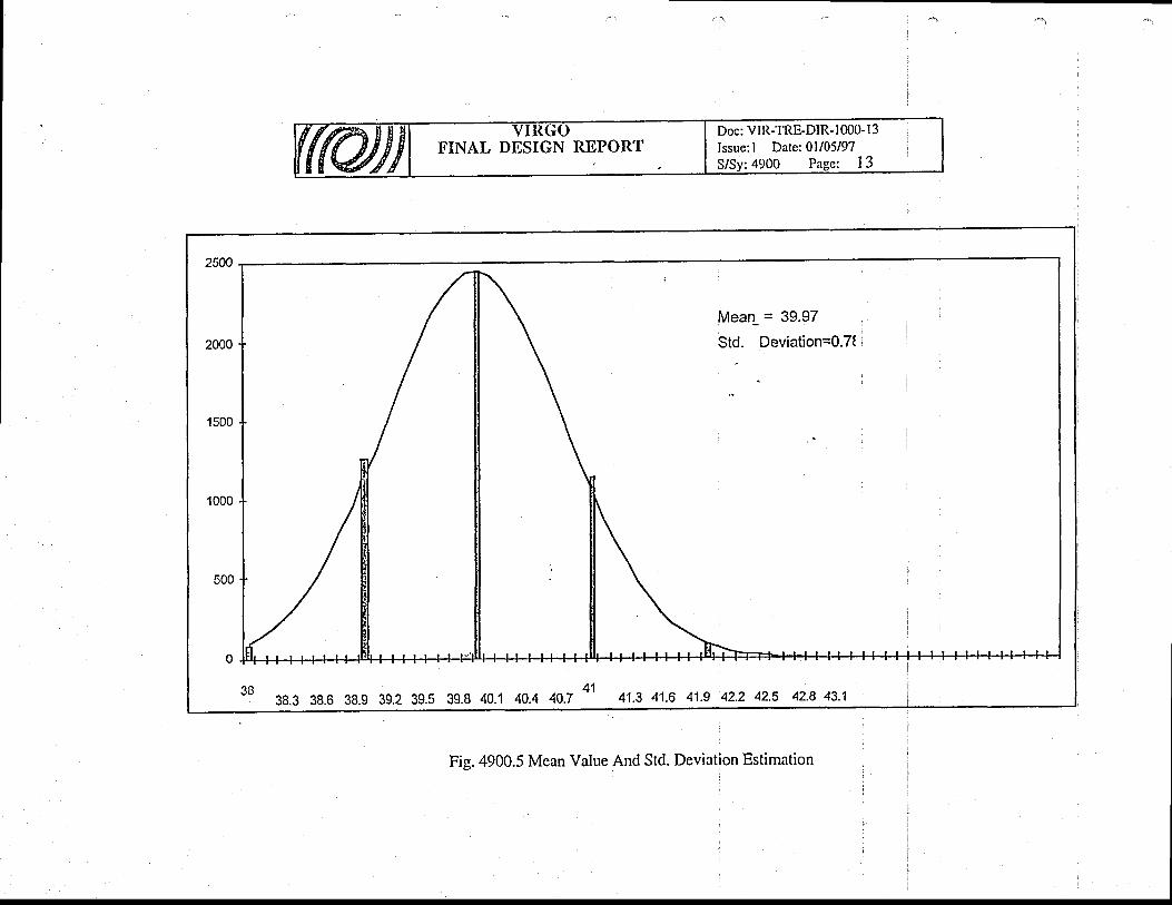
v)frloi,
a!)
roar
dv@C\i
sl-
rooitrNoilirol!i,qctq(l?tf
$
t\orir\{-c;.rfd.qcoo;(?rr)oi(r)
cYo,o,cd(.)(ocd(o(occi(f)
@(a
cnTXx
-x
,=
=i
6E
=H
()
'r
H
>:
()
=o
4Fr-1 '
za,\
z
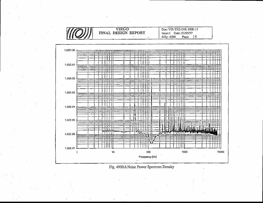
t4a)hlFC
)c)
U)Lrc.)>Hc)u)
z\OOolvJr
lll I lllllri-'ii
s
q)
-fv,
o r-.
=\"
*O
A=
HC
)
FN
>=
..
oo
3O
6
t-'
zaFI
Fl
z

U'
oI.hc)
HrrLr
c,l)
oot1oFc-Or
:f,
NLOc\!C
OLOtl
€
l-G)
-F'
ir-c)oz
rr)C)
.tU)
U)
c.l
**
=e
J3
E=
HC
)
tia
F:
,.
o8
AF.t
r,l
zV)
r-'!
Ft
z
N=LOo'l
9E
(u
'=
-o
>6
s
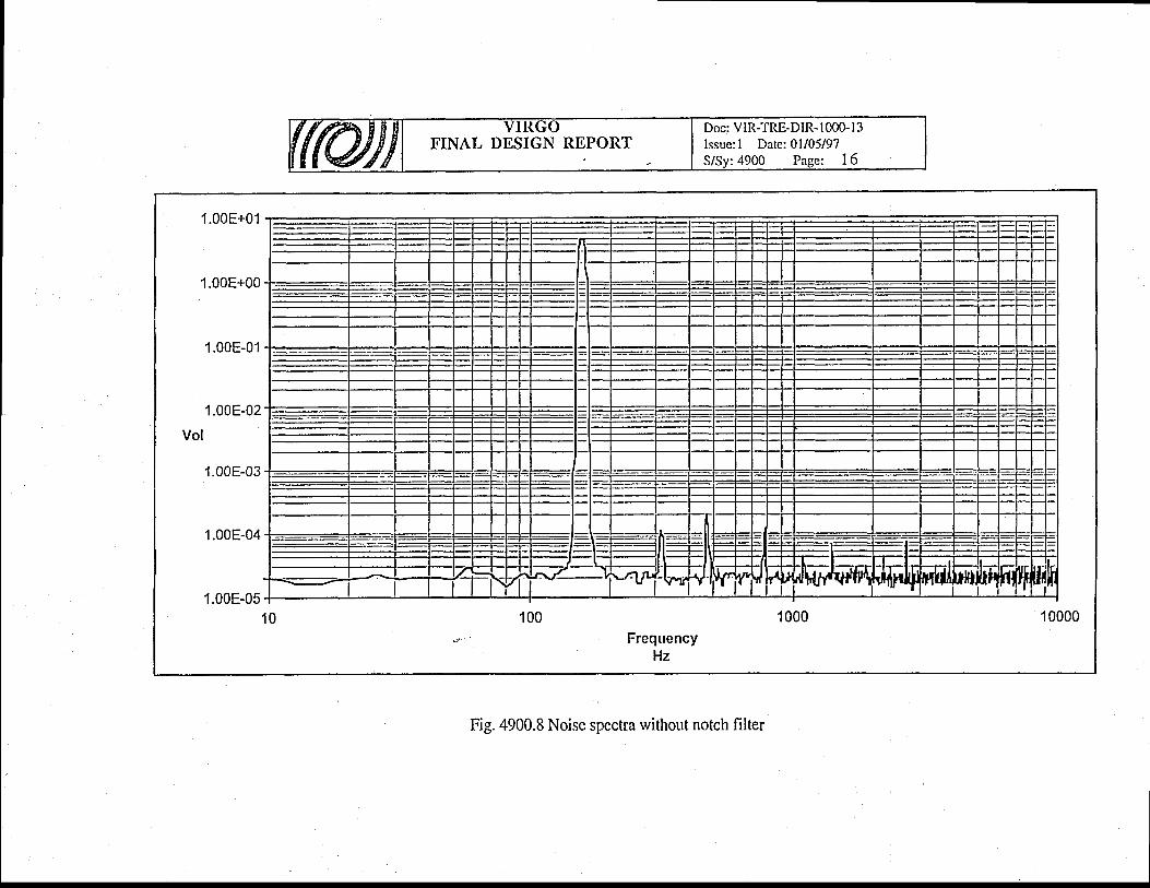
Oc
-=
<l
PO
=>
HO
FA
>-
..
oo
:J
aql-izCA
r-'l
Flzr-.
t<C)
o-koC)
u)c)U'
z$
IJ9x
o1I
lr)oI
tlJoq
.<r
oIr
l
Oq
cOodoq
E
NoI
tUoq
oI
uJq
oo+UJ
oq
ro+IJoq
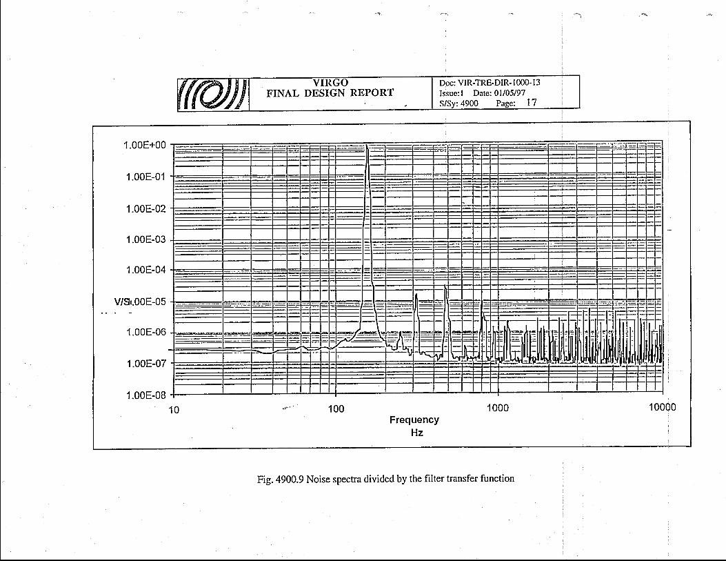
r-.q
8--
9q
^/
O
E=
HC
J
TO
>-
.. c
)E
;Ei
t=l
riaFl
oU
_EX
tLLl 5
oalr N
oir
ON
cq
*t
lO
(O
F-
@o
oo
oo
oo
oo
,i
,d
dd
dd
dd
dx
oo
oo
oo
oo
Sq
q-
-r
-6
'r
r-
\
:
()L
,C)
U)
!wLoh:eo0)
thc)t))
zo\Oo\.<rbo
?t
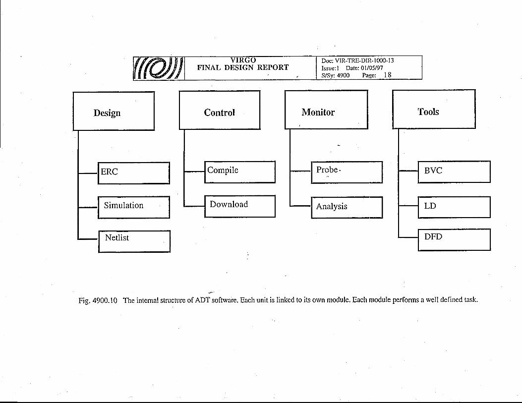
va(),-C
)
()3U)
r,oL()()oEI()
'tJa/1
oa,()IY l
IB
\a
4
f<(gc)kouarl
FC)
c)FO.+bof r
-
(t)(t)h
t-{
a
ooos(nv)
R*
56
NO
n=
rH
o
FA
>i
Q'
o4F
t
FIzU)
r-\
z
.dFo
oF
U
F
cn
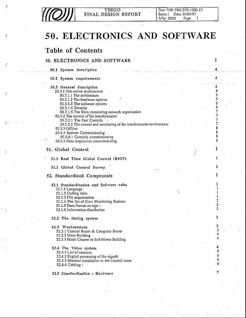
Doc: VIR-TRE-DIR- I 000- l3Issue: l Date:01/05/97S/Sy:5000 Page: I
FINAL DESIGN REPORT
50. E,LECTRONICS AND SOFTWARE
Table of Contents50. ELECTRONICS AND SOFTWARE
50.1 System descr ipt ion
50.2 System requirements
50.3 General descr ipt ion50.3.1 The online Architecture
50.3. l.l The architecture50.3.1.2 The hardware options50.3.1.3 The softrvare options50.3.1.4 Security50.3.1.5 The Slow monitoripg network organization
50.3.2 The control ofrthe interfer-ometer50.3.2.1 The Fast Controls .50.3.2.2 The control and monitoring of the interferometer environment
50.3.3 Offl ine50.3.4 System Commissioning
50.3.4. I Controls commissioning' 50.3.5 Data acquisit ion commissioning
51. Global Control
51.1 Real Time Global Control (RIOT)
51.2 Global Contro l Survey
52. Standardized Components
52.1 Standardization and Software rules52.1.1 Language52.1.2 Coding rules52.1.3 File organization52. 1.4 The list of Slow Monitoring Stations52.1.5 Data format on tape :52. 1.6 Information distribution
52,2 The timing system
52.3 lVorkstations52.3.1 Control Room & Computer Room52.3.2Main Building52.3.3 Mode Cleaner or End Mirror Building
52.4 The Video system52.4.1 List of cameras52.4.2Digital processing of the signals52.4.3 Monitor installation in the Control room52.4.4 Cabling :
52.5 Standardization : Hardrvare
4
4
44))661
7
1
8888
1
1
1
1
27
2
7
4
4A
666
7

FINAL DESIGN REPORTDoc: VIR-TRE-DIR-1000- l3Issue: l Date:01/05/97S/Sy: 5000 Pa-qe: 2
53. Netrvorks
54. Data Acquisit ion System
54.1 Requirements
54.2 Architecture and Components
54.3 Data Acquisit ion interfaces54.3.1 Interface with Slow Monitoring54.3.2 Interface with the Fast Controls54.3.3 Interface rvith Data Archiving and Global Control54.3.4 Interface with Supervisor54.3.5 Interface with off-line activity, simulation and Data Management
54.4 System Descr ipt ion54.4.1 Data Collection
54.4.1.1Local Readout54.4.1.1.1 Hardware Components and Connections5 4.4.1.1.2 Operational overview54.4.1.1.3 Configuration'
54.4.1.2 Data Transport and Format54.4.1.3 Local Frame Builder '
54.4.1.3. I Hardrvare Components and Connections54.4.1.3.2 Operational Overvierv
54,4,1.4 Frame Format. 54.4.1.5 Main Frame Builder and Frame Distribution
54.4.2Dara Quality54.4.3 Data Preselection
.55. Data Distr ibution & Archiving
55.1 Funct ion and concept
55.2 Requirements
55.3 Inter faces55.3.1 List of Data Distribution & Archiving interfaces55.3.2 Interface with Global Control55.3.3 Interface with Standardized Components55.3.4 Interface with Networks55.3.5 Interface with Data Acquisition55.3.6 Interface with Supervisor55.3.7 Interface rvith SAV Tools - Simulation55.3.8 Environment Monitoring55.3.9 Interface with SAV Tools - Distribution
55.4 Select ion of so lut ions
55.5 .Deta i led descr ipt ion55.5.1 Raw Data Archiving System
55.5.1.1 Function and concept55.5. 1.2 Detailed description
55.5.2 Data Distribution System55.5.2.1 Function and concept55.5.2.2 Detailed description
56. Supervisor & Associated Softrvare
56.1 The Superv isor
I
I
1
1
,,
22J
J
3
33J
4)5
)6666
7
1
1
1
t
2J
J
J
J
J
4
44i
66I
1
FINAL DESIGN REPORTDoc: VIR.TRE.DIR.IOOO. I 3Issue: l Date:01/05/97S/Sy:5000 Page: 3
56.2 The communicat ion tool
56.3 The Errorlogger
56.4 The Onl ine DataBase
57. Softrvare Tools - Simulation
57.1 General Descr ipt ion
57.2 Inter faces
57.3 Select ion of so lut ions
57.4 Deta i led descr ipt ion
58. Environment Monitoring
58.1 Funct ion and concept
58.2 Requirements
58.3 Inter face58.3.1 List of Environment Monitorine interfaces58.3.2 Interface with Infrastructure
' 58.4 Interface rvith Global Control
58.4. I Interface rvith S randardized Comoonen ts58.4.2 Interface with Networks58.4.3 Interface with Data Acquisition58.4.4 Interface with Data Distribution & Archivine58.4.5 Interface with Supervisor
58.5 Select ion of so lut ions
58.6 Deta i led descr ipt ion58.6.1 Building Monitoring System
58.6.1.1 Function and concept58.6. 1.2 Detailed description
58.6.2 Environment Monitoring System58.6.2.1 Function and concept58.6.2.2 Detailed description
59. Softrvare Tools - Distr ibution
59.1 Funct ion and concept
59.2 Requirements
59.3 Interfaces59.3.1 List of SAV Tools - Distribution interfaces59.3.2 Interface with Data Acquisition59.3.3 Interface rvith Data Distribution & fuchiving59.3.4 Interface rvith S/lV Tools - Distribution
59.4 Select ion of so lut ions
59.5 Deta i led descr ipt ion
I
1
I
I
1
I
I
I
I
1
7
3J
J
A
-̂4A
4
4
)J
666
1
I
I
1
7
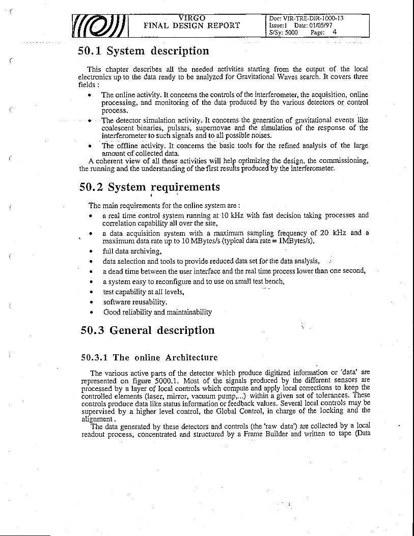
FINAL DESIGN REPORTDoc: VIR-TRE-DIR- I 000- l3Issue: I Date: 0l/05/97S/Sy:5000 Page: 4
50.L System description
This chapter describes all the needed activities starting from the output of the localelectronics up to the data ready to be analyzed for Gravitational Waves search. It covers tfueefields:
o The online activity. It concerns the controls of the interferometer, the acquisition, onlineprocessing, and monitoring of the data produced by the various detectors or controlprocess.
o The detector simulation activity. It concerns the generation of gravitational events likecoalescent binaries, pulsars, supemovae and the simulation of the response of theinterferometer to such signals and to all possible noises.
. The offline activity. It concems the basic tools for the refined analysis of the largeamount of collected data.
A coherent view of all these activities will help optimizing the design, the commissioning,the running and the understanding of thofirst results produced by the interferometer.
50.2 System requirementst '
The main requirements foi" the online system are :o a real time control system running at 10 kHz with fast decision talcing processes and
conelation capability all over the site,a data acquisition system rvith a maximum sarnpling frequency ofmaximum data rate up to 10 MBytes/s (typical data rate = lMBytes/s),full data archiving,data selection and tools to provide reduced data set for the data analysis,a dead time betrveen the user interface and the real time process lower than one seconc,
a system easy to reconfigure and to use on small test bench,. test capability at all levels,. softwarereusability.o Good reliability and maintainabilily
50.3 General description
50.3.L The onl ine Architecture
20 ktlz and a
a
o
o
a
The various active parts of the detector which produce digitized information or 'data' arerepresented on figure 5000.1. Most of the signals produced by the different sensors areprbcessed by a laler of local controls which compute ar,rd.apply local conections to keej. theiontrolled eiemenis (laser, mirror, vacuum pump,...) within i liven set of tolerances. Thesecontrols produce dati tike status information or fdedback values. Several local controls mqy pesupervis6d by a higher level control, the Global Control, in charge of the locking and thealignment.
The data generated by these detectors and controls (the 'raw data') are collectedreadout process, concentrated and structured by a Frame Builder and rvritten to
by a localtape @ata

FINAL DESIGN REPORTDoc: VIR-TRE-DiR-1000- l3Issue: l Date:01/05/97S/Sy:5000 Page: 5
archiving). They ar-e processed ('reconstructed') to convert, ADC counts and feedback signalsto an ft value, and 'filtered' to reduce their amount to a level manageable bv the offline analvsis.to an ft value, and 'filtered' to reduce their amount to a level manageable by the offline analysis.The data quality is permanently monitored by surveying the noise levei and a known sienalThe data quality is permanently monitored by surveying the noise level and a known signalproduced by a calibration device stimulating permanently the interferometer as a gravitationalproduced by a calibration device stilvave would do it. Finallv. the'filter'filtered' data are sent to a storage and distribution system rvhichis the experiment front end for the offline analysis. The system provides alio tools forhistogramming and data editing (including monitoring data).
All these controls are coordinated by a Supervisor and synchronized rvith a central Timingsystem.
50.3. 1 . 1 The arch i tecture
The interferometer is kept at its working point by a set of controls rvhich process dataprovided by sensors and adjust accordingly its main components : the laser, the twb mirrors ofeach Fabry Perot. cavity, the end mirror of the mode cleaner, the recycling mirror, the beamsplitter, the injection and detection benches.-
The archit6cture of the control ana reaA out systems has to account for the large distanceswhich may sepamte two components. To preserve flexibiliry in the interferometer setting up,the control sy_stems are organized as much as possible into independent units in charge of theadjustment of a rvell defined cornponent. They are run locally in standalone mode and accessedremotely by some high level control process. Similarly, the readout systems are implementedinto independent units in charge of the concentration of the data produc-ed near the componentslocated in a same building : end mirror West and North, mode cleaner, and main buildings. Acentral data acquisition system, located in the control room, collects and assembles these databefore writing them to tape.' The knowledge of the precise timing of the various measurements and actions performedaround the interferometer is one of the key points of its operation as a gravitational wavedetector. This is implemented rvith a central timing system, located in the control room, and setup to distribute a well defined clocking sequence all over the site.
50.3. 1 .2 The hardrvare opt ions
To achieve a ferv kHz bandlvidth on the interferometei iensitivity, one has to design itsvarious servo loops rvith a much higher bandwidth in the range of 10 kHz. As a consequence,one has to implement the system with 'fast' sensors, processors and actuators connected with'fast' links. To execute the various feedback loops rvithin a constant time the system has to bebuilt with conflict free accesses. ,
Sensors, processors, and their actuators sampled at those high rates are thus implemented:hin the commercially available VME standard. High transfer rate digital servo loops arewithin the commercially available VME standard. High transfer rate digital servowltrun me commerctally available vM-b standard. lllgn ffansler rate dlgltal servo loops are
implemented with a dedicated bus. Conflictual bus accesses are avoided by housing onlyexclusive controls in the same crate. To keep proper track of all the measurements only digitalinformation can be exchanged. Higher level control processes transfer their information frombuilding to building via a Digital Optical Link (DOL). Short distance transfers between differentcontrols are performed through mirrored memories connected on a local bus or using a DOL.
The environment status is generally measured rvith sensors sampled at a low rate. They arethus implemented in VME or G64, depending on their availability and cost. They are read outby sloiv monitoring systems and th^e data-are exchanged usiirg a dedicated'ETHERNETnetwork (the slow monitoring netrvork) extending all over the site.
The data sampled at high rates are collected bythe local fast readout systems. Then they aretransfened to the main control room by a digital optical link.
All the processors are netrvorked via gftfgnNpf or FDDI and accessible for control andfile exchange by all rvorkstations. Figure 5000.2 shows the netrvorking rvhich has to beimplemented between the main building, an end mirror building and the-control room. Thebasic rule is that hardrvare links are used for all real time connections rvhile computer netrvorksare used for state control and for slow monitoring.
The use of standard hardware is mandatory since it allorvs easy reconfiguration and longterm maintenance.
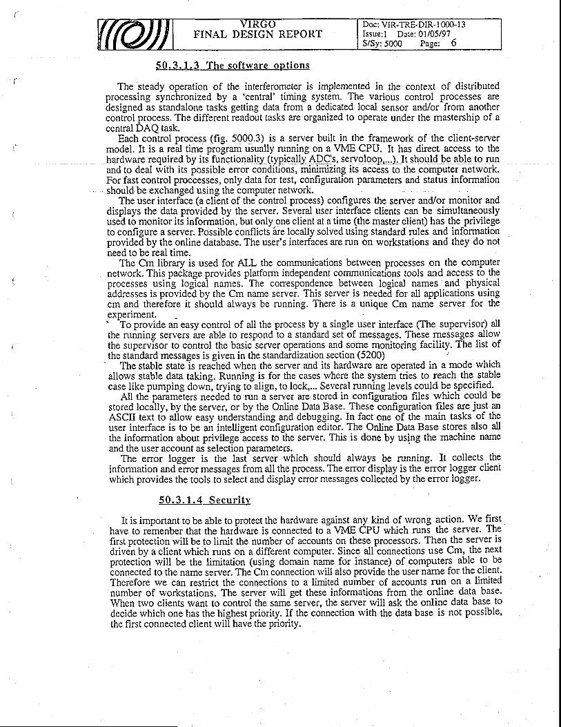
FINAL DESIGN REPORTDoc: VIR-TRE.DIR. I OOO.I 3Issue: I Date: 0l/05/97S/Sy:5000 Page: 6
50.3. 1 .3 The sof t rvare opt ions
The steady operation of the interferometer is implemented in the context of distributedprocessing synchronized by a 'central' timing system. The various control processes aredesigned as standalone tasks getting data from a dedicated local sensor and/or from anothercontrol process. The different readout tasks are organized to operate under the mastership of acentral DAQ task.
Each control process (fig. 5000.3) is a server built in the framework of the client-servermodel. It is a real time program usually running on a VME CPU. It has direct access to thehardrvare required by its functionality (typically ADC's, servoloop,.,.).Iq should be qble to runand to deal with its possible error conditions, minimizing its access to the computer network.For fast control proccesses, only data for test, configuration parameters and status informationshould be exchanged using the computer netrvork.
The user interface (a client of the control process) configures the server and/or monitor anddisplays the data provided by the seryer. Several user interf,ace clients can be simultaneouslyused to monitor its information, but only one client at a time (the master client) has the privilegeto configure a server. Possible conflicts are locally solved using standard rules and informationprovided by the online database. The user's interfaces are run on workstations and they do notneed to be real time.
The Cm library is used for ALL the communications betrveen processes on the computernetwork. This package provides platform independent communicatibns tools and access to theprocesses using loglcal names.-The correspondence between logical names and physicaladdresses is provided by the Cm name server. This server is needed for all applications usingcm and therefore it should always be running. There is a unique Cm name server for theexperiment.' To provide an easy control of all the process by a single user interface (The supervisor) allthe running servers are abie to respond to a stanciard set of messages. These messages allol-the supervisor to control the basic-server operations and some monitoring facility. The list ofthe standard messages is given in the standardization section (5200) ':
' The stable state ls reached when the server and its hardrvare are operated in a mode which
allows stable data taking. Running is for the cases rvhere the systern-tries to reach the stablecase like pumping dowri, trying to align, to lock,... Several rulning levels could be specifie-d.
ell tne parimeters needed to run f server are stored in configfration files which could bestored locally, by the seryer, or by the Online Data Base. These configuration files are just anASCIi text tb aliow easy understinding and debugging. In fact one df the main tasks-of theuser interface is to be an intelligent confrguration editor. The Online Data Base stores also allthe information about privilege access to the server. This is done by using the machine nameand the user account as selection parameters.
The error logger is the last- server which should always be running. It collects theinformation andEnor messages from all the process. The enor display is the error logger clientrvhich provides the tools to select and display error messages collected by the error logger.
5 0 . 3 . 1 . 4 S e c u r i t y
It is important to be able to protect the hardware against any kind of rvrong action. We firsthave to remenber that the hardware is connected to a WIE CPU which runs the server. Thefirst protection will be to limit the number of accounts on these processors. Then the server isdrivdn by a client rvhich runs on a different computer. Since all'connections use Cm, the nextprotection rvill be the limitation (using domain name for instance) of computers able to bebonnected to the name server. TheCmEonnection rvill also provide ihe user n-ame for the client.Therefore we can restrict the connections to a limited nuinber of accounts run on a limitednumber of rvorkstations. The server will get these informations from the online data base.When two clients want to conrol the same server, the server will ask the online data base todecide rvhich one has the highest priority. If the connection rvith the data base is not possible,the first connected client rvill have the priority.

FINAL DESIGN REPORTDoc: VIR-TRE-DIR- I 000- I 3Issue: l Date:01/05/97S/Sy:5000 Page: 7
50.3.1.5 The Slorv moni tor ing netrvork orsanizat ion
The slorv monitorin_g_netrvork is designed to control and collect data from Slorv MonitoringStation (SMS). A SMS is a standalone system rvhich controls some hardrvare and rvhic[provides a small amount of data ',vith no p:ecise timing information (the foreseen timingaccuracy is I second). A typical SMS is a Tube control station rvhich controls a pumpingstation.
A SMS follorvs the standard software rules. It is a server rvith user interface run on differentmachines (see figure 5000.4). The data read by the SMS are formated and sent to the framebuilder on its reqLlest once per frame. The frame builder rvill send these data to the datadistribution and the archiving system even if the fast data acquisition is not running. Thelisto.ry of the parameters ca1 be displayed on a workstation using the Data display and the datadistribution systems. For this data collection the SMS has to be able to ansrvei to standard Cmmessages described in the standardization section (5200)_. To preserve the aetwork bandwidth, a dedicated netrvork is used for the slow monitoring.The only connected CPU's on this network a.re the SMS, the needed rvorkstations to run tlieuser interfaces and the fame builder.
50.3.2 The control of the interferometer
. :50 .3 .2 .L The Fas t Con t ro l s
The various optical and electrical components of the interferometer are driven by local,standalone, controls. Se.veral components can be correlated by a higher level process (like theGlobal control for locking & aligiment) acting through local contiols and uiing informationfrom variori! photcdiodes. During setting up, any local control .can be operaied using thesupervisor. The figure 5000.5 is a sketch of this general control architecture.
. Figure 5000.6 presents the chain of hardware components needed for '' the contolimplementation. It is a distributed digital servo loop running at a frequency equal to 10 kHz(this frequency is limited by the tra-nsfer time betrveen thJ compondnts, live'n their relativedistances). The status of each component is controlled by the sulervisor using the computernetwork, rvhile the real time data are exchanged using dedicated hardware connections (DOL).The data exchanged in the links are :
' From signal detection : power seen by the various photodiodes in watts (DC anddemodulated signals)
. From the local position measurement : tfuee absolute positions and angles' From the suspension control to the Global Control : the minor absolute position from
the local position, the force applied on the mirror and any relevant status information.. From the Global Control to the suspension control : the position and angle error.
This scheme is basically the same for the longitudinal locking and for the alignment . Strongconnections between them will be possible, though we will try to disconnect as much aspossible all the functions.
50.3.2.2 The control and monitoring of the interferometerenvi ronment
These control are done using the Slow Monitoring Station. They are :- The Building control station- The Environment Monitoring Station- The Tube Control Station- The Tower Control Station- The caiibrator control
o
a
o
a
o
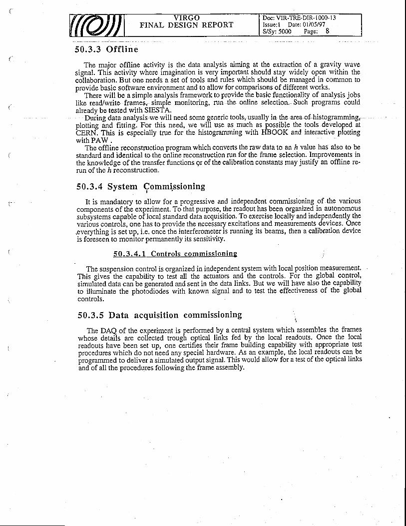
FINAL DESIGN REPORTDoc: VIR-TRE-DIR- I 000- l3Issue: l Date:01/05/97S/Sy:5000 Page: 8
50 .3 .3 O f f l i ne
The major offline activity is the data analysis aiming at the extraction of a gravity wavesignal. This activity where imagination is very important should stay rvidely open rvithin thecollaboration. But one needs a set of tools and rules which should be managed in common toprovide basic softrvare environment and to allow for comparisons of different works.-
There will be a simple analysis framervork to provide the basic functionality of analysis jobslike read/rvrite frames, simple monitoring, run the online selection. Such programs couldalreadv be tested with SIESTA.
Dunng data analysls lve wlll need some genenc tools, usualplotting and fittine. For this need, rve rvill use as much asbEnNI This is esbecially true for the histogramming with .
During data analysis rve rvill need some ic tools, usually in the area of histogramming,ing. For this need, rve rvill use as much as possible the tools -developed atespecially true for the histogramming with FIBOOK and interactive plotting
with PAW .The offline reconstruction program which converts the raw data to an lr value has also to be
standard and identical to the online reconstruction run for the frame selection. Improvements inthe knowledge of the transfer functions 9r of the calibration constants may justify an offline re-run of the ft reconstruction.
50.3.4 System Commi,ssioning
It is mandatory to allow for a progressive and independent commissioning of the various
is foreseen to monitor pennanently its sensitivity.
50.3.4. 1 Contro ls commiss ioning
It is mandatory to allow tbr a progresslve and rndependent corTrrrusslorung or me varrouscomponents of th-e experiment. To that purpose, the readout has been organized in autonomoussubsvstems capable oFlocal standard data atquisition. To exercise locally and independently thesubsystems capable of local standard dala atquisition. To exercise locally and independently thevari6us controis, one has to provide the necessary excitations and measurements devices.-Oncevari6us controls, one has to provide the necessary excitations and measurements devices. Once.everything is set up, i.e. once the interferometer is running its beams, then a calibration device
The suspension control is organized in independent system with local position measurement.This gives'the capabiliry to teit atl the acildtors and-the controls- F6r the glo.bal control,simulited data can be geirerated and sent in the data links. But rve will have also the capabilifyto illuminate the phoi-odiodes with knorvn signal and to test the effectiveness of the globalcontrols.
50.3.5 Data acquisi t ion commissioning ,
The DAQ of the experiment is performed by a centrai system which assembles the frameswhose details are collected trough optical links fed by the local readouts. Once the localreadouts have been set up, one certifies their frame building capability with appropriate testprocedures rvhich do not ieed any special hardrvare. As an example, the local readouts can be
irrogrammed to deliver a simulat6d 6utput signal. This would allow for a test of the optical linksandof all the procedures following the frame assembly.
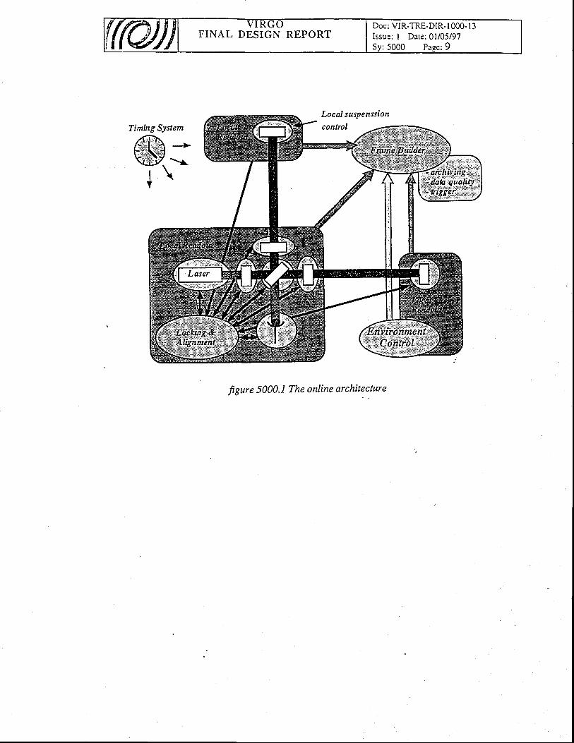
FINAL DESIGN REPORTDoc: VIR-TRE-DIR- I 000- I 3Issue: I Date: 0l/05/97
Timing System
/f,:F,,.--|.r,!i4t:j:i:::::a *
r-q?rl*ii'l\Ltty \r
t \Y
LocaI suspenssion
contrcl
figure 5000J The online architecture
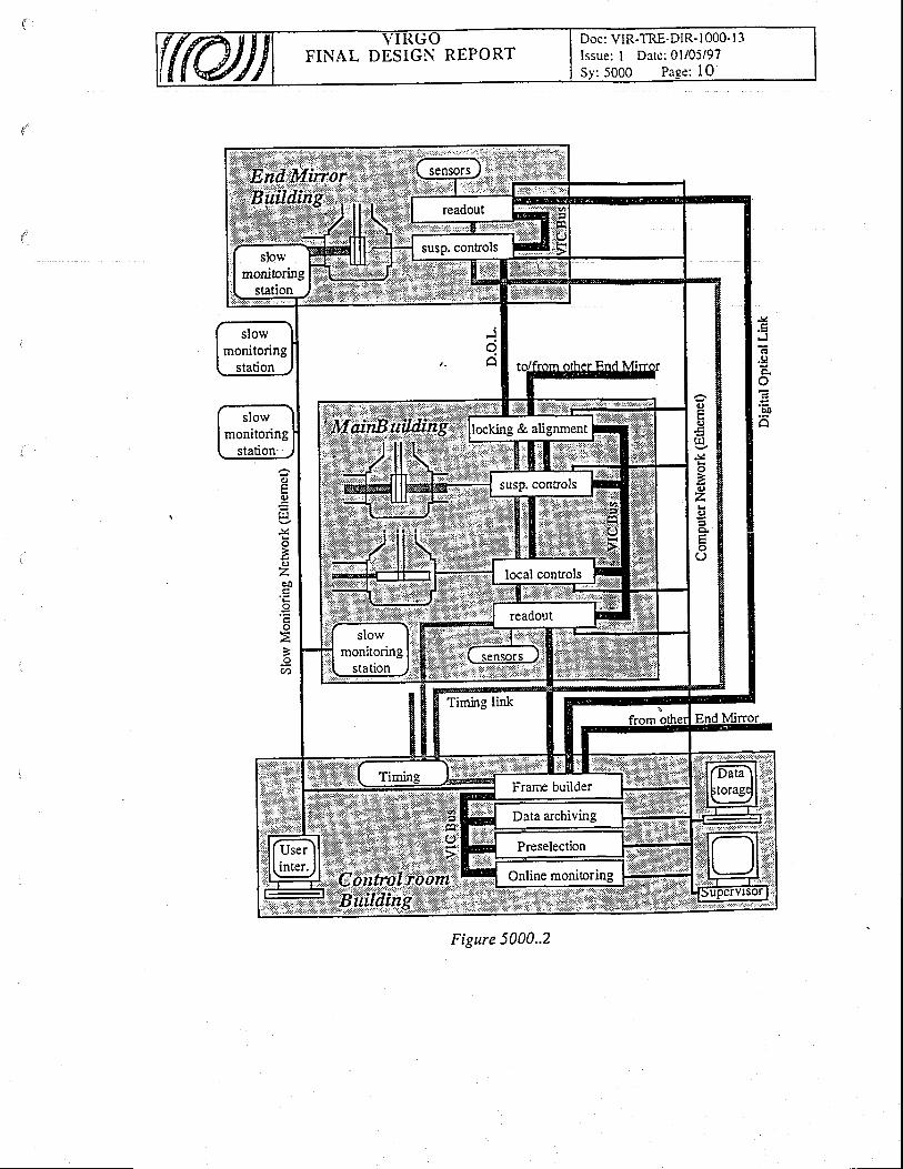
Doc: VIR-TRE-DIR- I 000' I 3Issue: I Date: 0l/05/97Sr :5000 Paee: l0
FINAL DESIGN REPORT
J(
Fl
.9
o
()
X
ozcO
I
'(t')
Figure 5000..2
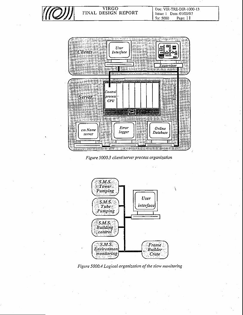
FINAL DESIGN REPORTDoc: VIR-TRE-DIR- 1000- l 3Issue: I Date: 0l/05/97Sy: 5000 Paee: I I
F i g ur e 5 000.3 c Ii ent I s e rv er p ro ces s o r I anizati on
Figure 5000.4 Logical organiTation of the slow monitoring

Doc: VIR-TRE-DIR-l 000- | 3Issue: I Date: 0l/05/97Sv: 5000 Page:,l '2
FINAL DESIGN REPORT
Timing System
z6flj*.} -b-'.N!*iY*.?\ti!tz\ >r
t \Y
(loccf suspenssion
conlrol
Figure 5000.5 Globalvibw of the contols.
Figure 5000.6 Principle of the control implementation.

FINAL DESIGN REPORTDoc: VIR-TRE-DIR- 1000- I 3Issue: I Date: 0ti05l97S/Sy:5100 Page: I
51". Global Control
5L.L ReaI Time Global Control (RIOT)
The first component of the Global Control is located in the RIOT (Real time glObal conTrol)crate, in the main building : it is completed by the Global Conrrol Survey in theiontrol room.
RIOT is activated by the Supervisor once all the needed sub-syst6ms have reached theirryling mo$e. At setting up (non-linear. regime), RIOT has to bring the differenr componentsof the interferometer close- enough to the idea] positions in order to activate the "rJnning"algorithms. In running mode (linear regime), zuOT is in charge of the longirudinal locking ai'dalignment of the interferometer.
The Global Control software is flexible enough to accommodate different kinds of lockingschemes, to handle lo-ngitudinal as well as alignment drifts, and to be able to guarantee smootf,operation ofthe interferometer both in its linear and non-linear regime.^ A set of three procerssors is ,foreseen. This hierarchy is based--on the time response neededfor the various processes i ea.c! one uses its orvn (mori: or less sophisticated and, hence, timeconsuming) model of the interferometer...In the running.mode, one is dedicated to the longitudinal locking, another one to the
alignment. The- third higher level process-or does monitoring and cheJks the validity of thervork doneby the other two processors. If some troubles are-detected, the models us6d at theJower levels can be updated. When necessary, it can take care directly of the locking andalignment.. In the s.tarting m-ode, the higher processor is the only one at work. Through a dedicated userinterface., it can perform malual operations using geneial ressources (beam-imaging system forexample) and/or photodiodes signals and run- predefined algorithms in ord6r [o bring theinterterometer in the linear regime. When the conditions are fulfilled or the user wishes, it startsthe lower processors and goes to survey mode.- RIOT uses the signals provided by the various signal detebtion systems to compute the timedependent -parameters needed to describe the status of the interferometer. It is also keptinformed of the relevant actions decided locally, for example, by the servo-loops in charge 6fthe suspension chains or of the second stabiiisation stag-e of ihe laser. Its riain task ls tocompute the-corrections to be applied on the main optical elements. These conection requestsare sent to the conesponding local controls which are in charge of imilementing them. Thecorrections, together rvith the enor signals and the status of NOt anO-tocal servoloops aresent to the DAQ, for monitoring and for the Global Control Survey.
5t.2 GIobaI Control Survey ;
_ _ T!. second component of the Global Control is the Global Control Survey, complement ofRIOT. Its main role is to detect unwanted trends in the various servo-ioops ind, moregenerally, to react on faulty behaviours thwarting the locking of the interferomet,r. It should bein position to perform all correlations deemed necessary io fulfil its task. Its decisions arereached on the basis of the overall response of the interferometer, taking into account as muchas possible, all the information available at this level. Its other function is to permit thedevelopment online of Global Control softwares.
Doc: VIR-TRE-DIR- 1000- l3Issue: I Date: 0l/05/97
:5200 Page: IFINAL DESIGN REPORT
52. Standardized components
52,t Standardization and Software rules
52,1.L Language
- Lynx OS for real time VME CPU (or OS9 for G64crates)- UNIX system for workstation- Motif and X window for graphic- C rvith C++ style for language ,.
The softrvare running on various processors rvill be written in C language as much as possiblein order to be able to us6 it in the simulation and analysis programs if needed. This is also true formonitoring tasks runnin$ on the Tront end rvorkstaiions-rvhich are in charge of the control andmonitoring of the real time processors.
52.1,2 Coding rules
. Here is a short list of the main coding rules to be followed :
o Use double instead of f loac (for'scientific' calculations),
uSo lons instead of inu (to make sure lve have 32 bits).o use a naming convention:
o all function names, structure types and variables which are not local shouldstart with the two key letters of the library. Example l. frrawdata
o keeP uPPercase for define.. staft local variables with lower case.. start global variables with upper case.
'*,
. to build composed words use upper case instead of underscore.. write'simple'C code. onlY one instruction per line (except for f or, while). use indentation for loops, if... (at least 2 spaces). no C++ keyword to allow a futur migration to C++. As a reminder here is the list of C++
keyrvords i utrn, catch, class, deliie, friend, inline, new, operator, private, protected,public, template, try, this, throw, virtual.
. use contments, especially in the header file to describe each variable defined in a structure'
52.L.3 Fi le organizat ion
The file organization is presented in figure 5200.1. The reference version for the VIRGOsofrrvare is stored in ttt" madtiine virgoat.in"Zpj.fiiot the time being. It rvill be moved on the site
FINAL DESIGN REPORTDoc: VIR-TRE-DIR- 1000- l3Issue: I Date: 0l/05/97S/Sv:5200 Paee: 2
rvhen computers will be available. This directory and the software documentation could beaccessed using W\WV at the follorving address :
http://lapphp .in2p3.fr / virgo/sdoc/doc.html. -All packages .are stored in a separate directory. A readme file should give some basicinformation like the person in charge of this package and rvho to contact in casebf problem. Thelist of the_cunent packages and their key rvords and manager is included in the /virgoAppdir-ectory. Each package has a single person in charge of the updates. The standard version of ih!software is found by using the 'pro' directory rvhich contains logical links on the variouspackages. When several people are rvorking on the same package, CVS is used as code manager.
52.L.4 The list of Slow Monitoring Stations
Here is the list of the foreseen slow monitoring stations with their name :
Tube control station :Tower control :
Building control :
Envi ronment moni t :
. Laser control : "
Benchs :
Calibrator :
TWOl,TW02,...TWll,TNOl,...TNll (for west & north arm)TOIB (input bench), TOMC (mode cleaner),TOPR (porver recycling), TOBS (beam splitter),TOIN (input mirror north), TOEN (end minor north)TpIW (input mirror west), TOEW (end minor west)TOSR (signal recycling), TODB (detection bench)BCCE (for central building), BCMC( for mode cleaner)BCEW (for end west), BCEN(for end north)EMCE (for central building), EMlvlC( for mode cleaner)EMEW (for end rvest), EMEN(for end north)LASR
IBEN (input), DBEN (detection), NBEN (north arm bench),\YBEN (west arm bench)CALI
52,L.5 Data format on tape :
Frame number and sampling number are limited to 65536 iir brder to store them in a single wordin the timing board. Frames collected rvith the same experimental condition are grouped in 'Run'identified with a run number.
When frames are exchanged between client and server, we just send one binary file per framervith the same format as the one used to wdte on tape. More information about data fo-rmat andexamples could be found in the Framelib (Fr) directory.
52.L.6 fnformation distribution
Nervs can be broadcast to a list of VIRGO peoN"ews can be broadcast to a list of ViRGO people by sending a mail to [email protected].\WnV servers are available in most of the labl. Moreinformation about the news system and oldnews system and oldnews could be found at :
http://l apphp.in2p3.frlvirgo/news/news.html
52.2 The timing systemA central timing system is required to synchronize the interferometer controls, servo loops and
readout systems. This is achieved with a master clock driving a bunch of timers rvhich reduce theoriginal frequency to the frequency specific to a given device (see figure 5200.4). Practically, themaster clock is derived frorn-a GPS system located in the control roo-m building. Clocking signals

FINAL DESIGN REPORTDoc: VIR-TRE-DIR- l0O0- I3Issue: I Date:01/05/97S/Sv:5200 Pase: 3
are distributed by an optical fiber link to the different buildings where they are converted to TTLsignals for local use.
Whereas the different sensors and controls are sampled and operated at rates adapted to theirsensitivities, the basic acquisition cycle is set to the sampling frequency of the dark fringe. Thetiming system produces the necessary interrupts (at 20 kHz) to trigger the acquisitions rvith a'sampling number' for their later identification. Depending 9n ttle required sensitivity, .one may beled to group together severalThe timing system
,veral acquisition cycles, covering thus larger time intervals called frames.ides the frame number for their later identification. The frame starting timeI he tl[ung system provldes tne Irame numoer ror tnelr larcr roenullcatron. I ne rrame stanlng ume
is given by the GPS system at reception of this interrupt. It is the time stamp of the dataacquisition.
The different controls and feedbacks are operated on fractions or multiples (i.e lMHz) of thebasic acquisition cycle. Their action is thus precisely known with respect to the acquisition time.The implementation of this clocking sequence is a corner stone of the safe operation of the detector.
For simplification, the number of clocks rvill be minimized. We foresee three basic clocks :. The fast servo loop clock (about I MHz). It rvill be used to oversample ADC's used for
precise measurements (signal detection or guspension damping)- . The sampling frequency (10 to 20 kllz). It will be used for most of the digital servo loops
(locking, suspension control) and for the main data acquisition. The seismic frequency (100 Hz). It will be used to record monitoring accelerometers.
Each timing board is able to generate a frequency signal by its own in order to guarantee a clocksignal to the ADC and DAC boards, even if the connection rvith the master source is lost. There isa timing server for each crate holding a timing board.
. The full timing.system could be tested and rvill be permanently monitored by measuring thesampling time inEaih local readout crate using independent GPS boards or by using a return signalfor fast servo loops
52,3 Workstations
Workstations are used to run the Graphical User Interfaces and control programs. Powerfulrvorkstations are needed to handle the large amount of data provided by the various detectors.Detail of the possible solutions can be found in the document ViR-TRE-LAPP-5200-102.
52,3.L Control Room & Computer Roomi
The Control room will contain two clusters of identical rvorkstations (Figure 5200.2). Eventhough they wilt be able to run any user interface, they will be dedicated to one or two specifictypeJ of c6n[ol. Trvo clusters rviil be used instead of one in order to do system maintenancewithout stopping VIRGO.
Here is the list of the foreseen workstations :. W l. W 2. W 3.W4. W 5. W 6. W 7. W 8. W 9
Tube control & Tower control (on slow mon. net.)Building control & Environment control (on slow mon. net.)Laser & input bench controlDetection bench control & Signal detectionSuspension controlLocking & Linear alignementName Server, Supervisor & Timing controlNon Linear Alignement & BeamlmagingLocal Readout & Frame Builder
. W10 : Data distribution control & Data archiving
FINAL DESIGN REPORTDoc: VIR-TRE-DIR- I 000- I 3Issue: I Date: 0l/05/97
. w l 1
. w12
The rack content is the follorving :. Rl Cabling arrival. R2 Netrvork Hardrvare
. R 4
. R 5
Trigger control & Data MonitoringData distribution : This workstation isIt is a more porverful workstation rvith
. Wl3 : Netrvork analvser
. Wl4 : Softrvare distribution
Iocated inside the comouter room.lot ofdisk space and ipecial hardrvare.
. R3 Master timing (1 c.) Frame Buidler(l.c) Reconstruction & Trigger (1c.)Data monitoring (1 c.)Data archiving (lcrate + space for tape drives and disks)Free (could hold CPU monitors)
52.3.2 Main Bui lding
A few workstations (or X terminals) rvill be available in the Data acquisition room to locallyrvork on the control. They rvill be on the same cluster as those in the Control Room.
Here is the list :(on slow mon. net.)
The rack content is the follorving :, . Rl1 Cabling arrival
. R12 Netrvork Hardware
. R13 Deteciion Bench control (1.c) Signal detection (2 c.)
. R14 Detection Bench Suspension control (2 crates)
. R15 local readout(1c.), Calibration (1 c.), Env. monit & Build control (1c.)
. R16 Input North and Input West Suspension control (2x2 crates)(These crates may need to be closer to these towers)Recycling and Beam Split. Suspension control (2x2 crates)Locking&alignment(1c.), alignement signals(1c.),Detection Bench (2 crates)Laser control (1 c.), Input bench control (1c.)
. w21
.\Y22
. w23, W24. w25
. R17
. R18
. R19
. R20
Tower cgntrol & fube control(for W3,W6)(forW4) i(for W6)(for W8)
52"3.3 Mode Cleaner or End Mirror Building I
One general purpose workstation (W31, 32,33) and one X Terminal rvill be available next tothe tor.ver. There will be also one rack rvith 2 crates for the suspension control and one for the localreadout.
52.4 The Video system
The requirement for the video system rvill evolve with time, from the survey of the minorinstallation to the control of the smo6th running of the interferometer. Therefore the video systemshould be easily reconfigurable. This means that we rvill have standardized cameras, monitors,cables and plugs.
We desciibJO here a reference solution where most of the monitors will be located in the controlroom. Since rve have a large number of cameras, we will have choosers in the control room todecide rvhich cameras are displayed. We will also use 'quadravision' to group four calneras in one
FINAL DESIGN REPORTDoc: VIR-TRE-DiR- 1000- I 3Issue: I Date: 0l/05/97S/Sv:5200 Page: 5
monitor. It rvill be possible to fonvard the image of a ferv selected monitors to the data acquisitionroom or near the optical benches to help for their tuning. It will be also ahvays possible to insert alocal monitor nearlhe corresponding camera. A tape recorder will be available in the control roomto keep track of some installation procedures or of the interferometer start-up for instance.
52.4.1 List of cameras
Human activity control :
The purpose of these cameras is to monitor the various rooms, the benches and minorsinstallation and to survey their operations. The corresponding monitors rvill be installed near theBuilding control rvorkstations. Colour cameras rvill be used to survey the halls to improve thevisual resolution (cameras Vl to V8). During the mirror installation inside the torver, we will usethe alignment cameras to monitor the operations. We should foresee a different set of lenses toincreaie their field. The list of cameras is the follorving :
VIY2,3v4,5V6v7v8v9v10
. v i 1v12v13v14
. v15v16vt7v18 ,19
(colour)(colour)(colour)(colour)(colour)(colour)(black & rvhite)(black & white)(black & rvhite)(black & rvhite)(black & rvhite)(black & white)(black & white)(black & white)(black & white)(black & white) --
Clean RoomGallery I ang 2Hall I and 2Data Acorlisition doomMode Cli:anerHall 'Laser roomLaser Benchoutside Input Benchoutside Detectibn BenchNorthEnd Minor HallWest End Minor Hal-North End Minor GalleryWest End Minor GalleryNorth End MinorBenchWest End Mirror BenchCentral building views
To reduce the cost of the 3.2km transmission, the camera signals from an end mirror buildingrvill be grouped together rvith a "quadravision", with a monitor in the end building and another onein the control room.
i.Mirrors and Benches position measurements :
The position of each suspended object is monitored rvith two cameras, one with lens and onervithouilens (see alignmentiection of the FD). These are high precision camera.s.read- by a. \A4Eboard. The purpose 6f the video monitors is to provide a fast check for the auxiliary laser.beamsand for the 6amera operation and also to survey ihe minor using the cameras e-quipped with lens.During the running 6f ttre interferometer, we 'ivill mostly display in the control room the camerasimaging a minor (6 cameras).
V21 Input Bench Positioning V31 (camera with lens)V22 Mode Cleaner Mirror Positioning V32 (camera rvith lens)V23 Recycling Minor Positioning V33 (camera with lens)V24Beam Splitter Positioning V34 (camera with lens)V25 Detection Bench Positioning V35 (camera with lens)V26 Signal Recycling Positioning V36 (camera with lens)
FINAL DESIGN REPORTDoc: VIR-TRE-DIR- I 000- I 3Issue: I Date: 0l/05/97
:5200 Page: 6
V27 Input North PositioningV28 Input West PositioningV29 End North PositioningV30 End West Positioning
Beam Imaging :
A set of high precision cameras readpositions in the interferometer. They areto monitor the running conditions. Theaddition to the digital images.
v41,v42,v43,V44v45v46v47v48v50,51,52,53
Torver separating
by a VME board is installed to image the beam at variousused to align the benches and the interferometer and alsopurpose of the video monitors is to have a fast check in
v37v38v39v40
(camera with lens)(camera with lens)(camera rvith lens)(camera with lens)
Laser & Input BenchRecycling minor screenMode CleanerEnd of nort[ arm benchEnd of west arm benchDetection Bench
roof po6ition measurements :
The position of suspension rvire inside the conductance will be monitored by a camera. A minorlocated near the conductance rvill provide a side view of the rvire position. Therefore we rvill use aset of black and rvhite cameras. Their images rvill be displayed in the control room to surveyseBarating roof displacement. Additional monitors could be installed near the tower .
Recycling Minor separating roof positioningBeam Splitter separating roof positioningInput North separating roof positioningInput West sepa.rating roof positioningEnd North separating roof positioningEnd West separating roof positioning
Digital processing of the signals
In order to get a fast treatment for the position measurements we will have one processor foreach couple of cameras looking at one mirror or bench (10 CPU's). Then six more processors rvillbe dedicated to the beam imaging. One for the cameras located in the laser and input bench, one atthe end of the mode cleaner, one at the end of each ann, one for the recycling mirror screen andone for the cameras located on the detection bench. Of course we need one MvIE interface for eachcamera. A softrvare (GalaXie, GX) is developped to process the images. This includes simpleimage presentation, local position measuremeniand tools for the non linear algnment. Most of theimage processing is done by the local MvIE processor. But the image presentation and the nonlineir alignment-analysis wiit be performed on'various rvorkstations aid ispecially on the imagingrvorkstation.
52.4.3 Monitor installation in the Control room
Tlvo colour monitors rvill be reserved in the control room to view the various halls (cameras Vlto V8). A chooser will select 2 of the 8 inputs. These monitors will be installed near the building
v61v62
. v63v64v65v66
52.4.2
control rvorkstation. One of this inputacquisition room.
witt be forwarded to a colour screen located in the data
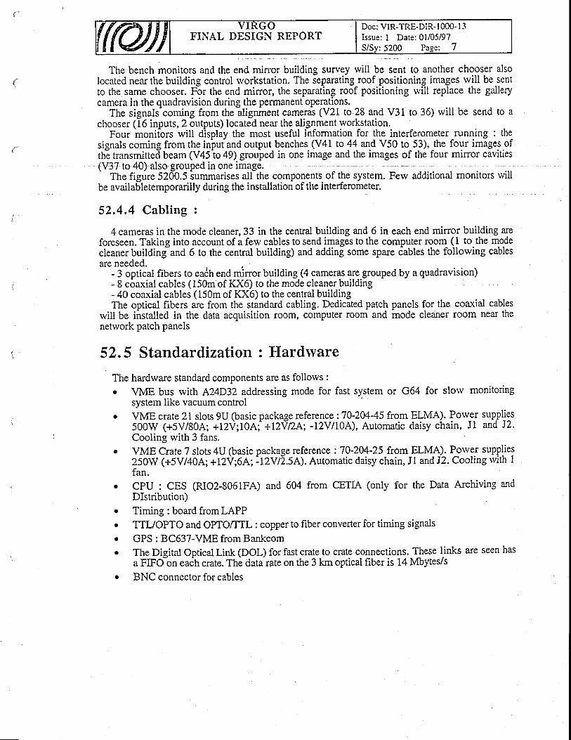
FINAL DESIGN REPORTDoc: VIR-TRE-DIR- I 000- I 3Issue: I Date:01/05/97S/Sy:5200 Page: 7
The bench monitors and the end mirror building survey rvill be sent to another chooser alsolocated near the building control rvorkstation. The separating roof positioning i ill be sentlocated near the building control rvorkstation. Ihe separatlng roof positionrng lmages wlll be sentto the same chooser. For the end miror, the separating roof positioning will replace the gallerycamera in the quadravision during the permanent operations.
The signals-coming from the alignment cameras (V21 to 28 and V31 to 36) rvill be send to achooser (16 inputs, 2 outputs) located near the alignment rvorkstation.
Four monitors will display the most useful information for the interferometer running : thesignals coming from the in'puiand output benches. (V41 to 1+. *.4 V50 to-53), the four images.ofth! transmitted beam (V45 to 49) grouped in one image and the images of the four mirror cavities(V37 to 40) also grouped in one image.
The figure 5200.5 iummarises all the components of the system.be availabletemporarilly during the installation of the interferometer.
52.4.4 Cabling :
additional monitors rvill
for the coaxial cablescleaner room near the
4 cameras in the mode cleaner,33 in the cental building and 6 in each end mirror building areforeseen. Taking into account of a few cables to send images to the computer room_ (1 to the modecleaner building-and 6 to the central building) and adding some spare iables the follorving cablesare needed.
- 3 optical fibers to eaCh end mirror building (4 cameras are.grouped by a quadravision)- 8 coaxial cables (150m of KX6) to the mode cleaner buildin"- 40 coaxial cables (150m of I(X6) to the central buildingThe optical fibers are from the standard cabling. Dedicated patch panels
ivill be installed in the data acqr.risition room, computer room and modenetwork patch panels
52.5 Standardization : Hardlvare
The hardware standard comDonents are as follows :r VME bus rvith A24D32 addressing mode for fast system or G64 for slorv monitoring
system like vacuum controlr VME crate 2l slots 9U (basic package reference :70-204-45 from ELIT4A). Potu_"_t supplies
500W (+5V/80A; +12V;10A; +tZtrlZ/,;; -l2vlloA), Automatic daisy chain, J1 and J2.Cooling with 3 fans.
. VME CrateT slots 4U (basic package reference :70-204-25 from ELMA). P_orv95 supplies250W (+5V/40A; +12V;6A; ?tZVtl.S/l). Automatic daisy chain, Jl and J2. Cooling with Ifan.CPU : CES (RIO2-8061FA)Dlstribution)Timing : board from LAPP
and 604 from CETIA (only for the Data Archiving and
TTIJOPTO and OPTO/TTL : copper to fiber converter for timing signals
GPS : 8C637-VME from BankcomThe Digital Optical Link (DOL) for fast crate to crate connections. These links are seen hasa FIFO-on eaih crate. The datarate on the 3 km optical fiber is 14 Mbytes/sBNC connector for cables
o
a
a
o
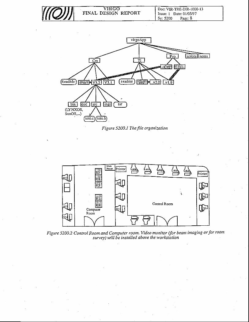
FINAL DESIGN REPORTDoc: VIR-TRE-DIR- l0O0- I 3Issue: I Date: 0l/05/97
: 5 2 0 0 P a e e : 8
Figttre 5200.1 The file organization
Figure 5200.2 Control Room and Computer room. Video monitor (for beam imaging or for roomsurvey) will be installed above the worlcstation
lErl
ffiffi
ComputerRoom
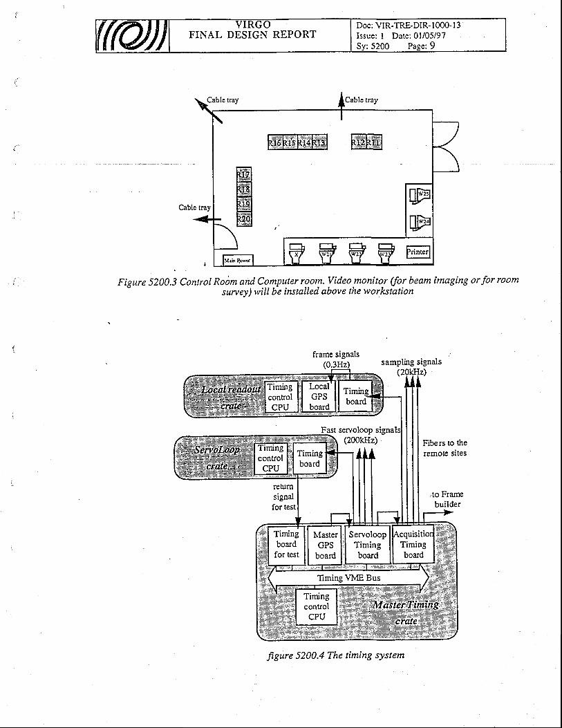
FINAL DESIGN REPORTDoc: VIR-TRE-DIR-1000- I 3Issue: I Date:01/05/97
Cable tray
Figure 5200.3 Control Roitm and Computer room. Video monitor (for beam imaging orfor roomsurvey) will be installed above the worl<station
frame signals(0
Fast servoloop signa
samplingsignalsIz)
Fibers to theremote sites
to Frarnebuilder
figure 5200.4 The timing systenl
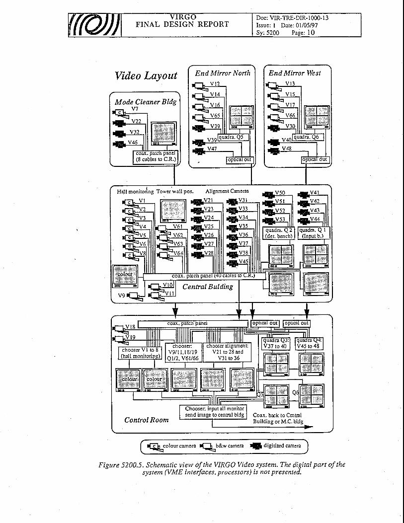
FINAL DESIGN REPORTDoc: VIR-TRE-DIR- I 000- I 3Issue: I Date: 0l/05/97Sy :5200 Page : 10
Video Layout
Eh colourcamera f[,b&rvcamera f digitircd camera
Figure 5200.5. Schematic view of the VIRGO Video system. The digital part of thesystem (VME interfaces, processors) is not presented.
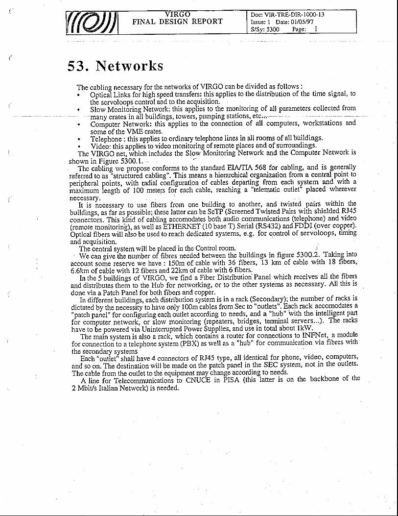
FINAL DESIGN REPORTDoc: VIR-TRE-DIR- 1000- l3Issue: I Date:01/05/97S/Sv:5300 Pase: I
53. NetworksThe cabling necessary for the networks of VIRGO can be divided as follorvs :. OpticaT Links foi nign speed transfers: this applies to the distribution of the time signal, to
th-e servoloops control and to the acquisition.. Slorv Monit6ring Netrvork: this appiies to the monitoring of all parameters collected from
many crates in all buildings, towers, pumping StationS,-etc.,.. Computer Network: thislpplies to ihe connection of all computers, rvorkstations and
some of the VME crates.. Telephone : this applies to ordinary telephone lines in all rooms of all buildings.. Video: this applieiio video monit6ringbf remote places and of-surroundings.The VIRGO net, which includes the Slorv-Monitoring Network and the Computer Network is
shown in Figure 5300.1. ''
The cabli-ng tve propose conforms to the standard EWTLA 568-for. cabling, and is generallyreferred to as-"struc1ur6d cabling". This means a hierarchical organization from a central_point toperipheral points, rvith fadial configuration of cables departing from each system and rvith ainaximum iength-of 100 mete[s for each cable, reaching a "telematic outlet" placed rvherever"ti;tilT*essa-ry
to use fibers from one building to anothq, and - twisted .pairs rvithin thebuildines, as far ds possible; these latter can be ScTP-(Screened Trvisted Pairs with shielded RJ45conn.cioir. This kirid of cabling accomodates both audio communications (!g!ep!o.ne) and video(remore monitoring), as rvell as gttmRNET (10 base T) Serial (RS432) and FDDI (over copper).bptical fibers will iiio be used to reach dedicated systems, e.g. for control of servoloops, timingand acquisition.
The central system will be placed in the Control room. .:' We can give ihe number of fibres needed between the buildings_ in figure 5-3-00.2.. Takin^g. into
accounr some reserve rve have : 150m of cable with 36 fibers, tg tm-of cable with 18 fibers'6.6km of cable with 12 fibers and 22Wn of cable with 6 fibers.
In rhe 5 buildings of VIRGO, we find a Fiber Distribution Panel which receives all the fibersand distributes their to the Hub for netrvorking, or to the other systems as necessary. All this isdone via a Patch Panel for both fibers and copper.
In different buildings, each distribution syiiem is in a rack (Secondaryl the number of racks isdictated by the necessiiy to have only 100m cables from Sec to "outlets". Each rack accomodates a"patch pafiel" for confijuring each oirtlet according to needs,- and a "hub" rvith the inteiligent partfbr cofiput.r n.t*oitl or iloru monitoring (repEaters, bridges, terminal serve_r_s...). The rackshave to 6e powered via Unintemrpted Power Supplies, and use in total about lkW.
The main system is also a rack, which containi a router for connections to INFNet, a modulefor connection to a telephone system (PBX) as rvell as a "hub" for communication via fibres rviththe secondary systems
Each "outiet; shall have4 connectors of RJ45 type, all identical for phone, video, c,omputers'and so on. The destination will be made on the patdli panel in the SEC iystem, not in the outlets'The cable from the outlet to the equipment may change according- to needs.
A line for Telecommunicatioris io CNUC'E in Fma (this-laner is on the backbone of the2 MbiVs Italian Netrvork) is needed.
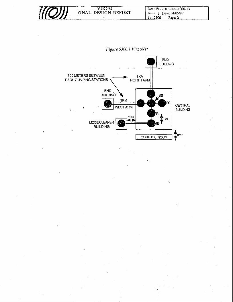
FINAL DESIGN REPORTDoc: VIR-TRE-DIR- 1000- I 3Issue: I Date: 0l/05/97Sv:5300 Paee:2
Figure 5300.1 VirgoNet
3KMNORTH
WESTARM
IvIODECLEA IERBUILDING
@NTROL BOOil/
* l,o,
I B Y
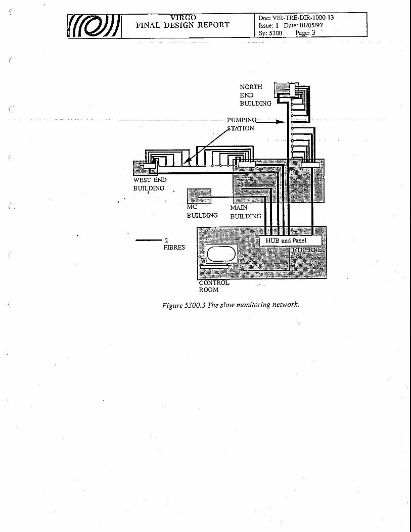
Doc: VIR-TRE-DIR- I 000- I 3Issue: I Date: 0l/05/97FINAL DESIGN REPORT
ROOM
Figure 5300.3 The slovv monitoring nenvork.
F'INAL DESIGN REPORTDoc: VIR-TRE-DIR- I 0O0- I 3Issue: I Date: 0l/05/97S/Sv:5100 Pase: I
54. Data Acquisit ion System
54,L Requirements
The Data Acquisition system (DAQ) is part of the overall online system and rvill fulfill thefollowing experimental iequirements :
. handle 5 Mbytes of continuous data per second rvith burst at 10 Mbytes/s,
. operate at a sampling frequency of 20 kHz,
. synchronize on the GPS based signals generated by the Timing System,
. implement a distributed readout syiiem,
. use the Frame format as a co[lmon data format.
Moreover, the DAQ frjncdonairequirements are the follorving :
r collect VIRGO Rarv Data and perform Data Compression if needed,. assume data transport betrveen DAQ components,
. I structure RAW Data into frames,. distribute frames to the online processing tasks,o perform Online Data Quality check,
. . operate the Online Data Preselection before the Data storage.
54.2 Architecture and Components .The DAQ architecture is shown on figure 5400.1. The DAQ system is broken dorvn into
components according to its primary functions.The Local Readout is the front end component of the DAQ system. Four of these are
implemented on the experimental site. In each building, a Local Realdout collects from the varioussub-systems the available data rvhich are not used in any controls or servoloops and sends them toa Local Frame builder via a Digital Optical Link (DOL).
Records from Slow Monitoring Stations (SMS) are passed to the DAQ system through the SMSFrame builder. Data samplings are structured into frames by two Local Frame builders.
The Main Frame builder combines the data samplings collected into frames lvith the associatedstatus information and distributes them to the storage and online processing units.
The DAQ system receives timing data from the Timing system which syncfuonizes the readoutoperations and makes extensive use of the Digital Optical Links.
All the DAQ components follorv the standa-rd hardrvare and software options defined by theElectronics & Software svstem.
The DAQ system also requires the precise definition of data channels (amount and rate) -to beread out. The iable below recalls the arnount of data to be recorded and gives the set up 9f _9ac\Local Readout according to VIRGO \4r4E Crate list rvhich is maintaif,ed in the StandardizedComponents "sub-system".
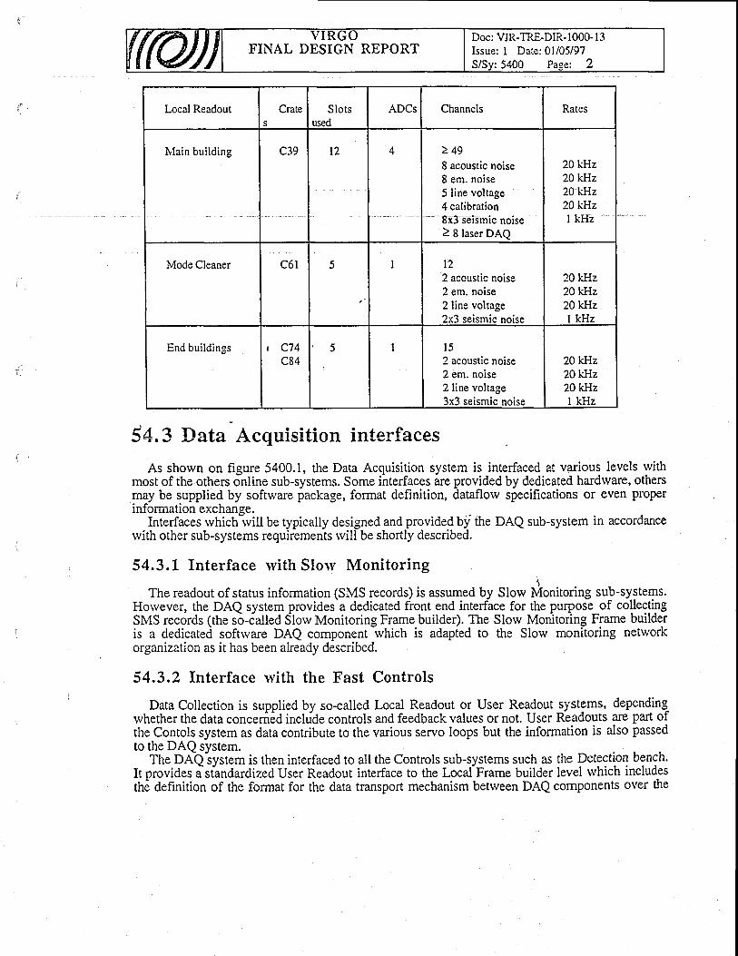
FINAL DESIGN REPORTDoc: VIR-TRE-DIR- 1000- I 3Issue: I Date: 0l/05197
:5400 Pase: 2
Local Readout Crates
Slotsused
ADCs Channels Rates
lvlain building c39 t2 t > 4 9
8 acoustic noise8 em. noise5 line voltage4 calibrationSxSSeismic noiie) 8 laser DAe
20 kHz20 kHz20 kHz20 kHzI kHz
Mode Cleaner c6l ) I t22 acoustic noise2 em. noise2 line voltage2x3 seismic noise
16 l.Llt
20 kHz20 kHzI kHz
End buildinss t C74c84
5 l 52 acoustic noise2 em. noise2 line voltage3x3 seismic noise
2Okllz20 kHz2OkElzI kHz
54.3 Data Acquisition interfaces
As shown on figure 5400.1, the Data Acquisition system is interfaced at various levels withmost of the others online sub-systems. Some interfaces are provided by dedicated hardware, othersmay be supplied by software package, format definition, dataflow specifications or even properinformation exchange.
Interfaces rvhich will be typically designed and provided by the DAQ sub-system in accordancewith other sub-systems requirements rvill be shortly described.
54.3.1 Interface lyi thSlow Monitor ing 1
The readout of status information (SMS records) is assumed by Slow Monitoring sub-systems.Horvever, the DAQ system provides a dedicated front end interface for the purpose of collectingSMS records (the so-ialled Slow Monitoring Frame builder). The Slow Monitoring Frame builderis a dedicated softrvare DAQ component whictr is adapted to the Slow monitoring networkorganization as it has been already described.
54.3.2 Interface with the Fast Controls
Data Collection is supplied by so-called Local Readout or User Readout systems, dependingrvhether the data concernJd incldde controls and feedback values or not. User Readouts are part ofthe Contols system as data contribute to the various servo loops but the information is also passedto the DAQ system.
The DAQiystem is then interfaced to all the Controls sub-systems such as the Detection bench.It provides dstandardized User Readout interface to the LocalFrame builder level which includestha definition of the format for the data transport mechanism between DAQ components over the

FINAL DESIGN REPORTDoc: VIR-TRE-DIR- 1000- I 3Issue: I Date: 0l/05/97
DOL links. The interface specifies the way the DOL boards capabilities are used in thiscase and the data format rvhich needs to be used over such connections. The DAQrecommends this as a standard for all data transports to the Local Frame Builder level.
54.3.3 Interface lyith Data Archiving and Global Control
The interface rvith those sub-system is assumed by the dataflow scheme used for the Framedistribution. It is based on a common agreement on hardware and software mechanisms.
54.3.4 Interface tyith Supervisor
The DA9 system will oper.ate under the central DAQ Supervisor. DAQ sofrrvare is developed inr rrs .L,A\e systclll wul ope rate unoer me Ceniral UAV )UpefVlSOf. DAQ Sotttvafe rSresPect^of the softrvare specifications and tools defined by the Supervisoisub-system.
DAO software comDonents follorv the Online client/server orJcnizntinn f-nlnmr,.Q software components follorv the Onfine client/s6rver organization. Coinmunications toolsand protocol for the message exchange allorv to interiace the various DAQ control processes andthe Supervisor.the Supervisor.
54.3.5 Interface tyith off-lineManagement
activity, simulation and Data
_,_The^DAQ sy_stem uses the same Frame format as any online or off-line sub-system involved inVIRGOData Managment. The Frame format is the VIRGO standard data format.-In this respect, itis one oJ thg major guideline for interfacing sub-systems accessing vIRGo data.
. The DAQ.sub-system may also enhance the use of SIESTA. fhe integration of all the differentcomponents is one of the most important aspects and SIESTA can be als6 conceived as an on-linetoolforthe DAQ commis.sionning. For this, we may use SIESTA capabilities of generating signaisfor the data readout and simulating the signal proceising.
i4. 4 System Description
54.4.L Data Col lect ion
The Data Acquisition system assumes the function of collecting data through :. four Local Readouts (in End Minors, Mode Cleaner, and Central b'uildings),
the User Readout interface for the Control and Locking information,and the Slow Monitoring Frame builder
54 .4 .1 .1 Loca l Readou t
54.4,L,1.1. Hardrvare Components and Connect ions
Figye 1100.3 provides a detailed vierv of the components which make up a Local Readoutcrate. Local Readout crate will be controlled by a Powel PC based RISC VO 6oard (R[O2 8061)froq CES running the LynxOS real time operaiing sysrem.
The CPU board will perform the followlng funitibns :o to run the Local Readout control process,
specificsystem
o
O
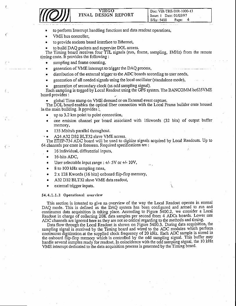
FINAL DESIGN REPORTDoc: VIR-TRE-DiR- l0O0- l3Issue: I Date:01/05/97S/Sy:5400 Page: 4
o to perform Interrupt handling functions and data readout operations,. VME bus controller,o to provide sockets based interface to Ethernet,o to build DAQ packets and supervise DOL access.The Timing board receives four TTL signals (run, frame, sampling, lMHz) from the remote
timing crate. It provides the following :. sampling and frame counting,
generation of VME intemrpt to trigger the DAQ process,
distribution of the external trigger to the ADC boards according to user needs,generation of all needed signals using the local oscillator (standalone mode),
. generation of secondary clock (as odd sampling signal).Each-sampling is tagged by Local Readout using the GFS system. The BANCOMM bc635VME
board provides ; ,.o global Time stamp on VME demand or on External event capture.The DOL board enables the optical fiber connection with the Local Frame builder crate housed
in the main building. It plovides :,. uP to3.2 km point to point connection,. one emision channel per board associated with l6kwords (32 bits) of output buffer
memory,o 135 Mbits/s parallel throughout.
\ o A24 A32D328W32 slave VME access.The ETEP-734 ADC board rvill be used to digitize signals
64 channels per crate is foreseen. Required specifications are :acquired by Local Readouts. UP to
i
1 6 individual, differential inputs,. 16-bits ADC,. User selectable input range : +/- 5V or +/- 10V,. 8 to 100 kHz sampling rates,o 2 x 128 Kwords (16 bits) onboard flip-flop memory,. A32D32BLT32 slave VME datareadout,. external trigger inputs.
54 ,4 .1 .1 .2 Opera t i ona l ove rv iew
This section is intented to give an overview of the w_ay the Lolal Readout operate in normalDAQ mode. This is defined ls the DAQ system has been conhgured and .armed to run andcontinuous data acouisition is takine olace.
-According to Fisure SqOO.Z, rve consider a Localcontinuous data acquisition is taking place.
-According to Figure 5400.2, rve consider a Local
Readout in charee of collectine 20Kd-ata samples per second from 4 ADCs boards. Lower rate
. a
a
a
Readout in charge of collectingADC channels are
VME intem:pt dedicated to ihe data acquisition process is generated by the Timing
adout in charge of collecting 20Kd-ata samples per second from 4 ADCs boards. Lower rate)C channels aie ignored here-as they are not
-so critical regarding to the methods and timing.
Data florv thrgug-h the Local Read6ut is shorvn on Figuie 549b.3..1D_uring.data u.,9.iitit]?1 8sampling signal isieciiveAUy ttre Timing board and wiied to the ADC mddules wtiigh perfgqncontinudus dieitization at the iupolied cloik frequencv of 20 kHz. Each ADC sample is stored incont'inudus Iigitization at the iupplied cloik frequency of 20 kHz. Each ADC sample is stored inthe onboard d'ip-flop memory wirictr is controllid by ttre odd sampling signal. This buffer maythe onboard i'ip-nop memory *iririctr is controilid by ttre odd sampling signal. This buffel ryyhandle several iamptes read/for readout. In coincidence with the odd sinpllng signal, the 10 kHzVME intemrot dedicated to ihe data acouisition Drocess is generated bv the Timing board.
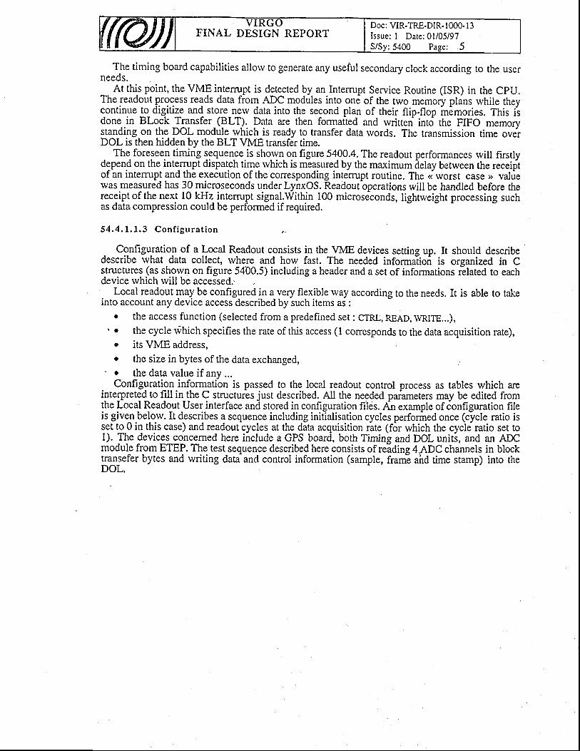
FINAL DESIGN REPORTDoc: VIR-TRE-DIR. lOOO. I 3Issue: I Date: 0l/05/97S/Sy:5400 Pase: 5
The timing board capabilities allorv to generate any useful secondary clock according to the userneeds._ At thi-s point, the VME intemrpt is detected by an Intemrpt Service Routine (ISR) in the CpU.The readout process reads data from ADC modules into one of the two memory plans while theyc-ontinue to_ digitize and store nerv data into the second plan of their flip-flop in6mories. This iidone in Block Transfer (BLT). Data are then formatted and rvritten into the FIFO memorvstanding on the DOL module rvhich is ready to transfer data rvords. The transmission time overDOL is then hidden by the BLT VME transfer rime.
The foreseen timing sequence.is sho-ryn- or figure 54OO.4. The readout performances will firstlydepend on the interrupt dispatch time rvhich is measured by the maximum delay between the receiftof an intemrp! ryd the execution of the conesponding interrupt routine. The <i worst case o valriewas measured has 30 microseconds under LynxOS. Readout operations will be handled before thereceipt of the next l0 kHz- intemrpt signal.Within 100 microseconds, lightweight processing suchas data compression could be performed if required.
5 4 . 4 . 1 . 1 . 3 C o n f i g u r a t i o n
- Configuration of a Local Readout consists in the VME devices setting up. It should describedescribe what data collect, rvhere and how fast. The needed informa'lioi is organized in Cstructures (as shorvn on figure 5400.5) including a header and a set of informations rllated to eachdevice which will be accessed.'
Local readout may be configured in a very flexible rvay according to the needs. It is able to takeinto account any device accesidescribed by such items ai:
o the access function (selected from a predefined set : crRL, READ, WRITE...),\ o the cycle rvhich specifies the rate of this access ( I conesponds to the data acquisition rate),
- : + ^ \ t l / f E ^ l l - - - -r l l s YMALI ( . I I t rSS,
r the size in bytes of the data exchanged,' . the data value if anv ...
. Configurati_qn.informatibn is passed to the local readout control process as tables which areinterpreted to fill in_the C structures just described. AII the needed parameters may be edited fromthe Local Readout User interface and stored in configuration filds. An example of ionfiguration fi.leis give^n.belo.w. It describes a sequence including initialisation cycles performed once (cycle ratio isq9t t9 0 in this case) and readout cycles at the data acquisition rate (f6r which the cycle ratio set to1). Tle devicelconcerned here include a GPS board, both Timing and DOL uniti, and an ADCmodule from ETEP. The test sequence described here consists of readine 4.ADC channels in blocktran_sefer bytes and writing data and control information (sample, fram! ahd time stamp) into theDOL.
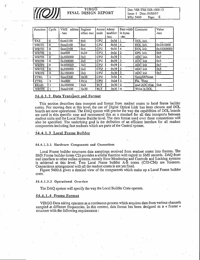
FINAL DESIGN REPORTDoc: VIR-TRE-DIR- 1000- l3Issue: I Date:01/05/97
:5400 Page: 6
Function Cycle VME address- hex
Registeroflset- hex
Accessmode
Adressmodifier-hex
Data rvidthin bytes- dec
Comnrent Value-hex
TAS 0 0xee2 100 0x0 CPU 0x3d I DOL nrt .WRITE 0 0xee2 I 00 0x4 CPU 0,r3d DOL nl t . 0.'<2010000WRITE 0 0xee2 100 0x4 CPU 0x3d 4 DOL nrt , 0x10200000WRITE 0 0xe00O 0x24 CPU 0x2d ) GPS ni t 0x9\!R.iTE 0 0x 00000 0x2 CPU 0x39 2 ADC init. 0x7\YRITE 0 0x 00000 0x2 CPU 0x39 2 ADC init 0x3WRITE 0 0x 00000 0x2 CPU 0x39 2 ADC init Ox7WRITE 0 0x 00000 0x2 CPU 0x39 2 ADC init 0x3WRITE 0 0x 00000 0x2 CPU 0x39 2 ADC init 0x7CTRL I Oxee2200 0x30 CPU 0x3d 4 Samol&FrameCTRL I 0xe000 0xlc CPU 0x2d 2 Fix. TimeREAD I 0x I 00000 0x0 BLT 0x39 2 read ADC chan 0x4WRITE I 0xee2 100 0x20 BLT 0x3f 4 Write in DOL
54.4.1.2 Data Transbor t and Format
This section describes data transport and format from readout crates to local frame buildercrates. For moving data at this level, the use of Digital Optical Link has been chosen and DOLboards are now operational. The DAQ system rvill precise the way the capabilities of DOL boardsare used in this specific case and recommend this as a standard for all data transports betweenreadout units andlhe Local Frame Builder level. The data format used over those connections willalso be specified. The underlying goal is the definition of an efficient interface for all readoutcomponents including fast readouts rvhich are parts of the Control system. .t
54.4.1.3 Local Frame Bui lder
54.4.L.3.1 Hardrvare Components and Connect ions
Local Frame builder structures data samplings received from readout crates into frames. TheSMS Frame builder (crate C2) provides a siririlar function with regard to SMS recordg. DAQ frontend interface to other online systems, namely Slorv Monitoring and Controls and Locking_systemsis achieved at this level. Two Local Frame builder A-B crates (C55-C56) are foreseen.Connections arrangement with all the readout crates is not yet fixed.
Figure 5400.6 gives a detailed view of the components rvhich make up a Local Frame buildercrate.
54 .4 .1 ,3 ,2 Opera t i ona l Ove rv iew
The DAQ system will specify the way the Local Builder Crate operate.
54 .4 .1 .4 F rame Format
VIRGO Data taking operates as a continuous process rvhich acquires data from various channelssampled at different fieq'uencies. In this contexi data format has been designed as a <( frame >structure rvith the following requirements :
FINAL DESIGN REPORTDoc: VIR-TRE-DIR- 1000- l3Issue: I Date: 0l/05/97
:5400 Pase: 7
. to afford a little overhead for data organizationr to handle different data and various informationsr to organize a data set offew seconds lenght. to allow data content evolutiono to afford large data rate by efficient input/ouput mechanismso to enhance software reusability by an identical format everywhere (on-line, off{ine, test).A frame is a unit of information containing all the infomration necessary for the understanding
of the interferometer behaviour over a finite-time interval which integrates several samplings. Iicontains thus not only the sampling performed during the integrated time interval, but also thoseperformed at a frequency smaller than the frame frequency.
To simplify its manipulation, a frame is organized as a set of C structures described by a headerholding pointers to additional structures and values of parameters expected to be stable over theintegrated time interval : the starting time of the frame, its duration, values produced by the slorvmonitoring. This header is followed by an arbitrary number of additional structures, each holdingthe values of a rapidly varying parameter like the main signal, the seismic noise. Each activeelement producing data at a rate higher than the frame rate is thus accumulated in a dedicatedstructure.
This frame structure (figure 5d00.7) is a standard rvhich is conserved over the various stages ofthe analysis. Frame history-, detector geometry, trigger results, monitoring data, reconstructed'data,simulation results lead thus just to additional structures. It is ahvays possible to add new structuresor to drop old ones.
The input and output routines used for their creation and the specifications of their format areu$que and kept as stable as possible. Their format is saved on tape to allow for automaticprocesslng.
54.4.1.5 lVlain Frame Builder and Frame Distr ibution ;'
The Main Frame Builder combines information received, from Local Frame Builders A and Brvith the associated status information into final frames. It also performe the frames distribution tothe Online Processing units over a Reflective Memory Network.
The Figure 5400.8 shorvs the Main Frame Builder crate (C3) as it is foreseen.
54.4.2 Data Qual i ty
This online task rvill survey permanently the data quality produced by th'e interferometer. It usesthe signal induced by the calibrators, the noise level, and runs data quality algorithms. It shouldprovide a fast feedback in case of problems. It is a real time data quality check. The conespondinginformations are stored in the data storage system to allow further data selection according to thedata quality requirements of the offline analysis. It may be mn as part of the Trigger system.
54.4,3 Data Preselect ion
Let us remember the typical data rate of 2 MBytes/sec in continuous mode. This means about 2DAT tapes (4 GBytes) ei6ry hour and translates into about 16000 tapes/year. Such an amount ofdata is riot aprob6m ior thd online rvriting or for the storage, but it may v6ry quickly overflow anydata analysis. Therefore it may be rvise to reduce their amount for the detailed data analysis. Atypical gdal rvould be a reduction of more than one order of magnitude. The final reduction factorrvill in fact be driven by our data analysis capability and by the data production rate. Remember thatthis rate is also function of our operational efficiency.
FINAL DESIGN REPORTDoc: VIR-TRE-DIR- 1000- l3Issue: I Date:01/05/97
:5400 Page: 8
Prior to any kind of physics analysis one has to convert raw data (i.e. ADC counts provided bythe main feedback and the remaining dark fringe signal) to physical quantities and to compute the hvalues. This is the first task of the trigger. This computation requires the knorvledge of the'transfer functions' of the various controls and of the calibration constants. These quantities areavailable from a special database accessible from any VIRGO laboratory. This reconstructionshould be the same as the offline reconstruction.
Then trigger algorithms looking for burst events are run. Triggered frames are defined within'time rvindows' during rvhich binary coalescence or burst candidates may occur. These candidateswill be selected using simple and robust search algorithms to minimize a possible bias in the furtheroffline analysis : selection efficiency has to supersede rejection'efficiency. Random triggers arerecorded to monitor the trigger algorithm efficiency. To cover a large type of astrophysical events,several trigger algorithms will be run in parallel.
The informations kept after trigger selection are rvritten to Data Summaryare the following for each frame :- reconstructed h value at 20 WLz and eventuallv reconstructed h
Tapes (DST). They
resampled at lowerfrequency (2l lz): this represents less than 100 kBytes per second.slow monitoring records (less than 5 kBytes per second) to follorv permanently theinterferometers environment.
;gered frames'r:I the rarv data required to perform a fu
For'triggered frames" :all the rarv data reall the rarv data required to perform a full analysis of the signal candidates.
The triggered frames are sent to the data storage system using a standard network.Of course, false signals will be selected. But this filtering is not the final data analysis and a lot
of rvork is still needed to extract and prove the existence of a gravitational rvave signal from theDST tapes. The achieved data reduction should provide the conditions for a fast analysis and a fastdita didpatching over the collaboration. Most oi the data analysis rvill thus be perf6rmed on thisfiltered sample. But remember that it will always be possible to start again from the original rawdata sample. The filtering algorithms rvill be designed and tuned using simulated and real data. They will
certainly change and improve with some learning experience. This is why we arc prepared toreprocess the original raw data. Dedicated computers will be installed on the site for this purpose.
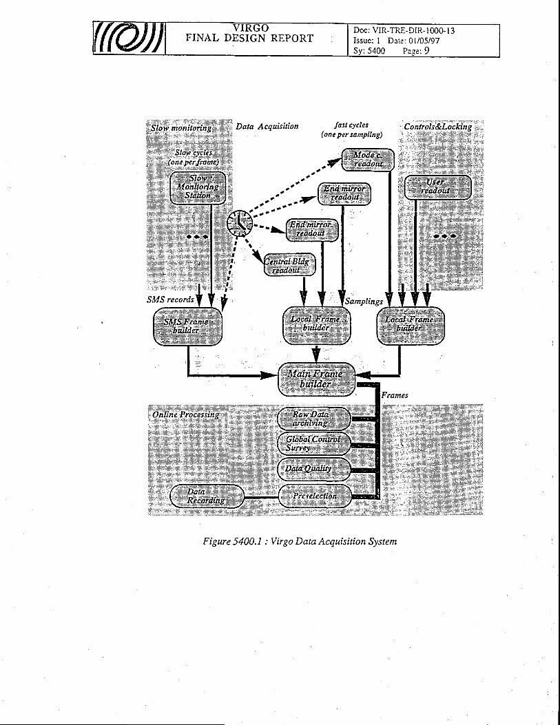
FINAL DESIGN REPORTDoc: VIR-TRE-DIR- 1000- I 3Issue: I Date: 0l/05/97Sv :5400 Pase :9
Data Acquisition tast cycles(one per sampling)
(111"""'7
a .a,
Samplings
Figure 5400.1 : Virgo Data Acquisition System
:rii

FINAL DESIGN REPORTDoc : VIR-TRE-DIR- I 000- I 3Issue: I Date: 0l/05/97Sv:5400 Paee: 10
From the remote Timing crate (run,Jrame, sampling ond 7 MHz signals)
o a o a 0 . . e e,. c o c o e
aru DOL ADC ADC ADC A.DC
Eiiaa
3
If"
o
E
!=:gggEI:oIIee
rffiBt
,g
l @ @I
l e @
@ @
@ @
9 9@ @
9 99 9
Ar - 1
9 9@ @
9 9e 99 99 99 9e 9fr)
@ @
@ @
@ @
@ @
@ @
@ @
@ o
I6
I
9. I9 99 99 99 99 99 99 9
_@/A\
4*ttt ( a t
EA HtoI r@Ef,EP ETEP ETEP Ef,EP
o l a a a a C l t o . 6 l e g
To Local.Flame Builder
Figure 5400.2 : The Local Readout Crate (Components and Connections)
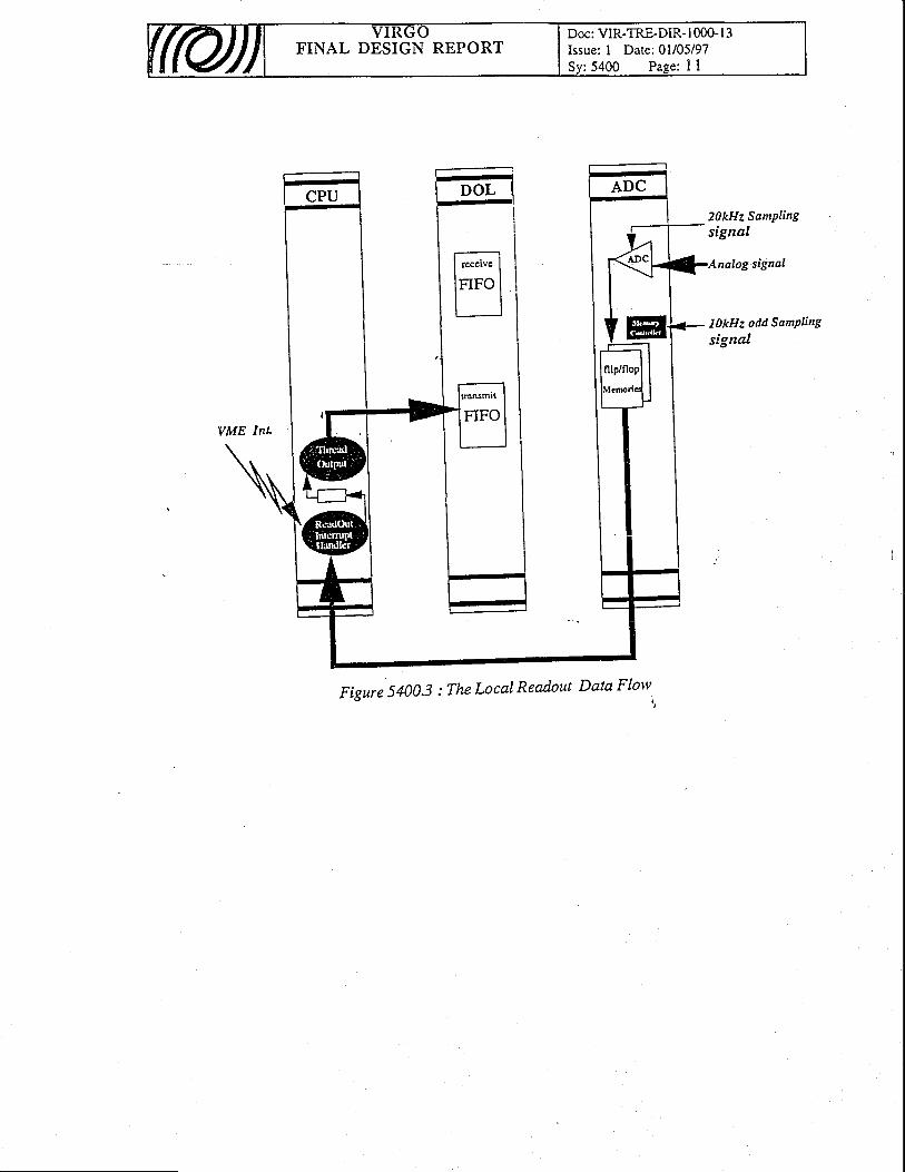
FINAL DESIGN REPORTDoc: VIR-TRE-DIR- I 000- I 3Issue: I Date: 0l/05/97Sv:5400 Pase: I I
20kHz SamPlingsignal
nalog signal
ILkHz odd SamPling
signal
Figure 5400.3 : The Local Readout Data Flotv.
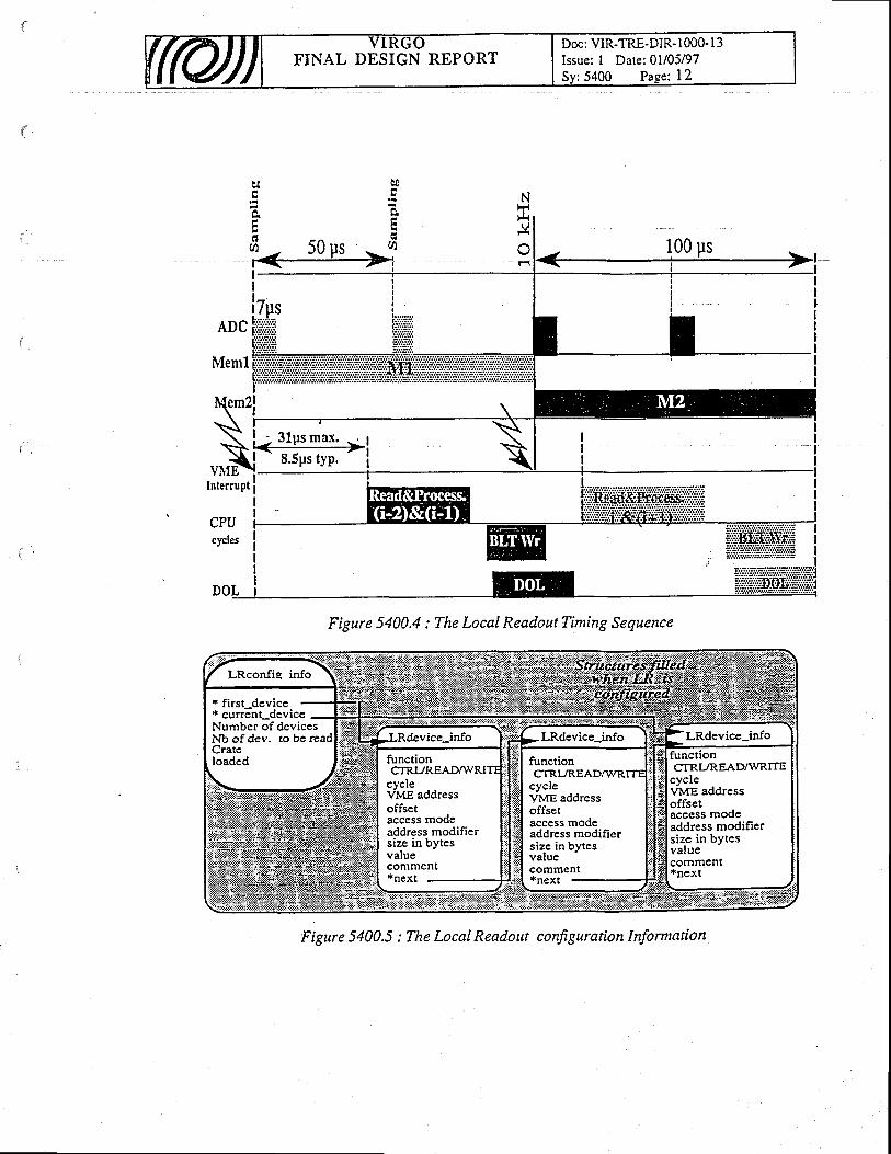
Doc: VIR-TRE-DIR- 1000- I 3Issue: I Date:01/05/97Sv: 5400 Pas.e: t2
FINAL DESIGN REPORT
NFri
V
aU)
ADC
Meml
WIEInterrupt
CPUcycles
I<++=+l!
- 8.5ps typ.
- i
Figure 5400.4 : The Local ReadoutTiming Sequence
* first-device* current-deviceNumber of devicesNb of dev. to beCratcloaded
functionCTRI,./READNVRITE
cyclevME addressoffsetaccess modeaddress modifiersize in bytesvalue
cvcleVv-e ad&essoffsetaccess modeaddress modifiersize in bytesvaluecomment*next -
functionCTRI./REA
cycleVME addressoffsetaccess modeaddress modifiersizc in bytesvatuecomment
Figure 5400.5 : The Local Readout configuration Information
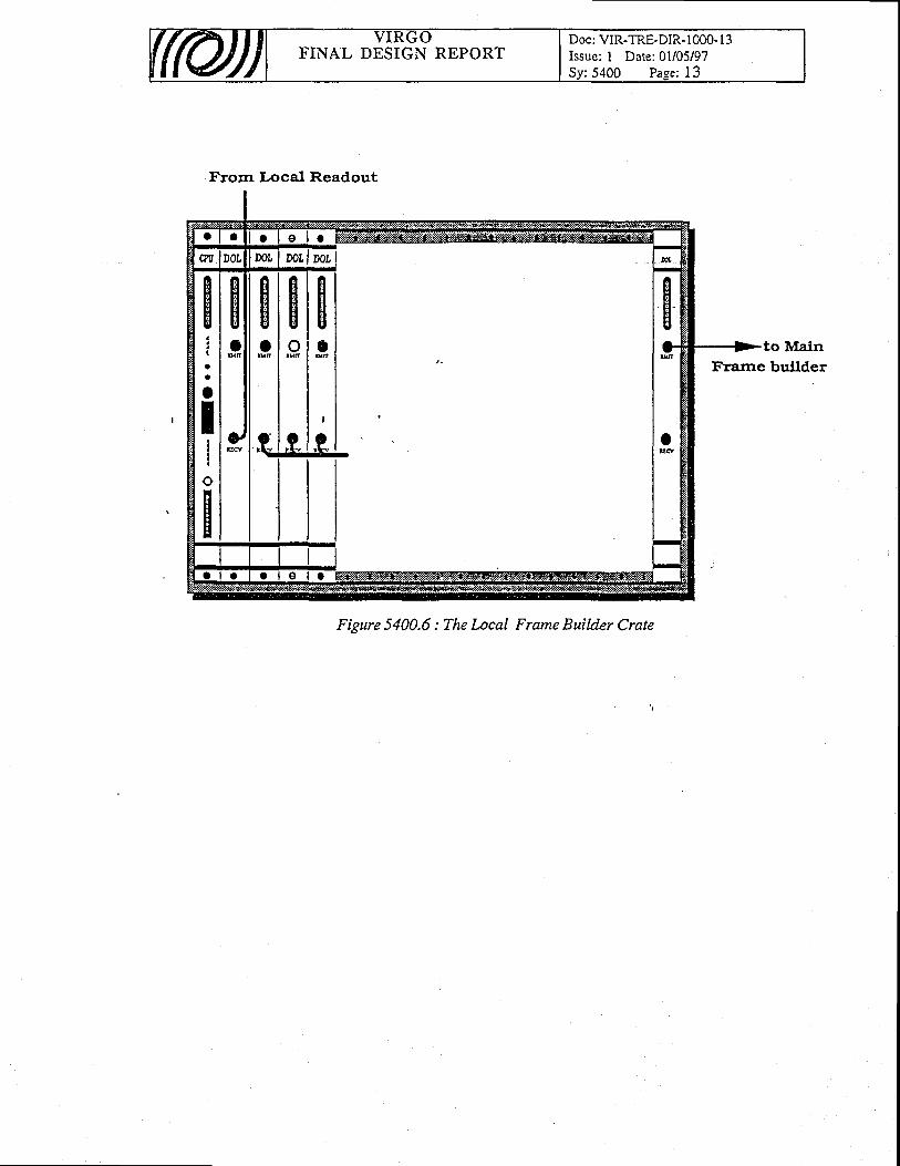
FINAL DESIGN REPORTDoc: VIR-TRE-DIR- I 000- I 3Issue: I Date:01/05/97
: 5400 Paee: I 3
giaa
o
t,
o
H
Frorn Local Readout
Figure 5400.6 : The l-ocal Frame Builder Crate
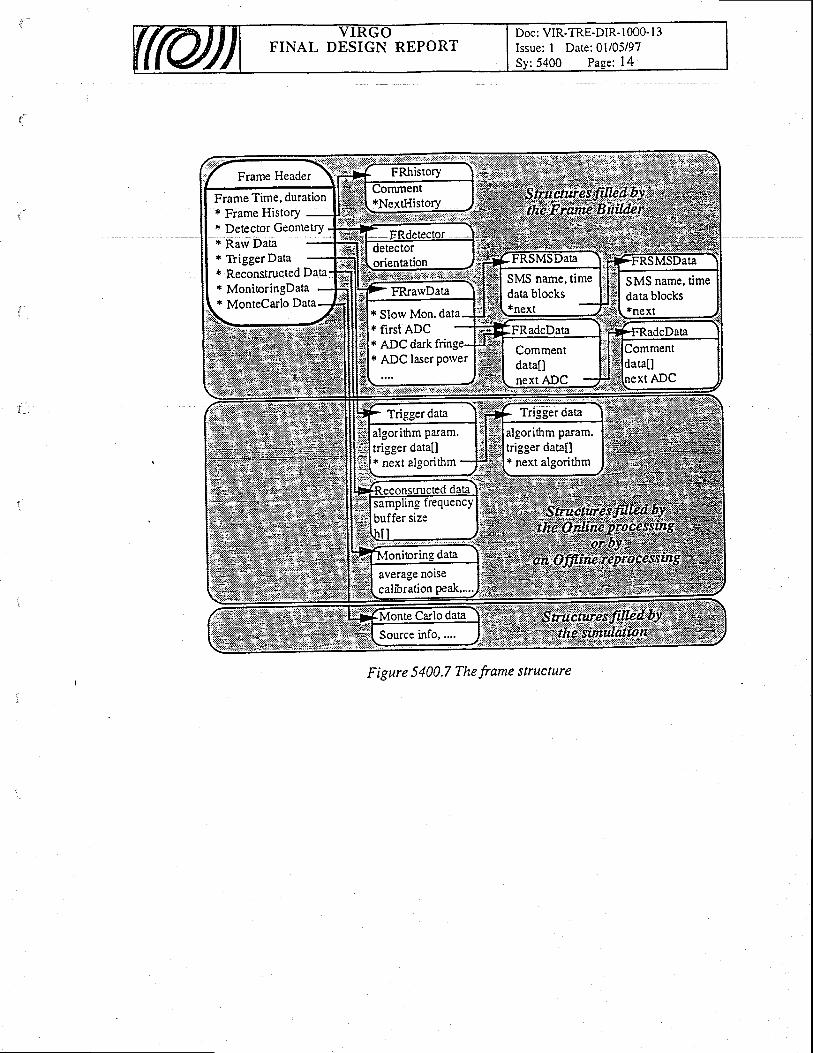
Doc: VIR-TRE-DIR- I 000- I 3Issue: I Date: 0l/05/97
:5400 Paee: 14FINAL DESIGN REPORT
Frame Time, duration* Frame History* Detector Geometry* Rarv Data* Trigger Data* Reconstructed Data* MonioringData* MonteCarlo Data
SMS name, timedata blocks*next* Slow Mon.
* first'ADC* ADC dark fringe* ADC laser power
algorithm param.trigger data[]* next algorithm
algorihm patam.trigger data[]* next algorithm
Figure 5400.7 The frame structure

FINAL DESIGN REPORTDoc: VIR-TRE-DIR- 1000-13Issue: I Date: 0l/05/97Sv:5400 Pase: 15
Frorl Local Frasrc Bulldcr
Ii
a
a
Tio
b D 6 c r t F - t t N
DiATA gur+rtrY
Figure 5400.8 The Main Frame Builder Crate

Doc: VIR-TRE-DIR- 1000- l3Issue: I Date: 0l/05/97S/Sy: 5500 Pa.qe: I
FINAL DESIGN REPORT
55. Data Distribution & ArchivingThe Data Distribution & Archiving is the Virgo sub-system rvhich talces care of the on-line and
off-line archive and distribution of Virgo data. The large amount of expected data (from 1- 5Mbyte/sec in continuous mode, but up to 10 Mbyte/sec in burst mode) and the different needs ofacc6ssing totally or partially these data have suggested the specialization of this system into twosubs sterns, strbngly related but different fo: structure and use : the Raw Data Archiving Systemand the Data Distribution SYstem.
5 5 . 1 Function and concept
In Figure 5500.1 the scheme of principle of the.Data Distribution & Archiving and itsconnection with the Frame Builder and Ori-Line Processing are shown.
As described in section 5400, all Virgo data are organized in frames, that is the unitaryinformation rvhich records the Virgo behavibur over a finite time interval. Each frame, organized asa set of C structures described by a header, is basically made of three parts :
. structures filled by the Frame Builder, rvhich contain all the raw data collected by detectorsand probes;
. structures filled by the On-line Processing (or by the Off-line Reprocessing),.which contain. the reconstructed ilata ([t,h] pairs at the sampling frequency of 20 kHz) and the necessary
auxiliary information;. structures filled by the Simulation, rvhich are necessary for comparison of the behaviour of
the interferometer with the modelled one.' The Raw Data Archiving System collects and stores all the frames produced Uy !h9 ItT"
Builder (ralv data). Thesb d-ata are necessary for any reprocessing starting from the original datalike the'improvement of the reconstructed data if more refined off-line data analyses Teimplemented^ or the study and check of the Virgo perforrnances along the time.- According tq there{uirements on the continuous data florv rate, tf,e imount_of data to 6e archived spans from 86,4Gdyte/day (lMbyte/sec data flow rate) to 432 Gbyte/day (5 Mbyte/sec data flow rate). Such a lar.geam6unt of itata iannot be maintained'onJine accbrdinj to the-status of the technology. For thisreason the Raw Data Archiving System archives aI the frames o_n RDT (!.aw Data Tapes), whilethe Rarv Data Retrieval and Ofi-nne Data Repiocessing is a Data Distributicin System task.
The Data Distribution System archives dtt ttre frames selected ,by !h" _on-line_Data AnalysisAlgorithms (i.e. the frames wtrictr include also the structures filled by the On-line Processing andby'the Simuiation). These frames should contain the gravitational wave events and, for this reason,rliey need a more iefined analysis. Actually, this on-Iine frame selection well applies to impulsivero,ir..r, but may be inadequite for conti'nuous or quryi-cguntinuous sources,
-rvhich -trqy legq
v-ry renneO off-iine analysels. For ihi, ,"uton, tle Dara Distribution System also.stores all the -[t,h]paiis and the necessary alxifiary information of all the frames at-the ieal sampling tate .(20 kHz)'ijnfortunately, also iti tt it cusJ the large amount of data limits the ryglJy o-f dga rvhich can bemaintained o"n-lin. because of the cosis of the disks and of the
'CPU'i. In fact, about =.12
CUit.lOuv foitrrJ stoiige of G i.f.it"O nurn.i (i.". i5o Kuytrt/sec as mean data flow assumingro iuii dr""";i; ;;;ii y;;;;i^.q"iiitio" "t s iwuytelsec dita flow) a4 : 10 Gbyte/dav for.thett,frt puirt ar the sampting rite oi iO Wtr (includin'g qla-liry factor ioefficients and the auxiliaryinformation n..6tutf fo-r"* off-line Aita aiatysis) ivoirta have been the necessary disk space,f-oran on-line storage. Filr this reason, we split the Data Distribution System into two Pa,ts..: on-ltnedata distribution-and off-line data distribrition. The on-line data distribution allorvs the Virgo user
FINAL DESIGN REPORTDoc: VIR-TRE-DIR- I 000- l3Issue: I Date: 0l/05/97
:5500 Pase: 2
to get all the data_p-rod_u9ed by Virgo in the last month via computer network. This task requires tomaintain at least 500 -Gbyte onJine (assuming a mean data flori, of only 2 Mbyte/sec). At the sametime all the content of the on-line archive is written on DST (Data summary Tapes) and distributedgqryquest to the Virgo laboratories.In order to optimise the data distribution and analysis, specialDST are also foreseen according to the data analysis needs,
These solutions. put no restrictions to the off-line data analyses made by Virgo users. In fact,every time a raw data reprocessing is necessary (i.e. for making conelation with environmentaldata, rvith other antennas, etc.) the RDT can be loaded and reprocessed by the Data DistributionSystem (Off-line Reprocessing) using the same tools implemenfed for the 6n-[ne Processing. Forthis reason a list of the contents of the data stored in RDT and in DST is maintained on-line on aData Distribution System Database. These database also includes an online archive of theenvironmental parameters necessary for a check of the Virgo environmental status.
55,2 Requirements
As shorvn before, the- requiremenrc n6cessary to overcome the problem of data storage anddistribution concern mainly the data florv and the amount of data storage. The requirements lor theRaw Data Archiving System and for the Data Distribution System are summariseil in Table 5500.Iand Table 5500.[, respebtively. '
Rarv Data Archiving System Requirements
Data Distribution System Requirements
uata i.low Kate < l Mbyte/sec . continuous mode< 1 0 Mbvte/sec burst mode
Data I ransler Rate < l u Movte/sec trom the On{ine Processing< l Mbvte/sec to users via FDDI lrne
Data On-Irne >)UU Gbyte I month data
ullements ystem
55.3 Interfaces
The trvo systems require a direct connection rvith the main sub-systems of the electronics.
55.3.L List of Data Distribution & Archiving interfaces
5100 Global Control5200 Standardized Components5300 Networks5400 Data Acquisition5600 Supervisor5700 SAV Tools - Simulation
Doc: VIR-TRE-DIR- 1000- I 3Issue: I Date: 01105/97S/Sv:5500 Page: 3
FINAL DESIGN REPORT
5800 Environment Monitoring5900 S/lV Tools - Distribution
55.3.2 Interface rvith Global Control
The Data Distribution and Archiving System uses the Cm package for communication rvithin thesystem and rvith other related Virgo subsystems. In particular, it.sends every enor message to theIJrror Logger, rvhile its on-line configuration is stored in the On-line Database.
55.3.3 Inteiface itith Standafdized Components
The Data Distribution and Archiving System is projected with great part of standard Virgohardware and software components : this makes it eaiier their replacement and smaller the numberof spare components. In particular, the CPU's (PPC604), the crates_(V}4E), the.operating systems(LyirxOS and OSVI;, thd language (C), the network (Ethernet and FDDI) and the tapes (DLT andDAT) are standard Virgo components (5200).
55.3.4 fnterface lYith Netlvorks
The Data Distributiorl and Archiving System requires the standard Virgo Ethernet line forinternal connections (i.e. User Interface, Enbr Loggei On-line Database, Supervisor, etc.). On the-other hand, due to the expected large data transfer rates (of the order of MbyteAec), the access ofthe Virgo users to the Data Distribution Systems is made via an independent Ethernet (and/orFDDI) Iine in order not to perturb the internal Virgo operations.
55.3.5 Interface \vith Data Acquisition
. The data transfers Brame Builder - RarvDistributionl is made via VIC interfaces (datamemories (data transfer rate up to 40 Mbyte/sec).
55.3.6 Interface \Yith Supervisor
The Supervisor keeps track, requests, allowssubsystem and can act as an User Interface.
55.3.7 Interface \vith S/W Tools - Simulation
The SAV Tools - Simulation are used by the Data Distribution System during the reprocessingof the RDT for rebuilding the full frames.
55.3.8 Environment Monitor ing
A database of the environmental quantities is maintained in its On-line Database. Some of theenvironmental data u.quii"O Ui ttre givironment tvtonitoring for sp_ecific studies on environmentalu*iuUf.r ian be acquir'.d und'directly sent to the Data Distrilbution'System, rvhich stores them in itsOn-line Database.
Data Archivel and lOn-line Proc6ssing - Datatransfer rate up to tO Mbyte/sec) or reflective
the of the status of this
FINAL DESIGN REPORTDoc: VIR-TRE-DIR- 1000- l3Issue: I Date:01105197S/Sv:5500 Page: 4
55.3.9 Interface lvi th S/W Tools - Distr ibut ion
The SAV Tools - Distribution are used by Virgo users for off-line data analysis for getting thedata archived by the Data Distribrltion System via Ethernet (and/or FDDD netrvoik choosfng amongthe frames stored on-line and the frames stored in RDT and DST, rvhose list is maintained on-line.
55.4 Selection of solutions
Although the Raw Data Archiving System and the Data Distribution Systems are strucrurallydifferent, the technical solutions are designed according to the following general criteria :
. system easy to use and to upgrade;
. system completely open to Virgo people :1. softrvare sources available, dopumented, easy to change and to upgrade
future Virgo needs ;2. standard and commercial hardware, whenever possible;
. system completely expandable : every further upgrade necessary for the improvement of theperformances of the system can be obtained by simply adding components or upgradingpart of them without changing the hardware and softrvare structure of the system;
. system made of as many standard Virgo components as possible, in order to reduce thenumber of spare components.
55.5 Detai led descript ion
In the follorving, detailed descriptions of the Rarv Data Archiving System and Data DistributionSystem are reported.
55.5.L Ralv Data Archiving System
to
s5. s. 1. 1 Funct ion and concent
All the data generated by the different detectors and controls (raw data), pollected by distributedlocal readout processes and slow monitoring systems and structured by the Frame Builder are thenarchived on RDT's by the Raw Data Archiving System. These data are the real output of theinterferometer and are necessa{y for any eventualdata reprocessing starting from the origlnal data.
! ! . 5 . 1 .2 De ta i l ed desc r ip t i on
The architectureof the Rarv Data Archiving System, shorvn in Figure 5510.1, is the typicalclient/server Virgo architecture, in which thE fiaw Data Archive (ierver) is configurqd-qndcontrolled by its User Interface (client). The configuration of the system is stored in the On-lineDatabase wliile the Enor Loggei recoids all the erior messages generated the Raw Data Archive.The Supervisor may act as an User Interface.
As slia above thl major technical specification for the Raw Data Archive is given by the n-eed o-fstoring a maximum burit data florv eqiral to 10 Mbyte/sec, although a continuoirs dataflorv from Ito 5 Mbyte/sec is expected. On the basis of the actiral technology such a large amount of data hasnecessaiily to be miintained off-line. Although an off-line arcEive can use 6oth optical disks andmagnetic tapes, actually the only economical affordable solution is that of using magnetic tapes. At
FINAL DESIGN REPORTDoc: VIR-TRE-DIR- I 000- I 3Issue: I Date: 0l/05/97S/Sy:5500 Page: 5
the moment the best candidate as media is the DLT (Digital Linear Tape) rvhich is becoming a de-facto standard. These tapes have a good data storage capacity (20 Gbyte - 40 Gbyte in compressedmode [81,600 bit/in]) and a maximum sustained transfer rate of 3 Mbyte/sec (rvriting mode) with acvnchrnnorrs nenk fransfer rate of l0 Mhvte/sec and an averase file access time of 68s. Therefore.Therefore,synchronous peak transfer rate of l0 Mbyte/sec-1n_d 3n average file access time ofaisumins the maximum continuous data flow of 5 Mbvte/sec and the maximum stcassuming the maximum continuous data of 5 Mbyte/sec and the maximum storage capaciry of
On the basis of the above iefined structure the Raw data Archiving System Server is made of aticatert VME crare c2- units) controlled bv a master CPU PoierFC6O4 - 64 Mbyte RAM
DLT (4O-Gbyte), then about 4000 DlT/year/copy arq necessary to maintain a Raw data Archive.fni plfiolution is much more efficient and reliable than a solution which would make use of
the more diffused DAT, rvhich are also de-facto standard and have a good storage capacity (4Gbyte - 8 Gbyte in compressed mode) with a maximum sustained transfer rate of the order of 1.0Mbyte/sec (writing mod-e) and an average file access time of 30s. In this case, assuming again thgmzuiimum iontinur=ous data flow of 5 Mbyte/sec and their maximum data storage capacity of 8Gbyte, then at least 20000 DAT/year/copy would have been necessary.-
the matching of the sustained transfer rate (rvriting mode) of the DLT with the reqlirement.onthe maximum c6ntinuous data flow and with the restriction of a sequentiai writing on DLT, whichrvould render it easy every data distribution and retrieval, is obtained. with the implgmentation of atwo srage storage piocedlre. A modular sqlution to this problem,-rvhich can be easily integrated inVirgo, donsistsln ihe parallel staging of the data on disks (which can sustain a transfer data flowhigfrei than 6 MByte/iec in writiig
-mode and can have a storage capacity up to 4 - 9 Gbyte) and
then copying the data on DLT.fneiiheiae of principle of the'Rarv Datia fuchiving System Server structure which implements
this solution is shorvn iri Figure 5510.2. The system is made of a dedicated VME crate controlledby a master CPU, running- the operating sysJenl. Lyqxo! and linking the Raw Data Ar_chivingSvstem Server to its User-Interface, to the On-linc Database, to the Enor Logger and to theSirpervisor via the netrvork (Ethemet) using Cm for communication. In the same \A4E crate, nslave CPU's are housed, each one provided rvith disks and with a DLT autoloader. The masterCPU controls the frame acquisition from the Frame Builder via_VfC bus enabling the first slaveCPU which writes the fram6s on its disks. When these disks are full, then the master CPU enablesthe second slave CPU to rvrite the frames on its disks, while the first one starts to download thecontent of the disks on the first DLT. When it finishes, it changes the tape and_ waits until themaster CPU enables it to rvrite again. The procedure requires the number of CPU's necessary tomatch the data flow to the sustaiied transfei rate of the DLT. This solution makes it easy also toreconfigure the system on the basis of the actual data flow and to have higher data flows for shorttimes if the disks andTor the RAM memory on board are used as buffers.
Thetemporalcourseof thestoragepro6edure with DLT is shown in the scheme of_Fi555_10.3for a data flbw equal to 5 Mbyte/seJarid a sustained transfer rate of 2.5 Mbyte/sec on DLT. Threeslave CPU's are necessary, eich provided with 40 Gbyte total disk memory and autoloader with 7media. In this conhguration a full cycle lasts 24 ksec (apppx 6.7- hours), that is new data arervritten on the sameiisk after 24 ks6c. And assuming that,the autoloader houses uP tq 7 DI-T, .utotal memory of 840 Gbyte is foreseen and it is necessary to change the Cartridge Magazine of eachslave CPU approximate[y every 48 hours. In order to increase this time it is necessary to provideeach CPU with larger au'toloaders or with more DLT autoloadets._qtry configuration has also theadvantage of leaviig the autoloaders enough dead time to rervind a DLT and to load another one onthe samE unit. Fin;fy, this configuration ii completely open and expandable and can easily sustainhigher data flow rates.-Moreover,
the hardware can be easily upgraded without changing substantially the softwarearchitecture.
Due to the importance of these data, whichrepresent thereal output o.f the Virgo interferometer,the Raw pata erctriving Syit"nl ii provided rvith a shadow corirpanion. in order to render theiyiti* fautt toterani. tnitrii way, the'system rvrites trvo copies of the archive rvhich are located intwo different places for safety.
dedicated VME crate(12 units) controlled by master CPU (Powe 64 Mbyte RAM
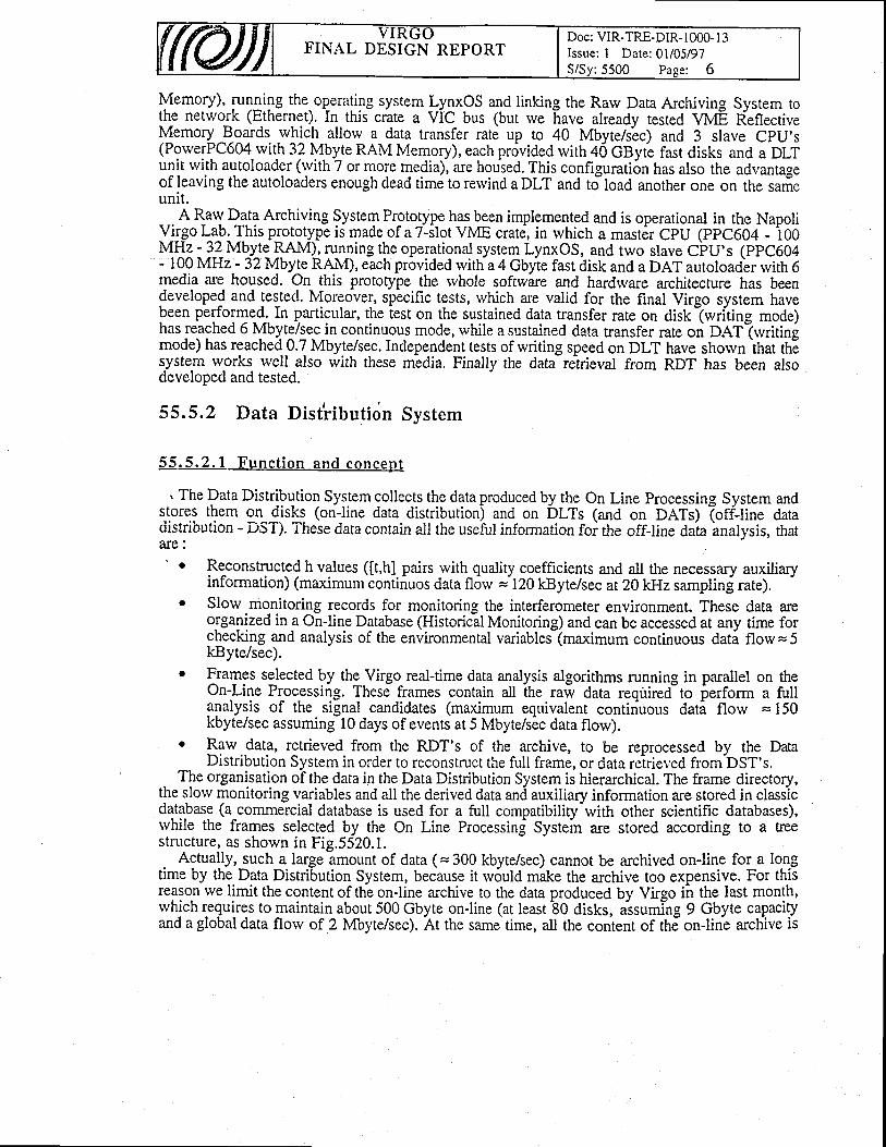
FINAL DESIGN REPORTDoc: VIR-TRE-DIR- I 000- I 3Issue: I Date; 0l/05/97S/Sv:5500 Pase: 6
Memory), Pryilg the.operating system _I.y1xOS and linking the Rarv Data Archiving Sysrem toth_e network (Ethernet). In this crate a ViC bus (but rve have already tested Vil4E ReflectiveMemory lgards rvhich allorv a data transfer rate up to 40 Mbyte/s'ec) and 3 slave CpU's(PorverPC604 with S? Y!yJ. RAM Memory), each pr6vided with 40 GByie fast disks and a DLTunit rvith autoloader (rvith 7 or more media), are housed. This configuration has also the advantageof leaving the autoloaders enough dead time to rervind a DLT and to-load another one on the sarieunit.
A Rarv Data Archiving System Prototype B-r-b:.n implemented and is operational in the NapoliY-ltgo L-ab. This pjototype is made of a 7-ilot VME crate, in which a masr6r CpU (ppc604 - i00l4E: ]-!Mb_y_tg BAM).11n_1ing the operational system LynxOS, and two slave CFU's (ppC604- 10-0 MFIz - 32 Mbyte RAM), each provided rvitlra 4 Gbyie fast disk and a DAT autoload-er rvith 6media are housed. On this prototype the rvhole softwire and hardrvare architecture has beendeveloped and tested. Moreover, specific tests, which are valid for the final Virgo system havebeen perforrye-d-..In particular, the iest on the sustained data transfer rate on diskiwriting mode)has reached 6 Mbyte/sec in continuous mode, while a sustained data transfer rate on DdT-(rvritingmode) has reached 0.7 MbyteAec. Independent tests of writing speed on DLT have shorvn inat ttEs.yste.m w-orks- rvell also *ith these m-edia. Finally the datJre^trieval from RDT has been alsodeveloped and tested.
55.5.2 Data Dist'riUution Svstem
55 .5 .2 .1 Func t i on and concep t
. The Data Distribution System collects the data produced by the On Line Processing System andstores them on disks (on-line data distribution) and on Dtts lana on DATs) (off-line datadistribution - DST). These dara contain ail the useful information foi the off-line dala bnalysis, tharare:
Reconstructed h values ([t,h] pairs with quality coefficients and all the necessary auxiliaryinformation) (maximum continuos data fl6rv :120 kByte/sec at 2QWlzsamplinj rate).
' Slorv monitoring records for monitoring the interferometer environment. These data areorganized in a On-line Database (Historical Monitoring) and can be accessed at any time forchecking and analysis of the environmental variablei(maximum continuous dati flow= 5kByte/sec).
o Frames selected by the Virgo real-time data analysis algorithms running in parallel on theOn-Line Processing. These frames contain all ihe raw data requiredlto ierform a fullanalysis of the signal candidates (ma{mum equivalent continuous dati flow = 150kbyte/sec assuming 10 days of events at 5 Mbyte/sic data flow).
. B?w data, retrieved from the RDT's of the archive, to be reprocessed by the DataDistribution System in order to reconstmct the full frame, or data reirieved from-DST's.
. TI,. organlsation of the data in the Data Distribution System is hierarchical. The frame directory,the slorv monitoring variables and all the derived data and auxiliary information are stored in classicdatabase (a commercial database is used for a full compatibiliry-with other scientific databases),rvhile the frames selected by the On Line Processing Systein are stored according to a treestructure, as shown in Fig.5520.1.
Actually, such a large amount of data ( = 300 kbyte/sec) cannot be archived on-line for a long.e by the. Data Distribution System, because it rvould make the archive too expensive. For thistime by the Data Distribution
reason rve limit the content of the on-line archive to the data produced by Virgorvhich requires to maintain about 500 Gbyte on-line (at least 80 disks, aisumilng
by Virgo il t!9 last month,rvhich requires to maintain about 500 Gbyte on-line (at least 80 disks, assuming 9 Gbyte capaciryand a global data florv of 2 Mbyte/sec). At the same, time, all the conlent of thJ on-line archive is
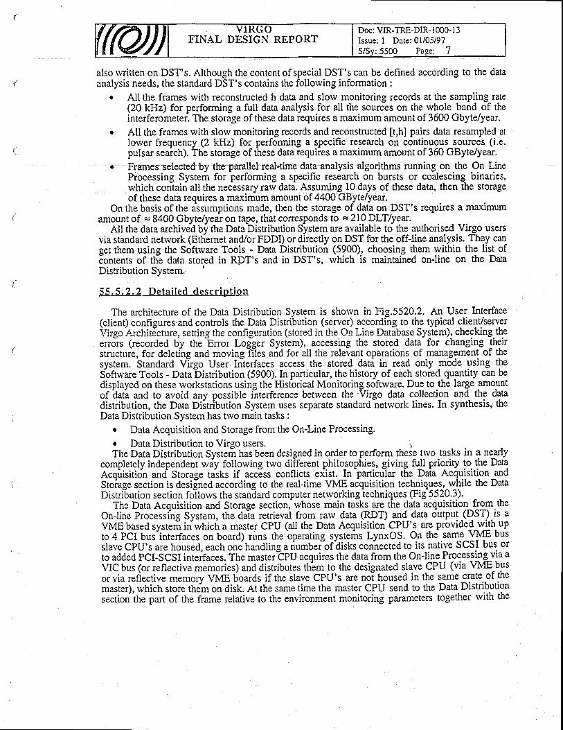
Doc: VIR-TRE-DIR- 1000- l3Issue: I Date: 0l/05i97S/Sv:5500 Pase: 7
FINAL DESIGN REPORT
also rvritten on DST's. Although the content of special DST's can be dehned according to the dataanalysis needs, the standard DST's contains the follorving information :
All the frames rvith reconstructed h data and slorv monitoring records at the sampling rate(20 kHz) for performing a full data analysis for all the sources on the rvhole band of theinterferometer. The storage of these data requires a maximum amount of 3600 Gbyte/year.
All the frames with slorv monitoring records and reconstructed [t,h] pairs data resampled atlower frequency (2 kHz) for performing a specific research on continuous sources (i.e.pulsar seaich). The storage of these data requires a maximum amount of 360 GByte/year.
o Frames selected by the parallel real+ime data analysis algorithms running on the On LineProcessing Systerir for performing a specific research on bursts or coalescing binaries,rvhich conlairi all the necessary raw data. As-syirryS_lO days of these data, then the storageof these data requires a maximum amount of 4400 GByte/year
Onthebasisof the assumptions made, then the storage of dataon DST's requires a maximumamount of = 8400 Gbytelyear on tape, that corresponds to =Zl}DHlyear.
All the data archived Uy ttre Databistribution System are available to the authorised.Virgo usersvia standard network (Etiiernet and/or FDDI) or directly on DST for the off-line analysis. They canget them using the Software Tools - Data Distribution (5?q0)., choosing them within the list ofcontents of tfr? data stored in RDT's and in DST's, rvhich is maintained on-line on the DataDistribution System. '
55 .5 .2 .2 De ta i l ed desc r ip t i on
The architecture of the Data Distribution System is shorvn in Fig.5520.2. An User lnterface(client) configures.and controls the Data Distribution (server) according to the typical client/serverVirgo ArchitJcture, setting the configuration (stored in the On I.ine Database System), checking.theenJrs (recorded by the Enor Logger System), accessing the stoied data for changing theirstructure, for deleting and moving Tltes ariA for all the relevant operations of management of thesystem. Standard Vhgo User Interfaces access the stored data in read only -mode using theSbftrvare Tools - Data-Distribution (5900). In particular, the history of each stored quantity can bedisplayed on these workstations using the Historical Monitoring software. Due to the large .amo.untof iatla and to avoid any possible i-nterference between the -Virgo data collecti_on and the datadistribution, the Data Diitribution System uses separate standard netrvork lines. In synthesis, theData Distribution System has trvo main tasks :
. Data Acquisition and Storage from the On-Line Processing.r Data Distribution to Virgo users. r, _The Data Distribution Systeri has been designed in order to perform these two tasks in a nearly
completely independent wdy following two different phito_sophies, giving {l prio.riry to- the Dataecqirisiticin and Storag" tasks if accEss conflicts ex:ist. In-particuilar the Daia AcquisitionandStoiage section is desi[ned according to the real-time VME acquisition technique_s-,-while the DataDistribution section follorvs the standard computer netrvorking techniques (Fig 5520.3).
The Data Acquisition and Storage section, whose main taiks ar: the data acquisition from theOn-line Processing System, the daTa retrieval from rarv data (RDT) glg_^data output -(DST).is aVME based systeti in which a master CPU (all the Data Acquisition CIU ! are provide9_tu1lh. upto 4 PCI bus'interfaces on board) runs the operating systerirs LynxOS. On the.same VME busslave CPU's are housed, each one handling a riumbeiof disks conirected to its native SCSI bus orto added PCI-SCSI interfaces. The mastertPU acquires the data from the On{ine Proces-sing via aViC bus (or reflective mlmorieg and distributes thlm to the designated slave CPU (via VME-busor via refiective memorv VME boards if the slave CPU's are noi housed in the same crate of the*urt.r;, which store ihl'm on dist. etlire same time the master CPU send to the Data Distributioni..ii"" iit. p^n-of if," frame relative to the environment monitoring parameters together rvith the
FINAL DESIGN REPORTDoc: VIR-TRE-DIR- l0O0- I 3Issue: I Date: 0l/05/97S/Sv:5500 Pase: 8
information of the location and the content of the stored frames, necessary for any data retrievaland content list makine.
The Data DistributJon section, rvhich manages the requests of the Virgo users, follorvs astandard networking procedure. For this task, a fully expandable server (Alpha server), rvhich canaccommodate multiple Alpha CPU's running the operating systems OSF/1, memory boards, PCIperipherals buses for the VO rvhich supports several SCSI buses to rvhich it is possible to attachdisks and tapes, is used. The link between with the master VlvfE CPU is made via a VME-PCIbus-to-bus adapter interface. This channel is used by the seryer to receive all the workinginformation (and part of the data) necessary for checking the correct working of the DataAcquisition and Storage section and to send commands (configuration, upgrading of directories,etc.). All thiS information is stored in an online database. The data retrieval is done using a FDDIinternal netrvork. For this reason, each slave VME CPU is provided with a FDDI-PCI interfacewhich is used by the server for accessing the data stored in the disks.
A Data Distribution System Prototype has been implemented and is operational in the NapoliVirgo Lab. This prototype is made of a 3 VME crates, in rvhich a master CPU (PPC60I - 100MHz - 64 Mbyte RAM), running the oper4tional system LynxOS, and tfuee slave CPU's (PPC604- 100 MHz - 32 Mbyte RAM with 2 PCI slots on board), each provided with a2 4 Gbyte fast disksand a DAT are housed. The Alpha Server is a 2100 Alpha Server W4E running the operatingsystem OSF/I. On this prototype the whole software and hardrvare architecture has been developedand tested. Moreover, spOcific tests, rvhich are valid for the final Virgo system ,have already beenperformed.
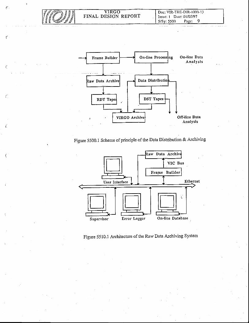
FINAL DESIGN REPORTDoc: VIR-TRE-DIR- 1000- I -1Issue; I Date: 0l/05/97S/Sv: 5500 Parlcr 9ffi
OnJine DataA n a l y s i s
Offline DataAnalysis
Figure 5500.1 Scheme of principle of the Dala Distibution & Archiving
Supervisor Error Logger On'l ine Database
Figure 5510.1 Architecture of the Raw Data Archivrng System
On-line P
rv Data Archi
Frape Bui lder
VIC Bus
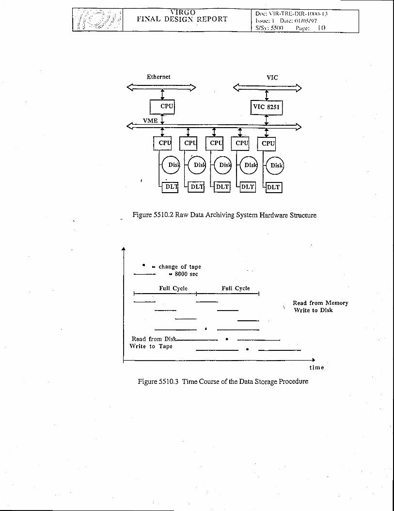
I D o c : \ ' l R - T R l : - l ) l R - l ( x x l - l . ilsstrc: I Dltc' : () l /O5/()7S/Sr : . i5 (X) l ) l {c : I o
TTINAL DDSIGN RtrPORT
Figure 5510.2 Raw Data Archiving System Hardware Sb:u*ure
' = change of tape= 8000 sec
Full Cycle Full Cycle
Read from lVlemoryWrite to Disk
Read from Dislc- .lYrite to Tape
t i m e
Figure 5510.3 Time Course of the Data Storage hocedure
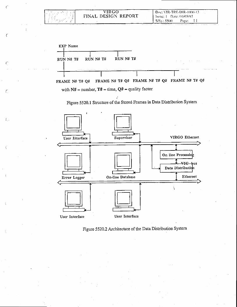
FINAL DESIGN REPORTDrrc : \ : l l l , -TRl : -D l l t - l ( l (X) - l . il s : t t c : I Dr r l c : ( l I /O5/97
S/.Sr: . iS(X) l ' : rqs': I I
RUN N# T# RUN Nf T# RUN N# T#
FRAIVTE N# T# Q# FRAME N# T# Q# FRAIVIE N# T# Q# FRAME Nf T# Q#
with N# - number, T#: time, Q#: quality factor
;
Figure 5520.L Structure of the Stored Frames in Data Disribution System
User Interface Supervisor VIRGO Ethernet
Error Logger On-line Database Ethernet
User Interface User Interface
Figure 5520.2 Architecture of the Data Distribution System
EXP Name
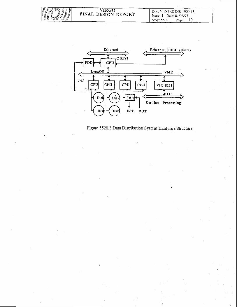
{{t }, FINAL DESIGN REPORTDoc: VIR-TRE-DIR- 1000- 1.1Issue: I Dare; 0l/0-i/97S/Sv: 5500 Paee: I 2
Ethernet, FDDI
Figure 5520.3 Data Distribution System Hardware Stnrcrure
FINAL DESIGN REPORTDoc: VIR-TRE-DIR- I 000- I 3Issue: I Date: 0l/05/97S/Sv:5600 Pase: I
56. Supervisor & associated software
56. L The Supervisor
The function of the Supervisor is to keep track of, tq request, allorv or inhibit modif,tcations ofthe status of the various components of the interferometer. With respect to this functionalitydirected towards Organisation and Security, it is intended to provide the overall user interface (themaster client) of VIRGO. The Supervisor, in particular, provides a graphic display of the status ofall the VIRGO components. It will also use the output of the Data Monitoring programs and shouldlater house the expert system in charge of the interferometer. A set of automatic sequences will beavailable for the interferometer start up for instance.
The Supervisor controls all the servers tsing the messages described in table 5000.1. It displaysthe status of all the available servers. When a special action is required for a given seryer it can startthe conesponding client and delegate its privileges.
The lisl of servers controlled by the supervisor is called the partition. This partition which canbe modified, is desciibed in the supervisoiconfiguration. The supervisor is in fact the 'front page'of VIRGO as it provides a very short description of the status of all available tasks using a colorcode. The possible status are:
- Not in partition grey- In partition but not connected black
Connecte-d and no configuration file- Connected and config available- Connected and config loaded- Connected and running- Connected and stable
,i'
default, or ordinary client)color. The figure 5100.1
shows a possible supervisor.By clicking wittrin the Supervisor panel on a server icon, one may perform the following
actions on a server with the help of a pop up menu :- add or remove from the partition- configure (set parameters like server names,...) ,- start server (taik)- ask for connection- read status- read and load server configuration file- run and stop the action performed by the server- start the corresponding user interface- kill the seryer- become master or slave user
Under smooth conditions there is only one Supervisor running in the control room rvith all theprivileges for itre hardware access. It c6llects th6 status informalion from the servers and checksih. "116r logger for warning or error messages. It asks periodically for status. A r-ron answeringserver could'6e considered is an error m.ssig.. Additional supervisors without privileges for thehardlvare access could be run in different places to monitor the interferometer.
redorangeyellowbluegreen
In addition, the type of client can be specified (master rvhich is theand a message displayed. A changing status is indicated by a flashing
FINAL DESIGN REPORTDoc: VIR-TRE-DiR- 1000- I 3Issue: I Date: 0l/05/97S/Sv:5600 Pase: 2
56.2 The communication tool
This package manages task to task communications by providing a rvide range of mechanismsrequ-ired to manipulate transparently the network layer (TCPIP) and unifomly across the variousplatforms. A complete description is available rvithin the Cm distribution kit. Horvever, one maysummarize the basic features it implements as follows :
Cm is meant to manage the iask to task communications (sending or receiving messages)running on heterogenous machines (with different architectures or operating systems) withoutlimitations on the number of active connections apart from those induced by the operating systems.
The set sf tasks or applications that may participate this network define a Cm domain managedby one special application - the NameServer - in charge of the physical addressing scheme,allowing several independant such domains to coexist.
An application rvith which a connection is requested is referenced by a name, that must beunique rvithin one Cm domain and that does not need to mention anyhow the machine on which itruns, nor the transport charectiristics (such as TCPIP parameters).
The central manager application Nam'eServer is in charge of every mechanism for nameregistration, port number allocation, and physical addressing operations transparently for the userapplication.
The Cm Message part handles the formatting issues, insuring that a structuredframe is transmitted across the netrvork (reaching heterogenous architectures) withoutintegrity.
Elements of security management are introducedhost name and user name of the message senders.
56.3 The Errorlogger
by the internal protocole, by transmitting the
The enor logger collects the information and error messages from all the processes. Themessages are sent using the El library which uses Cm.
Each message contains a severity code and a text. The levels of severity are :
informationloosing its
. info
. warning
. severe
. fatal
just infonnation messagetheir is some problem but the standard operation can continuesome non standard procedure has to be follorved to fix the problem. Theserver goes one state down for severe error.the server is stopped or going to kill. It goes more than one state dorvn.
The error display is the enor logger client which provides the tools to.select and display enormessages collected by the error logger.
seventy,Query operations can be requested by aplications giving selection criteria based on the date, the'eritv. the source- the messase. The diaenostics and monitorino annlication-s will be the normalrce, the message. The diagnostics and monitoring applications will be the normal
users of the error logger.
56.4 The Online DataBase
. This package is meant to handle the online configuration database. It is based on one server(atttrough several seryers may coexist) responsible foi the accesses to the stored objects (controlingthe prolections, the selections and th6 manipulations) and of the effective storage medium for theobjects. Accessto the data base will be achieved from any application through thE network. (DB isbased on Cm)
Data items consist on named C objects and can be of most legal C type.Management of items is centralize'd in a DB server (that also-handlei access control on objects)

FINAL DESIGN REPORTDoc: VIR-TRE-DIR- 1000-13Issue: I Date: 0l/05/97S/Sv:5600 Page: 3
Items (or objects) are accessed by their nam transparently over the netrvork and selections ofset-of-objects can be done rvith various criteria (name pattern, conditions on nvalue, ...)
An history of the contents evolution for el'ery object is maintained by the system and recoveriesof object values are possible on the basis of azbsolute or relative time and date specifications.
Objects are evenfually stored into textual files (using a human readable format) that may evenpermit a non-network access to objects.
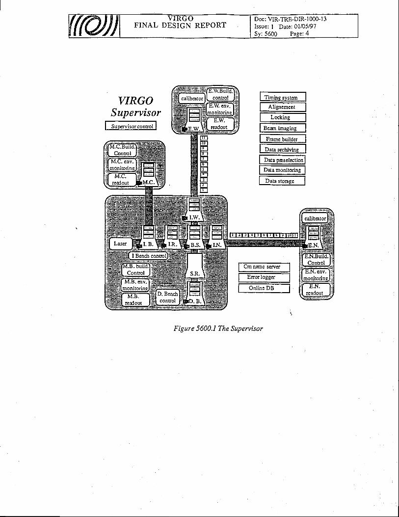
FINAL DESIGN REPORTDoc: VIR-TRE-DIR-1000-13Issue: I Date: 0l/05/97Sy: 5600 Page:4
VIRGOSupervisor
m
Figure 5600.1 The Supervisor
t Ti-totr "*"" II Alterc,n.", It L*kt"s IlT.-t i-rstrs II F*rt. b,rtld* 1
I D." *.nJ"trr IfD"-j"r"lcc,t*lI D.t. r"rit"rl"gl
I D." t."sr I
Suocrvisor control
Cm nane servcf,
Enor loggcr
Online DB
Doc: VIR-TRE-DIR- 1000-13Issue: I Date: 0l/05/97S/Sv:5?00 Pase: I
FINAL DESIGN REPORT
57 . Software Tools - Simulation
57 ,I General Description
The simulation softrvare tool of VIRGO is SIESTA. It is an integrated, general purposesimulation program. .O1e of- its goals is to provide a tool for the detector_design T.dcommtsstonrng, especially as far as the control of the interferometer is concerned. To reach thisgoal, a global Jimuiation 6f ttre interferometer operation is needed , not only for the case rvhen theinterfer6meter is around its rvorking point, but also for the lock acquisition phase. The other .majolgoal of SIESTA is to provide siriuiated data for data analysis,-in order-to develop search.andirigger algorithms. Moieover, an effort has been made_ 1q41ke the softrvare modular enough sothit somJpieces may be used in connectioh with other VIRGO softwares.
57 .2 Interfacep
SIESTA is interfaced to theFramelib package that allorvs to write/read formatted data.
57 .3 Selection of solutionsa -
One of the choices has been to perform the simuiation in the time domain. This is important fordata analysis since it allorvs to pro-duce the same type of simulated daia as real data. It is also usefulwhen non-linear effects have to be taken into acc6rlnt, such as non-lin earitiesin the interferometeroptical response or in the electronics.'
SIESTA is written in the C language, and is based on an object-oriented structure that is mostsuitable to build un int"g.ut"O siitui'ation involving many diiferent aspects. The implementedframework allorvs to integ-rate the generation of gravitational wave events with the simulation ot themost relevant aspects of"the deteitor operatiori : behavior of susp_ended mirrors, interferometeropii.a respons", control, DAQ(seefigure 5700.1). Since.the levdl of accuracy needed for someuip*it oi'tfr"iii"uiiti*'*uyiiry aciording to the issue investigated, various models are madeavailable as options whenever possible. :.
Not all thetimulation devel6p.enS are integrated into SIESTA : very. specihc issues have beenaddressed through dedicated siriulation tools tliat need not be integrated in the general software.
57 .4 Detailed description
For a detailed description we refer to the SIESTA user's guide that is available with the SIESTApackage and can be found at the following http address :
http:/Aapphp.i n2p3.frlvirgo/sDoc/dirvirgoApp.
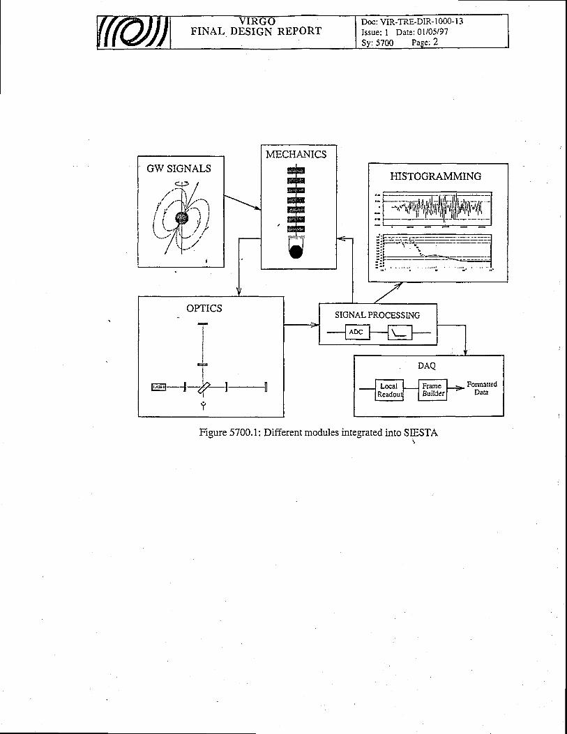
Doc: VIR-TRE-DIR- 1000-13Issue: I Date: 0l/05/97FINAL DESIGN REPORT
GW SIGNALSECHAN
#ryryrywffi, #:!lLi?.iii:I
l-lrt
HISTOGRAMMING
i
Ii
iI
F, I
!r;=;e--l-j4-|.-tlE < j . l u
I
9I
SIGNAL PROCESSING
Figure 5700.1: Different modules integrated into SIFSTA
FINAL DESIGN REPORTDoc: VIR-TRE-DIR- I 000- I 3Issue: I Date: 01i05/97S/Sy:5800 Page: I
5 8. Environment MonitoringThe Environment Monitoring S monitors all the environmental quantities which can'l he .bnvtronment l\4orutonng System monllors au Ine envffonmenmr quanttlles wnlcn can
have effects on the sensitivity of Virgo. This monitoring is necessary both for understandingible malfunctioning of the interferometer due to environmental causes and forany posslDle malrunctlonlng ot me tntenerometer (]ue to envlronmentar causes an(l lof
pr6viding the data analysis algorithms rvith the necessary environmental data for reducing theialse alarm probability of gravitational rvave events detection by means of correlationtechniques.
5 8 . 1 Function and concept
be monitored has led to the Table 5800.1.I. More indications on the acrual number andbe monitored has led to the Table 5800.I.1. More precrse lndlcatlons on me acrual numoer airufinal position of the probes is going to be obtained both from better theoretical approaches, by
direci measuremend on the"exiiting Virgo prototypes and, later on, on iite with theinterferometer rvorkin g.
The environmental sources of noise can be divided into two groups : the building noise (i.e.the noises due to the big appliances, like,the power supply noises, itre air conditioning noises,etc., of the Virgo buildings), rvhich are moniiored by th-e Building Monit.oring System througha distributed acquisition netrvork, and the environmental noise (i,e. acoustic noise,electromagnetic n6ise, etc.), which are monitored and analysed by the Environrnent MonitoringSystem. I
' The Environment Monitoring takes care of both continuos and impulsive noise sources. But
rvhile the continuous noise soirrces are theoretically predictable and can be experimentallychecked once for all (together rvith their effects on the sensitive curye of Virgo)., on the otherhand, accidental causesfrvhich can last also for a long time and can mime a gravitational rvaveeveni, must be experimentally measured, even if the conesponding continuous noise is some'orders
of magnitude belorv th'e Virgo sensitiviry curve, and continubusly monitored..For thesereasons, theEnvironment Monitoing must be a an extremely flexible iyst-em, ryhi+ must beadapted to the real needs of Virgo-: rvithout any substantlal change-of the hardware andsoft'ware architecture of the systeni, it must ailow air easy increase (oidecrease) in the numberand type of probes and changes of their positions for I improving their_sensitivity. For thisreason'the niritaing Monitorin'g Servers arid the Environmenf Moniloring Servers -(one for eachbuilding) are charaiterised by in open architecture which makes it easy-to add other probes, ifnecessiry, or simply to chinge the type of probe used. Moreover, for making -it easy. toposition ihe probeis and to m-ake all the neceisary tests,. alsg during the normal Virgo dataicquisition phase, the Environment Monitoring is provided.rvith the necess-ary comPutingpoiuer on b6ard for performing all the necessa:j anaiysis. on_the environmental quantities andihe capabiliry of sending alt thele data directly tcj the On-line Database of the Data DistributionSysteir, rvithout perur6ing in any rvay the Virgo acquisition procedures. In Figure 5800.1 thesiructute of principle of
-the Eivironment Monitoiing in cbnnection with the other Virgo
systems is shorvn.' A preliminary study on the type and the number of environmental quantities rvhich need to

FINAL DESIGN REPORTDoc: VIR-TRE-DIR- I 000- I 3Issue: I Date: 0l/05/97
: 5800 Pa*Qe: 2
reoue nc
md l)lrectlon
CB = Central Building MCB = Mode Cleaner BuildingNB = Nord End Building WB = West End BuildingNT = Nord Tunnel' WT = West Tunnel
Environment Monitori Parameters
In particular, as it is possible to see in this Table, the sampling frequency is not the same forall of the environmentd quantities, because of the different bands of the noises and the differenteffects on the sensitivity currve of Virgo. In fact, the same sampling rate of the output signal ofthe interferometer (20 kHz) and a precise timing is necessary for some of them (i.e.electromagnetic noise, acoustic noise, etc.) rvhile a lorver frequency sampling rate rvith noprecise timing definition is sufficient for other quantities (i.e. temperature, pressure, humidity,etc.). On the basis of the structure of the Virgo systems, then the best solution for the.acquisition of thb environmental parameters is the follorving :
o The acquisition of fast variables ivhich need precise timing is iniegrated rvithin a fastVME data acquisition system (local readout), rvhich makes it easy to handle the data andto transfer tliem to the Frame Builder. For this reason the fast ADCs of the' Environments Monitoring are housed within the Local readout System. At the same timethese variables are acquired for checks and for spectral analysis by the EnvironmentMonitoring System, rvhich record and send their main characteristics to the FrameBuilder and to the Data Distribution System via the Slorv Monitoring Netowrk(Ethernet).
o The acquisition of slow variables is made by the Environment Monitoring Servers,rvhich send them directly to the Frame Builder by means of .the Slow MonitoringNetrvork (Ethemet). i.
. The acquisition of quantities related to the noise of the Building is made by the BuildingMonitoiing Servers, rvhich send them directly to the Frame Builder by means of theSlorv Monitoring Netrvork (Ethernet).
The architecture of the Environment Monitoring is shorvn in Fig.5800.2. A user interfacenrnning on one of the control room rvorkstations iranages the rvhole Environment MonitoringNetwoik, sets the configuration of each seryer (stored in the Online Database System), of allthe fast and slow acquididon boards and ofthe probes, checks the errors (recorded by the Enor
!.ogg", System). Srch user interface has a grdphic_al pqge for each type of variable and candisplay the main characteristics and the history of each environment monitoring Parameter'using the Historical Monitoring sofrware in connection rvith the Data Distribution System'
58,2 Requirements
The main requirements relative to the Environment Monitoring concem the samplingfrequency and the sampling accuracy. The requirements for the Building Monitoring Syst_e_Tand Environment trlohitoiing Syst6m are slrotun in Table 5800.II
-and taUle 5800.III,
respectively.
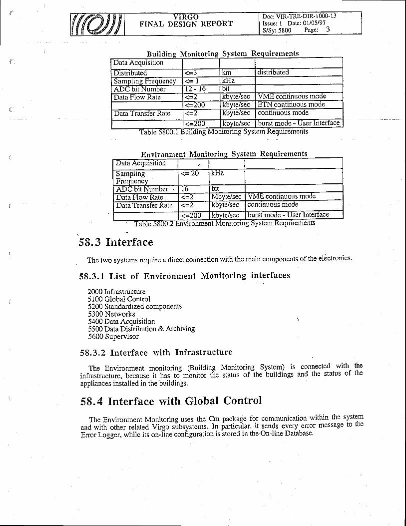
Doc: VIR-TRE-DIR' I 000- l3Issue: I Date: 0l/05/97S/Sy:5800 Page: 3
FINAL DESIGN REPORT
Bui ld i Monitorin stem uirements
urrements
En Monitori stevrronmen n rn ulremenData Acquisition
SamplingFrequency
1='/-U kHz
ADU blt Number l 6 bilData Florv Rate. 1='/ Mbvte/secVME continuous modellata'l'ranster Kate 1='l kbyte/sec continuous mode
(=2UU kbyte/sec burst mode - User Intertacevironment Monitoring System Requirements
58.3 fnterface
The two systems require a direct connection rvith the main components of the elictronics.
58.3.L List of Environment Monitoring interfaces
2000 Infrastructure5100 Global Control5200 Standardized components5300 Networks5400 Data Acquisition i'
5500 Data Distribution & Archiving5600 Supervisor
58.3.2 Interface lvith Infrastructure
The Environment monitoring (Building Monitoring- System) is connected with the
infrastructure, because it has to monitor tfie status of-the buildings and the status of the
appliances installed in the buildings.
58.4 Interface with Global Control
The Environment Monitoring uses the Cm package for communication within the systern
and with other related VirSo subsystems. I" itttiafiar, it sends every elror message to the
Enor Logger, while its on-l'ine configuration is stored in the On-line Database'
lng

FINAL DESIGN REPORTDoc: VIR-TRE-DIR-l 000- I -jIssue: I Date: 0l/05/97S/Sy:5800 Page: 4
58.4.1 Interface rvi th Standardized Components
The Environment Monitoring uses, rvhere possible, standard Virgo hardware and softrvarecomponents : this makes it easy their replacement and smaller the number of spare components.In particular, the CPU's (PPC604), the crates (VME), the operating systems (LynxOS), thelanguage (C) and the netrvork (Ethernet) are standard Virgo components (5200).
58.4,2 Interface lvith Netrvorks
The Environment Monitoring requires the standard Virgo Ethemet line for internalconnections (i.e. User Interface, Enor Logger, OnJine Database, Supervisor, Frame Builder,Dara Distribution, etc.).
58.4.3 Interface lvith Data Acquisition
All the fast environmental quantities 120 kjlz) rvhich need the timing are acquired by theLocal Readout using the ADCs of the Environment monitoring, rvhile the slorv quantities andthe main parameters of the all the fast ones acquired and processed by the EnvironmentMo.nitoring are transfened to the Frame Builder is made via the slorv monitoring network(Ethernet).
58.4.4 Interface lvith Data Distribution & Archiving
Some environmental data acquired by the Environment Monitoring for specific studies on.environmental variables can be directly sent to the Data Distribution System, which stores themin its On-line Database.
58.4.5 Interface \vith Supervisor -'
The Supervisor keep track, request allow od inhibits the modifications of the status of thissubsystem and can act as an User Interface.
58.5 Selection of solut ions
Although the Building Monitoring System and Environment Monitoring System arestrucfurally different, the iechnical solutions are designed according to ihe following generalcriteria:
. system easy to use and to upgrade;
. system completely open to Virgo people :1. softrvare sources available, documented and easy to change and to upgrade
according to future Virgo needs;2. standard cornmercial hardware components when possible;
. system completely expandable, that is every further upgrade necessary for theimprovemeni of ttre p.hor-an."s of the system can be oUlained by simply lddingcomponents or upgrdding part of them rvi[hout changing the hardrvare and softwarestructure of the rvhole system.
. system made of as many standard Virgo components as possible, in order to reduce thenumber of spare components..
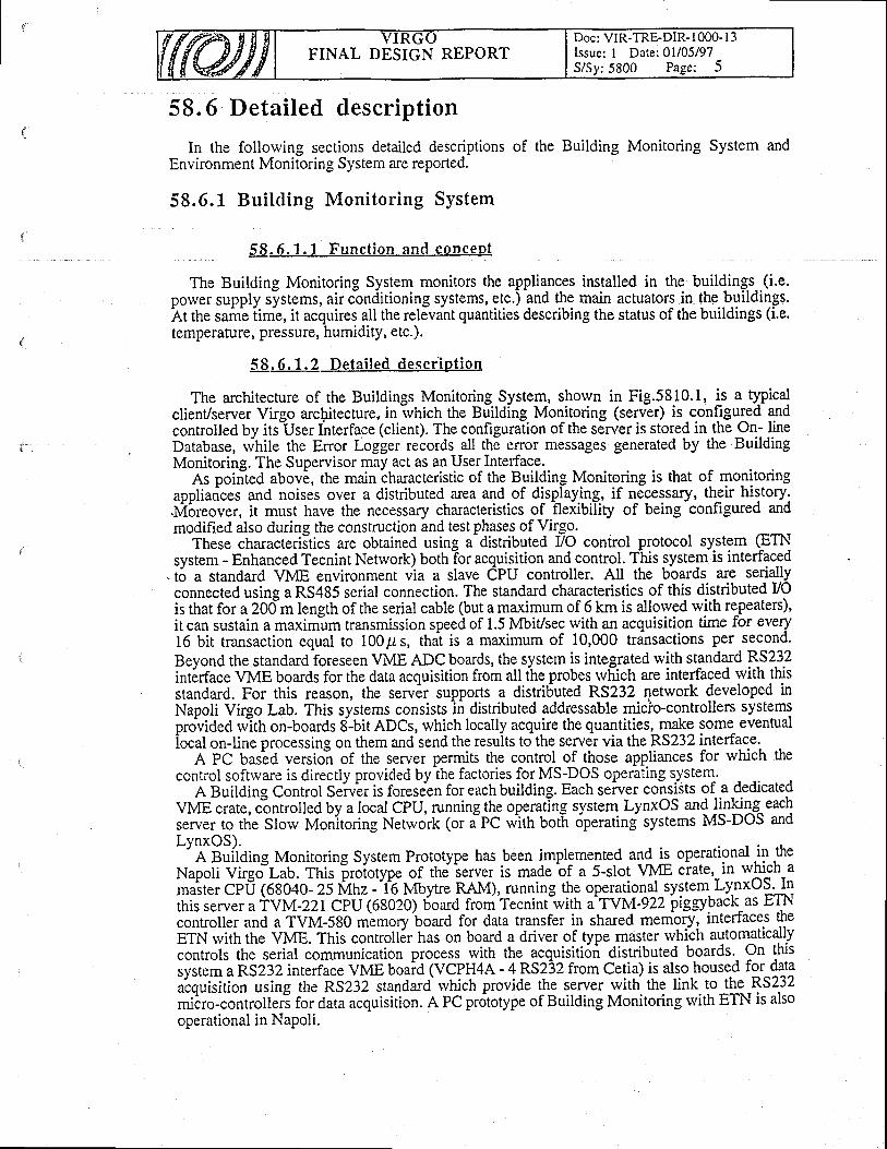
Doc: VIR-TRE-DIR- I 000- I 3Issue: I Date: 0l/05/97S/Sy:5800 Page: 5
FINAL DESIGN REPORT
58.6 Detailed description
In the follorving sections detailed descriptions of the Building Monitoring System andEnvironment Monitoring system are reported.
58.6.1 Bui lding Monitor ing System
58. 6. 1 . I Funct ion and qoncept
The Building Monitoring System monitors the appliances installed in the buildings-.(i.e.power supply systems, air cbnditioning systems, etc.) and the main actuators in the buildings.ht the sami iime, it acquires all the relJvint quantities describing the status of the buildings (i.e.temperature, pressure, humidity, etc.).
5 8. 6 . I . 2 Deta i led descr ip t ion
The architecture of the Buildings Monitoring System, shown in Fig.5810.1, is a typicalclient/server Virgo architecture, in rvhich the Building Monitoring (server) is configuled gdcontrolled by itsllser Ihterface (client). The configuraiion of the server is stored in the On- IineDatabase, rvhile the Enor Logger records all the elror messages generated by the BuildingMonitoring. The Supervisor may act as an User Interface.
As poirited abovi, the main characteristic of the Building Monitoring is that of monitoringappliarices and noises over a distributed area and of displaying, if necessary, their history..Mbr.ou"., it must have the necessary characteristics of flexibiliry of being configured andmodified also during the construction and test phases of Vilgo.
These characteriitics are obtained using a-distributed VO control protocol system (ETNsysrem - Enhanced Tecnint Network) bothlor acquis_ition andcontro!. fhis system is interfaced
.t6 a standard VME environment via a slave CPU controller. All the boards are seriallyconnected using a RS485 serial connection. The standard characteristics of this distributed VOis that for a 20d"m length of the serial cable (but a maximum of 6 km is allorved rvith repeaters),it can sustain a maxim-um transmission speed of 1.5 Mbit/sec with an acquisition time for every16 bit transaction equal to 100p s, thai is a maximum of 10,000 transactions per second.
Beyond the standard foreseen VME ADC boards, the system is integrated with standard RS232int6rface VME boards for the data acquisition from all ihe probes rvhich are interfaced with thisstandard. For this reason, the serv6r supports a distri6uted RS232 network 4gveloped inNapoli Virgo Lab. This systems consists
-ii distributed addressable micio-controllers systems
pro^uided rvith on-boards 8-bit ADCs, which locally acquire the quantities:_T{9 some evenrualiocal on-line processing on them and send the resuits to the server via the RS232 interface.
A PC basbO versio-n of the server permits the control of those appliances for which thecontrol sofrrvare is directly provided by the factories for MS-DOS operating system.
A Building Control Seiv^er is foreseen for each building. Each server consilts of a dedicatedVME crate, c"onrrolled by a local CPU, running the operatlng system. LynxOS and linling^eachseryer ro rhe Slow Monltoring N-tt*rk (or a-PC with botl 6perating systems MS-DOS andLynxOS).-"
A guilding Monitoring System Prototype has been implemented alq i:. operational in theNapoli Virfiau. Thi;-"di"tp. or ittJ i.*.r is made bf a s-slot VME ciate,_in which amuit", CPfi (68040- ii fi4nz -'t6 Muyt.r RAM), running the operational_system. Ly.nxOSJnthis server aTYM-221CPU (68020) board from Tecnint with aTYM-922 piggybacr as -trll\controller and a TVM-580 mLmory board for data transfer in shared memgr1, interfaces theETN rvith the VME. This controll6r has on board a driver of type master rvhich automaticallycontrols the serial "o*tnrni.ution process rvith the acquisition distributed boards. On thisiyrt.* o nSZ:Z interface VME boaid (VCPH4A - 4 RS232 from Cetia) is als.o.housed for dataalouisition using the nSZgZ standa-rd rvhich provide the server wittr the link to the RS232*iiio-.ontrott.ri f* data acquisition. A PC prdtotype of Building Monitoring with ETN is alsooperational in Napoli.

FINAL DESIGN REPORTDoc: VIR-TRE-DIR-l 000- I 3Issue: I Date: 0l/05/97S/Sy: 5800 Pa-se: 6
58.6.2 Environment Monitor ing System
58 .6 .2 .1 Func t i on and concep t
The Environment Monitoring System monitors all the environment variables, which are notdirectly related to the status of interferometer, but necessary for the conelation analysis rvith theinterferometer output signals. At the same time is acquires and processes the data relative to theenvironment quantities rvhich are necessary to analyse in more detail.
58 .6 .2 .2 De ta i l ed desc r ip t i on
The architecture of the Environment Monitoring System, shorvn in Fig.5820.1, is a rypicalclient/server Virgo architecture, in rvhich the Environment Monitoring (server) is configuredand controlled by its User Interface (client). The configuration of the server is stored in the On-line Database, while the Enor Logger regords all the error messages generated by the BuildingMonitoring. The Supervisor may act as an User Interface.
As pointed above, the main characteristic of the Environment Monitoring is that ofmonitoring all the environmental quantities which can have effects on Virgo, eventuallyprocessing them in order to study in detail each quantity and displaying, if necessary, theirhistory. For these reasons, .it must have the necessary characteristics of flexibiliry of beingconfigured and modified also during the construction and test phases of Virgo.
These characteristics are obtained using a VIvIE system on rvhich DSP boards and ADCboards are housed rvhich use the fast bus for data transfer, and standard CPU's which use theVSB bus for data acouisition from the ADC boards in order to maintain their sustained data'florv rate if rvoii<ing in multiplexing mode. Moreover, the server supports VME boards withRS232 interface and the distributed RS232 network deveioped in Napoli Virgo Lab, as shownfor the Building Monitoring System.
An Environment Monitoririg System Prototype has been implemented and is operational in' the Napoli Virgo Lab. This proiotype of the servlr is made of a^l2-slot VME crate, in which amastefCPu (PPC601 - 100 Mtrz - 16 Mbytre RAM), running the operational system LynlO-S.In this server a DSP DV96 from Loughborough is housed which atquires data from ADC viaits bus and processes them. Two adC 16 bi'[ 8 channels 50 kHz s'ampling rate (MPV912Afrom Pentland) are used by the PCC601 for data acquisition.
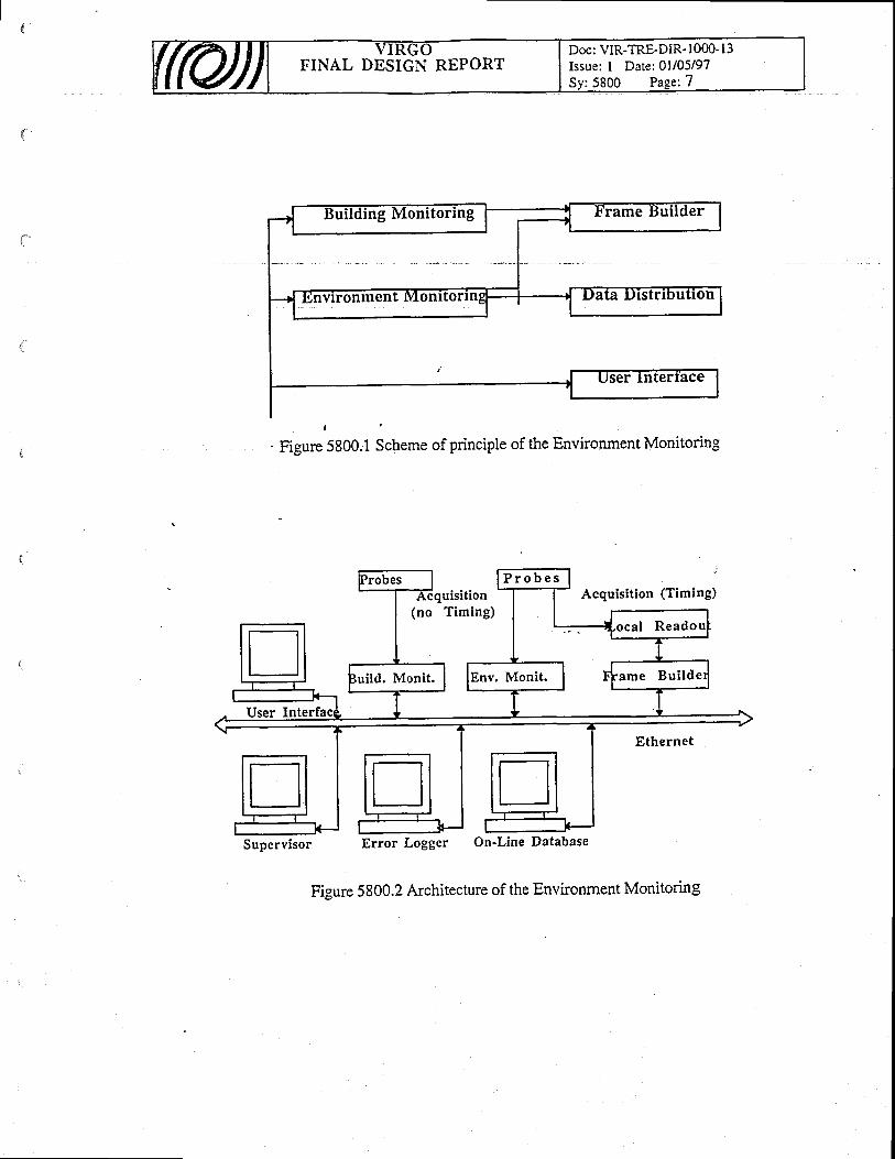
Doc: VIR-TRE-DIR- 1000- l3Issue: I Date:01105197Sv:5800 Page:7
FINAL DESIGN REPORT
ronment Monltor
. Figure 5800.1 scheme of principle of the Environment Monitoring
Probes l P r o b e sAcquisit ion (Timing)Acquisit ion
(no Timing.
-l
. Nu Itui ld. Monit. I lrnt
D C a l
ame
11eauuu
-tBu i l de r
User I' T l l E t h e r n e t
[] n nt-J
Supervisor Error Logger On'Line Database
Figure 5800.2 Architecture of the Environment Monitoring
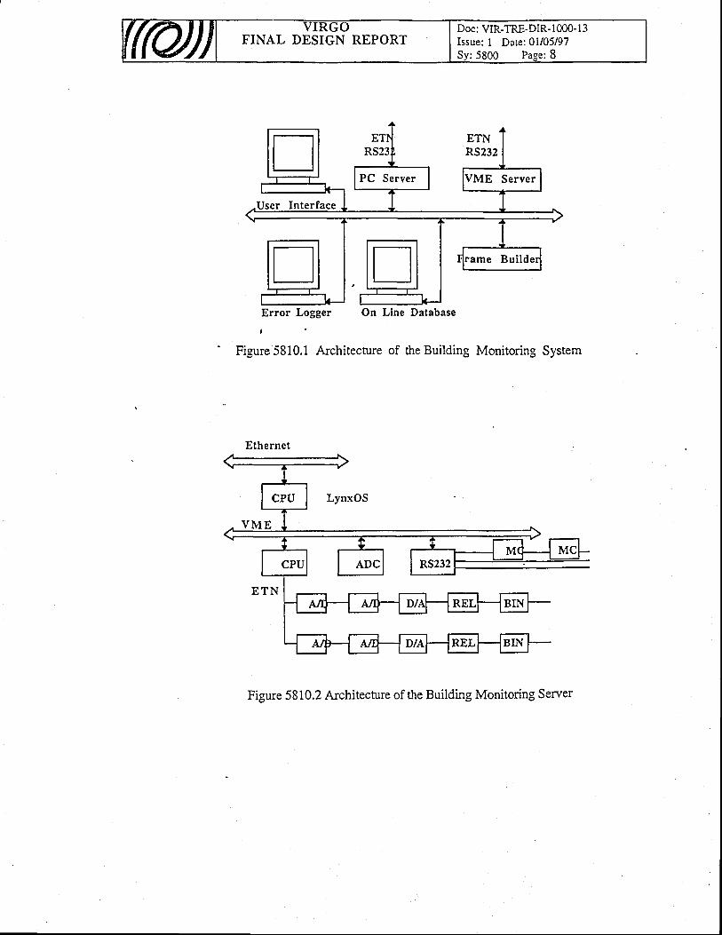
FINAL DESIGN REPORTDoc: VIR-TRE-DIR- 1000- I 3Issue: I Date: 01i05/97Sy:5800 Page: 8
n ETNRS232
PC Server I lvun Server
User Interface
tl ! :ame Bui lder
Error Logger On Line Database
Figure 5810.1 Architecture of the Building Monitoring System
Figure 5810.2 Architecture of the Building Monitoring Server
Ethernet
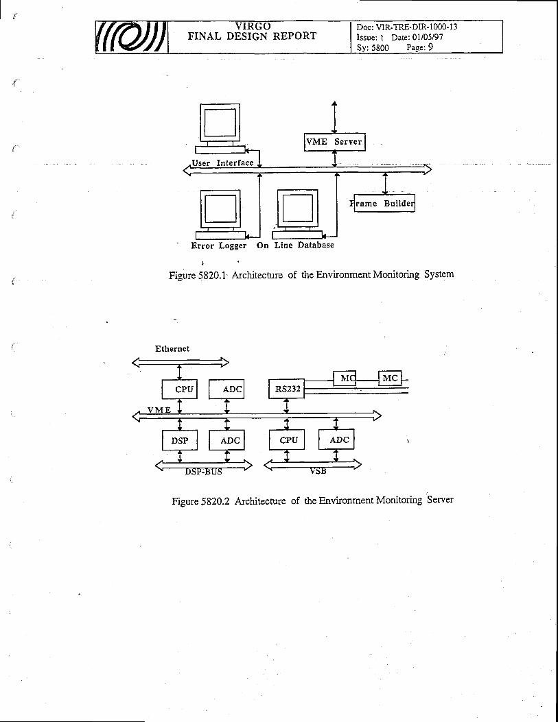
Doc: VIR-TRE-DIR- 1000- l3Issue: I Date: 01i05/97
:5800 Page:9FINAL DESIGN REPORT
tlVME Server
User Interface
n n :ame Bui lde
k_J'
Error Logger On Line Database
Figure 5820.1' Architecture of the Environment Monitoring System
Ethernet
Figure 5820.2 Architecture of the Environment Monitoring Server
FINAL DESIGN REPORTDoc: VIR-TRE-DIR- I 000- l -?Issue: I Date: 0l/05/97Sy: 5900 Pa-ee: I
59. Software Tools - DistributionThe offline Softrvare Tools Distribution provides all the softrvare for data retrival and
distribuiton that the Virgo users will use for every access to the Virgo Data fuchive (on-line andoff-line). This softrvare rvill allow the user to extract, to vierv, to process and to reconstruct allthe stored information useful for data analysis and general checks on Virgo.
59. L Function and concept
The off-line SAV Tools are organized in such a way that the Virgo users can extract, vier.v,process, reconstruct and download all the data stored in RDT's, DST's and on the on-linedatabases of the Data Distribution System in the easiest way. It uses, where they exists, theSAV Tools designed and used also in other subsystems in such a way to define an unique Virgostandard, without any duplication of work.
59.2 Requirements:
The only requirements are relative to use a standard procedure and languages for dataretrieval and reprocessing according to the Virgo standards and to satisfy the maximum datatransfer rate of I Mbyte/sec which is in the requirements of the Data Distribution & Archiving(ss00).
5 9 . 3fnterfaces'
This system requires a direct connection rvith the main softrvare delevoped for other systmesof the electronics.
59.3.1 List of S/W Tools - Distr ibut ion interfaces
5400 Data Acquisition5500 Data Distribution & Archivine5700 SnV Tools - Simulation
59.3.2 Interface ryith Data Acquisition
The system uses some tools developed for the Data Acquisition, like the Data Display, On-line Processing, etc.
59.3.3 Interface with Data Distribution & Archiving
The SAV Tools -Distribution have access to the data onJine stored in the Data Distribution,to DST's and to the RDT's.
59.3.4 Interface \yith S/W Tools - Distribution
The SAV Tools - Simulation must be used by the SAV Tools - Distribution for thereprocessing of RDT's for rebuilding the frames after their retrieval.
FINAL DESIGN REPORTDoc: VIR-TRE-DIR-l 000- I 3Issue: I Date:01/05/97Sy: 5900 Pa-se: 2
59.4 Selection of solutions
The system is developed according to the following general criteria :o to implement the system and easy to use and to upgrade.o to implement a system completely open to Virgo people rvith softrvare sources available,
documented and easy to change and to upgrade according to the future Virgo needs.
59.5 Detailed description
The structure of the SAV tools - Distribution is organised in modules, lvritten in Clanguage for portability. These modules include many modules developed for othersubsystems which are keep as they,are in order to have standard Virgo software. Othersoftware, including the softrvare for the data distribution via network, is written ad hoc orstandard software with large diffusion is used.
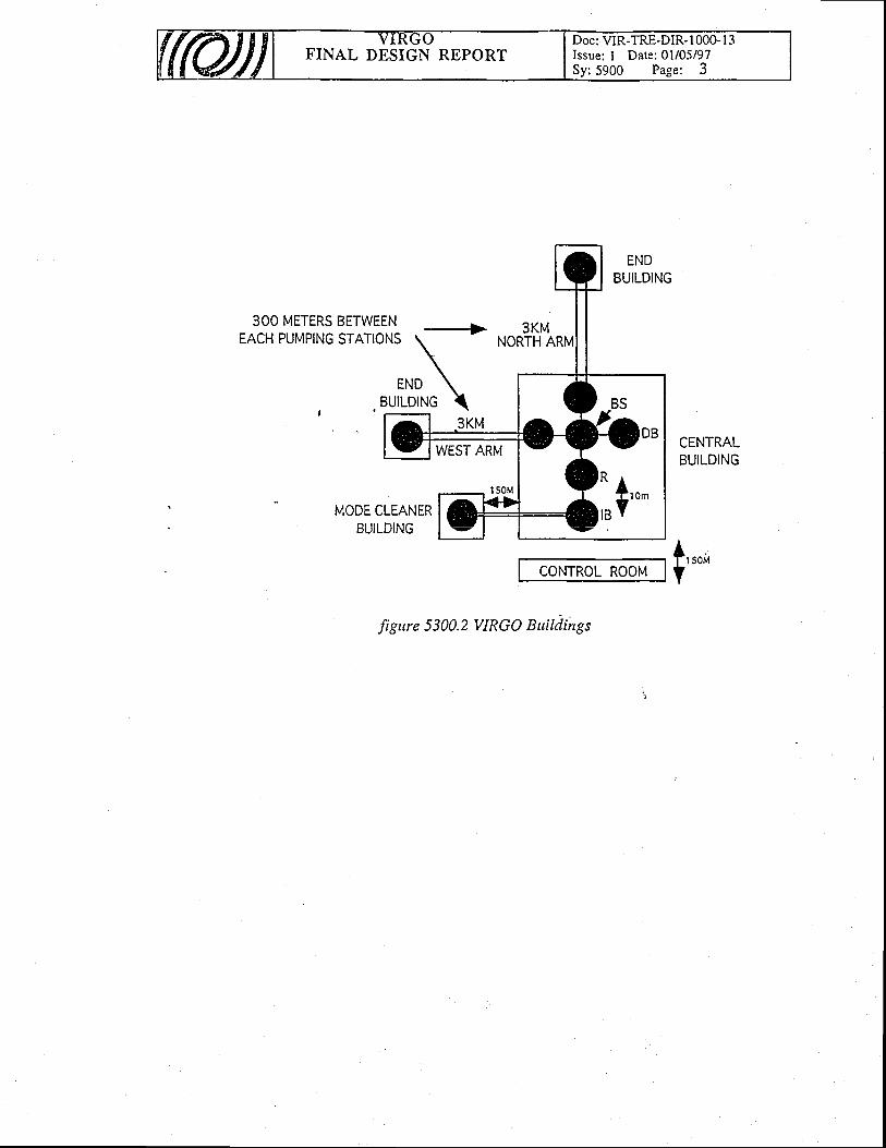
FINAL DESIGN REPORTDoc: VIR-TRE-DIR-1000- I 3Issue: I Date: 0l/05/97Sy:5900 Page: 3
ENDBUILDING
3OO METERS BETWEENF A ^ r I n t t t t h t l r
^ - a - r ^ r t ^trALn rutvtril\u D I At lL/t\J
3KMNORTH r
CENTRALBUILDING
MODE CLEANERb t t i l h l t t ^D U I L I J I I Y \ J
CONTROL ROOMf,,ouY
figure 5300.2 VIRGO Buildings
,, +'*
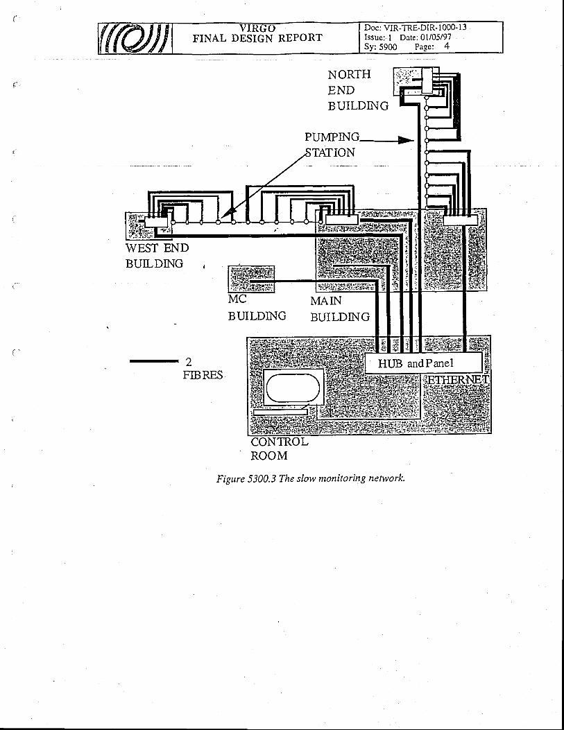
FINAL DESIGN REPORTDoc: VIR-TRE-DIR- 1000- I 3Issue: I Date: 0l/05/97Sy:5900 Page: 4
WEST ENDBUILDING
NORTHENDBUILDING
PUMPING--->'ATION
M MAINBUILDINGBUILDING
ROOM
Figure 5300.3 The slow monitoring network.
2FIBRES

FINAL DESIGN REPORTDoc: VIR-TRE-DIR- 1000- l3Issue:1 Date:01/05/97
The VIRGO Col laborat ion on January 1997
D i r e c t i o n a n d P r o j e c t O f f i c e
Acker Y.
Benfat t i P.
Bri l let A.
Epard D.
Errico A.
Giazotto A.
Tofani C.

FINAL DESIGN REPORTDoc: VIR-TRE-DIR- I 000- I 3Issue:1 Date: 0l/05/97
ITALIAN LAB ORATORIES
INFN - F i re nzeCecchin i R.Ciuff i F.Mazzoni M.Pelfer P. G,Stanga R.
IN FN -F ras ca t iBabusci D.Cima E.Fang H.Giordano G.Iannarel l i M.Matone G.Tuni E.
I N F N - N a p o l iBa rone F .Cal lon i E.Di F iore L.Flagiel lo M.Garuf i F.
. Grado A.Longo M.Lops M.Marano S.
' Milano L.So l imeno S .
I N F N - P e r u g i aAragona A.Babucci E.Cagnol i F.Gammaitoni L.Kovalik J.Marchesoni F.Punturo M.
I N F N - P i s aBeccaria M.Bemardin i M,Bracc in i S.Bradaschia C.Cella G.Ciampa A.Cosci R.Cuoco E.Curc i G.D'.Ambrosio E.Dirni lo V.De Carolis G.de Sa lvo R .Di Virgi l io A.Ferrante I.Fidecaro F.Gaddi A.Gennai A.G iass i ALa Penna P .Losurdo G.Maggiore M.Mancin i S.Palla F.Pan H . B .Paolett i F.Pasqualett i A.Passuel lo D.Pogg ian i R .Popol iz io P.Raffaelli F.Ragonesi A.Ruberti R.Vicere' A.Zhang Z.
I N F N - R o m aAstone P.B ronz in i F .Capradossi G.Fenari V.Frasca S.Majorana E.Manei APapa M. A.Pellegrino F.Perciball i M.Puppo P.Rapagnani P.Ricci F.Serrani E.

FINAL DESIGN REPORTDoc: VIR-TRE-DIR- 1000-13Issue:1 Date:01/05/97
FRENCH LABORATORIES
E S P C I - P a r i sBoccara C.Deban J .B .Germain O.Gleyzes P.Lel iboux M.Loriette V.Nahum R.Roger J .P .
IPN - LYONDognin L.Ganau P.Lagrange B.Mackorvski J. M.Michel C.Morgado N.Morgue M.Napolitano M.Pinard L.
LAL - OrsayArnault C.Barrand G.Beney J . L .Bi lhaut R.Br isson V.Caval ier F.Chiche R.Combeau R.Corona P.Coulon J . P.Cuzon S .Davier M.Dehamme M.Dial inas M.Ducorps A.Eder C.Garn ier C.Gaspard M.Hel lo P.Heusse P.Ju les E.L iss i lour G.Marie M.Marin P.Marrucho J. CMatone L.Mencik M.Reboux A.Rivoirard P.Roudier P.Taur igna M.
LAPP - AnnecyBel lachia F.Bermond MBoget D.Busku luc D .Caron B.Carron T.Castel lazzi DChol le t F.Daguin G.David P. Y.Dedieu M. L.Derome L.Drezen C.Dufournaud D.Flamin io R.Gai l lard G.Giacobone L.Girard C.Grave X"Hermel R.Lacot te J . C.Le Marec J .C.L ieunard B.Marion F.Massonet L.Mehmel C.Moiand R.Mours B.Mugnier P.Sannibale V.
- Sbt t i le R.Verkindt D.Yvert MLAS - OrsayBar i l le t R.Barsugl ia M.Ber thet J . P.Bindz i Ph.Cachenaut J .Cleva F.Gourgoulhon E.Hei tmann H.Lucenay J. C.Man Nary C.Marck J-A.Pelat D.Pham-Tu M.Redon T.Reita V.Taubman M.Vinet J .Y.
Doc: VIR-TRE-DIR-1000- l3Issue: l Date:01/05i97
:5000 Page: IFINAL DBSIGN REPORT
50. ELECTRONICS AND SOFTWARE
Table of Contents
50. ELECTRONICS AND SOFTWARE
5O.1 System description
50.2 System requirements
50.3 General descr ipt ion50.3.1 The online Architecture
50.3. l. l The architecture50.3.1 .2 The hardware options50.3.1.3 The softrvare options50.3.1.4 Secur i ty50.3. 1.5 The Slow. monitorir,rg network organization
50.3.2 The control ofihe interferometer50.3.2.1 The Fast Controls ,50.3.2.2 The control and monitoring of the interferometer environment
50.3.3 Offl ine50.3.4 System Commissioning
50.3.4. I Controls commissioning' 50.3.5 Data acquisit ion commissioning
51. Global Control
' 51.1 Real T ime Global Contro l (RIOT)
51.2 Global Contro l Survey
52. Standardized Components
52.1 Standardization and Software rules52.1.1 Language52.1.2 Coding rules52.1.3 File organization52.1.4 The list of Slow Monitoring Stations52.1.5 Data format on tape:52. 1.6 Information distribution
52.2 The timing system
52.3 Workstations52.3.1 Control Room & Computer Room52.3.2 Main Building52.3.3 Mode Cleaner or End Minor Building
52.4 The Video system52.4.1 List o[ cameras52.4.2Digital processing of the signals52.4.3 Monitor installation in the Control room52.4.4 Cabling :
52.5 Standardization : Hardrvare
4
4
44
66I
1I
78888
1
I
1
1
3)A
^
4A
666
7


![[TC 025] Alvenaria estrutural_2020 - dcc@ufpr](https://static.fdokumen.com/doc/165x107/631358cfaca2b42b580d255f/tc-025-alvenaria-estrutural2020-dccufpr.jpg)