Advanced LIGO Two-Stage Twelve-Axis Vibration Isolation ...
78
Pre-print for submission to Precision Engineering 1 Advanced LIGO Two-Stage Twelve-Axis Vibration Isolation and Positioning Platform Part 1: Design and Production Overview F. Matichard 1,2,* , B. Lantz 3 , K. Mason 1 , R. Mittleman 1 , B. Abbott 2 , S. Abbott 2 , E. Allwine 5 , S. Barnum 1 , J. Birch 4 , S. Biscans 1 , D. Clark 3 , D. Coyne 2 , D. DeBra 3 , R. DeRosa 6 , S. Foley 1 , P. Fritschel 1 , J.A. Giaime 4,6 , C. Gray 5 , G. Grabeel 5 , J. Hanson 4 , M. Hillard 1 , J. Kissel 5 , C. Kucharczyk 3 , A. Le Roux 4 , V. Lhuillier 5 , M. Macinnis 2 , B. O’Reilly 4 , D. Ottaway 1 , H. Paris 5 , M. Puma 4 , H. Radkins 5 , C. Ramet 4 , M. Robinson 5 , L. Ruet 1 , P. Sareen 1 , D. Shoemaker 1 , A. Stein 1 , J. Thomas 4 , M. Vargas 4 , J. Warner 5 . 1 MIT, Cambridge, MA, USA 2 Caltech, Pasadena, CA, USA 3 Stanford University, Stanford, CA, USA 4 LIGO Livingston Observatory, Livingston, LA, USA 5 LIGO Hanford Observatory, Hanford, WA, USA 6 Louisiana State University, Baton Rouge, LA, USA
-
Upload
khangminh22 -
Category
Documents
-
view
0 -
download
0
Transcript of Advanced LIGO Two-Stage Twelve-Axis Vibration Isolation ...

Pre-print for submission to Precision Engineering
1
Advanced LIGO Two-Stage Twelve-Axis Vibration Isolation
and Positioning Platform
Part 1: Design and Production Overview
F. Matichard1,2,*, B. Lantz3, K. Mason1, R. Mittleman1, B. Abbott2, S. Abbott2, E.
Allwine5, S. Barnum1, J. Birch4, S. Biscans1, D. Clark3, D. Coyne2, D. DeBra3, R.
DeRosa6, S. Foley1, P. Fritschel1, J.A. Giaime4,6, C. Gray5, G. Grabeel5, J.
Hanson4, M. Hillard1, J. Kissel5, C. Kucharczyk3, A. Le Roux4, V. Lhuillier5, M.
Macinnis2, B. O’Reilly4, D. Ottaway1, H. Paris5, M. Puma4, H. Radkins5, C.
Ramet4, M. Robinson5, L. Ruet1, P. Sareen1, D. Shoemaker1, A. Stein1, J.
Thomas4, M. Vargas4, J. Warner5.
1 MIT, Cambridge, MA, USA
2 Caltech, Pasadena, CA, USA
3 Stanford University, Stanford, CA, USA
4 LIGO Livingston Observatory, Livingston, LA, USA
5 LIGO Hanford Observatory, Hanford, WA, USA
6 Louisiana State University, Baton Rouge, LA, USA

Pre-print for submission to Precision Engineering
2
* Corresponding Author: [email protected]
LIGO Project MIT
MIT NW22-295
185 Albany Street
Cambridge, MA 02139 USA
Phone: +001-617-253-6410
Fax: +001-617-253-7014

Pre-print for submission to Precision Engineering
3
Abstract
New generations of gravity wave detectors require unprecedented levels of vibration
isolation. This paper presents the final design of the vibration isolation and
positioning platform used in Advanced LIGO to support the interferometer’s core
optics. This five-ton two-and-half-meter wide system operates in ultra-high vacuum.
It features two stages of isolation mounted in series. The stages are imbricated to
reduce the overall height. Each stage provides isolation in all directions of translation
and rotation. The system is instrumented with a unique combination of low noise
relative and inertial sensors. The active control provides isolation from 0.1 Hz to 30
Hz. It brings the platform motion down to 10 /√ at 1 Hz. Active and passive
isolation combine to bring the platform motion below 10 /√ at 10 Hz. The
passive isolation lowers the motion below 10 /√ at 100 Hz. The paper
describes how the platform has been engineered not only to meet the isolation
requirements, but also to permit the construction, testing, and commissioning
process of the fifteen units needed for Advanced LIGO observatories.
Keywords: Vibration Isolation, Seismic Isolation, Active Isolation, Passive
Isolation, Vibration Isolator, Multi-axis Platform, Positioning System,
Vacuum compatible, Low-noise instrument.

Pre-print for submission to Precision Engineering
4
1 Introduction
Physics experiments and precision systems often require a large amount of vibration
isolation. Isolators have been developed for a variety of application such as scanning
tunneling microscopy [1]-[2], gravitometers [3]-[4], atom interferometric
measurements [5], atomic force microscopy [6], colliders [7], and space pointing [8].
Ground based gravity waves detectors have set very stringent requirements in terms
of vibration isolation [9]. These instruments use km long interferometers in order to
detect strains of space-time caused by astrophysical events [10]. To make gravity
waves detection possible, the detector’s components must be isolated from all
environmental disturbances, including ground motion, which is the dominant
disturbance at low frequency.
Seismic isolation concepts and prototypes were developed in early experiments
carried out for gravity waves detectors [11]. During the past two decades, several
observatories have been built around the world [12]-[16]. Multiple pendulum
suspensions equipped with springs blades providing vertical isolation were
developed to isolate the optics of the 600 meter long GEO detector located in
Germany. Silica fibers are used between the two bottom stages to increase the
quality factor and therefore reduce the thermal noise [17]-[18]. This technique in now
being used in other gravity waves detectors [19]. The 3 km long VIRGO detector
combines 7 meter high inverted pendulums, multi-stage suspended pendulums and
inertial control to provide the suitable isolation to all degrees of freedom [20]-[21].
This system called the super-attenuator features natural frequencies as low as 40

Pre-print for submission to Precision Engineering
5
mHz. It provides 15 orders of magnitude of isolation at 10 Hz [22]. The 3 km long
KAGRA detector in Japan is currently being built underground. The seismic motion
in this environment is roughly two orders of magnitude quieter than at the surface
level. A combination of seismic attenuation systems and multiple pendulums are
used to achieve the isolation requirements [23]. Estimated noises show that the
seismic noise will be well under other noise sources in the detection band.
The LIGO observatory based in the US consists of 4 km long detectors, located in
Washington State and Louisiana State [12]. After a decade of operation, the initial
LIGO interferometers are currently being retrofitted with a new generation of
instruments called Advanced LIGO [24]. To provide very high vibration isolation at
all frequencies, Advanced LIGO combines Hydraulic Exo-vacuum Pre-Isolators
(HEPI), Intra-vacuum Seismic Isolators (ISI) and multistage passive suspensions
(SUS) [25]-[27]. The HEPI system is based on the quiet hydraulic actuators and
control techniques developed at Stanford [28]-[29]. This active platform provides
long-range alignment capability to all directions of translation and rotation. It is used
to reject very low frequency disturbances such as tidal and micro-seismic motion
[30]. It provides active inertial isolation from 100 mHz to 10 Hz [31]. The ISI platforms
feature large optical tables on which the LIGO optics are mounted [32]. Instrumented
with low noise instruments, they provide alignment capability and inertial isolation
from about 100 mHz to 30 Hz. They also provide passive isolation above a few Hertz
to several hundreds of Hertz. Two different types of platform have been developed:
the HAM-ISI for the auxiliary optics [33]-[34], and the BSC-ISI for the core optics

Pre-print for submission to Precision Engineering
6
which require further seismic isolation [35]. The LIGO suspensions holding the
interferometer optics are mounted on the ISI systems. These multiple pendulums
provide multistage passive isolation. They are equipped with relative sensors and
actuators to damp the suspension resonances and to position the interferometer
optics. Different types of suspensions have been designed for the different optics
used in the interferometers [27].
This paper presents the ISI active platform designed to support the Advanced LIGO
core optics suspensions. Installed in the large LIGO vacuum chambers called Basic
Symmetric Chambers (BSC), this isolator is often referred to as the BSC-ISI system.
It features a two meter wide optical table capable of supporting more than 1000 kg
of equipment (optical payload). The design requirement is to provide more than three
orders of magnitude of isolation at low frequency, to bring the optical motion down
to 10 /√ at 1 Hz, and 10 /√ at 10 Hz [36]. Five BSC-ISI units per
interferometer are necessary to support the core optics (one for the beam splitter,
one for each of the two input test masses, and one for each of the two output test
masses).
The concept used for the BSC-ISI is based on early prototypes built at JILA in the
nineties [37]-[39]. These experiments demonstrated the performance achievable
with multi-dof active platforms instrumented with inertial instruments and driven with
voice coil actuators through feedback controls. The results obtained motivated the
construction of a rapid prototype as a concept for the Advanced LIGO project [40]-
[41]. This two-stage system was instrumented with commercial seismometers and

Pre-print for submission to Precision Engineering
7
voice coil actuators. All six degrees of freedom of each stage were servo controlled.
The conclusive results led to the construction of a full-scale two-stage Technical
Demonstrator (Tech-Demo) built and tested at the LIGO Stanford facilities [42]. This
system had the size and payload capacity required for the Advanced LIGO project.
Like the rapid prototype, the Tech-Demo was made of two stages in series, each
having six degrees of freedom. Vertical springs were used for the vertical isolation,
and flexure rods for the horizontal isolation. An optimal combination of low noise
commercial instruments was used for the active control. A unique feature of the
Tech-Demo is that it uses “reasonably” stiff springs. Unlike most isolators used in
similar applications, the low frequency isolation is entirely achieved actively. All the
rigid body natural frequencies are near or above 1 Hz. This system demonstrated
that the use of stiffer springs greatly simplifies the assembly, leveling, and
commissioning steps, but does not affect the active control performance achievable
at low frequency.
After this successful experiment, the “stiff spring” two-stage concept became the
baseline design of the In-vacuum Seismic Isolation system needed to support the
Advanced LIGO core optics. In 2004, detailed design requirements were defined for
the system [43]. A prototype was designed during the following year [44]-[45]. The
BSC-ISI prototype was built and tested at MIT between 2006 and 2008 [35]. The
lessons learned during the prototyping phase were used to engineer the final design
in 2009 and 2010 [46]-[47]. The first unit was successfully tested at the LIGO MIT

Pre-print for submission to Precision Engineering
8
test facility in 2011. In the past two years, 13 of the 15 units have been built for the
LIGO observatories (The last two units are currently under construction).
This manuscript is the first part of a series of two companion papers presenting the
BSC-ISI platform for Advanced LIGO. It presents the system and focuses on design
and production considerations. The next section gives an overview of the two-stage
isolator concept. The third section describes the design of the sub-systems. It
highlights the technical challenges related to the design of high precision isolators
and details how they have been solved. The fourth section describes design choice
trade-offs driven by practical aspects of the production and testing process. The
paper concludes with a comparison of the theoretical and experimental transfer
functions. The second part of this series of two companion papers focuses on the
testing investigation during the prototyping and production phase of this project [48].
2 Concept Overview
The final design of the BSC-ISI system is based on the architecture of the system
used during the prototyping phase [35]. A conceptual representation is shown in Fig.
1. It represents the structure and the spring components in a schematic section view.
Actuators and sensors are not displayed. The system is made of three main sub-
assemblies: a base called “Stage 0” and two suspended stages called “Stage 1” and
“Stage 2”. The stages are imbricated to minimize the volume occupied. The bottom
plate of Stage 2 is the optical table on which the Advanced LIGO equipment is
mounted.

Pre-print for submission to Precision Engineering
9
Stage 1 is suspended from Stage 0, and Stage 2 is suspended from Stage 1. The
spring assemblies provide horizontal and vertical flexibility. They are symbolically
represented by helicoids. Their actual shape and location is presented in section 3.5.
The springs decouple the stages from each other in all directions of translation
(called Longitudinal, Transverse and Vertical in Fig. 1) and all directions of rotation
(called Pitch, Roll and Yaw in Fig. 1). The system is designed to minimize the cross
couplings between degrees of freedom. In each direction, the system behaves as a
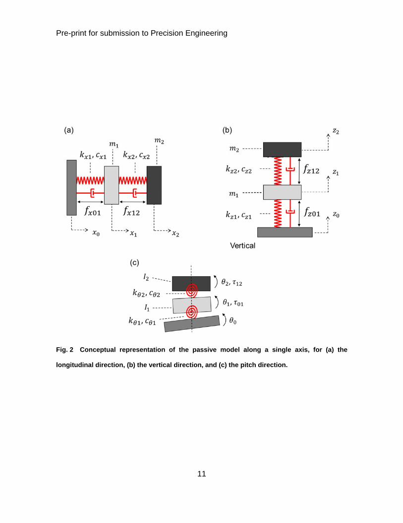
two-mass-spring system as illustrated in Fig. 2 for three of the six directions. In Fig.
2 (a), , and are the longitudinal motions of Stage 0, Stage 1 and Stage 2.
, and are the stiffness, damping and mass of Stage 1. , and are
the stiffness, damping and mass of Stage 2. is the actuation force between
Stage 0 and Stage 1. is the actuation force between Stage 1 and Stage 2. Similar
notations and subscripts are used in Fig. 2 (b) for the vertical motion and in Fig. 2
(c) for the pitch motion, where the letter is used to denote the vertical direction,
is used for the angular pitch motion, for the torques and for the quadratic moment
of inertia.
In each direction, the system provides passive isolation as described in the system
of equations (1)-(3), using the longitudinal direction as an example. In these
equations, is the input motion, is the first stage motion and is the second
stage motion. The mass, damping and stiffness matrices are called , and
respectively. The matrices and give the influence of the input disturbance and
the control forces on the system respectively.

Pre-print for submission to Precision Engineering
10
Fig. 1 Conceptual representation of the BSC-ISI passive components. Sensors and actuators
not represented. Springs assembly are symbolically represented by helicoids.
Pre-print for submission to Precision Engineering
11
Fig. 2 Conceptual representation of the passive model along a single axis, for (a) the
longitudinal direction, (b) the vertical direction, and (c) the pitch direction.

Pre-print for submission to Precision Engineering
12
(1)
00 , , (2)
0 0, 1 1
0 1 (3)
At low frequencies, Stage 1 and Stage 2 are controlled actively. Each of the twelve
degrees of freedom are controlled independently. For instance, the longitudinal
motion of the first mass ( ) is controlled with the force applied between Stage
0 and Stage 1, and the longitudinal motion of the second mass ( ) is controlled with
the force applied between Stage 1 and Stage 2. Fig. 3 shows the feedback
control block diagram for a single degree of freedom, where is the degree of
freedom under control. It is valid for both stages. The subscript value n can be 1 for
stage 1, or 2 for stage 2. Capital letters are used to denote the analysis is performed
in the harmonic domain. The stage motion is disturbed by the input motion
through the seismic path called . It is controlled with the force (Complex
amplitude of if analyzing Stage 1, or if analyzing Stage 2) through the force
path called .The system’s harmonic responses and can be calculated from
theoretical models such as in equations (1)-(3) for the preliminary design phases.
Experimental transfer functions are used for the final design of the control loops [48].

Pre-print for submission to Precision Engineering
13
Fig. 3 Feedback control principle for one degree of freedom.

Pre-print for submission to Precision Engineering
14
On each of the two active stages (Stage1 and Stage 2), two types of sensors are
used: inertial and relative sensors. The inertial sensors (geophones or
seismometers) are used to measure the stage’s absolute motion ( ) which is
necessary to provide active seismic isolation (isolation/decoupling from the previous
stage). The absolute measurement (inertial instrument signal) is called in Fig. 3.
It includes a noise component called . This noise is dominant at low frequency
where the inertial sensor loses sensitivity. The relative sensors are capacitive
gauges measuring the differential motion between the stages ( ). They are
used for DC and low-frequency positioning of the stages. The relative measurement
is called . It includes a noise component called . This noise is typically much
lower than the inertial sensor noise at low frequencies. Details related to the type of
sensors used on each stage are given in section 3. A sensor fusion is used to
combine the absolute and the relative measurement. The inertial sensor signal is
filtered with the high-pass called . The relative sensor is filtered with the low-pass
. The outputs of these filters are summed to form the error signal. A compensator
is used to command the control force .
The components of this block diagram are summarized in Eq. (4) to (7), assuming
that the absolute measurement ( ) and relative measurement ( ) are calibrated
in displacements units. This is done practically using digital filters inverting the
instruments frequency response. Equation (4) gives the stage motion as a function
of the input motion (disturbance) and the control force. Equation (5) gives the control
force as a function of inertial measurement ( ) and the relative measurement ( ).

Pre-print for submission to Precision Engineering
15
Equations (6) and (7) introduce the sensor noise. To simplify the control design, the
low-pass and high-pass filters are designed to be complementary [30], as shown in
Eq (8). Equation (9) gives the closed loop motion (power spectral density)
assuming the input motion and the sensor noises are uncorrelated. The first term
shows the contribution of the input stage motion ( ). The second term shows the
contribution of the absolute (inertial) motion sensor noise ( ). The third term shows
the contribution of the relative motion sensor noise ( ). Assuming large loop gain in
the control bandwidth, the amplitude spectral density can be written as shown in Eq.
(10). The input motion contribution is filtered by the low-pass filter L. Therefore, the
lower the cutoff frequency the better for the isolation, but the high pass-filter and
low-pass filter must also be adequately designed to minimize the sensor noise
contribution. The optimization consists of designing complementary filters that
provide both isolation and enough filtering of the instrument’s noise. More details
can be found in [30].
(4)
) (5)
(6)
(7)
1 (8)

Pre-print for submission to Precision Engineering
16
1 1
1
(9)
→ (10)
3 System and Sub-Systems Design Description
3.1 System Overview
The base of the system (Stage 0), the first suspended stage (Stage 1) and the
second suspended stage (Stage 2) are shown in grey shades in the Computer Aided
Design (CAD) representation in Fig. 4. Stage 1 is suspended from Stage 0 using
three sets of blades and flexures. Stage 2 is suspended from Stage 1 using three
sets of blades and flexures similar to those used between Stage 0 and Stage 1. One
instance of each type of spring sub-assembly is indicated in Fig. 4. The picture shows
how Stage 1 and Stage 2 are imbricated to reduce the system’s volume. The two
stages’ mass, inertia properties, and the spring’s stiffness are chosen to obtain
suitable rigid-body natural frequencies. More details on that are provided in the
following sub-sections. The springs are positioned to minimize the cross couplings
as explained in the sub-section related to blades and flexures. A BSC-ISI unit
undergoing the test process at the LIGO Hanford observatory is shown in Fig. 5. In
this picture, 1100 kg of dummy mass is mounted on the top plate to float the stages
during the testing phase. Once the testing is completed, the dummy mass removed,
the unit is moved to the detector area where interferometer components are attached

Pre-print for submission to Precision Engineering
17
to the inverted (down-facing) optical table of Stage 2. Details on the system
component shapes and features can be found in the top assembly and sub-assembly
drawings [49]. The following sub-sections give a detailed description of the sub-
systems.

Pre-print for submission to Precision Engineering
18
Fig. 4. CAD representation of the BSC-ISI system.

Pre-print for submission to Precision Engineering
19
Fig. 5. A BSC-ISI unit in testing at the LIGO Hanford observatory.

Pre-print for submission to Precision Engineering
20
3.2 Stage 0
Stage 0 is the base of the BSC-ISI system. A CAD representation of Stage 0 is
shown in Fig. 6, with the components attached to Stage 0. They are the Stage 0-1
spring assemblies, actuator posts, and motion limiters. The structure of Stage 0 is
made of a hexagonal hollow structure approximately 2.4 meters wide and 0.3 meter
high. It consists of two monolithic halves bolted together (called top half and bottom
half in Fig. 6). Each half structure is machined out bulk aluminum 6061 T6. The inner
shapes and webbings have been designed to optimize the structural stiffness, in
particular the torsion deformation as illustrated by the blue arrows (angular
deformation θ P , where P is the static load). The weight of the two half structures
combined is 540 kg. The total weight with the components attached to Stage 0 (as
shown in Fig. 6) is 885 kg. The 1.6 meter wide hexagonal opening in the inner section
of Stage 0 permits access the down-facing optical table of Stage 2.
Machining and assembly errors result in imperfection of the stage locations, spring
load, and leveling offsets. The tolerances must, therefore, be adequately chosen and
controlled. A machining tolerance of 0.125 mm is specified for the flatness and
parallelism of Stage 0 reference surfaces to ensure accurate location and orientation
of the sub-assemblies mounted on it. Location pins are used to position the two half-
structures relative to each other and to position the components mounted on it.
Special care has be given to the press-pin process due to the high friction (the
system is ultra-clean to operate in UHV environment, more detail is given in the next
sections). Stainless steel hardware is necessary for corrosion resistance during the

Pre-print for submission to Precision Engineering
21
cleaning process and for UHV compatibility. Preload and torques values in the bolted
joints have been calculated to account for the high friction in the clean assemblies.
Helicoils made from Nitronic 60 are used in bolted assemblies requiring high preload.
Similar machining, tolerancing, positioning, bolting, and cleaning techniques are
used for the other sub-assemblies presented in the following sub-sections.

Pre-print for submission to Precision Engineering
22
Fig. 6. A CAD Representation of the Stage 0 structure, Stage 0-1 spring components, actuator
posts and motion limiters.

Pre-print for submission to Precision Engineering
23
3.3 Stage 1
A CAD representation of Stage 1 is shown in Fig. 7. It is made of a 1.75 meter-wide
three-branch structure. The aluminum structure weighs 550 kg and carries 350 kg of
instrumentation (podded sensors and actuators). The structure has been designed
to optimize the stiffness over mass ratio. Design and finite element analysis iterations
have been carried out to raise the natural frequencies of the structural global bending
and torsion modes along the arrows shown in Fig. 7. Related information can be
found in [47]. The lowest natural frequency of the metal structure has been measured
to be 260 Hz. It drops to 215 Hz when the stage is fully instrumented with all
equipment and sub-assemblies. The design is three fold symmetric around the
vertical axis. Each of the three branches of the structure is equipped with two relative
position sensors, one three-axis seismometer, two geophones, and two actuators.
Two voice coil electromagnetic actuators designed for LIGO by Planning Systems
Incorporated are mounted in each branch of Stage 1. One actuator is mounted
vertically, and one is mounted horizontally. The horizontal actuators are positioned
with respect to the spring assembly and the stage center of mass to minimize the
cross couplings between horizontal and tilt motion as explained in the section on
flexure rods. The coil is mounted on Stage 0 to improve the heat conduction path
out of the vacuum chamber. The magnet assembly is mounted on Stage 1. The
magnets are positioned in pairs of North-South and South-North dipoles to reduce
the magnetic field which escapes the actuator assembly. The actuator has a return

Pre-print for submission to Precision Engineering
24
yoke to minimize the escaped magnetic field which can interfere with the sensitive
equipment surrounding the platform.
These actuators produce 40 N/Amp, with a coil resistance of 6.5 Ohms. Coil drivers
capable of supplying a +/- 20 V range are used to drive the actuators. More
information on the coil drivers is given in section 3.6. The maximum force delivered
by each actuator is approximately 125 N. The first pole induced by the impedance
of the coil is at 32 Hz. The dynamic response of the actuator is characterized in [50].
A CAD representation of the actuator assembly is shown in Fig. 8 and a picture of
an actual assembly is shown in Fig. 9. Tooling bars (not shown) are used to lock the
coil and the magnet components during the assembly process. Aluminum brackets
are used to connect each half of the actuator to the stage. Copper bars are used to
conduct the heat out of the assembly. Spherical support and washers are used in
the joints to reduce over-constrains between the coil and the magnets occurring
during the assembly process.
Capacitive gauges supplied by Microsense are used to sense the relative motion
between Stage 0 and Stage 1. These sensors are collocated with the actuators as
shown in Fig. 8. The sensor gauges are attached to Stage 0 so that their wires do
not introduce unwanted friction on the isolated stage. The aluminum sensor targets
are attached to Stage 1. They are diamond turned to obtain a very smooth finish
necessary to minimize the cross-sensitivity to lateral motion. A
modulation/demodulation scheme is used to sense the motion. The Stage 0-1
sensors range of sensing is +/- 1 mm. Their noise floor is 2 10 /√ at 1 Hz.

Pre-print for submission to Precision Engineering
25
The sensor electronic boards are mounted outside of the vacuum system. Tri-ax
cables are used to minimize the cable capacitance and radiation.
One three-axis seismometer is used in each of the three branches of Stage 1. They
are 240 seconds period instruments (T240) supplied by Nanometrics. One of the two
horizontal axes is oriented tangentially, and the other radially. These sensors are
very low noise instruments at low frequency. The noise of these inertial sensors is in
the range of 2 10 /√ at 100 .
In order to be used in ultra-high vacuum, each seismometer is mounted in a sealed
chamber, as shown in Fig. 10. The chamber is custom-made for this application. It
is made of Stainless Steel 304. The welded parts are subjected to a thorough leak-
check process to validate the fabrication. For this test, the chamber is filled with
Helium, and subjected to a RGA scan. For the final assembly, the pod containing
the instrument is filled with Neon, which is used as a tracker for leak detection during
operations. Additionally, each pod is instrumented with pressure sensors to help
identify a faulty pod in case of a leak. The pod used for the T240 has been designed
to minimize the volume between the instruments and the sealed chamber, and
therefore reduce noise disturbances related to gas currents induced by temperature
gradients.
Stage 1 is also equipped with six passive inertial sensors. They are L4C geophones
supplied by Sercel. There is one instrument mounted horizontally and one mounted
vertically in each branch. The instruments are encapsulated in custom made sealed
chambers as previously described for the T240 seismometers. A CAD

Pre-print for submission to Precision Engineering
26
representation of the L4C sealed assembly is shown in Fig. 11. The instruments are
equipped with low-noise custom-made pre-amplifiers and pressure sensors
mounted on the instrument inside their sealed chamber. The instrument sensor noise
is 2 10 /√ at 1 and 10 /√ at 10 . The T240 seismometers and
L4C geophones are combined for very low noise broadband inertial sensing. More
information on the sensor fusion is given in [48]. Fig. 12 shows all the components
in one branch of stage 1. It also shows the front door and vibration absorbers used
to damp the structural modes (they were not displayed in Fig. 7 to better show the
instrument location in the branch).

Pre-print for submission to Precision Engineering
27
Fig. 7 A CAD Representation of Stage 1 (Front door not shown).

Pre-print for submission to Precision Engineering
28
Fig. 8. A CAD representation of the Stage 0-1 actuators and capacitive position sensors
assembly.

Pre-print for submission to Precision Engineering
29
Fig. 9. Stage 0-1 actuator assembly.

Pre-print for submission to Precision Engineering
30
Fig. 10. Custom made sealed chamber to use the Trillium T240 in ultra-high-vacuum.

Pre-print for submission to Precision Engineering
31
Fig. 11. Custom made sealed chamber to use the Sercel L4C in ultra-high-vacuum.

Pre-print for submission to Precision Engineering
32
Fig. 12. Front view of one of the three branches of Stage 1.

Pre-print for submission to Precision Engineering
33
3.4 Stage 2
A CAD picture of Stage 2 is shown in Fig. 13. The 1.85 meter-wide aluminum
structure weighs 1350 kg. The total mass of Stage 2 including the podded sensors,
actuators, springs, and motion limiters is 1750 kg. Additionally, it supports 1200 kg
of equipment, including 350 kg usually configured as ballast. The Stage 2 threefold
symmetric structure is built so as to encompass Stage 1. The assembly process of
the imbricated stages is detailed in [51]. The bottom plate of Stage 2 features an
optical table with a 25 mm x 25 mm hole pattern. Like the two other stages already
presented, Stage 2 has been optimized for overall stiffness and local rigidity where
the instruments are mounted. It is suspended from Stage 1 using three sets of blades
and flexures similar to those used on Stage 1. These components are described in
the section 3.5.
In each of its three corners, Stage 2 is instrumented with two actuators, two relative
sensors, and two inertial sensors. Fig. 14 and Fig. 15 show the actuators. They are
similar to those described for Stage 1. The coils are mounted on Stage 1 to provide
a shorter conduction path for the heat to transfer out. It also reduces the risk of a
mechanical shortcut through the actuator cabling. Since Stage 1 provides sufficient
positioning capability, smaller actuators are used on Stage 2. These actuators
develop 27 N/Amp. The coil resistance is 10 Ohms. The maximum force delivered
by each actuator is approximately 55 N. The first pole induced by the impedance of
the coil is at 50 Hz. The dynamic response of the actuator is characterized in [50].

Pre-print for submission to Precision Engineering
34
The Stage 1-2 position sensors are collocated with the Stage 1-2 actuators. The
gauges are mounted on Stage 1 and the targets on Stage 2. The Stage 1-2 position
sensor construction is identical to those used for Stage 0-1, but they are four times
more sensitive, at the cost of four times less sensing range. Their noise floor is
6 10 /√ at 1 . The low noise performance of these instruments is
necessary for the positioning control not to compromise the seismic isolation of
Stage 2.
The inertial sensors used for Stage 2 are passive GS13 geophones supplied by
Geotech. The instrument flexures have been replaced by custom made beryllium-
copper notch-style flexures [52]. This modification makes the instrument more robust
to shock, and eliminates the need for locking the instrument during transportation
and installation. The instruments are equipped with low noise pre-amplifiers carefully
chosen to minimize the noise in the control bandwidth [53]. The instrument sensor
noise is 8 10 /√ at 1 and 4 10 /√ at 10 . Fig. 16 shows
pictures of the GS13’s pod assembly. The aluminum external shell of the instrument
has been replaced by a mu-metal can to shield the instruments against magnetic
fields. Like the inertial instruments of Stage 1, the GS13s are encapsulated in
custom-made sealed chambers equipped with pressure sensors, filled with Neon,
leak checked after assembly and monitored during operations.

Pre-print for submission to Precision Engineering
35
Fig. 13. A CAD Representation of the Stage 2 Assembly.

Pre-print for submission to Precision Engineering
36
Fig. 14. Stage 1-2 actuator assembly.

Pre-print for submission to Precision Engineering
37
Fig. 15. Stage 1-2 vertical actuator CAD representation.

Pre-print for submission to Precision Engineering
38
Fig. 16. GS13 equipped with mu-metal shielding and sealed in a custom pod for use in ultra-
high-vacuum.

Pre-print for submission to Precision Engineering
39
3.5 Spring Components
3.5.1 Springs assembly overview
The design and engineering of the spring components is very critical to both the
performance and operability of a vibration isolation system. The rigid-body natural
frequencies must be low enough to provide adequate passive isolation, but the
springs must not be too compliant so that the system remains easy to commission
and operate. LIGO experience acquired during prototyping of vibration isolation
systems showed that rigid-body natural frequencies in the 1 Hz to 7 Hz range provide
an excellent compromise.
To reduce the complexity of the control strategy and to facilitate operation, the BSC-
ISI system has been engineered to minimize the couplings between the degrees of
freedom in the Cartesian basis. As a result, the system behaves as a two-spring-
mass system in each direction of translation and rotation as explained in the
introduction. The spring components have been designed to obtain in-phase rigid-
body modes in the 1 Hz to 2 Hz range (the two masses moving in phase at the
resonance), and out-of-phase rigid-body modes in the 5 Hz to 7 Hz range (the two
masses moving out of phase at the resonance).
Three blade-flexure assemblies are used on each stage, and positioned
symmetrically at 120 degrees around the vertical axis. The blades are designed to
provide the vertical flexibility, and the flexure rods are designed to provide the
horizontal flexibility. A symbolic cross-section representation of one of the three sets
is shown in Fig. 17. It shows one Stage 0-1 spring assembly and one Stage 1-2

Pre-print for submission to Precision Engineering
40
spring assembly. The blades are flat in the un-deformed state, and curved with a
constant radius of curvature in the loaded configuration as shown in Fig. 17. The
stage 0-1 blade center of curvature is located under the blade (with respect to the
ascending vertical axis), and the stage 1-2 blade center of curvature is located above
the blade to reduce the volume occupied by the springs assembly.
The blades, the flexures, the horizontal actuators and the stage’s center of mass are
positioned relatively to each over to minimize the cross couplings. Fig. 17 illustrates
how the static tilt-horizontal coupling has been minimized. The Stage 0-1 blade’s tip
and the Stage 0-1 horizontal actuator plane are located at a distance from the
flexure’s tips. The distance is chosen so that the horizontal actuator force ( )
produces a horizontal motion ( ), but no rotation. The distance is function of the
flexure geometric parameters, material, and the vertical load . More details are
given in the section on flexures. Similar positioning is done for the stage 1-2
components (location , horizontal force , horizontal motion ). A cross section
of the Stage 0-1 spring assembly is shown in the CAD representation in Fig. 18, and
a cross section of the Stage 1-2 spring assembly is shown in Fig. 19.

Pre-print for submission to Precision Engineering
41
Fig. 17. Conceptual representation of the spring assembly.

Pre-print for submission to Precision Engineering
42
Fig. 18. Stage 0-1 spring assembly.

Pre-print for submission to Precision Engineering
43
Fig. 19. Stage 1-2 spring assembly.
Pre-print for submission to Precision Engineering
44
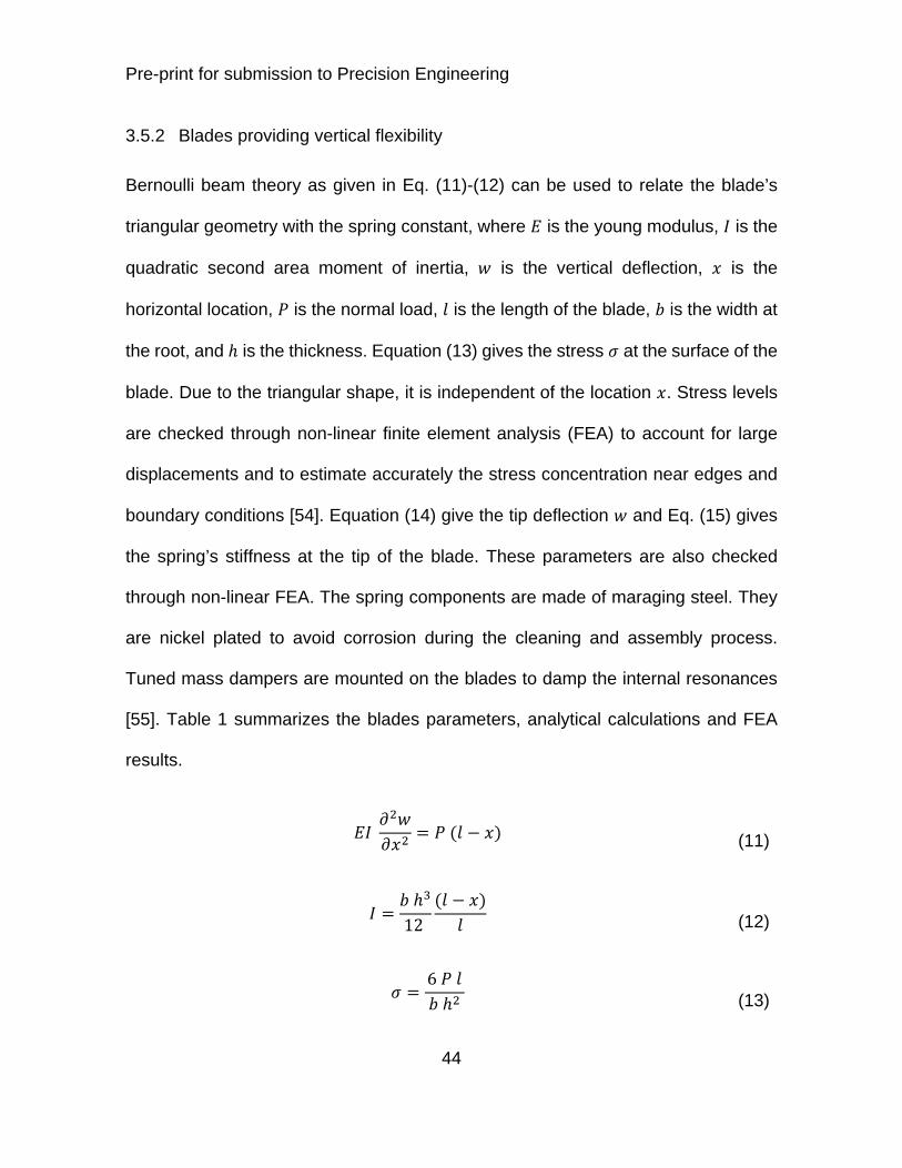
3.5.2 Blades providing vertical flexibility
Bernoulli beam theory as given in Eq. (11)-(12) can be used to relate the blade’s
triangular geometry with the spring constant, where is the young modulus, is the
quadratic second area moment of inertia, is the vertical deflection, is the
horizontal location, is the normal load, is the length of the blade, is the width at
the root, and is the thickness. Equation (13) gives the stress at the surface of the
blade. Due to the triangular shape, it is independent of the location . Stress levels
are checked through non-linear finite element analysis (FEA) to account for large
displacements and to estimate accurately the stress concentration near edges and
boundary conditions [54]. Equation (14) give the tip deflection and Eq. (15) gives
the spring’s stiffness at the tip of the blade. These parameters are also checked
through non-linear FEA. The spring components are made of maraging steel. They
are nickel plated to avoid corrosion during the cleaning and assembly process.
Tuned mass dampers are mounted on the blades to damp the internal resonances
[55]. Table 1 summarizes the blades parameters, analytical calculations and FEA
results.
(11)
12 (12)
6 (13)

Pre-print for submission to Precision Engineering
45
6 (14)
6 (15)
The clamps are designed to not provide unwanted flexibility (clamp flexibility noted
in Fig. 18). Particular attention has been given to minimize the gap between the
clamps and the root of the blade that could potentially result in friction and hysteresis
effects. Such a residual gap is illustrated in Fig. 19 and shown in Fig. 20 for Stage
1-2 blades. Silver plated screws and Nitronic 60 barrel nuts are used to reduce the
friction in the bolted assemblies and increase the preload in the joints. Jigs were
constructed to measure the friction in the clean assemblies and correlate the results
with FEA analysis.
The geometry of the spacers at the root of the blade must be controlled with accuracy
to not affect the system’s equilibrium position. The launch angle (machined to ¼
mrad angular tolerance) and the height (machined to 25 tolerance) of the
clamps have been used as degrees of freedom during the testing phase to bring the
system to its nominal mass and equilibrium position. They are shown in Fig. 18 for
stage 0-1 blades. Once the first production units clamp parameters had been
adequately tuned, all subsequent units were machined with the same set of
parameters.

Pre-print for submission to Precision Engineering
46
Fig. 20. Clamp gap inspection: a gap between the blade and its mount can arise if the load
force over comes the pre-load force in the bolted assembly. Friction in the ultra-clean bolted
assembly and pre-load are carefully controlled.

Pre-print for submission to Precision Engineering
47
Table 1: Blades Properties
Symbol Name Stage 0-1 Stage 1-2
Thickness 13.87 x 10⁻³ m 12.14 x 10⁻³ m
Base width 0.216 m 0.162 m
Length 0.429 m 0.322 m
Load per blade 12000 N 9125 N
Stiffness, Analytical 2.28 x 10⁵ N/m 2.72 x 10⁵ N/m
Stiffness, FEA 2.17 x 10⁵ N/m 2.57 x 10⁵ N/m
Deflection, Analytical 52.6 x 10⁻³ m 33.6 x 10⁻³ m
Deflection FEA 55.4 x 10⁻³ m 35.3 x 10⁻³ m
Stress, Analytical 750 MPa 740 MPa
Stress, FEA 1050 MPa 1200 MPa

Pre-print for submission to Precision Engineering
48
3.5.3 Flexure rods
The flexure rods are attached to the blade’s tip as shown in the schematic
representation in Fig. 21 (a) for the Stage 0-1 assembly, where is the actuator
horizontal force, is the normal load, and is the tip deflection. Beam equations
are used to calculate the distance so that the horizontal force produce no
rotation [56]. It can be summarized as follows. Fig. 21 (b) shows the flexure motion
parameters and external forces. The flexure’s deflection is . The axial load is .
The force, translation motion, torque and rotation at the top tip are , , and
respectively. The force, translation motion, torque and rotation at the bottom tip are
, , and respectively. Equation (16) gives the beams’ cross section
equilibrium, where is the young modulus, is the quadratic moment of inertia, and
is the vertical location. The general solution is given in Eq. (17) where the constant
values , , and are function of boundary conditions, and is given in Eq.
(18). The solution can be written as a function of the external forces and motions at
the tips as shown in the system in Eq. (19), where is the translational stiffness,
is the rotational stiffness, and are cross coupling terms. This system can
be solved to find the location of the forces and that produces pure translational
motion ( 0). This specific location, sometimes called “zero-moment-point”
location is noted and given in Eq. (20). The horizontal actuator mid-plane is
positioned at a distance from the bottom tip where the actuator force produces
a pure translation. The blade is positioned at a distance from the top tip where the
reaction force from the blade will not rotate the rod. Similar positioning is done for

Pre-print for submission to Precision Engineering
49
the Stage 1-2 blades. The flexures geometrical parameters are chosen to provide
both suitable stiffness and peak stress value. The maximum axial stress can be
estimated as shown in (21), where the maximum deflection is constrained by
motion limiters. The Stage 0-1 motion limiters allow +/- 0.5 mm of motion. The Stage
1-2 motion limiters allow +/- 0.25 mm of motion. The flexure rods properties are
summarized in Table 2.
(16)
cosh sinh (17)
(18)
(19)
1tanh
2 (20)
42 2
(21)

Pre-print for submission to Precision Engineering
50
Fig. 21. (a) Conceptual representation of the flexure rod attached to the blade. (b) Force and
position parameters.

Pre-print for submission to Precision Engineering
51
Table 2: Flexure rods properties
Symbol Name Stage 0-1 Stage 1-2
Diameter 5.92 x 10⁻³ m 6.35 x 10⁻³ m
Length 0.189 m 0.117 m
Load per Flexure 12000 N 9125 N
Stiffness, Analytical 9.41 x 10⁴ N/m 2.32 x 10⁵ N/m
Zero Moment Point 30.6x 10⁻³ m 32.9x 10⁻³ m
Maximum Deflection 0.6x 10⁻³ m 0.3x 10⁻³ m
Stress, Analytical 522 MPa 471 MPa

Pre-print for submission to Precision Engineering
52
3.6 Electronics and Computing
The electronics of high performance active vibration isolation systems must be very
carefully designed to allow such systems to perform at design sensitivity. For
instance, the pre-amps of passive geophones will likely limit the self-noise of the
instrument-preamp pair [57]-[58]. The amplification and filtering stages must be
sufficiently low noise to not compromise the measurement. The dynamic range must
be carefully considered. For that, adequate gain and filtering must be chosen to
maintain the signal above the quantization noise without saturating the analog to
digital converter (ADC). A detailed knowledge of the input motion and environmental
conditions is therefore necessary for the design of the amplification stages.
Switchable gains and whitening stages are often necessary to adjust the settings as
a function of a change of control state or fluctuation of input conditions.
Fig. 22 shows a simplified signal flow diagram for the BSC-ISI system. It indicates
the sensitivity of the instruments mounted on the platform. The L4C and GS13
geophones are equipped with custom-made pre-amplifying boards. Detailed
information regarding the selection of the op-amp can be found in [53]. The boards
are mounted directly on the sensor connector, inside the sealed pod. These
electronic boards also host the pressure sensors used to detect a possible leak.
Low-noise interface chassis are used to filter, collect and send the signals to the
ADC. The parameters of amplification and filtering are specific to each type of sensor
(though they are called “Ampli” in Fig. 22 ). The analog gains and whitening filters
can be switched by the control system in order to adjust the dynamic range to match

Pre-print for submission to Precision Engineering
53
operating conditions. The signals are digitized at 64 kHz using 16 bit +/- 20V ADC
cards. A third order Chebyshev with a notch near the sampling frequency is used for
the anti-aliasing filter. The signals are decimated to the digital controller sampling
frequency at 4 kHz. The digital control is based on the LIGO CDS real time code
[59]. An Epics database [60] is used for communication between the front-end real-
time controller and the control room machines. The operator interface is built in
MEDM code [61]. The controller output is up-sampled to the DAC cards frequency
at 64 kHz. Low-noise voltage amplifiers (coil drivers) are used to drive the magnetic
actuators. Actuator voltages and current read-back signals are monitored through
the digital system. Detailed information regarding these electronics can be found in
[62].

Pre-print for submission to Precision Engineering
54
Fig. 22 Simplified signal flow diagram.

Pre-print for submission to Precision Engineering
55
4 Design for series production
4.1 Production scale and Assembly considerations
Unlike similar prototypes previously built, the BSC-ISI system has been engineered
to allow timely production of a series of 15 units. As a result, a BSC-ISI unit can be
fully assembled and tested in less than 4 weeks. It can be commissioned to operate
near design sensitivity in about a week. Thirteen of the fifteen units necessary for
the Advanced LIGO project have been built and tested (as of July 2014).
In order to reach the level of isolation described in the introduction, the system must
operate in vacuum. All of the system’s components (structure, instruments & cables)
are ultra-high-vacuum compatible. They are subjected to a strict cleaning process
that includes chemical cleaning, ultra-sound baths and low temperature heating in
vacuum bake ovens. LIGO clean and bake procedures are detailed in [63]. The
components are subjected to a thorough quality control process, including RGA
scans and FTIR tests. The systems are assembled in Class 100 standard clean
room. A BSC-ISI unit during the assembly process is shown in Fig. 23. The assembly
process of the main structure and all the sub-assemblies is fully detailed in [64].

Pre-print for submission to Precision Engineering
56
Fig. 23 BSC-ISI Assembly in LIGO clean rooms.

Pre-print for submission to Precision Engineering
57
4.2 Testing process overview
To reach the level of isolation targeted with this system, all the mechanical
instruments and electronics components must operate at design sensitivity. The
testing process is therefore a critical step of the system’s integration phase. Before
assembly, each component and sub-component such as actuators, sensors, pod
assemblies, and electronic chassis is tested individually. After assembly, each BSC-
ISI unit is submitted to a thorough testing process. The unit’s testing procedure is
detailed in [65]. It is made of three phases that can be summarized as follows.
The first phase of testing is dedicated to validate the BSC-ISI assembly. After
assembly, the unit is loaded with dummy masses mounted on the top plate of stage
2 as shown in Fig. 5. The motion limiters are dis-engaged to release the two
suspended stages. Due to machining and assembly tolerances, a little lateral motion
is observed when the stages are released for the first time (typically a quarter of
mm). The motion limiters are laterally re-aligned with this natural static equilibrium
position. After that, the stages are leveled using trim masses attached to the
sidewalls. The mass budget is carefully checked. The series of tests performed on
each unit include geometry and leveling measurements, sensor noise tests, actuator
response tests, range of motion measurements, system static response
measurements, cross coupling measurements, linearity tests, transfer functions
measurements, and damping loops tests.
After assembly testing, the dummy payload is removed. The BSC-ISI unit is
transported from the assembly area to the detector area in a sealed container. The

Pre-print for submission to Precision Engineering
58
BSC-ISI is positioned on a stand designed for integration with the optical equipment.
The equipment is installed on the optical table of the BSC-ISI. Fig. 24 shows a BSC-
ISI supporting two multiple-pendulum suspensions. Great care must be given to the
routing of the payload cables so as to not shortcut the BSC-ISI passive isolation. Fig.
25 shows how cables are routed from Stage 2 to Stage 1, and from stage 1 to Stage
0, to avoid direct coupling from Stage 0 to Stage 2 through the cabling. The cable
parameters and symbolically represent the cable complex stiffness. Once the
payload installation and cable routing are completed, the BSC-ISI is subjected to a
second phase of testing called integration testing, during which the couplings
between the platform and its payload are carefully checked.
After completion of the Integration testing, the entire cartridge (isolator and
payload) is lifted and installed in the vacuum chamber. The third and last phase of
testing is dedicated to the commissioning of the isolator in the vacuum environment.
The digital controllers are installed and tuned to optimize the isolation performance
of each unit.

Pre-print for submission to Precision Engineering
59
Fig. 24 A BSC-ISI on integration stand.

Pre-print for submission to Precision Engineering
60
Fig. 25 Cable routing.

Pre-print for submission to Precision Engineering
61
4.3 Production units frequency response
In Fig. 26, the experimental transfer functions are compared with the response of an
ideal two-mass spring system. Fig. 26 (a) shows the transfer function in the
longitudinal ( ) direction for stage 1. The actuators are combined to drive in the
direction, and the L4Cs are used to sense the motion in the same direction. Below 1
Hz, the transfer function is very “flat”. It indicates that there is very little tilt-horizontal
coupling in static regime, and that the actuators are well aligned with respect to the
system’s static center of rotation. Between 1 Hz and 10 Hz, the main resonances
are in agreement with the model. A little bit of coupling between and is visible.
It indicates that the center of mass is not perfectly aligned with the center of
percussion, but it is sufficiently small so as to not affect the system’s controllability
and performance. The modal damping is induced by the magnetic actuators
dissipating energy in the input resistance of the amplification stages. Between 10 Hz
and 100 Hz, the system provides passive isolation as predicted. Above 150 Hz, the
peaks of the structural resonances are damped to low level by passive dampers [48].
The Stage 2 horizontal transfer function show a similar set of characteristics, as
shown in Fig. 26 (b). A notable difference is below 0.1 Hz, where the transfer
function’s corner frequency indicates higher tilt horizontal coupling ratio. This is
caused by the rotational reaction of Stage 1. This coupling is greatly reduced when
the rotational control of Stage 1 is engaged. Fig. 26 (c) and (d) show the transfer
functions for the vertical directions. The good agreement with the model shows that
there is very little cross-coupling between the degrees of freedom. The transfer

Pre-print for submission to Precision Engineering
62
functions measured in all other degrees of freedom are also in excellent agreement
with the ideal two-degrees of freedom model response. The transfer function results
are repeatable from one unit to another. Table 3 gives a summary of the system’s
rigid-body mode frequencies.

Pre-print for submission to Precision Engineering
63
Table 3: BSC-ISI Rigid-body modes frequencies.
Direction In Phase
Mode
Out of Phase
Mode
X (or Y) 1.25 Hz 5.25 Hz
Z 1.80 Hz 6.70 Hz
RX (or RY) 1.55 Hz 6.80 Hz
RZ 1.40 Hz 5.70 Hz

Pre-print for submission to Precision Engineering
64
Fig. 26 Comparison of theoretical transfer functions (Model) and experimental transfer
functions as measured by the inertial sensors (Expe).
10-1
100
101
102
103
10-11
10-10
10-9
10-8
10-7
10-6
10-5
10-4
Stage 1 X Transfer Function
Frequency
Am
plit
ud
e [
m/N
]
Expe
Model
10-1
100
101
102
103
10-11
10-10
10-9
10-8
10-7
10-6
10-5
10-4
Stage 1 Z Transfer Function
Frequency
Am
plit
ud
e [
m/N
]
Expe
Model
10-1
100
101
102
103
10-11
10-10
10-9
10-8
10-7
10-6
10-5
10-4
Stage 2 X Transfer Function
Frequency
Am
plit
ud
e [
m/N
]
Expe
Model
10-1
100
101
102
103
10-11
10-10
10-9
10-8
10-7
10-6
10-5
10-4
Stage 2 Z Transfer Function
Frequency
Am
plit
ud
e [
m/N
]
Expe
Model
(a)
(b)
(c)
(d)

Pre-print for submission to Precision Engineering
65
5 Conclusion
An extensive engineering effort has been led during the past several years to
develop the final version of the two-stage vibration isolation system for the Advanced
LIGO observatories. The goal was to engineer a system not only to meet very high
performance criteria, but also suitable for timely production, assembly, testing and
commissioning for a series of 15 units.
A detailed presentation of the system’s design has been made. It highlighted
features of interest for the field of vibration isolation in precision engineering. It
described the system architecture, the design of the flexure components, the
actuators, the low-noise instrumentation, electronics, and challenges related to
vacuum compatibility and the control strategy. It detailed how the system has been
engineered for the production of a series of units.
During the past two years, 13 BSC-ISI units have been assembled and tested.
The last two units are under construction and will be completed by the end of 2014.
All the units tested show extremely reproducible results and characteristics. Five
units are currently in use at each of the LIGO observatories and performing at very
high level of isolation required for Advanced LIGO. A companion paper (Part 2:
Experimental Investigation and Tests Results) covers in detail the results of the
prototyping and testing phase of this project.

Pre-print for submission to Precision Engineering
66
Acknowledgments
The authors acknowledge and gratefully thank the National Society Foundation for
their support. LIGO was constructed by the California Institute of Technology and
Massachusetts Institute of Technology with funding from the National Science
Foundation and operates under cooperative agreement PHY-0107417.
We thank the JILA group for pioneering the work on active isolation systems
using low frequency inertial sensors, and for demonstrating the feasibility of such
multi-stage systems. We thank our colleagues from the suspension groups in GEO
and LIGO for introducing us to the benefits of using triangular maraging steel blades
to provide vertical isolation. We thank High Precision Devices for the mechanical
design’s realization of the rapid prototype and the technical demonstrator. We thank
Alliance Space Systems Incorporation for the mechanical design’s realization of the
two-stage prototype. We thank Nanometrics, Streckeisen, Geotech, Sercel and
Microsense for supplying us with great instruments, and for their technical support.
Finally yet importantly, this work would not have been possible without the
outstanding support of the LIGO laboratory management, computer and data
systems, procurement, facility modification and preparation, assembly and
installation teams.
This document has been assigned LIGO Laboratory document number LIGO-
P1200010.

Pre-print for submission to Precision Engineering
67
References
[1] Okano M, Kajimura K, Wakiyama S, Sakai F, Mizutani W, & Ono M. Vibration
isolation for scanning tunneling microscopy. Journal of Vacuum Science &
Technology A: Vacuum, Surfaces, and Films. 1987; 5.6; 3313-3320.
[2] Kuk Y, and Silverman PJ. Scanning tunneling microscope instrumentation.
Review of scientific instruments. 1989; 60.2; 165-180.
[3] Rinker R. Super Spring - A New Type of Low-Frequency, Vibration Isolator.
Ph.D. thesis. University of Colorado, Boulder. 1983.
[4] Nelson PG. An active vibration isolation system for inertial reference and
precision measurement. Review of scientific instruments. 1991; 62.9; 2069-2075.
[5] Hensley JM, Peters A, & Chu S. Active low frequency vertical vibration isolation.
Review of scientific instruments. 1999; 70.6; 2735-2741.
[6] Suzuki H, and Ho CM. A magnetic force driven chaotic micro-mixer. Micro
Electro Mechanical Systems, 2002. The Fifteenth IEEE International Conference on.
IEEE. 2002.
[7] Artoos K, Collette C, Brunetti L, Coe P, Geffroy N, Guinchard M, et al. Study of
the stabilization to the nanometer level of Mechanical Vibrations of the CLIC Main
Beam Quadrupoles. No. CERN-ATS-2009-127. 2009.
[8] Preumont A, Horodinca M, Romanescu I, De Marneffe B, Avraam M,
Deraemaeker A, et al. A six-axis single-stage active vibration isolator based on
Stewart platform. Journal of sound and vibration. 2007; 300.3; 644-661.

Pre-print for submission to Precision Engineering
68
[9] Saulson PR. Vibration isolation for broadband gravitational wave antennas.
Review of scientific instruments. 1984; 55.8; 1315-1320.
[10] Abramovici A, Althouse WE, Drever RW, Gürsel Y, Kawamura S, Raab FJ, et
al. LIGO: The laser interferometer gravitational-wave observatory. Science. 1992;
256.5055; 325-333.
[11] Robertson NA, Drever RWP, Kerr I, & Hough J. Passive and active seismic
isolation for gravitational radiation detectors and other instruments. Journal of
Physics E: Scientific Instruments. 1982; 15.10; 1101.
[12] Abbott BP, Abbott R, Adhikari R, Ajith P, Allen B, Allen G, et al. LIGO: the laser
interferometer gravitational-wave observatory. Reports on Progress in Physics.
2009; 72.7; 076901.
[13] Willke B, Aufmuth P, Aulbert C, Babak S, Balasubramanian R, Barr BW, et al.
The GEO 600 gravitational wave detector. Classical and Quantum Gravity. 2002;
19.7; 1377.
[14] Bradaschia C, Del Fabbro R, Di Virgilio A, Giazotto A, Kautzky H, Montelatici
V, et al. The VIRGO project: a wide band antenna for gravitational wave detection.
Nuclear Instruments and Methods in Physics Research Section A: Accelerators,
Spectrometers, Detectors and Associated Equipment. 1990; 289.3; 518-525.
[15] Ando M, & TAMA collaboration. Current status of the TAMA300 gravitational-
wave detector. Classical and Quantum Gravity. 2005; 22.18; S881.

Pre-print for submission to Precision Engineering
69
[16] Kuroda K. Status of LCGT. Classical and Quantum Gravity. 2010; 27.8;
084004.
[17] Plissi MV, Torrie CI, Husman ME, Robertson NA, Strain KA, Ward H, et al. GEO
600 triple pendulum suspension system: Seismic isolation and control. Review of
scientific instruments. 2000; 71.6; 2539-2545.
[18] Grote H, and LIGO Scientific Collaboration. The status of GEO 600. Classical
and Quantum Gravity. 2008; 25.11; 114043.
[19] Aston SM, Barton MA, Bell AS, Beveridge N, Bland B, Brummitt AJ, et al.
Update on quadruple suspension design for Advanced LIGO. Classical and
Quantum Gravity. 2012; 29.23; 235004.
[20] Losurdo G, Calamai G, Cuoco E, Fabbroni L, Guidi G, Mazzoni M, et al. Inertial
control of the mirror suspensions of the VIRGO interferometer for gravitational wave
detection. Review of Scientific Instruments. 2001; 72.9; 3653-3661.
[21] Accadia T, Acernese F, Antonucci F, Astone P, Ballardin G, Barone F, et al.
Status of the Virgo project. Classical and Quantum Gravity 2011; 28.11; 114002.
[22] Acernese F, Antonucci F, Aoudia S, Arun KG, Astone P, Ballardin G, et al.
Measurements of Superattenuator seismic isolation by Virgo interferometer.
Astroparticle Physics. 2010; 33.3; 182-189.
[23] Somiya K. Detector configuration of KAGRA–the Japanese cryogenic
gravitational-wave detector. Classical and Quantum Gravity. 2012; 29.12; 124007.

Pre-print for submission to Precision Engineering
70
[24] Harry GM. Advanced LIGO: the next generation of gravitational wave detectors.
Classical and Quantum Gravity. 2010; 27.8; 084006.
[25] Abbott R, Adhikari R, Allen G, Cowley S, Daw E, DeBra D et al. Seismic
isolation for Advanced LIGO. Classical and Quantum Gravity. 2002; 19.7; 1591.
[26] Abbott R, Adhikari R, Allen G, Baglino D, Campbell C, Coyne D, et al. Seismic
Isolation Enhancements for Initial and Advanced LIGO. Class. Quantum Grav. 2004;
21; 915-921.
[27] Robertson NA, Abbott B, Abbott R, Adhikari R, Allen GS, Armandula H, et al.
Seismic Isolation and Suspension Systems for Advanced LIGO. Gravitational Wave
and Particle Astrophysics Detectors. Proceedings of SPIE. 2004.
[28] Hardham CT, Allen GS, DeBra DB, Hua W, Lantz BT, Nichol JG. Quiet
Hydraulic Actuators for the Laser Interferometer Gravitational Wave Observatory
(LIGO). Proceedings of ASPE conference on Control of Precision Systems. 2001.
[29] Hardham CT, Abbott B, Abbott R, Allen G, Bork R, Campbell C, et al. Multi-
DOF Isolation and Alignment with Quiet Hydraulic Actuators Control of Precision
Systems. Proceedings of ASPE conference on Control of Precision Systems. 2004.
[30] Hua W, Adhikari R, DeBra DB, Giaime JA, Hammond GD, Hardham CT, et al.
Low frequency active vibration isolation for Advanced LIGO. Proc. of SPIE Vol. Vol.
5500. 2004.

Pre-print for submission to Precision Engineering
71
[31] Wen S, Mittleman R, Mason K, Giaime JA, Abbott R, Kern J, O'Reilly B, et al.
Hydraulic External Pre-Isolator System for LIGO. arXiv preprint arXiv:1309.5685
(2013).
[32] Matichard F, et al. LIGO Vibration Isolation and Alignment Platforms: an
Overview of Systems, Features and Performance of Interest for the Field of Precision
Positioning and Manufacturing. In Proceedings of ASPE conference on Precision
Control for Advanced Manufacturing Systems. 2013.
[33] Danaher C, Hollander B, et al. Advanced LIGO Single Stage HAM Vibration
Isolation Table. LIGO document LIGO-G070156 (2007).
[34] Kissel JS. Calibrating and Improving the Sensitivity of the LIGO Detectors. Diss.
Louisiana State University. 2010.
[35] Matichard F, Abbott B, Abbott S, Allewine E, Barnum S, Biscans S. et al.
Prototyping, Testing, and Performance of the Two-Stage Seismic Isolation System
for Advanced LIGO Gravitational Wave Detectors. In Proceedings of ASPE
conference on Control of Precision Systems. 2010.
[36] Fritschel P. Seismic isolation subsystem design requirement. LIGO document
E990303. 2001.
[37] Stebbins RT, Newell D, Richman SN, Bender PL, Faller JE, et al. Low-
frequency active vibration isolation system. Proc. SPIE. Vol. 2264. 1994.

Pre-print for submission to Precision Engineering
72
[38] Richman SJ, Giaime JA, Newell DB, Stebbins RT, Bender PL, et al. Multistage
active vibration isolation system. Review of Scientific Instruments. 1998; 69.6; 2531-
2538.
[39] Newell DB, Richman SJ, Nelson PG, Stebbins RT, Bender PL, Faller JE, &
Mason J. An ultra-low-noise, low-frequency, six degrees of freedom active vibration
isolator. Review of scientific instruments. 1997; 68.8; 3211-3219.
[40] Giaime JA, et al. Baseline LIGO-II implementation design description of the stiff
active seismic isolation system. LIGO document T000024. 2000.
[41] Giaime JA, et al. Advanced LIGO Seismic Isolation System Conceptual Design.
LIGO document E010016. 2001.
[42] Lantz B, Lessons from the ETF Technology Demonstrator, LIGO document
G050271. 2005.
[43] Coyne D, & al, Design Requirements for the In-Vacuum Mechanical Elements
of the Advanced LIGO Seismic Isolation System for the BSC Chamber. LIGO
Document E030179. 2004.
[44] Smith K, Advanced LIGO BSC Prototype Critical Design Review. ASI
Document 20008644. 2004.
[45] Smith K, Post-CDR Design Assessments of BSC Structure. ASI Technical
Memorandum 20009033. 2004.
[46] Matichard F, et al. Advanced LIGO Preliminary Design Review of the BSC ISI
system. LIGO Document L0900118. 2009.

Pre-print for submission to Precision Engineering
73
[47] Matichard F, Mason K, Mittleman R, Lantz B, Abbott B, MacInnis M, et al.
Dynamics Enhancements of Advanced LIGO Multi-Stage Active Vibration Isolators
and Related Control Performance Improvement. In ASME 2012 International Design
Engineering Technical Conferences and Computers and Information in Engineering
Conference (pp. 1269-1278). American Society of Mechanical Engineers. 2012.
[48] Matichard, F., et al. LIGO Two-Stage Vibration Isolation and Positioning
Platform, Part 2: Experimental Investigation and Tests Results. Submitted for
publication to Precision Engineering. 2014.
[49] Matichard F, et al. aLIGO BSC-ISI, Top and Sub-Assemblies Drawings. LIGO
document E1000397. 2010.
[50] Matichard F, et al. ISI actuator dynamic response identification. LIGO document
T0900226. 2009.
[51] Hilliard M, et al. aLIGO BSC-ISI, General Assembly Procedure. LIGO document
E0900357. 2009.
[52] Clark D. Replacement Flexures for the GS-13 Seismometer. LIGO document
T0900089. 2009.
[53] Lantz B. LT1012 is the best op-amp for the GS13 preamp. LIGO document
T0900457. 2009.
[54] Stein A, FEA of BSC ISI Springs. LIGO document T0900569. 2009.
[55] Clark D. Damping Structures - Poster for LVC Arcadia Meeting. LIGO document
G1000237. 2010.

Pre-print for submission to Precision Engineering
74
[56] Smith K, Analysis of LIGO Flexures Rods. ASI Technical Note 20007235. 2004.
[57] Rodgers, Peter W. Maximizing the signal-to-noise ratio of the electromagnetic
seismometer: The optimum coil resistance, amplifier characteristics, and circuit.
Bulletin of the Seismological Society of America 83.2 (1993): 561-582.
[58] Rodgers, P. W. (1994). Self-noise spectra for 34 common electromagnetic
seismometer/preamplifier pairs. Bulletin of the Seismological society of America,
84(1), 222-228.
[59] Bork R, et al. New control and data acquisition system in the Advanced LIGO
project. Proc. of Industrial Control And Large Experimental Physics Control System
(ICALEPSC) conference. 2011.
[60] Dalesio LR, et al. The experimental physics and industrial control system
architecture: past, present, and future. Nuclear Instruments and Methods in Physics
Research Section A: Accelerators, Spectrometers, Detectors and Associated
Equipment. 1994; 352.1; 179-184.
[61] Evans K. MEDM Reference Manual. Argonne National Laboratory. 2005.
[62] Abbott B. SEI Electronics Document Hub, LIGO document T1300173. 2013.
[63] Bland B, Coyne D, Fauver J. LIGO Clean and Bake Methods and Procedures.
LIGO document E960022-v25. 2013.
[64] Hillard M, Le Roux A, & al. aLIGO BSC-ISI, General Assembly Procedure. LIGO
Document E0900357-v28. 2012.

Pre-print for submission to Precision Engineering
75
[65] Matichard F, Lantz B, et al. aLIGO BSC-ISI Testing and Commissioning
Documentation. LIGO Document E1000306. 2013.

Pre-print for submission to Precision Engineering
76
List of Figures
Fig. 1 Conceptual representation of the BSC-ISI passive components. Sensors
and actuators not represented. Springs assembly are symbolically represented by
helicoids.
Fig. 2 Conceptual representation of the passive model along a single axis, for (a)
the longitudinal direction, (b) the vertical direction, and (c) the pitch direction.
Fig. 3 Feedback control principle for one degree of freedom.
Fig. 4. CAD representation of the BSC-ISI system.
Fig. 5. A BSC-ISI unit in testing at the LIGO Hanford observatory.
Fig. 6. A CAD Representation of the Stage 0 structure, Stage 0-1 spring
components, actuator posts and motion limiters.
Fig. 7 A CAD Representation of Stage 1 (Front door not shown).
Fig. 8. A CAD representation of the Stage 0-1 actuators and capacitive position
sensors assembly.
Fig. 9. Stage 0-1 actuator assembly.
Fig. 10. Custom made sealed chamber to use the Trillium T240 in ultra-high-vacuum.
Fig. 11. Custom made sealed chamber to use the Sercel L4C in ultra-high-vacuum.
Fig. 12. Front view of one of the three branches of Stage 1.
Fig. 13. A CAD Representation of the Stage 2 Assembly.

Pre-print for submission to Precision Engineering
77
Fig. 14. Stage 1-2 actuator assembly.
Fig. 15. Stage 1-2 vertical actuator CAD representation.
Fig. 16. GS13 equipped with mu-metal shielding and sealed in a custom pod for use
in ultra-high-vacuum.
Fig. 17. Conceptual representation of the spring assembly.
Fig. 18. Stage 0-1 spring assembly.
Fig. 19. Stage 1-2 spring assembly.
Fig. 20. Clamp gap inspection: a gap between the blade and its mount can arise
if the load force over comes the pre-load force in the bolted assembly. Friction in the
ultra-clean bolted assembly and pre-load are carefully controlled.
Fig. 21. (a) Conceptual representation of the flexure rod attached to the blade. (b)
Force and position parameters.
Fig. 22 Simplified signal flow diagram.
Fig. 23 BSC-ISI Assembly in LIGO clean rooms.
Fig. 24 A BSC-ISI on integration stand.
Fig. 25 Cable routing.
Fig. 26 Comparison of theoretical transfer functions (Model) and experimental
transfer functions as measured by the inertial sensors (Expe).

Pre-print for submission to Precision Engineering
78
List of Tables
Table 1: Blades Properties
Table 2: Flexure rods properties
Table 3: BSC-ISI Rigid-body modes frequencies.