
Improvement of Hydraulic Power Unit Design for Hose ...
38
Improvement of Hydraulic Power Unit Design for Hose Loading Station Tero Köyhäjoki Bachelor’s Thesis Technology, Communication and Transport Industrial Management Bachelor in Engineering 2016
-
Upload
khangminh22 -
Category
Documents
-
view
1 -
download
0
Transcript of Improvement of Hydraulic Power Unit Design for Hose ...

Improvement of Hydraulic Power Unit Design for Hose Loading Station
Tero Köyhäjoki
Bachelor’s Thesis Technology, Communication and Transport
Industrial Management Bachelor in Engineering
2016

Tekniikan ja liikenteen ala Tuotantotalouden koulutusohjelma
Opinnäytetyön tiivistelmä
Insinööri (AMK)
Tekijä Tero Köyhäjoki Vuosi 2016 Ohjaaja Juha Kaarela Toimeksiantaja National Oilwell Varco AS Työn nimi Improvement of Hydraulic Power Unit Design for Hose
Loading Station Sivu- ja liitemäärä 35 + 3
Tämän opinnäytetyön tavoitteena oli luoda uusi suunnittelumalli hose loading station -yksikölle kustannussäästöjen saavuttamiseksi työtuntien määrässä ja osien hinnassa National Oilwell Varco yhtiölle. Tämä kustannusten alentamisen vaatimus on syntynyt asiakkaiden tarpeesta, sillä aikaisemmin öljyala on kukois-tanut, koska öljyn hinta on ollut korkea ja asiakas on vaatinutkin korkeatasoisia laitteita öljyntuotantoon ja jalostukseen. Nyt kun öljyn hinta on pudonnut huo-mattavasti ja markkinat ovat epävakaat, niin asiakkaat haluavat saavuttaa kus-tannussäästöjä vaatimalla halvempia tuotteita öljyn tuotantoa ja jalostamista varten. Tämä kaikki on aiheuttanut sen, että kyseisen yksikön hintaa oli saatava alhai-semmaksi, laadun tai luotettavuuden heikentymättä. Mahdolliset kehitysideat annettiin alussa ja näiden avulla suoritettiin varsinainen työ. Tutkiminen aloitet-tiin alkuperäisestä mallista ja miten sitä voisi muuttaa, jotta siitä saataisiin hal-vempi tuottaa. Seuraavassa vaiheessa luonnosteltiin kolme mahdollista vaihtoehtoa ongelmaa varten joista vain yhtä käytettiin lopullisessa mallissa. Kyseistä mallia varten laskettiin ja mitoitettiin käytettävät hydrauliikan komponentit ja mitkä näistä osis-ta jätettiin pois, koska joitakin alkuperäisessä mallissa olevia osia ei tarvittu ja ne lisäsivätkin vain yksikön hintaa tarpeettomasti. Käytetty tutkimusmateriaali oli suurimmilta osin yrityksen omaa materiaalia, mutta myös joitakin nettisivuja, joista hain käytettävät komponentit ja laskukaa-vat. Kaikki tavoitteet työlle saavutettiin ja saatua suunnitelmaa voidaan käyttää pie-nillä muutoksilla lopullista tuotantoa varten. Avainsanat Hydrauliikka, voimayksikkö, putkisto

Technology, Communication and Transport Industrial Engineering and Man-agement Bachelor of Engineering (B.Eng.)
Abstract of Thesis
Author Tero Köyhäjoki Year 2016 Supervisor Juha Kaarela Commissioned by National Oilwell Varco AS Title of Thesis Improvement of Hydraulic Power Unit design for Hose
Loading Station No. of pages + app. 35 + 3
The objective of this thesis for National Oilwell Varco was to create new design for the hose loading station to achieve savings in labour and part costs. This demand for cost efficiency comes from customers as previously oil business has been blooming for many years and this bloom has given the huge demand for good quality equipment in oil drilling and processing. Now however oil price has dropped vastly and the oil market situation is very unpredictable so cus-tomers now want to achieve cost savings by demanding cheaper equipment for the use in oil drilling and processing. This all had caused that new solutions had to be found for making production of hose loading station cheaper without compromising the quality and reliability. The task with possible area of improvement were given. Work was started from original design, which was first investigated and from which it was pointed out what could be changed to make new design more effective. This gave three different possible solutions for the problem and one was chosen to be used in the final solution. For this design the hydraulic components like pipe and tank dimensions had to be calculated and also to find what kinds hy-draulic components should be used and left out from the design as some of the components in HLS original design were obsolete and just increased the price of the mentioned unit unnecessarily. All the research material used was mostly of the NOV own data but also web-sites were used to find out components and formulas for the hydraulic systems. All the requirements for the thesis were achieved and this design can be used for the new design with some minor changes or improvements. Key words Hydraulics, power unit, piping, hose loading station

CONTENTS
1 INTRODUCTION ............................................................................................ 7
2 PRESENTATION OF THE COMPANY AND CASE ....................................... 8
3 FRAME OF REFERENCE .............................................................................. 9
3.1 Methods and execution of work ........................................................... 10
3.2 Current situation and design of hose loading station ........................... 11
3.3 Areas and focusing points of improvements ........................................ 13
4 DEVELOPMENT ACTIVITY AND PROGRESS ............................................ 15
4.1.1 First design .................................................................................... 16
4.1.2 Second design .............................................................................. 16
4.1.3 Third design .................................................................................. 17
4.2 Calculations and completing final design ............................................. 18
5 POSSIBLE FURTHER DEVELOPMENTS ................................................... 32
6 CONCLUSIONS ........................................................................................... 33
REFERENCES ................................................................................................. 34
APPENDICES ................................................................................................... 35

5
FOREWORD
I would like to thank the National Oilwell Varco for this interesting opportunity to
do my thesis and especially the people involved in this project: Andreas Ei-
lertsen, Ole Rekdal and other personnel in NOV Molde. I would also like to give
thanks to my wife and child for understanding and supporting me for the whole
time.

6
SYMBOLS AND ABBREVIATIONS
HPU Hydraulic Power Unit
HLS Hose Loading Station
SCM Supply Chain Management
Rev Revolution
Rpm Revolution per minute
NOV National Oilwell Varco
7
1 INTRODUCTION
This thesis was made for National Oilwell Varco, which is a worldwide leader
providing equipment to oil and gas sectors. The office where I have completed
my assignment is located in Molde, Norway and they specialize in offshore
cranes, hose loading stations and winches. The research subject for this work
was to improve the design of the Hydraulic Power Unit (HPU) for the Hose
Loading Station (HLS). HPU produces hydraulic pressure to be used in the HLS
for hydraulic motors driving the hose reels.
The purpose of work was to improve the design of the HPU unit so that it would
have a more simple design, smaller size and it would be cheaper to be pro-
duced. The work included investigation for possibility to use a ring-line system
that would consist of only 2 hydraulic pipes from the HPU delivered to all the
motors instead of having 2 pipes from the HPU for each motor in the current
design.
The new design for the HPU was made with AutoCAD and the assembly and
installation time with building cost had to be calculated for the current and new
system so that both systems could be compared.

8
2 PRESENTATION OF THE COMPANY AND CASE
National Oilwell Varco is a worldwide leader providing equipment to oil and gas
sectors. The company headquarters is based in Houston Texas, but it operates
around 1200 locations across six continents with nearly 64000 employees
(Master Rig int’l, National Oilwell Varco 2015). The company designs and pro-
duces heavy hardware for oil well drilling including mud pumps, rotary tables for
rigs, draw-works (hoisting machinery), derricks, top drives, blowout preventers,
riser equipments and even complete drilling rigs. The location where this thesis
was carried out was located in Molde, Norway and its specialty is offshore
cranes, winch systems and hose reel stations. (National Oilwell Varco, About
NOV 2015)
For a long-time, oil prices have been high which has kept the oil industry busy
and products have to be manufactured with only the highest quality in mind
without considering too much the price. Now that oil prices have come hugely
down it has caused uncertainty and hesitation in market. The effect of this is
that the customers try to keep operating expenses as low as possible and to
find the cheapest possible solutions with quality in the second place. That is
why the NOV did give the possibility to do the thesis as to investigate solutions
to lower the material costs and manufacturing costs for the HLS. The main
points to concentrate were the piping, valves and the HPU. In piping the pur-
pose was to find a way to use less piping and also to route piping according to
my own design. In valves and the HPU it was solved how to get rid of valves
inside HPU and where the new valves could be installed. The components to be
used for the HPU had to be found with the solutions how to make it smaller and
more compact.

9
3 FRAME OF REFERENCE
The purpose of this thesis was to review the current HPU design, come up with
new fresher, simpler and cheaper solutions for the design and then choose one
of the solutions for the final design. This design had to be made considering
assembly and material cost reduction. After the research and, design the origi-
nal and new designs were compared to each other to see how big cost savings
were achieved. The things to keep in mind with the new design reliability had to
be at same level as the original design. Some of the functions which are con-
sidered as luxury or unnecessary could be taken out or changed to another
type.
Comparing prices was done by calculating all the needed components for the
whole assembly and estimating the assembly time. The purpose of the whole
work was to offer the company a possible solution in achieving cost savings and
it will not be the final design used for production as this will need further fine
tuning. A same type of research will be done also by a team inside the company
and they will compare the results with their own to see if they got the same solu-
tions and possibly combine some of the solutions to further improve the design.
In this thesis any prices or sensitive information cannot be published.

10
3.1 Methods and execution of work
The work was carried out mainly in the NOV office and at home. The company
laptop included all needed software. The software for the designing work was
AutoCAD mechanical and Autodesk inventor. Microsoft Office was used for
price calculation and material list. For parts and current design the company
has its own software called Rig Office, which has all schematics and
parts/numbers needed. Beside that search engines like Google and some
known part supplier’s websites like Parker were used to find special parts and
information as needed. Supply chain management was helping with the prices
and information for the parts and other engineers helped with the design, selec-
tion of parts and required standards. During work the standards required by
regulatory bodies, rules and regulations had to be followed.
The work did start with finding out the current system cost and how it is divided
into labour and parts. The next step was to come with different solutions and
simple designs and descriptions of these solutions. Those ideas were presented
to other engineers to choose one to be used for the final design. The chosen
solution was continued and schematics were finished for the second presenta-
tion. This second presentation then should either accept the design or give
some tips if some fine adjusting was needed.

11
3.2 Current situation and design of hose loading station
The loading of fluids and dry bulk materials between supply vessels and fixed or
floating production or drilling units have been necessary to maintain in continu-
ous operation. This is done by using of an HLS whose main function is to store
the loading hoses and to be a foundation for the loading hoses during loading
operations. The On/Off-loading operation is executed by un-reeling the loading
hose, lift it on-board to the supply vessel by using a crane, connect it to the ves-
sel bulk system and reel it back when the refilling is finished. When the loading
operation is completed, the fluid will be drained back to the supply vessel stor-
age tank and finally the hose is reeled back onto the reel. No manual handling
of the hoses is necessary as the crane is used for guiding the hose both on and
off the vessel. In Figure 1 the hose loading station can be seen in a typical envi-
ronment. (National Oilwell Varco, Hose loading systems 2015)
Figure 1. Hose loading station in its working environment (NOV picture ar-
chives)

12
The HLS is a standalone machine and has no interface or communication with
any other monitoring system in the vessel. 1 to 12 hose reels are placed on a
frame with working platforms and handrails. Each reel is driven by a hydraulic
motor with fail safe multi-disc brakes and they are powered by the hydraulic
power unit called HPU. Only one hose reel is to be operated at a time. The
hose reels are easily controlled by forward-backward motion of the portable
control lever or the fixed control lever located inside the control cabinet. The
reeling time is approx. 2-3 minutes, depending on the length of the loading
hose. In Error! Reference source not found. 8 reel station and hydraulic pow-
er unit in middle can be seen. (National Oilwell Varco, Hose loading systems
2015)
Figure 2. 8-reel station with hydraulic power unit (NOV picture archives)
The HPU, driven by an electric motor, is located inside the control cabinet. The
control cabinet also contains a local control panel with push buttons for start
and stop, a valve selection block for choosing which reel to drive, oil lev-
el/temperature switches and an emergency push-button. The HLS is also deliv-
ered with a remote control unit equipped with a pilot control valve and emergen-
cy stop button.

13
3.3 Areas and focusing points of improvements
For the long time the oil price has been high and climbing up. This has meant
that oil industry has needed a new, safe and quality equipment without consid-
ering the cost too much. This has caused that the cost factor has not been tak-
en into account so far in manufacturing. Now that oil price has fallen down and
stayed low for some time it has caused a lot of market turmoil and uncertainty.
This has then driven customers to look for where they can save. The customers
now evaluate the products that have a lower price instead of the highest quality
or standards. The purpose of this work is to answer the customers’ demands to
lower the price of this hose loading station. (Eilertsen 2015)
Some areas to concentrate on in the research were given and those included
investigation if the design of the control cabinet, HPU and hydraulic system can
be further improved. The control cabinet can be seen in the Figure 4. Original
HPU design was designed to house both the HPU, local control panel and the
valve selection block, regardless if the HLS contains 2 or 12 reels. The valve
selection blocks were delivered as a 4 valve or a 6 valve selection block. These
two types of valve blocks were combined according to the number of hose reels
to be delivered. This means that even for a 4 reel HLS, the cabinet was big
enough to house a 12 reel valve selection block. Between the valve selection
block and each hose reel, a pair of 16mm hydraulic pipes were installed. This
meant that a total of up to 24 individual A and B lines plus one set of leak line
were installed on a 12 reel HLS. (Eilertsen 2015)
This meant that there was an opportunity to improve the design by investigating
the possibility for a ring-line system which has only one pair of A and B lines,
branching to each hose reel motor. This would eliminate valve selection blocks
in the HPU unit which again would help to reduce the size of the HPU unit and
the number of the pipes between the HPU unit and the HLS unit motors. The
next step was to investigate how and where to mount the valves and what valve
types to be used. Part of the project was also to investigate the potential for cost
savings, evaluation of fabrication and assembly cost and time for the original

14
and new design. The main idea was to reduce the size of the HPU that it would
be more compact and to reduce the cost of the system by reducing the number
of needed pipes and by using less material for the whole system. This original
routing of the pipes can be seen in Figure 3.
Figure 3. Original routing of pipes (NOV picture archives)
15
4 DEVELOPMENT ACTIVITY AND PROGRESS
Naturally the work was started with getting familiar with the current design and
system, how it works and where to start the improvements. This meant that
some estimates of the cost had to be made and how the cost is divided into
parts and labour. This information was then later used to compare the new de-
sign to the current design and find out if the new design had succeeded to
reach the cost savings. The work was carried out in cooperation with the supply
chain management and a group of the engineers who helped with the design,
prices, parts and other information that was needed.
When the cost estimate was done it was pointed out that cost were distributed
very evenly between labour and used parts. It was noted out also that it takes
two full working weeks for two persons to carry out the assembly of the whole
hydraulic system which means total of 150 hours. The conclusion was that a
good place to save many in assembly hours and in part prices was the piping
itself as the piping was slightly complicated and required a lot of work in bend-
ing and installing. The calculations were made for the Table 1 using the original
design 3D model for the pipe lengths. The table shows how the number of pip-
ing increases related to the reel number. This current piping means also a lot of
consumed fastening materials for piping even though fastening materials are
not very costly, but this still adds final costs and mostly labour.
Table 1. Number of reels and required piping
Reels Used piping
6 95m
8 130m
10 175m
12 230m
Totally three new solutions and hydraulic schematics were made for the design,
including short descriptions for how the design would work and how it would
help to lower the price. Next the three design ideas are explained.

16
4.1.1 First design
The first solution consisted of getting rid of all the valves inside the HPU so that
it would consist only of the following original design parts: hydraulic pump, elec-
tric motor, tank, filters and oil level/temperature instrument. Besides this the
separate pressure relief valve was to be installed to control the hydraulic pres-
sure in the system since the original design valve block was to be removed and
this block included the pressure relief valve internally. This way the cabinet for
the HPU would be considerably smaller. Controlling the HLS would happen
from the HLS standing platform where the hydraulic valves will be mounted in
rails so that every reel would have its own valve mounted next to it. This way
the remote control valve with hoses and components could be also removed
from the original design. This would be also easier to use since the end user
would not need to carry a heavy remote control with long hoses around the sta-
tion anymore because the operating would happen exactly at the location of the
reel to be operated. This also would remove some possible dangers which
could happen when carrying the remote control and if the hoses get possibly
stuck somewhere in the deck and cause the operator to stumble. Beside, this
design was very simple and used a minimal number of parts, which also would
increase the reliability and ease of maintenance. In this design the only flaw
was that there was no possibility for electrical remote controlling or at least it
would be very costly to make necessary changes to have electrical control ap-
plied to this system.
4.1.2 Second design
The second solution consisted generally of the same principle as the first one.
The selector valves would be removed from HPU, but the original remote con-
trolled valve would be left in place including the remote controller. The selector
valves would be then mounted near the reels so that every reel has its own 6/2
selector valve. This way it is also possible to adjust the HPU size to have it
slightly smaller, but not as small as in the first design. The remote control func-
tion would stay intact so it could have also the electrical remote control possibil-

17
ity as the original design had. The reel to be used had to be chosen by closing
or opening selector valves located near each reel before operating. This design
offers the least cost savings between the three designs, but also the least modi-
fication and changes to the original design.
4.1.3 Third design
The third solution was more special and advanced among all the solutions. The
HPU station would have a different hydraulic pump and instead of a gear pump
it would have a remote pressure controlled piston pump, which could be con-
trolled directly with the same remote control unit as in the original design. This
pump would heat the oil less than the vane pump since it can adjust the output
flow depending on the requirement and system load, also the idle temperature
raise would be significantly lower than in the vane pump. This lesser heating
would mean that the hydraulic reservoir could be even smaller and thus this
would offer savings in the used materials. This gives the advantage of the re-
mote control system and the ease to upgrade it to the electrical remote control.
The hydraulic piloted remote control has its disadvantages as mentioned in the
first design, but the possibility for electrical control gives the best and safest
choice for the user. The selection of the reel to be used would happen by man-
ual selector valves located near each reel motor. This of course means that the
user has to walk to each reel to be operated to open the valve first and to be
sure that other valves are closed or otherwise more than one reel will turn dur-
ing operating.
This solutions was presented to the engineers to be discussed and see if it was
possible to continue further with one of the designs. It was agreed that the first
design offered the cheapest and the simplest solution for the current market
where reliability and price matter the most. So the next step was to finish the
first design, make a 3D model of it with a full hydraulic schematic and make
price estimations so it could be compared to the original design. The other solu-
tions were abandoned as this would have made the work too complicated and
unnecessary long as time was also a limiting factor.

18
4.2 Calculations and completing final design
Equations used for calculation:
Equation 1
Q = 𝐷 ∗ 𝑛/1000
where
Q is flow rate (l/min)
D is displacement (cm3/rev)
n is revolutions per minute (rpm)
Equation 2
𝑇 = 𝐷 ∗ 𝑝/20 ∗ 𝜋
where
T is torque (Nm)
p is pressure (bar)
Equation 3
𝑃𝑖𝑑 = 4.61 ∗ √𝑄
𝑉
where
Pid is pipe inner diameter (mm)
V is velocity (m/s)
Equation 4
𝑉𝑡 = 𝐻 ∗ 𝐿 ∗ 𝑊 ∗ 1000
where
Vt is tank volume in l
H is height in m
L is length in m
W is width in m

19
For the final design some important things were calculated e.g. how big the flow
rate would be in the system and possible tank dimensions to contain the right
amount of oil. Formulas form Bosch Rextroth were used for calculations (Bosch
Rexroth. 2013. Hydraulic Formulary. 4-9.). The reel has the speed of 14s / revo-
lution and it is required to stay around the same. This meant that the hydraulic
system and gears would be kept original in this design. The electric motor used
to drive the pump is ABB 3-phase 11kW 1500rpm at 50Hz and 1735rpm at
60Hz. The pump is a Parker vane pump, which is very reliable. The pump pro-
duction is 25cm3/rev so with that data the following rate was calculated regard-
ing both 50Hz and 60Hz with Equation
25𝑐𝑚3 ∗ 1500𝑟𝑝𝑚/1000 = 37.5𝑙/ min 𝑓𝑜𝑟 50 𝐻𝑧
25𝑐𝑚3 ∗ 1735𝑟𝑝𝑚/1000 = 43.4𝑙/ min 𝑓𝑜𝑟 60 𝐻𝑧
As we can see that with 1500rpm the production would be ~38l/min and this
was true as long as the electric motor that drives the pump was used with 50 Hz
system, but in some platforms the electric system is 60 Hz so it means that the
electric motor will run at 1735rpm. That would mean that the same hydraulic
pump would produce ~43l/min. The pressure relief valve that was directly
mounted to the pump to minimize the overall size of the unit was chosen for this
design. If an inline valve was chosen, which was mounted freely between the
pump and valve, it would have meant that a place had to be found for it and add
extra bracket in the design. For final flow rate calculations the overall efficiency
had to be taken into account, which is around 85% for the vane pump as seen
in Table 2Error! Reference source not found.. This means that with 1735rpm
around ~37l/min flow rate can be got in real life use.

20
Table 2. Typical overall efficiencies of hydraulic pumps (Brendan Casey, Ma-
chinery Lubrication 2015)
Pump type Overall efficiency %
External gear 85
Internal gear 90
Vane 85
Radial piston 90
Bent axis piston 92
Axial piston 91
The piping in the whole system had to be calculated to match with every part of
the design. Having an oversized piping was of course possible and this causes
no problem in the system, but this just would make the piping more expensive
without any real benefit. Using too small piping causes very high pressure loss-
es in the pressure lines and also an insufficient flow rate, which would have
made the reels to turn too slowly and cause long reeling times. The calculated
pump flow rate had to be taken into account in the overall piping design and
especially in the return pipe between the pressure relief valve and return filter.
In the return line the small piping will cause the pressure to raise too high which
can cause many problems with breaking down the valve or pump besides pro-
ducing a lot of extra heating to the oil. The suction pipe and the hose sizing are
also very critical as too a small pipe causes starvation and cavitation in the
pump which leads to the pump failure and even more severe failures if the par-
ticles from the pump travel further in the system. The suction is also important
to avoid too sharp bending radiuses in the pipes and hoses as that can cause
cavitation too.
The highest flowrate was used for calculating pipe dimensions used in the the
system so that this unit can be safely used with the both 50hz and 60hz sys-
tems. The pressure relief valve in the system will stay the same as in the origi-
nal design 150bar as this will be enough for the new design too. From the fol-
lowing table Table 3 the velocity used in the calculation can be found.

21
Table 3. Maximum velocity in pipe for specific pressure or for tank / suction line
(Hydra products, oil pipe diameter 2015)
Pipe Recommended velocity
Pressure up to 100bar Max. 3.25 m/s
Pressure from 100 up to 150bar 3.5 up to max. 5m/s
Pressure from 150 up to 200bar 5.25 up to max. 7m/s
Pressure from 200 up to 350bar 7.25 up to max. 9m/s
Return / tank line 1.25 up to max. 3m/s
Suction line 0.5 up to max. 1m/s
The flow rate was chosen to be 4m/s as this would fall between 3.5 and 5m/s
and give some tolerance for the flow. By using Equation 3 the needed pipe min-
imum inner dimension for all the pressure and return pipes was calculated.
𝑃𝑖𝑑 = 4.61 ∗ √37/𝑚𝑖𝑛
4𝑚/𝑠≈ 14𝑚𝑚
This would mean that the ideal dimension for piping would end up being ~14mm
so 20x2.5mm pipe was chosen for the design as its inner diameter would be
15mm which fits perfectly for the required flow rate. The calculation for piping
also revealed that the original 16x2mm piping with the inner dimension 12mm
had been in limits when using the 60Hz system. It also leads to the conclusion
that this choice of dimension in the piping could also allow oil to run cooler as
the flow rate is lower.
For the suction line piping value of 0.8mm/s was decided to use, which were
between recommended 0.5-1.0m/sec. This would mean that ~31mm inner di-
mension was needed for so 1 1/2inch connections, hoses were chosen. This
allowed the line between the tank and pump to be closed during the service for
the pump or filter change.
22
The hydraulic oil reservoir redesign was also important part of the work to get
the HPU smaller, which then gave the possibility to make the whole HLS small-
er in size. The oil reservoir has also other purposes besides providing enough
space for the oil in the whole system and these other purposes are to keep the
oil cooler as the reservoir acts as a radiator to dissipate heat from the oil and
also to act as a settling tank where the heavy particles of contamination can
settle out from the oil and remain on the bottom of the tank until removed by
cleaning or flushing the reservoir (Metal Tanks, Hydraulic reservoir guide).
The oil tank dimensions and the design are also in a great role for the overall
design and the sizing was important to keep the oil cool for longer times. There
were some other available options for more effective cooling like external cool-
ers, bigger oil capacity and surface area so the heat dissipates better to the at-
mosphere. For this design there was no need for external cooling as the ma-
chine was only used during the medium filling process so it were staying on only
relatively a short period of time. The company has ready-made estimates for the
general use and the total running time was 100 minutes from which the actual
driving time was around 30 minutes. The oil capacity was chosen to be kept at
the minimum the same as in the original design as this would keep the oil cool
enough during the whole operation. The amount of oil in the original design was
110L and with the already calculated usage it will heat up from 20C ambient up
to ~52C in the total running time of 98 minutes. (Noria Corporation, Hydraulic
systems and fluid selection)
The real design work was started with finishing the hydraulic drawing for the
system so that a better insight to the whole system could be achieved. It was
also important to see what components are required and how the 3D model for
the unit itself could be designed. In the beginning there was consideration to
use a different types of pumps, motors and gears for the system, but as options
for these were looked and some calculations made the conclusion could be
made that it was best to leave the gears, motors and pump original as it per-
formed very well currently and it would work the same way with the new design

23
too. Changing the mentioned parts to another type would mean a lot of extra
work in the company without any achieved benefit.
Figure 4. Original HPU design
The original HPU cabinet can be seen in Figure 4. It consists of stainless steel
cabinet with all components inside it. As mentioned the selector valves were
located also inside this cabinet with a control valve. Between every reel motor
and selector valve go 2 pipes. This meant that ordinary 8 reel stations had 16
separate pipes going out of the cabinet. This caused a lot of used time for bend-
ing/ installing pipes and routing the pipes in the station frame.
In the new design the tank was changed so that it was now taller, but smaller in
length and width since this was now possible as the valve blocks were removed
from the HPU. The dimensions that were ended up with are depth 400mm,
height 800mm and width 400mm. The oil level will reach the height of 600mm
which meant that the tank will now contain maximum of 120L. The remote con-
trol was decided to drop out with a 2 way valve block and the selector valves as
these were not needed anymore. The stainless manometer/measure point valve
was also removed because that is not necessarily needed as in the case of a

24
broken manometer the whole system can be turned off to replace it. Now in-
stead the manometer is mounted directly after the pressure relief valve with T
connection for the measure point. From the filtration system the pressure filter
was decided to be removed as the original design had both a pressure and re-
turn filter, but having two filters in this system did not bring that great benefit
compared to the price increase and that is why the pressure filter was dropped
out as it was the more expensive part of this two (Parker Filtration`s. 2006.
Handbook of hydraulic filtration, 32-33). The reason for this decision was that
usually the particles in the oil do not come from tank itself, but from the hydrau-
lic system as the pump, valves and motors and return filter can filter these parti-
cles out from the system. In the case of a broken pump the user will usually no-
tice it without operating the system or at minimal when operating only one of the
reels. This would mean that in the worst case only one motor would break with
the pump.

25
Figure 5. HPU design version 1 front view
The design version 1 was finished as seen in Figure 5. In this design it can now
be seen how the pump and motor are placed outside of the tank. The bottom of
the tank was tilted towards the drain valve to be able to empty the tank totally.
This makes any possible particles to stay on the tilted side and not end up in the
suction line. This design was good otherwise, but there were some problems as
can be seen: the motor/pump stand has been welded from one end to the tank
and the other was standing on two feet. The tank was only 5mm thick stainless
and motor/pump unit weighs nearly 200kg so it was possible that this stainless
26
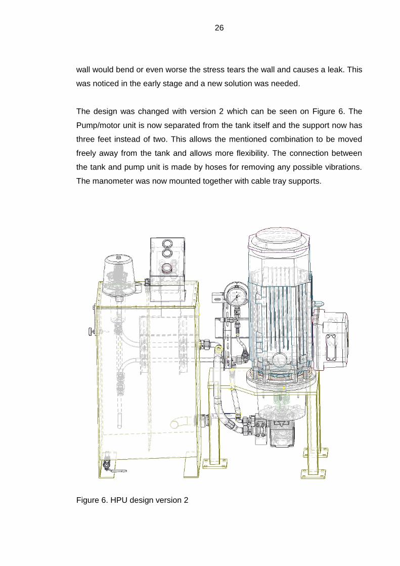
wall would bend or even worse the stress tears the wall and causes a leak. This
was noticed in the early stage and a new solution was needed.
The design was changed with version 2 which can be seen on Figure 6. The
Pump/motor unit is now separated from the tank itself and the support now has
three feet instead of two. This allows the mentioned combination to be moved
freely away from the tank and allows more flexibility. The connection between
the tank and pump unit is made by hoses for removing any possible vibrations.
The manometer was now mounted together with cable tray supports.
Figure 6. HPU design version 2

27
Another thing that was uncertain with the design was the fact of having the mo-
tor and pump outside of the tank and with no enclosure around it. This did bring
a question if the noise level would be too high and it was important to find out
the motor and pump volume level in dB(A) at used rpm range. The noise level
that was found from the data sheet was 64db(A) for each part and after consult-
ing with one of the engineers the conclusion was that this noise level was still
under the maximum level and the gear in the reel actually produces much more
noise anyway. This all meant that the enclosure would not be needed and no
any extra material would be needed to have an enclosure for the motor/pump
unit.
The piping was designed to go in the support beam for the hose loading station.
This allowed shortest the possible piping distances and also a good protection
for the pipes. The valves will be mounted in every platform between the two
reels. This allows the valve pipes connected to the mainline by T connections
which allowed the use of straight ready cut pipes between each T connection.
This new piping was more modular so it could be now possible to have all the
pipes made ready beforehand by a robot bender for a faster and cheaper pro-
duction.
The HLS needed also a new solution for how to mount the valves and what type
of valves could be used. Maintenance had also to be taken into account for the
design as the lubrication of the reels happens usually when the operator drives
the reel and inserts lubrication into the lubrication point. In the original design
this was easy with the remote control, but now that there will be no remote this
had to be considered and weighed in the final design.

28
Figure 7. HLS valves mounting design 1
Totally two new mounting solutions were designed for the valves and piping,
first one can be seen in Figure 7 and it has a separate valve to each reel and it
being mounted directly next to reel. Piping would have second T connection
under the platform for dividing the mainline to each of the valves. This would

29
allow also operator easily to lubricate the gear while driving the reels as the lu-
brication hole would be located next to the valve.
In the second design one 2 handle valve block was installed at the end of each
platform. This would allow a better view of loading for the operator and would
have almost no effect on the piping length. It is still possible for the operator to
lubricate the gear though the distance will be around 1 meter from the valves to
the lubrication point so this would mean it has to be done by two persons. One
person driving the reel and the other lubricating. In the following Figure 8 is the
final setup for the valves pipes and hoses. Two pipe coming from HPU and
connecting to the mainline. The mainline extends to the length of the whole
frame and it is connected to each valve unit with T connections. The valve is
mounted in a stainless plate that is mounted on the railing by pipe clamps. The
mainline has T connections and will continue again straight to the next reel
where there will be the next T connection and a valve unit.
Figure 8. Final valves mounting design

30
Overall this all offered very good savings in number of piping which was calcu-
lated in Table 4Error! Reference source not found.. The table shows the es-
timated number of original design piping compared to the new design and how
many meters in the piping this design will save. As it can be seen in the table,
some savings in the piping can be achieved and also its complexity will be re-
duced vastly as now the piping will consist a lot of straight pipes and T connec-
tions. This means that the cost of the assembly will be a lot lower too. Estimat-
ed work amount in the current design for the 8 reel station piping and connec-
tions is 155 hours. The new design was estimated to lower this work amount
from the original design 155 hours to 70 hours. The original design consists of
16x2mm piping and with the new design the piping size will be increased to
20x2.5mm to have a better flow and a smaller pressure drop which means less
oil heating, but of course the price will be slightly higher.
Table 4. Original and new design required amount of piping.
Reels Original design New design Saved
amount
6 95m 50m 45m
8 130m 75m 55m
10 175m 100m 75m
12 230m 110m 120m
As can be seen in Table 4, this new design would mean big saving in the
amount of piping to be used. With the new design the remote control was re-
moved with the 2 way valve block and so the cost reduction in the control valves
will be achieved as now every reel has its own simple selector valve instead of
a big and very costly selector valve block inside the HPU cabinet. Now that the
HPU will not have a cabinet and the size was smaller it allows more mounting
options and the area width where it is mounted can be narrower.
The casing itself will now consist of only the oil tank itself which has a top cover
for on/off and emergency button, return filter, oil level switch. The electric motor

31
and pump in the HPU will be left outside of the casing for some extra saved
space and material. This also offers an easier access to the pump for mainte-
nance as in the original design the pump is located inside the oil reservoir and
that means the reservoir has to be opened and oil drained to access the pump.
For the cost savings in labour the estimation was made that working hours of
the hydraulics assembly would be reduced from 150 hours to 80 hours which
would mean ~47% reduction in the assembly time based on the reduced num-
ber in piping and complexity. This gives again lot needed cost savings and
gives more value to this design, even this estimation was not yet fully accurate
as it has to be tested in a real assembly line as it was based on experience and
calculation. The cost savings that was estimated to be achieved can be seen in
Table 5.
The estimated savings in piping would be around 40% based directly on re-
duced piping and adding little extra cost for the increased piping dimension. La-
bour costs were estimated based on how the deducted piping and simplicity of
new HPU design will affect to the required work amount. Other parts savings of
30% were achieved with the removed stainless casing of the HPU including EX
certified cable glands, removed HPU casing, selector valves which will be re-
placed by the new direct control valves and removed parts like remote control,
stainless valve for manometer and measuring point, removed pressure filter. All
of this will add even more for savings, but this was harder to estimate as per-
centage because there was no good enough reference point for the prices of
these specific parts so some estimation of 30% was made for these. All of these
savings are not that huge of course when the whole HLS price will be taken into
account, but still gives the cost deductions which were looked for.
Table 5. Estimated cost savings in percentage
Cost savings in piping 40%
Savings in work hours for hydraulics 45%
Cost savings in other parts 30%
32
5 POSSIBLE FURTHER DEVELOPMENTS
During this assignment as there were discussions with engineers this new de-
sign would allow to make the system modular later on. The new design of piping
allowed that each reel could be one module that has flanges that could be bolt-
ed to the next one, this modular design would allow the customer to buy more
reels on the station or remove reels easily if ever required. There was also dis-
cussion that the reel sizes could be possibly reduced as the reels were little
oversized. This could help achieve again more savings in materials as a smaller
pump and motor would be required to drive the reels because of the reduced
torque requirement.
Another possible considerations for the hydraulic pump could be a variable dis-
placement type vane pump which would offer more compact package, better
flow control and reduced heat production because when the pump is running
without a load, it will circulate only on minimal amount of oil. This could allow
even a smaller tank and less oil to be used in the system.
Finally the company could go further with the third design as this has totally dif-
ferent approach for the pump/control system. It would use a vane type pump,
which would lower power consumption and also heat production. Lower heat
production again would give a chance to use smaller tank dimensions and less
oil and lower production cost and also maintenance costs.

33
6 CONCLUSIONS
The thesis project was very interesting overall and offered a good insight of
product developing and also into financial aspects of the product and its devel-
oping process. This also showed how fast the business can change and has to
adapt to new demands in the market, like a sudden demand for lower prices.
This is connected to the oil price and it probably will have a huge impact still on
all oil related business in future.
This thesis purpose was to respond to the demand of cost savings and to have
capability to produce cheaper hose loading stations in oil rigs and boats. Some
research had to be done for current design and also how it could be possible to
do the new design, with focus on the production cost with still having the same
functionality and reliability. This gave challenges in many tasks as designing,
cost and time calculations for production of the station.
A big challenge was also the complicated rule and safety requirements in oil
industry and especially in offshore equipment, which gave often questions if the
right mounting position or if the right equipment for the offshore purpose was
chosen. Luckily the engineers from NOV were ready to answer any of the ques-
tions related to these requirements and rules.
At end of this thesis the design was finished and it can be used for the produc-
tion design with some small changes. The final conclusion is that the work suc-
ceeded though it will still need some adjustments e.g. material strength calcula-
tions for the pump/motor unit so that it can be built for testing.

34
REFERENCES
Bosch Rexroth. 2013. Hydraulic Formulary. 4-9. Accessed 12 November 2015 https://www.boschrexroth.com/business_units/bri/de/downloads/hyd_formelsammlung_en.pdf
Brendan Casey, Machinery Lubrication (3/2011). Accessed 1 October 2015
http://www.machinerylubrication.com/Read/28430/hydraulic-pump-motors-maintenance
Eilertsen, A. 2015. National Oilwell Varco. Machinery Manager’s interview 8 October 2015. Hydra products, oil pipe diameter. Accessed 12 November 2015 http://www.hydraproducts.co.uk/hydraulic-calculators/oil-pipe-diameter.aspx National Oilwell Varco, About NOV. Accessed 1 November 2015. https://www.nov.com/About_NOV.aspx National Oilwell Varco, Hose loading systems. Accessed 1 November 2015
http://nov.com/Segments/Rig_Systems/Offshore/Lifting_and_Handling/Product_Catalogue/Hose_Loading_Stations/Hose_Loading_Stations.aspx
Noria Corporation, Hydraulic systems and fluid selection. Accessed 1 November 2015 http://www.machinerylubrication.com/Read/277/hydraulic-systems-fluid Master Rig int’l, National Oilwell Varco. Accessed 1 October 2015. http://www.masterrig.com/index.php/parts/partial-inventory/producer/1-nov Metal Tanks, Hydraulic reservoir guide. Accessed 5 January 2016 http://www.metaltanks.com/hydraulic-reservoir-guide Parker Filtration`s. 2006. Handbook of hydraulic filtration. Accessed 10 December 2015
http://www.parker.com/literature/Hydraulic%20Filter%20Division%20Europe/fdhb289uk.pdf
The engineering toolbox, Hydraulic pumps and motors. Accessed 10 November 2015 http://www.engineeringtoolbox.com/hydraulic-pumps-d_1628.html

35
APPENDICES
First hydraulic design appendix 1
Second hydraulic design appendix 2
Third hydraulic design appendix 3

36
Appendix 1

37
Appendix 2

38
Appendix 3