(4) ANALOG TO DIGITAL CONVERTER
11
Digital Communications LAB VI (EE4331) Analog to Digital Converter -11- (4) ANALOG TO DIGITAL CONVERTER 1. OBJECTIVES To understand the operation of an analog-to-digital converter (the pulse code modulation PCM). Understanding the characteristics of ADC0804 and ADC0809. Understanding the applications of ADC0804 and ADC0809. 2. DISCUSSION OF FUNDAMENTALS Analog-to-digital converters (ADC’s or A/D converters) translate from analog measurements, which are usually continuous voltages or currents, to digital words used in computing, data transmission, information processing and storage, and control systems. We do this conversion, because digital signals are easy to store, debug (using a wide variety of encoding techniques), and are almost free from noise. The Operation of Analog-to-Digital Converter Figure 4-1 shows the transfer characteristic of an ideal 3-bit ADC. The analog input range, from 0 to 1V, is quantized by dividing this continuum into 8 discrete ranges. All analog values within each given range are represented by the same digital code, which corresponds to the nominal midrange value. Therefore, there is an inherent quantization uncertainty or quantization error of ±1/2 least significant bit (LSB) in the analog-to- digital conversion process. The only way to reduce this quantization uncertainty is to increase the number of bits. The Q, quantization value or quantum, is the smallest analog difference which can be resolved or distinguished by the ADC. It can be expressed by = 2 −1 = 1 2 (1) where FS is the full-scale range which is equal to [(2 − 1)/2 ], and 2 is the resolution determined by digital output bits . Thus, the greater the n value, the higher the resolution. In general, ADC manufacturers indicate the resolution in the unit of bits, for example, the resolution of ADC0804 is expressed by 8 bits on technical manual. There are a great number of circuit designs for A/D converters: such as digital-ramp, successive approximation, flash and tracking types. The successive approximation is the
-
Upload
khangminh22 -
Category
Documents
-
view
5 -
download
0
Transcript of (4) ANALOG TO DIGITAL CONVERTER

Digital Communications LAB VI (EE4331) Analog to Digital Converter
-11-
(4) ANALOG TO DIGITAL CONVERTER
1. OBJECTIVES
To understand the operation of an analog-to-digital converter (the pulse code
modulation PCM).
Understanding the characteristics of ADC0804 and ADC0809.
Understanding the applications of ADC0804 and ADC0809.
2. DISCUSSION OF FUNDAMENTALS
Analog-to-digital converters (ADC’s or A/D converters) translate from analog
measurements, which are usually continuous voltages or currents, to digital words used
in computing, data transmission, information processing and storage, and control
systems. We do this conversion, because digital signals are easy to store, debug (using a
wide variety of encoding techniques), and are almost free from noise.
The Operation of Analog-to-Digital Converter
Figure 4-1 shows the transfer characteristic of an ideal 3-bit ADC. The analog input range,
from 0 to 1V, is quantized by dividing this continuum into 8 discrete ranges. All analog
values within each given range are represented by the same digital code, which
corresponds to the nominal midrange value. Therefore, there is an inherent quantization
uncertainty or quantization error of ±1/2 least significant bit (LSB) in the analog-to-
digital conversion process. The only way to reduce this quantization uncertainty is to
increase the number of bits.
The Q, quantization value or quantum, is the smallest analog difference which can be
resolved or distinguished by the ADC. It can be expressed by
𝑄 =𝐹𝑆
2𝑛 − 1=
1
2𝑛 (1)
where FS is the full-scale range which is equal to [(2𝑛 − 1)/2𝑛], and 2𝑛 is the resolution
determined by digital output bits 𝑛 . Thus, the greater the n value, the higher the
resolution. In general, ADC manufacturers indicate the resolution in the unit of bits, for
example, the resolution of ADC0804 is expressed by 8 bits on technical manual.
There are a great number of circuit designs for A/D converters: such as digital-ramp,
successive approximation, flash and tracking types. The successive approximation is the

Digital Communications LAB VI (EE4331) Analog to Digital Converter
-12-
only type of ADC used in our experiments; we therefore introduce the operation of
successive-approximation ADC as follows.
Figure 4-1 Ideal 3-bit ADC transfer characteristic
Figure 4-2 shows the block diagram of 8-bit successive approximation ADC. The normal
operation proceeds as follows. The sample-and-hold (S/H or S&H) circuit is used to retain
the analog input voltage V, that was present at a given time before the conversion starts,
and maintain it constant to avoid any change during the conversion period. The control
logic sets the most significant bit (MSB) 𝐷7 of register to 1, with all other bits to 0. The
digital-to-analog converter (DAC or D/A) converts the binary codes into an analog output
V(D), and which can be evaluated by
The DAC output V(D) is just a half of the reference voltage 𝑉ref. The comparator compares
the V(D) with the analog input Vi. If Vi > V(D), the 1 remains in D7. If Vi < V(D), the 1 is
removed from D7, and it is tried in the next most significant bit D6. Thus a 1 is tried in
each bit of register outputs until at the end of the process the binary equivalent of Vi is
obtained.

Digital Communications LAB VI (EE4331) Analog to Digital Converter
-13-
Figure 4-2 Block diagram of a successive approximation ADC
Analog-to-Digital Converter -- ADC0804
The ADC0804, which is a 20-pin dual-in-line package, is an 8-bit ADC which operates on
the successive approximation principle. Its major characteristics include single 5V power
supply, OV to 5V analog input voltage range, 15mW power dissipation, and 100µs
conversion time. Since the resolution of ADC0804 is 8 bits, the analog input is divided into
28 , or 256 discrete ranges. With 5V reference voltage, each range represents
5/256=0.01953V. Thus, the digital output code 00000000 (OOH) corresponds to an
analog input voltage of 0.00V, and 11111111 (FFH) represents 4.9805V. The unadjusted
error, which contains full-scale, offset and nonlinearity errors, is ±1 LSB or 0.01953V.
The connection diagram of ADC0804 is shown in Figure 4-3. When data is to be read from
the output port D0 ~ D7, the combination of both 𝐶𝑆̅̅̅̅ and 𝑅𝐷̅̅ ̅̅ being low will enable the 3-
state output latches to provide the 8-bit digital outputs. Either of 𝐶𝑆̅̅̅̅ or 𝑅𝐷̅̅ ̅̅ is high, the
outputs D0 to D7 will be floating. The ADC0804 converter is started by having 𝐶𝑆̅̅̅̅ and 𝑊𝑅̅̅ ̅̅ ̅
simultaneously low.
This resets the 8-bit register. When 𝑊𝑅̅̅ ̅̅ ̅ goes to high, the converter starts the conversion
process. The CLK IN (pin 4) is the input pin of clock pulses whose frequency can be from
100 to 800kHz. The 𝐼𝑁𝑇𝑅̅̅ ̅̅ ̅̅ ̅ pin remains high during the conversion and will make a high-
to-low transition if the conversion is completed. The analog differential input voltage is
applied to the pins Vin(+) and Vin(-). If a single-end input is desired, the Vin(-) should be
connected to ground. The AGND is the ground for analog signal and the DGND is for digital
signal. Notice
that the reference voltage is either a half of the voltage which is applied to the Vcc pin, or
is equal to the voltage which is externally forced at the Vref/2 pin.

Digital Communications LAB VI (EE4331) Analog to Digital Converter
-14-
Figure 4-3 ADC0804 pin configuration
Figure 4-4 Internal clock generator of ADC0804
The clock for the ADC0804 can be derived from an external source connected to CLK IN
(pin 4), or an external RC network can be added to provide self-clocking. As shown in
Figure 4-4, an external RC network is connected to the pins CLK R (pin 19) and CLK IN
(pin 4) to provide the clock for the ADC. The clock frequency can be found by
𝑓𝐶𝐿𝐾 =1
1.1𝑅𝐶 (Hz) (9-3)
Figure 4-5 shows an analog-to-digital converter with the ADC0804. The analog input
signal is connected to Vin(+) input and the amplitude is controlled by the VR2. Another
input Vin(-) is connected to ground. The reference voltage to the Vref/2 (pin 9) is
provided by +5V with the voltage divider containing R1, R2 and VR1. The combination of
C1 and R3 determines the clock frequency. The 𝐶𝑆̅̅̅̅ (pin 1) and 𝑅𝐷̅̅ ̅̅ (pin 2) are directly
connected to ground to enable the ADC. For convenience, the 𝑊𝑅̅̅ ̅̅ ̅ (pin 3) and 𝐼𝑁𝑇𝑅̅̅ ̅̅ ̅̅ ̅ (pin
5) are wired to the switch SW1 to simulate the control signal in our experiment late.

Digital Communications LAB VI (EE4331) Analog to Digital Converter
-15-
Figure 4-5 Fig 9-5 ADC0804 ADC circuit
Analog to Digital Converter - ADC0809
The ADC0809, which is a 28-pin dual-in-line package, is an 8-bit ADC which operates on
the successive approximation technique with 8-channel multiplexer. It operates in the
conditions of single 5 V power supply, OV to 5V analog input voltage range and 15 mW
power dissipation. The ADC0809 includes 8 analog inputs due to the 8-channel
multiplexer circuit. Since the resolution of ADC0809 is 8 bits, the analog input is divided
into 28 , or 256 discrete ranges. With 5Vdc reference voltage, each range represents
5V/256=0.01953V. Thus, the digital output code 00000000 (OOH) corresponds to an
analog input voltage of 0.00V, and 11111111 (FFH) represents (255/256)×5V = 4.9805V.
Total unadjusted error including full-scale, offset, nonlinearity and multiplexer errors is
±1 LSB or 0.01953V. The clock, 10 kHz to 1280 kHz, is required to control the ADC0809
operation. The typical conversion time at the clock of 640kHz is 100µs.
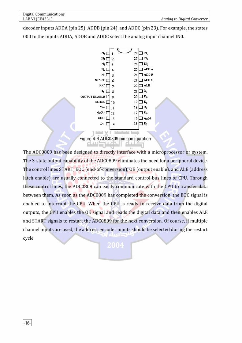
Figure 4-6 shows the connection diagram of ADC0809. Pins 5, 4, 3, 2, 1, 28, 27 and 26 are
the analog inputs IN7 to IN0; and pins 21, 20, 19, 18, 8, 15, 14, 17 are the digital outputs
D7 to D0, respectively. Pin 10 is clock input. In practice, the power input Vcc (pin 11) and
the reference voltage input Vref(+) (pin 12) can be tied together for convenience. Notice
that this arrangement will reduce the accuracy of the ADC if the power supply has a bad
stability. Any particular input channel is selected by controlling the states of the address
Digital Communications LAB VI (EE4331) Analog to Digital Converter
-16-
decoder inputs ADDA (pin 25), ADDB (pin 24), and ADDC (pin 23). For example, the states
000 to the inputs ADDA, ADDB and ADDC select the analog input channel IN0.
Figure 4-6 ADC0809 pin configuration
The ADC0809 has been designed to directly interface with a microprocessor or system.
The 3-state output capability of the ADC0809 eliminates the need for a peripheral device.
The control lines START, EOC (end-of-conversion), OE (output enable), and ALE (address
latch enable) are usually connected to the standard control-bus lines of CPU. Through
these control lines, the ADC0809 can easily communicate with the CPU to transfer data
between them. As soon as the ADC0809 has completed the conversion, the EOC signal is
enabled to interrupt the CPU. When the CPU is ready to receive data from the digital
outputs, the CPU enables the OE signal and reads the digital data and then enables ALE
and START signals to restart the ADC0809 for the next conversion. Of course, if multiple
channel inputs are used, the address encoder inputs should be selected during the restart
cycle.

Digital Communications LAB VI (EE4331) Analog to Digital Converter
-17-
Figure 4-7 Fig 9-7 ADC0809 ADC circuit
A practical ADC circuit with the ADC0809 is shown in Figure 4-7. The EOC pin is directly
connected to the START pin. This uses the EOC output signal to start the ADC0809. The
clock pulses are applied to ALE and CLK pins to control the ADC operation. The magnitude
of the analog voltage to IN0 input is controlled by adjusting the VR1), whereas those of
other inputs (IN1 to IN7) are determined by the voltage divider network (R1 to R7). The
analog channel inputs are selected by the states of SW1, SW2 and SW3. The LED display
indicates the states of digital outputs.
3. EQUIPMENT REQUIRED
Module KL-92001
Module KL-94001
DMM
4. EXPERIMENTS AND RECORDS
Experiment 9-1 ADC0804 A/D Converter
Locate ADC0804 Analog-to-Digital Converter circuit on Module KL-94001. Power on
the power supply.

Digital Communications LAB VI (EE4331) Analog to Digital Converter
-18-
Using the DVM, measure the voltage at Vref/2 input (pin 9) and slowly adjust the VR1
until the measured voltage reaches 2.5V. This sets the ADC0804 analog voltage input
range from 0V to 5V.
Measure the analog input (pin 6) and slowly adjust the VR2 until the measured voltage
reaches 0V.
Insert the connect plug in J1. This will hold the digital outputs. Observe LED display
states and record the results in Table 4-1.
Remove the connect plug from J1. The digital output will vary with the change of
analog input.
Carefully adjust the VR2 to get other analog input voltages listed on Table 4-1, and
repeat steps 4 and 5. Complete Table 4-1.
Experiment 9-2 ADC0809 A/D Converter
Locate ADC0809 Analog-to-Digital Converter circuit on Module KL-94001. Power on
the power supply.
Connect a 120kHz, 2.5V square wave with 2.5V offset (high=5V, low=0V) to the clock
input (CLK).
Set the switches SW3, SW2 and SW1 to GND positions. The analog signal will come to
the IN0 input port.
Carefully adjust the VR1 to get individual analog voltage listed on Table 4-2.
Observe LED display states for each analog input and record the results in Table 4-2.
Calculate the input voltage at input ports IN1 to IN7 and record the results in Table
4-2.
Set the positions of switches SW3, SW2 and SW1 listed on Table 4-3 to assign an input
port (IN1 to IN7) as the analog input each time.
Observe LED display states and record the results in Table 4-3.
5. QUESTIONS
Comment on the function of R3 and Ci in ADC0804 ADC circuit of Figure 4-5.
Comment on the function of switches SW1, SW2 and SW3 in ADC0809 ADC circuit of
Figure 4-7.
Name the unadjusted error of ADC0804.
Name the unadjusted error of ADC0809.

Digital Communications LAB VI (EE4331) Analog to Digital Converter
-19-
Table 4-1
Analog
Voltage
Input (V)
Digital Output
Calculated Value Measured Value
Binary Hexa-Decimal Binary Hexa-Decimal
0.0
0.5
1.0
1.5
2.0
2.5
3.0
3.5
4.0
4.5
5.0

Digital Communications LAB VI (EE4331) Analog to Digital Converter
-20-
Table 4-2
Analog
Voltage
Input (V)
Digital Output
Calculated Value Measured Value
Binary Hexa-Decimal Binary Hexa-Decimal
0.0
0.5
1.0
1.5
2.0
2.5
3.0
3.5
4.0
4.5
5.0

Digital Communications LAB VI (EE4331) Analog to Digital Converter
-21-
Table 4-3