Design Optimization of an Enhanced Stop-band UWB Bow-Tie ...
Upload
fh-joanneumCategory
view
0download
0
Time-Interleaved Digital-to-Analog Converters for UWB Signal Generation Christoph Krall 1,2 , Christian Voge12 , Klaus Witrisa12
lChristian Doppler Laboratory for Nonlinear Signal Processing 2 Signal Processing and Speech Communication Laboratory
Graz University of Technology Inffeldgasse 1211, Graz, Austria
{christoph.krall, vogel, witrisal}@tugraz.at
Abstract-In this paper, a differentially encoded TimeInterleaved Digital-to-Analog Converter (TIDAC) structure for Ultra-Wideband (UWB) signal generation is presented. We show that the output spectrum of the TIDAC is identical to the output of a DAC running at a higher sampling rate. To support the mathematical derivations, the UWB signal generator has been implemented on FPGA hardware and measurements have been taken for a sinusoidal wave, a Gaussian UWB pulse shape and for a UWB OFDM signal. The measurements show that, compared to the single-channel DAC, the mirror images around the sampling frequency can be reduced by about 30 dB and the analog interpolation filter design is simplified.
I. INTRODUCTION
Ultra Wide-Band (UWB) signal generation is an important task within the design of UWB systems for data transmission and positioning applications [1]. Thus, several approaches have been proposed for wideband signal generation. For pulse based UWB systems, the authors in [2], [3] have compared different pulse shapes and their spectra. The applicability of the studied pulses for communication scenarios has been presented. However, most important is the generation of wideband signals that comply with the spectral mask of the FCC [4] and other standardization authorities. Generally, pulse based UWB signals can be generated with a very simple analog circuit, which contains step recovery diodes or other active elements. However, for each pulse shape a different circuitry has to be designed and optimized.
If the system should be universally applicable and flexible in adaptation to changes in the environment (e.g. adapting to mutual antenna coupling), then analog pulse generator circuits appear not flexible enough. As an alternative, a Digital-toAnalog Converter (DAC) can be used to generate different wideband signals. Since technological limits have been pushed recently (for DACs even further than for Analog-to-Digital Converters (ADCs)) up to several GSafs of conversion rate [5], direct broadband signal generation becomes feasible. Moreover, the standardized Multi Band (MB)-OFDM signals have to be generated with DACs anyway. The pulse shapes generated by the DAC can be arbitrary, allowing quick adaptation to different broadband systems, or an adaptive antenna matching according to the scenario.
In this work we focus on time-interleaved DACs (TIDACs) which consist of M DACs operating at low sampling rate.
1-4244-0521-1/07/$20.00 ©2007 IEEE
Each of the DACs is used with a phase shifted clock which results in time-shifted contribution to the output signal. The main advantage of the TIDAC is that due to the phase shifted signals, the output signal seems to be generated at a higher sampling rate, given that the settling time of the individual DACs is high.
For the TIDAC, the clock generation adds more implementation complexity. However, this additional effort remains low because only a multi phase clock generator has to be used to clock the different DACs. For the two channel case, this can be easily done by using differential signals. Hence, the additional complexity is traded for flexibility in pulse shape adaptation and generation which is needed in a demonstration environment. Using a TIDAC on a mobile device may consume more chip area than using a single DAC at the M -times higher speed.
The TIDAC proposed in this paper distinguishes itself from previous works as follows. The authors in [6] consider a time-interleaved scheme that consists of two DACs that are alternately switched on, i.e., either the first or the second DAC contributes to the output signal. An improvement for the output signal is achieved by mapping the data words with a return to zero (RTZ) code which helps avoiding glitches in the output signal [7]. However, this RTZ coding is not applicable to our structure because the output signal combination in our scheme is always the sum of the contributions of the individual DACs in the TIDAC.
Another approach using TIDACs is shown in [8], where the DACs are operated in a time-interleaved manner to achieve a signal with less distortions due to aliasing effects. The interleaving structure generates samples of the output signal with four DACs operating in parallel. At the output the signal is summed up and due to the overlapping of different samples at low sampling rate in one sampling instance at high sampling rate, an "averaging" (without normalization by the number of samples) effect is achieved and a similar signal is generated at the output. This scheme is depicted for a two-channel TIDAC in Fig. 1. The individual signals from the DACs are phaseshifted and the summed output is shown in the lowest picture. The approach discussed in this paper uses a similar structure with time-interleaved DACs, but uses a precoding scheme that allows to generate exactly the same signal on an M -times
366
TIDAC1
1 I~I
t •
TIDAC2
w~ I t •
t
Fig. 1. Comparison of high rate DAC and TIDAC structure (M = 2; T~ = 2Ts)
higher signal processing rate than the clock rate of a single DAC in the TIDAC. This enables to generate oversampled signals and allows low-complexity analog filters. Accordingly, the signals for UWB systems are generated by interleaving two or more DACs, where the precoding is done on an FPGA.
The paper is organized as follows. In Section II we derive exact equations for the output of the time interleaved DAC structure. We show further that interleaving the structure with differential precoding results in an exact representation of the signal with a higher sampling rate. The mathematic expressions for the equivalence of the two structures are supported with a physically implemented scheme with DACs operated in time interleaved mode in Section III. Finally, conclusions about the proposed signal generation scheme are drawn in Section IV.
II. SYSTEM MODEL
In the following section, we derive a system model for the Time-Interleaved Digital-to-Analog Converter (TIDAC). When a signal is generated by a single DAC, each sample value applied to the digital inputs is converted into a voltage/current corresponding to its binary representation, and held over the sampling period Ts. This holding function is usually called zero-order hold (ZOH) function and simplifies the physical realization of a DAC which would have to generate 5-pulses filtered by an ideal lowpass filter. Thus, signals up to half the sampling frequency fs, i.e., fs/2 = 1/2Ts can be generated with this converter. All other frequencies in the output spectrum are caused by aliasing effects, and are attenuated by the zero order hold of the DAC. If we generate a sinusoidal signal with a frequency fa with a DAC that operates at a sampling frequency fs we get sinc-weighted copies at frequencies kfs ± fa, k = 1,2, .... Conversely, if we want to generate a signal in a TIDAC, like shown in Fig. 1 for the two-channel case, not only one DAC is contributing to one
« CJ PAC y( t) 0.... h(t) LL t fs
IDAC1 YO(t)
h(t) L:mYm
«~ IDAC2 Yl(t-Ts ) G- y(t) CJ~ h(t) 0....\...'J • I LL I I • I
I I • I
YM-l(t - (M - l)Ts)
Fig. 2. Comparison of high rate DAC and TIDAC structure
sampling interval, but generally M DACs are contributing in one sampling instance. Thus, in the time-domain the difference from the sum of all currently contributing samples to the new output value has to be computed to achieve correct signal representation for the next value to generate with one of the DACs in the TIDAC.
We compare our proposed structure to a single channel DAC that runs on an M -times higher sample rate. Thus we assume that we have M channels in parallel in the time interleaved structure. Each of these converters is characterized by the impulse response of the ZOH hk (t) = h( t) as shown in Fig. 2. In contrast, the single channel DAC has an M times higher sampling frequency and an M times shorter ZOH response h(t).
For a mathematical description we first describe the output signal y( t) of the single-channel DAC at high sampling rate Ts. The DAC can be characterized with its ZOH response as
h(t)={ 1 O<t::;Ts
o else ' (1)
where one can easily show, that the frequency domain representation is given as [9]
~ . ) _ -jOTs /2 sin(OTs /2) H(JO - e 0/2' (2)
Thus, the generated signal spectrum Y(jO) is computed by the multiplication of the periodic, discrete-time spectrum of the signal x[n] with the frequency domain representation of the ZOH function.
Contrary, the output y(t) of the TIDAC structure is the sum of the M parallel DACs Ym(t)
M-l
y(t) = L Ym(t - mTs), (3) m=O
367

where Ym (t - mTs) is the converted signal for each of the branches (cf. Fig. 2), i.e., the time shifted, overlapping outputs of the DACs. The overall response for the TIDAC structure with prefiltering is
00 M-1
y(t) = L L ((x[kM + m]g[kM + m])x k=-oo m=O (4)
5(t - kMTs - mTs)) * h(t),
where x[kM + m] is the discrete time signal, g[kM + m] is the precoding filter, 5 (t) is the Dirac delta function, h( t) is the reconstruction filter for each of the DACs (i.e. the zero order hold function), and * denotes convolution. For the sake of simplicity, the filter h( t) is assumed to be the same for each DAC. For the precoding of the signal we generally need an IIR filter of M - 1 taps since we have to account for all currently contributing M DACs and have to compute the new value to generate for the m-th DAC in the TIDAC. Thus only the additional difference to achieve the desired value in the converter array has to be computed. This filter operation can be described by an input/output relation as y[n] = x[n]-y[n-1]- ... - y [n - M + 1], which is given in the frequency domain as the transfer function of a filter
1 G(z) = M-1
L:m=O z-m
(5)
We see that this filter has M poles in its frequency domain representation. For a practical implementation of this filter, an FIR approximation can be used. The continuous-time representation of the zero-order hold for one DAC is given by
h(t) = {I 0 < t ::; MTs o else '
(6)
where MTs is the sampling time of one single DAC in the TIDAC. Thus the frequency domain description of the output filter of one channel is easily obtained as
(7)
which is a similar sinc function as in (2) but at the low sampling rate.
With these assumptions, the time-domain expression of (4) can be computed in the frequency domain as
100M
-1 (( 27f) ) Y(jrl) = Ts L LX j rl- k Ts x k=-oo m=O (8)
G (j (rl- k~:)) H(jrl),
where G(jrl) = G(ejOTs ) is the filter operation performed in digital domain. The filter responses are equivalent as long as the frequency remains below half the sampling frequency of the DAC at high rate. Each of the M converters is running at a sampling rate which is low compared to the sampling rate of the combined signal.
In the frequency domain, the filter operation computed for signal generation, are compensated by the combining stage in the continuous-time domain. The resulting signal spectrum of a TIDAC structure should be the same as the one for a DAC, which operates at an M -times higher rate, i.e., the transfer functions G(jrl) and H(jrl) in (8) should compensate. For the output spectrum of the TIDAC structure, we get with (5) and (7)
Y(jrl) =~s kJ;oo X (j (rl- k~:)) x (9)
1 1 (e-jMOTs 1) ",M-1 -' OTD -, L.,m=O e Jm s-J
which should, if our assumption is correct, be equivalent to the spectrum Y (j rl) which is given at the high sampling rate as
Y(jrl) = ~s kJ;oo X (j ( rl - k ~:) ) H(jrl), (10)
where H(jrl) is given in (2). Thus, the two transfer functions G(jrl) and H(jrl) have to combine to H(jrl), i.e.,
Y (jrl) = ~s kJ;oo X (j ( rl - k ~: ) ) x
1 1 (e-jMOTs _ 1) ",M-1 -jmOTs -J'rl L.,m=O e
~ ~s kJ;oo X (j ( rl - k ~: ) )
x _1_. (e- jOTs _ 1) = Y(jrl). -Jrl
By using geometric series we can simplify (11) to
Y(jrl)= ~s kJ;oo X (j (rl- k~)) x
(11)
which proofs our assumption that the two spectra are equal. Thus by digital precoding of the signal, the time-interleaved DAC produces the same signal as a DAC operating at an Mtimes higher rate by simply adding the signals at the outputs of the DACs. The computational complexity for the digital part of the transmitter is only slightly increased since the precoding is a rather simple filter operation. An alternative way to achieve similar results would be to store the waveforms and use lookup tables for signal generation.
368

timeDiv Channel A Channel B XY 2ns/div 50 mV /div 50 mV /div OFF
,. ~
11 ~ ~j 1\ ',# ~ ~ ~\
~ !l J. .~ ~ j ,~ f ~~ IZ
.~~ '( . V1 ~ U \ , t " 1
'T "'" OffsetA OffsetB OffsetC
a a a
Fig. 3. Scope screen for time-interleaved sinusoids
III. HARDWARE IMPLEMENTATION
To show the results of our proposed architecture for UWB signal generation, we have realized a time-interleaved DAC on hardware. A Xilinx Virtex 4 evaluation board [10] was programmed to generate the data sequence. For the Digitalto-Analog conversion we used two AD9734 high speed DACs from Analog Devices [5] which can generate signals at conversion rates of up to 1.2 GSa/s. During our experiments we used a clock fs of 800 MHz corresponding to the speed grade of the FPGA on the evaluation board. The data signals from the FPGA are differential LVDS signals which are fed into the DACs with a trace length/impedance matched adapter board. The clock was generated by a Stanford Research Systems CG635 clock generator [11], which provides a stable differential clock up to 2 GHz. The differential outputs from the clock generator were used to extract synchronous, 180 degrees phase shifted clock signals for the two DACs.
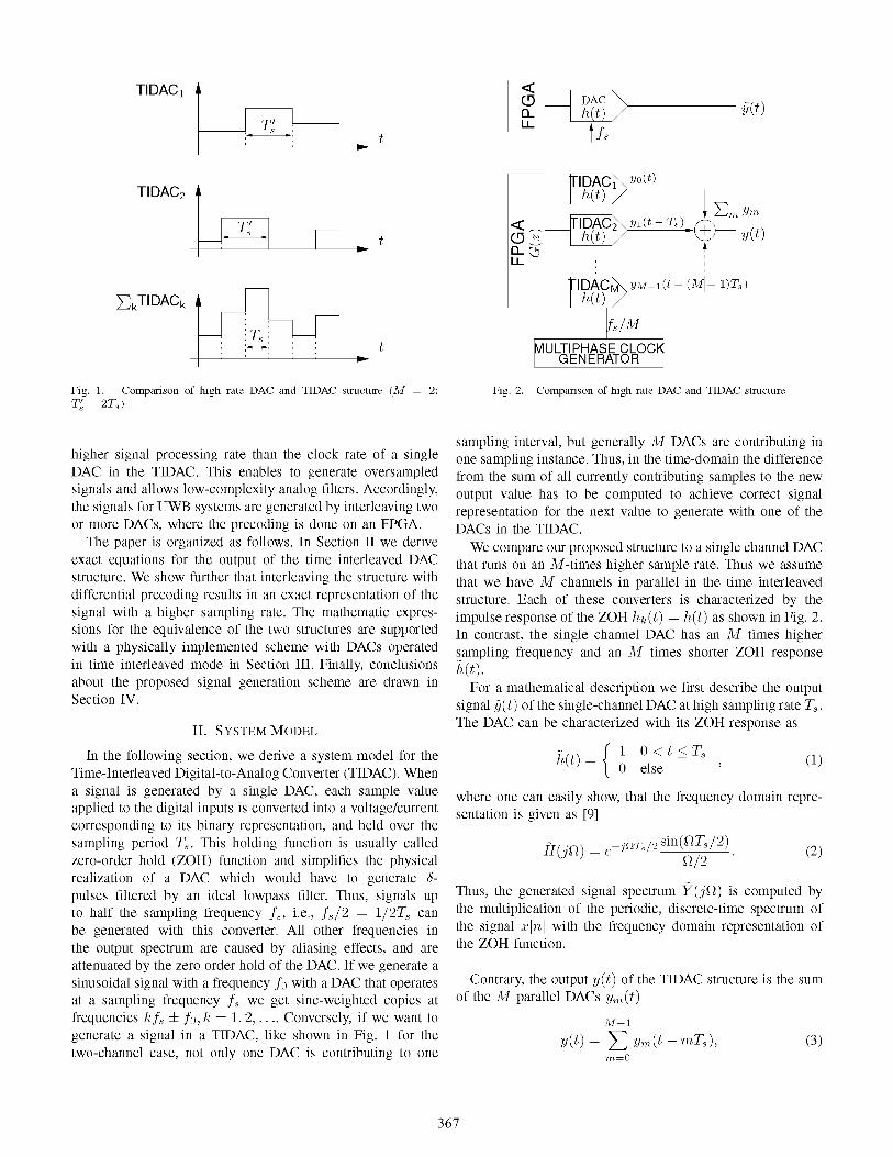
The signals presented here were captured using an Agilent 54588A Infiniium Scope, which operates at 20 GSa/s and has an analog bandwidth of 6 GHz. This is necessary in order to capture the sinc weighted periodic repetitions of the spectra due to the zero-order hold function of the DACs. Due to the limited space here, we want to focus on the presentation of three examples for the TIDAC signal generation approach. The first one is a sinusoidal wave which has a frequency of 100 MHz. The differences of the samples are computed once and are then fed into the DACs. Since the sinusoid is a periodic wave, nothing has to be computed anymore and the samples can be read out forever. In Fig. 3 a scope screenshot of the two interleaved sinusoids is shown. Furthermore, the added signal, which was generated over a simple power combiner, is shown here as well. In Fig. 4 the corresponding signal spectra are shown. The signal energies are normalized to 0 dB for visualization. For the single-channel DAC we see the sincweighted mirror images of the sinusoid in the spectrum. The next periodic repetition of the signal is already at double the sampling frequency, which is in our case at 1.6 GHz. If we
-10
-1.5 -1 -0.5 0 0.5 1.5 Frequency [GHz[
Fig. 4. Spectra for time interleaved sinusoid generation
use two DACs in interleaved mode, the spectral components at fs ± fa vanish and a similar behavior for a signal with twice the sampling frequency is seen in the spectrum. In our application a reduction of about 30 dB of these signal components is possible as our generated signal bandwidth is rather low. However, the mirror images for the combined signal are at 2fs ± fa. These copies are easily filtered by a low-complexity filter.
As a second example we used a 5th order Gaussian UWB pulse to show that also broadband signal generation is possible with our structure. The pulse shape in the time domain is given as
w(t) = A ( tS
+ 10_t3 __ 15_
t_) e(~) , 0(711 0(79 0(77
(13) where (7 is a width parameter of the pulse and was set to (7 = 5.1 . 10-9 . Again, a scope screenshot of the differentially encoded signals and the sum of the signals is shown in Fig. 5.
timeDiv Channel A Channel B XY 5ns/div 50 mV /div 50 mV /div OFF
11
~ 1\ .... r1
.~ ......
~
OffsetA OffsetB OffsetC
a a a
Fig. 5. Scope screen for time-interleaved UWB pulses
369
-10
'-, t--20 -t
I \ ,-i I !>
I i 'i '0 j I aJ i ~ -30 I ,
<D
~ ~ -40 :;;
-SO
-60
Frequency [GHz[
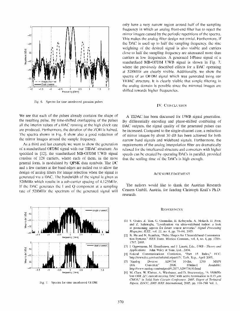
Fig_ 6_ Spectra for time interleaved gaussian pulses
We see that each of the pulses already contains the shape of the resulting pulse. By time-shifted overlapping of the pulses all the interim values of a DAC running at the high clock rate are produced. Furthermore, the duration of the ZOH is halved. The spectra shown in Fig. 6 show also a good reduction of the mirror images around the sample frequency.
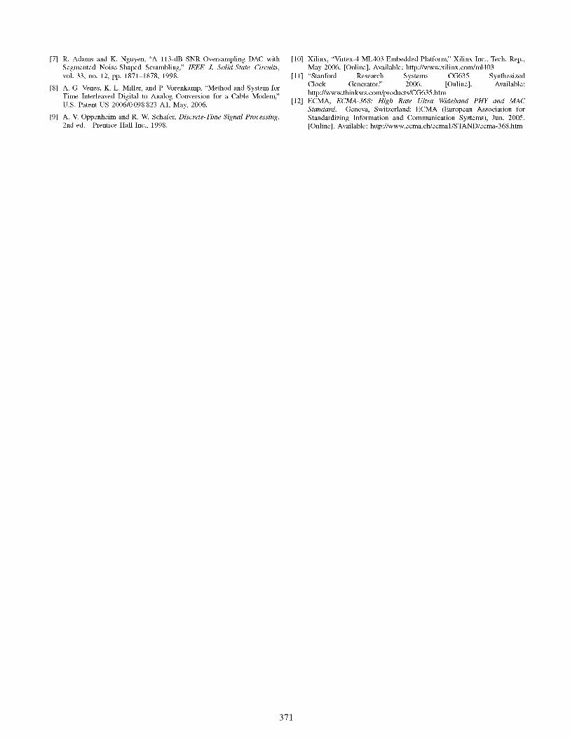
As a third and last example we want to show the generation of a standardized OFDM signal with our TIDAC structure. As specified in [12], the standardized MB-OFDM UWB signal consists of 128 carriers, where each of them, in the most general form, is modulated by QPSK data symbols. The DC and a few carriers at the band edges are nulled out to allow the design of analog filters for image rejection when the signal is generated via a DAC. The bandwidth of the signal is given as 528MHz which results in a sub-carrier spacing of 4.125MHz. If the DAC generates the I and Q component at a sampling rate of 528MHz the spectrum of the generated signal will
-1.S -1 -o.s o.s I.S frequency [G Hz[
;H' -10 ~ <D
] -20 c
'" :l! -30
-40 -1.S -1 -O.S 0
frequency [G Hz[
Fig. 7. Spectra for time interleaved OFDM
only have a very narrow region around half of the sampling frequency in which an analog front-end filter has to reject the mirror images caused by the periodic repetitions of the spectra. This makes the analog filter design not trivial. Furthermore, if the DAC is used up to half the sampling frequency, the sinc weighting of the desired signal is also visible and carriers close to half the sampling frequency are attenuated more than carriers at low frequencies. A generated I-Phase signal of a standardized MB-OFDM UWB signal is shown in Fig. 7, where the previously described effects for a DAC operating at 528MHz are clearly visible. Additionally, we show the spectra of an OFDM signal which was generated using our TIDAC structure. It is clearly visible that simple filtering in the analog domain is possible since the mirrored images are shifted towards higher frequencies.
IV. CONCLUSION
A TIDAC has been discussed for UWB signal generation. By differentially encoding and phase-shifted combining of DAC outputs, the signal quality of the generated pulses can be increased. Compared to the single-channel case, a reduction of mirror images by about 30 dB has been achieved for both narrow band signals and wideband signals. Furthermore, the requirements of the analog interpolation filter are dramatically relaxed for the interleaved structure and converters with higher speeds can be created by operating DACs in parallel, provided that the settling time of the DACs is high enough.
ACKNOWLEDGEMENT
The authors would like to thank the Austrian Research Centers GmbH, Austria, for funding Christoph Krall's PhD. research.
[1]
[2]
[3]
[4]
[5]
[6]
REFERENCES
S. Gezici, Z. Tian, G. Giannakis, H. Kobayashi, A. Molisch, H. Poor, and Z. Sahinoglu, "Localization via ultra-wideband radios: a look at positioning aspects for future sensor networks," Signal Processing Magazine, IEEE, vol. 22, no. 4, pp. 70-84, 2005. B. Hu and N. Beaulieu, "Pulse Shapes for Ultrawideband Communication Systems," IEEE Trans. Wireless Commun., vol. 4, no. 4, pp. 1789-1797, 2005. I. Oppermann, M. Hiimiiliiinen, and J. Linatti, Eds., UWB - Theory awl Applications. John Wiley & Sons, Ltd., 2004. Federal Communications Comission, "Part 15 Rules," FCC, http://www.fcc.gov/oetlinfo/rules/partI5/, Tech. Rep., April 2005. "Analog Devices AD9734 lO-Bit, 1200 MSPS D/A Converter," 2006. [Online]. Available: http://www.analog.com/en/prodlO.2877.AD9734. OO.html M. Clara, w. Klatzer, A. Wiesbauer, and D. Straeussnigg, "A 350MHz low-OSR .6.~ current-steering DAC with active termination in 0.13 11m CMOS," in Solid-State Circuits Conference, 2005. Digest of Technical Papers. ISSCC. 2005 IEEE International, 2005, pp. 118-588 Vol. 1.
370
[7] R. Adams and K. Nguyen, "A 113-dB SNR Oversampling DAC with Segmented Noise-Shaped Scrambling," IEEE 1. Solid-State Circuits, vol. 33, no. 12, pp. 1871-1878, 1998.
[8] A. G. Venes, K. L. Miller, and P. Vorenkamp, "Method and System for Time Interleaved Digital to Analog Conversion for a Cable Modem," u.S. Patent US 2006/0098823 AI, May, 2006.
[9] A. V. Oppenheim and R. W. Schafer, Discrete-Time Signal Processing, 2nd ed. Prentice Hall Inc., 1998.
[10] Xilinx, "Virtex-4 ML403 Embedded Platform," Xilinx Inc., Tech. Rep., May 2006. [Online]. Available: hUp:llwww.xilinx.comlml403
[11] "Stanford Research Systems CG635 Synthesized Clock Generator," 2006. [Online]. Available: hUp:llwww.thinksrs.comlproducts/CG635.htm
[12] ECMA, ECMA-368: High Rate Ultra Widebarul PHY and MAC Standard. Geneva, Switzerland: ECMA (European Association for Standardizing Information and Communication Systems), Jun. 2005. [Online]. Available: hUp:llwww.ecma.chlecmal/STAND/ecma-368.htm
371
Copyright © 2022 FDOKUMEN