Signal converters, limit switches and process indicators ...
246
Analogue signal conditioning Signal converters, limit switches and process indicators Catalogue 2014/2015 Let’s connect.
-
Upload
khangminh22 -
Category
Documents
-
view
2 -
download
0
Transcript of Signal converters, limit switches and process indicators ...
Cata
logue
201
4/20
15An
alogu
e sign
al co
nditio
ning
Analogue signal conditioning
Signal converters, limit switches and process indicatorsCatalogue 2014/2015Let’s connect.


Dear Customers,The PDF versions of our catalogues offer practical additional functions, helping you to find your way around our product range and simplifying the ordering process.
In addition to the catalogue, the PDF also contains: • Internal page links• Links to the online catalogue
Try it out for yourself. Click the order number to obtain more detailed information and close-up images via you web browser. The links in the PDF file also enable you to go directly to the next desired catalogue page.
Further Weidmüller product catalogues can be accessed by clicking the following:

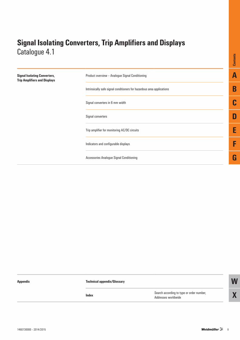
Signal Isolating Converters, Trip Amplifiers and Displays
Product overview – Analogue Signal Conditioning
Intrinsically safe signal conditioners for hazardous area applications
Signal converters in 6 mm width
Signal converters
Trip amplifier for monitoring AC/DC circuits
Indicators and configurable displays
Accessories Analogue Signal Conditioning
Appendix Technical appendix/Glossary
Index Search according to type or order number, Addresses worldwide
Signal Isolating Converters, Trip Amplifiers and DisplaysCatalogue 4.1
ABCDEFG
WX
Cont
ents
I1460730000 – 2014/2015

Signal Isolating Converters, Trip Amplifiers and Displays
Product overview
Intrinsically safe signal converters – ACT20X Page B.6
Signal converter, 6 mm – ACT20M Page C.4
Signal converter and monitoring components, 6 mm – MCZ Page C.30
• Analogue and binary signal interfaces to Ex Zone 0 / Division 1
• FDT/DTM software configurable• 2 channel modules in 22.5 mm housing
• Isolating and converting of temperature signals and DC signals (3-way isolation, supply isolators and passive isolators)
• Up to 2 channels with a width of 6 mm• Power supply via the CH20M DIN rail bus
• Signal converter in terminal format• Passive isolator, temperature/frequency converter
and threshold monitoring• Simple wiring with pluggable cross-connection
channels
Network-compatible signal converters ACT20C Page D.6
Signal converters and monitoring components – ACT20P Page D.8
Signal converters – WAVE Page D.18
• Separation and conversion of current or voltage signals
• Limit value monitoring, diagnosis, monitoring via Ethernet networks
• PC configuration with FDT/DTM software
• Separation and conversion of temperature and DC signals (3-way isolation, supply isolators and passive isolators)
• Strain gauge transmitter for reading from load cells
• High levels of galvanic isolation and accuracy
• Separation and conversion of temperature and DC signals (3-way isolation, supply isolators and passive isolators)
• A large selection of standard signal- and measurement isolating transformers
• High level of galvanic isolation
Interface converters Page D.62
Trip amplifiers for monitoring – WAVE Page E.4
Displays Page F.6
• RS232/ RS485/ TTY interface converter in WAVE housing
• RS232 connection with SUB-D connector• Bi-direction communication enabled
• Monitoring DC and AC currents and voltages• Current/voltage ranges and switching points can
be set manually.• Pluggable units for monitoring current – on DIN
rail base
• Large four-character LED display• 1/8"-DIN-standard front-panel with IP 65
protection• Integrated signal converter and trip amplifier
II 1460730000 – 2014/2015

Product overview
Configuration adapter Page G.4
Markers and cross-connectors Page G.11
Calibration device Page G.15
• USB interface adapter for configuring signal converters
• Compatible with ACT20X, WAVE TTA and ITX+ modules
• Simple installation with plug-in connector
• Suitable MultiCard markers for all modules• Pluggable cross-connectors for WAVE, MCZ and
MICROSERIES
• Measures and simulates voltage and current signals
• Adjustable continuous level and ramping functions• Easy to adjust with buttons on front
III1460730000 – 2014/2015

IV 1460730000 – 2014/2015

Product overview – Analogue Signal Conditioning
Product overview –Analogue Signal Conditioning
Introduction A.2
Quick select – Analogue Signal Conditioning A.4
Contents
A
Prod
uct o
verv
iew –
Analo
gue S
ignal
Cond
ition
ing
A.11460730000 – 2014/2015
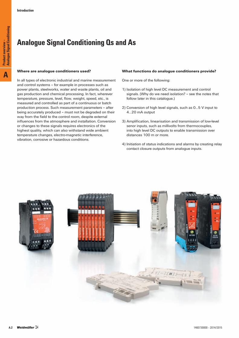
Where are analogue conditioners used?
In all types of electronic industrial and marine measurement and control systems – for example in processes such as power plants, steelworks, water and waste plants, oil and gas production and chemical processing. In fact, wherever temperature, pressure, level, flow, weight, speed, etc., is measured and controlled as part of a continuous or batch production process. Such measurement parameters – after being accurately produced – must not be degraded on their way from the field to the control room, despite external influences from the atmosphere and installation. Conversion or changes to these signals requires electronics of the highest quality, which can also withstand wide ambient temperature changes, electro-magnetic interference, vibration, corrosive or hazardous conditions.
What functions do analogue conditioners provide?
One or more of the following:
1) Isolation of high level DC measurement and control signals. (Why do we need isolation? – see the notes that follow later in this catalogue.)
2) Conversion of high level signals, such as 0...5 V input to 4…20 mA output
3) Amplification, linearisation and transmission of low-level senor inputs, such as millivolts from thermocouples, into high level DC outputs to enable transmission over distances 100 m or more.
4) Initiation of status indications and alarms by creating relay contact closure outputs from analogue inputs.
Analogue Signal Conditioning Qs and As
Introduction
A
Prod
uct o
verv
iew –
Analo
gue S
ignal
Cond
ition
ing
A.2 1460730000 – 2014/2015

Why do we need separate analogue modules nowadays? Surely the control system (PLC or DCS) can perform the same functions?
1) Sometimes this is true, but look at where the cabling from the field devices (transmitters, sensors, valves and actuators) needs to go. It will usually go not just straight to the control system. Many signals are also passed to local indicators and alarms, and each will need isolating from the others.
2) Often sensors - like thermocouples for temperature – need isolating, converting and linearising locally to a standardised high level signal (e.g. 4…20 mA) for long distance transmission – instead of running expensive compensation cable to the control system.
3) Where the control system has no isolated analogue inputs, a separate isolator will often be needed.
4) Where the control system cannot provide power for the sensor / transmitter and it is convenient to do this from an isolating module.
5) Where a high integrity, dedicated display is required, separate from the control system display, and the input needs splitting.
6) Where local linearisation is needed for a plant operator – for example where a liquid volume indicator is needed for filling a bulk storage tank, but the measurement is level (level to volume conversion depends on the shape of the tank).
7) Where the control system only takes 4…20 mA analogue inputs and the sensors provide other less common ranges, such as 0…20 mV, 2…10 V, 0…10 kΩ, 0…1 mA, 4…12 kHz, 0…5 A AC etc
8) Where the control system needs to be protected from electrical noise pulses on it’s analogue inputs
9) Where expansion of the analogue inputs would mean an expensive new I/O board for the control system
How can I select the right product for my application?
1) Weidmüller has a formidable range of analogue conditioners, covering most application requirements, and our range is expanding. We also have some useful tools for selection and configuration.
2) If you cannot find a suitable product for your application, it doesn’t mean we don’t have one! Tell us your requirement, and if we can’t provide a solution from our current range of products, there may be a customised version that we could create for you.
Introduction
A
Prod
uct o
verv
iew –
Analo
gue S
ignal
Cond
ition
ing
A.31460730000 – 2014/2015

Selection tableOrder No. Product Input Width Output Configuration Auxiliary
powerRatedvoltage
Isolation
Conn
ectio
n sys
tem
Special characteristics Page
Amou
nt
0...2
0 mA
4...2
0 mA
0...1
0 V
0…5 V
TC RTD
Freq
uenc
y
Miscellaneous
Sens
or fe
ed
Amou
nt
0...2
0 mA
4...2
0 mA
0...1
0 V
Relay
Miscellaneous
Intrinsically safe signal converter for the Ex zone8965340000 ACT20X-HDI-SDO-RNO-S 1 X Namur Initiator 22.5 mm 1 X Software 24 V DC 300 V 3-way S With ATEX approval B.178965350000 ACT20X-HDI-SDO-RNC-S 1 X Namur Initiator 22.5 mm 1 X Software 24 V DC 300 V 3-way S With ATEX approval B.178965370000 ACT20X-2HDI-2SDO-RNO-S 2 X Namur Initiator 22.5 mm 2 X 2 relay outputs Software 24 V DC 300 V 3-way S With ATEX approval B.178965380000 ACT20X-2HDI-2SDO-RNC-S 2 X Namur Initiator 22.5 mm 2 X 2 relay outputs Software 24 V DC 300 V 3-way S With ATEX approval B.178965360000 ACT20X-HDI-SDO-S 1 X Namur Initiator 22.5 mm 1 Transistor output Software 24 V DC 300 V 3-way S With ATEX approval B.198965390000 ACT20X-2HDI-2SDO-S 2 X Namur Initiator 22.5 mm 2 Transistor output Software 24 V DC 300 V 3-way S With ATEX approval B.198965400000 ACT20X-SDI-HDO-L-S 1 NPN PNP switching signal 22.5 mm 1 X Software 24 V DC 300 V 3-way S With ATEX approval B.218965420000 ACT20X-2SDI-2HDO-S 2 NPN PNP switching signal 22.5 mm 2 X Software 24 V DC 300 V 3-way S ATEX approval, ignition protection group IIC B.218965410000 ACT20X-SDI-HDO-H-S 1 NPN PNP switching signal 22.5 mm 1 X Software 24 V DC 300 V 3-way S ATEX approval, ignition protection group IIB B.238965470000 ACT20X-HTI-SAO-S 1 X X X X 22.5 mm 1 X X X Software 24 V DC 300 V 3-way S With ATEX approval B.118965480000 ACT20X-2HTI-2SAO-S 2 X X X X 22.5 mm 2 X X X 2 relay outputs Software 24 V DC 300 V 3-way S With ATEX approval B.118965490000 ACT20X-HUI-SAO-S 1 X X X X X X X 22.5 mm 1 X X Software 24 V DC 300 V 3-way S With ATEX approval B.131318220000 ACT20X-HUI-SAO-LP-S 1 X X X X X X X 22.5 mm 1 X 300 V 2-way S Output-side power supply B.158965430000 ACT20X-HAI-SAO-S 1 X HART®- transparent X 22.5 mm 1 X X Software 24 V DC 300 V 3-way S ATEX approval, HART®- transparent B.78965440000 ACT20X-2HAI-2SAO-S 2 X HART®- transparent X 22.5 mm 2 X X 2 relay outputs Software 24 V DC 300 V 3-way S ATEX approval, HART®- transparent B.78965450000 ACT20X-SAI-HAO-S 1 X HART®- transparent 22.5 mm 1 X X Software 24 V DC 300 V 3-way S ATEX approval, HART®- transparent B.98965460000 ACT20X-2SAI-2HAO-S 2 X HART®- transparent 22.5 mm 2 X X 2 relay outputs Software 24 V DC 300 V 3-way S ATEX approval, HART®- transparent B.98978580000 CBX200 1 ACT20X 1 Software USB Programming accessories G.4
Signal converter in 6 mm width1176020000 ACT20M-AI-2SAO-S 1 X X X X 6.1 mm 2 X X X DIP 24 V DC 300 V 4-way S C.111175990000 ACT20M-CI-2CO-S 1 X X 6.1 mm 2 X X DIP 24 V DC 300 V 4-way S C.101176000000 ACT20M-AI-AO-S 1 X X X X 6.1 mm 1 X X X DIP 24 V DC 300 V 3-way S C.141176010000 ACT20M-AI-AO-E-S 1 X X X X 6.1 mm 1 X X X DIP 24 V DC 300 V 3-way S C.151175980000 ACT20M-CI-CO-S 1 X X 6.1 mm 1 X X none 24 V DC 300 V 3-way S C.131176030000 ACT20M-UI-AO-S 1 X X X X X X 6.1 mm 1 X X X Software 24 V DC 300 V 3-way S C.171176070000 ACT20M-CI-CO-ILP-S 1 X X X 6.1 mm 1 X X none 300 V 2-way S C.181176080000 ACT20M-2CI-2CO-ILP-S 2 X X X 6.1 mm 2 X X none 300 V 2-way S C.181176040000 ACT20M-CI-CO-OLP-S 1 X X X 6.1 mm 1 X X none 300 V 2-way S C.191176050000 ACT20M-2CI-2CO-OLP-S 2 X X X 6.1 mm 2 X X none 300 V 2-way S C.198965500000 ACT20-Feed-In-PRO-S 1 22.5 mm 1 X none 24 V DC S ATEX approval C.291282490000 ACT20-Feed-In-S 1 6.1 mm 1 none 24 V DC S ATEX approval C.291375450000 ACT20M-BAI-AO-S 1 -10(20)…+10(20) mA, -5(10)…+5(10) V 6.1 mm 1 x x x DIP switch 24 V DC 300 V 2-way S ATEX approval C.161375470000 ACT20M-BAI-2AO-S 1 -10(20)…+10(20) mA, -5(10)…+5(10) V 6.1 mm 2 x x x 2 x -10(20)…+10(20) mA DIP switch 24 V DC 300 V 2-way S ATEX approval C.121375480000 ACT20M-TCI-AO-S 1 x 6.1 mm 1 x x x 0(1)…5 V DIP switch 24 V DC 300 V 2-way S ATEX approval C.241375500000 ACT20M-TCI-AO-E-S 1 x 6.1 mm 1 x x x 0(1)…5 V DIP switch 24 V DC 300 V 2-way S ATEX approval C.251375510000 ACT20M-RTI-AO-S 1 x 6.1 mm 1 x x x 0(1)…5 V DIP switch 24 V DC 300 V 2-way S ATEX approval C.221375520000 ACT20M-RTI-AO-E-S 1 x 6.1 mm 1 x x 0(1)…5 V DIP switch 24 V DC 300 V 2-way S ATEX approval C.231435590000 ACT20M-RTCI-CO-OLP-S 1 x 6.1 mm 1 x 20…4 mA DIP switch 300 V 2-way S Passive converter C.201435610000 ACT20M-RTI-CO-EOLP-S 1 x 6.1 mm 1 x 20…4 mA DIP switch 300 V 2-way S Passive converter C.21
Standard-signal isolator8540180000 WAS5 CCC 0-20/0-20mA 1 X 17.5 mm 1 X 24 V DC 300 V 3-way S D.328540190000 WAZ5 CCC 0-20/0-20mA 1 X 17.5 mm 1 X 24 V DC 300 V 3-way Z D.328540270000 WAS5 CVC 0-20mA/0-10V 1 X 17.5 mm 1 X 24 V DC 300 V 3-way S D.338540200000 WAS5 CCC 4-20/0-20MA 1 X 17.5 mm 1 X 24 V DC 300 V 3-way S D.348540250000 WAS5 CCC 0-20/4-20mA 1 X 17.5 mm 1 X 24 V DC 300 V 3-way S D.328540230000 WAS5 CVC 4-20mA/0-10V 1 X 17.5 mm 1 X 24 V DC 300 V 3-way S D.348447160000 WAS5 CCC HF 0-20/0-20MA 1 X 17.5 mm 1 X 24 V DC 300 V 3-way S Limiting frequency >15 kHz D.288447170000 WAZ5 CCC HF 0-20/0-20MA 1 X 17.5 mm 1 X 24 V DC 300 V 3-way Z Limiting frequency >15 kHz D.288447250000 WAS5 CCC HF 4-20/0-20MA 1 X 17.5 mm 1 X 24 V DC 300 V 3-way S Limiting frequency >15 kHz D.298447220000 WAS5 CVC HF 0-20/0-10V 1 X 17.5 mm 1 X 24 V DC 300 V 3-way S Limiting frequency >15 kHz D.288447280000 WAS5 CVC HF 4-20/0-10V 1 X 17.5 mm 1 X 24 V DC 300 V 3-way S Limiting frequency >15 kHz D.298444980000 WAS4 CCC DC 4-20/4-20MA 1 X 12.5 mm 1 X 24 V DC 300 V 2-way S Output-side power supply D.388444990000 WAZ4 CCC DC 4-20/4-20MA 1 X 12.5 mm 1 X 24 V DC 300 V 2-way Z Output-side power supply D.38
Connection system: S = screw / Z = tension clamp, ILP (Input Loop Powered) = Input Loop Powered, OLP (Output Loop Powered) = Output Loop Powered
Quick select – Analogue Signal Conditioning
Quick select – Analogue Signal Conditioning
A
Prod
uct o
verv
iew –
Analo
gue S
ignal
Cond
ition
ing
A.4 1460730000 – 2014/2015

Selection tableOrder No. Product Input Width Output Configuration Auxiliary
powerRatedvoltage
Isolation
Conn
ectio
n sys
tem
Special characteristics Page
Amou
nt
0...2
0 mA
4...2
0 mA
0...1
0 V
0…5 V
TC RTD
Freq
uenc
y
Miscellaneous
Sens
or fe
ed
Amou
nt
0...2
0 mA
4...2
0 mA
0...1
0 V
Relay
Miscellaneous
Intrinsically safe signal converter for the Ex zone8965340000 ACT20X-HDI-SDO-RNO-S 1 X Namur Initiator 22.5 mm 1 X Software 24 V DC 300 V 3-way S With ATEX approval B.178965350000 ACT20X-HDI-SDO-RNC-S 1 X Namur Initiator 22.5 mm 1 X Software 24 V DC 300 V 3-way S With ATEX approval B.178965370000 ACT20X-2HDI-2SDO-RNO-S 2 X Namur Initiator 22.5 mm 2 X 2 relay outputs Software 24 V DC 300 V 3-way S With ATEX approval B.178965380000 ACT20X-2HDI-2SDO-RNC-S 2 X Namur Initiator 22.5 mm 2 X 2 relay outputs Software 24 V DC 300 V 3-way S With ATEX approval B.178965360000 ACT20X-HDI-SDO-S 1 X Namur Initiator 22.5 mm 1 Transistor output Software 24 V DC 300 V 3-way S With ATEX approval B.198965390000 ACT20X-2HDI-2SDO-S 2 X Namur Initiator 22.5 mm 2 Transistor output Software 24 V DC 300 V 3-way S With ATEX approval B.198965400000 ACT20X-SDI-HDO-L-S 1 NPN PNP switching signal 22.5 mm 1 X Software 24 V DC 300 V 3-way S With ATEX approval B.218965420000 ACT20X-2SDI-2HDO-S 2 NPN PNP switching signal 22.5 mm 2 X Software 24 V DC 300 V 3-way S ATEX approval, ignition protection group IIC B.218965410000 ACT20X-SDI-HDO-H-S 1 NPN PNP switching signal 22.5 mm 1 X Software 24 V DC 300 V 3-way S ATEX approval, ignition protection group IIB B.238965470000 ACT20X-HTI-SAO-S 1 X X X X 22.5 mm 1 X X X Software 24 V DC 300 V 3-way S With ATEX approval B.118965480000 ACT20X-2HTI-2SAO-S 2 X X X X 22.5 mm 2 X X X 2 relay outputs Software 24 V DC 300 V 3-way S With ATEX approval B.118965490000 ACT20X-HUI-SAO-S 1 X X X X X X X 22.5 mm 1 X X Software 24 V DC 300 V 3-way S With ATEX approval B.131318220000 ACT20X-HUI-SAO-LP-S 1 X X X X X X X 22.5 mm 1 X 300 V 2-way S Output-side power supply B.158965430000 ACT20X-HAI-SAO-S 1 X HART®- transparent X 22.5 mm 1 X X Software 24 V DC 300 V 3-way S ATEX approval, HART®- transparent B.78965440000 ACT20X-2HAI-2SAO-S 2 X HART®- transparent X 22.5 mm 2 X X 2 relay outputs Software 24 V DC 300 V 3-way S ATEX approval, HART®- transparent B.78965450000 ACT20X-SAI-HAO-S 1 X HART®- transparent 22.5 mm 1 X X Software 24 V DC 300 V 3-way S ATEX approval, HART®- transparent B.98965460000 ACT20X-2SAI-2HAO-S 2 X HART®- transparent 22.5 mm 2 X X 2 relay outputs Software 24 V DC 300 V 3-way S ATEX approval, HART®- transparent B.98978580000 CBX200 1 ACT20X 1 Software USB Programming accessories G.4
Signal converter in 6 mm width1176020000 ACT20M-AI-2SAO-S 1 X X X X 6.1 mm 2 X X X DIP 24 V DC 300 V 4-way S C.111175990000 ACT20M-CI-2CO-S 1 X X 6.1 mm 2 X X DIP 24 V DC 300 V 4-way S C.101176000000 ACT20M-AI-AO-S 1 X X X X 6.1 mm 1 X X X DIP 24 V DC 300 V 3-way S C.141176010000 ACT20M-AI-AO-E-S 1 X X X X 6.1 mm 1 X X X DIP 24 V DC 300 V 3-way S C.151175980000 ACT20M-CI-CO-S 1 X X 6.1 mm 1 X X none 24 V DC 300 V 3-way S C.131176030000 ACT20M-UI-AO-S 1 X X X X X X 6.1 mm 1 X X X Software 24 V DC 300 V 3-way S C.171176070000 ACT20M-CI-CO-ILP-S 1 X X X 6.1 mm 1 X X none 300 V 2-way S C.181176080000 ACT20M-2CI-2CO-ILP-S 2 X X X 6.1 mm 2 X X none 300 V 2-way S C.181176040000 ACT20M-CI-CO-OLP-S 1 X X X 6.1 mm 1 X X none 300 V 2-way S C.191176050000 ACT20M-2CI-2CO-OLP-S 2 X X X 6.1 mm 2 X X none 300 V 2-way S C.198965500000 ACT20-Feed-In-PRO-S 1 22.5 mm 1 X none 24 V DC S ATEX approval C.291282490000 ACT20-Feed-In-S 1 6.1 mm 1 none 24 V DC S ATEX approval C.291375450000 ACT20M-BAI-AO-S 1 -10(20)…+10(20) mA, -5(10)…+5(10) V 6.1 mm 1 x x x DIP switch 24 V DC 300 V 2-way S ATEX approval C.161375470000 ACT20M-BAI-2AO-S 1 -10(20)…+10(20) mA, -5(10)…+5(10) V 6.1 mm 2 x x x 2 x -10(20)…+10(20) mA DIP switch 24 V DC 300 V 2-way S ATEX approval C.121375480000 ACT20M-TCI-AO-S 1 x 6.1 mm 1 x x x 0(1)…5 V DIP switch 24 V DC 300 V 2-way S ATEX approval C.241375500000 ACT20M-TCI-AO-E-S 1 x 6.1 mm 1 x x x 0(1)…5 V DIP switch 24 V DC 300 V 2-way S ATEX approval C.251375510000 ACT20M-RTI-AO-S 1 x 6.1 mm 1 x x x 0(1)…5 V DIP switch 24 V DC 300 V 2-way S ATEX approval C.221375520000 ACT20M-RTI-AO-E-S 1 x 6.1 mm 1 x x 0(1)…5 V DIP switch 24 V DC 300 V 2-way S ATEX approval C.231435590000 ACT20M-RTCI-CO-OLP-S 1 x 6.1 mm 1 x 20…4 mA DIP switch 300 V 2-way S Passive converter C.201435610000 ACT20M-RTI-CO-EOLP-S 1 x 6.1 mm 1 x 20…4 mA DIP switch 300 V 2-way S Passive converter C.21
Standard-signal isolator8540180000 WAS5 CCC 0-20/0-20mA 1 X 17.5 mm 1 X 24 V DC 300 V 3-way S D.328540190000 WAZ5 CCC 0-20/0-20mA 1 X 17.5 mm 1 X 24 V DC 300 V 3-way Z D.328540270000 WAS5 CVC 0-20mA/0-10V 1 X 17.5 mm 1 X 24 V DC 300 V 3-way S D.338540200000 WAS5 CCC 4-20/0-20MA 1 X 17.5 mm 1 X 24 V DC 300 V 3-way S D.348540250000 WAS5 CCC 0-20/4-20mA 1 X 17.5 mm 1 X 24 V DC 300 V 3-way S D.328540230000 WAS5 CVC 4-20mA/0-10V 1 X 17.5 mm 1 X 24 V DC 300 V 3-way S D.348447160000 WAS5 CCC HF 0-20/0-20MA 1 X 17.5 mm 1 X 24 V DC 300 V 3-way S Limiting frequency >15 kHz D.288447170000 WAZ5 CCC HF 0-20/0-20MA 1 X 17.5 mm 1 X 24 V DC 300 V 3-way Z Limiting frequency >15 kHz D.288447250000 WAS5 CCC HF 4-20/0-20MA 1 X 17.5 mm 1 X 24 V DC 300 V 3-way S Limiting frequency >15 kHz D.298447220000 WAS5 CVC HF 0-20/0-10V 1 X 17.5 mm 1 X 24 V DC 300 V 3-way S Limiting frequency >15 kHz D.288447280000 WAS5 CVC HF 4-20/0-10V 1 X 17.5 mm 1 X 24 V DC 300 V 3-way S Limiting frequency >15 kHz D.298444980000 WAS4 CCC DC 4-20/4-20MA 1 X 12.5 mm 1 X 24 V DC 300 V 2-way S Output-side power supply D.388444990000 WAZ4 CCC DC 4-20/4-20MA 1 X 12.5 mm 1 X 24 V DC 300 V 2-way Z Output-side power supply D.38
Connection system: S = screw / Z = tension clamp, ILP (Input Loop Powered) = Input Loop Powered, OLP (Output Loop Powered) = Output Loop Powered
Quick select – Analogue Signal Conditioning
A
Prod
uct o
verv
iew –
Analo
gue S
ignal
Cond
ition
ing
A.51460730000 – 2014/2015

Selection tableOrder No. Product Input Width Output Configuration Auxiliary
powerRatedvoltage
Isolation
Conn
ectio
n sys
tem
Special characteristics Page
Amou
nt
0...2
0 mA
4...2
0 mA
0...1
0 V
0…5 V
TC RTD
Freq
uenc
y
Miscellaneous
Sens
or fe
ed
Amou
nt
0...2
0 mA
4...2
0 mA
0...1
0 V
Relay
Miscellaneous
Standard-signal isolator8445010000 WAS4 CCC DC 4-20/0-20MA 1 X 12.5 mm 1 X 24 V DC 300 V 2-way S Output-side power supply D.388445040000 WAS4 CVC DC 4-20/0-10V 1 X 12.5 mm 1 X 24 V DC 300 V 2-way S Dual-side power supply D.398445050000 WAZ4 CVC DC 4-20/0-10V 1 X 12.5 mm 1 X 24 V DC 300 V 2-way Z Dual-side power supply D.398540310000 WAS5 VCC 0-10V/0-20MA 1 X 17.5 mm 1 X 24 V DC 300 V 3-way S D.358540320000 WAZ5 VCC 0-10V/0-20MA 1 X 17.5 mm 1 X 24 V DC 300 V 3-way Z D.358540290000 WAS5 VCC 0-10V/4-20MA 1 X 17.5 mm 1 X 24 V DC 300 V 3-way S D.358540300000 WAZ5 VCC 0-10V/4-20MA 1 X 17.5 mm 1 X 24 V DC 300 V 3-way Z D.358540330000 WAS5 VVC 0-10V/0-10V 1 X 17.5 mm 1 X 24 V DC 300 V 3-way S D.368540340000 WAZ5 VVC 0-10V/0-10V 1 X 17.5 mm 1 X 24 V DC 300 V 3-way Z D.368561610000 WAS5 VVC HF +-10V/+-10V 1 -10…+10 V 17.5 mm 1 -10…+10 V 24 V DC 300 V 3-way S Limiting frequency >15 kHz D.318447310000 WAS5 VCC HF 0-10/0-20MA 1 X 17.5 mm 1 X 24 V DC 300 V 3-way S Limiting frequency >15 kHz D.308447340000 WAS5 VCC HF 0-10/4-20MA 1 X 17.5 mm 1 X 24 V DC 300 V 3-way S Limiting frequency >15 kHz D.308447370000 WAS5 VVC HF 0-10/0-10V 1 X 17.5 mm 1 X 24 V DC 300 V 3-way S Limiting frequency >15 kHz D.318447380000 WAZ5 VVC HF 0-10/0-10V 1 X 17.5 mm 1 X 24 V DC 300 V 3-way S Limiting frequency >15 kHz D.318411190000 MCZ CCC 0-20mA/0-20mA 1 X 6 mm 1 X 100 V 2-way Z Passive isolator ILP C.328444950000 WAS5 CCC LP 0-20/0-20mA 1 X 17.5 mm 1 X 300 V 2-way S Passive isolator ILP D.438444960000 WAZ5 CCC LP 0-20/0-20mA 1 X 17.5 mm 1 X 300 V 2-way Z Passive isolator ILP D.438463580000 WAS5 CCC LP 0-20/0-20mA 2 X 17.5 mm 2 X 300 V 2-way S Passive isolator ILP D.438463590000 WAZ5 CCC LP 0-20/0-20mA 2 X 17.5 mm 2 X 300 V 2-way Z Passive isolator ILP D.438543720000 WAS5 OLP 1 X X X X 17.5 mm 1 X DIP switch 300 V 2-way S Passive isolator OLP D.428543730000 WAZ5 OLP 1 X X X X 17.5 mm 1 X DIP switch 300 V 2-way Z Passive isolator OLP D.427940024139 WAVEPak DC/DC 1 X X X 12.5 mm 1 X X Pluggable bridge 24 V DC 300 V 3-way S D.27
Network-compatible signal converters1334490000 ACT20C-AI-AO-MTCP-S 1 X X X X 22.5 mm 1 X X X Software 24 V DC 300 V 4-way S Network-compatible, Ethernet D.7
Standard signal isolators7760054114 ACT20P-CI-CO 1 x x 2-/3-wire transmitter X 12.5 mm 1 X X 24 V DC 300 V 3-way S HART transparency D.127760054115 ACT20P-CI-2CO 1 x x 2-/3-wire transmitter X 12.5 mm 2 X X 24 V DC 300 V 3-way S HART transparency D.117760054117 ACT20P-2CI-2CO-12 2 x x 12.5 mm 2 X X 24 V DC 300 V 3-way S HART transparency D.13
Universal isolator8560750000 WAZ4 PRO DC/DC 1 X X X
User adjustable: +/-20 mV…+/-200 V +/-0.1 mA…+/-100 mA
12.5 mm 1 X X X Adjustable:0/2…+/-10 V0/1…+/-5 V0…+/-20 mA
DIP switch 22...230 V AC/DC
600 V 3-way Z D.26
8560740000 WAS4 PRO DC/DC 1 X X X 12.5 mm 1 X X X DIP switch 22...230 V AC/DC
600 V 3-way S D.26
Standard-signal duplicator8581160000 WAS5 CCC 2OLP 1 X 17.5 mm 2 X 300 V 2-way S Passive isolator OLP D.408581170000 WAZ5 CCC 2OLP 1 X 17.5 mm 2 X 300 V 2-way Z Passive isolator OLP D.40
Universal measuring transducer8939670000 WAS6 TTA 1 X X X X X X X User adjustable: -200…500 mV
-20…50 V 2 Hz…100 kHz
RTD, TC, resistor, potentiometer
X 45 mm 3 X X X X 1 analogue output,2 relay outputs
Software18…264 V AC/DC
300 V 3-way S D.228939680000 WAZ6 TTA 1 X X X X X X X X 45 mm 3 X X X X 300 V 3-way Z D.228964310000 WAS6 TTA EX 1 X X X X X X X X 45 mm 3 X X X X 300 V 3-way S With ATEX approval D.238964320000 WAZ6 TTA EX 1 X X X X X X X X 45 mm 3 X X X X 300 V 3-way Z With ATEX approval D.23
7940016563 ITX+ 4-20mA/4-20mA 1 X X X XUser adjustable: -5...+10 V
-100...+200 mV -10...+20 mA
12.5 mm 1 X Software 300 V 2-way S Passive isolator OLP D.25
Connection system: S = screw / Z = tension clamp, ILP (Input Loop Powered) = Input Loop Powered, OLP (Output Loop Powered) = Output Loop Powered
Quick select – Analogue Signal Conditioning
Quick select – Analogue Signal Conditioning
A
Prod
uct o
verv
iew –
Analo
gue S
ignal
Cond
ition
ing
A.6 1460730000 – 2014/2015

Selection tableOrder No. Product Input Width Output Configuration Auxiliary
powerRatedvoltage
Isolation
Conn
ectio
n sys
tem
Special characteristics Page
Amou
nt
0...2
0 mA
4...2
0 mA
0...1
0 V
0…5 V
TC RTD
Freq
uenc
y
Miscellaneous
Sens
or fe
ed
Amou
nt
0...2
0 mA
4...2
0 mA
0...1
0 V
Relay
Miscellaneous
Standard-signal isolator8445010000 WAS4 CCC DC 4-20/0-20MA 1 X 12.5 mm 1 X 24 V DC 300 V 2-way S Output-side power supply D.388445040000 WAS4 CVC DC 4-20/0-10V 1 X 12.5 mm 1 X 24 V DC 300 V 2-way S Dual-side power supply D.398445050000 WAZ4 CVC DC 4-20/0-10V 1 X 12.5 mm 1 X 24 V DC 300 V 2-way Z Dual-side power supply D.398540310000 WAS5 VCC 0-10V/0-20MA 1 X 17.5 mm 1 X 24 V DC 300 V 3-way S D.358540320000 WAZ5 VCC 0-10V/0-20MA 1 X 17.5 mm 1 X 24 V DC 300 V 3-way Z D.358540290000 WAS5 VCC 0-10V/4-20MA 1 X 17.5 mm 1 X 24 V DC 300 V 3-way S D.358540300000 WAZ5 VCC 0-10V/4-20MA 1 X 17.5 mm 1 X 24 V DC 300 V 3-way Z D.358540330000 WAS5 VVC 0-10V/0-10V 1 X 17.5 mm 1 X 24 V DC 300 V 3-way S D.368540340000 WAZ5 VVC 0-10V/0-10V 1 X 17.5 mm 1 X 24 V DC 300 V 3-way Z D.368561610000 WAS5 VVC HF +-10V/+-10V 1 -10…+10 V 17.5 mm 1 -10…+10 V 24 V DC 300 V 3-way S Limiting frequency >15 kHz D.318447310000 WAS5 VCC HF 0-10/0-20MA 1 X 17.5 mm 1 X 24 V DC 300 V 3-way S Limiting frequency >15 kHz D.308447340000 WAS5 VCC HF 0-10/4-20MA 1 X 17.5 mm 1 X 24 V DC 300 V 3-way S Limiting frequency >15 kHz D.308447370000 WAS5 VVC HF 0-10/0-10V 1 X 17.5 mm 1 X 24 V DC 300 V 3-way S Limiting frequency >15 kHz D.318447380000 WAZ5 VVC HF 0-10/0-10V 1 X 17.5 mm 1 X 24 V DC 300 V 3-way S Limiting frequency >15 kHz D.318411190000 MCZ CCC 0-20mA/0-20mA 1 X 6 mm 1 X 100 V 2-way Z Passive isolator ILP C.328444950000 WAS5 CCC LP 0-20/0-20mA 1 X 17.5 mm 1 X 300 V 2-way S Passive isolator ILP D.438444960000 WAZ5 CCC LP 0-20/0-20mA 1 X 17.5 mm 1 X 300 V 2-way Z Passive isolator ILP D.438463580000 WAS5 CCC LP 0-20/0-20mA 2 X 17.5 mm 2 X 300 V 2-way S Passive isolator ILP D.438463590000 WAZ5 CCC LP 0-20/0-20mA 2 X 17.5 mm 2 X 300 V 2-way Z Passive isolator ILP D.438543720000 WAS5 OLP 1 X X X X 17.5 mm 1 X DIP switch 300 V 2-way S Passive isolator OLP D.428543730000 WAZ5 OLP 1 X X X X 17.5 mm 1 X DIP switch 300 V 2-way Z Passive isolator OLP D.427940024139 WAVEPak DC/DC 1 X X X 12.5 mm 1 X X Pluggable bridge 24 V DC 300 V 3-way S D.27
Network-compatible signal converters1334490000 ACT20C-AI-AO-MTCP-S 1 X X X X 22.5 mm 1 X X X Software 24 V DC 300 V 4-way S Network-compatible, Ethernet D.7
Standard signal isolators7760054114 ACT20P-CI-CO 1 x x 2-/3-wire transmitter X 12.5 mm 1 X X 24 V DC 300 V 3-way S HART transparency D.127760054115 ACT20P-CI-2CO 1 x x 2-/3-wire transmitter X 12.5 mm 2 X X 24 V DC 300 V 3-way S HART transparency D.117760054117 ACT20P-2CI-2CO-12 2 x x 12.5 mm 2 X X 24 V DC 300 V 3-way S HART transparency D.13
Universal isolator8560750000 WAZ4 PRO DC/DC 1 X X X
User adjustable: +/-20 mV…+/-200 V +/-0.1 mA…+/-100 mA
12.5 mm 1 X X X Adjustable:0/2…+/-10 V0/1…+/-5 V0…+/-20 mA
DIP switch 22...230 V AC/DC
600 V 3-way Z D.26
8560740000 WAS4 PRO DC/DC 1 X X X 12.5 mm 1 X X X DIP switch 22...230 V AC/DC
600 V 3-way S D.26
Standard-signal duplicator8581160000 WAS5 CCC 2OLP 1 X 17.5 mm 2 X 300 V 2-way S Passive isolator OLP D.408581170000 WAZ5 CCC 2OLP 1 X 17.5 mm 2 X 300 V 2-way Z Passive isolator OLP D.40
Universal measuring transducer8939670000 WAS6 TTA 1 X X X X X X X User adjustable: -200…500 mV
-20…50 V 2 Hz…100 kHz
RTD, TC, resistor, potentiometer
X 45 mm 3 X X X X 1 analogue output,2 relay outputs
Software18…264 V AC/DC
300 V 3-way S D.228939680000 WAZ6 TTA 1 X X X X X X X X 45 mm 3 X X X X 300 V 3-way Z D.228964310000 WAS6 TTA EX 1 X X X X X X X X 45 mm 3 X X X X 300 V 3-way S With ATEX approval D.238964320000 WAZ6 TTA EX 1 X X X X X X X X 45 mm 3 X X X X 300 V 3-way Z With ATEX approval D.23
7940016563 ITX+ 4-20mA/4-20mA 1 X X X XUser adjustable: -5...+10 V
-100...+200 mV -10...+20 mA
12.5 mm 1 X Software 300 V 2-way S Passive isolator OLP D.25
Connection system: S = screw / Z = tension clamp, ILP (Input Loop Powered) = Input Loop Powered, OLP (Output Loop Powered) = Output Loop Powered
Quick select – Analogue Signal Conditioning
A
Prod
uct o
verv
iew –
Analo
gue S
ignal
Cond
ition
ing
A.71460730000 – 2014/2015

Selection tableOrder No. Product Input Width Output Configuration Auxiliary
powerRatedvoltage
Isolation
Conn
ectio
n sys
tem
Special characteristics Page
Amou
nt
0...2
0 mA
4...2
0 mA
0...1
0 V
0…5 V
TC RTD
Freq
uenc
y
Miscellaneous
Sens
or fe
ed
Amou
nt
0...2
0 mA
4...2
0 mA
0...1
0 V
Relay
Miscellaneous
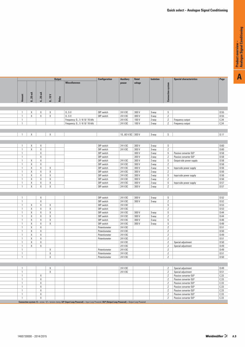
Frequency measuring transducer8581180000 WAS4 PRO Freq 1 X 2- and 3-wire PNP/NPN;
Namur Initiator, push-pull step12.5 mm 1 X X X 0…5 V DIP switch 24 V DC 300 V 3-way S D.55
8581190000 WAZ4 PRO Freq 1 X 12.5 mm 1 X X X 0…5 V DIP switch 24 V DC 300 V 3-way Z D.558461480000 MCZ CFC 0-20MA 1 X 6 mm 1 Frequency: 0...1/ 4/ 8/ 16 kHz 24 V DC 100 V 2-way Z Frequency output C.348461470000 MCZ VFC 0-10V 1 X 6 mm 1 Frequency: 0...1/ 4/ 8/ 16 kHz 24 V DC 100 V 2-way Z Frequency output C.34
Strain gauge transmitter1067250000 ACT20P-BRIDGE-S 1 adjustable +/-10 mV…+/- 50 mV 22.5 mm 1 X X 10...60 V DC 300 V 3-way S D.17
AC/DC measuring transducer8581220000 WAS2 VMA V ac 1 Adjustable: 0...450 V AC 22.5 mm 1 X X DIP switch 24 V DC 300 V 3-way S D.608581230000 WAZ2 VMA V ac 1 22.5 mm 1 X X DIP switch 24 V DC 300 V 3-way Z D.608528650000 WAS1 CMA LP 1/5/10A ac 1 Adjustable: 0…10 A AC 22.5 mm 1 X DIP switch 300 V 2-way S Passive converter OLP D.588528660000 WAZ1 CMA LP 1/5/10A ac 1 22.5 mm 1 X DIP switch 300 V 2-way Z Passive converter OLP D.588523400000 WAS1 CMA 1/5/10A ac 1 Adjustable: 0…10 A AC 22.5 mm 1 X X DIP switch 24 V DC 300 V 2-way S Output-side power supply D.588523410000 WAZ1 CMA 1/5/10A ac 1 22.5 mm 1 X X DIP switch 24 V DC 300 V 2-way Z D.588526610000 WAS2 CMA 5/10A uc 1 Adjustable: 0…10 A AC/DC 22.5 mm 1 X X X DIP switch 24 V DC 300 V 2-way S Input-side power supply D.568526620000 WAZ2 CMA 5/10A uc 1 22.5 mm 1 X X X DIP switch 24 V DC 300 V 2-way Z D.568545830000 WAS2 CMA 20/25/30A uc 1 Adjustable: 0…30 A AC/DC 22.5 mm 1 X X X DIP switch 24 V DC 300 V 2-way S Input-side power supply D.568545840000 WAZ2 CMA 20/25/30A uc 1 22.5 mm 1 X X X DIP switch 24 V DC 300 V 2-way Z D.568513330000 WAS2 CMA 40/50/60A uc 1 Adjustable: 0…60 A AC/DC 22.5 mm 1 X X X DIP switch 24 V DC 300 V 2-way S Input-side power supply D.578526590000 WAZ2 CMA 40/50/60A uc 1 22.5 mm 1 X X X DIP switch 24 V DC 300 V 2-way Z D.57
Temperature measuring transducer8560720000 WAS5 PRO Thermo 1 X 17.5 mm 1 X DIP switch 24 V DC 300 V 3-way S D.528560730000 WAZ5 PRO Thermo 1 X 17.5 mm 1 X DIP switch 24 V DC 300 V 3-way Z D.528432300000 WTS4 THERMO 1 X 12.5 mm 1 X X X DIP switch 24 V DC S D.538432310000 WTZ4 THERMO 1 X 12.5 mm 1 X X X DIP switch 24 V DC Z D.538560700000 WAS5 PRO RTD 1 X 17.5 mm 1 X X X DIP switch 24 V DC 300 V 3-way S D.448560710000 WAZ5 PRO RTD 1 X 17.5 mm 1 X X X DIP switch 24 V DC 300 V 3-way Z D.448679490000 WAS5 PRO RTD 1000 1 X 17.5 mm 1 X X X DIP switch 24 V DC 300 V 3-way S D.468638950000 WAS5 PRO RTD Cu 1 X 17.5 mm 1 X X X DIP switch 24 V DC 300 V 3-way S D.488432220000 WTZ4 PT100/2 C 0/4-20mA 1 X 12.5 mm 1 X X Potentiometer 24 V DC Z D.518432160000 WTZ4 PT100/3 C 0/4-20mA 1 X 12.5 mm 1 X X Potentiometer 24 V DC Z D.508432280000 WTZ4 PT100/4 C 0/4-20mA 1 X 12.5 mm 1 X X Potentiometer 24 V DC Z D.498432229999 WTZ4 PT100/2 C 0/4-20mA variabel 1 X 12.5 mm 1 X X Potentiometer 24 V DC Z D.518432169999 WTZ4 PT100/3 C 0/4-20mA variabel 1 X 12.5 mm 1 X X 24 V DC Z Special adjustment D.508432289999 WTZ4 PT100/4 C 0/4-20mA variabel 1 X 12.5 mm 1 X X 24 V DC Z Special adjustment D.498432250000 WTZ4 PT100/4 V 0-10V 1 X 12.5 mm 1 X Potentiometer 24 V DC Z D.498432190000 WTZ4 PT100/2 V 0-10V 1 X 12.5 mm 1 X Potentiometer 24 V DC Z D.518432130000 WTZ4 PT100/3 V 0-10V 1 X 12.5 mm 1 X Potentiometer 24 V DC Z D.50
Temperature measuring transducer8432259999 WTZ4 PT100/4 V 0-10V variabel 1 X 12.5 mm 1 X 24 V DC Z Special adjustment D.498432199999 WTZ4 PT100/2 V 0-10V variabel 1 X 12.5 mm 1 X 24 V DC Z Special adjustment D.518425720000 MCZ PT100/3 CLP 0...100C 1 X 6 mm 1 X Z Passive converter OLP C.338483680000 MCZ PT100/3 CLP 0...120C 1 X 6 mm 1 X Z Passive converter OLP C.338604420000 MCZ PT100/3 CLP 0...150C 1 X 6 mm 1 X Z Passive converter OLP C.338473010000 MCZ PT100/3 CLP 0...200C 1 X 6 mm 1 X Z Passive converter OLP C.338473020000 MCZ PT100/3 CLP 0...300C 1 X 6 mm 1 X Z Passive converter OLP C.338473000000 MCZ PT100/3 CLP -50C...+150C 1 X 6 mm 1 X Z Passive converter OLP C.338604430000 MCZ PT100/3 CLP -40C...100C 1 X 6 mm 1 X Z Passive converter OLP C.33
Connection system: S = screw / Z = tension clamp, ILP (Input Loop Powered) = Input Loop Powered, OLP (Output Loop Powered) = Output Loop Powered
Quick select – Analogue Signal Conditioning
Quick select – Analogue Signal Conditioning
A
Prod
uct o
verv
iew –
Analo
gue S
ignal
Cond
ition
ing
A.8 1460730000 – 2014/2015
Selection tableOrder No. Product Input Width Output Configuration Auxiliary
powerRatedvoltage
Isolation
Conn
ectio
n sys
tem
Special characteristics Page
Amou
nt
0...2
0 mA
4...2
0 mA
0...1
0 V
0…5 V
TC RTD
Freq
uenc
y
Miscellaneous
Sens
or fe
ed
Amou
nt
0...2
0 mA
4...2
0 mA
0...1
0 V
Relay
Miscellaneous
Frequency measuring transducer8581180000 WAS4 PRO Freq 1 X 2- and 3-wire PNP/NPN;
Namur Initiator, push-pull step12.5 mm 1 X X X 0…5 V DIP switch 24 V DC 300 V 3-way S D.55
8581190000 WAZ4 PRO Freq 1 X 12.5 mm 1 X X X 0…5 V DIP switch 24 V DC 300 V 3-way Z D.558461480000 MCZ CFC 0-20MA 1 X 6 mm 1 Frequency: 0...1/ 4/ 8/ 16 kHz 24 V DC 100 V 2-way Z Frequency output C.348461470000 MCZ VFC 0-10V 1 X 6 mm 1 Frequency: 0...1/ 4/ 8/ 16 kHz 24 V DC 100 V 2-way Z Frequency output C.34
Strain gauge transmitter1067250000 ACT20P-BRIDGE-S 1 adjustable +/-10 mV…+/- 50 mV 22.5 mm 1 X X 10...60 V DC 300 V 3-way S D.17
AC/DC measuring transducer8581220000 WAS2 VMA V ac 1 Adjustable: 0...450 V AC 22.5 mm 1 X X DIP switch 24 V DC 300 V 3-way S D.608581230000 WAZ2 VMA V ac 1 22.5 mm 1 X X DIP switch 24 V DC 300 V 3-way Z D.608528650000 WAS1 CMA LP 1/5/10A ac 1 Adjustable: 0…10 A AC 22.5 mm 1 X DIP switch 300 V 2-way S Passive converter OLP D.588528660000 WAZ1 CMA LP 1/5/10A ac 1 22.5 mm 1 X DIP switch 300 V 2-way Z Passive converter OLP D.588523400000 WAS1 CMA 1/5/10A ac 1 Adjustable: 0…10 A AC 22.5 mm 1 X X DIP switch 24 V DC 300 V 2-way S Output-side power supply D.588523410000 WAZ1 CMA 1/5/10A ac 1 22.5 mm 1 X X DIP switch 24 V DC 300 V 2-way Z D.588526610000 WAS2 CMA 5/10A uc 1 Adjustable: 0…10 A AC/DC 22.5 mm 1 X X X DIP switch 24 V DC 300 V 2-way S Input-side power supply D.568526620000 WAZ2 CMA 5/10A uc 1 22.5 mm 1 X X X DIP switch 24 V DC 300 V 2-way Z D.568545830000 WAS2 CMA 20/25/30A uc 1 Adjustable: 0…30 A AC/DC 22.5 mm 1 X X X DIP switch 24 V DC 300 V 2-way S Input-side power supply D.568545840000 WAZ2 CMA 20/25/30A uc 1 22.5 mm 1 X X X DIP switch 24 V DC 300 V 2-way Z D.568513330000 WAS2 CMA 40/50/60A uc 1 Adjustable: 0…60 A AC/DC 22.5 mm 1 X X X DIP switch 24 V DC 300 V 2-way S Input-side power supply D.578526590000 WAZ2 CMA 40/50/60A uc 1 22.5 mm 1 X X X DIP switch 24 V DC 300 V 2-way Z D.57
Temperature measuring transducer8560720000 WAS5 PRO Thermo 1 X 17.5 mm 1 X DIP switch 24 V DC 300 V 3-way S D.528560730000 WAZ5 PRO Thermo 1 X 17.5 mm 1 X DIP switch 24 V DC 300 V 3-way Z D.528432300000 WTS4 THERMO 1 X 12.5 mm 1 X X X DIP switch 24 V DC S D.538432310000 WTZ4 THERMO 1 X 12.5 mm 1 X X X DIP switch 24 V DC Z D.538560700000 WAS5 PRO RTD 1 X 17.5 mm 1 X X X DIP switch 24 V DC 300 V 3-way S D.448560710000 WAZ5 PRO RTD 1 X 17.5 mm 1 X X X DIP switch 24 V DC 300 V 3-way Z D.448679490000 WAS5 PRO RTD 1000 1 X 17.5 mm 1 X X X DIP switch 24 V DC 300 V 3-way S D.468638950000 WAS5 PRO RTD Cu 1 X 17.5 mm 1 X X X DIP switch 24 V DC 300 V 3-way S D.488432220000 WTZ4 PT100/2 C 0/4-20mA 1 X 12.5 mm 1 X X Potentiometer 24 V DC Z D.518432160000 WTZ4 PT100/3 C 0/4-20mA 1 X 12.5 mm 1 X X Potentiometer 24 V DC Z D.508432280000 WTZ4 PT100/4 C 0/4-20mA 1 X 12.5 mm 1 X X Potentiometer 24 V DC Z D.498432229999 WTZ4 PT100/2 C 0/4-20mA variabel 1 X 12.5 mm 1 X X Potentiometer 24 V DC Z D.518432169999 WTZ4 PT100/3 C 0/4-20mA variabel 1 X 12.5 mm 1 X X 24 V DC Z Special adjustment D.508432289999 WTZ4 PT100/4 C 0/4-20mA variabel 1 X 12.5 mm 1 X X 24 V DC Z Special adjustment D.498432250000 WTZ4 PT100/4 V 0-10V 1 X 12.5 mm 1 X Potentiometer 24 V DC Z D.498432190000 WTZ4 PT100/2 V 0-10V 1 X 12.5 mm 1 X Potentiometer 24 V DC Z D.518432130000 WTZ4 PT100/3 V 0-10V 1 X 12.5 mm 1 X Potentiometer 24 V DC Z D.50
Temperature measuring transducer8432259999 WTZ4 PT100/4 V 0-10V variabel 1 X 12.5 mm 1 X 24 V DC Z Special adjustment D.498432199999 WTZ4 PT100/2 V 0-10V variabel 1 X 12.5 mm 1 X 24 V DC Z Special adjustment D.518425720000 MCZ PT100/3 CLP 0...100C 1 X 6 mm 1 X Z Passive converter OLP C.338483680000 MCZ PT100/3 CLP 0...120C 1 X 6 mm 1 X Z Passive converter OLP C.338604420000 MCZ PT100/3 CLP 0...150C 1 X 6 mm 1 X Z Passive converter OLP C.338473010000 MCZ PT100/3 CLP 0...200C 1 X 6 mm 1 X Z Passive converter OLP C.338473020000 MCZ PT100/3 CLP 0...300C 1 X 6 mm 1 X Z Passive converter OLP C.338473000000 MCZ PT100/3 CLP -50C...+150C 1 X 6 mm 1 X Z Passive converter OLP C.338604430000 MCZ PT100/3 CLP -40C...100C 1 X 6 mm 1 X Z Passive converter OLP C.33
Connection system: S = screw / Z = tension clamp, ILP (Input Loop Powered) = Input Loop Powered, OLP (Output Loop Powered) = Output Loop Powered
Quick select – Analogue Signal Conditioning
A
Prod
uct o
verv
iew –
Analo
gue S
ignal
Cond
ition
ing
A.91460730000 – 2014/2015

Selection tableOrder No. Product Input Width Output Configuration Auxiliary
powerRatedvoltage
Isolation
Conn
ectio
n sys
tem
Special characteristics Page
Amou
nt
0...2
0 mA
4...2
0 mA
0...1
0 V
0…5 V
TC RTD
Freq
uenc
y
Miscellaneous
Sens
or fe
ed
Amou
nt
0...2
0 mA
4...2
0 mA
0...1
0 V
Relay
Miscellaneous
Monitoring modules8260280000 MCZ SC 0-10V 1 X 6 mm 2 X 24 V DC Z C.358227350000 MCZ SC 0-20MA 1 X 6 mm 2 X 24 V DC Z C.358543820000 WAS5 DC/Alarm 1 X X X 17.5 mm 2 X DIP switch 24 V DC 300 V 3-way S Adjustable switching thresholds E.48543880000 WAZ5 DC/Alarm 1 X X X 17.5 mm 2 X DIP switch 24 V DC 300 V 3-way Z Adjustable switching thresholds E.48705640000 WAS5 VMR 1ph 1 Adjustable: 24…260 V AC/DC 1-phase
reset input17.5 mm 1 X CO contact DIP switch 300 V 3-way S Adjustable switching thresholds,
supply from the measurement circuitE.8
8705630000 WAS2 VMR 3ph 1 Adjustable: 80…250 V AC/DC 3-phase 200…400 V AC/DC 1-phase
22.5 mm 1 X Monitoring of low and surgevoltages
DIP switch 600 V 2-way S Adjustable switching thresholds,supply from the measurement circuit
E.9
8516560000 WAS2 CMR 1/5/10A ac 1 0…10 A AC 22.5 mm 1 X DIP switch 24 V DC 300 V 2-way S Adjustable switching thresholds E.58516570000 WAZ2 CMR 1/5/10A ac 1 0…10 A AC 22.5 mm 1 X DIP switch 24 V DC 300 V 2-way Z Adjustable switching thresholds E.58513340000 WAS2 CMR 20/40/60A ac 1 0…60 A AC 22.5 mm 1 X DIP switch 24 V DC 300 V 2-way S Adjustable switching thresholds E.58526600000 WAZ2 CMR 20/40/60A ac 1 0…60 A AC 22.5 mm 1 X DIP switch 24 V DC 300 V 2-way Z Adjustable switching thresholds E.5
Connection system: S = screw / Z = tension clamp, ILP (Input Loop Powered) = Input Loop Powered, OLP (Output Loop Powered) = Output Loop Powered
Quick select – Analogue Signal Conditioning
Quick select – Analogue Signal Conditioning
A
Prod
uct o
verv
iew –
Analo
gue S
ignal
Cond
ition
ing
A.10 1460730000 – 2014/2015

Selection tableOrder No. Product Input Width Output Configuration Auxiliary
powerRatedvoltage
Isolation
Conn
ectio
n sys
tem
Special characteristics Page
Amou
nt
0...2
0 mA
4...2
0 mA
0...1
0 V
0…5 V
TC RTD
Freq
uenc
y
Miscellaneous
Sens
or fe
ed
Amou
nt
0...2
0 mA
4...2
0 mA
0...1
0 V
Relay
Miscellaneous
Monitoring modules8260280000 MCZ SC 0-10V 1 X 6 mm 2 X 24 V DC Z C.358227350000 MCZ SC 0-20MA 1 X 6 mm 2 X 24 V DC Z C.358543820000 WAS5 DC/Alarm 1 X X X 17.5 mm 2 X DIP switch 24 V DC 300 V 3-way S Adjustable switching thresholds E.48543880000 WAZ5 DC/Alarm 1 X X X 17.5 mm 2 X DIP switch 24 V DC 300 V 3-way Z Adjustable switching thresholds E.48705640000 WAS5 VMR 1ph 1 Adjustable: 24…260 V AC/DC 1-phase
reset input17.5 mm 1 X CO contact DIP switch 300 V 3-way S Adjustable switching thresholds,
supply from the measurement circuitE.8
8705630000 WAS2 VMR 3ph 1 Adjustable: 80…250 V AC/DC 3-phase 200…400 V AC/DC 1-phase
22.5 mm 1 X Monitoring of low and surgevoltages
DIP switch 600 V 2-way S Adjustable switching thresholds,supply from the measurement circuit
E.9
8516560000 WAS2 CMR 1/5/10A ac 1 0…10 A AC 22.5 mm 1 X DIP switch 24 V DC 300 V 2-way S Adjustable switching thresholds E.58516570000 WAZ2 CMR 1/5/10A ac 1 0…10 A AC 22.5 mm 1 X DIP switch 24 V DC 300 V 2-way Z Adjustable switching thresholds E.58513340000 WAS2 CMR 20/40/60A ac 1 0…60 A AC 22.5 mm 1 X DIP switch 24 V DC 300 V 2-way S Adjustable switching thresholds E.58526600000 WAZ2 CMR 20/40/60A ac 1 0…60 A AC 22.5 mm 1 X DIP switch 24 V DC 300 V 2-way Z Adjustable switching thresholds E.5
Connection system: S = screw / Z = tension clamp, ILP (Input Loop Powered) = Input Loop Powered, OLP (Output Loop Powered) = Output Loop Powered
Quick select – Analogue Signal Conditioning
A
Prod
uct o
verv
iew –
Analo
gue S
ignal
Cond
ition
ing
A.111460730000 – 2014/2015

A
Prod
uct o
verv
iew –
Analo
gue S
ignal
Cond
ition
ing
A.12 1460730000 – 2014/2015
Intrinsically safe signal conditionersfor hazardous area applications
Intrinsically safe signal conditionersfor hazardous area applications
Intrinsically safe signal conditioners for hazardous area applications – Overview B.2
ACT20X – Overview B.4
Current supply isolator B.6
Current output isolator B.8
Temperature transducer B.10
Universal measurement and signal isolator-converter B.12
NAMUR isolating switching amplifier B.16
Valve control module B.20
Contents
B
Intri
nsica
lly sa
fe si
gnal
cond
ition
ers
for h
azar
dous
area
appli
catio
ns
B.11460730000 – 2014/2015
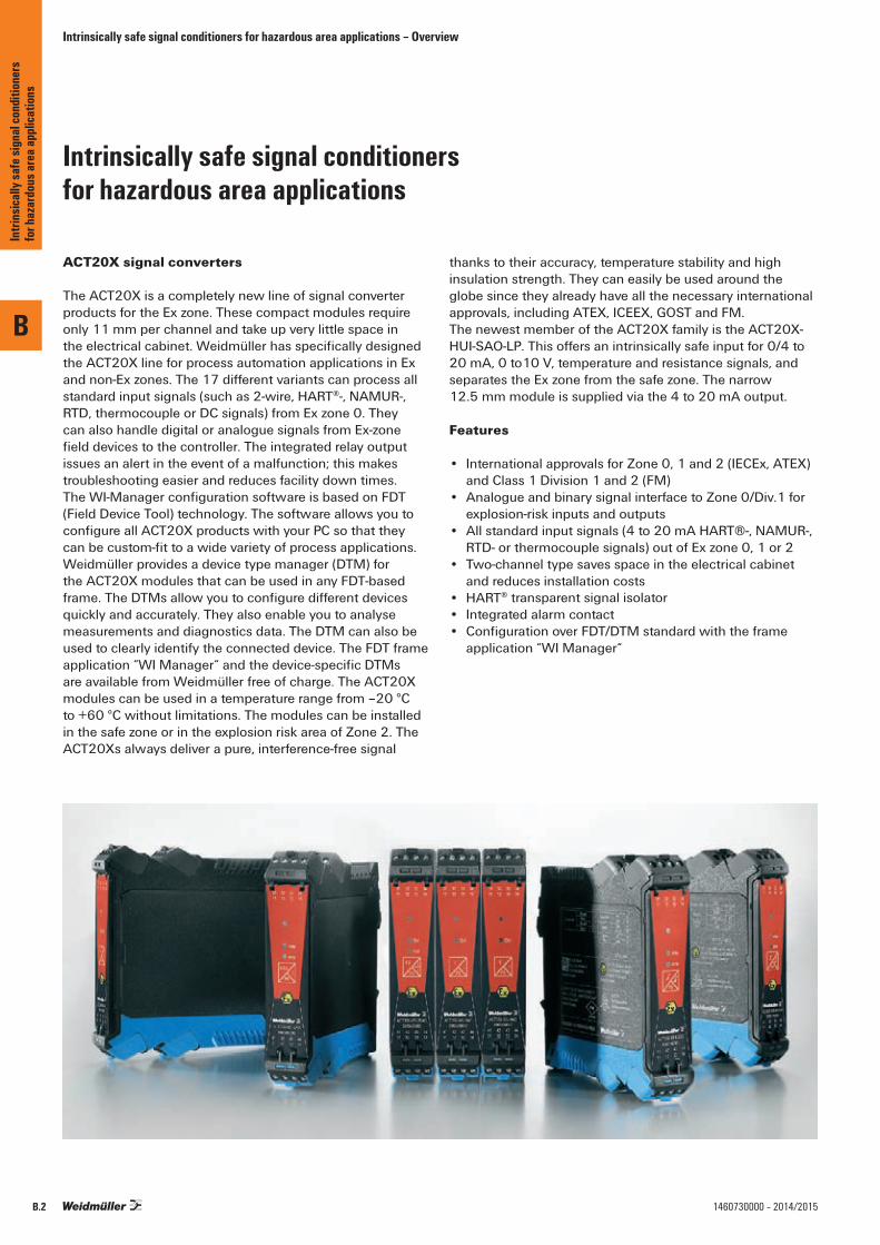
ACT20X signal converters
The ACT20X is a completely new line of signal converter products for the Ex zone. These compact modules require only 11 mm per channel and take up very little space in the electrical cabinet. Weidmüller has specifically designed the ACT20X line for process automation applications in Ex and non-Ex zones. The 17 different variants can process all standard input signals (such as 2-wire, HART®-, NAMUR-, RTD, thermocouple or DC signals) from Ex zone 0. They can also handle digital or analogue signals from Ex-zone field devices to the controller. The integrated relay output issues an alert in the event of a malfunction; this makes troubleshooting easier and reduces facility down times. The WI-Manager configuration software is based on FDT (Field Device Tool) technology. The software allows you to configure all ACT20X products with your PC so that they can be custom-fit to a wide variety of process applications. Weidmüller provides a device type manager (DTM) for the ACT20X modules that can be used in any FDT-based frame. The DTMs allow you to configure different devices quickly and accurately. They also enable you to analyse measurements and diagnostics data. The DTM can also be used to clearly identify the connected device. The FDT frame application “WI Manager“ and the device-specific DTMs are available from Weidmüller free of charge. The ACT20X modules can be used in a temperature range from –20 °C to +60 °C without limitations. The modules can be installed in the safe zone or in the explosion risk area of Zone 2. The ACT20Xs always deliver a pure, interference-free signal
thanks to their accuracy, temperature stability and high insulation strength. They can easily be used around the globe since they already have all the necessary international approvals, including ATEX, ICEEX, GOST and FM.The newest member of the ACT20X family is the ACT20X-HUI-SAO-LP. This offers an intrinsically safe input for 0/4 to 20 mA, 0 to10 V, temperature and resistance signals, and separates the Ex zone from the safe zone. The narrow 12.5 mm module is supplied via the 4 to 20 mA output.
Features
• International approvals for Zone 0, 1 and 2 (IECEx, ATEX)and Class 1 Division 1 and 2 (FM)
• Analogue and binary signal interface to Zone 0/Div.1 for explosion-risk inputs and outputs
• All standard input signals (4 to 20 mA HART®-, NAMUR-, RTD- or thermocouple signals) out of Ex zone 0, 1 or 2
• Two-channel type saves space in the electrical cabinet and reduces installation costs
• HART® transparent signal isolator• Integrated alarm contact • Configuration over FDT/DTM standard with the frame
application “WI Manager“
Intrinsically safe signal conditionersfor hazardous area applications
Intrinsically safe signal conditioners for hazardous area applications – Overview
B
Intri
nsica
lly sa
fe si
gnal
cond
ition
ers
for h
azar
dous
area
appli
catio
ns
B.2 1460730000 – 2014/2015

Intrinsically safe signal conditioners for hazardous area applications – Overview
ACT20X
B
Intri
nsica
lly sa
fe si
gnal
cond
ition
ers
for h
azar
dous
area
appli
catio
ns
B.31460730000 – 2014/2015
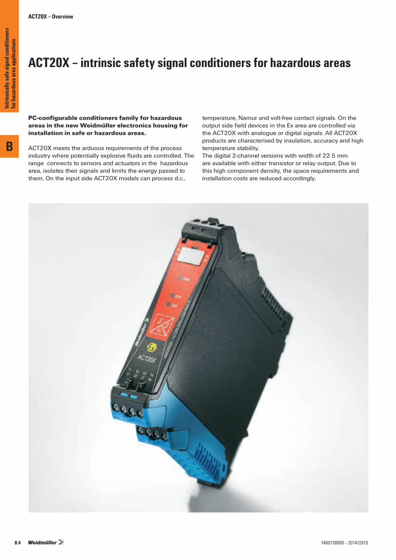
ACT20X – intrinsic safety signal conditioners for hazardous areas
PC-configurable conditioners family for hazardous areas in the new Weidmüller electronics housing for installation in safe or hazardous areas.
ACT20X meets the arduous requirements of the process industry where potentially explosive fluids are controlled. The range connects to sensors and actuators in the hazardous area, isolates their signals and limits the energy passed to them. On the input side ACT20X models can process d.c.,
temperature, Namur and volt-free contact signals. On the output side field devices in the Ex area are controlled via the ACT20X with analogue or digital signals. All ACT20X products are characterised by insulation, accuracy and high temperature stability.The digital 2-channel versions with width of 22.5 mm are available with either transistor or relay output. Due to this high component density, the space requirements and installation costs are reduced accordingly.
ACT20X – Overview
B
Intri
nsica
lly sa
fe si
gnal
cond
ition
ers
for h
azar
dous
area
appli
catio
ns
B.4 1460730000 – 2014/2015

ACT20X – Overview
Configuration via FDT
All modules can be quickly and conveniently configured with manufacturer-independent FDT/DTM software.
Intelligent connection system
Pluggable, coded, with release lever.The release lever simplifies maintenance and allows disconnection without damaging the cables.
Worldwide application
Fulfils the strict standards and require-ments of the process industry. Can be used worldwide due to international and local approvals ATEX, IECEX, CULUS, FM, GOST and DNV.
Alarm function
No laborious troubleshooting. Alarm function integrated for cable or sensor errors. In case of failures, a diagnostic signal is sent to the control system.
Robust
Wide ambient temperature range from– 20 °C … + 60 °C.
\
;
"
Current supply isolator, HART® Transparent
Current output isolator, HART® Transparent
Temperature transducer
Universal measurement and signal isolator/converter
NAMUR disconnect-switch amplifier
Valve control component
+60 °Cto–20 °C
B
Intri
nsica
lly sa
fe si
gnal
cond
ition
ers
for h
azar
dous
area
appli
catio
ns
B.51460730000 – 2014/2015

ACT20X
Current-supply isolator, HART® Transparent
The ACT20X-HAI-SAO current supply isolator is a HART®-protocol transparent signal isolator for analogue input signals from Ex zone 0. It provides an analogue signal for the safe zone on the output side. It is available in a single-channel or double-channel version.
EX area Zone 0, 1, 2, 20, 21, 22 Safe area Zone 2 / FM Class 1, Division 2
Chan
nel 1
:Ch
anne
l 2:
51
52
53
54
Input Signals
44
43
42
41
14
13
12
11
24
23
22
21
Output Signals
Gnd. -
Supply +19,2...31,2 V DC
Module status
Module status
mA mA4...20 mA+
–
42
41
44
43
–
+
– –mA mA
4...20 mA
Analogue, 4...20 mA
2-wire supply +
2-wire supply –
2-wire supply +
2-wire supply –
N.C.
active or passive sensor
active or passive outputactive or passive sensor
+
-Tx
+
-Current
+
-Tx
+
-Current
Power Supply andModule Status
Ex label (excerpt)ATEX FM Uo/Ui 0 V / 30 VII 3 G Ex nA nC IIC T4 Gc Installation in CL I DIV2 GP A-D T4
Kl. I-III ABT 1/2 GP A-G or Kl. I Zn2 AEx/Ex nA nC [ia] IIC T4
Io/li 0 mA / 120 mAII (1) G [Ex ia Ga] IIC/IIB/IIA Po/Pi 0 mW / 0,85 WII (1) D [Ex ia Da] IIIC Li 0 µH
Example: Ci 2 nFIECEx ATEX version,
Ex input, External Current Source:(More details in ATEX certificate)
IIC Co = 0,08 µF, Lo= 3 mHEx nA nC IIC T4 Gc IIB Co = 0,6 µF, Lo= 12 mH[Ex ia Ga] IIC/IIB/IIA IIA Co = 2,15 µF, Lo= 25 mH
Application example: Measuring temperature with a head transmitter, signal transmission with HART®
Control system
2 wire HART® head transmitter for temperature
Tank
A.C. supply
Zone 0ACT20X-HAI-SAO
To other isolators
+24 V DC
0 V
4-20 mA / HART® output
Passive input
channel4-20 mA / HART®
input
EX-Zone
\%
Removableterminals(black)
LED green= supply
Marker
Removableterminals(blue)
LED Channel 2red = inactive,
flashing = fault
LED Channel 1red = inactive,
flashing = fault
B
Intri
nsica
lly sa
fe si
gnal
cond
ition
ers
for h
azar
dous
area
appli
catio
ns
B.6 1460730000 – 2014/2015
B
B.71460730000 – 2014/2015
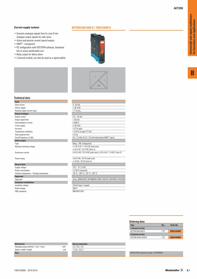
Current supply isolator
• Converts analogue signals from Ex zone 0 into analogue output signals for safe zones.
• Active and passive current inputs/outputs• HART® - transparent• PC configuration with FDT/DTM software, download
link at www.weidmueller.com• Relay output for failure alarm• 2-channel module, can also be used as a signal splitter
Technical dataInputInput currentSensor supplyResidual ripple (current loop) Output analogueOutput currentOutput signal limitload impedance current2-wire supplyAccuracyTemperature coefficientStep response timeCut-off frequency (-3 dB)Alarm outputType Nominal switching voltage
Continuous current
Power rating
General dataSupply voltagePower consumptionAmbient temperature / Storage temperatureApprovalsApprovalsInsulation coordinationInsulation voltageRated voltageEMC standards
DimensionsClamping range (nominal / min. / max.) mm²Depth x width x height mmNote
ACT20X-HAI-SAO-S / 2HAI-2SAO-S
I
I
PS
4...20 mA≤ 28 V DC< 7.5 mVeff
3.5 – 23 mA< 28 mA≤ 600 Ω≤ 26 V DC< 0.1% span< 0.01% of span/°C (TU)≤ 5 ms0.5…2.5 kHz @ 3.5…23 mA bi-directional HART® signal
Relay, 1 NC (voltage-free)≤ 125 V AC / 110 V DC (safe area) ≤ 32 V AC / 32 V DC (Zone 2)≤ 0.5 A AC / 0.3 A DC (safe zone), ≤ 0.5 A AC / 1 A DC ( Zone 2)
≤ 62.5 VA / 32 W (safe area) ≤ 16 VA / 32 W (Zone 2)
19.2 – 31.2 V DC≤ 3 W (2 channels)-20 °C...+60 °C / -20 °C...+85 °C
cULus; DEKRAATEX; DETNORVER; FMEX; GOSTEX; GOSTME25; IECEXDEK
2.6 kV (input / output)300 VDIN EN 61326
Type Qty. Order No.1-channel versionACT20X-HAI-SAO-S 1 ST 89654300002-channel versionACT20X-2HAI-2SAO-S 1 ST 8965440000
CBX200 USB configuration adapter - 8978580000
Ordering data
Screw connection2.5 / 0.5 / 2.5113.6 / 22.5 /
Intri
nsica
lly sa
fe si
gnal
cond
ition
ers
for h
azar
dous
area
appli
catio
ns
ACT20X

ACT20X
Current output isolator, HART® Transparent
The ACT20X-SAI-HAO current output isolator is HART®-transparent. The input is connected to the safe area controller or PLC, and the output is connected to an analog actuator in a hazardous area, e.g. Zone 0. It is available in a single-channel or double-channel version.
EX area Zone 0, 1, 2, 20, 21, 22 Safe area Zone 2 / FM Class 1, Division 2
Chan
nel 1
:Ch
anne
l 2:
51
52
53
54
Ex Output signals
44
43
42
41
14
13
12
11
24
23
22
21
Input signals
Gnd. -
Supply +19,2...31,2 V DC
Module status
Module status
42
41
44
43
Analogue, 4...20 mA
N.C.
passive valve
active inputpassive valve
Ch1
Ch 2Load
4...20 mA
Load4...20 mA
+
-
+
-
Power Supply andModule Status
Ex label (excerpt)ATEX FM Uo 28 VII 3 G Ex nA nC IIC T4 Gc Installation in CL I DIV2 GP A-D T4
Kl. I-III ABT 1/2 GP A-G or Kl. I Zn2 AEx/Ex nA nC [ia] IIC T4
Io 93 mAII (1) G [Ex ia Ga] IIC/IIB/IIA Po 0.65 WII (1) D [Ex ia Da] IIIC IIC Co = 0.08 µF, Lo= 4 mHIECEx Example: IIB Co = 0.65 µF, Lo= 16 mHEx nA nC IIC T4 Gc ATEX version, IIA Co = 2.15 µF, Lo= 32 mH[Ex ia Ga] IIC/IIB/IIA Ex output,[Ex ia Da] IIIC (More details in ATEX certificate)
Application example: controlling an actuator in the Ex zone.
Control system
A.C. supply
ACT20X-SAI-HAO
+24 V DC
0 V
4-20 mA / HART input
+24 V DC
Output –Control system
4-20 mA / HART output
HART valveActuator
Actuator
Position-transmitter
Control valve
EX-Zone
\%
Removableterminals(black)
LED green= supply
Marker
Removableterminals(blue)
LED Channel 2red = inactive,
flashing = fault
LED Channel 1red = defective,flashing = fault
B
Intri
nsica
lly sa
fe si
gnal
cond
ition
ers
for h
azar
dous
area
appli
catio
ns
B.8 1460730000 – 2014/2015
B
B.91460730000 – 2014/2015
Intri
nsica
lly sa
fe si
gnal
cond
ition
ers
for h
azar
dous
area
appli
catio
ns
ACT20X
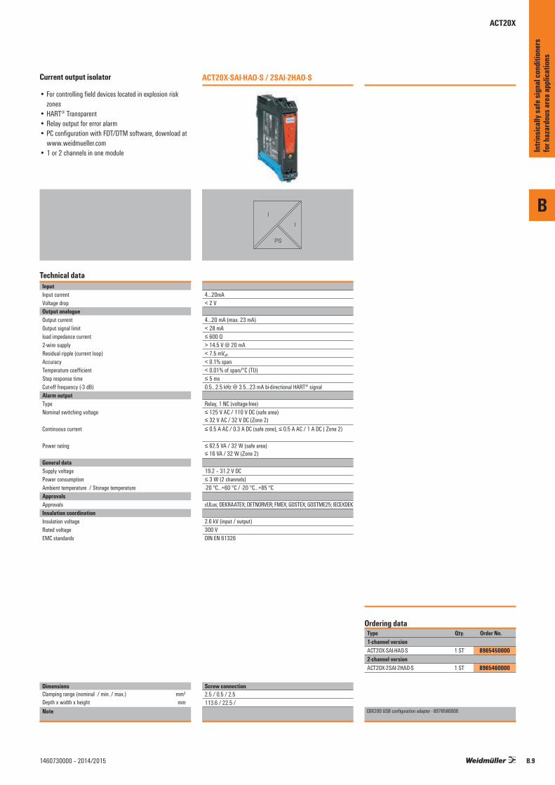
Current output isolator
• For controlling field devices located in explosion risk zones
• HART® Transparent• Relay output for error alarm• PC configuration with FDT/DTM software, download at
www.weidmueller.com• 1 or 2 channels in one module
Technical dataInputInput currentVoltage dropOutput analogueOutput currentOutput signal limitload impedance current2-wire supplyResidual ripple (current loop) AccuracyTemperature coefficientStep response timeCut-off frequency (-3 dB)Alarm outputType Nominal switching voltage
Continuous current
Power rating
General dataSupply voltagePower consumptionAmbient temperature / Storage temperatureApprovalsApprovalsInsulation coordinationInsulation voltageRated voltageEMC standards
DimensionsClamping range (nominal / min. / max.) mm²Depth x width x height mmNote
ACT20X-SAI-HAO-S / 2SAI-2HAO-S
I
I
PS
4…20mA< 2 V
4…20 mA (max. 23 mA)< 28 mA≤ 600 Ω > 14.5 V @ 20 mA< 7.5 mVeff
< 0.1% span< 0.01% of span/°C (TU)≤ 5 ms0.5…2.5 kHz @ 3.5…23 mA bi-directional HART® signal
Relay, 1 NC (voltage-free)≤ 125 V AC / 110 V DC (safe area) ≤ 32 V AC / 32 V DC (Zone 2)≤ 0.5 A AC / 0.3 A DC (safe zone), ≤ 0.5 A AC / 1 A DC ( Zone 2)
≤ 62.5 VA / 32 W (safe area) ≤ 16 VA / 32 W (Zone 2)
19.2 – 31.2 V DC≤ 3 W (2 channels)-20 °C...+60 °C / -20 °C...+85 °C
cULus; DEKRAATEX; DETNORVER; FMEX; GOSTEX; GOSTME25; IECEXDEK
2.6 kV (input / output)300 VDIN EN 61326
Type Qty. Order No.1-channel versionACT20X-SAI-HAO-S 1 ST 89654500002-channel versionACT20X-2SAI-2HAO-S 1 ST 8965460000
CBX200 USB configuration adapter - 8978580000
Ordering data
Screw connection2.5 / 0.5 / 2.5113.6 / 22.5 /

ACT20X
Temperature transducer
The ACT20X-HTI-SAO temperature transducer processes temperature signals from PT100 sensors and thermocouples originating in the Ex zone. A current signal (mA) can also be connected as the input signal. The input is part of an intrinsically safe circuit (Zone 0). The isolated milliamp analogue output is the input to the receiver or controller in the safe area. It is available in a single-channel or double-channel version.
EX area Zone 0, 1, 2, 20, 21, 22 Safe area Zone 2 / FM Class 1, Division 2
Ex label (excerp)ATEX FM Uo/Ui 8.7 V / 10 VII 3 G Ex nA nC IIC T4 Installation in CL I DIV2 GP A-D T4
Kl. I-III ABT 1/2 GP A-G or Kl. I Zn2 AEx/Ex nA nC [ia] IIC T4
Io/li 18.4 mA / 30 mAII (1) G [Ex ia] IIC/IIB/IIA Po 400 mWII (1) D [Ex iaD] Lo/Ro/Li 892 µH/Ω / 820 nH
Example: Ci 30 nFIECEx ATEX version, IIC Co = 5 µF, Lo= 100 mHEx nA nC IIC T4 Gc Ex input Temperature, IIB Co = 50 µF, Lo= 300 mH[Ex ia Ga] IIC/IIB/IIA (More details in ATEX certificate) IIA Co = 1000 µF, Lo= 700 mH
Application example: temperature measurements in the Ex zone
Control system
Resistancetemperature sensor
Tank
Zone 0
EX-Zone
19.2 - 31.2 V
A.C. supply
Input 4-20mA(Active/passive)
Accuracy / temperature coefficients ACT20X-HTI-SAO
Input Accuracy Temperature coefficient
Input mA ≤ ±4 μA ≤ ±4 μA / °CInput RTDPt100 ≤ ±0.2 °C ≤ ±0.02 °C / °CNi100 ≤ ±0.3 °C ≤ ±0.03 °C / °CInput TCType B ≤ ±4.5 °C ≤ ±0.45 °C / °CType E, J, K, L, N, T, U ≤ ±1 °C ≤ ±0.1 °C / °CType R, S, W3, W5, LR ≤ ±2 °C ≤ ±0.2 °C / °CNote
\ %
Removableterminals(black)
LED green= supply
Marker
Removableterminals(blue)
LED Channel 2red = defective,flashing = fault
LED Channel 1red = defective,flashing = fault
B
Intri
nsica
lly sa
fe si
gnal
cond
ition
ers
for h
azar
dous
area
appli
catio
ns
B.10 1460730000 – 2014/2015

B
B.111460730000 – 2014/2015
Temperature transducer
• Converts intrinsically safe RTD, thermocouple and mA signals into analogue signals for safe zones.
• PC configuration with FDT/DTM software, download link at www.weidmueller.com
• Relay output for failure alarm• 1 or 2 channels in one module• 2-channel module, can also be used as a signal splitter
Technical dataInputTypeSensor supplyTemperature input rangeLine resistance in measuring circuitInput currentInput resistance, currentOutputOutput currentOutput signal limitload impedance currentInfluence of load resistanceCurrent loop outputOutput current (current loop)Load resistanceInfluence of load resistance 2-wire supplyAlarm outputType Nominal switching voltage
Continuous current
Power rating
General dataSupply voltagePower consumptionTightening torque, min. / Tightening torque, max.Ambient temperature / Storage temperatureApprovalsApprovals
Insulation coordinationInsulation voltageRated voltageEMC standards
DimensionsClamping range (nominal / min. / max.) mm²Length x width x height mmNote
ACT20X-HTI-SAO-S / 2HTI-2SAO-S
J, I,U
I
PS
RTD, TC, DC (mA)
Configurable≤ 50 Ω0...20 mA, 4…20mA20 Ω + PTC 50 Ω
0(4)…20 mA / 20…4 mA (configurable)3.8…20.5 mA / 0…20.5 mA (dependent on range)≤ 600 Ω≤ 0.01% of span / 100 Ω
4…20 mA(UB - 3.5) / 0.023 A≤ 0.01% of span / 100 Ω3.5…26 V DC
Relay, 1 NC (voltage-free)≤ 125 V AC / 110 V DC (safe area) ≤ 32 V AC / 32 V DC (Zone 2)≤ 0.5 A AC / 0.3 A DC (safe zone), ≤ 0.5 A AC / 1 A DC ( Zone 2)
≤ 62.5 VA / 32 W (safe area) ≤ 16 VA / 32 W (Zone 2)
19.2 – 31.2 V DC≤ 3 W (2 channels)0.4 Nm / 0.6 Nm-20 °C...+60 °C / -20 °C...+85 °C
cULus; DETNORVER; FMEX; GOSTEX; GOSTME25; IECEXKEM; KEMAATEX
2.6 kV (input / output)300 VDIN EN 61326
Type Qty. Order No.1-channel versionACT20X-HTI-SAO-S 1 ST 89654700002-channel versionACT20X-2HTI-2SAO-S 1 ST 8965480000
CBX200 USB configuration adapter - 8978580000
Ordering data
Screw connection2.5 / 0.5 / 2.5119.2 / 22.5 /
Intri
nsica
lly sa
fe si
gnal
cond
ition
ers
for h
azar
dous
area
appli
catio
ns
ACT20X

ACT20X
Universal measurement and signal isolator-converter
The ACT20X-HUI-SAO-S is a universal input signal isolator/converter. This model processes temperature signals from PT100 sensors and thermocouples as well as DC voltage and current signals (mA) from the hazardous area. On the output side, an isolated milliamp signal is passed to the receiver or controller in the safe area. This model also has a relay output which can be used for a process alarm or trip.
EX area Zone 0, 1, 2, 20, 21, 22 Safe area Zone 2 / FM Class 1, Division 2
Ex label (excerpt)ATEX FM Ui / Uo 30 V / 8.3 VII 3 G Ex nA nC IIC T4 Installation in CL I DIV2 GP A-D T4
Kl. I-III ABT 1/2 GP A-G or Kl. I Zn2 AEx/Ex nA nC [ia] IIC T4
Ii / Io 120 mA / 0.2 mAII (1) G [Ex ia] IIC/IIB/IIA Pi /Po 900 mW / 0.4 mWII (1) D [Ex iaD] Ci 3 nFIECEx Example: Li 1 μHEx nA nC IIC T4 Gc ATEX version, IIC Co= 7 μF Lo=1000 mH[Ex ia Ga] IIC/IIB/IIA Ex input External Current Source IIB Co= 73 μF Lo=1000 mH[Ex ia a] IIIC (More details in ATEX certificate) IIA Co= 1000 μF Lo=1000 mH
Application example: position measurement of an actuator
Control systemA.C. supply
ACT20X-HUI-SAO
Other devices
+24 V DC
0 V
4-20 mA output
Passive input
channel
EX-Zone
Positionalpotentiometer
Valve
Accuracy / temperature coefficients ACT20X-HUI-SAO
Input Accuracy Temperature coefficient
Input mA ≤ ±4 μA ≤ ±4 μA / °CInput Volt ≤ ±20 μV ≤ ±2 μV / °CInput RTDPt100 ≤ ±0.2 °C ≤ ±0.02 °C / °CNi100 ≤ ±0.3 °C ≤ ±0.03 °C / °CInput TCType B ≤ ±4.5 °C ≤ ±0.45 °C / °CType E, J, K, L, N, T, U ≤ ±1 °C ≤ ±0.1 °C / °CType R, S, W3, W5, LR ≤ ±2 °C ≤ ±0.2 °C / °CNote
\%
Removableterminals(black)
LED green= supply
Marker
Removableterminals(blue)
LED Channel 2red = inactive,
flashing = fault
LED Channel 1configurable
B
Intri
nsica
lly sa
fe si
gnal
cond
ition
ers
for h
azar
dous
area
appli
catio
ns
B.12 1460730000 – 2014/2015
B
B.131460730000 – 2014/2015
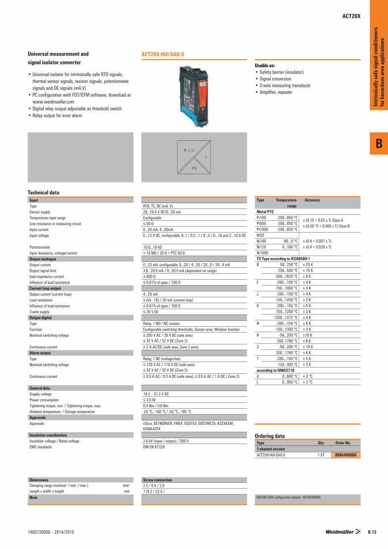
Universal measurement and signal isolator converter
• Universal isolator for intrinsically safe RTD signals, thermal sensor signals, resistor signals, potentiometer signals and DC signals (mA,V)
• PC configuration with FDT/DTM software, download at www.weidmueller.com
• Digital relay output adjustable as threshold switch• Relay output for error alarm
Technical dataInputTypeSensor supplyTemperature input rangeLine resistance in measuring circuitInput currentInput voltage
PotentiometerInput resistance, voltage/currentOutput analogueOutput currentOutput signal limitload impedance currentInfluence of load resistanceCurrent loop outputOutput current (current loop)Load resistanceInfluence of load resistance 2-wire supplyOutput digitalType Function Nominal switching voltage
Continuous current Alarm outputType Nominal switching voltage
Continuous current
General dataSupply voltagePower consumptionTightening torque, min. / Tightening torque, max.Ambient temperature / Storage temperatureApprovalsApprovals
Insulation coordinationInsulation voltage / Rated voltageEMC standards
DimensionsClamping range (nominal / min. / max.) mm²Length x width x height mmNote
ACT20X-HUI-SAO-S
J, I, U
I
PS
RTD, TC, DC (mA, V)28...16.5 V DC/0…20 mAConfigurable≤ 50 Ω0...20 mA, 4…20mA0…12 V DC, configurable: 0..1 / 0.2…1 / 0…5 / 0…10 and 2…10 V DC
10 Ω…10 kΩ> 10 MΩ / 20 Ω + PTC 50 Ω
0…23 mA, configurable: 0…20 / 4…20 / 20…0 / 20…4 mA3.8…20.5 mA / 0…20.5 mA (dependent on range)≤ 600 Ω≤ 0.01% of span / 100 Ω
4…20 mA≤ (Vs - 10) / 20 mA (current loop)≤ 0.01% of span / 100 Ω≤ 26 V DC
Relay, 1 NO / NC contactConfigurable switching thresholds, Sensor error, Window function≤ 250 V AC / 30 V DC (safe area) ≤ 32 V AC / 32 V DC (Zone 2)≤ 2 A AC/DC (safe area, Zone 2 area)
Relay, 1 NC (voltage-free)≤ 125 V AC / 110 V DC (safe area) ≤ 32 V AC / 32 V DC (Zone 2)≤ 0.5 A AC / 0.3 A DC (safe zone), ≤ 0.5 A AC / 1 A DC ( Zone 2)
19.2 – 31.2 V DC≤ 3.5 W0.4 Nm / 0.6 Nm-20 °C...+60 °C / -20 °C...+85 °C
cULus; DETNORVER; FMEX; GOSTEX; GOSTME25; IECEXKEM; KEMAATEX
2.6 kV (input / output) / 300 VDIN EN 61326
Type Qty. Order No.1-channel versionACT20X-HUI-SAO-S 1 ST 8965490000
CBX200 USB configuration adapter - 8978580000
Ordering data
Screw connection2.5 / 0.5 / 2.5119.2 / 22.5 /
Intri
nsica
lly sa
fe si
gnal
cond
ition
ers
for h
azar
dous
area
appli
catio
ns
ACT20X

ACT20X
Output loop powered universal measurement and signal isolating converter
The ACT20X-HUI-SAO-LP is a universal input, isolating signal converter. This model processes temperature signals from PT100 sensors and thermocouples as well as DC voltage and current signals (mA) from the hazardous area. The 12.5 mm wide module is powered through it‘s 4-20 mA output.
EX area Zone 0, 1, 2, 20, 21, 22 Safe area Zone 2 / FM Class 1, Division 2
Input signals Output signals
41
42
11
12
21
22
- Loop Powered (4-20 mA)
+Loop Powered (4-20 mA)
-20 ≤ Ta ≤ +60 °C
VoltPOTRTD/RES
3-wire2-wire TC mV mA
+
+
+
-
Zone 0, 1, 2, 20, 21, 22 /Cl. I/II/III, div. 1 gr. A-G
Zone 2 / FM Cl. 1, div. 2,gr. A-D or safe area
Ex label ATEX Uo 5.88 VII 3 G Ex nA nC IIC T4 Io 3.1 mA II (1) G [Ex ia] IIC/IIB/IIA Po 4.6 mWII (1) D [Ex iaD] Ci 0.001 μFIECEx Li negligibleEx nA IIC T4 Gc Example:[Ex ia Ma Ga] I/IIC [Ex ia Da] IIIC IECEx version
(More details in IECEx certificate)
Application example: Temperature measurement in the EX-zone
Resistancetemperature sensor
Tank
Zone 0
EX-Zone Safe Zone
ACT20X-HUI-SAO
Controlsystem
4-20 mA Output
Input channel active
Accuracy / temperature coefficients ACT20X-HUI-SAO-LP
Input Accuracy Temperature coefficient
Input mA ≤ ±4 μA ≤ ±4 μA / °CInput Volt ≤ ±20 μV ≤ ±2 μV / °CInput RTDPt100 ≤ ±0.2 °C ≤ ±0.02 °C / °CNi100 ≤ ±0.3 °C ≤ ±0.03 °C / °CInput TCType B ≤ ±4.5 °C ≤ ±0.45 °C / °CType E, J, K, L, N, T, U ≤ ±1 °C ≤ ±0.1 °C / °CType R , S, W3, W5, LR ≤ ±2 °C ≤ ±0.2 °C / °CNote
\%
Removableterminals(black)
Marker
Removableterminals(blue)
B
Intri
nsica
lly sa
fe si
gnal
cond
ition
ers
for h
azar
dous
area
appli
catio
ns
B.14 1460730000 – 2014/2015

B
B.151460730000 – 2014/2015
Universal measurement and signal isolator-converter Output-loop powered• Universal isolator for intrinsically safe RTD signals,
thermal sensor signals, resistor signals, potentiometer signals and DC signals (mA,V)
• Supply via output loop• 12.5 mm thin housing• PC configuration with FDT/DTM software, download at
www.weidmueller.com
Technical dataInputTypeTemperature input rangeInput currentInput voltagePotentiometerInput resistance, voltage/currentOutput analogueOutput currentload impedance currentResidual ripple (current loop) AccuracyTemperature coefficientStep response timeCut-off frequency (-3 dB)General dataSupply voltageTightening torque, min. / Tightening torque, max.Ambient temperature / Storage temperatureApprovalsApprovals
Insulation coordinationInsulation voltage / Rated voltageRated voltageEMC standards
DimensionsClamping range (nominal / min. / max.) mm²Length x width x height mmNote
ACT20X-HUI-SAO-LP-S
J, I, U
I
RTD, TC, DC (mA, V), 2 - 3 wire resistorConfigurable± 25 mA± 28 V DC10 Ω…10 kΩ> 10 MΩ @ 600 mV, 2 MΩ @ 28 V / 70 Ω
4…20 mA (max. 23 mA)≤ 700 Ω≤ 10 mVss
< 0.1 % of end valueMax. 200 ppm/K of output range< 400 ms (10…90 %)100 Hz
11…28 V DC (loop powered)0.4 Nm / 0.6 Nm0 °C...+60 °C / -20 °C...+70 °C
cULus; GOSTEX
4 kV (input / output) / 300 Veff
300 Veff
DIN EN 61326
InputsType Thermocouples (TC), RTD, mA,
Volt, mV, resistor, potentiometer
Ther
moco
uple
input
s
Type Standard Lower limit
Upper limit
Min. area
B
IEC584
100 °C 1820 °C 400 °CE -270 °C 1000 °C
80 °CJ -270 °C 1200 °CK -270 °C 1372 °CL DIN43710 -100 °C 900 °CN
IEC584-180 °C 1300 °C 100 °C
R, S -50 °C 1768 °C 300 °CT -270 °C 400 °C 80 °CU DIN43710 -200 °C 600 °C 100 °C
User-defined Input Up to 101 valuesError detection Upper error signalling value:
23 mA,Lower error signalling value: 3,5 mA
mA ±25 mA @ 70 Ω 4 mA
Volt±28 V @ 2 MΩ 2,0 V±12 V @ 2 MΩ 1,0 V
mV±600 mV @ >10 MΩ 50 mV±150 mV @ >10 MΩ 15 mV
2-, 3-
, 4-w
ire R
TD Pt100, Pt200
DIN43710-200 °C 850 °C -20 °C
Pt1000Ni120 -80 °C 320 °C 15 °CCu10 -100 °C 260 °C 100 °CUser-defined Input Up to 101 values
Resistance 0 to12 kΩ 500 Ω0 to15 kΩ 100 Ω0 to 750 Ω 50 Ω
Potentiometer 1.2 kΩ to 500 kΩ
Type Standard Lower limit
Upper limit
Min. area
Type Qty. Order No.1-channel versionACT20X-HUI-SAO-LP-S 1 ST 1318220000
CBX200 USB configuration adapter - 8978580000
Ordering data
Screw connection2.5 / 0.5 / 2.5119.2 / 12.5 /
Intri
nsica
lly sa
fe si
gnal
cond
ition
ers
for h
azar
dous
area
appli
catio
ns
ACT20X

ACT20X
NAMUR isolating switching amplifier: with relay output
The ACT20X-HDI-SDO-RNO (NC) isolating switching amplifier is a specialised signal isolating converter for Namur sensor signals or for volt-free contacts from a Zone 0 hazardous area. A single relay, available optionally as NC or NO, provides the output signal in the safe zone. Single-channel or double-channel versions are also available.
EX area Zone 0, 1, 2, 20, 21, 22 Safe area Zone 2 / FM Class 1, Division 2
Chan
nel 1
:Ch
anne
l 2:
51
52
53
54
Input signals
44
43
42
41
14
13
12
11
24
23
22
21
Output signals
Gnd. –
Supply +19,2...31,2 V DC
Module status
Module status
44
43
42
41
N.C.
Power supply
Relay
Relay
RelayChannel 1:N.O. or N.C.
Relay
Channel 2:N.O. or N.C.
NAMUR
+
– Rp
Rs
Rp
Mechanicalswitch
NAMUR
+
– Rp
Rs
Rp
Mechanicalswitch
Ex label (excerpt)ATEX FM Uo 10.6 VII 3 G Ex nA nC IIC T4 Installation in CL I DIV2 GP A-D T4
Kl. I-III ABT 1/2 GP A-G oder Kl. I Zn2 AEx/Ex nA nC [ia] IIC T4
Io 12 mAII (1) G [Ex ia Ga] IIC/IIB/IIA Po 32 mWII (1) D [Ex iaD] Lo / Ro 1150 µH/ΩIECEx Example: IIC Co = 2 µF, Lo= 260 mHEx nA nC IIC T4 Gc ATEX version, IIB Co = 6 µF, Lo= 780 mH[Ex ia Ga] IIC/IIB/IIA Ex input IIA Co = 18 µF, Lo= 1000 mH[Ex ia Da] IIIC (More details in ATEX certificate)
Application: monitoring of fill level with the ACT20X HDI-SDO-RNO (relay output)
\%
Removableterminals(black)
LED green= supply
Marker
Removableterminals(blue)
LED Channel 2yellow = active
flashing red= fault
LED Channel 1yellow = active
flashing red = fault
B
Intri
nsica
lly sa
fe si
gnal
cond
ition
ers
for h
azar
dous
area
appli
catio
ns
B.16 1460730000 – 2014/2015

B
B.171460730000 – 2014/2015
NAMUR isolating switching amplifier
• Converts intrinsically safe digital signals (NAMUR / switching contact) from EX Zone 0 into digital output signals (relay output) for the safe zone
• PC configuration with FDT/DTM software, download at www.weidmueller.com
• Relay output for error alarm, cable break, short-circuit• 1 or 2 channels in one module
Technical dataInputSensorSensor supplyResistanceInput frequencyPulse durationInput resistanceTrigger level low / Trigger level highOutput signal in case of wire breakOutputType Rated switching voltage
Continuous currentPower rating
Alarm outputType Nominal switching voltage
Continuous current
Power rating
General dataSupply voltageNAMUR supplyPower consumptionTightening torque, min. / Tightening torque, max.Ambient temperature / Storage temperatureApprovalsApprovals
Insulation coordinationInsulation voltageRated voltageEMC standards
DimensionsClamping range (nominal / min. / max.) mm²Length x width x height mmNote
ACT20X-HDI-SDO-RNO-S / RNC-S ACT20X-2HDI-2SDO-RNO-S / RNC-S
PS
NAMUR sensor, according to EN60947, switch with or without RS, RP8 V DC / 8 mARP = 750 Ω / RS = 15kΩ0...5 kHz> 0.1 ms1 kΩ< 1.2 mA / > 2.1 mA< 0.1 mA, > 6.5 mA (in case of wire break)
Relay, 2 NC (voltage-free), Switching frequency 20 Hz≤ 250 V AC / 30 V DC (safe area) ≤ 32 V AC / 32 V DC (Zone 2)≤ 2 A AC/DC (safe area, Zone 2 area)≤ 500 VA / 60 W (safe area) ≤ 16 VA / 32 W (Zone 2)
Relay, 1 NC (voltage-free)≤ 125 V AC / 110 V DC (safe area) ≤ 32 V AC / 32 V DC (Zone 2)≤ 0.5 A AC / 0.3 A DC (safe zone), ≤ 0.5 A AC / 1 A DC ( Zone 2)
≤ 62.5 VA / 32 W (safe area) ≤ 16 VA / 32 W (Zone 2)
19.2 – 31.2 V DC8 V DC / 8 mA≤ 3 W (2 channels)0.4 Nm / 0.6 Nm-20 °C...+60 °C / -20 °C...+85 °C
cULus; DETNORVER; FMEX; GOSTEX; GOSTME25; IECEXKEM; KEMAATEX
2.6 kV (input / output)300 VDIN EN 61326
Type Qty. Order No.1-channel version, NOACT20X-HDI-SDO-RNO-S 1 ST 89653400001-channel version, NCACT20X-HDI-SDO-RNC-S 1 ST 89653500002-channel version, NOACT20X-2HDI-2SDO-RNO-S 1 ST 89653700002-channel version, NCACT20X-2HDI-2SDO-RNC-S 1 ST 8965380000CBX200 USB configuration adapter - 8978580000
Ordering data
Screw connection2.5 / 0.5 / 2.5119.2 / 22.5 /
Intri
nsica
lly sa
fe si
gnal
cond
ition
ers
for h
azar
dous
area
appli
catio
ns
ACT20X

ACT20X
Pulse Isolator, with NPN transistor output.
The ACT20X-HDI-SDO isolating switching amplifier is a digital pulse signal isolator for Namur sensors or volt-free contacts from a Zone 0 hazardous area. A transistor (NPN) output is provided for the receiver or controller in the safe area. Single-channel or double-channel versions are also available.
EX area Zone 0, 1, 2, 20, 21, 22 Safe area Zone 2 / FM Class 1, Division 2
Chan
nel 1
:Ch
anne
l 2:
51
52
53
54
Input signals
44
43
42
41
14
13
12
11
24
23
22
21
Output signals
Gnd –
Supply +19,2...31,2 V DC
Module status
Module status
44
43
42
41
N.C.
Power Supply
NAMUR
+
– Rp
Rs
Rp
Mechanicalswitch
NAMUR
+
– Rp
Rs
Rp
Mechanicalswitch
Opto +
Opto –
Opto +
Opto –
Channel 1:
Channel 2:
Ex label (excerpt)ATEX FM Uo 10.6 VII 3 G Ex nA nC IIC T4 Installation in CL I DIV2 GP A-D T4
Kl. I-III ABT 1/2 GP A-G oder Kl. I Zn2 AEx/Ex nA nC [ia] IIC T4
Io 12 mAII (1) G [Ex ia Ga] IIC/IIB/IIA Po 32 mWII (1) D [Ex iaD] Lo / Ro 1150 µH/ΩIECEx Example: IIC Co = 2 µF, Lo= 260 mHEx nA nC IIC T4 Gc ATEX version IIB Co = 6 µF, Lo= 780 mH[Ex ia Ga] IIC/IIB/IIA Ex input IIA Co = 18 µF, Lo= 1000 mH[Ex ia Da] IIIC (More details in ATEX certificate)
Application: monitoring the fill level with isolating switching amplifier
\%
Removableterminals(black)
LED green= supply
Marker
Removableterminals(blue)
LED Channel 2yellow = active
flashing red= fault
LED Channel 1yellow = active
flashing red= fault
B
Intri
nsica
lly sa
fe si
gnal
cond
ition
ers
for h
azar
dous
area
appli
catio
ns
B.18 1460730000 – 2014/2015

B
B.191460730000 – 2014/2015
NAMUR isolating switching amplifier
• Converts intrinsically safe signals (NAMUR / switching contact) from EX Zone 0 into digital output signals (relay output) for the safe zone
• PC configuration with FDT/DTM software, download at www.weidmueller.com
• Relay output for error alarm• 1 or 2 channels in one module
Technical dataInputSensorSensor supplyResistanceInput frequencyPulse durationInput resistanceTrigger level low / Trigger level highOutput signal in case of wire breakOutputType Switching frequencyPulse duration Rated switching voltagePower ratingVoltage drop at max. loadAlarm outputType Nominal switching voltage
Continuous current
Power rating
General dataPower consumptionSupply voltageNAMUR supplyPower consumptionTightening torque, min. / Tightening torque, max.Ambient temperature / Storage temperatureApprovalsApprovals
Insulation coordinationInsulation voltageRated voltageEMC standards
DimensionsClamping range (nominal / min. / max.) mm²Length x width x height mmNote
ACT20X-HDI-SDO-S / 2HDI-2SDO-S
PS
NAMUR sensor, according to EN60947, switch with or without RS, RP8 V DC / 8 mAParallel resistor 15kΩ, Series resistor 750Ω0...5 kHz> 0.1 ms1 kΩ< 1.2 mA / > 2.1 mA< 0.1 mA, > 6.5 mA (in case of wire break)
NPN transistor output5 kHz> 0.1 ms≤ 30 V DC≤ 80 mA / ≤ 2.4 W< 2.5 V DC
Relay, 1 NC (voltage-free)≤ 125 V AC / 110 V DC (safe area) ≤ 32 V AC / 32 V DC (Zone 2)≤ 0.5 A AC / 0.3 A DC (safe zone), ≤ 0.5 A AC / 1 A DC ( Zone 2)
≤ 62.5 VA / 32 W (safe area) ≤ 16 VA / 32 W (Zone 2)
≤ 3 W (2 channels)19.2 – 31.2 V DC8 V DC / 8 mA≤ 3 W (2 channels)0.4 Nm / 0.6 Nm-20 °C...+60 °C / -20 °C...+85 °C
cULus; DETNORVER; FMEX; GOSTEX; GOSTME25; IECEXKEM; KEMAATEX
2.6 kV (input / output)300 VDIN EN 61326
Type Qty. Order No.1-channel versionACT20X-HDI-SDO-S 1 ST 89653600002-channel versionACT20X-2HDI-2SDO-S 1 ST 8965390000
CBX200 USB configuration adapter - 8978580000
Ordering data
Screw connection2.5 / 0.5 / 2.5119.2 / 22.5 /
Intri
nsica
lly sa
fe si
gnal
cond
ition
ers
for h
azar
dous
area
appli
catio
ns
ACT20X

ACT20X
Valve control component for gas group IIC, 35 mA
The ACT20X-SDI-HAO-S solenoid/actuator driver takes a switched input from e.g. a safe area controller and delivers an corresponding output to operate an actuator in a hazardous area, e.g. Zone 0. It is available in a single-channel or double-channel version.
EX area Zone 0, 1, 2, 20, 21, 22 Save area Zone 2 /FM Kl. 1 Abt. 2
Chan
nel 1
:Ch
anne
l 2:
51
52
53
54
Ex-Output Signals
44
43
42
41
14
13
12
11
24
23
22
21
Input signals
Gnd –
Supply +19,2...31,2 V DC
Module status
Module status
42
41
44
43
N.C.
Power Supply
Alarm Solenoid V+V+
V+V+
Alarm Solenoid
Ex label (excerpt)ATEX FM Uo 28 VII 3 G Ex nA nC IIC T4 Installation in CL I DIV2 GP A-D T4
Kl. I-III ABT 1/2 GP A-G oder Kl. I Zn2 AEx/Ex nA nC [ia] IIC T4
Io 100 mAII (1) G [Ex ia Ga] IIC/IIB/IIA Po 0.70 mWII (1) D [Ex iaD] IIC Co = 0.08 µF, Lo= 2.9 mHIECEx Example: IIB Co = 0.64 µF, Lo= 12.8 mHEx nA nC IIC T4 Gc ATEX version IIA Co = 2.1 µF, Lo= 22.8 mH[Ex ia Ga] IIC/IIB/IIA Ex Output Terminal (11-14)[Ex ia Da] IIIC (More details in ATEX certificate)
Application: Inflow control in Ex zone with gas group IIC
Controlsystem
A.C. supply Ignition protection group IIC
ACT20X-2SDI-2HDO
19.2-31.2 V DC
Channel 1 digital input
Channel 2 digital input
Alarm signal
Valve open/closed signal
Solenoid valve
Ex alarm siren
Tank
Zone 0
Channel 1 digital output
Channel 2 digital output
EX-Zone
\%
Output data For gas group IIC (≤ 35 mA)
Connection terminalChannel 1 U without load U with load I max11-12 Min. 24 V Min. 12.5 V 35 mA11-13 Min. 24 V Min. 13.5 V 35 mA11-14 Min. 24 V Min. 14.5 V 35 mANote
For gas group IIC (≤ 35 mA)Connection terminalChannel 2 U without load U with load I max21-22 Min. 24 V Min. 12.5 V 35 mA21-23 Min. 24 V Min. 13.5 V 35 mA21-24 Min. 24 V Min. 14.5 V 35 mANote
Removableterminals(black)
LED green= supply
Marker
Removableterminals(blue)
LED Channel 2yellow = active
red = fault
LED Channel 1yellow = active
red = fault
B
Intri
nsica
lly sa
fe si
gnal
cond
ition
ers
for h
azar
dous
area
appli
catio
ns
B.20 1460730000 – 2014/2015

B
B.211460730000 – 2014/2015
Valve control module
• Valve control component for control of intrinsically safe valves, LEDs, acoustic alarms, etc.
• PC configuration with FDT/DTM software, download at www.weidmueller.com
• Output current is limited to 35 mA for ignition group IIC• 1 or 2 channels in one module• Relay output for error alarm
Technical dataInputTypeInput voltageInput resistance, voltageTrigger level lowTrigger level highAlarm outputType Nominal switching voltage
Continuous current
Power rating
General dataSupply voltagePower consumptionTightening torque, min. / Tightening torque, max.Ambient temperature / Storage temperatureApprovalsApprovals
Insulation coordinationInsulation voltageRated voltageEMC standards
DimensionsClamping range (nominal / min. / max.) mm²Length x width x height mmNote
ACT20X-SDI-HDO / 2SDI-2HDO
PS
NPN, PNP switching signal≤ 28 V DC3.5 kΩ≤ 2.0 V DC (NPN), ≤ 8.0 V DC (PNP)≥ 4.0 V DC (NPN), ≥ 10V DC (PNP)
Relay, 1 NC (voltage-free)≤ 125 V AC / 110 V DC (safe area) ≤ 32 V AC / 32 V DC (Zone 2)≤ 0.5 A AC / 0.3 A DC (safe zone), ≤ 0.5 A AC / 1 A DC ( Zone 2)
≤ 62.5 VA / 32 W (safe area) ≤ 16 VA / 32 W (Zone 2)
19.2 – 31.2 V DC≤ 3.5 W (with 2 channels)0.4 Nm / 0.6 Nm-20 °C...+60 °C / -20 °C...+85 °C
cULus; DETNORVER; FMEX; GOSTEX; GOSTME25; IECEXKEM; KEMAATEX
2.6 kV (input / output)300 VDIN EN 61326
Type Qty. Order No.1-channel versionACT20X-SDI-HDO-L-S 1 ST 89654000002-channel versionACT20X-2SDI-2HDO-S 1 ST 8965420000
CBX200 USB configuration adapter - 8978580000
Ordering data
Screw connection2.5 / 0.5 / 2.5119.2 / 22.5 /
Intri
nsica
lly sa
fe si
gnal
cond
ition
ers
for h
azar
dous
area
appli
catio
ns
ACT20X
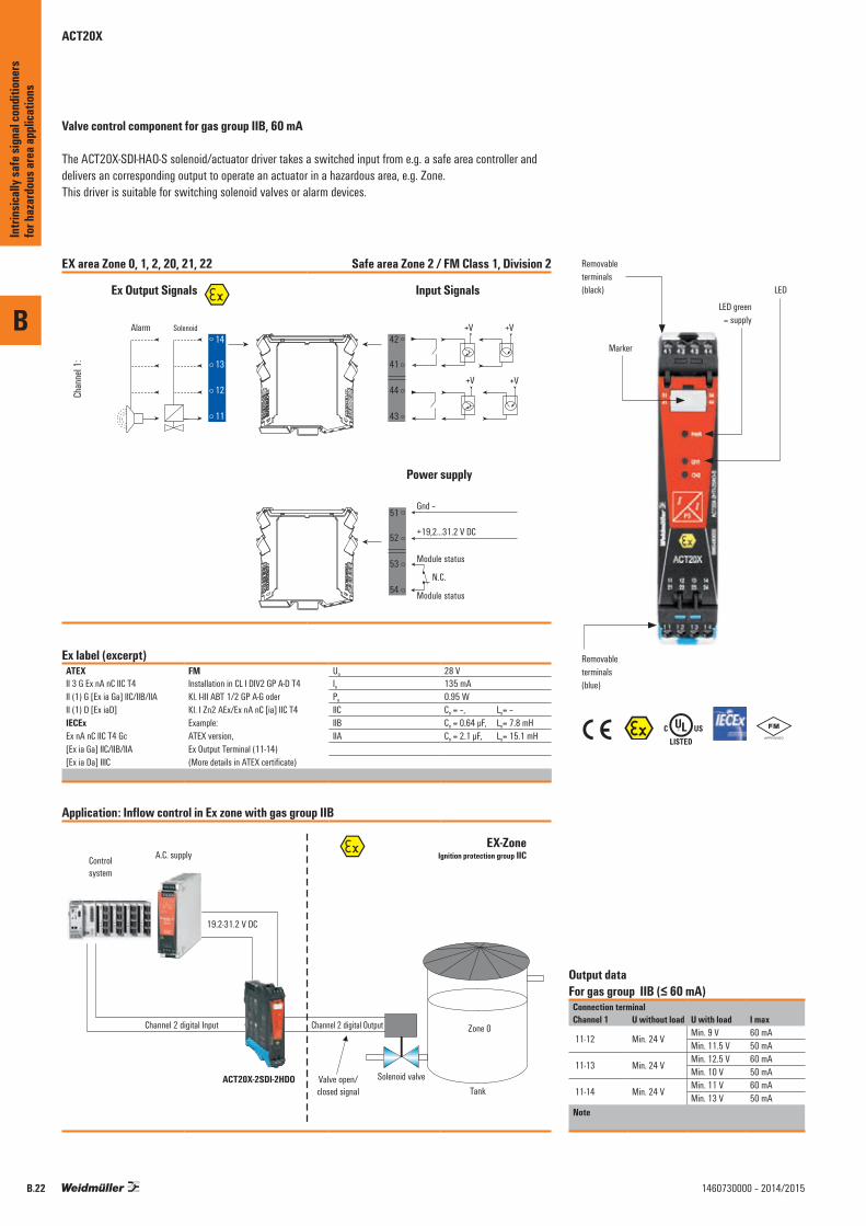
ACT20X
Valve control component for gas group IIB, 60 mA
The ACT20X-SDI-HAO-S solenoid/actuator driver takes a switched input from e.g. a safe area controller and delivers an corresponding output to operate an actuator in a hazardous area, e.g. Zone. This driver is suitable for switching solenoid valves or alarm devices.
EX area Zone 0, 1, 2, 20, 21, 22 Safe area Zone 2 / FM Class 1, Division 2
Chan
nel 1
:
51
52
53
54
Ex Output Signals
44
43
42
41
14
13
12
11
Input Signals
Gnd –
+19,2...31.2 V DC
Module status
Module status
42
41
44
43
N.C.
Power supply
Alarm Solenoid V+V+
V+V+
Ex label (excerpt)ATEX FM Uo 28 VII 3 G Ex nA nC IIC T4 Installation in CL I DIV2 GP A-D T4
Kl. I-III ABT 1/2 GP A-G oder Kl. I Zn2 AEx/Ex nA nC [ia] IIC T4
Io 135 mAII (1) G [Ex ia Ga] IIC/IIB/IIA Po 0.95 WII (1) D [Ex iaD] IIC Co = –, Lo= –IECEx Example: IIB Co = 0.64 µF, Lo= 7.8 mHEx nA nC IIC T4 Gc ATEX version, IIA Co = 2.1 µF, Lo= 15.1 mH[Ex ia Ga] IIC/IIB/IIA Ex Output Terminal (11-14)[Ex ia Da] IIIC (More details in ATEX certificate)
Application: Inflow control in Ex zone with gas group IIB
Controlsystem
A.C. supply Ignition protection group IIC
ACT20X-2SDI-2HDO
19.2-31.2 V DC
Channel 2 digital Input
Valve open/closed signal
Solenoid valveTank
Zone 0Channel 2 digital Output
EX-Zone
\%
Output data For gas group IIB (≤ 60 mA)
Connection terminalChannel 1 U without load U with load I max
11-12 Min. 24 VMin. 9 V 60 mAMin. 11.5 V 50 mA
11-13 Min. 24 VMin. 12.5 V 60 mAMin. 10 V 50 mA
11-14 Min. 24 VMin. 11 V 60 mAMin. 13 V 50 mA
Note
Removableterminals(black)
LED green= supply
Marker
Removableterminals(blue)
LED
B
Intri
nsica
lly sa
fe si
gnal
cond
ition
ers
for h
azar
dous
area
appli
catio
ns
B.22 1460730000 – 2014/2015
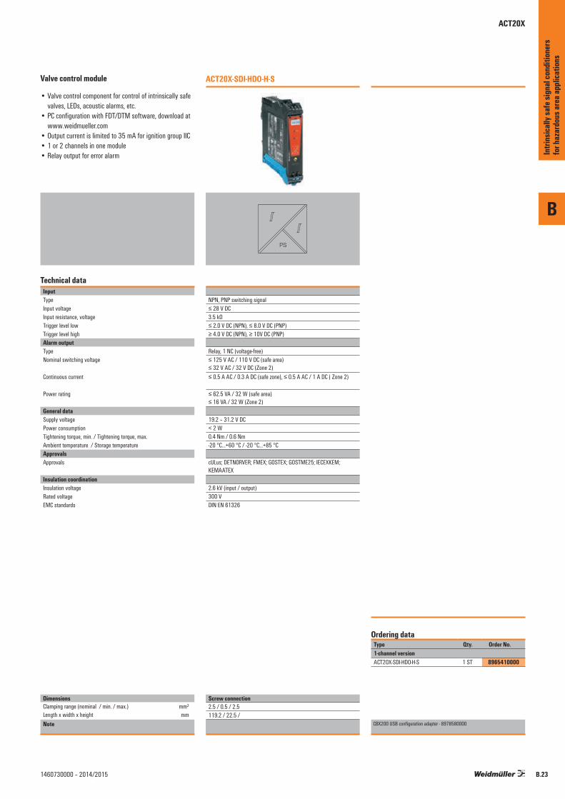
B
B.231460730000 – 2014/2015
Valve control module
• Valve control component for control of intrinsically safe valves, LEDs, acoustic alarms, etc.
• PC configuration with FDT/DTM software, download at www.weidmueller.com
• Output current is limited to 35 mA for ignition group IIC• 1 or 2 channels in one module• Relay output for error alarm
Technical dataInputTypeInput voltageInput resistance, voltageTrigger level lowTrigger level highAlarm outputType Nominal switching voltage
Continuous current
Power rating
General dataSupply voltagePower consumptionTightening torque, min. / Tightening torque, max.Ambient temperature / Storage temperatureApprovalsApprovals
Insulation coordinationInsulation voltageRated voltageEMC standards
DimensionsClamping range (nominal / min. / max.) mm²Length x width x height mmNote
ACT20X-SDI-HDO-H-S
PS
NPN, PNP switching signal≤ 28 V DC3.5 kΩ≤ 2.0 V DC (NPN), ≤ 8.0 V DC (PNP)≥ 4.0 V DC (NPN), ≥ 10V DC (PNP)
Relay, 1 NC (voltage-free)≤ 125 V AC / 110 V DC (safe area) ≤ 32 V AC / 32 V DC (Zone 2)≤ 0.5 A AC / 0.3 A DC (safe zone), ≤ 0.5 A AC / 1 A DC ( Zone 2)
≤ 62.5 VA / 32 W (safe area) ≤ 16 VA / 32 W (Zone 2)
19.2 – 31.2 V DC< 2 W0.4 Nm / 0.6 Nm-20 °C...+60 °C / -20 °C...+85 °C
cULus; DETNORVER; FMEX; GOSTEX; GOSTME25; IECEXKEM; KEMAATEX
2.6 kV (input / output)300 VDIN EN 61326
Type Qty. Order No.1-channel versionACT20X-SDI-HDO-H-S 1 ST 8965410000
CBX200 USB configuration adapter - 8978580000
Ordering data
Screw connection2.5 / 0.5 / 2.5119.2 / 22.5 /
Intri
nsica
lly sa
fe si
gnal
cond
ition
ers
for h
azar
dous
area
appli
catio
ns
ACT20X

B
Intri
nsica
lly sa
fe si
gnal
cond
ition
ers
for h
azar
dous
area
appli
catio
ns
B.24 1460730000 – 2014/2015

Signal converters in 6 mm width
Signal converters in 6 mm width Universal signal converter in 6 mm width – Overview C.2
ACT20M – Overview C.4
CH20M rail bus C.26
MCZ-SERIES – Overview C.30
MCZ SERIES – DC/DC passive isolator C.32
MCZ-SERIES – PT100 /RTD signal converter C.33
MCZ-SERIES – Frequency signal converter C.34
MCZ-SERIES – Threshold monitoring C.35
Contents
C
Sign
al co
nver
ters
in 6
mm w
idth
C.11460730000 – 2014/2015

Universal signal converter in 6 mm width – Overview
The thinnest signal converter for isolating, converting and monitoring analogue signals
The signal converters and the signal separators in the product family ACT20M, MICROSERIES and the MCZ enables the user to integrate many signal channels within a compact space. In addition to galvanic separation, these products offer the conversion and conditioning of DC and
temperature signals (TC and RTD) to standard norm signals (e.g. 4…20 mA, 0…10 V). The pluggable cross-connections option for MAS/MAZ and MCZ ranges, or the Weidmüller rail bus option for the ACT20M ensure a quick installation.
Analogue signal converter in 6 mm width
C
Sign
al co
nver
ters
in 6
mm w
idth
C.2 1460730000 – 2014/2015

Universal signal converter in 6 mm width – Overview
ACT20M
MCZ-SERIES
Sie benötigen eine hohe FunktionsdichteWir wandeln und verdoppeln Ihre Signale auf engstem RaumLet’s connect.
In der Prozesstechnik setzt sich der Trend zur Funktionsverdichtung auf kleinstem Raum weiter fort. So müssen beispielsweise im Kernelement eines Dampfkreis-laufes sehr viele analoge Signale gewandelt werden. Der ACT20M-Signalsplitter trennt, wandelt und vervielfacht Ihre analogen Signale auf nur 6 mm Baubreite. Mit dieser Funktion kann das Signal parallel zur Wandlung zu Kontroll- und Über wachungszwecken auch lokal über ein Anzeigeelement visualisiert werden.
Mit der Kombination der ACT20M-Serie, dem ACT20-FEED-IN und den PRO-H-Stromversorgungen bieten wir Ihnen eine präzise aufeinander abgestimmte Versorgungslösung für die Signalwandler-Serie ACT20M. Die Spannungs versorgung mit kontinuierlichen 24 V erfolgt über den CH20M-Trag-schienenbus. Neben der besonders schmalen Baubreite überzeugt ACT20M durch die internationalen Zulassungen cULus, ATEX Zone 2, FM Div. 2, GL und DNV, womit die Signalwandler für den weltweiten Einsatz in vielfältigen Anwendungen geeignet sind.Das Einspeisegerät ACT20 -FEED -IN kann bis zu 120 ACT20M-Signalwandler versorgen. Im Fehlerfall erkennt es sofort den Ausfall eines Netzteils, zeigt diesen über
LEDs an und schaltet die Versorgung automatisch auf die redundante Spannungsversorgung um.
Die sichere und zuverlässige Schaltnetzteilreihe PRO-H in kompakter Bauform haben wir speziell für hohe Anforderun-gen, insbesondere auch zum Einsatz im explosionsgefährde-ten Bereich, entwickelt. Parallele Stromversorgungen bieten zuverlässige Funktionssicherheit, wenn bei Ausfall eines Gerätes die volle Last durch das zweite Gerät übernommen wird. Dank hoher MTBF -(Mean -Time -Between -Failures )Werte von bis zu 1,8 Millionen Stunden ist PRO-H besonders für den Prozessbereich und die Energietechnik geeignet.
ACT20M
• Signalverdopplung mit Sensorspeisung auf nur 6 mm Baubreite
• Spannungsversorgung über Tragschienenbus • Konfi guration über DIP-Schalter oder FDT/DTM-Software • Galvanische Trennung bis 2,5 kV bei 300 V Bemessungs-
spannung
PRO-H
• MTBF-Zeit bis 1,8 Mio. Stunden • Remote ON/OFF zum gezielten externen Ein-/Ausschalten • Redundanter Systemaufbau mit 100%iger Lastverteilung • Einsetzbar von –25 bis +70 °C
C
Sign
al co
nver
ters
in 6
mm w
idth
C.31460730000 – 2014/2015
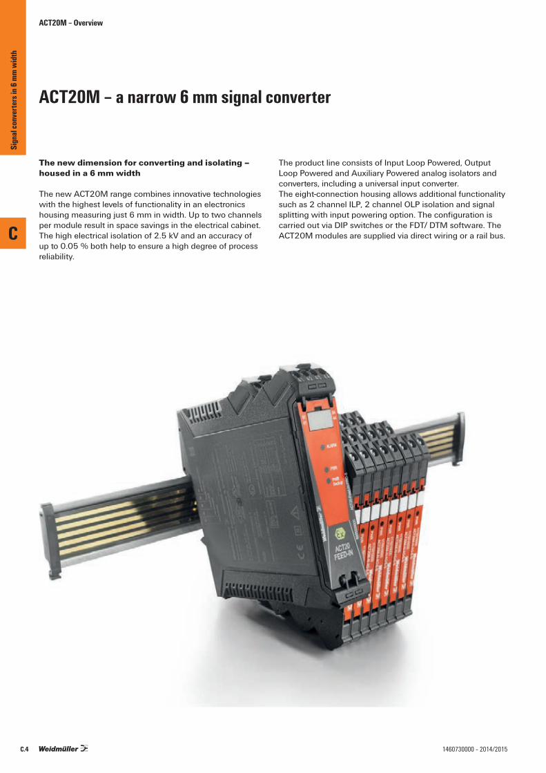
ACT20M – a narrow 6 mm signal converter
The new dimension for converting and isolating – housed in a 6 mm width
The new ACT20M range combines innovative technologies with the highest levels of functionality in an electronics housing measuring just 6 mm in width. Up to two channels per module result in space savings in the electrical cabinet. The high electrical isolation of 2.5 kV and an accuracy of up to 0.05 % both help to ensure a high degree of process reliability.
The product line consists of Input Loop Powered, Output Loop Powered and Auxiliary Powered analog isolators and converters, including a universal input converter. The eight-connection housing allows additional functionality such as 2 channel ILP, 2 channel OLP isolation and signal splitting with input powering option. The configuration is carried out via DIP switches or the FDT/ DTM software. The ACT20M modules are supplied via direct wiring or a rail bus.
ACT20M – Overview
C
Sign
al co
nver
ters
in 6
mm w
idth
C.4 1460730000 – 2014/2015

Signal splitter
Signal converter
Universal measurement and signal converter
Passive isolator
Temperature transducer
CH20M rail bus
Power-feed modules
The DIP switch can be configured simply on the module
In the “ACT20M Tool” software, simplyselect the type of input and output,and set the DIP switch configuration as displayed.
Installation is simple and quick
The power supply is simply snapped onto the rail bus for fast and easy installation. The supply can be through any ACT20M module or a separate power-feed unit.
High level of galvanic isolation
2.5 kV of electrical isolation (300 V rated voltage) ensures excellent process reliability.
ACT20M – Overview
U, I,R, T U, I
PS
Easy configuration
DIP switches on the side are used to configure the input and output parameters, as well as the response time.
C
Sign
al co
nver
ters
in 6
mm w
idth
C.51460730000 – 2014/2015

Output
Current Voltage
Power supply Function 0 … 20 mA1-channel
4 … 20 mA1-channel
2 x 0 … 20 mA2-channel / splitter
2 x 4 … 20 mA2-channel / splitter
–10 mA … 0 … 10 mA1-channel bipolar
–20 mA … 0 … 20 mA1-channel bipolar
0 … 5 V / 1 … 5 V1-channel
0 … 10 V / 2 … 10 V1-channel
2 x 0 … 5 V / 2 x 1 … 5 V2-channel / splitter
2 x 0 … 10 V / 2 x 2 … 10 V 2-channel / splitter
-10 V… 0 … 10 V1-channel
Inpu
t
Curre
nt
0 … 20 mA 24 V DC and rail bus universal ACT20M-UI-AO-S ACT20M-UI-AO-S ACT20M-UI-AO-S ACT20M-UI-AO-S
U/I ACT20M-AI-2AO-S ACT20M-AI-2AO-S ACT20M-AI-2AO-S ACT20M-AI-2AO-S
Current ACT20M-CI-2CO-S ACT20M-CI-2CO-S
U/I ACT20M-AI-AO-E-S ACT20M-AI-AO-E-S ACT20M-AI-AO-E-S ACT20M-AI-AO-E-S
U/I ACT20M-AI-AO-S ACT20M-AI-AO-S ACT20M-AI-AO-S ACT20M-AI-AO-S
Current ACT20M-CI-CO-S ACT20M-CI-CO-S
U/I
Input Loop Powered Current
Output Loop Powered Current ACT20M-CI-CO-OLP-S
Current
2 x 0 … 20 mA Output Loop Powered Current ACT20M-2CI-2CO-OLP-S
Input Loop Powered Current
24 V DC Current
4 … 20 mA 24 V DC and rail bus universal ACT20M-UI-AO-S ACT20M-UI-AO-S ACT20M-UI-AO-S ACT20M-UI-AO-S
U/I ACT20M-AI-2AO-S ACT20M-AI-2AO-S ACT20M-AI-2AO-S ACT20M-AI-2AO-S
Current ACT20M-CI-2CO-S ACT20M-CI-2CO-S
U/I ACT20M-AI-AO-E-S ACT20M-AI-AO-E-S ACT20M-AI-AO-E-S ACT20M-AI-AO-E-S
U/I ACT20M-AI-AO-S ACT20M-AI-AO-S ACT20M-AI-AO-S ACT20M-AI-AO-S
Current ACT20M-CI-CO-S ACT20M-CI-CO-S
U/I
1 x 4 … 20 mA Output Loop Powered Current ACT20M-CI-CO-OLP-S
Current
2 x 4 … 20 mA Output Loop Powered Current ACT20M-2CI-2CO-OLP-S
24 V DC Current
Input Loop Powered Current
Current ACT20M-2CI-2CO-ILP-S ACT20M-2CI-2CO-ILP-S
1 x 4 … 20 mA Input Loop Powered Current
Current ACT20M-CI-CO-ILP-S ACT20M-CI-CO-ILP-S
–10 mA…0…10 mA 24 V DC and rail bus bipolar ACT20M-BAI-AO-S ACT20M-BAI-AO-S ACT20M-BAI-2AO-S ACT20M-BAI-2AO-S ACT20M-BAI-2AO-S ACT20M-BAI-2AO-S ACT20M-BAI-AO-S ACT20M-BAI-AO-S ACT20M-BAI-2AO-S ACT20M-BAI-2AO-S
–20 mA…0…20 mA 24 V DC and rail bus bipolar ACT20M-BAI-AO-S ACT20M-BAI-AO-S ACT20M-BAI-2AO-S ACT20M-BAI-2AO-S ACT20M-BAI-2AO-S ACT20M-BAI-2AO-S ACT20M-BAI-AO-S ACT20M-BAI-AO-S ACT20M-BAI-2AO-S ACT20M-BAI-2AO-S
with sensor power supply 24 V DC and rail bus universal ACT20M-UI-AO-S ACT20M-UI-AO-S ACT20M-UI-AO-S ACT20M-UI-AO-S
U/I ACT20M-AI-AO-S ACT20M-AI-AO-S ACT20M-AI-AO-S ACT20M-AI-AO-S
Volta
ge
0 … 5 V1 … 5 V
24 V DC and rail bus universal ACT20M-UI-AO-S ACT20M-UI-AO-S ACT20M-UI-AO-S ACT20M-UI-AO-S
U/I ACT20M-AI-AO-E-S ACT20M-AI-AO-E-S ACT20M-AI-AO-E-S ACT20M-AI-AO-E-S
U/I ACT20M-AI-AO-S ACT20M-AI-AO-S ACT20M-AI-AO-S ACT20M-AI-AO-S
U/I
Output Loop Powered U/I
0 …10 V2 … 10 V
24 V DC and rail bus universal ACT20M-UI-AO-S ACT20M-UI-AO-S ACT20M-UI-AO-S ACT20M-UI-AO-S
U/I ACT20M-AI-AO-E-S ACT20M-AI-AO-E-S ACT20M-AI-AO-E-S ACT20M-AI-AO-E-S
U/I ACT20M-AI-AO-S ACT20M-AI-AO-S ACT20M-AI-AO-S ACT20M-AI-AO-S
U/I
Output Loop Powered U/I
–5 V … 0 … 5 V 24 V DC and rail bus bipolar ACT20M-BAI-AO-S ACT20M-BAI-AO-S ACT20M-BAI-2AO-S ACT20M-BAI-2AO-S ACT20M-BAI-AO-S ACT20M-BAI-AO-S ACT20M-BAI-2AO-S ACT20M-BAI-2AO-S
–10 V… 0 …10 V 24 V DC and rail bus bipolar ACT20M-BAI-AO-S ACT20M-BAI-AO-S ACT20M-BAI-2AO-S ACT20M-BAI-2AO-S ACT20M-BAI-AO-S ACT20M-BAI-AO-S ACT20M-BAI-2AO-S ACT20M-BAI-2AO-S
bipolar
ACT20M - Overview
ACT20M – Selection table
Note: *) available from July 2013
C
Sign
al co
nver
ters
in 6
mm w
idth
C.6 1460730000 – 2014/2015
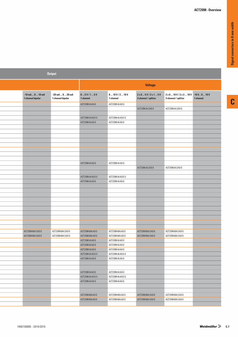
Output
Current Voltage
Power supply Function 0 … 20 mA1-channel
4 … 20 mA1-channel
2 x 0 … 20 mA2-channel / splitter
2 x 4 … 20 mA2-channel / splitter
–10 mA … 0 … 10 mA1-channel bipolar
–20 mA … 0 … 20 mA1-channel bipolar
0 … 5 V / 1 … 5 V1-channel
0 … 10 V / 2 … 10 V1-channel
2 x 0 … 5 V / 2 x 1 … 5 V2-channel / splitter
2 x 0 … 10 V / 2 x 2 … 10 V 2-channel / splitter
-10 V… 0 … 10 V1-channel
Inpu
t
Curre
nt
0 … 20 mA 24 V DC and rail bus universal ACT20M-UI-AO-S ACT20M-UI-AO-S ACT20M-UI-AO-S ACT20M-UI-AO-S
U/I ACT20M-AI-2AO-S ACT20M-AI-2AO-S ACT20M-AI-2AO-S ACT20M-AI-2AO-S
Current ACT20M-CI-2CO-S ACT20M-CI-2CO-S
U/I ACT20M-AI-AO-E-S ACT20M-AI-AO-E-S ACT20M-AI-AO-E-S ACT20M-AI-AO-E-S
U/I ACT20M-AI-AO-S ACT20M-AI-AO-S ACT20M-AI-AO-S ACT20M-AI-AO-S
Current ACT20M-CI-CO-S ACT20M-CI-CO-S
U/I
Input Loop Powered Current
Output Loop Powered Current ACT20M-CI-CO-OLP-S
Current
2 x 0 … 20 mA Output Loop Powered Current ACT20M-2CI-2CO-OLP-S
Input Loop Powered Current
24 V DC Current
4 … 20 mA 24 V DC and rail bus universal ACT20M-UI-AO-S ACT20M-UI-AO-S ACT20M-UI-AO-S ACT20M-UI-AO-S
U/I ACT20M-AI-2AO-S ACT20M-AI-2AO-S ACT20M-AI-2AO-S ACT20M-AI-2AO-S
Current ACT20M-CI-2CO-S ACT20M-CI-2CO-S
U/I ACT20M-AI-AO-E-S ACT20M-AI-AO-E-S ACT20M-AI-AO-E-S ACT20M-AI-AO-E-S
U/I ACT20M-AI-AO-S ACT20M-AI-AO-S ACT20M-AI-AO-S ACT20M-AI-AO-S
Current ACT20M-CI-CO-S ACT20M-CI-CO-S
U/I
1 x 4 … 20 mA Output Loop Powered Current ACT20M-CI-CO-OLP-S
Current
2 x 4 … 20 mA Output Loop Powered Current ACT20M-2CI-2CO-OLP-S
24 V DC Current
Input Loop Powered Current
Current ACT20M-2CI-2CO-ILP-S ACT20M-2CI-2CO-ILP-S
1 x 4 … 20 mA Input Loop Powered Current
Current ACT20M-CI-CO-ILP-S ACT20M-CI-CO-ILP-S
–10 mA…0…10 mA 24 V DC and rail bus bipolar ACT20M-BAI-AO-S ACT20M-BAI-AO-S ACT20M-BAI-2AO-S ACT20M-BAI-2AO-S ACT20M-BAI-2AO-S ACT20M-BAI-2AO-S ACT20M-BAI-AO-S ACT20M-BAI-AO-S ACT20M-BAI-2AO-S ACT20M-BAI-2AO-S
–20 mA…0…20 mA 24 V DC and rail bus bipolar ACT20M-BAI-AO-S ACT20M-BAI-AO-S ACT20M-BAI-2AO-S ACT20M-BAI-2AO-S ACT20M-BAI-2AO-S ACT20M-BAI-2AO-S ACT20M-BAI-AO-S ACT20M-BAI-AO-S ACT20M-BAI-2AO-S ACT20M-BAI-2AO-S
with sensor power supply 24 V DC and rail bus universal ACT20M-UI-AO-S ACT20M-UI-AO-S ACT20M-UI-AO-S ACT20M-UI-AO-S
U/I ACT20M-AI-AO-S ACT20M-AI-AO-S ACT20M-AI-AO-S ACT20M-AI-AO-S
Volta
ge
0 … 5 V1 … 5 V
24 V DC and rail bus universal ACT20M-UI-AO-S ACT20M-UI-AO-S ACT20M-UI-AO-S ACT20M-UI-AO-S
U/I ACT20M-AI-AO-E-S ACT20M-AI-AO-E-S ACT20M-AI-AO-E-S ACT20M-AI-AO-E-S
U/I ACT20M-AI-AO-S ACT20M-AI-AO-S ACT20M-AI-AO-S ACT20M-AI-AO-S
U/I
Output Loop Powered U/I
0 …10 V2 … 10 V
24 V DC and rail bus universal ACT20M-UI-AO-S ACT20M-UI-AO-S ACT20M-UI-AO-S ACT20M-UI-AO-S
U/I ACT20M-AI-AO-E-S ACT20M-AI-AO-E-S ACT20M-AI-AO-E-S ACT20M-AI-AO-E-S
U/I ACT20M-AI-AO-S ACT20M-AI-AO-S ACT20M-AI-AO-S ACT20M-AI-AO-S
U/I
Output Loop Powered U/I
–5 V … 0 … 5 V 24 V DC and rail bus bipolar ACT20M-BAI-AO-S ACT20M-BAI-AO-S ACT20M-BAI-2AO-S ACT20M-BAI-2AO-S ACT20M-BAI-AO-S ACT20M-BAI-AO-S ACT20M-BAI-2AO-S ACT20M-BAI-2AO-S
–10 V… 0 …10 V 24 V DC and rail bus bipolar ACT20M-BAI-AO-S ACT20M-BAI-AO-S ACT20M-BAI-2AO-S ACT20M-BAI-2AO-S ACT20M-BAI-AO-S ACT20M-BAI-AO-S ACT20M-BAI-2AO-S ACT20M-BAI-2AO-S
bipolar
ACT20M - Overview
C
Sign
al co
nver
ters
in 6
mm w
idth
C.71460730000 – 2014/2015
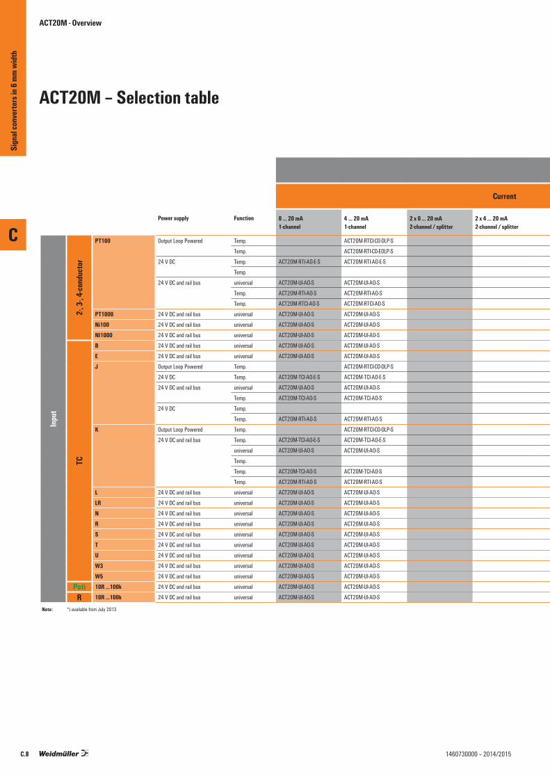
Output
Current Voltage
Power supply Function 0 … 20 mA1-channel
4 … 20 mA1-channel
2 x 0 … 20 mA2-channel / splitter
2 x 4 … 20 mA2-channel / splitter
–10 mA … 0 … 10 mA1-channel bipolar
–20 mA … 0 … 20 mA1-channel bipolar
0 … 5 V / 1 … 5 V1-channel
0 … 10 V / 2 … 10 V1-channel
2 x 0 … 5 V / 2 x 1 … 5 V2-channel / splitter
2 x 0 … 10 V / 2 x 2 … 10 V 2-channel / splitter
-10 V… 0 … 10 V1-channel
Inpu
t
2-, 3-
, 4-co
nduc
tor
PT100 Output Loop Powered Temp. ACT20M-RTCI-CO-OLP-S
Temp. ACT20M-RTI-CO-EOLP-S
24 V DC Temp. ACT20M-RTI-AO-E-S ACT20M-RTI-AO-E-S ACT20M-RTI-AO-E-S ACT20M-RTI-AO-E-S
Temp.
24 V DC and rail bus universal ACT20M-UI-AO-S ACT20M-UI-AO-S ACT20M-UI-AO-S ACT20M-UI-AO-S
Temp. ACT20M-RTI-AO-S ACT20M-RTI-AO-S ACT20M-RTI-AO-S ACT20M-RTI-AO-S
Temp. ACT20M-RTCI-AO-S ACT20M-RTCI-AO-S ACT20M-RTCI-AO-S ACT20M-RTCI-AO-S
PT1000 24 V DC and rail bus universal ACT20M-UI-AO-S ACT20M-UI-AO-S ACT20M-UI-AO-S ACT20M-UI-AO-S
Ni100 24 V DC and rail bus universal ACT20M-UI-AO-S ACT20M-UI-AO-S ACT20M-UI-AO-S ACT20M-UI-AO-S
NI1000 24 V DC and rail bus universal ACT20M-UI-AO-S ACT20M-UI-AO-S ACT20M-UI-AO-S ACT20M-UI-AO-S
TC
B 24 V DC and rail bus universal ACT20M-UI-AO-S ACT20M-UI-AO-S ACT20M-UI-AO-S ACT20M-UI-AO-S
E 24 V DC and rail bus universal ACT20M-UI-AO-S ACT20M-UI-AO-S ACT20M-UI-AO-S ACT20M-UI-AO-S
J Output Loop Powered Temp. ACT20M-RTCI-CO-OLP-S
24 V DC Temp. ACT20M-TCI-AO-E-S ACT20M-TCI-AO-E-S ACT20M-TCI-AO-E-S ACT20M-TCI-AO-E-S
24 V DC and rail bus universal ACT20M-UI-AO-S ACT20M-UI-AO-S ACT20M-UI-AO-S ACT20M-UI-AO-S
Temp. ACT20M-TCI-AO-S ACT20M-TCI-AO-S ACT20M-TCI-AO-S ACT20M-TCI-AO-S
24 V DC Temp.
Temp. ACT20M-RTI-AO-S ACT20M-RTI-AO-S ACT20M-RTI-AO-S ACT20M-RTI-AO-S
K Output Loop Powered Temp. ACT20M-RTCI-CO-OLP-S
24 V DC and rail bus Temp. ACT20M-TCI-AO-E-S ACT20M-TCI-AO-E-S ACT20M-TCI-AO-E-S ACT20M-TCI-AO-E-S
universal ACT20M-UI-AO-S ACT20M-UI-AO-S ACT20M-UI-AO-S ACT20M-UI-AO-S
Temp.
Temp. ACT20M-TCI-AO-S ACT20M-TCI-AO-S ACT20M-TCI-AO-S ACT20M-TCI-AO-S
Temp. ACT20M-RTI-AO-S ACT20M-RTI-AO-S ACT20M-RTI-AO-S ACT20M-RTI-AO-S
L 24 V DC and rail bus universal ACT20M-UI-AO-S ACT20M-UI-AO-S ACT20M-UI-AO-S ACT20M-UI-AO-S
LR 24 V DC and rail bus universal ACT20M-UI-AO-S ACT20M-UI-AO-S ACT20M-UI-AO-S ACT20M-UI-AO-S
N 24 V DC and rail bus universal ACT20M-UI-AO-S ACT20M-UI-AO-S ACT20M-UI-AO-S ACT20M-UI-AO-S
R 24 V DC and rail bus universal ACT20M-UI-AO-S ACT20M-UI-AO-S ACT20M-UI-AO-S ACT20M-UI-AO-S
S 24 V DC and rail bus universal ACT20M-UI-AO-S ACT20M-UI-AO-S ACT20M-UI-AO-S ACT20M-UI-AO-S
T 24 V DC and rail bus universal ACT20M-UI-AO-S ACT20M-UI-AO-S ACT20M-UI-AO-S ACT20M-UI-AO-S
U 24 V DC and rail bus universal ACT20M-UI-AO-S ACT20M-UI-AO-S ACT20M-UI-AO-S ACT20M-UI-AO-S
W3 24 V DC and rail bus universal ACT20M-UI-AO-S ACT20M-UI-AO-S ACT20M-UI-AO-S ACT20M-UI-AO-S
W5 24 V DC and rail bus universal ACT20M-UI-AO-S ACT20M-UI-AO-S ACT20M-UI-AO-S ACT20M-UI-AO-S
Poti 10R …100k 24 V DC and rail bus universal ACT20M-UI-AO-S ACT20M-UI-AO-S ACT20M-UI-AO-S ACT20M-UI-AO-S
R 10R …100k 24 V DC and rail bus universal ACT20M-UI-AO-S ACT20M-UI-AO-S ACT20M-UI-AO-S ACT20M-UI-AO-S
ACT20M - Overview
ACT20M – Selection table
Note: *) available from July 2013
C
Sign
al co
nver
ters
in 6
mm w
idth
C.8 1460730000 – 2014/2015
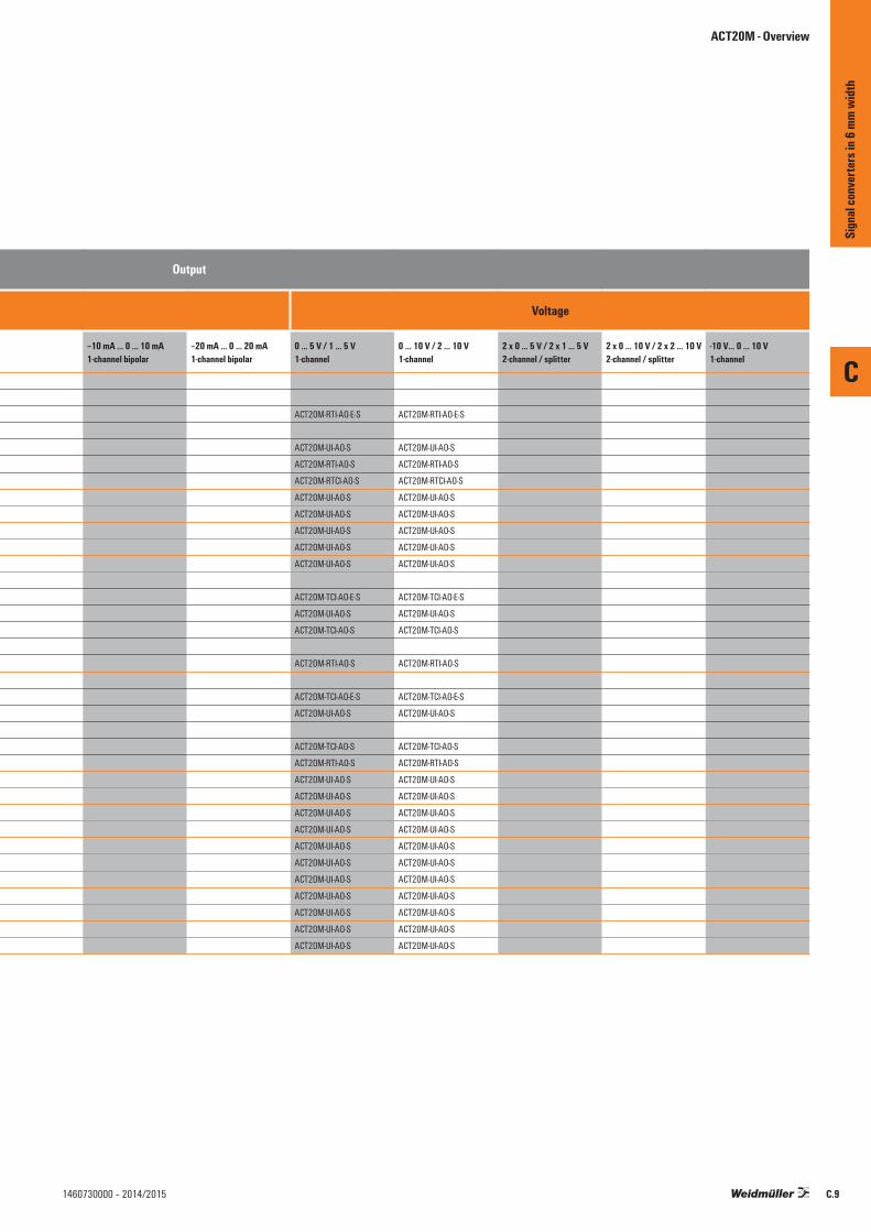
Output
Current Voltage
Power supply Function 0 … 20 mA1-channel
4 … 20 mA1-channel
2 x 0 … 20 mA2-channel / splitter
2 x 4 … 20 mA2-channel / splitter
–10 mA … 0 … 10 mA1-channel bipolar
–20 mA … 0 … 20 mA1-channel bipolar
0 … 5 V / 1 … 5 V1-channel
0 … 10 V / 2 … 10 V1-channel
2 x 0 … 5 V / 2 x 1 … 5 V2-channel / splitter
2 x 0 … 10 V / 2 x 2 … 10 V 2-channel / splitter
-10 V… 0 … 10 V1-channel
Inpu
t
2-, 3-
, 4-co
nduc
tor
PT100 Output Loop Powered Temp. ACT20M-RTCI-CO-OLP-S
Temp. ACT20M-RTI-CO-EOLP-S
24 V DC Temp. ACT20M-RTI-AO-E-S ACT20M-RTI-AO-E-S ACT20M-RTI-AO-E-S ACT20M-RTI-AO-E-S
Temp.
24 V DC and rail bus universal ACT20M-UI-AO-S ACT20M-UI-AO-S ACT20M-UI-AO-S ACT20M-UI-AO-S
Temp. ACT20M-RTI-AO-S ACT20M-RTI-AO-S ACT20M-RTI-AO-S ACT20M-RTI-AO-S
Temp. ACT20M-RTCI-AO-S ACT20M-RTCI-AO-S ACT20M-RTCI-AO-S ACT20M-RTCI-AO-S
PT1000 24 V DC and rail bus universal ACT20M-UI-AO-S ACT20M-UI-AO-S ACT20M-UI-AO-S ACT20M-UI-AO-S
Ni100 24 V DC and rail bus universal ACT20M-UI-AO-S ACT20M-UI-AO-S ACT20M-UI-AO-S ACT20M-UI-AO-S
NI1000 24 V DC and rail bus universal ACT20M-UI-AO-S ACT20M-UI-AO-S ACT20M-UI-AO-S ACT20M-UI-AO-S
TC
B 24 V DC and rail bus universal ACT20M-UI-AO-S ACT20M-UI-AO-S ACT20M-UI-AO-S ACT20M-UI-AO-S
E 24 V DC and rail bus universal ACT20M-UI-AO-S ACT20M-UI-AO-S ACT20M-UI-AO-S ACT20M-UI-AO-S
J Output Loop Powered Temp. ACT20M-RTCI-CO-OLP-S
24 V DC Temp. ACT20M-TCI-AO-E-S ACT20M-TCI-AO-E-S ACT20M-TCI-AO-E-S ACT20M-TCI-AO-E-S
24 V DC and rail bus universal ACT20M-UI-AO-S ACT20M-UI-AO-S ACT20M-UI-AO-S ACT20M-UI-AO-S
Temp. ACT20M-TCI-AO-S ACT20M-TCI-AO-S ACT20M-TCI-AO-S ACT20M-TCI-AO-S
24 V DC Temp.
Temp. ACT20M-RTI-AO-S ACT20M-RTI-AO-S ACT20M-RTI-AO-S ACT20M-RTI-AO-S
K Output Loop Powered Temp. ACT20M-RTCI-CO-OLP-S
24 V DC and rail bus Temp. ACT20M-TCI-AO-E-S ACT20M-TCI-AO-E-S ACT20M-TCI-AO-E-S ACT20M-TCI-AO-E-S
universal ACT20M-UI-AO-S ACT20M-UI-AO-S ACT20M-UI-AO-S ACT20M-UI-AO-S
Temp.
Temp. ACT20M-TCI-AO-S ACT20M-TCI-AO-S ACT20M-TCI-AO-S ACT20M-TCI-AO-S
Temp. ACT20M-RTI-AO-S ACT20M-RTI-AO-S ACT20M-RTI-AO-S ACT20M-RTI-AO-S
L 24 V DC and rail bus universal ACT20M-UI-AO-S ACT20M-UI-AO-S ACT20M-UI-AO-S ACT20M-UI-AO-S
LR 24 V DC and rail bus universal ACT20M-UI-AO-S ACT20M-UI-AO-S ACT20M-UI-AO-S ACT20M-UI-AO-S
N 24 V DC and rail bus universal ACT20M-UI-AO-S ACT20M-UI-AO-S ACT20M-UI-AO-S ACT20M-UI-AO-S
R 24 V DC and rail bus universal ACT20M-UI-AO-S ACT20M-UI-AO-S ACT20M-UI-AO-S ACT20M-UI-AO-S
S 24 V DC and rail bus universal ACT20M-UI-AO-S ACT20M-UI-AO-S ACT20M-UI-AO-S ACT20M-UI-AO-S
T 24 V DC and rail bus universal ACT20M-UI-AO-S ACT20M-UI-AO-S ACT20M-UI-AO-S ACT20M-UI-AO-S
U 24 V DC and rail bus universal ACT20M-UI-AO-S ACT20M-UI-AO-S ACT20M-UI-AO-S ACT20M-UI-AO-S
W3 24 V DC and rail bus universal ACT20M-UI-AO-S ACT20M-UI-AO-S ACT20M-UI-AO-S ACT20M-UI-AO-S
W5 24 V DC and rail bus universal ACT20M-UI-AO-S ACT20M-UI-AO-S ACT20M-UI-AO-S ACT20M-UI-AO-S
Poti 10R …100k 24 V DC and rail bus universal ACT20M-UI-AO-S ACT20M-UI-AO-S ACT20M-UI-AO-S ACT20M-UI-AO-S
R 10R …100k 24 V DC and rail bus universal ACT20M-UI-AO-S ACT20M-UI-AO-S ACT20M-UI-AO-S ACT20M-UI-AO-S
ACT20M - Overview
C
Sign
al co
nver
ters
in 6
mm w
idth
C.91460730000 – 2014/2015
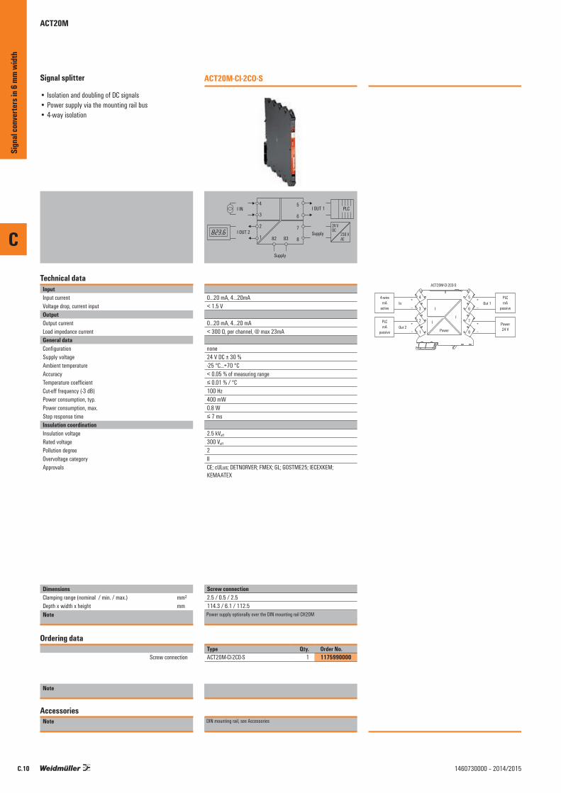
C
C.10 1460730000 – 2014/2015
Signal splitter
• Isolation and doubling of DC signals• Power supply via the mounting rail bus• 4-way isolation
Technical dataInputInput currentVoltage drop, current inputOutputOutput currentLoad impedance currentGeneral dataConfigurationSupply voltageAmbient temperature AccuracyTemperature coefficientCut-off frequency (-3 dB)Power consumption, typ.Power consumption, max.Step response timeInsulation coordinationInsulation voltageRated voltagePollution degreeOvervoltage categoryApprovals
DimensionsClamping range (nominal / min. / max.) mm²Depth x width x height mmNote
Ordering data
Screw connection
Note
AccessoriesNote
ACT20M-CI-2CO-S
4
3
2
1
5
6
7
8
I OUT 1
Supply
I IN
I OUT 2
82
Supply
83
24 VDC
230 VAC
PLC
0...20 mA, 4…20mA< 1.5 V
0...20 mA, 4...20 mA< 300 Ω, per channel, @ max 23mA
none 24 V DC ± 30 %-25 °C...+70 °C< 0.05 % of measuring range≤ 0.01 % / °C100 Hz400 mW0.8 W≤ 7 ms
2.5 kVeff
300 Veff
2IICE; cULus; DETNORVER; FMEX; GL; GOSTME25; IECEXKEM; KEMAATEX
Screw connection2.5 / 0.5 / 2.5114.3 / 6.1 / 112.5Screw connectionPower supply optionally over the DIN mounting rail CH20M
Type Qty. Order No.ACT20M-CI-2CO-S 1 1175990000
DIN mounting rail, see Accessories
1
2
3
4
8
7
6
5
I
I
Power
PLCmA
passive
+
–Out 1
Power24 V
+
–
4-wiremA
active
+
–In
IPLCmA
passive
+
–Out 2
ACT20M-CI-2CO-S
Sign
al co
nver
ters
in 6
mm w
idth
ACT20M

C
C.111460730000 – 2014/2015
Signal splitter
• Isolation, conversion and doubling of DC signals• Configuration via DIP switches• Power supply via the mounting rail bus• 4-way isolation• Support for adjustment by ACT20M Tool software,
download link at www.weidmueller.com
Technical dataInputInput currentInput voltageSensor supplyInput resistance, voltageVoltage drop, current inputOutputOutput currentOutput voltageLoad impedance currentLoad impedance voltageGeneral dataConfigurationSupply voltageAmbient temperature AccuracyTemperature coefficientCut-off frequency (-3 dB)Power consumption, typ.Power consumption, max.Step response timeInsulation coordinationInsulation voltageRated voltagePollution degreeOvervoltage categoryApprovals
DimensionsClamping range (nominal / min. / max.) mm²Depth x width x height mmNote
Ordering data
Screw connection
Note
AccessoriesNote
ACT20M-AI-2AO-S
4
3
2
1
5
6
7
8
I, U
OUT 1
Supply
I, U
IN
I, U
OUT 2 82
Supply
83
24 VDC
230 VAC
PLC
0...20 mA, 4…20mA0(2)…10 V, 0(1)…5 V > 17 V DC at 20 mA500 kΩ < 1.5 V
0...20 mAadjustable, 0(2)...10 V, 0(1)...5 V< 300 Ω, per channel, @ max 23mA ≥ 10 kΩ
DIP switch 24 V DC ± 30 %-25 °C...+70 °C< 0.05 % of measuring range≤ 0.01 % / °C100 Hz400 mW1.2 W≤ 7 ms
2.5 kVeff
300 Veff
2IICE; cULus; DETNORVER; FMEX; GL; GOSTME25; IECEXKEM; KEMAATEX
Screw connection2.5 / 0.5 / 2.5114.3 / 6.1 / 112.5Screw connectionPower supply optionally over the DIN mounting rail CH20M
Type Qty. Order No.ACT20M-AI-2AO-S 1 1176020000
DIN mounting rail, see Accessories
1
2
3
4
8
7
6
5
U, I
U, I
Power
PLCV, mA
passive
+
–Out 1
Power24 V
+
–
2-wiremA
passive
+
–In
1
2
3
4
8
7
6
5 PLCV, mA
passive
+
–Out 1
Power24 V
+
–
4-wireV, mAactive
+
–In
U, IPLCV, mA
passive
+
–Out 2
PLCV, mA
passive
+
–Out 2
U, I
U, I
Power
U, I
ACT20M-AI-2AO-S
Output 1
5 6 70 … 20 mA4 … 20 m0 … 10 V2 … 10 V0 … 5 V1 …5 V
Switch
Input
1 2 3 40 … 20 mA4 … 20 m0 … 10 V2 … 10 V0 … 5 V1 …5 V0 ... 20 mA loop4 ... 20 mA loop
Switch
◼ ◼ ◼ ◼◼ ◼ ◼ ◼◼ ◼ ◼ ◼◼ ◼ ◼ ◼◼ ◼ ◼ ◼◼ ◼ ◼ ◼◼ ◼ ◼ ◼◼ ◼ ◼ ◼
◼ ◼ ◼◼ ◼ ◼◼ ◼ ◼◼ ◼ ◼◼ ◼ ◼◼ ◼ ◼
Output 2
8 9 100 … 20 mA4 … 20 m0 … 10 V2 … 10 V0 … 5 V1 …5 V
Switch
◼ ◼ ◼◼ ◼ ◼◼ ◼ ◼◼ ◼ ◼◼ ◼ ◼◼ ◼ ◼
◼◼
= on= off
Sign
al co
nver
ters
in 6
mm w
idth
ACT20M

C
C.12 1460730000 – 2014/2015
Signal splitter
• Isolation and conversion of bipolar DC signals• Splitting into standard signal or bipolar output• Configuration via DIP switches• Power supply via the mounting rail bus• 4-way isolation• Support for adjustment by ACT20M Tool software,
download link at www.weidmueller.com
Technical dataInputInput currentInput voltageOutputOutput currentOutput voltageLoad impedance currentLoad impedance voltageGeneral dataSupply voltageAmbient temperature Storage temperatureAccuracyTemperature coefficientCut-off frequency (-3 dB)Insulation coordinationInsulation voltageRated voltagePollution degreeOvervoltage categoryApprovalsApprovals
DimensionsClamping range (nominal / min. / max.) mm²Depth x width x height mmNote
Ordering data
Note
AccessoriesNote
ACT20M-BAI-2AO-S
4
3
2
1
5
6
7
8
I, U
OUT 1
Supply
I, U
IN
I, U
OUT 2 82
Supply
83
24 VDC
230 VAC
PLC
-10 mA…0…+10 mA, -20 mA…0…+20 mA-5 V…0…+5 V, -10 V…0…+10 V
adjustable, 0...20 mA, 4...20 mA, ± 10mA, ± 20mAadjustable, 0(2)...10 V, 0(1)...5 V< 300 Ω, per channel≥ 10 kΩ
24 V DC ± 30 %-25 °C...+70 °C-40 °C...+85 °C< 0.05 % of measuring range< 0.01% of span/°C (TU)≥ 100 Hz, 10 Hz
2.5 kVeff
300 Veff
2II
cULus; DETNORVER; FMEX; GL; IECEXKEM; KEMAATEX
2.5 / 0.5 / 2.5114.3 / 6.1 / 112.5Screw connection
Type Qty. Order No.ACT20M-BAI-2AO-S 1 1375470000
DIN mounting rail, see Accessories
Sensor(activ / passiv)
PLC passiv
Supply
Supply
I, V
OUT 2
OUT 1
1
I, V
2
3
4
8
7
6
5
82 83
+/-I, +/-V
Usage as bipolar output
Sign
al co
nver
ters
in 6
mm w
idth
ACT20M

C
C.131460730000 – 2014/2015
Signal isolator
• Isolation of DC signals• Power supply via the mounting rail bus• 3-way isolation
Technical dataInputInput currentVoltage drop, current inputOutputOutput currentLoad impedance currentGeneral dataConfigurationSupply voltageAmbient temperature AccuracyTemperature coefficientCut-off frequency (-3 dB)Power consumption, typ.Power consumption, max.Step response timeInsulation coordinationInsulation voltageRated voltagePollution degreeOvervoltage categoryApprovals
DimensionsClamping range (nominal / min. / max.) mm²Depth x width x height mmNote
Ordering data
Screw connection
Note
AccessoriesNote
ACT20M-CI-CO-S
4
3
2
1
5
6
7
8
I OUT
Supply
I IN
82
Supply
83
24 VDC
230 VAC
PLC
0...20 mA, 4…20mA< 1.5 V
0...20 mA, 4...20 mA≤ 600 Ω, @ max 23mA
none 24 V DC ± 30 %-25 °C...+70 °C< 0.05 % of measuring range≤ 0.01 % / °C100 Hz400 mW0.8≤ 7 ms
2.5 kVeff
300 Veff
2IICE; cULus; DETNORVER; FMEX; GL; GOSTME25; IECEXKEM; KEMAATEX
Screw connection2.5 / 0.5 / 2.5114.3 / 6.1 / 112.5Screw connectionPower supply optionally over the DIN mounting rail CH20M
Type Qty. Order No.ACT20M-CI-CO-S 1 1175980000
DIN mounting rail, see Accessories
1
2
3
4
8
7
6
5
I
I
Power
PLCmA
passive
+
–Out 1
Power24 V
+
–
4-wiremA
active
+
–In
ACT20M-CI-CO-S
Sign
al co
nver
ters
in 6
mm w
idth
ACT20M

C
C.14 1460730000 – 2014/2015
Signal converter
• Isolation and conversion of DC signals• Configuration via DIP switches• Power supply via the mounting rail bus• 3-way isolation• Support for adjustment by ACT20M Tool software,
download link at www.weidmueller.com
Technical dataInputInput currentInput voltageSensor supplyInput resistance, voltageVoltage drop, current inputOutputOutput currentOutput voltageLoad impedance currentLoad impedance voltageGeneral dataConfigurationSupply voltageAmbient temperature AccuracyTemperature coefficientCut-off frequency (-3 dB)Power consumption, typ.Power consumption, max.Step response timeInsulation coordinationInsulation voltageRated voltagePollution degreeOvervoltage categoryApprovals
DimensionsClamping range (nominal / min. / max.) mm²Depth x width x height mmNote
Ordering data
Screw connection
Note
AccessoriesNote
ACT20M-AI-AO-S
4
3
2
1
5
6
7
8
I, U
OUT
Supply
I, U
IN
82
Supply
83
24 VDC
230 VAC
PLC
0...20 mA, 4…20mA0(2)…10 V, 0(1)…5 V > 17 V DC at 20 mA>500 kΩ <1,5 V
adjustable, 0...20 mA, 4...20 mAadjustable, 0(2)...10 V, 0(1)...5 V≤ 600 Ω, @ max 23mA ≥ 10 kΩ
DIP switch 24 V DC ± 30 %-25 °C...+70 °C< 0.05 % of measuring range≤ 0.01 % / °C100 Hz400 mW1.2 W≤ 7 ms
2.5 kVeff
300 Veff
2IICE; cULus; DETNORVER; FMEX; GL; GOSTME25; IECEXKEM; KEMAATEX
Screw connection2.5 / 0.5 / 2.5114.3 / 6.1 / 112.5Screw connectionPower supply optionally over the DIN mounting rail CH20M
Type Qty. Order No.ACT20M-AI-AO-S 1 1176000000
DIN mounting rail, see Accessories
1
2
3
4
8
7
6
5
U, I
U, I
Power
PLCV, mA
passive
+
–Out 1
Power24 V
+
–
2-wiremA
passive
+
–In
1
2
3
4
8
7
6
5
U, I
U, I
Power
PLCV, mA
passive
+
–Out 1
Power24 V
+
–
4-wireV, mAactive
+
–In
ACT20M-AI-AO-S
Input
1 2 3 40 … 20 mA4 … 20 m0 … 10 V2 … 10 V0 … 5 V1 …5 V0 ... 20 mA loop4 ... 20 mA loop
Switch
Output 1
5 6 70 … 20 mA4 … 20 m0 … 10 V2 … 10 V0 … 5 V1 …5 V
Switch
◼ ◼ ◼ ◼◼ ◼ ◼ ◼◼ ◼ ◼ ◼◼ ◼ ◼ ◼◼ ◼ ◼ ◼◼ ◼ ◼ ◼◼ ◼ ◼ ◼◼ ◼ ◼ ◼
◼ ◼ ◼◼ ◼ ◼◼ ◼ ◼◼ ◼ ◼◼ ◼ ◼◼ ◼ ◼
◼◼
= on= off
Sign
al co
nver
ters
in 6
mm w
idth
ACT20M

C
C.151460730000 – 2014/2015
Signal converter
• Isolation and conversion of DC signals• Configuration via DIP switches• Power supply via the mounting rail bus• 3-way isolation• Support for adjustment by ACT20M Tool software,
download link at www.weidmueller.com
Technical dataInputInput currentInput voltageInput resistance, voltageVoltage drop, current inputOutputOutput currentOutput voltageLoad impedance currentLoad impedance voltageGeneral dataConfigurationSupply voltageAmbient temperature AccuracyTemperature coefficientCut-off frequency (-3 dB)Power consumption, typ.Power consumption, max.Step response timeInsulation coordinationInsulation voltageRated voltagePollution degreeOvervoltage categoryApprovals
DimensionsClamping range (nominal / min. / max.) mm²Depth x width x height mmNote
Ordering data
Screw connection
Note
AccessoriesNote
ACT20M-AI-AO-E-S
4
3
2
1
5
6
7
8
I, U
OUT
Supply
I, U
IN
82
Supply
83
24 VDC
230 VAC
PLC
0...20 mA, 4…20mA0(2)…10 V, 0(1)…5 V >500 kΩ <1,5 V
adjustable, 0...20 mA, 4...20 mAadjustable, 0(2)...10 V, 0(1)...5 V≤ 600 Ω, @ max 23mA ≥ 10 kΩ
DIP switch 24 V DC ± 30 %0 °C...+70 °C< 0.2 % of measuring range≤ 0.015 % / °C100 Hz400 mW1.2 W≤ 7 ms
2.5 kVeff
300 Veff
2IICE; cULus; DETNORVER; GL; GOSTME25
Screw connection2.5 / 0.5 / 2.5114.3 / 6.1 / 112.5Screw connectionPower supply optionally over the DIN mounting rail CH20M
Type Qty. Order No.ACT20M-AI-AO-E-S 1 1176010000
DIN mounting rail, see Accessories
1
2
3
4
8
7
6
5
U, I
U, I
Power
PLCV, mA
passive
+
–Out 1
Power24 V
+
–
4-wireV, mAactive
+
–In
ACT20M-AI-AO-E-S
◼◼
= on= off
Input
1 2 3 40 … 20 mA4 … 20 m0 … 10 V2 … 10 V0 … 5 V1 …5 V
Switch
Output 1
5 6 70 … 20 mA4 … 20 m0 … 10 V2 … 10 V0 … 5 V1 …5 V
Switch
◼ ◼ ◼ ◼◼ ◼ ◼ ◼◼ ◼ ◼ ◼◼ ◼ ◼ ◼◼ ◼ ◼ ◼◼ ◼ ◼ ◼
◼ ◼ ◼◼ ◼ ◼◼ ◼ ◼◼ ◼ ◼◼ ◼ ◼◼ ◼ ◼
Sign
al co
nver
ters
in 6
mm w
idth
ACT20M
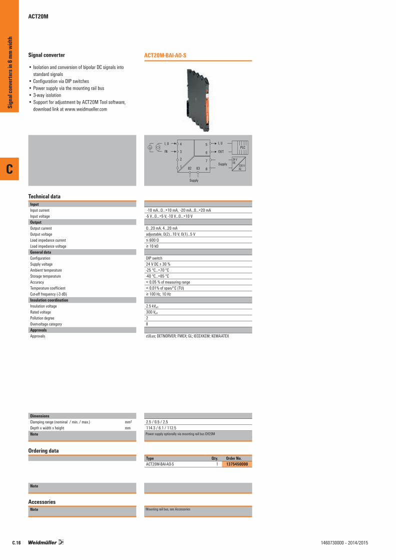
C
C.16 1460730000 – 2014/2015
Signal converter
• Isolation and conversion of bipolar DC signals into standard signals
• Configuration via DIP switches• Power supply via the mounting rail bus• 3-way isolation• Support for adjustment by ACT20M Tool software,
download link at www.weidmueller.com
Technical dataInputInput currentInput voltageOutputOutput currentOutput voltageLoad impedance currentLoad impedance voltageGeneral dataConfigurationSupply voltageAmbient temperature Storage temperatureAccuracyTemperature coefficientCut-off frequency (-3 dB)Insulation coordinationInsulation voltageRated voltagePollution degreeOvervoltage categoryApprovalsApprovals
DimensionsClamping range (nominal / min. / max.) mm²Depth x width x height mmNote
Ordering data
Note
AccessoriesNote
ACT20M-BAI-AO-S
4
3
2
1
5
6
7
8
I, U
OUT
Supply
I, U
IN
82
Supply
83
24 VDC
230 VAC
PLC
-10 mA…0…+10 mA, -20 mA…0…+20 mA-5 V…0…+5 V, -10 V…0…+10 V
0...20 mA, 4...20 mAadjustable, 0(2)...10 V, 0(1)...5 V≤ 600 Ω≥ 10 kΩ
DIP switch24 V DC ± 30 %-25 °C...+70 °C-40 °C...+85 °C< 0.05 % of measuring range< 0.01% of span/°C (TU)≥ 100 Hz, 10 Hz
2.5 kVeff
300 Veff
2II
cULus; DETNORVER; FMEX; GL; IECEXKEM; KEMAATEX
2.5 / 0.5 / 2.5114.3 / 6.1 / 112.5Screw connectionPower supply optionally via mounting rail bus CH20M
Type Qty. Order No.ACT20M-BAI-AO-S 1 1375450000
Mounting rail bus, see Accessories
Sign
al co
nver
ters
in 6
mm w
idth
ACT20M

C
C.171460730000 – 2014/2015
Universal measurement and signal converter• Isolation and conversion of temperature signals and DC
signals• Configuration using FDT/DTM software• Power supply via the mounting rail bus• 3-way isolation
Technical dataInputSensor
PotentiometerResistanceInput currentInput voltageInput resistance, voltageVoltage drop, current inputSensor supplyOutputOutput currentOutput voltageLoad impedance currentLoad impedance voltageGeneral dataConfigurationSupply voltageAmbient temperature AccuracyTemperature coefficientPower consumption, typ.Power consumption, max.Step response timeInsulation coordinationInsulation voltageRated voltagePollution degreeOvervoltage categoryApprovals
DimensionsClamping range (nominal / min. / max.) mm²Depth x width x height mmNote
Ordering data
Screw connection
Note
AccessoriesNote
ACT20M-UI-AO-S
4
3
2
1
5
6
7
8
I, U
OUT
Supply
I, U, R
IN24 VDC
230 VAC
PLC
82
Supply
83
Thermocouples: B, E, J, K, L, LR, N, R, N, R, S, T, U, W3, W5, RTD: PT100, PT1000, Ni100, Ni1000, 2-/3-/4-wire10 Ω…10 kΩ 10 Ω…10 kΩ 0...20 mA, 4…20mA0(2)…10 V, 0(1)…5 V > 10 MΩ < 3 V > 15 V DC at 20 mA
adjustable, 0...20 mA, 4...20 mAadjustable, 0(2)...10 V, 0(1)...5 V≤ 600 Ω, @ max 28mA ≥ 10 kΩ
With FDT/DTM software24 V DC ± 30 %-25 °C...+70 °C< 0.1 % of measuring range≤ 0.01 % / °C400 mW1.2 W400 ms (10...90%) @ U/I, 1 s @ temp
2.5 kVeff
300 Veff
2IIcULus; DETNORVER; FMEX; GL; GOSTME25; IECEXKEM; KEMAATEX
Screw connection2.5 / 0.5 / 2.5114.3 / 6.1 / 112.5Screw connectionPower supply optionally over the DIN mounting rail CH20M
Type Qty. Order No.ACT20M-UI-AO-S 1 1176030000
CBX200 USB configuration adapter - 8978580000DIN mounting rail, see Accessories
1
2
3
4
8
7
6
5
U, I, ϧ
U, I
Power
PLCmA
passive
+
–Out 1
Power24 V
+
–
4-wiremA
active
+
–In
1
2
3
4
8
7
6
5
U, I, ϧ
U, I
Power
PLCmA
passive
+
–Out 1
Power24 V
+
–
2-wiremA
passive
+
–In
ACT20M-UI-AO-S
1
2
3
4
8
7
6
5
U, I, ϧ
U, I
Power
PLCmA
passive
+
–Out 1
Power24 V
+
–
4-wireV
active
+
–In
1
2
3
4
8
7
6
5
U, I, ϧ
U, I
Power
PLCmA
passive
+
–Out 1
Power24 V
+
–
TC +
–In
ACT20M-UI-AO-S
1
2
3
4
8
7
6
5
U, I, ϧ
U, I
Power
PLCmA
passive
+
–Out 1
Power24 V
+
–
RTD
Sense +
R +
R –
Sense –
ACT20M-UI-AO-S
Sign
al co
nver
ters
in 6
mm w
idth
ACT20M

C
C.18 1460730000 – 2014/2015
Passive isolator
• Isolation of DC signals without additional voltage supply• Supply from the input measuring circuit• Optionally available as a 1-channel / 2-channel version• 2-way isolation
Technical dataInputVoltage drop, current inputInput currentOutputOutput currentLoad impedance currentGeneral dataConfigurationAmbient temperature AccuracyTemperature coefficientCut-off frequency (-3 dB)Power consumption, max.Step response timeInsulation coordinationInsulation voltageRated voltagePollution degreeOvervoltage categoryApprovals
DimensionsClamping range (nominal / min. / max.) mm²Depth x width x height mmNote
Ordering data
1-channel version2-channel version
Note
AccessoriesNote
ACT20M-CI-CO-ILP-S
4
3
2
1
5
6
7
8
I IN 1
I IN 2
I OUT 1
I OUT 2
24 VDC
230 VAC
PLC
PLC
1.25 V + 0.015 Vout @25°C 0...20 mA, 4…20mA
0...20 mA, 4...20 mA≤ 600 Ω, @ max 23mA
none-25 °C...+70 °C< 0.1 % of measuring range≤ 0.01 % / °C100 Hz30 mW per channel≤ 5 ms
2.5 kVeff
300 Veff
2IIcULus; DETNORVER; FMEX; GL; GOSTME25; IECEXKEM; KEMAATEX
Power supply optionally over the DIN mounting rail CH20M
1-channel version2.5 / 0.5 / 2.5114.3 / 6.1 / 112.5
Type Qty. Order No.ACT20M-CI-CO-ILP-S 1 1176070000ACT20M-2CI-2CO-ILP-S 1 1176080000
DIN mounting rail, see Accessories
1
2
3
4
8
7
6
5
I
I
PLCmA
passive
+
–Out
4-wiremA
active
+
–In
1
2
3
4
8
7
6
5 PLCmA
passive
+
–Out 1
Out 2PLCmA
passive
+
–
4-wiremA
active
+
–In 1
4-wiremA
active
+
–In 2
II
II
ACT20M-CI-CO-ILP-S
ACT20M-2CI-2CO-ILP-S
Sign
al co
nver
ters
in 6
mm w
idth
ACT20M
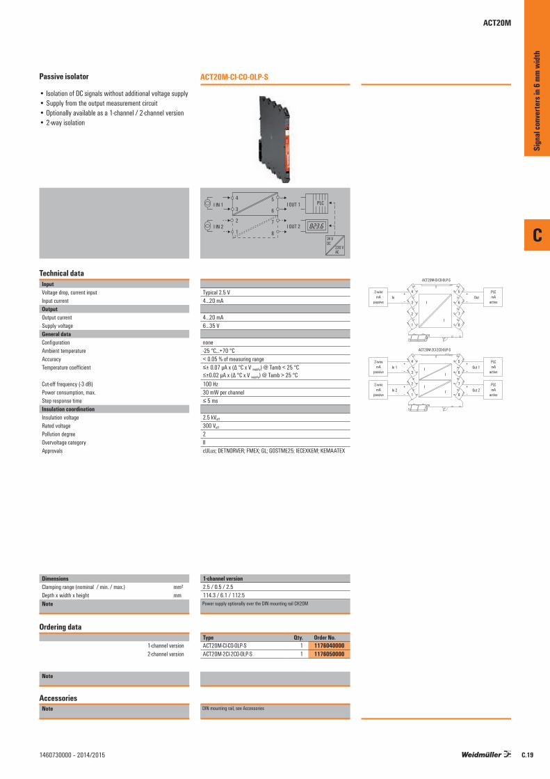
C
C.191460730000 – 2014/2015
Passive isolator
• Isolation of DC signals without additional voltage supply• Supply from the output measurement circuit• Optionally available as a 1-channel / 2-channel version• 2-way isolation
Technical dataInputVoltage drop, current inputInput currentOutputOutput currentSupply voltage General dataConfigurationAmbient temperature AccuracyTemperature coefficient
Cut-off frequency (-3 dB)Power consumption, max.Step response timeInsulation coordinationInsulation voltageRated voltagePollution degreeOvervoltage categoryApprovals
DimensionsClamping range (nominal / min. / max.) mm²Depth x width x height mmNote
Ordering data
1-channel version2-channel version
Note
AccessoriesNote
ACT20M-CI-CO-OLP-S
4
3
2
1
5
6
7
8
I IN 1
I IN 2
I OUT 1
I OUT 2
24 VDC
230 VAC
PLC
Typical 2.5 V 4...20 mA
4...20 mA6…35 V
none-25 °C...+70 °C< 0.05 % of measuring range≤± 0.07 µA x (Δ °C x V supply) @ Tamb < 25 °C ≤±0.02 µA x (Δ °C x V supply) @ Tamb > 25 °C100 Hz30 mW per channel≤ 5 ms
2.5 kVeff
300 Veff
2IIcULus; DETNORVER; FMEX; GL; GOSTME25; IECEXKEM; KEMAATEX
Power supply optionally over the DIN mounting rail CH20M
1-channel version2.5 / 0.5 / 2.5114.3 / 6.1 / 112.5
Type Qty. Order No.ACT20M-CI-CO-OLP-S 1 1176040000ACT20M-2CI-2CO-OLP-S 1 1176050000
DIN mounting rail, see Accessories
1
2
3
4
8
7
6
5
I
I
PLCmA
active
+
–Out
2-wiremA
passive
+
–In
1
2
3
4
8
7
6
5 PLCmA
active
+
–Out 1
Out 2PLCmA
active
+
–
2-wiremA
passive
+
–In 1
2-wiremA
passive
+
–In 2
II
II
ACT20M-CI-CO-OLP-S
ACT20M-2CI-2CO-OLP-S
Sign
al co
nver
ters
in 6
mm w
idth
ACT20M

C
C.20 1460730000 – 2014/2015
Temperature transducer
• Isolation and conversion of temperature signals, (RTD and thermocouple)
• Configuration via DIP switches• Power supply via the output circuit• 2-way isolation
Technical dataInputSensor
Input measurement range
Temperature input rangeOutputOutput currentSensor error detectionGeneral dataConfigurationSupply voltagePower consumptionStorage temperatureAccuracy
Galvanic isolationStep response timeAmbient temperature Insulation coordinationInsulation voltageRated voltagePollution degreeOvervoltage categoryApprovalsApprovals
DimensionsClamping range (nominal / min. / max.) mm²Depth x width x height mmNote
Ordering data
Note
AccessoriesNote
ACT20M-RTCI-CO-OLP-S
4
3
2
1
5
6IN
I, U
OUT
24 VDC
230 VAC
PLC
PT100 / 2-/3-/4-wire, Thermocouple acc. to IEC 584, type: J, Thermocouple acc. to IEC 584, type: KPT100 -200…+850 °C, Thermocouple type J -100…+1200°C, Thermocouple type K -200…+1370°CConfigurable
4...20 mA, 20…4 mA3.5 mA ⁄ 23 mA ⁄ none
DIP switchOutput loop poweredca. 1 W -40 °C...+85 °CAbsolute accuracy: < ±0.05 % of the measurement range, RTD (PT100) Basic accuracy: < ±0.1 °C of the measurement range, TC (J,K) Basic accuracy: < ±0.5 °C of the measurement range2-way isolator≤ 30 ms, < 300 ms-25 °C...+70 °C
1.5 kVeff
300 Veff
2II
cULus; DETNORVER; FMEX; GL; IECEXKEM; KEMAATEX
2.5 / 0.5 / 2.5114.3 / 6.1 / 112.5
Type Qty. Order No.ACT20M-RTCI-CO-OLP-S 1 1435590000
DIN mounting rail, see Accessories
Sign
al co
nver
ters
in 6
mm w
idth
ACT20M
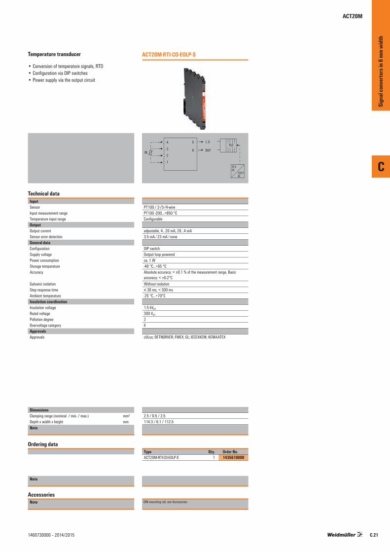
C
C.211460730000 – 2014/2015
Temperature transducer
• Conversion of temperature signals, RTD• Configuration via DIP switches• Power supply via the output circuit
Technical dataInputSensorInput measurement rangeTemperature input rangeOutputOutput currentSensor error detectionGeneral dataConfigurationSupply voltagePower consumptionStorage temperatureAccuracy
Galvanic isolationStep response timeAmbient temperature Insulation coordinationInsulation voltageRated voltagePollution degreeOvervoltage categoryApprovalsApprovals
DimensionsClamping range (nominal / min. / max.) mm²Depth x width x height mmNote
Ordering data
Note
AccessoriesNote
ACT20M-RTI-CO-EOLP-S
4
3
2
1
5
6IN
24 VDC
230 VAC
PLCI, U
OUT
PT100 / 2-/3-/4-wirePT100 -200…+850 °CConfigurable
adjustable, 4...20 mA, 20…4 mA3.5 mA ⁄ 23 mA ⁄ none
DIP switchOutput loop poweredca. 1 W -40 °C...+85 °CAbsolute accuracy: < ±0.1 % of the measurement range, Basic accuracy: < ±0.2°CWithout isolation≤ 30 ms, < 300 ms-25 °C...+70°C
1.5 kVeff
300 Veff
2II
cULus; DETNORVER; FMEX; GL; IECEXKEM; KEMAATEX
2.5 / 0.5 / 2.5114.3 / 6.1 / 112.5
Type Qty. Order No.ACT20M-RTI-CO-EOLP-S 1 1435610000
DIN mounting rail, see Accessories
Sign
al co
nver
ters
in 6
mm w
idth
ACT20M

C
C.22 1460730000 – 2014/2015
Temperature transducer
• Isolation and conversion of temperature signals, RTD (PT100)
• Configuration via DIP switches• Power supply via the mounting rail bus• 3-way isolation
Technical dataInputSensorInput measurement rangeTemperature input rangeOutputOutput currentOutput voltageLoad impedance currentLoad impedance voltageSensor error detectionGeneral dataConfigurationSupply voltagePower consumptionAccuracy
Galvanic isolationTemperature coefficientStep response timeAmbient temperature Insulation coordinationInsulation voltageRated voltagePollution degreeOvervoltage categoryApprovalsApprovals
DimensionsClamping range (nominal / min. / max.) mm²Depth x width x height mmNote
Ordering data
Note
AccessoriesNote
ACT20M-RTI-AO-S
4
3
2
1
5
6
7
882 83
IN
Supply
24 VDC
230 VAC
PLCI, U
OUT
Supply
PT100 / 2-/3-/4-wirePT100 -200…+850 °CConfigurable
adjustable, 0...20 mA, 4...20 mAadjustable, 0(1)...5 V, 0(2)...10 V≤ 600 Ω≥ 10 kΩ3.5 mA ⁄ 23 mA ⁄ none
DIP switch24 V DC ± 30 %ca. 1 W Absolute accuracy: < ±0.05 % of the measurement range, Basic accuracy: < ±0.1°C3-way isolator≤0.01 % of the measurement range⁄°C or 0.02 °C ⁄ °C≤ 30 ms, < 300 ms-25 °C +70 °C
2.5 kVeff
300 Veff
2II
cULus; DETNORVER; FMEX; GL; IECEXKEM; KEMAATEX
2.5 / 0.5 / 2.5114.3 / 6.1 / 112.5
Type Qty. Order No.ACT20M-RTI-AO-S 1 1375510000
DIN mounting rail, see Accessories
Sign
al co
nver
ters
in 6
mm w
idth
ACT20M
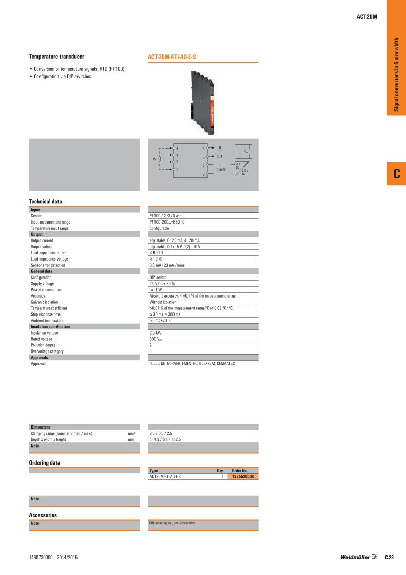
C
C.231460730000 – 2014/2015
Temperature transducer
• Conversion of temperature signals, RTD (PT100)• Configuration via DIP switches
Technical dataInputSensorInput measurement rangeTemperature input rangeOutputOutput currentOutput voltageLoad impedance currentLoad impedance voltageSensor error detectionGeneral dataConfigurationSupply voltagePower consumptionAccuracyGalvanic isolationTemperature coefficientStep response timeAmbient temperature Insulation coordinationInsulation voltageRated voltagePollution degreeOvervoltage categoryApprovalsApprovals
DimensionsClamping range (nominal / min. / max.) mm²Depth x width x height mmNote
Ordering data
Note
AccessoriesNote
ACT-20M-RTI-AO-E-S
4
3
2
1
5
6
7
8
IN 24 V
DC230 VAC
PLCI, U
OUT
Supply
PT100 / 2-/3-/4-wirePT100 -200…+850 °CConfigurable
adjustable, 0...20 mA, 4...20 mAadjustable, 0(1)...5 V, 0(2)...10 V≤ 600 Ω≥ 10 kΩ3.5 mA ⁄ 23 mA ⁄ none
DIP switch24 V DC ± 30 %ca. 1 W Absolute accuracy: < ±0.1 % of the measurement rangeWithout isolation≤0.01 % of the measurement range⁄°C or 0.02 °C ⁄ °C≤ 30 ms, < 300 ms-25 °C +70 °C
2.5 kVeff
300 Veff
2II
cULus; DETNORVER; FMEX; GL; IECEXKEM; KEMAATEX
2.5 / 0.5 / 2.5114.3 / 6.1 / 112.5
Type Qty. Order No.ACT20M-RTI-AO-E-S 1 1375520000
DIN mounting rail, see Accessories
Sign
al co
nver
ters
in 6
mm w
idth
ACT20M
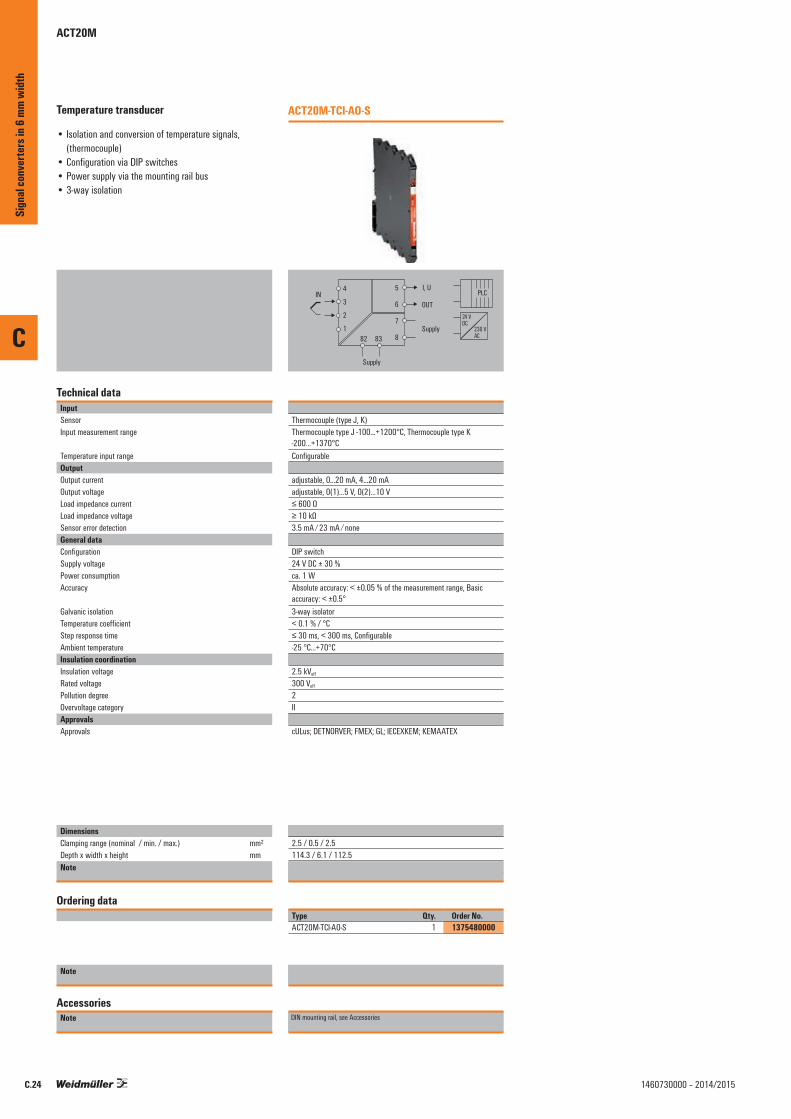
C
C.24 1460730000 – 2014/2015
Temperature transducer
• Isolation and conversion of temperature signals, (thermocouple)
• Configuration via DIP switches• Power supply via the mounting rail bus• 3-way isolation
Technical dataInputSensorInput measurement range
Temperature input rangeOutputOutput currentOutput voltageLoad impedance currentLoad impedance voltageSensor error detectionGeneral dataConfigurationSupply voltagePower consumptionAccuracy
Galvanic isolationTemperature coefficientStep response timeAmbient temperature Insulation coordinationInsulation voltageRated voltagePollution degreeOvervoltage categoryApprovalsApprovals
DimensionsClamping range (nominal / min. / max.) mm²Depth x width x height mmNote
Ordering data
Note
AccessoriesNote
ACT20M-TCI-AO-S
4
3
2
1
5
6
7
882 83
Supply
24 VDC
230 VAC
PLCI, U
OUT
Supply
IN
Thermocouple (type J, K)Thermocouple type J -100…+1200°C, Thermocouple type K -200…+1370°CConfigurable
adjustable, 0...20 mA, 4...20 mAadjustable, 0(1)...5 V, 0(2)...10 V≤ 600 Ω≥ 10 kΩ3.5 mA ⁄ 23 mA ⁄ none
DIP switch24 V DC ± 30 %ca. 1 WAbsolute accuracy: < ±0.05 % of the measurement range, Basic accuracy: < ±0.5°3-way isolator< 0.1 % / °C≤ 30 ms, < 300 ms, Configurable-25 °C...+70°C
2.5 kVeff
300 Veff
2II
cULus; DETNORVER; FMEX; GL; IECEXKEM; KEMAATEX
2.5 / 0.5 / 2.5114.3 / 6.1 / 112.5
Type Qty. Order No.ACT20M-TCI-AO-S 1 1375480000
DIN mounting rail, see Accessories
Sign
al co
nver
ters
in 6
mm w
idth
ACT20M
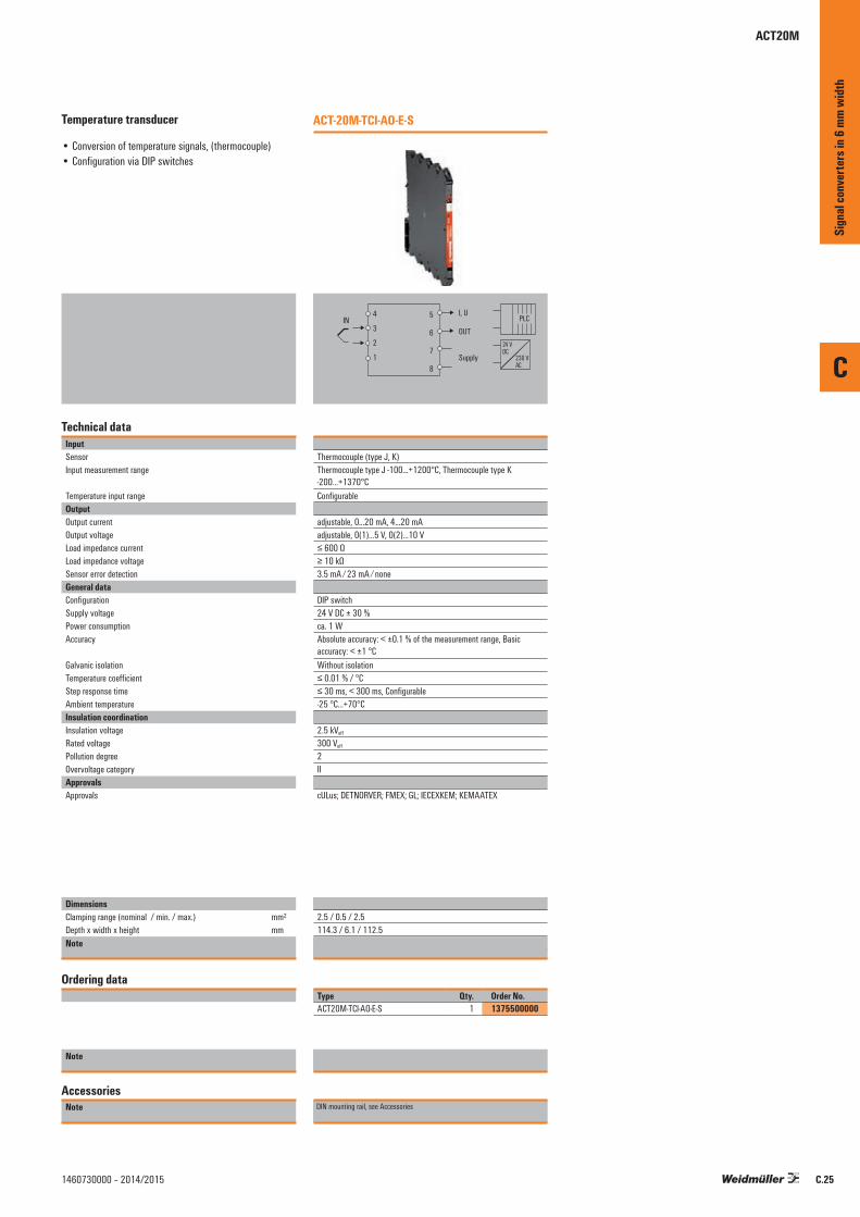
C
C.251460730000 – 2014/2015
Temperature transducer
• Conversion of temperature signals, (thermocouple)• Configuration via DIP switches
Technical dataInputSensorInput measurement range
Temperature input rangeOutputOutput currentOutput voltageLoad impedance currentLoad impedance voltageSensor error detectionGeneral dataConfigurationSupply voltagePower consumptionAccuracy
Galvanic isolationTemperature coefficientStep response timeAmbient temperature Insulation coordinationInsulation voltageRated voltagePollution degreeOvervoltage categoryApprovalsApprovals
DimensionsClamping range (nominal / min. / max.) mm²Depth x width x height mmNote
Ordering data
Note
AccessoriesNote
ACT-20M-TCI-AO-E-S
4
3
2
1
5
6
7
8
24 VDC
230 VAC
PLCI, U
OUT
Supply
IN
Thermocouple (type J, K)Thermocouple type J -100…+1200°C, Thermocouple type K -200…+1370°CConfigurable
adjustable, 0...20 mA, 4...20 mAadjustable, 0(1)...5 V, 0(2)...10 V≤ 600 Ω≥ 10 kΩ3.5 mA ⁄ 23 mA ⁄ none
DIP switch24 V DC ± 30 %ca. 1 WAbsolute accuracy: < ±0.1 % of the measurement range, Basic accuracy: < ±1 °CWithout isolation≤ 0.01 % / °C≤ 30 ms, < 300 ms, Configurable-25 °C...+70°C
2.5 kVeff
300 Veff
2II
cULus; DETNORVER; FMEX; GL; IECEXKEM; KEMAATEX
2.5 / 0.5 / 2.5114.3 / 6.1 / 112.5
Type Qty. Order No.ACT20M-TCI-AO-E-S 1 1375500000
DIN mounting rail, see Accessories
Sign
al co
nver
ters
in 6
mm w
idth
ACT20M

CH20M rail bus
CH20M rail bus
Quick and safe power supply through the DIN rail.
This customer-friendly infrastructure solution brings power, signals and data to the rail in a quick and reliable manner. The rail bus can replace the tedious individual wiring process with a flexible and uninterrupted system solution. As a result, the customer saves time and cost-especially if any module changes are needed later, as other adjacent modules are not disturbed. The uninterrupted system bus is securely integrated within the 35 mm standard mounting rail.Whether 7.5 mm or 15 mm high, the custom-fit rail profiles are easy to install on all TS 35 standard rails in accordance with DIN EN 60715.
The resistant gold-plated contacts ensure a permanent and reliable contact. The ACT20M modules are simply snapped onto the mounting rail and are automatically in contact with the DIN rail bus.
The supply of 24 V DC to the power rail can be from any one of the auxiliary powered ACT20M modules, when that module is itself externally supplied. This allows the rail to power up to 8 other modules (approximately 400 mA). For powering additional ACT20Ms, a separate Feed-In module can be used. The ACT20-Feed-In-Basic provides a simple and compact (6 mm width) power supply interface to the rail, for supplying up to 2.5 A (up to 50 x ACT20M modules).
The ACT20-Feed-In-Pro is a more powerful 22.5 mm wide solution. This takes 2 external 24 V DC inputs, and via internal diodes provides a redundant supply to the rail, and an alarm output in the case of input failure.
C
Sign
al co
nver
ters
in 6
mm w
idth
C.26 1460730000 – 2014/2015

CH20M rail bus
Rail bus accessories
CH20M BUS 4.50/05 AU/1000Bus PCB
• Bus circuit board for use on TS 35 x 7.5 and TS 35 x 15
• Length: 250, 500 or 750 mm• Five conductor paths, gold-plated• Electrical rating: 63 V AC, 5 A/conductor path
Ordering dataType Qty. Order No.CH20M BUS 4.50/05 AU/250 10 1248220000CH20M BUS 4.50/05 AU/500 10 1248230000 CH20M BUS 4.50/05 AU/750 5 1248240000
CH20M BUS-PROFIL TS35x7.5/1000Support section for bus circuit board
• Support section for TS 35 x 7.5• Length: 250, 500 or 750 mm
Ordering dataType Qty. Order No.CH20M BUS-PROFIL TS35x7.5/250 10 1248150000CH20M BUS-PROFIL TS35x7.5/500 10 1248160000 CH20M BUS-PROFIL TS35x7.5/750 5 1248170000
CH20M BUS-PROFIL TS35x15/1000Support section for bus circuit board
• Support section for TS 35 x 15• Length: 250, 500 or 750 mm
Ordering dataType Qty. Order No.CH20M BUS-PROFIL TS35x15/250 5 1248180000CH20M BUS-PROFIL TS35x15/500 5 1248190000 CH20M BUS-PROFIL TS35x15/750 5 1248210000
CH20M BUS-AP RE TS35x7.5 & 15End plate
• End plate for DIN rail bus• Fits on TS 35 x 7.5 and TS 35 x 15• right
Ordering dataType Qty. Order No.CH20M BUS-AP RE TS35x7.5 & 15 50 1193170000
CH20M BUS-ADP TS35/1000Cover plate
• Cover plate for DIN rail bus• Length: 250, 500 or 750 mm
Ordering dataType Qty. Order No.CH20M BUS-ADP TS35/250 10 1248250000CH20M BUS-ADP TS35/500 10 1248260000CH20M BUS-ADP TS35/750 5 1248270000
SET CH20M BUS 250MM TS 35X15Set
• SET consists of one each of CH20M BUS 4.50/05 AU/250 CH20M BUS-ADP TS 35/250 CH20M BUS-AP LI TS 35X7.5 & 15 CH20M BUS-AP RE TS 35X7.5 & 15 CH20M BUS-PROFIL TS 35X15/250
Ordering dataType Qty. Order No.SET CH20M BUS 250MM TS 35X15 1 1335150000
CH20M BUS-AP LI TS35x7.5 & 15End plate
• End plate for DIN rail bus• Fits on TS 35 x 7.5 and TS 35 x 15• left
Ordering dataType Qty. Order No.CH20M BUS-AP LI TS35x7.5 & 15 50 1193160000
SET CH20M BUS 250MM TS 35X7.5Set
• SET consists of one each of CH20M BUS 4.50/05 AU/250 CH20M BUS-ADP TS 35/250 CH20M BUS-AP LI TS 35X7.5 & 15 CH20M BUS-AP RE TS 35X7.5 & 15 CH20M BUS-PROFIL TS 35X7.5/250
Ordering dataType Qty. Order No.SET CH20M BUS 250MM TS 35X7.5 1 1335140000
TS 35x7.5 / TS 35x15DIN rail
• DIN rail with slot• Passivated galvanised steel
Ordering dataType Qty. Order No.TS 35X7.5/LL 1M/ST/ZN 10 0514510000TS 35X15/LL 1M/ST/ZN 10 0236510000
C
Sign
al co
nver
ters
in 6
mm w
idth
C.271460730000 – 2014/2015

CH20M rail bus
Power-feed module for the CH20M DIN rail bus
4 A supply with backup supply and error analysis
The power-feed unit ACT20-FEED-IN-PRO-S supplies the devices on the CH20M DIN rail bus with 24 V DC. At the same time, the FEED-IN device reads the group error contact – optionally provided by the installed devices – from the CH20M rail bus and sends a message through the status relay to the external controller. Optionally, two power supplies can be connected as a primary and back-up, to create a redundant 24 V DC source. An installation in Zone 2 / Division 2 is also possible. Three LEDs show the status of the power supply and the error status.
The FEED-IN-PRO can supply a maximum of 4 A to feed up to 120 devices mounted on a CH20M rail bus. Quick identification of errors on the DIN rail bus is through the internal status relay. The FEED-IN-PRO device immediately recognises and displays when a power supply has failed. The supply is then switched automatically to the redundant power supply.
Weidmüller offers a compact and narrow 6 mm feed-in module as an alternative. This feeds the 24 V DC from it‘s field terminals directly to the to the DIN rail bus. Up to 80 modules can be fed with a maximum available current of 2.5 A.
C
Sign
al co
nver
ters
in 6
mm w
idth
C.28 1460730000 – 2014/2015

C
C.291460730000 – 2014/2015
ACT20 power-feed module
• Distributes the supply onto the busbar• Compatible with Weidmüller CH20 DIN rail bus• Optional connection for backup supply• Approved for use in Ex-Zone 2 /Div. 2• Monitoring of the supply voltage• Alarm alerts via the status relay
Technical dataInputSupply voltageInput current
Trigger level for the power supplyOutput, power supplyOutput voltageOutput powerOutput currentOutput, status relay in safe zoneMax. switching voltage, AC / Max. switching voltage, DCContinuous currentAC power, max.General dataDegree of efficiencyAmbient temperature Power consumptionProtection degreeWeightHumidityApprovals
DimensionsClamping range (nominal / min. / max.) mm²Length x width x height mmNote
Ordering data
Screw connection
Note
AccessoriesNote
ACT20-Feed-In-PRO-S
51
52
53
54
Power supply, 0 V
Power supply,+24V
Backup, 0 V
Backup, +24 V
NC
Status relay, N.C.
Status relay, shared
Status relay, N.O.
44
43
42
41
8182838485N
C
NC 0 V
+24
V
Sta
tus
Alarm
21.6...26.4 V DCMax. 4 A 21.6...26.4 V DC Fault < 21 V DC
Input voltage -0.5 V DC / 4 A96 WMax. 4 A
250 V / 30 V2 A AC / DC 500 VA / 60 W
0,976-20 °C...+60 °C < 2 W IP 2014095 %, no condensationDEKRAATEX; DETNORVER; FMEX; GOSTME25; IECEXDEK
Screw connection2.5 / 0.5 / 2.5119.2 / 22.5 / 113.6
Type Qty. Order No.ACT20-FEED-IN-PRO-S 1 8965500000
DIN mounting rail, see Accessories
ACT20-Feed-In-BASIC-S
Power supply, +24 V
Power supply, 0 V
NC
NC
NC 0 V
+24
V
21.6...26.4 V DC0.5...2.5 A DC
Corresponds to the input voltage
Equivalent to input current
250 V / 30 V
100 %-25 °C...+70 °C
IP 207095 %, no condensationcULus; DETNORVER; FMEX; GL; GOSTME25; IECEXKEM; KEMAATEX
Screw connection2.5 / 0.5 / 2.5114.3 / 6.1 / 112.5
Type Qty. Order No.ACT20-FEED-IN-BASIC-S 1 1282490000
DIN mounting rail, see Accessories
Sign
al co
nver
ters
in 6
mm w
idth
ACT20 power-feed unit

MCZ-SERIES – Overview
Signal converter in a terminal format
The MCZ-SERIES signal converters have a slim terminal design and convert, isolate and monitor analogue signals. They have five tension clamp connections. The open side of the housing can be closed using a standard cover plate accessory. The housing has a low height of just 6.3 cm. It also accommodates a cross-connector for reducing the wiring of multiple module‘s 24 V and 0 V connections. Two WS10/6 markers can be used for labelling. These are available in MultiCard format and can be printed using Weidmüller‘s professional printing system.
C
Sign
al co
nver
ters
in 6
mm w
idth
C.30 1460730000 – 2014/2015
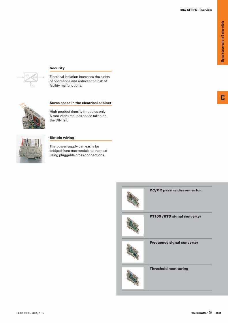
6 mm
MCZ-SERIES – Overview
DC/DC passive disconnector
PT100 /RTD signal converter
Frequency signal converter
Threshold monitoring
Security
Electrical isolation increases the safety of operations and reduces the risk of facility malfunctions.
Simple wiring
The power supply can easily be bridged from one module to the next using pluggable cross-connections.
Saves space in the electrical cabinet
High product density (modules only 6 mm wide) reduces space taken on the DIN rail.
C
Sign
al co
nver
ters
in 6
mm w
idth
C.311460730000 – 2014/2015
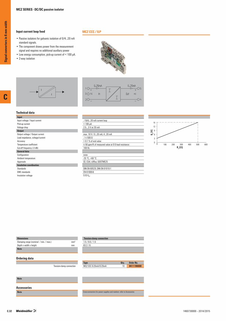
C
C.32 1460730000 – 2014/2015
Input current loop feed
• Passive isolators for galvanic isolation of 0/4...20 mA standard signals.
• The component draws power from the measurement signal and requires no additional auxiliary power
• Low energy consumption, pick-up current of < 100 µA.• 2-way isolation
I
I
Technical dataInputInput voltage / Input currentPick-up currentVoltage dropOutputOutput voltage / Output currentLoad impedance, voltage/currentAccuracyTemperature coefficientCut-off frequency (-3 dB)General dataConfigurationAmbient temperature ApprovalsInsulation coordinationStandardsEMC standardsInsulation voltage
DimensionsClamping range (nominal / min. / max.) mm²Depth x width x height mmNote
Ordering data
Tension-clamp connection
Note
AccessoriesNote
MCZ CCC / ILP
/ 0(4)...20 mA current loop< 100 µA2.5....3 V at 20 mA
max. 10 V / 0...20 mA, 4...20 mA / ≤ 500 Ω< 0.1 % of end value≤ 50 ppm/K of measured value at 0 Ω load resistance100 Hz
none-25 °C...+60 °CCE; CSA; cURus; GOSTME25
DIN EN 60529, DIN EN 61010-1EN 61000-6510 Veff
Tension-clamp connection1.5 / 0.5 / 1.563.2 / 6Tension clamp connection
Type Qty. Order No.MCZ CCC 0-20mA/0-20mA 10 8411190000
Cross-connectors for power supplies and markers: refer to Accessories
0
3
6
9
12
15
0 100 200 300 400 500 600
U E [V]
RL [Ω]
Sign
al co
nver
ters
in 6
mm w
idth
MCZ SERIES - DC/DC passive isolator

C
C.331460730000 – 2014/2015
RTD 2-/3-conductor converter Output-loop powered• RTD signal converter for galvanic isolation and
conversion of PT100 signals• The component draws power from the output circuit and
requires no additional auxiliary power• 2-way isolation
PT100
J U/I
VC
Technical dataInputSensorSensor supplyOutputOutput currentLoad impedance, voltage/currentGeneral dataConfigurationAmbient temperature / Storage temperatureAccuracyApprovalsStandardsEMC standards
DimensionsClamping range (nominal / min. / max.) mm²Depth x width x height mmNote
Ordering data
0...100 °C Tension-clamp connection0...120 °C Tension-clamp connection0...150 °C Tension-clamp connection0...200 °C Tension-clamp connection0...300 °C Tension-clamp connection-50...+150 °C Tension-clamp connection-40...+100 °C Tension-clamp connection
Note
AccessoriesNote
MCZ PT100/3 CLP / OLP
PT100/2-/3-wire (in compliance with IEC 751)0.8 mA / 9…30 V DC
4...20 mA (current loop) / ≤ 600 Ω
none-25 °C...+50 °C / -25 °C...+85 °CTypical 0.2%, max. 0.5% of FSRCE; CSA; cURus; GOSTME25DIN EN 50178, DIN EN 61000-4-2EN 61000-6
Tension-clamp connection1.5 / 0.5 / 1.563.2 / 6 /
Type Qty. Order No.MCZ PT100/3 CLP 0...100C 10 8425720000MCZ PT100/3 CLP 0...120C 10 8483680000MCZ PT100/3 CLP 0...150C 10 8604420000MCZ PT100/3 CLP 0...200C 10 8473010000MCZ PT100/3 CLP 0...300C 10 8473020000MCZ PT100/3 CLP -50C...+150C 10 8473000000MCZ PT100/3 CLP -40C...100C 10 8604430000
Cross-connectors for power supplies and markers: refer to Accessories
Sign
al co
nver
ters
in 6
mm w
idth
MCZ-SERIES - PT100 / RTD - signal isolator
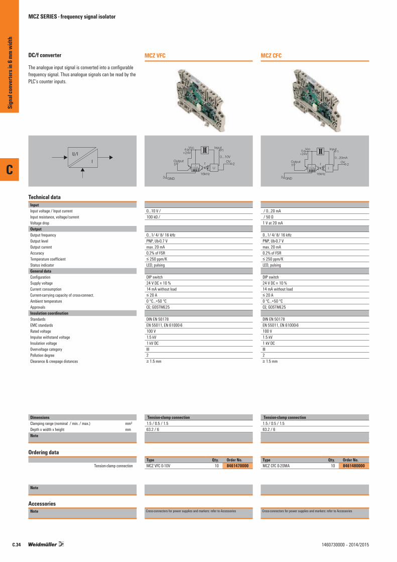
C
C.34 1460730000 – 2014/2015
DC/f converter
The analogue input signal is converted into a configurable frequency signal. Thus analogue signals can be read by the PLC‘s counter inputs.
IU/I
Technical dataInputInput voltage / Input currentInput resistance, voltage/currentVoltage dropOutputOutput frequencyOutput levelOutput currentAccuracyTemperature coefficientStatus indicatorGeneral dataConfigurationSupply voltageCurrent consumption Current-carrying capacity of cross-connect.Ambient temperature ApprovalsInsulation coordinationStandardsEMC standardsRated voltageImpulse withstand voltageInsulation voltageOvervoltage categoryPollution degreeClearance & creepage distances
DimensionsClamping range (nominal / min. / max.) mm²Depth x width x height mmNote
Ordering data
Tension-clamp connection
Note
AccessoriesNote
MCZ VFC
2OV
1
5
4
3
0...10V
fU
ff f/2f/4f/16
Output
InputVcc
+24V
16kHzGND
0...10 V / 100 kΩ /
0...1/ 4/ 8/ 16 kHzPNP, Ub-0.7 Vmax. 20 mA0.2% of FSR≤ 250 ppm/KLED, pulsing
DIP switch24 V DC ± 10 %14 mA without load≤ 20 A0 °C...+50 °CCE; GOSTME25
DIN EN 50178EN 55011, EN 61000-6100 V1.5 kV1 kV DCIII2≥ 1.5 mm
Tension-clamp connection1.5 / 0.5 / 1.563.2 / 6Tension clamp connection
Type Qty. Order No.MCZ VFC 0-10V 10 8461470000
Cross-connectors for power supplies and markers: refer to Accessories
MCZ CFC
2OV
1
5
5
3
0...20mA
fI
ff f/2f/4f/16
Output
InputVcc
+24V
16kHzGND
/ 0...20 mA / 50 Ω1 V at 20 mA
0...1/ 4/ 8/ 16 kHzPNP, Ub-0.7 Vmax. 20 mA0.2% of FSR≤ 250 ppm/KLED, pulsing
DIP switch24 V DC ± 10 %14 mA without load≤ 20 A0 °C...+50 °CCE; GOSTME25
DIN EN 50178EN 55011, EN 61000-6100 V1.5 kV1 kV DCIII2≥ 1.5 mm
Tension-clamp connection1.5 / 0.5 / 1.563.2 / 6Tension clamp connection
Type Qty. Order No.MCZ CFC 0-20MA 10 8461480000
Cross-connectors for power supplies and markers: refer to Accessories
Sign
al co
nver
ters
in 6
mm w
idth
MCZ SERIES - frequency signal isolator
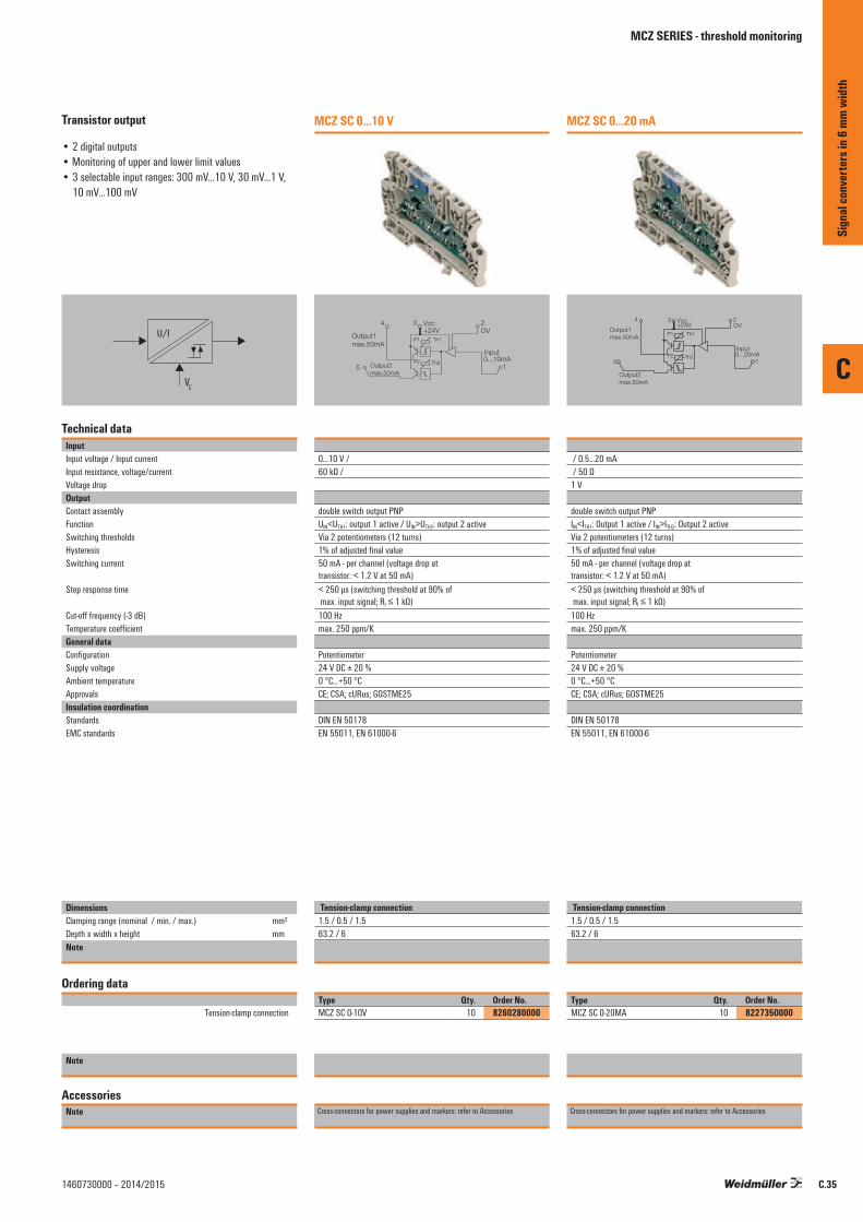
C
C.351460730000 – 2014/2015
Transistor output
• 2 digital outputs• Monitoring of upper and lower limit values• 3 selectable input ranges: 300 mV...10 V, 30 mV...1 V,
10 mV...100 mV
U/I
VC
Technical dataInputInput voltage / Input currentInput resistance, voltage/currentVoltage dropOutputContact assemblyFunctionSwitching thresholdsHysteresisSwitching current
Step response time
Cut-off frequency (-3 dB)Temperature coefficientGeneral dataConfigurationSupply voltageAmbient temperature ApprovalsInsulation coordinationStandardsEMC standards
DimensionsClamping range (nominal / min. / max.) mm²Depth x width x height mmNote
Ordering data
Tension-clamp connection
Note
AccessoriesNote
MCZ SC 0...10 V
Vcc +24V
3 2 OV
P1
P2
Th1
Th2 1
4
5
Input 0...10mA
Output1 max.50mA
Output2 max.50mA
0...10 V / 60 kΩ /
double switch output PNPUIN<UTH1: output 1 active / UIN>UTH2: output 2 activeVia 2 potentiometers (12 turns)1% of adjusted final value50 mA - per channel (voltage drop at transistor: < 1.2 V at 50 mA)< 250 µs (switching threshold at 90% of max. input signal; RI ≤ 1 kΩ)100 Hzmax. 250 ppm/K
Potentiometer24 V DC ± 20 %0 °C...+50 °CCE; CSA; cURus; GOSTME25
DIN EN 50178EN 55011, EN 61000-6
Tension-clamp connection1.5 / 0.5 / 1.563.2 / 6Tension clamp connection
Type Qty. Order No.MCZ SC 0-10V 10 8260280000
Cross-connectors for power supplies and markers: refer to Accessories
MCZ SC 0...20 mA
Vcc+24V
3 2OV
P1
P2
Th1
Th21
4
5
Input0...20mA
Output1max.50mA
Output2max.50mA
/ 0.5...20 mA / 50 Ω1 V
double switch output PNPIIN<ITH1: Output 1 active / IIN>ITH2: Output 2 activeVia 2 potentiometers (12 turns)1% of adjusted final value50 mA - per channel (voltage drop at transistor: < 1.2 V at 50 mA)< 250 µs (switching threshold at 90% of max. input signal; RI ≤ 1 kΩ)100 Hzmax. 250 ppm/K
Potentiometer24 V DC ± 20 %0 °C...+50 °CCE; CSA; cURus; GOSTME25
DIN EN 50178EN 55011, EN 61000-6
Tension-clamp connection1.5 / 0.5 / 1.563.2 / 6Tension clamp connection
Type Qty. Order No.MCZ SC 0-20MA 10 8227350000
Cross-connectors for power supplies and markers: refer to Accessories
Sign
al co
nver
ters
in 6
mm w
idth
MCZ SERIES - threshold monitoring

C
C.36 1460730000 – 2014/2015
Sign
al co
nver
ters
in 6
mm w
idth
Signal converters Universal signal converters – Overview D.2
ACT20C – Overview D.4
ACT20C – Network-compatible signal converter D.7
ACT20P – Overview D.8
ACT20P – Signal splitter D.11
ACT20P – Signal converter D.12
ACT20P – Bridge measuring transducer D.16
WAVESERIES – Overview D.18
WAVESERIES – Universal signal converter D.22
WAVESERIES – DC/DC 3-way isolator, configurable D.26
WAVESERIES – DC/DC 3-way isolator D.28
WAVESERIES – DC/DC 2-way isolator D.38
WAVESERIES – DC/DC passive isolator D.40
WAVESERIES – Temperature measuring transducer D.44
WAVESERIES – Frequency signal isolator/converter configurable D.54
WAVESERIES – Current measuring transducer D.56
WAVESERIES – Voltage measuring transducer D.60
Isolating converter for serial interfaces D.62
Signal converters
Contents
D
Sign
al co
nver
ters
D.11460730000 – 2014/2015
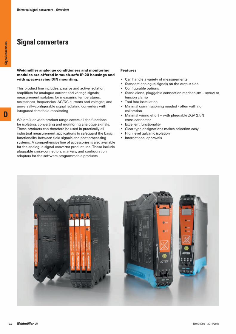
Universal signal converters – Overview
Weidmüller analogue conditioners and monitoring modules are offered in touch-safe IP 20 housings and with space-saving DIN mounting.
This product line includes: passive and active isolation amplifiers for analogue current and voltage signals; measurement isolators for measuring temperatures, resistances, frequencies, AC/DC currents and voltages; and universally-configurable signal isolating converters with integrated threshold monitoring.
Weidmüller wide product range covers all the functions for isolating, converting and monitoring analogue signals. These products can therefore be used in practically all industrial measurement applications to safeguard the basic functionality between field signals and post-processing systems. A comprehensive line of accessories is also available for the analogue signal converter product line. These include pluggable cross-connectors, markers, and configuration adapters for the software-programmable products.
Features
• Can handle a variety of measurements• Standard analogue signals on the output side• Configurable options• Stand-alone, pluggable connection mechanism – screw or
tension clamp• Tool-free installation• Minimal commissioning needed - often with no
calibration.• Minimal wiring effort – with pluggable ZQV 2.5N
cross-connector• Excellent functionality• Clear type designations makes selection easy• High level galvanic isolation• International approvals
Signal converters
D
Sign
al co
nver
ters
D.2 1460730000 – 2014/2015

Universal signal converters – Overview
ACT20C
ACT20P
WAVESERIES
D
Sign
al co
nver
ters
D.31460730000 – 2014/2015
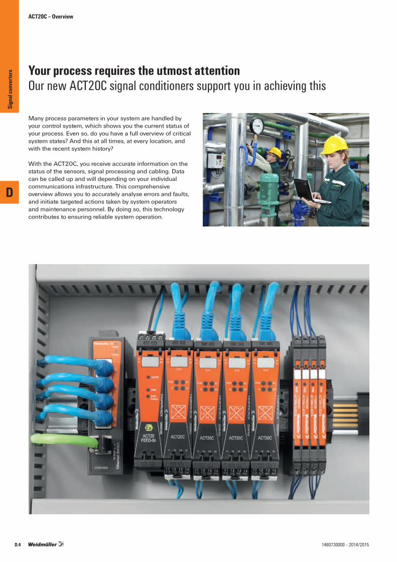
ACT20C – Overview
Many process parameters in your system are handled by your control system, which shows you the current status of your process. Even so, do you have a full overview of critical system states? And this at all times, at every location, and with the recent system history?
With the ACT20C, you receive accurate information on the status of the sensors, signal processing and cabling. Data can be called up and will depending on your individual communications infrastructure. This comprehensive overview allows you to accurately analyse errors and faults, and initiate targeted actions taken by system operators and maintenance personnel. By doing so, this technology contributes to ensuring reliable system operation.
Your process requires the utmost attentionOur new ACT20C signal conditioners support you in achieving this
D
Sign
al co
nver
ters
D.4 1460730000 – 2014/2015

ACT20C – Overview
You would like more process transparency for your systems. We support you with signal conditioners that supply you with precise information via our Ethernet interace. Let’s connect.
To be able to control systems and processes optimally, you require a constant flow of information on the current states of individual applications, devices and functions.
Our ACT20C signal conditioner not only monitors the signal conversion, but also communicates precise information on device status, signals and data directly to connected computer and control systems.
Our Ethernet interface enables an event-controlled transfer of diagnostics information, which in turn supports the elimination of faults in, for example, plant operation.
ACT20C signal conditioner with Ethernet interfaceComprehensive process transparency is provided by the transfer of diagnostics information, signals and data
Universal signal conversion Can be used in a multitude of applications thanks to customer and application specific defined conversion methods with just one single module.
Simple operation and configurationSoftware supported configuration allows a fast application of settings and simple operation.
Simple remote accessContinuous monitoring of device and system functions, simple and affordable integration of existing Ethernet networks.
ETHI, UI, U
PS
D
Sign
al co
nver
ters
D.51460730000 – 2014/2015
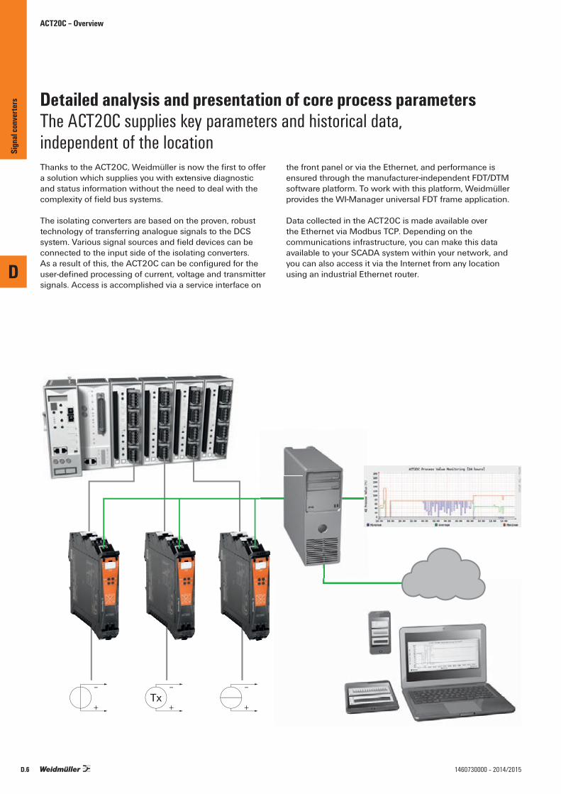
ACT20C – Overview
Thanks to the ACT20C, Weidmüller is now the first to offer a solution which supplies you with extensive diagnostic and status information without the need to deal with the complexity of field bus systems.
The isolating converters are based on the proven, robust technology of transferring analogue signals to the DCS system. Various signal sources and field devices can be connected to the input side of the isolating converters. As a result of this, the ACT20C can be configured for the user-defined processing of current, voltage and transmitter signals. Access is accomplished via a service interface on
the front panel or via the Ethernet, and performance is ensured through the manufacturer-independent FDT/DTM software platform. To work with this platform, Weidmüller provides the WI-Manager universal FDT frame application.
Data collected in the ACT20C is made available over the Ethernet via Modbus TCP. Depending on the communications infrastructure, you can make this data available to your SCADA system within your network, and you can also access it via the Internet from any location using an industrial Ethernet router.
Detailed analysis and presentation of core process parametersThe ACT20C supplies key parameters and historical data, independent of the location
D
Sign
al co
nver
ters
D.6 1460730000 – 2014/2015

D
D.71460730000 – 2014/2015
Network-ready signal converter for DC voltage and current signalsNetwork-compatible signal converter with Ethernet• Scalable current or voltage input• Current or voltage output• Limit-value monitoring with parameterisation options• Diagnostics on device status, signals and line faults
via Modbus• PC configuration with FDT/DTM software, download
link at www.weidmueller.com
Technical dataInputInput currentInput voltageSensor supplyOutputOutput currentOutput voltageLoad impedance currentLoad impedance voltageSignal processingTransfer functionsLimit-value monitoringCondition MonitoringDiagnostics
General dataSupply voltagePower consumptionAccuracy
Temperature coefficientAmbient temperature (operational)Storage temperatureHumidityProtection degreeInsulation coordinationGalvanic isolationRated voltage ⁄ test voltage: inpututput to output/input ⁄ supply⁄ Ethernet interfaceRated voltage ⁄ test voltage: Ethernet interface to supply ⁄ functional earth to supply ⁄ Ethernet interfaceRated voltage ⁄ test voltage: functional earth to input ⁄ output
Pollution degreeCommunicationRJ45 portsInterfaceAddressingProtocolConfigurationApprovalsStandardsRecommendations
DimensionsClamping range (nominal / min. / max.) mm²Depth x width x height / Weight mmNote
ACT20C-AI-AO-MTCP-S
U I I U I
ETH
I, UI, U
PS
RJ4511
12
13
14
51
52
53
5463 64
–
+ –
+
–
+
–
+ –
+V
mATx
24 V DC– +
0...20 mA, 4...20 mA0(2)…10 V> 17 V DC at 20 mA
0...20 mA, 4...20 mA0...10 V≤ 500 Ω≥ 10 kΩ
Linear, InverseProcess alarms with adjustable delay and hysteresisProcess value: sensor value, output valueDevice status, Short-circuit (input/output), Cable break (input/output), Overload (sensor/output)
24 V DC ± 25 %≤ 3.5 W< 0.15% end value (+ 0.05% > 55°C), Current: 1 uA / 30 uA (+ 10 uA > 55°C), Voltage: 1 mV / 15 mV (+ 5 mV > 55°C)≤ 0.01 % / °C-20 °C...+70 °C-20 °C...+85 °C0...95 % (no condensation)IP 20
4-way isolator;, between input / output / power supply / Ethernet300 Vrms / 1.7 kV rms on secondary electric circuits, reinforced insulation31.2 VDC / 0.9 kV rms on secondary electric circuits, basic insulation
300 Vrms / 1.1 kV rms on secondary electric circuits, basic insulation
2
10/100BaseT(X), auto negotiationRJ45: female-female, Cat.5 to 100 MHz, Jack plug for CBX200DHCP or manual adjustmentFDT/DTM, Modbus/TCPFDT/DTM (Ethernet or service interface)
DIN EN 61010-1, EN 61326-1:2006Namur NE43, Namur NE44, Namur NE107
Type Qty. Order No.
ACT20C-AI-AO-MTCP 1 1334490000
Ordering data
2.5 / 0.5 / 2.5113.6 / 22.5 / / 180
Sign
al co
nver
ters
ACT20C - Network-compatible signal converter

ACT20P – Overview
More space in the cabinet Two channels measure a mere 12.5 mm wide.
12.5 mm
Rapid device replacementPractical release lever for simple removal of the female connector.
Reliable connection Individually customisable protection against mismatching.
Variants for different applicationsThe range of products is rounded off by the intrinsically safe ACT20X signal converter and the high-performance ACT20M signal converter, which is just 6 mm across.
Can be integrated in HART® communicationSignal converters are suitable for HART®, transparent communication.
transparent
D
Sign
al co
nver
ters
D.8 1460730000 – 2014/2015

ACT20P – Overview
Reliable connection
Individually configurable protection against mismating with release lever
Simple signal conditioning
Devices configured for converting standard sensor signals to standard DC signals.
High level of galvanic isolation
The galvanic isolation of 2 kV(300 V rated voltage ) ensures high pro-cess reliability
U, I,R, T U, I
PS
Signal splitter
Signal converter
D
Sign
al co
nver
ters
D.91460730000 – 2014/2015

Output
Current
Power supply Function 0 … 20 mA1-channel
4 … 20 mA1-channel
2 x 0 … 20 mA2-channel / splitter
2 x 4 … 20 mA2-channel / splitter
Inpu
t
Curre
nt
0 … 20 mA 24 V DC and rail bus Current ACT20P-CI-CO-SCurrent ACT20P-CI-2CO-S ACT20P-CI-2CO-S
Output Loop Powered Current ACT20P-CI1-CO-OLP2 x 0 … 20 mA Output Loop Powered Current ACT20P-2CI-2CO-12
Input Loop Powered Current ACT20P-2CI-2CO-ILP24 V DC Current ACT20P-2CI-2CO-12 ACT20P-2CI-2CO-12
4 … 20 mA 24 V DC and rail bus Current ACT20P-CI-CO-S ACT20P-CI-CO-SCurrent ACT20P-CI-2CO-S ACT20P-CI-2CO-S
2 x 4 … 20 mA 24 V DC Current ACT20P-2CI-2CO-12 ACT20P-2CI-2CO-12
ACT20P – Overview
ACT20P – Selection table
Note: *) available from July 2013
D
Sign
al co
nver
ters
D.10 1460730000 – 2014/2015

D
D.111460730000 – 2014/2015
Signal splitter
• Isolation and splitting of DC signals• Passive transmitter or active current input• 3-way isolation• HART® - transparent
Technical dataInputInput signalInput currentVoltage drop, current inputVoltage dropOutputOutput currentLoad impedance currentGeneral dataConfigurationSupply voltageAccuracyStep response timeTemperature coefficientAmbient temperature Insulation coordinationEMC standardsInsulation voltageTest voltageImpulse withstand voltagePollution degreeOvervoltage category
DimensionsClamping range (nominal / min. / max.) mm²Depth x width x height mmNote
Ordering data
Note
AccessoriesNote
ACT20P-CI-2CO
11
12
21
2261 62
I
OUT
24 VDC
230 VAC
PLC
passive
passive
823.6I
IN
Currentsource
3 wire transmitter
2 wire transmitter
11
12
2-/3-wire transmitter, HART digital signal 0...20 mA, 4…20mA ≥ 17V @20mA ≤ 1 V
0...20 mA, 4...20 mA < 300 Ω
none 24 V DC ± 20 % < 0.1 % of end value ≤ 0,5 ms 80 ppm/K -20 °C...+60 °C
EN 61010-1:2011, UL 61010-1, EN 61326-1 2 kV inputs / outputs / power supply 300 V4 kV (1.2/50 µs) 2 III
2.5 / 0.5 / 2.5114 / 12.5 / 117.2
Type Qty. Order No.ACT20P-CI-2CO 1 7760054115
Sign
al co
nver
ters
ACT20P - Signal splitter
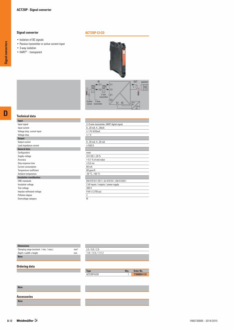
D
D.12 1460730000 – 2014/2015
Signal converter
• Isolation of DC signals• Passive transmitter or active current input• 3-way isolation• HART® - transparent
Technical dataInputInput signalInput currentVoltage drop, current inputVoltage dropOutputOutput currentLoad impedance currentGeneral dataConfigurationSupply voltageAccuracyStep response timeCurrent consumption Temperature coefficientAmbient temperature Insulation coordinationEMC standardsInsulation voltageTest voltageImpulse withstand voltagePollution degreeOvervoltage category
DimensionsClamping range (nominal / min. / max.) mm²Depth x width x height mmNote
Ordering data
Note
AccessoriesNote
ACT20P-CI-CO
11
12
21
2251 52
IN
I
OUT
24 VDC
230 VAC
PLC
passive
Currentsource
3 wire transmitter
2 wire transmitter
11
12
2-/3-wire transmitter, HART digital signal0...20 mA, 4…20mA ≥ 17V @20mA ≤ 1 V
0...20 mA, 4...20 mA ≤ 550 Ω
none 24 V DC ± 20 % < 0.1 % of end value ≤ 0,5 ms 60 mA80 ppm/K -20 °C...+60 °C
EN 61010-1:2011, UL 61010-1, EN 61326-1 2 kV inputs / outputs / power supply 300 V4 kV (1.2/50 µs) 2 III
2.5 / 0.5 / 2.5114 / 12.5 / 117.2
Type Qty. Order No.ACT20P-CI-CO 1 7760054114
Sign
al co
nver
ters
ACT20P - Signal converter

D
D.131460730000 – 2014/2015
Signal converter
• Isolation of DC signals• Passive input• 2 channels in one module• 3-way isolation• HART® - transparent
Technical dataInputInput currentVoltage dropOutputOutput currentLoad impedance currentGeneral dataConfigurationSupply voltageAccuracyStep response timeTemperature coefficientAmbient temperature Insulation coordinationEMC standardsInsulation voltageTest voltageImpulse withstand voltagePollution degreeOvervoltage category
DimensionsClamping range (nominal / min. / max.) mm²Depth x width x height mmNote
Ordering data
Note
AccessoriesNote
ACT20P-2CI-2CO-12
0...20 mA, 4…20mA ≤ 1 V
0...20 mA, 4...20 mA < 300 Ω, per channel
none 24 V DC ± 20 % < 0.1 % of end value ≤ 0,5 ms 80 ppm/K -20 °C...+60 °C
EN 61010-1:2011, UL 61010-1, EN 61326-1 2 kV inputs / outputs / power supply 300 V4 kV (1.2/50 µs) 2 III
2.5 / 0.5 / 2.5114 / 12.5 / 117.2
Type Qty. Order No.ACT20P-2CI-2CO-12 1 7760054117
Sign
al co
nver
ters
ACT20P - Signal converter

ACT20P – Overview
The ACT20P Bridge converts load cell/strain gauge measurement signals to standard analogue signals.
The ACT20P family offers the customer precise and functional signal converters in a compact design. The ACT20P Bridge is the first product from this new line of signal converters.
Load cells, with integral strain gauges, are used for weighing and load measurements throughout factory and process automation, in such applications as batch and recipe control, silo contents for granular products, bag weighing, engine strain measurements, and tank level.The strain gauges, within the load cell, are film resistors in a measurement bridge network, which deform with load changes and create a varying millivolt output from the bridge. The ACT20P Bridge reads these signals and converts them to a standard signal 0(4) – 20 mA or 0 – 10 V.
The high input to output isolation provided protects the control PLC against signal line interference. A digital input representing the “empty“ condition of the container (tare function) is a standard feature which zeroes the output of the ACT20P Bridge.
Features
• Adjust to load cells using push button• Easy tare function using the integrated control input• Intelligent pluggable connection method
The release lever simplifies maintenance and enables the connection to be unplugged without any wire damage.
• Integrated captive coding with the unique “auto-set“ function
ACT20P Strain gauge transmitter
D
Sign
al co
nver
ters
D.14 1460730000 – 2014/2015
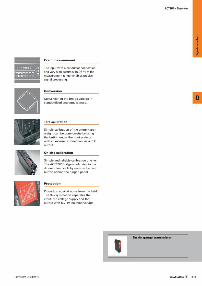
ACT20P – Overview
Strain gauge transmitter
Exact measurement
The input with 6-conductor connectionand very high accuracy (0.05 % of themeasurement range) enables precisesignal processing.
Tare calibration
Simple calibration of the empty (tare)weight can be done on-site by using the button under the front plate or with an external connection via a PLC output.
Conversion
Conversion of the bridge voltage instandardised analogue signals.
On-site calibration
Simple and reliable calibration on-site.The ACT20P Bridge is adjusted to thedifferent load cells by means of a pushbutton behind the hinged panel.
5.000047
Protection
Protection against noise from the field.The 3-way isolation separates the input, the voltage supply and the output with 5.7 kV isolation voltage.
D
Sign
al co
nver
ters
D.151460730000 – 2014/2015

ACT20P – Bridge measuring transducer
ACT20P Bridge measuring transducer
Bridge measuring transducer for reading from load cells
GeneralThe ACT20P Bridge is a DIN rail mounted, signal conditioner for industrial measuring bridges. It provides a precise excitati-on voltage for the bridge, and converts the input measure-ment to an isolated current/voltage signal. Bridge measuring transducers are used for various measurements like weight, force, tension, pressure, torque, and deflection.
Bridge excitation supplyVoltage sense connections are provided so that the excitation voltage can be measured at the bridge. Known as ‘remote sensing’ this method compensates for cabling and contact resistance errors. It is recommended for all new installations or where an upgrade is possible. Remote sensing wiring requires three twisted pairs.
TARE adjustmentThe installed strain gauge is normally subjected to an initial load independent of the measurement taken. The TARE connection allows you to correct for this initial loading by operating a switch. Alternatively there is a button on the front of the unit (under the front cover) that performs the same function. Press for two seconds to correct for the initial load (the ‘CAL HI’ LED will light for one second).
Gauge factorEvery strain gauge has a ‘gauge factor’ which gives the output voltage at full-scale for a one volt excitation voltage (given in mV/V). You multiply this by the bridge excitation voltage to get the output voltage when the gauge is fully loaded. For example, a load cell with 10 V excitation and 2 mV/V gauge factor will give 20 mV when fully loaded. The meaning of a 20 mV output depends on the type of the strain gauge. If it was designed to measure 0-1000 Kg then 20 mV indicates a 1000 Kg load.
SetupThe ACT20P Bridge has internal switch settings that determine the excitation voltage (5 V or 10 V) and Input range limits. Select the appropriate settings from the table below. Once you have set the DIP switches, you simply calibrate the unit to the input and output range for your application.
CalibrationThere are three options for calibrating the ACT20P Bridge:• Kalibrierung über einen Messbrückensimulators
(Bench calibrate using a bridge simulator (if you know the gauge factor)
• Calibrate on-site by loading the actual installed strain gauge
• Bench calibrates using a mV source (if you know the gauge factor).
For more information please read the manual from theweb page: www.weidmueller.com
D
Sign
al co
nver
ters
D.16 1460730000 – 2014/2015

D
D.171460730000 – 2014/2015
Configurable
Bridge measuring transducer for reading from load cells• 3-way isolation• Supply for measuring bridges up to 4 x 350 Ω• Simple calibration of the tare weight using external
switch or PLC input • Input and output ranges adjustable via DIP switch
Technical dataInputTypeBridge sensitivityInput measurement rangeInput resistanceSensor supplyBridge supply voltageOutputType Output voltage / Output currentLoad impedance, voltage/currentGeneral dataConfigurationSupply voltagePower consumptionLinearityRepeat accuracyHumidityTemperature coefficientLong-term driftStep response timeAmbient temperature ApprovalsInsulation coordinationStandardsEMC standardsRated voltageImpulse withstand voltagePollution degreeOvervoltage categoryInsulation voltage
DimensionsClamping range (nominal / min. / max.) mm²Depth x width x height mmNote
Ordering data
Screw connection
Note
AccessoriesNote
ACT20P-BRIDGE-S
V/I
PS
+
2323 2424
5354
11
2214
12
1321
+
excitation +
sense -sensexcitation -
signal +signal -
sense +
StrainGauge
10...60 V DC
44
41
42
43
mA test point +
mA test point -
0...10 V
I0/4...20 mA
Tare
+
--
-
Resistance measuring bridge1.0 mV / V to 5.0 mV / V± 10 mV / ± 20 mV / ± 30 mV / ± 50 mV (adjustable)> 1 MΩ120 mA @ 10 V (= 4 x 350 Ω bridge resistors)5 V or 10 V
Voltage and current output (configurable)0 ...11 V (adjustable) / 0...22 mA (adjustable)600 Ω / ≤ 600 Ω
DIP switch10…60 V DC3 W @ 24 V DCTypically ± 0.05 % of signal range± 0.05% of signal range10...90 % (no condensation)typ. 0.005 % / °C0.1 % / 10.000 h< 400 ms (10…90 %)-40 °C...+70 °C GOSTME25
DIN EN 61010-1, DIN EN 61000-4-2EN 61326300 Veff
4 kV (1.2/50 µs)2III5.7 kV (input / output, input / supply)
Screw connection2.5 / 0.5 / 2.5 / 22.5 / 113.6Screw connection
Type Qty. Order No.ACT20P-BRIDGE-S 1 1067250000
Front panel DIP Switch settingsSwitch Action if On Action if Off1 10 V Excitation 5 V Excitation2 mA Output Voltage Output3 10 mV Span4 20 mV Span Turn off for other ranges5 30 mV Span6 50 mV Span7 4-wire Measurement 6-wire Measurement8
ConnectionsTerminal Signal11 Signal − Input signal12 Signal +13 Sense + 14 Sense − Bridge Excitation Voltage21 Excitation +22 Excitation −23 Tare + External Tare switch24 Tare −41 mA Output − 42 Output +43 mA-Test Point − Output signal44 Voltage Output −44 mA-Test Point +54 + Power Supply53 −
Sign
al co
nver
ters
ACT20P - Bridge measuring transducer
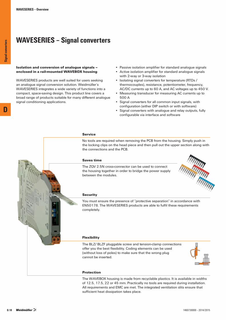
WAVESERIES – Overview
WAVESERIES – Signal converters
Isolation and conversion of analogue signals – enclosed in a rail-mounted WAVEBOX housing
WAVESERIES products are well suited for users seeking an analogue signal conversion solution. Weidmüller‘s WAVESERIES integrates a wide variety of functions into a compact, space-saving design. This product line covers a broad range of products suitable for many different analogue signal conditioning applications.
• Passiveisolationamplifierforstandardanaloguesignals• Activeisolationamplifierforstandardanaloguesignals
with 2-way or 3-way isolation• Isolating signal converters for temperature (RTDs /
thermocouples), resistance, potentiometer, frequency, AC/DC currents up to 60 A, and AC voltages up to 450 V.
• Measuring transducer for measuring AC currents up to 500 A
• Signal converters for all common input signals, with configuration(eitherDIPswitchorwithsoftware)
• Signal converters with analogue and relay outputs, fully configurableviainterfaceandsoftware
Service
No tools are required when removing the PCB from the housing. Simply push in the locking clips on the head piece and then pull out the upper section along with the connections and the PCB.
Saves time
The ZQV 2.5N cross-connector can be used to connectthe housing together in order to bridge the power supplybetween the modules.
Security
You must ensure the presence of “protective separation“ in accordance with EN50178.TheWAVESERIESproductsareabletofulfiltheserequirementscompletely.
Flexibility
The BLZ/ BLZF pluggable screw and tension-clamp connectionsofferyouthebestflexibility.Codingelementscanbeused(without loss of poles) to make sure that the wrong plugcannot be inserted.
Protection
The WAVEBOX housing is made from recyclable plastics. It is available in widths of 12.5, 17.5, 22 or 45 mm. Practically no tools are required during installation.All requirements and EMC are met. The integrated ventilation slits ensure that sufficientheatdissipationtakesplace.
D
Sign
al co
nver
ters
D.18 1460730000 – 2014/2015
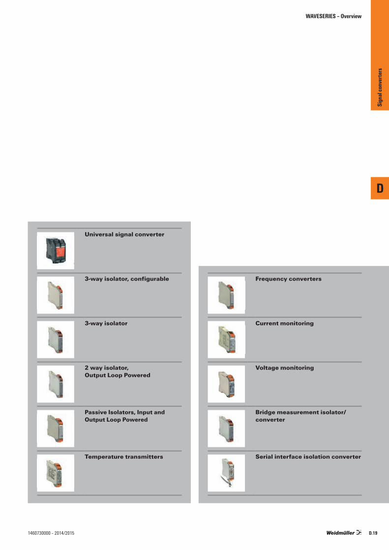
WAVESERIES – Overview
Universal signal converter
3-way isolator, configurable
3-way isolator
2 way isolator, Output Loop Powered
Passive Isolators, Input and Output Loop Powered
Temperature transmitters
Frequency converters
Current monitoring
Voltage monitoring
Bridge measurement isolator/converter
Serial interface isolation converter
D
Sign
al co
nver
ters
D.191460730000 – 2014/2015
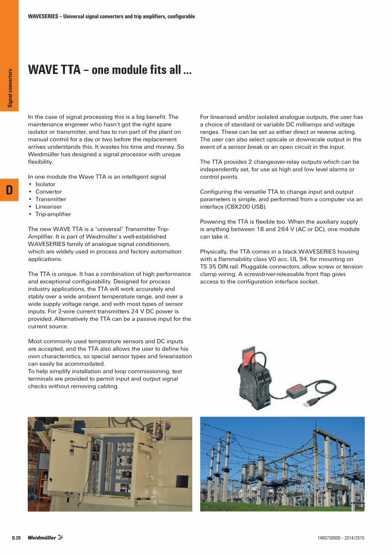
WAVE TTA – one module fits all ...
Inthecaseofsignalprocessingthisisabigbenefit.Themaintenance engineer who hasn’t got the right spare isolator or transmitter, and has to run part of the plant on manual control for a day or two before the replacement arrives understands this. It wastes his time and money. So Weidmüller has designed a signal processor with unique flexibility.
In one module the Wave TTA is an intelligent signal• Isolator• Convertor• Transmitter• Lineariser• Trip-amplifier
The new WAVE TTA is a “universal“ Transmitter Trip-Amplifier.ItispartofWeidmüller’swell-establishedWAVESERIES family of analogue signal conditioners, which are widely used in process and factory automation applications.
The TTA is unique. It has a combination of high performance andexceptionalconfigurability.Designedforprocessindustry applications, the TTA will work accurately and stably over a wide ambient temperature range, and over a wide supply voltage range, and with most types of sensor inputs. For 2-wire current transmitters 24 V DC power is provided. Alternatively the TTA can be a passive input for the current source.
Most commonly used temperature sensors and DC inputs areaccepted,andtheTTAalsoallowstheusertodefinehisown characteristics, so special sensor types and linearisation can easily be acommodated.To help simplify installation and loop commissioning, test terminals are provided to permit input and output signal checks without removing cabling.
For linearised and/or isolated analogue outputs, the user has a choice of standard or variable DC milliamps and voltage ranges. These can be set as either direct or reverse acting.The user can also select upscale or downscale output in the event of a sensor break or an open circuit in the input.
The TTA provides 2 changeover-relay outputs which can be independently set, for use as high and low level alarms or control points.
ConfiguringtheversatileTTAtochangeinputandoutputparameters is simple, and performed from a computer via an interface (CBX200 USB).
PoweringtheTTAisflexibletoo.Whentheauxiliarysupplyis anything between 18 and 264 V (AC or DC), one module can take it.
Physically, the TTA comes in a black WAVESERIES housing withaflammabilityclassV0acc.UL94,formountingonTS 35 DIN rail. Pluggable connectors, allow screw or tension clampwiring.Ascrewdriver-releasablefrontflapgivesaccesstotheconfigurationinterfacesocket.
WAVESERIES – Universal signal converters and trip amplifiers, configurable
D
Sign
al co
nver
ters
D.20 1460730000 – 2014/2015
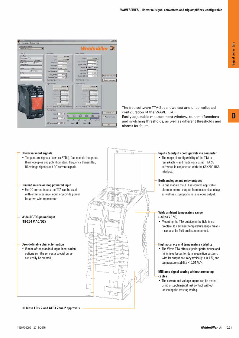
Universal input signals • Temperature signals (such as RTDs), One module integrates
thermocouples and potentiometers, frequency transmitter, DC voltage signals and DC current signals.
Current source or loop powered input• For DC current inputs the TTA can be used
with either a passive input, or provide power for a two-wire transmitter.
Wide AC/DC power input(18-264 V AC/DC)
User-definable characterisation• If none of the standard input linearisation
options suit the sensor, a special curve can easily be created.
UL Class I Div.2 and ATEX Zone 2 approvals
Inputs & outputs configurable via computer•TherangeofconfigurabilityoftheTTAis
remarkable – and made easy using TTA SET software, in conjunction with the CBX200 USB interface.
Both analogue and relay outputs• In one module the TTA integrates adjustable
alarm or control outputs from mechanical relays, as well as it‘s proportional analogue output.
Wide ambient temperature range(–40 to 70 °C) •MountingtheTTAoutsideinthefieldisno
problem. It‘s ambient temperature range means itcanalsobefieldenclosuremounted.
High accuracy and temperature stability• The Wave TTA offers superior performance and
minimises losses for data acquisition systems, with its output accuracy typically < 0.1 %, and temperature stability < 0.01 %/K
Milliamp signal testing without removing cables• The current and voltage inputs can be tested
using a supplemental test contact without loosening the existing wiring.
WAVESERIES – Universal signal converters and trip amplifiers, configurable
The free software TTA-Set allows fast and uncomplicated configurationoftheWAVETTA.Easily adjustable measurement window, transmit functions and switching thresholds, as well as different thresholds and alarms for faults.
D
Sign
al co
nver
ters
D.211460730000 – 2014/2015

D
D.22 1460730000 – 2014/2015
WAVE TTA
• Input and outputs can be configured on PC with the TTA-SET software, download at www.weidmueller.com
• Universal input signals• Loop-powered or passive input• Pluggable connection terminals
Technical dataInputSensor
PotentiometerResistanceInput frequencyInput voltageInput currentSensor supplyOutput analogueOutput voltageOutput currentLoad impedance, voltage/currentSignal outputTransmit functionOutput digitalType Switching voltage AC, max. / DC, max.Continuous currentGeneral dataConfigurationSupply voltagePower consumptionAccuracyTemperature coefficient
Ambient temperature / Storage temperatureStep response timeHumidityApprovalsInsulation coordinationStandardsEMC standardsRated voltageImpulse withstand voltagePollution degreeOvervoltage categoryClearance & creepage distancesInsulation voltage
DimensionsClamping range (nominal / min. / max.) mm²Depth x width x height mmNote
WAS6 TTA / WAZ6 TTA
3-Ports IsolationAnalogue Inputs
RelayChannel 1RelayChannel 2Output0 ... 11 V /0 ... 22 mA
18-264 V AC/DC supply
+24 V DC
J V, I
PS
V, I
Thermocouples: B, E, J, K, L, N, R, S, T (IEC 60584), PT100, PT1000, (EN 60571) Ni100, Ni1000, (JIS1604), Cu10, Cu25, Cu50, Cu100 (DIN 43760) 2-/3-/4-wire100 Ω...100 kΩ10 Ω…5 kΩ2 Hz…100 kHz-200...500 mV (min. 4 mV span), -20...50 V DC (min. 0.5 V span)-20...50 mA (min. span 0.4 mA)24 V DC / 22 mA
Adjustable between -10...+10 V (min. span of 2.5 V)Adjustable between 0...20 mA (min. span of 5 mA)> 10 kΩ @ 0...10 V / > 20 kΩ @ -10...+10 V / < 700 Ωdirect or invertedLinear, x1/2, x3/2, x5/2 or user-defined curve (101 points)
2 x 1 CO contact (hard gold-plated)250 V / 30 V3 A AC / 2 A DC
TTA Set Software18...264 V AC/DC< 3.5 W< 0.1 % span (DC. RTD); 0.2 % span (or 1 °C) + CJ failure< 0.1 % / K (DC, RTD); < 0.1 % FSR / K + CJ error 0.07 °C/K (thermocouples )-40 °C...+70 °C / -40 °C...+85 °C50 ms...1 sec (RTD, mV inputs), 110 ms...1 sec (V, mA inputs)5...95 %, no condensationCE; cULus; GL
DIN EN 50178, DIN EN 61000-4-2EN 55011, EN 61000-6300 V6 kV2III≥ 5.5 mm (1 mm Input/output)2.5 kV
Typical functions
I
PS
I, V
Isolator
f, I, V
PS
I, V
Converter
J
PS
I, V
Transmitter
I, V
PS
I, V
Lineariser
J
PS
Trip amplifier
Type Qty. Order No.Screw connectionWAS6 TTA 1 8939670000Tension clamp conn.WAZ6 TTA 1 8939680000
CBX200 USB configuration adapter - 8978580000
Ordering data
Screw connection Tension clamp connection2.5 / 0.5 / 2.5 2.5 / 0.5 / 2.5112.4 / 45 / 112.4 / 45 /
Sign
al co
nver
ters
WAVESERIES – Universal signal converters and trip amplifiers, configurable

D
D.231460730000 – 2014/2015
WAVE TTA EX
• Input and outputs can be configured on PC with the TTA-SET software, download at www.weidmueller.com
• Universal input signals• Loop-powered or passive input• Pluggable connection terminals• ATEX 3 G Ex nA IIC T4• UL Class I, Div.2
Technical dataInputSensor
PotentiometerResistanceInput frequencyInput voltageInput currentSensor supplyOutput analogueOutput voltageOutput currentLoad impedance, voltage/currentSignal outputTransmit functionOutput digitalType Switching voltage AC, max. / DC, max.Continuous currentGeneral dataConfigurationSupply voltagePower consumptionAccuracyTemperature coefficient
Ambient temperature / Storage temperatureStep response timeHumidityApprovalsInsulation coordinationStandardsEMC standardsRated voltageImpulse withstand voltagePollution degreeOvervoltage categoryClearance & creepage distancesInsulation voltage
DimensionsClamping range (nominal / min. / max.) mm²Depth x width x height mmNote
WAS6 TTA EX / WAZ6 TTA EX
3-Ports IsolationAnalogue Inputs
RelayChannel 1RelayChannel 2Output0 ... 11 V /0 ... 22 mA
18-264 V AC/DC supply
+24 V DC
J V, I
PS
V, I
Thermocouples: B, E, J, K, L, N, R, S, T (IEC 60584), PT100, PT1000, (EN 60571) Ni100, Ni1000, (JIS1604), Cu10, Cu25, Cu50, Cu100 (DIN 43760) 2-/3-/4-wire100 Ω...100 kΩ10 Ω…5 kΩ2 Hz…100 kHz-200...500 mV (min. 4 mV span), -20...50 V DC (min. 0.5 V span)-20...50 mA (min. span 0.4 mA)24 V DC / 22 mA
Adjustable between -10...+10 V (min. span of 2.5 V)Adjustable between 0...20 mA (min. span of 5 mA)> 10 kΩ @ 0...10 V / > 20 kΩ @ -10...+10 V / < 700 Ωdirect or invertedLinear, x1/2, x3/2, x5/2 or user-defined curve (101 points)
2 x 1 CO contact (hard gold-plated)250 V / 30 V2 A AC/DC
TTA Set Software24...240 V AC/DC; 24...36 V AC / 24...50 V DC (ATEX Zone 2)< 3.5 W< 0.1 % span (DC. RTD); 0.2 % span (or 1 °C) + CJ failure< 0.1 % / K (DC, RTD); < 0.1 % FSR / K + CJ error 0.07 °C/K (thermocouples )-40 °C...+70 °C / -40 °C...+85 °C50 ms...1 sec (RTD, mV inputs), 110 ms...1 sec (V, mA inputs)5...95 %, no condensationCE; cULus; cULusEX; KEMAATEX
DIN EN 50178, DIN EN 60079, DIN EN 61000-4-2EN 55011, EN 61000-6300 V6 kV2III≥ 5.5 mm (1 mm Input/output)2.5 kV
Typical functions
I
PS
I, V
Isolator
f, I, V
PS
I, V
Converter
J
PS
I, V
Transmitter
I, V
PS
I, V
Lineariser
J
PS
Trip amplifier
Type Qty. Order No.Screw connectionWAS6 TTA EX 1 8964310000Tension clamp conn.WAZ6 TTA EX 1 8964320000
CBX200 USB configuration adapter - 8978580000
Ordering data
Screw connection Tension-clamp connection2.5 / 0.5 / 2.5 2.5 / 0.5 / 2.5112.4 / 45 / 112.4 / 45 /
Sign
al co
nver
ters
WAVESERIES – Universal signal converters and trip amplifiers, configurable

WAVESERIES – Universal signal converters, output loop powered
ITXPlus
Universal, loop powered signal isolating converter
The ITXPlus is a compact signal isolating converter that is loop-powered, programmable and electrically isolated. On the input side, the user can connect DC-current/voltage signals, 2-, 3-, or 4-wire PT100s, and thermocouples. The ITXPlus measures, filters and isolates the input signals. It converts them into a proportional signal from 4 to 20 mA. The ITXPlus provides a 4 to 20 mA current loop output. For linear temperature measurements, you can connect all standard types of thermocouples and resistance temperature detectors (RTDs). The ITXPlus can also process signals from any non-linear device, such as a NTC or PTC sensor, or log. potentiometer. User-definable curves can be programmed into a table containing up to 101 co-ordinates for thermocouple and RTD ranges and 25 for other variables.Furthermore, the ITXPlus can be connected to resistors, potentiometers and sensors which operate in the mV/mA
range. Functionality also includes square root extraction, and x to the power 3/2 and 5/2 transfer functions. Other characteristic curves which have not been pre-programmed can be entered directly using a PC. In this way you can reproduce any sensor’s characteristic curve. The T-Set software can be used for configuration or for showing measurement trends. The CBX100 interface connects the ITXPlus with the PC. It implements complete electrical isolation between the serial port and the signal converter.
Technical dataInputs Type
Ther
moco
uple
input
s
Type StandardB
IEC584CEJKL DIN 43710N
IEC584RSTW3, W5 ASTM E98890User-defined InputCold-junction compensationWire-break recognition
mAVoltmV
Type Standard
2, 3,
4-wi
re R
TD
PT 100 DIN 43710PT 100 JISPT 200 DIN 43710PT 200 JISNI 120 DIN 43710CU 100 DIN 43710Cable resistanceSensor currentInfluence of cable resistance sensor (3/4 wire)
ResistanceAccuracy
Type RangeE,J,K,L,N,T,U < 500 °C
> 500 °CB, C, R, S, W3, W5
AllmV, V, mAPT100/RTDResistance
Thermocouple, PT100/RTD, mA, volt, mV, resistanceLower limit Upper limit Min. range400 °C 1828 °C 200 °C0 °C 2000 °C–100 °C 1000 °C
50 °C–100 °C 1200 °C–180 °C 1372 °C–100 °C 900 °C–180 °C 1300 °C 100 °C–50 °C 1760 °C 200 °C–50 °C 1760 °C–200 °C 400 °C 50 °C0 °C 2300 °C 200 °C2–101 values± 1.0 °Cyes–10 mA to + 20 mA to 40 Ω input resistance (min. range 1 mA)–5 V to + 10 V to 2 M Ω input resistance (min. range 0.5 V)–100 mV to + 200 mV to 2 M Ω input resistance (min range 4 mV)
Lower limit Upper limit Min. range–200 °C 850 °C
50 °C–200 °C 630 °C–200 °C 850 °C–200 °C 630 °C–80 °C 320 °C–100 °C 260 °C 100 °C5 Ω max.0,1 mA < 0.002 Ω per Ω wire resistance0 to 10 k Ω (min. range 10 Ω)
Temperature coefficient Accuracy± 0.02 °C per C° ambient temperature ≤ ± 1.0 °C± 0.01 % of end value per °C ambient temperature± 0.02 °C per C° ambient temperature ≤ ± 2.0 °C
≤ ± 0.1 % of end value≤ ± 0.5 °C≤ ± 0.1 % of end value
D
Sign
al co
nver
ters
D.24 1460730000 – 2014/2015
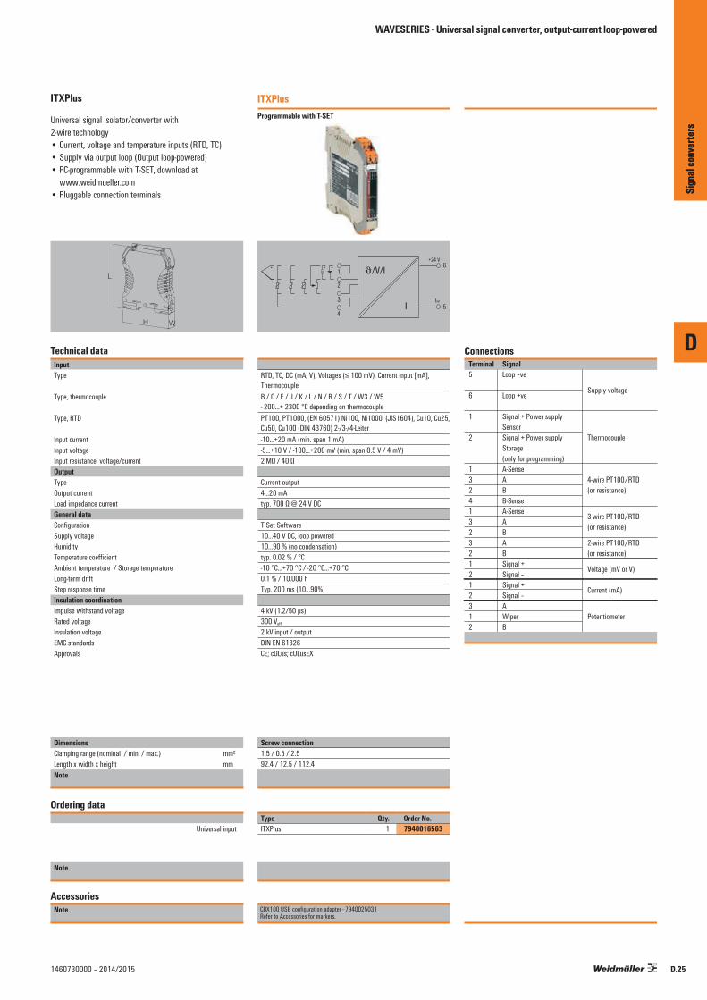
D
Sign
al co
nver
ters
D.251460730000 – 2014/2015
ITXPlus
Universal signal isolator/converter with2-wire technology• Current, voltage and temperature inputs (RTD, TC)• Supply via output loop (Output loop-powered)• PC-programmable with T-SET, download at
www.weidmueller.com• Pluggable connection terminals
W
L
H
Technical dataInputType
Type, thermocouple
Type, RTD
Input currentInput voltageInput resistance, voltage/currentOutputType Output currentLoad impedance currentGeneral dataConfigurationSupply voltageHumidityTemperature coefficientAmbient temperature / Storage temperatureLong-term driftStep response timeInsulation coordinationImpulse withstand voltageRated voltageInsulation voltageEMC standardsApprovals
DimensionsClamping range (nominal / min. / max.) mm²Length x width x height mmNote
Ordering data
Universal input
Note
AccessoriesNote
ITXPlusProgrammable with T-SET
6
5
J/V/I+ + +
I
+24 V
Iout
1
2
3
4
RTD, TC, DC (mA, V), Voltages (≤ 100 mV), Current input [mA], ThermocoupleB / C / E / J / K / L / N / R / S / T / W3 / W5 - 200...+ 2300 °C depending on thermocouplePT100, PT1000, (EN 60571) Ni100, Ni1000, (JIS1604), Cu10, Cu25, Cu50, Cu100 (DIN 43760) 2-/3-/4-Leiter-10...+20 mA (min. span 1 mA)-5...+10 V / -100...+200 mV (min. span 0.5 V / 4 mV)2 MΩ / 40 Ω
Current output4...20 mAtyp. 700 Ω @ 24 V DC
T Set Software10...40 V DC, loop powered10...90 % (no condensation)typ. 0.02 % / °C-10 °C...+70 °C / -20 °C...+70 °C0.1 % / 10.000 hTyp. 200 ms (10...90%)
4 kV (1.2/50 µs)300 Veff
2 kV input / outputDIN EN 61326CE; cULus; cULusEX
Screw connection1.5 / 0.5 / 2.592.4 / 12.5 / 112.4Screw connection
Type Qty. Order No.ITXPlus 1 7940016563
CBX100 USB configuration adapter - 7940025031Refer to Accessories for markers.
Connections Terminal Signal 5 Loop –ve 6 Loop +ve
Supply voltage
1 Signal + Power supply Sensor 2 Signal + Power supply Thermocouple Storage (only for programming) 1 A-Sense 3 A 4-wire PT100/RTD 2 B (or resistance) 4 B-Sense 1 A-Sense 3 A
3-wire PT100/RTD
2 B (or resistance)
3 A 2-wire PT100/RTD 2 B (or resistance) 1 Signal + 2 Signal –
Voltage (mV or V)
1 Signal + 2 Signal –
Current (mA)
3 A 1 Wiper Potentiometer 2 B
Sign
al co
nver
ters
WAVESERIES - Universal signal converter, output-current loop-powered
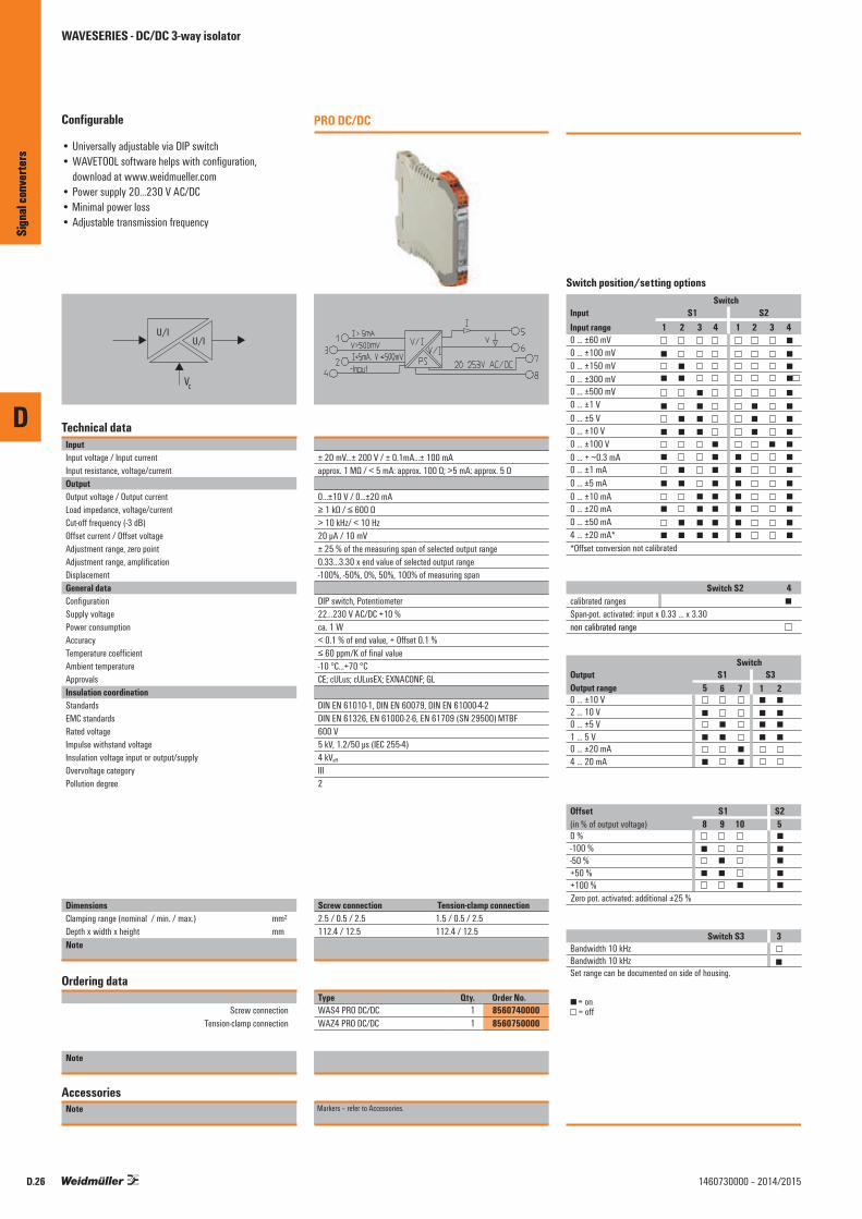
D
Sign
al co
nver
ters
D.26 1460730000 – 2014/2015
Configurable
• Universally adjustable via DIP switch• WAVETOOL software helps with configuration,
download at www.weidmueller.com• Power supply 20...230 V AC/DC• Minimal power loss• Adjustable transmission frequency
U/IU/I
VC
Technical dataInputInput voltage / Input currentInput resistance, voltage/currentOutputOutput voltage / Output currentLoad impedance, voltage/currentCut-off frequency (-3 dB)Offset current / Offset voltageAdjustment range, zero pointAdjustment range, amplificationDisplacementGeneral dataConfigurationSupply voltagePower consumptionAccuracyTemperature coefficientAmbient temperature ApprovalsInsulation coordinationStandardsEMC standardsRated voltageImpulse withstand voltageInsulation voltage input or output/supplyOvervoltage categoryPollution degree
DimensionsClamping range (nominal / min. / max.) mm²Depth x width x height mmNote
Ordering data
Screw connection Tension-clamp connection
Note
AccessoriesNote
PRO DC/DC
± 20 mV...± 200 V / ± 0.1mA...± 100 mAapprox. 1 MΩ / < 5 mA: approx. 100 Ω; >5 mA: approx. 5 Ω
0...±10 V / 0...±20 mA≥ 1 kΩ / ≤ 600 Ω> 10 kHz/ < 10 Hz20 µA / 10 mV± 25 % of the measuring span of selected output range0.33...3.30 x end value of selected output range-100%, -50%, 0%, 50%, 100% of measuring span
DIP switch, Potentiometer22…230 V AC/DC +10 %ca. 1 W< 0.1 % of end value, + Offset 0.1 %≤ 60 ppm/K of final value-10 °C...+70 °CCE; cULus; cULusEX; EXNACONF; GL
DIN EN 61010-1, DIN EN 60079, DIN EN 61000-4-2DIN EN 61326, EN 61000-2-6, EN 61709 (SN 29500) MTBF600 V5 kV, 1.2/50 µs (IEC 255-4)4 kVeff
III2
Screw connection Tension-clamp connection2.5 / 0.5 / 2.5 1.5 / 0.5 / 2.5112.4 / 12.5 112.4 / 12.5
Type Qty. Order No.WAS4 PRO DC/DC 1 8560740000WAZ4 PRO DC/DC 1 8560750000
Markers – refer to Accessories.
Sign
al co
nver
ters
WAVESERIES - DC/DC 3-way isolator

D
Sign
al co
nver
ters
D.271460730000 – 2014/2015
Configurable
Configurable signal isolating converter• Provides external sensor supply• Supply with 12...60 V DC• Current or voltage input can be configured with DIP
switch• Input or output scaling• Direct or negated output signal• Low input resistance, ideal for a long sensor wire
Wiring possibility B (input active)
PS
+24 V
V/IV/I
0 V1 7
0 V2
3
4
TP+
TP–
+24 V 0 V
8
5
6
Iout
Vout
Technical dataInputTypeInput signalSensor supplyInput resistance, voltage/currentResolutionOutputType Output current / Output voltageLoad impedance currentLoad impedance voltageGeneral dataConfigurationSupply voltagePower consumptionLinearityHumidityAmbient temperature / Storage temperatureTemperature coefficientLong-term driftStep response timeApprovalsInsulation coordinationImpulse withstand voltageEMC standardsInsulation voltageRated voltageOvervoltage categoryPollution degree
DimensionsClamping range (nominal / min. / max.) mm²Depth x width x height mmNote
Ordering data
Universal converter
Note
AccessoriesNote
WAVEPak3-way isolator
PS
+24 V
V/IV/I
0 V1 7
Iin
0 V
Vin
2
3
4
0 V
8
5
6
Iout
Vout
Wiring possibility A (input passive)
Current or voltage output configurable with jumper0...22 mA or 0...10 V20 mA @ 24 V DC output> 1 MΩ / 100 Ω3.5 µA / 1.76 mV per bit
Current of voltage output, configured with jumper0...22 mA / 0...10 V≤ 1kΩ≤ 500 Ω
DIP switch12...60 V DC2.5 W @ 24 V DC< ± 0.1 % (typically ± 0.05 %)10...90 % (no condensation)0 °C...+60 °C / -25 °C...+70 °C≤ 0.05 % / °C0.1 % / 10.000 h< 220 ms (10...90 %)CE; cULus; cULusEX
4 kV (1.2/50 µs)DIN EN 613262 kV input / output / power supply300 Veff
III2
Screw connection1.5 / 0.5 / 2.5 / 12.5 / 112.4Screw connection
Type Qty. Order No.WAVEPak DC/DC 1 7940024139
Markers – refer to Accessories.
ConnectionsTerminal Signal1 Signal +7 Signal –
Supply voltage
4 Signal +3 Signal –
Voltage input
2 Signal +3 Signal –
Current input
3 Signal +2 Signal –
Loop Powered Input
6 Signal +5 Signal –
Voltage output
8 Signal +5 Signal –
Current output
WAVESERIES - DC/DC 3-way isolator
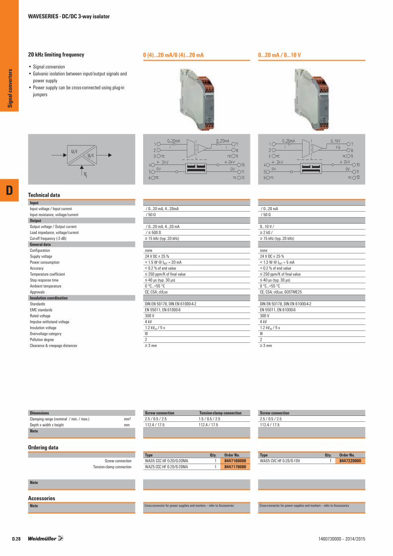
D
Sign
al co
nver
ters
D.28 1460730000 – 2014/2015
20 kHz limiting frequency
• Signal conversion• Galvanic isolation between input/output signals and
power supply• Power supply can be cross-connected using plug-in
jumpers
U/IU/I
VC
Technical dataInputInput voltage / Input currentInput resistance, voltage/currentOutputOutput voltage / Output currentLoad impedance, voltage/currentCut-off frequency (-3 dB)General dataConfigurationSupply voltagePower consumptionAccuracyTemperature coefficientStep response timeAmbient temperature ApprovalsInsulation coordinationStandardsEMC standardsRated voltageImpulse withstand voltageInsulation voltageOvervoltage categoryPollution degreeClearance & creepage distances
DimensionsClamping range (nominal / min. / max.) mm²Depth x width x height mmNote
Ordering data
Screw connection Tension-clamp connection
Note
AccessoriesNote
0 (4)...20 mA/0 (4)...20 mA
/ 0...20 mA, 4…20mA / 50 Ω
/ 0...20 mA, 4...20 mA / ≤ 500 Ω≥ 15 kHz (typ. 20 kHz)
none24 V DC ± 25 %< 1.5 W @ IOUT = 20 mA< 0.2 % of end value≤ 250 ppm/K of final value≤ 40 µs (typ. 30 µs)0 °C...+55 °CCE; CSA; cULus
DIN EN 50178, DIN EN 61000-4-2EN 55011, EN 61000-6300 V4 kV1.2 kVeff / 5 sIII2≥ 3 mm
Screw connection Tension-clamp connection2.5 / 0.5 / 2.5 1.5 / 0.5 / 2.5112.4 / 17.5 112.4 / 17.5Screw connection Tension clamp connection
Type Qty. Order No.WAS5 CCC HF 0-20/0-20MA 1 8447160000WAZ5 CCC HF 0-20/0-20MA 1 8447170000
Cross-connector for power supplies and markers – refer to Accessories
0...20 mA / 0...10 V
/ 0...20 mA / 50 Ω
0...10 V / ≥ 2 kΩ / ≥ 15 kHz (typ. 20 kHz)
none24 V DC ± 25 %< 1.3 W @ IOUT = 5 mA< 0.2 % of end value≤ 250 ppm/K of final value≤ 40 µs (typ. 30 µs)0 °C...+55 °CCE; CSA; cULus; GOSTME25
DIN EN 50178, DIN EN 61000-4-2EN 55011, EN 61000-6300 V4 kV1.2 kVeff / 5 sIII2≥ 3 mm
Screw connection2.5 / 0.5 / 2.5112.4 / 17.5Screw connection
Type Qty. Order No.WAS5 CVC HF 0-20/0-10V 1 8447220000
Cross-connector for power supplies and markers – refer to Accessories
WAVESERIES - DC/DC 3-way isolator

D
Sign
al co
nver
ters
D.291460730000 – 2014/2015
20 kHz limiting frequency
• Signal conversion• Galvanic isolation between input/output signals and
power supply• Power supply can be cross-connected using plug-in
jumpers
U/IU/I
VC
Technical dataInputInput voltage / Input currentInput resistance, voltage/currentOutputOutput voltage / Output currentLoad impedance, voltage/currentCut-off frequency (-3 dB)General dataConfigurationSupply voltagePower consumptionAccuracyTemperature coefficientStep response timeAmbient temperature ApprovalsInsulation coordinationStandardsEMC standardsRated voltageImpulse withstand voltageInsulation voltageOvervoltage categoryPollution degreeClearance & creepage distances
DimensionsClamping range (nominal / min. / max.) mm²Depth x width x height mmNote
Ordering data
Screw connection
Note
AccessoriesNote
4...20 mA / 0...20 mA
/ 4...20 mA / 50 Ω
/ 0...20 mA / ≤ 500 Ω≥ 15 kHz (typ. 20 kHz)
none24 V DC ± 25 %< 1.5 W @ IOUT = 20 mA< 0.2 % of end value≤ 250 ppm/K of final value≤ 40 µs (typ. 30 µs)0 °C...+55 °CCE; CSA; cULus; GOSTME25
DIN EN 50178, DIN EN 61000-4-2EN 55011, EN 61000-6300 V4 kV1.2 kVeff / 5 sIII2≥ 3 mm
Screw connection2.5 / 0.5 / 2.5112.4 / 17.5Screw connection
Type Qty. Order No.WAS5 CCC HF 4-20/0-20MA 1 8447250000
Cross-connector for power supplies and markers – refer to Accessories
4...20 mA / 0...10 VUL Class I, Div. 2
/ 4...20 mA / 50 Ω
0...10 V / ≥ 2 kΩ / ≤ 600 Ω≥ 15 kHz (typ. 20 kHz)
none24 V DC ± 25 %< 1.3 W @ IOUT = 5 mA< 0.2 % of end value≤ 250 ppm/K of final value≤ 40 µs (typ. 30 µs)0 °C...+55 °CCE; CSA; cULus; cULusEX; GOSTME25
DIN EN 50178, DIN EN 61000-4-2EN 55011, EN 61000-6300 V4 kV1.2 kVeff / 5 sIII2≥ 3 mm
Screw connection2.5 / 0.5 / 2.5112.4 / 17.5Screw connection
Type Qty. Order No.WAS5 CVC HF 4-20/0-10V 1 8447280000
Cross-connector for power supplies and markers – refer to Accessories
WAVESERIES - DC/DC 3-way isolator

D
Sign
al co
nver
ters
D.30 1460730000 – 2014/2015
20 kHz limiting frequency
• Signal conversion• Galvanic isolation between input/output signals and
power supply• Power supply can be cross-connected using plug-in
jumpers
U/IU/I
VC
Technical dataInputInput voltage / Input currentInput resistance, voltage/currentOutputOutput voltage / Output currentLoad impedance, voltage/currentCut-off frequency (-3 dB)General dataConfigurationSupply voltagePower consumptionAccuracyTemperature coefficientStep response timeAmbient temperature ApprovalsInsulation coordinationStandardsEMC standardsRated voltageImpulse withstand voltageInsulation voltageOvervoltage categoryPollution degreeClearance & creepage distances
DimensionsClamping range (nominal / min. / max.) mm²Depth x width x height mmNote
Ordering data
Screw connection
Note
AccessoriesNote
0...10 V / 0...20 mA
0...10 V / 500 kΩ /
/ 0...20 mA / ≤ 500 Ω≥ 15 kHz (typ. 20 kHz)
none24 V DC ± 25 %< 1.5 W @ IOUT = 20 mA± 0.2 % of final value≤ 250 ppm/K of final value≤ 40 µs (typ. 30 µs)0 °C...+55 °CCE; CSA; cULus; GOSTME25
DIN EN 50178, DIN EN 61000-4-2EN 55011, EN 61000-6300 V4 kV1.2 kVeff / 5 sIII2≥ 3 mm
Screw connection2.5 / 0.5 / 2.5112.4 / 17.5Screw connection
Type Qty. Order No.WAS5 VCC HF 0-10/0-20MA 1 8447310000
Cross-connector for power supplies and markers – refer to Accessories
0...10 V / 4...20 mAUL Class I, Div. 2
0...10 V / 500 kΩ /
/ 4...20 mA / ≤ 500 Ω≥ 15 kHz (typ. 20 kHz)
none24 V DC ± 25 %< 1.5 W @ IOUT = 20 mA± 0.2 % of final value≤ 250 ppm/K of final value≤ 40 µs (typ. 30 µs)0 °C...+55 °CCE; CSA; cULus; cULusEX; GOSTME25
DIN EN 50178, DIN EN 61000-4-2EN 55011, EN 61000-6300 V4 kV1.2 kVeff / 5 sIII2≥ 3 mm
Screw connection2.5 / 0.5 / 2.5112.4 / 17.5Screw connection
Type Qty. Order No.WAS5 VCC HF 0-10/4-20MA 1 8447340000
Cross-connector for power supplies and markers – refer to Accessories
WAVESERIES - DC/DC 3-way isolator

D
Sign
al co
nver
ters
D.311460730000 – 2014/2015
20 kHz limiting frequency
• Signal conversion• Galvanic isolation between input/output signals and
power supply• Power supply can be cross-connected using plug-in
jumpers
U/IU/I
VC
Technical dataInputInput voltage / Input currentInput resistance, voltage/currentOutputOutput voltage / Output currentLoad impedance, voltage/currentCut-off frequency (-3 dB)General dataConfigurationSupply voltagePower consumptionAccuracyTemperature coefficientStep response timeAmbient temperature ApprovalsInsulation coordinationStandardsEMC standardsRated voltageImpulse withstand voltageInsulation voltageOvervoltage categoryPollution degreeClearance & creepage distances
DimensionsClamping range (nominal / min. / max.) mm²Depth x width x height mmNote
Ordering data
Screw connection Tension-clamp connection
Note
AccessoriesNote
0...10 V / 0...10 V
0...10 V / 500 kΩ /
0...10 V / ≥ 2 kΩ / ≥ 15 kHz (typ. 20 kHz)
none24 V DC ± 25 %< 1.3 W @ IOUT = 5 mA± 0.2 % of final value≤ 250 ppm/K of final value≤ 40 µs (typ. 30 µs)0 °C...+55 °CCE; CSA; cULus
DIN EN 50178, DIN EN 61000-4-2EN 55011, EN 61000-6300 V4 kV1.2 kVeff / 5 sIII2≥ 3 mm
Screw connection Tension-clamp connection2.5 / 0.5 / 2.5 1.5 / 0.5 / 2.5112.4 / 17.5 112.4 / 17.5Screw connection Tension clamp connection
Type Qty. Order No.WAS5 VVC HF 0-10/0-10V 1 8447370000WAZ5 VVC HF 0-10/0-10V 1 8447380000
Cross-connector for power supplies and markers – refer to Accessories
-10 V...+10 V / -10 V...+10 V
-10...+10 V / 500 kΩ /
-10...+10 V / ≥ 2 kΩ / ≥ 15 kHz (typ. 20 kHz)
none24 V DC ± 25 %< 1.3 W @ IOUT = 5 mA± 0.2 % of measuring range≤ 250 ppm/K of measuring range≤ 40 µs (typ. 30 µs)0 °C...+55 °CCE; cULus; GOSTME25
DIN EN 50178, DIN EN 61000-4-2EN 55011, EN 61000-6300 V4 kV1.2 kVeff / 5 sIII2≥ 3 mm
Screw connection2.5 / 0.5 / 2.5112.4 / 17.5Screw connection
Type Qty. Order No.WAS5 VVC HF +-10V/+-10V 1 8561610000
Cross-connector for power supplies and markers – refer to Accessories
WAVESERIES - DC/DC 3-way isolator

D
Sign
al co
nver
ters
D.32 1460730000 – 2014/2015
10 Hz limiting frequency
• Signal conversion• Galvanic isolation between input/output signals and
power supply• Power supply can be cross-connected using plug-in
jumpers
U/IU/I
VC
Technical dataInputInput voltage / Input currentOutputOutput voltage / Output currentLoad impedance, voltage/currentCut-off frequency (-3 dB)General dataConfigurationSupply voltagePower consumptionAccuracyTemperature coefficientStep response timeAmbient temperature ApprovalsInsulation coordinationStandardsEMC standardsRated voltageImpulse withstand voltageInsulation voltageOvervoltage categoryPollution degreeClearance & creepage distances
DimensionsClamping range (nominal / min. / max.) mm²Depth x width x height mmNote
Ordering data
Screw connection Tension-clamp connection
Note
AccessoriesNote
0(4)...20 mA / 0(4)...20 mA
/ 0...20 mA, 4…20mA
/ 0...20 mA, 4...20 mA / ≤ 600 Ω10 Hz
none24 V DC ± 25 %< 1.5 W @ IOUT = 20 mA0.2 %± 250 ppm/K≤ 45 ms0 °C...+55 °CCE; cULus
DIN EN 50178, DIN EN 61000-4-2EN 55011, EN 61000-6300 V4 kV2 kVeff / 5 sIII2≥ 3 mm
Screw connection Tension-clamp connection2.5 / 0.5 / 2.5 1.5 / 0.5 / 2.5112.4 / 17.5 112.4 / 17.5Screw connection Tension clamp connection
Type Qty. Order No.WAS5 CCC 0-20/0-20mA 1 8540180000WAZ5 CCC 0-20/0-20mA 1 8540190000
Cross-connectors for power supplies and markers: refer to accessories
0...20 mA / 4...20 mA
/ 0...20 mA
/ 4...20 mA / ≤ 600 Ω10 Hz
none24 V DC ± 25 %< 1.5 W @ IOUT = 20 mA0.2 %± 250 ppm/K≤ 45 ms0 °C...+55 °CCE; cULus; GOSTME25
DIN EN 50178, DIN EN 61000-4-2EN 55011, EN 61000-6300 V4 kV2 kVeff / 5 sIII2≥ 3 mm
Screw connection2.5 / 0.5 / 2.5112.4 / 17.5Screw connection
Type Qty. Order No.WAS5 CCC 0-20/4-20mA 1 8540250000
Cross-connectors for power supplies and markers: refer to accessories
WAVESERIES - DC/DC 3-way isolator

D
Sign
al co
nver
ters
D.331460730000 – 2014/2015
10 Hz limiting frequency
• Signal conversion• Galvanic isolation between input/output signals and
power supply• Power supply can be cross-connected using plug-in
jumpers
U/IU/I
VC
Technical dataInputInput voltage / Input currentOutputOutput voltage / Output currentLoad impedance, voltage/currentCut-off frequency (-3 dB)General dataConfigurationSupply voltagePower consumptionAccuracyTemperature coefficientStep response timeAmbient temperature ApprovalsInsulation coordinationStandardsEMC standardsRated voltageImpulse withstand voltageInsulation voltageOvervoltage categoryPollution degreeClearance & creepage distances
DimensionsClamping range (nominal / min. / max.) mm²Depth x width x height mmNote
Ordering data
Screw connection
Note
AccessoriesNote
0...20 mA / 0...10 V
/ 0...20 mA
0...10 V / ≥ 1 kΩ / 10 Hz
none24 V DC ± 25 %< 1.3 W @ IOUT = 5 mA0.2 %± 250 ppm/K≤ 45 ms0 °C...+55 °CCE; cULus; GOSTME25
DIN EN 50178, DIN EN 61000-4-2EN 55011, EN 61000-6300 V4 kV2 kVeff / 5 sIII2≥ 3 mm
Screw connection2.5 / 0.5 / 2.5112.4 / 17.5Screw connection
Type Qty. Order No.WAS5 CVC 0-20mA/0-10V 1 8540270000
Cross-connectors for power supplies and markers: refer to accessories
WAVESERIES - DC/DC 3-way isolator

D
Sign
al co
nver
ters
D.34 1460730000 – 2014/2015
10 Hz limiting frequency
• Signal conversion• Galvanic isolation between input/output signals and
power supply• Power supply can be cross-connected using plug-in
jumpers
U/IU/I
VC
Technical dataInputInput voltage / Input currentOutputOutput voltage / Output currentLoad impedance, voltage/currentCut-off frequency (-3 dB)General dataConfigurationSupply voltagePower consumptionCurrent-carrying capacity of cross-connect.AccuracyTemperature coefficientStep response timeAmbient temperature ApprovalsInsulation coordinationStandardsEMC standardsRated voltageImpulse withstand voltageInsulation voltageOvervoltage categoryPollution degreeClearance & creepage distances
DimensionsClamping range (nominal / min. / max.) mm²Depth x width x height mmNote
Ordering data
Screw connection
Note
AccessoriesNote
4...20 mA / 0...20 mA
/ 4...20 mA
/ 0...20 mA / ≤ 600 Ω10 Hz
none24 V DC ± 25 %< 1.5 W @ IOUT = 20 mA≤ 2 A0.2 %± 250 ppm/K≤ 45 ms0 °C...+55 °CCE; cULus; GOSTME25
DIN EN 50178, DIN EN 61000-4-2EN 55011, EN 61000-6300 V4 kV2 kVeff / 5 sIII2≥ 3 mm
Screw connection2.5 / 0.5 / 2.5112.4 / 17.5Screw connection
Type Qty. Order No.WAS5 CCC 4-20/0-20MA 1 8540200000
Cross-connectors for power supplies and markers: refer to accessories
4...20 mA / 0...10 V
/ 4...20 mA
0...10 V / ≥ 1 kΩ / 10 Hz
none24 V DC ± 25 %< 1.3 W @ IOUT = 5 mA≤ 2 A0.2 %± 250 ppm/K≤ 45 ms0 °C...+55 °CCE; cULus; GOSTME25
DIN EN 50178, DIN EN 61000-4-2EN 55011, EN 61000-6300 V4 kV2 kVeff / 5 sIII2≥ 3 mm
Screw connection2.5 / 0.5 / 2.5112.4 / 17.5Screw connection
Type Qty. Order No.WAS5 CVC 4-20mA/0-10V 1 8540230000
Cross-connectors for power supplies and markers: refer to accessories
WAVESERIES - DC/DC 3-way isolator

D
Sign
al co
nver
ters
D.351460730000 – 2014/2015
10 Hz limiting frequency
• Signal conversion• Galvanic isolation between input/output signals and
power supply• Power supply can be cross-connected using plug-in
jumpers
U/IU/I
VC
Technical dataInputInput voltage / Input currentOutputOutput voltage / Output currentLoad impedance, voltage/currentCut-off frequency (-3 dB)General dataConfigurationSupply voltagePower consumptionAccuracyTemperature coefficientStep response timeAmbient temperature ApprovalsInsulation coordinationStandardsEMC standardsRated voltageImpulse withstand voltageInsulation voltageOvervoltage categoryPollution degreeClearance & creepage distances
DimensionsClamping range (nominal / min. / max.) mm²Depth x width x height mmNote
Ordering data
Screw connection Tension-clamp connection
Note
AccessoriesNote
0...10 V / 0...20 mA
0...10 V /
/ 0...20 mA / ≤ 600 Ω10 Hz
none24 V DC ± 25 %< 1.5 W @ IOUT = 20 mA0.2 %± 250 ppm/K≤ 45 ms0 °C...+55 °CCE; cULus
DIN EN 50178, DIN EN 61000-4-2EN 55011, EN 61000-6300 V4 kV2 kVeff / 5 sIII2≥ 3 mm
Screw connection Tension-clamp connection2.5 / 0.5 / 2.5 1.5 / 0.5 / 2.5112.4 / 17.5 112.4 / 17.5Screw connection Tension clamp connection
Type Qty. Order No.WAS5 VCC 0-10V/0-20MA 1 8540310000WAZ5 VCC 0-10V/0-20MA 1 8540320000
Cross-connectors for power supplies and markers: refer to accessories
0...10 V / 4...20 mA
0...10 V /
/ 4...20 mA / ≤ 600 Ω10 Hz
none24 V DC ± 25 %< 1.5 W @ IOUT = 20 mA0.2 %± 250 ppm/K≤ 45 ms0 °C...+55 °CCE; cULus
DIN EN 50178, DIN EN 61000-4-2EN 55011, EN 61000-6300 V4 kV2 kVeff / 5 sIII2≥ 3 mm
Screw connection Tension-clamp connection2.5 / 0.5 / 2.5 1.5 / 0.5 / 2.5112.4 / 17.5 112.4 / 17.5Screw connection Tension clamp connection
Type Qty. Order No.WAS5 VCC 0-10V/4-20MA 1 8540290000WAZ5 VCC 0-10V/4-20MA 1 8540300000
Cross-connectors for power supplies and markers: refer to accessories
WAVESERIES - DC/DC 3-way isolator

D
Sign
al co
nver
ters
D.36 1460730000 – 2014/2015
10 Hz limiting frequency
• Signal conversion• Galvanic isolation between input/output signals and
power supply• Power supply can be cross-connected using plug-in
jumpers
U/IU/I
VC
Technical dataInputInput voltage / Input currentOutputOutput voltage / Output currentLoad impedance, voltage/currentCut-off frequency (-3 dB)General dataConfigurationSupply voltagePower consumptionCurrent-carrying capacity of cross-connect.AccuracyTemperature coefficientStep response timeAmbient temperature ApprovalsInsulation coordinationStandardsEMC standardsRated voltageImpulse withstand voltageInsulation voltage input or output/supplyOvervoltage categoryPollution degreeClearance & creepage distances
DimensionsClamping range (nominal / min. / max.) mm²Depth x width x height mmNote
Ordering data
Screw connection Tension-clamp connection
Note
AccessoriesNote
0...10 V / 0...10 V
0...10 V /
0...10 V / ≥ 1 kΩ / 10 Hz
none24 V DC ± 25 %< 1.3 W @ IOUT = 5 mA≤ 2 A0.2 %± 250 ppm/K≤ 45 ms0 °C...+55 °CCE; cULus
DIN EN 50178, DIN EN 61000-4-2EN 55011, EN 61000-6300 V4 kV2 kVeff / 5 sIII2≥ 3 mm
Screw connection Tension-clamp connection2.5 / 0.5 / 2.5 1.5 / 0.5 / 2.5112.4 / 17.5 112.4 / 17.5Screw connection Tension clamp connection
Type Qty. Order No.WAS5 VVC 0-10V/0-10V 1 8540330000WAZ5 VVC 0-10V/0-10V 1 8540340000
Cross-connectors for power supplies and markers: refer to accessories
WAVESERIES - DC/DC 3-way isolator

D
Sign
al co
nver
ters
D.371460730000 – 2014/2015

D
Sign
al co
nver
ters
D.38 1460730000 – 2014/2015
Output-side supply• Signal conversion• Galvanic isolation between input and output signals• Power supply can be cross-connected using plug-in
jumpers
I
U/I
VC
Technical dataInputInput voltage / Input currentOutputOutput voltage / Output currentLoad impedance, voltage/currentCut-off frequency (-3 dB)General dataConfigurationSupply voltageCurrent consumption Current-carrying capacity of cross-connect.AccuracyTemperature coefficientStep response timeAmbient temperature ApprovalsInsulation coordinationStandardsEMC standardsRated voltageImpulse withstand voltageInsulation voltageOvervoltage categoryPollution degreeClearance & creepage distances
DimensionsClamping range (nominal / min. / max.) mm²Depth x width x height mmNote
Ordering data
Screw connection Tension-clamp connection
Note
AccessoriesNote
4...20 mA / 4...20 mAUL Class I, Div. 2
/ 4...20 mA (current loop)
/ 4...20 mA / ≤ 500 Ω≥ 15 Hz (typ. 20 Hz)
none24 V DC ± 20 %< 32 mA @ IOUT = 20 mA≤ 2 A± 0.2 % of final value≤ 250 ppm/K of final value≤ 30 ms (typ. 20 ms)0 °C...+55 °CCE; CSA; cULus
DIN EN 50178, DIN EN 61000-4-2EN 55011, EN 61000-6300 V4 kV1.2 kVeff / 5 sIII2≥ 3 mm
Screw connection Tension-clamp connection2.5 / 0.5 / 2.5 1.5 / 0.5 / 2.5112.4 / 12.5 112.4 / 12.5Screw connection Tension clamp connection
Type Qty. Order No.WAS4 CCC DC 4-20/4-20MA 1 8444980000WAZ4 CCC DC 4-20/4-20MA 1 8444990000
Cross-connector for power supplies and markers – refer to Accessories
4...20 mA / 0...20 mA
/ 4...20 mA (current loop)
/ 0...20 mA / ≤ 500 Ω≥ 15 Hz (typ. 20 Hz)
none24 V DC ± 20 %< 32 mA @ IOUT = 20 mA≤ 2 A± 0.2 % of final value≤ 250 ppm/K of final value≤ 30 ms (typ. 20 ms)0 °C...+55 °CCE; CSA; cULus; GOSTME25
DIN EN 50178, DIN EN 61000-4-2EN 55011, EN 61000-6300 V4 kV1.2 kVeff / 5 sIII2≥ 3 mm
Screw connection2.5 / 0.5 / 2.5112.4 / 12.5Screw connection
Type Qty. Order No.WAS4 CCC DC 4-20/0-20MA 1 8445010000
Cross-connector for power supplies and markers – refer to Accessories
WAVESERIES - DC/DC 2-way isolator

D
Sign
al co
nver
ters
D.391460730000 – 2014/2015
Output-side supply• Signal conversion• Galvanic isolation between input and output signals• Power supply can be cross-connected using plug-in
jumpers
I
U/I
VC
Technical dataInputInput voltage / Input currentOutputOutput voltage / Output currentLoad impedance, voltage/currentCut-off frequency (-3 dB)General dataConfigurationSupply voltageCurrent consumption Current-carrying capacity of cross-connect.AccuracyTemperature coefficientStep response timeAmbient temperature ApprovalsInsulation coordinationStandardsEMC standardsRated voltageImpulse withstand voltageInsulation voltageOvervoltage categoryPollution degreeClearance & creepage distances
DimensionsClamping range (nominal / min. / max.) mm²Depth x width x height mmNote
Ordering data
Screw connection Tension-clamp connection
Note
AccessoriesNote
4...20 mA / 0...10 VUL Class I, Div. 2
/ 4...20 mA (current loop)
0...10 V / ≥ 1 kΩ / ≥ 15 Hz (typ. 20 Hz)
none24 V DC ± 20 %< 20 mA @ IOUT = 10 mA≤ 2 A± 0.2 % of final value≤ 250 ppm/K of final value≤ 30 ms (typ. 20 ms)0 °C...+55 °CCE; CSA; cULus
DIN EN 50178, DIN EN 61000-4-2EN 55011, EN 61000-6300 V4 kV1.2 kVeff / 5 sIII2≥ 3 mm
Screw connection Tension-clamp connection2.5 / 0.5 / 2.5 1.5 / 0.5 / 2.5112.4 / 12.5 112.4 / 12.5Screw connection Tension clamp connection
Type Qty. Order No.WAS4 CVC DC 4-20/0-10V 1 8445040000WAZ4 CVC DC 4-20/0-10V 1 8445050000
Cross-connector for power supplies and markers – refer to Accessories
WAVESERIES - DC/DC 2-way isolator
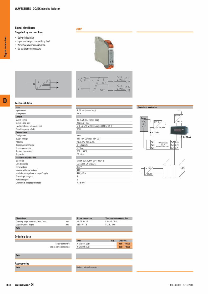
D
Sign
al co
nver
ters
D.40 1460730000 – 2014/2015
Signal distributor Supplied by current loop• Galvanic isolation• Input and output current loop feed• Very low power consumption• No calibration necessary
I I
I
Technical dataInputInput currentVoltage dropOutputOutput currentOutput signal limitLoad impedance, voltage/currentCut-off frequency (-3 dB)General dataConfigurationSupply voltageAccuracyTemperature coefficientStep response timeAmbient temperature ApprovalsInsulation coordinationStandardsEMC standardsRated voltageImpulse withstand voltageInsulation voltage input or output/supplyOvervoltage categoryPollution degreeClearance & creepage distances
DimensionsClamping range (nominal / min. / max.) mm²Depth x width x height mmNote
Ordering data
Screw connection Tension-clamp connection
Note
AccessoriesNote
2OLP
4...20 mA (current loop)3.8 V
2 x 4...20 mA (current loop)Approx. 31 mA / RL = (UB-12 V) / 20 mA z.B. 600 Ω at 24 V30 Hz
nonemin. 12 V DC/ max. 30 V DCtyp. 0.1 %; max. 0.2 %≤ 150 ppm/K< 20 ms0 °C...+55 °CCE; cULus
DIN EN 50178, DIN EN 61000-4-2EN 55011, EN 61000-6300 V4 kV4 kVeff / 5 sIII2≥ 5.5 mm
Screw connection Tension-clamp connection2.5 / 0.5 / 2.5 1.5 / 0.5 / 2.5112.4 / 17.5 112.4 / 17.5Screw connection Tension clamp connection
Type Qty. Order No.WAS5 CCC 2OLP 1 8581160000WAZ5 CCC 2OLP 1 8581170000
Markers – refer to Accessories.
WAVESERIES - DC/DC passive isolator

D
Sign
al co
nver
ters
D.411460730000 – 2014/2015
Signal distributor Supplied by current loop• Galvanic isolation• Input and output current loop feed• Very low power consumption• No calibration necessary• ATEX II 3 G Ex nA IIC T4• UL Class I, Div. 2
I I
I
Technical dataInputInput currentVoltage dropOutputOutput currentOutput signal limitLoad impedance, voltage/currentCut-off frequency (-3 dB)General dataConfigurationSupply voltageAccuracyTemperature coefficientStep response timeAmbient temperature ApprovalsInsulation coordinationStandardsEMC standardsRated voltageImpulse withstand voltageInsulation voltage input or output/supplyOvervoltage categoryPollution degreeClearance & creepage distances
DimensionsClamping range (nominal / min. / max.) mm²Depth x width x height mmNote
Ordering data
Screw connection
Note
AccessoriesNote
2OLP
4...20 mA (current loop)3.8 V
2 x 4...20 mA (current loop)Approx. 31 mA / RL = (UB-12 V) / 20 mA z.B. 600 Ω at 24 V30 Hz
nonemin. 12 V DC/ max. 30 V DCtyp. 0.1 %; max. 0.2 %≤ 150 ppm/K< 20 ms0 °C...+55 °CCE; cULusEX; DEMKOATEX; GOSTME25
DIN EN 60079, DIN EN 61000-4-2EN 55011, EN 61000-6300 V4 kV4 kVeff / 5 sIII2≥ 5.5 mm
Screw connection2.5 / 0.5 / 2.5112.4 / 17.5Screw connection
Type Qty. Order No.WAS5 CCC 2OLP EX 1 8975640000
Markers – refer to Accessories.
WAVESERIES - DC/DC passive isolator

D
Sign
al co
nver
ters
D.42 1460730000 – 2014/2015
Output-current loop-powered
• Galvanic isolation• Very low power consumption• Input range selected via DIP switch• No calibration necessary
U/I
I
Technical dataInputInput voltageInput resistance, voltage/currentInput currentRated current OutputOutput currentOutput signal limitLoad impedance, voltage/currentCut-off frequency (-3 dB)General dataConfigurationSupply voltageAmbient temperature Default settingAccuracyTemperature coefficientStep response timeApprovalsInsulation coordinationStandardsEMC standardsRated voltageImpulse withstand voltageInsulation voltageOvervoltage categoryPollution degreeClearance & creepage distances
DimensionsClamping range (nominal / min. / max.) mm²Depth x width x height mmNote
Ordering data
Screw connection Tension-clamp connection
Note
AccessoriesNote
OLP
0...5 V: 210 kΩ; 0...10 V: 430 kΩ / 51 Ω0...20 mA, 4…20mA40 mA
4...20 mA (current loop)Approx. 31 mA / RL = (UB-12 V) / 20 mA z.B. 600 Ω at 24 V10 Hz/ 100 Hz switchable
DIP switchmin. 12 V DC/ max. 30 V DC0 °C...+55 °C0...20mA, 10 Hz0.2% of measuring range final value≤ 150 ppm/K< 10 Hz: 80 ms; 100 Hz: 50 msCE; cULus
DIN EN 50178, DIN EN 61000-4-2EN 55011, EN 61000-6300 V4 kV4 kVeff / 5 sIII2≥ 5.5 mm
Screw connection Tension-clamp connection2.5 / 0.5 / 2.5 1.5 / 0.5 / 2.5112.4 / 17.5 112.4 / 17.5Screw connection Tension clamp connection
Type Qty. Order No.WAS5 OLP 1 8543720000WAZ5 OLP 1 8543730000
Markers – refer to Accessories.
WAVESERIES - DC/DC passive isolator
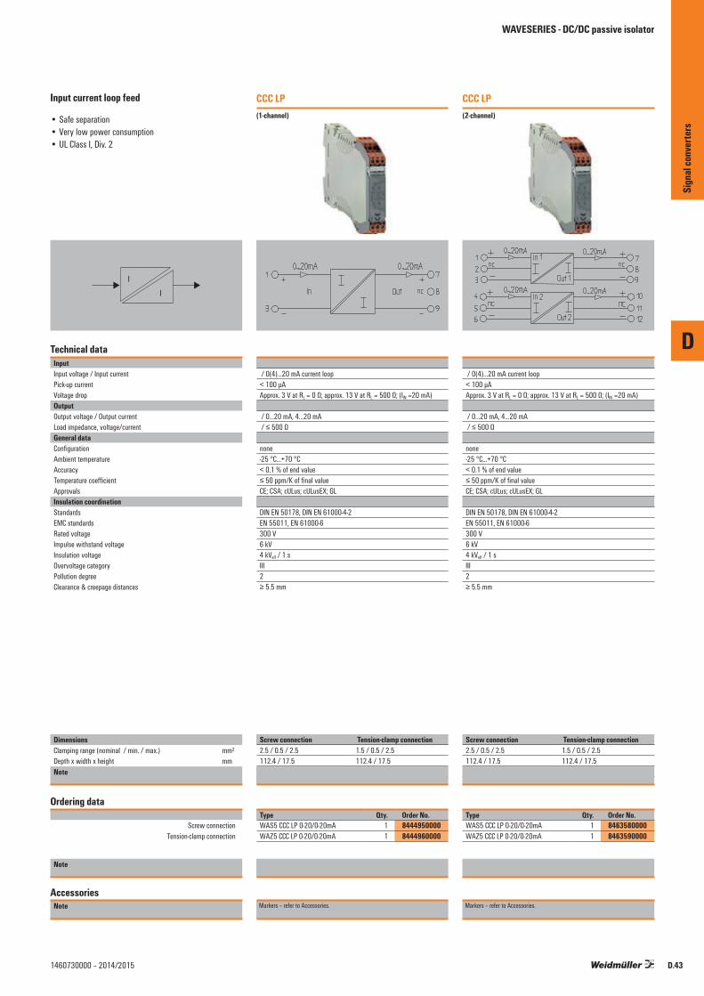
D
Sign
al co
nver
ters
D.431460730000 – 2014/2015
Input current loop feed
• Safe separation• Very low power consumption• UL Class I, Div. 2
I
I
Technical dataInputInput voltage / Input currentPick-up currentVoltage dropOutputOutput voltage / Output currentLoad impedance, voltage/currentGeneral dataConfigurationAmbient temperature AccuracyTemperature coefficientApprovalsInsulation coordinationStandardsEMC standardsRated voltageImpulse withstand voltageInsulation voltageOvervoltage categoryPollution degreeClearance & creepage distances
DimensionsClamping range (nominal / min. / max.) mm²Depth x width x height mmNote
Ordering data
Screw connection Tension-clamp connection
Note
AccessoriesNote
CCC LP(1-channel)
/ 0(4)...20 mA current loop< 100 µAApprox. 3 V at RL = 0 Ω; approx. 13 V at RL = 500 Ω; (IIN =20 mA)
/ 0...20 mA, 4...20 mA / ≤ 500 Ω
none-25 °C...+70 °C< 0.1 % of end value≤ 50 ppm/K of final valueCE; CSA; cULus; cULusEX; GL
DIN EN 50178, DIN EN 61000-4-2EN 55011, EN 61000-6300 V6 kV4 kVeff / 1 sIII2≥ 5.5 mm
Screw connection Tension-clamp connection2.5 / 0.5 / 2.5 1.5 / 0.5 / 2.5112.4 / 17.5 112.4 / 17.5Screw connection Tension clamp connection
Type Qty. Order No.WAS5 CCC LP 0-20/0-20mA 1 8444950000WAZ5 CCC LP 0-20/0-20mA 1 8444960000
Markers – refer to Accessories.
CCC LP(2-channel)
/ 0(4)...20 mA current loop< 100 µAApprox. 3 V at RL = 0 Ω; approx. 13 V at RL = 500 Ω; (IIN =20 mA)
/ 0...20 mA, 4...20 mA / ≤ 500 Ω
none-25 °C...+70 °C< 0.1 % of end value≤ 50 ppm/K of final valueCE; CSA; cULus; cULusEX; GL
DIN EN 50178, DIN EN 61000-4-2EN 55011, EN 61000-6300 V6 kV4 kVeff / 1 sIII2≥ 5.5 mm
Screw connection Tension-clamp connection2.5 / 0.5 / 2.5 1.5 / 0.5 / 2.5112.4 / 17.5 112.4 / 17.5Screw connection Tension clamp connection
Type Qty. Order No.WAS5 CCC LP 0-20/0-20mA 1 8463580000WAZ5 CCC LP 0-20/0-20mA 1 8463590000
Markers – refer to Accessories.
WAVESERIES - DC/DC passive isolator

D
Sign
al co
nver
ters
D.44 1460730000 – 2014/2015
RTD signal isolator/converter
• Universally adjustable via DIP switch• 3-way isolation• Linearisation• Power supply can be cross-connected using plug-in
jumpers• WAVETOOL software helps with configuration,download
at www.weidmueller.com
RTDJ,R U/I
VC
Technical dataInputSensor
Temperature input rangeOutputOutput current / Output voltageOffset current / Offset voltageLoad impedance, voltage/currentSensor error detectionFine adjustmentStatus indicator
General dataConfigurationSupply voltagePower consumptionStep response timeAmbient temperature ApprovalsInsulation coordinationStandardsEMC standardsRated voltageImpulse withstand voltageInsulation voltageOvervoltage categoryPollution degreeClearance & creepage distances
DimensionsClamping range (nominal / min. / max.) mm²Depth x width x height mmNote
Ordering data
Screw connection Tension-clamp connection
Note
AccessoriesNote
PRO RTDUL Class I, Div. 2
PT100/2-/3-/4-wire, Ni100/2-/3-/4-wire, potentiometer: min. 0–100 Ω, max. 0–100 kΩ, resistance: 0–450 ΩConfigurable
0...20 mA, 4...20 mA / 0...10 Vmax. 100 µA / max. 0.05 V≥ 1 kΩ / ≤ 600 ΩLED flashing (output value: > 20 mA, >10 V)≥ ± 5 %, Version 1 and later: ≥ 12.5 % / potentiometer: 12.5%...25%Module active: LED on/ wire breakage: LED flashing/ Error: LED off
DIP switch, Potentiometer24 V DC ± 20 %830...880...980mW at IOUT = 20 mAfast/slow: 2-/3-/4-conductor: 1.2 s/2.2 s; potentiometer: 0.5 s/1.1 s0 °C...+55 °CCE; cULus; GL
DIN EN 50178, DIN EN 61000-4-2EN 55011, EN 61000-6300 V4 kV2 kVeff / 5 sIII2≥ 3 mm
Screw connection Tension-clamp connection2.5 / 0.5 / 2.5 1.5 / 0.5 / 2.5112.4 / 17.5 112.4 / 17.5Screw connection Tension clamp connection
Type Qty. Order No.WAS5 PRO RTD 1 8560700000WAZ5 PRO RTD 1 8560710000
Cross-connector for power supplies and markers – refer to Accessories
WAVESERIES - Temperature measuring transducer
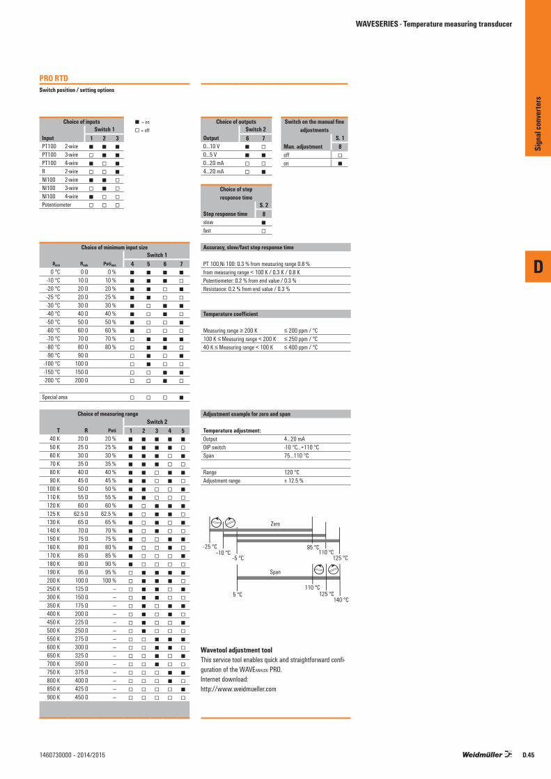
PRO RTDSwitch position / setting options
Choice of inputs = on Switch 1 = off
Input 1 2 3PT100 2-wire PT100 3-wire PT100 4-wire R 2-wire NI100 2-wire NI100 3-wire NI100 4-wire Potentiometer
Choice of minimum input sizeSwitch 1
ϑmin Rmin Potimin 4 5 6 70 °C 0 Ω 0 %
-10 °C 10 Ω 10 % -20 °C 20 Ω 20 % -25 °C 20 Ω 25 % -30 °C 30 Ω 30 % -40 °C 40 Ω 40 % -50 °C 50 Ω 50 % -60 °C 60 Ω 60 % -70 °C 70 Ω 70 % -80 °C 80 Ω 80 % -90 °C 90 Ω
-100 °C 100 Ω -150 °C 150 Ω -200 °C 200 Ω
Special area
Choice of measuring rangeSwitch 2
T R Poti 1 2 3 4 540 K 20 Ω 20 % 50 K 25 Ω 25 % 60 K 30 Ω 30 % 70 K 35 Ω 35 % 80 K 40 Ω 40 % 90 K 45 Ω 45 %
100 K 50 Ω 50 % 110 K 55 Ω 55 % 120 K 60 Ω 60 % 125 K 62.5 Ω 62.5 % 130 K 65 Ω 65 % 140 K 70 Ω 70 % 150 K 75 Ω 75 % 160 K 80 Ω 80 % 170 K 85 Ω 85 % 180 K 90 Ω 90 % 190 K 95 Ω 95 % 200 K 100 Ω 100 % 250 K 125 Ω --- 300 K 150 Ω --- 350 K 175 Ω --- 400 K 200 Ω --- 450 K 225 Ω --- 500 K 250 Ω --- 550 K 275 Ω --- 600 K 300 Ω --- 650 K 325 Ω --- 700 K 350 Ω --- 750 K 375 Ω --- 800 K 400 Ω --- 850 K 425 Ω --- 900 K 450 Ω ---
WAVESERIES - Temperature measuring transducer
Choice of outputs Switch on the manual fine adjustmentsSwitch 2
Output 6 7 S. 10...10 V Man. adjustment 80...5 V off 0...20 mA on 4...20 mA
Choice of step response time
S. 2Step response time 8slow fast
Accuracy, slow/fast step response time
PT 100,Ni 100: 0.3 % from measuring range 0.8 %from measuring range < 100 K / 0.3 K / 0.8 KPotentiometer: 0.2 % from end value / 0.3 %Resistance: 0.2 % from end value / 0.3 %
Temperature coefficient
Measuring range ≥ 200 K ≤ 200 ppm / °C100 K ≤ Measuring range < 200 K ≤ 250 ppm / °C 40 K ≤ Measuring range < 100 K ≤ 400 ppm / °C
Adjustment example for zero and span
Temperature adjustment:Output 4…20 mADIP switch -10 °C…+110 °CSpan 75…110 °C
Range 120 °CAdjustment range ± 12.5 %
Zero
–25 °C–10 °C
–5 °C
Span
5 °C
95 °C110 °C
125 °C
110 °C125 °C
140 °C
Wavetool adjustment toolThis service tool enables quick and straightforward confi-guration of the WAVEANALOG PRO.Internet download:http://www.weidmueller.com
D
Sign
al co
nver
ters
D.451460730000 – 2014/2015
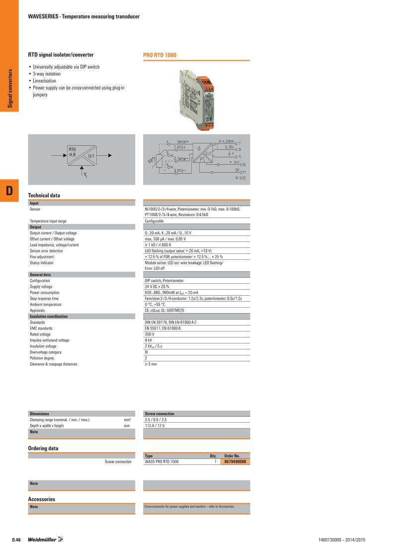
D
D.46 1460730000 – 2014/2015
RTD signal isolator/converter
• Universally adjustable via DIP switch• 3-way isolation• Linearisation• Power supply can be cross-connected using plug-in
jumpers
RTDJ,R U/I
VC
Technical dataInputSensor
Temperature input rangeOutputOutput current / Output voltageOffset current / Offset voltageLoad impedance, voltage/currentSensor error detectionFine adjustmentStatus indicator
General dataConfigurationSupply voltagePower consumptionStep response timeAmbient temperature ApprovalsInsulation coordinationStandardsEMC standardsRated voltageImpulse withstand voltageInsulation voltageOvervoltage categoryPollution degreeClearance & creepage distances
DimensionsClamping range (nominal / min. / max.) mm²Depth x width x height mmNote
Ordering data
Screw connection
Note
AccessoriesNote
PRO RTD 1000
Ni1000/2-/3-/4-wire, Potentiometer: min. 0-1kΩ, max. 0-100kΩ, PT1000/2-/3-/4-wire, Resistance: 0-4.5kΩConfigurable
0...20 mA, 4...20 mA / 0...10 Vmax. 100 µA / max. 0.05 V≥ 1 kΩ / ≤ 600 ΩLED flashing (output value: > 20 mA, >10 V)± 12.5 % of FSR; potentiometer: ± 12.5 % ... ± 25 %Module active: LED on/ wire breakage: LED flashing/ Error: LED off
DIP switch, Potentiometer24 V DC ± 20 %830...880...980mW at IOUT = 20 mAFast/slow:2-/3-/4-conductor: 1.2s/2.3s; potentiometer: 0.5s/1.2s0 °C...+55 °CCE; cULus; GL; GOSTME25
DIN EN 50178, DIN EN 61000-4-2EN 55011, EN 61000-6300 V4 kV2 kVeff / 5 sIII2≥ 3 mm
Screw connection2.5 / 0.5 / 2.5112.4 / 17.5Screw connection
Type Qty. Order No.WAS5 PRO RTD 1000 1 8679490000
Cross-connector for power supplies and markers – refer to Accessories
Sign
al co
nver
ters
WAVESERIES - Temperature measuring transducer

WAVESERIES - Temperature measuring transducer
PRO RTD 1000Switch position / setting options
Choice of inputs = on Switch 1 = off
Input 1 2 3PT1000 2-wire PT1000 3-wire PT1000 4-wire R 2-wire NI1000 2-wire NI1000 3-wire NI1000 4-wire Potentiometer
Choice of minimum input sizeSwitch 1
ϑmin Rmin Potimin 4 5 6 70 °C 0 Ω 0 %
-10 °C 100 Ω 10 % -20 °C 200 Ω 20 % -25 °C 200 Ω 25 % -30 °C 300 Ω 30 % -40 °C 400 Ω 40 % -50 °C 500 Ω 50 % -60 °C 600 Ω 60 % -70 °C 700 Ω 70 % -80 °C 800 Ω 80 % -90 °C 900 Ω
-100 °C 1000 Ω -150 °C 1500 Ω -200 °C 2000 Ω
Special area
Choice of measuring rangeSwitch 2
T R Poti 1 2 3 4 540 K 200 Ω 20 % 50 K 250 Ω 25 % 60 K 300 Ω 30 % 70 K 350 Ω 35 % 80 K 400 Ω 40 % 90 K 450 Ω 45 %
100 K 500 Ω 50 % 110 K 550 Ω 55 % 120 K 600 Ω 60 % 125 K 625 Ω 62.50 % 130 K 650 Ω 65 % 140 K 700 Ω 70 % 150 K 750 Ω 75 % 160 K 800 Ω 80 % 170 K 850 Ω 85 % 180 K 900 Ω 90 % 190 K 950 Ω 95 % 200 K 1000 Ω 100 % 250 K 1250 Ω --- 300 K 1500 Ω --- 350 K 1750 Ω --- 400 K 2000 Ω --- 450 K 2250 Ω --- 500 K 2500 Ω --- 550 K 2750 Ω --- 600 K 3000 Ω --- 650 K 3250 Ω --- 700 K 3500 Ω --- 750 K 3750 Ω --- 800 K 4000 Ω --- 850 K 4250 Ω --- 900 K 4500 Ω ---
Choice of outputs Switch on the manual fine adjustmentsSwitch 2
Output 6 7 S. 10...10 V Man. adjustment 80...5 V off 0...20 mA on 4...20 mA
Choice of step response time
S. 2Step response time 8slow fast
Accuracy, slow/fast step response time
PT 100,Ni 100: 0.3 % from measuring range 0.8 %from measuring range < 100 K / 0.3 K / 0.8 KPotentiometer: 0.2 % from end value / 0.3 %Resistance: 0.2 % from end value / 0.3 %
Temperature coefficient
Measuring range ≥ 200 K ≤ 200 ppm / °C100 K ≤ Measuring range < 200 K ≤ 250 ppm / °C 40 K ≤ Measuring range < 100 K ≤ 400 ppm / °C
Adjustment example for zero and span
Temperature adjustment:Output 4…20 mADIP switch -10 °C…+110 °CSpan 75…110 °C
Range 120 °CAdjustment range ± 12.5 %
Zero
–25 °C–10 °C
–5 °C
Span
5 °C
95 °C110 °C
125 °C
110 °C125 °C
140 °C
Wavetool adjustment tool This service tool enables quick and straightforward configuration of the WAVEANALOG PRO.Internet download:http://www.weidmueller.com
D
Sign
al co
nver
ters
D.471460730000 – 2014/2015
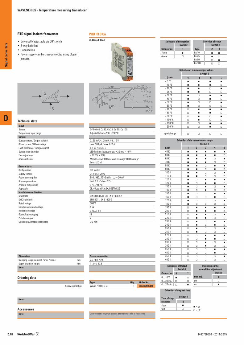
D
D.48 1460730000 – 2014/2015
RTD signal isolator/converter
• Universally adjustable via DIP switch• 3-way isolation• Linearisation• Power supply can be cross-connected using plug-in
jumpers.
CuU/I
VC
Technical dataInputSensorTemperature input rangeOutputOutput current / Output voltageOffset current / Offset voltageLoad impedance, voltage/currentSensor error detectionFine adjustmentStatus indicator
General dataConfigurationSupply voltagePower consumptionStep response timeAmbient temperature ApprovalsInsulation coordinationStandardsEMC standardsRated voltageImpulse withstand voltageInsulation voltageOvervoltage categoryPollution degreeClearance & creepage distances
DimensionsClamping range (nominal / min. / max.) mm²Depth x width x height mmNote
Ordering data
Screw connection
Note
AccessoriesNote
PRO RTD CuUL Class I, Div.2
3-/4-wired, Cu 10. Cu 25, Cu 50. Cu 100Adjustable from -200...+260°C
0...20 mA, 4...20 mA / 0...10 Vmax. 100 µA / max. 0.05 V≥ 1 kΩ / ≤ 600 ΩLED flashing (output value: > 20 mA, >10 V)± 12.5% of FSRModule active: LED on/ wire breakage: LED flashing/ Error: LED off
DIP switch24 V DC ± 20 %880...980...1030mW at IOUT = 20 mAFast: 1.2 s/ slow: 2.2 s0 °C...+55 °CCE; cULus; cULusEX; GOSTME25
DIN EN 50178, DIN EN 61000-4-2EN 55011, EN 61000-6300 V4 kV2 kVeff / 5 sIII2≥ 3 mm
Screw connection2.5 / 0.5 / 2.5112.4 / 17.5Screw connection
Type Qty. Order No.WAS5 PRO RTD Cu 1 8638950000
Cross-connector for power supplies and markers – refer to Accessories
Cu 10Cu 25Cu 50Cu 100
◼ ◼
◼
Selection of minimum input values Switch 1
4 5 6 7
Selection of the measurement range Switch 2
Span 1 2 3 4 5
◼◼
= on= off
Selection of senor
Type 2 3Switch 1
◼ ◼ ◼ ◼◼ ◼ ◼ ◼◼ ◼ ◼ ◼◼ ◼ ◼ ◼◼ ◼ ◼ ◼◼ ◼ ◼ ◼◼ ◼ ◼ ◼◼ ◼ ◼ ◼◼ ◼ ◼ ◼◼ ◼ ◼ ◼◼ ◼ ◼ ◼◼ ◼ ◼ ◼◼ ◼ ◼ ◼◼ ◼ ◼ ◼
◼ ◼ ◼ ◼special range
minϑ– 0 °C– 10 °C– 20 °C– 25 °C– 30 °C– 40 °C– 50 °C– 60 °C– 70 °C– 80 °C– 90 °C– 100 °C– 150 °C– 200 °C
◼ ◼◼ ◼◼ ◼
◼ ◼ ◼ ◼ ◼◼ ◼ ◼ ◼ ◼◼ ◼ ◼ ◼ ◼◼ ◼ ◼ ◼ ◼◼ ◼ ◼ ◼ ◼◼ ◼ ◼ ◼ ◼◼ ◼ ◼ ◼ ◼◼ ◼ ◼ ◼ ◼◼ ◼ ◼ ◼ ◼◼ ◼ ◼ ◼ ◼◼ ◼ ◼ ◼ ◼◼ ◼ ◼ ◼ ◼◼ ◼ ◼ ◼ ◼◼ ◼ ◼ ◼ ◼◼ ◼ ◼ ◼ ◼◼ ◼ ◼ ◼ ◼◼ ◼ ◼ ◼ ◼◼ ◼ ◼ ◼ ◼◼ ◼ ◼ ◼ ◼◼ ◼ ◼ ◼ ◼◼ ◼ ◼ ◼ ◼◼ ◼ ◼ ◼ ◼◼ ◼ ◼ ◼ ◼◼ ◼ ◼ ◼ ◼◼ ◼ ◼ ◼ ◼◼ ◼ ◼ ◼ ◼◼ ◼ ◼ ◼ ◼◼ ◼ ◼ ◼ ◼◼ ◼ ◼ ◼ ◼◼ ◼ ◼ ◼ ◼◼ ◼ ◼ ◼ ◼◼ ◼ ◼ ◼ ◼
40 K50 K60 K70 K80 K90 K100 K110 K120 K125 K130 K140 K150 K160 K170 K180 K190 K200 K210 K220 K230 K240 K250 K260 K270 K280 K290 K300 K350 K400 K450 K460 K
Selection of connection Switch 1
Connection3-wire4-wire
1◼ ◼
Selection of Output Switch 2
Connection0 ... 10 V0 ... 20 mA4 ... 20 mA
6 7◼ ◼ ◼ ◼◼ ◼
Switching on themanual fine adjustment
Switch 1man adj.offon
8◼◼
Selection of step set time
Switch 2Time of stepresponseslowfast
8◼◼
Sign
al co
nver
ters
WAVESERIES - Temperature measuring transducer
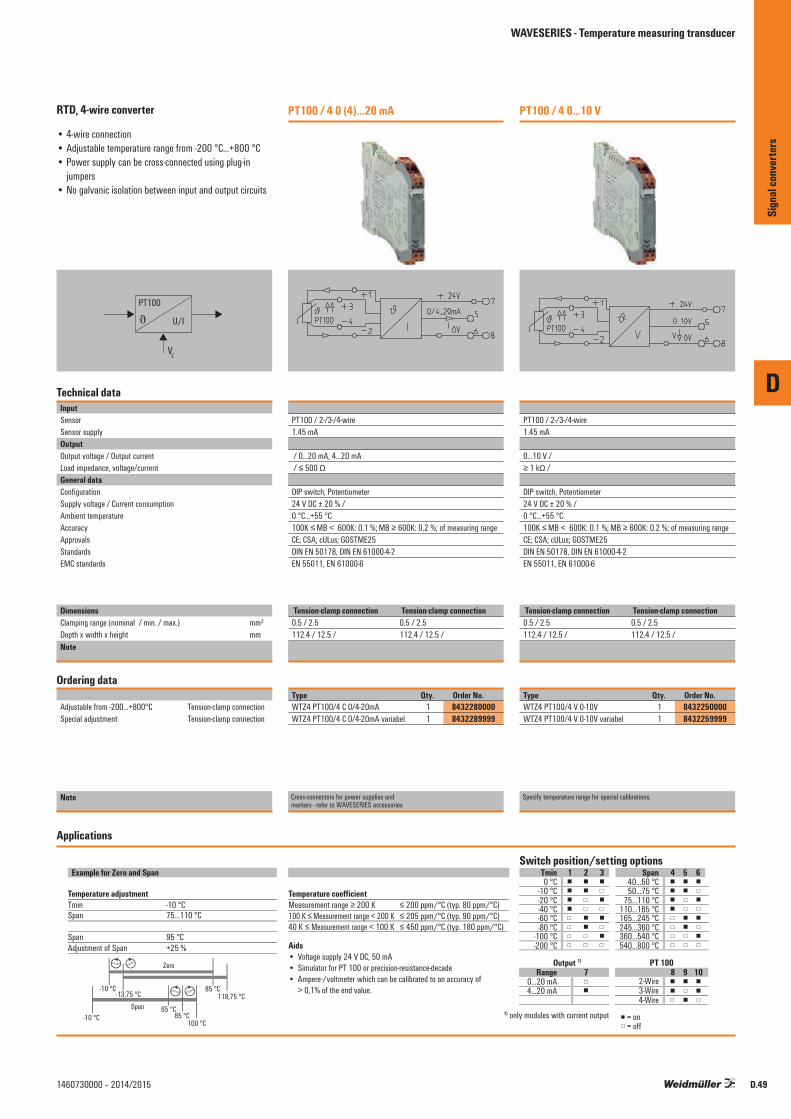
D
D.491460730000 – 2014/2015
RTD, 4-wire converter
• 4-wire connection• Adjustable temperature range from -200 °C...+800 °C• Power supply can be cross-connected using plug-in
jumpers• No galvanic isolation between input and output circuits
PT100
J U/I
VC
Technical dataInputSensorSensor supplyOutputOutput voltage / Output currentLoad impedance, voltage/currentGeneral dataConfigurationSupply voltage / Current consumptionAmbient temperature AccuracyApprovalsStandardsEMC standards
DimensionsClamping range (nominal / min. / max.) mm²Depth x width x height mmNote
Ordering data
Adjustable from -200...+800°C Tension-clamp connectionSpecial adjustment Tension-clamp connection
Note
PT100 / 4 0 (4)...20 mA
PT100 / 2-/3-/4-wire1.45 mA
/ 0...20 mA, 4...20 mA / ≤ 500 Ω
DIP switch, Potentiometer24 V DC ± 20 % / 0 °C...+55 °C 100K ≤ MB < 600K: 0.1 %; MB ≥ 600K: 0.2 %; of measuring rangeCE; CSA; cULus; GOSTME25DIN EN 50178, DIN EN 61000-4-2EN 55011, EN 61000-6
Tension-clamp connection Tension-clamp connection0.5 / 2.5 0.5 / 2.5112.4 / 12.5 / 112.4 / 12.5 /
Type Qty. Order No.WTZ4 PT100/4 C 0/4-20mA 1 8432280000WTZ4 PT100/4 C 0/4-20mA variabel 1 8432289999
Cross-connectors for power supplies and markers - refer to WAVESERIES accessories
PT100 / 4 0...10 V
PT100 / 2-/3-/4-wire1.45 mA
0...10 V / ≥ 1 kΩ /
DIP switch, Potentiometer24 V DC ± 20 % / 0 °C...+55 °C 100K ≤ MB < 600K: 0.1 %; MB ≥ 600K: 0.2 %; of measuring rangeCE; CSA; cULus; GOSTME25DIN EN 50178, DIN EN 61000-4-2EN 55011, EN 61000-6
Tension-clamp connection Tension-clamp connection0.5 / 2.5 0.5 / 2.5112.4 / 12.5 / 112.4 / 12.5 /
Type Qty. Order No.WTZ4 PT100/4 V 0-10V 1 8432250000WTZ4 PT100/4 V 0-10V variabel 1 8432259999
Specify temperature range for special calibrations.
Example for Zero and Span Tmin
Range 7Output 1)
1) only modules with current output = on= off
PT 100
1 2 3 Span 4 5 6
8 9 10
Temperature coefficient
Switch position/setting options
Aids• Voltage supply 24 V DC, 50 mA• Simulator for PT 100 or precision-resistance-decade• Ampere-/voltmeter which can be calibrated to an accuracy of > 0,1% of the end value.
Temperature adjustmentTminSpan
Measurement range ≥ 200 K100 K ≤ Measurement range < 200 K 40 K ≤ Measurement range < 100 K
SpanAdjustment of Span
-10 °C 75…110 °C
95 °C+25 %
Zero
Span 65 °C85 °C
85 °C118,75 °C
100 °C-10 °C
-10 °C-13,75 °C
≤ 200 ppm/°C (typ. 80 ppm/°C)≤ 205 ppm/°C (typ. 90 ppm/°C)≤ 450 ppm/°C (typ. 180 ppm/°C)
0 °C-10 °C-20 °C-40 °C-60 °C
0…20 mA4…20 mA
-80 °C-100 °C-200 °C
40…50 °C50…75 °C
75…110 °C110…165 °C165…245 °C245…360 °C360…540 °C540…800 °C
2-Wire3-Wire4-Wire
Applications
Sign
al co
nver
ters
WAVESERIES - Temperature measuring transducer

D
D.50 1460730000 – 2014/2015
RTD, 3-wire converter
• 3-wire connection• Adjustable temperature range from -200 °C...+800 °C• Power supply can be cross-connected using plug-in
jumpers• No galvanic isolation between input and output circuits
PT100
J U/I
VC
Technical dataInputSensorSensor supplyOutputOutput voltage / Output currentLoad impedance, voltage/currentGeneral dataConfigurationSupply voltage / Current consumptionAmbient temperature AccuracyApprovalsStandardsEMC standards
DimensionsClamping range (nominal / min. / max.) mm²Depth x width x height mmNote
Ordering data
Adjustable from -200...+800°C Tension-clamp connection
Note
PT100 / 3 0...10 V
PT100/3-wire1.45 mA
0...10 V / ≥ 1 kΩ /
DIP switch, Potentiometer24 V DC ± 20 % / 0 °C...+55 °C ± 0.5 % of measuring rangeCE; CSA; cULus; GOSTME25DIN EN 50178, DIN EN 61000-4-2EN 55011, EN 61000-6
Tension-clamp connection1.5 / 0.5 / 2.5112.4 / 12.5 /
Type Qty. Order No.WTZ4 PT100/3 V 0-10V 1 8432130000
Specify temperature range for special calibrations.
PT100 / 3 0 (4)...20 mA
PT100/3-wire1.45 mA
/ 0...20 mA, 4...20 mA / ≤ 500 Ω
DIP switch, Potentiometer24 V DC ± 20 % / 0 °C...+55 °C ± 0.5 % of measuring rangeCE; CSA; cULus; GOSTME25DIN EN 50178, DIN EN 61000-4-2EN 55011, EN 61000-6
Tension-clamp connection Tension-clamp connection1.5 / 0.5 / 2.5 1.5 / 0.5 / 2.5112.4 / 12.5 / 112.4 / 12.5 /
Type Qty. Order No.WTZ4 PT100/3 C 0/4-20mA 1 8432160000WTZ4 PT100/3 C 0/4-20mA variabel 1 8432169999
Cross-connectors for power supplies andmarkers - refer to WAVESERIES accessories
Example for Zero and Span Tmin
Range 7Output 1)
1) only modules with current output = on= off
PT 100
1 2 3 Span 4 5 6
8 9 10
Temperature coefficient
Switch position/setting options
Aids• Voltage supply 24 V DC, 50 mA• Simulator for PT 100 or precision-resistance-decade• Ampere-/voltmeter which can be calibrated to an accuracy of > 0,1% of the end value.
Temperature adjustmentTminSpan
Measurement range ≥ 200 K100 K ≤ Measurement range < 200 K 40 K ≤ Measurement range < 100 K
SpanAdjustment of Span
-10 °C 75…110 °C
95 °C+25 %
Zero
Span 65 °C85 °C
85 °C118,75 °C
100 °C-10 °C
-10 °C-13,75 °C
≤ 200 ppm/°C (typ. 80 ppm/°C)≤ 205 ppm/°C (typ. 90 ppm/°C)≤ 450 ppm/°C (typ. 180 ppm/°C)
0 °C-10 °C-20 °C-40 °C-60 °C
0…20 mA4…20 mA
-80 °C-100 °C-200 °C
40…50 °C50…75 °C
75…110 °C110…165 °C165…245 °C245…360 °C360…540 °C540…800 °C
2-Wire3-Wire4-Wire
Applications
Sign
al co
nver
ters
WAVESERIES - Temperature measuring transducer

D
D.511460730000 – 2014/2015
RTD, 2-wire converter
• 2-wire connection• Adjustable temperature range from -200 °C...+800 °C• Power supply can be cross-connected using plug-in
jumpers• No galvanic isolation between input and output circuits
PT100
J U/I
VC
Technical dataInputSensorSensor supplyOutputOutput voltage / Output currentLoad impedance, voltage/currentGeneral dataConfigurationSupply voltage / Current consumption Ambient temperature AccuracyApprovalsStandardsEMC standards
DimensionsClamping range (nominal / min. / max.) mm²Depth x width x height mmNote
Ordering data
Adjustable from -200...+800°C Tension-clamp connectionSpecial adjustment Tension-clamp connection
Note
PT100 / 2 0...10 V
PT100/2-wire1.45 mA
0...10 V / ≥ 1 kΩ /
DIP switch, Potentiometer24 V DC ± 20 % / < 38 mA @ IOUT = 20 mA0 °C...+55 °C ± 0.5 % of measuring rangeCE; CSA; cULus; GOSTME25DIN EN 50178, DIN EN 61000-4-2EN 55011, EN 61000-6
Tension-clamp connection Tension-clamp connection1.5 / 0.5 / 2.5 1.5 / 0.5 / 2.5112.4 / 12.5 / 112.4 / 12.5 /
Type Qty. Order No.WTZ4 PT100/2 V 0-10V 1 8432190000WTZ4 PT100/2 V 0-10V variabel 1 8432199999
Specify temperature range for special calibrations.
PT100/2 0 (4)...20 mA
PT100/2-wire1.45 mA
/ 0...20 mA, 4...20 mA / ≤ 500 Ω
DIP switch, Potentiometer24 V DC ± 20 % / < 48 mA @ IOUT = 20 mA0 °C...+55 °C ± 0.5 % of measuring rangeCE; CSA; cULus; GOSTME25DIN EN 50178, DIN EN 61000-4-2EN 55011, EN 61000-6
Tension-clamp connection Tension-clamp connection1.5 / 0.5 / 2.5 1.5 / 0.5 / 2.5112.4 / 12.5 / 112.4 / 12.5 /
Type Qty. Order No.WTZ4 PT100/2 C 0/4-20mA 1 8432220000WTZ4 PT100/2 C 0/4-20mA variabel 1 8432229999
Cross-connectors for power supplies andmarkers - refer to WAVESERIES accessories
Example for Zero and Span Tmin
Range 7Output 1)
1) only modules with current output = on= off
PT 100
1 2 3 Span 4 5 6
8 9 10
Temperature coefficient
Switch position/setting options
Aids• Voltage supply 24 V DC, 50 mA• Simulator for PT 100 or precision-resistance-decade• Ampere-/voltmeter which can be calibrated to an accuracy of > 0,1% of the end value.
Temperature adjustmentTminSpan
Measurement range ≥ 200 K100 K ≤ Measurement range < 200 K 40 K ≤ Measurement range < 100 K
SpanAdjustment of Span
-10 °C 75…110 °C
95 °C+25 %
Zero
Span 65 °C85 °C
85 °C118,75 °C
100 °C-10 °C
-10 °C-13,75 °C
≤ 200 ppm/°C (typ. 80 ppm/°C)≤ 205 ppm/°C (typ. 90 ppm/°C)≤ 450 ppm/°C (typ. 180 ppm/°C)
0 °C-10 °C-20 °C-40 °C-60 °C
0…20 mA4…20 mA
-80 °C-100 °C-200 °C
40…50 °C50…75 °C
75…110 °C110…165 °C165…245 °C245…360 °C360…540 °C540…800 °C
2-Wire3-Wire4-Wire
Applications
Sign
al co
nver
ters
WAVESERIES - Temperature measuring transducer
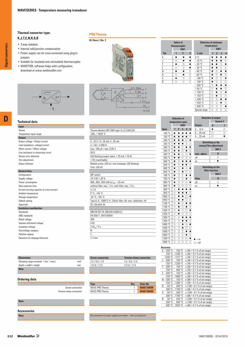
D
D.52 1460730000 – 2014/2015
Thermal converter type: K,J,T,E,N,R,S,B• 3-way isolation• Internal cold-junction compensation• Power supply can be cross-connected using plug-in
jumpers• Suitable for insulated and uninsulated thermocouples• WAVETOOL software helps with configuration,
download at www.weidmueller.com
J U/I
VC
Technical dataInputSensorTemperature input rangeOutputOutput voltage / Output currentLoad impedance, voltage/currentOffset current / Offset voltageLine resistance in measuring circuitSensor error detectionFine adjustmentStatus indicator
General dataConfigurationSupply voltagePower consumptionStep response timeCurrent-carrying capacity of cross-connect.Ambient temperature Storage temperatureDefault settingApprovalsInsulation coordinationStandardsEMC standardsRated voltageImpulse withstand voltageInsulation voltageOvervoltage categoryPollution degreeClearance & creepage distances
DimensionsClamping range (nominal / min. / max.) mm²Depth x width x height mmNote
Ordering data
Screw connection Tension-clamp connection
Note
AccessoriesNote
PRO ThermoUL Class I, Div. 2
Thermo element (IEC 584) type: K,J,T,E,N,R,S,B-200...+1820 °C
0...10 V / 0...20 mA, 4...20 mA≥ 1 kΩ / ≤ 600 Ωmax. 100 µA / max. 0.05 V50 ΩLED flashing (output value: > 20 mA, >10 V)± 5% (switchable)Module active: LED on/ wire breakage: LED flashing/ Error: LED off
DIP switch24 V DC ± 20 %800...850...950 mW at IOUT = 20 mAwithout filter: max. 1.4 s; with filter: max. 7.5 s≤ 2 A0 °C...+55 °C-20 °C...+85 °CType K; 0...1000°C; 4...20mA; filter: off; man. calibration: offCE; cULusEX; GL
DIN EN 50178, DIN EN 61000-4-2EN 55011, EN 61000-63004 kV2 kVeff / 5 sIII2≥ 3 mm
Screw connection Tension-clamp connection2.5 / 0.5 / 2.5 1.5 / 0.5 / 2.5112.4 / 17.5 112.4 / 17.5Screw connection Tension clamp connection
Type Qty. Order No.WAS5 PRO Thermo 1 8560720000WAZ5 PRO Thermo 1 8560730000
Cross-connector for power supplies and markers – refer to Accessories
Select ofthermocoupler
SW1Typ
KJTENRSB
1 2 3◼ ◼ ◼◼ ◼ ◼◼ ◼ ◼◼ ◼ ◼◼ ◼ ◼◼ ◼ ◼◼ ◼ ◼◼ ◼ ◼
Selection of minimumtemperature
SW1 1 2 3 4◼ ◼ ◼ ◼◼ ◼ ◼ ◼◼ ◼ ◼ ◼◼ ◼ ◼ ◼◼ ◼ ◼ ◼◼ ◼ ◼ ◼◼ ◼ ◼ ◼◼ ◼ ◼ ◼◼ ◼ ◼ ◼◼ ◼ ◼ ◼◼ ◼ ◼ ◼◼ ◼ ◼ ◼◼ ◼ ◼ ◼◼ ◼ ◼ ◼◼ ◼ ◼ ◼◼ ◼ ◼ ◼
0 °C– 10 °C– 20 °C– 30 °C– 40 °C– 50 °C– 100 °C– 150 °C– 200 °C+ 50 °C+ 100 °C+ 150 °C+ 200 °C+ 250 °C+ 500 °CSpecial range
minϑ
Selection of outputSwitch 2
Output0 ... 10 V0 ... 20 mA4 ... 20 mA
6 7◼ ◼ ◼ ◼◼ ◼
Switching on themanual fine adjustment
SW 2man. adjust.offon
6◼◼
Switching on thefilter function
SW 2Filteroffon
8◼◼
AccuracyK -200 °C … -150 °C ± (5K + 0.1 % of set range) -150 °C … 1200 °C ± (3K + 0.1 % of set range) 1200 °C … 1372 °C ± (4K + 0.1 % of set range)J -200 °C … -150 °C ± (4K + 0.1 % of set range) -150 °C … 1200 °C ± (3K + 0.1 % of set range)T -200 °C … -150 °C ± (5K + 0.1 % of set range) -150 °C … 400 °C ± (3K + 0.1 % of set range)E -200 °C … -150 °C ± (4K + 0.1 % of set range) -150 °C … 1000 °C ± (3K + 0.1 % of set range)N -200 °C … -150 °C ± (6K + 0.1 % of set range) -150 °C … 1300 °C ± (3K + 0.1 % of set range)R -50 °C … 200 °C ± (10K + 0.1 % of set range) 200 °C … 1760 °C ± (6K + 0.1 % of set range)S -50 °C … 200 °C ± (10K + 0.1 % of set range) 200 °C … 1760 °C ± (6K + 0.1 % of set range)B 50 °C … 250 °C ± (25K + 0.1 % of set range) 250 °C … 500 °C ± (10K + 0.1 % of set range) 500 °C … 1820 °C ± (6K + 0.1 % of set range)
Selection oftemperature span
SW2
100 °C150 °C200 °C250 °C300 °C350 °C400 °C450 °C500 °C550 °C600 °C650 °C700 °C750 °C800 °C850 °C900 °C950 °C
1000 °C1050 °C1100 °C1150 °C1200 °C1250 °C1300 °C1350 °C1400 °C1450 °C1500 °C1600 °C1700 °C1800 °C
Span 1 2 3 4 5◼ ◼ ◼ ◼ ◼◼ ◼ ◼ ◼ ◼◼ ◼ ◼ ◼ ◼◼ ◼ ◼ ◼ ◼◼ ◼ ◼ ◼ ◼◼ ◼ ◼ ◼ ◼◼ ◼ ◼ ◼ ◼◼ ◼ ◼ ◼ ◼◼ ◼ ◼ ◼ ◼◼ ◼ ◼ ◼ ◼◼ ◼ ◼ ◼ ◼◼ ◼ ◼ ◼ ◼◼ ◼ ◼ ◼ ◼◼ ◼ ◼ ◼ ◼◼ ◼ ◼ ◼ ◼◼ ◼ ◼ ◼ ◼◼ ◼ ◼ ◼ ◼◼ ◼ ◼ ◼ ◼◼ ◼ ◼ ◼ ◼◼ ◼ ◼ ◼ ◼◼ ◼ ◼ ◼ ◼◼ ◼ ◼ ◼ ◼◼ ◼ ◼ ◼ ◼◼ ◼ ◼ ◼ ◼◼ ◼ ◼ ◼ ◼◼ ◼ ◼ ◼ ◼◼ ◼ ◼ ◼ ◼◼ ◼ ◼ ◼ ◼◼ ◼ ◼ ◼ ◼◼ ◼ ◼ ◼ ◼◼ ◼ ◼ ◼ ◼◼ ◼ ◼ ◼ ◼
◼◼
= on= off
Sign
al co
nver
ters
WAVESERIES - Temperature measuring transducer

D
D.531460730000 – 2014/2015
Thermal converter type: K, J, T, E, N, R, S, B• No calibration necessary• Internal cold-junction compensation• Output signal selectable• Power supply can be cross-connected using plug-in
jumpers• Suitable for insulated thermocouples• No galvanic isolation between input and output circuits
VC
U/IJ
Technical dataInputSensorTemperature input rangeOutputOutput voltage / Output currentLoad impedance, voltage/currentTemperature coefficientStep response timeSensor error detectionGeneral dataConfigurationSupply voltageCurrent consumption Current-carrying capacity of cross-connect.Ambient temperature Storage temperatureApprovalsInsulation coordinationStandardsEMC standards
DimensionsClamping range (nominal / min. / max.) mm²Depth x width x height mmNote
Ordering data
Screw connection Tension-clamp connection
Note
AccessoriesNote
Thermo Select
Thermo element (IEC 584) type: K,J,T,E,N,R,S,B-200...+1820 °C
0...10 V / 0...20 mA, 4...20 mA≥ 1 kΩ / ≤ 500 Ω± (200 ppm from the span + 0.075 K)/Kwithout filter: 1.1 s; with filter: 6 sLED flashing (output value: > 20 mA, >10 V)
DIP switch24 V DC ± 20 %< 38 mA @ IOUT = 20 mA≤ 2 A0 °C...+55 °C-20 °C...+85 °CCE; CSA; cULus; GOSTME25
DIN EN 50178, DIN EN 61000-4-2EN 55011, EN 61000-6
Screw connection Tension-clamp connection2.5 / 0.5 / 2.5 1.5 / 0.5 / 2.5112.4 / 12.5 112.4 / 12.5
Tension clamp connection
Type Qty. Order No.WTS4 THERMO 1 8432300000WTZ4 THERMO 1 8432310000
Cross-connector for power supplies and markers – refer to Accessories
Switch position/setting optionsSW 2SW 1
Type
SW 2
AccuracyK -200 °C … -150 °C ± (5K + 0,1 % of set range) -150 °C … 1200 °C ± (3K + 0,1 % of set range) 1200 °C … 1372 °C ± (4K + 0,1 % of set range)J -200 °C … -150 °C ± (4K + 0,1 % of set range) -150 °C … 1200 °C ± (3K + 0,1 % of set range)T -200 °C … -150 °C ± (5K + 0,1 % of set range) -150 °C … 400 °C ± (3K + 0,1 % of set range)E -200 °C … -150 °C ± (4K + 0,1 % of set range) -150 °C … 1000 °C ± (3K + 0,1 % of set range)N -200 °C … -150 °C ± (6K + 0,1 % of set range) -150 °C … 1300 °C ± (3K + 0,1 % of set range)R -50 °C … 200 °C ± (10K + 0,1 % of set range) 200 °C … 1760 °C ± (6K + 0,1 % of set range)S -50 °C … 200 °C ± (10K + 0,1 % of set range) 200 °C … 1760 °C ± (6K + 0,1 % of set range)B 50 °C … 250 °C ± (25K + 0,1 % of set range) 250 °C … 500 °C ± (10K + 0,1 % of set range) 500 °C … 1820 °C ± (6K + 0,1 % of set range)
100 °C150 °C200 °C250 °C300 °C350 °C400 °C450 °C500 °C550 °C600 °C650 °C700 °C750 °C800 °C850 °C900 °C950 °C
1000 °C1050 °C1100 °C1150 °C1200 °C1250 °C1300 °C1350 °C1400 °C1450 °C1500 °C1600 °C1700 °C1800 °C
Span 1 2 3 4 5◼ ◼ ◼ ◼ ◼◼ ◼ ◼ ◼ ◼◼ ◼ ◼ ◼ ◼◼ ◼ ◼ ◼ ◼◼ ◼ ◼ ◼ ◼◼ ◼ ◼ ◼ ◼◼ ◼ ◼ ◼ ◼◼ ◼ ◼ ◼ ◼◼ ◼ ◼ ◼ ◼◼ ◼ ◼ ◼ ◼◼ ◼ ◼ ◼ ◼◼ ◼ ◼ ◼ ◼◼ ◼ ◼ ◼ ◼◼ ◼ ◼ ◼ ◼◼ ◼ ◼ ◼ ◼◼ ◼ ◼ ◼ ◼◼ ◼ ◼ ◼ ◼◼ ◼ ◼ ◼ ◼◼ ◼ ◼ ◼ ◼◼ ◼ ◼ ◼ ◼◼ ◼ ◼ ◼ ◼◼ ◼ ◼ ◼ ◼◼ ◼ ◼ ◼ ◼◼ ◼ ◼ ◼ ◼◼ ◼ ◼ ◼ ◼◼ ◼ ◼ ◼ ◼◼ ◼ ◼ ◼ ◼◼ ◼ ◼ ◼ ◼◼ ◼ ◼ ◼ ◼◼ ◼ ◼ ◼ ◼◼ ◼ ◼ ◼ ◼◼ ◼ ◼ ◼ ◼
KJTENRSB
1 2 3◼ ◼ ◼◼ ◼ ◼◼ ◼ ◼◼ ◼ ◼◼ ◼ ◼◼ ◼ ◼◼ ◼ ◼◼ ◼ ◼
SW 1 4 5 6 7◼ ◼ ◼ ◼◼ ◼ ◼ ◼◼ ◼ ◼ ◼◼ ◼ ◼ ◼◼ ◼ ◼ ◼◼ ◼ ◼ ◼◼ ◼ ◼ ◼◼ ◼ ◼ ◼◼ ◼ ◼ ◼◼ ◼ ◼ ◼◼ ◼ ◼ ◼◼ ◼ ◼ ◼◼ ◼ ◼ ◼◼ ◼ ◼ ◼◼ ◼ ◼ ◼
0 °C– 10 °C– 20 °C– 30 °C– 40 °C– 50 °C– 100 °C– 150 °C– 200 °C+ 50 °C+ 100 °C+ 150 °C+ 200 °C+ 250 °C+ 500 °C
Tmin
Output0 ... 10 V0 ... 20 mA4 ... 20 mA
6 7◼ ◼ ◼ ◼◼ ◼
Filteroffon
8◼◼
◼◼
= off= on
Sign
al co
nver
ters
WAVESERIES - Temperature measuring transducer

WAVEANALOG PRO Frequency delivers settings help, for any input and output values.
The input range is set using the DIP switches (a frequency generator is not required)
There are 2 different methods:
1. Lower measuring frequency = 0 Hz
• Choose operating mode “= … fmax” S2.3 = 0 and S2.4 = 0
• Set the upper measuring frequency using DIP switches S1 and S2.1, S2.2 (see table)
• That’s all!
2. Lower measuring frequency ≠ 0 Hz
• First the lower measuring frequency must be saved. Select mode “save fmin”. S2.3 = 1 and S2.4 = 0. Set the frequency using DIP switches S1 and S2.1, S2.2 (see table) To save the frequency, briefly connect the module to the power supply.
• Select mode “fmin … fmax” S2.3 = 0 and S2.4 = 1
• Set the upper measuring frequency using DIP switches S1 and S2.1, S2.2 (see table).
• That’s all!
Adjusting input range using frequency device to be measured:
• Select the switch setting for saving the frequency: S2.1 = 0, S2.2 = 1, S2.3 = 1 and S2.4 = 1
• Apply min. frequency to the module• Connect the module to the power
supply• The LED lights up when the input
frequency is being measured. If the LED goes off, the frequency has been saved and the module can be disconnected from the power supply again.
• Repeat with max. frequency: S2.1 = 1, S2.2 = 0, S2.3 = 1 and S2.4 = 1
• Select special range: S2.1 = 1, S2.2 = 1, S2.3 = 1 and S2.4 = 1
WAVESERIES – Frequency signal isolator/converter configurable
Connection configuration for the sensors
3-wire initiator with PNPOutput
3-wire initiator with NPNOutput
2-wire initiator
(residual current < 1 mA)
(1) +15 V(2) PNP(3) NPN / Namur(4) GND
(1) +15 V(2) PNP(3) NPN / Namur(4) GND
(1) +15 V(2) PNP(3) NPN / Namur(4) GND
3-wire initiator with NPN output and external supply
NamurInitiator
(1) +15 V(2) PNP(3) NPN / Namur(4) GND
N+N -
U=24 V
U=24 V
(1) +15 V(2) PNP(3) NPN / Namur(4) GND
(1) +15 V(2) PNP(3) NPN / Namur(4) GND
3-wire initiator with PNP output and external supply
U=24 V(1) +15 V(2) PNP(3) NPN / Namur(4) GND
Push pull output cascade
NamurInitiator
WAVEanalog PRO Frequency
D
Sign
al co
nver
ters
D.54 1460730000 – 2014/2015

D
D.551460730000 – 2014/2015
f/DC isolator/converter
• 3-way isolation• Max. input frequency: 100 kHz• Input and output ranges can be adjusted via DIP
switches• No calibration necessary• Supplies the NAMUR sensor• Programmable custom range• Can be adjusted and set using the WAVETOOL software,
download from www.weidmueller.com
fU/I
VC
Technical dataInputSensorRated input level
OutputOutput voltage / Output currentLoad impedance, voltage/currentOffset current / Offset voltageStatus indicatorGeneral dataConfigurationSupply voltagePower consumptionAccuracyTemperature coefficientStep response timeAmbient temperature ApprovalsInsulation coordinationStandardsEMC standardsRated voltageImpulse withstand voltageInsulation voltageOvervoltage categoryPollution degreeClearance & creepage distances
DimensionsClamping range (nominal / min. / max.) mm²Depth x width x height mmNote
Ordering data
Screw connection Tension-clamp connection
Note
AccessoriesNote
PRO FrequencyUL Class I, Div. 2
2-, 3-wire PNP/NPN, Namur initiator, push-pull step, FrequencyThreshold/hysteresis: Namur: approx. 1.7 mA/approx. 0.2 mA; NPN: approx. 6.5 V/approx. 0.2 V; PNP: approx. 6,7 V/approx. 0.5 V
0...10 V / 0...20 mA, 4...20 mA≥ 1 kΩ / ≤ 600 Ωmax. 100 µA / max. 0.05 VGreen LED
DIP switch24 V DC ± 20 %Max. 1.6 W at IOUT = 20 mA< 0.2% of output rangeMax. 200 ppm/K of output range360 ms + 2 times the period time of input frequency0 °C...+55 °CCE; cULusEX
DIN EN 50178, DIN EN 61000-4-2EN 55011, EN 61000-6, EN 61326300 V6 kV4 kVeff / 5 sIII2≥ 5.5 mm
Screw connection Tension-clamp connection2.5 / 0.5 / 2.5 1.5 / 0.5 / 2.5112.4 / 12.5 112.4 / 12.5
Type Qty. Order No.WAS4 PRO Freq 1 8581180000WAZ4 PRO Freq 1 8581190000
Cross-connector for power supplies and markers – refer to Accessories
Output0…10 V
0…20 mA 4…20 mA
0…5 V
Switch 2 Operating mode3 4
0 … fmaxfmin … fmax
saving of fmin
Switch1A 43210123456789
00.10.20.30.40.50.60.70.80.9
101112131415 x1
x10x100
x1000
Switch 1
Switch 2
Switch 2
B 8
◼◼
= on= off
Special range (frequency generator is required)
save min. frequencysave max. frequencyselect special range
f = (A+B) x C
SPS
87
5 6
21
3 4
<= 1,2 mA>= 2,1 mA
N–
N+
∼Registering motorrevolutions usingNamur sensor
Namuractivated:not activated:
WAV
EANA
LOG
PRO
FREQ
UENC
Y85
8118
0000
/858
1190
000
0…20
mA
Application
230 V AC
24 V DC
Selecting theoperating mode
Selecting the output
Selectingthe frequency
Selectingthe frequency
Selectingthe frequency
76
C 21
5
FunctionSwitch 2
5 6 7 8◼ ◼ ◼ ◼◼ ◼ ◼ ◼◼ ◼ ◼ ◼◼ ◼ ◼ ◼
1 2 3 4◼ ◼ ◼ ◼◼ ◼ ◼ ◼◼ ◼ ◼ ◼
◼ ◼◼ ◼◼ ◼◼ ◼
◼ ◼ ◼ ◼◼ ◼ ◼ ◼◼ ◼ ◼ ◼◼ ◼ ◼ ◼◼ ◼ ◼ ◼◼ ◼ ◼ ◼◼ ◼ ◼ ◼◼ ◼ ◼ ◼◼ ◼ ◼ ◼◼ ◼ ◼ ◼◼ ◼ ◼ ◼◼ ◼ ◼ ◼◼ ◼ ◼ ◼◼ ◼ ◼ ◼◼ ◼ ◼ ◼◼ ◼ ◼ ◼
◼ ◼ ◼ ◼◼ ◼ ◼ ◼◼ ◼ ◼ ◼◼ ◼ ◼ ◼◼ ◼ ◼ ◼◼ ◼ ◼ ◼◼ ◼ ◼ ◼◼ ◼ ◼ ◼◼ ◼ ◼ ◼◼ ◼ ◼ ◼
◼ ◼◼ ◼
◼ ◼
Sign
al co
nver
ters
WAVESERIES - Frequency signal isolator / converter configurable

D
D.56 1460730000 – 2014/2015
Analogue output
• Monitors AC/DC currents• Input and output are electrically isolated• Input and output ranges adjustable via DIP switch
I AC/DC
U/I
VC
Technical dataInputInput currentInput frequencyMax. currentVoltage of measuring circuitSensorDiameter of cable feed-throughOutputOutput current / Output voltageOffset currentOutput signal limitLoad impedance, voltage/currentStep response timeAccuracyTemperature coefficientStatus indicator
General dataConfigurationSupply voltageCurrent consumption Current-carrying capacity of cross-connect.Ambient temperature / Storage temperatureDefault settingApprovalsInsulation coordinationStandardsEMC standardsRated voltageImpulse withstand voltagePollution degreeOvervoltage categoryClearance & creepage distancesInsulation voltage
DimensionsClamping range (nominal / min. / max.) mm²Depth x width x height mmNote
Ordering data
Screw connection Tension-clamp connection
Note
AccessoriesNote
5/10 A AC/DC
0...5 A AC/DC / 0...10 A AC/DC0…2 kHz (True RMS)Depends on wire cross-section10–400 VAC, > 400 VAC depending on wire insulationHall sensor (internal)8 mm
0(4)...20 mA / 0...10 Vmax. 150 µAApprox. 13 V or 24 mA≥ 1 kΩ / ≤ 600 Ωtyp. 700 ms, Frequency-independent1 % FSR≤ 650 ppm/KLED ON: OK; FLASHING: signal out of range; LED OFF: Error
DIP switch24 V DC ± 10 %50 mA @ IOUT = 20 mA≤ 2 A0 °C...+50 °C / -20 °C...+70 °C0…5 A, 4…20 mACE; cULus
DIN EN 50178 (secure separation)EN 55011, EN 61000-6300 V6 kV2III≥ 5.5 mm4 kVeff / 5 s
Screw connection Tension-clamp connection2.5 / 0.5 / 2.5 1.5 / 0.5 / 2.5112.4 / 22.5 112.4 / 22.5Screw connection Tension clamp connection
Type Qty. Order No.WAS2 CMA 5/10A uc 1 8526610000WAZ2 CMA 5/10A uc 1 8526620000
Cross-connectors for power supplies and markers – refer to Accessories
20/25/30 A AC/DC
0...20 A AC/DC / 0...25 A AC/DC / 0...30 A AC/DC0…2 kHz (True RMS)Depends on wire cross-section400 VAC, > 400 VAC depending on wire insulationHall sensor (internal)8 mm
0(4)...20 mA / 0...10 Vmax. 150 µAApprox. 13 V or 24 mA≥ 1 kΩ / ≤ 600 Ωtyp. 700 ms1 % FSR≤ 650 ppm/KLED ON: OK; FLASHING: signal out of range; LED OFF: Error
DIP switch24 V DC ± 10 %50 mA @ IOUT = 20 mA≤ 2 A0 °C...+50 °C / -20 °C...+70 °C 0…25 A, 4…20 mACE; cULus
DIN EN 50178 (secure separation)EN 55011, EN 61000-6300 V6 kV2III≥ 5.5 mm4 kVeff / 5 s
Screw connection Tension-clamp connection2.5 / 0.5 / 2.5 1.5 / 0.5 / 2.5112.4 / 22.5 112.4 / 22.5Screw connection Tension clamp connection
Type Qty. Order No.WAS2 CMA 20/25/30A uc 1 8545830000WAZ2 CMA 20/25/30A uc 1 8545840000
Cross-connectors for power supplies and markers – refer to Accessories
Sign
al co
nver
ters
WAVESERIES - Current measuring transducer

D
D.571460730000 – 2014/2015
Analogue output
• Monitors AC/DC currents• Input and output are electrically isolated• Input and output ranges adjustable via DIP switch
I AC/DC
U/I
VC
Technical dataInputInput currentInput frequencyMax. currentVoltage of measuring circuitSensorDiameter of cable feed-throughOutputOutput current / Output voltageOffset currentOutput signal limitLoad impedance, voltage/currentStep response timeAccuracyTemperature coefficientStatus indicator
General dataConfigurationSupply voltageCurrent consumption Current-carrying capacity of cross-connect.Ambient temperature / Storage temperatureDefault settingApprovalsInsulation coordinationStandardsEMC standardsRated voltageImpulse withstand voltagePollution degreeOvervoltage categoryClearance & creepage distancesInsulation voltage
DimensionsClamping range (nominal / min. / max.) mm²Depth x width x height mmNote
Ordering data
Screw connection Tension-clamp connection
Note
AccessoriesNote
40/50/60 A AC/DC
0...40 A AC/DC / 0...50 A AC/DC / 0...60 A AC/DC0…2 kHz (True RMS)Depends on wire cross-section400 VAC, > 400 VAC depending on wire insulationHall sensor (internal)8 mm
0(4)...20 mA / 0...10 Vmax. 150 µAApprox. 13 V or 24 mA≥ 1 kΩ / ≤ 600 Ωtyp. 700 ms1 % FSR≤ 650 ppm/KLED ON: OK; FLASHING: signal out of range; LED OFF: Error
DIP switch24 V DC ± 10 %50 mA @ IOUT = 20 mA≤ 2 A0 °C...+50 °C / -20 °C...+70 °C0...50 A, 4...20 mACE; cULus
DIN EN 50178 (secure separation)EN 55011, EN 61000-6300 V6 kV2III≥ 5.5 mm4 kVeff / 5 s
Screw connection Tension-clamp connection2.5 / 0.5 / 2.5 1.5 / 0.5 / 2.5112.4 / 22.5 112.4 / 22.5Screw connection Tension clamp connection
Type Qty. Order No.WAS2 CMA 40/50/60A uc 1 8513330000WAZ2 CMA 40/50/60A uc 1 8526590000
Cross-connectors for power supplies and markers – refer to Accessories
Sign
al co
nver
ters
WAVESERIES - Current measuring transducer
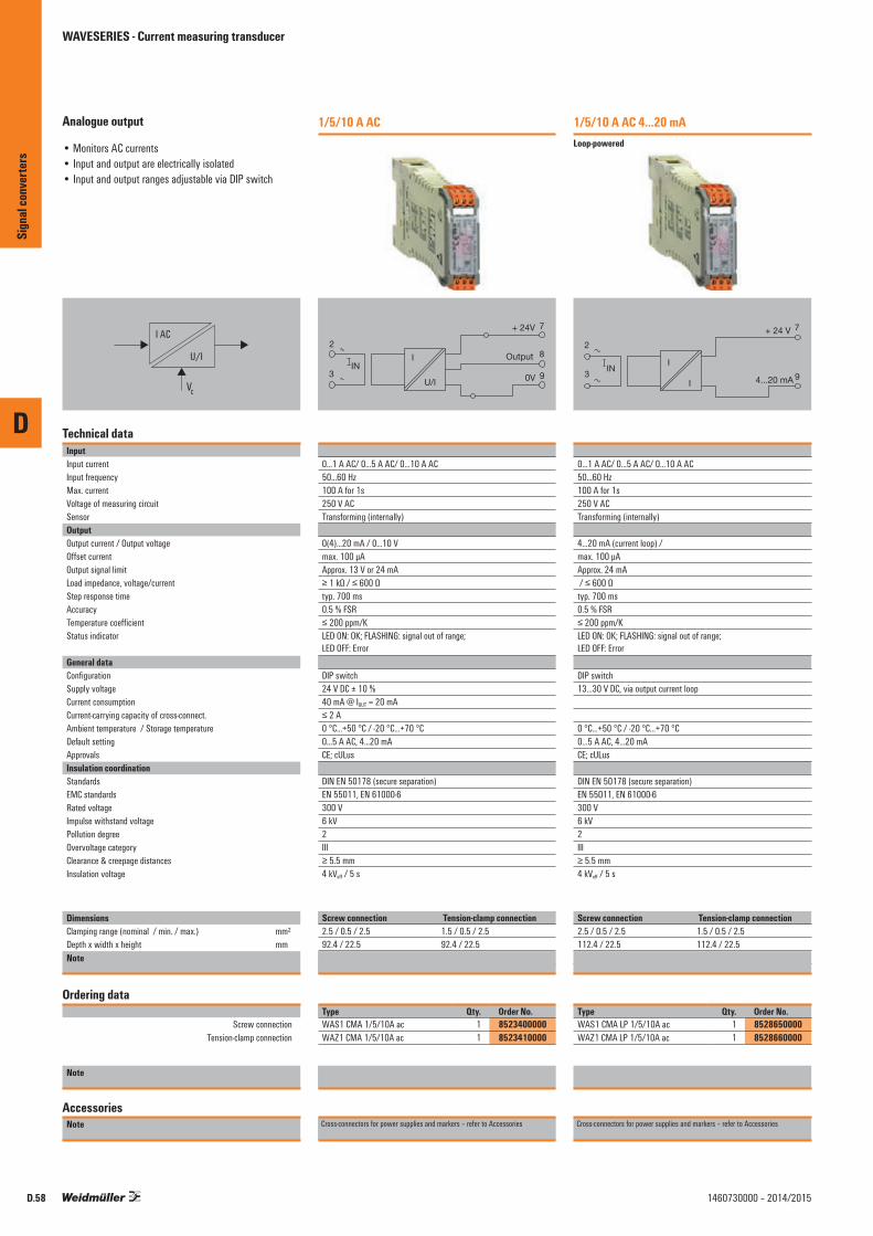
D
D.58 1460730000 – 2014/2015
Analogue output
• Monitors AC currents• Input and output are electrically isolated• Input and output ranges adjustable via DIP switch
I AC
U/I
VC
Technical dataInputInput currentInput frequencyMax. currentVoltage of measuring circuitSensorOutputOutput current / Output voltageOffset currentOutput signal limitLoad impedance, voltage/currentStep response timeAccuracyTemperature coefficientStatus indicator
General dataConfigurationSupply voltageCurrent consumption Current-carrying capacity of cross-connect.Ambient temperature / Storage temperatureDefault settingApprovalsInsulation coordinationStandardsEMC standardsRated voltageImpulse withstand voltagePollution degreeOvervoltage categoryClearance & creepage distancesInsulation voltage
DimensionsClamping range (nominal / min. / max.) mm²Depth x width x height mmNote
Ordering data
Screw connection Tension-clamp connection
Note
AccessoriesNote
1/5/10 A AC
2
3
I
U/I 0V
+ 24V 7
8
9
OutputIN
0...1 A AC/ 0...5 A AC/ 0...10 A AC50...60 Hz100 A for 1s250 V ACTransforming (internally)
0(4)...20 mA / 0...10 Vmax. 100 µAApprox. 13 V or 24 mA≥ 1 kΩ / ≤ 600 Ωtyp. 700 ms0.5 % FSR≤ 200 ppm/KLED ON: OK; FLASHING: signal out of range; LED OFF: Error
DIP switch24 V DC ± 10 %40 mA @ IOUT = 20 mA≤ 2 A0 °C...+50 °C / -20 °C...+70 °C0...5 A AC, 4...20 mACE; cULus
DIN EN 50178 (secure separation)EN 55011, EN 61000-6300 V6 kV2III≥ 5.5 mm4 kVeff / 5 s
Screw connection Tension-clamp connection2.5 / 0.5 / 2.5 1.5 / 0.5 / 2.592.4 / 22.5 92.4 / 22.5Screw connection Tension clamp connection
Type Qty. Order No.WAS1 CMA 1/5/10A ac 1 8523400000WAZ1 CMA 1/5/10A ac 1 8523410000
Cross-connectors for power supplies and markers – refer to Accessories
1/5/10 A AC 4...20 mALoop-powered
I
I
IN
2
34...20 mA
7
9
+ 24 V
0...1 A AC/ 0...5 A AC/ 0...10 A AC50...60 Hz100 A for 1s250 V ACTransforming (internally)
4...20 mA (current loop) / max. 100 µAApprox. 24 mA / ≤ 600 Ωtyp. 700 ms0.5 % FSR≤ 200 ppm/KLED ON: OK; FLASHING: signal out of range; LED OFF: Error
DIP switch13...30 V DC, via output current loop
0 °C...+50 °C / -20 °C...+70 °C0...5 A AC, 4...20 mACE; cULus
DIN EN 50178 (secure separation)EN 55011, EN 61000-6300 V6 kV2III≥ 5.5 mm4 kVeff / 5 s
Screw connection Tension-clamp connection2.5 / 0.5 / 2.5 1.5 / 0.5 / 2.5112.4 / 22.5 112.4 / 22.5Screw connection Tension clamp connection
Type Qty. Order No.WAS1 CMA LP 1/5/10A ac 1 8528650000WAZ1 CMA LP 1/5/10A ac 1 8528660000
Cross-connectors for power supplies and markers – refer to Accessories
Sign
al co
nver
ters
WAVESERIES - Current measuring transducer

D
D.591460730000 – 2014/2015
Analogue output
• Monitors AC currents• Input and output are electrically isolated• Input and output ranges adjustable via DIP switch• No calibration required• ATEX II 3 G nL IIC T4• UL Class I, Div.2
I AC
U/I
VC
Technical dataInputInput currentInput frequencyMax. currentVoltage of measuring circuitSensorOutputOutput current / Output voltageOffset currentOutput signal limitLoad impedance, voltage/currentStep response timeAccuracyTemperature coefficientStatus indicator
General dataConfigurationSupply voltageCurrent consumption Current-carrying capacity of cross-connect.Ambient temperature / Storage temperatureDefault settingApprovalsInsulation coordinationStandardsEMC standardsRated voltageImpulse withstand voltagePollution degreeOvervoltage categoryClearance & creepage distancesInsulation voltage
DimensionsClamping range (nominal / min. / max.) mm²Depth x width x height mmNote
Ordering data
Screw connection
Note
AccessoriesNote
1/5/10 A AC 4...20 mALoop-powered
I
I
IN
2
34...20 mA
7
9
+ 24 V
0...1 A AC/ 0...5 A AC/ 0...10 A AC50...60 Hz100 A for 1s250 V ACTransforming (internally)
4...20 mA (current loop) / max. 100 µAApprox. 24 mA / ≤ 600 Ωtyp. 700 ms0.5 % FSR≤ 200 ppm/KLED ON: OK; FLASHING: signal out of range; LED OFF: Error
DIP switch13...30 V DC, via output current loop
0 °C...+50 °C / -20 °C...+70 °C0...5 A AC, 4...20 mACE; cULusEX; DEMKOATEX; GOSTME25
DIN EN 50178 (secure separation)EN 55011, EN 61000-6300 V6 kV2III≥ 5.5 mm4 kVeff / 5 s
Screw connection2.5 / 0.5 / 2.5112.4 / 22.5Screw connection
Type Qty. Order No.WAS1 CMA LP 1/5/10A EX 1 8975590000
Cross-connectors for power supplies and markers – refer to Accessories
Sign
al co
nver
ters
WAVESERIES - Current measuring transducer
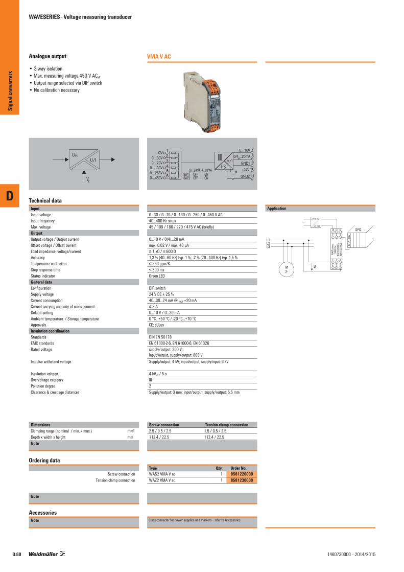
D
D.60 1460730000 – 2014/2015
Analogue output
• 3-way isolation• Max. measuring voltage 450 V ACeff
• Output range selected via DIP switch• No calibration necessary
U/I
VC
Uac
Technical dataInputInput voltageInput frequencyMax. voltageOutputOutput voltage / Output currentOffset voltage / Offset currentLoad impedance, voltage/currentAccuracyTemperature coefficientStep response timeStatus indicatorGeneral dataConfigurationSupply voltageCurrent consumption Current-carrying capacity of cross-connect.Default settingAmbient temperature / Storage temperatureApprovalsInsulation coordinationStandardsEMC standardsRated voltage
Impulse withstand voltage
Insulation voltageOvervoltage categoryPollution degreeClearance & creepage distances
DimensionsClamping range (nominal / min. / max.) mm²Depth x width x height mmNote
Ordering data
Screw connection Tension-clamp connection
Note
AccessoriesNote
VMA V AC
1
1110987
0V0…30V
0…20mASW1SW2
OFFOFF
ONON
4…20mA0…130V
0…10V0/4…20mA
GND1+24VGND2
0…250V0…450V
23456
0…70V
0...30 / 0...70 / 0...130 / 0...250 / 0...450 V AC40...400 Hz sinus45 / 100 / 180 / 270 / 475 V AC (briefly)
0...10 V / 0(4)...20 mAmax. 0.02 V / max. 40 µA≥ 1 kΩ / ≤ 600 Ω1,3 % (40...60 Hz) typ. 1 %; 2 % (70...400 Hz) typ. 1,5 %≤ 250 ppm/K< 300 msGreen LED
DIP switch24 V DC ± 25 %40...30...24 mA @ IOUT =20 mA≤ 2 A0...10 V / 0...20 mA0 °C...+50 °C / -20 °C...+70 °CCE; cULus
DIN EN 50178EN 61000-2-6, EN 61000-6, EN 61326supply/output: 300 V; input/output, supply/output: 600 VSupply⁄output: 4 kV; input⁄output, supply⁄input: 6 kV
4 kVeff / 5 sIII2Supply/output: 3 mm; input/output, supply/output: 5.5 mm
Screw connection Tension-clamp connection2.5 / 0.5 / 2.5 1.5 / 0.5 / 2.5112.4 / 22.5 112.4 / 22.5Screw connection Tension clamp connection
Type Qty. Order No.WAS2 VMA V ac 1 8581220000WAZ2 VMA V ac 1 8581230000
Cross-connector for power supplies and markers – refer to Accessories
1
∼
M3⁓
U
2 3
4 5 6
10 11 12
7 8 9
L1L2L3
230 V AC
24 V DC
Application
WAV
ECON
TROL
VMA
Vac
8581
2200
00/
8581
1230
000 0...2
0 mA
SPS
Sign
al co
nver
ters
WAVESERIES - Voltage measuring transducer

D
Sign
al co
nver
ters
D.611460730000 – 2014/2015

Interface converter – Overview
Isolating converters for serial interfaces
Isolating converters for serial interfaces RS232/RS485/422 or TTY
Serial interface are used for exchanging data between data processing systems, controllers and peripherals. The WDS2 interface isolating converter is particularly well suited for harsh conditions located near to the process. Versions are available for a variety of industrial applications: • RS232/RS422 or RS485 • RS232/TTY
The thin (22.5 mm wide) rail-mounted modules come with a 9-pole SUB-D connector for the RS232 connection and a shield connection for the RS485/422 or TTY signal line. In order to ensure high transmission security, the serial interface isolating converters are equipped with high-quality 4-kV 3-way electrical isolation.
• Easy to service: the electronic components can be removed from the housing/base without using any tools. The terminating resistor can be selected with DIP switch.
• High data transmission speeds up to 115 kBit/s and freely adjustable
• Secure connection: 9-pole Sub-D connector for the RS232 interface. For the serial RS485/422 and TTY connection, the user can connect the shield using the LLBU or the EMC Set (1067470000).
D
Sign
al co
nver
ters
D.62 1460730000 – 2014/2015
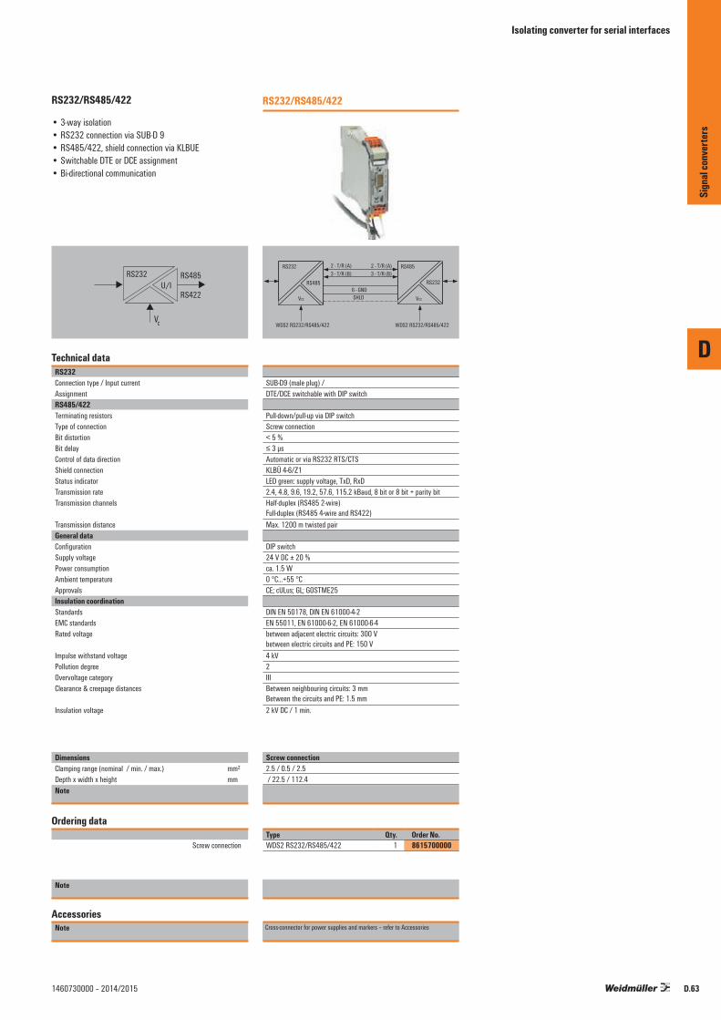
D
D.631460730000 – 2014/2015
RS232/RS485/422
• 3-way isolation• RS232 connection via SUB-D 9• RS485/422, shield connection via KLBUE • Switchable DTE or DCE assignment• Bi-directional communication
RS232
RS422
RS485U/I
VC
Technical dataRS232Connection type / Input currentAssignmentRS485/422Terminating resistorsType of connectionBit distortionBit delayControl of data directionShield connectionStatus indicatorTransmission rateTransmission channels
Transmission distanceGeneral dataConfigurationSupply voltagePower consumptionAmbient temperature ApprovalsInsulation coordinationStandardsEMC standardsRated voltage
Impulse withstand voltagePollution degreeOvervoltage categoryClearance & creepage distances
Insulation voltage
DimensionsClamping range (nominal / min. / max.) mm²Depth x width x height mmNote
Ordering data
Screw connection
Note
AccessoriesNote
RS232/RS485/422
WDS2 RS232/RS485/422 WDS2 RS232/RS485/422
2 - T/R (A) 2 - T/R (A)
RS485
RS232
RS232
RS485
VCC
3 - T/R (B) 3 - T/R (B)
6 - GNDSHLDVCC
SUB-D9 (male plug) / DTE/DCE switchable with DIP switch
Pull-down/pull-up via DIP switchScrew connection< 5 %≤ 3 µsAutomatic or via RS232 RTS/CTSKLBÜ 4-6/Z1LED green: supply voltage, TxD, RxD2.4, 4.8, 9.6, 19.2, 57.6, 115.2 kBaud, 8 bit or 8 bit + parity bitHalf-duplex (RS485 2-wire) Full-duplex (RS485 4-wire and RS422)Max. 1200 m twisted pair
DIP switch24 V DC ± 20 %ca. 1.5 W0 °C...+55 °CCE; cULus; GL; GOSTME25
DIN EN 50178, DIN EN 61000-4-2EN 55011, EN 61000-6-2, EN 61000-6-4between adjacent electric circuits: 300 V between electric circuits and PE: 150 V4 kV2IIIBetween neighbouring circuits: 3 mm Between the circuits and PE: 1.5 mm2 kV DC / 1 min.
Screw connection2.5 / 0.5 / 2.5 / 22.5 / 112.4
Type Qty. Order No.WDS2 RS232/RS485/422 1 8615700000
Cross-connector for power supplies and markers – refer to Accessories
Sign
al co
nver
ters
Isolating converter for serial interfaces
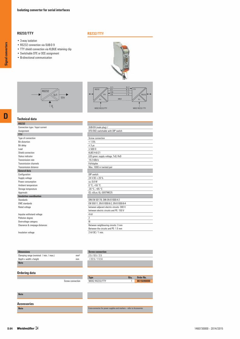
D
D.64 1460730000 – 2014/2015
RS232/TTY
• 3-way isolation• RS232 connection via SUB-D 9• TTY shield connection via KLBUE retaining clip• Switchable DTE or DCE assignment• Bi-directional communication
RS232
TTYU/I
VC
Technical dataRS232Connection type / Input currentAssignmentTTYType of connectionBit distortionBit delayLoadShield connectionStatus indicatorTransmission rateTransmission channelsTransmission distanceGeneral dataConfigurationSupply voltagePower consumptionAmbient temperature Storage temperatureApprovalsInsulation coordinationStandardsEMC standardsRated voltage
Impulse withstand voltagePollution degreeOvervoltage categoryClearance & creepage distances
Insulation voltage
DimensionsClamping range (nominal / min. / max.) mm²Depth x width x height mmNote
Ordering data
Screw connection
Note
AccessoriesNote
RS232/TTY
WDS2 RS232/TTY WDS2 RS232/ TTY
5 T+ R+ 2
TTY
RS232
RS232
TTY 6 T- R- 3
3 R- T- 6
SHLD
T+ 5 2 R+
VCCVCC
SUB-D9 (male plug) / DTE/DCE switchable with DIP switch
Screw connection< 1.5%≤ 3 µs≤ 500 ΩKLBÜ 4-6/Z1LED green: supply voltage, TxD, RxD19.2 kBit/sFull-duplexMax. 1000 m twisted pair
DIP switch24 V DC ± 20 %ca. 0.8 W0 °C...+55 °C-20 °C...+85 °CCE; cULus; GL; GOSTME25
DIN EN 50178, DIN EN 61000-4-2EN 55011, EN 61000-6-2, EN 61000-6-4between adjacent electric circuits: 300 V between electric circuits and PE: 150 V4 kV2IIIBetween neighbouring circuits: 3 mm Between the circuits and PE: 1.5 mm2 kV DC / 1 min.
Screw connection2.5 / 0.5 / 2.5 / 22.5 / 112.4
Type Qty. Order No.WDS2 RS232/TTY 1 8615690000
Cross-connector for power supplies and markers – refer to Accessories
Sign
al co
nver
ters
Isolating converter for serial interfaces

Trip amplifier for monitoring AC/DC circuits Trip amplifier for monitoring AC/DC circuits – Overview E.2
WAVESERIES – Limit value monitoring E.4
PLUGCONTROL – Current monitoring E.6
WAVESERIES – Voltage monitoring E.8
Contents
Trip amplifier for monitoring AC/DC circuits
E
Trip
ampli
fier f
or m
onito
ring
AC/D
C cir
cuits
E.11460730000 – 2014/2015
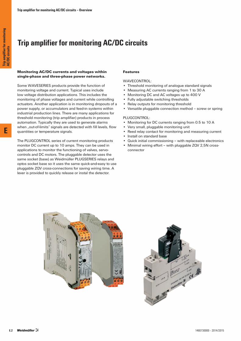
Trip amplifier for monitoring AC/DC circuits
Trip amplifier for monitoring AC/DC circuits – Overview
Monitoring AC/DC currents and voltages withinsingle-phase and three-phase power networks.
Some WAVESERIES products provide the function of monitoring voltage and current. Typical uses include low voltage distribution applications. This includes the monitoring of phase voltages and current while controlling actuators. Another application is in monitoring dropouts of a power supply, or accumulators and feed-in systems withinindustrial production lines. There are many applications forthreshold monitoring (trip amplifier) products in process automation. Typically they are used to generate alarms when „out-of-limits“ signals are detected with fill levels, flow quantities or temperature signals.
The PLUGCONTROL series of current monitoring products monitor DC current up to 10 amps. They can be used in applications to monitor the functioning of valves, servo-controls and DC motors. The pluggable detector uses the same socket (base) as Weidmüller PLUGSERIES relays and optos socket base so it uses the same quick-and-easy to use pluggable ZQV cross-connections for saving wiring time. A lever is provided to quickly release or instal the detector.
Features
WAVECONTROL:• Threshold monitoring of analogue standard signals• Measuring AC currents ranging from 1 to 30 A• Monitoring DC and AC voltages up to 400 V• Fully adjustable switching thresholds• Relay outputs for monitoring threshold• Versatile pluggable connection method – screw or spring
PLUGCONTROL:• Monitoring for DC currents ranging from 0.5 to 10 A• Very small, pluggable monitoring unit• Reed relay contact for monitoring and measuring current• Install on standard base• Quick initial commissioning – with replaceable electronics• Minimal wiring effort – with pluggable ZQV 2,5N cross-
connector
E
Trip
ampli
fier f
or m
onito
ring
AC/D
C cir
cuits
E.2 1460730000 – 2014/2015

Trip amplifier for monitoring AC/DC circuits – Overview
Threshold monitoring of analoguestandard signals
Current monitoring
Voltage monitoring
E
Trip
ampli
fier f
or m
onito
ring
AC/D
C cir
cuits
E.31460730000 – 2014/2015
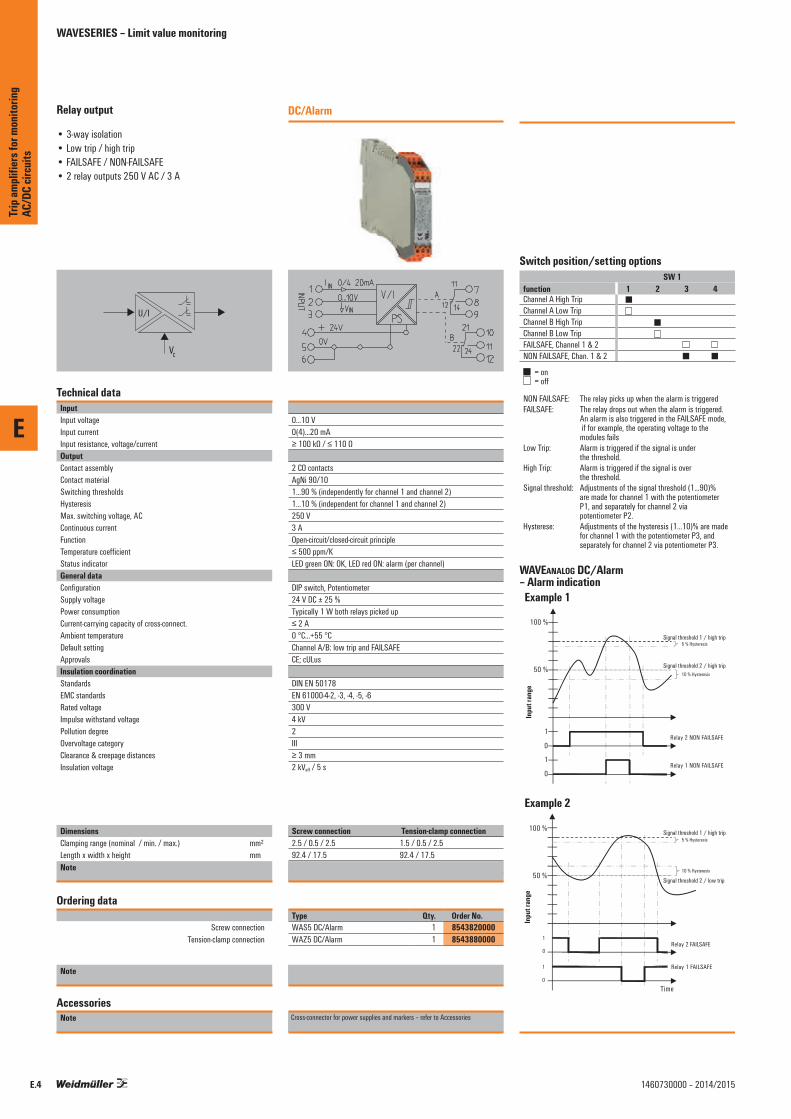
E
E.4 1460730000 – 2014/2015
Relay output
• 3-way isolation• Low trip / high trip• FAILSAFE / NON-FAILSAFE• 2 relay outputs 250 V AC / 3 A
U/I
VC
Technical dataInputInput voltageInput currentInput resistance, voltage/currentOutputContact assemblyContact materialSwitching thresholdsHysteresisMax. switching voltage, ACContinuous currentFunctionTemperature coefficientStatus indicatorGeneral dataConfigurationSupply voltagePower consumptionCurrent-carrying capacity of cross-connect.Ambient temperature Default settingApprovalsInsulation coordinationStandardsEMC standardsRated voltageImpulse withstand voltagePollution degreeOvervoltage categoryClearance & creepage distancesInsulation voltage
DimensionsClamping range (nominal / min. / max.) mm²Length x width x height mmNote
Ordering data
Screw connection Tension-clamp connection
Note
AccessoriesNote
DC/Alarm
0...10 V0(4)...20 mA≥ 100 kΩ / ≤ 110 Ω
2 CO contactsAgNi 90/101...90 % (independently for channel 1 and channel 2)1...10 % (independent for channel 1 and channel 2)250 V3 AOpen-circuit/closed-circuit principle≤ 500 ppm/KLED green ON: OK, LED red ON: alarm (per channel)
DIP switch, Potentiometer24 V DC ± 25 %Typically 1 W both relays picked up≤ 2 A0 °C...+55 °CChannel A/B: low trip and FAILSAFECE; cULus
DIN EN 50178EN 61000-4-2, -3, -4, -5, -6300 V4 kV2III≥ 3 mm2 kVeff / 5 s
Screw connection Tension-clamp connection2.5 / 0.5 / 2.5 1.5 / 0.5 / 2.592.4 / 17.5 92.4 / 17.5Screw connection Tension clamp connection
Type Qty. Order No.WAS5 DC/Alarm 1 8543820000WAZ5 DC/Alarm 1 8543880000
Cross-connector for power supplies and markers – refer to Accessories
Trip
ampli
fiers
for m
onito
ring
AC/D
C cir
cuits
WAVESERIES – Limit value monitoring
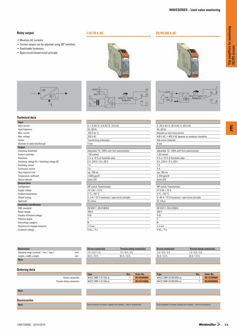
E
E.51460730000 – 2014/2015
Relay output
• Monitors AC currents• Current ranges can be adjusted using DIP switches• Switchable hysteresis• Open-circuit/closed-circuit principle
I AC
VC
K1
Technical dataInputInput currentInput frequencyMax. currentMax. voltageSensorDiameter of cable feed-throughOutputSwitching thresholdsContact assemblyHysteresisSwitching voltage AC / Switching voltage DCSwitching currentContinuous currentStep response timeTemperature coefficientStatus indicatorGeneral dataConfigurationSupply voltageAmbient temperature Default settingApprovalsInsulation coordinationEMC standardsRated voltageImpulse withstand voltagePollution degreeOvervoltage categoryClearance & creepage distancesInsulation voltage
DimensionsClamping range (nominal / min. / max.) mm²Length x width x height mmNote
Ordering data
Screw connection Tension-clamp connection
Note
AccessoriesNote
1/5/10 A AC
123
5
6IN
0V
+24V
K1
10%Setpoint
100% 1114
12
10
11
12
0...1 A AC/ 0...5 A AC/ 0...10 A AC50...60 Hz100 A for 1s250 V ACTransforming (internally)4 mm
Adjustable 10...100% with front potentiometer1 CO contact5 % or 10 % of threshold value6 V...250 V / 6 V...60 V7 A3 Atyp. 700 ms≤ 800 ppm/KGreen LED
DIP switch, Potentiometer24 V DC ± 10 %0 °C...+50 °C0...5 A / 10 % hysteresis / open-circuit principleCE; cULus
EN 55011, EN 61000-6300 V4 kV2III≥ 3 mm4 kVeff / 5 s
Screw connection Tension-clamp connection2.5 / 0.5 / 2.5 1.5 / 0.5 / 2.592.4 / 22.5 92.4 / 22.5Screw connection Tension clamp connection
Type Qty. Order No.WAS2 CMR 1/5/10A ac 1 8516560000WAZ2 CMR 1/5/10A ac 1 8516570000
Cross-connector for power supplies and markers – refer to Accessories
20/40/60 A AC
311
12
1410%
Setpoint100%
7
8
9
21
~
~
OV
+24V
K1
0...20 A AC/ 0...40 A AC/ 0...60 A AC50...60 HzDepends on wire cross-section400 V AC, > 400 V AC depends on conductor insulationHall sensor (internal)8 mm
Adjustable 10...100% with front potentiometer1 CO contact5 % or 10 % of threshold value6 V...250 V / 6 V...60 V7 A3 Atyp. 700 ms≤ 250 ppm/KGreen LED
DIP switch, Potentiometer24 V DC ± 10 %0 °C...+50 °C0...40 A / 10 % hysteresis / open-circuit principleCE; cULus
EN 55011, EN 61000-6300 V4 kV2III≥ 3 mm4 kVeff / 5 s
Screw connection Tension-clamp connection2.5 / 0.5 / 2.5 1.5 / 0.5 / 2.592.4 / 22.5 92.4 / 22.5Screw connection Tension clamp connection
Type Qty. Order No.WAS2 CMR 20/40/60A ac 1 8513340000WAZ2 CMR 20/40/60A ac 1 8526600000
Cross-connector for power supplies and markers – refer to Accessories
Trip
ampli
fiers
for m
onito
ring
AC/D
C cir
cuits
WAVESERIES – Limit value monitoring

E
E.6 1460730000 – 2014/2015
Relay output
• Monitors currents up to 10 A DC• Used with valves, servo-controls or DC motors• Pull-up / pull-down resistor 4.7 kΩ
Technical dataInputInput currentMax. currentMaking current thresholdResistance of sensor circuitSecure offPulse durationOutputSwitching currentSwitching voltage AC / Switching voltage DCMax. switching frequencyContact assemblyContact materialGeneral dataConfigurationAmbient temperature HumidityApprovalsInsulation coordinationStandardsEMC standardsRated voltageImpulse withstand voltageInsulation voltageOvervoltage categoryPollution degreeClearance & creepage distances
DimensionsClamping range (nominal / min. / max.) mm²Length x width x height mmNote
Ordering data
Screw connection
Note
AccessoriesNote
PAS CMR 0.5...2.5 A DC
A1
A2
0.5...2.5A DC
11/21
14/24
12/22
100V 0.1A
4.7kΩ
0.5...2.5 A DC7.5 A for 10 s≤ 500 mA50 Ω≤ 50 mAmin. 1 ms
100 mA1 V...100 V / 1 V...100 V15 Hz1 NO contactRH/Rd (Reed contact)*
none0 °C...+55 °C5–95% rel. humidity, Tu = 40°C, no condensationCE; cULus
DIN EN 50178 (secure separation)EN 55011, EN 61000-6-1, 2, 3, 4300 V6 kV4 kVeff / 1 min.III2≥ 5 mm (grout encapsulated)
Screw connection1.5 / 2.5 / 2.592 / 15.3Screw connection* The peak current should be limited to 100 mA when under capacitive loads.
Type Qty. Order No.PAS CMR 0,5...2,5 A DC 10 8742610000
Cross-connectors and markers - refer to WAVESERIES Accessories
PAS CMR 2.0...5.0 A DC
A1
A2
2.0...5.0A DC
11/21
14/24
12/22
100V 0.1A
4.7kΩ
2...5.0 A DC15 A for 10 s≤ 2 A50 Ω≤ 300 mAmin. 1 ms
100 mA1 V...100 V / 1 V...100 V15 Hz1 NO contactRH/Rd (Reed contact)*
none0 °C...+55 °C5–95% rel. humidity, Tu = 40°C, no condensationCE; cULus
DIN EN 50178 (secure separation)EN 55011, EN 61000-6-1, 2, 3, 4300 V6 kV4 kVeff / 1 min.III2≥ 5 mm (grout encapsulated)
Screw connection1.5 / 2.5 / 2.592 / 15.3Screw connection* The peak current should be limited to 100 mA when under capacitive loads.
Type Qty. Order No.PAS CMR 2,0...5,0 A DC 10 8742620000
Cross-connectors and markers - refer to WAVESERIES Accessories
Trip
ampli
fiers
for m
onito
ring
AC/D
C cir
cuits
PLUGCONTROL – Current monitoring

E
E.71460730000 – 2014/2015
Relay output
• Monitors currents up to 10 A DC• Used with valves, servo-controls or DC motors• Pull-up / pull-down resistor 4.7 kΩ
Technical dataInputInput currentMax. currentMaking current thresholdResistance of sensor circuitSecure offPulse durationOutputSwitching currentSwitching voltage AC / Switching voltage DCMax. switching frequencyContact assemblyContact materialGeneral dataConfigurationAmbient temperature HumidityApprovalsInsulation coordinationStandardsEMC standardsRated voltageImpulse withstand voltageInsulation voltageOvervoltage categoryPollution degreeClearance & creepage distances
DimensionsClamping range (nominal / min. / max.) mm²Length x width x height mmNote
Ordering data
Screw connection
Note
AccessoriesNote
PAS CMR 4.5...10 A DC
A1
A2
4.5...10A DC
11/21
12/22
100V 0.1A
4.7kΩ
14/24
4.5...10 A DC30 A for 10 s≤ 4.5 A50 Ω≤ 600 mAmin. 1 ms
100 mA1 V...100 V / 1 V...100 V15 Hz1 NO contactRH/Rd (Reed contact)*
none0 °C...+55 °C5–95% rel. humidity, Tu = 40°C, no condensationCE; cULus
DIN EN 50178 (secure separation)EN 55011, EN 61000-6-1, 2, 3, 4300 V6 kV4 kVeff / 1 min.III2≥ 5 mm (grout encapsulated)
Screw connection1.5 / 2.5 / 2.592 / 15.3 / 95Screw connection* The peak current should be limited to 100 mA when under capacitive loads.
Type Qty. Order No.PAS CMR 4,5...10 A DC 10 8742630000
Cross-connectors and markers - refer to WAVESERIES Accessories
Trip
ampli
fiers
for m
onito
ring
AC/D
C cir
cuits
PLUGCONTROL – Current monitoring

E
E.8 1460730000 – 2014/2015
Relay output
• 3-way isolation• Monitoring of single-phase systems up to 260 V AC/DC• 4 input ranges per DIP switch can be selected• 1 relay module with CO contact• Switchable hysteresis• Switch adjusted via potentiometer• Reset input
Uac
VC
Technical dataInputInput voltageInput frequencyMax. voltageOutputMax. switching voltage, ACSwitching currentContinuous currentHysteresis
Temperature coefficientStep response timeRepeat accuracyStatus indicatorGeneral dataSupply voltageReset input voltage, min./max.Pulse durationConfigurationDefault settingAmbient temperature Storage temperatureApprovalsInsulation coordinationStandardsEMC standardsRated voltage
Impulse withstand voltage
Insulation voltageOvervoltage categoryPollution degreeClearance & creepage distances
DimensionsClamping range (nominal / min. / max.) mm²Length x width x height mmNote
Ordering data
Screw connection
Note
AccessoriesNote
VMR V AC / DCSingle-phase
110
11
11
WAS5
VMR
1ph1214
+ 18 V DC…60 V DC
24 V AC/DC…260 V AC/DC
Setpointnc
–3
4
5
6
ResetInput
24...70 / 70...140 / 140...210 / 210...260 V AC / DC50...60 Hz260 V AC / DC
250 V8 A3 A24...70 V AC, small = 5 V / large = 10 V, 70–260 VAC, small = 8 V ⁄ large = 16≤ 250 ppm/K< 300 ms< 0.3 % of set rangeLED green = OK / LED yellow/red = alarm status
from the measuring circuit18 V DC / 30 V DC≤ 700 msDIP switch, PotentiometerDIP switches: ON = 1,2,5,8 / OFF = 3,4,6,7-10 °C...+55 °C-20 °C...+70 °CCE; cULus; GOSTME25
DIN EN 50178EN 55011, EN 61000-6, EN 61326input/output, input/reset input, reset input/output: 300 V
Input/output, input/reset input, reset input/output: 4 kV
2 kVeff
III2≥ 3 mm
Screw connection2.5 / 0.5 / 2.596.5 / 17.5Screw connection
Type Qty. Order No.WAS5 VMR 1ph 1 8705640000
Markers – refer to Accessories.
Trip
ampli
fiers
for m
onito
ring
AC/D
C cir
cuits
WAVESERIES – Voltage monitoring

E
E.91460730000 – 2014/2015
Relay output
• 2-way isolation• Monitoring of 1- and 3-phase systems from 80 to 400 V AC/DC• Adjustable by DIP switches• Monitoring of low and surge voltages• Detects loss of phase• 2 relay modules with CO contact
Uac
Technical dataInputInput voltageInput currentOutputContact assemblyMax. switching voltage, ACContinuous currentHysteresisTemperature coefficientStep response timeRepeat accuracyStatus indicatorGeneral dataConfigurationSupply voltageDefault settingAmbient temperature ApprovalsInsulation coordinationStandardsEMC standardsRated voltageImpulse withstand voltageInsulation voltageOvervoltage categoryPollution degreeClearance & creepage distances
DimensionsClamping range (nominal / min. / max.) mm²Length x width x height mmNote
Ordering data
Screw connection
Note
AccessoriesNote
VMR V ACThree-phase
1
10
11
1112
14
789
12
22
21
24
200…400 V AC/DC
80…250 V AC/DC L1
80…250V AC/DC L2
80…250V AC/DC L3L1 L2 L3
N
3
456
200…400 V AC/DC 1~, 80…250 V AC/DC 3~< 10 mA DC; 15 mA AC
2 CO contacts250 V3 A5% of final value≤ 300 ppm/K< 300 ms< 0.3 % of set rangeGreen LED
DIP switch, Potentiometerfrom the measuring circuitDIP switches: ON = 1,2,4 / OFF = 30 °C...+50 °CCE; cULus; GOSTME25
DIN EN 50178EN 55011, EN 61000-6, EN 61326600 V6 kV4 kVeff / 1 min.III2Output circuit: 1.8 mm; input circuit, output circuit 1/output circuit 2: 3 mm; input/output: 5.5 mm
Screw connection2.5 / 0.5 / 2.596.5 / 22.5Screw connection
Type Qty. Order No.WAS2 VMR 3ph 1 8705630000
Markers – refer to Accessories.
Table of setting options
Upper operating point
0
Hysteresis
1
0
Relay 1/Operating currentprinciple, Overvoltage
1
0
Outp
ut
Relay 2/Operating currentprinciple, Undervoltage
Time
U
Lower operating point
Hysteresis
Input
rang
e 10%
Upper operating point
0
Hysteresis
1
0
Relay 1 /Closed-circuitcurrent principle, Overvoltage
1
0
Outp
ut
Relay 2 /Closed-circuitcurrent principle, Undervoltage
Time
U
Lower operating point
Hysteresis
Input
rang
e
20%
1 2 3 4Input3 phases 80 V AC/DC...250 V AC/DC ◼1 phase 200 V AC/DC...400 V AC/DC n◼Limit valueSetting to upper switching point ◼Setting to lower switching point n◼HysteresisHysteresis, small ◼Hysteresis, large n◼Fault toleranceOperating current method ◼Closed-circuit current method n◼
n◼ = on◼ = off
Fig.1: Overvoltage and undervoltage monitoring, example of setting– 3-phase monitoring– Setting limit value to upper operating point: 230 V Hysteresis 5% = -12.5 V– Lower operating point 10% less 230 V - 25 V = 205 V Hysteresis 5% = + 12.5 V– The device operates with the operating current principle.– All 3 phases monitored in parallel
Fig. 2: Overvoltage and undervoltage monitoring, example of setting– 3-phase monitoring– Setting limit value to lower operating point: 150 V Hysteresis 5% = +12.5 V– Upper operating point 20% greater 150 V + 50 V = 200 V Hysteresis 5 % = –12. 5 V– The device operates with the closed-circuit current principle.– All 3 phases monitored in parallel
Status indicatorVoltage is in set range
Trip
ampli
fiers
for m
onito
ring
AC/D
C cir
cuits
WAVESERIES – Voltage monitoring

E
E.10 1460730000 – 2014/2015
Trip
ampli
fiers
for m
onito
ring
AC/D
C cir
cuits

Indicators and configurable displays Overview F.2
Process value displays with LED display F.4
Process value displays with LCD display F.20
Indicators and configurable displays
Contents
F
Indic
ator
s and
confi
gura
ble di
splay
s
F.11460730000 – 2014/2015
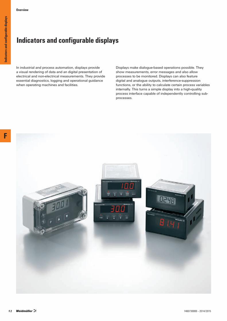
Overview
Indicators and configurable displays
In industrial and process automation, displays provide a visual rendering of data and an digital presentation of electrical and non-electrical measurements. They provide essential diagnostics, logging and operational guidance when operating machines and facilities.
Displays make dialogue-based operations possible. They show measurements, error messages and also allow processes to be monitored. Displays can also feature digital and analogue outputs, interference-suppression functions, or the ability to calculate certain process variables internally. This turns a simple display into a high-quality process interface capable of independently controlling sub-processes.
F
Indic
ator
s and
confi
gura
ble di
splay
s
F.2 1460730000 – 2014/2015

Overview
Flow rate or volume monitoring with LED display
Process value indication with LCD display
All-purpose
A fitting solution for any application – with a multitude of input ranges, external of input loop-powered supply, and analogue or digital outputs.
Saves time
Easy push-button configuration.
Security
No additional signal isolation is required since there is a high insulation voltage.
Protection
IP 65 protection allows for use in harshindustrial conditions.
…
…
IP 65
F
Indic
ator
s and
confi
gura
ble di
splay
s
F.31460730000 – 2014/2015

Process value displays with LED display
CountersPTX800 SERIES
Panel-mounted totaliser/counter/rate monitors
The configurable monitors of the PTX800 SERIES are available in two designs:
• PTX800A for analogue (mA, Volts) inputs• PTX800D with digital pulse inputs (NAMUR,
NPN/PNP sensors, TTL, etc)
The eight-digit LED rate/total display can be changed via a button on the front of the unit. Both versions make use of output relays to close values when the “total“ setpoint is reached. They also have electrically-isolated analogue outputs for re-transmission.
The display can be globally scaled based on the flow quantity per second, minute, hour or day. The flow-quantity counter can be multiplied by factors of 0.001, 0.01, 0.1, 1, 10, 100 or 1000. This allows for best use of the display.
The PTX800A counter processes standardised analogue current and voltage signals. Linearisation and filtering functions are available for processing measurement signals. In addition, the counter has a 24 V DC power supply for loop-powered sensors.
The PTX800D can be connected on the input side to all standard initiators (NPN/PNP/Namur) and with other current/voltage transmitters. The monitor will accept any periodic signal type and can total the input pulses into a “total“ display.
It can also calculate the resulting flow rate. External proximity switches can be supplied with 12 V DC directly from the PTX800D.
Typical application of PTX800
Control valves
Remote
PLC/SMSPTX800D
Pulse input12 DC sensor supply
Output Control Relay 1
Output Control Relay 2
Liquid flow
Remotel „Reset“
4...20 mA output
Positive DisplacementFlowmeter
Technical Features
• Display of the flow quantity/rate• Easily-readable eight-digit LED display • Up to two outputs for alarm monitoring or control• Optional analogue output• Pulse output• Reset function can be controlled locally or remotely, for
fill-quantity monitoring (batching)• The most recent measured value is stored in case of a
power outage• DC power supply• LED display for values outside of range• Complete electrical isolation• DIN-standard 1/8 front panel with IP 65 protection• Integrated power supply for initiators• Changing the device configuration is possible without
performing a new calibration• No internal adjustments needed
96.6 mm
137.00 mm
Wall thickness Max 18.0 mm
48.8
mm
44.7
mm
96.6
mm
60.0
mm
143.5 mm
15.5
mm
15.5
mm
PGMENT
RESET
18.0 mmGasket 92.0 mm (+0.8/-0.0 mm)
Cut-out
45.0
mm
(+0.
6/-0.
0 mm
)
PGMENT
TOTALRATE
AL1 AL2
F
Indic
ator
s and
confi
gura
ble di
splay
s
F.4 1460730000 – 2014/2015

Process value displays with LED display
Common technical dataDisplayTypeBrightnessDisplay valuePartial displayTime range, partial displayTotal displayDecimal pointStatus indicatorPulse outputTypeDisplay valuePulse durationCut-off timeAnalogue output (optional)TypeDisplay range
ResolutionLoad resistance, currentLoad resistance, voltageResidual rippleAlarm output (optional)TypeSwitching currentIsolationInput resetTypeFunctionGeneral informationSupply voltagePower consumptionAccuracyLinearityRepeat accuracyHumidityTemperature coefficientLong-term driftImpulse withstand voltageAmbient temperature (operational)/storage temperature
Eight digits, red LED, 7.2 mmAdjustable to 14 levels of brightnessPercent or real-value displayedDisplay from 0 to 50,000 (five digits)per sec., min., hour (PT800A also per day)Display from 0 to 99,999,999 (8 digits)Adjustable separately for partial and total displayAlarm 1/2; Status LED
Transistor outputOne pulse per signal jump of the total display32 msMinimum of 32 ms
Current or voltage output configurable with jumperDependent on the calibration (within 0 to 22 mA, or 0 to 11 V)1.6 μA or 0.8 mV / Bit≤ 900 Ω≥ 1 kΩ< 20 mVss
2 relay contacts (CO)3 A at 240 V AC, 5 A at 24 V DC / 110 V AC (resistive load)1.5 kV between ports
Normally openComplete reset (display/alarm)
24 V DC ±10 %6 W at 24 V DC< 0.05 %< 0.05 %± 0.02 % of signal range0...90 % (no condensation)< 0.02 % of signal range0.1 % / 10,000 h4 kV (1.2/50 μs)0 °C...60 °C / –25 °C...70 °C
ConnectionsTerminal Signal1 L+
Supply voltage2 L-3 Signal + Analogue output
(optional)4 Signal -5 0 V
Pulse output6 Pulse7
Optional, depending on type
Inputs
8910111213 NO contacts
Alarm channel 1(optional)
14 Common15 NC contact16 NO contacts
Alarm channel 2(optional)
17 Common18 NC contact F
Indic
ator
s and
confi
gura
ble di
splay
s
F.51460730000 – 2014/2015

F
F.6 1460730000 – 2014/2015
PTX800 Series
Counter and totaliser with additional functionality and limit-value monitoring• Installation in control panels• Pluggable connection terminals• Scalable impulse and frequency counters for digital input
signals• Suitable on input side for all standard initiators
H
W
L
Technical dataInputType
Input signalSensor supplyInput voltage Total display, display rangeAnalogue output (optional)Type (analogue output)Input resetPulse duration, min.Pulse outputPulse rate, max.General dataType EMC standardsApprovals
DimensionsClamping range (nominal / min. / max.) mm²Length x width x height mmNote
Ordering data
without analogue / alarm outputwith analogue/alarm output
Note
AccessoriesNote
PTX800DDigital pulse input
Digital pulse (NAMUR, PNP/NPN, TTL logic, optocoupler, voltage pulse, no-voltage contacts)0...10 Hz12 V DC to 25 mA50 mV...250 V adjustable Configurable (≤ 10 pulse per signal jump)
Current of voltage output, configured with jumper
100 ms
16 / s
RO/AO version with 1 analogue output and 2 alarm outputsDIN EN 61326CE; cULus
Screw connection1.5 / 0.5 / 2.5137 / 96.6 / 48.8
Type Qty. Order No.PTX800D 1 7940011133PTX800D RO/AO 1 7940012323
PS
0 V
f
+24 V1 2
Reset counterPull up/down0 Vfin
+12 V
79
101112
V/I/f
3Vout/Iout (opt)
0 Vfout
Ch 1Ch 1
(opt)
(opt)
NCCommon
NCCommon
NO
NO
+–
456
131415161718
+
ConnectionsTerminal Signal
7 Reset by connection to
Reset class 12
8 Setup configuration by
Configuration connection to class 129 Pull Up /Down 10 Signal –/0 V
Inputs
11 Signal + 12 12 V DC
Indic
ator
s and
conf
igura
ble di
splay
sProcess value displays with LED display

F
F.71460730000 – 2014/2015
PTX800 Series
Counter and totaliser with additional functionality and limit-value monitoring• Installation in control panels• Pluggable connection terminals• Configurable for analogue current and voltage signals• Linearisation and interference suppression • Power supply for external sensors
H
W
L
Technical dataInputType
Input signalSensor supplyResolutionInput resistanceTotal display, display rangeAnalogue output (optional)Type (analogue output)Input resetPulse duration, min.Pulse outputPulse rate, max.General dataType EMC standardsApprovals
DimensionsClamping range (nominal / min. / max.) mm²Length x width x height mmNote
Ordering data
without analogue / alarm outputwith analogue/alarm output
Note
AccessoriesNote
PTX800AAnalogue current input / voltage input
Conversion of linear/quadratic input signals into analogue signals
-24...+24 mA / -11...+11 V24 V DC (up to 25 mA)0.6 µ, A / 0.3 mV22 Ω (current input); 1 MΩ (voltage input)0,001; 0,01; 0,1; 1; 10; 100; 1000
Current of voltage output, configured with jumper
250 ms
15 / s
RO/AO version with 1 analogue output and 2 alarm outputsDIN EN 61326CE; cULus
Screw connection1.5 / 0.5 / 2.5137 / 96.6 / 48.8
Type Qty. Order No.PTX800A 4-20mA 1 7940010243PTX800A 4-20mA/RO/AO 1 7940014374
PS
0 V
f
+24 V1 2
Reset counterReset common0 VVin/Iin+12 V
78
101112
V/I/f
3Vout/Iout (opt)
0 Vfout
Ch 1Ch 1
(opt)
(opt)
NCCommon
NCCommon
NO
NO
+–
456
131415161718
+
ConnectionsTerminal Signal
7 Reset by connection to
Reset class Kl. 8
8 Common
Setup configuration by Configuration
9 connection to class 8
10 Signal –/0 V Inputs
11 Signal + 12 24 V DC
Indic
ator
s and
conf
igura
ble di
splay
s
Process value displays with LED display
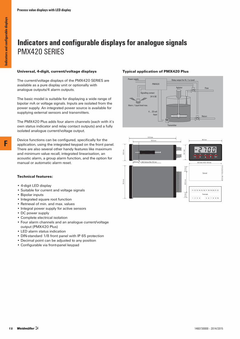
Process value displays with LED display
Indicators and configurable displays for analogue signals PMX420 SERIES
Universal, 4-digit, current/voltage displays
The current/voltage displays of the PMX420 SERIES are available as a pure display unit or optionally withanalogue outputs/4 alarm outputs.
The basic model is suitable for displaying a wide range of bipolar mA or voltage signals. Inputs are isolated from the power supply. An integrated power source is available for supplying external sensors and transmitters.
The PMX420 Plus adds four alarm channels (each with it’s own status indicator and relay contact outputs) and a fully isolated analogue current/voltage output.
Device functions can be configured, specifically for the application, using the integrated keypad on the front panel.There are also several other handy features like maximum and minimum value recall, integrated linearisation, an acoustic alarm, a group alarm function, and the option for manual or automatic alarm reset.
Technical features:
• 4-digit LED display• Suitable for current and voltage signals• Bipolar inputs• Integrated square root function• Retrieval of min. and max. values• Integral power supply for active sensors• DC power supply• Complete electrical isolation• Four alarm channels and an analogue current/voltage
output (PMX420 Plus)• LED alarm status indication• DIN-standard 1/8 front panel with IP 65 protection• Decimal point can be adjusted to any position• Configurable via front-panel keypad
Typical application of PMX420 Plus
Power supply
Signalling contact
Alarm / Liquid level max.
24 V DC
4 ... 20 mAInput
Transmitter
Return
Agitator Flow
Relay output for Hi / Lo Level
PMX420
96.6 mm137.0 mm
mm 8.84
mm7 .44
mm
6.69
mm
0.06
143.5 mm
mm5.51
mm5.51
18.0 mm 92.0 mm (+0.8/–0.0 mm)
Cut-out
)m
m0
.0-/6.0+(
m m0.54
AL1 AL2 AL4AL3
11 12 13 14 15 16 17 18 19 20 21 22
Terminals
1 2 3 4 5 6 7 8 9 10
Wall thickness Max 18.0 mm
PGM
F
Indic
ator
s and
confi
gura
ble di
splay
s
F.8 1460730000 – 2014/2015
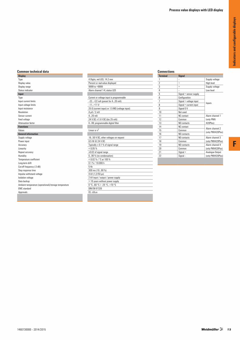
Process value displays with LED display
Common technical dataDisplayTypeDisplay valueDisplay rangeStatus indicatorInputTypeInput current limitsInput voltage limitsInput resistanceResolutionSensor currentFeed voltageAttenuation factorFunctionsValuesGeneral informationSupply voltagePower inputAccuracyLinearityRepeat accuracyHumidityTemperature coefficientLong-term driftCut-off frequency (-3 dB)Step response timeImpulse withstand voltageIsolation voltageData backupAmbient temperature (operational)/storage temperatureEMC standardApprovals
4 Digits, red LED, 14.2 mmPercent or real-value displayed9999 to +9999Alarm channel 1-4; status LED
Current or voltage input is programmable–22…+22 mA (preset for 4...20 mA)–11...+11 V25 Ω (current input) or 1.5 MΩ (voltage input)4 µA / 2 mV4…20 mA24 V DC ±1.5 V DC (bis 25 mA)0…99; programmable digital filter
Linear or √
18...50 V DC, other voltages on request8.5 W @ 24 V DCTypically ± 0.1 % of signal range< 0.05 %±0.02 of signal range0...90 % (no condensation)< 0.02 % / °C at 100 %0.1 % / 10.000 h5 Hz300 ms (10...90 %)4 kV (1,2/50 µs)2 kV input / output / power supply> 10 years without power supply0 °C…60 °C / –25 °C…+70 °CDIN EN 61326CE, cULus
ConnectionsTerminal Signal1 – Supply voltage
High level2 +3 + Supply voltage
Low level4 –5 Signal + sensor supply
Inputs
6 Configuration7 Signal + voltage input8 Signal + current input9 Signal 0 V10 Not used11 NC contact Alarm channel 1
(only PMX-420Plus)
12 Common13 NO contacts14 NC contact
Alarm channel 2(only PMX420Plus)
15 Common16 NO contacts17 NO contacts Alarm channel 3
(only PMX420Plus)18 Common19 NO contacts Alarm channel 4
(only PMX420Plus)20 Common21 Signal + Analogue Output
(only PMX420Plus)22 Signal –
F
Indic
ator
s and
confi
gura
ble di
splay
s
F.91460730000 – 2014/2015

F
F.10 1460730000 – 2014/2015
PMX420 Series
Universal, 4-character current/voltage display• Display instrument for control panel installation• Pluggable connection terminals• 4-character, scalable display• Simple menu-driven configuration
H
W
L
Technical dataAlarmType ScalingOutput currentOutput voltageTransmit functionLoad impedance, voltage/current
Residual rippleAlarmType
Number of channelsType of contactSwitching current
Insulation voltageLeakage current quenching
DimensionsClamping range (nominal / min. / max.) mm²Length x width x height mmNote
Ordering data
Voltage input/Current input
Note
AccessoriesNote
PMX420PlusDisplay with analogue output and 4 alarm channels
Adjustable output for current or voltageVariable0...22 mA0...11 Vdirect or inverted850 Ω @ 20 mA (current output) / < 500 Ω (voltage output)
≤ 20 mVss
Internal Alarm via LED or output signal to external controller
42 CO contact und 2 NO contacts5 A @ 240 V AC, 10 A @ 24 V DC2 kV input / power supplyinternal
Screw connection1.5 / 0.5 / 2.5137 / 96.6 / 48.8
Type Qty. Order No.PMX420Plus 1 7940018957
PS
0 V
V/I
+24 V4 3
+24 V5
7
8
9
+V/I
Vout/Iout
Ch 1 (opt)
Ch 2 (opt)
NCCommon
NO
+––
131415161718192021222324
Vin
Iin
0 V
Ch 3 (opt)
Ch 4 (opt)
NCCommon
NONC
CommonNONC
Common
Option
NO
IoutVout
235
ConnectionsTerminal Signal1 – Supply voltage2 + High level3 + Supply voltage4 – Low level5 Signal + sensor supply6 Configuration7 Signal + voltage input Inputs8 Signal + current input9 Signal 0 V10 Not used11 NC contact12 Common Alarm channel 113 NO contacts 14 NC contact15 Common Alarm channel 216 NO contacts 17 NO contacts Alarm channel 318 Common 19 NO contacts Alarm channel 420 Common 21 Signal + Analogue Output22 Signal –
Indic
ator
s and
conf
igura
ble di
splay
sProcess value monitoring with LED display

F
F.111460730000 – 2014/2015
PMX420 Series
Universal, 4-character current/voltage display• Display instrument for control panel installation• Pluggable connection terminals• 4-character, scalable display• Simple menu-driven configuration
H
W
L
Technical dataDisplayType ScalingDisplay rangeStatus indicatorInputsTypeInput currentInput resistanceResolutionSensor currentCurrent outputTransfer functionsPower supplySupply voltageInputAttenuation factorGeneral dataSampling rateLinearityRepeat accuracyTemperature coefficientLong-term driftCut-off frequency (-3 dB)Step response timeInsulation coordinationRated voltageOvervoltage categoryImpulse withstand voltageInsulation voltageAmbient temperature (operational)Storage temperaturePollution degreeHumidity
DimensionsClamping range (nominal / min. / max.) mm²Length x width x height mmNote
Ordering data
Voltage input/Current input
Note
AccessoriesNote
PMX420Display
4-digit, red LED, 14.2 mm
-9999...9999
Adjustable input for current or voltage-22...+22 mA (preset to 4...20 mA)25 Ω (current input) or 1.5 MΩ (voltage input)4 µA / 2 mV4...20 mA
18...50 V DC, other voltages on request
0...99, programmable digital filter
< 0.05 %
0.1 % / 10.000 h5 Hz
4 kV (1.2/50 µs)2 kV input / power supply0 °C...+60 °C-25 °C...+70 °C
0...90 % (no condensation)
Screw connection1.5 / 0.5 / 2.5137 / 96.6 / 48.8
Type Qty. Order No.PMX420 1 7940018956
ConnectionsTerminal Signal1 – Supply voltage2 + High level3 + Supply voltage4 – Low level5 Signal + sensor supply6 Configuration7 Signal + voltage input Inputs8 Signal + current input9 Signal 0 V10 Not used
PS
0 V+24 V3 4
V/I
+ 24 V5789
Vin
Iin
0 V
+
+
Indic
ator
s and
conf
igura
ble di
splay
s
Process value monitoring with LED display

Process value displays with LED display
Indicators and configurable displays for temperaturePMX400 SERIES
Four-digit temperature and frequency displays with analogue-value read-out and alarm monitoring
The PMX400 SERIES consists of two modules:
• Temperature display• Frequency display / tachometer
A variety of temperature or frequency signals can be processed. On the output side, optional analogue signals are available, as well as either two or four relay contacts for alarm monitoring. The PMX400 HZX frequency display module offers, as default, two open-collector outputs as the relay contacts. The outputs are designated for the alarm function. An integrated power supply can be used for supplying external sensors and input devices.
Technical features:
• Four-digit digital LED display• Up to four alarm channels and an analogue current/
voltage output• Retrieval of min. and max. values• Integral power supply for active sensors• DC power supply• Complete electrical isolation• LED alarm status indication• DIN-standard 1/8 front panel with IP 65 protection• Decimal point can be adjusted to any position• Configurable via front-panel keypad
Typical application of PMX400
Mixture inletGas phase outlet
Separator
Heater Contactor
Liquid phase outlet
RTD
PMX400 TMP
RemotePLC/SMS
Low temp alarm
InputDC Power Supply
Relay Supplye.g. 240 V AC
Output Relay Channel 1
Output Relay Channel 2
4...20 mA output
96.6 mm137.0 mm
mm 8.84
mm7 .44
mm
6.69
mm
0.06
143.5 mm
mm5.51
mm5.51
18.0 mm 92.0 mm (+0.8/–0.0 mm)
Cut-out
)m
m0
.0-/6.0+(
m m0.54
AL1 AL2 AL4AL3
Wall thickness Max 18.0 mm
PGM
F
Indic
ator
s and
confi
gura
ble di
splay
s
F.12 1460730000 – 2014/2015

Process value displays with LED display
Common technical dataDisplayTypeDisplay valueDisplay rangeStatus indicatorOutputTypeScalingOutput signal limitsLoad resistanceResidual rippleTransmit functionGeneral informationAccuracyLinearityRepeat accuracyHumidityTemperature coefficientLong-term driftCut-off frequency (-3 dB)Impulse withstand voltageIsolation voltageData backupAmbient temperature (operational)/storage temperatureEMC standardApprovals
Four-digit, red LED, 14.2 mmPercent or real-value displayed-9999 to +9999Alarm channel 1-4; Status LED
Current or voltage outputVariable0…20 mA or 0…11 V≤ 850 Ω (current), ≥1 MΩ (voltage)< 20 mVss
direct or reverse
Typically ± 0.1 % of signal range≥ 0.05 %± 0.02 % of signal range0...90 % (no condensation)≤ 0.02 % / °C0.1 % / 10,000 h5 Hz4 kV (1.2/50 μs)1 kV input / output / power supply≥ 100 years (without power supply)0 °C…60 °C / –25 °C…75 °CDIN EN 61326CE, cULus
ConnectionsTerminal Signal1 –
Supply voltage2 +3 Signal + Analogue output
(only for AO version)4 Signal – current5
Optional, depending on type
6789101112891011128910111213 NO contacts
Alarm channel 1(only for 4RO version)
14 Common15 NC contact16 NO contacts
Alarm channel 2(only for 4RO version)
17 Common18 NC contact19
Depending on the individual module
2021222324
F
Indic
ator
s and
confi
gura
ble di
splay
s
F.131460730000 – 2014/2015
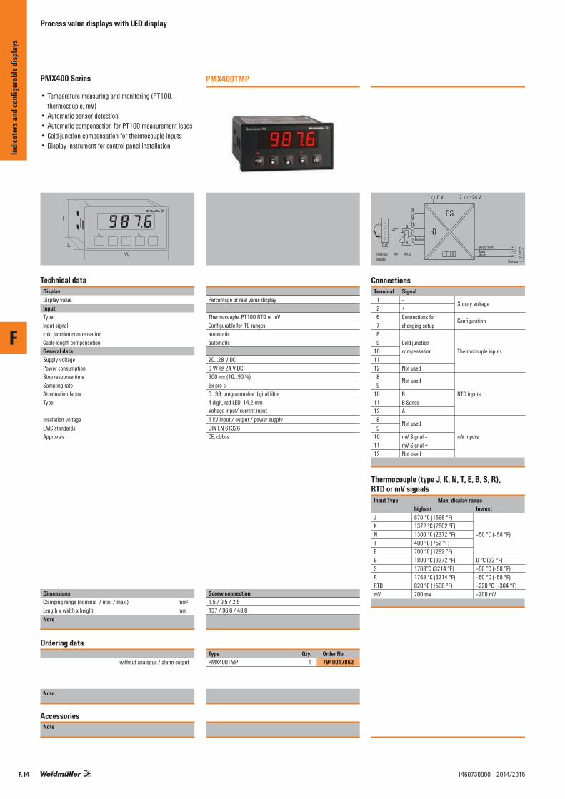
F
F.14 1460730000 – 2014/2015
PMX400 Series
• Temperature measuring and monitoring (PT100, thermocouple, mV)
• Automatic sensor detection• Automatic compensation for PT100 measurement leads• Cold-junction compensation for thermocouple inputs• Display instrument for control panel installation
H
W
L
Technical dataDisplayDisplay valueInputTypeInput signalcold junction compensationCable-length compensationGeneral dataSupply voltagePower consumptionStep response timeSampling rateAttenuation factorType
Insulation voltageEMC standardsApprovals
DimensionsClamping range (nominal / min. / max.) mm²Length x width x height mmNote
Ordering data
without analogue / alarm output
Note
AccessoriesNote
PMX400TMP
Percentage or real value display
Thermocouple, PT100 RTD or mVConfigurable for 10 rangesautomaticautomatic
20...28 V DC6 W @ 24 V DC300 ms (10...90 %)5x pro s0...99, programmable digital filter4-digit, red LED, 14.2 mm Voltage input/ current input1 kV input / output / power supplyDIN EN 61326CE; cULus
Screw connection1.5 / 0.5 / 2.5137 / 96.6 / 48.8
Type Qty. Order No.PMX400TMP 1 7940017862
Thermocouple (type J, K, N, T, E, B, S, R), RTD or mV signals
PS
0 V +24 V1 2
8
Vout/Iout
Option
+––
IoutVout
235
9
10
11
12
B
ABsense
+
–
CJC
mV RTDSThermo-couple
J
ConnectionsTerminal Signal 1 – Supply voltage 2 + 6 Connections for Configuration 7 changing setup 8 9 Cold-junction 10 compensation Thermocouple inputs11 12 Not used 8 Not used 9 10 B RTD inputs11 B-Sense 12 A 8 Not used 9 10 mV Signal – mV inputs11 mV Signal + 12 Not used
Input Type Max. display range highest lowestJ 870 °C (1598 °F) K 1372 °C (2502 °F) N 1300 °C (2372 °F) –50 °C (–58 °F)T 400 °C (752 °F) E 700 °C (1292 °F) B 1800 °C (3272 °F) 0 °C (32 °F)S 1768°C (3214 °F) –50 °C (–58 °F)R 1768 °C (3214 °F) –50 °C (–58 °F)RTD 820 °C (1508 °F) –220 °C (–364 °F)mV 200 mV –200 mV
Indic
ator
s and
conf
igura
ble di
splay
sProcess value displays with LED display

F
F.151460730000 – 2014/2015
PMX400 Series
• Frequency measuring and monitoring (3-wire NPN/PNP, NPN/PNP Open Collector, TTL logic, solid-state switch, potential-free contacts)
• Integrated power supply for external sensors• Two outputs for monitoring limit-values • De-bouncing of switched input pulses
H
W
L
Technical dataDisplayDisplay valueInputTypeInput signalSensor supplyInput voltageAlarm (channel 1/2)Type
Rated switching currentRated switching voltageAlarm (channel 3/4)Type
Switching currentGeneral dataSupply voltagePower consumptionStep response timeAttenuation factorType Insulation voltageEMC standardsApprovals
DimensionsClamping range (nominal / min. / max.) mm²Length x width x height mmNote
Ordering data
without analogue / alarm outputwith analogue/alarm output
Note
AccessoriesNote
PMX400HZX
Percentage or real value display
Adjustable frequenciesConfigurable for 4 ranges12 V DC to 25 mA
Channel 1/2: transistor output channel 3/4: relay contact (CO)200 mA50 V DC
Channel 1/2: transistor output channel 3/4: relay contact (CO)Channel 3/4: 3 A @ 240 V AC / 24 V DC (resistive load)
24 V DC ± 10 %6 W @ 24 V DC< 220 ms (10...90 %)0...99, programmable digital filterRO/AO version with 1 analogue output and 2 alarm outputs1 kV input / output / power supplyDIN EN 61326CE; cULus
Screw connection1.5 / 0.5 / 2.5137 / 96.6 / 48.8
Type Qty. Order No.PMX400HZX 1 7940015595PMX400HZX RO/AO 1 7940011979
Input Offset Resolutionrange0...9.999 Hz 0...9.998 Hz 0.001 Hz 0...99.99 Hz 0...99.98 Hz 0.01 Hz 0...999.9 Hz 0...999.8 Hz 0.1 Hz0...9999 Hz 0...9998 Hz 1 Hz
PS
0 V
f
+24 V1 2
Pull up/down9
10
11
12
+ V/Ifin
0 V
+12 V
3Vout/Iout (opt)
0 VAlarm Ch 1
Ch 3*Ch 4*
*Optional
NCCommon
NCCommon
NO
NO
+
456
131415161718
Alarm Ch 2 7com
ConnectionsTerminal Signal 1 – Supply voltage 2 + 3 Signal + Analogue output 4 Signal – (only for AO version) 5 Common Alarm channel 1 and 2 6 Channel 1 (only for 4RO version) 7 Channel 2 8 Configuration 9 Pull up / pull down Inputs/Configuration10 Signal – (Set-up: 12/8 connection)11 Signal + 12 12 V DC 13 Common Alarm channel 314 NC contact (only for 4RO version)15 NO contacts 16 Common Alarm channel 417 NC contact (only for 4RO version)18 NO contacts
Indic
ator
s and
conf
igura
ble di
splay
s
Process value displays with LED display
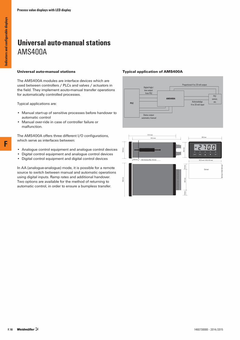
Process value displays with LED display
Universal auto-manual stations AMS400A
Universal auto-manual stations
The AMS400A modules are interface devices which are used between controllers / PLCs and valves / actuators in the field. They implement aouto-manual transfer operations for automatically controlled processes.
Typical applications are:
• Manual start-up of sensitive processes before handover to automatic control
• Manual over-ride in case of controller failure or malfunction.
The AMS400A offers three different I/O configurations, which serve as interfaces between:
• Analogue control equipment and analogue control devices• Digital control equipment and analogue control devices• Digital control equipment and digital control devices
In AA (analogue-analogue) mode, it is possible for a remote source to switch between manual and automatic operations using digital inputs. Ramp rates and additional handover. Two options are available for the method of returning to automatic control, in order to ensure a bumpless transfer.
Typical application of AMS400A
Digital high/low output
from PLC
Status output automatic/manual
PLC
AMS400A
Proportional 4 to 20 mA output
Acknowledge 4 to 20 mA input
PLC sensor,
etc.
96.6 mm137.0 mm
Wall thickness Max 18.0 mm
48.8
mm
44.4
mm
96.6
mm
60.0
mm
143.5 mm
15.5
mm15
.5mm
MANAUTO ENT
18.0 mm 92.0 mm (+0.8/-0.0 mm)
Cut-out
45.0
mm
(+0.
6/-0.
0 mm
)
F
Indic
ator
s and
confi
gura
ble di
splay
s
F.16 1460730000 – 2014/2015

F
F.171460730000 – 2014/2015
AMS400A
Universal interface device• Display instrument for control panel installation• 1/8 DIN standard front• IP 65 fully insulated• Pluggable connection terminals
H
W
L
Technical dataDisplayType Display valueDisplay rangeInputType
Input signalInput resistanceSampling ratePulse width, min.OutputType Output analogueOutput currentOutput voltageLast resistor, max.Alarm (RO version only)Type Number of channelsType of contactRatingsGeneral dataSupply voltagePower consumptionAccuracyRepeat accuracyTemperature coefficientCut-off frequency (-3 dB)Step response timeImpulse withstand voltageInsulation voltageAmbient temperature / Storage temperatureEMC standardsApprovals
DimensionsClamping range (nominal / min. / max.) mm²Length x width x height mmNote
Ordering data
Analogue output
Note
AccessoriesNote
AMS400AUniversal interface device
4-digit, red LED, 14.2 mmPercentage or real value display-9999...9999
Current input or digital input (pulse-controlled or no-voltage contact)
0...24 mA / 0...12 V DC50 Ω (mA) / 10 MΩ (V)5x per sec. (current input)64 ms (digital input)
Analogue and digital outputCurrent or voltage, configured with jumper0...24 mA0...18 V900 Ω @ 20 mA
Status relay2CO contact3 A @ 240 V AC or 5 A @ 24 V DC
24 V DC ± 10 %, other voltages on request6 W @ 24 V DCTypically ± 0.1 % of signal range± 0.02 % of signal range≤ 0.02 % / °C5 Hz300 ms (10...90 %)4 kV (1.2/50 µs)1 kV input / output / power supply0 °C...+60 °C / -25 °C...+70 °CDIN EN 61326CE; cULus
Screw connection1.5 / 0.5 / 2.5137 / 96.6 / 48.8
Type Qty. Order No.AMS400A 4-20mA/AO 1 7940011895
PS
0 V
V/I V/I
+24 V1 2
Vin/Iin0 VCommonSignal amplifierSignal amplifier
1112
89
10
3Vout/Iout
0 V
Automatic / manual
456
0 V
Change operating mode 7
ConnectionsTerminal Signal1 –2 + Supply voltage
3 Signal +4 Signal – Analogue Output
5 Signal – 0 V6 Automatic / manual Status outputs7 Change operating mode8 Common9 Signal amplifier Digital inputs10 Signal reduction11 Signal +12 Signal – Analogue inputs
Indic
ator
s and
conf
igura
ble di
splay
s
Process value displays with LED display
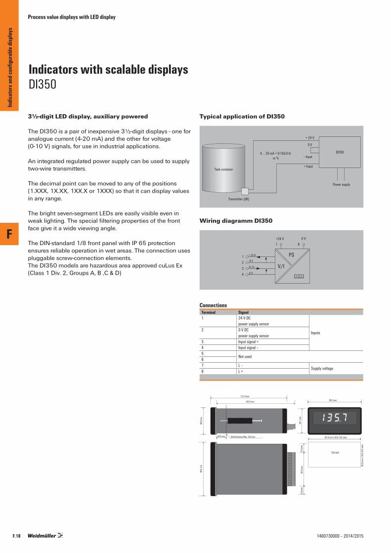
Process value displays with LED display
Indicators with scalable displays DI350
3½-digit LED display, auxiliary powered
The DI350 is a pair of inexpensive 3½-digit displays - one for analogue current (4-20 mA) and the other for voltage (0-10 V) signals, for use in industrial applications.
An integrated regulated power supply can be used to supply two-wire transmitters.
The decimal point can be moved to any of the positions (1.XXX, 1X.XX, 1XX.X or 1XXX) so that it can display values in any range.
The bright seven-segment LEDs are easily visible even in weak lighting. The special filtering properties of the front face give it a wide viewing angle.
The DIN-standard 1/8 front panel with IP 65 protection ensures reliable operation in wet areas. The connection uses pluggable screw-connection elements. The DI350 models are hazardous area approved cuLus Ex (Class 1 Div. 2, Groups A, B ,C & D)
Typical application of DI350
Power supply
+ 24 V
0 V
– Input
+ Input
4 ... 20 mA = 0-150.0 kl or %
Transmitter [dB]
Tank container
DI350
Wiring diagramm DI350
PS
0 V+24 V7 8
V/I
+ 24 V1234
0 V
Vin/Iin
0 V
ConnectionsTerminal Signal1 24 V DC
power supply sensor
Inputs2 0 V DC
power supply sensor3 Input signal +4 Input signal –5
Not used67 L –
Supply voltage8 L +
96.6 mm137.0 mm
Wall thickness Max 18.0 mm
48.8
mm
44.7
mm
96.6
mm
60.0
mm
143.5 mm
15.5
mm15
.5mm
18.0 mm 92.0 mm (+0.8/-0.0 mm)
Cut-out
45.0
mm
(+0.
6/-0.
0 mm
)
F
Indic
ator
s and
confi
gura
ble di
splay
s
F.18 1460730000 – 2014/2015

F
F.191460730000 – 2014/2015
DI350
• Display instrument for control panel installation• 1/8 DIN standard front• 3½ digits• IP 65 fully insulated• Pluggable connection terminals
H
W
L
Technical dataInputInput signalInput resistanceSupply voltageDisplayType Display rangeDisplay valueFormatSettingsOffsetRange of adjustmentGeneral dataSupply voltagePower consumptionLinearityHumidityTemperature coefficientLong-term driftStep response timeImpulse withstand voltageInsulation voltageAmbient temperature / Storage temperatureEMC standardsApprovals
DimensionsClamping range (nominal / min. / max.) mm²Length x width x height mmNote
Ordering data
Voltage input/Current input
Note
AccessoriesNote
DI350Display with voltage input
• Integrated power supply for external sensors• Linearity with an accuracy of 0.1 % of the measuring
range• Complete galvanic isolation
0...10 V1 MΩ24 V DC (up to 25 mA)
3.5 digits, red LED, 14.2 mm-1999…1999Percentage or real value display1-line / decimal point: 1.000, 100.0, 10.00
± 1200 digital steps20 - 2100 digital steps
24 V DC (12...35 V DC)6 W @ 24 V DC< 0.1 % typ.0...90 % (no condensation)≤ 0.02 % / °C0.1 % / 10.000 h200 ms (10...90 %)4 kV (1.2/50 µs)1 kV input / power supply0 °C...+60 °C / -25 °C...+70 °CDIN EN 61326CE; cULus; cULusEX
Screw connection1.5 / 0.5 / 2.5137 / 96.6 / 48.8
Type Qty. Order No.DI350 0-10V/0-100.0 1 7940011570
DI350Display with current input
• Integrated power supply for external sensors• Linearity with an accuracy of 0.1 % of the measuring
range• Complete galvanic isolation
4...20 mA22 Ω24 V DC (up to 25 mA)
3.5 digits, red LED, 14.2 mm-1999…1999Percentage or real value display1-line / decimal point: 1.000, 100.0, 10.00
± 1200 digital steps20 - 2100 digital steps
24 V DC (12...35 V DC)6 W @ 24 V DC< 0.1 % typ.0...90 % (no condensation)≤ 0.02 % / °C0.1 % / 10.000 h200 ms (10...90 %)4 kV (1.2/50 µs)1 kV input / power supply0 °C...+60 °C / -25 °C...+70 °CDIN EN 61326CE; cULus; cULusEX
Screw connection1.5 / 0.5 / 2.5137 / 96.6 / 48.8Screw connection
Type Qty. Order No.DI350 4-20mA/0-100.0 1 7940010185
Indic
ator
s and
conf
igura
ble di
splay
s
Process value displays with LED display

Process value displays with LCD display
Indicators and configurable displays LPD350
3½-digit digital display, loop powered
The LPD350 is a compact, cost effective, 3½ digit digital indicator designed specifically for current loop signals. The decimal point can be moved to any position (1.XXX, 1X.XX, 1XX.X or 1XXX) so that it can display values in a range of ±1999.
The LPD350 uses a liquid crystal display which can be read even under poor lighting conditions.
No additional wiring is needed for a power supply. The user can simply break the loop and connect to the LPD350.
The housing has a DIN-standard 1/8 front panel with IP 65 protection. The connection uses pluggable screw-connection elements.
Technical features:
• Large 3½-digit digital LCD display • 4...20 mA input• Loop-powered two-wire design (125 Ω loop load)• Direct or reverse-action display• Linearity is ± 0.1 % of the corresponding signal range• DIN-standard front-panel with IP 65 protection • Pluggable screw-connection mechanism• Hazardous area approved cuLus Ex (Class 1 Div. 2,
Groups A, B, C & D)
Typical application of LPD350
LPD350
Temperatureprobe
Input4 ... 20 mA
24 V DC
WAVEPakIsolator
Power supply
Output4 ... 20 mA
PLC
75 mm
Wall thickness Max 18.0 mm
48.8
mm
96.6
mm
91 m
m
65 mm
18.0 mm
92.0 mm (+0.8/-0.0 mm)
Cut-out
45.0
mm
(+0.
6/-0.
0 mm
)
96.6 mm
44.7
mm
F
Indic
ator
s and
confi
gura
ble di
splay
s
F.20 1460730000 – 2014/2015

F
F.211460730000 – 2014/2015
LPD350
• Display instrument for control panel installation• 1/8 DIN standard front• 3½ digits• IP 65 fully insulated• Pluggable connection terminals
H
W
L
Technical dataInputInput currentVoltage dropInput resistanceInput current, max.Input current, max. when wired incorrectlyDisplayType Display rangeFormatSettingsOffsetRange of adjustmentGeneral dataAccuracyRepeat accuracyTemperature coefficient
Step response timeSampling rateAmbient temperature / Storage temperatureEMC standardsApprovals
DimensionsClamping range (nominal / min. / max.) mm²Length x width x height mmNote
Ordering data
Current input
Note
AccessoriesNote
LPD350Current input
4...20 mA2.5 V @ 20 mA125 Ω100 mA constant / 500 mA for 10 s500 mA constant
3.5 digits, black LCD with clear background, 12.7 mm-1999…1999Single-line
± 1999 digital steps in two switching ranges0...3998 in three switching ranges
± 0.05 % from signal range ± 1 digital step± 0.05 % of signal rangeOffset ± 0.1 digital steps per °C adjustment range ± 0.1 digital steps per °C200 ms (10...90 %)2,5 x pro s-20 °C...+70 °C / -25 °C...+85 °CDIN EN 61326CE; cULus; cULusEX; GOSTME25
Screw connection1.5 / 0.5 / 2.575 / 96.6 / 48.8
Type Qty. Order No.LPD350 4-20mA/0-100.0 1 7940010163
ConnectionsTerminal Signal1 Input –2 Input +
I2
1
Iin
0 V
Indic
ator
s and
conf
igura
ble di
splay
s
Process value displays with LCD display

Process value displays with LCD display
Configurable IP 67 field-mounted LCD indicator LPD405F
4½-digit display, loop powered
The display is loop powered by the 4...20 mA current loop with no external supply required. The twenty-mm LCD displays can be read even under poor light conditions.
A sheet of perforated self-adhesive labels is included. They include standard engineering units and can be used for all label needs.
The electronic subassembly is housed in a rugged, glass reinforced polycarbonate, IP 67 case. This housing is suitable for any industrial environment.
Optionally available is a pipe mounting bracket which can be used for horizontal and vertical mounting.
Technical features:
• Big 20 mm LCD dispaly• 4...20 mA inputs (two-wire loop-powered)• Integratedsignallinearisation(√,x3/2, x5/2oruser-defined)• Min./max. value display feature• IP 67 protection• Pipe mount bracket option• Hazardous area approved cULus Ex (Class 1 Div. 2,
Groups A, B, C & D)
Typical application of LPD450F
Open liquid flow,container, tube lines
Measurementprobe
(hall sensor)
4...20 mA current loop/2-wire
LPD450F display andflow measurer
PLC controllevel /enterprise
managementlevel
24 V DC
P
80 mm
70 mm
65 mm
1 8 m m
Mounting holes 120 mm
Mounting holes 60 mm
140 mm
F
Indic
ator
s and
confi
gura
ble di
splay
s
F.22 1327190000 – 2012/2013
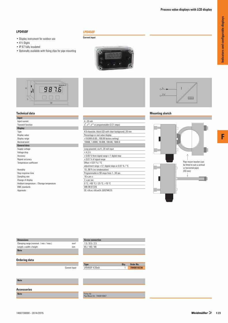
F
F.231460730000 – 2014/2015
LPD450F
• Display instrument for outdoor use• 4½ Digits• IP 67 fully insulated• Optionally available with fixing clips for pipe mounting
H
W
L
Technical dataInputInput currentTransmit functionDisplayType Display valueDisplay rangeDecimal pointGeneral dataSupply voltageVoltage dropAccuracyRepeat accuracyTemperature coefficient
HumidityStep response timeSampling rateChange of displayAmbient temperature / Storage temperatureEMC standardsApprovals
DimensionsClamping range (nominal / min. / max.) mm²Length x width x height mmNote
Ordering data
Current input
Note
AccessoriesNote
LPD450FCurrent input
4...20 mA√, x3/2, x5/2 or programmable (2-21 steps)
4.5-character, black LCD with clear background, 20 mmPercentage or real value display±19.999 (0.00…100.00 factory setting)18888, 1.8888, 18.888, 188.88, 1888.8
Loop powered, via 4...20 mA input< 4.3 V± 0.05 % from signal range ± 1 digital step± 0.01 % of signal rangeOffset ± 0.01 % / °C adjustment range ± 0.1 digital steps or 0.01 % / °C10...90 % (no condensation)Programmable in 99 steps from 1...30 sec.16 x pro s2 x per sec.0 °C...+60 °C / -25 °C...+70 °CDIN EN 61326CE; cULus; cULusEX; GOSTME25
Screw connection1.5 / 0.5 / 2.565 / 140 / 80
Type Qty. Order No.LPD450F 4-20mA 1 7940010236
Fixing clipPipe Mount Kit - 7940010667
IIin
0 V
Indic
ator
s and
conf
igura
ble di
splay
s
Process value displays with LCD display

F
F.24 1460730000 – 2014/2015
Indic
ator
s and
conf
igura
ble di
splay
s
Contents
Accessories Analogue Signal Conditioning Accessories Analogue Signal Conditioning – Overview G.2
USB configuration adapter G.4
CH20M DIN rail bus G.6
ACT20 power-feed modules for rail bus G.8
ACT20X/ACT20C/ACT20P – Accessories G.10
MICROSERIES/ACT20M – Accessories G.11
MCZ/WAVE – Accessories G.12
Calibrators G.14
Accessories Analogue Signal Conditioning
Acce
ssor
ies
Analo
gue S
ignal
Cond
ition
ing
G.1
G
1460730000 – 2014/2015

Accessories Analogue Signal Conditioning – Overview
Configure, calibrate, mount, mark, (cross-) connect.
A comprehensive line of accessories is available for the analogue signal converter product family. The line includes configuration adapters for software-programmable products, interface modules, calibrators and mounting accessories (such as cross-connectors, end plates and terminal connectors) – all naturally in the top Weidmüller quality that you‘ve come to expect.
Accessories Analogue Signal Conditioning
Acce
ssor
ies
Analo
gue S
ignal
Cond
ition
ing
G.2
G
1460730000 – 2014/2015

Accessories Analogue Signal Conditioning – Overview
USB configuration interface
CH20M DIN rail bus
Power supply modules for rail bus
ACT20X/ACT20P – Accessories
MICROSERIES ACT20M Accessories
MCZ/Wave Accessories
Calibrators
Acce
ssor
ies
Analo
gue S
ignal
Cond
ition
ing
G.3
G
1460730000 – 2014/2015

G
G.4 1460730000 – 2014/2015
CBX200
• Interface converter for configuration, with galvanic isolation
• USB port for connecting to PC• TX and RX status displays• WI-Manager and TTA Set configuration software
programs, download at www.weidmueller.com
Technical dataInputTypeInput currentInput resistanceInput voltageOutputType Output voltageOutput currentLevel on interfacesBaud rateActivation signalInsulation coordinationInsulation voltage
Note
Ordering data
Note
AccessoriesNote
CBX200 USB
USB 2.0 (USB type A plug)≤ 100 mA22 kΩ1.6 … 5.6 V
RS232 (4-pole 2.5-mm jack plug)3.3 V regulated3 A1.8…5.6 V (automatically adapted)≤ 115 kBd9…15 V typ. 12 V / 4 mA
2.5 kV (input / output)
Type Qty. Order No.CBX200 USB 1 8978580000
Table for selecting a configuration adapter
Pin assignments for jack plug
Product CBX100 CBX200ACT20X XWAVE TTA X XITX+ X
DTR* Vcc 0 3,3 V 1 0 V
The CBX200 USB is a USB2.0/RS232-interface converter with galvanic isolation. It has additional functionality for controlling and supplying the connected RS232 device. The CBX200 USB makes it possible to configure the intrinsically safe ACT20X product line and the WAVE TTA signal converter.The CBX200 USB is not compatible with the CBX100 USB.
Installation notesThe power supply to the device comes from the USB portvia a USB type-A plug. The output-side of the RS232 interfaceuses a four-pole 2.5-mm jack plug to connect. This jack plugis also capable of activating the RS232 interface when neededwith a 12-V control voltage. With the assistance of the DTM,the USB interface is diverted to a COM interface. The RS232interface can be activated with an RTS signal(RTS = 1 output activated) via the diverted COM interface.The jack plug is also capable of supplying the RS232 nodewith a regulated voltage of 3.3 V at 4 mA current.The DTR signal (DTR = 0 supply activated) is used for control. It is also possible to query the status using the DSR signal (DSR = 0 output activated).
The "WI-Manager" software, the "TTA Set" and the DTM library can all be downloaded free of charge fromwww.weidmueller.com.
GND RxD TxD
Vcc/control input
Control input RTS* RS232 interface 12 V 1 active 12 V 0 active 0 V 1 active 0 V 0 not active
* RTS and DTR are internal control signals
Acce
ssor
ies
Analo
gue s
ignal
proc
essin
gUSB configuration adapter
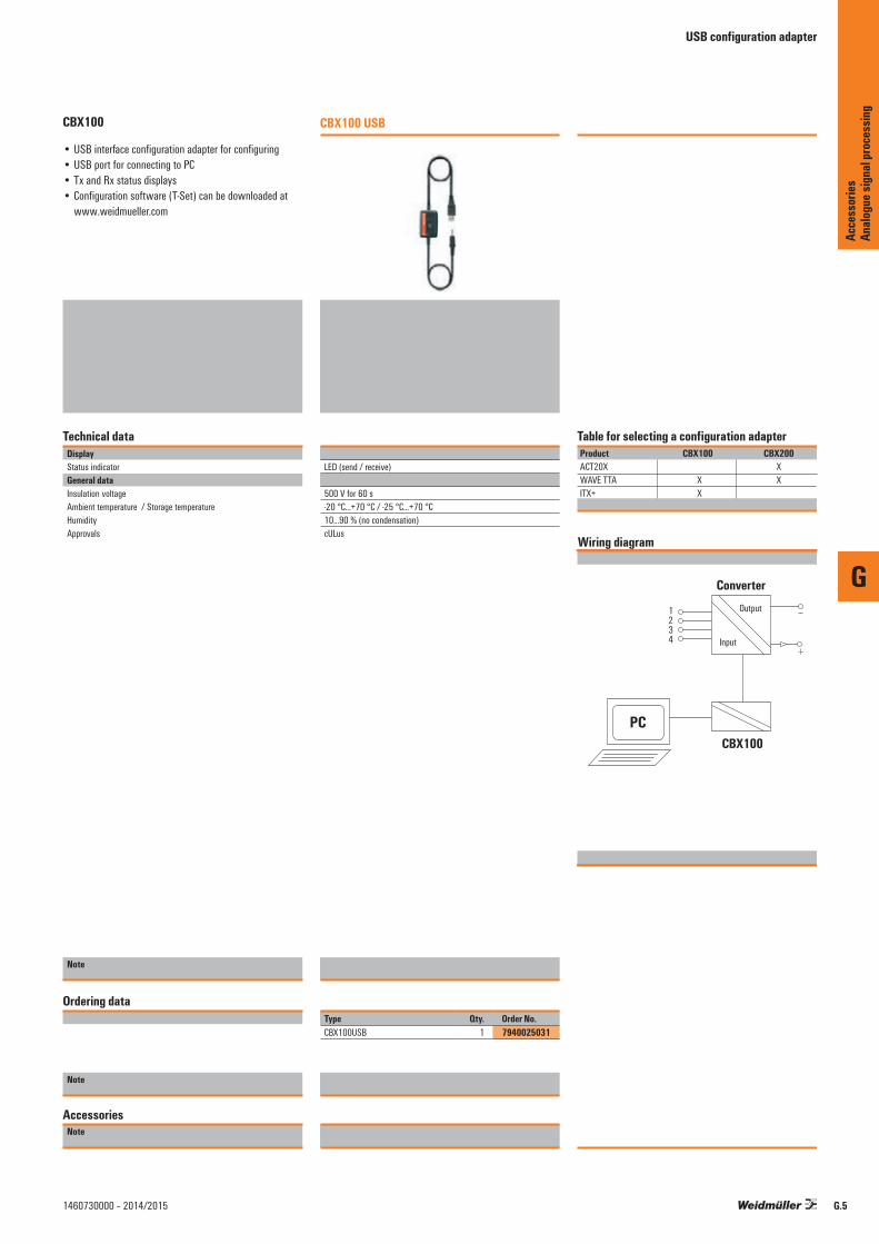
G
G.51460730000 – 2014/2015
CBX100
• USB interface configuration adapter for configuring• USB port for connecting to PC• Tx and Rx status displays• Configuration software (T-Set) can be downloaded at
www.weidmueller.com
Technical dataDisplayStatus indicatorGeneral dataInsulation voltageAmbient temperature / Storage temperatureHumidityApprovals
Note
Ordering data
Note
AccessoriesNote
CBX100 USB
LED (send / receive)
500 V for 60 s-20 °C...+70 °C / -25 °C...+70 °C10...90 % (no condensation)cULus
Type Qty. Order No.CBX100USB 1 7940025031
Wiring diagram
1234 Input
CBX100
ConverterOutput
PC
Table for selecting a configuration adapterProduct CBX100 CBX200ACT20X XWAVE TTA X XITX+ X
Acce
ssor
ies
Analo
gue s
ignal
proc
essin
g
USB configuration adapter

G
CH20M DIN rail bus
CH20M DIN rail bus
Quick and safe power supply through the mounting rail.
This customer-friendly infrastructure solution brings power, signals and data to the rail in a quick and reliable manner. The DIN rail bus can replace the tedious individual wiring process with a flexible and uninterrupted system solution. As a result, the wiring overhead and the error rate are both reduced. The uninterrupted system bus is securely integrated within the 35 mm standard mounting rail. Whether 7.5 mm or 15 mm high, the custom-fit rail profiles are easy to install on all TS 35 standard rails in accordance with DIN EN 60715.
The resistant gold-plated contacts ensure a permanent and reliable contact. The ACT20M modules are simply snapped onto the mounting rail and are automatically in contact with the DIN rail bus.
The supply to the 24 V power supply can be from either one of the modules (up to 400 mA) or a separate power supply terminal (up to 4 A). This is sufficient for up to 120 modules. The ACT20-Feed-In-Basic provides a simple and compact (6 mm width) power supply terminal solution. The ACT20-Feed-In-Pro is a more powerful 22.5 mm wide solution. This makes a backup power supply that includes error messaging possible.
Acce
ssor
ies
Analo
gue S
ignal
Cond
ition
ing
G.6 1460730000 – 2014/2015

G
CH20M DIN rail bus
Rail bus accessories
CH20M BUS 4.50/05 AU/1000Bus PCB
• Bus circuit board for use on TS 35 x 7.5 and TS 35 x 15
• Length: 250, 500 or 750 mm• Five conductor paths, gold-plated• Electrical rating: 63 V AC, 5 A/conductor path
Ordering dataType Qty. Order No.CH20M BUS 4.50/05 AU/250 10 1248220000CH20M BUS 4.50/05 AU/500 10 1248230000 CH20M BUS 4.50/05 AU/750 5 1248240000
CH20M BUS-PROFIL TS35x7.5/1000Support section for bus circuit board
• Support section for TS 35 x 7.5• Length: 250, 500 or 750 mm
Ordering dataType Qty. Order No.CH20M BUS-PROFIL TS35x7.5/250 10 1248150000CH20M BUS-PROFIL TS35x7.5/500 10 1248160000 CH20M BUS-PROFIL TS35x7.5/750 5 1248170000
CH20M BUS-PROFIL TS35x15/1000Support section for bus circuit board
• Support section for TS 35 x 15• Length: 250, 500 or 750 mm
Ordering dataType Qty. Order No.CH20M BUS-PROFIL TS35x15/250 5 1248180000CH20M BUS-PROFIL TS35x15/500 5 1248190000 CH20M BUS-PROFIL TS35x15/750 5 1248210000
CH20M BUS-AP RE TS35x7.5 & 15End plate
• End plate for DIN rail bus• Fits on TS 35 x 7.5 and TS 35 x 15• right
Ordering dataType Qty. Order No.CH20M BUS-AP RE TS35x7.5 & 15 50 1193170000
CH20M BUS-ADP TS35/1000Cover plate
• Cover plate for DIN rail bus• Length: 250, 500 or 750 mm
Ordering dataType Qty. Order No.CH20M BUS-ADP TS35/250 10 1248250000CH20M BUS-ADP TS35/500 10 1248260000CH20M BUS-ADP TS35/750 5 1248270000
SET CH20M BUS 250MM TS 35X15Set
• SET consists of one each of CH20M BUS 4.50/05 AU/250 CH20M BUS-ADP TS 35/250 CH20M BUS-AP LI TS 35X7.5 & 15 CH20M BUS-AP RE TS 35X7.5 & 15 CH20M BUS-PROFIL TS 35X15/250
Ordering dataType Qty. Order No.SET CH20M BUS 250MM TS 35X15 1 1335150000
CH20M BUS-AP LI TS35x7.5 & 15End plate
• End plate for DIN rail bus• Fits on TS 35 x 7.5 and TS 35 x 15• left
Ordering dataType Qty. Order No.CH20M BUS-AP LI TS35x7.5 & 15 50 1193160000
SET CH20M BUS 250MM TS 35X7.5Set
• SET consists of one each of CH20M BUS 4.50/05 AU/250 CH20M BUS-ADP TS 35/250 CH20M BUS-AP LI TS 35X7.5 & 15 CH20M BUS-AP RE TS 35X7.5 & 15 CH20M BUS-PROFIL TS 35X7.5/250
Ordering dataType Qty. Order No.SET CH20M BUS 250MM TS 35X7.5 1 1335140000
TS 35x7.5 / TS 35x15DIN rail
• DIN rail with slot• Passivated galvanised steel
Ordering dataType Qty. Order No.TS 35X7.5/LL 1M/ST/ZN 10 0514510000TS 35X15/LL 1M/ST/ZN 10 0236510000
Acce
ssor
ies
Analo
gue S
ignal
Cond
ition
ing
G.71460730000 – 2014/2015

G
ACT20 power-feed modules for rail bus
Power-feed module for the CH20M DIN rail bus
4 A supply with backup supply and error analysis
The power-feed unit ACT20-FEED-IN-PRO-S supplies the devices on the CH20M DIN rail bus with 24 V DC. At the same time, the FEED-IN device reads the group error contact – optionally provided by the installed devices – from the CH20M rail bus and sends a message through the status relay to the external controller. Optionally, two power supplies can be connected for the primary and secondary supplies (backup). An installation in Zone 2 / Division 2 is also possible. Three LEDs show the status of the power supply and the error status.
The FEED-IN-PRO can supply a maximum of 4 A to feed up to 120 devices mounted on a CH20M rail bus. Quick identification of errors on the DIN rail bus is through the internal status relay. The FEED-IN-PRO device immediately recognises and displays when a power supply has failed. The supply is then switched automatically to the redundant power supply.
Weidmüller offers a compact and narrow 6 mm feed-in module as an alternative. This wires the terminal level directly to the DIN rail bus. Up to 80 modules can be fed with a maximum available current of 2.5 A.
Acce
ssor
ies
Analo
gue S
ignal
Cond
ition
ing
G.8 1460730000 – 2014/2015

G
G.91460730000 – 2014/2015
ACT20 power-feed module
• Distributes the supply onto the busbar• Compatible with Weidmüller CH20 DIN rail bus• Optional connection for backup supply• Approved for use in Ex-Zone 2 /Div. 2• Monitoring of the supply voltage• Alarm alerts via the status relay
Technical dataInputSupply voltageInput current
Trigger level for the power supplyOutput, power supplyOutput voltageOutput powerOutput currentOutput, status relay in safe zoneMax. switching voltage, AC / Max. switching voltage, DCContinuous currentAC power, max.General dataDegree of efficiencyAmbient temperature Power consumptionProtection degreeWeightHumidityApprovals
DimensionsClamping range (nominal / min. / max.) mm²Length x width x height mmNote
Ordering data
Screw connection
Note
AccessoriesNote
ACT20-Feed-In-PRO-S
51
52
53
54
Power supply, 0 V
Power supply,+24V
Backup, 0 V
Backup, +24 V
NC
Status relay, N.C.
Status relay, shared
Status relay, N.O.
44
43
42
41
8182838485N
C
NC 0 V
+24
V
Sta
tus
Alarm
21.6...26.4 V DCMax. 4 A 21.6...26.4 V DC Fault < 21 V DC
Input voltage -0.5 V DC / 4 A96 WMax. 4 A
250 V / 30 V2 A AC / DC 500 VA / 60 W
0,976
< 2 W IP 2014095 %, no condensationDEKRAATEX; DETNORVER; FMEX; GOSTME25; IECEXDEK
Screw connection2.5 / 0.5 / 2.5119.2 / 22.5 / 113.6
Type Qty. Order No.ACT20-FEED-IN-PRO-S 1 8965500000
DIN mounting rail, see Accessories
ACT20-Feed-In-BASIC-S
Power supply, +24 V
Power supply, 0 V
NC
NC
NC 0 V
+24
V
21.6...26.4 V DC0.5...2.5 A DC
Corresponds to the input voltage
Equivalent to input current
250 V / 30 V
100 %-20 °C...+60 °C
IP 207095 %, no condensationcULus; DETNORVER; FMEX; GL; GOSTME25; IECEXKEM; KEMAATEX
Screw connection2.5 / 0.5 / 2.5114.3 / 6.1 / 112.5
Type Qty. Order No.ACT20-FEED-IN-BASIC-S 1 1282490000
DIN mounting rail, see Accessories
Acce
ssor
ies
Analo
gue s
ignal
proc
essin
g
ACT20 power-feed modules for rail bus
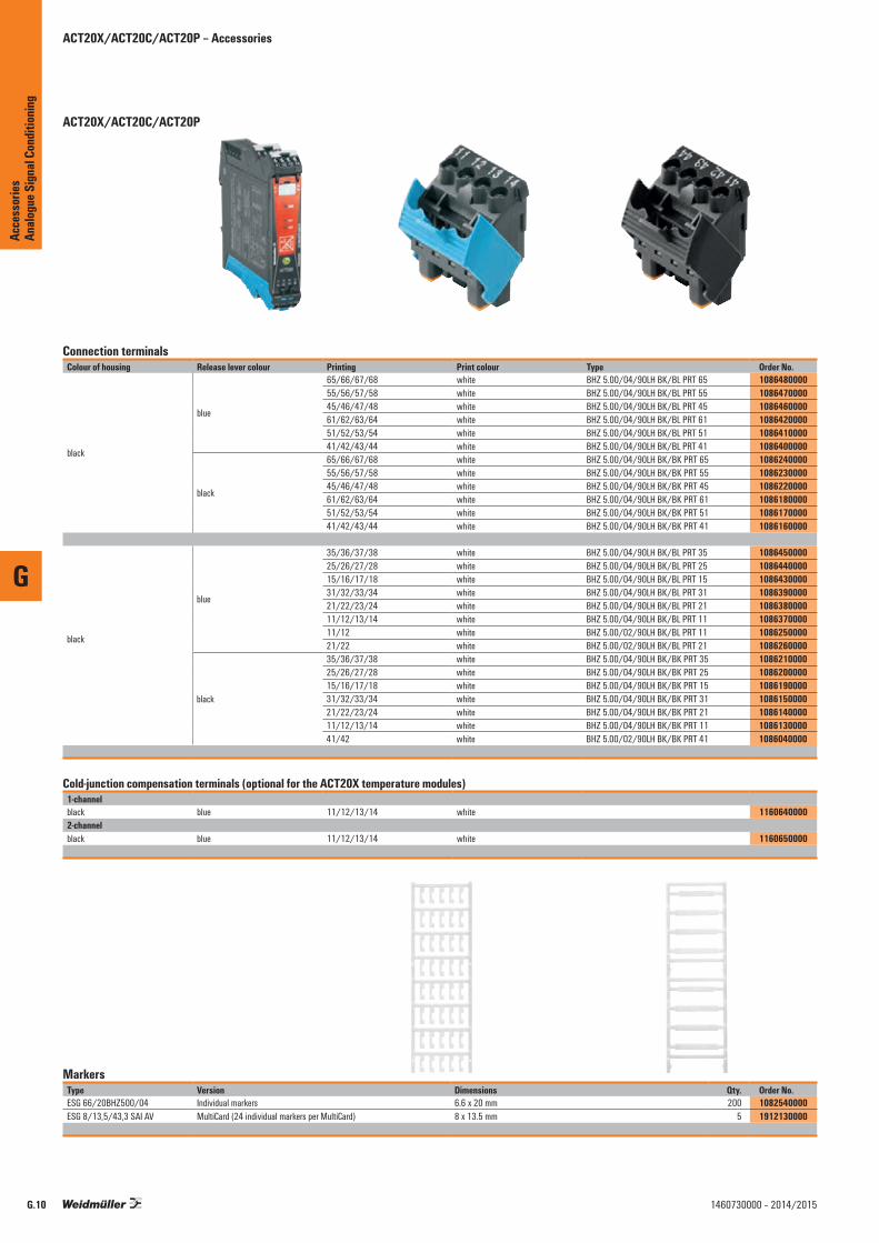
G
ACT20X/ACT20C/ACT20P – Accessories
ACT20X/ACT20C/ACT20P
Connection terminalsColour of housing Release lever colour Printing Print colour Type Order No.
black
blue
65/66/67/68 white BHZ 5.00/04/90LH BK/BL PRT 65 108648000055/56/57/58 white BHZ 5.00/04/90LH BK/BL PRT 55 108647000045/46/47/48 white BHZ 5.00/04/90LH BK/BL PRT 45 108646000061/62/63/64 white BHZ 5.00/04/90LH BK/BL PRT 61 108642000051/52/53/54 white BHZ 5.00/04/90LH BK/BL PRT 51 108641000041/42/43/44 white BHZ 5.00/04/90LH BK/BL PRT 41 1086400000
black
65/66/67/68 white BHZ 5.00/04/90LH BK/BK PRT 65 108624000055/56/57/58 white BHZ 5.00/04/90LH BK/BK PRT 55 108623000045/46/47/48 white BHZ 5.00/04/90LH BK/BK PRT 45 108622000061/62/63/64 white BHZ 5.00/04/90LH BK/BK PRT 61 108618000051/52/53/54 white BHZ 5.00/04/90LH BK/BK PRT 51 108617000041/42/43/44 white BHZ 5.00/04/90LH BK/BK PRT 41 1086160000
black
blue
35/36/37/38 white BHZ 5.00/04/90LH BK/BL PRT 35 108645000025/26/27/28 white BHZ 5.00/04/90LH BK/BL PRT 25 108644000015/16/17/18 white BHZ 5.00/04/90LH BK/BL PRT 15 108643000031/32/33/34 white BHZ 5.00/04/90LH BK/BL PRT 31 108639000021/22/23/24 white BHZ 5.00/04/90LH BK/BL PRT 21 108638000011/12/13/14 white BHZ 5.00/04/90LH BK/BL PRT 11 108637000011/12 white BHZ 5.00/02/90LH BK/BL PRT 11 108625000021/22 white BHZ 5.00/02/90LH BK/BL PRT 21 1086260000
black
35/36/37/38 white BHZ 5.00/04/90LH BK/BK PRT 35 108621000025/26/27/28 white BHZ 5.00/04/90LH BK/BK PRT 25 108620000015/16/17/18 white BHZ 5.00/04/90LH BK/BK PRT 15 108619000031/32/33/34 white BHZ 5.00/04/90LH BK/BK PRT 31 108615000021/22/23/24 white BHZ 5.00/04/90LH BK/BK PRT 21 108614000011/12/13/14 white BHZ 5.00/04/90LH BK/BK PRT 11 108613000041/42 white BHZ 5.00/02/90LH BK/BK PRT 41 1086040000
Cold-junction compensation terminals (optional for the ACT20X temperature modules)1-channelblack blue 11/12/13/14 white 11606400002-channelblack blue 11/12/13/14 white 1160650000
MarkersType Version Dimensions Qty. Order No.ESG 66/20BHZ500/04 Individual markers 6.6 x 20 mm 200 1082540000ESG 8/13,5/43,3 SAI AV MultiCard (24 individual markers per MultiCard) 8 x 13.5 mm 5 1912130000
Acce
ssor
iesAn
alogu
e Sign
al Co
nditi
oning
G.10 1460730000 – 2014/2015

G
MICROSERIES/ACT20M – Accessories
Ordering data markers
ACT20M markerNote
Ordering data markers
ACT20M markerNote
Type Qty. Order No.MS 5/7,5 MC NEUTRAL 320 1877680000The ACT20M voltage supply is cross-connected using the CH20M rail bus. Details are available on pages C.14 and G.6
Type Order No.ESG 8/13.5/43.3 SAI AU 1912130000
ACT20M
ACT20P
Acce
ssor
iesAn
alogu
e Sign
al Co
nditi
oning
G.111460730000 – 2014/2015
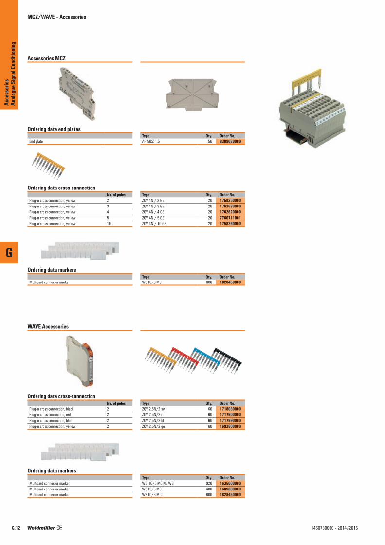
G
Accessories MCZ
WAVE Accessories
MCZ/WAVE – Accessories
Ordering data cross-connectionNo. of poles
Plug-in cross-connection, yellow 2Plug-in cross-connection, yellow 3Plug-in cross-connection, yellow 4Plug-in cross-connection, yellow 5Plug-in cross-connection, yellow 10
Ordering data markers
Multicard connector marker
Type Qty. Order No.ZQV 4N / 2 GE 20 1758250000ZQV 4N / 3 GE 20 1762630000ZQV 4N / 4 GE 20 1762620000ZQV 4N / 5 GE 20 7760711001ZQV 4N / 10 GE 20 1758260000
Type Qty. Order No.WS10/6 MC 600 1828450000
Ordering data end plates
End plateType Qty. Order No.AP MCZ 1.5 50 8389030000
Ordering data cross-connectionNo. of poles
Plug-in cross-connection, black 2Plug-in cross-connection, red 2Plug-in cross-connection, blue 2Plug-in cross-connection, yellow 2
Ordering data markers
Multicard connector markerMulticard connector markerMulticard connector marker
Type Qty. Order No.ZQV 2,5N/2 sw 60 1718080000ZQV 2,5N/2 rt 60 1717900000ZQV 2,5N/2 bl 60 1717990000ZQV 2,5N/2 ge 60 1693800000
Type Qty. Order No.WS 10/5 MC NE WS 920 1635000000WS15/5 MC 480 1609880000WS10/6 MC 600 1828450000
Acce
ssor
iesAn
alogu
e Sign
al Co
nditi
oning
G.12 1460730000 – 2014/2015

G
Screw-connect connector strip for the WAVESERIES
MCZ/WAVE – Accessories
3-poleType Printing Order No.BLZ 5.08/3 SN OR BEDR. 1, 2, 3 2242030000BLZ 5.08/3 SN OR BEDR. 4, 5, 6 2242050000BLZ 5.08/3 SN OR BEDR. 7, 8, 9 2242060000BLZ 5.08/3 SN OR BEDR. 10, 11, 12 2242070000
2-poleType Printing Order No.BLZ 5.08/02/180 SN OR BX without labelling 1526460000BLZ 5.08/02/180 SN OR PRT 1, 2 2246070000BLZ 5.08/02/180 SN OR PRT 3, 4 2246080000BLZ 5.08/02/180 SN OR PRT 5, 6 2246090000BLZ 5.08/02/180 SN OR PRT 7, 8 2246100000
Acce
ssor
iesAn
alogu
e Sign
al Co
nditi
oning
G.131460730000 – 2014/2015

G.14
Calibrators
Portacal 1000EU
Calibration device for current and voltage signals
The Portacal 1000EU is a calibration device which is controlled by a microprocessor. It is used for current and voltage signals. It has three output modes for simulating signals:
• Voltage source: for the simulation of externally-supplied voltage transmitters
• Current source: for the simulation of externally-supplied current sensors
• Current sink mode: simulates the outputs of a two-wire (loop-powered) transmitter.
Commonly used calibration functions can be invoked for each mode by pressing a button. Up to 9 storage locations per mode are available to save the individual values.
Furthermore, the Portacal 1000EU can be programmed in a way that all modes can be cycled automatically. The corresponding values are controlled continually for a pre-defined time by means of a value storage. The following values can be checked and parameterised:
• Voltage outputs• Current outputs• Two-wire transmitter outputs
The Portacal 1000EU provides the necessary voltage supply for the sensor in order to check a two-wire transmitter.
Technical features:
• Complete diagnosis tool for current and voltage supply• Measuring and simulating of voltage and current signals• Simulation of function of signal transmitter, which can be
auxiliary-powered or process-powered (two-wire type)• Continually adjustable step and ramping function• Accuracy < 0.05 % in all signal domains• Light and portable• Supply via NiMH rechargeable battery or comparable
battery• Signal tone at the press of a button
Typical application of Portacal 1000EU
2-wire, 4…20 mA output currentof Portacal 1000EU
Signalconverter
(ITX+)
Transmitter TestInput
thermocouple
Portacal 1000EU
Acce
ssor
ies
Analo
gue S
ignal
Cond
ition
ing
G
1460730000 – 2014/2015

G.15
Technical dataOutput voltage modeOutput voltageResolutionLoad currentAccuracyResidual rippleInternal storageOutput current modeOutput currentResolutionLoad resistance
max. input voltage current sinkAccuracyResidual rippleInternal storageInput voltage modeInput voltageInput resistanceAccuracyInput current modeInput currentInput resistanceAccuracyLoop powered modeTypeInput currentFeed voltageAccuracyAuto step/ramp modeStepRampNumber of recorded valuesTime intervalDisplayTypeStatus indicatorDisplay valueKeyboardTypeCalibration
MemoryDecimalsGeneral dataSupply voltageTemperature coefficientAmbient temperature (operational)/storage temperatureType of connectionEMC standardApprovalsDimensionsLength x width x heightNote
Ordering dataType
Note
AccessoriesNote
0…13 V0.01 V0…10 mA±5 mV< 1 mVNine user-defined voltages
0…26 mA0.01 mA600 Ω @ 20 mA (power source)100 Ω (current sink)9…45 V DC±5 µA< 1 µANine user-defined currents
0…13 V200 kΩ±5 μA or ±1 digital step
0…26 mA47 Ω±5 μA or ±1 digital step
Mode for loop-powered signal-converters0…26 mA16 V ±10 %±5 μA or ±1 digital step
Output of each value within a certain time periodOutput via a programmed ramp function2…910…4200 s
Four-digit display with LCD, 12 mmFive LEDs for output mode, signal amplification and reductionPercent or real-value displayed
16 buttons with acoustic signalAdjustable fixed values: 0, 2, 4, 8, 10, 12, 16, 18, 20 mA0, 1, 2, 4, 5, 6, 8, 9, 10 VNine freely-definable values1 / 0.1 / 0.01 mA or V
Battery, 4x type ‚AA‘< 0.01 % / °C at 100 %0 °C…60 °C / –25 °C…+70 °CSocketsDIN EN 61326CE, cULus
44 x 100 x 180 mm
Type Qty. Order No.PORTACAL 1000EU 1 14396400002 x 1 m test cable sw/rt with banana plug/terminal
Portacal 1000EUInstrument Calibrator
H
WL
S R
PORTACAL 1000
Calibrators
Acce
ssor
ies
Analo
gue S
ignal
Cond
ition
ing
G
1460730000 – 2014/2015

G.16
Calibrators
Portacal 275
Hand-held signal source and loop calibrator
The Portacal 275 is a precise hand-held signal source for current and voltage signals. It can be used in four modeswhich allows the calibration of standard current/voltage transmitters.
The operating mode “voltage source“ simulates auxiliary-powered transmitters with proportional voltage outputs. The mode “current source“ allows emulation of transmitters with proportional current outputs. The “mv source“ mode simulates a variety of other analogue signals from many different applications. The “current sink“ mode simulates the outputs of a two-wire (loop powered) transmitter.
The Portacal 275 is equipped with a scalable potentiometer(0 to 100 %) that can be adjusted in steps to an accuracy of 0.1 %. Together with the output-range switch, the potentiometer allows for a quick and precise adjustment of the signal value. A typical accuracy of ± 0.25 % is possible. An integrated test point, for connecting external measurement devices, allows for a higher accuracy of ± 0.1 %.
Technical features:
• Light and portable device• Simulates loop-powered transmitter operation• LED for indication of source/sink operating mode• Current ranges: 0 to 20 mA / 4 to 20 mA / Voltage
ranges: 0 to 5 V / 1 to 5 V / 0 to 200 mV• 0.1 % accurate current source• Test points for current output monitoring• Switch select 0 %, 100 % or variable output• Signal outputs can be adjusted with spindle
potentiometer for high accuracy• Powered from two 9 V block batteries
Acce
ssor
ies
Analo
gue S
ignal
Cond
ition
ing
G
1460730000 – 2014/2015
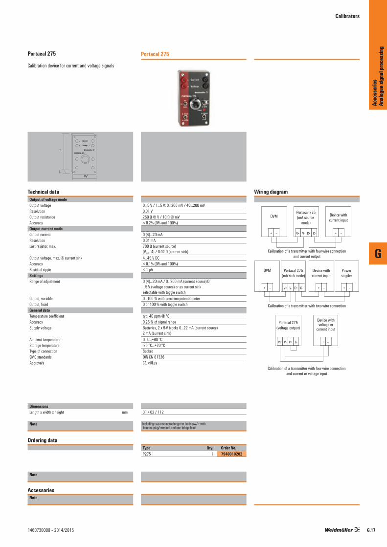
G
Acce
ssor
ies
Analo
gue s
ignal
proc
essin
g
G.171460730000 – 2014/2015
Portacal 275
Calibration device for current and voltage signals
H
WL
PORTACAL 275
+ Current -
+ Voltage -
Technical dataOutput of voltage modeOutput voltageResolutionOutput resistanceAccuracyOutput current modeOutput currentResolutionLast resistor, max.
Output voltage, max. @ current sinkAccuracyResidual rippleSettingsRange of adjustment
Output, variableOutput, fixedGeneral dataTemperature coefficientAccuracySupply voltage
Ambient temperature Storage temperatureType of connectionEMC standardsApprovals
DimensionsLength x width x height mm
Note
Ordering data
Note
AccessoriesNote
Portacal 275
0...5 V / 1...5 V; 0...200 mV / 40...200 mV0.01 V250 Ω @ V / 10 Ω @ mV< 0.2% (0% and 100%)
0 (4)...20 mA0.01 mA700 Ω (current source) (Vout - 4) / 0.02 Ω (current sink)4...45 V DC< 0.1% (0% and 100%)< 1 µA
0 (4)...20 mA / 0...200 mA (current source).0 ...5 V (voltage source) or as current sink selectable with toggle switch0...100 % with precision potentiometer0 or 100 % with toggle switch
typ. 40 ppm @ °C0.25 % of signal rangeBatteries, 2 x 9-V blocks 6...22 mA (current source) 2 mA (current sink)0 °C...+60 °C-25 °C...+70 °CSocketDIN EN 61326CE; cULus
31 / 62 / 112
Including two one-metre-long test leads sw/rt with banana plug/terminal and one bridge lead
Type Qty. Order No.P275 1 7940010202
Wiring diagram
Portacal 275(mA sink mode)
Powersuppler
C+ C- + –
Portacal 275(mA source
mode)
Device withcurrent input
V+ V-
+ –
DVM
+ –
Device withcurrent input
+ –
Calibration of a transmitter with two-wire connection
Calibration of a transmitter with four-wire connectionand current output
V+ V-
DVM
+ – C+ C-
Portacal 275(voltage output)
Device withvoltage or
current input
V+ V- + – C+ C-
Calibration of a transmitter with four-wire connectionand current or voltage input
Acce
ssor
ies
Analo
gue s
ignal
proc
essin
g
Calibrators

G
Acce
ssor
ies
Analo
gue s
ignal
proc
essin
g
G.18 1460730000 – 2014/2015

Technical appendix/Glossary
Contents
Technical appendix/Glossary Dimensioned drawings W.2
Introduction W.4
Technical data W.6
FDT/DTM – The standard solution for device configuration W.10
EX basics W.12
ATEX W.18
Electrical data W.20
General technical information W.22
Glossary W.26
W
Tech
nical
appe
ndix/
Glos
sary
W.11460730000 – 2014/2015

Dimensioned drawings
MICROSERIES
Screw connection Tension clamp connection
88 mm
90 m
m
97.8
mm
6.1
mm
92 mm
90 m
m
97.8
mm
6.1
mm
ACT20M – Dimensioned drawings
114.
3
107
107.6
112.5
6,1
left right
105.7 mm
117.2 mm
113.
7 mm
22.5
mm
ACT20X/ACT20C/ACT20P
113.
6 mm
107
mm
117.9 mm
12.5
mm
ACT20X HUI-SAO-LP-S
W
Tech
nical
appe
ndix/
Glos
sary
W.2 1460730000 – 2014/2015

Dimensioned drawings
WAVEBOX S 22,5 WAVEBOX L 22,5
WAVEBOX 12,5 WAVEBOX 17,5
72 mm
92.4
mm
71 mm
71 mm
22.5
mm
90 mm
92.4 mm
112.
4 mm
90 mm
22.5
mm
V
H
90 mm
92.4 mm
112.
4 mm
90 mm
12.5
mm
90 mm
92.4 mm
112.
4 mm
90 mm
17.5
mm
W
Tech
nical
appe
ndix/
Glos
sary
W.31460730000 – 2014/2015

Different types of analogue signalling
The working environment can be measured in many differentforms, e.g. in terms of temperature, humidity or air pressure. The values of these physical variables change constantly. Components that monitor the status and changes of a given environment and provide alerts of any changes must be able to continuously display the changes taking place.
In industrial and process automation, the outputs received from field sensors, switches and transmitters provides measurement and status data which becomes the analogue and digital inputs (AI and DI) for the control system. Similarly, control signals are passed from the control system to field control equipment such as analog and digital valves and actuators.
If automation processes are expected to reach certain statuses or keep them constant, then analogue signal conditioning is required. It is also important in areas where this has already been part of long established practice, e. g. in process engineering or the chemicals industry.
In process engineering, standardised electrical signals arenormally used. Currents of 0 … 20 mA, 4 … 20 mA or voltages of 0 ... 10 V have become established as the output variables for sensors recording various different physical parameters.
Weidmüller takes account of the growing preference forautomation – including and the resulting need for analogue signal conditioning – and offers a wide range of products tailor-made to the requirements involved in handling sensor signals. Units for the common signals (0 ... 20 mA, 4 ... 20 mA, 0 ... 10 V) generate an output signal as a proportional value of the variable input signal. “Protective separation”, e.g. of the sensor circuit from the evaluation circuit, is also taken into account. “Protective separation” prevents mutual interference among several sensor circuits, e.g. as in the case of earth loops in interlinked measuring circuits.
The wide range of Weidmüller products completely coversthe functions involved in signal conversion, signal separationand signal monitoring. The products can thus handle nearly all applications in industrial measuring technology, and safeguard elementary functions between field signals and further processing systems. The mechanical properties of the products are built up around a consistent concept.
Signal converters can be used with other Weidmüller products and combined with each other. They are designed to entail a minimum wiring workload and maintenance in both electrical and mechanical terms.
The product range contains the following functions:• DC/DC converters• Current converters• Voltage converters• Temperature converters for resistance thermometers
(RTDs) and thermocouples• Frequency converters• Potentiometer transducers• AC transducers• Bridge transducers (strain gauges)• Threshold monitoring modules• AD/DA converters
The products are available as pure signal converters, or with 2-port or 3-port isolation and a choice of passive or output loop powered or auxiliary powered, depending on the application requirements.
Introduction
W
Tech
nical
appe
ndix/
Glos
sary
W.4 1460730000 – 2014/2015

Introduction
2-way isolation separates the signals from each other electrically and decouplesthe measuring circuits. Potential differences – caused by long line lengths andcommon reference points – are eliminated. Furthermore, the electrical separationprotects against irreparable damage caused by overvoltages as well as inductiveand capacitive interference.
3-way isolation decouples the supply voltage from the input and output circuitsas well and enables the function to operate with just one operating voltage.
The passive separator offers an extra, decisive advantage – it requires no additional voltage supply. The power supply to the module is achieved via the input or output circuit and is transmitted to the input/output. This current loop feed is characterised by a very low consumption.
A number of products are available for temperature measurements. For example,PT100 signals in 2-, 3- and 4-wire systems are converted into standard 0…20 mA,4…20 mA and 0…10 V signals.
The modules for connecting conventional thermoelements are fitted with cold trap compensation as standard. Furthermore, they amplify and linearise the voltage signal provided by the thermocouple. This guarantees accurate analogue signal conditioning while eliminating sources of interference or error.
Frequency converters convert frequencies into standard analogue signals. Downstream controls can therefore directly process pulse strings for measuring rpm or speed.
AD or DA converters are required for bringing together the analogue signal forms mapping the local conditions and the digital processing in the process monitoring system. Weidmüller can supply such components for the customary 0…20 mA, 4…20 mA and 0…10 V input and output signals. 8-bit processors are available on the digital side.
Current-monitoring modules can be used to control DC and AC currents up to 60 amps. A switching operation is triggered when the set current values are not met or exceeded. Components with analogue outputs monitor the current load continuously via downstream controls.
Voltage monitoring modules can be used to monitor AC and DC voltages.Adjustable switching thresholds can be used to reliably detect and notify in theevent of fluctuations caused by switching operations or mains overloads.
W
Tech
nical
appe
ndix/
Glos
sary
W.51460730000 – 2014/2015

Technical data
Common Mode Noise Elimination
• Generally, signals emitted by sensors have low levels and are thus susceptible to capacitive and inductive interference, such as those generated by motors, frequency changers and other change processes.
This noise contents the measuring value and frequently destroys expensive analog I/O cards in the control electronics. Through the utilisation of analogue signal isolators this interferace, which usually actions both signal lines in common mode (push push), is effectively eliminated through the zero potential input.
Active Isolator / Passive Isolator
• Active isolators draw their power supply from a separate supply terminal to ensure that they can operate perfectly. Depending upon the applications the input, output and additionally the power supply are isolated from each other. Only one supply is required for 3-port isolation. However, it is isolated from the input and output circuits. Thus even in the event of a short circuit, surge voltage or reverse polarity, the downstream control electronics cannot be damaged. Isolating the signals between the input and output can be conducted either optically or by transformer barrier depending upon the transfer rate. Active isolators are non interacting, i.e. a change in the load does not exert any influence on an input circuit.
• Passive isolators generate the current required for the supply from the measuring signal. The current required internally is so small that transfer problems do not occur here.
• The feed can be effected from either the input or the output side. Isolation is by transformer barrier. The advan-
tages are: cessation of network influences, outstanding accuracy, low signal delay and low potential requirement. Passive isolators are not non interacting; a change in load in the output circuit will influence the input circuit.
Ground Loops
• The voltage supply‘s secondary side is earthed for the purpose of setting up fast and secure ground loop monitoring. If an analogue signal is fed in from a separate voltage supply or if the sensing device itself is earthed, then transient currents will flow between the ground potentials across the interconnected ground connectors, which in turn corrupts the measuring signal. Analogue signal isolating amplifiers prevent this form of measuring signal corruption and influence.
2-port Isolation
• The simplest form of analogue signal isolator is that of 2-port isolation. It serves to isolate the input circuit from the output circuit as well as the two auxiliary voltages from each other. Depending upon the isolator design and the observed isolation data one refers here to base isolation (galvanic isolation) or safe separation. ① For current signals, 4...20 mA input current loop fed modules are available. An additional auxiliary voltage for the input circuit is not required here. ② By connecting the input and output side voltage supplies, the 2-port isolation can be converted to operate as a simple signal converter. This is of particular interest where isolation is not required for an application, but a signal conversion has to be performed.
① ②
Technical data
W
Tech
nical
appe
ndix/
Glos
sary
W.6 1460730000 – 2014/2015

3-port Isolation
• 3-port isolation is the most universal form of signal isolator
• An optical coupler or transformer isolates the input from the output circuit. Together with the clearance and creepage distances it serves to define the isolation level. For example, the input signal is converted by means of pulse-width modulation into a frequency signal and demodulated again on the output side to form an analogue value. An amplifier then generates a standardised analogue signal. A galvanic isolated DC/DC converter feeds the input and output circuit with a potential free supply voltage. It also determines the isolation level through its data, air and creepage distances. In the case of these three isolation paths (input/output, input/auxiliary voltage, output/auxiliary voltage) one refers to 3-port isolation.
Temperature Signal Measuring Method
• Measurement using resistors (RTD) When measuring with temperature-dependent resistors a current of approx. 1.5 mA is passed through the resistor from a constant current source in the signal converter.
An operational amplifier is used to measure the potential drop at the resistor (2-wire circuit).
In order to take account of lead length, the voltage drop is measured at the return conductor and calculated with double the value (3-wire circuit). This simulates the wire resistances from the feed and return lines. Accurate measurements are achieved by separately measuring the voltage drop at the feed and return lines (4-wire circuit). The values for the supply lines are calculated against the measured value.
Temperature Signal Measuring Method
• Measurements using thermocouples When conducting measurements using thermocouples
the voltage that is generated when two differently alloyed metals come into contact with each other is measured. A differential amplifier is then used to recondition the signal. The easiest (and the most cost-efffective) method of subsequent processing is conducted by means of an amplifier circuit, which converts these signals into standard signals. High-end components process the measuring signal using a microprocessor, which simultaneously reconditions the signal (filtering, linearisation)
Cold Junction Compensation For Thermocouples
• Recording temperatures by using thermocouples encounters the problem of a thermal voltage forming at the clamping terminals on the signal converter on account of the different materials in the conductors and bus bar. This voltage then counteracts the thermal element‘s voltage.
In order to compensate for the error to the measured value which arises here, the temperature is measured at the clamping terminal. The microprocessor in the signal converter reads the value measured there and calculates it against the measured value. This procedure is known as cold junction compensation.
Voltage at the measuring point (Vmeas) + Voltage at the terminal (Vterminal) = Voltage at the thermocouple (Vthermo) => Temperature at the thermocouple (Tthermo)
Linearisation
• Temperature-dependent components do not normally have linear characteristic curves. To ensure that further processing can take place with the necessary accuracy, these characteristic curves have to be linearised to some extent. The graph showing measurements of thermocouples, in particular, reveals significant deviations at some points from the “ideal graph”. As a consequence, the signal which has been measured is worked up by microprocessor.
Technical data
W
Tech
nical
appe
ndix/
Glos
sary
W.71460730000 – 2014/2015

The microprocessor compares the value measured with the characteristic curve for the thermocouple in its memory and calculates the corresponding value on the “ideal characteristic curve”. At the output, it supplies the latter to an amplifier, which produces the analogue value in linear form. The output stage converts this into a standardised value or into a switching output with a switching threshold. The linearisation of PT100-elements can be undertaken via simple amplifier stages. The first stage corrects the peak value of the graph of the measurements. The deviation at the end of the graph resulting from this is corrected by a second stage. The under- and over-shooting generated in this way is very slight and is covered by the tolerance for the module.
Current Measurement Using A Measuring Transformer
• Transformer principle: Each conductor through which current flows is surrounded by a magnetic field H, the intensity of which is proportional to the current. The field, which is bundled in a magnetic core, generates a magnetic flux B, through which suitable sensors are used to measure current.
Converters with transformer-type couplings are used to establish the most cost effective measurement method for simple sinusoidal currents. The current to be measured flows directly through the measuring transformer‘s primary winding.
The secondary winding supplies the measuring electronics with a proportional current signal. Because of power loss this method of measuring current is limited to smaller currents up to 5 A. These converters react sensitively to peak loads and therefore have to be fused on the primary winding side.
Measuring Current Using A Hall-type Sensor
• Hall-type sensor principle: Hall-type sensors also measure the magnetic flux B and supply a proportional voltage at the measured output, which is then reconditioned to form a standard signal by an amplifier circuit.
• Components with Hall-type sensors are ideally suited to measuring higher currents, as any possible high residual currents from motors or peak loads cannot damage the component. Additionally, they are also ideal for measuring direct and alternating currents of various curve shapes.
Root Mean Square Measurement / Crest Factor
• The root mean square value (r.m.s) of a sinusoidal shaped alternating current is the value, which in an ohmic resistor converts the same (effective) output as that of an equal sized direct current.
• Non sinusoidal shaped signals can only be measured with “True RMS” capable devices and/or further processed.
• True RMS = True root mean square• Root mean square measurement is required where the
(effective) output content of alternating voltages or currents are to be measured or evaluated.
• The crest factor indicates the ratio of the crest factor to the root mean square value.
Technical data
W
Tech
nical
appe
ndix/
Glos
sary
W.8 1460730000 – 2014/2015
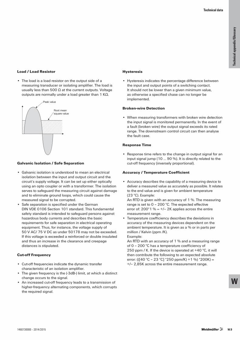
Load / Load Resistor
• The load is a load resistor on the output side of a measuring transducer or isolating amplifier. The load is usually less than 500 Ω at the current outputs. Voltage outputs are normally under a load greater than 1 KΩ.
Peak value
Root mean square value
Galvanic Isolation / Safe Separation
• Galvanic isolation is understood to mean an electrical isolation between the input and output circuit and the circuit‘s supply voltage. It can be set up either optically using an opto coupler or with a transformer. The isolation serves to safeguard the measuring circuit against damage and to eliminate ground loops, which could cause the measured signal to be corrupted.
• Safe separation is specified under the German DIN VDE 0106 Section 101 standard. This fundamental safety standard is intended to safeguard persons against hazardous body currents and describes the basic requirements for safe separation in electrical operating equipment. Thus, for instance, the voltage supply of 50 V AC/ 75 V DC as under 50178 may not be exceeded. If this voltage is exceeded a reinforced or double insulated and thus an increase in the clearance and creepage distances is stipulated.
Cut-off Frequency
• Cut-off frequencies indicate the dynamic transfer characteristic of an isolation amplifier.
• The given frequency is the (-3dB-) limit, at which a distinct change occurs to the signal.
• An increased cut-off frequency leads to a transmission of higher-frequency alternating components, which corrupts the required signal.
Hysteresis
• Hysteresis indicates the percentage difference between the input and output points of a switching contact. It should not be lower than a given minimum value, as otherwise a specified chase can no longer be implemented.
Broken-wire Detection
• When measuring transformers with broken wire detection the input signal is monitored permanently. In the event of a fault (broken wire) the output signal exceeds its rated range. The downstream control circuit can then analyse the fault case.
Response Time
• Response time refers to the change in output signal for an input signal jump (10 … 90 %). It is directly related to the cut-off frequency (inversely proportional).
Accuracy / Temperature Coefficient
• Accuracy describes the capability of a measuring device to deliver a measured value as accurately as possible. It relates to the end value and is given for ambient temperature (23 °C). Example:
An RTD is given with an accuracy of 1 %. The measuring range is set to 0 – 200 °C. The expected effective error of: 200*1 % = +/– 2K applies across the entire measurement range.
• Temperature coefficiency describes the deviations in accuracy of the measuring devices dependent on the ambient temperature. It is given as a % or in parts per million / Kelvin (ppm /K). Example:
An RTD with an accuracy of 1 % and a measuring range of 0 – 200 °C has a temperature coefficiency of 250 ppm / K. If the device is operated at +40 °C, it will then contribute the following to an expected absolute error: (([40 °C – 23 °C] *250 ppm/K) +1 %) *200K) = +/– 2,85K across the entire measurement range.
Technical data
W
Tech
nical
appe
ndix/
Glos
sary
W.91460730000 – 2014/2015

FDT/DTM – The standard solution for device configuration
FDT/DTM – The standard solution for device configuration
Field Device Tool (FDT)
FDT technology specifies and standardises the integration of communicating devices from different manufacturers. It makes use of a superimposed device management program. The key feature is its independence from the communication protocol and software used by the device and the host system. FDT allows access to any device from any host using any protocol.
Device Type Manager (DTM)
Device manufacturers make available a Device Type Manager (DTM) software driver for each device or device group. The DTM specifies all device-specific information, functions and rules (such as the device structure, communication capabilities, internal dependencies and the human-machine interface (HMI)). DTMs define functions for access to device parameters, troubleshooting, configuration and operation of devices. DTMs are available which can be simple GUIs for setting device parameters or more complex applications that are capable of carrying out calculations for diagnostic or maintenance purposes.
There are several different types of DTMs:
• Device DTM This is a “normal“ field device that uses communication channels to communicate with the connected physical device.
• Communication DTM This is a communications device that provides communication using communication channels. Communication channels provide access to the communications infrastructure (such as PC interface cards or modems). They are used by device DTMs or gateway DTMs for communication services.
• Gateway DTM This is a gateway device. It allows data to be exchanged between two communication channels. For example, this could be a gateway between PROFIBUS-DP and PROFIBUS-PA.
The DTM is loaded and started up within a FDT containerprogram or “frame“ application.
W
Tech
nical
appe
ndix/
Glos
sary
W.10 1460730000 – 2014/2015
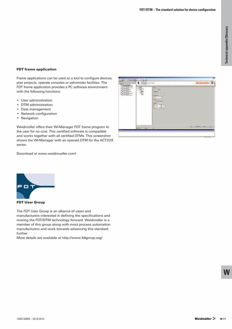
FDT/DTM – The standard solution for device configuration
FDT frame application
Frame applications can be used as a tool to configure devices, plan projects, operate consoles or administer facilities. The FDT frame application provides a PC software environment with the following functions:
• User administration• DTM administration• Data management• Network configuration• Navigation
Weidmüller offers their WI-Manager FDT frame program to the user for no cost. This certified software is compatible and works together with all certified DTMs. This screenshot shows the WI-Manager with an opened DTM for the ACT20X series.
Download at www.weidmueller.com!
FDT User Group
The FDT User Group is an alliance of users and manufacturers interested in defining the specifications and moving the FDT/DTM technology forward. Weidmüller is a member of this group along with most process automation manufacturers and work towards advancing this standard further. More details are available at http://www.fdtgroup.org/
W
Tech
nical
appe
ndix/
Glos
sary
W.111460730000 – 2014/2015
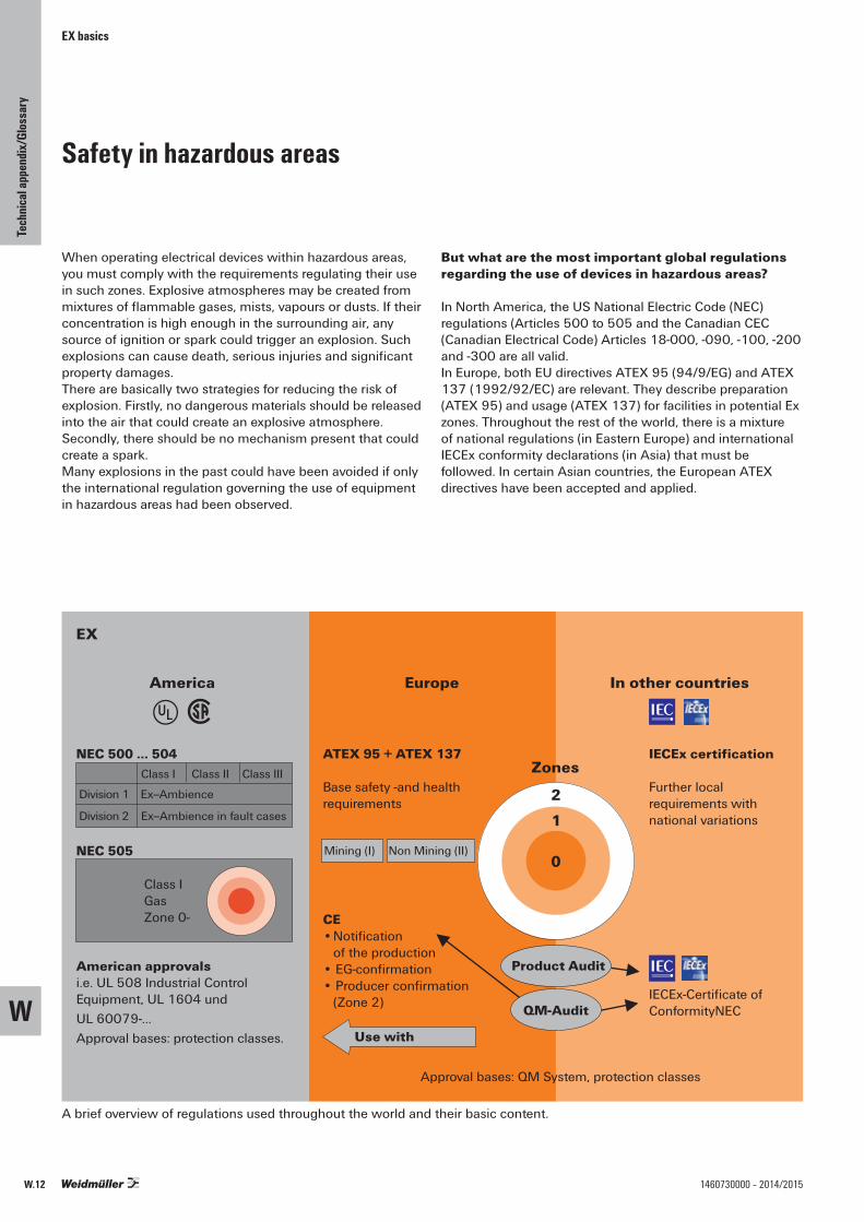
EX basics
Safety in hazardous areas
When operating electrical devices within hazardous areas, you must comply with the requirements regulating their use in such zones. Explosive atmospheres may be created from mixtures of flammable gases, mists, vapours or dusts. If their concentration is high enough in the surrounding air, any source of ignition or spark could trigger an explosion. Such explosions can cause death, serious injuries and significant property damages.There are basically two strategies for reducing the risk ofexplosion. Firstly, no dangerous materials should be released into the air that could create an explosive atmosphere. Secondly, there should be no mechanism present that could create a spark.Many explosions in the past could have been avoided if onlythe international regulation governing the use of equipment in hazardous areas had been observed.
But what are the most important global regulationsregarding the use of devices in hazardous areas?
In North America, the US National Electric Code (NEC) regulations (Articles 500 to 505 and the Canadian CEC (Canadian Electrical Code) Articles 18-000, -090, -100, -200 and -300 are all valid.In Europe, both EU directives ATEX 95 (94/9/EG) and ATEX 137 (1992/92/EC) are relevant. They describe preparation (ATEX 95) and usage (ATEX 137) for facilities in potential Ex zones. Throughout the rest of the world, there is a mixture of national regulations (in Eastern Europe) and international IECEx conformity declarations (in Asia) that must be followed. In certain Asian countries, the European ATEX directives have been accepted and applied.
EX
America
v rEurope In other countries
NEC 500 … 504 ATEX 95 + ATEX 137
Base safety -and health requirements
CE• Notification of the production • EG-confirmation• Producer confirmation (Zone 2)
IECEx certification
Further local requirements with national variations
IECEx-Certificate of ConformityNEC
NEC 505
Class IGasZone 0-
Class I Class II Class III
Division 1 Ex--Ambience
Division 2 Ex--Ambience in fault cases
American approvalsi.e. UL 508 Industrial Control Equipment, UL 1604 und UL 60079-…Approval bases: protection classes.
Zones
0
12
Use with
Approval bases: QM System, protection classes
Product Audit
QM-Audit
Mining (I) Non Mining (II)
A brief overview of regulations used throughout the world and their basic content.
W
Tech
nical
appe
ndix/
Glos
sary
W.12 1460730000 – 2014/2015

EX basics
The European ATEX Regulation applies to facilities and their usage in hazardous areas.
The term “ATEX“ derives from the French phrase “Atmospheres Explosive“. The regulation currently includes two directives from the European Union concerning explosion protection. These are the ATEX operational directive 1999/92/EG (ATEX 137) and the ATEX product directive 94/9/EG (ATEX 95). The ATEX 137 operational directive specifies the minimum requirements for improving the protection of health and security of workers in environments at risk of explosions. The ATEX 95 product directive specifies the rules for introducing products on the market that will be used in zones where there is risk of explosion. This directive is the first to include non-electric devices within its jurisdiction.
The purpose of the directive is to protect personnel who work in hazardous areas. Appendix II of the directive contains the basic health and safety requirements. These must be followed by the manufacturer and compliance must be proven by declarations of conformity. Since June 30, 2003, all devices, components and protective systems brought to the market must be in compliance with the ATEX 95 product directive.
Group II=> Devices for use in the other hazardous areas
For applications in the oil, gas and chemical industries, it isparticularly important to follow the Group-II “G“ requirements concerning electrical or electronic devices and components.
The ATEX 95 directive classifies devices and components for the Ex zone into two main groups:
Group I=> Devices for use in mining, for underground and
above-ground operations • Coal dust • Methane • Harsh operating conditions
No additional divisions
Categories
1 2 3
Zones
0 1 2Zones
20 21 22
Gases, Vapours and Mists
G
Dusts
DCategory
M 1 M 2
W
Tech
nical
appe
ndix/
Glos
sary
W.131460730000 – 2014/2015

EX basics
Safety in hazardous areas
Group II “G“ divides the Ex zone into three zones with different safety requirements.
• Zone 0 This zone applies to dangerous explosive atmospheres where the risk is present often or over long time periods. => > 50 % of the operational time, or more than 1.000 hours per year.
• Zone 1 This zone applies to situation where explosive atmospheres may occasionally be present during normal operations. => Occasionally, less than 10 hours per year.
• Zone 2 This zone applies to situation where explosive atmospheres are normally not present or only briefly present during normal operations. => Max. 30 min/year.
Direct surroundings = Zone 1
Piping, Zone 0
Fuel pumpsManholesZone 1
(Zone 0)Zone 1Zone 2
Tank, Zone 0When flash point < 35 °C
≥ 4.0 m²
0.8 – 1.0 m²Sand filling
0.2 m² 0.2 m²
Typical division of zones at a fuelling station
Hazardous areas
Zone 0 Zone 1 Zone 2 Safe zone
Explosion risk Continual,long-term, often Occasionally Rarely None
Spark source None Rarely and short-term Occasionally Continual,long-term, often
W
Tech
nical
appe
ndix/
Glos
sary
W.14 1460730000 – 2014/2015
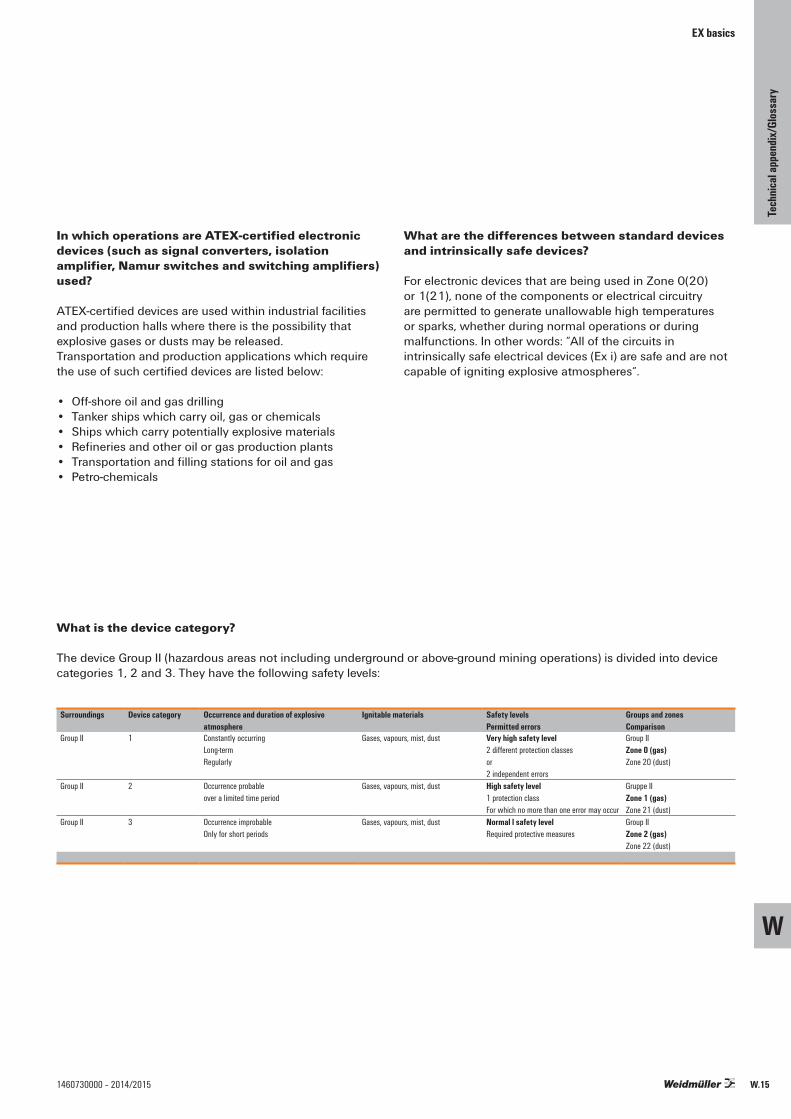
EX basics
In which operations are ATEX-certified electronic devices (such as signal converters, isolation amplifier, Namur switches and switching amplifiers) used?
ATEX-certified devices are used within industrial facilities and production halls where there is the possibility that explosive gases or dusts may be released. Transportation and production applications which require the use of such certified devices are listed below:
• Off-shore oil and gas drilling• Tanker ships which carry oil, gas or chemicals• Ships which carry potentially explosive materials• Refineries and other oil or gas production plants• Transportation and filling stations for oil and gas• Petro-chemicals
What are the differences between standard devices and intrinsically safe devices?
For electronic devices that are being used in Zone 0(20) or 1(21), none of the components or electrical circuitry are permitted to generate unallowable high temperatures or sparks, whether during normal operations or during malfunctions. In other words: “All of the circuits in intrinsically safe electrical devices (Ex i) are safe and are not capable of igniting explosive atmospheres“.
What is the device category?
The device Group II (hazardous areas not including underground or above-ground mining operations) is divided into device categories 1, 2 and 3. They have the following safety levels:
Surroundings Device category Occurrence and duration of explosiveatmosphere
Ignitable materials Safety levelsPermitted errors
Groups and zonesComparison
Group II 1 Constantly occurringLong-termRegularly
Gases, vapours, mist, dust Very high safety level 2 different protection classesor2 independent errors
Group IIZone 0 (gas)Zone 20 (dust)
Group II 2 Occurrence probableover a limited time period
Gases, vapours, mist, dust High safety level1 protection class For which no more than one error may occur
Gruppe IIZone 1 (gas)Zone 21 (dust)
Group II 3 Occurrence improbableOnly for short periods
Gases, vapours, mist, dust Normal l safety level Required protective measures
Group IIZone 2 (gas)Zone 22 (dust)
W
Tech
nical
appe
ndix/
Glos
sary
W.151460730000 – 2014/2015
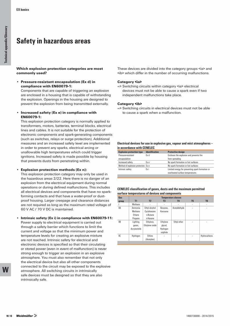
EX basics
Safety in hazardous areas
Which explosion protection categories are most commonly used? • Pressure-resistant encapsulation (Ex d) in
compliance with EN60079-1: Components that are capable of triggering an explosion are enclosed in a housing that is capable of withstanding the explosion. Openings in the housing are designed to prevent the explosion from being transmitted externally.
• Increased safety (Ex e) in compliance with EN60079-1: This explosion protection category is normally applied to transformers, motors, batteries, terminal blocks, electrical lines and cables. It is not suitable for the protection of electronic components and spark-generating components (such as switches, relays or surge protection). Additional measures and an increased safety level are implemented in order to prevent any sparks, electrical arcing or unallowable high temperatures which could trigger ignitions. Increased safety is made possible by housing that prevents dusts from penetrating within.
• Explosion protection methods (Ex n): This explosion protection category may only be used in the hazardous areas 2/22. Here there is no danger of an explosion from the electrical equipment during normal operations or during defined malfunctions. This includes all electrical devices and components that have no spark-forming contacts and that have a water-proof or dust-proof housing. Larger creepage and clearance distances are not required as long as the maximum rated voltage of 60 V AC / 70 V DC is maintained.
• Intrinsic safety (Ex i) in compliance with EN60079-11: Power supply to electrical equipment is carried out through a safety barrier which functions to limit the current and voltage so that the minimum power and temperature levels for creating an explosive mixture are not reached. Intrinsic safety for electrical and electronic devices is specified so that their circulating or stored power (even in event of malfunction) is never strong enough to trigger an explosion in an explosive atmosphere. You must also remember that not only the electrical device but also all other components connected to the circuit may be exposed to the explosive atmosphere. All switching circuits in intrinsically safe devices must be designed so that they are also intrinsically safe.
These devices are divided into the category groups <ia> and <ib> which differ in the number of occurring malfunctions.
Category <ia>=> Switching circuits within category <ia> electrical
devices must not be able to cause a spark even if two independent malfunctions take place.
Category <ib> => Switching circuits in electrical devices must not be able
to cause a spark when a malfunction.
Electrical devices for use in explosive gas, vapour and mist atmospheres – in accordance with CENELEC
Explosion protection type Identification Protective designPressure-resistantencapsulation
Ex d Encloses the explosion and prevents firefrom spreading
Increased safety Ex e No spark formation or hot surfacesMethod of explosion protection Ex n No spark formation or hot surfacesIntrinsic safety Ex i Limited energy for preventing spark formation or
overheated surface temperatures
CENELEC classification of gases, dusts and the maximum permitted surface temperatures of devices and components
Gas group
Temperature classesT1 T2 T3 T4 T5 T6
I Methane – – – – – IIA Ammonia
MethaneEthane
Propane
Ethyl alcoholCyclohexane
n-Butanen-Hexane
Benzene, Kerosene
Acetaldehyde – –
IIB Lighting gases,
Acrylonitrile
Ethylene,Ethylene oxide
Ethylene glycol,
Hydrogensulphide
Ethyl ether – –
IIC Hydrogen Ethine (Acetylen)
– – – Hydrocarbons
W
Tech
nical
appe
ndix/
Glos
sary
W.16 1460730000 – 2014/2015

IEC (group II) Classification
Max. surfacetemperature
Comment
T1 450 °C (842 °F)
The temperature is relevant to all partsof the devices that can come into contact with potentially explosive materials.
T2 300 °C (572 °F) T3 200 °C (392 °F) T4 135 °C (275 °F) T5 100 °C (212 °F) T6 85 °C (185 °F)
Tx Max. surface temperature undefined
Valid for the closed tank systems usedon container ships where the individualcontents cannot be monitored in eventof a fire. It is the responsibility of theoperator to assess each temperatureclass.
What labelling is considered proper?
An example of device labelling:
CE 0539 T II 2 G Ex ia IIA T4
Certification authority
ex. DEMKO
European Commission mark for Ex
devices
Device group “Surface“
Device category zone 1
Gas Protection explosion type: intrinsically safe
category <ia>
Gas group Surface temperature: max 135 °C
EX basics
W
Tech
nical
appe
ndix/
Glos
sary
W.171460730000 – 2014/2015

ATEX
ATEX directives
Since July 1, 2003, all new facilities in hazardous areas must be certified according to ATEX Directive 94/9/EG or ATEX 95 (ATEX: ATmosphère EXplosive = explosive atmosphere). This directive is one of the “New-Approach” directives. It is valid in all European Union countries, as well as Iceland, Lichtenstein and Norway. In these countries, the directive refers to the sale and commissioning of products which have been designed particularly for high explosion risk environments (where explosive atmospheres exist due to gases, vapours, mists, or dusts). It now also covers the mining sector and purely mechanical devices.
Class of protectionType of protection Code CENELEC EN IEC Product category
explosion protect.General requirements – 60079-0 60079-0 –Oil immersion o 60079-6 60079-6 2Pressurised apparatus p 60079-2 60079-2 2Powder filling q 60079-5 60079-5 2Flameproof enclosure d 60079-1 60079-1 2Increased safety e 60079-7 60079-7 2Intrinsic safety ia 60079-11 60079-11 1Intrinsic safety ib 60079-11 60079-11 2Intrinsic safety ic 60079-11 60079-11 3Typ n (Ex n) n 60079-15 60079-15 3Encapsulation m 60079-18 60079-18 2
Classification for potentially hazardous areasCENELEC classificationIEC60079-10
Presence of potentiallyexplosive atmosphere
Product-category
US classification NEC 500
Combustiblemedia
Zone 0 permanent, long-term 1G Class I, Div 1 gases, vapoursZone 20 or frequently 1D Class II, Div 1 dustZone 1 occasionally 2G Class I, Div 1 gases, vapoursZone 20 2D Class II, Div 1 dustZone 2 rarely and 3G Class I, Div 2 gases, vapoursZone 22 briefly 3D Class II, Div 2 dust
Explosion groupsGas (e.g.) CENELEC NEC 500
Propane IIA DEthylene IIB CHydrogen IIC BAcetylene IIC AMethane (mining) I mining (MSHA)
Temperature classesMax. surfacetemperatur (°C)
Temperature classCENELEC
Temperature classNEC 500-3
450 T1 T1300 T2 T2280 – T2A260 – T2B230 – T2C215 – T2D200 T3 T3180 – T3A165 – T3B160 – T3C135 T4 T4120 – T4A100 T5 T5 85 T6 T6
W
Tech
nical
appe
ndix/
Glos
sary
W.18 1460730000 – 2014/2015
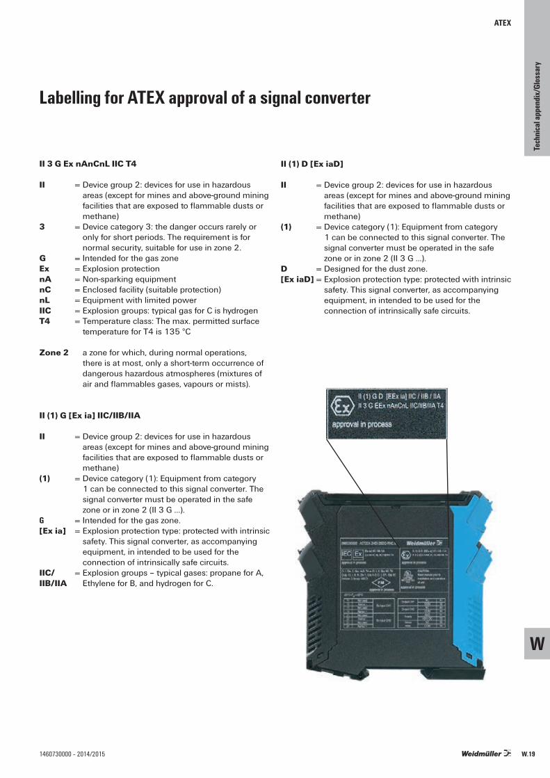
ATEX
Labelling for ATEX approval of a signal converter
II 3 G Ex nAnCnL IIC T4
II = Device group 2: devices for use in hazardous areas (except for mines and above-ground mining facilities that are exposed to flammable dusts or methane)
3 = Device category 3: the danger occurs rarely or only for short periods. The requirement is for normal security, suitable for use in zone 2.
G = Intended for the gas zoneEx = Explosion protectionnA = Non-sparking equipmentnC = Enclosed facility (suitable protection)nL = Equipment with limited powerIIC = Explosion groups: typical gas for C is hydrogenT4 = Temperature class: The max. permitted surface
temperature for T4 is 135 °C
Zone 2 a zone for which, during normal operations, there is at most, only a short-term occurrence of dangerous hazardous atmospheres (mixtures of air and flammables gases, vapours or mists).
II (1) G [Ex ia] IIC/IIB/IIA
II = Device group 2: devices for use in hazardous areas (except for mines and above-ground mining facilities that are exposed to flammable dusts or methane)
(1) = Device category (1): Equipment from category 1 can be connected to this signal converter. The signal converter must be operated in the safe zone or in zone 2 (II 3 G …).
G = Intended for the gas zone.[Ex ia] = Explosion protection type: protected with intrinsic
safety. This signal converter, as accompanying equipment, in intended to be used for the connection of intrinsically safe circuits.
IIC/ = Explosion groups – typical gases: propane for A,IIB/IIA Ethylene for B, and hydrogen for C.
II (1) D [Ex iaD]
II = Device group 2: devices for use in hazardous areas (except for mines and above-ground mining facilities that are exposed to flammable dusts or methane)
(1) = Device category (1): Equipment from category 1 can be connected to this signal converter. The signal converter must be operated in the safe zone or in zone 2 (II 3 G …).
D = Designed for the dust zone.[Ex iaD] = Explosion protection type: protected with intrinsic
safety. This signal converter, as accompanying equipment, in intended to be used for the connection of intrinsically safe circuits.
W
Tech
nical
appe
ndix/
Glos
sary
W.191460730000 – 2014/2015

Electrical data
Rated impulse withstand voltage The rated impulse withstand voltage is derived from:• Voltage conductor – earth
(the rated voltage of the network, taking into account all networks)
• Surge category
Surge categoriesare stipulated in accordance with theGerman standard DIN VDE 0110-1 (for electrical equipment fed directly from the low-voltage network).
Surge category I• Equipment that is intended to
be connected to the permanent electrical installation of a building. Measures to limit transient surges to the specific level are taken outside the equipment, either in the permanent installation or between the permanent installation and the equipment.
Surge category II• Equipment to be connected to the
permanent electrical installation of a building, e.g. household appliances, portable tools, etc.
Surge category III• Equipment that is part of the
permanent electrical installation and other equipment where a higher degree of availability is expected, e.g. distribution boards, circuit-breakers, wiring systems (including cables, busbars, junction boxes, switches, power sockets) in the permanent installation, and equipment for industrial use and some other equipment, e.g. stationary motors with permanent connections to the permanent installation.
Surge category IV• Equipment for use at or near the
power supplies in the electrical installations of buildings, between the principal distribution and the mains, e.g. electricity meters, circuit-breakers and centralised ripple controllers.
Pollution severity categories
Pollution severity category 1• No pollution, or only dry, non-
conductive pollution that has no influence.
Pollution severity category 2• Non-conductive pollution only;
occasional condensation may cause temporary conductivity.
Pollution severity category 3• Conductive pollution, or dry, non-
conductive pollution that is liable to be rendered conductive through condensation.
Pollution severity category 4• Contamination results in constant
conductivity, e.g. caused by conductive dust, rain or snow.
Unless explicitly stated otherwise, the measurement of clearance and creepage distances and the resulting rating data for electromechanical components is based on pollution severity 2 and surge category III, taking account of all network types.
Design of clearance and creepage distances in electrical equipment – influencing factors
Table 1: Rated impulse withstand voltages for electrical equipmentRated voltage of power supplies system *) in V Rated impulse withstand voltage in kV
Three-phase systems
Single-phase systems with neutral point
Electrical equipment at the supplies point of the installation
(Surgecategory IV)
Electrical equipment as part of the permanent installation
(Surgecategory III)
Electrical equipment to be connected to the permanent installation
(Surgecategory II)
Specially protected electrical equipment
(Surgecategory I)
120 to 240 4.00 2.50 1.50 0.80230/400277/480 6.00 4.00 2.50 1.50400/690 8.00 6.00 4.00 2.501000 Values depend on the particular project of, if no values are available, the values of thepreceding line apply.
*) to IEC 38
W
Tech
nical
appe
ndix/
Glos
sary
W.20 1460730000 – 2014/2015
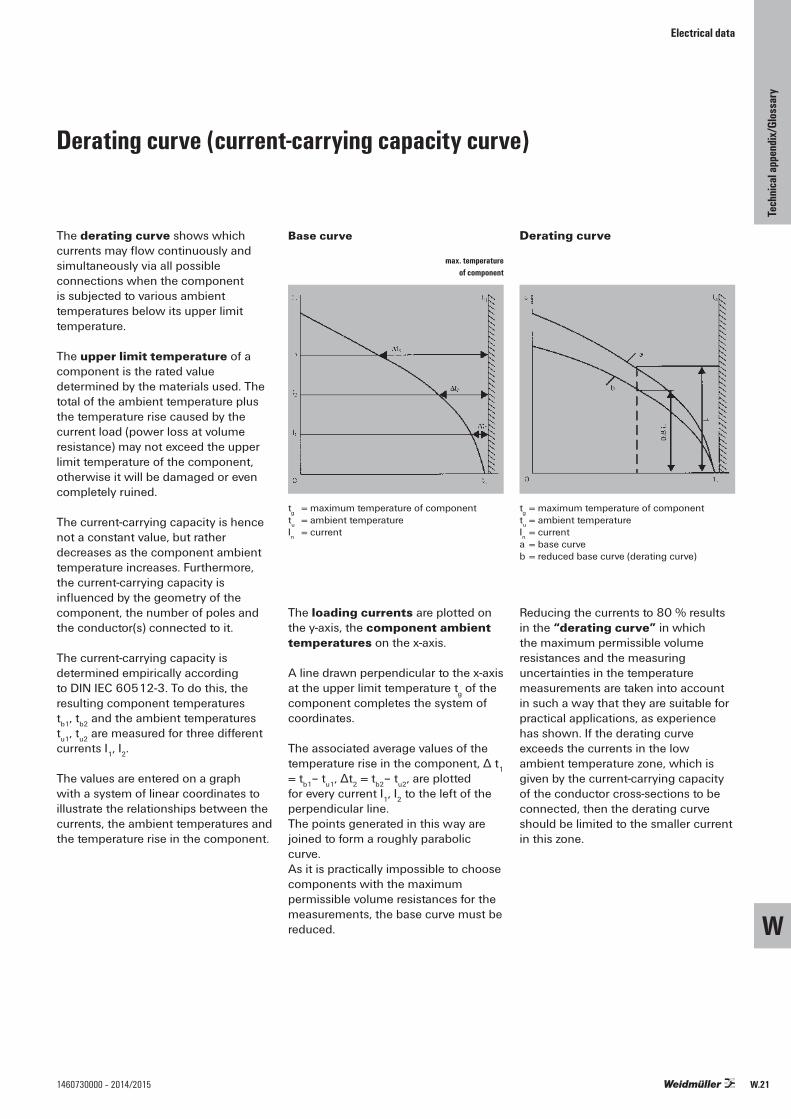
Electrical data
The derating curve shows whichcurrents may flow continuously andsimultaneously via all possible connections when the component is subjected to various ambient temperatures below its upper limit temperature.
The upper limit temperature of acomponent is the rated value determined by the materials used. The total of the ambient temperature plus the temperature rise caused by the current load (power loss at volume resistance) may not exceed the upper limit temperature of the component, otherwise it will be damaged or even completely ruined.
The current-carrying capacity is hence not a constant value, but ratherdecreases as the component ambient temperature increases. Furthermore, the current-carrying capacity is influenced by the geometry of the component, the number of poles and the conductor(s) connected to it.
The current-carrying capacity is determined empirically according to DIN IEC 60512-3. To do this, the resulting component temperatures tb1, tb2 and the ambient temperatures tu1, tu2 are measured for three different currents I1, I2.
The values are entered on a graph with a system of linear coordinates to illustrate the relationships between the currents, the ambient temperatures and the temperature rise in the component.
Derating curve (current-carrying capacity curve)
The loading currents are plotted on the y-axis, the component ambient temperatures on the x-axis.
A line drawn perpendicular to the x-axis at the upper limit temperature tg of the component completes the system of coordinates.
The associated average values of the temperature rise in the component, Δ t1 = tb1– tu1, Δt2 = tb2– tu2, are plottedfor every current I1, I2 to the left of theperpendicular line. The points generated in this way are joined to form a roughly parabolic curve. As it is practically impossible to choose components with the maximum permissible volume resistances for the measurements, the base curve must be reduced.
Reducing the currents to 80 % results in the “derating curve” in which the maximum permissible volume resistances and the measuring uncertainties in the temperature measurements are taken into account in such a way that they are suitable for practical applications, as experience has shown. If the derating curve exceeds the currents in the low ambient temperature zone, which is given by the current-carrying capacity of the conductor cross-sections to be connected, then the derating curve should be limited to the smaller current in this zone.
tg = maximum temperature of componenttu = ambient temperatureIn = current
tg = maximum temperature of componenttu = ambient temperatureIn = currenta = base curveb = reduced base curve (derating curve)
Base curve
max. temperature of component
Derating curve
W
Tech
nical
appe
ndix/
Glos
sary
W.211460730000 – 2014/2015

General technical information
IP class of protection to DIN EN 60529
The class of protection is indicated by a code consistingof the two letters IP and two digits representing the class of protection.
Example: I P 6 5 2nd digit: protection from liquids 1st digit: protection from solid bod
Protection against intrusion of external particle matter (1st digit)Digit
0 No protection
1Protection against ingress of large solid bodies with diame-ter > 50 mm. (Protection to prevent dangerous parts being touched with the back ofthe hand.)
2Protection against ingress of large solid bodieswith diameter > 12.5 mm. (Protection to prevent dangerous parts being touched with the fingers.)
32.5 mm
Protection against ingress of large solid bodies with diameter > 2.5 mm. (Protection to prevent dangerous parts being touched with a tool.)
41.0 mm
Protection against ingress of large solid bodieswith diameter > 1 mm. (Protection to prevent dangerous parts being touched with a piece of wire.)
5Protection against harmful deposits of dust, which cannot enter in an amount sufficient to interfere with satisfactory operation.
6 Complete protection against ingress of dust.
Protection against penetration of liquids (2nd digit)Digit
0 No protection
1 Protection against drops of condensed water fallingvertically.
2 Protection against drops of liquid falling at an angle of 15° with respect to the vertical.
3 Protection against drops of liquid falling at an angle of 60° with respect to the vertical.
4 Protection against liquids splashed from any direction.
5 Protection against water jets projected by a nozzle from any direction.
6 Protection against water from heavy sea on ships’ decks.
7 1 m Protection against immersion in water under defined
conditions of pressure and time.
8Protection against indefinite immersion in water underdefined conditions of pressure (which must be agreed between manufacturer and user and must be more adverse than number 7).
W
Tech
nical
appe
ndix/
Glos
sary
W.22 1460730000 – 2014/2015
General technical information
Overview of CE labelling
The CE marking, seen on various products and their packaging, is neither a sign of quality nor safety. The CE marking is a conformity marking that was introduced to ensure the unhindered movement of goods throughout the Single European Market.It is not intended to be a reference for end consumers. TheCE marking merely shows that the manufacturer has complied with all the EU directives applicable to that product. Therefore, the CE marking should be regarded as verification of conformity with the relevant directives and is aimed at the monitoring authorities responsible. For goods crossing the political borders of the European Union, the CE marking is like a “passport”. Weidmüller takes into account all the relevant EU directives according to the best of its knowledge and belief.
Currently the following directives apply:2006/95/EG – Electrical equipment for use within specificvoltage ranges (Low-voltage Directive)2004/108/EG – Electromagnetic compatibility (EMC Directive)2006/42/EG – Safety of machines (Machinery Directive)
CE marking / EMC directives
The standards cited in the directives have long since been intrinsic to Weidmüller’s development standards. This providesthe guarantee of conformity with the EU directives. Our testing laboratory, accredited to EN 45001, performs the tests in accordance with the standards. The test reports are recognised within Europe within the framework of the accreditation process.
2006/95/EC Low Voltage Directive – Electrical equipment in this directive means all electrical equipment with a nominal voltage between 50 and 1000 V AC and between 75 and 1500 V DC. For an electrical product to be given the CE marking, it must fulfil the requirements of the EMC Directive and, if applicable, the Low-voltage Directive (50 V AC or 75 V DC). According to the Low-voltage Directive, a conformity assessment procedure has to be carried out for the product. Conformity with the directive is deemed to be given if there is a reference to a harmonised European standard or another “technical specification”, e.g. IEC standards or national standards.
2004/108/EG EMC directives – With the decree of the directive of the European Council dated 3 May 1989 for the alignment of the legal requirements of the member states concerning „Electromagnetic Compatibility“, the European Union has declared EMC as a protection objective. The former EMC directive 89/336/EWG was replaced onDecember 31, 2004 by the revised version 2004/108/EG which has been valid since July 20, 2009.
W
Tech
nical
appe
ndix/
Glos
sary
W.231460730000 – 2014/2015

General technical information
CE marking / EMC directives
The safety goals are defined in Article 5 of the EMC regulation of December, 31 2004. They state the following:• The electromagnetic disturbance generated must not
exceed a level allowing radio and telecommunications equipment and other apparatus to operate as intended.
• The apparatus has an adequate level of intrinsic immunity to electromagnetic disturbance to enable it to operate as intended.
Apparatus is defined in the EMC Directive as follows:• All electrical and electronic appliances together with
equipment and installations containing electrical and/or electronic components.
This applies to the active/passive components and intelligent modules produced and stocked by Weidmüller.Compliance with this directive is deemed to be given for apparatus that conforms with the harmonised European standards that are published in, for example, in Germany, in the Gazette of the Federal Minister for Post and Telecommunications.
Such apparatus is utilised in the following areas:• industrial installations,• medical and scientific equipment and devices• information technology devices.Weidmüller tests its electronic products according to the relevant standards in order to fulfil the agreed protection objectives.
Electronic products from Weidmüller with respect to EMCdirectives
Category 1All passive components such as:• terminals with status displays• fuse terminals with status indicators• passive interface units with and without status indicators• surge protectionThese products cause no interference and they have a suitable immunity to interference. These products are not labelled with the CE marking concerning the EMC Directive or the German EMC Act.
Category 2These products are labelled with the CE marking after theconformity assessment procedure has been carried out which includes the reference to the harmonised European standards.
The following are harmonised standards:EN 61000-6-3 – Generic Emission Standard – Part 1: residential, commercial and light industryEN 61000-6-1 – Generic Immunity Standard – Part 1: residential, commercial and light industryEN 61000-6-4 – Generic Emission Standard – Part 2: industrial environmentEN 61000-6-2 – Generic Immunity Standard –Part 2: industrial environmentEN 55011 – Industrial, scientific and medical (ISM) radio-frequency equipment – Radio disturbance characteristics – Limits and methods of measurementEN 55022 – Information technology equipment –Radio disturbance characteristics – Limits and methods of measurementEN 61000-3-2 – Electromagnetic compatibility (EMC) – Part 3-2: Limits for harmonic current emissions (equipment inputcurrent up to and including 16 A per phase).EN 61000-3-3 – Electromagnetic compatibility (EMC) – Part 3-3: Limitation of voltage fluctuations and flicker in low-voltage supplies systems for equipment with rated current less than or equal to 16 A per phase and not subject to conditional connection
Use of TestsGeneric standards are always used when no specific product standard for the particular devices exist. The generic standards EN 61000-6-X are used as the basis for Weidmüller products.
Note:The relevance of EN 61000-6-1 for certain products must be checked as well as and how far generic standards EN 61000-6-3 or EN 61000-6-2 were considered during testing. The environment phenomena and test interference levels are specified in the generic immunity standards. In addition, Weidmüller considers the assessment criteria A, B and C.
Extract from the generic standard EN 61000-6-2:
Criterion AThe equipment shall continue to operate as intended. No degradation of performance or loss of function is allowed below a minimum performance level as specified by the manufacturer, when the equipment is used as intended.In certain cases the nominal performance level can be replaced by a permissible loss of performance. If the minimal performance level or permissible loss of performance is not specified by the manufacturer, both of these specifications can be derived from the description of the product, the relevant documentation and from what the operator expects from the equipment during its intended operation.
W
Tech
nical
appe
ndix/
Glos
sary
W.24 1460730000 – 2014/2015

Criterion B The equipment shall continue to operate as intended afterthe test. No degradation of performance or loss of function is allowed below a minimum performance level as specified by the manufacturer, when the equipment is used as intended. In certain cases the minimal performance level can be replaced by an permissible loss of performance. During testing degradation of the performance level is permitted; however, changes to the specified operation mode or data loss are not permitted. If the minimal performance level or permissible loss of performance is not specified by the manufacturer, both of these specifications can be derived from the description of the product, the relevant documentation and from what the operator expects from the equipment during its intended operation.
Criterion CTemporary loss of function is allowed, provided the loss of function is self-recoverable or can be restored by the operation of the controls. Criterion B is most frequently specified in the generic standards and is used by Weidmüller. Taking the example of a WAVEANALOG analogue coupler: During testing, the analogue coupler may convert values that lie outside the permissible tolerances. After testing, however, the values must lie within the given tolerances.
General installation instructionsIn conformity with the performance level and criteria A and B, the products may and can be affected by external influences during a fault. However, the aim should be to suppress this as far as possible by means of an optimum installation.
General technical information
Measures• Install the products in a metal enclosure (control cabinet,
metal housing).• Protect the voltage supplies with a surge protection
device• Use only shielded cables for analogue data signals.• Apply ESD measures during installation, maintenance and
operation.• Maintain min. 200 mm clearance between electronic
modules and sources of interference (e.g. inverters) or power lines.
• Ensure ambient temperature and relative humidity values do not exceed those specified.
• Protect long cables with surge protection devices.
For safety reasons, do not operate walkie-talkies and mobile telephones within a radius of 2 m of the equipment.
W
Tech
nical
appe
ndix/
Glos
sary
W.251460730000 – 2014/2015

Glossary
Glossary
1-92-way isolation The input and output signals are separated electrically from each other and
decoupled. Potential differences caused by long wire lengths and common reference points are eliminated.
3-way isolation Also decouples the power supply to the input and output circuit and enables supply with only one operating voltage.
AA/D converter Converts standardised analogue current and voltage signals into an 8-bit, 12-bit
or 16-bit digital signal. It may be necessary to convert analogue signals into digital signals when you need the analogue signal from the surroundings to work with the typical digital processing requirements of process monitoring.
AC Alternating current
Accuracy Describes the ability of an analogue signal isolating converter to transmit a measured value as precisely as possible. It is specified in the percent deviation from the measuring range end value at room temperature.
Active sensor In an active sensor, an electrical signal is generated from the measurement itself, for example dynamometric or piezo-electric. Thus no auxiliary power source is required. Because of their physical operating principals (since energy cannot be sent during the static and quasi-static states), only a change in the measured variable can be detected.
Actuator The actuator is a sensor counterpart – it converts electrical current into another form of energy.
Alarm contact A switching contact that activates when a disturbance occurs (for example, an overload or short circuit).
Ambient temperature DIN EN 60204-1 uses this term to refer to the temperature of the surrounding air or medium at which the equipment can be properly and safely operated. This is a part of the surrounding physical and operational conditions. Failure to maintain this temperature level can invalidate the product warranty.
Analogue signal A signal is designated as an analogue signal if it transmits parameter information that is infinitely variable between a minimum and maximum value (this includes instantaneous values such as current, voltage or temperature). This applies to practically all real-world processes or states. It is theoretically possible to registerany small signal changes (there is a very large dynamic range).
W
Tech
nical
appe
ndix/
Glos
sary
W.26 1460730000 – 2014/2015
Glossary
ATEX The ATEX directive from 23.4.1994 is valid within the EU and the EFTA Western European nations. It applies to devices, machinery components, controllers and protective systems that are to be used in hazardous areas. This directive harmonises the different national regulations from the EU member nations concerning the proper and intended use of machines and facilities in hazardous areas.ATEX is derived from the phrase “ATmosphere EXplosive”. It stipulates that operators should prevent explosions and ensure protection.Regarding explosion protection in a potentially explosive atmosphere, the ATEX directive 94/9/EC has precedence over machinery directives and must be followed The directive describes the following steps:• Describe how often a potentially explosive atmosphere occurs and where it
occurs.• These areas are then divided into zones according to the specifications.• Make sure that only properly categorised equipment is present within each
different zone. As soon as an area is classified as being dangerous, steps must be taken to limit the potential ignition sources that are present there.
CCalibration device A special instrument used for the calibration and configuration of analogue
signal conditioning devices. The calibration device produces highly precise standardised signals. It is equipped with a load indicator for quick loop diagnostics.
CE Abbreviation for Communauté Européenne (the European Community). Manufacturers use the CE label to confirm that their products comply with the corresponding EC directives and the “essential requirements” therein.
Cold-junction compensation Thermocouples require a temperature reference point to compensate for unwanted “cold junctions”. The usual method for achieving this is by measuring the temperature at the reference junction with a temperature sensor that can be read immediately. The interfering voltage can then be compensated for in the measurement results. This process is referred to as cold-junction compensation (CJC).
Common-mode interference Interfering currents and voltages that can occur on the connecting cables between electrical devices and facility components. These can then spread with similar phase and current direction to the feed line and the return line.
Counter A counter can be used for measuring flow or for counting events. Analogue or digital input signals (pulses) may also be processed. Integrated function such as linearisation, interference suppression, hysteresis configuration and reference values expand the range of use of a counter. Switching contacts are available on the output side for monitoring threshold.
W
Tech
nical
appe
ndix/
Glos
sary
W.271460730000 – 2014/2015

Glossary
Creepage and clearance distances The safety gaps between two current-carrying wires. The creepage distance is the shortest path along an insulating surface between two live components. The clearance distance is the shortest path in the air between two points of reference.
Clearance distance
Creepage distance
Housing contours
Live, current-carrying parts
DD/A converter D/A converters convert standardised digital signals (for example, with an 8-bit
structure) into analogue current and voltage signals.It may be necessary to convert digital signals into analogue signals when you need the analogue signal from the surroundings to work with the typical digital processing requirements of process monitoring.
DC Direct current
Derating The continuous current level reduction in relation to an ambient temperature increase, represented as a derating curve (a load reduction curve).
Derating curve
Cur
rent
str
engt
h
Temperature
Over the limit
Operating range
W
Tech
nical
appe
ndix/
Glos
sary
W.28 1460730000 – 2014/2015

Glossary
Device categories The device category determines which equipment can be used in which zone. There are six device categories. The categories 1 G, 2 G and 3 G are classifications for gas explosion protection (G = Gas). Equipment with 1 G is suitable for zones 0, 1 and 2. Equipment with 2 G is suitable for zones 1 and 2. Equipment with 3 G is suitable for zone 2. The categories 1 D, 2 D and 3 D are classifications for dust explosion protection (D = Dust). Equipment with 1 D is suitable for zones 20, 21 and 22. Equipment with 2 D is suitable for zones 21 and 22. Equipment with 3 D is suitable for zone 22.
Device groups Equipment is divided into groups I and II. Group I concerns underground mining while group II concerns explosion protection for gas and dust in all other applications.
DTM DTMs (Device Type Manager) are software drivers that are vendor- and device-neutral. DTMs define functions for access to device parameters, troubleshooting, configuration and operation of devices The DTM specifies all device-specific information, functions and rules (such as the device structure, communication capabilities, internal dependencies and the human-machine interface (HMI)).Device manufacturers make available a Device Type Manager (DTM) software driver for each device or device group.
EEIA-232/ RS232 The term EIA-232 (originally RS232) refers to a serial interface standard
developed by a U.S. standards committee (now known as the EIA – Electronic Industries Alliance) in the early 1960s. EIA-232 specifies the connection between the data terminal equipment (DTE) and the modem (data communication equipment or DCE). It defines timing, voltage level, plug and protocol details. EIA-232 defines a voltage interface. The information bits are encoded using electrical voltage. The data lines (TxD and RxD) use a negative logic whereby a voltage level between -3 V and -15 V (ANSI/EIA/TIA-232-F-1997) represents a logical one and a voltage level between +3 V and +15 V represents a logical zero. Signal levels between -3 V and +3 V are undefined.
EIA-422/ RS422 EIA-422 (also known as RS422) is an interface standard for cable-based differential, serial data transmission. In contrast to the asymmetric serial interface specified by the EIA-232 standard, the EIA-422 interface is designed for symmetric transmissions. This means that two sets of twisted pair wires are required to carry the positive and negative signals from the sender to the receiver. This minimises common-mode interferences and also increases the data rates in comparison to the asymmetric EIA-232 interface. EIA-422 can be used to establish a full-duplex, point-to-point connection. Multi-drop networks with one sender and up to ten receivers are also possible. The sender and receiver in multi-drop networks can only be operated in half-duplex (in one direction). Because of the high data rate (up to several MBit/s), a wire pair on the EIA-422 interface must be terminated with a terminating resistor (normally 120 ohm). W
Tech
nical
appe
ndix/
Glos
sary
W.291460730000 – 2014/2015
Glossary
EIA-485/ RS485 EIA-485, also referred to as RS485, is an interface standard for digital, cable-based, differential, serial data transmissions. EIA-485 uses a wire pair for transmitting inverted and non-inverted levels for a single-bit data signal. The original data signal is reconstructed by the receiver as the difference between the two voltage levels. This has the advantage of increasing the resistance to interference, since common-mode interference then has no effect on the transmission. The EIA-485 interface operates with a voltage differential of +/-200 mV, so that the voltage interface has a differential related to half of the operational voltage. It normally uses a single wire pair and is operated in half-duplex. However full-duplex operations are possible with two wire pairs.This connection has multi-point capabilities; up to 32 nodes can be connected to an EIA-485 bus. Standard cable lengths run up to 1.2 km in length and support transmission speeds up to 10 MBit/s. The wire pairs must be terminated with resistors (typically 120 Ohm) because of the cable length and high data rates.
Electrical equipment All of the electrical and electronic components and circuits within an enclosure.
Explosion groups Depending on the ignition protection, explosion-protected equipment intended for gases, vapours and mists are divided into three explosion groups (IIA-IIB-IIC).The explosion group provides a measure of the explosive break-though capability of gases (in an explosive atmosphere). The requirements for the equipment increase in strictness from II A to II C.
Explosion protection types The ignition protection type is a term used in explosion protection that refers to the various types of protective construction designed into the product. Ignition protection types are formulated to minimise the risk that an ignition source will be present in an explosive atmosphere.The following ignition protection types are specified:
• For electrical equipment in a gas• Intrinsic safety Ex i• Pressure-resistant Ex d encapsulation• Increased safety Ex e• Pressurization encapsulation Ex p• Oil immersion Ex o• Moulded encapsulation Ex m• Sand encapsulation Ex q• Ignition protection type for zone 2 Ex n• Special ignition protection type Ex s
• For electrical equipment in dust• Pressurization encapsulation Ex pD• Intrinsic safety Ex iD• Moulded encapsulation Ex mD• Protection provided by housing Es tD
W
Tech
nical
appe
ndix/
Glos
sary
W.30 1460730000 – 2014/2015

Glossary
Explosive atmospheres This is defined as a mixture of flammable materials and oxygen. An ignition leads to a explosive burning process throughout the entire mixture. Usually the oxygen is supplied by the surrounding air. Flammable materials may be gases, liquids, vapours, mists or dusts. Explosion protection considers this to be normal atmospheric conditions. The explosiveness of the mixture depends of the flammability of the materials and the concentration of air or oxygen.
FFlammability rating Flammability class specification according to the American UL 94 specification.
Duration of burning, annealing time and the burning drop formation are all taken into account. The highest category is V-0.
Frequency converter Converts frequencies into analogue signals (or vice versa). In-line control systems can then directly process pulse strings from speed or rotational measurements.
GGalvanic isolation Potential-free isolation between electrical components.
Normally, the inputs circuit, output circuit and power supply are designed so that they are electrically isolated from each other. The isolation can be achieved using optical means (an optocoupler) or by using a transformer. The electrical isolation of measurement signals ensures that the differences in earth potentials and common-mode interference are suppressed
GOST-R The Russian certification for products, materials and technical facilities.
HHall sensor current measurement Hall sensors can measure the magnetic field of a conducting wire. They then
generate a proportional voltage on the measurement output (the Hall voltage).This can be converted to a standardised signal by means of an amplifier circuit. Such a measurement is well suited for measuring high DC and AC currents with frequencies up to 1 kHz. Start-up currents and current peaks cannot damage a Hall sensor.
W
Tech
nical
appe
ndix/
Glos
sary
W.311460730000 – 2014/2015
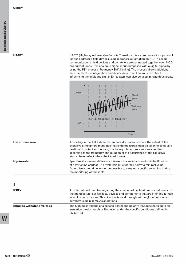
Glossary
HART® HART® (Highway Addressable Remote Transducer) is a communications protocol for bus-addressed field devices used in process automation. In HART®-based communications, field devices and controllers are connected together over 4–20 mA current loops. This analogue signal is superimposed with a digital signal by using the FSK process (Frequency Shift Keying). The process allows additional measurements, configuration and device data to be transmitted without influencing the analogue signal. Ex isolators can also be used in hazardous areas.
Time
4 mA
20 mADigitalsignal
Analoguesignal
Bit 1 Bit 0 Bit 0 Bit 1 Bit 1 Bit 0 Bit 1
Hazardous area According to the ATEX directive, an hazardous area is where the extent of the explosive atmosphere mandates that extra measures must be taken to safeguard health and protect surrounding machinery. Hazardous areas are classified according to the frequency and duration of the occurrence of the explosive atmosphere (refer to the sub-divided zones).
Hysteresis Specifies the percent difference between the switch-on and switch-off points of a switching contact. The hysteresis must not fall below a minimal value. Otherwise it would no longer be possible to carry out specific switching during the monitoring of threshold.
IIECEx An international directive regarding the creation of declarations of conformity by
the manufacturers of facilities, devices and components that are intended for use in explosion risk zones. This directive is valid throughout the globe but is only currently used in some Asian nations.
Impulse withstand voltage The high pulse voltage of a specified form and polarity that does not lead to an insulation breakthrough or flashover, under the specific conditions defined inEN 60664-1.
W
Tech
nical
appe
ndix/
Glos
sary
W.32 1460730000 – 2014/2015
Glossary
Initiator PNP/NPN switched Two wires in a three-wire sensor are responsible for keeping the supply activated. The third connecting wire is used for transferring commands (NO/NC contact). Initiators with NPN outputs switch the load in active mode towards the minus potential. Proximity switches with PNP outputs switch toward the plus potential.
Insulation voltage For electronics components with electrical isolation, this is the maximum AC testvoltage that can be applied for a specified time interval (5 s / 60 s) without causing a break-through.
Intrinsic safety “i” Electrical equipment for hazardous areas with the ignition protection type “Intrinsic safety Ex i” Intrinsic safety is divided into ignition protection types “ia” or “ib” The ignition protection type “intrinsic safety” is a protective strategy that requires a complex analysis of electronic devices. So it is not only important to protect intrinsically safe current from the other unsafe circuits. It is also important to limit the open-circuit voltage, short-circuit current, power, stored energy and the surface temperature of components that will be exposed to the explosive atmosphere.Intrinsically safe circuits are circuits where a spark or thermal effect (as may occur under the testing conditions specified by EN 60079-11) is not capable of igniting an explosive atmosphere (of sub-groups IIA, IIB or IIC) or a dust-air mixture. The testing conditions cover normal operations and certain error conditions as specified in the standard.
IP protection classes Equipment is assigned an IP protection class to indicate which environmental conditions it can be used in.
Isolation amplifier (active isolator) An isolation amplifier is used to provide electrical isolation for analogue standard signals. They are designed with 2-way or 3-way isolation. The isolation of the potentials eliminates interference on the measurement signal that can be caused by earth loops or common-mode noise. The active isolator makes use of a separate voltage source for its power supply. It functions without feedback; a change on the output side load does not influence the input circuit.
LLeakage current The current on the load side of an optocoupler that flows towards the output
circuit while in a closed state.
Limiting frequency The limiting frequency of an analogue signal isolating converter is that frequency where the output signal is reduced to 1/(sqr2) of the value of the input signal (approx. 70.7 % = -3 dB).
Line break monitoring Analogue measuring transducer with wire-break detection capability that permanently monitors the input signal. In the event of an fault (a wire break), the output signal jumps up to a defined value over the nominal range so that a controller wired further down the circuit can evaluate the error.
W
Tech
nical
appe
ndix/
Glos
sary
W.331460730000 – 2014/2015

Glossary
Linearisation Temperature-dependent components normally do not have a linear characteristic curve. Their characteristic curves must be linearised so that they can be evaluated as precisely as possible. The measurement curves of thermocouples and temperature-dependent resistors (NTC/ PTC), in particular, exhibit significant deviation from an “ideal curve”. In the linearisation process, the measurement signal is processed by a microprocessor and an ideal characteristic curve is generated which can then be analysed or processed further.
Load cell A load cell is a special type of force sensor used in weighing systems (i.e., with scales). They are calibrated in grams (g), kilograms (kg) or tons (t).Load cells usually have a spring mechanism used as a force sensor. The spring is a specially shaped piece of metal whose shape changes slightly when under the influence of weight. This elastic deformation is recorded by strain gauges and converted into an electrical signal. Weights can be recorded ranging from a few hundred grams to several thousand tons.
Load resistance (load) This is the load resistance on the output side of a measuring transducer or transmitter. For analogue current outputs, the load is 500–600 ohms maximum. Voltage outputs normally have a load of at least 10 kOhm.
MMeasurement isolating transformer Converts electric and non-electric input signals into standard analogue signals.
At the same time it provides electrical isolation between the input and output (2-way isolation) or between the input, output and supply (3-way isolation). Measurement isolators are typically used to record temperatures (RTD, thermocouples) or for measuring current, voltage, power, frequency, resistance and conductivity.
Measuring bridge Sensors based on Wheatstone bridge circuitry can capture force, pressure and torque. Relatively small length changes under 10 – 4 mm can be recorded using DMS strain gauges in the form of resistance changes. A typical application is for capturing measurements in load cells.
NNamur sensor NAMUR-compliant sensors (The standardization commission for measuring
and control technology in the German chemical industry) operate with a load-independent current. They have four modes so that an analogue evaluative unit can detect a sensor malfunction.1) Current of 0 mA => wire break, circuit is open2) Current of approx. 20 % of the max. value => Sensor ready, activated3) Current of approx. 60 % of the max. value => Sensor ready, not activated4) Current at max. value => short circuit, max. currentNAMUR sensors are suited for use in hazardous areas.
NEC 500 – 505 The relevant directives for the classification of explosion protection in the USA.NEC 500 regulates the standard Ex classifications (class – division – model). The NEC 505 defines the zone model based on the European and IEC classifications.
W
Tech
nical
appe
ndix/
Glos
sary
W.34 1460730000 – 2014/2015

Glossary
Nominal switching current – load side
The permitted load current of a relay contact or semiconductor contact when in continuous operations.
Nominal switching voltage – load side
The switching voltage that a relay contact or semiconductor contact uses in relation to its application.
OOutput-current loop-powered Output loop powered 2-wire transmitters have a 4 – 20 mA output. The
transmitter is supplied with power via the current loop on the output side. A typical loop consists of a regulated DC power supply, the 2-wire transmitter and a receiving device.
Overvoltage category The overvoltage categories are described in DIN EN 60664-1. The category dictates the insulation clearance gaps required. Category III is the default specification (EN 50178).
• Overvoltage category I Devices that are intended to be connected to the permanent electrical building installation. The measures for limiting transient surge voltages to the proper level are taken outside of the device. The protective mechanisms can either be in the permanent installation or between the permanent installation and the device.
• Overvoltage category II Devices that are intended to be connected to the permanent electrical building installation (such household appliances or portable tools).
• Overvoltage category III Devices that are a part of the permanent installation and other devices where a higher degree of availability is required. This includes the distributor panels, power switches, distribution systems (including cable, busbars, distributor boxes, switches and outlets) that are part of the permanent installation, devices intended for industrial use, and devices that are continually connected to the permanent installation (such as stationary motors).
• Overvoltage category IV Devices that are intended to be used on or near the power feed in a building’s electrical installation – ranging from the main distribution to the mains power system. This includes electrical meters, surge protection switches and ripple control equipment.
W
Tech
nical
appe
ndix/
Glos
sary
W.351460730000 – 2014/2015

Glossary
PPassive isolator/ input loop powered Generates its power supply from the input signal (0/4–20 mA).
The amount of current needed internally is so small that the measurement signal is not influenced. Transformers are used to provide the isolation between the input and the output.The advantages include: eliminates the influence of the mains power system, highly accurate, minimal signal delay, and minimal power used. Passive isolators do not function free from feedback;so a load change on the output circuit will automatically effect the input circuit as well.
Passive sensor Contains passive components whose parameters can be changed by the measured variables. A primary electronic mechanism converts these parameters into electric signals. An auxiliary external power source is needed for the passive sensor. Passive sensors can be used to determine both static and semi-static measured variables. For this reason, the majority of sensors have a passive construction. Examples of this type include load cells and resistance thermometers.
Pollution severity level The pollution severity level specifies the conditions of the immediate surroundings. It is defined in DIN EN 50178, Section 5.2.15.2.The pollution (contamination) severity level should be used to determine the required creepage distance for the insulation. Pollution degree 2 is the default specification.
• Pollution severity level 1 There is no contamination or only dry occurrences of non-conductive pollution.This pollution has no influence.
• Pollution severity level 2 There is only non-conductive pollution. Temporary occurrences of conductivity caused by condensation may also occur.
• Pollution severity level 3 Conductive pollution or dry, non-conductive pollution that can become conductive due to condensation is likely to occur.
• Pollution severity level 4 The contamination leads to continual conductivity which can be caused by such contaminants as conductive dust, rain or snow.
RRated voltage Specified by the insulation coordination – the rated voltage is the voltage level
at which the product can be safely operated, in relation to the corresponding pollution severity level and the surge voltage category.
Relative humidity The relationship between the actual moisture and the maximum possible quantity of water in the air. Expressed as a percentage.
W
Tech
nical
appe
ndix/
Glos
sary
W.36 1460730000 – 2014/2015
Glossary
RoHS The EC directive 2002/95/EC – concerning the restriction of the use of certain hazardous substances in electrical and electronic equipment – regulates the use of hazardous materials within devices and components. This directive, and it’s various implementations into national laws, are referred to by the abbreviation RoHS (Restriction of Hazardous Substances).
RTD/ PT100/ 1000 RTD sensors are temperature probes that operate based on the resistance changes which take in metal as the temperature changes. They are resistance thermometers based on PTC resistors. The electrical changes in resistance of a platinum wire or platinum film is often used for measuring temperatures ranging from -200 °C to 850 °C. The platinum temperature sensors are characterised by their nominal resistance R0 at a temperature of 0 °C. The standard types include:• PT100 (R0= 100 Ohm)• PT1000 (R0= 1 kOhm)A two-wire, three-wire or four-wire electrical connection can be used to electrically connect the PT/RTD sensor to the evaluative electronics. A three-wire or four-wire method eliminates any errors caused by the inherent resistance of the sensor connecting wires.In the three-wire method, one end is equipped with two pigtail connectors. In the four-wire method, both ends are equipped with two pigtail connectors.
SSelf-heating Self-heating refers to the temperature increase in an operating device caused by
the internal power loss.
Sensor A sensor is a physical component capable of capturing certain physical or chemical properties (such as thermal radiation, temperature, humidity, pressure, noise, brightness or acceleration) as a measurement. It may also be able to analyse the quality of the composition of the material surroundings. These values are captured using physical or chemical phenomena and then converted into another form (usually electrical signals) so they can be post-processed.
Signal distributorsplitter A signal isolator that accepts an analogue input signal and delivers at least two signals on the output side. This permits the signal to be transmitted to a PLC/DCS system and to a separate display. A signal multiplier is designed either as an active isolator with an external power feed or as an output loop powered version.
SIL Safety Integrity Level.The components must meet the requirements of IEC 61508 is order to reduce risk. This standard provides general requirements for avoiding and minimising device and equipment outages. It stipulates organization and technical requirements concerning device development and operation. Four safety levels are defined (from SIL1 for minimal risk to SIL4 for very high risk) for classifying facilities and risk-reduction measures. Risk-reduction measures must be more reliable when the classified risk level is higher.
Status indicator An LED that displays the operational status, such as operational (yellow), switching (green), and alarm/malfunction (red).
Step response time This is the time delay in the output signal change when there is a signal jump ranging from 10 to 90 % on the input side. The step response time is inversely proportional to the limiting frequency
Storage temperature The permitted ambient temperature, related to a specific relative humidity level, for which the product should be stored while in a current-free state.
W
Tech
nical
appe
ndix/
Glos
sary
W.371460730000 – 2014/2015

Glossary
Switching threshold The switch-on or switch-off point.
TTemperature classes Explosion-protected equipment that is to be installed into the Ex zone is
subdivided into six temperature classes (T1 to T6).These temperature classes define the maximum surface temperature permitted for the equipment. The definition is based on an ambient temperature of +40 °C.This temperature may not be exceeded on any part of the equipment at any point in time. In all cases, the maximum surface temperature must be lower than the ignition temperature of the surrounding medium. The requirements placed on the equipment become stricter from class T1 to T6.
Temperature coefficient The temperature coefficient describes the relative change of a physical variable based on the temperature change relative to a reference temperature (room temperature). It directly influences the precision of an analogue signal converter. The coefficient is specified in ppm/K of the corresponding measuring range end value.
Thermocouple A thermocouple is a component made of two different materials which are connected to each other at one end. An electrical voltage is created (based on the principle of the Seebeck effect) along a wire that connects the unattached ends when there is a temperature differential.The juncture point and the unattached ends must have different temperatures for a voltage to be generated.
The following thermocouples are used for industrial applications:
Thermal pair Short name Type Temperature range in °CNickel/Chrome-Nickel/Al NiCr-Ni/Al K -200 ... +1372Iron-constantan Fe-CuNi J -200 ... +1200Copper-constantan Cu-CuNi T -200 ... +400Nickel/Chrome constantan NiCr-CuNi E -200 ... +1000Platinum/10 % Rhodium-Platinum Pt10Rh-Pt S –50 ... +1760Platinum/13 % Rhodium-Platinum Pt13Rh-Pt R -50 ... +1760Nickel/Chrome-Nickel/Magnesium NiCr-NiMg N -200 ... +1300Platinum/30 % Rhodium - Platinum/6 % Rhodium Pt30Rh - Pt6Rh B 0 ... +1820
Temperature in °C
Volt
age
in u
V
6000
5000
4000
3000
2000
1000
0
-1000-400 -200 0 200 400 600 800 1000 1200 1400
W
Tech
nical
appe
ndix/
Glos
sary
W.38 1460730000 – 2014/2015
Glossary
Threshold monitoring The limiting values of physical variables must be continually monitored for industrial processes. This includes fill levels, temperatures, speed, positions, weights and frequencies. Specialised threshold monitoring components are used for this purpose. The sensor signals are captured on the input side, evaluated electronically and converted. The corresponding threshold (min/max) are then made available via the digital switching outputs (relays or transistors) to the external devices. Potentiometers can be used to customise each switching point and its minimum/maximum threshold as well as the switching hysteresis.
Transformer-based current measurement
Signal converters with transformer coupling are used for taking cost-effective measurements of sinusoidal currents (50/60 Hz). The current being measured flows directly through the primary coil of the measurement transformer. It is then stepped down and electronically processed in the converter.
True RMS value True RMS is the measure of the active component of alternating current and voltages. The root mean square (RMS) is a measure of the magnitude of varying quantities (such as alternating current and voltage). It is a constant value that relates to the power consumed by a resistive load in a specified time period. The RMS is dependent on the amplitude and the curve slope. Non-sinusoidal signals can only be measured and processed with “true RMS”-compliant devices.
TTY The TTY interface is a serial interface. This interface is often referred to as a 20-mA-current interface since a constant DC current of 20 mA flows through it during the idle state. In contrast to RS232, the data transmission for the asymmetric signal connection is not controlled by voltage changes but by a load-independent line current (typically 20 mA for High and 0 mA for Low). Thus there is no significant length-dependent voltage loss to take into consideration. Here the cable lengths can run up to several kilometres.TTY interfaces are currently used mostly where dedicated connections are required: for exchanging data between electronic scales, for large industrial displays, or for log printers.
Type of contact A contact is called normally open (NO) or a make contact if it is open when the armature is dropped out (no current in coil) and closed when the armature is picked up (current flowing in coil). A contact is called a break contact or normally closed (NC) contact if it interrupts the circuit when the armature is picked up. A combination of NC and NO is called a changeover (CO) contact. A relay may have one or more of such contacts:NC – Normally Closed = break contact (11, 12: NC contact)NO – Normally Open = make contact ( 13, 14: NO contact)CO – Change Over contact (11, 12, 14: CO contact
(11 is the shared (root) contact))
W
Tech
nical
appe
ndix/
Glos
sary
W.391460730000 – 2014/2015
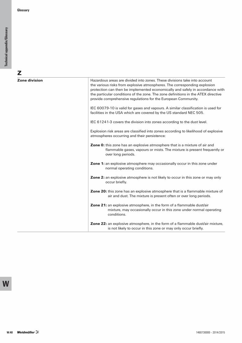
Glossary
ZZone division Hazardous areas are divided into zones. These divisions take into account
the various risks from explosive atmospheres. The corresponding explosion protection can then be implemented economically and safely in accordance with the particular conditions of the zone. The zone definitions in the ATEX directive provide comprehensive regulations for the European Community.
IEC 60079-10 is valid for gases and vapours. A similar classification is used for facilities in the USA which are covered by the US standard NEC 505.
IEC 61241-3 covers the division into zones according to the dust level.
Explosion risk areas are classified into zones according to likelihood of explosive atmospheres occurring and their persistence:
Zone 0: this zone has an explosive atmosphere that is a mixture of air and flammable gases, vapours or mists. The mixture is present frequently or over long periods.
Zone 1: an explosive atmosphere may occasionally occur in this zone under normal operating conditions.
Zone 2: an explosive atmosphere is not likely to occur in this zone or may only occur briefly.
Zone 20: this zone has an explosive atmosphere that is a flammable mixture of air and dust. The mixture is present often or over long periods.
Zone 21: an explosive atmosphere, in the form of a flammable dust/air mixture, may occasionally occur in this zone under normal operating conditions.
Zone 22: an explosive atmosphere, in the form of a flammable dust/air mixture, is not likely to occur in this zone or may only occur briefly.
W
Tech
nical
appe
ndix/
Glos
sary
W.40 1460730000 – 2014/2015

Glossary
W
Tech
nical
appe
ndix/
Glos
sary
W.411460730000 – 2014/2015

Glossar
W
Tech
nical
appe
ndix/
Glos
sary
W.42 1460730000 – 2014/2015

X.1
X
1460730000 – 2014/2015
Inde
x
Index
Index Index Type X.2
Index Order No. X.3
Contents

X.2
X
1460730000 – 2014/2015
Type Order No. Page Type Order No. Page Type Order No. Page
Inde
x / Ty
pe
AACT20-FEED-IN-BASIC-S 1282490000 C.29ACT20-FEED-IN-BASIC-S 1282490000 G.9ACT20-FEED-IN-PRO-S 8965500000 C.29ACT20-FEED-IN-PRO-S 8965500000 G.9ACT20C-AI-AO-MTCP 1334490000 D.7ACT20M-2CI-2CO-ILP-S 1176080000 C.18ACT20M-2CI-2CO-OLP-S 1176050000 C.19ACT20M-AI-2AO-S 1176020000 C.11ACT20M-AI-AO-E-S 1176010000 C.15ACT20M-AI-AO-S 1176000000 C.14ACT20M-BAI-2AO-S 1375470000 C.12ACT20M-BAI-AO-S 1375450000 C.16ACT20M-CI-2CO-S 1175990000 C.10ACT20M-CI-CO-ILP-S 1176070000 C.18ACT20M-CI-CO-OLP-S 1176040000 C.19ACT20M-CI-CO-S 1175980000 C.13ACT20M-RTCI-CO-OLP-S 1435590000 C.20ACT20M-RTI-AO-E-S 1375520000 C.23ACT20M-RTI-AO-S 1375510000 C.22ACT20M-RTI-CO-EOLP-S 1435610000 C.21ACT20M-TCI-AO-E-S 1375500000 C.25ACT20M-TCI-AO-S 1375480000 C.24ACT20M-UI-AO-S 1176030000 C.17ACT20P-2CI-2CO-12 7760054117 D.13ACT20P-BRIDGE-S 1067250000 D.17ACT20P-CI-2CO 7760054115 D.11ACT20P-CI-CO 7760054114 D.12ACT20X-2HAI-2SAO-S 8965440000 B.7ACT20X-2HDI-2SDO-RNC-S 8965380000 B.17ACT20X-2HDI-2SDO-RNO-S 8965370000 B.17ACT20X-2HDI-2SDO-S 8965390000 B.19ACT20X-2HTI-2SAO-S 8965480000 B.11ACT20X-2SAI-2HAO-S 8965460000 B.9ACT20X-2SDI-2HDO-S 8965420000 B.21ACT20X-CJC-HTI-S PRT 11 1160640000 G.10ACT20X-CJC-HTI-S PRT 21 1160650000 G.10ACT20X-HAI-SAO-S 8965430000 B.7ACT20X-HDI-SDO-RNC-S 8965350000 B.17ACT20X-HDI-SDO-RNO-S 8965340000 B.17ACT20X-HDI-SDO-S 8965360000 B.19ACT20X-HTI-SAO-S 8965470000 B.11ACT20X-HUI-SAO-LP-S 1318220000 B.15ACT20X-HUI-SAO-S 8965490000 B.13ACT20X-SAI-HAO-S 8965450000 B.9ACT20X-SDI-HDO-H-S 8965410000 B.23ACT20X-SDI-HDO-L-S 8965400000 B.21AMS400A 4-20mA/AO 7940011895 F.17AP MCZ1.5 8389030000 G.12
BBHZ 5.00/02/90LH BK/BK PRT 41 1086040000 G.10BHZ 5.00/02/90LH BK/BL PRT 11 1086250000 G.10BHZ 5.00/02/90LH BK/BL PRT 21 1086260000 G.10BHZ 5.00/04/90LH BK/BK PRT 11 1086130000 G.10BHZ 5.00/04/90LH BK/BK PRT 15 1086190000 G.10BHZ 5.00/04/90LH BK/BK PRT 21 1086140000 G.10BHZ 5.00/04/90LH BK/BK PRT 25 1086200000 G.10BHZ 5.00/04/90LH BK/BK PRT 31 1086150000 G.10BHZ 5.00/04/90LH BK/BK PRT 35 1086210000 G.10BHZ 5.00/04/90LH BK/BK PRT 41 1086160000 G.10BHZ 5.00/04/90LH BK/BK PRT 45 1086220000 G.10BHZ 5.00/04/90LH BK/BK PRT 51 1086170000 G.10BHZ 5.00/04/90LH BK/BK PRT 55 1086230000 G.10BHZ 5.00/04/90LH BK/BK PRT 61 1086180000 G.10BHZ 5.00/04/90LH BK/BK PRT 65 1086240000 G.10BHZ 5.00/04/90LH BK/BL PRT 11 1086370000 G.10BHZ 5.00/04/90LH BK/BL PRT 15 1086430000 G.10BHZ 5.00/04/90LH BK/BL PRT 21 1086380000 G.10BHZ 5.00/04/90LH BK/BL PRT 25 1086440000 G.10BHZ 5.00/04/90LH BK/BL PRT 31 1086390000 G.10BHZ 5.00/04/90LH BK/BL PRT 35 1086450000 G.10BHZ 5.00/04/90LH BK/BL PRT 41 1086400000 G.10BHZ 5.00/04/90LH BK/BL PRT 45 1086460000 G.10BHZ 5.00/04/90LH BK/BL PRT 51 1086410000 G.10BHZ 5.00/04/90LH BK/BL PRT 55 1086470000 G.10BHZ 5.00/04/90LH BK/BL PRT 61 1086420000 G.10BHZ 5.00/04/90LH BK/BL PRT 65 1086480000 G.10BLZ 5.08/02/180 SN OR BX 1526460000 G.13BLZ 5.08/02/180 SN OR PRT 2246070000 G.13BLZ 5.08/02/180 SN OR PRT 2246080000 G.13BLZ 5.08/02/180 SN OR PRT 2246090000 G.13BLZ 5.08/02/180 SN OR PRT 2246100000 G.13BLZ 5.08/03/180 SN OR PRT 2242030000 G.13BLZ 5.08/03/180 SN OR PRT 2242050000 G.13BLZ 5.08/03/180 SN OR PRT 2242060000 G.13BLZ 5.08/03/180 SN OR PRT 2242070000 G.13
CCBX100USB 7940025031 G.5CBX200 USB 8978580000 G.4CH20M BUS 4.50/05 AU/250 1248220000 C.27CH20M BUS 4.50/05 AU/250 1248220000 G.7CH20M BUS 4.50/05 AU/500 1248230000 C.27CH20M BUS 4.50/05 AU/500 1248230000 G.7CH20M BUS 4.50/05 AU/750 1248240000 C.27
CH20M BUS 4.50/05 AU/750 1248240000 G.7CH20M BUS-ADP TS 35/250 1248250000 C.27CH20M BUS-ADP TS 35/250 1248250000 G.7CH20M BUS-ADP TS 35/500 1248260000 C.27CH20M BUS-ADP TS 35/500 1248260000 G.7CH20M BUS-ADP TS 35/750 1248270000 C.27CH20M BUS-ADP TS 35/750 1248270000 G.7CH20M BUS-AP LI TS 35X7.5 & 15 1193160000 C.27CH20M BUS-AP LI TS 35X7.5 & 15 1193160000 G.7CH20M BUS-AP RE TS 35X7.5 & 15 1193170000 C.27CH20M BUS-AP RE TS 35X7.5 & 15 1193170000 G.7CH20M BUS-PROFIL TS 35X15/250 1248180000 C.27CH20M BUS-PROFIL TS 35X15/250 1248180000 G.7CH20M BUS-PROFIL TS 35X15/500 1248190000 C.27CH20M BUS-PROFIL TS 35X15/500 1248190000 G.7CH20M BUS-PROFIL TS 35X15/750 1248210000 C.27CH20M BUS-PROFIL TS 35X15/750 1248210000 G.7CH20M BUS-PROFIL TS 35X7.5/250 1248150000 C.27CH20M BUS-PROFIL TS 35X7.5/250 1248150000 G.7CH20M BUS-PROFIL TS 35X7.5/500 1248160000 C.27CH20M BUS-PROFIL TS 35X7.5/500 1248160000 G.7CH20M BUS-PROFIL TS 35X7.5/750 1248170000 C.27CH20M BUS-PROFIL TS 35X7.5/750 1248170000 G.7
DDI350 0-10V/0-100.0 7940011570 F.19DI350 4-20mA/0-100.0 7940010185 F.19
EESG 6.6/20 BHZ 5.00/04 1082540000 G.10ESG 8/13.5/43.3 SAI AU 1912130000 G.10ESG 8/13.5/43.3 SAI AU 1912130000 G.11
IITXPlus 7940016563 D.25
LLPD350 4-20mA/0-100.0 7940010163 F.21LPD450F 4-20mA 7940010236 F.23
MMCZ CCC 0-20mA/0-20mA 8411190000 C.32MCZ CFC 0-20MA 8461480000 C.34MCZ PT100/3 CLP -40C...100C 8604430000 C.33MCZ PT100/3 CLP -50C...+150C 8473000000 C.33MCZ PT100/3 CLP 0...100C 8425720000 C.33MCZ PT100/3 CLP 0...120C 8483680000 C.33MCZ PT100/3 CLP 0...150C 8604420000 C.33MCZ PT100/3 CLP 0...200C 8473010000 C.33MCZ PT100/3 CLP 0...300C 8473020000 C.33MCZ SC 0-10V 8260280000 C.35MCZ SC 0-20MA 8227350000 C.35MCZ VFC 0-10V 8461470000 C.34MF 5/7.5 MC NE WS 1877680000 G.11
PP275 7940010202 G.17PAS CMR 0,5...2,5 A DC 8742610000 E.6PAS CMR 2,0...5,0 A DC 8742620000 E.6PAS CMR 4,5...10 A DC 8742630000 E.7PMX400HZX 7940015595 F.15PMX400HZX RO/AO 7940011979 F.15PMX400TMP 7940017862 F.14PMX420 7940018956 F.11PMX420Plus 7940018957 F.10PORTACAL 1000EU 1439640000 G.15PTX800A 4-20mA 7940010243 F.7PTX800A 4-20mA/RO/AO 7940014374 F.7PTX800D 7940011133 F.6PTX800D RO/AO 7940012323 F.6
SSET CH20M BUS 250MM TS 35X15 1335150000 C.27SET CH20M BUS 250MM TS 35X15 1335150000 G.7SET CH20M BUS 250MM TS 35X7.5 1335140000 C.27SET CH20M BUS 250MM TS 35X7.5 1335140000 G.7
TTS 35X15/LL 1M/ST/ZN 0236510000 C.27TS 35X15/LL 1M/ST/ZN 0236510000 G.7TS 35X7.5/LL 1M/ST/ZN 0514510000 C.27TS 35X7.5/LL 1M/ST/ZN 0514510000 G.7
WWAS1 CMA 1/5/10A ac 8523400000 D.58WAS1 CMA LP 1/5/10A ac 8528650000 D.58WAS1 CMA LP 1/5/10A EX 8975590000 D.59WAS2 CMA 20/25/30A uc 8545830000 D.56WAS2 CMA 40/50/60A uc 8513330000 D.57WAS2 CMA 5/10A uc 8526610000 D.56
WAS2 CMR 1/5/10A ac 8516560000 E.5WAS2 CMR 20/40/60A ac 8513340000 E.5WAS2 VMA V ac 8581220000 D.60WAS2 VMR 3ph 8705630000 E.9WAS4 CCC DC 4-20/0-20MA 8445010000 D.38WAS4 CCC DC 4-20/4-20MA 8444980000 D.38WAS4 CVC DC 4-20/0-10V 8445040000 D.39WAS4 PRO DC/DC 8560740000 D.26WAS4 PRO Freq 8581180000 D.55WAS5 CCC 0-20/4-20mA 8540250000 D.32WAS5 CCC 0-20/0-20mA 8540180000 D.32WAS5 CCC 2OLP 8581160000 D.40WAS5 CCC 2OLP EX 8975640000 D.41WAS5 CCC 4-20/0-20MA 8540200000 D.34WAS5 CCC HF 0-20/0-20MA 8447160000 D.28WAS5 CCC HF 4-20/0-20MA 8447250000 D.29WAS5 CCC LP 0-20/0-20mA 8444950000 D.43WAS5 CCC LP 0-20/0-20mA 8463580000 D.43WAS5 CVC 0-20mA/0-10V 8540270000 D.33WAS5 CVC 4-20mA/0-10V 8540230000 D.34WAS5 CVC HF 0-20/0-10V 8447220000 D.28WAS5 CVC HF 4-20/0-10V 8447280000 D.29WAS5 DC/Alarm 8543820000 E.4WAS5 OLP 8543720000 D.42WAS5 PRO RTD 8560700000 D.44WAS5 PRO RTD 1000 8679490000 D.46WAS5 PRO RTD Cu 8638950000 D.48WAS5 PRO Thermo 8560720000 D.52WAS5 VCC 0-10V/0-20MA 8540310000 D.35WAS5 VCC 0-10V/4-20MA 8540290000 D.35WAS5 VCC HF 0-10/0-20MA 8447310000 D.30WAS5 VCC HF 0-10/4-20MA 8447340000 D.30WAS5 VMR 1ph 8705640000 E.8WAS5 VVC 0-10V/0-10V 8540330000 D.36WAS5 VVC HF +-10V/+-10V 8561610000 D.31WAS5 VVC HF 0-10/0-10V 8447370000 D.31WAS6 TTA 8939670000 D.22WAS6 TTA EX 8964310000 D.23WAVEPak DC/DC 7940024139 D.27WAZ1 CMA 1/5/10A ac 8523410000 D.58WAZ1 CMA LP 1/5/10A ac 8528660000 D.58WAZ2 CMA 20/25/30A uc 8545840000 D.56WAZ2 CMA 40/50/60A uc 8526590000 D.57WAZ2 CMA 5/10A uc 8526620000 D.56WAZ2 CMR 1/5/10A ac 8516570000 E.5WAZ2 CMR 20/40/60A ac 8526600000 E.5WAZ2 VMA V ac 8581230000 D.60WAZ4 CCC DC 4-20/4-20MA 8444990000 D.38WAZ4 CVC DC 4-20/0-10V 8445050000 D.39WAZ4 PRO DC/DC 8560750000 D.26WAZ4 PRO Freq 8581190000 D.55WAZ5 CCC 0-20/0-20mA 8540190000 D.32WAZ5 CCC 2OLP 8581170000 D.40WAZ5 CCC HF 0-20/0-20MA 8447170000 D.28WAZ5 CCC LP 0-20/0-20mA 8444960000 D.43WAZ5 CCC LP 0-20/0-20mA 8463590000 D.43WAZ5 DC/Alarm 8543880000 E.4WAZ5 OLP 8543730000 D.42WAZ5 PRO RTD 8560710000 D.44WAZ5 PRO Thermo 8560730000 D.52WAZ5 VCC 0-10V/0-20MA 8540320000 D.35WAZ5 VCC 0-10V/4-20MA 8540300000 D.35WAZ5 VVC 0-10V/0-10V 8540340000 D.36WAZ5 VVC HF 0-10/0-10V 8447380000 D.31WAZ6 TTA 8939680000 D.22WAZ6 TTA EX 8964320000 D.23WDS2 RS232/RS485/422 8615700000 D.63WDS2 RS232/TTY 8615690000 D.64WS 10/5 MC NE WS 1635000000 G.12WS 10/6 MC NE WS 1828450000 G.12WS 15/5 MC NE WS 1609880000 G.12WTS4 THERMO 8432300000 D.53WTZ4 PT100/2 C 0/4-20mA 8432220000 D.51WTZ4 PT100/2 C 0/4-20mA variabel 8432229999 D.51WTZ4 PT100/2 V 0-10V 8432190000 D.51WTZ4 PT100/2 V 0-10V variabel 8432199999 D.51WTZ4 PT100/3 C 0/4-20mA 8432160000 D.50WTZ4 PT100/3 C 0/4-20mA variabel 8432169999 D.50WTZ4 PT100/3 V 0-10V 8432130000 D.50WTZ4 PT100/4 C 0/4-20mA 8432280000 D.49WTZ4 PT100/4 C 0/4-20mA variabel 8432289999 D.49WTZ4 PT100/4 V 0-10V 8432250000 D.49WTZ4 PT100/4 V 0-10V variabel 8432259999 D.49WTZ4 THERMO 8432310000 D.53
ZZQV 2.5N/2 BL 1717990000 G.12ZQV 2.5N/2 GE 1693800000 G.12ZQV 2.5N/2 RT 1717900000 G.12ZQV 2.5N/2 SW 1718080000 G.12ZQV 4N/10 GE 1758260000 G.12ZQV 4N/2 GE 1758250000 G.12ZQV 4N/3 GE 1762630000 G.12ZQV 4N/4 GE 1762620000 G.12ZQV 4N/5 7760711001 G.12
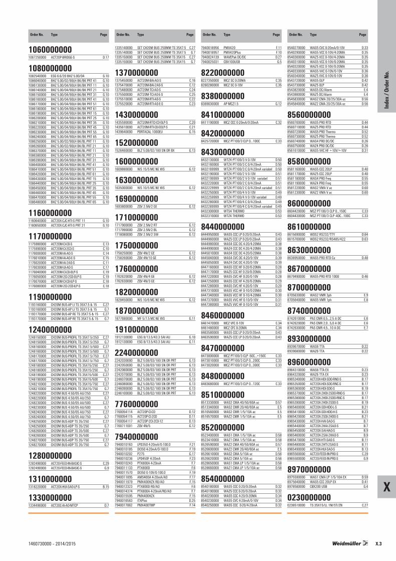
X.3
X
1460730000 – 2014/2015
Order No. Type Page Order No. Type Page Order No. Type Page Order No. Type Page
Inde
x / O
rder
No.
10600000001067250000 ACT20P-BRIDGE-S D.17
10800000001082540000 ESG 6.6/20 BHZ 5.00/04 G.101086040000 BHZ 5.00/02/90LH BK/BK PRT 41 G.101086130000 BHZ 5.00/04/90LH BK/BK PRT 11 G.101086140000 BHZ 5.00/04/90LH BK/BK PRT 21 G.101086150000 BHZ 5.00/04/90LH BK/BK PRT 31 G.101086160000 BHZ 5.00/04/90LH BK/BK PRT 41 G.101086170000 BHZ 5.00/04/90LH BK/BK PRT 51 G.101086180000 BHZ 5.00/04/90LH BK/BK PRT 61 G.101086190000 BHZ 5.00/04/90LH BK/BK PRT 15 G.101086200000 BHZ 5.00/04/90LH BK/BK PRT 25 G.101086210000 BHZ 5.00/04/90LH BK/BK PRT 35 G.101086220000 BHZ 5.00/04/90LH BK/BK PRT 45 G.101086230000 BHZ 5.00/04/90LH BK/BK PRT 55 G.101086240000 BHZ 5.00/04/90LH BK/BK PRT 65 G.101086250000 BHZ 5.00/02/90LH BK/BL PRT 11 G.101086260000 BHZ 5.00/02/90LH BK/BL PRT 21 G.101086370000 BHZ 5.00/04/90LH BK/BL PRT 11 G.101086380000 BHZ 5.00/04/90LH BK/BL PRT 21 G.101086390000 BHZ 5.00/04/90LH BK/BL PRT 31 G.101086400000 BHZ 5.00/04/90LH BK/BL PRT 41 G.101086410000 BHZ 5.00/04/90LH BK/BL PRT 51 G.101086420000 BHZ 5.00/04/90LH BK/BL PRT 61 G.101086430000 BHZ 5.00/04/90LH BK/BL PRT 15 G.101086440000 BHZ 5.00/04/90LH BK/BL PRT 25 G.101086450000 BHZ 5.00/04/90LH BK/BL PRT 35 G.101086460000 BHZ 5.00/04/90LH BK/BL PRT 45 G.101086470000 BHZ 5.00/04/90LH BK/BL PRT 55 G.101086480000 BHZ 5.00/04/90LH BK/BL PRT 65 G.10
11600000001160640000 ACT20X-CJC-HTI-S PRT 11 G.101160650000 ACT20X-CJC-HTI-S PRT 21 G.10
11700000001175980000 ACT20M-CI-CO-S C.131175990000 ACT20M-CI-2CO-S C.101176000000 ACT20M-AI-AO-S C.141176010000 ACT20M-AI-AO-E-S C.151176020000 ACT20M-AI-2AO-S C.111176030000 ACT20M-UI-AO-S C.171176040000 ACT20M-CI-CO-OLP-S C.191176050000 ACT20M-2CI-2CO-OLP-S C.191176070000 ACT20M-CI-CO-ILP-S C.181176080000 ACT20M-2CI-2CO-ILP-S C.18
11900000001193160000 CH20M BUS-AP LI TS 35X7.5 & 15 C.271193160000 CH20M BUS-AP LI TS 35X7.5 & 15 G.71193170000 CH20M BUS-AP RE TS 35X7.5 & 15 C.271193170000 CH20M BUS-AP RE TS 35X7.5 & 15 G.7
12400000001248150000 CH20M BUS-PROFIL TS 35X7.5/250 C.271248150000 CH20M BUS-PROFIL TS 35X7.5/250 G.71248160000 CH20M BUS-PROFIL TS 35X7.5/500 C.271248160000 CH20M BUS-PROFIL TS 35X7.5/500 G.71248170000 CH20M BUS-PROFIL TS 35X7.5/750 C.271248170000 CH20M BUS-PROFIL TS 35X7.5/750 G.71248180000 CH20M BUS-PROFIL TS 35X15/250 C.271248180000 CH20M BUS-PROFIL TS 35X15/250 G.71248190000 CH20M BUS-PROFIL TS 35X15/500 C.271248190000 CH20M BUS-PROFIL TS 35X15/500 G.71248210000 CH20M BUS-PROFIL TS 35X15/750 C.271248210000 CH20M BUS-PROFIL TS 35X15/750 G.71248220000 CH20M BUS 4.50/05 AU/250 C.271248220000 CH20M BUS 4.50/05 AU/250 G.71248230000 CH20M BUS 4.50/05 AU/500 C.271248230000 CH20M BUS 4.50/05 AU/500 G.71248240000 CH20M BUS 4.50/05 AU/750 C.271248240000 CH20M BUS 4.50/05 AU/750 G.71248250000 CH20M BUS-ADP TS 35/250 C.271248250000 CH20M BUS-ADP TS 35/250 G.71248260000 CH20M BUS-ADP TS 35/500 C.271248260000 CH20M BUS-ADP TS 35/500 G.71248270000 CH20M BUS-ADP TS 35/750 C.271248270000 CH20M BUS-ADP TS 35/750 G.7
12800000001282490000 ACT20-FEED-IN-BASIC-S C.291282490000 ACT20-FEED-IN-BASIC-S G.9
13100000001318220000 ACT20X-HUI-SAO-LP-S B.15
13300000001334490000 ACT20C-AI-AO-MTCP D.7
1335140000 SET CH20M BUS 250MM TS 35X7.5 C.271335140000 SET CH20M BUS 250MM TS 35X7.5 G.71335150000 SET CH20M BUS 250MM TS 35X15 C.271335150000 SET CH20M BUS 250MM TS 35X15 G.7
13700000001375450000 ACT20M-BAI-AO-S C.161375470000 ACT20M-BAI-2AO-S C.121375480000 ACT20M-TCI-AO-S C.241375500000 ACT20M-TCI-AO-E-S C.251375510000 ACT20M-RTI-AO-S C.221375520000 ACT20M-RTI-AO-E-S C.23
14300000001435590000 ACT20M-RTCI-CO-OLP-S C.201435610000 ACT20M-RTI-CO-EOLP-S C.211439640000 PORTACAL 1000EU G.15
15200000001526460000 BLZ 5.08/02/180 SN OR BX G.13
16000000001609880000 WS 15/5 MC NE WS G.12
16300000001635000000 WS 10/5 MC NE WS G.12
16900000001693800000 ZQV 2.5N/2 GE G.12
17100000001717900000 ZQV 2.5N/2 RT G.121717990000 ZQV 2.5N/2 BL G.121718080000 ZQV 2.5N/2 SW G.12
17500000001758250000 ZQV 4N/2 GE G.121758260000 ZQV 4N/10 GE G.12
17600000001762620000 ZQV 4N/4 GE G.121762630000 ZQV 4N/3 GE G.12
18200000001828450000 WS 10/6 MC NE WS G.12
18700000001877680000 MF 5/7.5 MC NE WS G.11
19100000001912130000 ESG 8/13.5/43.3 SAI AU G.101912130000 ESG 8/13.5/43.3 SAI AU G.11
22400000002242030000 BLZ 5.08/03/180 SN OR PRT G.132242050000 BLZ 5.08/03/180 SN OR PRT G.132242060000 BLZ 5.08/03/180 SN OR PRT G.132242070000 BLZ 5.08/03/180 SN OR PRT G.132246070000 BLZ 5.08/02/180 SN OR PRT G.132246080000 BLZ 5.08/02/180 SN OR PRT G.132246090000 BLZ 5.08/02/180 SN OR PRT G.132246100000 BLZ 5.08/02/180 SN OR PRT G.13
77600000007760054114 ACT20P-CI-CO D.127760054115 ACT20P-CI-2CO D.117760054117 ACT20P-2CI-2CO-12 D.137760711001 ZQV 4N/5 G.12
79400000007940010163 LPD350 4-20mA/0-100.0 F.217940010185 DI350 4-20mA/0-100.0 F.197940010202 P275 G.177940010236 LPD450F 4-20mA F.237940010243 PTX800A 4-20mA F.77940011133 PTX800D F.67940011570 DI350 0-10V/0-100.0 F.197940011895 AMS400A 4-20mA/AO F.177940011979 PMX400HZX RO/AO F.157940012323 PTX800D RO/AO F.67940014374 PTX800A 4-20mA/RO/AO F.77940015595 PMX400HZX F.157940016563 ITXPlus D.257940017862 PMX400TMP F.14
7940018956 PMX420 F.117940018957 PMX420Plus F.107940024139 WAVEPak DC/DC D.277940025031 CBX100USB G.5
82200000008227350000 MCZ SC 0-20MA C.358260280000 MCZ SC 0-10V C.35
83800000008389030000 AP MCZ1.5 G.12
84100000008411190000 MCZ CCC 0-20mA/0-20mA C.32
84200000008425720000 MCZ PT100/3 CLP 0...100C C.33
84300000008432130000 WTZ4 PT100/3 V 0-10V D.508432160000 WTZ4 PT100/3 C 0/4-20mA D.508432169999 WTZ4 PT100/3 C 0/4-20mA variabel D.508432190000 WTZ4 PT100/2 V 0-10V D.518432199999 WTZ4 PT100/2 V 0-10V variabel D.518432220000 WTZ4 PT100/2 C 0/4-20mA D.518432229999 WTZ4 PT100/2 C 0/4-20mA variabel D.518432250000 WTZ4 PT100/4 V 0-10V D.498432259999 WTZ4 PT100/4 V 0-10V variabel D.498432280000 WTZ4 PT100/4 C 0/4-20mA D.498432289999 WTZ4 PT100/4 C 0/4-20mA variabel D.498432300000 WTS4 THERMO D.538432310000 WTZ4 THERMO D.53
84400000008444950000 WAS5 CCC LP 0-20/0-20mA D.438444960000 WAZ5 CCC LP 0-20/0-20mA D.438444980000 WAS4 CCC DC 4-20/4-20MA D.388444990000 WAZ4 CCC DC 4-20/4-20MA D.388445010000 WAS4 CCC DC 4-20/0-20MA D.388445040000 WAS4 CVC DC 4-20/0-10V D.398445050000 WAZ4 CVC DC 4-20/0-10V D.398447160000 WAS5 CCC HF 0-20/0-20MA D.288447170000 WAZ5 CCC HF 0-20/0-20MA D.288447220000 WAS5 CVC HF 0-20/0-10V D.288447250000 WAS5 CCC HF 4-20/0-20MA D.298447280000 WAS5 CVC HF 4-20/0-10V D.298447310000 WAS5 VCC HF 0-10/0-20MA D.308447340000 WAS5 VCC HF 0-10/4-20MA D.308447370000 WAS5 VVC HF 0-10/0-10V D.318447380000 WAZ5 VVC HF 0-10/0-10V D.31
84600000008461470000 MCZ VFC 0-10V C.348461480000 MCZ CFC 0-20MA C.348463580000 WAS5 CCC LP 0-20/0-20mA D.438463590000 WAZ5 CCC LP 0-20/0-20mA D.43
84700000008473000000 MCZ PT100/3 CLP -50C...+150C C.338473010000 MCZ PT100/3 CLP 0...200C C.338473020000 MCZ PT100/3 CLP 0...300C C.33
84800000008483680000 MCZ PT100/3 CLP 0...120C C.33
85100000008513330000 WAS2 CMA 40/50/60A uc D.578513340000 WAS2 CMR 20/40/60A ac E.58516560000 WAS2 CMR 1/5/10A ac E.58516570000 WAZ2 CMR 1/5/10A ac E.5
85200000008523400000 WAS1 CMA 1/5/10A ac D.588523410000 WAZ1 CMA 1/5/10A ac D.588526590000 WAZ2 CMA 40/50/60A uc D.578526600000 WAZ2 CMR 20/40/60A ac E.58526610000 WAS2 CMA 5/10A uc D.568526620000 WAZ2 CMA 5/10A uc D.568528650000 WAS1 CMA LP 1/5/10A ac D.588528660000 WAZ1 CMA LP 1/5/10A ac D.58
85400000008540180000 WAS5 CCC 0-20/0-20mA D.328540190000 WAZ5 CCC 0-20/0-20mA D.328540200000 WAS5 CCC 4-20/0-20MA D.348540230000 WAS5 CVC 4-20mA/0-10V D.348540250000 WAS5 CCC 0-20/4-20mA D.32
8540270000 WAS5 CVC 0-20mA/0-10V D.338540290000 WAS5 VCC 0-10V/4-20MA D.358540300000 WAZ5 VCC 0-10V/4-20MA D.358540310000 WAS5 VCC 0-10V/0-20MA D.358540320000 WAZ5 VCC 0-10V/0-20MA D.358540330000 WAS5 VVC 0-10V/0-10V D.368540340000 WAZ5 VVC 0-10V/0-10V D.368543720000 WAS5 OLP D.428543730000 WAZ5 OLP D.428543820000 WAS5 DC/Alarm E.48543880000 WAZ5 DC/Alarm E.48545830000 WAS2 CMA 20/25/30A uc D.568545840000 WAZ2 CMA 20/25/30A uc D.56
85600000008560700000 WAS5 PRO RTD D.448560710000 WAZ5 PRO RTD D.448560720000 WAS5 PRO Thermo D.528560730000 WAZ5 PRO Thermo D.528560740000 WAS4 PRO DC/DC D.268560750000 WAZ4 PRO DC/DC D.268561610000 WAS5 VVC HF +-10V/+-10V D.31
85800000008581160000 WAS5 CCC 2OLP D.408581170000 WAZ5 CCC 2OLP D.408581180000 WAS4 PRO Freq D.558581190000 WAZ4 PRO Freq D.558581220000 WAS2 VMA V ac D.608581230000 WAZ2 VMA V ac D.60
86000000008604420000 MCZ PT100/3 CLP 0...150C C.338604430000 MCZ PT100/3 CLP -40C...100C C.33
86100000008615690000 WDS2 RS232/TTY D.648615700000 WDS2 RS232/RS485/422 D.63
86300000008638950000 WAS5 PRO RTD Cu D.48
86700000008679490000 WAS5 PRO RTD 1000 D.46
87000000008705630000 WAS2 VMR 3ph E.98705640000 WAS5 VMR 1ph E.8
87400000008742610000 PAS CMR 0,5...2,5 A DC E.68742620000 PAS CMR 2,0...5,0 A DC E.68742630000 PAS CMR 4,5...10 A DC E.7
89300000008939670000 WAS6 TTA D.228939680000 WAZ6 TTA D.22
89600000008964310000 WAS6 TTA EX D.238964320000 WAZ6 TTA EX D.238965340000 ACT20X-HDI-SDO-RNO-S B.178965350000 ACT20X-HDI-SDO-RNC-S B.178965360000 ACT20X-HDI-SDO-S B.198965370000 ACT20X-2HDI-2SDO-RNO-S B.178965380000 ACT20X-2HDI-2SDO-RNC-S B.178965390000 ACT20X-2HDI-2SDO-S B.198965400000 ACT20X-SDI-HDO-L-S B.218965410000 ACT20X-SDI-HDO-H-S B.238965420000 ACT20X-2SDI-2HDO-S B.218965430000 ACT20X-HAI-SAO-S B.78965440000 ACT20X-2HAI-2SAO-S B.78965450000 ACT20X-SAI-HAO-S B.98965460000 ACT20X-2SAI-2HAO-S B.98965470000 ACT20X-HTI-SAO-S B.118965480000 ACT20X-2HTI-2SAO-S B.118965490000 ACT20X-HUI-SAO-S B.138965500000 ACT20-FEED-IN-PRO-S C.298965500000 ACT20-FEED-IN-PRO-S G.9
89700000008975590000 WAS1 CMA LP 1/5/10A EX D.598975640000 WAS5 CCC 2OLP EX D.418978580000 CBX200 USB G.4
02300000000236510000 TS 35X15/LL 1M/ST/ZN C.27

X.4
X
1460730000 – 2014/2015
Order No. Type Page
Inde
x / O
rder
No.
0236510000 TS 35X15/LL 1M/ST/ZN G.7
05100000000514510000 TS 35X7.5/LL 1M/ST/ZN C.270514510000 TS 35X7.5/LL 1M/ST/ZN G.7

X.5
X
1460730000 – 2014/2015
Inde
x
X.5
X

X.6
X
1460730000 – 2014/2015
Inde
x
We cannot guarantee that there are no mistakes in thepublications or software provided by us to the customer for thepurpose of making orders. We try our best to quickly correcterrors in our printed media.
All orders are based on our general terms of delivery, which canbe reviewed on the websites of our group companies where youplace your order. On demand we can also send the general termsof delivery to you.


Order number: 1460730000/10/2013/SMDM
Cata
logue
201
4/20
15An
alogu
e sign
al co
nditio
ning
Weidmüller – Your partner in Industrial Connectivity
As experienced experts we support our customers and partners around the worldwith products, solutions and services in the industrial environment of power,signal and data. We are at home in their industries and markets and know thetechnological challenges of tomorrow. We are therefore continuously developinginnovative, sustainable and useful solutions for their individual needs. Together weset standards in Industrial Connectivity.
Your local Weidmüller partner canbe found on our website:www.weidmueller.com/countries
Weidmüller Interface GmbH & Co. KGKlingenbergstraße 1632758 Detmold, GermanyT +49 5231 14-0F +49 5231 [email protected]
Made in Germany