Basis of Design Upgrade Automatic Transfer Switches
82
700 Nicholas Blvd. | Suite 300 | Elk Grove Village, Illinois 60007 California | Connecticut | Colorado | Florida | Louisiana | Oklahoma | Pennsylvania | Virginia | Wisconsin 847.952.9362 | www.bancroft-ae.com Basis of Design Ann Arbor VA Medical Center 2215 Fuller Road I Ann Arbor, MI Upgrade Automatic Transfer Switches VA Contract No. VA250-17-C-0179 Station Project No. 506-16-101 Bancroft-AE Project No. 16-130 Bid Documents September 17, 2018
-
Upload
khangminh22 -
Category
Documents
-
view
3 -
download
0
Transcript of Basis of Design Upgrade Automatic Transfer Switches

700 Nicholas Blvd. | Suite 300 | Elk Grove Village, Illinois 60007
California | Connecticut | Colorado | Florida | Louisiana | Oklahoma | Pennsylvania | Virginia | Wisconsin
847.952.9362 | www.bancroft-ae.com
Basis of Design
Ann Arbor VA Medical Center
2215 Fuller Road I Ann Arbor, MI
Upgrade Automatic Transfer Switches
VA Contract No. VA250-17-C-0179
Station Project No. 506-16-101
Bancroft-AE Project No. 16-130
Bid Documents
September 17, 2018

Upgrade Automatic Transfer Switches
BASIS OF DESIGN P a g e | 2
Contract No. VA250-17-C-0179
Station Project No. 506-16-101
Bancroft-AE Project No. 16-130 09-17-2018
GENERAL
A New Central Communication for New Automatic Transfer Switches (ATS) is planned for Ann
Arbor, VA Medical Center Campus. The project will involve the removal of existing automatic
transfer switches (ATS) and installation of New Automatic Transfer Switches (ATS) in entire
campus.
The New Automatic Transfer Switches (ATS) with By-Pass Isolation shall be ASCO 7000 Series and
shall be open transition with overlapping neutral.
Retrofit the existing ASCO 7000 Series with modified control per schedule. Upgrade new Group 5
Controller and Firmware complete with new accessories 18B, 18G, 30B3, 31Z, 150A.
Provide CPMS OIT and 5950S CPMS Desktop Workstation in “VA/COR” office, Plant Engineer’s
office, Paralleling Emergency Switchgear room, and Building 32: Control room and HVAC
Supervisor with DVR only. Provide data connection to the network (LAN) with Cat 5/6 cable and
quadruplex outlets (in red color) and connect to emergency Life Safety Panel.
Provide multi-mode fiber optic cables (62.5/125 type 24 strands) and ST Connector connected
from Building to Building (if necessary) and provide Ethernet cable CAT 5/6 from New ATS data
port to closest telephone closet. Provide 30’ cable slack on top of the IT rack. IT/VA shall connect
to IT switcher data port in telephone closet, program, and connect to Building Management
System (BMS).
New 4800 volts ASCO 7000 series will replace the existing 4800 KV S & C Switchgear. Existing
4800 volts emergency switchgear will remain. Extend or replace the 15kV cable from the existing
outdoor 4.8kV switchgear to the NEW 4.8kV ASCO 7000 series. Modified connection shall be
provided between the new normal switchgear and emergency switchgear. Extend conduits to the
new location 4.8kV ATS switchgear stubs up.
Provide new Day Tank similar to existing day tank in Building 28 and fuel piping to the existing tank
as indicated in drawing.
EXISTING AUTOMATIC TRANSFER SWITCHES
The existing automatic transfer switches are consist of ASCO 962 series (old) and ASCO 7000
Series (15 to 25 years old) and not equipped with latest version controls. There are automatic
transfer switches which are not ASCO but other brand as surveyed to be replaced. These ATS are
rated from 800 amperes down to 70 amperes, 480 volts or 208 volts, three phase, four wires, 60
hertz. Refer to picture “A” as attached.
There are existing ASCO 7000 series (15 to 25 years) that are upgraded with controller (5 years old
or over) but still needs to be retrofitted for the latest controller and firmware. Refer to ATS schedule.
The existing ATS Annunciators for Freedom Building (1E), Liberty Building (1W), and
Independence Building (28) with partitions (A, B, C, D, E, & F) are group together and located in
existing emergency switchgear room (BB26C), refer to picture “B” as attached. The Outdoor
Buildings 15 and 32 existing ATS Annunciators are located in there corresponding electrical
emergency room.

Upgrade Automatic Transfer Switches
BASIS OF DESIGN P a g e | 3
Contract No. VA250-17-C-0179
Station Project No. 506-16-101
Bancroft-AE Project No. 16-130 09-17-2018
The existing 4800 volts outdoor Switchgears are to be replaced with circuit breaker type as
indicated in drawings and specifications
APPLICABLE CODES AND STANDARDS
1. NFPA 2016 Standards 70,
2. NFPA 90
3. Department of Veterans Affairs Power Design Manual
4. VA Master Construction Specifications
5. State and Local Building Codes
AUTOMATIC TRANSFER SWITCHES RECOMMENDATIONS
Preliminary site inspections and discussions with VA personnel responsible for this project (COR),
BAE recommends complete replacement of the automatic transfer switches to the entire campus
except as mentioned in ATS schedule. Retain the existing conduits and feeders. Retain existing
controls wires and conduits for ATS annunciators. Retain existing controls wires and conduits for
generator controls.
Design recommendation as follows:
a. Replace all existing automatic transfer switches which are not currently ASCO 7000
series switches. Existing ASCO 7000 series switches to be upgraded to the new
standard.
b. Coordinate with COR for interruption of normal and emergency power by priorities.
c. Follow an appropriate approved lockout tag-out procedure for all work involved in this
project.
d. Disconnect the feeders for normal, emergency, and load side of existing ATS.
e. Remove the ATS device elements.
f. Pull-out ATS load side feeder. Remove the bushing and locknut, loosen up the conduit
coupling and remove the conduit nipple.
g. Remove the bushings and locknuts for normal and emergency conduits, loosen the
coupling and remove the conduit nipple.
h. After completion for items c to g. Then remove the box for existing ATS.
TYPICAL EXISTING AUTOMATIC TRANSFER SWITCHES PHOTOS
(See attached Pictures)

Upgrade Automatic Transfer Switches
BASIS OF DESIGN P a g e | 4
Contract No. VA250-17-C-0179
Station Project No. 506-16-101
Bancroft-AE Project No. 16-130 09-17-2018
A. EXISTING AUTOMATIC TRANSFER SWITCHES ATS5-4 AND ATSB-8

Upgrade Automatic Transfer Switches
BASIS OF DESIGN P a g e | 5
Contract No. VA250-17-C-0179
Station Project No. 506-16-101
Bancroft-AE Project No. 16-130 09-17-2018
B. EXISTING ATS ANNUNCIATOR AT PARALLELING SWITCHGEAR /SWITCHBOARD 1-Bi-1
AUTOMATIC TRANSFER SWITCH PRODUCT
(See attached Brochures)


The Power to Know
Your need to know what’s happening with your facil-ity’s on-site power and distribution system. That includes automatic transfer switches, generator paral-leling control switchgear, gensets, circuit breakers, paralleling bus, protective relays and other gear.
It’s not only to know, but to understand. To act. To solve issues when seconds count.
Your need to know about equipment condition, operation and status is more critical than ever. Essentially, to make sure that all equipment and
It’s all about the need to know...
components are healthy and “playing nice.” That’s especially important as system complexity and sophistication increase.
Knowing can help ensure power reliability for criti-cal operations, and thus continuity of those opera-
tions. To make sure when questions are asked, you have answers.
Now there’s a way to get exactly the amount of communication, monitor-ing and control capabilities you want for your utility source and on-site power system.
2

FULFILL YOUR NEED
Drill down for a closer look - Each transfer switch, generator, breaker and any other power equip-ment has its own dedicated screens.
It’s the new ASCO Power-Quest® Power Monitoring and Control family.
The PowerQuest® family is the most comprehensive communication, monitor-ing and control solution ever offered by Emerson Network Power. It empowers you. It fulfills your need to test, man-age loads, optimize the bus bar, remotely monitor and otherwise be aware of the status of your facility's utility source and on-site power. You have both the Power to Know and the Power to Do.
Whether you require standard monitoring and control, or a comprehen-sive Critical Power Manage-ment System, PowerQuest can satisfy your needs.
Hardware. Software. Instal-lation and testing. Service. And upgrades and technol-ogy refreshes. A truly com-plete solution for all your communication, monitor-ing and control needs.
This brochure can help you determine—easily— the type of PowerQuest system you need for your ASCO power switching and controls, and third-party equipment.
ASCO PowerQuest® Power Monitoring and Control Systems
PowerQuest provides monitoring, alarming and control of Critical Power ManagementSystems, which comprise transfer switches, paralleling control switchgear, gensets, circuitbreakers, distribution and other gear. It also integrates with building management systems.
UPS
Security
Fire AlarmMonitoring
HVAC
Critical Power Management System (CPMS)
Static Transfer Switches
Transfer Switches
Paralleling Control Switchgear
Generators
CPMS Display
Terminal
Remote Display
Terminal
Building Management System (BMS)
BE EMPOWERED
PowerQuest can enable you to: • Monitor and control power transfer switches, paralleling control switch-
gear, gensets, breakers, bus bars and other equipment • Monitor normal and emergency voltages and frequency and their settings • Know transfer switch position and source availability • Transfer and re-transfer loads for system testing • View and adjust transfer switch time-delay settings • Know each transfer switch’s rating and identification • Receive automatic alerts on system operation via e-mail, pager, or selected
system alarms • View current, power and power factor • View transfer switch event log and know the transfer switch test schedule
3
Internet

Monitoring and Control Continuum
A Critical Power Manage-ment System providing system-wide monitoring, alarming and control of transfer switches, paral-leling control switchgear, gensets and distribution, both on and off site; also integrates PLCs, building management systems and on-site, simulator training. Power quality and a range of other information is provided.
A ‘specify-your-own’ Critical Power Manage-ment System (CPMS) that includes gensets, circuit breakers, and reports on energy, trending, power demand, bypass status, diagnostics, alarming, and component-level monitor-ing and control.
Basic monitoring, remote alarming and control, or, if you simply want to know transfer switch status or perform monthly transfer testing
You Need... Your Application Is... Desired Capabilities
Local or remote, floor-level monitoring and control, or as part of a larger, facility-wide monitoring and control system
Local, floor-level, or facility-level monitoring and control; 5700 systems can be configured in three capability levels: • Essential (single building)• Professional (multiple buildings, single campus)• Enterprise (multiple campuses)
Local floor-level monitoring and control, and remote system-wide monitoring and control seamlessly integrated with building management systems; communication paths can be Ethernet, Web-based PC’s and monitors; simula-tor training that mimics the live system allows conduct-ing ‘what if’ scenarios, without risking system operation.
Residential, light commercial and retail establishments
Commercial, retail, telecom, agriculture, municipal, such as waste water treatment, light in-dustrial plants, educational campuses and healthcare facilities requiring dis-tributed power and load management
Regional and global networks of data centers, financial institutions, Web hosting companies and healthcare campuses that operate expansive and so-phisticated on-site power systems that are essential for providing 24/7 power reliability
Selecting the system that provides your level of need-to-know information and control...
PowerQuestStandard Capabilities
PowerQuestConfigurable Flexibility
PowerQuestUltimate Customization
4
Ess
enti
al
Pro
fess
ion
al
En
terp
rise

Required Components FunctionalityProducts
ASCO Series 185 and Series 300 Automatic Transfer Switches
ASCO 4000 Series and 7000 Series Automatic Transfer Switches, including 7000 Series Bypass-Isolation.
ASCO 7000 Series Auto-matic Transfer Switches, including Bypass-Isolation and 7000 Series Generator Paralleling Control Switchgear.
Connectivity Modules and Annunciators
Standard components, plus Power Control System Management and Operator Interface Terminals
Standard and Configurable components, plus higher per-formance Power Control System and Data Management Screens, and an on-site Simulator Training System
Locally monitor switch position, source availability and the status of on-site power system devices via customized Web page. Initiate tests and push-button remote transfer. Aural, visual alarms.
Monitor voltage and phase currents. Capture/store more data points. Display data on 19” screen. Interface with power control system, BMS. Integrate with Group 5 Controller. Get email alerts. For single build-ings, single campuses and global facilities.
Interact fully with incoming utility service boards, mis-sion critical paralleling gear, transfer switches, UPSs, STSs and PDUs...and interface with Building Management Systems. Capture, store and analyze quantities of data to optimize on-site power operation. Use your display devices and/or ASCO 42” LCD screen. Highly customize your GUI with sophis-ticated HMI/SCADA software.
Identifies the ASCO products and components required to provide the functionality you need.
5

Power Monitoring and Control Compatibility Matrix
6
Power Quest
PowerQuest Specified Components
ASCO TransferSwitches
ASCO PowerControl Systems
Other Power Equipment
Product Number 300 4000 7000 300 4000 7000
Generators, Breakers, Uninterrupted Power Supplies, Load Banks and more
PowerQuest Specified Packaged Approach
5150
5160
5210
5220
5221
5310
5350
5710
5750
5790
5900
5221 PMU Required
5221 PMU Required
5221 PMU Required
Stan
dard
Cap
abili
ties
Con
figur
able
Fle
xibi
lity
Ult
imat
e C
usto
miz
atio
n
5400

PowerQuest 5700 is a feature-rich system.
It offers unsurpassed flexibility for configuring a range of functionalities tailored specifically to your monitoring, control and reporting requirements.
Features
5710 Essential
CPMS
5750 Professional
CPMS
5790 Enterprise
CPMS
Display 15" 19" 42"HD
Performance
Database Storage None
Number of Devices 32 64 128
Number of Clients 3 10 100
Real time Monitoring and Control Historical Events
Historical Trending
PowerQuest Reports
BMS Modbus Server
Facility Messaging
Redundant Power Supply
Hot Swappable Hard Drives
PowerQuest 5700 CPMS: Configurable Flexibility
Once configured, it is ex-ceptionally easy to set up and operate day to day.
Functionalities include:• Alarms/Events • Notification • Status • Remote Control• Power/Energy
• Statistics • Settings/Set Points • Test Scheduling• Diagnostics • Time Synchronization • Reporting • Trending• Browser Independence
• Resolution Independence (800 x 600 to 1920 x 1080) • Windows® Support• Apple® Mac OS® Support
Superior performance is a hallmark of PowerQuest 5700, as it is with the 5300 and 5900 families of power monitoring and control systems.
System performance char-acteristics encompass:• Distributed Processing • Dynamic Data Update • 1000 Mbps Ethernet• Prioritized Data Update • Dynamic Throttling • Diagnostic Logging
Ease of access and strong data security often can seem a contradiction in terms, but the 5700 enhances access, while maintaining data security.
Login and data security features include:• Login Security • 3-Level Security Access • AES 128-bit Encryption• Firewall Network Security • Auto Log Out
3 Critical Power Management Systems (CPMS) Optimize Flexibility, Set Up/Operation, Performance, Access and Data Security
PowerQuest 5300 Standard CapabilitiesPowerQuest 5300 moni-tors and controls ASCO Power Transfer Switches in all amperages and these configurations:• Manual or Automatic• Closed Transition• Open Transition• Delayed Transition• Bypass-Isolation• Indoor or Outdoor • Service Entrance Rated
PowerQuest 5300 provides standard monitoring and control capabilities—status, auditory and visual alarm-ing, and local and remote control.
One connectivity module is required to connect each transfer switch to monitor-ing servers.
Annunciators monitor one, or up to eight transfer switches. Multiple annun-ciators can accommodate larger numbers of transfer switches.
PowerQuest 5900 CPMS OffersUnlimited Customization
Unlimited Number of On-Site Power Devices
UPS
Circuit Breakers
Engine-Generators
Low Voltage Paralleling Control Switchgear
Medium Voltage Paralleling Control Switchgear
Static Transfer Switch
Power Distribution Unit
Power Transfer Switch
Mission-critical data centers rely on comprehensive power monitoring and control of on-site power systems to help operate, test and diagnose equipment, thus helping ensure long-term power reliability.
If you want the ultimate in monitoring and control customization, redundancy and scalability, consider the ASCO PowerQuest 5900 Critical Power Man-agement System.
It’s ideal for complex on-site power systems that support ultra-critical applications such as data centers, large hospitals, financial centers and other operations where the stakes are high. Where 24/7 power reliabil-ity is absolutely essential.When you must know what’s happening all the time, especially when sys-tem operation is outside of established parameters. The PowerQuest 5900 can be tailor made to your on-site power system. It includes an on-site simula-tor that allows convenient staff training and re-train-ing, and the ability to test ‘what if’ scenarios that can prepare staff for practically any eventuality.
The schematic on the right illustrates the PowerQuest 5900, including • 5990 Simulator• 5950 Power Control
System Management • 5910 Operator Interface
Terminal • 5220 Power Managers • 5310 and 5350
Annunciators, and• 5110 and 5150
Connectivity Modules.
The PowerQuest 5900 can provide all the Power to Know and Power to Do needed for even the most complex on-site power systems with multiple, par-alleled gensets, ATS’s and a range of power distribution equipment.
If You Want to Monitor and Control an Unlimited Number of These Types of On-Site Power Devices...
And These Monitoring Servers.
And You Want These ‘Power to Know’ Capabilities...
If You Want to Monitor and Control ASCO Power Transfer Switches
Specify This Connectivity Component...
ASCO 5150 Connectivity Module
Series 185
Series 300
4000 Series
ASCO 5310 Annunciator
ASCO 5350 ATS Annunciator
Protective Relay
Power QualityMeter
Load Bank
PanelBoard
79 12
The Power Monitoring and Control Compat-ibility Matrix (left) shows components that can be configured for a range of ASCO Automatic Transfer Switches and Generator Paralleling Control Switch-gear. Some components also can monitor third-par-
ty devices, such as gensets, paralleling bus, circuit breakers and other gear.
Consider including remote monitoring capability.Remote capabilities can minimize the need for personnel to be near equipment and perhaps avoid suiting up in arc flash
protective gear. The following pages illustrate the components and monitoring servers for PowerQuest 5300, 5700 or 5900 systems, based on the equipment at your facility and the monitoring and control capabilities you want.
For example, if you want browser independence (IE, Safari, Firefox, Chrome, Opera), multilingual sup-port, Modbus and BacNet BMS support, NTP device time synchronization and test reports for complying with JCAHO requirements, consider PowerQuest 5700 or 5900 systems.
Power Monitoring Made Easy

PowerQuest 5710 CPMS Essential A Value of Standard Features
And These Monitoring Servers.
And You Want These 'Power to Know' Capabilities...
Engine-Generators
If You Want to Monitor and Control Up to 32 of These Types of On-Site Power Equipment...
PowerQuest 5750 CPMS ProfessionalFeature Rich with Comprehensive and Diagnostic Reporting
PowerQuest 5790 CPMS EnterpriseFull Redundancy and Scalability
Specify These Connectivity and Power Monitoring Components...
And These Monitoring Servers.
ASCO 5750 CPMS Server
ASCO 5710 CPMS Server
And You Want These ‘Power to Know’ Capabilities...
If You Want to Monitor and Control Up to 64 of These Types of On-Site Power Equipment...
Specify These Connectivity and Power Monitoring Components...
If You Want to Monitor and Control Up to 128 of These Types of On-Site Power Equipment...
Specify These Connectivity and Power Monitoring Components...
And You Want These ‘Power to Know’ Capabilities...
And These Monitoring Servers.
ASCO 5750 CPMS Server
ASCO 5790 CPMS Server
ASCO 5350 ATS Annunciator
ASCO 5350 ATS Annunciator
ASCO 5350 ATS Annunciator ASCO 5150
Connectivity Module
ASCO 5150 Connectivity Module
ASCO 5150 Connectivity Module
ASCO 5210 Power Meter
7000Series
Series 300
4000 Series
ASCO 5210 Power Meter
ASCO 5210 Power Meter
Circuit Breakers
Bus Bar
Engine-Generators
7000Series
4000 Series
Circuit Breakers
Bus Bar
Engine-Generators
7000Series
4000 Series
ASCO 5221 Power
Manager Unit
ASCO 5221 Power
Manager Unit
ASCO 5221 Power
Manager Unit
ASCO 5710 CPMS Server
ASCO 5350 ATS Annunciator
ASCO 5350 ATS Annunciator
ASCO 5710 CPMS Server
PanelBoard
8 10 11
Which 5700 package is right for you?
The 5700 line offers versa-tile options with a range of capabilities starting with the Essential package and building up through the Professional and Enterprise packages.
The Essential package offers a value solution for your monitoring needs. Control up to 32 devices, with basic ‘Power to Know’
capabilities such as energy summary, notification and site statistic, along with standard power moni-toring devices, remote annunciators and 15 inch monitoring servers. The 5700 Professional package offers richer features to your monitor-ing needs. Control up to 64 devices, with even more ‘Power to Know’ capa-bilities such as reports, trending and diagnos-
tics, along with standard power monitoring devices, remote annunciators and additional 19 inch monitor-ing servers. The Enterprise package offers full redundancy features with control of up to 128 devices, all ‘Power to Know’ capabilities, standard power monitor-ing devices, remote an-nunciators and additional42 inch monitoring servers.

PowerQuest 5700 is a feature-rich system.
It offers unsurpassed flexibility for configuring a range of functionalities tailored specifically to your monitoring, control and reporting requirements.
Features
5710 Essential
CPMS
5750 Professional
CPMS
5790 Enterprise
CPMS
Display 15" 19" 42"HD
Performance
Database Storage None
Number of Devices 32 64 128
Number of Clients 3 10 100
Real time Monitoring and Control Historical Events
Historical Trending
PowerQuest Reports
BMS Modbus Server
Facility Messaging
Redundant Power Supply
Hot Swappable Hard Drives
PowerQuest 5700 CPMS: Configurable Flexibility
Once configured, it is ex-ceptionally easy to set up and operate day to day.
Functionalities include:• Alarms/Events • Notification • Status • Remote Control• Power/Energy
• Statistics • Settings/Set Points • Test Scheduling• Diagnostics • Time Synchronization • Reporting • Trending• Browser Independence
• Resolution Independence (800 x 600 to 1920 x 1080) • Windows® Support• Apple® Mac OS® Support
Superior performance is a hallmark of PowerQuest 5700, as it is with the 5300 and 5900 families of power monitoring and control systems.
System performance char-acteristics encompass:• Distributed Processing • Dynamic Data Update • 1000 Mbps Ethernet• Prioritized Data Update • Dynamic Throttling • Diagnostic Logging
Ease of access and strong data security often can seem a contradiction in terms, but the 5700 enhances access, while maintaining data security.
Login and data security features include:• Login Security • 3-Level Security Access • AES 128-bit Encryption• Firewall Network Security • Auto Log Out
3 Critical Power Management Systems (CPMS) Optimize Flexibility, Set Up/Operation, Performance, Access and Data Security
PowerQuest 5300 Standard CapabilitiesPowerQuest 5300 moni-tors and controls ASCO Power Transfer Switches in all amperages and these configurations:• Manual or Automatic• Closed Transition• Open Transition• Delayed Transition• Bypass-Isolation• Indoor or Outdoor • Service Entrance Rated
PowerQuest 5300 provides standard monitoring and control capabilities—status, auditory and visual alarm-ing, and local and remote control.
One connectivity module is required to connect each transfer switch to monitor-ing servers.
Annunciators monitor one, or up to eight transfer switches. Multiple annun-ciators can accommodate larger numbers of transfer switches.
PowerQuest 5900 CPMS OffersUnlimited Customization
Unlimited Number of On-Site Power Devices
UPS
Circuit Breakers
Engine-Generators
Low Voltage Paralleling Control Switchgear
Medium Voltage Paralleling Control Switchgear
Static Transfer Switch
Power Distribution Unit
Power Transfer Switch
Mission-critical data centers rely on comprehensive power monitoring and control of on-site power systems to help operate, test and diagnose equipment, thus helping ensure long-term power reliability.
If you want the ultimate in monitoring and control customization, redundancy and scalability, consider the ASCO PowerQuest 5900 Critical Power Man-agement System.
It’s ideal for complex on-site power systems that support ultra-critical applications such as data centers, large hospitals, financial centers and other operations where the stakes are high. Where 24/7 power reliabil-ity is absolutely essential.When you must know what’s happening all the time, especially when sys-tem operation is outside of established parameters. The PowerQuest 5900 can be tailor made to your on-site power system. It includes an on-site simula-tor that allows convenient staff training and re-train-ing, and the ability to test ‘what if’ scenarios that can prepare staff for practically any eventuality.
The schematic on the right illustrates the PowerQuest 5900, including • 5990 Simulator• 5950 Power Control
System Management • 5910 Operator Interface
Terminal • 5220 Power Managers • 5310 and 5350
Annunciators, and• 5110 and 5150
Connectivity Modules.
The PowerQuest 5900 can provide all the Power to Know and Power to Do needed for even the most complex on-site power systems with multiple, par-alleled gensets, ATS’s and a range of power distribution equipment.
If You Want to Monitor and Control an Unlimited Number of These Types of On-Site Power Devices...
And These Monitoring Servers.
And You Want These ‘Power to Know’ Capabilities...
If You Want to Monitor and Control ASCO Power Transfer Switches
Specify This Connectivity Component...
ASCO 5150 Connectivity Module
Series 185
Series 300
4000 Series
ASCO 5310 Annunciator
ASCO 5350 ATS Annunciator
Protective Relay
Power QualityMeter
Load Bank
PanelBoard
79 12
The Power Monitoring and Control Compat-ibility Matrix (left) shows components that can be configured for a range of ASCO Automatic Transfer Switches and Generator Paralleling Control Switch-gear. Some components also can monitor third-par-
ty devices, such as gensets, paralleling bus, circuit breakers and other gear.
Consider including remote monitoring capability.Remote capabilities can minimize the need for personnel to be near equipment and perhaps avoid suiting up in arc flash
protective gear. The following pages illustrate the components and monitoring servers for PowerQuest 5300, 5700 or 5900 systems, based on the equipment at your facility and the monitoring and control capabilities you want.
For example, if you want browser independence (IE, Safari, Firefox, Chrome, Opera), multilingual sup-port, Modbus and BacNet BMS support, NTP device time synchronization and test reports for complying with JCAHO requirements, consider PowerQuest 5700 or 5900 systems.
Power Monitoring Made Easy

ASCO 5150 Connectivity Module
ASCO 5900 SCADA
ASCO 5150 Connectivity Module
ASCO 5150 Connectivity Module
ASCO 5150 Connectivity Module
ASCO 5150 Connectivity Module
And These Monitoring Servers.
And You Want These ‘Power to Know’ Capabilities...
Specify These Connectivity and Power Monitoring Components...
ASCO 5350 Annunciator
ASCO 5350 Annunciator
ASCO 5750 CPMS Server
ASCO 5790 CPMS Server
Controls Simulator
13

A typical PowerQuest monitoring overview screen
Designing a communica-tions pathway between a PowerQuest system and on-site power equipment is straightforward.
ASCO 5150 and 5160 con-nectivity devices and ASCO 5210 and 5220 Power Managers connect directly to equipment via Modbus, Ethernet or fiber optic cable.
Modules and power man-agers typically are installed on or near the equipment to which they are con-nected.
The modules and power managers connect to ASCO Monitoring Servers and building management systems via Ethernet or fiber optic cable.
Monitoring servers can be installed near the equip-ment or remotely. Remote locations range from nearby engineering offices to sites around a single campus, multiple campus-
es in a region, or buildings spread nationally, or even globally.
The distances between modules and power man-agers and the monitoring servers they connect to are important considerations in designing a power com-munication, monitoring and control system.
For example, to maintain good communication, the distance for an ethernet over category 6 cable connection should be no longer than 300 ft. For fiber optic cable, it's 6,500 ft.
When distances for those ASCO 5160 RCUs (Remote Connecitvity Units) exceed their respective limits, ASCO Remote Connectivity Units effectively extend the distance.
An example: A facility manager wants to connect PowerQuest to on-site pow-er equipment using the facility's legacy Ethernet communications network. But, the distances be-tween modules and power managers and monitoring servers is 900 ft. Remote connectivity units daisy-chained at the 300 ft. and 600 ft. marks will permit the use of the legacy Ether-net network.
Remote connectivity units effectively extend the dis-tances for fiber optic cable networks as well.
Web-based communica-tion satisfies connectivity requirements regionally, nationally and globally.
Sample schematics show typical connectivity con-figurations.
PowerQuest Facilitates Effective ConnectivityWith Multiple Communications ModalitiesSELECT ETHERNET, MODBUS OR FIBER OPTIC CABLE. ASCO SUGGESTSETHERNET FOR NEW CONSTRUCTION.
Only PowerQuest Employs AES 128-bit Encryption to Protect On-site Power Systems Against Unauthorized Data Access and Control
Securing and protecting your on-site power system from unauthorized moni-toring and control is paramount.
PowerQuest Power Monitoring and Control systems employ Advanced En-cryption Standard (AES 128-bit Encryp-tion) It's the same advanced encryption standard used by the National Security Agency to protect top secret informa-tion. In fact, AES 128-bit Encryption is the encryption standard adopted by the entire Federal government.
PowerQuest is the only on-site power monitoring and control system outfit-ted with AES 128-bit Encryption. The standard is based on a cryptographic algorithm that securely protects elec-tronic data. It's encryption and decryp-tion process is fast in both hardware and software.
Trust PowerQuest to secure and protect your on-site power equipment from unauthorized access.
14

Monitoring Server300 ft.300 ft.
Typical Ethernet Cat 6 Connection
6,500 ft.
Monitoring Server
Typical Ethernet Fiber Connection
Type Medium Performance Distance
EthernetEthernet
Cat 6Fiber
300 Feet6,500 Feet
llllllll
5160 RCU
300 ft.
This configuration Ethernet over Fiber Optic Cable:
-Equipment within 300 Feet of a central location can be connected to an ASCO 5160 using Ethernet over Category 6 cable.
-ASCO 5160 Remote Connectivity units can all be connected together using Ethernet over Category 6 cable (300 Feet Max) or Ethernet over Fiber Optic cable (6500 Feet Max).
This configuration Ethernet over Category 6 Cable:
-Equipment within 300 Feet of a central location can be connected together via an ASCO 5160 Remote Connectivity Unit (RCU) using Ethernet over Category 6 cable.
5160 RCU
Circuit Breakers
Engine-Generators
300 ft.To AdditionalEquipment
300 ft.
300 ft.300 ft.
5160 RCU
Circuit Breakers
Engine-Generators
300 ft.
Building Management
System
To AdditionalEquipment
To AdditionalEquipment 6,500 ft.
Power Transfer Switch
Power Transfer Switch
15
6,500 ft.
Remote Annunciator
Typical Remote Annunciator Configuration
300 ft.
300 ft.300 ft.
5160 RCU
Remote Annunciator
Power Transfer Switch
Power Transfer Switch
Power Transfer Switch
Power Transfer Switch
300 ft.300 ft.
Remote Annunciator
Connection Types
Remote Annunciator
Internet

The Component Approach : Built on Proven Technology
Building-block components can be configured easily to provide exactly the degree of monitor-ing, control and communication you want for your on-site power system.
5310, 5350Annunciators
16
5210, 5220Power Manager
5990 TrainingSimulator
5900Custom Terminals
5710, 5750, 5790 Display Terminals
ASCO 5210 (left) and 5220 (right) Power Meters measure, displays and provides single- or 3-phase Energy and Power information with Ethernet via the ASCO 5150 Communication Module.
An ASCO 5990 Simulator allows convenient, on-site staff training and testing of ‘what if’ scenarios. It is not connected to live power monitoring and control devices.
The ASCO 5900 Series provides a Customized Critical Power Management System with support of just paralleling switchgear to the most advanced critical power system with a wide-array of critical power components, such as, UPSs, STSs, Load Banks, Panel Boards, etc.
ASCO 5710(center), 5750(left) and 5790(right) Critical Power Management System provides various levels of monitoring, control and management capability of power equipment. It seamlessly monitors ASCO transfer switches as well as generators, breakers, paralleling buss, panel boards and other power equipment via a 5221 PMU. It consists of servers and touch screen interfaces.
ASCO 5310(left) and 5350(right) ATS Remote Annunciators provide distributed monitoring of transfer switch position and source availability as well as transfer test and re-transfer control.
ASCO 5221 Power Manager Unit
ASCO 5221 Power Manager Unit (PMU) is used to enable power measure-ment, discrete inputs for status and output relays for control of generators, breakers and other power equipment via 5700 Series CPMS solutions.
ASCO 5400 Power Quality MetersThe ASCO Power Quality Meters provides intelligent power analysis, energy measurement and event recording for critical and sensitive loads. Its unique continuous waveform and harmonic recording capabilities ensure all events are captured, improves response time, and helps identify corrective action to power quality related issues.
5150, 5160Connectivity Modules
An ASCO 5150 Connectivity Module (left) provides 100 Mbps Ethernet Connectivity for ASCO Transfer Switches and Power Meters and includes AES 128-bit Encryption, as per NIST, for enhanced security. The ASCO 5160 Remote Connectivity Unit (RCU) (right) provides 10 Ethernet and Dual-Fiber Optic connections in a NEMA 3R enclosure.
5400Power QualityMeter

ASCO Test Reports is available with PowerQuest Power Monitoring and Con-trol Systems.
Test Reports create ac-curate, precise reports formatted according to NFPA monthly exercis-ing logs, which facilitates compliance with NFPA 99 and 110. It can trigger event log-ging, respond to spontane-ous events and produce a complete report. It also initiates tests through au-tomatic transfer switches and gets data directly from generators and transfer switches.
Configure ASCO Test Reports To Your On-Site Power System
Your need to know critical information about your facility’s on-site power system can mean the dif-ference between ensuring power reliability…and not.
Now’s the Time To Know
With the stakes so high, be sure you have the com-munication, monitoring and control capabilities you need to optimize power reliability for your facility’s critical operations.
Have the peace of mind knowing the information you want will be there when you need it.
Call 1-800-800-ASCO (2726) or email ASCO [email protected].
For more information about ASCO PowerQuest Power Monitor-ing and Control capabilities, visit EmersonNetworkPower.com/ASCO, or ascoapu.com.
Healthcare facilities can more easily comply with JCAHO* and NFPA** reporting requirements with a PowerQuest power monitoring and control system and ASCO Test Reports.
* Joint Commission on the Accreditation of Healthcare Organizations
** National Fire Protection Association
Energy Reports provides Normal, Emergency and Total Energy consumption
Alarms Reports graph alarm statistics for all configured transfer switches and other equipment via Power Man-ager Units.
Setting Reports provides all communications settings, equipment setpoints and statistics.
JCAHO/Outage Reports sum-marize generator loading and electrical parameters during tests.
Historical Log Reports provide time-stamped event logs for a variety of events by devices and severity level.
ASCO Services technicians can produce diagnostic re-ports on equipment during service calls.
17


2
Healthcare Facilities
Web Hosting, Internet Data Centers
Commercial Buildings / Industrial Buildings
Telecom Central Offices
Process Manufacturing
Distributed Power / Load Management
As we become more depen-dent on the quality and reliability of electrical power, interruption or complete loss of power can create serious and even crippling financial losses, or impose dangers to life and safety.
ASCO Power Technologies (ASCO) provides the solu-tions to handle the transfer of critical loads to emer-gency sources reliably and with state of the art prod-ucts. Using ASCO products can mean the difference between a minor inconve-nience and a major catastro-phe. You’ll find ASCO Power Transfer Switches wherever there is a critical load to be protected.
When flexibility in power switching is a must, ASCO offers a variety of product solutions to meet virtually every application require-ment, including distributed generation applications. That’s why the 7000 SerieS is available in open, delayed, closed and closed soft load configurations. Additionally, switched or overlapping neutral options provide for reliable operation of ground fault protection systems and reduction of voltage tran-sients from unbalanced load switching. ASCO Power Transfer Switches are the first CE Marked, IEC 60947-6-1 compliant Transfer Switches in the world.
ASCO 7000 Series
Power Transfer Switches
Critical Loads Demand ASCO
Protecting:

The Recognized Leader in Power Transfer Switch Technology Offers the Most Advanced Transfer Switches in the World.
• Conventional two-position transfer configuration, plus closed and delayed transition modes of operation. All configurations available with either automatic or non-automatic control.
• UL listed to 1008 Transfer Switch Equipment & CSA certified to CSA 22.2 No.178-1978 Automatic Transfer Switches.
• Qualified and certified to IEC 60947-6-1, CE marked (optional). (Limited to certain accessories.)
• Rated up to 600 VAC, 30 through 4000 Amperes.
• Reliable and field proven solenoid operating mechanism.
• High withstand and close-on ratings including short time withstand current rating for optimum flexibility in circuit breaker coordination (600-4000 Amperes).
• Solid, switched, or overlapping neutral conductor options.
ASCO Power Transfer Switches are the standard of the industry. High speed transfer of loads between alter-nate sources of power, regardless of ampacity size, is achieved by a reliable, field proven solenoid operating mechanism. When combined with a programmable microprocessor controller with keypad and LCD display, they offer the most advanced method of transferring all types of loads, such as motors, electronic drives, UPS’s and microprocessor based systems. 7000 SerieS Power Transfer Switches are available open or enclosed, in ampacity sizes from 30 through 4000 Amperes with the largest selection of optional accessories offered any-where. All switching configurations are available with an integrally mounted bypass-isolation switch and/or rated for use in service entrance applications.
• Front replaceable main and arcing contacts (800-4000 Amperes).
• Programmable microprocessor controller with keypad and LCD display.
• Centrally located terminal block for customer control connections (260-4000 Amperes).
• 16mm, industrial grade control switches and indicating lights.
• Switch position LED indicators and source acceptability lights.
• Standard ground conductor connections.
• Four auxiliary contacts, two contacts closed when switch is in normal position and two contacts closed when switch is in emergency position.
• Local/remote communications capability for interfacing with ASCO POWERQUEST® communication products.
• Protected by a comprehensive warranty.
3
7000 series
7000 series Power Transfer Switches Product Features
Fig. 1: Three Pole 7000 SerieS Automatic Transfer Switch rated 1600 Amperes (shown with optional front
connected terminals and Power Manager).

Delayed Transition Transfer Switching
Fig. 3: Four pole, Delayed Transition Transfer Switch rated 2000 Amperes.
ASCO Delayed Transition Transfer Switches are designed to provide transfer of loads between power sources with a timed load disconnect position for an adjustable period of time. Applications include older style variable frequency drives, rectifier banks, and load management applications.
• Available in 150 through 4000 Amperes.
• Utilizes reliable, field proven solenoid operating mechanisms.
• Mechanical interlocks to prevent direct connection of both sources.
• Indicator light (16mm, industrial grade type LED) for load disconnect position.
• Adjustable time delay for load disconnect position.
Closed Transition Transfer SwitchingASCO Automatic Closed Transition Transfer Switches feature main contacts that overlap, permitting the transfer of electrical loads without power interruption. The switch transfers in a make-before-break mode if both sources are within acceptable parameters. Control logic continuously monitors source conditions and automatically determines whether the load transfer should be open (conventional non-overlap mode) or closed transition. Available 150 through 4000 Amperes.
Closed Transition Transfer within 5 electrical degrees is achieved passively, without control of engine generator set. Therefore, no additional control wire runs are required between the ATS and engine generator set governor. Plus, protective relaying may not be required under normal operation since the contact over-lap time is less than 100 milliseconds (consult your local utility on protective relay requirements).
Failure to synchronize indication and extended parallel time protection is built-in to all 7000 SerieS closed transition controls to prevent abnormal operation.
Fig. 2: Four pole, Closed Transition Transfer Switch rated 1000 Amperes in Type 1 enclosure.
4
7000 series Power Switching Solutions

Non-Automatic Transfer SwitchingASCO Non-Automatic Transfer Switches are electrically operated units which are operated with manual control switches mounted locally or at remote locations.
• Sizes from 30 through 4000 Amperes. • Microprocessor based controller provides for addition
of optional accessories.
• Controller prevents inadvertent operation under low voltage conditions.
• Low control circuit operating currents allow for long line runs between remotely mounted manual control switches and the transfer switch.
• Source acceptability lights inform operator if sources are available to accept load.
• Standard inphase monitor can be activated for transferring motor loads.
Fig. 4: Three pole Non-Automatic, electrically operated 400 ampere switch
shown in Type 1 enclosure.
5
7000 series Power Switching Solutions
Withstand and Close-On Ratings for all 7000 series Products1,2
(RMS Symmetrical Amps)
480V 600V Max Size, Class 240V 480V 600V Time 240V 480V 600V .1 .13 .3 .5 .1 .13 .3 .5D 30 - 100kA - 60 J 22kA 22kA 10kA 0.025 10kA 10kA 10kA
35kA 35kA 200 RK1200kA 35kA 200 J35kA 35kA 200 RK1
200kA 35kA 200 JD 200 - 200kA - 200 J 65kA 25kA - 0.025 10kA 10kA -D 230 - 100kA - 300 J 65kA 25kA - 0.025 10kA 10kA -E 260, 400 - 200kA - 600 J 65kA 42kA 35kA 0.05 35kA 35kA 22kA
J 600 600 200kA 200kA 800 L 50kA 50kA 42kA 0.05 65kA 42kA5 35kAH 600 600 200kA 200kA 800 L 65kA 65kA 65kA 0.05 50kA 50kA 50kA - -P 600 600 200kA 200kA 800 L 65kA 65kA 65kA 0.05 50kA 50kA 50kA 30kA -P 800 800 - 1200 200kA 200kA 1600 L 65kA 65kA 65kA 0.05 50kA 50kA 50kA 30kA -H 800 - 1200 800 - 1200 200kA 200kA 1600 L 65kA 65kA 65kA 0.05 50kA 50kA 50kA - -Q 600-1600 600-1600 200kA 200kA 2000 L 65kA 65kA 65kA 0.05 65kA 65kA 65kAS 800 - 1200 800 - 1200 200kA 200kA 2500 L 100kA 100kA 65kA 0.05 100kA 100kA 65kAG 1000 - 1200 1000 - 1200 200kA 200kA 2000 L 85kA 85kA 85kA 0.05 85kA 85kA 85kAG 1600 - 20004 - 200kA 200kA 2500 L 85kA4 85kA4 85kA4 0.05 85kA4 85kA4 85kA4
G 1600 - 2000 1600 - 2000 200kA 200kA 3000 L 125kA8 125kA8 100kA 0.05 100kA 100kA 100kA - -S 1600 - 2000 1600 - 2000 200kA 200kA 2500 L 100kA 100kA 85kA 0.05 100kA 100kA 85kA 65kA 65kAG 2600 - 3000 2600 -3000 200kA 200kA 4000 L 100kA 100kA 100kA 0.05 100kA 100kA 100kA - -G 3200 - 200kA - 4000 L 100kA 100kA - 0.05 100kA 100kA -G 4000 4000 200kA 200kA 5000 L 100kA 100kA 100kA 0.05 100kA 100kA 100kAU 2600 - 4000 2600 - 4000 200kA 200kA 5000 L 125kA9 125kA9 125kA9 0.06 125kA9 125kA9 125kA9
Notes: 1) All WCR values indicated are tested in accordance with the requirements of UL 1008, 7th Edition. See ASCO Pub. 1128 for more WCR information2) Application requirements may permit higher WCR for certain switch sizes.3) Short Time ratings are provided for applications involving circuit breakers that utilize trip delay settings for system selective coordination4) Optional front connected service (Accy 40MY and 40NY) limits WCR on 1600 and 2000A G Frame switches5) Switches utilizing overlapping neutral (code "C") have 35kA, 0.050 Sec time based rating at 480V Max6) 3000A ratings are for Transfer Switch configurations only7) J150, 200, 230 Amp available in 7ACTS, 7ADTS, 7ASLS, & All 7000 Bypass Switches only8) Rating shown is for Bypass switches only, Transfer Switch rating is 100kA9) Service Entrance Switches rating is 100kA
35kA - -
10kA
D 150
1507, 2007, 2307,260, 400
J 1507, 2007, 2307,260, 400
200kA 200kA 600 J 50kA 50kA 42kA 0.05 65kA 42kA5
- 42kA 22kA
Short Time Ratings3 (sec)
Transfer Switches Bypass Switches 480V Max. 600V Max.Frame
Switch Rating (Amps)Current Limiting Fuses Specific Breaker
D 70, 100
10kA 10kA- 65kA 25kA
85kA
-
10kA 10kA
42kA 42kA
36kA 36kA36kA 36kA
- -- -
100kA65kA
-
10kA 10kA
65kA
42kA 42kA6
36kA 36kA
36kA 36kA
- -
85kA
65kA
-
-85KA 65kA
100kA
-
10kA
50kA 50kA
Time Based
0.025
0.025
--
-
- -
-
- -
-

Automatic Transfer Bypass-Isolation Switches
ASCO Automatic Transfer & Bypass-Isolation Switches are available in open transition, closed transition and delayed transition designs. The bypass and isolation features allow the primary automatic transfer switch to be inspected, tested, and maintained without any interruption of power to the load. They also provide redundant power transfer in the event the ATS is disabled or removed from service.
• Available 150 to 4000 Amperes.
• Allows bypass-isolation without load interruption.
• Bypass switch and transfer switch have identical electrical
ratings.
• Heavy duty mechanical interlocks prevent undesirable operation.
• Bypass contacts carry current only during bypass mode.
• Transfer switch is drawout design for ease of maintenance.
• Bypass and isolation handles are permanently mounted. The bypass switch has dead front quick-make, quick-break operation for transferring of loads between live sources.
• Bypass switch is fully rated for use as a manual 3-position transfer switch.
• Bypass and isolation functions are simple, requiring a total of two operating handles.
• No toggle switches, push buttons, selector switches or levers are required for bypass-isolation operation.
• Mechanical indicators show bypass and transfer switch positions.
• 800 -1200 ampere available in shallow depth, front connected or rear connected designs.
Fig. 6: Rated 600- 1200 Amps
Transfer Switch Drawout Features (150-4000 Amperes)
• Automatic secondary disconnects remove all control power as switch is withdrawn.
• Drawout carriage provides for easy transfer switch maintenance and/or removal via commercially available breaker hoists.
• Optional transfer switch lifting yoke kit available
• Optional automatic shutters which close when the transfer switch is withdrawn to provide bus isolation, specify accessory 82C.(1600-4000A only)
AutomaticSecondary
Disconnects
Automatic Shutters
(optional on 1600-4000amps)
Fig. 9: Bypass-Isolation Transfer Switch secondary disconnects and
optional automatic shutters.
6
Self Aligning
Jaws
Fig. 10: Bypass-Isolation Transfer Switch self
aligning power jaws.
7000 series Power Switching Solutions
Fig. 5: Rated 150-600 Amps
Fig. 7: Rated 800-3000 Amps
Fig. 8: Rated 4000 Amps

Push in bypass handle and turn it counter clockwise
7
7000 series Power Switching Solutions
Bypass Switch E
L
N
Automatic Transfer Switch
Bypass Switch E
L
N
Automatic Transfer Switch
Bypass Switch E
L
N
Automatic Transfer Switch
Turn isolation handle counter clockwise until window shows “Test”
Mechanical isolation handle position window (connected/test/isolate)
Padlocking provisions
Mechanical bypass switch position flags
Turn isolation handle counter clockwise until window shows “Isolate”
Bypass to Normal
Test Position
Isolation Position
Isolation Handle
Bypass Handle
Isolation Handle
Isolation HandleIsolation handle
Bypass and Isolation Handles - Simple as 1, 2, 3
1
2
3
Key: Represents Current Flow
In test position control panel remains energized to allow for electrical operation of a transfer switch.
Fig. 12: Bypass-Isolation Switch user interface
Source availability
Bypass switch position
Transfer switch
position
Isolationhandleposition
Not in“auto”flashingLED
Fig. 11: Transfer BypassStatus Panel*
*Standard on switches up through H 1200A. Specify ACC 82E for G frame 1600-4000A
LED Indicators

Optional Features• Enclosures - Secure Double Door
- UL Type 3R w/strip heater & thermostat
- UL Type 4 or 4X
- UL Type 12
• Connections
- Crimp lugs
- Bus Riser on Normal, Emergency or Load
• Protective Relays/Metering
- Accessory 85L , see page 15
• Surge Suppression - Accessory 73, Surge protector (see pg. 14)
• ASCO POWERQUEST® products (see pages 16-21) - ASCO 72E Ethernet Connectivity module, page 17 - ASCO 5310/5350 Remote annunciators, page 17 - ASCO 5400 Power Quality Meters, page 17
• Additional Breaker(s) - Circuit Breaker on Emergency - Load Distribution Panel
• Optional high AIC ratings on breakers
Consult ASCO for additional features
7000 series Service Entrance Power Transfer Switches
The ASCO Service Entrance Power Transfer Switch combines automatic power switching with a discon-nect and overcurrent protective device on the utility source. The power transfer switch meets all National Electric Code requirements for installation at a facil-ity’s main utility service entrance. Service entrance rated transfer switches generally are installed at facilities that have a single utility feed and a single emergency power source. A circuit breaker serves as the utility disconnect and links are provided to dis-connect both neutral and ground connections.
This product is either UL 1008 or UL 891 listed and is available up to 600V and 4000A in Standard, Delayed, Closed Transition, Soft Load, and Bypass Isolation Configurations.
8
Standard Features• Available from 150 to 4000 Amperes• ASCO 7000 SerieS Power Transfer Switch is
UL 1008 Listed • Standard UL Type 1 Enclosure• Disconnect and overcurrent protective device on
the utility source: molded case circuit breaker 150 to 2000 Amp; insulated case 3000 to 4000 Amp
• Disconnect link on Neutral• Disconnect link on Ground• Ground and Neutral Bus, all silver-plated copper• Solderless screw type terminals for External
Power Connections• Meets all NEC requirements for use as
service entrance• Internet enabled monitoring and control • Service entrance breakers are rated: - 100% for 1000 Amps and above; 80% below 1000 Amps for all bypass switches - 100% for 2500 Amps and above; 80% below 2500 Amps for all standard transfer switches
NeutralDisconnect
Link
Ground Disconnect Link
Ground FaultCurrent
Transformer*
Utility
CircuitBreaker
ATS
Emergency
LoadN
Ø
N Ø
GFCT - Ground FaultCurrent Transformer
ATS - Automatic Transfer Switch
Switched Neutral
One line diagram of a typical service entrance rated transfer switch available in Solid, Switched or Overlapping Neutral* Ground fault trip protection provided on sizes of 1000 Amperes and above
Fig. 13: Ground and neutral disconnect links

The Example Catalog Number above is 7AUSA3400N5XC (X is used to specify optional accessories).
7000 series Service Entrance Power Transfer Switches
9
Dimensions and Weights for non-bypass configurationsType 1 and 3R Enclosures4
System Short Circuit Rating
7AUS/7ACUS/7ADUS
System Short Circuit Rating
7AUB/7ACUB/7ADUB
A Automatic
N Non-Automatic
US Conventional 2-Position
UB Open Transition Bypass
CUS Closed TransitionCUB Closed Transition
BypassDUS Delayed TransitionDUB Delayed Transition
Bypass
A Solid Neutral (standard)B Switched
NeutralC Overlapping
Neutral
23
70, 100150, 200225, 250400, 600800,1000
1200,1600,2000,2500,
30004000
C 208 D 220 E 230 F 240 H 380 J 400 K 415 L 440 M 460 N 480 P 550 Q 575 R 600
5 5X-
optional acces-sories
Ordering Information
Product Neutral Code*
Phase Poles
Voltage Code
GrpCode
EnclosureAmperes
To order an ASCO 7000 SerieS Service Entrance Power Transfer Switch, complete the following catalog number.7 A US + A + 3 + 400 + N + 5X + C
*Note: Switches rated 150-4000 amps available with 2, 3 or either conventional switched neutral 4 pole (B3) or optional overlapping neutral (C3). For 4 pole applications on E7AUS, and E7NUS switch sizes 250 and 400 amps specify optional overlapping neutral (C3).
Frame Switch Amp RatingsType 1 Dimensions, In. (mm) Approx. Shipping
Weight Lb. (kg) Width Height Depth
D70, 100, 150, 200, 225
7AUS/7NUS Only36.5 (927) 48.5 (1232)
13.25 (337)
490 (226)
J 250, 400 38 (965) 91 (2311) 28 (711) 880 (407)
J150, 200, 225
7ADUS/7NDUS and 7ACUS/7NCUS only38 (965) 91 (2311) 28 (711) 880 (407)
J 6001 38 (965) 91 (2311) 28 (711) 980 (452)
H 8001 38 (965) 91 (2311) 28 (711) 1280 (590)
H 10001 38 (965) 91 (2311) 48 (1219) 1280 (590)
H 12001 38 (965) 91 (2311) 48 (1219) 1480 (683)
G 16001, 20001 38 (965) 91 (2311) 48 (1219) 2890 (1333)
G 25001, 30001 38 (965) 91 (2311) 72 (1829) 5200 (2400)
Switch Amp Ratings @480V
70 - 225 22,000
250, 400 35,000
600 50,000
800 65,000
1000, 1200 50,000
1600, 2000 65,000
2500, 3000 100,000
4000 100,000
Switch Amp Ratings @480V
150 - 400 35,000
600 50,000
800 65,000
1000, 1200 85,000
1600, 2000 100,000
2500, 3000 100,000
4000 100,000
Frame Switch Amp RatingsType 3R Dimensions, In. (mm) Approx. Shipping
Weight Lb. (kg) Width Height Depth
D70, 100, 150, 200, 225
7AUS/7NUS Only36 (914) 48 (1219) 16 (406) 540 (249)
J 250, 400 41 (1041) 95½ (2426) 33 (838) 1880 (544)
J150, 200, 225
7ADUS/7NDUS and 7ACUS/7NCUS only41 (1041) 95½ (2426) 33 (838) 1880 (544)
J 6001 41 (1041) 95½ (2426) 33 (838) 1280 (590)
H 8001 41 (1041) 95½ (2426) 33 (838) 1480 (683)
H 10001 41 (1041) 95½ (2426) 62 (1575) 1480 (683)
H 12001 41 (1041) 95½ (2426) 62 (1575) 1940 (895)
G 16001, 20001 41 (1041) 95½ (2426) 62 (1575) 2990 (1379)
G 25001, 30001 41 (1041) 96 (2437) 85 (2159) 5300 (2444)
Notes: 1. Unit is designed for top and bottom cable entry for all services and load. 2. Enclosures for 600 – 3000 amps are free standing. 3. When temperatures below 32° F can be experienced, special precautions should be taken, such as the inclusion of strip heaters, to prevent condensation and freezing of this condensation. This is particularly important when environmental enclosures (Type 3R, 4 & 12) are ordered for installation outdoors. Type 3R enclosures are not suitable for installations conducive to windblown snow or rain conditions. 4. Dimensional data is approximate and subject to change. Certified dimensions available upon request. Type 3R enclosures are not suitable for installations conducive to windblown snow or rain conditions.
5. A comprehensive ASCO Limited Guardian Warrany covers 7000 Series Power Transfer Switch(s) and warranties the product to be free of defects in material and workmanship from date of shipment. The warranty provides:
• 2 years for labor and travel expenses (extendable in 1 year increments up to 5 years for a nominal fee). • 5 years for parts (2 years for circuit breakers). • 10 years for main contacts.
Refer to Publication 3227 for warranty details, terms and conditions.
C Type 1 enclosureM Type 3R secure
double doorN Type 4 secure
double doorP Type 4X secure
double door (316 SS)
Q Type 12 secure double door
S Type 4X secure double door (304 SS)

The 7000 SerieS Microprocessor Based Controller is used with all sizes of Power Transfer Switches from 30 through 4000 Amperes. It represents the most advanced digital controller in the industry and includes, as standard, all of the voltage, frequency, control, timing and diagnostic functions required for most emergency and standby power applications.
Because of severe voltage transients frequently encountered with industrial distribution systems, the microprocessor logic board is separated and isolated from the power board as shown below. This improves electrical noise immunity perfor-mance and helps assure compliance with the rigorous transient suppression stan-dards highlighted below.
10
Fig.15: Microprocessor Power and Logic PC Boards.
Fig. 14: 7000 SerieS Microprocessor Controller.
7000 series Microprocessor Based Controller
Emission Standard - Group 1, Class A EN 55011:1991Generic Immunity Standard, from which: EN 50082-2:1995 Electrostatic Discharge (ESD) Immunity EN 61000-4-2:1995 Radiated Electromagnetic Field Immunity ENV 50140:1993 Electrical Fast Transient (EFT) Immunity EN 61000-4-4:1995 Surge Transient Immunity EN 61000-4-5:1995 Conducted Radio-Frequency Field Immunity EN 61000-4-6:1996 Voltage Dips, Interruptions and Variations Immunity EN 61000-4-11:1994
7000 series Microprocessor Controller

Voltage and Frequency Sensing• 3-Phase under and over voltage settings on normal
and emergency sources.
• Under and over frequency settings on normal and emergency.
• True RMS Voltage Sensing with +/- 1% accuracy; Frequency Sensing Accuracy is +/- 0.2%.
• Selectable settings: single or three phase voltage sensing on normal and emergency; 50 or 60Hz.
• Phase sequence sensing for phase sensitive loads.
• Voltage unbalance detection between phases.
Status and Control Features• Output contact (N/O or N/C) for engine-start signals.
• Selection between “commit/no-commit” on transfer to emergency after engine start and normal restores before transfer.
• Advanced inphase algorithm which automatically measures the frequency difference between the two sources and initiates transfer at appropriate phase angles to mini-mize disturbances when transferring motor loads.
• Event log displays 99 logged events with the time and date of the event, event type and event reason.
• Output signals for remote indication of normal and emer-gency source acceptability
• Statistical ATS/System monitoring data screens which provide:
• Total number of ATS transfers.
• Number of ATS transfers caused by power source failure.
• Total number of days ATS has been in operation.
• Total number of hours that the normal and emergency sources have been available.
Time Delays• Engine start time delay - delays engine starting signal to
override momentary normal source outages - adjustable 0 to 6 seconds.
• Transfer to emergency time delay - adjustable 0 to 60 minutes.
• Emergency source stabilization time delay to ignore momentary transients during initial generator set loading - adjustable 0 to 6 seconds.
• Retransfer to normal time delay with two settings:
• Power failure mode - 0 to 60 minutes.
• Test mode - 0 to 10 hours.
• Unloaded running time delay for engine cool down - adjustable 0 to 60 minutes.
• Pre and post transfer signal time delay for selective load disconnect with a programmable bypass on source failures - adjustable 0 to 5 minutes. This signal can be used to drive a customer furnished relay, or for (2) sets of double throw contacts rated 3 amps at 480 volts AC, spec-ify ASCO optional accessory 31Z.
• Fully programmable engine exerciser with seven independent routines to exercise the engine generator, with or without loads, on a daily, weekly, bi-weekly or monthly basis.
• Contains all alarm signals, logic and time delays for use with closed transition switches.
• In synch time delay - 0 to 3 seconds.
• Failure to synchronize - 1 to 5 minutes.
• Extended parallel - 0.1 to 1.0 seconds.
• Delayed transition load disconnect time delay - adjustable 0 to 5 minutes.
11
7000 series Microprocessor Controller
Features
• Digital microprocessor.
• Touch pad programming of features and settings without the need for meters, or variable power supplies.
• Sixteen (16) selectable operating voltages available in a single Controller.
• On-board diagnostics provide control panel and ATS sta-tus information to analyze system performance.
• Displays and counts down active timing functions.
• Selectable multi-language display (English, German, Portuguese, Spanish, or French. For others contact ASCO).
• Password protection to prevent unauthorized tampering of settings.
• Remote monitoring and control with ASCO POWERQUEST® communications products. Specify optional accessory 72E.
• Load shed option for bus optimization applications. Specify optional accessory 30B.
• Historical event log
• Statistical ATS systems monitoring information

12
The 7000 SerieS microprocessor controller is a Power Control Center which allows the user to easily access detailed information on: system status; power source parameters; voltage, frequency and time delay settings; optional feature settings; historical event log; and system diagnostics. A four line, (20) character LCD has a backlit display which enables easy viewing under all conditions. The user can navigate through all screens using only six buttons, which also allows selection of: (18) different source parameter settings; (16) standard time delays; (12) standard feature settings; up to seven independent engine exercise routines; and even the language (English, German, Spanish, French, etc.) which appears on the display.
Since the Power Control Center must be visible and operable through the enclosure door, it has been qualified for use in industrial and outdoor applications. This includes installation in Type 3R (outdoor/rainproof), 4 (weatherproof) and 12 (indoor/industrial) enclosures. For applications with regular exposure to direct sunlight a double door for UV protection is recom-mended.
7000 series Power Control Center
Control Switches and Indicating Lights for Conventional 2-Position Switches
Control Switches and Indicating Lights for Closed Transition Switches
Fig. 16: 7000 SerieS User Controls and Indicators.
Fig. 18: 7000 SerieS Power Control Center.
Fig. 17: 7000 SerieS User Controls and Indicators.
• Switch position indicating lights (16 mm, industrial grade LEDs).
• Source acceptability indicating lights with true indication of the acceptability of each source, as determined by the voltage, frequency, voltage unbalance, and phase sequence settings of the control panel (16mm, industrial grade LEDs).
• Three position (16mm, industrial grade type) selector switch:
• Automatic: Normal maintained position.
• Test: Momentary position to simulate normal source failure for system test function.
• Reset Delay Bypass: Momentary position to bypass transfer and re-transfer time delay.
• Extended Parallel Time - Provides visual indication when the pre-set extended parallel time has been exceeded. The controls automatically open the emergency or normal main contacts. Separate contact also available to shunt trip external breaker.
• Failure To Synchronize - Visually displays a failure to synchronize alarm if the time delay settings is exceeded, during closed transition transfer operation.
• TS Locked Out - Prevents transfer in either direction if the extended parallel time is exceeded.
• Alarm Reset - Resets extended parallel and failure to synchronize alarms.
• Closed Transition Bypass - Pushbutton allows transfer between sources in an open transition mode.
7000 series User Controls and Indicators

Normal Source Vab=480V....................ABC Vbc=480V.........Vunbal=1% Vca=480V................60.0Hz
P1..................Engine.Exerciser Enable:.....Yes....WLoad:....Yes Start:19h30. ALL MON Run.Time:...............2h15min
16.AUG02/95..........13h10:17 Eng.Start...............NormFail. 15.AUG02/95...........13h10:25 Xfer.N>E................................
Normal OK
TD.Engine.Cooldown: 4min15s
Normal OK
Load on Normal
Normal Voltage Dropout.............85%.408V Pickup...............90%.432V O.V. Trip.........110%.528V
Displays voltage for each phase, frequency, phase rotation and voltage unbalance for both
normal and emergency sources.
Provides voltage and frequency setting values for normal and emergency sources. Voltage pick-up,
dropout and trip settings are set in percentage of nominal voltage and are also displayed in rms voltage values.
Seven independent programs, load/no load selection, flexible run times and daily, weekly,
bi-weekly and monthly exercise routines.
Active time delay status displays time remaining until next control event.
TD N>E Xfer Signal Bypass if N Fail: No Pre Xfer: 0 min 20S
Post Xfer: 0 min 20S
Provides direct reading display for setting time delays.
Displays system status in clear, concise language. Message shown indicates normal source is acceptable
and the load is connected to the normal source.
Displays detailed information for last 99 events, including time of occurrence, length of event,
date and reason for event.
ATS Statistics ATS Total Xfers: 46
SRC Fail Tot Xfers: 20 Days Energized: 36.5
Instant availability of statistical information on total number of ATS transfers, number of transfers caused by power failures and
total days controller has been energized, plus more.
13
Source Status
Time Delay Status
Voltage and Frequency Settings Time Delay Settings
Engine Exerciser
Historical Event Log
System Status
ATS Statistics
Emerg OK
Waiting for In-Sync -45o 0.02Hz
Displays the relative phase angle between sources and frequency differential to indicate
the controller is awaiting an inphase condition.
Shed Load
Direction: From E Inphase: No TD/0.25
Standard features can be activated with the keypad. As an example, when enabled, the “shed load” option causes the
transfer switch to transfer the load off of the specified source. If desired, the load shed transfer can be made inphase.
Inphase Transfer Mode
Feature Settings
Status
Settings
Data Logging
7000 series Power Control Center Screens

14
Time Delays2C Provides an extended time delay on engine starting.
The standard feature one time delay is adjustable from zero to six seconds. Accessory 2C allows this time delay to be adjustable from zero to sixty minutes in one second intervals factory set at five minutes.
1G Similar to accessory 2C except using 24 volt DC external input signal. 7000 SerieS controller remains active when both power sources are de-energized*
1GB Same as accessory 1G except using 120 volt AC external input* * add suffix 1 to include external power to power manager or
power meter when applicable
Manual Controls for Automatic Transfer Switches6C Reset switch for manual retransfer to normal with
automatic retransfer in the event of emergency source failure.
6D Selector switch for automatic/manual retransfer to normal. Automatic bypass if emergency fails.
Indicators14A/14B Additional auxiliary contact sets to indicate switch
position. Two sets are standard. Specify total num-ber of sets if more are required.
18B Two-pole, double-throw contacts operate when emergency source voltage is present at transfer switch terminals.
18G Two-pole, double-throw contacts operate when normal source voltage is present at transfer switch terminals.
99 “Push-to-Test” feature on all pilot light indicators.
Customer Control Circuits30A Load-shedding circuit initiated by opening of a
customer-supplied contact.
30B* Load-shedding circuit initiated by removal of customer-supplied control voltage. *(Specify voltage).
31Z Selective load disconnect control contacts (two provided) which operate with time delay prior to and/or after load transfer and retransfer.
43R Terminal block for all customer control connections on 30-150 amp only (standard on all other sizes).
Neutral Conductor Options• Solid neutral, with fully-rated terminals. (AL-CU) UL Listed.
• Conventional neutral switching pole.
• Overlapping neutral transfer contacts. Allows for proper ground-fault sensing and avoids generator voltage transients during transfer.
Note: Specify neutral option in catalog number, see page 22 for instructions.
Extension Harness37B Six foot (6’) extension harness to increase distance between
transfer switch and control panel on open-type units.
Communications72E 5150 Ethernet Connectivity Module offers communication to transfer switch and metering with embedded web pages. 72SW An Industrial Ethernet Switch mounted in the enclosure used in conjunction with 5150 Connectivity Module (acc. 72E) metering device. Includes 2 available Ethernet ports and 2 multimode ST Fiber connectors.
Surge ProtectionASCO Pulsar 450 rated 65KA
73AC1 Normal source protection. (3Ø, 4wire WYE)73AC2 Emergency source protection. (3Ø, 4wire WYE)73AC3 Load side protection. (3Ø, 4wire WYE)
Note: Other distribution voltages available (Contact ASCO).
Special Applications
45 Custom Alphanumeric nameplate mounted on the front of the switch
111A Generator - to - Generator for Standby Applications
111B Generator - to - Generator for Prime Power Applications
125 Seismic Certification to the requirements of the international building code for electrical equipment 131 Certification of compliance with the American Recovery & Reinvestment ACT (Buy American Provision) - Must be specified at time of order placement Bypass-Isolation Switch Options14A1 Auxiliary contact to close in “Bypass to Normal”
position.
14B1 Auxiliary contact to close in “Bypass to Emergency” position.
14T Auxiliary contact to close when transfer switch is in “Automatic” position.
14U Auxiliary contact to close when transfer switch is in “Isolate” position.
14V Auxiliary; contact to close when transfer switch is in “Test” position.
82C Automatic shutters for bus isolation when transfer switch is withdrawn. (see page 6 for details)
82E LED Bypass status indicator, optional on G frame 1600A-4000A only. Standard for all other size switches
Note: An externally operable quick-make, quick-break (QMQB), manual handle is avail-able on some 7000 SerieS product configurations. (Consult ASCO for guidance.)
7000 series Optional Accessories

15
Optional Configurations and Connection Arrangements
Connected To: 5210 5220Load Acc. 135L Acc. 85LNormal Acc. 135L Acc. 85NEmergency Acc. 135E Acc. 85MLoad (BPS only) N/A Acc. 85SB*
Add suffix A1 to above metering designation if neutral conductor monitoring is required
Note: Accessory 85L and 135L includes component mounting, CTs, shorting blocks and all necessary interwiring.
*Bypass & isolation switch contacts wired to discrete Power Manager inputs.
7000 series Optional Accessories
Power Metering• Voltage:
Line - Line: VAB, VBC, VCA, VAVERAGE Line - Neutral: VAN, VBN, VCN, VAVERAGE
• Frequency: 45.0 to 66.0 Hertz
• Current: IA, IB, IC, IAVERAGE
• Unbalance %: Voltage, Amps
• Real Power: KWA, KWB, KWC, KWNET
• Reactive Power: KVARA, KVARB, KVARC, KVARNET
• Apparent Power: KVAA, KVAB, KVAC, KVANET
• Real Energy: KWHIMPORT, KWHEXPORT, KWHNET
• Reactive Energy: KVARHIMPORT, KVARHEXPORT, KVARHNET
• Power Factor: PFA, PFB, PFC, PFNET
5220 Power Manager Data Access• Eight digital inputs, four relay outputs.
• Input/Output 15-character, user definable screen display for identification of input/output signals.
Communications• Modbus RTU and TCP/IP capability
• Ethernet compatible when combined with 5150 Connectivity Module (72E).
Fig. 19: ASCO 5210 SerieS
Power Meter.
Configurable Designations• Local - A four line, 20 character LCD backlit display.
• 5220 Power Manager provides user programmable setpoints based on twelve metering and I/O parameters. Each setpoint allows the user to select the parameter, the trip & reset levels, the trip & reset time delays and the alarm type or relay output to trigger. This can be used for protective relaying and peak shaving applications.
• 100 event data logging feature.
Integrated ATS FeaturesWhen configured on load of ATS:
• Displays ATS position.
• Displays power data as a function of ATS position (normal/emergency).
• Accumulates energy data separately for normal and emergency sources.
ASCO 5200 series Metering Power Manager The ASCO 5200 SerieS Power Meters are microprocessor based metering devices that provides real-time measure-ment of single and three phase power systems. The 5200 SerieS uses digital signal processing technology to measure voltage and current per phase; real, reactive and apparent power, and bi-directional energy. All measurements can be viewed locally with a backlit liquid crystal display and/or displayed remotely with ASCO POWERQUEST ® products.
Direct voltage input for systems up to 600 Volts AC can be monitored without the use of external potential transformers (PTs). Measures three phase currents and a fourth current input is available for measuring current in the neutral conductor. The 5200 SerieS includes one discrete input for transfer switch position.
Note: The ASCO Power Manager is also available as a separate unit for monitoring electrical parameters anywhere in the power distribution system.
Fig. 20: ASCO 5220 SerieS
Power Manager.

16
PowerQuest® Power Monitoring and Control Systems
FULFILL YOUR NEED
Drill down for a closer look - Each transfer switch, generator, breaker and any other power equipment has its own dedicated screens.
It’s the new ASCO PowerQuest® Power Monitoring and Control family.
The PowerQuest® family is the most comprehensive communi-cation, monitoring and control solution ever offered by ASCO. It empowers you. It fulfills your need to test, manage loads, optimize the bus bar, remotely monitor and otherwise be aware of the status of your facility’s utility source and on-site power. You have both the Power to Know and the Power to Do.
Whether you require stan-dard monitoring and control, or a comprehensive Critical Power Management System, PowerQuest can satisfy your needs.
Hardware. Software. Installation and testing. Service. And upgrades and technology refreshes. A truly complete solu-tion for all your communication, monitoring and control needs.
The following PowerQuest® pages can help you determine—easily— the type of PowerQuest system you need for your ASCO power switching and controls, and third-party equipment.
UPS
Security
Fire AlarmMonitoring
HVAC
Critical Power Management System (CPMS)
Static Transfer Switches
Transfer Switches
Paralleling Control Switchgear
Generators
CPMS Display
Terminal
Remote Display
Terminal
Building Management System (BMS)
Internet
PowerQuest® provides monitoring, alarming and control of Critical Power Management Systems, which comprise transfer switches, paralleling control switchgear, gensets, circuit breakers, distribution and other gear. It also integrates with building management systems.
BE EMPOWERED
PowerQuest® can enable you to: • Monitor and control power transfer switches, paralleling control switchgear, gensets, breakers, bus bars and other equipment • Monitor normal and emergency voltages and frequency and their settings • Know transfer switch position and source availability • Transfer and re-transfer loads for system testing • View and adjust transfer switch time-delay settings • Know each transfer switch’s rating and identification • Receive automatic alerts on system operation via e-mail, pager, or selected system alarms • View current, power and power factor • View transfer switch event log and know the transfer switch test schedule

17
7000 series PowerQuest® Monitoring & Control Components
An ASCO 5150 Connectivity Module (left) pro-vides 100 Mbps Ethernet Connectivity for ASCO Transfer Switches and Power Meters and includes AES 128-bit Encryption, as per NIST, for enhanced security. The ASCO 5160 Remote Connectivity Unit (RCU) (right) provides 10 Ethernet and Dual-Fiber Optic connections in a NEMA 3R enclosure.
ASCO 5210 (left) and 5220 (right) Power Meters measure, displays and provides single- or 3-phase Energy and Power information with Ethernet via the ASCO 5150 Communication Module.
5150, 5160ConnectivityModules
5210, 5220Power Meters
5310, 5350Annunciators
ASCO 5310(left) and 5350(right) ATS Remote Annunciators provide distributed monitoring of transfer switch position and source availability as well as transfer test and re-transfer control.
Building-block components can be configured easily to provide exactly the degree of monitoring, control and communication you want for your on-site power system.
ASCO 5400 Series Power Quality Meters The ASCO Power Quality Meters provide intelli-gent power analysis, energy measurement and event recording for critical and sensitive loads. Its unique continuous waveform and harmonic recording capabilities ensure all events are cap-tured, improves response time, and helps identify corrective action to power quality related issues.
5010 Remote Display Unit,(left) 5490 Critical Power Quality Meter, (right)
Enterprise Critical Power Management System
5700 Series provide various levels of monitoring, control and management capability of power equipment. It seamlessly monitors ASCO trans-fer switches as well as generators, breakers, paralleling bus, panel boards and other power equipment via a 5221 PMU. It consists of serv-ers and touch screen interfaces.
Note: On the 7000 Series Non-Automatic Transfer Switch, the Remote Annunciator (5350) will provide switch status but not control.
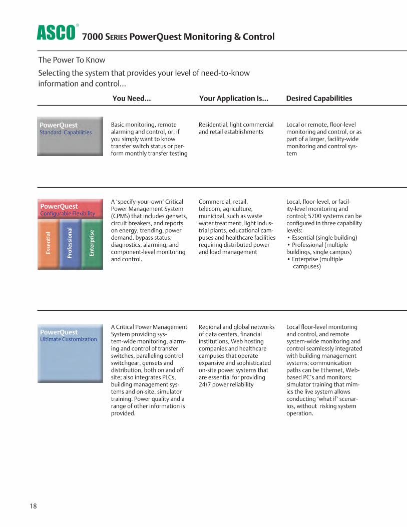
18
7000 series PowerQuest Monitoring & Control
The Power To Know
Selecting the system that provides your level of need-to-know information and control...
You Need... Your Application Is... Desired Capabilities
Basic monitoring, remote alarming and control, or, if you simply want to know transfer switch status or per-form monthly transfer testing
Residential, light commercial and retail establishments
Local or remote, floor-level monitoring and control, or as part of a larger, facility-wide monitoring and control sys-tem
A ‘specify-your-own’ Critical Power Management System (CPMS) that includes gensets, circuit breakers, and reports on energy, trending, power demand, bypass status, diagnostics, alarming, and component-level monitoring and control.
Commercial, retail, telecom, agriculture, municipal, such as waste water treatment, light indus-trial plants, educational cam-puses and healthcare facilities requiring distributed power and load management
Local, floor-level, or facil-ity-level monitoring and control; 5700 systems can be configured in three capability levels: • Essential (single building)• Professional (multiple buildings, single campus)• Enterprise (multiple campuses)
A Critical Power Management System providing sys-tem-wide monitoring, alarm-ing and control of transfer switches, paralleling control switchgear, gensets and distribution, both on and off site; also integrates PLCs, building management sys-tems and on-site, simulator training. Power quality and a range of other information is provided.
Regional and global networks of data centers, financial institutions, Web hosting companies and healthcare campuses that operate expansive and sophisticated on-site power systems that are essential for providing 24/7 power reliability
Local floor-level monitoring and control, and remote system-wide monitoring and control seamlessly integrated with building management systems; communication paths can be Ethernet, Web-based PC’s and monitors; simulator training that mim-ics the live system allows conducting ‘what if’ scenar-ios, without risking system operation.
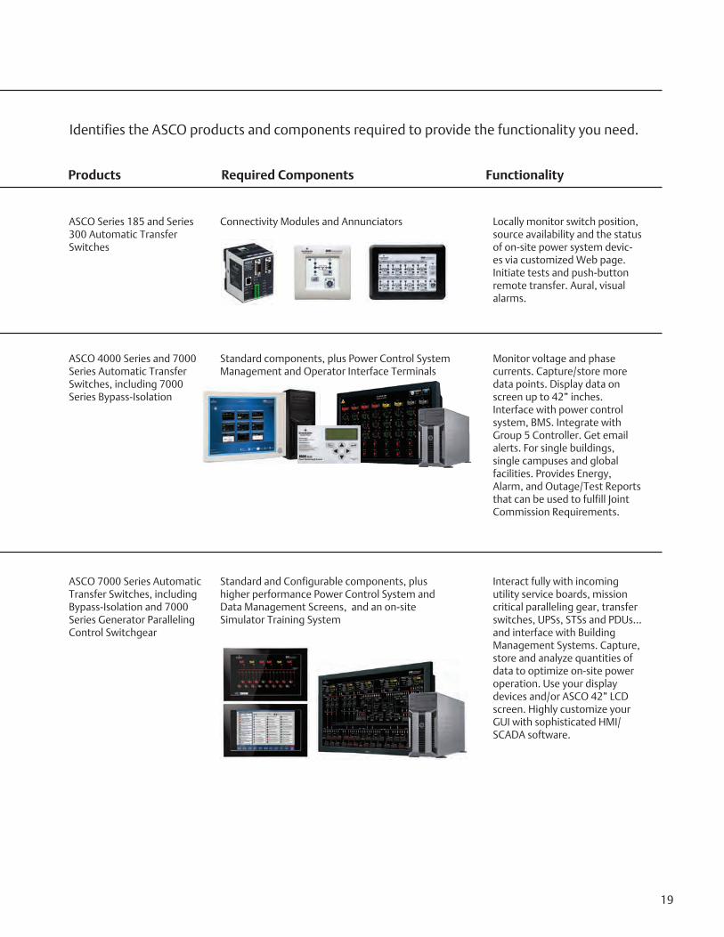
19
Identifies the ASCO products and components required to provide the functionality you need.
Products Required Components Functionality
ASCO Series 185 and Series 300 Automatic Transfer Switches
Connectivity Modules and Annunciators Locally monitor switch position, source availability and the status of on-site power system devic-es via customized Web page. Initiate tests and push-button remote transfer. Aural, visual alarms.
ASCO 4000 Series and 7000 Series Automatic Transfer Switches, including 7000 Series Bypass-Isolation
Standard components, plus Power Control System Management and Operator Interface Terminals
Monitor voltage and phase currents. Capture/store more data points. Display data on screen up to 42” inches. Interface with power control system, BMS. Integrate with Group 5 Controller. Get email alerts. For single buildings, single campuses and global facilities. Provides Energy, Alarm, and Outage/Test Reports that can be used to fulfill Joint Commission Requirements.
ASCO 7000 Series Automatic Transfer Switches, including Bypass-Isolation and 7000 Series Generator Paralleling Control Switchgear
Standard and Configurable components, plus higher performance Power Control System and Data Management Screens, and an on-site Simulator Training System
Interact fully with incoming utility service boards, mission critical paralleling gear, transfer switches, UPSs, STSs and PDUs...and interface with Building Management Systems. Capture, store and analyze quantities of data to optimize on-site power operation. Use your display devices and/or ASCO 42” LCD screen. Highly customize your GUI with sophisticated HMI/SCADA software.

20
PowerQuest® 5700 Critical Power Management System
5221 Power
Manager Units
24 VDCQTY 4, 14 Awg3P Volts/Amps
Utility Generator Generator
24 VDCQTY 8, 14 Awg3P Volts/Amps
24 VDCQTY 8, 14 Awg3P Volts/Amps
5160 RCU
24VDC or 120 VAC(Requires UPS)
7000 ATS
300 ATS
Tx/R
x (p
air o
f Fib
er)
24VDC
24VDC
5350 Annunciator
To RCU and AdditionalNetworked
Devices
19” 5702 OperatorTouch Panel
(up to 100 with 5790 Server)
19” 5702 OperatorTouch Panel
(up to 100 with 5790 Server)
5160 RCU
24VDC or 120 VAC(Requires UPS)
5160 RCU
24VDC or 120 VAC(Requires UPS)

21
Breaker
24 VDCQTY 4, 14 Awg3P Volts/Amps
UPS/Distribution
24 VDCQTY 8, 14 Awg3P Volts/Amps
7000 ATS
5350 AnnunciatorATS Status AnnunciationTransfer TestSupports 8 ATS’s24VDC/120VAC/220VAC
To RCU and AdditionalNetworked
Devices
5710 CPMS Server• Drives 3 Remote 5702
Panels•Supports 32 Power Devices•Basic Monitoring and Control•Standard Performance
5750 CPMS ServerEssential Features PLUS:• Drives 10 Remote
5702 Panels• Supports 64 Power
Devices• Historical Trending
• 5 Reporting Packages• BMS Modbus Support•Remote E-Mail Alarming
5790 CPMS ServerProfessional Features PLUS:•Drives 100 5702 Touch Panels•Redundant Power•Redundant Storage
•Redundant Processors•Ultimate Performance•128 Power Devices•Expanded Storage•Inter-facility Messaging
AWG Wire Size and Distance by othersCategory 6 Ethernet (300 Feet Max)Multi-Mode Fiber, 1300nm, 50/125um, ST Connectors (6500) Feet Max
5700 CPMS ServersNote - Select One Server to install in Centralized Office 50° to 95°F (10°C to 35°C)
NOTES - 1. This Drawing is to be used as a Model only; Actual network architecture will depend on equipment placement, cable length and type.2. 5700 Series Products Operating Temperature is 50° to 95°F (10°C to 35°C) For altitudes above 2950 feet, the maximum operating temperature is derated 1°F/550 ft.
19” 5702 OperatorTouch Panel
(up to 100 with 5790 Server)

+ + + + + + TSA A 3 400 N 5X C
22
The Example Catalog Number above is 7ATSA3400N5XC (X is used to specify optional accessories).
7
*Notes: 1. 200 and 230 amp switch limited to 480 volts maximum.
2. Type 304 stainless steel is standard. To provide an improved
reduction in corrosion in salt or marine environments, specify
optional type 316 stainless steel.
3. Type 3R enclosures are not suitable for installations conducive
to windblown snow or rain conditions.
4. Conventional switch neutral is provided on closed and delayed transition
transfer products when specified.
Amperes VoltageCode
GrpCode
Enclosure Neutral Code*
Product PhasePoles
115120208220230240380400415440460480550575600
TS
TB
CTS
CTB
DTS
DTB
23
A
N
M
Automatic
Non-Automatic
ManuallyOperated
55X-
optionalaccesso-
ries
---
A
B
C
Conventional 2-Position
Open Transition Bypass
Closed Transition
Closed Transition Bypass
Delayed Transition
Delayed Transition Bypass
No Neutral
Solid Neutral
SwitchedNeutral
OverlappingNeutral
ABCDEF HJKLMNPQR
Transfer Switch Configurations7ATS, 7NTS, 7ADTS, 7ACTS, 7NDTS, 7NCTS
Transfer/Bypass Configurations7ATB, 7NTB, 7ADTB, 7ACTB, 7NDTB, 7NCTB
Sizes of UL-Listed Solderless Screw-Type Terminals for External Power Connections
Notes: 1. Unit is designed for top cable entry of emergency and load and bottom entry of normal. Optionally, the switch may be supplied with reverse source and/or bottom entry load, when specified.
2. All main terminals are rear connected.
Switch Rating amps
Max # of Conductors per Terminal
Range of AL- CU Conductor Sizes
One
One
Two
Two
Four
Six
Twelve
#14 to 4/0 AWG
#4 AWG to 600 MCM
#1/0 AWG to 600 MCM
#1/0 AWG to 600 MCM
#1/0 AWG to 600 MCM
#1/0 AWG to 250 MCM
#1/0 AWG to 600 MCM
30 -2303 ATS & NTS Only
600
800-12001
1600-20002
2600-30002
40002
150*, 260, 400 *150 for CTS and DTS Only
Sizes of UL-Listed Solderless Screw-Type Terminal for Power Connections
Switch Rating amps
Max # of Conductors per Terminal
Range of AL-CU Conductor Sizes
One
Two
Two
Four
Three
Six
Ten
Twelve
# 1/0 AWG to 250 MCM
# 4 AWG to 600 MCM
# 2 AWG to 600 MCM
# 1/0 AWG to 600 MCM
# 2 AWG to 600 MCM
# 1/0 AWG to 600 MCM
# 1/0 AWG to 600 MCM
# 1/0 AWG to 600 MCM
150, 200, 230 260,400
6004
800,1000,12004
800,1000,1200 Front Connect
1600-20004
2600, 30004
40004
3. 200 and 230 amp rating for copper conductors only for transfer switch
configurations only.
4. All main terminals are rear connected. A front connected version is available in 600 and 1200 amp ratings only with top cable entry only. See pages 25-27 for dimensional data and additional information.
7000 series Ordering Information
Twelve #2/0 AWG to 600 MCM
30 70
100 150
200230
260 400 600 800
100012001600 2000 2600 3000 4000
1
1
5. A comprehensive ASCO Limited Guardian Warrany covers 7000 Series Power Transfer Switch(s) and warranties the product to be free of defects in material and workmanship from date of shipment. The warranty provides:
• 2 years for labor and travel expenses (extendable in 1 year increments up to 5 years for a nominal fee). • 5 years for parts (2 years for circuit breakers). • 10 years for main contacts.
Refer to Publication 3227 for warranty details, terms and conditions.
To order an ASCO 7000 series Power Transfer Switch, complete the following catalog number:
No enclosure
Type 1 enclosure
Type 3R3 enclosureType 4 enclosure
Type 4X2 enclosure (304 stainless steel)Type 12 enclosure
Type 3R3 secure double doorType 4 secure double door
Type 4X2 secure double door (304 stainless steel)Type 12 secure double door
Type 3RX2 secure double door (304 stainless steel)Type 4X enclosure (316 stainless steel)Type 4X secure double door (316 stainless steel)
---
C
FG
H
L
M
N
P
Q
R
U V
Rgeorge
Rectangle
Rgeorge
Rectangle
Rgeorge
Rectangle
Rgeorge
Rectangle
Rgeorge
Typewritten Text
Rgeorge
Typewritten Text
FRAME
Rgeorge
Typewritten Text
Rgeorge
Typewritten Text
Rgeorge
Typewritten Text
D
Rgeorge
Typewritten Text
Rgeorge
Typewritten Text
Rgeorge
Typewritten Text
J
Rgeorge
Typewritten Text
H
Rgeorge
Typewritten Text
G
Rgeorge
Typewritten Text
Rgeorge
Typewritten Text
Rgeorge
Typewritten Text
Rgeorge
Typewritten Text
Rgeorge
Typewritten Text
Rgeorge
Typewritten Text
Rgeorge
Typewritten Text
Rgeorge
Typewritten Text
Rgeorge
Typewritten Text
FRAMES D J H G
Rgeorge
Typewritten Text
Rgeorge
Typewritten Text
Rgeorge
Typewritten Text
Rgeorge
Typewritten Text
Rgeorge
Typewritten Text
Rgeorge
Typewritten Text
Rgeorge
Typewritten Text
Rgeorge
Typewritten Text
Rgeorge
Typewritten Text

23
2-Position Transfer Switching 7ATS, 7NTS (Non-Bypass)
Notes: 1. Enclosures are free-standing with removable top, sides, and back. 2. Consult ASCO for dimensions on enclosures other than UL type 1.3. Order accessory 40MY for 1600A and 40NY for 2000A F/C design.
*All dimensions and weights shown are approximate and should not be used for construction purposes. Certified dimensions can be furnished upon request.
7000 series Designed to Fit Anywhere*
2-Position Transfer Switching 7ATS, 7NTSShipping Weights
Notes: 1. Open weights include transfer switch and controller. 1200-4000 amp enclosures require ventilation openings, refer to drawing for details. 2. Weights for 1600 and 2000 amp are based on rear connected design.
*All dimensions and weights shown are approximate and should not be used for construction purposes. Certified dimensions can be furnished upon request.
Frame Switch Rating AmpsWidth
Inches (mm)Height
Inches (mm)Depth
Inches (mm)
Enclosed UL Type 12
D 30, 70, 100, 150, 200, 230 18 (457) 48 (1219) 13 (330)
J 260, 400 24 (610) 56 (1422) 14 (356)
J 600 24 (610) 63 (1600) 17 (432)
H 800, 1000 34 (864) 72 (1829) 20 (508)
H 1200 38 (965) 87 (2210) 23 (584)
G 1600, 20001 38 (965) 91 (2311) 60 (1524)
G 1600, 20003 (Front Connected) 38 (965) 87 (2210) 23(584)
G 2600, 30001 38 (965) 91 (2311) 60 (1524)
G 40001 60 (1524) 92 (2311) 72 (1829)
Open Configuration
D 30, 70, 100, 125, 150, 200, 230 10¼ (260) 10¼ (260) 5½ (140)
J 260, 400 18½ (470) 25 (635) 8 (203)
J 600 19 (483) 30 (762) 97∕8 (251)
H 800, 1000, 1200 27 (686) 31 (787) 127∕8 (327)
G 1600, 2000 33¼ (845) 28 (711) 26¼ (667)
G 2600, 3000 33¼ (845) 29 (711) 30¾ (781)
G 4000 60 (1524) 70 (1778) 53 (1272)
Frame Switch Rating Amps PolesEnclosed lb
(kg)Open lb
(kg
D 30, 70, 100 2 70 (32) 30 (14)
D 30, 70, 100 3 80 (36) 35 (16)
D 30, 70, 100 3 with B/C 85 (39) 40 (18)
D 150, 200, 230 2 115 (52) 35 (16)
D 150, 200, 230 3 120 (55) 40 (18)
D 150, 200, 230 3 with B/C 130 (59) 45 (21)
J 260, 400 2 270 (123) 220 (100)
J 260, 400 3 280 (128) 230 (105)
J 260, 400 3 with B/C 290 (132) 240 (109)
J 600 2 370 (169) 260 (119)
J 600 3 380 (173) 270 (123)
J 600 3 with B/C 390 (178) 280 (128)
H 800, 1000 2 470 (214) 260 (119)
H 800, 1000 3 480 (219) 270 (123)
H 800, 1000 3 with B/C 490 (223) 280 (128)
H 1200 2 670 (308) 300 (137)
H 1200 3 680 (310) 310 (141)
H 1200 3 with B/C 690 (315) 320 (146)
Frame Switch Rating Amps PolesEnclosed lb
(kg)Open lb
(kg
G 1600, 20002 2 1330 (606 450 (205)
G 1600, 20002 3 1350 (616) 470 (214)
G 1600, 20002 3 with B/C 1400 (638) 500 (228)
G 2600, 3000 2 2150 (980) 890 (406)
G 2600, 3000 3 2180 (994) 920 (420)
G 2600, 3000 3 with B/C 2230 (1017)1000 (456)
G 4000 2 2250 (1026) 990 (451)
G 4000 3 2280 (1040)1020 (465)
G 4000 3 with B/C 2330 (1062)1100 (502)

7000 series Designed to Fit Anywhere*
Notes: 1. Enclosures are free- standing with removable top, sides, and back.2. Consult ASCO for dimen-sions on enclosures other than UL type 1.3. Order accessory 40MY for 1600A and 40NY for 2000A front connected design.
Closed Transition and Delayed Transition Transfer Switching 7ADTS, 7ACTS, 7NDTS, 7NCTS
Shipping Weights
Notes:
1. Open weights include transfer switch and con- trol panel. 1200-4000 amp enclosures require ventila- tion openings, refer to drawings for details.
2. Weights for 1600 and 2000 amp are based on rear connected design
*All dimensions and weights shown are approximate and should not be used for con- struction purposes. Certified dimensions can be furnished upon request.
24
Closed Transition and Delayed Transition Transfer Switching 7ADTS, 7ACTS, 7NDTS, 7NCTS
*All dimensions and weights shown are approximate and should not be used for construction purposes. Certified dimensions can be furnished upon request.
Frame Switch Rating AmpsWidth
Inches (mm)Height
Inches (mm)Depth
Inches (mm)
Enclosed UL Type 12
J 150, 260, 400 24 (610) 56 (1422) 14 (356)
J 600 24 (610) 63 (1600) 17 (432)
H 800, 1000 34 (864) 72 (1829) 20 (508)
H 1200 38 (965) 87 (2210) 23 (584)
G 1600, 20001 38 (965) 91 (2311) 48 (1219)
G 1600, 20003 (Front Connected) 38 (965) 87 (2210) 23½ (597)
G 2600, 30001 38 (965) 91 (2311) 60 (1524)
G 40001 60 (1524) 92 (2311) 72 (1829)
Open Configuration
J 150, 260, 400 18½ (470) 25 (635) 8 (203)
J 600 19 (483) 30 (762) 97∕8 (251)
H 800, 1000, 1200 27 (686) 31 (787) 127∕8 (327)
G 1600, 2000 33¼ (845) 28 (711) 26¼ (667)
G 2600, 3000 33¼ (845) 29 (711) 30¾ (781)
G 4000 60 (1524) 70 (1778) 53 (1272)
Frame Switch Rating Amps PolesEnclosed lb
(kg)Open lb (kg
J 150, 260, 400 3 320 (146) 220 (100)
J 150, 260, 40 3 with B 330 (150) 230 (105)
J 600 3 380 (173) 260 (119)
J 600 3 with B 390 (178) 270 (123)
H 800, 1000 3 480 (219) 360 (164)
H 800, 1000 3 with B 490 (223) 370 (169)
H 1200 3 680 (310) 360 (164)
H 1200 3 with B 690 (315) 380 (173)
G 1600, 20002 3 1350 (616) 580 (264)
G 1600, 20002 3 with B 1400 (638) 600 (274)
G 2600, 3000 3 2180 (994) 1060 (483)
G 2600, 3000 3 with B 2230 (1017) 1100 (502)
G 4000 3 2290 (1044) 1060 (483)
G 4000 3 with B 2380 (1085) 1140 (520)

7000 series Designed to Fit Anywhere*
Automatic Transfer Bypass-Isolation Switching with Transfer Switch Engaged 7ATB, 7NTB
Shipping Weights
Notes: 1.Open weights include transfer switch, bypass-isolation switch and controller. 1600-4000 amp enclosures require ventilation openings, refer to drawings for details.
*All dimensions and weights shown are approximate and should not be used for construction purposes. Certified dimensions can be furnished upon request.
25
Frame Switch Rating AmpsPower Connection
ConfigurationWidth
Inches (mm)Height
Inches (mm)Depth
Inches (mm)
Enclosed UL Type 1
J 150, 200, 230, 260, 400, 600 Front Connected 34 (864) 85 (2159) 28 (711)
H 8003 Front Connected 38 (965) 91 (2311) 32 (813)
H 1000, 12003 Front Connected 38 (965) 91 (2311) 34 (864)
H 600, 800, 1000, 12001 Rear Connected 38 (965) 91 (2311) 48 (1219)
G 1600, 20002 Rear Connected 38 (965) 91 (2311) 60 (1524)
G 2600, 30002 Rear Connected 38 (965) 91 (2311) 72 (1829)
G 40002 Rear Connected 60 (1524) 91 (2311) 96 (2438)
Open Configuration
J 150, 200, 230, 400, 600 Front Connected 34 (864) 85 (2159) 28 (711)
H 600, 800, 1000, 12002 Rear Connected 38 (965) 72 (1829) 38 (965)
G 1600, 2000, 2600, 30002 Rear Connected 38 (965) 72 (1829) 38 (965)
G 40001 Rear Connected 60 (1524) 91 (2311) 96 (2438)
Automatic Transfer Bypass-Isolation Switching with Transfer Switch Engaged 7ATB, 7NTB
Notes: 1. Handles extend 6-1/4 inches (159mm). 2. Recommended clearance to enclosure: 3 feet (914mm) from rear, 4 feet (1219mm) from front (25 inches required for transfer switch drawout).
Side or rear access required. 3. Specify optional accessory 40J Y for 800 Amp front, 40KY for 1000 Amp, and 40LY for 1200 Amp - connected arrangement. All service and load cables limited to top entry only. *All dimensions and weights shown are approximate and should not be used for construction purposes. Certified dimensions can be furnished upon request.
Frame Switch Rating Amps Poles Enclosed lb (kg) Open lb (kg
J 150, 200, 230, 260, 400 (Front Connected) 2 1230 (561) 1100 (502)
J 150, 200, 230, 260, 400 (Front Connected) 3 1240 (565) 1110 (506)
J 150, 200, 230, 260, 400 (Front Connected) 3 with B/C 1260 (575) 1130 (515)
J 600 (Front Connected) 2 1290 (588) 1190 (543)
J 600 (Front Connected) 3 1300 (593) 1200 (547)
J 600 (Front Connected) 3 with B/C 1320 (602) 1220 (556)
H 600, 800, 1000 (Rear Connected) 3 1720 (784) 1260 (575)
H 600, 800, 1000 (Rear Connected) 3 with B/C 1740 (793) 1280 (584)
H 1200 (Rear Connected) 3 1820 (830) 1290 (588)
H 1200 (Rear Connected) 3 with B/C 1840 (839) 1310 (597)
H 800 (Front Connected) 3 1400 (638) 1320 (602)
H 800 (Front Connected) 3 with B/C 1420 (648) 1340 (611)
G 1600, 2000 (Rear Connected) 3 2360 (1076) 1500 (684)
G 1600, 2000 (Rear Connected) 3 with B/C 2540 (1158) 1680 (766)
G 2600, 3000 (Rear Connected) 3 2730 (1245) 1690 (771)
G 2600, 3000 (Rear Connected) 3 with B/C 3360 (1532) 2290 (1044)
G 4000 (Rear Connected) 3 6300 (2873) Contact ASCO
G 4000 (Rear Connected) 3 with B/C 6900 (3146) Contact ASCO

Automatic Transfer Bypass-Isolation in Closed Transition and Delayed Transition Switching. 7ADTB, 7ACTB, 7NDTB, 7NCTB
Notes: 1. Open weights include transfer switch, bypass-isolation switch and controller. 1600-4000 amp enclosures require ventilation openings, refer to drawings for details.
*All dimensions and weights shown are approximate and should not be used for construction purposes. Certified dimensions can be furnished upon request.
7000 series Designed to Fit Anywhere*
26
Notes: 1. Handles extend 6-1/4 inches (159mm). 2. Recommended clearance to enclosure: 3 feet (914mm) from rear, 4 feet (1219mm) from front (25 inches required for transfer switch drawout).
Side or rear access required. 3. Specify optional accessory 40J Y for 800 Amp front, 40KY for 1000 Amp, and 40LY for 1200 Amp - connected arrangement. All service and load cables limited to top entry only. *All dimensions and weights shown are approximate and should not be used for construction purposes. Certified dimensions can be furnished upon request.
Frame Switch Rating AmpsPower Connection
ConfigurationWidth
Inches (mm)Height
Inches (mm)Depth
Inches (mm)
Enclosed UL Type1
J 150, 200, 230, 260, 400, 600 Front Connected 34 (864) 85 (2159) 28 (711)
H 8003 Front Connected 38 (965) 91 (2311) 32 (813)
H 1000, 1200 Front Connected 38 (965) 91 (2311) 34 (864)
H 600, 800, 1000, 12002 Rear Connected 38 (965) 91 (2311) 48 (1219)
G 1600, 20002 Rear Connected 38 (965) 91 (2311) 60 (1524)
G 2600, 30002 Rear Connected 38 (965) 91 (2311) 72 (1829)
G 40002 Rear Connected 60 (1524) 91 (2311) 96 (2438)
Open Configuration
J 150, 200, 230, 400, 600 Front Connected 34 (864) 85 (2159) 28 (711)
H 600, 800, 1000, 12002 Rear Connected 38 (965) 72 (1829) 38 (965)
G 1600, 2000, 2600, 30002 Rear Connected 38 (965) 72 (1829) 38 (965)
G 40002 Rear Connected 60 (1524) 91 (2311) 96 (2438)
Frame Switch Rating Amps Poles Enclosed lb (kg) Open lb (kg
J 150, 200, 230, 260, 400 (Front Connected) 2 1255 (572) 1125 (513)
J 150, 200, 230, 260, 400 (Front Connected) 3 1265 (577) 1135 (518)
J 150, 200, 230, 260, 400 (Front Connected) 3 with B/C 1285 (586) 1155 (527)
J 600 (Front Connected) 2 1315 (600) 1215 (554)
J 600 (Front Connected) 3 1325 (604) 1225 (559)
J 600 (Front Connected) 3 with B/C 1345 (613) 1245 (568)
H 600, 800, 1000 (Rear Connected) 3 1745 (796) 1285 (586)
H 600, 800, 1000 (Rear Connected) 3 with B/C 1765 (805) 1280 (595)
H 1200 (Rear Connected) 3 1845 (841) 1315 (600)
H 1200 (Rear Connected) 3 with B/C 1865 (850) 1335 (609)
H 800 (Front Connected) 3 1425 (650) 1345 (613)
H 800 (Front Connected) 3 with B/C 1445 (659) 1365 (622)
G 1600, 2000 (Rear Connected) 3 2385 (1088) 1525 (695)
G 1600, 2000 (Rear Connected) 3 with B/C 2565 (1170) 1705 (777)
G 2600, 3000 (Rear Connected) 3 2755 (1256) 1715 (782)
G 2600, 3000 (Rear Connected) 3 with B/C 3385 (1544) 2315 (1056)
G 4000 (Rear Connected) 3 6325 (2884) Contact ASCO
G 4000 (Rear Connected) 3 with B/C 6925 (3158) Contact ASCO
Automatic Transfer Bypass-Isolation in Closed Transition and Delayed Transition Switching. 7ADTB, 7ACTB, 7NDTB, 7NCTB
Shipping Weights

17.00
38.76
35.24
91.00
Transfer SwitchCompartment
Controls andIndication
Group 5Controller UserInterface
Field WiringTerminal Block(TB)
Bypass Handle
IsolationHandle
59.05 REF
39.00 CG
12.42 REF
32.00
CableCompartment
Ground Bus
Load Lugs
Normal Lugs
Emergency Lugs
800 Amp Optional Front Connected Design
Bypass Switch Manual Operation Handle
IsolationHandle
*All dimensions and weights shown are approximate and should not be used for con-struction purposes. Certified dimensions can be furnished upon request.
27
Front Views (Covers Installed) Right Side Views (Covers Removed)
7000 series Designed to Fit Anywhere*
Optional Front Connected Design Saves Valuable Space
1000-1200 Amp Optional Front Connected Design
Field WiringTerminal Block(TB)
Group 5Controller UserInterface
Controls andIndication
Transfer SwitchCompartment
Bypass Switch Manual Operation
Handle
Isolation Handle
Load Lugs
Normal LugsEmergency Lugs
Ground Bus
34.00Cable AccessHinge Cover
Isolation Handle
91.00
38.00
59.05 REF
6.22 REF

Publication 3040 R15Emerson. Consider it Solved., Emerson Network Power and the Emerson Network Power logo are trademarks and service marks of Emerson Electric Co. ©2015 Emerson Electric Co. All rights reserved.
© October, 2015 Printed in the U.S.A.
www.EmersonNetworkPower.com/ASCO www.ascoapu.com
Emerson Network Power - Global Headquarters1050 Dearborn Drive
Columbus, OH 43085Tel: +1 614 888 0246
ASCO Power Technologies - Global Headquarters50 Hanover Road
Florham Park, NJ 07932Tel: 800 800 ASCO


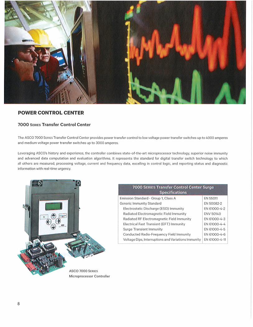

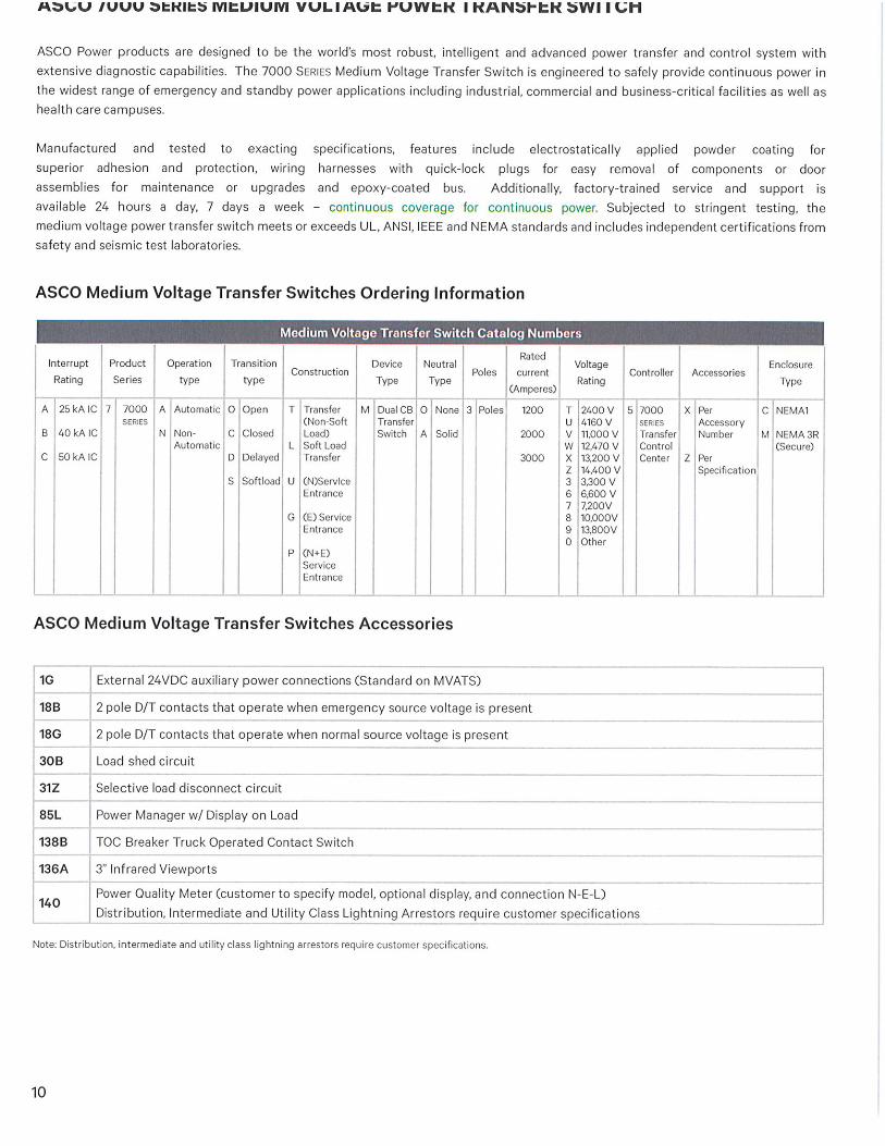

12.0-2
For more information, visit: www.eaton.com/consultants CA08104001E
October 2015
Transfer Switches—Medium Voltage
i
ii
1
2
3
4
5
6
7
8
9
10
11
12
13
14
15
16
17
18
19
20
21
Sheet 12
Vacuum Breaker Transfer Switch (VCP-W-ATC)General Description
002
Reliability and Control with Vacuum Technology and Microprocessor-Based Logic
Medium Voltage Vacuum Breaker Transfer Switch
Eaton’s Electrical Sector is an innovator of low and medium voltage manual transfer switches and has expanded these capabilities into medium voltage automatic transfer switches (MV ATS) conforming to UL® 1008A that combine proven vacuum technology and micro-processor-based logic.
Why Use Vacuum Circuit Breakers Instead of Load Interrupter Switches for Automatic Transfer?■ Vacuum circuit breakers are suitable
for multiple switching (5000–10,000 or even more) operations between sources involved in automatic transfer system. Duty cycle of load interrupter switch is limited (5 to 50 operations) by IEEE C37.20.4
■ Vacuum circuit breakers are rated for both load current switching as well as interrupting fault currents, where as the load interrupter switches are rated for load current switching only
■ Vacuum circuit breakers allow use of various relay schemes (for example, phase and ground overcurrent, under and overvoltage, under and overfrequency, directional overcur-rent, directional power, differential, etc.) for protection and coordination as desired for a given application. Relaying schemes are either not possible or very limited when using load interrupter switches
■ Drawout circuit breakers are easily maintainable
Metal-CladThe metal-clad switchgear with drawout vacuum circuit breakers used for medium voltage transfer switch is designed, manufactured and tested in accordance with the latest applicable standards of:
■ UL 1008A dated March 2012—standard for medium voltage transfer switches
■ IEEE® C37.20.2 dated 1999—standard for metal-clad switchgear
■ ANSI C37.55 dated 2002—conformance test procedures
■ NEMA® SG-5—power switchgear assemblies
■ CSA® C22.2 No. 31-04 dated January 2004—CSA standard for switchgear assemblies
■ ANSI and IEEE standards for high voltage AC circuit breakers—IEEE C37.04-1999, ANSI C37.06-2000 and 2009, and IEEE C37.09-1979 and 2009
■ Available as an option—Type 2B arc-resistant design conforming to IEEE C37.20.7 dated 2007, guide for testing metal-enclosed switchgear for internal arcing faults
The MV ATS style is perfect for any emergency or backup system and suitable for service entrance use. It provides reliable automatic transfer to standby power when:
■ The normal power source fails■ Peak shaving is used■ The power source is unreliable■ Backup power is mandated by code
or local regulations
Eaton manufactures all MV ATS basic components and provides one year full warranty, eliminating problems that can arise with multiple warranties for a single piece of equipment. Assembly and manufacturing is completed in ISO® certified facilities.
Seismic QualifiedEaton’s medium voltage circuit breaker transfer switch assemblies are seismically tested or qualified by analysis based on actual testing done on similar equipment, to exceed the requirements based upon 2009 IBC parameters and CBC 2010.
Standard Control FeaturesMV ATS control is provided by Eaton’s ATC-900 automatic transfer controller. Some of the standard features of ATC-900 are as follows. Refer to Eaton’s Technical Data TD140001EN for complete details of ATC-900 features and capabilities.
■ Lights:❑ Normal position❑ Emergency position❑ Normal source available❑ Emergency source available
■ Undervoltage/overvoltage, underfrequency/overfrequency sensing on Source 1
■ Undervoltage/overvoltage, underfrequency/overfrequency sensing on Source 2
■ Timers:❑ Time Delay Normal to Emergency❑ Time Delay Emergency to Normal❑ Time Delay Engine Start❑ Time Delay Engine cool-off❑ Time Delay Emergency Failure❑ Time Delay Neutral❑ Time Delay pre- and/or
post-transfer
■ Programmable engine test mode and test run timer
■ Source 1 available—one Form C contact
■ Source 2 available—one Form C contact
■ Communication via Modbus® RTU, USB (for flash drives), Modbus TCP/IP (optional)
■ Real-time clock and date■ Phase reversal on Source 2■ Phase reversal on Source 1■ Go to Emergency feature■ Preferred source selector for use on
systems comprised of utility/utility or utility/generator
■ Overcurrent lockout feature■ Plant Exerciser with fail-safe feature■ Automatic or manual
pushbutton re-transfer selection■ PT ratio set points■ Closed Transition with Default to
In-Phase Transition with Default to Time Delay Neutral (for closed transition switches only)

CA08104001E For more information, visit: www.eaton.com/consultants
12.0-3October 2015
Transfer Switches—Medium Voltage
i
ii
1
2
3
4
5
6
7
8
9
10
11
12
13
14
15
16
17
18
19
20
21
Sheet 12
Vacuum Breaker Transfer Switch (VCP-W-ATC)General Description
003
Additional Options■ Lockout on phase and/or ground
overcurrents and/or internal bus faults
■ Load current, power and PF metering with optional DCT module
■ 24 Vdc control power input■ Up to four additional I/O modules,
each with four programmable digital inputs and digital outputs
■ Overcurrent protection:❑ Normal❑ Emergency
■ Eaton’s Power Xpert® and IQ metering: normal and emergency
■ Space heater■ Partial discharge InsulGard® relay
Circuit Breaker SwitchesSwitching is provided by Eaton’s VCP-W Vacuum Circuit Breakers in ANSI voltages of 5 and 15 kV.
Circuit breaker switches (CBS) are horizontal drawout types up to 15 kV.
The CBS includes five major components: vacuum interrupter pole units, stored energy mechanism, push rod assembly, primary discon-necting contacts, and removable glass polyester insulating barriers.
Vacuum InterruptersEach CBS includes three vacuum interrupters, separately mounted in a self-contained, self-aligning pole unit that is easily removed. A direct reading contact erosion indicator is clearly visible when the CBS is withdrawn from the compartment. Each vacuum interrupter pole unit is mounted on glass polyester supports for 5 kV and 15 kV ratings.
The unique, nonsliding current transfer system from the movable vacuum interrupter stem to the CBS consists of a series of tin-plated, high conductivity copper leaf conductors. The conductors are swaged onto the movable vacuum interrupter stem and provide:
■ Improved current flow because the multi-point contact offers very low electrical resistance
■ No required maintenance because the current transfer from the movable stem to the CBS primary conductor is a nonsliding and nonrolling design
■ Longer vacuum interrupter life
OperationOperation is by a motor-charged stored energy spring mechanism charged by a universal electric motor, or a manual levering tool in an emer-gency. The stored energy mechanism is a true mechanically and electrically trip-free design, meaning that while holding a mechanical trip command, the breaker contacts will not close or touch while receiving an electrical or mechanical close command.
Each CBS is electrically operated by these control voltages: 120 Vac close and ac capacitor trip, or 48 Vdc, 125 Vdc or 250 Vdc. AC control voltage is derived from potential transformers connected in the line side of each CBS. The DC control voltage is provided by the user.
Controls and indicators are functionally grouped on the front control panel and include: closing spring status, close and trip button, operation counter, contact status indicators and a “T” handle latch (located at the bottom of the control panel). Each CBS includes a control switch, and red and green lights to indicate the CBS contact position.
ContactsPrimary disconnects are silver-plated copper. Secondary contacts are silver-plated and automatically engage in the CBS operating position. They can be manually engaged in the CBS test position.
SafetyDouble deadfront shields isolate the operator from high voltage when the CBS is energized. The CBS can be connected or disconnected with the compartment door closed by a manually operated levering device.
Safety interlocks provide for the mechanism to be held mechanically trip-free during racking. Closing springs will discharge automatically when the CBS is being withdrawn.
MaintenanceThe stored energy mechanism and control components are easily accessi-ble and can be inspected by removing the front panel. Minor maintenance when required, such as lubricating the mechanism and accessing the control components, is simplified.
Operation SequenceTransfer is initiated by Eaton’s ATC-900 microprocessor-based logic controller mounted on the door.
The ATC-900 can be programmed for open or closed transition. The controller will not initiate the closed transfer until both power sources are synchronized in voltage, frequency and phase angle. If a power source is lost, the closed transition control will return to the open mode.
ATC controller capabilities include:
■ Continuous monitoring of all three phases of all loads and voltage on the source and bus
■ Generator testing under load■ Simplified, custom programming
on the faceplate keypad to meet specific user requirements. There are no DIP switches to set
■ Visual status indications of both sources and the load.
■ Easy-to-use:❑ At-a-glance overview of the MV
ATS status and parameters and key diagnostic data
❑ Real-time values for volts and frequency can be viewed on the LED display plus the power source in use
❑ Displays historical information including Source 1 and Source 2 run time, available time, and connected time, load energized time, number of transfers, and the date, time and reason for the last 100 transfers
❑ Oscillographic data for last 10 transfers can be downloaded via USB port or displayed in the controller’s display window

12.0-4
For more information, visit: www.eaton.com/consultants CA08104001E
October 2015
Transfer Switches—Medium Voltage
i
ii
1
2
3
4
5
6
7
8
9
10
11
12
13
14
15
16
17
18
19
20
21
Sheet 12
Vacuum Breaker Transfer Switch (VCP-W-ATC)General Description
004
ATC-900 Open Transition TransferWhen the system is operating from the normal source, the ATC-900 controller indicates real-time values for volts and frequency on the front panel LED display with an indication of the power source in use. The ATC-900 controller continuously monitors either single-phase or three-phase voltages for Source 1, Source 2 and the load. The ATC-900 controller allows system configuration selection for Source 1/Source 2 as Utility/Generator, or Dual Generator, or Dual Utility.
When Source 1 voltage or frequency is detected to be below user-programmed set points, transfer to Source 2 is initiated. The transfer occurs when Source 2 voltage and frequency are detected to be within programmed parameters.
While the load is connected to Source 2, the ATC-900 controller continues to monitor Source 1. When Source 1 voltage and frequency return to within programmed parameters of Source 1, and after a programmed time delay, load transfer back to Source 1 is initiated.
The load transfer back to Source 1 is open type because the Source 2 circuit breaker switch is opened first after which the Source 1 circuit breaker switch is closed.
ATC Controller
ATC-900
ATC-900 Closed Transition TransferWhen the system is operating from the normal source, Eaton’s ATC-900 controller indicates real-time values for volts and frequency on the front panel LED display with an indication of the power source in use. The ATC-900 controller continuously monitors either single-phase or three-phase voltages for Source 1, Source 2 and the load. The ATC-900 controller allows system configuration selection for Source 1/Source 2 as Utility/Generator, or Dual Generator, or Dual Utility.
The ATC-900 controller provides for selection of closed transition enabled or disabled.
When enabled, it is possible for load to be transferred from Source 1 to Source 2 without interruption of power to the load when both sources are available. The source paralleling during load transfer is less than 100 milliseconds.
When disabled, the two sources cannot operate in parallel.
When Source 1 voltage or frequency is detected to be below the user-programmed set points, transfer to Source 2 is initiated. The transfer occurs when Source 2 voltage and frequency are detected to be within the programmed parameters.
While the load is connected to Source 2, the ATC-900 controller continues to monitor Source 1. When Source 1 frequency and voltage return to within programmed limits of Source 1, and after a programmed time delay, the load is transferred back to Source 1.
When the closed transition mode is enabled, Source 1 is closed first, then Source 2 is opened without power interruption to the load. When in the disabled mode, Source 2 is opened first and then Source 1 is closed.
Note: See Page 12.0-8 for ATC-900 controller programming selections and ratings.
Bus and Bus Insulation
Bus The main bus is copper. A set of either 1200 A or 2000 A main bus is provided with provisions for future extension.
Bolted bus connections are silver-plated for positive contact and low resistance. Each joint is insulated with easily installed boots. The bus is braced to withstand fault currents equal to the close and latch rating of the circuit breakers. All bus, bus sup-ports and connections will withstand stresses produced by currents equal to the momentary ratings of the circuit breakers.
Temperature rise of the bus and con-nections conforms to ANSI standards and is documented by factory testing.
The copper ground bus extends the entire length of the MV ATS. An optional fully rated neutral bus (insulated or noninsulated) extends the entire length of the MV ATS.
Bus InsulationThe main bus is insulated with epoxy, applied in the fluidized bed process. When applied in this process, the epoxy is nonhygroscopic, inert, and track, mold and fungus resistant.
Thermal and electrical performance is enhanced because the epoxy is bonded directly to the bus bar conduc-tor, eliminating the air gap between insulation and conductor. Heat transfer is greatly improved, resulting in the bus system running cooler. No air gap exists for insulation damage or corona discharge.
The main bus supports are glass polyester for 5 kV and 15 kV ratings, except the main bus supports for 63 kA ratings are porcelain.

CA08104001E For more information, visit: www.eaton.com/consultants
12.0-5October 2015
Transfer Switches—Medium Voltage
i
ii
1
2
3
4
5
6
7
8
9
10
11
12
13
14
15
16
17
18
19
20
21
Sheet 12
Vacuum Breaker Transfer Switch (VCP-W-ATC)General Description
005
Terminations and Secondary WiringEaton’s MV ATS includes terminal blocks for secondary wire terminations plus an inventory of spare terminal connections. One control circuit cutout device is provided in each CBS housing.
Secondary wire is #14 AWG, Type SIS rated 600 Vac, 90 °C. The wires termi-nate on terminal blocks, identified on marker strips numbered in agreement with the connection diagrams.
Incoming line and feeder cable lugs are provided.
Protective RelaysCustomer-requested protective relays can be provided and installed in the MV ATS. Refer to Tab 4.
Partial Discharge Sensing and MonitoringRefer to Tab 5, Section 5.3 for details of partial discharge sensing and monitoring option.
MeteringCustomer-requested metering can be provided. Associated instrument transformers are included.
Current transformers are provided and wired to shorting-type terminal blocks.
Potential transformers are provided including primary and secondary fuses with disconnecting means for metering.
A choice of Eaton microprocessor-based metering is available, such as IQ Series or Power Xpert. Refer to Tab 2.
Enclosure ConstructionMetal-clad integrity provides maxi-mum circuit separation and safety through isolated grounded metal compartments, complete isolation of all conductors, and no live parts are exposed when a door is opened.
CommunicationsATC-900 controller allows an MV ATS to be included on a communications network, providing for remote monitoring and control using a PC.
Outdoor EnclosuresTwo outdoor enclosure styles are available.
■ Aisleless, mounted on an integral base frame with a weatherproof enclosure for field assembly. A weath-erproof door is provided on the circuit breaker switch drawout side
■ Sheltered aisle mounted on an inte-gral base frame with a weatherproof enclosure for field assembly. The enclosure is extended on the circuit breaker switch drawout side to form an operating and/or maintenance aisle with sufficient space to permit interchange of circuit breaker switches. A weatherproof door with an inside quick release latch mecha-nism is located at each end of the inside, even when locked from the outside. Interior lights, light switches, and duplex ground fault receptacles are provided in the aisle.
Each vertical section is provided with tubular-type space heaters operated at half voltage for long life. 500 V or 250 V rated heaters are used at 240 V or 120 V respectively. Power is furnished from a control power transformer mounted in the MV ATS.
As an option, heaters can be wired to provide temporary heating during storage.
Auxiliary Equipment
Voltage and Control Power TransformersVoltage transformers are drawout-drawer mounted for ratings up to 15 kV. Up to three voltage transformers can be mounted in a drawer.
Control power transformers up to 15 kV, 15 kVA, single-phase are drawout-drawer mounted.
Drawers are in enclosed auxiliary compartments and can be withdrawn on rails for easy inspection, testing and fuse replacement. When a drawer is withdrawn, the fuses are automatically disconnected, grounded, and primary bus stabs isolated by glass polyester shutters.
A mechanical interlock is provided so that the secondary circuit breaker must be open before the control power transformer drawer or control power transformer primary fuse drawer can be withdrawn.
Current TransformersRing-type current transformers are provided with thermal and mechanical ratings coordinated with the circuit breakers. Current transformer accuracy meets ANSI standards.
Standard current transformer location on the bus side and line side of the 5 kV and 15 kV CBS units provide front accessibility so that adding or changing transformers can be accom-plished when an Eaton’s MV ATS is de-energized without breaking the high voltage connections and primary insulation.
Shorting terminal blocks are provided on each current transformer secondary.
Arc-Resistant SwitchgearIndoor MV ATS assembly conforming to UL 1008A can be supplied with arc-resistant designs and features conforming to Type-2B accessibility that provide arc-resistant protection on the front, sides and rear of the equipment in accordance with IEEE C37.20.7.
Each individual vertical section of the MV ATS assembly is provided with integral- and top-mounted pressure release flaps to facilitate a controlled upward release of arc-created over-pressures, smoke and gasses.
Individual vertical sections are of a unitized design to allow removal of a damaged vertical section after a fault incident, without requiring the removal of the adjacent vertical sections.
An enclosed arc chamber with arc duct exit is provided above the switchgear for exhaust collection and discharge. The arc exhaust is vented from the arc chamber to the exit location via the arc duct. Arc duct is optional.

12.0-6
For more information, visit: www.eaton.com/consultants CA08104001E
October 2015
Transfer Switches—Medium Voltage
i
ii
1
2
3
4
5
6
7
8
9
10
11
12
13
14
15
16
17
18
19
20
21
Sheet 12
acuum Breaker Transfer Switch (VCP-W-ATC)General Description
006
NameplatesExternal engraved nameplates are screw mounted on the face of each MV ATS assembly for each main and feeder circuit. Nameplates are laminated plastic with black 0.2-inch (5.1 mm) high characters on a white background.
A master nameplate includes MV ATS designation, voltage and ampere ratings, short circuit rating, manufac-turer’s name, and shop order number.
Internal engraved nameplates are screw mounted within the MV ATS to identify control components such as fuse blocks, relays, pushbuttons and switches.
Eaton MV ATS switches are provided with all required markings and labels in accordance with UL 1008A.
FinishStandard finish, inside and out, is a thermosetting, polyester powder paint (ANSI 61 gray) applied electro-statically to all metal parts (steel and aluminum) that are first precleaned and phosphatized.
This finish provides excellent mechani-cal strength and scratch resistance, resists chalking caused by the sun’s ultraviolet rays, and meets the salt spray requirements of ASTM B-117.
AccessoriesProvided for testing, inspection, maintenance and operation.
Standard Accessories■ Maintenance tool for manually
charging the circuit breaker closing spring and manually operating the shutter
■ Levering crank for moving the circuit breaker between test and connected positions
■ Test jumper for electrically operating the circuit breaker while out of the compartment
■ Lifting yoke for lifting the circuit breaker on or off compartment rails
■ Rail extensions and rail clamps
Optional Accessories■ Portable lifting device for lifting the
circuit breaker on or off the rails■ Ramp for rolling a circuit breaker
directly onto the floor from the lower compartment
■ Test cabinet for testing electrically operated circuit breakers’ outside housing
■ Dockable transport dolly for moving a circuit breaker outside of the cabinet
■ Portable electrical levering device■ Integral levering device (refer to
Tab 5, Pages 5.3-4 and 5.3-6)
Factory Testing
Circuit Breaker Switch Element■ Alignment test with master cell to ver-
ify all interfaces and interchangeability■ Circuit breaker operated over a
range of minimum to maximum control voltage
■ One-minute dielectric test
Circuit Breaker Switch Housing■ Alignment test with master circuit
breaker to verify interfaces■ One-minute dielectric test on
primary and secondary circuits■ Operational sequence test to
verify operation of wiring, relays and other devices
■ Final inspection and quality check
Three certified copies of the factory test reports are provided.
Test WitnessingAs an option, all factory tests can be witnessed by the customer or customer representative.
InstallationComplete installation, startup, testing and long-term maintenance is avail-able from Eaton’s Electrical Services & Systems (EESS).

CA08104001E For more information, visit: www.eaton.com/consultants
12.0-7October 2015
Transfer Switches—Medium Voltage
i
ii
1
2
3
4
5
6
7
8
9
10
11
12
13
14
15
16
17
18
19
20
21
Sheet 12
Vacuum Breaker Transfer Switch (VCP-W-ATC)Available Ratings
007
Table 12.0-1. Medium Voltage Automatic Transfer Switch, Model VCP-W-ATC, Ratings per IEEE C37.20.2 and UL 1008A
1 Circuit breakers are rated to standards for HV AC circuit breakers—ANSI/IEEE C37.04, C37.06 and C37.09.2 Please note that use of certain current transformers (for example, bar type CTs) and protective devices may limit the duration to a value less
than 2 seconds.3 These values exceed 2.6*K*I required by IEEE C37.20.2-1999 and ANSI C37.06-2000.4 These values exceed 1.55*K*I required by IEEE C37.20.2-1999.
Rate
d M
axim
um
Vo
ltag
e
Types and Ratings of Vacuum Circuit Breakers 1 Ratings per IEEE C37.20.2-1999 (Metal-Clad, Non-Arc Resistant) Optional—Ratings per IEEE C37.20.7
UL 1
008A
Op
era
tin
g D
uty
Cla
ss
(Cla
ss A
= 2
00
0 O
pera
tio
ns)
Breaker Type
Rate
d S
ho
rt-C
ircu
it C
urr
en
t
at
Rate
d M
axim
um
Vo
ltag
e
I
Rate
d V
olt
ag
e
Ran
ge F
acto
r
K
Rate
d In
terr
up
tin
g
Tim
e in
Cycle
s
Insulation Level
Rate
d M
ain
Bu
s
Co
nti
nu
ou
s C
urr
en
t
Rate
d S
ho
rt T
ime S
ho
rt-C
ircu
it
Cu
rren
t W
ith
sta
nd
(2-S
eco
nd
) Rated Momentary
Short-Circuit Current
Withstand (10 cycle)
[167 ms]
Enclosure Internal Arc Withstand
Po
wer
Fre
qu
en
cy
Wit
hsta
nd
Vo
ltag
e,
60 H
z, 1 M
inu
te
Lig
htn
ing
Im
pu
lse
Wit
hsta
nd
Vo
ltag
e
[LIW
V]
(BIL
)
Accessib
ilit
y T
yp
e
Rated Arc Short-
Circuit Withstand
Current
Rate
d A
rc D
ura
tio
n
K*I 2 2.7 *K*I 3 1.6 *K* I
(Ref. only) 4Isc 2.6*Isc
kV rmskA rms
sym
Based on
60 Hz
kV rms kV peak Amperes kA rms
Sym
kA Crest kA rms
Asym
kA rms
Sym
kA peak Sec
4.76 50 VCP-W 25 25 1 3 19 60 1200, 2000 25 68 40 2B 25 65 0.5 A
50 VCP-W 40 40 1 3 19 60 1200, 2000 40 108 64 2B 40 104 0.5 A
50 VCP-W 50 50 1 3 19 60 1200, 2000 50 135 80 2B 50 130 0.5 A
50 VCP-W 250 29 1.24 5 19 60 1200, 2000 36 97 58 2B 36 93.6 0.5 A
50 VCP-W 350 41 1.19 5 19 60 1200, 2000 49 132 78 2B 49 127.4 0.5 A
8.25 75 VCP-W 40 40 1 3 36 95 1200, 2000 40 111 66 2B 40 104 0.5 A
75 VCP-W 50 50 1 3 36 95 1200, 2000 50 135 80 2B 50 130 0.5 A
75 VCP-W 500 33 1.25 5 36 95 1200, 2000 41 111 66 2B 41 106.6 0.5 A
15 150 VCP-W 25 25 1 3 36 95 1200, 2000 25 68 40 2B 25 65 0.5 A
150 VCP-W 40 40 1 3 36 95 1200, 2000 40 108 64 2B 40 104 0.5 A
150 VCP-W 50 50 1 3 36 95 1200, 2000 50 135 80 2B 50 130 0.5 A
150 VCP-W 500 18 1.3 5 36 95 1200, 2000 23 62 37 2B 23 59.8 0.5 A
150 VCP-W 750 28 1.3 5 36 95 1200, 2000 36 97 58 2B 36 93.6 0.5 A
150 VCP-W 1000 37 1.3 5 36 95 1200, 2000 48 130 77 2B 48 124.8 0.5 A

12.0-8
For more information, visit: www.eaton.com/consultants CA08104001E
October 2015
Transfer Switches—Medium Voltage
i
ii
1
2
3
4
5
6
7
8
9
10
11
12
13
14
15
16
17
18
19
20
21
Sheet 12
Vacuum Breaker Transfer Switch (VCP-W-ATC)Technical Data
008
Table 12.0-2. ATC-900 Programmable Set Points
1 Load voltage decay feature requires a set of bus VTs (optional).
Option Number Description Range Factory Default
General Settings — Set new password 0000–9999 0900
— Selected language English, French or Spanish English
— Nominal frequency 50 or 60 Hz As ordered
— Nominal voltage 110–600 V As ordered
— Number of phases 1 or 3 As ordered
— Number of generators 0, 1 or 2 1
— Preferred source Source 1 or Source 2 Source 1
— PT ratio 2:1–500:1 As ordered
— CT ratio 200–5000 —
— Daylight Saving Time On or Off 1
— Operating mode Stand-alone/Master or Slave Master
— Phase sequence check ABC, CBA or Off Off
— Commitment to transfer in TDNE Yes or No No
— Manual retransfer Auto, Manual or External As ordered
— Modbus address 1–247 1
— Modbus baud rate 0 = 9600, 1, Even 1 = 9600, 1, Odd 2 = 9600, 2, None 3 = 9600, 1, None 4 = 19,200, 1, Even 5 = 19,200, 1, Odd 6 = 19,200, 2, None 7 = 19,200, 1, None
9600 — — — — — — —
Transition Settings 47 Closed transition
Closed transition On or Off Closed voltage difference Closed frequency difference
On or Off1–5%0.001500.3 Hz
As ordered2%0.3
32f/32d Open—in-phase transition
In-phase On or Off In-phase frequency difference
Disable, in-phase default to alarm, in-phase default to open transition0.0–3.0 Hz
As ordered1.0
— Synchronization timer 1–60 minutes 5
32a/32d Open—delayed transition
Time delay neutral Load voltage decay 1
0–120 seconds2–30% of nominal voltage
06%
Time Delays 1a Time delay normal to emergency 0–9999 seconds 0:00
3a Time delay emergency to normal 0–9999 seconds 5:00
35A Time delay pre-transfer 0–120 seconds 0:01
35C Time delay post-transfer 0–120 seconds 0:10
2A Time delay engine 1 start 0–120 seconds 0:03
— Time delay engine 2 start 0–120 seconds 0:03
4A Time delay engine cool-off 0–9999 seconds 5:00
7A Time delay engine fail timer 0–6 seconds 0:06
— Voltage unbalance time delay 10–30 seconds 0:30

CA08104001E For more information, visit: www.eaton.com/consultants
12.0-9October 2015
Transfer Switches—Medium Voltage
i
ii
1
2
3
4
5
6
7
8
9
10
11
12
13
14
15
16
17
18
19
20
21
Sheet 12
Vacuum Breaker Transfer Switch (VCP-W-ATC)Technical Data
009
Table 12.0-2. ATC-900 Programmable Set Points (Continued) Option Number Description Range Factory Default
Source Settings 26P Source 1 undervoltage dropout
Source 1 undervoltage pickup70–97% of nominal(dropout + 2%) to 99% of nominal
80% 90%
5P Source 2 undervoltage dropoutSource 2 undervoltage pickup
70–97% of nominal(dropout + 2%) to 99% of nominal
80% 90%
26K Source 1 overvoltage dropoutSource 1 overvoltage pickup
105–120% of nominal (0 = disabled)103% of nominal to (dropout - 2%) (0 = disabled)
115% 105%
5K Source 2 overvoltage dropoutSource 2 overvoltage pickup
105–120% of nominal (0 = disabled)103% of nominal to (dropout - 2%) (0 = disabled)
115% 105%
26J Source 1 underfrequency dropoutSource 1 underfrequency pickup
90–97% of nominal (0 = disabled)(dropout + 1 Hz) to 99% of nominal (0 = disabled)
94% 96%
5J Source 2 underfrequency dropoutSource 2 underfrequency pickup
90–97% of nominal (0 = disabled)(dropout + 1 Hz) to 99% of nominal (0 = disabled)
94% 96%
26N Source 1 overfrequency dropoutSource 1 overfrequency pickup
103–110% (0 = disabled)101% to (dropout - 1 Hz) (0 = disabled)
106% 104%
5N Source 2 overfrequency dropoutSource 2 overfrequency pickup
103–110% (0 = disabled)101% to (dropout - 1 Hz) (0 = disabled)
106% 104%
26L Source 1 percent for unbalanced voltage dropout Source 1 percent for unbalanced voltage pickup
5–20% of phase-to-phase voltage unbalance (0 = disabled)3% to (dropout - 2%) (0 = disabled)
12% 10%
5L Source 2 percent for unbalanced voltage dropoutSource 2 percent for unbalanced voltage pickup
5–20% of phase-to-phase voltage unbalance (0 = disabled)3% to (dropout - 2%) (0 = disabled)
12% 10%
Engine Test/Plant Exerciser (PE1 and PE2 are Independently Programmable) 6B Engine test pushbutton on panel
Test mode Engine run test time
No load, load transfer, disabled0–600 minutes
Load transfer Load transfer
23M PE time delay normal to emergency PE time delay emergency to normal PE time delay engine cooldown PE1/PE2 test mode PE1/PE2 run time PE1/PE2 schedule
PE1/PE2 calendar date
PE1/PE2 day of week PE1/PE2 plant start time
0–9999 seconds 0–9999 seconds 0–9999 seconds No load, load transfer, disabled 0–600 minutes Off, daily, 7-day, 14-day, 28-day or calendar date(up to 12 user-specified dates) Month: 1–12; Day: 1–31 1 Sunday, 2 Monday, 3 Tuesday, 4 Wednesday, 5 Thursday, 6 Friday or 7 Saturday HH:MM AM/PM
1 minute 1 minute 5 minutes Disabled 30 minutes
Accessory I/O — Accessory I/O modules 0–4 —

12.0-10
For more information, visit: www.eaton.com/consultants CA08104001E
October 2015
Transfer Switches—Medium Voltage
i
ii
1
2
3
4
5
6
7
8
9
10
11
12
13
14
15
16
17
18
19
20
21
Sheet 12
Vacuum Breaker Transfer Switch (VCP-W-ATC)Technical Data
010
Typical One-Line Diagram
Figure 12.0-1. Typical Medium Voltage Automatic Transfer Switch
Digitrip3010DualPowered
Power XpertMeter
(optional)
(Note)
SurgeArrestors(optional)
Note:External control power is required if not using self-powered OC relay.
Digitrip3010DualPowered
Power XpertMeter
(optional)
(Note)
SurgeArrestors(optional)
SurgeArrestors(Optional)
Load Bus
OptionalItems
To Load
120/240 VAuxiliary Power
Single-PhaseCPT
5/10/15 kVA(2) or (3)Bus VTs
ATC 900
VCB VCB52-M1 52-M252-M1
Breaker Controls52-M1
Breaker Controls
(3) CTs(3) CTs
(2) or (3) VTs (2) or (3) VTs
Source 1 Source 2

CA08104001E For more information, visit: www.eaton.com/consultants
12.0-11October 2015
Transfer Switches—Medium Voltage
i
ii
1
2
3
4
5
6
7
8
9
10
11
12
13
14
15
16
17
18
19
20
21
Sheet 12
Vacuum Breaker Transfer Switch (VCP-W-ATC)Layout Dimensions—Standard Metal-Clad
011
Layout Dimensions in Inches (mm)—Standard Metal-Clad
Figure 12.0-2. Indoor 5 kV or 15 kV, 1200 A Main Breakers1 Circuit breakers are packaged and shipped separately.
Table 12.0-3. Approximate Shipping Weight in Lb (kg)
Figure 12.0-3. Outdoor Aisleless 5 kV or 15 kV, 1200 A Main Breakers2 Circuit breakers are packaged and shipped separately.
Table 12.0-4. Minimum Recommended Clearances in Inches (mm) Equipment
Type
Switchgear
Assembly
Circuit
Breaker
Indoor 4400 (1998) 350–575 (159–261)
Outdoor aisleless 5600 (2542) 350–575 (159–261)
18.50(469.9)
Main 1If Bottom Entry Main 2Main 2If Top Entry Main 1
SecondaryControl Wires
Entrance
7.00(177.8)
Power Cable Entrance
C L
LoadCables
(Top orBottom)
C L
96.25(2444.8)
72.00 �(1828.8)
Main 2Breaker(1200A)
Main 1Breaker(1200A)
Line 1 VTs
Bus CPT(Optional)
Bus VTs(Optional)
Line 2 VTs
Shipping Group �
95.00(2413.0)
Floor Plan
Front Elevation
Equipment
Type
Front Side Rear
Indoor 70.00 (1778.0) 32.00 (812.8) 36.00 (914.4)
Outdoor aisleless 70.00 (1778.0) 32.00 (812.8) 36.00 (914.4)
Main 2Breaker(1200A)
Main 1Breaker(1200A)
Line 1 VTs
Bus CPT(Optional)
Bus VTs(Optional)
Line 2 VTs
115.00(2921.0)
SecondaryControl Wires
Entrance
Power Cable Entrance
C L
LoadCables
C L
72.00(1828.8)
101.25(2571.8)
Floor Plan
Front Elevation
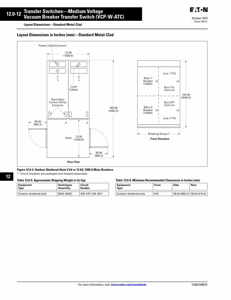
12.0-12
For more information, visit: www.eaton.com/consultants CA08104001E
October 2015
Transfer Switches—Medium Voltage
i
ii
1
2
3
4
5
6
7
8
9
10
11
12
13
14
15
16
17
18
19
20
21
Sheet 12
Vacuum Breaker Transfer Switch (VCP-W-ATC)Layout Dimensions—Standard Metal-Clad
012
Layout Dimensions in Inches (mm)—Standard Metal-Clad
Figure 12.0-4. Outdoor Sheltered Aisle 5 kV or 15 kV, 1200 A Main Breakers1 Circuit breakers are packaged and shipped separately.
Table 12.0-5. Approximate Shipping Weight in Lb (kg) Table 12.0-6. Minimum Recommended Clearances in Inches (mm)
SecondaryControl Wires
Entrance
Power Cable Entrance
C L
LoadCables
C L
72.00(1828.8)
169.38(4302.3)
38.00(965.2)
38.00(965.2)
Aisle 72.00(1828.8)
Main 2Breaker(1200A)
Main 1Breaker(1200A)
Line 1 VTs
Bus CPT(Optional)
Bus VTs(Optional)
Line 2 VTs
Shipping Group
120.00(3048.0)
Floor Plan
Front Elevation
Equipment
Type
Switchgear
Assembly
Circuit
Breaker
Outdoor sheltered aisle 8000 (3632) 350–575 (159–261)
Equipment
Type
Front Side Rear
Outdoor sheltered aisle N/A 38.00 (965.2) 36.00 (914.4)


InsulationOkoguard is Okonite’s registered trade namefor its exclusive ethylene-propylene rubber(EPR) based, thermosetting compound,whose optimum balance of electrical andphysical properties is unequaled in othersolid dielectrics. Okoguard insulation, withthe distinctive red color and a totally inte-grated EPR system, provides the optimumbalance of electrical and physical propertiesfor long, problem free service.The triple tandem extrusion of the screenswith the insulation provides optimum electri-cal characteristics.
JacketThe Okoseal (PVC) jacket supplied with thiscable is mechanically rugged and has excel-lent resistance to oil, acids and mostchemicals.
ApplicationsOkoguard shielded Okoseal Type MV-105power cables are recommended for distribu-tion circuits, and for feeders or branchcircuits.Type MV cables may be installed in wet ordry locations, indoors or outdoors (exposedto sunlight), in any raceway or undergroundduct, directly buried if installed in a systemwith a grounding conductor in close proximitythat conforms with NEC Section 250.4(A)(5),or messenger supported in industrial estab-lishments and electric utilities.
SpecificationsConductor: Annealed uncoated coppercompact stranded per ASTM B-496.Strand Screen: Extruded semiconductingEPR strand screen. Meets or exceedselectrical and physical requirements ofICEA S-93-639/NEMA WC74, AEIC CS8,CSA C68.10 and UL 1072.Insulation: Meets or exceeds electrical andphysical requirements of ICEA S-93-639/NEMA WC74 & S-97-682, AEIC CS8,CSA C68.10 and UL 1072.Insulation Screen: Extruded semiconduct-ing EPR insulation screen . Meets orexceeds electrical and physical requirementsof ICEA S-93-639/NEMA WC74 & S-97-682,AEIC CS8, CSA C68.10 and UL 1072.Shield: 5 mil bare copper tape helically ap-plied with 12.5% nominal overlap.
Jacket: Meets or exceeds electricaland physical requirements of ICEA S-93-639/NEMA WC74 & S-97-682, CSAC68.10 and UL 1072 for polyvinyl chlo-ride jackets.UL Listed as Type MV-105 and sunlightresistant in accordance with UL 1072 .CSA C68.10 listed as FT1, SR, andLTDD (-25�C).
Product Features• Triple tandem extruded, all EPR system.
• Okoguard cables meet or exceed allrecognized industry standards (UL,AEIC, NEMA/ICEA, IEEE).
• 105°C continuous operating temperature.
• 140°C emergency rating.
• 250°C short circuit rating.
• Excellent corona resistance.
• Screens are clean stripping.
• Exceptional resistance to “treeing”.
• Moisture resistant.
• Resistant to most oils, acids, and alkalies.
• Sunlight resistant.
• Improved Temperature Rating.
COMPACT STRAND
CONSTRUCTION
Okoguard®-Okoseal® Type MV-10515kV Shielded Power CableOne Okopact® (Compact Stranded) Copper Conductor/105°C Rating100% and 133% Insulation Level
Product DataSection 2: Sheet 9
A Uncoated, Okopact (CompactStranded) Copper Conductor
B Strand Screen- ExtrudedSemiconducting EPR
C Insulation-Okoguard EPRD Insulation Screen- Extruded semi-
conducting EPRE Shield-Copper TapeF Jacket Okoseal
ULR

Okoguard-Okoseal Type MV-10515kV Shielded Power CableOne Okopact (Compact Stranded)Copper Conductor/105°C Rating
Okoguard Insulation: 175 mils (4.45mm), 100% Insulation Level
115-23-3011115-23-3013
21
33.642.4
0.670.70
0.730.76
6080
1.522.03
0.870.94
22.123.9
555665
610720
165190
225260
165185
33
115-23-3015115-23-3017115-23-3019
1/02/03/0
53.567.485.0
0.740.780.83
0.800.840.89
808080
2.032.032.03
0.981.021.07
24.825.827.2
755865
1000
820930
1070
215255290
295335380
215245275
333
115-23-3021115-23-3023115-23-3027
4/0250350
107.0127.0177.0
0.880.931.03
0.940.991.07
808080
2.032.032.03
1.121.181.26
28.330.032.0
117013251700
125014051800
330365440
435475575
315345415
331
2
312
115-23-3031115-23-3035115-23-3037
500750
1000
253.0380.0507.0
1.141.321.47
1.191.371.52
808080
2.032.032.03
1.381.551.71
35.139.443.4
224031053950
238533404185
535655755
700865
1005
500610690
455
Okoguard Insulation: 220 mils (5.59mm), 133% Insulation Level
� 115-23-3111115-23-3113
21
33.642.4
0.760.79
0.810.85
8080
2.032.03
1.001.04
25.426.4
670755
720820
165190
225260
165185
33
� 115-23-3115� 115-23-3117
115-23-3119
1/02/03/0
53.567.485.0
0.830.870.92
0.890.920.98
808080
2.032.032.03
1.071.111.16
27.128.229.3
845950
1100
91510201180
215255290
295335380
215245275
3331
2
� 115-23-3121� 115-23-3123� 115-23-3127
4/0250350
107.0127.0177.0
0.961.011.11
1.021.071.16
808080
2.032.032.03
1.201.261.35
30.532.034.3
126014151790
136015001920
330365440
435475575
315345415
312
312
4
� 115-23-3131� 115-23-3135� 115-23-3139
500750
1000
253.0380.0507.0
1.221.401.54
1.281.461.60
8080
110
2.032.032.79
1.471.641.84
37.341.746.7
232532204075
251034554340
535655755
700865
1005
500610690
456
Okonite's web site, www.okonite.com contains the most up to date information.
� Authorized stock Item. Available from our Customer Service Centers.
Aluminum Conductors
(1) Aluminum conductors are available on special order.
Ampacities
(2) Ampacities are in accordance with Table 310.60(C)(73) of the NEC for threesingle Type MV-105 conductors, or single conductors twisted together (tri-plexed) and installed in an isolated conduit in air at an ambient temperature of40°C and a conductor temperature of 105°C.
(3) Ampacities are in accordance with Table 310.60(C)(81) of the NEC for aninsulated single conductor directly buried with a conductor temperature rating of105°C, ambient earth temperature of 20°C, 100% Load Factor, thermal resis-tance (RHO) of 90, 7 1/2 inch spacing between conductor center lines, and 24inch spacing between circuits.
(4)Ampacities are in accordance with Table 310.60(C)(77) of the NEC for threesingle conductors or triplexed cable in one underground raceway, three feet
deep with a conductor temperature of 105°C, 100% Load Factor, an ambientearth temperature of 20°C, and thermal resistance (RHO) of 90.
Refer to the NEC, IEEE/ICEA S-135 Power Cable Ampacities, or the OkoniteEngineering Data Bulletin for installation in duct banks, multiple point groundedshields, other ambient temperatures, circuit configurations or installation re-quirements.
(5) Recommended size of rigid or nonmetallic conduit for three conductorsbased on 40% maximum fill.
*The jam ratio, conduit l.D. to cable O.D. should be checked to avoid possiblejamming.
L/17040209
Product DataSection 2: Sheet 9
Conductor Size
-mm2
Catalo
gNum
ber(1
)
Approx.
Dia.ove
r
Scree
n(in
.)
Conductor Size
AWG
or kcm
il
Jack
etThick
ness - m
m
Approx.
Dia.ove
r
Insu
latio
n(in
.)
Approx.
NetW
eight
lbs./
1000
’
Jack
etThick
ness - m
ils
Approx.
O.D. -
mm
Approx.
O.D. -
Inch
es
ConduitSize
Inch
es(5
)*
Approx.
ShipW
eight
lbs./
1000
’
Ampac
ities
(3)
Direct
Burial
Ampac
ities
(4)
Undergro
undDuct
Ampac
ities
(2)
Conduitin
Air
THE OKONITE COMPANYRamsey, New Jersey 07446
ULR

SPECIFICATION Design Number:
VersaLAN® INDOOR/OUTDOOR LT55553 4 PAIR #23 AWG UTP CAT 6
Rev Description Date Init. J UPDATE PATENT INFO 08/15/11 JS K UPDATE STDS; ADD NOTE FOR SUN-RES 10/28/11 JS L ADD PULLING TENSION 05/25/12 JS M ADD SWP & WT, IV, GY JKTS; UPD HD/FT & FLM TST 01/08/13 JS
Date: 01/12/07 Page 1 of 2 Part Number:
Orig: Review: M58772
MOHAWK Cabling Excellence for Open Architecture
324 Clark Street Worcester, MA 01606 USA (978) 537-9961 Fax: (978) 537-4358
(800) 422-9961 www.mohawk-cable.com This document is the property of Mohawk. The information
contained herein is considered proprietary and not to be reproduced by any means without written consent of Mohawk.
Mohawk reserves the right to change any specification in the interest of product enhancement. This cable complies with the EU-RoHS directive 2002/95/EC (restrictions on hazardous substances) regulations.
DESCRIPTION THE CABLE IS SUITABLE FOR USE IN BUILDINGS IN WET LOCATIONS AND SUITABLE FOR USE OUTDOOR IN DUCT AND FOR AERIAL LASHING. IT IS FULLY WATER BLOCKED AND HAS A BLACK *SUNLIGHT RESISTANT JACKET. IT IS NOT SUITABLE FOR DIRECT BURIAL. THIS PRODUCT AND/OR ITS MANUFACTURE IS COVERED BY US PATENT NOS. 6074503, 7663061 & 7977575. THE CABLE IS NEC RATED FOR GENERAL PURPOSE COMMUNICATIONS USE IN ACCORDANCE WITH ARTICLE 800 OF THE NATIONAL ELECTRICAL CODE (NEC). THE CABLE IS UL (USA) & cUL (CANADA) LISTED FOR THIS APPLICATION BY PASSING UL 1581 VERTICAL TRAY FLAME TEST.
SUPPORTED APPLICATIONS IEEE 802.3 10BASE-T (ETHERNET), 100BASE-T (FAST ETHERNET), AND 1000BASE-T (GIGABIT ETHERNET), IEEE 802.3af POWER OVER ETHERNET FOR VoIP, ANSI.X3.263 FDDI TP-PMD, IEEE 802.5 4 AND 16 Mbps TOKEN RING, ATM UP TO 155 Mbps, 550 MHz BROADBAND VIDEO AND STANDARDS UNDER DEVELOPMENT SUCH AS ATM AT 622 Mbps, 1.2 & 2.4 Gbps.
CONSTRUCTION PRIMARIES: CONDUCTOR: 23 AWG (.6 mm) SOLID BARE COPPER INSULATION: THERMOPLASTIC POLYOLEFIN PAIR ASSEMBLY: 2 PRIMARIES TWISTED IN VARIED LAYS
COLOR CODE: SEE TABLE 1 (WHITE CONDS HAVE INTEGRAL STRIPE TO MATCH THEIR MATE) CABLE ASSEMBLY: 4 PAIRS CABLED TOGETHER WITH A FLEXWEB® CORE SEPARATOR
JACKET: MATERIAL: FR POLYOLEFIN NOMINAL WALL: .040" (1.02 mm) NOMINAL DIAMETER: .275 (6.99 mm) COLOR: SEE TABLE 2
NOTE: CABLE FLOODED FOR MOISTURE PROTECTION
LISTINGS: C(UL)US OR C(ETL)US TYPE CM-LS ABS APPROVED
TABLE 2 PART
NUMBER DESIGN
NUMBER *JACKET COLOR
M58772 LT55553 UV-BLACK M59010 LT57442 GREEN M59092 LT57686 WHITE M59093 LT57687 IVORY M59094 LT57688 GRAY
* Unless specifically denoted as UV, jacket colors other than black are not considered sunlight resistant.
TABLE 1
PAIR NUMBER
PAIR COLOR CODE
1 WHITE-BLUE BLUE 2 WHITE-ORANGE ORANGE 3 WHITE-GREEN GREEN 4 WHITE-BROWN BROWN
PHYSICAL CHARACTERISTICS CABLE WEIGHT w/REEL: 43 lbs/1000ft (64 kg/km)
BEND RADIUS: 2.75” (70 mm) MIN (10 x CABLE OD)
PULLING TENSION: 25 lbf (110 N) MAX
OPERATING TEMP.: -40°C to +60°C (-40°F to +140°F)
STORAGE TEMP.: -40°C to +75°C (-40°F to +167°F)
∗INSTALLATION TEMP.: -20°C to +60°C (-4°F to +140°F)
∗ THE INSTALLATION TEMPERATURE REFERS TO THE TEMPERATURE OF THE CABLE WHILE BEING INSTALLED OR PULLED.
FLAME, SMOKE, ZERO HAL. CHARACTERISTICS FLAME TESTS: UL 1685 VERTICAL TRAY, IEEE 383 IEC 60332-1-2, 1-3, UL VW-1, CSA FT1
LIMITED SMOKE: -LS PER UL 1685
SMOKE DENSITY: IEC 61034-1 & -2
COMBUSTION GASSES: IEC 60754-1 & -2
Jacket
Insulation
Conductor
FloodedCore
FlexWeb

SPECIFICATION Design Number:
VersaLAN® INDOOR/OUTDOOR LT55553 4 PAIR #23 AWG UTP CAT 6
Rev Description Date Init. J UPDATE PATENT INFO 08/15/11 JS K UPDATE STDS; ADD NOTE FOR SUN-RES 10/28/11 JS L ADD PULLING TENSION 05/25/12 JS M ADD SWP & WT, IV, GY JKTS; UPD HD/FT & FLM TST 01/08/13 JS
Date: 01/12/07 Page 2 of 2 Part Number:
Orig: Review: M58772
MOHAWK Cabling Excellence for Open Architecture
324 Clark Street Worcester, MA 01606 USA (978) 537-9961 Fax: (978) 537-4358
(800) 422-9961 www.mohawk-cable.com This document is the property of Mohawk. The information
contained herein is considered proprietary and not to be reproduced by any means without written consent of Mohawk.
Mohawk reserves the right to change any specification in the interest of product enhancement. This cable complies with the EU-RoHS directive 2002/95/EC (restrictions on hazardous substances) regulations.
ELECTRICAL CHARACTERISTICS (REF TABLE 3)
STANDARDS: EXCEEDS ANSI/TIA-568-C.2 CAT 6, ICEA S-90-661-1997 CAT 6, ISO/IEC 11801:2002 CAT 6 & IEC 61156-5 CAT 6 HORIZONTAL CABLE VOLTAGE RATING: 300 VOLTS CONDUCTOR DCR: 7.8 Ω/100m (23.8 Ω/Mft) MAX
DCR UNBALANCE: 3% MAX
MUTUAL CAPACITANCE: 51.5 pF/m (15.7 pF/ft) NOM
CAPACITANCE UNBALANCE PAIR/GROUND: 66 pF/100m (200 pF/Mft) MAX
CHARACTERISTIC IMPEDANCE: 100 Ω ± 15% (1-350 MHz)
INPUT 100 Ω ± 15% (1-100 MHz) IMPEDANCE: 100 Ω ± 18% (>100-200 MHz) 100 Ω ± 22% (>200-350 MHz)
RETURN LOSS (RL): 20 + 5 log10(f ) dB MIN (1-10 MHz) 25 dB MIN (>10-20 MHz) 25 – 7 log10(f /20) dB MIN (>20 MHz)
INSERTION LOSS
(ATTENUATION): f
ff 20.017.795.1 ++ dB/100m MAX
NEAR END CROSSTALK (NEXT): 45.3 – 15 log10(f /100) dB/100m MIN
POWER SUM NEAR END CROSSTALK (PS-NEXT): 43.3 – 15 log10(f /100) dB/100m MIN
EQUAL LEVEL FAR END CROSSTALK (ELFEXT): 30 – 20 log10(f /100) dB/100m MIN
POWER SUM EQUAL LEVEL FAR END CROSSTALK (PS-ELFEXT): 28 – 20 log10(f /100) dB/100m MIN
PROPAGATION DELAY: 534 + 36/√f ns/100m MAX
DELTA DELAY (SKEW): 25 ns/100m MAX
NOMINAL VELOCITY OF PROPAGATION (NVP): 65%
WHERE f = FREQUENCY IN MHz from .772 to 350 MHz, except for ELFEXT and PS-ELFEXT from 1 to 350 MHz.
TABLE 3 REFERENCE ELECTRICAL CHARACTERISTICS
FREQ INSERTION LOSS NEXT ACR PS-NEXT PS-ACR ELFEXT PS-ELFEXT RL (MHz) (dB/100m) (dB/100m) (dB/100m) (dB/100m) (dB/100m) (dB/100m) (dB/100m) (dB)
avg max avg min min avg min min min min min .772 1.6 1.8 86 77.0 75.2 80 75.0 73.2 − − − 1.0 1.8 2.0 82 75.3 73.3 75 73.3 71.3 70.0 68.0 20.0 4.0 3.5 3.8 73 66.3 62.5 65 64.3 60.5 58.0 56.0 23.0 8.0 5.0 5.3 69 61.8 56.5 61 59.8 54.5 51.9 49.9 24.5 10.0 5.6 5.9 67 60.3 54.4 60 58.3 52.4 50.0 48.0 25.0 16.0 7.1 7.5 66 57.2 49.7 58 55.2 47.7 45.9 43.9 25.0 20.0 7.9 8.4 64 55.8 47.4 56 53.8 45.4 44.0 42.0 25.0 25.0 8.9 9.4 63 54.3 44.9 54 52.3 42.9 42.0 40.0 24.3 31.25 10.0 10.6 62 52.9 42.3 53 50.9 40.3 40.1 38.1 23.6 62.5 14.4 15.3 58 48.4 33.1 49 46.4 31.1 34.1 32.1 21.5 100.0 18.5 19.7 54 45.3 25.6 45 43.3 23.6 30.0 28.0 20.1 155.0 23.5 25.0 52 42.4 17.4 43 40.4 15.4 26.2 24.2 18.8 200.0 27.2 28.8 50 40.8 12.0 42 38.8 10.0 24.0 22.0 18.0 250.0 30.7 32.6 49 39.3 6.7 40 37.3 4.7 22.0 20.0 17.3 300.0 34.0 36.2 48 38.1 2.0 39 36.1 0.0 20.5 18.5 16.8 350.0 37.2 39.5 47 37.1 − 38 35.1 − 19.1 17.1 16.3 400.0 40.2 42.7 46 36.3 − 37 34.3 − − − 15.9 500.0 45.8 48.6 45 34.8 − 36 32.8 − − − 15.2 550.0 48.4 51.5 44 34.2 − 35 32.2 − − − 14.9
SWEEP TESTED TO 550 MHz; VALUES ABOVE 350 MHz ARE FOR ENGINEERING INFORMATION ONLY.

4602106/104602106/10 | | 2004 ICAT5E TEAL REEL2004 ICAT5E TEAL REEL Sunlight and Oil Resistant Category 5e F/UTP 2004 Flexible Cable, nonplenum, teal jacket, 4 pair count, 1000 ft (305 m) length, reel
Cross Section Drawing
Construction Materials Jacket Material PVC Conductor Material Tinned copper Inner Jacket Material PVC Insulation Material Polyolefin Shield (Braid) Coverage 65 % Shield (Braid) Material Tinned copper Shield (Tape) Material Aluminum/Polypropylene/Aluminum tape
Dimensions Cable Length 305 m | 1000 ft Cable Weight 44.97 lb/kft Diameter Over Inner Jacket 6.096 mm | 0.240 in Diameter Over Jacket 8.001 mm | 0.315 in Diameter Over Shield (Tape) 6.909 mm | 0.272 in Inner Jacket Thickness 0.762 mm | 0.030 in Jacket Thickness 0.508 mm | 0.020 in
Electrical Specifications ANSI/TIA Category 5e dc Resistance Unbalance, maximum 5 % dc Resistance, maximum 9.38 ohms/100 m Delay Skew, maximum 45 ns Mutual Capacitance 5.6 nF/100 m @ 1 kHz Nominal Velocity of Propagation (NVP) 69 %
Product SpecificationsProduct Specifications
©©2016 CommScope, Inc. All rights reserved. All trademarks identified by 2016 CommScope, Inc. All rights reserved. All trademarks identified by ® ® or ™ are registered trademarks, respectively, of CommScope.or ™ are registered trademarks, respectively, of CommScope. All specifications are subject to change without notice. See www.commscope.com for the most current information. Revised: January 16, 2016All specifications are subject to change without notice. See www.commscope.com for the most current information. Revised: January 16, 2016
page 1 of 3page 1 of 3March 28, 2016March 28, 2016

Operating Frequency, maximum 100 MHz Transmission Standards ANSI/TIA568C.2 Safety Voltage Rating 300 V Dielectric Strength, minimum 1500 Vac | 2500 Vdc
Environmental Specifications Environmental Space Nonplenum Flame Test Method CMR Installation Temperature 0 °C to +60 °C (+32 °F to +140 °F) Operating Temperature 40 °C to +75 °C (40 °F to +167 °F)
General Specifications Cable Type F/UTP (shielded) Pairs, quantity 4 Application Industrial Cable Component Type Cordage Packaging Type Reel Brand CommScope® Jacket Color Teal Product Number 2004 Conductor Gauge, singles 24 AWG Conductor Type, singles Stranded Conductors, quantity 8
Mechanical Specifications Pulling Tension, maximum 11 kg | 25 lb
Regulatory Compliance/CertificationsAgency ClassificationRoHS 2011/65/EU CompliantISO 9001:2008 Designed, manufactured and/or distributed under this quality management system
Product SpecificationsProduct Specifications4602106/10 | 2004 ICAT5E TEAL REEL4602106/10 | 2004 ICAT5E TEAL REEL
©©2016 CommScope, Inc. All rights reserved. All trademarks identified by 2016 CommScope, Inc. All rights reserved. All trademarks identified by ® ® or ™ are registered trademarks, respectively, of CommScope.or ™ are registered trademarks, respectively, of CommScope. All specifications are subject to change without notice. See www.commscope.com for the most current information. Revised: January 16, 2016All specifications are subject to change without notice. See www.commscope.com for the most current information. Revised: January 16, 2016
page 2 of 3page 2 of 3March 28, 2016March 28, 2016

Electrical Performance
Refers to the standard value listed under Transmission Standards in the Electrical Specifications above Std
Insertion Loss (dB/100m)
Near End Crosstalk (dB/100m)
Attenuation to Crosstalk Ratio (dB/100m)
Power Sum Near End Crosstalk (db/100m)
Power Sum Attenuation to Crosstalk Ratio (dB/100m)
Attenuation to Crosstalk Ratio Far End (dB/100m)
Power Sum Attenuation to Crosstalk Ratio – Far End (dB/100m)
Return Loss (dB)
IL
NEXT
ACR
PSNEXT
PSACR
ACRF
PSACRF
RL
Freq. MHz
IL NEXT ACR PSNEXT PSACR ACRF PSACRF RL
Std Std Std Std Std Std Std Std
1 2.4 65.3 62.9 62.3 59.9 63.8 60.8 20.0
4 4.9 56.3 51.4 53.3 48.4 51.8 48.8 23.0
8 6.9 51.8 44.8 48.8 41.8 45.7 42.7 24.5
10 7.8 50.3 42.5 47.3 39.5 43.8 40.8 25.0
16 9.9 47.2 37.3 44.2 34.3 39.7 36.7 25.0
20 11.1 45.8 34.7 42.8 31.7 37.8 34.8 25.0
25 12.5 44.3 31.8 41.3 28.8 35.8 32.8 24.2
31.25 14.1 42.9 28.8 39.9 25.8 33.9 30.9 23.3
62.5 20.4 38.4 17.9 35.4 14.9 27.9 24.9 20.7
100 26.4 35.3 8.9 32.3 5.9 23.8 20.8 19.0
Product SpecificationsProduct Specifications4602106/10 | 2004 ICAT5E TEAL REEL4602106/10 | 2004 ICAT5E TEAL REEL
©©2016 CommScope, Inc. All rights reserved. All trademarks identified by 2016 CommScope, Inc. All rights reserved. All trademarks identified by ® ® or ™ are registered trademarks, respectively, of CommScope.or ™ are registered trademarks, respectively, of CommScope. All specifications are subject to change without notice. See www.commscope.com for the most current information. Revised: January 16, 2016All specifications are subject to change without notice. See www.commscope.com for the most current information. Revised: January 16, 2016
page 3 of 3page 3 of 3March 28, 2016March 28, 2016

Detailed Specification & Technical Data
WP9E043T
2 Fiber OM4 Distribution Indoor Outdoor OFNP
Audio, Video and Data 40G Network
CONDUCTOR PARAMETERS - Conductor Type Optical Fiber
Number Of Fibers 2
Fiber Optic Size 50/125
OM Fiber Optic Rating OM4
INSULATION PARAMETERS - Insulation Type Thermoplastic
Buffer Size 900 µm
Insulation Color Code 1.Blue,2.Orange
SHIELDING PARAMETERS - Fiber Optic Design Distribution
ELECTRICAL CHARACTERISTICS -
OVERALL CONSTRUCTION -Jacket Type UV Resistant Polyolein
Nominal Cable O.D. 0.19 in
Plenum Yes
NEC UL Rating OFNP
RoHS Compliant Yes
TIA Test TIA455-82 Water Penetration Test, ANSI/TIA-568-C.3
Pull Tension 300 lbs
Bend Radius 1.9 in
Cable Weight 14 lbs
Indoor/Outdoor OFNP Yes
OVERALL ELECTRICAL/OPTICAL CHARACTERISTICS -UL Flammability NFPA 262 Plenum
CSA Flammability FT6
Operating Range -40 to 70 Deg C
Operating Wavelength 850/1300
Min. OFL Bandwidth 3500/4700 Mhz
Max. Attenuation 3.50/1.25
Construction & Dimenstions
Overall Construction
Overall Electrical & Optical Characteristics
2833 West Chestnut Street | Washington, PA 15301 | Toll Free: 800-245-4964 | www.westpenn-wpw.com