
Magnetic Components of Power Converters - CERN Indico
58
Magnetic Components of Power Converters P. Viarouge LEEPCI - Electrical Eng. Dept – Laval University Quebec Canada
-
Upload
khangminh22 -
Category
Documents
-
view
4 -
download
0
Transcript of Magnetic Components of Power Converters - CERN Indico

Magnetic Components of
Power Converters
P. Viarouge
LEEPCI - Electrical Eng. Dept – Laval University
Quebec Canada

Outline
• Introduction
• Magnetic Components in Power Converters
• Basic Electromagnetic Theory for Magnetic Component Design
• Dimensioning with Magnetostatics & Electrostatics
• Transformer & Inductor Dimensional Analysis
• Optimal Design Methodology of Magnetic Components
Introduction
Main presentation Objectives
• Present design problematic of power converter magneticcomponent for the Power Electronics Designer
• How to: – specify a magnetic component– evaluate size & performance from specifications with simple
dimensional analysis
• Review of:– simple dimensioning models of magnetic components– basic design methodology (with analytical & FEA tools)– optimal design methodology of magnetic components
• Introduction to integrated optimal dimensioning of power converters

MAGNETIC COMPONENTS IN POWER CONVERTERS
@ P.Viarouge

Magnetic Components in Power Converters
Magnetic Components functionalities
• Storage
• Filtering
• Galvanic Isolation-Voltage/Current adaptation
• Couplers

Magnetic Components in Power Converters
Inductor Functionalities
• Electrical Energy storage: SMES, indirect-link converters
• Adaptation of converter I/O sources: DC or AC current & voltage filters, Bouncers ...
• Phase control of power flow through HF resonant LC stage
Inductors in Power Converters
• DC polarized inductor
• AC reactance

Magnetic Components in Power Converters
Transformer Functionalities
• High Voltage or Low Voltage adaptation
• Galvanic Isolation
• Transformers in Power Converters
• Voltage or Current transformers
• Low or Medium Frequency
• Medium or High Voltage
• Pulse Transformers

Magnetic Components in Power Converters
Influence of Reactive Components on Power Converter Performance & Size
• Converter Efficiency
• Converter Power Density: W/m3 & W/kg
• Converter Control Bandwith: Filter Time constants

Requirements of Power Converters MagneticComponents
• Equivalent circuit model of magnetic components is essential for the power electronics designer
But….
• Feasibility, size & performance specifications of magneticcomponents based on electrical equivalent circuit specifications onlymust be evaluated in the early steps of the converter design procedure to avoid unexpected surprises or poor performance
• Early interactivity between converter designers & magneticcomponent designers is mandatory
• In any discipline even genial designers cannot make miracles & violate laws of physics (it’s why systematic practice of simple dimensional analysis is mandatory)
Magnetic Components in Power Converters
Requirements of Magnetic Components
• Energy (J)
• Apparent Power (VA)
• Frequency
• Saturation limits
• Electrical isolation
• Grounding
• Size, Volume & mass
• Efficiency
• Temperature Rise & Ambient temperature
• Operation Cycle
• Lifetime estimation
Specifications of Magnetic Components in Power Converters
Magnetic component specifications for technical proposal to manufacturer
• Deliver simplified electrical circuit of system
• Identify connections & grounding system
• Specify operation with simulated instantaneous I/O Voltage and current shapes
• Define ambient temperature & temperature rise
• Specify electrical parameters (resistance, inductance capacitance) with absolute precision in %
• Specify relative tolerance between components in case of series production
• Specify magnetic saturation limit in terms of max current & voltage
• Specify Electrical isolation (grounded core)
• Specify estimated lifetime in terms of hours of operation or total number of pulses for pulsed applications
• Specify max current to withstand (duration amplitude & waveshape)
• Impose functional tests before delivery
• ….

BASIC ELECTROMAGNETIC
THEORY FOR MAGNETIC
COMPONENT DESIGN
@ P.Viarouge
Basic Electromagnetic Theory
Magnetic components Modelling & Dimensioning methodology based on simplified formulations of Maxwell equations
• Magnetostatics for magnetic circuit dimensioning– Determination of Core & coil dimensions– Choice of current & flux density according to material limits– Dimensioning model based on Ampere law, Magnetic flux conservation
& stored magnetic energy
• Magnetodynamics for AC supplied component dimensioning– Voltage vs frequency design adaptation– Evaluation of high frequency copper loss associated to skin & proximity
effects– Dimensioning model based on Faraday law
• Electrostatics for isolation– Insulation dimensioning: estimation of voltage gradients & conservative
insulation distances – Dimensioning model based on Gauss law, voltage gradients & electrical
energy stored

Basic Electromagnetic Theory
Maxwell equations in material media
• General formulation in any medium (vacuum, Matter)
Electric Fied Magnetic Field Total Current Density
Vacuum Permittivity Vacuum Permeability Total volume charge
density
Electrical Conductivity
EJ σ=
E B J
ρo
µoε
σ
0=Bdivr
)(t
EJBrot
oo
∂
∂+= εµ
r
t
BErot
∂
∂−=
r
o
Edivε
ρ=
AmVso
/10..47−
= πµVmCo
/10.85.812−
=ε
lf JJJ +=
lf ρρρ +=

Basic Electromagnetic Theory
In engineering, introduction of Fields & related to free Current & charge density only, more adapted
to «continuous medium» modelling of materials (B(H) & D(E))
Electric Field Magnetic Field
(created by )
Free Current Density
Electric
Displacement Field
Magnetic Field or
Induction
Volumic free Charge
Density
Permittivity Permeability Electrical Conductivity
E
D
H
B
lf JJJ +=
µε σ
fJJ =
lf ρρρ +=
fρ
HHBor
µµµ ==
EJ σ=
0=Bdivr t
DJHrot f
∂
∂+=
rr
t
BErot
∂
∂−=
r
fDdiv ρ=
r
EEDor
εεε ==
fJ
H D

Basic Electromagnetic Theory
Magnetic components Modelling & Design tools derived fromsimplified formulations of Maxwell equations. For many technical examples, low-frequency approximations of Maxwell equations are applicable
Displacement currents negligeable with respect to conduction currents at low frequency & voltage:
for f=105 Hz, E= 105 V/m, Id ≈ 10-7 A/mm2 << Conduction currents ≈ 1 to 10A/mm2
Maxwell Equations
Low frequency
Assumption Waves
Electrostatics
Magnetodynamics
Magnetostatics
induced current density neglected
Displacement current density neglected Modeling wave propagation
0. ≈∂
∂= ∫∫
S
dsd
t
DI
r
0=∂
∂
t
E0=
∂
∂
t
B
0=∂
∂
t
D0≠
∂
∂
t
D
0≠∂
∂
t
B

Basic Electromagnetic Theory
Magnetostatics used to design Magnetic circuits & compute inductance of equivalent circuits
• Ampere’s Law
Ampere-turn magnetomotive force
Kirchhoff's Mesh rule in Magnetic circuits
• Magnetic flux conservation
Kirchhoff's Node rule in Magnetic circuits
• Magnetic material characteristic
• Volumic density of stored magnetic energy (J/m3)
∫ ∫∫=⋅
)(
.
SL S
sdJldHr
rrr
∫ =⋅
)(
.
SL
InldH
rr
µ
2
2
1 BWmagvol =
0n
i =ϕ∑
InFMM .=
0. =−∑∑n iin i
lHFMM
HB ⋅µ=
∫∫ ⋅=ϕ
S
sdBr
r
0=Bdivr

Basic Electromagnetic Theory
Magnetodynamics used to design magnetic circuits of Transformers & Inductors
• Faraday-Lenz law
Electromotive force Emf
Magnetodynamics used for dimensioning of AC supplied magneticcomponents & evaluation of high frequency copper loss associatedto skin & proximity effects
∫∫∫∫∂
∂−=
SS
sdt
BsdErot
rr
r
..
dt
dldEe
SL
ϕ−=⋅= ∫
)(
rr

Basic Electromagnetic Theory
Electrostatics used to design Isolation system of High Voltage Transformers & compute capacitance of equivalent circuits
• Gauss Theorem
• Electrical field & voltage gradient
• Volumic density of stored electrostatic energy (J/m3 )
VCQdvdvDdivVV
... === ∫∫∫∫∫∫ ρ
r
VgradE −=
r
2.
2
1EW
elvolε=
DIMENSIONING WITH
MAGNETOSTATICS &
ELECTROSTATICS
@ P.Viarouge

• For simple structures and small airgaps, simple analyticaldimensioning model can be derived from resolution of Magnetostatic problems
• For structures with large airgaps, Inductance must be computedby FEA Magnetostatic solvers
Inductor Dimensioning using Magnetostatics

Inductor Dimensioning using Magnetostatics
Inductor with ungapped Core
• Magnetic Flux concentrated in
material with permeability µ>>µo
• Ampere’s law
• Magnetic flux in core
• lmcore average length
• AeCore section
• H & B uniform on Ae
mml
BlHni ⋅=⋅=
µ
i
n
01000 µµ ⋅>>
ϕ
ϕe
AB ⋅=ϕ
e
m
m
e
mm
A
ll
Al
BlHni ⋅⋅=⋅
⋅
=⋅=⋅=
µϕ
µ
ϕ
µ
1

• Magnetomotive force FMM = ni
• Magnetic flux circulating in core ϕ
• Core reluctance
• Magnetic equivalent circuit
ϕ⋅=Rni
e
m
A
l⋅=
µ
1R
Rni
ϕ
Inductor Dimensioning using Magnetostatics
ϕµ
ϕµ
ϕ
µ⋅=⋅⋅=⋅
⋅
=⋅=⋅= R
e
m
m
e
mm
A
ll
Al
BlHni
1

• Inductance Φ total magnetic flux in coil
• L vs core reluctance
• Inductor Dimensioning model
• Inductance depends on
– Coil turn number n
– Core dimensions lmA
e
– Material permeability µ
iL
Φ=
RR
2
nni
i
n
i
n
iL =⋅=
⋅=
Φ=
ϕ
R
2nL =
m
eA
nLl
⋅
⋅=
µ2
Inductor Dimensioning using Magnetostatics

• Magnetic energy stored in inductor with ungapped core
• Core volume
Volumic density of stored magnetic energy (J/m3)
• proportional to
• but also inversely proportional to core material permeability!
emememagAl
BBAHlBAniiniLiW ⋅=⋅==⋅=Φ==
µϕ
2
2
1
2
1
2
1
2
1
2
12
2
1.
2
2
1
2
2
1LiV
BW
emag=⋅=
µ
emeAlV =
2B
Inductor Dimensioning using Magnetostatics
airgapRni
ϕ
coreR
airgapRcoreR
Inductor Dimensioning using Magnetostatics
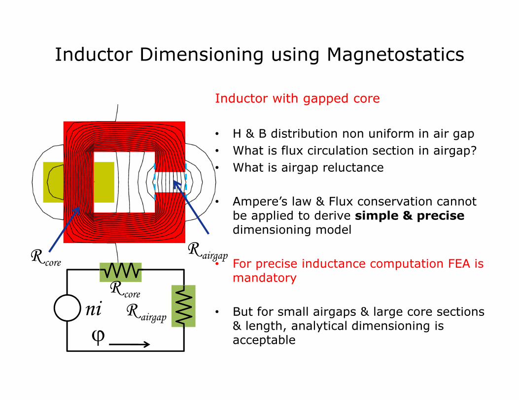
Inductor with gapped core
• H & B distribution non uniform in air gap
• What is flux circulation section in airgap?
• What is airgap reluctance
• Ampere’s law & Flux conservation cannotbe applied to derive simple & precise
dimensioning model
• For precise inductance computation FEA ismandatory
• But for small airgaps & large core sections & length, analytical dimensioning isacceptable

Simplified assumption for inductor with gapped core:
• flux circulation section in airgap = core section Ae
entrefernoyau RR +
=
2n
L
eA
e⋅≈
0
1
µairgapR
e
m
A
l⋅=
µ
1
coreR
e
lm
⋅=
µ
µ0
airgap
core
R
R
Inductor Dimensioning using Magnetostatics
airgapRni
ϕ
coreR
e
An
nL
eo⋅
⋅=≅
µ2
2
airgapR
airgapcore RR <<if e << lm
& µ >> µo
Simple dimensioning model
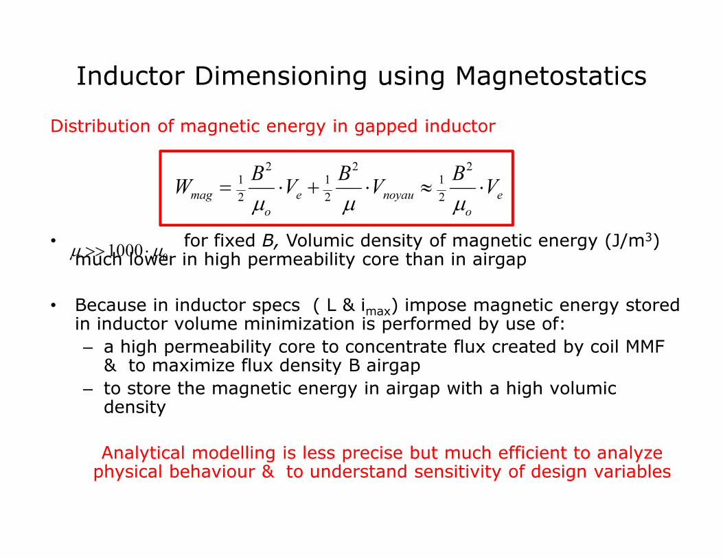
Distribution of magnetic energy in gapped inductor
• for fixed B, Volumic density of magnetic energy (J/m3) much lower in high permeability core than in airgap
• Because in inductor specs ( L & imax) impose magnetic energy storedin inductor volume minimization is performed by use of:
– a high permeability core to concentrate flux created by coil MMF & to maximize flux density B airgap
– to store the magnetic energy in airgap with a high volumicdensity
Analytical modelling is less precise but much efficient to analyzephysical behaviour & to understand sensitivity of design variables
e
o
noyaue
o
magV
BV
BV
BW ⋅≈⋅+⋅=
µµµ
2
2
1
2
2
1
2
2
1
Inductor Dimensioning using Magnetostatics
01000 µµ ⋅>>

HF Transformer Electrical Equivalent Circuit
LmRm
a=n1/n2
l11
R2R1
C11 C22
C12
l12
V1-V2
Electrostatic Modeling
Magnetostatic Modeling
Transformer Electrical Equivalent circuit
29
Determination of Transformer Electrical Equivalent circuit elements
inductances with Magnetostatics, capacitances with Electrostatics
2D (or 3D) FEA identification in Magnetostatics & Electrostatics preferred to simplified analytical computation (better precision)
• FEA “simulated experiment” technique

FEA Identification of Equivalent Circuit Inductances
Magnetostatics 2D FEA tool
Direct identification of transformer inductances
2 FEA identification tests:
Open Secondary (no load operation)
Short-circuit operation
Magnetizing inductance derived from
FEA computation of magnetic energy
stored during no-load operation
Total leakage inductance derived from
FEA computation of magnetic energy
stored during short-circuit operation
Magnetic Flux Density Distribution
under short-circuit operation
30

FEA Identification of Equivalent CircuitCapacitances
V2
V1=0
-V2
V1=V
2
2
1
2
121
.2
V
WCC
cc
=+
2
2
1
122
.2
V
WCC
cc
=+
2
2
122
21
.2
V
WCC =+
Electrostatics 2D FEA tool
direct identification of capacitors C1, C2, C12
3 FEA identification tests:
Secondary short circuited & grounded,
Primary short circuited & grounded,
Primary & secondary supplied with V2n linear voltage distribution
C1, C2, C12 derived from electrical energies W2cc, W1cc & W122
computed by electrostatic FEA
31
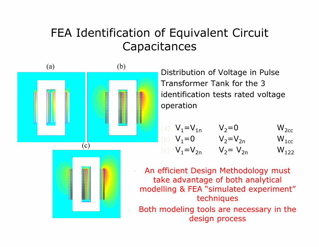
Distribution of Voltage in Pulse
Transformer Tank for the 3
identification tests rated voltage
operation
(a) V1=V1n V2=0 W2cc
(b) V1=0 V2=V2n W1cc
(c) V1=V2n V2= V2n W122
32
(a) (b)
(c)
FEA Identification of Equivalent CircuitCapacitances
• An efficient Design Methodology must take advantage of both analytical
modelling & FEA “simulated experiment” techniques
• Both modeling tools are necessary in the design process

33
• An efficient Design Methodology must take advantage
• of both analytical modelling & FEA “simulated experiment” techniques
• Both modeling tools are necessary in the design process

TRANSFORMER & INDUCTOR
DIMENSIONAL ANALYSIS
@ P.Viarouge
Transformer Power dimensioning model
v1
i1
v2
i2
i3
v3
v4
i4
vk
ik
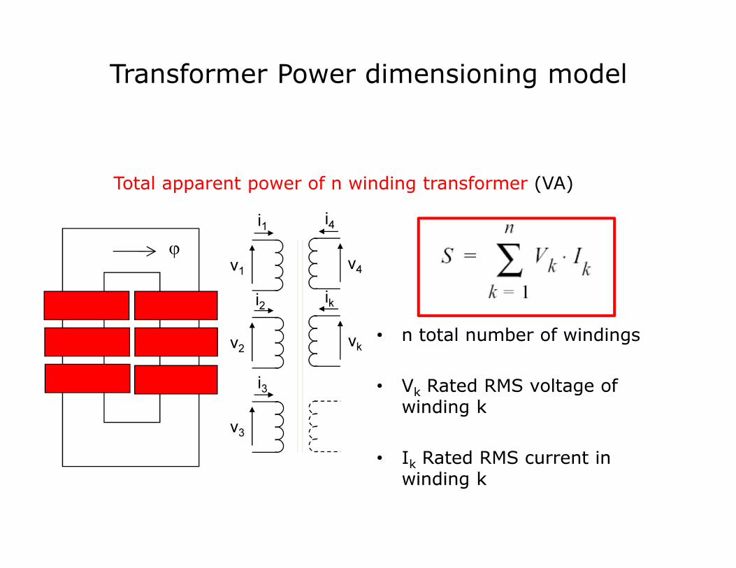
Total apparent power of n winding transformer (VA)
• n total number of windings
• Vk Rated RMS voltage of winding k
• Ik Rated RMS current in winding k
ϕ
Transformer Power dimensioning model
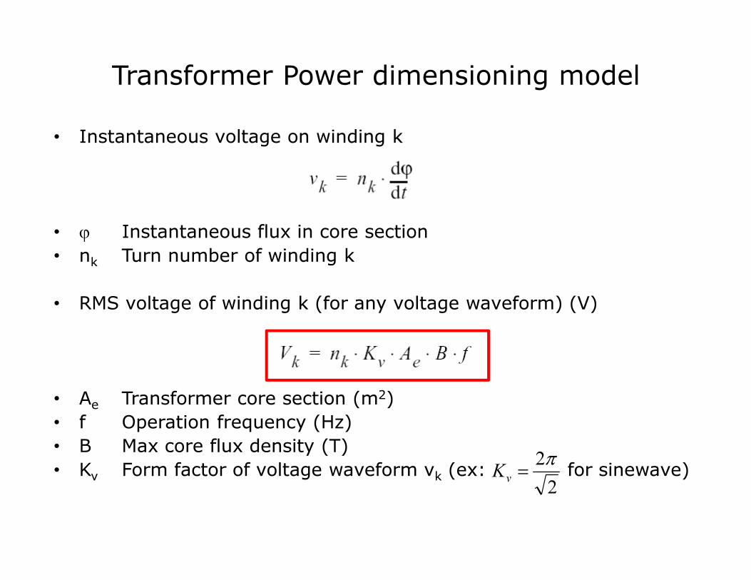
• Instantaneous voltage on winding k
• ϕ Instantaneous flux in core section
• nk Turn number of winding k
• RMS voltage of winding k (for any voltage waveform) (V)
• Ae Transformer core section (m2)
• f Operation frequency (Hz)
• B Max core flux density (T)
• Kv Form factor of voltage waveform vk (ex: for sinewave) 2
2π=
vK
Transformer Power dimensioning model
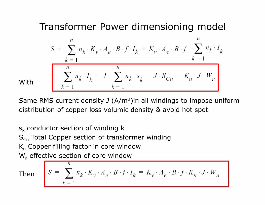
With
Same RMS current density J (A/m2)in all windings to impose uniform
distribution of copper loss volumic density & avoid hot spot
sk conductor section of winding k
SCu Total Copper section of transformer winding
Ku Copper filling factor in core window
Wa effective section of core window
Then
Transformer Power dimensioning model
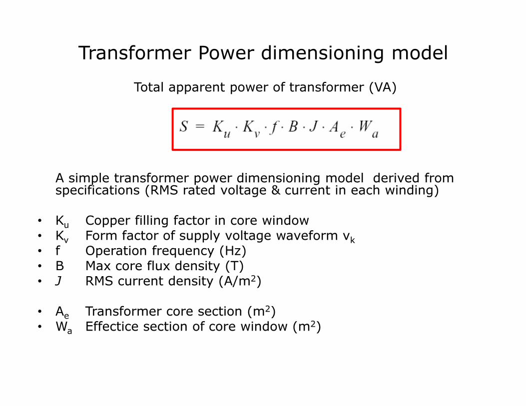
Total apparent power of transformer (VA)
A simple transformer power dimensioning model derived fromspecifications (RMS rated voltage & current in each winding)
• Ku Copper filling factor in core window• Kv Form factor of supply voltage waveform vk
• f Operation frequency (Hz)• B Max core flux density (T)• J RMS current density (A/m2)
• Ae Transformer core section (m2)• Wa Effectice section of core window (m2)

Transformer Dimensioning Power (VA)
Transformer Power dimensionning model
B
J
Ae
SCu
CuevSAJBKfVIS .....==∑
CuevSAJBKfVIS .....==∑
Converter Supply Specs
Size (m4)Material& Loss
VA/m3 & VA /kg improved at medium frequency … for fixed JB.

Transformer Dimensional Analysis
For fixed and all linear dimensions multiplied by kJB.
[ ]4.. LJBfS ⋅∝In terms of dimensional analysis
f
LCuevkLSkSkAkJBKfS 422
..... ==

Inductor Stored Energy dimensioning model
Magnetic Energy stored in inductor (J)
Inductor specifications
• L Inductance (H)
• I Maximum Supply Current (A)
2
2
1LIW
mag=
ϕ

Inductor Stored Energy dimensioning model
Magnetic Energy stored in inductor (J)
I Maximum Supply Current (A)
Φ Total magnetic flux in coil
• ϕ Magnetic flux circulating in core
• Ae core section (m2)
• B Max core flux density (T)
Wmag1
2--- L I
2⋅ ⋅
1
2--- Φ I⋅ ⋅= =
Φ n ϕ⋅ n B Ae
⋅ ⋅= =
iL
Φ=

Inductor Stored Energy dimensioning model
Magnetic Energy stored in inductor (J)
s Coil conductor section
SCu Total Copper section of inductor winding
J RMS current density (A/m2)
B Max core flux density (T)
Ku Copper filling factor in core window
Wa effective section of core window
Wmag
1
2--- K
uB J⋅ ⋅ W
aAe
⋅ ⋅ ⋅=
Wmag
1
2--- n B A
e⋅ ⋅( ) J s⋅ ⋅ ⋅
1
2--- B A
e⋅ J S
cu⋅ ⋅ ⋅= =
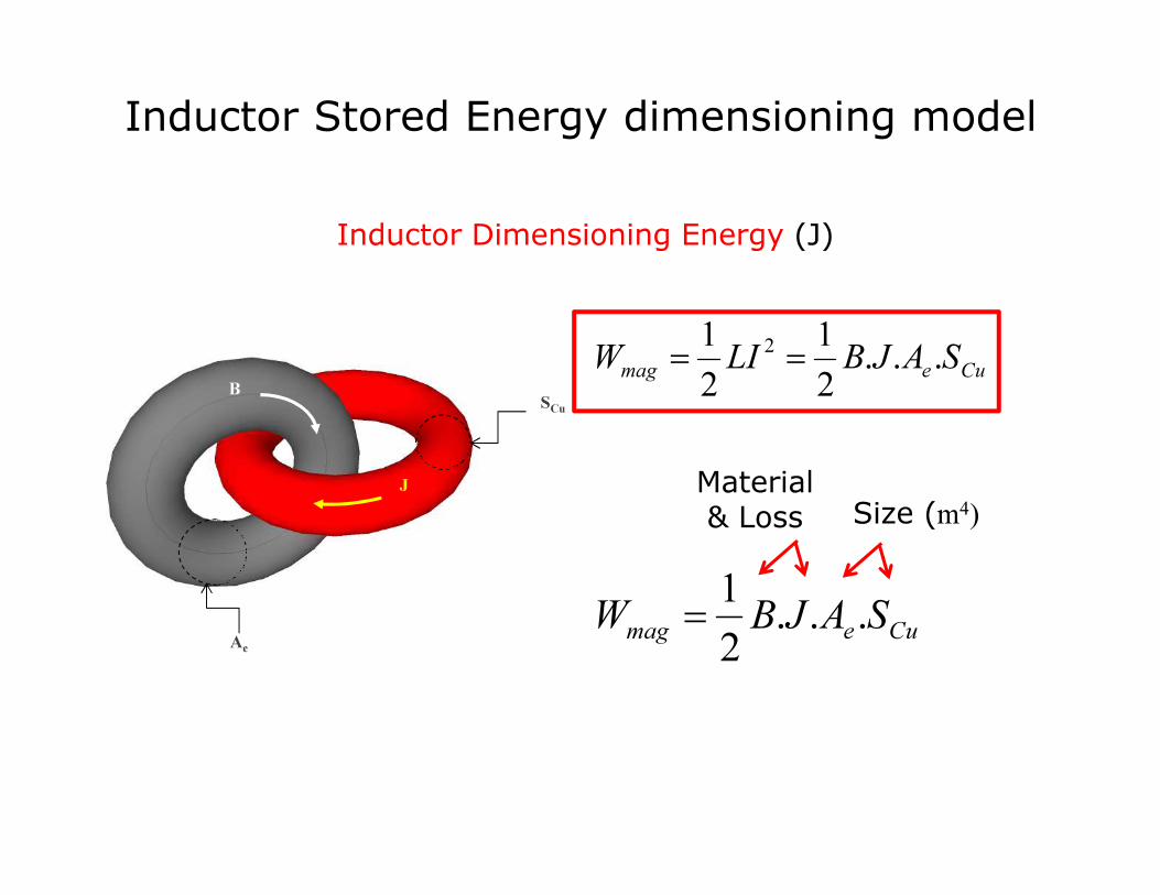
Inductor Dimensioning Energy (J)
Inductor Stored Energy dimensioning model
B
J
Ae
SCu
Size (m4)Material& Loss
Cuemag SAJBLIW ...2
1
2
1 2==
Cuemag SAJBW ...2
1=

Inductor Dimensional Analysis
For fixed and all linear dimensions multiplied by kJB.
In terms of dimensional analysis
f
magLCuemagkL WkSkAkJBW422
...2
1==
[ ]4. LJBWmag
⋅∝
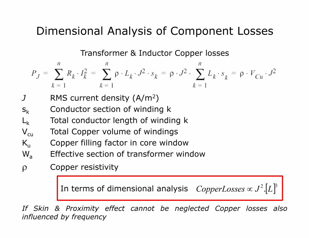
Dimensional Analysis of Component Losses
[ ]32. LJesCopperLoss ∝
Transformer & Inductor Copper losses
J RMS current density (A/m2)
sk Conductor section of winding k
Lk Total conductor length of winding k
Vcu Total Copper volume of windings
Ku Copper filling factor in core window
Wa Effective section of transformer window
ρ Copper resistivity
In terms of dimensional analysis
If Skin & Proximity effect cannot be neglected Copper losses alsoinfluenced by frequency

Dimensional Analysis of Component Losses
In terms of dimensional analysis
Simplified Transformer Magnetic losses (Steinmetz)
B Core flux density (T)
Cm, x, y Loss coefficient of material
Ve Core volume (m3)
Pmag
Ve
Cm
fx
By
⋅ ⋅ ⋅ Pmagv
Ve⋅= =
[ ]3. LBfMagLosses yx∝

Simplified Heat Transfer at external surface
∆T Temperature Rise External Surface
Sext External dissipation surface
h Heat transfer coefficient (convection & radiation)
Dimensional Analysis of Temperature Rise
[ ]LSh
LossesTempRise
ext
∝=
.
[ ][ ]2
3
. L
L
Sh
PPT
ext
magJ∝
+=∆
In terms of dimensional analysis
For fixed andJB. f

Correction of Scaling Laws
• Max Temperature Rise is always constrained by thermal limits of Insulation & Magnetic materials
• For high power components of large dimensions, dimensionalanalysis demonstrates that correction mechanisms must beadopted to limit Max Temperature rise within acceptable limits:
– Heat transfer coefficient h can be improved by use of forcedconvection, or cooling fluids
– Heatsinks and cooling fins can increase external dissipation surface Sext
– & are decreased according to
• Consequently with
• Use of active cooling fluids is necessary to maintain acceptable values of W/m3 J/m3 , W/kg & J/kg
[ ] 1
.
−
∝ LJB
[ ]CLS ∝ [ ]Cmag LW ∝ 4<C
BJ

OPTIMAL DESIGN
METHODOLOGY OF
MAGNETIC COMPONENTS
@ P.Viarouge

Magnetic Component Design Problem
The design problem is an optimization problem
• More design variables than constraint equations leads to an infinite number of feasible solutions. Optimal solution in terms of performance must be selected in this space
• Determination of optimal dimensions of a given device structure to maximize a cost/ performance objective function according to application & production constraints
MaterialProperties
Switch technology
Production Process
& Cost
Application Specifications
DeviceStructure & Dimensions
Application Specifications
Production Process &
CostOptimal Compromise

Optimal Design Methodology of Magnetic Components
Design Problem formulation
• Optimal Design problem formulation: selection of design variables, constraints, objectives & dimensioning models & their couplings (electromagnetic, electrical circuits, thermal, mechanical modeling)
Design variables (or optimization state variables)
• Design variables controllable by designer: physical dimensions, current densities, etc… Design variables can be continuous or discrete but continuous variables improve efficiency of optimization methods. Design variables are bounded, with max & min values
Optimal Design Methodology use “inverse problem” resolution method
• Iterative optimization procedure is trying virtual prototypes & evaluating their performance with explicit analytical dimensioning models or by testing them using FEA “simulated experiment”
@ P.Viarouge
Optimal Design Methodology of Magnetic Components
Constraints functions of design variables
• Constraints must be respected for design feasibility according to specifications & physical limits of materials or bounds on the validity of dimensioning models or performance (efficiency, temp rise,…). The constraint functions usually incorporated into objective functions using Lagrange multipliers
Objective functions of design variables
• An objective is a numerical value to be maximized or minimized: weight, volume, cost. Single or multi-objective optimization methods are available. A suitable formulation of design objective function is preferable to simple weighting of different objective function (example: transformer input apparent power to weight ratio for rated load)
Dimensionning Models
• Dimensionning Models used to evaluate the objective & constraint functions of the design variables of optimization problem
@ P.Viarouge

Dimensioning model used to derive performance & constraintsimposed by specifications of the application & material operating limits
Generic Dimensioning Model
DimensionsDensities B&JMaterial data
PerformancesConstraints
ElectricalEquivalentCircuit
Electromagneticmodelling
Thermalmodelling
Mechanicalmodelling
Magnetic Component dimensioning Model

Determination of Electrical Equivalent Circuit (inductances & Capacitances) can be performed analytically or directly identified from FEA simulated experiment approach
Generic Dimensioning Model
DimensionsDensities B&JMaterial data
PerformancesConstraints
ElectricalEquivalentCircuit
Thermalmodelling
Mechanicalmodelling
Magnetic Component dimensioning Model
FEA Identification
Equivalent Circuit
Capacitances & Inductances identifiedfrom FEA simulated tests

State Variables Vector
Objective &
ContraintsFunctionsEvaluation
ElectricalEquivalentCircuit
Electromagneticmodelling
Thermalmodelling
Mechanicalmodelling
Non-linear constrained optimization procedure is used to solve the inverse design problem iteratively
Optimal Design Methodology
Magnetic Component dimensioning Model
Non Linear ConstrainedOptimization Procedure

Integrated design or Global optimization of Power Converters
• Multi-disciplinary design optimization (MDO) can be extended to Global Design Optimization of Power Converters including optimal dimensioning of power stage, magnetic components, … even control strategies & tuning
• MDO allows designers to incorporate all their design dimensioning tools simultaneously in a single CAD environment, to talk together, to share & improve their global expertise
• Global optimal solution usually better than the design found by optimizing each component sequentially, since it can exploit their interaction in terms of global performance to find optimal compromises.
@ P.Viarouge

Integrated design or Global optimization
State Variables Vector
ModulatorElectricalModelling
2D FEA Identification
Equivalent Circuit
Thermal Modelling
MechanicalModelling
Klystron RatedOperation Point
Objective &
ContraintsFunctionsEvaluation
Non Linear ConstrainedOptimization Procedure
Design of Monolithic Pulse Transformer Modulator with Global Optimization Approach