
Error Control Coding - CERN Indico
34
1 1 Coding with emphasis on Error Control Coding A. Marchioro / PH-ESE-ME 2 “The fundamental problem of communication is that of reproducing at one point either exactly or approximately a message selected at another point” Claude Shannon A Mathematical Theory of Communication, The Bell System Technical Journal, vol. 27, pp.379-423, July 1948
-
Upload
khangminh22 -
Category
Documents
-
view
4 -
download
0
Transcript of Error Control Coding - CERN Indico

1
1
Coding
with emphasis on
Error Control Coding
A. Marchioro / PH-ESE-ME
2
“The fundamental problem of communication is that of reproducing at one point either exactly or approximately a message selected at
another point”
Claude Shannon
A Mathematical Theory of Communication,
The Bell System Technical Journal, vol. 27, pp.379-423, July 1948
2
3
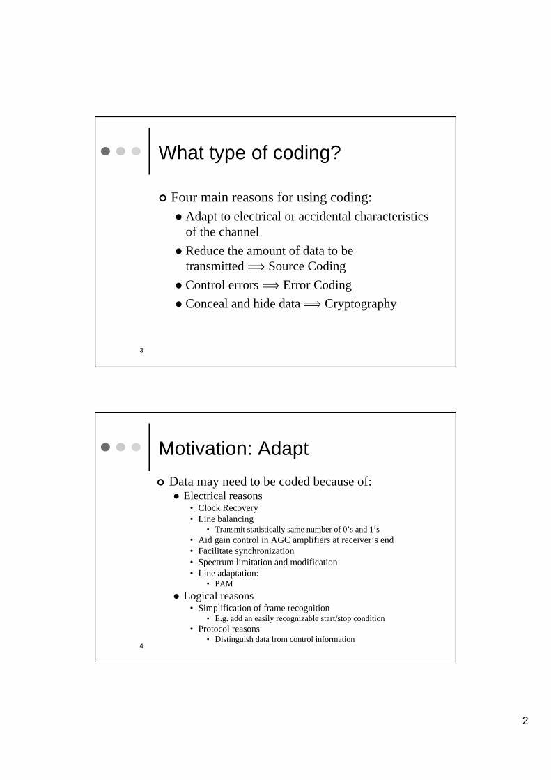
What type of coding?
Four main reasons for using coding:
Adapt to electrical or accidental characteristics
of the channel
Reduce the amount of data to be
transmitted ï Source Coding
Control errors ï Error Coding
Conceal and hide data ï Cryptography
4
Motivation: Adapt
Data may need to be coded because of: Electrical reasons
• Clock Recovery
• Line balancing • Transmit statistically same number of 0’s and 1’s
• Aid gain control in AGC amplifiers at receiver’s end
• Facilitate synchronization
• Spectrum limitation and modification
• Line adaptation: • PAM
Logical reasons • Simplification of frame recognition
• E.g. add an easily recognizable start/stop condition
• Protocol reasons • Distinguish data from control information
3
5
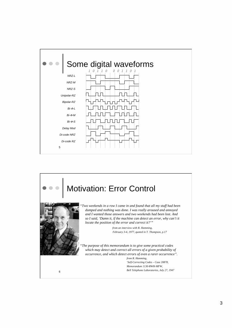
Some digital waveforms
NRZ-L
NRZ-M
NRZ-S
Unipolar-RZ
Bipolar-RZ
Bi- -L
Bi- -M
Bi- -S
Delay Mod
Di-code NRZ
Di-code RZ
1 0 1 1 0 0 0 1 1 0 1
6
Motivation: Error Control
“Two weekends in a row I came in and found that all my stuff had been
dumped and nothing was done. I was really aroused and annoyed
and I wanted those answers and two weekends had been lost. And
so I said, ‘Damn it, if the machine can detect an error, why can’t it
locate the position of the error and correct it?’”
from an interview with R. Hamming,
February 3-4, 1977, quoted in T. Thompson, p.17
“The purpose of this memorandum is to give some practical codes
which may detect and correct all errors of a given probability of
occurrence, and which detect errors of even a rarer occurrence”. from R. Hamming,
‘Self-Correcting Codes – Case 20878,
Memorandum 1130-RWH-MFW,
Bell Telephone Laboratories, July 27, 1947

4
7
Motivation: Error Control
Hardware is not perfect Errors are introduced by:
• Signal reduction • Transmission from satellite
• Trans-oceanic optical fibers
• Noise and interference • Radio communication
• People • Reading a Credit Card number
• Imperfect parts • Richard Hamming worked first to avoid catastrophic errors in early relay-based
computers
• Radioactive particles causing perturbation in electronic circuits
• Wear-out and aging • e.g. fingerprint and scratches on CD and DVDs
Basic idea: Add redundant information as to make up for lost or garbled information
8
Applications

5
9
Applications Voyager 2 Flight System Performance (Dec 2008)
Down transmission speed ~ 7Kbit/sec
Up transmission speed ~50 bits/sec
PROPELLANT/POWER CONSUMABLES STATUS AS OF THIS REPORT
Spacecraft Consumption One Week[*] (gm) 6.29
Propellant Remaining (Kg) 28.63
Output (Watts) 281.5
RANGE, VELOCITY AND ROUND TRIP LIGHT TIME AS OF Nov 7,2008
Distance from the Sun (Km) 13,077,000,000
Distance from the Earth (Km) 13,132,000,000
Total Distance Traveled (Km) 19,409,000,000
Velocity Relative to Sun (Km/sec) 15.524
Velocity Relative to Earth (Km/sec) 41.592
[*] Power Source is Radioisotope Thermoelectric Generator
http://voyager.jpl.nasa.gov/mission/weekly-reports/
10
Applications
6
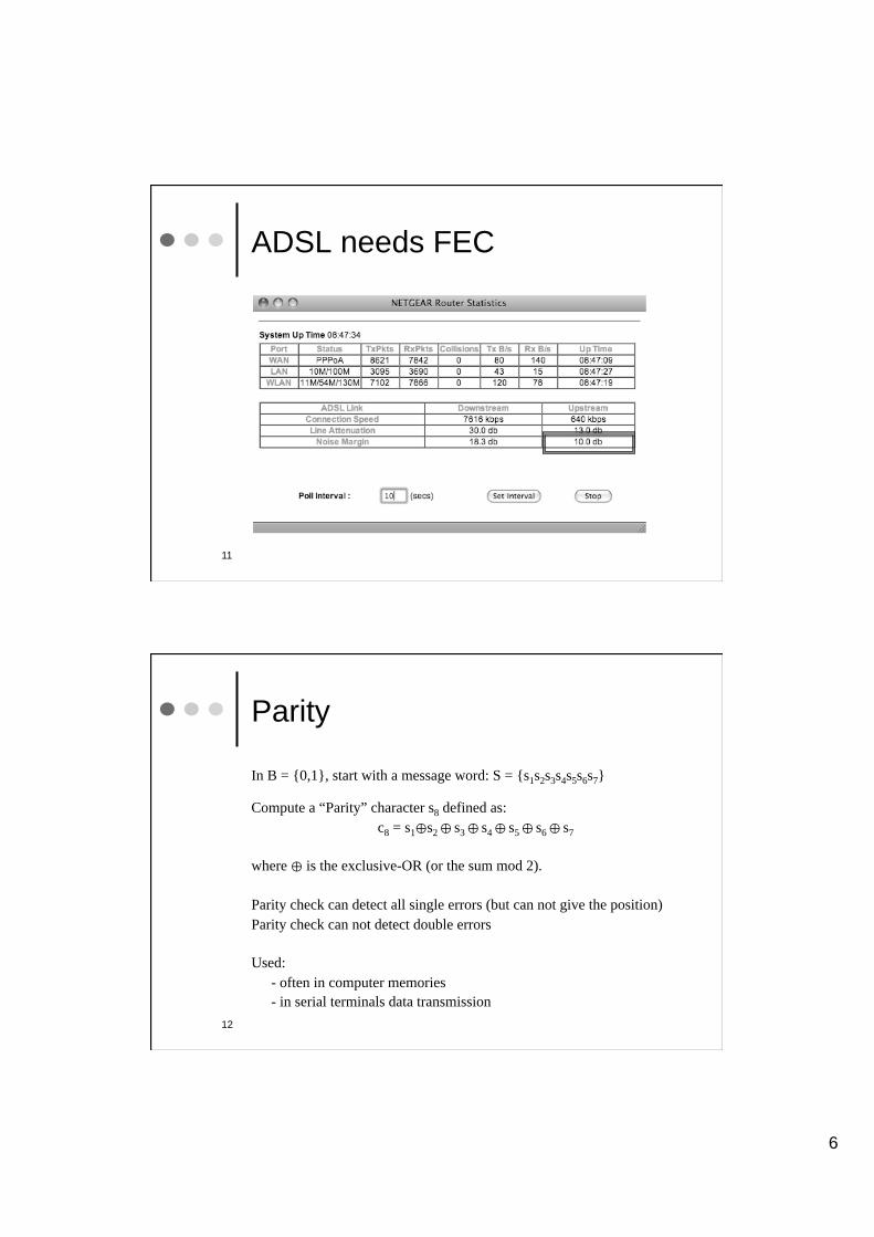
ADSL needs FEC
11
12
Parity
In B = {0,1}, start with a message word: S = {s1s2s3s4s5s6s7}
Compute a “Parity” character s8 defined as:
c8 = s1 s2 s3 s4 s5 s6 s7
where is the exclusive-OR (or the sum mod 2).
Parity check can detect all single errors (but can not give the position)
Parity check can not detect double errors
Used:
- often in computer memories
- in serial terminals data transmission

7
13
Two-Dimensional Parity
Pa
rity
X
ParityY
2 Errors
1 0 1 1 1 0 0 0
0 1 0 0 0 1 1 1
1 1 0 0 0 0 1 1
0 1 0 1 1 0 1 0
1 0 0 1 0 1 1 0
0 0 0 1 0 1 0 0
1 1 0 0 1 0 0 1
0 0 1 0 1 1 0
1 0 1 1 1 0 0 0
0 1 0 0 0 1 1 1
1 1 0 0 0 0 1 1
0 1 0 1 0 0 1 1
1 0 0 1 1 1 1 1
0 0 0 1 0 1 0 0
1 1 0 0 1 0 0 1
0 0 1 0 1 1 0
14
Two-Dimensional Parity
8
15
Repetition Code
Take each symbol si in S and repeat it n times.
This is an (n, 1) code.
For example the word {s1s2s3} becomes the codeword
{s1s1s1s2s2s2s3s3s3}
Efficiency (= rate) of the code is: 1/n
The minimum distance (see later) is n and the number of errors t that can
be corrected is:
t = (n – 1)
16
Repetition anywhere?
Redundancy in mainframes:
http://www.research.ibm.com/journal/rd/435/spainhower.html
http://www.fujitsu.com/downloads/PRMQST/documents/whitepaper/PRIMEQUEST-High-Availability.pdf
In RAID disk arrays:
RAID1 (Mirroring)
Space electronics:
“A Comparison of Fault-Tolerant State Machine Architectures for Space-Borne Electronics”, IEEE Transactions on Reliability, Vol. 45. No. 1. 1996 March
9
17
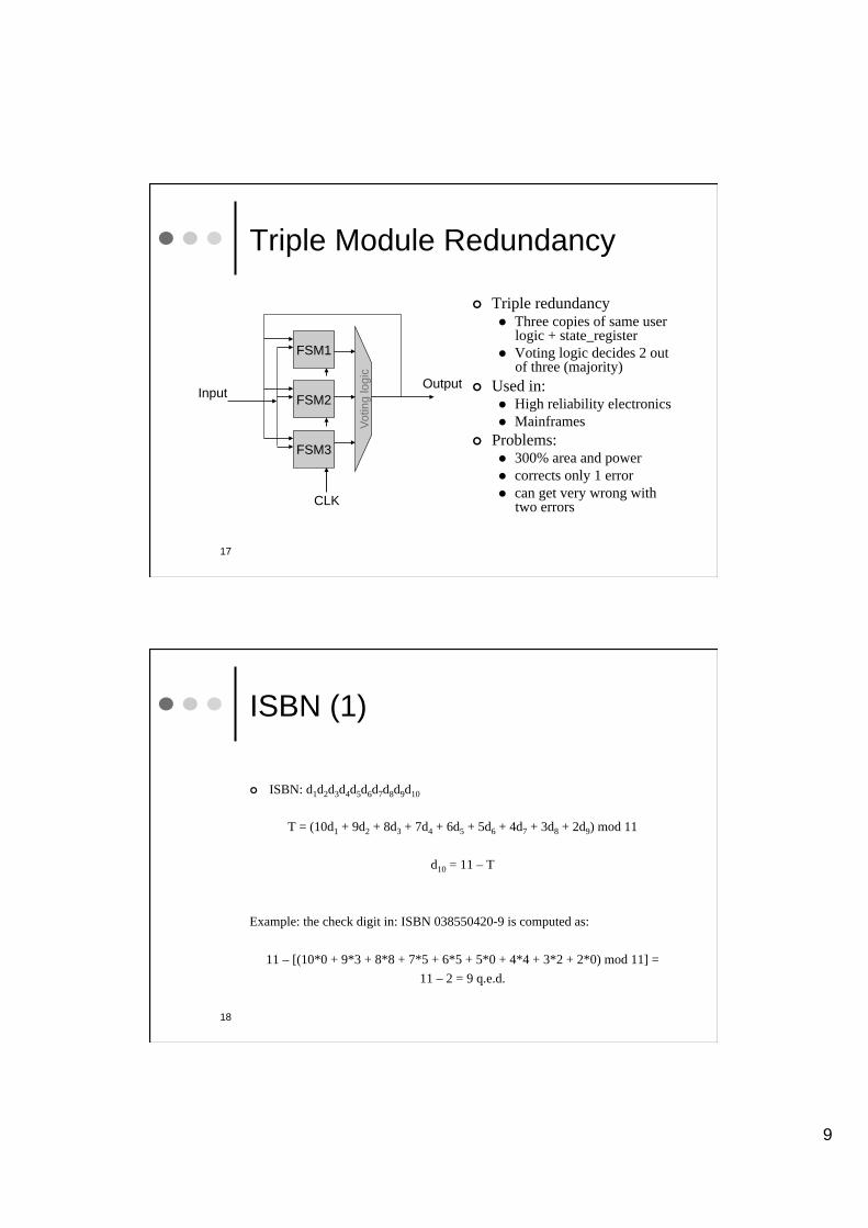
Triple Module Redundancy
Triple redundancy Three copies of same user logic + state_register
Voting logic decides 2 out of three (majority)
Used in: High reliability electronics
Mainframes
Problems: 300% area and power
corrects only 1 error
can get very wrong with two errors
FSM1
FSM2
FSM3
Voting logic
Input Output
CLK
18
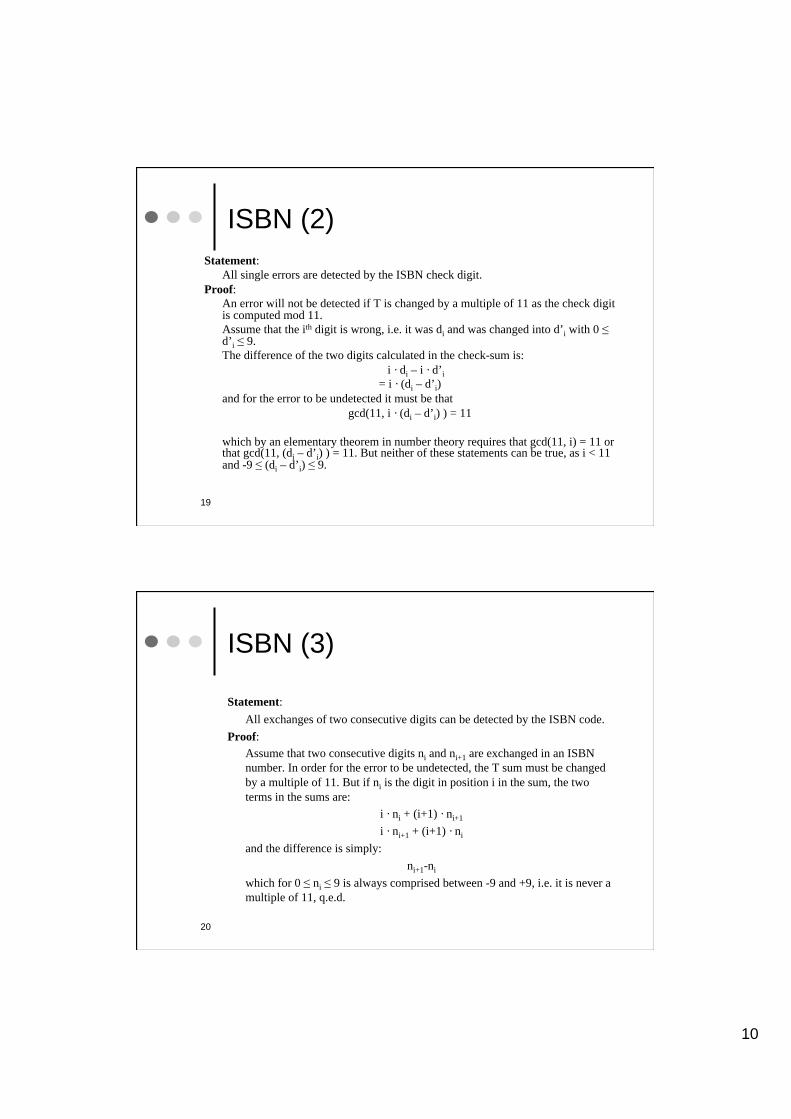
ISBN (1)
ISBN: d1d2d3d4d5d6d7d8d9d10
T = (10d1 + 9d2 + 8d3 + 7d4 + 6d5 + 5d6 + 4d7 + 3d8 + 2d9) mod 11
d10 = 11 – T
Example: the check digit in: ISBN 038550420-9 is computed as:
11 – [(10*0 + 9*3 + 8*8 + 7*5 + 6*5 + 5*0 + 4*4 + 3*2 + 2*0) mod 11] =
11 – 2 = 9 q.e.d.
10
19
ISBN (2)
Statement:
All single errors are detected by the ISBN check digit.
Proof:
An error will not be detected if T is changed by a multiple of 11 as the check digit is computed mod 11.
Assume that the ith digit is wrong, i.e. it was di and was changed into d’i with 0 d’i 9.
The difference of the two digits calculated in the check-sum is:
i · di – i · d’i
= i · (di – d’i)
and for the error to be undetected it must be that
gcd(11, i · (di – d’i) ) = 11
which by an elementary theorem in number theory requires that gcd(11, i) = 11 or that gcd(11, (di – d’i) ) = 11. But neither of these statements can be true, as i < 11 and -9 (di – d’i) 9.
20
ISBN (3)
Statement:
All exchanges of two consecutive digits can be detected by the ISBN code.
Proof:
Assume that two consecutive digits ni and ni+1 are exchanged in an ISBN
number. In order for the error to be undetected, the T sum must be changed
by a multiple of 11. But if ni is the digit in position i in the sum, the two
terms in the sums are:
i · ni + (i+1) · ni+1
i · ni+1 + (i+1) · ni
and the difference is simply:
ni+1-ni
which for 0 ni 9 is always comprised between -9 and +9, i.e. it is never a
multiple of 11, q.e.d.

11
ISBN-13 (4)
The new 13 digit ISBN-13 control code is constructed as:
T = (d1 + 3*d2 + d3 + 3*d4 + d5 + 3*d6 + d7 + 3*d8 + d9 + 3*d10 + d11 + 3*d12 ) mod 10
d13 = 10 – T
Now several digits exchange can NOT be recognized, but more books can be cataloged…
21
Families of Error Control Methods
Block Codes: codeword built only on current message-word
Non-block codes: codeword depends on current message word and
of some past words, ex:
Convolutional
Examples of codes:
Hamming
Bose-Chauduri-Hocqueghem (BCH)
Golay
Reed-Solomon (RS)
Reed-Müller
Low Density Parity Check Codes
Turbo Codes
… 22
12
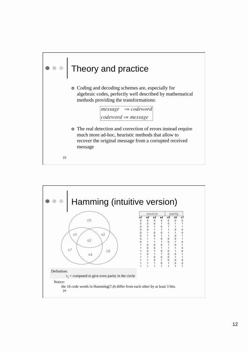
Theory and practice
Coding and decoding schemes are, especially for
algebraic codes, perfectly well described by mathematical
methods providing the transformations:
The real detection and correction of errors instead require
much more ad-hoc, heuristic methods that allow to
recover the original message from a corrupted received
message
23
24
Hamming (intuitive version)
s1 s2
s3
s4
c5
c6 c7
Definition:
cj = computed to give even parity in the circle
source parity
Notice:
the 16 code words in Hamming(7,4) differ from each other by at least 3 bits.
13
25
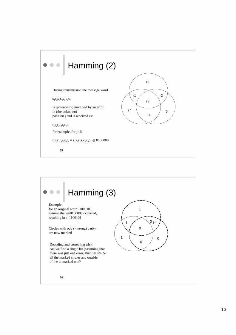
Hamming (2)
r1 r2
r3
r4
r5
r6 r7
During transmission the message word
s1s2s3s4c5c6c7
is (potentially) modified by an error
in (the unknown)
position j and is received as:
r1r2r3r4r5r6r7
for example, for j=2:
r1r2r3r4r5r6r7 = s1s2s3s4c5c6c7 0100000
26
Hamming (3)
1 1*
0
0
1
0 1
Example:
for an original word: 1000101
assume that e=0100000 occurred,
resulting in r=1100101
Circles with odd (=wrong) parity
are now marked
Decoding and correcting trick:
can we find a single bit (assuming that
there was just one error) that lies inside
all the marked circles and outside
of the unmarked one?
0
14
27
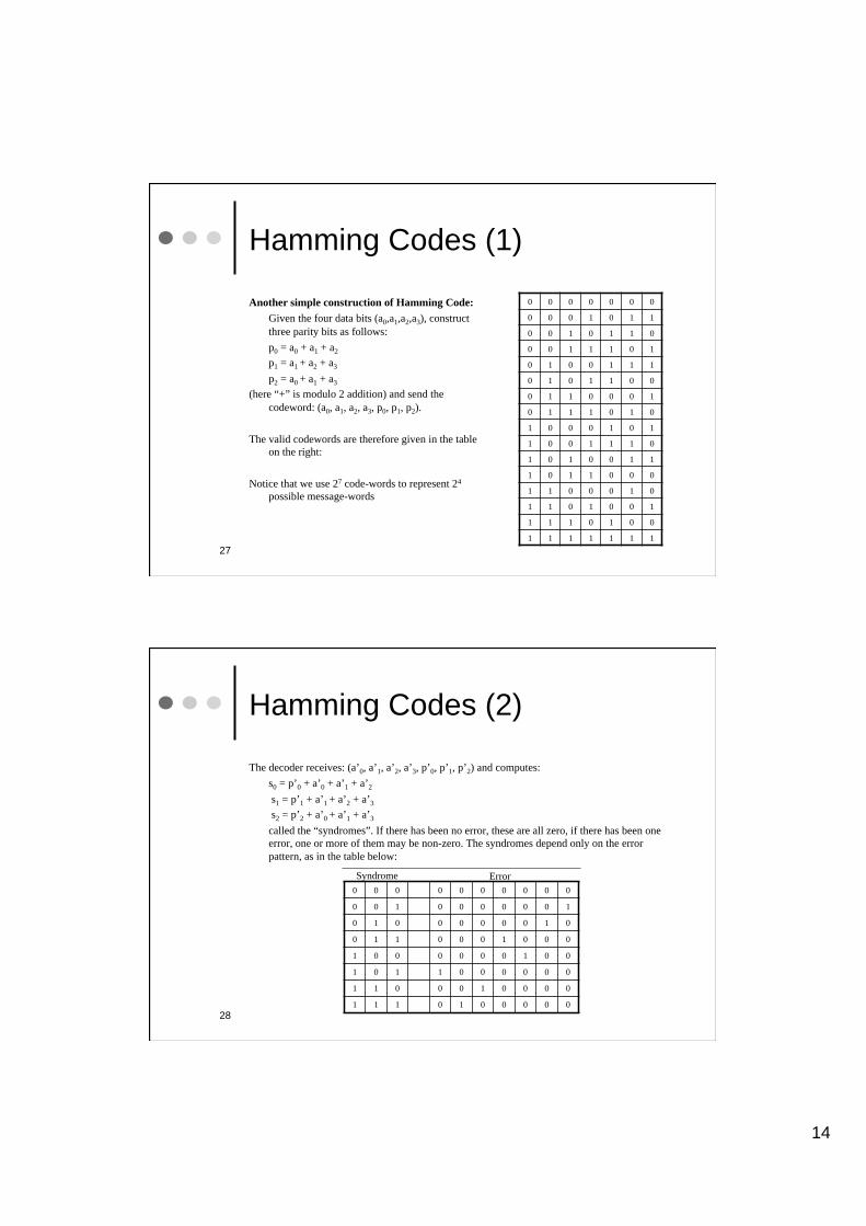
Hamming Codes (1)
Another simple construction of Hamming Code:
Given the four data bits (a0,a1,a2,a3), construct
three parity bits as follows:
p0 = a0 + a1 + a2
p1 = a1 + a2 + a3
p2 = a0 + a1 + a3
(here “+” is modulo 2 addition) and send the
codeword: (a0, a1, a2, a3, p0, p1, p2).
The valid codewords are therefore given in the table
on the right:
Notice that we use 27 code-words to represent 24
possible message-words
0 0 0 0 0 0 0
0 0 0 1 0 1 1
0 0 1 0 1 1 0
0 0 1 1 1 0 1
0 1 0 0 1 1 1
0 1 0 1 1 0 0
0 1 1 0 0 0 1
0 1 1 1 0 1 0
1 0 0 0 1 0 1
1 0 0 1 1 1 0
1 0 1 0 0 1 1
1 0 1 1 0 0 0
1 1 0 0 0 1 0
1 1 0 1 0 0 1
1 1 1 0 1 0 0
1 1 1 1 1 1 1
28
Hamming Codes (2)
The decoder receives: (a’0, a’1, a’2, a’3, p’0, p’1, p’2) and computes:
s0 = p’0 + a’0 + a’1 + a’2
s1 = p’1 + a’1 + a’2 + a’3
s2 = p’2 + a’0 + a’1 + a’3
called the “syndromes”. If there has been no error, these are all zero, if there has been one
error, one or more of them may be non-zero. The syndromes depend only on the error
pattern, as in the table below:
0 0 0 0 0 0 0 0 0 0
0 0 1 0 0 0 0 0 0 1
0 1 0 0 0 0 0 0 1 0
0 1 1 0 0 0 1 0 0 0
1 0 0 0 0 0 0 1 0 0
1 0 1 1 0 0 0 0 0 0
1 1 0 0 0 1 0 0 0 0
1 1 1 0 1 0 0 0 0 0
Syndrome Error
15
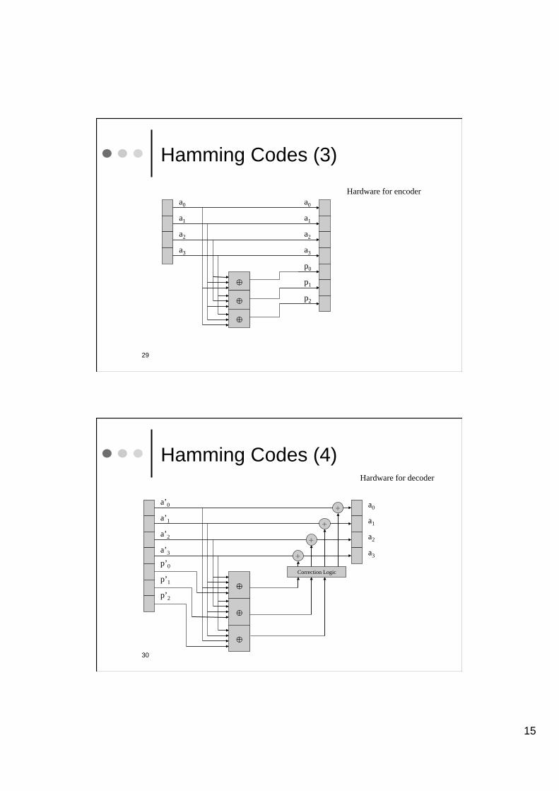
29
Hamming Codes (3)
a0
a1
a2
a3
a0
a1
a2
a3
p0
p1
p2
Hardware for encoder
30
Hamming Codes (4)
a0
a1
a2
a3
a’0
a’1
a’2
a’3
p’0
p’1
p’2
Hardware for decoder
Correction Logic
+
+
+
+
16
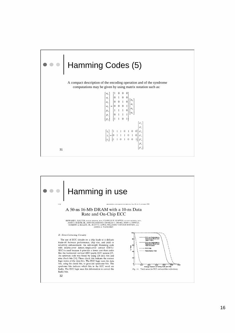
31
Hamming Codes (5)
A compact description of the encoding operation and of the syndrome
computations may be given by using matrix notation such as:
32
Hamming in use
17
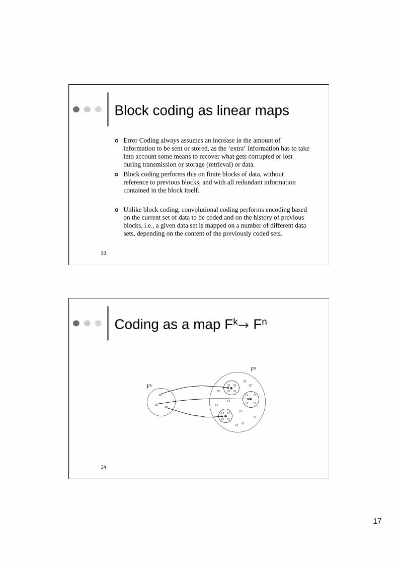
33
Block coding as linear maps
Error Coding always assumes an increase in the amount of
information to be sent or stored, as the ‘extra’ information has to take
into account some means to recover what gets corrupted or lost
during transmission or storage (retrieval) or data.
Block coding performs this on finite blocks of data, without
reference to previous blocks, and with all redundant information
contained in the block itself.
Unlike block coding, convolutional coding performs encoding based
on the current set of data to be coded and on the history of previous
blocks, i.e., a given data set is mapped on a number of different data
sets, depending on the content of the previously coded sets.
34
Coding as a map FkØ Fn
Fk
Fn

18
35
Error Detection in Fn
Degradation due to
Transmission or storage
(retrieval)
Recoverable
Undetected Error
Confused, unrecoverable
36
Linear Codes: Structure
Definition: Linear Block Code
A linear code C is a subspace of dimension k of the vector space Bn
for simple binary vectors, or in general of GF(q)n.
In other words, C is a non-empty set of n-tuples over GF(q)n, called
codewords, respecting the structure of a vector space, that is the
addition of two codewords is always a codeword, and the
multiplication of a codeword by a scalar element of the field is also
always a codeword. From the definition, it follows that the zero word
must always be part of a linear codeword, as
" c œ C , (c ) + (-c) = 0 œ C
19
37
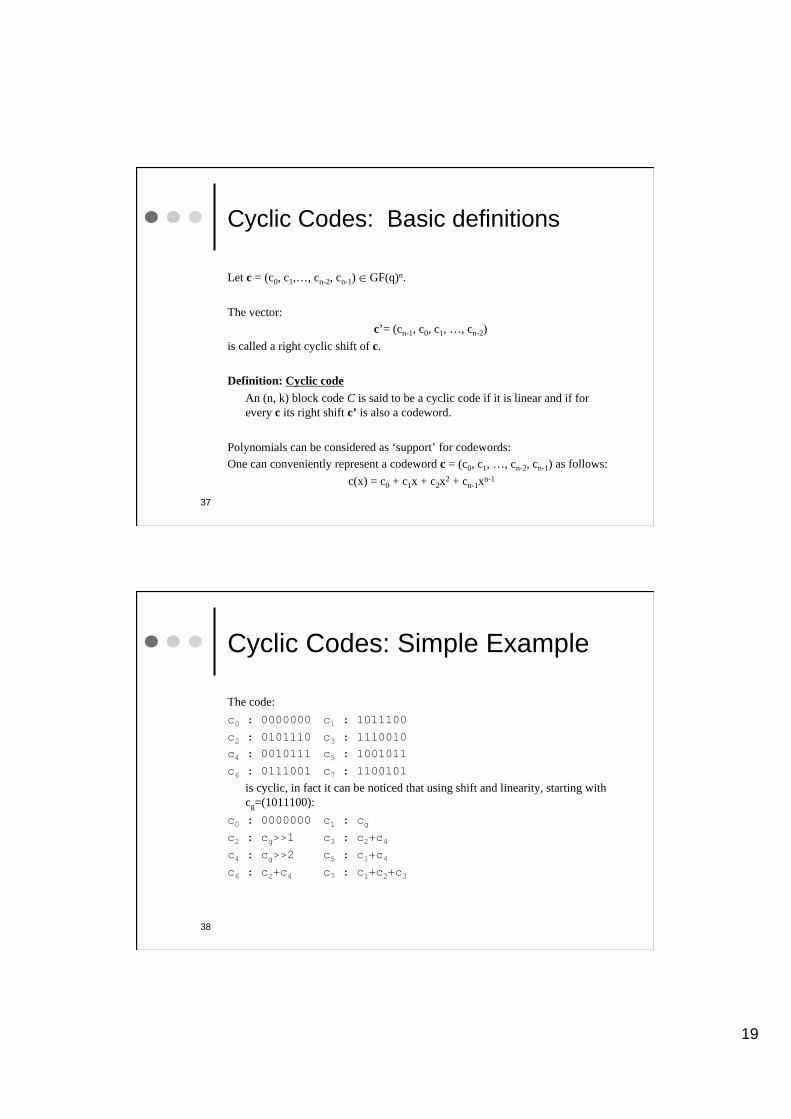
Cyclic Codes: Basic definitions
Let c = (c0, c1,…, cn-2, cn-1) œ GF(q)n.
The vector:
c’= (cn-1, c0, c1, …, cn-2)
is called a right cyclic shift of c.
Definition: Cyclic code
An (n, k) block code C is said to be a cyclic code if it is linear and if for
every c its right shift c’ is also a codeword.
Polynomials can be considered as ‘support’ for codewords:
One can conveniently represent a codeword c = (c0, c1, …, cn-2, cn-1) as follows:
c(x) = c0 + c1x + c2x2 + cn-1x
n-1
38
Cyclic Codes: Simple Example
The code:
c0 : 0000000 c1 : 1011100
c2 : 0101110 c3 : 1110010
c4 : 0010111 c5 : 1001011
c6 : 0111001 c7 : 1100101
is cyclic, in fact it can be noticed that using shift and linearity, starting with
cg=(1011100):
c0 : 0000000 c1 : cg
c2 : cg>>1 c3 : c2+c4
c4 : cg>>2 c5 : c1+c4
c6 : c2+c4 c7 : c1+c2+c3

20
Reed-Solomon: very
elementary introduction
39
40
RS coding, very simplified version
Let’s imagine we want to transmit just two numbers and that we are ready
to add some redundancy to ‘repair’ faulty data.
One method could be:
Compute the straight line that goes through the two numbers intended as y
values in a plot at fixed x=1 and x=2 coordinates, i.e. the line going though
the points (1, y1) and (2, y2).
Instead of transmitting just the two numbers, now transmit the five y numbers
on the same straight line corresponding to x-coordinates x=1,2, and 3,4,5
Now assume that one of the yi gets corrupted
Clearly the other 4 numbers are sufficient to establish a straight line and the y
value corresponding to the corrupted one can be reconstructed from the other
points
21
41
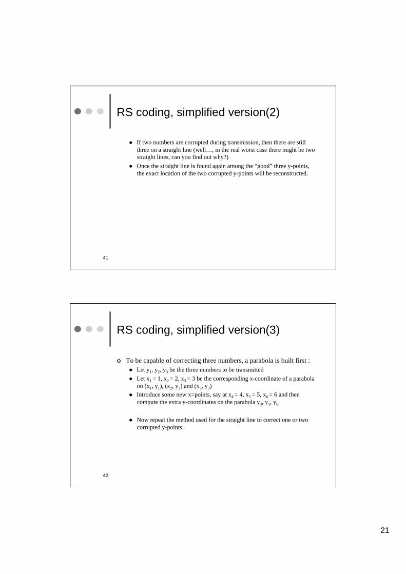
RS coding, simplified version(2)
If two numbers are corrupted during transmission, then there are still
three on a straight line (well…, in the real worst case there might be two
straight lines, can you find out why?)
Once the straight line is found again among the “good” three y-points,
the exact location of the two corrupted y-points will be reconstructed.
42
RS coding, simplified version(3)
To be capable of correcting three numbers, a parabola is built first :
Let y1, y2, y3 be the three numbers to be transmitted
Let x1 = 1, x2 = 2, x3 = 3 be the corresponding x-coordinate of a parabola
on (x1, y1), (x2, y2) and (x3, y3)
Introduce some new x=points, say at x4 = 4, x5 = 5, x6 = 6 and then
compute the extra y-coordinates on the parabola y4, y5, y6.
Now repeat the method used for the straight line to correct one or two
corrupted y-points.
22
43
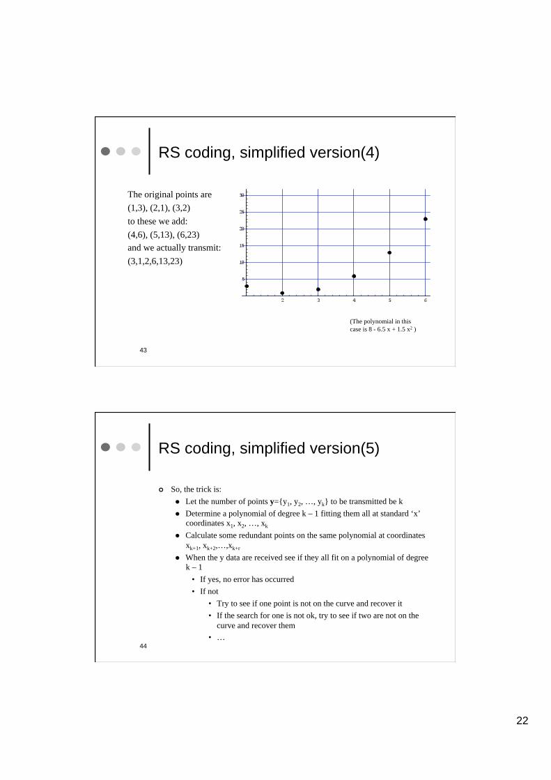
RS coding, simplified version(4)
The original points are
(1,3), (2,1), (3,2)
to these we add:
(4,6), (5,13), (6,23)
and we actually transmit:
(3,1,2,6,13,23)
(The polynomial in this
case is 8 - 6.5 x + 1.5 x2 )
44
RS coding, simplified version(5)
So, the trick is:
Let the number of points y={y1, y2, …, yk} to be transmitted be k
Determine a polynomial of degree k – 1 fitting them all at standard ‘x’
coordinates x1, x2, …, xk
Calculate some redundant points on the same polynomial at coordinates
xk+1, xk+2,…,xk+r
When the y data are received see if they all fit on a polynomial of degree
k – 1
• If yes, no error has occurred
• If not
• Try to see if one point is not on the curve and recover it
• If the search for one is not ok, try to see if two are not on the
curve and recover them
• …
23
45
Example
1. Music or Data CD ROM Coding
46
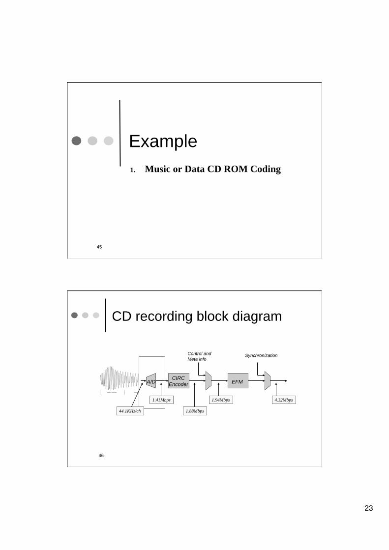
CD recording block diagram
A/D EFM CIRC
Encoder
Control and
Meta info Synchronization
44.1KHz/ch
1.41Mbps
1.88Mbps
1.94Mbps 4.32Mbps
24
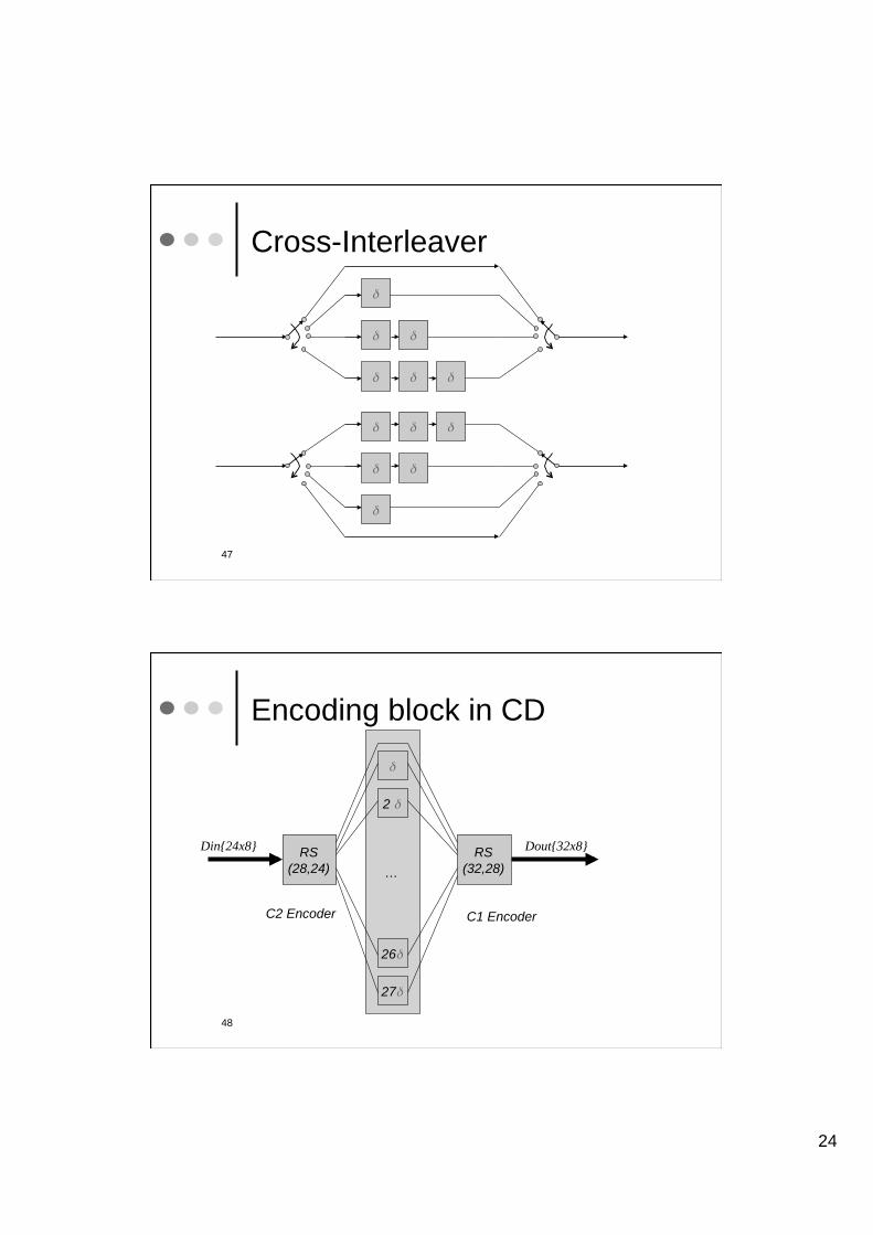
47
Cross-Interleaver
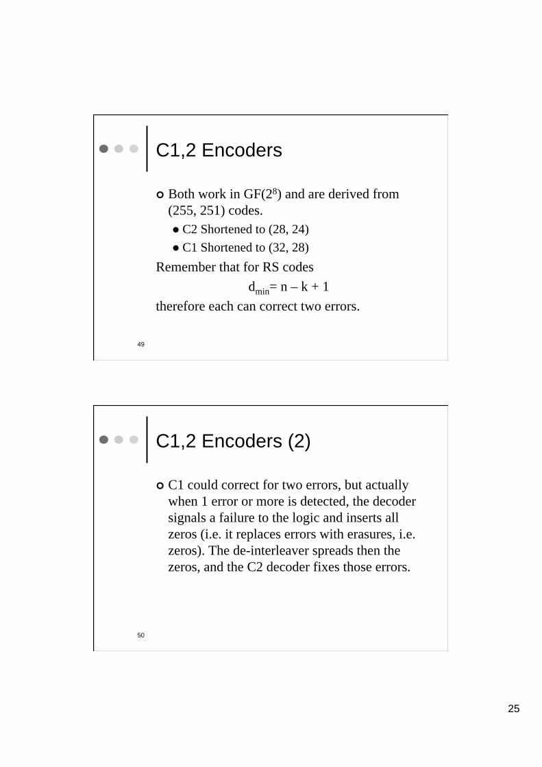
48
Encoding block in CD
RS
(28,24)
RS
(32,28) …
2
26
27
Din{24x8} Dout{32x8}
C2 Encoder C1 Encoder
25
49
C1,2 Encoders
Both work in GF(28) and are derived from
(255, 251) codes.
C2 Shortened to (28, 24)
C1 Shortened to (32, 28)
Remember that for RS codes
dmin= n – k + 1
therefore each can correct two errors.
C1,2 Encoders (2)
C1 could correct for two errors, but actually
when 1 error or more is detected, the decoder
signals a failure to the logic and inserts all
zeros (i.e. it replaces errors with erasures, i.e.
zeros). The de-interleaver spreads then the
zeros, and the C2 decoder fixes those errors.
50
26
51
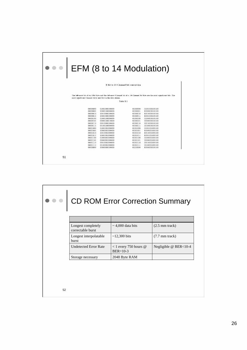
EFM (8 to 14 Modulation)
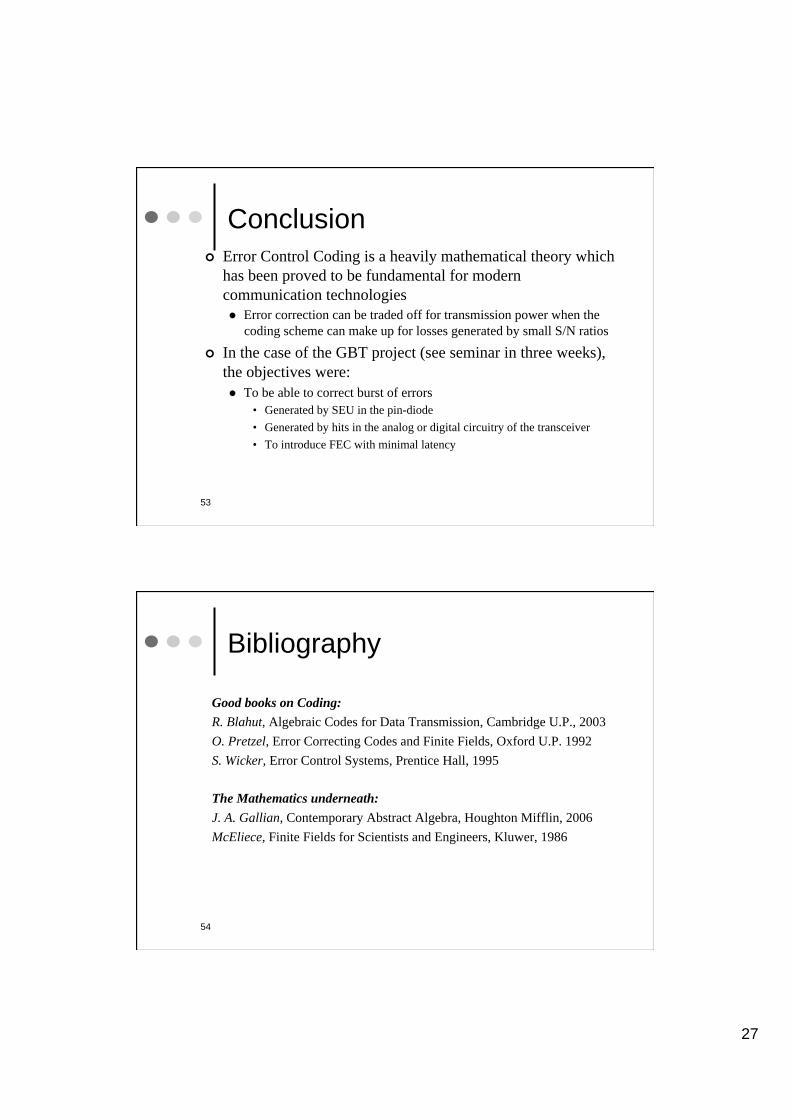
CD ROM Error Correction Summary
Longest completely
correctable burst
~ 4,000 data bits (2.5 mm track)
Longest interpolatable
burst
~12,300 bits (7.7 mm track)
Undetected Error Rate < 1 every 750 hours @
BER=10-3
Negligible @ BER<10-4
Storage necessary 2048 Byte RAM
52
27
Conclusion
Error Control Coding is a heavily mathematical theory which
has been proved to be fundamental for modern
communication technologies
Error correction can be traded off for transmission power when the
coding scheme can make up for losses generated by small S/N ratios
In the case of the GBT project (see seminar in three weeks),
the objectives were:
To be able to correct burst of errors
• Generated by SEU in the pin-diode
• Generated by hits in the analog or digital circuitry of the transceiver
• To introduce FEC with minimal latency
53
54
Bibliography
Good books on Coding:
R. Blahut, Algebraic Codes for Data Transmission, Cambridge U.P., 2003
O. Pretzel, Error Correcting Codes and Finite Fields, Oxford U.P. 1992
S. Wicker, Error Control Systems, Prentice Hall, 1995
The Mathematics underneath:
J. A. Gallian, Contemporary Abstract Algebra, Houghton Mifflin, 2006
McEliece, Finite Fields for Scientists and Engineers, Kluwer, 1986
28
Extra material
55
56
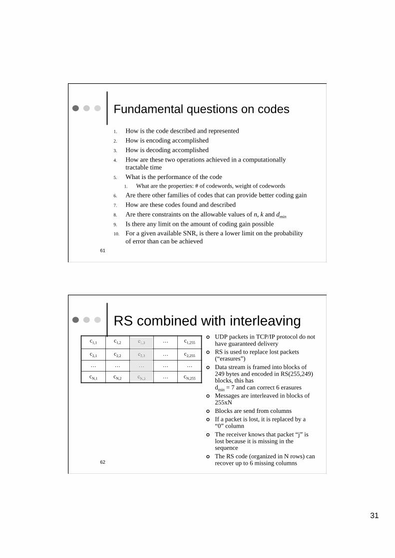
CRC (1)
CRC codes are a class of binary codes built on cyclic codes, i.e. with codewords
built as multiples of a generator polynomial g(x) with coefficients in GF[2].
CRC codes allow error detection (see below), but no error correction and are used
extensively in network protocols which allow for retransmission.
Let us denote as:
Rg(x)[·]
the operation of computing the remainder of the argument after dividing by g(x).
If m(x) is the original message polynomial, a CRC encoding operation can be
written as:
c(x) = xr m(x) + Rg(x)[xr m(x) ]
notice that deg( c(x) ) = r + deg( m(x) )

29
57
CRC (2)
If an error occurs during transmission, the received word is now:
r(x) = c(x) + e(x)
where e(x) is the polynomial representing the error pattern.
To find out if an error has occurred we now compute the syndrome:
s(x) = Rg(x)[ r(x) ]
that is:
s(x) = Rg(x)[ c(x) + e(x) ] = Rg(x)[ c(x) ] + Rg(x)[ e(x) ]
but by construction of the cyclic code Rg(x)[ c(x) ] = 0 (see Encoding (systematic)) , therefore:
s(x) = Rg(x)[ e(x) ]
Notice that if e(x) is a code polynomial, say e(x) = c1(x), then s(x)=0 and the error
passes undetected.
58
CRC (3)
CRC: an example
g(x) = x16 + x15 + x2 + 1
m = [0,1,1,0,1,1,0,1,0,0,1,0,0,1,1,1] ñ x14 + x13 + x11 + x10 + x8 + x5 + x2 + x + 1
We get: x16 m(x) + Rg(x)[x16 m(x) ] =
x30 + x29 + x27 + x26 + x24 + x21 + x18 + x17 + x16 + x14 + x13 + x11 + x10 + x9 + x7
+ x6 + x4 + x2
or in bit format:
c=[0,1,1,0,1,1,0,1,0,0,1,0,0,1,1,1,0,1,1,0,1,1,1,0,1,1,0,1,0,1,0,0]

30
59
CRC (4)
Table of commonly used CRC generator polynomials
CRC-4 g(x) = x4+x3+x2+x+1
CRC-7 g(x) = x7+x6+x4+1
CRC-8 g(x) = x8+x7+x6+x4+x2+1
CRC-12 g(x) = x12+x11+x3+x2+x+1
CRC-ANSI g(x) = x16+x15+x2+1
CRC-CCITT g(x) = x16+x12+x5+1
CRC-24 g(x) = x24+x23+x14+x12+x8+1
CRC-32b g(x) = x32+x26+x23+x22+x16+x12+x11+x10+x8+x7+x5+
x4+x2+x+1
60
CRC (5)
Statement
All single bit errors can be detected by CRC
Proof:
The generator polynomial must have more than one non-zero term,
otherwise the code would be an (n, n) code (this can be seen by shifting and
linearly combining all codewords), and the minimum distance between
codewords would be 1 (i.e. a meaningless code).
Now, if the codeword polynomial have more than one non-zero terms, then it
can not divide a polynomial with a single xi term evenly, so there is always a
non-zero remainder, i.e. all single bit errors can be detected.
For an error to be undetected, it must itself be a codeword (seen above); but a
valid codeword is generated with a generator codeword that has more than
one xi term, so it can not be a polynomial with a single xi term set.
31
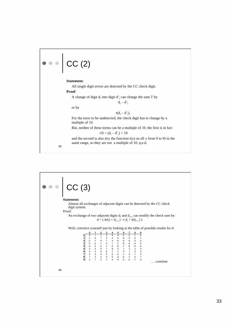
Fundamental questions on codes
1. How is the code described and represented
2. How is encoding accomplished
3. How is decoding accomplished
4. How are these two operations achieved in a computationally
tractable time
5. What is the performance of the code
1. What are the properties: # of codewords, weight of codewords
6. Are there other families of codes that can provide better coding gain
7. How are these codes found and described
8. Are there constraints on the allowable values of n, k and dmin
9. Is there any limit on the amount of coding gain possible
10. For a given available SNR, is there a lower limit on the probability
of error than can be achieved
61
62
RS combined with interleaving UDP packets in TCP/IP protocol do not have guaranteed delivery
RS is used to replace lost packets (“erasures”)
Data stream is framed into blocks of 249 bytes and encoded in RS(255,249) blocks, this has dmin = 7 and can correct 6 erasures
Messages are interleaved in blocks of 255xN
Blocks are send from columns
If a packet is lost, it is replaced by a “0” column
The receiver knows that packet “j” is lost because it is missing in the sequence
The RS code (organized in N rows) can recover up to 6 missing columns
c1,1 c1,2 c1,3 … c1,255
c2,1 c2,2 c2,3 … c2,255
… … … … …
cN,1 cN,2 cN,3 … cN,255

32
63
EFM Coding
Data for EFM coding are considered in bytes. Each byte is translated according to a lookup table into a corresponding 14-bit codeword.
The 14-bit words are chosen such that binary ones are always separated by a minimum of two and a maximum of ten binary zeroes. This is because bits are encoded with NRZI encoding, or modulo-2 integration, so that a binary one is stored on the CD surface as a change from a zero to a one or a one to a zero, while a binary zero is indicated by no change. A sequence 0011 would be changed into 1101 or its inverse 1101 depending on the previous one written. If there are 2 zeros between 2 consecutive ones, then the written sequence will have 3 consecutive zeros (or ones), for example, 010010 will translate into 1100011 (or 0011100). The EFM sequence 100100010010000100 will translate into 111000011100000111 (or its inverse).
Because EFM ensures there are at least 2 zeroes between every 2 ones, it thus ensures that every one and zero is at least three bit clock cycles long. This property is very useful since it reduces the demands on the optical pickup used in the playback mechanism. The ten consecutive-zero maximum ensures worst-case clock recovery in the player.
EFM requires 3 merging bits between adjacent 14-bit codewords to ensure that consecutive codewords can be cascaded without violating the specified minimum and maximum runlength constraint. The 3 merging bits are also used to shape the spectrum of the encoded sequence. Thus, in the final analysis, 17 bits of disc space are needed to encode 8 bits of data.
64
CC (1)
CC: d1d2d3d4 d5d6d7d8 d9d10d11d12 d13d14d15d16
T = (t(d1) + d2 + t(d3) + d4 + t(d5) + d6 + t(d7) + … + d14 + t(d15) ) mod 10
where
t(di) = add digits of (2*di),
i.e.
t(di) = (2 · di) for (2 · di) < 10
= ((2 · di) -10) + 1 for (2 · di) 10
d16 = 10 – T
Example: the check digit in: CC 1234 5678 9012 345 is d16 = 2.
33
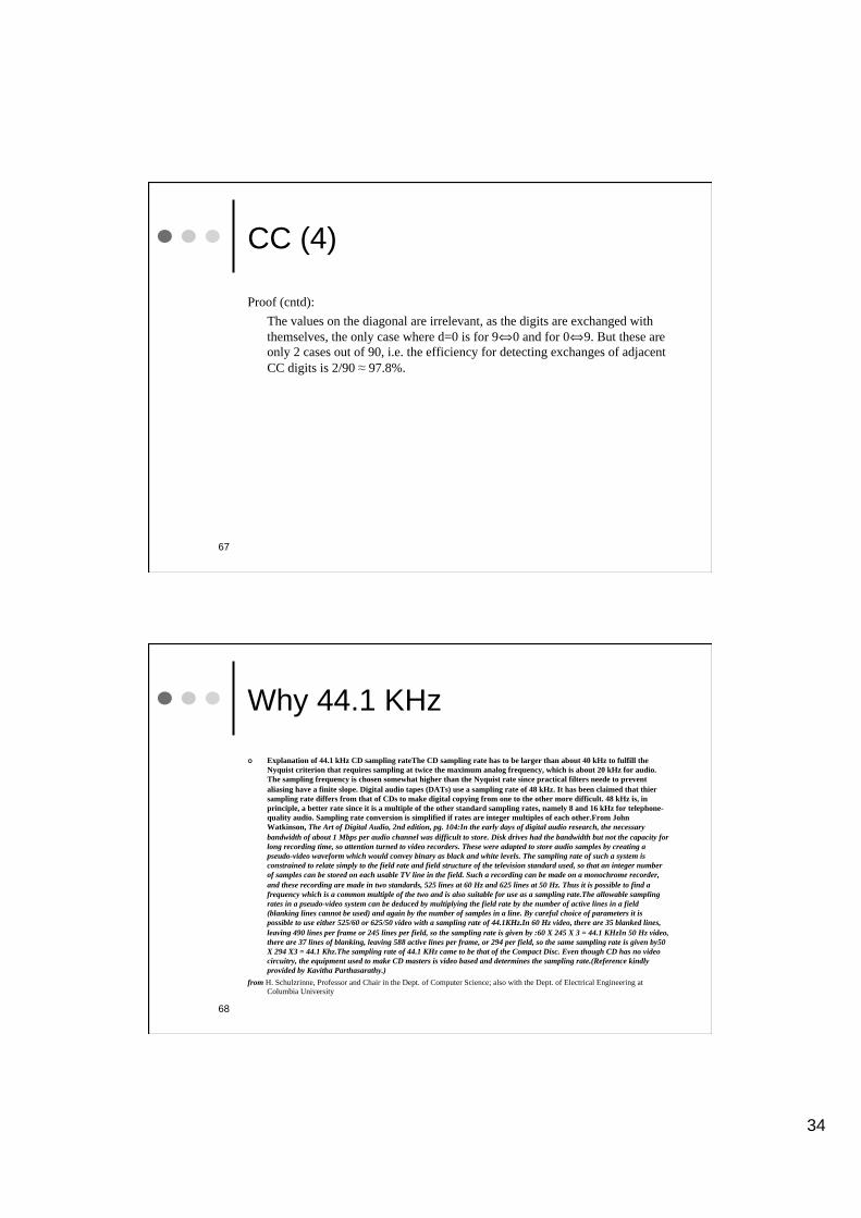
65
CC (2)
Statement:
All single digit errors are detected by the CC check digit.
Proof:
A change of digit di into digit d’i can change the sum T by
di – d’i
or by
t(di – d’i).
For the error to be undetected, the check digit has to change by a
multiple of 10.
But, neither of these terms can be a multiple of 10, the first is in fact
-10 < (di – d’i) < 10
and the second is also (try the function t(x) on all x from 0 to 9) in the
same range, so they are not a multiple of 10, q.e.d.
66
CC (3)
Statement:
Almost all exchanges of adjacent digits can be detected by the CC check digit system.
Proof:
An exchange of two adjacent digits di and di+1 can modify the check sum by:
d = ( t(di) + di+1 ) - ( di + t(di+1 ) )
Well, convince yourself just by looking at the table of possible results for d:
… continue
34
67
CC (4)
Proof (cntd):
The values on the diagonal are irrelevant, as the digits are exchanged with
themselves, the only case where d=0 is for 9ñ0 and for 0ñ9. But these are
only 2 cases out of 90, i.e. the efficiency for detecting exchanges of adjacent
CC digits is 2/90 97.8%.
Why 44.1 KHz
Explanation of 44.1 kHz CD sampling rateThe CD sampling rate has to be larger than about 40 kHz to fulfill the
Nyquist criterion that requires sampling at twice the maximum analog frequency, which is about 20 kHz for audio.
The sampling frequency is chosen somewhat higher than the Nyquist rate since practical filters neede to prevent
aliasing have a finite slope. Digital audio tapes (DATs) use a sampling rate of 48 kHz. It has been claimed that thier
sampling rate differs from that of CDs to make digital copying from one to the other more difficult. 48 kHz is, in
principle, a better rate since it is a multiple of the other standard sampling rates, namely 8 and 16 kHz for telephone-
quality audio. Sampling rate conversion is simplified if rates are integer multiples of each other.From John
Watkinson, The Art of Digital Audio, 2nd edition, pg. 104:In the early days of digital audio research, the necessary
bandwidth of about 1 Mbps per audio channel was difficult to store. Disk drives had the bandwidth but not the capacity for
long recording time, so attention turned to video recorders. These were adapted to store audio samples by creating a
pseudo-video waveform which would convey binary as black and white levels. The sampling rate of such a system is
constrained to relate simply to the field rate and field structure of the television standard used, so that an integer number
of samples can be stored on each usable TV line in the field. Such a recording can be made on a monochrome recorder,
and these recording are made in two standards, 525 lines at 60 Hz and 625 lines at 50 Hz. Thus it is possible to find a
frequency which is a common multiple of the two and is also suitable for use as a sampling rate.The allowable sampling
rates in a pseudo-video system can be deduced by multiplying the field rate by the number of active lines in a field
(blanking lines cannot be used) and again by the number of samples in a line. By careful choice of parameters it is
possible to use either 525/60 or 625/50 video with a sampling rate of 44.1KHz.In 60 Hz video, there are 35 blanked lines,
leaving 490 lines per frame or 245 lines per field, so the sampling rate is given by :60 X 245 X 3 = 44.1 KHzIn 50 Hz video,
there are 37 lines of blanking, leaving 588 active lines per frame, or 294 per field, so the same sampling rate is given by50
X 294 X3 = 44.1 Khz.The sampling rate of 44.1 KHz came to be that of the Compact Disc. Even though CD has no video
circuitry, the equipment used to make CD masters is video based and determines the sampling rate.(Reference kindly
provided by Kavitha Parthasarathy.)
from H. Schulzrinne, Professor and Chair in the Dept. of Computer Science; also with the Dept. of Electrical Engineering at Columbia University
68