Design Optimization of an Enhanced Stop-band UWB Bow-Tie ...
7
Ⅰ. Introduction The UWB technology is very useful in IoT application for the shortage of free frequency range in these days. The UWB antenna is required to work in a wide-band (3.1-10.6 GHz), but there are several other existing services which occupy frequency bands within the UWB bandwidth. A few examples of hostile systems are WiMAX (3.3–3.7 GHz), Wireless LAN 5GHz (5.15–5.825 GHz) and ITU 8 GHz (8.025–8.4 GHz) band. A multi-band system also deals with a wide frequency band and has to have stop-bands to filter out non-service bands to avoid interferences. The stop-band is a rather wide range and needs a sharp-skirt gradient for a better quality. Several UWB antennas with band rejection characteristics have been proposed [1]-[5], but the skirt property was not fully considered. In this paper, we propose a novel Bow-Tie Antenna (BTA) which has a wide sharp-skirt rejecting band property and is operated in a full UWB range. By embedding two horizontal parallel resonant slots as a pair and adjusting the dimensions of the slots and the mutual coupling values between them, the characteristics of the notch response, such as the center frequency and Design Optimization of an Enhanced Stop-band UWB Bow-Tie Antenna Kyung Choi * ★ , Hyeong-Seok Kim ** , Hee-Yong Hwang *** Abstract An improved design of Ultra Wide Band(UWB) Bow-Tie antenna, which can control an enhanced wide stop-band, is presented. The mutually coupled slot-pair improves and controls the rejection band. The UWB antenna is composed of an electromagnetically coupled Bow-Tie patch and a parasitic ground patch, whose working frequency is extended to full UWB range in this work. By adding slot-pairs on the main patch and optimizing, they can give any requested wide rejection bands and sharp skirt characteristics, as is often required for UWB antennas and multi-band antennas. All the parameters are precisely calculated by an adequate optimization method. The Particle Swarm Optimization(PSO) technique is appropriately adopted. The proposed design and method is proved to give and control the sharp-skirt wide stop-band to UWB Bow-Tie antennas. Key words:Antennas, Band Stop characteristics, UWB(Ultra Wide Band), Bow-Tie Antenna, Optimization * Dept. of Electronics Engineering, Kangwon National University ** Daeyeong Ubitec Co. Limited. *** Dept. of Electrical and Electronics Engineering, Kangwon National University ★ Corresponding author E-mail:[email protected], Tel:+82-33-250-6324 ※ Acknowledgment This sturdy was supported by 2016 Research Grant from Kangwon National University. (No. 520160125) Manuscript received Sep. 7, 2018; revised Sep. 19, 2018; accepted Sep. 20. 2018 This is an Open-Access article distributed under the terms of the Creative Commons Attribution Non-Commercial License (http://creativecommons.org/licenses/by-nc/3.0) which permits unrestricted non-commercial use, distribution, and reproduction in any medium, provided the original work is properly cited. ISSN:1226-7244 (Print) ISSN:2288-243X (Online) j.inst.Korean.electr.electron.eng.Vol.22,No.3,793∼799,September 2018 논문번호 18-03-41 http://dx.doi.org/10.7471/ikeee.2018.22.3.793 272 (793)
-
Upload
khangminh22 -
Category
Documents
-
view
1 -
download
0
Transcript of Design Optimization of an Enhanced Stop-band UWB Bow-Tie ...
Ⅰ. Introduction
The UWB technology is very useful in IoT
application for the shortage of free frequency
range in these days. The UWB antenna is
required to work in a wide-band (3.1-10.6 GHz),
but there are several other existing services
which occupy frequency bands within the UWB
bandwidth. A few examples of hostile systems
are WiMAX (3.3–3.7 GHz), Wireless LAN 5GHz
(5.15–5.825 GHz) and ITU 8 GHz (8.025–8.4
GHz) band. A multi-band system also deals with
a wide frequency band and has to have
stop-bands to filter out non-service bands to
avoid interferences. The stop-band is a rather
wide range and needs a sharp-skirt gradient for
a better quality. Several UWB antennas with
band rejection characteristics have been proposed
[1]-[5], but the skirt property was not fully
considered.
In this paper, we propose a novel Bow-Tie
Antenna (BTA) which has a wide sharp-skirt
rejecting band property and is operated in a full
UWB range. By embedding two horizontal
parallel resonant slots as a pair and adjusting the
dimensions of the slots and the mutual coupling
values between them, the characteristics of the
notch response, such as the center frequency and
Design Optimization of an Enhanced Stop-band UWB
Bow-Tie Antenna
Kyung Choi*★
, Hyeong-Seok Kim**, Hee-Yong Hwang***
Abstract
An improved design of Ultra Wide Band(UWB) Bow-Tie antenna, which can control an enhanced wide
stop-band, is presented. The mutually coupled slot-pair improves and controls the rejection band. The UWB
antenna is composed of an electromagnetically coupled Bow-Tie patch and a parasitic ground patch, whose
working frequency is extended to full UWB range in this work. By adding slot-pairs on the main patch and
optimizing, they can give any requested wide rejection bands and sharp skirt characteristics, as is often
required for UWB antennas and multi-band antennas. All the parameters are precisely calculated by an
adequate optimization method. The Particle Swarm Optimization(PSO) technique is appropriately adopted. The
proposed design and method is proved to give and control the sharp-skirt wide stop-band to UWB Bow-Tie
antennas.
Key words:Antennas, Band Stop characteristics, UWB(Ultra Wide Band), Bow-Tie Antenna, Optimization
* Dept. of Electronics Engineering, Kangwon National University
** Daeyeong Ubitec Co. Limited.
*** Dept. of Electrical and Electronics Engineering, Kangwon National University
★ Corresponding author
E-mail:[email protected], Tel:+82-33-250-6324
※ Acknowledgment
This sturdy was supported by 2016 Research Grant from Kangwon National University. (No. 520160125)
Manuscript received Sep. 7, 2018; revised Sep. 19, 2018; accepted Sep. 20. 2018
This is an Open-Access article distributed under the terms of the Creative Commons Attribution Non-Commercial License
(http://creativecommons.org/licenses/by-nc/3.0) which permits unrestricted non-commercial use, distribution, and reproduction
in any medium, provided the original work is properly cited.
ISSN:1226-7244 (Print)ISSN:2288-243X (Online) j.inst.Korean.electr.electron.eng.Vol.22,No.3,793∼799,September 2018논문번호 18-03-41 http://dx.doi.org/10.7471/ikeee.2018.22.3.793272
(793)
Design Optimization of an Enhanced Stop-band UWB Bow-Tie Antenna 273
the band rejection skirt gradient, can be
controlled. Therefore, the optimized slots can
give the required wide rejection band and sharp
skirt characteristics, as is often required for
UWB antennas and multi-band antennas, compared
to the conventional one with one slot or no one.
This technique allows a wideband antenna to be
a multi-band antenna, and many systems to be
compactly designed without adding extra components
such as notch filters. There reside so many
design factors, so that a proper design tool is
needed to handle them. The Particle Swarm
Optimization (PSO) is utilized to optimally
determine the parameters [6]. And the PSO is
successfully applied to enhancing the operating
frequency range too.
Ⅱ. Design Process
2.1. Primary Research
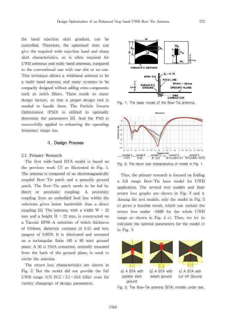
The first wide-band BTA model is based on
the previous work [7] as illustrated in Fig. 1.
The antenna is composed of an electromagnetically
coupled Bow-Tie patch and a parasitic ground
patch. The Bow-Tie patch needs to be fed by
direct or proximity coupling. A proximity
coupling from an embedded feed line within the
substrate gives better bandwidth than a direct
coupling [8]. The antenna, with a width W = 22
mm and a height H = 22 mm, is constructed on
a Taconic RF60-A substrate of which thickness
of 0.64mm, dielectric constant of 6.15 and loss
tangent of 0.0028. It is fabricated and mounted
on a rectangular finite (80 x 80 mm) ground
plane. A 50 Ω SMA connector, centrally mounted
from the back of the ground plane, is used to
excite the antenna.
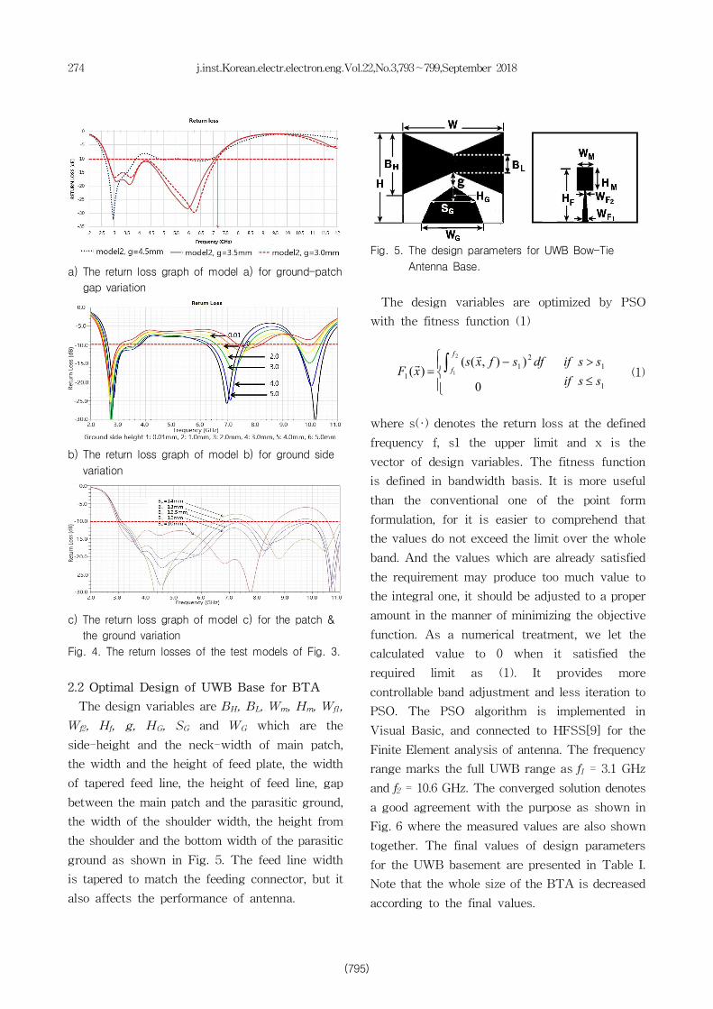
The return loss characteristics are shown in
Fig. 2. But the model did not provide the full
UWB range (US FCC:3.1~10.6 GHz) even for
variety changings of design parameters.
Fig. 1. The base model of the Bow-Tie antenna.
Fig. 2. The return loss characteristics of model in Fig. 1.
Thus, the primary research is focused on finding
a full range Bow-Tie base model for UWB
application. The several test models and their
return loss graphs are shown in Fig. 3 and 4.
Among the test models, only the model in Fig. 3
c) gives a feasible result, which can sustain the
return loss under -10dB for the whole UWB
range as shown in Fig. 4 c). Then, we try to
calculate the optimal parameters for the model c)
in Fig. 3.
a) A BTA with
parallel slant
ground
b) A BTA with
aslant ground
c) A BTA with
cut-off Ground
Fig. 3. The Bow-Tie antenna (BTA) models under test.
(794)
274 j.inst.Korean.electr.electron.eng.Vol.22,No.3,793∼799,September 2018
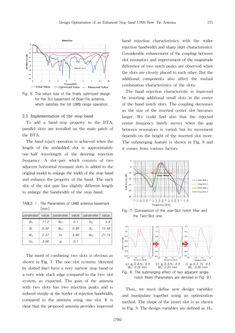
a) The return loss graph of model a) for ground-patch
gap variation
b) The return loss graph of model b) for ground side
variation
c) The return loss graph of model c) for the patch &
the ground variation
Fig. 4. The return losses of the test models of Fig. 3.
2.2 Optimal Design of UWB Base for BTA
The design variables are BH, BL, Wm, Hm, Wf1,
Wf2, Hf, g, HG, SG and WG which are the
side-height and the neck-width of main patch,
the width and the height of feed plate, the width
of tapered feed line, the height of feed line, gap
between the main patch and the parasitic ground,
the width of the shoulder width, the height from
the shoulder and the bottom width of the parasitic
ground as shown in Fig. 5. The feed line width
is tapered to match the feeding connector, but it
also affects the performance of antenna.
Fig. 5. The design parameters for UWB Bow-Tie
Antenna Base.
The design variables are optimized by PSO
with the fitness function (1)
1
12
1
1
0
)),(()(
2
1
ssif
ssifdfsfxsxF
f
f
£
>
ïî
ïí
ì -= ò
rr
(1)
where s(·) denotes the return loss at the defined
frequency f, s1 the upper limit and x is the
vector of design variables. The fitness function
is defined in bandwidth basis. It is more useful
than the conventional one of the point form
formulation, for it is easier to comprehend that
the values do not exceed the limit over the whole
band. And the values which are already satisfied
the requirement may produce too much value to
the integral one, it should be adjusted to a proper
amount in the manner of minimizing the objective
function. As a numerical treatment, we let the
calculated value to 0 when it satisfied the
required limit as (1). It provides more
controllable band adjustment and less iteration to
PSO. The PSO algorithm is implemented in
Visual Basic, and connected to HFSS[9] for the
Finite Element analysis of antenna. The frequency
range marks the full UWB range as f1 = 3.1 GHz
and f2 = 10.6 GHz. The converged solution denotes
a good agreement with the purpose as shown in
Fig. 6 where the measured values are also shown
together. The final values of design parameters
for the UWB basement are presented in Table I.
Note that the whole size of the BTA is decreased
according to the final values.
(795)
Design Optimization of an Enhanced Stop-band UWB Bow-Tie Antenna 275
Fig. 6. The return loss of the finally optimized design
for the 3c) basement of Bow-Tie antenna,
which satisfies the full UWB range operation.
2.3. Implementation of the stop band
To add a band-stop property to the BTA,
parallel slots are installed on the main patch of
the BTA.
The band reject operation is achieved when the
length of the embedded slot is approximately
one-half wavelength of the desiring rejection
frequency. A slot-pair which consists of two
adjacent horizontal resonant slots is added to the
original model to enlarge the width of the stop-band
and enhance the property of the band. The each
slot of the slot-pair has slightly different length
to enlarge the bandwidth of the stop-band.
TABLE Ⅰ. The Parameters of UWB antenna basement
[mm]
parameter value parameter value parameter value
BH 11.2 WF1 0.1 HG 3.9
BL 6.92 WF2 0.69 SG 15.48
Wm 2.57 Hf 9.86 WG 21.74
Hm 3.96 g 0.1
The merit of combining two slots is obvious as
shown in Fig. 7. The one-slot systems (denoted
by dotted line) have a very narrow stop-band or
a very wide slack edge compared to the two-slot
system, as expected. The gain of the antenna
with two slots has two rejection peaks and is
reduced steeply at the border of rejection bandwidth,
compared to the antenna using one slot. It is
clear that the proposed antenna provides improved
band rejection characteristics with the wider
rejection bandwidth and sharp skirt characteristics.
Considerable enhancement of the coupling between
slot resonators and improvement of the magnitude
difference of two notch peaks are observed when
the slots are closely placed to each other. But the
additional components also affect the mutual
combination characteristics of the slots.
The band rejection characteristic is improved
by inserting additional small slots in the center
of the band-notch slots. The coupling decreases
as the size of the inserted center slot becomes
larger. We could find also that the rejected
center frequency barely moves when the gap
between resonators is varied, but its movement
depends on the height of the inserted slot more.
The submerging feature is shown in Fig. 8 and
it comes from various factors.
Fig. 7. Comparison of the one-Slot notch filter and
the Two-Slot one.
a)gs:0.4,Hc: 0.5 Wm: 0.24 mm
b) gs:0.3,Hc: 0.5 Wm: 0.24 mm
c) gs:0.3, Hc: 0.5 Wm: 0.20 mm
Fig. 8. The submerging effect of two adjacent single
notch filters (Parameters are denoted in Fig. 9.).
Thus, we must define new design variables
and manipulate together using an optimization
method. The shape of the insert slot is as shown
in Fig. 9. The design variables are defined as HS,
(796)

276 j.inst.Korean.electr.electron.eng.Vol.22,No.3,793∼799,September 2018
HC, WS, gS, LS1, and LS2 which are the position of
the upper slot from the top of the main patch,
the height and the width of center notch of the
slot, the gap between two slots and the lengths
of the two slots respectively.
Fig. 9. The design parameters for a slot-pair.
The fitness function is defined as a multi-band
basis[10] for this stop-band installation as (2).
dfxSwdfxSwdfxSwxFf
fU
f
fL
f
fU )()()()(
6
5
4
3
2
13212
rrrròòò ++=
U
U
band
UU ssif
ssifsfxsxS
£
>
îíì -
=
3,1
2
0
)),(()(
rr
(2)
L
L
band
LL
ssif
ssifsfxsxS
³
<
îíì -
=
2
2
0
)),(()(
rr
The upper limit of return loss sU for operating
band 1 and 3 is set to -12dB and the lower limit
sL for notch band 2 to -8 dB for the test. The
band frequency positions are set to f1 = 3.1 GHz,
f2 = f3 = 5.1 GHz, f4 = f5 = 5.9 GHz and f6 = 10.6
GHz in this case. The weighting factors w1, w2
and w3 are the inverse of the each bandwidth
respectively for normalization.
The solution is converged in a few iterations
for the optimizing scheme was split in two
procedure of enhancing the working frequency
band and the stop-band to have less design
parameters as accomplished in the sub-session B
& C.
Fig. 10. Variations of return loss by slot-pair and
parameters change.
The appropriateness is also obvious in Fig. 10
that the UWB borders of working frequency are
barely changed as the new design variables are
varied. Thus, it is quite reasonable to separate
the design procedure into two categories, i.e. 1)
Widening the working range and 2) Controlling
& Enhancing the stop-filter property.
We placed 15 particles only and gave humble
initial data producing bad return losses as shown
in Fig. 11 for a sample. But it is converged to an
acceptable range within only 8 iterations. The
converged value of the design parameters are
shown in Table II and the resultant return loss
is also shown in Fig. 11 with the radiation
patterns as Fig. 12.
TABLE Ⅱ. The Parameters of Band-Stop UWB Antenna [mm].
parameter value parameter value parameter value
HS 4.0 WS 1.0 LS1 16.0
HC 0.95 gS 0.18 LS2 13.86
Fig. 11. The return losses of the initial and the converged
design.
(797)
Design Optimization of an Enhanced Stop-band UWB Bow-Tie Antenna 277
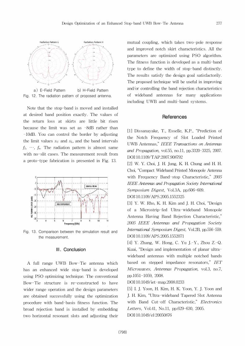
a)E-Field Pattern b) H-Field Pattern
Fig. 12. The radiation pattern of proposed antenna.
Note that the stop-band is moved and installed
at desired band position exactly. The values of
the return loss at skirts are little bit risen
because the limit was set as -8dB rather than
-10dB. You can control the border by adjusting
the limit values sU and sL, and the band intervals
f1, ···, fn. The radiation pattern is almost same
with no-slit cases. The measurement result from
a proto-type fabrication is presented in Fig. 13.
Fig. 13. Comparison between the simulation result and
the measurement.
Ⅲ. Conclusion
A full range UWB Bow-Tie antenna which
has an enhanced wide stop-band is developed
using PSO optimizing technique. The conventional
Bow-Tie structure is re-constructed to have
wider range operation and the design parameters
are obtained successfully using the optimization
procedure with band-basis fitness function. The
broad rejection band is installed by embedding
two horizontal resonant slots and adjusting their
mutual coupling, which takes two-pole response
and improved notch skirt characteristics. All the
parameters are optimized using PSO algorithm.
The fitness function is developed as a multi-band
type to define the width of stop-band distinctly.
The results satisfy the design goal satisfactorily.
The proposed technique will be useful in improving
and/or controlling the band rejection characteristics
of wideband antennas for many applications
including UWB and multi-band systems.
References
[1] Dissanayake, T., Esselle, K.P., “Prediction of
the Notch Frequency of Slot Loaded Printed
UWB Antennas,” IEEE Transactions on Antennas
and Propagation, vol.55, no.11, pp.3320-3325, 2007.
DOI:10.1109/TAP.2007.908792
[2] W. Y. Choi, J. H. Jung, K. H. Chung and H. H.
Choi, “Compact Wideband Printed Monopole Antenna
with Frequency Band-stop Characteristic,” 2005
IEEE Antennas and Propagation Society International
Symposium Digest, Vol.3A, pp.606-609.
DOI:10.1109/APS.2005.1552325
[3] Y. W. Rho, K. H. Kim and J. H. Choi, “Design
of a Microstrip-fed Ultra-wideband Monopole
Antenna Having Band Rejection Characteristic,”
2005 IEEE Antennas and Propagation Society
International Symposium Digest, Vol.2B, pp.556-559.
DOI:10.1109/APS.2005.1552071
[4] Y. Zhang, W. Hong, C. Yu J.-Y., Zhou Z.-Q.
Kuai, “Design and implementation of planar ultra-
wideband antennas with multiple notched bands
based on stepped impedance resonators,” IET
Microwaves, Antennas Propagation, vol.3, no.7,
pp.1051-1059, 2008.
DOI:10.1049/iet-map.2008.0233
[5] I. J. Yoon, H. Kim, H. K. Yoon, Y. J. Yoon and
J. H. Kim, “Ultra-wideband Tapered Slot Antenna
with Band Cut-off Characteristic,” Electronics
Letters, Vol.41, No.11, pp.629-630, 2005.
DOI:10.1049/el:20050876
(798)
278 j.inst.Korean.electr.electron.eng.Vol.22,No.3,793∼799,September 2018
[6] Jacob Robinson and Yahya Rahmat-Samii,
“Particle Swarm Optimization in Electro- magnetics,”
IEEE Transaction on Antenna and Propagation,
vol.52, no.2, pp.397-407, 2004.
DOI:10.1109/TAP.2004.823969
[7] Soo-Deok Moon, H.Y. Hwang, “Improvements
in Band Rejection Characteristics of a Wideband
Antenna using Resonant Slots,” Microwave Journal,
2007.
[8] L. Le Coq, S. Von der Mark, M. Drissi and J.
Citerne, “Printed Bow-tie Antenna Fed by
Electromagnetic Coupling,” 1999 IEEE Antennas
and Propagation Society International Symposium,
vol.4, pp.2710-2713, 1999.
DOI:10.1109/APS.1999.789367
[9] HFSS, Version 13, Ansoft Corporation LLC,
225 West Station, Square Suite 200, Pittsburgh,
PA 15219-1119, 2011.
[10] Koon-Tae Kim, Jeong-Hyeok Lee, Kyung
Choi, Tae-Kyung Chung, Hyeong-Seok Kim “An
Optimal Design of Compact Ring-Slot Antenna
for a Rectenna System With Numerical Manipulation,”
IEEE Transactions on Magnetics, vol.50, no.2,
2014. DOI:10.1109/TMAG.2013.2283541
BIOGRAPHY
Kyung Choi (Member)
1981:BS degree in Electrical
Engineering, Seoul National
University.
1983:MS degree in Electrical
Engineering, Seoul National
University.
1988:PhD degree in Electrical Engineering, Seoul
National University.
1989~:Professor in Dept. of Electronics Engineering,
Kangwon National University.
Hyeong-Seok Kim (Member)
1985:BS degree in Electrical
Engineering, Seoul National
University.
1987:MS degree in Electrical
Engineering, Seoul National
University.
1990:PhD degree in Electrical Engineering, Seoul
National University.
1990~2015:Professor in Dept. of Electrical Engineering
at Sooncheonhyang University and Chungang University,
2015~:Technical Advisor in DaeYoung Ubitec. Co.
Limiterd.
Hee Yong Hwang (Member)
1988:BS degree in Biology
Education, Seoul National University.
1992:BS degree in Electronics
Engineering, Seoul National
University.
1995:MS degree in Electronics
Engineering, Sogang University.
2000:PhD degree in Electronics Engineering, Sogang
University.
2000~2001:BK Professor in Sogan University.
2001~2002:Research Scholar in University of
Maryland, 2002~2003:Research Director in Amotec Co.
2003~:Professor in Dept. of Electrical and Electronics
Engineering, Kangwon National University.
(799)