Tie Rod Design
80
1/78 Hydraulic Cylinder Tie Rod Design Series CD 70 / CG70 Nominal pressure 70 bar Piston dia. 25 to 200 mm Piston rod dia. 12 to 140 mm 16 types of mounting RE 17016/07.03 Replaces: 08.99 Features – Easily serviced modular system: • Tie rod construction therefore simple assembly and dis-assembly for servicing • Port threads available optionally in ISO 228/1 or metric ISO forms. • Bleed points (standard) • Adjustable cushioning • Installation length identical for models with or without cushioning. • Stroke freely selectable within maximum available range. K4639-10 Note! When choosing cylinder type, please note definitions on page 7
-
Upload
khangminh22 -
Category
Documents
-
view
3 -
download
0
Transcript of Tie Rod Design

1/78Hydraulic CylinderTie Rod Design
Series CD 70 / CG70
Nominal pressure 70 barPiston dia. 25 to 200 mmPiston rod dia. 12 to 140 mm16 types of mounting
RE 17016/07.03Replaces: 08.99
Features
– Easily serviced modular system:• Tie rod construction
therefore simple assembly and dis-assembly for servicing
• Port threads available optionally in ISO 228/1 or metric ISO forms.
• Bleed points (standard)
• Adjustable cushioning
• Installation length identical for models with or without
cushioning.
• Stroke freely selectable within maximum available range.
K4639-10
Note!
When choosing cylinder type, please note defi nitions on page 7

2/78 Bosch Rexroth AG Industrial Hydraulics CD 70 / CG 70 RE 17016/07.03
Overview of contents
Contents Page
Features 1
Technical data 2
Forces and areas 3
Ordering code 4
Position of ports 5
Types of mounting (overview) 6
Explanation of positions and defi nitions 7
Piston dia. 25 8 to 13
Piston dia. 32 14 to 19
Piston dia. 40 20 to 25
Piston dia. 50 26 to 31
Piston dia. 63 32 to 37
Piston dia. 80 38 to 43
Contents Page
Piston dia. 100 44 to 49
Piston dia. 125 50 to 55
Piston dia. 150 56 to 61
Piston dia. 200 62 to 67
Weights 68
Permissible strokes 69 to 71
Calculation of buckling 72
Stop tube extensions 72
Inductive proximity switch 73
Installation lengths and positional tolerances 74
Seals (standard versions) 75
Cushioning 75
Calculation of deceleration forces 76
Spare parts diagram 77
Technical Data (for applications outside these parameters, please consult us!)
generalInstallation position Optional
Piston velocity m/s 0,5 (dependent upon port size)
For permissible installation lengths and
tolerances see page 74
Stroke lengths Permissible deviation
0 to 1250 +1–1,5
1251 to 2000 +1–2
2001 to 3000 +1–3
hydraulicMax. Operating pressure 1) bar 105 (dependent upon piston dia. and type of mounting)
Static test pressure Max. operating pressure x 1,3(dependent upon piston dia. and type of mounting)
Fluid Mineral oils to (HL, HLP) nach DIN 51 524Phosphate ester (HFD-R)
Fluid temperature range °C – 20 to + 70
ISO code cleanliness class Maximum permissible degree of contamination of fl uid to ISO 4406 (C) class 20/18/15 2)
Viscosity range mm2/s 2,8 to 380
Cylinders outside the above parameters are also available if required. Please enquire, giving exact details of the applicati-on.
1) The specifi ed operating pressures are only valid for applicati-ons with shock-free operation.If extreme loads occur, e.g. as happens in high sequence cycles, the fi xings and piston rod thread connections need to be designed for durability (fatigue strength).
2) The cleanliness classes specifi ed for components must be adhered to in hydraulic systems. Effective fi ltration prevents malfunction and, at the same time, increases the service life of components.
For the selection of fi lters, see data sheets: RE 50070, RE 50076 and RE 50081.

Industrial Hydraulics Bosch Rexroth AGRE 17016/07.03 CD 70 / CG 70 3/78
Forces, Areas
Operating pressure in
bar
Piston diameter mm 25 32 40 50
Piston rod diameter mm 12 16 18 22 25 16 18 25 22 25 36
40 Force; piston end kN 1,96 3,22 5,03 7,85
Force; piston rod end kN 1,55 1,19 2,19 1,69 1,25 4,21 3,99 3,06 6,32 5,87 3,78
50 Force; piston end kN 2,46 4,02 6,29 9,82
Force; piston rod end kN 1,94 1,49 2,74 2,11 1,56 5,27 5,00 3,83 7,91 7,35 4,73
70 Force; piston end kN 3,44 5,63 8,80 13,75
Force; piston rod end kN 2,71 2,08 3,84 2,96 2,19 7,38 7,01 5,40 11,08 10,31 6,62
105 Force; piston end kN 5,16 8,45 13,20 20,62
Force; piston rod end kN 3,96 3,04 5,77 4,44 3,28 11,07 10,52 8,03 16,62 15,44 9,93
Piston area cm2 4,91 8,04 12,56 19,63
Annulus area cm2 3,78 2,90 5,50 4,24 3,13 10,55 10,02 7,65 15,83 14,71 9,46
Cushion area Force; piston end cm2 2,63 5,77 10,30 15,11
Force; piston rod end cm2 2,63 2,63 4,90 3,52 2,50 8,70 8,76 7,05 14,33 13,47 8,29
Operating pressure in
bar
Piston diameter mm 63 80 100
Piston rod diameter mm 25 28 36 45 36 45 56 45 50 70
40 Force; piston end kN 12,47 20,10 31,42
Force; piston rod end kN 10,49 9,99 8,38 6,00 16,02 13,73 10,25 25,04 23,55 16,01
50 Force; piston end kN 15,59 25,10 39,27
Force; piston rod end kN 13,12 12,50 10,49 7,62 20,03 17,16 12,80 31,29 29,43 20,02
70 Force; piston end kN 21,82 35,18 54,98
Force; piston rod end kN 18,36 17,50 14,68 10,68 28,04 24,03 17,93 43,80 41,20 28,01
105 Force; piston end kN – – –
Force; piston rod end kN – – – – – – – – – –
Piston area cm2 31,16 50,24 78,50
Annulus area cm2 26,25 25,01 20,98 15,26 40,07 34,34 25,62 62,60 58,88 40,04
Cushion area Force; piston end cm2 26,65 40,64 58,90
Force; piston rod end cm2 23,13 23,13 19,80 13,08 37,70 30,60 20,07 58,90 54,70 31,97
Operating pressure in
bar
Piston diameter mm 125 150 200
Piston rod diameter mm 50 56 63 90 63 70 80 100 90 100 140
40 Force; piston end kN 49,09 70,68 125,66
Force; piston rod end kN 41,20 39,20 36,59 23,63 58,17 55,25 50,54 39,23 100,13 94,16 64,03
50 Force; piston end kN 61,35 88,35 –
Force; piston rod end kN 51,49 49,01 45,83 29,53 72,71 69,06 63,16 49,05 – – –
70 Force; piston end kN 85,90 – –
Force; piston rod end kN 72,10 68,60 64,03 41,35 – – – – – – –
105 Force; piston end kN – – –
Force; piston rod end kN – – – – – – – – – – –
Piston area cm2 122,66 176,63 314,00
Annulus area cm2 103,03 98,04 91,50 59,08 145,47 138,17 126,38 98,13 250,42 235,50 160,14
Cushion area
Force; piston end cm2 103,08 138,23 275,68
Force; piston rod end cm2 92,50 92,50 47,20 47,20 130,10 130,10 81,70 81,70 238,70 219,00 137,50
4/78 Bosch Rexroth AG Industrial Hydraulics CD 70 / CG 70 RE 17016/07.03
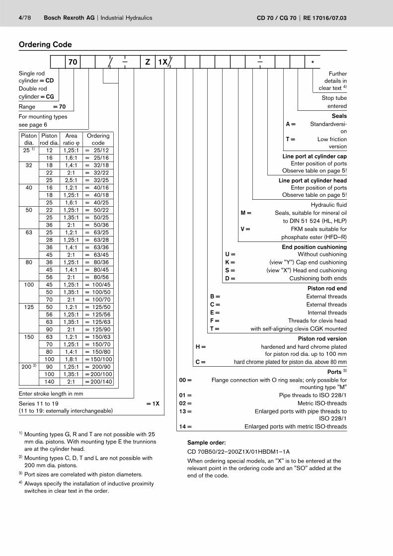
Ordering Code
Single rod cylinder = CDDouble rodcylinder = CG
Range = 70
For mounting typessee page 6
Piston dia.
Piston rod dia.
Arearatio ϕ
Ordering code
25 1) 12 1,25:1 = 25/1216 1,6:1 = 25/16
32 18 1,4:1 = 32/1822 2:1 = 32/2225 2,5:1 = 32/25
40 16 1,2:1 = 40/1618 1,25:1 = 40/1825 1,6:1 = 40/25
50 22 1,25:1 = 50/2225 1,35:1 = 50/2536 2:1 = 50/36
63 25 1,2:1 = 63/2528 1,25:1 = 63/2836 1,4:1 = 63/3645 2:1 = 63/45
80 36 1,25:1 = 80/3645 1,4:1 = 80/4556 2:1 = 80/56
100 45 1,25:1 = 100/4550 1,35:1 = 100/5070 2:1 = 100/70
125 50 1,2:1 = 125/5056 1,25:1 = 125/5663 1,35:1 = 125/6390 2:1 = 125/90
150 63 1,2:1 = 150/6370 1,25:1 = 150/7080 1,4:1 = 150/80
100 1,8:1 = 150/100200 2) 90 1,25:1 = 200/90
100 1,35:1 = 200/100140 2:1 = 200/140
Enter stroke length in mm
Series 11 to 19 = 1X(11 to 19: externally interchangeable)
Further details in
clear text 4)
Stop tubeentered
SealsA = Standardversi-
onT = Low friction
version
Line port at cylinder capEnter position of ports
Observe table on page 5!
Line port at cylinder headEnter position of ports
Observe table on page 5!
Hydraulic fl uidM = Seals, suitable for mineral oil
to DIN 51 524 (HL, HLP)V = FKM seals suitable for
phosphate ester (HFD–R)
End position cushioningU = Without cushioningK = (view "Y") Cap end cushioningS = (view "X") Head end cushioningD = Cushioning both ends
Piston rod endB = External threadsC = External threadsE = Internal threadsF = Threads for clevis headT = with self-aligning clevis CGK mounted
Piston rod version H = hardened and hard chrome plated
for piston rod dia. up to 100 mmC = hard chrome plated for piston dia. above 80 mm
Ports 3)
00 = Flange connection with O ring seals; only possible for mounting type "M"
01 = Pipe threads to ISO 228/102 = Metric ISO-threads13 = Enlarged ports with pipe threads to
ISO 228/114 = Enlarged ports with metric ISO-threads
70 Z 1X *
1) Mounting types G, R and T are not possible with 25 mm dia. pistons. With mounting type E the trunnions are at the cylinder head.
2) Mounting types C, D, T and L are not possible with 200 mm dia. pistons.3) Port sizes are correlated with piston diameters.4) Always specify the installation of inductive proximity
switches in clear text in the order.
Sample order:
CD 70B50/22–200Z1X/01HBDM1–1A
When ordering special models, an "X" is to be entered at the relevant point in the ordering code and an "SO" added at the end of the code.

4 2
1
3
Industrial Hydraulics Bosch Rexroth AGRE 17016/07.03 CD 70 / CG 70 5/78
Position of ports
By rotating the cylinder cap and/or the cylinder head, the position of the ports can be changed for most types of cylinder mounting. The options can be seen in the table below.
The throttle and non return valves change their positions accordingly.
With mounting types F, L, N and T and also at the cylinder cap with mounting G, the throttle and non return valve remain in position 1 when the port position are rotated.
Selectable position of ports
Mounting types B C D E F G H K L M N P Q R S T
At cylinder head 1 1 1 1 1 1 1 1 1 – 1 1 1 1 1 1
2 2 2 2 2 2 2 2 2 – 2 2 2 – 2 2
3 3 3 3 – 3 3 3 – 3 – 3 3 3 3 –
4 4 4 4 4 4 4 4 4 – 4 4 4 – 4 4
At cylinder cap 1 1 1 1 1 1 1 1 1 – 1 1 1 1 1 1
2 2 2 2 2 2 2 2 2 – 2 2 2 2 – 2
3 3 3 3 – 3 3 3 – 3 – 3 3 3 3 –
4 4 4 4 4 4 4 4 4 – 4 4 4 4 – 4
= Positions 2 and 4 are not possible with:
– Piston dia. 25 to 100 with enlarged port threads 13 and 14
– Piston dia. 25, 32/22 and 32/25 with port threads 01 and 02
– Piston dia. 32/18, 40/25, 50/36 and 63/45 each with cushioning
= Positions 2 and 4 are not possible with:
– Piston dia. 25
– Piston dia. 32 to 100 with enlarged port threads 13 and 14
= Positions 2 and 4 are not possible with piston dia. 25
= Positions 2 and 4 are not possible with piston dia. 25 with enlarged port threads 13 and 14
= Positions 2 and 4 are not possible with:
– Piston dia. 25 to 200 with enlarged port threads 13 and 14
– Piston dia. 25, 32 and 40 with port threads 01 and 02
– Piston dia. 50/36 and 63/45 with cushioning
= Positions 2 and 4 are not possible with:
– Piston dia. 25 to 63 with enlarged port threads 13 and 14

6/78 Bosch Rexroth AG Industrial Hydraulics CD 70 / CG 70 RE 17016/07.03
A/Fivel clevis at cylinder cap
B
Trunnion mounting
at cylinder cap
S
Clevis fork at cylinder cap
G
Foot mounting
F
Rectangular fl ange at cylinder
head
C
Foot mounting with key
L
Square fl angeat cylinder head
H
Foot mounting with O ring seals for subplate
mounting
M
Rectangular fl ange
at cylinder cap
D
Threaded holes in cylinder cap and
head
N
Square fl angeat cylinder cap
K
Foot mounting with key
T
Trunnion moun-ting at cylinder
head
R
Extended tie rods at cylinder head
P
Centre trunnion mounting
E
Extended tie rods at cylinder cap
Q
Types of mounting

Industrial Hydraulics Bosch Rexroth AGRE 17016/07.03 CD 70 / CG 70 7/78
Explanation of positions and defi nitions
1 Selectable position of ports (see page 5).
2 Raised cylinder head face in model with enlarged port types 13 and 14.
3 Raised cylinder head face except for 18 mm dia. piston rod without cushioning at rod end.
4 Raised cylinder head face for 25 mm dia. piston rod with cushioning at rod end.
5 Raised cylinder head face for 36 mm dia. piston rod with cushioning at rod end.
6 Raised cylinder head face for 45 mm dia. piston rod with cushioning at rod end.
7 Raised cylinder head face by means of screw-in adaptor, in model with enlarged port types 13 and 14.
8 Raised cylinder cap face in model with enlarged port types 13 and 14.
9 Raised cylinder cap face by means of screw-in adaptor, in model with enlarged port types 13 and 14.
10 Counterbore dia. D1 is only suitable at head end for O ring pipe fi ttings.
11 Counterbore dia. D1 is only suitable at head end with port threads 01 and 02 for O ring pipe fi ttings
12 Non return valve and bleed point. Bleed point is stan-dard.
13 Adjustable throttle for cushioning.
14 Threads B and C. Threads D and F together with the associated trunnion head are always on the last side of each cylinder diameter stated.
16 Associated clevis pin diameter – tolerance m6. Minimum pin material strength σ0,2 = 600 N/mm2 (pin not inclu-ded in supply).
17 Clevis pins and split pins are included in supply.
18 6 usable fi xing screw holes available with raised cylinder head.
19 6 usable fi xing screw holes available with raised cylinder cap.
20 Lubricating nipple to DIN 71 412 form A. Lubricants can be normally commercially available, corrosion preventati-ve, lithium based greases.
21 Re-lubrication possible via lubrication bore in housing.

8/78 Bosch Rexroth AG Industrial Hydraulics CD 70 / CG 70 RE 17016/07.03
Mounting type: B Operating pressure 105 bar
A
A
A-ASW1
R17ø
31
16 33
øKK
5,510
A
38 26 1025
EED1; 0,5
11
612 38
43
195
910–0,12
ø 12
10°
10°
149+Hub
14 1; 10 13 12 16
Mounting type: C Operating pressure for rod dia. 12 and dia. 16: 40 bar at cap end; 105 bar at rod
øRD
10
6,516
6
M5
MA = 5,5 Nm
„Y”
38 27,5
43
6,5
19
6351
38
„X”
114+Hub 152+2xHub16+Hub
14 1; 10 13 12
Strokemin = 25 mm for thread type „E“(only for double rod cylinders)
Stroke
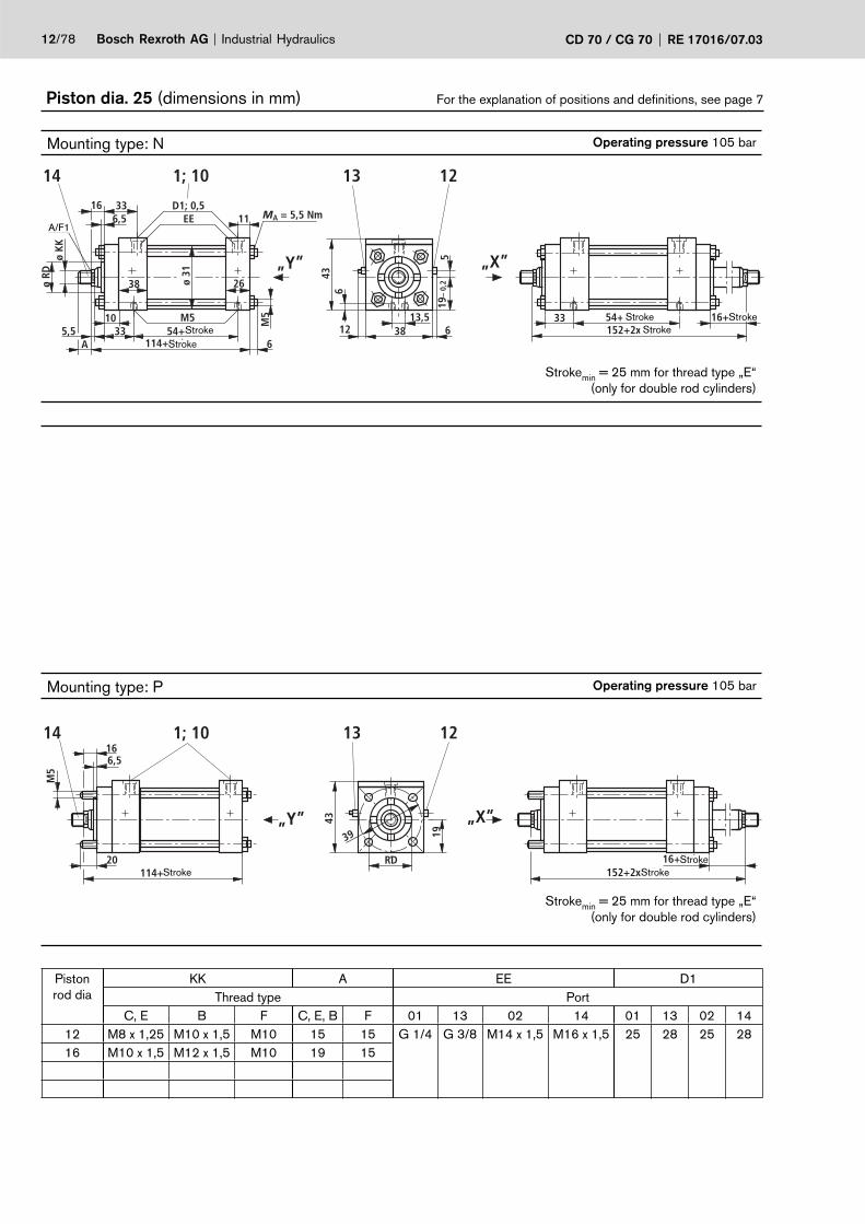
Piston dia. 25 (dimensions in mm) For the explanation of positions and defi nitions, see page 7
Piston rod
dia.
KK A EE D1Thread type Port
C, E B F C, E, B F 01 13 02 14 01 13 02 1412 M8 x 1,25 M10 x 1,5 M10 15 15 G 1/4 G 3/8 M14 x 1,5 M16 x 1,5 25 28 25 2816 M10 x 1,5 M12 x 1,5 M10 19 15
Stroke
Stroke
Stroke
A/F1

Industrial Hydraulics Bosch Rexroth AGRE 17016/07.03 CD 70 / CG 70 9/78
Piston dia. 25 (dimensions in mm) For the explanation of positions and defi nitions, see page 7
Mounting type: H Operating pressure 105 bar
øRD
16
635138
27,510
6,5
6325
,543
27,5
196,
5
„X”„Y”
114+Hub
152+2xHub16+Hub
14 1; 10 13 12
Strokemin = 25 mm for thread type „E“(only for double rod cylinders)
Mounting type: D Operating pressure 105 bar
10
6351
38
43 38 27,5
6,5
19
16
124+Hub
14 1; 10 13 12
Mounting type: K Operating pressure 105 bar
10
635138
27,5
6325
,543
27,5
6,5
19
16
124+Hub
14 1; 10 13 12
Piston rod dia RDf7 A/F1
Cushion length
Full bore end rod end
12 25,5 10 22 23
16 28,5 13
Stroke
StrokeStroke
Stroke
Stroke

10/78 Bosch Rexroth AG Industrial Hydraulics CD 70 / CG 70 RE 17016/07.03
Piston dia. 25 (dimensions in mm) For the explanation of positions and defi nitions, see page 7
Mounting type: E Operating pressure 105 bar
Ø 1
9,05
–0,
03
ø 31
SW 16,5 33
26
A44,510
38
6
MA = 5,5 Nm11
D1; 0,5EE
øKK
44,538 –0,3 19
19
R2
43+
1,3
M5
„X”„Y”
16
øRD
5,5 6
12
114+Hub
16+Hub152+2xHub
19
14 1; 10
13 12 Strokemin = 25 mm for thread type „E“(only for double rod cylinders)
Mounting type: S Operating pressure 105 bar
ø 19
,05–
0,03
26
19
19 1938– 0,3
R2
16
101,5+Hub114+Hub
43+
1,3
14 1; 10
13 12
Piston rod dia
KK A EE D1Thread type Port
C, E B F C, E, B F 01 13 02 14 01 13 02 1412 M8 x 1,25 M10 x 1,5 M10 15 15 G 1/4 G 3/8 M14 x 1,5 M16 x 1,5 25 28 25 2816 M10 x 1,5 M12 x 1,5 M10 19 15
Stroke
StrokeStroke
StrokeStroke
A/F 1

Industrial Hydraulics Bosch Rexroth AGRE 17016/07.03 CD 70 / CG 70 11/78
Piston dia. 25 (dimensions in mm) For the explanation of positions and defi nitions, see page 7
Mounting type: F Operating pressure 105 bar
ø11
ø717,5
38
70+1,4
80,
5
19h1
0
16
17,5
„Y”„X”
54
5
612
73+Hub114+Hub
85+Hub152+2xHub
16+Hub
43+
1,3
14 1;10 13 12
Strokemin = 25 mm for thread type „E“(only for double rod cylinders)
Mounting type: L Operating pressure 105 bar
16
8–0,07
5– 0
,2
5– 0
,2
8– 0,07
„X”„Y”
19h1
0
114+Hub 152+2xHub16+Hub
43+
1,3
14 1; 10 13 12
Strokemin = 25 mm for thread type „E“(only for double rod cylinders)
Mounting type: M Operating pressure 105 bar
16
33ø 17
ø 1033
„X”„Y”
19h1
0
54+Hub114+Hub
O-Ringe 13x2 54+Hub152+2xHub
16+Hub
43+
1,3
14 13 12
Strokemin = 25 mm for thread type „E“(only for double rod cylinders)
Piston rod dia ØRDf7 A/F1
Cushion length
Full bore end Rod end
12 25,5 10 22 23
16 28,5 13
Stroke StrokeStroke
Stroke
Stroke Stroke
Stroke Stroke
Stroke
StrokeStroke
Stroke
Stroke
12/78 Bosch Rexroth AG Industrial Hydraulics CD 70 / CG 70 RE 17016/07.03
Piston dia. 25 (dimensions in mm) For the explanation of positions and defi nitions, see page 7
Mounting type: N Operating pressure 105 bar
M5
16MA = 5,5 Nm
M5
19–
0,2
643
3813,5 33
„X”„Y”26
6A5,5
1033
38
ø KK
SW1
ø RD
6,533
EED1; 0,5
11
ø 31
612
5
54+Hub114+Hub
54+Hub152+2xHub
16+Hub
14 1; 10 13 12
Strokemin = 25 mm for thread type „E“(only for double rod cylinders)
Mounting type: P Operating pressure 105 bar
20
16
M5
39
RD
„X”„Y”
19
43
6,5
114+Hub 152+2xHub16+Hub
14 1; 10 13 12
Strokemin = 25 mm for thread type „E“(only for double rod cylinders)
Piston rod dia
KK A EE D1Thread type Port
C, E B F C, E, B F 01 13 02 14 01 13 02 1412 M8 x 1,25 M10 x 1,5 M10 15 15 G 1/4 G 3/8 M14 x 1,5 M16 x 1,5 25 28 25 2816 M10 x 1,5 M12 x 1,5 M10 19 15
StrokeStroke
Stroke Stroke
Stroke
Stroke StrokeStroke
A/F1

50˚
12˚
12˚
7
9 -0,12
Ø10
M10
SW17
15
43
58
146,
5
27
Ø15
Ø19
16
A
Ø K
K
Ø K
K
A
Industrial Hydraulics Bosch Rexroth AGRE 17016/07.03 CD 70 / CG 70 13/78
Piston dia. 25 (dimensions in mm) For the explanation of positions and defi nitions, see page 7
Mounting type: Q Operating Pressure 105 bar
16
M5
39 19
43
114+Hub
14 1; 10 13 12
204
Piston rod dia ØRDf7 A/F1
Cushion length
Full bore end Rod end
12 25,5 10 22 23
16 28,5 13
Additional thread types Clevis head CGK 10to suit
Thread type „F”
Ordering code.: R900001653
Weight: 0,07 kg
Thread type „F“
Thread type „E”
Nut DIN 936
A/F17
6
Stroke

Mounting type: B Operating Pressure 105 bar
A
A
A-ASW1
R19Ø
38
WH 33
ØKK
B310
A
38 26 1025
EED1; 0,5 11
612 45
45
35,5
7
910–0,12
Ø12
10°
10°
XN+Hub
14 1; 10 13 12 16
35,5
2; 3 8
Mounting type: G Operating Pressure 105 bar
A-A
R11
A
A
19
35,5
5240
20 +0,5
6
35,5
+1,
3
WH
XC + HubØ12,7 f7
H7
14 1; 10 13 12 2; 3 17 8
Mounting type: C Operating Pressure for rod dia 18: 45 bar at cap end; 105 bar rod endOperating Pressure for rod dia 22 und 25: 25 bar at cap end; 105 bar rod end
ØRD
10
VDWH
6
M5
MA = 5,5 Nm
„Y”
45 32
8,5
8063
45
„X”
ZJ+Hub ZM+2xHubWH+Hub
14 1; 10 13 12
35,5
2; 3 ; 8
Strokemin = 25 mm for thread type „E“(only for double rod cylinders)
14/78 Bosch Rexroth AG Industrial Hydraulics CD 70 / CG 70 RE 17016/07.03
Piston dia. 32 (dimensions in mm) For the explanation of positions and defi nitions, see page 7
Piston rod dia
KK A EE D1Thread type Port
C, E B F C, E, B F 01 13 02 14 01 13 02 1418 M10 x 1,5 M12 x 1,5 M12 19 18 G 1/4 G 3/8 M14 x 1,5 M16 x 1,5 25 28 25 2822 M16 x 1,5 M20 x 1,5 M12 28 1825 M20 x 1,5 M22 x 1,5 M12 28 18
Stroke
Stroke
StrokeStroke
Stroke
A/F1

Industrial Hydraulics Bosch Rexroth AGRE 17016/07.03 CD 70 / CG 70 15/78
Piston dia. 32 (dimensions in mm) For the explanation of positions and defi nitions, see page 7
Mounting type: H Operating Pressure 105 bar
ØRD
WH
8063453210
VD
80 63 45 32
8,5
„X”„Y”
ZJ+Hub
ZM+2xHubWH+Hub
14 1; 10 13 12
35,5
2; 3; 818
Strokemin = 25 mm for thread type „E“(only for double rod cylinders)
Mounting type: D Operating Pressure 105 bar
10
8063
45
45 32
8,5
WH
ZF+Hub
14 1; 10 13 12
35,5
2; 3; 8
Mounting type: K Operating Pressure 105 bar
8,5
35,5
32456380
80 63 45 32
10ZF+Hub
WH
14 1; 10 19 13 2; 3; 812
Piston rod dia ØRDf7 VD WH XC XN ZF ZJ ZM B3 A/F1
Cushion length
Full bore end Rod end
18 32 6 16 134 150 125 115 153 5,5 14 22 23
22 34 13 25 143 159 134 124 171 8 19
25 38 13 25 143 159 134 124 171 8 22
Stroke
Stroke
Stroke
Stroke
Stroke

16/78 Bosch Rexroth AG Industrial Hydraulics CD 70 / CG 70 RE 17016/07.03
Piston dia. 32 (dimensions in mm) For the explanation of positions and defi nitions, see page 7
Mounting type: R Operating Pressure 105 bar
WH+Hub
Ø25
,4 –
0,03
45 –0,310 25
12
XG25
6
46 +
1,3 35,5
+1,
3
R2„X”„Y”
38B3
XGA
26
11VD33WH
EED1; 0,5
Ø38
ØRD
ØKK
SW1
ZJ+Hub
ZM+2xHub
14 1; 10 2; 3; 8
13 12
Stroke min = 25 mm for thread type „E“(only for double rod cylinders)
Mounting type: E Operating Pressure 105 bar
Ø25
,4 –
0,03
32
6
50 –0,3 2525
35,5
50 +
1,3
45
R2
MA = 5,5 Nm
M5
„X”„Y”
WH
XV+Hub/2ZJ+Hub
XV+Hub/2ZM+2xHub
WH+Hub
14 1; 10 2; 3; 8
13 12Strokemin = 10 mm Strokemin = 25 mm for thread type „E“
(only for double rod cylinders)
Mounting type: S Operating Pressure 105 bar
Ø25
,4 –
0,03
26
35,5
+1,
3
25 2545–0,3
R2
WH
XJ+HubZJ+Hub
46
14 1; 10
13 12
2; 3; 8
Piston rod dia
KK A EE D1Thread type Port
C, E B F C, E, B F 01 13 02 14 01 13 02 1418 M10 x 1,5 M12 x 1,5 M12 19 18 G 1/4 G 3/8 M14 x 1,5 M16 x 1,5 25 28 25 2822 M16 x 1,5 M20 x 1,5 M12 28 1825 M20 x 1,5 M22 x 1,5 M12 28 18
Stroke
Stroke
Stroke
Stroke Stroke Stroke/2
Stroke Stroke/2
A/F1
Stroke Stroke

Industrial Hydraulics Bosch Rexroth AGRE 17016/07.03 CD 70 / CG 70 17/78
Piston dia. 32 (dimensions in mm) For the explanation of positions and defi nitions, see page 7
Mounting type: F Operating Pressure 105 bar
Ø18
Ø1119
45
85+1,5
131
22,5
h10
WH
19
„Y”„X”
64
7
612
70+HubZJ+Hub
83+HubZM+2xHub
WH+Hub
46+
1,3
14 1;10 13 12
35,5
+1,
3
2; 3; 8
Strokemin = 25 mm for thread type „E“(only for double rod cylinders)
Mounting type: L Operating Pressure 105 bar
WH
8 –0,07
5 –0
,2
5 –0
,2
8 –0,07
„X”„Y”
22,5
h10
ZJ+Hub ZM+2xHubWH+Hub
14 1; 10 13 12
35,5
+1,
3
2; 3; 8
Strokemin = 25 mm for thread type „E“(only for double rod cylinders)
Mounting type: M Operating Pressure 105 bar
WH
33,5Ø17
Ø1033,5
„X”„Y”
22,5
h10
54+HubZJ+Hub
O-Ringe 13x2 54+HubZM+2xHub
WH+Hub
14 13 12
Strokemin = 25 mm for thread type „E“(only for double rod cylinders)
Piston rod dia ØRDf7 VD WH XG XJ XV ZJ ZM B3 A/F1
Cushion length
Full bore end Rod end
18 32 6 16 44,5 102 76,5 115 153 5,5 14 22 23
22 34 13 25 53,5 111 85,5 124 171 8 19
25 38 13 25 53,5 111 85,5 124 171 8 22
Stroke StrokeStroke
Stroke Stroke
Stroke Stroke
Stroke
Stroke Stroke
Stroke Stroke
Stroke

18/78 Bosch Rexroth AG Industrial Hydraulics CD 70 / CG 70 RE 17016/07.03
Piston dia. 32 (dimensions in mm) For the explanation of positions and defi nitions, see page 7
Mounting type: N Operating Pressure 105 bar
M6
WHMA = 5,5 Nm
M5 22
,5–0
,2
B245
4514,5 33,5
„X”„Y”26
6AB3
1033,5
38
ØKK
SW1
ØRD
VD33
EED1; 0,5
11
Ø38
612
35,5
54+HubZJ+Hub
54+HubZM+2xHub
WH+Hub
14 1; 10 13 12
7
2; 3; 8
Strokemin = 25 mm for thread type „E“(only for double rod cylinders)
Mounting type: T Operating Pressure 105 bar
22,5
–0,
2
0,2
–0,4
8 –0,07
5 –0
,2
„Y”
„Y”
Ø6,6Ø11Ø6,6
19719 7
WH
112
35,5
3333
11
45
35,5
137+Hub
14 1; 10 13 12 2; 3 8
Mounting type: P Operating Pressure 105 bar
20
WH
M5
46,5
RD
„X”„Y”
VD
ZJ+Hub ZM+2xHubWH+Hub
14 1; 10 13 12
35,5
2; 3; 8
Strokemin = 25 mm for thread type „E“(only for double rod cylinders)
Piston rod dia
KK A EE D1Thread type Port
C, E B F C, E, B F 01 13 02 14 01 13 02 1418 M10 x 1,5 M12 x 1,5 M12 19 18 G 1/4 G 3/8 M14 x 1,5 M16 x 1,5 25 28 25 2822 M16 x 1,5 M20 x 1,5 M12 28 1825 M20 x 1,5 M22 x 1,5 M12 28 18
Stroke Stroke Stroke
Stroke
Stroke Stroke
Stroke StrokeStroke
A/F1

50˚
11˚
11˚
8
10-0,12
Ø12
M12
SW19
18
50
67
167
34
Ø19
Ø22
16
A
Ø K
K
Ø K
K
A
Industrial Hydraulics Bosch Rexroth AGRE 17016/07.03 CD 70 / CG 70 19/78
Piston dia. 32 (dimensions in mm) For the explanation of positions and defi nitions, see page 7
Mounting type: Q Operating Pressure 105 bar
WH
M5
46,5
35,5
ZJ+Hub
14 1; 10 13 12
204
2; 3; 8
Piston rod dia ØRDf7 VD WH ZJ ZM B2 B3 A/F1
Cushion length
Full bore end Rod end
18 32 6 16 115 153 9 5,5 14 22 23
22 34 13 25 124 171 7 8 19
25 38 13 25 124 171 7 8 22
Additional thread types Clevis head CGK 12to suit
Thread type „F”
Ordering code.: R900001327
Weight: 0,1 kg
Thread type „F“
Thread type „E”
Nut DIN 936
A/F19
7
Stroke

20/78 Bosch Rexroth AG Industrial Hydraulics CD 70 / CG 70 RE 17016/07.03
Piston dia. 40 (dimensions in mm) For the explanation of positions and defi nitions, see page 7
Mounting type: B Operating Pressure 105 bar
A
A
A-ASW1
R20Ø
46
WH 33
ØKK
B310
A
38 26 1030
EED1; 0,5 11
39 51
51
38,5
8
1012–0,12
Ø15
8°8°
XN+Hub
14 1; 10 13 12 16
38,5
2; 4 820
Mounting type: G Operating Pressure 105 bar
A
A-A
A
38,5
+1,
3
20 +0,5
4456
38,5R12
Ø12,7 f7H7
19
6
XC + Hub
WH
14 1; 10 13 12 2; 4 17 8
Mounting type: C Operating Pressure for rod dia 16 und 18: 45 bar at cap end; 105 bar Rod endOperating Pressure for rod dia 25: 25 bar at cap end; 105 bar Rod end
ØRD
10
VDWH
6
M5
MA = 5,5 Nm
„Y”
51 36,5
8,5
8570
51
„X”
ZJ+Hub ZM+2xHubWH+Hub
14 1; 10 13 12
38,5
2; 4; 8
Strokemin = 25 mm for thread type „E“(only for double rod cylinders)
Piston rod dia
KK A EE D1Thread type Port
C, E B F C, E, B F 01 13 02 14 01 13 02 1416 M10 x 1,5 M12 x 1,5 M14 19 21 G 1/4 G 3/8 M14 x 1,5 M16 x 1,5 25 28 25 2818 M10 x 1,5 M12 x 1,5 M14 19 2125 M20 x 1,5 M22 x 1,5 M14 28 21
Stroke
Stroke
StrokeStroke
Stroke
A/F1

Industrial Hydraulics Bosch Rexroth AGRE 17016/07.03 CD 70 / CG 70 21/78
Piston dia. 40 (dimensions in mm) For the explanation of positions and defi nitions, see page 7
Mounting type: H Operating Pressure 105 bar
ØRD
WH
857051
36,510
VD
85 70 51 36,5
8,5
„X”„Y”
ZJ+Hub
ZM+2xHubWH+Hub
14 1; 10 13 12
38,5
2; 4; 818
Strokemin = 25 mm for thread type „E“(only for double rod cylinders)
Mounting type: D Operating Pressure 105 bar
9
8570
51
51 36,5
8,5
WH
ZF+Hub
14 1; 10 13 12
38,5
2; 4; 8
Mounting type: K Operating Pressure 105 bar
36,5517085
36,5517085
8,5
38,5
WH
ZF+Hub9
14 1; 10 19 13 12 2; 4; 8
Piston rod dia ØRDf7 VD WH XC XN ZF ZJ ZM B3 A/F1
Cushion length
Full bore end Rod end
16 28,5 6 16 137 158 127 118 156 5,5 13 22 23
18 32 6 16 137 158 127 118 156 5,5 14
25 38 13 25 146 167 136 127 174 8 22
Stroke
Stroke
Stroke
Stroke
Stroke

22/78 Bosch Rexroth AG Industrial Hydraulics CD 70 / CG 70 RE 17016/07.03
Piston dia. 40 (dimensions in mm) For the explanation of positions and defi nitions, see page 7
Mounting type: R Operating Pressure 105 bar
WH+HubØ
25,4
–0,
03
51 –0,310 259
XG25
3
53 +
1,4
38,5
+1,
3
R2„X”„Y”
38B3
XGA
26
11VD33WH
EED1; 0,5
Ø46
ØRD
ØKK
SW1
ZJ+Hub
ZM+2xHub
14 1; 10 2; 4; 8
13 12Strokemin = 25 mm for thread type „E“
(only for double rod cylinders)
Mounting type: E Operating Pressure 105 bar
Ø25
,4 –
0,03
32
6
63,5 –0,3 2525
38,5
65 +
1,4
51
R2
MA = 5,5 Nm
M5
„X”„Y”
WH
XV+Hub/2ZJ+Hub
XV+Hub/2ZM+2xHub
WH+Hub
14 1; 10 2; 4; 8
13 12Strokemin = 10 mm Strokemin = 25 mm for thread type „E“
(only for double rod cylinders)
Mounting type: S Operating Pressure 105 bar
Ø25
,4 –
0,03
26
38,5
+1,
3
25 2551–0,3
R2
WH
XJ+HubZJ+Hub
53 +
1,4
14 1; 10
13 12
2; 4; 8
Piston rod dia
KK A EE D1Thread type Port
C, E B F C, E, B F 01 13 02 14 01 13 02 1416 M10 x 1,5 M12 x 1,5 M14 19 21 G 1/4 G 3/8 M14 x 1,5 M16 x 1,5 25 28 25 2818 M10 x 1,5 M12 x 1,5 M14 19 2125 M20 x 1,5 M22 x 1,5 M14 28 21
StrokeStroke
Stroke
Stroke/2
StrokeStroke/2 Stroke
Stroke
StrokeStroke
A/F1

Industrial Hydraulics Bosch Rexroth AGRE 17016/07.03 CD 70 / CG 70 23/78
Piston dia. 40 (dimensions in mm) For the explanation of positions and defi nitions, see page 7
Mounting type: F Operating Pressure 105 bar
Ø18
Ø1119
51
91+1,5
131
25,5
h10
WH
19
„Y”„X”
70
8
39
73+HubZJ+Hub
86+HubZM+2xHub
WH+Hub
51+
1,4
14 1;10 13 12
38,5
+1,
3
2; 4; 8
Strokemin = 25 mm for thread type „E“(only for double rod cylinders)
Mounting type: L Operating Pressure 105 bar
WH
8 –0,07
5 –0
,2
5 –0
,2
8 –0,07
„X”„Y”
25,5
h10
ZJ+Hub ZM+2xHubWH+Hub
14 1; 10 13 12
38,5
+1,
3
2; 4; 8
Strokemin = 25 mm for thread type „E“(only for double rod cylinders)
Mounting type: M Operating Pressure 105 bar
WH
35Ø20
Ø1235
„X”„Y”
25,5
h10
54+HubZJ+Hub
O-Ringe 16x2 54+HubZM+2xHub
WH+Hub
14 13 12
Strokemin = 25 mm for thread type „E“(only for double rod cylinders)
Piston rod dia ØRDf7 VD WH XG XJ XV ZJ ZM B3 A/F1
Cushion length
Full bore end Rod end
16 28,5 6 16 44,5 105 78 118 156 5,5 13 22 23
18 32 6 16 44,5 105 78 118 156 5,5 14
25 38 13 25 53,5 114 87 127 174 8 22
Stroke Stroke
StrokeStroke
Stroke
Stroke
StrokeStroke
StrokeStroke Stroke
StrokeStroke

24/78 Bosch Rexroth AG Industrial Hydraulics CD 70 / CG 70 RE 17016/07.03
Piston dia. 40 (dimensions in mm) For the explanation of positions and defi nitions, see page 7
Mounting type: N Operating Pressure 105 bar
M6
WHMA = 5,5 Nm
M5 25
,5–0
,2
B251
5115,5 33,5
„X”„Y”26
6AB3
1033,5
38
ØKK
SW1
ØRD
VD33
EED1; 0,5
11
Ø46
39
38,5
57+HubZJ+Hub
57+HubZM+2xHub
WH+Hub
14 1; 10 13 12
8
2; 4; 8
Strokemin = 25 mm for thread type „E“(only for double rod cylinders)
Mounting type: T Operating Pressure 105 bar
25,5
–0,
2
0,2
–0,4
8 –0,07
5 –0
,2
„Y”
„Y”
Ø9Ø14Ø9
19,56,518,5 7,5
WH
145
38,5
36,536,5
14
51
38,5
140+Hub
14 1; 10 13 12 2; 4; 8 8
Mounting type: P Operating Pressure 105 bar
25
WH
M5
51,5
RD
„X”„Y”
VD
ZJ+Hub ZM+2xHubWH+Hub
14 1; 10 13 12
38,5
2; 4; 8
Strokemin = 25 mm for thread type „E“(only for double rod cylinders)
Piston rod dia
KK A EE D1Thread type Port
C, E B F C, E, B F 01 13 02 14 01 13 02 1416 M10 x 1,5 M12 x 1,5 M14 19 21 G 1/4 G 3/8 M14 x 1,5 M16 x 1,5 25 28 25 2818 M10 x 1,5 M12 x 1,5 M14 19 2125 M20 x 1,5 M22 x 1,5 M14 28 21
Stroke Stroke StrokeStroke
Stroke
Stroke
StrokeStroke
Stroke
A/F1

50˚
8˚8˚
10
12-0,12
Ø15
M14
SW22
21
61
81
188
41
Ø22
Ø26
16 21
A
Ø K
K
Ø K
K
A
Industrial Hydraulics Bosch Rexroth AGRE 17016/07.03 CD 70 / CG 70 25/78
Piston dia. 40 (dimensions in mm) For the explanation of positions and defi nitions, see page 7
Mounting type: Q Operating Pressure 105 bar
WH
M5
51,5
38,5
ZJ+Hub
14 1; 10 13 12
254
2; 4; 8
Piston rod dia ØRDf7 VD WH ZJ ZM B2 B3 A/F1
Cushion length
Full bore end Rod end
16 28,5 6 16 118 156 9 5,5 13 22 23
18 32 6 16 118 156 6 5,5 14
25 38 13 25 127 174 6 8 22
Additional thread types Clevis head CGK 15to suit
Thread type „F”
Ordering code.: R900001328
Weight: 0,16 kg
Thread type „F“
Thread type „E”
Nut DIN 936
A/F22
8
Stroke

26/78 Bosch Rexroth AG Industrial Hydraulics CD 70 / CG 70 RE 17016/07.03
Piston dia. 50 (dimensions in mm) For the explanation of positions and defi nitions, see page 7
Mounting type: B Operating Pressure 105 bar
A
A
A-ASW1
R25Ø
56
WH 33
ØKK
B310
A
38 26 1035
EED1; 0,5 11
39 63
63
44,5
10
1416–0,12
Ø20
9°9°
XN+Hub
14 1; 10 13 12 16
44,5
2; 5 820
Mounting type: G Operating Pressure 105 bar
A
A-A
A
44,5
+1,
3
20 +0,5
4456
44,5R16
Ø12,7 f7H7
19
8
XC + Hub
WH
14 1; 10 13 12 2; 5 17 8
Mounting type: C Operating Pressure for rod dia 22 und 25: 25 bar at cap end; 105 bar Rod endOperating Pressure for rod dia 36: 15 bar at cap end; 105 bar Rod end
ØRD
10
VDWH
8
M5
MA = 23 Nm
„Y”
63 46,5
9,5
10585,5
63
„X”
ZJ+Hub ZM+2xHubWH+Hub
14 1; 10 13 12
44,5
2; 5; 8
Strokemin = 30 mm for thread type „E“(only for double rod cylinders)
Piston rod dia
KK A EE D1Thread type Port
C, E B F C, E, B F 01 13 02 14 01 13 02 1422 M16 x 1,5 M20 x 1,5 M20 x 1,5 28 30 G 1/4 G 3/8 M14 x 1,5 M16 x 1,5 25 28 25 2825 M20 x 1,5 M22 x 1,5 M20 x 1,5 28 3036 M26 x 1,5 M30 x 2 M20 x 1,5 41 30
Stroke
Stroke
Stroke
StrokeStroke
A/F1

Industrial Hydraulics Bosch Rexroth AGRE 17016/07.03 CD 70 / CG 70 27/78
Piston dia. 50 (dimensions in mm) For the explanation of positions and defi nitions, see page 7
Mounting type: H Operating Pressure 105 bar
ØRD
WH
10585,5
6346,510
VD
105
85,5 63 46,5
9,5
„X”„Y”
ZJ+Hub
ZM+2xHubWH+Hub
14 1; 10 13 12
44,5
2; 5; 818
Strokemin = 30 mm for thread type „E“(only for double rod cylinders)
Mounting type: D Operating Pressure 105 bar
9
10585,563
63 46,5
9,5
WH
ZF+Hub
14 1; 10 13 12
44,5
2; 5; 8
Mounting type: K Operating Pressure 105 bar
46,563
85,5105
46,56385,5
105
9,5
44,5
WH
ZF+Hub9
14 1; 10 19 13 12 2; 5; 8
Piston rod dia ØRDf7 VD WH XC XN ZF ZJ ZM B3 A/F1
Cushion length
Full bore end Rod end
22 38 13 25 146 172 136 127 174 8 19 22 23
25 38 13 25 146 172 136 127 174 8 22
36 50 16 32 153 179 143 134 188 10 30
Stroke Stroke
Stroke
Stroke
Stroke

28/78 Bosch Rexroth AG Industrial Hydraulics CD 70 / CG 70 RE 17016/07.03
Piston dia. 50 (dimensions in mm) For the explanation of positions and defi nitions, see page 7
Mounting type: R Operating Pressure 105 bar
WH+HubØ
25,4
–0,
03
63,5 –0,310 259
XG25
3
64 +
1,4 44,5
+1,
3
R2„X”„Y”
38B3
XGA
26
11VD33WH
EED1; 0,5
Ø56
ØRD
ØKK
SW1
ZJ+Hub
ZM+2xHub
14 1; 10 2; 5; 8
13 12Strokemin = 30 mm for thread type „E“
(only for double rod cylinders)
Mounting type: E Operating Pressure 105 bar
Ø25
,4 –
0,03
38
8
76 –0,3 2525
44,5
75 +
1,4
63
R2
MA = 23 Nm
M8
„X”„Y”
WH
XV+Hub/2ZJ+Hub
XV+Hub/2ZM+2xHub
WH+Hub
14 1; 10 2; 5; 8
13 12Strokemin = 10 mm Strokemin = 30 mm for thread type „E“
(only for double rod cylinders)
Mounting type: S Operating Pressure 105 bar
Ø25
,4 –
0,03
26
44,5
+1,
3
25 2563,5 –0,3
R2
WH
XJ+HubZJ+Hub
64 +
1,4
14 1; 10
13 12
2; 5; 8
Piston rod dia
KK A EE D1Thread type Port
C, E B F C, E, B F 01 13 02 14 01 13 02 1422 M16 x 1,5 M20 x 1,5 M20 x 1,5 28 30 G 1/4 G 3/8 M14 x 1,5 M16 x 1,5 25 28 25 2825 M20 x 1,5 M22 x 1,5 M20 x 1,5 28 3036 M26 x 1,5 M30 x 2 M20 x 1,5 41 30
Stroke
Stroke
StrokeStroke
Stroke
Stroke/2 StrokeStroke
Stroke
A/F1
Stroke/2

Industrial Hydraulics Bosch Rexroth AGRE 17016/07.03 CD 70 / CG 70 29/78
Piston dia. 50 (dimensions in mm) For the explanation of positions and defi nitions, see page 7
Mounting type: F Operating Pressure 105 bar
Ø18
Ø1119
63
104+1,5
121
31,7
h10
WH
19
„Y”„X”
82,5
10
39
73+HubZJ+Hub
86+HubZM+2xHub
WH+Hub
64+
1,4
14 1;10 13 12
44,5
+1,
3
2; 5; 8
Strokemin = 30 mm for thread type „E“(only for double rod cylinders)
Mounting type: L Operating Pressure 105 bar
WH
8 –0,07
5 –0
,2
5 –0
,2
8 –0,07
„X”„Y”
31,7
h10
ZJ+Hub ZM+2xHubWH+Hub
14 1; 10 13 12
44,5
+1,
3
2; 5; 8
Strokemin = 30 mm for thread type „E“(only for double rod cylinders)
Mounting type: M Operating Pressure 105 bar
WH
35Ø20
Ø1235
„X”„Y”
31,7
h10
54+HubZJ+Hub
O-Ringe 16x2 54+HubZM+2xHub
WH+Hub
14 13 12
Strokemin = 30 mm for thread type „E“(only for double rod cylinders)
Piston rod dia ØRDf7 VD WH XG XJ XV ZJ ZM B3 A/F1
Cushion length
Full bore end Rod end
22 38 13 25 53,5 114 87 127 174 8 19 22 23
25 38 13 25 53,5 114 87 127 174 8 22
36 50 16 32 60,5 121 94 134 188 10 30
Stroke Stroke Stroke
Stroke
Stroke Stroke
StrokeStroke
StrokeStroke Stroke
Stroke
Stroke

30/78 Bosch Rexroth AG Industrial Hydraulics CD 70 / CG 70 RE 17016/07.03
Piston dia. 50 (dimensions in mm) For the explanation of positions and defi nitions, see page 7
Mounting type: N Operating Pressure 105 bar
M8
WHMA = 23 Nm
M8 31
,5–0
,2
B263
6322 33,5
„X”„Y”26
8AB3
1033,5
38
ØKK
SW1
ØRD
VD33
EED1; 0,5
11
Ø56
39
44,5
57+HubZJ+Hub
57+HubZM+2xHub
WH+Hub
14 1; 10 13 12
10
2; 5; 8
Strokemin = 30 mm for thread type „E“(only for double rod cylinders)
Mounting type: T Operating Pressure 105 bar
31,5
–0,
2
0,2
–0,4
8 –0,07
5 –0
,2
„Y”
„Y”
Ø9,5Ø14Ø9,5
23,57,523,5 7,5
WH
195
44,5
46,546,5
19
63
44,5
149+Hub
14 1; 10 13 12 2; 5 8
Mounting type: P Operating Pressure 105 bar
28
WH
M8
66
RD
„X”„Y”
VD
ZJ+Hub ZM+2xHubWH+Hub
14 1; 10 13 12
44,5
2; 5; 8
Strokemin = 30 mm for thread type „E“(only for double rod cylinders)
Piston rod dia
KK A EE D1Thread type Port
C, E B F C, E, B F 01 13 02 14 01 13 02 1422 M16 x 1,5 M20 x 1,5 M20 x 1,5 28 30 G 1/4 G 3/8 M14 x 1,5 M16 x 1,5 25 28 25 2825 M20 x 1,5 M22 x 1,5 M20 x 1,5 28 3036 M26 x 1,5 M30 x 2 M20 x 1,5 41 30
StrokeStroke
StrokeStroke
StrokeStrokeStroke
Stroke
Stroke
A/F1

50˚
9˚9˚
13
16-0,12
Ø20
M20 x 1,5
SW32
30
77
104
2310
53
Ø28
Ø34
16 21
A
Ø K
K
Ø K
K
A
Industrial Hydraulics Bosch Rexroth AGRE 17016/07.03 CD 70 / CG 70 31/78
Piston dia. 50 (dimensions in mm) For the explanation of positions and defi nitions, see page 7
Mounting type: Q Operating Pressure 105 bar
WH
M8
66
44,5
ZJ+Hub
14 1; 10 13 12
286,5
2; 5; 8
Piston rod dia ØRDf7 VD WH ZJ ZM B2 B3 A/F1
Cushion length
Full bore end Rod end
22 38 13 25 127 174 12 8 19 22 23
25 38 13 25 127 174 12 8 22
36 50 16 32 134 188 8 10 30
Additional thread types Clevis head CGK 20to suit
Thread type „F”
Ordering code.: R900001329
Weight: 0,34 kg
Thread type „F“
Thread type „E”
Nut DIN 936
A/F30
9
Stroke

32/78 Bosch Rexroth AG Industrial Hydraulics CD 70 / CG 70 RE 17016/07.03
Piston dia. 63 (dimensions in mm) For the explanation of positions and defi nitions, see page 7
Mounting type: B Operating Pressure 70 bar
A
A
A-ASW1
R30Ø
69
WH 33
ØKK
B310
A
38 26 1040
EED1; 0,5 11
06 76
76
5115
1416–0,12
Ø20
9°9°
XN+Hub
14 1; 10 13 12 16
51
2; 6 820
Mounting type: G Operating Pressure 70 bar
A
A-A
A
51
20 +0,5
4456
51 +
1,4
R16
Ø12,7 f7H7
19
6
XC + Hub
WH
14 1; 10 13 12 2; 6 17 8
Mounting type: C Operating Pressure for rod dia 25 und 28: 20 bar at cap end; 70 bar Rod endOperating Pressure for rod dia 36 und 45: 10 bar at cap end; 70 bar Rod end
ØRD
10
VDWH
8
M8
MA = 23 Nm
„Y”
76 55,5
9,5
11598,5
76
„X”
ZJ+Hub ZM+2xHubWH+Hub
14 1; 10 13 12
51
2; 6; 8
Strokemin = 30 mm for thread type „E“(only for double rod cylinders)
Piston rod dia
KK A EE D1Thread type Port
C, E B F C, E, B F 01 13 02 14 01 13 02 1425 M20 x 1,5 M22 x 1,5 M24 x 2 28 36 G 1/4 G 3/8 M14 x 1,5 M16 x 1,5 25 28 25 2828 M20 x 1,5 M22 x 1,5 M24 x 2 28 3636 M26 x 1,5 M30 x 2 M24 x 2 41 3645 M33 x 2 M39 x 2 M24 x 2 51 36
Stroke
Stroke
Stroke Stroke Stroke
A/F1

Industrial Hydraulics Bosch Rexroth AGRE 17016/07.03 CD 70 / CG 70 33/78
Piston dia. 63 (dimensions in mm) For the explanation of positions and defi nitions, see page 7
Mounting type: H Operating Pressure 70 bar
ØRD
WH
11598,5
7655,510
VD
115
98,5 76 55,5
9,5
„X”„Y”
ZJ+Hub
ZM+2xHubWH+Hub
14 1; 10 13 12
51
2; 6; 818
Strokemin = 30 mm for thread type „E“(only for double rod cylinders)
Mounting type: D Operating Pressure 70 bar
10
11598,576
76 55,5
9,5
WH
ZF+Hub
14 1; 10 13 12
51
2; 6; 8
Mounting type: K Operating Pressure 70 bar
55,576
98,5115
55,57698,5
115
9,5
51
WH
ZF+Hub10
14 1; 10 1913 12 2; 6; 8
Piston rod dia ØRDf7 VD WH XC XN ZF ZJ ZM B3 A/F1
Cushion length
Full bore end Rod end
25 38 13 25 149 180 140 130 177 8 22 22 23
28 42 13 25 149 180 140 130 177 8 22
36 50,7 16 32 156 187 147 137 191 10 30
45 60 19 38 162 193 153 143 203 12 41
Stroke
StrokeStroke
Stroke
Stroke

34/78 Bosch Rexroth AG Industrial Hydraulics CD 70 / CG 70 RE 17016/07.03
Piston dia. 63 (dimensions in mm) For the explanation of positions and defi nitions, see page 7
Mounting type: R Operating Pressure 70 bar
WH+HubØ
25,4
–0,
03
76 –0,310 256
XG25
0
76 +
1,4 51
+1,
4
R2„X”„Y”
38B3
XGA
26
11VD33WH
EED1; 0,5
Ø69
ØRD
ØKK
SW1
ZJ+Hub
ZM+2xHub
14 1; 10 2; 6; 8
13 12Strokemin = 30 mm for thread type „E“
(only for double rod cylinders)
Mounting type: E Operating Pressure 70 bar
Ø25
,4 –
0,03
38
8
89 –0,3 2525
51
90 +
1,5
76
R2
MA = 23 Nm
M8
„X”„Y”
WH
XV+Hub/2ZJ+Hub
XV+Hub/2ZM+2xHub
WH+Hub
14 1; 10 2; 6; 8
13 12Strokemin = 10 mm Strokemin = 30 mm for thread type „E“
(only for double rod cylinders)
Mounting type: S Operating Pressure 70 bar
Ø25
,4 –
0,03
26
51 +
1,4
25 2576 –0,3
R2
WH
XJ+HubZJ+Hub
76 +
1,4
14 1; 10
13 12
2; 6; 8
Piston rod dia
KK A EE D1Thread type Port
C, E B F C, E, B F 01 13 02 14 01 13 02 1425 M20 x 1,5 M22 x 1,5 M24 x 2 28 36 G 1/4 G 3/8 M14 x 1,5 M16 x 1,5 25 28 25 2828 M20 x 1,5 M22 x 1,5 M24 x 2 28 3636 M26 x 1,5 M30 x 2 M24 x 2 41 3645 M33 x 2 M39 x 2 M24 x 2 51 36
Stroke/2 Stroke
Stroke
Stroke Stroke
Stroke Stroke/2
StrokeStroke
Stroke
A/F1

Industrial Hydraulics Bosch Rexroth AGRE 17016/07.03 CD 70 / CG 70 35/78
Piston dia. 63 (dimensions in mm) For the explanation of positions and defi nitions, see page 7
Mounting type: F Operating Pressure 70 bar
Ø18
Ø1119
76
116+1,5
121
38h1
0
WH
19
„Y”„X”
95,5
15
06
76+HubZJ+Hub
89+HubZM+2xHub
WH+Hub
76+
1,4
14 1;10 13 12
51 +
1,4
2; 6; 8
Strokemin = 30 mm for thread type „E“(only for double rod cylinders)
Mounting type: L Operating Pressure 70 bar
WH
8 –0,07
5 –0
,2
5 –0
,2
8 –0,07
„X”„Y”
38h1
0
ZJ+Hub ZM+2xHubWH+Hub
14 1; 10 13 12
51 +
1,4
2; 6; 8
Strokemin = 30 mm for thread type „E“(only for double rod cylinders)
Mounting type: M Operating Pressure 70 bar
WH
35Ø20
Ø1235
„X”„Y”
38h1
0
57+HubZJ+Hub
O-Ringe 16x2 57+HubZM+2xHub
WH+Hub
14 13 12
Strokemin = 30 mm for thread type „E“(only for double rod cylinders)
Piston rod dia ØRDf7 VD WH XG XJ XV ZJ ZM B3 A/F1
Cushion length
Full bore end Rod end
25 38 13 25 53,5 117 88,5 130 177 8 22 22 23
28 42 13 25 53,5 117 88,5 130 177 8 22
36 50,7 16 32 60,5 124 95,5 137 191 10 30
45 60 19 38 66,5 130 101,5 143 203 12 41
Stroke
Stroke Stroke Stroke
Stroke Stroke
Stroke StrokeStroke
Stroke
Stroke Stroke Stroke

36/78 Bosch Rexroth AG Industrial Hydraulics CD 70 / CG 70 RE 17016/07.03
Piston dia. 63 (dimensions in mm) For the explanation of positions and defi nitions, see page 7
Mounting type: N Operating Pressure 70 bar
M10
WHMA = 23 Nm
M8
38–0
,2
B276
7631 33,5
„X”„Y”26
8AB3
1033,5
38
ØKK
SW1
ØRD
VD33
EED1; 0,5
11
Ø69
06
51
60,5+HubZJ+Hub
60,5+HubZM+2xHub
WH+Hub
14 1; 10 13 12
15
2; 6; 8
Strokemin = 30 mm for thread type „E“(only for double rod cylinders)
Mounting type: T Operating Pressure 70 bar
38 –
0,2
0,2
–0,4
8 –0,07
5 –0
,2
„Y”
„Y”
Ø9,5Ø14Ø9,5
27827 8
WH
224,
5
51
55,555,5
22
76
51
159+Hub
14 1; 10 13 12 2; 6; 8 8
Mounting type: P Operating Pressure 70 bar
28
WH
M8
78,5
RD
„X”„Y”
VD
ZJ+Hub ZM+2xHubWH+Hub
14 1; 10 13 12
51
2; 6; 8
Strokemin = 30 mm for thread type „E“(only for double rod cylinders)
Piston rod dia
KK A EE D1Thread type Port
C, E B F C, E, B F 01 13 02 14 01 13 02 1425 M20 x 1,5 M22 x 1,5 M24 x 2 28 36 G 1/4 G 3/8 M14 x 1,5 M16 x 1,5 25 28 25 2828 M20 x 1,5 M22 x 1,5 M24 x 2 28 3636 M26 x 1,5 M30 x 2 M24 x 2 41 3645 M33 x 2 M39 x 2 M24 x 2 51 36
StrokeStroke
StrokeStroke
Stroke
Stroke
Stroke StrokeStroke
A/F1

50˚
7˚7˚
17
20-0,12
Ø25
M24 x 2
SW36
36
94
126
2712
64
Ø35
Ø42
16 20
A
Ø K
K
Ø K
K
A
Industrial Hydraulics Bosch Rexroth AGRE 17016/07.03 CD 70 / CG 70 37/78
Piston dia. 63 (dimensions in mm) For the explanation of positions and defi nitions, see page 7
Mounting type: Q Operating Pressure 70 bar
WH
M8
78,5
51
ZJ+Hub
14 1; 10 13 12
286,5
2; 6; 8
Piston rod dia ØRDf7 VD WH ZJ ZM B2 B3 A/F1
Cushion length
Full bore end Rod end
25 38 13 25 130 177 15 8 22 22 23
28 42 13 25 130 177 16 8 22
36 50,7 16 32 137 191 9 10 30
45 60 19 38 143 203 9 12 41
Additional thread types Clevis head CGK 25to suit
Thread type „F”
Ordering code.: R900001330
Weight: 0,6 kg
Thread type „F“
Thread type „E”
Nut DIN 936
A/F36
10
Stroke

38/78 Bosch Rexroth AG Industrial Hydraulics CD 70 / CG 70 RE 17016/07.03
Piston dia. 80 (dimensions in mm) For the explanation of positions and defi nitions, see page 7
Mounting type: B Operating Pressure 70 bar
A
A
A-ASW1
R35Ø
86
WH 42
ØKK
B316
A
45 33 1545
EED1; 0,5 15
1012 95
95
73,5
15
1820–0,18
Ø25
7°7°
XN+Hub
14 1; 11 13 12 16
73,5
7 920
Mounting type: G Operating Pressure 70 bar
A
A-A
A
73,5
+1,
4
33 +0,5
6577
73,5R24
Ø19,1 f7H7
32
10
XC + Hub
WH
14 1; 11 13 12 7 17 9
Mounting type: C Operating Pressure for rod dia 36 und 45: 30 bar at cap end; 70 bar Rod endOperating Pressure for rod dia 56: 25 bar at cap end; 70 bar Rod end
ØRD
16
VDWH
10
M10
MA = 46 Nm
„Y”
95 70
11
140119
95
„X”
ZJ+Hub ZM+2xHubWH+Hub
14 1; 11 13 12
73,5
7; 9
Strokemin = 30 mm for thread type „E“(only for double rod cylinders)
Piston rod dia
KK A EE D1Thread type Port
C, E B F C, E, B F 01 13 02 14 01 13 02 1436 M26 x 1,5 M30 x 2 M30 x 2 41 45 G 1/2 G 3/4 M22 x 1,5 M26 x 1,5 34 34 34 3445 M33 x 2 M39 x 2 M30 x 2 51 4556 M39 x 2 M45 x 2 M30 x 2 57 45
Stroke
Stroke
StrokeStrokeStroke
A/F1

Industrial Hydraulics Bosch Rexroth AGRE 17016/07.03 CD 70 / CG 70 39/78
Piston dia. 80 (dimensions in mm) For the explanation of positions and defi nitions, see page 7
Mounting type: H Operating Pressure 70 bar
ØRD
WH
140119957016
VD
140
119
95 70
11
„X”„Y”
ZJ+Hub
ZM+2xHubWH+Hub
14 1; 11 13 12
73,5
7; 918
Strokemin = 30 mm for thread type „E“(only for double rod cylinders)
Mounting type: D Operating Pressure 70 bar
16
140119
95
95 70
11
WH
ZF+Hub
14 1; 11 13 12
73,5
7; 9
Mounting type: K Operating Pressure 70 bar
7095119140
7095119
140
1173
,5
WH
ZF+Hub16
14 1; 11 19 13 12 7; 9
Piston rod dia ØRDf7 VD WH XC XN ZF ZJ ZM B3 A/F1
Cushion length
Full bore end Rod end
36 50 10 25 181 209 165 149 202 10 30 27 25
45 60 13 32 188 216 172 156 216 12 41
36 70 13 35 191 219 175 159 222 15 46
Stroke Stroke
Stroke
Stroke
Stroke

40/78 Bosch Rexroth AG Industrial Hydraulics CD 70 / CG 70 RE 17016/07.03
Piston dia. 80 (dimensions in mm) For the explanation of positions and defi nitions, see page 7
Mounting type: R Operating Pressure 70 bar
WH+HubØ
25,4
–0,
03
95 –0,316 2512
XG25
10
95 +
1,5 73,5
+1,
4
R2„X”„Y”
45B3
XGA
33
15VD42WH
EED1; 0,5
Ø86
ØRD
ØKK
SW1
ZJ+Hub
ZM+2xHub
14 1; 11 7; 9
13 12Strokemin = 30 mm for thread type „E“
(only for double rod cylinders)
Mounting type: E Operating Pressure 70 bar
Ø25
,4 –
0,03
50
10
114 –0,3 2525
73,5
115
+1,
5
95
R2
MA = 46 Nm
M10
„X”„Y”
WH
XV+Hub/2ZJ+Hub
XV+Hub/2ZM+2xHub
WH+Hub
14 1; 11 7; 9
13 12Strokemin = 20 mm Strokemin = 30 mm for thread type „E“
(only for double rod cylinders)
Mounting type: S Operating Pressure 70 bar
Ø25
,4 –
0,03
33
73,5
+1,
4
25 2595 –0,3
R2
WH
XJ+HubZJ+Hub
95 +
1,5
14 1; 11
13 12
7; 9
Piston rod dia
KK A EE D1Thread type Port
C, E B F C, E, B F 01 13 02 14 01 13 02 1436 M26 x 1,5 M30 x 2 M30 x 2 41 45 G 1/2 G 3/4 M22 x 1,5 M26 x 1,5 34 34 34 3445 M33 x 2 M39 x 2 M30 x 2 51 4556 M39 x 2 M45 x 2 M30 x 2 57 45
Stroke/2
Stroke
StrokeStroke
Stroke
Stroke
Stroke/2Stroke
StrokeStroke
A/F1

Industrial Hydraulics Bosch Rexroth AGRE 17016/07.03 CD 70 / CG 70 41/78
Piston dia. 80 (dimensions in mm) For the explanation of positions and defi nitions, see page 7
Mounting type: F Operating Pressure 70 bar
Ø20
Ø1428,5
95
145+1,6
201
47,5
h10
WH
28,5
„Y”„X”
120,5
15
1012
82,5+HubZJ+Hub
95+HubZM+2xHub
WH+Hub
95+
1,5
14 1;11 13 12
73,5
+1,
4
7; 9
Strokemin = 30 mm for thread type „E“(only for double rod cylinders)
Mounting type: L Operating Pressure 70 bar
WH
14 –0,07
8 –0
,2
8 –0
,2
14 –0,07
„X”„Y”
47,5
h10
ZJ+Hub ZM+2xHubWH+Hub
14 1; 11 13 12
73,5
+1,
4
7; 9
Strokemin = 30 mm for thread type „E“(only for double rod cylinders)
Mounting type: M Operating Pressure 70 bar
WH
42,5Ø24
Ø1642,5
„X”„Y”
47,5
h10
67+HubZJ+Hub
O-Ringe 19x2,5 67+HubZM+2xHub
WH+Hub
14 13 12
Strokemin = 30 mm for thread type „E“(only for double rod cylinders)
Piston rod dia ØRDf7 VD WH XG XJ XV ZJ ZM B3 A/F1
Cushion length
Full bore end Rod end
36 50 10 25 63,5 133 101 149 202 10 30 27 25
45 60 13 32 70,5 140 108 156 216 12 41
56 70 13 35 73,5 143 111 159 222 15 46
Stroke Stroke
Stroke
Stroke
Stroke Stroke
StrokeStroke
Stroke
StrokeStroke
Stroke
Stroke

42/78 Bosch Rexroth AG Industrial Hydraulics CD 70 / CG 70 RE 17016/07.03
Piston dia. 80 (dimensions in mm) For the explanation of positions and defi nitions, see page 7
Mounting type: N Operating Pressure 70 bar
M12
WHMA = 46 Nm
M10
47,5
–0,2
B295
9538 42,5
„X”„Y”33
10AB3
1642,5
45
ØKK
SW1
ØRD
VD42
EED1; 0,5
15
Ø86
1012
73,5
67+HubZJ+Hub
67+HubZM+2xHub
WH+Hub
14 1; 11 13 12
15
7; 9
Strokemin = 30 mm for thread type „E“(only for double rod cylinders)
Mounting type: T Operating Pressure 70 bar
47,5
–0,
2
0,2
–0,4
14 –0,07
8 –0
,2
„Y”
„Y”
Ø11Ø18Ø11
221022 10
WH
255
73,5
7070
25
95
73,5
168+Hub
14 1; 11 13 12 7 9
Mounting type: P Operating Pressure 70 bar
35
WH
M10
99
RD
„X”„Y”
VD
ZJ+Hub ZM+2xHubWH+Hub
14 1; 11 13 12
73,5
7; 9
Strokemin = 30 mm for thread type „E“(only for double rod cylinders)
Piston rod dia
KK A EE D1Thread type Port
C, E B F C, E, B F 01 13 02 14 01 13 02 1436 M26 x 1,5 M30 x 2 M30 x 2 41 45 G 1/2 G 3/4 M22 x 1,5 M26 x 1,5 34 34 34 3445 M33 x 2 M39 x 2 M30 x 2 51 4556 M39 x 2 M45 x 2 M30 x 2 57 45
StrokeStroke
Stroke
StrokeStroke
Stroke
StrokeStroke
Stroke
A/F1
50˚
6˚6˚
19
22-0,12
Ø30
M30 x 2
SW41
45
110 14
7
3015
73
Ø42
Ø50
16 20
A
Ø K
K
Ø K
K
A
Industrial Hydraulics Bosch Rexroth AGRE 17016/07.03 CD 70 / CG 70 43/78
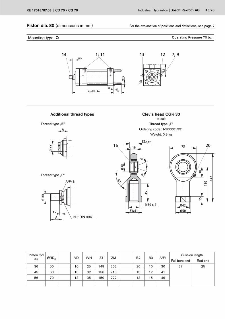
Piston dia. 80 (dimensions in mm) For the explanation of positions and defi nitions, see page 7
Mounting type: Q Operating Pressure 70 bar
WH
M10
99
73,5
ZJ+Hub
14 1; 11 13 12
358
7; 9
Piston rod dia ØRDf7 VD WH ZJ ZM B2 B3 A/F1
Cushion length
Full bore end Rod end
36 50 10 25 149 202 20 10 30 27 25
45 60 13 32 156 216 13 12 41
56 70 13 35 159 222 13 15 46
Additional thread types Clevis head CGK 30to suit
Thread type „F”
Ordering code.: R900001331
Weight: 0,9 kg
Thread type „F“
Thread type „E”
Nut DIN 936
A/F46
12
Stroke

44/78 Bosch Rexroth AG Industrial Hydraulics CD 70 / CG 70 RE 17016/07.03
Piston dia. 100 (dimensions in mm) For the explanation of positions and defi nitions, see page 7
Mounting type: B Operating Pressure 70 bar
A
A
A-ASW1
R42Ø
106
WH 42
ØKK
B316
A
45 33 1555
EED1; 0,5 15
79 114
114
8320
1820–0,18
Ø25
7°7°
XN+Hub
14 1; 11 13 12 16
83
7 920
Mounting type: G Operating Pressure 70 bar
A
A-A
A
83 +
1,5
33 +0,5
6577
83
R24
Ø19,1 f7H7
32
12
XC + Hub
WH
14 1; 11 13 12 7 17 9
Mounting type: C Operating Pressure for rod dia 45 and 50: 25 bar at cap end; 70 bar rod end Operating Pressure for rod dia 70: 15 bar at cap end; 70 bar rod end
ØRD
16
VDWH
12
M12
MA = 80 Nm
„Y”
114
84,5
11
160138
114
„X”
ZJ+Hub ZM+2xHubWH+Hub
14 1; 11 13 12
83
7; 9
Strokemin = 45 mm for thread type „E“(only for double rod cylinders)
Piston rod dia
KK A EE D1Thread type Port
C, E B F C, E, B F 01 13 02 14 01 13 02 1445 M33 x 2 M39 x 2 M39 x 3 51 65 G 1/2 G 3/4 M22 x 1,5 M26 x 1,5 34 34 34 3450 M39 x 2 M45 x 2 M39 x 3 57 6570 M48 x 2 M56 x 2 M39 x 3 76 65
Stroke
Stroke
Stroke StrokeStroke
A/F1

Industrial Hydraulics Bosch Rexroth AGRE 17016/07.03 CD 70 / CG 70 45/78
Piston dia. 100 (dimensions in mm) For the explanation of positions and defi nitions, see page 7
Mounting type: H Operating Pressure 70 bar
ØRD
WH
160138114
84,516
VD
160
138
114
84,5
11
„X”„Y”
ZJ+Hub
ZM+2xHubWH+Hub
14 1; 11 13 12
83
7; 918
Strokemin = 45 mm for thread type „E“(only for double rod cylinders)
Mounting type: D Operating Pressure 70 bar
16
160138
114
114
84,5
11
WH
ZF+Hub
14 1; 11 13 12
83
7
Mounting type: K Operating Pressure 70 bar
84,5114138160
84,5
114
138
160
1183
WH
ZF+Hub16
14 1; 11 19 13 12 7; 9
Piston rod dia ØRDf7 VD WH XC XN ZF ZJ ZM B3 A/F1
Cushion length
Full bore end rod end
45 60 13 32 188 226 172 156 216 12 41 27 25
50 66,6 13 35 191 229 175 159 222 15 46
70 90 16 41 197 235 181 165 234 15 60
Stroke
StrokeStroke
Stroke
Stroke

46/78 Bosch Rexroth AG Industrial Hydraulics CD 70 / CG 70 RE 17016/07.03
Piston dia. 100 (dimensions in mm) For the explanation of positions and defi nitions, see page 7
Mounting type: R Operating Pressure 70 bar
WH+HubØ
25,4
–0,
03
114 –0,316 259
XG25
7
114
+1,
5 83 +
1,5
R2„X”„Y”
45B3
XGA
33
15VD42WH
EED1; 0,5
Ø10
6
ØRD
ØKK
SW1
ZJ+Hub
ZM+2xHub
14 1; 11 7; 9
13 12Strokemin = 45 mm for thread type „E“
(only for double rod cylinders)
Mounting type: E Operating Pressure 70 bar
Ø25
,4 –
0,03
50
12
133 –0,3 2525
83
135
+1,
6
114
R2
MA = 80 Nm
M12
„X”„Y”
WH
XV+Hub/2ZJ+Hub
XV+Hub/2ZM+2xHub
WH+Hub
14 1; 11 7; 9
13 12Strokemin = 20 mm Strokemin = 45 mm for thread type „E“
(only for double rod cylinders)
Mounting type: S Operating Pressure 70 bar
Ø25
,4 –
0,03
33
83 +
1,5
25 25114 –0,3
R2
WH
XJ+HubZJ+Hub
114
+1,
5
14 1; 11
13 12
7; 9
Piston rod dia
KK A EE D1Thread type Port
C, E B F C, E, B F 01 13 02 14 01 13 02 1445 M33 x 2 M39 x 2 M39 x 3 51 65 G 1/2 G 3/4 M22 x 1,5 M26 x 1,5 34 34 34 3450 M39 x 2 M45 x 2 M39 x 3 57 6570 M48 x 2 M56 x 2 M39 x 3 76 65
StrokeStroke
Stroke/2
Stroke
Stroke
Stroke/2 StrokeStroke
StrokeStroke
A/F1

Industrial Hydraulics Bosch Rexroth AGRE 17016/07.03 CD 70 / CG 70 47/78
Piston dia. 100 (dimensions in mm) For the explanation of positions and defi nitions, see page 7
Mounting type: F Operating Pressure 70 bar
Ø20
Ø1428,5
114
164+1,6
201
57,1
h10
WH
28,5
„Y”„X”
139,5
15
79
82,5+HubZJ+Hub
95+HubZM+2xHub
WH+Hub
114+
1,5
14 1;11 13 12
83 +
1,5
7; 9
Strokemin = 45 mm for thread type „E“(only for double rod cylinders)
Mounting type: L Operating Pressure 70 bar
WH
14 –0,07
8 –0
,2
8 –0
,2
14 –0,07
„X”„Y”
57,1
h10
ZJ+Hub ZM+2xHubWH+Hub
14 1; 11 13 12
83 +
1,5
7; 9
Strokemin = 45 mm for thread type „E“(only for double rod cylinders)
Mounting type: M Operating Pressure 70 bar
WH
42,5Ø24
Ø1642,5
„X”„Y”
57,1
h10
67+HubZJ+Hub
O-Ringe 19x2,5 67+HubZM+2xHub
WH+Hub
14 13 12
Strokemin = 45 mm for thread type „E“(only for double rod cylinders)
Piston rod dia ØRDf7 VD WH XG XJ XV ZJ ZM B3 A/F1
Cushion length
Full bore end Rod end
45 60 13 32 70 140 108 156 216 12 41 27 25
50 66,6 13 35 73 143 111 159 222 15 46
70 90 16 41 79 149 117 165 234 15 60
StrokeStroke
StrokeStroke
Stroke
StrokeStrokeStroke
StrokeStroke
StrokeStroke
Stroke

48/78 Bosch Rexroth AG Industrial Hydraulics CD 70 / CG 70 RE 17016/07.03
Piston dia. 100 (dimensions in mm) For the explanation of positions and defi nitions, see page 7
Mounting type: N Operating Pressure 70 bar
M12
WHMA = 80 Nm
M12
57–0
,2
B211
4114
52 42,5
„X”„Y”33
12AB3
1642,5
45
ØKK
SW1
ØRD
VD42
EED1; 0,5
15
Ø10
6
79
83
67+HubZJ+Hub
67+HubZM+2xHub
WH+Hub
14 1; 11 13 12
20
7; 9
Strokemin = 45 mm for thread type „E“(only for double rod cylinders)
Mounting type: T Operating Pressure 70 bar
57,1
–0,
2
0,2
–0,4
14 –0,07
8 –0
,2
„Y”
„Y”
Ø11Ø18Ø11
261124,5 12,5
WH
325
83
84,584,5
32
114
83
174,5+Hub
14 1; 11 13 12 7 9
Mounting type: P Operating Pressure 70 bar
35
WH
M12
119,5
RD
„X”„Y”
VD
ZJ+Hub ZM+2xHubWH+Hub
14 1; 11 13 12
83
7; 9
Strokemin = 45 mm for thread type „E“(only for double rod cylinders)
Piston rod dia
KK A EE D1Thread type Port
C, E B F C, E, B F 01 13 02 14 01 13 02 1445 M33 x 2 M39 x 2 M39 x 3 51 65 G 1/2 G 3/4 M22 x 1,5 M26 x 1,5 34 34 34 3450 M39 x 2 M45 x 2 M39 x 3 57 6570 M48 x 2 M56 x 2 M39 x 3 76 65
StrokeStroke
Stroke
Stroke
StrokeStrokeStrokeStroke
Stroke
A/F1

50˚
7˚7˚
23
28-0,12
Ø40
M39 x 3
SW55
65
142 19
0
4418
92
Ø52
Ø65
16 20
A
Ø K
K
Ø K
K
A
Industrial Hydraulics Bosch Rexroth AGRE 17016/07.03 CD 70 / CG 70 49/78
Piston dia. 100 (dimensions in mm) For the explanation of positions and defi nitions, see page 7
Mounting type: Q Operating Pressure 70 bar
WH
M12
119,5
83
ZJ+Hub
14 1; 11 13 12
3510
7; 9
Piston rod dia ØRDf7 VD WH ZJ ZM B2 B3 A/F1
Cushion length
Full bore end Rod end
45 60 13 32 156 216 25 12 41 27 25
50 66,6 13 35 159 222 20 15 46
70 90 16 41 165 234 15 15 60
Additional thread types Clevis head CGK 40to suit
Thread type „F”
Ordering code.: R900001332
Weight: 2 kg
Thread type „F“
Thread type „E”
Nut DIN 936
A/F60
16
Stroke

50/78 Bosch Rexroth AG Industrial Hydraulics CD 70 / CG 70 RE 17016/07.03
Piston dia. 125 (dimensions in mm) For the explanation of positions and defi nitions, see page 7
Mounting type: B Operating Pressure 70 bar
A
A
A-ASW1
R55Ø
135
WH 42
ØKK
1516
A
45 33 1565
EED1; 0,5 15
79 140
140
9630
2022–0,18
Ø30
6°6°
XN+Hub
14 1; 11 13 12 16
96
7 920
Mounting type: G Operating Pressure 70 bar
A
A-A
A
96 +
1,5
33 +0,5
6577
96
R24
Ø19,1 f7H7
32
13
XC + Hub
WH
14 1; 11 13 12 7 17 9
Mounting type: C Operating Pressure for rod dia 50 und 56: 15 bar at cap end; 70 bar Rod endOperating Pressure for rod dia 63 und 90: 10 bar at cap end; 70 bar Rod end
ØRD
16
VDWH
13
M14
MA = 125 Nm
„Y”
140
104
14
195168
140
„X”
ZJ+Hub ZM+2xHubWH+Hub
14 1; 11 13 12
96
7; 9
Strokemin = 55 mm for thread type „E“(only for double rod cylinders)
Piston rod dia
KK A EE D1Thread type Port
C, E B F C, E, B F 01 13 02 14 01 13 02 1450 M39 x 2 M45 x 2 M42 x 3 57 65 G 1/2 G 3/4 M22 x 1,5 M26 x 1,5 34 34 34 3456 M39 x 2 M45 x 2 M42 x 3 57 6563 M48 x 2 M56 x 2 M42 x 3 76 6590 M64 x 2 M76 x 2 M42 x 3 89 65
Stroke
Stroke
StrokeStrokeStroke
A/F1

Industrial Hydraulics Bosch Rexroth AGRE 17016/07.03 CD 70 / CG 70 51/78
Piston dia. 125 (dimensions in mm) For the explanation of positions and defi nitions, see page 7
Mounting type: H Operating Pressure 70 bar
ØRD
WH
19516814010416
VD
195
168
140
104
14
„X”„Y”
ZJ+Hub
ZM+2xHubWH+Hub
14 1; 11 13 12
96
7; 918
Strokemin = 55 mm for thread type „E“(only for double rod cylinders)
Mounting type: D Operating Pressure 70 bar
16
195168
140
140
104
14
WH
ZF+Hub
14 1; 11 13 12
96
7; 9
Mounting type: K Operating Pressure 70 bar
104140168195
104
140
168
195
1496
WH
ZF+Hub16
14 1; 11 19 13 12 7; 9
Piston rod dia ØRDf7 VD WH XC XN ZF ZJ ZM A/F1
Cushion length
Full bore end Rod end
50 66,6 13 35 197 245 181 165 228 46 27 25
56 70 13 35 197 245 181 165 228 46
63 79,3 16 41 203 251 187 171 240 55
90 108 16 41 203 251 187 171 240 75
Stroke
Stroke
StrokeStroke
Stroke

52/78 Bosch Rexroth AG Industrial Hydraulics CD 70 / CG 70 RE 17016/07.03
Piston dia. 125 (dimensions in mm) For the explanation of positions and defi nitions, see page 7
Mounting type: R Operating Pressure 70 bar
WH+HubØ
25,4
–0,
03
140 –0,316 259
XG25
7
140
+1,
6 96 +
1,5
R2„X”„Y”
4515
XGA
33
15VD42WH
EED1; 0,5
Ø13
5
ØRD
ØKK
SW1
ZJ+Hub
ZM+2xHub
14 1; 11 7; 9
13 12Strokemin = 55 mm for thread type „E“
(only for double rod cylinders)
Mounting type: E Operating Pressure 70 bar
Ø25
,4 –
0,03
50
13
159 –0,3 2525
96
160
+1,
6
140
R2
MA = 125 Nm
M14
„X”„Y”
WH
XV+Hub/2ZJ+Hub
XV+Hub/2ZM+2xHub
WH+Hub
14 1; 11 7; 9
13 12Strokemin = 20 mm Strokemin = 55 mm for thread type „E“
(only for double rod cylinders)
Mounting type: S Operating Pressure 70 bar
Ø25
,4 –
0,03
33
96 +
1,5
25 25140 –0,3
R2
WH
XJ+HubZJ+Hub
140
+1,
6
14 1; 11
13 12
7; 9
Piston rod dia
KK A EE D1Thread type Port
C, E B F C, E, B F 01 13 02 14 01 13 02 1450 M39 x 2 M45 x 2 M42 x 3 57 65 G 1/2 G 3/4 M22 x 1,5 M26 x 1,5 34 34 34 3456 M39 x 2 M45 x 2 M42 x 3 57 6563 M48 x 2 M56 x 2 M42 x 3 76 6590 M64 x 2 M76 x 2 M42 x 3 89 65
Stroke
Stroke
StrokeStroke
Stroke/2Stroke/2
Stroke
Stroke Stroke
Stroke
A/F1

Industrial Hydraulics Bosch Rexroth AGRE 17016/07.03 CD 70 / CG 70 53/78
Piston dia. 125 (dimensions in mm) For the explanation of positions and defi nitions, see page 7
Mounting type: F Operating Pressure 70 bar
Ø33
Ø2333,5
140
210+1,8
251
69,8
h10
WH
33,5
„Y”„X”
174,5
30
79
79,5+HubZJ+Hub
91+HubZM+2xHub
WH+Hub
140+
1,6
14 1;11 13 12
96 +
1,5
7; 9
Strokemin = 55 mm for thread type „E“(only for double rod cylinders)
Mounting type: L Operating Pressure 70 bar
WH
14 –0,07
8 –0
,2
8 –0
,2
14 –0,07
„X”„Y”
69,8
h10
ZJ+Hub ZM+2xHubWH+Hub
14 1; 11 13 12
96 +
1,5
7; 9
Strokemin = 55 mm for thread type „E“(only for double rod cylinders)
Mounting type: M Operating Pressure 70 bar
WH
42,5Ø24
Ø1642,5
„X”„Y”
69,8
h10
73+HubZJ+Hub
O-Ringe 19x2,5 73+HubZM+2xHub
WH+Hub
14 13 12
Strokemin = 55 mm for thread type „E“(only for double rod cylinders)
Piston rod dia ØRDf7 VD WH XG XJ XV ZJ ZM A/F1
Cushion length
Full bore end Rod end
50 66,6 13 35 73 149,5 114 165 228 46 27 25
56 70 13 35 73 149,5 114 165 228 46
63 79,3 16 41 79 155,5 120 171 240 55
90 108 16 41 79 155,5 120 171 240 75
Stroke Stroke
Stroke Stroke
Stroke
Stroke
Stroke Stroke
Stroke Stroke
Stroke
Stroke Stroke

54/78 Bosch Rexroth AG Industrial Hydraulics CD 70 / CG 70 RE 17016/07.03
Piston dia. 125 (dimensions in mm) For the explanation of positions and defi nitions, see page 7
Mounting type: N Operating Pressure 70 bar
M16
WHMA = 125 Nm
M14
70–0
,2
B214
0140
66 42,5
„X”„Y”33
13A15
1642,5
45
ØKK
SW1
ØRD
VD42
EED1; 0,5
15
Ø13
5
79
96
73+HubZJ+Hub
73+HubZM+2xHub
WH+Hub
14 1; 11 13 12
30
7; 9
Strokemin = 55 mm for thread type „E“(only for double rod cylinders)
Mounting type: T Operating Pressure 70 bar
70 –
0,2
0,2
–0,4
14 –0,07
8 –0
,2
„Y”
„Y”
Ø14Ø20Ø14
271327 13
WH
386
96
104104
38
140
96
184+Hub
14 1; 11 13 12 7 9
Mounting type: P Operating Pressure 70 bar
45
WH
M14
150
RD
„X”„Y”
VD
ZJ+Hub ZM+2xHubWH+Hub
14 1; 11 13 12
96
7; 9
Strokemin = 55 mm for thread type „E“(only for double rod cylinders)
Piston rod dia
KK A EE D1Thread type Port
C, E B F C, E, B F 01 13 02 14 01 13 02 1450 M39 x 2 M45 x 2 M42 x 3 57 65 G 1/2 G 3/4 M22 x 1,5 M26 x 1,5 34 34 34 3456 M39 x 2 M45 x 2 M42 x 3 57 6563 M48 x 2 M56 x 2 M42 x 3 76 6590 M64 x 2 M76 x 2 M42 x 3 89 65
Stroke Stroke Stroke
Stroke Stroke
Stroke
Stroke Stroke
Stroke
A/F1

50˚
7˚7˚
27
32-0,12
Ø45
M42 x 3
SW60
65
145 19
9
4820
102
Ø58
Ø70
16 20
A
Ø K
K
Ø K
K
A
Industrial Hydraulics Bosch Rexroth AGRE 17016/07.03 CD 70 / CG 70 55/78
Piston dia. 125 (dimensions in mm) For the explanation of positions and defi nitions, see page 7
Mounting type: Q Operating Pressure 70 bar
WH
M14
150
96
ZJ+Hub
14 1; 11 13 12
4511
7; 9
Piston rod dia ØRDf7 VD WH ZJ ZM B2 A/F1
Cushion length
Full bore end Rod end
50 66,6 13 35 165 228 25 46 27 25
56 70 13 35 165 228 25 46
63 79,3 16 41 171 240 19 55
90 108 16 41 171 240 19 75
Additional thread types Clevis head CGK 45to suit
Thread type „F”
Ordering code.: R900001333
Weight: 2,7 kg
Thread type „F“
Thread type „E”
Nut DIN 936
A/F65
16
Stroke

56/78 Bosch Rexroth AG Industrial Hydraulics CD 70 / CG 70 RE 17016/07.03
Piston dia. 150 (dimensions in mm) For the explanation of positions and defi nitions, see page 7
Mounting type: B Operating Pressure 50 bar
A
A
A-ASW1
R70Ø
160
38 48
ØKK
1519
A
51 40 2080
EED1; 0,5 18
1216 165
165 11
2,5
35
2325–0,12
Ø35
6°6°
284+Hub
14 1; 11 13 12 16
112,
5
7 920
Mounting type: G Operating Pressure 50 bar
A
A-A
A
112,
5 +
1,5
40 +0,5
8092
112,
5R30
Ø25,4 f7H7
38
15
222+Hub
38
14 1; 11 13 12 7 17 9
Mounting type: C Operating Pressure for rod dia 63 und 70: 20 bar at cap end; 50 bar Rod endOperating Pressure for rod dia 80 und 100: 15 bar at cap end; 50 bar Rod end
ØRD
19
1338
15
M16
MA = 195 Nm
„Y”
165
124
14
220193,5
165
„X”
184+Hub 252+2xHub38+Hub
14 1; 11 13 12
112,
5
7; 9
Strokemin = 75 mm for thread type „E“(only for double rod cylinders)
Piston rod dia
KK A EE D1Thread type Port
C, E B F C, E, B F 01 13 02 14 01 13 02 1463 M48 x 2 M56 x 2 M45 x 3 76 68 G 3/4 G 1 M26 x 1,5 M33 x 2 42 42 42 4270 M48 x 2 M56 x 2 M45 x 3 76 6880 M58 x 2 M68 x 2 M45 x 3 89 68
100 M76 x 2 M95 x 2 M45 x 3 101 68
Stroke
Stroke
Stroke Stroke
Stroke
A/F1

Industrial Hydraulics Bosch Rexroth AGRE 17016/07.03 CD 70 / CG 70 57/78
Piston dia. 150 (dimensions in mm) For the explanation of positions and defi nitions, see page 7
Mounting type: H Operating Pressure 50 bar
ØRD
38
220193,5
16512419
13
220
193,
516
512
4
14
„X”„Y”
184+Hub
252+2xHub38+Hub
14 1; 11 13 12
112,
5
7; 918
Strokemin = 75 mm for thread type „E“(only for double rod cylinders)
Mounting type: D Operating Pressure 50 bar
19
220193,5165
165
124
14
38
203+Hub
14 1; 11 13 12
112,
5
7; 9
Mounting type: K Operating Pressure 50 bar
124165
193,5220
124
165
193,
522
0
1411
2,5
38
203+Hub19
14 1; 11 19 13 12 7; 9
Piston rod dia ØRDf7 A/F1
Cushion length
Full bore end Rod end
63 79,3 55 32 30
70 90 60
80 95,2 75
100 120 85
Stroke
Stroke
Stroke Stroke
Stroke

58/78 Bosch Rexroth AG Industrial Hydraulics CD 70 / CG 70 RE 17016/07.03
Piston dia. 150 (dimensions in mm) For the explanation of positions and defi nitions, see page 7
Mounting type: R Operating Pressure 50 bar
38+HubØ
34,9
2 –0
,03
165 –0,319 3516
82,535
12
165
+1,
6
112,
5 +
1,5
R2„X”„Y”
5115
82,5A
40
18134838
EED1; 0,5
Ø16
0
ØRD
ØKK
SW1
184+Hub
252+2xHub
14 1; 11 7; 9
13 12Strokemin = 75 mm for thread type „E“
(only for double rod cylinders)
Mounting type: E Operating Pressure 50 bar
Ø34
,92
–0,0
3
64
15
194 –0,3 3535
112,
5
195
+1,
8
165
R2
MA = 195 Nm
M16
„X”„Y”
38
126+Hub/2184+Hub
126+Hub/2252+2xHub
38+Hub
14 1; 11 7; 9
13 12Strokemin = 30 mm Strokemin = 75 mm for thread type „E“
(only for double rod cylinders)
Mounting type: S Operating Pressure 50 bar
Ø34
,92
–0,0
3
40
112,
5 +
1,5
35 35165 –0,3
R2
38
165+Hub184+Hub
165
+1,
6
14 1; 11
13 12
7; 9
Piston rod dia
KK A EE D1Thread type Port
C, E B F C, E, B F 01 13 02 14 01 13 02 1463 M48 x 2 M56 x 2 M45 x 3 76 68 G 3/4 G 1 M26 x 1,5 M33 x 2 42 42 42 4270 M48 x 2 M56 x 2 M45 x 3 76 6880 M58 x 2 M68 x 2 M45 x 3 89 68
100 M76 x 2 M95 x 2 M45 x 3 101 68
Stroke Stroke
Stroke
Stroke/2 Stroke
Stroke Stroke Stroke x2
Stroke
Stroke
A/F1

Industrial Hydraulics Bosch Rexroth AGRE 17016/07.03 CD 70 / CG 70 59/78
Piston dia. 150 (dimensions in mm) For the explanation of positions and defi nitions, see page 7
Mounting type: F Operating Pressure 50 bar
Ø33
Ø2336,5
165
235+1,8
251
82,5
h10
38
36,5
„Y”„X”
200
35
1216
92+Hub184+Hub
103+Hub252+2xHub
38+Hub
165+
1,6
14 1;11 13 12
112,
5 +
1,5
7; 9
Strokemin = 75 mm for thread type „E“(only for double rod cylinders)
Mounting type: L Operating Pressure 50 bar
38
18 –0,07
9,5
–0,2
9,5
–0,2
18 –0,07
„X”„Y”
82,5
h10
184+Hub 252+2xHub38+Hub
14 1; 11 13 12
112,
5 +
1,5
7; 9
Strokemin = 75 mm for thread type „E“(only for double rod cylinders)
Mounting type: M Operating Pressure 50 bar
38
48,5Ø30
Ø2248,5
„X”„Y”
82,5
h10
79+Hub184+Hub
O-Ringe 25x2,5 79+Hub252+2xHub
38+Hub
14 13 12
Strokemin = 75 mm for thread type „E“(only for double rod cylinders)
Piston rod dia ØRDf7 A/F1
Cushion length
Full bore end Rod end
63 79,3 55 32 30
70 90 60
80 95,2 75
100 120 85
Stroke
Stroke
Stroke Stroke
Stroke Stroke
Stroke
Stroke Stroke
Stroke Stroke
Stroke Stroke

60/78 Bosch Rexroth AG Industrial Hydraulics CD 70 / CG 70 RE 17016/07.03
Piston dia. 150 (dimensions in mm) For the explanation of positions and defi nitions, see page 7
Mounting type: N Operating Pressure 50 bar
M20
38MA = 195 Nm
M16
82,5
–0,2
B216
5165
80 48,5
„X”„Y”40
15A15
1948,5
51
ØKK
SW1
ØRD
1348
EED1; 0,5
18
Ø16
0
1216
112,
5
79+Hub184+Hub
79+Hub252+2xHub
38+Hub
14 1; 11 13 12
35
7; 9
Strokemin = 75 mm for thread type „E“(only for double rod cylinders)
Mounting type: T Operating Pressure 50 bar
82,5
–0,
2
0,2
–0,4
18 –0,07
9,5
–0,2
„Y”
„Y”
Ø14Ø1425,514,5
25,5 14,5
38
40
112,
5
124124
40
165
112,
5
197+Hub
14 1; 11 13 12 7 9
Mounting type: P Operating Pressure 50 bar
45
38
M16
177
RD
„X”„Y”
13
184+Hub 252+2xHub38+Hub
14 1; 11 13 12
112,
5
7; 9
Strokemin = 75 mm for thread type „E“(only for double rod cylinders)
Piston rod dia
KK A EE D1Thread type Port
C, E B F C, E, B F 01 13 02 14 01 13 02 1463 M48 x 2 M56 x 2 M45 x 3 76 68 G 3/4 G 1 M26 x 1,5 M33 x 2 42 42 42 4270 M48 x 2 M56 x 2 M45 x 3 76 6880 M58 x 2 M68 x 2 M45 x 3 89 68
100 M76 x 2 M95 x 2 M45 x 3 101 68
Stroke Stroke
Stroke
Stroke Stroke Stroke
Stroke Stroke
Stroke
A/F1

50˚
6˚6˚
30
35-0,12
Ø50
M45 x 3
SW65
68
160 22
1
5820
112
Ø62
Ø75
16 20
A
Ø K
K
Ø K
K
A
Industrial Hydraulics Bosch Rexroth AGRE 17016/07.03 CD 70 / CG 70 61/78
Piston dia. 150 (dimensions in mm) For the explanation of positions and defi nitions, see page 7
Mounting type: Q Operating Pressure 50 bar
38
M16
177
112,
5
184+Hub
14 1; 11 13 12
4513
7; 9
Piston rod dia ØRDf7 B2 A/F1
Cushion length
Full bore end Rod end
63 79,3 35 55 32 30
70 90 35 60
80 95,2 30 75
100 120 25 85
Additional thread types Clevis head CGK 50to suit
Thread type „F”
Ordering code.: R900001334
Weight: 3,5 kg
Thread type „F“
Thread type „E”
Nut DIN 936
A/F70
18
Stroke

62/78 Bosch Rexroth AG Industrial Hydraulics CD 70 / CG 70 RE 17016/07.03
Piston dia. 200 (dimensions in mm) For the explanation of positions and defi nitions, see page 7
Mounting type: B Operating Pressure 40 bar
A
A
A-ASW1
R80Ø
215
38 48
ØKK
1519
A
51 40 2595
EED1; 0,5 18
1014 216
216
138
55
3032–0,12
Ø45
6°6°
307+Hub
14 1; 11 13 12 16
138
7 920
Mounting type: G Operating Pressure 40 bar
A
A-A
A
138
+1,
6
40 +0,5
8092
138R30
Ø25,4 f7H7
38
15
225+Hub
38
14 1; 11 13 12 7 17 9
M16
MA = 195 Nm
Piston rod dia
KK A EE D1Thread type Port
C, E B F C, E, B F 01 13 02 14 01 13 02 1490 M64 x 2 M76 x 2 M52 x 3 89 70 G 3/4 G 1 M26 x 1,5 M33 x 2 42 42 42 42
100 M76 x 2 M95 x 2 M52 x 3 101 70140 M100 x 2 M130 x 2 M52 x 3 140 70
Stroke
Stroke
A/F1

Industrial Hydraulics Bosch Rexroth AGRE 17016/07.03 CD 70 / CG 70 63/78
Piston dia. 200 (dimensions in mm) For the explanation of positions and defi nitions, see page 7
Mounting type: H Operating Pressure 40 bar
„Y” „X”
38+Hub255+2xHub17
,5B1192,5216
216
192,
5
187+Hub19
ØRD
1338
14 1; 11 13 12 7; 9
138
Strokemin = 115 mm for thread type „E“(only for double rod cylinders)
Mounting type: K Operating Pressure 40 bar
„Y”
“Y”
138
17,5192,5
192,
5
138
216
216
38
187+Hub40
14 1; 11 13 12 7; 9 9
Piston rod dia ØRDf7 B1 A/F1
Cushion length
Full bore end Rod end
90 108 140 75 32 30
100 120 140 85
140 158 178 120
Stroke Stroke
Stroke
Stroke

64/78 Bosch Rexroth AG Industrial Hydraulics CD 70 / CG 70 RE 17016/07.03
Piston dia. 200 (dimensions in mm) For the explanation of positions and defi nitions, see page 7
Mounting type: R Operating Pressure 40 bar
38+HubØ
34,9
2 –0
,03
216 –0,319 3514
82,535
10
216
+1,
8
138
+1,
6
R2„X”„Y”
5115
82,5A
40
18134838
EED1; 0,5
Ø21
5
ØRD
ØKK
SW1
187+Hub
255+2xHub
14 1; 11 7; 9
13 12Strokemin = 115 mm for thread type „E“
(only for double rod cylinders)
Mounting type: E Operating Pressure 40 bar
Ø34
,92
–0,0
3
64
15
248 –0,3 3535
138
250
+1,
8
216
R2
MA = 195 Nm
M16
„X”„Y”
38
127,5+Hub/2187+Hub
127,5+Hub/2255+2xHub
38+Hub
14 1; 11 7; 9
13 12Strokemin = 30 mm Strokemin = 115 mm for thread type „E“
(only for double rod cylinders)
Mounting type: S Operating Pressure 40 bar
Ø34
,92
–0,0
3
40
138
+1,
6
35 35216 –0,3
R2
38
168+Hub187+Hub
216
+1,
8
14 1; 11
13 12
7
Piston rod dia
KK A EE D1Thread type Port
C, E B F C, E, B F 01 13 02 14 01 13 02 1490 M64 x 2 M76 x 2 M52 x 3 89 70 G 3/4 G 1 M26 x 1,5 M33 x 2 42 42 42 42
100 M76 x 2 M95 x 2 M52 x 3 101 70140 M100 x 2 M130 x 2 M52 x 3 140 70
Stroke Stroke
Stroke
Stroke Stroke
Stroke Stroke/2
Stroke/2
Stroke Stroke
A/F1

Industrial Hydraulics Bosch Rexroth AGRE 17016/07.03 CD 70 / CG 70 65/78
Piston dia. 200 (dimensions in mm) For the explanation of positions and defi nitions, see page 7
Mounting type: F Operating Pressure 40 bar
Ø33
Ø2336,5
216
286+1,9
251
108h
10
38
36,5
„Y”„X”
251
55
1014
95+Hub187+Hub
106+Hub255+2xHub
38+Hub
216+
1,8
14 1;11 13 12
138
+1,
6
7; 9
Strokemin = 115 mm for thread type „E“(only for double rod cylinders)
Mounting type: M Operating Pressure 40 bar
38
48,5Ø30
Ø2248,5
„X”„Y”
108h
10
82+Hub187+Hub
O-Ringe 25x2,5 82+Hub255+2xHub
38+Hub
14 13 12
Strokemin = 115 mm for thread type „E“(only for double rod cylinders)
Piston rod dia ØRDf7 A/F1
Cushion length
Full bore end Rod end
90 108 75 32 30
100 120 85
140 158 120
Stroke Stroke Stroke
Stroke Stroke
Stroke Stroke Stroke
Stroke Stroke

66/78 Bosch Rexroth AG Industrial Hydraulics CD 70 / CG 70 RE 17016/07.03
Piston dia. 200 (dimensions in mm) For the explanation of positions and defi nitions, see page 7
Mounting type: N Operating Pressure 40 bar
114,5M20
38MA = 195 Nm
M16
108–
0,2
B221
6216
48,5
„X”„Y”40
15A15
1948,5
51
ØKK
SW1
ØRD
1348
EED1; 0,5
18
Ø21
5
1014
138
82+Hub187+Hub
82+Hub255+2xHub
38+Hub
14 1; 11 13 12
55
7; 9
Strokemin = 115 mm for thread type „E“(only for double rod cylinders)
Mounting type: P Operating Pressure 40 bar
58
38
M16
232
RD
„X”„Y”
13
187+Hub 255+2xHub38+Hub
14 1; 11 13 12
138
7; 9
Strokemin = 115 mm for thread type „E“(only for double rod cylinders)
Piston rod dia
KK A EE D1Thread type Port
C, E B F C, E, B F 01 13 02 14 01 13 02 1490 M64 x 2 M76 x 2 M52 x 3 89 70 G 3/4 G 1 M26 x 1,5 M33 x 2 42 42 42 42
100 M76 x 2 M95 x 2 M52 x 3 101 70140 M100 x 2 M130 x 2 M52 x 3 140 70
Stroke Stroke
Stroke
Stroke Stroke
Stroke Stroke
Stroke
A/F1

50˚
6˚6˚
38
44-0,12
Ø60
M52 x 3
SW75
70
175 24
6
6820
135
Ø70
Ø88
16 20
A
Ø K
K
Ø K
K
A
Industrial Hydraulics Bosch Rexroth AGRE 17016/07.03 CD 70 / CG 70 67/78
Piston dia. 200 (dimensions in mm) For the explanation of positions and defi nitions, see page 7
Mounting type: Q Operating Pressure 40 bar
38
M16
232
138
187+Hub
14 1; 11 13 12
5813
7; 9
Piston rod dia ØRDf7 B2 A/F1
Cushion length
Full bore end Rod end
90 108 40 75 32 30
100 120 40 85
140 158 28 120
Additional thread types Clevis head CGK 60to suit
Thread type „F”
Ordering code.: R900001335
Weight: 5,6 kg
Thread type „F“
Thread type „E”
Nut DIN 936
A/F80
20
Stroke

68/78 Bosch Rexroth AG Industrial Hydraulics CD 70 / CG 70 RE 17016/07.03
Weight
Piston dia. mm 25 32 40 50
Piston rod dia mm 12 16 18 22 25 16 18 25 22 25 36
Weight per 100 mm Stroke
in kg
Single rod cylinder 0,3 0,37 0,5 0,6 0,7 0,55 0,6 0,8 0,9 1,0 1,3
Double rod cylinder 0,4 0,52 0,7 0,9 1,0 0,75 0,8 1,2 1,2 1,3 2,1
Mounting type CD CG CD CG CD CG CD CG
Weight bei 0-Stro-ke in kg
B 1,2 – 1,9 – 2,4 – 4,0 –
G – – 1,7 – 2,2 – 3,7 –
E 1,2 1,5 2,2 2,5 2,9 3,5 4,5 6,0
H 1,2 1,5 1,9 2,4 2,5 3,0 4,0 5,3
K, D 1,4 – 2,2 – 2,7 – 4,5 –
C, F, L, M, R, S, T 1,1 1,4 1,8 2,3 2,3 2,8 3,7 5,0
N, P, Q 1,1 1,4 1,5 2,0 2,0 2,6 3,4 4,7
Piston dia. mm 63 80 100
Piston rod dia mm 25 28 36 45 36 45 56 45 50 70
Weight per100 mm Stroke
in kg
Single rod cylinder 1,1 1,2 1,5 1,9 1,7 2,2 2,8 2,4 2,7 4,1
Double rod cylinder 1,5 1,6 2,1 3,0 2,5 3,4 4,7 3,6 4,3 7,1
Mounting type CD CG CD CG CD CG
Weight bei 0-Stro-ke in kg
B 5,9 – 10,8 – 16,2 –
G 5,5 – 10,0 – 15,2 –
E 6,7 8,5 12,4 16,2 25,3 31,4
H 5,9 8,0 10,7 14,4 15,3 21,7
K, D 6,5 – 11,8 – 17,6 –
C, F, L, M, R, S, T 5,5 7,6 9,9 13,7 14,9 21,4
N, P, Q 5,2 7,3 9,2 12,9 13,5 20,0
Piston dia. mm 125 150 200
Piston rod dia mm 50 56 63 90 63 70 80 100 90 100 140
Weight per100 mm Stroke
in kg
Single rod cylinder 3,5 3,9 4,4 7,9 5,1 5,6 6,6 8,7 9,5 10,7 17,7
Double rod cylinder 5,4 5,8 6,9 12,0 7,6 8,6 10,6 14,8 14,5 16,9 29,8
Mounting type CD CG CD CG CD CG
Weight bei 0-Stro-ke in kg
B 26,7 – 40,7 – 75,4 –
G 25,5 – 39,0 – 72,0 –
E 29,3 40,1 47,1 62,1 84,8 111,1
H 26,9 37,7 40,7 55,7 68,2 94,5
K, D 29,3 – 44,8 – 70,4 –
C, F, L, M, R, S, T 25,2 36,0 38,5 53,5 71,6 98,0
N, P, Q 24,1 34,9 37,2 52,2 70,7 97,0
CD = Single rod cylinder
CG = Double rod cylinder

I
I
I
Industrial Hydraulics Bosch Rexroth AGRE 17016/07.03 CD 70 / CG 70 69/78
Permissible stroke lengths
Piston dia. in mm
Piston rod dia. in
mm
Mounting types:
C, F, H, L, M, N, P, T
Mounting types:
D, K, Q
Maximum available Stroke lengthin mm
(Standard)
Operating Pressure in bar Operating Pressure in bar40 50 70 105 40 50 70 105
Max. stroke in mm Max. stroke in mm
25 12 600 600 530 425 460 410 330 250 60016 600 600 600 600 600 600 600 520
32 18 800 800 800 800 580 500 420 325 80022 800 800 800 800 800 760 630 50025 800 800 800 800 800 800 800 745
40 16 805 715 585 465 350 300 240 175 100018 1000 920 770 610 450 390 320 25025 1000 1000 1000 1000 900 780 635 500
50 22 1200 1090 900 720 540 460 360 280 120025 1200 1200 1200 965 765 670 550 43036 1200 1200 1200 1200 1200 1200 1110 890
63 25 1255 1115 920 – 570 500 405 – 140028 1400 1400 1130 – 700 610 490 –36 1400 1400 1400 – 1310 1160 960 –45 1400 1400 1400 – 1400 1400 1390 –
80 36 1700 1700 1545 – 910 800 630 – 170045 1700 1700 1700 – 1620 1435 1190 –56 1700 1700 1700 – 1700 1700 1670 –
100 45 2000 2000 1930 – 1170 1020 820 – 200050 2000 2000 2000 – 1580 1395 1155 –70 2000 2000 2000 – 2000 2000 2000 –
125 50 2300 2300 2300 – 1220 1075 885 – 230056 2300 2300 2300 – 1470 1290 1140 –63 2300 2300 2300 – 2035 1805 1500 –90 2300 2300 2300 – 2300 2300 2300 –
150 63 2600 2600 – – 1670 1465 – – 260070 2600 2600 – - 1890 1680 – –80 2600 2600 – – 2600 2470 – –
100 2600 2600 – – 2600 2600 – –200 90 3000 – – – 2380 – – – 3000
100 3000 – – – 3000 – – –140 3000 – – – 3000 – – –
Max
. str
oke
Max
. str
oke
sK = I • 12
sK = I • 12
Max
. str
oke

I
I
70/78 Bosch Rexroth AG Industrial Hydraulics CD 70 / CG 70 RE 17016/07.03
sK = I
Max
. str
oke
Permissible stroke lengths
Piston dia. in mm
Piston rod dia. in
mm
Mounting types:
B, G, S
Mounting type:
E
Maximum available Stroke lengthin mm
(standard)
Operating Pressure in bar Operating Pressure in bar40 50 70 105 40 50 70 105
Max. stroke in mm Max. stroke in mm
25 12 175 145 110 70 460 410 330 250 60016 390 340 275 200 600 600 600 520
32 18 390 340 300 200 580 500 420 325 80022 600 550 450 335 800 760 630 50025 800 745 615 480 800 800 800 690
40 16 200 165 120 80 320 275 215 160 100018 240 220 190 100 450 390 320 25025 600 550 450 335 900 780 635 500
50 22 375 300 245 170 540 460 360 280 120025 480 420 335 250 700 615 500 39036 1200 1000 820 700 1200 1200 1110 890
63 25 345 295 225 – 520 450 360 – 140028 500 410 340 – 700 610 490 –36 860 755 615 – 1205 1065 880 –45 1400 1250 1000 – 1400 1400 1390 –
80 36 680 580 420 – 680 580 420 – 170045 1070 940 765 – 1495 1325 1095 –56 1700 1500 1250 – 1700 1500 1250 –
100 45 800 740 600 – 800 740 600 – 200050 1030 900 730 – 1450 1275 1055 –70 2000 1900 1600 – 2000 1900 1600 –
125 50 775 670 535 – 1120 985 805 – 230056 1050 880 750 – 1050 880 750 –63 1345 1185 965 – 1880 1665 1375 –90 2300 2300 2200 – 2300 2300 2200 –
150 63 1065 925 – – 1525 1340 – – 260070 1350 1220 – – 1350 1220 – –80 1855 1635 – – 2580 2285 – –
100 2600 2600 – – 2600 2600 – –200 90 1750 – – – 1750 – – – 3000
100 2175 – – – 3000 – – –140 3000 – – – 3000 – – –
sK = I
Max
. str
oke

I
Industrial Hydraulics Bosch Rexroth AGRE 17016/07.03 CD 70 / CG 70 71/78
sK = I
Max
. str
oke
Permissible stroke lengths
Piston dia. in mm
Piston rod dia. in
mm
Mounting type:
R
Maximum available strokein mm
(standard)
Operating Pressure in bar40 50 70 105
Max. stroke in mm25 12 – – – – 600
16 – – – –32 18 800 800 670 520 800
22 800 800 800 80025 800 800 800 800
40 16 510 445 355 270 100018 720 625 510 40025 1000 1000 1000 800
50 22 865 735 575 450 120025 1085 955 785 61536 1200 1200 1200 1200
63 25 810 710 575 – 140028 1120 975 785 –36 1400 1400 1355 –45 1400 1400 1400 –
80 36 1455 1280 1010 – 170045 1700 1700 1675 –56 1700 1700 1700 –
100 45 1870 1630 1310 – 200050 2000 1955 1620 –70 2000 2000 2000 –
125 50 1720 1515 1245 – 230056 2300 2065 1680 –63 2300 2300 2105 –90 2300 2300 2300 –
150 63 2330 2055 – – 260070 2600 2600 – –80 2600 2600 – –
100 2600 2600 – –200 90 3000 – – – 3000
100 3000 – – –140 3000 – – –

2 1 2 13
72/78 Bosch Rexroth AG Industrial Hydraulics CD 70 / CG 70 RE 17016/07.03
Calculation for buckling
Calculations for buckling are normally carried out according to Euler, as the piston rod is normally considered as a slender column.
Bucklingload K =π2 • E • J
in NsK
2
i.e. at this load, the rod will buckle!
Maximum operating load F =K
in NS
sK = free buckling length in mm
E = module of elasticity in N/mm2 = 2,1 • 105 for steel
J = moment of inertia in mm4 for circular cross sectio-nal area
=d4 • π
= 0,0491 • d464
S = safety factor (3,5)
Stop tube extension
With long strokes and compressive loads, a stop tube is recommended in order to reduce bearing loads when the rod is extended. In this way, a distance bush (3) is inserted betweenn
piston (1) and cylinder head(2). This distance bush extends the lever arm and thus reduces the bearing loads.
Without stop tube extension With stop tube extension
Distance between bearings Distance between bearings
Mounting type Stop tube extension in mm for all piston diameters
– 25 50 75 100 125 150 175
Stroke length in mm
B, G, S to 500 501 to 625 626 to 750 751 to 875 876 to 1000
1001 to 1125
1126 to 1250
1251 to 3000
C, F, H, L to 1425 1426 to 1785
1786 to 2150
2151 to 2500
2501 to 2860
2861 to 3000
– –
D, E, K, Q to 665 666 to 835 836 to 1000
1001 to 1165
1166 to 1335
1336 to 1500
1501 to 1665
1666 to 3000
R to 1000 1001 to 1250
1251 to 1500
1501 to 1750
1751 to 2000
2001 to 2250
2251 to 2500
2501 to 3000
M, N, P, T to 1425 1426 to 1785
1786 to 2150
2151 to 2500
2501 to 2860
2861 to 3000
– –
Installation length of cylinders with stop tube extensions:
Installation length of standard cylinder + stop tube extension
(The position of the trunnions is not changed).

H
E
H
E
+
–
Industrial Hydraulics Bosch Rexroth AGRE 17016/07.03 CD 70 / CG 70 73/78
Inductive proximity switch (please state in clear text in the order)
Inductive proximity switches are used for reliably checking the end position of hydraulic cylinders. They are an important com-ponent for reliably and precisely monitoring safety equipment, locks and/or other machinery functions in their end position by issuing corresponding signals.
Depending on the cylinder version, the switching point is located 1 mm to 4 mm before the end of the stroke, with a repeatability of ≤ 0.5 mm.
For safety reasons, the proximity switch is protected against being screwed in too deeply. The switching distance can therefore not be changed.
– Reliable and precise check of end position
– Contactless and wear-free switching
– Pressure-tight up to max. 500 bar
– Due to integrated installation protection against damage and environmental infl uences
– Integrated short-circuit protection
Technical Data:
Maximum pressure resistance 500 bar
Operating voltage, incl. residual ripple content
10 to 30 V DC
Residual ripple content of the opera-ting voltage
max. 15 %
Output technology PNPSwitching function Normally openNo-load current ≤ 10 mALoad carrying capacity of the output: ≥ 200 ΩOutput resistance Ra and diode 4,7 kΩReproducibility ≤ 0,5 mmMaximum switching frequency 1 kHzShort-circuit-proof versionType of protection IP 67 (DIN 40050)Ambient temperature – 25 °C to + 70 °CType of connection 2 m cable, cast-in;
3 x 0,34 mm2
Note:
• Installation: 180° opposite to the line connec-tions
• Port: For enlarged line ports, please consult us
• Mounting type: With mounting types F, L, M, N and T the installation at 180° opposite to the port is not possible
• For mounting types and unit dimensions, see pages 8 to 67
Piston dia. in mm
Piston rod dia. in mm
H E 1) Piston dia. in mm
Piston rod dia. in mm
H E 1)
25 12 37,5 100 100 45 57 11916 50
32 18 42,5 105 70 83 13022 125 50 70 12225 56
40 16 42,5 105 63 – –18 90 96 14025 150 63 82,5 146
50 22 44,5 105 7025 8036 48 110 100
63 25 51 110 180 80 – –28 9036 12545 53 115 200 90 108 166
80 36 73,5 122 10045 14056 1) Installation space
Output circuit
brown
black
blue

WH
A0,
1
A AZ A
WH
XG
A0,
05
A
Z A
A0,
1
A0,
2
Z A
A 0,3 A
0,2
WH
XS
WH
74/78 Bosch Rexroth AG Industrial Hydraulics CD 70 / CG 70 RE 17016/07.03
Installation Lengths, Positional Tolerances
XN + Stroke
XJ + Stroke
XV + Stroke/2
ZF + Stroke
Stroke
SS + Stroke
Stroke length in mm
to 1250 1251 to 2000 2001 to 3000
Stroke tole-rance in mm
+ 1 + 1 + 1
– 1,5 – 2 – 3
WH ± 2 ± 2 + 3
– 2
ZF ± 1 ± 1,5 ± 2
XS ± 2 ± 2 + 3
– 2
SS ± 1,25 + 1,5 + 1,5
– 2 – 3
XG ± 2 ± 2 + 3
– 2
XV ± 2 ± 2 ± 2
XJ ± 2 ± 2 ± 2
XN ± 1,25 ± 2 ± 2
Z 0,1 / 100
retra
cted

5 3 6 8 9 7
1 2 10 11 4
Industrial Hydraulics Bosch Rexroth AGRE 17016/07.03 CD 70 / CG 70 75/78
Cushion
Cushioning at cylinder cap.
Piston (1) is threaded directly on to the cylinder rod. Cus-hioning bush (2) is held on to the cylinder rod by means of retaining ring (3).
As the tapered damping bush enters cylinder cap (4) the open area for the fl ow of oil into the cylinder cap (4) is very much reduced until it fi nally becomes zero. The fl uid can then only fl ow via drilling (6) and adjustable throttle valve (7). The degree of cushioning is controlled by the setting of throttle (7). The smaller the opening to fl ow, the greater the degree of cushioning.
Adjustable throttle valve
The design of the throttle valve prevents needle valve (8) from being completely screwed out when setting the cushioning. When the cushioning is correctly set, screw (8) is locked by means of nut (9).
Non return valve with bleed screw
Check valve (10) permits the throttle valve to be by-passed at the start of the outward stroke of the cylinder. The cylinder is bled of air by means of bleed screw (11).
The bleed screw is always present, even in cylinders without cushioning.
The throttle valve and check valve are interchangeable and may be interchanged in situ.
Seals (standard - version)
Piston rod seals
Piston seals Version "T"
Glide ring for low friction operation
Version "A"
Lip ring for leak free operati-on under static conditions
Version related to piston dia. 32/25 Version related to piston rod dia. 50, 63 and 80 mmmm

76/78 Bosch Rexroth AG Industrial Hydraulics CD 70 / CG 70 RE 17016/07.03
Calculation of deceleration force
The cushioning must produce a controlled deceleration of the cylinder, in both end positions.
In doing this, the total energy comprising the product of the moving mass and its velocity must not exceed the working parameters of the damping system.
The energy is converted into heat by means of throttling the out going fl uid in the cushioning zone.
Calculation of cushioning force
When the cylinder is installed horizontally, the deceleration force can be calculated as follows:
Cylinder extending
FB = m • a + AK • p
Cylinder retracting
FB = m • a + AR • p v = piston velocity in m/s
s = damping length in m
AK = piston area in cm2
AR = annulus area in cm2
p = system pressure in N/cm2
FB = deceleration force in N
m = moving mass in kg
a = deceleration in m/s2
a =v2
2 • s
1 bar ~ 10 N/cm2
For vertical operation of the cylinder, the pressure generated by the weight applied to the cylinder (consisting of the external load plus the cylinder rod and piston) must be added or sub-tracted dependent upon the direction of movement.
The cylinder friction is ignored in these calculations.
Calculation of mean damping pressure
Normally, the damping pressure may not exceed the nominal pressure of the cylinder.
pD =FB
AD
pD = mean damping pressure in N/cm2
FB = deceleration force in N
AD = effective damping area in cm2
1 bar ~ 10 N/cm2
If the above calculation results in a higher value, the damping length must be increased or the system pressure reduced.

35
36 35
3 6 5 1 4 11 20 21 2
33 34 37 8 7 35 9 10 1935
“X”
Industrial Hydraulics Bosch Rexroth AGRE 17016/07.03 CD 70 / CG 70 77/78
Spare parts diagram
Non return valve and bleed point for piston dia. 25 to 63
Throttle and non return valve cylinder cap and cylinder head
Version for
piston dia. 40 to 200
Version for
piston dia. 25 und 32
Ordering of spare parts:
– When designating individual parts from the spare parts diagram, please give complete ordering code of the cylinder.
– For seal sets, please give complete ordering code of the cylinder.
1 Head
2 Cap
3 Piston rod
4 Cylinder tube
5 Flange
6 Guide bush
7 Piston
8 Cushioning bush
9 Cushioning bush
10 Threaded ring
11 Tie rod
19 Nut
20 Guide ring
21 Piston seal
33 Wiper
34 Piston rod seal
35 O ring
36 Back-up ring
37 O ring
View"X"
Throttle valve forpiston dia. 25 to 63
Throttle valve forpiston dia. 80 to 200
Non return valve and bleed point for piston dia. 80 to 200

© 2003 by Bosch Rexroth AG, Industrial Hydraulics, 97813 Lohr am MainAll rights reserved. No part of the document may be reproduced or stored, processed, duplicated or circulated using electronic systems, in any form or bymeans, without the prior written authorisation of Bosch Rexroth AG, Industrial Hydraulics. In the event of contravention of the above provisions, the contravening party is obliged to bay compensation.
The data specifi ed above only serves to describe the product. No state-ments concerning a certain condition or suitability for a certain application can be derived from our information. The details stated do not release you from the responsibility for carrying out your own assessment and verifi -cation. It must be remembered that our products are subject to a natural process of wear and ageing.
Bosch Rexroth AGIndustrial HydraulicsZum Eisengießer 197816 Lohr am Main, GermanyTelefon +49 (0) 93 52 / 18-0Telefax +49 (0) 93 52 / 18-23 [email protected]
Bosch Rexroth Teknik ABVaruvägen 7, ÄlvsjöS-125 81 StockholmTelefon +46(08) 72 79 20 0Telefax +46(08) 86 87 [email protected]
78/78 Bosch Rexroth AG Industrial Hydraulics CD 70 / CG 70 RE 17016/07.03
Bosch Rexroth SABP 37 – Z.I. Les FourmisF-74131 Bonneville CedexTelefon +33(0)4 50 25 35 45Telefax +33(0)4 50 25 35 19www.boschrexroth.fr
Notes

© 2003 by Bosch Rexroth AG, Industrial Hydraulics, 97813 Lohr am MainAll rights reserved. No part of the document may be reproduced or stored, processed, duplicated or circulated using electronic systems, in any form or bymeans, without the prior written authorisation of Bosch Rexroth AG, Industrial Hydraulics. In the event of contravention of the above provisions, the contravening party is obliged to bay compensation.
The data specifi ed above only serves to describe the product. No state-ments concerning a certain condition or suitability for a certain application can be derived from our information. The details stated do not release you from the responsibility for carrying out your own assessment and verifi -cation. It must be remembered that our products are subject to a natural process of wear and ageing.
Industrial Hydraulics Bosch Rexroth AGRE 17016/07.03 CD 70 / CG 70 79/78
Bosch Rexroth AGIndustrial HydraulicsZum Eisengießer 197816 Lohr am Main, GermanyTelefon +49 (0) 93 52 / 18-0Telefax +49 (0) 93 52 / 18-23 [email protected]
Bosch Rexroth Teknik ABVaruvägen 7, ÄlvsjöS-125 81 StockholmTelefon +46(08) 72 79 20 0Telefax +46(08) 86 87 [email protected]
Bosch Rexroth SABP 37 – Z.I. Les FourmisF-74131 Bonneville CedexTelefon +33(0)4 50 25 35 45Telefax +33(0)4 50 25 35 19www.boschrexroth.fr
Notes

© 2003 by Bosch Rexroth AG, Industrial Hydraulics, 97813 Lohr am MainAll rights reserved. No part of the document may be reproduced or stored, processed, duplicated or circulated using electronic systems, in any form or bymeans, without the prior written authorisation of Bosch Rexroth AG, Industrial Hydraulics. In the event of contravention of the above provisions, the contravening party is obliged to bay compensation.
The data specifi ed above only serves to describe the product. No state-ments concerning a certain condition or suitability for a certain application can be derived from our information. The details stated do not release you from the responsibility for carrying out your own assessment and verifi -cation. It must be remembered that our products are subject to a natural process of wear and ageing.
Bosch Rexroth AGIndustrial HydraulicsZum Eisengießer 197816 Lohr am Main, GermanyTelefon +49 (0) 93 52 / 18-0Telefax +49 (0) 93 52 / 18-23 [email protected]
Bosch Rexroth Teknik ABVaruvägen 7, ÄlvsjöS-125 81 StockholmTelefon +46(08) 72 79 20 0Telefax +46(08) 86 87 [email protected]
80/78 Bosch Rexroth AG Industrial Hydraulics CD 70 / CG 70 RE 17016/07.03
Bosch Rexroth SABP 37 – Z.I. Les FourmisF-74131 Bonneville CedexTelefon +33(0)4 50 25 35 45Telefax +33(0)4 50 25 35 19www.boschrexroth.fr
Notes