Sectoral patterns of collaborative tie formation: investigating ...
Upload
independentCategory
view
0download
0
886 IEEE TRANSACTIONS ON POWER ELECTRONICS, VOL. 26, NO. 3, MARCH 2011
A High-Efficiency Grid-Tie Battery EnergyStorage System
Hao Qian, Student Member, IEEE, Jianhui Zhang, Jih-Sheng (Jason) Lai, Fellow, IEEE,and Wensong Yu, Member, IEEE
Abstract—Lithium-ion-based battery energy storage system hasstarted to become the most popular form of energy storage systemfor its high charge and discharge efficiency and high energy density.This paper proposes a high-efficiency grid-tie lithium-ion-battery-based energy storage system, which consists of a LiFePO4 -battery-based energy storage and a high-efficiency bidirectional ac–dcconverter. The battery management system estimates the state ofcharge and state of health of each battery cell and applies activecharge equalization to balance the charge of all the cells in the pack.The bidirectional ac–dc converter works as the interface betweenthe battery pack and the ac grid. A highly efficient opposed-currenthalf-bridge-type inverter along with an admittance-compensatedquasi-proportional resonant controller is adopted to ensure highpower quality and precision power flow control. A 1-kW proto-type has been designed and implemented to validate the proposedarchitecture and system performance.
Index Terms—Battery energy storage system, battery manage-ment system, bidirectional ac–dc converter, microgrid.
I. INTRODUCTION
W ITH the increased concerns on environment and costof energy, more renewable energy sources are inte-
grated into the power grid in the form of distributed genera-tion (DG). California has mandated that 20% of its power comefrom renewables by 2010 and 33% by 2020. Many other statesand countries have similar regulations. The renewable-energy-source-based DG systems are normally interfaced to the gridthrough power electronic converters and energy storage sys-tems. A systematic organization of these DG systems, energystorage systems, and a cluster of loads form a microgrid. Themicrogrid not only has the inherited advantages of single DGsystem but also offers more control flexibilities to fulfill systemreliability and power quality requirement with proper manage-ment and control [1]–[5].
Rather than using fossil fuel, energy storage such as batteryor ultracapacitor systems can be used to provide fast frequencyregulation, load following, and ramping services when the DGsare integrated into the power grid [6]–[14]. Recent develop-
Manuscript received July 1, 2010; revised October 11, 2010; acceptedNovember 14, 2010. Date of current version May 13, 2011. This paper waspresented at the second IEEE Energy Conversion Congress and Exposition,Atlanta, GA, September 12–16, 2010. Recommended for publication by Asso-ciate Editor Y. Xing.
H. Qian, J.-S. Lai, and W. Yu are with the Bradley Department of Elec-trical and Computer Engineering, Virginia Polytechnic Institute and StateUniversity, Blacksburg, VA 24061 USA (e-mail: [email protected]; [email protected];[email protected]).
J. Zhang is with the National Semiconductor Corporation, Santa Clara, CA95051 USA (e-mail: [email protected]).
Color versions of one or more of the figures in this paper are available onlineat http://ieeexplore.ieee.org.
Digital Object Identifier 10.1109/TPEL.2010.2096562
Fig. 1. Simplified diagram of the lithium-ion battery energy storage system.
ments in lithium-ion battery technology show many advantagescompared to lead-acid batteries and nickel-metal-hydride bat-teries, such as high power and energy density, high working cellvoltage, low self-discharge rate, and high charge–discharge effi-ciency [15]–[19]. This paper presents a high-efficiency grid-tielithium-ion battery energy storage system.
As shown in Fig. 1, the energy storage system consists of threesubsystems, a LiFePO4 battery pack and associated battery man-agement system (BMS), a bidirectional ac–dc converter, and thecentral control unit that controls the operation mode and gridinterface of the energy storage system. The BMS controller es-timates the state of charge (SOC) and state of health (SOH) ofeach battery cell and applies active charge equalization to bal-ance the charge of all the cells in the pack. The bidirectionalac–dc converter works as the interface between the battery packand the ac grid, which needs to meet the requirements of bidi-rectional power flow capability and to ensure high power factorand low total harmonic distortion as well as regulate the dc-sidepower regulation.
In a lithium-ion battery system, BMS is the key componentto ensure all cell voltages being strictly kept in boundaries forsafety operation and cycle life. The BMS controller monitors theparameters of each battery cell, such as cell voltage, temperature,and charge and discharge current, and estimates the SOC andSOH of each battery cell in the pack. The SOC information isthen used to control the charge-equalization circuits to mitigatethe mismatch among the series-connected battery cells. Thedetails of the system configuration and design of the BMS arepresented in Section II.
The proposed high-efficiency bidirectional ac–dc converterin the paper adopts opposed current half-bridge inverter archi-tecture [20]. Since it consists of two buck converters and alsohas features of the conventional half-bridge inverter, it is named
0885-8993/$26.00 © 2010 IEEE
QIAN et al.: HIGH-EFFICIENCY GRID-TIE BATTERY ENERGY STORAGE SYSTEM 887
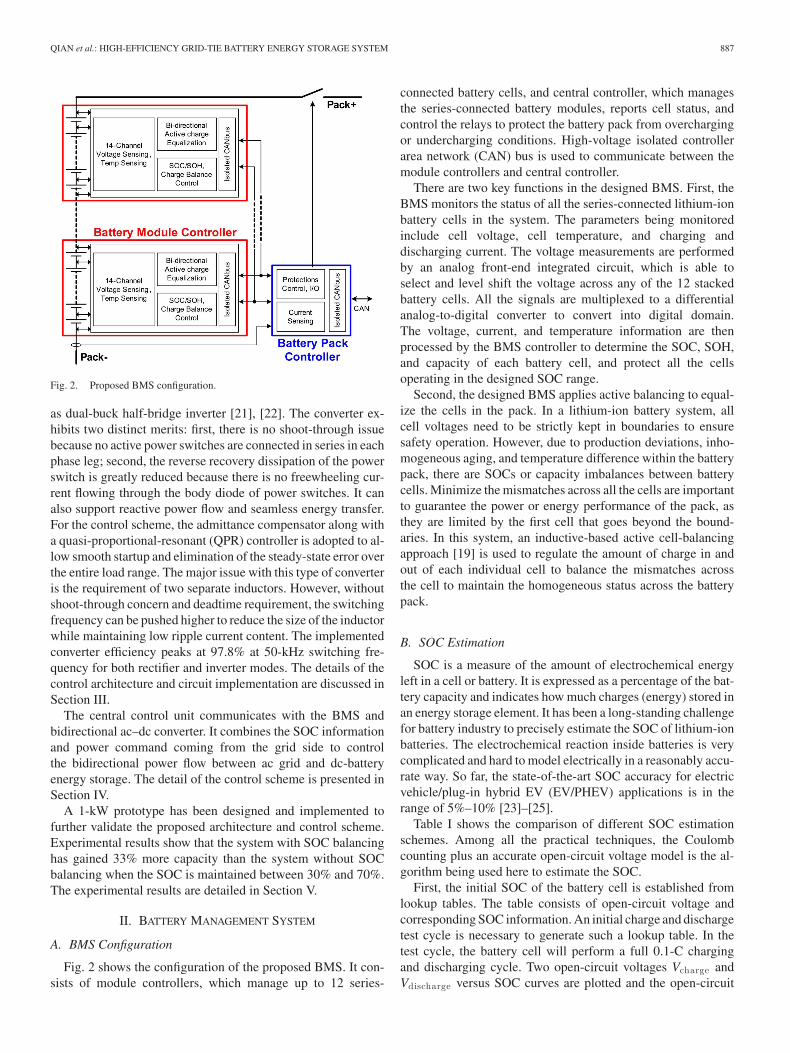
Fig. 2. Proposed BMS configuration.
as dual-buck half-bridge inverter [21], [22]. The converter ex-hibits two distinct merits: first, there is no shoot-through issuebecause no active power switches are connected in series in eachphase leg; second, the reverse recovery dissipation of the powerswitch is greatly reduced because there is no freewheeling cur-rent flowing through the body diode of power switches. It canalso support reactive power flow and seamless energy transfer.For the control scheme, the admittance compensator along witha quasi-proportional-resonant (QPR) controller is adopted to al-low smooth startup and elimination of the steady-state error overthe entire load range. The major issue with this type of converteris the requirement of two separate inductors. However, withoutshoot-through concern and deadtime requirement, the switchingfrequency can be pushed higher to reduce the size of the inductorwhile maintaining low ripple current content. The implementedconverter efficiency peaks at 97.8% at 50-kHz switching fre-quency for both rectifier and inverter modes. The details of thecontrol architecture and circuit implementation are discussed inSection III.
The central control unit communicates with the BMS andbidirectional ac–dc converter. It combines the SOC informationand power command coming from the grid side to controlthe bidirectional power flow between ac grid and dc-batteryenergy storage. The detail of the control scheme is presented inSection IV.
A 1-kW prototype has been designed and implemented tofurther validate the proposed architecture and control scheme.Experimental results show that the system with SOC balancinghas gained 33% more capacity than the system without SOCbalancing when the SOC is maintained between 30% and 70%.The experimental results are detailed in Section V.
II. BATTERY MANAGEMENT SYSTEM
A. BMS Configuration
Fig. 2 shows the configuration of the proposed BMS. It con-sists of module controllers, which manage up to 12 series-
connected battery cells, and central controller, which managesthe series-connected battery modules, reports cell status, andcontrol the relays to protect the battery pack from overchargingor undercharging conditions. High-voltage isolated controllerarea network (CAN) bus is used to communicate between themodule controllers and central controller.
There are two key functions in the designed BMS. First, theBMS monitors the status of all the series-connected lithium-ionbattery cells in the system. The parameters being monitoredinclude cell voltage, cell temperature, and charging anddischarging current. The voltage measurements are performedby an analog front-end integrated circuit, which is able toselect and level shift the voltage across any of the 12 stackedbattery cells. All the signals are multiplexed to a differentialanalog-to-digital converter to convert into digital domain.The voltage, current, and temperature information are thenprocessed by the BMS controller to determine the SOC, SOH,and capacity of each battery cell, and protect all the cellsoperating in the designed SOC range.
Second, the designed BMS applies active balancing to equal-ize the cells in the pack. In a lithium-ion battery system, allcell voltages need to be strictly kept in boundaries to ensuresafety operation. However, due to production deviations, inho-mogeneous aging, and temperature difference within the batterypack, there are SOCs or capacity imbalances between batterycells. Minimize the mismatches across all the cells are importantto guarantee the power or energy performance of the pack, asthey are limited by the first cell that goes beyond the bound-aries. In this system, an inductive-based active cell-balancingapproach [19] is used to regulate the amount of charge in andout of each individual cell to balance the mismatches acrossthe cell to maintain the homogeneous status across the batterypack.
B. SOC Estimation
SOC is a measure of the amount of electrochemical energyleft in a cell or battery. It is expressed as a percentage of the bat-tery capacity and indicates how much charges (energy) stored inan energy storage element. It has been a long-standing challengefor battery industry to precisely estimate the SOC of lithium-ionbatteries. The electrochemical reaction inside batteries is verycomplicated and hard to model electrically in a reasonably accu-rate way. So far, the state-of-the-art SOC accuracy for electricvehicle/plug-in hybrid EV (EV/PHEV) applications is in therange of 5%–10% [23]–[25].
Table I shows the comparison of different SOC estimationschemes. Among all the practical techniques, the Coulombcounting plus an accurate open-circuit voltage model is the al-gorithm being used here to estimate the SOC.
First, the initial SOC of the battery cell is established fromlookup tables. The table consists of open-circuit voltage andcorresponding SOC information. An initial charge and dischargetest cycle is necessary to generate such a lookup table. In thetest cycle, the battery cell will perform a full 0.1-C chargingand discharging cycle. Two open-circuit voltages Vcharge andVdischarge versus SOC curves are plotted and the open-circuit

888 IEEE TRANSACTIONS ON POWER ELECTRONICS, VOL. 26, NO. 3, MARCH 2011
TABLE ICOMPARISON OF DIFFERENT SOC ESTIMATION SCHEMES
Fig. 3. (a) Open-circuit voltage versus SOC curve. (b) SOC lookup tables fordifferent temperatures.
voltage (VOC) will be the average of the Vcharge and Vdischarge ,as shown in Fig. 3(a). This process will be repeated at differenttemperatures to generate a set of lookup tables to accommodatedifferent temperature situations, as shown in Fig. 3(b).
Then, a Coulomb counter is initiated to count how manyCoulombs of charge being pumped into or out of the battery cell.The Coulomb counter consists of an accurate battery currentsense analog front end as well as a digital signal-processing unitto perform the offset calibration as well as charge integration forCoulomb counting purpose. Coulomb counting provides higheraccuracy than most other SOC measurements, since it measuresthe charge flow in and out of battery cell directly. However, itdepends on the accuracy of the current measurement and doesnot take an account of Columbic efficiency of the battery cell.Therefore, an accurate loss model is desired and necessary. Theloss comes from different mechanisms, which includes physicalresistance of the cathode, anode, metal materials, the lithium-ion diffusion loss, as well as other chemical reaction thermalloss. An accurate model to include all these mechanisms is dif-ficult to establish in reality. Hereby, a combination of Coulombcounting with SOC adjustment by open-circuit-voltage lookup
table method is applied. During battery charging or discharging,Coulomb counting is used to estimate the change of SOC for itsaccurate measurement of direct charge flow. The SOC of startand end of charging or discharging is being calibrated by usingopen-circuit-voltage lookup table. This method combines theadvantage of relative higher accuracy of both Coulomb count-ing and open-circuit voltage, but mitigate the slow responsetime of open-circuit-voltage scheme and lacking relative refer-ence point of Coulomb counting method.
C. Charge Equalization
Due to inevitable differences in chemical and electrical char-acteristics from manufacturing, aging, and ambient tempera-tures, there are SOC or capacity imbalances between batterycells. When these unbalanced batteries are left in use with-out any control, such as cell equalization, the energy storagecapacity decreases severely. Thus, charge equalization for aseries-connected battery string is necessary to minimize themismatches across all the cells and extend the battery life cycle.Charge balancing methods can be classified into two categories:active and passive.
Active cell balancing helps balance the cells in a battery mod-ule to maintain the same voltage or SOC by monitoring and in-jecting appropriate balancing current into individual battery cellbased on the balancing scheme. Compared with the traditionalpassive cell-balancing approach, the active cell balancing offersthe advantage of high system efficiency and fast balancing time.
An inductive-based active cell-balancing scheme similar tothe design in [19] is applied in this study to perform the cellequalization and mitigate the SOC mismatches among the cells.The unidirectional dc–dc converter is replaced by an isolatedbidirectional dc–dc converter. The isolated bidirectional dc–dcconverter regulates from the 12-cell battery stack voltage toeach individual cell voltage. The average current-mode controlis employed such that the average inductor current is regulatedto the command current, which is set by the active cell-balancingcontrol algorithm. The voltage measurement circuit senses andconverts all cell voltages into digital domain. Depending on theactive cell-balancing control algorithm, the battery cells couldbe balanced by targeting either toward the same SOC or thesame cell voltage. The algorithm built into the embedded mi-crocontroller determines how much extra charge each batterycell needs and sends commands to the switch matrix to open theassociated switches at certain time and sequence to perform theactive cell balancing.
III. BIDIRECTIONAL AC–DC CONVERTER
Fig. 4 shows the circuit diagram of the proposed dual buck-converter-based bidirectional ac–dc converter. The circuit con-sists of two power switches a1 and a2 , two diodes D1 and D2 ,two inductors L1 and L2 , and two split dc-bus capacitors C1and C2 . The converter works as a rectifier when the power istransferred from ac grid to dc source. Alternately, it works asan inverter when the power is transferred from dc source toac grid. The voltage across each capacitor C1 and C2 should be
QIAN et al.: HIGH-EFFICIENCY GRID-TIE BATTERY ENERGY STORAGE SYSTEM 889
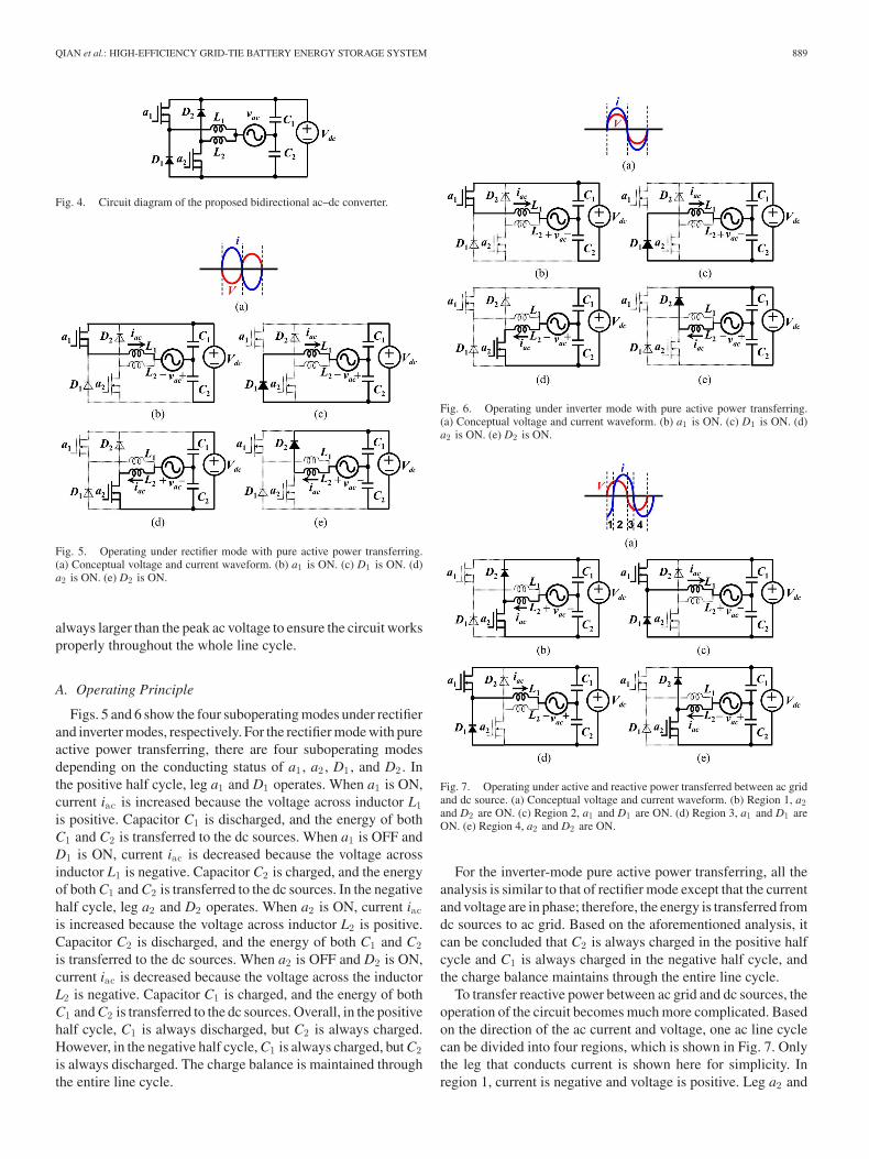
Fig. 4. Circuit diagram of the proposed bidirectional ac–dc converter.
Fig. 5. Operating under rectifier mode with pure active power transferring.(a) Conceptual voltage and current waveform. (b) a1 is ON. (c) D1 is ON. (d)a2 is ON. (e) D2 is ON.
always larger than the peak ac voltage to ensure the circuit worksproperly throughout the whole line cycle.
A. Operating Principle
Figs. 5 and 6 show the four suboperating modes under rectifierand inverter modes, respectively. For the rectifier mode with pureactive power transferring, there are four suboperating modesdepending on the conducting status of a1 , a2 , D1 , and D2 . Inthe positive half cycle, leg a1 and D1 operates. When a1 is ON,current iac is increased because the voltage across inductor L1is positive. Capacitor C1 is discharged, and the energy of bothC1 and C2 is transferred to the dc sources. When a1 is OFF andD1 is ON, current iac is decreased because the voltage acrossinductor L1 is negative. Capacitor C2 is charged, and the energyof both C1 and C2 is transferred to the dc sources. In the negativehalf cycle, leg a2 and D2 operates. When a2 is ON, current iacis increased because the voltage across inductor L2 is positive.Capacitor C2 is discharged, and the energy of both C1 and C2is transferred to the dc sources. When a2 is OFF and D2 is ON,current iac is decreased because the voltage across the inductorL2 is negative. Capacitor C1 is charged, and the energy of bothC1 and C2 is transferred to the dc sources. Overall, in the positivehalf cycle, C1 is always discharged, but C2 is always charged.However, in the negative half cycle, C1 is always charged, but C2is always discharged. The charge balance is maintained throughthe entire line cycle.
Fig. 6. Operating under inverter mode with pure active power transferring.(a) Conceptual voltage and current waveform. (b) a1 is ON. (c) D1 is ON. (d)a2 is ON. (e) D2 is ON.
Fig. 7. Operating under active and reactive power transferred between ac gridand dc source. (a) Conceptual voltage and current waveform. (b) Region 1, a2and D2 are ON. (c) Region 2, a1 and D1 are ON. (d) Region 3, a1 and D1 areON. (e) Region 4, a2 and D2 are ON.
For the inverter-mode pure active power transferring, all theanalysis is similar to that of rectifier mode except that the currentand voltage are in phase; therefore, the energy is transferred fromdc sources to ac grid. Based on the aforementioned analysis, itcan be concluded that C2 is always charged in the positive halfcycle and C1 is always charged in the negative half cycle, andthe charge balance maintains through the entire line cycle.
To transfer reactive power between ac grid and dc sources, theoperation of the circuit becomes much more complicated. Basedon the direction of the ac current and voltage, one ac line cyclecan be divided into four regions, which is shown in Fig. 7. Onlythe leg that conducts current is shown here for simplicity. Inregion 1, current is negative and voltage is positive. Leg a2 and

890 IEEE TRANSACTIONS ON POWER ELECTRONICS, VOL. 26, NO. 3, MARCH 2011
Fig. 8. (a) Separate controllers controlled system. (b) Unified controller con-trolled system.
D2 conducts the current. In region 2, both current and voltageare positive. Leg a1 and D1 conducts the current. Region 3 issimilar to region 2 except that voltage is negative. Region 4 issimilar to region 1 except that voltage is negative. Based onthe aforementioned analysis, it can be concluded that the legconsisting of a1 and D1 conducts positive current, and the legconsisting of a2 and D2 conducts negative current whenevervoltage is positive or negative.
B. Unified Controller for Bidirectional Power Flow Control
In order to simplify the controller and at the same time stabi-lize the system during the mode transition, a unified controlleris proposed. Fig. 8(a) shows that traditional way of two separatecontrollers: rectifier- and inverter-mode controllers. These twocontrollers can be merged into one, as shown in Fig. 8(b).
From Fig. 5(b) and (c), when current is positive in the rectifiermode, the total voltseconds applied to the inductor L1 over oneswitching period are as follows:(
Vdc
2+ vac
)da1 rec +
(−Vdc
2+ vac
)(1 − da1 rec) = 0
(1).
The duty cycle for switch a1 can be derived as
da1 rec =12
(1 − vac
Vdc/2
)=
12
(1 − vpk sin ωt
Vdc/2
)
= 0.5(1 − M sin ωt) (2)
where M = vpk /(Vdc /2) is modulation index and sin ωt > 0.Similarly, the duty cycle for switch a2 in the rectifier mode canbe derived as follows:
da2 rec = 0.5(1 + M sin ωt). (3)
The duty cycle for switch a1 in the inverter mode can be obtainedas
da1 inv = 0.5(1 + M sinωt). (4)
The duty cycle for switch a2 in the inverter mode can be obtainedas
da2 inv = 0.5(1 − M sinωt). (5)
Fig. 9. Circuit diagram of the proposed converter with current control loop.
Fig. 10. Block diagram of the current control loop with the adding admittancecompensator.
It can be concluded that da 1 rec = da 2 inv and da 2 rec = da 1 inv .By changing the current reference from iac
∗ to−iac∗, the control
output applied to da 1 to conduct positive current will be used forda 2 to conduct negative current and the control output applied toda 2 to conduct negative current will be used for da 1 to conductpositive current. One controller can be used to regulate currentunder both rectifier and inverter modes.
Fig. 9 shows the complete circuit diagram that includes a uni-fied current-loop controller. Current command iref is obtainedfrom the active power command Pref and the reactive powercommand Qref , which are commanded by the battery SOC andgrid, and the ac-voltage phase information, which is producedby a digital phase-locked loop.
Fig. 10 shows the block diagram of the compensated systemthat adds Gi(s), Gvb (s), and Gc (s). Here Giv (s) is current-to-voltage transfer function and Gid (s) is current-to-duty transferfunctions. Hv (s) and Hi(s) are the voltage- and current-sensorgains. The voltage balance compensator Gvb (s) is designed tobalance the voltage across the two dc-split capacitors vc1 andvc2 . The admittance compensator Gc (s) is designed to reject thedisturbance from Giv (s). The current-loop controller Gi(s) is de-signed to compensate the error between iref and the feedback-sensed current ifb . By feeding the output of the current-loopcontroller to the pulsewidth modulation (PWM) block, whichis represented by Fm , the output signal is gating signal d.The output current iac can be derived in (6) from Fig. 9 asfollows:
iac(s) = Gid(s)d − Giv (s)vac (6)

QIAN et al.: HIGH-EFFICIENCY GRID-TIE BATTERY ENERGY STORAGE SYSTEM 891
where
Gid(s) =iac(s)d(s)
=Vdc/2sL
(7)
Giv (s) =iac(s)vac(s)
=1sL
. (8)
The overall equivalent admittance can be represented asfollows:
Y (s) =iac(s)vac(s)
=Im HvGi(s)Fm Gid(s)
1 + Ti− Giv (s)
1 + Ti
= Y1(s) + Y2(s) (9)
where
Ti(s) = GiFm GidHi,
Y1(s) =Im HvGi(s)Fm Gid(s)
1 + Tiand Y2(s) =
−Giv (s)1 + Ti
.
The reference active and reactive power command can beused to calculate Im and θ shown as follows:
Im =
√P 2
ref + Q2ref
vpk/2(10)
θ = tan−1(
Qref
Pref
). (11)
The term Y1(s) is generated by active and reactive powercommand Pref and Qref , which provides desired output. Theterm Y2(s) is related to the closed-loop voltage-to-current trans-fer function, which reduces current induced in Y1 . Thus, Y2 isundesired and needs to be eliminated by the use of the followingadmittance compensator Gc (s):
Gc(s) =Giv (s)
Fm Gid(s)=
1Fm (Vdc/2)
(12)
Equation (12) indicates that Gc (s) is independent of convertertransfer functions and proportional to the multiplicative inverseof the half dc-bus voltage Vdc /2 and the PWM gain [26], [27].
In order to reduce the steady-state error at the fundamentalfrequency, or 60 Hz in the designed case, the QPR controller,which is shown in (13), is adopted for the current loop controller,which can provide a high gain at 60 Hz without phase offset [28].
Gi(s) = kp +2krωcs
s2 + 2ωcs + ω20
(13)
where kp is a proportional gain, kr is a resonant gain, and ωc
is an equivalent bandwidth of the resonant controller. The QPRcontroller is designed to have the following parameters: kp =1.5, kr = 50, ωc = 10 rad/s, and ωo = 2π × 60 rad/s.
A proportional–integral controller, Gvb (s) = kp + ki /s, isadopted to balance the voltage across the two dc-split capacitorsvc1 and vc 2 . kp is designed as small as possible to have lessinfluence on the main control loop, and ki is designed to havelarge time constant. In this design, kp = 0.6 and ki = 60.
Fig. 11. Control block diagram for the battery energy storage system.
IV. SYSTEM CONTROL AND POWER MANAGEMENT
The battery pack consists of three series connected batterymodules. Each battery module consists of 12 series-connectedbattery units, which have four parallel-connected battery cells(=2.3 A·h × 4) in one unit. The total energy capacity of thebattery pack consisting of three series-connected battery mod-ules is W = 1.09 kW·h (=2.3 A·h × 4 × 12 × 3 × 3.3 V). Thedc-voltage range is from 108 to 129.6 V (assume working cellvoltage is from 3.0 to 3.6 V).
Fig. 11 shows the control block diagram of the battery energystorage system. The whole control consists of three subcontrols:1) central control; 2) bidirectional power flow control; and 3)SOC balancing control.
The bidirectional power flow control is presented inSection III. The SOC balancing control consists of cell-balancing control and module balancing. The target of the cell-balancing control is to keep each of the 12-cell SOC values in amodule (for example, SOCBa 1 , SOCBa 2 , . . . , SOCBa 12) equalto the mean SOC value of the corresponding module (SOCBa ).Similarly, the target of module-balancing control is to keep eachof the three-module SOC values in a pack (SOCa , SOCb , . . . ,SOCc ) equal to the mean SOC value of the pack (SOCabc )⎡⎣ SOCBa
SOCBb
SOCBc
⎤⎦ =
112
⎡⎣SOCBa1 + SOCBa2 + · · · + SOCBa12
SOCBb1 + SOCBb2 + · · · + SOCBb12SOCBc1 + SOCBc2 + · · · + SOCBc12
⎤⎦
(14)
SOCabc =13(SOCa + SOCb + SOCc) (15)
⎡⎣SOCa
SOCb
SOCc
⎤⎦ =
⎡⎣ SOCBa1 + SOCBa2 + · · · + SOCBa12
SOCBb1 + SOCBb2 + · · · + SOCBb12SOCBc1 + SOCBc2 + · · · + SOCBc12
⎤⎦
(16)
SOC = SOCa + SOCb + SOCc . (17)

892 IEEE TRANSACTIONS ON POWER ELECTRONICS, VOL. 26, NO. 3, MARCH 2011
Fig. 12. Simulation results under (a) inverter mode and (b) rectifier mode,both with vac = 30 Vrm s and iac = 23 Arm s .
The central controller has three main inputs: Pref grid andQref grid commands from the grid and SOC estimation from thebattery pack. Assume 30%–70% SOC is the range for the batterypack to operate to have a longer life cycle. When Pref grid is toolarge and beyond battery pack’s capability, SOC will take chargeof the control. Otherwise, Pref grid will be taken as the controlreference.
The inputs Max (SOCa, b, c,) and Min (SOCa, b, c,) of the cen-tral controller are used to limit the power in and out of the batterypack. In case the total SOC meets the power transferring require-ment but the three battery modules are not balanced very well,then the maximum power transferred from battery pack to grid islimited by Min (SOCa, b, c,) and the maximum power transferredfrom grid to battery pack is limited by Max (SOCa, b, c,). The in-puts Max (SOCBa 1 , . . . ,Ba12), Min (SOCBa 1 , . . . ,Ba12), Max(SOCBb1 , . . . ,Bb12), Min (SOCBb1 , . . . ,Bb12), Max (SOCBc1 ,. . . ,Bc12), and Min (SOCBc1 , . . . ,Bc12) have the similarfunctions.
V. SIMULATION AND EXPERIMENTAL RESULTS
A. Converter Steady-State and Transient Waveforms
The 120-V battery pack only allows a maximum ac-line volt-age 42 Vrms with the use of dual buck-type inverter; therefore,a 1:4 ratio transformer is connected between the battery energystorage system and ac grid (120 Vrms) to provide required acvoltage and isolation.
Fig. 13. Experimental results under (a) inverter mode and (b) rectifier mode,both with vac = 30 Vrm s and iac = 23 Arm s .
Figs. 12 and 13 show the simulation and experimental re-sults under both rectifier and inverter modes for the bidirec-tional ac–dc converter, respectively. Fig. 12(a) shows the sim-ulated inverter-mode current and voltage, which are in phase.Fig. 12(b) shows the simulated rectifier-mode current and volt-age, which are 180◦ phase shifted. Fig. 13(a) shows the exper-imental inverter-mode current and voltage, which are in phase.Fig. 13(b) shows the experimental rectifier-mode current andvoltage, which are 180◦ phase shifted.
Fig. 14(a) and (b) shows the waveforms of reactive powerflow. Fig. 14(a) shows current leads voltage by 90◦. Fig. 14(b)shows current lags voltage by 90◦.
Fig. 15(a) shows transient waveforms from rectifier modeto inverter mode in 40 μs with a SOC value of around 70%.Fig. 15(b) shows the transient waveforms from inverter mode torectifier mode in 40 μs with a SOC value of around 70%. Thesewaveforms show seamless energy transfer.
The experimental results match simulation results very well,and the bidirectional power flow capability of the proposedcircuit and control system is well verified. Fig. 16 shows theexperimental efficiency of the proposed converter under bothrectifier and inverter modes. The efficiency peaks at 97.8% at50-kHz switching frequency for both rectifier and invertermodes.
B. Battery-Pack Charging and Discharging Waveforms
Fig. 17 shows the experimental results when battery pack wasrepetitively charged to a SOC of 70% and discharged to a SOC

QIAN et al.: HIGH-EFFICIENCY GRID-TIE BATTERY ENERGY STORAGE SYSTEM 893
Fig. 14. Experimental results with reactive power flow. (a) Current leadsvoltage by 90◦. (b) Current lags voltage by 90◦.
Fig. 15. Experimental results with a SOC value of 70%. (a) Changing fromrectifier mode to inverter mode. (b) Changing from inverter mode to rectifiermode.
Fig. 16. Experimental efficiency for both rectifier and inverter modes.
Fig. 17. Experimental results of repetitively charging and discharging of thebattery pack with a SOC between 30% and 70%. (a) Voltage versus time. (b)SOC versus time.
of 30%. A wider window, for example, from 10% to 90%, maybe used in an actual system. However, the lithium-ion batteriesshow longer life cycle with a lower depth-of-discharge (DOD).The charging and discharging battery current is set at 9.2 A,which is equivalent to 1.0 C (=9.2 A/2.3 A·h /4). The samplingrate of voltage and SOC is 2/s.
C. Effectiveness of the SOC Balancing Control
The SOC balancing control is to keep each of the 12-unitSOC values in a module equal to the mean SOC value of thecorresponding module. In the experiment, each unit consistsof four parallel-connected cells except one unit is configuredto have three parallel-connected cells. Thus, there is a 25%capacity mismatch inside the module.
Fig. 18 shows the test results with SOC balancing and with-out SOC balancing. For the test without SOC balancing, all

894 IEEE TRANSACTIONS ON POWER ELECTRONICS, VOL. 26, NO. 3, MARCH 2011
Fig. 18. Experimental results of discharging and charging of one battery module. (a) Discharging without SOC balancing control. (b) Charging without SOCbalancing control. (c) Discharging with SOC balancing control. (d) Charging with SOC balancing control.
the 12 units are charged up to 100% SOC in the initial point.For 1-C discharging, the total time for discharging the mod-ule from 100% SOC to 0% is limited by the unit consistingof three parallel-connected cells, which is around 45 min. For1-C charging, the total time for charging the module from 0%SOC to 100% is limited by the unit consisting of three parallel-connected cells, which is also about 45 min. For the testingwith SOC balancing, the corresponding discharging and charg-ing time are both 55 min. It can be concluded that the systemwith SOC balancing has 22% more capacity than the systemwithout SOC balancing.
In actual system, a SOC window between 30% and 70% maybe used to extend battery-cycle lifetime. For 1-C dischargingwithout SOC balancing, the time for discharging the modulefrom 70% SOC to 30% is around 18 min. The time for chargingthe module from 30% SOC to 70% is about 18 min. For thetesting with SOC balancing, the corresponding discharging andcharging time are both 24 min. It can be concluded that thesystem with SOC balancing has gained 33% more capacity thanthe system without SOC balancing when the SOC is between30% and 70%. Without SOC balancing, lower capacity batteryunits in a battery module can be easily damaged with a higherDOD.
D. System Efficiency
For 1-C charging and discharging, the relationship betweenbattery-pack voltage and SOC is shown in Fig. 19. The arrows
Fig. 19. Experimental results of repetitively charging and discharging of thebattery pack with SOC ranging between 30% and 70%.
show the charging and discharging directions. The area 1 insidethe curve is the relative losses when the battery pack is chargedfrom 30% SOC to 70% SOC and discharged back to 30%. Thelosses consist of battery loss and BMS loss. The efficiency is95.0% for the battery pack. The overall efficiency for the batteryenergy storage system consisting of battery pack with associatedBMS and bidirectional ac–dc converter is 92.63%.
VI. CONCLUSION
In this paper, a high-efficiency grid-tie lithium-ion battery-based energy storage system was proposed. The system con-sisted of three subsystems, a LiFePO4 battery pack and asso-ciated BMS, a bidirectional ac–dc converter, and the central

QIAN et al.: HIGH-EFFICIENCY GRID-TIE BATTERY ENERGY STORAGE SYSTEM 895
control unit that controls the operation mode and grid interfaceof the energy storage system.
The designed BMS monitors and reports all battery cellsparameters in the pack; these include cell voltage, temperature,and current. Based on these parameters, the BMS controllerestimates the SOC and SOH of each battery cell in the pack.The SOC information is then used to control the active cell-balancing circuits to mitigate the mismatch among the series-connected cells. The SOC and SOH information is also usedby the central control unit to determine the operating mode ofthe energy storage system. Using the proposed SOC balancingtechnique, the entire battery storage system has demonstratedmore capacity than the system without SOC balancing. Underthe charging condition from 0% to 100% SOC and dischargingcondition from 100% SOC to 0%, the use of SOC balancingtechnique has 22% more capacity. Under the charging conditionfrom 30% to 70% SOC and discharging condition from 70% to30% SOC, the use of SOC balancing technique has 33% morecapacity.
The high-efficiency bidirectional ac–dc converter clearlydemonstrated the feasibility of bidirectional power flow ca-pability with the proposed control method. Since there isno shoot-through issue with the dual buck-type inverter, thepower switches can switch at a high switching frequency toallow the passive component size reduction while maintaininghigh-efficiency operation. The implemented converter prototypedemonstrated a peak efficiency of 97.8% under 50-kHz switch-ing frequency for both rectifier and inverter modes.
Detailed operating modes and energy transfer mechanismhave been described in this paper. Along with the admittancecompensation, a QPR controller has been designed to signifi-cantly increase the loop gain at the fundamental frequency whilemaintaining enough phase margins. The proposed controllerhas been simulated and implemented in a field-programmablegate array (FPGA) based 1-kW prototype. Both simulation andexperimental results match very well and validate the designfeatures of the high-efficiency high-reliability converter. Thissingle-phase converter can be easily extended to a three-phaseconverter by tripling the two-leg configuration and connectingthe neutral points together. The converter not only can transferactive power, but also can transfer reactive power.
Experimental results have demonstrated that the proposedhigh-efficiency battery energy storage system effectively miti-gates the mismatch among the series-connected cells and sup-port reactive power flow and seamless energy transfer.
REFERENCES
[1] E. Barklund, N. Pogaku, M. Prodanovic, C. Hernandez-Aramburo, and T.C. Green, “Energy management in autonomous microgrid using stability-constrained droop control of inverters,” IEEE Trans. Power Electron.,vol. 23, no. 5, pp. 2346–2352, Sep. 2008.
[2] Y. A.-R. I. Mohamed and E. F. El-Saadany, “Adaptive decentralized droopcontroller to preserve power sharing stability of paralleled inverters indistributed generation microgrids,” IEEE Trans. Power Electron., vol. 23,no. 6, pp. 2806–2816, Nov. 2008.
[3] Y. W. Li and C.-N. Kao, “An accurate power control strategy for power-electronics-interfaced distributed generation units operating in a low-voltage multibus microgrid,” IEEE Trans. Power Electron., vol. 24, no. 12,pp. 2977–2988, Dec. 2009.
[4] Z. Chen, J. M. Guerrero, and F. Blaabjerg, “A review of the stage of theart of power electronics for wind turbines,” IEEE Trans. Power Electron.,vol. 24, no. 8, pp. 1859–1875, Aug. 2009.
[5] A. Timbus, M. Liserre, R. Teodorescu, P. Rodriguez, and F. Blaabjerg,“Evaluation of current controllers for distributed power generation sys-tems,” IEEE Trans. Power Electron., vol. 24, no. 3, pp. 654–664, Mar.2009.
[6] N. Stretch and N. Kazerani, “A Stand-alone, split-phase current-sourcedinverter with novel energy storage,” IEEE Trans. Power Electron., vol. 23,no. 6, pp. 2766–2774, Nov. 2008.
[7] H. Krishnaswami and N. Mohan, “Three-port series-resonant DC-DCconverter to interface renewable energy sources with bidirectional loadand energy storage ports,” IEEE Trans. Power Electron., vol. 24, no. 10,pp. 2289–2297, Oct. 2009.
[8] A. Payman, S. Piefederici, and F. Meibody-Tabar, “Energy management ina fuel cell/supercapacitor multisource/multiload electrical hybrid system,”IEEE Trans. Power Electron., vol. 24, no. 12, pp. 2681–2691, Dec. 2009.
[9] G.-J. Su and L. Tang, “A reduced-part, triple-voltage DC-DC converterfor EV/HEV power management,” IEEE Trans. Power Electron., vol. 24,no. 10, pp. 2406–2410, Oct. 2009.
[10] C. Zhao, S. D. Round, and J. W. Kolar, “An isolated three-port bidirectionalDC-DC converter with decoupled power flow management,” IEEE Trans.Power Electron., vol. 23, no. 5, pp. 2443–2453, Sep. 2008.
[11] R.-Y. Kim and J.-S. Lai, “A seamless mode transfer maximum powerpoint tracking controller for thermoelectric generator applications,” IEEETrans. Power Electron., vol. 23, no. 5, pp. 2310–2318, Sep. 2008.
[12] L. Maharjan, T. Yamagishi, H. Akagi, and J. Asakura, “Fault-tolerantoperation of a battery-energy-storage system based on a multilevel cascadePWM converter with star configuration,” IEEE Trans. Power Electron.,vol. 25, no. 9, pp. 2386–2396, Sep. 2010.
[13] K. Jin, X. Ruan, M. Yang, and M. Xu, “Power management for fuel-cellpower system cold start,” IEEE Trans. Power Electron., vol. 24, no. 10,pp. 2391–2395, Oct. 2009.
[14] F. Z. Peng, M. Shen, and K. Holland, “Application of Z-source inverter fortraction drive of fuel cell-battery hybrid electric vehicles,” IEEE Trans.Power Electron., vol. 22, no. 3, pp. 1054–1061, May 2007.
[15] H.-S. Park, C.-E. Kim, C.-H. Kim, G.-W. Moon, and J.-H. Lee, “A mod-ularized charge equalizer for an HEV lithium-ion battery string,” IEEETrans. Ind. Electron., vol. 56, no. 5, pp. 1464–1476, May 2009.
[16] Y.-S. Lee and M.-W. Cheng, “Intelligent control battery equalization forseries connected lithium-ion battery strings,” IEEE Trans. Ind. Electron.,vol. 52, no. 5, pp. 1297–1307, Oct. 2005.
[17] Y.-S. Lee and G.-T. Cheng, “Quasi-resonant zero-current-switching bidi-rectional converter for battery equalization applications,” IEEE Trans.Power Electron., vol. 21, no. 5, pp. 1213–1224, Sep. 2006.
[18] L. Maharjan, S. Inoue, H. Akagi, and J. Asakura, “State-of-charge (SOC)-balancing control of a battery energy storage system based on a cascadePWM converter,” IEEE Trans. Power Electron., vol. 24, no. 6, pp. 1628–1636, Jun. 2009.
[19] S. W. Moore and P. J. Schneider, “A review of cell equalization methodsfor lithium ion and lithium polymer battery systems,” presented at theSAE 2001 World Congr., Detroit, MI, Mar. 2001.
[20] G. R. Stanley and K. M. Bradshaw, “Precision DC-to-AC power con-version by optimization of the output current waveform-the half bridgerevisited,” IEEE Trans. Power Electron., vol. 14, no. 2, pp. 372–380, Mar.1999.
[21] J. Liu and Y. Yan, “A novel hysteresis current controlled dual buck halfbridge inverter,” in Proc. IEEE PESC, Acapulco, Mexico, Jun. 2003,pp. 1615–1620.
[22] Z. Yao, L. Xiao, and Y. Yan, “Control strategy for series and parallel outputdual-buck half bridge inverters based on DSP control,” IEEE Trans. PowerElectron., vol. 24, no. 2, pp. 434–444, Feb. 2009.
[23] I.-S. Kim, “Nonlinear state of charge estimator for hybrid electric vehiclebattery,” IEEE Trans. Power Electron., vol. 23, no. 4, pp. 2027–2034, Jul.2008.
[24] I.-S. Kim, “A technique for estimating the state of health of lithium batter-ies through a dual-sliding-mode observer,” IEEE Trans. Power Electron.,vol. 25, no. 4, pp. 1013–1022, Apr. 2010.
[25] M. Coleman, C. K. Lee, C. Zhu, and W. G. Hurley, “State-of-chargedetermination from EMF voltage estimation: Using impedance, terminalvoltage, and current for lead-acid and lithium-ion batteries,” IEEE Trans.Ind. Electron., vol. 54, no. 5, pp. 2550–2557, Oct. 2007.
[26] S.-Y. Park, C.-L. Chen, J.-S. Lai, and S.-R. Moon, “Admittance compen-sation in current loop control for a grid-tie LCL fuel cell inverter,” IEEETrans. Power Electron., vol. 23, no. 4, pp. 1716–1723, Jul. 2008.

896 IEEE TRANSACTIONS ON POWER ELECTRONICS, VOL. 26, NO. 3, MARCH 2011
[27] S.-Y. Park, C.-L. Chen, and J.-S. Lai, “A wide-range active and reactivepower flow controller for a solid oxide fuel cell power conditioning sys-tem,” IEEE Trans. Power Electron., vol. 23, no. 6, pp. 2703–2709, Nov.2008.
[28] D. N. Zmwd and D. G. Holmes, “Stationary frame current regulationof PWM inverters with zero steady-state error,” IEEE Trans. PowerElectron., vol. 18, no. 3, pp. 814–822, May 2003.
Hao Qian (S’09) received the B.S. and M.S. degreesin electrical engineering from Zhejiang University,China, in 2003 and 2006, respectively. He is cur-rently working toward the Ph.D. degree at VirginiaPolytechnic Institute and State University (VirginiaTech), Blacksburg.
Since 2006, he has been a Research Assistantat the Future Energy Electronics Center (FEEC),Virginia Tech. His current research interests in-clude soft-switching converters, grid-tie inverters,and high-efficiency power conditioning systems for
renewable energy and energy storage applications.
Jianhui Zhang received the B.S. and M.S. degreesin electrical engineering from Tsinghua University,China, and the Ph.D. degree in electrical engineeringfrom the University of California, Berkeley, in 1999,2001, and 2006 respectively.
He was the Principal Architect and Designer forthe design and development of the SolarMagic prod-uct. In June 2005, he joined National SemiconductorCorporation, Santa Clara, CA, where he is currentlythe Design Engineering Manager of the Battery Man-agement System Business Unit, focusing in the archi-
tecture and design of mixed signal devices and systems for large format lithiumbattery management system. His research interests include research and devel-opments of circuits and system associated with renewable energy, smart gridand battery management system for electric vehicle, and grid energy storageapplication.
Jih-Sheng (Jason) Lai (S’85–M’89–SM’93–F’07)received M.S. and Ph.D. degrees in electrical engi-neering from the University of Tennessee, Knoxville,in 1985 and 1989, respectively.
From 1980 to 1983, he was the Head of the Elec-trical Engineering Department, Ming-Chi Instituteof Technology, Taipei, Taiwan, where he initiated apower electronics program and received a grant fromhis college and a fellowship from the National Sci-ence Council to study abroad. In 1986, he became aStaff Member at the University of Tennessee, where
he taught control systems and energy conversion courses. In 1989, he joinedthe Electric Power Research Institute (EPRI) Power Electronics ApplicationsCenter (PEAC), where he managed EPRI-sponsored power electronics researchprojects. From 1993, he worked with the Oak Ridge National Laboratory asthe Power Electronics Lead Scientist, where he initiated a high power elec-tronics program and developed several novel high power converters includingmultilevel converters and soft-switching inverters. In 1996, he joined VirginiaPolytechnic Institute and State University, Blacksburg, where he is currently aProfessor and the Director of the Future Energy Electronics Center. His researchinterests include high-efficiency power electronics conversions for high powerand energy applications. He has published more than 220 technical papers and2 books, and holds 20 U.S. patents.
Dr. Lai is a recipient of the Technical Achievement Award in Lockheed MartinAward Night, three IEEE Industry Applications Society (IAS) Conference Pa-per Awards, Best Paper Awards from the Industrial Electronics Society Confer-ence (IECON-97), the International Power Electronics Conference (IPEC-05),and the Power Conversion Conference (PCC)-07. His student teams won threeawards from the future energy challenge competitions and the first place awardfrom TI Enginous Prize Analog Design Competition. He was the Chair of the2000 IEEE Workshop on Computers in Power Electronics (COMPEL 2000),the 2001 IEEE/Department of Energy (DOE) Future Energy Challenge, andthe 2005 IEEE Applied Power Electronics Conference and Exposition (APEC2005).
Wensong Yu (M’07) received the M.S. degree fromthe Huazhong University of Science and Technology,Wuhan, China, and the Ph.D. degree from the SouthChina University of Technology, Guangzhou, China,in 1995 and 2000, respectively, both in mechanicaland electrical engineering.
During 2000, he was with the Emerson Net-work Power Co., Ltd., Shenzhen, China, where hewas involved in digital uninterruptible power supplyprojects. He is currently a Research Assistant Pro-fessor with the Bradley Department of Electrical and
Computer Engineering, Future Energy Electronics Center, Virginia PolytechnicInstitute and State University, Blacksburg, VA. He is the author or coauthorof more than 20 technical papers, and holds three patents. His research inter-ests include soft-switching power converter, grid-tied inverter, industrial powerelectronics, digital control applied to power electronics, and renewable energypower conditioning systems.
Copyright © 2022 FDOKUMEN