
Lead Acid Battery
60
Lead Acid Battery Definition: The battery which uses sponge lead and lead peroxide for the conversion of the chemical energy into electrical power, such type of battery is called a lead acid battery. The lead acid battery is most commonly used in the power stations and substations because it has higher cell voltage and lower cost Construction of Lead Acid Battery The various parts of the lead acid battery are shown below. The container and the plates are the main part of the lead acid battery. The container stores chemical energy which is converted into electrical energy by the help of the plates. 1. Container – The container of the lead acid battery is made of glass, lead lined wood, ebonite, the hard rubber of bituminous compound, ceramic materials or moulded plastics and are seated at the top to avoid the discharge of electrolyte. At the bottom of the container, there are four ribs, on two of them rest the positive plate and the others support the negative plates. The prism serves as the support for the plates and at the same time protect them from a short-circuit.The material of which the battery containers are made should be resistant to sulfuric acid, should not deform or porous, or contain impurities which damage the electrolyte. 2. Plate – The plate of the lead-acid cell is of diverse design and they all consist some form of a grid which is made up of lead and the active material. The grid is essential for conducting the electric current and for distributing the current equally on the active material. If the current is not uniformly distributed, then the active material will loosen and fall out. The grids are made up of an alloy of lead and antimony. These are usually made with the transverse rib that crosses the places at a right angle or diagonally. The grid for the positive and negative plates are of the same design, but the grids for the negative plates are made lighter because they are not as essential for the uniform conduction of the current. The plates of the battery are of two types. They are the formed plates or plante plates and pasted or faure plates.
-
Upload
khangminh22 -
Category
Documents
-
view
0 -
download
0
Transcript of Lead Acid Battery

Lead Acid Battery
Definition: The battery which uses sponge lead and lead peroxide for the conversion of
the chemical energy into electrical power, such type of battery is called a lead acid battery.
The lead acid battery is most commonly used in the power stations and substations because
it has higher cell voltage and lower cost
Construction of Lead Acid Battery
The various parts of the lead acid battery are shown below. The container and the plates
are the main part of the lead acid battery. The container stores chemical energy which is
converted into electrical energy by the help of the plates.
1. Container – The container of the lead acid battery is made of glass, lead lined wood,
ebonite, the hard rubber of bituminous compound, ceramic materials or moulded plastics
and are seated at the top to avoid the discharge of electrolyte. At the bottom of the
container, there are four ribs, on two of them rest the positive plate and the others support
the negative plates.
The prism serves as the support for the plates and at the same time protect them from a
short-circuit.The material of which the battery containers are made should be resistant to
sulfuric acid, should not deform or porous, or contain impurities which damage the
electrolyte.
2. Plate – The plate of the lead-acid cell is of diverse design and they all consist some form
of a grid which is made up of lead and the active material. The grid is essential for
conducting the electric current and for distributing the current equally on the active
material. If the current is not uniformly distributed, then the active material will loosen and
fall out.
The grids are made up of an alloy of lead and antimony. These are usually made with the
transverse rib that crosses the places at a right angle or diagonally. The grid for the positive
and negative plates are of the same design, but the grids for the negative plates are made
lighter because they are not as essential for the uniform conduction of the current.
The plates of the battery are of two types. They are the formed plates or plante plates and
pasted or faure plates.

Plante’s plates are used largely for stationary batteries as these are heavier in weight and
more costly than the pasted plates. But the plates are more durable and less liable to lose
active material by rapid charging and discharging. The plantes plate has low capacity
weight-ratio.
Faure process is much suitable for manufacturing of negative plates rather than positive
plates. The negative active material is quite tough, and it undergoes a comparatively low
change from charging and discharging.
3. Active Material – The material in a cell which takes active participation in a chemical
reaction (absorption or evolution of electrical energy) during charging or discharging is
called the active material of the cell. The active elements of the lead acid are
1. Lead peroxide (PbO2) – It forms the positive active material. The PbO2 are dark
chocolate broom in colour.
2. Sponge lead – Its form the negative active material. It is grey in colour.
3. Dilute Sulfuric Acid (H2SO4) – It is used as an electrolyte. It contains 31% of
sulfuric acid.
The lead peroxide and sponge lead, which form the negative and positive active materials
have the little mechanical strength and therefore can be used alone.
4. Separators – The separators are thin sheets of non-conducting material made up of
chemically treated leadwood, porous rubbers, or mats of glass fibre and are placed between
the positive and negative to insulate them from each other. Separators are grooved
vertically on one side and are smooth on the other side.
5. Battery Terminals – A battery has two terminals the positive and the negative. The
positive terminal with a diameter of 17.5 mm at the top is slightly larger than the negative
terminal which is 16 mm in diameter.
Working Principle of Lead Acid Battery
When the sulfuric acid dissolves, its molecules break up into positive hydrogen ions (2H+)
and sulphate negative ions (SO4—) and move freely. If the two electrodes are immersed in
solutions and connected to DC supply then the hydrogen ions being positively charged and
moved towards the electrodes and connected to the negative terminal of the supply. The
SO4— ions being negatively charged moved towards the electrodes connected to the
positive terminal of the supply main (i.e., anode).

Each hydrogen ion takes one electron from the cathode, and each sulphates ions takes the
two negative ions from the anodes and react with water and form sulfuric and hydrogen
acid.
The oxygen, which produced from the above equation react with lead oxide and form lead
peroxide (PbO2.) Thus, during charging the lead cathode remain as lead, but lead anode
gets converted into lead peroxide, chocolate in colour.
If the DC source of supply is disconnected and if the voltmeter connects between the
electrodes, it will show the potential difference between them. If wire connects the
electrodes, then current will flow from the positive plate to the negative plate through
external circuit i.e. the cell is capable of supplying electrical energy.
Chemical Action During Discharging
When the cell is full discharge, then the anode is of lead peroxide (PbO2) and a cathode is
of metallic sponge lead (Pb). When the electrodes are connected through a resistance, the
cell discharge and electrons flow in a direction opposite to that during charging.
The hydrogen ions move to the anode and reaching the anodes receive one electron from
the anode and become hydrogen atom. The hydrogen atom comes in contacts with a PbO2,
so it attacks and forms lead sulphate (PbSO4), whitish in colour and water according to the
chemical equation.
The each sulphate ion (SO4—) moves towards the cathode and reaching there gives up two
electrons becomes radical SO4, attack the metallic lead cathode and form lead sulphate
whitish in colour according to the chemical equation.

Chemical Action During Recharging
For recharging, the anode and cathode are connected to the positive and the negative
terminal of the DC supply mains. The molecules of the sulfuric acid break up into ions of
2H+ and SO4—. The hydrogen ions being positively charged moved towards the cathodes
and receive two electrons from there and form a hydrogen atom. The hydrogen atom reacts
with lead sulphate cathode forming lead and sulfuric acid according to the chemical
equation.
SO4— ion moves to the anode, gives up its two additional electrons becomes radical SO4,
react with the lead sulphate anode and form leads peroxide and lead sulphuric according to
the chemical equation.
The charging and discharging are represented by a single reversible equation given below.
The equation should read downward for discharge and upward for recharge.

Li ion battery
They give us all the convenience of electricity in a handy, portable form
The only trouble is, most batteries run flat very quickly and, unless one use a specialized
charger, you then have to throw them away. It's hard on the pocket and bad for the
environment as well: worldwide, we throw away billions of disposable batteries every
single year. Rechargeable batteries help to solve this problem and the best kind use a
technology called lithium ion. cellphone, laptop computer, and MP3 player probably all
use lithium-ion batteries. They've been in widespread use since about 1991, but the basic
chemistry was first discovered by American chemist Gilbert Lewis (1875–1946) way back
in 1912.
The trouble with ordinary batteries
If you've read our main article on batteries, you'll know a battery is essentially a chemical
experiment happening in a small metal canister. Connect the two ends of a battery to
something like a flashlight and chemical reactions begin: chemicals inside the battery
slowly but systematically break apart and join themselves together to make other
chemicals, producing a stream of positively charged particles called ions and negatively
charged electrons. The ions move through the battery; the electrons go through the circuit
to which the battery's connected, providing electrical energy that drives the flashlight. The
only trouble is, this chemical reaction can happen only once and in only one direction:
that's why ordinary batteries usually can't be recharged.
Rechargeable batteries = reversible reactions
Different chemicals are used in rechargeable batteries and they split apart through entirely
different reactions. The big difference is that the chemical reactions in a rechargeable
battery are reversible: when the battery is discharging the reactions go one way and the
battery gives out power; when the battery is charging, the reactions go in the opposite
direction and the battery absorbs power. These chemical reactions can happen hundreds of
times in both directions, so a rechargeable battery will typically give you anything from
two or three to as much as 10 years of useful life (depending on how often you use it and
how well you look after it).
How lithium-ion batteries work
Like any other battery, a rechargeable lithium-ion battery is made of one or more power-
generating compartments called cells. Each cell has essentially three components: a
positive electrode (connected to the battery's positive or + terminal), a negative electrode
(connected to the negative or − terminal), and a chemical called an electrolyte in between
them. The positive electrode is typically made from a chemical compound called lithium-
cobalt oxide (LiCoO2) or, in newer batteries, from lithium iron phosphate (LiFePO4). The

negative electrode is generally made from carbon (graphite) and the electrolyte varies from
one type of battery to another—but isn't too important in understanding the basic idea of
how the battery works.
All lithium-ion batteries work in broadly the same way. When the battery is charging up,
the lithium-cobalt oxide, positive electrode gives up some of its lithium ions, which move
through the electrolyte to the negative, graphite electrode and remain there. The battery
takes in and stores energy during this process. When the battery is discharging, the lithium
ions move back across the electrolyte to the positive electrode, producing the energy that
powers the battery. In both cases, electrons flow in the opposite direction to the ions around
the outer circuit. Electrons do not flow through the electrolyte: it's effectively an insulating
barrier, so far as electrons are concerned.
The movement of ions (through the electrolyte) and electrons (around the external circuit,
in the opposite direction) are interconnected processes, and if either stops so does the other.
If ions stop moving through the electrolyte because the battery completely discharges,
electrons can't move through the outer circuit either—so you lose your power. Similarly,
if you switch off whatever the battery is powering, the flow of electrons stops and so does
the flow of ions. The battery essentially stops discharging at a high rate (but it does keep
on discharging, at a very slow rate, even with the appliance disconnected).
Unlike simpler batteries, lithium-ion ones have built in electronic controllers that regulate
how they charge and discharge. They prevent the overcharging and overheating that can
cause lithium-ion batteries to explode in some circumstances
How a lithium-ion battery charges and discharges

As their name suggests, lithium-ion batteries are all about the movement of lithium ions:
the ions move one way when the battery charges (when it's absorbing power); they move
the opposite way when the battery discharges (when it's supplying power):
1. During charging, lithium ions (yellow circles) flow from the positive electrode (red)
to the negative electrode (blue) through the electrolyte (gray). Electrons also flow
from the positive electrode to the negative electrode, but take the longer path around
the outer circuit. The electrons and ions combine at the negative electrode and
deposit lithium there.
2. When no more ions will flow, the battery is fully charged and ready to use.
3. During discharging, the ions flow back through the electrolyte from the negative
electrode to the positive electrode. Electrons flow from the negative electrode to
the positive electrode through the outer circuit, powering your laptop. When the
ions and electrons combine at the positive electrode, lithium is deposited there.
4. When all the ions have moved back, the battery is fully discharged and needs
charging up again.
How are the lithium ions stored?
lithium ions are stored in
the negative graphite electrode (left) and positive cobalt-oxide electrode (right).
This figure shows what's going on in the battery in a bit more detail. Again, the negative
graphite electrode (blue) is shown on the left, the positive cobalt-oxide electrode (red) on
the right, and the lithium ions are represented by yellow circles. When the battery is fully
charged, all the lithium ions are stored between layers of graphene (sheets of carbon one
atom thick) in the graphite electrode (they have all moved over to the left). In this charged-
up state, the battery is effectively a multi-layer sandwich: graphene layers alternate with
lithium ion layers. As the battery discharges, the ions migrate from the graphite electrode
to the cobalt-oxide electrode (from left to right). When it's fully discharged, all the lithium
ions have moved over to the cobalt-oxide electrode on the right. Once again, the lithium
ions sit in layers, in between layers of cobalt ions (red) and oxide ions (blue). As the battery
charges and discharges, the lithium ions shunt back and forth from one electrode to the
other.

Advantages of lithium-ion batteries
Generally, lithium ion batteries are more reliable than older technologies such as nickel-
cadmium (NiCd, pronounced "nicad") and don't suffer from a problem known as the
"memory effect" (where nicad batteries appear to become harder to charge unless they're
discharged fully first). Since lithium-ion batteries don't contain cadmium (a toxic, heavy
metal), they are also (in theory, at least) better for the environment—although dumping
any batteries (full of metals, plastics, and other assorted chemicals) into landfills is never
a good thing. Compared to heavy-duty rechargeable batteries (such as the lead-acid ones
used to start cars), lithium-ion batteries are relatively light for the amount of energy they
store.
Disadvantages of lithium-ion batteries
If we're interested in the drawbacks of lithium-ion batteries, it's important to bear in mind
what we're comparing them with. As a power source for automobiles, we really need to
compare them not with other types of batteries but with gasoline. Despite considerable
advances over the years, kilo for kilo, rechargeable batteries still store only a fraction as
much energy as ordinary gas; in more scientific words, they have a much lower energy
density (they store less energy per unit of weight). That also explains why you can fully
"recharge" (refuel) a gas-powered automobile in a couple of minutes, whereas it'll generally
take you hours to recharge the batteries in an electric car. Then again, you have to bear in
mind that these disadvantages are balanced by other advantages, such as the greater fuel
economy of electric cars and their relative lack of air pollution (zero tailpipe/exhaust
emissions from the vehicle itself).
The big difference between solid-state batteries and other types of batteries is the use of
solid electrolytes, rather than the liquid electrolytes used in other batteries. Lithium-ion
batteries have seen technological advances, but experts widely believe that lithium-ion
technology has reached the limits of its efficiency. The next step into the future requires a
different type of battery, and that’s where solid-state batteries come into the picture.
Solid-state batteries are smaller, lighter, and provide greater power density than lithium-
ion batteries based on liquid electrolytes. The main challenge to their widespread adoption
has been the search for a solid electrolyte with sufficient conductive capacity for large
batteries, as well as a manufacturing method that allows for economies of scale.
How Does a Battery Work?
All batteries have three primary parts: the anode, the cathode, and the electrolyte. A battery
works because charged ions want to travel from the cathode to the anode through the
electrolyte. This happens because the carefully-chosen battery components create a
chemical reaction that produces free electrons. As a result, a positive charge builds up on
the battery’s cathode. This attracts the negatively charged free electrons from the anode.
Those free electrons want to travel from anode to cathode. As they do, they power your
device.

Keep in mind that electrical and chemical forces always want to equalize. Picture a charged
battery like a seesaw tilted in one direction. The charges want to slide down this plane until
the reaction is equalized. Recharging moves all the ions back into their starting positions.
Imagine charging as cranking up our unbalanced seesaw from the previous metaphor.
How Are Modern Batteries Better?
Only some materials are capable of working as batteries, so components have to be chosen
very carefully based on their chemical properties. As a result, advancing battery tech either
involves improving the efficiency of an existing battery material or discovering new
materials that work better. And since we’ve looked in all the obvious places for battery
improvements, now we have to start looking under the rocks of nanotechnology and

material science. Solid-state batteries are one of the discoveries to come out of that process,
using different electrolytes to achieve the same goal as any other type of battery, but faster,
cheaper, and less prone to exploding.
The electrolyte best poised to replace lithium-ion batteries is a sodium-based glass
electrolyte. According to researchers, a glass electrolyte produces a battery with three times
the energy density of a lithium-ion battery. The sodium required for manufacturing these
batteries is plentiful. This dramatically reduces the ecological impact of battery production.

How Are Solid-State Batteries Better?
Solid-state batteries improve lithium-ion batteries by using a solid electrolyte in place of a
liquid or polymer electrolyte. It just so happens that this change improves nearly all the
battery’s characteristics. Solid-state batteries tick all the boxes of our fantasy battery tech.
They’re lightweight, have a low environmental impact, use plentiful components, are less
likely to catch fire, and offer more power.
The one problem is the manufacturing process. We’re still figuring out how to make these
batteries cheaply and at scale. Right now, solid-state batteries are too expensive for
widespread adoption. Fortunately, we’re very good at finding novel ways to make things
more efficiently. Solid-state batteries should eventually yield to economies of scale and see
broad adoption.
Fuel Cell
Fuel cell, any of a class of devices that convert the chemical energy of a fuel directly into
electricity by electrochemical reactions. A fuel cell resembles a battery in many respects,
but it can supply electrical energy over a much longer period of time. This is because a fuel
cell is continuously supplied with fuel and air (or oxygen) from an external source, whereas
a battery contains only a limited amount of fuel material and oxidant that are depleted with
use. For this reason fuel cells have been used for decades in space probes, satellites, and
manned spacecraft. Around the world thousands of stationary fuel cell systems have been
installed in utility power plants, hospitals, schools, hotels, and office buildings for both
primary and backup power; many waste-treatment plants use fuel cell technology to
generate power from the methane gas produced by decomposing garbage.
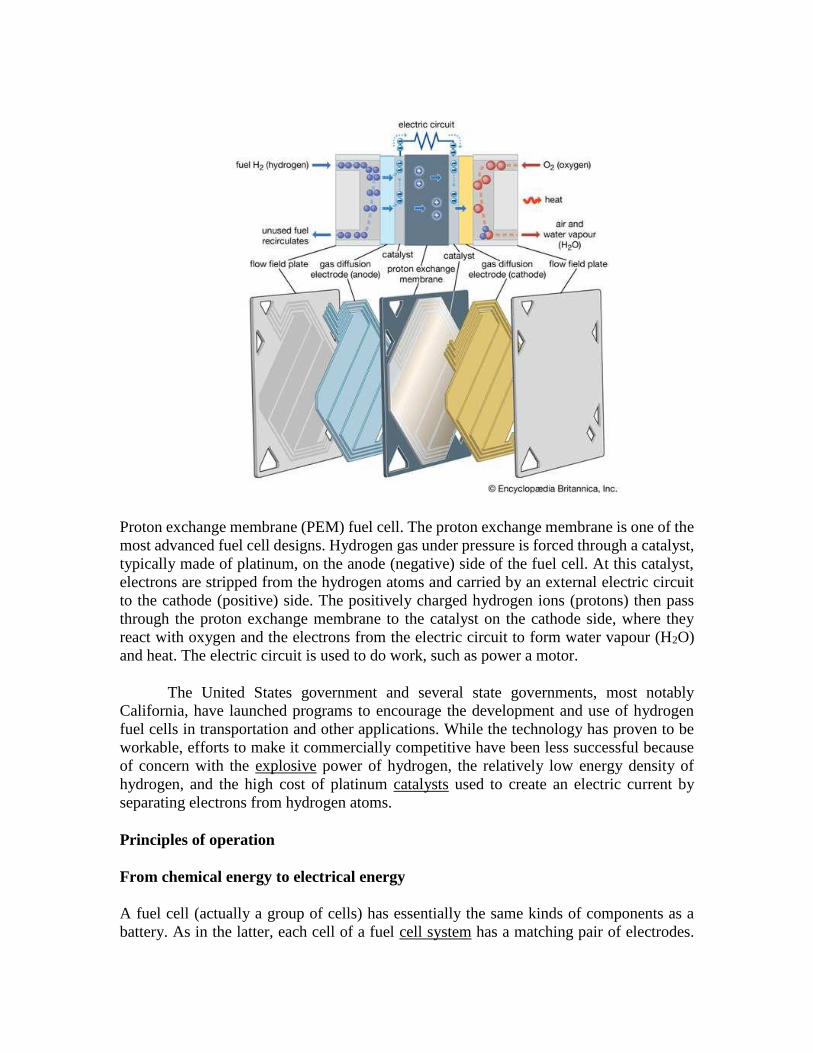
Proton exchange membrane (PEM) fuel cell. The proton exchange membrane is one of the
most advanced fuel cell designs. Hydrogen gas under pressure is forced through a catalyst,
typically made of platinum, on the anode (negative) side of the fuel cell. At this catalyst,
electrons are stripped from the hydrogen atoms and carried by an external electric circuit
to the cathode (positive) side. The positively charged hydrogen ions (protons) then pass
through the proton exchange membrane to the catalyst on the cathode side, where they
react with oxygen and the electrons from the electric circuit to form water vapour (H2O)
and heat. The electric circuit is used to do work, such as power a motor.
The United States government and several state governments, most notably
California, have launched programs to encourage the development and use of hydrogen
fuel cells in transportation and other applications. While the technology has proven to be
workable, efforts to make it commercially competitive have been less successful because
of concern with the explosive power of hydrogen, the relatively low energy density of
hydrogen, and the high cost of platinum catalysts used to create an electric current by
separating electrons from hydrogen atoms.
Principles of operation
From chemical energy to electrical energy
A fuel cell (actually a group of cells) has essentially the same kinds of components as a
battery. As in the latter, each cell of a fuel cell system has a matching pair of electrodes.

These are the anode, which supplies electrons, and the cathode, which absorbs electrons.
Both electrodes must be immersed in and separated by an electrolyte, which may be a liquid
or a solid but which must in either case conduct ions between the electrodes in order to
complete the chemistry of the system. A fuel, such as hydrogen, is supplied to the anode,
where it is oxidized, producing hydrogen ions and electrons. An oxidizer, such as oxygen,
is supplied to the cathode, where the hydrogen ions from the anode absorb electrons from
the latter and react with the oxygen to produce water. The difference between the respective
energy levels at the electrodes (electromotive force) is the voltage per unit cell. The amount
of electric current available to the external circuit depends on the chemical activity and
amount of the substances supplied as fuels. The current-producing process continues for as
long as there is a supply of reactants, for the electrodes and electrolyte of a fuel cell, unlike
those in a regular battery, are designed to remain unchanged by chemical reaction.
A practical fuel cell is necessarily a complex system. It must have features to boost the
activity of the fuel, pumps and blowers, fuel-storage containers, and a variety of
sophisticated sensors and controls with which to monitor and adjust the operation of the
system. The operating capability and lifetime of each of these system design features may
limit the performance of the fuel cell.
As in the case of other electrochemical systems, fuel cell operation is dependent on
temperature. The chemical activity of the fuels and the value of the activity promoters, or
catalysts, are reduced by low temperatures (e.g., 0 °C, or 32 °F). Very high temperatures,
on the other hand, improve the activity factors but may reduce the functioning lifetime of
the electrodes, blowers, construction materials, and sensors. Each type of fuel cell thus has
an operating-temperature design range, and a significant departure from this range is likely
to diminish both capacity and lifetime.
A fuel cell, like a battery, is inherently a high-efficiency device. Unlike internal-
combustion machines, in which a fuel is burned and gas is expanded to do work, the fuel

cell converts chemical energy directly into electrical energy. Because of this fundamental
characteristic, fuel cells may convert fuels to useful energy at an efficiency as high as 60
percent, whereas the internal-combustion engine is limited to efficiencies near 40 percent
or less. The high efficiency means that much less fuel and a smaller storage container are
needed for a fixed energy requirement. For this reason, fuel cells are an attractive power
supply for space missions of limited duration and for other situations where fuel is very
expensive and difficult to supply. They also emit no noxious gases such as nitrogen dioxide
and produce virtually no noise during operation, making them contenders for local
municipal power-generation stations.
A fuel cell can be designed to operate reversibly. In other words, a hydrogen-oxygen cell
that produces water as a product can be made to regenerate hydrogen and oxygen. Such a
regenerative fuel cell entails not only a revision of electrode design but also the
introduction of special means for separating the product gases. Eventually, power modules
comprising this type of high-efficiency fuel cell, used in conjunction with large arrays of
thermal collectors for solar heating or other solar energy systems, may be utilized to keep
energy-cycle costs lower in longer-lived equipment. Major automobile companies and
electrical-machinery manufacturing companies worldwide have announced their intention
to produce or use fuel cells commercially in the next few years.
Designing fuel cell systems
Because a fuel cell produces electricity continuously from fuel, it has many output
characteristics similar to those of any other direct-current (DC) generator system. A DC
generator system can be operated in either of two ways from a planning viewpoint: (1) fuel
may be burned in a heat engine to drive an electric generator, which makes power available
and current flow, or (2) fuel may be converted to a form suitable for a fuel cell, which then
generates power directly.
A wide range of liquid and solid fuels may be used for a heat-engine system, while
hydrogen, reformed natural gas (i.e., methane that has been converted to hydrogen-rich
gas), and methanol are the primary fuels available for current fuel cells. If fuels such as
natural gas must be altered in composition for a fuel cell, the net efficiency of the fuel cell
system is reduced, and much of its efficiency advantage is lost. Such an “indirect” fuel cell
system would still display an efficiency advantage as high as 20 percent. Nonetheless, to
be competitive with modern thermal generating plants, a fuel cell system must attain a good
design balance with low internal electrical losses, corrosion-resistant electrodes, an
electrolyte of constant composition, low catalyst costs, and ecologically acceptable fuels.
The first technical challenge that must be overcome in developing practical fuel cells is to
design and assemble an electrode that allows the gaseous or liquid fuel to contact a catalyst
and an electrolyte at a group of solid sites that do not change very rapidly. Thus, a three-
phase reaction situation is typical on an electrode that must also serve as an electrical
conductor. Such can be provided by thin sheets that have (1) a waterproof layer usually
with polytetrafluoroethylene (Teflon), (2) an active layer of a catalyst (e.g., platinum, gold,
or a complex organometallic compound on a carbon base), and (3) a conducting layer to

carry the current generated in or out of the electrode. If the electrode floods with electrolyte,
the operation rate will become very slow at best. If the fuel breaks through to the electrolyte
side of the electrode, the electrolyte compartment may become filled with gas or vapour,
inviting an explosion should the oxidizing gas also reach the electrolyte compartment or
the fuel gas enter the oxidizing gas compartment. In short, to maintain stable operation in
a working fuel cell, careful design, construction, and pressure control are essential. Because
fuel cells have been used on Apollo lunar flights as well as on all other U.S. orbital manned
space missions (e.g., those of Gemini and the space shuttle), it is evident that all three
requirements can be met reliably.
Providing a fuel cell support system of pumps, blowers, sensors, and controls for
maintaining fuel rates, electric current load, gas and liquid pressures, and fuel cell
temperature remains a major engineering design challenge. Significant improvements in
the service life of these components under adverse conditions would contribute to the wider
use of fuel cells.
Types of fuel cells
Various types of fuel cells have been developed. They are generally classified on the basis
of the electrolyte used, because the electrolyte determines the operating temperature of a
system and in part the kind of fuel that can be employed.
Alkaline fuel cells
These are devices that, by definition, have an aqueous solution of sodium hydroxide or
potassium hydroxide as the electrolyte. The fuel is almost always hydrogen gas, with
oxygen (or oxygen in air) as the oxidizer. However, zinc or aluminum could be used as an
anode if the by-product oxides were efficiently removed and the metal fed continuously as
a strip or as a powder. Fuel cells generally operate at less than 100 °C (212 °F) and are
constructed of metal and certain plastics. Electrodes are made of carbon and a metal such
as nickel. Water, as a reaction product, must be removed from the system, usually by
evaporation from the electrolyte either through the electrodes or in a separate evaporator.
The operating support system presents a significant design problem. The strong, hot
alkaline electrolyte attacks most plastics and tends to penetrate structural seams and joints.
This problem has been overcome, however, and alkaline fuel cells are used on the U.S.
space shuttle orbiters. Overall efficiencies range from 30 to 80 percent, depending on the
fuel and oxidizer and on the basis for the calculation.
Phosphoric acid fuel cells
Such cells have an orthophosphoric acid electrolyte that allows operation up to about 200
°C (400 °F). They can use a hydrogen fuel contaminated with carbon dioxide and an
oxidizer of air or oxygen. The electrodes consist of catalyzed carbon and are arranged in
pairs set back-to-back to create a series generation circuit. The framing structure for this
assembly of cells is made of graphite, which markedly raises the cost. The higher
temperature and aggressive hot phosphate create structural design problems, particularly

for joints, supporting pumps, and sensors. Phosphoric acid fuel cells have been proposed
and tested on a limited scale for local municipal power stations and for remote-site
generators.
Molten carbonate fuel cells
Fuel cells of this type operate quite differently from those so far discussed. The fuel consists
of a mixture of hydrogen and carbon monoxide generated from water and a fossil fuel. The
electrolyte is molten potassium lithium carbonate, which requires an operating temperature
of about 650 °C (1,200 °F). Warming up to operational temperatures may take several
hours, making these cells unsuitable for vehicles. In most cases, the electrodes are metallic-
based, and the containment system is made of metals and special engineering plastics. Such
combinations of materials are anticipated to be relatively inexpensive, perhaps only three
times that of the alkaline fuel cell and less than that of the phosphoric acid variety. The
cells combine the hydrogen and carbon monoxide first with the carbonate electrolyte and
then with oxidizing oxygen to produce a reaction product of water vapour and carbon
dioxide.
Molten carbonate fuel cells are expected to be useful in both local and larger power stations.
Efficiencies of 45 percent may be attained where fossil fuels are already used. Operation
at high temperatures creates a design problem for long-lived system parts and joints,
especially if the cells must be heated and cooled frequently. The toxic fuel and high
temperature together make power plant safety an area of special concern in engineering
design and testing as well as in commercial operation.
Solid oxide fuel cells
In some ways solid oxide fuel cells are similar to molten carbonate devices. Most of the
cell materials, however, are special ceramics with some nickel. The electrolyte is an ion-
conducting oxide such as zirconia treated with yttria. The fuel for these experimental cells
is expected to be hydrogen combined with carbon monoxide, just as for molten carbonate
cells. While internal reactions would be different in terms of path, the cell products would
be water vapour and carbon dioxide. Because of the high operating temperatures (900 to
1,000 °C, or 1,600 to 1,800 °F), the electrode reactions proceed very readily. As in the case
of the molten carbonate fuel cell, there are many engineering challenges involved in
creating a long-lived containment system for cells that operate at such a high-temperature
range.
Solid oxide fuel cells would be designed for use in central power-generation stations where
temperature variation could be controlled efficiently and where fossil fuels would be
available. The system would in most cases be associated with the so-called bottoming
steam (turbine) cycle—i.e., the hot gas product (at 1,000 °C) of the fuel cell could be used
to generate steam to run a turbine and extract more power from heat energy. Overall
efficiencies of 60 percent might be possible.

Solid polymer electrolyte fuel cells
A cell of this sort is built around an ion-conducting membrane such as Nafion (trademark
for a perfluorosulfonic acid membrane). The electrodes are catalyzed carbon, and several
construction alignments are feasible. Solid polymer electrolyte cells function well (as
attested to by their performance in Gemini spacecraft), but cost estimates are high for the
total system compared with the types described above. Engineering or electrode design
improvements could change this disadvantage.
Development of fuel cells
The general concept of a fuel battery, or fuel cell, dates back to the early days of
electrochemistry. British physicist William Grove used hydrogen and oxygen as fuels
catalyzed on platinum electrodes in 1839. During the late 1880s two British chemists—
Carl Langer and German-born Ludwig Mond—developed a fuel cell with a longer service
life by employing a porous nonconductor to hold the electrolyte. It was subsequently found
that a carbon base permitted the use of much less platinum, and the German chemist
Wilhelm Ostwald proposed, as a substitute for heat-engine generators, electrochemical
cells in which carbon would be oxidized to carbon dioxide by oxygen. During the early
years of the 20th century, Fritz Haber and Walther H. Nernst in Germany and Edmond
Bauer in France experimented with cells using a solid electrolyte. Limited success and high
costs, however, suppressed interest in continuing developmental efforts.
From 1932 until well after World War II, British engineer Francis Thomas Bacon and his
coworkers at the University of Cambridge worked on creating practical hydrogen-oxygen
fuel cells with an alkaline electrolyte. Research resulted in the invention of gas-diffusion
electrodes in which the fuel gas on one side is effectively kept in controlled contact with
an aqueous electrolyte on the other side. By mid-century O.K. Davtyan of the Soviet Union
had published the results of experimental work on solid electrolytes for high-temperature
fuel cells and for both high- and low-temperature alkaline electrolyte hydrogen-oxygen
cells.
The need for highly efficient and stable power supplies for space satellites and manned
spacecraft created exciting new opportunities for fuel cell development during the 1950s
and ’60s. Molten carbonate cells with magnesium oxide pressed against the electrodes were
demonstrated by J.A.A. Ketelaar and G.H.J. Broers of the Netherlands, while the very thin
Teflon-bonded, carbon-metal hybrid electrode was devised by other researchers. Many
other technological advances, including the development of new materials, played a crucial
role in the emergence of today’s practical fuel cells. Further improvements in electrode
materials and construction, combined with the rising costs of fossil fuels, are expected to
make fuel cells an increasingly attractive alternative power source, especially in Japan and
other countries that have meagre nonrenewable energy resources. At the beginning of the
21st century, many electrical-equipment manufacturers were developing power-generation
equipment based on fuel cell technology.

The American military is funding development of small fuel cells for soldiers to carry in
their backpacks in order to power various electronic devices, for powering small pilotless
reconnaissance aircraft, and for powering robots to clear minefields.
What are solar cells?
A solar cell is an electronic device that catches sunlight and turns it directly into electricity.
It's about the size of an adult's palm, octagonal in shape, and colored bluish black. Solar
cells are often bundled together to make larger units called solar modules, themselves
coupled into even bigger units known as solar panels (the black- or blue-tinted slabs you
see on people's homes—typically with several hundred individual solar cells per roof) or
chopped into chips (to provide power for small gadgets like pocket calculators and digital
watches).
Just like the cells in a battery, the cells in a solar panel are designed to generate electricity;
but where a battery's cells make electricity from chemicals, a solar panel's cells generate
power by capturing sunlight instead. They are sometimes called photovoltaic (PV) cells
because they use sunlight ("photo" comes from the Greek word for light) to make electricity
(the word "voltaic" is a reference to Italian electricity pioneer Alessandro Volta, 1745–
1827).
We can think of light as being made of tiny particles called photons, so a beam of sunlight
is like a bright yellow fire hose shooting trillions upon trillions of photons our way. Stick
a solar cell in its path and it catches these energetic photons and converts them into a flow
of electrons—an electric current. Each cell generates a few volts of electricity, so a solar
panel's job is to combine the energy produced by many cells to make a useful amount of
electric current and voltage. Virtually all of today's solar cells are made from slices of
silicon (one of the most common chemical elements on Earth, found in sand), although as
we'll see shortly, a variety of other materials can be used as well (or instead). When sunlight
shines on a solar cell, the energy it carries blasts electrons out of the silicon. These can be
forced to flow around an electric circuit and power anything that runs on electricity. That's
a pretty simplified explanation! Now let's take a closer look...

How are solar cells made?
Photo: A single solar cell. Picture by Rick Mitchell, courtesy of US Department of
Energy/National Renewable Energy Laboratory (DOE/NREL).
Silicon is the stuff from which the transistors (tiny switches) in microchips are made—and
solar cells work in a similar way. Silicon is a type of material called a semiconductor. Some
materials, notably metals, allow electricity to flow through them very easily; they are called
conductors. Other materials, such as plastics and wood, don't really let electricity flow
through them at all; they are called insulators. Semiconductors like silicon are neither
conductors nor insulators: they don't normally conduct electricity, but under certain
circumstances we can make them do so.
A solar cell is a sandwich of two different layers of silicon that have been specially treated
or doped so they will let electricity flow through them in a particular way. The lower layer
is doped so it has slightly too few electrons. It's called p-type or positive-type silicon
(because electrons are negatively charged and this layer has too few of them). The upper
layer is doped the opposite way to give it slightly too many electrons. It's called n-type or
negative-type silicon. (You can read more about semiconductors and doping in our articles
on transistors and integrated circuits.)
When we place a layer of n-type silicon on a layer of p-type silicon, a barrier is created at
the junction of the two materials (the all-important border where the two kinds of silicon
meet up). No electrons can cross the barrier so, even if we connect this silicon sandwich to
a flashlight, no current will flow: the bulb will not light up. But if we shine light onto the
sandwich, something remarkable happens. We can think of the light as a stream of
energetic "light particles" called photons. As photons enter our sandwich, they give up their
energy to the atoms in the silicon. The incoming energy knocks electrons out of the lower,
p-type layer so they jump across the barrier to the n-type layer above and flow out around
the circuit. The more light that shines, the more electrons jump up and the more current
flows.
This is what we mean by photovoltaic—light making voltage—and it's one kind of what
scientists call the photoelectric effect.
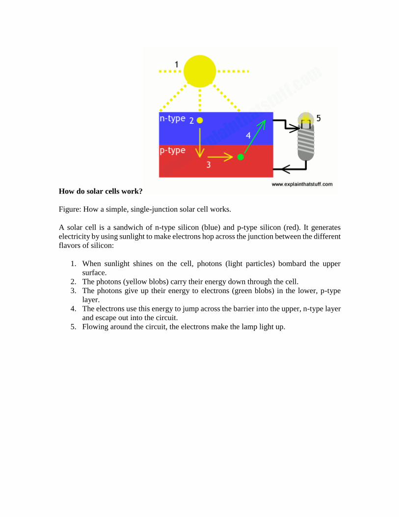
How do solar cells work?
Figure: How a simple, single-junction solar cell works.
A solar cell is a sandwich of n-type silicon (blue) and p-type silicon (red). It generates
electricity by using sunlight to make electrons hop across the junction between the different
flavors of silicon:
1. When sunlight shines on the cell, photons (light particles) bombard the upper
surface.
2. The photons (yellow blobs) carry their energy down through the cell.
3. The photons give up their energy to electrons (green blobs) in the lower, p-type
layer.
4. The electrons use this energy to jump across the barrier into the upper, n-type layer
and escape out into the circuit.
5. Flowing around the circuit, the electrons make the lamp light up.

How efficient are solar cells?
Chart: Efficiencies of solar cells compared: The very first solar cell scraped in at a mere 6
percent efficiency; the most efficient one that's been produced to date managed 46 percent
in laboratory conditions. Most cells are first-generation types that can manage about 15
percent in theory and probably 8 percent in practice.
A basic rule of physics called the law of conservation of energy says that we can't magically
create energy or make it vanish into thin air; all we can do is convert it from one form to
another. That means a solar cell can't produce any more electrical energy than it receives
each second as light. In practice, as we'll see shortly, most cells convert about 10–20
percent of the energy they receive into electricity. A typical, single-junction silicon solar
cell has a theoretical maximum efficiency of about 30 percent, known as the Shockley-
Queisser limit. That's essentially because sunlight contains a broad mixture of photons of
different wavelengths and energies and any single-junction solar cell will be optimized to
catch photons only within a certain frequency band, wasting the rest. Some of the photons
striking a solar cell don't have enough energy to knock out electrons, so they're effectively
wasted, while some have too much energy, and the excess is also wasted. The very best,
cutting-edge laboratory cells can manage 46 percent efficiency in absolutely perfect
conditions using multiple junctions to catch photons of different energies.
Real-world domestic solar panels might achieve an efficiency of about 15 percent, give a
percentage point here or there, and that's unlikely to get much better. First-generation,
single-junction solar cells aren't going to approach the 30 percent efficiency of the
Shockley-Queisser limit, never mind the lab record of 46 percent. All kinds of pesky real-
world factors will eat into the nominal efficiency, including the construction of the panels,
how they are positioned and angled, whether they're ever in shadow, how clean you keep
them, how hot they get (increasing temperatures tend to lower their efficiency), and
whether they're ventilated (allowing air to circulate underneath) to keep them cool.

Types of photovoltaic solar cells
Most of the solar cells you'll see on people's roofs today are essentially just silicon
sandwiches, specially treated ("doped") to make them better electrical conductors.
Scientists refer to these classic solar cells as first-generation, largely to differentiate them
from two different, more modern technologies known as second- and third-generation. So
what's the difference?
First-generation
Photo: A colorful collection of first-generation solar cells. Picture courtesy of NASA Glenn
Research Center (NASA-GRC).
About 90 percent of the world's solar cells are made from wafers of crystalline silicon
(abbreviated c-Si), sliced from large ingots, which are grown in super-clean laboratories in
a process that can take up to a month to complete. The ingots either take the form of single
crystals (monocrystalline or mono-Si) or contain multiple crystals (polycrystalline, multi-
Si or poly c-Si). First-generation solar cells work like we've shown in the box up above:
they use a single, simple junction between n-type and p-type silicon layers, which are sliced
from separate ingots. So an n-type ingot would be made by heating chunks of silicon with
small amounts of phosphorus, antimony, or arsenic as the dopant, while a p-type ingot
would use boron as the dopant. Slices of n-type and p-type silicon are then fused to make
the junction. A few more bells and whistles are added (like an antireflective coating, which
improves light absorption and gives photovoltaic cells their characteristic blue color,
protective glass on front and a plastic backing, and metal connections so the cell can be
wired into a circuit), but a simple p-n junction is the essence of most solar cells. It's pretty
much how all photovoltaic silicon solar cells have worked since 1954, which was when
scientists at Bell Labs pioneered the technology: shining sunlight on silicon extracted from
sand, they generated electricity.
Second-generation

Photo: A thin-film, second-generation solar "panel." The power-generating film is made
from amorphous silicon, fastened to a thin, flexible, and relatively inexpensive plastic
backing (the "substrate"). Photo by Warren Gretz courtesy of NREL (image id #6321083).
Classic solar cells are relatively thin wafers—usually a fraction of a millimeter deep (about
200 micrometers, 200μm, or so). But they're absolute slabs compared to second-generation
cells, popularly known as thin-film solar cells (TPSC) or thin-film photovoltaics (TFPV),
which are about 100 times thinner again (several micrometers or millionths of a meter
deep). Although most are still made from silicon (a different form known as amorphous
silicon, a-Si, in which atoms are arranged randomly instead of precisely ordered in a regular
crystalline structure), some are made from other materials, notably cadmium-telluride (Cd-
Te) and copper indium gallium diselenide (CIGS). Because they're extremely thin, light,
and flexible, second-generation solar cells can be laminated onto windows, skylights, roof
tiles, and all kinds of "substrates" (backing materials) including metals, glass, and polymers
(plastics). What second-generation cells gain in flexibility, they sacrifice in efficiency:
classic, first-generation solar cells still outperform them. So while a top-notch first-
generation cell might achieve an efficiency of 15–20 percent, amorphous silicon struggles
to get above 7 percent, the best thin-film Cd-Te cells only manage about 11 percent, and
CIGS cells do no better than 7–12 percent. That's one reason why, despite their practical
advantages, second-generation cells have so far made relatively little impact on the solar
market.
Third-generation

Photo: Third-generation plastic solar cells produced by researchers at the National
Renewable Energy Laboratory. Photo by Jack Dempsey courtesy of NREL (image id
#6322357).
The latest technologies combine the best features of first and second generation cells. Like
first-generation cells, they promise relatively high efficiencies (30 percent or more). Like
second-generation cells, they're more likely to be made from materials other than "simple"
silicon, such as amorphous silicon, organic polymers (making organic photovoltaics,
OPVs), perovskite crystals, and feature multiple junctions (made from multiple layers of
different semiconducting materials). Ideally, that would make them cheaper, more
efficient, and more practical than either first- or second-generation cells.
How much power can we make with solar cells?
"The total solar energy that reaches the Earth's surface could meet existing global energy
needs 10,000 times over."
European Photovoltaic Industry Association/Greenpeace, 2011.
In theory, a huge amount. Let's forget solar cells for the moment and just consider pure
sunlight. Up to 1000 watts of raw solar power hits each square meter of Earth pointing
directly at the Sun (that's the theoretical power of direct midday sunlight on a cloudless
day—with the solar rays firing perpendicular to Earth's surface and giving maximum
illumination or insolation, as it's technically known). In practice, after we've corrected for
the tilt of the planet and the time of day, the best we're likely to get is maybe 100–250 watts
per square meter in typical northern latitudes (even on a cloudless day). That translates into
about 2–6 kWh per day (depending on whether you're in a northern region like Canada or
Scotland or somewhere more obliging such as Arizona or Mexico). Multiplying up for a
whole year's production gives us somewhere between 700 and 2500 kWh per square meter
(700–2500 units of electricity). Hotter regions clearly have much greater solar potential:
the Middle East, for example, receives around 50–100 percent more useful solar energy
each year than Europe.

Unfortunately, typical solar cells are only about 15 percent efficient, so we can only capture
a fraction of this theoretical energy. That's why solar panels need to be so big: the amount
of power you can make is obviously directly related to how much area you can afford to
cover with cells. A single solar cell (roughly the size of a compact disc) can generate about
3–4.5 watts; a typical solar module made from an array of about 40 cells (5 rows of 8 cells)
could make about 100–300 watts; several solar panels, each made from about 3–4 modules,
could therefore generate an absolute maximum of several kilowatts (probably just enough
to meet a home's peak power needs).
A brief history of solar cells
1839: French physicist Alexandre-Edmond Becquerel (father of radioactivity
pioneer Henri Becquerel) discovers some metals are photoelectric: they produce
electricity when exposed to light.
1873: English engineer Willoughby Smith discovers that selenium is a particularly
effective photoconductor (it's later used by Chester Carlson in his invention of the
photocopier).
1905: German-born physicist Albert Einstein figures out the physics of the
photoelectric effect, a discovery that eventually earns him a Nobel Prize.
1916: American physicist Robert Millikan proves Einstein's theory
experimentally.
1940: Russell Ohl of Bell Labs accidentally discovers that a doped junction
semiconductor will produce an electric current when exposed to light.
1954: Bell Labs researchers Daryl Chapin, Calvin Fuller, and Gerald Pearson
make the first practical photovoltaic silicon solar cell, which is about 6 percent
efficient (a later version manages 11 percent). They announce their invention—
initially called the "solar battery"—on April 25.
1958: Vanguard, Explorer, and Sputnik space satellites begin using solar cells.
1962: 3600 of the Bell solar batteries are used to power Telstar, the pioneering
telecommunications satellite.
1997: US Federal government announces its Million Solar Roofs initiative—to
construct a million solar-powered roofs by 2010.
2002: NASA launches its Pathfinder Plus solar plane.
2009: Scientists discover that perovskite crystals have great potential as third-
generation photovoltaic materials.
2014: A collaboration between German and French scientists produces a new
record of 46 percent efficiency for a four-junction solar cell.
2020: Solar cells are predicted to achieve grid parity (solar-generated electricity
you make yourself will be as cheap as power you buy from the grid).
Polymer Cell
What is polymer cell?
A lithium polymer battery, or more correctly lithium-ion polymer battery (abbreviated
as LiPo, LIP, Li-poly, lithium-poly and others), is a rechargeable battery of lithium-ion

technology using a polymer electrolyte instead of a liquid electrolyte. High conductivity
semisolid (gel) polymers form this electrolyte.
The term polymer is commonly used to describe certain type of lithium-based battery that
may or may not be polymer based. These typically include pouch and prismatic cells. While
the word “polymer” is perceived as a plastic, polymers range from synthetic plastics to
natural biopolymers and proteins that form fundamental biological structures.
Lithium-polymer differs from other battery systems in the type of electrolyte used. The
original polymer design dating back to the 1970s used a solid (dry) polymer electrolyte that
resembles a plastic-like film. This insulator allows the exchange of ions (electrically
charged atoms) and replaces the traditional porous separator that is soaked with electrolyte.
A solid polymer has poor conductivity at room temperature, and the battery must be heated
to 60°C (140°F) and higher to enable current flow. Large polymer batteries for stationary
applications were installed that needed heating, but these have since disappeared. The
much anticipated hype of the “true plastic battery” promised in the early 2000s did not
materialize as conductivity could not be attained at ambient temperature.
To make the modern Li-polymer battery conductive at room temperature, gelled electrolyte
has been added. Most Li-ion polymer cells today incorporate a micro porous separator with
some moisture. Li-polymer can be built on many systems, the likes of Li-cobalt, NMC, Li-
phosphate and Li-manganese, and is not considered a unique battery chemistry. The
majority of Li-polymer packs are cobalt based; other active material may also be added.
With gelled electrolyte added, what is the difference between a normal Li ion and Li ion
polymer? As far as the user is concerned, lithium polymer is essentially the same as lithium-
ion. Both systems use identical cathode and anode material and contain a similar amount
of electrolyte.
Li-polymer is unique in that a micro porous electrolyte replaces the traditional porous
separator. Li-polymer offers slightly higher specific energy and can be made thinner than
conventional Li-ion, but the manufacturing cost is said to be higher than cylindrical design.
For the purpose of discussion, pouch cells are often identified as being Li-polymer.
Li-polymer cells also come in a flexible foil-type case that resembles a food package. While
a standard Li-ion needs a rigid case to press the electrodes together, Li-polymer uses
laminated sheets that do not need compression. A foil-type enclosure reduces the weight
by more than 20 percent over the classic hard shell. Thin film technology liberates the
design as the battery can be made into any shape, fitting neatly into stylish mobile phones
and tablet. Li-polymer can also be made very slim to resemble a credit card (See Pouch
Cell.) Light weight and high specific power make Li-polymer the preferred choice for
hobbyists.
Charge and discharge characteristics of Li-polymer are identical to other Li-ion systems
and do not require a dedicated charger. Safety issues are also similar in that protection
circuits are needed. Gas buildup during charge can cause some prismatic and pouch cells

to swell, and equipment manufacturers must make allowances for expansion. Li-polymer
in a foil package may be less durable than Li-ion in the cylindrical package.
How long does lithium polymer battery last?
If the voltage of a lithium-ion cell drops below a certain level, it's ruined. Lithium-ion
batteries age. They only last two to three years, even if they are sitting on a shelf unused.
So do not "avoid using" the battery with the thought that the battery pack will last five
years.
Are lithium polymer batteries safe?
Devices on the market that heat up lithium polymer batteries can increase the risk of a
fire. Lithium polymer cell manufacturers suggest that exceeding 140 degrees is NOT a
safe temperature for a lithium polymer cell. At 140 degrees, the pack can become unstable
and very dangerous.
Can lithium polymer batteries explode?
The very thing that makes lithium-ion batteries so useful is what also gives them the
capacity to catch fire or explode. Lithium is really great at storing energy. When it's
released as a trickle, it powers your phone all day. When it's released all in one go, the
battery can explode
Are lithium batteries better than alkaline?
Lithium batteries supply more energy than alkaline batteries and are lighter weight.
Lithium batteries perform well in extreme weather environments. Very long shelf life
even compared to alkaline batteries which often last for 5 to 7 yerars.
Difference between lithium ion and lithium polymer battery
The most significant difference between lithium-ion and lithium-polymer batteries is
the chemical electrolyte between their positive and negative electrodes.
1. Lithium ion batteries: They have high energy density and cost less than lithium
polymer. They are essentially a group of very rigid electricity generating
compartments, which consists of three pieces: a positive electrode; a negative
electrode; and an electrolyte, or liquid chemical compound between them. Most
lithium-ion batteries, unlike more traditional ones, also include an electronic
controller, which regulates power and discharge flows so your battery doesn’t
overheat or explode.
2. Lithium polymer batteries: They are light weight and have improved safety.
However their cost is high (30% average) as compared to lithium ion. Also the the

energy density of Li-Polymer battery compared to Li-Ion Batteries is quite less.
In Li-Po batteries it isn’t a liquid. Instead, Li-Po technology uses one of three forms:
a dry solid, which was largely phased out during the prototype years of lithium
polymer batteries; a porous chemical compound; or, a gel-like electrolyte. The most
popular among these is the last one, which is the type of battery you’ll find in newer
laptop computers and electric cars. The catch is that plenty of companies are not
actually selling you a true Li-Po battery, instead it’s a lithium-ion polymer battery,
or a Li-ion in a more flexible casing. Lithium-polymer batteries are generally
robust and flexible, especially when it comes to the size and shape of their build.
They have an extremely low profile, and have a lower chance of suffering from
leaking electrolyte. But they are significantly more costly to manufacture, and they
do not they have the same energy density nor lifespan as a lithium-ion.
Nanomaterials:
Nanomaterials describe materials of which a single unit is sized (in at least one dimension)
between 1 and 1000 nanometers, but is usually 1—100 nm. Nanomaterials research takes
a materials science-based approach to nanotechnology, leveraging advances in materials
metrology and synthesis which have been developed in support of microfabrication
research. Materials with structure at the nanoscale often have unique optical, electronic, or
mechanical properties.


Graphene Synthesis, Properties, And Applications
Introduction To Graphene
Graphene-atomic-structure-3d-illustration

This introduction to graphene has been created to impart a general understanding of what
graphene is, the types of graphene available, as well as synthesis methods and applications
of graphene.
Graphene is quickly finding it’s way into a variety of applications and there are many
advantages to using graphene to develop new products as well as to enhance specific
properties in existing products.
What is Graphene?
Graphene is an allotrope of carbon that exists as a two-dimensional planar sheet. One way
to think of graphene is as a single atomic graphite layer.
Graphene is technically a non-metal but is often referred to as a quasi-metal due to its
properties being like that of a semi-conducting metal. As such, it has many unique
properties that you don’t find with other non-metallic materials.
Each carbon atom is covalently bonded (sp2 hybridized) to three other carbon atoms in a
hexagonal array, leaving one free electron per each carbon atom.
This free electron exists in a p-orbital that sits above the plane of the material. Each
hexagon in the graphene sheet exhibits two pi-electrons, which are delocalized, allowing
for an efficient conduction of electricity.
The holes in the structure also allow phonons to pass through unimpeded, which gives rise
to a high thermal conductivity.
Graphene has many unique properties, making it an ideal material for use in electronic
applications when compared to conventional materials.
Electrical conductivity the most prevalent and important property of graphene. Graphene
doesn’t have an electronic band-gap (meaning that it can’t be switched on or off) as the
valence and conduction bands have a small overlap and the electrons act as massless
relativistic particles.
At room temperature, graphene can exhibit a concentration of charge carriers up to 1013
cm-2, with a mobility of 1 X 104 cm2 V-1 s-1. At low temperatures, this can increase to 2 X
105 cm2 V-1 s-1.
Because the charge carriers act as quasi-particles, otherwise known as massless Dirac
Fermions, graphene also exhibits a half-integer Quantum Hall Effect (QHE).
The QHE is the relationship of the charge, density and velocity of the charge carriers. It
occurs when a magnetic field is applied along the axis perpendicular to the plane of the
conducting material.

Under these conditions, the path of the carriers becomes curved, leading to an accumulation
of opposite charges at either end of the material. Due to the two-dimensional nature of
graphene, the electron confinement produces discrete band levels known as Landau levels,
which are filled by the charge carriers.
Unlike other materials, the charge carriers in graphene only half-fill these levels, leading
to a quantization of the Landau levels, and in effect the energy levels of graphene.
Graphene also has great optical, thermal and mechanical properties. Single sheet graphene
is a highly transparent material but each layer in thickness absorbs up to 2.3% of white
light, with less than 0.1% reflectance.
There is also a linear absorbance increase with respect to the number of layers stacked on
top of each other. A suspended graphene sheet can exhibit a thermal conductivity of 3000-
5000 W m-1 K-1 at room temperature. However, this can drop to as low as 600 W m-1 K-1
when it is attached to another substrate.
The drop is caused by a scattering of phonons at the interface which impedes their
movement, whereas in free standing graphene the phonon path is uninterrupted. Even at
this lower conductivity, the thermal conductivity is still twice as high as copper.
Graphene is also known to be one of the strongest materials ever made and a single-layer
graphene sheet can withstand up to 42 N m-1 of stress, with a Young’s modulus of 1.0 Tpa.
Types Of Graphene
Graphene-molecular-structure
There are many types of graphene. True Graphene is only one atomic layer thick (often
called a monolayer) and it typically exists as a film but it can be floated off the substrate
and can be redeposited onto another substrate or used in it’s isolated form.
There are, however, several types of graphene containing powder form materials such as
graphene oxide, graphene nanoplatelets, graphene nanoribbons, and graphene quantum
dots as well as graphene enabled products such as graphene ink or graphene masterbatches.
There are 3 main ways to synthesize graphene, they are:
Chemical Vapor Deposition
Chemical or Plasma Exfoliation from natural Graphite

Mechanical cleavage from natural Graphite
Graphene can also be fully synthetic but those methods haven’t proven to be commercially
viable.
Chemical Vapor Deposition (CVD) Graphene Films
Monolayer Graphene Film On Wafer
Graphene films can be produced by varying methods, which include mechanical and
thermal exfoliation, chemical reduction and epitaxial growth; but the most common
method used in production today is by chemical vapor deposition (CVD).
CVD works by combining and depositing volatile gas molecules onto a substrate. The
process takes place in a reaction chamber, where the material is formed on the surface of
the substrate and the waste gases are pumped out.
Temperature dependence plays a vital role and can affect the type of reaction that occurs.
CVD produces graphene films of high quality and purity, but the by-products produced
during the reaction can be toxic due to the volatile nature of the precursor gases.
The graphene film is created by CVD in two steps. The first involves the pyrolysis of a
precursor material to form carbon atoms on a substrate material.
By pyrolyzing the material on the substrate, carbon clusters are prevented from forming.
Due to the amount of energy required to break the carbon bonds (C-C = 347 kjmol-1, C=C
= 614 kjmol-1, C≡C = 839 kjmol-1, C-H = 413 kjmol-1), a high heat is required, and therefore
a metal catalyst is required during the process.
The second step is a heat intensive step which assembles the dissociated carbon atoms onto
a substrate (in the presence of a catalyst), which forms a single layer structure.
CVD graphene films are predicted to have strong chemical, electronic, mechanical and
magnetic properties depending on the arrangement of the atoms in the film. Due to the five-

order-of-magnitude difference between the grains and atoms at grain boundaries, only a
few experiments have been produced to study these interactions.
One substrate that is known to produce high-quality graphene is copper. Copper acts as
both a catalyst and the substrate.
The copper bonds to the carbon atoms, which provides strong carbon-substrate interactions,
allowing for a single graphene layer to be easily formed on the surface. Copper oxide can
also be inserted between layers of graphene, making it an easy process to remove a single
layer.
Treating the copper substrate can also rearrange the surface morphology of the substrate-
catalyst and is known to produce graphene with fewer defects.
Graphene Oxide (GO)
Single Layer Graphene Oxide
Molecular Structure
Graphene oxide (GO) is most commonly produced by the oxidation of graphite oxide. The
oxidation process is beneficial, as it functionalizes the surface of the graphene layers with
multiple species of oxygenated functional groups.
The multiple functional groups provide an enhanced layer separation and improved
hydrophilicity. The hydrophilicity allows the graphene oxide to undergo ultrasonic
irradiation, which produces a single/a few graphene layers that are highly stable when
dispersed in DI Water and other solvents.
GO has many desirable properties. It disperses very easily in various mediums including
aqueous solvents, organic solvents and various matrices.
The presence of both electron rich oxygen species and an electron rich graphene backbone
allow for further surface functionalization, which gives rise to an adaptable material for
multiple applications.
Graphene oxide does however suffer from a low electrical conductivity and is an electrical
insulator. Graphene oxide is also soluble in many solvents, both aqueous and organic.

Graphene Oxide Solubility
Graphene Oxide Is Highly Soluble
To gain the benefits of graphene oxide, it is typically dispersed, added into a formulation,
made into a film or other nano-enabled product and then reduced to restore the graphene
structure.
Reduced Graphene Oxide (rGO)
There are many methods to reduce graphene oxide (GO) into reduced graphene oxide
(rGO), but most fall into three main categories: chemical reduction, thermal reduction and
electrochemical reduction.
The other methods include hydrazine vapor treatment, annealing, laser and microwave
reduction. The reduction process is vital to producing rGO, as it determines how consistent
the rGO structure is with the GO precursor.
Many commercial producers of Graphene Nanoplatelets are in fact providing a product
similar to industrial scale rGO as their GNP product. However this method differs from the
rGO most people refer to which is a higher quality research product used for nano enabled
devices.
Chemical reduction is a scalable method but can often result in poor yields and utilizes
highly toxic materials such as hydrazine. rGO produced by this method generally exhibits
a low surface area and has a low conductivity compared to the GO precursor.
Thermal reduction produces rGO with a high surface area that is close to the surface area
of pristine graphene. However, the intense heating process causes a high-pressure build-up
of carbon dioxide which causes structural damage to the graphene layers.

The structural imperfections can then give rise to a reduction in the overall mass (and yield
against the theoretical output), vacancies, voids and it can hinder the mechanical strength
of the material.
Electrochemical reduction shows the best results in terms of production and quality. The
rGO produced is consistent with that of pristine graphene.
During the electrochemical process, the substrates (generally ITO or glass) are coated with
a layer of GO and a current is passed through the material (via electrodes at either end of
the substrate). rGO produced by this method have shown to have a high carbon to oxygen
ratio and have exhibited conductivity comparable to that of silver.
The process also benefits from no toxic waste. This process does however suffer from
issues regarding the feasibility of the scalability of the method.
Graphene Nanoplatelets (GNPs)
Graphene Nanoplatelets SEM Image
Graphene Nanoplatelets are typically synthesized by micromechanical cleavage of bulk
graphite and can only produce graphene flakes in limited quantities which are mixed in
with graphitic stacks. Large scale GNP production often uses mechanical cleavage
followed by chemical reduction to produce the final GNP product.
Another method to make GNPs in bulk is by plasma exfoliation. A unique benefit of plasma
exfoliation is the ability to synthesize and functionalize the GNPs to promote dispersion in
the host matrix in a single, dry, processing step.
The RF or Microwave Plasma Reactor has a vacuum applied to remove atmospheric
contaminants as well as residual contaminants which are liberated during the plasma
milling process. These benefits make the material an excellent choice for large scale
industrial applications with a wide variety of available functional groups such as OH,
COOH, NH2, N2, & F.

Due to the lower cost of input materials, capital equipment, and plasma purification and/or
functionalization, the GNPs can ultimately be a cheaper material than CNTs on a ton level
thus paving the way for increased industrial applications with early adopters.
Graphene And Graphene Oxide Quantum Dots
Graphene Quantum Dots with Nitrogen Atoms
Graphene and graphene oxide quantum dots (GQDs) can be synthesized into various forms,
from single-layer to tens of layers, but are generally less than 30 nm. GQDs also show
similar properties to other types of quantum dots.
Like many graphene-based materials, GQDs exhibit a large surface area, a good linear
dispersibilty and a high charge carrier mobility. GQDs also exhibit an efficient hole
transporting ability, making them efficient materials for hole-transport layers.
They are useful materials for both electronic and opto-electronic applications.
GQDs can now be produced by a multitude of methods which includes both top-down and
bottom-up approaches. Production by bottom-up methods can produce GQDs with a
controlled size (due to the ability to control the band gap), but the synthesis itself can be
complex which requires stringent conditions.
Top-down methods are in their infancy, but do provide a much simpler and cheaper
approach. The breakdown of graphite oxide can produce single layered GQDs, but the
yields aren’t high and the size distribution cannot be easily controlled. GQDs can also be
synthesized by the breakdown of range of carbon allotropes including CNTs, fullerenes
and carbon fibers.
Other methods include ultrasonication, microwave irradiation, radical methods and hydro-
thermal or solvo-thermal methods.The main challenge that faces GQD production today is
finding an efficient process that can take the production to industrial levels, as they have
potential for many applications.
The applications of GQDs include lithium-ion batteries, supercapacitors and solar cells.
But one area in which they are particularly useful is in LED displays. GQD-LEDs are a

growing area and have been produced by etching CVD-grown graphene with block
copolymers, followed by fabrication with graphite intercalating compounds.
The process produces graphene flakes that are low in oxygenated functional groups, of low
toxicity and environmentally safe. It is also both a cheap and scalable process. GQDs emit
light upon excitation, so are now being tested as emitters in organic light-emitting diodes
(OLEDS). So far, they have exhibited a luminescence of 1000 cdm-2. The thin nature of
GQDs may also open up future opportunities to create and perfect fold-able displays.
Graphene Nanoribbons
Graphene Nanoribbons
Unlike many other forms of graphene which are two-dimensional, graphene nanoribbons
(GNRs) are quasi-one-dimensional materials with an ultra-thin width.
The electrical properties that GNRs exhibit are highly tunable and can be manipulated by
dimension confinement, edge morphology and functionalization of the GNR.
GNRs also exhibit large aspect ratios, a high surface area, a conductive matrix and good
mechanical flexibility. The combination of these properties has given GNRs a strong
footing in composite materials for electronic applications. GNR anode composites have
been shown to exhibit a specific reversible capacity of 1130 mAh g-1, with a coulombic
efficiency >98%.
GNRs are produced by various methods. One of the most common methods involves
unzipping the walls of MWCNTs with sodium and potassium-based compounds,
sonicating and drying under vacuum.
They can also be produced by plasma etching of nanotubes onto polymer films, epitaxial
growth and annealing on silicon carbide and CVD.

Graphene Nanoribbon Band Gaps Are
Contollable
GNRs can enhance the performance of lithium-ion batteries through edge chirality effects.
GNRs have a band gap that is inversely proportion to their width, which is dependent upon
their edge chirality.
Chirality occurs at the edges because the electron confinement potential deforms the wave-
function and causes the electrons move in a single direction, with more weight in the
‘positive x’ direction. This leads to a current in the ‘positive y’ direction.
For electronic applications, the edges in GNRs have shown the best results when armchair
and metallic edges are present due to their semi-conducting abilities. Armchair edges also
reduce the band gap energy when there is a defined width.
The energy at the edges of GNRs is proportional to their density and armchair edges are
more tightly packed at the graphene interface, so the energy is higher than that of zig-zag
edges. Such edges can be produced on GNRs by electron beam irradiation and electron
beam lithography.
A GNR with a high concentration and purity of armchair edges has been found to provide
highly efficient p-n junctions in electronic devices.
Graphene Aerogels
A Graphene Aerogel Foam Sits On A
Flower
Carbon aerogels are derived by sol-gel synthesis methods and are a unique class of high-
surface-area materials. Their high mass-specific surface area, electrical conductivity,
environmental compatibility, and chemical inertness make them very promising materials
for many energy related applications.

Recent developments in controlling their morphology make them especially well suited to
super capacitor applications.
Aerogels are a special class of open-cell foams that exhibit many unique and interesting
properties, such as low mass density, continuous porosity and high surface areas. These
properties are derived from the aerogel microstructure, which consists of three-dimensional
networks of interconnected nanometer-sized particles.
Aerogels are typically prepared by sol–gel methods, a process that transforms molecular
precursors into highly cross-linked inorganic or organic gels that can then be dried using
techniques such as supercritical drying, freeze drying, ect to preserve the insubstantial solid
network.
For organic and carbon aerogels, the transformation involves the polymerization of multi-
functional organic species into three-dimensional polymer networks.
Graphene Masterbatches
Graphene Masterbatches
Graphene masterbatches are composite materials that contain a graphene-based compound
(most commonly GO) and a polymer.
The graphene is used to enhance the properties of various common polymeric materials.
Many polymers exhibit desirable properties such as low cost, low toxicity, bio-
compatibility and chemical resistance, but they lack desirable mechanical properties.
By incorporating graphene nanoplatelets into polymer matrices, the polymers retain their
original properties but benefit from enhanced rigidity and stiffness, while still being
lightweight.
Using graphene as a filler compound rather than conventional inorganic materials can bring
an enhanced electrical conductivity to the polymer, but it does have some issues.
In many graphene-based composites, graphene oxide acts as the dispersing support for
other ions and molecules.

In polymer masterbatches, this can lead to problems as graphene doesn’t always disperse
well in polymer phases (especially polyolefins) due to a lack of positive interactions at the
grpahene polymer interface.
However, this can be overcome by the use of a surfactant, or by tailoring surface
functionality of the graphene surface. The surfactant increases the surface interaction
between the polymer and graphene.
If functionalized, the functional groups promote interaction between itself and the polymer
molecules. If the functional groups aren’t compatible, you may observe what we call
“islands of masterbatch” with easily observed islands of polymer in between well dispersed
graphene-polymer masterbatches.
Properties Of Graphene
The properties of graphene are unique due to its all carbon structure and nanoscale
geometry.
Electronic Properties
Flexible Graphene Transistors
Because graphene has a delocalized pi-electron system across the entirety of its surface,
the movement of electrons is very fluid.
The graphene system also exhibits no band gap, due to overlapped pi-electrons, allowing
for an easy movement of electrons without the need to input energy into the system.
The electronic mobility of graphene is very high and the electrons act like photons, with
respect to their movement capabilities.
The electrons are also able to move sub-micrometer distances without scattering. From
tests done to date the electron mobility has found to be in excess of 15,000 cm2V-1s-1, with
the potential of producing up to 200,000 cm2V-1s-1.
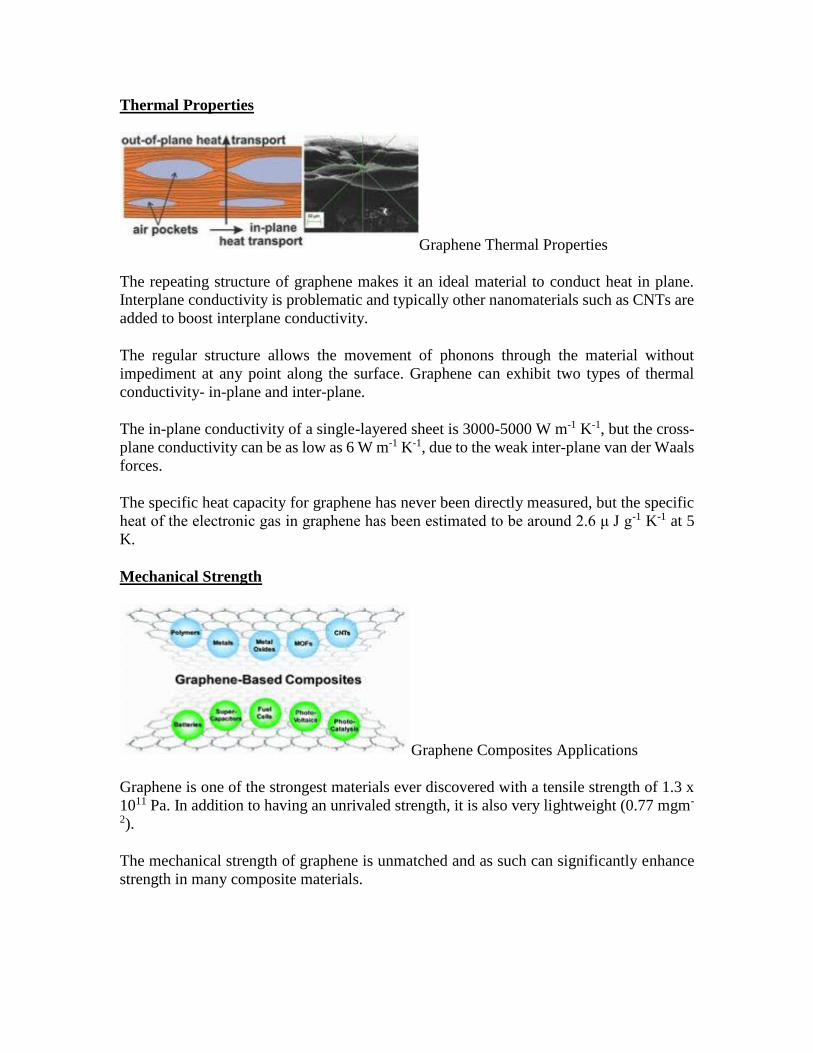
Thermal Properties
Graphene Thermal Properties
The repeating structure of graphene makes it an ideal material to conduct heat in plane.
Interplane conductivity is problematic and typically other nanomaterials such as CNTs are
added to boost interplane conductivity.
The regular structure allows the movement of phonons through the material without
impediment at any point along the surface. Graphene can exhibit two types of thermal
conductivity- in-plane and inter-plane.
The in-plane conductivity of a single-layered sheet is 3000-5000 W m-1 K-1, but the cross-
plane conductivity can be as low as 6 W m-1 K-1, due to the weak inter-plane van der Waals
forces.
The specific heat capacity for graphene has never been directly measured, but the specific
heat of the electronic gas in graphene has been estimated to be around 2.6 μ J g-1 K-1 at 5
K.
Mechanical Strength
Graphene Composites Applications
Graphene is one of the strongest materials ever discovered with a tensile strength of 1.3 x
1011 Pa. In addition to having an unrivaled strength, it is also very lightweight (0.77 mgm-
2).
The mechanical strength of graphene is unmatched and as such can significantly enhance
strength in many composite materials.
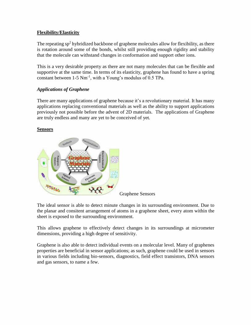
Flexibility/Elasticity
The repeating sp2 hybridized backbone of graphene molecules allow for flexibility, as there
is rotation around some of the bonds, whilst still providing enough rigidity and stability
that the molecule can withstand changes in conformation and support other ions.
This is a very desirable property as there are not many molecules that can be flexible and
supportive at the same time. In terms of its elasticity, graphene has found to have a spring
constant between 1-5 Nm-1, with a Young’s modulus of 0.5 TPa.
Applications of Graphene
There are many applications of graphene because it’s a revolutionary material. It has many
applications replacing conventional materials as well as the ability to support applications
previously not possible before the advent of 2D materials. The applications of Graphene
are truly endless and many are yet to be conceived of yet.
Sensors
Graphene Sensors
The ideal sensor is able to detect minute changes in its surrounding environment. Due to
the planar and consitent arrangement of atoms in a graphene sheet, every atom within the
sheet is exposed to the surrounding environment.
This allows graphene to effectively detect changes in its surroundings at micrometer
dimensions, providing a high degree of sensitivity.
Graphene is also able to detect individual events on a molecular level. Many of graphenes
properties are beneficial in sensor applications; as such, graphene could be used in sensors
in various fields including bio-sensors, diagnostics, field effect transistors, DNA sensors
and gas sensors, to name a few.

Batteries
Lithium Reduced Graphene Oxide Battery
Graphene can be incorporated into both the anode or the cathode in various battery systems
to increase the efficiency of the battery and improve the charge/discharge cycle rate.
The excellent electrical conductivity, surface area and dispersibility of graphene enhances
the beneficial properties present in many traditional inorganic-based electrodes, whilst
simultaneously relieving the electrodes of their limitations.
Due to its versatile nature, graphene has been incorporated into lithium-ion batteries,
lithium-sulphur batteries, supercapacitors and fuel cells, of which there are multiple
variations of each available on the market today.
Check out our detailed Graphene Batteries User’s Guide here.
Electron Emission Displays
Graphene Displays
Graphene is an ideal material for use in electron emission displays as it exhibits a high
aspect ratio and the dangling bonds at either end of the sheet allow for efficient electron
tunneling.

The linear disperisty that the graphene surface provides produces massless Dirac Fermions.
When exposed to an electric field, the field emission liberated electrons avoid all back-
scattering because their escape velocity is independent to their energy.
Graphene can turn-on an electric field at 0.1 V µm-2, with a field enhancement factor of up
to 3700. This can increase up to 4500 in screen printed graphene films.
Structural Composites
Graphene is incorporated into various composites for applications where strength and
weight are limiting factors, for example in the aerospace industry.
Graphene is being incorporated into many materials to make the existing material stronger
and more lightweight. For the aviation industry, a composite material which is much lighter
than steel but will still provide the necessary strength will save a lot of money on fuel
consumption, which is why graphene has started to be incorporated into such materials.
Graphene-based structural composites have a huge potential to become a widely used
alternative to many materials used today.
Catalyst Supports
Graphene Catalyst Supports
Even though the surface of graphene is planar and uniform, like any other material in
existence it is subject to intrinsic defects.
Catalysts in the form of metal ions can sit in these cavities and be supported. In addition to
providing mechanical support, the excellent charge carrier ability of graphene assists the
charge transfer reactions involving the catalyst.
Graphene is also inert and does not interfere (in a negative way) with the interaction
between the catalyst and the substrate materials. Graphene also provides an even dispersion
of catalyst particles, so the catalyst-substate reaction is consistent across the whole support.

Polymer Masterbatches
Graphene can be incorporated into polymeric materials to form graphene-polymer
composite materials.
As many polymeric materials suffer from strength-related problems, the incorporation of
graphene can help to increase the tensile strength of the polymers, increasing the shelf life
of the polymeric material in commercial applications.
Incorporating graphene into polymers can also give polymers electrical conductivity
properties.
Functional Inks
Graphene can be used in functional inks for electronic, heat resistant and anti-corrosion
purposes. By incorporating graphene into ink formulations, the conductivity properties
associated with graphene influence the ink, causing it to become conductive.
The inks can then be used to coat electronics. Compared to other conducting inks, graphene
is non-toxic, environmentally friendly, cheaper, quick-drying and recyclable. Graphene
also has a high thermal stability, making it an ideal for heat resistant ink coating in
electronic applications that produce large amounts of heat.
It is also an ink of choice when processing temperatures need to be high, as the graphene
won’t break down during the manufacturing process. Graphene also exhibits excellent
chemical stability and is inert.
For applications where environmental factors are an issue, graphene inks can provide a
stable barrier to protect materials from chemicals and corrosion.
plasmonic material
it is a metamaterial that uses surface plasmons to achieve optical properties not seen in
nature. Plasmons are produced from the interaction of light with metal-dielectric materials.
Under specific conditions, the incident light couples with the surface plasmons to create
self-sustaining, propagating electromagnetic waves known as surface plasmon polaritons
(SPPs). Once launched, the SPPs ripple along the metal-dielectric interface. Compared
with the incident light, the SPPs can be much shorter in wavelength.[1]
The properties stem from the unique structure of the metal-dielectric composites, with
features smaller than the wavelength of light separated by subwavelength distances. Light
hitting such a metamaterial is transformed into surface plasmon polaritons, which are
shorter in wavelength than the incident light.
Materials
Silicon sandwich
Negative refraction for visible light was first produced in a sandwich-like construction with
thin layers. An insulating sheet of silicon nitride was covered by a film of silver and
underlain by another of gold. The critical dimension is the thickness of the layers, which
summed to a fraction of the wavelength of blue and green light. By incorporating this
metamaterial into integrated optics on an IC chip, negative refraction was demonstrated
over blue and green frequencies. The collective result is a relatively significant response to
light.[4][5]
Graphene
Graphene also accommodates surface plasmons,[15] observed via near field infrared optical
microscopy techniques[16][17] and infrared spectroscopy.[18] Potential applications of
graphene plasmonics involve terahertz to midinfrared frequencies, in devices such as
optical modulators, photodetectors and biosensors.[19]
Superlattice
A hyperbolic metamaterial made from titanium nitride (metal) and aluminum scandium
nitride (dielectric) have compatible crystal structures and can form a superlattice, a crystal
that combines two (or more) materials. The material is compatible with existing CMOS
technology (unlike traditional gold and silver), mechanically strong and thermally stable at
higher temperatures. The material exhibits higher photonic densities of states than Au or
Ag.[20] The material is an efficient light absorber.[21]
The material was created using epitaxy inside a vacuum chamber with a technique known
as magnetron sputtering. The material featured ultra-thin and ultra-smooth layers with
sharp interfaces.[21]
Possible applications include a “planar hyperlens” that could make optical microscopes
able to see objects as small as DNA, advanced sensors, more efficient solar collectors,
nano-resonators, quantum computing and diffraction free focusing and imaging
The material works across a broad spectrum from near-infrared to visible light. Near-
infrared is essential for telecommunications and optical communications, and visible light
is important for sensors, microscopes and efficient solid-state light sources.

Semiconductors-
Semiconductors, as we noted above, are somewhat arbitrarily defined as insulators with
band gap energy < 3.0 eV (~290 kJ/mol). This cutoff is chosen because, as we will see,
the conductivity of undoped semiconductors drops off exponentially with the band gap
energy and at 3.0 eV it is very low. Also, materials with wider band gaps (e.g. SrTiO3, Egap
= 3.2 eV) do not absorb light in the visible part of the spectrum
There are a number of places where we find semiconductors in the periodic table:
Early transition metal oxides and nitrides, especially those with d0 electron counts
such as TiO2, TaON, and WO3
Oxides of later 3d elements such as Fe2O3, NiO, and Cu2O
Layered transition metal chalcogenides with d0, d2 and d6 electron counts including
TiS2, ZrS2, MoS2, WSe2, and PtS2
d10 copper and sliver halides, e.g., CuI, AgBr, and AgI
Zincblende- and wurtzite-structure compounds of the p-block elements, especially
those that are isoelectronic with Si or Ge, such as GaAs and CdTe. While these are
most common, there are other p-block semiconductors that are not isoelectronic and
have different structures, including GaS, PbS, and Se.
A 2" wafer cut from a GaAs single crystal. GaAs, like many p-block semiconductors, has
the zincblende structure.
The p-block octet semiconductors are by far the most studied and important for
technological applications, and are the ones that we will discuss in detail.
Zinc blende- and wurtzite-structure semiconductors have 8 valence electrons per 2
atoms. These combinations include 4-4 (Si, Ge, SiC,…), 3-5 (GaAs, AlSb, InP,…), 2-6
(CdSe, HgTe, ZnO,…), and 1-7 (AgCl, CuBr,…) semiconductors. Other variations that
add up to an octet configuration are also possible, such as CuIInIIISe2, which has the
chalcopyrite structure, shown at the right.

The chalcopyrite structure is adopted by ABX2 octet semiconductors such as CuIInIIISe2
and CdIISnIVP2. The unit cell is doubled relative to the parent zincblende structure
because of the ordered arrangement of cations. Each anion (yellow) is coordinated by two
cations of each type (blue and red).
How does the band gap energy vary with composition? There are two important trends
(1) Going down a group in the periodic table, the gap decreases:
Egap (eV): 5.4 1.1 0.7 0.0
This trend can be understood by recalling that Egap is related to the energy splitting
between bonding and antibonding orbitals. This difference decreases (and bonds
become weaker) as the principal quantum number increases.
(2) For isoelectronic compounds, increasing ionicity results in a larger band gap.
This trend can also be understood from a simple MO picture, as we discussed in Ch. 2. As
the electronegativity difference Δχ increases, so does the energy difference between
bonding and antibonding orbitals.
The band gap is a very important property of a semiconductor because it determines its
color and conductivity. Many of the applications of semiconductors are related to band
gaps:
Narrow gap materials (HgxCd1-xTe, VO2, InSb, Bi2Te3) are used as infrared
photodetectors and thermoelectrics (which convert heat to electricity).
Wider gap materials (Si, GaAs, GaP, GaN, CdTe, CuInxGa1-xSe2) are used in
electronics, light-emitting diodes, and solar cells.
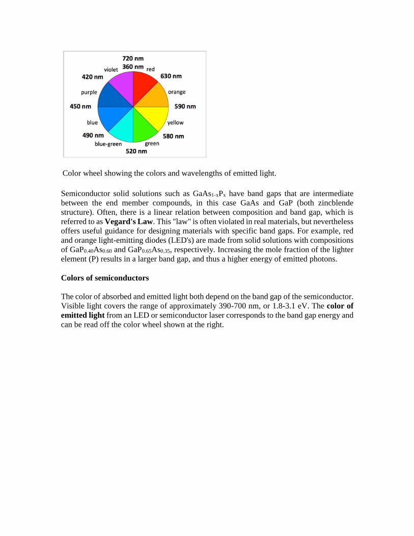
Color wheel showing the colors and wavelengths of emitted light.
Semiconductor solid solutions such as GaAs1-xPx have band gaps that are intermediate
between the end member compounds, in this case GaAs and GaP (both zincblende
structure). Often, there is a linear relation between composition and band gap, which is
referred to as Vegard's Law. This "law" is often violated in real materials, but nevertheless
offers useful guidance for designing materials with specific band gaps. For example, red
and orange light-emitting diodes (LED's) are made from solid solutions with compositions
of GaP0.40As0.60 and GaP0.65As0.35, respectively. Increasing the mole fraction of the lighter
element (P) results in a larger band gap, and thus a higher energy of emitted photons.
Colors of semiconductors
The color of absorbed and emitted light both depend on the band gap of the semiconductor.
Visible light covers the range of approximately 390-700 nm, or 1.8-3.1 eV. The color of
emitted light from an LED or semiconductor laser corresponds to the band gap energy and
can be read off the color wheel shown at the right.

Fe2O3 powder is reddish orange because of its 2.2 eV band gap
The color of absorbed light includes the band gap energy, but also all colors of higher
energy (shorter wavelength), because electrons can be excited from the valence band to a
range of energies in the conduction band. Thus semiconductors with band gaps in the
infrared (e.g., Si, 1.1 eV and GaAs, 1.4 eV) appear black because they absorb all colors of
visible light. Wide band gap semiconductors such as TiO2 (3.0 eV) are white because they
absorb only in the UV. Fe2O3 has a band gap of 2.2 eV and thus absorbs light with λ < 560
nm. It thus appears reddish-orange (the colors of light reflected from Fe2O3) because it
absorbs green, blue, and violet light. Similarly, CdS (Egap = 2.6 eV) is yellow because it
absorbs blue and violet light.
Electrons and holes in semiconductors
Pure (undoped) semiconductors can conduct electricity when electrons are promoted, either
by heat or light, from the valence band to the conduction band. The promotion of an
electron (e-) leaves behind a hole (h+) in the valence band. The hole, which is the absence
of an electron in a bonding orbital, is also a mobile charge carrier, but with a positive
charge. The motion of holes in the lattice can be pictured as analogous to the movement of
an empty seat in a crowded theater. An empty seat in the middle of a row can move to the
end of the row (to accommodate a person arriving late to the movie) if everyone moves
over by one seat. Because the movement of the hole is in the opposite direction of electron
movement, it acts as a positive charge carrier in an electric field.
The opposite process of excitation, which creates an electron-hole pair, is their
recombination. When a conduction band electron drops down to recombine with a valence
band hole, both are annihilated and energy is released. This release of energy is responsible
for the emission of light in LEDs.

An electron-hole pair is created by adding heat or light energy E > Egap to a semiconductor
(blue arrow). The electron-hole pair recombines to release energy equal to Egap (red
arrow).
At equilibrium, the creation and annihilation of electron-hole pairs proceed at equal rates.
This dynamic equilibrium is analogous to the dissociation-association equilibrium of H+
and OH- ions in water. We can write a mass action expression:
n×p=Keq=ni2
where n and p represent the number density of electrons and holes, respectively, in units of
cm-3. The intrinsic carrier concentration, ni, is equal to the number density of electrons or
holes in an undoped semiconductor, where n = p = ni.
Note the similarity to the equation for water autodissociation:
[H+][OH−]=Kw
By analogy, we will see that when we increase n (e.g., by doping), p will decrease, and
vice-versa, but their product will remain constant at a given temperature.
Temperature dependence of the carrier concentration. Using the equations
Keq=e(−ΔGoRT)
and ΔGo=ΔHo−TΔSo

, we can write:
n×p=ni2=e(ΔSoR)e(−ΔHoRT)
The entropy change for creating electron hole pairs is given by:
ΔSo=Rln(NV)+Rln(NV)=Rln(NCNV)
where NV and NC are the effective density of states in the valence and conduction bands,
respectively.
and thus we obtain
ni2=NCNVe(−ΔHoRT)
Since the volume change is negligible, ΔHo≈ΔEo
, and therefore ΔHoR≈Egapk
, from which we obtain
ni2=NCNVe(−Egap/kT)
and finally
n = p = ni = (NCNV)1/2e(−Egap/2kT)
For pure Si (Egap = 1.1 eV) with N ≈ 1022/cm3, we can calculate from this equation a carrier
density ni of approximately 1010/cm3 at 300 K. This is about 12 orders of magnitude lower
than the valence electron density of Al, the element just to the left of Si in the periodic
table. Thus we expect the conductivity of pure semiconductors to be many orders of
magnitude lower than those of metals.
Conductivity of intrinsic semiconductors
The conductivity (σ) is the product of the number density of carriers (n or p), their charge
(e), and their mobility (µ). Recall from Chapter 6 that µ is the ratio of the carrier drift
velocity to the electric field and has units of cm2/Volt-second. Typically electrons and holes
have somewhat different mobilities (µe and µh, respectively) so the conductivity is given
by:
σ = neμe + peμh
For either type of charge carrier, we recall from Ch. 6 that the mobility μ is given by:
μ=vdrift/E=eτ/m
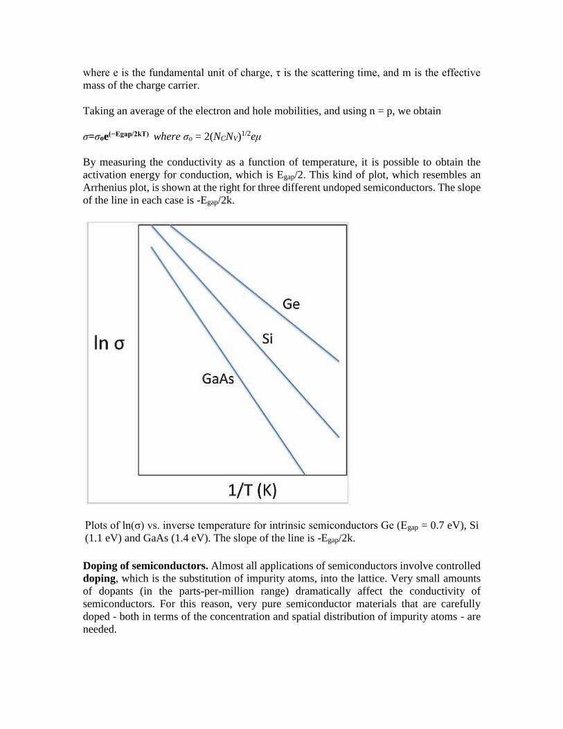
where e is the fundamental unit of charge, τ is the scattering time, and m is the effective
mass of the charge carrier.
Taking an average of the electron and hole mobilities, and using n = p, we obtain
σ=σoe(−Egap/2kT) where σo = 2(NCNV)1/2eμ
By measuring the conductivity as a function of temperature, it is possible to obtain the
activation energy for conduction, which is Egap/2. This kind of plot, which resembles an
Arrhenius plot, is shown at the right for three different undoped semiconductors. The slope
of the line in each case is -Egap/2k.
Plots of ln(σ) vs. inverse temperature for intrinsic semiconductors Ge (Egap = 0.7 eV), Si
(1.1 eV) and GaAs (1.4 eV). The slope of the line is -Egap/2k.
Doping of semiconductors. Almost all applications of semiconductors involve controlled
doping, which is the substitution of impurity atoms, into the lattice. Very small amounts
of dopants (in the parts-per-million range) dramatically affect the conductivity of
semiconductors. For this reason, very pure semiconductor materials that are carefully
doped - both in terms of the concentration and spatial distribution of impurity atoms - are
needed.

n- and p-type doping. In crystalline Si, each atom has four valence electrons and makes
four bonds to its neighbors. This is exactly the right number of electrons to completely fill
the valence band of the semiconductor. Introducing a phosphorus atom into the lattice (the
positively charged atom in the figure at the right) adds an extra electron, because P has five
valence electrons and only needs four to make bonds to its neighbors. The extra electron,
at low temperature, is bound to the phosphorus atom in a hydrogen-like molecular orbital
that is much larger than the 3s orbital of an isolated P atom because of the high dielectric
constant of the semiconductor. In silicon, this "expanded" Bohr radius is about 42 Å, i.e.,
80 times larger than in the hydrogen atom. The energy needed to ionize this electron – to
allow it to move freely in the lattice - is only about 40–50 meV, which is not much larger
the thermal energy (26 meV) at room temperature. Therefore the Fermi level lies just below
the conduction band edge, and a large fraction of these extra electrons are promoted to the
conduction band at room temperature, leaving behind fixed positive charges on the P atom
sites. The crystal is n-doped, meaning that the majority carrier (electron) is negatively
charged.
Alternatively, boron can be substituted for silicon in the lattice, resulting in p-type doping,
in which the majority carrier (hole) is positively charged. Boron has only three valence
electrons, and "borrows" one from the Si lattice, creating a positively charged hole that
exists in a large hydrogen-like orbital around the B atom. This hole can become delocalized
by promoting an electron from the valence band to fill the localized hole state. Again, this
process requires only 40–50 meV, and so at room temperature a large fraction of the holes
introduced by boron doping exist in delocalized valence band states. The Fermi level (the
electron energy level that has a 50% probability of occupancy at zero temperature) lies just
above the valence band edge in a p-type semiconductor.

n- and p-type doping of semiconductors involves substitution of electron donor atoms
(light orange) or acceptor atoms (blue) into the lattice. These substitutions introduce extra
electrons or holes, respectively, which are easily ionized by thermal energy to become
free carriers. The Fermi level of a doped semiconductor is a few tens of mV below the
conduction band (n-type) or above the valence band (p-type).
As noted above, the doping of semiconductors dramatically changes their conductivity. For
example, the intrinsic carrier concentration in Si at 300 K is about 1010 cm-3. The mass
action equilibrium for electrons and holes also applies to doped semiconductors, so we can
write:
n×p=n2i=1020cm−6at300K(10.5.9)
If we substitute P for Si at the level of one part-per-million, the concentration of electrons
is about 1016 cm-3, since there are approximately 1022 Si atoms/cm3 in the crystal.
According to the mass action equation, if n = 1016, then p = 104 cm-3. There are three
consequences of this calculation:
The density of carriers in the doped semiconductor (1016 cm-3) is much higher than
in the undoped material (~1010 cm-3), so the conductivity is also many orders of
magnitude higher.
The activation energy for conduction is only 40–50 meV, so the conductivity does
not change much with temperature (unlike in the intrinsic semiconductor)
The minority carriers (in this case holes) do not contribute to the conductivity,
because their concentration is so much lower than that of the majority carrier
(electrons).
Similarly, for p-type materials, the conductivity is dominated by holes, and is also much
higher than that of the intrinsic semiconductor.
Chemistry of semiconductor doping. Sometimes it is not immediately obvious what kind
of doping (n- or p-type) is induced by "messing up" a semiconductor crystal lattice. In
addition to substitution of impurity atoms on normal lattice sites (the examples given above
for Si), it is also possible to dope with vacancies - missing atoms - and with interstitials -
extra atoms on sites that are not ordinarily occupied. Some simple rules are as follows:
For substitutions, adding an atom to the right in the periodic table results in n-
type doping, and an atom to the left in p-type doping.
For example, when TiO2 is doped with Nb on some of the Ti sites, or with F on O sites, the
result is n-type doping. In both cases, the impurity atom has one more valence electron than
the atom for which it was substituted. Similarly, substituting a small amount of Zn for Ga
in GaAs, or a small amount of Li for Ni in NiO, results in p-type doping.
Anion vacancies result in n-type doping, and cation vacancies in p-type doping.

Examples are anion vacancies in CdS1-x and WO3-x, both of which give n-type
semiconductors, and copper vacancies in Cu1-xO, which gives a p-type semiconductor.
Interstitial cations (e.g. Li) donate electrons to the lattice resulting in n-type
doping. Interstitial anions are rather rare but would result in p-type doping.
Sometimes, there can be both p- and n-type dopants in the same crystal, for example B and
P impurities in a Si lattice, or cation and anion vacancies in a metal oxide lattice. In this
case, the two kinds of doping compensate each other, and the doping type is determined
by the one that is in higher concentration. A dopant can also be present on more than one
site. For example, Si can occupy both the Ga and As sites in GaAs, and the two substitutions
compensate each other. Si has a slight preference for the Ga site, however, resulting in n-
type doping.