
Aeon Battery
40
Aeon Battery A48-40 Installation Manual Pty. Ltd.
-
Upload
khangminh22 -
Category
Documents
-
view
0 -
download
0
Transcript of Aeon Battery
Aeon BatteryA48-40Installation Manual
Pty. Ltd.


Aeon Battery Installation Manual V3.1 APR 2021 | pg. 3
• Information within this guide is accurate at the time of publication and is subject to change without notice.
• Illustrations and images are only for the purpose of assisting with installation and system configuration and for illustration purposes only.
• Read this documentation in its entirety before installation.
• Retain a copy of this document for reference purposes.
• Once complete, give this document to the customer for their reference purposes
pg. 4 | Zenaji Australia Pty Ltd
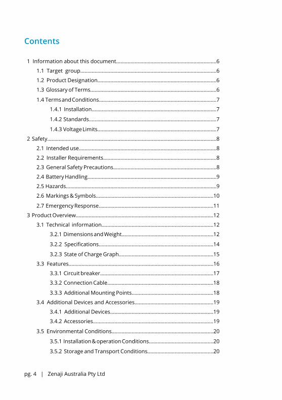
Contents 1 Information about this document......................................................................6
1.1 Target group...............................................................................................6
1.2 Product Designation...................................................................................6
1.3 Glossary of Terms........................................................................................6
1.4 Terms and Conditions..................................................................................7
1.4.1 Installation.......................................................................................7
1.4.2 Standards.........................................................................................7
1.4.3 Voltage Limits...................................................................................7
2 Safety......................................................................................................................8
2.1 Intended use................................................................................................8
2.2 Installer Requirements...............................................................................8
2.3 General Safety Precautions........................................................................8
2.4 Battery Handling..........................................................................................9
2.5 Hazards.........................................................................................................9
2.6 Markings & Symbols..................................................................................10
2.7 Emergency Response................................................................................11
3 Product Overview................................................................................................12
3.1 Technical information..............................................................................12
3.2.1 Dimensions and Weight................................................................12
3.2.2 Specifications................................................................................14
3.2.3 State of Charge Graph..................................................................15
3.3 Features.....................................................................................................16
3.3.1 Circuit breaker...............................................................................17
3.3.2 Connection Cable..........................................................................18
3.3.3 Additional Mounting Points.........................................................18
3.4 Additional Devices and Accessories.......................................................19
3.4.1 Additional Devices........................................................................19
3.4.2 Accessories....................................................................................19
3.5 Environmental Conditions.......................................................................20
3.5.1 Installation & operation Conditions.............................................20
3.5.2 Storage and Transport Conditions..............................................20

Aeon Battery Installation Manual V3.1 APR 2021 | pg. 5
4 Installation..........................................................................................................22
4.1 Minimum distances..................................................................................22
4.1.1 Distances from power equipment.............................................22
4.1.2 Distances from walls, vents & other equipment......................23
4.2 Mounting the Battery...............................................................................24
4.2.1 Mounting to a wall........................................................................24
4.2.2 Wall Mounting Plate.....................................................................26
4.3 Connecting and commissioning the battery.........................................27
4.3.1 Inverter Settings...........................................................................27
4.3.2 Connecting a single battery........................................................27
4.3.3 Multiple Batteries.........................................................................27
4.3.4 Adding a battery to an existing Zenaji battery system............28
4.3.5 Earthing the battery......................................................................29
4.3.6 Inverter Settings - Commissioning..............................................29
4.3.7 Initial Charge.................................................................................30
5 Battery Maintenance........................................................................................32
5.1 Battery Periodic Maintenance.................................................................32
5.2 Isolation Procedure..................................................................................32
5.3 Shutdown Procedure...............................................................................32
6 Uninstallation & Return..................................................................................33
6.1 Uninstallation for Repair or Return........................................................33
6.2 Disposal.....................................................................................................33
7 Troubleshooting................................................................................................34
8 Battery & Cell Designation Information.....................................................36
9 Registration & Installer Agreement.............................................................37
9.1 Installer Details.........................................................................................37
9.2 Qualified Personnel Agreement & Notes...............................................38
10 Contact................................................................................................................39

pg. 6 | Zenaji Australia Pty Ltd
1INFO 1 Information about this document
1.1 Target group
This document is intended for Qualified Personnel and any action described in this document must be carried out by qualified personnel.
1.2 Product Designation
This document designated for the following Zenaji Products.
A48-40
1.3 Glossary of Terms
Read this summary of terms before reading the remainder of the manual.
Power Equipment: This refers to an electronic device an Aeon battery can be connected to that can charge and/or discharge the battery. Most commonly this will be a Battery Charger/Inverter or Hybrid Solar Inverter used with a solar photovoltaic power system for a house.
Battery: In this document refers to one 1.93kWh Aeon Battery.
Battery System: A battery or group of batteries connected to a single piece of power equipment or multiple power equipment that is connected together.
Installed Battery: A battery that is part of a battery system, already installed, commissioned and in use.
Additional Battery: A battery that is to be added to a previously commissioned battery System.
Commission: To begin the use of a battery system, after installing the batteries and the circuit breakers have been switched to ON.
Qualified Personnel: Personnel who have completed the required training and are certified to undertake electrical works in their state.
Load weight: The total weight of a battery system on the supporting wall.
Self-managed battery: A battery which contains its own cell balancing and protection equipment.
LTO: Lithium Titanate, the cell chemistry used in Zenaji Aeon Batteries

Aeon Battery Installation Manual V3.1 APR 2021 | pg. 7
1INFO1.4 Terms & Conditions
When installing and operating the Aeon battery the following Terms & Conditions must be met. Failure to comply will void any warranty provided by Zenaji.
1.4.1 Installation
Installation must be carried out by qualified personnel.
1.4.2 Standards
The Aeon battery must be installed according to current local authority standards. In Australia and New Zealand these include but are not exclusive to:
AS/NZS 5139:2019AS/NZS 3000
1.4.3 Voltage & Current Limits
The Power Equipment which charges and discharges the Aeon Battery must not bring the voltage of the battery above 56.5V or below 42V. The maximum allowable continuous current should not be set above 50A per battery connected to the Power Equipment.

pg. 8 | Zenaji Australia Pty Ltd
2SAFETY
2 Safety
2.1 Intended use
The Aeon Battery is a nominal 48V LTO self-managed battery intended for use with power equipment to store and provide electrical energy. Improper use or handling poses risk of death or injury to the user or third parties as well as damage to the battery or other items of value, especially power equipment the battery is connected to.
The following must be observed to comply with use of this product:• The battery must be installed according to the installation instructions.• The battery must be installed by qualified personnel.• The battery must be used in a suitable location.
Failure to comply to these conditions or warranty conditions invalidates any warranty claims.
2.2 Installer Requirements
Installers are responsible for reading and understanding this document before installation
1. The battery must be installed by qualified personnel. Qualified personnel must be a qualified electrician and considered competent and registered to work to the AU/NZS 3000:2018 safety standard, or equivalent local authority safety standard where outside of Australia and New Zealand.
2. To install the battery according to Australian Battery Safety Standards AS/NZS 5139:2019 or equivalent local authority standards.
3. For Zenaji to provide the “20 year, 22,000 Cycle Warranty” the installer must register the battery after installation.
2.3 General Safety Precautions
• Over-voltages or incorrect wiring can damage the battery or connected equipment.• Avoid installing the battery in locations where flammable materials are present.• Do not install in locations where explosive chemicals or gasses are present.• Installation must be carried out by Qualified Personnel.• Battery is not user serviceable.• Inspect battery for any damage prior to installation.

Aeon Battery Installation Manual V3.1 APR 2021 | pg. 9
2SAFETY
2.4 Battery Handling
• Ensure circuit breaker on the base of the battery is set to OFF when handling, transporting, connecting or disconnecting the battery.
• Two person lift, 36kg (39kg net packaged), ensure any lifting calculations are carried out as according to state regulations.
• Do not expose battery to open flame.• Do not expose battery to temperatures over 60°C• Do not damage the unit in any ways physical such as crushing, dropping, piercing
with a sharp object, impacting. This may cause leakage of electrolyte or short circuit with the risk of fire.
• Do not connect positive and negative wires to each other causing a short circuit.• Do not charge or discharge damaged battery.• Do not place the battery with the connection cable on the ground.• Unqualified personnel are not to disconnect, disassemble or repair the battery.
Services must be made by Qualified Personnel only.• Ensure Connection cables ends are not exposed prior to final connection to power
equipment.• Keep out of reach of children and animals• All wiring must be protected from intrusion and cutting.• Store the battery in a dry place.• Ensure temperature is maintained between -5°C to 35°C when handling or
transporting the battery (recommended 20°C to 30°C).• No foreign object is to be placed on top of the battery.• Only use battery with Zenaji authorised power equipment.• Do not immerse in water.
2.5 Hazards
Leaking electrolyte and gases can cause irritation and harm.• Skin: On contact, the electrolyte solution contained in the battery causes irritation
to skin. Symptoms include irritation and burns.• Eyes: On contact, the electrolyte solution contained in the battery or gases released
due to battery damage cause irritation to ocular tissue and skin around the eyes. Symptoms include irritation, redness, tearing and burns. The electrolyte is corrosive to all ocular tissues.
• Inhalation: Gases due to high heat or abundance of leaking batteries cause burns of the respiratory system. Symptoms include coughing, wheezing, and shortness of breath.
• Ingestion: The ingestion of the battery is harmful. Content of the battery can cause serious chemical burns to the mouth, oesophagus and gastrointestinal tract.

pg. 10 | Zenaji Australia Pty Ltd
2SAFETY
2.6 Markings & Symbols
The images below show the symbols and markings found on the top and bottom covers of the battery. This gives critical battery information which is also provided in the installation manual.
Current:
CHARGE INSTRUCTIONSMaximal Charge:
Float Charge:Minimal Discharge:
57V55.5V
42V50A
DO NOT OPEN
Designed & Made in Australia
Type: Rechargeable Li-ion Battery System
Capacity Rated/Calculated: 40Ah/40Ah x 48.3V = 1930Wh
IP65 -40°C to 60°CNominal Voltage/Capacity: 48.3V/40Ah
Rated Current: Charge & Discharge 1.25C(Max)
Designation: XXR/66/160/[24S]L/-40+60/95
Protective class: I
SERIAL : ZENA48-03-2010-0001
Zenaji Pty Ltd
48V DCREDBLACK
DO NOT OPEN
CAUTION DO NOT OPEN
This symbol indicates the battery should not be opened and opening could result in a hazardous situation resulting in injury, if not avoided.
Do not dispose of the battery with domestic waste.
For further information on disposal, refer to section 6.1 of this manual.
Zenaji Pty Ltd
48V DCREDBLACK
This marking indicates the installation manual contains information, processes and procedures that must be read and followed in the installation and operation of the battery and must be read prior to installation and operation of the battery.

Aeon Battery Installation Manual V3.1 APR 2021 | pg. 11
2SAFETY
2.7 Emergency Response
If exposed to leaking electrolyte from ruptured or leaking battery the following actions are recommended
• Skin Contact: If the battery is leaking and the contained material contacts skin, flush with copious amounts of clear water for at least 15 minutes.
• Eye Contact: If the battery is leaking and the contained material contacts eyes, flush with copious amounts of clear water for at least 15 minutes. Seek medical attention immediately.
• Inhalation: If the battery is leaking, leave the contaminated area to fresh air. If irritation persists, seek medical attention.
• Ingestion: If the battery is leaking and the contained material is ingested, rinse the mouth and surrounding area with clear water at once. Seek medical Attention immediately.
Fire Fighting Measures• If fire occurs when charging or discharging the batteries, if it is safe to do so, shut
off the power to the battery.• Extinguishing Media – Dry chemical type extinguishers are the most effective means
to extinguish a battery fire. A CO2 extinguisher will also work effectively.• Fire Fighting Procedures – Use a positive pressure self-contained breathing
apparatus batteries are involve in a fire. Full protective clothing is necessary. During water application, caution is advised as burning pieces of flammable particles may be ejected from the fire.
Accidental release• In the event of rupture and leakage, collect all released material that are not
burning or hot in an appropriate waste disposal container while wearing proper protective equipment and ventilate the area. Dispose according to local regulations.
pg. 12 | Zenaji Australia Pty Ltd
3PRO
DU
CT
3 Product Overview
3.1 Technical Information
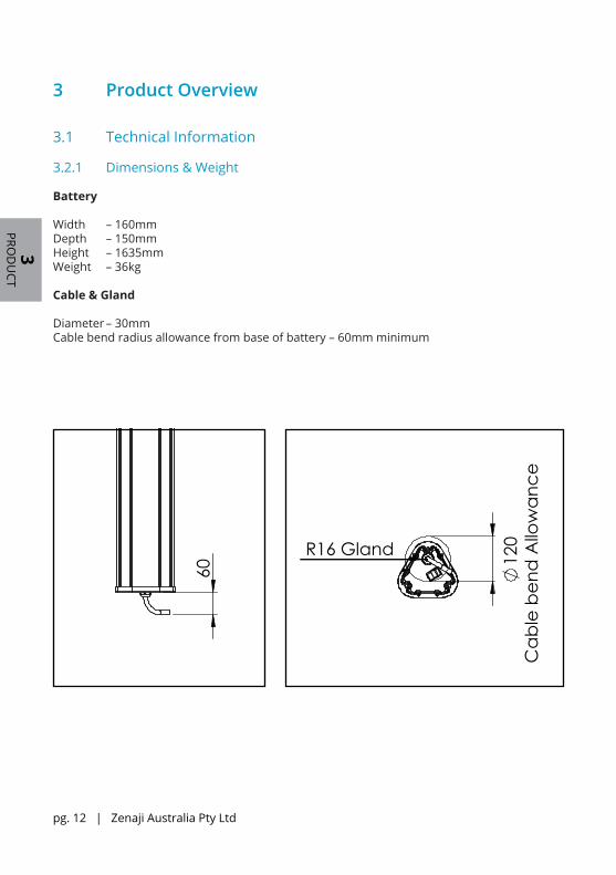
3.2.1 Dimensions & Weight
Battery
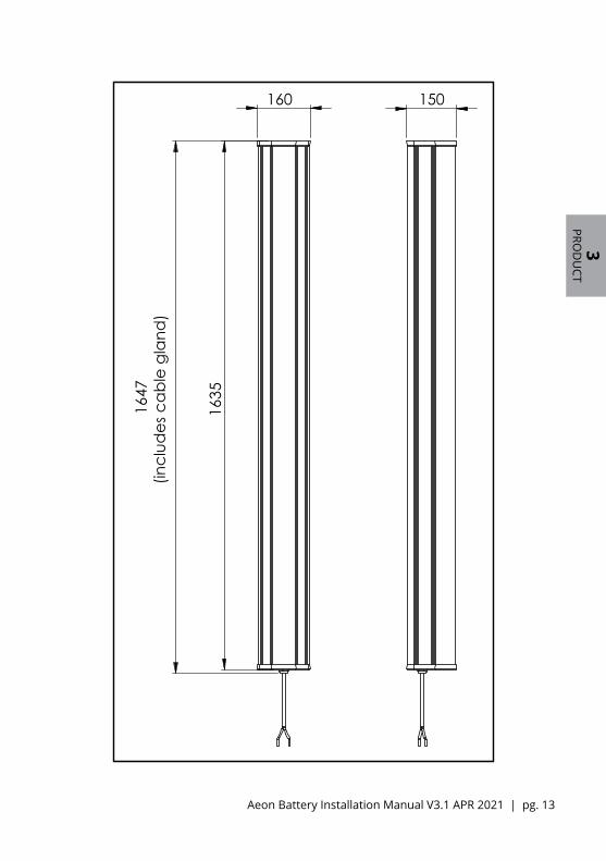
Width – 160mmDepth – 150mmHeight – 1635mmWeight – 36kg
Cable & Gland
Diameter – 30mmCable bend radius allowance from base of battery – 60mm minimum
160
60
115
99.
6
R16 Gland
1
20C
able
ben
d A
llow
ance
160
60
115
99.
6
R16 Gland
1
20C
able
ben
d A
llow
ance
Aeon Battery Installation Manual V3.1 APR 2021 | pg. 13
3PRO
DU
CT
160
1647
(incl
udes
cab
le g
land
)
1635
150
115
99.
6
R16
12
0

pg. 14 | Zenaji Australia Pty Ltd
3PRO
DU
CT
Specification Value
Nominal Capacity (25°C ± 5°C) (Useable Capacity) 1.93KWh (40Ah)
Chemistry Lithium Titanate (LTO)
Dimensions (Height x Width x Depth) 1635 x 155 x 145 mm
Nominal Voltage 48.3V
Charge Cut-off Voltage (Bulk/Absorption Voltage)* 56.5V
Float Voltage* 55.5V
Discharge Cut-off Voltage (Low Cut-off Voltage)* 42V
Low Restart Voltage (Reconnect Voltage)* 44.6V
Mass 36kg
Rated DC Charge/Discharge Current (25°C ± 5°C) 50A (1.25C) continuous DC, 38A (0.95C) pulsed DC**
Rated DC Charge/Discharge Power (25°C ± 5°C) 2415W continuous DC, 1835W pulsed DC**
Max DC Charge/Discharge Current (10s, 25°C ± 5°C) 120A (3C)
Max DC Charge/Discharge Power (10s, 25°C ± 5°C) 5796W
Battery Management SystemInternal cell balancing, failure detection and trip.
Under-Voltage, Over-Voltage, Over-Current, Over-Temp, Under-Temp protection and trip
Isolation & Distribution Block Requirement 50A per battery connected in parallel
Battery Short Circuit Current 1700A
Operating Temperature -40°C to 60°C (recommended 5°C to 35°C)
Storage Temperature -5°C to 35°C
Cycle Life (1C, 25°C ± 5°C) 22,000
Depth of Discharge 100%
Round Trip Efficiency (1C, 25°C ± 5°C) 96%
Ingress Rating IP65
Installation Indoors or outdoors
Connections 8mm² (8 AWG) (Ø3mm) wire per pole
Warranty 20 Years or 22,000 cycles, whichever comes first, see warranty document for details
3.2.2 Specifications
Aeon Battery Installation Manual V3.1 APR 2021 | pg. 15
3PRO
DU
CT
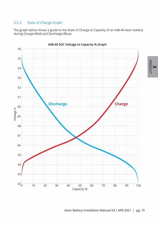
3.2.3 State of Charge Graph
The graph below shows a guide to the State of Charge to Capacity of an A48-40 Aeon battery during Charge (Red) and Discharge (Blue).
42
43
44
45
46
47
48
49
50
51
52
53
54
55
56
0 10 20 30 40 50 60 70 80 90 1000 2010 30 40 50 60 70 80 90 10042
43
44
45
46
47
48
49
50
51
52
53
54
55
56
Capacity %
Volta
ge V
ChargeDischarge
A48-40 SOC Voltage to Capacity % Graph
pg. 16 | Zenaji Australia Pty Ltd
3PRO
DU
CT
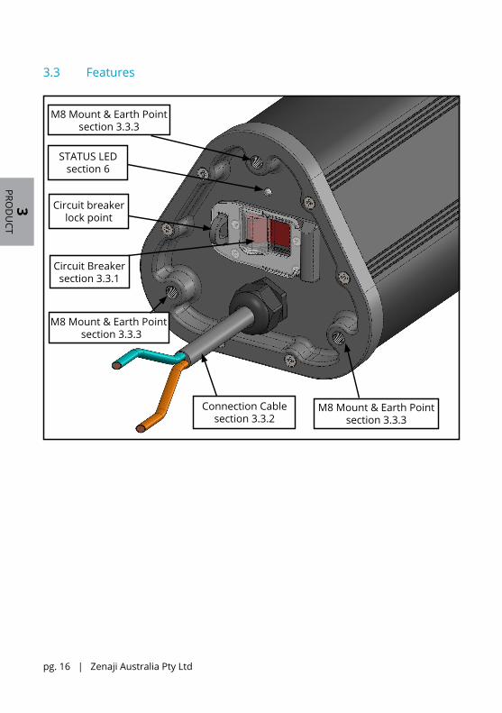
3.3 Features
M8 Mount & Earth Pointsection 3.3.3
Circuit Breakersection 3.3.1
Connection Cablesection 3.3.2
M8 Mount & Earth Point section 3.3.3
STATUS LEDsection 6
Circuit breaker lock point
M8 Mount & Earth Pointsection 3.3.3

Aeon Battery Installation Manual V3.1 APR 2021 | pg. 17
3PRO
DU
CT
3.3.1 Circuit breaker
Circuit Breaker: CBi-Electric C Frame MKIV - AS Current Rating Curve (shown below)• The circuit breaker is located at the base of the battery next to the cable.• When On the ON switch will be flat and current can flow, when Off the ON button will be
raised and current cannot flow.• The circuit breaker is dual pole• The circuit breaker has a nominal DC rating of 50A, refer to the rating curve below for
more detail
Circuit Breaker - ON Circuit Breaker - OFF

pg. 18 | Zenaji Australia Pty Ltd
3PRO
DU
CT
3.3.2 Connection Cable
As standard, each battery is fitted with a 2m length of dual core 8 AWG (Ø3mm) cable. The cable will need to be stripped prior to connection.
• Where possible, do not cut cables.• In the event cables must be shortened, all batteries must be of equal length and
never shortened to less than 1000mm.
The RED cable is the POSITIVE connection.
The BLACK cable is the NEGATIVE connection.
A
2000mm ±50mm
DETAIL A
SCALE 1 : 2
160
1647
(incl
udes
cab
le g
land
)
1635
150
115
99.
6
R16
12
0
M8 Mounting Locations
3.3.3 Additional Mounting Points
Where the provided mounting plate and brackets are not suitable for installation a custom mounting system can be used.
6 mounting points are provided for this purpose, 3 at the top and 3 at the bottom. Dimensions for these are to the right.
Any custom mounting system must be rated to a carry a gross load of 40kg.

Aeon Battery Installation Manual V3.1 APR 2021 | pg. 19
3PRO
DU
CT
3.4 Additional Devices and Accessories
3.4.1 Additional Devices
Distribution blocks, bus bars or terminal blocks (one per pole) must be used when connecting more than one battery to power equipment. Zenaji recommends a 300A or higher rated block be used to allow for flexibility of the installation.
The M8 Countersunk Bolts provided require a T40 Security (Tamper-proof) Torx bit, these are available at your local tool or hardware shop.
3.4.2 External Protection Devices
Additional information for selecting and connecting external protection devices to the Aeon Battery.
Output Short circuit current - 1700AMaximum Allowable Prospective Short Circuit Current - 1700AMinimum Required Prospective Short Circuit Current - 50AAeon Battery Overvoltage Category - III
3.4.2 Accessories
Included with each battery are brackets to allow mounting of the battery to a wall or other structure and an Earthing kit for earthing the battery when required.
2x Mounting Plates
4x M8x20mm Countersunk Socket Head Bolts
(5mm Hex Bit or Allen Key required - not provided)
Top Mounting Hook Bottom Mounting Hook
Earthing Kit(M5 Screw, M5 Lock Washer, 6mm² Earth Cable)

pg. 20 | Zenaji Australia Pty Ltd
3PRO
DU
CT
3.5 Environmental Conditions
3.5.1 Installation & Operation Conditions
The Aeon Battery must be kept in sheltered conditions described as 3K7 low/3Z2/3Z6/3Z7/3Z8/3B2/3C2(3C3)/3S3/3M5(3M3) in IEC 60721-3-3 for installation & operation. A summary of these conditions and additional information is below.
• Indoors or Outdoors• No direct sunlight• No excessive heat radiation close by <600 W/m2, a minimum distance of 600mm
from any heat source• No excessive water spray• Pollution levels kept to normal levels• Location protected from seismic shock• Free from corrosive and explosive gases• No coolant required• Ambient Temperature between -40° to 60°C• Wall or surface is suitable for heavy loads• Applicable local building codes must be observed• Well Ventilated space, if indoors the space must be ventilated
3.5.2 Storage & Transport Conditions
The Aeon Battery must be kept in Temperature-controlled locations as described as 3K3/3Z2/3Z4/3B1/3C2(3C1)/3S2/3M1 in IEC 60721-3-3 for storage & transport. A summary of these conditions and additional information is below.
• No direct sunlight• No excessive heat radiation close by <600 W/m2, a minimum distance of 600mm
from any heat source• No water spray or dripping• Pollution levels kept to normal levels• Location protected from seismic shock & excessive vibration• Free from corrosive and explosive gases• No coolant required • Ambient Temperature between 5° to 45°C• Well Ventilated space

This page intentionally left blank
pg. 22 | Zenaji Australia Pty Ltd
4IN
STALL
4 Installation
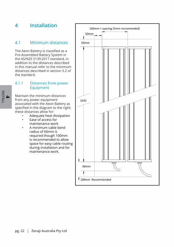
4.1 Minimum distances
The Aeon Battery is classified as a Pre-Assembled Battery System in the AS/NZS 5139:2017 standard, in addition to the distances described in this manual refer to the minimum distances described in section 5.2 of the standard.
4.1.1 Distances from power Equipment
Maintain the minimum distances from any power equipment associated with the Aeon Battery as specified in the diagram to the right; these distances allow for:
• Adequate heat dissipation• Ease of access for
maintenance work• A minimum cable bend
radius of 60mm is required though 100mm is recommended to allow space for easy cable routing during installation and for maintenance work.
1635
50mm
50mm
160mm + spacing (5mm reccomended)
60mm
100mm Recommended

Aeon Battery Installation Manual V3.1 APR 2021 | pg. 23
4IN
STALL
4.1.2 Distances from walls, vents & other equipment
Maintain the minimum distances of the Aeon battery system as shown below from any floor, roof, vent, structure, opening, wall standoff or other equipment for;
Non-habitable zones:• 200mm in all directions• this allows for easy access for maintenance and uninstallation
Aeon BatterySystem
200mm
200mm
Floor of Building
200mm 200mm
Roof of Building
Non-habitable zone restrictions
Aeon BatterySystem
600mm
900mm
Habitable Zones
Floor of Building
Roof of Building
600mm
200mm
Aeon BatterySystem
600mm
<900mm
Wall
Habitable Zones:• 600mm beyond vertical sides of the battery system• 900mm above the battery system, or when less than 900mm extending 600mm past the
edge of the roof• 200mm below the battery system• A suitably non-combustible material must also be present within this distance
Aeon BatterySystem
200mm
200mm
Floor of Building
200mm 200mm
Roof of Building
Non-habitable zone restrictions
Aeon BatterySystem
600mm
900mm
Habitable Zones
Floor of Building
Roof of Building
600mm
200mm
Aeon BatterySystem
600mm
<900mm
Wall

pg. 24 | Zenaji Australia Pty Ltd
4IN
STALL
4.2 Mounting the Battery
4.2.1 Mounting to a wall
The provided mounting brackets are the recommended mounting method, to mount the battery to a wall using the provided mounting brackets, take the following steps.
1. When installing the battery on a wall, ensure the wall is capable of holding the total combined load weight of the batteries to be installed, 40kg per battery.
2. Mark and Pre drill holes the wall for fasteners. Dimensions are in the diagram to the right.
• The 4 outermost screw holes are required; the middle 2 holes are optional.
• Be advised, when mounting horizontally the battery will rest on the mounting hooks with a 12mm drop.
3. Screw through the holes in the Top Mounting Bracket and the Bottom mounting bracket into the holes.
• A minimum of 4 fasteners must be used in the required hole locations.
• The fasteners must be capable of a combined shear load strength of greater than 400N (40kg) and a combined pull out load of 1600N (80kg).
• Due to the large variance between installations Zenaji does not provide fasteners.
22.5mm
160mm+spacing (5mm recommended)
RequiredRequired
45mm
22.5mm
Required Required
1561mm

Aeon Battery Installation Manual V3.1 APR 2021 | pg. 25
4IN
STALL
4. Attach the 2 Mounting Plates with the 4 provided M8 bolts, tighten till firm, if loctite is available coat the bolts with loctite prior to insertion. Ensure the Mounting Plates are attached in line with each other. The mounting plates must be mounted to ensure the back of the Aeon battery faces the wall (the cable side should be closest to the wall).
5. Mount the battery by sliding the Mounting Plates at the top and bottom of the battery onto the mounting brackets.
• When horizontal allow the mounting plate to slide down to lock in place
• When vertical the battery is allowed to slide loosely
6. If desired the battery may be locked in place using the locking hole on the Top Mounting Bracket.
B
DETAIL B
SCALE 1 : 2
C
DETAIL C
SCALE 1 : 2
C
DETAIL C
SCALE 1 : 2 173
23
126 57
Mounted Dimensions
173
23
126 57

pg. 26 | Zenaji Australia Pty Ltd
4IN
STALL
4.2.2 Wall Mounting Plate
For mounting multiple batteries to the same wall we recommend you use the optional Wall Mounting Plate, this provides a simpler, quicker and cleaner installation and can accommodate up to 8 batteries in either vertical or horizontal configuration.
Two mounting plates are required, to install;
• Use the mounting plates 8.5mm holes as guides for where to drill into the wall for mounting.
• Ensure mounts are level, parallel to each other and 1561mm apart.
• Mounts may be cut to length using a hacksaw, angle grinder or other suitable cutting tool as required at the cut locations, the mount is made of aluminium. Ensure to remove all burrs after cutting.
• Once attached to the wall, the battery mounting hooks are attached with the provided M6 Screws, use three for each hook.
To purchase the Wall Mounting Plate please contact Zenaji.
1561mm
1410 mm
60m
m
24 x M6x1.0 tapped through hole16 x 8.5mm diameter through hole
6m
m
Wall Mounting Plate Dimensions
Aeon Battery Installation Manual V3.1 APR 2021 | pg. 27
4IN
STALL
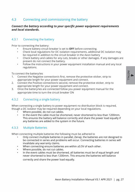
4.3 Connecting and commissioning the battery
Connect the battery according to your specific power equipment requirements and local standards.
4.3.1 Connecting the battery
Prior to connecting the battery:• Ensure battery circuit breaker is set to OFF before connecting.• Check local regulations for DC isolation requirements, additional DC isolation may
be required in addition to the circuit breaker in the Aeon battery• Check battery and cables for any cuts, breaks or other damages. If any damages are
present do not connect the battery.• Follow the instructions in your power equipment installation manual and any local
regulations. To connect the battery/ies1. Connect the Negative connection/s first, remove the protective sticker, strip to
appropriate length for your power equipment and connect. 2. Connect the Positive connection/s second, remove the protective sticker, strip to
appropriate length for your power equipment and connect.3. Once the battery/ies are connected follow you power equipment manual for the
appropriate time to turn the circuit breaker ON
4.3.2 Connecting a single battery
When connecting a single battery to power equipment no distribution block is required, though a DC isolator may be required depending on your local regulations.
• Where possible, do not cut cables.• In the event the cable must be shortened, never shortened to less than 1200mm.
This ensures the battery will balance correctly and share the power load equally if any batteries are added to the system in the future.
4.3.3 Multiple Batteries
When connecting multiple batteries the following must be adhered to• Only connect multiple batteries in parallel, Zenaji, the batteries are not designed to
be connected in series and problems will occur. Connecting batteries in series will invalidate any warranty claims.
• When connecting ensure batteries are within ±0.5V of each other.• Where possible, do not cut cables.• In the event cables must be shortened, all batteries must be of equal length and
never shortened to less than 1200mm. This ensures the batteries will balance correctly and share the power load equally.

pg. 28 | Zenaji Australia Pty Ltd
4IN
STALL
4.3.4 Adding a battery to an existing Zenaji battery system
If the voltage difference between the installed battery and additional battery is greater than ±0.5V they must be balanced. Balancing and connection can be achieved by one of two methods. In both methods the option to charge or discharge the battery is given, though in most cases (especially if connected to a grid or a generator) it is easier to charge either the installed battery or additional battery. Suggested method choice is shown below.
Installed Battery voltage < Additional battery – use Method 1
Additional Battery voltage < Installed Battery voltage – use Method 2
Method 1: Adjusting installed battery voltage
1. Note down the voltage of the additional battery.2. Charge or discharge the installed batteries using the power equipment to within ±0.5V
of the additional battery.3. Leave for 10 minutes and recheck the installed battery voltage, repeat step 2 as
required.4. Turn off your power equipment.5. Shutdown all installed batteries by switching the circuit breakers to OFF.6. Ensure the additional battery circuit breaker is set to OFF.7. Connect the additional battery to the system using the specific requirements of your
system. Multiple additional batteries can be connected at once, so long as their voltages are with ±0.5V of each other.
8. Follow your power equipment instructions to finish connecting and commissioning the battery system.
Method 2: Adjusting additional battery voltage 1. Note down the voltage of the installed batteries.2. Turn off your power equipment.3. Disconnecting the installed batteries by either:
a. Switching the circuit breakers to OFF on the base of the batteries, or;b. In some cases you may be required to disconnect the wires from the power
equipment, to do so switch the circuit breakers to OFF on the base of the batteries and then disconnect the wires from the power equipment.
4. Ensure the additional battery circuit breaker is set to OFF.5. Connect the additional battery to the power equipment. Multiple additional batteries
can be connected at once, so long as their voltages are with ±0.5V of each other.6. With the installed batteries disconnected commission the additional battery, following
your power equipment instructions.7. Charge or discharge the additional battery to within ±0.5V of the installed batteries.8. Leave for 10 minutes and recheck the additional battery voltage, repeat step 2 as
required.9. Turn off your power equipment.10. Disconnect the additional battery by switching the circuit breakers to OFF.11. If disconnected as in step 3b, reconnect the wires for the installed batteries.12. Follow your power equipment instructions to finish connecting and commissioning the
battery system.

Aeon Battery Installation Manual V3.1 APR 2021 | pg. 29
4IN
STALL
4.3.5 Earthing the Battery
To earth the battery, connect the Earth cable (6mm²) using the supplied M5 screw and Tooth lock Washer to one of the mounting plates in the earth screw point.
After connecting check for continuity between stripped end of the cable and an exposed screw on the battery then proceed to connect the earth cable to earth.
A
DETAIL ASCALE 1 : 1
MATERIAL / ADDITIVES / GRADE:
A48PROJECT
PRG-XXX-1XDRAWING NO.
ALUMINIUM CASE
FINISH:1:10 UNLESS NOTED
DRAWN/Date:
SCALE:
SHEET:
REV
TITLE:
CAD REF.
1 OF 1
X
A48-902-V2 Aeon 48V
A48-40-01/02 Aeon Battery
A2SHEET SIZE
ANGULAR TOLERANCES0. ° = 1 0.0 ° = 0.5
UNLESS OTHERWISE SPECIFIED: DIMENSIONS ARE IN MILLIMETERS3rd ANGLE PROJECTION
CHECKED/Date:
First Floor, 2 Shearson Cres,Mentone, Victoria, AustraliaTel: +61 418 104 496Email: [email protected]
COLOUR:
BLACK
City, State, CountryTel: +61 123 456 789 Email: [email protected]
PART NO.A48-902
LINEAR TOLERANCES0. = 0.5 0.0 = 0.250.00 = 0.1
CLIENT CONTACT:
IMPORTANTREAD ALL NOTES ON THIS DRAWING
BEFORE PROCEEDING WITH MANUFACTURE OF PART.
IF IN DOUBT - ASKCJC / 10 DEC 19
XCHECKEDDRAWNDATEDESCRIPTIONSTATUSREVISION
V2CAD REV
A A
B B
C C
D D
E E
F F
G G
H H
12
12
11
11
10
10
9
9
8
8
7
7
6
6
5
5
4
4
3
3
2
2
1
1
4.3.6 Inverter Settings - Commissioning
Inverters must be configured to the correct settings as specified in the A48-40 inverter settings document. For inverters not mentioned in the document configure standard two or three stage battery chargers/inverters with the settings below.
Inverter Settings - A48-40 systemHigh Cut-off Voltage (Bulk/Absorption voltage) ≤ 56.5VFloat Voltage ≤ 55.5VLow Cut-off Voltage ≥ 42VLow Restart (Reconnect) Voltage ≥ 44.6VMaximum Charge/Discharge Current ≤ 38A (due to pulsed DC from inverters, 50A for continuous DC)
While compatible with the first generation Aeon batteries, when connecting the A48-40 battery to a Zenaji Battery system with first generation A48-40-01 batteries, the settings below must be used to accommodate the required balancing sequence of the first generation.
Inverter Settings - A48-40-01 & A48-40 mixed systemHigh Cut-off Voltage (Bulk/Absorption voltage) ≤ 55.5VFloat Voltage ≤ 54.5VLow Cut-off Voltage ≥ 42VLow Restart (Reconnect) Voltage ≥ 44.6VMaximum Charge/Discharge Current ≤ 38A (due to pulsed DC from inverters, 50A for continuous DC)

pg. 30 | Zenaji Australia Pty Ltd
4IN
STALL
4.3.7 Initial Charge
Zenaji Aeon Batteries are pre charged up to 80% capacity prior to leaving the factory. Unfortunately, they may spend considerable time in storage, on boats and trucks before they are installed – sometimes as long as 6 months. Lithium Titanate batteries can lose around 0.5% of charge per day while in storage and after a few months they may be in a fully discharged and/or unbalanced state.
The balancing circuitry can compensate for ~5.8 Amps of imbalance between the cells during charging. If the battery is too out of balance a slow equalisation charge of 5A per battery will be required. In addition we recommend that for the initial charge up the absorption time be increased to 1hr
Follow procedure below on the initial charge of the battery.
Initial Slow Equalisation Charge Procedure1. Measure the voltage of the battery, if the voltage of the battery is lower than 46V,
proceed with the slow equalisation charge, otherwise you may skip the remaining steps and commission the battery as normal.
2. Set inverter to the below settings Inverter Settings - Initial Slow Equalisation Charge
High Cut-off Voltage (Bulk/Absorption voltage) As per A48-40 inverter settings document Float Voltage As per A48-40 inverter settings document Low Cut-off Voltage As per A48-40 inverter settings document Low Restart (Reconnect) Voltage As per A48-40 inverter settings document Maximum Charge/Discharge Current 5A per battery Bulk/Absorption Time 1h
3. Proceed to charge the battery till the High Cut-off Voltage or Float charge state has been reached.
4. Commission battery with normal Current and Absorption times as set out in the A48-40 inverter settings document

This page intentionally left blank

pg. 32 | Zenaji Australia Pty Ltd
5M
AINTAIN
5 Battery Maintenance, Isolation & Shutdown
5.1 Battery Periodic Maintenance
To maintain cell balance within the Aeon battery, the battery needs periodic maintenance, by charging the battery to 100% SOC. For every 100 charge/discharge cycles or every 2 weeks, whichever occurs first, the battery must be fully charged. Where possible, this should be automated with the inverter used, commonly known as Equalisation. If the Equalisation cannot automated periodically it must be performed manually.
Every 100 partial charge/discharge cyclesA partial charge/discharge cycle occurs when the battery has been charged and discharged to any SOC. i.e., the battery is discharged from 80% SOC to 40% SOC then charged up to 80% SOC is one charge/discharge cycle 100 times. Charge the battery to 100% SOC, or an Equalisation charge must be completed.
Every two weeksIf no full 100% SOC is reached within a two week period the battery must be charged to 100% SOC, or an Equalisation charge must be completed.
Setting Value Notes
Equalisation Voltage 56.5V this is the same as the high cutoff voltage
Equalisation Time 10min either 10min or the minimum time available on the charger
5.2 Isolation Procedure
To isolate the battery, follow the procedure below1. Switch off any isolator or selector switches connected to the battery to isolate the
battery from power equipment.2. If the battery is connected non-isolated in parallel with other batteries, switch all other
non-isolated connected batteries Circuit breakers to OFF.
5.3 Shutdown Procedure
To shutdown the battery, follow the procedure below1. Switch off any power equipment attached to the battery.2. Switch off any isolator or selector switches connected to the battery.3. Switch off any other connected batteries.4. Switch the battery Circuit Breaker to OFF.
Checks for CorrosionCorrosion can occur at termination of the battery cable. Checking the termination annually is recommended and any corrosion removed to ensure the battery is operating at peak capacity. Shutdown the battery before disconnecting and removing corrosion.

Aeon Battery Installation Manual V3.1 APR 2021 | pg. 33
6U
NIN
STALL
6 Uninstallation & Return
6.1 Uninstallation for Repair or Return
Note: Uninstallation must be carried out by qualified personnel
1. Switch off any power equipment attached to the battery.2. Switch the battery Circuit Breaker to OFF.3. Disconnect the Positive Battery wire from the power equipment and cover any bare wire
with electrical tape or other insulating tape.4. Disconnect the Negative Battery wire from the power equipment and cover any bare
wire with electrical tape or other insulating tape.5. Unlock any lock attached to the Top Mounting Bracket.6. Lift battery off of mounting brackets. NOTE: 36kg weight, two person lift.7. Ensure Circuit Breaker is set to OFF8. If required, remove the Mounting Plates from the top and base of the battery.
6.2 Disposal
The battery must not be disposed of in domestic waste.
Dispose of the battery by returning to Zenaji for processing or in an environmentally friendly way through suitable collection system.

pg. 34 | Zenaji Australia Pty Ltd
7TRO
UBLE
7 TroubleshootingLED Status States are listed below.
For more information please visit the FAQ page on zenaji.com, email us at [email protected], or call us using the details on the final page.
Note(s):
1. An alarm is only retained if the fault state is maintained for a minimum of 3 minutes during the first 30 minutes of the fault’s detection. If the faulty state corrects fast enough no alarm will be retained.
2. A higher priority alarm will overwrite the display of a lower priority alarm. 3. An alarm state will clear after 7 days provided the corresponding fault state does not
reoccur.
LED Status State State Description & Action
GREEN “heartbeat” Healthy Battery has functioned normally with no faults detected.
RED “heartbeat” Dead Battery Fifth time there has been a cell fault longer than one hour.
Return battery to manufacturer.
No light at all Flat Battery
Protection board is faulty, or the battery is completely flat. Check battery voltage. If the voltage is within the normal operating range, recharge the battery. If the voltage is not within the normal operating range, return the unit to manufacture.
Four RED “double-flashes”
Cell Fault Cell fault has occurred and not restored to a safe state. DO NOT CHARGE BATTERY and contact manufacturer.
GREEN flash
followed by four RED “double-flashes”
Cell Fault with Restore
Cell fault has occurred and restored to a safe state. Contact manufacture immediately and DO NOT RECONNECT THE BATTERY TO THE SYSTEM without authorization.

Aeon Battery Installation Manual V3.1 APR 2021 | pg. 35
7TRO
UBLE
LED Status State State Description & Action
Three BLUE “double-flashes”
Over-voltage
The battery voltage is greater than its maximum operating voltage (57V) and is not restoring to normal operating conditions. Check inverter settings before contacting manufacturer.
GREEN flash followed by three BLUE “double-flashes”
Over-voltage with Restore
The battery voltage was greater than its maximum operating voltage (57V) and has restored to normal operating conditions. Check inverter settings before reconnecting the battery to the system. Contact manufacture if the alarm re-occurs.
Three BLUE “single-flashes”
Under-voltage
The battery voltage is less than its minimum operating voltage (42V) and is not restoring to normal operating conditions. Check inverter settings and battery voltage before attempting to recharge the battery.
GREEN flash followed by three BLUE “single-flashes”
Under-voltage with Restore
The battery voltage was less than its minimum operating voltage (42V) and has returned to normal operating conditions. Check inverter settings before recharging the battery.
Two BLUE “Double-flashes”
Over-temperature
The battery temperature has exceeded its maximum normal operating conditions (above 60°C) and has not restored to a safe temperature. Check the battery location is appropriate (not in full sunlight or near heat sources) and wait for the battery to cool before reconnecting it to the system.
GREEN flash followed by two BLUE “Double-flashes”
Over-temperature with Restore
The battery temperature has exceeded its maximum normal operating conditions (above 60°C) and restored to a safe temperature. Check the battery location is appropriate (not in full sunlight or near heat sources) before reconnecting it to the system.
Two BLUE “Single-flashes”
Low-temperature
The battery temperature has decreased below minimum normal operating conditions (below -40°C) and has not restored to a functional temperature. Check that this temperature is below -40°C. If not contact the manufacture.
GREEN flash followed by two BLUE “Single-flashes”
Low-temperature with Restore
The battery temperature has decreased below minimum normal operating conditions (below -40°C) and restored to a functional temperature. Check that this is possible in the location that the battery is installed before reconnecting it to the system. If not contact the manufacture.
pg. 36 | Zenaji Australia Pty Ltd
8D
ESIGN
ATION
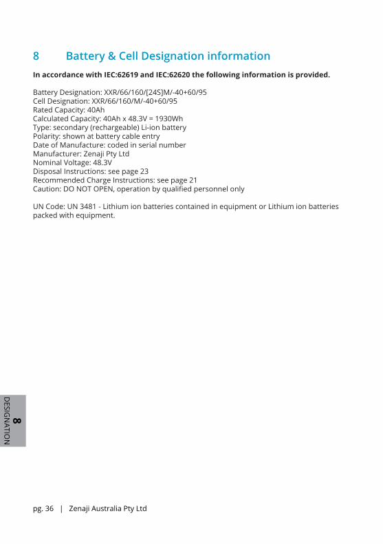
8 Battery & Cell Designation informationIn accordance with IEC:62619 and IEC:62620 the following information is provided.
Battery Designation: XXR/66/160/[24S]M/-40+60/95Cell Designation: XXR/66/160/M/-40+60/95Rated Capacity: 40AhCalculated Capacity: 40Ah x 48.3V = 1930WhType: secondary (rechargeable) Li-ion batteryPolarity: shown at battery cable entryDate of Manufacture: coded in serial numberManufacturer: Zenaji Pty LtdNominal Voltage: 48.3VDisposal Instructions: see page 23Recommended Charge Instructions: see page 21Caution: DO NOT OPEN, operation by qualified personnel only
UN Code: UN 3481 - Lithium ion batteries contained in equipment or Lithium ion batteries packed with equipment.
Aeon Battery Installation Manual V3.1 APR 2021 | pg. 37
9IN
STALLER
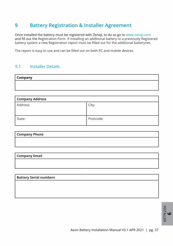
9.1 Installer Details
Company
Company Address
Address: City:
State: Postcode:
Company Phone
Company Email
Battery Serial numbers
9 Battery Registration & Installer Agreement
Once installed the battery must be registered with Zenaji, to do so go to www.zenaji.com and fill out the Registration Form. If installing an additional battery to a previously Registered battery system a new Registration report must be filled out for the additional battery/ies.
The report is easy to use and can be filled out on both PC and mobile devices.

pg. 38 | Zenaji Australia Pty Ltd
9IN
STALLER
9.2 Qualified Personnel Acknowledgement
I acknowledge that I have read through the instruction manual and installed the Aeon Battery system as specified in this document.
Name: _______________________________________________
Signed: _______________________________________________
Date: / /
Notes

Aeon Battery Installation Manual V3.1 APR 2021 | pg. 39 10CO
NTACT
10 ContactZenaji Australia Pty Ltd
Australia+61 448 818 [email protected]
International+61 418 104 [email protected]
First Floor, 2 Shearson Cres,Mentone, Victoria 3194Australia
Revision: V3.1Document Number: ZEN-015Publication date: 1 APRIL 2021