
Battery Reference Book Third Edition
774
T. R. Crom Re i Thirc Boo1 m
-
Upload
khangminh22 -
Category
Documents
-
view
1 -
download
0
Transcript of Battery Reference Book Third Edition

T. R. Crom
Re i Thirc
Boo1 m


Battery Reference Book


Battery Reference Book Third Edition
T R Crompton MSC, BSic
Newnes OXFORD AlJCKLAND BOSTON JOHANNESBURG MELBOURNE NEW DELHI

Newnes An imprint of Butterworth-Heinemann Linacre House, Jordan Hill, Oxford OX2 8DP 225 Wildwood Avenue, Woburn, MA 01801-2041 A division of Reed Educational and Professional Publishing Ltd
-&A member of the Reed Elsevier plc group
First published 1990 Second edition 1995 Thrd edition 2000
0 Reed Educational and Professional Publishing Ltd 1990, 1995, 2000
All rights reserved. No part of this publication may be reproduced in any material form (including photocopying or storing in any medium by electronic means and whether or not transiently or incidentally to some other use of this publication) without the written permission of the copyright holder except in accordance with the provisions of the Copyright, Designs and Patents Act 1988 or under the terms of a licence issued by the Copyright Licensing Agency Ltd, 90 Tottenham Court Road, London, England W1P 9HE. Applications for the copyright holder's written permission to reproduce any part of this publication should be addressed to the publishers
British Library Cataloguing in Publication Data A catalogue record for this book is available from the British Library
ISBN 07506 4625 X
Library of Congress Cataloguing in Publication Data A catalogue record for this book is available from the Library of Congress
Typeset by Laser Words, Madras, India Printed in Great Britain
Contents
Preface
Acknowledgements
1 1ntroduc:tion to battery technology
Electromotive force . Reversible cells . Reversible electrodes . Relationship between electrical energy and energy content of a cell . Free energy changes and elec- tromotive forces in cells . Relationship between the energy changes accompanying a cell reaction and con- centration of the reactants . Single electrode potentials . Activities of electrolyte solutions . Influence of ionic concentration1 in the electrolyte on electrode poten- tial . Effect of sulphuric acid concentration on e.m.f. in the lead-acid battery . End-of-charge and end-of- discharge e.m.f. values . Effect of cell temperature on e.m.f. in the lead-acid battery . Effect of tempera- ture and temperature coefficient of voltage dEldT on heat content change of cell reaction . Derivation of the number of electrons involved in a cell reaction . Thermodynamic calculation of the capacity of a bat- tery . Calculation of initial volume of sulphuric acid . Calculation of operating parameters for a lead-acid battery from calorimetric measurements . Calculation of optimum acid volume for a cell Effect of cell lay- out in batteries on battery characteristics . Calculation of energy density of cells . Effect of discharge rate on performance characteristics . Heating effects in batter- ies . Spontaneous reaction in electrochemical cells . Pressure development in sealed batteries
4 Nickel batteries
Nickel-cadmium secondary batteries . Nickel-iron secondary batteries . Nickel-zinc secondary batteries . Nickel-hydrogen secondary batteries . Nickel-metal hydride secondary batteries . Sodium-nickel chloride secondary batteries
2 Guidelines to battery selection
Primary batteries . Secondary batteries . Conclusion
Pat3 1 Battery Characteristics
3 Lead-acid secondary batteries Open-type lead-acid batteries . Non-spill lead-acid batteries . Recombining sealed lead-acid batteries
5 Silver batteries
Silver oxide-zinc primary batteries . Silver-zinc sec- ondary batteries . Silver-cadmium secondary batteries . Silver-hydrogen secondary batteries
6 Alkaline manganese batteries
Alkaline manganese primary batteries . Alkaline man- ganese secondary batteries
7 Carbon-zinc and carbon-zinc chloride primary batteries
Carbon-zinc batteries . Carbon-zinc chloride batteries
8 Mercury batteries
Mercury-zinc primary batteries . Mercury-indium- bismuth and mercury -cadmium primary batteries
9 Lithium batteries
Introduction . Lithium- sulphur dioxide primary batteries . Lithium-thionyl chloride primary batteries . Lithium-vanadium pentoxide primary batteries . Lithium-manganese dioxide primary batteries . Lithium-copper oxide primary batteries . Lithium- silver chromate primary batteries . Lithium-lead bismuthate primary cells . Lithium-polycarbon monofluoride primary batteries . Lithium solid electrolyte primary batteries . Lithium-iodine primary batteries . Lithium-molybdenum disulphide secondary batteries . Lithium (aluminium) iron monosulphide
v
vi Contents
secondary batteries . Lithium-iron disulphide primary cells . Lithium- silver-vanadium pentoxide batteries
10 Manganese dioxide-magnesium perchlorate primary batteries
Reserve type
11 Magnesium-organic electrolyte primary batteries
12 Metal-air cells
Zinc-air primary batteries . Zinc-air secondary bat- teries . Cadmium-air secondary batteries . Alu- minium-air secondary batteries . Iron-air secondary batteries
13 High-temperature thermally activated primary reserve batteries
Performance characteristics of calcium anode thermal batteries . Performance characteristics of lithium anode thermal batteries
14 Zinc-halogen secondary batteries
Zinc-chlorine secondary batteries . Zinc-bromine secondary batteries
15 Sodium-sulphur secondary batteries
16 Other fast-ion conducting solid systems
17 Water-activated primary batteries
Magnesium-silver chloride batteries . Zinc- silver chloride batteries . Magnesium-cuprous chloride bat- teries
Part 2 Battery theory and design
18 Lead-acid secondary batteries
Chemical reactions during battery cycling . Mainten- ance-free lead-acid batteries . Important physical characteristics of antimonial lead battery grid alloys . Lead alloy development in standby (stationary) batteries . Separators for lead-acid automotive batteries Further reading
19 Nickel batteries
Nickel-cadmium secondary batteries . Nickel-hydro- gen and silver-hydrogen secondary batteries . Nickel-zinc secondary batteries . Nickel-metal hydride secondary batteries . Nickel-iron secondary batteries . Sodium-nickel chloride secondary batteries
20 Silver batteries
Silver oxide-zinc primary batteries . Silver-zinc sec- ondary batteries . Silver-cadmium secondary batteries
21 Alkaline manganese batteries
Alkaline manganese primary batteries . Alkaline man- ganese secondary batteries
22 Carbon-zinc and carbon-zinc chloride batteries
Carbon-zinc primary batteries . Carbon-zinc chloride primary batteries
23 Mercury-zinc batteries
Mercury-zinc primary batteries . Mercury-zinc car- diac pacemaker batteries
24 Lithium batteries
Lithium-sulphur dioxide primary batteries . Lithium- thionyl chloride primary batteries . Lithium-vanadium pentoxide primary batteries . Lithium solid elec- trolyte primary batteries . Lithium-iodine prim- ary batteries . Lithium-manganese dioxide primary batteries . Lithium-copper oxide primary batteries . Lithium-carbon monofluoride primary batteries . Lithium-molybdenum disulphide secondary batteries . Lithium (aluminium) iron sulphide secondary cells . Lithium-iron disulphide primary batteries
25 Manganese dioxide-magnesium perchlorate primary batteries
26 Metal-air batteries
Zinc-air primary batteries . Metal-air secondary bat- teries . Aluminium-air secondary reserve batteries
27 High-temperature thermally activated primary batteries
Calcium anode-based thermal batteries . Lithium anode thermal batteries . Lithium alloy thermal batteries
28 Zinc- halogen secondary batteries
Zinc-chlorine batteries . Zinc-bromine batteries
29 Sodium-sulphur secondary batteries
References on sodium-sulphur batteries

Contents vii
Pard: 3 Battery performance evaluation
30 Primary batteries
Service time--voltage data . Service life-ohmic load curves . Effect of operating temperature on service life Voltage-capacity curves . Shelf life-percentage capacity retained . Other characteristic curves
31 Secondary batteries
Discharge curves . Terminal voltage-discharge time curves . Plateau voltage-battery temperature curves I Capacity returned (discharged capacity)-discharge rate curves . Capacity returned (discharged capa- city)-discharge temperature curves and percentage withdrawable capacity returned-temperature curves . Capacity returned (discharged capacity)-terminal voltage curves . Withdrawable capacity-terminal voltage cunies . Capacity returned (discharged capacity) -discharge current curves . Discharge rate-capacity returned (discharged capacity) curves . Discharge rate-terminal voltage curves . Discharge rate-mid-point voltage curves . Discharge rate-energy density curves . Self-discharge characteristics and shelf life . Float life characteristics
Part 4 Battery Applications
32 Lead-acid secondary batteries
Stationary type or standby power batteries . Traction or motive power type . Starting, lighting and ignition (SLI) or automotive batteries . Partially recombining sealed lead-acid batteries . Load levelling batteries . Electric vehicle batteries
33 Nickel lbatteries
Nickel-cadmium secondary batteries . Nickel-zinc secondary batteries . Nickel-hydrogen secondary batteries . Nickel-metal hydride secondary batteries . Nickel-iron secondary batteries . Sodium-nickel chloride secondary batteries
34 Silver batteries
Silver-zinc primary batteries . Silver-zinc secondary batteries . Silver-cadmium batteries
35 Alkaline manganese primary batteries
36 Carbon-zinc primary batteries
Comparison of alkaline manganese and carbon-zinc cell drain rates . Drain characteristics of major con- sumer applications
37 Mercury batteries
Mercury -zinc primary batteries . Mercury-cadmium primary batteries . Mercury-indium-bismuth primary batteries
38 Lithium primary batteries
Lithium- sulphur dioxide . Lithium-vanadium pentox- ide . Lithium-thionyl chloride . Lithium-manganese dioxide . Lithium-copper oxide Lithium- silver chro- mate . Lithium-lead bismuthate . Lithium-polycarbon monofluoride . Lithium solid electrolyte . Lithium- iodine . Comparison of lithium-iodine and nickel- cadmium cells in CMOS-RAM applications . Lithium-iron disulphide primary cells . Lithium- molybdenum disulphide secondary cells . Lithium (aluminium) iron sulphide secondary cells
39 Manganese dioxide-magnesium perchlorate primary batteries
Reserve batteries . Non-reserve batteries
40 Metal-air batteries
Zinc-air Primary batteries . Zinc-air secondary bat- teries . Aluminium-air secondary batteries
41 High-temperature thermally activated primary batteries
42 Seawater-activated primary batteries
43 Electric vehicle secondary batteries
Lead-acid batteries . Other power sources for vehicle propulsion
Part 5 Battery charging
44 Introduction
45 Constant-potential charging
Standard CP charging . Shallow cycle CP charging of lead-acid batteries . Deep cycle CP charging of lead-acid batteries . Float CP charging of lead-acid batteries . Two-step cyclic voltage-float voltage CP charging
46 Voltage-limited taper current charging of alkaline manganese dioxide batteries
47 Constant-current charging
Charge control and charge monitoring of sealed nickel-cadmium batteries . The Eveready fast-charge cell (nickel-cadmium batteries) . Types of constant- current charging . Two-step constant-current charging
viii Contents
. Constant-current charger designs for normal-rate charging . Controlled rapid charger design for nickel-cadmium batteries . Transformer-type charger design (Union Carbide) for nickel-cadmium batteries . Transformerless charge circuits for nickel-cadmium batteries
48 Taper charging of lead-acid motive power batteries
Types of charger . Equalizing charge . How to choose the right charger . Opportunity charging
49 Methods of charging large nickel-cadmium batteries
Trickle charge/float charge . Chargeldischarge opera- tions on large vented nickel-cadmium batteries . Standby operation . Ventilation
Part 6 Battery suppliers
50 Lead-acid (secondary) batteries
Motive power batteries . Standby power batteries Automotive batteries . Sealed lead-acid batteries Spillproof lead-acid batteries
51 Nickel batteries
Nickel-cadmium secondary batteries . Nickel-hydro- gen batteries . Nickel-zinc batteries . Nickel-metal hydride secondary batteries . Nickel-iron secondary batteries . Sodium-nickel chloride secondary batteries
52 Silver batteries
Silver-zinc batteries . Silver-cadmium (secondary) batteries . Silver-hydrogen secondary batteries . Sil- ver-iron secondary batteries
53 Alkaline manganese dioxide batteries
Primary batteries . Secondary batteries
54 Carbon-zinc batteries (primary) and carbon-zinc chloride batteries
55 Mercury batteries Mercury-zinc (primary) batteries . Mercury-zinc car- diac pacemaker batteries . Other types of mercury battery
Lithium-thionyl chloride batteries . Lithium-manga- nese dioxide batteries . Lithium-silver chromate bat- teries . Lithium-copper oxide batteries . Lithium-lead bismuthate batteries . Lithium-copper oxyphosphate cells . Lithium- polycarbon monofluoride batteries . Lithium solid electrolyte batteries . Lithium-iodine batteries . Lithium-molybdenum disulphide secondary batteries . Lithium-iron disulphide primary batteries . Lithium alloy -iron sulphide secondary batteries
57 Manganese dioxide-magnesium perchlorate (primary) batteries
Reserve-type batteries . Non-reserve batteries
58 Magnesium-organic electrolyte batteries
59 Metal-air cells
Zinc-air primary batteries . Zinc-air secondary bat- teries . Aluminium-air secondary batteries . Iron-air secondary batteries
60 Thermally activated batteries
61 Zinc- halogen batteries
Zinc-bromine secondary batteries
62 Sodium-sulphur batteries
63 Water-activated batteries
McMurdo Instruments magnesium-silver chloride seawater batteries . SAFT magnesium-silver chloride batteries . SAFT zinc-silver chloride batteries . SAFT magnesium-copper iodide seawater-energized primary batteries . Eagle Picher water activated primary batteries
Suppliers of primary and secondary batteries
Glossary
Battery standards
Battery journals, trade organizations and conferences
Bibliography
Index
56 Lithium batteries Lithium-vanadium pentoxide (primary) batteries . Lithium-sulphur dioxide (primary) batteries .
Preface
Primary (non-rechargeable) and secondary (recharge- able) batteries are an area of manufacturing industry that has undlergone a tremendous growth in the past two or three decades, both in sales volume and in variety of products designed to meet new applica- tions. Not so long ago, mention of a battery to many people brought to mind the image of an automo- tive battery or a torch battery and, indeed, these accounted for the majority of batteries being produced. There were of course other battery applications such as submarine and aircraft batteries, but these were of either the lead-acid or alkaline type. Lead-acid, nickel-cadmium, nickel-iron and carbon-zinc repre- sented the only electrochemical couples in use at that time.
There now exist a wide range of types of bat- teries, both primary and secondary, utilizing couples that were not dreamt of a few years ago. Many of these couples have been developed and utilized to pro- duce batteries to meet specific applications ranging from electric vehicle propulsion, through minute bat- teries for incorporation as memory protection devices in printed circuits in computers, to pacemaker batter- ies used in h.eart surgery. This book attempts to draw together in one place the available information on all types of battery now being commercially produced. It starts with a chapter dealing with the basic the- ory behind t!he operation of batteries. This deals with the effects omf such factors as couple materials, elec- trolyte composition, concentration and temperature on battery performance, and also discusses in some detail such factors as the effect of discharge rate on bat- tery capacity. The basic thermodynamics involved in battery operation are also discussed. The theoretical treatment concentrates OK the older types of battery, such as lead--acid, where much work has been carried out over the years. The ideas are, however, in many cases equally applicable to the newer types of battery and one of the objectives of this chapter is to assist the reader in carrying out such calculations.
The following chapters ,discuss various aspects of primary and secondary batteries including those
batteries such as silver-zinc and alkaline manganese which are available in both forms.
Chapter 2 is designed to present the reader with information on the types of batteries available and to assist him or her in choosing a type of battery which is suitable for any particular application, whether this be a digital watch or a lunar landing module.
Part 1 (Chapters 3-17) presents all available information on the performance characteristics of various types of battery and it highlights the parameters that it is important to be aware of when considering batteries. Such information is vital when discussing with battery suppliers the types and characteristics of batteries they can supply or that you may wish them to develop.
Part 2 (Chapters 18-29) is a presentation of the the- ory, as far as it is known, behind the working of all the types of battery now commercially available and of the limitations that battery electrochemistry might place on performance. It also discusses the ways in which the basic electrochemistry influences battery design. Whilst battery design has always been an important factor influencing performance and other factors such as battery weight it is assuming an even greater importance in more recently developed batteries.
Part 3 (Chapters 30 and 3 1) is a comprehensive dis- cussion of practical methods for determining the per- formance characteristics of all types of battery. This is important to both the battery producer and the battery user. Important factors such as the measurement of the effect of discharge rate and temperature on available capacity and life are discussed.
Part 4 (Chapters 32-43) is a wide ranging look at the current applications of various types of battery and indicates areas of special interest such as vehicle propulsion, utilities loading and microelectronic and computer applications.
Part 5 (Chapters 44-49) deals with all aspects of the theory and practice of battery charging and will be of great interest to the battery user.
Finally, Part 6 (Chapters 50-63) discusses the mas- sive amount of information available from battery
ix

x Preface
manufacturers on the types and performance charac- teristics of the types of battery they can supply. The chapter was assembled from material kindly supplied to the author following a worldwide survey of bat- tery producers and their products and represents a considerable body of information which has not been assembled together in this form elsewhere.
Within each Part, chapters are included on all available types of primary batteries, secondary batteries and batteries available in primary and secondary versions. The primary batteries include carbon-zinc, carbon-zinc chloride, mercury-zinc and other mercury types, manganese dioxide-magnesium perchlorate, magnesium organic, lithium types (sulphur dioxide, thionyl chloride, vanadium pentoxide, iodine and numerous other lithium types), thermally activated and seawater batteries. Batteries available in primary and secondary forms include alkaline manganese, silver-zinc, silver-cadmium, zinc-air and cadmium-air. The secondary batteries discussed include lead-acid, the nickel types (cadmium, iron, zinc, hydrogen), zinc-chlorine, sodium-sulphur and other fast ion types.
The book will be of interest to battery manufacturers and users and the manufacturers of equipment using batteries. The latter will include manufacturers of domestic equipment, including battery-operated household appliances, power tools, TVs, radios, computers, toys, manufacturers of emergency power and lighting equipment, communications and warning beacon and life-saving equipment manufacturers. The manufacturers of medical equipment including pacemakers and other battery operated implant devices will find much to interest them, as will the manufacturers of portable medical and non-medical recording and logging equipment. There are many applications of batteries in the transport industry, including uses in conventional vehicles with internal combustion engines and in aircraft, and the newer developments in battery-operated automobiles, fork lift trucks, etc. Manufacturers and users of all types of defence equipment ranging from torpedoes to ground- to-air and air-to-air missiles rely heavily on having
available batteries with suitable characteristics and will find much to interest them throughout the book; the same applies to the manufacturers of aerospace and space equipment, the latter including power and back-up equipment in space vehicles and satellites, lunar vehicles, etc. Finally, there is the whole field of equipment in the new technologies including computers and electronics.
The teams of manufacturers of equipment who man- ufacture all these types of equipment which require batteries for their performance include the planners and designers. These must make decisions on the per- formance characteristics required in the battery and other relevant factors such as operating temperatures, occurrence of vibration and spin, etc., weight, volume, pre-use shelf life; these and many other factors play a part in governing the final selection of the battery type. It is a truism to say that in many cases the piece of equipment has to be designed around the battery.
Battery manufacturers will also find much to interest them, for it is they who must design and supply batter- ies for equipment producers and who must try to antici- pate the future needs of the users, especially in the new technologies. Battery manufacturers and users alike will have an interest in charging techniques and it is hoped that Part 5 will be of interest to them. The devel- opment of new types of batteries usually demands new charger designs, as does in many instances the devel- opment of new applications for existing battery types.
Throughout the book, but particularly in Chapter 1, there is a discussion of the theory behind battery operation and this will be of interest to the more theoretically minded in the user and manufacturer industries and in the academic world. Students and postgraduates of electrical and engineering science, and design and manufacture will find much to interest them, as will members of the lay public who have an interest in power sources and technology.
Finally, it is hoped that this will become a source book for anyone interested in the above matters. This would include, among others, researchers, journal- ists, lecturers, writers of scientific articles, government agencies and research institutes.

Acknowledgements
Acknowledgements are hereby given to the companies listed under !Suppliers at the end of the book for sup- plying infomiation on their products and particularly to the following companies for permission to reproduce figures in the text.
Catalyst Research Corporation, 9.10, 24.14, 24.15,
Chloride Batteries, 4.2, 4.3, 11.1, 18.2, 18.5-18.8, 27.2-27.9, 27.1 1, 27.12-27.15, 56.2 1, 56.23 -56.29
19.9-19.11, 32.1, 32.2-32.6,43.1-43.3,48.1,48.2, 49.3-49.8, 50.1, 50.2, 50.4-50.11, 50.14
Chloride Silent Power, 29.2 Crompton-Parkinson, 8.1, 8.2, 31.2, 50.16 Dryfit, 4.6-4..11, 20.2, 31.17, 31.45, 50.15 Duracell, 30.22, 30.30, 30.50, 30.53-30.55, 52.4,
56.11, 56.12, 59.1 Eagle Picher. 4.12-4.14, 10.1, 18.3, 19.13-19.21,
20.1, 24.9, 24.10, 24.16, 25.1, 27.10, 30.5,
32.14. 31.19, 31.29, 31.31, 31.32, 31.44, 43.4, 43.5, 45.5, 45.6, 50.17-50.19, 51.25, 51.26,
30.24-30.27, 30.32, 30.42, 30.52, 31.1, 31.11-
51.38, 51.42-51.44, 52.1, 52.2, 52.7, 52.11-52.13, 56.18-56.20, 56.22, 57.1-57.3, 60.1, 60.2
Energy Development Associates, 28.1 Ever Ready l(Berec), 19.5-19.6, 26.1 Ford Motors, 29.1 General Electric, 3 1.23, 3 1.24, 3 1.4 1, 3 1.47, 45.1,
W. R. Groce, 18.20-18.23 47.1, 50.20, 51.23
Honeywell, 9.1 -9.9, 24.1 -24.8, 24.1 1, 24.12, 30.14, 30.19-30.21, 30.33, 30.46, 56.1
Mallory, 8.3, 23.2, 23.3, 30.1, 30.10, 30.15-30.18, 30.28, 30.29, 30.31, 30.34, 30.35, 30.49, 53.1, 53.2,
Marathon, 11.1, 25.2, 30.38-30.41, 30.51, 30.57,
McGraw Edison, 30.43-30.45, 59.2 Nife Jungner, 31.40, 31.48, 33.1, 47.7, 47.11, 47.15,
55.3, 55.5, 55.6, 56.2-56.4
31.25, 57.4, 57.5
51.20-51.22, 51.30-51.32
31.35, 31.40, 47.8-47.10, 47.12, 47.13, 51.1-51.3, SAFT, 4.5, 30.23, 30.56, 31.22, 31.26-31.28,
56.7-56.10, 56.13, 56.17, 59.3-59.8, 63.1-63.3 Silberkraft FlUWO, 56.5, 56.6 Swiss Post Office, Berne, 18.9-18.19 Union Carbide, 5.1, 5.2, 6.1-6.5, 7.1, 8.1, 19.7,
30.6-30.9, 30.36, 30.37, 30.47, 31.4, 31.20, 31.21, 19.8, 19.12, 21.1, 21.2, 22.1-22.3, 23.1, 30.2-30.4,
31.30, 51.10-51.19, 52.3, 53.3-53.7, 55.1, 55.2
31.33, 45.3, 46.1-46.5, 47.4-47.7, 47.17,
Varley, 31.16, 31.34, 50.21 Varta, 4.1, 4.4, 19.1, 19.2, 19.4, 31.5-31.10, 31.38,
31.39, 31.49, 40.1, 40.2, 47.3, 47.16, 50.12, 50.13, 51.4-51.9, 51.34-51.37, 56.14-56.16
Vidor, 30.11-30.13, 55.4 Yardney, 20.3, 31.42, 31.43, 33.2-33.5, 47.14,
Yuasa, 18.4, 31.3, 31.18, 31.36, 31.37, 31.46, 31.50, 5 1.39-51.41, 52.8-52.10
31.51, 45.2, 45.4, 51.27-51.29, 52.5, 52.6, 54.1


Introduction to battery technology


Electromotive force 4/3
produce a current from the solution to the mercury. This is represented by another arrow, beside which is placed the potential difference between the electrode and the solution, thus:
Z~/N ZnS04/HgzClz in N KCVHg + 0.281
+ 1.082
Since the total e.m.f. of the cell is 1.082 V, and since the potential of the calomel electrode is 0.281 V, it follows that the potential difference between the zinc and the solution of zinc sulphate must be 0.801V, referred to the normal hydrogen electrode, and this must also assist the potential difference at the mercury electrode. Thus:
Z~/N ZnS04/Hg2Clz in N KCVHg
0.801 0.281 + +
+ 1.082
From the diagram it is seen that there is a tendency for positive electricity to pass from the zinc to the solu- tion, i.e. the zinc gives positive ions to the solution, and must, therefore, itself become negatively charged rel- ative to the solution. The potential difference between zinc and the normal solution of zinc sulphate is there- fore -0.801 V. By adopting the above method, errors both in the sign and in the value of the potential dif- ference can be easily avoided.
If a piece of copper and a piece of zinc are placed in an acid solution of copper sulphate, it is found, by connecting the two pieces of metal to an electrometer, that the copper is at a higher electrical potential (i.e. is more positive) than the zinc. Consequently, if the copper and zinc are connected by a wire, positive electricity flows from the former to the latter. At the same time, a chemical reaction goes on. The zinc dissolves forming a zinc salt, while copper is deposited from the solution on to the copper.
Zn + CuS04(aq.) = ZnS04(aq.) + Cu
This is the principle behind many types of electncai cell.
Faraday’s Law of Electrochemical Equivalents holds for galvanic action and for electrolytic decomposition. Thus, in an electrical cell, provided that secondary reactions are excluded or allowed for, the current of chemical action is proportional to the quantity of elec- tricity produced. Also, the amounts of different sub- stances liberated or dissolved by the same amount of electricity are proportional to their chemical equiva- lents. The quantity of electricity required to produce one equivalent of chemical action (i.e. a quantity of chemical action equivalent to the liberation of I g of hydrogen from and acid) is known as the faraday (F). One faraday is equivalent to 96494 ampere seconds
1 .I Electromotive force A galvanic or voltaic cell consists of two dissimilar electrodes irnmersed in a conducting material such as a liquid electrolyte or a fused salt; when the two elec- trodes are connected by a wire a current will flow. Each electrode, in general, involves an electronic (metallic) and an ionic conductor in contact. At the surface of separation between the metal and the solution there exists a difference in electrical potential, called the electrode potential. The electromotive force (e.m.f.) of the cell is then equal to the algebraic sum of the two electrode potentials, appropriate allowance being made for the sign of each potential difference as fol- lows. When a metal is placed in a liquid, there is, in general, a potential difference established between the metal and the solution owing to the metal yielding ions to the solution or the solution yielding ions to the metal. In the former case, the metal will become neg- atively charged to the solution; in the latter case, the metal will become positively charged.
Since the total e m f . of a cell is (or can in many cases he made practically) equal to the algebraic sum of the potential differences at the two electrodes, it follows that, if the e.m.f. of a given cell and the value of the potential difference at one of the electrodes are known. the potential difference at the other electrode can be calculated. For this purpose, use can be made of the standard calomel electrode, which is combined with the electrode and solution between which one wishes to determine the potential difference.
In the case of any particular combination, such as the following:
Z ~ / N ZnS04/Kg2C12 in N KCI/Hg
the positive pole of the cell can always be ascertained by the way in which the cell must be inserted in the side circuit of a slide wire potentiometer in order to obtain a point of balance, on the bridge wire. To obtain a point of balance, the cell must be opposed to the working cell; and therefore, if the positive pole of the latter is connected with a particular end of the bridge wire, it follows that the positive pole of the cell in the side circuit must also he connected with the same end of the wire.
The e.m.f. of the above cell at 18°C is 1.082V and, from the way in which the cell has to he connected to the bridge wire, mercury is found to be the positive pole; hence, the current must flow in the cell from zinc to mercury. An arrow is therefore drawn under the diagram of the cell to show the direction of the current. and beside it is placed the value of the e.m.f., thus: Z ~ N ZnS04/HgzClz in i~ KCI/Hg -
1.082
It is also known that the mercury is positive to the solution of calomel, so that the potential here tends to

1/4 Introduction to battery technology
or coulombs. The reaction quoted above involving the passage into solution of one equivalent of zinc and the deposition of one equivalent of copper is there- fore accompanied by the production of 2 F (192 988 C), since the atomic weights of zinc and copper both con- tain two equivalents.
1.1.1 Measurement of the electromotive force The electromotive force of a cell is defined as the potential difference between the poles when no current is flowing through the cell. When a current is flowing through a cell and through an external circuit, there is a fall of potential inside the cell owing to its internal resistance, and the fall of potential in the outside circuit is less than the potential difference between the poles at open circuit.
In fact if R is the resistance of the outside cir- cuit, r the internal resistance of the cell and E its electromotive force, the current through the circuit is:
E C x - R f r
The potential difference between the poles is now only E‘ = CR, so that E’IE = RIR + r
The electromotive force of a cell is usually measured by the compensation method, i.e. by balancing it against a known fall of potential between two points of an auxiliary circuit. If AB (Figure 1.1) is a uniform wire connected at its ends with a cell M, we may find a point X at which the fall of potential from A to X balances the electromotive force of the cell N. Then there is no current through the loop ANX, because the potential difference between the points A and X, tending to cause a flow of electricity in the direction ANX, is just balanced by the electromotive force of N which acts in the opposite direction. The point of bal- ance is observed by a galvanometer G, which indicates when no current is passing through ANX. By means of such an arrangement we may compare the electromo- tive force E of the cell N with a known electromotive force E’ of a standard cell N ‘ ; if X‘ is the point of balance of the latter, we have: A X E AX’ E‘
-
M
N
Figure 1.1 The Poggendorf method of determining electromotive force
1.1.2 Origin of electromotive force It is opportune at this point to consider why it comes about that certain reactions, when conducted in gal- vanic cells, give rise to an electrical current. Many theories have been advanced to account for this phe- nomenon. Thus, in 1801, Volta discovered that if two insulated pieces of different metals are put in con- tact and then separated they acquire electric charges of opposite sign. If the metals are zinc and copper, the zinc acquires a positive charge and the copper a neg- ative charge. There is therefore a tendency for negative electricity to pass from the zinc to the copper. Volta believed that this tendency was mainly responsible for the production of the current in the galvanic cell. The solution served merely to separate the two metals and so eliminate the contact effect at the other end.
It soon became evident that the production of the current was intimately connected with the chemical actions occurring at the electrodes, and a ‘chemical theory’ was formulated, according to which the elec- trode processes were mainly responsible for the pro- duction of the current. Thus there arose a controversy which lasted, on and off, for a century.
On the one hand the chemical theory was strength- ened by Faraday’s discovery of the equivalence of the current produced to the amount of chemical action in the cell and also by the discovery of the relation between the electrical energy produced and the energy change in the chemical reaction stated incompletely by Kelvin in 1851 and correctly by Helmholtz in 1882. Nernst’s theory of the metal electrode process (1889) also added weight to the chemical theory.
On the other hand, the ‘metal contact’ theorists showed that potential differences of the same order of magnitude as the electromotive forces of the cells occur at the metal junctions. However, they fought a losing battle against steadily accumulating evidence on the ‘chemical’ side. The advocates of the chemical the- ory ascribed these large contact potential differences to the chemical action of the gas atmosphere at the metal junction at the moment of separating the metals. They pointed out that no change occurred at the metal junction which could provide the electrical energy pro- duced. Consequently, for 20 years after 1800 little was heard of the metal junction as an important factor in the galvanic cell. Then (1912-1916) it was conclu- sively demonstrated by Richardson, Compton and Mil- likan, in their studies on photoelectric and thermionic phenomena, that considerable potential differences do occur at the junction of dissimilar metals. Butler, in 1924, appears to have been the first to show how the existence of a large metal junction potential difference can be completely reconciled with the chemical aspect.
Nernst’s theory of the electrode process
In the case of a metal dipping into a solution of one of its salts, the only equilibrium that is possible is that of metal ions between the two phases. The solubility of
Electromotive force 1/5
the metal, as neutral metal atoms, is negligibly small. In the solution the salt is dissociated into positive ions of the metal and negative anions, e.g.
CuSO4 = CuZi + SO:-
and the electrical conductivity of metals shows that they are dissociated, at any rate to some extent, into metal ions and free electrons, thus:
cu = CU*+ + :!e The positive metal ions are thus the only constituent of the system that is common to the two phases. The equilibrium of a metal and its salt solution therefore differs from an ordinary case of solubility in that only one constituent of the metal, the metal ions, can pass into solution.
Nernst, in 1889, supposed that the tendency of a substance to go into solution was measured by its solution pressure and its tendency to deposit from the solution by its osmotic pressure in the solution. Equilibrium was supposed to be reached when these opposing tendencies balanced each other, i.e. when the osmotic pressure in the solution was equal to the solution pressure.
In the case of a metal dipping into a solution containing its ions, the tendency of the metal ions to dissolve is th'us determined by their solution pressure, which Nemst called the electrolytic solution pressure, P, of the metal. The tendency of the metal ions to deposit is measured by their osmotic pressure, p.
Consider what will happen when a metal is put in contact with a solution. The following cases may be distinguished :
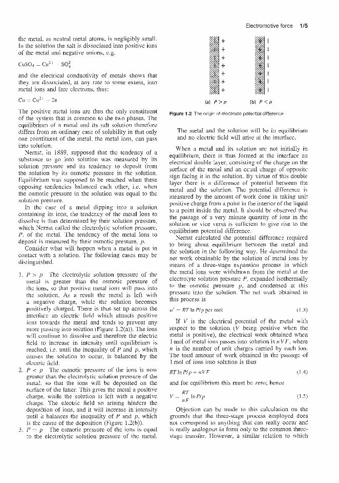
1. P > p The electrolytic solution pressure of the metal is greater than the osmotic pressure of the ions, so that positive metal ions will pass into the solution. As a result the metal is left with a negative charge, while the solution becomes positively charged. There is thus set up across the interface an electric field which attracts positive ions towards the metal and tends to prevent any more passing into solution (Figure 1.2(a)). The ions will continue to dissolve and therefore the electric field to increase in intensity until equilibrium is reached, i.e. until the inequality of P and p , which causes the solution to occur, is balanced by the electric field.
2. P < p The osmotic pressure of the ions is now greater than the electrolytic solution pressure of the metal, so that the ions will be deposited on the surface of the latter. This gives the metal a positive charge, w.hile the solution is left with a negative charge. Tlhe electric field so arising hinders the deposition of ions, and it will increase in intensity until it balances the inequality of P and p , which is the cause of the deposition (Figure L.2(b)).
3. P = p The osmotic pressure of the ions is equal to the ele'ctrolytic solution pressure of the metal.
(a) P > P b) P < P
Figure 1.2 The origin of electrode potential difference
The metal and the solution will be in equilibrium and no electric field will arise at the interface.
When a metal and its solution are not initially in equilibrium, there is thus formed at the interface an electrical double layer, consisting of the charge on the surface of the metal and an equal charge of opposite sign facing it in the solution. By virtue of this double layer there is a difference of potential between the metal and the solution. The potential difference is measured by the amount of work done in taking unit positive charge from a point in the interior of the liquid to a point inside the metal. It should be observed that the passage of a very minute quantity of ions in the solution or vice versa is sufficient to give rise to the equilibrium potential difference.
Nernst calculated the potential difference required to bring about equilibrium between the metal and the solution in the following way. We determined the net work obtainable by the solution of metal ions by means of a three-stage expansion process in which the metal ions were withdrawn from the metal at the electrolyte solution pressure P , expanded isothermally to the osmotic pressure p , and condensed at this pressure into the solution. The net work obtained in this process is
(1 .3)
If V is the electrical potential of the metal with respect to the solution (V being positive when the metal is positive), the electrical work obtained when 1 mol of metal ions passes into solution is nVF, where n is the number of unit charges carried by each ion. The total amount of work obtained in the passage of 1 mol of ions into solution is thus
RT In P l p + n V F (1.4)
and for equilibrium this must be zero; hence
w' = RT In P l p per mol
RT V = - l n P / p
n F
Objection can be made to this calculation on the grounds that the three-stage process employed does not correspond to anything that can really occur and is really analogous in form only to the common three- stage transfer. However, a similar relation to which
1/6 Introduction to battery technology
this objection does not apply has been obtained by thermodynamic processes.
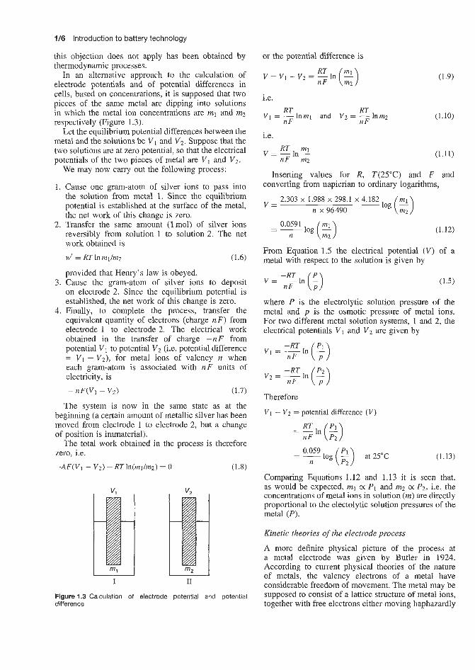
In an alternative approach to the calculation of electrode potentials and of potential differences in cells, based on concentrations, it is supposed that two pieces of the same metal are dipping into solutions in which the metal ion concentrations are rnl and m2 respectively (Figure 1.3).
Let the equilibrium potential differences between the metal and the solutions be V1 and V2. Suppose that the two solutions are at zero potential, so that the electrical potentials of the two pieces of metal are V1 and V2.
We may now carry out the following process:
1. Cause one gram-atom of silver ions to pass into the solution from metal 1. Since the equilibrium potential is established at the surface of the metal, the net work of this change is zero.
2. Transfer the same amount (lmol) of silver ions reversibly from solution 1 to solution 2. The net work obtained is w' = RT In m1Imz (1.6)
provided that Henry's law is obeyed. 3. Cause the gram-atom of silver ions to deposit
on electrode 2. Since the equilibrium potential is established, the net work of this change is zero.
4. Finally, to complete the process, transfer the equivalent quantity of electrons (charge n F ) from electrode 1 to electrode 2. The electrical work obtained in the transfer of charge -nF from potential V1 to potential V 2 (i.e. potential difference = V 1 - V2), for metal ions of valency n when each gram-atom is associated with nF units of electricity, is
- nF(V1 - Vz) (1.7)
The system is now in the same state as at the beginning (a certain amount of metallic silver has been moved from electrode 1 to electrode 2, but a change of position is immaterial).
The total work obtained in the process is therefore zero, i.e.
-AF(V1 - V2) + RTln(ml/mz) = 0 (1.8)
V
I I1
Figure 1.3 Calculation of electrode potential and potential difference
or the potential difference is
RT nF (2) V = V 1 - V 2 = - l n
i.e. RT RT
V1 = -1nml and V2 = -1nm2 nF nF
i.e. RT ml
V = - l n - n F m2
(1.9)
(1.10)
(1.11)
Inserting values for R, T(25"C) and F and converting from napierian to ordinary logarithms,
V = 2.303 x 1.988 x 298.1 x 4.182
n x 96490
(1.12)
From Equation 1.5 the electrical potential (V) of a metal with respect to the solution is given by
-RT v = nF1n ($) (1.5)
where P is the electrolytic solution pressure of the metal and p is the osmotic pressure of metal ions. For two different metal solution systems, 1 and 2, the electrical potentials V I and V2 are given by
Therefore
V1 - Vz = potential difference ( V )
=Eln($) n F
= __ 0.059 log (2) at 25°C n
(1.13)
Comparing Equations 1.12 and 1.13 it is seen that, as would be expected, rnl 0: P I and m2 0: P2, i.e. the concentrations of metal ions in solution (m) are directly proportional to the electolytic solution pressures of the metal (P) .
Kinetic theories of the electrode process
A more definite physical picture of the process at a metal electrode was given by Butler in 1924. According to current physical theories of the nature of metals, the valency electrons of a metal have considerable freedom of movement. The metal may be supposed to consist of a lattice structure of metal ions, together with free electrons either moving haphazardly
Electromotive force ln
among them or arranged in an interpenetrating lattice. An ion in the surface layer of the metal is held in its position by the cohesive forces of the metal, and before it can escape from the surface it must perform work in overcoming these forces. Owing to their thermal agitation the surface ions are vibrating about their equilibrium positions, and occasionally an ion will receive sufficient energy to enable it to overcome the cohesive forces entirely and escape from the metal. On the other hand, the ions in the solution are held to the adjacent water molecules by the forces of hydration and, in order that an ion may escape from its hydration sheath and become deposited on the metal, it must have sufficient energy to overcome the forces of hydration.
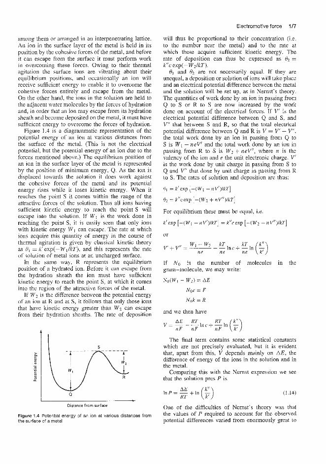
Figure 1.4 is a diagrammatic representation of the potential energy of an ion at various distances from the surface of the metal. (This is not the electrical potential, but the potential energy of an ion due to the forces mentioned above.) The equilibrium position of an ion in the surface layer of the metal is represented by the position of minimum energy, Q. As the ion is displaced tovvards the solution it does work against the cohesive forces of the metal and its potential energy rises while it loses kinetic energy. When it reaches the point S it comes within the range of the attractive forces of the solution. Thus all ions having sufficient kinetic energy to reach the point S will escape into the solution. If W1 is the work done in reaching the point S, it is easily seen that only ions with kinetic energy W1 can escape. The rate at which ions acquire this quantity of energy in the course of thermal agitation is given by classical kinetic theory as Q1 = k‘ exp(-W1lkT), and this represents the rate of solution of metal ions at an uncharged surface.
In the same way. R represents the equilibrium position of a hydrated ion. Before it can escape from the hydration sheath the ion must have sufficient kinetic energy to reach the point S, at which it comes into the region of the attractive forces of the metal.
If Wz is the difference between the potential energy of an ion at FL and at S, it follows that only those ions that have kinetic energy greater than Wz can escape from their hydration sheaths. The rate of deposition
t r
L Q * Distance from surface
Figure 1.4 Potential energy of an ion at various distances from the surface of a metal
will thus be proportional to their concentration (is. to the number near the metal) and to the rate at which these acquire sufficient kinetic energy. The rate of deposition can thus be expressed as Q2 = kl‘c exp(-WZlkT).
Q1 and Qz are not necessarily equal. If they are unequal, a deposition or solution of ions will take place and an electrical potential difference between the metal and the solution will be set up, as in Nenast’s theory. The quantities of work done by an ion in passing from Q to S or R to S are now increased by the work done on account of the electrical forces. If VI is the electrical potential difference between Q and S, and VI’ that between S and R, so that the total electrical potential difference between Q and R is V = V’ + V”, the total work done by an ion in passing from Q to S is W1 - neV’ and the total work done by an ion in passing from R to S is Wz + neV”, where n is the valency of the ion and e the unit electronic charge. V’ is the work done by unit charge in passing from S to Q and V” that done by unit charge in passing from R to S. The rates of solution and deposition are thus:
81 = k’exp [-(Wl - nV’)/kT]
82 = k’lcexp [-(Wz + nV”)/kT]
For equilibrium these must be equal, i.e.
k’exp [-(Wl - nV’)ikT] = kl’cexp [-(W2 + nY”)/kT]
or
If N o is the number of molecules in the gram-molecule, we may write:
No(W1 - W z ) = AE
Noe = F
Nok = R
and we then have RT AE RT
nF nF nF v = - + - lnc + - In (G)
The final term contains some statistical constants which are not precisely evaluated, but it is evident that, apart from this, V depends mainly on AE, the difference of energy of the ions in the solution and in the metal.
Comparing this with the Nernst expression we see that the solution pres P is
(1.14)
One of the difficulties of Nernst’s theory was that the values of P required to account for the observed potential differences varied from enormously great to
1/8 Introduction to battery technology
almost infinitely small values, to which it was difficult to ascribe any real physical meaning. This difficulty disappears when it is seen that P does not merely represent a concentration difference, but includes a term representing the difference of energy of the ions in the two phases, which may be large.
The electrode process has also been investigated using the methods of quantum mechanics. The final equations obtained are very similar to those given above.
Work function at the metal-metal junction
When two dissimilar metals are put in contact there is a tendency for negative electricity, i.e. electrons, to pass from one to the other. Metals have different affinities for electrons. Consequently, at the point of junction, electrons will tend to pass from the metal with the smaller to that with the greater affinity for electrons. The metal with the greater affinity for electrons will become negatively charged and that with the lesser affinity will become positively charged. A potential difference is set up at the interface which increases until it balances the tendency of electrons to pass from the one metal to the other. At this junction, as at the electrodes, the equilibrium potential difference is that which balances the tendency of the charged particle to move across the interface.
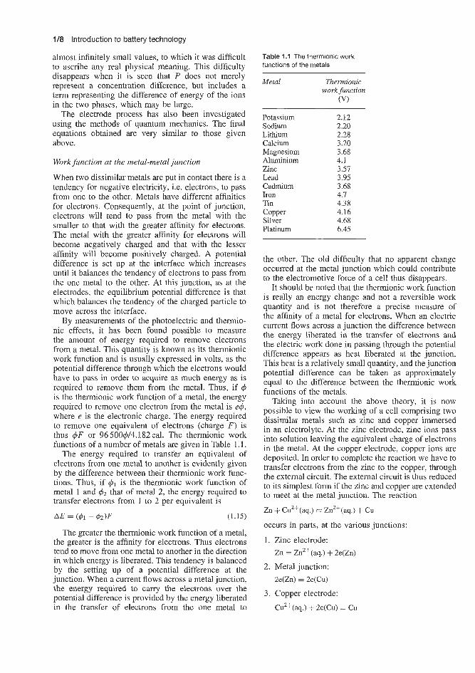
By measurements of the photoelectric and thermio- nic effects, it has been found possible to measure the amount of energy required to remove electrons from a metal. This quantity is known as its thermionic work function and is usually expressed in volts, as the potential difference through which the electrons would have to pass in order to acquire as much energy as is required to remove them from the metal. Thus, if 9 is the thermionic work function of a metal, the energy required to remove one electron from the metal is e@, where e is the electronic charge. The energy required to remove one equivalent of electrons (charge F ) is thus +F or 96 500qY4.182 cal. The thermionic work functions of a number of metals are given in Table 1.1.
The energy required to transfer an equivalent of electrons from one metal to another is evidently given by the difference between their thermionic work func- tions. Thus, if is the thermionic work function of metal 1 and q5z that of metal 2, the energy required to transfer electrons from 1 to 2 per equivalent is
AE = ($1 - 42)F (1.15)
The greater the thermionic work function of a metal, the greater is the affinity for electrons. Thus electrons tend to move from one metal to another in the direction in which energy is liberated. This tendency is balanced by the setting up of a potential difference at the junction. When a current flows across a metal junction, the energy required to carry the electrons over the potential difference is provided by the energy liberated in the transfer of electrons from the one metal to
Table 1.1 The thermionic work functions of the metals
Metal Thermionic work function
(VI
Potassium 2.12 Sodium 2.20 Lithium 2.28 Calcium 3.20 Magnesium 3.68 Aluminium 4.1 Zinc 3.51 Lead 3.95 Cadmium 3.68 Iron 4.7 Tin 4.38 Copper 4.16 Silver 4.68 Platinum 6.45
the other. The old difficulty that no apparent change occurred at the metal junction which could contribute to the electromotive force of a cell thus disappears.
It should be noted that the thermionic work function is really an energy change and not a reversible work quantity and is not therefore a precise measure of the affinity of a metal for electrons. When an electric current flows across a junction the difference between the energy liberated in the transfer of electrons and the electric work done in passing through the potential difference appears as heat liberated at the junction. This heat is a relatively small quantity, and the junction potential difference can be taken as approximately equal to the difference between the thermionic work functions of the metals.
Taking into account the above theory, it is now possible to view the working of a cell comprising two dissimilar metals such as zinc and copper immersed in an electrolyte. At the zinc electrode, zinc ions pass into solution leaving the equivalent charge of electrons in the metal. At the copper electrode, copper ions are deposited. In order to complete the reaction we have to transfer electrons from the zinc to the copper, through the external circuit. The external circuit is thus reduced to its simplest form if the zinc and copper are extended to meet at the metal junction. The reaction
Zn + CuZi(aq.) = Zn2+(aq.) + cu occurs in parts, at the various junctions:
Zinc electrode: Zn = Zn2+(aq.) + 2e(zn)
Metal junction: 2e(Zn) = 2e(Cu)
Copper electrode:
Cu2+(aq.) + 2e(Cu) = ~u

Reversible cells 1/B
If the circuit is open, at each junction a potential difference arises which just balances the tendency for that particular process to occur. When the circuit is closed there is an electromotive force in it equal to the sum of all the potential differences. Since each potential difference corresponds to the net work of one part of the reaction, the whole electromotive force is equivalent to the net work or free energy decrease of the whole reaction.
1.2 Reversible cells During the operation of a galvanic cell a chemical reaction occurs at each electrode, and it is the energy of these reactions that provides the electrical energy of the cell. If there is an overall chemical reaction, the cell is referred to as a chemical cell. In some cells, however, there is no resultant chemical reaction, but there is a change in energy due to the transfer of solute from one concentration to another; such cells are called ‘concentration cells’. Most, if not all, practical commercial batteries are chemical cells.
In order that the electrical energy produced by a galvanic cell may be related thermodynamically to the process occurring in the cell, it is essential that the latter should .behave reversibly in the thermodynamic sense. A reversible cell must satisfy the following conditions. If the cell is connected to an external source of e.m.f. which is adjusted so as exactly to balance the e.m.f. of the cell, i.e. SQ that no current flows, there should be no chemical or other change in the cell. If the external e.m.f. is decreased by an infinitesimally small amount, current will flow from the cell, and a chemical or other change, proportional in extent to the quantity of electricity passing, should take place. On the other hand. if the external e.m.f. is increased by a very small amount, the current should pass in the opposite direction, and the process occurring in the cell should be exactly reversed.
It may be noted that galvanic cells can only be expected to behave reversibly in the thermodynamic sense, when the currents passing are infinitesimally small; so that the system is always virtually in equi- librium. If large currents flow, concentration gradi- ents arise within the cell because diffusion is rela- tively slow; i.n these circumstances the cell cannot be regarded as existing in a state of equilibrium. This would apply to most practical battery applications where the currents drawn from the cell would be more than infinitesimal. Of course, with a given type of cell, as the current drawn is increased the departure from the equilibrium increases also. Similar comments apply during the charging of a battery where current is supplied and the cell is not operating under perfectly reversible conditions.
If this charging current is more than infinitesimally small, there i,s a departure from the equilibrium state and the cell is; not operating perfectly reversibly in the thermodynamic sense. When measuring the e.m.f. of
a cell, if the true thermodynamic e.m.f. is required, it is necessary to use a type of measuring equipment that draws a zero or infinitesimally small current from the cell at the point of balance. The e.m.f. obtained in this way is as close to the reversible value as is experimentally possible. If an attempt is made to determine the e.m.f. with an ordinary voltmeter, which takes an appreciable current. the result will be in error.
In practical battery situations, the e.m.f. obtained is not the thermodynamic value that would be obtained for a perfectly reversible cell but a non-equilibrium value which for most purposes suffices and in many instances is, in fact, close to the value that would have been obtained under equilibrium conditions.
One consequence of drawing a current from a cell which is more than infinitesimally small is that the cur- rent obtained would not be steady but would decrease with time. The cell gives a steady current only if the current is very low or if the cell is in action only intermittently. The explanation of this effect, which is termed ’polarization’, is simply that some of the hydrogen bubbles produced by electrolysis at the metal cathode adhere to this electrode. This results in a two- fold action. First, the hydrogen is an excellent insulator and introduces an internal layer of very high elec- trical resistance. Secondly, owing to the electric field present, a double layer of positive and negative ions forms on the surface of the hydrogen and the cell actu- ally tries to send a current in the reverse direction or a back e.m.f. develops. Clearly, the two opposing forces eventually balance and the current falls to zero. These consequences of gas production at the electrodes are avoided, or at least considerably reduced, in practical batteries by placing between the positive and nega- tive electrodes a suitable inert separator material. The separators perform the additional and, in many cases, more important function of preventing short-circuits between adjacent plates.
A simple example of a primary (non-rechargeable) reversible cell is the Daniell cell, consisting of a zinc electrode immersed in an aqueous solution of zinc sulphate, and a copper electrode in copper sulphate solution:
Zn 1 ZnSO4(soln) j CuS04(soln) j Cu
the two solutions being usually separated by a porous partition. Provided there is no spontaneous diffu- sion through this partition, and the electrodes are not attacked by the solutions when the external circuit is open, this cell behaves in a reversible manner. If the external circuit is closed by an e.1n.f. just less than that of the Daniell cell, the chemical reaction taking place in the cell is
Zn + cu2+ = Zn2+ + cu
i.e. zinc dissolves from the zinc electrode tQ form zinc ions in solution, while copper ions are discharged and deposit copper on the other electrode. Polarization is

1/10 Introduction to battery technology
prevented. On the other hand, if the external e.m.f. is slightly greater than that of the cell, the reverse process occurs; the copper electrode dissolves while metallic zinc is deposited on the zinc electrode.
A further example of a primary cell is the well known LeclanchC carbon-zinc cell. This consists of a zinc rod anode dipping into ammonium chloride paste outside a linen bag inside which is a carbon rod cathode surrounded by solid powdered manganese dioxide which acts as a chemical depolarizer.
The equation expressing the cell reaction is as fol- lows: 2Mn02 + 2NH4Cl+ Zn -+ 2MnOOH + Zn(NH3)2C1z
The e.m.f. is about 1.4V. Owing to the fairly slow action of the solid depolarizer, the cell is only suitable for supplying small or intermittent currents.
The two cells described above are primary (non- rechargeable) cells, that is, cells in which the nega- tive electrode is dissolved away irreversibly as time goes on. Such cells, therefore, would require replace- ment of the negative electrode, the electrolyte and the depolarizer before they could be re-used. Secondary (rechargeable) cells are those in which the electrodes may be re-formed by electrolysis, so that, effectively, the cell gives current in one direction when in use (dis- charging) and is then subjected to electrolysis (rechar- ging) by a current from an external power source passing in the opposite direction until the electrodes have been completely re-formed. A well known sec- ondary cell is the lead-acid battery, which consists of electrodes of lead and lead dioxide, dipping in dilute sulphuric acid electrolyte and separated by an inert porous material. The lead dioxide electrode is at a steady potential of about 2V above that of the lead electrode. The chemical processes which occur on dis- charge are shown by the following equations:
1. Negative plate:
Pb + SO:- -+ PbS04 + 2e
2. Positive plate: PbOz + Pb + 2HzSO4 + 2e -+ 2PbSO4 + 2HzO
or for the whole reaction on discharge: PbOz -5 Pb + + 2PbSO4 + 2HzO
The discharging process, therefore, results in the for- mation of two electrodes each covered with lead sul- phate, and therefore showing a minimum difference in potential when the process is complete, i.e. when the cell is fully discharged. In practice, the discharged negative plate is covered with lead sulphate and the positive plate with compounds such as PbO.PbS04.
In the charging process, current is passed through the cell in such a direction that the original lead electrode is reconverted into lead according to the equation: PbSO4 + 2H+ + 2e- -+ HzS04 + Pb
I 2.6 + $ 2.4
-
while the lead peroxide is re-formed according to the equation:
PbS04 + 2Hz0 + PbOz + HzS04 + 2e- + 2HS
Overall, the charge cell reaction is:
2PbSO4 + 2Hz0 -+ Pb + PbOz + 2HzSO4
It is clear from the above equations that in the discharging process water is formed, so that the rel- ative density of the acid solution drops steadily. Con- versely, in the charging process the acid concentration increases. Indeed, the state of charge of an accumu- lator is estimated from the density of the electrolyte, which varies from about 1.15 when completely dis- charged to 1.21 when fully charged. Throughout all these processes the e.m.f. remains approximately con- stant at 2.1 V and is therefore useless as a sign of the degree of charge in the battery.
The electromotive force mentioned above is that of the charged accumulator at open circuit. During the passage of current, polarization effects occur, as dis- cussed earlier, which cause variations of the voltage during charge and discharge. Figure 1.5 shows typi- cal charge and discharge curves. During the charge the electromotive force rises rapidly to a little over 2.1 V and remains steady, increasing very slowly as the charging proceeds. At 2.2V oxygen begins to be liberated at the positive plates and at 2.3V hydrogen at the negative plates. The charge is now completed and the further passage of current leads to the free evolution of gases and a rapid rise in the electromo- tive force. If the charge is stopped at any point the electromotive force returns, in time, to the equilibrium value. During discharge it drops rapidly to just below 2V. The preliminary ‘kink’ in the curve is due to the formation of a layer of lead sulphate of high resistance while the cell is standing, which is soon dispersed. The electromotive force falls steadily during cell discharge; when it has reached 1.8 V the cell should be recharged, as the further withdrawal of current causes the voltage to fall rapidly.
The difference between the charge and discharge curves is due to changes of concentration of the acid
-
-
.- E 1.8 P 5 1.6
ii 1.4- 0 20 40 60 80 100
Time (rnin)
Figure I d Charge and discharge curves for a lead-acid battery
Discharge -
-

Reversible electrodes 1/11
in contact with the active materials of the plates. These are full of small pores in which' diffusion is very slow, so that the coincentration of the acid is greater during the charge anld less during the discharge than in the bulk of the solution. This difference results in a loss of efficiency.
The current efficiency of the lead accumulator, Le.
Amount of current taken out during discharge
Amount of current put in Current efficien'cy =
during charge
is high, about 94-96%, but the charging process takes place at a higher electromotive force than the dis- charge, so that more energy is required for the former.
Energy obtained
The energy efficiency measured by
(Discharge voltage x Quantity in discharge ~2 of electricity)
to charge C of electricity) Energy requirez = (Charge voltage x Quantity
is comparatively low, at 75585%. A further example of a rechargeable battery is the
nickel-iron cell. In the discharged state the negative plate of this cell is iron with hydrated ferrous oxide, and the positive plate is nickel with hydrated nickel oxide. When charged, the ferrous oxide is reduced to iron, and the nickel oxide is oxidized to a hydrated peroxide. The cell reaction may thus be represented by
(charge FeO + 2Ni0 F======+ Fe + Ni2O3
discharge
The three oxides are all hydrated to various extents, but their exact compositions are unknown. In order to obtain plates having a sufficiently large capacity, the oxides halve to be prepared by methods which give particularly finely divided and active products. They are pac:ked into nickel-plated steel containers, perforated by numerous small lholes - an arrangement which gives exceptional mechanical strength. The elec- trolyte is usuallly a 21% solution of potash, but since hydroxyl ions do not enter into the cell reaction the electromotive force (1.33-1.35 V) is nearly indepen- dent of the concentration. Actually, there is a differ- ence between the amount of water combined with the oxides in the charged and discharged plates. Water is taken up and the alkali becomes more concentrated during the discharge, but water is given out during the charge. The electromotive force therefore depends to a small extent 011 the free energy of water in the solution, which in turn is determined by the concentration of the dissolved potaish. Actually 2.9mol of water are liber- ated in the discharge reaction, as represented above, and the variation of the electromotive force between 1 . 0 ~ and 5 . 3 ~ potash is from 1.351 to 1.335V. The potential of the positive plate is +OS5 and that of the negative plate -0.8 on the hydlrogen scale.
The current efficiency, about 82%, is considerably lower than that of the lead accumulator. The voltage
during the charge is about 1.65 V, rising at the end to 1.8 V, whereas during the discharge it falls gradually from 1.3 to 1.1 V. Hence the energy efficiency is only about 60%.
1.3 Reversible electrodes The electrodes constituting a reversible cell are reversible electrodes, and three chief types of such electrodes are known. The combination of any two reversible electrodes gives a reversible cell.
The first type of reversible electrode involves a metal (or a non-metal) in contact with a solution of its own ions, e.g. zinc in zinc sulphate solution, or copper in copper sulphate solution, as in the Daniel1 cell. Electrodes of the first kind are reversible with respect to the ions of the electrode material, e.g. metal or non- metal; if the electrode material is a univalent metal or hydrogen, represented by M, the reaction which takes place at such an electrode, when the cell of which it is part operates, is
M + M + + e
where e indicates an electron, and M+ implies a hydrated (or solvated) ion in solution. The direction of the reaction depends on the direction of flow of current through the cell. If the electrode material is a univalent non-metal A, the ions are negative and the corresponding reaction is
A - + A + e
As will be seen later, the potentials of these elec- trodes depend on the concentration (or activity) of the reversible ions in the solution.
Electrodes of the second type involve a metal and a sparingly soluble salt of this metal in contact with a solution of a soluble salt of the same anion:
M 1 MX(s) HX(so1n)
The electrode reaction in this case may be written as
Mfs) +X- + MX(s)+ e
the ion X being that in the solution of the soluble acid, e.g. HX. These electrodes behave as if they were reversible with respect to the common anion (the ion X in this case).
Electrodes of the second type have been made with various insoluble halides (silver chloride, silver bro- mide, silver iodide and mercurous chloride) and also with insoluble sulphates, oxalates, etc.
The third important type of reversible electrode con- sists of an unattackable metal, e.g. gold or platinum, immersed in a solution containing both oxidized and reduced states of an oxidation-reduction system, e.g. Sn4+ and Sn2+; Fe3+ and Fez+; or Fe(CN)i- and Fe(CN):-. The purpose of the unattackable metal is to act as a conductor to make electrical contact, just

1/12 Introduction to battery technology
as in the case of a gas electrode. The oxidized and reduced states are not necessarily ionic. For example, an important type of reversible electrode involves the organic compound quinone, together with hydrogen ions, as the oxidized state, with the neutral molecule hydroquinone as the reduced state. Electrodes of the kind under consideration, consisting of conventional oxidized and reduced forms, are sometimes called oxi- dation-reduction electrodes; the chemical reactions taking place at these electrodes are either oxidation of the reduced state or reduction of the oxidized state of the metal ion M:
M2+ + M4+ + 2e
depending on the direction of the current. In order that the electrode may behave reversibly it is essential that the system contain both oxidized and reduced states.
The three types of reversible electrodes described above differ formally as far as their construction is concerned; nevertheless, they are all based on the same fundamental principle. A reversible electrode always involves an oxidized and a reduced state, using the terms ‘oxidized’ and ‘reduced’ in their broadest sense; thus, oxidation refers to the liber- ation of electrons while reduction implies the tak- ing up of electrons. If the electrode consists of a metal M and its ions M+, the former is the reduced state and the latter is the oxidized state; similarly, for an anion electrode, the A- ions are the reduced state while A represents the oxidized state. It can be seen, therefore, that all three types of reversible electrode are made up from the reduced and oxi- dized states of a given system, and in every case the electrode reaction may be written in the general form
Reduced state + Oxidized state + ne
where n is the number of electrons by which the oxidized and reduced states differ.
A reversible electrode consists of an oxidized and a reduced state, and the reaction which occurs at such an electrode, when it forms part of an oper- ating cell, is either oxidation (i.e. reduced state + oxidized state + electrons) or reduction (i.e. oxidized state + electrons -+ reduced state). It can be readily seen, therefore, that in a reversible cell consisting of two reversible electrodes, a flow of electrons, and hence a flow of current, can be maintained if oxida- tion occurs at one electrode and reduction at the other. According to the convention widely adopted, the e.m.f. of the cell is positive when in its normal operation oxi- dation takes place at the left-hand electrode of the cell as written and reduction occurs at the right-hand elec- trode. If the reverse is the case, so that reduction is taking place at the left-hand electrode, the e.m.f. of the cell, by convention, will have a negative sign.
The Daniel1 cell, represented by
Zn 1 MZnS04(soln) MCuS04(soln) 1 cu
has an e.m.f. of l.lOV, and by the convention its sign is positive. This means that when the cell operates oxidation occurs at the left-hand electrode; that is to say, metallic zinc atoms are being oxidized to form zinc ions in solution, i.e.
Zn = Zn2+ + 2e
At the right-hand electrode there must, therefore, be reduction of the cupric ions, from the copper sulphate solution, to copper atoms, i.e.
cu2+ + 2e = cu
The electrons liberated at the zinc electrode travel along the external connecting circuit and are available for the discharge (reduction) of the cupric ions at the copper electrode. The complete cell reaction, obtained by adding the separate electrode reactions, is conse- quently:
Zn + cu2+ = zn2+ + cu
Since two electrons are involved for each zinc (or copper) atom taking part in the reaction, the whole process as written, with quantities in gram-atoms or gram-ions, takes place for the passage of 2 F of elec- tricity.
The practical convention, employed in connection with cells for yielding current, is to call the ‘negative’ pole the electrode at which the process is oxidation when the cell is producing current; the ‘positive’ elec- trode is the one at which reduction is the spontaneous process. The reason for this is that oxidation is accom- panied by the liberation of electrons, and so the elec- trode metal acquires a negative charge; similarly, the reduction electrode will acquire a positive charge, because electrons are taken up from it. According to the widely used convention, the e.m.f. of a cell is pos- itive when it is set up in such a way that the negative (oxidation) electrode is to the left, and the positive (reduction) electrode is to the right.
1.4 Relationship between electrical energy and energy content of a cell It may be asked what is the relation between the electrical energy produced in a cell and the decrease in the energy content of the system, as a result of the chemical reaction going on therein. Considering only cells working at constant (atmospheric) pressure, when a chemical reaction occurs at constant pressure, without yielding any electrical energy, the heat evolved is equal to the decrease in the heat content of the system. In 1851, Kelvin made the first attempt to answer the question, by assuming that in the cell the whole of the heat of reaction appeared as electrical energy, i.e. the electrical energy obtained is equal to the decrease in the heat content of the system. This was

Relationship between electrical energy and energy content of a cell 1/13
supported by imeasurement on the Daniel1 cell. When the reaction
Zn + CuSOd.(aq.) = Cu + ZnS04(aq.)
is carried out in a calorimeter, an evolution of heat of 50.13kcal occurs, which agrees well with the value of 50.38 kcal obtained for the electrical energy yielded by the reactio'n. This agreement, however, has since proved to be a coincidence. In other cell reactions, the electrical ener,gy is sometimes less, sometimes greater, than the difference in heat content of the system. In the former case, the balance must appear as heat evolved in the working of the cell; in the latter case heat must be absorbed by the cell from its surroundings and to maintain the conservation of energy it is necessary to have
w ' = - H $ q (1.16)
where w' is the electrical energy yielded by the cell reaction, -H the decrease in heat content of the system and q the heat absorbed in the working of the cell.
It is necessary, therefore, to determine the heat absorbed in the working of the cell before the electrical energy yield of the cell can be found.
In methods for the accurate measurement of the electromotive force of a cell, the electromotive force of the cell is balanced by an applied potential difference. If the applied potential difference is slightly decreased, the cell reaction will go forward and the cell will do electrical work against the applied potential difference. If the applied potential difference is slightly increased, the reaction will occur in the reverse direction and work will be done by the external electromotive force on the cell. The reaction thus occurs reversibly in the cell when its electromotive force is balanced by an outside potential difference. When a reaction goes forward under these conditions, Le. when the tendency of the reaction to go is just balanced by an external force. the maximum work that the reaction can yield is obtained. In a reaction at constant pressure, work is necessarily done against the applied pressure if any volume change occurs anid this work cannot be obtained as electrical energy. The electrical energy obtained under these conditions is: therefore, the net work of the reaction.
For n equivalents of chemical reaction, n F coulombs are produced. If E is the electromotive force of the cell, an applied potential difference E is required to balance it. The electrical work w' done when the reaction goes forward in a state of balance (or only infinitesimally removed from it) is thus nFE. and this is equal to the net work of the reaction. Thus
w' = I Z F E (1.17)
It should be observed that w' is the electrical work done against the applied potential difference. If there is no opposing potential difference in the circuit, no work is done against an applied potential difference, and the
electrical energy n F E is dissipated in the circuit as heat.
According to the Gibbs-Helmholtz equation,
(1.18)
putting w' = n FE and dw'ldT = n F(dEldT),
Le.
AH(J) = -nF [. - T ($)d (1.19)
(1.201
where dEldT is the temperature coefficient of the electromotive force at constant pressure.
Comparing Equation 1.19 with Equation I . 16 it can be seen that
(1.21)
corresponds with the heat absorbed in the working of the cell. Thus
q = w' - ( - A H )
= nFT ( % I p (1.22)
where q is the heat absorbed in working the cell, w' is the electrical energy yielded by the cell reaction, and -AH is the decrease in heat content of the system.
The sign of q thus depends on the sign of the temperature coefficient of the electromotive force:
If dEldT is positive, heat is absorbed in the working of the cell, i.e. the electrical energy obtained is greater than the decrease in the heat content in the reaction.
w' - ( - A H ) is positive
If dEldT is negative, heat is evolved in the working of the cell, i.e. the electrical energy obtained is less than the decrease in the heat content in the reaction.
w' - ( - A H ) is negative
If dEldT is zero, no heat is evolved in the working of the cell, Le. the electrical energy obtained is equal to the decrease in the heat content in the reaction.
w' - ( - A H ) = 0

1/14 Introduction to battery technology
1.5 Free energy changes and electromotive forces in cells More recent work has regarded the processes occur- ring in a cell in terms of free energy changes. The free energy change accompanying a process is equal to the reversible work, other than that due to a vol- ume change, at constant temperature and pressure. When a reversible cell operates, producing an infinites- imal current, the electrical work is thermodynamically reversible in character, and does not include any work due to a volume change. Furthermore, since the tem- perature and pressure remain constant, it is possible to identify the electrical work done in a reversible cell with the free energy change accompanying the chemical or other process taking place in the cell. The work done in a cell is equal to the product of the e.m.f. and the quantity of electricity passing. The practical unit of electrical energy is defined as the energy devel- oped when one coulomb is passed under the influence of an e.m.f. of one volt; this unit is called the volt- coulomb, and is equivalent to one international joule. The calorie defined by the US Bureau of Standards is equivalent to 4.1833 international joules, and hence one volt-coulomb is equivalent to U4.1833, Le. 0.2390 (defined), calorie.
If the e.m.f. of a reversible cell is E volts, and the process taking place is associated with the passage of n faradays, i.e. nF coulombs, the electrical work done by the system is consequently n F E volt-coulombs or international joules. The corresponding increase of free energy ( A F ) is equal to the electrical work done on the system; it is therefore possible to write
AF = -nFE (1.23)
This is an extremely important relationship, which forms the basis of the whole treatment of reversible cells.
The identification of the free energy change of a chemical reaction with the electrical work done when the reaction takes place in a reversible cell can be justified experimentally in the following manner. By the Gibbs-Helmholtz equation,
(1.24)
where AH is the heat change accompanying the cell reaction and T is temperature in kelvins. If AF is replaced by -nFE, the result is
-nFE = A H - nFT - (a AH = nF [. - T ( g)p] (1.25)
It can be seen from Equation 1.20 that if the e.m.f. of the reversible cell, i.e. E, and its temperature coef- ficient dEldT, at constant pressure, are known, it is
possible to evaluate the heat change of the reaction occurring in the cell. The result may be compared with that obtained by direct thermal measurement; good agreement would then confirm the view that -nFE is equal to the free energy increase, since Equation 1.20 is based on this postulate.
Using Equation 1.20 it is possible, having the e.m.f. of a cell on open circuit at a particular temperature, the temperature coefficient of dEldT and the emf . , to calculate the heat change accompanying the cell reaction AH:
A H = n F E - T - VC [ (3J - -"F [. - T cal -
4.183
For example, the open circuit voltage of a lead-acid cell is 2.01V at 15°C (288K) and its temperature coefficient of resistance is dEldT = 0.000 37 VIK, n = 2. The heat change accompanying the cell reaction in calories is
-2 x 96500 AH = (2.01 - 288 x 0.000 37)
4.18 = -87500cai = -87.5kcal
which is in quite good agreement with the calorimet- rically derived value of -89.4 kcal.
Similarly, in the Clark cell, the reaction
Zn(ama1gam) + Hg2S04(s) + 7Hz0
= ZnS04.7HzO(s) + 2Hg(1)
gives rise to 2 F of electricity, i.e. n = 2, the open circuit voltage is 1.4324 V at 15°C and the temperature coefficient is 0.000 19, hence:
-2 x 96 540 A H = (1.4324 - 288 x 0.001 19)
4.18 = 81.92kcal
which agrees well with the calorimetric value of 8 1.13 kcal.
1.6 Relationship between the energy changes accompanying a cell reaction and concentration of the reactants It is important when studying the effect of concentra- tions of reactants in a cell on the e.m.f. developed by the cell to consider this in terms of free energies ( A F ) .
Free energy ( A F ) is defined by the following expression:
-AF = w - PAV
at constant temperature and pressure.

Single electrode potentials 1/15
reaction as written occurs for the passage of n fara- days, it follows from Equation 1.26 that A F , as given by Equation 1.27 or 1.28, is also equal to -nFE. Fur- thermore, if the e.m.f. of the reversible cell is Eo when all the substances involved are in their standard states, the A F o is equal to -nFEo. Substituting these val- ues for A F and A F o into Equation 1.28 and dividing through by -nF, the result is
In a reversible, isothermal process, w is the maxi- mum work that can be obtained from the system in the given change.
The quantity PAV is the work of expansion done against the external pressure, and so - A F repre- sents the maximum work at constant temperature and pressure, other than that due to volume change. The quantity w - PAV is called the net work and so the decrease -AF in the free energy of a system is equal to the net work obtainable (at constant temperature and pressure) from the system under reversible con- ditions. An important form of net work, since it does not involve external work due to a volume change, is electrical work; consequently, a valuable method for determining the free energy change of a process is to carry it out electrically, in a reversible manner, at constant temperature and pressure.
By Equation 1.23,
A F == -nFE
where A F i s the free energy increase, E the e.m.f. of a reversible cell, n F the number of faradays associated with the process occurring ( F = 1 F), and
- A F E = - n F
(1.26)
The free energy change accompanying a given reac- tion depends on the concentrations or, more accurately, the activities, of the reactants and the products. It is evident, therefore, that the e.m.f. of a reversible cell, in which a particular reaction takes place when producing current, will vary with the activities of the substances present in the (cell. The exact connection can be readily derived in the following manner. Suppose the general reaction
a A + bB + . . . -+ 1L + mM + . . . occurs in a reversibie cell; the corresponding free energy change is then given by the following equation
a'L x amM x . . . aaA x abB x . . .
AF = A F O + RTIn (1.27)
where aA, aB, . . . , aL, aM, . . . now represent the activities of A9 €3. . . . , L, M, . . .as they occur in the reversible cell. If the arbitrary reaction quotient, in terms of activities, is represented by the symbol Qa, Equation 1.27 may be written as
A F = A F o + XT In Qa (1.28)
As before, A F o is the free energy change when all the substances taking part in the cell reaction are in their standard states.
If E is the e.m.f. of the cell under consideration when the various substances have the arbitrary activi- ties aA, aB, . . . ~ aL, aM. . . . , as given above, and the
RT E = E 0 - - h Q , n F (1.29)
This expression is seen to relate the e.m.f. of a cell to the activities of the substances taking part; Eo, the standard e.m.f., is a constant for the given cell reaction, varying only with the temperature, at 1 atmosphere pressure.
The foregoing results may be illustrated by reference to the cell
iHz(g) + AgCl(s) = H+ t C1- t Ag(s)
for the passage of 1 F. The reaction quotient in terms of activities is
but since the silver and the silver chloride are present in the solid state, their activities are unity; hence
Inserting this expression into Equation 1.29, with n equal to unity, the e.m.f. of the cell is given by
F (1.30)
The e.m.f. is thus seen to be dependent upon the activities of the hydrogen and chloride ions in the solution of hydrochloric acid, and of the hydrogen gas in the cell. If the substances taking part in the cell behaved ideally, the activities in Equation 1.30 could be replaced by the corresponding concentrations of the hydrogen and chloride ions. and by the pressure of the hydrogen gas. The resulting form of Equation 1.30. namely
RT cH+ x cCI-
F ( PHzR E = E O - - I I ~ (1.31)
could be used if the solution of hydrochloric acid were dilute and the pressure of the hydrogen gas low.
1.7 Single electrode potentials There is at present no known method whereby the potential of a single electrode can be measured; it is

1/16 Introduction to battery technology
only the e.m.f. of a cell, made by combining two elec- trodes, that can be determined experimentally. How- ever, by choosing an arbitrary zero of potential, it is possible to express the potentials of individual elec- trodes. The arbitrary zero of potential is taken as the potential of a reversible hydrogen electrode, with gas at 1 atm. pressure, in a solution of hydrogen ions of unit activity. This particular electrode, namely H2 (1 atm.) H+ (a = 1), is known as the standard hydrogen elec- trode. The convention, therefore, is to take the potential of the standard hydrogen electrode as zero; electrode potentials based on this zero are said to refer to the hydrogen scale. If any electrode, M, M', is combined with the standard hydrogen electrode to make a com- plete cell, i.e.
M 1 1 M+(soln) H+(a = 1) 1 1 Hz(l atm.)
the e.m.f. of this cell, E , is equal to the potential of the M, M+ electrode on the hydrogen scale.
When any reversible electrode is combined with a standard hydrogen electrode, as indicated above, and oxidation reaction takes place at the former, while the hydrogen ions are reduced to hydrogen gas at the latter. The electrode (oxidation) process may be written in the following general form:
Reduced state = Oxidized state + ne
and the corresponding hydrogen electrode reaction is
nH+ + n e = inHz(g)
The complete cell reaction for the passage of n fara- days is consequently
Reduced state + nH+ = Oxidized state + $nHz(g) (1.32)
The e.m.f. of the cell, which is equal to the potential of the reversible electrode under consideration, is then given by Equation 1.29 as
E 0
(1.33) 1 (Oxidized state) x a:; (Reduced state) x a;-
where parentheses have been used to represent the activities of the oxidized and reduced states as they actually occur in the cell. In the standard hydrogen electrode, the pressure of the gas is 1 atm., and hence the activity aH2 is unity; furthermore, by definition, the activity of the hydrogen ions UH+ in the electrode is also unity. It can thus be seen that Equation 1.33 for the electrode potential can be reduced to the simple form
(1.34) E = E : ~ - - In
This is the general equation for the oxidation potential of any reversible electrode; E:, is the corresponding standard electrode potential; that is, the potential of
I (Oxidized state) n F RT [ (Reduced state)
the electrode when all the substances concerned are in their standard states of unit activity. The qualification 'oxidation' is used because it describes the process tak- ing place at the electrode; the corresponding 'reduction potentials' will be considered below.
The application of Equation 1.34 may be illustrated by reference to a few simple cases of different types. Consider, first, an electrode consisting of a metal in contact with a solution of its own cations, e.g. copper in copper (cupric) sulphate solution. The electrode (oxidation) reaction is
cu = C U ~ ' + 2e
the Cu being the reduced state and Cu2+ the oxidized state; in this case n is 2, and hence by Equation 1.34
The activity of acu of the solid metal is unity, by convention, and hence
RT 2F E = E ! ~ - - Inacuz+ (1.35)
so that the electrode potential is dependent on the standard (oxidation) potential E:, of the Cu, Cu2+ system, and on the activity acu2+ of the cupric ions in the copper sulphate solution. The result may be generalized, so that for any metal M (or hydrogen) in equilibrium with a solution of its ions M' of valence n , the oxidation potential of the M, M+ electrode is given by
RT nF
E = E:] - - InaM+
At 25"C,
0.059 15 E = E o el -~ log aM+ (1.36)
where a M + is the activity of the M+ ions in the solution. For a univalent ion (e.g. hydrogen, silver, cuprous), n is 1; for a bivalent ion (e.g. zinc, nickel, ferrous, cupric, mercuric), n is 2 and so on.
Similarly, the general equation for the oxidation potential of any electrode reversible to the anion A- of valence n is
RT nF
E = Efl + - lnaA-
At 25T ,
E = E:l + 0.059 15 log a*- (1.37)
where UA- is the activity of the A- ions in the given electrode solution. It should be noted, in compar- ing Equations 1.36 and 1.37 that in the former, for cations, the second term is preceded by a negative sign, whilst in the latter, for anions, the sign is pos- itive. To make practical use of the electrode potential

Single electrode potentials 1/17
is occurring. The situation is, fortunately, quite sim- ple; the reduction potential of any electrode is equal to the oxidation potential for the same electrode but with the sign reversed. It is quite unnecessary, and in fact undesirable, to write out separate formulae for reduction potentials. The recommended procedure is to derive the oxidation potential for the given electrode and then merely to reverse the sign. For example, the reduction potential of the copper-cupric ion electrode, for which the reaction is
cu2+ + 2e = cu would be given by an equation identical to Equation 1.35 but with the sign reversed.
To facilitate the representation of electrodes, a sirn- ple convention is adopted; when the electrode is a metal M, and the process is oxidation to M+ ions, the reduced state of the system is written to the left and the oxidized state to the right. namely M, M', as in the electrochemical equation M + M+ + electrons. Examples of oxidation electrodes are thus
CU, CU'+ (or CU, C U S O ~ (solnj)
Zn, zn2+ (or Zn, ZnSo4 (soln))
The potentials of such electrodes are given by Equation 1.34 or 1.36. On the other hand, if the elec- trodes are represented in the reverse manner; i.e. ha', M, with the oxidized state to the left and the reduced state to the right, e.g.
cu2+, cu (or C U S O ~ (solnj, CU)
Zn2+, Zn (or Z ~ S O ~ (solnj, zn)
the electrode process is reduction, and the potentials are opposite in sign to those of the corresponding oxidation electrodes.
If two reversible electrodes are combined to form such cells as
~n I ~n~04(so ln j CuSO4 (soh) 1 Cu
then, in accordance with the convention given above, the reaction at the left-hand electrode is oxidation, while at the right-hand electrode a reduction process is taking place when the cell operates spontaneously to produce current upon closing the external circuit. Thus, the e.m.f. of the complete cell is equal to the algebraic sum of the potentials of the two electrodes, one being an oxidation potential and the other a reduc- tion potential. An important point to which attention may be called is that since the e.m.f. of a cell is equal to the sum of an oxidation and a reduction electrode potential, it is equivalent to the difference of two oxi- dation potentials. As a consequence, the e.m.f. of a cell is independent of the arbitrary notential chosen as the zero of the potential scale; the actual value; whatever it may be, cancels out when taking the difference of the two oxidation potentials based on the same (e& hydrogen) scale.
equations it is necessary to insert values for R and F in the factor RTInF which appears in all such equations. The potential is always expressed in volts, and since F is known to be 96 500 C, the value of R (R = 1.998 cal) must be in volt coulombs, i.e. in inter- national joules; thus R(1.998 x 4.18) is 8.314 absolute joules or 8.312 international joules per degree per mole. Taking Equation 1.36 for the oxidation poten- tial of an electrode reversible with respect to cations, that is
inserting the values of R and F given above, and intro- ducing the factor 2.303 to convert natural logarithms TO common logarithms, i.e. to the base 10, the result is
2.303 x 8.312 T 96500 n
E=E0---- log aMT
(1.38)
At 25"C, i.e. T = 298.16K, which is the temperature most frequently employed for accurate electrochemical measurements, this equation becomes
0.059 15 E = E:l - ~ log a M t
Kl (1.39)
Similarly, for the oxidation potential of an anion elec- trode at 25T ,
0.059 15 E =E;, + ~- l o g q (1.40)
The general form of the equation at 25"C, which is applicable to all reversible electrodes (see Equation 1.34) is
(1.41) I 0.059 15 (Oxidized state) n log [(Reduced state)
E = E:l - ~
where the parentheses are used to indicate activities. It should be evident from the foregoing examples
that it is not a difficult matter to derive the equation for the oxidation potential of any electrode; all that is necessary is to write down the electrode reaction, and then to insert the appropriate activities of the oxidized and reduced states in Equation 1.34. The result is then simplified by using the convention concerning the standard states of unit activity. Thus, for any metal present in the pure state, for any pure solid compound, for a gas at 1 atm. pressure, and for water forming part of a dilute solution, the activity is taken as unity. The corresponding activity factors may then be omitted from the electrode potential equation.
It has been seen that, in every galvanic cell, oxida- tion occurs at one electrode, but a reduction process takes place at the other electrode. The equations just derived give the potential of the electrode at which oxidation occurs, and now reference must be made to the potential of the electrode at which reduction

1/18 Introduction to battery technology
According to the equations derived above, the poten- tial of any electrode is determined by the standard potential E:l, and by the activity or activities of the ions taking part in the electrode process. These activi- ties are variable, but the standard potential is a definite property of the electrode system, having a constant value at a given temperature. If these standard poten- tials were known, it would be a simple matter to calculate the actual potential of any electrode, in a solution of given concentration or activity, by using the appropriate form of Equation 1.34. The standard potentials of many electrodes have been determined, with varying degrees of accuracy, and the results have been tabulated. The principle of the method used to evaluate E:l for a given electrode system is to measure the potential E of the electrode, on the hydrogen scale, in a solution of known activity; from these two quantities the standard potential EZ1 can be calculated at the experimental temperature, using Equation 1.34. Actually the procedure is more com- plicated than this, because the activities are uncer- tain. The results obtained for the standard oxidation potentials of some electrodes at 25°C are recorded in Table 1.2; the appropriate electrode process is given in each case.
Table 1.2 Standard oxidation potentials at 25°C on the hydrogen scale
Electrode Reaction E:,
K, K+ Na, Na+ zn, Zn2+ Fe, Fez+ Cd, Cd2+ co, co2+ Ni, Ni2+ Sn, Sn2+ Pb, Pb2+
Pt, &Hz, H+
R, Sn2+, sn4+ Pt, cu+, cu2+ Ag, AgCl(s), C1- cu, cu2+ Pt, Fe(CN):-. Fe(CN)g-
Pt, 0 2 , OH-
Pt, MS), 1-
Ag, Ag+
Hg, HgZf
Pt, Fez+, Fe3+
Pt, Hg:+, Hg2+
Pt, Br3(1), Br
Pt, CMg), c1- pt, ce3+, ce4+
K + K + + e Na --f Na+ + e z n + Zn2+ + 2e Fe + Fez+ + 2e Cd + Cd2+ + 2e co + CO'+ + 2e Ni + Ni2+ + 2e Sn + Sn2+ + 2e Pb + Pb" + 2e
& H z + H + + e
Snz+ + sn4+ + 2e CU+ + CU*+ + e Ag + C1- + AgCl + e cu + CU*+ + 2e Fe(CN):- + Fe(CN)g- + e
20H-+ &Oz+HzO+2e
1- + 412 + e
Fez+ + Fe3+ + e Ag + Ag' + e
Hg --t $H& + e Hg;+ + 2Hg2+ + 2e
+2.924 +2.714 f0.761 f0.441 +0.402 +0.283 +0.236 +0.140 +0.126
fO.OOO
-0.15 -0.16 -0.2224 -0.340 -0.356
-0.401
-0.536
-0.771 -0.799
-0.799 -0.906
It should be remembered that the standard potential refers to the condition in which all the substances in the cell are in their standard states of unit activity. Gases such as hydrogen, oxygen and chlorine are thus at 1 atm. pressure. With bromine and iodine, however, the standard states are chosen as the pure liquid and solid, respectively; the solutions are therefore saturated with these elements in the standard electrodes. For all ions the standard state of unit activity is taken as the hypothetical ideal solution of unit molality or, in other words, a solution for which the product my is unity, where rn is the molality of the ion and y its activity coefficient.
The standard reduction potentials, corresponding to the oxidation potentials in Table 1.2 but involving the reverse electrode processes, would be obtained by reversing the sign in each case; thus, for example, for the zinc electrode,
Zn, Zn2+ EEl = 1-0.761 V
Zn2+, Zn E:l = -0.761 V
whereas, for the chlorine electrode,
Zn = Zn2+ + 2e
Zn2' + 2e = Zn
Cl-, C12(g). Pt EZl = +1.358V $Clz(g) + e = C1-
1.8 Activities of electrolyte solutions The use of activities instead of concentrations in the types of thermodynamic calculations dealing with cells is of great significance. The extensive use of the activ- ity term has been seen in the preceding equations. For an ideal solution, activity equals the concentra- tions of dissolved electrolytes. Very few solutions, in fact, behave ideally, although in some cases very dilute solutions approach ideal behaviour. By defini- tion, however, cell electrolytes are not dilute and hence it is necessary when carrying out thermodynamic cal- culations to use activities rather than concentrations. Most electrolytes consist of a solute dissolved in a solvent, commonly water, although, in some types of cell, solutions of various substances in organic solvents are used. When a solute is dissolved in a liquid, the vapour pressure of the latter is lowered. The quanti- tative connection between the lowering of the vapour pressure and the composition of a solution was dis- covered by F. M. Raoult. If po is the vapour pressure of pure solvent at a particular temperature, and p is the vapour pressure of the solution at the same tem- perature, the difference po - p is the lowering of the vapour pressure. If this is divided by po the result, ( p o - p ) / p o , is known as the relative lowering of the
Br- + $Brz + e vipouS pressure for the given solution. According to one form of Raoult's law, the relative lowering of the vapour pressure is equal to the mole fraction of the solute in the solution. If 1 z 1 and n2 are the numbers
C1- -+ &Clz + e -1.358 ce3+ + ce4+ + e -1.61

Activities of electrolyte solutions 1/19
of the same solvent and soiute at a different concen- tration, whose vapour pressure is p". The external pressure, e.g. 1 atm., and the temperature, T , are the same for both vessels. One mole of solvent is then vaporized isothermally and reversibly from the first solution at constant pressure p'; the quantity of solu- tion is supposed to be so large that the removal of 1 mol of solvent does not appreciably affect the concentration or vapour pressure. The vaporization has been carried out reversibly. and so every stage represents a state of equilibrium. Furthermore, the temperature and pressure have remained constant, and hence there is no change of free energy.
The mole of vapour at pressure p' is now removed and compressed or expanded at constant temperature until its pressure is changed to p", the vapour pressure of the second solution. If the pressures are sufficiently low for the vapour to be treated as an ideal gas without incurring serious error, as is generally the case, the increase of free energy is given by
of moles of solvent and solute, respectively, the mole fraction xz of the solute is
n2 x2 = ____
ni +nz
and hence, by Raoult's law,
(1.42)
This law, namely that
Relative lowering of vapour pressure Mole fraction of solute
= I
is obeyed, at least approximately, for many solute-solvent systems. There are, however, theoreti- cal reasons for believing that Raoult's law could only be expected to hold for solutions having a heat of dilu- tion of zero, and for which there is no volume change upon mixing the components in the liquid state. Such solutions, which should obey Raoult's law exactly at all concentrations and all temperatures, are called ideal solutions. Actually very few solutions behave ide- ally and some deviation from Raoult's law is always to be anticipated; however, for dilute solutions these deviations are small and can usually be ignored.
An alternative form of Raoult's law is obtained by subtracting unity from both sides of Equation 1.42; the result is
(1.43) P - = 1 -x2 PO
The sum of the mole fractions of solvent and solute must always equal unity; hence, if x1 is the mole fraction of the solvent, and .x2 is that of the solute, as given above, it follows that
xi +x2 = 1 (1.44)
Hence Equation 1.43 can be reduced to
P =xlP 0 (1.45)
Therefore, the vapour pressure of the solvent in a solution is directly proportional to the mole fraction of the solvent, if Raoult's law is obeyed. It will be observed that the proportionality constant is p o , the vapour pressure of the solvent.
As, in fact, most cell electrolyte solutions are rel- atively concentrated, they are non-ideal solutions and Raoult's law i s not obeyed. To overcome this problem the activity concept is invoked to overcome departure from ideal behaviour. It applies to solutions of elec- trolytes, e.g. s,dts and bases, arid is equally applicable to non-electrolytes and gases. The following is a sim- ple method of developing the concept of activity when dealing with non-ideal solutions.
Consider a system of two large vessels, one con- taining a solution in equilibrium with its vapour at the pressure p', arid the other containing another solution,
F = RT In ($1 (1.46)
Finally, the mole of vapour at the constant pressure p" is condensed isothermally and reversibly into the second solution. The change of free energy for this stage, like that for the first stage, is again zero; the total free energy change for the transfer of 1 mol of solvent from the first solution to the second is thus given by Equation 1.46.
Let F' represent the actual free energy of 1 mol of solvent in the one solution and F" the value in the other solution. Since the latter solution gains l m o l while the former loses 1 mol, the free energy increase F is equal to F" - F'; it is thus possible to write, from Equation 1.46,
F" - F' = F T l n - (1.47)
If both solutions behave ideally, so that Raoult's law is applicable, the vapour pressure is proportional to the mole fraction of the solvent in the particular solution (Equation 1.45); hence, for ideal solutions, Equation 1.47 becomes
(1.48)
For non-ideal solutions this result is not applicable, but the activity of the solvent, represented by a, is defined in such a way that the free energy of transfer of l m o l of solvent from one solution to the other is given exactly by:
F" - F' = RT In ( z ) ( 1.49)
This means, in a sense, that the activity is the property for a real solution that takes the place of the

1/20 Introduction to battery technology
mole fraction for an ideal solution in the free energy equation.
Although the definition of activity as represented by Equation 1.49 has been derived with particular reference to the solvent, an exactly similar result is applicable to the solute. If F' is the free energy of 1 mol of solute in one solution, and F" is the value in another solution, the increase of free energy accompanying the transfer of 1 mol of solute from the first solution to the second is then given by Equation 1.49, where a' and a" are, by definition, the activities of the solute in the two solutions.
Equation 1.49 does not define the actual or abso- lute activity, but rather the ratio of the activities of the particular substances in two solutions. To express activities numerically, it is convenient to choose for each constituent of the solution a reference state or standard state, in which the activity is arbitrarily taken as unity. The activity of a component, solvent or solute in any solution is thus really the ratio of its value in the given solution to that in the chosen standard state. The actual standard state chosen for each component is the most convenient for the purpose, and varies from one to the other, as will be seen shortly. If the solution indicated by the single prime is taken as representing the standard state, a' will be unity, and Equation 1.49 may be written in the general form
F - F O = R T ~ ~ ~ (1.50)
the double primes being omitted, and a superscript zero used, in accordance with the widely accepted conven- tion, to identify the standard state of unit activity. This equation defines the activity or, more correctly, the activity relative to the chosen standard state, of either solvent or solute in a given solution.
The deviation of a solution from ideal behaviour can be represented by means of the quantity called the activity coefficient, which may be expressed in terms of various standard states. In this discussion the solute and solvent may be considered separately; the treatment of the activity coefficient of the solute in dilute solution will be given first. If the molar concentration, or molarity of the solute, is c moles (or gram-ions) per litre, it is possible to express the activity a by the relationship
a = f c or f = f (1.51) C
where f is the activity coefficient of the solute. Insert- ing this into Equation 1.50 gives the expression
F - F: = RTln f c (1.52)
applicable to ideal and non-ideal solutions. An ideal (dilute) solution is defined as one for which f is unity, but for a non-ideal solution it differs from unity. Since solutions tend to a limiting behaviour as they become more dilute, it is postulated that at the same time f approaches unity, so that, at or near infinite dilution,
Equation (1.5 1) becomes
a, = CO (1.53)
that is, the activity of the solute is equal to its molar concentration. The standard state of unit activity may thus be defined as a hypothetical solution of unit molar concentration possessing the properties of a very dilute solution. The word 'hypothetical' is employed in this definition because a real solution at a concentration of 1 mol (or gram-ion) per litre will generally not behave ideally in the sense of having the properties of a very dilute solution.
Another standard state for solutes that is employed especially in the study of galvanic cells is that based on the relationships
a = y m or y = - (1.54)
where m is the molality of the solute, i.e. moles (or gram-ions) per 1000 g solvent, and y is the appropriate activity coefficient. Once again it is postulated that y approaches unity as the solution becomes more and more dilute, so that at or near infinite dilution it is possible to write
a0 = mo (1.55)
the activity being now equal to the molality. The standard state of unit activity is consequently defined as a hypothetical solution of unit molality possessing the properties of a very dilute solution. The difference between the actual value of the activity coefficient y and unity is a measure of the departure of the actual solution from an ideal solution, regarded as one having the same properties as at high dilution.
In view of Equations 1.53 and 1.55 it is evident that in the defined ideal solutions the activity is equal to the molarity or to the molality, respectively. It fol- lows, therefore, that the activity may be thought of as an idealized molarity (or molality), which may be sub- stituted for the actual molarity (or molality) to allow for departure from ideal dilute solution behaviour. The activity coefficient is then the ratio of the ideal molar- ity (or molality) to the actual molarity (or molality). At infinite dilution both f and y must, by definition, be equal to unity, but at appreciable concentrations the activity coefficients differ from unity and from one another. However, it is possible to derive an equation relating f and y , and this shows that the difference between them is quite small in dilute solutions.
When treating the solvent, the standard state of unit activity almost invariably chosen is that of the pure liquid; the mole fraction of the solvent is then also unity. The activity coefficient f of the solvent in any solution is then defined by
a = f , x or f x = f (1.56)
where x is the mole fraction of the solvent. In the pure liquid state of the solvent, a and x are both equal to
a
m
X

Activities of electrolyte solutions 1/21
unity, and thle activity coefficient is then also unity on the basis of the chosen standard state.
Several methods have beein devised for the deter- mination of activities; measurements of vapour pres- sure, freezing point depression, etc., have been used to determine departure from ideal behaviour, and hence to evaluate activities. The vapour pressure method had been used particularly to obtain the activity of the sol- vent in the following manner.
Equation 11.49 is applicable to any solution, ideal or non-ideal. provided only that the vapour behaves as an ideal gas; comparison of this with Equation 1.49 shows that the activity of the solvent in a solution must be proportional to the vapour pressure of the solvent over a given solution. If a represents the activity of the solvent in the solution and p is its vapour pressure, then a = k p , where k is a proportionality constant. The value of this constant can be determined by making use of the standard state postulated above, namely that a = 1 for the pure solvent, Le. when the vapour pressure is p o ; it follows, therefore, that k , which is equal to alp, is Upo, and hence
P a = - PO
(1.57)
The activity of the solvent in a solution can thus be determined from measurements of the vapour pressure of the solution, p , and of the pure solvent, po at a given temperature. It is obvious that for an ideal solution obeying Raonlt's law pIpo will be equal to x, the mole fraction of solvent. The activity coefficient as given by Equation 1.56 will then be unity. It is with the object of obtaining this result that the particular standard state of pure solvent was chosen. For a non-ideal solution the activity coefficient of the solvent will, of course, differ from unity, and its value can be determined by dividing the activity as given by Equation 1.57 by the mole fraction of the solvent.
Table 1.3 Activity coefficients (y ) and activities (a) of strong electrolytes
Molality, in Potassium Sulphuric (mol solute1 hydroxide acid
Y a Y a 1000 g solvent)
0.01 0.02 0.05 0.1 0.2 0.5 1 2 3 4 5
0.920
0.822 0.792 0.763 0.740 0.775
1.136
-
-
- -
0.009 20
0.041 10 0.079 2 0.1526 0.370 0.775
3.408
-
-
- -
0.617 0.519 0.397 0.313 0.244 0.178 0.150 0.147 0.166 0.203 0.202
0.006 17 0.010 38 0.019 85 0.031 3 0.048 8 0.089 0 0.150 0.294 0.498 0.812 1.010
0.6
0.5 0 m 0
3 r .- L
P 0.4 2 - r
c 0 C .8 0.3 .- r r
8 'S 0.2
4
> c .- c
0.1
0 1 2 3 4 5 Concentration of sulphuric acid (mollkg)
Figure 1.6 Activity coefficient-molality relationship for aqueous sulphuric acid
Table 1.3 gives the activity coefficients at various concentrations of two typical liquids used as bat- tery electrolytes, namely sulphuric acid and potassium hydroxide. It will be seen that the activity coefficients initially decrease with increasing concentrations. Sub- sequently at higher concentrations activity coefficients rise becoming greater than one at high concentrations. The activity coefficient molality relationship for sul- phuric acid is shown in Figure 1.6. Figure 1.7 shows the relationship between activity, a , and molality for sulphuric acid.
For many purposes, it is of more interest to know the activity, or activity coefficient, of the solute rather than that of the solvent as discussed above. Fortunately, there is a simple equation which can be derived ther- modynamically, that relates the activity al of solvent and that of solute az; thus
n21naz = -nl lnal (1.58)
where n l and n2 are the numbers of moles of solvent and solute. If the values of al for the solvent are known at a series of concentrations nl , the activity a2 of the solute can be solved by graphical integration of the above equation.
The activity of a solution changes with the tem- perature. For many purposes in thermodynamic cal- culations on batteries this factor may be ignored but, nevertheless, it is discussed below.
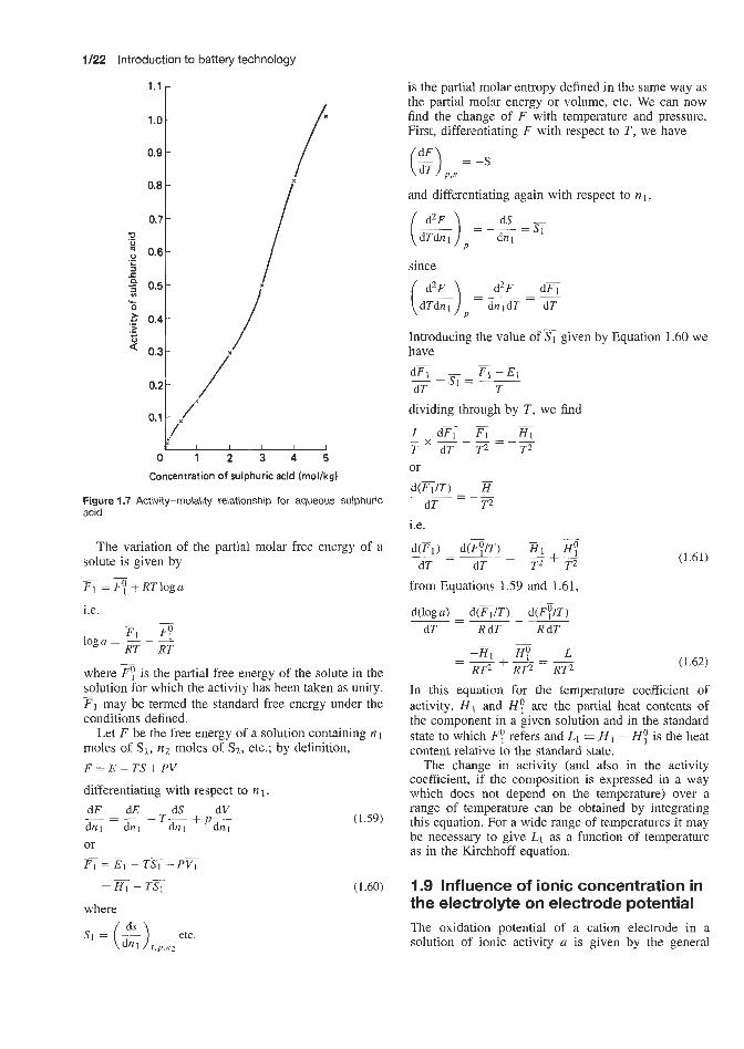
1/22 Introduction to battery technology
0.1 - /
Concentration of sulphuric acid (rnol/kg)
Figure 1.7 Activity-molality relationship for aqueous sulphuric acid
The variation of the partial molar free energy of a solute is given by
- - F1 = F y + R T l o g a
i.e. - -
Fi FY loga = - - - RT RT
where 3 is the partial free energy of the solute in the solution for which the activity has been taken as unity. F1 may be termed the standard free energy under the conditions defined.
Let F be the free energy of a solution containing nl moles of SI, n2 moles of SI, etc.; by definition,
-
F = E - T S t PV
differentiating with respect to IZ 1,
dF dE dS dV - -T-++-
dnl dnl dn l d n l or - F i = F - T G + P &
= ? r ; - T q
where
(1.59)
(1.60)
is the partial molar entropy defined in the same way as the partial molar energy or volume, etc. We can now find the change of F with temperature and pressure. First, differentiating F with respect to T , we have
and differentiating again with respect to n1,
dS -
P
since
Introducing the value of have d c - F 1 - E 1 - =s* = - dT T
dividing through by T , we find
I d E c 5 T dT T 2 T 2 or d ( 6 I T ) 7f
dT T2
i.e.
given by Equation 1.60 we
-
- x _ - - =--
- = --
- d(F1) d($/T) - % HY
from Equations 1.59 and 1.61,
~ - -- T2 ' F ~- -
dT dT
d(1og a) d ( 5 I T ) d ( q / T ) dT R dT R dT
-=---
-
(1.61)
(1.62)
In this equation for the temperature coefficient of activity, H I and H ; are the partial heat contents of the component in a given solution and in the standard state to which FY refers and Li = H 1 - HY is the heat content relative to the standard state.
The change in activity (and also in the activity coefficient, if the composition is expressed in a way which does not depend on the temperature) over a range of temperature can be obtained by integrating this equation. For a wide range of temperatures it may be necessary to give L1 as a function of temperature as in the Kirchhoff equation.
I .9 Influence of ionic concentration in the electrolyte on electrode potential The oxidation potential of a cation electrode in a solution of ionic activity a is given by the general

Influence of ionic concentration in the electrolyte on electrode potential 1/23
such as Zn”, Cd2+, Fez+, Cu2+, etc., the value of n is 2, and hence the electrode potential changes by 0.059 1512, i.e. 0.0296 V, for every ten-fold change of ionic activity; a hundred-fold change, which is equiv- alent to two successive ten-fold changes, would mean an alteration of 0.059 15 V in the potential at 25°C. For univalent ions, n is 1 and hence ten-fold and hundred- fold changes in the activities of the reversible ions produce potential changes of 0.059 15 and 0.1183V, respectively. The alteration of potential is not deter- mined by the actual ionic concentrations OI- activities, but by the ratio of the two concentrations; that is, by the relative change of concentration. Thus, a change from 1 .O gram-ion to 0.1 gram-ion per litre produces the same change in potential as a decrease from to 10-7gram-ions per litre; in each case the ratio of the two concentrations is the same, namely 10 to 1.
An equation similar to Equation 1.67, but with a negative sign, can be derived for electrodes reversible with respect to anions; for such ions, therefore, a ten- fold decrease of concentration or activity, at 2 5 T , causes the oxidation potential to become 0.0594 151n V more negative. For reduction potentials, the changes are of the same magnitude as for oxidation potentials, but the signs are reversed in each case.
To quote a particular example, the concentration of sulphuric acid in a fully charged lead-acid battery is approximately 29% by weight (relative density 1.21) whilst that in a fully discharged battery is 21% by weight (relative density 1.15).
Weight concentrations of 29% and 21 % of sulphuric acid in water, respectively, correspond to molalities ( m o l HzS04/1000 g water) of
equation
RT n F
E l = E L - - - l n a (1.63)
As has been seen from Equation 1.54,
a = y m
where m is the molality of the solute (moles or gram- ions per lOOOg solvent) and y is the appropriate activity coefficient. Hence
RT n F
E1(Vj = E L -- - lnym
(1.64)
If the solution is diluted to decrease the activity of the cations to one-tenth of its initial value, that is to say to O.lu, i.e. 0 . 1 ~ = y’rn’, the electrode potential becomes
RT nF
Ez(Vj = E L -- - 1nO.la
- - E L __ log 0, l a (1.65) n
i.e.
E ~ ( v ) = E& - - In y’m’ RT nF 0.059 15
= E L __ ~ log y’rn’ n
(1.66)
The resulting change of potential is obtained by sub- tracting El from E z :
RT Ez - E1(V) = -(lnO.la - lna)
n F RT n F
= -1n10
0.059 15 n
log 10 -~ -
0.059 15 n
- -
i.e. RT nF
E Z - E I ( V ) = -((In y’m’ - In ym)
(1.67)
(1.68)
It can be seen, therefore, that at 25°C every ten- fold decrease in ionic activity or, approximately, in the concentration of the cations results in the oxida- tion potential becoming more positive by 0.059 1% V, where n is the valence of the ions. For bivalent ions,
21 x 1000 98 x (100 - 21)
m = = 2.71
and , 29 x 1000
m = = 4.17 98 x (100 - 29)
The activity coefficients ( y ) corresponding to m = 2.71 and m’ = 4.17 molal sulphuric acid are respec- tively y = 0.161 and y’ = 0.202 (obtained from stand- ard activity tables, see Table 1.3).
Hence the activities (pn) are
a = 0.161 x 2.71 = 0.436
and
2a‘ = 0.202 x 4.17 = 0.842
Hence, from Equation 1.64,
E~ = E ; - 0‘059 l5 log 0.436
From Equation 1.65,
E z = E ; - 0‘059 l5 log 0.842

1/24 Introduction to battery technology
Table 1.4 Change of e.m.f. with concentration of electrolyte
Concentration, Activity Activity Ratio of Ratio Of E2 - E1(V) m coeficient, a = ym concentrations activities n = 2
(mol44 Y
2 1.56 0.005 71
10 4.70 0.019 9
0.03 1 3 0.2 molal HzSO4 0.2 0.244
diluted two-fold 0.1 0.313 0.2 molal HzSO4 0.2 0.244 0.048 8 }
diluted ten-fold 0.02 0.519 0.01038 2 molal H2SO4
diluted two-fold 2 1
0.147 0.294 } 0.150 0.150
2 1.96 0.008 64
0.294 } 10 6.02 0.023 0 2 molal H2SO4 2 0.147 diluted ten-fold 0.2 0.244 0.048 8
From Equation 1.68,
0.059 15 log (0.842) E Z - E l = ~
__ n 0.436
0.059 15 n
log 1.931 - -
if n = 2, E2 - El, the potential change accompanying an increase in the concentration of sulphuric acid from 2.71 to 4.17 molal, is 0.008 45 V at 25°C. For relatively concentrated solutions of sulphuric acid, as in the case of the example just quoted, the ratio of the activities at the two acid concentrations is similar to the ratio of the molal concentrations:
Molality of H2SO4, m 2.71 4.17 Activity coefficient of H2SO4, y 0.161 0.202 Activity, a = ym 0.436 0.842
Ratio of molalities = ~ = 1.54 4.17 2.71 0.842 0.436 - 1’93
Ratio of activities = __ -
i.e. the two ratios are fairly similar. For less con- centrated sulphuric acid solutions (0.01 molal and 0.0154 molal, i.e. in the same concentrations ratio as the stronger solutions) these two ratios are not as sim- ilar, as the following example illustrates:
Molality of H2SO4, m 0.01 0.0154 Activity coefficient of HzS04, y 0.617 0.555 Activity, a = ym 0.006 17 0.0855
Ratio of molalities = ~ = 10.00 0.1 0.01 0.0855
0.006 17 Ratio of activities = ~ - - 1.38
Potential changes at 25°C resulting from the same two- fold change in concentration of sulphuric acid are as follows:
From 2.71 to 4.17 molal
E Z - E l = ~ 0.0; 15 log (0.600) ~
0.393
= 0.005 43 V
From 0.01 to 0.0154 molal
0.0; 15 log ( 0.0855 ) E 2 - E l = ~
0.006 27
= 0.0418 V
That is, when more dilute solutions and stronger solu- tions are diluted by the same amount, the e.m.f. dif- ference obtained with the former is greater than that obtained with the latter.
The greater the concentration difference of the two solutions, the greater the e.m.f. difference E2 - El , as shown in Table 1.4.
1.10 Effect of sulphuric acid concentration on e.m.f. in the lead -acid battery For the reaction
Pb + PbO2 + 2HzS04 = 2PbSO4 + 2Hz0
from the free energy (Equation 1.27),
as, from Equation 1.23,
AF = -nFE and A F o = -nFEo
we have
where a is the activity of sulphuric acid solution (my), m the concentration in moles per kilogram, y the activity coefficient, Eo the e.m.f. in standard state, E the cell e.m.f., F = 1 F (96 500 C), n the number of

Effect of sulphuric acid concentration on e.m.f. in the lead-acid battery 1/25
electrons involved in the net chemical reaction, T the temperature in kelvins, and R the gas constant (8.312 international ,joules).
By definitison, apbso4 = aH20 = apb = apb02 = 1.
at 25°C
8.312 (273 + 25) x 2.203 2 x 96500
E = E O -
= Eo - 0.029 57 log (7) 1
H2S04
(1.70)
(1.71)
Consider the previously discussed case of a lead-acid battery at the start and the end of discharge. At the start of discharge the electrolyte contains 29% by weight of sdphuric acid, i.e. molality = 4.17 and activity coefficient = 0.202 (Table 1.3). Therefore, the activ- ity is 0.202 x 4.17 = 0.842. Similarly, at the end of discharge, the acid strength is 21% by weight, i.e. m = 2.71 and y = 0.161, i.e. a = 0.436.
If the cell potentials at the start and end of discharge are respectively by E29 and Ezl, then
1 - ((0.842)')
E29 = Eo - 0.029 57 log
= Eo - 0.004 40 V
and
E21 =EO- 0.029 57 log (-) 1
(0.436)2
= E o - 0.021 32V
Therefore the potential decrease (E29 - E211 during discharge is given by
E29 - E21 = -.0.00440 + 0.021 52V
= 0.0169V at 25°C
Alternatively
(2) E29 = Eo - 0.029 57 log
M E21 = Eo - 0.029 57 log
where E29 is c.he cell e.m.f. at 25°C when the sulphuric acid concentration is 29% by weight, i.e. activity a29 = 0.842, and E21 is the cell e.m.f. at 25°C when the sulphuric acid concentration is 21% by weight, i.e. activity ~2~ = 0.436.
(3 = 2 x 0.029 57 log
= 0.059 15 log (E) = 0.0169 V at 25°C
or, in general, 2 x 8.312 x (273 + T ) x 2.303log(a,,/u,,)
2 x 96500 E,, -E,, =
= 0.000 1984(273 + T)log(a,,/a,)
where E,, is the e.m.f. at T"C when the acid has activity acl at the start of discharge, E,, is the e.m.f. at T"C when acid has activity a,, at the end of discharge, and T is the cell temperature in "C. That is,
To ascertain the value of the standard potential Eo
According to the literature, the e.m.f. of a cell contain- ing 21% by weight (2.71 molal) sulphuric acid at 15°C is 2.0100V.
2.303 x 8.312 x 288 2 x 96500
1 E = E O -
= Eo - 0.02856 x log (-) 1 (0.436)'
1 - ( (0.436y ) Eo = E + 0.02856 x log
= 2.0100 + 0.02856 = 2.03059V
E29(25"C) = 2.030 59 - 0.00440 = 2.0262 V
and
E21 (25°C) = 2.03059 - 0.021 32 = 2.0093 V
These equations can be used to calculate the effect of sulphuric acid concentration (expressed as activity) and cell temperature on cell e.m.f. If, for example, the electrolyte consists of 29% by weight sulpharic acid at the start of discharge (i.e. activity a 2 9 = 0.842) decreasing to 21% by weight sulphuric acid @e. activ- ity a21 = 0.436) at the end of discharge, and if the tem- perature at the start of discharge, T I , is 15°C increasing to 40"C(TF) during discharge, then from Equation 1.71
8.312 x (273 + 15) x 2.303 E29 = Eo - 2 x 96500 log (&) and
8.312 x (273 + 40) x 2.303 2 x 96500
E21 = Eo -
If Eo = 2.0359 V, E29 = 2.0263 V
E21 = 2.0082V
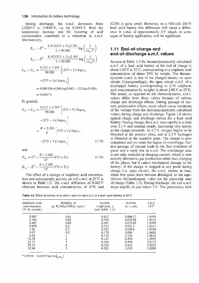
1/26 Introduction to battery technology
During discharge, the e.m.f. decreases from 2.0263V to 2.0082V, Le. by 0.0181V. Both the temperature increase and the lowering of acid concentration contribute to a reduction in e.m.f. Alternatively,
8.312(273 + T1)2.303 Ecl = Eo -
2 x 96500
8.312(273 + T~)2.303 E,, =Eo -
2 x 96500
8'312 2'303 { (273 + TI)logacl Ec1 - Ec2 = 96 500
-(273 + TF) log aC2
= 0.000 1984(28810g0.842 - 31310g0.436)
= 0.0181 v In general,
8'312 2'303 [ (273 + T I ) log a,, 96 500 Eq - Ec, =
- - R2 [ (273 + T I ) log acl F
(1.73) 1 -(273 + TF) log a,,
and
E -Eo-- (273 + TI) (1.74) R x 2.303
2F c1 -
R x 2.303 E -Eo- - (273 + T F )
2F c2 -
The effect of a change of sulphuric acid concentra- tion and consequently activity on cell e.m.f. at 25°C is shown in Table 1.5. The e.m.f. difference of 0.062V obtained between acid concentrations of 47% and
32.9% is quite small. However, on a 500-cell 100-V lead-acid battery this difference will cause a differ- ence in e.m.f. of approximately 3V which, in some types of battery application, will be significant.
1 .I 1 End-of-charge and end-of-discharge e.m.f. values
As seen in Table 1.5 the thermodynamically calculated e.m.f. of a lead-acid battery at the end of charge is about 2.03 V at 25T , corresponding to a sulphuric acid concentration of about 29% by weight. The thermo- dynamic e.m.f. is that of the charged battery on open circuit. Correspondingly, the open circuit e.m.f. of a discharged battery (corresponding to 21% sulphuric acid concentration by weight) is about 2.00V at 25°C. The actual, as opposed to the thermodynamic, e.m.f. values differ from these values because of various charge and discharge effects. During passage of cur- rent, polarization effects occur which cause variations of the voltage from the thermodynamically calculated values during charge and discharge. Figure 1.8 shows typical charge and discharge curves for a lead-acid battery. During charge, the e.m.f. rises rapidly to a little over 2.1 V and remains steady, increasing very slowly as the charge proceeds. At 2.2 V, oxygen begins to be liberated at the positive plate, and at 2.3V hydrogen is liberated at the negative plate. The charge is now completed and we enter the region of overcharge. Fur- ther passage of current leads to the free evolution of gases and a rapid rise in e.m.f. The overcharge state is not only wasteful in charging current, which is now entirely devoted to gas production rather than charging of the plates, but it causes mechanical damage to the battery. If the charge is stopped at any point during charge (i.e. open circuit), the e.m.f. returns in time, when free gases have become dislodged, to the equi- librium thermodynamic value for the particular state of charge (Table 1.5). During discharge, the cell e.m.f. drops rapidly to just below 2 V. The preliminary kink
Table 1.5 Effect of activity of sulphuric acid on cell e m f . of a lead-acid battery at 25°C
Sulphuric acid Molality, rn Activity Activity e.rn.5
(% by weight) concentration (g H2S04/1000g water) coeficient, y (a = vm) (V)*
(see Table 1.3)
0.097 0.196 0.487 0.970 1.92 4.67 8.92
16.39 22.72 28.16 32.88
0.01 0.02 0.05 0.1 0.2 0.5 1 2 3 4 5
0.617 0.006 17 1.8999 0.519 0.010 38 1.9133 0.397 0.019 85 1.9299 0.313 0.031 3 1.9417 0.244 0.048 8 1.9530 0.178 0.089 1.9685 0.150 0.150 1.9819 0.147 0.294 1.9992 0.166 0.498 2.0127 0.203 0.812 2.0253 0.202 1.010 2.0308
*2.03059 - O.O295710g(l/u~~,,~)

Effect of cell temperature on e.m.f. in the lead-acid battery 1/27
2.4 . Practical
charge / thermodynamic charge Discharge
i 1.4 L I I I I I I I I
0 10 20 30 40 50 60 70 80 90 Time (min)
Figure 1.8 Practical and thermodynamic charge and discharge curves of lead-acid battery at 25°C
Table 1.6 Electromotive force and temperature coefficient of voltage for various concentrations of sulphuric acid electrolfle in the lead-acid battery
Sulphuric acid E Temperature coeficient, dEldT Decrease in e.m$ (V) with 25°C 15°C 25°C 40°C 15-25°C 25-40°C 15-40°C temperature rise concentration
(5% by weight)
0.097 0.196 0.487 0.970 1.920 4.67 8.92
16.39 21 22.72 28.16 29 32.88
1.9043 1.9172 1.9333 1.9446 1.9556 1.9706 1.9835 2.0002 2.0100 2.0133 2.0254 2.0263 2.0308
1.8999 1.9133 1.9299 1.9417 1.9530 1.9685 1.9819 1.9992 2.0092 2.0127 2.0253 2.0262 2.0308
1.8934 1.9074 1.9249 1.9372 1.9491 1.9654 1.9794 1.9976 2.0082 2.0118 2.0250 2.0260 2.0308
0.000 44 0.000 39 0.000 34 0.000 29 0.000 26 0.000 21 0.000 16 0.000 10 0.000 07 0.000 06 0.00001 0.000 01 0.000 00
0.000 43 0.000 39 0.000 33 0.000 30 0.000 26 0.000 20 0.000 17 0.000 11 0.000 07 0.000 06 0.000 02 0.000 01 0.000 00
0.000 44 0.000 39 0.000 34 0.000 30 0.000 26 0.000 21 0.000 16 0.000 10 0.000 07 0.000 06 0.000 02 0.000 01 0.00000
0.0109 0.0098 0.0084 0.0074 0.0065 0.0852 0.0041 0.0026 0.0018 0.0015 0.0004 0.0003 0.0000
observed in Figure 1.8 is due to the formation of a high-resistance layer of lead sulphate on the surface of the plates which is soon dispersed. The e.m.f. falls steadily during the discharge, and when it has reached 1.8 V the cell should be recharged, as the further with- drawal of current causes the voltage to fall rapidly. The difference between the practically observed charge and discharge curves shown in Figure 1.8 is due to changes in concentration of the acid in contact with the active material of the plates. The plates are full of small pores in which acid diffusion is very slow, so that the concentration of acid is greater during the charge and less during the discharge than in the bulk of electrolyte. The thermodynamic treatment previously discussed does not take acco'unt of such effects as
these, which occur in a practical battery. Figure 1.8 compares cell e.m.f. values during charge and dis- charge at 25°C with the thermodynamic curve at 25°C for charge and discharge.
1.1 2 Effect of cell temperature o e.m.f. in the lead-acid battery Table 1.6 and Figure 1.9 illustrate the effect of cell temperature on thermodynamic cell e.m.f. at various sulphuric acid concentrations. Three temperatures likely to be encountered in battery operation are included: W C , 25°C and 40°C. Also calculated are the average temperature coefficients of voltage
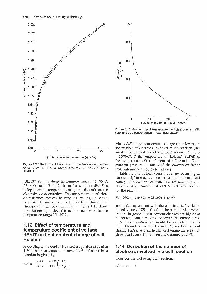
1/28 Introduction to battery technology
1.89 1 t I t t 1 0 10 20 30
Sulphuric acid concentration (% w/w)
Figure 1.9 Effect of sulphuric acid concentration on thermo- dynamic cell e.rn.f. of a lead-acid battery: 0, 15°C; x, 25°C; e, 40°C
(dEldT) for the three temperature ranges 15-25"C, 2 5 4 0 ° C and 15-40°C. It can be seen that dEldT is independent of temperature range but depends on the electrolyte concentration. The temperature coefficient of resistance reduces to very low values, i.e. e.m.f. is relatively insensitive to temperature change, for stronger solutions of sulphuric acid. Figure 1.10 shows the relationship of dEldT to acid concentration for the temperature range 15-40°C.
1.13 Effect of temperature and temperature coefficient of voltage d€/dT on heat content change of cell reaction According to the Gibbs-Helmholtz equation (Equation 1.20) the heat content change ( A H calories) in a reaction is given by
nFE 4.18 4.18 dT , AH = ___ f (!?!!I
0.5
Sulphuric acid concentration (% w/w)
Figure 1.10 Relationship of temperature coefficient of e.m.f. with sulphuric acid concentration in lead-acid battery
where A H is the heat content change (in calories), n the number of electrons involved in the reaction (the number of equivalents of chemical action), F = 1 F (96 500C), T the temperature (in kelvins), (dEldT), the temperature ( T ) coefficient of cell e.m.f. (E) at constant pressure, p , and 4.18 the conversion factor from international joules to calories.
Table 1.7 shows heat content changes occurring at various sulphuric acid concentrations in the lead-acid battery. The A H values with 21% by weight of sul- phuric acid at 15-40°C of 91 915 to 91 749 calories for the reaction
Pb + PbO2 + 2H2SO4 = 2PbSO4 + 2H20
are in fair agreement with the calorimetrically deter- mined value of 89 400 cal at the same acid concen- tration. In general, heat content changes are higher at higher acid concentrations and lower cell temperatures.
A linear relationship would be expected, and is indeed found, between cell e.m.f. ( E ) and heat content change ( A H ) , at a particular cell temperature (T) as shown in Figure 1.11 for results obtained at 25°C.
1 .I 4 Derivation of the number of electrons involved in a cell reaction Consider the following cell reaction:
An' + ne = A

Thermodynamic calculation of the capacity of a battery 1/29
Table 1.7 Heat content changes in the lead-acid cell as a function of cell temperature, temperature coefficient of e m f . and acid concentration
% &SO4 E (VI (dE ldT)p T (dEldT), AH = 46191(T(dE/dT), - E)cal (wiw) - 15°C 25°C 40°C 15-292 25-40°C 15-40°C 288K 298K 313K 288K 298K 313K
0.097 1,9043 1.8999 1.8934 0.00044 0.00043 0.00043 0.1267 0.1281 0.1346 -82109 -81795 -81 241 0.196 1.'9172 1.9133 1.9074 0.00039 0.00039 0.00039 0.1123 0.1162 0.1221 -83 370 -83010 -82465 0.487 1,9333 1.9299 1.9249 0.00034 0.00033 0.00034 0.0950 0.0983 0.1064 -84913 -84603 -83998 0.970 1.9446 1.9417 1.9372 0.00029 0.00030 0.00030 0.0864 0.0894 0.0939 -85 832 -85559 -85 144 1.92 1.9556 1.9530 1.9491 0.00026 0.00026 0.00026 0.0759 0.0775 0.0814 -86825 -86631 -86271
8.92 1.9835 1.9819 1.9794 0.000 16 0,000 17 0.000 16 0.0490 0.0507 0.0501 -89356 -89204 -89 I16 16.39 2.0002 1.9992 1.9976 0,000 10 0,000 11 0.000 10 0.0289 0.0328 0.0313 -91 056 -90 830 -90825 21 2.0100 2.0093 2.0082 0.00070 0.00070 0.00070 0.0201 0.0209 0.0219 -91 915 -91 846 -91 749
28.16 2.0254 2.0253 2.0250 0.00001 0.00002 0.00002 0.0029 0.0060 0.0062 -93 421 -93 273 -93 250
4.67 1.9706 1.9685 1.9654 0.00021 0.00020 0.00021 0.0576 0.0626 0.0657 -88363 -88035 -87749
22.72 2.0133 2.0127 2.0118 0.00060 0.00060 0.00060 0.0173 0.0179 0.0188 -92 197 -92 142 -92058
29 2.0263 2.0262 2.0260 0,00001 0,00001 0.00001 0.0029 0.0029 0.0031 -93463 -93458 -93440 32.88 2.0308 2.0308 2.0308 0.00000 0,00000 0.00000 0.0000 0.0000 0.0000 -93805 -93 805 -93 805
92 1 97 I
[ i
/
electrochemically, n can be found from Equation 1.20, as follows:
u/ i.e.
4.18AH n =
(1.75)
1.15 Thermodynamic calculation of the capacity of a battery In the reaction in which 1 mol of lead and lead dioxide react with 2 mol of sulphuric acid to produce 2 mol of lead sulphate and 2mol of water (Le. the discharge process in a lead-acid battery):
Pb + PbOz + 2HzS04 + 2e = 2PbS04 + 2 8 2 0
79 1.90 1.92 1.94 1.96 1.98 2.00 2.02
Electromotive force a t 25 "C
4 , , , 1 , , , , , ! , ,
Figure 1.11 Lead-acid battery. Relationship between cell e.m.f. and heat cont'ent change (AH) at 25°C
or
B + n e = B n -
The number of equivalents of chemical action or the number of electrons involved in the reaction is denoted by n (Le. n x F = n x 96500amp-seconds). If the heat content change ( A H ) of this cell reaction is determined by calorimetry and the e.m.f. ( E ) and tem- perature coefficient of e.m.f. (dEldT) are determined
the amount of electrical current produced is 2 F, Le. 193 000 C and the heat content change in the reaction, A N , is approximately -90 500 cal.
If the initial concentration of sulphuric acid in the battery is 29% by weight and the final concentration at the end of discharge is 21% by weight, the cell e.m.f. values are (at 25°C) respectively 2.0262 and 2.0093 V, and the temperature coefficients at these e.m.f. values are 0.000010 and 0.000070 (Table 1.6).
In the above reaction 2mol (196g) of sulphuric acid are consumed, thus reducing the volume of elec- trolyte by 196L.8305 = 107.07ml (the relative density

1/30 Introduction to battery technology
of 100% sulphuric acid is 1.8305) and 2 mol of water are produced increasing the volume of electrolyte by 36ml. Thus the net volume reduction in the elec- trolyte accompanying the production of 93 000 C is 107.07 - 36 = 71.07 ml. This electrolyte volume is, of course, recovered during the next charge cycle when the sulphuric acid is regenerated.
By definition, the quoted values of AH and 193 000 C (2 F) refer to the above reaction in which 1 mol of lead and of lead dioxide react with 2mol of sulphuric acid.
Knowing A H , E , dEldT and the cell temperature (in kelvins) it is possible to calculate the ampere hour capacity (C) of this cell from Equation 1.18:
0 .- L 2 20- P - a 0 19 P
2 18- 0
8
U
1 7 -
16
3600 x C 4.18
- -
i.e. nF = 3600C. Therefore
4.18 x AH
-
- c = -
3600 [. - T (g )] (1.76)
as AH is negative, C will have a positive value. At 2YC, in 29% by weight sulphuric acid,
E = 2.0262 V dE - = 0.00004 (mean value of 21-29% by weight
sulphuric acid) dT
AH = -93458
T = 298K
c = 53.9 c
This is illustrated in Figure 1.12. We thus have the capacity of this battery based on
the molar reaction accompanied by the production of 95 458 cal.
On this basis it is possible to devise a calorimetric method for obtaining the capacity of any battery, as will be discussed later.
In the system described above it was assumed that the initial concentration of sulphuric acid at the start of the discharge was 29% by weight (i.e. the normal concentration recommended for a lead-acid battery) and the final concentration of sulphuric acid at the end of discharge was 21% by weight. During discharge, 196g of sulphuric acid were consumed and 36g of water produced. It remains to calculate the initial volume of 29% sulphuric acid that must be used in the battery such that, when it has supplied 196g of sulphuric acid to form lead sulphate, the final acid concentration of the electrolyte will be 21%.
25 261 S L P 24
g
22 .! 8 231 p- 2 1 1 0
15 0 1000 2000 3000 4000 5000 Initial volume of sulphuric acid (ml)
Figure 1.12 Effect of initial volume of sulphuric acid electrolyte (29% w/w or 35.10g/100ml) in a lead-acid battery on final end-of-discharge concentration
At the start of discharge there are:
100% by wt H2S04 / 29% by wt HzSO4
29 g 100 g
i.e.
-- 29 - 15.842ml __ loo -82.617ml - 1.8305 1.2104
(where 1.8305 and 1.2104, respectively, are the relative densities of 100% and 29% by weight sulphuric acid). Therefore
Volume or weight of water present
= 66.775 ml or g per 82.617 ml solution
= 80.824% W/V
and
29 g 100% HzS04/100ml solution
29 x 100 82.617
-- -
= 35.102% W/V
At the end of discharge:
100% by wt HzS04 / 21% by wt HzSO4
21 g 100 g
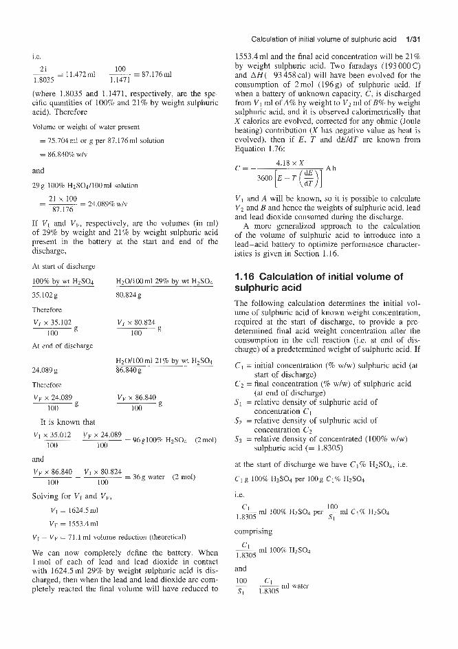
Calculation of initial volume of sulphuric acid 1/31
1553.4ml and the final acid concentration will be 21% by weight sulphuric acid. Two faradays (193000C) and AH(-93 458 cal) will have been evolved for the consumption of 2mol (196g) of sulphuric acid. If when a battery of unknown capacity, C, is discharged from V1 ml of A% by weight to V2 ml of B% by weight sulphuric acid, and it is observed calorimetrically that X calories are evolved, corrected for any ohmic (Joule heating) contribution (X has negative value as heat is evolved), then if E , T and dEldT are known from Equation 1.76:
i.e.
= 11.472ml __ loo - - 87.176ml 1.8035 1.1471
(where 1.8035 and 1.1471, respectively, are the spe- cific quantities of 100% and 21% by weight sulphuric acid). Therefore
Volume or weight of water present
= 75.704mi or g per 87.176ml solution
= 86.840% W/V
and
29 g 100% H2S04/100 ml solution
21 x 100 87.176
= 24.089% W/V - ~- -
If V I and V F , respectively, are the volumes (in ml) of 29% by weight and 21% by weight sulphuric acid present in the battery at the start and end of the discharge,
At start of discharge
100% by wt H2SO4
35.102g 80.824 g
Therefore
H20/100ml29% by wt H2S04
V I x 35.102 100
At end of discharge
V I x 80.824 100
H20/100ml21% by wt H2S04 24.089 g 86.840g
Therefore
VF x 24.089 100
It is known that
VF x 86.840 100
VI x 35.012 VF x 24.089 __ = 96 glOO% H2S04 (2mol)
100 100
and
= 36g water (2 mol) V F x 86.8408 V I x 80.824
- 100 100
Solving for VI and VF,
VI = 1624.5ml
VF = 1553.4d
VI - VF = 71.1 ml volume reduction (theoretical)
We can now completely define the battery. When lmol of each of lead and lead dioxide in contact with 1624.5ml 29% by weight sulphuric acid is dis- charged, then when the lead and lead dioxide are com- pletely reacted the final volume will have reduced to
4.18 x X r c = -
3600 E - T - L (J V1 and A will be known, so it is possible to calculate V2 and B and hence the weights of sulphuric acid, lead and lead dioxide consumed during the discharge.
A more generalized approach to the calculation of the volume of sulphuric acid to introduce into a lead-acid battery to optimize performance character- istics is given in Section 1.16.
1 .16 Calculation of initial volume of sulphuric acid The following calculation determines the initial vol- ume of sulphuric acid of known weight concentration, required at the start of discharge, to provide a pre- determined final acid weight concentration after the consumption in the cell reaction (i.e. at end of dis- charge) of a predetermined weight of sulphuric acid. If
c Cz = final concentration (% wlw) of sulphuric acid
SI = relative density of sulphuric acid of
S2 = relative density of sulphuric acid of
S3 = relative density of concentrated (100% wlw)
at the start of discharge we have Cl% H2SO4, Le.
C1 g 100% H2SO4 per lOOg C1% HzS04
i.e.
- initial concentration (% wlw) sulphuric acid (at start qf discharge)
(at end of discharge)
concentration C1
concentration C2
sulphuric acid (= 1.8305)
comprising
A mi 100% H ~ S O ~ 1.8305
and
loo '1 ml water Si 1.8305

1/32 Introduction to battery technology
i.e. 100 - ml total solution s1
Therefore
g H2S04 per 100ml (C1% w/w) acid = ClSl
g H20 per 100ml (C1% w/w) acid = 1.8305
At the end of discharge, we have C2% H2S04, i.e.
C2 g 100% H2S04 per 1OOg C2% H2S04
i.e. 100
1.8305 s2 ml100% ~ 2 ~ 0 4 per - m l ~ 2 % ~ 2 ~ 0 4
comprising
and 100 c2
S2 1.8305 ml water
i.e. loo/& ml total solution.
g H2S04 per 100ml (C2% w/w) acid = C2S2
c g H20 per lOOml (C2% w/w) acid = - - 2) s2 ( yzo 1.8305
If VI and VF, respectively, denote the volumes of acid in the cell at the start and the end of the discharge process, the weight (in g) of 100% H2SO4 in the cell at the start of discharge is
VI x c1 x SI 100 w1= (1.77)
the weight of 100% H2S04 in the cell at the end of discharge is
(1.78)
the weight of 100% H2S04 consumed during dis- charge is
WA = w1 - w2
VI x c1 X s1 VF X c2 X s2 - (1.79)
the weight of water in the cell at start of discharge is
- - 100 100
(1.80)
the weight of water in the cell at the end of discharge is
(1.81)
and the weight of water consumed during discharge is
w w = (W3 - W4)
(1.82)
As it is known from theory that for every 196 g (2 mol) of sulphuric acid consumed 36g (2mol) of water are produced, if the weight of sulphuric acid consumed is WA g then (WA x 36)/196g of water are produced, i.e.
WA x 36 w, = ~ 196 Thus, if
then 36 x WA VF x S2 100 C2
196 - 100 ((1 -E)
These two equations can be solved for V I and VF:
100 I
VF = (1.83)
(1.84)
and the net volume decrease in electrolyte occurring on discharge is
= 0.3627 x WA (1.85)
1 .I 7 Calculation of operating parameters for a lead-acid battery from calorimetric measurements Suppose that when the electrochemical cell reaction n n -Pb + -Pb02 + nH2S04 = nPbS04 + nH2O 2 2
is carried out in a calorimeter the observed number of calories produced during a discharge is denoted by

Calculation of operating parameters for a lead-acid battery from calorimetric measurements 1/33
Q. As well as heat produced in the electrochemical reaction, additional heat will be produced due to Joule heating:
1 2 x R x t
4.18 cal in t s (1.86)
(where I is current in amps, and R is the electrical resistance of cell and external contacts).
Every attempt should be made to minimize Joule heating by using low electrical resistance components in the experimental arrangement.
Suppose that the ohmic heating component is denoted by Q' calories during the discharge; then the heat production due to the above electrochemical reaction above is given by
(2" = Q - Q'
If Q" is known, it is then possible (using Equation 1.20) to calculate n; as heat is evolved Q has a negative value:
(1.20)
(1.87)
where Q is the calories evolved during discharge due to electrochemical reaction, n the number of moles of sulphuric acid involved in the electrochemical reaction, F = 1 F (96 SO0 C), E is the cell e.m.f. (V), T the cell temperature (K) and dEldT the temperature coefficient of e.m.f.
The weight of sulphuric acid (W,) is given by
Q" x 4.18 x 98 WA =98 X I;, = - (1.88)
Now nF = 3600 C, where C is the A h capacity of the battery. Therefore
n F 0" x 4.18 (1.89)
To take a particular example, if Q" is - 150 000 cal per discharge,
E = 2.010V
!E = 0.00001 dT
T = 293 Km(20"C)
then 150000 x 4.18
n = 96500(2.0100 - 293 x 0.00001)
= 3.237 mol sulphuric acid
= molecular weight of sulphuric acid x n
W A = 98 x
= 317.226g sulphwic acid
150000 x 4.18 C =
3600 (2.0100 - 293 x 0.000 01)
= 86.76Ah
Suppose that the initial concentration of sulphuric acid at the start of discharge is Cl% by weight, its rel- ative density is S1 and its volume is VI nil, all of which are known (Cl = 29, S1 = 1.2104, VI = 1624ml). As 3 17.226 g of sulphuric acid have been consumed in the electrochemical reaction we can, from Equation 1.84, find the final volume concentration (C2) and relative density (S2) of sulphuric acid at the end of the dis- charge:
(1.84)
Le.
(1.90) +- 196 1.8305 WA
Since C1 = 29% by weight
Si = 1.2104
CIS1 = 35.102g sulphuric acid100ml
V I = 16241111
WA = 317.228
Then CzS2 = 16.75 g sulphuric acid100ml
and, since Sz (the relative density of 100% sulphuric acid) is 1.8305,
c2 = 16.75 x 100
100f 16.75 1 - ~ ( 1.A05)
C2 = 15.56g sulphuric acid100g
Therefore 16.75 15.56
s2 = ~ = 1.076
The final volume (VFml) of electrolyte is then given by Equation 1.85:
I 36 VF=vI - ( - - -> 1.8305 196
= 0.3627W~ = 15091111

1/34 Introduction to battery technology
The volume reduction in acid during discharge is
VF - VI = 1624 - 1509 = 115ml
1 .I8 Calculation of optimum acid volume for a cell It is obvious in the battery discussed above that dis- charge has occurred to such an extent that the acid relative density has been reduced to the point that cell e.m.f. would reduce appreciably, i.e. we have entered the region of overdischarge, which is not re- commended. To overcome this a further battery is stud- ied in which the initial volume, VI, of acid is increased from 1.624 litre by various amounts up to 5 litres.
The relative density (&), percentage weight concen- tration (Cz) and final volume (VF) of electrolyte at end of discharge are calculated as above. The results are presented in Table 1.8. This table enables one to select, for the particular cell in question, a volume of acid to use in the cell which will be adequate to maintain the necessary acid concentration in the electrolyte through- out the discharge, i.e. will ensure that the cell e.m.f. is satisfactory throughout discharge. From Figures 1.12 and 1.13 it would seem that an initial electrolyte vol- ume of about 2500ml would be adequate to ensure an acid concentration of 21% by weight at the end of charge. This corresponds to a relative density of about 1.10.
Table 1.8 Effect of initial volume (V j ) of electrolyte on final acid gravity (&), weight concentration (C2) and final electrolyte volume (VF)
VI czsz c2 sz VF (ml) (g H ~ S O ~ / (g/mP) (% H ~ S O ~ (ml)
100 ml) by wt)
1624 16.75 15.56 1.076 1509 3000 25.5 22.85 1.112 2885 4000 28.0 24.54 1.127 3885 5000 29.4 25.93 1.134 4885
SI = 1.2104, C1 = 29, ClSl = 35.102, W A = 317.22
1.19 Effect of cell layout in batteries on battery characteristics Consider a series of m 2-V cells connected in series, each cell having an e.m.f. of E, volts, an internal electrical resistance of R, = 0.1 C2 and producing a current of I , amps:
Total e.m.f., ET = mE, (1.91)
Total internal resistance, RT = mR, (1.92)
ET mE E, Total current, IT - - = 2 = -
RT mR, R, (1.93)
1.14-
1.12
c TI c $' 1.06 .- c
1.02
a
1- 0 1000 2000 3000 4000 5000
Initial volume of sulphuric acid (ml)
Figure 1.13 Effect of initial volume of sulphuric acid electrolyte (29% w/w or 35.10g/lOOml) in a lead-acid battery on final acid concentration at end of discharge
If n = 3, 6 and 9 cells in series, the corresponding characteristics are as shown in Table 1.9 and the total internal resistance and e.m.f. increase as the number of cells is increased but the current remains constant.
Table 1.9 Battery characteristics: cells in series
~ ~
3 6 0.3 20 28.7 120 6 12 0.6 20 57.4 240 9 18 0.9 20 86.1 360
* I ; R ~ x t 4.18
, where t = I
Suppose now that these cells are arranged in parallel. If the internal resistance of each cell is denoted by R, = 0.1 Q, its e.m.f. by E , = 2 V and its current by I , amps, then for n 2-V cells in parallel,
ET (total e.m.f.) = E , = 2V
1 1 - = n x - Q RT Rc
(Le. RT = R,/n) and E RT
Current = 2
If n = 3, 6 and 9 cells in parallel, the correspond- ing characteristics are as shown in Table 1.10. Thus,

Effect of cell layout in batteries on battery characteristics 1/35
Table 1 . I O Battery characteristics: cells in parallel Consider next a series of in such cells in series. The total e.m.f. (ET) , internal electrical resistance (RT), current ( I T ) and ampere hour capacity (67) of this arrangement are as follows:
ET = mEc (1.91)
RT = mR, (1.92) 3 2 0.113 = 0.0330 60.0 28.4 120 6 2 0.116 = 0.0167 119.8 57.3 239.6 9 2 Ci.i/9 = 0.0111 180.2 86.2 360.4 (1.93)
(1.95) ' I : x RT x t , where t = 1
4.18
(1.96) CT Duration of discharge = - h
m h for an arrangement of nine 2-V cells each with a total internal electrical resistance of 0.1 R, if all the cells are arranged in series a current of 20 A is delivered at 18 V, whereas if all the cells are arranged in parallel a current of l8OA is delivered at 2V. With either cell arrange- ments, the heat producing capacity is 9.56 cake11 per second. In :general, higher currents and lower internal resistances but lower potential differences result when cells are arranged in parallel to produce a battery.
In practical battery arrangements, in order to obtain a compromise between the various characteristics required in h e battery, it is common practice to adopt a layout that (combines batteries in parallel and in series. Thus, a 48-cell 2-V battery might be arranged in any of the layouts of n files in parallel of m cells in series shown in Table 1.11.
Consider now an arrangement consisting of n fifes in parallel of m cells in series, i.e. an m x n cell battery, in this example a 48-cell battery. The total e.m.f. ( E T O T ) , internal electrical resistance (RToT), cur- rent ( Z T O ~ ) and ampere hour capacity (eToT) of this arrangement are as follows:
ETOT = WEc I n x l
- RTOT mRc
(1.91)
i.e. m
RTOT = -R, (1.97)
(1.98) Table 1.1 1 Practical battery arrangements
Number of Number of batteries m (n) in each series (m)
E = mnh?
R, A B C D E F G H I J
1 2 3 4 6 8
12 16 24 48
48 24 16 12 8 6 4 3 2 1
m2hE, RTOT
- mhEToT
-~ -
- RTOT
The duration of discharge (in hours) is
CTOT x RC - - CTOT x RTOT m x m x E , m 2 x E ,
- CTOT x RTOT -
mETOT
(1.99)
The batt'ery characteristics that would result from these various cell arrangements are discussed below.
Consider a single cell of e n f . E, and internal electrical resistance R,, with an ampere hour capacity of G , A h and producing a current of I , amps. For this cell,
(1. IQQ)
Using these equations it is now possible to calcu- late for any arrangement of n files in parallel of m cells in series the values of ETOT, RTOT, ITOT, CTOT, the Joule heating effect and the wattage if val- ues are assumed for the following characteristics of each individual cell in the arrangement: E , = 2V, internal electrical resistance (R,) = 0.1 Wcell, dura- tion of discharge = 4 h. These results are given in
CTOT -~ - mrTOT
E, I C = R, (1.93)
and
(1.94)
where h is the duration of the discharge in hours.

1/36 Introduction to battery technology
lOOg go,& 80 70.
20 10
0
- -
I I I I I I I I I I 10 20 30 40 50 60 70 8090100
(mlnl I?,
Rem Number of cells 1 2 3 4 6 8 12 16 24 48 inseries,m 48 24 16 12 8 6 4 3 2 1 Nurnberof strings
of cells, n (al
Imax = 105 A 110
70 x X
\ "\
30 'y 20 30 'y 20
\ "\
x\ x
(mln)R, 10
-1.5 -1.0 -0.5 0.0 f0.5 t1.0 +1.5 t2.0 O ' I I I I I I log -
t (mln)R,
R,,, 1 -=
Number of cells in series, m 1 2 3 4 6 812162448
Number of strings of cells, n 4a241s12 a 8 4 3 2 1
Assuming Ec = 2 V,
Internal resistance per cell, Rc - 0.1 External resistance, RSxt = 0.05 S-2
rn = number of cells in series in each string n = number of strings in parallel
i.e.
2m mln X 0.1 + 0.05 IToT
I,, is achieved when m is 4 to 6 and n is 12 to 8
(bl
Figure 1.14 Various configurations of 48 two-volt cells. Effect of configuration on emf. , current and electrical resistance
Table 1.12 and Figures 1.14 and 1.15. Depending on the arrangement of forty-eight 80 ampere hour capa- city 2-V cells we can obtain a range of amperages and voltages ranging from 20 A at 96 V (48 cells in series)
to 960A at 2 V (48 cells in parallel). It can be seen from Table 1.12 and Figures 1.14 and 1.15 that if, for example, 24 V at 80 A is required then four strings in parallel of 12 cells are required, i.e. n = 4, m = 12. Duration of discharge, Joule heating and wattage are unaffected by cell arrangement. Internal electrical res- istance is highest when all the cells are in series and decreases dramatically as parallel arrangements of cells are introduced. The above calculations do not take into account the external electrical resistance of the battery. This factor is included in the methods of cal- culation discussed below. The choice of connection of cells in series or in parallel or a combination of both depends on the use to which the cells are to be put. For the best economy in electrical energy, as little as possible should be wasted as heat internally. This requires the internal resistance of the combination to be as small as possible compared to the external res- istance, and the cells are therefore grouped in parallel. For the quickest action, such as may be required in a circuit of high induction, for example an electro- magnet, the total resistance of the circuit should be as high as possible. The cells are therefore connected in series.
To obtain the maximum current in a given external circuit the grouping of cells varies according to the particular value of the external resistance. The cal- culations below take into account both the internal electrical resistances (R,) of each cell and the external resistance of the whole battery (Rext). To obtain max- imum current, it is necessary to group the cells partly in series and partly in parallel, so that the combined internal electrical resistance of the combination is as nearly as possible equal to the external resistance.
Consider the case where there are n files in parallel of m cells in series. Each cell has an internal resistance of R, and an e.m.f. of E,, the external resistance of the whole battery being kXt. The total number of cells, N , is given by:
N = n m
and
Total e.m.f., E ~ T = mE,
mEc Total current, ITOT = RTOT + Rext
(1.91)
(1.101)
where R m is the total internal resistance, Rex, is the total external resistance, and R, is the internal resistance of each of the mn cells in the battery. Eliminating m from this equation (m = Nln),
NnE, ITOT = NR, + Rextn2
(1.102)

Effect of cell layout in batteries on battery characteristics 1/37
I P
900
1 2 4 6 8 10 12 14 16 18 20 22 24 26 28 30 32 34 36 38 40 42 44 4648 Number in series, m 482412 8 6 4 3 2 1 Number of strings, n
Figure 1.15 Various configurations of 48 two-volt cells. Effect of configuration on e.m.f., current and electrical resistance
Table 1.12 Characteristics of series-parallel multi-cell batteries (48-cell)
Number of Cells in - m Internal ETOT ITQT CTOT Duration oj Joule heating Power strings of series in
parallel (n) (m) cells in e8ach string RTOT
(a) (Ah) (cays)
1 2 3 4 6 8
12 16 24 48
48 24 16 12 8 6 4 3 2 1
48 12 5.33 3.00 1.33 0.75 0.33 0.19 0.083 0.021
4.8 1.2 0.533 0.300 0.133 0.075 0.033 0.019 0.0083 0.0021
96 20 3 840 48 40 3840 32 60 3840 24 80 3840 16 120 3840 12 160 3 840 8 240 3 840 6 320 3840 4 480 3840 2 960 3840
4 4 4 4 4 4 4 4 4 4
459 459 459 459 459 459 459 459 459 459
1920 1920 1920 1920 1920 1920 1920 1920 1920 1920
“h = 4 h discharge per cell
For a maximiam value of ITOT (Le. I,,), forming the expression: dlToT/dn and equating to zero, we find that
&TOT - - ( N R , + Rextn2 dn dn
= NR, - R,,trz2 = 0 (1.103)
Hence
NR, = Rextn2
and
but
(1.104)
where RTOT is the total internal resistance of the group of n x m cells. Hence
RTOT = R a t (1 .l05)
Thus, to obtain the maximum current (Im,) from a group of m x n cells, the external resistance. R,,,, for the group of cells should be equal to the combined internal resistance (RTOT = (rn/n)R,) of the group of N cells.

1/38 Introduction to battery technology
As NnE,
- ITOT NRc +Rex,,* -
(1.102)
(1.104)
(1.106)
If we consider the example of a battery comprising 48 two-volt cells (i.e. N = 48), each cell having an e.m.f., E,, of 2 V, it is required to calculate the number, n , of files in parallel of rn cells in series to achieve the maximum current, I,,,, from the battery. It is assumed that the battery has a total external electrical resistance, Rex,, of 0.05 Q and that the internal resistance per cell, R,, is 0.1 Q, i.e. the total internal resistance of a 48- cell battery is R T ~ T rn/n x 0.1. The total internal plus external resistance of the battery is R = (rn/n)R, + ReXtQ. Considering all the possibilities between rn = 48, n = 1, i.e. 48 cells in series, and rn = 1, n = 48, Le. 48 cells in parallel, and all possible configurations of cells between these limits, it is possible to calculate the total current, ITOT, produced by the battery:
900 0
800 -
700 -
600 -
5 - 500 -3 6 400 -2 L k-
(1,101)
As the maximum current, I,,, is obtained when (rn/n)R, = RCxt it is possible to obtain I,, graphically by plotting m --Rc
Rext __
or, better: m -Re
Rat log n
against the calculated value of I T o ~ and to read off the maximum current, I,,, corresponding to m -Rc L = 1 Rext
or m -Rc
Rext log n = 0
The data for the above battery are tabulated in Tables 1.13 and 1.14 and plotted in Figure 1.16. It can be seen clearly from the log plot in Figure 1.17 that a maximum achievable current of 96A will be obtained from a battery comprising 12 strings of four cells in series (i.e. n = 12, rn = 4), or eight strings of six cells in series (i.e. n = 8, rn = 6). If currents other than the maximum are required, the values of n and rn required to achieve these currents can be deduced from Figure 1.17. The other characteristics of these two battery configurations are shown in Table 1.15.
0 5 10 15 20 25 30 35 40 45 50 Number in series = 2 Number of strings n
Figure 1.16 48-cell 2V/cell lead-acid battery. Demonstration that maximum internal resistance of battery, (m/n)R, equals total external resistance (Rea), i.e. (m/n)R, = Rext or mRclnRea = I

Effect of cell layout in batteries on battery characteristics 1/39
Table 1.13 Derrionstrating that maximum current is obtained when total internal resistance of battery equals total external resistance
Internal resistance per cell, R, = 0.01 C2 External resistance of battery, R,,t = 0.05 Q Voltage per cell, E, = 2 V Duration of discharge of each cell, h = 4 h Number of strings of
Number of cells in series per string, m 48 24 mln 48 12 (mln )&(a) 4.800 1.200 RTOT = (m/n)R, + RCxt 4.850 1.250
cells, n 1 2
(m/n)R, a - Rext 0.05
log (e;) 96 24
1.982 1.380
ETOT = mEc 96 48 Current, [TOT
- mEc (A) 19.79 38.40 - (m/n)R, x Rext
Capacity, CTO.:
3800 3686
3
16 5.333 0.533 0.583
16
1.028
32
54.89
3512
4
12 3.000 0.300 0.350
6
0.778
23
68.57
3291
6
8 1.330 0.133 0.183
2.66
0.425
16
87.43
2798
8
6 0.750 0.075 0.125
1.50
0.176
12
96.00
2304
12
4 0.330 0.033 0.083
0.660
-0.180
8
96.03
1537
16
3 0.190 0.019 0.069
0.380
-0.420
6
86.95
1043
24
2 0.083 0.0083 0.0583
0.167
-0.778
4
68.61
549
48
1 0.021 0.0021 0.0521
0.042
-1.377
2
38.39
153
Table 1.14 Effect of cell configuration on e.m.f. and current achieved in arrangements of 48 two-volt cells
Internal resistance per cell, R, = 0.1 External resistance, Rext = 0.05 Voltage per cell, 2 V Number of strings of cells, n Number of cells in series per string, m mln log mln Current, [TOT
- mE, A - W r ) & + Rext
Totzl resistance, I?, = (rn/n)R, + Rex Voltage, V = TOT x R Wattage, V x ITOT Joule heating
Current* as % of I,,
1 2 3 4 6 8 12 16 24 48
48 24 16 12 8 6 4 3 2 1
48 12 5.333 3.000 1.330 0.750 0.330 0.190 0.083 0.021 1.681 1.072 0.727 0.477 0.124 -0.125 -0.523 -0.721 -1.081 -1.678
19.79 38.40 54.89 68.57 87.43 96.00 96.03 86.95 68.61 38.39
4.850 1.250 0.583 0.350 0.183 0.125 0.083 0.069 0.583 0.0521 96 48 32 24 16 12 8 6 4 2
1899 1843 1756 1645 1400 1152 768 522 274 76.8
454 440 420 393 335 275 183 124.8 64.9 18.4
18.8 36.6 52.2 65.3 83.3 91.4 91.4 82.8 65.3 36.6
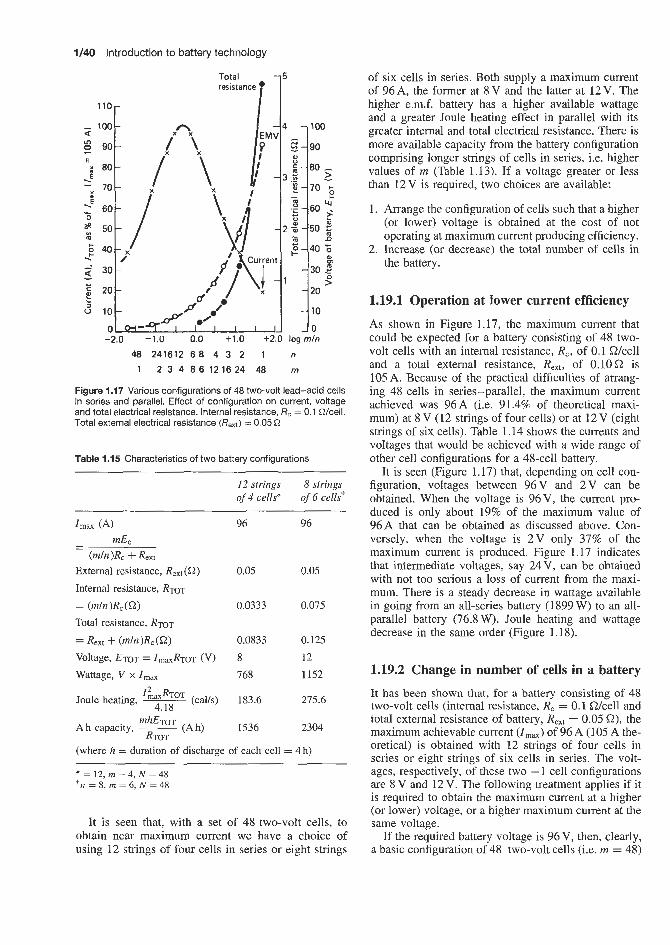
1/40 Introduction to battery technology
Total -5 resistance 0
of six cells in series. Both supply a maximum current of 96 A, the former at 8 V and the latter at 12 V. The higher e.m.f. battery has a higher available wattage and a greater Joule heating effect in parallel with its greater internal and total electrical resistance. There is more available capacity from the battery configuration comprising longer strings of cells in series, i.e. higher values of rn (Table 1.13). If a voltage greater or less
110 - 100
90
80
70 -
4 7100
than 12 V is required, two choices are available:
x-x -
1. Arrange the configuration of cells such that a higher (or lower) voltage is obtained at the cost of not operating at maximum current producing efficiency.
2. Increase (or decrease) the total number of cells in
-
-
2 - 4 0 % 0 m the battery.
30 - 3 0 3
1.19.1 Operation at lower current efficiency 20
As shown in Figure 1.17, the maximum current that 10
-2.0 -1.0 0.0 +1.0 f2.0 log mln could be expected for a battery consisting of 48 two- 48 241612 6 8 4 3 2 1 n volt cells with an internal resistance, R,, of 0.1 Wcell
1 2 3 4 8 6 1 2 1 6 2 4 48 m and a total external resistance, Rex,, of 0.lOQ is 105 A. Because of the Dractical difficulties of arrann-
- - 1 - 20
10
-
- -0
-
o w - 9 1 I I I I I
Figure 1.17 Various configurations of 48 two-volt lead-acid cells in series and parallel. Effect of configuration on current, voltage and total electrical resistance. Internal resistance, R, = 0.1 Wcell. Total external electrical resistance (Rea) = 0.05 Q
Table 1.15 Characteristics of two battery configurations
12 strings 8 strings of 4 cells* of 6 cells?
Imax (A) 96 96 - mE, -
(m/n 1% + Rext External resistance, ReXt ( 9 ) 0.05 0.05 Internal resistance, RTOT = (m/n)Rc(S22) 0.0333 0.075 Total resistance, RTOT
= Rext + (m/n)Rc(W 0.0833 0.125 Voltage, ETOT = ImaxRTOT (v) 8 12 Wattage, V x I,, 768 1152
(cas) 183.6 275.6 I ~ J ~ o T Joule heating, ~
4.18
Ah capacity, ~ mhEToT (Ah) 1536 2304 RTOT
(where h = duration of discharge of each cell = 4 h)
* = 12, m = 4, N = 48 + n = 8, m = 6, N = 48
It is seen that, with a set of 48 two-volt cells, to obtain near maximum current we have a choice of using 12 strings of four cells in series or eight strings
Y
ing 48 cells in series-parallel, the maximum current achieved was 96A (i.e. 91.4% of theoretical maxi- mum) at 8 V (12 strings of four cells) or at 12V (eight strings of six cells). Table 1.14 shows the currents and voltages that would be achieved with a wide range of other cell configurations for a 48-cell battery.
It is seen (Figure 1.17) that, depending on cell con- figuration, voltages between 96V and 2 V can be obtained. When the voltage is 96V, the current pro- duced is only about 19% of the maximum value of 96A that can be obtained as discussed above. Con- versely, when the voltage is 2 V only 37% of the maximum current is produced. Figure 1.17 indicates that intermediate voltages, say 24V, can be obtained with not too serious a loss of current from the maxi- mum. There is a steady decrease in wattage available in going from an all-series battery (1899 W) to an all- parallel battery (76.8 W). Joule heating and wattage decrease in the same order (Figure 1.18).
1.19.2 Change in number of cells in a battery
It has been shown that, for a battery consisting of 48 two-volt cells (internal resistance, R, = 0.1 Wcell and total external resistance of battery, Rex, = 0.05 Q), the maximum achievable current (Zma) of 96 A (105 A the- oretical) is obtained with 12 strings of four cells in series or eight strings of six cells in series. The volt- ages, respectively, of these two - 1 cell configurations are 8 V and 12 V. The following treatment applies if it is required to obtain the maximum current at a higher (or lower) voltage, or a higher maximum current at the same voltage.
If the required battery voltage is 96 V, then, clearly, a basic configuration of 48 two-volt cells (i.e. m = 48)
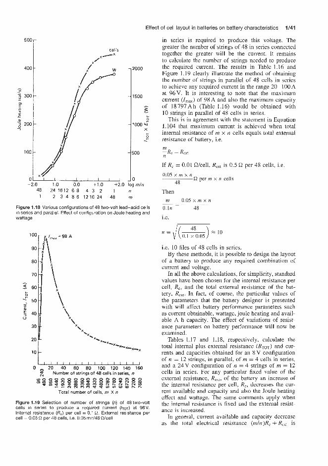
Effect of cell layout in batteries on battery characteristics 1/41
500
400
- Ln a s 300 m I
. _ ” m a, 5:
W 2 200 -7
100
2000
1500
- B I
c
1000 lu‘
6 .! X
500
-2.0 -1.0 0.0 +1.0 +2.0 log mln 48 24 1612 6 8 4 3 2 1 n
1 2 3 4 8 6 1216 24 48 m
Figure 1.18 Various configurations of 48 two-volt lead-acid cells in series and parallel. Effect of configuration on Joule heating and wattage
I00
90
80
70
5 60
+: 50 2 40
30
20
10
6 c
0
CJ
0 L--
20 40 60 80 100 120 140 160 Number of strings of 48 cells in series, n
Total number of cells, m X n
Figure 1.19 Selection of number of‘ strings (n) of 48 two-volt cells in series to produce a required current (/TOT) at 96V. Internal resistance (R,) per cell = 0.1 2. External resistance per cell = 0.05 R per 48 cells, i.e. 0.05 mn/48 Wcell
in series is required to produce this voltage. The greater the number of strings of 48 in series connected together the greater will be the current. It remains to calculate the number of strings needed to produce the required current. The results in Table 1.16 and Figure 1.19 clearly illustrate the method of obtaining the number of strings in parallel of 48 cells in series to achieve any required current in the range 20- 100 A at 96V. It is interesting to note that the maximum current (Zmax) of 98 A and also the maximum capacity of 18 797 A h (Table 1.16) would be obtained with 10 strings in parallel of 48 cells in series.
This is in agreement with the statement in Equation 1.104 that maximum current is achieved when total internal resistance of m x n cells equals total external resistance of battery, i.e. m --Rc = Rext
If R, = 0.01 Wcell, Re,, is 0.5 !2 per 48 cells, i.e. 0.05 x m x n
48 R per m x n cells
Then m
0. In 48
i.e.
0.05 x m x n - - ~
i.e. 10 files of 48 cells in series. By these methods, it is possible to design the layout
of a battery to produce any required combination of current and voltage.
In all the above calculations, for simplicity, standard values have been chosen for the internal resistance per cell, R,, and the total external resistance of the bat- tery, Re,,. In fact, of course, the particular values of the parameters that the battery designer is presented with will affect battery performance parameters such as current obtainable, wattage, joule heating and avail- able A h capacity. The effect of variations of resist- ance parameters on battery performance will now be examined.
Tables 1.17 and 1.18, respectively, calculate the total internal plus external resistance (R*oT) and cur- rents and capacities obtained for an 8 V configuration of n = 12 strings, in parallel, of rn = 4 cells in series, and a 24V configuration of n = 4 strings of m = 12 cells in series. For any particular fixed value of the external resistance, R,,,, of the battery an increase of the internal resistance per cell, R,, decreases the cur- rent available and capacity and also the Joule heating effect and wattage. The same comments apply when the internal resistance is fixed and the external resist- ance is increased.
In general, current available and capacity decrease as the total electrical resistance (mln)R, +Rex, is

1/42 Introduction to battery technology
Table 1.16 Selection of number (n) of strings of 48 two-volt cells in series (rn = 48) to produce a required current (IToT) at 96V
rn n nrn mln Rex,* Riati RTOT* RintlRext’ ITOT** Capacity?+
(Q2) (Q) (a) (A) (A h)
48 1 48 48 0.05 4.8 4.85 96 19.79 3 800 48 2 96 24 0.1 2.4 2.5 24 38.4 7 313 48 3 144 16 0.15 1.6 1.75 10.66 54.8 10 522 48 4 192 12 0.2 1.2 1.4 6 68.6 13 171 48 5 240 9.6 0.25 0.96 1.21 3.84 79.3 15 225 48 6 288 8 0.30 0.8 1.10 2.67 87.3 16761 48 7 336 6.86 0.35 0.686 1.036 1.96 92.7 17 798 48 8 3 84 6 0.4 0.6 1 .oo 1.5 96 18432
48 10 480 4.8 0.50 0.48 0.98 0.96 97.9 18 797 48 20 960 2.4 1.0 0.24 1.24 0.24 77.4 14 861 48 30 1440 1.6 1.5 0.16 1.66 0.107 57.8 11 098 48 40 1920 1.2 2.0 0.12 2.12 0.06 45.3 8 698 48 50 2400 0.96 2.5 0.096 2.596 0.038 4 37.0 7 104 48 60 2880 0.8 3.0 0.08 3.08 0.026 7 31.1 5 971 48 70 3360 0.686 3.5 0.0686 3.568 0.0196 26.9 5 165 48 80 3840 0.6 4.0 0.06 4.06 0.015 23.6 4531 48 90 4320 0.533 4.5 0.0533 4.53 0.011 8 21.2 4 070 48 100 4800 0.48 5.0 0.048 5.048 0.009 6 19.0 3 648 48 110 5280 0.436 5.5 0.0436 5.544 0.007 93 17.3 3 322 48 120 5760 0.4 6.0 0.04 6.04 0.006 66 15.9 3 053 48 130 6240 0.369 6.5 0.0369 6.537 0.005 67 14.7 2 822 48 140 6720 0.343 7.0 0.0343 7.034 0.004 9 13.6 2611 48 150 7200 0.32 7.5 0.032 7.532 0.004 26 12.7 2 438 48 160 7680 0.3 8.0 0.03 8.03 0.003 75 11.9 2 285
48 9 432 5.33 0.45 0.533 0.983 1.184 97.9 18 797
Internal resistance per cell, R, = 0.1 $2
* External resistance per mn cells, ReXt = 0.05 Q/48 cells
0.05 nm 48
=- Q/nm cells
Total internal resistance, Rint = (m/n)R,
Total resistance, R T ~ T = (rn/n)R, +Re,,
(mln )Rc -~ - Rat
D R ” Rat
mEc (m/n )Rc + Rex,
** Total current, I ~ T =
where h = duration of discharge of a single cell = 4 h
increased. Figure 1.20 shows the expected linear rela- tionship between current and the reciprocal of the electrical resistance and Figure 1.21 shows the resist- ance-capacity relationships. Naturally, these relation- ships change as the configuration of the 48 cells is changed.
It is obviously desirable from the point of view of maximizing current production when designing batter- ies to take every possible step to keep internal and external electrical resistances to a minimum as far as
this is compatible with other aspects of battery design such as maintaining the mechanical strength of com- ponents.
1.20 Calculation of energy density of cells It has been shown (Section 1.17) that, in a lead-acid battery discharge of lmol of each of lead and lead dioxide from an initial sulphuric acid concentration of

Calculation of energy density of cells
Table 1.17 Effect of internal, external and total electrical resistance on available current from a 48 two-volt (6) cell battery (8V) comprising 12 strings of four cells in series
1/43
~~ ~
mln ReXt (total for battery) (Q)
R,, internal resistance/cell (Q)
IIRTOT
ETOT = mE,
RTOT = (m1n)Rc + Rext
(A h) m x h x ETOT
Capacity, ~- RTOT
0.333 0.1
r T
0.1 0.2 0.1333 0.1666 7.50 6.00 8 8
60 48
114.8 91.8
480 384
960 768
0.333 0.5
0.1 0.2 0.5333 0.5666 1.87 1.76 8 8
15 14.1
28.7 26.9
120 112.8
240 225
0.5 0.6665 1.50 8
12
22.9
96
192
0.333 2 P
0.2 0.5 2.0666 2.1665 0.484 0.461 8 8
3.87 3.69
7.40 6.87
31.0 29.5
61.9 59.0
Table 1.18 Effect of internal, external and total electrical resistance on available current from a 48 two-volt (Ec) battery (24V) comprising four strings of twelve cells in series
mln Re,, (total for battery) (Q)
(Ah) ~ ~ E T O T Capacity, __-
&or
3.000 0.1
, A
0.1 0.2 0.400 0.700 2.50 1.42
24 24
60 34.3
344.4 197.0
1440 823
2880 1646
3.000 0.5
0.1 0.800 1.25
24
30
172.2
720
1440
0.2 0.5 1.100 2.000 0.909 0.500
24 24
21.8 12.0
125.0 68.9
523 288
1046 576
3.000 2
0.2 0.5 3.600 4.500 0.277 0.222
P
24 24
6.7 5.3
38.7 30.2
160.8 127.2
321 254
29% by weight to a final concentration of 21% by weight, 53.9 A h are produced when the cell temper- ature is 25T , i.e. capacity = 53.9Ah at a voltage of about 2V. Thus 107.8 W h are produced. The weights in grams of active materials involved are as follows:
Lead 207.2 Lead dioxide 223.2 Sulphuric acid 196.0
Total active matlerial 626.4 g
Thus the gravimetric energy density in W h k g of active material is: 107.8 x lOOQ
626.4 =: 172 (or 250.5 if electrolyte i s excluded)
This can be considered to be the maximum theoreti- cal energy density of the lead-acid battery. In practice,
24 V battery 4 strings of 12 cells
8 V battery 12 strings of 4 cells
7 O r ( m = l ~ , n = 4 ) ( m = 4. n = 12)
=TOT 0 ~ - ‘TOT RTOT
Slope of line = ETor
Reciprocal electrical resistance. l lRTo,
Figure 1.20 Plot of reciprocal of total electrical resistance l / R ~ o r versus current, /Tor
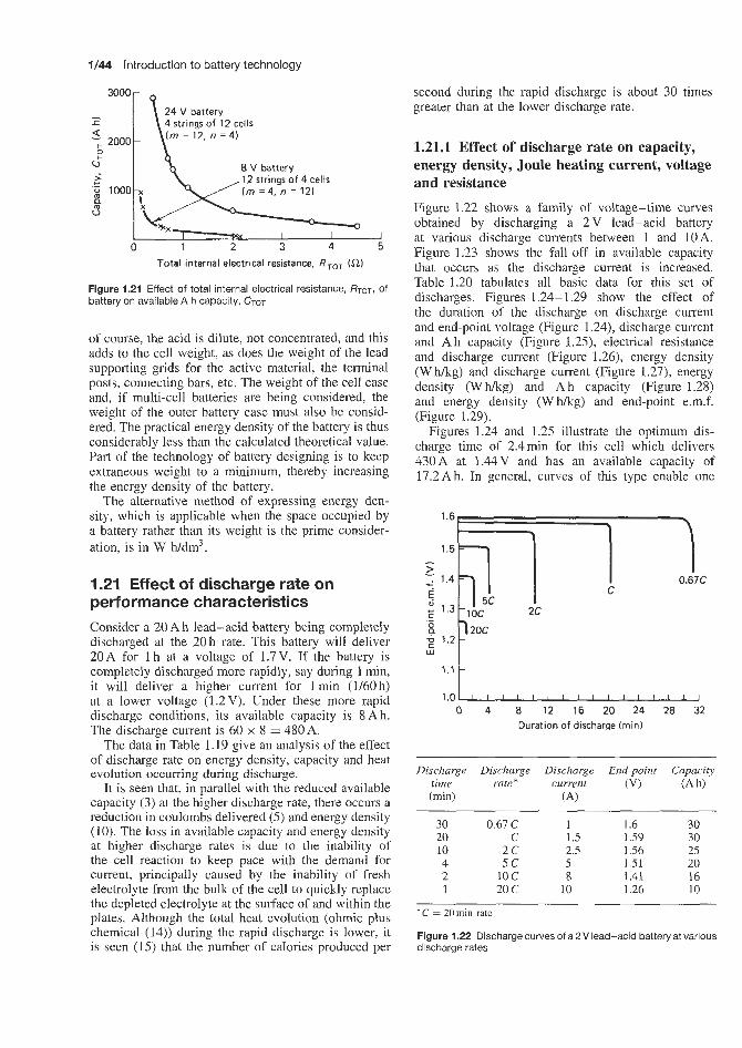
1/44 Introduction to battery technology
0 1 2 3 4 --J
5 Total internal electrical resistance, RToT (a)
Figure 1.21 Effect of total internal electrical resistance, RTOT, Of battery on available A h capacity, CTOT
of course, the acid is dilute, not concentrated, and this adds to the cell weight, as does the weight of the lead supporting grids for the active material, the terminal posts, connecting bars, etc. The weight of the cell case and, if multi-cell batteries are being considered, the weight of the outer battery case must also be consid- ered. The practical energy density of the battery is thus considerably less than the calculated theoretical value. Part of the technology of battery designing is to keep extraneous weight to a minimum, thereby increasing the energy density of the battery.
The alternative method of expressing energy den- sity, which is applicable when the space occupied by a battery rather than its weight is the prime consider- ation, is in W h/dm3.
1.21 Effect of discharge rate on performance characteristics Consider a 20 A h lead-acid battery being completely discharged at the 20 h rate. This battery will deliver 20 A for 1 h at a voltage of 1.7 V. If the battery is completely discharged more rapidly, say during 1 min, it will deliver a higher current for 1 min (1/60h) at a lower voltage (1.2 V). Under these more rapid discharge conditions, its available capacity is 8 Ah. The discharge current is 60 x 8 = 480A.
The data in Table I . 19 give an analysis of the effect of discharge rate on energy density, capacity and heat evolution occurring during discharge.
It is seen that, in parallel with the reduced available capacity (3) at the higher discharge rate, there occurs a reduction in coulombs delivered ( 5 ) and energy density (IO). The loss in available capacity and energy density at higher discharge rates is due to the inability of the cell reaction to keep pace with the demand for current, principally caused by the inability of fresh electrolyte from the bulk of the cell to quickly replace the depleted electrolyte at the surface of and within the plates. Although the total heat evolution (ohmic plus chemical (14)) during the rapid discharge is lower, it is seen (15) that the number of calories produced per
second during the rapid discharge is about 30 times greater than at the lower discharge rate.
1.21.1 Effect of discharge rate on capacity, energy density, Joule heating current, voltage and resistance
Figure 1.22 shows a family of voltage-time curves obtained by discharging a 2 V lead-acid battery at various discharge currents between 1 and 10A. Figure 1.23 shows the €all-off in available capacity that occurs as the discharge current is increased. Table 1.20 tabulates all basic data for this set of discharges. Figures 1.24- 1.29 show the effect of the duration of the discharge on discharge current and end-point voltage (Figure 1.24), discharge current and A h capacity (Figure 1.25), electrical resistance and discharge current (Figure 1.26), energy density (W hkg) and discharge current (Figure 1.27), energy density (W hkg) and A h capacity (Figure 1.28) and energy density (Whkg) and end-point e.m.f. (Figure 1.29).
Figures 1.24 and 1.25 illustrate the optimum dis- charge time of 2.4min for this cell which delivers 430A at 1.44V and has an available capacity of 17.2Ah. In general, curves of this type enable one
16-
1.5 - 1
* 1.2 1.1 ': 1 .o 0 I 4 8 12 16 20 24 28 32
Duration of discharge Iminl
Discharge time (min)
Discharge rate *
Discharge current
(A)
End-point (VI
30 20 10 4 2 1
0.67 C C
2 c 5 c
10 c 20 c
1 1.5 2.5 5 8
10
1.6 1.59 1.56 1.51 1.41 1.26
30 30 25 20 16 10
* C = 20 min rate
Figure 1.22 Discharge curves of a 2 V lead-acid battery at various discharge rates

Effect of discharge rate on performance characteristics 1/45
Table 1.19 Effect of discharge rate on energy density and other parameters
l h 1 min discharge discharge
1. Duration of discharge (min) 2. Voltage, E (V) 3. Capacity (A h) 4. Discharge current (A) 5. Coulombs delivered during discharge 6. Volt coulombs 7. Watts (E x A) delivered during discharge 8. Watts delivered per second 9. Watt hours delivered during discharge
10. Practical energy density (W h/kg) 11. Ohmic (Joule) heating during discharge (cal)
E x A x seconds 4.18
A2 x 17 x seconds 4.18
J = - -
-~ -
12. Internal resistance, E/A (Q) 13. Heat content change of cell reaction during
discharge (negative sign = heat evolved)
(see Equation 1.20) (assuming dEldP = 0,000 25, n = 2, F = 96 500 C, T = 25°C ((298 K))
14. Total heat evolution during discharge,
15. Heat evolution (cal/s) .I + AH cal
60 1.7 20 20 72 O O O h 122 400 34h 0.009 44 34 34 29 282h
0.085
-75 053h
104 3 3 5 h 29
1 1.2 8 480 28 800/min 34 560 576/min 9.6 9.6 9.6 8268/min
0.0025
-52 890/min
60 390/min 1006
Table 1.20 Disc.harges of 2 V lead-acid battery at different rates-basic data
t (min) E (VI Capacity (Ah) Current (A) Coulombs Volt coulombs Watts Wattskcond Watt hours Energy density (W Nkg) Joule (ohmic) heating R = E/A(Q)
A H = - -3600 C ~-T(Z)J 4.18
Joule + AH Heatlsecond
Total Joule
A H AH as % of total Joule as 9% of total
30 1.6 30 60 108 000 172 800 96.0 0.0533 48.00 48.00 41 340 0.0267
-39415
80 755
44.86 22.97 21.89 48.8 51.2
20 1.59 30 90.09 108 108 171 892 143.2 0.1193 47.72 47.72 41 110 0.0176
-39 157
80 267
66.90 34.25 32.63 48.8 51.2
10 1.56 25 149.70 89 820 140 119 233.5 0.3892 38.92 38.92 33 517 0.0104
-31982 -
65 499
109.16 55.86 53.30 48.8 51.2
4 1.51 20 299.85 71 964 108 666 452.8 1.8867 30.18 30.18 25 998 0.005 03
-24 722
50 720
211.33 108.32 103.00 48.7 51.3
2 1.41 16 480.48 57 658 81 298 677.4 5.6450 22.58 22.58 19447 0.002 93
I I .26 10 602.41 36 144 45 541 759.6) 1.2650 12.66 12.66 10 895 0.002 09
-18400 - 10 208
37 847 21 103
315.39 351.71 162.06 181.58 153.3 170.13 48.6 48.4 51.4 51.6

1/46 Introduction to battery technology
to select the desired combination of the various para- meters that would be required in battery service.
Figures 1.27 - 1.29 illustrate the interrelationship of discharge time with discharge current, end-point e.m.f., A h capacity and energy density. Thus, if 2min and 30 min discharges are adopted, the effect of this on the above parameters would be as illustrated in Table 1.2 1. Information of this kind enables trade-offs to be made in the various aspects of battery performance.
Another aspect of battery performance can be stud- ied by preparing plots of discharge current against end-point e.m.f. and electrical resistance (Figure 1.30) and Ah capacity and energy density (Figure 1.31).
Again considering the effect of carrying out the discharge at two different currents lOOA and 600A on battery operating parameters, we have the effects illustrated in Table 1.22.
--x-X
- Optimum 430 A a t 1.44 V,
Current - 0
30
24
-600
- 500 a I
-400 '$ E 3
-300 F
n -200 $ .-
100
'ii 16 14
0 12 10
0 2 4 6 8 10 12 14 16 18 20 Discharge rate (X C \
Figure 1.23 2 V lead-acid battery: influence of discharge rate on capacity
1 . 0 3 10 0 4 8 12 16 20 24 28
Discharge time (min)
Figure 1.24 2 V lead-acid battery: relationships of discharge time with end-point e.m.f. and discharge current
Capacity (Ah ) X
26
1 6oo
discharge current 430 A, 2.4 min discharge
10 8
- 500 - a - 400 E
E!
P
6
I
2 - 300
- 200 ; - 100
,
0 4 8 12 16 20 24 28
Discharge time (min)
Figure 1.25 2 V lead-acid battery: relationship of discharge time with Ah capacity and current
0.03 r Resistance / 1 6 0 0
- 500 2 I
-400 E
: -200 5
t - 300 $
6 - 100
0 0 4 8 12 16 20 24 28
Discharge time (min)
Figure 1.26 2 V lead-acid battery: relationship of discharge time with electrical resistance and discharge current
- 500 4
- 400 E E
- 300 $ P
6
I
- 200 ; Y)
- 100
- 0
Discharge time (rnin)
Figure 1.27 2 V lead-acid battery: relationship of discharge time with energy density and discharge current
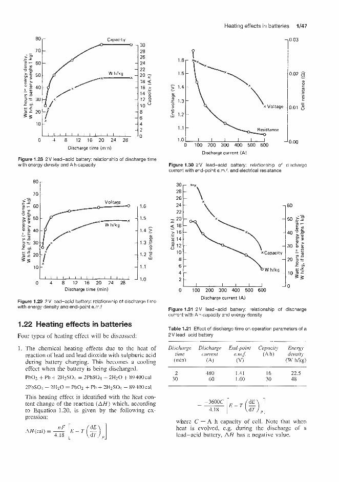
Heating effects in batteries 6/47
0.03 - -
- - - - - - - -
-
Capacity 30 20 26 24 22
18 5 16 2 14 'i
10
20 2
12 g
- 8 - 6 - 4 - 2 - 0
W h/kg X
L-- 0 4 8 12 16 20 24 28
Discharge Tim@ (min)
Figure 1.28 2 V lead-acid battery: relationship of discharge time with energy density and Ah capacity
-- 0 4 8 12 16 20 24 28
Discharge time ( m i d
1.6
1.5
1.4
1.3 2 W m
? 1.2 F
w
1.1
1.0
Figure 1.29 2 V lead-acid battery: relationship of discharge time with energy density and end-point e.m.f
1.22 Heating effects in batteries Four types of heating effect will be discussed:
1. The chemical heating effects due to the heat of reaction of lead and lead dioxide with sulphuric acid during battery charging. This becomes a cooling effect when the battery is being discharged. PbOz + Pb + 2HzSO4 = 2PbSO4 + 2H20 + 89 400 cal
2PbS04 + 2H20 = PbOz + Pb + 2HzS04 - 89 400 cal
This heating effect is identified with the lieat con- tent change of the reaction ( A H ) which, according to Equation 1.20, is given by the following ex- pression:
1.6- I 0.02 5 - 1.5 -
W - C > 1.4- m
E m
c
m W ._ - - P 1.3- -
? 0.01 6 5 1.2- -0
1.1
1 .o I I I I I
-
0 100 200 300 400 500 600
Discharge current (A)
Figure 1.30 2 V lead-acid battery: relationship of discharge current with end-Doint e.m.f. and electrical resistance
JO 0 100 200 300 400 500 600
\ 1 3 0 ta XCapacity
Discharge current (A)
Figure 1.31 2 V lead-acid battery: relationship of discharge current with Ah capacity and energy density
Table 1.21 Effect of discharge time on operation parameters of a 2 V lead-acid battery
Discharge Discharge End-point Capacity Energy time current e m f (Ah) density (min) (A) (VI (W m)
~~
2 480 1.41 16 22.5 30 60 1.60 30 48
-3600C - -
4.18
where C = A h capacity of cell. Note that when heat is evolved, e.g. during the discharge of a lead-acid battery, A H has a negative value.

1/48 Introduction to battery technology
Table 1.22 Effect of discharge current on operating parameters of a 2 V lead-acid battery
Discharge End-point Electrical Capacity Energy current em.$ resistance (Ah) density
(A) (V) (a) (W m g )
90
EO - - E ; 70- P
. _ 6 0 -
m
T, 50-
Y
c
-0 - I
C
3 .- L
TJ 40- P - 0
E 30- m I al
20
10
100 1.58 0.0155 29.7 46.5 600 1.26 0.002 10.0 12.5
-
- "*,
-
-
2. Chemical heating effect due to dissociation of water to hydrogen and oxygen towards the end of charge. This only applies to certain types of battery, e.g. lead-acid
H z + 4 0 2 =HzO+57410cal
This type of heating occurs to an appreciable extent only when batteries are fully charged, i.e. on over- charge, and will not be discussed further.
3. Ohmic heating effects due to Joule heating effects related to operating current and the electrical res- istance of the battery. From Equation 1.86,
Joule heating = RToT caUt s 4.18
4. Localized heating effects due to tracking of current along low-conductivity paths on the top of the battery.
1.22.1 Consideration of chemical (AH) and ohmic (Joule) heating effects in a lead-acid battery Information on the chemical and ohmic Joule heating effects during the discharge of a lead-acid battery is given in Table 1.20, which tabulates the extent of those effects during the discharge at various rates of a 2 V lead-acid battery.
This information is summarized in Figures 1.32 and 1.33 which, respectively plot discharge time and cur- rent versus the chemical ( A H ) and ohmic (Joule) contributions to the heat produced during a total dis- charge. It can be seen that, in this particular example, regardless of the discharge time, the chemical heat- ing effect is very similar to the ohmic heating effect. It should be noted that the above comments apply only to the total discharge of a lead-acid battery when both the chemical and Joule effects contribute to the production of heat. Obviously, during charge, the chemical effect is one of cooling (Le. A H is pos- itive), whilst the Joule effect still leads to heating (Equation 1.86 - Joule heating is positive whether cur- rent is being withdrawn during discharge (positive) or supplied during charge (negative), as the square of the current is used in the calculation of heat pro- duction). During the total battery charge in this par- ticular example, there is a small net heating effect of the battery as illustrated in Figure 1.34, which shows
120
110
100
- 90 al 80
.g 70
I! 60 m
- m Y - $ c '0 - m 4-
.- L
; 50
e 40 0 2 - al - ! 3c
2c
1c
C
Discharge net total Joule + AH
I I I I I I I I I I I I I I I 2 4 6 8 1012141618202224262830
Discharge time (rnin)
Figure 1.32 Discharge of a 2 V lead-acid battery: chemical (AH), ohmic (Joule) and net total (Joule + 4H) heating effect
l o o r
1 I I I I I I I 0 100 200 300 400 500 600 700
Discharge current (A)
Figure 1.33 Discharge of a 2 V lead-acid battery: chemical (4H), ohmic (Joule) and net total (Joule + AW heating effect

Heating effects in batteries 1/49
+45 r- Joule +40 +35 +30 +25 +20 +I5 +lo +5
Charge net total, Joule - AH
0 0
-5 oP-o
ZI -45 $ -50
2 -65 '& -70 ? -75
0 2 4 6 8 10 12 14 16 18 20 222426 28 30 Charge time (rnin)
Figure 1.34 Discharge of a 2 V lead-acid battery: chemical (AH), ohmic (Joule) and net total (Joule + AH) cooling effect
heat evolution due to ohmic heating, heat absorption (cooling) due to the chemical reaction, and a net heat evolution due to the combined heating and cooling effects.
It is assumed, in the above example of the charging of a lead-acid battery, that the charging currents used are the same as the discharge currents used in the battery discharge as quoted in Table 1.20, i.e. 60-600 A during 30 s to 1 min charges or discharges. In fact, of course, during an actual battery charge, the charge currents and the duration of the charge may differ from these values and this will have an effect on chemical and ohmic heat evolution as discussed later.
The heat data quoted in the examples cited are the total heat evolution or absorption occurring during a total charge or a total discharge, Le. during the whole discharge or charge process. Calculations of this type enable the number of kilocalories produced to be calculated, and provide data on the amount of cooling that would be required if there is a likelihood of the battery developing excessive temperatures in use. Cooling can be achieved by correct spacing of batteries, natural or forced air cooling, water cooling (internal or external), or the use of cooling fins.
An additional useful parameter which can be used when studying the heating effects of batteries in use
0.4
I - m
g, 0.3
0
Y - L
m r
-0 .- m
a ._ L
-0
7 0.2 0 u I 2 a
- z 0 2 0.1 4- m
I
\
"-------. I l l l l l l l l l i l l l l 2 4 6 8 10 12 14 1618 2 0 2 2 2 4 2 6 28 30
Discharge time (rnin)
602480300 150 90 60 Jischarge current (A )
Figure 1.35 Discharge of a 2 V lead-acid battery: heat production per unit time as a function of discharge time
is the average number of calories produced per sec- ond during a charge or a discharge. During battery discharge this parameter is obviously dependent on the discharge time and discharge current. Greater heat- ing effects per unit time would be expected at higher discharge currents, i.e. lower discharge times. This is illustrated in Figures 1.35 and 1.36, which are prepared from data in Table 1.20 and plot average kilocalories per second for various discharge times between 1 and 30 min (Figure 1.35) corresponding to discharge cur- rents between 602 and 60A (Figure 1.36). It is seen that at the highest discharge rate quoted, i.e. 1 min discharge at 602 A between 0.3 and 0.4 kcal/s are pro- duced on average, throughout the discharge and this may well indicate that cell cooling is required during such rapid battery discharges.
Discharge timeheat evolution graphs
In addition to heat evolved during a complete discharge and mean heat evolved per second, other battery parameters such as end-point volts, discharge current, A h capacity, energy density and electrical resistance are plotted against discharge time of a 2 V lead-acid battery (Figures 1.37-1.46). In Figures 1.47-2.54 these same parameters are plotted against discharge current.

1/50 introduction to battery technology
0.4
- - m Y - a, 0.3 P r
U m ._ a .- L s U
C 0.2
1l G a P e 0.1 - .- m
I
-
-
-
-
L I I I I I I I 0 100 200 300 400 500 600 700
Discharge current ( A )
Figure 1.36 Discharge of a 2 V lead-acid battery: heat production per unit time as a function of discharge current
-
-
-
-
-
-
E l
1.6
1.5 - >
1.4 - c -
1.3 2" 1.2 8
C .-
P W
1.1
0 4 8 12 16 20 24 28 Discharge time (min)
1.6
1.5 - >
1.4 g
1.3 g
I
m w - c C ._
1.2 @ U
1.1
1 .o
Figure 1.37 Discharge of a 2 V lead-acid battery: heat evolved during whole discharge, and end-point volts as a function of discharge time
0.4
m 1
Y
W
E 0.3
P 2 ::
- .- U
0.2 .- L s U
- P ; 0.1 B a, I
I I I I I I I I I I I I I I J Ji.0 0 4 8 12 16 20 24 28
Discharge time (m id 602480300 150 90 60
Discharge current (A)
Figure 1.38 Discharge of a 2 V lead-acid battery: heat production per unit time, and end-point voltage as a function of discharge time
Discharge net total Joule + A H
r 80 a
x 70 U
c I
Discharge
1 1 1 I I I I 1 I I I l l I I I 0 4 8 12 16 20 24 28
Discharge time (min)
600
500 - 400 E F
a -
300 ;
100 a
P
P 200 2 ._
0
Figure 1.39 Discharge of a 2 V lead-acid battery: heat evolved during whole discharge, and discharge current as a function of discharge time

Heating effects in batteries 1/51
0.4
m 1 2 0.3 P
P
P 0.2
- W
.c
U ._
.- L
3 U
- P $ ; 0.1 W I
X
,Discharge current
L J 1 1 1 1 1 1 I I I I I I
Discharge time (rnin) 0 4 8 12 16 20 24 28
602 480 300 150 90 60
Discharge current (A)
600
500 - a
404 E E
300
-
P 200 2
P 6
100
0
0.4
- CA 2-
0.3 Y
W
m IT
U
- m
t! p 0.2
.-
._ L 2 U
- 3 ; 0.1 9 W I
0
Figure 1.40 Discharge of a 2 V lead-acid battery: heat production per unit time, and discharge current as a function of discharge time
120
110
- 100 - m Discharge
Joule + A H 5 90 net total P w
80
0 4 8 12 16 20 24 28
Discharge time (min)
Figure 1.41 Discharge of a 2V lead-acid battery: heat evolved during whole discharge and Ah capacity as a function of discharge time
Capacity ( A h )
c l i l l l l l l l l l l l l l
4 8 12 16 20 24 28 Discharge time (min)
602 480 300 150 90 60 Discharge current (A)
Figure 1.42 Discharge of a 2V lead-acid battery: heat production per unit time and Ah capacity as a function of discharge time
Discharge net total Joule + A H
f nn
0 4 8 12 16 20 24 28 Discharge time (min)
50
40
L
m
30 f Y -z
- 1 4-
VI C
U 1
.-
20 p w
10
0
Figure 1.43 Discharge of a 2V lead-acid battery: heat evolved during whole discharge and energy density as a function of discharge time

1/52 Introduction to battery technology
-
-
-
-
-
- -lo 0 4 8 12 16 20 24 2%
1.6
1.5 > -
-1.4 g m c -
1.3 z 1.2 fL
F 1.1
C 0 .-
w
Discharge time (min)
Discharge current (A)
Figure 1.44 Discharge of a 2 V lead-acid battery: heat production per unit time and energy density as a function of discharge time
602 480 300 150 90 60
Discharge net total Joule + A H m & 80-
Discharge time (min)
Figure 1.45 Discharge of a 2 V lead-acid battery: heat evolved during whole discharge and cell electrical resistance as a function of discharge time
Y
W 1
P / 40.024
Electrical resistancex/ 0.028
/ 40.026
e P -u 0. .- cn .- J U
B S O -
CI
W r
0.022 5 0.020 ; 0.018 0.016 .: 0.014 E 0.012
0.008 3 Total I 0.006 tu 0.010 'S
I I I I I I I I I I I I I I I I JO'--- 0 4 8 12 16 20 24 28
Discharge time (min)
Discharge current ( A ) 602 480 300 150 90 60
Figure 1.46 Discharge of a 2 V lead-acid battery: heat production per unit time and cell electrical resistance as a function of discharge time
loo 90 1 al
7 0 -
TJ 60-
.c Y) .- - m Y
0 50-
$ 40-
5 30-
.- L
P - W Y
9 20-
10 -
L I I I I I I J Jl.0 0 100 200 300 400 500 600 700
Discharge current (A)
Figure 1.47 Discharge of a 2 V lead-acid battery: heat evolved during whole discharge and end-point voltage as a function of discharge current

Heating effects in batteries 9/53
100
90
5 80
!& 70
.; 60
0 Y I
L m r
U - m Y (51
5 50- .- 2 4 0 - U U
30- ?I
s 20- 10
I
I I I l I I I
Discharge current (A ) 100 200 300 400 500 600 700
-
-
-
-
-
-
I .6
1.5
1.4
1.3 z I >
m 4- - C ._
1.2 g U w
1.1
I .o
0.4
I
(0 . m 0.3 Y
m P P r
U .- p 0.2
P
.- L 3 U
- 2 5 0.1 r
Figure 1.48 Discharge of a 2 V lead-acid battery: heat production per unit time and end-point voltage as a function of discharge
I I l l I I 1 I o 0 100 200 300 400 500 600 700
Discharge current (A)
Figure 1.49 Discharge of a 2 V lead-acid battery: heat evolved during whole discharge and A h capacity as a function of discharge current
1.22.2 Effect of charging current and cell resistance on heat prodamction in lead-acid batteries
During the charging of a lead-acid battery two pro- cesses occur which are associated with the production
I I I / I l l 0 100 200 300 400 500 600 700
Discharge current (A)
Figure 1.50 Discharge of a 2 V lead-acid battery: heat production per unit time and A h capacity as a function of discharge current
100 -
90 m 2 80-
-
- - m m
j 70- Y U
60 - I
4-
F 50 a
- - b
0
> u 40- - 2 30- I = 2 0 -
10
I
-
x.
\
I I I I I I 1 0 100 200 300 400 500 600 700
Discharge current (A )
Figure 1.51 Discharge of a 2 V lead-acid battery: heat evolved during whole discharge and energy density as a function of discharge current
or loss of heat. The heat content AH of the reaction of lead sulphate to produce lead and lead dioxide has

1/54 Introduction to battery technology
0.4
- r n 1
Z 0.3
P Y
0 - c
U (0 .-
p 0.2
P P z 0.1 r
.- L
3 0
-
0.4
- Ln I
Y
m
Fi 0.2
F M
- r
0 .-
.- P 0.2
0
L a U
P -
0.1 I
c
-
-
-
.
I I I I I I I 100 200 300 400 500 600 70(
Discharge current (A )
- - - - - - - - - - - - - -
Figure 1.52 Discharge of a 2 V lead-acid battery: heat production per unit time and energy density as a function of discharge current
0.028 0.026 0.024 I 0.022 :: 0.020 2
0.012 .g
0.018 0.016 0.014
0.010 4 0.008 tu 0.006 0.004 0.002
-0
'OoC 90
- 0.028 - 0.026 - 0.024 - - 0.022 c: - 0.020 E
0.018 $ 0.016 '5 0.014 0.012
'D 50-
0.006 - 0.004
0.002
Y
l o - Electrical r e s i s t a d L x - I I I I I I I o
0 100 200 300 400 500 600 700 Discharge current (A)
Figure 1.53 Discharge of a 2 V lead-acid battery: heat evolved during whole discharge, and cell electrical resistance as a function of discharge current
a positive value indicating that heat is absorbed from the surroundings to enable this process to occur, i.e. the electrolyte cools down. The other processes, ohmic (Joule) heating, depending on the charging current and
I I I I I I I ) 0 100 200 300 400 500 600 700
Discharge current (A)
Figure I .54 Discharge of a 2 V lead-acid battery: heat production per unit time, and cell electrical resistance as a function of discharge current
the resistance of the cell always has a positive value, i.e. heat is evolved. Whether a battery cools down or heats up during charge depends on the relative magni- tude of these two opposite cooling and heating effects which, in turn, depend on the operating conditions dur- ing battery charge.
The cooling effect is given by:
cal during the charge 4.18 1
The heating effect is given by:
1 2 x R x t 4.18
J = - cal during the charge time@)
I ~ R Le. AH = - Is
4.18 where C is the capacity increase of battery dur- ing charge (Ah), E the thermodynamic cell e.m.f. at end of charge (assumed to be 2.01V), (dEldT), the temperature coefficient of cell e.m.f. (assumed to be 0.000 25 VPC), T the cell temperature (K), I the char- ging current (A), R the cell internal resistance (a), and t the duration of charge (s).
If J - AH is negative, the cell will cool down during charge. Conversely, if J - AH is positive, the cell will heat up during charge.
In practical cell charging, there is an additional factor to be contended with, namely loss of calories by
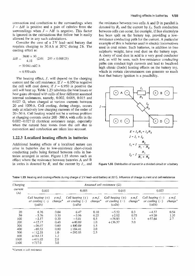
Heating effects in batteries 1/56
the resistance between two cells A and D in parallel is denoted by Rz and the current by 1 2 . Such conduction between cells can occur, for example, if free electrolyte has been spilt on the battery top, providing a low- resistance conducting path for the current. A particular example of this is batteries used in electric locomotives used in coal mines. Such batteries, in addition to free sulphuric weight, have coal dust on the battery tops. A slurry of coal dust in acid is a very good conductor and, as will be seen, such low-resistance conducting paths can conduct high currents and lead to localized high ohmic (Joule) heating effects on the battery top, which in certain circumstances can generate so much heat that battery ignition is a possibility.
convection and conduction to the surroundings when J - AH is positive and a gain of calories from the surroundings when J - AH is negative. This factor is ignored in the calculations that follow but is easily allowed for in any such calculations.
Consider the case of a 2 V lead-acid battery that requires charging to 30Ah at 20°C during 2h. The cooling effect is:
A f j = __- 3600 ': 30 (2.01 - 293 x 0.000 25) 4.18
= 50 041 'calf2 h
= 6.950 calk
The heating effect, J , will depend on the charging current and the cell resistance. If J - 6.950 is negative the cell will cool down; if J - 6.950 is positive the cell will heat up. Table 1.23 tabulates the heat losses or heat gains obtained with cells of four different assumed internal resistances, namely, 0.002, 0.005, 0.015 and 0.027 Q, when charged at various currents between 20 and 1000A. Cell cooling, during charge, occurs only at relatively low charging currents of the order of 20-50A. Cell heating would not be a serious problem at charging currents under 200-300A with cells in the 0.002-0.027 Q electrical resistance range, especially when the natural heat losses from the cell due to convection and conduction are taken into account.
1.22.3 Localized heating effects in batteries
Additional h[eating effects of a localized nature can arise in batieries due to low-resistance short-circuit conducting paths being formed between cells in bat- teries arranged in series. Figure 1.55 shows such an effect where the resistance between batteries A and B in series is denoted by R1 and the current by 11, and
E = I, R, = I ,R2
I = I , 4- I2
R2 I,=l- R , + R,
R, 1 2 = 1 - Rl + R2
Figure 1.55 Distribution of current in a divided circuit on a battery
Table 1.23 Heating and cooling effects during charge of 2 V lead-acid battery at 20°C. Influence of charge current and cell resistance
Charging Assumed cell resistance (a) -
current 0.002 0.005 0.015 0.021 (A)
Cell heating (+) e.m.5 Cell heating (+) em.$ Cell heating (+) e.m.5 Cell heating (+) em.$ or cooling (-) change* or cooling (-) change* or cooling (-) change* or cooling (-) change*
(calls) (calfs) (calls) (calls)
20 -6.76 50 -5.76
100 -2.17 200 +12.17 300 f36.07 400 +69.53 500 +112.55 600 +l63.13
1000 +471.05 1500 +717.0
0.04 -6.41 0.10 -5.52 0.3 -4.31 0.54 0.10 -3.96 0.25 f2.02 0.75 +9.20 1.35 13.20 -5.01 0.5 +28.93 1.5 +57.64 2.7 13.40 +40.89 1 .o +136.57 3.0 13.60 +100.69 1.5 10.80 +184.41 2.0 1 .o +292.05 2.5 1.2 2.0 3.0
*Current x cell resistance
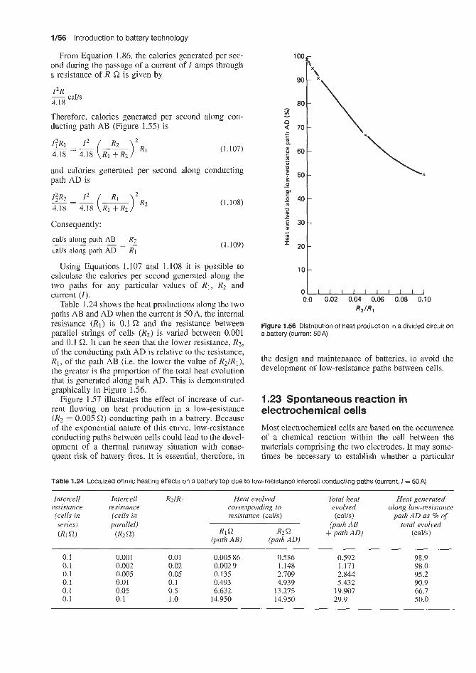
1/56 Introduction to battery technology
From Equation 1.86, the calories generated per sec- ond during the passage of a current of Z amps through a resistance of R L2 is given by
12R ~ calls 4.18
Therefore, calories generated per second along con- ducting path AB (Figure 1.55) is
@ = ~ I 2 ( -I2Rl R2
4.18 4.18 R1 +R2 (1.107)
and calories generated per second along conducting path AD is
Consequently:
ca!./s along path AB R2
c a b along path AD R1 - - -
(1.108)
(1.109)
Using Equations 1.107 and 1.108 it is possible to calculate the calories per second generated along the two paths for any particular values of R1, R2 and current (I).
Table 1.24 shows the heat productions along the two paths AB and AD when the current is 50 A, the internal resistance (R1) is 0.1 '2 and the resistance between parallel strings of cells (R2) is varied between 0.001 and 0.1 a. It can be seen that the lower resistance, R2, of the conducting path AD is relative to the resistance, R1, of the path AB (Le. the lower the value of R2/R1), the greater is the proportion of the total heat evolution that is generated along path AD. This is demonstrated graphically in Figure 1.56.
Figure 1.57 illustrates the effect of increase of cur- rent flowing on heat production in a low-resistance (Rz = 0.005 L2) conducting path in a battery. Because of the exponential nature of this curve, low-resistance conducting paths between cells could lead to the devel- opment of a thermal runaway situation with conse- quent risk of battery fires. It is essential, therefore, in
100
90
80 s a Q 70 5 2. 2 60
-
m +
't 50 2 - 0)
- 40 m P - Sj 30 0)
0
w
= 20
10
0 0.0 0.02 0.04 0.06 0.08 0.10
RZIR,
Figure 1.56 Distribution of heat production in a divided circuit on a battery (current 50A)
the design and maintenance of batteries, to avoid the development of low-resistance paths between cells.
1.23 Spontaneous reaction in electrochemical cells Most electrochemical cells are based on the occurrence of a chemical reaction within the cell between the materials comprising the two electrodes. It may some- times be necessary to establish whether a particular
Table 1.24 Localized ohmic heating effects on a battery top due to low-resistance intercell conducting paths (current, I = 50A)
Intercell Intercell RdRi Heat evolved Total heat Heat generated resistance resistance corresponding to evolved along low-resistance (cells in (cells in resistance (calls) (cavs) path AD as % of series) parallel) (path AB total evolved (Ri Q) (R2Q) R1 Q R2 Q + path AD) (calls)
(path AB) (path AD)
0.1 0.001 0.01 0.005 86 0.586 0.592 98.9 0.1 0.002 0.02 0.002 9 1.148 1.171 98.0 0.1 0.005 0.05 0.135 2.709 2.844 95.2 0.1 0.01 0.1 0.493 4.939 5.432 90.9 0.1 0.05 0.5 6.632 13.275 19.907 66.7 0.1 0.1 1 .o 14.950 14.950 29.9 50.0

Spontaneous reaction in electrochemical cells 1/57
hence,
A F = ( ~ F L + mFM + . . .) - (UFA + ~ F B + . . .) (1.110)
The molar free energy, F , of a substance in any state can be expressed in terms of its activity, a, in that state by means of Equation 1.1 10. which may be written as
F = F O + R T ~ " ~ (1.111)
where Fo is the molar free energy in the standard state of unit activity.
If the values of F A , F g , . . . , F L , FM, . . . , in Equation 1.1 10 are replaced by the corresponding expressions derived from Equation 1.111, it is seen that
A F = ( l (F: + RTlnaL) + m ( F L + R T I ~ u M ) + . . .) (U(F1 fRTIllaA)+b(Fi +RThUB)+. . . )
(1.112)
where UA, UB, . . . , aL , UM, are the activities of the various substances involved in the reaction in their arbitrary state. Upon rearranging Equation I . 1 12, the result is
1100
1 Do0
900
800
700 I
m > 2 600
2 505 I
- P c
I 400
300
200
150
0
0.OCl5 S2 (path AD)
0.1 S2 (path
.¶ 200 400 800 800 1000
0.1 S2 (path
.¶ 200 400 800 800 1000
AB)
Current EA)
Figure 1.57 Eflect of current on distribution of heat production in a divided circuit on a battery: 0.005 Q lower resistance versus 0.1 s2 higher resistance
reaction would form the basis of an electrochemical cell. The following treatment enables calculations to be made to dletermine whether a given reaction will or will not occur spontaneously, i.e. whether it is theoret- ically possible.
a A + bB + . . . + l L + m M + . . .
and suppose that the reactants A, B, etc., and the products L, M. etc., are not necessarily present in their equilibrium amounts, but in any arbitrarily chosen state. The word 'state' here refers essentially to the par- tial pressure or concentration of any substance present in the system; the temperature may be regarded as constant. If the molar free energies of the various sub- stances taking part in the reaction are F A , F B , . . ., F L , F M , . . ., in these arbitrary states, then
Free energy o'f products = ~ F L + mFM + Free energy of reactants = a F A + ~ F B + . . . The increase of free energy, A F , accompanying the reaction with the reactants and products in the specified states is the difference between these two quantities;
Consider the general equation
a; x ag x . . . a ~ x u ~ x . . .
4F = A F o +RTln (1.113)
where A F O , the increase in free energy accompanying the reaction when all the reactants and products are in their respective standard states, is given by an equation analogous to Equation 1.110, i.e.
A F = (IF! + m F k + . . .) - ( a F i + b F i + . . .) ( l . i l4 )
It will be noted that the quantity whose logarithm is involved in Equation 1.113, which may be called the arbitrary reaction quotient, is exactly similar in form to the expression for the equilibrium constant. In the latter, the activities of reactants and products are the values when the system as a whole is in equilibrium, whereas in the reaction quotient in Equation I . 1 I3 the activities correspond to the arbitrary specified states for the various substances, and these may or may not correspond to a condition of equilibrium.
For a system in equilibrium the free energy change, A F , is zero, provided the temperature and pressure at equilibrium are not allowed to alter. Consequently, when the arbitrarily chosen conditions represent those for equilibrium, A F in Equation 1.113 may be put equal to zero, so that
a[ x u $ x ... a i x a ; x . . .
4F0 = -RTln (1.115)
where the subscript, e, indicates that the activities are those for the system at equilibrium. Since the standard free energy change A F o refers to the reactants and products in the definite states of unit activity, it is apparent that A F o must be constant; consequently,

1/58 Introduction to battery technology
the right-hand side of Equation 1.115 must also be constant. The gas constant R has, of course, a definite value and so it follows that, if the temperature T is constant,
(u6 x a; x . . .) = constant = K
(UZ x a; x . . .) (1.116)
This is the exact expression for the equilibrium con- stant K , as given in Equation 1.113; it has been derived from thermodynamic considerations alone, without the assumption of the law of mass action. It may be sim- plified for systems which do not depart appreciably from ideal behaviour, i.e. for reactions in solution mole fractions. In dilute solutions, concentrations may be employed. In general, however, with concentrated solutions such as cell electrolytes, it is best to use activities.
1.23.1 The reaction isotherm
If the symbol K for the equilibrium constant, as given by Equation 1.116, is substituted in Equation 1.115, the result is
A F o = -RTInK (1.117)
This is a very important' equation, as it relates the standard free energy change of a reaction to the experimentally determinable equilibrium constant. If this value for A F o is now inserted in Equation 1.113, it follows that the free energy change for the reaction with reactants and products in any arbitrary state is given by
u i x a$ x . . . a i x af; x . . . AF = -RTInK+RTIn
where the a values refer to the activities in these arbitrary states. The arbitrary reaction quotient in terms of activities may be represented by the symbol Qa, that is
u ; x u ; x ... Qa =
u ~ x a ~ x . . . (1.119)
so that Equation 1.118 becomes
A F = -RTlnK+RTlnQ, (1.120)
which is a form of what is known as the reaction isotherm. It is evident that, if the arbitrary states hap- pen to correspond to those for the system at equilib- rium, Qa will become identical with the equilibrium constant K , since the expressions for both these quanti- ties are of exactly the same form (see Equations 1.1 16 and 1.119). By Equation 1.120 the value of A F would then be zero, as indeed it should be for an equilibrium system.
The standard state of unit activity may be defined in any convenient manner and so it is obvious that the
standard free energy change A F o must depend upon the particular choice of standard states.
Attention may be drawn to the fact that although A F o depends on the particular standard states that are chosen, the value of A F is as it should be, independent of their nature. This may be readily seen by writing Equation 1.120 in the simple form
(1.121) Qa AF=RTln- K
from which it is evident that A F is determined by the ratio of Qa to K. Consequently, as long as both of these quantities are expressed in terms of the same standard states, that is, in terms of the same units, the result will be independent of the particular standard state employed.
For reactions in dilute solution, the standard state is chosen as the (hypothetical) ideal solution of unit concentration, i.e. 1 mol (or 1 gram-ion) per litre, or of unit molality, i.e. 1 mol/1000 g of solvent. Under these conditions the standard free energy is given by
AF: = -RTlnK, (1.122)
and the reaction isotherm becomes
(1.123) Qc A F = -RTlnKc + RTInQ, = RTln - Kc
where Qc is the arbitrary reaction quotient with the states of the reactants and products expressed in terms of concentrations in their ideal solutions. If the solu- tions are sufficiently dilute, the actual concentrations may be employed in place of the ideal values.
1.23.2 Criteria of spontaneous reaction
The essential importance of the reaction isotherm lies in the fact that it provides a means of determining whether a particular reaction is possible or not, under a given set of conditions. For a thermodynamically irre- versible process taking place at constant temperature and pressure, AF must be negative; that is, the free energy of the system diminishes. If a particular phys- ical or chemical change is to be theoretically possible it must be able to occur spontaneously; spontaneous processes are, however, irreversible in the thermody- namic sense and hence it follows that a reaction can take place spontaneously only if it is accompanied by a decrease of free energy, i.e. A F must be negative, at constant temperature and pressure. This result applies to any process, physical or chemical; it is immaterial whether the latter is reversible, in the chemical sense, or if it goes to virtual completion.
If the value of A F under a given set of conditions is positive, the reaction cannot possibly occur spon- taneously under those conditions, although it may be able to do so if the conditions are altered. By writing the reaction isotherm in the general form
Q A F = R T l n - K

Spontaneous reaction in electrochemical cells 1/59
by Equation 1.23
A F = -nFE (1.23)
so that A F is negative if E is positive. Consequently, when the e.m.f. of a reversible cell is positive, the cor- responding cell reaction will take place spontaneously.
The e.m.f. of a cell and even its sign depend on the activities, or concentrations, of the reactants and products of the reaction taking place in the cell: hence, the value of the free energy change will vary in an analogous manner. This is in agreement with the conclusions reached above. For many purposes it is convenient to consider the free energy change AF' associated with the reaction when all the substances are in their standard states of unit activity. The appropriate form of Equation 1.23 is
it can be seen that a particular process will be possible theoretically -if the reaction quotient Q is less than the corresponding equilibrium constant K ; A F will then involve the logarithm of a fraction and hence will be negative. If, however, the arbitrary concentrations are such as to m.ake Q greater than A, the value of A F will be positive, and the reaction will not be possible under these conditions.
It should be borne in mind, of course, that a change in temperature may affect the value of the equilibrium constant to such an extent that a reaction that previ- ously could not QCCW spontaneously, for a given value of the quotient Q, can now do so. At some tempera- tures K is less than Q, but as the temperature is altered K may becoime greater than Q; the sign of AF will thus reverse from positive to negative, and the reaction becomes posisible, when the temperature is changed.
It is of interest to consider the physical significance of the conclusion that a reaction will be able to take place spontaneously if (2 is less than A, but not if Q is greater than A. A comparison of Equations 1.116 and 1.119, which define K and Q respectively, shows that when Q is less than K , the arbitrary activities (or concentratiorls) of the products are relatively less than those in the equilibrium state. The occurrence of the reaction will mean that the amounts of the products are increased, while those of the reactants decrease correspondingly. In other words, the state of the system will tend to move spontaneously towards the state of equilibrium. On the other hand, if Q is greater than A , the products will be present in excess of the equilibrium activities and for the reaction to continue would mean a still greater departure from equilibrium; such a change would never occur spontaneously. In these circumstances, of course, the reaction would tend to take place in the reverse direction.
Although any reaction accompanied by a decrease of free energy is theoretically possible, this is no indication that the process will actually occur with measurable speed. In a series of analogous reactions, the rates at which the processes occur are roughly in the order of the free energy decrease, but in general, for different reactions, there is no connection between the magnitude of the decrease of free energy and the rate at which the reaction occurs. For example, at ordinary temperatures and pressures the free energy change for the combination of hydrogen and oxygen to form water has a very large negative value, yet the reaction, in the absence of a catalyst, is so slow that no detectable amount of water would be formed in years. The passage of an electric spark or the presence of a suitable catalyst, however. facilitates the occurrence of a reaction which the free energy change shows to be theoretically possible.
As shown. above, a reaction can take place spon- taneously if it is accompanied by a decrease of free energy, i.e. when A F is negative. If the reaction can be made to take place, for the passage of n fara- days. in a reversible cell of e.m.f. equal to E, then
A F o = -nFE2e11 (1.124)
where E:e,l is the standard e m f . of the reversible cell in which the given reaction occurs. The value of E&,! can be obtained by subtracting the standard oxidation potentials of the electrodes constituting the cell, Le.
where Eoleft and Eorlght are the standard oxidation potentials of the left-hand and right-hand electrodes, respectively, as given in Table 1.2. The standard free energy change of the cell reaction can then be derived from Equation 1.124.
ZnlZnS04(az,z+ = 1)IICuS04(ac.z+ = 1)ICu = (-0.340)
for which the reaction is
Zn + CU'+ = ~ n ' + + cu for the passage of 2F. The standard oxidation poten- tial of the left-hand (Zn, Znzf) electrode is +0.761V (Table 1.2), while the standard oxidation potential of the right-hand (Cu, Cu") electrode is -0.340V; the standard e.m.f. of the complete cell, E:ell is thus +0.761 - (-0.340) = 1.101V at 2YC, and by Equation 1.124:
Consider, for example, the Daniel1 cell:
A F o = -2 x 96500 x 1.101 = -2125005
= -212500 x 0.2390 = -50790cal
i.e. -50.79 kcal, at 25°C. the standard e.m.f. of the cell, is positive,
the standard free energy change, AF', is negative, and the reaction as written is spontaneous; hence, metallic zinc can react spontaneously with cupric ions zt unit activity to produce metallic copper and zinc ions also at unit activity.
Suppose it is required to determine whether the reaction
Cd+2H+(a= l)=Cd'+(a= l)+Hz(latm.)
Since

1/60 Introduction to battery technology
that is, the displacement of hydrogen ions from solu- tion by metallic cadmium, is possible theoretically when all the substances are in their standard states. This reaction would occur in the cell
CdljCdz+(a = l)IIHf(a = l)IIHz(l atm.) t0.402 0
the standard e.m.f. of which is the same as the oxida- tion potential of the cadmium electrode, i.e. +0.402V at 25°C. Since E:ell is positive, A F o is negative and the reaction should be capable of taking place spontaneously; the actual value of the standard free energy change could be determined, if required, from Equation 1.124, using n = 2 for the cell reaction as written above.
An illustration of another kind is provided by the cell
AgllAgC104(a = l)I/Fe(C104)2, Fe(C104)3(a = 1)IIPt -0.799 -(-0.771)
in which the reaction is
Ag(s) + Fe3+ = Ag' + Fez+
for the passage of 1F. The standard oxidation potential of the left-hand (Ag, Ag+) electrode is -0.799V, while the reduction potential of the right-hand (Fez+, Fe3+, Pt) electrode is -(-0.771), i.e. +0.771V (Table 1.2). The standard e.m.f. of the cell depicted is thus -0.799 + 0.771 - 0.028V; since Eocell is negative, A F o is positive, and the reaction as written will not occur spontaneously for the reactants and products in their standard states. For the reverse reaction, however, AF' will be negative, so that the process
Fez' + Agf = Fe3+ + Ag(s)
can be spontaneous if all the substances taking part are at unit activity.
An examination of the foregoing results, or a general consideration of the situation, will reveal the fact that the standard e.m.f. of a cell is positive when the standard oxidation potential of the left-hand electrode is greater algebraically than the standard oxidation potential of the right-hand electrode; that is, when the former lies above the latter in Table 1.2. When this is the case, the cell reaction will be capable of occurring spontaneously, oxidation taking place at the left-hand side and reduction at the right-hand side. It follows, therefore, that any system in Table 1.2 should he able, theoretically, to reduce any system lying below it in the table, while it is itself oxidized, provided all the substances concerned are in their standard states of unit activity. Thus, as seen above, zinc (higher in the table) reduces cupric ions to copper (lower in the table), while it is itself oxidized to zinc ions; similarly, cadmium reduces hydrogen ions to hydrogen gas, and is itself oxidized to cadmium ions. In general, any
metal higher in Table 1.2 will displace from solution, Le. reduce, the ions of a metal (or of hydrogen) lower in the table of standard oxidation potentials.
These conclusions are strictly applicable only when the ions are all at unit activity. By changing the activity it is possible for a process to be reversed, particularly if the standard potentials of the systems involved are not far apart. For example, copper should be unable to displace hydrogen ions from solution, since the Cu, Cu2+ system has a lower oxidation potential than the H2, H+ system; this is true in so far as copper does not normally liberate hydrogen from acid solution. However, if the concentration of the cupric ions is decreased very greatly (for example, by the formation of complex ions), the oxidation potential is increased until it is greater than that of hydrogen against hydrogen ions in the same solution. In these circumstances, the displacement of hydrogen ions by metallic copper, with the evolution of hydrogen gas, becomes possible.
Similar observations have been made in connection with the Ag, Ag' and Fez+, Fe3+ systems; as seen above, if all the substances are in their standard states of unit activity, the spontaneous reaction should be the reduction of silver ions to metallic silver by ferrous ions, as is actually the case. The standard oxidation potentials of the two systems are not very different, although that of the Fez+, Fe3+ system is the higher.
Although the standard potentials provide some indi- cation, therefore, of the direction in which a particular reaction may he expected to proceed spontaneously, especially if the potentials are appreciably different for the two systems involved, the results may sometimes be misleading. The real criterion, which is always sat- isfactory, is that the e.m.f. of the actual cell, i.e. E, with the substances at the given activities, and not neces- sarily EEel,, when the activities are all unity, should be positive for the reaction to be spontaneous. In other words, the actual oxidation potential of the left-hand electrode must be greater algebraically than that of the right-hand electrode if the reaction occurring in the cell is to proceed spontaneously.
1.23.3 Equilibrium constants For many purposes it is more convenient to calculate the equilibrium constant of a reaction, instead of the free energy change; this constant provides the same information from a slightly different viewpoint. The equilibrium constant is related to the standard free energy change by Equation 1.117, namely
AFo = -RTlnK
and since A F o is equal to -nFE:e,l, by Equation 1.124 it follows that:
RT n F
= - 1nK (1.125)

Pressure development in sealed batteries 1/63
battery, this gas production represents a loss of water from the electrolyte, which, unless the water is replen- ished, makes the acid more concentrated with con- sequent adverse effects on battery performance and, eventually, physical deterioration of the battery. The concept of a sealed battery is to reduce or eliminate gassing during charging and discharging of the battery so that water loss does not occur from the electrolyte. In this situation the battery can be fully sealed during manufacture (with the proviso that a pressure relief valve is supplied to relieve gas pressure if untypica! conditions develop) and will not require topping up with water during its life.
Two main approaches have been made in the design of sealed batteries. In one approach, gassing is con- trolled at a very low level by attention to battery design such as using calcium-lead grid alloys and avoiding the presence of free electrolyte by attention to charging methods. In the other method, any hydrogen or oxy- gen produced is recombined back to water by means such as catalytic conversion or methods based on the third electrode principle. Reconversion of hydrogen and oxygen to water does, however, present problems. It is a fact that towards the end of charge, and on over- charge, the hydrogen and oxygen are not produced in exactly the stoichiometric amounts as indicated by the equation
H20 = H2 + 4 0 2
Were this the case the electrolysis gas would contain 66.7% v/v hydrogen and 33.3% vlv oxygen (i.e. the stoichiometric composition) and, provided the recomb- ination device were efficient, complete recombination of these gases to water would occur:
H2 + 1 0 2 = H2O
In fact, as will be discussed later, in the later stages of charge and the earlier stages of discharge, the hydro- gen-oxygen mixture in a sealed battery has a com- position which is non-stoichiometric. An excess of either hydrogen or oxygen remains over the stoichio- metric composition and this excess does not, of course, react. Therefore, a pressure build-up occurs in the cell. Whilst cells can be designed to tolerate a certain pres- sure build-up, there is a practical limit to this. During a complete charge/discharge cycle, the total amounts of hydrogen and oxygen produced are stoichiometric; and consequently, in the long term, complete recomb- ination would occur and internal cell pressure would be relieved, i.e. cell pressure would not continually increase with continued cycling of the battery but a maximum pressure excursion would occur within each single chargeldischarge cycle.
or at 2 5 T , with E$: in volts,
(1.126)
By means of these equations the equilibrium constant of any reaction can be readily calculated from the standard e.m.f. of the reversible cell in which the reaction occurs.
The reaction in the Daniel1 cell, for example, is
Zn(si + cu2- = Zn2+ + CU(S)
for the passage of 2F, i.e. n = 2, and the equilibrium constant is given by
(1.127)
where the subscript, e, is used to show that the activ- ities are the values when the reacting system attains equilibrium. The activities of the solid zinc and cop- per are, as usual. taken as unity. The standard e.m.f. of the cell, sLs seen above, is equal to E& -E;", Le. 1.101 V at 25°C; hence, by Equations 1.126 and 1.127,
The ratio of the activities of the zinc and copper ions in the solution at equilibrium will be approximately equal to the ratio of the concentrations under the same conditions; hence, when a system consisting of metallic zinc and copper and their bivalent ions in aqueous solution attains equilibrium, the ratio of the zinc ion to the cupric ion concentration is extremely large. If zinc is placed in a solution of cupric ions, the latter will be displaced to form metallic copper until the czn2-/ccu2+ ratio in the solution is about In other words, the zinc will displace the copper from the solution until the quantity of cupric ions remaining is extremely small.
1.24 Pressure development in sealed
This discussion is concerned with the development of gas pressures due to hydrogen and oxygen in sealed lead-acid batteries, although the comments made would zipply, equally, to other types of batter- ies where hydrogen and oxygen are produced. As a lead-acid battery approaches the end of charge, i.e. its voltage exceeds 2V, and also on overcharge, an increasing proportion of the charge current is used up not in charging the plates but in electrolysing the sul- phuric acid to produce hydrogen and oxygen. Besides being wasteful in charging current and damaging to the
1.24.1 Overvoltage
At a platinized platinum cathode, hydrogen is liber- ated practically at the reversible hydrogen potential

1/62 Introduction to battery technology
of the solution. With other electrodes, e.g. lead, a more negative potential is required to secure its lib- eration. The difference between the reversible hydro- gen potential and the actual decomposition potential in the same solution is known as the hydrogen over- voltage of the metal. Approximate determinations of the hydrogen overvoltage can be made by observ- ing the potential of the lead cathode when the cur- rent-voltage curve shows that appreciable electrolysis i s taking place, or by making the cathode very small and observing its potential when the first visible bub- bles of hydrogen occur. Hydrogen overvoltages in the range 0.36-0.64 V have been obtained by these meth- ods at a lead cathode.
Similar considerations apply in the case of liberation of oxygen at the lead dioxide anode. The reversible anode oxygen potential for the liberation of oxygen at the lead dioxide anode is considerably more positive than the value calculated from free energy data and is, in fact, in the region 0.4-0.5 V.
Although the decomposition potential of an aqueous solution of sulphuric acid to produce hydrogen and oxygen is constant at about 1.7V with smooth plat- inum electrodes, due to the overvoltage phenomenon, the value is different if other materials are employed as electrode materials. If the cathode is lead and the anode is platinum, for example, the decomposition potential increases to about 2.2 V.
The decomposition voltage for the electrolysis of sulphuric acid to hydrogen and oxygen is about 1.7 V and the hydrogen overvoltage at the cathode is 0.6 V; thus hydrogen does not start to be evolved in a lead-acid battery until the charging potential reaches 2.3 V. Similarly, the oxygen overvoltage at the anode is 0.5 V; thus oxygen does not start to be evolved until the charging potential reaches 2.2 V. In this sense, in a lead-acid battery, the anode and cathode behave inde- pendently of each other, each releasing oxygen and hydrogen, respectively, as dictated by the electrode e.m.f.
During the discharge of a lead-acid battery the following reactions occur:
H2S04 = 2H' + SO:-
1 At the positive electrode (anode):
PbOz + H2S04 + 2H' + 2e = PhS04 + 2H20
above 2.2 V (oxygen evolution):
PbOz + 2H' + 2e + SO:- = PhS04 + H20 + $ 0 2
2. At the negative electrode (cathode):
Pb + SO:- = PbS04 + 2e
above 2.3 V (hydrogen evolution):
Pb + SO% + 2H' = PbS04 + HZ
During charge the above reactions occur in reverse.
According to the Tafel relationship:
i = Ke-* (1.128)
where i is the current (A), b a constant characteristic of the electrode, E the potential (V) of the cathode or the anode, and a is a constant identified as
F 2RT
where F = 96 500 C, R is the gas constant (1.987) and T is the temperature (K).
i = kexp(-FE/2RT) (1.129)
Taking logarithms of Equation 1.129,
~
Hence
FE In i = constant - __
2 x R T
or FE
2 x 2.303 x RT log i = constant -
or dE 2 x 2.203 x RT
- d log i F
(1.130)
(1.131)
(1.132)
Inserting values in Equation 1.132, at 18°C (291 K): dE 2 x 2.303 x 1.987 x 291
- = 0.116V d log i 96 500
Le. the cathode potential becomes 0.116V more neg- ative for each ten-fold increase in the current and the anode potential becomes 0.116V more positive for each ten-fold increase in the current.
If E, denotes the e.m.f. of the cathode and i, the current flowing, and E, denotes the e.m.f. of the anode and i, the current flowing, then from Equation 1.1 3 1 :
FEC log i, = c - 2 x 2.303 x RT
and FE,
2 x 2.303 x RT logi, = C -
then
At 18°C
(1.133)
ia log 7 = 36.233(Ec - E,) 1,
Assume that E,, the e.m.f. of the cathode, is 2.3V (hydrogen liberation) and assume a range of values of 2.2-2.35V for E,, the e.m.f. of the anode (oxygen liberation), Le. the anode e.m.f. starts off being less than and finishes up being greater than the cathode e.m.f.
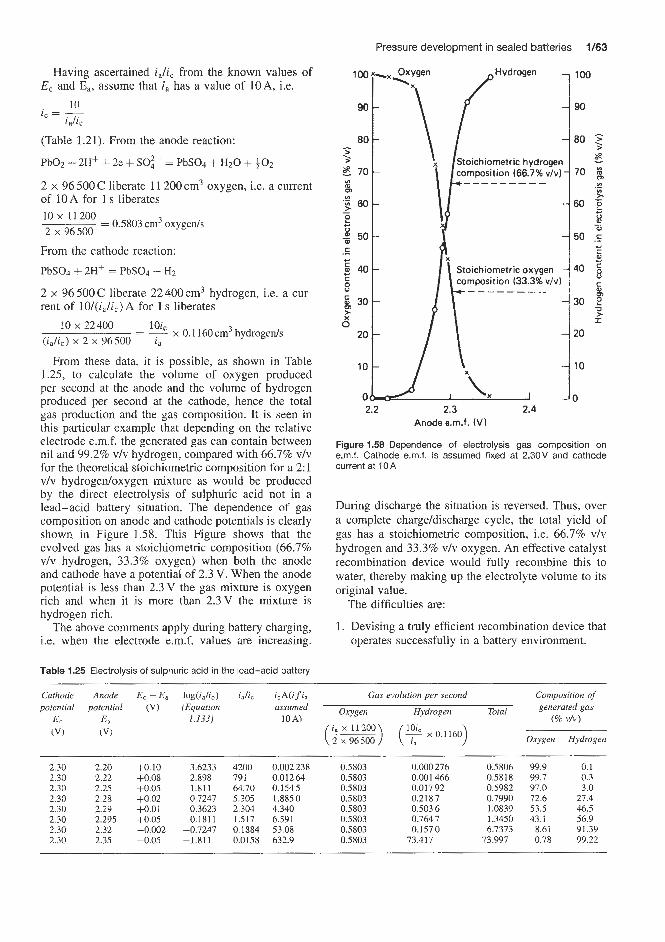
Pressure development in sealed batteries 3/63
Waving ascertained ia/ic from the known values of E, and E,, assume that i , has a value of 10 A, Le.
10 i -- z a & c - .
(Table 1.21). From the anode reaction:
PbO2 + 2H' i- 2e + SO?- = PbSo4 + H2O + $ 0 2
2 x 96 500 C liberate 11 200 cm3 oxygen, i.e. a current of 10 A for 1 s liberates 10 x 11 200 2 x 96500
=Z 0.5803 cm3 oxygeds
From the cathode reaction:
PbSO4 + 2Hf = PbS04 + H2
2 x 96 500 C liberate 22 400 cm3 hydrogen, i.e. a cur- rent of 101(i8/ic) A for 1 s liberates
lOi,
i, = ~ x 0.1 160 cm3 hydrogeds
10 x 22400 (ia/i,.) x 2 x 96500
From these data, it is possible, as shown in Table 1.25, to calculate the volume of oxygen produced per second at the anode and the volume of hydrogen produced per second at the cathode, hence the total gas production and the gas composition. IC is seen in this particular example that depending on the relative electrode e.m.f. the generated gas can contain between nil and 99.2% vlv hydrogen, compared with 66.7% vlv for the theoretical stoichiometric composition for a 2: 1 vlv hydrogeldoxygen mixture as would be produced by the direct electrolysis of sulphuric acid not in a lead-acid battery situation. The dependence of gas composition on anode and cathode potentials is clearly shown in Figure 1.58. This Figure shows that the evolved gas has a stoichiometric composition (66.7% v/v hydrogen, 33.3% oxygen) when both the anode and cathode have a potential of 2.3 V. When the anode potential is less than 2.3V the gas mixture is oxygen rich and when it is more than 2.3V the mixture is hydrogen rich.
The above comments apply during battery charging, i.e. when the electrode e.m.f. values are increasing.
Table 1.25 Elesctrolysis of sulphuric acid in the lead-acid battery
position (33.3% v/ - - - - - - -
2.2 2.3 2.4 Anode e.m.f. (V)
Figure 1.58 Dependence of electrolysis gas composition on e.m.f. Cathode e.m.f. is assumed fixed at 2.30V and cathode current at 10 A
During discharge the situation is reversed. Thus, over a complete charge/discharge cycle, the total yield of gas has a stoichiometric composition, i.e. 66.7% v/v hydrogen and 33.3% vlv oxygen. An effective catalyst recombination device would fully recombine this to water, thereby making up the electrolyte volume to its original value.
1. Devising a truly efficient recombination device that operates successfully in a battery environment.
The difficulties are:
Cathode potential
E, (VI
2.30 2.30 2.30 2.30 2.30 2.30 2.30 2.30
Anode potential
E , (VI
log (i& ) (Equation
1.133)
iJi, i,A(i f i, assumed
10A)
Gas evolution per second
Oxygen Hydrogen Total
Composition of generated gas
(% v h )
Oxygen Hydrogen
2.20 2.22 2.25 2.28 2.29 2.295 2.32 2.35
+0.10 +0.08 +0.05 1-0.02 +0.01 +0.05 -0.002 -0.05
3.6233 2.898 1.811 0.7247 0.3623 0.1811
-0.7247 -1.811
4200 0.002238 791 0.01264 64.70 0.1545 5.305 1.8850 2.304 4.340 1.517 6.591 0.1884 53.08 0.0158 632.9
0.5803 0.5803 0.5803 0.5803 0.5803 0.5803 0.5803 0.5803
0.000 276 0.001 466 0.017 92 0.2187 0.503 6 0.764 7 0.1570
73.417
0.5806 0.5818 0.5982 0.7990 1.0839 1.3450 6.7373
73.997
99.9 0.1 99.7 0.3 97.0 3.0 72.6 27.4 53.5 46.5 43.1 56.9
8.61 91.39 0.78 99.22

1/64 Introduction to battery technology
2. Handling the pressure excursions that occur at cer- tain parts of the chargeldischarge cycle due to the presence of excess over stoichiometric amounts of unrecombined oxygen or hydrogen.
Even small departures from stoichiometric gas com- position at certain periods of the chargeldischarge cycle would cause excessive gas pressure build-up within the cell as shown below.
Suppose that the dead space above the electrolyte in a sealed cell was 100cm3 and that this space was filled with gas having a composition 70% vlv hydrogen and 30% oxygen, Le. 70 cm3 hydrogen and 30 cm3 oxygen. With effective recombination the 30 cm3 of oxygen would consume 60 cm3 hydrogen leaving 10 cm3 of hydrogen unconsumed. If 100 ml of 70:30 vlv hydrogedoxygen were being generated per minute the dead space would contain 1 O m l of unconsumed hydrogen, i.e. the internal cell pressure would be
10 - = 0.1 x 760mmHg 100
At the end of 10 min the internal pressure would be
10 x 0.1 x 760 = 760mmHg
and at the end of 30,min the pressure would be
30 x 0.1 x 760 = 2280 mmHg
Le. three atmospheres. Clearly, the occurrence of internal pressures between one-tenth of an atmosphere and three atmospheres or higher has implications in the problems of designing cells capable of withstanding such pressure cycling.
It is very important, therefore, when designing sealed cells to avoid these problems as far as possible by reducing gas production to an absolute minimum during charge and discharge so that pressure excur- sions are kept to a minimum. The non-stoichiometry problem cannot be avoided, but, by keeping gas evo- lution to a minimum, maximum internal cell pressure can be kept low and gas loss by venting avoided so that in a subsequent stage of the charge/discharge cycle excess oxygen and hydrogen can be recombined back to water, thereby avoiding any long-term reduction in electrolyte volume.
Guidelines to battery selection


Primary batteries 2/13
densities, the open circuit and on-load cell e m f . and the minimum and maximum recommended operating temperatures of a wide range of primary batteries. These are some, but not all, OS the factors that must be taken into account when selecting a type of battery.
Gravimetric energy density controls the weight of the battery required for a given energy output. Primary carbon-zinc and alkaline manganese dioxide batteries have relatively low gravimetric energy densities in the ranges, respectively, of 55-77 and 66-99Whkg or 120-152 and 122-268Wh/dm3 on a volumetric basis. Only mercury-cadmium batteries and specialist batteries developed for particular applications, such as the thermally activated batteries and cuprous chloride and silver chloride type seawater-activated batteries, have lower gravimetric energy densities than the carbon-zinc and alkaline manganese dioxide types. More recently developed primary batteries, such as the manganese dioxide-magnesium perchlorate (90- 1 10 W h/kg, 120- 130 W h/dm3), mercury -zinc (99- 123 W hkg, 300-500 W h/dm3) and silver-zinc (110-267 Whkg, 215-915 Wh/dm3) batteries, have appreciably higher gravimetric (and volumetric) energy densities (upto 330 W hkg, 610 W h/dm3), as do some of the batteries based on magnesium electrodes and organic electrolytes, as opposed to the normal aqueous electrolyte systems.
A further, even more recently developed type of primary battery, with appreciably higher energy densities, is that based on lithium and organic
The first choice to be made is whether a primary or secondaq batteq is required. Usually, there is no doubt about the requirement in this respect. We shall therefore pnoceed to a discussion of the selection of the particulin type of primary or secondary battery required for the application in mind.
There is increasing environmental pressure to stop the use of mercury batteries. As these are still used to a limited extent, eg. some military applications, a discussion of them is included in this book.
2.1 Primary batteries Until the 1970s, primary batteries were predom- inantly zinc-anode-based systems. Performance of these cells has undergone progressive improvements through development of the original Leclanch6 (carbon-zinc) system and introduction of new couples such as zinc-mercuric oxide, alkaline manganese (dioxide, and zinc-silver oxide. Figure 2.1 shows these improvements for one aspect of cell behaviour - energy density. More recently, significant advances in energy density have been achieved, together with improvements in other areas, such as low-temperature performance and storage capability, through the development of lithium-anode-based systems and specialist couples using anode materials such as cadmium, magnesium and indium-bismuth.
Table 2.1 shows, in order of increasing gravimetric energy density, the gravimetric and volumetric energy
275 -
220 -
..-.. m Y . L
2 ~ 165-
E
P E 110-
c ._
-0 1
w
Figure 2.1 lrriprovement in primary battery performance at 21 "C since 1946: 0, initial: W, after 2 years storage
Zinc High- Magnesium High- High-energy dry performance dry cell performance systems cell zinc dry cell magnesium
1946 1955 1968 1972 1978
battery

W4 Guidelines to battery selection
Table 2.1 Energy densities of primary batteries in order of increasing W h/kg energy density
Battery system Open circuit On-load Practical energy dens& Operating voltage per voltage per temperature
cell (V) cell (V) w m g w wdm3 (" C)
Thermal cells
Water-activated cuprous chloride Mercury-cadmium Water-activated silver chloride Carbon-zinc Alkaline manganese Mercury- cadmium-bismuth Zinc chloride Manganese dioxide-magnesium
Mercury -zinc Magnesium-organic electrolyte Silver-zinc (monovalent)
Lithium-iodine Zinc-air
Lithium-sulphur dioxide Lithium-vanadium pentoxide Lithium-thionyl chloride
perchlorate (reserve)
*2.30-3.00 +2.70 1.50-1.60 0.90
1.5 1.5 1.17 1.5
1.85-2.70 1.35
1.60-1.70
* 1.90-2.00
2.70-3.00 *1.6 + 1.85 2.80
* 1.40 1.40- 1.50 2.90 3.4 3.60
- 2.20-2.60 1.20- 1.40 0.75 1.20- 1 s o 1.2 1.25
1.2 1.50- 1.55 1.35- 1.60 1.25
1.5
-
1.70-2.70
1.30-1.55
1.20 1.2- 1.30 2.15 2.4 3.20-3.40
-
10-30 1-9 11-110 22 22-155 55-77 66-99 17 88 90-110 44-110 99-123 133-330 110-126 110-267 200 > 220 155-330 260-330 264 2660
- 2.4-18 18-213 73 43-305
120-152 122-268 201 183 120-130
300-500 60-180
430-610 400-550 215-915 530
180-490 420 660 }
1080
180-900
-54 to 93 -45 to 93 -40 to 70 -45 to 93 -1 to 54
-30 to 54 -20 to 90 -18 to 71
-
-40 to 74 -20 to 54 -54 to 74 -40 to 54
0 to 54 -
-
-29 to 52 -40 to 60 -54 to 60
"+Data from different sources
electrolytes. These comprise, basically, three types of battery, the lithiun; -sulphur dioxide, lithium-vana- dium pentoxide and lithium-thionyl chloride types, with energy densities, respectively, of 260-300 W h/kg (420 W h/dm3), 264 W h/kg (660 W h/dm3) and greater than 660Whkg (1080Wh/dm3). An example of a high energy density specialist battery is the lithium-iodine system with a gravimetric energy density of 200 W h/kg (530 W h/dm3).
Mechanically rechargeable zinc-air batteries can give twice the energy density of carbon-zinc types of cell currently in production. Energy densities up to 220Whkg are well within the capability of this system, compared with the 55-77 W h/kg obtainable from carbon-zinc types of primary cell.
Care is required in interpreting energy density data supplied to users by battery manufacturers. The figure of least value to the user is the theoretical energy den- sity of the cell reaction involved. This figure takes into account only the weight of the active materials and ignores the weight of the cell construction materials (containers, terminals, separators). Others might pub- lish energy densities for single cells, which is of more value. When cells are made up into batteries, further components contribute weight but not electrical energy to the battery and this further complicates the interpre- tation of energy density data. These factors need to he taken into account when determining energy density data for the same type of cell supplied by different types of cell now available.
Frequently, the practical or commercial energy den- sity of a battery is between one-half and one-third of the theoretical value, and this factor must be very carefully taken into account when selecting a type of battery.
As previously mentioned, energy density can be expressed in two ways; W h k g and W h/dm3. It would be expected, therefore, that there would exist an approximate relationship between these two quantities, provided that the mean density did not vary too much from one battery type to another. That this is indeed so is shown by examination of Figures 2.2 and 2.3 in which W h k g is plotted against Wh/dm3. With some notable exceptions, e.g. lithium-thionyl chloride (Figure 2.2) a reasonably smooth plot is obtained which suggests that the mean densities (W hkg)(W h/dm3) of the various types of battery are in the range 2.0-3.2g/cm3.
It will be appreciated, however, that high energy density is only one of the parameters which must be taken into consideration when selecting a primary battery for a particular application. For example, great improvements in operation at low temperature have also been achieved during the 1970s. In this context manganese dioxide-magnesium perchlorate cells have excellent operating characteristics at -40°C with little loss of capacity, even though this type of cell has a lower energy density than alternative new types of cell now available.
Operating temperature ranges for various types of primary battery are listed in Table 2.1. The
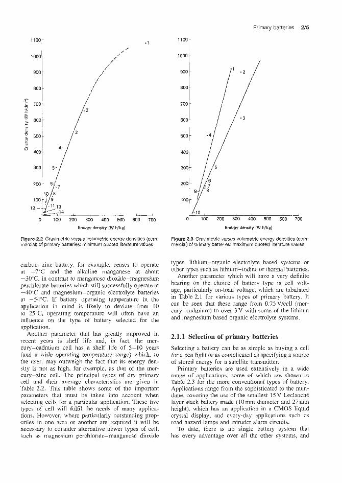
Primary batteries 2/5
1000 - /
/ /
/ /
/' /
/ /
/ /
/
"E . U 7001 1
I ' ; 600' h ._ 5001
E? C Lu
40#
1100-
1000
900
800
300
12
0 100 200 300 400 500 600 700 Energy density (W h/kg)
Figure 2.2 Gravimetric versus volumetric energy densities (com- mercial) of primary batteries: minimum quoted literature values
carbon-zinc battery, for example, ceases to operate at -7°C arid the alkaline manganese at about -3O"C, in contrast to manganese dioxide-magnesium perchlorate batteries which still successfully operate at -40°C and magnesium-organic electrolyte batteries at -54°C. If battery operating temperature in the application in mind is likely to deviate from 10 to 2 5 T , operating temperature will often have an influence on the type of battery selected for the application.
Another parameter that has greatly improved in recent years is shelf life and, in fact, the mer- cury-cadmium cell has a shelf life of 5-10 years (and a wide operating temperature range) which, to the user. may outweigh the fact that its energy den- sity is not as high, for example, as that of the mer- cury-zinc cell. The principal types of dry primary cell and their average characteristics are given in Table 2.2. This table shows some of the important parameters that must be taken into account when selecting cells for a particular application. These five types of cell will fulfil the needs of many applica- tions. However, where particularly outstanding prop- erties in one area or another are required it will be necessary to consider alternative newer types of cell, such as magnesium perchlorate-manganese dioxide
0 100 200 300 400 500 600 700
Energy densiry (W h/kg)
Figure 2.3 Gravimetric versus volumetric energy densities (com- mercial) of primary batteries: maximum quoted literature values
types, lithium-organic electrolyte based systems or other types such as lithium-iodine or thermal batteries.
Another parameter which will have a very definite bearing on the choice of battery type is cell volt- age, particularly on-load voltage, which are tabulated in Table 2.1 for various types of primary battery. It can be seen that these range from 0.75Vkell (mer- cury-cadmium) to over 3 V with some of the lithium and magnesium based organic electrolyte systems.
2.1.1 Selection of primary batteries
Selecting a battery can be as simple as buying a cell for a pen light or as complicated as specifying a source of stored energy for a satellite transmitter.
Primary batteries are used extensively in a wide range of applications, some of which are shown in Table 2.3 for the more conventional types of battery. Applications range from the sophisticated to the mun- dane, covering the use of the smallest 15 V LeclanchC layer stack battery made (10 mm diameter and 27 mm height), which has an application in a CMOS liquid crystal display, and everyday applications such as road hazard lamps and intruder alarm circuits.
To date, there is no single battery system that has every advantage over all the other systems, and
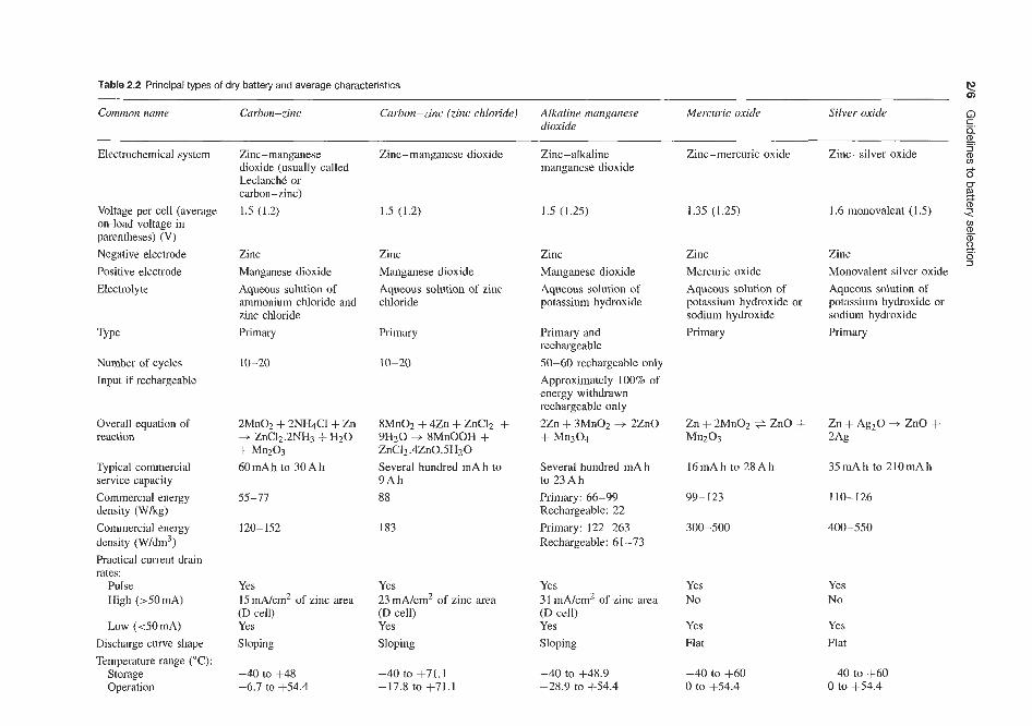
s f
Table 2.2 Principal types of dry battery and average characteristics
Common name Carbon-zinc Carbon-zinc (zinc chloride) Alkaline manganese Mercuric oxide Silver oxide Q dioxide (D _.
Electrochemical system Zinc-manganese dioxide (usually called Leclanchk or carbon-zinc) 1.5 (1.2)
Zinc-manganese dioxide Zinc-alkaline manganese dioxide
Zinc-mercuric oxide 3
8 a
Zinc-silver oxide
0- 2 1.6 monovalent (1.5) 2 Voltage per cell (average
on-load voltage in parentheses) (V) Negative electrode Positive electrode Electrolyte
1.5 (1.2) 1.5 (1.25) 1.35 (1.25)
Zinc Manganese dioxide Aqueous solution of ammonium chloride and zinc chloride Primary
Zinc Manganese dioxide Aqueous solution of zinc chloride
Zinc Manganese dioxide Aqueous solution of potassium hydroxide
Zinc Mercuric oxide Aqueous solution of potassium hydroxide or sodium hydroxide Primary
Aqueous solution of potassium hydroxide or sodium hydroxide Primary Primary Primary and
rechargeable 50-60 rechargeable only Approximately 100% of energy withdrawn rechargeable only 2Zn + 3Mn02 3 2Zn0 + Mn304
Number of cycles Input if rechargeable
10-20 10-20
Overall equation of reaction
2MnO2 + 2NH4Cl + Zn + ZnC12.2NH3 + H20 + Mn203 60mAh to 30Ah
8MnO2 + 4Zn + ZnCl2 + 9Hzo + 8Mn00H -I- ZnCl2 .4ZnOSH20 Several hundred mA h to 9 A h 88
Typical commercial service capacity Commercial energy density (Wkg) Commercial energy density (W/dm3) Practical current drain rates:
Pulse High (>50mA)
Low ( 4 0 m A ) Discharge curve shape Temperature range (“C):
Storage Operation
Several hundred mA h to 23Ah Primary: 66-99 Rechargeable: 22 Primary: 122-263 Rechargeable: 61 -73
16mAh to 28Ah
99- I23
300-500
35mAh to 2lOmAh
55-77 110-126
120-152 183 400-550
Yes 15 mA/cm2 of zinc area (D cell) Yes Sloping
Yes 23 mA/cm2 of zinc area (D cell) Yes Sloping
Yes 31 mA/cm2 of zinc area (D cell) Yes Sloping
Yes No
Yes Flat
Yes No
Yes Flat
-40 to +71.1 -17.8 to +71.1
-40 to +48.9 -28.9 to 444.4
-40 to +60 0 to +54.4
-40 to +60 0 to +54.4
-40 to +48 -6.7 to +54.4
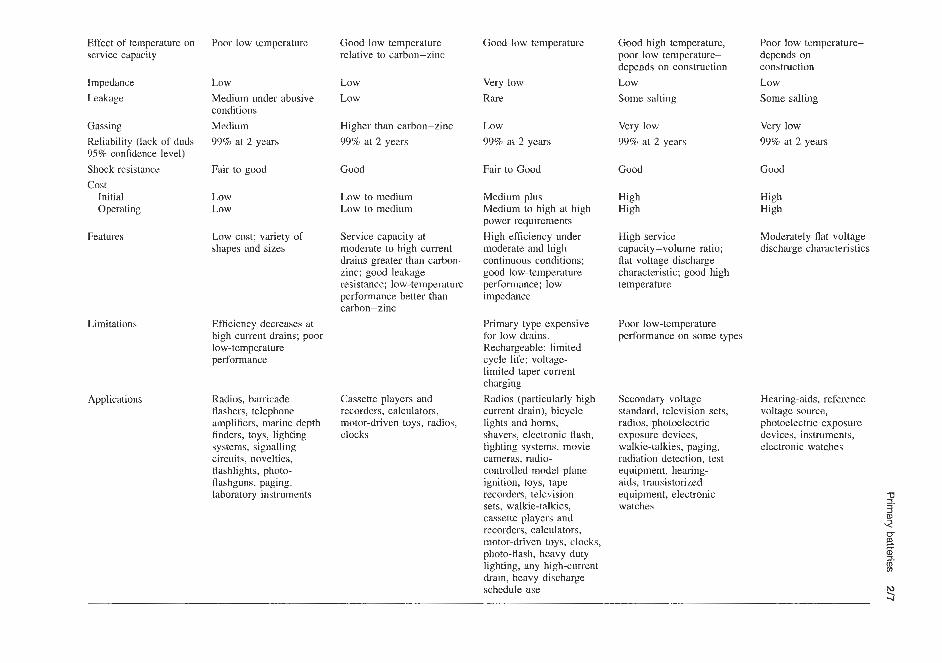
Effect of temperature on service capacity
Poor low temperature Good low temperature relative to carbon-zinc
Good low temperature Good high temperature, poor low temperature- depends on construction Low Some salting
Poor low tempcrature- dcpends on construction Low Some salting
Impedance Leakage
Low Medium under abusive conditions Medium 99% at 2 years
Low Low
Very low Rare
Very low 99% at 2 years
Very low 99% at 2 years
Gassing Reliability (lack of duds 95% confidence level) Shock rcsistance Cos t
Initial Operating
Higher than carbon-zinc 99% at 2 years
Low 99% at 2 years
Fair to Good Good Good Fair to good Good
Low to medium Low to medium
Medium plus Medium to high at high power requirements High efficiency under moderate and high continuous conditions; good low-temperature performance; low impedance
High High
High High
Low Low
Moderately flat voltage discharge characteristics
Features Low cost; variety of shapes and sizes
Service capacity at moderate to high current drains greater than carbon- zinc; good leakage resistance; low-temperature performance better than carbon-zinc
High service capacity-volume ratio; flat voltage discharge characteristic; good high temperature
Efficiency decreases at high current drains; poor low-temperature performance
Primary type expensive for low drains. Rechargeable: limited cycle life; voltage- limited taper current charging Radios (particularly high current drain), bicycle lights and horns, shavers, electronic flash, lighting systems, movie cameras, radio- controlled model plane ignition, toys, tape recorders, television sets, walkie-talkies, cassette players and recorders, calculators, motor-driven toys, clocks. photo-flash, heavy duty lighting, any high-current drain, heavy discharge schedule use
Poor low-temperature performance on some types
Limitations
Secondary voltage standard, television scts, radios, photoelectric exposure deviccs, walkie-talkies, paging, radiation detection, test equipment, hearing- aids, transistorized equipment, electronic watches
Hearing-aids, referencc voltage source, photoelcctric exposurc devices, inskuments, electronic watches
Applications Radios, barricade flashers, telephone amplifiers, marine dcpth finders, toys, lighting systems, signalling circuits, novelties, flashlights, photo- flashguns, paging, laboratory instruments
Cassette players and recorders, calculators, motor-driven toys, radios, clocks

Table 2.3 Some applications of primary batteries
Application Battery hystem Loud requirement Life required (approx.) Acceptable voltage Reason for buttery s 2 regulation (%) choice Q
Roadside hazard lamp (flashing) Roadside hazard lamp Personal locator beacon
Location beacon
Sealed metering and indicator Portable warning lamp
Roadside hazard lamp continuously burning Alarm system Laser beam detector
Memory core standby supply Intruder alarm system Radio location buoy
Solid-state relay
Emergency and portable fluorescent handlamp Detonator
Direct reading frequency meter Radio microphone
Wide-range oscillator Communication transceiver
Tape recorder Miniature ignition device
Carbon-zinc
Air depolarized Mercury - zinc
Mcrcury ~indium-bismuth
Mercury-cadmium
Zinc-air
Carbon-zinc
Air depolarized Mercury-zinc
Mercury-indium-bismuth
Carbon-zinc Air depolarized
Mercury-zinc
Carbon-zinc
Mercury - zinc
Carbon-zinc Mercury-zinc
Carbon-zinc Carbon-zinc
Carbon-zinc Carbon-zinc
6 V 0.3 A bulb approx. 60 pulseslmin 3.8 V 250mA bulb 13.4V 30mA continuous at 0°C 14.7 V 60 mA pulse train 15 mA pulse sporadically 250 mA
12V 0.1Abulb
3.0 mA continuously 13.4V 20mA intermittently 20 pA
12V 300mA 750 mA pulse 2 mA quiescent 13.4V 10pA continuously 12V 600mA
1.34 V 500 mA pulse
9 V 25mA 13.4V 15mA 2Wday
18 V 25 mA 12V T, 1.2A R, 0.6A
6 V 200 mA 400 mA pulses
1200 h
120 h continuous 30h
Operation alter storage at 70°C; 300 h 48 months
10 h continuous
63 h
18 months IOOh
24 months
8 h after 12 months storage 12 months
18 months
3 h continuously
One shot after 18 months 200 h at 4 Wday 50h
200 h at 4 hlday 24 h continuous on TJR, = 119 20days at 30minlday 6-9 months
40
20 20
5
10
5
30
20 5
5
30 20
1
25
10
25 10
25 30
35 30
n, -. Economy; availability 2 CD 0)
Economy 6
Operation at 0°C; % good storage v
u-
4 . Operation after 0)
storage at 70°C (D co
Special termination; a good storage 9 Low weight requirement and voltage regulation; economy Economy; availability
Economy Special termination; good storage Special termination; good storage Economy; availability Weight; cconomy
Long lifc and voltage regulation Economy; availability
Good storage and special termination Size; economy; availability Voltage regulation; special shape Size; economy; availability Economy; weight
Availability; economy Miniaturization

Primary batteries
by meeting the critical needs of the application and subordinating the others.
The selection of a battery is best achieved by setting out a list of minimum requirements, conditions and limitations. as follows:
therefore a procedure for selecting the most suitable system is necessary. The factors involved in the selec- tion of primary batteries suitable to meet a particular requirement are extremely complex. It is essential at an early stage in the design to liaise with the technical department of the battery manufacturer to ensure that the characteristics of the battery and the equipment are matched SO that the user of the equipment obtains the best possible performance from both.
There are tkree basic applications for which primary batteries are used:
1. Miniature equipment (worn or carried unobtrusively
2. Equipment that is portable in use (often moved
3. Transportable equipment (not frequently carried)
in use).
during or between discharge periods).
and standby systems.
Each of these can be based on one of several electro- chemical systems. Batteries in miniature equipment are discussed in !<ection 2.1.2, and in portable equipment in Section 2.1.3. Transportable batteries are usually of the rechargeable type and are dealt with in Chapter 2.2.
One of the problems facing a designer is selecting the correct system for the application from a choice of many. Some of the available systems are listed in Table 2.1, which gives open-circuit voltage, aver- age on-load voltage, energy densities and operating temperatures for various systems, including all those commonly available for commercial use.
Although the many types of battery available may seem to make a proper choice difficult, the problem can be somewhat simplified by first outlining the applica- tion requirements and then matching a battery to the job. The preliminary information that must be avail- able before a battery can be specified is set out below. The discussion of the basic characteristics and features of various batteries in the following sections will indi- cate which one(s) are most suitable for the application. Unfortunately, the ideal characteristics cannot be found in any one battery design; nor can the characteristics of one battery always be compared directly with those of another. Therefore optimum performance of a bat- ter~' in an application can usually be achieved best
1.
2.
3.
4.
5.
6. 7. 8. 9.
Maximum permissible voltage at the beginning of discharge. Normal voltage during discharge (voltage stability on load). End-voltage, that is, voltage at which equipment ceases to function properly. Current-voltage relationships: constant current (amps), constant resistance (ohms), constant power (watts). Type of discharge and current drain (duty cycle): continuous, intermittent, continuous with pulses. Storage and service life. Environmental conditions in storage and in service. Physical restrictions such as dimensions and weight. Special requirements.
It is important that all these points be considered because they are interdependent. This information will allow the battery manufacture to recommend to the equipment designer a battery suitable for the proposed application.
Table 2.4 gives some idea of the relative running costs between three different primary systems: car- bon- zinc, alkaline manganese and mercury -zinc of the R20 size cell covering heavy, medium and light duties. In this comparison of running costs no account is taken of voltage regulations. Although the voltage tolerances differ widely between systems (10% for mercury-zinc, 20% for alkaline manganese, 25% for air depolarized and up to 40% for carbon-zinc), it should be noted that good voltage regulation may be obtained from any battery system using devices such as Zener diodes. Thus, it can be seen that by careful design of a given circuit the lower-cost system could be used, or, because of the more stable voltage of another system, the number of cells in a giver, battery could be reduced, which could reduce the volume and weight. The operating voltage range of the equipment deter- mines the extent to which the available capacity in a battery is realized. A cut-off voltage (that IS, complete
Table 2.4 Running cost comparison, relative to Carbon-zinc cell size R20
System Retail price Cost per hour
Heavy-duty* Medium-duty* Light-duty* (30 mA, (37.5 mA, (10 mA,
30 midday) 4 Wday) 12 Wday)
Carbon-zinc (Vidor SP2) 1 .o Alkaline manganese 5.5 Mercury-zinc 26.0
1 .o 2.6 1 .o
1 .o 2.8
10.0
I .o 5.0
18.0
'End-voltage 0.8 V/cell

2/10 Guidelines to battery selection
useful discharge) of about 0.9Vkell is desirable but not always possible for many types of cell.
Current is directly linked with voltage tolerance, regulation and load and, by taking into account the period of time for which the current is required, the required capacity in ampere hours can be determined. Ampere hour capacity of the zinc-carbon system can be obtained provided that the period of time for which current is required is known and the end-voltage to which the equipment can work efficiently is given. Electrical loading and required service life will deter- mine the required capacity of the battery and this is the basic parameter in deciding the type of cell to be used. Duty cycle may also be a factor in the choice of battery. Applications requiring heavy pulses of short duration will be met by a battery with a different internal construction from that used for a very low continuous current duty.
Battery volume is dependent on the required voltage, ampere hour capacity, temperature and termination and is dictated in many cases by the commercially available types such as the round cell range and layer stack batteries. Primary batteries are made up of individual cells; in the case of carbon-zinc batteries these can be round or flat cells. A primary battery made from flat cells, known as a 'layer stack', generally gives a higher voltage and consequently lower capacity than a round cell battery of the same volume. The trend is to fit all round cells into equipment, but by careful selection of round cells and a layer stack battery the volume required by the batteries can be reduced by more than 40% in some cases. Such combinations have been very successful in reducing the size of military portable communication transceivers. In special applications for industrial and military use, shape is generally as important as volume.
If a standard commercial battery or cell is chosen, the size and type of terminals are already specified, but care is none the less required; for example, on round cells the tolerance allowable (BS 397: 1976, Primary Cells and Batteries, covering R20, D size (American Standards Association) and Vidor SP2) is 2.3mm in height and 1.6mm in diameter. The difference in size between cells from different manufacturers is particu- larly apparent when several cells are connected end to end in series. The construction of a battery container to allow for the difference can be difficult and expen- sive. The use of layer stack batteries having connec- tors, in which there is no such build-up of tolerances, can therefore greatly simplify the construction of the battery container. In applications for industrial and mil- itary use, termination is of major importance and much attention is paid to terminal design so that it can meet the environmental testing demanded.
Allowable size and weight will sometimes determine which battery is selected in spite of other requirements. A premium is usually paid for small size with high output capacity. Bulky and heavy batteries can be
reliable as well as economical if their size can be accommodated.
All electrochemical systems are temperature sens- itive, some giving better performance than others at the extremes; service temperature affects both capacity and life. The suggested operations temperature ranges of some battery systems are given in Table 2.5.
Table 2.5
Suggested operational Battery system temperature range("C)
-7 to +54 -29 to +50 -30 to +50 -20 to +50 -40 to +70 -20 to +90 -40 to +60 -54 to t60
Carbon-zinc Zinc-air Alkaline manganese Mercury-zinc Mercury-cadmium Mercury -indium- bismuth Lithium-based system,
depending on type
The majority of battery manufacturers publish dis- charge figures taken at 20°C. By the correct matching of size and current drain, the carbon-zinc and other primary systems can successfully be operated at lower temperatures than those indicated, but liaison with the battery manufacturer is essential.
To select a system that can be stored and operated at the extreme temperatures of -40 to +90"C-a require- ment with which battery manufacturers are sometimes presented - is difficult and expensive; therefore it is important to specify temperature requirements, partic- ularly the dwell times at the extremes. This is essen- tial information which the designer of the equipment should be able to give to the battery manufacturer.
Table 2.6 gives a guide to the period, at 20°C, for which some battery systems can be stored, at the end of which the cells would have retained between 80 and 90% of their capacity.
Table 2.6
System Shelf life at 20°C
before use* (months)
Carbon-zinc Alkaline manganese Mercury-zinc Mercury-indium-bismuth Mercury-cadmium Air depolarized Silver oxide-zinc Lithium-sulphur dioxide
18-30
24-30 36 48 48 18 60
18-30
*Varies with cell size

Primary batteries 2 / 7 1
of mercury that form as the cathode is discharged. In a watch, the batteries must perform adequately over a period of months or years, and the discharge pattern may be one of short periods of a drain of tens of milliamperes superimposed on a microampere continuous drain. Under these conditions a separator with carefully controlled properties is required to avoid possible mercury penetration and short-circuiting of the cell.
Silver oxide-zinc cells are often specified for elec- tronic watch applications. Sodium hydroxide elec- trolyte, which has a lower conductivity than potassium hydroxide, is often used because it has a lower ten- dency to ‘creep’ at the seal. The separator in the silver oxide system must retain soluble silver species pro- duced by chemical dissolution of the oxide, and a mul- tiple layer separator of low-porosity film achieves this.
There are two types of silver oxide cell: one has a cathode of monovalent silver oxide (Ag20) and the other type uses divalent silver oxide (Ago). The latter type has a higher theoretical potential (1.8V) and, because there is an additional chemical reduction from Ago to AgzO it has a higher capacity. (The theoretical energy density is 424 W hkg.) The two-stage reduction process would normally result in a discharge curve with two plateaux at 1.7 and 1.5 Q and the voltage drop in the middle of discharge may necessitate a voltage regulator in the equipment. If the surface layer of the electrode is of Ag20, however, discharge takes place at the lower potential throughout. In order to achieve voltage stability, the surface may be treated to reduce Ago to AgnO or, in various patented arrangements, a ‘dual-oxide’ system may be adopted. Nigher raw material costs mean that silver oxide cells are more expensive than their mercury equivalents.
Shock or libration may indicate the need for a rugged battery construction. Unusual rates of acceler- ation or high-altitude operation are also vital environ- mental considerations. Storage time and temperature under any of these conditions should be noted.
It should be noted from Table 2.3 that batteries with different type:; of electrochemical system are chosen for different types of duty application. Obviously, some batteries based on a particular type of electro- chemical system are more suited to particular applica- tions than are others, and here one is confronted with the dilemma that any particular primary battery manu- facturer will have only some of these electrochemical systems included in their range and that the one recom- mended may not be absolutely the best from the total range available. It is advisable, therefore, to discuss battery requirements at an early stage of design with several battery suppliers covering the whole range of types of battery.
2.1.2 Batteries in miniature equipment
Miniature applications have become more important in recent years with the general acceptance of the behind- the-ear hearing-aid and the advent of the electronic watch. High energy density per unit volume is the prime requirement for a battery in these products. The mercuric oxide-zinc, silver oxide-zinc, zinc-air and lithium-based systems appear to be likely contenders for this market. Although the last two types of battery have been produced in sizes suitable for miniature applications, they are not widely available in this format. These systems will therefore be discussed later in their usual cylindrical form, and the conclusions drawn then may explain the difficulties that have prevented their wide acceptance.
The mercuric oxide-zinc cell for miniature applica- tions is usually based on the familiar ‘button’ construc- tion using a compressed cathode of mercuric oxide and graphite (added for conductivity) in a plated steel can. The cell seal is supported by a cathode sleeve on top of which is placed a synthetic separator and an elec- trolyte absorbing pad; the electrolyte is a solution of potassium hydroxide. The amalgamated zinc anode is added and the cell sealed with a polymeric gasket and a metal top cap.
The mercury cell has a low internal resistance and high cathode efficiency. Discharge characteristics are substantially flat, an obvious advantage for hearing- aid use. Capacity retention of the system on storage is good. Multi-cell batteries using the mercury system are available for applications requiring higher voltages, and some cylindrical sizes are produced. In general, the high cost of the system restricts it to those uses where space is at a premium or where voltage regulation is critical.
In hearing-aids, the current drain may be of the order of 1mA for a total discharge of several days. The low-resistivity separator is able to retain the droplets
2.1.3 Portable-in-use batteries This category includes test eqnipment, portable radio apparatus, lighting and calculators, and is a much larger market than the miniature or transportable sectors.
Lithium has several advantages as a possible anode material for an electrochemical power source. It has a low equivalent weight and density and is the most electronegative element that is solid at normal tempera- tures. However, lithium reacts with water, the common electrolyte solvent, and with most non-metallic ele- ments and compounds; it is therefore normally essen- tial to use a non-aqueous electrolyte.
Solid electrolyte lithium batteries have been produced for low-drain applications. The Catalyst Research Corporation produce a lithium-iodine solid electrolyte system, rated at 20pA for heart pacemaker use.
For a battery that is to sustain high current densities at ambient temperatures, a solid electrolyte is unlikely to be acceptable. A suitable electrolyte solvent must provide stable solutions of the electrolyte over a wide

2/12 Guidelines to battery selection
temperature range and be stable towards lithium and the cathode material.
In order to exploit the value of a lithium-based sys- tem to the maximum, the positive electrode (cathode) material should also be of high energy density. The search for the ideal combination of cathode mater- ial and electrolyte has attracted a great deal of effort in the 1970s. The lithium-polycarbon-monofluoride system is one of two lithium systems that have been commercially promoted. Developed by the Matsushita Electric Industrial Co. in Japan, the cells are avail- able in several cylindrical sizes. The patented cathode material is of the form (CF,), where x has a value between 0.5 and 1.0 and is formed by reacting carbon with fluorine under various conditions of temperature and pressure, depending on the type of carbon used as the starting material. Except where batteries are intended for low-rate applications, acetylene black or graphite is added to the electrode to improve con- ductivity. The electrolyte is lithium tetrafluoroborate dissolved in a-butyrolactone. Honeywell Inc. and the Mallory Battery Co. in the United States have intro- duced lithium batteries based on the lithium-sulphur dioxide electrochemical couple. The positive active material in these batteries, liquid sulphur dioxide, is dissolved in an electrolyte of lithium bromide, ace- tonitrile and propylene carbonate, and is reduced at a porous carbon electrode.
Both types of lithium battery have a spiral-wound electrode pack, made up from rectangular foil elec- trodes. Lithium foil is rolled on to an expanded metal mesh current collector as the negative electrode, and is separated from the similarly supported cathode by a polypropylene separator.
Practical open-circuit voltages of the lithium- polycarbon-monofluoride and lithium- sulphur dioxide systems are approximately 2.8 V and 2.9 V respectively at 20°C. The high voltage means that these batteries are not interchangeable with other electrochemical systems in existing equipment, unless a 'dummy' cell is also included.
The high volumetric energy densities reflect the high voltages of the lithium-based systems. One reason for some lack of acceptance in miniature applications is that although one lithium cell could be specified where it is necessary to use two mercury cells in series, a lithium button cell would have a capacity approximately one-half that of the equivalent mercury cell, and the frequency of battery changing would in extreme cases be correspondingly increased.
The volumetric ampere hour capacity of mercuric oxide-zinc cells is higher than that of lithium-based systems. However, in many cases using two lithium cells in parallel or one larger lithium cell will give the same ampere hour capacity that can be achieved in an equal or even smaller volume than an equiv- alent two-cell series mercury -zinc battery of similar voltage. This is illustrated in Table 2.7, which gives a
Table 2.7
Lithium-sulphur Mercuric dioxide oxide - zinc
Volumetric energy density (W h/dm3) 420 500 (best) Normal working voltage (V) 2.75 1.25 Volumetric capacity (A Wdm) 153 400 Relative cell volume per A h 2.6 1.0
comparison of lithium-sulphur dioxide and mercuric oxide-zinc cells.
Thus one lithium- sulphur dioxide cell (voltage 2.75V) occupies about 30% more space than two series mercuric oxide-zinc cells (voltage 2.5 V). Admittedly, this compares the worst cited case for lithium against the best for mercuric oxide-zinc. Higher energy density systems such as lithium-vanadium pentoxide and lithium-sulphur dioxide would show significant volume savings over an equivalent ampere hour mercuric oxide-zinc system. In fact lithium-sulphur dioxide systems are being increasingly considered for high-rate miniature power source applications including military applications where it is found that a two-cell mercuric oxide-zinc battery can occupy considerably more space than the equivalent lithium-sulphur dioxide cell; there are the added advantages inherent in the lithium-sulphur dioxide system of excellent storage life (5-10 years, that is, very low self-discharge), wide operating temperature range (-50 to +60"C) and stable voltage characteristics on load.
The reactivity of lithium necessitates controlled- atmosphere assembly - in some cases the use of expen- sive materials in the cell construction to avoid cor- rosion, and in some cases (for example, lithium- sulphur dioxide) the provision of a sophisticated seal design.
Although lithium batteries have high-rate discharge capability, their use at very high rates or accidental shorting could result in temperatures leading to seal failure or explosion. Manufacturers have incorporated vents and/or fuses to minimize these risks.
The zinc-air system, which attracted a great deal of investment in the late 1960s and early 1970s to make a consumer product in standard cylindrical sizes, suffered initially from four problems. It was difficult to produce air-breathing cathodes of consistent qual- ity; the need to allow air into the cell led to elec- trolyte leakage; carbonation of the electrolyte occurred on long-term discharge; during intermittent discharge oxygen ingress products caused wasteful corrosion of the active material.

Primary batteries a13
Despite these initial difficulties, commercially avail- able D and N cells were available in the UK in the early 1970s. The ECL D-size cell outperformed D-size nickel-cadmium cells under most conditions, except at sub-zero tl-mperatures, in a military ‘manpack‘ radio application. The cost of this zinc-air cell was about 25% of that of an equivalent nickel-cadmium cell and proved to be more economical. However, the nickel-cadmium cell had the advantage of being rechargeable. (Primary zinc-air batteries were used extensively during the Vietnam War.) The N-size cell has been used successfully for the small pocket paging equipment market. The demise of zinc-air D and N cells rests on economic factors rather than on technical grounds. The picture for zinc-air button cells is quite different; Gould have manufactured them in the USA for several years for applications such as hearing-aids, watches, etc., and Gould and Berec have both been marketing them in the UK since 1980.
LeclanchC and alkaline manganese batteries retain the great majority of the primary battery market for portable-in-use applications. They are widely available in a variety of equivalent cylindrical sizes.
The LeclanchC system has the property of ‘recov- ering’ during rest periods in the discharge regimen. This property and the low cost resulting from high- volume automated manufacture make the EeclanchC ideal for the intermittent usage pattern found in most consumer appliances. Figure 2.4 shows the effect of increased current drain on the service life of the SP2 (R20 size) battery. The discharge period is 5 Wday to an end-voltage of 0.9 V.
For higher current &rains, for example in motorized equipment, a high-power (HP) battery should be used. HP batteries contain electrolyte or chemically prepared manganese dioxides, which have enhanced discharge properties. Figure 2.5 compares SP11 and HPl 1 (R14 size) types on a 10 Q, 2Wday discharge - the advan- tage of using the high-power type is obvious. For
100
ao
Percentage of service life
Figure 2.4 SP2 (R20) Leclanche cells. Effect of increased current drawn on service life
1.7
1.6
1.5
1.4 - > m 5 1.3
1.2
1.1
1 .o
e
>
0 20 40 60 80 100 Percentage of service life
Figure 2.5 Heavy duty effect. SP11 and H P I I (R14) alkaline manganese dioxide batteries. Beneficial effect of using a high- power battery (HPI 1) on service life; high current drain (10 a, 2 h/day discharge)
1.6
1.5
1.4 > ; 1.3 a = 1.2
1.1
1 .o 0.9
8
0.8 0 20 40 60 80 100
1.6
1.5
1.4 > ; 1.3 a = 1.2
1.1
1 .o 0.9
8
0.8 0 20 40 60 80 100
Percentage of service life
Figure 2.6 Low discharge effect. SP11 and HP1 1 (R14) alkaline manganese dioxide batteries. Effect of using a high-power battery (HPI 1) on service life; high current drain (300 R , 2 h/day discharge)
low-rate discharges, the additional cost of the HP ver- sion is not warranted; Figure 2.4 compares the same cells on a 300 Q, 2 Wday discharge.
The storage properties of modern LeclanchC batter- ies are much better than those of early dry batteries because of technological improvements. For example, average discharge levels of SP l l and HPl l batter- ies, on radio and tape recorded discharge respectively, after 2 years’ storage at 20”C, are over 95% of those obtained for similar batteries discharged within a few weeks of production.
Transistor applications require multiples of the unit cell voltage; the layer stack (‘power pack’) format provides a convenient battery in a smaller volume than the equivalent combination of round cells. Only one unit needs to be replaced, and connection is by simple non-reversible press studs ensuring correct polarity. Selection of the most economical layer stack battery should be made in conjunction with the battery manufactuer. Specification of a battery which is too

2/14 Guidelines to battery selection
5 0 20 40 60 80 100
Percentage of service life
Figure 2.7 Size effect. Leclanche batteries: comparative service lives of two 9V power packs, PP9 and PP6, on a 450Q, 4 h/day discharge
small for the current drain can lead to unnecessarily frequent battery replacement. Figure 2.7 shows the comparative service lives of two 9 V power packs, PP9 and PP6, on a 450 Q, 4 Wday discharge.
The additional cost of the alkaline manganese con- struction is usually not warranted for intermittent discharges, despite its improved performance. For example, comparing an HP2 LeclanchC cell with an Mn1300 (IECLR 20) alkaline manganese cell on a 5 C2, 2hlday discharge to an end-voltage of 1.1 V, the Mn1300 gives twice the discharge life but costs three times as much as the HP2. Only on continuous high-rate discharges does the alkaline manganese sys- tem have an undoubted economic advantage. It is also recommended for low-temperature discharges.
Magnesium cells incorporate a manganese dioxide cathode, magnesium anode and magnesium perchlor- ate or bromide electrolyte. They have excellent shelf storage properties, and a higher energy density than the LeclanchC battery. However, they have a non-standard voltage and a characteristic voltage drop at the begin- ning of discharge. On intermittent use, gassing at the magnesium electrode means that the batteries cannot be properly sealed.
Where a rechargeable power source is required for portable-in-use apparatus, the nickel-cadmium system is generally specified. Nickel-cadmium batteries and cells are available in a wide range of cylindrical and button sizes, and they are ideally suited to high-rate applications. Both sintered electrode cylindrical batter- ies and mass plate electrode button cells constructions are available. The following discussion refers largely to the former type, since these occupy the major part of the market.
Because of the low internal resistance of nickel-cadmium batteries, constant-current charging is recommended to avoid elevated battery temperatures and thermal runaway. Batteries that have been
discharged to 1.0V may be brought to the fully charged state in 12 h by charging at the C8 rate. The nickel-cadmium system will accept overcharge more readily than the lead-acid battery, but for permanent trickle charging a lower charge current than the above is recommended.
2.2 Secondary batteries Table 2.8 shows, in order of increasing gravimet- ric density, the gravimetric and volumetric densities, the open circuit and on-load cell e.m.f. values and the minimum and maximum recommended operat- ing temperatures of a range of secondary batter- ies. For simplicity, Table 2.8 tabulates the mean data and some features that make these batteries attrac- tive for particular applications. It is now possible from the data in Table 2.9 to approximately rank sec- ondary batteries in order of increasing gravimetric energy density and on-load voltage, to take but two of the important battery parameters. Table 2.10 shows, for example, that lead-acid, nickel-cadmium, sil- ver-cadmium, nickel-zinc and nickel-hydrogen are in the lower energy density groups; silver-hydrogen, silver-zinc, zinc-chlorine and zinc-air are in the medium energy density group; and sodium-sulphur, lithium-chlorine and lithium-sulphur are in the high energy density group. This general impression is con- firmed by examination of Figure 2.8 which presents gravimetric energy density data at the 5 h rate of dis- charge, obtained from another source.
With data of this type, it is possible to make a start in the process of selecting a suitable type of secondary battery to meet a particular application. However, as discussed in Section 2.1 on primary batteries, many other considerations would apply in making the final selection.
As in the case of primary batteries (see Figures 2.2 and 2.3) it is possible to plot commercial volumet- ric veysus gravimetric energy densities of secondary batteries as shown in Figure 2.9, which indicates a rea- sonably good correlation between the two parameters. Average densities are between 1.8 and 2.3 g/cm3 com- pared to 2.0-3.2 g/cm3 for primary batteries.
The number of applications calling for an integrated energy system has been increasing impressively. To meet the varied power needs of these applications, manufacturers have created a number of variations within each family of available systems.
Battery designs that provide such advantages as recyclability, extended shelf life prior to use, remote activation, adjustment in load current with minimum voltage variations, and operation under extreme tem- perature conditions, have been developed over the years. All these performance characteristics, however, cannot be found in any one battery design; a few

Secondary batteries 2/15
Table 2.8 Energy densities of secondary batteries
Battery system Open circuit On-load Practical energy density Operating temperature
("(3 W Ndm3 voltage per voltage per cell (V) cell (VI h/kg
Sealed lead-acid Eagle Picher Sonnenschein Other sources
Unsealed lead-acid Silver-cadrniurri-as cells
Eagle Picher Yardney
Eagle Picher Yardney SAFT Other sources
Silver-cadmium-as batteries
Sealed nickel-cadmium Eagle Picher Nife
button mass round mass round sintered rectangular mass rectangular sintered other sources
Vented nickel-cadmium Nife
Nickel-zinc Eagle Picher Yardney Other sources
Alkaline manganese rechargeable* Silver-zinc (theoretical 440 W h/kg)
Eagle Picher: as cells as batteries
Yardney SAFT Other sources,
Silver-zinc (remotely activated) Nickel- hydrogen
Eagle Picher Silver-hydrogen
Eagle Picher Zinc-chlorine* Zinc - air* Sodium-sulphur" Lithium-chlorine* Lithium-sulphur*
2.12
2.10 2.10
1.40
-
-
I .40 - - -
1.40
1.30- 1.35 - -
-
-
-
- 1.35
1.35
1.85
1.71 -
-
-
1.85 1.85
-
- -
- -
1.85
1.40
1.50 - - - - -
1.50-2.00 -
- -
0.80- 1.10 -
0.80- 1.10 - -
- -
1.00- 1.25 -
- - -
-
-
-
1.5-1.65 - -
-
-
1.30- 1.55 1.30- 1.55
-
- -
- -
1.20-1.55
1.20- 1.30
1.00-1.10 - - - - -
18-33
22-33 23-34
15-26
24-73 40-75
18-44 18-51 30-7.5 77 24-120
18-44 24-35 21-22 22 22 18 21 26-37
26-44
29-55 44 - 77 up to 66 33-77 50
55-209 37-114 70-120
55-220 50-150
123 130 11-110
56-67
90-100 130 150 240 330 370
43-85 51-83
31-122 49-83
40- 180 91-165
24-122
40-150
37-250
37-120
61-62 69 78 37 52 61-85
-
171
60-91
61-99
60-110 79-134
67-134 134
-
80-415 55-262
120-250 80-300 80-610
220 -
24-240
55
60 - - - - -
-40 to 60 -
-51 to 70 -54 to 54
-40 to 43 -
-40 to 43
-47 to 75
-48 to 71
-
-
-40 to 70 - -
-
-
- -
-40 to 60
-51 to 60
-40 to 93 -
-
-48 to 71 -
-40 to 74 -40 to 74
-40 to 75 -48 to 71
- -
-35 to 49
-18 io 27
4 to 27 - - - - -
'At 5 hrate
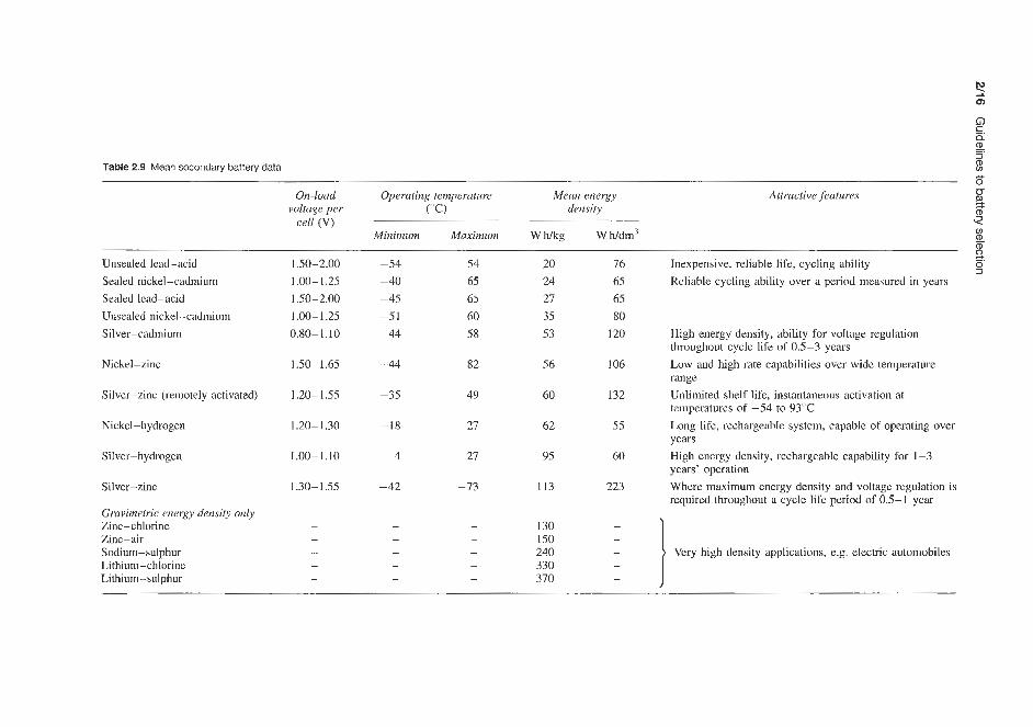
Table 2.9 Mean secondary battery data f
s B 2 cs On-loud Operating temperature Mean energy Attructive features
cell (V) voltage per (" C) density
0)
m 2 Minimum Maximum W h k g Wh/dm3
a 9 Unsealed lead-acid 1.50-2.00 -54 54 20 76 Inexpensive, reliable life, cycling ability
Sealed nickel-cadmium 1 .00- 1.25 -40 65 24 65 Rcliable cycling ability over a period measured in years Sealed lcad-acid 1.50-2.00 -45 65 27 65 Unsealed nickel-cadmium 1.00-1.25 -51 60 35 80 Silver-cadmium
Nickel-zinc
Silver-zinc (remotely activated)
Nickel-hydrogen
Silver-hydrogcn
Silver-zinc
Gravimetric energy density only Zinc - chl orine Zinc-air Sodium-sulphur Lithium-chlorine Lithium - sulphur
0.80-1.10
1.50- 1.65
1.20- I .55
1.20-1.30
1.00-1.10
1.30-1.55
-44
-44
-35
-18
4
-42
58
82
49
27
27
-73
53
56
60
62
95
113
130 150 240 330 370
120
106
132
55
60
223
High energy density, ability for voltage regulation throughout cycle life of 0.5-3 years Low and high rate capabilities over wide temperature range Unlimited shelf life, instantaneous activation at temperatures of -54 to 93°C Long life, rechargeable system, capablc of operating over years High energy density, rechargeablc capability for 1-3 years' operation Where maximum energy density and voltage regulation is required throughout a cycle life period of 0.5-1 year

Secondary batteries 2/17
3CU
cn Y 2 3
.z 20c
- > r
W U > P C w
1 CIC
- t W
g - B v)
m I E
E
- 2 ._
P I
m Y - .- ...:.:.:.: 0.. ..... .......... .......... .......... .:.:.:.:.: .......... ......... .......... $$$;* ll '.. :".
- >
.- z L Q
0
N
C
- .-
e >:<::.:!
..... :/.: >>>; .+:.:.. >:(.??
:.:::::. (:::,:.::
...... ........ ........
.......... .......... ..........
......... .>:.:.:.: B $$;g
Figure 2.8 Typical energy densities at 5 h rate of discharge for known electrochemical cells
Table 2.10 Ranking of energy density and on-load voltage of secondary batteries
Ranking in terms of gravimetric energy voltage (V) density (W Wkg)
Ranking in terms of on-load
lead-acid nickel-cadmium Silver-cadmium Nickel-zinc Nickel-hydrogen Silver- hydrogen Silver-zinc Zinc-chlorine Zinc-air Sodium-sulphur Lithium-chlorine Lithium -sulphur
-20 Silver-cadmium 0.81 - 1.10 -35 Silver-hydrogen 1.00- 1.10
53 Nickel-cadmium 1.00-1.25 56 Nickel-hydrogen 1.20-1.30 62 Silver-zinc 1.30- 1.55 95 Nickel-zinc 1.50-1.65
113 lead-acid 1.50-2.00 130 150 240 330 370
are incompatible and some features must be subor- dinated to others. To achieve optimum performance in each application, therefore, it is necessary to direct the design of the battery systems towards meeting the critical needs of the application.
Five major types of secondary rechargeable batter- ies are lead-acid, nickel-cadmium, silver-zinc, sil- ver-cadmium and nickel-zinc, and these are discussed in more detail below.
2.2.1 Lead-acid batteries
The lead-acid battery is the most widely used of the five mentioned, its main application being in the auto- motive field. Its advantages are low cost, high voltage per cell and good capacity life. Its disadvantages are that it is relatively heavy, it has poor low-temperature characteristics and it cannot be left in the discharged state for too long without being damaged.

2/18 Guidelines to battery selection
220
210-
200
190
180
170-
160
G 150- E 2 140-
130-
5 120-
5 110-
5 100-
fi 90-
r: 1
.- UI
-0
al
80
70
-
- - -
-
- -
50-
40-
30
20
10
Figure 2.9 Gravimetric versus volumetric energy densities (com- mercial) of secondary batteries. Mean literature values
/ /
/ /
-
- -
, 1 1 1 1 1 1 1 1 1 1 1
Since the late 1950s sealed rechargeable batteries based on the lead-lead dioxide couple have become available and while these are not produced in the same quantities as the non-sealed type their uses are increas- ing. For transportable applications weight is not of major importance, while the power requirements of the apparatus may be considerable. Here the lead-acid battery has the advantage of low cost. Transportable batteries are usually of the rechargeable type and are discussed later. The disadvantages associated with this system in its usual form, the SLI (starting, lighting and ignition) battery for vehicles, have been largely overcome by the low-maintenance types of lead-acid battery now available. Valve regulated lead-acid bat- teries are now a permanent feature of the business.
Charging may be carried out with a simple charger under controlled-time conditions. The rated capacity is given at the C20 rate, that is, the capacity obtained when a fully charged battery is discharged to bring it to an end-voltage of 1.75 Vlcell in 20 h.
Sealed nickel-cadmium batteries have a higher ini- tial cost, but these batteries may be economical for some transportable applications, where their long cycle
life and indefinite shelf life in any state of charge with- out electrode deterioration are advantageous. They are particularly suitable for trickle charge uses such as emergency lighting.
2.2.2 Nickel-cadmium batteries The nickel-cadmium battery is mechanically rugged and long lived. In addition it has excellent low- temperature characteristics and can be hermetically sealed. Cost, however, is higher than for either the lead-acid or the nickel-zinc battery and, by compar- ison, its capacity on light drain in terms of watt hours per kilogram is also poorer than for nickel-zinc.
For many everyday batteries, the choice is still between the lead-acid and the nickel-cadmium sys- tems, rather than the more recently developed systems discussed below.
Each of these two main types of battery has its own advantages and the choice between nickel-cadmium and lead-acid batteries depends very much on the particular application and on the performance charac- teristics required.
In addition to these two types of battery, there are several others which, because of their higher cost, are not used as extensively, but are nevertheless of direct interest in particular fields. This is because of their out- standing performance characteristics in certain special- ized applications, e.g. silver-zinc and silver-cadmium batteries.
2.2.3 Silver-zinc batteries Rechargeable silver-zinc batteries can provide higher currents, more level voltage and up to six times greater watt hour capacity per unit weight and volume than the lead-acid, nickel-zinc and nickel-cadmium storage batteries. Because it is capable of delivering high watt hour capacities at discharge rates less than 30 min, the silver-zinc battery is used extensively for missile and torpedo applications. Its high energy density makes it attractive in electronics applications, satellites and portable equipment where low weight and high perfor- mance are prime considerations. It is highly efficient and mechanically rugged, operates over a wide temper- ature range and offers good shelf life; quick readiness for use and the ability to operate at -40°C without heating are two of the features of this battery. It is available in both high-rate and low-rate cells. Until now, the fact that it is more expensive, sensitive to overcharge and has a shorter cycle life than ordinary storage batteries has limited the silver-zinc battery to applications where space and weight are prime con- siderations. However, long-life silver-zinc batteries have been developed in which some 400 cycles over a period of 30 months’ application have been achieved.

Secondary batteries 2/19
not be commercially available for several years. Cer- tainly, sealed versions of these batteries can only be considered to be a prospect for the future. The cad- mium-air system has a theoretical energy density of 445 W hkg. The cadmium anode used is the type that has demonstrated good stability and low seif-discharge in other alkaline systems. The air cathode is similar to that used in the mechanically rechargeable zinc-air battery. The battery consists of two air cathodes in parallel, positioned on the two sides of a plastics frame, and one anode. The bifunctional air electrode can be used for both discharge and charge. Over 300 cycles have been obtained with the best combination of materials.
There are several problems associated with the operation of the cadmium-air battery, such as the loss of cadmium on cycling, cadmium penetration and poisoning of the air electrode by a soluble cadmium species migrating to the air electrode. Water must be added to this cell periodically because water loss occurs by transpiration of water vapour through the air electrode - a characteristic of batteries using an air electrode. Operating cell voltage varies between 0.70 and 0.85V at the C/2 to C/lQ rate (that is, the discharge current is numerically equal to one-half to one-tenth of capacity, C). At these rates practical bat- teries produce 80-90 W h k g and 14-24 W h/drn3.
2.2.4 Silver-cadmium batteries The silver-cadmium battery combines the high energy and excellent space and weight characteristics of the silver-zinc ba.tte1-y with the long-life, low-rate char- acteristics and some resistance to overcharge of the nickel-cadmium battery. The battery also provides high efficiency on extended shelf life in charged or uncharged conditions, level voltage and mechanical ruggedness. Watt hour capacity per unit of weight and volume are two to three times greater than those of a comparable nickel-cadmium battery and it has superior charge retention. The silver-cadmium battery promises great weight and space savings and superior life characteristics to those of the nickel-cadmium bat- tery currently used as storage batteries in most satellite programmes.
Today a silver-zinc system offers the greatest avail- able energy dlensity in terms of watt hours per kilo- gram. There are newer so-called high energy density couples which have been under development for many years; the effective energy density of many of these systems tends to decline as they are developed close to the point of practical utilization. In addition, chronic safety problems have already caused serious difficul- ties with the lithium systems and are potentially dan- gerous in others, most of which are high-temperature systems based on volatile materials. The use of silver as a couple obviously increases initial costs (although silver costs are recoverable) when compared to other existing systems such as lead-acid, nickel-cadmium, etc. When space and weight are limiting factors, the silver-zinc system is a very attractive proposition.
Other metal couples that are considered at present to be of great potential are the nickel-hydrogen and nickel-zinc systems. These may be batteries of the future in applications such as utilities load levelling and electric vehicles; the latter type is, in fact, now in commercial production.
2.2.5 Nickel-zinc batteries With the development of new separators and improved zinc electrodes, the nickel-zinc battery has now become competitive with the more familiar battery systems. It has a good cycle life and has load-voltage characteristics higher than those of the silver-zinc system. The energy per unit of weight and volume are slightly lower than those of the silver-cadmium system. Good capacity retention (up to 6 months) has made thle nickel-zinc battery a more direct competitor of h e silver-zinc and silver-cadmium systems. Nickel-zinc batteries are not yet available in a sealed form.
2.2.6 Cadrn.ium-air batteries Rechargeable cadmium-air and zinc-air batteries are currently still only at the development stage and may
2.2.7 Zinc-air batteries Development of the zinc-air electrically rechargeable battery is under way. Experimental cells have given 155-175 W h k g at the C/5 rate of discharge. These energy densities are approximately twice those of the best existing rechargeable systems. However, there is the problem of internal shorting after several cycles as a result of zinc dendrite growth. This problem can be overcome to a great extent by proper selection of separator materials. It was also found that the air electrodes, which contain platinum as the catalyst and have been used successfully in the mechanically rechargeable zinc-air battery and the cadmium-air electrically rechargeable battery, do not function in the charging as well as the discharging mode. This is because platinum on the anode surface acts as a low hydrogen overvoltage site, thereby enhancing zinc self- discharge and reducing the available capacity of the zinc electrode. Thus, until an adequate air electrode is developed, a third electrode will be required for charging purposes.
Table 2.11 compares some basic parameters of the five main types of rechargeable battery system. Some of these data must, of course, be interpreted with cau- tion - particularly energy density data. Discharge char- acteristics for these five types of battery are compared in Figure 2.10.
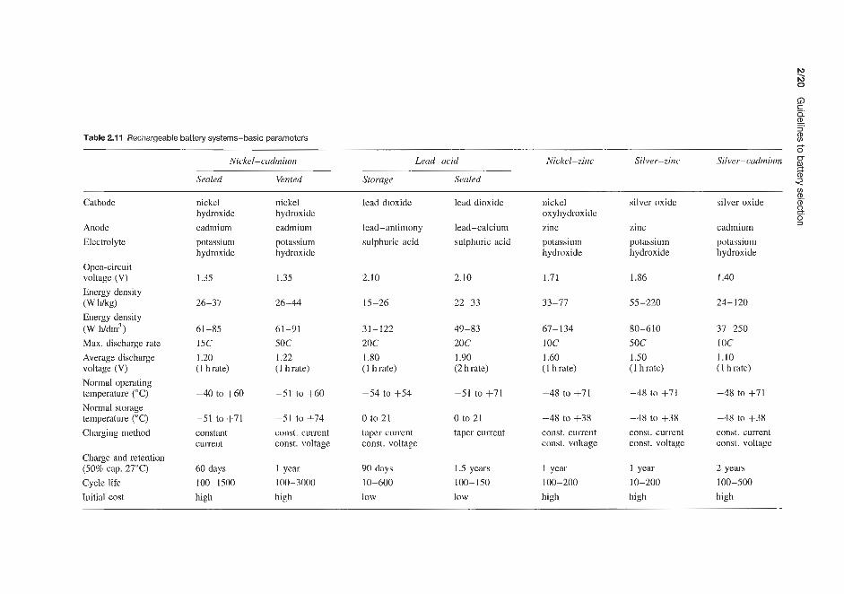
Table 2.1 1 Rechargeable battery systems-basic parameters B
Silver-cadmium * 3 E
Cathodc nickel nickel lead dioxide lead dioxide nickel silver oxidc silver oxide (D
2
Nickel-cadmium Lead-acid Nickel-zinc Silver-zinc 2 Sealed Vented Storage Sealed
v1
hydroxide hydroxide oxyhydroxide 0, _.
Anode cadmium cadmium lead-antimony lead-calcium zinc zinc cadmium Electrolyte potassium potassium sulphuric acid sulphuric acid potassium potassium potassium
hydroxide Opcn-circuit voltage (V) 1.35 1.35 2.10 2.10 1.71 1.86 1.40 Energy density (W Wkg) 26-37 26-44 15-26 22-33 33-77 55-220 24-120 Energy density
hydroxide hydroxide hydroxide hydroxide
(W h/dm3) 61-85 61-91 31-122 49-83 67-134 80-610 37-250 Max. discharge rate 15C 5oc 20c 20c IOC 5oc 1 oc Average discharge 1.20 1.22 1 .so 1.90 1.60 1.50 1.10 voltage (V) (1 h rate) (1 h rate) (I h rate) (2 h rate) ( 1 h rate) (1 h rate) (I h rate) Normal operating
Normal storage
Charging method constant const. current taper current taper current const. current
Charge and retention (50% cap. 27°C) 60 days 1 year 90 days 1.5 years 1 year 1 year 2 years
Initial cost high high low low high high high
-48 to +71 teinperature ("C) -40 to +60 -51 to +60 -54 to +54 -51 to +71 -48 to +71 -48 10 +71
temperahxe ("C) -51 to +71 -51 to +74 0 to 21 0 to 21 -48 to +38 -48 10 +38 -48 to +38 const. current
current const. voltage const. voltage const. voltage const. voltage const. voltage const. current
Cycle life 100-1500 100-3000 10-600 100-150 100-200 10-200 100-500

Secondary batteries 2/21
1.2
1 .o
0.8
0.6
0.4 ‘Nickel-iron
0.2 c I- I I I I I I I I I I
0 1 2 3 4 5 6 7 8 9 10
Discharge time ( h )
Figure 2.10 Typical discharge characteristics of various secondary battery systems of equal weight discharging under the same conditions
Table 2.12 Energy density data quoted by different manufacturers for rechargeable batteries
Tjpe Source w f i g W h/dm3
Nickel-zinc
Nickel-cadmium sealed
Silver-zinc
Silver-cadmium
Lead-acid
Theoretical Yardne y Eagle Picher Other sources Other sources Nife Button mass Round mass Round sintered Rectangular mass Rectangular sintered Other sources (Vented) Theoretical Yardney Eagle Picher Eagle Picher
Other sources Other sources Other sources Theoretical Yardney Yardney
Eagle Picher Eagle Picher
Other sources Other sonrces Sonnenschein (sealed) Other sources
374 44-77 29-75 up to 66 33-77 24-33 21-22 22 27 18 21 26-37 26-44 440 70- 120 55-209 (as cells) 37-114 (as batteries) 123 130 55-220 310 48-75 (as cells) 18-51 (as batteries) 24-73 (as cells) 18 to 44 (as batteries) 77 24-120 23-34 22-33
-
79-134 52-126 134 67-134 61-90 61-62 69 78 37 52 61-85 61-99
150-250 80-415 55-262
220
80-610
91-165
-
-
-
-
40-171 24-122
171 37-250 51-83 49-83

2/22 Guidelines to battery selection
As is seen in Table 2.12, the energy density data quoted by different battery manufacturers for any par- ticular type of battery vary over a wide range - more so in the case of the newer types of battery such as nickel-zinc, silver-zinc and silver-cadmium where battery designs have not yet been fully optimized. In addition to battery design, several factors such as battery size and whether the data quoted refer to a cell or a battery (where the additional weight or volume of the outer case affects the calculated energy density) have to be taken into account. For sil- ver-zinc cells Yardney quote 70-120 W hlkg depend- ing on type, while Eagle Picher quote 55-209 W hlkg for cells and, as would be expected, a lower value of 37-114Whlkg for batteries (where extra non- capacity-producing weight is required). The theoretical energy density of the silver-zinc cell is 440 W h/kg (that is, only weight of active material is taken into account, while weight of battery case, separa- tors and terminals is ignored). On a volumetric basis Yardney quote 150-250 W h/dm3 and Eagle Picher 80-415 W Wdm3 as cells and 55-262 W h/dm3 as bat- teries. These data highlight the differences between the products and the effect on energy density of whether the data are calculated for a cell or for a battery. Com- parable data for the silver-cadmium system are as above.
It is thus seen that considerable caution must be exercised when interpreting claims for energy density in manufacturers’ literature and, indeed, this comment would apply to many of the quoted performance data of cells and batteries.
2.3 Conclusion
In conclusion, it can be said regarding the battery selection process, whether primary or secondary bat- teries are being considered, that the design engineer is faced with many commercial portable power sys- tems in a wide variety of models. The battery selection process cannot therefore be reduced to an exact sci- ence. Seldom does any one battery system meet all the requirements for a given application. The selec- tion of a battery is further complicated by the fact that the performance characteristics of battery systems vary with temperature, current drain, service schedules, etc. Consequently the selection process usually involves a trade-off or compromise between battery requirements and battery system characteristics.
The battery or portable power source is an integral part of the electrical system and should be considered as early as possible in the design process. In selecting a battery the following four basic steps should be followed:
1. Determine the battery requirements, including: physical - size and weight limitations, shape, shock and vibration resistance, operating posi- tion, acceleration, high-altitude use; electrical - voltage, current drain (initial and operating), constant or interrupted demand, dis- charge schedule; environmental - storage and operating temper- atures, moisture and humidity factors; special considerations - cost, replace or re- charge, service life, shelf life, operating schedule, activation, type of terminals, end- point voltage (if equipment will not operate below a certain critical voltage).
2. Establish relative importance of requirements- determine those that are mandatory and those that are desirable. List the requirements in order of importance.
3. Compare the characteristics of each battery system with the battery requirements. For each requirement list those systems that can meet the requirement.
4. Determine necessary compromises. The selected system must meet the mandatory requirements. Trade off on the desirable requirements, beginning with those of least importance.
Through proper battery system design following the demands of the user, one of the following battery systems can be established:
1. An automatically activated primary. 2. A manually activated primary. 3. A rechargeable secondary.
When designing for any one of the above batteries, the following special considerations for each of the systems should be kept in mind:
1 . Automatically activated primary: (a) Method of activation - mechanical or electrical. (b) Activation time required to distribute elec-
(c) Wet stand time after activation prior to applica-
(d) Orientation during activation - upright, upside-
(e) Orientation during operation. (f) Temperature in storage prior to use.
(a) Soak time after activation prior to use. (b) Cycle life (if any) - number of charge/discharge
(c) Wet shelf life (if any) - wet stand time after
(d) Temperature in storage prior to use.
trolyte.
tion of load.
down, etc.
2. Manually activated primary:
cycles.
activation.

Conclusion 2/23
3. Rechargeable secondary: (a) Cycle life - number of charge/discharge cycles. (b) Wet shelf life - wet stand time after activation. (c) Capacity as a function of cycling - capacity
at first cycle compared with capacity at last cycle.
(d) Charge retention - ability to stand in charged condition.
(e) Method of recharging. ( f ) Maintenance.
Because of the varying performance characteristics of battery systems under different conditions, it is virtually impossible to select the battery best suited for a particular application. In selecting the proper battery for a specific application, the designer should consult battery specialists for assistance early in the design process. Since the battery is an integral part of the electrical system, unwarranted and costly compromises may be avoided by coordinating battery selection and product design.


Part 1


Lead-acid secondary batteries


Recombining sealed lead-acid batteries 313
3.1 Qpen,-type lead-acid batteries The lead-acid battery is still the most widely used, its main application being iii the automotive field, although it hLas a growing number of other applica- tions. Its advantages are low cost, high voltage per cell and good capacity life. Its disadvantages are that it is relatively heavy, it has poor Bow-temperature charac- teristics, and it cannot be left in the dischaged state for too long without being damaged. Since the late 1950s sealed rechargeable batteries based on the lead-lead dioxide couple have become available and while these are not produced in the same quantities as the non- sealed type their uses are increasing.
3.2 Non-spill lead-acid batteries Several manufacturers supply small lead-acid bat- teries which, although not sealed, are specifically designed to be spillproof. Thus, although these bat- teries will require topping up with electrolyte during their life, they have specific advantages in the field of portable battery-operated equipment. Sonnenschein manufacture a range of spillproof accumulators with capacities between 2 and 9.5 A h designed for use with photofl,ash equipment and other portable units (Table 50.23). These batteries are housed in a tough transparent plastics case and feature a labyrinth-like construction below the vent opening through which no acid will pass even with extreme changes of position and vibration. The vent does, however, permit the pas- sage of gases, during charging. Each individual cell has an indicator based on floats, which accurately indicates the state of charge. The batteries at -40°C retain 38% of the capacity they possess at 20°C. These batteries are available in two versions; standard and permanent.
The standnd batteries are traditional lead accumu- lators. When not in use? depending on the ambient temperature, recharging is required every 4-6 weeks to compensate for the self-discharge. They are extra- ordinarily resistant to frequent cycling operation and ?e outstanding for requirements where regular use without long, idle periods is likely to occur. Even in case of intensive use they have an excellent lifetime. Permanent batteries, in contrast, may be stored at an average ambient temperature of 20°C for some months without maintenance and should be recharged after 10 months (old'er batteries after 6 months). Discharged permanent batteries should be recharged within 2 weeks. Thei.r low self-hscharge is achieved through the use of a special lead alloy. These batteries are intended especially for use in applications where they are not used regularly. Their expected lifetime is higher than that of the standard batteries.
Vxley Gates Dry Accumulators supply a range of non-spill lead-acid batteries in :he capacity range 9-5QA h (Table 50.32).
3.3 Recombining sealed lead-acid batteries There are two categories of sealed lead-acid cell. These are the non-recombining or partially recombin- ing type, such as those manufactured by Sonnenschein and by Crompton-Parkinson Ltd, and the fully recom- bining types, as manufactured by the General Electric Company and by the Gates Rubber Company. The fully recombining types are also produced in the UK under licence by Chloride Energy Ltd under the trade name Cyclon.
Particularly towards the end of charge and when being overcharged, the sulphuric acid electrolyte in lead-acid batteries undergoes electrolysis to produce hydrogen and oxygen. Consequently, in service, the electrolyte level drops and the concentration of sul- phuric acid increases, both of which are deleterious to battery performance and, unless attended to by periodic topping up with distilled water, will lead to the even- tual destruction of the battery. Aware of this danger manufacturers recommend a periodic topping up of the electrolyte to the prescribed mark with distilled water.
The need for regular topping up has in the past limited the applications in which lead- acid batteries can be used. Manufacturers have adopted two methods of avoiding the need to top up lead-acid batteries:
1. The development of non-recombining or partially recombining batteries in which, by attention to battery design (new lead alloys for grids, etc.) and by using more sophisticated battery charging methods, gassing is reduced to a Aninimum and topping up is avoided.
2. The development of fully recombining types of bat- tenes in which any hydrogen and oxygen produced by gassing is fully recombined to water, thereby avoiding loss of electrolyte volume.
Both methods have been used to produce a range of non-spill either partially or fully recombining sealed lead-acid batteries which are now finding an ever- increasing range of applications for this type of battery. The theory and design of both of these types Of
batteries are discussed in Part 2.
3.3.1 Partially recombining sealed lead-acid batteries Various manufacturers supply these batteries, including Sonnenschein (West Germany), Dryfit batteries (avail- able up to 36 A h capacity), Crompton-Parkinson (UK; up to 45 A h capacity), Eagle Picher (USA), Carefree (up to 44 A h capacity) and Yuasa (Japan; up to 8 A h capacity) - see Part 5 for details; 6 and 12V versions are also available. These batteries have several design features, which contribute to their non-maintenance characteristic and their ability not to require overcharg- ing to maintain full capacity. In fact, no water needs
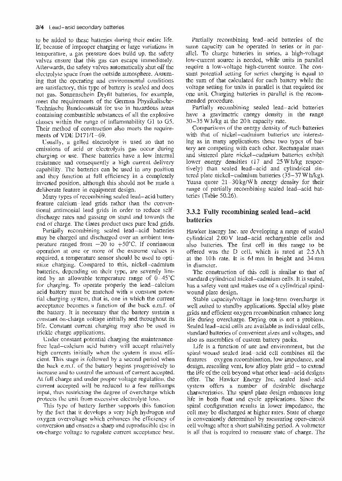
314 Lead-acid secondary batteries
to be added to these batteries during their entire life. If, because of improper charging or large variations in temperature, a gas pressure does build up, the safety valves ensure that this gas can escape immediately. Afterwards, the safety valves automatically shut off the electrolyte space from the outside atmosphere. Assum- ing that the operating and environmental conditions are satisfactory, this type of battery is sealed and does not gas. Sonnenschein Dryfit batteries, for example, meet the requirements of the German Physikalische- Technische Bundesanstalt for use in hazardous areas containing combustible substances of all the explosive classes within the range of inflammability G1 to G5. Their method of construction also meets the require- ments of VDE D171/1-69.
Usually, a gelled electrolyte is used so that no emissions of acid or electrolysis gas occur during charging or use. These batteries have a low internal resistance and consequently a high current delivery capability. The batteries can be used in any position and they function at full efficiency in a completely inverted position, although this should not be made a deliberate feature in equipment design.
Many types of recombining sealed lead-acid battery feature calcium-lead grids rather than the conven- tional antimonial lead grids in order to reduce self- discharge rates and gassing on stand and towards the end of charge. The Gates product uses pure lead grids.
Partially recombining sealed lead- acid batteries may be charged and discharged over an ambient tem- perature ranged from -20 to +50"C. If continuous operation at one or more of the extreme values is required, a temperature sensor should be used to opti- mize charging. Compared to this, nickel-cadmium batteries, depending on their type, are severely lim- ited by an allowable temperature range of 0-45°C for charging. To operate properly the lead-calcium acid battery must be matched with a constant poten- tial charging system, that is, one in which the current acceptance becomes a function of the back e.m.f. of the battery. It is necessary that the battery sustain a constant on-charge voltage initially and throughout its life. Constant current charging may also be used in trickle charge applications.
Under constant potential charging the maintenance- free lead-calcium acid battery will accept relatively high currents initially when the system is most effi- cient. This stage is followed by a second period when the back e.m.f. of the battery begins progressively to increase and to control the amount of current accepted. At full charge and under proper voltage regulation, the current accepted will be reduced to a few milliamps input, thus restricting the degree of overcharge which protects the unit from excessive electrolyte loss.
This type of battery further supports this function by the fact that it develops a very high hydrogen and oxygen overvoltage which enhances the efficiency of conversion and ensures a sharp and reproducible rise in on-charge voltage to regulate current acceptance best.
Partially recombining lead-acid batteries of the same capacity can be operated in series or in par- allel. To charge batteries in series, a high-voltage low-current source is needed, while units in parallel require a low-voltage high-current source. The con- stant potential setting for series charging is equal to the sum of that calculated for each battery while the voltage setting for units in parallel is that required for one unit. Charging batteries in parallel is the recom- mended procedure.
Partially recombining sealed lead-acid batteries have a gravimetric energy density in the range 30-35 W h/kg at the 20 h capacity rate.
Comparisons of the energy density of such batteries with that of nickel-cadmium batteries are interest- ing as in many applications these two types of bat- tery are competing with each other. Rectangular mass and sintered plate nickel-cadmium batteries exhibit lower energy densities (17 and 25 W h k g respec- tively) than sealed lead-acid and cylindrical sin- tered plate nickel-cadmium batteries (35-37 W hkg). Yuasa quote 21-30kgiWh energy density for their range of partially recombining sealed lead-acid bat- teries (Table 50.26).
3.3.2 Fully recombining sealed lead-acid batteries Hawker Energy Inc. are developing a range of sealed cylindrical 2.00 V lead-acid rechargeable cells and also batteries. The first cell in this range to be offered was the D cell, which is rated at 2.5Ah at the 10 h rate. It is 61 mm in height and 34mm in diameter.
The construction of this cell is similar to that of standard cylindrical nickel-cadmium cells. It is sealed, has a safety vent and makes use of a cylindrical spiral- wound plate design.
Stable capacity/voltage in long-term overcharge is well suited to standby applications. Special alloy plate grids and efficient oxygen recombination enhance long life during overcharge. Drying out is not a problem. Sealed lead-acid cells are available as individual cells, standard batteries of convenient sizes and voltages, and also as assemblies of custom battery packs.
Life is a function of use and environment, but the spiral-wound sealed lead-acid cell combines all the features - oxygen recombination, low impedance, seal design, resealing vent, low alloy plate grid - to extend the life of the cell beyond what other lead-acid designs offer. The Hawker Energy Inc, sealed lead-acid system offers a number of desirable discharge characteristics. The spiral plate design enhances long life in both float and cycle applications. Since the spiral configuration results in lower impedance, the cell may be discharged at higher rates. State of charge is conveniently determined by measuring open-circuit cell voltage after a short stabilizing period. A voltmeter is all that is required to measure state of charge. The

Recombining sealed lead-acid batteries 3/6
Hawker Energy Ltd Cyclon range of sound electrode combination batteries and the Hawker Energy Inc. range discussed above are equivalent and hence the Chloride product, available in the UK, will not be discussed in great detail here.
These batteries are contined in a polypropylene case with a metal outer canister and are available as single cells and in battery packs including a lantern battery. Batteries will be specially designed and produced to meet customers' requirements.
The standard types of cell now available are the D, X and BC cells (Table 3.1).
Temperature ranges are -65 to +65T (storage and discharge) and -40 to +65"C (charge). Storage lives from full charge are 18 years at o"C, 3 years at 25°C and 1 year at W C . The expected cycle life varies from 300 to 2000 cycles and the float life is 8-10 years. Charging is by most conventional methods including constant voltage, constant current, taper charging, pulse charging, etc., according to the application. Self-discharge is typically 6-8% per month at room temperature.
The manufacturers claig that the D cell will give instantaneous discharges of up to 100 A and sustained discharges of up to 30A. Double these figures can be obtained with the X cell, and up to 800A with the BC cell.
Table 3.1 Characteristics of standard cells
D X BC
Nominal voltage (v) 2.0 2.0 Capacity rating (Ah)
10 h rate 2.5 5.0
1 h rate 2.8 3.2 (250mA) (500mA)
(2.5A) (5A)
(at 135 A) (at 200A) Peak power rating (W) 135 200
( x 1 0 - 3 ~ ) 10 6 Diameter (mm) 34.2 44.4
Internal resistance
Height (mm) 67.6 80.6 Weight (kg) 0.181 0.369
2.0
25 (2.5 A) 20
600 (at 600A)
(25 AI
2.2 65.7 176.5 1.67
Batteries (6 and 12V) are available with capacities in the range 2.7-52A (20h rate), 2.5-50A (10h rate).
The characteristics (including discharge characteris- tics, battery life, safety, storage and battery testing) of sealed lead-acid batteries have been discussed further in a book published by Gates Energy Products (see Bibliography).


Nickel batteries


Nickel-cadmium secondary batteries 4/3
Discharge current inrensity in % 1,
10h 53 5 h 100
4.1 Nickel-cadmium secondary batteries The nickel-cadmium battery is mechanically rugged and long lived. In addition, it has excellent low- temperature characteristics and can be hermetically sealed. Cost, Ihowever, is higher than for either the lead-acid or tlhe nickel-zinc battery and, by compar- ison, its capacity on light drain in terms of watt hours per kilogram i s also poorer than for nickel-zinc.
Cells using the nickel-cadmium couple can be divided into two main groups: cells having thick plates in which the active material is compressed into finely perforated metal sheets in the form of tubes or pock- ets, and cells with thin sintered plates in which the active material: is deposited in porous metal supports. The latter type has a very low internal resistance and a high lo'ad capacity which result in improved power-to-volume and power-to-weight ratios. The bat- teries are manufactured as open or semi-open type cells in which the electrolysis gas escapes through a vent (which require periodic topping up with water to replace the electrolyte) and as fully sealed batteries which are designed in such a way that gas evolu- tion does not occur and consequently topping up of the electrolyte, with water is not required. In gen- eral: the open or semi-open types of battery are in the higher capacity range, used for applications such as traction and large emergency power installations. Sealed nickel-cadmium batteries that are usually in the lower capacity range (up to about 30 Ah) are the type that find extensive application in the electronics, small appliances, domestic products, defence equip- ment and space research markets.
4.1.1 Open :and semi-open, low-maintenance, unsealed nickel - cadmium batteries Various manufacturers supply small low-maintenance cells and batteries. Varta supply a non-sealed double cell (DTN) for portable lamps. This battery is avail- able in the capacity range 4.5-11 A h (Table 4.1); it is recommended for applications such as portable lamps where its light weight, even voltage level, good capa- city, long service iife, lack of maintenance and low
2.8 r 4 h 121 2.8 1 7 5
2.6
2.4 > 10 h
5 h - 2.2 lu
2.0 4 h 3 h
-0 I
7 5
2.6
2.4 > 10 h
5 h - 2.2 lu
2.0 4 h 3 h
-0 I
Table 4.1 Varta DTN range of low-maintenance nickel-cadmium batteries
1.8 1.6 I I I I I I I I I I I 0 10 20 30 40 50 60 70 80 90 100 110
% c,
Figure 4.1 Discharge curves showing dependence on capacity available at 20°C of a Varta double cell DTN battery (Courtesy of Varta)
self-discharge rate are of advantage. Discharge curves for a DTN battery are shown in Figure 4.1.
Chloride Alkad supply their Unibloc range of alkal- ine batteries, which are virtually maintenance free but are not sealed. These range from 7.5 to 27 A h capacity (Table 4.2). Unlike traditional alkaline batteries, which are built up from individual separately packaged cells, Unibloc starts off as a five 1.2 V cell battery in a lidded container (Figure 4.2). The Unibloc range is available in four basic capacities, each providing low-rate dis- charge performance:
7.5Ah Type 5LP7 12.5Ah Type 5LP12 15Ah Type 5LPl5 27Ah Type 5LP27
The five cells are incorporated into a resilient plastics case containing sufficient extra potassium hydroxide electrolyte to enable periodic topping up of the battery to be extended up to a maximum of 20 years on a con- stant 1.42Vfcell float charge without any boost char- ging, although 7- 10 years will probably be the average.
Unibloc batteries are recommended for applications such as switch tripping, emergency lighting and fire alarm operation.
For most applications, constant-voltage charging is recommended to minimize electrolyte loss which is
Charging Type Nominal Nominal Median Nominal Charging Filled Quantity of Battery No.333 capacity discharge discharge charging voltage weight electrolyte
tYPe in 5 h current voltage current (V) (kg) (dm3) (Ah) in 5 h (A) (V) in 7 h (A)
DTN4.5K 2452010 4.5 0.9 2.4 0.9 0.42 0.08 DTN6.5K :!652010 6.5 1.3 2.4 1.3 increasing 0.61 0.11
DTN12K 3122020 11.0 2.2 2.4 2.2 to 3.6 0.90 0.20 DTN7K 2702010 7.0 1.4 2.4 1.4 from 2.7 0.75 0.14

4/4 Nickel batteries
Table 4.2 Unibloc batteries: dependence of maintenance-free intervals on capacity and charging methods
Type Capacity at Maintenance intewal (years) 10 h rate (Ah)
Fully automatic operation without boost (float voltage 1.47 Vkell)
Close voltage application with 6-monthly boost of 1.65- 1.70 V/cell (float voltage 1.42 V/cell)
5LP7 7.5 8 14 5LP7 12.5 5 9 5LP12 15.0 4 7.5 5LP27 27.0 2.5 5
Simple snap-on or bolt-on terminals
1 2 3 4 5 1015 30451 2 3 4 5 101520 Time (min) (h)
Figure 4.3 Discharge curves at 25°C: Chloride Alkad Unibloc nickel-cadmium battery (Courtesy of Chloride Batteries)
Easy-to-clean surfaces provide maximum protection against corrosion and dirt
Extra-generous electrolyte reserve means negligible maintenance
Figure 4.2 Chloride Alkad Unibloc nickel-cadmium battery con- struction (Courtesy of Chloride Batteries)
dependent on the float charge voltage, the capacity of the battery and the frequency of boost-charging. Table 4.2 shows how the maintenance interval across the Unibloc range of batteries is related to battery capacity and charging method.
The discharge performance of Unibloc batteries is shown in Figure 4.3.
4.1.2 Sealed nickel-cadmium batteries Characteristics of sealed n i c k e k a d m i u m batteries
Sealed nickel-cadmium batteries were first developed in the 1950s from vented nickel-cadmium batteries
and therefore originally used the same active mater- ial and similar intercell components that had proved their reliability in production and service. Because the active material in the vented batteries was a pow- dered mass, it was logical for the earlier ranges of sealed batteries to use the same material. Since then materials and production techniques have improved, enabling sealed battery performance to be improved by optimizing the active material. These changes in active material, while not significantly improving the performance at low discharge rates (10 or 5 h rate), have changed the voltage characteristics at the higher rates of discharge. An example of this improvement for a Varta 0.225 A h cell (10 h rated, 22 mA discharge current at 10 h rate) is shown in Figure 4.4 by compar- ison of the characteristics in (a) original plate materials and (b) improved plate materials. This improvement in discharge performance has been achieved without adversely affecting the cell’s good charge retention or external dimensions.
Sealed nickel-cadmium cells are normally rated at either the 5 or 10h rate, that is, the discharge current that can be taken from a cell to discharge it fully in 5 or 1Oh. Sintered cells are rated at the 5 h rate ( I 5 ) and, occasionally, particularly with US manufacturers, at the 1 h rate ( I I ) , and mass plate cells at the 10 h rate (Ilo). The nominal on-load voltage of a nickel-cadmium cell is 1.2V and this voltage is said to be the average value for the total discharge period. The cell’s fully charged open-circuit voltage, if taken within 24 h of terminating a charge, can vary between 1.35 and 1.4V. The voltage characteristic is flat for most of the discharge curve, even at comparatively

Nickel-cadmium secondary batteries 4/5
recharged many times. They are small convenient packages of high energy output, hermetically sealed in leak-resistant steel cases, and will operate in any position. The cells have very low internal resistance and impedance, and are rugged and highly resistance to shock and vibration. Some general comments on sealed nickel-cadmium batteries are made below.
._ g 2 0 1 I I l l I l l l I
$ 0 2 4 6 8 10 Discharge current ( X I , o )
(a) - - 0 c 100 - 8 60 i e 80
Figure 4.4 Effects of improvement in plate active materials since the 1950s on the performance of the Varta 0.225Ah nickel-cadmium sealed battery: available capacity at 20°C (a) before and (b) after improved materials were incorporated (Courtesy of Varta)
high discharge rates, therefore the discharge voltage is not indicative of the cell's state of charge. At rates of discharge up to ten times the 110 rate, a cell is said to be fully discharged at 0.9V. The voltage of a cell when discharged below 0.9 V falls rapidly to zero and it is therefore possible for some cells in a battery to reverse their polarity. Provided the discharge rate is at the I I 0 rate or less, this reversal will not harm the nickel-cadmium cell, but with maximum life in view it should be avoided.
Sealed nickel-cadmium cells and batteries exhibit relatively constant discharge voltages. They can be
Temperature of operation
Cells and batteries may be charged, discharged and stored over a very wide temperature range. The stated maximum permissible temperature ranges for these batteries are as follows:
Charge 0 to +45"C Discharge -20 to +45"C Storage -40 to +50"C
Discharge and storage at + 6 0 T are permissible for a maximum of 24 h (see also Table 4.3).
Use at high temperatures, however, or charging at higher than recommended rates, or repeated dis- charge beyond the normal cut-offs, may be harmful. In the case of button cells which do not contain a safety vent, charging at temperatures lower than those recommended may cause swelling or cell rupture.
For low-temperature operation (0°C or below), sin- tered cells are recommended. At these temperatures, the cell's internal resistance increases and this can greatly affect the voltage characteristic at high dis- charge rates. The low temperature charge problems of sealed nickel-cadmium cells are caused partly by the poor charge efficiency of the negative electrode at these temperatures. Also, at low temperatures, the cell's ability to recombine oxygen during overcharge
Table 4.3 Effect of high and low temperatures on storage, discharging and charging of Eveready nickel-cadmium cells and b- dieries
Low temperature High temperature
Storage (all types) At -40°C At 60°C No detrimental effect. However, cells or batteries should be allowed to return to room temperature prior to charging
No detrimental effect. However, self-discharge is more rapid starting at 32°C and increases as temperature is further elevated
Discharge (all types) At -20°C At 45°C No detrimental effect, but capacity will be reduced as shown by curves
No detrimental effect
Charge CF and CH At 0°C At 45°C types (10 h rate)
CF types (1-3 h rate) At 15.6"C At 45°C
Cells or batteries should not be charged below 0°C at the 10h rate
Cells or batteries should not be charged below 15.6"C at the 1 h rate or below 10°C at the 3 h rate
Cells or batteries show charge acceptance of approximately 50%
Cells or batteries show charge acceptance of approximately 90%
Button cells At 0°C At 45°C Cells or batteries should not be charged below 0°C at the 10h rate
Cells or batteries show charge acceptance of approximately 60%. Also possible detrimental effect on cycle life

4/6 Nickel batteries
is inhibited and therefore, under normal circumstances, charging at low temperatures is not recommended. In addition, at sub-zero temperatures hydrogen evolution may be promoted (cathode overcharge), causing vent- ing of gas and consequent electrolyte loss. The cells have a negative temperature coefficient of approxi- mately 4mVkell per 0°C. When selecting cells for low-temperature operation, both their reduced capacity and changed cell voltage should be taken into consid- eration.
Eficiency
Sealed nickel-cadmium cells with mass plate elec- trodes have an ampere hour efficiency of approxi- mately 72%, while those with sintered electrodes have approximately 84% efficiency at about 20°C. (The effect of temperature will be discussed later.) For this reason the charging factor for mass plate cells is 1.4 and for sintered plates 1.2; therefore to fully charge a fully discharged cell, either 40% (1.4) or 20% (1.2) more capacity than has been withdrawn must be put back into the cell.
The watt hour efficiency is the quotient of the discharged energy and the necessary energy to fully charge a cell. Comparing the mean discharge voltage with the mean charge voltage confirms a figure of approximately 61% for a cell with mass electrodes and 73% for a cell with sintered electrodes when discharged at the Zlo rate (both at approximately 20°C).
Storage
Sealed nickel-cadmium batteries can be stored indefinitely, ideally in a clean, dry atmosphere, in a discharged state, unlike lead-acid batteries which will sulphate if stored in a discharged state. Nickel-cadmium batteries can be stored in any state of charge, without a significant loss of life.
Maintenance charging is not required. However, after prolonged storage, up to three cycles of charge and discharge may be required to achieve the battery’s rated capacity. It is recommended that the first charge following storage should be for 24 h at the Zl0 rate.
During operation and storage, it is possible that crystals may form in the area of the sealing between the positive and the negative poles. This is due to minute pores in the sealing ring allowing electrolyte to combine with carbon dioxide in the air to form potassium carbonate crystals. This crystallization has no detrimental effect on the electrical properties or life expectancy of the battery but, if it is thought to be aesthetically unacceptable, removal of the crystals with a dry cloth and then a smear of silicone grease will inhibit further growth.
Internal resistance
Unlike open-cell batteries, where the internal resist- ance decreases linearly with an increase of capacity,
the internal resistance of a sealed nickel-cadmium bat- tery is dependent mainly on plate surface area, distance between the plates, separator resistance, amount and density of electrolyte, and temperature. The internal resistance will also change with the state of charge. As an example, the d.c. internal resistance of typically fully charged 1 A h sealed cells is as follows:
Standard button cell 110 mQ/cell Heavy-duty button cell 50 mWcell Rolled sintered cell 19 mWcell
In some applications it is an advantage to know the a.c. internal resistance. As a comparison, the a.c. resistance at 1OOOHz is:
Standard button cell 42 mWcel1 Heavy-duty button cell 14 mQ/cell Rolled sintered cell 17 mWcell
Cyclic life
The life of a sealed battery depends on the operat- ing conditions. It is principally affected by the depth of discharge (capacity dischargedrated capacity) in a charge/discharge application, or in ampere hours over- charged in a permanent charge application. Life is also affected by temperature, though less so at high temper- atures, and by end-point requirements regarding rate and capacity (increased cycle life will ordinarily be the result of a shallow discharge regimen).
Any treatment that causes a cell to vent itself is harmful. Frequent or extended venting of even prop- erly valved cells eventually destroys them. In rating cycle life, the end of life for a sealed nickel-cadmium cell is considered to be when it no longer provides 80% of its rated capacity. The discharge currents used in determining the cycle lives listed below are the 10 h rate for button cells and the 1 h rate for cylindrical types. The charge current is terminated after return of approximately 140% of the capacity previously removed. If a cell can be considered to be satisfac- tory while delivering less than the arbitrary 80% end- point figure, the reliability characteristic of the sealed nickel-cadmium battery corresponds to the ‘bathtub’ curve of electronics components. In cycling applica- tions, as in the supply to a portable transceiver, the service life of a battery is most conveniently expressed as the number of cycles of charge and discharge, and the failure rate in failures per cycle.
In applications with permanent maintenance charge, the life of a battery is expressed as the multiple of Cs A h of overcharge or as hours of operation, and the failure rate as failures per operating hour. As an example, Figure 4.5 shows the estimated cycling life at 20°C as a function of discharge for SAFT sealed nickel-cadmium batteries.
The following results have been obtained at 20°C: bum-in period lasts a few cycles or a few tens of C5 A h of overcharge; failure rate of the order of per cycle with rapid charge at 2C5A and discharge

Nickel-cadmium secondary batteries 4/7
nominal capacity. Partial discharging will significantly increase the number of cycles achieved. Similarly, discharging at high rates will reduce the expected life of the battery.
Sintered electrode batteries supplied by Varua. when continuously trickle charged at rates between one- fifth and one-half of the 10h rate, will give, typi- cally, a life of approximately 5 years to 60-70% of nominal capacity.
When a fast charge is applied to a sintered cell battery at a maximum of 20 x 110, provided the charge is terminated at 80% capacity. a life can be achieved similar to that of a sintered cell battery at normal rates of charge.
Number of cycles ( X I O 3 )
Figure 4.5 Estimated life cycle at 20°C as a function of discharge (SAFT sealed nickel-cadmium batteries) (Courtesy of SAW
over several hours; failure rate also of the order of 10-' per cycle with permanent maintenance charge at rates below 0.05C5 A.
During the service life of sealed nickel-cadmium batteries obtained from a reputable manufacturer, there are practically no failures through loss of performance, and the mortality law is very pirobably of an expo- nential nature, under the following types of service condition:
1. 500 cycles with charge for 14h at O.1CsA and complete discharge over several hours.
2. 1000 cycles with the same type of charge but discharge 50% of capacity over several hours.
3. At least 1500 cycles with rapid charge at 2CsA and discharge over several hours; the failure rate in this case is tgpically of the order of failures per cycle.
4. At 2000CsAh with overcharge at a rate below 0.05C5 A, the maximum service life is 8 years (at a rate of 0.02Cs A): 200OCs A h corresponds to 100 000 h or a theoretical service life of 11 years.
As a further example of the life expectancy of sealed nickel-cadmium batteries Varta claim that their products are not affected by prolonged storage provided the recommended storage temperatures (-40 to +50"C) are not exceeded. Thus less than 20% capacity loss occurs in 2 years storage at -2O"C, approximately 40% in 10 or 12 months at 20"C, and proportionally higher rated capacity loss at higher temperatures. In applications of these cells where they are operated in a purely cyclic mode (that is, chargeldischarge cycles), mass plate batteries will give 300 cycles at the 10h rate to approximately 80% of
Energy density
The energy contents of the various types of sealed nickel-cadmium battery supplied by one particular manufacturer are as shown in Table 4.4.
Table 4.4 Energy contents of various sealed nickel-cadmium batteries
Volumetric Gravimetric energy energy densig density
(WWdm3) (Wh/kg)
Button cell (mass plate) 61-62 21-22 Round cell (mass plate) 69 22 Round cell (sintered plate) 78 21
Rectangular (sintered plate) 52 21 Rectangular (mass plate) 37 18
Cylindrical, rectangular and button designs of sealed nickel-cadmium battery are available from most sup- pliers. These three types are available with compressed and with sintered electrodes. Batteries with sintered electrodes have a very low internal resistance and a high load capacity which results in an improved power to size and weight ratio. These three types of nickel-cadmium cell are discussed in detail in Part 2.
Generally speaking, nickel-cadmium button cells are available in a lower capacity range than cylindrical cells. Thus one manufacturer supplies button cells in the 20-l000mAh range and cylindrical cells in the 150-4000mAh range, Voltages of between 1.2V and 14.4V (12 cell) are available.
The characteristics (including discharge characteris- tics, storage, battery life, safety and battery testing) of sealed nickel-cadmium batteries have been discussed further in a book published by Gates Energy Products (see Bibliography).
4.1.3 Nickel-cadmium button cells
Nickel-cadmium button cells have a nominal discharge voltage of 1.2 V per cell. The rated capacity
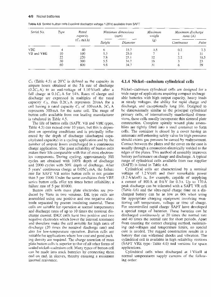
4/8 Nickel batteries
Table 4.5 Sealed button cells (nominal discharge voltage 1.20V) available from SAFT
Serial No. Type Rated Maximum dimensions Maximum Maximum discharge capacity (mm) weight rates (A)
(" mA h, Height Diameter Continuous Pulse (g) ~ ~ ~ ~ ~~~
VBE 4 40 6 15.7 3.5 0.2 2.3 VB and VBE IO 100 5.3 23.0 7 I I I
22 220 7.8 25.1 12 2.2 18.5 30 300 5.5 34.7 18 3 23 60 600 9.8 34.7 31 6 29
C j (Table 4.5) at 20°C is defined as the capacity in ampere hours obtained at the 5 h rate of discharge (0.2C5 A) to an end-voltage of l.lOV/cell after a full charge at 0.1CsA for 14h. Rates of charge and discharge are expressed in multiples of the rated capacity C5, thus 0.2CjA represents 20mA for a cell having a rated capacity C5 of 100 mA h. 5C5 A represents 500mA for the same cell. The range of button cells available from one leading manufacturer is tabulated in Table 4.5.
The life of button cells (SAFT, VB and VBE types, Table 4.5) can extend over 10 years, but this is depen- dent on operating conditions and is pricipally influ- enced by the depth of discharge (discharged capa- cityhated capacity) in a cycling application and by the number of ampere hours overcharged in a continuous charge application. The great reliability of button cells makes their life comparable with that of most electron- ics components. During cycling, approximately 500 cycles are obtained with 100% depth of discharge and 2000 cycles with 50% depth of discharge. After 5 years' continuous charge at 0.05c5 mA, the failure rate for SAFT VB series button cells is not greater than 5 per 1000. Under the same conditions their VBE series button cells offer ten times better reliability; a failure rate of 5 per 10000.
Button cells with mass plate electrodes are pro- duced by Varta in two versions. DK type cells are assembled using one positive and one negative elec- trode separated by porous insulating material. These cells are suitable for operation at normal temperatures and discharge rates of up to 10 times the nominal dis- charge current. DKZ cells have two positive and two negative electrodes which lower the internal resistance and therefore make the cell suitable for high rates of discharge (20 times the nominal discharge rate) and also for low-temperature operation. Button cells are suitable for applications where low cost and good pack- ing density are required. The charge retention of mass plate button cells is superior to that of a11 other forms of sealed nickel-cadmium cell. Many types of button cell can be made into stack batteries by connecting them end on end, in sleeves, thereby ensuring a minimum internal resistance.
4.1.4 Nickel-cadmium cylindrical cells
Nickel-cadmium cylindrical cells are designed for a wide range of applications requiring compact recharge- able batteries with high output capacity, heavy loads at steady voltages, the ability for rapid charge and discharge, and exceptionally long life. Designed to be dimensionally similar to the principal cylindrical primary cells, of internationally standardized dimen- sions, these cells usually incorporate thin sintered plate construction. Complete spirally wound plate assem- blies are tightly fitted into a steel container to form cells. The container is closed by a cover having an automatic self-releasing safety valve for high pressures should excess gas pressure be caused by maltreatment. Contact between the plates and the cover on the case is usually through a connection electrically welded to the edges of the plates. This method of assembly improves battery performance on charge and discharge. A typical range of cylindrical cells available from one supplier (SAFT) is listed in Table 4.6.
Cylindrical cells are characterized by a nominal voltage of 1.2 V/cell and their remarkable power (1.2 A Wcell) is, for example, capable of supplying a current of 100A at 0.6V for 0.3 s. Up to 170A peak discharge can be tolerated with a SAFT VR cell (Table 4.6) and the ultra-rapid charge time on a dis- charged battery can be as low as 60s when using the appropriate charging equipment involving mon- itoring cell temperature, voltage or time of charge. For uncontrolled rapid charge SAFT have developed a special range of batteries. These batteries can be discharged continuously at 20 times the normal rate and 40 times the normal rate for short periods. Apart from ensuring the correct charging method, maintain- ing end-voltages and temperature limits, no special care is needed. The rugged construction results in a battery that can withstand shocks and vibration. The cylindrical cell is available in high reliability versions (SAFT VRE type-Table 4.6) and versions for space applications.
Cylindrical cells when discharged at 1 V/cell at normal temperatures supply currents of the follow- ing order:

Nickel-cadmium secondary batteries 4/9
1.2Ah cell 12A 2 A b cell 14A 4Ah cell 28 A 7 A h cell 35 A
l0Ah cell 80A
Short-duration peaks (maximum power) can obtained (300 ms at 0.65 V/cell), typically:
1.2Ah cell 93A 2Ah cell 93A 4Ah cell 145A 7Ah cell 170A
1OAh cell 250A
Cylindrical cells with mass electrodes (Varta D series)
These cells are available from Varta. They are phys- ically equivalent to primary cells and are suitable for either one- or two-cell operations. These cells are suit- able for comparatively low rates of discharge where good charge retention is important. They are suitable for a continuous discharge up to 10 times nominal discharge rate.
be
Cylindrical cells and batteries are designed for use in applications that require good high rates of discharge performance (continuous and peak). Due to their low internal resistance. higher discharge currents can be drawn and also substantially better voltages than apply in the case of cells available a few years ago.
SAFT also produce the VX series of cylindrical cells (Table 4.6). These have the same characteristics as those of the standard VR range. The VX cells have the novel conception of a plate which improves the recombinatioin of oxygen produced on overcharge. They may thus be charged or overcharged at higher rates than those for standard VR cells. VX cells have a smaller capacity than the corresponding standard cells (about 50%:) but the power characteristics are the same.
4.1.5 Nickel-cadmium rectangular cells
Rectangular or prismatic cells offer the highest capac- ities within the sealed nickel-cadmium range, and in
Table 4.6 Sealed cells supplied by SAFT
Cylindrical cells with sintered electrodes (Vararta RS series)
These cells are suitable for applications where a high rate of discharge, or operation at extremes of temper- ature, or permanent trickle charge or fast charging is required. The cells are constructed from rolled sintered positive and negative plates, separated by a highly porous separator which absorbs all the free electrolyte within the cell. A safety vent is incorporated within each cell to enable gas, which may build up under fault conditions, to be released. Batteries containing RS cells are available either in standard formats or designed for specific applications.
Serial No. TyDe Equivalent Rated Maximum Maximum Maximum discharge Maximum primary capacity dimensions (mm) weight rafes (A) power
C5 (Ah) Heipht Diameter (g) Continuous Pulse battery
VR 0.1 L'3AA R6 0.100 17.4 14.5 i l 1.5 15 I0 1.2 Vlcell 0.45 Il2A 0.450 28.1 17.3 21 4.5 31 20
0.5 AA R6 0.500 50.2 14.5 24 5.0 24 16 0.7 L'2C 0.700 26.2 26.4 39 7.0 46 7 1.2 RR 1.2 42.1 22.7 51 12 93 1.2 1.8 c: R14 1.8 49.7 25.9 77 14 93 - 2.5 2/3D 2.5 43.5 32.9 105 20 120 78 4D R20 4 60.5 32.9 150 28 145 95 7F 7 91.3 32.9 240 35 170 110 10 SIF 10 89.2 41.7 400 75 280 170
vx AA R6 0.200 50.2 14.5 21 5 24 RR 0.500 42.1 22.7 45 12 93 c R14 0.700 49.7 25.9 70 14 93 D R20 1.6 60.5 32.9 135 28 145
VRE 1 RR 1 .o 43.2 23.2 49 9 70 1.6C 1.6 48.8 26.4 74 11 70 3.5 r) 3.5 59.2 33.4 150 18 92 6 F 6.0 90.0 33.4 240 24 123
VRS D 3.5 64.8 33.1 174 11 - F 6.0 93.8 33.1 270 18 -

4/10 Nickel batteries
fact differ very little in construction from the heavy- duty nickel-cadmium type. Capacities are up to 23 A h at 1.22V. This battery weights 1.390kg, its dimen- sions being 51 x 91 x 125 mm. Permissible operating temperatures are the same as for the button type. These cells comprise an assembly of two groups of rectangular thin sintered plates and the separator in rectangular nickel-plated steel cases. Current take-off is through terminal studs. They have medium-pressure (4 x lo5 N/m2) self-reclosing safety valves. SAFT, for example, supply three sizes of rectangular cell (VD series). There are three sizes of cell with capaci- ties below 10 Ah: V04G (3.8 Ah), VO4US (4.4A h) and VO9 (9.9Ah) (Table 4.7). There are also high- reliability sealed VO cells for space applications (VOS cells). VO cells and batteries may be continuously discharged at currents up to 5C5A. They can supply short-duration peaks of up to 10C5 A.
Sealed rectangular cells with mass electrodes (Varta D23 type) are suitable for continuous discharge up to 10 times the nominal discharge current. They are fitted with a safety vent which prevents exces- sive internal pressure damaging the cell case in fault conditions.
Rectangular cells with sintered electrodes, SD series (Varta CD type), are suitable for applications in which a high rate of discharge, or operations at extremes of temperature, or permanent trickle is required. The cells are constructed from cut sintered positive and negative plates, separated by a highly porous separ- ator which absorbs all the free electrolyte within the cell. A safety vent is incorporated within each cell to enable gas which may build up under fault conditions to be released. All cells in this range have the cases connected to the positive electrode. All cases are not insulated but intercell separators and nickel-plated con- nective links are available. The CD series is available made up in metal boxes.
A range of rectangular cells available from SAFT is listed in Table 4.7.
Table 4.7 Sealed rectangular cells available from S A f 7
4.1.6 Comparison of characteristics of lead-acid and nickel-cadmium sealed batteries For many everyday battery applications, the choice is still between the lead-acid and the nickel-cadmium systems, rather than the more recently developed sys- tems. Each of these two main types of sealed bat- tery has its own advantages and the choice between nickel-cadmium and lead-acid batteries depends very much on the particular application and on the perfor- mance characteristics required.
The characteristics of the two types of battery are compared in Table 4.8. Although this information will be of assistance to the designer in helping to select whether a lead-acid or a nickel-cadmium battery is most appropriate to the application in mind, it is strongly recommended that a final decision should not be made until the problem has been discussed with the suppliers of both types of battery. The lead-acid bat- teries referred to in Table 4.8 are the Dryfit type sup- plied by Accummulator-enfabrik Sonnenschein (West Germany), although no doubt in many respects the comparisons will hold good for sealed lead-acid bat- teries produced by other suppliers.
Figure 4.6 plots the energy density (Whkg) as a function of the 20h capacity for Dryfit batter- ies and nickel-cadmium batteries supplied by Varta and SAFT. It can be seen that the rectangular mass and sintered plate nickel-cadmium batteries exhibit lower energy densities than Dryfit batteries and cylin- drical sintered plate nickel-cadmium batteries. The increase in capacity which occurs in Dryfit batteries after several charging cycles together with the as- sociated increase in energy density has not been taken into consideration in the data presented in Figure 4.6. Also not considered is the increase in weight when five nickel-cadmium cells are connected in a supplemen- tary housing to form a 6 V battery. The usual cylin- drical sinter cell batteries, the large button cells and
Serial No. Rated Maximum dimensions Maximum Maximum discharge capacity (mm) weight rates (A)
mA h, Height Width Depth Continuous Pulse (g)
~ ~~
vo 4 c 4 u s 9
vos 4 7 10 23 26
~~ ~
3.8 14 4.4 14 9.9 107 4 78.5 7 112.5
10 91 23 165 26 186
~
64 64 98 53 53 76.2 76.2 76.2
19 19 19 20.5 20.5 28.9 28.9 28.9
~~
180 220 400 230 360 500
1060 1200
20 38 22 44 50 100 20 - 35 - 40 - 60 -
80 -

Nickel-cadmium secondary batteries 4/11
Table 4.8 Comparison of sealed lead-a,cid and nickel-cadmium batteries
Property Lead-acid (DlrJit) Nickel-cadmium
Capacity range
Cell voltage
Number of cells/l2 V battery
Case material
Stability of case dimensions during charging
Stabilization of electrolyte
Gassing
Cell closure
Energy density
Current-dependent capacities
Allowable continuous current- carrying capacity
Self-discharge
Series connections
Parallel connections
Storage life when discharged
Charging temperature range
Discharge temperature range
Rapid charging temperature range
Charging methods
Charging time
Shortest charging time
Chargers
Quick charge units-trickle charge
Cyclic service life
Service life under trickle charge
A300 series, standby operation 1-9.5 Ah; A200 series, high cyclic applications 1-36 A h
2.1 v 1.25V
6 10
Plastics Nickel-plated steel
Do not change
Mass cells, lOmAh to 23 Ah: sinter cells 100 mA h to 15 A h
Button cells increase by up to 3%
With gelled acid -
Practically no escape of gas Practically no escape of gas
Self-closing safety valve Plastics seal or self-closing or non-resealing safety vent
The same order of magnitude for Dryfit, nickel-cadmium button cells, sintered cylindrical cells and sinter cells in plastics cases. Rectangular nickel-cadmium mass and sinter cells in steel cases exhibit lower energy densities
Average
Very good
Very low
Permitted
Permitted
Weeks to over 1 year depending on temperature
-30 to t50"C
-45 to f50"C
-30 to +50°C
Voltage limited
No time limit
1 h approx.
Require voltage stabilization
Normal, but with higher performance. Constant
Up to 500 deep discharge cycles and 1000 shallow discharge cycles
5 years approx.
Button cells, average; sintered cylindrical cells, above average; rectangular sinter cells, below average
Sinter cells, goodhery good; mass cells, poor
Mass cells, slightly higher than Dryfit; sinter cells, exceptionally high
Not allowed for small capacities, not recommended for high capacities
Permitted
Weeks to over 1 year depending on temperature
Mass cells, 0 to 45°C; sinter cells, -30 to f50"C
Mass cells, -20 to f45"C; sinter cells, -40 to +50"C
Not recommended for mass cells; sinter cells,
Current limited
Above 1x0 dependent on current
Mass cells, 3 h with supplement voltage control; sinter cells, 15 min for part charge with voltage and temperature control
Mass and sinter cells, no stabilization required for cyclic operation
Mass cells, permitted only up to 0.1 120; sinter cells constant but adequate current limit
Mass cells, approx. 300 shallow discharge cycles; sinter cells, 500- 1000 deep discharge cycles or up to 15 000 shallow discharge cycles
Mass cells, 4-5 years at small current up to 0.1 I lo ; sinter cells, approximately 10 years
-30 to +50"C

4/12 Nickel batteries
Dryfit batteries are thus seen to occupy approximately the same W h k g range with the bandwidth of the range being in general defined by the individual type variants.
The relationship between multiples of the 20 h nom- inal discharge current and the available percentage of the nominal capacity for Dryfit and nickel-cadmium batteries is shown in Figure 4.7. The shaded area rep- resents the variation of capacity of Dryfit batteries from low discharge currents to very high currents. The lower edge of the band is for a new battery after recharging while the upper edge represents the characteristic after 30-50 charging cycles or several months of trickle
40
2 35
> 30
25
P 20
5 15
I
m Y
z r
U >
1 5 10 15 20 26 20 h capacity, I,
Figure 4.6 Energy density comparisons: Dryfit and different types of sealed nickel-cadmium battery (6V). M + ML, prismatic sintered cells in plastic cases; RS, sintered round cells (varta); VR, sintered round cells (SAFT); SD, prismatic sintered cells (varta); D, prismatic mass cells (varta); DK (Courtesy of Dryfit, SAFT and Varta)
l o I 01 I I I I 1 I 1 I
1 2 4 6 10 20 40 70 140 Multiple of the 20 h discharge nominal current, I,,
Figure 4.7 Removable capacity dependence on charge current: Dryfit and nickel-cadmium batteries. Sinter round cells: RS 1-7, 1 -7Ah (varta); VR (SAFT). Prismatic sinter round cells: SD 1-15, 1-15Ah (Varta). Prismatic mass cells: D (varta). Button cells with mass electrodes: DK 1000-3000 (varta). Prismatic sinter cell batteries: ML, M (varta) (Courtesy of Dryfit)
charging. From 1 to 40 x Zzo, the various types of sin- tered nickel-cadmium cell perform better than the Dryfit batteries, and similar or worse performance is obtained up to 20 x 120 for the various button cells with mass electrodes.
Looking at the high current end of the curves in Figure 4.7, it is clear that definite limits are placed on nickel-cadmium batteries. These limits are imposed by the maximum allowable discharge current as shown in Figure 4.8. The upper curve emphasizes the excep- tionally high maximum load capacity of Dryfit batter- ies, especially at the lower end of the capacity range where it is a number of times greater than that of nickel - cadmium batteries.
The self-discharge properties of sealed nickel-cad- mium batteries differ greatly for mass plate and sinter plate cells, but compared to the Dryfit battery they are substantially inferior. As Figure 4.9 indicates, mass plate nickel-cadmium cells discharge at 20°C to half their original value after 13 months. The decrease in the first months is exceptionally steep and not as flat as that for the sealed lead-acid battery (16 months to lose half original capacity) - see Figure 4.10. The construction of the mass plate cell, whether button cells with single or double electrodes, or rectangular cells, makes practically no difference. The self-discharge of sinter cells, as shown in Figure 4.11, is many times greater. After 6 weeks at 20"C, half the capacity has already been lost. Compared to lead-acid batteries, longer storage of a deeply discharged (due to self- discharge) nickel-cadmium battery does not damage it, whereas such treatment of discharged lead-acid batteries results in an irreversible loss in capacity. However, the nickel-cadmium battery cannot be used for applications demanding immediate availability without continuous recharging and therefore increased maintenance costs.
Dryfit batteries may be charged and discharged over an ambient temperature range of -20 to +50"C. If continuous operation at one or more of the extreme values is required, a temperature sensor should be used to optimize charging. This can, however, be omitted if the battery is operated infrequently at extremes of temperature during the course of its life. The over- charging at high temperatures and the charging, which cannot be completed in its usual time at low tempera- tures because of the lack of temperature compensation, affect the quality of the battery to only a minor degree. Short-term temperatures up to 75°C can be tolerated. No precautions need be taken against the lower temper- ature of about -50"C, since the gelled electrolyte in the charged state cannot freeze solid. The nickel-cadmium battery also works at its best only if charging takes place at 20°C. Many types are severely limited by an allowable temperature range of 0 to 45°C for charging. Charging to a certain achievable percentage of full charge occurs in the freezing range and charging above

Nickel-iron secondary batteries 4/13
0 2 4 6 8 1 0 1 2 Capacity ( A h )
Figure 4.8 Maximum allowable permanent discharge currents: Dryfit and nickel-c.admium batteries with mass electrodes and sintered electrodes: 1, Dryfit; 2, nickel-cadmium with sintered electrodes; 3, niclqei-cadmium with mass electrodes (varta) (Courtesy of Dryfit)
100 -20 "C > 0
m
c .- g 75 -
0°C ------m +20 OC
W 2 5 1
a I l l l l l l l l l ~ l l 0 2 4 6 8 10 12 14 16 18 20 22 24
Standing time (months)
Figure 4.9 Self-discharge of sealed nickel-cadmium cells at different temperatures (Courtesy of Dryfit)
45°C is possible only for special types using sintered plate constructions. Compared to lead-acid batteries, charging at temperatures between 40 and 50°C is pos- sible only at the expense of considerable loss of capa- city. Mass elect]-ode cells exhibit even more changes in voltage at extreme temperatures, especially low tem- peratures. Sinter electrode cells, despite their increased self-discharge, are preferable at extreme temperatures. Charging of sinier cells at low temperatures requires a reduction in the usual charging current, which in turn leads to increased charging times.
ickel-iron secondary batteries Nickel-iron batteries commercially available today are virtually the same as those developed by Thomas Edi- son approximately 70 years ago. The system offers very long cyclie life but, primarily as the result of the iron electrode, a low energy density at high dis- charge rates has made this system unattractive for electric vehicles. Other problems associated with the iron electrode are related to a low hydrogen over- voltage potential resulting in poor charge efficiency, substantial self-discharge and poor utilization of the
0 3 6 9 12 15 18 21 24 Standing time (months)
Figure 4.10 Self-discharge of Dryfit batteries at different temper- atures compared with standard battery in lead-antimony alloy. 1, Dryfit battery (calcium-lead alloy); 2, conventional antimonial lead-acid battery (Courtesy of Dryfit)
25 W a
I I I I I I ' l l l l l 0 2 4 6 8 10 12 14 16 18 20 22 24
Standing time (months)
Figure 4.1 1 Self-discharge of sealed sintered electrode nickel- cadmium cells at different temperatures (Courtesy of Dryfit)
active material (approximately 25% of the theoret- ical capacity is achieved). However, as a result of abundant material, inexpensive design and potential high capacity, the iron electrode is experiencing a renaissance.
Recent reports have been very encouraging. A pilot production facility is reported which is producing nickel-iron batteries with energy densities greater than 44Whkg. The iron electrode is receiving par- ticular interest in Europe and significant improve- ments in the performance of nickel-iron batteries have been reported. One group reports electrodes that yield capacities two to three times greater than that of commercially available iron electrodes, provide higher numbers of cycles and require an overcharge of only 15%.
Eagle Picher's experience with the nickel-iron sys- tem has been equally encouraging. They have 40 A h nickel-iron cells on cycle test with energy densities between 40 and 50 Whikg.
The mean discharge voltage of these cells is 1.2V. The theoretical energy density is 268 W h/kg-'.
Eagle Picher are active in the development of the nickel-iron battery system. Their development pro- gramme is primarily targeted for developing the sys- tem for use in electric vehicle propulsion. However, other applications are lift trucks, deep mining vehicles, off-peak utility storage, standby storage and solar. Eagle Picher, through a cooperative agreement with the Swedish National Development Company, has brought into the programme advanced iron electrode techno- logy previously not available in the United States. The

4/14 Nickel batteries
2 6 0.5 - -
presently developed technology offers to the user a bat- tery with high specific energy, low maintenance, deep discharge capability and long cycle life. Full-scale electrodes have exceeded 1300 deep discharge cycles. Full-scale cells as well as 6 V modules have been fab- ricated and show no capacity fade under 100% depth- of-discharge cycling. Energy efficiencies are typically 70% or greater (see Table 4.9).
Charge Discharge Cl5 rate C13 rate
Table 4.9 Nickel-iron battery performance
2 0.75
1980 to present Goals state of the art
Specific energy at battery level (W hkg) 50 60 Energy density at battery
Specific peak power at battery level (Wkg) I10 125 Deep discharge (100%)
level (W M) 102 120
cycle life 1000 2000
--- (73.5 discharge - --.- C11.5 discharge - U0.75 discharge Figure 4.12 shows the voltage profile for a single
nickel-iron cell tested to the constant current modes as indicated.
The set of discharge curves shown in Figure 4.13 was taken from actual tests of a 280Ah cell. Note the retention of capacity at the higher discharge rates, indicating the good power characteristics of this type of battery. The 6 V modules shown in Figure 4.14 have been fabricated by Eagle Picher, and placed under test. Nominal capacities of these modules are 280 A h when discharged at the 3 h rate. Nominal operating voltage is 6.15V. Capacities of these modules have been stable under 100% depth of discharge (DOD) cycling. Cycle life has presently reached 300 cycles as testing continues. Energy densities are 50 W h k g and 102 W h/l respectively, with an energy efficiency of 70% or greater. A return factor of 110% has been established as the most optimum for the nickel-iron system with respect to required maintenance. Tests to date show no thermal problem to exist with the cur- rently established design when the module is subjected to the expected vehicle driving profile.
The nickel-iron system may suffer the disadvan- tage of being a vented system, which will require periodic maintenance. However, the cost advantage is significant in this system’s favour. Combining a projected cost of $50- lOOkWh with extremely long cycle life, this system could offer an economical type of battery for use in electric vehicles.
4.3 Nickel-zinc secondary batteries With the development of new types of separator and zinc electrodes, the nickel-zinc battery has now
I I I I t 0 50 100 50 0
State of charge (Om\
Figure 4.12 Nickel-iron cell chargeldischarge profile (Courtesy of Eagle Picher)
1.50 c
Figure 4.14 280A h nickel-iron electric vehicle battery (Courtesy of Eagle Picher)
become competitive with the more familiar battery sys- tems. It has a good cycle life and has load-voltage characteristics higher than that of the silver-zinc sys- tem. The energy available per unit weight and volume are slightly lower than those of the silver-cadmium

Nickel-zinc secondary batteries 4/15
the highest available in alkaline batteries). wide temperature tolerances (-39 to $8 1°C operating temperature, -53 to +73"C storage temperature), moderate cycle life (150 cycles maximum), and recycle flexibility. Eagle Picher claim that, with further improvements in design, coupled with a lowering of unit costs through mass production, the nickel-zinc battery holds promise of the lowest potential production cost per unit of energy supplied. The batteries have high-rate low-temperatwe capabilities, a flat discharge voltage for a large portion of the discharge, which is maintained over a wide current range, and can be left fully discharged for long periods without deterioration. These batteries are claimed to have an excellent shelf life even when wet and a charge retention of 60% for 30 days. Charging is non-critical and is carried out for 4 h at constant current until the voltage rises to 2.1 V, when charging is stopped. The batteries can be fully recharged with 10-15% overcharge.
The basic cell reaction is:
2NiOOH + Zn + 2HzO + Ni(OH), + Zn(OH), (4.1)
Until recently one company (Yardney) offered a range of vented nickel-zinc cells in the capacity range 2 to 3.5 A h at a working voltage of 1.6 V per cell. Typical characteristics of a .5 A h nickel zinc battery are shown
system. Good capacity retention (up to 6 months) has made the nickel-zinc battery a more direct competi- tor of the silver-zinc and silver-cadmium systems. Nickel-zinc batteries are available from only a limited number of suppliers (e.g. Medicharge, UK). Yardney have pioneered the development of the nickel-zinc couple for electric traction, and a number of road vehicles that axe now operating are powered by Yard- ney nickel-zinc experimental batteries. If development work is successful. the nickel-zinc battery will be a useful contender for electric vehicle propulsion in that it will offer a significant performance improve- ment over Peatl-acid at a modest increase in price. Of particular importance in the consolidation of the design of this battery is the effect of charging on cell performance, on frequency of reconditioning and on battery cycle life. Certain techniques have been identified by Yardney that have a favourable effect on these parameters. The main characteristics of the nickel-hydrogen battery are listed in Table 4.10.
Eagle Picher offer a range of vented nickel-zinc batteries in the capacity range 2-35Ah. These are commerciadly available and are particularly re- commended for field communication power supplies. They are recommended for use whenever one or more of the following characteristics are required: high voltage 1(1.5-1.6 V working voltage per cell,
Table 4.10 Characteristics of Yardney nickel-zinc batteries
Theoretical energy density Practical energy density Open-circuit cell voltage Nominal voltage under load Voltage regulation Recommended discharge cut-off voltage Cycle life
Wet life
Dry storage life Gassing on discharge or stand Operational temperature range Storage temperature range Operating attitude Internal resistance Resistance to mechanical stress
Charging time Charge retention
374 w h/kg 44-77 W hkg and 79- 134 W h/dm3 depending on cell model and conditions of use 1.75-1.8 V (Le. the highest operating voltage of any of the alkaline batteries) 1.6V 55% at a fixed load and temperature limits within &5"C 1 .ov
Dependent on model and conditions of use; typical number of complete charge/discharge cycles obtainable: Depth of discharge(%) Approx. cycles 95-75 100-200 75-50 200-400 50-25 over 400 Up to 3 years when manufacturer's recommended charge and discharge rates are used and operating and storage temperatures do not exceed 37°C Up to 5 yeas Slight +73 to -21°C; down to -53°C with heaters; for optimum cell performance, from 1 5 6 to -45°C Wet, +37 to -47°C; dry +73 to -64°C In any position although, for optimum service, upright is recommended Very low; varies with cell model, temperature and rate of discharge Excellent, extremely rugged. leakproof and spillproof. Construction similar to design of Yardney Silvercel batteries which have met the stringent requirements of Spec. MIL E-5272A. Can be packaged to meet the most severe requirements Can be fully iecharged within 10-20 h, depending on requirements and type of cell Up to 70% of nominal capacity after 6 months charged stand at room temperature

4/16 Nickel batteries
1.6 % 1.5 = 1.4
1.2
m
1.0 - I I I I I I I
0 1 2 3 4 5 6 0 50 100 150 200 250 300 350
Capacity (A h) (a)
Capacity (A h) (b)
Figure 4.15 (a) Eagle Picher NZSL5.0 (5A h) nickel-zinc battery at 27°C (Courtesy of Eagle Picher) (b) Projected effect of discharge temperature on a Yardney nickel-zinc cell of 300Ah capacity (Courtesy of Yardney)
in Figure 4.15(a). If the battery is operated in a cold climate performance is affected (Figure 4.15(b)) and a cooling or heating system is required.
This system has never really been commercially successful. Despite all efforts the system is plagued by poor cycle life. Even in recent trials on prototype Yuasa electric vehicle batteries only 200 cycles were obtained.
4.4 Nickel-hydrogen secondary batteries Some of the advantages of the nickel-hydrogen com- pared to nickel-cadmium battery are: (a) longer cycle life; (b) higher specific energy; (c) inherent protection against overcharge and overdischarge (reversal) and (d) cell pressure can be used as an indication of state of charge. Some of the disadvantages are (a) relatively high initial cost due to limited production, which could be offset by cycle life costs, and (b) self discharge which is proportional to hydrogen pressure.
Nickel-hydrogen batteries have captured a large share of the space battery market in recent years.
For a representative Spacenet battery cell the dis- charge voltage plateau as a function of ampere-hours removed at 0, 10, and 20°C is relatively independent of temperature over the range tested.
The effect of discharge rate on capacity at 10°C for a representative 48 ampere-hour Hughes cell is relatively independent of the discharge rate over the range tested. In general, the charge voltage increases with decreasing temperature. The pressure increases with state of charge. The temperature effect on cell pressure is minor over the range tested.
During normal operation of a sealed rechargeable nickel-hydrogen battery cell, hydrogen is produced during charge and consumed during discharge. The hydrogen pressure is proportional to the ampere-hours into or out of the cell and can be used as an indica- tor of stage of charge. A linear variation of pressure
occurs with state of charge. It should be noted, how- ever, that the cell pressure can increase with cycling; this can cause a shift in the state of charge versus pressure curve. In a nickel-hydrogen cell the hydro- gen gas is not isolated. It comes into direct contact with the nickel electrodes, resulting in a relatively slow discharge on the NiOOH active electrode mass. The rate of this reaction is dependent on temperature and hydrogen pressure. The Spacenet battery cells on average lose about 15.5% capacity during a 72 hour open circuit stand at 10°C. For a low earth orbit cycle regime the self-discharge is acceptable. For extended storage, however, the battery should be trickle charged if a full charge is required. They are rapidly replac- ing nickel-cadmium as the energy storage system of choice. In Table 4.11 characteristics are listed of three commercially available types of nickel-hydrogen cells
Table 4.1 1 Characteristics of three types of nickel-hydrogen cells and batteries
Spacenet Intelstat V Superbird Comset Comset (similar to Design Design Airjforce Hughes
+ Design)
Individual cells Rated capacity (Ah) Weight (kg) Capacity (Ah) 20°C 0°C Discharge voltage (V) Specific energy Whkg-' at 20°C 27 cell batteries Battery weight (kg) Energy W h at 10°C Specific energy Wh/kg-' at IO'C
40 117
42 50
1.25
44.6
32.6 1328
40.7
30 0.89
32 35
1.25
44.8
30.1 1174
39
~
83 1.87
92 -
1.24
60.9
64.5 3448
53
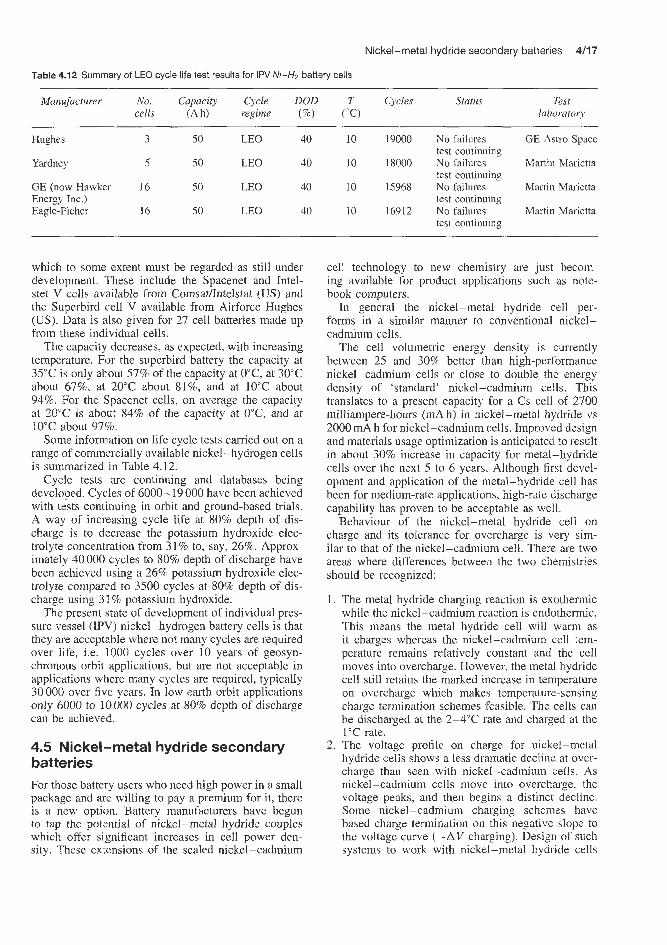
Nickel-metal hydride secondary batteries 4/17
Table 4.12 Summary of LEO cycle life test results for IPV Ni-H2 battery cells
Manufacturer No. Capacity Cycle DOD T Cycles Status Test cells (Ah) reginze (%) ("C) laborator):
Hughes 3 50 LEO 40 10 19000 No failures GE Astro Space test continuing
Yardney 5 50 LEO 40 10 18000 No failures Martin Marietta test continuing
GE (now Hawker 16 50 LEO 40 10 15968 No failures Martin Marietta Energy Inc.) test continuing Eagle-Picher 16 50 LEO 40 10 16912 No failures Martin Marietta
test continuing
which to some extent must be regarded as still under development. 'These include the Spacenet and Intel- stet V cells available from Comsaflntelstat (US) and the Superbird cell V available from Airforce Hughes (US). Data is also given for 27 cell batteries made up from these individual cells.
The capacity decreases, as expected, with increasing temperature. For the superbird battery the capacity at 35°C is only about 57% of the capacity at WC, at 30°C about 6796, at 20°C about 81%, and at 10°C about 94%. For the Spacenet cells, on average the capacity at 20°C is about 84% of the capacity at WC, and at lWC about 97'%/0.
Some information on life cycle tests carried out on a range of commercially available nickel-hydrogen cells is summarized in Table 4.12.
Cycle tests are continuing and databases being developed. Cycles of 6000- 19 0100 have been achieved with tests continuing in orbit and ground-based trials. A way of increasing cycle life at 80% depth of dis- charge is to decrease the potassium hydroxide elec- trolyte concentration from 3 1% to, say, 26%. Approx- imately 40 000 cycles to 80% depth of discharge have been achieved using a 26% potassium hydroxide elec- trolyte compared to 3500 cycles at 80% depth of dis- charge using 3 1 % potassium hydroxide.
The present state of development of individual pres- sure vessel (PV) nickel-hydrogen battery cells is that they are acceptable where not many cycles are required over life, Le. 1000 cycles over 10 years of geosyn- chronous orbit applications, but are not acceptable in applications wlhere many cycles are required, typically 30 000 over five years. In low earth orbit applications only 6000 to 10000 cycles at 80% depth of discharge can be achieved.
4.5 Nickel-metal hydride secondary atteries
For those battery users who need high power in a small package and are willing to pay a premium for it, there is a new opti'on. Battery manufacturers have begun to tap the potential of nickel-metal hydride couples which offer significant increases in cell power den- sity. These extensions of the sealed nickel-cadmium
cell technology to new chemistry are just becom- ing available for product applications such as note- book computers.
In general the nickel-metal hydnde cell per- forms in a similar manner to conventional nickel- cadmium cells.
The cell volumetric energy density is currently between 25 and 30% better than high-performance nickel-cadmium cells or close to double the energy density of 'standard' nickel-cadmium cells. This translates to a present capacity for a Cs cell of 2700 milliampere-hours (mA h) in nickel-metal hydride vs 2000 mA h for nickel-cadmium cells. Improved design and materials usage optimization is anticipated to result in about 30% increase in capacity for metal-hydride cells over the next 5 to 6 years. Although first devel- opment and application of the metal-hydride cell has been for medium-rate applications, high-rate discharge capability has proven to be acceptable as well.
Behaviour of the nickel-metal hydride cell on charge and its toIerance for overcharge is very sim- ilar to that of the nickel-cadmium cell. There are two areas where differences between the two chemistries should be recognized:
1. The metal hydride charging reaction is exothermic while the nickel-cadmium reaction is endothermic. This means the metal hydride cell will warm as
2.
it charges whereas the nickel-cadmium cell tem- perature remains relatively constant and the cell moves into overcharge. However, the metal hydride cell still retains the marked increase in temperature on overcharge which makes temperature-sensing charge termination schemes feasible. The cells can be discharged at the 2-4T rate and charged at the 1°C rate. The voltage profile on charge for nickel-metal hydride cells shows a less dramatic decline at over- charge than seen with nickel-cadmium cells. As nickel-cadmium cells move into overcharge, the voltage peaks, and then begins a distinct decline. Some nickel-cadmium charging schemes have based charge termination on this negative slope to the voltage curve (-AV charging). Design of such systems to work with nickel-metal hydride cells

4/18 Nickel batteries
will require careful attention to selection of proper charge parameters.
Despite these differences, fast charging (return to full capacity in 1 hour or less) of nickel-metal hydride cells with appropriate charge control and termination is fully feasible. In general, the same methods of char- ging used for nickel-cadmium cells work well for nickel-metal hydride although some of the control parameters may require adjustment for optimum per- formance and service life.
The nickel-metal hydride cell is expected to have a service life approaching that of the nickel-cadmium cell. Effects of operating temperature on both discharge performance and charge acceptance are also similar between cells.
One difference in performance between the two cell types occurs in self-discharge, i.e. loss of capacity in storage. The nickel-metal hydride cell currently self-discharges at a slightly higher rate (about 5% per day) than that seen with nickel-cadmium cells in storage. Development work is targeted at reducing the self-discharge rate to about the level seen with nickel-cadmium cells. Based on normal usage profiles expected with portable computers, self-discharge is not a major problem in this application.
Extensive testing of the environmental impact of the materials used in nickel-metal hydride cells
has to date not identified any significant concerns. The occupational health and environmental disposal concerns associated with the use of cadmium in nickel-cadmium cells appears to have been eliminated with nickel-metal hydride cells. Testing of metal hydride cells indicates that their leachable cadmium content is below EPA's threshold limit value. Cadmium content of metal hydride cells is below the European Community's limit of 0.025% by weight. No other environmental problems have been associated with the metal hydride cell. However, the performance and environmental benefits of nickel-metal hydride cells come at a price. At this time, the price per cell for metal hydride cells is approximately double an equivalent high-performance nickel -cadmium cell. This price premium will decline within the next couple of years as production volumes increase.
4.6 Sodium-nickel chloride secondary batteries These newly developed cells, discussed further in a later section, operate at high temperatures around 300°C. Their open circuit voltage is about 2.6 V in the 200-300°C temperature range. The theoretical energy density is about 750 W k/kgg' against practically real- ized values of 100 W a g - ' (160 Wh/dm-3).

Silver batteries


Silver oxide-zinc primary batteries 5/3
PM Silvercel battery. This manually filled silver-zinc battery, which has a higher specific energy output than alkaline manganese, carbon-zinc or mercury types of battery, provides rapid activation and an activated stand time far longer than that of any other high-energy primary. Additionally, it offers a limited recyclabil- ity which allows performance testing before actual use. Silver-zinc batteries have surpassed the stringent mechanical requirements of missile applications and proved their ruggedness and reliability in the field. The following advantages are offered by this battery system over alternative systems: up to 75% higher capacity, or higher capacity with optimum life, or higher voltages at peak pulses. By carefully choos- ing the critical application requirement that must be met, whether it be capacity, life or voltage, and then optimizing these in relationship to each other, it is possible to satisfy the single most stringent demand. The characteristics of the Yardney PM cell are iden- tical to those of the Yardney HR and LR Silver- cel rechargeable secondary battery system with the exception that cycle life and wet life are somewhat limited.
Details of the types of silver-zinc batteries available from some suppliers are tabulated in Table 5.1.
Performance data for monovalent silver oxide (Ag,O)-zinc primary watch cells and divalent silver oxide (Ago)-zinc primary watch cells are given in Table 5.2
5.1 Silver oxide-zinc primary batteries The weight and size of a silver-zinc battery or cell is less than half that of a lead-acid or nickel-cadmium type of similar capacity. The silver oxide-alkaline zinc (Ag,O KOH Zn) primary battery is a major contribu- tion to mniatiire power sources, and is well suited for hearing-aids, instruments, photoelectric exposure devices, electronic watches and as reference voltage sources.
Silver oxide batteries provide a higher voltage than mercuric oxide batteries. They offer a flat voltage characteristic and have good low-temperature charac- teristics. Their impedance is low and uniform. The silver oxide cell operates at 1.5 V (open circuit volt- age 1.6 V) whiile mercury cells operate at about 1.35 or 1.4V. Two major suppliers, Union Carbide and Mallory, supply silver-zinc button cells in capacity ranges between 35 and 210 mA b and 36 and 250 mA h respectively. Cylindrical and button cells are avail- able from vaious suppliers. The impedance of silver oxide batteries for hearing-aid use is low and consis- tent. It does not rise appreciably until after the volt- age of the battery has fallen below a useful operating level.
Silver oxide cells have excellent service mainten- ance; generally 90% after 1 year’s storage at 21”C, and for up to 2 years without serious detriment. Cells will last up to 5 years in inactive sealed storage conditions.
There are numerous applications in the aerospace field, particularly where a high energy density bat- tery is required which can offer both fast activation and a long wet-stand charged life. It was to meet this demand that Yardney Electric launched the primary
5.1.1 Remotely activated silver oxide-zinc batteries Silver-zinc primary batteries can be remotely activ- ated for single use within seconds or fractions of a second, even after long-term storage, by inserting the
Table 5.1 Equivalents in silver-zinc cells using the silver oxide system
Nominal Nominal Height Diameter Duracell IEC National Ray-o-Vac Ucar Varta voltage capacity (mm) (mm) (Mallmy)
(VI h)
1.5 1.5 1.5 1.5 1.5 1.5
1.5 1.5
1.5
1.5 1.5 1.5 1.5
115 4.19 83 3.43 - 6.33 85 3.48 70 2.79 75 5.33
120 4.19 38 3.58
:250 4.83
:200 5.59 180 70
120
11.56 11.56 11.56 11.56 11.56 7.75
11.56 7.75
15.49
11.56
WSll ws12 IOL14 IOL120 IOL122 IOL123
IOL124 IOL125
IOL129
WS14 MS76H MS13H MS41H
SR43 WSll RW14. RW34
SR44 WL14 RW22, RW42
SR48 WS6 RW18, RW28 RW28, RW48
SR43 WL11 SR41 WSl/ RW24, RW44
WL1 RW47
RW15, RW25 RW35
WS14 RW12. RW32
301
357
309 393
386 384 392 355
303 EPX71
528 5 29 541 549
546
548 527 547
521 7301 7306 7308
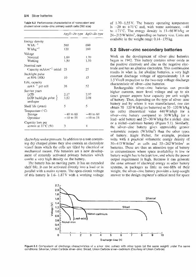
5/4 Silver batteries
0.4 0.2
Table 5.2 Performance characteristics of monovalent and divalent silver oxide-zinc primary watch cells (392 size)
- -
, I 1 I I I I
AgzO-Zn type Ago-Zn type
Energy density W m-' W hk-'
Voltage Nominal Working
Nominal rate Capacity mA/cm-2 initial
Backlight pulse at 80% DOD
Life, capacity mA h-' per cell
Service years LCD LCD backlight pulse analogue
Shelf life (years) Temperature ("C)
Storage Operation
annum at 21°C (%) Capacity loss per
500 120
1.60 1.50
25
10
38
2.17 1.52
5
-40 to 60 -10 to 55
3
680 160
1.70 1.50
25
15
52
2.97 2.08
5
-40 to 60 -10 to 55
4
electrolyte under pressure. In addition to a unit contain- ing dry charged plates they also contain an electrolyte vessel from which the cells are filled by electrical or mechanical means. Pile batteries are a new develop- ment of remotely activated primary batteries which confer a very high density on the battery.
The battery has no moving parts. It has an extended shelf life. It can be activated directly into a load or in parallel with a mains system. The open-circuit voltage of this battery is 1.6-1.87V with a working voltage
of 1.20- 1.55 V. The battery operating temperature is -29 to + 7 1 T and, with water assistance, -48 to +71"C. The energy density is 11-66Whkg or 24-213 WWdm3, depending on battery size. Units are available in the weight range 0.14-135 kg.
5.2 Silver-zinc secondary batteries Work on the development of silver-zinc batteries began in 1942. This battery contains silver oxide as the positive electrode and zinc as the negative elec- trode and has an alkaline electrolyte. This combination results in what is, for alkaline batteries, a very high constant discharge voltage of approximately 1.8 or 1.5 Vlcell respective to the two-step voltage discharge characteristic of silver-zinc batteries.
Rechargeable silver-zinc batteries can provide higher currents, more level voltage and up to six times greater ampere hour capacity per unit weight of battery. Thus, depending on the type of silver-zinc battery and by whom it was manufactured, one can obtain 70- 120 W h/kg (as batteries) or 55- 120 W h k g (as cells) (theoretical value 440Whkg) for a silver-zinc battery compared to 30Whkg for a lead-acid battery and 25-3OWhkg for a nickel-zinc or a nickel-cadmium battery (Figure 5.1). Similarly, the silver-zinc battery gives appreciably greater volumetric outputs (Wh/dm3) than the other types of battery. Eagle Picher, for example, produce units with a practical volumetric energy density of 50-415WWdm3 as cells and 55-262Wh/dm3 as batteries. These are thus an attractive type of battery in circumstances where space availability is low or battery weight has to be kept low, and where the power output requirement is high. Because it can generate the same amount of electrical energy as other battery systems, in packages as little as one-fifth of their weight, the silver-zinc battery provides a long-sought answer to the design engineer's critical need for space
Silver-cadmium secondary batteries 515
and weight savings. Because it is capable of delivering high watt hour capacities at discharge rates less than 30 min, the silver-zinc battery is used extensively, for example, in missile and torpedo applications. Its high energy density makes it attractive in electronics applications, satellite and portable equipment where low weight, high performance and low cost are prime considerations. It is highly efficient and mechanically rugged, operates over a wide temperature range, and offers good shelf life; quick readiness for use and the ability to operate at temperatures down to -40°C without heating, and up to 7 3 T , are two of the features of this battery. The corresponding battery storage temperatures are -53°C and 73°C. Eagle Picher claim a dry shelf life of 2.5 years and a wet shelf life of up to 1 year at 21°C for their silver-zinc batteries. In excess of 500 cycles are claimed with a charge retention of up to 1 year at 26°C. Either constant-current or constant- potential (I .96- 1.98 V) charging methods can be used and 16h is a typical recharge time.
The extremeliy low internal resistance of silver-zinc batteries permits discharges at rates as high as 30 times the ampere hour capacity rating, and its flat voltage characteristic enables highest operational efficiency and dependability. Cells have been built with capacity ranging from 0.1 A h to 20 000 A h.
The cells a:re leakproof and spillproof. The sil- ver-zinc battery is available in high-rate and low-rate cells, Le. it cam be subject to high or low rates of discharge.
Rechargeable silver-zinc batteries are available as cells for discharges at high discharge rates (high-rate batteries) where the total energy must be delivered within 1 h or as low-rate versions with discharge times of 2 h or more. The latter type can be discharged in from 2 h down to a few minutes. The high-rate and low-rate systems differ principally in their elec- trode surface areas and the thickness of the separators between the plates, both of which have an effect on the internal resistance of the cell.
Silver-zinc batteries are also available in modular packs; one supplier (Yardney) supplies packs in nor- mal capacities between 3 and 80Ah. These batteries have voltages 'between 2.8 and 15.8 V and equivalent energy densities of about 100 W Nkg, which exceeds the energy of a. nickel-cadmium battery by four times and a lead-acid battery by five times. They are, of course, more expensive, but in many applications their characteristics make them an attractive alternative.
Untii recently, the fact that the rechargeable sil- ver-zinc battery has been more expensive and more sensitive to overcharge and has a shorter cyclic life than conventional storage batteries has limited it to applications where space and weight are prime consid- erations. However, long-life silver-zinc batteries have now been devdoped in which up to 400 cycles over a period of 30 months can be achieved with ease.
The data below indicate, in brief, the performance capabilities achieved with silver-zinc cells supplied by Yardney showing the requirements which can be met:
1. liibration: 30-40 sinusoidal vibration. 2. Random Gaussian vibration: 5-2000 Nz band,
with as high as 60g r.m.s. equivalent in both non-operational and operational conditions; hard mounted unit.
3. Shock: tested up to 200g in all directions. 4. Acceleration: lOOg in all directions of sustained
acceleration, except in the direction of the vent for vented cell systems.
5. Thermal shock: from +70 to -50°C and repeated, with stabilization occurring at each temperature.
6. Altitude: successful activation, and operation at a simulated altitude of 60km, for a period of 1 h without pressurization; with pressurization there is no limit.
Table 5.3 gives the basic characteristics of the high- rate and low-rate versions of the Yardney Silvercel.
5.3 Silver-cadmium secondary batteries The silver-cadmium battery has a voltage of 1.4-1.1 Vkell (open circuit), 0.9-1.14V/ce!l (closed circuit) and combines the high energy and excellent space and weight characteristics of the silver-zinc battery with the long life, low-rate Characteristics and resistance to overcharge of the nickel-cadmium battery. Operating temperatures are between -43°C and 75°C. The silver-cadmium battery also provides high efficiency on extended shelf life in the charged or the uncharged condition, level voltage and mechanical ruggedness. Watt hour capacity per unit of weight and volume is two to three times greater than that of a comparable nickel-cadmium battery, and the silver-cadmium battery has superior charge retention. The principal characteristics of silver-zinc and silver-cadmium cells and batteries are compared and their important differences shown in Table 5.4. The silver-cadmium battery promises great weigh: and space savings and superior life characteristics to those of nickel-cadmium batteries cunently in use as storage batteries in most satellite programmes. Yardney have reported 6000 cycles with a 50% depth of discharge in satellite applications.
Prior to the introduction of silver-cadmium batter- ies most available types of battery fell into the cat- egories of low-energy long-life types or high-energy short-life types. Silver-cadmium batteries go a long way to combining the best features of both types giv- ing two to three times more energy density per unit of volume than the lead-acid, nickel-cadmium and nickel-iron systems, and at the same time offering ruggedness and long life (Figure 5.2).

516 Silver batteries
. - I 9 E 200 9 2 150 Sizlc
N ickel-cadmium
Lead-acid UI Nickel-iron
0 2 4 6 8 10 Discharge time (h )
Figure 5.2 Comparison of energy density at various discharge rates: Silcad silver-cadmium batteries (Courtesy of Union Carbide)
Although the theoretical energy density of the silver-cadmium battery is 310 Wh/kg, the actual
Table 5.3 Characteristics of Yardney HR and LR Silvercell silver-zinc batteries
energy density of practical batteries is in the range 24-73Whkg as cells and 18-44Whikg as batteries. The practical volumetric energy density is 36-171 Wh/dm3 as cells and 24-122Wh/dm3 as batteries.
The low internal resistance of silver-cadmium bat- teries permits heavy drains and wide variations in load at virtually constant voltage. Leakproof, spill- proof packaging with high impact strength helps ensure dependable operation under severe environmental and mechanical stress conditions. The extremely low in- ternal resistance of silver-zinc batteries permits dis- charges at rates as high as 30 times the ampere hour capacity rating, and its flat voltage characteristic allows the highest operational efficiency and dependability. Cells have been built with capacity ranging from 0.1 A h to 20 000 Ah. The use of silver in silver-zinc and silver-cadmium cells obviously increases initial
Chemical reaction Ag + Zn(0H)z = Ago + Zn + H20 discharged charged
Energy output 20- 120 W hikg; as much as 220 W hlkg for certain types Open-circuit voltage 1.86 f 0.04V (70-100% charged)
1.60 f 0.04V (30-70% charged) Nominal voltage under load Plateau voltage regulations
cut-off voltage Recommended charge cut-off 2.05 V voltage Cycle life (before output drops to SO% of nominal capacity- depends on model and conditions of use)
Dry storage life
1 S O V &2% at a fixed load and temperature limits within f 5°C
Recommended discharge 1.oov
HR cells: 5-20 cycles (1 h rate)
5- 10 cycles (time-limited dncharge) 1 cycle (6min rate or higher, full-capacity discharge)
10-15 cycles (30min rate)
LR cells: SO-100 cycles Up to 5 years
Operating (wet) life HR cells: 6-12 months LR cells: 1-2 years
Gassing on discharge or stand Very slight Operational temperature range
+7 to -23°C down to -50°C with heaters; optimum cell performances at 51-10°C
Storage temperature range Operating attitude Internal resistance Resistance to mechanical stress
Wet, 37 to -48°C; dry, 73 to -65°C In any position, although for optimum service upright is recommended Very low, varies with cell model, temperature and rate of discharge Excellent; Silvercell batteries have met the stringent requirements of Spec. MIL-E-5272A and are currently used in missiles, rockets, torpedoes, etc.; they are extremely rugged, leakproof and spillproof, and can be packaged to meet the most severe requirements Can be fully recharged in 10-20 h, depending on requirements and type of cell Indicated by sharp rise in cell voltage at 2.0 Vkell during charge Up to 85% of nominal capacity after 3 months charged stand at room temperature
Charging time Charge completion Charge retention
These data apply mainly to individual cells; when the cells are assembled to form batteries, performance will be determined by specific application and packaging requirements. HR = high-rate batteries; LR = low-rate batteries

Silver-cadmium secondary batteries 517
Table 5.4 Comparison of characteristics of Yardney Silvercell and Silcad batteries
Silvercel (silver-zinc) Silcad (silver-cadmium)
Energy output W h/kg W h/dm3
Open-circuit voltage
Nominal voltage under load Plateau voltage regulation at fixed load and f.5"C Cycle life (dependent on model and usage conditions); typical life to 80% of nominal
Operating life: wet shelf life (varies with temperature and state of charge) Dry storage life Operating temperature range
Storage temperature range
Operating attituda
Internal resistance
Resistance to mechanical sress
Charging times (dependent on cell design) Charge completion Charge retention
88-110 150-190 1.82-1.86 V
1.5V 2%
LR series:
HR series: 80-100 cycles
1 h rate, 15-20 cycles 30min rate, 10-15 cycles 10 min rate, 5- 10 cycles 6 min rate, single cycles
LR series: 1-2 years HR series: 6-12 months
Up to 5 years +73 to -21°C with heaters; optimum performance 10-51 "C Wet: +37 to -47°C
Any position except inverted; for optimum service, use upright Very low, varies with cell model design temperature and discharge rate Excellent
Dry: +73 to -64°C
48-75 90-160 1.40 =k 0.04V (70-100% charged) 1.1 v 5%
150-300 cycles (3000 cycles under ideal conditions)
2-3 years
Up t o 5 years +73 to -21°C with heaters; optimum performance 10-51°C Wet: +37 to -47°C Dry: +73 to -64°C Any position except inverted: for optimum service, use upright Very low, varies with cell model design, temperature and discharge rate Excellent
Both types have met the stringent requirements of Spec. MIL-E-5272A and are currently used in missiles, rockets, torpedoes and Moodspace applications; extremely rugged, leakproof and spillproof, they can be packaged to meet the most severe requirements 10-20 h 10-20 h
Sharp voltage rise at 2.0Vkell Up to 85% of nominal capacity after 3 months' charged stand at room temperature temperature
Sharp voltage rise at 1.55-1.6V/ceI1 Up to 85% of nominal capacity after 3 months' charged stand at room-
costs (although silver costs are recoverable) and intro- duces security problems when compared to other bat- tery systems such as lead-acid, nickel-cadmium, etc. However, when space and weight are limiting factors, the silver-zinc system is a very attractive proposition.
The full range of characteristics of silver-cadmium batteries is givlen in Table 5.5.
These batteries are available in high and low rate versions (0.1-300Ah) and in modular packs (2- 10 Ah) from Yardney a d other suppliers.
The major application for the high-rate series is for service conditions where maximum energy density and voltage regulation at high rates of discharge are
required throughout a cycle life of 6- 18 months. This system also has an exceptional ability to retain its charge during long periods of wet storage.
The major application for the low-rate series is for service conditions where maximum energy density and voltage regulation at low rates of discharge are required throughout a cycle life of 12-36 months. The system also has an exceptional ability to retain its charge during long periods of wet storage.
Constant-current charging is recommended for sil- ver-cadmium batteries, with a charge rate of one-tenth nominal capacity to 1.65 V/cel! or 1.55 V/cell mini- mum. Alternatively, constant-potential charging can be

5/8 Silver batteries
Table 5.5 Characteristics of Yardney Silcad silver-cadmium batteries
Chemical reaction
Energy output Open-circuit voltage
Nominal voltage under load Plateau voltage regulations Recommended discharge cut-off voltage Recommended charge cut-off voltage Cycle life
Wet life
Dry storage life Gassing on discharge or stand Operational temperature range Storage temperature range Operating attitude Internal resistance Resistance to mechanical stress
Charging time
Charge retention
Ag + Cd(OH)2 = AgO + Cd + HzO discharged charged
Theoretical 310 W a g ; 48-75 W Wkg; 90-160 Wb/dm3 1.40 * 0.04V (70-100% charged) 1.16 & 0.04V (30-70% charged) 1.1v &5% at a fixed load and temperature limits within f 5 " C 0.60 V
1.65 V (indicated by sharp rise in cell voltage at 1.55- 1.60 Vkell during charge)
Dependent on model and conditions of use; typical number of complete charge/discharge cycles obtainable: Depth of discharge(%) Approx. cycles 95-75 200-300 75-50 300-600 50-25 over 600 Up to 3 years when manufacturer's recommended charge and discharge rates are used and operating and storage temperatures do not exceed 37°C Up to 5 years Very slight f73 to -21°C; down to - 5 3 T with heaters; for optimum cell performance, from 10 to 51°C Wet, +37 to -47°C; dry +73to - 64°C In any position although, for optimum service, upright is recommended Very low; varies with cell model, temperature and rate of discharge Excellent, extremely rugged, leakproof, spillproof. Construction similar to design of Yardney Silvercel batteries which meet requirements of Spec. MIL-E-5272A, and are currently used in missiles, rockets, torpedoes, etc. Can be packaged to meet the most severe requirements Can be fully recharged within 10-20 h, depending on requirements and type of cell (in some cases rapid charging possible) Up to 85% of nominal capacity after 3 months' charged stand at room temperature
adopted with an input of 1.65 f 0.02 V. With constant- potential charging the current is limited to one-fifth of nominal capacity charging to the trickle charge rate.
design concepts to those of their nickel-hydrogen sys- tem. The silver-hydrogen couple is believed to be capable of achieving energy densities in the range 90- 110 W h/kg with maximum cell operating pres- sure of 2.75kN/m2 and an energy volume relation- ship of between 61 and 79Wh depending on cell design. The silver-hydrogen system is believed to be capable of 600 deep discharge cycles (80-90% depth of discharge).
5.4 Silver-hydrogen secondary
Eagle Picher have also explored the possibilities of developing a silver-hydrogen battery using similar
batteries

AI kaline manganese batteries


Alkaline manganese secondary batteries 6/3
Service capacity remains relatively constant as the dis- charge schedule is varied. Capacity does not vary as much with current drain as for the carbon-zinc bat- tery. Service capacity ranges from several hundred mi - liampere hours to up to tens of ampere hours depending on current drain and cut-off voltage.
The alkaline manganese battery is intended for applications requiring more power or longer life than can be obtained from carbon-zinc batteries. Alkal- ine manganese batteries contain 50- 100% more total energy than a conventional carbon-zinc battery of the same size. Energy densities of alkaline manganese types are superior to those of carbon-zinc batteries of the same size. In a conventional carbon-zinc battery, heavy current drains and continuous or heavy-duty usage impair the efficiency to the extent that only a small fraction of the built-in energy can be removed. The chief advantage of the alkaline manganese bat- tery lies in its ability to work with high efficiency under continuous or heavy-duty high-drain conditions where the carbon-zinc battery is unsatisfactory. Under some conditions, alkaline manganese batteries will provide as much as seven times the service of stan- dard carbon-zinc batteries. Discharge characteristics of alkaline manganese and carbon-zinc batteries are compared in Figure 6.2.
perform carbon-zinc batteries in any type of service, as indicated earlier, they may now show economic advantage over them at light drains, or under intermittent-duty conditions, or both. For example, with intermittent use at current drains below about 300 mA the D cell size alkaline type, while performing very well, will begin to lose its economic advantage over carbon-zinc batteries.
Although alkaline manganese batteries caL '1 out-
Ikalince manganese primary batteries Alkaline manganese batteries are a direct competitor to the standard carbon-zinc (LeclanchC) battery over which, in certain applications, they enjoy advantages in performance. The primary alkaline manganese battery, which first became available in 1960, represents a major advance over the standard carbon-zinc battery and meets the growing need for a high-rate source of electrical energy.
Alkaline manganese batteries have a high depolar- izing efficiency. On continuous or heavy drains they perfom very well and have distinct advantages over the relatively cheaper carbon-zinc batteries, on a per- formance per unit cost basis. Both alkaline manganese and mercury blatteries have a superior operating life to carbon-zinc batteries. For applications where volt- age stability and extremely small size are not of prime importance, the alkaline manganese battery may be considered preferable to the more expensive mercury battery. As witlh the mercury battery, the alkaline man- ganese battery has a long shelf life, is self-venting and is of corrosion-free construction. Alkaline man- ganese batteries are capable of providing heavy cur- rents for long periods, which makes them very suitable for applications requiring high surge currents, and can operate successfully at temperatures between -20 and +70°C; in certain cases even higher temperatures can be tolerated.
The voltage of an alkaline manganese cell is 1.5 V in standard I\$, AAA, AA, C! and D cell sizes. Batteries are available with voltage up to 9 V and in a nuIliber of different service capacities. The closed- circuit voltage of an alkaline manganese battery falls gradually as the battery is discharged (Figure 4.1). This stability is superior to that obtained with a carbon-zinc battery but dis,tinctly inferior to that obtained with a mercury - zinc battery.
Alkaline manganese batteries perform similarly to carbon-zinc batteries in that the service hours deliv- ered axe greater when the cut-off voltage is lower. The cut-off voltage should be made as low as possible so that the high energy density of the cell can be used.
1.4,
1 1 A (starting drain)
6.2 Alkaline manganese secondary batteries The alkaline manganese battery is an example of a type of battery that, until quite recently, was available only in the non-rechargeable (primary) form but has now become available in a rechargeable (secondary)
0 2 4 6 8 10
Discharge time (h)
Figure 6.1 Voltage discharge characteristics of an alkaline manganese battery (D cell) discharged continuously (Courtesy of Union Carbide)

6/4 Alkaline manganese batteries
f - - .- a 1.1
.- e 0.9 0 -0
0.7 - u
- 1 > 1.5r
1.3-\\ -
- Alkaline
Carbon-zinc - I I I , I 1 I
form. Certain manufacturers supply rechargeable alkal- ine manganese cells and batteries; for example, Union Carbide offer the Eveready rechargeable alkaline man- ganese battery range. These batteries use a unique elec- trochemical system, are maintenance free, hermetically sealed, and will operate in any position. They have been designed for electronic and electrical applica- tions where low initial costs and low operating costs, compared with the cost of nickel-cadmium cells, are of paramount importance. Rechargeable alkaline man- ganese cells can also be used as an alternative to dry cells, since, although they have a higher initial cost, they are cheaper overall owing to their recycling property. They therefore bridge the gap between low initial cost batteries and the more expensive but recy- clable secondaries. The alkaline manganese dioxide battery cannot be recharged as many times as the nickel-cadmium type, but the initial cost is only a fraction of the cost of an equivalent nickel-cadmium battery. Its operating cost is also normally lower.
Present types of Eveready battery available from Union Carbide include 4.5 and 7.5V batteries using D size cells, and 6, 13.5 and 15V batteries composed of G size cells. Specifications are listed in Table 6.1 and average performance characteristics are for the 4.5 V cell shown in Figure 6.3.
The discharge characteristics of the rechargeable alkaline manganese dioxide battery are similar to those exhibited by primary batteries; the battery voltage
Table 6.1 Characteristics of cells in Eveready rechargeable alkaline manganese dioxide batteries
Cell Voltage Average Rates Max. size (V) operating capacity recommended
voltage (Ah) discharge (VI current
(A)
D 1.5 1.0-1.2 2.5 0.625 G 1.5 1.0-1.2 5.0 1.250
3 r 0 Voltage a t end of 4 h discharge 7- ' t
I I I I I I I I 0 10 20 30 40 50 60 70
Number of cycles
Figure 6.3 Average performance characteristics: voltage versus cycles at 21 .I "C, Eveready rechargeable alkaline manganese dioxide batteries, 4.5-15V. (Discharge cycle: 4 h through 5.76 R. Charge cycle: 16 h voltage taper current charging -voltage limit 5.25V, filtered regulated power supply 1 % regulation, with 2.4 s2 limiting resistor.) (Courtesy of Union Carbide)
decreases slowly as energy is withdrawn from the bat- tery. The shape of this discharge curve changes slightly as the battery is repeatedly discharged and charged. The total voltage drop for a given energy withdrawal increases as the number of dischargekharge cycles increases. Coupled with this is the fact that the avail- able energy per cell lessens with each dischargekharge cycle even though the open-circuit voltage remains quite constant; this is shown graphically in Figure 6.4. When a rechargeable battery of the alkaline manganese dioxide type is discharged at the maximum rate for a period of time to remove the rated ampere hour capa- city and then recharged for the recommended period
14-
2 h of discharge 3 h of discharge
e 'G 10-
G 9 -
3
4 h of discharge R - -
1 I I I I J 10 20 30 40 50 60
Number of cycles
Figure 6.4 Changes in battery performance with every fifth cycle: Eveready 561 alkaline manganese dioxide battery on 9.6R load for 4 h. (Discharge cycle: 4 h through 9.6 R. Charge cycle: 16h voltage-limited taper current charging - voltage limit 17.5V, filtered regulated power supply 1 % regulation, with 4.0 R limiting resistor.) (Courtesy of Union Carbide)

Alkaline manganese secondary batteries 6/5
of time, the complete dischargdcharge cycle can be repeated many times before the battery voltage will drop below 0.9 Vkell in any discharge period, depend- ing on cell size. Decreasing either the discharge current or the total ampere hour withdrawal, or both, will increase the cycle life of the battery by a signifi- cant percentage. Conversely, if the power demands are increased to a point where they exceed the rated battery capacity, the cycle life will decrease more quickly than the increase in power demand. During the early part of its cycle life there is a very large power reserve in the Eveready rechargeable alkaline manganese dioxide battery. In these early cycles, the battery terminal volt- ages may measure 1.0-1.2Vlcell after the battery has delivered its rated ampere hour capacity. This reserve power can be used in situations where maximum total battery life can be sacrificed for immediate power. During the latter part of cycle life, there is little or no reserve power and the terminal voltage of the battery will fall to between 1 .O and 0.9 V/cell at the end of dis- charge. Figure 6.5 shows the maximum and minimum discharge voltages that the battery will reach on evenly spaced cycles throughout its cycle life; the curves show 561 battery performance on a 9.6 52 load for 4 h.
Eveready rechargeable alkaline manganese dioxide batteries have excellent charge-retention properties. The new battery is fully charged and has the charge- retention characteristics of a primary battery. These characteristics also apply during the chargeldischarge cycling of the battery. With this type of battery it is necessary to discharge it to its rated capacity before it will be capable of standing any overcharge.
Rayovac supply their Renewal range of zinc-man- ganese dioxide RAM cells. In the 1.8 A h AA size the voltage ranges from 1.9 V to 0.9 V at end of discharge. The 1.8 A h initial capacity of this cell decreases to
l 7 t '61-
P % 6 11
10
9
1.09 A D .\ J 1 h of discharge
8 4 h of discharge I I I 1 I
10 20 30 40 50 Number of cycles
Figure 6.5 Typical voltage performance on voltage-limit4 taper current charge: Eveready 561 rechargeable 15 V alkaline manganese dioxide battery. (Charge and discharge conditions as for Figure 6.4.) (Courtesy of Union Carbide)
1 A h after three years' storage at 25°C (self-discharge rate 0.01% per day compared to 1% per day for nickel-cadmium cells). More than 100 cycles are achieved if a regime of partial discharges is adopted. The energy density of these cells is 80 WNkg-l (220 W l~ /dm-~) , i.e. approximately twice the value achieved for nickel-cadmium cells.


Carbon -zinc and carbon-zinc chloride primary batteries


Carbon-zinc batteries 7J3
7.1 I Carboin-zinc batteries The standard carbon-zinc LeclanchC battery is expected to remain one of the most widely used dry primary batteries in the future because of its low cost and reliable performance. This type of battery is manufactured in many styles by many companies-one company alone manufactures over 100 versions with voltages varying from 1.5 V to approximately 500V and with various shapes, sizes and terminal arrangements.
The chemical efficiency of a carbon-zinc battery improves as current density decreases. This reveals an important application principle: consistent with physi- cal limitations, use as large a battery as possible. Over a certain rang:. of current density, service life may be tripled by halving the current drain. This is equivalent to using a larger battery for a given application and so reducing current density within the cells. This is true to a certain point beyond which shelf deterioration becomes an important factor.
The service capacity depends on the relative time of discharge and recuperation periods. The performance is normally better when the service is intermittent. Continuous use is not necessarily inefficient if the current drain is very light.
Figure 7.1 illustrates the service advantage to be obtained by proper selection of a battery for an applica- tion. The figure indicates how the rate of discharge and frequency of (discharge affect the service efficiency of a battery. The energy-volume ratio of a battery using round cells is inherently poor because of voids occur- ring between the cells. This factor accounts for an improvement in energy-volume ratio of nearly 100% for flat cells compared with round cell assemblies. Two
Figure 7.1 Battery service life as a function of initial current drain and duty cycle: D size carbon-zinc battery (Courtesy of Union Carbide)
basic types of carbon-zinc LeclanchC cell are avail- able; the SP type and the high-power HIP type. The HP type is intended for applications where high cur- rent drains are involved; the SP type is recommended for low current drain applications.
There is no simple or rapid method for determin- ing the service capacity of a dry battery. Tests must be run which closely duplicate the class of service for which the battery is intended. The scheduie of opera- tion is very important, except for very light drains. The service capacity of a battery used 2Wday on a given drain will be considerably different from that of the same battery used 12Wday. There is no relation- ship between continuous-duty service and intermittent service. It is therefor:. impossible to rate the merits of different batteries on intermittent service by comparing results of continuous-duty tests.
Another fallacy concerning dry batteries is that rel- ative ‘quality’ or service capacity of a battery can be determined by amperage readings. This is not true, and in most instances gives results that are totally misleading. The D size photoflash round cell and the flashlight cell are identical in size and shape. However, the photoflash cell, which will show more than twice the amperage of the flashlight cells, has less service capacity in typical flashlight uses.
The short-circuit amperage of a zinc-carbon cell may be adjusted over a wide range by varying the carbon and electrolyte content of the depolarizing mix. Carbon contributes nothing to &he service capacity of the zinc-carbon cell and is used primarily to control cell resistance. It is obvious that, as carbon is added to a cell, depolarizer must be removed; this means that service capacity is reduced.
Dry batteries can be tested with a loaded voltmeter to check their present condition. A meter test, however, will give no indication of remaining service capacity unless the exact hisiory of the battery is known and can be compared on a capacity against meter-reading basis with other batteries tested in similar service. A loaded voltmeter is considered the best spot-check device, since open-circuit voltmeter readings give no indication of internal resistance, and a sho~--circuit amperage reading is damaging.
The internal resistance of cells becomes important when battery-operated devices require a high current for short periods of time. If the internal resistance of a cell is too high to provide the current, a larger cell may be used. The internal resistance of unused carbon-zinc cells is low and is usually negligible in most applications. Internal resistance may be measured by flash current or short-circuit amperage. which is defined as the maximum current, observed on a dead- beat (damped) ammeter, which a cell or battery can deliver through a circuit of 0.01 s2 resistance, including the ammeter. Amperage readings are not necessarily related to service capacity. Amperage is usually higher in large cells.

7/4 Carbon-zinc and carbon-zinc chloride primary batteries
Table 7.1 Approximate internal resistance of standard carbon-zinc and carbon-zinc chloride cylindrical cells
ANSI Average $ash current (A) Approx. internal resistance (a) cell size Standard carbon-zinc Zinc chloride Standard carbon-zinc Zinc chloride
N AAA AA C D F G 6
2.50 3.80 5.30 3.90 5.60 9.00
12.00 30.00
- -
4.50 6.50 8.50
11.30 - -
0.60 0.40 0.28 0.39 0.27 0.17 0.13 0.05
- -
0.33 0.23 0.18 0.13 -
-
The internal resistance increases with storage time, use and decreasing temperature. The cell dries out with age. During discharge some of the ingredients are con- verted to different chemical forms which have higher resistance. Table 7.1 lists the approximate internal res- istance, as determined by the flash current, of several round cells of the carbon-zinc and carbon-zinc chlor- ide types.
Carbon-zinc cells (1.5V) come in a variety of standard sizes covered by the ANSI designation; the type numbers of 1.5 V cells available from one particular supplier (Union Carbide) under each ANSI designation are listed in Table 7.2.
7.2 Carbon-zinc chloride batteries
The zinc chloride cell is a special modification of the carbon-zinc cell. It differs principally in the elec- trolyte systems used. The electrolyte in a zinc chloride cell contains only zinc chloride, while in a carbon-zinc cell the electrolyte contains a saturated solution of ammonium chloride in addition to zinc chloride. The omission of ammonium chloride in the zinc chlor- ide cell improves the electrochemistry of the cells but places greater demands on the cell seal.
Zinc chloride cells are able to operate at higher electrode efficiencies than carbon-zinc cells and hence have a higher useful current output and will operate at higher current drains than carbon-zinc cells of the same size. In addition, the voltage lever under load
Table 7.2 Type numbers of Union Carbide carbon-zinc Leclanche dry cells available under various ANSI designations
Union Carbide ANSI Voltage Suggested type number designation (V) current
range (A)
HS6, IF6, IS6, IS6T, EA6F, EA6, EA6FT, EA6ST HS150, HS50, 11T0, 8 500 001, T50, 1050, 950, 1250 HS35, 935, T35, 835, 1035, 1235 HS15, 815, 915, 1015, 1215 904 20 1 812, 912 E340E
6
D
C
AA
N wo AAA N
1.5
1.5
1.5
1.5
1.5 1.5 1.5 1.5
0-1.50
0-1.15
0-0.08
0-0.025
0-0.02 0-0.06 0-0.02 0-0.02
holds up longer into the discharge. Zinc chloride cells also perform better at low temperatures.
The internal resistance of zinc chloride (and carbon-zinc) cells increases with storage time, use and decreasing temperature. Table 7.1 compares the approximate internal resistance, as determined by flash currents of several types of round cell of the carbon-zinc and zinc chloride types.

Mercury batteries


Mercury-indium-bismuth and mercury-cadmium primary batteries
ereury-zinc primary batteries Mercury batteries have an appreciably higher energy- to-weight ratio than carbon-zinc batteries, resulting from the high energy density of the materials used in their construction. Thus mercury batteries are only one-third the size of conventional dry batteries of the same capacity.
Characteristics and features of the mercuric oxide electrochemical system include the following:
1. 2.
3. 4. 5. 6. 7.
8. 9.
10.
11. 12.
13. 14. 15.
Long life. High capacity-to-volume ratio, resulting in sev- eral times the capacity of alkaline manganese and carbon-zinc cells in the same volume, or propor- tionally reduced volume for the same capacity. Flat discharge characteristic. Higher sustained voltage under load. Relatively constant ampere hour capacity. LOW and substantially constant internal impedance. No recuperation required, therefore the same capacity is obtained in either intermittent or continuous usage. Good high-temperature characteristics. High resistance to shock, vibration and accel- eration. Electrically welded or pressure intercell connec- tions. Single or double steel case encapsulation. Chemical balance - all the zinc is converted at the end of the battery's life. Automatic vent. Resistance to vacuum and pressure. Resistance to corrosive atmospheres and high relative humidity.
The ampere halur capacity of mercury cells and bat- teries is relatitely unchanged with variation of dis- charge scheduk and, to some extent, with variation of discharge current. They have a relatively flat dis- charge charactierisfic (see Figure 8.1; compare this with Figure 6.11 for alkaline manganese types). The mercury system withstands both continuous and inter- mittent discharge with relatively constant ampere hour output and this allows the capacity rating to be
specified. Rest periods are not required as in the case of carbon-zinc batteries.
Mercuric oxide batteries are available with two for- mulations designed for different field usage. In general, the 1.35 V cells (that is, 100% mercuric oxide depolar- ization) or batteries using these cells are recommended for voltage reference sources (that is. high degree of voltage stability) and for use in applications where higher than normal temperatures may be encountered (and for instrumentation and scientific applications). The 1.4V cells (mixture of manganese dioxide and mercuric oxide depolarization) or batteries using these cells are used for all other commercial applications. The 1.4V cells or batteries should be used for long- term continuous low-drain applications if a very flat voltage characteristic is not needed.
Although Union Carbide and Mallory are two of the major producers of mercury-zinc cells and batteries, there are, of course, other important producers such as Ever Keady (Berec) (UK), Crompton-Parkinson (Hawker Siddeley) (UK) and Varta (West Germany). Table 8.1 gives the type numbers of equivalent cells that meet a given International Electrochemical Com- mission (IEC) designation as produced by Union Car- bide. Mallory, Ever Ready (Berec) and Varta. In many instances equivalent cells are available from more than one manufacturer. In such instances comparative cost quotations would be of interest to the intending pur- chaser.
The performance characteristics of a 675 size mer- cury-zinc primary button cell are Listed in Table 8.2.
8.2 Mercury-indium-bismuth an mercury-cadmium primary batteries Mercury-indium-bismuth and mercury-cadmium batteries are available from some manufacturers ( q . Crompton-Parkinson). These are alkaline systems recommended for applications where high reliability in particularly onerous long-term storage and use conditions is a prime requirement.
For example, the particular advantage of mer- cury-cadmium is that it will show good performance at low temperatures even below -20°C where most
1.4
- > 1.2 - m 01
1.Q
0.8
s 0 10 20 30 40 50
Discharge time (h)
Figure 8.1 Typical voltage discharge characteristics of mercury-zinc cells under continuous load conditions at 21 "C. At 1.25V, equivalent current drains for the resistances are: 15 S2, 83 mA; 25 I;t, 50 mA; 32 Q,40 mA; 42 S2, 30 m A 50 a, 25 mA; 60 Q, 20 mA (Courtesy of Union Carbide)

Table 8.1 Some equivalent mercury-zinc cells from different manufacturers e P
MR41 MR08
NR48 MR48
NR08 MR42 NR43 MR43 MR07 NR07
MR44 MR9
MR52 NR52 MR1
MR50
MR7
NR50 NRI MR17 NR6 MR6
MR5 1
325 E400N E400
E138, E13E 323
343
354 EPX675
313 E625 E630 E625N EPX625 EPX13
E401N E401, E401N
EPXl El
E3
E502E E9 E502
1.35 1.35 1.40
1.40 1.35
1.35
1.35 1.35
1.35 1.40 1.40 1.35 1.35 1.35
1.35 1.40
1.35 1.40
1.35
1.40 1.40 1.35
50 80 80
85 95
120
150 220
220 350 350 250 250 250
800 800
1000 1000
2200
2400 2500 2400
RMl3H WH6
RM575H WH 12NM RM41
PX675 MP675H SP675 WH3
PX625 RM625N PX640 RM640H
RMIN PX 1
RM1 MP401
ZM9C
RM12R RM675H RM625 RM3 12H RM41H PX825
1.40 1.35
I .40 1.35 1.40
1.35 1.40 1.40 1.35
1.35 1.35 1.35 1.40
1.35 1.35
I .40 1.40
1.40
1.35 1.40
85 95
100 110 150
210 210 230 220
250 350 500 500
1000 1000
1000 1000
2400
3600
5 No. Voltage CapacitJ NO. Voltage Capacity No. Voltage No. Voltage Ti
(VI .5 %
IEC Union Carbide Eveready Mallory Duracell Varta Ever Ready (Berec) designation
rn (VI (mA h) (V) (mA hI (VI
9
7106 1.40 RM13H
7109 1.40 RM575H
7001 1.35 7103 MP6754
7002 1.35 PX625 RM625N
_. n, v)
1.40
1.40
1.40
1.35 1.35
RMW 1.35 PX 1 1.35
ZM9C
7101 1.40 RM675H 7102 1.40 7107 1.40 7 108 1.40 7201 1.50
1.40
1.40
RMlH 1.40 RM401H 1.40

Mercury-indium-bismuth and mercury-cadmium primary batteries 815
other primary systems just would not function. How- ever, as the temperature drops, the operating volt- age also drops as expected. Away from these very low temperaturjes, mercury-indium shows a better power-to-volume ratio than mercury-cadmium, and still gives exceptional perfonnance in difficult environ- ments. Both these systems also have the advantage of level voltage discharge characteristics. Typical applica- lions include reactor and high-temperature processing, telemetry systems and military uses.
Table 8.2 Performance characteristics of 675 size mercury-zinc primary button cells
Energy density W hl-1 W h/kg-'
Voltage Nominal 'Workmg
Nominal rate Capacity m ~ i l l c m - l initid
Pulse current m.4 per cell
Life capacity mA h/ceIl Service
625 S2 pert16 h day Shelf years
Storage temperature -"C Operating temperature ("67) Capacity loss per annum
21°C (8)
650 110
1.35 1.25
80
50 275
8 3 -40 to 60 -10 to 55
4
In mercury-cadmium batteries, the battery contains a cadmium anode (similar to that used in a nickel-cadmiurn cell), a mercuric oxide cathode, and a potassium hydroxide electrolyte. Batteries are fabricated in prismatic or flat button designs. They have an open-circuit voltage of approximately 0.9 V and an operating voltage between 0.75 and 0.9V depending on the discharge load. Energy densities for mercury-cadmium systems range between 44 and 66Wh/kg depending on discharge rate, which is lower than that of a mercury-zinc cell. The cell is characterized by good stability because both electrodes exhibit a high degree of insolubility in the electrolyte. Resulting excellent storage characteristics
1 .oo
0.80
- 3 0.60 e - I 8 0.401
0.201
\ 0.0 0.1 0.2 0.3 0.4 0.5 0.6 0.7
Capacity (A h)
Figure 8.2 Operating characteristics for 0.6A h rnercury-cad- mium cell at various temperatures. Hourly discharge rate is 2% of capacity, i.e. C/50 (Courtesy of Crompton-Parkinson)
14 13 - 12
2. 11 8 10 z 9 '8
7
0 200 400 600 800 1000 12 Hours of service a t 20 "C
Figure 8.3 Mallory No. 3041 16,12.6V mercury-cadmium battery; two-stage discharge curve. Current drain at 1 1.5 V: 13 k R, 0.884 mA (Courtesy of Mallory)
(5-10 years) are its main advantage. These cells also have inherently better high-temperature storage than other primary batteries. Operating characteristics of mercury-cadmium cells are shown in Figure 8.2. The low voltage and high cost of materials are the main drawbacks of the system as a primary battery.
Mallory also supply a mercury-cadmium battery in their Duracell range. This battery (No. 304196) is of 12.6V with a capacity of 63QmA h to an end-point of 10.3 V, or 900MA h to an end-point of 7.OV, both on 13 000Q at 20°C. This cylindrical battery weighs 127 g and occupies a volume of 40.5 crn' and is recom- mended for use in applications such as alarm systems using voltage-sensitive low-battery indicators. Typical two-step discharge characteristics for this battery are shown in Figure 8.3.


Lithium batteries

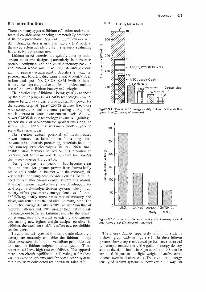
Introduction 913
2oo r LIS: CI, 500 A h cell
There are many types of lithium cell either under com- mercial consideration or being commercially produced. A list of representative types of lithium batteries with their characteristics is given in Table 9.1. A look at these characteristics should help engineers evaluating batteries for equipment use.
Lithium-based batteries are quickly entering main- stream electronic designs, particularly in consumer, portable equipm’ent and non-volatile memory back-up applications where small size, long life and low cost are the primary requirements. Specifically, watches, pacemakers, Kodak’s disc camera and Mostek’s dual- in-line packaged 16K CMOS RAM (with on-board battery back-up) are good examples of devices making use of the newer lithium battery technologies.
The practicality of lithium is being greatly enhanced by the current progress in CMOS technology. Indeed, lithium batteries can easily provide standby power for the current crop of ‘pure’ CMOS devices (i.e. those with complete p- and n-channel pairing throughout), which operate at nanoampere current levels. As low- power CMOS device technology advances - gaining a greater share of semiconductor applications along the way - lithium battery use will undoubtedly expand to serve these new areas.
The electrochemical potential of lithium-based power sources has been known for a long time. Advances in materials processing, materials handling and non-aqueous electrolytes in the 1960s have enabled manufacturers to reduce this potential to practical cell hardware and demonstrate the benefits that were theoretically possible.
During the past few years, it has become clear that the need for greater power from hermetically sealed cells could not be met with the mercury, sil- ver or alkaline manganese dioxide systems. To fill the need for a higher energy density system at a reason- able cost, various manufacturers have developed prac- tical organic electrolyte lithium systems. The lithium battery offers gravimetric energy densities of up to 330Wh/kg, nearly three times that of mercury and silver, and four times that of alkaline manganese. The volumetric ener,gy density is 50% greater than that of mercury batteries and 100% greater than that of alkal- ine manganese batteries. Lithium cells offer the facility of reducing size and weight in existing applications, and making new lighter weight designs possible. In addition, the excellent shelf life offers new possibilities for designers.
Thee principal types of lithium organic electrolyte battery are currently available; the lithium- thionyl chloride system, the lithium-vanadium pentoxide sys- tem and the lithium-sulphur dioxide system. These batteries all have high-rate capabilities. The approxi- mate open-circuit equilibrium cell voltages for these various cathode systems and for some other systems that have been considered are shown in Table 9.2.
-zinc
Figure 9.1 Comparison of energy densityof lithium cells and other types of cell (Courtesy of Honeywell)
300
250
1
m * 200
3
E 150
r 1
z w .-
Iy Q
> P 5 100
50
0 LISO, ZnIHgO
MnQ, MnOz
Figure 9.2 Comparison of energy density of lithium-sulphur and other types of cell (Courtesy of Honeywell)
The energy density superiority of lithium systems is shown graphically in Figure 9.1. The three lithium systems shown represent actual performance achieved by battery manufacturers. The gains in energy density seen in the data shown in Figures 9.2 and 9.3 can be attributed in part to the light weight of active com- ponents used in lithium cells. The volumetric energy density of lithium systems is, however, not always so

U
rc 2 2. % Table 9.1 Representative types of lithium battery
Chemistry Electrolyte Initial Discharge Supplier Purt no. Capacity Current Operating Shape and size Price voltage curve (mA h) temperuture (mm)* ( 100 qty)
(VI ("C)
Lithium-iodine Solid 2.8
Lithium-carbon Organic 2.7 mono fluoride
Lithium-manganese Organic 3.0 dioxide
Lithium-sulphur Organic 2.8 dioxide Lithium-thionyl Inorganic 3.5 chloride liquid
Lithium-copper Organic 2.0 oxide
Sloping Catalyst Research Catalyst Research Medtronics
Flat Pmasonic Ray-o-Vac Ray-0-Vac
Sloping SAFT SAFT Duracell Duracell
Duracell
Union Carbidc Tadiran Tadiran
Flat SAFT
Flat SAFT
Flat SAFT (at 1.5V)
1935 2736 Custom? BR2I3A BR-1225
LM 2020 LM 2425 DL 2430 DL 2/3A LX 16/34 LO 26SX LS6 L3 1 TL 2150 TL 2100 LC6
BR-2325
200 350 NA 1200
35 160 90
200 200
1 1000 8500 1700 1000 850
1750 3400
Low WA -55 to +70 Low p A -55 to +125 NA NA To 1 A -40 to +85 Low pA -40 to +85 Low FA -40 to +85 To 1OmA pulse -20 to +SO To 15mA pulse -20 to +50 Low pA 0 to +40 l0OmA 0 to +40 1 to 100mA -40 to +55 To 1 A -40 to +52 50 mA -40 to +71 40 mA -60 to +75 l0OmA -55 to +75 100 mA -55 to +75 1 mA -55 to +125
Coin 19 x 3.5 Coin 25 x 3.6 Custom 2/3lA Coin 12 x 2.5 Coin 23 x 2.5 Cylinder 20 x 2.0 Coin 24 x 2.5 NA 213 A Cylinder 16 x 34 D Cylinder 50 x 13 Cylinder 46 x 13 1/2AA AA A A
6.88 5.62 NA 1 .oo 1.50 1 .so 1.30 1.30 1 .oo 3.50 5.60
10.00 8.05 1.46 NA NA 1.30
NA, not available *Size of batteries can be decoded h m part numbering +MedUonics specializes in custom shapes $Most batteries available off the shell

264 r
Introduction W5
Table 9.2 Open-circuit equilibrium cell voltages for various cathode systems
ithium-organic electrolyte primary battery
0 l-2- -291 -18 -6 4 15 26 38 49
Temperature ("C)
Figure 9.3 Comparison of energy density of organic versus magnesium batteries at various temperatures at nominal 30 h rate (Courtesy of Honeywell)
greatly differen1 from that of aqueous systems. The higher gravimetric energy density of the lithium sys- tem is demonstrated by the comparison of weights of standard size D-cells of various systems given in Table 9.3.
Typical voltage characteristics on medium load for a lithium type (lithium-sulphur dioxide) battery is compared with those for other types of primary battery in Figure 9.4. The outstandingly higher voltage of the lithium system is apparent.
The construction of organic lithium cells is some- what different from that of mercury and alkaline man- ganese cells. A lithium foil anode, a separator and a carbonaceous cathode 2re spirally wound together. This assembly is placed in a steel case, and the anode and cathode are connected with welded tabs to the case and top assembly. Since the electrolyte is non-aqueous, there is no hydrogen gas evolved during discharge. The
System Formula Cell voltage (V)
Thionyl chloride soc12 3.6
Sulphur dioxide so2 2.9 Molybdenum trioxide Moo3 2.9
Silver chromate AgzCrO4 3.0
Vanadium pentoxide vzo5 3.4
Copper fluoride CuF2 3.4
Copper sulphide cus 2.2
Table 9.3 Weights of various standard size D-cells
System Weight jor D-cells (g)
Lithium-sulphur dioxide 94 Carbon-zinc 94 Magnesium perchlorate-manganese dioxide 99 Lithium- thionyl chloride 100 Lithium-vanadium pentoxide 128 Alkaline manganese dioxide 128
assembly contains a vent to prevent the build-up of high internal gas pressure resulting from improper use or disposal.
Lithium organic cells offer higher energy density. superior cold temperature performance, longer active life and greater cost effectiveness.
9.1.1 Higher energy density The higher energy density is attributable, to a large extent, to the operating voltage of most lithium-based
3.0 r
2.5
2.0
> - & '1.5 c 0
Mercury \
-
'. Alkaline manganese
> 1.0
Zinc-carbon 0.5
I I I 1 I I I I 0 10 20 30 40 50 60 70 80 90
Length of service (h)
Figure 9.4 Typical voltage characteristics on medium load of lithium and other types of battery (Courtesy of Honeywell)

9/6 Lithium batteries
4.0 r " 2 0 5 SOCI,
0 25 50 75 100 Percentage of active life
Figure 9.5 Voltage discharge profile of lithium-vanadium pen- toxide (V~OS), lithium-thionyl chloride (SOCIz), lithium-sulphur dioxide (SO2) lithium-molybdenum trioxide (MoOQ) cells (Courtesy of Honeywell)
electrochemical couples. Lithium, having the highest potential of metals in the electromotive series, provides an operating voltage of about twice that of traditional systems. The voltage discharge profiles of the systems mentioned above are shown in Figure 9.5.
9.1.2 Superior cold temperature performance
Because of the non-aqueous nature of the electrolytes used in lithium systems, the conductivity of these systems at cold temperatures is far superior to that of previously available systems. Table 9.4 compares the relative performance of two lithium systems with the cold temperature performance of other systems. The lithium-vanadium pentoxide and lithium-sulphur dioxide data shown are from tests conducted on prac- tical hardware configurations and at moderate dis- charge rates. The numbers given reflect the percentage of room temperature performance that is achievable at the colder temperatures. Lithium-vanadium pentox- ide and lithium-sulphur dioxide systems will operate
satisfactorily at temperatures as low as -55°C with efficiencies approaching 50%.
9.1.3 Long active shelf life Another significant benefit offered by lithium-based systems is their potential for long active shelf life. Her- metically sealed cells, made possible by using systems that do not generate gas during discharge, protect the cell from impurities from external environments and prevent leakage of electrolyte from the cell. This, in addition to the absence of self-discharge reactions, or the low rate at which they occur, gives lithium sys- tems in active primary batteries the potential for 5-10 years' shelf life without providing special storage envi- ronments. Also, the discharge products of most lithium systems are such that they do not contribute to, or increase the rate of, self-discharge. Therefore, lithium cells can also be reliably used intermittently over sev- eral years in applications where it is advantageous or required. A comparison of the projected shelf life for various cell systems is shown in Table 9.5. In this com- parison, acceptable shelf life is defined as the time after which a cell will still deliver 75% of its ori- ginal capacity. Hermetically sealed lithium-sulphur dioxide double-C cells after storage for 180 days at 71°C deliver 88% of their fresh cell capacity when dis- charged at room temperature into an 8 !J load. By some standards 180 days' storage at 71°C is approximately equivalent to over 12 years at room temperature. This would imply that these cells would exhibit about 1% annual degradation at room temperature. This has been confirmed by discharge of non-hermetically sealed Honeywell lithium-sulphur dioxide double-C cells which were stored for approximately 1 year at 27°C. After storage these cells exhibited no losses in
Table 9.4 Cold temperature performance of lithium-organic electrolyte systems
Temperature Percentage of room temperature performance
Lithium- Lithium- Merculy Magnesium Alkaline Carbon-zinc vanadium sulphur pentoxide dioxide
("C)
-7 88 96 0 58 15 5 - 29 78 85 0 23 3 0 -40 13 60 0 0 0 0
Table 9.5 Comparison of projected shelf life for various lithium-organic electrolyte cell systems
Storage tempe rature
("C)
Lithium Mercury Magnesium Alkaline Carbon- manganese zinc
dioxide
21 10 years + 3-4 years 5-7 years 2-3 years 1-2 years 54 12 months + 4 months 7 months 2 months 1.5 months

Approximately 330 W h/kg have been obtained in experimental cells at the 100 h rate using this couple in a propylene carbonate electrolyte. Cells consisting of lithium-cupric chloride have operated down to -40°C and give 100 W h k g at high discharge rates (approxi- mately 10 h rate). However, both of these systems have poor activated shelf life and are currently practical only in reserve structures.
There are in fact many other types of lithium cell at present under commercial consideration, and a range of lithium cells that have been considered by the Catalyst Research Corporation for use for watch and calculator applications is discussed below.
Because the introduction of lithium power sources to the electronics industry is so recent, many poten- tial users are not aware that lithium batteries are not all alike. Lithium is only the first name of any lithium power source. Just as there are many zinc batteries available (zinc-carbon. zinc-silver oxide, zinc-mercuric oxide) there are many varieties of lithium system, each with its own peculiar internal chemistry and construction. Several of these systems are briefly described below.
Table 9.6 shows the lithium systems available for commercial use from Catalyst Research Corporation. Most are button cells approximately 20-30mm in diameter and 1.5-3 mrn thick. All are high-voltage cells with moderate or high internal resistances. The first two have seen use in watches or calculators only; the remaining three have also been used in the pacemaker field.
Like any common batteries, lithium batteries will rupture if exposed to fire. The low-rate lithium batteries, intended for watches, should be safe if used within manufacturers’ specified temperatures. Thick separators in these low-rate cells prevent shorting and their small size permits easy heat dissipation if any local internal reactions should occur. In fact, a good case can be made that most low-rate lithium cells are safer than zinc-mercury cells, whch can introduce poisonous mercury into the atmosphere when incinerated. SAFT supply lithium-copper oxide
performance under identical test conditions, based on lot acceptance test data generated with fresh cells.
9.1.4 Cost effectiveness In high-volume production the lithium-based systems will compete directly with mercury and silver systems on a cost per watt hour basis. Cost comparisons with alkaline systems will be marginal on a per watt hour basis, but cost advantages can be realized by consid- ering the cost advantages of other systems with that achievable with a lithium power source. The increases in overall system cost effectiveness can be achieved as
1. More payloald may be possible when using lithium batteries due to their smaller size and/or lighter weight.
2. More operating life will be achievable with the same size but lighter battery.
3. Performance at colder temperatures will be pos- sible.
4. Longer active life will result in reduced main- tenance cost:; associated with battery replacements, especially in remote locations, or in other applications where replacing the battery is a labour- intensive function.
5. Replacement inventory costs will be reduced because periodic replacement of batteries will be significantly decreased or eliminated.
fQllOW S:
6. No special storage provisions are required.
Even though cell costs may be high initially, peo- ple responsible for maximizing a system’s overall cost effectiveness must look at the total life-cycle tests and take these points into consideration. As well as lithium--vanadium pentoxide, lithium-sulphur dioxide and lithium-thionyl chloride systems, there exist other types of cell containing organic elec- trolytes and lithium. For example, the lithium-copper fluoride couple has a theoretical voltage of 3.5V and a theoretical energy-to-weight ratio of 1575 W hkg.
Table 9.8 Types of lithium cell available from Catalyst Research Corporation
System Energy density
(Wh/dm3)
Lithium-manganese 440 dioxide Lithium-carbon 330 fluoride Lithium-thionyl 500 chloride Lithium-lead iodide 470 Lithmm-iodine 600 P2VP
Seal Voltage (VI
Crimp 2.9
crimp 2.8
Hermetic 3.6
Hermetic 1.9 Hermetic 2.8
Electrolyte
Liquid organic Liquid organic Liquid inorganic Solid salt Solid salt
Volume change
?
?
Small shnnkage ?
None
Self- Internal discharge resistance
? Moderate
Moderate Moderate
? Moderate
Low High ~ 5 % in High 10 years
Separator added
Yes
Yes
Yes
Yes No: forms in situ

9/8 Lithium batteries
and lithium-silver chromate cells. Matsushita supply lithium-carbon fluoride cells. Venture Technology (formerly Ever Ready (Berec)), Ray-o-Vac and Say0 (Japan) supply lithium-manganese dioxide cells. A further type of cell which has reached commercial realization is the Venture Technology lithium-ferrous sulphide cell (1.5 V/cell nominal). It has a volumetric energy density of 500-900Wh/dm3 and has an excellent shelf and working life and very good low- temperature performance, with similar applications to the lithium-manganese dioxide cell.
9.2 Lithium-sulphur dioxide primary batteries Of all the lithium battery systems developed over the last decade, the system based on sulphur dioxide and an organic solvent is now acknowledged to have emerged as the most successful both commercially and technically. Other lithium batteries are capable of delivering as great or greater energy densities, in particular the lithium-thionyl chloride systems. How- ever, the latter system may give rise to spontaneous decomposition of explosive violence in high-rate bat- teries, while the other lithium systems do not have the high-rate capabilities of the lithium-sulphur dioxide battery.
The reactivity of lithium necessitates controlled- atmosphere assembly during manufacture, and in some cases the use of expensive materials in the cell con- struction to avoid corrosion and the provision of a sophisticated seal design.
Although lithium batteries have high-rate discharge capability, their use at very high rates or accidental shorting could result in temperatures leading to seal failure or explosion. Manufacturers incorporate vents and/or fuses to minimize these risks.
Honeywell Inc. and the Mallory Battery Company in the USA have introduced lithium batteries based on the lithium-sulphur dioxide electrochemical couple. The positive active material in these batteries, liquid sul- phur dioxide, is dissolved in an electrolyte of lithium bromide, acetonitrile and propylene carbonate, and is reduced at a porous carbon electrode.
This type of battery has a spiral-wound electrode pack, made from rectangular foil electrodes. Lithium foil is rolled on to an expanded metal mesh current collector as the negative electrode, and is separated from the similarly supported cathode by a polypropy- lene separator. Two types of cell construction are used: jelly-roll electrodes in crimp-sealed or hermetically sealed cylindrical cells, and large 20-100Ah 12V flat-plate electrodes in large reserve batteries. It is a relatively high-pressure system and cells must have safety vents to avoid explosion in the event of acci- dental incineration (see Part 2 for further details of construction).
The lithium-sulphur dioxide cell has an open circuit voltage of 2.92V at 20°C and a typical voltage under
rated load of 2.7V compared with 1.5V for most conventional types of battery. The specific voltage on discharge is dependent on the discharge rate, discharge temperature and state of charge. The end or cut- off voltage is 2V. The lithium system is capable of maintaining more stable voltage plateaux at higher currents than any other cell of comparable size.
It is also claimed that the lithium-sulphur dioxide system operates very efficiently over a wide range of temperatures (typically from -40 to +70"C), achiev- ing higher discharge rates at lower temperatures than are possible with other types of cell, which provide little service below -18°C. The cells can be operated with success at elevated temperatures. When operated at very high currents outside the recommended lim- its, the cells may produce heat and high internal gas pressures, and these conditions should be avoided. The cells are, however, an excellent source for high pulse currents. Multicell batteries contain additional insula- tion as well as a fuse for protection from mishandling such as short-circuits.
A typical energy density of a lithium-sulphur diox- ide cell is 420Wh/dm3 or 260Whkg according to one manufacturer and 330 W h k g and 525 W h/dm3 according to another. These are nearly three times the values expected for mercury-zinc cells, four times that of an alkaline manganese dioxide cell and two to four times higher than that of conventional zinc and magnesium type batteries.
The high volumetric energy densities reflect the high voltages of the lithium-based systems. One reason for some lack of acceptance in miniature applications is that although one lithium cell could be specified where it is necessary to use two mercury cells in series, a lithium button cell would have a capacity approximately one-half that of the equivalent mercury cell, and the frequency of battery charging would in extreme cases be correspondingly increased.
The volumetric ampere hour capacity of mercuric oxide-zinc cells is higher than that of lithium-based systems. However, in many cases, using two lithium cells in parallel or one larger lithium cell will give the same ampere hour capacity as can be achieved in an equal or even smaller volume by an equiv- alent two-cell series mercury -zinc battery of sim- ilar voltage. This is illustrated in Table 9.7. One lithium-sulphur dioxide cell (voltage 2.7.5 V) occu- pies about 30% more space than two series mer- curic oxide-zinc cells (voltage 2.5 V). Admittedly, this compares the worst cited case for lithium against the best for mercuric oxide-zinc. Higher energy den- sity systems such as lithium-vanadium pentoxide and lithium-sulphur dioxide would show significant vol- ume savings over an equivalent ampere hour mercuric oxide-zinc system. In fact lithium-sulphur dioxide systems are being increasingly considered for high-rate miniature power source applications including military applications where it is found that a two-cell mercuric

Lithium-thionyl chloride primary batteries 9/9
as great or greater energy densities, in particular the lithium-thionyl chloride systems (see below). How- ever, the latter system may give rise to sponta- neous decomposition of explosive violence in high- rate batteries while the other lithium systems do not have the high-rate capabilities of those using soluble depolarizers.
Lithium-sulphur dioxide cells are available in a variety of cylindrical cell sizes from companies such as Honeywell and Duracell International. capacities available ranging from 0.45 to 21 Ah. Larger cells are under development. A number of the cells are manufactured in standard ANSI (American National Standards Institute) cell sizes in dimensions of popular conventional zinc primary cells. While these single cells may be physically interchangeable, they are not electrically interchangeable because of the high cell voltage of the lithium cell.
Standard and high-rate cells are available. The standard cell is optimized to deliver high-energy output over a wide range of discharge loads and tempera- tures. The high-rate cell is designed with longer and thinner electrodes than the standard cell and delivers more service at a high discharge rate (higher than the 10 h rate) and at low temperatures. At lower discharge rates, the service life of the high-rate cell is less than that delivered by the standard cell.
In addition, Duracell manufacture a lithium limited (or balanced) cell (designated SX). The cell is designed with a stoichiometric ratio of lithium to sulphur diox- ide in the order of 1: 1 rather than the excess of lithium used in the other designs. The lithium-limited feature ensures the presence of sulphur dioxide throughout the life of the cell to protect the lithium from chemically reacting with the other cell components. This design has been found successfully to withstand extended reverse discharge below 0 V at rated loads. In addition, these cells do not produce the toxic chemicals that form when standard cells are fully discharged, thus simplify- ing disposal procedures. The lithium-limited cell does, however, deliver lower capacity at low discharge rates, compared with the standard cell (below the 5 h rate).
Claimed advantages of lithium-sulphur dioxide cells are their high energy density (275Wh/kgg1), three times that of carbon-zinc cells, their high power density, a wide operating temperature range (-54 to 71"C), high cell voltage (2.95V), flat discharge curve and long shelf life (99% capacity retention after 5 to 10 years storage at 2l'C).
Table 9.7 Comparison of lithium-sulphur dioxide and mercuric oxide-zinc cells
Lithium-sulphur Mercuric dioxide oxide-zinc
Volumetric energy density (W h/dm3) 420 500 (at best) Normal working voltage (V) 2.75 1.25 Volumetric capacii y (A w h ) 153 400 Relative cell volume (per A h) 2.6 1 .o
oxide-zinc battery can occupy considerably more space than the equivalent lithium-sulphur dioxide cell.
The lithium-sulphur dioxide system is versatile and relatively inexpensive. This battery has excellent stor- age characteristics. Honeywell claim that the batteries should store for 12 years at 20°C. The battery can be supplied either as reserve batteries with capacities between 20 and lO0Ah or as active batteries in the 0.7-20Ah range (see Table 56.2).
The lithium-sulphur dioxide battery has a high power density and is capable of delivering its energy at high current or power levels, well beyond the capability of conventional primary batteries. It also has a flat discharge characteristic.
Lithium-sulphur dioxide batteries are subject to the phenomenon known as voltage delay, a char- acteristic shared with lithium-vanadium pentoxide arid lithium-thionyl chloride batteries. After extended long-term storage at elevated temperatures, the cell may exhibit a delay in reaching its operating voltage (above 2.0 V) when placed on discharge, especially at high current loads and at low temperatures. This start- up delay is basically caused by film formed on the anode, the characteristic responsible for the excellent shelf life of the cell. The voltage delay is minimal for discharge temperatures above -30°C. No delay is measurable for discharge at 21°C even after storage at 71°C for 1 year. On -30°C discharges, the delay (time to 2V) was less than 200ms after 8 weeks' storage at 71°C on discharges below the 40h rate. At higher rates, the voltage delay increased with an increase in storage temperature and time. However, even at the 2 h discharge rate, the maximum start-up time is 80 s after 8 weeks' storage at 71°C. After 2 weeks' storage, the s t a -up time is only 7 s. The start-up voltage delay can be eliminated by preconditioning with a short dis- charge at a higher rate until the opening voltage is reached, since tlhe delay will return only after another extended storage period.
As mentioned above, the lithium-sulphur dioxide system has emerged as the leading candidate among the high energy density batteries for high-rate applica- tions. Other lithiurn batteries are capable of delivering
9.3 Lithium-thionyl chloride primary batteries This system uses a lithium anode and a gaseous cath- ode dissolved in an inorganic electrolyte. It has a 3.63 V open-circuit voltage and a typical voltage under rated load of 3.2-3.4V. Like the lithium-sulphur dioxide system, it has a very flat discharge profile through 90% of its life. Cell construction is similar

9/10 Lithium batteries
- - J 1 -
to that of the lithium-sulphur dioxide cell, except that hermetically sealed cells are mandatory at present. The lithium-thionyl chloride system is a very low- pressure system and, because of that, it is potentially superior to lithium-sulphur dioxide systems in high- temperature and/or unusual form factor applications. The cells are manufactured without any initial internal gas pressure and, because the discharge reaction gen- erates only a limited amount of gas, the need for venting is eliminated. The system appears to be safe in low-rate cell designs, and may be safe, if prop- erly vented, in high-rate cell designs; however, there is an insufficient database on the system (particularly in the high-rate configuration) to make that claim with a high degree of confidence. One manufacturer claims to supply cells that have an energy density in excess of 1100 W h/dm3 and 660 W Wkg. Another manufacturer claims an energy density of 800 Wh/dm3, compared to 400 W h/dm3 for zinc-mercury, 200 W h/dm3 for zinc-carbon and 300 W h/dm3 for alkaline manganese dioxide (the corresponding W h k g data for the four types of cell are 420, 100, 80 and 100).
Yet another manufacturer claims the following energy densities at low rates of discharge:
Small cells 500Whflcgp1
Large cells 700 W h/kg-'
Theory 1489 W fig-' 2000 W h/dm-3
Cells operate at temperatures between -55 to 150°C. They have a shelf life of up to 10 years due to their
negligibly low self-discharge rate, e.g. 97% of original capacity is retained after five years' storage. Earlier versions of this battery exhibited severe passivation of the lithium anode, which severely limited shelf life. For example, at discharge current density as low as 0.6 mA/cm2, significant initial voltage drop and volt- age delay were observed at 25°C after storage periods as short as 1 week at 72°C. The primary cause of the voltage drop is the formation of a film. which results in excessive anode passivation. This becomes evident on closed circuit as a sharp initial voltage drop and a long recovery before the voltage stabilizes (that is, voltage delay). This is clearly illustrated in Figure 9.6, which shows the strong anode polarization and initial cell voltage drop followed by a slow recovery to a useful cell voltage. Investigations by workers at Honeywell have shown that the passivation film on the anode pro- duced in the lithium-aluminium chloride electrolyte consists of lithium chloride. They have also shown that the formation of this film can be prevented by the inclusion of 5% sulphur dioxide in the electrolyte. It is significant that effective control of lithium passivation appears to be critically dependent on the sulphur diox- ide concentration. As shown in Figure 9.7, discharge performance after storage can be adversely affected at
100owwdm-~
1000 w w w 3 / ,tlO%SO, - e - - -
1 1 1 1 1 1 1 1 1 1 1 1 1 1 1
W
L 4.0- Cathode 2 3.0 -
2 'E 2.0 f .- .3 1.0 E 5 I
8 E
2 2 0 1.5 3.0 4.5 6.0 7.5 9.0 10.5 12.0
W 0
I I I I I I I I J 0 1.5 3.0 4.5 6.0 7.5 9.0 10.5 12.0
Time (h)
Figure 9.6 Honeywell lithium-thionyl chloride cell: polarization and voltage delay of a lithium-thionyl chloride cell at 24°C after 3 weeks' storage at 24°C; loads 120 mA (30 min) to 45 mA (30 min); electrolyte 1.5 M LiAICI4 (commercial grade) SOCln (Courtesy of Honeywell)
A , -0cv -
n 1 > 3
greater than 5 weight % level. At these higher sul- phur dioxide levels after 2 weeks at 74"C, cells were found to be anode limited and showed severe polariza- tion under a 120mA load when they were discharged at -29°C.
Short circuiting of lithium-thionyl chloride cells with the risk of subsequent cell explosions have led to a limited use of these cells in particular areas, e.g. military and medical applications.
These cells are available in small prismatic and cylindrical cell designs with capacities up to 1 A h and in flat, cylindrical and prismatic designs with capacities up to 20000Ah. Twenty year reserve cells are also available.
9.4 Lithium-vanadium pentoxide primary batteries This system utilizes the lithium anode, a car- bon-vanadium pentoxide cathode and a double-salt metal fluoride electrolyte (lithium hexafluoroarsenate

Lithium-vanadium pentoxide primary batteries 9/11
3.5
3.0
2.5
\ Eveready \ ZnAg,O I
- > 2.0 - 0 m
2 1.5 - -
Eveready ZnAgO
1.0
0.5
I I I I I I I -I 0 40 80 120 160 200 240 280 320
Capacity (rnA h)
System Diameter Height Rate Nominal Capacity (mm) (mm) voltage
mAh mWh (VI
ZnAgO 12 4 65K 1.5 170 255
Z d g 2 0 ZnHgO 12 4 65K 1.35 150 203
12 4 65K 1.5 120 180 LiV205 28 3 5K 3.3 100 330 LiV205 28 5 5K 3.3 300 990 LiCF, 22 2.5 5K 2.65 140 370
Figure 9.8 Button cell comparison: Honeywell lithium versus other systems (Courtesy of Honeywell)
dissolved in methyl formate). It has a unique two- plateau discharge profile (see Figure 9.8) of approx- imately 3.4V for the first 50% of life and 2.4V for the last 50%. When both plateaux are used it offers an energy density (660 W h/dm3, 264 W hkg) intermedi- ate between that of the lithium-sulphur dioxide and the lithium-thionyl chloride systems. It is a relatively low-pressure system and low-rate cells using it need not be vented. IC is ideal for those applications in which safety is of the utmost importance. This battery has excellent storage characteristics (Figure 9.9).
The voltage discharge profile of the lithium-vana- diurn pentoxide battery is compared with that of lithium-thionyl chloride and 1il.hium-sulphur dioxide systems in Figure 9.5. Lithium-vanadium pentoxide systems operate satisfactorily at temperatures as low as -55°C with efficiencies approaching 50% (Table 9.3).
Lithium-vanadium pentoxide cells lose about 3% capacity per annum when stored at 24°C. Cell per- formance decreases at elevated storage temperatures. Thus, the cell becomes completely discharged after 40-70 days' storage at 71°C.
Honeywell can supply small lithium-vanadium pentoxide cells with capacities up to 100mAh,
3 5
- > - 3.0 %
g c -
2.5 V Average voltage: baseline = 3.26 V
storage = 3.21 V 2.0 0 50 1 00
Percentage of rated capacity
Figure 9.9 Honeywell lithium-vanadium pentoxide cell discharge performance after 1 and 2 years' active storage at 24°C current density 0 4 mNcm2 (Courtesy of Honeywell)
glass ampoule reserve cells with capacities up to 500 mA h, cylindrical, button, prismatic and flexible cell configurations, and a range of active cells.
Honeywell have recently developed a high-integrity crimp-sealed lithium-vanadium pentoxide button cell. This has an open-circuit voltage of 3.42V and a voltage under load of more than 3V. The G3093 model has a rated capacity of 300 mA h and the (33094

9/12 Lithium batteries
of 100mAh, both under the rated load. The energy density is 180-300 W Wdm3 and 132 Whkg. The cells are 29.08 mm in diameter, 25-50 mm thick and weigh 6-8g. The operational temperature range is -29 to + 4 9 T and they have a projected storage capability at 23°C of more than 20 years.
Development work carried out by Honeywell has shown that although a solution of lithium hexaflu- oroarsenate dissolved in methyl formate at a concen- tration of 2 movl is one of the most conductive organic electrolyte solutions known, at high temperatures it decomposes to produce gases including carbon monox- ide and dimethyl ether. This instability becomes appar- ent in active cells through case swelling caused by a rise in internal pressure, which is often accompanied by self-discharge due to cell distortion. In reserve cells instability becomes evident by premature cell activa- tion caused by rupture of the glass electrolyte ampoule.
As a result of their investigation work, Honeywell concluded that electrolyte decomposition at elevated operating temperatures in lithium-vanadium pentox- ide cells could be considerably reduced if the elec- trolyte were made basic. Thus an electrolyte with the composition 2 M lithium hexafluoroarsenate (LiAsF6) plus 0.4 M lithium borofluoride (LiBF4) is now used in these cells.
9.5 Lithium-manganese dioxide primary batteries More than 80% of all lithium batteries produced are of the lithium-manganese dioxide type.
This is claimed to be a reliable high-energy miniature power source with a long shelf life and good low-temperature performance, which is safe, leakproof and non-corrosive. The lithium-manganese dioxide battery is a 3 V system combining a lithium anode and a manganese dioxide cathode in a lithium perchlorate electrolyte. The electrolyte is dissolved in an organic solvent (a mixture of propylene carbonate and dimethoxyethane), and the system is completely non-aqueous. The problem of gas evolution due to dissociation of water has now been solved and lithium-manganese dioxide cells will not bulge during storage or under normal operating conditions. The system offers a stable voltage, starting at approximately 3.3 V, and may be considered fully discharged at a cut-off voltage of 2 V. The high voltage is supported by the high energy density associated with lithium, making the system attractive as a substitute for high-energy silver oxide in 3 V and 6 V photographic applications. The energy output of the lithium cell is up to ten times that of a zinc alkaline cell.
Lithium-manganese dioxide batteries are suitable for loads ranging from a few microamps to a few tens of milliamps, with potential for upward extension. The cells may be stored for up to 6 years at room tempera- ture and still retain 85% of the original capacity. Tem- perature excursions to 70°C are permissible, although
extensive storage beyond 55°C is discouraged. Crimp sealed batteries can be operated between -20 and 70"C, whilst more recently produced laser sealed bat- teries can be operated between -40 and 85°C. The system will work between 50 and -2O"C, subject to derating at low temperature. In some designs, up to 70% of the rated capacity is delivered at -20°C. Prop- erties include good storage life and the ability to supply both pulse loads and very low currents. This combina- tion matches the requirements for many applications incorporating microprocessors,
Table 9.8 compares the energy density of Dura- cell lithium-manganese dioxide button and cylindrical cells with those of conventional mercury-zinc, sil- ver-zinc and zinc-alkaline manganese dioxide and carbon-zinc cells.
Table 9.8 Comparison of energy density of lithium-manganese dioxide cells with conventional types
Cell type Energy density
Wh/dm3 W h k g
Button cells (low-rate, C1200 rate) LiMnOz ZnHgO ZnAgO
610 225 425 92 535 135
Cylindrical cells, N size (moderate-rate, 100 mA discharge)
LiMnOz 400 215 Zinc-alkaline manganese dioxide 180 63
60 32 Carbon-zinc
Lithium-manganese dioxide cells are manufactured in a variety of button cell and cylindrical cell forms ranging in capacity from 30 to 1400 mA. Larger capac- ities are under development by Duracell. Ratings are C/200h rate for low-rate cells, and C/30h rate for high-rate and cylindrical cells. In some instances, inter- changeability with other battery systems is provided by doubling the size of the cell to accommodate the 3 V output of the lithium-manganese dioxide cell compared to the 1.5 V of the conventional primary cell. Performance Characteristics are summarized in Table 9.9. These cells exhibit no gassing or pres- sure development in service and are therefore intrinsi- cally safe.
9.6 Lithium-copper oxide primary batteries SAFT supply this type of battery. The particular advan- tages claimed for lithium-copper oxide batteries are long operating life, long shelf life (up to 10 years pro- jected) and high operating temperature (tested between -20 and +5OoC). Volumetric capacity (Ah/dm3) is 750 compared with 300 for alkaline manganese diox- ide, 400 for mercury-zinc and 500 for lithium-sulphur

Lithium-lead bismuthate primary cells 9/13
Table 9.9 Characteristics of lithium-manganese dioxide cells
Open Volts Discharge Gravimetric Volumetric Gravimetric circuit under voltage energy energy power volts load proJile density density density (VI (Wmg- ' ) (W h/dm3) (W kg-' )
3.0-3.6 2.7-3.0 Relatively 150-350 450-750 flat
Volumetric Storage power temperature density ("C)
(W ~ m - ~ )
Operation temperature
("C)
Self Calendar Types discharge life available
rate
- 4 0 -20 to 70 (crimp seal)
(laser seal) -40 to 85
-20 to 70 (crimp seal)
(laser seal) -40 to 85
~~
1% pfa Up to 6y at 20°C Coin, cylindrical, (crimp seal) flat, prismatic,
0.5% (85% capacity available ?la retained)
(laser seal)
dioxide. (Corresponding Whkg values are 300, 100, 100 and 300.) 'The annual self-discharge rate at 20°C is 2-3%. Battery packs containing groups of cells connected in seriedparallel are available for specific applications.
This cell exhibits two voltage plateaux on discharge at higher temperatures (70°C). Discharge starts off at about 1.6V reducing to 1.3V towards the end of discharge. The cell can be operated at temperatures between -55 and 150°C. Cells which had been stored for two years at 21°C gave 93.5% of their original capacity. Self-discharge rates are acceptably low. Volt- age delay effects do not occur.
The cells have resilience to electrical and mechanical abuse. The use of safety shunt diodes across each cell limits voltage reversal to within safety limits.
Cylindrical IL .5 V batteries are available in 3.6 A h (type LCOI), 1.6Ah (type LC02) and 0.5Ah (type LC07). Applications of this type of cell include oil well logging equipment, microprocessors, telephone systems, public address systems, high-temperature heat counters, CMOS memory protection, telex systems, high-temperature devices and specialized industrial and military applications. Details of performance are given in Table 9.10.
On-load voltage is nomnally 1.5 but this depends on rate of discharge and temperature. This is a high energy density system (300 W kg-' , 630 W h dm-3) which leads to high capacity cells, e.g., the AA size has a capacity of 3.7 Ah. The system is ideally suited to low load applications when lives in excess of 10 years have been obtained. An AA size 3.7Ah cell discharged at I, m A cmp2 (lithium electrode area) at 20°C to an end-point voltage of 0.9V gave a cell voltage of about 1.4V for about 150 hours discharge,
decreasing gradually to 0.9 V over a further 150 hours, i.e., 300 hours discharge to 0.9V.
The system has exceptional storage characteristics. Cells can be exposed to a wide range of conditions in which they are exposed to forced current in both the charge and discharge directions without incident. Over charge can cause cell ruptures as does exposure to temperatures above 180°C. Mechanical abuse does not cause fires or explosions. In general, provided the guidelines are adhered to, no hazards are presented to the user.
9.7 Lithium-silver chromate primary batteries SAFT supply a range of these 3.1 V cells with capaci- ties in the range 130-3100mAh (cylindrical cells) and 2090-2450mAh (rectangular cells), see Part 6.
The special features of these cells are high reliabil- ity (better than 0.7 x lo-'), indication of end of life by a second plateau voltage, a discharge capability up to 100pA, and low internal impedance. Applica- tions of lithium-silver chromate cells include cardiac stimulators and other human implantable devices, high reliability memory protection for inertial navigation systems, and RAM back-up power sources.
9.8 Lithium-lead bismuthate primary cells SAFT supply this type of cell. It has a nominal voltage of 1.5 V, exhibits a high energy density (400-500WNdm3, 90-150Whkg), has long life expectancy and is interchangeable with normal IEC button cells with a nominal voltege of I .5 V. The cells

9/14 Lithium batteries
Table 9.10 Characteristics of lithium-copper oxide cells
Volumetric Gravimetric Open Volts Discharge Gravimetric circuit under voltage energy energy power volts load projile density density density (VI (VI (Wmg- ' ) (Wh/dmp3) (Wkg-')
2.4 1.5 Depends on 300 630 630 max current
Volumetric Storage Operation Self Calendar Types power temperature temperature discharge life available density ("C) (" C) rate
(W cm3)
na -40 to 55 -40 to 55 1% p/a 20°C 14Y AA, iAA available
possess a low internal resistance which makes them particularly suitable for analogue quartz watches and pulsing electronic devices. The characteristics of these cells make them interchangeable alternatives in the many applications currently using the traditional silver oxide and mercury oxide button cells. The annual self- discharge rate of lithium-lead bismuthate button cells is 2-3%. The operating temperature range is -10 to f45"C. The cells have a discharge pulse capability up to 500 PA. Applications include, in addition to quartz analogues and LCD watches, cameras, calculators and scientific instruments and any applications in which they replace silver oxide button cells. SAFT supply these 1.5V button cells at three capacities: 185mAh (type LP1154), llOmAh (type LP1136) and 5OmAh (type LP1121).
9.9 Lithium-polycarbon monofluoride primary batteries
In order to exploit the value of a lithium-based sys- tem to the maximum the positive electrode (cathode) material should also be of high energy density. The search for the ideal combination of cathode material and electrolyte attracted a great deal of effort in the 1970s. The lithium-polycarbon monofluoride system has been commercially developed by the Matsushita Electric Industrial Co. in Japan. The cells are avail- able in several cylindrical sizes. They have an open circuit voltage of 2.8 V. This battery has a fairly level discharge voltage profile. The battery is highly reliable and has a claimed shelf life of 10 years. The theoretical energy density is 2000 W h/kg-' against a practically realized value of 200 W h/kg-' or 350 W h/dm-3. The patented cathode material is of the form (CF,), , where x has a value between 0.5 and 1.0, and is formed by reacting carbon with fluorine under various con- ditions of temperature and pressure, depending on the
type of carbon used as the starting material. Except where batteries are intended for low-rate applications, acetylene black or graphite is added to the electrode to improve conductivity. The electrolyte is lithium tetrafluoroborate dissolved in a-butyrolactone. These cells have a spiral wound electrode pack made from rectangular foil electrodes. Lithium foil is rolled on to an expanded metal mesh current collector as the negative electrode and is separated from the simi- larly supported cathode by a polypropylene separ- ator. The characteristics of this cell are tabulated in Table 9.11.
As an example of a low drain application, a BR 2/3AA 3 volt 600mAh cylindrical cell on approx- imately 20 yA drain at temperatures between 0 and 45°C has a life of approximately 5 years. Pulse dis- charge behaviour is good. A 3 volt 255mAh coin cell under 10 C2 load shows a flat voltage characteristic of 2.8V for 10,000 hours duration. Voltage increases somewhat on increasing temperature from 20 to 70°C with little change in duration. Decrease in cell tem- perature from 20°C to -10°C decreases voltage and duration somewhat.
These batteries have a consistently good safety record even under arduous conditions.
9.1 0 Lithium solid electrolyte primary batteries Duracell supply these batteries, which consist basically of a 2 V system capable of supplying currents up to a few hundred microamps at room temperature. The electrolyte is a dry mixture of lithium iodide, activated alumina and lithium hydroxide sandwiched between the lithium anode and the lead/lead iodide/lead sul- phide cathode. The absence of liquid means that the solid electrolyte cell is intrinsically leakproof. The chemistry is exceptionally stable, and it is possible
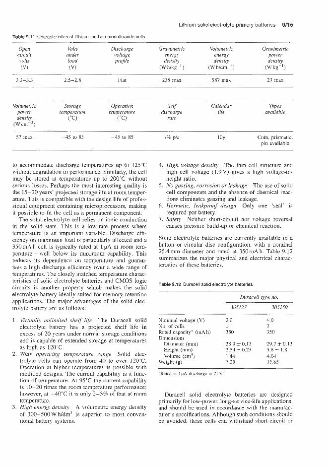
Lithium solid electrolyte primary batteries 9/15
Table 9.11 Characteristics of lithium-carbon monofluoride cells
Open circuit volts 07
Volts Discharge Gravimetric Volumetric Gravimetric under voltage energy energy power load proJile density density density (VI (W mg-' ) (W h / d r ~ - ~ ) (Wkg-')
3.3-3.5 2.5-2.8 Flat 235 max 587 rnax 23 rnax
Volumetric Storage Operation Selj' Calendur Types power temperature temperature discharge life available density ("C) ("C) rate
Cm-3)
57 max -45 to 85 -45 to 85 1% pla 1 OY Coin: prismatic, pin available
to accommodate discharge temperatures up to 125°C without degradation in performance. Similarly, the cell may be stored at temperatures up to 200°C without serious losses. Perhaps the most interesting quality is the 15-20 years' projected storage life at room temper- ature. This is compatible with the design life of profes- sional equipment containing microprocessors, making it possible to fit the cell as a permanent component.
The solid electrolyte cell relies on ionic conduction in the solid state. This is a low-rate process where temperature is ,an important variable. Discharge effi- ciency on maximum load is particularly affected and a 350mA h cell is typically rated at 1 pA at room tem- perature - well below its maximum capability. This reduces its dependence on temperature and guaran- tees a high discharge efficiency over a wide range of temperatures. The closely rnatched temperature charac- teristics of solid electrolyte batteries and CMOS logic circuits is another property which makes the solid electrolyte battery ideally suited for memory-retention applications. The major advantages of the solid elec-
Tab,e 9.12 Durace,l sol,d e,ectrolyte batter,es
Duracell type no.
trolyte battery are as follows: 305127 305159
4. High voltage density The thin cell structure and high cell voltage (1.9V) gives a high voltage-to- height ratio.
The use of solid cell components and the absence of chemical reac- tions eliminates gassing and leakage.
6. Hermetic, leakproof design Only one 'seal' is required per battery.
7. Safety Neither short-circuit nor voltage reversal causes pressure build-up or chemical reaction.
Solid electrolyte batteries are currently available in a button or circular disc configuration, with a nominal 25.4mm diameter and rated at 350mAh. Table 9.12 summarizes the major physical and electrical charac- teristics of these batteries.
5. No gassing, corrosion or leakage
1. Virtuallv unlimited shelf life The Duracell solid Nominal voltage (V) 2.0 4.0 d I I
electrolyte battery has a projected shelf life in excess of 20 years under normal storage conditions and is capable of extended storage at temperatures as high as 120°C. Wide operating temperature range Solid elec- trolyte cells can operate from 40 to over 120°C. Operation at higher temperatures is possible with modified designs. The current capability is a func- tion of temperature. At 95°C the current capability is 10-20 times the room temperature performance; however, at -48°C it is only 2-3% of that at room temperature. High energy density A volumetric energy density of 308-500WWdm' is superior to most conven- tional battery systems.
No. of cells 1 2 Rated capacity* (mA h) 350 350 Dimensions
Diameter (mm) 28.9 i 0.13 29.7 i 0.13 Height (mm) 2.54 + 0.25 5.8 zk 1.8 Volume (cm3) 1.44 4.04
Weight (g) 7.25 15.85
*Rated at 1 discharge at 21°C
Duracell solid electrolyte batteries are designed primarily for low-power, long-service-life applications, and should be used in accordance with the manufac- turer's specifications. Although such conditions should be avoided, these cells can withstand short-circuit or
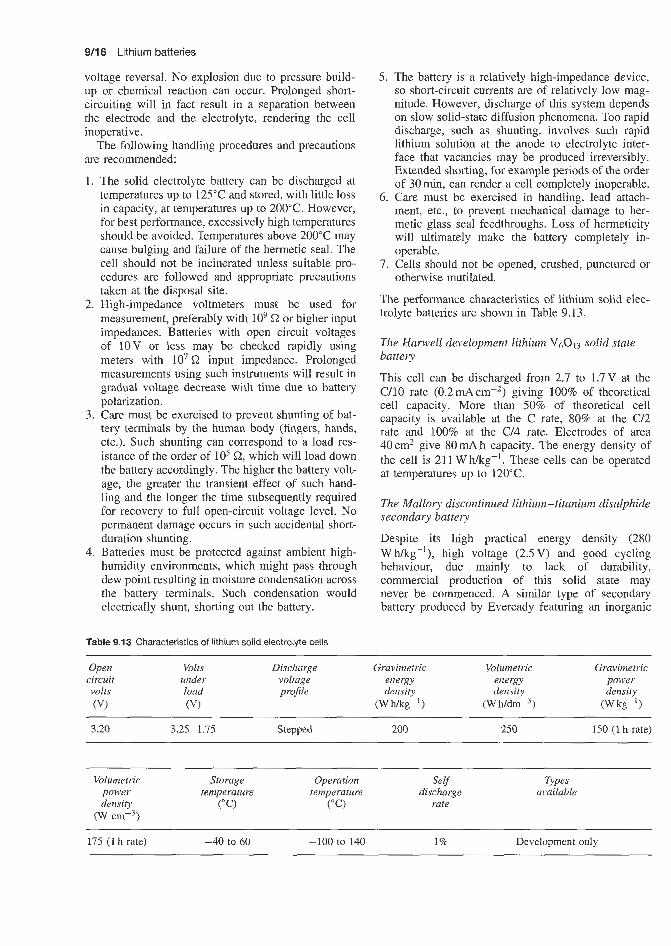
9/16 Lithium batteries
voltage reversal. No explosion due to pressure build- up or chemical reaction can occur. Prolonged short- circuiting will in fact result in a separation between the electrode and the electrolyte, rendering the cell inoperative.
The following handling procedures and precautions are recommended:
The solid electrolyte battery can be discharged at temperatures up to 125°C and stored, with little loss in capacity, at temperatures up to 200°C. However, for best performance, excessively high temperatures should be avoided. Temperatures above 200°C may cause bulging and failure of the hermetic seal. The cell should not be incinerated unless suitable pro- cedures are followed and appropriate precautions taken at the disposal site. High-impedance voltmeters must be used for measurement, preferably with lo9 Q or higher input impedances. Batteries with open circuit voltages of 1OV or less may be checked rapidly using meters with lo7 Q input impedance. Prolonged measurements using such instruments will result in gradual voltage decrease with time due to battery polarization. Care must be exercised to prevent shunting of bat- tery terminals by the human body (fingers, hands, etc.). Such shunting can correspond to a load res- istance of the order of lo5 Q, which will load down the battery accordingly. The higher the battery volt- age, the greater the transient effect of such hand- ling and the longer the time subsequently required for recovery to full open-circuit voltage level. No permanent damage occurs in such accidental short- duration shunting. Batteries must be protected against ambient high- humidity environments, which might pass through dew point resulting in moisture condensation across the battery terminals. Such condensation would electrically shunt, shorting out the battery.
Table 9.13 Characteristics of lithium solid electrolyte cells
5. The battery is a relatively high-impedance device, so short-circuit currents are of relatively low mag- nitude. However, discharge of this system depends on slow solid-state diffusion phenomena. Too rapid discharge, such as shunting, involves such rapid lithium solution at the anode to electrolyte inter- face that vacancies may be produced irreversibly. Extended shorting, for example periods of the order of 30min, can render a cell completely inoperable.
6. Care must be exercised in handling, lead attach- ment, etc., to prevent mechanical damage to her- metic glass seal feedthroughs. Loss of hermeticity will ultimately make the battery completely in- operable.
7. Cells should not be opened, crushed, punctured or otherwise mutilated.
The performance characteristics of lithium solid elec- trolyte batteries are shown in Table 9.13.
The Hanvell development lithium V6O13 solid state battery
This cell can be discharged from 2.7 to 1.7V at the C/10 rate ( 0 . 2 m A ~ m - ~ ) giving 100% of theoretical cell capacity. More than 50% of theoretical cell capacity is available at the C rate, 80% at the C/2 rate and 100% at the C/4 rate. Electrodes of area 40cm2 give 80mAh capacity. The energy density of the cell is 21 1 W h/kg-'. These cells can be operated at temperatures up to 120°C.
The Mallory discontinued lithium-titanium disulphide secondary battery
Despite its high practical energy density (280 W a g - ' ) , high voltage (2.5V) and good cycling behaviour, due mainly to lack of durability, commercial production of this solid state may never be commenced. A similar type of secondary battery produced by Eveready featuring an inorganic
Open Volts Discharge Gravimetric Volumetric Gravimetric circuit under voltage energy energy power volts load projile density density density (VI (VI (W fig-') (Wh/dmb3) (W kg- 1
3.20 3.25- 1.75 Stepped 200 250 150 (1 h rate)
Volumetric Storage Operation Self Types power temperature temperature discharge available density ("C) ("C) rate
(W crnp3)
175 (1 h rate) -40 to 60 -100 to 140 1% Development only
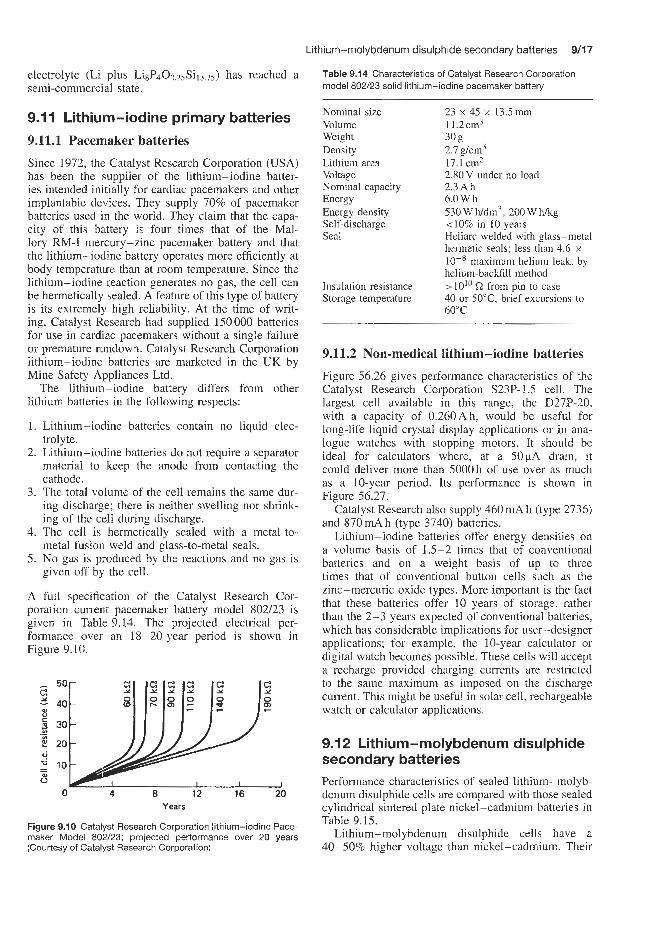
Lithium-molybdenum disulphide secondary batteries 9/17
Table 9.14 Characteristics of Catalyst Research Corporation model 802/23 solid lithium-iodine pacemaker battery
Nominal size 23 x 45 x 13.5mm Volume 11.2cm3 Weight 30 E Density 2.7 gkm3 Lithium area 17.1 cm2 Voltage Nominal capacity 2.3Ah Energy 6.0 W h Energy density 530Wh/dm3, 200Whlkg Self-discharge <lo% in 10 years Seal Heliarc welded with glass-metal
2.80 V under no load
hermetic seals; less than 4.6 x 1W8 maximum helium leak, by helinm-backfill method
40 or 50"C, brief excursions to 60°C
Insulation resistance > 10'' from pin to case Storage temperature
electrolyte (Li plus Li8P400.25Si13.75) has reached a semi-commercial state.
.I 1 Lithiuim-iodine primary batteries 9.11.1 Pacemaker batteries Since 1972, the Catalyst Research Corporation (USA) has been the supplier of the lithium-iodine batter- ies intended initially for cardiac pacemakers and other implantable devices. They supply 70% of pacemaker batteries used in the world. They claim that the capa- city of this battery is four times that of the Mal- lory MU-I mercury-zinc pacemaker battery and that the lithium-iodine battery operates more efficiently at body temperature than at room temperature. Since the lithium-iodine reaction generates no gas, the cell can be hermetically sealed. A feature of this type of battery is its extremely high reliability. At the time of writ- ing, Catalyst Research had supplied 150 000 batteries for use in cardiac pacemakers without a single failure or premature rundown. Catalyst Research Corporation lithium-iodine batteries are marketed in the UK by Mine Safety Appliances Ltd.
The lithium-iodine battery differs from other lithium batteries in the following respects:
1. Lithium-iodine batteries contain no liquid elec- trolyte.
2. Lithium-iodine batteries do not require a separator material to keep the anode from contacting the cathode.
3. The total volume of the cell remains the same dur- ing discharge; there is neither swelling nor shrink- ing of the cell during discharge.
4. The cell is hermetically sealed with a metal-to- metal fusiori weld and glass-to-metal seals.
5. No gas is piioduced by the reactions and no gas is given off by the cell.
A full specification of the Catalyst Research Cor- poration current pacemaker battery model 802/23 is given in Table 9.14. The projected electrical per- formance over an 18-20-year period is shown in Figure 9.10.
0 4 8 12 16 20 Years
Figure 9.10 Catalyst Research Corporation lithium-iodine Pace- maker Model 802/23; projected performance over 20 years (Courtesy of Catalyst Research Corporation)
9.11.2 Non-medical lithium-iodine batteries
Figure 56.26 gives performance characteristics of the Catalyst Research Corporation S23P-1.5 cell. The largest cell available in this range, the D27P-20, with a capacity of 0.260Ah, would be useful for long-life liquid crystal display applications or in ana- logue watches with stopping motors. It should be ideal for calculators where, at a 50pA drain, it could deliver more than 5000 h of use over as much as a 10-year period. Its performance is shown in Figure 56.27.
Catalyst Research also supply 460mA h (type 2736) and 870 mA h (type 3740) batteries.
Lithium-iodine batteries offer energy densities on a volume basis of 1.5-2 times that of conventional batteries and on a weight basis of up to three times that of conventional button cells such as the zinc-mercuric oxide types. More important is the fact that these batteries offer 10 years of storage. rather than the 2-3 years expected of conventional batteries, which has considerable implications for user-designer applications; for example, the 10-year cakulator or digital watch becomes possible. These cells will accept a recharge provided charging currents are restricted to the same maximum as imposed on the discharge current. This might be useful in solar cell, rechargeable watch or calculator applications.
9.1 2 Lithium-molybdenum disulphide secondary batteries Performance characteristics of sealed lithium-molyb- denum disulphide cells are compared with those sealed cylindrical sintered plate nickel-cadmium batteries in Table 9.15.
Lithium-molybdenum disulphide cells have a 40-50% higher voltage than nickel-cadmium. Their

9/18 Lithium batteries
energy density is up to 100% higher than conven- tional nickel-cadmium cells and up to 30% higher than advanced nickel-cadmium designs. The charge retention of lithium-molybdenum disulphide cells at 10% per annum at 21°C is at least one order of mag- nitude less than is the case with nickel-cadmium cells.
Lithium-molybdenum disulphide cells suffer loss in performance when cycled continuously at high voltage. The cell should be used with both charge and discharge control circuitry where termination voltages are set and should not exceed 2.4 V per cell for charge and 1.1 V per cell for discharge. Cell failure which is character- ized by the development of gradually worsening short circuits is caused by degradation of active components in the cell, particularly changes in molybdenum disul- phide structure and reactions between lithium and the electrolyte producing ethylene, propylene and lithium carbonate.
(9.11
CH2,
(9.21 I , co3+ Li = LiCO3 -k CHCH3 = CH2 CHCH3
These cells have many safety features and will not explode on being punctured, crushed or inciner- ated. Regulations and exemptions to regulations exist regarding their shipment, particularly on passenger aircraft.
The performance characteristics of lithium molyb- denum sulphide cells are shown in Table 9.16.
The open circuit voltage varies from 2.4 V at start of discharge to 1 V at 80-100% discharge.
Several hundred full charge discharge cycles are possible with lithium-molybdenum disulphide cells. They exhibit good charge retention on storage. No voltage delay effects occur upon discharge. Based on the change in voltage for cells stored at 1.85 V a self-discharge rate of 5% per annum has been found. Stabilization of cells can be achieved by cycling before storage. Such stabilization exhibits a capacity loss of only 8% per annum and at 2.4V when stored at 21°C.
Charging of cells at rates greater than the 1-h rate leads to cell overheating and eventually combustion.
Multicell batteries are not as efficient as individual cells due to imbalances between individual cells.
9.13 Lithium (aluminium) iron monosulphide secondary batteries The system operates with an open circuit voltage of 1.33V. It has a theoretical energy density of 458 W h kg-', the energy density achieved in practical cells is 105 W h kg-'. Other characteristics of this cell are tabulated in Table 9.17. Li(A1)FeS cells can be thermally cycled between temperatures of 450/500"C and 20°C without adverse effects.
In addition to the cells, this system requires a ther- mal management system to maintain the proper oper- ating temperature for the battery and a specialized charger in which careful voltage control is maintained thereby preventing the positive electrode from reach- ing a potential high enough to produce soluble iron species which deposit in the separator during cycling. The battery is contained in a low thermal conductivity box with an inner vacuum space lined with aluminium foil and glass fibre paper.
Table 9.15 Comparison of sealed rechargeable lithium molybdenum disulphide and sealed cylindrical sintered plate nickel-cadmium cells
Sealed rechargeable Sealed cylindrical sintered plate lithium-molybdenum disulphide nickel-cadmium
Open circuit voltage (V) 2.4- 1.1 1.3 Volts under load (V) 1.854 (C10) 1.2 nominal Discharge voltage profile Sloping Flat
Volumetric energy density (W h dn-3) Gravimetric power density (W kg-') Volumetric power density (W dm-')
Gravimetric energy density (W h kg-') 61 13-35 175 130 375
50-120 according to cell size 750-1000 according to cell size 2500-3500 according to cell size
Storage temperatures ("C) -54 to 55 -40 to 70 Operation temperature ("C) -30 to 55 discharge -40 to 70
-10 to 45 charge Self discharge rate 5% p/a at 21°C 120-300% p/a Cycle life 200 >500 Calender life 10 y estimated 4-8 y in operation
Types available AA (0.6-0.8 Ah) Cylindrical (0.1 - 10 Ah) 5-10y in storage
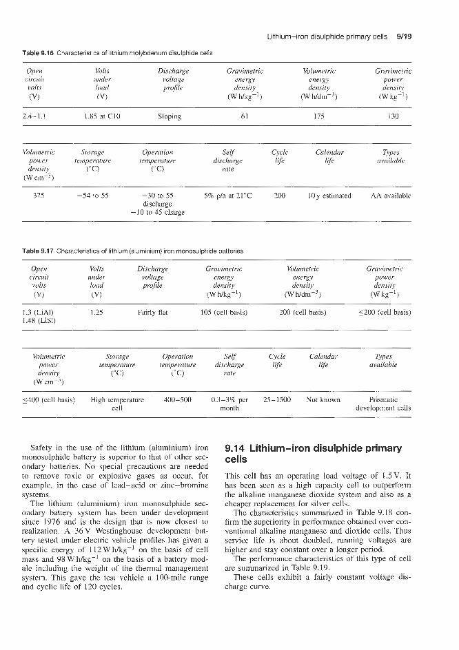
Lithium-iron disulphide primary cells 9/19
Table 9.16 Characteristics of lithium molybdenum disulphide cells
Open Volts Discharge Gravimetric Volumetric Gravimetric circuit under voltage energy energy power volts load pro$le density density density (VI (V) (W mg-') (W h/dm-3) (W kg-' 1
2.4- 1.1 1.85 at C10 Sloping 61 175 130
Volumetric Storage Operation Self Cycle Calendar Types
(W ~ r n - ~ )
power temperature temperature discharge life life available density (" C) ("C) rate
315 -54 io 55 -30 to 55 5% p/a at 21°C 200 1Oy estimated AA available bscharge
-10 to 45 charge -
Table 9.17 Charicteristics of lithium (aluminium) iron monosulphide batteries
Open Volts Discharge Gravimetric Volumetric circuit under voltage energy energy volts load projle density density
(VI (W w-') (W k~ldm-~) 07
- Gravimetric
power density
(Wkg-') ~~ ~ -
1.3 (LiA1) i.25 Fairly flat 105 (cell basis) 200 (cell basis) 5200 (cell basis) 1.48 (LiSi)
~~ -
Volumetric Storage Operation Self Cycle Calendar Types
(W Cm-3)
power temperature temperature discharge life life available density ("C) ("C) rate
5400 (cell basis) High temperature 400-500 0.3-3% per 25-1500 Not known Prismatic cell month developnent cells
Safety in the use of the lithium (aluminium) iron monosulphide battery is superior to that of other sec- ondary batteries. No special precautions are needed to remove toiiic or explosive gases as occur, for example, in the case of lead-acid or zinc-bromine systems.
The lithium (aluminium) iron monosulphide sec- ondary battery system has been under development since 1976 and is the design that is now closest to realization. A 36 V Westinghouse development bat- tery tested under electric vehicle profiles has given a specific energy of 112 W h/kg-l on the basis of cell mass and 98 Wh/kg-l on the basis of a battery mod- ule including the weight of the thermal management system. This gave the test vehicle a 100-mile range and cyclic life of 120 cycles.
9.14 Lithium-iron disulphide primary cells
This cell has an operating load voltage of 1.5V. It has been seen as a high capacity cell to outperform the alkaline manganese dioxide system and also as a cheaper replacement for silver cells.
The characteristics summarized in Table 9.18 con- firm the superiority in performance obtained over con- ventional alkaline manganese and dioxide cells. Thus service life is about doubled, running voltages are higher and stay constant over a longer period.
The performance characteristics of this type of cell are summarized in Table 9.19.
These cells exhibit a fairly constant voltage dis- charge curve.

9/20 Lithium batteries
Table 9.18 Comparison of lithium-iron disulphide and alkaline manganese dioxide cells
Lithium-iron disulphide Alkaline manganese dioxide ~~
Open circuit volts (V) Volts under load (V) Discharge voltage profile Gravimetric energy density (W h kg-') Volumetric energy density (W hdm-3) Gravimetric power density (Wkg-') Volumetric power density (W dm-3) Storage temperature ("C) Operation temperature (" C) Self discharge rate
1.9 1.5 at C/100 rate Flat at medium drain 240 at C/100 rate 550 at C/100 rate 32 13 -40 to 60 -20 to 50 12% p/a
1.5 Variable start near 1.5 Sloping 9-20 150-220 523 557 -40 to 50 -30 to 55 13% p/a (20°C)
Table 9.19 Characteristics of lithium-iron disulphide cells
Open Volts Discharge Gravimetric Volumetric Gravimetric circuit under voltage energy energy power volts load profile density density density (V) (V) (W h kg-l) (W h dmP3) w k g - 9
1.9 1.5 at C/100 rate Flat at medium 240 at C/100 rate 550 at W O O rate 32 drain
Types Volumetric Storage Operation Self Cycle Calendar power temperature temperature discharge life life available density (" C) ("C) rate
( ~ c m - ~ )
13 -40 to 60 -20 to 50 420% p/a AA available
The discharge characteristics of the Eveready No. 803 (R44 size) button lithium-iron disulphide primary cell on a 30'2 load corresponding to 50pA drain shows a running voltage starting at 1.7V reducing to 1.6V half way through its discharge life. On the heavier drain of 2 3 0 ~ A (6.5kQ load) the running voltage is 1.5 V and the step in the voltage curve is not perceptible. The capacity obtained is around 180 mA h to a 1 .O V level point.
This performance compares favourably to that of a monovalent silver oxide cell which delivers around 130 mA h. However. the latter type of cell will deliver much higher currents and the load voltage is substan- tially independent of the current drain over a wide range of discharge rates.
9.15 Lithium-silver-vanadium pentoxide batteries This is a development battery and is a modification of the lithium-vanadium pentoxide battery. It discharges at a range of voltages between 3.2 and 2.6V. It has a good volumetric energy density (870 W h/dm-3) and rate capability, and good current pulsing behaviour. The shelf life is excellent as are safety characteristics.
Possible applications for this cell are cardiac defib- rillators and drug delivery systems.
Manganese dioxide-magnesium perchlorate primary batteries

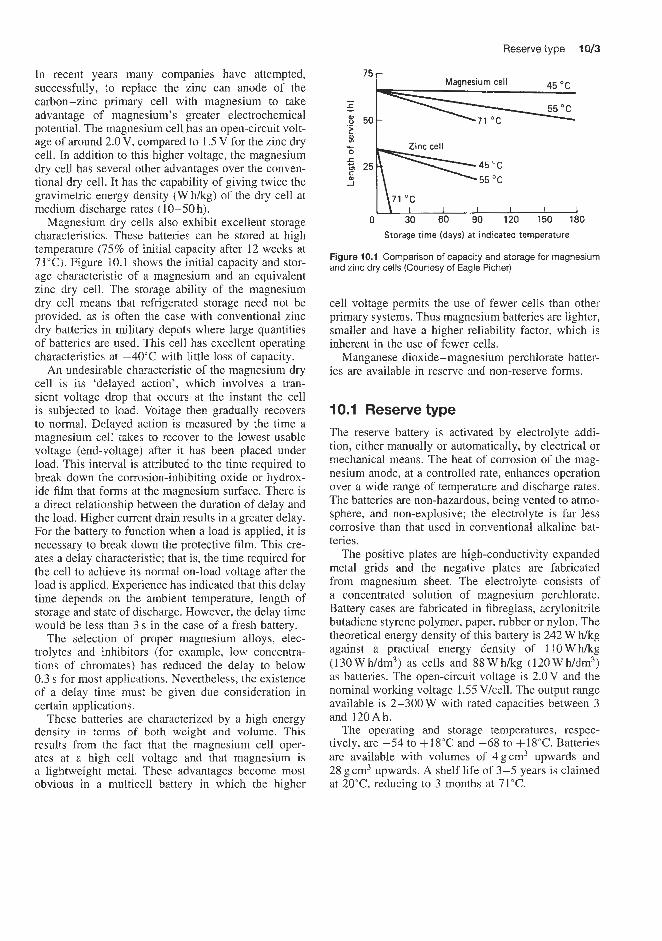
Reserve type 1013
In recent years many companies have attempted, successfully, to replace the zinc can anode of the carbon-zinc primary cell with magnesium to take advantage of magnesium's greater electrochemical potential. The magnesium cell has an open-circuit volt- age of around 2.0 V, compared to 1.5 V for the zinc dry cell. In addition to this higher voltage, the magnesium dry cell has several other advantages over the conven- tional dry cell. It has the capability of giving twice the gravimetric energy density (W f i g ) of the dry cell at medium dischmge rates (10-50 h).
Magnesium dry cells also exhibit excellent storage characteristics;. These batteries can be stored at high temperature ('75% of initial capacity after 12 weeks at 71°C). Figure 10.1 shows the initial capacity and stor- age characteristic of a magnesium and an equivalent zinc dry cell. The storage ability of the magnesium dry cell means that refrigerated storage need not be provided, as is often the case with conventional zinc dry batteries in military depots where large quantities of batteries are used. This cell has excellent operating characteristics at -40°C with little loss of capacity.
An undesirable characteristic of the magnesium dry cell is its 'dlelayed action', which involves a tran- sient voltage drop that occurs at the instant the cell is subjected to load. Voltage then gradually recovers to normal. Delayed action is measured by the time a magnesium cell takes to recover to the lowest usable voltage (end-voltage) after it has been placed under load. This interval is attributed to the time required to break down tlne corrosion-inhibiting oxide or hydrox- ide film that forms at the magnesium surface. There is a direct relationship between the duration of delay and the load. Highler current drain results in a greater delay. For the battery to function when a load is applied, it is necessary to break down the protective film. This cre- ates a delay characteristic; that is, the time required for the cell to achieve its normal on-load voltage after the load is applied. Experience has indicated that this delay time depends on the ambient temperature, length of storage and state of discharge. However, the delay time would be less than 3 s in the case of a fresh battery.
The selection of proper magnesium alloys, elec- trolytes and inhibitors (for example, low concentra- tions of chromates) has reduced the delay to below 0.3 s for most applications. Nevertheless, the existence of a delay time must be given due consideration in certain applications.
These batteries are characterized by a high energy density in terns of both weight and volume. This results from the fact that the magnesium cell oper- ates at a high cell voltage and that magnesium is a lightweight metal. These advantages become most obvious in a multicell battery in which the higher
75
I
r ._ $ 50 z
55 "C
71 "C I I I I I 1
0 30 60 90 120 150 180 Storage time (days) a t indicated temperature
Figure 10.1 Comparison of capacity and storage for magnesium and zinc dry cells (Courtesy of Eagle Picher)
cell voltage permits the use of fewer cells than other primary systems. Thus magnesium batteries are lighter, smaller and have a higher reliability factor: which is inherent in the use of fewer cells.
Manganese dioxide-magnesium perchlorate batter- ies are available in reserve and non-reserve forms.
10.1 Reserve type The reserve battery is activated by electrolyte addi- tion, either manually or automatically, by electrical or mechanical means. The heat of corrosion of the mag- nesium anode, at a controlled rate, enhances operation over a wide range of temperature and discharge rates. The batteries are non-hazardous, being vented to atmo- sphere, and non-explosive; the electrolyte is far less corrosive than that used in conventional alkaline bat- teries.
The positive plates are high-conductivity expanded metal grids and the negative plates are fabricated from magnesium sheet. The electrolyte consists of a concentrated solution of magnesium perchlorate. Battery cases are fabricated in fibreglass, acrylonitrile butadiene styrene polymer, paper, rubber or nylon. The theoretical energy density of this battery is 242 W f i g against a practical energy density of 110 W h k g (130Wh/dm3) as cells and 88Whkg (120Wh/dm3) as batteries. The open-circuit voltage is 2.0V and the nominal working voltage 1.55 V/cell. The output range available is 2-300 W with rated capacities between 3 and 120Ah.
The operating and storage temperatures, respec- tively, are -54 to + 1 8 T and -68 to +18"@. Batteries are available with volumes of 4gcm3 upwards and 28 g cm3 upwards. A shelf life of 3-5 years is claimed at 20T , reducing to 3 months at 71°C.


Magnesium -organic electrolyte primary batteries


Magnesium-organic electrolyte primary batteries 1113
Theoretical considerations predict that organic com- pounds, such as meta-dinitrobenzene (m-DNB), are especially attractive as cathode materials in primary cells. For example, if one assumes the complete reduc- tion of meta-dinitrobenzene, a yield of 1915 W h k g is possible.
Considerable effort has been spent by various battery manufacturers, including Marathon, on the development of magnesium-magnesium perchlorate- meta-dinitrobenzene cells. They have been made with a cylindrical structure similar to that used with the manganese dioxide-magnesium perchlorate dry cells. The organic cell requires the use of a higher surface area electrolyte absorbent (carbon black) to be mixed with the meta-dinitrobenzene that is used with manganese dioxide. Also, the ratio of the meta- dinitrobenzene to carbon black is lower (of the order of 2:l) and the water content is higher than for the manganese dioxide cell. Water participates in the electrochemical reaction of the meta-dinitrobenzene cell by supplying hydrogen and hydroxyl ions. The operating voltage of this cell is lower than for the other dry cells; however, it has a flat discharge curve (Figure 11.1). Up to 121 W a g have been obtained
0.6 L I I I J 0 8 16 24 32
Discharge time ih l
Figure 11 .I Discharge curves for different types of dry cell at 21 ‘C (A-cells, 16.66 S2 drain). *Synthetic manganese dioxide (Courtesy of Chloride Batteries)
in practice for an A size cell at 21°C at the 25 h rate (time for ‘total’ discharge), compared to IOOWhkg for the equivalent size manganese dioxide-magnesium perchlorate cell. Improvements are required in the high-rate characteristics of this system, however.


Metal - air cells


Cadmium-air secondary batteries la3
Table 12.1 Performance characteristics of small (I 0-7000 mA h) primary zinc-air batteries, 675 size button cell
inc-air primary batteries
Metal-air and fuel cells are not discussed in detail in this book. A brief discussion follows in which the Characteristics of zinc-air primary cells are compared with those of other types of primary cell. Details are also given of zinc-air button cells.
In relation to their physical size, zinc-air batter- ies store more energy per unit of weight (in excess of 200Wh/kg) than any other primary type. Other superior features include the ability to supply high currents for longer periods and the maintenance of an almost constant voltage throughout the discharge period. Up to ten times the rated current can be sup- plied for pulse loads. Batteries are supplied in standard international sizes and the largest has a capacity of 18 A h at 2 A within a size of 33 nun diameter x 6 1 mm long and a weight of 85 g.
One type of zinc-air primary battery is that in which the active electrodes are inserted into the elec- trolyte, the so-c,alled mechanically rechargeable sys- tem. The zinc-air system is capable of operating down to -18°C and g,iving 80% of the 21°C performance at this lower temperature. Some start-up time is nec- essary for the battery to warm itself and to achieve proper air convection. When this is achieved, proper operation can be sustained. At the higher temperature, there is a dryingout problem, which can be alleviated by designing the cells with a reservoir of water. At 54°C approximately 60% of 21°C capacity is obtained. Of course, these figures, for operation at the temper- ature extremes, depend on rate of discharge. These zinc-air batteries are capable of 100 cycles of dis- charge (replacement of anode-electrolyte composites). This is highly desirable because of the cost of the air cathodes, which (contain an expensive noble metal cata- lyst. A projected development is a one-shot throwaway version of these batteries using low-cost catalysts for the air e1ectrode.s such as spinels and mixed oxides, and activated carbons such as Darco G60. Two ver- sions of the throwaway are possible; a reserve type in which water .will be added to the cells just before use, and a non-reserve type, which will just require the removal of plastics strips that cover the air ports.
The demise of the zinc-air cell has been brought about by econornic rather than technical factors. The picture for zinc-air button cells is quite different and Gould have manufactured these for several years for applications such as hearing-aids and watches. Gould and Berec have been marketing them in the UK since 1980.
Performance characteristics of small (10- 1000 mA h) primary zinc air batteries are tabulated in Table 12.1.
inc-aiir secondary batteries Development of the rechargeable zinc-air battery is under way. Experimental cells have given 155-
Standard iwrenziurn grade grade
Energy density W mg-1 Whh-’
Nominal Working
Nominal rate capacity mA/cm-’ (initial) Pulse current (mA open cell)
Capacity, mA h per cell Service, 625 Shelf life (years)
Storage (“C) Operation (“C)
Voltage
Life
per 16 h day
Temperature
Capacity loss per annum at 21°C (%)
300 900
1.40 1.23
16 20
400 12 5
-40 to 50 -10 to 55
3
400 1200
1.40 1.22
28 35
540 16 5
-40 to 50 -10 to 55
3
175 Wh/kg at the C/5 rate of discharge. These energy densities are approximately twice those of many of the best existing rechargeable systems. However, there is the problem of internal shorting, after several chargeldischarge cycles, which occurs as a result of zinc dendrite growth through the separator. This problem can be overcome to a great extent by proper selection of separator materials. It was also found that the air electrodes, which contain platinum as a catalyst and have been used successfully in the mechanically rechargeable zinc-air battery (Section 12.1 and Chapter 26) and the electrically rechargeable cadmium battery, do not function in the charging as well as in the discharging mode. This is because platinum on the anode surface acts as a low hydrogen overvoltage site, thereby enhancing zinc self- discharge and reducing the available capacity of the zinc electrode. Thus, until an adequate air electrode is developed, a third electrode will be required for charging purposes.
The theoretical reversible voltage of this cell is 1.83 V and the practical open circuit voltage achieved is in the range of 1.75 to 1.8OV.
12.3 Cadmium-air secondary batteries
Rechargeable cadmium-air and zinc-air batteries are currently still only at the development stage and may not be commercially available for several years. Cer- tainly sealed versions of these batteries can only be considered to be a project for the future. On the other

12/4 Metal -air cells
Table 12.2 Characteristics of aluminium-air batteries
Volumetric Gravimetric Open Volts Discharge Gravimetric circuit under voltage energy energy power volts load projile density density density (VI (V) (Wmg-') (W h / d ~ ~ - ~ ) (W kg- 1
Flat 1500 1500 7 (90 achieved) 1.9 1.2-1.6
Storage Operation Self Cycle Calendar Types Volumetric power temperature temperature discharge life life available density ("C) ("C) rate
(W ~ r n - ~ )
- 7 (50 achieved) -40 to 60 -40 to 60 No reserve - Telecom- applications munications
hand, non-rechargeable one-shot types are available and are discussed in Chapter 26.
The cadmium-air system has a theoretical energy density of 445 W f i g . The cadmium anode used is the type that has demonstrated good stability and low self-discharge in other alkaline systems, such as the nickel-cadmium battery. It has been found that opti- mum cadmium anode performance is achieved with a sponge-type anode prepared from cadmium oxide, a small amount of nickel carbonyl powder and an exten- der such as iron or titanium oxide, which is pressed on to the nickel grid. This negative electrode had a porosity of about 60% when fully charged. Perlon, cel- lophane, polyethylene and inorganic materials are used as separators. A solution of about 30% by weight of potassium hydroxide is usually used as electrolyte. The air cathode is similar to that used in the mechanically rechargeable zinc-air battery. The battery consists of two air cathodes in parallel, positioned on the two sides of a plastic frame, and one anode. The functional air electrode can be used for both discharge and charge. Over 300 cycles have been obtained with the best com- bination of materials.
There are several problems associated with the operation of a cadmium-air battery. One is the loss of cadmium on cycling the batteries; use of an extender and of air scrubbed free of carbon dioxide signifi- cantly reduces this problem. Cadmium penetration of the separator is another problem, which can be min- imized by eliminating carbonate from the cell (i.e. by using carbonate-free electrolyte and air scrubbed free from carbon dioxide), by using proper separation between anode and cathode and by limiting overcharg- ing. A third problem is that of poisoning of the air electrode by a soluble cadmium species, believed to be cadmium hydroxide (Cd(OH)3), migrating to the
air electrode; the addition of zincate or aluminate ions is claimed to reduce this effect. Water must be added to the cell periodically because water loss occurs by transpiration of water vapour through the air electrode, a characteristic of batteries using air electrodes. Oper- ating cell voltage varies between 0.2 and 0.85 V at the C/2 to C/10 rate (i.e. the discharge current is numeri- cally equal to one-half to one-tenth of capacity c). At these rates practical batteries produce 80-90 W h k g (as opposed to a theoretical 445 Whkg) and, on a volumetric basis, 14-24 W h/dm3.
It is seen that many problems remain to be solved if cadmium-air batteries are to become accepted as serious competitors to other available types of battery. The same comment applies to zinc-air batteries.
12.4 Aluminium-air secondary batteries
The performance characteristics of an Alcan Alu- minium Ltd saline electrolyte air aluminium cell are shown in Table 12.2
12.5 Iron-air secondary batteries
These batteries are currently being developed by various manufacturers such as Matsushita Battery Industry Co. Japan, Swedish National Development Co., Westinghouse in the US and Siemens in Germany.
Current types are achieving an energy density of 80Wh/kgp' at C/5 and 200 cycles at 60% depth of discharge. The self-discharge rate is rather high at 2% per day at 25°C. The cells deliver 1.3 V. The theoretical energy density is 970 W hkg-'.

High-temperature thermally activated primary reserve batteries


Performance characteristics of lithium anode thermal batteries 1313
Thermal electrochemical batteries have been manufac- tured since 1946 to meet the needs of applications requiring instant power, fast activation, short oper- ating life, high energy density, high amperage and a shelf life claimed by various manufacturers to be between 12 and over 20 years. Battery voltages from 2.3 to 500V XI- available. Thermal batteries contain an electrochemical system that is inert until activated by application of heat. They may be stored on load or open circuit. The cell electrolyte used is a mixture of anhydrous salts which conduct current only when molten. A heat source, which can be ignited either by an electric match or a mechanical primer (percussion cap), is an integral part of a thermal battery. When the battery is ignited, this heat source develops snf- ficient heat energy to melt the electrolyte and thus permit the battery to deliver a considerable amount of electrical power. Activation times are rapid (as low as 0.3-2.5 s). The batteries have an open-circuit volt- age of 2.3-3.0 Irkell. Voltage regulation is within 10% of nominal undier constant resistive load. The battery operating range covers the interval 1-300 s. There are two principal types of high-temperature thermally activated battery; those based on calcium anodes and those based on lithium anodes. Within each of these types there are many possible configurations available.
.I Performance characteristics of calcium anode thermal batteries Catalyst Resezrch Corporation have designed and developed a higlh-efficiency electrochemical system for use in high cunrent density applications. This 'Power Cell' system has the flexibility for use in both short- and long-life battery requirements. Available power output is approximately 2.5% greater than that of con- ventional thermal battery systems. Performance data on this battery are given in Table 60.3.
Catalyst Research Corporation also supply fast- activation therrnal batteries. Th.ese are to meet the needs of applications requiring battery power to fire squibs, electric matches, dimple motors, explosive bolts, etc., after battery activation.
Table 60.2 presents size and performance for some typical units which have been supplied in the three categories of fast-start batteries; high current pulse, medium life and high current. Catalyst Research Cor- poration also piroduce a high-voltage thermal battery designed to meet the need for high-voltage low-current power supplies. Typical specifications for such units are shown in Table 60.4.
Calcium anode thermal batteries are capable of operation at temperatures between -54 and + 7 3 T at accelerations up to 2500 lateral, under a shock of up to 200g and vibration of 30g and also at spin rates of 400 rev/§.
Activation of the battery by ignition or an internal heat source can be achieved by several methods:
1. Electrical High- and low-energy matches and squibs with wire bridges are available. Firing energies of two of the units are shown in Table 13.1.
2. Mechanical An M42G primer similar to that in a .38 calibre bullet, with a modified charge, has been used extensively in thermal batteries. Spring or explosive-driven firing pins are used to deliver the 1800cmg of energy required for primer firing. A second method of mechanical initiation uses a self-contained inertial starter which is activated by forces o f 300-600g imposed on the battery.
The corresponding parameters for calcium anode thermal batteries supplied by Eagle Picher are similar (see Table 13.2).
Table 13.1 Firing energies of Catalyst Research Corporation calcium anode thermal batteries
No j r e Alljre
Match Igniter 1Afor5min 3.5 A for 20 ms
0.25 A for 5 s 0.50 A for 50 ms
Table 13.2 Eagle Picher calcium anode thermal batteries
High-rate capacity Low-rate capacity Activation time Operating temperature Storage temperature Storage life
Vibration Shock Acceleration
10 A for 60 s 250 mA for 300 s 100ms to 3.5 s -54 to +93"C -54 to +74"c Up to 10 years at storage
Withstand 300g all areas Withstand 3000g longitudinal Withstand 450g longitudinal
temperature
13.2 Performance characteristics of lithium anode thermal batteries
Quite large thermal batteries of this type are being produced; one lithium-iron sulphide battery produced by Mine Safety Appliances weighs 3.8 kg, consisting of 30 series cells housed in a container 89mm in diameter by 235 mm long. This battery shows smooth discharges and freedom from electrical disturbance for average current densities varying from 0.3 to 1.86A/cm3. To 80% of the peak voltage, durations range from 3 to 21 min. It is also noteworthy that the cell capacity is very constant at 275A minimum over this range of discharge rates, although there are indications of some reduction ai the highest current density. To compare the performance with typical results obtained for the Ca/LiCl-KCI, CaCr04Fe system for this capacity of lithium-iron sulphide cell,

13/4 High-temperature thermally activated primary reserve batteries
the current density performance is at least 15 times better than with CdCaCr04, for discharge densities of over 2-3 min, and analysis of the discharge curves also shows that the energy density achieved by the cell (including pyrotechnic) is 113 W hJkg, with 63 W h k g for the battery. The volumetric energy density of the battery is 113 W h/dm3.
A further battery design gives a duration of 7min, a short activation time and a low internal resistance for good voltage regulation for a wide range of current drains. It uses two parallel stacks of 75 mm nominal diameter cells, housed in a container 89mm in diameter and 190mm long. The battery weight is 2.9kg. At an average discharge current of 20A (0.23A/cm2 electrode current density), 8min discharge duration is obtained to 80% of the maximum voltage for both conditioning temperatures. The battery
internal resistance remains constant for the discharge duration to 80% of mean voltage, with a value of 0.09-0.1 1 a. The batteries tested after initial conditioning at f50"C activate in approximately 1.6 s giving 12.8A at 25.5V, and those conditioned at -30°C in approximately 3.0s. The battery design uses anodes with excess coulombic capacity (380 A minimum) and considerable improvement in activation time is possible if these are matched to the rated cathode capacity of 200 A minimum.
Various other battery designs to meet particular requirements are available from Mine Safety Appli- ances, who claim that these batteries have a wide range of possible military uses. Designs optimized for maximum energy can achieve energy densities up to 1OOWhkg and power densities of up to 1500Whkg.

Zinc- halogen secondary batteries


Zinc-bromine secondary batteries 1413
perimentally, it has been found that, with a 50 kW h, 363 kg battery system, the vehicle could accelerate from 0 to 6 4 M in 10s. This requires a minimum power density of 10Wkg. To maintain an average speed of 80.5 km/h on level ground requires 12kW, equivalent to an energy density of 23 W Wkg. At a 4 h discharge rate, this would yield a 322pUn range between charges.
As can be seen from Table 14.1 the lead-acid battery will accelerate the vehicle, but its low energy density seriously limits the operating range. The zinc-chlorine battery, on the other hand, yields an energy density of 154WWkg (well above the 23 W h/kg required for a viable vehicle). Note also that the zinc-chlorine battery offers better performance in terms of rechargeability, cycle life md volume, in addition to a significant cost advantage.
14.6 Zinc-(chlorine secondary batteries The rechargeable zinc-chlorine battery currently under development by Energy Development Associates, Michigan is proposed as a new approach to energy- saving power systems for vehicles. This is an interesting new concept in battery design, which may prove to have (applications in the small-battery field. The object that Energy Development Associates have in mind is to produce a battery capable of propelling a 1 tonne vehicle 322 km at a steady speed of 80.5 km/h with 120 h d h i excursions. Comparative claimed performance characteristics for the zinc-chlorine battery with those of the conventional lead-acid electric vehicle battery are given in Table 14.1.
The performance figures become important when measured against the needs of a 1 tonne car. Ex-
Table 14.1 Comparative performance data on zinc-chlorine and lead-acid electric vehicle batteries
Zinc-chlorine Lend-acid
Delivered energy (4 h rate) (kW h) Weight (kg) Power output (1 rnin peak) (kW) Minimum charge time (h) Cycle life Volume (dm3) Overall energy efficiency (%) Energy density (W hkg) Cost (estimated) ($) Average power to load (kW) Peak power for 30 s (kW) Peak power for 2 s (KW) Energy per unit weight at 41: rate (Whlkg) Energy per unit volume at 4 h rate (W h/dm3) Peak power density for 30 s (W hkg) Peak power density for 2 s (W hkg)
50 32 40 4
500-5000 285 70
154
12.5 40 50
154 177 125 154
500-750
50 137 150
2 300- 1000
570 75 35
1000-1500
Table 14.2 Characteristics of zinc bromine secondary battery ~~~
Open Volts Discharge Gravimetric Volumetric Gravimetric circuit under voltage energy energy power volts load projile density density density (VI (V (Whlkg-l) (W h/dmP3) (Wkg-'1
1.75-1.80 1.5-1.6 Flat one step 15-85 10-50 50- 150
Volumetric Storage Operation Self Cycle Calendar Types power temperature temperature discharge life life available density (" C) ("C) rate
(W cm3)
40-90 0 to 50 15 -45 5% in two days 3000 then 1% per projected 1 OY Not available month commercially
14/4 Zinc-halogen secondary batteries
14.2 Zinc- bromine secondary batteries This is a long-term battery development with poten- tial future applications in load levelling and vehicle propulsion where its long life and low cost would be very attractive. This battery is discussed only briefly here. The performance characteristics are summarized in Table 14.2.
The theoretical density is 430 W f i g - ' against a practically realized value of 15-85 W kg-'.
Exxon Research and Engineering Co. and Gould Inc. are major companies carrying out research on this battery system, although both companies have now licensed this battery technology with other developers, e.g. Gould transferred to Energy Research Corporation.
Both companies used a bipolar stack configuration with electrolyte storage and recirculation systems feed- ing the positive and negative electrodes. Liquid quar- ternary ammonium bromide is used as a bromine stor- age agent and microporous polyethylene as a separator. These batteries, in effect, resemble chemical plants. Many problems remain to be solved regarding con- struction materials used in these batteries that could survive the extremely corrosive environment to which they are subject over a battery life of 10 years or more. Various polymer and composite materials are being investigated.
Both 30KWh and 45kWh experimental electric vehicle battery designs are being investigated, also a conceptual design for a very large 50 MW h utility battery for load levelling.

Sodium-sulphur secondary batteries


Sodium-sulphur secondary batteries 15/3
This battery has attracted worldwide commercial interest because of the low cost and ready availability of its chemical components and its very high energy density, some five times greater than that of conven- tional lead-acid batteries. In the USA, beta batter- ies are being developed mainly for load levelling in the electricity supply industry; 100 MW h units with 10MW capacity are being designed and tested. In Europe the main thrust of research is directed towards automotive traction applications, especially for urban transport and delivery vehicles and also for rail cars. The engineering and materials problems associated with this battery are severe, and research involving industrial, government-funded and university labora- tories has been in progress for many years in order to improve battery lifetimes and to increase the commer- cial attractiveness of the system.
The characteristics of sodium-sulphur batteries are listed in Table 15.1. The open circuit voltage remains 16 2.075 V for about 70% of the discharge then it starts to decline as higher sodium polysulphides are formed and discharge is terminated when the voltage reaches 1.75 to 1.9 V. Up to 1000 charge/discharge cycles have now been achieved. The battery has a virtually zero self discharge rate.
The sodium-sulphur battery is a relatively high ampere hour rechargeable battery, envisaged as a power source on electric vehicles and trains. It was patented by the Ford Motor Company of Dearborn, USA in 1967. Chloride UK and British Rail have also taken out patents on the sodium-sulphur battery. Although developments have been in progress for over 10 years, batteries are not expected to be commercially available before the end of the 1980s. Its operation relies on the recently discovered property of B- alumina, namely that it combines very low electronic conductivity with an unusually high ionic conductivity, which is specific to sodium ions as charge carriers.
The cell voltage, 2.08 V, is derived from the chem- ical reaction between sodium and sulphur to produce sodium polysulphide; and the theoretical energy den- sity, about 750 W h/kg, is high compared with that of the lead-acid battery (about 170 W h/kg). The novelty of the properties discovered in sodium 0-alumina may be estimated from the fact that, although its melting point is around 2000"C, several amps per square cen- timetre of current may be passed across the electrolyte at 300°C. The cell operates at about 350°C. The key to the rapid sodium ion mobility lies in the crystal structure and the low potential energy path for sodium migration that this produces.
Table 15.1 Characteristics of sodium-sulphur batteries
Open Volts Discharge Gravimetric Volumetric Gravimetric circuit under voltage energy energy power volts load projile density density density (VI (V) (W h/kg-') (W Wdn-3) (Wkg-')
1.95 C13 Rate Linear reduction 188 377 210 at 66% of open 2.076 at 350°C circuit voltage
Types Storage Ope ration Self Cycle Calendar Volumetric life life available power temperature temperature discharge
densio ("C) ("C) rate (W cm3)
440 at 66% of Insensitive Insensitive Zero 8000, Ey, cell 20AhPB open circuit cell voltage
500, l Y , battery battery


Other fast-ion conducting solid systems


Other fast-ion conducting solid systems 16/24
One of the most attractive solid-solution electrodes so far reported is based on the semiconducting lay- ered transition metal dichalcogenide titanium disul- phide, TiS2. This is a layer material with adjacent layers of sulphur atoms held together only by van der Waals bonding. Titanium disulphide, and other sim- ilar chalcogenides of the transition metals, can absorb alkaline cations between the sulphur layers. There is a slight expansion of the crystal axis perpendicular to the layers but otherwise no change in the crystal structure. For lithium passing into titanium disulphide there is a continuous region of non-stoichiometry from Tis1 to LiTiS2. Moreover, the partial free energy of intercalation is relatively constant across the whole range. Titanium disulphide is quite light, cheap and readily available and the lithium-titanium sulphide battery developed by Exxon. which has an organic electrolyte and works at room temperature, has a the- oretical energy density of 480 W Wkg. This is already quite close to that of the sodium-sulphur couple, and there is the advantage of room temperature operation, the absence of liquid alkaline metals and, possibly, considerably reduced problems in fabrication and cor- rosion.
A wide range of solid-solution electrode mixed conductors has been investigated, including:
Many research centers in the USA and Europe have started programmes to discover new fast-ion conduct- ing solids. To date, this search has not been very successful. No sodium or other alkali metal ion con- ducting materials have yet been found that show signif- icantly improveld electrical properties over /3-alumina, and none has as low an activation energy for ionic mobility (0.13 eV).
One or two fast-iron conductors have been known for a considerable time. Thus, p-silver iodide trans- forms to a-silver iodide at 147°C and the first-order phase charge is accompanied by a 1000-fold increase in ionic conductivity. The structure of the phase was studied in 1934 by Strock, who postulated that the sil- ver ions were distributed over a large number of nearly equivalent sites, whereas the anions formed a regular well ordered lattice. The entropy change accompany- ing this transiti.on can be thought of as due to the ‘melting’ of the ordered Agf sublattice of the ,&phase.
A similar phenomenon was found with lithium sul- phate and extensively studied in the 1960s. The aim of most modern research into fast-ion conductors is to produce materials that show highly conductive behaviour at reiatively low temperatures for conve- nient incorporation into electrochemical devices. Thus, in 1967, RbAg41j and KAg41j, which have conduc- tances at ambient temperatures of over lOs/m, were described -- the same value as that of molar aque- ous solutions of potassium chloride. These are opti- mized Ag’ conductors having features in common with a-silver iodide.
One new and important concept which has emerged, involving fast-ion conductivity, is the insertion com- pound or solid-.solution electrode. In a solid-solution electrode there is both rapid ion transport and elec- tronic conductivity, but a third vital ingredient is the presence of a range of stoichiometry involving the mobile ion. Fast-ion conducting materials of this type, therefore, can be used not as electrolytes, as is the case for /3-alumina, but a battery electrodes with either a liquid electrolyte or a solid electrolyte. In the latter case fast-ion conducting materialls are used to make an all-solid-state battery. In the former case, although the arrangement of solid and liquid phases is formally sim- ilar to that found in conventional lead-acid or alkaline batteries, tlie energy densities obtainable using modem materials are much higher than was previously thought possible.
In contrast to solid electrolytes, where sodium is generally found to be the most mobile of the alkali ions, most good solid-solution electrode materials so far discovered act best as conductors of lithium ions:
xLi+ + Tis2 + x e F==+ Li,TiSz (16.1)
although this distinction may not survive further research.
1.
2.
3. 4.
5.
Tungsten and vanadium bronzes which have chan- nels that can incorporate metal atoms. Non-stoichiometric silver sulphide, which has a remarkably high diffusion coefficient for silver, but a very limited range of composition. Alloys such as Li,Al and &Si. Alkali metal p-ferrites. which are isomorphic with j3-alumina. Graphite and modified graphites such as (CF,),.
Recently a great deal of interest has been shown in polyacetyiene-films that can incorporate alkali metal ions reversibly at a cathode to form electronically conducting compounds of the form (CHNa,),. An ‘all- polymer’ solid-state battery has been developed in which the electrolyte is a sodium iodide-polyethylene oxide and the electrodes are doped polyacetylenes:
(CHNar),(s) Note. PEO.NaI(s)l (CHI, ),(s)
Such a power source has a relatively high energy density but the overall internal resistance of the cell is high.
Solid-solution electrodes therefore provide a field of complementary scientific interest to solid electrolytes and have at least equal potential application in bat- tery systems. Apart from the presence of rapid ion transport, the extra keys to the utility of solid-solution electrodes lie in the interfacial aspects of ions being able to pass directly between the electrolyte phase and the electrode without any change in crystal structure of the electrode or the necessity to form a new com- pound by electrocrystallization (compare the electrode

16/4 Other fast-ion conducting solid systems
reactions in lead-acid and alkaline batteries), and the ability of the electrode to absorb a sufficient quantity of the active ion to provide systems with very attractive energy densities.
A third, more traditional, concept being applied in advance battery design is the application of fused-salt electrolytes. The use of fused salts, of course, implied elevated temperatures, but fused-salt electrolytes can allow the drawing of higher current densities than are currently possible with solid-electrolyte-based bat- teries. The most notable current development using a fused-salt electrolyte is the lithium-iron sulphide battery, developed at the Argonne National Labora- tory (USA). This battery operates at around 400°C and uses a fused-salt eutectic electrolyte mixture of lithium chloride and potassium chloride. Using a lithium-aluminium anode, the theoretical energy den- sity is 650 W Nkg, similar to that of sodium-sulphur, and the expected actual energy densities of the two systems are comparable.
The alumina PbIz PbS fast ion solid state bat- tery relies on ionic conduction in the solid state. This is a low-rate process where temperature is an important variable. Discharge efficiency on maximum load is particularly affected and a 350 mA h cell is typ- ically rated at I uA at room temperature - well below its maximum capability. This reduces its dependence on temperature and guarantees a high discharge effi- ciency over a wide range .of temperatures. The closely matched temperature characteristics of solid electrolyte batteries and CMOS logic circuits is another property which makes the solid electrolyte battery ideally suited for memory-retention applications. The major advan- tages of the solid electrolyte battery are as follows:
1.
2.
3.
4.
5 .
6.
Virtually unlimited shelf life. The Duracell solid electrolyte battery has a projected shelf life in excess of 20 years under normal storage conditions and is capable of extended storage at temperatures as high as 120°C. Wide operating temperature range. Solid electrolyte cells can operate from 40 to over 120°C. Opera- tion at higher temperatures is possible with mod- ified designs. The current capability is a function of temperature. At 95°C the current capability is 10-20 times the room temperature performance; however, at -40°C it is only 2-3% of that at room temperature. High energy density. A volumetric energy density of 300-500 W h / d r ~ - ~ is superior to most conven- tional battery systems. High voltage density. The thin cell structure and high cell voltage (1.9V) gives a high voltage-to- height ratio. No gassing, corrosion or leakage. The use of solid cell components and the absence of chemical reac- tions eliminates gassing and leakage. Hermetic, leakproof design. Only one ‘seal’ is required per battery.
7. Safety. Neither short-circuit nor voltage reversal causes pressure build-up or chemical reaction.
Table 16.1 summarizes the major physical and electrical characteristics of these batteries.
Table 16.1 Duracell solid electrolyte batteries
Duracell type no.
305127 305159
Nominal voltage (V) 2.0 4.0 No. of cells 1 2 Rated capacity* (mA h) 350 350 Dimensions
Diameter (mm) 28.9 * 0.13 29.7 + 0.13 Height (mm) 2.54 f 0.25 5.8 k 1.8 Volume (cm3) 1.44 4.04
Weight (g) 7.25 15.85
*Rated at 1 pA discharge at 21°C
The solid electrolyte cell manufactured by Duracell is made of the following materials:
Anode: high-purity lithium sheet. Cathode: mixture of lead iodide, lead sulphide and lead. Electrolyte: blend of lithium iodide and lithium- hydroxide and activated alumina.
At the anode, the lithium loses electrons forming lithium ions (Li+). The ions travel through the solid electrolyte layer and the electrons travel through the external load to reach the cathode. At the cathode, the lithium ions react with the composite cathode material and the incoming electrons to form the discharge products. The discharge reactions can be expressed by the following equations:
2Li + PbIz + 2LiI + Pb (16.2)
2Li + PbS + LizS + Pb (16.3)
Lithium iodide is virtually a pure ionic conductor. The ionic conductivity is 10-7/(Gkm) at room temperature. The conductivity can be enhanced by incorporating high-surface-area alumina in the solid lithium iodide. The solid electrolyte used in these cells has an ionic conductivity of about 10-5/Skm) at room temperature, which enables the cell to deliver currents of 10 yA/cm2 at 20°C with high utilization of the active materials.
These batteries are available in button and cylin- drical designs with capacities up to 0.35Ah.
Solid electrolyte batteries are designed primarily for low-power, long-service life applications (15-20 years), and should be used in accordance with the manufacturers’ specifications. Although such con- ditions should be avoided, these cells can withstand

Other fast-ion conducting solid systems 1615
sible to incorporate these batteries as a permanent component of the equipment. The closely matched temperature characteristics of solid electrolyte batteries and CMOS logic circuits is a property that makes this type of battery ideally suited for memory protection applications. Basically, these batteries are suitable for any low-power long service life application.
short-circuit or voltage reversal. No explosion due to pressure build-up or chemical reaction can occur. Prolonged short-circuiting will in fact result in a separation between the electrode and the electrolyte, rendering the cell inoperative.
The long life of these batteries in compatible with the design life of microprocessors, making it pos-


Water-activated primary batteries


Magnesium-cuprous chloride batteries l7/3
There are three main types of water-activated battery: magnesium-s ilver chloride, zinc- silver chloride and magnesium-cuprous chloride. These batteries are all activated by water or seawater and have obvious applications in marine and aircraft safety lights, buoys and flashing beacons, military power systems, commun- ications and portable electronic devices, sonobuoys, torpedoes, flares, mines, pingers, balloons and life- jackets. These batteries have a long storage life pro- vided they are kept in a sealed condition. Once unsealed and immersed in water they must be con- sidered expended. They cannot be recharged.
Magnesium-silver chloride batteries Durations are between several seconds and 20 days for magnesium-silver chloride batteries. An example of this type of cell is the L18A diver's underwater search- light battery supplied by McMurdo Instruments Ltd (Aquacells). This cell is 103 x 35 x 25mm, weighs 95 g and has an output of 4 V for 1.5 h at a 1 A load- ing. The L37 submarine escape hatch lighting battery is a 24 V emergency supply system which is designed to operate at pressures up to 2756kPa. The battery is 305 x 254 x 72mm, weighs 6.6kg and will oper- ate two 24-V 36-W lamps for 8h. The L43H dis- tress beacon (13.5V) battery for ships and aircraft is 175 x 51 x 125mm, weighs l lOg and has a 90h
discharge time. McMurdo also supply a range of Aqua- cells for life-rafts and life-jackets (Table 17. I).
Magnesium-silver chloride batteries have an energy density of 30-120Wh/kg, 40-250Wh/dm3 and a power density of 1200 W kg between -20 and +60"C, and cells up to 150kW are obtainable. Designs in the range 1-250 V are available.
17.2 Zinc-silver chloride batt These cells have similar applications to those of magnesium-silver chloride batteries. They have an energy density of 15-60 W hikg (power density 100 W kg) and 20- 150 W h/dm3 (volumetric power density 2400 W dm3). Operating temperatures are between -30 and +60°C, and cells up to 2500W are available from SAFT. These cells are water or seawater activated. and have a long dry shelf life, high performance and a long discharge time capability at low rates (up to 300 days). Designs are available in the 1-50V range.
17.3 Magnesium-cuprous chloride batteries These cells have a similar energy density (20-98 W h k g and 10-150Wh/dm3) and operate in the temperature range -20 to +60"C. They are available with up to 50 W output and in the 1-10OV range.
Table 17.1 Magnesium-silver chloride cells for life-jackets and life-rafts available from McMurdo Instruments
Designation Application Dimensions Weight Power output Duration (mm) (g) @)
L8.1 Life-jacket 93 x 26 x 12 34 1.5 V, 0.3 W 8 M8M Life-jacket 93 x 26 x 12 34 l S V , 0.165 W 20
or 1.5V, 0.25W 14 L12B Life-jacket 110 x 30 x 22 80 3 v , 1 W 12
L50 Life-raft 117 x 66 x 36 120 3 V, 0.5 W 12
and life-rafi or 3 V, 0.25 W 24


Part 2


Lead-acid secondary batteries

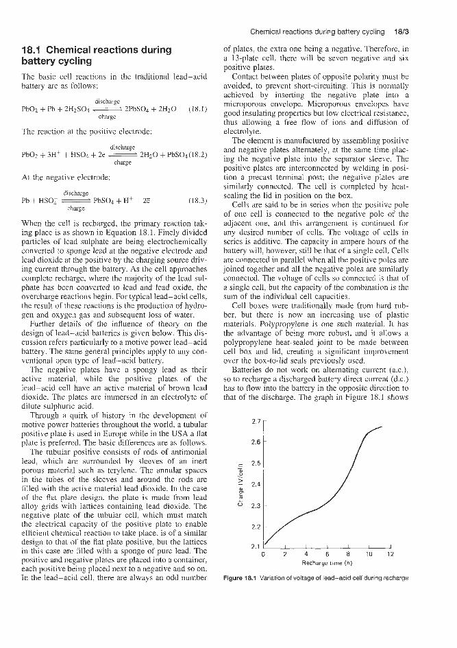
Chemical reactions during battery cycling 18/3
of plates, the extra one being a negative. Therefore, in a 13-plate cell. there will be seven negative and six positive plates.
Contact between plates of opposite polarity must be avoided, to prevent short-circuiting. This is normally achieved by inserting the negative plate into a microporous envelope. Microporous envelopes have good insulating properties but low electrical resistance, thus allowing a free flow of ions and diffusion of electrolyte.
The element is manufactured by assembling positive and negative plates alternately, zt the same time plac- ing the negative plate into the separator sleeve. The positive plates are interconnected by welding in posi- tion a precast terminal post; the negative plates are similarly connected. The cell is completed by he&- sealing the lid in position on the box.
Cells are said to be in series when the positive pole of one cell is connected to the negative pole of the adjacent one, and this arrangement is continued for any desired number of cells. The voltage of cells in series is additive. The capacity in ampere hours of the battery will, however, still be that of a single cell. Cells are connected in parallel when all the positive poles are joined together and all the negative poles are similarly connected. The voltage of cells so connected is that of a single cell, but the capacity of the combination is the sum of the individual cell capacities.
Cell boxes were traditionally made from hard rub- ber, but there is now an increasing use of plastic materials. Polypropylene is one such material. It has the advantage of being more robust, and it allows a polypropylene heat-sealed joint to be made between cell box and lid, creating a significant improvement over the box-to-lid seals previously used.
Batteries do not work on alternating current (a.c.), so to recharge a discharged battery direct current (d.c.) has to flow into the battery in the opposite direction to that of the discharge. The graph in Figure 18.1 shows
68.1 Chemical reactions during battery cycling The basic cell reactions in the traditional lead-acid battery are as flollows:
PbOz + Pb + 2H2SO4 2FbSO4 + 2H20 (18.1)
The reaction at the positive electrode:
PbOz + 3H+ + NSO4 + 2e __i 2Hz0 + PbSOd(l8.2)
At the negative electrode:
Pb + HSO; W PbSO4 + H+ + 2E (18.3)
When the cell is recharged, the primary reaction tak- ing place is as shown in Equation 18.1. Finely divided particles of lead sulphate are being electrochemically converted to sponge lead at the negative electrode and lead dioxide at the positive by the charging source driv- ing current through the battery. As the cell approaches complete recharge, where the majority of the lead sul- phate has been converted to lead and lead oxide, the overcharge reactions begin. For typical lead-acid cells, the result of these reactions is the production of hydro- gen and oxygen gas and subsequent loss of water.
Further details of the influence of theory on the design of lead-acid batteries is given below. This dis- cussion refers particularly to a motive power lead-acid battery. The same general principles apply to any con- ventional open type of lead-acid battery.
The negative plates have a spongy lead as their active material, while the positive plates of the lead-acid cell have an active material of brown lead dioxide. The plates are immersed in an electrolyte of dilute sulphuric acid.
Through a quirk of history in the development of motive power batteries throughout the world, a tubular positive plate is used in Europe while in the USA a flat plate is preferred. The basic differences are as follows.
The tubular positive consists of rods of antimonial lead, which are surrounded by sleeves of an inert porous material such as terylene. The annular spaces in the tubes of the sleeves and around the rods are filled with the active material lead dioxide. In the case of the flat plate design, the plate is made from lead alloy grids with lattices containing lead dioxide. The negative plate of the tubular cell, which must match the electrical capacity of the positive plate to enable efficient chemical reaction to talte place, is of a similar design to that o f the flat plate positive, but the lattices in this case are filled with a sponge of pure lead. The positive and negative plates are placed into a container, each positive being placed next to a negative and so on. In the lead-acid cell, there are always an odd number
discharge
charge
discharge
charge
discharge
charge
2.7 [
2.6
I 2.5 - - W .. 1 > 2.4
P 1
2.3
2.2
2.1 I I I I I 0 2 4 6 8 10 12
Recharge time (h)
Figure 18.1 Variation of voltage of lead-acid cell during recharge
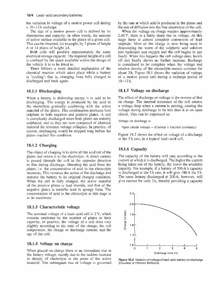
1814 Lead-acid secondary batteries
the variation in voltage of a motive power cell during a 10- 12 h recharge.
The size of a motive power cell is defined by its dimensions and capacity. In other words, the amount of active surface available in the plates of a given cell. This can be obtained, for example, by 7 plates of height A or 14 plates of height SA.
Both cells will produce approximately the same electrical storage capacity. The required height of a cell is confined by the space available within the design of the vehicle it is to be fitted to.
There follows a more detailed explanation of the chemical reaction which takes place while a battery is ‘cycling’; that is, changing from fully charged to discharged and back again.
18.1.1 Discharging When a battery is delivering energy it is said to be discharging. The energy is produced by the acid in the electrolyte gradually combining with the active material of the plates. This combination produces lead sulphate in both negative and positive plates. A cell is completely discharged when both plates are entirely sulphated, and as they are now composed of identical material the terminal voltage collapses. In practice, of course, discharging would be stopped long before the plates reached this condition.
18.1.2 Charging The object of charging is to drive all the acid out of the plates and return it to the electrolyte. A direct current is passed through the cell in the opposite direction to that during discharge, liberating the acid from the plates, i.e. the concentration of acid in the electrolyte increases. This reverses the action of the discharge and restores the battery to its original charged condition. When the cell is fully charged, the active material of the positive plates is lead dioxide, and that of the negative plates is metallic lead in spongy form. The concentration of acid in the electrolyte at this stage is at its maximum.
18.1.3 Characteristic voltage The nominal voltage of a lead-acid cell is 2V, which remains unaltered by the number of plates or their capacity. In practice, the voltage of a cell does vary slightly according to the state of the charge, the cell temperature, the charge or discharge current, and the age of the cell.
18.1.4 Voltage on charge When placed on charge there is an immediate rise in the battery voltage, mainly due to the sudden increase in density of electrolyte in the pores of the active material. The subsequent rise of voltage is governed
by the rate at which acid is produced in the plates and the rate of diffusion into the free electrolyte of the cell.
When the voltage on charge reaches approximately 2.40V, there is a fairly sharp rise in voltage. At this stage there is almost complete conversion of lead sulphate. Most of the charge is now being used in dissociating the water of the sulphuric acid solution into hydrogen and oxygen and the cell begins to gas freely. When this happens the cell voltage rises, levels off and finally shows no further increase. Recharge is considered to be complete when the voltage and relative density of the electrolyte remain constant for about 3 h. Figure 18.1 shows the variation of voltage of a motive power cell during a recharge period of 10-12h.
18.1.5 Voltage on discharge The effect of discharge on voltage is the reverse of that on charge. The internal resistance of the cell creates a voltage drop when a current is passing, causing the voltage during discharge to be less than it is on open circuit. This can be expressed as:
Voltage on discharge =
Open circuit voltage - (Current x Internal resistance)
Figure 18.2 shows the effect on voltage of a discharge at the 5 h rate, in a typical lead-acid cell.
18.1.6 Capacity The capacity of the battery will vary according to the current at which it is discharged. The higher the current being taken out of the battery, the lower the available capacity. For example, if a battery of 500 A h capacity is discharged at the 5 h rate, it will give 100 A for 5 h. The same battery discharged at 200A, however, will give current for only 2 h, thereby providing a capacity
2” I
1.8
1.7
1.6 0 1 2 3 4 5
Discharge time (h)
Figure 18.2 Variation of voltage of lead-acid battery on discharge (Courtesy of Chloride Batteries)

Maintenance-free lead-acid batteries 1815
of 400 Ah at the 2 h rate of discharge. This is because. at higher rates, the voltage drop IS more rapid and the final voltage is reached more quickly.
Motive power battery capacities are normally given at the 5 or 6 h rate of discharge. This hypothetical, continuous rate of discharge relates most closely to the actual performance of an industrial truck; stop-start operation over an 8 h shift. Ambient temperatures also affect the capacity of a battery. At low temperatures the capacity is considerably reduced.
18.2 Maintenance-free Bead-acid batteries Any battery. when overcharged, will liberate hydrogen and oxygen g a m as water is decomposed. For a bat- tery to be maintenance free, it is necessary to retard gas liberation, otherwise the electrolyte would be depleted prematurely and, catastrophic failure would result.
There are two principal types of maintenance-free lead-acid battery:
1. The type featuring calcium-lead alloys and im- mobilized sulphuric acid electrolyte, which reduces but does not completely eliminate gassing, i.e. there is electrolyte volume reduction. Such cells are usu- ally manufactured containing a reserve of electrolyte so that topping up is not required during battery life.
2. The type in which complete recombination of elec- trolysis gases occurs, Le. virtually no electrolyte loss occurs.
18.2.1 Calcium-lead alloy batteries This type of lead-acid battery is typified by batteries in the Sonnenschein Dryfit range. Under constant-potential charging, the maintenance-free lead-calcium-acid battery will accept relatively high currents initially when the system is most efficient. This stage is followed by a second period when the back e.m.f. of the battery begins progressively to increase to control the amount of current accepted. At full charge and under proper voltage regulation, the current accepted will be reduced to a few rnilliamps input, thus restricting the degree of overcharge which protects the unit from excessive electrolyte loss.
Various designs of these batteries further support this function by developing a very high hydrogen and oxygen overvoltage, which enhances the efficiency of conversion and ensures a sharp and reproducible rise in on-charge voltage to regulate current acceptance best.
Absolute recombination in a battery of hydrogen and oxygen produced towards the end of charge or on overcharge is achieved only in a closed container in which the gases are held under relatively high pressure. In such a system equilibrium occurs where the amount of oxygen electrochemically generated at the positive plates is chemically reacted with spongy lead to form lead oxide, which then reacts with sulphuric acid to
form lead sulphate and water. The oxygen is returned to the electrolyte in the form of water and the constant applied current is used up electrochemically to convert the lead sulphate back to spongy lead. This cycle can be repeated many times without losses to the system.
The act of absolute recombination can present a problem. It has been demonstrated that a sealed lead-acid battery can develop thermal runaway in a manner similar to sealed nickel-cadmium cells. This is a condition whereby a battery on charge under volt- age regulation begins to accept progressively higher currents resulting in the build-up of excessive internal heat. Both recombination and temperature decrease the back e.m.f. of the battery, allowing higher and higher currents to be accepted. The result is an uncontrollable system which can become hazardous.
Low-pressure vented maintenance-free batteries have the ability to recombine these gases. However, the degree of recombination is not complete since, from the hazard point of view. it is not considered advisable to operate batteries under excessively high gas pressures.
In practical designs of low-pressure maintenance- free batteries, reduction or elimination of gassing towards the end of charge and self-discharge is handled by battery design features such as special grid alloys and immobilized electrolytes, while gassing on over- charge is avoided by attention to charging method and charging control.
18.2.2 Use of calcium alloys to control gassing on overcharge or during self-discharge With lead-acid batteries, electrolyte decomposition into hydrogen and oxygen is accompanied by reduction of electrolyte volume, thereby increasing the concen- tration of the electrolyte. Damage is then caused by increased corrosion of the positive plate due to the highly oxidizing effect of the atomic oxygen being liberated. A further reason for the evolution of oxy- gen and for corrosion is anodic oxidation due to anode potential. At the same time there is a risk of explosion since the oxygen-hydrogen mixture evolved can be ignited at relatively low concentrations and tempera- tures. In partially recombining sealed lead-acid batter- ies, liberation of gas is reduced to minimum values by using a lead-calcium alloy containing only 0.08% cal- cium rather than the more usual lead-antimony alloy which contains 4-6% antimony. It is thus possible to reduce the self-discharge and the associated liberation of gas by a factor of about 5. In addition, other factors affect the self-discharge rate of conventional lead-acid batteries when not in use. One example is the virtually unhindered passage of atmospheric oxygen into the cell interior and then to the negative plate. This effect is hindered in many battery designs by the provision of one-way self-sealing vents. It is for these reasons that although the capacity of a conventional 5% antimonial

18/6 Lead-acid secondary batteries
lead-acid battery loses about half its initial capacity during 3 months at 2WC, the same decrease would take about 16 months in the case of a 0.08% calcium-lead battery (and more than 24 months at 8°C).
An additional advantage of using a lead-calcium alloy is that it allows the charging voltage to be limited to values of between 2.25 and 2.3V/cell while still being able to achieve complete charging at 20°C. These voltages lie below the values at which the evolution of gas begins. At 40°C the required charging voltages lie at 2.2-2.25V, which again is below the gassing voltage. During neither regular operation nor when continuously connected to a charger is there creation of such a high gas pressure that it could lead to opening of the relief valves installed in each cell. When stored under open-circuit conditions a lowering of pressure is brought about by the 'cold' combustion of small quantities of gas present, and occurs to a certain extent at the negative plate.
18.2.3 Immobilization of electrolyte
One of the design features of most of the available types of partially recombining lead-acid batteries is that the sulphuric acid electrolyte is immobilized with thixotropic silicic acid. A constant regeneration of the thixotropic gel structure takes place through changes in volumes and the formation of minute bubbles of gas in the pores of the electrode. This gives rise to a gentle mechanical movement of the gel, thereby avoiding loss of contact between the electrolyte and the plates. The thixotropically immobilized 'dry' electrolyte allows the electrolysis gases to contact the negative plate at which oxygen recombination occurs, thereby produc- ing a reduction in gas pressure. The electrolyte used in batteries obtainable from certain suppliers, e.g. Son- nenschein Dryfit batteries, also contains phosphoric acid additives to improve the constancy of recover- able charge during battery life. Lead-acid batteries are characterized by the presence of the relatively large volume of free electrolyte or, in the case of partially recombining batteries, of the gel. This is in contrast to nickel-cadmium batteries, in which there is a much smaller amount of potassium hydroxide electrolyte, which does not change greatly in volume during charge and discharge. In the alkaline battery the porosity of the electrodes and the fleecy plastics separator (com- monly Nylon) absorb and consequently immobilize most of the electrolyte. In alkaline button cells, the formation of damaging interstices is prevented by a spring mechanism, which compresses the group of plates. This spring simultaneously provides contact and a space for gas at the negative electrode.
Calcium-lead alloy batteries, because of the gelled electrolyte, are insensitive to orientation, as are sealed nickel-cadmium cells. They can therefore be stored, charged or discharged in any position, even upside-down. This characteristic has obvious advantages in cyclic or float applications such
as power tools, portable radios, lamps, electronic, communications and medical equipment, alarms and emergency lighting equipment.
A design of this type of battery is shown in Figure 18.3.
18.2.4 Fully recombining lead-acid battery This is typified by the Gates D-cell lead electrode combination battery, supplied by General Electric Co. (USA) and also available under the trade name of Cyclon from Chloride Batteries (UK).
A unique aspect of the Gates cell is that the majority of the oxygen generated within the cell on overcharge (up to the C/3 rate) is recombined within the cell. The pure lead grids used in the construction minimize the evolution of hydrogen on overcharge. Although most of the hydrogen is recombined within the cell, some is released to the atmosphere.
Oxygen will react with lead at the negative plate in the presence of sulphuric acid as quickly as it can diffuse to the lead surface. Hydrogen will be oxidized at the lead dioxide surface of the positive plate at a somewhat lower rate, as shown by the following overcharge recombination reactions:
Pb + HS04 + H+ + $ 0 2 + PbS04 + HzO
PbOz + HS04 + Hf + Hz + PbSO4 + 2Hz0
Potting material Terminal (black = negative,
Outer cover red = positive) Inner cover 1 (sonic welded)
Potting fillet
Pressure relief valve/ without ring seal
Absorbent separator used to immobilize electrolyte
0.040 inch vent hole
Cell case (high impact polystyrene)
& /
Semipermeable membrane separator
Figure 18.3 Eagle Picher Carefree maintenance-free lead-acid battery construction (Courtesy of Eagle Picher)

Maintenance-free lead-acid batteries 1
18.2.5 Gas recombination t e c ~ n o l o ~ ~ i automotive and commercial! vehicle lead-acid batteries Several principles have been used by various manufac- turers in the production of low-maintenance batteries, Le. batteries which do not require topping up of the electrolyte during service. Catalytic recornbination of electrolysis gases is not used for this type of battery.
In general, for automotive, vehicle and traction bat- teries the antimony-free grid technology such as used, for example, by Sonnenschein in their sealed batter- ies for power tools is not now used. A few years ago automotive SLI battery production fell into two cate- gories based on grid alloy composition. It was either an antimonial lead or a calcium-lead battery. Within the last few years, however, this distinction has become less clear as many manufacturers have gone into what could be termed hybrid constmction, which uses a low-antimony positive grid and a lead-calcium alloy negative grid. In taking this approach, many battery manufacturers have been able to minimize some of the potential shortcomings associated with the purely lead-calcium alloy batteries. At the same time, they have also minimized many of the undesirable traits of the conventional antimonial alloy battery.
The progression from a lead-calcium alloy battery to a hybrid construction employing a low-antimony positive grid and a lead-calcium alloy negative grid has reduced the necessity for a microporous separator in all battery designs. Enveloped polyethylene micro- porous separators are still widely used in batteries of the lead-calcium type, and are recommended at vir- t u d y all plate spaces. However, as one moves to the hybrid construction, the necessity for a microporous separator in all battery designs has been reduced. When plate spacings are less than about I mm, enveloped microporous separators are stili recommended. This separator construction precludes side and bottom shorts due to mossing or dendrite growth. At the closer plate spacing, shorting through the separator can be a problem and the use of a microporous polyethylene separator virtually eliminates this failure mode. Low electrical resistance leaf-type seprators can be substi- tuted for enveloped microporous separators when piate spacings are greater than 1 mm since the propensity for shorting at the greater plate spacing is reduced.
18.2.6 Highly porous separator, low free aci volume technology In a lead-acid battery, when the positive and negative plates become fully charged they start gassing. The positive plates give off oxygen and the negative plates give off hydrogen (oxygen is usually given off from the positive a little before hydrogen evolution starts at the negative), reducing the water content of the electrolyte and therefore the water level in the battery. Unless this water is replaced by topping up, the battery will eventually cease to operate.
In a flooded lead-acid cell, this diffusion of gases is a slow process and virtually all of the hydrogen and oxygen escapes from the cell rather than recombines.
In the Gates cell, the closely spaced plates are separated by a glass mat separator, which is composed of fine glass strands in a porous structure. The cell is filled with only enough electrolyte to coat the surfaces of the plates and the individual glass strands in the separator, thus creating the ‘starved electrolyte’ condition. This condition allows for homogeneous gas transfer between the plates, which is necessary to promote the recombination reactions.
The pressure release valve maintains an internal pressure of 40-60 psi. This condition aids recomb- ination by keeping the gases within the cell long enough for diffusion to take place. The net result is that water, rather than being released from the cell, is electrochemically cycled to take up the excess over- charge current beyond what is used for conversion of active material. ‘Thus the cell can be overcharged suf- ficiently to convert virtually all of the active material without loss of water, particularly at recommended recharge rates.
At continuous high overcharge rates (e.g. Cl3 and above), gas build-up becomes so rapid that the recomb- ination process is not as highly efficient and oxygen as well as hydrogen gas is released from the cell.
The D-cell was the first cell available within this range. It is rated at 2.5 A h at the 10h rate. It is 61 rnm in height and M m m in diameter. The construction of this cell is similar to that of standard cylindrical nickel-cadmium cells. It is sealed, has a safety vent, makes use of a cylindrical spiral-wound plate design for high energy density and low internal impedance, and can be charged and discharged in any orientation.
The starved system, porous separator and oxy- gen recombination allow efficient space utilization for active material in the spiral-wound sealed lead-acid cell, resulting in a 15-50% increase in volumetric energy density over gelled-electrolyte systems.
Low impedance is derived from the tightly wound design with multiple interconnecting tabs. In addition, the spiral-wound design maintains place spacing bet- ter than flat-plate designs; therefore the impedance remains more constant over life (as low as l 0 m Q compared 23.5 mQ for the closest gelled-electrolyte battery).
The spiral-wound plate roll is mechanically struc- tured to prevent interplate movement found in flat- plate design.
The sealed design, accomplished with a welded cell container, self-resealing pressure safety vent and oxy- gen recombinat:ion, obviates the need to add water. Oxygen recombination prevents electrolysis of the water in the electrolyte during overcharge. This design does not vent hydrogen and oxygen from the elec- trolyte during normal operation.

1818 Lead-acid secondary batteries
The problem has been partly solved with the introduction of maintenance-free batteries, with their improved grid alloys and reduced gassing and water loss. The drawback with this type of battery is the extra head space required to provide a reservoir of acid, enabling the battery to last 3-4 years. In addi- tion, there is skill the possibility of corrosion from acid spray.
In a conventional battery the gasses 'bubble' to the surface through the electrolyte-the easiest path to take.
~
+
Electrolyte ' Separator
(a) Conventional design (flooded)
-
Charge (%)
(c) No recombination
-
In a recombination electrolyte battery the electrolyte is completely absorbed in the plates and the highly absorbent and very porous separators consisting, usu- ally, of glass microfilms, which are closely wrapped around the plates and take up within its pores all the liquid electrolyte. There is no electrolyte above or below the cell assembly as in a conventional battery.
When the positive plates become charged and give off oxygen, the easiest path for the gas to take is through the highly porous separators to the negative
m*
2.3
2.1
2.0
1.9- 0 40 80 120 160
Charge (%)
(d) With recombination
Figure 18.4 Recombination technology in lead-acid batteries. In a conventional cell, oxygen from the positive plate rises to the top of the electrolyte and is lost. In a cell utilizing recombination electrolyte (RE) technology, oxygen passes through the special separator to the negative plate and, ultimately, back into the electrolyte (Courtesy of Yuasa)
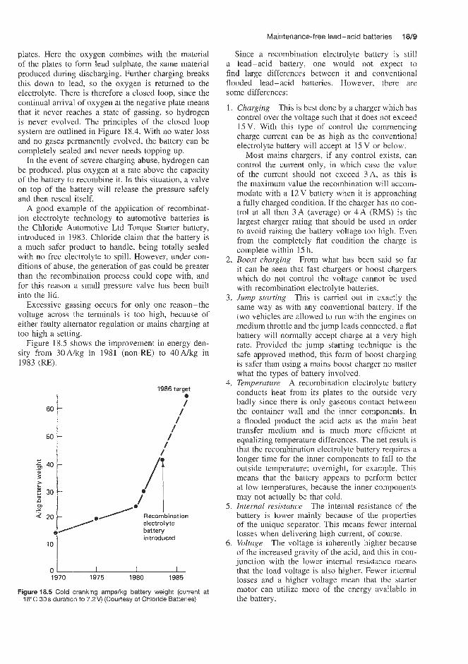
plates. Here the oxygen combines with the material of the plates to form lead sulphate, the same material produced during discharging. Further charging breaks this down to lead, so the oxygen is returned to the electrolyte. There is therefore a closed loop, since the continual arrival of oxygen at the negative plate means that it never reaches a state of gassing, so hydrogen is never evolved. The principles of the closed loop system are outlined in Figure 18.4. With no water loss and no gases permanently evolved, the battery can be completely sealed and never needs topping up.
In the event of severe charging abuse, hydrogen can be produced. plus oxygen at a rate above the capacity of the battery to recombine it. In this situation, a valve on top of the battery will release the pressure safely and then reseal itself.
A good example of the application of recombinat- ion electrolyte technology to automotive batteries is the Chloride Automotive Ltd Torque Starter battery, introduced in 1983. Chloride claim that the battery is a much safer product to handle, being totally sealed with no free electrolyte to spill. However, under con- ditions of abuse. the generation of gas could be greater than the recombination process could cope with, and for this reason a small pressure valve has been built into the lid.
Excessive gassing occurs for only one reason-the voltage across the terminals is too high, because of either faulty alternator regulation or mains charging at too high a setting.
Figure 18.5 shows the improvement in energy den- sity from 30Akg in 1981 (non-RE) to 40A/kg in 1983 (RE).
60
50
1986 target 0
/ 4 /
d / / /
I I I 1970 1975 1980 1985
Figure 18.5 Cold cranking amps/kg battery weight (current at -1 8°C 30 s duration to 7.2 V) (Courtesy of Chloride Batteries)
Maintenance-free lead-acid batteries 18f9
Since a recombination electrolyte battery is still a lead-acid battery, one would not expect to find large differences between it and conventional flooded lead-acid batteries. However, there are some differences:
1
2.
3.
4.
5.
6.
Charging This is best done by a charger which has control over the voltage such that it does not exceed 15V. With this type of control the commencing charge current can be as high as the conventional electrolyte battery will accept at 15 V or below.
Most mains chargers, if any control exists, can control the current only, in which case the value of the current should not exceed 3A, as this is the maximum value the recombination will accom- modate with a 12V battery when it is approaching a fully charged condition. If the charger has no con- trol at all then 3 A (average) or 4 A ( M S ) is the largest charger rating that should be used in order to avoid raising the battery voltage too high. Even from the completely flat condition the charge is complete within 15 h. Boost charging From what has been said so far it can be seen that fast chargers or boost chargers which do not control the voltage cannot be used with recombination electrolyte batteries. Jump starting This is carried out in exactly the same way as with any conventional battery. If the two vehicles are allowed to run with the engines on medium throttle and the jump leads connected, a flat battery will normally accept charge at a very high rate. Provided the jump starting technique is the safe approved method, this form of boost charging is safer than using a mains boost charger no matter what the types of battery involved. Temperature A recombination electrolyte battery conducts heat from its plates to the outside very badly since there is only gaseous contact between the container wall and the inner components. In a flooded product the acid acts as the main heat transfer medium and is much more efficient at equalizing temperature differences. The net result is that the recombination electrolyte battery requires a longer time for the inner components to f d tQ the outside temperature; overnight, for example. This means that the battery appears to perform better at low temperatures, because the inner components may not actually be that cold. Internal resistance The internal resistance of the battery is lower mainly because of the properties of the unique separator. This means fewer internal losses when delivering high current; of course. Voltage The voltage is inherently higher because of the increased gravity of the acid, and this in con- junction with the lower internal resistance means that the load voltage is also higher. Fewer internal losses and a higher voltage mean that the starter motor can utilize more of the energy available in the battery.
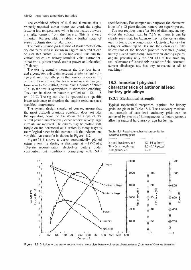
18/10 Lead-acid secondary batteries
The combined effects of 4, 5 and 6 means that a properly matched starter motor can crank the engine faster at low temperatures while in most cases drawing a smaller current from the battery. This is a very important feature, which enables a further stage of system optimization to take place.
The most common presentation of starter motorhatt- ery characteristics is shown in Figure 18.6 and it can be seen that current is on the horizontal axis and the vertical scales are battery terminal volts, starter ter- minal volts, pinion speed, output power and electrical efficiency.
The test rig actually measures the first four items, and a computer calculates internal resistance and volt- age and automatically plots the composite curves. To produce these curves, the brake resistance is changed from zero to the stalling torque over a period of about 10s, so the test is appropriate to short-time cranking. Tests can be done on batteries chilled to -12, -18 or -30°C. The rig can also be operated at a specific brake resistance to simulate the engine resistance at a specified temperature.
The system design should, of course, ensure that the most difficult cranking condition does not take the operating point too far down the slope of the output power and efficiency curve otherwise very large currents are required. The curves may be plotted with torque on the horizontal axis, which in many ways is more logical since in this context it is the independent variable. An example is shown in Figure 18.7.
Figure 18.8 shows a curve automatically plotted using a test rig during a discharge at -18°C of a 10-plate recombination electrolyte battery under constant-current conditions complying with SAE
specifications. For comparison purposes the character- istics of a 12-plate flooded battery are superimposed.
The test requires that after 30 s of discharge at, say, 440A the voltage must be 7.2V or more. It can be clearly seen that, for batteries having the same rating on this basis, the recombination electrolyte battery has a higher voltage up to 30s and then classically falls below that of the flooded product thereafter (owing mainly to acid starvation). However, in starting a petrol engine, probably only the first 15s of test have any real relevance (if indeed this rather artificial constant- current discharge test has any relevance at all to cranking).
18.3 Important physical characteristics of antimonial lead battery grid alloys
18.3.1 Mechanical strength Typical mechanical properties required for battery grids are given in Table 18.1. The necessary mechan- ical strength of cast lead-antimony grids can be achieved by means of homogeneous or heterogeneous alloying (natural hardness) or age-hardening.
Table 18.1 Required mechanical properties for industrial battery grids
Brinell hardness, H B 12-14kg/mm2 Tensile strength, CJB 4.5-6.5 kg/mm2 Elongation, 83 r3%
100
80 I z
60 ,G I
>
._ L + W
40
20
Current ( A ) I~ 0
Figure 18.6 Chloride torque starter recombination electrolyte battery volt-amps characteristics (Courtesy of Chloride Batteries)
0 50 100 150 200 250 300 350 400 450 500 550

Important physical characteristics of antimonial lead battery grid alloys 18/11
Voltage (supply curve)
a i o I 4 6 I I I I
Speed 90
a0
70
60 z - X P
5 .u ; 'z
1
50 5 Y 2 L -
40
30
20
10
0
Torque (N m)
Figure 18.7 Chloride torque starter recombination electrolyte battery. Torque - rev./min curves. Starter motor weight 5.7 kg, free spin at 1 I .71 V, 9633 rev./min at 8 s; current 73A at 8 s, coast time 1.85 s (Courtesy of Chloride Batteries)
12
11
10
-2 .- rnbination electrolyte ate A1051 a t 440 A 0
2 9 - 2
Flooded 12-plate 9830 at 440 A
a
7
6 0 15 30 45 60 75 90
Time (s)
Figure 18.8 Chloride torque starter recombination electrolyte battery. Discharge at -1 8°C under constant current conditions (SAE) (Courtesy of Chloride Batteries)

18/12 Lead-acid secondary batteries
Hardening by alloying (natural hardness)
Figure 18.9 illustrates the increase of hardness by using antimony as an alloying element. The curve shows the hardness of as-cast grids versus antimony content of the alloys. In the case of low antimony contents (t3% antimony), the antimony forms a solid solution with lead. An alloying element converted into a solid solution always hardens the solvent metal. When the antimony content is increased further, the solubility of antimony in lead is exceeded and two solid phases appear, forming an intimate mixture (the eutectic mixture). The percentage of the eutectic mixture increases with rising antimony content above 4% and produces a frame structure of the alloy. This hard eutectic frame structure brings about the high natural hardness of lead-antimony alloys containing more than 4% antimony.
- N
Age-hurdening
The above-mentioned solid solution of antimony in lead causes supersaturation when the usual technique of grid casting is applied, because at room tempera- ture the solubility of antimony in lead is extremely low compared to the 3.5% solubility at 252°C. The reduction of supersaturation by precipitation of finely dispersed antimony within the lead-antimony solid solution grains causes the ever-present age-hardening.
The supersaturation, and therewith the age- hardening of the grid, can be increased by fast cooling immediately after casting or by applying additional heat treatment (solution treatment and sudden quenching from about 250°C). Figure 18.10 shows the effect of different treatments on age- hardening. The precipitation of very fine planes (about 105-1010 planes/cm2) of almost pure antimony, which are arranged parallel to the (1 11) planes of lead, causes the age-hardening.
Figure 18.10 also shows that the age-hardening effect decreases with increasing antimony content. This is reasonable, because the hardness of the casted alloy is determined more and more by the framework of the eutectic mixture, which also reduces nucle- ation difficulties for antimony. Therefore, with increas- ing antimony content, increasing amounts of the ori- ginally supersaturated antimony (which produces age- hardening by fine dispersion) are lost due to precipita- tion of antimony within the eutectic mixture.
Total hardness
The total hardness finally achieved is the sum of natural hardness and hardness due to age- hardening (depending upon age-hardening conditions). Figure 18.11 shows the total hardness attained after 3 weeks. As can be seen, a definite pretreatment can raise the hardness of grids made from 2% antimony alloys to values which are known for alloys with higher antimony contents. However, it must be mentioned that
4 1 / c s o 7 I 1 ; k ; A ;
Antimony content (wt %)
Figure 18.9 Natural hardness of lead-antimony alloys (Courtesy of the Swiss Post Office, Bern)
- N
E E b 16
12
.
._
Z O 1 2 3 4 5 6 7 8 9 - Antimony content (wt %)
Figure 18.10 Age-hardening of lead-antimony alloys (Courtesy of the Swiss Post Office, Bern)
0
24 ,-
0 1 2 3 4 5 6 7 8 9 Antimony content (wt %I
Figure 18.11 Total hardness (natural hardness plus age- hardening) (Courtesy of the Swiss Post Office, Bern)
the amount of hardness due to age-hardening decreases again when the grids are exposed to higher temperature (between 50 and 200°C). This is caused by the dissolving or coarsening of finely dispersed antimony at higher temperature, so that the effectiveness of the antimony dispersion in producing age-hardening is decreased.

Important physical characteristics of antimonial lead battery grid alloys 18/13
Increase of age-hardening by further additives
The age-hardening is also increased by further additives, e.g. arsenic. The influence of arsenic is more effective when the supersaturation of antimony in lead is relatively low (e.g. for grids not subjected to special heat treatment). Figure 18.12 shows this effect; arsenic not only increases, but also accelerates the age- hardening process.
18.3.2 Castability In addition to the mechanical strength required for fur- ther treatment of the grids, castability is an important factor for producing sound grids at tolerable cost. The main difficulty with casting low-antimony alloys is that the decrease of antimony content is accompanied by the appearance of hot cracks if no special precau- tions are taken. For example, Figure 18.13 shows the cast structure of grids containing 2% antimony. The solidification takes place in a coarse dendritic structure containing cracks along grain boundaries. Inadequate grid quality (caused by these cracks) was one of the main reasons why low antimony alloys were formerly not used on a large scale in the battery industry.
The poor grid quality of low antimony alloys can be overcome by the addition of selenium. This addition forms a fine globulitic solidification which results in fewer casting faults (Figure 18.14). The grain size of an alloy containing 2% antimony decreases from about 100 pm to about 60 pm when 0.02% selenium is added. With respect to grain refinement, selenium proved to be superior to all other additives. The formation of
Age-hardening time at room temperature until HE = 14 kgf/rnmZ are achieved
; ; I 1 I I I ! ) ,
Without With arsenic aneni? .-m Ir
” As cast (without Heat treatment heat treatment) 1 h/240 ‘C/H,O ageing
a t room temperature
Figure 18.12 Influence of arsenic on the age-hardening of lead-2% antimony alloy (Courtesy of the Swiss Post Office, Bern)
Figure 18.13 Coarse dendritic cast structure with cracks (lead-2% antimony alloy). (a,b) Industrial grid (x100) (Courtesy of the Swiss Post Office, Bern)
Figure 18.14 Fine globulitic cast structure (lead-2% anti- mony-0.02% selenium alloy). (a) Automotive grid (x200), (b) industrial grid (x200) (Courtesy of the Swiss Post Office, Bern)
dendrites, which disturbs the feeding capacity of the mould during casting and leads to casting faults, is almost fully suppressed. With fine globulitic solidifi- cation, uniform mechanical properties are achieved in all directions, and hence ductility is increased.
Using the combination of alloying elements of antimony (1.5-3.5%) arsenic, selenium (and tin to

18/14 Lead-acid secondary batteries
increase the castability) with lead, it is feasible to manufacture battery grids with very low antimony con- tents, which achieve the necessary mechanical strength within suitable ageing times, and show the necessary grid quality.
18.4 Lead alloy development in standby (stationary) batteries Until 10 years ago, the grids of lead-acid batteries were usually made of lead-antimony alloys contain- ing 5- 11 wt% antimony. The necessary mechanical strength and castability are easily achieved with this content of antimony. However, the unavoidable cor- rosion of the positive grid liberates antimony from the grid, which proves to be both favourable as well as unfavourable with respect to battery performance. On the one hand, antimony stabilizes the active material of the positive electrode, the cycle life of the battery is improved and passivation effects disturbing mainly the discharge mechanism are not observed when alloys with a high antimony content are used for positive grids. On the other hand, antimony migrates to the negative plate where it is precipitated and reduces the hydrogen overvoltage. This leads to lower charge volt- age: increased self-discharge and therefore increased water loss of the battery.
As a consequence, most battery manufacturers tried to minimize or even eliminate the antimony addition, especially in batteries for stationary applications where smaller demands are made in respect to cycle service.
It has been found recently that, when selenium is used as an alloying constituent in grid metal, the antimony content can be reduced to the point that the drawbacks of antimony are almost eliminated, while the positive effects of antimony are largely retained.
Lead alloys characterized by the addition of sele- nium exhibit a fine grain structure even at very low antimony contents (12%). This structure yields accept- able quality of the castings as indicated by mechan- ical strength, natural hardness, age-hardening and total hardness, and also yields acceptable castability char- acteristics. The hardness necessary for handling the battery plates is achieved by age-hardening due to finely dispersed antimony.
Corrosion stability at constant potential or con- stant current proves to be slightly superior, but of the same order of magnitude as conventional antimony alloys (14%).
However, at constant cell voltage, the amount of antimony released from the positive grid is too small to affect the potential of the negative electrode markedly. Therefore the very low initial gassing rate, which is of the same order as experienced with antimony-free batteries, remains almost constant.
Of special importance is that the well-known sta- bilizing effect of antimony with respect to the positive active material is virtually maintained with these
selenium alloys. This results in capacity stability as well as good cycling performance.
Because of the extremely high potential of the pos- itive electrode, only lead can be used as grid material in stationary and, indeed, all types of lead-acid battery. This lead is unavoidably subject to gradual erosion from corrosion. For battery applications this corrosion rate must be reasonably low, otherwise the battery life is limited by the corrosion rate of the positive grid.
The potential of the electrode (the most important parameter) determines the electrochemical corrosion of lead. Therefore, potentiostatic corrosion tests are very suited to comparing corrosion rates for different grid alloys. Figure 18.15 shows the results obtained for different lead-antimony alloys. The samples used in these experiments were metal rods prepared carefully to avoid any sources of error caused, for example, by poor casting quality. The applied corrosion potential corresponds to about 2.6 V cell voltage.
As can be seen in Figure 18.15, the potentiostatic corrosion rate is of a comparable order of magnitude for all tested antimonial lead alloys. On the basis of these experiments the selenium alloys can be expected to perform slightly better with regard to corrosion attack than conventional lead-antimony alloys.
Corrosion tests on battery grids are usually carried out in cells using a negative battery plate as the counter electrode. Figure 18.16 shows results for battery grids with reference to antimony content. As can be seen, the result is fundamentally different, depending on the testing procedure. When a cycling regimen is applied, which means constant current is impressed on the electrode, the differences in corrosion attack are small. Actually the performance should be expected to be very similar to the result shown in Figure 18.15
X
0 1 2 3 4 5 6 7 8 Antimony content (%)
Figure 18.15 Lead corrosion at constant potential - 1.45V with reference to the Hg/Hg,S04 electrode (Courtesy of the Swiss Post Office, Bern)

Lead alloy development in standby (stationary) batteries 18/15
p.
Cycle load (constant current) Discharge: 11 mA/cmZ 15 rnin Charge: 10 mA/cm2 165 min
0 1 2 3 4 5 6 0
Antimony content I%)
Figure 18.16 Corrosion test on battery grids (tubular type, 70Ah, plate) (Courtesy of the Swiss Post Office, Bern)
because constant current more or less means constant potential of the positive electrode.
However, when constant cell voltage is applied in the experiment, the antimony content of the corroding grid largely detenxines the result, as can be seen in Figure 18.16. The reason is that antimony, released at the corroding positive grid, is precipitated at the neg- ative electrode, which results in a reduced hydrogen overvoltage. This means that the rate of hydrogen evo- lution is the same at a less negative electrode potential. Therefore, the negative electrode potential is shifted in a positive direction and consequently the positive electrode potential is raised because the cell voltage is kept constant. The rise in positive electrode potential leads to an increase in corrosion, which again pro- duces antimony at a faster rate and therefore gives rise to increased contamination of the negative elec- trode. In this way a self-accelerating process origi- nates, causing the strong effect of antimony content shown in Figure 18.16. The corrosion test at constant cell voltage therefore does not compare pure corrosion rates, but rather is a mixture of corrosion and poten- tial shift by antimony contamination of the negative electrode. However, this test reflects the situation in many battery applications, because lead-acid batteries are to a large degree charged at constant voltage, espe- cially stationa-y batteries which are kept on a constant floating voltage.
Therefore, battery performance in the field to a large extent corresponds to the constant voltage corrosion test. Compared with the bare grid, the rate of anti- mony release is somewhat reduced at a complete pos- itive plate; because antimony is absorbed to a marked degree by lead dioxide.
This antimony effect on battery performance is shown by the results of an accelerated floating test shown in Figure 18.17. Industrial batteries of the same type were used, with the only difference that the pos- itive grids consisted of various alloys. The floating voltage of 2.23 Vlcell was applied as usual for station- ary batteries. The acceleration of the test was achieved by periods of heavy overcharge of 3 times 100 h at a 3-month time interval.
Figure 18.17 shows the situation of constant voltage floating described above in relation to Figure 18.16. At an antimony content of less than 2% in the positive grid, the amount of antimony reaching the negative electrodes is obviously too small to cause a marked effect on the electrode potential. and the floating cur- rent is therefore stabilized at the low initial Bevel.
In Figure 18.18, results of floating tests on sta- tionary batteries with selenium alloys are compared with tests published by the Swiss Post Office in 1976. For his well founded experiments, Gerber used industrial batteries supplied by several manufacturers. The grid material of these batteries contained about 10% antimony. Some results on stationary batteries equipped with lead-calcium alloys are also given in Figure 18.18.
This comparison again shows the advantage of the extreme reduction of antimony content that is feasible in selenium alloys. The floating current at 2.23Vkell is even smaller than the floating current for ‘old batteries’ at 2.20 Vkell. Furthermore, for sele- nium batteries the increase of floating current is much smaller, which means that the self-accelerating pro- cess of corrosion and potential shift has nearly ceased. Topping up intervals are long and battery shelf life is high.
Antimony conteni of positive grid
Overcharge periods (3 X 100 h each)
0 10 20 35 Testing time [months)
Figure 18.17 Accelerated floating test. Tubular cells, 280A h, floating voltage 2.23V/cell (Courtesy of the Swiss Post Office, Bern)

18/16 Lead-acid secondary batteries
u P 180
160 140
L7
200 -c U 8 2 100
0
6% Sb 1.6% Sb - (positive grid alloy) - -
I I I I I I I I I I I I I I
D Stationary cells (Exide), 1 pasted plates, PbCa alloy
o OPZS stationary cells, - tubular plates, 1.6% Sb,
selenium
e
a @ a p = . 8 7 I *
1 2 3 4 Floating time (years)
Figure 18.18 Floating test on stationary batteries: I. T. Gerber, Technische Mitteilunger PlT, Nos 6/7 and 11, 1976, Bern, Switzerland (8-11 % antimony alloys) (Courtesy of the Swiss Post Office, Bern)
As already mentioned, the disadvantages of anti- mony apart, the antimony content in the positive grid material contributes beneficial effects for the lead-acid battery. Antimony stabilizes the positive active mater- ial, which results in good cycling performance and less sensitivity to deep discharges. This beneficial effect of antimony is illustrated in Figure 18.19, which shows the results of a cycling test, usually applied for motive power batteries. Each cycle in this test includes a dis- charge of 75% of nominal capacity; two cycles are performed per day. At intervals of about 50 cycles, the capacity is determined by complete discharge. For the single cell, the test is finished as soon as the capacity is less than 80% of nominal capacity.
The cells used for the test shown in Figure 18.19 dif- fered only in antimony content of the positive grid. The stabilizing effect of the antimony is obvious. While the cells without any antimony failed after about 200 cycles, the cells equipped with selenium alloy contain- ing only 1.6% antimony performed about 1000 cycles. This stabilizing effect is obviously an important advan- tage of selenium alloys. Even for batteries that are not
cycled, this stabilizing effect means less sensitivity to occasional deep discharges.
18.5 Separators for lead-acid automotive batteries Typical properties for separators for antimonial lead and non-antimonial lead automotive batteries are shown in Table 18.2 and 18.3.
Table 18.2 Typical properties of separators for antimonial automotive batteries
Cellulose PVC
Electrical resistance (mQ/cm2)
Backweb thickness (mm) Pore size (pm) Porosity (%) Mechanical strength Corrosion resistance Enveloping capability Selling price
3.0-4.9 40-91 35 60 Good Fair No Lowest
3.0-5.0 25-36 24 35-40 Fair Good With difficulty Moderate
The following are considered to be the key properties for separators for non-antimonial lead maintenance-free automotive batteries:
1. Low electrical resistance to maximize cold crank- ing voltage.
2. Thin backweb to minimize acid displacement. 3. Good oxidation resistance to give separator
4. Small pore size to minimize dendritic shorting. 5. Flexibility and capability of being enveloped. 6. Good chemical purity, i.e. low concentrations
of chloride and certain metals (iron, manganese, copper).
integrity at the end of battery life.
Figure 18.19 Cycling test according to IEC Publication 254 (Courtesy of the Swiss Post Office, Bern)

Separators for lead-acid automotive batteries 18/17
lS5O r Table 18.3 Typical properties of separators for non-antimonial automotive batteries
Microporous Sintered polyethylenes PVC
1.26 t Electrical resistance (mR/cm2) Backweb thickness (mm) Acid displacement (cm3/m2) Porosity (%) Oxidation resistance Maximum pore siLe (Fm) Flexibility Sealability Chemical pur;ty Cold voltage -3O"C/30 s (V)
1.4-1.8 25 146 55 Good 10.1 Good Good Good 8.76
2.5-3.5 25-35 25 0 35 Good 24 Poor Satisfactory Good 1.98
Recent work has shown that two parameters, namely low electrical resistance and low separator thickness, have a profound effect on cold cranking performance of low-maintenance calcium-lead alloy automotive batteries. Figure 18.20 and 18.21 show the beneficial effect of decreasing the electrical resistance of the separator on the cell voltage in tests run at -18°C and -30°C on low-maintenance lead-acid batteries.
Figure 18.22 shows that reducing the separator thickness improves cell voltage under high-rate dis- charge conditions. Although decreasing the separator thickness has a beneficial effect on cold cranking per- formance of the battery, it does have a deleterious effect on reserve capacity. This is because, with thin- ner separators, the volume of sulphuric acid adjacent to the plates is diminished, thereby decreasing the uti- lization of the lead and lead dioxide active material in the plates. This is illustrated in Figure 18.23. Thus there has to be a trade-off in selection of separator thickness to achieve a desired compromise between acceptable cold cranking performance on the one hand and acceptable reserve capacity on the other.
1.50 r 1.44 c
1.26
1.20 I I I I 1 2 3 4 5
Separator electrical resistance ( m a cm2)
Figure 18.20 18°C cold cranking perforinance: effect of separator electrical resistance. 30 s cell voltage at 280 A, 9 plate calcium alloy single cells SAE J-537; test procedure (Courtesy of W. R. Groce)
1 2 3 4 5
Separator electrical resistance ( m a cm2)
Figure 18.21 -30°C cold cranking performance: effect of separ- ator electrical resistance. 30s cell voltage at 210A: 9-plate calcium alloy single cells, SAE J-537; test procedure (Courtesy of W. R. Groce)
> 1.35 - -
1.20 u 40 50 60 70 80
Separator thickness (mi is 1
Figure 18.22 Effect of separator thickness on cold performance. -18°C cold cranking test at 280A, SAE J-537; test procedure. 9- plate antimonial alloy cells/cellulosic separators; 29 observations (Courtesy of W. R. Groce)
0, 5 8 5 1
a
80 40 50 60 70 80
Separator thickness (mil)
Figure 18.23 Effect of separator thickness on reserve capacity, SAE J-537; test procedure, 9-plate antimonial alloy cells/cellulosic separators. Reserve capacity = 87.1 + 0.096 x separator thick- ness (Courtesy of W. R. Groce)

18/18 Lead-acid secondary batteries
The shift away from a lead-calcium alloy battery to a hybrid construction employing a low-antimony positive grid and a lead-calcium alloy negative grid has reduced the necessity for having a microporous separator in all battery designs. Enveloped polyethy- lene microporous separators are still widely used in batteries of the lead-calcium type and are recom- mended at virtually all plate spaces. However, as one moves to the hybrid construction, the necessity for a microporous separator in all battery designs has been reduced. When plate spacings are less than about 1 mm, enveloped microporous separators are still recommended. This separator construction precludes side and bottom shorts due to mossing or dendrite growth. At the closer plate spacing, shorting through the separator can be a problem and the use of a micro- porous polyethylene separator virtually eliminates this failure mode. Low electrical resistance leaf-type sep- arators can be substituted for enveloped microporous separators when plate spacings are greater than 1 mm, since the propensity for shorting at the greater plate spacing is reduced. The need for a low electrical res- istance leaf-form separator can currently be satisfied by what is generically called a glass separator. The glass separator, because of its low electrical resist- ance, allows a significant improvement in the cold cranking performance of the battery, compared with similar constructions using either cellulosic or sintered PVC separators.
The separator needs for cycling batteries are somewhat different from those for automotive batteries. In the case of cycling batteries, low electrical resistance is not as important a parameter, but good oxidative stability, low acid displacement, improved voltage control and increased resistance to shorting are some important properties. The conventional glass matted paper separator, the cellulosic separator and the glass matted and a glass matted glass separator are suitable for this application.
18.6 Further reading
Beckmann, H. (1930) The microporous rubber diaphragm in storage batteries. Elekrotechnische Zeitschrift, 51, 1605-1 607 (in German)
Booth, F. (1970) Comparative Study on Battery Separators for Lead-Acid Starter Batteries (printed as manuscript, 12pp.)
Dafler, J. R. (1 978) Resin-bonded cellulose separators: an overview with prognoses. Journal of the Electrochemical Society, 125,833-842
Dafler, J. F. et a/. (1976) An X-ray diffraction, scanning electron microscopy study of separator failure. Journal of the flectro- chemical Society, 123, 780-789
Goldberg, B. S. et a/. (1 983) Accelerated cycle life testing of lead-acid golf car batteries and the influence of separator type on battery life, energy consumption and operating cost. Journal of Power Sources, 10,137-148
John, P. J. (1965) Battery separators. Batterien, 19, 827-833 Karr, C. (1980) The effect of separator upon cranking capacity.
IBMA 43rd Convention, Chicago, 1980, 49-53 Landers, J. J. (1970) Requirements and characteristics of sec-
ondary battery separators. In Proceedings of the Meeting of the Electrochemical Society, February 1970, pp. 4-24
Lundquist, J. T. Jr (1983) Separators for nickel-zinc batteries. Journal of Membrane Science, 13,337-347
Orsino, J. A. et a/. (1 962) Structure and Properties of Storage Battery Separators. Publication No. 253-62, National Lead Co., Brooklyn, NY, USA
Palanichamy, S. et a/. (1968) Importance of physical characteris- tics of separators on the performance of lead-acid battery. In Proceedings of the Symposium on Lead-Acid Batteries, Indian Lead-Acid Information Center, Calcutta, 1968, pp. 36-40
Robinson, R. G. eta/. (1963) Separators and their effect on lead-acid battery performance. Batteries, 1,15-41
Sundberg, E. G. (1970) A new microporous polymeric separator. Proceedings of the Meeting of the Electrochemical Society, February 1970, pp. 32-56
Vijayavalli, R. et a/. (1 976) Separators for Lead-Acid Batteries, Indian Lead Zinc Information Center, New Delhi, 10 pp.
Yamasaki, K. et a/. (1 983) A new separator for industrial lead-acid batteries. New Materials + New Processes, 2, 11 9-1 23
Yankow, L. et a/. (1983) Studies of phenolic resin-based micro- porous separator materials. Journal ofApplied Nectrochemistry,
Zehender, E. et a/. (1 964) The influence of separators on antimony migration in lead-acid batteries. Electrochimica Acta, 9, 55-62 (German with English summary)
13,619-622

Nickel batteries


Nickel-cadmium secondary batteries 191’3
necessary, and requires topping up and; in some cases, a complete electrolyte change. A battery cell consists of two plates containing nickel hydroxide (positive active material) and cadmium hydroxide (negative active material) kept apart by a separ- ator to maintain electronic insulation. An approxima- tion of the chemical equation is given below (see Figure 19.1).
19.1 Nickel--cadmium secondary batteries
Both sealed and open nickel-cadmium batteries are based on similar. chemical reactions. The sealed type is designed to be maintenance free and under nor- mal conditions will not release gas, whereas an open battery has been designed to release gases when
+ -
_t
T CR
I I I I t- 1
I
t. U
P U
.-
B 5 Y
DR
T 2Ni(OH), + 20H- -+
2NiOOH + 2H,O + 2e- Cd + 20H-
CdlOH), + 2e- +
(a) Charge
+
Ib) Discharge
1. t. 0 a U
3
.-
- c I
APM 1 T 20H- + H,O
t :o, + 2e-
1 z
I .- 0 m a 0 a,
m - n B E 5 -0
APN
T
-
Recombined
4 CR
1 4- 1.
.- U
P 0 - a c I
1 DR
T
(c) Overcharge
L
z 0 .- % a, - n 3 E f U
DR i T
0, Recombined
(d) Overdischarge
Figure 19.1 The electrochemical process in sealed nickel-cadmium batteries. (a) Charge on the positive electrode produces nickel(ll1) hydroxide, NiO(0H); charge on the negative electrode produces metallized cadmium, Cd. (b) Discharge on the positive electrode produces nickel(i1) hydroxide, Ni(OH),; discharge on the negative electrode produces cadmium hydroxide, Cd(OH),. See Equations 19.1 and 19.2. Electrolyte, dilute potassium hydroxide; APM, antipolar mass; CR, charge reserve; DR, discharge reserve (Courtesy of Varta)

19/4 Nickel batteries
On discharge (Figure 19.1),
discharge
charge ZNiO(0H) + Cd + 2H20 T--- 2Ni(OH), + Cd(OH),
Positive Negative Positive Negative electrode electrode electrode electrode
(19.1) Two parts of the charged positive mass of nickel(II1) hydroxide change to nickel(I1) hydroxide, while the negative mass of cadmium oxidizes to cadmium hydroxide, and two molecules of water are taken from the electrolyte. The above equation holds good on charge or discharge only so long as convertible material is still available. If, for instance, on charge the positive mass of nickel(I1) hydroxide in the positive electrode is completely converted to nickel(II1) hydroxide, then the reaction is modified and oxygen is evolved; that is, the plate is in an overcharged state:
Cd(OH), 4 0 2 + Cd + HzO (19.2)
If the same condition is applied to the negative plate, hydrogen gas will be evolved. With an open battery, both conditions will occur at the end of every charge and water will be decomposed.
Note that the electrolyte potassium hydroxide is not mentioned in Equations 19.1 and 19.2.
Water is produced when the battery is charging and taken up when it is discharging; when the electrolyte is in the correct proportion, this water has very little effect on the operation of the cell. In comparison, on discharge, if one of the electrodes becomes exhausted and the discharge current is maintained by the voltage of the other cells, then hydrogen is given off by the positive plate and oxygen by the negative plate. Also, in a discharged condition, the battery polarity can be reversed.
19.1.1 Sealed nickel-cadmium batteries Sealed nickel-cadmium cells normally operate at internal pressures well below the vent pressure because gas evolved during charging is reasily recombined. Compliance with three essential design criteria is necessary to accomplish this:
1. The capacity of the negative electrode must be greater than that of the positive electrode, i.e. the negative electrode must have more active material available than the positive. As a result, the posit- ive electrode achieves full charge and emits oxygen before the negative electrode is fully charged and emits hydrogen which cannot be readily ‘recombined.
2. The electrode must be uniformly distributed by the separator as a thin film across the surface of the two electrodes. The quantity of electrolyte used in the cell must be only enough to wet the plate surface or be absorbed in the separator. The electrodes are
overcharge
overdischarge
not immersed in a pool of electrolyte as they are in a flooded cell. Oxygen gas must be free to pass between the electrodes. There must be sufficient open area in and around the separator and electrolyte for oxygen to be able to diffuse from the positive to the negative electrode.
charging a sealed cell the positive electrode will reach full charge before the negative electrode. At this stage additional charging causes the positive electrode potential to rise until all the incoming current is oxi- dizing hydroxyl ions and generating oxygen gas at the positive electrode:
20H- + $ 0 2 + H20 + 2e
The oxygen generated at the positive electrode diffuses rapidly to the negative electrode where it is reduced back to hydroxyl ions:
$ 0 2 + H20 + 2e- + 20H-
The hydroxyl ions complete the circuit by migrating back to the positive electrode. Thus, in overcharge all the current generates oxygen which is subsequently recombined. The oxygen pressure initially increases but then stabilizes at a low equilibrium pressure deter- mined by cell design, the ambient temperature and the charge rate. In this equilibrium state the generated oxygen is recombined at the negative electrode, the negative electrode never becomes fully charged and no hydrogen gas is generated.
The efficient recombination of oxygen enables the sealed cell to be continuously overcharged at specific rates without developing excessive internal pressure. It can thus be kept on trickle charge, maintaining the cell in a fully charged condition for long periods.
It is important to remember that during charge the conversion of active material is an exothermic reaction. When the cell is in overcharge, essentially all of the energy in the current coming in is converted to heat. With proper matching of the charger to the battery and attention to battery location and heat dissipation, the battery system can be designed to reach a thermal steady state that will permit the battery to remain in overcharge indefinitely.
Figure 19.2 shows the electrode design of a typical sealed nickel-cadmium cell. When the cell is fully charged, the positive electrode active material has been converted to the high valence form, NiOOH, but the negative electrode still contains uncharged active material Cd(OH),. In overcharge, oxygen gas is evolved from the positive electrode.
In the modern sealed nickel-cadmium battery the active mass is modified so that the battery is ‘safe from overcharge’ and protected against ‘overdischarge’ due to oxygen only being evolved. In the case of over- charge this is achieved by the negative plate having a surplus amount of cadmium hydroxide incorporated

Nickel-cadmium secondary batteries 19/5
I Microporous separator I
I t I I I 1 I- Avaiiable-'
i I capacity i - I
li ! Charqing . . reserve $ i p =constant
t -------- a
Normal ' Overcharge charge
Figure 19.2 Schematic diagram of the charging process in sealed nickel-cadmium batteries with negative charging reserve (Courtesy of Varta)
in its structure, which ensures that the negative plate is partially charged when the positive plate is fully charged; this surplus mass is called the 'charge reserve' (Figure 19.2). The process is shown in Figure 19.1(c), which also shows that the oxygen produced on the pos- itive plate is recombined on the negative plate. This electrochemical reaction causes heat to be generated within the battery, unlike an open battery where the gases would be allowed to vent or escape from the plate area. It should be noted that the resultant tem- perature rise is not caused by the internal resistance of the battery. Tne capacity of a sealed battery increases in proportion to its volume, but the surface area, which determines the temperature rise, does not increase by so great a proportion. Therefore, it can be seen that it is necessary to pay more attention to heat genera- tion on overchaLrge in the larger-capacity sealed cells than in smaller-capacity batteries; generally 2 A h can be used as a dividing line.
When the ov'ercharge current is terminated the free oxygen in the battery continues the reaction at the neg- ative electrode. The negative electrode itself supplies the necessary electrons and some of the metaIlic cad- mium is oxidized to cadmium hydroxide. The oxygen pressure is then-fore decreased, and after a short time a vacuum may be formed.
The ability of the negative plate to consume the oxygen produced by the positive plate on overcharge is due to the following design features being incorporated into sealed batteries:
I. The capacity of the positive plate is less than that
2. The plate spacing is small (usually about 0.2mm). 3. The separators are very porous.
of the negative plate.
I t > lu 1
0
I , , k i i 0, production
t-
Figure 19.4 Schematic diagram of the discharge process in sealed nickel-cadmium batteries with antipolar mass in the positive electrode (Courtesy of Varta)
4. The quantity of electrolyte is just on the saturation limit of the plates and separator.
To protect the sealed battery against overdischarge, at least one manufacturer (Varta) adds a controlled quantity of negative mass to the positive electrode and this is called the antipolar mass (see Figure 19.4). The antipolar mass does not disturb the normal function of the positive electrode during charge and discharge since it is electrochemically ineffective cadmium hydroxide; this reaction is shown in Figure 19.1(d).
Thus, with the help of charge reserve and antipolar mass, sealed batteries can be made comparatively safe in normal operating conditions.
There are three main configurations of nickel- cadmium batteries - button cells. cylindrical cells and rectangular cells. These are discussed below.
Button cells
These cells have the form of a button in various thick- nesses. They are composed of a stack of disc-shaped sintered plates and separators held in two nickel- plated steel cups, one fitting into the other and pressed together with an insulating gasket (Figure 19.5). There is also available a high-reliability version of the button cell with improved performance on high-rate discharge at very low temperatures, e.g. SAFT VBE services button cells (Table 51.1). These have the same dimen- sions and capacities as the standard button cells and are designed to withstand more severe operating con- ditions. They have an improved voltage characteristic at low temperatures, high discharge rates, and higher mechanical strength and reliability.
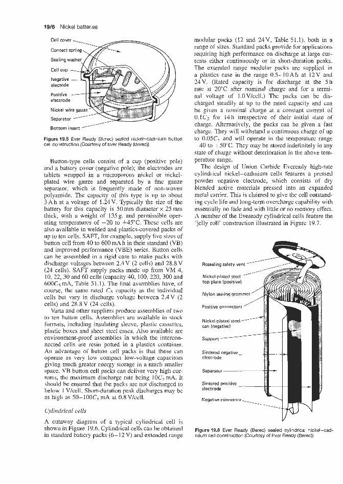
19/6 Nickel batteries
Bottom insert ' Figure 19.5 Ever Ready (Berec) sealed nickel-cadmium button cell construction (Courtesy of Ever Ready (Berec))
Button-type cells consist of a cup (positive pole) and a battery cover (negative pole); the electrodes are tablets wrapped in a microporous nickel or nickel- plated wire gauze and separated by a fine gauze separator, which is frequently made of non-woven polyamide. The capacity of this type is up to about 3 A h at a voltage of 1.24 V. Typically the size of the battery for this capacity is 50 mm diameter x 25 mm thick, with a weight of 135g, and permissible oper- ating temperatures of -20 to +45"C. These cells are also available in welded and plastics-covered packs of up to ten cells. SAFT, for example, supply five sizes of button cell from 40 to 600 mA h in their standard (VB) and improved performance (VBE) series. Button cells can be assembled in a rigid case to make packs with discharge voltages between 2.4V (2 cells) and 28.8V (24 cells). SAFT supply packs made up from VM 4, 10, 22, 30 and 60 cells (capacity 40, 100, 220, 300 and 600Cj mA, Table 51.1). The final assemblies have, of course, the same rated C5 capacity as the individual cells but vary in discharge voltage between 2.4V (2 cells) and 28.8V (24 cells).
Varta and other suppliers produce assemblies of two to ten button cells. Assemblies are available in stock formats, including insulating sleeve, plastic cassettes, plastic boxes and sheet steel cases. Also available are environment-proof assemblies in which the intercon- nected cells are resin potted in a plastics container. An advantage of button cell packs is that these can operate as very low compact low-voltage capacitors giving much greater energy storage in a much smaller space. VB button cell packs can deliver very high cur- rents, the maximum discharge rate being l0Cs mA. It should be ensured that the packs are not discharged to below 1 V/cell. Short-duration peak discharges may be as high as 50-100Cs mA at 0.8 V/cell.
Cylindrical cells
A cutaway diagram of a typical cylindrical cell is shown in Figure 19.6. Cylindrical cells can be obtained in standard battery packs (6-12 V) and extended range
modular packs (12 and 24V, Table 51.1), both in a range of sizes. Standard packs provide for applications requiring high performance on discharge at large cur- rents either continuously or in short-duration peaks. The extended range modular packs are supplied in a plastics case in the range 0.5-10Ah at 12V and 24V. (Rated capacity is for discharge at the 5 h rate at 20°C after nominal charge and for a termi- nal voltage of l.OV/cell.) The packs can be dis- charged steadily at up to the rated capacity and can be given a nominal charge at a constant current of 0.1Cj for 14h irrespective of their initial state of charge. Alternatively, the packs can be given a fast charge. They will withstand a continuous charge of up to 0.05C5 and will operate in the temperature range -40 to +50"C. They may be stored indefinitely in any state of charge without deterioration in the above tem- perature range.
The design of Union Carbide Eveready high-rate cylindrical nickel-cadmium cells features a pressed powder negative electrode, which consists of dry blended active materials pressed into an expanded metal carrier. This is claimed to give the cell outstand- ing cycle life and long-term overcharge capability with essentially no fade and with little or no memory effect. A number of the Eveready cylindrical cells feature the 'jelly roll' construction illustrated in Figure 19.7.
Figure 19.6 Ever Ready (Berec) sealed cylindrical nickel-cad- mium cell construction (Courtesy of Ever Ready (Berec))

Nickel-cadmium secondary batteries 19/7
These cells are based on the following reactions:
Negative electrode: Cd2+ + 20H- + Cd(OH), (19.3)
Positive electrode: Ni2+ + 20H- + Ni(0H)z (19.4)
The design comprises positive and negative electrodes and the separator being wound together to form a spiral which is inserted in a cylindrical can. The separator consists of polyamide or polypropylene non-woven felt. The negative electrode is connected to the cell cover which contains a resealing safety vent. The cover is insulated from the can by a plastic gasket which also acts as a gas-tight seal. Cell closure is achieved by crimping the top edge of the can over the gasket.
Cylindrical cells rely on gas recombination to main- tain internal pressure below the relief pressure of the safety vent during charging. The cell therefore has an excess of negative capacity ensuring that the pos- itive electrode always becomes fully charged before the negative electrode.
Oxygen is generated at the positive electrode and passes through the separator where it reacts with the negative electrode
2Cd + 0 2 + 2H20 - Cd(OH)2 (19.5)
Sealed cylindrical cells of this type are available in 0.29 to 7 A h rated capacity range.
Factors which need to be born in mind when select- ing sealed cylindrical cells for particular applications include:
whether cycling or standby duty operating voltage required capacity, peak current and duty load requirements temperature range self-discharge rate charging requirements.
Temperature controlled charging methods are used for this type of battery, see Section 47.
1. absolute voltage, temperature compensated, or 2. absolute temperature with internal thermostat, or 3. differential temperature control with two ther-
mostats, one in middle of battery pack and one outside battery.
Large vented nickel-cadmium rectangular batteries
A typical cell design of a large vented nickel-cadmium battery is shown in Figure 19.9. The schematic cross- section through a pocket plate shows that the active mass is supported by pockets of perforated, corrosion- protected steel tape (Figure 19.10). The pockets are sealed by folding the tape and then thoroughly con- nected together mechanically. The active materials used are:
1. Positive plate: nickel hydroxide. 2. Negative plate: cadmium hydroxide.
Most of the Eveready high-rate cylindrical cells have a resealing pressure vent; the others have a puncture- type failsafe venting mechanism. The resealing pres- sure vent is shown, for the 'Sub C' cell, in Figure 19.7; this vent permits the cell to release excess gas evolved if the cell is abused, for example. When the internal pressure has dropped to an acceptable level, the vent will reseal, permitting the cell to be recycled in the nor- mal manner wiih little or no further loss of electrolyte or capacity.
Manufacturers usually provide a complete specifi- cation for each of their range of batteries. A sample specification for a battery in the Union Carbide range is shown in Table 19.1 and Figure 19.8.
Recent years have seen distinct improvements in capacity of sealed nickel-cadmium cylindrical cells. Thus, the AA size cell has improved in capacity from 0.45Ah in 1970 to 0.8Ah in 1990.
Resealable Vent ball
cover
Cover
Jelly roll
Negative- tab
insulating washer -.
Pressed powdered negative electrode
Figure 19.7 Eveready 'Sub C' sealed high-rate nickel-cadmium battery with jelly roll construction (Courtesy of Union Carbide)
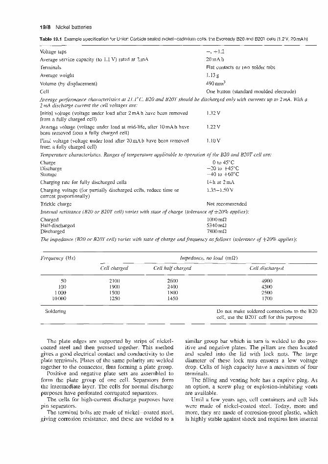
19/8 Nickel batteries
Table 19.1 Example specification for Union Carbide sealed nickel-cadmium cells: the Eveready 620 and B20T cells (1.2V, 20mAh) ~~
Voltage taps Average service capacity (to 1.1 V) rated at 2 mA
-, +1.2 20 mA h
Terminals
Volume (by displacement) 490 mm3 Cell Average performance characteristics at 2I.I"C. B20 and B20T should be discharged only with currents up to 2 mA. With a 2 mA discharge current the cell voltages are: Initial voltage (voltage under load after 2 mA h have been removed from a fully charged cell)
been removed from a fully charged cell)
from a fully charged cell) Temperature characteristics. Ranges of temperature applicable to operation of the B20 and B20T cell are:
Flat contacts or two solder tabs Average weight 1.13g
One button (standard moulded electrode)
1.32V
1.22 v
l.10V
Average voltage (voltage under load at mid-life, after l0mAh have
Final voltage (voltage under load after 20 mA h have been removed
Charge 0 to 45°C Discharge -20 to + 4 5 T Storage -40 to +60"C Charging rate for fully discharged cells
current proportionally) Trickle charge Not recommended Internal resistance (B20 or B20T cell) varies with state of charge (tolerance of f 2 0 % applies):
14h at 2mA Charging voltage (for partially discharged cells, reduce time or 1.35-lS0V
Charged Half-discharged Discharged
1000mfi 5340 m a 7800 m a
The impedance (B20 or B20T cell) varies with state of charge and frequency asfollows (tolerance of 520% applies):
Frequency (Hz) Impedance, no load (ma)
Cell charged Cell half charged Cell discharged
50 100
1 000 10 000
2100 1900 1500 1250
2600 2400 1800 1450
4900 4300 2500 1700
Soldering Do not make soldered connections to the B20 cell, use the B20T cell for this purpose
The plate edges are supported by strips of nickel- coated steel and then pressed together. This method gives a good electrical contact and conductivity to the plate terminals. Plates of the same polarity are welded together to the connector, thus forming a plate group.
Positive and negative plate sets are assembled to form the plate group of one cell. Separators form the intermediate layer. The cells for normal discharge purposes have perforated corrugated separators.
The cells for high-current discharge purposes have pin separators.
The terminal bolts are made of nickel-coated steel, giving corrosion resistance, and these are welded to a
similar group bar which in turn is welded to the pos- itive and negative plates. The pillars are then located and sealed into the lid with lock nuts. The large diameter of these lock nuts ensures a low voltage drop. Cells of high capacity have a maximum of four terminals.
The filling and venting hole has a captive plug. As an option, a screw plug or explosion-inhibiting vents are available.
Until a few years ago, cell containers and cell lids were made of nickel-coated steel. Today, more and more, they are made of corrosion-proof plastic, which is highly stable against shock and requires less internal
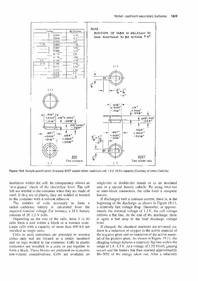
Nickel-cadmium secondary batteries 19/9
I Inches
0024 -
0 069 0 174 0 119
0213 0 >>3 0378 - 0 457
Millimetres
1.63 1.75
3.02 3.18 4.76
5.66
1 1 6
0"
Flat contacts ( - )
Nore : POSITION Of TABS IN PGLATIoN TO O N E AN0THe.P TO ,915 WITHIN r5°
--+ ,378"
+.ooo" - . 00 8 "
-.o 0 e/'
Two solder tabs ( - 1
Figure 19.8 Sample specification: Eveready B20T sealed nickel-cadmium cell, 1.2V, 20A h capacity (Courtesy of Union Carbide)
insulation within the cell. Its transparency allows an 'at-a-glance' check of the electrolyte level. The cell lids are welded to the container when they are made of steel. If they are of plastic, they are welded or bonded to the container with a solvent adhesive.
The number of cells necessary to form a nickel-cadmium battery is calculated from the required nominal voltage. For instance, a 24 V battery consists of 20 1.2-V cells.
Depending on the size of the ceIls, from 3 to 10 cells form a unit within a block or a wooden crate. Large cells with a capacity of more than 400 A h are installed as single units.
Cells in steel containers are provided in wooden crates only and are located as a totally insulated unit on lugs welded to the container. Cells in plastic containers are installed in a crate or put together to form a block. These blocks are preferred on economic low-volume considerations. Cells are available on
single-tier or double-tier stands or as an insulated unit in a special battery cubicle. By using inter-tier or inter-block connectors, the cells form a complete battery.
If discharged with a constant current, there is, at the beginning of the discharge, as shown in Figure 19.11, a relatively fast voltage drop. Thereafter, at approxi- mately the nominal voltage of 1.2 V, the cell voltage follows a flat line. At the end of the discharge, there is again a fast drop to the final discharge voltage level.
If charged, the chemical reactions are reversed, i.e. there is a reduction of oxygen in the active material of the negative plate and an oxidation of the active mater- ial of the positive plate. As shown in Figure 19.11, the charging voltage follows a relatively flat line within the range of 1.4-1.5 V. At a voltage of 1.55 V/cell, gassing occurs and the battery has then reached approximately 80-90% of the energy taken out. After a relatively

19/10 Nickel batteries
Terminal bolts to connect cables and intercell connectors
,Filling and venting hole with vent plug
Strip of nickel-coated steel
Positive and negative pocket plate, interleaving perforated corrugated separators
Cell container and cell lid of corrosion-proof plastic capable of withstanding shock treatment
Figure 19.9 Design of large vented nickel-cadmium battery (Courtesy of Chloride Batteries)
Fold Pocket plate Fold
Figure 19.10 Design of the pocket plate in large vented nickel-cadmium battery. Pocket plate with perforated upper and lower tap (Courtesy of Chloride Batteries)
steep ascent up to approximately 1.7 V, the charging curve follows a horizontal line again and the battery is now fully charged.
Comparison of vented lead-acid and nickel-cadmium batteries for standby and motive power applications A nickel-cadmium battery contains plenty of electrolyte. Positive and negative electrodes are kept apart by separators whose only purpose is to keep the electrodes electrically insulated from
each other. Lead-acid batteries, on the other hand, have separators which also have the task of preventing sedimentation from the active material and the formation of lead excrescences on the plates. These excrescences can otherwise cause short- circuiting. Since the separators are to a large extent responsible for the internal electrical resistance in the cells, the nickel-cadmium battery has low internal resistance due to the almost entirely open separators in the form of widely spaced grids

Nickel-cadmium secondary batteries 19/11
The alkaline electrolyte in nickel-cadmium batter- ies keeps its density and low freezing point constant when discharging. As a lead-acid battery runs down, the density of the sulphuric acid decreases, which means that the electrolyte freezes at low tempera- tures and the battery is damaged. Nickel-cadmium batteries therefore perform better at low tempera- tures than lead-acid batteries. The risk of damage to the batteries from cold is therefore practically non- existent.
The life of nickel-cadmium batteries is also less affected by high temperatures than that of lead-acid batteries. These batteries work in both tropical heat and arctic cold. The battery range covers temperatures from -50°C to +55"@.
All open batteries emit hydrogen and oxygen dur- ing the final stage of charging. In nickel-cadmium batteries these are the only gases given off, whereas lead-acid batteries also give off corrosive sulphuric acid fumes.
Modern lead batteries are generally fitted with acid- separating valves, which need regular maintenance and inspection to prevent the escape of corrosive acid fumes. Nickel-cadmium batteries can be safely kept beside sensitive electrical and mechanical equipment without causing any damage to it.
Nickel-cadmium batteries withstand overcharging and undercharging better than lead-acid batteries. They are not deformed by overcharging and can be completely run down and even negatively charged without damage, and can withstand short-circuiting.
Table 19.2 presents a list of maximum levels of impurities that can be tolerated in the potassium hydroxide electrolyte used for nickel-cadmium batteries.
1.8 1.7
1.6 1.5
2 1.4
I 3 1.3
3 1.2
1.1
- -
0.9 l.o i - \
Figure 10.1 1 Voltage characteristics nickel-cadmium battery: 1, charged; 2, disch,arged (Courtesy of Chloride Batteries)
or rods, and can therefore give excellent load performance.
The active material of most modem types of nickel-cadmium battery is enclosed in pockets of perforated steel strips, which are joined to the plate materials. The steel strips, which form the walls of the pockets, are perforated from both the inside and the outside. This double perforation creates a maximum surface area which makes for high output performance. This means that nickel-cadmium batteries can supply up to three times as much current in proportion to their nominal capacity as is normal for lead-acid batteries.
As well as their extremely high power output characteristics, nickel-cadmium batteries have many advantages from the electrical point of view. In con- trast to lead-acid batteries, the electrolyte of the alkaline battery does not change during charging and discharging. It retains its ability to transfer ions between the cell plates irrespective of the charge level. Nickel-cadmium batteries can be left uncharged or partially charged because there is no sulphating pro- cess, unlike lead-acid batteries.
Like the plates, the current collectors and mechm- icd connections of a nickel-cadmium battery are made entirely of steel. The alkaline electrolyte does not react with steel, which means that the supporting structure of the battery stays intact and unchanged for the entire lifetime of the battery. This should be com- pared with a lead-acid battery, in which the supporting parts and the current collectors are made of lead, which corrodes in suliphu~ic acid. For this reason the strength of a lead-acid. battery decreases progressively.
The corrosion in a lead-acid battery can lead to what is known as sudden death. A supporting part of a plate or some important component is eaten through, breaks and causes a short-circuit. The battery sud- denly stops working, or else the performance drops off rapidly. The steel construction of a nickel-cadmium battery guarantees that this can never happen, which is why nickelkadmiurn batteries give better reliability than lead-acid batteries.
19.1.2 The memory effect in nickel-cadmium batteries and cells The memory effect in a battery is the tendency of the battery to adjust its electrical properties to a certain duty cycle to which it has been subjected for an extended period of time. For instance, if a battery has been cycled to a certain depth of discharge for a large number of cycles, then on a subsequent normal discharge the battery will not give more capacity than that corresponding to the applied cycling regimen.
The memory effect was first noticed by workers at Nife Jungner with sealed sintered plate satellite cells. In the satellite programmes the cells were sub- jected to well defined dischargehecharge cycles. When after such tests at the 25% discharge level the cells were tested for capacity in a normal manner, it was found that the cells performed in accordance with Figure 19.12. The capacity was only about 25% to the normal cut-off voltage of 1 .O V. However, full capacity was obtained to a cut-off voltage of 0.6 V.
Thus the capacity was available but at a much lower voltage than normal. Accordingly, the effect can be
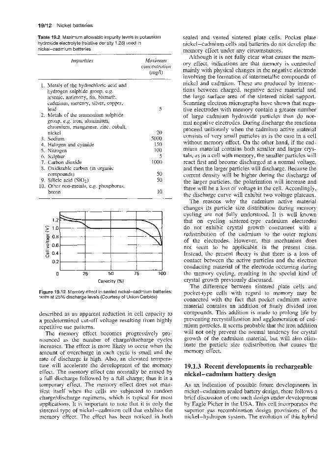
19/12 Nickel batteries
Table 19.2 Maximum allowable impurity levels in potassium hydroxide electrolyte (relative density 1.28) used in nickel-cadmium batteries
Impurities Moximum concentration
(mg4
1. Metals of the hydrochloric acid and hydrogen sulphide group, e.g. arsenic, antimony, tin, bismuth, cadmium, mercury, silver, copper, lead
2. Metals of the ammonium sulphide group, e.g. iron, aluminium, chromium, manganese, zinc. cobalt, nickel
3. Sodium 4. Halogen and cyanide 5. Nitrogen 6. Sulphur 7. Carbon dioxide 8. Oxidizable carbon (in organic
compounds) 9. Silicic acid (SiOz)
10. Other non-metals, e.g. phosphorus, boron
5
20 5000
150 100
5 1000
50 50
10
1.2
> 1.0
0 0.8 0.6
5 0.4
0.2
- .....
4- - - u
0 25 50 75 Capacity (%I
Figure 19.12 Memory effect in sealed nickel-cadmium batteries: tests at 25% discharge levels (Courtesy of Union Carbide)
described as an apparent reduction in cell capacity to a predetermined cut-off voltage resulting from highly repetitive use patterns.
The memory effect becomes progressively pro- nounced as the number of charge/discharge cycles increases. The effect is more likely to occur when the amount of overcharge in each cycle is small and the rate of discharge is high. Also, an elevated tempera- ture will accelerate the development of the memory effect. The memory effect can normally be erased by a full discharge followed by a full charge; thus it is a temporary effect. The memory effect does not man- ifest itself when the cells are subjected to random charge/discharge regimens, which is typical for most applications. It is important to note that it is only the sintered type of nickel-cadmium cell that exhibits the memory effect. The effect has been noticed in both
sealed and vented sintered plate cells. Pocket plate nickel-cadmium cells and batteries do not develop the memory effect under any circumstances.
Although it is not fully clear what causes the mem- ory effect, indications are that memory is connected mainly with physical changes in the negative electrode involving the formation of intermetallic compounds of nickel and cadmium. These are produced by interac- tions between charged, negative active material and the large surface area of the sintered nickel support. Scanning electron micrographs have shown that nega- tive electrodes with memory contain a greater number of large cadmium hydroxide particles than do nor- mal negative electrodes. During discharge the reactions proceed uniformly when the cadmium active material consists of very small particles as is the case in a cell without memory effect. On the other hand, if the cad- mium material contains both smaller and larger crys- tals, as in a cell with memory, the smaller particles will react first and become discharged at a normal voltage, and then the larger particles will discharge. Because the current density will be higher during the discharge of the larger particles, the polarization will increase and there will be a loss of voltage in the cell. Accordingly, the discharge curve will exhibit two voltage plateaux.
The reasons why the cadmium active material changes its particle size distribution during memory cycling are not fully understood. It is well known that on cycling sintered-type cadmium electrodes do not exhibit crystal growth concurrent with a redistribution of the cadmium to the outer regions of the electrodes. However, this mechanism does not seem to be applicable in the present case. Instead, the present theory is that there is a loss of contact between the active particles and the electron conducting material of the electrode occurring during the memory cycling, resulting in the special kind of crystal growth previously discussed.
The difference between sintered plate cells and pocket-type cells with regard to memory may be connected with the fact that pocket cadmium active material contains an addition of finely divided iron compounds. This addition is made to prolong life by preventing recrystallization and agglomeration of cad- mium particles. It seems probable that the iron addition will not only prevent the normal tendency for crystal growth of the cadmium material, but will also elim- inate the particle size redistribution that causes the memory effect.
19.1.3 Recent developments in rechargeable nickel-cadmium battery design As an indication of possible future developments in nickel-cadmium sealed battery design, there follows a brief discussion of one such design under development by Eagle Picher in the USA. This cell incorporates the superior gas recombination design provisions of the nickel-hydrogen system. The evolution of this hybrid

Nickel-cadmium secondary batteries 19/13
Positive electrode Gas smcer
metal-to-gas couple has resulted in the development of certain interesting and very successful internal cell design innovations, and this new technology could eas- ily be applied to the sealed nickel-cadmium system.
By incorporating the gas recombination design pro- visions of the nickel-hydrogen cell, the requirement for a high porosity separator material in the sealed nickel-cadmium cell is eliminated. High electrolyte absorption and retention, and non-temperature and non-time (cycle life) degradable inorganic separator materials such as potassium titanate or asbestos may be used. This same gas recombination also renders the sealed nickel-cadmium system less sensitive to elec- trolyte level increases of up to 50%, eliminating the need to operate the cell in a virtually starved elec- trolyte condition. Finally, by incorporating a small section of the nickel-hydrogen gas electrode mater- ial in unique electncal contact with the cell positive terminal, a hydrogen gas recombination mechanism (during charge and overcharge) is introduced. If, dur- ing operation, the cell is stressed to the point at which the hydrogen gas overvoltage potential of the negative (cadmium) ellectrode is achieved, the evolved gas is rapidly recombined at a low equilibrium pressure and one of the more serious problems associated with the sealed nickel-cadmium system is reduced.
The modified Eagle Picher nickel-cadmium cell incorporates Ihe ‘split negative’ design in which a sin- gle negative or cadmium electrode is replaced by two cadmium electrodes each of which is approximately one-half the thickness of the original. The two back- to-back negative electrodes are then separated by a gas spacer component to facilitate gas access, as in the nickel-hydrogen cell. To further enhame oxygen gas recombination, a thin film of Teflon may be applied to the back of each negative electrode (Figure 19.13)
TQ introduce a hydrogen gas recombination ability into the design, a section of the catalytic gas electrode from the nickel-hydrogen system is incorporated. A strip of this material, approximately the same width as the narrow edge of the cell, is wrapped in a U-shaped fashion around the entire edge of the electrode stack and connected electrically to the positive terminal of the cell.
Eagle Picher fabricated test cells incorporating various design features as follows:
Design A:
Design €3:
Design C:
Design D:
Design E:
Design F:
Non-woven nylon (Pellon 2505) separator material. Non-woven nylon (Pellon 2505) separator material with gas electrode. Asbestos mat (fuel cell grade) separator material with gas electrode. Asbestos mat (fuel cell grade) separator material. Non-woven (Pellon 2505) separator mater- ial with Teflon film. Asbestos mat (fuel cell grade) separator material with Teflon film.
Teflon film
- Negative electrode
Figure 19.13 ‘Split negative’ electrode stack design: Eagle Picher sealed nickel-cadmium cell (Courtesy of Eagle Picher)
The stainless steel container, incorporating two ceramic-to-metal seals, was approximately 114.3 mm tall (excluding terminals) by 76.2 mm wide, by 22.9mm thick. To simulate a thin negative electrode design using available materials, the positive elec- trodes used consisted of two 0.0064mm electrodes in a back-to-back configuration offering in effect a 0.0127 mm electrode (positive). Each test cell incor- porated five 0.0127 mm positive electrodes and ten 0.0064mm negative electrodes (Figure 19.12). The capacity of a cell was approximately 20Ah and the negative-to-positive capacity ratio was approximately 1.3:l. All cells were activated with electrolyte to a level of approximately 3.5 cm3/A h.
The influence of cell design on overcharge pres- sure characteristics, that is, potential improvement in oxygen recombination characteristics. is illustrated in Figure 19.14.
With the exception of design D, all cells using the asbestos designs appear to recombine oxygen gas sat- isfactorily at this rate. The high charge voltage associ- ated with design D may have resulted in the hydrogen gas overvoltage potential being exceeded and hence the generation of high pressure. The hydrogen gas over- voltage potential may have also been exceeded with design C but, in this case, the design incorporated a gas electrode which facilitated hydrogen gas recomb- ination. The relatively lower charge voltage associated with design F may have resulted from the application of the Teflon film which enhanced oxygen gas recomb- ination and maintained the negative electrodes at a

19/14 Nickel batteries
B + C .- E 6
F 2 e - 0 - w t t
;; ;; 9 0 - 3 3
$ $
Y m
100-
80- 7 70- 60- n n
m 'B 50 - 40 c 30 20 10 0
A B C D E F Design
Figure 19.14 Overcharge pressure characteristics: Eagle Picher split negative electrode stack design, sealed nickel-cadmium cell. Charge 200%, rate C/5, temperature ZO'C (Courtesy of Eagle Picher)
lower state of charge. The general higher charge volt- age associated with these asbestos separator designs is attributed to a very loose electrode stack assem- bly required by the use of available components. The nylon separator stacks did not fit snugly in the cell container and the asbestos material was only approx- imately one-half the thickness of the nylon material. To ensure hydrogen gas evolution for an evaluation of the gas electrode design, the nylon separator cells, designs A, B and E, were subjected to an overcharge at a C/10 rate and a temperature of approximately 0°C. The results of this test are presented in Figure 19.15.
The high charge voltages associated with all three cells indicated that the hydrogen gas overvoltage potential was exceeded; however, design B, incorp- orating the gas electrode, was capable of recombining the hydrogen gas and was stabilized at a low pres- sure. The high pressures associated with designs A and E were not appreciably reduced after several days of open-circuit stand.
Electrolyte quantity sensitivity of the advanced design cells with nylon separators (designs A, B and E) was evaluated by increasing the electrolyte quan- tity in each cell by approximately 0.5cm3/Ah and then subjecting the cells to an overcharge at a C/10 rate and a temperature of approximately 20°C. The preceding steps were then repeated until all cell pres- sures exceeded 6.9 x lo5 N/mz during overcharge. The results of this testing are presented in Figure 19.16.
As may be seen, all cells were able to accommodate the first increment of electrolyte without significant gas recombination degradation. However, after the second increment, the cell designs without the Teflon backing
P I m ._ E 6
P c W
6 100
90 80 70 60
m '2 50 40 30 20 10 0
N m 0 m
Design
Figure 19.15 Gas electrode versus non-gas electrode design: Eagle Picher split negative electrode stack design sealed nickel-cadmium cell. Charge ZOO%, rate C/10, temperature 0°C (Courtesy of Eagle Picher)
a m w
Figure 19.16 Overcharge pressure against electrolyte quan- tity: Eagle Picher split negative electrode stack design sealed nickel-cadmium cell. Charge 250%, rate C/10, temperature 20°C (Courtesy of Eagle Picher)
on the negative electrode (designs A and B) exhib- ited a notable pressure increase, probably as a result of negative electrode flooding. After the third incre- ment of electrolyte, the Teflon film cell design (design E) finally exceeded the 6.9 x lo5 N/m2 limit, but even in this case the recombination rate was still sufficient

Nickel-hydrogen and silver-hydrogen secondary batteries 19/15
to require an extended period of overcharge to achieve this limit.
Although the test results on the advanced design cell were not conclusive, the projected improved per- formance characteristics of the advanced design were realized. The split negative design successfully permit- ted the incorpclration of a low-porosity separator mater- ial which would significantly increase the list of poten- tial candidate materials. In addition, the split negative design resulted in an improved oxygen gas recombinat- ion rate (in this case up to a C/5 overcharge rate). The incorporation of a gas electrode was also successful in the recombination of hydrogen gas (again at least up to a C/lO overcharge rate). The application of a thin Teflon film to the back of the split negative elec- trodes was beneficial to all designs, particularly with respect to increases in electrolyte quantities. Although all cells accommodated greater electrolyte quantities than would normally be tolerated in a conventional cell, an even greater quantity could be accommodated in the Teflon film design.
Developments of this type in nickel-cadmium cell design promise even better cell characteristics in the future. In the particular example of battery design improvement discussed above, only minimal further development should evolve a system which offers both greater reliability and a significant improvement in cycle-life capacity.
The teflonated negative plate referred to above was studied as part of an investigation into the elimina- tion of potential failure modes and the enhancement of reliability c i f the nickel-cadmium system intended for use in satellites. The presence of a thin layer of porous Teflon film wrapped around the surface of the negative electrode was believed to offer the advan- tage of reducing or eliminating cadmium migration, which is knou7n to occur in present systems over time. The results obtained from cell testing have been very encouraging. The Teflon film does not affect the oper- ating voltage of the cell on charge or discharge, but does significantly improve the oxygen gas recombinat- ion rate.
After completior, of approximately 3000 low Earth orbit cycles followed by approximately 300 syn- chronous orbit cycles (Table 19.3) the Teflon film design batteries were opened up and it was shown that the nonwoven, nylon separator (Pellon 2505) was remarkably free of any indication of cadmium migration.
Very recent developments in minimum or zero maintenance nickel-cadmium pocket plate cells is dis- cussed below.
These cells use the following oxygen recombination cycle to prevent water loss, i.e. avoid the need for topping up.
Positive electmde: 40H- -+ 0 2 + 2H20 + f4e-
Negative electrode: 2Cd + 0 2 + 2H20 + Cd(OH)*
(19.6)
Table 19.3 Cycle test sequence of porous Teflon membrane in sealed nickel-cadmium batteries: Eagle Picher ceil RSN-50 (50 A h capacity)
Cycle Cell potential Cell pressure End-of-discharge on charge on charge voltage
(VI (i.w.g.) (VI
Near Earth orbit cycle Cycle: 56min; 14A charge 23min; 14A dischaxge 22min Temperature: 4.4"C
1 1.458 - 21 1.232 640 1.463 - 24 1.242
1270 1.460 -25 1.238 1920 1.459 -25 1.236 2650 1.462 -25 1.235 Synchronous orbit cycle Cycle: 24 h; 5 A charge 22.8 h; 25 A discharge 1.2 h Temperature: 26.6"C
3 1.405 - 14 1.217 14 1.412 -2 1.194 27 1.413 2 psi 1.199 44 1.383 10 psi 1.197
110 1.396 10 psi 1.190 Accelerated synchronous orbit cycle Cycle: 12 h; 5 A charge 10.8 h; 25 A discharge 1.2 h Temperature: 4.4"C
156 1.474 -5 1.206 162 1.480 - 10 1.200 185 1.480 - 10 1.202
Cadmium hydroxide is reduced back to cadmium at the cadmium electrode.
2Cd(OH), + 4eC -+ 2Cd + 40HC (19.7)
For these reactions to occur effectively the oxygen has to diffuse from the positive electrode to the negative and to permit this to occur at the required rate, the electrolyte has to be contained in an adsorbent separ- ator. These separators, as opposed to those used in open frame type cells, lead to an increase in electrical resistance of the cell, i.e. a slight loss in performance.
During the past 10 years the nickel film plate based on polypropylene felt has been introduced and has led to an improvement in performance. Plastic or rubber bonded plates have also been introduced. The use of Teflon bonded plates as a replacement for pocket electrodes has not fulfilled its earlier promise due to problems associated with swelling of the positive electrode.
19.2 Nickel-hydrogen and silver- hydrogen secondary batteries
These batteries are still at or slightly beyond the experimental stage. The basic nickel-hydrogen system consists of a catalytic gas electrode (negative) coupled with a nickel electrode (positive). Electrochemically

19/16 Nickel batteries
the reactions occurring at the positive electrode are the same as those occurring in the parent systems. At the negative electrode, hydrogen is displaced from water by electrolysis during charge. During discharge the reverse process occurs, namely, the electrochemical discharge of hydrogen ions in solution.
These cells use a nickel positive electrode that is similar to those used on aerospace nickel-cadmium cells. The negative is 30% potassium hydroxide just as with nickel-cadmium cells. But the negative elec- trode consists of gaseous hydrogen contained at high pressure.
At the positive electrode
NiOOH + Hz0 + e- e Ni(0H)Z + OH-
At the negative electrode
The pertinent reactions are:
discharge
charge (0.490 V)
(19.8)
discharge $Hz + OH- F=====+ HzO + e- (0.828V) (19.9)
charge
For the overall cell reactions discharge
charge +Hz +NiOOH W Ni(0H)z (1.318V) (19.20)
During overcharge oxygen generated at the nickel elec- trode and excess hydrogen recombine to form water using a platinum electrode to catalyze the recombinat- ion. The efficiency of this recombination process is one of the reasons why the nickel hydrogen cell is so tol- erant to overcharge. The positive and negative plates are separated by zirconium oxide cloth or asbestos felt separators.
Figure 19.17 shows a laboratory test cell system designed for evaluation of various nickel-hydrogen electrode and electrode stack designs. The system offers a very heavy-duty pressure vessel capable of withstanding virtually any pressure developed during system tests, and offers a convenient means of instru- mentation to obtain various data of interest. In this case ‘pineapple slice’ electrode designs are stacked
Gas port Positive terminal (semipermeable membrane)
together to form a 50Ah capacity electrode stack. All support mechanisms and electrical connections are accommodated through the centre of the stack, permit- ting placement of electrode edges very close to the cell container wall, which enhances thermal properties. In addition, this design significantly reduces the length of the path that the reactant gas must travel to reach any point on the electrode surfaces. Figure 19.18 shows prototype nickel-hydrogen cell designs manufactured by Eagle Picher. The cells exhibit the spherical geom- etry characteristics of pressure vessels. The cell in Figure 19.18 yields 20 A h capacity at approximately 55 W h/kg and is referred to as the ‘prismatic spheroid’ design. The electrode stack is contained within the prismatic area defined by the broken lines, and the spherical portions of the container serve as free vol- ume for the storage of hydrogen gas. The ratio of free volume to ampere hour capacity is selected so that the cell will operate at a maximum pressure of 3.5 m/m2 .
It is observed that the prismatic spheroid design is not a self-contained pressure vessel - the two flat surfaces must be supported. The design theory consid- ers that two parallel flat surfaces will greatly facilitate packaging of cells into a battery configuration. From an energy density standpoint, the transfer of strength requirements from individual cells to a common bat- tery frame supporting a number of cells offers a sig- nificant weight advantage. The flat surfaces are also in intimate contact with the electrode stack, providing effective areas for the application of thermal control measures.
This cell also features two specially designed high- pressure ceramic-to-metal seals incorporating caustic- resistant zirconium and nickel-gold braze materials. The seal body is internal to the cell and the com- plete assembly, in the configuration shown, is rated in excess of 13.8 MN/m2. Prototype units have demon- strated an energy density of 60 W h/kg at a maximum operating pressure of 3.5 kN/m2. This corresponds to a volumetric energy density of 67 W h/dm3 and a vol- umetric capacity of 55 Ah/dm3.
The cylindrical cell design shown in Figure 19.18 also yields 50Ah capacity, but at a slightly lower
Spiral-wound cell stack
Gas port (semipermeable membrane)
Negative terminal
Stack components
Gas volume macer Plastic cell case
Figure 19.17 Test cell of Eagle Picher nickel-hydrogen battery (Courtesy of Eagle Picher)
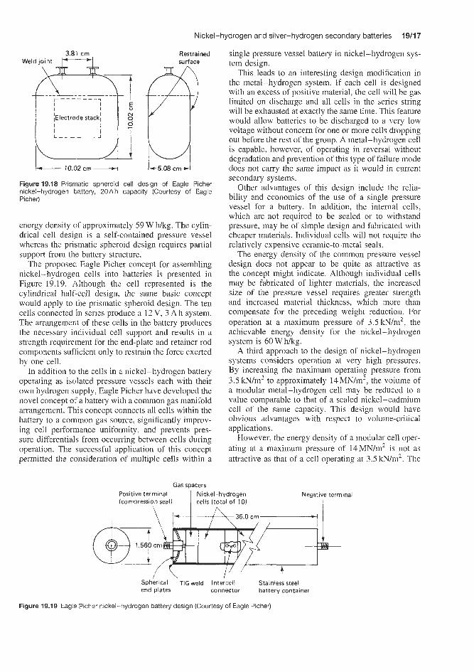
Nickel-hydrogen and silver-hydrogen secondary batteries 19/17
Restrained surface
Figure 19.18 Prismatic spheroid cell design of Eagle Picher nickel-hydrogen battery, 20A h capacity (Courtesy of Eagle Picher)
energy density of approximately 59 W f i g . The cylin- drical cell design is a self-contained pressure vessel whereas the prismatic spheroid design requires partial support from the battery structure.
The proposed Eagle Picher concept for assembling nickel-hydrogen cells into batteries is presented in Figure 19.19. Although the cell represented is the cylindrical half-cell design, the same basic concept would apply to the prismatic spheroid design. The ten cells connected in series produce a 12 V, 3 A h system. The arrangement of these cells in the battery produces the necessary individual cell support and results in a strength requirement for the end-plate and retainer rod components sufficient only to restrain the force exerted by one cell.
In addition to the cells in a nickel-hydrogen battery operating as isolated pressure vessels each with their own hydrogen supply, Eagle Picher have developed the novel concept OC a battery with a common gas manifold arrangement. This concept connects all cells within the battery to a common gas source, significantly improv- ing cell performance uniformity, and prevents pres- sure differentials from occuning between cells during operation. The successful application of this concept permitted the consideration of multiple cells within a
single pressure vessel battery in nickel-hydrogen sys- tem design.
This leads to an interesting design modification in the metal-hydrogen system. If each cell is designed with an excess of positive material, the cell will be gas limited on discharge and all cells in the series string will be exhausted at exactly the same time. This feature would allow batteries to be discharged to a very low voltage without concern for one or more cells dropping out before the rest of the group. A metal-hydrogen cell is capable, however, of operating in reversal without degradation and prevention of this type of failure mode does not carry the same impact as it would in current secondary systems.
Other advantages of this design include the relia- bility and economics of the use of a single pressure vessel for a battery. In addition, the internal cells, which are not required to be sealed or to withstand pressure, may be of simple design and fabricated with cheaper materials. Individual cells will not require the relatively expensive ceramic-to-metal seals.
The energy density of the common pressure vessel design does not appear to be quite as attractive as the concept might indicate. Although individual cells may be fabricated of lighter materials. the increased size of the pressure vessel requires greater strength and increased material thickness, which more than compensate for the preceding weight reduction. For operation at a maximum pressure of 3.51cN/m2, the achievable energy density for the nickel-hydrogen system is 60 W hkg.
A third approach to the design of nickel-hydrogen systems considers operation at very high pressures. By increasing the maximum operating pressure from 3.5kN/m2 to approximately 14MN/m2, the volume of a modular metal-hydrogen cell may be reduced to a value comparable to that of a sealed nickel-cadmium cell of the same capacity. This design would have obvious advantages with respect to volume-critical applications.
However, the energy density of a modular cell oper- ating at a maximum pressure of 14MN/m2 is not as attractive as that of a cell operating at 3.5 lcN/m2. The
Gas spacers Positive terminal Nickel-hydrogen (compression seal) 1 cells (total of 10)
Negative terminal I
\ I 3 6 . O c r n . I
Spherical ‘TIG weld Inteicell Stainles’s steel end plates connector battery container
Figure 19.19 Eagle Picher nickel-hydrogen battery design (Courtesy of Eagle Picher)

19/18 Nickel batteries
cell container material thickness would have to be increased to withstand the higher pressure, although it would not be a directly proportional increase because the reduction in the size of the pressure vessel increases strength with respect to internal pressure. The prob- lem results from the fact that a decrease in the volume of the vessel does not produce an equivalent reduc- tion in the surface area of the vessel. The projected energy density for the nickel-hydrogen system is again 60 W Wkg, with 90 W Wkg for the silver-hydrogen system.
The advantages of the high-pressure design are demonstrated in the volume parameters. A volumet- ric energy density of 183 Wh/dm3 and a volumet- ric capacity of 146Ah/dm3 are achievable with the nickel-hydrogen system.
Another approach to the design of nickel-hydrogen systems involves designs operating at relatively low pressure, eliminating the need for a pressure vessel. Hydrogen readily reacts with certain alloys to form a hydride and may be chemically stored in this fashion rather than as a gas. Many metals and intermetallic compounds are known to form hydrides. Compounds such as lanthanum nitride adsorb and desorb large quantities of hydrogen gas under relatively low pres- sures at room temperature. This hydride limits the maximum operating pressure for a metal-hydrogen system to approximately 0.7 kN/m2. Operation of mod- ular cells at this pressure is not only attractive from a safety standpoint, but permits the use of conven- tional, sealed nickel-cadmium, prismatic cell and bat- tery assembly technology.
Again, the projected energy density of the low- pressure cell design does not appear to be as high as that of the modular cell design operating at 3.5 N/m2. The lower operating pressure permits the use of lightweight cell container materials; however, the weight of current hydride compounds more than compensates for this advantage. The projected energy density for the nickel system is 60 Whkg. The hydride systems offer an advantage with respect to minimizing cell volume and an improvement in the volume parameters. The volumetric energy density of the nickel-hydrogen system is 213WWdm3 with a volumetric capacity of 170 Ah/dm3.
Table 19.4 presents comparative data on energy den- sity for the four designs of nickel-hydrogen sys- tem discussed above; data are also given for sil- ver-hydrogen systems.
Of the various designs, Eagle Picher appear to have made most progress with the modular cylindrical design (A in Table 19.4). They report that the per- formance recorded for this type of nickel-hydrogen cells and batteries is very encouraging. Such sys- tems have successfully completed thousands of cycles under both static and dynamic environmental con- ditions, under both simulated low Earth orbit and synchronous orbit cycle regimens. In addition, to
demonstrate the deep depth-of-discharge (DOD) capa- bilities of the nickel-hydrogen system ‘cylindrical’ 50 A h cell designs have been placed on 100% DOD cycles and have to date successfully passed approxi- mately 600 cycles. The nickel-hydrogen battery has a projected capability of more than 600 deep discharge cycles (in excess of 70% DOD) at an energy density of up to 70 W hkg. Representative results of this test are shown in Figure 19.20.
A low-cost nickel-hydrogen system proposed by Eagle Picher is based on the multiple cell per single battery pressure vessel concept. Additional system cost reduction is proposed through use of standardized com- ponents, ease of manufacture and an inherent design versatility able to meet various voltage and capacity requirements with only minor modifications.
Figure 19.19 shows the proposed nickel-hydrogen battery design. Essentially, the battery container con- sists of a long cylinder or tube of a length selected to accommodate a desired number of cells. The sys- tem depicted is a 10-cell 12 V battery which will yield 3 A h capacity at an energy density projected to be in excess of 55 W hkg. During assembly, the long tube is loaded with pre-manufactured cells spaced apart and positioned by the gas volume spacer component. The spacer component length is selected to render sufficient free volume to store the reactant gas at a desirable max- imum pressure. The battery end-plate is of a recessed spherical configuration to facilitate tungsten inert gas (TIG) welding of the interface joints and to ensure a reliable hermetic seal. Each end-plate accommodates a single low-cost high-pressure compression seal.
System versatility could be greatly enhanced by grouping the proposed battery designs into multi- ple battery units. Figure 19.21 shows a 12-battery nickel-hydrogen system. In this diagram, the battery has been wired to produce 36V and yield 12Ah capacity. Because the batteries are self-contained pres- sure vessels, the retaining and mounting components
1.6
0.7 k ! 600 cycles\
0.6 t . I I I I 0 0.5 1.0 1.5 2.0
Discharge (h) 0 1 .o 2.0 3.0 4.0
Charge (h)
Figure 19.20 Cycling of 50Ah Eagle Picher nickel-hydrogen RNH-50-3 battery, cylindrical modular design. Charge: 15A, 4 h. Discharge: 25A, 2 h . Ambient temperature 21°C. 100% DOD cycles (Courtesy of Eagle Picher)

Nickel-hydrogen and silver-hydrogen secondary batteries 19/19
Table 19.4 Comparison of Eagle Picher metal-hydrogen systems
A B C ID Modular cell Common pressure High-pressure Low-pressure
design vessel cell design cell design (3.5 m/rn2) (3.5w/m2) (14 MN/m2) (hydride)
Nickel electmde Energy density (W h/kg) IO 60 60 60 Volumetric energy density (W h/dm3) 73 13 183 213 Volumetric capacity (A h/dm3) 0.055 0.055 0.146 0.170
Silver electrode
Volumetric energy density (W h/dm3) 79 79 305 366 Energy density (W Mkg) 110 90 90 90
may be of ultra-lightweight design resulting in a bat- tery system that exhibits a very high energy density. Eagle Picher project that the proposed design con- cept will reduce nickel-hydrogen system cost from approximately 25% greater to approximately 50% less than current sealed nickel-cadmium system cost. With demonstrated superior performance characteris- tics, the proposed cost reduction design should render the nickel-hydrogen system an attractive alternative io lead-acid and nickel-cadmium systems in many non-space applications.
The electrochemical reactions for the normal, over- charge, and overdischarge (cell reversal) of a sealed nickel-hydrogen reversible battery cell or summarized in Table 19.5.
During normal operation of a sealed rechargeable nickel-hydrogen cell, hydrogen is produced during charge and consumed during discharge at the catalyzed hydrogen electrodes. The pressure is proportional to ampere-hours into or out of the cell, and it can be used as an indicator of state of charge. The hydrogen
is not segregated, and it reacts with the nickel oxy- hydroxide resulting in a relatively slow self-discharge. As indicated by the net electrochemical reaction, no net water is produced or consumed. Hence there is no net change in the overall potassium hydroxide (KOH) electrolyte concentration.
There are three similarly designed IPV nickel- hydrogen battery cells commercially available at present one of which is discussed in detail below. They are the Air ForceEIughes, CornsatIIntelsat, and recently the NASA advanced cell. The Air Forcemughes cell was designed for primarily low earth orbit applications, but is considered an all orbit cell. The ComsatAntelsat cell was designed for primarily geosynchronous orbit applications. The NASA advanced cell was designed for primarily long life earth orbit applications.
The Air Forcemughes cell is illustrated in Figure 9.22. It consists of a stack of nickel electrodes, separators, hydrogen electrodes, and gas screens assembled in a recirculation configuration. In this
Figure 19.21 Eagle Picher 36V nickel-hydrogen multiple battery unit design (Courtesy of Eagle Picher)
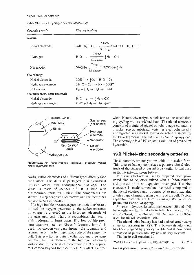
19/20 Nickel batteries
Table 19.5 Nickel-hydrogen cell electrochemistry
Operation mode Electrochemistr?,
Normal
Nickel electrode
Hydrogen
Net reaction
Overcharge Nickel electrode Hydrogen electrode Net reaction
Overdischarge (cell reversal) Nickel electrode Hydrogen electrode
Charge
Discharge Ni(OH)2 + OH- W NiOOH + H2O + e-
Charge
Discharge H20 + e- e aH2 + OH-
Charge
Discharge Ni(0H)z ___\ NiOOH + 4H2
20H- --f $ 0 2 + H2O + 2e- 2 HzO + 2e- .+ H2 + 20H- H2 + a 0 2 .+ H2O + HEAT
H20 + e- .+ $Hz +OH- OH- + bH2 .+ H2O + e-
&;ressure vessel Gas screen
Wall wick (not shown)
Hydrogen electrode Separator
Nickel stack
Hydrogen gas electrode
Figure 19.22 Air Force/Hughes individual pressure vessel nickel-hydrogen cells
configuration electrodes of different types directly face each other. The stack is packaged in a cylindrical pressure vessel, with hemispherical end caps. The vessel is made of Inconel 718. It is lined with a zirconium oxide wall wick. The components are shaped in a ‘pineapple’ slice pattern and the electrodes are connected in parallel.
If a high bubble pressure separator, such as asbestos, is used the oxygen generated at the nickel electrode on charge is directed to the hydrogen electrode of the next unit cell, where it recombines chemically with hydrogen to form water. If a low bubble pres- sure separator, such as ZircarTM (ceramic fabric), is used, the oxygen can pass through the separator and recombine on the hydrogen electrode of the same unit cell. This reaction is quite exothermic and care must be taken to limit damage to the hydrogen electrode surface due to the heat of recombination. The separa- tors extend beyond the electrodes to contact the wall
wick. Hence, electrolyte which leaves the stack dur- ing cycling will be wicked back. The nickel electrode consists of a sintered nickel powder plaque containing a nickel screen substrate, which is electrochemically impregnated with nickel hydroxide active material by the Pickett process. The gas screens are polypropylene. The electrolyte is a 31% aqueous solution of potassium hydroxide.
19.3 Nickel-zinc secondary batteries These batteries are not yet available in a sealed form. This type of battery comprises a positive nickel elec- trode of the sintered or pasted type similar to that used in the nickel-cadmium battery.
The zinc electrode is usually prepared from pow- dered zinc oxide, often mixed with a Teflon binder, and pressed on to an expanded silver grid. The zinc electrode is made somewhat oversized compared to the nickel electrode and is contoured to minimize zinc anode shape changes during cycling of the cell. Typical separator materials are fibrous sausage skin or cello- phane and Perlon wrapping.
Potassium hydroxide solutions between 30 and 40% by weight are the usual electrolytes for the cell. Cell constructions, prismatic and flat, are similar to those used for nickel-cadmium cells.
The nickel-zinc battery has had a checkered history since its inception in 1887. This battery development has been plagued by poor cyclic life and is now being surpassed in performance by new battery systems.
2NiOOH + Zn + H20 + Ni(OH)2 + Zn(0H)z
6-7 M potassium hydroxide is used as electrolyte.
The basic cell reaction is: (19.21)
Sodium-nickel chloride secondary batteries 1
This electrode has approximately 40% more theoretical capacity than the cadmium negative electrode in a nickel-cadmium couple. The metal hydride negative works well with essentially the same nickel positive electrode used in conventional nickel-cadmium cells, but provides power densities that are 20-30% higher in the finished cell.
The intrinsic voltage of the couple is approximately the same as with nickel-cadmium: values of 1.2 to 1.35V per cell having been quoted. This helps in maintaining applications compatibility between exist- ing nickel-cadmium cells and the new nickel-metal hydride cells.
The nickel-metai hydride couple lends itself to a wound construction similar to that used by present-day wound nickel-cadmium cells. The basic componeets consist of the positive and negative electrodes insu- lated by plastic separators similar to those used in nickel-cadmium products. The sandwiched electrodes are wound together and inserted into a metallic can which is sealed after injection of a small amount of potassium hydroxide electrolyte solution. The result is a cell which bears a striking resemblance to mr- rent sealed nickel-cadmium cells. The nickel-metal hydride chemistry is also applicable to prismatic cell designs which evoke greater interest as product profiles become thinner.
Quoted practical energy densities for nickel-metal hydride batteries are markedly superior (25% to 30%) to those of corresponding nickel-cadmium batteries.
Cyclic life is anode limited by dendritic growth, zinc corrosion, shape change and also zinc poisoning at the nickel cathode.
Yusaza, Japan, have been developing prototype bat- teries for electric vehicle applications, claiming 200 maintenance-free cycles at 100% depth of discharge. The more successful, but still unsatisfactory, batter- ies such as these are based on the use of PTFE bonded pressed plate zinc electrodes and sintered, plas- tic bonded pressed plate or fibre or expanded foam nickel electrodes to improve conductance.
Fibre and expanded nickel electrodes are the latest development and one being studied in Germany and Japan.
The use of fibre and expanded foam substitutes may increase the likelihood of a successful commercial nickel-zinc battery but such batteries will always have strong competition from newer types of batteries.
ydride secondary batteries The basis of the metal hydride technology is the abil- ity of certain metallic alloys to absorb the smaller hydrogen atoms in the interstices between the larger metal atoms. Two general classes of materials have been identified a5 possessing the potential for absorb- ing large volumes of hydrogen: rare earthhickel alloys generally based around LaN& and alloys consisting primarily of titanium and zirconium. In both cases, some fraction of the base metals is often replaced with other metallic elements. The exact alloy composition can be tailored somewhat to accomiiodate the spe- cific duty requirements of the final cell. Although cells using both types of materials are appearing on the mar- ket. precise alloy formulations are highly proprietary and specific to the manufacturer. These metal alloys are used to provide the active materials for the nega- tive electrode in cells which otherwise are very similar to a nickel-cadmium cell.
Use of a metal hydride provides the following reac- tions at the negative battery electrode:
Charge
When an electrical potential is applied to the cell, in the presence of the alloy, the water in the electrolyte is decomposed into hydrogen atoms which are absorbed into the alloy and hydroxyl ion as indicated below.
Alloy + I 3 2 0 + e- ----f Alloy(H) + OH- ( 19.22)
Discharge
During discharge. the reactions are reversed. The hydrogen is desorbed and combines with an hydroxyl ion to form water while also contributing an electron to the current.
Alloy(W) + OH- + Alloy + H20 + e- (19.23)
19.5 Nickel-iron secondary s
Until recently these batteries have been produced in Germany, the US and Russia in relatively small num- bers, due to poor charge retention and poor efficency in earlier types. Now, due to improvements ir, design. they are being produced in larger quantities and are being actively considered for electric vehicle applica- tions.
The cells have a voltage of 1.4V at 25°C. The basic cell reaction is:
Discharge Fe(s) + 2NiO(OH)(s) charge Fe(QH)z(s) + 2Ni(OR)p(s)
(19.24)
Energy densities currently being achieved are 20-30 W h/kg-' (tubular plate electrodes) and 40-60 W h/kg-' (sintered plate elecirodes). The pos- itive plate comprises thick sintered nickel plates on a nickel plated substrate. The negative plate comprises a mixture of powdered iron and Fe304. The electrolyte contains 1.2 to 1.3 g / ~ m - ~ potassium hydrioxide con- taining 1-2% lithium hydroxide. The cells are vented. Synthetic fibres are used for separators.

19/22 Nickel batteries
19.6 Sodium-nickel chloride secondary batteries
This is a relatively new type of rechargeable battery operating at 200-300°C with an emf of about 2.6V at operating temperatures and with possibilities for electric vehicle propulsion.
In this battery the positive electrode is a metal chloride. Nickel chloride has been particularly studied. The negative electrode is sodium metal. The liquid electrolyte consists of a basic sodium chloroaluminate
melt in @-alumina. The basic cell reaction is:
2Na + NiClz Ni + 2NaCl (19.25)
In this cell design the positive nickel electrode is sealed to a metallized @-alumina collar which is then attached to a @-alumina canister by a glass seal. This assembly is then welded onto a mild steel can and the space in between filled with sodium metal. The 8-alumina tube is then filled with positive electrode material, namely nickel powder, sodium chloride and aluminium powder.
Discharge
charge

Silver batteries


Silver oxide-zinc primary batteries 2013
20.1 Silver oxide-zinc primary batteries The are two tylpes of silver oxide cell: one has a cathode of monovalent silver oxide (Ag20) and the other type uses divalent silver oxide (Ago). The latter type has a highier theoretical potential (1.8 V) and, because there is an additional chemical reduction from A g o to Ag,O. it has a higher capacity (the theoretical energy density is 424 W f i g ) .
The cell reactions are as follows:
AgO + Zn + H20 + Ag + Zn(OH)2 (20.1)
Negative electrode:
Zn + 2 O K + &(OH), + 2e-
Zn(OH), + 2KOH + KZZn(OH),
Positive electrode:
Eo = -1.245V (20.2)
2Ag0 + H20 + 2e- + Ag,O + 2OH- Eo = +OS7 V
(20.3)
AgzO + IH20 + 2t- + 2Ag + 20H- Eo = +0.344V
(20.4)
Overall reaction:
Monovalent silver oxide-zinc
NgzO + Zn = 2Ag + ZnO (20.5)
v = 1.589V
Divalent silver oxide-zinc
AgO + Zn = Ag i- ZnO (20.6)
V = 1.815V
The two-stage reduction process would normally result in a discharge curve with two plateaux at 1.7 and 1.5 V, and the voltage drop in the middle of discharge may necessitate a voltage regulator in the equipment. If the surface Iayer of the electrode is of Ag20, however, discharge takes place at the lower potential throughout. In order to achieve voltage stability, the surface may be treated to reduce Ago to Ag20 or, in various patented arrangements, a ‘dual oxide’ system may be adopted. Higher raw material costs mean that silver oxide cells are more expensive than their mercury equivalents.
The silver oxide battery consists of a depolarizing silver oxide cathode, a zinc anode of high surface area and a highly alkaline electrolyte. The electrolyte is potassium hydroxide in hearing-aid batteries. This is used to obtain maximum power density at hearing- aid current drains. The electrolyte in watch batteries may be either sodium hydroxide or potassium hydrox- ide. Sodium hydroxide electrolyte, which has a lower conductivity than potassium hydroxide, is often used because it has a lower tendency to ’creep’ at the
seal. Mixtures of silver oxide and manganese dioxide may be tailored to provide a flat discharge curve or increased service hours. The separator in the silver oxide system must retain silver soluble species pro- duced by chemical dissolution of the oxide, and a mul- tiple layer separator of low-porosity film achieves this.
A cutaway of a silver oxide button cell is shown in Figure 20.1. The plated steel cell cap functions as the negative terminal of the cell. The zinc anode is a high-purity amalgamated zinc powder and the cathode is a compressed pellet of silver oxide plus graphite for conductivity. An absorbent pad of a non-woven natural material holds the alkaline eiectrolyte, which is a strongly alkaline potassium hydroxide solution. The separator is a synthetic ion-permeable membrane. A sealing grommet both seals the cell and insulates the positive and negative terminals. The plated steel can act as a cell container and as the positive terminal of the cell. The inner surface of the cell is of a metal electrochemically compatible with zinc, to minimize wasteful corrosion and harmful gas evolution, and the cell can is nickel-plated steel, which is highly resistant to the electrolyte.
The manner in which the cell is designed results in high volumetric efficiency. An effective radial seal is a unique feature of the construction of many types of silver-zinc cell (for example, Union Carbide cells). Briefly, the radial sealing system, developed in :he late 1950s, incorporates the use of a nylon gasket and a top which is a gold-plated bi-clad stainless steel anode cup which serves as the negative terminal. The cathode cup is usually a nickel-plated steel can. which serves as the positive terminal. The radial seal is formed during the final stages o f cell manufacture. The cell can is subjected to an operation that actually reduces the diameter of the can. This process tightly squeezes the nylon gasket against the bi-clad stainless
Cell cap I Zinc anode
Sealing grommet Cathode Separator pad
Figure 20.1 Cutaway view of a silver oxide cell (Courtesy of Eagle Picher)

2014 Sitver batteries
steel top, creating the initial radial seal. This operation is possible because a stainless steel anode top can withstand the extreme pressure during the diameter reducing operation. Secondly, the selection of nylon is important because nylon, after being squeezed, tries to retain its original position, Le. it has a memory. Once the can diameter is reduced, a secondary seal is effected by crimping the edge of the can over the gasket. Again the use of a nylon gasket is significant since nylon will continue to exert pressure as a result of the second sealing operation. The radial seal technique is highly effective in providing excellent protection against the incidence of salting.
Further details on the construction of the latest designs of monovalent silver oxide-zinc (Ag,O) and divalent silver oxide (Ago)-zinc button cells are given below.
Monovalent silver oxide-zinc
Button cells with solid cathodes are designed as anode limited (5-10% more cathode capacity than anode capacity). The anode is amalgamated powdered or gelled zinc and contains a gelling agent and is housed in a triclad metal top (nickel-stainless steel-copper) with the copper in direct contact with the zinc. The anode is separated from the silver monoxide cathode by a separator or absorbent layer (cotten-like material) and a semi-permeable membrane banier. The design of the absorbent separator system depends on the chemistry of the cathode and the intended use of cells. For example, a monovalent silver oxide-zinc cell for hearing aid applications may use a cellophane-type membrane to slow silver migration for 1-2 years, such a membrane is not applicable to watch applications where a life of 3 to 5 years is needed. In the latter case a graft irradiated polyethylene membrane is used giving a useful life of 5 years. The cathode is pelleted and contained in a nickel plated steel can. The cathode (positive) and anode (negative) plates are separated by a Nylon 66 grommet seal, The electrolyte is 9 - 1 0 ~ potassium hydroxide.
Bleeder valve in gas distributor with electrolyte
Divalent silver oxide-zinc
Again, in the button cell designs the solid cathodes are anode limited with 5-10% more cathode capacity than anode capacity. The anode is amalgamated pow- dered or gelled zinc and contains a gelling agent and is housed in a triclad metal top (nickel-stainless steel-copper) with the copper in direct contact with zinc. The anode is separated from the divalent sil- ver oxide cathode by a separator or absorbent material (cotton-like material) and a semi-permeable membrane barrier. The design of the absorbent separator sys- tem depends on the chemistry of the cathode and intended use.
The cathode is pelleted and contained in a nickel plated steel can. The cathode (positive) and anode (negative) are separated by a grommet seal of Nylon 66. The electrolyte is 9- 10 N potassium hydroxide.
20.1.1 Remotely activated silver oxide-zinc batteries
Silver-zinc primary batteries can be remotely activ- ated for single use within seconds or fractions of a second, even after long-term storage, by inserting the electrolyte under pressure. In addition to a unit containing dry charged plates they also contain an electrolyte vessel from which the cells are filled by electrical or mechanical means. Pile batteries are a new development of remotely activated primary bat- teries, which consist of bipolar electrodes that confer a very high density on the battery. A schematic repre- sentation of a remotely activated silver-zinc battery is shown in Figure 20.2. Such batteries are recommended for use in aerospace, torpedo and pyrotechnic ignition applications.
In an alternative design of remotely activated primary silver-zinc batteries the electrolyte reservoir is sealed at both ends with high-pressure (6.89 MPa burst strength) metal diaphragms. The gas generator to pump in the electrolyte is activated by a squib or a primer, which is electrically, mechanically or inertially activated. The expanding
Electrolyte Electrolyte Electrolyte tank
\ manifold
/exit I
--% trap \ A \ 7
Pressurized gas tank Ignition device Membrane for gas inlet Cell block or gas generator to electrolyte tank
Figure 20.2 Schematic layout of remotely activated Silberkraft silver-zinc battery (Courtesy of Dryfit)

Silver-cadmium secondary batteries 20/5
gas bursts the diaphragms and forces the electrolyte into the manifold and cells. In this cell design a vented system enhances the rapid clearing of the manifold and eliminates excessive intercell leakage paths. The battery has no moving parts and has an extended shelf life. It can be activated directly into a load or in parallel with a mains system. The open-circuit voltage of this battery is 1.6-1.87V with a working voltage of 1.20-1.55V. The battery operating temperature is -29 to +71"C and, with water assistance, -48 to +71"C. The energy density is 11-66Whkg or 24-213WNdm3, depending on battery size. Units are available in the weight in the weight range 0.14-135kg. The dry storage charge retention characteristics of this battery are excellent at temperatures up to 52°C.
Eagle Picher supply gas-generating pyrotechnic devices, which can be used for the activation of remotely activated batteries by transferring electrolyte from a reservoir to the battery cells. Eagle Picher have developed over 70 gas-generator configurations with capabilities ranging from 20 to 200 000 cm3 (standard condition gas output), many of which have been used in a majority of missile/spacecraft systems.
20.2 Silver-zinc secondary batteries
These cells are leakproof, spillproof and have high impact strength. The assembled cells can be enclosed in sturdy lightweight cases for special mechanical and environmental conditions. Batteries can also be designed and built to meet the most stringent requirements.
A typical battery design is shown in Figure 20.3. This battery contains silver oxide as the positive elec- trode and zinc as the negative electrode, and has an alkaline electrolyte.
Separators are made from cellophane or non-woven polyamide. Cells are fitted with a safety valve. Dry charged cells can be stored indefinitely.
Negative terminal \ Filter and vent plug
Figure 20.3 Yardney Silvercel silver-zinc battery construction. Positive electrode manufactured from special grades of silver with or without silver collectors. Negative electrode manufactured from zinc with or without collectors. Semipermeable and ion-exchange separators designed and patented by Yardney. Strong electrolyte solution of potassium hydroxide. Positive and negative terminals of silver-plated steel for maximum corrosion resistance and minimum contact resistance, or special nonmagnetic alloys. The filling vent allows activation of the cell with electrolyte, while the vent plug or screw valve, when placed in the cell, will allow gassing and prevent electrolyte spillage. Vent trap, designed to be moulded as part of the cover, prevents leakage and spillage, and so allows the cell to operate in any position. Case and cover moulded in plastics such as ABS, SAN, nylon, modif polypropylene oxide, polyarylether or polysulphone (Courtesy of Yardney)
20.3 Silver-cadmium secondary batteries The design of this battery is very similar to that of the silver-zinc battery, with the exception that the zinc negative electrode is replaced by one fabricated from cadmium.

Alkaline manganese batteries

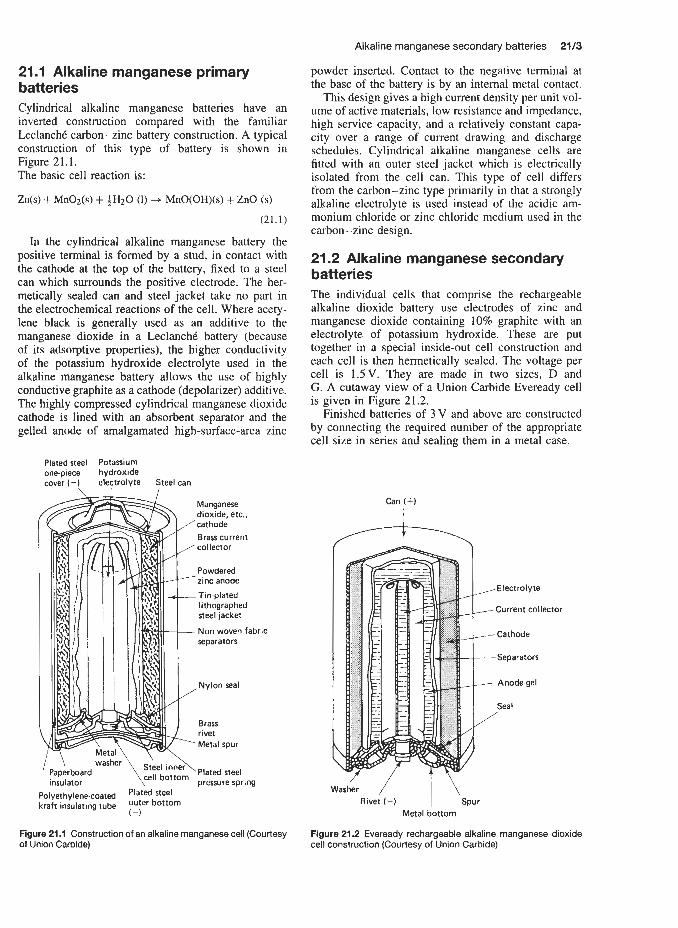
21.1 Alkaline manganese primary batteries Cylindrical alkaline manganese batteries have an inverted construction compared with the familiar LeclanchC carbon-zinc battery construction. A typical construction of this type of battery is shown in Figure 21.1. The basic cell reaction is:
Zn(s) + MnOz(s) + f HzO (1) + MnO(OH)(s) + ZnO (s)
(21.1)
In the cylindrical alkaline manganese battery the positive terminal is formed by a stud, in contact with the cathode at the top of the battery, fixed to a steel can which surrounds the positive electrode. The her- metically sealed can and steel jacket take no part in the electrochemical reactions of the cell. Where acety- lene black is generally used as an additive to the manganese dioxide in a LeclanchC battery (because of its adsorptive properties), the higher conductivity of the potassium hydroxide electrolyte used in the alkaline manganese battery allows the use of highly conductive graphite as a cathode (depolarizer) additive. The highly compressed cylindrical manganese dioxide cathode is lined with an absorbent separator and the gelled anode of amalgamated high-surface-area zinc
Plated steel Potassium one.piece hydroxide cover (+) electrolyte Steel can
cell Dressure spring Paperboard insu I at or lyethylenecoated ‘Iated steel aft insulating tube Outer bottom
(-1
Figure 21.1 Construction of an alkaline manganese cell (Courtesy of Union Carbide)
Alkaline manganese secondary batteries 2113
powder inserted. Contact to the negative terminal at the base of the battery is by an internal metal contact.
This design gives a high current density per unit vol- ume of active materials, low resistance and impedance, high service capacity, and a relatively constant capa- city over a range of current drawing and discharge schedules. Cylindrical alkaline manganese cells are fitted with an outer steel jacket which is electrically isolated from the cell can. This type of cell differs from the carbon-zinc type primarily in that a strongly alkaline electrolyte is used instead of the acidic am- monium chloride or zinc chloride medium used in the carbon-zinc design.
21.2 Alkaline manganese secondary batteries The individual cells that comprise the rechargeable alkaline dioxide battery use electrodes of zinc and manganese dioxide containing 10% graphite with an electrolyte of potassium hydroxide. These are put together in a special inside-out cell construction and each cell is then hermetically sealed. The voltage per cell is 1.5V. They are made in two sizes, D and G. A cutaway view of a Union Carbide Eveready cell is given in Figure 21.2.
Finished batteries of 3 V and above are constructed by connecting the required number of the appropriate cell size in series and sealing them in a metal case.
Can (+)
Current collector
I ‘Spur Washer /
Rivet (-) Metal bottom
Figure 21.2 Eveready rechargeable alkaline manganese dioxide cell construction (Courtesy of Union Carbide)


Carbon-zinc and carbon-zinc chloride batteries


Carbon-zinc chloride primary batteries 22/13
22.1 Carbon-zinc primary batteries The electrochemical system of the carbon-zinc. (LeclanchC) battery uses a zinc anode and a manganese dioxide cathode and an electrolyte of ammonium chloride and zinc chloride dissolved in water. Various grades of manganese dioxide are used for Leclanch6 cells. These range from the natural ores used for inexpensive low-rate cells to the synthetically produced or electrolytically prepared grades used in more expensive high-rate cells. Powdered carbon is used in the cathode depolarizing mix, usually in the form of acetylene black, to improve conductivity of the mix and to retain moisture.
The standard carbon-zinc dry battery is not designed to be recharged. The basic cell is made in many shapes and sizes, but two general categories exist for round cells, which are available as unit cells or in assembled batteries and flat cells.
The difference between the two is mainly physical. The chemical ingredients are the same for both: car- bon, depolarizing mix, separator, electrolyte and zinc. A flat cell, such as the Union Carbide ‘Mini-Max’, uses these materials in a laminated structure, while in a round cell they are arranged concentrically (see Figures 22.1 and 22.2).
In flat cells a zinc plate is coated with carbon to form a duplex electrode - a combination of the zinc of one cell and the carbon of the adjacent one. The Union Carbide Mini-Max cell contains no expansion chamber or carbon rod as does the round cell. This increases the amount of depolarizing mix available per unit cell volume and therefore increases the energy content. In addition, the flat cell, because of its rectangular form, reduces waste space in assembled batteries.
Elastic envelope
Y$(+;n coating
Liner
Separator
Figure22.1 Cross-section of a Union Carbide Mini-Max car- bon-zinc flat cell (Courtesy of Union Carbide)
One-piece metal Carbon Paperboard wver ( + I electrode vent washer \ 1 ,/ ,Asphalt Seal
I / /
,Wax ring Seal
Polyethylene-coated paperboard support washer
Jacket of polyethylene-coated
ammonium chloride and
Tin-plated Paperboard star bottom steel bottom
(-)
Figure 22.2 Cross-section of a standard carbon-zinc round cell (0-size). The rod in the centre of the cell is carbon and functions as a current collector (Courtesy of Union Carbide)
Electrode cap (+\
\ Metal bottom ( - )
Figure22.3 Cross-section of a zinc chloride cell (D-size) (Courtesy of Union Carbide)

22/4 Carbon-zinc and carbon-zinc chloride batteries
22.2 Carbon-zinc chloride primary batteries
The zinc chloride LeclanchC cell is a special modifi- cation of the carbon-zinc cell. They differ principally in the electrolyte systems used. The electrolyte in a zinc chloride cell contains only zinc chloride, while in a carbon-zinc cell the electrolyte contains a satu- rated solution of ammonium chloride in addition to zinc chloride. The omission of ammonium chloiide improves the electrochemistry of the cells but places greater demands on the cell seal. Zinc chloride cells therefore have either a new type of seal not previ- ously used in carbon-zinc cells or an improved con- ventional seal so that their shelf life is equivalent to that of carbon-zinc cells. Electrode blocking by reaction products and electrode polarization at high
current densities are minimized by the more uniform and higher diffusion rates that exist in an electrolyte containing only zinc chloride. Because of their abil- ity to operate at high electrode efficiencies, the use- ful current output of zinc chloride cells is usually higher than that of carbon-zinc, and zinc chloride cells will operate at high current drains for a consid- erably longer time than carbon-zinc cells of the same size. In addition, the voltage level under load holds up longer.
Because of the electrochemical reactions that occur in the zinc chloride cell during use, water in the cell is consumed (by a reaction product which is an oxide compound) along with the electrochemically active materials, so that the cell is almost dry at the end of its useful life.
A cross-section view of a D-size zinc chloride cell is shown in Figure 22.3.

Mercury-zinc batteries


Mercury-zinc primary batteries 23/3
electrolyte is 9- 1 0 ~ potassium hydroxide containing a low concentration of zinc oxide to reduce zinc gassing.
Mercury batteries and cells are produced in cylin- drical and button types. Electrochemically, both are identical and they differ only in can design and internal arrangement. The anode is formed from cylinders or pellets or powdered high-purity amalgamated zinc, or a gelled mixture of electrolyte and zinc. The depolariz- ing cathode is compressed mercuric oxide-manganese dioxide in sleeve or pellet form (cell voltage 1.4V) or pure mercuric oxide (cell voltage 1.35 V), and the electrolyte, which does not participate in the reaction, is concentrated aqueous sodium or potassium hydrox- ide. The cathode is separated from the anode by an ion-permeable barrier. In operation this combination produces metallic mercury, which does not inhibit the current flow within the cell (Figure 23.1). Zinc is ther- modynamically unstable with respect to water and in strongly alkaline solutions will tend to self-discharge with the evolution of hydrogen. Zinc anode corrosion is reduced to acceptable levels by amalgamating the zinc powder with mercury, which increases the hydro- gen overpotential of the zinc and by ensuring that the surface area of the porous electrodes is not too high. Also it is necessary to use only materials of high hydro- gen overpotential (silver, lead, tin and copper, not iron
23.1 Mercury-zinc primary batteries The overall cell reaction occurring in a mercuric oxide-zinc cell is:
HgO + Zn = ZnO + Wg (cell voltage 1.343 V) (23.1)
Up-to-date information on the construction of a mercuric oxide primary button cell is discussed below.
Button cells with solid cathodes are designed as anode limited 1:i.e. 5% more cathode capacity than anode capacity). The anode is amalgamated pow- dered or gelled zinc and contains a gelling agent, and is housed in a triclad metal top (nickel-stainless steel-copper) with the copper in direct contact with the zinc. The anode is separated from the mercuric oxide cathode by a separator or absorbent material (cotton- like material) and a semi-permeable membrane barrier.
The design of the absorbentkeparator system depends on the intended use of the cell. An im- portant application is hearing aid cells. These utilize a mercuric oxide cathode containing graphite for conductivity and a small amount of manganese dioxide to disperse imbibed mercury beads upon cell discharge. The cathode is pelleted and contained in a nickel plated steel can. The cathode (positive) and anode (negative) are separated by a grommet seal of Nylon 66. The
h
Figure 23.1 Electrochemical processes occurring in the mercury-zinc cell. (1) With the switch open, the zinc anode and the mercuric oxide cathode are both charged with respect to the alkaline electrolyte: Zn (+I .32V) and HgO- (-0.03V) + cell voltage = 1.35V, against normal hydrogen electrode in the same electrolyte. (2) With the switch closed, the cell voltage forces electrons to flow through the external circuit in accordance with Ohm’s iaw. (3) At the anode, loss of electrons through the external circuit disturbs the anode equilibrium. Hydroxyl ions from the electrolyte discharge at the anode to restore the anode charge, forming zinc oxide and water. (4) At the cathode, gain of electrons upsets the cathode equilibrium. Hydrogen ions from the electrolyte discharge at the cathode, forming mercury and water. There is no net change of water content in the electrolyte. (5) Overall chemical reaction may be expressed as Zn + HgO + ZnO + Hg with the liberation of 820 mA h of electricity for each gram of zinc in the cell (Courtesy of Union Carbide)

23/4 Mercury-zinc batteries
or nickel) in contact with both the zinc electrode and the electrolyte. It is for this reason that the cell has a centre case (nickel-plated steel) to provide mechanical strength and an inner case of suitable high hydrogen overpotential to avoid corrosion of the anode. The inside of the cell top is also electrochemically com- patible with the zinc anode. The cell components used provide precise mechanical assemblies having maxi- mum dimensional stability and a marked improvement in performance over batteries of the carbon-zinc type.
Most major producers of mercury-zinc cells and batteries use a vented construction, which renders their products leakproof and free from bulging under all normal working conditions. Self-venting occurs auto- matically if, for example, excessive gas is produced within the cell under sustained short-circuit conditions. This type of cell is manufactured in a wide variety of structures to provide batteries of varying size, voltage and capacity. A wide range of purpose-built batteries can also be obtained. For maximum reliability intercell connection is by spot welded strips of nickel-plated steel. Outer containers are made from materials rang- ing from cardboard to metal.
Some design features used by various manufactur- ers in the construction of mercury-zinc cells are as follows: 1. Depolarizing cathodes of mercuric oxide, to which
a small percentage of graphite is added, are shaped as shown in Figure 23.1 and either consolidated to the cell case (for flat electrode types) or pressed into the cases (of the cylindrical types).
2. Anodes are formed of amalgamated zinc powder of high purity, in either flat or cylindrical shapes.
3. A permeable barrier of specially selected material prevents migration of any solid particles in the cell, thereby contributing effectively to long shelf and service life and also inhibiting the diffusion and migration of soluble mercuric hydroxide species from the cathode, which causes self-discharge of the zinc anode.
4. Insulating and sealing gaskets are moulded of nylon, polyethylene or Neoprene, depending on the application for which the cell or battery will be used.
5. Inner cell tops are plated with materials that provide an internal surface to which zinc will form a zinc amalgam bond.
6. Cell cases and outer tops of nickel- or gold-plated steel are used to resist corrosion, to provide greatest passivity to internal cell materials and to ensure good electrical contact.
7. An outer nickel-plated steel jacket is generally used for single cells. This outer jacket is a necessary component for the ‘self-venting construction’ used on some cells, which provides a means of releasing excess gas in the cell. Venting occurs if operating abnormalities such as reverse currents or short- circuits produce excessive gas in the cell. At mod- erately high pressures, the cell top is displaced
upwards against the external crimped edge of the outer jacket, tightening that portion of the seal and relieving the portion between the top and the inner steel cell case. Venting will then occur in the space between the internal cell container and the outer steel jacket. Should any cell electrolyte be carried into this space, it will be retained by the safety absorbent ring. Corrosive materials are therefore not carried with the escaping gas through the vent hole at the bottom of the outer steel jacket. After venting excess gas and reducing the internal pressure, the cell stabilizes and reseals the top seal, continuing normal operation in the circuit.
23.2 Mercury-zinc cardiac pacemaker batteries The first pacemaker batteries were produced in about 1973, and since then many improvements have been made in their design. The layout of a Mallory mer- cury-zinc pacemaker battery is shown in Figure 23.2. The anode consists of amalgamated zinc, which is in contact with the welded top assembly, the inner face of which is also amalgamated to achieve electrochemical compatibility with the anode. It is surrounded by the absorbent barrier, which is impregnated with a solution of sodium hydroxide saturated with zinc oxide. This type of electrolyte minimizes hydrolysis of the zinc, which causes production of hydrogen and results in capacity loss. The annular cathode consists of mercuric oxide mixed with silver powder, which forms a solid amalgam with the mercury appearing during discharge. It is in contact with the welded can assembly, which forms the positive terminal of the battery. The seal- ing ring and insulators, which divide the battery into two compartments, reduce the risk of short-circuit and electrical leakage. The gasket is made of Neoprene; this material keeps its elasticity for a long period of time even under mechanical stress, thus ensuring the best possible seal.
The battery shown in Figure 23.2 has a nominal voltage of 1.35 V and a nominal capacity of 1000 mA h defined for a load of 1250 Q, with a cut-off voltage of 0.9V. For lighter loads, tests on early production batteries have given the results shown in Table 23.1,
Table 23.1 Mallory cell 317653 discharge at 73°C
Load Minimum Average Maximum (W
~ ~~
11 mAh 954 1066 1080 months 10.5 12.0 12.25
22 mAh 690 94 1 1035 months 15.2 20.7 23.2
33 mAh 622 791 1000 months 20.8 26.0 33.0

Mercury-zinc cardiac pacemaker batteries 23/5
'--. Depolarizer insulator
Figure 23.2 Mallory mercury-zinc pacemaker battery type 1 (Courtesy of Mallory)
assembly
Figure 23.3 Mallory mercury-zinc pacemaker battery type RM2 (Courtesy of Mallory)
The figures in Table 23.1 are to be considered as minima: One sees immediately that reducing the drain does not result in a proportional increase of life. To meet the demand for longer service life, Mallory have developed a new cell (RM2 type) (Figure 23.3). Its construction differs from the earlier one in a number of respects, as follows:
1. A collector in the form of a spring ensures a better contact with the anode material and increases its efficiency.
3 . Another microporous barrier is clamped over the absorbent-separator assembly to close the anodic compartment.
4. A secondary barrier has been added to minimize penetration of zinc dendrites.
5. The single can is made of pure nickel. 6. The gasket is moulded around a single biplate top.
Its nominal capacity is 1800mAh and a capa- city realization of 93% over 28 months' discharge is claimed. The service life of this battery is likely to be less than 5 years. 2. The multi-turn microporous barrier is heat sealed.


Lithium batteries


Lithium-sulphur dioxide primary batteries 2413
carbon electrode where the sulphur dioxide is reduced. Depending on the current density, the precipitate may deposit throughout the porous cathode (at low current densities) or predominantly at the surface of the cath- ode facing the anode (at high current densities).
The nature of this discharge process shows that the conductivity of the electrolyte plays an important role in determining the rate capability of the system, both from the point of view of the rate at which lithium ions can be transported to the cathode and from the point of view of the depth to which the discharge reactio~ can penetrate into the cathode.
Figure 24.2 shows the composition-conductivity contour of the lithium bromide-sulphur dioxide- acetonitrile electrolyte over a wide temperature range. A maximum conductivity of about 6 x 10p2/(G? cm) is obtained at 25°C. It may be seen that the conductivity contours form a ridge which follows closely the sul- phur dioxide depletion line. The latter is the extended line connecting the sulphur dioxide apex in the diagram and the point representing the initial composition of the electrolyte used in the cells. To enhance the rate capa- bility of the cells, an electrolyte composition should be selected on the sulphur dioxide-rich side of the con- ductivity maximum and represented by the start of the arrow in Figure 24.2 (71-75% sulphur dioxide). This choice is arbitrary to some extent, except for its loca- tion along the conductivity ridge. It was dictated by the recognition that, under the dynamic conditions of dis- charge, sulphur dioxide depletion will occur inside the porous cathode. Thus, by choosing a sulphur dioxide- rich electrolyte, depletion of the sulphur dioxide in the cathode will in fact lead to an increased conductivity o i the electrolyte in the cathode and an enhanced partic- ipation of the interior of the cathode in the discharge process. At low rates of discharge, the composition point moves towards the end of the arrow. At high rates of discharge, the sulphur dioxide utilization approaches 40-50% and the overall electrolyte composition at the end of discharge may be represented by a cornposition point close to the maximum point on the conductivity ridge.
Lithium-sulphur dioxide primary batteries The system uses a lithium anode, a gaseous sulphur dioxide cathode (about 70% of the weight of the electrolyte depolai%zer) and an electrolyte comprising lithium bromide dissolved in acetonitrile.
The discharge at the anode may be represented by the half-cell reaction: Li = Li+ + e- (24.1)
The cathode reaction may be written as:
2 ~ 0 2 + 2ep = ~ 2 0 2 -
and the overail cell reaction as 2Li + 2,502 = 12i2S20~(lithium dithionite) (24.3)
The discharge of lithium-sulphur dioxide cells is accompanied by the precipitation of lithium dithionite in the cathodes, but the precipitate appears not to lessen the rate capability of the cells noticeably. An optimal electrolyte composition can be specified that permits the cathodes to operate along a maximal conductivity path during discharge.
The high-rate capability of the cells is favoured by the high conductivity of the electrolyte and the small effect of temp'erature on the conductivity. Heat dissipa- tion structures are recommended for lithium- sulphur dioxide cells and batteries that operate at high power levels. Lithium- sulphur dioxide cells can operate at 460 W/kg while delivering LOO W k g in suitable high- rate configurations.
On the basis of postulated cell reactions, the dis- charge process of the lithium-sulphur dioxide cell may be illustrated schematically as shown in Figure 24.1. Lithium ions formed at the anode are transported to the cathode where charge neutralization occurs and insol- uble lithium dithionite deposits at and inside the porous
(24.2)
so Conductivity per s2 cm
an
10
N:PC 30°
LiBr
Figure 24.1 Schematic representation of the discharge process of a lithium-sulphur dioxide cell at 25°C. AN:PC = 3 : 1 by volume (Courtesy of Honeywell)
Li+ - Li+ -+
Lit d
Li+ +
so, -+
so, +
so, --b
so, 4
0 0 0 * - . = Li,S20,
Figure 24.2 The change in lithium bromide-sulphur dioxide electrolyte conductivity during discharge at 25°C (Courtesy of Honeywell)

24/4 Lithium batteries
The effect of temperature on the conductivity is shown in Figure 24.3, for an electrolyte composi- tion of 74% sulphur dioxide. It may be seen that a decrease in temperature from 25 to -50°C decreases the conductivity by a factor of only about one-half. This small effect of the temperature on the conductiv- ity explains the excellent high-rate capability of the lithium- sulphur dioxide system at low temperatures, coupled with the high exchange currents for the lithium oxidation and the sulphur dioxide reduction reactions. The small decrease of the conductivity with a lowering of the temperature can be attributed to the beneficial effects of the sulphur dioxide and solvent on the vis- cosity of the electrolyte.
Honeywell have described their work on the devel- opment of an alternative electrolyte for a multi-cell lithium-sulphur dioxide reserve battery. In develop- ing a multi-cell lithium reserve battery, the lithium bromide-sulphur dioxide acetonitrile electrolyte sys- tem used in their primary batteries was found to be unstable when stored by itself at high temperature - a functional capability required for all reserve applica- tions. In addition to consumption of the oxidant sul- phur dioxide in reactions causing instability, some of the products of electrolyte degradation are solid, which would cause major problems in activation. Primary active cells after storage do not undergo such degra- dation reactions.
The following reactions are believed to be responsi- ble for electrolyte decomposition in reserve batteries:
1. Reaction of sulphur dioxide with alkali metal halides:
4LiBr + 4so2 + 2Li2SO4 + S2Brz + Brz (24.4)
6 r
- 50 0 50 Temperature ("C)
Figure 24.3 The effect of temperature on lithium bromide-sulphur dioxide electrolyte conductivity, 74% sulphur dioxide (Courtesy of Honeywell)
2. Polymerization of acetonitrile:
I CH3
PzCH~C=N 3 (-C=N-),
3. Reaction(s) of acetonitrile or its polymer with inter- mediates and/or products of the LiBr-SO2 reaction.
As lithium bromide appeared to initiate the reac- tions causing electrolyte instabilities, Honeywell inves- tigated other lithium salts for use in reserve battery electrolytes and concluded that lithium hexafluoro- arsenate (LiAsF6) combined with acetonitrile and sul- phur dioxide was a suitable electrolyte, which did not exhibit discoloration or deposition of solids during storage. Table 24.1 compares the performance of bat- teries made up using the lithium bromide- and lithium hexafluoroarsenate-based electrolytes. Clearly, the 0.5 molal lithium hexafluoroarsenate electrolyte is func- tionally equivalent or superior to the lithium bromide electrolyte.
No adverse effects after 4 weeks' storage at -54 or +71"C are observed. On the contrary, the 0.5 molal LiAsFd -acetonitrile-SOz solution significantly improved in performance after 4 weeks' storage at +71"C.
Two typical cell constructions are used: jelly-roll electrodes in crimp sealed on hermetically sealed cylin- drical cells, and large 20-100Ah, 12V flat-plate elec- trodes in large reserve batteries.
It is a relatively high-pressure system and cells must have safety vents to avoid explosion in the event of accidental incineration. Diagrammatic representa- tions of Honeywell reserve and nonreserve (active) lithium-sulphur dioxide systems are shown, respec- tively, in Figures 24.4 and 24.5.
The external configuration of the reserve battery (Figure 24.4) is that of a right cylinder, which in cross-section reveals three main portions of the internal design:
1. The electrolyte storage reservoir sections. 2. The electrolyte manifold and activation system. 3. The reserve cell compartment.
Referring to the 20 A h battery cross-section, approx- imately half of the internal battery volume contains the electrolyte reservoir. The reservoir section consists primarily of a collapsible bellows in which the elec- trolyte solution is stored during the reserve phase of the battery life-cycle. The reservoir section contains a sufficient quantity of electrolyte solution (a mixture of sulphur dioxide, acetonitrile and the electrolyte salt) to provide the capacity rating of the battery. Surrounding the bellows, between it and the outer battery case, is space that holds a specific amount of Freon. The Freon gas is selected such that its vapour pressure always exceeds that of the electrolyte, thereby providing the

Table 24.1 Effect of electrolytes and storage conditions on discharge performance of Honeywell lithium - sulphur dioxide reserve batteries at 560mAh
Electrolyte No. of Electrolyte storage Life (h) tu Average voltage [ V ) Capacity (Ah) tu Cathode cells A kg to
2.71 V 2.00v 2.71 V 2.00v 2.71 V 2.00v 2.71 V
IM LiBr:acetonitrile:SOz 0.25M LiAsF6:acetonitrile:SOz 0 . 5 0 ~ LiAsF6:acetonitrile:SO2 IM LiBr:acetonitrile:SOz 0 . 2 5 ~ LiAsF6:acetonitrile:SOz 0 . 5 0 ~ LiAsF6:acetonitrile:SOz l~ LiBr:acetonitrile:SO2 0.25M LiAsF6:acetonitrile:SOz 0 . 5 0 ~ LiAsF6:acetonitrile:sOz
IM LiBr:acetonitrile:SO2 0 . 2 5 ~ LiAsF6:acetonitrile:SOz 0 . 5 0 ~ LiAsF6:acetonitrile:SOz IM LiBr:acetonitrile:SOz 0 . 2 5 ~ LiAsF6:acetonitrile:SOz 0 . 5 0 ~ LiAsF6:acetonitrile:SOz 1 M LiBr : acetonitrile: SO2 0 . 2 5 ~ LiAsF6:acetonilrile:SOz 0 . 5 0 ~ LiAsF6:acetonitrile:S02
3 2
No No No 4 weeks at +71"C 4 weeks at +71"C 4 weeks at +7t"C 4 weeks at -54°C 4 weeks at -54°C 4 weeks at -54°C
No No No 4 weeks at +71"C 4 weeks at +71"C 4 weeks at +71"C 4 weeks at -54°C 4 weeks at -54°C 4 weeks at -54°C
At -2°C 23 1 25 1 164 165 208 215 226 247 174 180 256 296 226 248 209 237 223 238
At +32"C 148 154 143 144 175 179 147 152 151 153 169 181 155 161 145 146 176 184
2.840 2.853 2.851 2.830 2.808 2.802 2.832 2.824 2.823
2.848 2.845 2.844 2.848 2.843 2.846 2.822 2.853 2.850
2.81 8 2.851 2.843 2.793 2.795 2.775 2.797 2.783 2.800
2.833 2.845 2.836 2.836 2.838 2.825 2.807 2.850 2.836
0.655 0.468 0.593 0.640 0.487 0.716 0.640 0.590 0.630
0.420 0.409 0.498 0.419 0.428 0.481 0.437 0.413 0.502
0.706 0.471 0.610 0.690 0.501 0.820 0.694 0.660 0.665
0.435 0.410 0.508 0.43 I 0.435 0.510 0.452 0.416 0.520
Cells were discharged through a constant resibtive load of 1000 C2, which corresponds to a current density of 0.24mA/cm3 of 560mAh reserve batteries at -2°C
1.64 1.17 1.48 1.60 1.22 1.80 1.60 1.48 1 .58
1.05 c: 1.02 rr
1.25 5
1.07 1.21 1.09 5
1.05 $ v)
U zi E
n 0
Q (D
I .03 1.26 25.
4. -
2 3

24/6 Lithium batteries
Intercell
Activation manifold
insulation Activation
Single / , Batterv
\ ' ' Battery top Manifold bulkhead
\ ' storage bellows diaphragm
Freon backfil I Electrolyte volume
20,60, 100 A h battery cross-section
Figure 24.4 Honeywell reserve lithium-sulphur dioxide cell (Courtesy of Honeywell)
driving force for eventual liquid transfer into the cell chamber section once the battery has been activated.
In the remaining half of the battery volume, shown at the top of the figure, is the centrally located elec- trolyte manifold and activation system housed in a 15.88 mm diameter tubular structure plus the series stack of four toroidally shaped cells, which surround the manifoldactivation system.
The manifold and cells are separated from the reser- voir by an intermediate bulkhead. In the bulkhead there is a centrally positioned diaphragm of sufficiently thin section that it can be pierced by the cutter contained within the manifold. In fabrication, the diaphragm is assembled as part of the tubular manifold, which in turn is welded as a subassembly to the immediate bulkhead.
Figure 24.6 is a more detailed cross-sectional view of the electrolyte manifold and activation system with the major components identified. The activating mech- anism consists of a cutter (5) which is manually moved into the diaphragm, cutting it and thereby allowing
electrolyte to flow. The movement of the cutter is accomplished by the turning of an external screw (7), which is accessible in the base of the battery. The cutter section and the screw mechanism are isolated from each other by a small collapsible metal cup (9), which is hermetically sealed between the two sections. This prevents external electrolyte leakage. The mani- fold section is a series of small non-conductive plastics tubes (10) connected at one end to the central cylinder (4) and to each of the individual cells at the other end. The long length and small cross-sectional area of the tubes minimize intercell leakage losses during the time that electrolyte is present in the manifold structure.
Using the lithium-sulphur dioxide system, four individual cells are required to achieve the voltage range desired for the total battery. The number of cells is, of course, adjustable with minor modification to meet a wide range of voltage needs. Each cell contains flat circular anodes and cathodes, which are separately wired in parallel to achieve the individual cell capacity and plate area needed for a given set of requirements. The components, with intervening separators, are alternately stacked around the cell centre tube, after which the parallel connections are made. The cells are individually welded about the inner tube and outer perimeter to form hermetic units ready for series stacking within the battery. Connections from the cells are made to external terminals, which are located in the bottom bulkhead of the battery.
Figure 24.7 is a photograph of the major battery components before assembly. The components shown are fabricated primarily from 321 stainless steel, and the construction is accomplished with a series of TIG welds.
When the battery is activated by cutting the diaphragm in the intermediate bulkhead, all the liquid stored in the reservoir does not enter the cell compartments. The amount of liquid initially placed in the cells is approximately 70% of the total contained in the reservoir. The balance remains in the manifold section and the uncollapsed portion of the bellows. The vapour pressure of the Freon gas behind the bellows maintains it in a collapsed position and therefore in the liquid state. As discharge proceeds in the cells, generating free volume, the bellows continue to collapse, forcing additional oxidant into the cells and permitting continued discharge. When the remaining 30% of the oxidant enters the cells, the bellows have bottomed on the intermediate bulkhead, which relieves the Freon pressure from the cell section. This permits vaporization of the sulphur dioxide, which consequently isolates the cells from one another by vapour locks created in the small tubes. The activation system, therefore, is dynamic in nature for the initial phases of the discharge life. For the concept to be practical. the hardware design must minimize intercell leakage, maximize activator efficiency in terms of liquid delivered, and ensure the maintenance of liquid flow during the early phase of discharge.

Lithium-sulphur dioxide primary batteries 24/7
Positive terminal cap
Glass insulator
Positive pin
\ Terminal insulator
Insulating jack
Top insulator
Safety feature
Ball seal (shown in fill hole) / Header 6 Weld
/Cell case (negative)
Negative electrode lead
- Positive electrode lead
Cathode (carbon)
Positive grid
Anode (lithium)
L ' Separator
,Bottom insulator
Figure 24.5 Honeywell
Diaphragm
active lithium-sulphur dioxide cell showing vent concepts (Courtesy of Honeywell)
Top bushing
Electrolyte Electrolyte Collapsing Drive entry flow supply tube cup disc
Figure 24.6 Honeywell lithium-sulphur dioxide battery electrolyte manifold and activation system (Courtesy of Honeywell)

2418 Lithium batteries
Figure 24.7 Honeywell lithium-sulphur dioxide battery 20A h reserve battery components (Courtesy of Honeywell)
Figure 24.8 presents data recorded during a test at 10°C with a 20Ah activator. A constant Freon pressure of 3.72 kg/cm2 absolute was noted throughout the electrolyte delivery cycle. This is as expected since, at this temperature, sufficient Freon is packaged to remain in a saturated condition within the activator. On activation, the electrolyte was allowed to flow into an evacuated volume, which simulated the internal volume environment of a cell stack. The tubes used for transfer of the liquid were identical to those used in a finished battery.
In this test, 305cm3 of electrolyte were pack- aged, 270cm3 of which were delivered to the simu- lated battery volume within 75s after activation. This represented a delivery efficiency of approximately 88%, which provides a sufficient quantity of elec- trolyte/oxidant to the cell stack to achieve the 20 A h output required.
The latest designs of lithium-sulphur dioxide cells feature a cathode comprising Teflon bonded acetylene block laminated to an aluminium grid, an electrolyte comprising sulphur dioxide dissolved in acetonitrile and a microporous polypropylene separator. The cells are hermetically sealed, of spiral wound construction,
300 r Delivery mmdetion
53.0 psia constant /
>
w Y _/Electrolyte
/ "O'IJme
10 20 30 40 50 60 70 Time ( 5 )
Figure 24.8 Activation delivery characteristics against time at -1 0°C. 20 Ah activator hardware, 305 ml electrolyte packaged, 270ml (88.5%) delivered, four-capillary tube with 10°C delivery (Courtesy of Honeywell)
equipped with a gas release vent and are housed in a stainless steel can.
24.2 Lithium-thionyl chloride primary batteries The cell reactions in the lithium-thionyl chloride cell are postulated as follows:
4Li + SOC12 -+ 4LiCI + SO2 + S (24.5)
On a partially discharged cell stored at 60°C and above, a possible consistent reaction could be:
2soc12 + 3s -+ 2s2c12 + so2 (24.6)
The electrolyte used in lithium-thionyl chloride bat- teries consists of a solution of 1 SM lithium aluminium chloride (LiAlC4) dissolved in thionyl chloride. This electrolyte is usually doped with 5% sulphur dioxide to prevent passivation of the anode by a lithium chlor- ide film. The anode is pure lithium foil mounted on a stainless steel collector plate, and the cathode is a cold-pressed sheet of 80% Shawinigan carbon and 20% Teflon mounted on stainless steel. The active lithium-thionyl chloride battery is available in capac- ities of 1.3, 160, 380 and 517Ah. The battery is con- structed in a jelly-roll configuration with the electrodes separated by a glass mat separator.
Lithium-thionyl chloride is often cited as having the highest performance potential of any of the lithium cells. It is particularly promising for high-current applications, though it has been used for low currents as well.
According to some experts in the field, this type of cell might replace carbon and alkaline C and D cells for general consumer and industrial applications. It is cur- rently limited to military applications. Lithium-thionyl chloride cells being produced now have five to eight times the capacity of an ordinary carbon cell, so the higher cost (84-9) is within reason. The growing in- clination of retailers to stock products with batteries on the shelf is another good argument for using long-life lithium cells as an alkaline replacement.
Like the sulphur dioxide combination, thionyl chlor- ide has been haunted by safety questions. One safety- related problem exists when a gas forms during the cell's operation, placing the cell under pressure. If heating occurs, there could be an explosion, or at least an output of toxic gases through the safety vents.
At the same time, one applications disadvantage of thionyl chloride i s that it has the same reaction delays and position sensitivity of sulphur dioxide. In fact, the response delays can be several seconds long, which could be a problem in memoryhack-up use.
Eagle Picher also manufacture lithium-thionyl chloride reserve batteries. Three types of electrolyte reservoir configurations are available, as shown in Figure 24.9, with the following characteristics:

Lithium-thionyl chloride primary batteries 2419
(a) The Eagle Picher GAP 9059 used in strategic defence systems
(b) The Eagle Picher GAP 9047 used in air-to-air missiles
(c) The Eagle Picher GAP 9049 used in re-entry vehicles (a
Figure 24.9 Eagle Picher lithium-thionyl chloride reserve batteries (Courtesy of Eagle Picher)
1. The spherical reservoir: (a) Smallest absolute volume. (b) Lightest weight. (c) Isolation between electrolyte and pressure
medium. 2. The cylinder-piston reservoir:
(a) Smallest packaged volume. (b) Flexibility in geometric shape. (c) Isolation between electrolyte and pressure
medium. 3 . The coil tubing reservoir:
(a) Unlimited flexibility in geometric shape.
The reserve battery operating concept developed by Eagle Picher is illustrated in Figure 24.10.
Recent improvements in lithium-thionyl cells include the addition of excess aluminium chloride in the electrolyte to extend the cell capacity.
4AlC13 + 2SOC12 + 4e- + 4AlCl; + SO2 + Sn (24.7)
The addition of aluminium chloride is limited to high rate reserve cells since aluminium chloride increases electrode corrosion.
Anticipated improvements in lithium-thionyl chloride cells include the extension of the shelf life of low rate cells to more than 10 years by reducing anodic film disruption caused by passivation.
In the case of high rate cells advances in safety and reliability are expected
(a) Unactivated condition
(b) Partially activated condition
(c) Completely activated condition
Figure 24.10 Eagle Picher lithium-thionyl chloride reserve battery operating concept (Courtesy of Eagle Picher)

24/10 Lithium batteries
(i) by the introduction of solid state electronics into battery design, and
(ii) by thermal management of the cells using circulating electrolytes, phase change heat sinks and cooling fins.
24.3 Lithium-vanadium pentoxide primary batteries The lithium-vanadium pentoxide cell is very attractive (as is the lithium-manganese dioxide cell) because the cathode, vanadium pentoxide, with its high oxidation state can provide a high open circuit voltage (3.4 V). It has a high energy density (224Whkg-') and power density. The cell exhibits multiple voltages on discharge under a 1000 R load giving four plateaux at 3.4, 3.2, 2.4 and 2.0V and under 3.3 K R load giving two plateaux at 3.0 and 1.8 V.
A disadvantage of the vanadium pentoxide cathode is its relatively low electronic conductivity. To offset this the cell is modified with 10% wlw carbon powder and 5% PTFE binder. The anode is pure lithium. The electrolyte consists of IM lithium perchlorate dissolved in propylene carbonate or 1:l propylene carbonate: 1:2 dimethoxyethane.
Lithium-vanadium pentoxide reserve cells are available in the capacity range 100-5oOmA. They undergo no capacity loss during 10 years' storage. A major outlet is munition system batteries. The electrolyte is stored in a glass ampoule, which when broken activates the battery within 5 seconds.
Diagrammatic representations of reserve and non- reserve (active) lithium-vanadium pentoxide batteries supplied by Honeywell are shown, respectively, in Figures 24.11 and 24.12.
24.4 Lithium solid electrolyte primary batteries The Duracell solid electrolyte cell is made of the following materials:
Anode: high-purity lithium sheet. Cathode: mixture of lead iodide, lead sulphide and
lead. Electrolyte: blend of lithium iodide and activated
alumina.
At the anode, the lithium loses electrons forming lithium ions (Lif). The ions travel though the solid electrolyte layer and the electrons travel through the external load to reach the cathode. At the cathode, the lithium ions react with the composite cathode material and the incoming electrons to form the discharge products. The discharge reactions can be expressed by the following equations:
2Li + PbI2 + 2LiI + Pb (24.8)
2Li + PbS + LizS + Pb (24.9)
Ampoule Glass-to-metal Support
--- --
Separator I mulation material
(a) G2666
Battery I
(b) G2664
Figure 24.1 1 Honeywell lithium-vanadium pentoxide reserve cells: typical construction (Courtesy of Honeywell)

Lithium solid electrolyte primary batteries 2416 1
These batteries currently under development hold the promise of spill-proof, rugged batteries with long shelf lives, with high energy density and virtually unlimited geometrical possibilities. They are based on a range of materials known as fast ion conductors such as beta alumina which are capable of conducting alkali metal ions such as lithium to levels greater than 1 0 - ~ s cm-'.
In solid polymer electrolyte-composite cathode types, solid polymer electrolytes, a more recently developed material, have this required conductivity and are seen as ideal electrolytes for solid state batteries.
A recent solid state battery design, lithium compos- ite cathode batteries, developed at Harwell, features a lithium ion conducting polymer electrolyte (e.g., polyethylene oxide) and a solid intercalation cathode. The battery is made up of a sandwich of lithiurn foil (50 pm), polymer-electrolyte (50 pm)3 composite cath- ode (various types have been studied including 'V6Q13,
Tis2, MoO2, etc., plus 5% carbon black) (56pm) and a nickel foil current collector (10 pm). Thus total cell thickness is 150-200pm and areas can range from cm2 to m2.
In a typical V601s-based cell design a cell area is 40cm2 and this gives a capacity of 80m Ah. The energy density is about 200W h/kg-'. This cell, when discharged at 120°C from 2.8V to 1.7V at the C/1@ rate yielded 100% of its theoretical capacity. More than 50% of theoretical cell capacity was available when discharge was carried out at the C rate, 80% at the C/2 rate and 100% at the C/4 rate or less. A disadvantage of this type of cell is capacity decline during cycling. Thus after 300 cycles capacity had decreased to about 60% of theoretical capacity. Attention to charging detail may overcome this limitation.
Current work is concerned with the development of cells which operate at room temperature as these are seen to have applications in the small. portable equipment market.
Cover EB Weld assembly
Insulator (cover)
RS Weld
Top spacer
Spacer
Anode SeDarator ~ assembly assembly
Cathodeand --i case assembly
(a) G2679
TlG Weld Ball seal Anode
assem bl y
! I 1 4 ,
Electrolyte
(b) G3025
Figure 24.12 Honeywell lithium-vanadium pentoxide cells: typical construction of active non-reserve cells (Courtesy of Honeywell)
Lithium iodidle is virtually a pure ionic conductor. The ionic con(ductivity is l@-'/(Qcm) at room temperature. Thle conductivity can be enhanced by incorporating high-surface-area alumina in the solid lithium iodide. The solid electrolyte used in these cells has an ionic conductivity of about 10-5/(Q~m) at room temperature, which enables the cell to deliver currents of 10 pA/sm2 at XYC with high utilization of the active materials.
These batteries are available in button and circular disc designs.
The Hawell development lithium-V205 solid state battery
The development of these solid state batteries hinged on the discovery of the fast ion conductions or solid electrolytes, e.g. /3 alumina and lithium nitride (Li3N) which are capable of conducting alkali metals.
Modern solid state batteries ose poiymeric elec- trolytes. Heteroatom containing high molecular weight polymers can conduct alkali metals.
Hanvell UK are developing a solid state cell based on four very thin layers (50-60pm each) comprising a lithium foil-polymer electrolyte-composite cath- ode-nickel foil current sollector (10 pm).
The polymer electrolyte comprises polyethylene oxide containing lithium triflate or polyethylene oxide containing lithium perchlorate. The composite czhode

24/12 Lithium batteries
is based on vanadium pentoxide (e.g. 45% VZQj, 5% carbon black, 50% polyethylene oxide, PEQ4).
The Duracell lithium-titanium disulphide secondary solid state battery
This battery produced by P.R. Mallory (now Duracell) operates at 300°C and uses a lithium-silicon alloy in cell construction, as lithium melts below its operating temperature. The cell has a voltage of 2.4V at 300°C and a practical energy density of 280Wh/kg-'. The basic cell reaction is:
Li,Si(s) + x TiS2(s) + Li,-lSi(s) + Li(TiSz),(s) (24.10)
24.5 Lithium-iodine primary batteries Lithium iodide provides a good example of a solid which has a moderately high conductivity owing to a large number of mobile cation vacancies. In Figure 24.13 the movement of such a defect from left to right is seen to result in the net transfer of a positive charge from right to left, i.e. the Li' vacancy behaves in effect as a singly charged anion.
Despite its rather modest ambient conductivity (5 x lO-jS/m), lithium iodide forms the electrolyte of a battery which is now one of the commonest power sources for implantable cardiac pacemakers. The battery is successful in this application since only small currents are drawn (typically 25 PA), thus keeping the iR drop in the cell low. It also meets the requirement of long service-life (8-10 years), and the high open circuit voltage and low equivalent mass of lithium guarantee a high energy density, so minimizing the weight of the implanted device. Finally, in this all- solid-state cell, it is possible to avoid many of the
Figure 24.13 Migration of a cation vacancy within a lithium iodide lattice, where 0 = Li+ and 0 = I-
problems associated with conventional batteries, such as leakage, self-discharge and separator failure, and so produce a power source of exceptional reliability.
A typical cell is constructed by placing in contact a lithium anode and an electronically conducting charge- transfer complex of iodine and poly-2-vinylpyridine (P2VP) containing an excess of iodine. A thin layer of lithium iodide is immediately formed, which becomes the electrolyte of the cell and prevents any further direct reaction between the active cell components.
Catalyst Research Corporation (USA) is a major manufacturer of lithium-iodine batteries used for pacemaker and other applications. The Catalyst Research Series 800 cells use the 'lithium envelope' concept. The cell is constructed with a centrally located cathode current collector and a lithium envelope which surrounds and contains the iodine depolarizer material (Figure 24.14). This depolarizer material is corrosive to the stainless steel case and must be kept from contacting the case for maximum cell life. A second barrier, formed from fluorocarbon plastics, surrounds the lithium envelope, insulates it from the case, and provides a second envelope for the containment of the depolarizer. The corrosive effect of iodine-containing depolarizer on stainless steel is lower than that of depolarizer made with more active halogens, such as bromine or chlorine.
The modes of failure of this battery are slow. It cannot suffer from separator rupture since the lithium iodide layer is self-healing. Nor does it suffer from electrolyte leakage since the electrolyte is solid.
A cell is formed when a lithium anode is brought into contact with a cathode composed of iodine and P2VP depolarizer. Between these components forms the third component necessary for any cell-the elec- trolyte (in this case solid lithium iodide). As cur- rent is drawn from the cell, lithium is oxidized and
304 stainless Cathode Anode steel cover lead ( + I jad ( - )
Hermetic 1 i
panel / 1 \ frame
Fluoroplastic Metallic Cathode 304 stainless enveiope lithium current steel case
anode collector
Figure 24.14 Catalyst Research Corporation model 802/803 solid lithium-iodine cell (Courtesy of Catalyst Research Corporation)
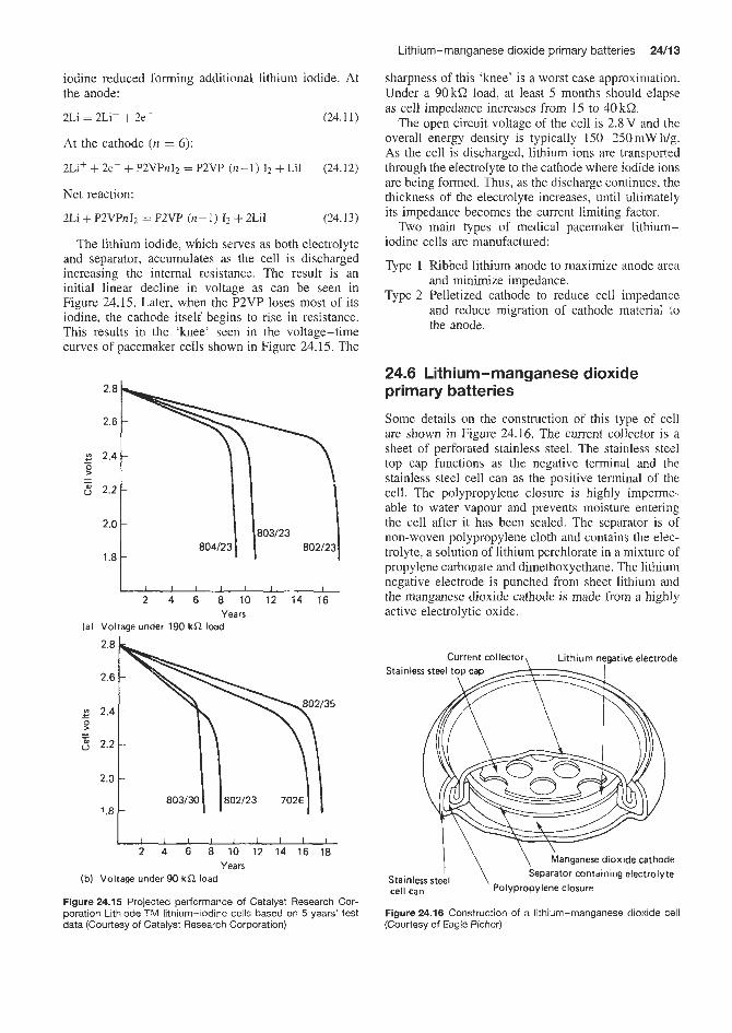
Lithium-manganese dioxide primary batteries 24/13
sharpness of this ‘knee’ is a worst case approximation. Under a 90 kQ load, at least 5 months should elapse as cell impedance increases from 15 to 40kQ.
The open circuit voltage of the cell is 2.8 V and the overall energy density is typically 150-25OmW h/g. As the cell is discharged, lithium ions are transported through the electrolyte to the cathode where iodide ions are being formed. Thus, as the discharge continues, the thickness of the electrolyte increases, until ultimately its impedance becomes the current limiting factor.
Two main types of medical pacemaker lithium- iodine cells are manufactured:
Type 1 Ribbed lithium anode to maximize anode area and minimize impedance.
Type 2 Pelletized cathode to reduce cell impedance and reduce migration of cathode material to the anode.
iodine reduced fiorming additional lithium iodide. At the anode:
2 ~ i = 2 ~ i + + 2e-
At the cathode (11 = 6):
2Li’ + 2e- + P2VPnIz = P2VP (n-1) 12 + LiI
Net reaction:
2Li + P2VPnI2 = P2VP (n- 1) 12 + 2LiI
(24.11)
(24.12)
(24.13)
The lithium iodide, which serves as both electrolyte and separator, aizcumulates as the cell is discharged increasing the internal resistance. The result is an initial linear decline in voltage as can be seen in Figure 24.15. Later, when the P2VP loses most of its iodine, the cathode itself begins to rise in resistance. This results in the ‘knee’ seen in the voltage-time curves of pacemaker cells shown in Figure 24.15. The
2 4 6 8 10 12 14 16 Years
(a) Voltage under 190 kR load
2 4 6 8 10 12 14 16 18 Years
(b) Voltage under 90 kR load
Figure 24.15 Projescted performance of Catalyst Research Cor- poration Lithiode TIM lithium-iodine cells based on 5 years’ test data (Courtesy of Catalyst Research Corporation)
24.6 Lithium-manganese dioxide primary batteries
Some details on the construction of this type of cell are shown in Figure 24.16. The current collector is a sheet of perforated stainless steel. The stainless steel top cap functions as the negative terminal and the stainless steel cell can as the positive terminal of the cell. The polypropylene closure is highly imperme- able to water vapour and prevents moisture entering the cell after it has been sealed. The separator is of non-woven polypropylene cloth and contains the elec- trolyte, a solution of lithium perchlorate in a mixture of propylene carbonate and dimethoxyethane. The lithium negative electrode is punched from sheet lithium and the manganese dioxide cathode is made from a highly active electrolytic oxide.
Current collector, Lithium negative electrode
\ Manganese dioxide cathode Separator containing electrolyte I \ Polypropylene closure
Stainless steel cell can
Figure 24.16 Construction of a lithium-manganese dioxide cell (Courtesy of Eagle Picher)

24/14 Lithium batteries
The separator is non-woven polypropylene cloth. The electrolyte is lithium perchlorate dissolved in 1:2 dimethoxypropane. The cell is housed in a stainless steel container.
Flat-type cells are available for low drain rates, and cylindrical cells with spiral wound and inside- out structures are available for high drain rates in applications such as strobes and cameras. Capacities in the range 35-5000mAh are available.
The Cell reactions:
Anode: Li + Li+ + e-
Cathode: Mn"02 + Li' + e- + Mn"'Oz(Li')
Overall: Mn"02 + Li + Mn"'Oz(Li+)
(24.14)
(24.15)
(24.16) (Li ion in MnOz lattice)
24.7 Lithium-copper oxide primary batteries Lithium-copper oxide primary cells have been estab- lished since 1969 as a versatile and reliable power source in a range of applications.
Overall: 2Li i CuO -+ Liz0 -t CuO, E" = 2.24V
Cell reaction:
(24.17)
Each cell comprises a pure lithium anode, a solid cupric oxidelgraphite cathode and a porous non-woven glass separator. The electrolyte is lithium perchlorate dissolved in 1,3 dioxolane. Cells are available in a bob- bin cylindrical cell format in which an electrolyte filled central tube (lithium anode) is wrapped in the separator and surrounded by an annular cathode (cupric oxide). The cell is sealed with a crimp-sealed polypropylene joint or glass to metal seals.
24.8 Lithium-carbon monofluoride primary batteries The basic chemistry is:
xLi + CF, + XLIF + C , E" = 3.2V (24.18)
(X = 0.5-1.0)
Cylindrical, pin and coin cell designs are available. A typical design for a cylindrical cell is shown in Figure 24.17.
The cathode is a mixture of CF, with acetylene black and binder such as PTFE. The electrolyte is a 1 : 1 mixture of dimethoxyethane and propylene carbonate containing 1M lithium borotetrafluoride. Alternatively, lithium arsenic hexafluoride in y-butyrolactone has been used.
The cylindrical cell construction in Figure 24.17 employs a spiral winding of lithium, separator and cathode. The cathode is bound to an expanded tita- nium metal grid. Sealing is achieved by means of a polypropylene disc which incorporates a safety vent.
gasket)
tnsulator
Figure 24.17 Cross sectional views of commercial Li-CFx bat- tery, cylindrical type
The separator is made from non-woven cloth made from polyethylene or microporous polypropylene.
Lithium-carbon monofluoride cells are available in capacities below 1 A h although attempts are now in progress to produce larger cells.
24.9 Lithium - molybdenum disulphide secondary batteries The development of this rechargeable lithium battery owes much to the discovery of a new crystalline phase of molybdenum disulphide in which a small quantity of lithium introduced into the crystal lattice stabilizes the crystalline phase (Lix MoS2). This shifts the equilibrium so the potential of the material is considerably more electropositive than occurs with molybdenum disulphide.
The main reaction is the electrochemical oxidation of lithium metal and the reduction of molybdenum disulphide via the intercalation reaction:
xLi + MoSz + LiwMoSz (24.19)
Lithium ions are generated at the anode during dis- charge and then transported through the liquid elec- trolyte and inserted into the molybdenum disulphide crystals without substantially changing the structure of the latter. Electrons are transported through the external circuit and recombined with lithium ions in the molybdenum disulphide host.
In these cells a lithium foil anode strip is placed between two molybdenum disulphide cathode strips. The latter electrode consisting of aluminium foil coated with the metal sulphide and organic binder with a final thin coating of molybdenum dioxide to ensure good conductivity.
The electrode stack is spirally wound around a mandrel and inserted in a nickel plated steel can. The anode is connected to a centre pin which is insulated

Lithium (aluminium) iron sulphide secondary cells 24/15
Glass -to-metal seal (with centre pin) \
Insulating disc >
7 Mandrel
Ball
Figure 24.18 Cut-away view of Li-MoS2 cell
Cathode /
F' Cathode I \ Sepa;ator I
Anode
from the rest of the can by a glass-to-metal seal. The cell is hermetically sealed by laser welding the cell top to the can. The lithium hexafluoroarsenate in 1: 1 v/v propylene carbonate: ethylene carbonate electrolyte is then introduced through a filling hole which is then closed by ball welding. The cell is vented to release pressure should it be subject to abusive conditions. See Figure 24.18.
The recommended voltage range of these cells depends on the discharge rate. For rates of 2 h or higher a voltage range of 2.2-1.1 V per cell is advised; for rates of 3 h or lower a voltage of 2.2- 1.3 V per cell is advised. The nominal capacity of AA cells is 600 mA h (A type) or 800 m A h (B type). Cells can operate suc- cessfully at temperatures down to -20°C.
24.10 Lithium (aluminium) iron sulphide secondary cells The discharge reaction of the lithium alloy negative electrode typically occurs through a series of voltage
Separator
plateaux, during each of which two solid phases are present in equilibrium. If the compositions of the two phases are denoted by LiaM and LibM where M = A1 or Si, then the discharge reaction on the plateau corresponding to Li,M --+ LibM is:
1 1 -LiaM + ~ LibM + Li+ + e- a - b a - b
(24.21)
Lithium-silicon alloys give a series of plateaux cor- responding to different values of a and b. For example, with a composition of coexisting phases of LisSi and L&Si the potential vs Li/Li+ at 450°C is 41mV. With a composition of existing phases of Li2Si and Li&i the potential vs Li/Li+ at 450°C is 329mV. The lithium-aluminium systems exhibit only two phases at 450"C, i.e. a constant electrode potential at 10-47 atom % lithium in the alloy. Specific capacity and voltametric capacity of lithium silicon alloys are con- siderably higher than those obtained with lithium

24/16 Lithium batteries
alloys. However, lithium silicon alloys are more cor- rosive in contact with steel cell components.
More work has been done on lithium-aluminium alloys than lithium-silicon alloys. However, Gould, Inc. (US) in their cell development have combined lithium-silicon alloy with lithium-aluminium alloy in their negative electrode. This increases the specific and volumetric capacity and avoids corrosion of cell components.
The electrolyte used in lithium (aluminium)-iron sulphide secondary cells is commonly a mixture of lithium chloride and potassium chloride. A lithium fluoride-lithium chloride-lithium bromide mixture has also been used. With the latter electrolyte the discharge occurs in two steps:
2FeS + 2Lif + 2e- 4 LizFeSz + Fe (24.22)
LizFeSr, + 2Li' + 2e- + 2Li2S + Fe (24.23)
In fact, this discharge occurs on a single voltage plateau because the equilibrium potentials of the above two reactions differ by only 0.02V. Thus the cell reactions is:
-Li,Al + FeS + L L i b A l f LizS + Fe a - b a - b
1 (24.24)
In these cells magnesium oxide powder in the form of a ceramic plate is used by Gould as a separator.
In a typical cell design (the GouldiWestinghouse 2OOAh cell), the negative electrode is a lithium alu- minium alloy, the positive electrode is a solid lithium chloride-potassium chloride and the separator is boron nitride. Magnesium oxide has been used as a separator in other batteries. '
During cell construction three positive plates are interleaved with four negative plates and separators
to form the cell assembly. Usually a number of cells are connected in series together with the thermal man- agement system to produce a battery.
The GouldiWestinghouse battery is the nearest to commercial production of those being developed by various companies. However, further improvement in cycle life, charging systems and thermal management are needed before the batteries can find use in vehicle traction applications.
These batteries are charged by constant current methods at the 10 h rate to a termination voltage.
They can also be charged with a constant voltage source in which case the maximum charge current should not exceed the 10h rate and the termination voltage should not exceed 2.1-2.2 V per cell. Charging should be carried out at the 20 h rate at temperatures below 0°C and should not be carried out at all at temperatures below - 10°C.
24.1 1 Lithium - iron disulphide primary batteries Cell reaction Overall: 4Li + FeS2 -+ 2LizS + Fe (24.25)
Two companies (Eveready and venture Technology) have been involved in the development of these cells. The venture Technology AAA type bobbin cell intro- duced in 1982 has a stainless steel can with lithium foil in contact with the inner surface. The positive electrode is a composite of iron disulphide (FeS2), graphite and PTFE binder on an aluminium grid. The separator is porous polypropylene and the electrolyte a solution of lithium perchlorate in a 1 : 1 v/v propylene carbonate 1 :2 dimethoxyethane mixture.

Manganese dioxide- magnesium perchlorate primary batteries

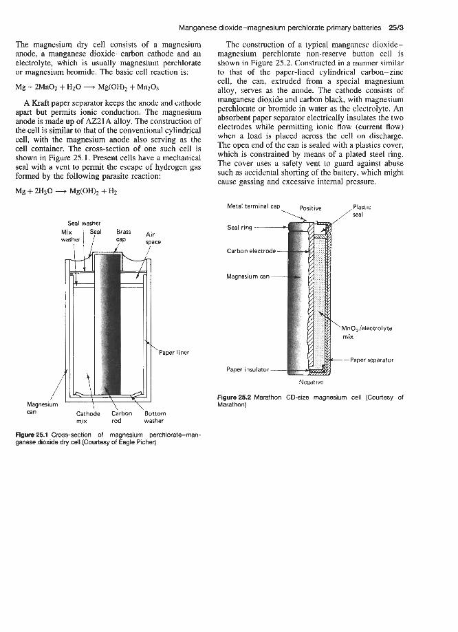
Manganese dioxide-magnesium perchlorate primaty batteries 25/3
The magnesium dry cell consists of a magnesium anode, a manganese dioxide-carbon cathode and an electrolyte, which is usually magnesium perchlorate or magnesium bromide. The basic cell reaction is:
Mg + 2Mn02 + H2O + Mg(OH), + Mn203
A Kraft paper separator keeps the anode and cathode apart but permits ionic conduction. The magnesium anode is made up of AZ21A alloy. The construction of the cell is similar to that of the conventional cylindrical cell, with the magnesium anode also serving as the cell container. The cross-section of one such cell is shown in Figure 25.1. Resent cells have a mechanical seal with a vent to permit the escape of hydrogen gas formed by the following parasite reaction:
Mg + 2H20 + Mg(OH), + H2
Seal washer
/ Magnesium
Cathc mix
can
Air space
‘Paper liner
: Carbon ‘Bottom rod washer
The construction of a typical manganese dioxide- magnesium perchlorate non-reserve button cell is shown in Figure 25.2. Constructed in a manner similar to that of the paper-lined cylindrical carbon-zinc cell, the can, extruded from a special magnesium alloy, serves as the anode. The cathode consists of manganese dioxide and carbon black, with magnesium perchlorate or bromide in water as the electrolyte. An absorbent paper separator electrically insulates the two electrodes while permitting ionic flow (current flow) when a load is placed across the cell on discharge. The open end of the can is sealed with a plastics cover, which is constrained by means of a plated steel ring. The cover uses a safety vent to guard against abuse such as accidental shorting of the battery, which might cause gassing and excessive internal pressure.
\Positive /ZiC Metal terminal cap
Seal ring - Carbon electrode-
Magnesium can
‘MnO, /electrolyte rn ix
-Paow SeDarator
Negative
Figure 25.2 Marathon CD-size magnesium cell (Courtesy of Marathon)
Figure 25.1 Cross-section of magnesium perchlorate-rnan- ganese dioxide dry cell (Courtesy of Eagle Picher)


Metal - air batteries


Zinc-air primary batteries 26/3
source. Cells have been designed with a structure that contains two cathodes (air electrodes) in parallel and one anode (Figure 26.l(a)). The two cathodes are cemented to a frame to form the cell container. With air cells, it is not necessary to incorporate a depolarizer, such as manganese dioxide, into the cell. Instead, oxy- gen from the air is used as the depolarizer. The replace- able element in the cell consists of a highly porous zinc anode, containing the proper amount of potassium hydroxide in dry form and wrapped with appropriate separator materials. When a cell is ready to be activ- ated, the cell container is filled with water. The zinc anode with the dry potassium hydroxide and separator is then inserted into the cell. The cell is now ready for use. Multi-cell batteries can be constructed. Spacers are placed between cells to permit air flow by convec- tion. For heavy loads and large batteries, convection may not suffice and blowers are required. When spent, the zinc anodes are replaced with new ones for another
Zinc-air primary batteries The chemical reactions occuning in a zinc-air cell are as follows: Cathode 0 2 + :2Hz0 + 4e- = 40H- (26.1)
Anode Zn + 40H- + Zn (OH):- (26.2)
Net reaction Zn + 0 2 + 2H20 + 2e- = Zn (OH);- (26.3)
The theoretical voltage of this cell is 1.64V. Most practical cells have an open circuit voltage range between 1.42 and 1.52V, the lower values being atributed to peroxide build-up at the electrode surface.
Although zinc-air batteries have been in use for many years, their use has been restricted to very low- rate applications. As a result of the work performed on fuel cells and advancements in technology for making thin gas electrodes that operate at high current dens- ities. zinc-sir cells are now being examined as a power
Cell top
anode with
i b affixed
Perforated intercell separator
Electroll e seal
Open cell frame
Porous anode Z n f K O H .-
with separator paper
\Porous cathode containing Pt catalyst
KOH electrolyte
Electrolyte seal
(a1
Zinc negative
Top cover ( A )
Seal (E)
Metal can (G)
Separator and electrolyte ( C )
Catalyst and metal grid (C)
air access PTFE (F) (b)
Figure 26.1 (a) Zinc-air cell. (b) Construction of the Berec zinc-air cell: A, the plated steel cell cap functions as the negative terminai of the cell; B, high-purity amalgamated zinc-powder anode, which also retains the alkaline electrolyte; C, synthetic ion-permeable membrane separator; D, cathode of carbonkatalyst mixture with a wet-proofing agent coated on to a plated steel mesh support, and with an outer layer of gas-permeable hydroplastic PTFE; E, sealing grommet to seal and insulate the positive and negative terminals, and seal the cathode to the stepped base; F, permeable diffusion membrane distributes air from the access holes uniformly across the cathode surface; G, plated steel can forms a support for the cathode and acts as a cell container and the positive terminal of the cell - the holes in the cathode c a i permit air access once a sealing strip is removed (Courtesy of Ever Ready (Berec))

26/4 Metal - air batteries
discharge cycle. A clamping mechanism on one side of the battery is desirable to maintain proper pressure on the cells once the anodes are inserted into the cells. Such zinc-air batteries are capable of giving energy densities up to 220 W hkg, which is much higher than for the magnesium-manganese dioxide systems.
Button cells
Button cells with solid cathodes are designed as anode limited, Le. 5- 10% more cathode capacity than anode capacity. The anode is amalgamated powdered or gelled zinc and contains a gelling agent, and is housed in a triclad metal (nickel-stainless steel-copper) top with the copper in direct contact with the zinc. The anode is separated from the air cathode by a diffusion pad between the air cathode and an air hole at the base of the positive can.
A constructional diagram of the Berec zinc-air button cell is given in Figure 26.l(b).
McGraw Edison supply a range of Carbonaire zinc-air cells and batteries. These batteries use a car- bon-zinc couple and a caustic potash and lime elec- trolyte, and are activated by the addition of water. The lime combines with, and thereby removes, the zinc reaction products, thus extending the useful life of the electrolyte.
McGraw Edison Carbonaire wet caustic potash-lime zinc-air cells
In these wet electrolyte cells containing 5 M potassium hydroxide, zincate ions (Zn (OH):-) diffuse away from the anode and migrate to a limed bed to pro- duce calcium zincate. This has a low solubility in the electrolyte and releases hydroxyl ions into the bulk of the electrolyte:
Ca (OH)2 + Zn (OH):- = CaZn (OH), + 20H- (26.4)
This process continues so long as oxygen is supplied to the cathode and there is sufficient lime left to remove the zincate. When the lime is exhausted, the zinc consumes the alkali, decreasing electrolyte alkalinity and passivating the zinc. The performance of the cell then starts to deteriorate.
McGraw Edison supply a range of batteries for use in navigational aids, railway lamps, etc. The batter- ies as supplied are contained in plastic bags to pre- vent deterioration of the zinc anode during storage by ingress of air and moisture. The batteries are activated simply by topping up with water. Individual cells can be connected in series or in parallel with external con- nections. Normally these batteries require no routine maintenance or inspection for the first year. Should the service period run well over a year, an annual visual inspection of battery solution levels is desirable. The transparent case permits the user to see when each battery is ready for replacement.
McGraw Edison supply 1100-3300A h versions of these batteries with voltages between 6 and 22.5 V.
Dry electrolyte zinc-air cells
In dry electrolyte zinc-air cells the gelled electrolyte thickened with cellulose derivatives is used. These cells are spill-proof. The dry cell has a much greater energy density output in terms of electrolyte cells. Much of the success of this type of cell is related to the plastic bonded carbon cathode design.
Hydrogen peroxide is produced by a secondary energy wasting reaction in the cell. This reaction is avoided by incorporating manganese dioxide into the cathode which removes the hydrogen peroxide by the following cyclic reactions:
MnOz + H202 + 2H+ = Mn2+ + 2Hz0 + 0 2
Mn2' + 2H20 = Mn (OHjz + 2Hf
Mn (OH12 + H20 = MnO2 + 2H20
(26.5 j
(26.6)
(26.7)
26.2 Metal-air secondary batteries
See Chapter 12, Sections 12.1-12.3. A rechargeable zinc battery with an e.m.f of 1.65 V
is being developed by AER Energy Resources Ltd, Electric Fuel Ltd (Israel) and CGE Ltd (France). Electric vehicle applications of this battery are being considered.
Reported energy densities:
AER Energy Reserves Inc. (USA),
Electric Fuels Ltd (Israel),
CGE Ltd. (France), 90 W h kg-'
CGE report cyclic lives of 500 to over 1000 cycles depending on type and battery layout.
Matsushita Battery Industry Co. (Japan) and Swedish International Development Co. are devel- oping rechargeable iron-air cells which achieve an energy density of about 80 Whplcg-' at the Ci5 rate and 200 charge-discharge cycles at 60% depth of discharge; Westinghouse (US) and Siemens (Ger- many) are also working on the development of iron - air batteries.
98 W h kg-'(C/S rate)
200 W h kg-'
26.3 Aluminium-air secondary reserve batteries To date the only supplier of this type of battery is Alcon Aluminium Ltd. Applications have been limited to the development of a telecommunications battery, although further applications are expected over the next few years. Although some work has been done on the development of an electric vehicle battery this has not, so far, reached fruition.

Aluminium-air secondary reserve batteries 26/5
Cell reactions in alkaline electrolytes. At the aluminium electrode: A1 + 40H- -+ Al(OH), + 3eC. E" = -2.35 V
At the air electrode: 0 2 + 2H20 + 4e- -+ 40H-, E" = +0.40V
Overall:
(26.8)
(26.9)
4A1+ 302 + 6H20 + 40H- + 4A1 (OH),, E" = 2.75 V (26.10)
Typically, the actual voltage achieved falls in the range 1 .O- 1.5 V. Eventually the solution becomes
supersaturated with the formation of aluminium hydroxide precipitate:
Al(OH), + Al(OH), + OH-
As well as the above current production reaction a parasitic heat producing reaction occurs with the for- mation of hydrogen:
2A1f 6Hz0 + 20H- -+ 2Al(OH), + 3HzH (26.1 1)
Cell reactions in saline electrolytes. Overall: 4A1+ 6H2O + 302 -+ Al(OH)3, E" = 2.06 V (26.12)
Parasitic side reaction:
2A1+ 6HzO + 2Al(OH)3 + 3H2 (26.13)
The aluminium anode is alloyed with an element such as indium or tin which activates the aluminium so that it displays an extremely negative potential in alkaline electrolytes (potassium hydroxide). The activation effect can also be achieved by adding an element, e.g. sodium stannate to the alkaline elec- trolyte when using an aluminium gallium alloy as anode.
The addition of sodium stannate (0.06 M) to the elec- trolyte increases the current density of the cells from 520mAcm-' obtained with a pure aluminium anode to 650 mA ern-'. Corrosion rates are also reduced with the alloy anode.
A typical air cathode comprises oxygen reduction catalyst and carbon substrate coated on either side (Le. the electrolyte side and the air side) of an expanded nickel mesh framehrrent collector.
In saline aluminium-air batteries, to prevent clog- ging of cells by an aluminium hydroxide precipitate it is necessary to pump the electrolyte continuously up and down the cell or stir the electrolyte by gas injection.


Hig h-temperature thermally activated primary batteries
Contents
27.1 Calcium anode-based thermal batteries 27/3 27.2 Lithium anode thermal batteries 27/8 27.3 Lithium alloy thcrmal hattcne, 27/10


Calcium anode-based thermal batteries 27/3
Much of the effort associated with thermal battery design involves determining the amount of pyrotechnic heat to give acceptable performance over the necessary temperature range. Many of the required temperature extremes range from -55 to + 7 5 T for initial ambi- ent. This 130°C difference is well within the opera- tional limits of 352"C, the melting point of lithium chloride-potassium chloride eutectic, and 6013"C, the approximate temperature of thermal runaway. How- ever, as discussed earlier for calcium-calcium chro- mate, a temperature of at least 485°C is necessary for minimal performance at moderate drain ( >50mA/cm2) due to freeze-out of double salt (KCl.CaC12) below that temperature. Thus, it is seen that the working tem- perature range is reduced to 115°C whereas military extremes exceed this by as much as 15°C.
Figure 27.1 shows the performance and physical characteristics of a 28 f 4V ea-DEB pellet-heat pel- let battery over the temperature range -54 to +71"C. The life to a 24 V limit is shown as a function of tem- perature at a 1 .5 A drain. The heat balance is adjusted for optimum performance at about 1 5 T , with the cold performance limited to freeze out on the one hand, and hot performance limited by self-discharge on the other. It is apparent that the thermal balance can be shifted to give optimum performance at something other than room temperature.
7.6 Calcium anode-based thermal batteries 27.1.1 Calcium-calcium chromate thermal batteries The overall reaction for the calcium-calcium chromate system is dependent on the discharge parameters. A postulated cell reaction is: 3Ca + 2CaCr04 -t 6LiCI
+ 3CaC12 + Cr203.2Ca0 + 3Lizo (27.1)
although the exact composition of the mixed oxide has not been determined. It is possible that lithium formed by reaction of calcium with lithium chloride electrolyte enters into the electrochemical reaction.
Side-reactions occur between calcium and LiC1- KC1, which can limit the full utilization of coulombic capacity between calcium and suitable depolarizers. The reaction: Ca + 2LiCI + 2Li + CaC12 (27.2)
occurs spontaneously in a thermal battery with the result that an alloy (Li2Ca) is formed which is liquid at thermal battery operational temperatures. This melt, known as an 'alloy', can be responsible for internal shorts, resulting in intermittent cell shorts (noise) and cell misfunction during the discharge. This alloy per- mits high anode current density but limits the use of the couple on open circuit or light loads because an excess causes cell shorting. The rate of alloy formation can be controlled by deactivating or passivating the cell to slow down the Ca + LiCl reaction. Techniques include controlling by current density, acetic acid treatment of calcium, addition of passivating agents and excess binder to the electrolyte, and reduction of electrolyte pellet density.
Calcium chloride, formed by the reaction of calcium with lithium chloride, reacts further with potassium chloride to form the double salt CaCl2.KC1. This salt has a melting point of 575°C and has been identified as a precipitate in calcium anode thermal cells. It has been suggested that it can coexist with molten chloride electrolytes up to about 485°C.
The self-discharge reaction of calcium with cal- cium chromate is highly exothermic, forming complex chromhm(m) oxides. Above about 600°C the self- discharge reaction accelerates, probably due to the markedly increasing solubility of the chromate in the chloride electrolyte. This acceleration increases the rate of fornation of calcium-lithium alloy. The result- ing thermal runaway Is characterized by short battery lives, overheating and cell step-outs, shorts, and noise characteristics of excess alloy.
The calcium-calcium chromate couple can be separ- ated by a discrete electrolyte (plus binder) layer or can be a homogeneous pelletizing mix of depolarizer, elec- trolyte and binder. The calciumlDEB battery devel- oped in the 1960s has been used considerably in mili- tary fusing.
200 1
-5.7 cm-
P A w t 4.2 cm
Nominal voltage: 28 2 4 V Nominal current: 1.9 A Operating temperature range: -54 to +71 "C Nominal life: 60 s Start time: 0.6 s Volume: 105 crn3 Weight: 316 g
71 0 -54 -26 15 43
Conditioning temperature ("C)
Figure 27.1 Thermal battery performance as a function of tem- perature

2714 High-temperature thermally activated primary batteries
27.1.2 Configurations Thermal batteries are manufactured in a wide range of configurations to suit various types of application. Some of the configurations available from Catalyst Research Corporation are illustrated in Figures 27.2-27.4.
Figure 27.2 shows the cell configuration of the cup cell design. This was the first thermal battery design used in production. The cup cell features a common anode and two depolarizer pads, thereby doubling the cell area. The eutectic lithium chloride-potassium chloride electrolyte is impregnated on to glass tape to serve as a separator. These are solidified and die-cut to fit the cell. The heat source is zirconium-barium chromate, which forms an insulating ceramic mass on combustion. A cathode lead on the periphery of the cell serves as an intercell connector. Tungstic oxide and calcium chromate depolarizers are commonly used in this design. The active positive material is often mixed with materials such as glass and quartz fibres and formed paper-thin to fit the cell.
Open cellhape electrolyte
An extension of the cup cell technology involved elimination of the cup itself. The cell configuration shown in Figure 27.3 has much in common with the cup cell design, in that the electrolyte is impregnated on to glass tape and fibre pad depolarizers such as tungstic oxide are used. The dumb-bell shaped part, coated with calcium on one side, is folded around heat paper discs and serves as the connector between cells.
Elimination of the cup is made possible by reducing the quantity of electrolyte and by restricting the battery to low or moderate dynamics. This design is useful for light to moderate loads (<50 mA/cm) for durations of 1-1.5min. A significant feature of this design is the thin cell, approximately 1.5 mm thick, including heat pad. The coulombic capacity per unit cell area of the design is, however, limited to levels below that of cup designs, particularly since the latter have two depolarizer pads and twice the cell area within the cell.
Insulator ring
/’ Heat pad Cathode lead (cell cup)
Figure 27.2 Construction of a tungstic oxide closed cell (Courtesy of Catalyst Research Corporation)
Figure 27.3 Construction of a tungstic oxide open cell (Courtesy of Catalyst Research Corporation)
Potassium dichromate depolarizer is used in an open cell, with lithium chloride-potassium chloride impreg- nated on glass tape. This depolarizer allows very high current density for fractions of seconds to about 5 s.
Pellet-type construction
This construction involves mixing finely divided inorganic binder, which acts as a separator, with finely ground electrolyte eutectic salts and compacting them into pellets. Finely ground positive active material (for example, calcium chromate) may be either mixed with the original binder or the basis for another pellet. The pellet cell may be a single or double layer.
Multi-layer pelletsheat paper designs
With the development of pellet electrolyte cells, suffi- cient electrolyte and depolarizer could be included in a cell to provide a coulombic capacity equivalent to the cup design without the necessity of a complex cell configuration. Binders added to the electrolyte tend to retain the shape of the pellet during thermal battery operations.
One such configuration is shown in Figure 27.4. The two-layer pellet consists of an electrolyte layer (lithium chloride-potassium chloride) with a binder such as kaolin or micro-size silica, and a second layer com- posed of calcium chromate, plus some electrolyte. Cal- cium metal is used as the anode and zirconium-barium chromate heat paper is again the heat source, with dumb-bell shaped parts serving as intercell connec- tions.
Glazed depolarizers
In the thermal battery configuration shown in Figure 27.5, one side of one face of nickel strip is coated with a glaze of vanadium pentoxide using boric oxide as a flux. The other side of the nickel is coated with calcium and the composite folded around heat paper. The resulting open-circuit voltage is approximately 3.2V. An asbestos mat serves as a matrix for electrolyte. The cell has a square

Calcium anode-based thermal batteries 27/5
+ CaCrO, eutectic
One complete cell
Figure 27.4 Consrruction of an open pellet cell (Courtesy of Catalyst Research Corporation)
Figure 27.5 Construction of a glazed vanadium pentoxide depol- arizer (Courtesy of Catalyst Research Corporation)
configuration and a thickness of only 1 .O mm. The thin cell characteristics and high voltage allow a significant voltage per unit height of cell stack.
Figure 27.6 shows the Mg/LiCl-KCW205-B203 three-layer pellet system.
, Heat paper I V205-B203 glaze
eutectic Eutectic LiCI-KCI
Three-layer I pellet
v2°5 +
J ' Magnesium powder
Figure 27.6 Construction of a magnesium-vanadium pentoxide pellet cell (Courtesy of Catalyst Research Corporation)
new heat source, iron-rich iron-potassium chlorate pellets, and the homogeneous DEB pellet, an advanced cell design was created (Figure 27.7) with the advan- tages of ease of assembly, low cost, high dynamic stability and suitability for longer life than is pos- sible with heat paper/two-layer pellet systems. After combustion, the heat pellet is an electronic conductor, supplying intercell connection. The heat pellet burns at a lower rate than heat paper so that heat pellet batteries generally start under load about 0.2 s slower than heat paper batteries. On combustion, however, the heat pellet retains its shape and, since it has a higher enthalpy than heat paper ash, it serves as a heat reser- voir, retaining considerable heat, reaching lower peak temperatures and re-emitting its heat back to the cell as the electrolyte starts to cool.
27.1.3 The pyrotechnic heat sources The two principal pyrotechnic heat sources used in thermal batteries are a paper-type composition of zir- conium and barium chromate powders supported on inorganic fibres and a pressed tablet made up of iron powder and potassium perchlorate, commonly known as a heat pellet.
The zirconium-barium chromate heat paper is man- ufactured from pyrotechnic-grade zirconium and bar- ium chromate, with a particle size of about l-lOpm. Inorganics such as ceramic and asbestos fibres are added. The mix is formed into paper as individual sheets by use of a mould or continuously by use of a paper-making process. The resultant sheets are cut into
Heat pellet/DEB pellet
In 1959, Catalyst Research Corporation conceived a cell design in which no distinct electrolyte layer was necessary; instead lithium chloride-potassium chlor- ide-calcium chromate and kaolin binder were formed into a homogeneous pellet. Since it was homogeneous, it could not be misassembled during construction as is the case with multi-layer pellets. Shortly thereafter a similar pellet was conceived by Sandia, where the binder was Cab-0-Sil, a microporous silica. Using a
L Salciun ' Iron
Figure 27.7 Construction of a heat pellet-DEB pellet cell (Cour- tesy of Catalyst Research Corporation)
27/6 High-temperature thermally activated primary batteries
parts and dried. Once dry, they must be handled very carefully since they are very susceptible to ignition by static discharge. Heat paper has a burning rate of about 10-15 c d s and a heat content of about 1675 J/g. Heat paper combusts to an inorganic ash with high electrical resistivity. Consequently, its use necessitates addition of nickel or iron electrode collectors and inter- cell connectors to conduct current around each cell’s heat paper pad.
Fine iron powder (1 - 10 pm) and potassium perchlor- ate are blended dry and pressed to form heat pellets. The iron content ranges from 80 to 88% by weight and is considerably in excess of stoichiometry. Excess iron provides the combustible pellet with sufficient electronic conductivity, eliminating the need for inter- cell connectors. The heat content of iron-potassium perchlorate pellets ranges from 920 J/g for 88% iron to 1420 J/g for 80% iron. Burning rates of pellets are gen- erally slower than those of heat paper, and the energy required to ignite them is greater. The heat pellet has higher activation energy and is therefore less suscepti- ble to inadvertent ignition during battery manufacture. However, the battery must be designed so that there is good contact of the heat pellet with the first fire or ignition source.
After combustion, the heat pellet is an electronic conductor, simplifying intercell connection and battery design. The heat pellet bums at a lower rate than heat paper, and so heat pellet batteries generally start about 0.2 s slower than heat paper batteries under load. Upon combustion, however, the heat pellet ash retains its original shape and, since it has a higher enthalpy than heat paper ash, it serves as a heat reservoir, retaining considerable heat, reaching lower peak temperatures, and releasing its heat to the cell as the electrolyte starts to cool. The heat paper combusts to shapeless refractory oxides causing slumping of the battery stack during ignition and less resistance to environmental effects.
27.1.4 Methods of activation Thermal batteries are initiated by either mechanical action using a percussion-type primer or an electrical pulse to an integral electric match (squib). For most military applications, safety considerations require the squib to be non-ignitable under a load of 1 W, 1 A. In heat pellet batteries, an intermediate heat paper firing train is often added to carry the ignition from the primer or squib to each pellet.
27.1.5 Insulation materials Thermal batteries are designed to maintain hermeticity throughout service life, even though internal temper- atures approach 600°C. Thermal insulation used to minimize peak surface temperatures must be anhy- drous and, if organic, must have high thermal stability.
Dehydrated asbestos, ceramic fibres, and Kapton (poly- imide) have been used. Insulative layers are tightly bound around the periphery of the battery stack, and several asbestos or ceramic fibre discs are placed on each end to ensure a tight pack in the metal can. Special end reservoir pellets are often-life (> 10 min) thermal batteries often low thermally conductive prod- uct called John-Manville Co.), which is manufactitania and silica.
27.1.6 Production batteries Thermal batteries produced by various suppliers (Cat- alyst Research Corporation, Eagle Picher, Mine Safety Appliances) have an electrochemical system that con- sists of an active calcium anode, a fused salt electrolyte (lithium chloride-potassium chloride eutectic mixture) and a cathode consisting of a relatively inert metal current iron or nickel collector containing calcium chromate (or tungstic oxide, ferric oxide, vanadium pentoxide cathode active materials). In typical thermal battery designs the nickel or iron cathode cup, pos- sibly with an added grid, contains a cathode active (on a depolarized) layer, one or two electrolyte lay- ers, a central calcium anode layer followed by further electrolyte and depolarizer layers, and a cathode cell cover. The edge of the closed cell is crimped over and sealed with a gasket. This cell is thus a double cell having a common anode. The cathode active mater- ial (depolarized) is fabricated as a chemical layer on inorganic fibre paper, and the electrolyte is dip coated on woven glass tape. The open-cell system is a simpler construction in which the electrolyte and depolarizer chemicals are fabricated into a two-layer pellet disc using an inorganic binder. Simple disc cathodes and anodes are used, connected together as a dumb-bell to link adjacent cells in a series configuration.
Batteries are made up from both the closed and open systems in any series or parallel configuration of stacked cells interleaved with the thermite layers required to activate the battery. Complete batteries are thus usually cylindrical, in the form of hermetically sealed metal canisters. Terminals providing connec- tions to cells are located in glass or ceramic insulating seals.
Before activation, the electrolyte is an inert solid. Since the case is hermetically sealed there is no deterioration of the electrochemical system. Battery storage and operation over a wide range of environ- mental conditions can be achieved. Because of heat losses and ultimate resolidification of the electrolyte, the active life of thermally activated reserve batteries is necessarily short, generally less than 5min. Typi- cal battery designs are shown in Figure 27.8. In this type of cell the cathode and electrolyte are combined in a single homogeneous ‘DEB’ pellet, consisting of Depolarizer, Electrolyte and Binder. An electrically conductive heat pellet functions as the cell heat source and intercell connector.

Calcium anode-based thermal batteries 27R
Heat pellet (+)
DEB pellet (cathode and electrolyte)
- - Calcium I/
anode
Current collector (-)
Figure 27.8 Typical thermal battery design (Courtesy of Catalyst Research Corporation)
Significant advantages come from the use of the molten salt electrolytes, usually lithium chlor- ide-potassium chloride eutectic (61 mol% lithium chloride), which has a melting point of 352°C. First, a wider span of operating temperatures can be used than in other types of system without serious degradation of performance. Using the internal heat source to raise the temperature of the electrolyte above its melting point, a range of ambient temperatures from -40 to +70"C is common and wider ranges of -55 to +100"C can also be accommodated. Secondly, a high cell voltage, up to 3.0Vkel1, can be obtained. A wide voltage band can be used in this battery system since neither oxida- tion nor reduction of the eutectic alkali-metal chloride electrolyte occurs over the range of 3.0 V, unlike aque- ous electrolyte systems or even molten alkali metal sulphates. Furthermore, conductivity of molten alkali electrolytes is considerably greater than that of aque- ous electrolytes. Lithium chloride-potassium chloride eutectic has a specific conductance of 2.1/(acm) at 900°C as against 0.24Qcm) for saturated aqueous sodium chloride and 0.039/(Q cm) for 0. IN hydrochlo- ric acid at 15°C. Thus significantly higher currents for limited periods can be carried in molten salt batteries compared with other systems.
A typical design of a calcium chromate thermal cell produced by Catalyst Research Corporation (Figure 27.9) consists of a folded bimetal dumb-bell and pad of pyrotechnic paper. The catholyte disc consists of glass fibre tape impregnated with a molten mixture of lithium chloride, potassium chloride and potassium dichromate. The tape acts as a binding matrix for the molten salt when the battery is active.
The pyrotechnic paper or 'heat paper' supplies the thermal energy to elevate the thermal battery cell to operating temperatures. The pad consists of a ceramic fibre paper, which acts as a bindedcarrier for a slurry of zirconium metal fuel and barium chromate oxidant. The paper is extremely fast burning, making it ideal for a fast activation cell. Because the remaining ash of the heat pad is electrically non-conductive, it is necessary to provide a means for series intercell connection.
The intercell connection is provided, along with the calcium anode, by a dumb-bell shaped piece of steel
K2Cr20,/LiCI-KCI impregnated fibreglass tape cathode
Vacuum- / deposited calcium , laver --I -.
at paper pad
Iron dumbbell
Figure 27.9 Cell cross-section of a Catalyst Research cal- cium-calcium chromate thermal cell (Courtesy of Catalyst Research Corporation)
strip, which is folded around the heat pad. The anode is a vacuum-deposited calcium layer on the steel base, which forms a bimetal assembly.
The EAP-6273 12-V battery (see Table 27.1) by Eagle Picher was specifically designed to provide emergency starting power for military vehicles and air- craft, and provides a good example of an application of thermal batteries.
The basic design of this battery is eight parallel cell stacks of 152.4mm diameter. The cell area of 181 cm2 per cell for the eight sections results in 1449cm' of active area. At a discharge rate of 0.7A/cm2, the EAP-6273 could produce 1OOOA. This rate is well within the normal operating limits of the standard cal- cium-calcium chromate system. The cell is fabricated in one piece using the standard two-layer (DEB) con- figuration and is 152.4 mm in diameter, 2.2 mm thick, and contains a 12.7mm centre hole. Each cell was pressed at 18.1 x 10⁴kg or about 1000kg/cm2.
The header is of standard 304 stainless steel 9.5 mm thick. Because of the high current, four terminals for each negative and positive lead are used. At the 800 A level, each terminal would carry 200A. The battery is connected externally by paralleling the four positive and the negative terminals at the load connections.
The battery case is assembled from 321 stainless steel welded tubing with a 9.5 mm steel plate welded in the bottom. The burst strength of this container was calculated to be in excess of 454 kg.
Because of the total height of the cell stacks (approx- imately 356 mm) the stack was assembled in two separ- ate sections, each containing four parallel stacks of cells. These are wrapped and inserted into the case sep- arately. The case is lined with 12 mm of thermoflex and 12 mm of asbestos in the bottom. Each battery section is wrapped with 3.8mm of glass cloth. Asbestos for the top of the battery and the header insulation are added to obtain a closing pressure of 10-22 kg. The total battery weights 20.4 kg and is 406.4 mm tall and 177.8 mm in diameter.
The load desired is 0.024 Q, capable of dissipating 25kW. A 15.8mm outside diameter stainless steel

2718 High-temperature thermally activated primary batteries
Table 27.1 Characteristics of thermal batteries available from Eagle Picher
EAO-6266: 101.6 mm diameter five-cell stacks Voltage 27 3z 3 V Life at 71"C, 221 s
at 24"C, 366 s at -54"C, 317 s
Load 33 A nominal Size 121 mm diameter x 193.7mm long Weight 5.2kg Watt hours 89.1 = 17.2Whkg EAP-6230: 101.6 mm diameter five-cell stacks, DEB type Voltage 28.5 f 3.5V Life at 3 8 T , 24min
at 5"C, 16min Load 4.3 A nominal Size 122 mm diameter x 104 mm long Weight 2.86kg
EAP-6251: 76 mm diameter parallel stacks Voltage 27 f 3V Life at 71"C, 110s
at 2 4 T , 200 s at -40"C, 140s
Load 23 A nominal Size 94mm diameter x 145 mm long
Watt hours 31 = 10.4Whkg EAT-6261: 76 mm diameter, parallel stacks
Watt hours 48.3 = 16.9 W ldkg
Weight 3 kg
Voltage 1-33 * 5.5 v -33 * 5.5 v
Life at 71"C, 170s at 24"C, 200s at -56"C, 135s
89 mm diameter x 117 mm long Load 4.2 A each section Size Weight 1.9kg Watt hours
EAP-6273 Voltage 12 * 3V Life at 24"C, 350s Load 500 A nominal Size Weight 20.4 kg
20 = 8.1 W h k g (138.6 x 2 sections)
177.8 mm diameter x 406 mm long
Watt hours 583.3 = 38.6 Wh/kg
pipe is cut to length and welded to two copper bars. Connections are made to allow water to flow through the pipe. A 1OOOA current shunt is bolted into series with one copper bar to provide current monitoring capabilities.
The performance of the EAP-6273 is shown in Figure 27.10. Essentially the battery performs as a 12 V battery delivering 550 A. Additional current could be drawn on if necessary, as would be required for an electric motor starter. However, the power developed would be capable of starting any 12 V vehicle requiring up to 800A of peak current loads.
I C 5'
-. ----- _--- Amps x 100
' I,---,- --- \
\
0 30 60 90120150180210240270300330360 Time (s)
Figure 27.10 Performance of an Eagle Picher EAP-6273 thermal battery under 0.024 L2 load (Courtesy of Eagle Picher)
To a large extent calcium anode thermal batteries are being displaced by ones using lithium rich alloys as discussed below. Lithium types avoid unwanted side reactions which characterize the calcium types which have electrochemical efficiencies down to 20% of theoretical values.
A comparison of some of the important characteris- tics of the calcium-calcium chromate and LAN-FeS2 systems is given in Table 27.2.
Table 27.3 summarizes the characteristics of the main types of thermal battery.
27.2 Lithium anode thermal batteries Since lithium metal is molten at thermal battery dis- charge temperatures, it is retained on high surface area metals by immersion of the metal matrix in molten lithium to form anodes. Often this structure is contained within a metal cup to prevent leakage during cell operation. Another method is the fabrica- tion of lithium alloy anodes, such as lithium-boron, lithium-aluminium and lithium- silicon, which are solid at battery discharge temperatures and thus offer the possibility of simpler construction. However, the lithium alloys are more difficult to fabricate than the metal matrix anodes and do not achieve this same peak current density. Most of the lithium anode batteries currently use the lithium chloride-potassium chloride electrolyte and an iron disulphide (FeS2) cathode.
The lithium-iron disulphide electrochemistry is more straightforward than that of the calcium chromate cell. The overall reaction is:
First step: 2Li + FeS2 + Li2S + FeS (27.3)
Second step: 2Li + FeS = LizS + FeS (27.4)
Nominal voltages are 1.6V for the first step and 1.2V for the second step. Lithium-iron disulphide batteries are usually only discharged to the end of the first step, i.e. at 1.6V, giving a specific energy density of 640 W f i g - ' compared to 250 W h/Kg-' for the lead acid battery and 120OWh/Kg-' for the lithium-sulphur dioxide battery.

Lithium anode thermal batteries 2719
Table 27.2 Comparison of properties of calcium-calcium chromate and lithium-iron sulphide systems
Calcium-calcium chromate Lithium-iron sulphide
Energy density (W/s) Activation time (s) Voltage range Multiple voltage taps Dependability Maintenance Shelf life (years) Severe environrnents
Operating temperature (" C) Units of shock during activated life g acceleration during activated life Humidity/pressure Activation
600 0.03 possible, 0.3 typical 2.5-500 Up to 5 voltagedunit are common 0.995 Nil 15
-55 to +93 10 000 2500 Unaffected Electrical percussion mechanical shock
1600 0.3 possible
4 voltagedunit currently employed 0.995 Nil >15 expected
-54 to +74 10000 2500 Unaffected Electrical percussion mechanical shock
2.5-500
Table 27.3 Types of thermal battery
Electrochemical system: Operating cell Characteristics andor applications anodeielectrolyteicathode voltage (V)
CalLiCl-KCl/WO3 2.4-2.6 Used principally for fuse applications where a low level of electrical noise is essential and where dynamic environments are not severe
CdLiCl-KCVCaCrQ4 2.2-2.6 Used in applications requiring short-term operation in severe dynamic environments
MgLiCl-KCVJ205 Used in applications requiring short-term operation in severe dynamic environments
Li(M)/LiCl - KCVFeS2 Overall advantages: low electrical noise, can operate in severe dynamic environments, long service life (up to 1 h)
2.2 - 2. I
1.6-2.1
Iron disulphide begins to decompose thermally at about 550°C, into sulphur and iron sulphide, but good cathode efficiencies have been obtained up to 600°C. Above 600°C. the rate of decomposition increases, but experience with this system shows that thermal runaway is not as much a problem as with cal- cium - calcium chromate.
Another advantage to the lithium-iron disulphide system is the absence of high-melting salt phases such as CaC12.KC1. The cell can thus operate close to 352°C. While calcium-calcium chromate may be used with homogeneous electrolyte-depolarizer blends, iron disulphide must be separated from the anode by a distinct electrolyte layer. Otherwise, the iron disulphide, which is a fairly good conductor, will be electronically shorted to the anode.
One of the constraints in designs of calcium anode- based thermal batteries has been the limited duration at high current densities due to a low electrochemical efficiency of the calcium anode, arising from the exis- tence of side-reactions involving the electrolyte and the electrode active materials. It has been demonstrated by Mine Safety Appliances Ltd that significant improve- ments in thermal battery performance can be achieved by the use of lithium as the active anode material in the cell, coupled with new cathodes. These batteries
are in production and are capable of operating at elec- trode current densities of up to 2.0A/cm2, with long battery durations. A capability has been demonstrated of achieving 100 W h/kg compared with approximately 20 W h/kg in designs of conventional calcium batter- ies, such as the CaLiCl-KC1 and CaCrOs/Fe systems. These latter designs, although they give very satisfac- tory performance for applications with durations of up to approximately 5 min, show a very significant drop in electrode current density, which results in a reduction in the power and energy density as discharge durations are extended.
Capabilities of lithium alloy -iron disulphide ther- mal cells include complete inertness during storage, the ability to operate at very low temperatures without pre- heating, resistance to mechanical vibration and shock, and the ability to deliver very high currents for a short period of time. Outputs can vary from 1 W for 10m seconds to several kW for tens of minutes. Lithium- based systems do not suffer to any major extent from efficiency reducing and exothermic side reactions and are now allowing thermal batteries to remain active longer and be made in much larger sizes.
Cells using lithium or the lithium-aluminium alloy -iron disulphide system with a lithium chlor- ide-potassium chloride electrolyte have an on-load

27/10 High-temperature thermally activated primary batteries
voltage of about 1.6V and can be worked at current densities up to several amps/cm-2 allowing thermal batteries to be discharged at very high currents and giving power densities at the 10-second or less rate which are better than those obtained by another com- plete battery system weighing a few kg. For example, a 6kg battery in a one-second discharge will have a specific power of 5 kWkg-'
27.2.1 Production of batteries Mine Safety Appliances have designed a system with lithium as the active anode material and ferrous sul- phide as the cathode, which shows significant improve- ments in performance over the conventional systems. The Li-FeS2 system is based on a pile-type construc- tion, which allows the battery voltage to be easily adjusted by varying the number of series cells to meet different application requirements. The components making up the cells are the lithium, which is held in the anode assembly by a porous support material, the cathode (depolarizer layer), which is a thin disc of iron disulphide with a proportion of electrolyte, and an elec- trolyte layer, which is a disc of the electro!yte with a binder added to immobilize the electrolyte when it is in the active molten state. The cells are interleaved with the heat source, also a disc of a pyrotechnic mixture of iron powder and potassium perchlorate. This com- ponent is electrically conducting and acts as the series connection between the cells. The battery is activated by the igniter flame being transmitted via pyrotechnic fuse-strips to ignite the individual pyrotechnic discs. The battery cell stack is thermally insulated and con- tained in a mild steel case, hermetically closed by argon are welding. The electrical output is through terminals in glass-to-metal compression seals.
A typical layout of such a battery is shown in Figure 27.11. The electrolyte-catholyte cathode pel- let is pelletized powder made by the compaction of two distinct powders in separate layers. The elec- trolyte layer is required to isolate the anode elec- trically from the iron pyrite cathode layer, which is electrically conductive. The electrolyte is a mixture
of lithium-potassium chloride eutectic electrolyte and ceramic binder. The cathode is a mixture of iron pyrite and electrolyte.
The iron-based pyrotechnic is a pelletized wafer or pill of iron powder and potassium perchlorate.
The anode assembly consists of an iron cup, which is crimped around an elemental lithium carrier matrix. Here, a binding agent is used which binds the lithium by surface tension in a manner similar to the 'gelling' of electrolyte by ceramic binders. This anode has numerous advantages when compared with lithium- aluminium or lithium-silicon alloys for the bulk of thermal battery applications. These include greater design versatility, higher power and energy densities, lower cost, excellent storage characteristics, higher current densities, very broad operational temperature range and excellent safety characteristics.
Most experience has been with molten lithium anode batteries where the lithium is mechanically retained. Figure 27.12 shows one version of a lithium-iron disul- phide thermal battery cell. The design uses a heat pellet, but heat paper versions are also feasible.
Figure 27.13 shows the average service life of a 14- cell lithium-iron disulphide thermal battery designed for power applications discharged at various constant- current loads to 24 V over a temperature range of -40 to +71"C. This battery has 5.1 cm external diameter and 4.4cm height and uses a modification of the cell shown in Figure 27.12. For comparison, the perfor- mance of a similar-sized calcium-calcium chromate thermal battery is also plotted. The lithium-iron disul- phide battery has a significantly higher capacity at the high power levels; at the lighter loads, the performance of both cells is limited by the cooling of the cell below the operating temperature.
27.3 Lithium alloy thermal batteries A further improvement on the lithium anode-iron sul- phide (FeS2) thermal cell is one in which the anode consists of a lithium alloy (usually lithium- aluminium alloy, although lithium-silicon and lithium-boron
1 1 Heat pellet
2-layer anolyte (LiCI/KCI)/ catholyte pellet (FeS,)
LAN disc
screen Anode assembly
Iron cup ' 1 Heat pellet (FelKClO,)
Figure 27.11 Cell cross-section of Catalyst Research Corporation's lithium-iron sulphide battery (Courtesy of Catalyst Research Corporation)

Lithium alloy thermal batteries 27/16
Iron powder/ potassium perchlorate mixture
Heat pellet
Anode cup
Lithiumhnert metal Anode disc
Magnesium oxide Lithium chloride/ potassium chloride eutectic
Iron disulphide
Lithium chloride/ potassium chloride
Silicon dioxide
Figure 27.12 Typical LAN (lithium-iron disulphide) cell construction
Approximate activation time (s)
33.6
31.2
28.8
26.4
24.0 4: -/ 21.6
19.2
2 16.8
E 14.4
2 5 9.6 0
7.2
4.8
2.4
0
r.
S: ._
c
+a 0)
:: 12.0
I I I I I I I I I I I I I I I I I I -
I I l l
1 2 3 4 5 6 7 8 10 20 3040 60 100 200 300 500 Discharge life to 24 V (s)
Figure 27.35 Average performance of lithium-iron disulphide thermal battery (P/N 406620) (Courtesy of Catalyst Research Corporation)

27/12 High-temperature thermally activated primary batteries
- >
P 3 1.0
v
a, - + 9 1.51;
- -
0.5
2.5'i'-~, CdCaCrO,
A A
A --ALA-
LiAIIFeS, \ ~ ~ ~ ~ ~ o ~ . - o - o - o - o - o - o - o ~ o ~ o ~ o ~ o ~ o ~ o ~ o ~ o ~
I 0-0.
' 0 MgIFeS, -0 .-.-.-.-.-.-.-.-.-.-.-.-. -.-.-.-,-,-,,. ~ .-. \ 0
\.io - \. -
I I I I I I I I I I
alloys have also been used) and an iron sulphide cath- ode. The lithium-boron alloys investigated contain 37% lithium and 63% boron. These lithium-boron liquid electrodes have not yet reached the production stage.
The load-carrying capacity of this LiA1-FeS2 (abbreviated LAN-FeS2) system is two to three times better than that of the calcium-calcium chromate system. The LAN-FeS2 system has a low and constant internal impedance which makes it ideal for both long discharge lives and pulse applications.
This type of battery can now replace many remotely activated silver oxide-zinc applications, resulting in an equal or smaller size, lightweight battery at lower cost.
27.3.1 Production batteries
Figure 27.14 shows the discharge curves comparing an LiAWeS2 cell with a magnesium-iron disulphide cell as well as with a typical calcium-calcium chromate cell. Both the magnesium and lithium anode cells give longer performance than the calcium cell; the main difference between magnesium and lithium is the higher voltage of the lithium cell. Figure 27.15 shows the activated life time and rise time for a 60 min, 28 V, 0.5 A thermal battery with a volume of 400 cm3 in the Li(Si)/LiC1.KC1/FeSz electrochemical system. The rise time decreases with increasing temperature; the activated life, however, maximizes in the range of
Table 27.4 presents data on two types of lithium- iron disulphide thermal battery and illustrates the advantage of the lithium anode systems. While the liquid lithium anode battery shows better performance than the lithium alloy battery, particularly in its rate
25 -50°C.
h
C .- 70
20
'e -50 -25 0 25
0 -- '. 3.0 $ ', 2.5 2
I - Y ' ! 2.0
I 50
2 Temperature ("C)
Figure 27.15 Activated life and rise time of an Li(Si)/FeSp thermal battery (Courtesy of Catalyst Research Corporation)
capability, some of the advantage is due to size and design differences, which caused the smaller LiSi battery to cool more rapidly.
The performance data for the lithium-iron disul- phide thermal battery cover a range from high power (4 min rate) to long life (40-60 min rate). Although the data are still based on prototype batteries, they already show a magnitude of improvement over the conven- tional thermal battery systems. The advantages are so pronounced that the lithium-iron disulphide thermal battery, it can be confidently predicted, will be the dominant system in the 1990s.
Figure 27.16 shows the design of a modem lithium- iron disulphide thermal battery.
The pyrotechnic discs are made from iron and potas- sium perchlorate powders. The thinner the pyrotechnic the more rapid will be the meeting of the electrolyte

Lithium alloy thermal batteries 27/13
Figure 27.16 internal arrangement of a thermal battery
Table 27.4 Comparison of LiFeS? thermal batteries
Connecting lead
Pyrotechnic pellet -Q7/D Cathode -
Anode
Y
Cell assembly
Duration of Li(llqjLzF-LiCl -LiBr/FeSz Li(Si)lLiCl - KCllFeS2
discharge Power Energy density Power Energy density (min) density of cell density of cell
(W/cm3) (W w (Wicm3) (W w 3.5 5.0 5.5
10.0 12 21 24 41
5.9
5.2
2.6 1.9
340
480
520 520
4.3
2.6
0.8 0.5
360
430
390 370
layer, dictating the speed at which power becomes available following activation. The 'heat paper' fuse train consists of powdered zirconium-barium chro- mate and ceramic fibres. Ignition is achieved either by an electric watch or a striking percussion cap or a stab detonator. Most modern batteries continue to use the enteric or near enteric lithium chloride-potassium chloride electrolyte (60 mmole % KC1) with a melting point of 352°C.
Its high decomposition potential allows the use of alkali earth electrodes. At the working temperature of 400-600°C it is almost fully ionized. Various other electrolytes are now being studied including lithium chloride-lithium bromide, lithium fluoride- sodium fluoride-potassium fluoride (both liquid electrolytes which can be solidified by adding about 35% magnesium oxide). Lithium iodide-alumina solid electrolyte is also being studied.

Zinc-halogen secondary batteries


Zinc-bromine batteries 2
at the negative electrode to form zinc ions, and chlorine reacts at the positive electrode to give chloride ions. The net result is the production of zinc chloride, which is dissolved in the circulating electroiyte, and chlorine is removed from the electrolyte. The electrolyte passes from the stack to the store, where more chlorine dis- solves in the electrolyte by decomposition of chlorine hydrate. This means that water is also added to the electrolyte from the store during discharge. This water provides for the zinc chloride added to the electrolyte in the stack. Thus the electrolyte concentration remains relatively constant during discharge. Electrolyte recir- culated to the stack carries chlorine with it to sustain the current being withdrawn. These processes continue until the store contains no chlorine hydrate, at which point the battery is deemed fully discharged.
28.2 Zinc-bromine batteries The battery stores energy by the electrolysis of an aqueous zinc bromide salt solution to zinc metal and dissolved bromide:
Zinc electrode Z@aq + 2eC __i Zn charge
discharge (28.1)
charge
discharge Bromine electrode 2Br-aq F=====+ Brzaq + 2eC (28.2)
inc-chlorine batteries
The chemical reactions occumng in the zinc-chlorine battery are very :straightforward (Figure 28.1). During charge, an electrolyte solution of zinc chloride in water is passed through the battery with the aid of a circuiator. As electrical direct current is passed through the battery from an external source of energy, zinc metal is deposited on the negative plates of the battery, and chlorine gas is generated at the positive plates. The chlorine gas is carried away with the circulating electrolyte stream, but the zinc metal remains at the negative electrodes as a uniform non-porous solid plate. Outside the plate area (the stack), the mixture of chlorine gas and excess electrolyte is cooled to about 0°C. At this point, a pale yellow solid. chlorine hydrate forms by reaction between the chlorine gas and water from the electrolyte. Chlorine hydrate has the chemical composition, C12 6Hz0. The solid chlorine hydrate is retained separate from the battery plates and the excess electrolyte is returned to the stack.
When the volume in the system assigned to the hydrate (the store) is full, the battery is deemed fully charged. At this time, the external source of energy is disconnected and the circulator and cooler are switched off. When the battery is discharged, circulation of the aqueous zinc chloride electrolyte is initiated. Since chlorine is slightly soluble in the electrolyte, this cir- culation carries chlorine to the positive plates of the stack and current may be withdrawn from the battery. As current passes to the external load, zinc metal reacts
charge
discharge Overall Znaq.” + 2Br-aq Zn Brzaq (28.3)
Stack
Zinc deDosited Chlorine released
Gas-liquid Store separator Screen Hydrate
2 Rectifieriinverter Zinc chloride
solution
Figure 28.1 Energy Developments Assoclates zinc-chlorine battery (Courtesy of Energy Developments Associates)


Sodium-sulphur secondary batteries


Sodium-sulphur secondary batteries 29/3
This cell has a theoretical e.m.f. of 2.076 V at the cell operating temperature of 350°C for 70% discharge. Reaction products are molten at this temperature. Dis- charge is normally terminated between 1.76 and 1.9 V.
During cell discharge sodium ions migrate through the solid electrolyte phase into the positive compart- ment, to combine with the S2- ions produced there. The sodium ions are pumped through the B-alumina to the negative compartment during recharge.
The role of B-alumina (a ceramic materid of approx- imate composition 1.22Na20 : llA1203) is critical. p- Alumina is a member of a class of solid materials with high ionic conductivities that have variousiy been called optimized ionic conductors, superionic conduc- tors and, more usually. fast-ion conductors. The study of this type of substance constitutes the new field of solid-state ionics.
The operation of this battery relies on the recently discovered properties of B-alumina; namely, that it combines very low electronic conductivity with an unusually high ionic conductivity which is specific to sodium ions as charge carriers.
In the sodium-sulphur battery, patented by Ford, for example, instead of solid electrodes separated by a liquid electrolyte (as in the conventional lead-acid car battery, for example), sodium B-alumina is used as a solid electrolyte. specifically conducting sodium ions between liquid electrodes of sodium metal and sulphur (Figure 29.1).
An alternative design has been developed by Chlor- ide Silent Power (UK). This cell is unusual because it embodies liquid electrodes (sodium and sulphur) and a solid electrolyte (p-alumina). The cell reaction can be represented as:
2Na + 3s = Na2S3 (29.1)
Charged level
7- Active sodium
Terminal
Insulator
Alumina collar
uding expansion volume)
8- Nut
I Redundant sodium
Electrolyte , - - t u b e
\ Figure 29.1 Schematic model of a sodium-sulphur battery which uses a sodium-p-alumina solid electrolyte as the separator between liquid electrodes (sodium anode and sulphur cathode), operating temperature 300-400°C (Courtesy of Ford Motors)
0 Na+ ions
0 column oxygen
Ions involved in concerted motion
(a) Elevation
(b) Plan
Figure 29.2 Structure of p-alumina showing (a) the alternation of spinel blocks and conduction planes; (b) the 'honeycomb pathway' along which Na+ ions migrate and the kind of concerted mechanism that is envisaged (Courtesy of Chloride Silent Power)

29/4 Sodium-sulphur secondary batteries
The structure of B-alumina itself is illustrated in Figure 29.2. This is a two-dimensional conductor; the Na+ ions migrate fairly freely in conduction plates which are located between the spinel blocks and con- tain many more possible sodium sites than there are ions to occupy them. The conductivity of ,&alumina at 350°C (100 S/m) is similar to that of molten sodium nitrate, and reference is sometimes made to the quasi- liquid behaviour of the sodium ions in order to distin- guish this type of electrolyte from, say, lithium iodide, where a point defect model is applied, such as lat- tice vacancies (Schottky defects) or interstitial ions (Frenkel defects).
Further, more recent information on the sodium- sulphur battery is given in the following references.
29.1 References on sodium-sulphur batteries* Ford Aerospace
Bridges, D. W., Harlow, R. A., Haskins, H. J. and Minck, R. W. (1 983) Operational experiences with sodium-sulfur batteries for utility and electric vehicle applications. One Hundred Sixty- Fourth Meeting of the Electrochemical Society, Washington, DC, USA, 9-14 October 1983
Crosbie, G. M., Tennenhouse, G. J., Tischer, R. P. and Wroblowa, H. S. (1 984) Electronically conducting doped chromium oxides. Journal of the American Ceramics Society, 67, 498
Gates, A. B. (1983) Status of the Ford Aerospace sodium-sulfur battery program. Eighteenth lntersociety Energy Conversion Engineering Conference, Orlando, Florida, USA, 21 -25 August 1983
Halbach, C. R., McClanahan, M. L. and Minck, R. W. (1983) The sodium-sulfur battery. Fall Meeting of the American Chemical Society, Washington, DC, USA, 28-31 August 1983
Harlow, R. A. (1983) An ovewiew of the DOWFord Aerospace/ Ford sodium-sulfur battery program. Beta Battery Workshop V, Washington, DC, USA, 18-20 October 1983
Harlow, R. A. and McClanahan, M. L. (1982) Sodium-sulfur bat- tery development for electric vehicle and stationary energy stor- age applications. Thirtieth Power Sources Conference, Atlantic City, NJ, USA, 7-10 June 1982
Harlow, R. A. and McClanahan, M. L. (1984) The status of the Ford Aerospace sodium-sulfur battery development program. Power Sources Conference, Cherry Hill, NJ, USA, 11 -14 June 1984
Harlow, R. A,, McClanahan, M. L., Minck, R. W. andGordon, R. S. (1 982) Status of the Ford/Ford Aerospace/DOE sodium-sulfur battery program. Fifth DO€ Battery and Electrochemical Con- tractors' Conference, Arlington, Virginia, USA, 7-9 December 1982
Harlow, R. A,, McClanahan, M. L. and Minck, R. W. (1984) Sodium-sulfur battery development. Extended Abstracts: Sixth DO€ Nectrochemical Contractors Review, Washington, DC, USA, 25-28 June 1984
Haskins, H. J. and Bridges, D. W. (1982) Operation of a 100- kilowatt-hour sodium-sulfur battery. Seventeenth lntersociety Energy Conversion Engineering Conference, Los Angeles, California, USA, 8-12 August 1982, Paper No. 829097
Haskins, H. J. and Minck, R. W. (1983) Design considerations for sodium-sulfur batteries for electric vehicles. Electric Vehicle Council EXPO, Dearborn, Michigan, USA, 4-6 October 1983
Haskins, H. J., Bridges, 0. W. and Minck, R. W. (1983) Evaluation of a sodium-sulfur battery module for electric vehicles. SA€
'Supplied by Ford Motor Co., Wixom, Michigan, and repro- duced by their kind permission.
lnternational Congress and Exposition, Detroit, Michigan, USA, 28 February-4 March 1983
Haskins, H. J., McClanahan, M. L. and Minck, R. W. (1983) Sodium-sulfur cells for high power spacecraft batteries. 18th lntersociety Energy Conversion Engineering Conference, Orlando, Florida, USA, 21-26 August 1983, Paper No. 839239
McClanahan, M. L. (1983) Shipping of NdS cells and batteries. Beta Battery Workshop V, Washington, DC, USA, 18-20 October 1983
McClanahan, M. L. (1983) Electrolyte durability from a user's viewpoint. Beta Battery Workshop V, Washington, DC, USA, 18-20 October 1983
McClanahan, M. L. and Minck, R. W. (1982) Durability of beta- alumina from a user's viewpoint. One Hundred Sixty-First Meeting of the Electrochemical Society, Montreal, Quebec, Canada, 9-14 May 1982
Minck, R. W. (1982) Corrosion problems of the sodium-sulfur battery. DOE Meeting on High Temperature Corrosion Problems in Battery Systems, London, 13-14 July 1982
Minck, R. W. (1983) Practical experiences with beta-alumina. Research Assistance Task Force Meeting on Beta-Alumina for Sodium-Sulfur Cells, Oak Ridge, Tennessee, USA, 8-1 0 March 1983
Minck, R. W. (1 983) SES and EV battery performance. Beta Battefy Workshop V, Washington, DC, USA, 18-20 October 1983
Minck, R. W. (1983) SES and EV cell performance. Beta Battery Workshop V, Washington, DC, USA, 18-20 October 1983
Minck, R. W. (1983) The sodium-sulfur battery-applicability to EV's and AV's. Electric and Hybrid Vehicle Systems Assessment Seminar, Gainsville, Florida, USA, 15-1 6 December 1983
Minck, R. W. and Halbach, C. R. (1982) Characteristics of sodium-sulfur cells for diverse applications. Seventeenth lntersociety Energy Conversion Engineering Conference, Los Angeles, California, USA, 8-1 2 August 1982, Paper No. 829 096
Sernka, R. P. (1983) Reduction of sodium-sulfur battery develop- ment costs. Beta Battery Workshop V, Washington, DC, USA, 18-20 October 1983
Sodium-Sulfur Battery Development (1 982) Interim Report, 1 March 1980 to 30 September 1981, DOE Contract No. DE-
Wroblowa, H. S., Markovac, V., Tischer, R. P. and Crosbie, G. M. (1 984) Corrosion of materials in high-temperature sodium-sulfur cells. 35th Meeting of the lnternational Society of Electro- chemistry, 6 August 1984 (Extended Abstract No. A5-2)
AM02-79Chl0012
Ford Motor Company
Crosbie, G. M., Tennenhouse, G. J., Tischer, R. P. and Wroblowa, H. (1983) Electronically conducting doped chromium oxides. Eighty-Fiffh Annual Meeting of the American Ceramic Society, Chicago, Illinois, USA, 24-27 April 1983
Gupta, N. K. and Tischer, R. P. (1972) Thermodynamic and physi- cal properties of molten sodium polysulphides and open circuit voltage measurements. Journal of the Electrochemical Society, 119,1033
Mikkor, M. (1 982) Current distribution within sulfur electrodes of cylindrical sodium-sulfur cells. Seventeenth lntersociety Energy Conversion Engineering Conference, Los Angeles, California, USA, 8-12 August 1982, Paper No. 829098
Tischer, R. P. (1 983) Review of the chemistry of the sodium-sulfur battery. lnvited Symposium Presentation at the One Hundred Sixty-Third Meeting of the Electrochemical Society, San Fran- cisco, California, USA, 8-13 May 1983
Tischer, R. P., Ed. (1983) The Sulfur Electrode. Academic Press, New York
Tischer, R. P., Wroblowa, H. S., Crosbie, G. M. and Tennenhouse, G. J. (1 983) Ceramic oxides as container/current collector materials for the sulfur electrode. Proceedings of the Fourth lnternational Symposium on Molten Salts, held in conjunction with the One Hundred Sixty-Third Meeting of the Electrochemi- cal Society, San Francisco, California, USA, 8-1 3 May 1983
Wroblowa, H. S. and Tischer, R. P. (1983) Carbon in sodium- sulfur cells. DOE Workshop on Carbon Electrochemistry, Case Western Reserve University, Cleveland, Ohio, USA, August 1983

Wrobiowa, H. S., Tischer, R. P., Crosbie, G. M., Tennenhouse, 6. J. and Markovac, V. (1983) Stability of materials for the current collector 'of the sulfur electrode. Beta Battery Workshop V, Washington, D'C, USA, 18-20 October 1983
Ceramatec Inc.
Gordon, R. S. and Miller, G. R. (1983) Overview of Ceramatec's research and development activities related to the development of beta batteries. Beta Battery Workshop V, Washington, DC, USA, 18-20 October 1983
Miller, G. R. (1983) Corrosion of oxides: Beta Battery Workshop V, Washington, DC, USA, 18-20 October 1983
References on sodium-sulphur batteries 29/5
Miller, G. R. and Gordon, R. S. (1983) Manufacturing cost reduc- tion of palumina. Beta Battery Workshop V, Washington, DC, USA, 18-20 October 1983
Rasmussen, J. R., Miller, 6. R. and Gordon, R. S. (1982) Degra- dation and lifetime of @-alumina electrolytes. One Hundred Sixty-First Meeting of the Nectrochemical Society, Montreal, Quebec, Canada, 9-14 May 1982
Chloride Silent Power Ltd (UK)
Lornax, G. R. (1971) Some UK Progress in Sodium Sulphur Technology. Chloride Batteries Ltd, UK


Part 3


Primary batteries


Service time-voltage data 3013
1.6 - > 1.4
p 1.2
2 1.0
1
W - - 0.8
0 Service time (h)
(a)
1.6
> 1.4 - -
30.1 Sewice time-voltaige data This is typified by the curves shown in Figure 30.1 for alkaline manganese dioxide 1 .5 V dry cells in which cell voltage is plotted against hours of service obtained from the cell whlen it is operated at a particular standard temperature (usually 20°C). Obviously such curves must be prepared when the cell is under a defined standard ohmic load. The alkaline manganese dioxide cell has a voltage of 1.5 V/cell. If, as occurs in this example, it is used in an application requiring 1.25 V and the ohinic load is 150 then the current drain is 1.25 x 100
150 = 0.83 mA
(see Figure 30.11). Cell voltage, capacity, current drain, ohmic load and temperature data should all be stated on such curves.
Voltage versus hours of service curves can be pre- pared at different temperatures to show the effect of cell temperature on hours of service obtainable.
30.1.1 Silver-zinc primary cells Typical discharge characteristics at stated current drains and resistances for a full range of silver-zinc cells are reproduced in Figure 30.2.
Figure 30.3 shows typical voltage-discharge curves for silver-zinc cells, relating estimated hours of ser- vice obtained a: 35°C with closed-circuit voltage at various starting drains and ohmic loads on a 24hlday test schedule. Figure 30.4 shows discharge curves obtained for silver-zinc cells on a 16hlday schedule at 21°C.
A typical performance profile at 27°C for an Eagle Picher remotely activated silver-zinc battery is shown in Figure 30.5.
30.1.2 Alkaline manganese dioxide primary cells Service time-voltage data for a series of these cells with capacities between 700 and 10000m4h are shown in Figure 30.6.
1.5 1.4
13 000
0 1.2
> 1.0
0.8
; 1 , , , , , , , I , ( , , 1 , , 1 / 1
0 200 400 600 800 10001200140016001800 Service time (h)
(bl
Figure 30.2 Service time-voltage data for silver-zinc cells: current drain at 1.55V, 13kC2, 0.12mA. (a) WS12, 83rnAh to 9V on 13 000 R at 20°C; (b) WS14,200 mAh, to 0.9V on 10000 R at 20°C (Courtesy of Union Carbide)
30.1.3 Carbon-zinc primary cells The closed-circuit or working voltage of a carbon-zinc cell falls gradually as it is discharged (Figure 30.7). The service hours delivered are greater as the cut-off or end-voltage is lower.
Typical cut-off voltages range from 0.65 to 1.1 V per 1.5 V cell, depending on the application. The cut- off voltage should be made as low as possible to use the available energy in the battery. This is sometimes done, if the equipment can tolerate it without causing failure and depending upon the character of the load, by using a slightly higher voltage battery than the application normally requires. The cut-off voltage per cell is then lower and more efficient use of the battery can be achieved.
Voltage-hours of service curves under particular stipulated test conditions a e given in Figure 30.8 for
Current drains at 1.25 V n mA
150 8.3 430 2.9
1.3
1.2
1.1
1 .o 0.9
0.8
0.7 I I I I I 1 0 20 40 M) 80 100
Hours of service at 20 "C
Figure 30.1 Typical discharge curve of a Mallory Duracell alkaline manganese 1.5V dry cell (PX825) 300 rnAh (Courtesy of Mallory)

30/4 Primary batteries
I 1.7r
0 50 100 150 200 250 300 350 400 Service time (h)
(a) No. 384: 35 mA h to 1.3 V; rated a t 15 000 R load, starting drain 104 pA
0 200 400 600 800 Service time (h)
rated a t 15 000 R load, starting drain 107 PA (b) No. 309: 60 mA h to 1.3 V;
1.1
0.9 107 PA
0.7 0 300 600 900 1200 1500
(c) No, 301: 100 mA h to 1.3 V; Service time (h)
rated a t 15 000 R load, starting drain 107 pA
1.3
1.1
0.9 246 PA
0.7 0 200 400 600 800
Service time Ih) (d) 165 mA h to 1.3 V;
rated a t 6500 R load, starting drain 246 pA
Figure 30.3 Union Carbide Eveready silver-zinc cell voltage-discharge curves: estimated hours of service at 35°C against closed-circuit voltage at stated starting drains and loads and on a 24 h/day schedule (Courtesy of Union Carbide)
1.7 r 1.3
0 1.1
0.9
>
0.71 I I I I I 1 0 10 20 30 40 50 60
Service time (h) (a) No. S312 and S312E:
38 mA h to 0.9 V; rated a t 1 mA
1.8 r 7; 1.6
0 1.2 2.56 mA 1.6 mA ” 0 1.4 1000 n > 1.0
0 20 40 60 80 100 120 Service time (h)
(b) No. S41 and 541 E: 120 mA h to 0.9 V; rated a t 1.6 rnA
> 1 .o
0 10 20 30 40 50 60 70 80 Service time (h)
(c) No. S13E and 513: 75 mA h to 0.9 V; rated at 1.07 mA
c 0 1.2 >
1 .o 0 20 40 60 80 100 120 140
Service time (h) (d) No. S76E:
190 mA h to 0.9 V; rated a t 2.56 mA
Figure 30.4 Union Carbide silver-zinc cell voltage-discharge curves: estimated hours of service at 21°C against voltage at stated starting drains raverage drains) and loads and on a 16 h/day schedule (Courtesy of Union Carbide)
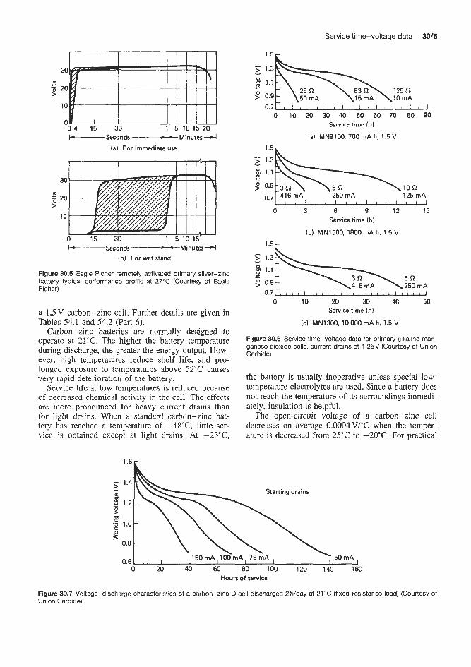
Service time-voltage data 3015
30
20
10
0 0 4 15 30 1 5 10 15 20 -Seconds -Minutes 4
(a) For immediate use
-Seconds -Minutes 4 (b) For wet stand
Figure 30.5 Eagle Picher remotely activated primary silver-zinc battery typical performance profile at 27°C (Courtesy of Eagle Picher)
a 1.5V carbon-zinc cell. Further details are given in Tables 54.1 and 54.2 (Part 6).
Carbon-zinc batteries are normally designed to operate at 21°C. The higher the battery temperature during discharge, the greater the energy output. How- ever, high temperatures reduce shelf life, and pro- longed exposure to temperatures above 52°C causes very rapid deterioration of the battery.
Service life at low temperatures is reduced because of decreased chemical activity in the cell. The effects are more pronounced for heavy current drains than for light drains. When a standard carbon-zinc bat- tery has reached a temperature of -18"C, little ser- vice is obtained except at light drains. At -23"C,
1.5r
p 1.1
9 0.9 50 mA
0 10 20 30 40 50 60 70 80 90 Service time lh)
(a) MN91M). 700 mA h, 1.5 V
1.5r
0 3 6 9 12 15 Service time (h)
(b) MN1500, 1800 mA h, 1.5 V
1.5,
\416 mA \ 250 mA ; 0.Y
0.7 a c 8 t 2 3 I 8 * a I a 0 t 8 I 5 a 9 1 J
0 10 20 30 40 50 Service time (hi
(c) MN1300, 10 Ow mA h, 1.5 V
Figure 30.6 Service time-voltage data for primary alkaline man- ganese dioxide cells, current drains at 1.25V (Courtesy of Union Carbide)
the battery is usually inoperative unless special low- temperature electrolytes are used. Since a battery does not reach the temperature of its surroundings immedi- ately, insulation is helpful.
The open-circuit voltage of a carbon-zinc cell decreases on average O.O004V/"C when the temper- ature is decreased from 25°C to -20°C. For practical
Starting drains 5: 1.4
m - 0)
- 2 1.2 9 m 5 1.0
P 0.8
0.6 0 20 40 60 80 100 120 140 160
Hours of service
Figure 30.7 Voltage-discharge characteristics of a carbon-zinc 0 cell discharged 2 h/day at 21 "C (fixed-resistance load) (Courtesy of Union Carbide)
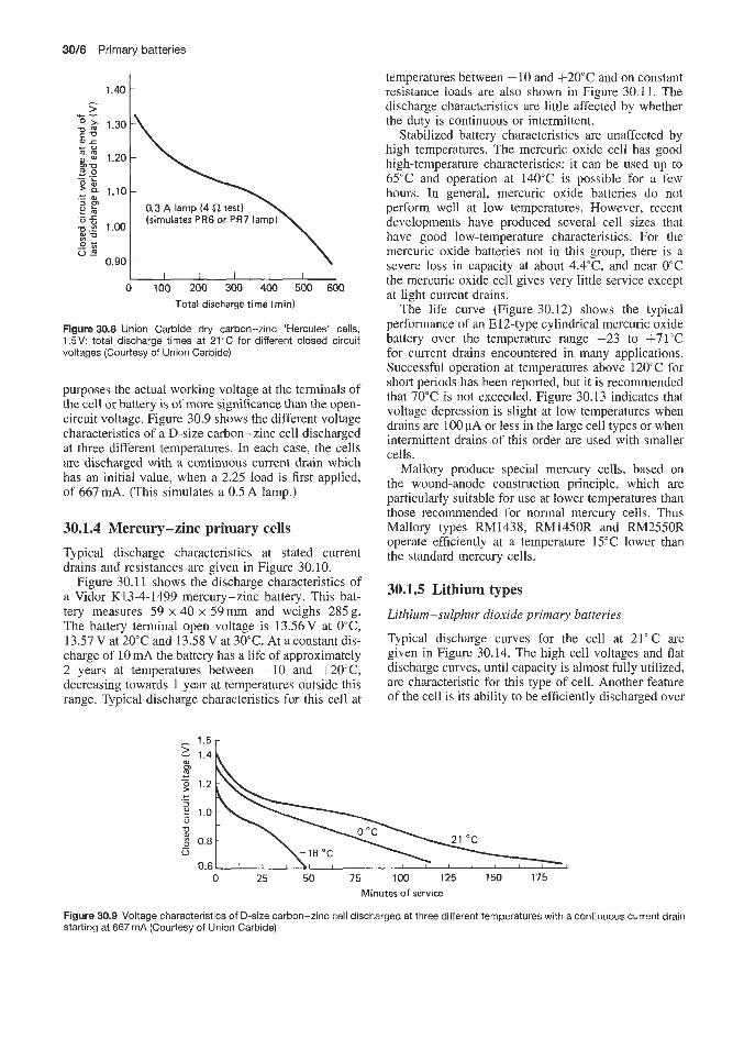
30/6 Primary batteries
1.30 I\
I 0.3 A lamp (4 i2 test) \
I I 1 1 I 1 0 100 200 300 400 500 600
Total discharge time (min)
Figure 30.8 Union Carbide dry carbon-zinc 'Hercules' cells, 1.5V total discharge times at 21°C for different closed circuit voltages (Courtesy of Union Carbide)
purposes the actual working voltage at the terminals of the cell or battery is of more significance than the open- circuit voltage. Figure 30.9 shows the different voltage characteristics of a D-size carbon-zinc cell discharged at three different temperatures. In each case, the cells are discharged with a continuous current drain which has an initial value, when a 2.25 load is first applied, of 667 mA. (This simulates a 0.5 A lamp.)
30.1.4 Mercury-zinc primary cells
Typical discharge characteristics at stated current drains and resistances are given in Figure 30.10.
Figure 30.11 shows the discharge characteristics of a Vidor K13-4-1499 mercury-zinc battery. This bat- tery measures 59 x 40 x 59mm and weighs 285 g. The battery terminal open voltage is 13.56V at 0"C, 13.57V at 20°C and 13.58 Vat 30°C. At a constant dis- charge of 10 mA the battery has a life of approximately 2 years at temperatures between -10 and +20°C, decreasing towards 1 year at temperatures outside this range. Typical discharge characteristics for this cell at
temperatures between - 10 and +20°C and on constant resistance loads are also shown in Figure 30.11. The discharge characteristics are little affected by whether the duty is continuous or intermittent.
Stabilized battery characteristics are unaffected by high temperatures. The mercuric oxide cell has good high-temperature characteristics: it can be used up to 65°C and operation at 140°C is possible for a few hours. In general, mercuric oxide batteries do not perform well at low temperatures. However, recent developments have produced several cell sizes that have good low-temperature characteristics. For the mercuric oxide batteries not in this group, there is a severe loss in capacity at about 4.4"C, and near 0°C the mercuric oxide cell gives very little service except at light current drains.
The life curve (Figure 30.12) shows the typical performance of an E12-type cylindrical mercuric oxide battery over the temperature range -23 to +71T for current drains encountered in many applications. Successful operation at temperatures above 120°C for short periods has been reported, but it is recommended that 70°C is not exceeded. Figure 30.13 indicates that voltage depression is slight at low temperatures when drains are 100 pA or less in the large cell types or when intermittent drains of this order are used with smaller cells.
Mallory produce special mercury cells, based on the wound-anode construction principle, which are particularly suitable for use at lower temperatures than those recommended for normal mercury cells. Thus Mallory types RM1438, RM1450R and RM2550R operate efficiently at a temperature 15°C lower than the standard mercury cells.
30.1.5 Lithium types
Lithium-sulphur dioxide primary batteries
Typical discharge curves for the cell at 21°C are given in Figure 30.14. The high cell voltages and flat discharge curves, until capacity is almost fully utilized, are characteristic for this type of cell. Another feature of the cell is its ability to be efficiently discharged over
0 25 50 75 100 125 150 175 Minutes of service
Figure 30.9 Voltage characteristics of D-size carbon-zinc cell discharged at three different temperatures with a continuous current drain starting at 667 rnA (Courtesy of Union Carbide)

Service time-voltage data 3017
1.4 1'5 1 1.3
3. 1.2
Current drain at 1.25 V
-.. -- E 1.1
2 1.0 *A I
0.9
0.8 0.7
0 20 60 80 100 120 140 160 180 Hours of service a t 20 "C
(a) P X W 1.35 V 80 mA h to 0.9 V on 25 000 R at 20 "C
1.6
1.5
1.4
2 1.3 - 5 1.2 I .w Current drains a t 1.25 V 2 1.1 k n mA
1.25 1 1 .o 0.9 0.8
0 100 200 300 400 500 600 700 800 900 Hours of service a t 20 "C
(b) PX675 1.35 V 210 mA h to 0.9 V on 250 R a t 20 O C
Figure 30.10 Mallory Duracell mercury-zinc cells and batteries, 1.35V: voltage-discharge curves-estimated average service at 21 "C against voltage (Courtesy of Mallory)
0 10 20 30 40 50 60 70 Time ih)
(a) Discharged a t f20 "C, medium loads 14 r
14 - 3. 13 - & 12 - 2 11 p 10
10 15 9
5 Time (h)
(d) Discharged a t +20 "C, heavy loads 1 4 r
0 10 20 30 40 50 60 70 Time ( h )
(b) Discharged a t 0 "C, medium loads
Time (h) (c) Discharged a t -10 'C , medium load
Time (h) (e) Discharged a t 0 'C. heavy loads
l A - . 1 -
1 > 13 & 12 g 11 9 10
9 0 10 20 30 40 50 60 70 80 90 100
Time (h) (f) Discharged a t +20 'C, cyclic load
Figure 30.11 Vidor K13-4-1499 mercury-zinc dry battery: typical discharge characteristics at temperatures between -1 0 and +20"C (constant resistance load). (f) Typical cyclic discharge characteristics at 100 mA followed by 9 min at 10 mA; typical voltages at the end of each 100 rnA cyck are plotted (Courtesy of Vidor)

3018 Primary batteries
120 110
70 E 60 F 50
- -
1.37 1.36 1.35
I 1.34 > 1.33 1.32
2 1.31 1.30 1.29
-
1.28
40 R, 31 rnA a t 1.25 V
30 R, 42 mA at 1.25 V
2 5 R , 5 O m A a t 1.25V
- - - -
- - -
- - -
15 R, 83 mA a t 1.25 V 10 R, 125 mA a t 1.25 V
2.8
2 2.6 - m
5 2.4 - >
W
I
2.2 - CI10 CI20 Cl30 Cl50 C1300 rate rate rate rate rate
5 a, 250 mA at 1.25 V r
I I I I I I I I I I I - 20 0 10 20 32 43 55 65 76
Temperature ("C)
"
Figure 30.12 Mercury-zinc cell: life against temperature (E12 type, 3.6Ah capacity) (Courtesy of Vidor)
1.27 1 I I I I I 1 -50 -20 0 20 50 80
Temperature of operation ("C)
Figure 30.13 Effect of temperature on operating voltage of mercury-zinc cells at different current drains: A, 50fl; 0, 11 fl; 0 , no current drain; 0, 1OOpA. Initial reading of an E12 cell (Courtesy of Vidor)
a wide range of current or power levels, from as high as the 2 h rate to low-drain continuous discharges for periods up to as long as 2 years, with good voltage regulation even at the extremes of discharge load. This cell is capable of delivering its energy at high current or power levels, well beyond the capacity of conventional batteries.
Mallory supply hermetically sealed lithium-sulphur dioxide organic electrolyte cells in the capacity range 1.1-10Ah with a nominal voltage of 3.00V. Fur- ther details are given in Tables 56.2 and 56.3. Dis- charge curves for two of these batteries are given in Figure 30.15.
The lithium-sulphur dioxide cell is noted for its ability to perform over a wide temperature range from -54 to +71"C, giving a higher discharge rate at low temperatures than is possible with other types of cells. Discharge curves for a standard 0.26 or D cell at various temperatures are shown in Figure 30.16. Of particular significance are the flat discharge curve over
3.0 r
Service time (h)
Figure 30.14 Typical discharge characteristics of a lithium- sulphur dioxide cell at various loads at 21°C (Courtesy of Honeywell)
the wide temperature range, the good voltage regula- tion, and the high percentage performance available at the temperature extremes. Naturally the relative per- formance of the cell depends on discharge rate and improves at low discharge rates. Even at high dis- charge rates, however, a high percentage of the 21°C performance is available at temperature extremes.
The cells can be operated with success at elevated temperatures. When operated at very high currents out- side the recommended limits, the cells may produce heat and high internal gas pressures and these con- ditions should be avoided. The cells are, however, an excellent source for high pulse currents. Multi-cell bat- teries contain additional insulation as well as a fuse for protection from mishandling such as short-circuits.
Figures 30.17 and 30.18 compare typical discharge performances of a lithium-sulphur dioxide battery at +2WC and -3O"C, showing that very low tempem- tures do not have any particularly adverse effect on discharge characteristics.

Service time-voltage data 30/9
3.0
> 2.6 - I 0 2.2 +- 5 1.8 >
1.4 n 0.0 0.2 0.5 1 2 5 10 20 50 100
Service time (h)
la) L0.32, 1.1 A h
3.0
3 2.6
% 1.8
1
g 2.2 m
> 1.4 I I I > , , l J u L , , , # l 1 I I l l l l i i l l i l l l l l l I I I !V~lW
0.0 0.2 0.5 1 2 5 10 20 50 100 0.1 0.3 Service time (h)
(bl L0.26, 10.0 A h
Figure 30.15 Discharge performance of Mallory lithium-sulphur dioxide batteries at 21 "C (Courtesy of Mallory)
3'0h 2.8
- 2 2.6 cn
3 2.4
2.2
W
c -
2.0 10 20 30
Hours of service
Figure 30.16 Typical discharge characteristics of a lithium- sulphur dioxide cell at various temperatures at C/30 rate (Couriesy of Mallory)
Lithium-thionyl chloride primary batteries
Discharge performance data for an active lithium- thionyl chloride cell are shown in Figure 30.19. Figures 30.20 and 30.21 compare the discharge performance of lithium-thionyl chloride batteries at -29 and 24°C.
Lithium-manganese dioxide primary batteries
Typical discharge curves for lithium-manganese diox- ide button cel1.s at 20°C are given in Figure 30.22, which presents the typical discharge curve for the 2N-size cell. It may be seen that only the heaviest discharge rates give a sloping discharge profile, thus indicating good rate capability.
0 10 20 30 40 5D Time (h)
Figure 30.17 Discharge curve of a lithium-sulphur dioxide cell at 20°C (Courtesy of Mallory)
0 10 20 30 40 50 Time (h)
Figure 30.18 Discharge curve of a lithium-sulphur dioxide cell at -30°C (Courtesy of Mallory)
4.0
2 3.0 I
- m c .- c s 2.0 a
%2 1.0 1 0
I I I I I I I l l
0 100 200 300 400 500 600 700 800 900 Time (h)
Figure 30.19 Honeywell lithium-thionyl chloride cell (G3037) Spacecraft B cell: discharge profile at 30°C; storage at 2 9 f 45°C; capacity 381 Ah; energy density 973 W h/drn3, 563 W h/kg (Courtesy of Honeywell)
Lithium-manganese dioxide cylindrical and button cells are eminently suited for applications requiring short-duration heavy-pulse discharge superimposed on a low background current. The cell can withstand 25 000 such discharges (1.25 s on, 15 min off? at 20°C before the cell voltage drops.
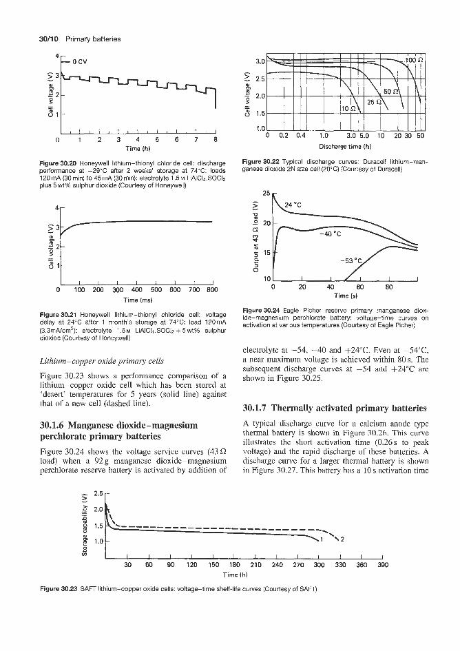
30/10 Primary batteries
4 F o c v
0 1 2 3 4 5 6 7 8 Time (h)
Figure 30.20 Honeywell lithium-thionyl chloride cell: discharge performance at -29°C after 2 weeks' storage at 74°C; loads 120 mA (30 min) to 45 mA (30 min): electrolyte 1.5 M LiAIC14.SOC12 plus 5 wt% sulphur dioxide (Courtesy of Honeywell)
'r
I
zll 0 100 200 300 400 500 600 700 800
Time (ms)
Figure 30.21 Honeywell lithium-thionyl chloride cell: voltage delay at 24°C after 1 month's storage at 74°C; load 120mA (3.3mNcm'); electrolyte 1.5 M LiAIC14.SOC12 + 5 wt% sulphur dioxide (Courtesy of Honeywell)
Lithium-copper oxide primary cells
Figure 30.23 shows a performance comparison of a lithium-copper oxide cell which has been stored at 'desert' temperatures for 5 years (solid line) against that of a new cell (dashed line).
30.1.6 Manganese dioxide-magnesium perchlorate primary batteries Figure 30.24 shows the voltage service curves (43 C2 load) when a 92 g manganese dioxide-magnesium perchlorate reserve battery is activated by addition of
0 0.2 0.4 1.0 3.0 5.0 10 20 30-50
Discharge time (h)
Figure 30.22 Typical discharge curves: Duracell lithium-man- ganese dioxide 2N size cell (20°C) (Courtesy of Duracell)
0 20 40 60 80 Time (s)
Figure 30.24 Eagle Picher reserve primary manganese diox- ide-magnesium perchlorate battery: voltage-time curves on activation at various temperatures (Courtesy of Eagle Picher)
electrolyte at -54, -40 and +24"C. Even at -54"C, a near maximum voltage is achieved within 80 s. The subsequent discharge curves at -54 and + 2 4 T are shown in Figure 30.25.
30.1.7 Thermally activated primary batteries A typical discharge curve for a calcium anode type thermal battery is shown in Figure 30.26. This curve illustrates the short activation time (0.26 s to peak voltage) and the rapid discharge of these batteries. A discharge curve for a larger thermal battery is shown in Figure 30.27. This battery has a 10 s activation time
W
1.0 s v)
30 60 90 120 150 180 210 240 270 300 330 360 390 Time (h)
Figure 30.23 SAFT lithium-copper oxide cells: voltage-time shelf-life curves (Courtesy of SAFT)
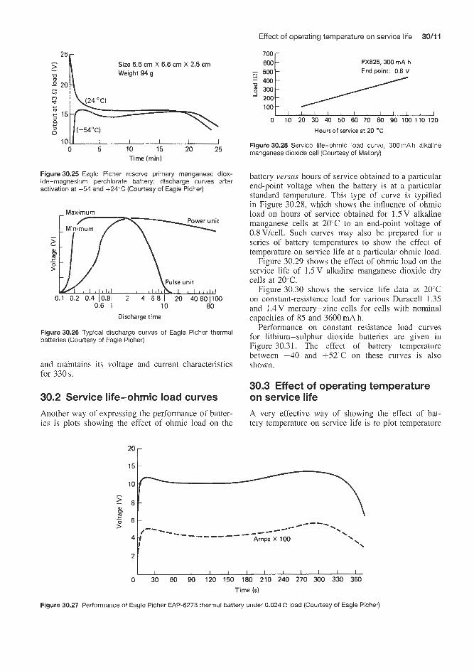
Effect of operating temperature on service life
PX825,300 mA h 700 600
End point: 0.8 Y
300 200 100
Size 6.6 cm X 6.6 cm X 2.5 cm Weight 94 g
0 5 10 15 20 25 Time (min)
Figure 30.25 Eafile Picher reserve primary manganese diox- ide-magnesium perchlorate battery: discharge curves after activation at -54 and +24“C (Courtesy of Eagle Picher)
Maximum t
Maximum t
>
c 0 >
0.1 0.2 0.4 10.81 2 4 6 8 I 20 40 601100 0.1-0 I .
0.6 1 10 80 Discharge time
Figure 30.26 Typical discharge curves of Eagle Picher thermal batteries (Courtesy of Eagle Picher)
and maintains its voltage and current characteristics for 330s.
30.2 Service life-ohmic load curves Another way of expressing the performance of batter- ies is plots showing the effect of ohmic load on the
0 10 20 30 40 50 60 70 80 90 100 110 120
Hours of service at 20 O C
Figure 30.28 Service life-ohmic load curve, 300 mA h alkaline manganese dioxide cell (Courtesy of Mailory)
battery versus hours of service obtained to a particular end-point voltage when the battery is at a particular standard temperature. This type of curve is typified in Figure 30.28, which shows the influence of ohmic load on hours of service obtained for 1.5V alkaline manganese cells at 20°C to an end-point voltage of 0.8V/cell. Such curves may also be prepared for a series of battery temperatures to show the effect of temperature on service life at a particular ohmic load.
Figure 30.29 shows the effect of ohmic load on the service life of 1.5 V alkaline manganese dioxide dry cells at 20°C.
Figure 30.30 shows the service life data at 20°C on constant-resistance load for various Duracell 1.35 and 1.4V mercury-zinc cells for cells with nominal capacities of 85 and 3600 mA h.
Performance on constant resistance load curves for lithium-sulphur dioxide batteries are given in Figure 30.31. The effect of battery temperature between -40 and +52”C on these curves is also shown.
30.3 Effect of operating temperature on service life A very effective way of showing the effect of bat- tery temperature on service life is to plot temperature
10
0
6 /e---
\ \
_-e4 .. ---_-____- --- 4 Amps X 100
2
‘“r
0 30 60 90 120 150 180 210 240 270 300 330 360 Time ($1
Figure 30.27 Performance of Eagle Picher EAP-6273 thermal battery under 0.024 Q load (Courtesy of Eagle Picher)

30/12 Primary batteries
1 r - T I I I 1 I I l l l l l l l l I I I I I I I I I I l l I l l ] l l
1 2 3 4 5 6 78910 20 30 40 50 607080 100 Hours of service
Figure 30.29 Effect of ohmic load on service life of Mallory alkaline manganese dioxide 1.5V primary cells at 20°C on constant resistance load (Courtesy of Mallory)
36
p 18 s 12
o t 1 I I 1 I 1 I I I I I I I , I / I 15 20 30 40 50 60 70 8090100
Service time Ih)
Figure30.30 Effect of ohmic load on service life of Duracell Rmi2R mercury-zinc 1.35 V primary batteries at 20°C on constant resistance load, 3600mA to 0.9V on 25Q (Courtesy of Duracell)
2 0
1 2 3 4 5 6 7 8 1 0 20304050 100 Service time (h)
(a) L0.26, 10.0 A h
p 120
-30 and f52 OC 40
1 2 3 4 5 678 10 20 30 50-70100
(b) L0.32, 1.1 Ah, end voltage 2.0 V Service time (h)
Figure 30.31 Typical ohmic load-service life performance of Mal- lory primary lithium-sulphur dioxide cells on constant resistance load (Courtesy of Mallory)
versus the battery capacity obtained to the end-point voltage at that temperature expressed as a percentage of the battery capacity obtained at a standard battery temperature, usually 20 or 21°C. Alternatively, plots of
r
O t -& -19 - I 8 -I6 k 4 +15 +:6
Temperature ("C)
Figure 30.32 Eagle Picher remotely activated primary silver-zinc battery: effect of temperature on capacity at constant discharge (Courtesy of Eagle Picher)
service time achieved as a percentage of service time obtained at 20°C versus temperature provide similar information.
Silver-zinc primary batteries
Figure 30.32 shows the effect of temperature on avail- able capacity for silver-zinc cells and batteries.
Lithium-sulphur dioxide batteries
The available capacity of this type of battery as a function of temperature and ohmic load is shown in Figure 30.33. Applications in which this system has been particularly valuable are those demanding high- rate operation at temperatures down to -40°C. Results covering the current range from lOmA to 1 A and the temperature range +60 to -23°C are quoted in Table 30.1.
It is interesting to note from the results quoted in the table that full nominal capacity is realized at 24°C regardless of load and that at lOmA load full nominal capacity i s realized regardless of temperature.

Effect of operating temperature on service life 30/13
100 120 r
0 bJ I I I I I -45 -23 - 1 1 21 43 65
Discharge temperature ("C)
Figure 30.33 Honeywell lithium-sulphur dioxide cell: discharge as a function of load and temperature. 1, one-seventh rated load; 2, rated load; 3, seven times rated load (Courtesy of Honeywell)
10 000
1000 I
Q E
E
-. c C
I CI 1W
1C I / I / I l i -20 0 20 40 60
Temperature ("C)
Figure 30.34 Mallory hermetic D-size lithium-sulphur dioxide cell: current and temperature limitsforvarlous capacity realizations (Courtesy of Mallory)
The estimated current and temperature limits for the hermetic D-size cell for 80, 90 and 100% capacity realization are shown in Figure 30.34. It is interesting that the high-rate properties have been optimized to the 20-30°C temperature range without great sacrifice at other temperatures.
Lithium-thionyl chloride primary batteries
Figure 30.35 shows the effect of battery temperatures on available capacity for a lithium-thionyl chloride cell.
Alkaline manganese dioxide primary batteries
Figure 30.36 shows a curve obtained for a 1.5V dry cell. It can be seen that a reduction in battery
2 , I I I , , , , , , , , , 0 -50-40-30-20-10 0 10 20 30 40 50 MI 70 80
Temperature (" C!
Figure 30.35 Effect of battery temperature on available capacity of a lithium-thionyl chloride cell (Courtesy of Mallory)
140 r
2 -40 -29 -18 -7 4 15 27 38 49 66
Temperature ("C)
Figure 30.36 Union Carbide, Eveready E91 alkaline manganese 1.5Vdrycell: effect of temperatureon service lifeat 21"C, 24 h/day discharge, 1 .OV cut-off. 1, starting drain 200 mA, load 7.5 Q; 2, starting drain 20 mA, load 75 Q (Courtesy of Union Carbide)
Table 30.1 High-rate discharge performance of Mallory lithium-sulphur dioxide hermetic D-size cell: test performed on resistive loads after 6 months' storage at 20°C
Nominal Capacity (Ah) discharge ab various discharge temperatures current (mA) -23°C 0°C 24°C 49°C 60°C
~ ~
1000 3.7 5.8 9.1 6.9 6.8 250 7.1 8.3 10.0 8.2 8.8 50 9.7 9.7 10.1 8.9 9.5 10 10.1 10.3 10.2 10.5 10.5
temperatures from 21°C to -2/+4"C approximately halves the service life attainable.

30/14 Primary batteries
140
130
120
110
100
> .g 90 ; 80 0
- 70
0 0 m 4 6C C
: 5c n
4c
3c
2c
1(
(
Cell temperature ("C)
la) Carbon-zinc type
I I I I I I I 3 -20 -10 0 10 20 30 40
Cell temperature ("C)
[b) Carbon-zinc chloride type
Figure 30.37 Effect of temperature on the capacity of D-sized cells: (a) carbon-zinc dry cells discharged continuously through a resistance of 2.25 R to an end-voltage of 0.9V; (b) zinc chloride cells when discharged 4rnin, 1 h, 8 h, 1 day with a 16 h rest through a resistance of 2.25 S2 to a cut-off voltage of 0.9V (Courtesy of Union Carbide)
Carbon-zinc and carbon-zinc chloride primary batteries
Figure 30.37 shows the variation of service capacity with temperature for a general-purpose D-size car- bon-zinc cell discharged continuously on a 2.25 C2 load to a 0.9 V cut-off. The initial curve drain (instantaneous value) is 667 mA. The load simulates a 0.5 A lamp.
Low temperatures, or even freezing, are not harm- ful to carbon-zinc cells as long as there is not repeated cycling from low or higher temperatures. Low-temperature storage is very beneficial to shelf life; a storage temperature of 4-10°C is effective.
The zinc chloride cell performs better at low temperatures than the standard carbon-zinc cell. Figure 30.37(b) indicates the variation of service capacity with temperature for a D-size zinc chloride cell discharged on the 2.25 C? light-industrial flashlight test. The load simulates a 0.5 A lamp.
30.4 Voltage-capacity curves If a battery or a cell has a nominal capacity of say lOAh at the standard rate of discharge, the
available capacity to a particular end-voltage becomes lower when the battery is discharged at a high cur- rent. This is equivalent to saying that the higher the current at which a given battery is discharged, the lower is the available capacity of the battery and the shorter is the time during which that capacity is avail- able (assuming that temperature is constant). Consider the example of a 6 A h nominal capacity manganese dioxide-magnesium perchlorate cell. This cell delivers its maximum capacity when it is continuously dis- charged for a period of about 100 h. However, when the continuous time of discharge exceeds 200 h, a decrease in available capacity becomes apparent. This is due to the self-discharge process at the magnesium anode. When discharged completely in relatively short, continuous periods of time, the magnesium battery, like other primary batteries, shows a reduction in avail- able capacity.
Figure 30.38 shows voltage capacity discharge curves for such a 6 A h cell at 23°C when discharged to 1.0/1.1 V/cell at a range of discharge current rates between 0.06 A and 0.80 A. It can be seen that, when discharged at the standard 0.06A discharge rate, a full available capacity of 6 A h is obtained, i.e. a life

Voltage-capacity curves 30115
I 1 I 1 I I J 1 2 3 4 5 6
Capacity (A h)
Figure 30.38 Marathon CD-size magnesium cell: constant- current discharge curves at 23°C (Courtesy of Marathon)
100
90 80 70
1 60
o 50 .c 1
20
10
0 1 2 3 4 5 6 7 Capacizy ( A h)
Figure 30.39 Marathon Magnesium CD cell, 23°C. Nominal capacity 6A h at 0.06A discharge rate (Courtesy of Marathon)
of 610.06 = 1OOh is obtained. However, when the discharge rate is increased from 0.06 to 0.8A the ampere hour capacity reduces from 6.0 A h to 1.5 Ah. That is, at 0.8 A h discharge rate the available capacity is only 25% of the nominal capacity. Correspondingly, the 0.8 A is available over 1.9 h (Figure 30.39) instead of 100 h.
Under intermittent conditions of use the realizable capacity of the magnesium battery depends on factors such as the magnitude of off-time period, the rate of discharge, the frequency of discharge intervals and the ambient temperature. The effect of each of these and their inten-elatJonship makes it difficult to predict the capacity of the battery unless the mode of appiication is completely defined. In general. it may be stated that intermittent usage at heavy discharge drains is a favourable cor,dition for optimum performance.
The magnesium battery performs better at higher operating temperatures than at 2 1 "C, especially at the higher current drains. This can readily be seen by comparing the family of curves in Figure 30.40
1 I I I 1 1 1 0 1 2 3 4 5 6
Capacity ( A h )
Figure 30.40 Marathon CD-size magnesium cell: constant- current discharge curve at 71 "C (Courtesy of Marathon)
1 2 Capacity (A h)
Figure 30.41 Marathon CD-size magnesium cell: constant- current discharge curves at 10°C (Courtesy of Marathon)
(discharged at 71°C) with those in Figure 30.38 (dis- charged at 23°C). Like all other battery systems, its performance diminishes when discharged at lower tem- peratures (see Figure 30.41). However, the magnesium battery is still able to operate at temperatures as low as -18°C especially at the light drain rates.
Naturally, the shape of voltage-capacity curves is dependent on battery temperature. Figure 30.42 shows discharge curves at -40°C and f52"C (rate-voltage characteristics) for a reserve primary 10A h five-cell manganese dioxide-magnesium perchlorate battery. The batteries were, at each of these temperatures, discharged to 5.5 V at three different rates; 40, 20 and 12A. If the 12A discharge rate is considered to be nominal, i.e. capacity 9.2Ah to 5.5V at -40°C and at +52"C, then the percentage capacity retentions at the three discharge rates, at each of the two battery temperatures, are as shown in Table 30.2.
Percentage capacity retention improves with de- crease of discharge rate and, at higher discharge rates,

30/16 Primary batteries
1 or-
4 0 A 20A 12 A I I I I 1
0 2 4 6 8 10 Capacity ( A h )
(a) lor
40A 20A 12A I I I I J
0 2 4 6 8 10 Capacity (A h)
(b)
Figure 30.42 Rate-voltage characteristics of a 60 g, 656crn3 Eagle Picher reserve primary manganese dioxide-magnesium perchlorate battery (1 OA h) of dimensions 10.7 x 10 x 5.6 cm, (a) at 52°C; (b) at -40°C (Courtesy of Eagle Picher)
1.4 r
ll"c _____. : ,.IC -18 'C
0 100 300 500 700 900 1100 Capacity IA h/cell)
Figure 30.43 Voltage-capacity curves for discharge of one IlOOAh cell of a McGraw Edison Carbonaire zinc-air battery type ST.22-discharge rate 0.15A (Courtesy of McGraw Edison)
with reduction in battery temperature. However, as can be seen from examination of Figure 30.42, at -40°C battery voltages (at all discharge rates) over the duration of life are considerably lower when discharges are conducted at a lower temperature (-4o"C), and in many applications this factor outweighs small improvements in percentage capacity retention and life at lower temperatures. The best voltage characteristic is obtained at the higher temperature (52°C) and the lowest discharge rate (12 A).
As an example of a voltage-ampere hour capa- city curve, for another type of battery, Figure 30.43 shows such a curve for an 1100 A h Edison Carbonaire
1.01 I I I I I , I I I , 1 0 100 300 500 700 900 1100
Capacity (A h/cell)
Figure 30.44 Voltage-capacity curves for discharge of one I l O O A h cell of a McGraw Edison Carbonaire zinc-air battery type ST.23-discharge rate 0.15A (Courtesy of McGraw Edison)
Table 30.2 Percentage capacity retention
Temperature Discharge rate ("C)
40 (A) 20 (A) 12 (A) (nominal)
+52 46 (6.0) 65 (18) 100 (46) -40 56 (7.8) 78 (21.6) 100 (46)
Figures in parentheses are life in minutes to 5.5 V
zinc-air cell. This figure shows the effect of cell temperature on cell voltage at a constant continuous moderate discharge rate of OSA, while Figure 30.44 shows the effect of reducing the discharge rate from 0.5 to 0.15A. Again, as with the primary manganese dioxide-magnesium perchlorate cell, best voltage sta- bility is shown at higher temperatures (21°C) and low- est discharge rates (0.15 A).
Voltage-percentage rated capacity curves
Plotting volts obtained on discharge to the cut-off voltage versus percentage of rated capacity at various discharge rates is another useful method of presenting data on battery performance. Such a curve for a 20-cell zinc-air battery is presented in Figure 30.45. Clearly, discharge at the 50 h rate gives the most stable voltage characteristic over the whole discharge process for this particular type of battery. The slower the discharge, the better the voltage characteristic. Figure 30.46 shows a similar discharge profile curve for a Honeywell lithium-sulphur dioxide cell at 21°C. Discharge was continued to a 2.0 Vkell cut-off. In this case, the cell was discharged at the rated load, 7x rated load and one-seventh rated load; again slow discharge, i.e. low load, leads to the best voltage characteristic.
30.5 Shelf life-percentage capacity retained Modem batteries retain their capacities well, some types more so than others, during storage before use. This applies particularly during storage at ambient

Shelf life-percentage capacity retained 3 W 7
4 5 7 50 25
Hourly rate
0 20 40 60 80 100 120
Percentage of rated capacity
Figure 30.45 Discharge characteristics under continuous duty of a 20-cell zinc-air battery (Courtesy of McGraw Edison)
- 3.0 > m - 0
: 2.5 P
Lu 2.0
- - 0
0 20 40 60 80 100 120
Percentage of rated capacity
Figure 30.46 Hc'neywell lithium-sulphur dioxide cell room temperature discharge profile as a function of load, with 2.0V cut-off (Courtesy of Honeywell)
temperatures near to 20°C. Obviously, capacity fall- off during storage is greater at elevated temperatures such as might occur in the tropics. Plots of percentage retained capacity versus shelf life at stated tempera- tures are a useful way of comparing this characteristic for various types of cell or battery. Figure 30.47, for example, shows a plot of percentage retained capacity versus shelf life in months at 20°C for a 1.5V alkal- ine manganese dry cell when the battery is under an ohmic load of 25 Q, i.e. a current drain of 60 mA. The preparation of such plots at a range of temperatures enables the temperature coefficient of the percentage capacity retention of the cell to be calculated.
30.5.1 Silver-zinc primary batteries The dry storage charge retention characteristics of this batteiy are excellent at temperatures up to 52°C.
30.5,.2 Alkalline manganese primary batteries Alkaline manganese batteries retain their capacity for 30 months without significant loss. For example, after 12 months' storage at 20°C batteries are capable of realizing over 92% of their initial capacity. With the best type of cells, approximately 80% capacity is
g 100
260
i? .: 20
- .+ 80 .-
I-'
0 12 24 36 Storage time at 20 "C (months)
c
Figure 30.47 Typical capacity retention of an MN 1500 alkaline manganese cell, 25 W20"C (Courtesy of Union Carbide)
retained after 4 years' storage at 20°C. A typical performance curve is shown in Figure 30.47.
30.5.3 Mercury-zinc primary batteries The service capacity of mercuric oxide batteries after 1 year of storage at 21°C is generally more than 90% of the capacity of a fresh battery. Figure 30.48 shows the effect of storage time on e.m.f. at 21 and 35°C. Batteries can be stored for periods of up to 3 years; it is not, however, good practice to store them for long periods.

30/18 Primary batteries
1'358
1.356 > - 1.354 - 5 1.352
-
0
c 2 1.350
$ 1.348
X, 1.346
1.344
1.342
L - - UI
1.340
7.3566 - -
-
-
-
1.3463 -
-
-
I I I I 1 1 1 1 I I 1 1
30.5.4 Lithium primary batteries
Lithium-sulphur dioxide batteries
Lithium- sulphur dioxide batteries have an excellent shelf life even at 71°C. Energy loss (Whkg) is less than 10% during 2 years' storage at 71°C.
After extended storage, a reactivation time of the order of a few seconds is required for the system to achieve operating voltage. This is not a feature exclu- sive to lithium-sulphur dioxide cells, but one which is also exhibited by lithium-vanadium pentoxide and lithium-thionyl chloride cells.
On standing unloaded, lithium-sulphur dioxide cells develop a passive inhibiting film of thionite on the anode, formed by the initial reaction of lithium and sulphur dioxide, which prevents any further reactions or loss of capacity during storage. By virtue of this trait, shelf life is excellent over a wide range of tem- perature. Short-term accelerated tests indicate retention of 50% of capacity after 10 years. The passive film is quickly removed when a load is applied to the cell.
Lithium-sulphur dioxide cells now being supplied by leading manufacturers are claimed to retain 75% of initial capacity after 5 years' storage at 21°C. Cor- rected for sulphur dioxide leakage, true capacity loss is estimated at 6% in 5 years, or 1% per year. Capa- city loss curves for lithium-sulphur dioxide batteries produced by Mdlory are shown in Figure 30.49. For the Mallory cell approximately 80% of the nominal capacity of the battery is available after storage for 4 years at 55"C, compared with 95% when stored at 20°C (Figure 30.49). Hermetic cells retain 65% of ini- tial capacity after 6 months at 72°C and about 50% after 12 months at 72°C or 6 months at 87°C.
Although permissible for shorter periods, prolonged storage at such high temperatures is detrimental to the capacity as well as to the high-rate properties of the system and should be avoided in applications in which such properties are important. Discharge tests at the 42 day rate (1OmA) at 49 and 60°C have indicated
0 12 24 36 Time (months)
Figure 30.49 Available capacity of a Mallory lithium-sulphur dioxide cell after storage for up to 4 years at 20 and 55°C (Courtesy of Mallory)
that no capacity was lost at these temperatures over the 42-day discharge period. The lithium system is capable of maintaining more stable voltage plateaux at higher currents than any other cell of comparable size. In 1975 Mallory introduced their new glass-to-metal hermetic seal to reduce sulphur dioxide losses from the cell and consequent capacity loss and corrosion effects during storage. Such cells with hermetic seals have been stored for 1.75 years at 21°C and 4 months at 72°C without leakage.
Lithium-manganese dioxide primary cells
The capacity or service life of lithium-manganese dioxide cells, normalized for a 1 g and a 1 cm3 cell, at various temperatures and loads, is summarized in Figure 30.50. These data can be used to calculate the performance of a given cell or to select a cell of suitable size or weight for a particular application. It is to be noted that, since the actual cell performance is dependent on cell size and construction and other such factors, these data are only approximate. These cells are a relatively new type and consequently only limited storage life data are available. Projections suggest that cells will provide 85% of initial capacity after 6 years storage at 20°C.
30.5.5 Manganese dioxide-magnesium perchlorate primary batteries Field experience has shown that shelf life is an out- standing characteristic of manganese dioxide-magnes- ium perchlorate batteries. After 18 months' storage at room temperature, magnesium batteries have yielded 90% of their initial capacity. Storage for 90 days at 55°C has shown that the battery still retains 85% of its initial capacity, and after storage at 71°C for 30 days the capacity retention is 85%. The shelf life of
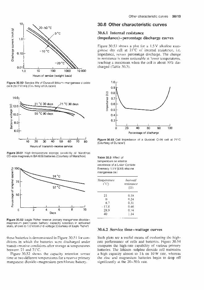
Other characteristic cuwes 30/19
30.6 Other characteristic curves
a E
E 1.0
E 0.10 P .- 0
1 .Q 10 loo loo0 loo00 Hours of service (weight basis)
Figure 30.50 Service life of Duracell lithium-manganese dioxide cells (to 2V/cell) (Courtesy of Duracell)
14.0 p - - > 12.0
2 10.0 P
d
W 0
z c 8.0
6.0
c
I I I I I I 10 20 30 40 50 60 70 80
Houn of transmit-receive service
Figure 30.51 High-temperature storage capability of Marathon CD-size magnesium BA4836 batteries (Courtesy of Marathon)
Days
Figure 30.52 Eagle Picher reserve primary manganese dioxide- magnesium perchlorate battery: capacity retention in activated state, shown to 1 .OV/cell end-voltage (Courtesy of Eagle Picher)
these batteries is demonstrated in Figure 30.5 1 for con- ditions in which the batteries were discharged under transit-receive conditions after storage at temperatures between 21 and 71°C.
Figure 30.52 shows the capacity retention versus time at two different temperatures for a reserve primary manganese dioxide-magnesium perchlorate battery.
30.6.1 Internal resistance (impedance) -percentage discharge curves
Figure 30.53 shows a plot for a 1.5V alkaline man- ganese dry cell at 21°C of internal resistance, i.e. impedance, versus percentage discharge. The change in resistance is more noticeable at lower temperatures, reaching a maximum when the cell is about 30% dis- charged (Table 30.3).
1 .o 0.9
c 0.8 - Q.7
$ 0.6 a 5 0.5
0.4 0.3
0 20 40 60 80 100 Percentage of discharge
Figure30.53 Cell impedance of a Duracell 0-26 cell at 21°C (Courtesy of Duracell)
Table 30.3 Effect of temperature on internal resistance of a Union Carbide Eveready 1.5V (E93) alkaline manganese cell
Temperature ("C)
21 0
-6.7 -17.8 -28.9 -40
Internal resistance (a) 0.18 0.24 0.31 0.46 0.74 1.14
30.6.2 Service time-wattage curves
Such plots are a useful means of evaluating the high- rate performance of cells and batteries. Figure 30.54 compares the high-rate capability of various primary batteries. The lithium-sulphur dioxide cell maintains a high capacity almost to 1 h on 10 W rate, whereas the zinc and magnesium batteries begin to drop off significantly at the 20-50 h rate.
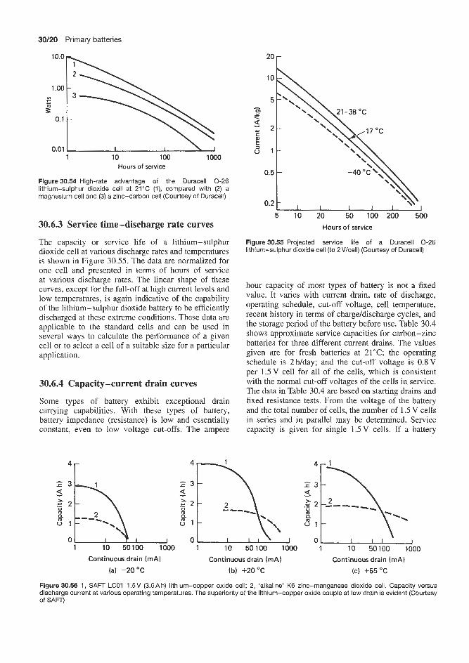
30/20 Primary batteries
2o r 1 1 ° . O h .oo
b b
J 1 10 loo0
Hours of service
Figure 30.54 High-rate advantage of the Duracell 0-26 lithium-sulphur dioxide cell at 21°C (I), compared with (2) a magnesium cell and (3) a zinc-carbon cell (Courtesy of Duracell)
30.6.3 Service time-discharge rate curves
The capacity or service life of a lithium-sulphur dioxide cell at various discharge rates and temperatures is shown in Figure 30.55. The data are normalized for one cell and presented in terms of hours of service at various discharge rates. The linear shape of these curves, except for the fall-off at high current levels and low temperatures, is again indicative of the capability of the lithium-sulphur dioxide battery to be efficiently discharged at these extreme conditions. These data are applicable to the standard cells and can be used in several ways to calculate the performance of a given cell or to select a cell of a suitable size for a particular application.
30.6.4 Capacity-current drain curves
Some types of battery exhibit exceptional drain carrying capabilities. With these types of battery, battery impedance (resistance) is low and essentially constant, even to low voltage cut-offs. The ampere
4 r
' O b 5
0.5 t -40 OC'\ bI 5 . I O 20 50 100 200 500
Hours of service
Figure30.55 Projected service life of a Duracell 0-26 lithium-sulphur dioxide cell (to 2V/cell) (Courtesy of Duraceil)
hour capacity of most types of battery is not a fixed value. It varies with current drain, rate of discharge, operating schedule, cut-off voltage, cell temperature, recent history in terms of charge/discharge cycles, and the storage period of the battery before use. Table 30.4 shows approximate service capacities for carbon-zinc batteries for three different current drains. The values given are for fresh batteries at 21°C; the operating schedule is 2Wday; and the cut-off voltage is 0.8V per 1.5V cell for all of the cells, which is consistent with the normal cut-off voltages of the cells in service. The data in Table 30.4 are based on starting drains and fixed resistance tests. From the voltage of the battery and the total number of cells, the number of 1.5 V cells in series and in parallel may be determined. Service capacity is given for single 1.5V cells. If a battery
4
z 3 a .- 2 2
5 1
- m Q
0 1 10 50100 1000
4
;f\.\J 0
0 1
0 1 10 50100 1000
\ 0 I J
1 10 50100 1000
Continuous drain (mA) Continuous drain (mA) Continuous drain (mA) (b) +20°C ( c ) +55 OC (a) -20 "C
Figure 30.56 1, SAFT LCOl 1.5V (3.6Ah) lithium-copper oxide cell; 2, 'alkaline' K6 zinc-manganese dioxide cell. Capacity versus discharge current at various operating temperatures. The superiority of the lithium-copper oxide couple at low drain is evident (Courtesy of SAFTj

Other characteristic curves 30121
Table 30.4 Service capacity of Union Carbide carbon-zinc Leclanche cells
Cell
- N
AAA
AA
B
C
D
F
G
6
55
105
I09
112
Starh'ng Service Cell Starting Service drain capacity drain capacity W L ) (h) (d) (h)
1.5 7.5
15.0 2.0
10.0 20.0 3.0
15.0 30.0 5.0
25.0 50.0 5.0
25.0 50.0 10.0 50.0
100.0 15.0 75.0
150.0 15.0 75.0
150.0 50.0
250.0 500.0
15.0 75.0
150.0 0.4 2.0 4.0 0.6 3.0 6.0 0.7 3.5 7.0
320 60 20
350 54 21
450 80 32
420 85 32
520 115 53
525 125 57
630 135 60
950 190 78
750 210 95
635 138 61
210 30 8
710 155 75
210 35 12
114
117
118
127
132
135
148
155
161
165
172
175
0.7 300 3.5 57 7.0 25 0.8 475 4.0 98 8.0 49 0.8 525 4.0 110 8.0 54 1 .o 475 5 .O 150
10.0 72 1.3 275 6.5 40
13.0 16 1.3 550 6.5 108
13.0 52 2.0 612
10.0 150 20.0 60 5.0 620
15.0 170 30.0 74 3.0 500
15.0 120 30.0 55 3.0 770
15.0 200 30.0 90 5.0 780
25.0 200 50.0 90 5.0 1000
25.0 260 50.0 110
uses cells in parallel, dividing the current drain the battery is supplying by the number of parallel strings of cells and looking up this value of current will give the service life.
Figure 30.56 shows actual capacities expressed as a function of discharge current of an LC0l lithium-copper oxide cell at three temperatures compared with a zinc-manganese battery of the same size.
30.6.5 Energy dependence on temperature curves The useful energy content of a battery is designated in watt hours and is the product of ampere hour capacity and the average discharge voltage. To enable compar- isons to be made between one battery and another this is often expressed as W h/dm3 on a volumetric basis or W hlkg on a weight basis.

30122 Primary batteries
71 r
-18 u 44 88 132
Energy density (W h/dm3)
(a) 0.16 A drain equivalent to 0.12 W/in3, 4.6 W hlkg, 7.3 W h/dm3 at 24 O C
711-
-18 1- 61 122 183
Energy density (W h/dm3)
(c) 0.8 A drain equivalent to 0.56 W/in3, 22.2 W h/kg, 34 W h/dm3 at 24 "C
-18 1111 44 88 132
Energy density (W h/dm3) (bl 0.4 A drain equivalent to 0.30 W/in3,
11.9 W h/kg, 18.3 W h/dm3 a t 24 O C j:v , , f e $ 4
-18 61 122 183
Energy density (W h/dm3) (d) 1.6 A drain equivalent to 1.04 W/in3,
41 W h/kg, 63 W h/dm3 at 24 "C
Figure 30.57 Effect of current density and temperature on the continuous discharge of a Marathon CD-size magnesium cell (Courtesy of Marathon)
Another useful method of presenting the overall temperature performance of batteries is a plot showing the energy dependence of W h/dm3 on temperature at different continuous discharge rates. Figure 30.57 shows such curves for the Marathon CD-size and 71°C).
magnesium cell for discharge rates between 0.16 and 1.6 A at a temperature of 24°C. The highest watt hour output (about 190 W h/dm3) is obtained at the lowest discharge current and the highest temperature (0.16 A

Secondary batteries

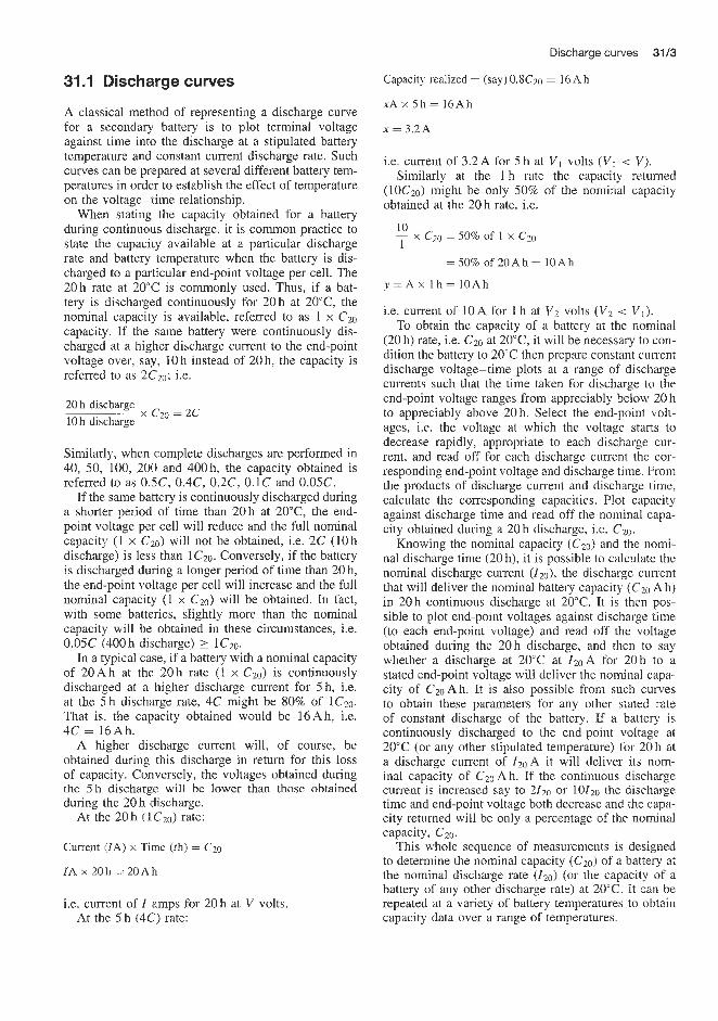
Discharge curves 31/3
31 .I Discharge curves
A classical method of representing a discharge curve for a secondary battery is to plot terminal voltage against time into the discharge at a stipulated battery temperature and constant current discharge rate. Such curves can be prepared at several different battery tem- peratures in order to establish the effect of temperature on the voltage-time relationship.
When stating the capacity obtained for a battery during continuous discharge, it is common practice to state the capacity available at a particular discharge rate and battery temperature when the battery is dis- charged to a particular end-point voltage per cell. The 20h rate at 20°C is commonly used. Thus, if a bat- tery is discharged continuously €or 20 h at 20"C, the nominal capacity is available, referred to as 1 x C20 capacity. If the same battery were continuously dis- charged at a higher discharge current to the end-point voltage over, STY, 10 h instead of 20 h. the capacity is referred to as 2Czo; i.e.
20 h discharge 10 h discharge
x Czo = 2c
Similarly, when complete discharges are performed in 40, 50, 100, 200 and 400 h, the capacity obtained is referred to as O.SC, 0.4C, 0.2C, 0.1C and 0.05C.
If the same battery is continuously discharged during a shorter period of time than 20h at 20°C, the end- point voltage per cell will reduce and the full nominal capacity (1 x C ~ O ) will not be obtained, i.e. 2C (10h discharge) is less than 1Czo. Conversely, if the battery is discharged during a longer period of time than 20 h, the end-point voltage per cell will increase and the full nominal capacity (1 x C20) will be obtained. In fact, with some batteries, slightly more than the nominal capacity will be obtained in these circumstances, i.e. 0.05C (400 h discharge) > lC20.
In a typical case, if a battery with a nominal capacity of 20 A h at the 20 h rate (I x C20) is continuously discharged at a higher discharge current for 5 h, i.e. at the 5 h discharge rate, 4C might be 80% of 1C20. That is, the capacity obtained would be 16Ah, i.e. 4C = 16Ah.
A higher discharge current will, of course, be obtained during this discharge in return for this loss of capacity. Conversely, the voltages obtained during the 5 h discharge will be lower than those obtained during the 20 h (discharge.
At the 2Qh (1C20) rate:
Current (IA) x Time (th) = C20
IA x 20h = 20Ah
i.e. current of Z amps for 20 h at V volts. At the 5 h (4C) rate:
Capacity realized = (say) 0.XCzo = 16 A h
x A x 5 h = 1 6 A h
x = 3.2A
i.e. current of 3.2A for 5 h at V I volts ( V I < VI. Similarly at the 1 h rate the capacity returned
(10C20) might be only 50% of the nominal capacity obtained at the 20 h rate, i.e.
- 10 x CZO = 50% of 1 x Czo 1
= 50% of 20Ah = 1OAh
y = A x l h = l O A h
i.e. current of 10A for 1 h at V2 volts (Vz < V I ) . To obtain the capacity of a battery at the nominal
(20 h) rate, i.e. C20 at 20°C, it will be necessary to con- dition the battery to 20°C then prepare constant current discharge voltage-time plots at a range of discharge currents such that the time taken for discharge to the end-point voltage ranges from appreciably below 20 h to appreciably above 20 h. Select the end-point volt- ages, Le. the voltage at which the voltage starts to decrease rapidly, appropriate to each discharge cur- rent, and read off for each discharge current the cor- responding end-point voltage and discharge time. From the products of discharge current and discharge time, calculate the corresponding capacities. Plot capacity against discharge time and read off the nominal capa- city obtained during a 20 h discharge, Le. C2o.
Knowing the nominal capacity (Cz0) and the nomi- nal discharge time (20 h), it is possible to calculate the nominal discharge current (Zzo), the discharge current that will deliver the nominal battery capacity (Czo Ah) in 20 h continuous discharge at 20°C. It is then pos- sible to plot end-point voltages against discharge time (to each end-point voltage) and read off the voltage obtained during the 20h discharge, and then to say whether a discharge at 20°C at ZzOA for 20h to a stated end-point voltage will deliver the nominal capa- city of C20 Ah. It is also possible from such curves to obtain these parameters for any other stated rate of constant discharge of the battery. If a battery is continuously discharged to the end-point voltage at 20°C (or any other stipulated temperature) for 20 h at a discharge current of ZzoA it will deliver its nom- inal capacity of CZO Ah. If the continuous discharge current is increased say to 2f20 or lOI20 the discharge time and end-point voltage both decrease and the capa- city returned will be only a percentage of the nominal capacity, C2o.
This whole sequence of measurements is designed to determine the nominal capacity (C~O) of a battery at the nominal discharge rate ( I zo) (or the capacity of a battery of any other discharge rate) at 20°C. i t can be repeated at a variety of battery temperatures to obtain capacity data over a range of temperatures.
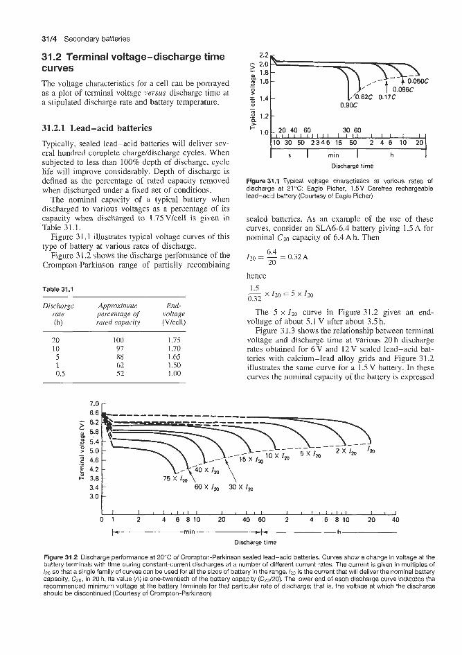
3114 Secondary batteries
31.2 Terminal voltage-discharge time curves The voltage characteristics for a cell can be portrayed as a plot of terminal voltage versus discharge time at a stipulated discharge rate and battery temperature.
31.2.1 Lead-acid batteries Typically, sealed lead-acid batteries will deliver sev- eral hundred complete charge/discharge cycles. When subjected to less than 100% depth of discharge, cycle life will improve considerably. Depth of discharge is defined as the percentage of rated capacity removed when discharged under a fixed set of conditions.
The nominal capacity of a typical battery when discharged to various voltages as a percentage of its capacity when discharged to 1.75Vlcell is given in Table 31.1.
Figure 31.1 illustrates typical voltage curves of this type of battery at various rates of discharge.
Figure 31.2 shows the discharge performance of the Crompton-Parkinson range of partially recombining
Table 31.1
Discharge Approximate End- rate percentage of voltage (h) rated capacity (Vkell)
20 100 1.75 10 97 1.70 5 88 1.65 1 62 1.50 0.5 52 1.00
3 1.2 - t e 30 60 F
I l l I 2346 15 50 2 4 6 10 20
Figure 31.1 Typical voltage charactistics at various rates of discharge at 21 "C: Eagle Picher, 1.5V Carefree rechargeable lead-acid battery (Courtesy of Eagle Picher)
sealed batteries. As an example of the use of these curves, consider an SLA6-6.4 battery giving 1.5 A for nominal CZO capacity of 6.4 Ah. Then
6.4 20
120 = - = 0.32A
hence - 1.5 x 120 = 5 x I20
0.32
The 5 x 1 2 0 curve in Figure 31.2 gives an end- voltage of about 5.1 V after about 3.5 h.
Figure 31.3 shows the relationship between terminal voltage and discharge time at various 20 h discharge rates obtained for 6 V and 12V sealed lead-acid bat- teries with calcium-lead alloy grids and Figure 31.2 illustrates the same curve for a 1.5 V battery. In these curves the nominal capacity of the battery is expressed
6.6 6.2
0 5.8 - J 5.4
5.0 4.6
E 4.2 3.8 3.4 3.0
- Ul
- .-
I - b-min h
Discharge time
Figure 31.2 Discharge performance at 20°C of Crompton-Parkinson sealed lead-acid batteries. Curves show a change in voltage at the battery terminals with time during constant-current discharges at a number of different current rates. The current is given in multiples of I20 so that a single family of curves can be used for all the sizes of battery in the range. /20 is the current that will deliver the nominal battery capacity, C ~ O , in 20 h. Its value (A) is one-twentieth of the battery capacity (C20/20). The lower end of each discharge curve indicates the recommended minimum voltage at the battery terminals for that particular rate of discharge; that is, the voltage at which the discharge should be discontinued (Courtesy of Crompton-Parkinson)

Terminal voltage-discharge time curves 31/5
will have more of a slope, a lower end-voltage will be necessary, and the ampere hours obtained per cycle will be reduced.
High-rate nickel-cadmium cells will deliver exceed- ingly high currents if they are discharged continu- ously under short-circuit conditions. Self-heating may do irreparable damage. If the output is withdrawn in pulses spaced to limit to a safe figure the temperatures of a few critical areas in the cell, high currents can be utilized.
The heat problems vary somewhat from one cell type to another, but in most cases internal metal strip tab connectors overheat and/or the electrolyte boils. General overheating is normally easy to prevent because the outside temperature of the battery can be used to indicate when rest, for cooling, is required. In terms of cut-off temperature during discharge, it is acceptable practice to keep the battery always below 65°C. The overheated internal connectors are difficult to detect. This form of overheating takes place in a few seconds or less, and overall cell temperature may hardly be affected. It is thus advisable to withdraw no more ampere seconds per pulse, and to withdraw it at no greater average current per complete discharge, than recommended for the particular cell in question. In special cases, where cooling of the cell or battery is likely to be poor (or unusually good), special tests should be run to check the important temperatures before any duty cycle adjustment is made.
1 2 V 6 V battery battery
- 12.0 - L
g 5 10.0 - c P ll.0b -
C .- 9.0 -
k 2’C 4.0Ll I I I I 8
1 2 4 6 10 20 4060 2 4 6 10 20
b-min-z-h-1 Discharge time
Figure 31.3 Discharge characteristic curves at 20°C for a Yuasa sealed lead-acid bsattery. C = A h rating at 20 h discharge rate to 1.75V/cell (Courtesy of Yuasa)
when discharged at a 20 h rate to the final voltage of 1.75Vkell. The curves show currents drawn at dif- ferent discharge capacity rates at 20°C after a few charge/discharge cycles. It is clear from Figure 31.3 that the ampere hour capacities of the battery at a 20 h rate expressed as standard values are smaller when the battery is subjected to discharge at greater than the 20 h rate.
31.2.2 Nickel-cadmium batteries
During discharge, the average voltage of a sealed nickel-cadmium battery is approximately 1.2 V/cell. At normal discharge rates the characteristic is very nearly flat until the cell approaches complete dis- charge. The battery provides most of its energy above 1 V/celP. If the cell is discharged with currents exceed- ing the rated value, however, the voltage characteristic
I
m 8 6.5 5 6.0 >
5.5 t- \ I Q O ~ A \ t: 5.0 d 4.5
0 2 4 6 8 1 0 1 2 1 4
(a) Discharge time (h)
5 7.0 6.5 6.0
- m
P 2 5.5
2 4.5 5.0
0 20 40 60 80 100 120 140
ib) Discharge time (rnin)
Cylindricul cell5
Figure 3 1.4 shows discharge curves for several cylindrical nickel-cadmium batteries of voltages between 6 and 14V and capacities between 0.5 and 4 Ah. Figures 3 1.5 and 3 1.6, respectively, compare discharge curves for typical sealed nickel-cadmium cylindrical cells made using mass electrodes and sintered electrodes.
- 16.8 15.6
” 0 14.4
4 13.2 12.0 10.8
- -
0 2 4 6 8 1 0 1 2 1 4
(C) Discharge time (h)
..
2 15.6
14.4 9 13.2 76 12.0
10.8
- -
0 20 40 60 80 100 120 140
Discharge time (rnin) (d)
Figure 31.4 Typical discharge curves at 20°C. Eveready sealed nickel-cadmium cylindrical batteries: (a,b) 6.0V, 0.5 Ah capacity, (c,d) 14.4V, 4.OAh capacity (Courtesy of Union Carbide)

3116 Secondary batteries
Button cells
The available capacity from a cell is dependent on the discharge rate and is proportionally greater with a sintered plate cell. The maximum discharge current for Varta D and DK type mass plate cells is 10 x 110 and for their DKZ type mass plate and RS and SD types of cell with sintered electrodes it is 20 x
2 x 110
g) 1.2 J 1.1
1.0 0.9
0 1 2 3 4 5 6 7 8 9 10 Duration of discharge Ih)
Figure31.5 Discharge curves for Varta 151D sealed nickel- cadmium cells with mass electrodes (Courtesy of Varta)
110 . In pulse load applications these rates can be doubled. Figure 31.7 shows the discharge at various rates between 110 and 20110 of fully charged rolled sintered cells of up to 2 A h capacity. The voltage of a cell when discharged below 1 V/cell rapidly falls to ;::rx> zero (Figure 31.7(b) and (c)) and it is then possible under these circumstances for some cells in a battery 1.2 to reverse their polarity. Provided that the discharge J 1.1
0 1.0 > 0.9 rate is at the I10 rate or less, this reversal will not ' ti l o harmanickel-cadmiumsealedcell, butfor maximum
Duration of discharge (h) life it should be avoided. Discharge curves for a
2 x 110
Y
button cell with mass plate electrodes are shown in Figure31.6 Discharge curves at 20'C for Varta RS sealed nickel-cadmium cells with sintered electrodes (Courtesy of Varta) Figure 1.8.
1
z - P 80-1
60-,
_ I
4 - 1 0 1 2 3 4 5 6 7 8 9 10 _ _ _ _ _ _ _ _ _ _ - - - - _ - - - _ - - --- - Start - Duration of discharge (h) - - Initial
1.0 - I Tverage -
-Final Varta) 8 0.8 - I
Figure 31.8 Discharge curves for a Varta 150 DK sealed nickel-cadmium button cell with mass electrodes (Courtesy of
- - -I I , I , I I I I I I
I , , 10 20 30 40 50 Discharge rate ( X I,,)
(a)
8 1.2 J 1.1
0 1 2 3 4 5 6 7 8 9 10
0 10 20 30 40 50 60 70 80 90 100 0 10 Time (min)
IC)
Figure 31.7 Discharge curves at various rates: Varta sealed nickel-cadmium rolled sintered cells up to 2Ah. (a) Starting voltage approx. 30min after end of charge. Initial voltage after 10% of discharge capacity. Average voltage approx. 1.22V. Final voltage approx. 0.99V. (b,c) Voltage during discharge of a fully charged cell when discharged to below 1 V (Courtesy of Varta)
' 0 . 9 L I I I I I I I I I I
0 1 2 3 4 5 6 7 8 9 10
Duration of discharge (h)
Figure 31.9 Discharge curves for Varta D23 type sealed nickel-cadmium rectangular cells with mass electrodes (Courtesy of Varta)
0 1 2 3 4 5 6 7 8 9 10
Duration of discharge (h)
Figure 31.10 Discharge curves of a Varta SD 1.6 sealed nickel-cadmium rectangular cell with sintered electrodes (Courtesy of Varta)


3118 Secondary batteries
60 min rate 30 min rate
I I I -40 -30 -20 -10 0 10 20 30
Temperature ( "C )
Figure 31.15 Effect of discharge temperature on plateau voltage for high-rate and low-rate rechargeable silver-cadmium batteries
at various rates of discharge against battery temper- ature at stipulated rates of discharge. Figure 31.15 shows such curves for high-rate and low-rate sil- ver-cadmium batteries.
A small change in plateau voltage occurs for the sil- ver-zinc system when battery temperature is lowered.
31.4 Capacity returned (discharged capacity)-discharge rate curves Plots of the variation of the returned capacity of battery versus the duration of the discharge in hours at a stipulated discharge rate and battery temperature are a useful means of assessing battery performance. The slower the discharge the greater the capacity returned. Figure 31.16 illustrates such curves for a 6 V non-spill lead-acid battery (9 and 28 Ah) discharged at 20°C at the 20 h rate. The relationship between capacity returned and discharge rate is discussed in more detail in Section 31.9.
31.5 Capacity returned (discharged capacity)-discharge temperature curves and percentage withdrawable capacity returned-temperature curves As mentioned earlier, the nominal capacity of a battery delivered at the nominal 20 h discharge rate, when dis- charged at the nominal Z20 discharge current, depends on the battery temperature. Generally speaking the higher the temperature the higher the capacity returned and vice versa. However, for many types of batteries, the capacity starts to decrease above a certain bat- tery temperature.
Such data are invaluable for predicting the perfor- mance of batteries at extremes of service temperature conditions from arctic to tropical. A refinement of this method of presentation is to plot the available capa- city obtained from the battery at the test temperature as a percentage of the nominal capacity at 20°C (i.e.
I l l l l l l l l l l 20 18 16 14 12 10 8 6 4 2 0
Discharge time (h)
(a) VPT 6.9/8 (6 V, 9 A h)
:j/ , I I I , I , ,
4
20 18 16 14 12 10 8 6 4 2 0 Discharge time (h)
( b ) VPT 6.15/30 (6 V. 28 A h)
Figure 31 . I6 Relationship between capacity returned and dis- charge rate at 20°C at 20 h rate for Varley 6 V non-spill lead-acid batteries (Courtesy of Varley)
percentage withdrawable capacity) against battery tem- perature for various discharge currents down to the end-point voltage.
Such data are discussed further below for several types of battery.
31.5.1 Lead-acid batteries
The curves in Figure 3 1.17 give information regarding the variation of available capacity of low-maintenance sealed lead-acid batteries, as a percentage of nomi- nal capacity (withdrawable capacity), as a function of temperature over the range -30 to +50T for three different loads with continuous discharge down to the relevant discharge cut-off voltage. For the values of the upper edges of the curves, the batteries were charged at an ambient temperature of 20°C voltage limited to 2.3Vkell. For the lower edge of the curves, the batteries were charged at the indicated low ambient temperature and hence under somewhat less favourable conditions. The curves show the behaviour of the bat- teries after a few charging cycles. When assessing both the upper and lower edges of the curves for the higher discharge currents, the dependence on the load must also be taken into account. This is already included

Capacity returned (discharged capacity)-terminal voltage curves 3119
> 0 n 0 a,
c .- m
- Q 3 E
5 b
U .- r
al
c al
m
E a
100 110 90
100 80 > 90 70
80 60 50 m
2 - 70 40
30 60 20 0
p 50 70 - -10 0 10 20 30 40 50 W
a
t d .-
3 c
F 4 0
Ambient temperature ("C) 30
Figure 31.17 Percentage of withdrawable capacity at different temperatures for three load examples. Upper edge of cuwe: charging at 2WC, discharging at quoted 'temperature. Lower edge of curve: charging and discharging at quoted temperature (Dryfit low-maintenance lead-acid batteries) (Courtesy of Dryfit)
in Figure 31.17. To prevent permanent damage to the capacity behaviour of the batteries at very low tem- peratures, the shaded areas in Figure 31.17 should be avoided. Permanent use at extremely high tempera- tures adversely affects the life of all types of battery, although for a few hours there is no objection to an ambient temperature up to a maximum of 80°C. For longer periods, allowance must be made for the cumu- lative permanent loss of capacity. Permanent use at temperatures above 50°C should be avoided.
Figure 31.18 shows a curve of percentage available capacity versus temperature for a low-maintenance partially recombining lead-acid battery. This battery functions satisfactorily over a wide range of service temperatures from sub-zero to high ambient temper- atures. At higher temperatures an increased capa- city is obtainable with a corresponding increase in self-discharge rate. Conversely. at lower temperatures available capacity and self-discharge rate are reduced. Outside the range 5-40°C for constant-voltage current- limited type chargers, a temperature compensation of
iu '20 1 9 100
0.05C
/--E===
-- h j , 0 -20 -10 0 10 20 30 40 50 60
Ambient temperature ("C)
Figure 31.18 Temperature effects in relation to battery capacity of a Yuasa sealed lead-acid battery (Courtesy of Yuasa)
2o v . Temperature ("C)
Figure 31.19 Capacity vemus temperature at various rates of discharge. Eagle Picher Carefree rechargeable lead-acid battery (Courtesy of Eagle Picher)
1 0 r
I I I I I I I I -20 -10 0 10 20 30 40 50
Temperature E"C)
Figure 31.20 Sample capacity versus temperature curve for Eveready OB90 and OB90T sealed nickel-cadmium cells, 12V, 20A h capacity. Ranges of temperature applicable to operation are: charge, 0-45°C; discharge, -20 to 45'C; storage, -40 to 60°C. Discharge current 9 mA (Courtesy of Union Carbide)
-4mV/"C per cell is applicable. Figure 31.19 illus- trates the effect of discharge rate on the plot of temperature versus percentage withdrawable capa- city for low-maintenance lead-acid batteries (see also Figure 3 1.18).
31.5.2 Nickel-cadmium batteries Figure 3 1.20 illustrates the effect of battery temper- ature on capacity returned (discharged capacity) for 1.2 V, 20 FA h and 1 A h capacity nickel-cadmium button cells. In both cases capacities start decreasing below 10°C and above 38°C. Similar plots compar- ing the performance of sealed nickel-cadmium but- ton and cylindrical cells are shown in Figure 31.21. Figure 31.22 shows a typical plot of percentage with- drawable capacity versus temperature for a sealed nickel-cadmium sintered button cell.

31/10 Secondary batteries
llOr
1 I I I I I I ] -20 -10 0 10 20 30 40 45
Temperature ("C) (a) Button cells
llOr
-20 -10 0 10 20 30 40 45 Temperature ("C)
(b) Cylindrical cells
Figure 31.21 Effect of discharge temperature on capacity at temperatures between -20 and +45"C for Eveready sealed nickel-cadmium cells. Discharge after initial charge at room temperature for 14 h at the 10 h rate (Courtesy of Union Carbide)
O' -20 -1; lb 20 30 do 5b Discharge temperature (TI
Figure 31.22 Influence of temperature on capacity of SAFT sealed nickel-cadmium sintered plate button cells (Courtesy of SAFT)
31.6 Capacity returned (discharged capacity)-terminal voltage curves As mentioned in Section 31.1, if the current drawn from a battery upon discharge is increased, the dura- tion of the discharge to the point where the end-point voltage is reached is decreased and, also, the volt- age profile decreases, i.e. lower voltages are obtained, during a rapid discharge. When considering a battery for use in a particular application there will usually be a particular voltage requirement during discharge and this will dictate the discharge rate used and pre- determine the capacity available. To obtain a desired combination of capacity and voltage at a particular temperature, compromise may be necessary and a deci- sion to use a larger (or smaller) battery may have to
be taken. Discharge current, discharge voltage capacity available, discharge duration and ambient temperature are all intimately connected. Plots of capacity returned versus terminal voltage (or percentage withdrawable capacity versus terminal voltage) and of capacity dis- charged versus current at various temperatures, if nec- essary, provide useful information when such decisions have to be taken.
31.6.1 Lead-acid batteries
Figure 31.23 illustrates the charge of terminal voltage as a function of capacity returned (discharged capacity) for a General Electric fully recombining D cell. Typical curves are shown for constant-current discharge rates at the standard conditions noted.
Both capacity and delivered voltage vary as inverse functions of discharge rate. At the lowest rates, voltage and capacity are the highest. A cut-off limit of the working voltage is arbitrarily set at 1.4 V. The voltage cut-off at that point is rapid, and little useful additional energy would be obtained from the cell by attempting to use it below this voltage level. As the curves in Figure 3 1.23 indicate, higher drain rates aggravate the condition of concentration polarization (a decrease in electrolyte concentration near the active materials in the plate caused by lack of sufficient ion diffusion) resulting in the reduction of available voltage and capacity.

Capacity returned (discharged capacity)-terminal voltage curves 31/11
3
.- 25 A 2.5 A 0.25 A
- S I
S I - .E E 0.51
I 1 I 0 1 .o 2 .o 3.0
Discharged capacity ( A h)
Figure 31.23 Typical discharge curves at various discharge rates (constant load) for a General Electric D cell. Standard conditions: charge2.45Vat 23"Cfor 16 h, dischargeat 23"Cto 1.4V(Courtesy of General Electric)
- 2 2.0 0 2 - .E 1.5 al 0 -40 " C - 1 O O C 25 'C 60 " C - 51.0 - S
Discharge capacity (A h)
Figure 31.24 Typical discharge curves at various discharge temperatures (constant-current load) for a General Electric D cell. Standard conditions: charge 2.45V at 23'C for 16h, discharge 0.25A to 1.4V at 23°C (Courtesy of General Electric)
The effect of temperature on the discharge curves of D cells is shown in Figure 31.24. All curves were obtained at 250mA discharge. As the temperature is lowered, the rate of ion diffusion in the elec- trolyte is reduced, and consequently the delivered voltage and available capacity are reduced at lower cell temperatures.
31.6.2 Nickel-cadmium batteries
Figure 31.25 shows the change in terminal voltage as a function of discharged capacity for a Marathon 1.2 V sealed nickel-cadmium cell. Figure 3 1.26 compares the performance of a 12V batltery at various rates and at temperatures of +20 and -20°C. As would be expected, the highest discharge rate combined with the lower temperature gives the poorest performance.
Figures 31.27 and 31.28 show discharge curves obtained by a continuous discharge and pulse dis- charge, respectively, obtained with nickel-cadmium button cells.
1.4
- 1.2 8 & 1.0
-
0
0.8
0.6 >
0 150 300 450 600 750 900 Capacity (mA h)
Figure 31.25 Discharge characteristics of a Marathon sealed nickel-cadmium cell (Courtesy of Marathon)
l4 r 13
12
1 1
10
9 I I I I I I
0 0.2 0.4 0.6 0.8 1.0 1.2 Discharged capacity (A h)
Figure 31.26 Continuous discharge characteristics of a SAFT IOVR 1.2RR ten 1.2Ah cell nickel-cadmium battery (12Ah) at +20 and -20°C (Courtesy of SAFT)
0.8 I I I \ I I I 0 20 40 60 80 100
Discharged capacity (rnA h)
Figure 31.27 Discharge curves for a SAFT VB 10, 1 OOCs (mA h) nickel-cadmium button cell (continuous discharge at 20 & 5% maximum permissible continuous rate 1 A) (Courtesy of SAFT)
31.6.3 Nickel-zinc and nickel-cadmium batteries Typical discharge characteristics of a 5 A h nickel-zinc battery are shown in Figure 31.29.
Figure 31.30 shows initial and subsequent discharge curves after 2 years' continuous overcharge, without periodic discharges, of a nickel-cadmium battery. The first discharge after the 2 year charge period yields a slightly reduced voltage curve and 65% capacity. The second cycle after 2 years' continuous overcharge provides essentially the same discharge curve as the initial one.

31/12 Secondary batteries
I 0.1 0.2 0.5 1 2 5 10 20 50 100 500
I
0.1 0.2 0.5 1 2 5 10 20 50 100 500 Pulse duration (5)
Figure 31.28 Discharge curves for a SAFT VB 10, 1 DOCS (mA h) nickel-cadmium button cell (pulse discharge at 20 f YC, 100% charged, maximum power for a 0.3s pulse = 7 W, maximum permissible pulse rate = 11 A). The voltages shown are the max- imum cell voltage for a pulse discharge of a given current and duration (Courtesy of SAFTj
1 . 8 r
" 0 1.3
25 A a t 26 "C
' 1.2
0 1 2 3 4 5 6 Capacity (Ah)
.....,.................
L 2 c
0 25 50 75 100 125
1.2 - I I I I I
Rated capacity (%)
(a)
38 OC 27 "C
1 .2L '"-28 "C f I i I I I
125 0 25 50 75 100 Rated capacity (%)
(b)
Figure 31.29 Typical discharge characteristics of an Eagle Picher NZS-5.0 (5A h) nickel-zinc battery (Courtesy of Eagle Picher)
Figure 31.31 Characteristics of Eagle Picher rechargeable sil- ver-zinc batteries. (a) Discharge at different rates at 27°C. (b) Discharge at different temperatures (Courtesy of Eagle Picher)
1 . 4 ~ Initial discharge
P 1.0 c First discharge after
0.8 Second discharge after 2 years continuous charge 0.7
0.6 I I I I I I I J 20 30 40 50 60 70 80 90 100
Capacity (%)
Figure 31.30 Initial and subsequent discharge curves after2 years continuous overcharge without periodic discharges: Eveready sealed nickel-cadmium cylindrical cells (Overcharging at C/20 rate, 60 mA, CH 1.2 cell) (Courtesy of Union Carbide)
d 0.5
0 10 20 30 40 50 60 70 80 90 100 Capacity (%)
Figure 31.32 Typical charge and discharge characteristics of a Silcad silver-cadmium cell (Courtesy of Eagle Picher)
various discharge rates and temperatures is shown in Figure 31.32.
31.6.4 Silver-zinc and silver-cadmium batteries voltage curves
31.7 Withdrawable capacity-terminal
Figure 3 1.3 1 shows typical capacity characteristics for high-rate and low-rate silver-zinc cells. Discharge characteristics at various rates (Figure 31.31(a)) and the effect of temperature (Figure 31.31(b)) on the dis- charge are also shown.
An alternative method of presenting the dependence of voltage on discharged capacity is to plot percent- age withdrawable capacity (Le. available capacity as a percentage of nominal capacity) as a function of bat- tery voltage. This type of plot is a useful means of
Similar curves for a silver-cadmium battery at assessing the overcharge capability of a battery.

Discharge rate-capacity returned (discharged capacity) curves 31/13
31.8 Capalcity returned (discharged capacity)-discharge current curves
This type of curve is illustrated in Figure 31.33, in which the discharge current is plotted against capacity returned (discharged capacity) to various end-voltages.
5 0 t \ 1.1 v
31.9 Dischtarge rate-capacity returned (discharged capacity) curves
A battery that is manufactured to have a capacity of, say, 20Ah when continuously discharged at the 20h rate to a fixed end-voltage will, under these conditions, realize its maximum capacity of 20Ah and deliver a current of 1 A for 20 h (ICzo), or, within reason, any multiples of 20 Ah, e.g. 0.5 A for 40 h (0.5Czo) or 2 A (2 x CZO) for 10h. Whereas the full capacity of 20Ah is always delivered (and sometimes slightly exceeded) when the continuous discharge period is increased above 20h, no matter how long the dis- charge time, this is not so when the time for com- plete discharge is dramatically decreased to, say, 2 h or to 10 min. Although, in these circumstances, higher currents will be produced, the durations for which these currents are available will be lower than those calculated from the simple relationship above. This is due to certain chemical and physicochemical rate- determining processes occurring in the battery, which limit the achievement of the full 20Ah capacity. For this reaso'n, if rapid discharge is broken down into several separate discharges, with rest periods in between, the .total capacity achieved will be nearer to the theoretical value of 20Ah due to the occur- rence of time-dependent recovery processes within the battery. To illustrate the effect of discharge rate on capacity delivered, Figure 3 1.34 shows the relation- ship between discharge current and discharge time for a series of non-spill lead-acid batteries. For the 6V, 12Ah VPT 6.13/12 battery, for example, 12Ah capacity is obtained when the discharge is performed relatively slowly at a discharge current of approxi- mately 0.6 A over 20 h. When, however, the battery is discharged rapidly, say during 1 min at 10 A> a capacity of only lOAh is obtained.
The decrease in cell voltage that accompanies the increase in discharge current for a nickel-cadmium cell is shown i n Figure 31.35. This decrease in voltage is even more dramatic at lower temperatures.
Various manufacturers supply curves for determin- ing the minimum battery size required for an intended application. Thus, for sealed lead-acid batteries, at a selected discharge current and discharge time, the required 20 h rate capacity of the battery can be read off (Figure 31.36): for example, 1 A for 40min would require a 1.2Ah battery. In general, there is a rela- tionship between depth of discharge of a battery and
01 1 1 1 I I I I I 1 1 1 0 10 20 30 40 50 60 70 80 90 100110
Discharge current ImA)
Figure 31.33 Typical capacity versus discharge current curves of Eveready sealed nickel-cadmium button cells, 1.2 V, 0.09A h capacity (Courtesy of Union Carbide)
u 9 10 11 12
(a) Discharge current (A)
2oc 18 I - 16 f. 14
w 10 c g 8 g 6
2
0
.- E 12
l i 4
Y
(b) Discharge current (A)
(C) Discharge current (A)
Figure 31.34 Discharge time versus discharge current for Varley non-spill lead-acid batteries: (a) VPT 6.9/8 (6V, 9A h), (b) VPT 12.7/50 (12V, 50Ah), (c)VPT 6.13/12 (6V, 12Ah) (Courtesy of Varley)
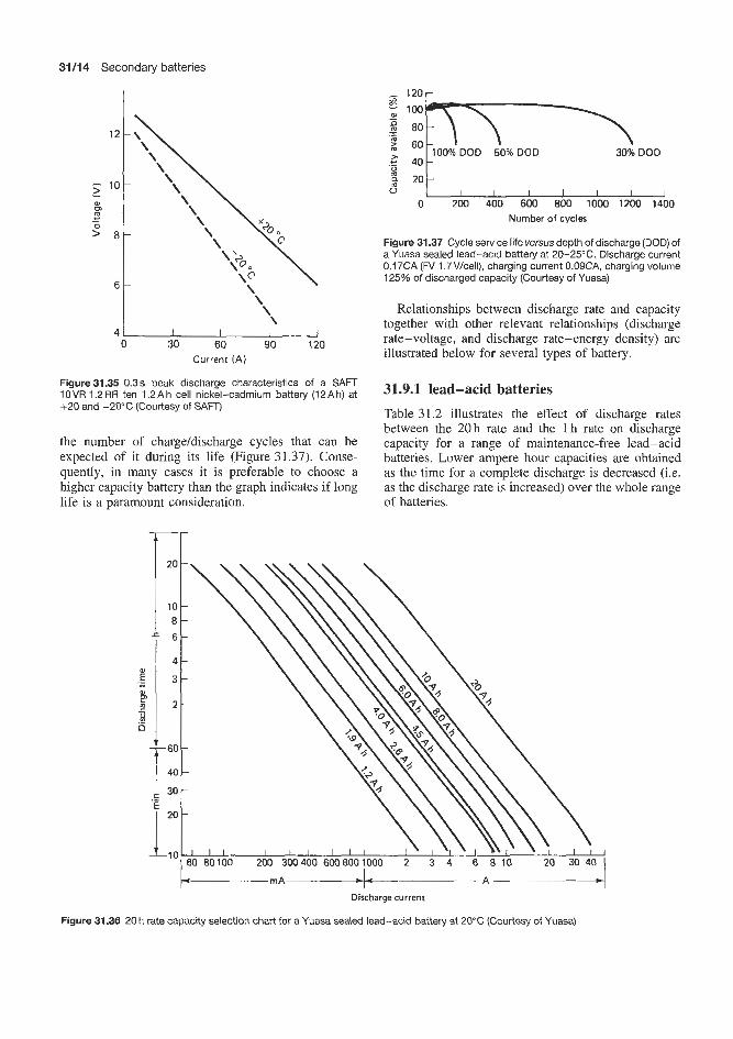
31/14 Secondary batteries
- 1 2 0 r
0 30 60 90 120 Current ( A )
Figure 31.35 0.3 s peak discharge characteristics of a SAFT IOVR 1.2RR ten 1.2Ah cell nickel-cadmium battery (12Ah) at +20 and -20°C (Courtesy of SAFT)
the number of charge/discharge cycles that can be expected of it during its life (Figure 31.37). Conse- quently, in many cases it is preferable to choose a higher capacity battery than the graph indicates if long life is a paramount consideration.
30% DOD .- - 40
g 2 o t I I , , I , I u
0 200 400 600 BOO 1000 1200 1400 Number of cycles
Figure 31.37 Cycle service life versus depth of discharge (DOD) of a Yuasa sealed lead-acid battery at 20-25°C. Discharge current 0.17CA (fV 1,7V/ceIl), charging current O.O9CA, charging volume 125% of discharged capacity (Courtesy of Yuasa)
Relationships between discharge rate and capacity together with other relevant relationships (discharge rate-voltage, and discharge rate-energy density) are illustrated below for several types of battery.
31.9.1 lead-acid batteries Table 31.2 illustrates the effect of discharge rates between the 20h rate and the 1 h rate on discharge capacity for a range of maintenance-free lead-acid batteries. Lower ampere hour capacities are obtained as the time for a complete discharge is decreased (Le. as the discharge rate is increased) over the whole range of batteries.
-r
Discharge currenr
Figure 31.36 20 h rate capacity selection chart for a Yuasa sealed lead-acid battery at 20°C (Courtesy of Yuasa)
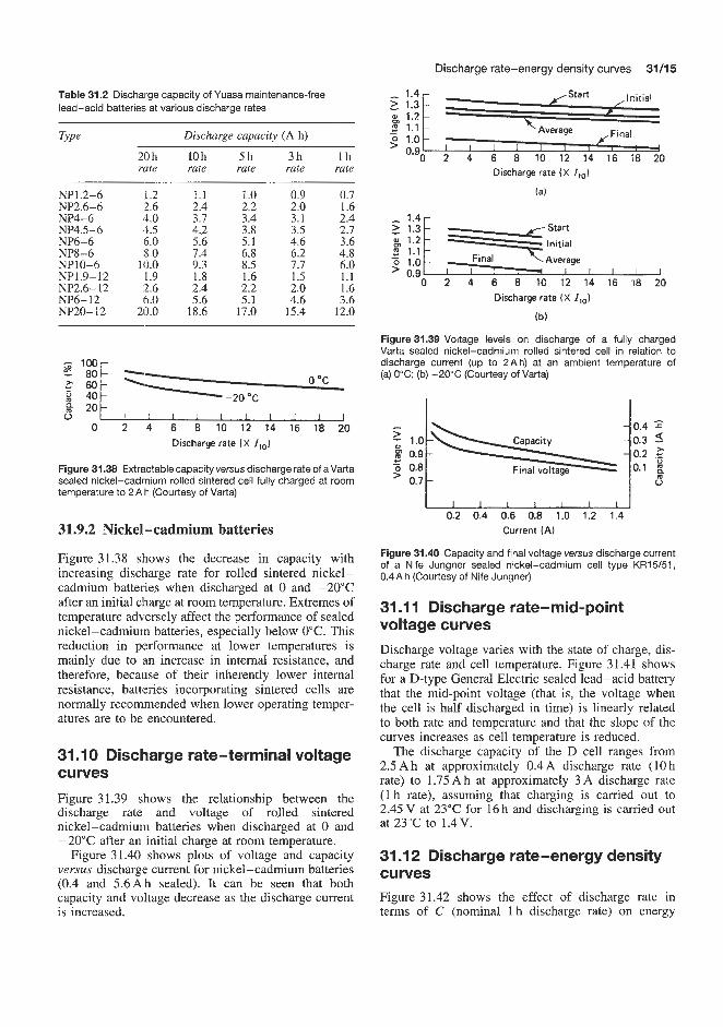
Discharge rate-energy density curves 31/15
Table 31.2 Discharge capacity of Yuasa maintenance-free lead-acid batteries, at various discharge rates
Tvve Discharge capacity (A h)
20h 10h 5 h 3h l h rate rate rate rate rate
NP1.2-6 1.2 1.1 1.0 0.9 0.7 NP2.6-6 2.6 2.4 2.2 2.0 1.6 NP4-6 4.0 3.7 3.4 3.1 2.4 NP4.5-6 4.5 4.2 3.8 3.5 2.7 NP6-6 15.0 5.6 5.1 4.6 3.6 NP8-6 8.0 7.4 6.8 6.2 4.8 NP10-6 113.0 9.3 8.5 7.7 6.0 NP1.9-12 1.9 1.8 1.6 1.5 1.1 NP2.6- 12 :2.6 2.4 2.2 2.0 1.6 NP6-12 6.0 5.6 5.1 4.6 3.6 NP20-i2 20.0 18.6 17.0 15.4 12.0
0 O C
I I I I I I I I I 0 2 4 6 8 10 12 14 16 18 20
Discharge rate ( X I,o)
Figure 31.38 Extractable capacity versus discharge rate of aVarta sealed nickel-cadmium rolled sintered cell fully charged at room temperature to 2 Ah (Courtesy of Varta)
31.9.2 Nickel-cadmium baateries
Figure 31.38 shows the decrease in capacity with increasing discharge rate for rolled sintered nickel- cadmium batteries when discharged at 0 and -20°C after an initial charge at room temperature. Extremes of temperature adversely affect the performance of sealed nickel-cadmium batteries, especially below 0°C. This reduction in performance at lower temperatures is mainly due to an increase in internal resistance, and therefore, because of their inherently lower internal resistance, batteries incorporating sintered cells are normally recommended when lower operating temper- atures are to be encountered.
31 . I O Discharge rate-terminal voltage cullles Figure 31.39 shows the relationship between the discharge rate and voltage of rolled sintered nickel-cadmium batteries when discharged at 0 and -20°C after an initial charge at room temperature.
Figure 31.40 shows plots of voltage and capacity versus discharge current for nickel-cadmium batteries (0.4 and 5.6Ah sealed). It can be seen that both capacity and vo'ltage decrease as the discharge current is increased.
Ly 1.2 B 1.1 Average
Discharge rate ( X I,o)
la)
- 1 . 4 r
"." 0 2 4 6 8 10 12 14 16 98 20
Discharge rate ( X I,,,)
(b)
Figure31.39 Voltage levels on discharge of a fully charged Varta sealed nickel-cadmium rolled sintered cell in relation to discharge current (up to 2Ah) at an ambient temperature of (a) 0°C; (b) -20°C (Courtesy of Varta)
0.9 0.2 .z c 5 0.8 0.1 ' 0.7
0.2 0.4 0.6 0.8 1.0 1.2 1.4 Current (A)
Figure 31.40 Capacity and final voltage versus discharge current of a Nife Jungner sealed nickel-cadmium cell type KR15/51, 0.4Ah (Courtesy of Nife Jungner)
31 .I 1 Discharge rate-mid-point voltage curves Discharge voltage varies with the state of charge, dis- charge rate and cell temperature. Figure 31.41 shows for a D-type General Electric sealed lead-acid battery that the mid-point voltge (that is, the voltage when the cell is half discharged in time) is linearly related to both rate and temperature and that the slope of the curves increases as cell temperature is reduced.
The discharge capacity of the D cell ranges from 2.5 Ah at approximately 0.4A discharge rate (10 h rate) to 1.75 Ah at approximately 3 A discharge rate (1 h rate), assuming that charging is carried out to 2.45 V at 23°C for 16 h and discharging is carried out at 23°C to 1.4V.
31 .I 2 Discharge rate-energy density curves Figure 31.42 shows the effect of discharge rate in terms of C (nominal 1 h discharge rate) on energy
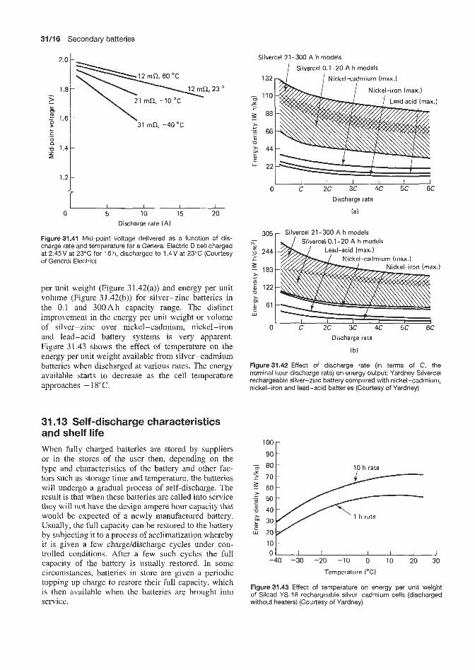
31/16 Secondary batteries
305
E -u 244-
183-
c) - . f
> +- .- E 122- -0 > $ w
2.0 t-
- Silvercel 21 - 300 A h models
X.)
6 1 - - 7 I I I 1 I
I \\ 1 . 8 1 \'
"9 0 5 10 15 20
Discharge rate (A )
Figure 31.41 Mid-point voltage delivered as a function of dis- charge rate and temperature for a General Electric D cell charged at 2.45V at 23°C for 16h, discharged to 1.4V at 23°C (Courtesy of General Electric)
per unit weight (Figure 31.42(a)) and energy per unit volume (Figure 3 1.42(b)) for silver-zinc batteries in the 0.1 and 300Ah capacity range. The distinct improvement in the energy per unit weight or volume of silver-zinc over nickel-cadmium, nickel-iron and lead-acid battery systems is very apparent. Figure 31.43 shows the effect of temperature on the energy per unit weight available from silver-cadmium batteries when discharged at various rates. The energy available starts to decrease as the cell temperature approaches - 18°C.
31 .I3 Self-discharge characteristics and shelf life When fully charged batteries are stored by suppliers or in the stores of the user then, depending on the type and characteristics of the battery and other fac- tors such as storage time and temperature, the batteries will undergo a gradual process of self-discharge. The result is that when these batteries are called into service they will not have the design ampere hour capacity that would be expected of a newly manufactured battery. Usually, the full capacity can be restored to the battery by subjecting it to a process of acclimatization whereby it is given a few charge/discharge cycles under con- trolled conditions. After a few such cycles the full capacity of the battery is usually restored. In some circumstances, batteries in store are given a periodic topping up charge to restore their full capacity, which is then available when the batteries are brought into service.
Silvercel 21-300 A h models
I I I I I I 0 C 2C 3C 4C 5C 6C
Discharge rate
(a)
100
90
8 0 - 10 h rate
- -
Y
L 70-
10 ;-
-40 -30 -20 -IO 0 10 20 30
Temperature ("C)
Figure 31.43 Effect of temperature on energy per unit weight of Silcad YS-18 rechargeable silver-cadmium cells (discharged without heaters) (Courtesy of Yardney)

Self-discharge characteristics and shelf life 31/17
Different types of batteries vary appreciably in their self-discharge rates; indeed, some types of batter- ies are designed to have inherently very low self- discharge rates. The self-discharge characteristics of various types of battery are discussed below.
31.13.8 Lead-acid batteries Low-maintenance lead-acid batteries usually fea- ture a special calcium-lead grid instead of the lead-antimony alloy used in conventional lead-acid batteries such a8 the traction battery. The elimination of antimony and other metallic impurities from the alloy increases the ability of the battery to retain its charge when not in use and gives the battery a shelf life of about file times as long as when the conven- tional lead-antimony alloy is used. Even at elevated temperatures the shelf life with calcium-lead alloys exceeds that ob1 ained with conventional alloy.
Figure 31.44 shows a curve of percentage of nom- inal capacity at various storage times at four temper- atures between 40 and 100°C for a low-maintenance lead-acid batteiy. Most manufacturers of this type of battery claim thlat during storage at normal tempera- tures around 15-20°C these batteries lose about 5%
100 - z - 2 75 .- 0
50 C C .- .- E 25 W
CT
I I I I I I I 0 3 6 9 12 15 18
Storage time (months)
Figure 31.46 Self-discharge characteristics of a Yuasa sealed lead-acid battery (Courtesy of Yuasa)
of their initial capacity during 12-16 months and an annual recharge is all that is necessary to reinstate the full charges (Figure 3 1.45). Another manufacturer of such batteries is more conservative, recommending storage at temperatures between 0 and 10°C with a 6-monthly recharge (Figure 3 1.46).
At 8°C the storage time to reach half the ini- tial capacity exceeds 2 years, while a conventional lead-antimony alloy battery would reach this value in about 3 months at 20°C.
Figure 31.47 shows the effect of time and tempera- ture on the self-discharge rate of a fully recombining lead-acid battery (the General Electric D cell). This shows, for example, that at 25°C the available capa- city is reduced to 60% of fully charged capacity after approximately 300 days’ storage.
38°C 27°C
W
1 6 ° C 31.13.2 Nickel-cadmium batteries
These cells have an acceptably low rate of self- discharge (Figure 3 1.48(a)). Self-discharge is very much dependent on temperature and increases rapidly
l o l 2 l4 l6 with rising temperature. Self-discharge is small at very low temperatures and is almost zero at -20°C (Figure 3 1.48(b)). These cells and batteries can be stored in the charged Or discharged condition. When charged they should be handled with care to avoid
Storage time (months)
Figure 31.44 Typical self-discharge characteristics between 40 and 100°C of Eagle Picher Carefree rechargeable lead-acid batteries (Courtesy of Eagle Picher)
I I 1 I I J a 1 2 3 4 5 6 7 8 9 10 1 1 12
Storage time (months)
Figure 3’1.45 Self-discharge of Sonnenschein spillproof lead-acid standard and permanent batteries at 20°C (Courtesy of Dryfit)

31/18 Secondary batteries
0°C
\ \ 25 "C
\ z 2 4 6 8 10 12 14 16 18 20 22 24
p 20 Storage time (months)
- (a) DK, DKZ and round mass plate types
.m 0 50 100 150 200 250 300 350
4 Storage time (days)
0 I I I I
c 4 -
Figure 31.47 Capacity retained as a function of storage time at various temperatures: General Electric D cell (Charge, 2.45V at
40 kko O c u
-20 O C
23°C for 16h; discharge, 0.25A at 23°C to 1.4v) (Courtesy of General Electric) c. 5 60 R 6 O ' C
5 80
100 r Storage time (months)
(b) RS and SD sintered plate types I
- 8 :\ 60 50 - .it:, -20 O C
60 40 30,
- I-'
1 2 3 4 5 6 80 6 0 0 ~ ' ' ' I ' I ' ' ' ' ' ' I
? a Storage time (months)
2 4 6 8 10 12 14 16 18 20 22 24 Storage time (months)
(c) D rectangular mass plate types
3L 2
Figure 31.49 Self-discharge charge retention characteristics of Varta sealed nickel-cadmium batteries (Courtesy of Varta)
temperature, they should not immediately be charged, -20 -10 0 10 20 30 40 50 but should first be fully discharged and then charged
(bl Temperature ("C)
Figure 31.48 Nife Jungner NlGA sealed nickel-cadmium cells: (a) self-discharge at 25°C (stored and charged at 25°C); (b) multiplication factor for calculating self-discharge at other tem- peratures between -20 and +50"C (Courtesy of Nife Jungner)
short-circuits because the short-circuit current is very high. When storing for more than 6 months a storage temperature less than 15°C is recommended by the manufacturers. As in the case of lead-acid batteries, self-discharge performance varies appreciably from one manufacturer to another and this point should be carefully investigated before a battery selection is made.
Button cells These cells have a moderate self- discharge characteristic at normal temperatures, as shown in Figure 31.49. For applications requiring good charge retention, mass plate electrodes are preferred. When button cells have been stored for a long period (over 6 months), regardless of storage
once at half the no&d rate,-that is, 28h at the 20 h rate.
31.14 Float life characteristics Batteries used in standby applications such as emer- gency power and lighting, where the demand for them to supply power is spasmodic, would often be returned to full charge by the float charging regimen in which the battery is kept on continuous charge. Under these conditions the battery is usually charged by the constant potential method at a potential suf- ficient to maintain it at full charge. In addition to making up any power loss due to use of the bat- tery this also compensates for any long-term self- discharge processes that occur when the battery is not under load.
In the case of lead-acid batteries the float constant potential is maintained continually at 2.28-2.30 Vkell. The limiting current is between 1 and 20% of the rated capacity.
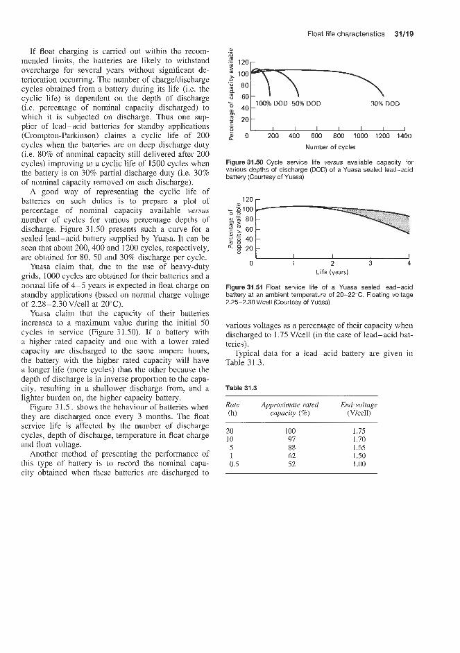
Float life characteristics 33/19
If float charging is carried out within the recom- mended limits, the batteries are likely to withstand overcharge for several years without significant de- terioration occurring. The number of charge/discharge cycles obtained from a battery during its life (Le. the cyclic life) is dependent on the depth of discharge (i.e. percentage of nominal capacity discharged) to which it is subjected on discharge. Thus one sup- plier of lead-acid batteries for standby applications (Crompton-Parkinson) claims a cyclic life of 200 cycles when the batteries are on deep discharge duty (i.e. 80% of nominal capacity still delivered after 200 cycles) improving to a cyclic life of 1500 cycles when the battery is on 30% partial discharge duty (i.e. 30% of nominal capacity removed on each discharge).
A good way of representing the cyclic life of batteries on such duties is to prepare a plot of percentage of nominal capacity available versus number of cycles for various percentage depths of discharge. Figure 31.50 presents such a curve for a sealed lead-acid battery supplied by Yuasa. It can be seen that about 200,400 and 1200 cycles, respectively, are obtained for 80, 50 and 30% discharge per cycle.
Yuasa claim that, due to the use of heavy-duty grids, 1000 cycles are obiained for their batteries and a norma! life of 4-5 years is expected in float charge on standby applications (based on normal charge voltage of 2.28-2.30Vlcell at 20°C).
Yuasa claim that the capacity of their batteries increases to a maximum value during the initial 50 cycles in service (Figure 31.50). If a battery with a higher rated capacity and one with a lower rated capacity are discharged to the same ampere hours, the battery with the higher rated capacity will have a longer life (more cycles) than the other because the depth of discharge is in inverse proportion to the capa- city, resulting in a shallower discharge from, and a lighter burden on, the higher capacity battery.
Figure 3 1.5 i shows the behaviour of batteries when they are discharged once every 3 months. The float service life is affected by the number of discharge cycles, depth of discharge, temperature in float charge and float voltage.
Another method of presenting the performance of this type of battery is to record the nominal capa- city obtained when these batteries are discharged to
P Y I I I I I I 1 I 2 0 200 4M) 600 800 1000 1200 1400
Number of cycles
Figure 31.50 Cycle service life versus available capacity for various depths of discharge (DOD) of a Yuasa sealed lead-acid battery (Courtesy of Yuasa)
120 r
I I I J 0 1 2 3 4
Life (years)
Figure3151 Float service life of a Yuasa sealed lead-acid battery at an ambient temperature of 20-22°C. Floating voltage 2.25-2.30V/cell (Courtesy of Yuasa)
various voltages as a percentage of their capacity when discharged to 1.75 V/cell (in the case of lead-acid bat- teries).
Typical data for a lead-acid battery are given in Table 31.3.
Table 31.3
Rate Approximate rated End-voltage (h) capacity ('36) (Vlcell)
20 100 1.75 10 97 1.70 5 88 1.65 1 62 1 S O 0.5 52 1 .oo


Lead-acid secondary batteries


Stationary type or standby power batteries 32l3
safe shutdown of the process. Classic cases of the use of standby power are in an operating theatre and an airport where, in the event of mains failure, power is required for lighting, communications and the operation of vital equipment. Power stations, tele- phone exchanges, lighthouses and computer installa- tions are other examples of the application of stationary or standby batteries.
32.1 Stationary type or standby power batteries
Large battery installations which are called upon only occasionally to supply power, usually in emergency or auxiliary power supply circumstances, are referred to as stationary or standby batteries. Such installations having total capacities in hundreds of ampere hours are commonly in use. Figure 32.1 illustrates a large secondary lead-acid battery installation.
Standby power can be defined as a source of electricity that becomes available when the mains source of electricity ceases to be available. The choice of a standby system lies between batteries, usually lead-acid or nickel-cadmium, and generators, or a combination of the two. For many applications, the battery's ability to provide the power required instantly makes it more suitable. Indeed, even in large installa- tions for which a generator is essential, batteries are often used both to start the generator and to provide power for the initial period until the generator is run- ning to speed.
Standby power is required in many situations. For department stores, offices, factories, cinemas and other public places, emergency power to light people to safety without panic may be enough. In industry, the need varies from keeping fire and burglar alarms and other communications working to supplying emer- gency power to vital production processes or even to supply the power necessary to effect a controlled
Figure 32.1 Large stationary lead-acid battery installation (Cour- tesy of Chloride Batteries)
32.1.1 Types of stationary or standby battery Several types of standby lead-acid batteries are manufactured to meet the needs of different types of application.
Plante' cells
For the long life with very high reliability needed in places like power stations and telephone exchanges, batteries are made up of cells of a kind named after Plant& They are kept on continuous trickle charge and are ready to spring into life immediately there is a mains failure. The capacity of a cell (the amount of electricity it can store) and its life depend largely on the design of its positive plate. In the Plant6 cell, this is cast from pure lead in a form that gives it a surface 12 times its apparent area. Figure 32.2 shows representations of a modem type of PlantC grid. The negative plate is of the pasted grid type made by forcing lead oxide paste into a cast lead alloy grid. Positive and negative plates are interleaved and insulated from each other to prevent short-circuits.
The all-important surface of the positive plate is continuously regenerated during the life of the bat- tery. Trickle charging compensates for natural open- circuit losses. The average life of a typical Plant6 bat- tery is 20 years and some designs extend to 35 years and sometimes even longer with no fall in capacity. Although the initial cost is high, the average annual cost over the life of the battery can be lower than that of other kinds used for standby power purposes.
Cell capacities are rated by relating current flow to time in ampere hours. High-performance Plant6 cells up to 2000 A h have transparent plastic containers to allow visual checking of the acid level and general condition. Large PlantC cells up to 15000Ah, often found in large telephone exchanges, are most com- monly housed in lead-lined wooden boxes.
Flat plate cells
Because of the high initial cost of Plant6 cells, spe- cially designed flat plate cells have been developed to provide a cheaper but shorter-lived alternative source of standby power. The layout of a typical modem flat plate cell is shown in Figure 32.2.
The flat (or pasted) plate cell, pioneered in the 1880s, has a positive plate made from a lead alloy lattice grid into which a paste of lead oxide and

32l4 Lead-acid secondary batteries
Figure 32.2 Layout of a typical modern flat Plante-type lead-acid standby battery (Courtesy of Chloride Batteries)
sulphuric acid is pressed. The negative plate is also of the pasted grid type, but is thinner.
Although this is the basis of the modem car battery, car batteries are wholly unsuitable as an emergency power source because they are designed to give high current for a short time, as when starting a car engine.
Like the Plant6 battery, pasted plate batteries man- ufactured for standby use have transparent containers. They are available in capacities of up to 500Ah and have a life expectancy of 10-12 years to meet emer- gency lighting regulations.
Tubular cells
Cells with tubular positive plates are normally used to power electric trucks, on which daily recharging is needed. They are also suitable for certain standby applications. They deliver high power at low and medium rates of discharge and work well in adverse conditions.
The positive plate consists of lead alloy spines sur- rounded by synthetic fibre tubes filled with a mixture of lead oxides (Figure 32.3). The tubes keep the active material in contact with the conducting spines during expansion and contraction resulting from the charge and discharge cycle, and so contain the stresses that would break up other types of plate.
Tubular cells are ideal for any kind of applica- tion that requires frequent charge/discharge cycles. When on standby duty, they have a life expectancy of 10-12 years, compared to 5 years when powering an electric truck. They are less costly than Plant6 cells, but fall in capacity as time goes on.
Table 32.1 shows the types of application for each of these types of battery as recommended by a lead- ing manufacturer of standby power batteries, Chloride Storage Batteries Ltd, UK.
Figure 32.3 Layout of a modern design of lead-acid tubular cell standby battery (Courtesy of Chloride Batteries)

Stationary type or standby power batteries 32f5
Table 32.1 Application of various types of lead-acid battery
Plant6 Flat plate Flat plate Tubular Marine Y M C f l H FNFC R range
Telephone exchanges 0
Mobile telephone exchanges Generating stations and substations 0
Obsolescent generating stations (short-term) Emergency lighting 0
Alarms * Computer emergency power 0
Engine starting 0
Oil rigs Marine
0
%
32.1.2 Selection of suitable stationary or standby power batteries for the application When someone who needs standby power has to select a battery, four questions arise:
1. What is the probability of power failure? 2. What is the likely duration of the failure? 3. What damage could power failure do to people,
4. What regulations have to be complied with?
It is generally accepted that lead-acid batteries are ideal for standby power systems, because they are reli- able and relatively low-cost. When it comes to selec- tion, the choice is between the kinds of battery referred to earlier. Batteries are tailor-made for specific standby applications, and Table 32.2 gives a rough guide to the suitability of different batteries for different jobs.
equipment and production?
Table 32.2
Life Publication Cell type expectancy No. range
(years)
Plant6 25 SPuKlI2 YANCTYH Flat plate 10-12 SPuK3 FA/FC Flat plate 5-6 SPUKs R range Tubular 10-12 SPUQ - Marine 10-12 M4 -
(Courtesy of Chloride Power Storage Ltd, Swinton, UK)
There is an all-too-common idea that ‘a battery is a battery’ and this sometimes leads to car batteries being used to supply standby power. Although this usually results in low initial cost, it has serious drawbacks. Car batteries are designed to supply high currents for short periods and are not intended to cany industrial type loads for any significant periods. Their life expectancy in standby applications is very low compared to that of Plant6 and other industrial batteries. More important,
the use of car batteries may also invalidate the specifi- cations of equipment makers and insurance companies.
Initial savings from incorrectly chosen batteries can evaporate rapidly in the face of short life, especially if the wrong size of battery is chosen as well as the wrong type. And the failure of an emergency lighting or fire alarm system can result in danger to human life or legal action. Expert opinion on whether the system is the right one for the job will be an important factor in deciding where the responsibility lies. The battery must therefore be selected from a range specifically designed for the purpose. A very important aspect involved in the selection of standby power batteries is to ascertain what is known as the load profile for the proposed application.
To be able to advise on this the battery manufacturer needs to know what is required in terns of current output, voltage and frequency of operation. If only one continuous load is to be supplied, sizing the battery can be simple. For example, an emergency lighting system drawing 20 A for 3 h on battery power would require a 60Ah battery at the 3 h rate. Since standby batteries are conventionally rated at the 10 h rate, this is equivalent to a 75 Ah battery at the 10 h rate.
Load projib I (Figure 32.4(a))
A battery is like an athlete who can be just as exhausted after running 100m as after 10000; the difference is in the rate at which energy is used up.
Most industrial standby power systems now tend to be more complex because their total load is the product of many varied and intermittent loads. One battery may serve different purposes within the same building.
Load pmjile 2 (Figure 32.4(b))
If a battery’s duty cycle can be arranged so that any high-current loads occur early, a battery of a smaller capacity can be used than if heavy currents are required at the end. This is because a piece of electrical equipment demands not only a certain current, but also a minimum voltage. If loads are likely to occur at any time in the work cycle a special approach will

3W6 Lead-acid secondary batteries
7- - 20 E
9
2 10
.+
0
0 60 120 180 240 Time (minl
(a) Load profile 1
600
500
A - a 400
200
100 0 60 120 180 240
Time (min) (b) Load profile 2
Figure 324 Load example profiles for lead-acid standby power battery type selection (Courtesy of Chloride Batteries)
be needed in deciding the battery size. It is safest to assume that the loads will occur at the end of the work cycle so that sufficient battery capacity and voltage are available for the work. Otherwise the voltage may drop so low that the battery fails to do its job and this can be costly, if not dangerous.
Choosing the most suitable and economical battery can be bewildering, but most manufacturers now have computer programs to help select the most effective type and battery size. Their advice should always be sought.
In any event specifying the correct size and type of battery is of paramount importance. It is certainly prudent to allow a margin of safety, as one day lives may depend on the correct battery standing behind the system.
Traditional alarm and emergency lighting standby batteries have thick plates reflecting the need for dura- bility (up to 20-year life), rather good energy and power density.
This type of cell is now gradually being replaced by a sealed cell design, e.g. the Bell Telephone Sys- tem and Western Electric Company Round Cell which contains saucer-shaped pure lead grids stacked hori- zontally. These cells have a life of about 30 years. Plant6 type cells are still in use to some extent but
are gradually being replaced by sealed valve regulated designs for telecom and USP applications. They have a life of 10 years, do not need topping up during this time and give off little gas, Le. can be located in offices without special venting requirements. The energy den- sity of these sealed cell valve regulated designs is about twice that of the Plant6 and flat plate designs. These sealed battery plates are cast in antimony-free lead alloys, usually lead-calcium or lead-calcium-tin, and electrolyte immobilization may or may not be used.
32.1.3 Charging and operation of standby power batteries For completeness, this is included here. Battery char- ging is discussed more fully in Part 5.
The essential feature of any standby power system is immediate availability of the battery power if the normal mains supply fails. The battery must, there- fore, always be in a fully charged condition. Charging equipment is essential to a reliable system, and the recommendations of the battery manufacturer should always be followed.
The basic charging equipment is a means of trans- forming the normal alternating current (a.c.) mains supply to a direct current (d.c.) matching the bat- tery requirements. Two rates of charge are normally provided, quick boost and trickle. The quick boost rate must be capable of an output between 2.0 and 2.70V/cell for recharging of the battery. The trickle charge output should be capable of compensating for the internal losses of the battery, at a voltage level of 2.25 V/cell. The outputs required, in terms of current, will depend on the ampere hour capacity of the battery.
During charging, ‘gassing’ will start when the cell voltage has reached approximately 2.30-2.40 V/cell. The cell voltage will continue to rise and the charge may be considered to be completed when the volt- age and relative density have remained the same for approximately 3 h.
The voltage could be as high as 2.70 V and charging should not be allowed to continue beyond this level.
A recharge voltage table for a Plant6 cell is illus- trated in Table 32.3.
Trickle charging
The essential requirement of present applications of standby batteries is that the battery shall be ready instantly to perform its duty. One method of meet- ing this requirement is by trickle charging of the bat- tery. After a battery has been discharged, it must be recharged at the recommended quick rate as soon as possible. Once restored to the fully charged condition, trickle charging will then keep it fully charged until the next demand. No amount of trickle charging will ever recharge a substantially discharged battery, but when it is part of the duty of a standby system to meet occasional brief demands the energy thus used can be gradually replaced by trickle charging at a suitable rate.

Traction or motive power type 32/7
32.2 Traction or motive power Traction or motive power lead-acid batteries are the power source used for every kind of electric vehicle from road transport to fork life trucks in industry.
In many applications electrically operated vehicles are replacing vehicles with internal combustion engines. Electric vehicles are cheaper to run because of the lower fuel cost, and because of their relative simplicity they are easier to maintain than vehicles equipped with internal combustion engines. They also present fewer environmental pollution problems. In an electric vehicle the motor and controller are virtually maintenance-free and this is equally true of the battery and charger. With the introduction of automatic battery topping-up devices and self-compensating battery chargers, these once onerous battery and charger maintenance routines have now become almost non- existent. Present indications are that petrol and diesel fuel costs will probably escalate more steeply than electricity prices, and that the price differential will continue to remain in favour of electricity. Some data, supplied by Chloride Motive Power, on actual costs of electric versus diesel vehicles, are givec in Tables 32.4 and 32.5. Both on vehicle maintenance and fuel cost, therefore, electric vehicles are displacing conventional vehicles in many applications.
The interior design of lead-acid batteries intended for traction purposes, such as milk floats and electric locomotives and fork lift trucks, differs from that of stationary batteries because of their different service requiremens.
Table 32.3 Recharge voltage table for a typical Plante cell at 15°C
Cell e.rn.6
2.70 2.40
2.25
2.20
2.05
Top of charge volts at 7% of A W10 Minimum top of charge volts to recharge with good gassing Ideal for trickle charge float and minimum voltage for rechar,ge, but subject to problems such as stratification Floating/trickle charge, but with need for freshening charges Open-circuit voltage for 1.210 electrolyte relative density
It is satisfactory only if the amount of discharge is a very small proportion of the ampere hour capacity of the battery.
Float charging
Float charging is used where the connected load will not tolerate even a momentary interruption. A simple example of such a scheme would be a continuous process plant where even a millisecond failure of the supply would result in the complete breakdown of a manufacturing run, which could be extremely costly.
To guard against such interruptions, the battery, load and charger are connected in parallel, the charger being of the constant-voltage type, capable of delivering an output equivalent to the normal load demand plus the battery charging requirements. With the float system, should a failure occur, the battery takes over the load with no interruption whatsoever.
A constant voltage charger is a statically controlled rectifier, normally employing transductor or thyristor devices to correct for changes in output. The trans- ductor can be regarded as an inductive choke, the a.c. impedance of which is varied by the degree of mag- netic saturation produced by direct current in an auxil- iary winding. Thyristor control is achieved by variation in the firing angle of the a.c. waveform.
The normal float level of a floating battery system is equivalent to 2.25V/cell. This preset voltage is held within usual limits of +2% irrespective of mains voltage variations of f6%, with load variations of 0-100% of the charger rating. Facilities are usually incorporated for quick boost facilities for recharging of the battery following a deep emergency discharge.
The selection of the correct charger for a battery- operated standby power system is of vital importance, and the advice of both battery and charger manufactur- ers should be Sought to ensure the most efficient and properly matched combination.
32.2.1 Selection of motive power batteries The duties the battery will be expected to perform can be broken down into a series of components, e.g. vehicle range, hills to be negotiated or loads to be lifted in the case of a fork lift truck, each of which will demand a certain amount of discharge current from the battery.
The amount of capacity available from a battery is dependent largely on the number and size of plates in the cells. Clearly, battery manufacturers cannot dictate to the vehicle designer how much room must be allowed for the battery, as thls is only one of very many design considerations that must be taken into account.
Normally, the battery maker is presented with a given space into which the battery must fit, and this space is a compromise between overall design require- ments and the need for a battery of sufficient size to make the vehicle a viable, economic proposition to the user.
In practice, therefore, the exact battery capacity is not usually calculated in advance for a particular duty. Instead, the type of truck required is determined by the maximum loads, and one of the standard batteries for the truck is used. There is usually some limited choice

32/8 Lead-acid secondary batteries
Table 32.4 Yardstick operating costs
30 cwt payload urban delivery vehicles Case I Case 2
Electric Diesel Electric Diesel
Capital costs (5) Vehicle Battery Charger
Standing chargedyear (5) Vehicle depreciation (years) Battery depreciation (years) Charger depreciation (years) Interest on capital Licence Insurance
Running costslmile (p) Electricity 1.5kW Wmile @ 2pkW h Derv 12/15mpg @ E1.15 Maintenance materials, labour and overheads
including tyres and lubricants Total running costdmile Add standing charge reduced to cost/mile
Total cost/mile
Index
(9125/7500 miledyear) (p)
4800 3076 650
8526 -
__
320 (15) 615 (5) 43 (15)
639
112 1729
-
-
__
3.0 -
4.7 7.7 -
18.9 26.6
100
~
__
7690 - - -
7690 __
1098 (7) -
- 577 101 152
1928 __
-
-
9.6
9.1 18.7
21.1 39.8
150
-
-
__
6330 3076 650
10056 __
-
422 (15) 615 (5) 43 (15)
754
112 1946
-
__
3.0 -
4.3 7.3 -
25.9 33.2 __
100
7300 - - -
7300 __
730 (10) - - 548 101 152
1531 __
__
- 7.7
8.2 15.9 -
20.4 36.3
109
__
__
Case 1: vehicle with open milk-float body used 365 daydyeax. Top speed 15 mph. Range capability is approximately 50miles laden. This analysis is done on 25-mile range with 250 stops, which is comfortably within daily range of the electric with reducing load Case 2: vehicle similar to case 1 but with aluminium box-van body with hinged rear doors. Driven less intensively than a milk-float, the vehicle averages 30 miledday on general urban deliveries
Source: Electric Vehicle Association, 1980
between the minimum capacity recommended and the maximum that can be fitted.
Experience shows that, over their lifetime, vehicles are required to fulfil a number of duties differing from their original application. So if a vehicle is to be flex- ible enough to be switched to a more demanding duty it makes sound economics to fit the largest possible battery initially. This will also help to avoid overdis- charging the battery, which can cause it irreparable damage.
Where intensive and continuous operation of a vehicle is involved, and the largest battery that can be accommodated is not capable of completing the vehicle’s duties between recharges, it is actually nec- essary to calculate the total capacity required.
Every electric vehicle, whether on the road or in industry, has a predetermined pattern of use. A milk float is needed to cover a certain route, with a known number of stops, distance to be travelled, and the terrain it is required to negotiate. (It is important to know of any steep hills the vehicle must climb, for instance, as this will demand extra energy from the
battery.) The needs of a fork lift truck can similarly, although less exactly, be calculated. How heavy are the loads to be lifted? What speed is it required to do? What travelling time must be allowed from the truck’s base to where it will work? Are there any steep gradients involved?
Each of these facets will demand a known amount of discharge current from the battery and this is the basis of the calculation. The discharge current obtained from the battery is multiplied by the time (in minutes) taken to perform each movement, giving a series of figures in ampere minutes. These figures can be added together to give the total value of ampere minutes required to complete a delivery round or working shift.
For example, a fork lift truck lifting 2 tonnes might require a discharge current of 200A for 0.25 min or 50 A min. This truck travels 6 m at 1 d s , during which the discharge current is 80A, or 480As (8Amin). These calculations are continued for the whole series of operations. The ampere minutes are added together and the total converted into ampere hours.

Traction or motive power type 3W9
Table 32.5 Yardstick operating costs
2-tonne lift capacity counterbalanced Case 1 Case 2
fork lift trucks Electric Diesel Propane Electric Diesel Propane
Capital costs (5) Truck Battery (number used) Charger (8 or 12h)
8595 2043 ( I ) 657 (12)
~
11295 Standing chargeslyear (E)
Truck depreciation Battery depreciation Charger depreciation Interest on capi:al Rental of fuel facility
Total standing charge/year
Running costh (E) Electricity 4 units @ 2I3p Gas oil 1.75litres @ 25p Propane 4litres @ 13p Maintenance labour + overheads Replacement pa ts and tyres
including mid-life overhaul
Add standing charge/year reduced
Total costh in service (5)
Index
to costh (g.)
716 340 55
847
1958
- ___
0.08 - -
0.57
0.65
0.98 1.63
~
100
9486 -
-
9486
1897
-
0.44 -
0.89
1.33
0.95 2.28
140
9486 -
- - 9486
8595 4086 ( 2 ) 873 (8)
~
13554
1186 - -
711 126
2023 ~
~
- -
0.52
0.89
1432 680 73
1016 -
9486 -
-
9486 -
-
9486
2371
~
-
- 711 -
9486
2371
~
-
-
7i1 126
3201 3082 3208
0.12 -
-
0.57
-
0.44 -
0.89
- -
0.52
0.89
1.41
1.01 2.42
0.69
0.80 1.49
1.33
0.77
1.41
0.80 2.10 2.21
148 100 141 148
Case 1: one truck with one battery operated on single-shift use Case 2: one similar mck with two batteries operated with battery exchange on two-shift use
Source: Electric Vehicle Association, 1980
This gives the total number of ampere hours con- sumed by the truck’s motors. However, other factors must be considered before the ampere hour capacity of the battery or batteries required can be decided. To ascer- tain current values and duration of discharge for a motive power battery several factors must be considered:
1. The actual value of the discharge currents. The higher the average discharge current, the lower the available capacity.
2. The total time over which the battery’s discharge is spread. The shorter the time, the lower the available capacity.
Figure 32.5 shows a typical curve of capacity avail- able at various discharge currenl.s, and for discharges spread over various times. For example, when a LOOAh battery IS discharged continuously at 100A, the available ca19acity is 54% of nominal capacity and it will last 0.54 h, but when the same capacity is spread over 1 h, the available capacity is 61%.
Finally, when spread over 8h, it is almost 88%. Because the required battery capacity depends on the
percentage current, and the percentage current itself is dependent on the chosen battery capacity, one must choose the battery first and then check the currents to determine whether the chosen battery allows sufficient margin.
However, it is generally satisfactory to assume that the total number of ampere hours consumed by the motor should be divided by 0.7 to take account of the factors discussed above.
The result of this calculation will give a total of ampere hours that would completely discharge the bat- tery. At this stage, it must still be considered a theoret- ical calculation, as in practice this is an unacceptable premise in view of the following:
3. The vehicle’s eventual duty may, on occasion, be
4. As a battery becomes older, its ability to give full heavier than at first assumed.
rated capacity reduces slightly.
In either of these events, to assume full discharge from a battery in the original calculation would leave the vehicle unable to perform satisfactorily.

32/10 Lead-acid secondary batteries
11OP
100 -
90
a s 80 - P 8 70-
- r - c .-
- Q - a .- J 60 -
50 -
40-
I I I I I I I I I
0 20 40 60 80 100 120 140 160 180 200
Discharge current (A)
Figure 32.5 Capacity on intermittent discharge at 30°C. (Nominal cell capacity lOOAh in 5 h) (Courtesy of Chloride Batteries)
To cover these factors, it is accepted that a battery should not be regularly discharged by more than about 80% of its normal capacity. This is also good battery operating practice to protect it against overdischarge and general abuse.
Therefore, the ampere hour value should now be divided by a further factor of 0.80.
Figure 32.6 shows how a battery’s life and therefore the cost per kilowatt hour of output is affected by the depth to which the battery is discharged each day; thus the necessity for the above calculation.
To summarize so far, we have reached a calcula- tion of Nominal 5-h capacity required
I I = ampere hours consumed by the motor x - x - 0.70 0.80
I = ampere hours consumed by the motor x ~
0.56 This final figure represents the total nominal battery capacity required for the duty of the vehicle.
It will now be apparent whether one, two or three batteries will be needed, and, at this stage, it is import- ant to lay down a suitable working schedule, which will ensure that the work of each battery is shared equally between recharges.
On no account should a battery be worked until the vehicle’s performance begins to deteriorate. It is far better either to ensure that the duty does not make this demand, or to change the battery before recharging. In terms of efficient performance, and increased bat- tery life, it is far more economic to organize battery charging routines that avoid this situation.
32.3 Starting, lighting and ignition (SLI) or automotive batteries These are discussed in Part 6.
32.4 Partially recombining sealed lead-acid batteries These batteries may be used in either cyclic or float service in a wide range of applications which include: point of sales terminals of centrally controlled cash register systems, electronic cash registers, portable test
120 r 110
L:
2 loo
g 90
zi n
u
80
60 70 80 90 100 110
Daily discharge (% of nominal capacity)
Figure 32.6 Battery cost for different extents of daily discharge (Courtesy of Chloride Batteries)

Electric vehicle batteries 3211 1
equipment, fire and security systems, communications equipment, photographic equipment, portable power tools, computer rnemory systems, portable televisions, hand lamps, propelled toys, power packs, invalid carriages, intrudler and fire alarm systems, medical instrumentation, emergency lighting, uninterrupted power supply, lawn mowers, portable lighting,
32.5 Load levelling batteries Southern California Edison in 1988 installed a load levelling battery comprising 8256 standard traction- motive power cells each of 3250Ah capacity. This 40 MW h 2000 V battery was the lowest cost option for storage load management for duties of 1 hour,
cordless appliances, toys, cellula phones, consumer elec&onics and instrumentation. The batteries feature lead-calcium alloy grids for achieving long and good (2000 cycies).
engines taking Over for to hours. Load management needs long life (lo year) batteries with
32.6 Electric vehicle batteries reliable service and also a suspended electrolyte system. These batteries are available in capacities between 5 and 51D Ah. These are discussed in Section 43.


Nickel batteries


Nickel-cadmium secondary batteries
5. Switch tripping batteries in high-voltage distribu- tion systems are well suited for use with distribution ring mains. They offer reliability of operation and provide the high current necessary to close the cir- cuit breakers and switches associated with power stations and substation networks.
6. Small hand lamps for powerful light output. 7. Train lighting batteries are installed in containers
below the carriages and supply the coach lights during steps at stations or in the case of a power supply failure. Nickel-cadmium cells are also used for the uninterrupted emergency power supply to railway main stations and signalling systems.
8. Marine applications require an unintenuptible power supply to the emergency systems for radar, communications, steering and navigation, and for the emergency lighting on board.
9. Air transport batteries provide the ground power supplies and also the support battery systems on board aircraft. Also, at the airport, all the essential lighting and communication relies on the batteries. In this method of working, the system will operate in the standby mode, giving uninterrupted power supply on mains failure.
ickel--cadmium secondary batteries 33.1.6 Open and semi-open smaller types The wide applicability and range of sealed nickel- cadmium batteries is a result of their remarkable performance characteristics, some features of which are:
1. Total absence of maintenance. 2. Very long operational life. 3. Ability to accept permanent overcharge. 4. Very favourable prolonged storage time character-
istics in stock, whatever the state of charge; bat- teries producled by some manufacturers are better in this respect than those produced by others. If charge acceptance deteriorates markedly after a few months' storage the capacity can be restored by cycling.
5. Ability to be overcharged at high rates. 6. Rapid and ultra-rapid chargeability. 7. Constancy of discharge voltage characteristics even
8. Mechanically robust and resistant to electrical dam-
9. Operation over a wide temperature range: -40 to
Some applications of vented large nickel-cadmium batteries axe discussed below.
Large nickel-cadmium batteries are made in a vari- ety of designs to suit different types of application. The major appli'cations are discussed below:
1. Central batteries for emergency, safety and auxil- iary lighting are used for public meeting places (theatres, warehouses, sports halls, etc.) and fac- tories. They permit the safe evacuation of buildings in the case of mains failure, by providing secondary illumination.
2. Nickel-cadmium batteries are used for special emergency power supplies, as required in medical centres, intensive care units and operating theatres and similar applications where lighting interruption can be a matter of life or death.
3. Engine starting batteries are used to start motor generator sets as required for standby power sys- tems. The batteries have to start the engines in bad weather conditions where low temperatures may prevail. These engine starting batteries must be highly reliable, have a high performance capabil- ity and be free from the effects of high stress and vibration, such as occurs in vehicles and the engine rooms of shilps.
4. Back-up standby batteries provide power in the event of a mains failure, for example in the opera- tion of a crane to prevent the load being released. Another application is in computers and processing systems.
at very high discharge rate.
age (overcharge reversal).
+50"c. 33.1.2 Sealed nickel-cadmium batteries The application of sealed nickel-cadmium batteries may be subdivided into four main categories, which are discussed below: self-contained supply, emer- gency supply, auxiliary supply, starting and highpower supplies.
Self-contained supply
Sealed nickel-cadmium batteries are mainly used in portable devices as the only source of energy. Examples of this type of application are: transceivers. razors, portable equipment and tools, remote radio and ultrasonic controls, flashguns, toys, portable spray equipment, toothbrushes, hair curlers, hearing aids, cine cameras, calculators, computers, model ships, etc., test and control instruments, survey equipment, rangefinders, sonar, timers, digital counters, domes- tic electricity and telephone meters, clocks, time and security check clocks, ticket, money and petrol dis- pensers, identity check machines, electronically con- trolled machine tools, lamps, tape recorders, television dictation equipment, measuring and test instruments, medical equipment, miners' lamps, transceivers, tele- phones, incubators, heated clothing, underwater lamps, portable refrigerators, telephone answering machines, metal detectors, invalid chairs, control instruments, emergency lighting, security alarms, portable electron- ics, portable tools, communications, computers, elec- tronic back-up and, most recently, mobile telephones.
In these types of application, sealed nickel-cadmium batteries are ideal sources of energy, meeting the requirements of medium energy ai low rate and free- dom from a.c. supply loads. Thus, in the operation

33/4 Nickel batteries
of an electronic flashgun, the battery is capable of recharging the capacitor in a few seconds at a current of 10-20C5 A. Battery recharge takes 30min (rapid charge) or 3 h (accelerated charge).
SkyLab, the manned space vehicle developed by NASA, was powered by eight secondary nickel-cadmium batteries (as well as 16 primary or secondary silver-zinc batteries). Nickel-cadmium batteries are used to power the NATO111 communica- tion satellite.
Emergency supply
In the last few years, the need for emergency sup- plies during ax. supply failure has been considerably extended in electronics and security equipment. Sealed nickel-cadmium batteries are kept on constant charge when the a.c. supply is present and incorporated in utilization circuits, which must continue to function during a.c. supply failure. Sealed nickel-cadmium bat- teries are particularly suited for these applications by reason of their ability to accept overcharge, their free- dom from maintenance and their reliability.
The principal applications in emergency supplies are in electronics, emergency lighting, fire and burglar detection, signalling and alarms, medical apparatus and surveillance systems (including defibrillators, resusci- tation units, portable electrocardiographs and blood transfusion pumps), switch tripping, logic memories, control of switchgear, circuit breakers and signalling.
As an example of these applications consider the case of a self-contained emergency lighting unit for a building. The unit has a charge circuit which applies a permanent charge to the battery, at a rate of 0.05C5 A. Complete charging of the battery is required in 24 h. When the a.c. supply fails the battery is connected to the lamps by a relay; when the ax. supply is re-established the lamps go out and the battery is recharged.
Consider as a further example an electrical supply for the memory in a data system. In order not to lose data in case of a s . supply failure, certain data sys- tems are fitted with self-contained emergency power supplies for relatively low powers. Data systems are generally supplied from the a.c. supply and are par- ticularly sensitive to very short breaks and transient voltage variations. To overcome the weaknesses of the a.c. supply, there are various types of equipment, in particular inverters, supplied by battery-charger com- binations. The inverter derives its supply with a.c. supply present from the rectifier and with ax. supply absent from the battery.
In these systems the battery serves also as a filter for commutating currents injected by the inverter when switching on or removing the load. For example, a 300 ms hold for a 5 kV A inverter with 110 V input can be obtained with a 4 A h battery (1lOVR 4D SAFT). The peak current is 65 A (l6C5 A) and the battery is charged at a permanent rate of 0.02C5 A with excellent
reliability. The theoretical service life of this unit is 9 years.
Examples of the application of nickel-cadmium batteries in emergency power and lighting applications include multistorey buildings, aviation safety, railway vehicles, ships, tunnels, sports areas, shops and offices. Nickel-cadmium batteries are also used for starting up diesel generators to supply electrical power in the event of a mains failure (Figure 33.1).
A good example of a situation in which there is a critical requirement for the very rapid availability of emergency power is an operating theatre. Here, in the event of a mains failure, the operating staff must have a system that restores light and power for instruments within a fraction of a second. Such systems are usually based on the nickel-cadmium battery with associated electronic equipment. Another, lesser, example is a bell-ringing tower. Losing control of all the bells at the same instant of time could have unwanted effects both on the music produced and the well-being of the ringers.
An example in which the proper supply of emer- gency lighting and power is mandatory is an airport. Traffic interruptions due to bad weather at airports is an increasing problem in today’s intensive air traffic. Therefore, airports are equipped with different landing aids such as runway lights, instrument landing systems and radar. An interruption in the supply of electrical power to this equipment means that an approaching aircraft will lose guidance to the runway and a critical situation might develop. For this reason, emergency power must be available to use in case of interruption of the normal power supply. The International Civil Aviation Organization (ICAO) has made standards for equipment of airports to allow safe landing at different visibilities.
These standards have different categories. The lowest category is ‘Non-Instrument Runway’, where 1.5 km visibility is required. The highest category is ‘Precision Approach Runway Category 111’ , intended for operations below 400 m runway visual range (visibility of the lights along the runway). The standards also determine the airport equipment, which landing aids shall have emergency power and the maximum time for switching to emergency power. The emergency power source can be a power station completely independent of the airport’s normal power supply, motor generator sets or battery-powered inverters.
Category Z Most airports around the world intended for international traffic are in Category I. This category is intended for operations down to 60 m decision height (the height at which the pilot has to abort the approach if not able to continue visually) and 800m runway visual range. During a power failure, the instrument landing aids must have emergency power within 10 s and the runway light within 15 s.

Nickel-cadmium secondary batteries 3315
Figure 33.1 Nickel-cadmium battery for starting up diesel generators for emergency lighting (Courtesy of Nife Jungner)
Category ZZ Increasingly, intensive air traffic has cre- ated a demand to improve regularity (to minimize the time when an airport is closed due to bad weather). The less time an airport is closed, the smaller are the losses in landing and starting fees. It also gives nego- tiating power to attract flights, since companies will select airports that are also available in bad weather. For this reason, there is now a trend to improve inter- national airports to Category 11. This is intended for operations down to 30 m decision height and 400 m runway visual range.
Some airport instruments require completely unin- terrupted power supply while other instruments and runway lights must be able to switch to emergency power in a maximum of 1 s. The power demand of the systems requiring completely uninterrupted power is not so high, and is normally arranged by direct feeding from batteries. It is more difficult to arrange an emer- gency supply for the runway lights, which normally require hundreds of kilowatts.
Auxiliary supply
When the power required by a consuming device exceeds the output of the source, a local battery is necessary. Nickel-cadmium sintered plate sealed bat- teries, by their performance on discharge at high rates, have the perfect attributes for use to provide auxiliary supplies.
The battery plays a similar role to that of a capacitor used to store energy, but with the difference that it can discharge for considerably longer periods. Except during these periods of discharge, the battery is left on permanent charge.
For example, the case of an auxiliary supply for direction indicators on a lightweight motor cycle illus- trates the possibilities of using uncontrolled rapid charge with cylindrical sealed nickel-cadmium bat- teries. When the generator on the motor cycle is a magdyno and when the engine speed is low, an aux- iliary supply is necessary to supply the indicators. In this application only the charge presents a problem because the output of the magdyno depends on the engine speed and whether lights are on or not. In some machines the maximum charge current available may vary from lOmA to 1 A. The use of a battery with a capacity of 0.5 Ah gives a perfect solution because it can withstand overcharge at 2C5 A (1 A).
Another example of using sealed nickel-cadmium batteries as an auxiliary power source concerns the carrier wave equipment that permits the connection of a second telephone subscriber when only one line is available. The signal is modulated at the exchange, transmitted on the single line and demodulated at the receiver. The battery is kept on permanent charge for the telephone lines at a current of about 0.02C5A. When the user is called, the battery supplies the energy necessary for the bell and the transmission. The daily load is small, a few milliampere hours, the source being a VBE type SAFT battery. A failure rate per operational hour of lo-* would be typical for this type of SAFT battery.
Vehicle starting and high-power supplies
Nickel-cadmium sealed batteries are particularly well suited to starting small engines and high powers. Because of their very low internal resistance they can

3316 Nickel batteries
deliver very high rates of discharge for short periods. For example, the starting of light-weight motor cycles requires a breakaway current of 30-50A followed by a discharge for several seconds at 20-25A at a nominal 12V. Recharge must be rapid in order to be sufficient, since runs are short and uncontrolled. All these requirements can be satisfactorily met by using a battery of 0.5 A h capacity, with the following characteristics:
1. Voltage at end of starting at 20°C: 11 V. 2. Voltage at end of starting at -10°C: 9V. 3. Uncontrolled rapid charge rate 0.8 A, which permits
recharge after starting in less than 3 min.
The same type of application is the starting of a lawnmower, where the breakaway current may be as high as 75A. The power necessary is supplied by a 1.2 A h battery.
The nickel-cadmium battery is now the type used almost exclusively for engine starting in larger aircraft. Batteries with capacities up to 200Ah are now avail- able. Lead-acid batteries are used in the majority of small private aircraft and in some larger aircraft, e.g. the UK Harrier 'Jump Jet' and BAC Concorde.
33.2 Nickel-zinc secondary batteries Nickel-zinc batteries may be the batteries of the future in applications such as utilities load levelling and electric vehicles, and indeed the nickel-zinc battery is now in commercial production in the USA.
Nickel-zinc cells have a voltage of 1.85V at 25°C and a high energy density (75Wh/kg-', 150 W Wdm-').
33.2.1 Electric vehicles In an effort to broaden the field use of the nickel-zinc system and to provide an early demonstration of the state of the art of this system in vehicle propulsion, Yardney are making available an unoptimized pro- totype battery module of 300 A h nominal capacity, which can be assembled into a vehicle battery of the desired voltage; thus baseline performance can be established on which future performance can be pro- jected. A specially designed charger is available, which maximizes the capacity maintenance and cycle life of this prototype battery.
The battery is 264 mm wide, 179 mm deep, 285 mm high and weighs 2.9 kg. At the C13 discharge rate, the nominal voltage is 6.4V and the nominal capacity is 300 Ah. The estimated cycle life is 200-400 cycles at 80% depth of discharge.
The module consists of four series-connected 300Ah cells providing 6.4V. The cells may be installed in any essentially upright orientation provided that the 179mm x 285mm face is constrained by the battery box or by adjacent modules. A typical
15-module arrangement, connected in series, would yield a 28.8 k W h (U3) total energy content battery at a nominal 96V.
The cell design uses electrochemidly impregnated sintered nickel positive electrodes and rolled-bonded zinc oxide negative electrodes. The separator is a three-part system using proprietary Yardney separators. Factors affecting cycle life and capacity maintenance include depth of discharge, operating temperatures, vehicle design, battery mounting provisions, propul- sion system design (that is, operating currents, pulse magnitudes, etc.) and frequency of maintenance.
The nickel-zinc battery is lighter and smaller for a given energy output and is capable of a higher specific power than either the lead-acid or nickel-iron systems and is consequently a prime candidate for a future elec- tric vehicle power source. These features affect vehicle performance beneficially by both extending range and improving acceleration and operation at lower temper- atures. The major limitation of the nickel-zinc battery system is its relatively short life. Extensive use of nickel-zinc batteries, particularly as electric vehicle power sources, will depend on significantly extending the deep discharge cycle life of full batteries beyond the current level of 100-300 cycles. The major prob- lem with the nickel-zinc battery arises from the high solubility of zinc oxide, a discharge product of the negative electrode, in the battery's alkaline electrolyte. This results in zinc dendrite formation under charging conditions, as well as shape change and densification of the negative electrode on repeated charge/discharge cycles. In addition, active material may be lost from the negative electrodes through deposition of zinc oxide in the separators and negative electrodes of the battery. Each of these factors both reduces cycle life and is significantly influenced by the separator. Workers at W. R. Grace and Co., battery separator manufactur- ers, at Maryland, USA, have studied this problem of extending the deep discharge cycle life of nickel-zinc batteries and concluded that cycle life appears to be related to the separator's mass transport properties. Batteries containing separators with the lowest elec- trolytic resistivity and highest water permeability give the longest cycle life. The results favour the use of microporous separators with an average pore diameter of about 300 x lo-'' cm which provide the necessary mass transfer while retaining adequate dendrite penet- ration resistance.
For best battery performance, the Yardney nickel- zinc battery charger should be used. This battery charger is basically a voltage-controlled current source with preregulation to minimize internal power dis- sipation and maximize efficiency. During the initial and final charge rate step, the unit is a constant- current charger. When charge is initiated, the battery is charged at a high rate (60A) until the gas flow from a single pilot cell reaches a specific level, at which point the charger automatically switches over to

Nickel-zinc secondary batteries 33/7
1.8
1.7
1.6
- I > 7.5
0 P 8 1.3
r 1.4 __ -
1.2
1 . 'I
613
1.0 I I I I I I I 14 50 100 150 200 250 300
Capacity ( A h )
Figure 33.2 Projected performance at various discharge rates for a Yardney nickel-zinc cell, 300A h capacity (Courtesy of Yardney)
a lower (20A) final charging rate. The charge is con- tinued at this rale until gas evolution reaches a second specific level, a.t which time the charge is automat- ically terminated. An SCR (thyristor) located at the output prevents both reverse charging from the bat- tery and charger destruction from improper charger connection to the battery. The unit incorporates bat- tery overvoltage protection. Charger dimensions for a 96 V battery charger are approximately 508 mm deep, 483 mrn wide and 71 1 mm high; it weighs approxi- mately 63.5 kg.
Typical curves of projected performance for the Yardney nickel-zinc battery as a function of discharge rate and temperature are shown in Figure 33.2. If the battery is to be operated in severe hot or cold climates, performance is affected (Figure 33.3) and a suitable cooling or heating system might be advisable to restore full performance as required by the user. The discharge and charge curves of the 75 A h battery used to make the above module are shown in Figures 33.4 and 33.5.
0 50 100 150 200 250 300 350 Capacity (A hl
Figure 33.3 Projected effect of discharge temperature of a Yardney nickel-zinc cell, 300A h capacity (Courtesy of Yardney)
1.8r
0 10 20 30 40 50 60 70 80 Capacity ( A h )
Figure 33.4 Typical discharge curve of a Yardney NZ EV3-XPI prototype bonded nickel-zinc cell, 75A h nominal capacity, 25°C at 15A discharge rate (Courtesy of Yardney)
1.5 :::FYL-I 10 20 30 40 50 60 70 80 90 100
Percentage of capacity
Figure 33.5 Typical charge curve (voltage versus percentage capacity) of a Yardney NZ EV6 (FIAT) nickel-zinc cell at 25°C and 25A charge rate (Courtesy of Yardney)
33.2.2 Load levelling The installation of batteries on electric utility networks would permit the utilities to store energy generated at

33/8 Nickel batteries
night by coal-burning or nuclear base-load plants. The battery could then discharge energy to the network during the day when demand is highest. This would reduce the need for gas- or oil-burning turbine gen- erators. The successful development of batteries for either application would reduce dependence on for- eign sources of oil and also have beneficial effects on overall fuel costs.
33.3 Nickel-hydrogen secondary batteries
Some likely key future developments for nickel- hydrogen batteries could include: (1) increasing the cycle life for low earth orbit applications to 40000 cycles (6.9 years) at modest to deep depths of discharge (40% to 80%); (2) increasing the specific energy from the state-of-the-art (SOA) 50 W h kg-' to 100 W h kg-' for geosynchronous orbit applications, and (3) developing a bipolar nickel-hydrogen battery for high pulse power applications.
lmproving the cycle life will reduce satellite cycle life costs by reducing the frequency of battery replace- ment. This may be accomplished by modifying the state-of-the-art design to eliminate identified failure mechanisms and by using 26% rather than 31% (SOA) KOH electrolyte.
As the power required for satellites increases, the fraction of satellite mass occupied by the SOA power system will also increase, reducing payload mass. This situation can be altered by increasing the battery specific energy. For a given fixed power requirement, increasing the specific energy will increase the payload mass or decrease the launch mass. Increased specific energy could be accomplished by operating at a deeper depth of discharge and using a thick light-weight nickel electrode substrate which has a high porosity and is heavily loaded.
Bipolar batteries have been under development, using boiler plate pressure vessels. Design feasibil- ity has been demonstrated, and the program is now being directed to design and demonstrate bipolar flight batteries for high power pulse applications.
33.4 Nickel-metal hydride secondary batteries These batteries are under evaluation for application to electric vehicle traction. The target energy density for this application is 80 W hkg-l and 70 W hlkg-' has already been achieved in trials. The target power den- sity is 200 W h/kg-' and the target cycle life is 1000 plus cycles. Other applications include camcorders, cellular telephones and computers. This battery may overtake nickel-cadmium types in output and applica- tions by the end of the century.
33.5 Nickel-iron secondary batteries Applications for this type of battery include motive power for industrial trucks, tractors and mine loco- motives, and also electric vehicles. An energy density of 50 W hlkg-* has been achieved. Electric vehicles have achieved a range of 200km on a single charge and the batteries are currently achieving cycle lives of 1000-2000 cycles.
33.6 Sodium-nickel chloride secondary batteries The 2.6V sodium-nickel chloride battery is at the pilot plant production stage as a possible battery for electric passenger vehicles and buses. Eagle Picher are leading workers in this field. Over 1000 charge- discharge cycles have already been achieved.
Silver batteries


Silver-zinc secondary batteries 34/3
in proportion to load, but holds constant throughout the useful section of the discharge curve. Shelf life is several times longer than for ordinary dry cells at room temperature. However, the cells should not be stored below 0°C. Shelf life is 6 months under correct storage conditions and this may be extended by cold storage.
34.1 Silver-zinc primary batteries This type of battery is available from several suppli- ers. Vata, for example, produce a range of 1.55V silver-zinc cells in the capacity range 45-175 mA h and a 6 V battery of capacity 170mAh (Table 34.1). These are used mainly in calculators, hearing-aids and photographic applications.
Varta also produce a range of 1.5 V low-drain sil- ver-zinc cells for electric and electronic watches with analogue or LCD display in the capacity range 50- 180 mA h; and 1.5 V silver-zinc high-drain cells in the 38- 190 mA h capacity range for use in solid-state watches with LED or LCD display with backlight.
Silver-zinc batteries are used, in addition, in pho- toelectric exposure devices, flashlights, instruments, reference voltage sources and missile telemetry, space launch vehicles, aerospace, portable equipment and military applications.
Other suppliers (Eable Picher, Silberkraft) pro- duce remotely activated silver-zinc batteries for applications such as torpedoes, rockets, missiles and pyrotechnic devices, ignition and fuse applications, and emergency standby batteries.
Eagle Picher supply gas-generating pyrotechnic devices, which can be used for the activation of remotely activ,ated batteries by transferring electrolyte from a reservoir to the battery cells. Eagle Picher have developed over 70 gas-generator configurations with capabilities ranging from 20 to 200 000 cm3 (standard condition gas output), many of which have been used in a majority of missile/spacecraft systems.
The Chloride of Silver Dry Cell Battery Co. of Baltimore supply a silver-zinc battery with a mild acid electrolybe containing silver chloride as a depol- arizer. This battery is recommended as a power unit in test instruments such as blasting galvanometers, circuit testers, volt-ohmmeters and clocks. Multi-cell batteries for B-voltages and bias are available for use in elec- tronic circuits, electromedical instruments and other specialized lowdrain uses where constant voltage and long life are important. The battery has an open-circuit voltage of 1.05 V. Under load, terminal voltage drops
Table 34.1 Silver-zinc cells and batteries supplied by Varta
Varta type No.
v 8 GS V 13 HS V 10 GS V41 HS v 12 GS V 76 IHS V 76 PX V 13 GS V 28 IPX
34.2 Silver-zinc secondary batteries Some, now commonplace, applications for silver-zinc batteries are:
1. Television and broadcasting Electronic news gathering cameras, video tape recorders, portable lighting.
2. Portable industrial instrumentation Ultrasonic detectors, portable court recorders, portable ther- mocouple sensors, portable inventory devices, portable methane detectors, portable miners’ lamps, portable crane control, portable oxy- gen mask testers, portable underground radios, portable floodlights, portable measuring and con- trol instrument converters, emergency power sup- ply of data-processing machines, flash and film lights in cameras.
3. Medical instrumentation Portable ambulance emergency transceivers, heart action recorders, portable organ transfer and storage devices, physi- cians’ hand-held examining lights, portable cysto- scopes, portable emergency operating-room light- ing, portable defibrillators.
Power for instrumentation for examination devices, under- water sleds for external pipeline and drilling rig base examination, down-hole instrumentation power, heated diving suits.
5. Oceanographic exploration Commercial sub- mersibles, underwater seabed surface mining devices, underwater lighting portable cameras, buoys.
4. Oil and gas pipeline and exploration
Voltage (VI
-~ 1.55 1.55 1.55 1.55 1.55 1.55 1.55 1.55 6.00
Internal resistance
(Q2)
Dimensions
Wei ht (g5
IEC reference
Main Vavta application order
N O .
45 75 85
120 130 175 175 175 170
20.0 4.2-6
10.0 3.2-5 6.0 3.5-5 3.5-5 3.5-5
15.0-22
11.6 2.1 7.9 5.4
11.6 3.1 11.6 4.2 11.6 4.2 11.6 5.4 11.6 5.4 11.6 5.4 13.0 25.8
0.9 1.1 1.4 1.8 1.9 2.4 2.4 2.4
12.8
-
SR 48
SR 43 SR 43 SR 44 SR 44 SR 44
-
-
Calculators 4173 Hearing-aids 4012 Calculators 4174 Hearing-aids 4041 Calculators 4178 Hearing-aids 4076 Photography 4075 Calculators 4176 Photography 4028

34/4 Silver batteries
6.
7. 8.
9.
10.
Computers and microprocessors Portable power for microprocessors and data banks, computer- ized portable weighing scales, portable paddles in stores for inventory of stock fed to computer. Vehicles Power for electric vehicles. Hobbies Remote-controlled model planes, ships, trains and vehicles. Aerospace and communications Balloon flight- powering instrumentation, rocket instnunentation, stabilized aerostatic balloons (tethered), portable telephones in future computerized systems, portable heavy-duty radios, sonobuoy batteries, telemetry, energy storage for solar converters, launchers (satellites), planetary probes, energy systems, helicopter and aircraft batteries, portable receivers and transmitters, emergency systems for emergency lighting and power at airports. Military Torpedoes, submarines, noiseless-run- ning combat vehicles, rocket power supply, radio transmitters, night vision equipment.
have achieved ranges of up to 350 miles in one dis- charge, making them a very attractive alternative to lead-acid batteries, which give a maximum range of about 70 miles.
A motorbike powered by a silver-zinc battery has broken the electric bike world speed record by achiev- ing 165.3 milesh. The battery, developed by Eagle picher, weighed 40kg, and had a nominal capacity of 100 A h and an energy content of 4680 W h.
Submarines
Yardney quote the following example of the use of silver-zinc batteries in submersibles in the place of batteries conventionally used in this application. A silver-zinc battery system designed to replace the lead-acid battery in the US Navy’s turtle (DSV-3) would make the difference shown in Table 34.2.
Table 34.2
34.2.1 Specialized applications Lead-acid Silver-zinc battery battery
Some silver-zinc batteries are used in military ap- plications; some other specialized applications are described below.
Space applications
Secondary (and high-rate primary) batteries were spe- cially developed for the US Space Administration (NASA) Apollo ILM Saturn programme. A total of 24 secondary and primary silver-zinc batteries were used on each Saturn V vehicle. The Moon Buggy or Lunar Rover used for driving on the surface of the moon in 1971 was powered by two manually activated secondary silver-zinc batteries. This vehicle reached speeds of 5-6 mile&. The Agena, a workhorse launch vehicldsatellite since 1959, is powered with silver-zinc batteries. When originally developed, in 1959, these batteries had a power density of 36 W hkg. This has since been increased to 53 W hkg.
Electric vehicles
Eagle Picher have developed an electric car, the Silver Eagle, utilizing 174 space-type secondary silver-zinc batteries as the power source. These tests were con- ducted in 1971 and 21 world speed records were bro- ken, most of which stand today.
The Silver Eagle weighed 517 kg, including 118 kg of batteries. The vehicle was 409 cm long, 85 cm high, 129 cm wide and featured a wheelbase of about 278 cm overall. Basically, the car was designed as a drag- ster. The engineering that went into the design of the car produced a very tangible result in that the unique speed control system was later to become part of golf or recreational vehicles manufactured by this com- pany. Electric cars powered by silver-zinc batteries
Volume (m3) 0.78 0.78 Weight (kg) 1735 1643 Endurance at 1.5 knots (h) 10 31 Endurance at 2.5 knots (h) 1.9 6.07
The critical profit parameter in operating sub- mersibles is the cost per hour while submerged. If the following assumptions are made, it would appear that, on cost considerations, the silver-zinc battery is more attractive than the lead-acid battery:
1. Cost of lead-acid battery, $15 000. 2. Cost of replacement of silver-zinc battery, $60 OOO. 3. Incremental cost of silver-zinc battery, $45 000. 4. Daily operating cost of the total system, $2200. 5. Daily incremental cost of silver-zinc battery
(2 year life), $65.
With a lead-acid batteq, a submersible can explore for 1.9h at 2.5 knots for a distance of 4.75 miles. Thus, the cost per hour submerged is $1158. With a silver-zinc battery, submersibles could explore 6.07 h at 2.5 knots for a distance of 15.2 miles. Thus the cost per hour submerged is $373, and the potential saving is $785/h.
34.3 Silver-cadmium batteries Applications for primary silver-cadmium batteries include oceanographic buoys, torpedoes, missiles, underwater scooters, portable field equipment balloons, sonar devices, planetary probes, and various civil and military applications.

Silver-cadmium batteries 3445
Secondary batteries have a lower power density torpedoes (rockets/missiles), target drones, flashlights, than silver-zinc batteries but have a greater underwater scooters and portable electronic equipment, cycle life. They are recommended, therefore, in balloon experiments, oceanographic buoys, and applications where cycle life is paramount over total various commercial applications (portable televisions, weight. Applications include underwater vehicles and garden equipment, etc.).


AI kaline manganese primary batteries


Alkaline manganese primary batteries 3513
shavers, electronic photo-flash, movie cameras, pho- tography, radio-controlled model planes and boats, glo-plug ignition (model planes), toys, cassette players and recorders, any high-drain heavy-discharge sched- ule use, alarm systems, roadside hazard lamps, radio location buoys, pocket calculators, hearing-aids, light meters, measuring instruments.
The choice of battery type from the wide variety available for a particular application undergoes distinct changes as new types of battery are developed over the years. Consider, for example, the use of primary batteries in cameras, which goes back two decades and is now accepted at all levels of photography. Modern cameras have numerous electrical functions. with loads ranging from the 20 min rate in built-in direct-fire flash bulbs to the 1 year-plus rate found in exposure meters under dim lighting conditions. The old distinctions between meter, motor and flash batteries has become diffuse, with power now often supplied from a central source and subsequently stabilized to suit the different functions. The following camera functions may be electrically operated:
1. Film transport 2. Light meter 3. Aperture 4. Shutter 5. Focus 6. Focal length 7. Flash 8. Low light warning 9. Sound.
Table 35.1 shows that the number of camera applications has increased more than seven times since 1965. Note that alkaline manganese overtook mercury batteries in terms of number of applications in 1971 and are now well ahead. Silver oxide batteries are not very significant, but are rapidly gaining strength.
The additional cost of the alkaline manganese construction, as opposed to the carbon-zinc type of battery, is usually not warranted for intermittent discharges, despite its improved performance. For example, comparing an HIP2 carbon-zinc battery with an Mn1300 (E.C LR20) alkaline manganese cell on a five 2Wday dixharge to an end-voltage of 1.1 V, the Mn1300 gives twice the discharge life but costs three times as much as the HP2. Only on continuous high- rate discharges does the alkaline manganese system have an undoubted economic advantage. It is also recommended for low-temperature discharges.
In radios, alkaline manganese batteries usually last twice as long as standard carbon-zinc batteries. In battery-powered toys, alkaline manganese batteries last up to seven times as long as standard carbon-zinc bat- teries. Alkaline manganese batteries are excellent for photo-flash applications. In addition to high amper- age, they have more energy than standard carbon-zinc photo-flash batteries. Some electronic flash units use transistor or vibrator circuits in a converter to change low-voltage d.c. into the high voltage necessary to charge the flash capacitor. The current drains involved strain the capabilities even of high-amperage photo- flash batteries. The alkaline manganese battery pro- vides both a sustained short recycling time and two to three times as many flashes as carbon-zinc photoflash or general-purpose batteries. This is because of the unusual cell construction, which provides a very low internal resistance, such that the battery delivers its energy faster than standard carbon-zinc types. The characteristics of these batteries make possible the development of equipment which up to this time had been thought impractical because of the lack of a suit- able power source.
Alkaline manganese primary batteries are ideally suited for USE: in many types of battery-operated equipment, for example heavy-duty lighting, transis- tor radios (particularly heavy current drain), electric
Table 35.4 Increase in number of applications of different types of primary battery in cameras since 1965
Approximate launch year
Up to 1966 I967 I969 1971 I972 I974 1976 1978 1980 1965
New applications Alkaline manganese Mercury -zinc Silver oxide-zinc Carbon-zinc Total
Cumulative number Alkaline manganese Mercury-zinc Silver oxide-zinc Carbon-zinc Total
173 185
0 0
358
173 185
0 0
358
82 104
3 0
189
255 289
3 0
547
42 30 0 0
72
297 319
3 0
619
107 172 135 91 112 120 6 7 21 2 16 0
212 307 276
404 576 711 416 528 648
9 16 37 2 18 18
831 1138 1414
312 253 46
5 616
1023 90 1
83 23
2030
313 168 68 2
551
1336 1069 151 25
2581
385 138 118
0 64 1
1721 1207 269
25 3222
441 104 160
0 711
2168 1311 429
25 3933

35/4 Alkaline manganese primary batteries
Table 35.2 Applications growth rates for different types of primary battery in cameras since 1966
I967 I969 1971 1972 1974 1976 1978 1980
Alkaline manganese 16.5 18.0 21.3 23.4 21.9 15.3 13.0 12.0 Mercury-zinc 10.4 15.2 13.5 22.1 19.5 9.3 5.5 4.0 Silver oxide-zinc - - - - 56.0 41.0 21.5 25.0
4
.
~
1967 1969 1971 1973 1975 1977 19791980 Approximate launch year
Figure 35.1 Cumulative growth rate of photographic applications of primary batteries, 1867-1980
Table 35.2 shows applications growth rate by sys- tem. Three points are of interest:
1. The growth rates for both alkaline and mercury batteries peaked between 1972 and 1974.
2. The growth rate of mercury battery applications is declining more rapidly than that of alkaline batteries.
3. The growth rate for silver oxide batteries, although declining, is significantly higher than for either mercury or alkaline batteries.
Figure 35.1 shows that 13 out of 14 of the growth rates listed in Table 35.2 are consistent with long-term effects, which means that it is possible to extrapolate
the curves with a reasonable assurance of accuracy. The projected growth rates and the consequent new applications are added to Table 35.1, bringing the figures up to 1980.
Detailed analyses carried out by manufacturers fore- cast that, as far as camera applications are con- cerned, the popularity of alkaline batteries with camera designers will continue to increase, and so will the popularity of silver oxide. The corresponding decline in applications support for mercury batteries is already drastic, falling at roughly the same rate up to 1980, when only one in seven new camera applications required a mercury battery. One of the primary causes is not lack of battery performance but the developing worldwide antimercury lobby.

Carbon -zinc primary batteries


Carbon-zinc primary batteries 36/3
size) types on a 10 R 2Wday discharge; the advantage of using the high-power type is obvious. For low-rate discharges, the additional cost of the HP version is not warranted; Figure 36.3 compares the same cells on the 300 C2 2 Wday discharge.
Transistor applications require multiples of the unit cell voltage; the layer stack (‘power pack’) format provides a convenient battery in a smaller volume than the equivalent combination of round cells. Only one unit needs to be replaced, and connection is by simple non-reversible press studs ensuring correct polarity. Selection of the most economical layer stack battery should be made in conjunction with the battery manufacturer. Specification of a battery which is too small for the current drain can lead to unnecessarily frequent battery replacement. Figure 36.4 shows the comparative service lives of two 9 V power packs, PP9
These batteries retain the great majority of the primary battery market for portable-in-use applications. They are widely available in a variety of equivalent cylin- drical sizes.
The earlier carbon-zinc system has the property of ‘recovering’ during rest periods in the discharge regimen. This property and the low cost resulting from high-volme automated manufacture make the earlier carbon-zinc systems ideal for the intermit- tent usage pattern found in most consumer appli- ances. Figure 36.1 shows the effect of increased cnr- rent drain on service life of the SP2 (R20 size) bat- tery. The dischzge period is 5 Wday to an end-voltage of 0.9 V.
For higher current drains, for example in motorized equipment, a hngh-power (HP) battery should be used. HP batteries contain electrolyte or chemically prepared manganese dioxides, which have enhanced discharge properties. Figure 36.2 compares SP11 and HPll (R14
loo 90 t 1.6
1.5
1.4
> 1.3 - -
20
10 0 20 40 60 80 100
Percentage of service life
Percentage of service life
Figure 36.3 Low discharge effect. SP11 and HP11 (R14) aikaline manganese batteries: effect of using a high-power battery (HPII) on service life at high current drain (300 S2, 2 h/day discharge)
Figure36.1 Effect of increased current drain on service life of SP2 (R20) Leclanche cells
0 20 40 60 80 100 Percentage of service life
Figure36.2 Heavy duty effect. SP11 and HPl l (R14) alkaline manganese battenes. beneficial effect of using a high-power battery (HP11) or service life at high current drain (loa, 2 h/day discharge)
Percentage of service life
Figure 36.4 Size effect of Lecianch6 batteries: comparative service lives of two 9 V power packs, PP9 and PP6, on a 450 Q, 4 hlday discharge
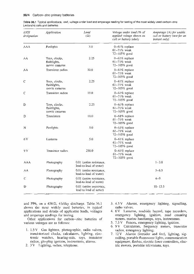
3614 Carbon-zinc primary batteries
Table 36.1 Typical applications, load, voltage under load and amperage reading for testing of the most widely used carbon-zinc Leclanche cells and batteries ~
ANSI Application designation
Load Voltage mder load (% of Amperage (A) for usable cell or battery (test for an instant only)
(a) applied voltage shown on cell or battery label)
AAA
AA
AA
C
C
D
D
N
6V
9v
AAA
AA
C
D
Penlights
Toys, clocks, flashlights, movie cameras Transistor radios
Toys, clocks, flashlights, movie cameras Transistor radios
Toys, clocks, flashlights, movie cameras Transistors
Penlights
Lanterns
Transistor radios
Photography
F'hotogaph y
Photography
Photography
3.0
2.25
10.0
2.25
10.0
2.25
10.0
3.0
5.0
250.0
0.01 (entire resistance, lead-to-lead of tester) 0.01 (entire resistance, lead-to-lead of tester) 0.01 (entire resistance, lead-to-lead of tester) 0.01 (entire resistance, lead-to-lead of tester)
0-61% replace 61-71% weak 72-105% good 0-61% replace
61-'71% weak 72-105% good 0-61% replace
61-71% weak 72-105% good 0-61% replace
61-71% weak 72-105% good
61-71% weak 0-61% replace
72-105% good 0-61% replace
61-71% weak 72-105% good 0-61% replace
61-71% weak 72-105% good
0-61% replace 61-71% weak 72-105% good
61-71% weak 0-61% replace
72-105% good 0-61% replace
61-71% weak 72-105% good
1-3.8
3-6.5
4-9
10-13.5
and PP6, on a 450 Q, 4 Wday discharge. Table 36.1 shows the most widely used batteries, in typical applications and details of applicable loads, voltages and amperage readings for testing.
Other applications for carbon-zinc batteries of various voltages are as follows:
1. 1.5V Gas lighters, photographic, radio valves, transistorized clocks, calculators, lighting, elec- tronic watches, hearing-aids, toys, transistor radios, glo-plug ignition, instruments, alarms.
2. 3 V Lighting, radios, telephone.
3. 4.5 V Alarms, emergency lighting, signalling, radio valves.
4. 6 V Lanterns, roadside hazard, tape recorders, emergency lighting, ignition, road counting meters, marine handlamps, toys, instruments.
5. 7.5 V Fences, emergency lighting, ignition. 6. 9V Calculators, frequency meters, transistor
radios, emergency lighting. 7. 12V Alarms (intruder and fire), lighting, sig-
nalling, portable fluorescent lights, communication equipment, flashes, electric fence controllers, elec- tric motors, portable televisions, toys.

8.
9. 10.
15-30 V Photographic, wide-range oscillators, radiopaghg, hearing-aids, portable applications, instrument operation, electronic cigarette lighters. 60-90 V Portable applications, lighting. 225-500 V Electronic flash, geiger counters, mass spectrometers.
36.1 Comparison of alkaline manganese and carbon-zinc cell drain rates In general, devices using lights or motors will have high drain rates. The bigger the job to do (i.e. the brighter the light, the greater the load the motor is driving), the greater the drain rate will be. Another general point is that when any device is used continuously it will exhaust the energy of the cells much more rapidly, since the cells are deprived of a chance to rest and recover some of their energy.
Alkaline manganese dioxide cells have a superior performance over carbon-zinc cells at various drain rates. The benefits to be derived from alkaline batteries depend, of course, on the type of equipment and how it is used. Generally, the higher the drain rate of the equipment and the heavier the use, the greater the margin of superiority of alkaline cells. They are the ideal power source for calculators, photo-flash units, toys, flashlights, cassette recorders and other heavy- drain equipment. No matter what kind of battery- operated equipment is used, if it runs on regular carbon-zinc cells, it will always run longer on alkaline manganese cells.
Another point worth mentioning is the ability of alkaline manganese cells to deliver a constant level of power with high efficiency under continuous or heavy duty, high-drain conditions where carbon-zinc cells are unsatisfactory. In such applications as flashlights and cassette recorders, reduced power could result in dim lights and reduced tape speeds, respectively.
36.2 Drain characteristics of major consumer applications 36.2.1 Flashlights and lanterns Because they )obviously involve lightbulbs, these are an application with a relatively high drain rate, with active drains running anywhere in the range of 250-5OOmA. Alkaline systems are proving especially suitable to lighting applications because of their long storage life and dependable performance.
When flashlights are used intermittently, as by a night watchman making his rounds and turning the light on occa,sionalIy to check a meter or a lock, the drain is the least severe and the alkaline cell would have only a small advantage. However, in situations of an emergency nature (power shortages, flat tyres, etc.) or when the light is used for longer periods (on
Drain characteristics of major consumer applications 36/5
night hikes or camping trips), the alkaline cell provides significantly greater performance. When an ordinary 2D cell flashlight is used continuously, the alkaline- powered light can last 18-20 h or more while ordinary carbon-zinc flashlight cells will only last 3-4 h.
Another area where alkaline cells have an even greater advantage is in the smaller penlight flashlights. The advantage for alkaline cells applies to smaller cells to an even greater degree. Also, since flashlights may be called on to do their job only once or twice a year, shelf life can be a very important factor to the user. Alkaline cells have distinct advantage in this respect and this is the reason why the smaller carbon-zinc flashlights have never become very popular.
36.2.2 Radios Radios generally involve the lowest current drain of all the major categories of application. The drain of the more typical or popular radios runs from 10 to 20 mA. The bigger transoceanic or A W M radios that are becoming more and more popular can run higher than this, at about 50mA. Also, if the volume of the radio is turned up very high, the drain will be higher. Again, the greater the power output, the greater the required drain rate. Of course, the life of cells in radios is dramatically affected by how the radio is played, but the generally lower drain rates will assure many more hours of use than are available for flashlights. Some radios can be played continuously for more than lOOh with alkaline batteries. However, in this application, the advantage for alkaline is a matter of degree, running from a low of about 2:l to a high of about 4: 1 over ordinary carbon-zinc radio cells.
36.2.3 Tape recorders Tape recorders are becoming an increasingly important usage, and currently account for between 10 and 15% of the total replacement cell market. The sound reproduction in a tape recorder is, of course, much the same as in a radio, but the added requirement of a motor to turn the spindle for the tape adds quite significantly to the drain. As a result, the drain rate in tape recorders runs between 100 and 200mA, which explains why they are a popular application for alkaline cells.
36.2.4 Toys There is, of course, a wide variety of battery-powered toys and the newer electronic games. Generally speaking, the function of a cell in a toy or game is to provide the power for either a light or a motor that causes the toy to move in one way or another. For this reason, toys or games in general have a very high drain rate, running anywhere from 50 to 1000 m.4 (1 A). Many devices of this type would be at the high end of this scale, where the superiority of alkaline cells

36/6 Carbon-zinc primary batteries
is most dramatic. At these drain rates they out-perform ordinary carbon-zinc cells by as much as 1O:l.
36.2.5 Calculators Some pocket calculators on the market today still employ LED (light emitting diode) display. This is the same basic circuitry or chip used in the new LED watches. A considerable amount of energy is required to power these displays when they are in use, and a relatively high drain rate results. The drain rate of the LED calculator runs from 30 to 80 mA.
Some of the newer calculators employ the LCD (liquid crystal display), which does not light up; therefore, the drain rates are dramatically lower than with LEDs. Drain rates on LCD-type calculators can run as low as 0.05 mA (50 p A). The drain rates in these new LCD-type calculators are so low that any type of cell would last for a considerable period of time. In fact, it is likely that shelf life may be a factor of equal importance to service life in these applications. Since smallness in size is the key with portable calculators, the smaller cells are generally involved. This will lead to the use of alkaline-type button cells or other new shapes. In addition, the new low-drain lithium cells are becoming a serious contender here because of their extremely long shelf life.
However, since the majority of calculators on the market or in use today employ LED display, they present ideal applications for alkaline cells. Consumers are discovering this advantage very quickly as over 40% of the cells used in calculators are alkaline. The advantage of alkaline cells over carbon-zinc cells in these types of calculators runs as high as 6:l.
36.2.6 Cameras In cameras, cells perform a wide variety of functions, including discharging flash units, motor powering, shutter control and film ejection. Obviously, the drain rate for these different functions varies significantly. The higher drain rates again apply to those applications involving motors or lights (flash). The drain rate in
movie camera applications runs from 250 to 500mA. Cameras with cell-operated flash require up to 750 mA. Electronic shutters require up to 90mA.
While most applications in cameras have sufficient drain rates to justify alkaline (or mercury or silver) cells, there are other reasons why most camera mandacturers design their photographic equipment almost exclusively around this system. Their superiority in resisting extreme temperature variations is perhaps the most important of these, since cameras are obviously used extensively out-doors in all kinds of weather. The shelf life advantage is also important, as cameras are often left for long intervals between use.
In flash applications, the sharp demands in drain rate over very short time periods can only be handled by premium cells, as carbon-zinc cells simply could not respond to them.
36.2.7 Hearing-aids and watches Unlike most conventional battery applications, hearing- aids and watches require miniature specialized mercury or silver oxide cells to provide the continuous power supply necessary. While the button cells used in hearing-aids and watches are similar in appearance, they differ in internal construction as they are designed to satisfy various power requirements at different drain rates and they are therefore not interchangeable.
LCD and quartz analogue watches (watches with a conventional face) have drain rates as low as 0.0025 mA (2.5 PA). Generally speaking, drain rates for hearing-aids are moderate, ranging from 0.15 mA to a high of 5 mA. In hearing-aids, as well as in LCD and quartz analogue watches, the drains are continuous. However, LED watches require drains up to 40mA during the pulse. Thus, the requirements needed to power the displays in these watches are about eight times greater than in hearing-aids and 16000 times greater than in LCD and quartz analogue watches. For this reason, a wide variety of mercury and silver oxide cells meets the growing demands of the various types of hearing-aids and watches.

Mercury batteries

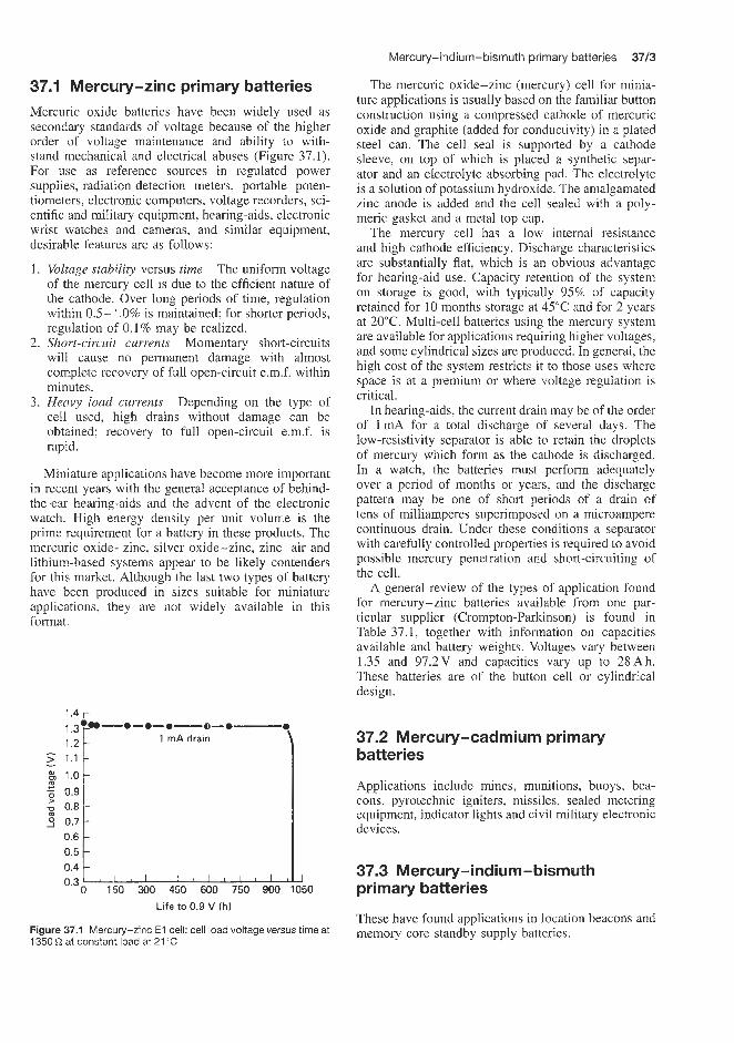
Mercury-indium-bismuth primary batteries 3713
The mercuric oxide-zinc (mercury) cell for minia- ture applications is usually based on the familiar button construction using a compressed cathode of mercuric oxide and graphite (added for conductivity) in a plated steel can. The cell seal is supported by a cathode sleeve. on top of which is placed a synthetic separ- ator and an electrolyte absorbing pad. The electrolyte is a solution of potassium hydroxide. The amalgamated zinc anode is added and the cell sealed with a poly- meric gasket and a metal top cap.
The mercury cell has a low internal resistance and high cathode efficiency. Discharge characteristics are substantially flat, which is an obvious advantage for hearing-aid use. Capacity retention of the system on storage is good, with typically 95% of capacity retained for 10 months storage at 45°C and for 2 years at 20°C. Multi-cell batteries using the mercury system are available for applications requiring higher voltages, and some cylindrical sizes are produced. In general, the high cost of the system restricts it to those uses where space is at a premium or where voltage regulation is critical.
In hearing-aids, the current drain may be of the order of I d for a total discharge of several days. The low-resistivity separator is able to retain the droplets of mercury which form as the cathode is discharged. In a watch, the batteries must perform adequately over a period of months or yeas , and the discharge pattern may be one of short periods of a drain of tens of milliamperes superimposed on a microampere continuous drain. Under these conditions a separator with carefully controlled properties is required to avoid possible mercury penetration and short-circuiting of the cell.
A general review of the types of application found for mercury-zinc batteries available from one par- ticular supplier (Crompton-Parkinson) is found in Table 37.1, together with information on capacities available and battery weights. Voltages vary between 1.35 and 97.2V and capacities vary up to 28Ah. These batteries are of the button cell or cylindrical design.
37.1 Mercury-zinc primary batteries Mercuric oxide. batteries have been widely used as secondary standards of voltage because of the higher order of voltage maintenance and ability to with- stand mechanical and electrical abuses (Figure 37.1). For use as reference sources in regulated power supplies, radiation detection meters, portable poten- tiometers, electronic computers, voltage recorders, sci- entific and miiitary equipment, hearing-aids, electronic wrist watches and cameras, and similar equipment, desirable features are as follows:
Voltage stabiZi9 versus time The uniform voltage of the mercury cell is due to the efficient nature of the cathode. Over long periods of time, regulation within 0.5-1.0% is maintained; for shorter periods, regulation of 0.1% may be realized. Short-circuil currents Momentary short-circuits will cause no permanent damage with almost complete recovery of full open-circuit e.m.f. within minutes. Heavy load currents Depending on the type of cell used, high drains without damage can be obtained; recovery to full open-circuit e.m.f. is rapid.
Miniature applications have become more important in recent years with the general acceptance of behind- the-ear hearing-aids and the advent of the electronic watch. High energy density per unit volume is the prime requirement for a battery in these products. The mercuric oxide-zinc, silver oxide-zinc, zinc-air and lithium-based systems appear to be likely contenders for this market. Although the last two types of battery have been produced in sizes suitable for miniature applications, they are not widely available in this format
1.4 r ----.-e--.--.--.-
l mA drain
L A 0 1'50 300 450 600 750 900 1050 0.3
Life to 0.9 V (h)
Figure 37.1 Merclury-zinc E l cell: cell load voltage versus time at 1350Q at constant load at 21°C
37.2 Mercury-cadmium primary batteries
Applications include mines, munitions, buoys, bea- cons, pyrotechnic igniters, missiles, sealed metering equipment, indicator lights and civil military electronic devices.
37.3 Mercury-indium-bismuth primary batteries
These have found applications in location beacons and memory core standby supply batteries.

3714 Mercury batteries
Table 37.1 Applications of mercury-zinc primary batteries available from Crompton-Parkinson
Application Voltage Capacity range available (A h)
Approx. weight (g)
Photography
Light meters Flash units Hearing-aids
Watches Instruments
Detonators Electric eyes
Radio receivers
Radio transmitters Transistor applications
Voltage reference instruments Radiation equipment
Geophysical applications
Paging devices Fire alarms
TV tuners Test equipment Depth finders Garage door openers Chart recorders Tape recorders Transceivers
Laser beam detectors Personal location beacons Solid-state relays Radiomicrophones Radiosondes
1.35-4.0 2.7-2.8 5.4-5.6 1.35-4.0 5.4-5.6 1.35-4.0 2.7-2.8 1.35-4.0 1.35-4.0 2.7-2.8
5.4-5.6 4.05-4.2
6.75-7.0 8.1-8.4 9.45-9.8 12.6 27 29.7 1.35-4.0 1.35-4.0 4.05-4.12 1.35-4.0 4.05-4.2 5.4-5.6 6.75-7.0 8.1-8.4 9.45-9.8 97.2
4.05-4.2 2.7-2.8
6.75-7.0 1.35-4.0 1.35-4.0 6.75-1.0 9.45-9.8 10.8-11.2 16.2-16.8 2.7-2.8 47.25 4.05-4.2 5.4-5.6 6.15-7.0 6.75-7.0 6.75-7.0 8.1-8.4 9.45-9.8 9.45-9.8
12.6 13.4 15.4
13.4 13.4 13.4 13.4 13.4
10.8-11.2
16.2-16.8
80- 1000 250-350 100-500 250 110 16-2400 1000 50-230 45-14 000 350
500-2200 250-2200 1000-2200 1000-3400 500 3400 250 500 220-1000 160-250 500-2500 1000-2200 500 180 575-750 215 1000 1000 500 350 14 000 28 000 250 250 250 - 3400 250 2200 1000 500 2200-3400 2400 500
3600 160 2400 3600 750 1000 2200 2200
350-1000
2200-3400
4 8 30 4 7 0.3-30 27 0.8-25 0.8-174 11 17-89 34-119 20-149 81-179 94-329 76 950 142
2.5-12 7-14
-
5-30 40-90 34 12 51-71 24 910 21 25 20 40 380 21 28 37-340 51 57 480 25 128 170 42 170 265 28 255 400 100 - -
370
Lithium primary batteries


Lithium-thionyl chloride 38/3
Current research is attempting to develop a portable equipment battery that operates not at its normal oper- ating temperature of 120°C but at room tempera- ture. (polyethylene oxide)gLiCF3 SO3 electrolytes hold such promise. The y-alumina-lithium fluoride prim- ary solid state battery has some applications in the cardiac pacemaker field.
The lithium-titanium disulphide solid state re- chargeable battery was at one time considered by P.R. Mallory (now Duracell) as a candidate for large- scale energy storage applications but, due to lack of durability, interest in this application has now declined.
A secondary 2.5 V lithium-titanium disulphide battery developed in the mid-eighties by Eveready, employing a LiI-LisP400,25Si13,75 vitreous inorganic electrolyte has reached the semi-commercial stage.
Applications of some of the batteries are des'cribed below.
ithiunn-sulphur
main types of lithium
dioxide
Because of their favourable characteristics these cells and batteries have found many applications in the military field and in the operation of electronic com- ponents, especirdly where high energy density, long shelf life and low weight are requirements. Portable radio transmitters, night vision devices, pyrotechnic ignition batteries, buoys, emergency power supply for laser devices, cameras, hand lamps, medical electron- ics, operation of micro-processors and signal lamps are some of the applications that have been found.
Applications for the lithium-sulphur dioxide reserve systems include underwater mine batteries and (active batteries) memory protection, manpack communications, life-support equipment, sonobuoys, space probes, missiles, mines, security systems, data buoysistations, weather sondes and electronic counter measures. The non-reserve (active) systems are used for covert sensors, memory protection and weather sondes.
Other applications include utility meters, random access memory applications, weather balloons, oceano- graphic equipmlent, process controllers, switch gear, test equipment, on-board aircraft computers, emer- gency locator equipment, rocket propulsion equipment for satellites, military equipment and anti-satellite mis- siles. Lithium-sulphur dioxide is the principal high energy primary battery system used in the world to power military electronics equipment, e.g. the BA 5990 type cell is used by the US military to power some 40 different types of electronic equipment.
So far attempts to produce a rechargeable lithium- sulphur dioxide battery have been unsuccessful.
Applications to consumer goods have been limited to safety considixations.
38.2 Lithium-vanadium pentoxide There are two main applications for this type of cell. Reserve batteries are for applications requiring extremely long shelf and operational life (10-30 years) and relatively low discharge rates. The non-reserve types are used for applications such as covert sensors, i.mplantable medical devices, watches, currency trackers, memory protectors and frangible weather sondes.
Other medical applications include insulin pumps, pacemakers and automatic defibrillators.
The major ontlet for lithium-vanadium pentoxide reserve batteries, is in munitions systems.
The Harwell development lithium-vanadium pen- toxide solid state battery is being investigated as a possible power source for satellite power and vehicle propulsion.
38.3 Lithium-thionyl chloride
Applications for lithium-thionyl chloride cells and active batteries include all those for which active lithium-sulphur dioxide cells and batteries are recommended, and also high-temperature applications.
Eagle Picher recommend their active lithium- thionyl chloride cells for micropower sources in advanced application areas, e.g. airborne instrumen- tation, undersea communications, mineral exploration, remote site monitoring safety controls, security, and space and/or defence systems.
Eagle Picher reserve batteries have found many applications in military and aerospace applications such as missiles and re-entry vehicles. They have also been used in mines.
Other applications of lithium-thionyl chloride cells include utility metering gauges, security alann sys- tems, automobile electronic systems and well logging, electronic applications, e.g. power back-up for volatile random access memories. The US Army has placed large orders for the BA 6598 lithium-thionyl chloride battery produced by Eveready. There are no significant industrial or consumer applications to date for high rate wound lithium-thionyl chloride cells.
Eagle Picher have supplied Keeper I and Keeper I1 small (350-11600mAh) prismatic cells for use on printed circuit boards with dual in-line pin connectors. These are used in memory and clock applications.
Very large prismatic cells have been supplied by CITE Power Systems Operations and by Atlas Cor- poration for standby power to activate US Interconti- nental Ballistic Missiles, e.g. Minuteman and Peace- keeper. The largest of these is 10000Ah and weighs 68 kg.
These batteries have energy densities of 480 W h/kg-' (905 W h/dm-3). Nine cells are combined to produce a 33 V battery.
Lithium-thionyl chloride reserve cells have recently been introduced. They have the advantage of a 10-20 year shelf life. Military applications include missiles,

38/4 Lithium primary batteries
Table 38.1
Sanyo Duracell
Button Cylindrical Button Multicell batteries
V nominal 3 3 3 6 6
Capacity nominal 35-500 160-5000 70-1300 160- 1300
Diameter (mm) 12.5-24.5 11.6-23 11.6-20 13-35 Height (mm) 1.6-5 10.8-60 1.6-34.5 25-36
Weight (g) 0.8-6.2 3.3-40 1.8-17 9.4-40
(m.4 h)
sonabuoys, fuzes, torpedoes, emergency power for crew rescue and space applications. (Suppliers: Eagle Picher, Honeywell (US), Yardney (US), Philips USFA BV, Power Conversion Ltd (UK), Silberkraft Gmbh (Germany) and Sonnenschein GmbH (Germany.)
38.4 Lithium -manganese dioxide
With the microprocessor involvement in all kinds of applications, the lithium-manganese dioxide battery has become extensively used. Possible applications include LCD watches, pocket calculators, CMOS memory protection, measuring instruments, electronic alarms and pace setters. The cells may either provide back-up for memory retention in fixed installations or act as a side or part power source in portable equipment.
SAFT supply a range of 3 V button cells recom- mended for use in LCD watches, pocket calculators, CMOS memory protection measuring instruments and electronic alarms. These cells have an energy den- sity of 400-500Wh/dm3 (120-150Whkg) and an annual self-discharge rate of 2-3%. The capacities vary from 200 mA h (type LM 2425) through 90 mA h (type LM 2020) to 50mAh (LM 2016). The tempera- ture operating range is -20 to + S O T .
Varta also supply a range of 3 V lithium-manganese dioxide button cells ranging in capacity from 3 to 1400 mA h.
Lithium-manganese dioxide cells are a strong con- tender for CMOS data retention applications. The main drawback of lithium-manganese dioxide cells is that they are susceptible to damage from even small reverse currents and therefore require a more careful selection of isolation diodes. One maker cautions that the isola- tion diodes must have less than 10 nA leakage. Because of the tight specification on the isolation-diode leak- age and the limited temperature specifications for the material, lithium-manganese dioxide is not an ideal choice for high-temperature applications.
This battery was invented by Sanyo and is now manufactured under licence by over ten companies throughout the world. The major fields of application
are: memory back-up, calculators, cameras, watches, microprocessors, pace setters, electronic alarms, measuring instruments. (Memory back-up, watch and camera applications together account for 75% of world production.)
The following types of battery available from man- ufacturers are shown in Table 38.1.
Applications for these cells are now well estab- lished. Advantages that they enjoy over conventional primary cells are: high voltage and energy density, excellent discharge characteristics, good leak resist- ance, good storage characteristics, wide operating tem- perature range, stability and safety.
More recent applications of lithium-manganese cells include camera autowinding in fully automatic cameras, shavers, interphones, fishing floats, hearing aids, lamps, alarms and high alarm batteries strobes and camera equipment. Envisaged future applications include high performance lights, handy telephones, transceivers and highly portable electronic equipment.
38.5 Lithium-copper oxide The lithium-copper oxide battery has two special characteristics. Its initial voltage is approximately 2 V, but when fully loaded it drops to a flat 1.5 V. Thus it can be used as a direct replacement for carbon and alkaline cells. (Most other lithium batteries have volt- ages from 2.8 to 3.5 V.) Lithium-copper oxide also has a wide temperature range, spanning -55 to +125"C. Although it is not the highest performance lithium combination, its voltage and temperature characteris- tics permit applications in specific niches.
The lithium-copper oxide battery has applications in power well lagging equipment, microprocessors, public address systems, high-temperature heat coun- ters, CMOS memory protection, telex systems, high- temperature devices, and specialized industrial and military applications.
Cells are supplied by SAFT (France) in bobbin cylindrical cell format and by Sanyo (Japan) in button construction. AA and 1AA cylindrical and bobbin constructions are also available. The AA cell has a capacity of 3.7 Ah.
Lithium-iodine 3815
Matsuchita (Panasonic) discovered this type of cell. Other manufacturers (Eagle Picher, Royovac, Eveready, Duracell, etc.) have agreements with Matsuchita to manufacture these cells.
Its applications are: electric watches, calculators, cameras, back-up power in electronic devices. lighted night time fishing boats, low current continuous drain applications, airborne instrumentation, safety controls, space applications, defence, CMOS -RAM applica- tions.
Three-volt cylindrical cells are available in the nom- inal capacity range 600-50OmA h, 3-volt coin cells in the range 25-500mAh and 3-volt pin cells in the range 5.4 mA h.
38.6 bithium-silver chromate These batteries are used in cardiac stimulators, other human implantable devices, high-reliability memory protection, inertial navigation systems and RAM back- up power sources.
38.7 Lithium-lead bisrnuthate These are used in analogue quartz watches and pulsing electronic devices .
38.8 Bithiurn - polycarbcan monofluoride These batteries are suitable for use in applications that require high-rate pulses of power, in low-current continuous drain applications and as a stable long- term reference voltage. They provide a high energy density when compared with other battery chemistries. These batteries ,are designed for applications requiring micropower sources in advanced application areas such as airborne instrumentation, undersea communications, mineral exploration, remote site monitoring and safety controls.
While lithium-iodine batteries suit low-current applications, the lithium-carbon monofluoride is becoming economically attractive for both low- and high-current requirements. The cost factor was improved when Panasonic convinced Eastman Kodak that thk chemistry should be used in the mass- produced Kodak disc camera. In this camera, cylindrical cells., slightly smaller than AA size, produce the high 1.5A pulses needed to recharge the flash and run the motor during automatic picture taking. This type of ceil is not only being used in consumer products. Indeed, configured as small button- or coin- sized cells, lithium-carbon monofluoride batteries are being used by at least one computer manufacturer for CMOS-RAM data retention. The button cells are small enough to fit right on top of RAM dual-in-line packages and th'ese button cells cost only 69-90 cents.
This lithium-based composition also has its disad- vantages. Batteries are packaged with crimped rather than welded seals and are therefore subject to leakage. As a result, UL requirements dictate that a 1 kC2 series resistor be used to limit current if load short-circuiting does occur, or if an isolation diode fails to block forced charging from the main power source. However, according to Panasonic, the lithium-carbon monoflu- oride chemical combination forms a safe mixture; even if it does leak out past the seals, it is non-toxic. The wide distributions and use of the Kodak disc camera, using two UL-listed 1200mA h cylindrical cells (Pana- sonic model BR.21 3A) connected in series, is cited as proof thiat this chemistry will not pose regulatory prob- lems for designers. Panasonic warn prospective users, however, that there can be regulatory restrictions for air shipment on passenger-carrying aircraft if the prod- uct has more than two cells connected in series.
38.9 Lithium solid electrolyte These have a 15-20-year life, which is compatible with the design life of microprocessors, making it possible to incorporate these batteries as a permanent component of the equipment. The closely matched temperature characteristics of solid electrolyte batteries and CMOS logic circuits is a property that makes this type of battery ideally suited for memory protection applications. Basically, these batteries are suitabie for any low-power long service life application.
The Harwell development lithium-vanadium pen- toxide solid state battery is being investigated as a possible power source for satellite power and vehicle propulsion.
Current research is attempting to develop a portable equipment battery that operates not at its noma1 operating temperature of 120°C but at room tem- perature. (polyethylene oxide)g LICF3S03 electrolytes hold such promise. The y-alumina-lithium fluoride primary solid state battery has some applications in the cardiac pacemaker field.
The lithium-titanium disulphide solid state re- chargeable-battery was at one time considered by P.R. Mallory (now Duracell) as a candidate for large- scale energy storage applications but, due to lack of durability, interest in this application has now declined.
A secondary 2.5 V lithium-titanium disulphide battery developed in the mid-eighties by Eveready, employing a LiI-Li8PqOo.25Si13.75 vitreous inorganic electrolyte, has reached the semi-commercial stage.
38.10 Lithium-iodine Many lithium cells are now available to the watch and calculator industry, but the designer should take care in selecting the right lithium cell for the application. Factors such as reliability, energy density, internal resistance and hermeticity should be considered. Since almost all lithium cells work best with a large area package, Catalyst Research Corporation propose standard button cell sizes of three diameters, 19,23 and 27 mm, and a-range of thicknesses from 1 to 3 mm in

3816 Lithium primary batteries
0.5 mm steps. Many advantages will become apparent to the design engineer.
The lithium-iodine cell is an example of a highly reliable lithium power source, proven in the pacemaker industry. It is used in security, space and defence sys- tems and, more recently, CMOS-RAM data retention applications. It is available in several sizes, suitable for watches (LCD and analogue stepping motor) and for low-current LCD calculators. Life spans as long as 10 years are possible in watches. In calculators, 5000 h operating times can be obtained over a 10-year period; for example, a 0.27 A h battery on a 50 mA drain would deliver 5000 h of service over a 10-year period.
More recently, Catalyst Research Corporation have issued a preliminary specification sheet for a 7.5Ah oil well logging battery (model 407220, Military spec- ification D-cell). This is housed in a 38 mm x 57 mm circular container and is hermetically welded with a glass-metal compression seal. It has a voltage of 2.8 V (open circuit 2.8 V), a maximum operating tempera- ture of 150°C and a self-discharge rate of about 5% in 10 years at 25°C. The prototype D-34 cell maintains its voltage of 2.8 V during 6 weeks continuous operation at lOmA constant current at 130°C.
Also available is the model CRC Li D 2.8 D-type cell (2.8V) with a capacity of 14Ah at 25°C and an operating temperature of -20 to +50"C. The bat- tery weighs 80g and has a height of 33.8mm and a width of 57.1 mm. This cell suffers a capacity loss of less than 5% in 10 years at 25°C and can with- stand substantial shock, vibration and short-circuiting at temperatures up to 150°C without venting, leaking, swelling or exploding. The cell continues operating at 2.8 V (25°C) for 18 months (1 mA) and 2.7-2.8 V for about 8 months (2mA).
Lithium-iodine batteries in the 35- 1000 mA h capacity range are available for printed circuit board applications.
Of all the lithium compositions, lithium-iodine is considered by its inventor, Catalyst Research Cor- poration, to be a completely solid-state cell (although the electrolyte is purported to have a 'tar-like', rather than rock-hard, consistency).
The lithium-iodine combination has been used for most implanted cardiac pacemakers since 1972. It thus has a believable reliability history, at least at human body temperature. Because of its critical main use, the lithium-iodine cell comes in a hermetically sealed (laser-welded) nickel or steel container, which makes it more expensive than other types ($5-8 for the 200-350 mA h coin-shaped cells). Yet the high quality of the chemical processing and encapsulation makes it a good choice where very long shelf life (10 years and beyond) is the objective.
Besides its higher cost, the main disadvantage of the lithium-iodine system is that the current output is small; a maximum of only 50pA is recommended at room temperature. Even with this current level, however, one of these cells has enough capacity to
back-up 65 kbytes of CMOS-RAM. In addition, these cells withstand a considerable amount of overloading, and even dead shorts, without suffering damage.
According to Catalyst Research Corporation, in the case of a continuous dead short, the battery cells are protected by the formation of a film, which raises the internal impedance, thereby limiting current. This self- limiting effect makes lithium-iodine safer than those lower impedance chemistries that heat up and, in the larger sizes, even explode when shorted.
Another important characteristic of a lithium-iodine cell is its sloping discharge curve over time; the volt- age drops approximately 0.1 V every few years over a 10-year period for a current drain of a few micro- amperes. Many designers, however, might not consider this characteristic a disadvantage; it provides an easy means of monitoring the remaining life.
38.1 1 Comparison of lithium-iodine and nickel-cadmium cells in CMOS-RAM applications Applications of CMOS-RAM (complementary metal oxide random access memory) are growing at a rapid pace. Manufacturers are using these memories with increasing frequency in industrial process controls and communications, energy management and security sys- tems, consumer electronics, data loggers and computer peripherals such as teleprinters and word processing equipment, among others. Advantages of CMOS-RAM memories include relatively high data volumes, rela- tively fast reading and writing, easy reprogramming, low power requirements for memory operation and retention, comparatively low cost, and immunity to high noise.
Unfortunately, CMOS-RAM memories suffer one major drawback-they are susceptible to memory losses during power fluctuations or outages. This memory volatility dictates the need for some type of back-up power source.
This could be accomplished by backing up the entire system with a large uninterruptible power supply which, in many cases, would be impractical because of the small size of many systems. A much more logical alternative is to selectively protect the individual mem- ory chip or array of memory chips with an on-board battery power supply.
Selective battery back-up of a CMOS-RAM pro- vides numerous benefits, including space savings, easy inspection and servicing, long-life expectancy and reli- ability. Most importantly, a battery-backed CMOS- RAM serves as a cost-effective non-volatile memory system.
The ideal battery for CMOS-RAM back-up would be printed circuit board mountable and wave solder- able, provide data retention of the life of the memory, retain data over a wide temperature range, not require recharging, not require replacement during memory
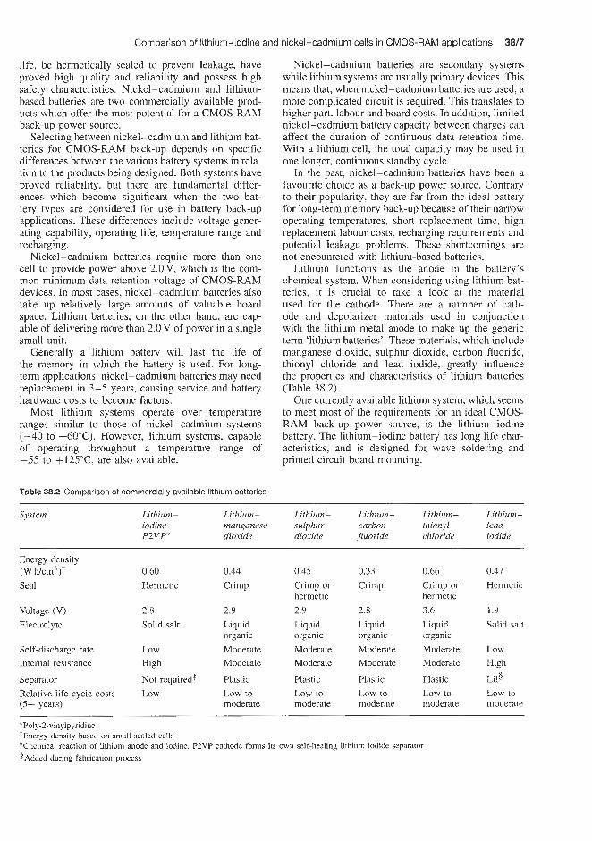
life, be hermetically sealed to prevent leakage, have proved high quality and reliability and possess high safety characteristics. Nickel-cadmium and lithium- based batteries are two commercially available prod- ucts which offer the most potential for a CMOS-RAM back-up power source.
Selecting between nickel-cadmium and lithium bat- teries for CMOS-RAM back-up depends on specific differences between the various battery systems in rela- tion to the products being designed. Both systems have proved reliability, but there are fundamental differ- ences which become significant when the two bat- tery types are considered for use in battery back-up applications. These differences include voltage gener- ating capability, operating life, temperature range and recharging.
Nickel-cadmium batteries require more than one cell to provide power above 2.0V, which is the com- mon minimum data retention voltage of CMOS-RAM devices. In most cases, nickel-cadmium batteries also take up relatively large amounts of valuable board space. Lithium batteries, on the other hand, are cap- able of delivering more than 2.0 V of power in a single small unit.
Generally a iithium battery will last the life of the memory in which the battery is used. For long- term applications, nickel-cadmium batteries may need replacement in 3-5 years, causing service and battery hardware costs to become factors.
Most lithium systems operate over temperature ranges similar to those of nickel-cadmium systems (-40 to f60"C). However, lithium systems, capable of operating tlxoughout a temperature range of -55 to +125"C, are also available.
Table 38.2 Compal4son of commercially available lithium batteries
Nickel-cadmium batteries are secondary systems while lithium systems are usually primary devices. This means that, when nickel-cadmium batteries are used, a more complicated circuit is required. This translates to higher part, labour and board costs. In addition, limited nickel-cadmium battery capacity between charges can affect the duration of continuous data retention time. With a lithium cell, the total capacity may be used in one longer, continuous standby cycle.
In the past, nickel-cadmium batteries have been a favourite choice as a back-up power source. Contrary to their popularity, they are far from the ideal battery for long-term memory back-up because of their narrow operating temperatures, short replacement time. high replacement labour costs, recharging requirements and potential leakage problems. These shortcomings are not encountered with lithium-based batteries.
Lithium functions as the anode in the battery's chemical system. When considering using lithium bat- teries, it is crucial to take a look at the material used for the cathode. There are a number of cath- ode and depolarizer materials used in conjunction with the lithium metal anode to make up the generic term 'lithium batteries'. These materials, which include manganese dioxide, sulphur dioxide, carbon fluoride, thionyl chloride and lead iodide, greatly influence the properties and characteristics of lithium batteries (Table 38.2).
One currently available lithium system, which seems to meet most of the requirements for an ideal CMOS- RAM back-up power source, is the lithium-iodine battery. The lithium-iodine battery has long life char- acteristics, and is designed for wave soldering and printed circuit board mounting.
Comparison of lithium-iodine and nickel-cadmium cells in CMOS-RAM applications 3%/7
-
System Lithium- Lithium- iodine manganese P 2 V P dioxide
Lithium- Lithium- Lithium- Lithium- sulphur carbon thionyl lead dioxide Jluoride chloride iodide
Energy density (W h/cm3 )+ 0.60 0.44 0.45 0.33 0.66 0.47
Seal Hermetic Crimp Crimp or Crimp Crimp or Hermetic hermetic hermetic
Voltage (V) 2.8 2.9 2.9 2.8 3.6 1.9
Electrolyte Solid salt Liquid Liquid Liquid Liquid Solid salt organic organic organic organic
Self-discharge rate Low Internal resistance High
Moderate Moderate Moderate Moderate Low Moderate Moderate Moderate Moderate High
Separator Not required* Plastic Plastic Plastic Plastic Lii§
Relative life cycle costs Low (5+ years)
Low to Low to Low to Low to Low to moderate moderate moderate moderate moderate
* Poly-Zvinylpyridine 'Energy density based on small sealed celk :Chemical reaction of lithium anode and iodine. PZVP cathode forms its own self-healing lithium iodide separator $Added during fabrication process

38/8 Lithium primary batteries
Table 38.3 CMOS memory back-up parameters for Nicad and lithium comparison
Item
Voltage (V) Low current capability Shelf life Self-discharge Operating life (years) Energy density (W h/cm3) Temperature range ("C) Sealing Recharge circuit
ldeal Nicad
2.0 1.2 Required Yes 10 years 1 montht Low High
Higher the better 0.09 Mil Spec -40 to +60§ Hermetic Hermetickrimp
Life of memory 3-5*
- Required
Lithiurn+
2.8 Yes 95% of capacity retained after 10 years Low 10 0.33 or better -55 to $125 Hermetickrimp Not required
*This i s a summary of all commercially available lithium systems 'Between charges 'Exceptions claimed $Available from limited manufacturers, most are -40 to +60"C
When current is not being drawn from a lithium-iodine battery, as is often the case in memory back-up applications, self-discharge takes place. Self- discharge is a natural process which consumes active battery materials and, hence, battery capacity. Capacity losses at 25°C vary from less than 5% over I O years for lithium-iodine batteries to more than 25% per month for some secondary batteries.
A high equipment storage temperature will increase self-discharge and must be considered when selecting a battery for back-up applications. Lithium-iodine batteries stored at an average temperature of 50°C or less will hold a charge for more than 10 years. On the other hand, a nickel-cadmium battery has a shelf life of about 1 month before recharging is required and is limited to 300-500 chargehecharge cycles (Table 38.3).
An advantage of the lithium-iodine battery is its temperature performance. Not only does the battery operate over a wide temperature range (-55 to +125"C), but it has a high impedance at low temperatures and low impedance at high temperatures. Therefore, as the power requirements of the memory chip decrease with a decrease in temperature, the lithium-iodine battery reacts similarly by providing less current to the chip and vice versa.
Hazardous incidents have been experienced with some lithium systems, particularly those using sulphur dioxide and thionyl chloride cathodes. These incidents generally occur at later stages in battery life, under reverse current conditions, during voltage reversal and while operating at high temperatures. Safety incidents have not been experienced with lithium-iodine cells, which is why they power 90% of the cardiac pace- makers presently in use.
In theory, devising a workable memory-battery connecting circuit sounds simple, but in actual practice it is a major obstacle to adapting the battery back-up concept. The battery, the memory, and other circuit component specifications must be considered when
adapting a back-up system. More specifically, addi- tional consideration should be given to current drains and voltages of components, selection of RAM devices for minimal current and voltage drain properties, selec- tion of diodes for optimal voltage drop and verification of data integrity after power-up. All of these factors must be considered in combination with battery spec- ifications.
The connecting circuitry should constantly monitor system voltage to avoid causing errors in the software because of inadequate power. As long as the voltage remains above a specified level, usually around 2.9 V, the system's power retains the memory. It is when the voltage drops below this specified point that a smooth transition to data retention power is needed.
Recent research efforts have resulted in the develop- ment of an interface circuit that will dependably mon- itor voltage availability and switch between external power and battery back-up as needed. The circuit and the lithium battery have been incorporated into module form. One module design even contains a 16 K RAM. Modules are designed to be mounted on a printed cir- cuit board, thus providing system designers with a black-box method of meeting the need for non-volatile memory.
38.12 Lithium-iron disulphide primary cells To date only one cell the AA size 3.7 A h and possibly the AAA size cell seem to be available on the market. Output and demand for these cells is still poor despite earlier promise due in part to the high manufacturing costs and small production rates.
Eveready have announced their intention to produce AA type (IECR6) high rate cells for photographic use. Lithium-iron disulphide cells have also been used in paging applications.

Lithium (aluminium)-iron sulphide secondary cells 3819
38.14 Lithium (aluminium)-iron sulphide secondary cells This battery is seen as a possible contender in the elec- tric vehicle market. Eagle Picher, Gould and Argonne National Laboratory are involved in these develop- ments. Of various samples studies the lithium (alu- minium)-iron monosulphide (LiAL-FeS) secondary system is the closest to commercial realization.
Earlier in its development this battery was consid- ered as a candidate for utility off-peak load level- ling. However, nowadays it is mostly being considered for traction applications for electric vehicles, includ- ing vans, forklift trucks, aircraft towing vehicles and underground mining vehicles.
Westinghouse are developing a lithium (alu- minium)-iron sulphide 36 V electric vehicle battery which has a specific energy of 112WNkg-' on the basis of cell mass and 98Whkg-' on the basis of battery module weight including a heat dissipating sys- tem. This gives the battery a 100-mile range under standard electric vehicle test profiles. The battery has a cyclic life of 120 cycles.
38.13 Lithium-molybdenum disulphide secondary cells Rechargeable lithium-molybdenum disulphide cells in AA sizes (600--800mAh) are available from Moli Energy Ltd; mudti cell (4 and 8 cell) batteries are also available. lintended applications of these cells, which are at present being produced in relatively small numbers (0.6 million per annum compared with about 300 million per annum for sealed nickel cadmium), are those for which small sealed nickel batteries are cur- rently used. Rechargeable lithium-molybdenum disul- phide cells are claimed to have several advantages over sealed nickel cadmium cells including a 40 to 50% higher voltage per cell, higher energy den- sity (30-100%)1, higher charge retention (5% per annum compared to 120 to 300% per annum for sealed nickel-cadmium) and absence of voltage delay effects.
Applications include those where the cells are used infrequently or irregularly and include applications in portable cellular telephones, lap top computers and portable data terminals.


Manganese dioxide- magnesium perchlorate primary batteries


Non-reserve batteries 39/3
are activated, to use reserve batteries fairly soon, as they undergo self-discharge.
Reserve batteries are recommended for use in portable transceivers, locator beacons, electronic counter measures and expendable electronic equip- ment.
Magnesium dry batteries are now finding wide- spread use in military communications equipment. With Increasing use and production, the cost of these batteries has dropped significantiy. For example, for the BA4386/U battery consisting of 16 long C-size cells, the cost dropped from $12.50 per battery to below $5.00 over 3 years. The equivalent zinc battery costs approximately $3.00.
Attempts to fabricate magnesium dry cell batteries using flat cell constructions have to date been unsuc- cessful. This is due to an expansion problem caused by the build-up of reaction products.
There are two main types of primary battery: the non-reserve type3 which is ready for use off the shelf and requires no activation or pre-use conditioning, and the reserve type, which usually contains the active electrode materials but requires the addition of water or an electrolyte just before use.
esewe batteries Manganese dioxide-magnesium perchlorate reserve- type batteries are available from Eagle Picher.
The advantage of reserve manganese diox- ide-magnesium perchlorate batteries is that they can be stored for years in an inactivated condition (that is, longer than the non-reserve type) and require activation with the electrolyte before use. However, unlike the non-reserve type, it is necessary, once they
39.2 Non-reserve batteries
Recently, Marathon have announced a battery for mil- itary use. It is being used in equipment exposed to tropical conditions. The most important magnesium battery now in production by Marathon is the BA4386, which serves as the power source for the PRC 25 and PRC 77 transceiver sets, formerly powered exclusively by the BA386 carbon-zinc battery. The BA4386 bat- tery consists of 18 CD-size cells in a series-parallel construction. It is used by the military not only because it has greater capacity per unit volume and weight than its carbon-zinc counterpart, but also because of its superior storage life both at normal and at higher temperatures.
Applications for non-reserve batteries include fire and burglar alarm systems, barricade lights, lantern and flasher applications, small d.c. motor applications, such as tape recorders, toys, etc., light packs for emergency slide crates in commercial aircraft, and emergency location transmitters on aircraft.

Metal-air batteries

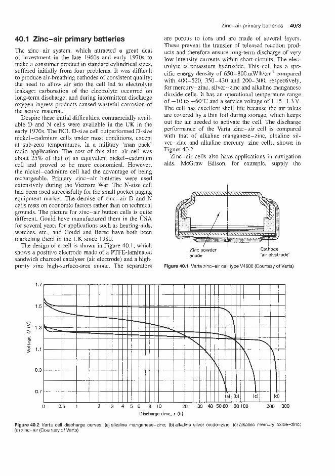
Zinc-air primary batteries 40/3
are porous to ions and are made of several layers. These prevent the transfer of released reaction prod- ucts and therefore ensure long-term discharge of very low intensity currents within short-circuits. The elec- trolyte is potassium hydroxide. This cell has a spe- cific energy density of 650-800 mW h/cm3 compared with 400-520, 350-430 and 200-300, respectively, for mercury-zinc, silver-zinc and alkaline manganese dioxide cells. It has an operational temperature range of -10 to +60"C and a service voltage of 1.15-1.3V. The cell has excellent shelf life because the air inlets are covered by a thin foil during storage. which keeps out the air needed to activate the cell. The discharge performance of the Varta zinc-air cell is compared with that of alkaline manganese-zinc, alkaline sil- ver-zinc and alkaline mercury-zinc cells, shown in Figure 40.2.
Zinc-air cells also have applications in navigation aids. McGraw Edison, for example, supply the
40.1 Zinc-air primary batteries The zinc-air system, which attracted a great deal of investment in the late 1960s and early 1970s to make a consumer product in standard cylindrical sizes, suffered initially from four problems. It was difficult to produce air-breathing cathodes of consistent quality; the need to allow air into the cell led to electrolyte leakage; carbonation of the electrolyte occurred on long-term discharge; and during intermittent discharge oxygen ingress products caused wasteful corrosion of the active material.
Despite these initial difficulties, commercially avail- able D and N cells were available in the UK in the early 1970s. The ECL D-size cell outperformed D-size nickel-cadmium cells under most conditions, except at sub-zero temperatures, in a military 'man pack' radio application. The cost of this zinc-air cell was about 25% of that of an equivalent nickel-cadmium cell and proved to be more economical. However, the nickel-cadmium cell had the advantage of being rechargeable. Primary zinc-air batteries were used extensively during the Vietnam War. The N-size cell had been used successfully for the small pocket paging equipment market. The demise of zinc-air D and N cells rests on economic factors rather than on technical grounds. The picture for zinc-air button cells is quite different. Gould have manufactured them in the USA for several years for applications such as hearing-aids, watches, etc., and Gould and Berec have both been marketing them in the UK since 1980.
The design of a cell is shown in Figure 40.1, which shows a positive electrode made of a PTFE-laminated sandwich charcoal catalyser (air electrode) and a high- purity zinc high-surface-area anode. The separators
, Zinc powder I Cathode
'air electrode' anode
Figure 40.1 Varta zinc-air cell type V4600 (Courtesy of Varta)
Figure 40.2 Varta cell discharge curves: (a) alkaline manganese-zinc; (b) alkaline silver oxide-zinc: (c) alkaline mercury oxide-zinc; (d) zinc--air (Courtesy of Varta)

40/4 Metal-air batteries
Carbonaire range of batteries covering the following applications: short lights of all types (either flashed or continuously burned) such as reef lights and lights on fixed structures, offshore lights on oil platforms, fog horns, bell strikers, range lights, lights on barges under tow, bridge lights, pier and dock lights, obstruction lights, fish net marker lights, buoys (two standard types of 12 V disposable buoy battery packs, with capacities of 1100 and 3300 A h are available), portable warning lamps.
One outstanding advantage of Carbonaire batteries is that they may be activated with seawater. In nav- igation aid services, this means that batteries can be transported dry to the location. The weight to be trans- ported is thus reduced to a minimum and the possibility of spillage of battery electrolyte in transit is completely eliminated.
In addition to this practical feature, the most desir- able type of primary battery for navigation aids is one that combines large capacity with a minimum amount of labour required for setting up and replacing. While each of these advantages has been available previously in separate types of primary batteries, the Carbonaire is the first battery to combine them.
With available capacities of up to 2800Ah, only infrequent battery renewals are required. The result is a substantial saving in time and money, especially where the navigation aids are installed at remote, iso- lated or hard-to-reach locations. Another very pertinent operating characteristic of Carbonaire batteries is their narrow voltage range, which eliminates the necessity for adding or subtracting cells in an installation at any time during the service life of the battery.
McGraw Edison produce a 2.5 V, 1OOOAh (type 2- S-J-I) and a 3.75 V, 1OOOA h (type 3-S-J-I) battery and
Table 40.2 Saline zinc-air depolarized batteries supplied by SAFT
these, together with the 1.25 V, 2800 A h (type Y), can be used in various combinations to produce a variety of battery voltages, as shown in Table 40.1.
Table 40.1 Voltage classification chart for Carbonaire batteries
Voltage Types and number of Carbonaires required recommended
(VI
2.5 3.75 6.0
10.0 12.0
1 x 2-S-J-I or 2 x type Y 1 x 3-S-J-I or 3 x type Y 1 x 2-S-J-I, 1 x 3-S-J-I or 5 x type Y 4 x 2-S-J-I or 8 x type Y 2 x 2-S-J-I, 2 x 3-S-J-I, 5 x 2-S-J-I or 10 x type Y
Some of the recommended applications of the range of zinc-air depolarized batteries (saline and alkaline electrolyte types) are illustrated in Tables 40.2 and 40.3.
40.2 Zinc-air secondary batteries Three companies have been working on electric vehicle applications for this type of battery including CGE (France), AER Energy Resources (US) and Electric Fuel Ltd (Israel). Practical energy densities in the range 90-200Whflcg-' have been achieved to date. Elec- tric Fuel Ltd are working on a system in which the whole battery assembly is removed from the vehicle and replaced at 'filling stations'.
Type Rated Open- End-point Average Applications capacity circuit voltage current
(A h) voltage (VI (A) W)
AD 517-4 AD 517
AD 524
AR 40
AD 538 AD 539 AD 542
ADH 121 AD2-519 AD2-522
1000 270
145
85
80 45 25
6 130 70
1.45 1.45
1.45
1.45
1.45 1.45 1.45
1.45 2.90 2.90
0.8 0.8
0.8
0.8
0.8 0.8 0.8
0.8 1.6 1.6
0.80 0.20
0.10
0.10
0.09 0.04 0.025
0.01 0.10 0.08
Meteorology, railway signalling, marine navigation Railway signalling, telephone circuits, marine navigation, clocks Motorway emergency telephones, telephone circuits, clocks Telephone circuits, telecommunications, railway signalling Lift alarms, warning lamps, railway signalling Railway signalling Master clocks, railway signalling, measuring instrnments Security systems, clocks Telephone circuits, railway signalling Warning lamps

Aluminium-air secondary batteries 40/5
Table 40.3 Alkalin,e zinc-air depolarized batteries supplied by SAFT
Type Rated Opeit- End-point Average Applications capacii)i circuit voltage current
(A h) voltage (V) (A) (VI
AD 600 10 000 1.45 0.9 1.50 VHFAJHF relays, TV repeaters, radio guidance
AD 308 A 2 000 0.1 0.9 1 .oo Railway signalling, meteorology, VNFKJHF relays,
AD 318 A 1000 0.1 0.9 0.25 Railway signalling, telecommunications, telephone
AD 304 J 800 0.1 0.9 3.00 Marine navigation AD 319 J 350 0.1 0.9 0.30 Motorway emergency telephone, railway signalling AD 810 2 200 0.1 0.9 1.5 Marine navigation, railway signalling, radio
AD 820 1 200 0.1 0.9 1.2 Marine navigation, road traffic controls AD 840 350 0.1 0.9 0.5 Roadside emergency warning lamps, railway
systems, radio telephone
radio telephone, TV, marine navigation
circuits, marine navigation
telephone
signalling, marine navigation
40.3 Aluminium-air secondary applications: marine lights, toys, reserve lights, trac- tion batteries, torpedo batteries, submersible vehicles, reserve batteries and range extenders for lead-acid vehicle batteries.
batteries Aluminium-air batteries have a high power density. This has led to proposals for their use in the following


Hig h-temperature thermally activated primary batteries


These batteries find uses in fast activation applica- tions such as firing squibs and explosive bolts. Other applications include electric matches, dimple motors and emergency starting power for military vehicles and aircraft.
Eagle Picher are supplying thermally activated bat- teries for a wide range of military and projectile applications. The latter include Maverick, Side-winder, Dragon, Stringer Paveway, ACE, Viper, Korworan, Buzzard, Lance and ACE SI1 projectiles (calcium thermal cells); and Paveway, ASHT, AMRAAM and Hoe projectiles (lithium thermal cells). This Company
High-temperature thermally activated primary batteries 4113
also supplies cells for artillery fuses, mortar fuses, rocket fuses, proximity fuses and seat ejection devices in aircraft.
MSH supply thermally activated batteries for terminal guidance, actuation of control surfaces, telemetry, guidance and control systems, aircraft emergency power supplies, safety and arming power, and fuses for missiles, rockets, torpedoes, bombs, ammunition and missilelrocket firing units.
Thermally activated batteries are widely used as power sources in projectiles, rockets, bombs, mines, missiles, decoys, jammers and torpedoes.


Seawater- activated primary batteries


Seawater-activated primary batteries 42/3
Silver chloride-magnesium batteries These are used Copper chloride-magnesium batteries These are in sonarbuoys, beacons, emergency equipment, tor- used in balloons, beacons, flares, sonarbuoys, pingers pedoes, flares, mines, pingers, balloons and life-jackets. and oceanographic equipment.
Silver chloride-zinc batteries These are used in bal- loons, buoys, rnilitary power systems, communications equipment and portable electronic devices.


Electric vehicle secondary batteries


Lead-acid batteries 4313
An effort to develop a practical electric vehicle is con- suming a significant portion of the technical resources of the technically advanced nations. Its projected impact upon the environment is well known; an elec- tric vehicle would contribute to a major reduction in emission pollutants, particularly in metropolitan areas. In addition, as natural energy resources become more scarce, it has been and will continue to be necessary to develop new energy sources and to centralize the use of old resources for greater efficiency. In virtu- ally all of thesle new and changing energy systems, the conversion or usable output is in the form of elec- trical energy. The ability of an electric vehicle to use this future primary energy source directly may well overshadow its more familiar environmental benefits.
43.1 Lead-acid batteries The starting point of power sources for electric vehicles was, of course, the lead-acid battery. Because of their relatively low power density, compared with other types of battery which are now becoming available, other types of batteries are now being considered for this application. The low power density of the lead-acid system puts severe limitations on the range that can be achieved between battery charges, although the restrictions regarding acceleration and maximum speed are not as lirriting as they once were.
The lead-acid battery should not be dismissed lightly as a power source for electric vehicles. It is, in fact, the only type of battery being used in large- scale prototype vehicle trials. Chloride Batteries UK are currently conducting several such trials.
43.1.1 The Silent Carrier Programme
Silent Can-ier is a 1.Xton urban delivery van. The earlier versions of this vehicle had a maximum range of 35-40 miles and this has since been improved. The maximum speed is 49 milesh and the hill climbing ability is 1 in 8. Although the basic cost of early production models will be a little higher than that of vehicles with internal combustion engines, running costs will be lower. It is claimed that the maintenance
costs of the battery-powered vehicle vary from 60% to as low as 30% of those of petrol and diesel-powered vehicles.
43.1.2 The Silent Rider Programme
Silent Rider is an electric bus. It will carry 50 people at 40 milesh over a 40-mile range on one charge. Trials are being conducted in collaboration with bus companies in two counties, Lancashire and Cheshire. Figures 43.1 and 43.2 show the layout of this bus. The 330 V battery in this vehicle weighs 4.4 tons, and consists of 165 cells, each with a capacity of 329Ah. Investigations by Chloride Batteries have shown that nearly 50% of buses on city centre journeys during peak periods cover less than 25 miles, with a further 40% covering no more than 40 miles. The shaded areas in Figure 43.3 show the potential for a battery-operated bus with a range of 40 miles.
A more recent application of lead-acid batteries to electric vehicle propulsion is the General Motors G-van. This vehicle was developed under the EPRI Transportation Plan and is now marketed. The vehicle has a range of 90km in simulated city driving, a top speed of 52 mph and an acceleration from 0 to 30 rnph in 13 seconds. It was planned to introduce up to 10,000 of these vehicles in the Los Angeles areas between 1991 and 1996.
Performance data on the 6 V monobloc cells is listed below:
under 40 kw Load, per monobloc Peak power 1.0 per cell: fully charged 112 Wkg 80% discharged 57 wkg
General Motors are continuing to develop the Impact lightweight electric car. This vehicle is capable of accelerations of 0 to 60mph in 8 seconds and has a top speed of 100 mph. It is fitted with 3210 V lead acid batteries weighing 396 kg.
Developments in flat or tubular plate designs for lead-acid electric vehicle traction has in recent years concentrated on improving energy density and power
Figure 43.1 Layout of the Silent Rider battery-powered bus. 1, main 330V battery; 2, auxiliary 24V battery; 3, power steering pump and motor assembly; 4 , air compressor and motor assembly; 5, motor cooling fan: 6, main air tanks; 7, auxiliary air tank; 8, exit: 9, entrance; 10, bus heater: 11, motor: 12, control panels (Courtesy of Chloride Batteries)
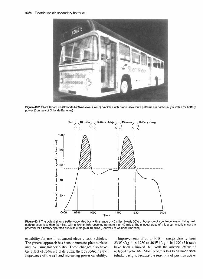
43/4 Electric vehicle secondary batteries
Figure 43.2 Silent Rider Bus (Chloride Motive Power Group). Vehicles with predictable route patterns are particularly suitable for battery power (Courtesy of Chloride Batteries)
Rest m i l e s h Battery charge m40 I miles),, Battery charge 4 . 7 -
3 0 5 1000 1500 1830 Time
2400
Figure 43.3 The potential for a battery-operated bus with a range of 40 miles. Nearly 50% of buses on city centre journeys during peak periods cover less than 25 miles, with a further 40% covering no more than 40 miles. The shaded areas of this graph clearly show the potential for a battery operated bus with a range of 40 miles (Courtesy of Chloride Batteries)
capability for use in advanced electric road vehicles. The general approach has been to increase plate surface area by using thinner plates. These changes also have the effect of reducing plate pitch, thereby reducing the impedance of the cell and increasing power capability.
Improvements of up to 40% in energy density from 23 W h/kg-' in 1980 to 40 W h/kgg' in 1990 (5 h rate) have been achieved, but with the adverse effect of reduced cyclic life. More progress has been made with tubular designs because the retention of positive active

Other power sources for vehicle propulsion 43/5
of thinner cross-section and greater oxidation res- istance are now being produced from polyethylene and polypropylene, which offer the advantages of decreased weight and volume, and increased res- istance to oxidation degradation during overcharge. These materials, in conjunction with cellulosic films, or alone, can increase energy densities and life.
The utilization of the nickel-zinc system for elec- tric vehicle propulsion is dependent on the realization of cycle life in excess of 500 deep cycles. Currently, cycle life is limited by the zinc electrode; specifi- cally, the phenomenon known as zinc shape change. Work is currently being done at Eagle Picher which has demonstrated a capability to achieve 300 cycles at a 65% depth of discharge. This performance is based on an improved separator system, controlled charging methods, and incorporation of construction features designed to minimize zinc electrode shape change. Further improvements are anticipated in the zinc electrode based on construction features designed to control the concentration gradients of dissolved zinc ionic species within the cell.
An interesting cost trade-off for the nickel-zinc system is available concerning the nickel electrode. The ultimate design objective is, of course, to develop a deep cycling capability upwards io 1000 cycles. However, if a much lower cycle life can be tolerated (200-250 cycles), it is possible to construct cells with non-sintered nickel oxide electrodes at a lower cost.
Comparative cost and performance data for nickel-hydrogen, nickel-iron and nickel-zinc sys- tems are given in Table 43.1.
Yuasa, Japan have been developing prototype nickel-hydrogen batteries for electric vehicle applica- tions. They have claimed 200 maintenance free cycles at 100% depth of discharge.
material in the tube reduces losses of active mater- ial which usually occurs with increase of utilization. Elecbic vehicle batteries are usually assembled in 6 V monobloc units thereby improving energy density.
The General Motors G-Van, now marketed, has a range of 90km In simulated city driving conditions with a top speed of 52mph and acceleration from 0 to 30mph in 13 seconds. Problems with this battery are associated with a loss of power capability as the battery is discharged.
The General Motors ImpactTM lightweight car (39101cg gross weight) can accelerate from 0 to 60 mph in 8 seconds and has a top speed of 100 mph. It is fitted with 32 10 V 42 A h batteries weighing 400 kg, giving a total output of 13.6 kW h.
43.2 Ot propslls 43.2.1 Nickel!-cadmium
Nickel-cadmium batteries are used extensively in France for electric vehicle propulsion, e.g. by Renault and Peugeot.
ower sources for vehicle
3.2.2 The nickel-zinc battery system
The nickel-zinc system is a viable candidate for elec- tric vehicle propulsion based on its high energy density and power density. The voltage is 1.85V at 25°C. The zinc electrode contributes a high electrode poten- tial and a low equivalent weight, resulting in energy densities of 706;Vhkg presently obtainable in a con- figuration suitable for an electric vehicle application. Other features of the system that make it attractive for electric vehicles are:
1. The capability of accepting either constant-potential or constant-current charging with little overcharge required.
2. The potential of operation as a sealed, maintenance- free unit.
3. The ability to withstand considerable overdischarge without cell reversal, owing to the excess of zinc oxide active material.
Separator systems for nickel-zinc cells have exten- sively employed cellulosic materials. New materials
43.2.3 Lithium aluminium alloy-iron sulphide batteries for vehicle propulsion
Eagle Picher entered into the development of the lithium-metal sulphide battery system for vehicle propulsion in 1975. The electrochemical system under study utilizes an anode of a lithium-aluminium alloy and a cathode of the metal sulphides. Iron sulphide (FeS) or iron disulphide (FeS2) is currently most com- monly utilized. Initial efforts were directed toward
Table 43.1 Nickel battery systems cost and performance summary
Nickel-hydrogen Nickel-iron Nickel-zinc
Energy density at 2h rate (W hkg) 60 SO 70 Cycle life (100% depth of discharge) (cycles) 2000 2000 500 Power density (minimum) (Wkg) 100 100 150 Battery costs (SkW h) 100-200 so-100 50-100 Costskycle ($kW h) 0.05-0.10 0.03-0.05 0.10-0.20

43/6 Electric vehicle secondary batteries
developing engineering-scale cells suitable for elec- tric vehicle and utility load levelling applications. These cells have yielded energy densities in excess of 100Whkg and cycle life in excess of 1000 cycles. Cells have been vibrated under road load condi- tions which simulate invehicle use with no problems encountered.
In 1979 Eagle Picher used this type of battery to power an electric van. A top speed of 45 milesh and a range of 80 miles were achieved. Figure 43.4 shows the single cell voltage profiles for typical FeS and FeSz 4 h rate discharges.
Feasibility of the lithium-metal sulphide battery technology has been demonstrated by Eagle Picher in engineering-scale cells and modules. Figure 43.5 shows a typical 10-cell module exhibiting a nominal 12 V e.m.f. curve and a capacity of 340 Ah. The com- pact 12 V, 4k W h package has been cycled in the insu- lated battery container in excess of 250 deep discharge cycles as testing continues. Ampere hour efficiencies
1.5
Table 43.2 Program goals: lithium-metal sulphide systems
-
are stable between 97 and loo%, while energy effi- ciency remains in excess of 85%. Low maintenance, high charge rates and minimal thermal management are characteristic of the system under a broad range of climatic conditions.
Table 43.2 lists the program goals Eagle Picher have defined for the lithium-metal sulphide system and the time frame for accomplishment.
Nearly all of the effort on the development of these batteries is now centred on traction applications for electric vehicles. Delivery vans, fork lift trucks and underground mining trucks are considered to be likely early uses - Westinghouse, Oceanic Division, Chardon, Ohio have had batteries tested at Argonne National Laboratory which have an estimated vehicle range of 16Okm. SAFT America has been awarded a multi-million-dollar contract by the US Department of Energy to develop this type of battery. Other com- panies involved in programmes of work include Elec- tro Fuel Co., Canada and Eagle Pitcher and Gould.
1.0
0.5
1981 1983 1986 1988
c - -
0 >
- 0.5 -
I I I I
Specific energy (W hkg) Cell 95 Battery 70
Cell 320 Energy density (W NI)
Battery 100
Battery 120
Peak power (Wkg) Cell 150
Battery heat loss (W) 300 Life
Deep discharges 250 Equivalent miles 25 000
120 150 100 130
400 525 200 300
185 200 120 160 150 125
500 1 000 60 000 150000
200 160
650 375
250 200 120
1000 200 000
la) Capacity, state of charge (%I (b) Capacity, state of charge (%)
Figure 43.4 Lithium aluminium alloy-iron sulphide cells supplied by Eagle Picher. Typical single-cell voltage profiles for 4 h rate discharges for (a) FeS and (b) FeSz cells (Courtesy of Eagle Picher)

Other power sources for vehicle propulsion 43/7
Figure 43.5 Ten-cell lithium aluminium alloy-iron sulphide ten-cell module for vehicle propulsion (Courtesy of Eagle Picher)
Westinghouse are developing a 36 V electric vehicle lithium-aluminium-iron sulphide battery which has a specific energy of 112 W h/kg on the basis of cell mass and 98 W h/kg-' on the basis of battery module weight including heat dissipating system.
This gives the battery a 100-mile range under stan- dard electric vehicle test profiles. The battery has a cyclic life of 120 cycles.
Westinghouse batteries for vehicle production in the 2.5 to 7.5 W h range are near to commercial pro- duction.
In general the technology of lithium-aluminium- iron sulphide cells for electric vehicle applications is now estalished but needs evolutionary improvements to become fully commercial.
A target energy density is 150 W h kg-'.
43.2.4 Aluminium-air batteries It has been shown that an aluminium-air battery could power a compact car provided 14kg of fresh aluminium and 23 litres of water could be installed every 400km and 41 kg of hydroxide sludge disposed of. Clearly, this is a very speculative project. Alcan, US has carried out some work on the development of this type of battery.
The latest development of the Alcan aluminium air battery is a hybrid unit comprising eight lead-acid batteries and a bank of aluminium-air batteries to power a small hatchback vehicle. The target is a range of 105 miles at 30mph. Eltech Corporation US are developing a 100 V aluminium-air traction battery.
43.2.5 Zinc Bromine batteries Exxon Research and Engineering Co., and Gould Inc., both of the USA have done extensive research and development and engineering work, funded by the US Department of Energy and the Electric Power Research Institute, on the development of a zinc-bromine battery for electric vehicle use.
In the 1980s both Gould and Exxon curtailed their work on this development and transferred it to other companies-Johnson Controls Inc. (USA), Meiden- sha Electric Co. (Japan) and SEA GmbH (Austria). No commercial battery has yet emerged from these activities.
43.2.6 Lithium solid state batteries This type of battery has been considered for vehicle propulsion and scaling-up programmes hopefully lead- ing up to demonstration units are underway at Harwell Atomic Energy Establishment UK.
43.2.7 Sodium sulphur battery This battery has not yet been developed to the com- mercial stage, despite intensive efforts by several companies.
Calculations show that battery specific energies of around 100-150 W h/kg-' and peak power capabilities of 120 Wkg-' are needed for traffic compatible elec- tric delivery vans with worthwhile ranges, with even more demanding requirements for smaller vehicles such as automobiles.
To put this into perspective, specific energies cur- rently being achieved by lead-acid, nickel-iron and iron-air batteries are respectively 25-45, 50 and 20 W h kg-' .
Several manufacturers are attempting to develop sodium-sulphur batteries for electric vehicle applica- tions. Some of the advantages of sodium-sulphur bat- teries are: low rising resistance during cycling (by control of impurity levels), no memory effects, no sec- ondary reactions, unlimited charge retention, amp hour capacity independent discharge rate and high shelf life.
Chloride Silent Power are developing a 960 cell bat- tery which has been tested at Ford Motor Company. The delivery van (GM GriHon van) constructed by Chloride Silent Power has a range of 163 miles at 35 mph or 120 miles at 50 mph. Chloride Silent Power

43/8 Electric vehicle secondary batteries
is constructing a production module capable of man- ufacturing 5000 sodium-sulphur cells per week to use in customer field trials.
Yuasa have constructed a 400 kWh battery intended for stationary application testing. Argonne National Laboratory, US have published projected ranges and speeds for different simulated driving profiles cornpar- ing sodium-sulphur batteries with lead-acid and nickel- iron (Table 43.3).
Table 43.3 Projected ranges for simulated driving profiles
Driving projle Schedule SFUDS79 J227aD J227aC
Average speed (mph) 19 28 15 Battery range (miles) NaS 148 182 - NaFe 75 98 93 Lead acid 47 54 65
Vehicle IDSEP 1ETV-1 G-Vm
Sodium sulphur batteries have also been used in aerospace applications and load levelling in utilities.
43.2.8 Zinc-air battery This battery is currently under development by three companies, CGE (France), AER Energy Resources Inc. (US) and Electric Fuel Ltd (Israel), who are achieving energy densities in the range of 90-200 Wh/kg-'.
43.2.9 Iron-nickel battery This type of battery is now being developed for motive power applications including industrial trucks, trac- tors, mine locomotives and electric vehicles. On elec-
tric vehicles energy densities of 50 W h/kg-' plus are being achieved and a range of 200km on a single charge is possible. Charge-discharge cyclic times of 1000-20 000 cycles have been achieved.
43.2.10 Nickel-metal hydride batteries This type of battery is under evaluation for electric vehicle applications. An energy density of 70 W hikg-' has been achieved and a charge-discharge cycle life exceeding 1000 cycles.
43.2.11 Sodium-nickel chloride batteries
This battery is in the pilot plant production stage as a possible battery for passenger electric vehicles and buses. Over 1000 charge-discharge cycles and a prac- tical energy density of 100 W h/kg-l (160 w h / d ~ ~ - ~ ) have been achieved in the Eagle Picher battery. The battery operates at elevated temperatures (ZOO-300°C) and is equipped with insulation to reduce heat losses, heaters to bring the battery to operating temperature and a cooling system to cool the battery on high rate discharge.
43.2.12 Iron-air batteries Matsushita Battery Industry Co. (Japan) and the Swedish National Development Co. are developing iron-air batteries for electric vehicle applications. To date an energy density of 8OWh/kg-l at the CI5 rate has been achieved. Two hundred cycles at 60% depth of discharge is possible. The Swedish National Development Co. are developing at 30 k W h battery.
Westinghouse (US) and Siemens (Germany) are also active in the development of this type of battery.

Part 5


Introduction


Introduction 4413
ies). Another proposal, which has been tried out for charge control of sealed nickel-cadmium cells, is to incorporate an oxygen-consuming auxiliary electrode in the cell to consume oxygen gas as it is evolved towards the end of charge and on overcharge and thus prevent the build-up of excessive internal gas pres- sure. This, however, needs extensive modifications of the cell structure and consequently is expensive and increases the overall cost. The various methods used to charge different types of battery by these methods are discussed in Chapters 45-49.
Two principal methods of battery charging are used; constant-potentiad charging and constant-current char- ging. Many variants of these methods exist, such as the float charge regimen and the shallow charge regi- men, which are modifications of the constant-potential method. Also, mmy methods of control of the charging process exist. These include charging for a particular time to a particular end-voltage, charging to a par- ticular end-current, charging controlled by electrolyte temperature, and charging controlled by the internal pressure of the battery (in the case of sealed batter-


Constant-potential charging


Standard CP charging 4513
45.1 Stand,ard 45.1.1 Calcium-lead alloy lbatteries This is the preferred method for charging calcium-lead alloy grid low-maintenance batteries. By selecting an appropriate constant charging voltage and initial charging current, the battery can be safely recharged regardless of the depth of discharge in previous dis- charge cycles. The recommended initial charging cur- rents for calciurn-lead alloy low-maintenance batteries are listed in Table 45.1.
Table 46.1 Initial constant-potential charging currents for calcium-lead alloy iow-maintenance batteris
Nominal capacit). Maximum initial charge current (Ah) (A)
~~
1.2 1.9 2.6 4.0 4.5 6.0 8.0
BQ.0 213.0
0.3 0.5 0.7 1.0 1.1 1.5 2.0 2.5 5.0
When carrying out constant-potential chargeddis- charges in cyclic use, the battery should be charged at a maximum of 2.5Vkell. Charging current can be monitored and cut off when the voltage reaches the required value as indicated in Table 45.2.
Table 45.2 Charging current-charging voltage relationship: constant-potential charging of calcium-lead alloy low-maintenance batteries
Nominal capaci5 (Ah) Charging current (A)
At 2.40 V k e l l At 2.50 V/cell
1.2 1.9 2.6 4.0 4.5 6.0 8.0
10.0 20.0
10-30 20-40 30-60 40-80 50-100 60-120 80-160
100-200 200-400
30-60 60-120 80-160
110-220 130-250 180-360 250-500 300-600 600-1200
Figure 45.1 shows a typical charging curve for an approximately 10 A h lead-acid battery showing pro- files of charge current as a function of charge time for two constant-potential voltages (2.3 and 2.5 V). The initial current resulting from constant potential char- ging is high (2.2-3 A) and reduces to a relatively low
3.0
2.8
2.6
2.4
2.2
2.0
Q 1.8
1.6
a 1.4 e
I - t 8
L 3
6 1.2
1 .o
0.8
0.6
0.4
0.2
0
I i i i
1 2 3 4 5 6 7 8 9 10 1 2 3 4 5 6 7 8 9 10
Time (h i
Figure 45.1 Constant-potential charging current versus time for a General Electric D cell at 23°C. Actual recharge time and current are circuit dependent. Charge CP at 23"C, discharge 250mA at 23°C to 1.4V (Courtesy of General Electric)
current of less than 0.1 A as the cell approaches full charge after 4-5 h.
Figure 45.2 shows, in somewhat more detail, a constant-potential charging curve obtained by char- ging at 6.9V a particular calcium-lead alloy low- maintenance battery (0-25C A) produced by Yuasa (Japan). The curve shows a plot against charging time of charging current, terminal voltage and charging vol- ume. The charged capacity is indicated as a perceni- age against the discharged capacity in the previous cycle, i.e. percentage of charging volume. Normally, 100-130% recharge (charging volume) is required to charge a discharged battery fully. The initial charging current is limited to 0.25CA. The solid lines indicate 100% 10-h rate discharge in the preceding discharge cycle. The broken lines show their charging charac- ter after a recharge for 5 h (50%) at the same 10-h rate. The reduction in charge time required to attain an arbitrary 100% and 120% charging volume with increase in the constant potential used is clearly seen in the figures shown in Table 45.3.
The charging of low maintenance lead-acid batter- ies has been discussed in a book published by Gate Energy Products (see Bibliography).
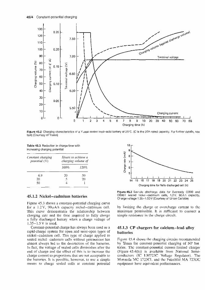
4514 Constant-potential charging
130 -
110
100
90
-
0.20 - - -
I I I I 0 1 2 3 4 5 6 7 8 9 I 0 2 0 3 0 4 0 5 0 6 0 7 0 8 0
Charging time (h)
Figure 45.2 Charging characteristics of a Yuasa sealed lead-acid battery at 25°C. (C is the 20 h rated capacity. For further details, text) (Courtesy of Yuasa)
Table 45.3 Reduction in charge time with increasing charging potential
Constant charging Hours to achieve a potential (V) charging volume of
100% 120%
6.9 20 50 20 5 20 50 4 1
45.1.2 Nickel-cadmium batteries Figure 45.3 shows a constant-potential charging curve for a 1.2V, 90pAh capacity nickel-cadmium cell. This curve demonstrates the relationship between charging rate and the time required to fully charge a fully discharged battery when a charge voltage of 1.35-1.5V is used.
Constant-potential charge has always been used as a rapid-charge system for open and semi-open types of nickel-cadmium cell. This type of charge applied to sealed nickel-cadmium cells without precautions has almost always led to the destruction of the batteries. In fact, the voltage of sealed cells diminishes after the end of charge and the effect of this is to increase the charge current to proportions that are not acceptable to the batteries. It is possible, however, to use a simple means to charge sealed cells at constant potential
l o r
I 1 I I I I I 1 1 1 1 1 14 15 16 17 18 19 20 21 22 23 24 25
see
Charging time for fully discharged cell (h)
Figure45.3 Sample discharge data for Eveready OB90 and OB90T sealed nickel-cadmium cells, 1.2V, 90A h capacity. Charge voltage 1.35-1.5OV (Courtesy of Union Carbide)
by limiting the charge or overcharge current to the maximum permissible. It is sufficient to connect a simple resistance in the charge circuit.
45.1.3 CP chargers for calcium-lead alloy batteries Figure 45.4 shows the charging circuits recommended by Yuasa for constant-potential charging of NP bat- teries. The constant-potential current-limited charger (Figure 45.4(b)) is available from National Semi- conductors (IC LM723C Voltage Regulator). The Motorola MC 1723CL and the Fairchild MA 723DC equipment have equivalent performances.
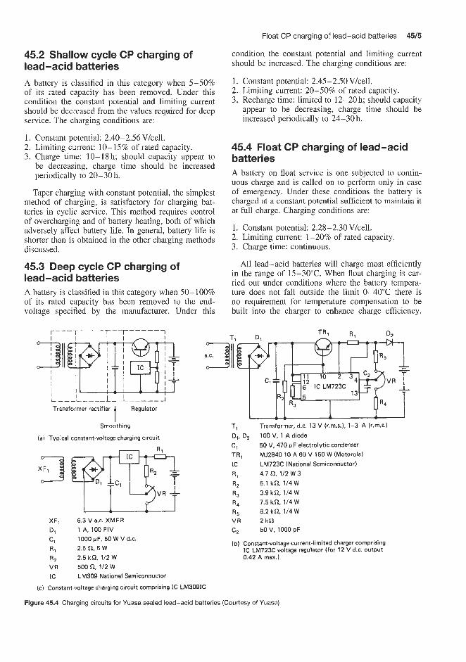
Float CP charging of lead-acid batteries 4515
condition the constant potential and limiting current should be increased. The chargng conditions are:
1. Constant potential: 2.45-2.50 V/cell. 2. Limiting current: 20-50% of rated capacity. 3. Recharge time: limited to 12-20 h; should capacity
appear to be decreasing, charge time should be increased periodically to 24-30 h.
45.2 Shallow cycle CP charging of lead-acid batteries A battery is classified in this category when 5-50% of its rated capacity has been removed. Under this condition the constant potential and limiting current should be decreased from the values required for deep service. The charging conditions are:
1. Constant potential: 2.40-2.56 V/cell. 2. Limiting ciment: 10-15% of rated capacity. 3. Charge time: 10-18h; should capacity appear to
be decreasing, charge time should be increased periodically to 28-30 h.
Taper charging with constant potential, the simplest method of charging, is satisfactory for charging bat- teries in cyclic service. This method requires control of overcharging and of battery heating, both of which adversely affect battery life. In general, battery life is shorter than is obtained in the other charging methods discussed.
45.3 Deep cycle CP charging of lead-acid batteries A battery is cllassified in this category when 50- 100% of its rated capacity has been removed to the end- voltage specified by the manufacturer. Under this
Transformer rectifier Regulator t Smoothing
(a) Typical constant-voltage charging circuit
XF, 6.3 V a.c. XMFR D, 1 A, 1OOPIV
C, R , 2.5Q. 5W R, 2.5 k n , 112 W VR 500Q 112 W IC LM309 National Semiconductor
1000 pF, 50 W V d.c.
45.4 Float CP charging of lead-acid batteries A battery on float service is one subjected to contin- uous charge and is called on to perform only in case of emergency. Under these conditions the battery is charged at a constant potential sufficient to maintain it at full charge. Charging conditions are:
1. Constant potential: 2.28-2.30V/cell. 2. Limiting current: 1-20% of rated capacity. 3. Charge time: continuous.
All lead-acid batteries will charge most efficiently in the range of 15-30°C. When float charging is car- ried out under conditions where the battery tempera- ture does not fall outside the limit 0-40°C there is no requirement for temperature compensation to be built into the charger to enhance charge efficiency.
T, Transformer, d.c. 13 V (r.m.s.), 1-3 A (r.m.5.) D,, D, 100 V, 1 A diode C, 50 V, 470 pF electrolytic condenser TR, MJ2840 10 A 60 V 150 W (Motorola) IC LM723C (National Semiconductor) R, 4.7 n. 112 W 3 R, 5.1 kn, 1/4W R, 3.9 kn, 114 W R, 7.5 kn, 114 W R, 8.2 kn, 1/4W VR 2 k n C, 50 V, 1000 pF
(b) Constant-voltage current-limited charger comprising I C LM723C voltage regulator (for 12 V d.c. output 0.42 A max.)
(c) Constant-voltage charging circuit comprising IC LM3091C
Figure 45.4 Charging circuits for Yuasa sealed lead-acid batteries (Courtesy of Yuasa)

45/6 Constant-potential charging
Many applications, however, require operation in envi- ronments from extreme cold to extreme heat. When batteries are likely to reach temperatures outside the 0-40°C range a temperature compensator built into the charger, operating on 4mVPC per cell based on 25°C is desirable. Constant-potential charge voltages for various battery temperatures and modes of service are shown in Figure 45.5.
45.5 Two-step cyclic voltage-float voltage CP charging
There are applications that require a lead-acid battery in standby service to be recharged rapidly after a discharge. Under this condition a two-step charger would be most efficient; that is, one having a capability to switch from a cyclic voltage to a float voltage. In these circumstances the following conditions are recommended:
1. Initial constant potential: 2.45-2.50Vkell. 2. Float constant potential: 2.28-2.30 Vkell. 3. Limiting current: 20-40% of rated capacity. 4. Initial charge time: time required to reach
5. Float charge time: continuous. 2.50 Vlcell.
Partially recombining sealed lead-acid batteries have the ability efficiently to accept a high-rate charge without a serious sacrifice in life. In applications where it is necessary to recharge in a limited time, the battery can be restored to 90-95% of full capacity within a 1-3 h period. A charger with the following character- istics is required:
Deep cyclic regimen 1 /Shallow cyclic regimen
2.7 r %
\ L' 2.6
% 2.4
2.3
2.2
4,,,,,,,,, -20-10 0 10 20 30 40 50
Ambient temperature ("C)
Figure 45.5 Charge voltage per cell versus temperature for an Eagle Picher Carefree rechargeable lead-acid battery (Courtesy of Eagle Picher)
1. Constant potential: 2.50-2.55 Vkell. 2. Limiting current: 100% of rated capacity. 3. Charging time: 1-3h.
If charging at the high rate is allowed to continue excessively beyond a 3 h period, greater than normal amounts of gassing will occur. It i s not recommended that high-rate charging be performed in an airtight enclosure. It is recommended that battery compart- ments have adequate ventilation to prevent an accumu- lation of gases, which could reach dangerous propor- tions in the event of a charger or battery malfunction.
In general, the end of charge of the battery can be determined when the charge voltage has reached the level discussed above for the various modes of service, and the on-charge current has dropped to the approxi- mate amounts shown in Table 45.4 (Eagle Picher Care- free Batteries). When the current has reached the value shown in the table, it can be removed from the charge source or switched to the float mode.
A charger two-step circuit for a 6 V battery is shown in Figure 45.6.
Table 45.4 Eagle Picher Carefree maintenance-free lead-acid batteries: current acceptance versus charge voltage
Batteries Current (mA)
All 0.9 A h < 20 All 2.5 and 2.6Ah <50 All 5 A h 175 All 8 A h < 100 All 12Ah <150 All 30 A h <200
T, TR.
T i 241 7-16 signa1 Trans c o FWB, MDA952-1 Motorola
TR, MJ2955 Motorola
IC, MC7805CP Motorola
R2 15 n Ohmite
0, F2
R , 10K POT Bourn*
Sarker- Taman
Figure 45.6 Charger circuit for 12, 15 and 30Ah Eagle Picher Carefree rechargeable lead-acid batteries. Note that TRI should have an adequate heatsink (Courtesy of Eagle Picher)

Vo I tag e- I i m it ed taper current charging of alkaline manganese dioxide batteries


Voltage-limited taper current charging of alkaline manganese dioxide batteries 46/3
The recommended method for charging alkaline sec- ondary batteries is the use of voltage-limited taper current charging. This method offers the maximum cycle life and consequently the lowest battery oper- ating costs. Cycle life can be as much as twice that obtained with other methods of charging. Although constant-current charging can be used for this type of battery, with c’onsequent loss of cycle life, it is recom- mended that careful enquiries be made before such charging methsods are contemplated.
Batteries should not be charged continuously, or float charged for extended periods, after the charge cur- rent has returned 120% of the ampere hours removed on previous discharge.
A rechargeable alkaline manganese dioxide battery must not be discharged completely. For best results, the rated capacity of the battery should not be exceeded on discharge. During deep discharge a secondary elec- trochemical reaction takes place. This reaction is not reversible and will seriously reduce the battery cycle life. To avoid1 short battery service, it is therefore desirable that the device using the battery contain some provision against excessive discharge of the battery.
The charger will replace the energy needed to recharge the battery, and a timer or ampere hour control is unnecessary to monitor the charging time. However, the battery should be removed from the charger after completion of the charge. Also, to pre- vent deep cell discharge, a timer will provide effective control over the energy withdrawn from the cell during any cycle.
With constant-current charging for this type of bat- tery, a d.c. timer or ampere hour counter is needed to control both the discharge and charge cycles. A system of this sort would be adjustable to permit removal of the rated ampere hour capacity from the battery and thereby ensure: maximum battery service life.
Voltage-limited taper current charging involves use of an inexpensive voltage regulator added to the basic constant-current type transformer-rectifier circuit with a current-limiting resistor between the battery and the regulated output voltage. This removes the burden of adjusting charge time to discharge time and pro- vides automatic current control. Although the regulator circuit is somewhat more expensive than other com- mon circuits, the initial cost is more than offset by 50- 100% greater cycle life.
The basic characteristics of sealed alkaline man- ganese dioxide rechargeable cells when using voltage- limited taper current charging are given in Table 46.1 (based on a 6 h charge period).
A regulator providing voltage regulation of 2-3% at low current values is adequate. Poorer regulation when the battery is first placed on charge and the voltage is low is often satisfactory. The regulator output volt- age is adjusted to the battery end-of-charge voltage. Correct battery voltage is determined by the number of cells and cell voltages given in Table 46.1. The current-limiting resistance (the total current-limiting resistance consists of the series resistance plus inher- ent resistance of the regulator circuit, which may vary with design and component selection) should limit the initial current to the 4-6 h rate at start of charge when the battery voltage is low. A typical starting voltage after withdrawal of rated capacity is 1.30- 1.35 V/cell. The maximum recommended initial charge currents at these voltages are shown in Table 46.1.
The minimum voltage that a cell will reach at the end of the recommended discharge capacity is shown in Figure 46.1. This voltage is measured while the dis- charge current is flowing. The curves in Figure 46.1 represent cell behaviour at maximum discharge cur- rent rating to rated capacity and a minimum of 16 h recharge time. The initial closed-circuit and end-of- discharge voltage curves give the ‘working’ voltage range of the cell at various discharge levels. To pre- vent damage to the cell on charge cycle the charging potential should be limited to about 1.8Vkell with a permissible maximum of 1.75 V/cell. The voltage rise on the charge and end-of-charge voltage value is dependent on the charge current character. As shown in Figure 46.1, the end-of-charge voltage will decrease slightly as cycle life progresses as the result of gradual change in the reversibility of the system.
Since the current tapers as the result of battery voltage increase, or is ‘voltage responsive’, the end-of- charge current will increase as cycling progresses. The current will equilibrate at some specific value but will never reach zero or shut-off since the voltage decreases as current is reduced as the result of internal resistance and chemical reaction. The battery voltage after charge will gradually decrease to a value of 1.5 Vkell when the charger is disconnected and the battery remains on open circuit. When changing from charge to discharge cycle with no time delay between, the battery voltage decay rate will vary with discharge current. At rates
Table 46.1 Basic: characteristics of sealed alkaline manganese dioxide cells when using voltage-limited taper current charging
Cell size Average operating voltage Maximum initial charging Current-limiting Source voltage current at 1.3 V/cell (A) resistance (Wcell) limit (Vkell) at maximum current (V)
D G
1.0-1.2 1.0- 1.2
0.6 1.12
0.8 1.70- 1.75 0.4 I .70- 1.75

46/4 Voltage-limited taper current charging of alkaline manganese dioxide batteries
18
1 7 -
16
A 15 L 0 14- +- -
- End-of-charge voltage
-
-
i o 20 30 40 50 Number of cycles
Figure 46.1 Typical voltage performance on voltage-limited taper current charge of an Eveready 561 1 5 4 rechargeable alkaline manganese dioxide battery. Discharge cycle, 4 h through 9.6 a; charge cycle, voltage-limited taper current charging for 16 h, voltage limit 17.5V, filtered regulated power supply, 1 % regulation with 4,OQ limiting resistor (Courtesy of Union Carbide)
near 1 A, the battefy voltage will fall to the indicated initial closed-circuit values within 5 min.
Figure 46.2 shows a voltage-limited taper current charge circuit suitable for recharging a 15V, 5 A h
120
T.
r 1.2 n 130 V a x .
\120 v a x .
0.8
E
Battery voltage ( V )
Figure 46.3 Suggested and actual linear taper currents obtained during 16h voltage-limited taper current charging of 15V, 5 A h Eveready 561 alkaline manganese dioxide battery (Courtesy of Union Carbide)
battery in 16 h. A tapered charging current is supplied to the battery through the series current-limiting resistor Rq, as battery voltage increases with charge.
UCC Patent 3 281 639
Stancor RT 201 (input a.c. to terminals 1 and 7; connect terminals 3 and 6) (secondary connections to bridge 8 and 11: connect terminals 9 and 10) 2A50 Solitron devices, Inc. (or equivalent) 500 pF 50 V d.c. 1/4 M12 2 (Motorola) in 9636 TI or Int. Rec. 2N1304 RCA, TI or equivalent 2N1557 Motorola, 2N514 TI 4700 52. 112 W 390 n. 112 W 1000 52, 1 w 4 5 2 , i o w
Figure 46.2 Voltage-limited taper current charger circuit suitable for charging a 1 5 V , 5 A h Eveready 561 alkaline manganese dioxide battery in 16 h (Courtesy of Union Carbide)
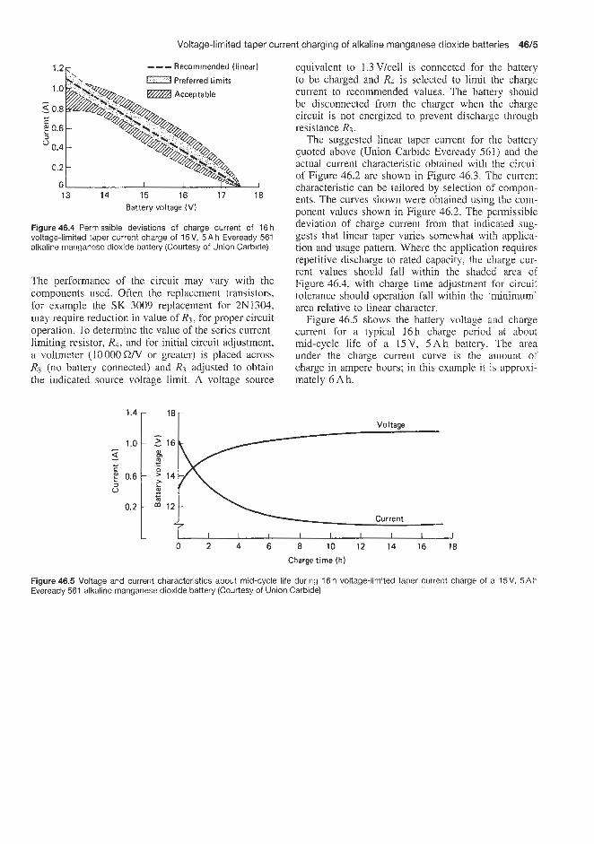
Voltage-limited taper current charging of alkaline manganese dioxide batteries 46f5
--- Recommended (linear) 7.2K
Acceptable 1 .o
5 0.8
E 0.6 a
0.4 0
0.2
0
- c
13 14 15 16 17 18 Battery voltage (V)
Figure 46.4 Permissible deviations of charge current of 16 h voltage-limited taper current charge of 15V, 5 A h Eveready 561 alkaline manganese dioxide battery (Courtesy of Union Carbide)
The performance of the circuit may vary with the components used. Often the replacement transistors, for example the SK 3009 replacement for 2N1304, may require reduction in value of R3, for proper circuit operation. To determine the value of the series current- limiting resistor, Rd, and for initial circuit adjustment, a voltmeter (10 000 C22N or greater) is placed across R3 (no battery connected) and R3 adjusted to obtain the indicated source voltage limit. A voltage source
equivalent to 1.3 Vlcell is connected for the battery to be charged and Rd is selected to limit the charge current to recommended values. The battery should be disconnected from the charger when the charge circuit is not energized to prevent discharge through resistance R3.
The suggested linear taper current for the battery quoted above (Union Carbide Eveready 561) and the actual current characteristic obtained with the circuit of Figure 46.2 are shown in Figure 46.3. The current characteristic can be tailored by selection of compon- ents. The curves shown were obtained using the com- ponent values shown in Figure 46.2. The permissible deviation of charge current from that indicated sug- gests that linear taper varies somewhat with applica- tion and usage pattern. Where the application requires repetitive discharge to rated capacity. the charge cur- rent values should fall within the shaded area of Figure 46.4, with charge time adjustment for circuit tolerance should operation fall within the 'minimum' area relative to linear character.
Figure 46.5 shows the battery voltage and charge current for a typical 16h charge period at about mid-cycle life of a 15V, 5 A h battery. The area under the charge current curve is the amount of charge in ampere hours; in this example it is approxi- mately 6 Ah.
0 2 4 6 8 10 12 14 16 18
Charge time (h)
Figure 46.5 Voltage and current characteristics about mid-cycle life during 16 h voltage-limited taper current charge of a 15V, 5 A h Eveready 561 alltaline manganese dioxide battery (Courtesy of Union Carbide)

Constant-current charging


Charge control and charge monitoring of seaied nickel-cadmium batteries 47/3
When recharge time is critical and it is desirable to determine the amount of capacity restored to the bat- tery, recharge with constant current is recommended. Constant-current charging is suitable when the dis- charged ampere hours taken out in the previous dis- charge cycle are known. It is necessary to monitor battery voltage or manually cut off the current at the end of charge to ensure a good service life for the battery. This type of charging requires regulation by means of an automatic timer. A normal recharge time of 20 h is recommended, whereby the constant-current charging rate is established to give an input of 110% of the previous output. If necessary, the charge time can be decreased, although it will require an increase in charging current such that
Amperes x Holurs = 1 .I x Discharge output (Ah)
Figure 47.1 shows a typical charging voltage profile as a function of percentage capacity returned, obtained at various constant-current charging rates between 25 and 500 mA, for a General Electric fully recombining lead-acid D cell.
7.1 Charge control and charge monitoring of sealed nickel-cadmium batteries Many methods have been tried to determine the state of charge of a sealed nickel-cadmium battery, but none has yet been successful. Except in the case of complete discharge, nei.ther cell condition nor state of charge can be determined by open-circuit voltage. Within a short time after charging it may be above 1.4V; it will fall shortly thereafter to 1.35 V and continue to drop as the cell loses charge. To determine the capacity available it is necessary to discharge a fully charged battery at a constant current to 1 V and note the time taken to reach this fully discharged voltage. If the state of charge is unknown, a 12 h charge at the Zl0 rate will not harm the battery.
Sealed nickel-cadmium cells should not be charged in parallel unless each cell or series string of the paral- lel circuit has its own current-limiting resistor. Minor differences in internal resistance of the cells may result, after cycling, in extreme variation in their state of charge. This may lead to overcharge at excessive currents in some cells and undercharge in other cells.
Overcharge rates in excess of the I10 rate should be avoided; however, 100h at the I l o rate will have no detrimental effect.
If cells or batteries are discharged below lV/cell, that is, overdischarged, and reverse polarity takes place, it is usually recommended that an extended charge of 24 h at the I lo rate be given to ensure that all the cells are charged to the same level.
Sealed nickel-cadmium batteries and cells have a charge factor of 1.4; that is, 1.4 times the capacity withdrawn should be replaced. Therefore, at the 10 h
2.8
2.7
2.6
250 mA
A
0 25 50 75 100 125 150 Capacity returned (percentage of previous discharge)
Figure 47.1 Typical voltage curves of a General Electric D cell charged at various constant-current rates at 23°C. Charge constant current at 23”C, discharge 250mA at 23’C to 1.4V (Courtesy of General Electric)
rate (Q.lClo), 14h are required to fully charge a discharged battery (1 Vkell). If a celllbattery has been overdischarged, a 24 h charge is recommended. This 24 h charge is also recommended for the first charge on a cellhattery that has been stored for prolonged periods. A further two cycles may be required to achieve the cell’s rated capacity.
The maximum charge current to be considered for a particular method of charge is determined by the ability of the battery to accept this current on overcharge. These maximum currents differ with type of cell and battery and may even be different for various sizes of the same type. Such information is always available from the battery supplier.
When a nickel-cadmium battery is charged at a constant current, the cell voltage rises, as does the electrolyte temperature and the internal pressure of the cell. All three of these parameters offer a means of monitoring and controlling the battery charging operation. Figure 47.2 shows, in the case of charge at 0.3Gj (accelerated charge) and Cs A (rapid charge), the relationship between the state of charge (Le. per- centage of capacity charged), voltage, temperature and pressure.
The effects of these three parameters are discussed below.
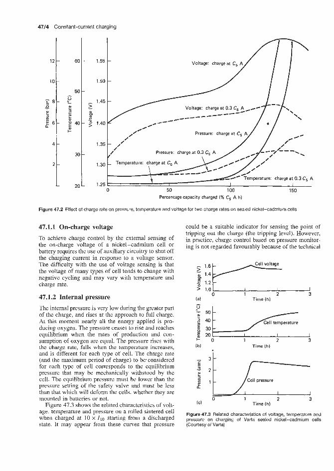
4714 Constant-current charging
60
50 u e E w c t 4 0 -
?
30
20
-
-
- 2 W rn 4- - 2
-
-
12
10
z 8 - d ?!
!! 6-
- In
0
1.55 -
1.50 -
Pressure: charge at 0.3 C, A
I 0 50 100 150
-
-
4 -
2-
L
Percentage capacity charged (% C, A h)
Figure 47.2 Effect of charge rate on pressure, temperature and voltage for two charge rates on sealed nickel-cadmium cells
47.1.1 On-charge voltage To achieve charge control by the external sensing of the on-charge voltage of a nickel-cadmium cell or battery requires the use of auxiliary circuitry to shut off the charging current in response to a voltage sensor. The difsculty with the use of voltage sensing is that the voltage of many types of cell tends to change with negative cycling and may vary with temperature and charge rate.
47.1.2 Internal pressure The internal pressure is very low during the greater part of the charge, and rises at the approach to full charge. At this moment nearly all the energy applied is pro- ducing oxygen. The pressure ceases to rise and reaches equilibrium when the rates of production and con- sumption of oxygen are equal. The pressure rises with the charge rate, falls when the temperature increases, and is different for each type of cell. The charge rate (and the maximum period of charge) to be. considered for each type of cell corresponds to the equilibrium pressure that may be mechanically withstood by the cell. The equilibrium pressure must be lower than the pressure setting of the safety valve and must be less than that which will deform the cells, whether they are mounted in batteries or not.
Figure 47.3 shows the related characteristics of volt- age, temperature and pressure on a rolled sintered cell when charged at 10 x Zlo starting from a discharged state. It may appear from these curves that pressure
could be a suitable indicator for sensing the point of tripping out the charge (the tripping level). However, in practice, charge control based on pressure monitor- ing is not regarded favourably because of the technical
5 1.0 I I I I 0 1 2 3
(a) Time (h) 1
30 5 20
a Cell pressure (C) n :%= 0 1 Time (h) 2 3 f 1
Figure 47.3 Related characteristics of voltage, temperature and pressure on charging of Varta sealed nickel-cadmium cells (Courtesy of Varta)

The Eveready fast-charge cell (nickel-cadmium batteries) 47/5
and economic problems involved in fixing a pressure- sensitive device to a standard cell or in designing a special pressure-sensitive cell.
47.1.3 Electrolyte temperature As shown in Figures 47.2 and 47.3, temperature is a suitable indicator of the state of charge of a battery. Temperature is practically constant during the greater part of the charge. When the fully charged state and overcharge are reached, the heat generated by the recombination reaction causes a rise of temperature. This stabilizes at a level that depends on the rate of charge and the thermal exchange characteristics of the cell or battery. The maximum rate of charge for the cell or battery corresponds to that at which the stabilized temperature is still acceptable; in general, this temperature should not exceed 60°C.
Cell voltage rises at the moment the charging ends; then the rise of temperature on overcharge has the effect of reducing the voltage. The increase of voltage at the end of charge is a function of the rate of charge and the tempcrature. This characteristic is developed in the system of controlled rapid charge.
One of the dangers of using electrolyte temperature as a means of controlling battery charging is that, if the battery is subjected to even short-term overcharge, the distinct temperature increase can cause physical damage to the cell and/or loss of cell capacity. High cell pressures are also a possible source of danger or damage.
Cell temperature monitoring has commonly been used as an indication of battery overcharge, the rise in temperature being fairly slow and concurrent with the rise in pressure. To achieve accurate temperature sensing it is necessary to have good thermal insula- tion between cells and normal ambient temperature during discharge. Without accurate control, cells may vent before the charge is terminated, with consequent dehydration and electrode imbalance.
In the sealed nickel-cadmium system most of the oxygen evolved is reduced at the cadmium-metal surface, with the consequent oxidation of the cadmium to cadmium hydroxide. This statement certainly applies for normal rates of charge. However, the rate of charge and temperature affect the recombination of oxygen. Provided the charge rate is sufficiently high, the oxygen evolved for a given temperature will not combine with the cadmium and the pressure will build up within the cell. While the pressure is rising, a pronounced rise in cell voltage will occur (approximately half the magnitude of that occurring in open cells). This voltage may be detected and used to terminate the charge.
More recently, however, cell temperature monitor- ing has been developed as a means of charge control as discussed below.
Sealed nickeI-cadmium cells normally tend to warm up om overcharge in proportion to the rate
of oxygen recombination at the negative electrode. Unfortunately, the ability of most commercially available nickel-cadmium cells to recombine oxygen gas is rather limited, as evidenced by the acceptance of the C/10 overcharge rate. The cells can withstand higher rates, but in overcharge at high rate only a fraction of the evolved oxygen will be recombined, resulting in heat generation. This change in temperature is gradual and difficult to detect. The excess of unrecombined oxygen will result in internal pressure build-up and cell venting. Excessive venting of cells may reduce useful capacity, and cause dehydration and electrode imbalance.
TO accomplish charge termination safely and reli- ably through temperature sensing requires fast-acting, precise and expensive equipment at the lower charge rates. Because of the size, cost and complexity of such a system, the thermal sensing approach to over- charge control has previously been impractical for the consumer-oriented nickel-cadmium battery-powered portable appliances and devices. To overcome these problems, Union Carbide have developed a special fast-charge sealed nickel-cadmium battery design (the Eveready cell) and a temperature-sensing high-rate bat- tery charger design.
The Eveready fast-charge cell has been specially designed to withstand high-rate overcharge (up to the 1 h rate) and thus to overcome these drawbacks. Nevertheless, Eveready cells and batteries should not be continually overcharged at high rates. Undesirable cell degradation or heat build-up damage will occur if batteries are left on high-rate charge.
Eveready sealed secondary nickel-cadmium cells and batteries are now widely used as a rechargeable power source in many different types of portable or cordless electrical appliance. Charging at the safe recommended C/10 rate has proved satisfactory for recharging the cells or batteries used in many of these appliances, such as toothbrushes, shavers, etc., where relatively long rest periods between uses are possible. However, there is now a demand for the use of sealed nickel-cadmium cells and batteries in other appliances, such as chain saws, electronic Rashes, portable drills and professional hair clippers, where the rest periods between uses of the appliances are much shorter; consequently shorter recharging times, from about 3 h to about 1 h, that is, C13 to C/1 rates, are required.
The charging of sealed nickel-cadmium batteries has been discussed further in a book published by Gate Energy Products (see Bibliography).
47.2 The Eveready fast-charge cell (nickel-cadmium batteries) As the design of the cell and the charger are, in this case, intimately linked a description of the cell design will be given first.

47/6 Constant-current charging
47.2.1 Cell design This cell has been designed to exhibit sufficient tem- perature rise to effect charge control without a sig- nificant change in operating pressures. The Eveready fast-charge cell series develop the desired temperature rise, and have the built-in ability to withstand short- term overcharge at rates to 1 h values without physical damage or loss in cell capacity. The cell construction is specifically designed to withstand overcharge at the 3 h rate without special control circuitry. Considerable heat can be generated within the cell, however, if over- charge is extended beyond a reasonable period of time. To prevent this heat from causing gradual cell degra- dation, it is recommended that the cell temperature should not exceed 46°C during this extended over- charge and that the cells be removed from the charger within 2 or 3 days of reaching full charge.
Before the introduction of this construction by Union Carbide, any cell overcharged at the 1 h rate would be permanently damaged. The Eveready fast- charge cell can withstand overcharge at these high rates long enough for the temperature rise to be sensed by simple control elements. This temperature rise is very pronounced, and provides a positive signal for charge control. As a result, the control element can be small, lightweight and inexpensive.
Sealed secondary nickel-cadmium cells have been manufactured for many years based on the so- called ‘oxygen recombination’ principle. The charge- accepting capacity of the negative electrode is made to exceed the charge-accepting capacity of the positive electrode. On charging, the positive electrode reaches a state of full charge before the negative electrode, and oxygen is evolved at the positive electrode. The oxygen gas reacts or combines with the active cadmium metal on the surfaces of the negative electrode. Thus, recombination of oxygen prevents the build-up of an excessive internal gas pressure.
In charging nickel-cadmium cells, an overcharge, that is, ampere hours input in excess of that previously removed upon discharge, must be provided to ensure that the cells have reached full charge. If overcharge is continued at too high a rate of charge current, the evolved oxygen gas may not fully recombine, and a build-up of excessive internal gas pressure may result. A safety resealable vent is provided to limit excessive build-up of pressure. In the Eveready design, proper selection of the electrolyte volume controls oxygen recombination pressure below the safety vent opening pressure. The safe charge rate for sealed secondary nickel-cadmium cells for extended charge periods has been established at the 10 h, or the C/10, rate; capacity (C) is the rated ampere hour capacity of the cell and 10 is the number of hours required at perfect charge efficiency to bring a completely discharged cell to full charge. At the 10h rate and lower currents, an equilibrium condition is maintained in the cell and consequently there is no excessive build-up of internal gas pressure.
47.2.2 Charger design The Eveready fast-charge cell exhibits a relatively sharp rise in temperature during high-rate overcharge. The particular type of thermal sensor to be used in combination with the cell or battery and the charger system is not critical. Probably the least expensive overall cell or battery control unit is provided by use of a simple snap-action thermostatic switch, which com- bines the temperature-sensing and circuit-switching functions in one small, inexpensive device that can be easily attached to the cell or battery.
A solid-state thermistor sensor may also be used. The thermistor is also relatively inexpensive and is even more compact, although it performs only the function of a sensor. Auxiliary circuitry and a switch- ing means are required to cut off the charging current in response to the thermistor input. Among the com- mercially available types of thermistor, the positive temperature coefficient type is preferred because it changes resistance abruptly at a predetermined temper- ature. Auxiliary circuitry is therefore simplified with- out loss of reliability.
In constructing individual cell or battery units, it is not critical that the thermal sensor be placed or main- tained in actual physical contact with the cell proper, although this is preferred. Individual cell units may be constructed with a small flat disc-type thermostatic switch welded in contact with the bottom of the cell. Similar battery units may be constructed with a small thermistor or bimetallic switch placed in the space between adjoining cells. Any arrangement is satisfac- tory provided the thermal sensor is well exposed to the heat generated by the individual cell or one or more cells of the battery. The use of extensive heat sinks, such as placing the entire battery in a water bath, is not recommended since this can prevent heat build- up, impede oxygen recombination within the cell, and lead to cell venting before sufficient heat rise occurs. The terminal leads from the thermal sensor may be connected by additional external contacts or may be brought out from the cell or battery unit and con- nected directly into the circuit. Where a sensor-switch device is used in a series-connected battery, it may be preferred to wire the switch internally between two series cells so that no additional external contacts are required. The practicality of this connection depends on discharge current value and sensor current rating. The advantage would be that the circuit would also open on discharge in case the battery becomes over- heated for any reason. The charger circuit required for charging the individual cell or battery is not unique. A constant-current charger is recommended, and due regard should be paid to heat dissipation and wattage ratings of all components.
Figure 47.4 shows typical voltage and temperature characteristics of the Eveready CF1 fast charge cells when charged at the 1 h rate. Note that the temperature remains relatively constant until the cell approaches
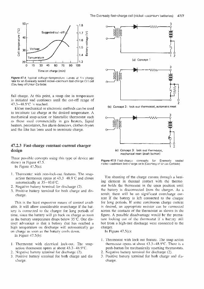
The Eveready fast-charge cell (nickel-cadmium batteries) 4717
,.
'ag 1 2
(a) Concept 1
0 15 30 45 60 75 90 105
Time on charge (min)
Figure 47.4 Typical voltage-temperature curves at 1 h charge rate for an Eveready sealed nickel-cadmium fast-charge CFI cell (Courtesy of Union Carbide)
full charge. At this point, a steep rise in temperature is initiated and continues until the cut-off range of 43.3-48.9"C is reached.
Either mechanical or electronic methods can be used to terminate tne charge at the desired temperature. A mechanical snap-action or bimetallic thermostat such as those used commercially in gas heaters, liquid heaters, percollators, fire alarm detectors, clothes dryers and the like has been used to terminate charge.
47.2.3 Fast-charge constant-current charger design
Three possible concepts using this type of device are shown in Figure 47.5.
In Figure 47.5(a):
1. ThLermostat with non-lock-out features. The snap- action thermostat opens at 43.3-48.9"C and closes automatically at 35 -40.6"C.
2. Negative battery terminal for discharge (2). 3. Positive battery terminal for both charge and dis-
charge.
This is the least expensive means of control avail- able. It will allow considerable overcharge if the bat- tery is connected to the charger for long periods of time, since the battery will go back on charge as soon as the battery temperature drops below 35°C. One dis- tinct advantage is that a battery that has reached a high temperature on discharge will automatically go on charge as soon as the battery cools down.
In Figure 47.5(b):
1. Thermostat with electrical lock-out. The snap- action thermostat opens at about 43.3-48.9"C.
2. Negative battery terminal for discharge (2). 3. Positive battery terminal for both charge and dis-
charge.
2 (b) Concept 2: lock out thermostat, automatic reset
1 2 (c) Concept 3: lock out thermostat,
mechanical reset (push button)
Figure 47.5 Fast-charge concepts for Eveready sealed nickel-cadmium fast-charge cells (Courtesy of Union Carbide)
The shunting of the charge current through a heat- ing element in thermal contact with the thermo- stat holds the thermostat in the open position until the battery is disconnected from the charger. As a result, there will be no signiscant overcharge cur- rent if the battery is left connected to the charger for long periods. If some continuous charge current is desired, an appropriate resistor can be connected across the contacts of the thermostat as shown in the figure. A possible disadvantage would be the prema- ture locking out of the thermostat if a battery still hot from a high-rate discharge were connected to the charger.
In Figure 47.5(c):
1. Thermostat with lock-out feature. The snapaction thermostat opens at about 43.3-48.9"C. There is a push-button for mechanically resetting thermostats.
2. Negative battery terminal for discharge (2). 3. Positive battery terminal for both charge and dis-
charge.

47/8 Constant-current charging
The snap-action thermostat would cut off all charge currents. This concept might be useful in an application where high-rate charge was not normally needed, but would be useful at certain times. A charger could be designed to provide more moderate charging such as the C/10 rate, unless the user pushed the reset button when a fast charge was required (as shown in the figure). Again a heated battery from high-rate discharge would necessitate a wait until the thermostat could be reset.
A second means of terminating the charge on the battery at the desired cut-off temperature is through the use of temperature-responsive electronic circuitry. In essence, this circuit will electronically terminate charge when the desired temperature is reached through the use of a sensing element and switching-type devices. A possible electronic circuit for this type of charge control is shown in Figure 47.6. The time to reach cut-off and the period of cycling 'on' and 'off' depend on charge rate, battery packaging and ambient temperature.
1 - 4 4 Figure 47.6 Fast-charge concept for Eveready sealed nickel- cadmium fast-charge cells. The circuit is designed to cut off charge at 43.3-48.9"C. The big advantage of this concept is the small size of the thermistor (R4) contained in the battery pack. The circuit must be specifically designed for each application and its stability checked over the temperature range encountered by the battery in use (Courtesy of Union Carbide)
47.3 Types of constant-current charging There are many constant-current methods that per- mit satisfactory charging of sealed nickel-cadmium batteries. These methods differ in the length of time required to charge, the complexity of the circuits used and the various techniques for charging with maximum safety and reliability. The following charging systems are worthy of mention (see Table 47.1):
1. Normal rate charge. 2. Accelerated charge. 3. Controlled rapid charge: timed, voltage-time con-
4. Ultra-rapid charge. 5 . Uncontrolled rapid charge. 6. Low-temperature charge. 7 . Permanent or floating charge.
The various methods of charging of sealed nickel-cadmium cells and batteries are discussed briefly below.
trol, voltage-tempei-ature control.
47.3.1 Normal constant-current charging This is the method recommended by all battery manu- facturers for the charging of sealed nickel-cadmium batteries at the normal (i.e. unaccelerated) rate of charge.
It is permissible to use a nominal constant current, where the initial current (when the battery is discharged) is not critical, provided the Zlo rate is not exceeded on overcharge.
Normal charge is carried out at a rate of 0.1Cs A or the recommended charging current at room ternper- ature for 14-16h and may, for example, be applied to all sealed cylindrical and button cells and batter- ies between 5 and 40"C, whatever the initial state
Table 47.1 Summary of non-permanent methods of charge recommended for SAFT sealed nickel-cadmium batteries
Charge method Duration Application Battely type Initial state Capacit): Continuous temperature before recoverable overcharge
("C) charge (%) rated acceptance at 20°C
Normal
Accelerated
Controlled Rapid timed Timed Voltage-time control Voltage- temperature control
Ultra-rapid Uncontrolled rapid
14h 14h 3h 7 h
50 min l h l h 15-60 min 1-15 min 30-60 min
5 to 40 5 to 40 5 to 40
10 to 40 10 to 40
-20 to +40 15 to 30 0 to 30
VB -VR VO sealed VR 0.1 to VR 1.8 VR 2.5 to VR 7
VB VR 0.1 to VR 1.8 VR (except VR 10) VR VR vx
Any
Any
Discharged
Discharged Any Any Any
Any
Discharged
100 100 100
80 80-100 80-100 80-100 10-80 100
20 000 h None 10 days continuous
None None None None None Several days

Types of constant-current charging 47/9
case of Nife Jungner sealed nickel-cadmium cells in Table 47.2. Continued charging to full state of charge must not be carried out with this high current, but the normal charging currents shown in Table 47.2 should be used. This requires several hours and thus charging to full charge with this method is not advantageous. In urgent situations, when full capacity is not required, it can be useful, however.
of charge. Overcharge acceptance at this rate is great (more than 20 000 h). Sealed rectangular cells must be in the dischagEd state before being recharged for 14 h at O.lCsA. Below 10°C the rate of charge must be reduced.
The 10h rate should not normally be exceeded unless overcharge is specifically to be prevented. Dur- ing charging, the cell voltage rises from approximately 1.30 V to a maximum of approximately 1.45 V at near full charge. Finally, the voltage is stabilized at approx- imately 1.43 V. The decreasing voltage at the end of charging depends on a temperature rise in the cell. It is caused by the reaction between oxygen and the neg- ative electrode in the cell. This voltage characteristic, with a gradual and relatively moderate voltage increase followed by stabilizing at a level slightly less than maximum. is typical for sealed nickel-cadmium cells. Typical constant-current charging curves for a 0.4 A h nickel-cadmium cell are shown in Figure 47.7.
Instead of the normal charging current, both lower and higher currents can be used. The final voltage is dependent on the charging current and increases with rising current (Figure 47.7). These curves show typical final charging voltages in relation to charging cur- rent when the cells have been charged with 1.8CAh. Because of low charging efficiency at low charging currents, the final voltages in these curves correspond- ing to charging currents below approximately 0.1C A do not represent a full state of charge.
47.3.2 Accelerated constant-current charging
This method is applicable only to sealed nickel- cadmium cylindrical cells at cell temperatures between 10 and 40°C. 3 h at 0.4c5 A or 7 h at 0.2C5 A suffices to fully charge the battery according to cell type, with high overcharge acceptance which must be limited to about 10 days to avoid an adverse effect on cell life. For cylindrical cells the accelerated rates correspond to the maximum permissible on long-term overcharge for the cells in the temperature range 5540°C. A few hours’ overcharging at these currents will not damage the cells. The cells must not be fully charged with currents higher than 0.2C A. Completely discharged cells at normal temperature can be charged to approximately 80% of charge in 1 h with seven times the normal charging current shown, for example in the
0 2 4 6 8 1 0 1 2 1 4 Charge time ( h )
Figure 47.7 Charge voltage versus charge time at a constant cur- rent of 0.05A at 25°C. Nife Jungner0.4A h sealed nickel-cadmium cells (Courtesy of Nife Jungner)
47.3.3 Controlled sapid constant-current charging This is understood to imply a charge period of less than 1 h. (When the period is less than 15 min the charge is called ultrarapid; see below.) Controlled rapid charge implies that there is a system that interrupts the charge before the cells or battery reaches an overchaxge state that is mechanically excessive (that is, could burst the case).
The methods of control recommended are suited to the operating temperature range and the ability of the nickel-cadmium cells or battery to accept or otherwise a degree of overcharge at high rate.
This method of charge should not be applied to cells and batteries that cannot accept overcharge at a high rate and which do not have safety valves that can operate in case of an excessive internal pressure.
Timed charge
Rapid charge for a limited time of cylindrical standard nickel-cadmium batteries (simplified 1 h rapid charge) is applicable to cylindrical standard batteries, differ- ing from voltage-temperature controlled rapid charge which requires specially adapted batteries. Accord- ing to whether the sizes of these cells will accept overcharge at a rate of Cs A, a distinction is made between two methods of limited time rapid charge which may be applied to cells of an unknown ini- tial state of charge. For example, SAFT VR 0.1 f AA 0.1 A h cylindrical cells and batteries (Table 5 1.1) can withstand a double charge at a rate of C5 A (0.1 A). The internal pressure does not reach the opening pres- sure of the safety valve and the temperature rise on overcharge is less than 20°C.
These batteries and cells may be charged at C5 A, whatever their initial state of charge, and the chargers necessary are of a very simple design, a timer ter- minating the charge after 1 h.
Cylindrical cells and standard batteries such as SAFT VR 0.45 1 A (0.45 Ah), VR 0.5 AA (0.5 Ah), VR 1.2RR (1.2Ah), and VR 1.8C (1.8Ah) (see Table 51.1) cannot accept a double charge at the rate of CsA; the internal pressure and temperature on overcharge exceed permissible limits. An overcharge of limited duration is, however, possible in com- plete operational safety. These cells and batteries can accept an overcharge at Cg A, 0.4 times their nom- inal capacity, without rises of internal pressure and
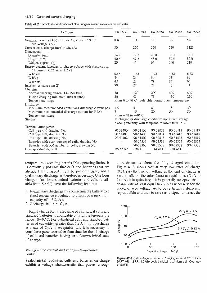
47/10 Constant-current charging
Table 47.2 Technical specification of Nife Jungner sealed nickel-cadmium cells
Cell type KR 15/51 KR 23/43 KR 27/50 KR 35/62 KR 35/92
Nominal capacity (Ah) (5 h rate Cg at 25 & 5°C to
Current on discharge (mA) (0.2Cg A) Dimensions
end-voltage 1 V)
Diameter (mm) Height (mm) Weight, approx. (g)
Energy content (average discharge voltage with discharge at 5 h current, 0.2CA, is 1.2V)
W Wcell w m g W Wdm3
Internal resistance (m i2) Charging
Normal charging current 14-16h (mA) Trickle charging minimum current (mA) Temperature range
Maximum recommended continuous discharge current (A) Maximum recommended discharge current for 5 (A) Temperature range
Discharge
Storage
Terminal arrangement: Cell type CF, drawing No. Cell type HH, drawing No. Cell type HB, drawing No. Batteries with even number of cells, drawing No. Batteries with odd number of cells, drawing No.
Corresponding dry cell
0.40 1.1 1.6 3.6 5.6
80 220 320 720 1120
14.5 22.7 26.0 33.2 33.2 50.3 42.2 48.0 59.5 89.0 20 45 65 140 210
0.48 1.32 1.92 4.32 6.72 24 29 30 31 32 65 81 78 86 90 90 27 22 13 11
50 120 200 400 600 20 45 75 150 250 From 0 to 40"C, preferably normal room temperature
1.5 5 8 15 20 7 15 20 50 80 From -40 to +40°C In charged or discharge condition: use a cool storage place, preferably with temperature lower than 15°C
90-51400 90-51405 90-52813 90-51411 90-51417 90-51401 90-51406 90-52814 90-51412 90-51418 90-51402 90-51407 90-52815 90-51413 90-51419
- 90-52359 90-53536 90-52357 90-52355 - 90-52360 90-53537 90-52358 90-52356
R6 or AA Sub C R14 or C R20 or D -
temperature exceeding permissible operating limits. It is obviously possible that cells and batteries that are already fully charged might be put on charge, and a preliminary discharge is therefore necessary. One hour chargers for these standard batteries and cells (avail- able from SAFT) have the following features:
1. Preliminary discharge by connecting the battery to a fixed resistance calculated to discharge a maximum capacity of 0.6Cs Ah.
2. Recharge in 1 h at Cg A.
Rapid charge for limited time of cylindrical cells and standard batteries is applicable only in the temperature range 10-40°C. For cylindrical cells and standard bat- teries of capacities greater than 1.8 A h, no overcharge at a rate of CgA is acceptable, and it is necessary to consider a parameter other than time for the 1 h charge of cells and batteries having an unknown initial state of charge.
Voltage-time control and voltage-temperature control
Sealed nickel-cadmium cells and batteries on charge exhibit a voltage characteristic that passes through
a maximum at about the fully charged condition. Figure 47.8 shows that at very low rates of charge (O.lCs A) the rise of voltage at the end of charge is very small; on the other hand at rapid rates (CgA to 2C5 A) it is quite large. It is generally accepted that a charge rate at least equal to Cs A is necessary for the end-of-charge voltage rise to be sufficiently sharp and reproducible and thus to serve as a signal to detect the
1.70-
2 C, A, 2.4 A
1.60 - I
>
1.30 L/ I I I 0 50 100 150
Capacity charged (% C,)
Figure 47.8 Cell voltage at various charging rates at 25°C for a SAFT VR 1.2 RR (1.2 A h) sealed nickel-cadmium cell (Courtesy of SAFT)

Types of constant-current charging 47/1 d
This system of control does not require the use of special batteries and may be applied to all standard batteries including cylindrical types with capacities up to 7 A h charged at the Cs A rate. The time-switch ter- minates the charge in all cases after 1 h. The capacity recharged is close to the rated capacity between 20 and 40°C and is less below this lower temperature.
In control by voltage-temperature, the termination of rapid charge is obtained from values of voltage that depend on the temperature of the battery. For eco- nomic reasons, it is not possible to follow precisely the theoretical characteristics of cut-off voltage as a function of temperature (Figure 47.9(a)). The charac- teristics may be linearized while retaining sufficient security for cut-off. Figure 47.9(b) shows the charac- teristics used in practice for a battery pack of ten SAFT lOVR 1.2RR 1.2Ah (i.e. 12Ah) cells (Table 51.11, charged at Gs A and 2C5 A.
The capacity obtained with this system remains satisfactory in the temperature range of -20 to +40"C. Most rapid-charge systems with voltage-temperature control leave the batteries on low-rate charge after cut- off of the rapid charge. The object of this is to give 100% of capacity charged. To provide maximum se- curity during charging, batteries can be equipped with thermostatic protection which interrupts this charge in case of irregularity in the battery or the charge system. This protection operates when the battery temperature reaches the abnormal value of 5.5-60°C. Batteries for rapid charge with voltage-temperature control must be adapted to this system because they must be equipped with a temperature sensor for voltage control and a thermostat for protection against overheating.
47.3.4 Ultra-rapid constant-current charging By limiting the capacity charged to a certain proportion of the rated capacity of the cell or battery, it is pos- sible to charge cylindrical and button nickel-cadmium sealed cells and batteries at very high rates and thus obtain a short-duration charge of the order of a few minutes. The amount of the capacity that may be charged is determined by the increase of internal pres- sure, which must always remain below the operating pressure of the valve for cylindrical cells and batter- ies and the deformation pressure for button cells and batteries. Ultra-rapid charge requires a prior discharge of the cells, which may be done in periods as short as 30 s.
Figure 47.10 shows the durations of ultra-rapid charge that are possible for a SAFT VR 0.5AA (0.5Ah) cylindrical cell (Table 51.11, as well as the security limit corresponding to opening of the valves at 20°C. A method of charge derived from the ultra- rapid is the one-shot charge for use in an application that requires only one single cycle, such as a mil- itary application where the battery is charged only once and is subsequently destroyed with the appara- tus it supplies. For operational reasons, the battery must be charged in a few seconds, which 3s possible
end of charge. The on-charge voltage characteristics vary with the temperature and the charge rate, and show significant differences between sizes of cylin- drical cells. For each cell, for a given rate of charge, it is possible to draw a theoretical cut-off voltage curve as a function of cell temperature. An example is shown in Figure 47.9(a) for a battery of ten SAFT VR 1.2RR (1.2 Ah) cylindrical cells (Table 5 1.1) charged at rates of Cs and 2Cj A. At each temperature the selected cut- off voltages are defined to coincide approximately with the fully charged condition and to be clearly above the first voltage plateau and below the maximum end-of- charge voltage.
Depending on the operating temperature range, two methods of control (voltage-time and volt- age-temperature) can be used. Control by volt- age-time is used in applications where the operating temperature is of the order of 20°C (from 10 to 40°C). Chargers designed for this method of operation ter- minate the charge when the battery voltage reaches a fixed preset value. This value corresponds to the cut- off voltage at 4YC (the lowest cut-off voltage in the temperature range under consideration). A time-switch ovenide is used to allow for the case where the battery temperature might exceed 40°C or the end-of-charge voltage might be abnormal.
'181
11 4 I i I I I 1 I
-20 -10 0 10 20 30 40 50 Battery temperature ("C)
I
--20 -10 0 10 20 30 40 50 Battery temperature ( "C)
Figure 47.9 (a) End-of-charge cut-off voltage versus temperature: SAFT IOVR 1.2RR battery pack (ten 1.2Ah cells, 12Ah battery); fast charge at C5A rate (1.2Ah) then 2CsA rate (2.4Ah). (b) Charger cut-off voltage versus temperature: SAFT 1 OVR 1.2 RR battery pack (ten 1.2 A h cells; 12 Ah battery); fast charge at CS A rate (I .2 A h) then 2C5 A rate (2.4A h) (Courtesy of SAFT)

47/12 Constant-current charging
Capacity chargeable before safety valve open
62 5
500
375
2 50
125
0 0.5 1 2.5 5 10 15 25 50
Charging rate (A)
Charge time
Figure 47.10 Duration of ultra-rapid charge for SAFT VR 0.5AA sealed cylindrical nickel-cadmium cells: charge duration versus charging rate (Courtesy of SAm
at very high rates if the capacity charged is limited to a few per cent of the rated capacity. This technique is applicable with complete safety over the temperature range -40 to +60°C. In the case of one-shot char- ging, the available capacity is small, but the power available for short periods remains high. Thus, fully discharged button cells will accept between -40 and +60T charge rates of up to 2OCsmA for a limited time. For example, §AFT VB 10 (0.1 Ah) button cells (Table 51.1) charged for 5 s at 1 A have an available capacity of 2400mA.
47.3.5 Uncontrolled rapid constant-current charging This method is applicable to nickel-cadmium cylin- drical cells and batteries such as the SAFT VO series (Table 51.1), which can withstand higher rates of charge and overcharge than standard cylindrical cells such as the SAFT VR range. This extra performance is made possible by the use in battery design of highly porous plates which improve oxygen consumption at the negative plate. A further consequence of this is that the available capacity per unit volume of the for- mer type of cell is reduced to about 40-50% of that of the latter type. However, the power-to-volume ratio remains high. Over-charge at high rate may continue for several days without affecting the battery life.
The ability to overcharge at high rates permits the uncontrolled rapid charge of cells of unknown state of charge using chargers of simple design and relatively low cost. The times for uncontrolled rapid charge for cells that can stand higher rates of charge and overcharge (e.g. the SAFT VX range (Table 51.1)) are between 30 and 60 min in the temperature range 0-30°C.
47.3.6 Low-temperature constant-current charging
Charging should preferably be done at normal tem- perature, but can be done between 0 and 40°C. Typ- ical charging voltages are lower at a temperature higher than room temperature, and higher at tempera- tures lower than room temperature. Typical charging curves for nickel-cadmium cells at 0°C are shown in Figure 47.11. Manufacturers claim that occasional overcharging during a few weeks of cell life with nor- mal recommended charging current will not damage the cells.
Table 47.3 compares the maximum charge rates (in milliamperes) for stated charge times (in hours) recom- mended for various charging temperatures between -30 and +lO"C in the normal and the continu- ous (float) charging of a series of SAFT VB series (Table 51.1) sealed nickel-cadmium button cells.
Figure 47.12 presents a series of typical voltage versus capacity charged curves for various discharge rates for a series of button nickel-cadmium batteries (SAFT VB series, Table 51.1).
When the temperature of batteries is less than YC, it is necessary to limit the rates of charge and over- charge. The charge rate must be chosen so that the internal pressure on overcharge is less than the oper- ating pressure of the valves in the case of cylindrical cells or the deformation pressure in the case of but- ton and sealed rectangular cells. Figure 47.13 shows, for cylindrical and button cells, the maximum permis- sible rates on overcharge for short periods (a few days)
0 2 4 6 8 1 0 1 2 1 4 Time (h)
(a) Type KR15/51, 0.4 A h, current 0.05 A
0 2 4 6 8 1 0 1 2 1 4 Time (h)
(b) Type KR35/92,5.6 A h, current 0.6 A
Figure 47.11 Charge voltage versus charge time of Nife Jungner sealed nickel-cadmium cells at constant current and 0°C (Courtesy of Nife Jungner)

Types of constant-current charging 47/13
Table 47.3 Comparison of maximum charge rates in normal and continuous (float) charging at various temperatures recommended for SAFT VB series sealed nickel-cadmium button cells
Cell type VB 4 VB 10 VB 22 VB 30 VB 40
Rated capacity (Ah)
Nominal discharge voltage per cell (V)
Normal charge from -30 to +lO"C, max. charge rates (mA) for charge time (h) in brackets
Continuous charge from -30 to +lO"C, m a . charge rates (mA) for charge time (h) in brackets
-30 (100) -20 (55) -10 (30)
0 (20) +10 (14) -30 (100) -20 (55) -10 (30)
0 (20) +10 (14)
40 100 220 300 600
1.20 1.20 1.20 1.20 1.20
0.4 1 .o 2.2 3.0 6.0 0.8 2.0 4.0 6.0 12.0 1.5 4.0 8.0 11.0 21 .0 2.5 6.0 13.0 18.0 36.0 4.0 10.0 22.0 30.0 60.0
0.2 0.5 1.0 1.5 3 .0 0.4 1 .0 2.0 3.0 6.0 0.8 2.0 4.0 5.0 11.0 1.2 3.0 6.5 9.0 18.0 2.0 5.0 11.0 15.0 30.0
Occasional overcharge at these rates beyond the prescribed times is not detrimental to the cell. Rapid and ultra-rapid charge systems can be obtained for charging in times from a few seconds to 1 h
1.6
1.5
2 1.4 m ooc z i .3
2.5 mA at 0 O C -
> 1.2 t 1.1 1 I I I 1 I I i
0 8 16 24 32 40 48 56 Capacity charged EmA h)
(a)
r 13 rnA at 0 "C
u&e= 1.:
5
I
1.5
2 1.4 0) 0 O C 2 1.3 5
1.2 i- 1.1 I L I I I I I I
Cl 44 88 132 176 220 264 308 Capacity charged (mA h)
(b)
1.6
1.5 > - 1.4 - m z 1.3 >
1.2
0 120 240 360 480 600 720 840 Capacity charged IinA h)
(C)
Figure 47.12 Voltage versus capacity for 'normal' charging of SAFT VB series sealed nickel-cadmium button cells. (a) UB4 40Cs m h h; (b) U B Z 220C5 rnA h; (c) VB60 600C5 mA h (Courtesy of SAFT)
and on permanent overcharge. A number of methods are used to vary the charge current as a function of temperature:
Fit into the battery a temperature sensor that oper- ates on the charger to adjust the charge current to suit the battery temperature. Charge at constant current and voltage limited to 1.55 Vkell, a voltage setting that will avoid all risk of internal overpressure at low temperature. Use the charge current corresponding to the lowest operating temperature.
Also, in certain cases, for example when charging at low temperatures, constant-current charging can be combined with voltage limitation. With a normal char- ging current of approximately 0.1C A a fully charged state is reached after 14-16h at room temperature. A lower current, 0.04-0.05C A, is often used as con- tinuous charging current in different applications. The charging efficiency is then lower, because proportion- ally more energy is used to produce oxygen. The char- ging efficiency is also dependent on the temperature, and decreases with rising temperature.
47.3.7 Permanent or floating constant-current charging
In applications with permanent charge, the object of the charge current is to maintain an already fully charged nickel-cadmium battery in this state over a period of time and when necessary to recharge any capacity discharged at regular intervals or in a random manner. The first charge may be carried out either at the permanent rate if this is sufficient (>O.O2C5 A), or at a higher rate where the permanent charge value is

47/14 Constant-current charging
VRO.l 1/3 AA a t VR 1.8 C cells
VR 2.5 2/3 D a t VR 4 D 20 -
-30 -20 -10 0 10 20 Temperature ("C)
(a) Sealed cylindrical cells, VR series
cells
01 I I I 1 -20 -10 0 10 20
Temperature ("C) Ib) Sealed button cells, VB series
Figure 47.13 Effect of temperature on optimum maximum permissible overcharge rates for short periods: SAFT VR and VB sealed nickel-cadmium cells: - , maximum rates for occasional overcharge: ---- , maximum recommended permanent charge rates (Courtesy of SAFT)
too low for the effective recharge of a fully discharged battery. Rates vary from 0.005CmA to 0.05CmA. Where the appropriate rate is below 0.02C5mA the battery should be given a normal charge (0.1C5 mA for 14 h) when commissioning.
Trickle charge can be used in applications where the cells must always be kept fully charged. The minimum recommended current for trickle charging (Table 47.2) is chosen so that a full state of charge can be obtained when recharging with the same current. After charging for 24h the state of charge is approximately SO%, and after 48 h approximately 95%. Full state of charge requires approximately 1 week.
In applications where the cells are mounted closely together with charging equipment or other
heat-generating devices, the temperature increase can be considerable. The life of the cell is adversely affected by increased temperature. Thus the capacity will decrease to 75% of nominal when the cells are trickle charged with recommended minimum current for 1 year at 40°C. Therefore the cells must be shielded from heat radiation and the battery compartment must be well ventilated. The cell voltage decreases only slightly during discharge and for a completely discharged cell on open circuit will quicMy be restored to approximately 1.2 V. The cell voltage can therefore not be used to determine the state of charge. Cells with an unknown state of charge should be considered discharged, but must not be recharged at the rapid- charge rate.
The nickel-cadmium battery can be trickle charged, but floating and constant-voltage charging are not re- commended. For maximum performance in situations of long-term trickle charge, the current should be kept to a minimum. The trickle charge current required to keep the battery fully charged is approximately the 30-50 h rate plus whatever is necessary to compen- sate for any major withdrawals. Lower trickle rates maintain the battery at some lower state of charge. If either floating or constant-voltage charging is manda- tory, a thermal cut-out that senses battery temperature must be included in the charge circuitry. Battery over- heating, which follows from any irregularity in the voltage-current control system, can be totally destruc- tive to either battery or charger, or both.
Permanent charge with occasional discharge
This is usually the case where the nickel-cadmium battery supplies emergency power to apparatus in the event of a.c. supply failure. Permanent charge currents may be very low, from 0.005C~ to 0.02C5A, when the depth of discharge foreseen is less than 50%. In this case, nickel-cadmium batteries are put into service after having been previously charged at a higher current. If the depth of discharge is great and if recharge must be obtained in a few hours, two solutions are possible:
1. Charge at a single rate, up to 0.05C5 A. 2. Charge by the two-rate method: fast charge at
0.1-0.3C~ A, then continue with a maintenance charge of 0.01Cs A.
Permanent charge with regular discharge
In this case the nickel-cadmium batteries are the power source for apparatus that requires a supply for more or less random periods, but for which the total capacity discharged in a given time is known. During the time when the batteries are not discharging they receive a continuous charge, the rate of which depends on the discharge capacity during a known period. Rates of charge may vary from 0.02Cs to

Constant-current charger designs for normal-rate charging 47/15
0. IC5 A. Telephones are an important application in which batterief, operate on this principle; the batteries discharge when the telephones are in use and remain on charge when no communication is taking place; for telephones, charge currents vary from 0.006C5 to 0.02C5 A.
For example, for SAFT cylindrical VR series cells (Table 5 1. l), tne following are the most appropriate
these particular types of battery at normal temperature:
2.0 1.8 I
2 1.4 8 1.2 c 1.0 9 0.8 0.6 0.4 0.2 charging methods for the constant-current charging of
0 10 20 30 40 50 60 70 80 90 100
1.
2.
3.
4.
5.
6.
Minimum charge 0.01C for 140h irrespective of state of charge (all cylindrical SAFT VR types). Normal charge 0.1 C for 10 h irrespective of state of charge (all cylindrical SAFT VR types). Accelerated charge Irrespective of state of charge, the following cylindrical cells can be charged within 3h: SAFT VR 0.1 SAA (0.1Ah) to VR 2 C (2Ah). Irrespective of state of charge, the following cells can be charged within 7 h: SAFT VR 2.5 (2.5Ah), VR 4 (4Ah) and VR 7 (7Ah) (Table 51.1). Uncontrolled rapid charge Irrespective of state of charge, cylindrical VR series cells can be charged within 15-60 min. Ultra-rapid charge 1-3 min. After discharge only cylindrical VR series cells type, SAFT VR 0.1 4 A h (0.1 Ah), VR 0.5 AA (0.5 Ah), VR 0.7 f C (0.7 Ah) and VR 1.2 RR (1.2Ah). Continuous overcharge current The SAFT VR series of cylindrical cells are unaffected by indefinite charging at relatively high currents. Typically: VR 1.2 RR (1.2A h) charged at 120 mA, VR 4 D (4 Ah) charged at 400 mA and the VR 7 F (7 Ah) charged at 700 mA.
Two-step constant-current
Because of the electrochemical processes involved, certain types of battery exhibit two distinct voltage steps when they are being charged by the constant- current method. The silver-zinc battery is a case in point. Figure 47.14 demonstrates such a charging curve for a Yardney silver-zinc battery, and it is seen that during the first 20% of the charge the potential across the electrodes is 1.6 V; thereafter for the remain- der of the charge the potential increases to approxi- mately 1.9 V.
47.5 Constant-current charger designs for normal-rate charging 47.5.1 SAFT charger designs for nickel-cadmium batteries
SAFT manufacture various types of charger for use with their sealed nickel-cadmium cells and batteries in
Percentage of full charge
Figure 47.14 Typical charging curve at 20°C for high- and low- rate Yardney Silvercel silver-zinc batteries (Courtesy of Yardney)
the cylindrical (VR), button (VB) and rectangular (VO) series. The specifications of two of these chargers are:
0 Model 4: 60mA Model 5: 100mA Model 7: 120mA
0 Charging capacity: CC 175; outputs available between 10 and 120mA for ten cells in series or batteries up to 12V.
CC 175/4E; output available at 60 mA for 20 cells in series or batteries of up to 24V.
0 Dimensions: base 70 x 5 0 m , height 41 mm. 0 Weight: all models 0.25 kg.
SAFT series S charger
This constant-current charger is designed for use with rechargeable sintered plate nickel-cadmium cells primarily of the rectangular and button types. All models (see Table 47.4) are fully transistorized and short-circuit proof. Cells or batteries on charge are protected against a.c. supply failure. The a.c. supply input is via a 110 or 230V selector and fuse. A 14 h adjustable electric timer is fitted to charger model S 70 IT.
Table 47.4
Model Charge rate No. of Case Weight (d) cells type* (kg)
s 202 100 10-20 B 0.9 S 401 400 10 B 1 .O S 402 400 20 B 1 .o S 70 IT 700 10 A 1.5
*Dimensions: Case type A: lOOmm high x 160mm wide x 230mm long; Case type B: lOOmm high x 120mm wide x 230mm long
SAFT CC I75 series charger
This is an encapsulated constant-current charger designed for use with button-type rechargeable sintered plate nickel-cadmium cells. The charger is fully

47/16 Constant-current charging
transistorized and short-circuit proof. Cells and batteries on charge are protected against a.c. supply failure.
0 AC supply input: 240V, 50Hz. Charging rates: Model 1, 1OmA.
Model 2, 22mA. Model 3, 30mA.
47.5.2 Varta charger designs for nickel-cadmium batteries Varta supply two types of universal constant-current charger for use with sealed nickel-cadmium batteries, the specifications of which are given below.
Vurtu type CC306C automatic
The charger will handle from one to 30 nickel- cadmium cells in series connection up to 6 A h capacity.
The rate of charge is adjustable over two ranges selected by the range switch 0-60 and 0-600mA. A potentiometer in conjunction with a calibrated meter provides fine adjustment. The meter is calibrated 0-60 and 0-600 mA.
The circuitry of the charger is safe against short- circuit and reverse polarity connection.
The instrument incorporates a timer with the facility to provide preselected charging periods from 1 to 14 h with automatic cut-off, thus allowing the charger to be left unattended once the charging cycle has been started.
0 AC supply input: 240V ax. 50Hz/120V ax. 60Hz by means of voltage selector mounted on the rear panel. AC supply cable: 2 m of three-core PVC covered.
0 Charging rate: up to 600 mA over two ranges: 0-60 and 0-6OOmA by means of panel-mounted range switch.
0 Cell capacity: 1-30 cells in series. Controls (all on the front panel): meter calibrated 0-60 and 0-6OOmA; potentiometer for current selection; manually reset timer with automatic cut-off.
Vurtu charger type CC106C OIK I1
The output is preset up to ten nickel-cadmium cells connected in series, and the rate of charge is internally selected prior to dispatch. The circuit is designed such that the output terminals are ‘floating’, this gives the unit added versatility in as much as more than one can be added together, thus two units (with the same output) with output terminals in parallel (positive to positive and negative to negative) can give a capability of charging up to 12 A h batteries at 1.2 A; conversely two units connected in series (positive to negative, etc.) give a capability of charging up to twenty cells up to 6Ah .
Another feature of this low-cost design is the choice of 240V a.c. or 120V a.c. by means of internal tap.
Nominal constant current is derived from a trans- former, full-wave silicon bridge rectifier and output limiting resistors.
AC supply input: 240 V a.c. 50 Hz/120 V a.c. 60 Hz; a.c. input fuse. AC supply cable: 2 m three-core. Charging rate: up to 600 mA by means of internally selected resistors (present before dispatch). Maximum cell capacity: 10 cells up to 6Ah. Output: Belling Lee 4 mm sockethpade captive-type terminals on front panel. DC output fuse.
The final charge voltage of a nickel-cadmium bat- tery can vary from approximately 1.4 to 1.5 V, but the effects of battery age, temperature and rate of charge will give variations outside this range. This voltage variation, together with the flat nature of the charge curve, makes it impossible to guarantee an overcharge rate by the constant-voltage method.
47.5.3 Nife Jungner designs for nickel - cadmium batteries
Nife Jungner recommend that their nickel-cadmium cells be charged with constant current and with the cells connected in series. In those cases where paral- lel batteries are used for capacity reasons, the char- ging equipment should be designed to give equal current to each battery. In effect, the parallel con- nection is eliminated during the charging sequence. Most applications require charging from a standard a.c. supply of 220 or l l 0V. The charging equipment can be very simple, but should give a reasonably con- stant current. Figure 47.15 shows two examples of full-wave rectifiers recommended for charging sealed nickel - cadmium batteries.
Ni$e Jungner type NUC-612
Nife Jungner supply a constant-current charger type NUC-612 designed to charge from one to 12 of any of the range of KR series nickel-cadmium rechargeable cells, connected in series, at a constant current. The combined rotary o d o f f and selector switch is set to the type of cell to be charged, and the output voltage is then automatically adjusted to maintain a constant charging current according to the number of cells being charged. The charger is provided with a safety fuse and LED indicator, but any other control or ammeter is rendered unnecessary by the automatic system. The specification of this charger is given below.
0 Supply voltage: Standard 220 V f 10% single phase (other voltages can be provided for as an optional extra).
0 Frequency: 50Hz.
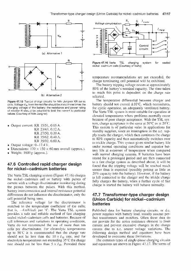
Transformer-type charger des
R
(a) Alrernative 1
R 1
(b) Alternative 2
Figure 47.15 Typical charge circuits for Nife Jungner KR series cells. Voltage V,, from the rectifier should be about three times the charging voltage csf the battery; the resistance and power rating of resistor R should be adapted to limit the current to particular values (Courtesy of Nife Jungner)
e Output current: KR 15/51, 0.05 A. KR 23/43, 0.12 A. KR 27/50, 0.20A. KR 35/62, 0.40A. KR 35/92, 0.60A.
e Output voltage: 0-17.4V. 0 Dimensions: 170 x 150 x 60mm overall (approx.). 0 Weight: 1600g (approx.).
47.6 Controlled rapid charger design for nickel-cadmium batteries The Varta TSL charging system (Figure 47.16) charges the nickel-cadmium cell or battery with pulses of current with a voltage discriminator monitoring during the pauses between the pulses. With this method, battery interconnection and internal resistance potential differences do not influence the discriminator, only the cell potential being seen.
The reference voltage for the discriminator is matched to the temperature coefficient of the cells; that is, -4mV/cell per "C. The Varta TSL system provides a safe and rcliable method of fast charging sealed nickel-cadmium cells and batteries. Because of cell tolerances and variations in operating conditions, Varta do not recommend the use of more than ten cells per discriminator. For electrolyte temperatures up to 50°C it is recommended that the charge rate should not be less than the 10 x Zl0 rate, and for electrollyte temperatures not exceeding 35°C the charge rate should not be less than 5 x Z ~ O . Provided these
;ign (Union Carbide) for nickel-cadmium batteries 47/17
Voltage compensation \ *
I
Figure 47.16 Varta TSL charging system for sealed nickel-cadmium cells (Courtesy of Vartz)
temperature recommendations are not exceeded, the charge terminating cell potential will be exhibited.
The battery tripping voltage occurs at approximately 80% of the battery's nominal capacity. The time taken to reach this point is dependent on the charge rate selected.
The temperature differential between charger and battery should not exceed &10"C, which necessitates, for cyclic operation, an adequately ventilated battery. The Varta TSL system is most suitable for operation at elevated temperatures where problems normally occur because of poor charge acceptance. With the TSL sys- tem, charge acceptance is the same at 50°C as at 20°C. This system is of particular value in applications for standby supplies, since an intemption in the a.c. sup- ply resets the charger, which then continues the charge to 80% capacity and then automatically switches over to trickle charge. This system gives similar battery life under normal operating conditions and superior bat- tery life at extremes of temperature when compared with normal charging systems. If batteries have been stored for a prolonged period and are then connected to a fast charge system as described above, it will be found that the tripping voltage will be reached much sooner than is expected (possibly putting as little as 20% capacity into the battery). However, if the battery is left connected to the charger and the trickle charge fully charges the battery, when a further cycle of fast charge is started the battery will behave normally.
47.7 Transformer-type charger design (Union Carbide) for nickel-cadmium batteries Published data for battery charging circuits. or d.c. power supplies with battery load, usually assume per- fect transformers and rectifiers. Often these data do not provide for the series resistance element to limit current and prevent excessive changes in the charge current due to a.c. source voltage variations. The following design method and equations have been developed to overcome these limitations.
The common types of single-phase charging circuits and equations are shown in Figure 47.17. The terms of

47/18 Constant-current charging
the design equations of Figure 47.17 will be taken in order for further definition. The value of Ed, or battery voltage varies with state of charge, temperature, type of nickel-cadmium cell construction and charge rate. These variations are less significant to constant-current operation than to other charge methods. The value of Ed, for a fully charged nickel-cadmium battery is between 1.35 and 1.4SVlcell for a 10h charge rate at room temperature. However, 1.5 V/cell may be used for charger design calculations. The charging current, Idc, is chosen to fit the specific application. The usage cycle, charge and discharge times of the particular device dictate the charge rate. The 10h rate is the highest recommended charge current for the more common nickel-cadmium cells. To maintain minimum charge current change with line voltage variations, the ratio of E, to Edc should be as large as possible. This, however, results in relatively high power losses and heat dissipation in the series current- limiting resistor. For practical reasons ratios of 1.5 to 2.5 are satisfactory, with the lower ratios being used for full-wave rectification in applications above 1 A.
Equations 47.2,47.5 and 47.8 show that the value of R is the sum of three separate resistances. The value Rt, the resistance of the transformer, must be deter- mined from manufacturers' specifications or by direct measurements of representative samples, and the value of Rd may be found in the caption to Figure 47.17. The value of the series limiting resistance, R,, must be determined from the formulae in Figure 47.17. The purpose of Rt is to limit current. The value of R, is normally high compared with the other resistances in the circuit, and in essence controls the current value since it constitutes the load on the power supply. The power dissipation in R, varies as the square of r.m.s. current flow. For calculating the wattage rating of R,, Equations 47.3, 47.6 and 47.10 give the relationship between I,, and I d c .
Typical values of rectifier forward threshold voltage, Vd, and rectifier dynamic resistance, Rd, for the design equations of Figure 47.17 are given in the caption to the figure. The current and peak inverse voltage rating of the rectifier must be adequate for desired circuit performance.
The equation factors K , M and F are functions of the current conduction angle. Their values are based on the ratio of E,,, the open-circuit r.m.s. voltage of the transformer secondary, to the sum of the battery voltage and the forward threshold voltage of the rec- tifiers. The a.c./d.c. ratio must first be calculated from the formula, then the values of K , M and F can be read directly from Figure 47.18.
The half-wave rectification circuits (Equations 47.1, 47.2 and 47.3) are generally used only for low-current applications, of the order of 0.SA or less. At higher currents, transformer efficiency is low and special core design is required because of the large direct current polarization effect.
(a) Half-wave I,, -
' rmr (b) Full-wave bridge
(c) Full
AI - - + m
D I o rms
U I t
-wave centre tap
(47.1)
(47.2)
(47.3)
(47.4)
(47.5)
(47.6)
Figure 47.17 Transformer-type charging circuits and equations for Eveready sealed nickel-cadmium cells and batteries. Edc = battery voltage during charge, /d, = average charging current (A), E,, = open-circuit r.m.s. voltage of secondary winding, R = total circuit resistance, Rt = transformer winding resistance referred to secondary, Rd = rectifier dynamic resistance, R, = series current- limiting resistor, v d = rectifier forward threshold voltage, R = number of rectifiercells in series per leg, K = d.c. voltageequation factor (see Figure 47.18), M = d.c. current equation factor (see Figure 47.1 8), F = current from factor = ratio of I,,, to /dc (see Figure 47.1 8). Rectifier materials and characteristics: germanium, Rd = 0, vd = 0.35; silicon, Rd = 0, vd = 0.80 (Courtesy of Union Carbide)
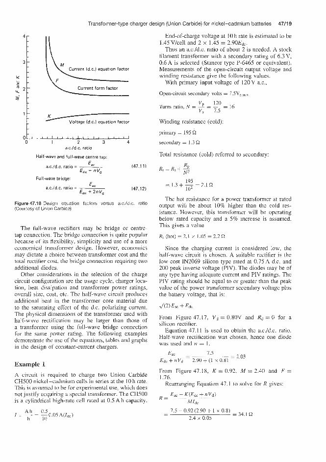
Transformer-type charger design (Union Carbide) for nickel-cadmium batteries 47/19
K .--/ Voltage (d.c.) equatton factor
4 ' ~ " ~ " " ' ~ ' " " " ' 1
0 1 2 3 a.c./d.c. ratio
Half-wave and full-wave centre tap:
a.c.1d.c. ratio = ___ E,, (47.11) E d c + nv,
E, E
EdC + 2nV,
Full-wave bridge:
(47.12) a.c./d.c. ratio =
Figure 47.18 Design equation factors versus a.c./d.c. ratio (Courtesy of Union Carbide)
The full-wave rectifiers may be bridge or centre- tap connection. The bridge connection is quite popular because of its flexibility, simplicity and use of a more economical transformer design. However, economics may dictate a choice between transformer cost and the total rectifier cost, the bridge connection requiring two additional diodes.
Other considerations in the selection of the charge circuit configuration are the usage cycle, charger loca- tion, heat dissipation and transformer power ratings, overall size, cost, etc. The half-wave circuit produces additional neat in the transformer core material due to the saturating effect of the d.c. polarizing current. The physical dimensions of the transformer used with haif-wave rectification may be larger than those of a transformer using the full-wave bridge connection for the same power rating. The following examples demonstrate the use of the equations, tables and graphs in the design af constant-current chargers.
Example 1 A circuit is required to charge two Union Carbide CH500 nickel-cadmium cells in series at the 10h rate. This is assumed to be for experimental use, which does not justify acquiring a special transformer. The CHS00 is a cylindrical high-rate cell rated at 0.5 A h capacity.
End-of-charge voltage at 10 h rate is estimated to be 1.45Vlcell and 2 x 1.45 = 2.90Edc.
Thus an a.c.1d.c. ratio of about 2 is needed. A stock filament transformer with a secondary rating of 6.3 V, 0.6 A is selected (Stancor type P-6465 or equivalent). Measurements of the open-circuit output voltage and winding resistance give the following values.
With primary input voltage of 120 V a.c.,
Open-circuit secondary volts = 7.5V,.,.,
120 VP - v, 7.5
Turns ratio, N = - - - = 16
Winding resistance (cold):
primary = 195 Q
secondary = 1.3 Q
Total resistance (cold) referred to secondary:
195 = 1.3 + - = 2.1 Q
162
The hot resistance for a power transformer at rated output will be about 10% higher than the cold res- istance. However, this transformer will be operating below rated capacity and a 5% increase is assumed. This gives a value
Rt (hot) = 2.1 x 1.05 = 2.2Q
Since the charging current is considered low, the half-wave circuit is chosen. A suitable rectifier is the low-cost IN2069 silicon type rated at 0.7SA d.c. and 200 peak inverse voltage (PIV). The diodes may be of any type having adequate current and PIV ratings. The PIV rating should be equal to or greater than the peak value of the power transformer secondary voltage plus the battery voltage, that is:
From Figure 47.17, Vd = 0.80V and Rd = 0 for a silicon rectifier.
Equation 47.11 is used to obtain the a.c.1d.c. ratio. Half-wave rectification was chosen, hence one diode was used and n = 1.
7.5 = 2.03 Eac - -
E d c + n v d 2.90 + (1 X 0.8)
From Figure 47.18, K = 0.92, M = 2.40 and F = 1.76.
Rearranging Equation 47.1 to solve for R gives:
Eac K(Edc + n v d )
MIdc R =
7.5 - 0.92 (2.90 + 1 x 0.8) - - = 34.1 Q 2.4 x 0.05

47/20 Constant-current charging
and
R, = R - Rt - nRd
= 34.1 - 2.2 - 0 = 31.9C2
From Equation 47.3, the secondary r.m.s. current is
I,, = FIdc = 1.76 X 0.05 = 0.088 A
Example 2 A circuit is required to charge four CH1.2 nickel-cadmium cylindrical cells in series at the 10 h rate or z d c of 0.12A. &c will be about 6V. The full- wave centre-tap circuit will be used for this design example. The specific application may dictate the best circuit configuration.
An a.c.1d.c. ratio of 2 is assumed for the trans- former secondary voltage. This requires two secondary windings of approximately 12V (2 x 6 = 12 V ) or a 24V centre-tapped secondary winding. For this first trial design, standard diodes will be used. The current rating should be selected to provide a safe tempera- ture during operation. Heat sinks may or may not be required. The non-conducting rectifier will see a PIV equal to the peak value of the full secondary wind- ing less the forward voltage drop of the conducting rectifier. Neglecting the rectifier drop the PIV will be
2Eac,/2 = 2 x 12 x 4 2 = 33.94V
Common diodes have ratings in excess of this value. From Figure 47.17, Vd = 0.8 v and Rd = 0 for
a silicon rectifier. From Equation 47.1 1, the a.c./d.c. ratio is
12 = 1.76 Ea, - -
Edc + nVd 6 + (1 X 0.8)
From Figure 47.18, K = 0.90, M = 2.42 and F = 1.80. Rearranging Equation 47.7 to solve for R gives:
12 - 0.9(6 + 1 x 0.8) = 4 l Q - -
(2.42/2)0.12
Rearranging Equation 47.8,
R , = R - n R d - R t
= 41 - 1 x 0 -Rt
=41 - R t Q
Total resistance, Rt, may be determined by the turns ratio and winding resistance (for the primary and half of the secondary) given in the transformer design data or by measurement of a sample. The measured value may be adjusted for operating temperature where warranted.
From Equation 47.10, the r.m.s. current in the centre leg is:
I,, = 0.707FIdc
= 0.707 x 1.8 x 0.12
= 0.153 A
The series resistance power rating must handle Z2R or
(0.153)2(41 - Rt )
The transformer secondary power is approximately
E , x I,, = 12 x 0.153 = 1.84W
A better design may be provided by the full-wave bridge circuit. Although the number of diodes required is doubled, the transformer may be less expensive and somewhat smaller.
Example 3
A circuit is required to charge four CF1.2 nickel-cadmium cylindrical cells in series at the 1 h rate or Idc of 1.2 A. Edc will be about 6.4 V.
Again an a.c./d.c. ratio of 2 is indicated for the trans- former secondary voltage. This means two secondary windings of approximately 12V (2 x 6.4 = 12.8V) or a 24 V centre-tapped secondary winding. For this first trial design, standard diodes will be used. The current rating should be selected to provide safe tempera- ture during operation. Heat sinks may or may not be required. The non-conducting rectifier will see a PIV equal to the peak value of the full secondary wind- ing less the forward voltage drop of the conducting rectifier. Neglecting the rectifier drop, the PIV will be:
2Eac42 = 2 x 12 x ,/2
= 3 4 v
Common diodes have ratings in excess of this value. From Figure 47.17, vd = 0.8V and Rd = 0 for a
silicon rectifier. From Equation 47.1 1, the a.c.1d.c. ratio is:
Eac - 12 - = 1.76
Edc + nVd 6.4 + (1 X 0.8)
From Figure 47.18, K = 0.90, M = 2.42 and F = 1.80. Rearranging Equation 47.7 to solve for R gives:
12 - 0.90(6.4 + 1 x 0.8) = 3.80Q - -
(2.42/2)1.2
Rearranging Equation 47.8,
R = R - nRd - Rt
= 3.9 - 1 x 0 - Rt
= 3.9 - Rt Q

Transformerless charge circuits for nickel-cadmium batteries 47/21
Total resistance, Rt, may be determined by the turns ratio and winding resistances (for the primary and half of the secondary) given in the transformer design data or by mea.surement of a sample. The measured value may be adjusted for operating temperature where warranted.
From Equation 47.10, the r.m.s. current in the centre leg is I,, = 0.707FIdC
= 0.707 x 1.8 x 1.2 = 1.53A
The series resistance power rating must handle Z2R or
(1.53)2(3.9 - Rt)
The transformer secondary power is approximately E,, x I,,, = 12 x 1.5 = 18 W
A better design may be provided by the full-wave bridge circuit. Although the number of diodes required is doubled, the transformer may be less expensive and somewhat smaller.
47.8 Transformerless charge circuits for nickel-cadmium batteries Though the transformer-type circuit offers versatility and desired isolation of battery terminals and a.c. power line there are other circuit configurations which are practical for special applications such as experimental batteries. The division or proportioning of the ‘charge source voltage and current values may be obtained by reactive or resistive networks. The former has the advantage of being heatless. The Union Carbide reactance-type charger of Figure 47.19(c) provides a constant current to nickel-cadmium batteries of one to five series-connected cells. This circuit has the advantages of simplicity, light weight, no heat, and can be used with variable numbers of cells. It is used quite widely in applications where the batteries and charger are built in and inaccessible to the user. This circuit usually takes the form of full-wave bridge rectification. The bridge circuit in Figure 47.19(b) will deliver about 4 0 d y F (value of capacitor, C) to the battery (see Table 47.5
Table 47.5 Values for capacitor C in Figure 47.1 9(c)
(a) Transformer and half-wave rectifier
R
Battery
R
Battery
(b) Transformer and full-wave bridge rectifier
Nickel-cadmium battery
12 a.c
/ -
ic) Reactance charger
D
a.c. D
(d) Resistance charger D-IN2069 silicon diode (or equivalent)
+L Oneor One deg %more
0 charging Dositions
2 Eveready No. 960 cells _ _ _ _ _ _ _ _ _ _ J
le) Charging from primary batteries
Figure 47.19 Charger circuits for Eveready sealed nickei- cadmium cells and batteries (Courtesy of Union Carbide)
for suggested capacitor values for use with various Union Carbide Eveready nickel-cadmium batteries).
Eveready batiely number Number of cells Charge current Nominal in series (mA) (10h rate) capacitance
( P I
$20 or B20T B50 or B50T OB90 or OB90T B150, B150T, CH150, CH15OT B225, B225T, BH225, BH225T, CH225, CH225T CH450, CH450T BH500, BHSOOT, CH500, CH5OOT
1 only
1-5
1-5
1-5
1-5
1-5
1-5
2 5 9
15 22.5 45 50
0.05 0.12 0.24 0.37 0.56 1.12 1.25

Table 47.6 Union Carbide sealed nickel - cadmium batteries and cells: resistance-type charger, circuit component values for charging
Eveready battery Description Transformer Rectifier Charge current Charge current Circuit number T D (mA) for 14 h (mA) for 4 h Jigure
ut this current at this current number
Resistance R to Resistance R charge one cell to charge two 3
cells in series E (or battery)
A A A B or C A A A A A A D or E B or C A A F or G
M M M M M M M M M M U M M M M
M
1 00
lob
1 20 120 120 150 180 220
400 2 5
50
I00
I
2.52d 350 2.52d
2.52d 420 2.52d
2.52d
Single cell Single cell Single cell Single cell Single cell Single cell Single cell Single cell Single cell Single cell Single cell Single cell Single cell Single cell Battery (12 CH 500 cells in series) Battery (11 CHI cells in series) Battery (5 C900 cells in series) Battery (5 rect- angular cells in series, 1.5 Ah) Battery (10 CH1.2 cells in series) Battery (17 OB90 cells in series) Single cell Battery (5 CH1.2 cells in series) Single cell Single cell Single cell Single cell Single cell Single cell Single cell Single cell Single cell Single cell Single cell Single cell Battery (8 CH4 cells in series)
BHl (and BHIT) CFI (and CFlT) CH1 (and CHIT) CFI .2 (and CFI .2T) CH1.2 (and CHI.2T) CH 1.2C CHI.2/D CH1.5 (and CHl.5T) CH1.8 (and CH1.8T) CH2.2 (and CH2.2T) CF4 (and CF4T) CH4 (and CH4T) B20 (and B20T) B50 (and B50T) N64
22 1 4.7 2
18 1 18 1 18 1 15 2 1 1 1 8.2 2 2.2 10 4.7 2
1200 0.5 560 0.5 I20 0.5
56 I
15 1 g 3.3 2 5
15 1 2 15 1 s
l e I co. 15
10 3 7 l a 5.6 2 1.8 10 3.3 2
lo00 0.5 390 0.5
2.52d 2.52d 2.52d 2.52d 2.52d
1 400 2.52d 2.52d 2.52d 2.52d 2.52d
2.52d N65
N67
N70
F or G
F or G
F or G
M
M
90
50
2.52d 100 2
2.52d 68 3
N86 F or G M 120
9
2.52d
2.52d
56 2
930 0.5
270 0.5 200 0.5 15 5
N88
OB90 and (OB90T) N9 1
E150 (and B150T) CF150 (and CF15OT) CHI50 (and CH15OT) B225 (and B225T) BH225 (and BH225T) CF225 (and CF225T) CH225 (and CH225T) CF450 (and CF450T) CH450 (and CH450T) BH500 (and.BH5OOT) CF500 (and CF5OOT) CH500 (and CHSOOT) 1007
F M
A F
M M
9 120
2.52d 2.52d
A A A A A A A A A A A A F or G
M M M M M M M M M M M M M
15
15 22.5 22.5
2.52d 50 2.52d
2.52d 2.52d 2.52d
75 2.52d 2.52d
150 2.52d 2.52d 2.52d
I75 2.52d 2.52d 2.52d
1 80 0.5 120 0.5 47 1 33 1
150 0.5 120 0.5 1 20 0.5 100 0.5 100 0.5 82 0.5 33 1 22 1
100 0.5 82 0.5 15 1 10 1 56 1 39 1 41 1 33 1 12 3 8.2 3 47 1 33 1 15 5
22.5
45 50
50 400

Transformerless charge circuits for nickel-cadmium batteries 47/23
47/24 Constant-current charging
Newer selenium bridge rectifiers and Mylar dielectric capacitors make practical charge currents possible in excess of 6.1 mA/cm ’.
The value of R1 in Figure 47.19(c) is not critical since it is a current-limitingqesistor to restrict ini- tial surge when the circuit is energized. The value of R1 may range from 25 to 250C2. This resistor is often omitted when more recent improved com- ponents are used. The bleeder resistor, Rz, provides a discharge path for the capacitor, removing possible shock hazard across a.c. prongs when removed from the receptacle. For circuits having large capacitance values (higher current ratings) the rectifier may be burned out if the battery is removed when the cir- cuit is connected to the 120V ax. supply. The res- istance type charger shown in Figure 47.19(d) (see
also Table 47.6) can also be used to provide a con- stant current to batteries of series connected cells. The circuit values shown will provide a charging current of approximately 4.5 mA for two B50 cells connected in series. This charger will not be damaged if it is connected to the a.c. power line with the batteries removed. By changing the resistor values, single cells or three to five cells in series could be charged. Higher currents requiring high wattage resistors would not be practical because of the excessive heat that would be produced. Small button cells, such as those used in hearing-aids, may be readily charged from flash- light cells or lantern batteries. Figure 47.19(e) (see also Table 47.6) is shown by way of example; this cir- cuit will charge one B50 cell at approximately 5 mA. Additional cells may be charged as shown by the broken lines.
Taper charging of lead-acid motive power batteries


Types of charger 4813
When a battery on charge reaches a voltage of between 2.35 and 2.40Vkell at the recommended charging rate, it is 75-80% charged. The time to termination of charge from this point is determined totally by the battery requirements and can vary over a wide range from say 1 to 6 h.
The self-compensating charger therefore monitors the battery voltage during the charging process and only when the stable voltage conditions achieved at the top of charge are reached will the controller terminate charge. A typical layout of such a charger is shown in Figure 48.1.
This seemingly complicated device is used instead of a voltage relay operating a switch at the end of charge because the top-of-charge voltage of a battery varies according to its age, condition and temperature. This would cause an old battery, which never reaches the tripping voltage, to go on receiving charge unnec- essarily, or a new battery to reach the tripping voltage too early and not receive the correct charge.
For each individual charge cycle, the battery itself determines exactly the amount of energy required, and the fully self-compensating charger purely responds to this demand without manual adjustment. The use of sophisticated electronic control to monitor battery condition permits recharge times for fully discharged batteries of 7.5 h to be achieved using a straightforward single-taper characteristic.
Large battery installations such as one used by opera- tors of fleets of electric vehicles, for example in distri- bution centres, require sophisticated battery charging systems to obtain the best possible performance from the batteries and to protect the large investment of cash involved. A good example of this type of charger for motive power batteries is the Spegel charger supplied by Chloride Legg UK and this equipment is described in some detail below.
Most chargers are designed so that, as the charging process progresses and the battery voltage rises during charge, the output current of the charger reduces. This charging characteristic is known as a ‘taper’ and is described by referring to the current obtained near the beginning and near the end of a typical charge.
The position chosen near the beginning of the charge is 2.1 Vkell, and near the end of the charge 2.6 Vkell. The values at these voltages are commonly expressed as ratios. Hence, a charger designed to give an out- put of lOOA at 2.1 V/cell and 5 0 A at 2.6V/cell, is said to have a taper characteristic of 2:l. The steep- ness of a charger taper is important because it affects the charger’s sensitivity to variations in mains volt- age, the charging time required and the temperature rise of the battery, which must be controlled during charge.
A battery will accept a higher current at the start of charge than at the end. However, the higher the starting rate, the more expensive the charger is to make and buy. So, in practice, the steepness of the charger’s taper is usually a compromise between economics and the battery’s requirements for the value of the finishing current. In any event, the finishing current must be kept below specified values:
1. It is necessary to restrict the temperature rise in the battery, as excessive temperature can damage its plates and separators.
2. When the battery is between 75 and 80% charged, oxygen and hydrogen gases are released owing to chemical reaction within the cells. If the finishing current is too high, the excessive flow of these gases can dislodge particles of active material from the positive plates, resulting in reduced battery life.
3. Nevertheless, gassing is an essential part of the charging process as it mixes the electrolyte. There- fore, the finishing rate must be sufficiently high to allow this process, but not so high as to damage the positive plates as described in (2).
48.1 Types of charger There are two basic types of charger.
48.1.1 Fully self-compensating chargers These are becoming increasingly popular as they require no supervision and bring a greater flexibility to the battery charging operation.
- a.c. input
- - -&ircuit breaker
Spegel Transformer m I I controller 1 I
EBallast I - 1 4-
Ammeter output batterv
t o
Fuse I * - o+ Figure48.1 Layout of a Spegel continuous control charger (Courtesy of Chloride Batteries)

48/4 Taper charging of lead-acid motive power batteries
48.1.2 Pre-programmed chargers
When 10 h or more recharge time is available, a single- taper charger is used. This type of charger incorporates a voltage-sensing device set to operate when the bat- tery voltage reaches 2.35 V/cell (42.3 V overall on an 18-cell battery). At this voltage a timing device is started which will terminate the charge after a prede- termined but adjustable period. As stated previously, a discharged battery can absorb a high current during the early part of charge, but there is a limit to the safe current after the gassing point has been reached.
With a single-taper charger the current must have fallen to a safe value by the time the gassing point
Table 48.1 Range of Chloride Legg Spegel chargers
is reached, and must continue to fall as the gassing rate increases; thus, this type of charger is limited to a minimum charge time of 10 h.
When less than 10h recharge time is available, a two-step taper charger is used, enabling battery manufacturers' recommendations to be met by using a higher current at the start of charge and a reduction to a lower level once the gassing point has been reached. As with the single-taper charger, a voltage-sensitive relay starts a timing device at the gassing point, but in this case it has a second function, which is to operate a contactor, which reduces the current to the required finishing rate. After 2.35 V/cell, both the single and two-step taper chargers have similar characteristics. In
Battery ampere hour capacity (5 h rate) with time available for recharge
71h 8h 8 i h 9h 91h 10h 1 0 t h l l h l l i h 12h 1 2 t h 13h 131h 14h
Starting current
(A)
25 26 50 53 75 79
100 105 125 132 150 158 175 184 200 211 225 237 250 263 275 289 300 316 325 342 350 368 375 395 400 421 425 447 450 474 475 500 500 526 525 552 550 579 575 605 600 632 650 684 700 737 750 789 800 842 850 895 900 947 950 1000
1000 1053 1050 1105 1100 1158 1150 1211 1200 1263
27 29 55 57 82 86
110 114 137 143 165 171 192 200 220 229 247 257 275 286 302 314 330 343 357 371 385 400 412 429 440 457 467 486 495 514 522 543 549 571 577 600 604 629 632 657 659 686 714 743 769 800 824 857 879 914 934 971 989 1029
1044 1086 1099 1143 1154 1200 1209 1257 1264 1314 1319 1371
30 60 89
119 149 179 208 238 268 298 327 357 387 417 446 476 506 536 565 595 625 655 685 714 774 833 893 953
1012 1071 1131 1190 1250 1310 1369 1429
31 62 93
123 154 185 216 247 27 8 308 340 370 40 1 432 463 494 525 556 586 617 648 679 710 741 802 864 926 988
1049 1111 1173 1235 1296 1358 1420 1481
32 64 96
128 160 192 224 256 288 321 353 385 417 449 48 1 513 545 577 609 64 1 673 705 737 769 833 897 962
1026 1090 1154 1218 1282 1346 1410 1474 1538
33 67
100 133 167 200 233 267 300 333 367 400 433 467 500 533 567 600 633 667 700 733 767 800 867 933
1000 1067 1133 1200 1267 1333 1400 1467 1533 1600
35 69
104 139 174 208 243 278 313 347 382 417 452 486 521 556 590 625 660 694 729 764 799 833 903 972
1042 1111 1181 1250 1319 1389 1458 1528 1597 1667
36 72
108 144 180 216 252 288 324 360 396 432 468 504 540 576 612 647 683 719 755 791 827 863 935
1007 1079 1151 1223 1295 1367 1439 1511 1583 1655 1727
37 75
112 155 187 224 26 1 299 336 373 410 448 485 522 560 597 634 672 709 746 784 821 858 896 970
1045 1119 1194 1269 1343 1418 1493 1567 1642 1716 1791
39 78
116 155 194 233 27 1 310 349 388 426 465 504 543 581 620 659 698 736 775 814 853 891 930
1008 1085 1163 1240 1318 1395 1473 1550 1628 1705 1783 1860
40 80
120 160 200 240 280 320 360 400 440 480 520 560 600 640 680 720 760 800 840 880 920 960
1040 1120 1200 1280 1360 1440 1520 1600 1680 1760 1840 1920
41 83
124 165 207 248 289 331 372 413 455 496 537 579 620 66 1 702 744 785 826 868 909 950 992
1074 1157 1240 1322 1405 1488 1570 1653 1736 1818 1901 1983
5 10 15 20 25 30 35 40 45 50 55 60 65 70 75 80 85 90 95
100 105 110 115 120 130 140 150 160 170 180 190 200 210 220 230 240
Spegel chargers have a type reference in terms of the number of battery cells to be charged and the initial value of the charging current (starting current). For example, charger type S3P 36/95 indicates 36 cells and 95 A starting current, i t . a 36-cell 500 A h battery will be charged in 8 h. Thus the correct size of charger will be determined by the number of cells, the ampere hour capacity and the time available for recharge

Opportunity charging 4815
A battery that is continuously worked for 8h , charged for the next 8 h and immediately worked again will have its life considerably reduced.
Batteries must be given a rest between charging and being discharged again, during which they can cool down. Where this kind of intense working is necessary, three-battery operation can be used.
summary, the two-step taper charger has two separate taper characteristics in operation; the first at a high current rate, the second at a lower rate, brought in by a voltage sensitive relay, which at the same time starts a timing device.
48.2 Equalizing charge Because each cell in a battery has its own charac- teristics, each requires a slightly different amount of charge. Fully self-compensating chargers cater for this during the normal recharge function, therefore a sep- arate ‘equalizing’ facility is not required.
With pre-programmed chargers an ‘equalizing charge’ is sometimes available via a switch that provides a continuous low current used to stabilize the voltage and relative density of the cells. If periodic equalizing charges are not given when pre- programmed chargers are being used, the life of the battery could be reduced. Frequency and extent of equalizing charges should be discussed with the battery manufacturer. who will assess the particular installation and make suitable recommendations.
48.3 How to choose the right charger A charger must always be chosen by taking note of the battery and charger manufacturer’s recommendations.
Table 48.1 illustrates the flexibility that can be achieved by using an electronically controlled self- compensating charger such as the Chloride Spegel. For example, a 36-cell 500A h battery can be recharged in 12h by a 36-cell Spegel charger with an output of 70A. The same battery can be recharged in 8 h with a 36-cell Spegel charger with an output of 95 A.
On the other hand, a 36-cell Spegel charger with an output of 70 A can be used to recharge 36-cell batteries of capacities ranging from 350 to 579 Ah.
Road vehicles are seldom needed to work more than 9-12Nday, which leaves up to 12h for recharging. The same is tnae of many industrial trucks. However, the demands of industry mean that trucks are some- times needed to work longer periods. Sometimes even round-the-clock operation is required of them, with three shifts of dnvers using the same vehicle.
In these circumstances, special charging methods have to be introduced. To overcome this problem, the truck can be eupplied with one, or even two, spare batteries.
Two-battery operation
This enables one battery to be on charge while the other i s at work on the truck. If this battery is recharged every 8 h (or once each shift) then obviously a charger capable of meeting this requirement must be used. Consequently, a two-step taper or Spegel charger would be required.
Three-battery operation
This gives each battery the chance to rotate between working, recharging, and resting after charge. Charging the battery after every 8 h shift means that each battery has a 16 h period for recharging and resting.
48.4 Opportunity charging
Where an electric vehicle is being intensively worked, plugging into a Spegel charger during breaks and other brief down-periods can also help to extend the vehicle’s effective working shift. However, too many opportunity-charging periods during a working shift may cause unacceptably high battery temperatures. This factor must be considered when planning an opportunity-charging schedule. Before the introduc- tion of modem self-compensating electronically con- trolled chargers, opportunity charging was discour- aged because of the high risk of battery overcharg- ing. However, when used with the Chloride Spegel charger, the battery dictates its charge requirements and receives the minimum overcharge for its needs. A typical battery might be opportunity-charged for two or three periods of 30 min each during a working day, when, depending on the battery’s state of charge when connected to the charger, this can boost the battery capacity by between 12 and 25%.
Table 48.2 shows that there is little benefit in char- ging the battery when it is 75% charged or above. Hence, opportunity charging should be carried oot only when the battery is less than 75% charged, which cor- responds to an electrolyte relative density of 1.240 or
Table 48.2 Ampere hours replaced by opportunity charging related to state of charge
Battery state of charge when ampere hour capacity
connected to charger (% charged)
Approximate percentage of
restored per hour
charger charger 8 h Spegel 12 h Spegel
95 85 75 65 50 25 0
6.0 4.5 8.0 6.5
10.0 8.0 13.5 11.0 15.0 12.0 17.0 12.5 17.5 13.0

48/6 Taper charging of lead-acid motive power batteries
less. For example, when a 65% discharged battery of 400 A h capacity is connected to a 12 h Spegel charger for 1 h, it will receive 44 A h of charge (Le. 11.0% of 400 Ah).
48.4.1 Principles of operation of the Spegel charger
This charger operates on the well proven principle of continuously monitoring the on-charge battery voltage and terminating the charge only when the stabilized conditions occurring at the top of charge are detected. The charge duration is therefore totally dictated by the battery and, in practice, will vary considerably depending on actual requirements.
The detection system employs fully solid-state components, and enables continuous monitoring to be achieved without interruption of the charge cycle.
The system is designed to compensate for mains voltage variation so that the battery always receives the correct amount of charge irrespective of mains supply fluctuation or battery condition. This is illustrated in Figure 48.2.
A failsafe circuit is included, which is totally electrically independent of the main control and pow- ered by the battery itself. This system will terminate charge after a fixed time from the commencement of gassing at 2.35 V/cell.
Following the connection of a battery and the switching on of the mains supply circuit breaker, a
short delay is provided before the contact closes and current begins to flow. If the battery is inadvertently disconnected during the charging process without first switching off the mains supply circuit breaker, the sup- ply contact within the charger will open. Electrical isolation of the exposed output terminals of the con- nector is therefore provided.
During the switch-on delay period the open circuit voltage of the battery is measured. The contact will be prevented from closing if the battery voltage lies outside the range of 1.8-3.4V/cell. This will avoid damage if a battery of the incorrect number of cells is connected to the charger.
If the battery is not required for use it should be left connected to the charger after the main charging phase is complete, so that it receives periods of refreshing charge of lOmin during every 6 h to maintain its condition.
Spegel chargers are designed to provide a taper characteristic, which means that the d.c. output current falls as the battery voltage rises during the charge cycle. The rated output current is delivered at a cell voltage of 2.1 V at the start of charge, tapering to 37.5% of this value at a cell voltage of 2.6V. Used in conjunction with Spegel control, this characteristic is suitable for all recognized makes of motive power lead-acid battery irrespective of age or condition.
When the charge time available has been determined (7.5-1421) and the battery capacity required is known, the correct charger can be easily selected from the chart.
Voltage rise constantly monitored
Freshening I k ~ ~ ~ ~ ~ ~ ~ ~ a g e charge I h- detected at d
Battery voltage I , I topof charge I ? y I i I
I I
I I 1 I I I Time I
1 4 White - I I indicator lights I i+ I -
Failsafe circuit ' White and flashing green ' operates indicator lights
Figure 48.2 Principle of operation of the Spegel charger (Courtesy of Chloride Batteries)
Methods of charging large nickel - cadrn i urn batteries


Methods of charging large nickel-cadmium batteries 49/3
To charge a large vented nickel-cadmium battery there are normally three methods. The difference between these methods is caused by different voltage and cur- rent characteristics and results in a different charging time. The following abbreviations are used in this chapter:
W = decreasing current I = constant current U = constant voltage 0 = automatic commutation a = automatic end of charge
To bring nickel-cadmium batteries to the fully charged condition (100% Cs) they must be charged with the charging factor of 1.4 to compensate for the charge efficiency (Figure 49.1).
If there is a regular cycling of the battery, or after a deep discharge below the final discharge voltage, it is necessary to recharge with an increased charging factor of 1.6-1.8.
The battery is fully charged if the maximum voltage obtained does not increase over a period of 1-2 h.
The relative density of the electrolyte does not indicate the condition o f the battery. The charging currents usuallly quoted are approximate values only as there is no theoretical limit. Compared with the lead-acid battery, it is not necessary to reduce the charging current if the gassing point has been reached. The true limit of the maximum value of the charging current is controlled by the electrolyte temperature, which must nlot exceed 45°C.
If charged with the I-characteristic, the charging cur- rent; ,TL, is constant (Figure 49.2(a)). Towards the end
140
- o* 120
/
i
Time of charging (h)
Figure 49.1 Graph of the charging efficiency of nickel-cadmium batteries
Charge (a)
End of charge
(a) I(a) characteristic
Time (c) W (a) characteristic
I
(b) I ( 0 ) I ( a ) characteristic Ti me
Ti me (e)
Figure 49.2 Methods of charging large nickel-cadmium batteries. - , current: ----, voltage. Charge with: (a,b) constant current characteristic; (c,d) decreasing current characteristic: (e) constant currentkonstant voltage characteristics
of the charge period the process is controlled manu- ally (I) or automatically I(a) or by changing to trickle charge I(0) (Figure 49.2(b)). The charge method with the W, W(a), W(0) characteristic is the most used one for nickel-cadmium batteries of all types and kinds. The initial current drops during the charge to a final value (final charging current) whilst the battery volt- age is increasing (Figure 49.2(c)). Towards the end of charge, the process is completed under manual control (W characteristic) or automatically (W(a) characteris- tic) (Figure 49.2(d)).
Using the IU characteristic, the charging current, ZL (initial charging current), is held constant until the fixed value of the charging voltage has been reached. Then the charging current, ZL, drops to a lower value (final charging current) whilst the char- ging voltage is kept constant (Figure 49.2(e)). The IU-charge is specially suited for charging batteries in parallel. This method of charging allows several sim- ilar batteries of identical voltage and capacity to be charged together irrespective of the individual state of charge.

49/4 Methods of charging large nickel-cadmium batteries
49.1 Trickle charge/float charge
To compensate for losses for self-discharge, a trickle charge current of approx. 50-80mA per lOOA h nom- inal capacity is essential. Depending on the type of battery and ambient temperature, the trickle charge voltage will be 1.35-1.45 Vkell. If charged in paral- lel using a constant potential of 1.40 Vkell, the trickle charge current, depending on the ambient temperature, will be 50-1OOmA per lOOAh nominal capacity. If, in addition to the self-discharge, there is a low or tem- porary load connected to the battery, a float charge is essential. The float charge current should be from 120 to 150mA per lOOAh nominal capacity. The cell voltage will be 1.4-1.45 V. The best float charge volt- age should be found by experiment, the criterion being the loss of electrolyte consistent with having a fully charged battery. If there is a continuous trickle or float charge, it is essential to make an equalization charge with a charging current of 1 5 every 3-6 months for 15 h or a boost charge depending on the characteristic of the charger to ensure full nominal capacity.
49.2 Charge/discharge operations on large vented nickel-cadmium batteries
1. Churge/dischurge operution The charge and dis- charge of the battery is arranged separately by con- necting the battery to the charger or by connecting the battery to the load (Figure 49.3).
2. Switch-tripping operation The battery is charged by the charger and kept in the fully charged condi- tion. If necessary the battery is switched to the load (Figure 49.4).
Automatic recharge is often used in emergency lighting systems.
At first the battery is boost charged with the charging current, ZL. until the gassing point is reached. Then the final charge-timer takes over. This is operated by
Figure 49.3 Chargddischarge operation of a large vented nickel-cadmium battery (Courtesy of Chloride Batteries)
El Battery
Figure 49.4 Switch-tripping operation of a large vented nickel-cadmium battery (Courtesy of Chloride Batteries)
Load
Battery
Figure 49.5 Automatic recharging of a large vented nickel- cadmium battery (Courtesy of Chloride Batteries)
the automatic charge unit. The normal running time of the timer is 2-6 h. During the final charge, the boost charge current continues until the fully charged condi- tion is reached. If the timer stops, the automatic charge unit connects the battery to the trickle charge. With the trickle charge current, the battery is maintained in the fully charged condition. The changeover to the load can be done manually or automatically (Figure 49.5).
The switch-trippinglcontinuous operation is another method used, e.g. in emergency lighting systems with continuous operation (maintained systems) (Figure 49.6). The load is supplied from the mains via a transformer and the battery is charged from the charger with the charging current. If the mains fails, the load is switched over to the battery supply by the mains-failure switch. This method normally includes the automatic charge unit.
49.3 Standby operation
If the standby method is used, the charger1d.c. supply and the battery are continuously connected in parallel with the load (Figure 49.7). The load is d.c. and

Standby operation 491%
With parallel operation and end cell switching, the load is supplied from the d.c. supplykharger with a voltage equal to 1.4V/celi (Figure 49.8). With a 20- cell battery, having a nominal voltage of 24V means that a voltage of 28V is available to ensure that the battery is fully charged by the charging current. In this mode of operation the end cell is bypassed. If the mains fails, the load is supplied without intemption directly from the battery with the current Iv .
With the mains reconnected. the battery will automatically experience initial boost charging at 1 .55 Vkell. With a 20-cell battery having a nominal voltage of 24 V, this constitutes a charging voltage of 31 V.
During the automatic boost charge, the end cell group is connected in series with the load, V , in order to reduce the boost charge voltage from 1.55 to 1.4 Vkell.
At the end of the charge at 1.55 Vkell. switchover to 1.4 V takes place automatically by the action of a relay, and at the same time the end cell group is bypassed.
Some notes follow regarding precautions to be t&en in battery charging rooms for vented nickel-cadmium batteries. Although these notes refer to the Geman Regulations (VDE 0510 and VDE 0100) they are applicable to any room in which charging of these batteries is carried out, and of course are similar to the UK and US regulations.
Rooms containing batteries up to 220V nominal voltage are covered by VDE 0100 ‘Electric Instal- lations’. Above 220V these are ‘Restricted Access Electric Installations’.
It is permitted to install nickel-cadmium batteries together with lead-acid batteries in the same room if there are provisions to ensure that the electrolyte spray of the lead-acid battery cannot contaminate the nickel-cadmium battery and vice versa.
The insulation resistance to earth or to a metal cubicle must be at least 1 m a when the battery is new. Batteries already in service must have a resistance of at least 50WV nominal voltage of the battery. The insulation resistance of the whole battery must not be less than 100OQ. The height of the roof above the
Figure 49.6 Auto switch-tripping/continuous operation rechar- ging of a large vented nickel-cadmium battery (Courtesy of Chloride Batteries)
I
1-4- Battery
Figure 49.7 Standby operation of a large vented nickel-cadmium battery (Courtesy of Chloride Batteries)
supplied by the current, I”. The d.c. supply is also responsible for the charging of the battery with the charging current, I L . If the mains fails, the battery takes over without any interruption to the load. If float operation is being used and the load current peaks exceed the output of the d.c. supplykharger, these peaks will be supplied from the battery.
f I u, - 1.4 V/cell
Battery
Figure 49.8 Padlei operation and end-cell switching of a large vented nickel-cadmium battery (Courtesy of Chloride Batteries)

49/6 Methods of charging large nickel-cadmium batteries
battery system must be at least 2m. Doors have to open outwards. Electric tools normally causing sparks must be positioned at least 1 m from the battery. Heating radiators with a surface temperature of more than 200°C are not allowed. Doors, windows, floor covers and paints on walls and roofs have to be electrolyte resistant. Windows accessible from outside have to be locked and barred or a wire glass may be used.
The installation of batteries in cubicles and en- closures with convection venting is allowed up to a charging power of only 2 kW. The power is calculated from the nominal charging current of the battery. Battery cubicles or enclosures have to be provided with venting facilities.
If there is other electrical equipment in the room, it must be separated from the battery by a wall or barrier. Electric tools normally causing sparks are not allowed near the venting ducts of the battery.
49.4 Ventilation
Battery rooms and enclosures must be vented in a manner such that the hydrogen emitted on charging is diluted by natural or artificial ventilation. The dilution must be such that the mixture becomes non-explosive. The amount of hydrogen dissipated during charging a battery at ambient temperature of 0°C and a pressure of 1.013 bar is 0.42 I/A h per cell. A mixture of hydrogen gas and air is explosive if the amount of hydrogen gas exceeds 3.8%. The venting of the battery room should be in accordance with VDE 0510. The air necessary for venting battery cubicles or enclosures can be either by inlet or extraction provided the volume of the battery room contains at least 2.5 times the necessary air to be changed per hour to ensure that an explosive mixture does not occur. Battery roorns that comply with regulation VDE 0510 can be regarded as being explosion proof.

Part 6

Lead-acid (secondary) batteries


Standby power batteries 5013
batteries for fork lift truck and electric vehicle opera- tion. Tubular plate monoblocs (6 and 12V) are avail- able in the 100-256 5-h capacity rate, 6 V flat plate monoblocs are available with 5 h capacities of 165 and 192. A range of motive power batteries housed in hard rubber containers with tubular positives are also avail- able (Table 50.5 shows some selected examples).
Chloride Motive Power also offer two devices for the automatic topping up of cells. Such devices are important as accurate topping up will prolong battery life and remove the risk of abuse. Automatic topping up also assists, of course, in the sense that it is an important aspect of automation in battery charging and maintenance operations.
The Chloride Motive Power Battopper (Figures 50.1 and 50.2) is fitted with control logic to prevent overfill- ing and is self-powered by a maintenance-free battery. The system is continually monitored for faults. It is suitable for use for approximately 5 h between charges.
The Autofil device also automatically tops up the battery to the correct level. The device operates by controlling the topping up water flow by the formation of an air lock in the cell.
50.1 Motive power batteries Motive power !ead-acid batteries are the power source used in every kind of electric vehicle from road trans- port to fork lift trucks in industry. Many manufacturers throughout the world supply these types of batteries and it would be impossible to review all their prod- ucts. Instead, the products of one major UK-based international producer, Chloride Motive Power, are considered in some detail. The applications of these types of batteries are considered in Part 4.
Chloride Motive Power Chloride Motive Power produce five basic ranges of motive power batteries, the Classic series (three ranges), monobloc batteries and cells in hard rub- ber cases.
Three ranges of Classic batteries are available, the Classic batteries; the Classic 15 series which have at least 15% more capacity from the same cell dimen- sions than the Classic series: and the Classic 25 series which give 27% more capacity from the same cell weight and dimensions when compared with the Clas- sic series. All the Ciassic batteries are housed in heat- sealed polypropylene containers and nave tubular pos- itive plate construction. The higher capacities per unit battery volume of the Classic 15 series are due to increases in the active material available in both nega- tive and positive plates. The higher capacities per unit weight and volume of the Classic 25 series are due to a redistribution of the active material of the plates. Both the positive and negative have been redesigned so that, compared with the plates of a standard cell, there is 20% increase in usable area. The non-active components used in a cell have also been redesigned to optimize performance, with the result that a cell now has up to 27% more energy density in terms of watt hours per kilogram. Table 50.1 shows the relationship between electrolyte gravity and state of charge for the three Classic series of batteries.
Table 50.1 Electrolyte relative density related to state of charge
State of charge Approximate relative densiry (% charged) (corrected to 15°C)
Classic Classic Classic cells 15 cells 25 cells
~
100 (fully charged) 1280 1 295 1 295 75 1240 1250 1 240 50 1200 1210 1 200 25 I160 1160 1150
In addition to the three Classic ranges (Tables 50.2-50.4 show selected examples), Chloride Motive Power also suppiy motive power monobloc
50.2 Standby power batteries 50.2.1 Chloride industrial batteries
Plant6 types YAP, YC? and YHP
These are designated as high-performance types. The range available is shown in Table 50.6 (types YAP and YCP) and Table 50.7 (Type YHP). A typical layout of a YHP battery is shown in Figure 50.3. Capacities up to 2000 A h per battery are available.
The nominal voltage is 2V/cell, i.e. a nominal 1lOV battery will have 55 cells. On discharge, the recommended final voltage at which the discharge should be terminated is shown in the discharge curves (Figure 50.4), i.e. the final voltage for the 3 h rate of discharge is 1.8V. After the final voltage has been reached the voltage will fall away at an increasing rate.
The capacity that can be taken from a cell varies with the discharge rate as indicated in the capacity tables. Capacity is also affected by temperature.
Trickle charging is a method of keeping these cells in a fully charged condition by passing a small current through them. The correct trickle charge current does not allow the cell to gas and does not allow the density to fall over a period of time. It is normally in the region of 1 mA per ampere hour of the 10 h capacity for YAP cells and 0.3 x capacity at the 10 h rate + 7QmA for YCP cells. With this small current flowing. the cell voltage will be approximately 2.2.5 V.
Float charging is keeping the voltage applied to the battery at 2.25V/cell, i.e. constant voltage. This method is usually used where continuous and variable d.c. loads exist, and has the added advantage that some degree of recharge can be achieved without manual
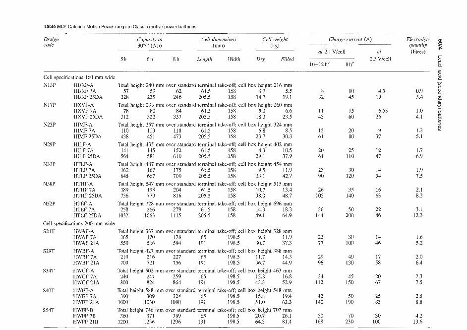
Table 50.2 Chloride Motive Power range of Classic motive power batteries
Design code
Capacity at Cell dimensions Cell weight 30°C (Ah) (mn) (kg)
5 h 6h 8h Length Width Dry Filled
Cell specifications 160 mm wide N13P HBKF-A Total height 240 mm over standard terminal take-off; cell box height 216 mm
HBKF 7A 57 59 62 61.5 158 4.3 5.5 HBKF 25DA 228 235 246 205.5 158 14.7 19.1
Total height 293 mm over standard terminal take-off; cell box height 260 mm HXVF 7A 78 80 84 61.5 158 5.3 6.6 HXVF 25DA 312 322 337 205.5 158 18.3 23.5
Total height 357 mm ovcr standard terminal take-off; cell box height 324 mrn HIMF 7A 110 113 118 61.5 158 6.8 8.5 HIMF 25DA 438 45 1 473 205.5 158 23.7 30.3
Total height 435 mm over standard tenninal take-off; cell box height 402 mm HILF 7A 141 145 152 61.5 158 8.3 10.5 HILF 25DA 564 581 610 205.5 158 29.1 37.9
Total height 487 mm over standard terminal take-off; cell box height 454 mm HTLF 7A 162 167 175 61.5 158 9.5 11.9 HTLF 25DA 648 667 700 205.5 158 33.1 42.7
Total height 547 mm over standard terminal take-ofc cell box height 515 mm HTHF 7A 189 195 204 61.5 158 10.7 13.4 HTHF 25DA 756 779 816 205.5 158 38.0 48.7
Total height 728 mm over standard terminal take-off; cell box height 696 mm HTEF 7A 258 266 279 61.5 158 24.3 18.3 HTEF 25DA 1032 1063 1115 205.5 158 49.1 64.9
Total height 367 mm over standard terminal take-off; cell box height 328 mm HWAF 7A 165 170 178 65 198.5 9.8 11.9 HWAF 21A 550 566 594 191 198.5 30.7 37.3
Total height 427 mm over standard terminal take-off; cell box height 388 mm HWBF 7A 210 21 6 227 65 198.5 11.7 14.3 HWBF 21A 700 721 756 191 198.5 36.7 44.9
Total height 502 mm over standard terminal take-off; cell box height 463 mm HWCF 7A 240 247 259 65 198.5 13.8 16.8 HWCF 21A 800 824 864 191 198.5 43.3 52.9
Total height 588 mm over standard terminal takeoff; cell box height 548 mm HWEF 7A 300 309 324 65 198.5 15.8 19.4 HWEF 21A 1000 1030 1080 191 198.5 51.0 62.3
Total height 746 mm over standard terminal take-off; cell box height 707 mm HWFF 7B 360 371 389 65 198.5 20.7 26.1 HWFF 21B 1200 1236 1296 191 198.5 64.3 81.4
N17P HXVF-A
N23P HIMF-A
N29P HILF-A
N33P HTLF-A
N38P HTHF-A
N52P HTEF-A
Cell specifications 200 mm wide S24T HWAF-A
S29T HWBF-A
S34T HWCF-A
S40T HWEF-A
S54T HWFF-B
Churge current (A)
at 2.1 Vlcell at 2.5 Vlcell
10-12h* 8ht
8 10 4.5 32 45 19
11 15 6.55 43 60 26
15 20 9 61 80 37
20 25 12 61 110 47
23 30 14 90 120 54
26 35 16 105 140 63
36 50 22 144 200 86
23 30 14 77 100 46
29 40 17 98 130 58
34 45 20 112 150 67
42 50 25 140 190 83
50 70 30 168 230 100
Electrolyte quantity 4
(litres) P
c P
1 6 ij: h
8 3.4 2
3.
5. 1.3 w
0.9 8 P,
1.0 4.1
5.1
1.7 6.9
1.9 7.5
2.1 8.3
3.1 12.3
I .6 5.2
2.0 6.4
2.3 7.5
2.8 8.8
4.2 13.6

Standby power batteries 5015
Table 50.3 Chloride Motive Power range of Classic 15 motive power batteries
Total height Cell box Chloride 5 h capacity Cell dimensions Filled Charge current over standard height type at 30°C (Ah) (mm) weight (A) at 2.1 Vlcell
(kg) 12h* 8h* terminal take- (mm)
off (mm) length Width
367 328
427 388
502 463
588 548
746 707
435 402
487 454
547 515
650 617
728 696
249 216
293 260
357 324
XWAF7 XWAF2 1 XWBF7 XWBF9 XWBFll XWBF13 XWBF15 XWBF17 XWBF19 XWBF21 XWCF7 XWCF21 XWEF7 XWEF21 XWFF7 XwFF2 1 XILM XILF25 XTLF7 XTLF25 XTHF7 XTHF25 XTOF7 XTOF25 XTEF7 XTEF25 XBKF7 XBKF25 XXVF7 XXVF25 XIMF7 XIMF25
195 650 240 320 400 480 560 640 720 800 275 920 345
1150 435
1450 162 848 189 756 219 876 25 8
1032 297
1188 63
252 86
342 I 20 480
65 191 65 83
101 119 137 155 173 191 65
191 65
191 65
191 61.5
205.5 61.5
205.5 61.5
205.5 61.5
205.5 61.5
205.5 61.5
205.5 61.5
205.5 61.5
203.5
198.5 198.5 198.5 198.5 198.5 198.5 198.5 198.5 198.5 198.5 198.5 198.5 198.5 198.5 198.5 198.5 I58 158 158 158 158 158 158 158 158 158 158 158 158 158 158 158
11.9 37.3 14.3 18.7 23.5 21.5 32.7 36.5 40.6 44.9 16.8 52.9 19.4 62.3 26.3 81.7 10.8 39.1 12.4 44.7 14.2 51.7 16.4 59.5 19.0 67.7 5.5
19.1 6.6
23.5 8.5
30.3
27 91 34 45 56 67 78 90
101 112 39
130 48
160 61
203 23 90 26
105 30
123 36
144 42
167 9
35 12 48 17 67
37 123 46 61 76 91
106 121 136 152 52
175 66
220 83
275 30
120 35
140 40
162 50
200 55
220 12 48 16 65 23 91
Taper characteristic 2.67: 1 between 2.1 and 2.6 Vicell.
attention. A simple hydrometer reading indicates the state of charge.
A fully charged cell will have a specific gravity of between 1.205 and 1.215.
The ampere hour efficiency of the cells is 90%; therefore, on recharge, the amount of recharge required is equal to the discharge in ampere hours plus 11%. A YAP 9 cell discharged at the 1 h rate (18 A for 1 h) will require a minimum of 18 + l l%, i.e. 20Ah recharge. At the finishing rate of charge (2 A), this will take 10 h. It is possible to recharge in a shorter time by starting the charge at the ‘starting rate’, as given in the capacity tables, but this should be reduced to the finishing rate of charge when the voltage per cell reaches 2.3 V.
On recharge, the voltage increases as the charge proceeds. The highest voltage reached with the finish- ing rate of charge flowing is approximately 2.70 V/cell. It is possible to recharge a cell by limiting the voltage
of the charging equipment to a lower value than 2.70 V/cell, 2.4 V/cell being the minimum desirable value. This will result in an extended recharge period, as the battery will automatically limit the charge cur- rent irrespective of the charger output.
Chloride Industrial Batteries Supply Super Plant6 type high-performance cells, type YCP-H, available in capacities up to 500 A h (Table 50.8).
This range of batteries is particularly suitable for any standby application calling for a good high-rate dis- charge characteristic. Such applications include elec- tronic computer and telecommunications equipment, which requires a no-break ‘clean’ power supply free from voltage surges, frequency variations and other transients.
To achieve this the power supply is usually obtained through a no-break, static inverter or a no-break rotary set.
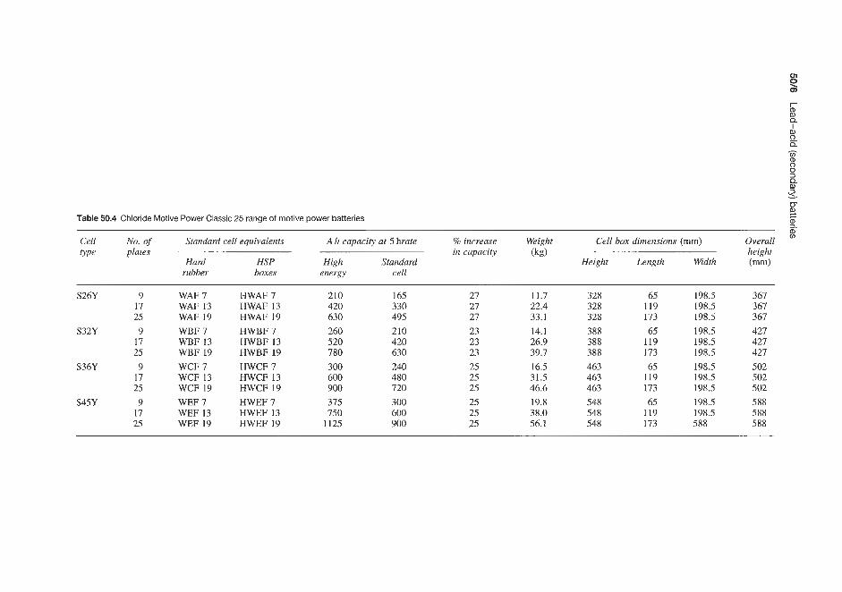
I
h cn m 0 0 3 Q m
W 3. 2 s. %
Table 50.4 Chloride Motive Power Classic 25 range of motive power batteries
Cell No. of Standard cell equivalents A h capacity at 5 hrate % increase Weight Cell box dimensions (mm) Overall type plates in capacity (kg) height
Hard HSP High Standard Height Length Width (mm) rubber boxes energy cell
S26Y 9 17 25
S32Y 9 17 25
S36Y 9 17 25
S45Y 9 17 25
WAF 7 WAF 13 WAF 19 WBF 7 WBF 13 WBF 19 WCF 7 WCF 13 WCF 19 WEF 7 WEF 13 WEF 19
HWAF 7 HWAF 13 HWAF 19 HWBF 7 HWBF 13 HWBF 19 HWCF 7 HWCF 13 HWCF 19 HWEF 7 HWEF 13 HWEF 19
210 420 630 260 520 780 300 600 900 375 750
1125
165 330 495 210 420 630 240 480 720 300 600 900
27 27 27 23 23 23 25 25 25 25 25 25
11.7 22.4 33.1 14.1 26.9 39.7 16.5 31.5 46.6 19.8 38.0 56.1
328 328 328 388 388 388 463 463 463 548 548 548
65 119 173 65
119 173 65
119 173 65
119 173
198.5 198.5 198.5 198.5 198.5 198.5 198.5 198.5 198.5 198.5 198.5 588
367 367 367 427 427 427 502 502 502 588 588 588

Standby power batteries 50R
Table 50.5 Chloride Motive Power range of motive power batteries in hard rubber containers
Overall height over Type Capacity at 30°C (Ah) Cell dimensions (mm) Filled standard terminal cell weight connectors (mm) 5h 6h 8h Length Width (kg)
245
289
352
430
483
543
740
363 428 498 578
BKF27A BKF29A BKF31A XVF27A XVF39A IMF27A IMF41A ILF27A ILF4 1 A TLF27A TLF4lA THF27A THF4 1A MTF9 MTF37 WAF5A WBF5A WCF5A WEF5A
247 255 266 274 285 294 338 348 494 508 475 489 730 752 61 1 629 940 968 702 723
1080 1112 819 844
1260 1298 488 503
2196 2263 110 113 140 144 160 165 200 206
267 287 308 365 534 512 788 660
1016 758
1166 884
1360 527
2372 119 151 172 216
224 240 255 224 319 224 335 224 335 224 335 224 335
81 310 47 47 47 47
160 160 160 160 160 160 160 160 160 160 160 160 160 222 227 200 200 200 200
20.6 22.0 23.5 25.4 38.7 32.8 49.5 40.9 62.4 45.8 70.4 52.5 79.2 35.4
153.8 8.7
10.2 11.9 14.2
Figure 50.1 Motive power Battoper automatic topping-up device (Courtesy of Chloride Batteries)
In either case a standby battery of proven reliabil- ity and maximum compactness is required, which is capable of supplying a high discharge current for a comparatively short period.
Figure 50.2 The Chloride Motive Power Battoper automatic topping-up device in use (Courtesy of Chloride Batteries)
A large percentage of EHT switchgear is battery operated. Here again the requirement is for a good high-rate discharge characteristic, since the switchgear closing solenoids take a high current for a very short time.

Table 50.6 High-performance Plante-type lead-acid standby power batteries available from Chloride Industrial Batteries e. a - VI m
Final Cell type 0 voltage 2
3 (V) YAP5 YAP9 YAP13 YAP17 YAP21 YCP9 YCP 11 YCP13 YCP17 YCP2I YCP2.5 YCP27 YCP29 YCP.33 YCP35
Capacity* at 15°C (Ah) when discharged in
10h 3h I h
Capacity* at 25°C (Ah) when discharged in
10h 3h 1h
Charge current (A) Starting Finishing
Weight of cell complete (kg) Filled Acid only (relative density 1.210)
Approx. quantity of acid, relative density 1.210 (litres) External dimensions of box (mm)
Lengtht Width Height
Overall height of cell (mm)
1.85 1.80 I .75
1.85 1.80 1.75
-
2.70
15 30 45 12 24 36 9 18 27
16 32 48 13 26 38.5 9.8 19.5 29.5
2 4 6 1 2 3
3.8 6.3 10.0
1.16 1.89 3.4
0.96 1.56 2.83
76 114 190 133 133 133 212 212 212 260 260 260
60 75 47.5 60 36 45
64 80 52 64 39 49
8 10 4 5
11.45 13.6
3.25 3.8
2.68 3.16
190 228 133 133 212 212 260 260
100 125 80 99 60 75
107 134 86 107 65 82
14 17 7 8.5
18.6 22.2
5.5 7.5
4.5 6.2
134 172 203 203 349 349 423 423
8 150 200 250 300 325 350 400 425 3. 119 159 199 239 258 278 318 338 90 120 150 180 195 210 240 255
161 214 268 322 348 375 429 456 129 172 215 258 279 301 344 365 98 131 163 196 212 229 262 278
20 28 34 42 46 48 56 60 10 14 17 21 23 23 28 30
7.2 8.7
5.9 7.2
172 210
10.4
8.6
48
24.9 30.6 36.9 43.4 52.6 54.4 58.4 60.3
15.1
12.5
12.1 16.6 16.2 15.5
10 13.7 13.4 12.8
86 362 362 362 62 203 203 203 203 203 203 203 203 349 349 349 349 349 349 349 349 423 423 423 423 423 423 423 423
* Larger capacity enclosed Plant6 cells are available in the YHP range (500-2000Ah) The lcngth of a box or cell is measured at right angles to the plates. The width is measured parallel to the plates

Table 50.7 High-performance Piante-type lead-acid standby power storage batteries available from Chloride Industrial Batteries
Final Cell type voltage
(V) YHP 11 YHP 13 YHP 15 YHP 17 YHP 19 YHP 21 YHP 23 YHP 25 YHP 27 YHP 29 YHP 31 YHP 33 YHP 35 YHP 37 YHP 39 YHP 41
Capacity* at 15°C (Ah) when discharged in
10h 1.85 500 600 700 800 900 1000 1100 1200 1300 1400 1500 1600 1700 1800 1900 2000 3h 1.80 406 487 568 649 730 811 892 973 1054 1135 1217 1298 1379 1460 1541 1622 I h 1.75 300 360 420 480 540 600 660 720 780 840 900 960 1020 1080 1140 1200
Capacity" at 25°C (Ah) when discharged in
10h 1.85 536 643 750 858 965 1072 1179 1286 1394 1501 1608 1715 1822 1930 2037 2144 3h 1.80 438 526 614 702 789 877 965 1052 1140 1228 1315 1403 1491 1578 1666 1754 l h 1.75 327 392 458 523 589 654 719 785 850 915 981 1046 1112 1177 1242 1308
Starting - 70 84 98 112 126 140 154 168 182 196 210 224 238 252 266 280 Finishing 2.7 35 42 49 56 63 70 77 84 91 98 105 112 119 126 133 140
Charge current (A)
Weight of cell complete (kg)
Filled 95.2 106.2 133.5 144.5 155.5 179.3 190.4 218.0 220.0 240.1 268.3 279.2 290.2 318.2 329.2 340.2 Acid only, relative density 1.210 32.2 30.6 45.3 43.7 42.1 53.3 51.8 66.8 65.2 63.7 79.3 77.6 76.0 91.4 89.8 88.2
2 Approx. quantity of acid, relative density 1.210 (litres) 27.1 25.7 38.1 36.7 35.4 44.8 43.5 56.1 54.8 53.5 66.6 65.2 63.9 76.8 75.5 74.1 3
4
3 Q
U __ ___._
* Larger capacitieh can he obtained by connecling cells in parallel. Smaller capacities are available in the YAP range (15-75 Ah) and YCP range (100-425 Ah)

50/10 Lead-acid (secondary) batteries
Vent plugs designed to eliminate spray but give free exit of gases
Cell pillars and connectors give minimum resistance and maximum current flow
Cell lids of opaque styrene acrylonitrile (SAN)
Negative plates, pasted grids, provide perfect balance with the positive to give maximum performance
Sintered microporous PVC separators give minimum resistance
Plante’positive plates constructed of pure lead ensure that there is no fall-off in capacity throughout theil long life
Plastic containers of transparent SAN allow the electrolyte level and cell condition to be clearly seen
Figure 50.3 Typical layout of Chloride Industrial Batteries type YHP standby power battery (Courtesy of Chloride Batteries)
The most reliable type of battery for engine starting is the Plant6 high-performance type. The standby engine is, of course, required for many emergency Chloride Industrial Batteries also supply high- applications where maximum reliability is essential. performance flat-plate cell type standby batteries in These applications include emergency lighting, the conventional vented (types FAP-H and FCP-H) sprinkler systems, industrial processes, telecommun- and low-maintenance (types SAP, SBP and SEP) ications, and any auxiliary power requirements. versions. Capacities up to 600 A h (vented, Table 50.9)
High-performance flat-plate types

Standby power batteries 50/1 I
Table 50.8 Super high-performance Plante type lead-acid standby batteries available from Chloride Industrial Batteries
Type YCP-H 13H 17H 23H 2 7H 31H 41H
Capacity at 15°C (Ah) 10h to 1.85V Charge current (A)
Starting Finishing
Weight (kg) Dry Filled
Volume of electrolyte (rekitive density 1.240) (likes) External box din- ensions (mm)
Length Width Height
Overall height (mm)
150
20 10
16.7 21.7
3.2
134 203 349 423
200
28 14
20.9 27.5
5.3
172 203 349 423
275
38 19
28.1 36.0
6.4
210 203 349 423
325
45 22
32.7 42.3
7.7
248 203 349 423
375
52 26
38.8 50.2
9.2
286 203 349 423
500
70 35
51.4 66.1
11.8
362 203 349 423
To calculate length of stands: double tiedsingle row = C x N / 2 + 5 0 m , double tieddouble row = C x N/4 + 50mm, where C = cell centre and N = cell numbers
and 1125 A h (low maintenance, Table 50.10) are available. Trickle and float charging methods are used as with the Plant6 types. A feature of both the vented and low-maintenance ranges is that a new plate alloy incorporating selenium is used in their manufacture. This new patented low-antimonial lead- selenium alloy has a substantially reduced antimony content, which reduces antimony migration and extends the battery life. The fine grain structure and strength of the alloy are maintained by the introduction of selenium to reduce intergranular corrosion.
, . 0 2 4 6 8 10 12 14
1.71 I I I I I - 0 1 2 3 4 5 6 7 8 9 10
(b) Time (h)
Figure 50.4 High-performance Plante-type lead-acid standby batteries available from Chloride Industrial Batteries. (a) Typical recharge characteristics following discharge at the 3 h rate. (b) Discharge voltage characteristics at 15°C (Courtesy of Chloride Batteries)
The lead oxide used in the plates is made finer, producing a greater surface area with improved material utilization, giving higher ampere hour capacity per plate.
The low maintenance SAP, SBP and SEP ranges, in addition to being suitable for high-rate applications, are also suitable for low-rate applications such as SP telecommunications, where a low-maintenance standby power battery is required.
Uninterrupted power supply (UPS) systems are becoming employed increasingly with sophisticated computer and telecommunications equipment. Many kinds of batteries are available as standby within such systems, and the choice depends on the requirements in each case.
The SP range has been developed to meet the following specifications:
1. Flat plate design. 2. Life expectation of 10 years. 3. Minimum maintenance. 4. Transparent container for ease of inspection. 5. Good high-rate discharge characteristic. 6. High reliability. 7. Low floor area. 8. Minimum initial cost.
New separator technology has been incorporated into these flat-plate cells. The vented types incorporate separation between adjacent plates consisting of a glass wool mat and ribbed microporous PVC. The glass wool mats are fitted against the positive plates and act as an effective retainer of the posifve active material. The low-resistance sepaators, which are inert chemically and have a high degree of porosity, provide a complete diaphragm between the plates but allow good circulation of the electrolyte and give mechanical support to the negative active material.

Table 50.9 High-performance flat-plate vented lead-acid standby power batteries available from Chloride Industrial Batteries
Capacity* at 20°C (Ah) to BS 440 final voltage
10 h 3 h l h
Capacity* at 20°C (A hj emergency lighting ratings to final voltage 85% ol' nominal
3 h 2 h l h
8h 3h I h
Starting Finishing
Filled Acid only, relative dcnsity 1.240*
Approx. quantity of acid, relative density 1.2401 (litres) External dimensions of box (mm)
Lengtht Width Height
Capacity* at 25°C (Ah)
Charge current (A)
Weight of cell completc (kgj
Overall height of cell (mm)
1.85 I .80 1.75
1.70 1.70 1.70
1.75 I .75 1.75
-
2.70
16 12.3 8.4
13.6 12 8.8
17 13.2 8.7
2 1
3.2
1.3
1.1
76 133 212 253
32 24.6 16.8
27.2 24 17.6
35 26.4 17.4
4 2
3.9
1.2
I .o
76 133 212 253
48 36.9 25.2
40.8 36 26.4
51 39.6 26.1
7 3
5.7
2.0
1.6
114 133 212 253
64 40.2 33.6
54.4 4x 35.2
68 52.8 34.8
9 4
6.5
2.0
I .5
114 133 212 253
W 80 96 128 160 120 180 240 300 360 420 480 540 600 $ 61.5 73.8 98.4 123 92 138 184 230 276 322 368 414 460 42 50.4 67.2 84 62 93 124 155 186 217 248 279 310 3 68 81.6 108.8 136 102 153 204 255 306 357 408 459 510 60 72 96 120 90 135 180 225 270 315 360 405 450 44 52.8 70.4 88 66 99 132 165 198 231 264 297 330
85 102 136 170 128 192 256 320 384 448 512 576 640 66 79.2 105.6 132 99 148.5 198 247.5 297 346.5 396 445.5 495 43.5 52.2 69.6 87 64 96 128 160 192 224 256 288 320
11 13 18 22 17 25 34 42 50 59 67 76 86 5 6 9 11 8 12 17 21 25 29 33 38 42
9.5 10.4 12.2 13.6 15.4 17.9 22.9 28.0 33.3 35.6 41.4 49.2 52.0
3.6 3.5 3.5 4.0 5.8 5.2 7.3 9.0 10.7 10.1 12.2 16.3 16.0
2.8 2.8 2.7 3.1 4.68 4.19 5.89 7.26 8.63 8.15 9.83 13.15 12.90
190 190 190 228 134 134 172 210 248 248 286 362 362 133 133 133 133 203 203 203 203 203 203 203 203 203 212 212 212 212 349 349 349 349 349 349 349 349 349 253 253 253 253 423 423 423 423 423 423 423 423 423
* Larger capacitics can be obtaincd by coniiecting cells in parallel. Capacity levels applicable after five dischargdcharge cycles t The length of a box or cell is measured at right angles to the plates. The width is measured parallel to the plates t 1.270 for FAP rangc

Standby power batteries 5W63
Table 50.10 High-performance flat-plate low-maintenance type lead-acid standby power batteries available from Chloride Industrial Batteries
o p e Nominal cupacig Width Length Height Filled (Ah) at 25°C in 10h (mm) (mm) over pillar weight
(mm) ( W
SAP 5 SAP 7 SAP 9 SAP 13 SAP 17 SAP 21 SBP 17 SBP 21 SBP 27 SEP 21 SEP 23 SEP 25 SEP 27 SEP 29 SEP 31 SEP 33 SEP 35 SEP 37
50 75
100 150 200 250 320 400 520 625 688 750 813 875 938
1000 1062 1125
206 206 206 206 206 206 206 210 210 210 210 191 191 191 240 240 240 240
103 103 103 145 145 187 166 254 254 210 210 233 233 233 270 270 270 270
389 389 389 389 389 389 505 505 505 694 694 694 694 694 648 648 648 648
12.0 13.6 14.8 19.5 22.7 28.3 35.4 47.1 54.3 63.8 66.5 74.3 77.0 79.7 90.0 92.7 95.4 98.1
Table 50.1 1 LCP range small-size flat-plate lead-acid standby batteries supplied by Chloride Power Storage
873 874 875 876 877 878 (LCP.5) (LCP7) (LCP9) (LCP13) (LCPI 7) (LCP21)
Nominal capacity at 20°C Nominal charge current (A) Trickle charge (mA) Length (mm) Width (mm) Height (mm) Cell centres (mni)
face to face edge to edge
Weight filled (kg) Quantity of electrolyte (litres)
20 1.3 10-20 35 129 219
38
1.79 0.46
-
30 2.0 15-30 54 129 219
57
2.58 0.75
-
40 2.7 20-. 54 129 219
57
2.92 0.77
-
40
60 80 4.0 5.3 30-60 40-80 115 115 129 129 219 219
117 117 132 132 5.10 5.70 1.93 1.79
100 6.3 50- 100 115 129 219
117 132 6.36 1.65
Voltage 12V (6 cells) 6 V (3 cells) Nominal voltage 2.0 Vice11 Floating voltage 2.20 to 2.25 Vice11 Charging voitage np to 2.70Vicell Final voltage 1.85 V at 10h rate of discliarge
The low-rnamtenance types have separation between adjacent plates consisting of a glass wool mat and ribbed microporous phenol formaldehyde. The glass wool mats are fitted against the positive plates and act as an effective retainer of the positive active material. The low-resistance separators, which are inert chemically and! have a high degree of porosity, provide a complete diaphragm between the plates but allow good circulation of the electrolyte and give mechanical support to the active material.
Standurd jat-plate types
Chloride Power Storage supply a lower capacity range ECP type (20- 1000 A h capacity) flat-plate type
of standby power battery (Table 50.11) suitable for performance in small installations such as telephone exchanges, emergency lighting, laboratory equipment and security systems. This range also uses the low- antimony selenium-containing grid alloy.
Also available in the standard range is the R series of engine-starting standby batteries. These batteries are supplied as single cell containers with capacities up to 384 Ah, or as monobloc containers with capacities up to 276Ah (Table 50.12).
Chloride also supply a range of marine batteries. These batteries are designed to fulfil a multitude of duties at sea. They are vital for communica- tions, engine starting, emergency lighting, sprinklers,
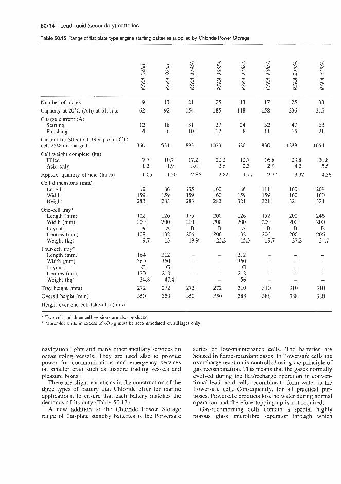
50/14 Lead-acid (secondary) batteries
Table 50.12 Range of flat plate type engine starting batteries supplied by Chloride Power Storage
Number of plates Capacity at 20°C (Ah) at 5 h rate Charge current (A)
Starting Finishing
Current for 30 s to 1.33 V p.c. at 0°C cell 25% discharged
9 62
13 92
21 154
25 185
13 118
17 158
25 236
33 315
12 4
18 6
31 10
37 12
24 8
32 11
47 15
63 21
3 60 534 893 1073 620 830 1239 1654 Cell weight complete (kg)
Filled 7.7 1.3 1 .os
10.7 1.9 1.50
17.2 3.0 2.36
20.2 3.6 2.82
12.7 2.3 1.77
16.8 2.9 2.27
23.8 4.2 3.32
30.8 5.5 4.36
Acid only Approx. quantity of acid (litres) Cell dimensions (mm)
Length Width Height
One-cell tray* Length (mm) Width (mm) Layout Centres (mm) Weight (kg)
Four-cell trayr Length (mm) Width (mm) Layout Centres (mm) Weight (kg)
Tray height (mm) Overall height (mm) Height over end cell take-offs (mm)
62 159 283
86 159 283
135 159 283
160 160 283
86 159 321
111 159 321
160 160 321
208 160 321
102 200
A 108
9.7
126 200
A 132 13
175 200
B 206
19.9
200 200
B 206 23.2
126 200
A 132 15.3
152 200
B 206
19.7
200 200
B 206 27.2
246 200
B 206 34.7
164 360
G 170 34.8
272 350
212 360
G 218 47.4
272 350
212 360
G 218 56
310 388
- -
310 388
-
310 388
272 350
310 388
* Two-cell and three-cell versions are also produced ' Monobloc units in excess of 60 kg must be accommodated on stillages only
navigation lights and many other ancillary services on ocean-going vessels. They are used also to provide power for communications and emergency services on smaller craft such as inshore trading vessels and pleasure boats.
There are slight variations in the construction of the three types of battery that Chloride offer for marine applications, to ensure that each battery matches the demands of its duty (Table 50.13).
A new addition to the Chloride Power Storage range of flat-plate standby batteries is the Powersafe
series of low-maintenance cells. The batteries are housed in flame-retardant cases. In Powersafe cells the overcharge reaction is controlled using the principle of gas recombination. This means that the gases normally evolved during the flathecharge operation in conven- tional lead-acid cells recombine to form water in the Powersafe cell. Consequently, for all practical pur- poses, Powersafe products lose no water during normal operation and therefore topping up is not required.
Gas-recombining cells contain a special highly porous glass microfibre separator through which

Standby power batteries 50115
Monobloc'
h 2 ti R T k Q
h 2 d g Q
d Q
13 21 25 33 11 13 17 23 17 21 23 29 17 144 240 288 384 77 92 123 169 158 197 217 276 192
29 48 58 77 15 18 25 34 32 39 43 55 38 9.5 16 19 26 5 6 8 11 11 13 14 18 13
713 1188 1426 1900 447 534 713 980 830 1034 1139 1449 950
14.5 23.4 27.4 35.4 38.2 45.0 60.0 54.5 52.9 84.8 99.0 57.1 81.0 2.5 4.1 4.8 6.4 6.5 7.6 9.8 11.1 8.8 14.4 16.7 10.0 14.0 2.00 3.23 3.82 5.00 5.10 6.0 7.7 8.7 6.9 11.3 13.1 7.8 11.0
86 135 160 208 170 194 248 160 359 296 305 391 248 159 159 160 160 340 343 343 483 184 343 327 185 343 356 356 356 356 288 288 288 281 325 326 319 326 360
126 175 200 246 200 200 200 200
A B B B 132 206 206 206 17.3 26.8 31.1 39.6
- - - -
345 345 345 345 423 423 423 423
340 340 340 334 378 378 372 378 411
oxygen evolved from the positive plate can diffuse to react at the negative electrode where it is electro-chemically reduced to water.
Powersafe is designed specifically for standby power applications. Low internal resistance gives super high- rate performance and novel design features make Pow- ersafe the ideal choice for a wide range of eqnip- ment including telecoms, unintermptible power sup- plies, emergency lighting, power distribution, engine starting and a host of other standby duties. Powersafe has a design life of 10 years.
Only constant-potential chargers are recommended for use with Powersafe, and for efficient power
consumption a current limit of 0.1C3 A, e.g. 8 A for the type 3VBI1, is recommended.
For maximum service life the recommended float voltage is 2.21V p.c. Where a higher float voltage is essential this is perfectly acceptable to Powersafe although this can be expected to reduce service life.
Powersafe will accept high currents for fast rechar- ging (with normal voltage safeguards). For example, with constant potential recharge at 2.27V p.c. and 30 A available current, a 3VBII battery would be 75% charged in 3 h.
Open-circuit losses of Powersafe from the fully charged condition are generally similar to those for

50/16 Lead-acid (secondary) batteries
Table 50.13 Batteries for marine applications
Basic construction All-purpose marine battery (M series)
Engine starting battery (R series) Buoy lighting battery MW 17 and MB 19
Positive plates Negative plates Separators
Cell boxes Cell lids Collectors
Container
Tubular plates Flat pasted plates Microporous sleeves
Resin rubber Resin rubber Bolted inter-unit Burned inter-cell Wood tray holding 2-8 cells
Flat pasted plates Flat pasted plates Microporous sheet and glass wool mat Resin rubber Resin rubber Bolted
Either resin rubber monoblocs or wood trays
Flat pasted plates Flat pasted plates Microporous sheet and glass wool mat Resin rubber Resin rubber Wing nuts
Either metal containers or wood trays
Table 50.14 Range of Powersafe low-maintenance lead-acid standby batteries available from Chloride Power Storage
Cell Voltage Capacity at Maximum dimensions (mm) Weight tyge (VI 3 h rate (kg)
(20"C/1.8 V p.c.) Height Length Width
VA17 2VB 1 1 3VB9 3VB 11 VC13 2VB13 2VB 15 2VB17 VB26 VB30 VB34
2 4 6 6 2 4 4 4 2 2 2
48 80 64 80
110 90
105 120 180 210 240
208 235 235 235 296 224.5 224.5 224.5 224.5 224.5 224.5
106 206 206 206 121 204 204 204 204 204 204
117.5 210 210 210 167.5 204 204 204 204 204 204
5.2 15.6 18.8 22.0 13.5 17.6 19.8 22.0 17.6 19.8 22.0
Plant6 cells. As with Plant6 cells, the rate of loss is dependent on ambient temperature and it is there- fore recommended that Powersafe batteries, which are delivered in fully charged condition, be stored at as low a temperature as possible and given a freshening charge every 6 months.
The product range is listed in Table 50.14.
Tubular plate types
Originally designed for electric road vehicles, the tubu- lar plate cell can be used for a wide variety of standby power applications. This construction gives a very high electrical output per unit volume. Because the tubu- lar plate design is compact it can be used particularly where space limitations are important. It will also stand up to vibration on work where movement of the equip- ment is involved, or where vibration occurs near the equipment.
The tubular plate construction is built up with anti- monial lead spines held firmly in place by a rugged frame. The active material is held in firm contact with the spines by terylene tubes, minimizing shed- ding of the active material and prolonging battery life. The positive plates are matched by perfectly balanced pasted negative plates. They are designed to give the
same commercial life as the positives, thus giving max- imum economy in the life of the cell. Microporous envelopes surround each negative plate to give high porosity and low electrical resistance, and allow good circulation of the electrolyte. These combine to give efficient internal electrochemical performance.
Capacities up to 2152 A h are available in this range (Table 50.15). Batteries are also available in moulded monobloc containers with capacities up to 250 Ah.
50.2.2 Standby power (stationary) batteries Most of the major manufacturers of lead-acid batteries produce a range of these batteries. A typical range is that supplied by Varta. The Varta bloc type range is available in a wide range of capacities and is claimed to be maintenance-free for 3 years. These batteries can be used both for short-term operation, with bridging periods in the minutes ranges, and for long-term loads with battery bridging periods of the order of hours.
The Varta range is available in translucent plastic containers as 6 V modules with capacities from 12.5 to 150 Ah, as 4 V modules with 175 and 200 Ah, and as single cells with capacities from 250 to 2000Ah (Table 50.16 and Figure 50.5).

Automotive batteries 50117
It can be seen that the bloc battery can provide a substantially higher utilization of capacity by the same discharge current or facilitate the use of a lower rated capacity by the same discharge currents.
Varta bloc batteries can be operated with a voltage of 2.23 Vkell without the necessity of an extra charging stage with 2.4Vkell. This voltage ensures that the battery attains and maintains a fully charged state. Supplementary charges are therefore unnecessary.
In contrast to conventional lead-acid battery con- structions, Varta bloc batteries ensure considerably higher energy throughput and also accept a low float charge current, and thereby ensure a minimum elec- trolyte decomposition of the water during the whole lifespan.
The quantity of electrolyte between the maximum and minimum level marks ensures maintenance-free operation for 3 years.
Because of the closed type of construction, together with the use of a safety vent plug system, a special battery room is not necessary. Installation of the block batteries and single cells up to type Vo 2312 is on steel step stands or steel tier stands. This type of assembly ensures ease of installation, which can be carried out by untrained pcrsonnel if necessary. Single cells of the types Vo 2407 and 2420 are installed on wooden base stands.
After filling with sulphuric acid, only a short com- missioning charge is required and then the full perfor- mance capacity is attained. Even after several years’ storage, a capacity of more than 80% is available immediately after filling.
The bloc container and lid are of high impact resistant, temperature-resistant plastic and are welded electrolyte-tight together. In block batteries, the cells are connected to another inside the block container by connector technology patented by Varta. This results in optimum voltage conditions during dis- charge. In the case of single cells, this is attained through the use of copper cores in the terminals and connectors.
Figure 50.6 compares the discharge current intensity for a Varta bloc battery (Vb type) and a conventional stationary battery (OPzS type).
Figure 50.5 Varta bloc standby power battery (Courtesy of Varta)
Time (min)
Figure 50.6 Varta bloc standby power battery discharge current depends on the bridging period EC-o = 1.8OV per 100Ah (Courtesy of Varta)
50.3 Automotive batteries Typical ranges of automotive batteries available from major manufacturers are exemplified in Tables 50.17 and 50.18. Table 50.17 illustrates the Motorcraft range of car, van and commercial batteries available from Ford Motors. These batteries are described either as low maintenance or as maintenance free, the latter employing recombination electrolyte technology (see Part 2). Reserve capacities of 46-210min are available in the 1OV car/van battery range and of 180-600min in the larger commercial 6 and 12 V batteries. Chloride Automotive Batteries supply two ranges of automotive batteries (Table 50.18). The Exide Punch Packer range is described as maintenance free with no topping up normally required. These batteries do have a facility for topping up with distilled water should component failure cause premature water loss.
The Torque Starter high-performance batteries (Table 50.18), which employ recombination electrolyte technology, are available in two sizes, designed in such a way that they will fit 92% of all cars. This has the advantage of enabling battery suppliers to carry less stock and thereby tie up less capital. In addition to zero maintenance, the recombination electrolyte principle of a fully sealed battery ensures that no acid spillage can

50118 Lead-acid (secondary) batteries
Table 50.15 Tubular plate lead-acid standby batteries available from Chloride Power Storage
Capacity (Ah) at 15°C
10 h 1.85 3h 1.80 l h 1.75
10 h 1.85 3 h 1.80 I h 1.75
at 25°C
Charge current (A) Start - Finish 2.75
Weight including container (kg)
Filled Acid only
Appmx. quantity of acid (litres) External dimensions of wood tray (mm) Length Width Height
Overall height of cell (mm) Unit or cell centres (m)
56 56 56 74 74 93 93 108 108 112 112 143 143 179 214 251 43 43 43 57 57 71 71 83 83 86 86 110 110 137 164 192 33 33 33 44 44 55 55 62 62 66 66 82 82 103 123 144
58 58 58 78 78 97 97 112 112 116 116 149 149 187 223 261 45 45 45 60 60 75 75 87 87 90 90 115 115 145 173 202 35 35 35 47 47 58 58 66 66 70 70 88 88 110 131 153
11.5 11.5 11.5 15 15 19 19 22 22 23 23 29 29 37 44 51 4 4 4 5 5 6.5 6.5 7.5 7.5 7.5 7.5 9.5 9.5 12 14.5 17
36.5 24.5 18.6 31.1 23.5 36.9 27.8 37.0 28.7 43.4 32.7 46.4 35.6 43.6 17.6 20.2 5.4 3.6 2.7 5.4 4.1 6.4 4.8 6.4 4.8 7.3 5.4 8.2 6.1 7.5 3.0 3.6
4.3 2.9 2.2 4.3 3.2 5.0 3.8 5.0 3.8 5.7 4.3 6.4 4.8 5.9 2.4 2.9
411 283 219 343 264 407 312 283 219 471 360 343 264 312 138 154 186 186 186 186 186 186 186 186 186 186 186 186 186 186 186 186 227 227 227 227 227 227 227 335 335 227 227 335 335 335 335 335
279 279 279 279 279 279 279 387 387 279 279 387 387 387 387 387
190 190 190 190 190 190 190 190 190 190 190 190 190 190 190 190
occur and that there is no corrosion at the terminals or in the engine compartment. The Torque Starter battery delivers as much power in that vital first 5 s of starting as a conventional battery rated 20% more in cold cranking amps. It is also more rugged than conventional batteries, despite the fact that it is 25% lighter than a conventional battery.
Chloride Automotive Batteries also supply a range of standard (non-maintenance-free) commercial vehicle and van batteries (Tables 50.19 and 50.20) and the Exide TIR range of maintenance-free commercial vehilcle batteries (Table 50.21).
The TIR batteries are available in three different starting performances: types 645 and 646 (350A), 643, 644 and 649 (420A), and 663, 664 and 665 (510A).
TIR batteries are maintenance free. This means no topping up for life unless equipment malfunction causes excessive water loss, when the batteries can be topped up.
The TIR range of low-maintenance commercial vehicle batteries features several novel design features such as straight bar intercell construction and plate locking devices (Figure 50.7). The straight bar inter- cell connection minimizes voltage drop and increases the power available at the starter, meaning quicker engine starting and less wear on battery and starter.
Figure 50.7 Design features of Chloride Automotive Batteries low-maintenance TIR range of commercial vehicle batteries (Courtesy of Chloride Batteries)

Sealed lead-acid batteries 50/19
309 370 432 494 555 617 679 741 802 864 926 988 1050 1111 1173 1235 1315 1435 2152 237 283 331 378 425 473 520 568 614 662 709 757 804 851 899 946 1007 1099 1648 175 209 245 280 314 349 384 419 454 489 524 559 594 629 664 699 713 778 1166
321 386 450 514 578 643 707 771 835 900 964 1028 1092 1157 1221 1285 1369 1493 2240 248 299 343 398 447 498 547 597 646 697 746 796 845 896 945 995 1060 1156 1734 186 223 260 297 334 372 409 446 483 520 557 594 631 669 706 743 758 827 1241
63 75 85 101 113 126 139 151 164 176 189 202 214 227 239 252 268 293 439 21 25 29 34 38 42 46 50 54 59 63 67 71 76 80 84 89 97 146
24.3 28.5 32.9 37.1 41.3 45.6 49.6 53.8 57.9 62.4 66.7 71.1 75.3 79.5 83.7 88.0 101.4 109.8 160.3 4.3 5.2 6.1 6.8 7.7 8.9 9.5 10.4 11.3 12.3 13.2 13.8 14.7 15.7 16.6 17.5 19.5 21.3 32.2
3.4 4.1 4.8 5.4 6.1 7.0 7.5 8.2 8.9 9.6 10.3 10.9 11.6 12.3 13.0 13.7 15.3 16.7 25.2
122 138 154 112 187 203 219 235 251 267 283 298 314 330 346 362 222 233 337 186 186 186 188 188 188 188 188 188 188 188 188 188 188 188 188 253 253 256 526 526 526 526 526 526 526 526 526 526 526 526 526 526 526 526 707 707 707
580 580 580 580 580 580 580 580 580 580 580 580 580 580 580 580 770 770 770
125 190 190 190 190 190 190 190 190 190 190 190 190 190 190 190 260 260 260
The plate locking device, together with the polypropy- lene container’s specially strengthened walls, ensures that every TIR battery will meet arduous on-vehicle vibration conditions. This combination means that each cell’s assembly is rigidly clamped in all directions to the container and lid. The battery vibrates as a whole, without over-stressing the intercell connectors, where a fracture would cause premature battery failure.
In the Exide range of low-maintenance bus bat- teries, low maintenance means 100000 miles or 12 months between routine topping up of electrolyte. Bat- tery design is such that battery topping up can be carried out as required, i.e. the batteries are not perma- nently sealed. These bus batteries are fitted with double duty separators. This type of separation is ideal where some dischargekharge cycling of batteries takes place, such as on public service vehicles. A dischargekharge regimen of operation can loosen the active material in the battery’s plates. With lordinary single separa- tion this active material will so’on fall to the bottom of the cell, reducing capacity and shortening active life. With double separation a glass wool sheet is added to the conventional separator, which binds the active material in the plates into a tight cell assembly and pre- vents premature shedding of the active material. These design features lead to good starting performance and prolonged active life.
50.4 Sealed lead-acid batteries As this type of battery is a relative newcomer, products available from the major suppliers are reviewed below.
There are two categories of sealed lead-acid cell. These are the non-recombining type, such as those manufactured by Sonnenschein and Crompton- Parkinson Ltd, and the fully recombining types, as manufactured by the General Electric Company and the Gates Rubber Company. The fully recombining types are also produced in the UK under licence by Chloride Gates Energy Ltd under the trade name Cyclon.
50.4.1 Sonnenschein
The lead-acid batteries referred to in Table 50.22 are some from the ‘Dryfit’ range supplied by Accumu- latorenfabrik Sonnenschein, West Germany, although no doubt in many respects the comparisons will hold good for sealed lead-acid batteries produced by other suppliers.
The Dryfit battery has several design features, which contribute to its no-maintenance characteristic and its ability not to require overcharging to maintain full capacity. In fact, no water needs to be added to these batteries during their entire life. If, because of improper

50/20 Lead-acid (secondary) batteries
Table 50.16 Varta Bloc type lead-acid stationary batteries
No. of Type Qpe No. Cell block Weight (kg) Capacity blocks designation external dimensions (Ah) or cells (mm) CelMblock Weight
weight of acid 10h 8h 3h l h Length Width
6V Vb 611 block Vb 612 3 cells Vb 613
Vb 614 Vb 615 Vb 616 Vb 624 Vb 625 Vb 626
4V Vb 427 block Vb 428 2 cells Single Vb 2305 cells Vb 2306
Vb 2307 Vb 2308 Vb 2309 Vb 2310 Vb 2311 Vb 2312 Vb 2407 Vb 2408 Vb 2409 Vb 2410 Vb 2411 Vb 2412 Vb 2413 Vb 2414 Vb 2415 Vb 2416 Vb 2417 Vb 2418 Vb 2419 Vb 2420
160 1310 305 125 160 1320 305 125 160 1330 305 203 160 1340 305 203 160 1350 305 281 160 1360 305 281 1602540 305 285 160 2550 305 285 160 2560 305 285 160 2570 205 248 160 2580 205 248
190 5205 175 131 190 5206 175 131 190 5207 175 197 190 5208 175 197 190 5209 175 197 190 5210 175 242 190 5211 175 242 190 5212 175 242 191 0207 175 383 191 0208 175 383 191 0209 175 383 191 0210 175 383 191 0211 175 383 191 0212 175 383 191 0213 175 383 191 0214 175 383 191 0215 175 383 191 0216 175 383 191 0217 175 383 191 0218 175 383 191 0219 175 383 191 0220 175 383
176 176 176 176 176 176 229 229 229 229 229
275 275 275 275 275 275 275 275 222 222 222 222 307 307 3 07 307 307 392 392 392 392 392
Height with acid
275 275 275 275 275 275 330 330 330 330 330
440 440 440 440 440 440 440 440 550 550 550 550 550 550 550 550 550 550 550 550 550 550
9.84 1 1.45 17.16 18.78 24.04 25.65 36.61 39.72 42.69 34.65 36.34
29.10 31.20 42.00 44.20 46.20 54.50 56.60 58.80 89.50 94.70 99.70
104.90 131.60 136.80 141.70 147.00 152.10 178.80 184.00 189.10 194.20 199.40
2.01 12.5 2.24 25 3.91 37.5 4.14 50 5.81 62.5 6.03 75
11.02 100 10.43 125 10.81 150 9.21 175 9.47 200
8.62 250 8.62 300
14.14 350 14.15 400 14.17 450 17.81 500 17.82 550 17.83 600 28.90 700 28.30 800 28.40 900 27.70 lo00 41.90 1100 41.00 1200 40.40 1300 40.50 1400 39.80 1500 54.00 1600 53.20 1700 52.50 1800 52.00 1900 51.90 2000
12.1 24.2 36.3 48.4 60.5 72.6 96.8
121 145 169 194
242 290 339 387 436 484 532 581 644 736 828 920
1012 1104 1196 1288 1380 1472 1564 1656 1748 1840
10.5 20.7 31.2 41.4 51.9 62.1 82.2
102.9 123.3 144 164.4
200 240 280 320 360 400 440 480 490 560 630 700 770 840 910 980
1050 1120 1190 1260 1330 1400
8 16 25 32 40 48 64 80 96
112 128
143 172 200 229 25 8 287 315 344 350 400 450 500 550 600 650 700 750 800 850 900 950
1000
charging or large variations in temperature, a gas pressure does build up, the safety valves ensure that this gas can escape immediately. Afterwards, the safety valves automatically shut off the electrolyte space from the outside atmosphere. Assuming that the operating and environmental conditions are satisfactory, Dryfit batteries are sealed and do not gas. They meet the requirement of the German Physikalische-Technische Bundesanstalt for use in hazardous areas containing combustible substances of all the explosive classes within the range of inflammability G1 to G5. Their method of construction also meets the requirements of VDE D17U1.69.
A 12 V, 36 Ah Dryfit battery will operate for over 4 years at 14V, 2.33Vkell. Over this time, the battery loses only about 25 g of water and that virtually in the course of the first year. Dryfit batteries are available in two series, the A 300 with capacity range from 1 to
9.5Ah for standby operation and the A 200 series, capacity range 1-36Ah for high cyclic operations (Table 50.22).
Dryfit batteries may be charged and discharged over an ambient temperature range of -20 to +50"C. If continuous operation at one or more of the extreme values is required, a temperature sensor should be used to optimize charging. This can, however, be omitted if the battery is operated infrequently at extremes of temperature during the course of its life. Overcharging at high temperatures and charging, which cannot be completed in its usual time at low temperatures because of the lack of temperature compensation, affect the quality of the battery to only a minor degree. Short-term temperatures up to 75°C can be tolerated. No precautions need be taken against the lowest temperature, about -5o"C, since the gelled electrolyte in the charged state cannot freeze solid.

Sealed lead-acid batteries 50121
Capacity Discharge current Final discharge voltage 1.75 Vlcell
f h $ h 10h 8h 3h l h i h bh 10h 8 h 3h I h 3 h a h 8h cwr. 8h
(Vlcell) Cap. Disch.
(Ah) (A)
(Ah) (Ah)
5.5 4 1.25 11 8 2.5 16.5 12 3.75 22 16 5 27.5 20 6.25 33 24 7.5 44 32 10 55 40 12.5 66 48 15 71 56 17.5 88 64 20
92 70 2.5 111 84 30 129 98 35 148 112 40 166 126 45 185 140 50 203 154 55 222 168 60 231 182 70 264 208 80 297 234 90 330 260 100 363 286 110 396 312 120 429 338 130 462 364 140 495 390 150 528 416 160 561 442 170 594 468 180 427 494 190 660 520 200
1.51 3.03 4.54 6.05 7.56 9.08
12.1 15.1 18.1 21.1 24.2
3.5 8 16.5 24 6.9 16 33 48
10.4 24 49.5 72 13.8 32 66 96 17.3 40 82.5 120 20.7 48 99 144 27.4 64 132 192 34.3 80 165 240 41.1 96 198 288 48 112 231 336 54.8 128 264 384
30.3 66.7 36.3 80 42.4 93.3 48.4 106.7 54.5 120 60.5 133.3 66.5 146.7 72.6 160 80.5 163.3 92 186.6
103.5 210 115 233.3 126.5 256.6 138 280 149.5 303.3 161 326.6 172.5 350 184 373.3 195.5 396.6 207 420 218.5 443.3 230 446.6 I
143 277 420 172 333 504 200 388 588 229 444 672 258 499 756 287 555 840 315 610 924 344 666 1008 350 693 1092 400 792 1248 450 891 1404 500 990 1560 550 1089 1716 600 1188 1872 650 1287 2028 700 1386 2184 750 1485 2340 800 1584 2496 850 1683 2652 900 1782 2808 950 1881 2964 1000 1980 3120
,1870 1865 1840 1800 1730 1665
,1870 1865 1840 1790 1705 1630
1865 1855 1830 1785 1705 1620
1860 1850 1845 1785 1685 1575
12.8 25.6 38.4 51.2 64.0 76.8
104.0 129.6 156.0 181.6 208.0
256.0 307.2 358.4 409.6 460.8 512.0 563.2 614.4 689.6 788.0 880.0 984.0
1080.0 1176.0 1280.0 1376.0 1472.0 1576.0 1672.0 1768.0 1864.0 1968.0
1.6 3.2 4.8 6.4 8.0 9.6
13.0 16.2 19.5 22.7 26.0
32.0 38.4 44.8 51.2 57.6 64.0 70.4 76.8 86.2 98.5
110.0 123.0 135.0 147.0 160.0 172.0 184.0 197.0 209.0 221.0 233.0 246.0
Many types are severely limited by an allowable temperature range of 0-45°C for charging. Charging to a certain achievable percentage of full charge occurs in the freezing range and charging above 45°C is possible only for special types using sintered plate construction.
Dryfit batteries should, as far as possible, be stored in a fully chaxged condition. When stored at an aver- age temperature of 20°C they need an additional charge after 16 months at the latest, and earlier when stored at higher temperatures. In general it is advisable to give an additional charge after storage periods correspond- ing to about 25% self-discharge.
The curves in Figure 50.8 give information regard- ing the variation of available capacity as a percentage of nominal capacity (withdrawable capacity) as a func- tion of temperature over the range -30 to + S O T for three different loads with continuous discharge
,g 100 : 90 8 80
70 60 F
'5 40 -z 30
20
E 50
g 10 $ 0 n. -30 -20 -10 0 10 20 30 40 50
Ambient temperature ("C)
Figure 50.8 Percentage of withdrawable capacity of Dryfit bat- teries at different temperatures for three load examples. Upper edge of curve: charging at 2O"C, discharging at quoted ternper- ature. Lower edge of curve: charging and discharging at quoted temperature (Courtesy of Dryfit)

Table 50.17 Motorcraft batteries (Ford) specification data
Bench Length
rate (A) charge (mm)
Width Height Layout (mm) (mm)
Terminals Container Approx. a weight with e acid (kg)
Motorcraft Reserve Cold start performance (A) number capacity
(mid BBS SAE AH
Cur/vun batteries, 12 V Motorcraft Superstart Maintenance Free EMF 015 72 215 315 45 EMF 016 72 205 315 45 EMF 036 55 170 230 38 EMF 037 60 180 250 40 EMF 038 60 180 250 40 EMF 048 65 185 290 40 EMF 049 65 185 290 40 EMF 063 65 210 310 41 EMF 065 84 265 410 54 EMF 067 115 300 480 66 EMF 069 120 330 500 70 EMF 074 100 260 430 60 EMF 077 60 195 335 44 EMF 083 50 185 270 40 EMF 085 60 195 360 40 EMF 091 80 220 340 48 EMF 093 75 300 500 54 EMF 097 110 385 610 63 EMF 099 210 445 700 90 Car/van hatteriey, 12 V Motorcraft SuperJtart Low Maintenance EBX 135 50 150 220 34 EBX 136 46 150 210 40 EBX 141 60 180 250 40 EBX 154 65 185 290 40 EBX 201 60 160 240 32 EBX 206 60 160 240 32 EBX 284 70 190 300 48 EBX 317 160 350 630 88 Commercial hatteriey, 12 V Motorcraft Superstart Maintenance Free EMF 070 120 520 710 70 EMF 635 230 560 770 120 EMF 649 160 400 550 150 Commercial batteries, 12 V Motorcrajt Superstart Low Maintenance EBX 222 210 450 620 120 EBX 243 180 430 650 96 EBX 244 180 430 650 96 EBX 323 220 430 590 110 EBX 325 340 550 760 I80 EBX 329 250 590 810 143 EBX 333 220 390 550 120 EBX 347 220 510 700 12.0 EBX 348 220 510 700 12.0 EBX 355 220 550 760 125 EBX 356 220 550 760 125 Commercial batteries, 6 V Motorcraft Superstart Low Maintenance EBX 414 370 655 900 190 EBX 451 320 520 710 190 EBX 484 600 700 820 242 EBX 531 230 410 560 130
r (D 12.5 Lu
13.5 12.2 lll 11.0 E
4.5 240 4.0 236 4.0 238 4.0 240 4.0 240 4.0 226 4.0 226 4.5 207 5.5 242 6.6 306 7.0 267 6.5 265 4.4 210 4.0 207 4.0 207 5.0 25 1 5.4 249 6.3 306 9.0 352
135 135 135 135 135 135 135
206 206 202 206 206 225 225
1 1 4 4
M012 M012 M012 M012 M012 M01 MO 1 M07 M07 M03 M06 N M03 M03 M03 N M03 M03 M03
0 1 0 1 0 1 0 1 0 1 1 1 0 0 1 0 0 0
4 1 1 I 1 1 1 1 1 1 4 4 1 4 4 4
11.0 rn 12.5 12.5 2 14.0 Q
16.0 2 19.0 ~
20.0 20.0 - 13.3 '. 12.5 17.0 15.5 18.4 24.0
11.0 8
175 175 175 175 175 175 175 175 175 175 175 175
17.5 175 190 223 206 190 175 175 175 175 175 175
4.0 240 4.0 240 4.0 240 4.0 226
135 135 135
206 206 206 225 175 175 206 190
4 1
M012 M012 M012 MO 1 M07 M07 N M03
10.5 10.5
1 3
11.0 12.5 11.0
135 175 175
3.5 210 3.5 210 5.0 265
11.5 17.0 24.2
175 175 8.8 381
7.0 -
14.8 345 14.8 340
-
172 165
~
284 233
-
2 2
-
N N
1 -
36.6 27.0
12.0 508 9.5 345 9.5 345
207 173 173 189 291 223 252 173 173 173 173
208 23 1
1 1
N N
43.0 29.5 29.5 40.0 56.0 44.0 42.0 34.5 34.5 37.0 37.0
23 1 225 242 225 233 282 282 282 282
1 1
N N N
11.0 513 18.0 518 14.3 513 12.0 356 12.5 345 12.5 345 13.0 345 13.0 345
0 1
1 1
19.0 344 19.0 410 24.0 347 13.0 319
173 173 173 173
240 225 29 1 222
1 1 1
N N N N
31.0 30.0 38.5
1 1 0
1 1 24.0

Sealed lead-acid batteries 50123
Table 50.18 Chloride Automotive Batteries Punch Packer and Torque Starter series of automotive batteries
No. Starting Reserve Bench Maximum overall Weight Layout Terminals
peflormance capacity charge dimensions with (A) b i n ) rate acid
(A) Length Width Height (kg) (m) (mm) (mm)
6 Vcar
404 216 6.5
12V maintenance free car Punch Packer
*
001 007 015 016 017 029 035 036 037 038 046 047 048 049 063 065 067 068 069 070 07 I 072 073 074 075 077 078 083 084 085 09 1 092
230 270 300 300 550 540 200 200 250 2.50 210 210 285 285 320 420 450 540 540 540 360 590 360 450 3'70 320 420 270 280 320 360 420
12V standard car
154 132 895 125
Torque Starter
RE1 420 RE2 3 10
*
40 50 60 60
150 120 40 40 50 50 45 45 55 55 60 75
110 120 120 120 85
120 85
105 90 60 75 50 60 60 85 75
3.0 3.5 4.0 4.0 9.0 7.0 3.5 3.5 4.0 4.0 3 .O 3.0 4.0 4.0 4.2 5.0 6.5 7.0 7.0 7.0 5.5 7.5 5.5 6.5 5.5 4.2 5.0 3.5 4.2 4.5 5.5 5.0
3.0 2.5
173
207 207 243 243 381 27 1 243 243 243 243 219 219 219 219 207 243 303 256 27 1 27 1 27 1 27 1 27 1 25 6 243 207 243 207 258 207 2.58 243
198 185
207 187
173
175 175 135 135 175 175 135 135 135 135 135 135 135 135 175 175 175 175 175 175 177 175 177 175 175 175 175 175 177 175 177 175
133 125
178 140
* Starting performance: SAE, 30 s at -18°C to 1.2V p.c. Starting performance: IEC, 60 s at -18°C to 1.4V p.c.
185
175 175 206 206 190 205 206 206 206 206 226 226 226 226 175 175 190 205 205 205 222 205 222 205 190 175 175 175 222 175 222 175
227 176
175 181
10.1 10.8 11.4 11.4 25.0 19.9 9.6 9.6
10.3 10.3 11.25 1 1.25 12.5 12.5 11.4 14.2 19.3 19.9 19.9 19.9 16.5 20.4 16.5 18.6 16.8 11.4 14.2 10.8 14.4 12.2 16.5 14.2
12.5 9.0
11.2 8.1
0
1 0 1 0 0 1 0 1 0 1 0 1 0 1 0 0 0 0 1 0 1 1 0 1 0 1 1 0 1 0 1 0
1 0
1 1 1 4 1 1 4 I 4 1 1 1 1 1 1 1 1 1 1 4 1 1 1 1 1 1 1 4 1 4 1 4
3 A
Container
b04
b03 b03 B12 B12 b03 B12 B12 B12 B12 B12 b01 b01 b01 b01 b03 b03 B14 N B12 B12 B12 B12 B12 N B14 b03 b03 b03 N b03 N b03
N N

Table 50.19 Chloride Automotive Batteries standard (non-maintenance-free) range of commercial vehicle batteries
Cranking perfonnance: 60 s to 1.4 V/cell s tanddrd 22 1 300
(12V) 222 450 333 350
Standard 414 655 (6 V) 45 1 545
47 1 420 484 750
Double duty 321 540 separation 323 540 (12V) 324 725
327 430 Cranlung pcrformance: 90 s to 1.4V/cell Double duty 602 186
separation 612 225 (12V)
Double duty 501 225 separation 5 1 I 260 (6 V) 521 29 5
53 1 335 541 370 59 1 355 70 1 310 702 375 703 500 711 310 712 375 713 500 72 1 340 722 425 732 340 733 425
120 8.0 205 12.0 192 11.0 370 19.0 390 19.0 260 15.0 525 24.0 270 14.3 270 14.3 375 21.0 215 11.0
105 7.5 140 9.0
140 9.0 170 10.0 210 12.0 245 13.0 275 15.0 260 14.0 300 16.0 390 19.0 545 26.0 300 16.0 390 19.0 545 26.0 280 15.0 375 19.0 280 15.0 375 19.0
434 175 508 208 360 253 344 173 412 173 319 173 347 173 513 224 513 224 518 290 513 192
378 173 440 173
227 172 262 172 29 1 173 319 173 348 173 267 173 258 181 315 181 372 181 25 8 181 315 181 372 181 364 176 422 176 3 64 176 422 176
r Type Cranking Reserve Bench Maximum overall Approx. Layout Terminals Container European $
petformance capacity charge dimensions weight code 6 (A) (min)* rute with acid equivalent h h
(A) Length Width Height (kg) (-1 (-1 (m) 0)
(D 0 P
208 206 234 240 225 222 29 1 220 220 240 220
22 1 22 1
22 1 22 1 222 222 222 294 370 370 370 370 370 370 260 260 243 243
30.0 43.0 42.0 31.0 30.0 25.0 38.5 40.7 40.7 54.3 34.4
28.5 34.0
16.5 18.0 21.0 24.0 27.0 27.0 36.0 42.0 53.0 36.0 42.0 53.0 34.0 41.0 34.0 41.0
0 3 6 1 1 0 I 3 4 4 3
1 1
0 0 0 0 0 0 0 0 0 0 0 0 0 0 0 0
1 1 1 1 1 1 1 1 1 1 1
1 1
1 1 1 1 1 1 9 9 9 I 1 1 9 9 1 1
N N N N N N N N N N N
N N
N N N N N N N N N N N N N N N N
2 Q
376 p, 396 5 053 $.
042 067 404 405 417 380
394 !g
051 $
449 45 1
018 032 030 042 048 046 - - -
068 070 072 - -
074 076
* The time laken for the voltage to drop to 1.75 V/cell when the battery ia discharging at 25 A at 25°C.

Sealed lead-acid batteries 50125
Table 50.20 Chloride Automotive Batteries standard (non-maintenance kee) range of batteries for light vans
Type Cranking Bench Maximum overall Approx. Layout Terminals Container perjforimance* change dimensions weight
(14) rate (with acid) (A) Length Width Height (kg)
(mm) (m) (mm)
00 1 016 017 037 038 049 063 067 069 070 073 074 075 077 078 083 085 09 1 092 154 RE1 RE2
230 300 550 250 250 285 3 20 450 540 540 360 450 370 320 420 270 320 3 60 420 132 420 310
3.0 207 175 175 4.0 243 135 206 9.0 381 175 190 4.0 243 135 206 4.0 243 135 206 4.0 219 135 226 4.2 207 175 175 6.5 303 175 190 7.0 27 1 174 205 7.0 27 1 174 205 5.5 27 1 177 222 6.5 256 174 205 5.5 243 175 190 4.2 207 175 I75 5.0 243 175 175 3.5 207 175 175 4.5 207 175 175 5.5 258 177 222 5.0 242 175 175 3.0 198 133 227
207 175 175 187 140 181
10.1 11.4 25.0 10.3 10.3 12.5 8.9
19.3 20.0 20.0 16.5 18.6 16.8 11.4 14.2 10.8 12.2 16.5 14.2 12.5 11.2 8.1
1 0 0 0 1 1 0 0 1 0 0 1 0 1 1 0 0 1 0 1
1 4 1 4 1 1 1 1 1 4 1 1 1 1 1 4 4 1 4 3
BO3 B12 BO3 B12 B12 BO1 BO3 B 14 B12 B12 B12 N B 14 BO3 BO3 B 03 B 03 N BO3 N
* Cranking performance: 30 s to I.ZV/cell (except type 154, which is 60 s to 1.4Vkell)
down to the relevant discharge cut-off voltage. For the values of the upper edges of the curves the batteries were charged at an ambient temperature of 20°C volt- age limited to 2.3Vkell. For the lower edge of the curves the batteries were charged at the indicated low ambient temperature, and hence under somewhat less favourable conditions. The curves show the behaviour of the batteries after a few charging cycles. When assessing both the upper and lower edges of the curves for the higher discharge currents, the dependence on the load must also be taken into account. (This is already included in Figure 50.8.) To prevent permanent damage to the capacity behaviour of the batteries at very low temperatures, the shaded areas in Figure 50.8 should be avoided.
50.4.2 Crompton-Parkinson This company supplies rechargeable lead-acid maintenance-free batteries in the 1.5-4.5 A h capacity range (Clo). No electrolyte topping up is required during the battery life. On float charging within the recommended limits, the batteries are able to withstand overcharge for several years without significant deterioration. On deep discharge cycling duty, at least 200 cycles are normally obtained (80% capacity retained at the end of 200 cycles). On 30% partial discharge at least 1500 cycles are normally obtained.
The batteries have a low internal resistance and consequently a high current delivery capability. They have a low level of self-discharge, and storage below 20°C would necessitate at most an annual recharge. The specification of the Crompton-Parkinson range of sealed lead-acid batteries is given in Table 50.23.
Figure 50.9 shows the discharge performance of this range of batteries.
50.4.3 Eagle Picher Eagle Picher offer their Carefree range of rechargeable maintenance-free spillproof batteries in the capacity range 0.9-44Ah (Table 50.24). These batteries are equipped with self-sealing pressure relief valves in each cell to retard self-discharge, enhance re- combination to water of hydrogen and oxygen gases released during self-discharge and ensure safety in the event of a malfunction.
Figure 50.10 illustrates typical voltage ciurves of Carefree rechargeable batteries at VX~QUS rates of dis- charge. The effects of temperature on capacity and voltage are illustrated in Figures 50.11 and 50.12.
50.4.4 Yuasa Yuasa manufacture a range of maintenance-free 6 and 12V sealed lead-acid batteries with capacities up to

[r
2. Table 50.21 Chloride Automotive Batteries low-maintenance TIR 12 V range of commercial vehicle batteries
Type Cranking Reserve Bench Maximum overall dimensions Approx. Layout Terminals Container European 8 + -.
performance* capacity charge weight code (A) (mid rate Length Width Height (with acid) equivalent
(A) (mm) (mm) (mm) (kg)
643 644 645 646 647 648 649 655 656 663 664 665
420 420 350 350 510 510 420 550 550 510 510 510
170 170 I50 150 220 220 170 220 220 170 170 170
9.0 9.0 7.5 7.5
12.0 12.0 9.0
12.0 12.0 9.0 9.0 9.0
345 345 345 345 345 345 345 345 345 345 345 345
173 173 173 173 173 173 173 173 173 173 173 173
233 233 233 233 284 284 233 284 284 233 233 233
28.1 28.1 27.1 27.1 36.9 36.9 28.1 36.9 36.9 29.0 29.0 29.0
0 1 0 1 0 1 1 0 1 0 1 I
1 1 1 1 1 1 8 1 1 1 1 8
N N N N N N N N N N N N
246 247 246 247 388 389 241 388 389 246 247 247
* Cranking performance: 60s to 1.4V/cell
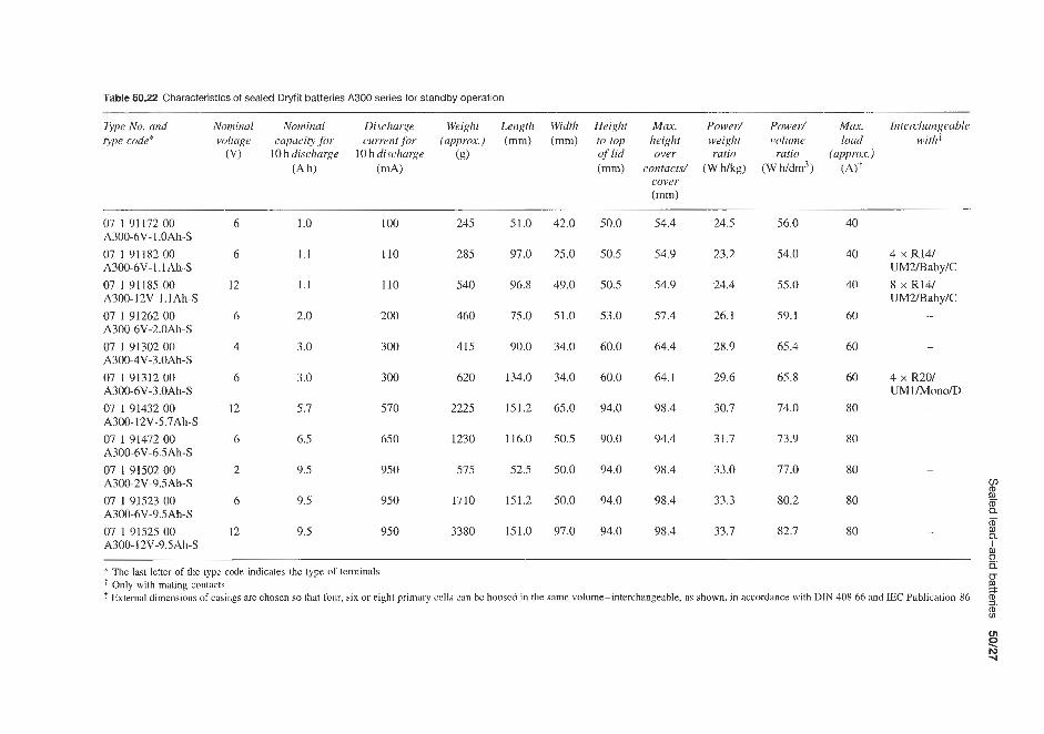
Table 50.22 Characteristics of sealed Dtyfit batteries A300 series for standby operation
Type No. and Nominal Nominal Discharge Weight Length Width Height Max. Power/ Power/ Mux. Interchangeable type code* volfage capacity jur current for (approx.) (mm) (mm) to top height weighf volume load with*
~~
(V) 10hdischarge 10hdischarge (g) of lid over ratio ratio (upprox.) (Ah) (mA) (mm) contacts/ (W hkg) (W h/dm3) (A).F
cover (mm)
07 1 91172 00
07 1 91182 00
07 191185 00 A300-12V-I. 1Ah-S 07 1 91262 00
07 1 91302 00
07 1 91312 00
07 1 91432 00
07 1 91472 00
07 I 91502 00
07 I91523 00
07 191525 00
A300-6V-I.OAh-S
A300-6V-l.lAh-S
A300-6V-2.0Ah-S
A300-4V-3.0Ah-S
A300-6V-3.0Ah-S
A300- 12V-5.7Ah-S
A300-6V-6.5Ah-S
A300-2V-9.5Ah-S
A300-6V-9.5Ah-S
A300- 12V-9.5Ah-S
6
6
12
6
4
6
12
6
2
6
12
1.0
1.1
1.1
2.0
3.0
3.0
5.7
6.5
9.5
9.5
9.5
100
110
I10
200
300
300
570
650
950
950
9 50
245
285
540
460
415
620
2225
1230
575
1710
3380
51.0
97.0
96.8
75.0
90.0
134.0
151.2
116.0
52.5
151.2
151.0
42.0
25.0
49.0
51.0
34.0
34.0
65.0
50.5
50.0
50.0
97.0
50.0 54.4 24.5 56.0
50.5 54.9 23.2 54.0
50.5 54.9 24.4 55.0
53.0 57.4 26.1 59.1
60.0 64.4 28.9 65.4
60.0 64.1 29.6 65.8
94.0 98.4 30.7 74.0
90.0 94.4 31.7 73.9
94.0 98.4 33.0 77.0
94.0 98.4 33.3 80.2
94.0 98.4 33.7 82.7
40
40
40
60
60
60
80
80
80
80
80
-
4 x R14/ UM2IBabylC 8 x R14/ UM2Baby/C
-
-
4 x R201 UMl /Mono/D
-
I m Q IJ
3.
8. * The last letter of the type code indicates the type of terminals
% w
Only with mating contacts * External dimensions of casings are chosen so that four, six or eight primary cells can bc housed in the same volume-interchangeable, as shown, in accordance with DIN 408 66 and E C Publication 86

50/28 Lead-acid (secondary) batteries
Table 50.23 Specification of Crompton-Parkinson sealed lead-acid batteries
Number of batter); units
per outer
Type Nominal Nominal Width Depth Height Weight Re$ voltage capacity (Ah) (-1 (mm) (mm) (g)
(V) 10h 20h pack rate rate
SLA6-1.6 6 1.5 1.6 66 33 85 380 24 SLA6-3.2 6 3.0 3.2 66 33 125 660 24 SLA6-4.8 6 4.5 4.8 94 33 125 920 24 SLA6-6.4 6 6.0 6.4 91 49 115 1120 24 SLA6-8.0 6 1.5 8.0 115 49 115 1500 12 SLA12-1.6 12 1.5 1.6 66 66 85 160 12 SLA 12-4.8 12 4.5 4.8 94 66 125 1840 12
I : w m i n Discharge time
Figure 50.9 Discharge performance at 20°C of Crompton-Parkinson sealed lead-acid batteries. The curves show change in voltage at battery terminals with time during constant-current discharges at a number of different current rates. The current is given in multiples of I20 so that a single family of curves can be used for all the sizes of battery in the range. I20 is the current that will deliver the nominal battery capacity, CZO, in 20 h. Its value (A) is one-twentieth of the battery capacity (C20/20). The lower end of each discharge curve indicates the recommended minimum voltage at the battery terminals for that particular rate of discharge; that is, the voltage at which the discharge should be discontinued (Courtesy of Crompton-Parkinson)
- 2.2 > m - S 1.8 - 1.6
1.4
1.2
- o, 2.0
- m 0
Figure 50.10 Typical voltage characteristics at various rates of discharge at 21°C of an Eagle Picher Carefree rechargeable lead-acid battery. To determine discharge
by factor shown. For example, the rate at which an 8A h battery must be discharged to yield a useful 10 h equals 0.096C or 0.096 x 8Ah = 0.77A (Courtesy of Eagle Picher) Discharge time
'E ,?'
rate of various batteries multiply rated capacity (C)
h-
20Ah. The characteristics of these batteries are listed in Table 50.25.
These batteries may be used in either cyclic or float services in a wide range of applications. The batteries incorporate a venting system to avoid excessive
pressure build-up in the event of battery or charger malfunction. Because of the heavy-duty grids, 1000 cycles are claimed for these batteries and a normal life of 4-5 years is expected in float charge on standby applications. Tables 50.26 and 50.27 show the

Sealed lead-acid batteries 56/29
Table 50.24 Specification of Eagle Picher Carefree maintenance-free lead-acid batteries
Battery No Normal voltage
(VI
Rated capacity at 20 h rate
(Ah)
Width (mm)
CF6Vl CF12Y1 CF12Vl -L CF18VI CF 12'4 I. 5 CF2V2.5 CF6V2.5 CF8V2.5 CF10V2.5 CF1 2V2.5 CF6V2.6 CF13V2.6 CF2V5 CF6V5 CF8V5 CFIOYS CF12V5
CF 12Y5PP CF8V6 CF6V8 CF12V8 CF6V15 CF12V15 CF12V20 CF2V30 CF6V30
CF12V30
CF6V40
CF 12V5-L
CF6V30-L
CF12V30-L
2 12 12 18 12 2 6 8
10 12 6
12 2 6 8
10 12 12 12 8 6
12 6
12 12 2 6 6
12 12 6
0.9 0.9 0.9 0.9 1.5 2.6 2.6 2.6 2.6 2.6 2.6 2.6 5.2 5.2 5.2 5.2 5.2 5.2 5.2 6.0 8.0 8.0
15.0 15.0 22.0 28.0 28.0 28.0 28.0 28.0 44.0
50.8 83.8
102.1 124.4 178.3 58.4 80.5
105.7 133.4 116.8 134.6 134.6 59.1 80.8
107.9 134.6 117.3 155.4 161.0 84.8
152.4 152.4 91.4
183.1 165.3 84.8
255.0 170.7 255.0 165.3
158.7
41.9 50.0 50.8 50.0 41.9 50.0 50.8 50.0 33.7 61.0 26.4 66.0 58.7 66.0 58.7 66.0 58.7 66.0 79.2 66.0 34.3 60.2 69.1 60.2 26.9 100.3 58.7 100.3 58.7 100.3 58.7 100.3 80.8 100.3 61.4 100.1 66.3 167.6 54.6 165.1 50.8 95.2
102.4 95.2 84.8 164.8 84.8 164.8
124.7 165.8 54.5 165.1 85.1 165.1 54.5 165.1
158.7 165.1 109.5 165.1 124.7 165.8
0.25 0.50 0.50 0.77 0.86 0.21 0.63 0.86 1.04 1.27 0.63 1.27 0.35 1.09 1.45 1.77 2.13 2.18 2.27 1.77 1.63 3.22 2.90 5.81 7.35 1.72 5.22 5.22
10.44 10.44 7.49
110
100
90
discharge current at stipulated charge rates from Yuasa batteries between 1.2 and 20 Ah, 20 h rated capacities and the discharge capacity at various discharge rates for various types of battery.
>.
m 50.4.5 SAFT : 80
3 SAFT manufacture the Gelyte range of sealed
Q
70 - - 60 rechargeable lead-acid batteries. These batteries are
maintenance free and can be used in any position. They are available in capacities between 2.6 and 30Ah in 2, 4, 6, 12 and 24V models (Table 50.28).
50.4.6 GECKhloride Gates (UK)
The fully recombining sealed lead-acid 2.00 V battery was developed by GEC. The first cylindrical cell in the range to be offered, and the only one for which details are currently available, is the D cell, which is rated at 2.5 A h at the 10 h rate. It is 61 rnm in height and
50 5 Y 40 23
30
20
10
-40 -20 0 20 40 60 Temperature ("C)
- Figure 50.14 Capacity versus temperature at various rates of discharge for an Eagle Picher Carefree rechargeable lead-acid battery (Courtesy of Eagle Picher)
34 rn in diameter. Capacities of 5.0 A h (x-type) and 25 ~h ( B C - ~ ~ ~ ~ ) are also available (see Table 50,291,

16
16
16
16
16
16
OP
OP
OP
OP
OP
OP
SP
00 I
OZ
SE
OP
SP
OE
SZ
6Z
PZ
9z
I Z
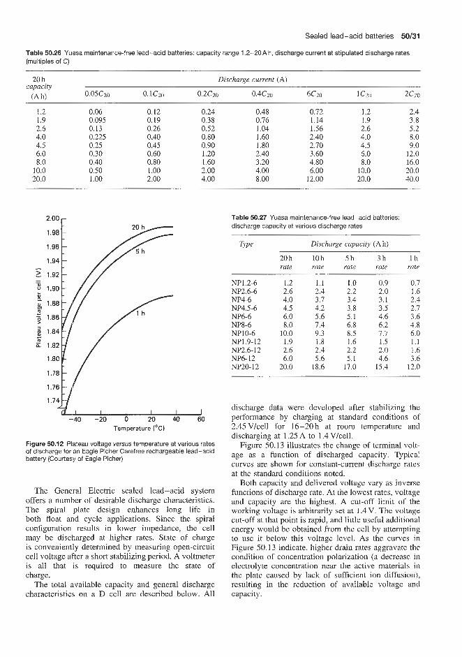
Sealed lead-acid batteries 50/31
Table 50.26 Yunsa maintenance-free lead-acid batteries: capacity range 1.2-20A h, discharge current at stipulated discharge rates (multiples of C) ___I_
20h Discharge current (A) capacity
(A hl 0.05Czo 0.1czo 0.2CZO 0.4c20 6Czo 1 czo 2c2o
1.2 1.9 2.6 4.0 4.5 6.0 8.0
10.0 20.0
0.06 0.095 0.13 0.225 0.25 0.30 0.40 0.50 1 .oo
0.12 0.19 0.26 0.40 0.45 0.60 0.80 1 .oo 2.00
0.24 0.38 0.52 0.80 0.90 1.20 1.60 2.00 4.00
0.48 0.76 1.04 1.60 1.80 2.40 3.20 4.00 8.00
0.72 1.14 1.56 2.40 2.70 3.60 4.80 6.00
12.00
1.2 1.9 2.6 4.0 4.5 6.0 8.0
10.0 20.0
2.4 3.8 5.2 8.0 9.0
12.0 16.0 20.0 40.0
2.00 r
1.98
1.96
1.94
1.90
g 1.88 m
CL
c - 7.86
$ 1.84
E 1.82
1.80
B
I I I I I I -40 -20 0 20 40 60
Temperature ("C)
Figure 50.12 Plateau voltage versus temperature at various rates of discharge for an Eagle Picher Carefree rechargeable lead-acid battery (Courtesy of Eagle Picher)
The General Electric sealed lead-acid system offers a number of desirable discharge characteristics. The spiral plate design enhances long life in both float and cycle applications. Since the spiral configuration results in lower impedance, the cell may be discharged at higher rates. State of charge is conveniently determined by measuring open-circuit cell voltage after a short stabilizing period. A voltmeter is all that is required to measure the state of charge.
The total available capacity and general discharge characteristics on a D cell are described below. All
Table 50.27 Yuasa maintenance-free lead-acid batteries: discharge capacity at various discharge rates
Type Discharge capacity (Ah)
20h rate
10 h rate
5h rate
NP1.2-6 NP2.6-6 NP4-6 NP4.5-6 NP6-6 NP8-6 NP10-6 NP1.9-12 NP2.6- 12 NP6- 12 NP20- 12
1.2 2.6 4.0 4.5 6.0 8.0
10.0 1.9 2.6 6.0
20.0
1.1 2.4 3.7 4.2 5.6 7.4 9.3 1.8 2.4 5.6
18.6
1.0 2.2 3.4 3.8 5.1 6.8 8.5 1.6 2.2 5.1
17.0
3h rate
0.9 2.0 3.1 3.5 4.6 6.2 7.7 1.5 2.0 4.6
15.4
l h rate
0.7 1.6 2.4 2.7 3.6 4.8 6.0 1.1 1.6 3.6
12.0
~
discharge data were developed after stabilizing the performance by charging at standard conditions Qf 2.45Vkell for 16-20h at room temperature and discharging at 1.25 A to 1.4 V/cell.
Figure 50.13 illustrates the change of terminal volt- age as a function of discharged capacity. Typical curves are shown for constant-current discharge rates at the standard conditions noted.
Both capacity and delivered voltage vary as inverse functions of discharge rate. At the lowest rates, voltage and capacity are the highest. A cut-off limit of the working voltage is arbitrarily set at 1.4 V. The voltage cut-off at that point is rapid, and little useful additional energy would be obtained from the cell by attempting to use it below this voltage level. As the curves in Figure 50.13 indicate, higher drain rates aggravate the condition of concentration polarization (a decrease in electrolyte concentration near the active materials in the plate caused by lack of sufficient ion diffusion), resulting in the reduction of available voltage and capacity.

50/32 Lead-acid (secondary) batteries
Table 50.28 Gelyte sealed lead-acid batteries available from SAFT
Model Nominal Nominal Length Width Height Weight voltage capacity (mm) (mm) (mm) (kg)
(V) (Ah) 20 h rate
SA-2300 SA-480 SA-626 SA-645 SA-645L SA-660 SA-680 SA-690 SA-6100
SA-6200 SA-6180
SA-6270 SA-6300 SA-1226 SA-1260 SA-1290 SA-12100 SA- 12 180 SA-12200 SA-12270 SA-12300 SA-24100
2 4 6 6 6 6 6 6 6 6 6 6 6
12 12 12 12 12 12 12 12 24
30.0 8.0 2.6 4.5 4.5 6.0 8.0 9 .O
10.0 18.0 20.0 27.0 30.0
2.6 6.0 9.0
10.0 18.0 20.0 27.0 30.0 10.0
46.3 103.1 134.6 67.1 67.1 70.6
151.9 96.3 96.3
192.5 192.5 175.3 175.3 134.9 141.2 192.5 192.5 192.5 192.5 192.5 192.5 192.5
58.4 51.1 35.1 67.1 67.1 70.6 51.1 58.4 58.4 58.4 58.4 96.3 96.3 35.1 70.6 58.4 58.4
116.8 116.8 175.2 175.2 116.8
144.0 94.7 59.7 97.5 96.3 99.7
144.0 144.0 145.0 145.0 145.0 145.0 145.0 125.7 97.8
145.0 145.0 145.0 145.0 195.0 145.0 145.0
1.90 1.09 0.64 0.86 0.86 1.04 1.63 1.68 1.90 3.36 3.81 5.03 5.71 1.27 2.09 3.36 3.81 6.71 7.62
10.07 11.43 7.62
Table 50.29 Fully recombining sealed lead-acid batteries from GEC
D X BC
Nominal voltage (V) Capacity rating (Ah)
10h rate 1 h rate
Peak power rating (W) Internal resistance (x10-3 Q) Diameter (mm) Height (mm) Weight (kg)
2.0
2.5 (250mA) 2.8 (2.5A) 135 (at 135A) 10 34.2 67.6 0.181
2.0
5.0 (500mA) 3.2 (5A) 200 (at 200A) 6 44.4 80.6 1.369
2.0
25 (2.5A) 20 (25 A) 600 (at 600A) 2.2 65.7 176.5 1.67
U 0.25 A
0 1 .o 2.0 3.0 Discharged capacity (A h)
Figure 50.13 Typical discharge curves at various discharge rates (constant load) for a General Electric D cell under standard conditions: charge 2.45V at 23°C for 16h, discharge at 23°C to 1.4 V (Courtesy of General Electric)
50.5 Spillproof lead-acid batteries Several manufacturers supply small lead-acid bat- teries which, although not sealed, are specifically designed to be spillproof. Thus, although these bat- teries will require topping up with electrolyte during their life, they have specific advantages in the field of portable battery-operated equipment.
50.5.1 Sonnenschein Sonnenschein manufacture a wide range of spill-proof accumulators designed for use with photo-flash equip- ment and other portable units. These batteries are housed in a tough transparent plastics case and feature a labyrinth-like construction below the vent opening through which no acid will pass even with extreme

Spillproof lead-acid batteries 50133
Table 50.30 Characteristics of Sonnenschein non-spill batteries
Tjpe No. a p e Nominal 20 h Max. Max. dimensions with designation voltage capacity charging terminals
(Ah) current V,cell Length Width Height
(VI
(mm) (mm) (mm) (A)
Permanent batteries 040 91511 00 2 23 F 4 2.0 0.20 42.0 58.0 66.5 040 91566 00 2 Bf3 G 4 3.5 0.35 42.0 58.0 102.0 040 91572 00 3 Bf3 S 6 3.5 0.35 62.0 58.0 100.5 040 91573 00 3 Bf3 K 6 3.5 0.35 62.0 58.0 98.5 040 91585 00 6 Bf3 SR 12 3.5 0.35 122.0 58.5 109.5 040 91706 00 1 B15 G 2 7.5 0.75 40.8 58.0 102.0 040 91727 00 3 B15 W/S 6 7.5 0.75 122.8 58.0 104.0 040 91742 00 3 T6 S 6 9.5 0.95 141.0 55.0 127.0 Standard batteries 040 91011 00 2 23 F 4 2.0 0.20 42.0 58.0 65.5 040 91066 00 2 Bf3 G 4 3.5 0.35 42.0 58.0 102.0 040 91073 00 3 Bf3 K 6 3.5 0.35 62.0 58.0 98.5 040 91072 00 3 Bf3 S 6 3.5 0.35 62.0 58.0 105.5 040 91106 00 3 KS3 G 6 3.6 0.36 85.5 58.0 101.0 040 9 1126 00 1 KS4 G 2 4.8 0.48 35.0 58.0 101.0 040 91146 00 1 KS5 G 2 6.0 0.60 41.0 58.0 101.0 040 91156 00 2 KS5 G/A 4 6.0 0.60 82.0 58.0 101.0 040 91166 00 3 KS5 G/A 6 6.0 0.60 124.0 58.0 101.0 040 91206 00 1 B15 G 2 7.5 0.75 40.8 58.0 102.0
Approx. weight (8)
Without With acid acid
256 305 390 465 570 685 570 685
1140 1370 340 430
1050 1320 1700 2015
256 305 390 465 570 685 570 685 690 840 265 330 3 00 380 600 765 900 1150 340 430
changes of position and vibration. The vent does, The batteries at -40°C retain 38% of the capa- however, permit the passage of gases during char- city they possess at 20°C. These batteries are avail- ging. Each individual cell has an indicator, based on able in two versions, standard and permanent (see floats, which accurately indicates the state of charge. Table 50.30).


Nickel batteries


Nickel-cadmium secondary batteries 51/3
the same dimensions and capacities as the standard VB cells and are designed to withstand more severe operating conditions. They have an improved voltage characteristic at low temperatures and high discharge rates and higher mechanical strength and reliability.
There are five sizes of VB cell from 40 to 600 mA h available in VB and VBE versions (see Table 51.1).
VB button cells have a nominal discharge voltage of 1.2Vkell. The rated capacity C5 (Table 51.1) at 20°C is defined as the capacity in ampere hours obtained at the 5 h rate of discharge (0.2C5 A) to an end-voltage of 1.10 Vkell after a full charge at 0.1 C5 A for 14 h. Rates of charge and discharge are expressed in multiples of the rated capacity C5, thus 0.2C5 A represents 20 mA for a cell having a rated capacity, C5, of l00mAh. 5C5 A represents 500 mA for the same cell.
The excellent temperature characteristic of the dis- charge of VB cells is illustrated in Figure 5 1.1.
The life of VB and VBE cells (Table 51.1) can extend over 10 years, but this is dependent on oper- ating conditions and is principally influenced by the depth of discharge (discharged capacitykated capacity) in a cycling application and by the number of ampere hours overcharged in a continuous charge application. The great reliability of VB and VBE cells makes their life comparable with that of most electronics com- ponents, During cycling approximately 500 cycles are obtained with 100% depth of discharge. After 5 years' continuous charge at 0.005Cs mA, the failure rate for VB cells is not greater than 5 per 1000. Under the same conditions, VBE cells offer ten times this reliability: a failure rate of 5 per 10000.
A typical discharge curve for a VB button cell is given in Figure 51.2 (continuous discharge).
VB batteries are also available in standard plastics- cased button packs made of n identical VB button cells, where n is between 2 and 24, each of rated capacity C5 mA h, connected in series and assembled in a rigid case, to make packs with discharge voltages between 2.4 V (2 cells) and 28.8 V (24 cells). Packs are available made up from VB 4, 10, 22, 30 and 60 cells (capacity 40, 100, 220. 300 and 600C5 mAh, see
51 -1 Nickel-cadmium secondary batteries 51.1.1 Sealed nickel-cadmium batteries
SAFT (SociCtC des Accumulateurs Fixes et de Trac- tion), a major inanufacturer of alkaline batteries, pro- duce a full range of sealed nickel-cadmium batter- ies, including 'open type (GPX) and semi-open type (VOK-VOKH-VHP), both of which are higher capa- city types. SAFT also produce sealed cells and batter- ies and button cells (VB, VR and VY types), which are discussed below.
Details of the main types of sealed cell and battery manufactured by SAFT are given in Table 51.1.
The SAFT range consists of button and cylindrical types and the VR series. The button cells have very thin sintered positive and negative plates with a porous separator enclosed by two nickel-plated steel cups. Capacities are up to SOQmAh at 1.2V for a size approximately 35mm diameter x l0mm thick with a weight of 100 g. Plastics-sleeved packs of button cells are available connected in series to give up to 12V. Similar metal-clad packs are also available.
The cylindrical batteries are designed for a wide range of applications requiring high capacity and exceptionally long life. Cells are dimensionally sim- ilar to the principai conventional dry batteries. The sintered plate construction consists of a spirally wound plate assembly, which is tightly fitted into a steel con- tainer. All batteries have a special venting system, with automatic resealing should excess gas pressure occur. The design satisfies the requirements of BS 3456: Section 2.36: 1973 on all points, including safety on reverse charge. Capacities are up to 1OAh at 1.2V for a size of 41.7 mm diameter x 90 mm height with a weight of 400 g. Series connected, plastics-coated modular packs are available to give up to 12V at the above capacity.
The SAFT VR series of cells have been produced for applications requiring rapid charge and discharge. Up to 130A pleak discharge can be tolerated and the rapid charge time on a discharged battery can be as low as 15-60niin when using the appropriate charging equipment, which monitors cell temperature, voltage or time of charge. The maximum capacity available in this range at the moment is 10 Ah. For uncontrolled rapid charge, S,AFT have develloped the VY range of cells.
SAFT
VB button cells These cells have the form of a button in various diameters and thicknesses, made up of a stack of disc-shaped sintered plates and separators held in two nickel-plated steel cups, one fitting into the other and pressed together with an insulating gasket. There is also a high-reliability version of the button cell with improved performance on high-rate discharge at very low temperatures (VBE cells). These have
L
0.1 c, A Q: 100 E
80 c5 A r
60 E
3 20 0 0 .; 40L -20 -10 0 10 20 30 40 50
Discharge temperature ("C)
Figure 51.1 Influence of temperature on capacity of SAFT sealed nickel-cadmium sintered plate VB type button cells (Courtesy of S A W

Table 51.1 Sealed cells supplied by SAFT
Serial TYP Equivalent Rated Max. dimensions (mm) Max. Max. discharge rates (A) Max. $ number primary capacity weight power =.
battery C5 (Ah) Height Diameter (g) Continuous Pulse cw) w 0-
Cylindrical cells VR 1.2 Vlcell 0.1113AA
0.45 112A 0.5 AA R6 0.8 AF 1.2RR 2.0 c R14 2.5 213 D 4D R20 7F 10 SF
VY c 5 VRE 1RR
1.6C 3.5 D 6 F
Button cells (nominal discharge voltage 1.20V) VBE 4 VB and VBE 10
22 30 60
Rectangular cells
vos 4 7
10 23 26
0.100 0.450 0.500 0.800 1.2 1.8 2.5 4 7
10 1.150 1 .0 1.6 3.5 6.0
40 loo* 220* 300* 600*
4* 7*
10* 23 * 26*
17.4 28.1 50.2 49.8 42.1 49.7 43.5 60.5 91.3 89.2 42.1 43.2 48.8 59.2 90.0
6 5.3 7.8 5.5 9.8
78.5 112.5 91
165 185
14.5 17.3 14.5 16.17 22.7 25.9 32.9 32.9 32.9 41.7 22.7 23.2 26.4 33.4 33.4
15.7 23.0 25.1 34.7 34.7
Width Depth 53 20.5 53 20.5 76.2 28.9 76.2 28.9 76.2 28.9
11 21 24 34 51 77
105 150 240 400 50 49 74
150 240
3.5 7
12 18 31
230 360 500
1060 1200
1.0 4.5 5.0 8.0
12 14 20 28 35 80 12 9
11 18 24
0.2 1 2.2 3 6
20 35 40 60 80
15.4 31 24.5
77 93
120 145 170 200 90 70 70 92
123
2.3 11 18.5 23 29
10 20 16
50 60 78 95
110 130 66
1.5 7
12 15 15
* Rated capacity CmAh

Nickel-cadmium secondary batteries 51/5
(Table 51.1). There is also a special version VRE cell available for missile applications.
VR cells when continuously discharged at normal temperatures supply currents of the order shown in Table 51.2. Short-duration peaks (maximum power) can be obtained. For example, for 300ms at 0.65 V per cell, typical currents are given in Table 51.3. " 0.91 5c, = 200 rnh
0.8 I I I I I 0 10 20 30 40
Discharged capacity irnA h)
Figure 51.2 Discharge curve of a typical SAF'T VB series nickel-cadmium button cell (continuous discharge at 20 f 5°C). Maximum permissible continuous rate 200 mA (Courtesy of SAFT)
Table 51.1). The final assemblies have, of course, the same rated C5 capacity as the individual cells but vary in discharge voltage.
Also availablle are environment-proof assemblies in which the interconnected cells are resin potted in a plastics container. An advantage of button cell packs is that these can operate as very compact low- voltage capacitors, giving much greater energy storage in a much smaller space. VB button cell packs can deliver very high currents, the maximum discharge rate being 10C5mA. It should be ensured that the packs are not discharged to below IVkell. Short-duration peak discharges may be as high as 50- lOOCs mA at 0.8 V/cell.
VR cylindrical cells Nickel-cadmium cylindrical cells are designed for a wide range of applications requiring compact rechargeable batteries with high out- put capacity and exceptionally long life. Designed to be dimensionally similar to the principal cylin- drical primary cells, of internationally standardized dimensions, the SAFT VR cells incorporate thin sin- tered plate construction. Complete spirally wound plate assemblies are tightly fitted into a steel container to form cells. The container is closed by a cover having an automatic self-reclosing safety valve for high pres- sure (9-14 x IO5 N/m2) should excess gas pressure be caused by maltreatment.
The cells satisfy BS 3456: Section 2.36: 1973 as regards safety on reverse charge. Contact between the plates and the cover or the case is through a special connection electrically welded to the edges of the plates. This method of assembly adopted by SAFT improves battey performance on charge and discharge. The range of VR cells available is from IOOmAh to lOAh (Table 51.1). VR cells are characterized by a nominal voltage of I .2 Vkell and their remarkable power (1.2Ah per cell) is, for example, capable of supplying a current of 77 A at 0.65 V for 0.3 s. The cylindrical cell is available in a high-reliability version (VRE). These cells have the cover welded directly on to the case, which improves the sealing. The plate group is also given supplementary support to increase the resistance to mechanical forces. Four sizes of VRE cell are available, covering the range 1-6Ah.
Table 51.2 Continuous discharge
Cell type Cell current (A)
VR 1.2 RR 12 V R 2 C 14 V R 4 D 28 V R 7 F 35 VR 10 80
Table 51.3 Short duration discharge peaks
Cell type Cell current (A)
VR 1.2 RR 77 V R 2 C 93 V R 4 D 145 V R 7 F 170 VR 10 200
VR cells and batteries are designed for use in applications which require good high-rate discharge performance (continuous and peak). Due to their low internal resistance, higher discharge currents can be drawn and also substantially better voltages than apply in the case of cells available a few years ago. On continuous discharge, VR cells may be discharged at currents representing up to ten times their rated capa- city (Table 5 1.4). In short-duration peak discharges currents may be drawn which are as much as 100 times the value of the rated capacity, with a cell voltage of 0.65 Vkell.
Table 51.5 shows the discharge performance for 0.3 s duration peaks at 20°C of various types of VR cell.
At low temperatures, VR cells and battefies give exceptional performance. Figure 51.3 shows a contin- uous peak discharge characteristic at +20 and -20°C for a 1.2Ah battery consisting of ten 1.2Ah VR 1.2 RR cells connected in series.
VR cells can also be obtained in standard battery packs of 2.4-28.8V (Table 51.6) and extended range modular packs of 12 and 24 V (Table 5 1.7), both in a range of capacities.
The VR series standard packs provide for applica- tions requiring high performance on discharge at large currents either continuously or in short-duration peaks. The extended range modular packs are supplied in a

51/6 Nickel batteries
Table 51.4 Continuous discharge performance of VR cells at 20°C
Cell type Rated Max. Capacity recoverable capacity permissible (Ah) at man. current C5 (Ah) current (end of discharge
(A) 0.9 V/cell)
VR 0.1 113AA VR 0.45 1/2A VR 0.5 AA VR 0.8 AF VR 1.2 RR VR 2.0 C VR 2.5 2/3D VR 4 D VR 7 F VR 10 SF
0.1
0.45
0.5
0.8
1.2
1.8
2.5
4.0
7.0
10.0
1 .o
4.5
5.0
8.0
12.0
14.0
20.0
28.0
35.0
80.0
0.062
0.23
0.18
0.35
0.65
0.87
1.20
1.90
3.5
6.0
Table 51.5 Discharge performance for short-duration peaks (0.3 s) at 20 & 5°C of VR cells
Cell Rated Max. power Current (A) Current type capacity (W) at atmax. (A) at
Cj (Ah) 0.65 Vkell power 1 Vlcell 0.65 V/cell
VR 0.1 1/3AA VR 0.45 1/2A VR 0.5 AA VR 0.8 AF VR 1.2 RR VR 2.0 C VR 2.5 2/3D VR 4 D VR 7 F VR 10 SF
0.1
0.45
0.5
0.8
1.2
2.8
2.5
4.0
7.0
10.0
10
18
16
50
60
78
95
110
130
15.4 7.5
28 12
25 14
72 32
93 42
120 56
195 70
170 80
100 100
l 4 r 1.2 A at +20 "C
1.2 A at -20 "C
81 1 I I I I I 0 0.2 0.4 0.6 0.8 1.0 1.2
Discharged capacity (A h)
Figure 51.3 Continuous discharge characteristics of a SAFT 10 VR 1.2 RR, ten 1.2 A h cell nickel-cadmium battery (1.2 A h) at f20 and -20°C (Courtesy of SAFT)
plastics case in the range 0.5-10Ah at 12V and 24V. (Rated capacity is for discharge at the 5 h rate at 20°C after nominal charge and to a terminal voltage of 1.1 (C5A) Vkell.) The packs can be discharged steadily at up to the rated capacity and can be given a nominal charge at constant current 0.1Cj for 14h irrespective of their initial state of charge. Alternatively, the packs can be given a fast or accelerated charge. They will withstand a continuous charge of up to 0.05Cj and will operate in the temperature range -40 to +50"C. They may be stored indefinitely in any state of charge without deterioration in the above temperature range.
Wcylindrical cells The characteristics of VY cells (Table 51.1) are the same as those of the VR range. The VY cells have the novel conception of a plate that improves the recombination of oxygen produced on overcharge. They may thus be charged or overcharged at higher rates than those for VR cells. VY cells have a smaller capacity than the corresponding VR cells but the power characteristics are improved.
The full range of SAFT Nicad standard cylindrical cells ranging from 0.7 to 10 A h is listed in Table 51.8. These cells have a wide operating temperature range (-40 to 50°C) and an excellent cycle life (300-1000 cycles).
SAFT also supply a range of quick-charge cells (Table 5 1.9) and special low-resistance cells (Table 51.10). The quick-charge cells are designed for applications where a full charge must be accomplished in 3.5-4h. The low-resistance cells can be fully charged in as little as 15min. They also demonstrate excellent voltage retention during very high rate discharging.
SAFT supply the Polytemp range of high- temperature nickel-cadmium cells (Table 5 1.1 1). The long life at high temperature of these cells makes them an ideal back-up power source for many applications including computers and computer peripherals, emergency lighting and alarms, telephone and telegraph equipment, stationary and portable electronic instruments, and process control equipment.
Polytemp performance is the result of a combination of electrode design innovations with a polypropylene

fable 51.6 Characteristics and dimensions of SAFT VR series standard 6-12 V battery packs
VR 0.45 1/2A 0.45 Ah 4.5* VR 0.5 AA 0.50 A h 5.0* VR 1.2 RR 1.2Ah 12.0" V R 2 C 2.0Ah 14.0" VR 2.5 2/3D 2.5 Ah 20.0* VR4 D 4.OAh 28.0* VR 7 F 7.0 Ah 35.0" VRl0 SF 10.0 Ah 80.0*
121.627
120.244
120.197
120.204
122.764
120.210
120.216
120.221
54 31 32 114
45 31 54 137
70 48 46 286
80 54 54 423
102 70 50 67 1
102 70 67 852
102 70 98 1320
130 88 96 214.5
121.630
120.41 2
120.430
120.482
122.767
120.440
120.464
120.309
71 37 32
59.4 31 54
92 48 46
105 54 54
135 70 50
135 70 67
135 70 98
177 88 96
182
203
429
638
932
1292
2024
3333
121.632
120.246
120.199
120.206
122.157
120.2 12
120.185
120.223
88 37 32
74 31 54
114 48 46
130 54 54
167 70 50
167 70 67
167 70 98
212 88 96
228
258
539
803
1155
1617
2530
4147
* Maximum current (A)
Table 51.7 Characteristics and dimensions of SAFT VR series extended range modular 12 and 24V packs
Cell type Battery voltage 12 V Battery voltage 24 V
VR 0.4 AA, 0.5 A h VR 1.2 RR, 1.2Ah VR 2 C, 2Ah VR 4 D, 4Ah VR 7 F, 7Ah VR 10 SF, l0Ah
104 33 68 270 132 51 53 600 141 57 58 870 187 74 77 1600 186 73 102 2403 230 90 1 05 3920
168 33 63 540 I69 77 51 1200 188 84 53 1740 171 14.5 81 3200 111 145 112 4860
v) (D
0 0 3 Q
9

X X X X H X ZI X X H ZI H ZI X H X H H H ZI H H H x X H ZI H H H H H H H
E'€ 5's P'P P'P OL O S O'S 0'5 O'S 0'6 0'9 0.01 S'8 5.8 O'LI S'8 O'SI 0'51 O'OZ 6'9 1 O'ZZ O'EZ O9Z O'9Z O'9Z 0'82 O'PZ O'8P 0'09 0'06 O'OZ L 0'001 0'08 O'OZZ
O'OOP VN O'OEZ VN O'OPZ 0'8 O'OPZ 0'8 O'OIZ 0'8 O'OPl VN O'OPI VN O'OST 0'8 0'0s t 0'8 O'OEI 0'8 O'SO 1 0'8 0'08 0'8 O'LL O'P O'LL OP 0'89 0'8 T'IS S'E P'SP 0'8 p' SP 0'8 L6E O'P 6'ZE S'E 8'62 O'P O'IE 0'8 O'PZ 0'8 I 'PZ S'E I 'PZ S'E 6 6 1 0'9 O I Z S ' E 9.51 O'P 8'0 1 O'P 8'01 0'8 0'6 0'8 6'L 0'8 S'9 O'P O'P O'P
VN VN
OOP' I OOP'I OOP' I
VN VN
008'0 008'0 008'0 OOS'O OPP'O 009'0 009.0 OOp'O O8P'O 0PZz'O OPZ'O OOZ'O OZE'O S9Z'O OSI'O OZI'O OOZ'O OOZ'O 59 I '0 081'0 OSI'O 080'0 SPOO 9EO'O OEO'O LEO'O EZO'O
91 91 91 91 91 91 91 91 91 91 91 91 91 91 9T 91 91 91 91 91 91 91 91 91 91 91 91 91 91 91 91 91 91 91
000' I OOL'O O O L O OOLO OOL'O OOP'O OOP'O OOP'O OOP'O OOP'O OSZ'O OZZ'O OOZ'O OOZ'O OOZ'O OZI'O OZI.0 OZT'O 00 I '0 080'0 080.0 SLO'O 009'0 OSO'O 050'0 OS00 SPOO SPO'O SZO'O EZO'O 810'0 SIO'O 110'0 LOO'O
000'0 1 OOO'L OOO'L OOO'L OOO'L OOOP 000% OOO'P 0003 OOO'P OOS'E OOZ'Z 000'2 000'2 000'2 OOZ' I OOZ' 1 OOZ'I 000'1 008'0 008.0 O S L O 009'0 OOS'O 005'0 OOS'O OSP'O OSP'O OSZ'O SZZ'O O8T'O 051.0 011'0 OLOO
000'6 OOE'9 OOE'9 OOE'9 OOE'9 OOS'E OOS'E OOS'E OOS'E OOS'E OOE'Z 000'2 008.1 008'1 008' I 080'1 090' I 090' I 088'0 OZL'O OZLO 099'0 OES'O OSP'O OSP'O OSP'O SOP'O SOP'O SZZ'O OOZ'O 091'0 OPI'O 001'0 090'0
SE'IP SS'ZE SS'ZE SS'ZE 6E'ZE SS'ZE SS'ZE SSZE SS'ZE 6E'ZE PS'ZE 6E'ZE SS'SZ SS'SZ OLSZ SE'ZZ SZ'ZZ SZ'ZZ OL'SZ 9P'9l 95'91 OL.SZ 9OS1 OE'PI OE'PI ZL'EI PO'LI 95'91 ZL'EI 9S'Y I S9'6 9O'Sl ZL'EI S9'6
02'68 tIS OE'16 tI OE'68 7d OE' 16 tI OE'68 d OS'8S 7a OS09 a OS09 a 88'8s a IS'EP auz 8L'9E azir
OS'% TU
OL'LP 73 OL'6P 3 LE'LP 3 OT'ZP IOOP 7 9 96'lP 12.62 3SIE 00'6P 'V 8Z'6P 3v OS'EZ 321 1 LL'8P V OZ'6P 7vv 020s vv 96'6P vv 6082 JVEIZ P6'LZ JVFIZ 8Z'OE VVZIT 68'9 1 'VEIL SP'PP VVV €1'91 VEll 9L.91 VVEIT 96'02 V V V Z I I
OlXA
LXA LXA
3SOL
PCRIA PXA PXA
3SO'P S ' Z W 3SZ'Z
Z X A ZXA
3SO'Z Z ' I X A 3SZ.1 3SZ' I 3SO' I 8'OXA
3SOO8.O 3SOSL'O 3S009'0
S'OXA S'OXA
3SOOS'O SP'OXA
3SOSP'O 3SOSz'O 3SSZZ'O 35087'0 3SOS L'O 3SOl 1.0 3SOLO'O
Laah
Pam

Table 51.9 Quick-charge sealed nickel-cadmium cells supplied by SAFT
Cell type Maximum bare cell C a p u c i ~ (Ah) Charge rates at 20°C Bare Internal Vent dimensions rated at 20°C cell resistance type*
weight (mQ) Continuous Maximum Model Size Height Diameter IC 0.2c (g) (mm) (mm) (A) (h) (A) (h)
0.070SC 0.1 l0SC 0.25osc 0.450sc VR0.45 0.50osc VR0.5 VRO.5 0.800SC VR0.8 VR1.2 VR2 VR2
1 l2AAA 1/3AA 1/2AA 213 A i 2/3At AA AA AAL 4 Af cs C CL
20.96 16.76 30.28 27.94 28.10 49.96 50.20 49.20 49.28 49.00 42.10 49.70 47.70
9.65 13.72 13.72 16.56 17.05 13.72 14.30 14.30 16.56 J 6.46 22.35 25.55 25.55
0.060 0.100 0.225 0.405 0.405 0.450 0.450 0.450 0.720 0.720 1.080 1.800 1.800
0.070 0.110 0.250 0.450 0.450 0.500 0.500 0.500 0.800 0.800 1.200 2.000 2.000
0.007 0.01 1 0.025 0.045 0.045 0.050 0.050 0.050 0.080 0.080 0.120 0.200 0.200
16 16 16 16 16 16 16 16 16 16 16 16 16
0.023 0.037 0.080 0.150 0.180 0.165 0.200 0.200 0.265 0.320 0.480 0.600 0.600
4.0 4.0 4.0 6.5 4.0 10.8 4.0 15.6 3.5 21.0 4.0 19.0 3.5 24.1 3.5 24.1 4.0 29.8 3.5 32.9 3.5 51.1 4.0 77.0 4.0 77.0
220.0 80.0 60.0 48.0 24.0 28.0 26.0 26.0 22.0 16.9 8.5 8.5 8.5
H H H H R H R R H R R R R
* H = hermetic; R = resealable
Table 51.10 Low resistance sealed nickel-cadmium cells supplied by SAFT
Cell type Maximum bare cell Capacity (Ah) Charge rates at 20°C Bare Internal Vent dimensions rated at 20°C cell resistance type*
Model Size Continuous Maximum weight (mQ) Height Diameter IC 0.2c (g) (mm) (mm) (A) (h) (A) (min)
VY1.15 CS 42.10 22.35 1.040 1.150 1.000 1 .5 4.000 15 51 .0 7.0 R
' R = tesealable

Table 51. POI!
9 : 0
z co 0 x
?mp high-temperature nickel-cadmium cells available from S
Cell type Maximum bare cell Capacity (Ah) Charge rates ai 20°C Bare Internal Vent dimemions rated at 20°C cell resistance type"
Model Size Continuous Muximum weight (ma) Height Diameter 1 c 0.2c (g) (mm) (mm) (A) (h) (A) (min)
0.070PT 0.110PT 0.150PT 0.1 80PT 0.250PT 0.450PT 0.500PT VT0.5 0.600PT 0.750pT 0.800PT I .OPT 1.2PT VT1.2 2.0PT VT2 2.2PT 4.OPT VT4 VT4 7.0PT VT7
1l2AAA 20.96 1/3AA 16.76 1/3A 16.13 AAA 44.45 U2AA 30.28 2/3Af 27.94 AA 49.96 AA 50.20 A 48.77 1/2c 23.50 Af 49.28 3/5c 29.21 cs 41.96 CS 42.10 C 47.37 C 49.70 1/2D 36.78 D 58.88 D 60.50 DL 58.50 F 89.10 F 91.30
9.65 13.72 15.06 9.65
13.72 16.56 13.72 14.30 15.06 25.70 16.56 25.70 22.25 22.35 25.70 25.55 32.39 32.39 32.55 32.55 32.39 32.55
0.060 0.100 0. I35 0.160 0.225 0.405 0.450 0.450 0.540 0.675 0.720 0.900 1.080 1.080 1.600 1.800 2.000 3.500 3.500 3.500 6.300 6.300
0.070 0.110 0.150 0.180 0.250 0.450 0.500 0.500 0.600 0.750 0.800 1.000 1.200 1.200 1.800 2.000 2.200 4.000 4.000 4.000 7.000 7.000
0.004 0.007 0.01 0 0.012 0.017 0.030 0.033 0.036 0.040 0.050 0.053 0.067 0.080 0.086 0.120 0.143 0.146 0.267 0.279 0.279 0.467 0.500
24+ 24+ 24+ 24+ 24+ 24+ 24+ 24+ 24+ 24+ 24+ 24+ 24+ 24+ 24+ 24+ 24+ 24+ 24+ 24+ 24+ 24+
0.007 0.01 I 0.015 0.018 0.025 0.045 0.050 0.050 0.060 0.075 0.080 0.100 0.120 0.120 0.180 0.200 0.220 0.400 0.400 0.400 0.700 0.700
16 16 16 16 16 16 16 16 16 16 16 16 16 16 16 16 16 16 16 16 16 16
4.0 6.6 7.9 9.0
10.8 15.6 19.9 24.1 24.4 31.2 29.8 39.7 45.4 51.1 68.1 77.0 79.5
130.5 150.4 150.4 210.0 241.0
220.0 80.0
100.0 120.0 60.0 48.0 28.0 32.5 26.0 23.0 22.0 20.0 15.0 12.1 17.0 11.2 10.0 9.0 7.0 7.0 7.0 5.5
H H H H H H H R H H H H H R H R H H R R H R
* H = hermetic; R = resealable

Nickel-cadmium secondary batteries 51/11
Rectangular or prismatic cells offer the highest capacities within the Varta range and in fact dif- fer very little in construction from the heavy-duty nickel-cadmium type. Capacities are up to 23Ah at 1.22 V, and the cells weigh 1.39 kg and measure 51 x 91 x 125mm. Permissible operating temperatures are the same as for the button type.
Single cells can be assembled into batteries, gen- erally consisting of two to ten cells, depending on voltage requirements; exceptions are the l0DK and 20DK button cells which are available only as single cells. Batteries are available in stack formats, includ- ing insulating sleeve, plastics cassettes, plastics boxes and sheet steel cases.
The energy contents of the various types of sealed nickel-cadmium battery supplied by Varta are tabu- lated in Table 51.19.
In some instances Varta sealed nickel-cadmium batteries are interchangeable with dry cells (see Table 51.20). Each of the different types of Varta cell is commented on below.
Cylindrical cells with mass electrode, D series The 151 D cells are physically equivalent to primary cells and are suitable for either one- or two-cell operations. These cells are suitable for comparatively low rates of discharge where good charge retention is important. They are suitable for a continuous discharge up to ten times nominal discharge rate.
separator material. Polypropylene is much more resis- tant to deterioration than the nylon separator used in standard designs.
Table 5 1.12 illustrates the relative effect of continu- ous overcharge at the 0.1 C rate on capacity over time (or life). The difference in life increases substantially as the continuous cell temperature is increased above 25°C.
Table 51.62 Percentage of life at 25°C
Cell temperature ("C) Standard Polytemp
25 35 45 55 65
100 100 40 I 5 20 60 10 45 1 30
Varta
Varta supply a range of sealed batteries and cells. Characteristics of some of these are detailed in Tables 5 1.13 -5 1.18. These include button, cylindrical, and rectangular types, some of which have sintered electrodes. The nominal voltage of the cells is 1.2 V. The final voltage, when discharging at the 10h rate, is 1.1 V. When discharging at higher rates, a lower voltage may be specified. Cells are normally recharged at the 10h rate (110) for 14h at room temperature. The end-of-charge voltage approximates to 1.35- 1.45 Vkell. The stated maximum pemssible temperature ranges for these batteries are as follows:
1. Chaxge: 0 to +45"C. 2. Discharge: -20 to +45"C. 3. Storage: -40 to +50"C. 4. Discharge and storage at +60"C permissible for a
maximum of 24 h.
Varta batteries with sintered electrodes have a very low internal resistance and a high load capacity, which result in an improved power to size and weight ratio. The capacity of their button-type cells is up to 3 A h at a voltage of 1.24 V. The size of the battery for this capacity is 50 mm diameter x 25 mm thick, weighing 135 g, and the permissible operating temperatures are -20 to 145°C. These cells are also available in welded and plastics-covered packs of up to ten cells.
Cylindrical batteries are suitable for heavy loads at steady voltages. They can be discharged continuously at 20 times the normal rate and 40 times the normal rate for short periods. Apart from ensuring the correct char- ging method, maintaining end-voltages and adhering to the temperature limits, no special care is needed. The rugged construction results in a battery that can with- stand shocks and vibration. Capacities are up to 6 A h at 1.24V, aad the battery weighs 240g and measures 35.5 mm diameter x 94 mm high. Permissible operat- ing temperatures are from -40 to +45"C.
Cylindrical cells with sintered electrodes, RS series These cells are suitable for applications where a high rate of discharge, or operation at extremes of temper- ature, or permanent trickle charge or fast charging is required. The cells are constructed from rolled sintered positive and negative plates, separated by a highly porous separator which absorbs all the free electrolyte within the cell. A safety vent is incorporated within each cell to enable gas, which may build up under fault conditions, to be released. Batteries containing RS cells are available either in standard formats or designed for specific applications.
Rectangular cells with mass electrodes, 0 2 3 type These cells are suitable for continuous discharge up to ten times the nominal discharge current. They are fitted with a safety vent which prevents excessive internal pressure damaging the cell case in fault conditions.
Rectangular cells with sintered electrodes, SD series These cells are suitable for applications where a high rate of discharge, or operation at extremes of temper- ature, or permanent trickle charge or fast discharge is required. The cells are constructed from cut sintered positive and negative plates, separated by a highly porous separator which absorbs all the free electrolyte within the cell. A safety vent is incorporated within each cell to enable gas, which may build up under fault conditions, to be released. All cells in this range

Table 51.13 Varta sealed nickel-cadmium cylindrical cells
Type Type No. Nominal Discharge Current Charge M a . Max. Internal Weight Diameter Height Remarks cupacity 10 h rate 5 h rate current recommended short- resistance (8) (mm) (m)
5-10h rate (mA) (mA) for 14h constant term fully
(A) (A) (!J Q)
(Ah) (mA) load load charged
Mass electrodes suitable for a continuous discharge up to 10 x nominalrate 151D 3930150311 0.15 1.5 30 12.7 180D 3930180011 0.18 18 36 10.0 900D 393090031 1 0.90 90 180 42.3
0.15 0.3 500 12 - - 10.5
0.90 1.8 100 14.0 -
29 1.0 44 1 .0 90 0.6
With contact cap and sleeving With solder tags and sleeving (Height measured without solder tags)
Sintered plate electrodes suitable for high-rate discharge und trickle charge l00RS 3960100081 0.10 IO 20 10.0 225RS 3960225041 0.225 22 44 22.0 RS4 3964000051 4.00 400 800 400 RS7 3967000051 7.00 700 1400 700
0.20 0.4 190 7.3 0.45 0.9 82 11.3 8.0 16.0 10 147.0
14.0 28.0 9 237.0
14.7 17.4 14.7 2.5.0 33.5 61.0 33.5 94.0
All cells can be provided with straight connectors

Nickel-cadmium secondary batteries 51/13
Table 51.14 Varta sealed nickel -cadmium cylindrical cells
Type Order No. Nominal 0.1 C5A 0.2 C5A Charge Weight Dimensions (mm) for bare cell in capacily (I101 ( 1 5 ) current ( g )
shrink sleeve at 0.2 C5A (mA) (mA) 14h Diameter Height (Ah) (m A)
~ ~ ~~ ~~~~~~~ ~~~
Sintered electrodes for continuous discharge rates up to 6CsA(60 x I l o )
150RS* 05001 101 111 0.15 15 30 15 9 12-0.5 29-1.0
800RS 501180 201 052 0.80 80 160 80 37 Max. 17.3 Max. 49.2 RS 1 508210 101 052 1 .o 100 200 100 41 23-1.0 35.7-1.0 Sintered electrodesfor continuous discharge rates up to: 1OC5A(lOO x I lo ) , 750 RSH-RSH 1.8; 7CsA(70 x I l o ) , RSH 4; 6CsA(6O x I l o ) , RSH 7 750RSH 508375 101 052 0.75 75 150 75 36 25.3-0.5 25-1.0 RSH 1.2 50412 101 052 1.2 120 240 120 50 23-1.0 42.2-1.0
RSH 4" 05020 101 111 4 400 800 400 147 33.5-1.0 61-1.0
Sintered electrodes for high-temperature applications up to 75°C
180RS 05003 101 111 0.18 18 36 18 10 10.5-1.0 44-1.0
RSH 1.8* 05014 101 111 1.8 180 360 180 67 26-1.0 49-1.0
RSH 7 501470 101 052 7 700 1400 700 237 33.5-1.0 94-1.0
lOORST 501710 201 052 0.09 9 18 9 8 14.3-0.6 16.8-0.6 5OORST 508750 101 052 0.5 50 100 50 24 14.5-0.5 49.5-1.0 RST 1.2 508812 101 052 1.2 120 240 120 50 23-1.0 42.2-1.0 RST 1.8 05814 101 111 1.8 180 360 180 67 26-1.0 49-1.0 RST 4 05820 101 111 4 400 800 400 147 33.5-1.0 61-1.0 RST 7 50870 101 052 7 700 1400 700 237 33.5-1.0 94- 1 .O
* These types are interchangeable with primary batteries of similar dimensions
Note: all characteristics assume cells are fully charged and discharged at 20°C
have the cases connected to the positive electrodes. Cell cases are not insulated but intercell separators and nickel-plated connective links are available. The SD series are available made up in metal boxes.
Button cells with mass plate electrodes, DK and DKZ series Button cells are produced by Varta in two ver- sions. IDK-type cells are assembled using one positive and one negative electrode separated by porous insu- lating material. These cells are suitable for operation at normal templeratures and discharge rates of up to ten times the nominal discharge current. DKZ cells have two positive and two negative electrodes, which lower the internal resistance and therefore make the cell suit- able for high rates of discharge (20 times nominal discharge rate) and also for low-temperature opera- tion. Button cells are suitable for applications where low cost and good packing density are required. The charge retention of mass plate button cells is superior to that of all ocher forms of sealed nickel-cadmium cell. All DK cells listed in Table 51.16, except the lODK, can be made into stack batteries by connecting end on end, in sleeves, thereby ensuring a minimum internal resistance.
Varta supply a sealed sintered electrode nickel-cad- miurn cell (RSH and RSX type) for very high rates of discharge. Figure 51.4 compares the performance characteristics of the RS type of cell and the RSH type. A by-product of the lower internal resistance
of the RSH cell is a reduction in its temperature on discharge.
Nickel-cudmium sealed cells f o r CMOS-RAM memory protection Varta supply the Mempac range of button cells for this application and these cells are suitable for printed circuit board mounting. The advantages claimed for these cells are as follows:
1. Rechargeable The cells can be recharged many times or trickle charged permanently.
2. Flat discharge curve The cells remain at or above their nominal voltage (1.2 Vkell) for approximately 80% of their discharge time.
Over 60% capacity remains after 6 months storage at +20°C.
This ensures that the good voltage level of these cells is maintained during pulse discharges.
5. Simple charging Only a nominal constant current charge is required.
6. Compact Batteries, when board mounted, allow an 18 nun board spacing to be achieved as standard; 10 mm for special applications.
7. Cost effective A combination of the battery's low initial cost and its facile nature ensures minimum user expense.
3. Low self-discharge
4. Low internal resistance

Table 51.15 Varta sealed nickel-cadmium rectangular cells
Type Type No. Nominal Discharge Current Charge M a . M a . Internal Weight Length Height Width capacity 10 h rate 5 h rate current recommended short- resistance (g) (mm) (mm) (lm 5-IOh (A) (A) for 14h constant term fully charged
rate (A) load load (PQ) (Ah) (A) (A)
Muss electrodes suitable for a continuous discharge up to IO x nominal rate D23 3900023501 23.0 2.3 - 2.3
(10h rate) Sintered electrodes suitable jor high-rate discharge and trickle charge SD1.6 3941600001 1.6 0.16 0.32 SD2.6 3942600001 2.6 0.26 0.52 SD4 3944000001 4.0 0.40 0.80 SD7 3947000001 7.0 0.70 1.40 SD15 3940015001 15.0 1.50 3.00 SD2.4 52024101000 2.4 0.24 0.48 SD4.5 52045101000 4.5 0.45 0.40 SDlO 52110101000 10 I .OO 2.00 SD15 52 11 51 01 000 15 1.50 3.00
0.16 0.26 0.40 0.70 1 .50 0.24 0.45 1 .00 1 .50
23 46 10 1390 51.0 91.0
3.2 6.4 16 115 5.2 10.4 13 180
- - 260 14.0 28.0 8 360 30.0 60.0 2.5 780
115 180 360 780
-
16.8 41.4 16.8 41.4 24.2 41.4 38.2 41.4 30.0 77.0 16.8 64 16.8 100 38.2 I02 30 I26
125
64.1 102 102 102 126 41.4 41.4 41.4 77
~~
All characteristics assume that cells are fully charged and discharged at 20°C
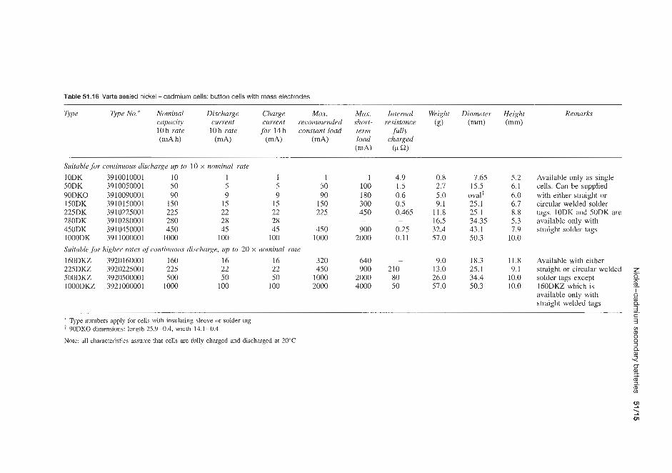
Table 51.16 Varta sealed nickel -cadmium cells: button cells with mass electrodes ~~ ~~~
Type Type No.* Nominal Diwharge Charge M U . M u . Internal Weight Diameter Height Remarks capacity current current recommended short- resistance (g) (mm) (mm) 10 h rate 10 h rate for 14 h constant load term fully
(d) (CL a) (d h) (d) (d) (mA) load charged
Suituble for continuous discharge up to 10 x nominal rate lODK 3910010001 10 1 I 50DK 3910050001 50 5 5 90DKO 3910090001 90 9 9 150DK 3910150001 150 15 15 225DK 3910225001 225 22 22 280DK 391 028000 I 280 28 28 450DK 3910450001 450 45 45 lOOODK 391 1000001 1000 100 100
Suitable for higher rates of continuous discharge, up to 20 x nominal 160DKZ 3920160001 160 16 16 225DKZ 3920225001 225 22 22 500DKZ 3920500001 500 50 50 IOOODKZ 3921000001 1000 100 100
I 50 90
150 225
450 1000
-
rule 320 450
1000 2000
1 100 I80 300 450
900 2000
-
640 900
2000 4000
4.9 1.5 0.6 0.5 0.465
0.25 0.11
-
-
210 80 50
0.X 7.65 2.7 15.5 5.0 oval+ 9.1 25.1
11.8 25.1 16.5 34.35 32.4 43.1 57.0 50.3
5.2 6.1 6.0 6.7 8.8 5.3 7.9
10.0
9.0 18.3 11.8 13.0 25. I 9.1 26.0 34.4 10.0 57.0 50.3 10.0
Available only as single cells. Can be supplied with either straight or circular welded solder tags. lODK and 50DK are available only with straight solder tags
Available with either straight or circular welded z solder tags except h 160DKZ which is (D
available only with straight welded tags
0
0 m 11 3
* Type numbers apply for cells with insulating sleeve or solder tag ' 90DKO dimensions: length 25.9-0.4, width 14.1-0.4
Note: all characteristics assunie that cclls arc fully chargcd and discharged at 20°C

i Q)
Table 51.17 Varta sealed nickel-cadmium batteries: miscellaneous types
Type Type No. Nominal Voltage Discharge Nominal Charge Max. M a . Weight Length Width Height $. voltage 10 h rate current capacity at current recommended .short- (g) (mm) (mm) (mm) 8
" %
iV) iV) 10h rate 10h rate for 14h constant load term i 1 w (Ah) imA) (A) load
(A)
Batteries ,for pocket receivers, microphones, portable radiotelephones, calculators, etc. TR718 3520090760 9 8.5 9 0.09 9 0.09 0.18 6 V batteries with sintered electrodes in plastics cases; suituble,for continuous discharge up to 10 x nominal rate and trickle charge SML2, 5 3602500594 6.0 6.0 250 2.5 250 5.0 10.0 SM6 3606000594 6.0 6.0 600 6.0 600 12.0 24.0 51900D 6.0 6.0 90 0.9 0.9 1.8 1 0lRS 1 12.0 12.0 100 1 .0 2.0 4.0 31SD1.6 3.6 3.6 160 1.6 3.2 6.4 31SD2.6 3.6 3.6 260 2.6 5.2 10.4 5lSD2.6 6.0 6.0 260 2.6 5.2 10.4
42.5 26.4 15.1
550 134 34.3 1000 90.5 50.5 220 37 37.0 475 119 50.0 360 52 43.0 570 52 43.0 980 67 59.0
49.0
62.2 112.2 97.0 42.0 67.5
110.0 106.0
Table 51.18 Varta sealed nickel-cadmium batteries: miscellaneous types
Type Type No. Nominal Nominal O.lC5 A Charging Weight Dimensions (mm) voltage capacity (110) current (6)
(110) (Ah) (d) iV) at 0.1C5 A imA) 14h Length Width Height
6V batteries with sintered electrodes in plastic housing for continuous discharge rates up to IC5 A (10 x 110) 5M 3 52530 101 063 6 3 300 300 550 134.5 34.3 62.2 5M 6 52560 101 063 6 6 600 600 1000 90.5 50.5 112.5 Button cell batteries with mass plate electrodes in plastic encapsulation 101250DK 53025710057 12 0.25 25 25 135 54.8 28.8 54.9
~ ~~
All characteristics awume that cell9 are fully charged and dischargcd at 20°C
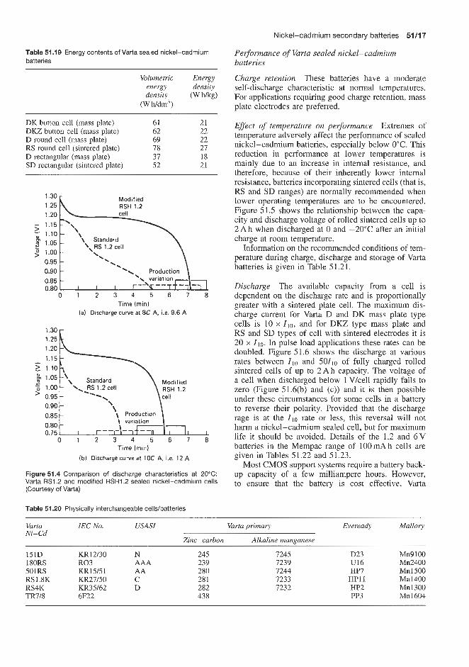
Nickel-cadmium secondary batteries 51/17
Performance of Varta sealed nickel-cadmium batteries
Charge retention These batteries have a moderate self-discharge characteristic at normal temperatures. For applications requiring good charge retention, mass plate electrodes are preferred.
Effect of temperature on performance Extremes of temperature adversely affect the performance of sealed nickel-cadmium batteries, especially below 0°C. This reduction in performance at lower temperatures is mainly due to an increase in internal resistance, and therefore, because of their inherently lower internal resistance, batteries incorporating sintered cells (that is, RS and SD ranges) are normally recommended when lower operating temperatures are to be encountered. Figure 51.5 shows the relationship between the capa- city and discharge voltage of rolled sintered cells up to 2 A h when discharged at 0 and -20°C after an initial charge at room temperature.
Information on the recommended conditions of tem- perature during charge, discharge and storage of Varta batteries is given in Table 51.21.
Discharge The available capacity from a cell is dependent on the discharge rate and is proportionally greater with a sintered plate cell. The maximum dis- charge current for Varta D and DK mass plate type cells is 10 x Zlo, and for DKZ type mass plate and RS and SD types of cell with sintered electrodes it is 20 x Zlo. In pulse load applications these rates can be doubled. Figure 51.6 shows the discharge at various rates between Zlo and 50110 of fully charged rolled sintered cells of up to 2 A h capacity. The voltage of a cell when discharged below 1 Vkell rapidly falls to zero (Figure 51.6(b) and (c)) and it is then possible under these circumstances for some cells in a battery to reverse their polarity. Provided that the discharge rage is at the Zl0 rate or less, this reversal will not harm a nickel-cadmium sealed cell, but for maximum life it should be avoided. Details of the 1.2 and 6 V batteries in the Mempac range of IOOmAh cells are given in Tables 5 1.22 and 5 1.23.
Most CMOS support systems require a battery back- up capacity of a few milliampere hours. However, to ensure that the battery is cost effective, Varta
Table 51.19 Energy contents of Varta sealed nickel-cadmium batteries
Volumetric Energy energy density density (Whkg)
(W h/dm3)
DK button cell (mass plate) 61 21 DKZ button cell (mass plate) 62 22 D round cell (mass plate) 69 22
D rectangular (mass plate) 31 18 SD rectangular (sintered plate) 52 21
RS round cell (sintered plate) 78 27
Modified RSH 1.2
1.20
\ . :::: L ..a .% Production \
'\ variation I I I --I
-3 -- - 0.85 0.80
0 1 2 3 4 5 6 7 8 Time (mini
( a i Discharge curve a t 8C A, i.e. 9.6 A
Modified FISH 1.2
0.85 Production
0.80 0.75
0 1 2 3 4 5 6 7 8 Time (rnin)
(bi Discharge curve at 1OC A, i.e. 12 A
Figure 51.4 Comparison of discharge characteristics at 20°C: Varta RS1.2 and modified RSHI .2 sealed nickel-cadmium cells (Courtesy of Varta)
Table 51.20 Physically interchangeable cells/batteries
Varfa Ni-Cd
151D 180RS 501RS RS1.8K RS4K TR7/8
IEC No. USASI Varta primary Eveready
Zinc-carbon Alkaline manganese
KR12/30 N 245 7245 R03 AAA 239 7239 KR15/51 AA 280 1244 KR27/50 C 28 1 7233 KR35/62 D 282 7232 6F22 438 - -
D23 U16 HP7
HP11 HP2 PP3
Malloiy
Mn9 100 Mn2400 Mn1500 Mn1400 Mn1300 Mn1600

51/18 Nickel batteries
Table 51.21 Varta sealed nickel-cadmium batteries: recommended conditions of temperature during charge, discharge and storage
Charge temperature (“C) Discharge temperature (“C) Storage temperature (“C)
Recommended Possible Recommended Possible Recommended Possible
D, DK and DKZ cells with mass plate electrodes 10 to 35 0 to 45 0 to 45 -20 to +50 0 to 45 -40 to +50
At temperatures below 0°C maximum discharge rate 5 5Clo (5 x 1 1 0 ) for DK and 5 lC10 (lox 110) for DKZ Up to 60°C for a maximum of 24h
Up to 60°C for a maximum of 24 h
RS and SD cells with sintered electrodes 10 to 35 -20 to +50 -20 to +45 -45 to +50 0 to 45 -45 to f50 At temperatures below 0°C charge current limited to 4110 with a voltage limit of 1.55 Vlcell
Up to 60°C for a maximum of 24 h Up to 60°C for a maximum of 24 h
~
g E 20
2 0 2 4 6 8 10 12 14 16 18 20 w
Discharge rate ( X I,o)
(a)
0 2 4 6 8 10 12 14 16 18 20
Discharge rate ( X I , , )
(b) 0°C
- Start
m m 1.1 -Average Y
Final - s o . 9 t TI I , < I I I I
0 2 4 6 8 10 12 14 16 18 20
Discharge rate ( X I,o)
(c) -20-c
Figure 51.5 Capacity and voltage versus discharge rate for fully charged Varta sealed nickel-cadmium roiled sintered cells up to 2 Ah (Courtesy of Varta)
recommend the use of the Mempac 100 DKO battery. This is rated at l O O m A h at the 10 h rate. However, at the discharge rates required for most memory support applications (possibly only a few hundred microamps), significantly greater capacity will be available.
I I I I I I I I I I I I , I, 10 20 30 40 50
Discharge rate ( X I , , ) (a)
2 x I , , ’ 0.9 0 1 2 3 4 5 6 7 8 9 10
Time (h)
(b)
3 0.9 0 10 20 30 40 50 60 70 80 90 100
Time (min)
(C)
Figure 51.6 Discharge curves at various rates of fully charged Varta sealed nickel-cadmium rolled sintered cells up to 2Ah. Starting voltage approx. 30 min after end of charge, initial voltage after 10% of discharge capacity, average voltage approx. 1.22V, final voltage approx. 0.99V. (b,c) Voltage during discharge below 1 V (Courtesy of Varta)
Figure 51.7 shows voltage characteristics for the Mempac cell when discharged at the 10 h rate O.lCloA

Nickel-cadmium secondary batteries 51/19
Table 51.22 Full range of Varta Mempac memory protection cells
Nominal capacity (mA h)
20 60 100 140
1.2 V nominal batter;\. voltage Battery type Drawing number Nominal voltage (V) Final voltage (V) End-of-charge on charge voltage (V) Trickle charge rate (mA) &IO% at 1.45V/cell DC internal resistance (fully charged) (ma) Battery length (mm) Maximum battery diameter (mm) 6.0 V nominal battery Battery type Drawing number Nominal voltage (V) Final voltage (V, End-of-charge on charge voltage (V) Trickle charge rate (mA) 3~10% at 1.45V/cell DC internal resistance (fully charged) ( m a ) Battery length (mm) Maximum battery diameter (mm)
1/20 DK DB 901/1 1.2 1 .o 1.45 0.2 2200 5.35-0.3 11.5
5/20 DK DB 901/5 6.0 5.0 7.25 0.2 11000 28.8-2.0 12.0
1/60 DK DB 892/1 1.2 1 .o 1.45 0.6 1300 6.2-0.4 15.5
5/60 DK DB 892/5 6.0 5.0 7.25 0.6 6500 31.5-2.0 15.8
M O O DKO DB 826/1 1.2 1 .o 1.45 1 .o 500 6.0-0.25 Oval
W O O DKO DB 826/5 6.0 5.0 7.25 1 .o 2500 30.4-1.25 oval
1/140 DK DB 862/1 1.2 1 .O I .45 1.4 450
25.1 6.1-0.6
5/140 DK DB 862/5 6.0 5.0 7.25 1.4 2250 30.9-3.0 26.0
170
1/170 DK DB 863/1 1.2 1 .o 1.45 1.7 375 6.7-0.6 26.0
5/170 DK DB 863/5 6.0 5.0 7.25 1.7 1875
26.0 33.9-3.0
250
1/250 DK DB 864/! I .2 1 .o I .45 2.5 300 8.8-0.6 26.0
5/250 DK DB 864/5 6.0 5.0 7.25 2.5 1500 44.4 - 3.0 26.0
Table 51 23 Varta Mempac S series of 100 mA h capacity cells for CMOS-RAM memory protection
Order No. Nominal Width Length Height Weight boltage (mm) (mm) without (g)
(V pins (mm)
53010701012 1.2 17-0.4 42.4 10.5 9 53010702012 2.4 17-0.4 42.4 16.0 15
53010704012 4.8 30.0-0.3 40.0 16.0 26 53010703012 3.6 22.2-0.4 40.3 16.0 21
i l . 0 1 I 1 I I I I I I I I .- 5: 0 1 2 3 4 5 6 7 8 9 10 D Time (h)
Figure 51.7 Discharge of a Varta Mempac 100mAh memory protection cell at the 10 h rate, O.IC,OPI (Courtesy of Varta)
at +20"C. When discharged at rates less than O.lCloA, the voltage plateau will be extended. Mempac batteries may be discharged at lower rates than O.lCloA.
Figure 5 1.8 shows the voltage a memory may expect to see when using a three-cell 100 DKO Mempac to supply a load current of 20 PA. It can be seen from this curve that even at extremes of temperature, when the
52.31 I I I I I I I I , I 0 600 1200 1800 2400 3000
Discharge time, r (h) at 20 pA
Figure51.8 Discharge of a Varta Mempac 100mAh memory protection cell to supply a load current of 20pA (Courtesy of Varta)
battery's negative temperature coefficient is taken into account, better than 2 V are still available, 2 V being the minimum voltage many volatile memories need in order to meet their performing specification.
To allow for variations in minimum operating volt- ages, the number of cells may be varied to suit the memory's requirements. Care should be taken to ensure that sufficient charging voltage is available to fully charge the battery.
Figure 51.9 shows the effect of discharge rate on discharge duration for a range of Mempac cells. The capacity required for memory support may be calcu- lated by multiplying the discharge time by the dis- charge rate, adding sufficient capacity to allow for self-discharge losses.
When choosing a battery for memory support:
1. Allow for self-discharge when deciding the capacity
2. When selecting the number of cells, ensure that: required.

51/20 Nickel batteries
Discharge rate (PA)
Figure 51.9 Effect of discharge rate of Varta Mempac memory protection cells on discharge duration (Courtesy of Varta)
(a) The minimum operating voltage of the chip can be achieved when the battery is fully discharged (1 Vkell).
(b) Sufficient charge voltage is available to allow for the voltage drop across the current-limiting resistor and the battery to attain at least 1.45 Vkell.
3. If the cell is used in a purely standby mode, use the appropriate trickle charge rates.
Union Carbide
Union Carbide market their products under the trade name Ever Ready, manufacturing a range of sealed cylindrical and button-type nickel-cadmium batteries in the range 1.2- 14.4 V.
In the Eveready design, gas evolution during charge and overcharge is prevented by the adoption of various design features. For the system to be overchargeable while sealed, the evolution of hydrogen must be pre- vented and provision is made for the reaction of oxy- gen within the cell container:
1. The battery is constructed with excess capacity in the cadmium electrode.
2. Starting with both electrodes fully discharged, charging the battery causes the positive electrode to reach full charge first, and it starts oxygen generation. Since the negative (cadmium) electrode has not reached full charge, hydrogen will not be generated.
3. The cell is designed so that the oxygen formed in the positive electrode can reach the metallic cadmium surface of the negative electrode, which it oxidizes directly.
4. Thus, in overcharge, the cadmium electrode is oxi- dized at a rate just sufficient to offset input energy,
keeping the cell in equilibrium indefinitely. At this point of equilibrium the positive electrode is fully charged and the negative is somewhat less than fully charged.
When cells are connected in series and discharged completely, small cell capacity differences will cause one cell to reach complete discharge sooner than the remainder. The cell that reaches full discharge first will be driven into reverse by the others. When this happens in an ordinary nickel-cadmium sealed cell, oxygen will be evolved at the cadmium electrode and hydrogen at the nickel electrode. Gas pressure will increase as long as current is driven through the cell and eventually it will either vent or burst. This condi- tion is prevented in the sealed nickel-cadmium cells produced by some suppliers by special construction features. These include the use of a reducible mater- ial in the positive electrode, in addition to the nickel hydroxide, to suppress hydrogen evolution when the positive electrode expires. If cadmium oxide is used it is possible to prevent hydrogen formation and to react the oxygen formed at the negative electrode by the same basic process used to regulate pressure dur- ing overcharge. A cell is considered electrochemically protected against reversal of polarity if, after discharge at the 10h rate down to l . lV , it may receive an additional 5 h discharge with the same current without being damaged or otherwise affected. This protection applies to all Eveready button nickel-cadmium cells except the B20.
Eveready cylindrical cells are protected against cell rupture (caused by gassing generated during polarity reversal) by a pressure-relief vent.
Eveready nickel-cadmium cells are available in two basic configurations: button and cylindrical. The
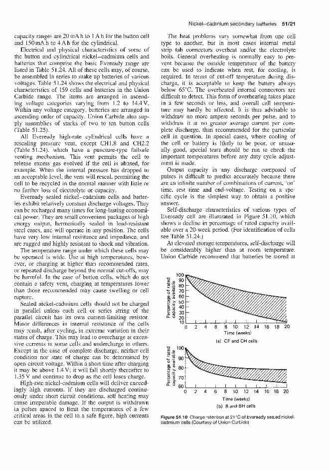
Nickel-cadmium secondary batteries 51/21
The heat problems vary somewhat from one cell type to another, but in most cases internal metal strip tab connectors overheat andor the electrolyte boils. General overheating is normally easy to pre- vent because the outside temperature of the battery can be used to indicate when rest, for coding, is required. In terms of cut-off temperature during dis- charge, it is acceptable to keep the battery always below 65°C. The overheated internal connectors are difficult to detect. This form of overheating takes place in a few seconds or less, and overall cell tempera- ture may hardly be affected. It is thus advisable to withdraw no more ampere seconds per pulse, and to withdraw it at no greater average current per com- plete discharge, than recommended for the particular cell in question. In special cases, where cooling of the cell or battery is likely to be poor, or unusu- ally good, special tests should be run to check the important temperatures before any duty cycle adjust- ment is made.
Output capacity in any discharge composed of pulses is difficult to predict accurately because there are an infinite number of combinations of current, 'on' time, rest time and end-voltage. Testing on a spe- cific cycle is the simplest way to obtain a positive answer.
Self-discharge characteristics of various types of Eveready cell are illustrated in Figure 51.10, which shows a decline in percentage of rated capacity avail- able over a 20-week period. (For identification of cells see Table 51.24.)
At elevated storage temperatures, self-discharge will be considerably higher than at room temperature. Union Carbide recommend that batteries be stored at
capacity ranges; are 20 rnA h to 1 A h for the button cell and 15OmAh to 4 A h for the cylindrical.
Electrical arid physical characteristics of some of the button and cylindrical nickel-cadmium cells and batteries that comprise the basic Eveready range are listed in Table 51.24. All of these cells may, of course, be assembled in series to make up batteries of various voltages. Table 51.24 shows the electrical and physical characteristics of 159 cells and batteries in the Union Carbide range. The items are arranged in ascend- ing voltage categories varying from 1.2 to 14.4V. Within any voltage category, batteries are arranged in ascending order of capacity. Union Carbide also sup- ply assemblies of stacks of two to ten button cells (Table 51.25).
All Evereadly high-rate cylindrical cells have a resealing pressare vent, except CH1.8 and CH2.2 (Table 51.24)$ which have a puncture-type failsafe venting mechamism. This vent permits the cell to release excess gas evolved if the cell is abused, for example. When the internal pressure has dropped to an acceptable level, the vent will reseal, permitting the cell to be recycled in the normal manner with little or no further loss of electrolyte or capacity.
Eveready sealed nickel-cadmium cells and batter- ies exhibit relatively constant discharge voltages. They can be recharged many times for long-lasting economi- cal power. They are small convenient packages of high energy output, hermetically sealed in lead-resistant steel cases, and will operate in any position. The cells have very low internal resistance and impedance, and are rugged and highly resistant to shock and vibration.
The temperature range under which these cells may be operated is wide. Use at high temperatures, how- ever, or charging at higher than recommended rates, or repeated discharge beyond the normal cut-offs, may be harmful. In the case of button cells, which do not contain a safety vent, charging at temperatures lower than those recommended may cause swelling or cell rupture.
Sealed nickel-cadmium cells should not be charged in parallel unless each cell or series string of the parallel circuit has its own current-limiting resistor. Minor differences in internal resistance of the cells may result, after cycling, in extreme variation in their states of charge. This may lead to overcharge at exces- sive currents in! some cells and undercharge in others. Except in the case of complete discharge, neither cell condition nor state of charge can be determined by open-circuit voltage. Within a short time after charging it may be above 1.4 V; it will fail shortly thereafter to 1.35 V and continue to drop as h e cell loses charge.
High-rate nickel-cadmium cells will deliver exceed- ingly high currents. If they are discharged continu- ously under sh'ort-circuit conditions, self-heating may cause irreparab~le damage. If the output is withdrawn in pulses spaced to limit the temperatures of a few critical areas in[ the cell to a safe figure, high currents can be utilized.
100
80
g,2 60 2 50
$ 30 a 20
10
8,90
' E 70
E.: 40
r -
0 2 4 6 8 10 12 14 16 18 20 Time (weeks)
(a) CF and CH cells
0 2 4 6 8 10 12 14 16 18 20
Time (weeks)
(b) B and BH cells
Figure 51 . I O Charge retention at 21 "C of Eveready sealed nickel- cadmium cells (Courtesy of Union Carbide)
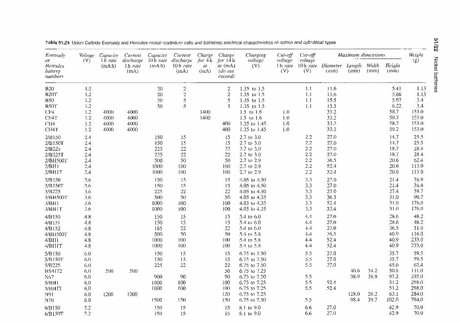
6'0L 6'OL O'P6L O'P8Z 0'862 0'862 O'SEZ 0'1 I I p'z9 5'6s S'6S O'EEZ O'EEZ 0'91 I 0'1s Z'8P Z'8P 0'9LI 0'9LI L'06 L'6E 6'9E 6'9E O'EI I O'EII p'z9 P'8Z p'8Z S'SZ S'SZ
O'ES 1 O'ESI O'ESI O'ES1 P'E P'E
€1.1 .a, €1'1 0
6'ZP 6'ZP O'ZOT L'6F P'86 I'E9 2.92 0'821 Z'IS 2.1 s Z'L6 6'8E 6% 8.0s ZPE 9'0P 9'SP L'SE L'SE 6'0P 6'0P 6'09 S'9E 9'8Z 9.82 O'IE 0'1E O'IE P'LZ P ' I Z p' LZ 9'02 9.0z 9'0Z L'8 1 L'81 L'P 1 L'PI Z'6S L'8S Z'6S L'8S
ZZ'9 L6'S 99'5 IP'S
0'LZ 0'LZ
P'ZS P'ZS
O'LZ 0'LZ 0'LZ VZS P'ZS S'9E O'LZ 0'LZ 0'LZ P'ZS P'ZS S'9E O'LZ QLZ O'LZ P'ZS P'ZS S'9E 0'LZ O'LZ 0'LZ 0'LZ Z'EE Z'EE Z'EE Z'EE S'ST S'S 1 9'1 I 9'11
9'9 9'9 S'S
S'S S'S S'S
S ' S S'S E'S P'P p'P p'P p'P P'P P'P €'E €'E E'S E'€ E'€ E'€ Z'Z Z 'Z Z 'Z Z'Z Z'Z Z'Z Z'Z
1.1 1'1 1.1 1.1
ij c f-. ni
SI SI OS1 oz 1 00 1 00 1 06 0s zz SI SI 001 00 1 OS zz SI SI 00 1 00 I OS ZZ SI SI 00 I 001 OS zz zz SI SI 00P 00P
S S Z Z
SI s1 OS1
00 1 00 I 06
ZZ SI SI 00 I 00 I OS zz SL SI 00 1 00T OS ZZ s1 SI 00 I 00 I OS zz zz SI SI
00P 1 00PI
S S z z
OS1 OS I 0051
0001 0001 006
SZZ os L os1 0001 0001 00s S81 051 os1 000 I 0001 00s SZZ OS L os1 000 1 0001 00s SZZ SZZ OS I OS1
OS OS 0z 0z
Z'L Z'L 0 9
00ZI 0021 0'9 0'9 0'9 0'9
00s 00s 0'9 0'9 0'9 0'9 8'P 8'P 8'8 8'P 8'P 8'P 9'E 9'E 9'E 9'E 9'E 9'E P'Z p'z p'z p'z P'z p'z p'z
OOOP 000P 2'1 000P O00P 2'1 000P 000P Z I 000P 000P Z'I
Z' I Z ' I Z I Z ' I
LO51 W9 OS1W9
0 LN L 6N
I I H W S IHWS
L9N ZLIPSH SZZWS
10SIfl/S OS1 WS
LIHWV IHWP
IOOFHWP ZSIWP [SIWP OSIWP
ILIH8IE IHWE
LOOSHEIIE SZZWE
10SlWE OSIWE
LIHBIZ IHWZ
100SHWZ 1SZZWZ
SZZEIIZ 10SlWZ
OFIfI/Z I P H 3
PH3 IPd3
Pd3 10SCt
0SB 10za
0za

6/B225 6IBHSOO 6/BH500T 6lBHl 6BHlT N88 7/B150 7lB 150T 7BH500T 7lBH1 7/BH1T 8lB150 8/B 150T 818225 8BH1 8/BHlT 1007 9lB150 9/B150T 9lB225 9BH.500 9/BH500T 9lBHI 9BHlT I0/B150 1 0/B 1 50T 10lB225 1 OIBH500T HS41.51 HS4153 lOIBH1 10/BHlT N86 N65 HS4280 HS4130 HS4080 HS4125 HS4068 N64 HS.4073
7.2 7.2 7.2 7.2 7.2 8.4 8.4 8.4 8.4 8.4 8.4 9.6 9.6 9.6 9.6 9.6 9.6
10.8 10.8 10.8 10.8 10.8 10.8 10.8 12.0 12.0 12.0 12.0 12.0 12.0 12.0 12.0 12.0 13.2 13.2 14.4 14.4 14.4 14.4 14.4 14.4
4000
500 500
1200 1000 1000 225 225 450 500 500
4000
4000
500 500
1200 1000 1000 225 225 450 500 500
4000 -
225 500 500
1000 1000
90 150 150 500
1000 1000 i 50 1 50 225
1000 1000
150 150 225 500 500
1000 1000 150 1 50 225 500
1000 1000
22 53 50
100 100
9 15 15 50
I00 100 is 15 22
100 100
15 15 22 50 50
100 100
15 15 22 50
100 100
22 50 50
100 100
9 15 15 50
100 100
i5 15 22
100 100 400
15 15 22 50 50
100 100 15 15 22 50
50 100 100 120 100 100 22
45 50 50
400
175
75
8.1 to 9.0 8.1 to 8.7 8.1 to 8.7 8.1 to 8.7 8.1 to 8.7 9.45 to 10.50 9.4s to 10.50 9.45 to 10.50 9.45 to 10.15 9.45 to 10.15 9.45 to 10.15 10.8 to 12.0 10.8 to 12.0 10.8 to 12.0 10.8 to 11.6 10.8 to 11.6 10.8 to 11.6 12.15 to 13.50 12.1.5 to 13.50 12.15 to 13.50 12.15 to 13.05 12.15 to 13.05 12.15 to 13.05 12.15 to 13.05 13.5 to 15.0 13.5 to 15.0 13.5 Lo 15.0 13.5 to 14.5 15.0 to 16.0 13.5 to 14.5 13.5 to 14.5 13.5 to 14.5 13.5 to 14.5 14.85 to 15.95 14.85 to 15.95 16.2 to 17.4 18.0 to 19.2 16.2 to 17.4 16.2 to 17.4 16.2 to 17.4 16.2 to 17.4
6.6 6.6 6.6 6.6 6.6 7.7 7.7 7.7 7.7 7.7 7.7 8.8 8.8 8.8 8.8 8.8 8.8 9.9 9.9 9.9 9.9 9.9 9.9 9.9
11.0 11.0 11.0 11.0
10 10
11.0 11.0
10 11 I1 12 12 12 12 12 12
27.0 36.5 36.5 52.4 52.4
27.0 27.0 36.5 52.4 52.4 27.0 27.0 27.0 52.4 52.4
27.0 27.0 27.0 36.5 36.5 52.4 52.4 27.0 27.0 27.0 36.5
52.4 52.4
54.8 61.1 61.1 61.1 61.1
26.6 15.5 49.2 49.6 49.6 71.4 71.4 71.4 56.8 56.8 72.6 81.4 81.4
163 81.8 79.4 63.9 63.9 81.8 91.7 91.7 91.7 91.7 70.6 70.6 86.9
102.0 63.6 16.5 144.0 63.6 16.5 144.0
102.0 102.0
128.0 51.6 62.3 186.0 37.1 78.7 186.0 37.1 78.7 55.3 19.3 70.1 55.3 19.3 70.1 55.3 32.1 70.1 73.0 33.7 71.1 73.0 33.7 71.1 84.9 66.7 203.0
79.4 170.0 170.0 354.0 354.0 42.5 82.2 82.2
198.0 414.0 414.0
93.6 93.6
102.0 471.0 471.0
L730.0 108 108 111 26 1 26 1 525 525 I19 119 122 289 $ 241 x
581 2 581 567 765 v)
765 8 142 2 142 a
255
255 y
5 a
2180 8 The capacity rating of Eveready nickel-cadmium cells and batteries is based on output in discharge at thc 1 h rate to an end-voltage of 1 V/cell lor all cylindrical cells (except CH1.8 and CH2.2) and at the IOh rate to 1.1 V/cell for button cells (and CH1.8 and CH2.2). If current is withdrawn at faster rates than these standards, capacity is decreased
5 0 13

51/24 Nickel batteries
Table 51.25 Union Carbide sealed nickel-cadmium button cell stack assemblies (jacketed with plastics tubing)
Eveready Number Voltage Terminals Max. dimensions Wei ht number per stack (gi Diameter Height
(mm) (-1 battery of cells (VI
Assemblies of B150 cells: 15OmAh capacity (10h rate) 2B150 2 2.4 flat 3B150 3 3.6 flat 4B150 4 4.8 flat 5B150 5 6.0 flat 6B150 6 7.2 flat 7B150 7 8.4 flat 8B150 8 9.6 flat 9 B 150 9 10.8 flat 10B150 10 12.0 flat Assemblies of B225 cells: 225 mA h capacity (10 h rate) 2B225 2 2.4 flat 3B225 3 3.6 flat 4B225 4 4.8 flat 5B225 5 6.0 flat 6B225 6 7.2 flat 7B225 7 8.4 flat 8B225 8 9.6 flat 9B225 9 10.8 flat 10B225 10 12.0 flat Assemblies of BH225 cells (high rate): 225 mA h capacity (10 h rate) 2BH225 2 2.4 flat 3BH225 3 3.6 flat 4BH225 4 4.8 flat 5BH225 5 6.0 flat 6BH225 6 7.2 flat 7BH225 7 8.4 flat 8BH225 8 9.6 flat 9BH225 9 10.8 flat 10BH225 10 12.0 flat Assemblies of BH500 cells (high rate): 500 mA h capacity (10 h rate) 2BH500 2 2.4 flat 3BH500 3 3.6 flat 4BH500 4 4.8 flat 5BH500 5 6.0 flat 6BH500 6 7.2 flat 7/BH500 7 8.4 flat 8BH500 8 9.6 flat 9BH500 9 10.8 flat 10BH500 10 12.0 flat Assemblies of BH1 cells (high rate): 1 Ah capacity (10h rate) 2BH1 2 2.4 flat 3BH1 3 3.6 flat 4BH1 4 4.8 flat 5BH1 5 6.0 flat 6BH1 6 7.2 flat 7BH1 7 8.4 flat 8BH1 8 9.6 flat 9BHl 9 10.8 flat 10BH1 10 12.0 flat
27 27 27 27 27 27 27 27 27
27 27 27 27 27 27 27 27 27
27 27 27 27 27 27 27 27 27
36.5 36.5 36.5 36.5 36.5 36.5 36.5 36.5 36.5
52.4 52.4 52.4 52.4 52.4 52.4 52.4 52.4 52.4
14.7 21.4 28.6 35.7 42.9 49.6 56.8 63.9 70.6
18.7 27.4 36.5 45.6 54.8 63.9 72.6 81.8 86.9
19.1 28.2 37.3 46.4 56.0 65.1 74.2 83.3 92.5
20.6 31.0 40.9 51.2 61.1 71.4 81.4 91.7
102.0
20.6 31.0 40.9 51.2 61.1 71.4 81.4 91.7
102.0
25.5 36.9 48.2 59.5 70.9 82.2 93.6
108.0 119.0
28.4 39.7 51.0 62.4 79.4 90.7
102.0 111.0 122.0
28.4 42.5 53.9 68.0 85.1 96.4
108.0 122.0 133.0
62.4 90.7
116.0 142.0 170.0 198.0 230.0 261.0 289.0
113.0 176.0 233.0 298.0 354.0 414.0 471.0 525.0 581.0
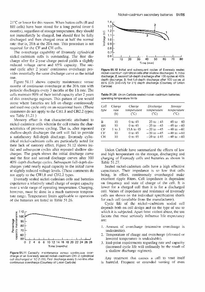
Nickel-cadmium secondary batteries 51/25
21°C or lower for this reason. When button cells (B and BH cells) have been stored for a long period (over 6 months), regardless of storage temperature, they should not immediately be charged, but should first be fully discharged and then charged once at half the normal rate; that is, 28 h at the 20 h rate. This procedure is not required for the CF and CH cells.
The overcharge capability of Eveready cylindrical nickel-cadmium cells is outstanding. The first dis- charge after the 2-year charge period yields a slightly reduced voltage curve and 65% capacity. The sec- ond cycle after 2 years’ continuous overcharge pro- vides essentially the same discharge curve as the initial one.
Figure 5 1.1 1 shows capacity maintenance versus months of continuous overcharge at the 20 h rate with periodic discharges every 3 months at the 1 h rate. The cells maintain 90% of their initial capacity after 2 years of this overcharge regimen. This pattern of use would occur where batteries are left on charge continuously and used one cycle only on an occasional basis. (These comments do not apply to the CH1.8 and CH2.2 types; see Table 5 1.2 1 .)
Memory effect is that characteristic attributed to nickel-cadmium cells wherein the cell retains the char- acteristics of previous cycling. That is, after repeated shallow-depth discharges the cell will fail to provide a satisfactory full-depth discharge. Eveready cylin- drical nickel-cadmium cells are particularly noted for their lack of memory effect. Figure 51.12 shows ini- tial and subsequent cycles after repeated shallow dis- charges. The graph shows the initial discharge curve and the first and second discharge curves after 100 40% depth discharge cycles. Subsequent full-depth dis- charges yield nearly equal capacity to the initial curve at slightly reduced voltage levels. (These comments do not apply to the CH1.8 and CH2.2 types.
Eveready sealed nickel-cadmium cells and batteries experience a relatively small charge of output capacity over a wide range of operating temperature. Charging, however, must be done in a much narrower tempera- ture range. Temperature limits applicable to operation of the batteries are listed in Table 51.26.
0, I l O r
i,c 70 6 0 L
5 5 0 -- 0 2 4 6 8 10 12 14 16 18 20 22 24 26 28
Time {months)
Figure 51.1 1 Capacity maintenance versus continuous over- charge of an Eveready sealed nickel-cadmium CHI .2 cylindrical cell discharged at I C (1.2A). First discharge every 3 months after continuous overcharge (Courtesy of Union Carbide)
14 ,
- 1.2
- > rn % 1.0 1:3P==ki 1.1 5 0.9 - o . * ~ I I , I I I , ,
0.7 0.6
0 10 20 30 40 50 60 70 80 Time (minl
Figure 51.12 Initial and subsequent cycles of Eveready sealed nickel-cadmium cylindrical cells after shallow discharges: 1, initial discharge; 2, second full-depth discharge after 100 cycles at 40% depth discharge; 3, first full-depth discharge after 100 cycles at 40% (C/5 (240mA) for 2 h) depth discharge (Courtesy of Union Carbide)
Table 51.26 Union Carbide sealed nickel-cadmium batteries: operating temperature limits
Cell Charge Charge Discharge Storage type rate temperature temperature temperature
(h) (“C) (“ C) (“C)
B 10 0 to 45 -20 to +45 -40 to +60 BH 10 0 to 45 -20 to +45 -40 to +60 CF 1 to 3 15.6 to 45 -20 to +45 -40 tQ +60 CF 10 0 to 45 -20 to +45 -40 to f60 CH 10 0 to 45 -20 to +45 -40 tQ +60
Union Carbide have summarized the effects of low and high temperature on the storage, discharging and charging of Eveready cells and batteries as shown in Table 51.27.
Sealed nickel-cadmium cells have a high effective capacitance. Their impedance is so low that cells being, in effect, continuously overcharged make excellent ripple filters. Cell impedance is dependent on frequency and state of charge of the cell. It is lower for a charged cell than it is for a discharged cell. Values of impedance and resistance of Eveready cells are shown on the individual specification sheets for each cell (available from the manufacturer).
Cycle life of the nickel-cadmium sealed cell depends both on cell design and on the type of use to which it is subjected. Apart from violent abuse, the use factors that most seriously influence life expectancy are:
1. Amount of overcharge (excessive overcharge is undesirable).
2. Temperature of charge and overcharge (elevated or lowered temperature is undesirable).
3. End-point requirements regarding rate and capacity (increased cycle life will ordinarily be the result of a shallow discharge regimen).
Any treatment that causes a cell to vent itself is harmful. Frequent or extended venting of even

51/26 Nickel batteries
Table 51.27 Effect of high and low temperatures on storage, discharging and charging of Eveready nickel-cadmium cells and batteries
Low temperature High temperature
Storage (all types)
Discharge (all types)
Charge CF and CH types (10h rate)
CF types (1 -3 h rate)
Button cells
at -40°C No detrimental effect. However, cells or batteries should he allowed to return to room temperature before charging at -20°C No detrimental effect, but capacity will be reduced as shown by curves
at 0°C Cells or batteries should not be charged below 0°C at the 10 h rate at 15.6"C Cells or batteries should not be charged below 15.6"C at the 1 h rate or below 10°C at the 3 h rate at 0°C Cells or batteries should not be charged below 0°C at the 10 h rate
Table 51.28 Cycle life
Cell Estimated average number of cycles
Cylindrical CH types 1000 (CH1.8 and CH2.2: 300) CF types 1000
Button B types 300 BH types 300
properly valved cells eventually destroys them. In rating cycle life, the end of life for a sealed nickel-cad- mium cell is considered to be when it no longer pro- vides 80% of its rated capacity. The discharge currents
Table 51.29 Types of Union Carbide Eveready battery available
at 60°C No detrimental effect. However, self-discharge is more rapid starting at 32°C and increases as temperature is further elevated at 45°C No detrimental effect
at 45°C Cells or batteries show charge acceptance of approximately 50% at 45°C Cells or batteries show charge acceptance of approximately 90%
at 45°C Cells or batteries show charge acceptance of approximately 60%. Also possible detrimental effect on cycle life
used in determining the cycle lives listed below are the 10 h rate for button cells and the 1 h rate for cylin- drical types. The charge current is terminated after return of approximately 140% of the capacity pre- viously removed. If a cell can be considered to be satisfactory while delivering less than the arbitrary 80% end-point figure, cycle life will be greater than that listed in Table 51.28. The ratings are for 21.1"C performance.
The following information is supplied for each type of Eveready cell: discharge curves (Figure 51.13), capacity versus temperature (Figure 51.14), and charge rate versus charging time (Figure 51.15). Figures 51.16 and 51.17, respectively, show the capacities available at various discharge currents for the 0.5Ah Eveready 1.2V cylindrical and button cells. Figure 51.18 shows the effect of temperature on
Voltage Number of Type number (V) 1.2 V cells
in assembly 0.09 0.225 0.45 0.5 0.9 1 .o 1.2 1.5 4.0 A h A h A h A h A h A h A h A h A h
6.0 5 8.4 7 N88
HS4172 N67 N91 N70
9.6 8 1007 12.0 10 HS4151 N86
13.2 11 N65
14.4 12 HS4130 HS4125 HS4068 HS4073
HS4153
HS4280
HS4080 HS4081 N64
Single 1.2V cylindrical cells, available capacities (Ah) 0.15, 0.225, 0.45, 0.50, 1.0, 1.2, 1.4, 1.8, 2.2 and 4.0

Nickel-cadmium secondary batteries 51/27
1.4 r
7 1.3
& 1.2
p 1.1
8 1.0
I
m I - - -
0.9 0 1 2 3 4 5 6 7 8 9 1 0 1 1 1 2
7 1.3
& 1.2
p 1.1
8 1.0
I
m I - - -
0.9 0 1 2 3 4 5 6 7 8 9 1 0 1 1 1 2
Discharge time (h)
1.4
0.9 !.O 0 L A 20 40 60 80 100 120
Discharge time bin)
100 r
- Y" ' 5 0 1 ... ~
0 L - f 1 1 1 I I 1 1 1 I I 0 10 20 30 40 50 60 70 80 90 100 110120
Discharge current (mA)
Figure 51.13 Sample discharge data: average performance char- acteristics of Eveready OB90 and OB90T sealed nickel-cadmium cells, 1.2 V, 90 pA h capacity, at 21 "C. Example: assume a 35 mA discharge to a 1.1 V end-point. The OB90 (or OB9OT) cell has a capacity of 70 rnA h. This provides a discharge time of 2 h (Courtesy of Union Carbide)
1 O O r
I I I I I I I J -30 -20 -10 0 10 20 30 40 50
Temperature ("C)
Figure 51.14 Sample capacity versus temperature curve for Eveready OB90 and OB90T sealed nickel-cadmium cells, 1.2 V, 20sAh capacity, at 9 mA discharge current. The temperature ranges applicable are 0-45°C (charge), -20 to 45°C (discharge) and -40 to 60°C (storage) (Courtesy of Union Carbide)
the capacity for a 1 Ah Eveready 1.2V button cell. Table 51.29 shows the available types of battery, with the stated capacity, made up from Eveready cylindrical cells. Discharge curves and capacity versus discharge currents data for some of these batteries are given in Figure 51.19.
I l l l l l l l l l l l 14 15 16 17 18 19 20 21 22 23 24 25 26
Charging time (h)
Figure 51.15 Sample discharge data for fully charged Eveready OB90 and OB90T sealed nickel-cadmium cells, 1.2V, 90uAh capacity. (Charge voltage 1.35-1.5Ov) (Courtesy of Union Car- bide)
700 ' A 6 0 0 r . E 500
'p 400
; 300
> c
a
0 400 800 1200 1600 2000 2400 Discharge current (mA)
Figure 51.16 Typical capacity versus discharge current curves for Eveready CF500, CFSOOT, CH500 and CH500T sealed nickel-cadmium cylindrical cells, 1.2V, 0.5A h capacity (Courtesy of Union Carbide)
600 r 500
2 400 0.9 v
200 1.1 v
1
.- ,Z 300 1.0 v -
0 200 400 600 800 1000 1200 1400 Discharge current (mA)
Figure 51.17 Typical capacity versus discharge current curves for Eveready BH500 and BHSOOT sealed nickel-cadmium button cells, 1.2V, 0.5A h capacity. Ranges of temperature applicable to operation of the cells are: charge 0 to 45"C, discharge -20 to +45"C, storage -40 to +60"C (Courtesy of Union Carbide)
N$e Jungner SPA (Italy)
This company manufactures a range of rechargeable sealed nickel-cadmium cells in the nominal capacity range 0.4-5.6Ah. These are available with three different terminal arrangements; HH, HB and CF (Figure 51.20). Each cell has a nomind voltage of 1.25 V. A battery is assembled by series connection of a number of cells, which determine the battery voltage. The simplest way to connect a number of cells is to stack them on top of each other as in an ordinary flashlight (terminal arrangement CF,

51/28 Nickel batteries
1200 c
o t I I I I I I 1 -20 -10 0 10 20 30 40 50
Temperature ("C)
Figure 51.18 Effect of temperature on capacity of Eveready BHI and BHlT sealed nickel-cadmium button cells, 12V, 1 A h capacity, discharge current 100 mA (Courtesy of Union Carbide)
Figure 51.20). This method, however, is suitable only for low loads. For high loads, and when high reliability is of great importance, cells with soldered or spot- welded soldering tabs are recommended. Battery packs made up of between two and 20 cells are available.
The characteristics of the Nife Jungner KR series of cells (0.4-5.6Ah) are given in Table 51.30. These
Figure 51.20 Terminal arrangements for Nife Jungner KR series sealed nickel-cadmium cells. The cells are available with three different terminal arrangements; HH, HB and CF. Types HH (head-head) and HB (head-base) are equipped with soldering tabs. Type CF (connection free) is equipped with a contact button on top, similar to dry cells (Courtesy of Nife Jungner)
cells have an acceptably low rate of self-discharge. Self-discharge is very much dependent on the temper- ature, and increases rapidly with rising temperature. At very low temperatures the self-discharge is small, and is almost zero at -20°C. These cells and batteries can be stored in the charged or discharged condition.
- 7 . 0 r \
- 7.0
: 6 . 5 b , ,,, I ,
P
2 4.5 m 4.5 ,,, I , ,, I
Discharge time (min)
2 6.0
5'5
5.0 5.0
6.0
100 mA 50 mA 2 2 A 500 mA 250 mA
0 2 4 6 8 1 0 1 2 1 4 0 20 40 60 80 100 120 140
(a) Type HS4172.6 V, 0.5 A h Discharge time (h)
450 mA t 5.5
2 4.5 180 mA
0 2 4 6 8 10 12 14 0 20 40 60 80 100 120 140 Discharge time (h)
6.0
5.5 240 mA z 5.0 2 4.5
0 2 4 6 8 1 0 Discharge time (h)
Discharge time (mid
(b) Type N67, 6 V, 0.9 A h
> - W m - - g
20 mA G 5
12 14
' i y m ; 5.0
0 20 40 60 80 100 120 140 4.5
Discharge time (min)
(c) Type N91, 6 V, 1.2 A h
Figure 51.19 Typical discharge curves at 20°C for Eveready sealed nickel-cadmium cylindrical batteries: see Table 51 29 (Courtesy of Union Carbide)

Nickel-cadmium secondary batteries 51/29
When charged they should be handled with care to avoid short-circuits because the short-circuit current is very high. When storing for more than 6 months a storage temperature lower than 15°C is recommended by the manufacturers.
Figure 51.21 shows the effect on delivered capa- city of KR cells of two of the factors that have most influence on capacity, namely current and cell temperature. The available capacity decreases at high currents and/or low temperatures. This is shown by the typical discharge curves for 25, 0 and -18°C in Figure 5 1.21. Maximum recommended continuous discharge current differs for different cell sizes. It ranges from 3.5 to 5 C A. Considerably higher current can be used at short discharges (see Table 51.30).
Figure 51.22 shows the relationship between dis- charge current and capacity and final voltage for a KR 15/51 0.4Ah cell.
1.3 1.2
5 1.1 0 1.0 E 0.9 3 0.8
- -
1 1 1 1 1 1 1 1 1 1 1 1 1 1 ,
0.1 0.2 0.3 0.4 Capacity (A h)
(a) 25 'C
1.3 1.2
> 1.1 g 1.0 - i? 0.9 3 0.8
- -
I I I I 1 I 0.05 0.10 0.15 0.20 0.25 0.30
Capacity (A h)
(b) 0 ° C
1.3 - 1.2 > (u 0.04 A - 1.1 p 1.0 ;5 0.9
0.8 > c
I I 0.05 0.10 0.15 0.20 0.25 0.30
Capacity (Ah )
(c) -18°C
Figure 51.21 Discharge voltage versus capacity (at the stated temperature) ol' Nife Jungner KR 15/51 sealed nickel-cadmium cells, 0.4Ah capacity (Courtesy of Nife Jungner)
- 9 0.8
0.7 U
0.2 0.4 0.6 0.8 1.0 1.2 1.4 A
Figure 51.22 Capacity and final voltage versus discharge current for a Nife Jungner sealed nickel-cadmium cell type KR 15/51, 0.4Ah (Courtesy of Nife Jungner)
Marathon (USA)
Marathon supply a range of vented rechargeable 1.25 V sealed cells in the capacity range up to 53Ah, and also made-up batteries to customers' specifications (see Table 51.31). These batteries are equipped with a pressure relief vent. It is claimed by Marathon that these cells can be charged using a simple trans- former-rectifier circuit, that they can safely be left on overcharge for months, if necessary, and that they have thousands of hours of life. Performance characteristics of these batteries are given in Table 51.28.
General Electric Corporation (USA)
General Electric manufacture a very wide range of rechargeable sealed nickel-cadmium cells, including cylindrical, oval and rectangular cells, and also the Perma-cell, which is offered as an alternative to primary cells. Each of the three types of cell has its own typical applications (Table 5 1.32). Thus cylin- drical, rectangular and oval cells are recommended for portable appliances and tools, photographic equipment, business machines, communications equipment, toys, hobby equipment, heating and lighting, while Perma- cells are recommended for calculators, tape recorders, toys, flashlights, photoflash equipment, etc. General Electric also supply special aerospace cells.
A range of extended-capability cells are available in three types. Goldtop cells are for normal charge rates and are capable of operating at cell temperatures up to 65°C. These cells are suitable for applications requiring long cell life at high ambient temperatures and/or high cell temperatures caused by continuous long-term overcharge. The second type of Goldtop cells are for use at quick charge rates where continuous overcharge rates of 0.3C are combined with high operating temperatures.
Power-Up-15 cells are supplied for use with Power- Up-15 battery charger systems that charge the cell or battery at fast charge rates of 1.0-4.OC. These cells have voltage/temperature versus state of charge char- acteristics that permit effective control, using circuits that sense both battery temperature and voltage. The charge is thus terminated by either voltage or temper- ature, permitting reliable fast charging.

51/30 Nickel batteries
Table 51.30 NlFE Jungner sealed nickel-cadmium cells: technical specifications ~~~
Cell type KR 15/51 KR 23/43 KR 27/50 KR 35/62 KR 35/92
Nominal capacity (A h) (5 h rate C5 at 25 f 5°C to end-voltage 1 V) Current on discharge (mA) (0.2C5A) Dimensions:
Diameter (mm) Height (mm)* Weight, approx. (g)
Energy content (average discharge voltage with discharge at 5 h current), 0.2 C A, is 1.2V:
W Wcell
W Wdm3 w m g
Internal resistance ( m a ) + Charging:
Normal charging current 14-16h (m A) Trickle charging minimum current (m A)* Temperature range
Maximum recommended continuous
Maximum recommended discharge
Discharge:
discharge current (A)
current for 5 (A) Temperature range Storing
0.40 1.1 1.6 3.6 5.6 80 220 320 720 1120
14.5 22.7 26 33.2 33.2 50.3 42.2 48 59.5 89 20 45 65 140 210
0.48 1.32 1.92 4.32 6.72 24 29 30 31 32 65 81 78 86 90 90 27 22 13 11
50 120 200 400 600 20 45 75 150 250 From 0 to 40"C, preferably normal room temperature
1.5 5 8 15 20
7 15 20 50 80 From -40 to +40"C In charged or discharged condition: use a cool storage place, preferably with temperature lower than 15°C
Terminal arrangement: Cell type CF, drawing No. Cell type HH, drawing No. Cell type HB, drawing No. Batteries with even number of cells,
Batteries with odd number of cells, drawing No.
drawing No. Corresponding dry cell
90-51400 90-51405 90-52813 90-5141 1 90-51417 90-51401 90-51406 90-52814 90-51412 90-51418 90-51402 90-51407 90-52815 90-51413 90-51419
- 90-52359 90-53536 90-52357 90-52355
- 90-52360 90-53537 90-52358 90-52356 R6orAA Sub C R14 orC R20 orD -
* Contact button is not included in the height with the exception of KR 15/51. Add 2mm for contact button. KR 15/51 always has a contact button even when soldering tabs are used
* Recommended tolerance for trickle charging current is +20 and -0% Obtained from d.c. measurements of voltage and current after discharging 10% of nominal capacity from a fully charged cell
The available GEC range is given in Table 51.33. A discharge curve for a typical cell in this range is shown in Figure 51.23.
Oval cells are available at a rated capacity at the 1 h rate of 4 A h at 25°C. Their continuous overcharge rate is 400 mA maximum and 200 mA minimum, and their internal resistance is 5 p C2. These cells are available either as a standard cell for normal charge rates (model G04.0) or as a Goldtop cell for normal charge rates (model G04.0ST). The rectangular cell VO-4 (model GR4.0) has a rated capacity of 4 A h at 25°C at the 1 h rate, maximum and minimum overcharge currents of 400 and 200mA respectively, and an internal resistance of 4 p 0.
The trade mark Perma-cell designates a rechargeable nickel-cadmium battery-charger system using sealed
cylindrical cells, which consumers may use as altern- atives to popular sizes of primary cell. Equipment for properly recharging sealed cells is not usually available where throwaway cells have been used, so General Electric provide the rechargeable cells as part of a whole Perma-cell system, which includes the proper charger for these nickel-cadmium batteries.
The Perma-cell system is a complete commercial battery-charger system. The most common sizes of consumer batteries (AA, C, and D) are available in the Perma-cell line. Typically these batteries can be recharged 1000 times or more with the Model BC-1, four-cell charger.
Three larger industrial chargers are available. Model BC-48 will recharge from one to 48 standard D-size model GC-3 Perma-cell batteries, rated 1.2 Ah. Model
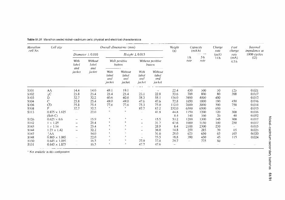
Table 51.31 Marathon sealed nickel-cadmium cells: physical and electrical characteristics
Marathon Cell size Overall dimensions (mm) Weight Capacity Charge Fast Internal cell No. (g) (mA h) rate charge impedance at
Diameter f. 0.010 Height f 0.015 (mA) rate 1000 cycles
With Without With positive Without positive rate rate label label button button and and
i n 5 h 14h b A ) (a) 4.5 h
jacket jacket With Without With Without label label label label and and and and
jacket jacket jucket jacket
Sl01 AA 14.4 14.0 49.1 19.1 - - 50 125 0.021 22.4 450 500 S102 ;C 25.8 25.4 25.4 25.4 23.1 22.8 33.6 700 800 80 200 0.017 SI03 D 32.7 32.2 60.6 60.6 58.3 58.1 154.0 3800 4000 400 - 0.012 S104 C 25.8 25.4 49.0 49.0 47.6 47.6 72.8 1650 1800 190 450 0.016
25.8 25.4 77.6 77.6 75.3 75.0 112.0 2600 3000 300 750 0.014 87.7 87.2 232.0 6300 6500 650 - 0.013
S106 CD S108 F 32.7 32.2 S113 0.875 x 1.625 - 22.0 - 41.9 44.8 1150 1200 120 300 0.016
40 0.052 * * z S126 0.625 x 0.6 15.9 15.5 53.2 1200 1300 145 300 0.017 0
S142 1 x 1.25 25.4 31.7 47.6 1000 1150 100 250 0.017 n, 1 x 1.14 25.4 28.9 8.4 2100 2300 230 0.015 A 1.27 x 1.42 32.2 36.0 14.8 250 285 30 65 0.025
S 143
- - 65 165 0.020 3. &AA 14.0 31.6 28.0 625 650 S 144 S 147
S150 0.645 x 1.095 16.3 27.9 27.8 29.7 - 775 80 - S148
S151 0.645 x 1.875 - 16.3 47.7 47.6 -
* Not availablc in this configuration
* * * *
(Sub C ) 8.4 140 160 20 - -
* * * * * * * 2
* * * *
- - - - - - - m
0.865 x 1.005 - 22.0 - 25.5 18.8 390 450 45 115 0.024 5
5
- - v) * % (D 0
Q
- - - - - 9

51/32 Nickel batteries
Table 51.32 Summary of GEC sealed nickel-cadmium cells (rechargeable)
Feature Cylindrical cells Rectangular and oval cells Perma-cells
Range of capacity ratings (Ah) at 1 h rate C 0.1 to 5.6 4.0 0.45 to 4.0
Outline Top view 0
Sealed construction High-pressure resealing vent Modular packaging efficiency High-rate discharge Low-rate discharge Maintenance-free Position-sensitive Constant-potential charge Constant-current charge
Yes Yes Good Excellent Good Yes No No Yes
Yes Yes Excellent Excellent Good Yes No No Yes
Yes Yes Good Excellent Good Yes No No Yes
1 . 4 ~
0.4 1 Type 1/3 AA, 100 mA h
0.2
0 20 40 60 80 100 120 140(%)
0 0.02 0.04 0.06 0.08 0.10 0.12 0.14 (A hl
Rated capacity
Figure 51.23 Typical discharge curve for General Electric sealed nickel-cadmium cells (Table 51.33) (Courtesy of General Electric)
BC-48B will recharge up to 48 C-size model CG-2 Perma-cells. Model BC-448 is designed to recharge from one to 48 heavy-duty model GC-4 Perma-cell batteries (Table 51.34).
The battery-charger systems are designed to pro- vide the economy, convenience and long life of nickel-cadmium sealed cells for a wide variety of
replaceable cell applications. These chargers operate under optimum conditions for safe operation (that is, avoidance of pressure and temperature increase). Details of three available types of GEC charger are given in Table 51.34.
Eagle Picher
This company supplies the Carefree I1 range of rechargeable sealed nickel-cadmium button cells. (The company also supplies sealed lead-acid batteries under the trade name of Carefree.) Three ranges are available. The ZA series (Table 51.35) has twin electrodes and is designed to produce maximum capacity with low internal resistance. The Carefree I1 nickel-cadmium batteries and cells provide a wide range of capacities (from 30 to 600mAh) and the flexibility of stacking cells to produce the required voltage.
The ZA series offers maximum performance when discharged over a long period of time at a low rate. The Z2A (Table 51.36) series has dual twin electrodes which, instead of the standard 1.2Vlcell has an e.m.f. of 2.4 V. This requires less space than individual single cells require. These twin cells can be series connected to provide multiple voltages. The DA and VA series of cells (Table 51.37) provide excellent performance under high-rate discharge or continuous overcharge conditions. Eagle Picher also supply an NC series of rectangular transistor batteries (Table 5 1.38).
Typical discharge curves for the ZA, Z2A, DA and VA series of button cells are shown in Figure 51.24.

Nickel-cadmium secondary batteries 51/33
Table 51.33 GEC sealed nickel-cadmium cells (nominal voltage 1.25v)
Type Model No. Application* Rated capacity Continuous over- Internal Weight (mAh) at 25°C charge rate (mA) resistance (g)
(1 h rate) (F Q') Max. Min.
113AA
113A
113AF 112AA
213AF AA (SD) AA
112cs A
CS
213C
315c Cs (1.2Ah) C
112D
D
F
GCFlOOST XGCFlOOST XKCFIOOST XFCFIOOST GCKl5OST XGCK130ST XFCK13OST GCL200ST GCF250ST XGCF250ST XKCF250ST XFCF250ST GCL450ST GCE450SB GCF500ST XGCF450ST XKCF450ST XFCF450ST GCR550ST GCROST XGCK600ST XKCK600ST XFCK600ST GCRlOST XGCRIOST XKCRlOST XFCRlOST GCTI. 1ST XGCT900ST XKCT900ST XFCT900ST GCTlOST GCR12ST GCTl.5SB GCTl.5ST XGCTI.5ST XKCTl.5ST XFCTISST GCW20ST XGCW20ST XKCW2OST XFCW20ST GCW35SB GCW35ST XGCW35ST XKCW35ST XFCW35ST XGCWS6ST
A B C D A B C A A B C D A A A B C D A A B C D A B C D A B C D A A A A B C D A B C D A A B C D B
100 100 100 100 150 150 150 175 250 250 250 250 400 450 500 450 450 450 550 600 600 600 600
1000 1000 1000 1000 1000 900 900 900
1000 I200 1500 1500 I500 1500 1500 2000 2000 2000 2000 3500 3500 3500 3500 3500 5600
10 IO 30 IO 15 13 45 20 25 25 75 25 40 45 50 45
150 45 55 60 60
180 60
100 100 300 100 110 90
270 90
100 120 150 I50 150 450 150 200 200 600 200 350 350 350
1000 350 560
5 5 5 5 8 7 7
IO 13 13 13 13 20 23 25 23 23 23 28 30 30 30 30 50 50 50 50 55 45 45 45 50 60 75 75 75 75 75
100 100 100 100 175 175 175 175 175 280
80 80 80 80 10 10 IO 80 60 60 60 60 35 35 28 28 28 28 28 26 26 26 26 12 12 12 12 22 15 15 15 17 13 10 10 10 10 10 8 8 8 8 5 5 5 5 5 3
9.9 9.9 9.9 9.9
11.3 11.3 11.3 14.2 17.0 17.0 17.0 17.0 22.7 21.3 28.3 28.3 28.3 28.3 28.3 28.3 28.3 28.3 28.3 42.5 42.5 42.5 42.5 45.4 45.4 45.4 45.4 45.4 42.5 65.2 65.2 65.2 65.2 65.2 90.7 90.7 90.7 90.7
147.0 147.0 147.0 147.0 147.0 221.0
A, standard cell for normal charge rate; B, Goldtop cell for normal charge rate: C, Goldtop cell for quick charge rate; D, Power-Up-15 cell (take fast charge rate up to predetermined fast charge cut-off point)
Values shown are for a 1Qh discharge of new cells at 20°C after a 16h charge.
Eagle Picher also supply a range of higher capa- city sealed nickel-cadmium cells and batteries (Tables
51.39 and 51.40). The RSN series of nominal 1.3 V cells have capacities in the range 3-220 Ah. Working voltages are between 1 and 1.25 Vkell. An SAR series of batteries containing between seven and thirty 1.3 V

51/34 Nickel batteries
cells is also available. These cells are housed in stain- less steel, magnesium and aluminium containers and are equipped with a Safety Pippet valve. Energy dens- ities are 26-36Whkg as cells and 19.5-33 W h k g as batteries. Operating temperature is in the range -18 to 5 2 T , and storage temperature in the range -18 to 32°C. A minimum shelf life of 5 years is claimed, and a cycle life of 5000. Self-discharge rates per day at various temperatures are given in Table 51.41. A typi- cal cell discharge curve is shown in Figure 51.25. The effect of temperature on cell discharge characteristics is shown in Figure 51.26.
These cells have been used in applications such as orbiting spacecraft, undersea power, environmental test sheds and sealed ground power units.
Table 51.34 GEC charging equipment
Model Cell Capacity Maximum GEC
1 h rate rate (mA) model No. size (Ah) charge charger
GCI AA 0.5 50 BC-1 GC2 C 1 .o 100 BC-1, BC-48B GC3 D 1.2 100 BC-1, BC-48 GC4 D 3.5 350 BC-448
Ever Ready (Berec) (UK)
This company supplies a range of sintered plate cylin- drical cells and mass plate button cells (Tables 51.42
Table 51.35 Rechargeable Carefree II sealed nickel-cadmium button cells, ZA series, supplied by Eagle Picher
ZA30 ZA35 ZA60 a 1 1 0 ZA180 ZA200 ZA280 ZA600
Nominal voltage (V) 1.2 1.2 1.2 1.2 1.2 1.2 1.2 1.2
when discharging down to 1.OV at (mA) 6 7 12 22 36 40 56 120
Surge power (max. 2 s ) (A) 0.3 0.5 0.7 1.5 2 1 2 3
Nominal rating (at 5 h rate) (mA h) 30 35 60 110 180 200 280 600
Rating typical = 100% (mA h) 33 40 75 120 190 220 310 650 Discharge rate, max. (mA) 30 50 75 165 250 100 280 300
Ri (charged, f = 50 cycles), approx. ( m a ) 700 350 300 170 120 170 120 70 Charge rate, max. (mA) 3 .O 3.5 6 11 18 20 28 60 Charge time (recommended) (h) 14-16 14-16 14-16 14-16 14-16 14-16 14-16 14-16 Charge voltage (V) 1.3-1.5 1.3-1.5 1.3-1.5 1.3-1.5 1.3-1.5 1.3-1.5 1.3-1.5 1.3-1.5 Current for trickle charge, max. (mA) 0.3 0.35 0.6 1.1 1.8 2.0 2.8 6.0 Cell diameter, d , approx. (mm) 11.Y9.5 15.5 15.5 22 25 22 25 35 Cell height, h, approx. (mm) 5.4 4 6 4.5 6 7.6 9 10
2.0 2.50 4 6 9 10 13.5 30 Cell weight, approx. (g) Battery diameter, D, approx. (mm) 12 16 16 23 26 23 26 36
Up to 10 cells may be connected in series to form a battery
Table 51.36 Rechargeable Carefree II sealed nickel-cadmium button cells, Z2A series, supplied by Eagle Picher
Z2A 35
Nominal voltage (V) 2.4 35 7
Rating typical = 100% (mAh) 40 Discharge rate, max. (mA) 40 Surge power (max. 2 s) (A) 0.5 Ri (charged, f = 50 cycles), approx. (m Q) 700
Nominal rating (at 5 h rate) (mA h) when discharging down to 2.0V at (mA)
Charge rate, max. (mA) Charge time (recommended) (h) Charge voltage (V) Current for trickle charge, max. (mA) Cell diameter, d , approx. (mm) Cell height, h, approx. (mm) Cell weight, approx. (g) Battery diameter, D, approx. (mm)
3.5 14-16 2.6-3.0 0.35 15.5 6.5 4 16
Z2A 110 Z2A 180 Z2A 250 Z2A 300
2.4 110 22 120 165 1.5 340 11 14-16 2.6-3.0 1.1 22 7.5 10 23
2.4 180 36 190 250 2 240 18 14-16 2.6-3.0 1.8 25 IO 14 26
2.4 2.4 250 300 50 60 280 350 250 600 2 4 240 130 25 14-16 2.6-3.0 2.5 25 13.5 22 26
30 14- 16 2.6-3.0 3.0 35 10 32 36
~
Up to 10 cells may be connected in series to form a battery

Nickel-cadmium secondary batteries 51/35
Table 51.37 Rechargeable Carefree I 1 sealed nickel-cadmium button cells, DA and VA series, supplied by Eagle Picher
DA 280 VA 600
Nominal voltage (V) 1.2 1.2
when discharging down to 1.OV at (mA) 56 120 Nominal rating (at 5 h rate) (mA h) 280 600
Rating typical = 100% (mAh) 320 750 Discharge rate, rriax. (mA) 500 1500 Surge power (max. 2 s) (A) 3 8 Ri (charged, f = 50 cycles), approx. ( m a ) 80 30 Charge rate, max. (mA) 28 60 Charge time (recommended) (h) 14-16 14-16 Charge voltage (11) 1.3-1.5 1.3-1.5 Current for trickle charge, max. (mk) 2.8 6.0 Cell diameter, d, approx. (mm) 25 35 Cell height. h, approx. (mm) 9 10 Cell weight, approx. (8) 13.5 30.5 Battery diameter, D, approx. (mm) 26 36
Up to 10 cells may be connected in series to form a battery
Table 51.38 Rechargeable Carefree I 1 sealed nickel-cadmium rectangular cells, NC series, supplied by Eagle Picher
1604 NC 1605 NC
Nominal1 voltage (V) Nominal rating (2.t 5 h rate) (mA h) when discharging at (mA) Rating typical = 100% (mAh) Discharge rate, max. (mA) Surge power ( m a . 2 s) (A) Ri (charged, .f = 50 cycles), approx. ( m a ) Charge rate, m a . (mA) Charge time (recommended) (h) Charge voltage (71) Current for trickle charge, max. (mk) Battery dimensions (length x width x height), approx. (mm) Weight, approx. (g)
7.2 110 22 120 I65 I .5 1200 11 14-16 9.1- 10.5 1 . 1
26 x 16.5 x 48.5 34
8.4 110 22 120 165 1.5 1200 11 14-16 9.1 -10.5 1.1
26 x 16.5 x 48.5 40
and 51.43). Ever Ready also supply batteries made up from standard single cell units to meet customers' requirements. These cells operate over a wide tem- perature range and in a variety of unusual environ- ments such as gravity-free conditions or in a vacuum. The cells may be used or charged in any position. For sintered cells the permanent temperature range is -30 to +5OoC on charge and discharge, and for mass plate button cells the temperatures are 0 to 45°C (charge) and --20 to +45"C (discharge). The cells have a good charge retention characteristic, retain- ing some 70% of capacity after lmonth's storage at 20°C. The charge retention characteristics of mass plate cells are significantly better than those of sintered cells. Charge retention is improved at lower tempera- tures.
In general, and in agreement with the recommen- dations of other suppliers of sealed nickel-cadmium batteries, Ever Ready recommend constant-current charging methods for these cells. Constant-potential charging will, because of the very low internal res- istance of these cells, lead to the drawing of very high currents, with the possibility of overheating or thermal runaway. These cells are also amenable to fast- charging methods and, when the application requires it, continuous charging can be used.
Yuasa (Japan)
The Yuasa hermetically sealed rechargeable. nickel- cadmium alkaline batteries are largely produced in two types: the button type with pressed plates and the

51/36 Nickel batteries
Table 51.39 Sealed nickel-cadmium cells available from Eagle Picher
Cell type Nominal Length Width Height Weight Volume Energy density capacity (mm) (mm) (m) (kg) (cm3)
(Ah) W h k g willdm3
RSN 2 RSN 3 RSN 6 RSN 8 RSN 8A RSN 9 RSN 10 RSN 12 RSN 12A RSN 15 RSN 16 RSN 20 RSN 20A
RSN 22 RSN 30 RSN 36 RSN 45 RSN 55 RSN 60 RSN 100 RSN 110 RSN 200
RSN 20-3
3.0 4.0 7.0
10 10 10 11 14 14 17 18 28 23 25 26 33 40 50 60 65
110 120 220
19.8 20.6 21.1 22.6 22.6 21.1 22.6 22.6 22.6 22.6 37.3 37.3 22.6 22.6 27.2 22.6 37.3 37.3 37.3 33.0 84.8 36.3 36.3
38.1 53.1 53.3 75.7 75.7 53.3 75.7 75.7 75.7 75.7 81.0 81.0 75.7 75.7 81.0 75.7 81.0 81.0 81.0
127.0 81.0
185.4 254.0
87.9 63.0 95.5 76.2 69.3
114.8 83.8
115.8 86.9
126.7 108.0 136.7 125.2 177.8 154.9 190.5 162.1 193.5 215.1 158.8 193.5 198.1 266.7
0.14 0.15 0.28 0.32 0.27 0.36 0.38 0.52 0.39 0.61 0.72 1.05 0.59 0.91 0.91 1.09 1.27 1.64 1.82 2.05 3.32 3.64 6.82
66 69
106 130 119 127 143 198 149 216 328 413 215 282 341 326 488 585 652 667
1330 1333 2457
26.4 31.0 29.7 33.9 44.7 33.4 35.0 32.1 43.6 33.2 29.9 32.1 46.6 33.0 34.3 36.3 37.6 36.7 39.6 38.1 39.6 39.6 38.7
54 70 79 92
101 94 92 85
113 94 66 82
129 106 92
121 98
102 110 117 99
108 107
Table 51.40 Sealed nickel-cadmium batteries available from Eagle Picher
Battery type Capacity No. of Length Width Height Weight Application (Ah) cells (mm) (mm) (mm) (kg)
SAR-8013 36 20 478 216 178 32.7 USAF SAR-8022-5 25 20 478 216 165 27.3 USAF SAR-8054 45 22 566 229 208 46.8 USAF SAR-8055-5 36 30 67 1 216 178 48.6 NASA SAR-8055-19 36 30 67 1 216 178 55.9 NASA SAR-8065 6 23 414 102 114 9.5 NASA SAR-8079 110 24 615 381 264 104.5 NASA SAR-8083 36 24 488 239 203 40.9 Navy SAR-8087 15 24 343 183 135 16.8 USAF SAR-8088 10 7 229 107 94 3.2 USAF SAR-8091 60 22 592 229 254 54.5 USAF SAR-8094 35 22 483 206 234 33.2 Space
Table 51.41 Self-discharge of Eagle Picher SAR batteries
Temperature Self-discharge ("C) per day (%)
26 38 49 60 71
1 .o 2.0 4.0 8.0
16.0
Table 51.42 Standard Ever Ready range of mass plate button cells
Re$ No. Nominal Diameter Thickness Weight capacity (mm) (mm) (approx.) (d h) (g)
NCB22M 225 25.0 8.8 13 NCB5OM 500 34.3 9.5 26 NCBlOOM 1000 50.3 10.0 57

Nickel-cadmium secondary batteries 51/37
1. Electrolyte supply is unnecessary and the batteries
2. All forms of quick charging are permitted. 3. Because the batteries are perfectly sealed they may
be placed in any position to meet specific usage requirements.
4. The batteries can be used repeatedly, for as many as 300-3000 times (depending on the charging and discharging conditions).
5. They possess excellent electrical characteristics and one can obtain d.c. current of uninterrupted high efficiency because there is hardly any internal res- istance.
6. The batteries are suitable for all emergency power requirements, when the battery is left in the float- charge state.
are perfectly sealed.
7. Permits overcharge and overdischarge.
The Yuasa button Fcell is suitable for standard dis- charge requirements while the button FZ cell is suitable for high-rate discharge (for charge and discharge char- acteristics see Figure 5 1.27). The Yuasa RS-type cylin- drical cell is for high-rate discharge applications, the NR-11 cell for high-temperature trickle charge require- ments and the RSF cell for quick charging.
RS cells ensure steady and stable voltage even when internal resistance diminishes and discharge current increases. These cells can readily be used instead of dry cells.
NR-H cells maintain their rated capacity even under high-temperature conditions and are more suitable for continuous trickle charging at high temperatures. Con- sequently, these cells are recommended for emergency lighting and indicator lamps as an emergency standby power source. The cells have a high charging effi- ciency, even at high temperatures, and have excellent discharge characteristics. A comparison of the dis- charge performance of RC and NR-H cells is given in Figure 51.28.
1 . 4 r
I 20 30 40 50 60 70 80 90 100
Capacity ( % I (a) ZA series
2.8r
20 30 40 50 60 70 80 90 100
(b) Z22A series Capacity ( % I
1.4 r
1.2bT,, ’.’ Discharye current
20 x I,o 20 x “lo 10 x Il0 2 x I , , ’ l (DAonly) (VAonly)
I I I I I I I
(%)
20 30 40 50 60 70 80 90 100
IC) DA and VA series
Figure 51.24 Discharge curves of Carefree II sealed nickel-cad- mium button cells series 2A.
cylindrical type with sintered plates (Tables 51.44 and 51.45). These batteries permit overcharge and overdischarge without any deterioration in perfor- mance characteristics. Features claimed by Yuasa for their batteries include the following:
Table 51.43 Standard Ever Ready range of sintered plate cylindrical cells
Size Re$ No. IEC Nominal Max. M U . Weight designation capacity* diameter height (approx. 1
(A h) (mm) (mm) (g)
113AA 1l2AA AA Super AA RR C
Dm D F
$D
-
NCC 12 NCC24 NCC5O NCC60 NCC 120 NCC200 NCC230 NCC350 NCC400 NCC700 NCClOOO
0.12 0.24
KR15/51 0.50 KR16/5 1 0.60 KR23/43 1.20 KR27/50 2.00
2.30 3.50
KR35/62 4.00 KR35/92 7.00 KR44/9 1 10.00
14.3 14.3 14.3 15.6 22.8 26.0 34.0 32.5 34.0 34.0 42.0
17.1 28.1 50.0 50.0 42.7 50.0 38.8 51.5 61.0 91.0 91.4
8 14 25 30 50 78
100 146 170 255 410
* Defined as that which will be obtained when fully charged cells are discharged at such a rate as will bring them to an end-point of 1.OV in 5 h

51/38 Nickel batteries
Table 51.44 Basic data on Yuasa sealed nickel-cadmium cells
Type JIS Dry Nominal capacit): Discharge Standard Dimensions Weight battery (mA h) voltage charging (approx. 1
code current Diameter Height (8) Average Final (mA) (mm) (mm)
(VI (VI
BUTTON TYPE For standard discharge 1 OF 10 (0.1C discharge) 30F 30 (0.1C discharge) 50F 50 (0.1C discharge) 1 OOF 100 (0.1C discharge) 150F 150 (0.1C discharge) 225F 225 (0.1C discharge) For high-rate discharge 225FZ 225 (0.2C discharge) 500FZ 500 (0.2C discharge) CYLINDRICAL TYPE (ROUND TYPE) For high-rate discharge 140RS 140 (0.2C discharge) 225RS NR2l3AA 225 (0.2C discharge) 270RS NR2l3AA 270 (0.2C discharge) 450RS NR-AA UM-3 450 (0.2C discharge) 500RS NR-AA UM-3 500 (0.2C discharge) 600RS 600 (0.2C discharge) lOOORS 1000 (0.2C discharge) 1200RS NR-SC 1200 (0.2C discharge) 1500RS UM-2 1500 (0.2C discharge) 1650RS (NR-C) 1650 (0.2C discharge) 3500RS (NR-D) UM-1 3500 (0.2C discharge) For quick charging 450SF UM-3 450 (0.2C discharge) 800SF 800 (0.2C discharge) For high-temperature trickle charging NR-SCH (NR-SCH) 1200 (0.2C discharge) NR-CH (NR-CH) UM-2 1650 (0.2C discharge) NR-DH (NR-DH) UM-1 3500 (0.2C discharge)
1.20 1.20 1.20 1.20 1.20 1.20
1.22 1.22
1.25 1.25 1.25 1.25 1.25 1.25 1.25 1.25 1.25 1.25 1.25
1.25 1.25
1.25 1.25 1.25
1.10 1.10 1.10 1.10 1.10 1.10
1 .oo 1 .oo
1 .oo 1 .oo 1 .oo 1 .oo 1 .oo 1 .oo 1.00 1 .oo I .oo 1 .oo 1 .oo
1.00 1 .oo
1.10 1.10 1.10
1 3 5
10 15 22
22 50
14 22 27 45 50 60
100 120 150 165 350
150 267
40 55
118
11.6 15.6 15.6 25.2 25.2 25.2
25.2 34.5
17.0 14.5 14.5 14.5 14.5 23.0 26.0 23.0 26.0 26.0 33.0
14.5 23.0
23.0 26.0 33.0
3.3 4.8 6.2 6.3 6.9 8.9
9.2 9.9
16.5 30.0 30.0 50.0 50.0 26.5 30.0 43.0 50.0 50.0 61.0
50.0 43.0
43.0 50.0 61.5
0.8 2.0 3.5 9.0
11.0 12.5
13.0 26.0
12 14 14.5 25 25 32 48 50 70 73
155
25 50
50 80
165
~
0 10 20 30 40 50 60 70 Time (rnin)
Figure 51.25 Typical cell discharge characteristics (26°C dis- charge) of Eagle Picher RSN series sealed nickel-cadmium cells (Courtesy of Eagle Picher)
, 0 10 20 30 40 50 60 70
Time (min)
Figure 51.26 Effect of temperature on characteristics of cell discharge at 1 h rate of Eagle Picher RSN series sealed nickel-cadmium cells (Courtesy of Eagle Picher)

Nickel-cadmium secoqdary batteries 51/39
Table 51.45 Specification of Yuasa button stack assemblies made up of 2-10 cells of five different types
Battery No. of Voltage Diameter Height Weight number cells per (VI (mm) (mm) (WJrox.)
stack (9)
Assemblies of 50F cells, 50 mA h capacity (5 h rate) 0150F 2 2.4 3150F 3 3.6 4150F 4 4.8 5150F 5 6.0 6150F 6 7.2 7150F 7 8.4 8150F 8 9.6 9150F 9 10.8 i0150F 10 12.0 Assemblies of 150F cells, 150mA h capacity (5 h rate) 21150F 2 2.4 31150F 3 3.6 41150F 4 4.8 51i50F 5 6.0 61150F 6 7.2 7li50F 7 8.4 81150F 8 9.6 9li50F 9 10.8 101150F 10 12.0 Assemblies of 225F cells, 225 mA h capacity (5 h rate) 21225F 2 2.4 31225F 3 3.6 41225F 4 4.8 51225F 5 6.0 61225F 6 7.2 71225F 7 8.4 8122% 8 9.6 91225F 9 10.8 101225F 10 12.0 Assemblies of 225FZ cells, 225 mA h capacity (5 h rate) 21225FZ 2 2.4 31225FZ 3 3.6 41225FZ 4 4.8 51225FZ 5 6.0 61225FZ 6 7.2 71225FZ 7 8.4 81225FZ 8 9.6 91225FZ 9 10.8 101225FZ 10 12.0 Assemblies of 500FZ cells, 500 mA h capacity (5 h rate) 215OOFZ 2 2.4 315OOFZ 3 3.6 415OOFZ 4 4.8 515OOFZ 5 6.0 61500FZ 6 7.2 715OOFZ 7 8.4 81500FZ 8 9.6 915OOFZ 9 10.8 1015OOFZ 10 12.0
15.5 f 0.5 15.5 f 0.5 15.5 f 0.5 15.5 f 0.5 15.5 f 0.5 15.5 f 0.5 15.5 f 0.5 15.5 f 0.5 15.5 f 0.5
25.5 f 0.5 25.5 f 0.5 25.5 f 0.5 25.5 f 0.5 25.5 f 0.5 25.5 rt 0.5 25.5 z t 0.5 25.5 f 0.5 25.5 i 0.5
25.5 f 0.5 25.5 f 0.5 25.5 f 0.5 25.5 f 0.5 25.5 f 0.5 25.5 f 0.5 25.5 f 0.5 25.5 f 0.5 25.5 f 0.5
25.5 f 0.5 25.5 k 0.5 25.5 f 0.5 25.5 f 0.5 25.5 h 0.5 25.5 f 0.5 25.5 f 0.5 25.5 f 0.5 25.5 f 0.5
35 f 0.5 35 f 0.5 35 f 0.5 35 f 0.5 35 f 0.5 35 f 0.5 35 It 0.5 35 f 0.5 35 f 0.5
12 f 0.5 18 f 0.5 2 4 f 1 3 0 i 1 36 f 2 42 f 2 48 f 2 54 f 2 60 f 2
14 f 0.5 21 * 1
21.5 f 1 34* 1 41 f 1.5
41.5 rt 1.5 54 f 2 61 *2
61.5 f 2
1 8 f l 27 f 1
35.5 f 1 44 rt 1.5 53 f 1.5
61.5 f 1.5 70.5 f 2
7 9 f 2 87.5 f 2
i8.5 f 1 27.5 f 1 36.5 f 1
45 f 1.5 54 f 1.5 6 3 f 2 7 2 f 2 81 f 2.5 90 f 2.5
20.5 f 1 30.5 f 1 40.5 f 1
50 f 1.5 60 f 1.5 7 0 f 2 80 & 2 90 f 2.5
99.5 f 2.5
7.0 10.5 14.0 17.5 21.0 24.5 28.0 31.5 35.0
22 33 44 55 66 71 88 99
110
25 38 50 63 75 88
100 113 125
26 39 52 65 78 91
1 04 117 130
53 79
105 131 157 183 209 235 26 1
RSF cells are well suited to quick charging due to the special plates used in their construction. Reduction in charging times of up to one-third are possible in comparison with RS cells. Charging methods are
simple. These cells can be used as an alternative to dry cells, with the advantage of greater efficiency and more reliable high-rate discharge performance. The standard charging voltage characteristics of the RSF cell are

51/40 Nickel batteries
1.6
0 20 40 60 80 100 120
(a) Capacity ( % I
- -
RSF cell 1/3C mA X 4.5 h
1 . 3 ~ 0 20 40 60 80 100 120 140 160
Charging quantity (%) (b)
2 4 6 8 10 12 15
Charging time (h) (C)
Figure 51.27 Standard discharge and charging characteristics for Yuasa F type sealed nickel-cadmium button cells. (a) Discharge afterchargeat O.lCmAforl5 h, chargeanddischargeat20-25°C. (b,c) Charging at 0.1 C mA for 15 h (Courtesy of Yuasa)
shown in Figure 51.29. The basic data on Yuasa button and cylindrical cells are presented in Table 5 1.4 1, with button stack assemblies in Table 51.42.
0 10 20 30 40 50 60 70 80 90 100 Capacity (%)
Figure 51.28 Temperature characteristic comparison of Yuasa RS and NR-H sealed nickel-cadmium cells at 45 f 2°C: charging at 1/3OC mA for 48 h, discharge at I C rnA (Courtesy of Yuasa)
1.3 t
Table 51.46 Varta DTN range of low-maintenance nickel-cadmium batteries
f,,,,,,,, 0 20 40 60 80 100 120 140 160
Charging quantity (%)
Figure 51.29 Standard charging voltage characteristics of a Yuasa RSF sealed nickel-cadmium battery at 20-25°C (Courtesy of Yuasa)
51.1.2 Unsealed (low-maintenance) nickel-cadmium batteries
Vavta
Varta supply a non-sealed double cell (DTN) for portable lamps. This battery is available in a capacity range 4.5- 11 A h (Table 5 1.46). It has a light weight, even voltage level, good capacity, long service life, lack of maintenance and low self-discharge rate.
Battery Type Nominal Nominal Medium Nominal Charging Filled Quantity of type No. 333 capacity discharge discharge charging voltage weight electrolyte
current (V) (kg) (h3) in 5 h (Ah) current voltage in 5 h (A) (VI in 7 h (A)
DTN4.5K 2452010 4.5 0.9 2.4 0.9 0.42 0.08 DTN6.5K 2652 010 6.5 1.3 2.4 1.3 Increasing 0.61 0.11
DTN12K 3122020 11.0 2.2 2.4 2.2 to 3.6 0.90 0.20 DTN7K 2702010 7.0 1.4 2.4 1.4 from 2.7 0.75 0.14

Nickel-cadmium secondary batteries 51/41
Table 51.47 Unibloc batteries: dependence of maintenance-free intervals on capacity and charging methods
TYP Capacity at Maintenance interval (years) 10h rate (Ah)
Fully automatic operation without boost
(float voltage 1.47 Vkell)
Close voltage application with 6-monthly boost of 1.6511.70 Vlcell
(float voltage 1.42 Vlcell)
5LP7 5LP7 5LP 12 5LP27
7.5 12.5 15.0 27.0
8 5 4 2.5
14 9 7.5 5
Chloride Alkad (UK)
Chloride Alkad supply the Unibloc range of alkaline batteries, which are virtually maintenance free but unsealed. These range from 7.5 to 27Ah capacity. Unlike traditional alkaline batteries, which are built up from individlual separately packaged cells, Unibloc starts off as a five 1.2V cell battery in a lidded container. The Unibloc range is available in four basic capacities, each providing low-rate discharge performance:
1. Type SLP7, 7.5 Ah. 2. Type SLP12, 12.5Ah. 3. Type SLP15, 15Ah. 4. Type SLP27, 27 Ah.
The five cells are incorporated in a plastic case containing sufficient extra potassium hydroxide elec- trolyte to enablle periodic topping up of the battery to extend battery life up to a maximum of 20 years (under ideal conditions), although 7- 10 years would prob- ably be the average. These batteries are recommended for applications such as switch-tripping, emergency
lighting and alarm systems. For most applications, constant-voltage charging is recommended to mini- mize electrolyte loss, which is dependent on float charge voltage, the capacity of the battery and the frequency of boost charge. Table 51.47 shows how the maintenance interval across the Unibloc range of batteries is related to battery capacity and charging method. In many cases it should be possible com- fortably to exceed these intervals up to a maximum of around 20 maintenance-free years for the lowest- capacity batteries on a constant 1.42 V/cell float charge without any boost charging.
The discharge performance of Unibloc batteries is summarized in Table 5 1.48.
51.1.3 Large vented nickel-cadmium batteries Although it is not possible to include all of the many suppliers of these batteries, a representative selection is covered below, including the various types of such batteries that are available for different applications.
Table 51.48 Chloride Alkad Unibloc battery performance to minimum voltage based on current and duration (fully discharged after 3 h open circuit)
Vlcel! Discharge current (A) at 25°C
1s 10s 3 0 s 1 min 5min 10min 30min l h 1.5h 2h 3h 5h 8h 10h
1.00 5LP7 5LP12 5LP15 5LP27
5LP12 SLP15 5LP27
5LP12 5LPP5 5LP27
5LP12 5LP15 5LP27
1.05 5LP7
1.10 5LP7
1.14 5LP7
18 14.0 13.0 12.0 9.2 8.0 6.1 5.1 4.2 3.5 2.6 1.6 1.00 29 23.0 22.0 19.0 14.8 13.0 10.0 8.3 6.8 5.6 4.1 2.6 1.70 33 26.0 25.0 22.0 17.3 15.1 11.5 9.6 7.9 6.5 4.8 3.0 1.90 62 49.0 47.0 42.0 32.4 28.4 22.6 18.1 14.9 12.3 9.1 5.7 3.60 16 13.0 11.0 10.0 7.6 6.6 5.0 4.3 3.6 3.2 2.4 1.6 1.00 25 20.0 18.0 17.0 12.4 10.7 8.1 6.7 5.8 5.2 3.6 2.6 1.60 29 23.0 21.0 19.0 14.4 12.5 9.5 8.1 6.8 6.0 4.6 3.0 1.90 54 43.0 40.0 36.0 27.2 23.4 17.7 15.1 12.8 11.3 8.6 5.6 3.60 14 11.0 9.1 8.0 6.2 5.3 4.1 3.7 2.9 2.6 2.2 1.5 1.00 22 17.0 14.7 13.0 10.0 8.6 6.5 6.0 4.7 4.2 3.5 2.5 1.60 25 20.0 17.2 15.1 11.7 10.0 7.6 7.0 5.4 4.9 4.1 2.9 1.90 47 36.0 32.2 28.4 22.0 18.9 14.3 13.2 10.2 9.2 7.7 5.4 3.50 12 9.0 7.5 7.1 5.0 4.4 3.3 2.9 2.5 2.1 1.7 1.3 0.95 18 14.3 12.4 11.5 8.1 7.1 5.3 4.7 4.0 3.3 2.8 2.2 1.54 21 16.4 14.1 13.3 9.5 8.3 6.2 5.5 4.7 3.9 3.3 2.5 1.79 41 30.8 26.4 25.1 17.7 15.5 11.7 10.2 8.8 7.3 6.1 4.8 3.37
0.83 1.33 1.55 2.92 0.83 1.32 1.53 2.90 0.81 1.31 1.53 2.88 0.78 1.27 1.48 2.78

51/42 Nickel batteries
Nife
Nife supply three versions of the vented nickel-cad- mium battery, the H, M and L series, which overlap each other in performance.
The H cell (high-performance cell for short dis- charge times) has the thinnest plates and hence the greatest plate area per amount of active material.
The L cell (low-performance cell for long discharge times) has the thickest plates and hence the greatest amount of active material per plate area.
The M cell (medium-performance) has a plate thick- ness between that of the H and L cells. Power and energy are balanced between the two extremes of H and L.
Charging These batteries can be charged by all nor- mal methods. Generally, batteries in parallel operation with charger and load are charged with constant volt- age. In operations where the battery is charged separ- ated from the load, charging with constant current or declining current is recommended. High-rate charge or overcharge will not damage the battery, but exces- sive charging will increase water consumption to some degree.
In constant-voltage charging (Figure 51.30) for con- tinuous parallel operation with occasional battery dis- charge, the recommended charging voltages are:
1. Float charge:
2. High-rate charge: 1.40-1.42V cell for types H, M and L.
1.55-1.65V/cell for types H and M. 1.55-1.70V/cell for type L.
The minimum recommended charger rating for high- rate charging is:
7 6 5 4 3 2 1
0.2
- < e = 0.1
2 a
. 4-
0
1. 0 . l C ~ A for type H. 2. 0.05Cj A for types M and L.
Discontinuous parallel operation, for example for generator-charged starter batteries, normally uses short heavy-current discharge or other shallow discharge. The recommended charging voltage is:
1. 1.50-1.55V/cell for types H and M. 2. 1.50- 1.58 V/cell for type L.
In buffer operation, where the load temporarily exceeds the charger rating, the recommended charging voltage is:
1. 1.50-1.55V/cell for type H. 2. 1.55-1.60V/cell for types M and L.
The following maximum charging current may be used provided that the charger voltage limit is not higher than 1.72 V/cell:
1. 5C5 A for type H. 2. 2 S C j A for type M. 3. 1.5Cs A for type L.
Constant-current charging currents (Figure 5 1.3 1) are:
1. Normal charging: 0.2C5 A for 7 h for types H, M and L.
2. Recommended fast recharging: 0.4CjA for 2.5h followed by 0.2Cj A for 2.5 h.
3. Minimum recommended charger rating for high- rate recharging: 0.1Cs A for type H; 0.05Cj A for types M and L.
4. Minimum recharging rate: 0.003Cj A. 5. Trickle charging rate: O.OOl-O.OO2C5 A. Adjust the
current value to achieve a charging voltage level of 1.40- 1.42 V/cell steady state.
Figure 51.30 Typical constant-voltage recharge characteristics for M-type cells available from Nife. Charging voltage (v/cell): 1, 1.40; 2, 1.45; 3, 1.50; 4, 1.55; 5, 1.60; 6 , 1.65; 7, 1.70 (Courtesy of Nife Jungner)

.-.. - W - P 1.80 > ; 1.70
1.60 5 1.50 .- c" 1.40
1.30 E 0 1 2 3 4 5 6 7 8
-
Figure 51.3'1 Typical constant current charge characteristics. Charging rate 0.2125 A at 25°C (Courtesy of Nife Jungner)
Typical discharge performance data for some of the Nife range is shown in Table 51.49 (to 1.14V end-voltage per cell) and Table 51.50 (to 0.83V end- voltage per cell).
The tabulated discharge performance data and the rated capacities are velid for fully charged cells. For all cell types the rated capacity Cs is defined as avail- able ampere hours at 5 h discharge to an end-voltage of 1 .O V/cell. The rated capacity is no measure of per- formance. The performance depends on the battery construction. For example, an H-type cell at 15min discharge can deliver about twice the discharge current compared to an L-type cell of equal rated capacity. It is therefore advisable to use the discharge perf'or- mance tables to find the proper H, M and L type alternatives for a specific application. The final choice of cell type should be made by comparison of prices, dimensions, etc.
Typical discharge performance curves for the three types of batter,y are shown in Figure 51.32.
Varta
Varta produce a range of vented nickel-cadmium stationary batteries designed for areas of application with special operation conditions such as:
1. Ambient temperatures between 0 and -40°C. 2. Danger of deep discharge. 3. High mechanical stresses. 4. Limited space availability. 5. Possibility of being taken out of service.
They produce two ranges of batteries, the Special X and the Special M range, which differ from one another in the construction of the electrodes used.
The Special X range is for application with extreme electrical and physical conditions, and for peak current loads in the seconds and minutes ranges. At ambient temperatures of -2O"C, these batteries yield 90% of their rated capacity.
The Special M range is for areas of application with battery bridging periods between 30 min and several hours.
The electrical characteristics of the product range available from Varta are shown in Table 51.51.
Nickel-cadmium secondary batteries 56/43
McGraw Edison
This company produces three ranges of batteries:
The CED range for low-rate discharge applications such as communications standby systems. The ED and MED ranges for medium-rate dis- charges in applications, respectively, such as rail- way signalling, communications, rail transit (ED) and switch gear power operations (MED). The HED range for high-rate discharge applications such as engine/turbine starting.
All the batteries in these ranges have a nominal voit- age of 1.2 Vkell. The charging voltages on float charge and high-rate charge, respectively, are 1.42- 1.47 and 1.52- 1.60 V/cell and operating temperatures are in the range -40 to 45°C.
The CED range is used for communications, telecommunications, security and fire alarm systems, and low power control loads with long time periods. The electrical characteristics of this range are presented in Tables 51.52 and 51.53.
The ED range is used for railway signalling, com- munications and rail transit applications. The elec- trical characteristics of this range are presented in Table 51.54.
The MED range is used for unintenvpted power systems, higWlow-rate duties, switchgear tripping and closing, emergency lighting power systems and solar applications. The electrical characteristics of this range are presented in Tables 51.55 and 51.56.
The HED range is used for engine starting, control power, uninterrupted power supply, switchgear trip- ping and closing, and pump and solenoid operation. The electrical characteristics of this range are presented in Tables 51.57-51.59.
FRIWO (West Germany)
This company manufactures two ranges. The TRP or HWHKP range is designed for normal discharge currents, i.e. capacity discharge of more than 1 h up to 3 h. The TS/TSP range is designed for high currents, i.e. a discharge of 1 h or less.
Each range has its advantages within its application limits. The T/TP and HWHKP ranges offer a maxi- mum capacity at low volume and low weight, whereas the TS/TSP range provides high-current short period discharges.
The design features of the TS/TSP range are:
1. Compared with the T/TP or HK/HKP ranges, a 30% increase in plates resulting in increased active material surface.
2. Pin separators instead of corrugated perforated PVC separators.
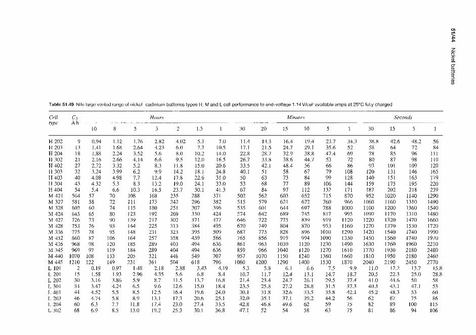
Table 51.49 Nife large vented range of nickel-cadmium batteries types H, M and L cell performance to end-voltage 1.14V/cell available amps at 25°C fully charged
Cell C5 Hours Minutes Seconds type A h
10 8 5 3 2 1.5 1 30 20 15 10 5 1 30 15 5 1
H 202 9 0.94 H203 13 1.41 H204 18 1.88 H302 21 2.16 H 402 27 2.72 H 303 32 3.24 H403 40 4.08 H 304 43 4.32 H404 54 5.4 M 421 564 57 M 327 581 58 M 328 603 60 M 424 645 65 M 427 726 73 M 428 753 76 M 336 775 78 M 432 860 87 M 436 968 98 M 345 969 97 M440 1070 108 M445 1210 122 L 101 2 0.19 L 201 15 1.58 L202 30 3.16 L 301 34 3.47 L401 44 4.52 L 203 46 4.74 L 204 60 6.3 L 302 68 6.9
1.12 1.68 2.24 2.66 3.32 3.99 4.98 5.3 6.6
70 72 74 80 90 93 95
106 120 119 133 149
0.97 1.93 3.86 4.24 5.5 5.8 7.7 8.5
1.76 2.64 3.52 4.14 5.2 6.2 7.7 8.3
10.3 108 111 115 123 139 144 148 164 I85 184 205 23 1
1.48 2.96 5.9 6.5 8.5 8.9
11.8 13.0
2.82 4.23 5.6 6.6 8.3 9.9
12.4 13.2 16.5
168 173 I80 192 217 225 23 1 257 289 289 321 361
2.18 4.35 8.7 9.6
12.5 13.1 17.4 19.2
4.02 6.0 8.0 9.5
11.8 14.2 17.8 19.0 23.7
235 242 25 1 269 302 313 323 358 403 404 448 504
2.88 5.6
11.5 12.6 16.4 17.3 23.0 25.3
5.1 7.7
10.2 12.0 15.0 18.1 22.6 24.1 30.1
288 296 307 330 371 384 395 439 494 494 549 618
3.43 6.8
13.7 15.0 19.6 20.6 27.4 30.1
7.0 10.5 14.0 16.5 20.6 24.8 31.0 33.0 41.3
371 382 396 424 477 495 509 566 636 63 6 707 796
4.19 8.4
16.8 18.4 24.0 25.1 33.5 36.8
11.4 17.1 22.8 26.7 33.5 40.1 50 53 67
502 515 535 574 646 670 687 765 861 859 957
1080 5.3
10.7 21.4 23.5 30.1 32.0 42.8 47.1
14.3 21.5 28.7 33.8 42.1 51 63 68 84
562 579 60 1 642 722 749 773 856 963 966
1070 1200
5.8 11.7 23.4 25.8 31.8 35.1 46.8 52
16.4 24.7 32.9 38.6 48.4 58 73 77 97
603 62 1 644 689 775 804 828 919
1030 1040 I150 1290
6.1 12.4 24.7 27.2 32.6 37.1 49.6 54
19.4 29.1 38.8 44.7 56 67 84 89
112 652 672 697 745 839 870 896 994
1120 1120 1240 1400
6.6 13.1 26.1 28.8 33.5 39.2 62 58
23.7 35.6 47.4 53 66 79 99
106 132 715 760 788 817 919 953
1010 1090 1230 1270 1360 1530
7.5 14.7 29.5 31.5 35.8 44.2 59 63
34.3 52 69 72 86
108 128 144 171 870 966
1000 995
1120 1160 1290 1330 1490 1610 1660 1870
9.9 18.7 37.4 37.3 42.1 56 75 75
38.8 58 78 80 93
120 140 159 187 952
1060 1100 1090 1220 1270 1420 1450 1630 1770 1810 2040
11.0 20.5 41.0 40.3 45.2 62 82 81
42.6 64 85 87
101 131 151 175 202
1020 1160 1200 1170 1320 1370 1540 1560 1760 1930 1950 2190
12.2 22.3 44.6 43.1 48.3 67 89 86
48.2 72 96 98
109 146 163 195 218
1140 1310 1360 1310 1470 1530 1740 1740 1960 2180 2180 2450
13.7 25.0 50 47.1 53 75
100 94
56 84
111 110 120 165 179 220 239
1290 1490 1540 1480 1660 1720 1990 1970 2210 2480 2460 2770
15.8 28.8 58 53 60 86
115 106

L 402 88 9.0 L 303 102 10.4 L403 133 13.6 L 304 136 13.9 L 305 170 17.4 L404 177 18.1 L 306 204 20.8 L 405 222 22.6 L 307 239 24.3 L 406 266 27.1 L 308 273 27.8 L 309 307 31.2 L407 311 31.6 L310 341 34.7 L408 355 36.2 L 311 375 38.2 L 409 400 40.7 L312 409 41.6 L410 444 45.2 L 411 489 49.7 L315 512 52 L412 533 54 L 318 614 62 L415 667 68 L320 682 69 L418 800 81 L324 819 83 L 325 853 87 L420 889 90 L 330 1020 104 L424 1060 108 L425 1110 113 L 430 1330 136
11.0 17.0 25 0 32.9 39.3 48.0 60 64 65 12.7 19.5 28.7 37.9 45.1 55 71 77 82 16.6 25.4 37.4 49.3 59 72 90 95 98 17.0 26.0 38.3 51 60 74 94 103 109 21.2 32.6 47.9 63 75 92 118 129 136 22.1 33.9 49.9 66 79 96 120 127 130 25.4 39.1 57 76 90 110 141 155 163 27.6 42.4 62 82 98 120 150 159 163 29.1 45.6 67 88 105 129 165 181 190 33.1 51 75 99 118 144 180 191 195 33.9 52 77 101 120 147 188 207 217 38.2 59 86 114 135 166 212 232 245 38.6 59 87 115 137 168 210 223 228 42.4 65 96 126 150 184 235 258 272 44.2 68 100 131 157 192 241 254 261 46.6 72 105 139 165 203 259 284 299 49.7 76 112 148 177 216 271 286 293 51 78 115 152 180 221 282 310 326 55 85 125 164 196 240 301 318 326 61 93 137 181 216 264 331 350 358 64 98 144 189 226 276 353 387 408 66 102 150 197 236 288 361 382 391 76 117 172 227 271 331 424 465 489 83 127 187 246 295 360 451 477 489 85 130 192 253 301 368 471 516 543 99 153 225 296 354 432 541 573 586
102 156 230 303 361 442 565 620 652 106 163 239 316 376 460 588 645 679 110 170 250 329 393 480 601 636 652 127 195 287 379 451 552 706 775 815 132 204 300 394 471 576 722 763 782 138 212 312 411 491 600 752 795 814 166 254 374 493 589 720 902 954 977
67 86
100 115 144 134 173 167 202 20 1 23 1 259 234 288 268 317 30 1 346 335 368 432 402 519 502 577 602 692 721 669 865 803 836
1000
72 95
107 126 158 143 189 179 22 1 21 5 252 284 250 315 286 347 322 378 358 393 473 429 568 536 63 1 644 757 788 715 946 858 894
1070
84 112 126 149 187 168 224 21 0 26 1 252 299 336 294 373 337 41 1 379 448 42 1 463 560 505 672 63 1 746 757 896 933 84 1
1120 1010 1050 1260
90 121 135 161 202 181 242 226 282 27 1 323 363 3 16 403 361 444 406 484 452 497 605 542 726 677 806 813 968
1010 903
1210 1080 1130 1350
97 129 145 173 216 193 259 24 1 302 290 345 388 338 43 1 386 474 435 518 483 53 I 647 579 776 724 863 869
1040 1080 996
1290 1160 1210 1450
106 141 159 189 236 212 283 265 330 318 377 424 37 1 47 1 424 519 477 566 530 583 707 636 849 195 943 955
1130 1180 1060 1410 1270 1330 1590
119 I60 179 213 266 239 319 298 373 358 426 479 418 532 478 586 537 639 597 657 798 716 958 895
1060 1070 1280 1330 1190 1600 z 1430 1490 1790 2
Q
c 3. 3

51/46 Nickel batteries
Table 51.50 Nife large vented nickel -cadmium battery types H, M and L Cell performance to end-voltage 0.83V/cell available amps at 25°C fully charged
Cell Minutes Seconds Cell Minutes Seconds QPe type
IO 5 1 30 15 5 1 10 5 1 30 15 5 1
H 202 H 203 H 204 H 302 H 402 H 303 H 403 H 304 H 404 H 305 M 303 M 403 M 304 M 404 M 405 M 406 M 407 M 408 M 409 M 410 M 411 M 314
33.8 55 51 83 68 111 78 122 97 153
116 184 146 229 155 245 194 306 194 306 202 276 252 339 270 368 336 453 420 566 504 679 588 792 673 905 757 1020 841 1130 925 1240 944 1290
119 179 239 257 303 386 454 514 606 643 381 449 508 598 748 879
1050 1200 1350 1500 1650 1780
136 205 273 289 333 434 500 579 667 724 424 482 566 642 803 963
1120 1280 1440 1610 1770 1980
151 226 301 311 357 466 535 62 1 713 777 459 517 612 689 861
1030 1210 1380 1550 1720 1890 2140
170 255 340 340 381 511 572 68 1 763 85 1 508 564 677 752 940
1130 1320 1500 1690 1880 2070 2370
197 296 394 373 42 1 560 632 746 842 933 556 644 742 859
1070 1290 1.500 1720 1930 2150 2360 2600
M 412 M 413 M 414 M 318 M 415 M 416 M 321 M 417 M 418 M 421 L 418 L 324 L 325 L 420 L 330 L 424 L 425 L 430
1010 1090 1180 1210 1260 1350 1420 1430 1510 1770 1900 2080 2160 2110 2600 2540 2640 3170
1360 1470 1580 1660 1700 1810 1930 1920 2040 2380 2240 2440 2540 2490 3050 2990 3120 3740
1790 1940 2090 2290 2240 2390 2670 2540 2690 3140 2740 3160 3290 3040 3950 3650 3800 4560
1930 2090 2250 2550 2410 2570 2970 2730 2890 3370 2940 3440 3590 3270 4300 3920 4080 4900
2070 2240 2410 2750 2580 2760 3210 2930 3100 3620 3130 3670 3830 3470 4590 4170 4340 5210
2260 2440 2630 30.50 2820 3010 3550 3200 3380 3950 3370 3980 4140 3750 4970 4500 4690 5620
2580 2790 3010 3340 3220 3440 3890 3650 3860 4510 3730 4350 4530 4140 5430 4970 5170 6210
Table 51.51 Varta large vented nickel -cadmium stationary batteries: electrical data
Type Capacity (Ah) designation
5h l h f h t h
Discharge current (A) Final discharge voltage (V)
5h l h h h $ h 5 h l h $ h $ h
Special X Vs 410 X 30 Vs 415 X 50 Vs 420 X 65 Vs 424 X 80 Vs431 X 100 v s 435 x 110 Vs 443 X 140 Vs451 X 165 Vs461 X 200 Special M Vs 105 M 45 Vs 107 M 60 Vs 110 M 85 Vs 112 M 105 Vs 115 M 130 Vs 117 M 1.50 Vs 121 M 18.5 Vs 125 M 215 Vs 129 M 255
28.5 47.5 61.8 76 95
105 133 157 190
43.2 57.6 81.6
101 125 144 178 206 245
27 45 58.5 72 90 99
126 149 180
40.5 54 76.5 94.5
117 135 167 194 230
24.75 41.25 53.75 66 82.5 90.75
115.5 136.25 165
37.8 50.4 71.4 88.2
109 126 155 181 214
6 10 13 16 20 22 28 33 40
9 12 17 21 26 30 37 43 51
28.5 47.5 61.8 76 95
1 05 133 157 190
14.4 19.2 27.2 33.7 41.7 48 59.3 68.7 81.7
54 90
1 I7 144 180 198 252 298 3 60
20.25 27 38.25 47.25 58.5 67.5 83.5 97
115
99 16.5 215 264 330 363 462 545 660
37.8 50.4 71.4 88.2
109 126 155 181 214
1.10 1 .os
1.03 0.90
1.0 0.98
0.96 0.91

Nickel-cadmium secondary batteries 51/47
0 10 20 30 40 50 60 70 80 90 100 la) Type H Capacity 1%)
Capacity (%) lbi TypeM
- 1.3
u 1.2
g 1.1
g 1.0
g 0.9
- aJ
> - m .- - 0)
L
0 0.8
0.7
0 10 20 30 40 50 60 70 80 90 100 Capacity (%I I C / Type L
Figure 51.32 Typical discharge characteristics at 25°C for Nife large vented nickel-cadmium batteries (Courtesy of Nife Jungner)
Table 51.52 Electrical performance data for McGraw Edison low-rate vented nickel-cadmium batteries, CED series
Cell type Discharge current (A) to 1.14V at 25°C
Nominal 10h 8 h 5 h 4 h 3 h 2 h I i h l h c,apacity
(Ah)
CED-16
CED-43 CED-58 CED-79 CED- 100 CED-120 CED-150 CED- 183 CED-216 CED-250
CED-32 16 32 43 58 79
100 120 150 183 216 250
1.53 3.07 4.12 5.5 7.58 9.6
11.5 14.5 17.5 20.8 23.8
1.87 3.74 5.01 6.75 9.31
11.8 14.1 17.7 21.6 25.5 29.4
2.83 3.34 3.97 4.9 5.4 6.25 5.7 6.5 7.7 9.4 10.6 12.3 7.65 8.6 10.2 12.1 13.7 15.8 9.1 10.2 11.45 13.25 14.5 16.6
13.1 14.6 16.7 19.6 22 25 16.9 18.8 22 26.1 29.2 33 19.4 22.2 26.1 31.1 34.3 39.1 24.1 27.6 32.2 38.9 42.7 48.8 30 34 39.7 47.9 52.7 59.5 36.2 41 47.6 57.1 63.1 72 41.4 47.6 56.1 67.1 73 83

51/48 Nickel batteries
Table 51.53 Electrical performance data for McGraw Edison low-rate vented nickel-cadmium batteries, CED series
Cell type Discharge current (A) to 1.OOV at 25°C
Nominal 10 h 8h 5h 4h 3h 2h l i h l h capacity
(A h)
CED- 16 CED-32 CED-43 CED-58 CED-79 CED-100 CED- 120 CED-150 CED- 183 CED-216 CED-250
16 32 43 58 79
100 120 150 183 216 250
1.63 3.28 4.39 5.92 8.06
10.2 12.3 15.3 18.7 22.1 25.5
2.03 4.06 5.46 7.35 9.95
12.55 15.2 18.9 23.1 27.3 32.1
3.19 3.97 6.4 7.8 8.6 10.6
11.5 13.7 15.45 18.8 20 25 23.1 28.5 29 36 35.9 44 40.5 50.7 50.1 61.9
5.05 9.85
13.4 16.3 23 31 36.1 45.5 55.1 65.1 79
6.85 13.86 17.7 21.5 31.1 40.5 48.5 63 76.7 90.5
106
8 16.8 21.8 25 36.3 48.8 56.5 74.1 90.2
106.5 124
9.25 21 25.3 30.5 45 60 68 88
107.6 127 146
Table 51.54 Electrical performance data for McGraw Edison medium-rate large nickel-cadmium batteries, ED series
Cell Discharge period type
8h 5 h 3h 60 min 30 min 15 min 5 min 1 min
Current (A) to 1.14 V/cell at 25°C ED-80 10 15.3 ED-120 15 22.3 ED-160 20 29.3 ED-240 30 44 ED-340 42.5 64 ED-400 50 74
Current (A) to l.lOV/cell at 25°C ED-80 10.4 16 ED-120 15.7 24 ED- 160 21 32 ED-240 31.5 48 ED-340 44.2 68 ED-400 52.3 80
Current (A) to l.OOV/cell at 25°C ED-80 10.7 16.6 ED-120 16.1 25.2 ED-160 21.4 33.6 ED-240 32 51 ED-340 44.8 70.2 ED-400 52.7 83
22.7 35 44 66 90
105
24.8 38.2 48.8 72
102 119
25.6 39.5 50.4 74
104 122
43 62 69
110 155 178
48 75 90
128 180 21 1
58 91
112 165 232 272
53 76 83
132 187 214
66 92
105 152 214 25 1
90 130 153 230 324 384
61 89 96
152 215 247
76 108 118 178 250 294
111 153 177 273 384 450
74 113 118 184 258 298
90 134 144 220 308 352
118 178 196 321 454 534
92 138 144 222 306 360
110 164 180 274 384 445
141 212 233 369 520 610
3. An increased diameter for the terminal configura- tion, and larger cross-sectional areas for conduc- tive sections of the plates. These features provide a low internal resistance, increasing high perfor- mance. Figure 5 1.33 indicates the enhanced voltage level of the TS/TSP range of cells compared with the general-purpose T/TP range. Figure 51.33 also indicates cells of the same capacity and discharge volt current.
Types T and TP These are storage batteries with pocket-type electrodes. The series T storage batter- ies, from 65 to 1250Ah, have a nickel-plated sheet steel case and are delivered in open wooden crates (from 65 to 380Ah) and as single cells (from 450 to 1250Ah). The 10-315Ah storage batteries, series TP, have a transparent plastic cell case, which makes it possible to control the electrolyte level from out- side. They are available as compact blocks, portable

Table 51.55 Electrical performance data for McGraw Edison medium-rate large nickel-cadmium batteries, MED series
Cell type Discharge current (A) to 1.14V at 25°C
Nominal Hours Minutes Seconds capuci1y
(Ah) 8 5 4 3 2 1; 1 30 20 15 10 5 14 60 30 I0 5 1
MED-10 MED-24 MED-36 MED-48 MED-65
MED-105
MED- I47
MED- 189
MED-231 MED-240 MED-270 MED-300
MED-360 MED-400
MED-80
MED-126
MED-168
MED-210
MED-340
10 24 36 48 65 80
1 05 126 147 168 189 210 23 1 240 270 300 340 360 400
1.25 3 4.5 6 8.12
10 13.1 15.8 18.4 21 23.6 26.3 28.9 29 33 37 42 45 50
1.93 2.4 3 4.63 5.7 7 6.94 8.5 10.6 9.2 11.4 14.2
12.5 15.5 19.2 15.4 19 23.6 20.2 25 31 24.3 30 37 28.3 35 43.5 32.4 40.2 50 36.4 45.1 56 40.5 50 62 44.5 54.9 68 45 55 70 51 62 79 57 70 88 65 79 100 69 85 105 76 95 117
3.9 9
13.9 19.2 26 32 41 49 57 66 74 82 90 90
102 115 130 140 155
4.6 5.5 10.5 12.3 16.2 18.7 22 25 29.5 34 36 42 46 54.5 55 65 66 77 75 87 84 98 93 110
102 120 106 124 119 140 132 155 150 176 159 186 176 207
7 15.3 25 34.5 46 55 69 80 98
112 125 138 152 150 169 188 214 226 252
8 8.8 16.7 18.5 28 30 40 43 53 58 63 69 77 82 89 94
110 116 125 133 140 148 154 164 169 180 162 172 184 193 206 219 234 251 2.51 267 279 298
10 12 20.8 24 33 38 47 54 63 72 76 87 88 101
104 120 126 143 144 163 160 183 178 202 195 222 185 213 211 242 236 271 268 308 288 330 320 367
15 31 47 64 86
106 121 143 172 199 220 243 265 254 289 324 368 394 438
16 18 33.5 38 50 56 68 74 91 99
112 122 128 143 152 166 182 200 208 226 232 255 258 280 285 305 273 292 311 333 349 373 396 424 424 454 472 504
20.5 45 66 84
113 139 159 183 22 1 250 282 310 338 324 369 414 470 504 560 -
22 48 72 91
122 1 50 172 197 235 267 299 330 360 345 393 44 1 500 536 596
25 55 82
102 134 165 191 215 254 290 317 350 385 $ 368 8 419 470 8)
572 5 636 v)
- ( D 0 0 3 a
534 $ _.

Table 51.56 Electrical performance data for McGraw Edison medium-rate large nickel-cadmium batteries, MED series
Cell type Discharge current (A) to 1.00V ut 25°C
Nominal Hours Minutes Seconds capacity
(Ah) 8 5 4 3 2 1h 1 30 20 15 10 5 1; 60 30 10 5 1
MED-10 E D - 2 4
MED-48 MED-65
MED-105
MED- 1 47
MED-36
MED-80
MED-126
MED-168 MED- 189 MED-2 10 MED-23 1
MED-270
MED-340 MED-360
MED-240
MED-300
MED-400
10 24 36 48 65 80
105 126 147 168 I89 210 23 1 240 270 300 340 360 400
1.31 3.15 4.72 6.28 8 .5
10.5 13.7 16.5 19.3 22.1 24.7 27.5 30.3 31.1 35.1 39.5 44.2 46.7 52
2.06 2.6 4.94 6.3 7.41 9.4 9.9 12.5
13.3 16.9 16.5 20.9 21.6 27.5 25.9 33 30.2 38.1 34.6 43.6 38.9 49.6 43.2 55 47.5 60.5 48.2 74 54.5 84 61.0 94 69.0 107 73 115 81 128
3.3 8
11.9 15.8 21.4 26.4 35 42 48 55 63 70 77 79.1 89.2
100.0 113 119 133
4.8 11.6 17.5 23.5 32 39 50 61 69 79 90
100 110 110 125 140 160 171 190
6.1 14.2 22 29.5 40 49 64 76 89
102 114 127 140 144 162 180 204 216 240
8.5 19.3 29 39 53 65 84
100 119 135 153 170 185 192 216 240 272 288 320
12 26.5 40 60 81
100 114 136 168 190 213 235 258 264 297 330 374 396 440
14 15.5 17.5 30.5 33 37 46 50 56 67 73 80 91 99 108
112 121 133 129 136 151 151 161 175 190 201 219 215 229 248 240 257 276 265 283 305 288 308 330 276 308 315 314 346 359 3.52 384 402 400 438 457 428 465 489 476 518 544
21 42 65 91
123 15 1 172 200 247 280 311 345 375 362 412 462 524 562 624
26 27.5 30.5 52 56 63.5 78 84 95
108 115 125 147 155 169 180 191 208 204 217 244 242 258 284 297 312 343 336 355 390 370 395 435 408 435 480 440 475 515 432 465 497 492 529 566 552 593 635 626 674 720 671 722 772 746 802 858
35 75
112 143 193 235 270 3 14 378 430 480 530 575 558 635 712 809 866 963
37 82
123 153 207 254 288 335 400 455 510 560 615 594 676 758 861 922
1025
42 94
140 173 228 280 325 370 435 495 540 590 650 634 722 809 918 984
1093
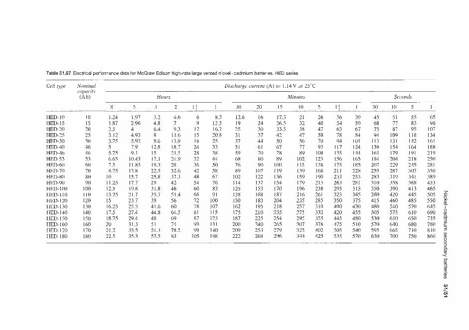
Table 51.57 Electrical performance data for McGraw Edison high-rate large vented nickel-cadmium batteries, HED series
Cell type Nominal Discharge current (A) to 1.14V ut 25°C cupacity (Ah) Hours Minutes Seconds
8 5 3 2 I f 1 30 20 15 10 5 I f 1 30 10 5 i
HED-10 HED- 15
HED-25
HED-40 HED-46 HED-53 HED-60 HED-70 HED-80 HED-90 HED-100
HED- 120
HED- 140 HED-150 HED- 160
HED- 180
HED-20
HED-30
HED-110
HED-130
HED- 170
10 1.24 15 1.87 20 2.5 25 3.12 30 3.75 40 5 46 5.75 53 6.63 60 7.5 70 8.75 80 10 90 11.25
100 12.5 110 13.75 120 15 130 16.25 140 17.5 150 18.75 160 20 170 21.2 180 22.5
1.97 3.2 2.96 4.8 4 6.4 4.93 8 5.92 9.6 7.9 12.8 9.1 15
10.45 17.1 11.85 19.3 13.8 22.5 15.7 25.8 17.7 29 19.6 31.8 21.7 35.7 23.7 39 25.5 41.6 27.4 44.8 29.4 48 31.3 51 33.5 54.3 35.3 57.5
4.6 6 7 9 9.3 12
11.6 15 13.9 18 18.7 24 21.5 28 24.9 32 28 36 32.6 42 37.3 48 42 54 46 60 51.4 66 56 72 60 78 64.5 81 69 87 14 93 78.5 99 83 105
8.3 12.5 16.7 20.8 25 33 38 44 50 58 61 76 83 91
I00 107 115 123 131 140 148
12.6 19 25 31 37 51 59 68 76 89
I02 114 125 138 150 162 175 187 200 209 222
16 24 30 37 44 61 70 80 90
107 122 137 153 168 183 195 210 225 240 253 268
17.3 26.5 33.5 42 50 67 78 89
100 119 136 154 170 187 204 218 235 254 265 279 296
21 26 32 40 38 47 47 58 56 70 77 93 89 108
102 123 115 138 139 168 159 190 179 213 196 238 216 261 235 285 257 310 275 332 295 355 307 378 325 402 344 425
36 54 63 78 94
117 135 1.56 175 21 1 233 263 295 323 350 400 420 445 475 505 535
39 45 59 68 67 75 84 94
101 113 124 139 144 161 165 184 185 207 228 255 253 283 281 310 315 350 345 380 375 415 430 480 455 505 480 530 510 570 540 595 570 630
51 55 65 77 83 98 87 95 107
109 118 134 131 142 161 154 164 188 179 191 219 204 218 250 229 245 281 287 307 350 319 341 389 358 388 433 390 413 465 420 445 505 460 485 550 7
540 570 645 ? 57.5 610 690 8 610 650 735 640 680 780 2. 665 710 810 700 750 860 %
0
9 9 b

Table 51.58 Electrical performance data for McGraw Edison high-rate large vented nickel-cadmium batteries, HED series
Cell type
HED- 1 0 HED-15 HED-20
HED-30
HED-46
HED-60
HED-25
HED-40
HED-53
HED-70 HED-80 HED-90 HED- 100 HED-110 HED- 120 HED-130 HED-140
HED-160 HED- 150
HED- 170 HED-180
Nominal capacity (Ah)
10 15 20 25 30 40 46 53 60 70 80 90
100 110 120 130 140 150 160 170 180
DiJcharge current (A) to 1 .00V at 25°C
Hours Minutes Seconds
8 5 3 2 14 1 30 20 15 10 5 14 1 30 10 5 1
1.3 2.03 3.4 5 6.5 9.3 18 22 26.7 34.5 47 62 67 76 87 95 112 1.95 3.04 5.1 7.5 9.7 14 27 33 40 52 71 92 101 114 131 143 168 2.6 4.07 6.8 10 13 18.7 34 45 52 63 82 106 115 129 151 161 184 3.25 5.08 8.5 12.5 16.3 23.3 42 56 65 79 102 133 144 161 188 202 231 3.9 6.1 10.2 15 19.5 28 51 67 78 94 122 162 173 193 226 242 277 5.2 8.1 13.6 19.9 26 37 69 91 105 124 157 209 220 240 267 287 320 6 9.4 15.6 22.9 30 42.5 80 105 121 143 181 240 256 279 311 334 367 6.9 10.8 17.9 26.4 34.5 49 92 120 139 165 209 276 292 318 355 381 418 7.8 12.2 20.2 29.8 39 55 104 135 156 185 235 312 328 358 399 428 470 9.1 14.5 24.2 35 46 67 116 158 183 218 285 364 392 441 494 535 598
10.4 16.5 27.6 40 52 76 132 180 209 249 325 404 435 490 548 594 664 11.7 18.6 31 45 59 86 149 203 235 280 365 455 485 532 615 660 744 13 20.7 35 50 65 95 165 216 250 300 390 500 530 590 660 700 795 14.3 22.7 37.5 55 71 105 179 238 277 330 430 545 580 650 725 765 865 15.6 24.7 41 60 78 114 195 260 305 360 470 595 638 710 790 835 945 16.9 26.8 45 65 85 122 215 285 335 400 525 685 740 830 920 975 1110 18.2 29 48.5 70 91 131 232 310 360 430 550 718 775 880 985 1045 1190 19.5 31 51.5 75 98 140 248 330 385 460 580 760 820 920 1030 1105 1260 20.8 33 56 80 104 150 263 345 400 475 620 810 890 1000 1110 1180 1340 22.1 35.2 59.5 85 111 159 278 367 425 505 655 850 915 1030 1150 1230 1410 23.4 37.3 63 90 117 168 295 389 450 535 695 900 970 1090 1220 1300 1490

Nickel-cadmium secondary batteries 51/53
Table 51.59 Electrical performance data for McGraw Edison high-rate large vented nickel-cadmium batteries, HED series
Cell type Nominal Discharge current (A) to 0.65 V at 25°C Discharge current (A) to 0.85 V at 25°C capacity ~
(Ah) 90s 60s 30s 10s 5 s I s 90s 60s 30s 10s 5 s I s
HED-10 HED-15 HED-20 HED-25 HED-30 HED-40 BED-46 HED-53
HED-70
HED-90
HED-60
WED-80
HED-100 HED-110 HED-120 HED-130 HED-140 HED- 1 50 HED- 160 HED- I70 NED- 180
10 123 15 185 20 217 25 27 1 30 325 40 442 46 510 53 587 60 660 70 732 80 813 90 905
lQ0 1010 110 1115 120 1215 130 1375 140 1440 150 1540 160 1610 170 1710 180 1810
137 206 238 298 358 459 530 610 685 810 a99 990
1075 1185 1290 1515 1590 1690 1x10 1880 1980
157 236 267 333 400 493 570 655 736 900 999
1095 1215 1340 1460 1705 1825 1900 2040 21 10 2230
181 27 1 313 392 470 546 629 725 815
1015 1132 1261 1350 1485 1620 1890 2020 2125 2270 2370 2500
196 294 335 417 500 579 666 768 864
1102 1223 1365 1435 1575 1715 2010 2150 2270 2420 2530 2670
23 1 346 378 472 567 661 757 864 97 1
1230 1365 1520 1610 1770 1930 2290 2450 2600 2770 2900 3060
88 132 155 193 232 309 354 408 458 525 586 660 715 790 860 990
1030 1090 1150 1220 1290
blocks. and in open wooden crates. Types T and TP are universally designed for discharges, i.e. for power supplies, from more than 10 h down to short time dis- charges of 1 h with a favourable voltage performance. They can be used excellently for charge/discharge operation, switch-tripping operation and standby paral- lel operation as well as for stabilizing operation. They can be charged with high charging currents within a short period of time. At low temperatures they provide favourable capacity characteristics. Deep discharges have no effect on the capacity.
Types HK and HKP Discharge data on types T and TP are given in Table 51.60. Types HK and HKP are storage batteries with pocket-type electrodes. The series HK storage batteries from 73 to 1390Ah have
'1.3 t; I 1.2 > - 1.1 c n , 8 1.0 g 0.9 8 0.8
- - -
0.7
10 20 30 40 50 60 Discharge period ( m i d
Figure 51.33 Schematic comparison between (a) T/TP and (b) TSnSP cells; >voltage-time characteristics when discharged with 5 x / 5 = I C
98 111 127 147 167 191 168 188 220 210 235 275 252 282 330 320 344 380 371 398 441 425 457 507 478 514 570 570 638 720 633 708 800 699 771 892 765 860 960 845 945 1050 920 030 1145
1070 195 1325 1120 280 1420 1195 355 1510 1280 1440 1600 1330 1.500 1670 1410 1590 1770
138 207 234 293 352 408 47 1 542 609 775 860 965
1015 1110 1210 1415 1515 1610 1710 1780 1890
163 245 267 333 400 470 535 615 692 87 1 967
1072 1150 1250 1365 1615 1730 1835 1960 2050 2170
a nickel-plated sheet steel case and are delivered in open wooden crates (from 73 to 420 Ah) and as single cells (from 500 to 1390Ah).
The 11 -35.5 A h storage batteries, series HKP, have a transparent plastic cell case, which makes it pos- sible to control the electrolyte level from outside. They are available as compact blocks, portable blocks and in open wooden crates. Alternatively they can be delivered in enclosed wooden crates or in steel con- tainers. Types HK and HKP are universally designed for discharges, i.e. for power supplies, from more than IO h down to short-time discharges of 1 h with a favourable voltage performance. They can be used for charge/discharge operation, switch-tripping operation and standby parallel operation as well as for stabiliz- ing operation. They can be charged with high charging currents within a short period of time. Even at low tem- peratures they provide favourable capacity character- istics. Deep discharges have no effect on the capacity.
Discharge data on types HK and HKP are given in Table 51.61.
Types TS and TSP These are high-rate storage batter- ies fitted with pocket-type electrodes and are specially designed for high-rate and impulse discharge. The stor- age batteries of series TS from 150 to 650Ah have a nickel-plated sheet steel case and are delivered in open wooden crates (from 150 to 275Ah) and as single cells (from 300 to 650Ah). The 7.5-23SAh storage batteries, series TSP, have a transparent plas- tic cell case which makes it possible to control the electrolyte level from outside. They are available as

z E 0 7i
0- Table 51.60 Discharge currents in amps (battery fully charged) at 20-25°C for FRlWO vented nickel-cadmium batteries types T and TP %
8. Type of cell Nominal capacity Times of discharge w
(C5) down to 1.15Vlcell (Ah) 0.5h l h 2h 3h 4h 5 h 6h 7 h 8h 9h 10h
TP 10 TP 18 TP 24 TP 30 TP 40 TP 55
T 65* TP 6.5 T 75* TP 75 T 90* TP 90 T 110* TP 110 T 125* TP 125 T 140* TP 140 T 165* TP 165 T 185 /TP 185 T 200*/TP 200 T 230 ITP 230 T 275 fTP 275 T 315 ITP 315 T 380 T 450 T 520 T 600 T 750 T 1000 T 1250
10 18 24 30 40 55 6.5 75 90
1 I O 125 140 165 185 200 230 275 315 380 450 520 600 750
1000 1250
7.00 12.60 16.80 21.00 28.00 38.50 45.50 52.50 63.00 77.00 87.50 98.00
115.50 129.50 140.00 161.00 192.50 220.50 266.00 315.00 364.00 420.00 525.00 700.00 875.00
5.00 9.40
12.50 15.60 20.80 28.60 33.80 39.00 46.80 57.20 65.00 72.80 85.80 96.20
104.00 119.60 143.00 163.80 197.60 234.00 270.40 312.00 390.00 520.00 650.00
4.00 7.20 9.60
12.00 16.00 22.00 26.00 30.00 36.00 44.00 50.00 56.00 66.00 74.00 80.00 92.00
110.00 126.00 152.00 180.00 208.00 240.00 300.00 400.00 500.00
3.00 5.40 7.20 9.00
12.00 16.50 19.50 22.50 27.00 33.00 37.50 42.00 49.50 55.50 60.00 69.00 82.50 94.50
114.00 135.00 156.00 180.00 225.00 300.00 375.00
2.40 4.36 5.78 7.10 9.50
13.00 15.40 17.80 21.30 26.10 29.60 33.20 39.10 43.90 47.40 54.50 65.20 74.70 90.00
106.70 123.30 142.20 177.80 237.00 296.30
2.00 3.60 4.80 6.00 8.00
1 1.00 13.00 15.00 18.00 22.00 25.00 28.00 33.00 37.00 40.00 46.00 55.00 63.00 76.00 90.00
104.00 120.00 150.00 200.00 250.00
1.70 3.00 4.10 5.10 6.80 9.30
1 1 .00 12.70 15.30 18.70 21.20 23.80 28.00 3 1.40 34.00 39.10 46.70 53.50 64.60 76.50 88.40
102.00 127.50 170.00 212.50
1 .50 2.65 3.50 4.40 5.90 8.10 9.50
11.00 13.20 16.10 18.30 20.50 24.20 27.20 29.40 33.80 40.40 46.30 55.80 66.15 76.45 88.20
110.20 147.00 183.70
1.30 2.35 3.10 3.90 5.20 7.15 8.45 9.75
11.70 14.30 16.25 18.20 21.45 24.00 26.00 29.90 35.70 40.90 49.40 58.50 67.60 78.00 97.50
130.00 162.50
1.15 2.10 2.80 3.50 4.70 6.45 7.60 8.78
10.50 12.80 14.60 16.30 19.30 21.65 23.40 26.90 32.10 36.80 44.40 52.60 60.80 70.20 87.70
117.00 146.20
1 .os 1.90 2.55 3.20 4.25 5.80 6.90 7.95 9.55
11.65 13.25 14.80 17.85 19.60 21.20 24.30 29.10 33.30 40.20 47.70 55.10 63.60 79.50
106.00 132.50
* Cell types in steel sheet cases
Final dischargc voltagae 1.15 Vlcell

Table 51.61 Discharge currents in amps (battery fully charged) at 20-25°C for FRlWO vented nickel-cadmium batteries types HK and HKP
Type qf cell Nominal capacity Times of discharge (Cs) down to
1 .O V/cell (A h)
HKP 1 HKP 2 HKP 2.7 HKP 3 HKP 5 HKP 6
HK7* HKP7 HK 9* HKP 9 HK 10* HKP 10 HK 12* HKP 12 HK 14* HKP 14 HK 16* HKP 16 HK 18* HKP 18 HK 20/ HKP 20 HK 23* HKP 23 HK 26/ HI@ 26 HK 31/ HKP 31 HK 36/ HKP 36 HK 43 HK 51 HK 59 HK 67 HK 85 HK 115 HK 140
11 19.5 26.5 33 44 61 73 83
100 122 138 155 182 205 220 255 305 350 420 500 575 665 830
1110 1390
0.5 h
7.00 12.60 16.80 21.00 28.00 38.50 45.50 52.50 63.00 77.00 87.50 98.00
115.50 129.50 140.00 161.00 192.50 220.50 266.00 31.5.00 364.00 420.00 525.00 700.00 875.00
I h
5.00 9.40
12.50 15.60 20.80 28.60 33.80 39.00 46.80 57.20 65.00 72.80 85.80 96.20
104.00 119.60 143.00 163.80 197.60 234.00 270.40 312.00 390.00 520.00 650.00
2h
4.00 7.20 9.60
12.00 16.00 22.00 26.00 30.00 36.00 44.00 50.00 56.00 66.00 74.00 80.00 92.00
110.00 126.00 152.00 180.00 208.00 240.00 300.00 400.00 500.00
__ 3h
3.00 5.40 7.20 9.00
12.00 16.50 19.50 22.50 27.00 33.00 37.50 42.00 49.50 55.50 60.00 69.00 82.50 94.50
114.00 135.00 156.00 180.00 225 .OO 300.00 375.00
~
4h
2.40 4.36 5.78 7.10 9.50
13.00 15.40 17.80 21.30 26.10 29.60 33.20 39.10 43.90 47.40 54.50 65.20 74.70 90.00
106.70 123.30 142.20 177.80 237.00 296.30
~
5 h
2.00 3.60 4.80 6.00 8.00
11.00 13.00 15.00 18.00 22.00 25.00 28.00 33.00 37.00 40.00 46.00 55.00 63.00 76.00 90.00
104.00 120.00 150.00 200.00 250.00
6h
1.70 3.00 4.10 5.10 6.80 9.30
11.00 12.70 15.30 18.70 21.20 23.80 28.00 3 1.40 34.00 39.10 46.70 53.50 64.60 76.50 88.40
102.00 127.50 170.00 212.50
7h 8h
1 .so 1.30 2.65 2.35 3.50 3.10 4.40 3.90 5.90 5.20 8.10 7.15 9.50 8.45
11.00 9.75 13.20 11.70 16.10 14.30 18.30 16.25 20.50 18.20 24.20 21.45 27.20 24.00 29.40 26.00 33.80 29.90 40.40 35.70 46.30 40.90 55.80 49.40 66.15 58.50 76.45 67.60 88.20 78.00
110.20 97.50 147.00 130.00 183.70 162.50
9h 10h
1.15 1.05 2.10 1.90 2.80 2.55 3.50 3.20 4.70 4.25 6.45 5.80 7.60 6.90 8.78 7.95
10.50 9.55 12.80 11.65 14.60 13.25 16.30 14.80 19.30 17.85 21.65 19.60 23.40 21.20 26.90 24.30 32.10 29.10 36.80 33.30 2 44.40 40.20 52.60 47.70 A 60.80 55.10 g 70.20 63.60 =J 87.70 79.50 -.
117.00 106.00 o)
146.20 132.50 2 5 0 3 a * Cell types in steel sheet cases 5 % s. w W Final discharge voltage l.I5V/cell

51/56 Nickel batteries
> - 16- +d P 15- - 9 14-
13 12 11
10 9 -
compact blocks, portable blocks and in open wooden crates. Alternatively, they can be delivered in enclosed wooden crates or in steel containers. Types TS and TSP are specially designed for high-rate discharges and for use as starting batteries, i.e. for discharges from less than 1 h down to short-time discharges and high-ratehmpulse loads with favourable voltage perfor- mance. They can be used for charge/discharge opera- tion, switch-tripping operation and standby parallel operation as well as for stabilizing operation.
They can be charged with high charging currents within a short period of time. At low temperatures they provide favourable capacity characteristics. Deep discharges have no effect on the capacity.
Discharge data on types TS and TSP are given in Table 51.62.
I I I I I
- I I
I
- -18OC I k t- I-; 1- 1
5 s res: 5 s rest 8 - I I I I
I I I I I I
51.1.4 Aircraft batteries Another major application of vented nickel-cadmium batteries is aircraft batteries. These batteries are equipped with a battery temperature monitoring facility in order to comply with the requirements of the FAA. One or more thermal switches are installed in the battery to give advance warning and to prevent overheating of the battery, thereby achieving a greater safety of flight operation.
The thermal switches are connected to a connector on the battery container from which a cable leads to a warning lamp situated on the instrument panel of the aircraft.
This warning lamp lights up when the predetermined temperature limit for the thermal switch is reached, e.g. 65°C. When the warning lamp lights up, charging of the battery must be stopped. When the battery is cooled
1400
- 1300 U I
1200- W =, 1100- 0
1000
900
800
q - 12
10 8 0
-
-
-
-
- -
0
6 -
5
0
1 6 - 5 0 300 400 500 600 700
\ - \ Capacity extracted = 18.70 A h
4 -
3 -
2-
1 - 845 A
I I I 1 I I
Current (A)
Figure 51.34 Varta vented nickel-cadmium battery type HI: dependence of initial voltage on current and temperature (Cour- tesy of Varta)
I I 1 I I I I I I I I 1 +- I I I I
M I I Final discharge voltage
7------ --+ ----- +--
- :"F 2 13
10 i
9 ,
Figure 51.36 Varta vented nickel-cadmium battery type F20/40HI (24V, 40Ah): effect of initial load on battery voltage at -12.2% (Courtesy of Varta)
down the warning lamp goes out and the battery is ready for service.
Technical data on several of the Varta range of aircraft batteries are given in Table 51.63. Typical discharge data are given in Figures 51.34-51.36. The effect of battery temperature in the range -30 to +3WC on discharge performance is shown in Figure 51.37.
Eagle Picher produce the VNC range of batteries for aircraft starting, aircraft emergency power and ground power units. Capacities up to 120 A h are available (see selected examples in Table 51.64). Cycling lives in excess of 5 years or 1000 cycles are claimed for these
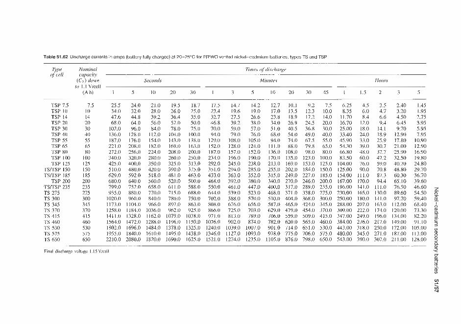
Table 51.62 Discharge currents in amps (battery fully charged) at 20-25°C for FRlWO vented nickel-cadmium batteries, types TS and TSP
TYP of cell
TSP 7.5 TSP 10 TSP 14 TSP 20 TSP 30 TSP 40 TSP 55 TSP 65 TSP 80 TSP 100 TSP 125
TSITSP 150 TSITSP 185
TSP 200 TSITSP 235 TS 275 TS 300 TS 345 TS 370 TS 415 TS 460 TS 530 TS 575 TS 650
Nominal cupacit)i (CS) down
to 1.1 V/CCll (Ah)
7.5 10 14 20 30 40 55 65 80
100 125 1.50 185 200 235 275 300 345 370 415 460 530 575 650
Times of discharge
Seconds Minutes
i 5 10 20 30 1 3 5 10
25.5 24.0 21.0 19.5 18.7 17.5 14.7 14.2 12.7 34.0 32.0 28.0 26.0 25.0 23.4 19.6 19.0 17.0 47.6 44.8 39.2 36.4 35.0 32.7 27.5 26.6 23.8 68.0 64.0 56.0 52.0 50.0 46.8 39.2 38.0 34.0
102.0 96.0 84.0 78.0 75.0 70.0 59.0 57.0 51.0 136.0 128.0 112.0 104.0 100.0 94.0 79.0 76.0 68.0 187.0 176.0 154.0 143.0 138.0 129.0 108.0 105.0 94.0 221.0 208.0 182.0 169.0 163.0 152.0 128.0 124.0 111.0 272.0 256.0 224.0 208.0 200.0 187.0 157.0 152.0 136.0 340.0 320.0 280.0 260.0 250.0 234.0 196.0 190.0 170.0 425.0 400.0 350.0 325.0 313.0 292.0 245.0 238.0 213.0 510.0 480.0 420.0 390.0 375.0 351.0 294.0 285.0 255.0 629.0 592.0 518.0 481.0 463.0 433.0 363.0 352.0 315.0 680.0 640.0 560.0 520.0 500.0 468.0 392.0 380.0 340.0 799.0 752.0 658.0 611.0 588.0 550.0 461.0 447.0 400.0 93.5.0 880.0 770.0 715.0 688.0 644.0 539.0 523.0 468.0
1020.0 960.0 840.0 780.0 750.0 702.0 588.0 570.0 510.0 1173.0 1104.0 966.0 897.0 863.0 808.0 676.0 656.0 587.0 1258.0 1184.0 1036.0 962.0 925.0 866.0 725.0 703.0 629.0 1411.0 1328.0 1162.0 1079.0 1038.0 971.0 813.0 789.0 706.0 1564.0 1472.0 1288.0 1196.0 1150.0 1076.0 902.0 874.0 782.0 1802.0 1696.0 1484.0 1378.0 1325.0 1240.0 1039.0 1007.0 901.0 1955.0 1840.0 1610.0 1495.0 1438.0 1346.0 1127.0 1093.0 978.0 2210.0 2080.0 1820.0 1690.0 1625.0 1521.0 1274.0 1235.0 1105.0
20 30 45 i 1.5
Hours
2 3 5
10.1 9.2 7.5 6.25 4.5 13.5 12.3 10.0 8.35 6.0 18.9 17.2 14.0 11.70 8.4 26.9 24.5 20.0 16.70 12.0 40.5 36.8 30.0 25.00 18.0 54.0 49.0 40.0 33.40 24.0 74.0 67.5 55.0 45.90 33.0 88.0 79.8 6.5.0 54.30 39.0
108.0 98.0 80.0 66.80 48.0 135.0 123.0 100.0 83.50 60.0 169.0 153.0 125.0 104.00 76.0 202.0 184.0 150.0 125.00 90.0 249.0 227.0 185.0 154.00 111.0 270.0 246.0 200.0 167.00 120.0 317.0 289.0 23.5.0 196.00 141.0 371.0 338.0 275.0 230.00 165.0 404.0 368.0 300.0 250.00 180.0 465.0 424.0 345.0 288.00 207.0 479.0 454.0 370.0 309.00 222.0 559.0 509.0 415.0 347.00 249.0 620.0 565.0 460.0 384.00 276.0 714.0 6.51.0 530.0 443.00 318.0 775.0 706.0 575.0 480.00 345.0 876.0 798.0 650.0 543.00 390.0
3.5 2.40 4.7 3.20 6.6 4.50 9.4 6.45
14.1 9.70 18.9 12.90 25.9 17.80 30.7 21.00 37.7 25.90 47.2 32.50 59.0 40.70 70.8 48.80 87.3 60.30 94.4 65.10
111.0 76.50 130.0 89.60 141.0 97.70 163.0 112.00 174.0 120.00 196.0 134.00 217.0 149.00 250.0 172.00 271.0 187.00 307.0 21 1 .00
I .45 1.95 2.75 3.95 5.95 7.95
10.90 12.90 16.90 19.80 24.80 29.70 36.70 39.60 46.60 54.50 59.40 68.40 73.30 82.20 91.10
105.00 113.00 128.00
Final discharge voltagc I . 15 Vice11 5 % 2. 8
U
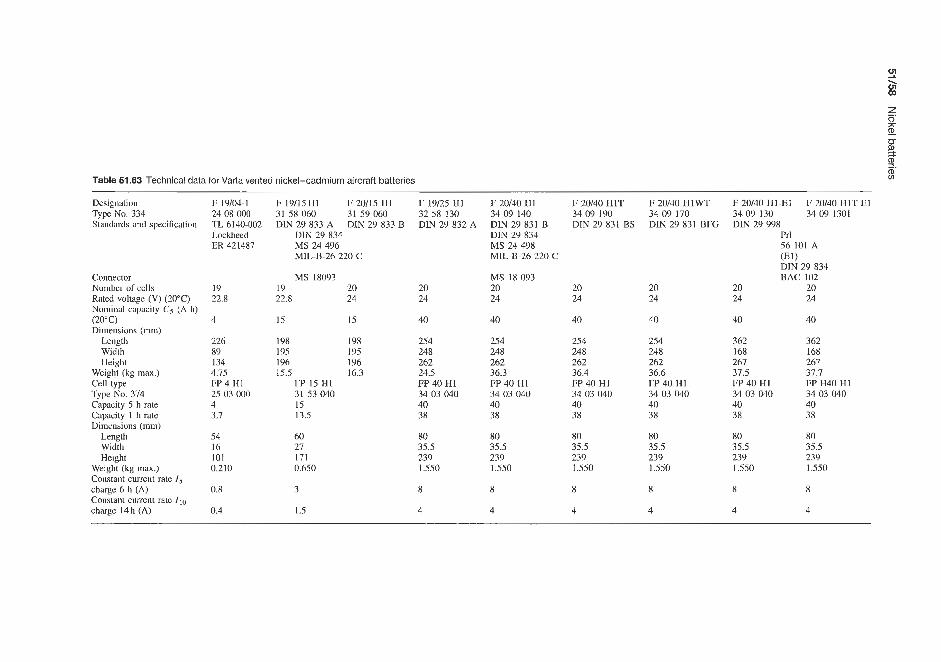
Table 51.63 Technical data for Varta vented nickel-cadmium aircraft batteries
Designation F 19104-1 Type No. 334 24 ox 000
Lockheed ER 421487
Standards and specification TL 6140-002
Connector Number of cells Rated voltage (V) (20°C) Nominal capacity C5 (Ah) (20" C) Dimensions (mm)
Length Width Height
Weight (kg max.) Cell type Type No. 374 Capacity 5 h rate Capacity 1 h rate Dimensions (mm)
Length Width Height
Weight (kg max.) Constant current rate 1 5 charge 6 h (A) Constant current rate I10 chargc 14h (A)
19 22.8
4
226 89 134 4.75 FP 4 H1 25 03 000 4 3.7
54 16 101 0.210
0.8
0.4
F 19/15H1 F 20/15 H1 31 58 060 DIN 29 833 A
31 59 060 DIN 29 833 B
DIN 29 834 MS 24 496 M1L-B-26 220 C
MS 18093 19 20 22.8 24
15 15
198 198 195 195 196 196 15.5 16.3
FP 15 HI 31 53 040 15 13.5
60 27 171 0.650
3
1.5
F 19/25 HI 32 58 130 DIN 29 832 A
20 24
40
254 248 262 24.5 FP 40 H1 34 03 040 40 38
80 35.5 239 1.550
8
4
F 20/40 H1 34 09 140 DIN 29 831 B DIN 29 834 MS 24 498 MIL-B-26 220 C
MS 18 093 20 24
40
254 248 262 36.3 FP 40 HI 34 03 040 40 38
80 35.5 239 1.550
8
4
F 20/40 H1T 34 09 190 DIN 29 831 BS
20 24
40
254 248 262 36.4 FP 40 HI 34 03 040 40 38
80 35.5 239 1.550
8
4
F 20/40 H1 WT 34 09 170 DIN 29 831 BFG
20 24
40
254 248 262 36.6 FP 40 H1 34 03 040 40 38
80 35.5 239 1.550
8
4
F 20/40 H1-El 3409 130 34 09 1301 DIN 29 998
F 20/40 H1T-E1
Prl 56 101 A ( E l f DIN 29 834 BAC 102
20 20 24 24
40 40
362 168 267 37.5 FP 40 H1 34 03 040 40 38
362 168 261 37.7 FP H40 H1 34 03 040 40 38
80 80 35.5 35.5 239 239 1.550 1.550
8 8
4 4

Nickel-cadmium secondary batteries 51/53
Table 51.64 VNC range of vented nickel-cadmium batteries supplied by Eagle Picher
Standard line Rated Energy density Weight Length Width Height Military cell types capacity (8) (mm) (mm) (mm) designation
(Ah)* ' W h k g Wh/dm3
VNC Q8 VNC 1.5 VNC 2A vnc 2B VNC 3 VNC 3.5 VNC 5.5A VNC 30 VNC 37 VNC 42 VNC 70 VNC 120
0.8" 17.6 1.5" 19.8 2.0" 21.1 2.0* 22.9 3.0* 18.9 3.5 28.8 5.5* 25.7
30.W 30.4 37.0* 30.1 42.0* 31.7 70.V 33.9
120.0 37.0
32 35 40 47 37 56 49 64 67 76 82 88
57 91
113 99
190 145 25 5 119
1474 1588 2466 3119
18 17 18 17 13 21 24 27 35 35 45 75
29 29 38 29 49 53 55 81 80 80
121 95
59 102 87
102 153 65
102 BB 615m 255 239 BB 600m 239 188 24 I
* Based on 1 h discharge rate
28 26 - 24
2 22 0 20 r 18 2 16
14 12
0 10 20 30 40 50 60 70 80 90 100 State of discharge ( % of nomlnal capacity)
( a ) 30°C 2 2 2 2 2 1 7 1 1
State of discharge (%of nominal capacity)
(b) 0 ° C
C/5 A - G 10 20 30 40 50 160 70 80 90 100
State of discharge (% of nornlnal capacity) (cl -30 "C
Figure 51.37 Electrical performance of a Varta vented nickel-cadmium battery: typical discharge curves at different load temperatures for a battery of 20 cells. Initial state of charge: 100% of nominal capacity. Charging: 6 h at 0.2CA (25°C) (Courtesy of Varta)
Table 51.65
Temperature Self-discharge ("C) (%/day)
27 0.5 37 1.1 49 2.5 60 5.0 71 10.0
batteries. The working voltages are 1.0-1.25 V/cel! with a voltage regulation that is uniform over 90% of the discharge. Operating temperatures are -40 to 74°C and storage temperatures -62 to 74°C when charged, and -54 to 38°C when discharged. Self-discharge rates are given in Table 51.65. Typical discharge character- istics are shown in Figure 51.38.
- 1.2 >
m 0.8
- W m I 0 - 5
0.4
0 10 20 30 40 50 60 70 Time (rnin)
Figure 51.38 Typical cell discharge characteristics at 27°C of Eagle Picher VNC vented nickel-cadmium aircraft batteries (Courtesy of Eagle Picher)

51.2 Nickel-hydrogen batteries 1.8
Eagle Pitcher Joplin, USA manufacture the Air 1.7 Forcemughes, ComsatAntelsat and advanced design - 1.6
cells. Over 10,000 cells have been manufactured. Whittaker-Yardney, Pawcatuck, USA manufacture Air Force Hughes, Comsat/Intelsat and advanced cell designs. Gates Aerospace Batteries, Gainsville, USA
advanced cell designs. They supply batteries for
2 1.5 1.4
0 l u 3
> 1.2 1.1 '.O,
manufacture Air Force Hughes, ComsatAntelsat and
51.3 Nickel-zinc batteries
-
- -20°C O°C 25°C 38°C
- 7% - - - - -
51.3.1 Yardney Corporation (USA)
Yardney USA pioneered the development of this type of battery and are still the main suppliers. The ori- ginal application was electric traction, and a number of road vehicles are now operating powered by Yardney experimental batteries. Further details of the Yardney traction battery assembled from 300 A h units are sup- plied elsewhere in this book. In a typical vehicle set-up, 15 of these modules are assembled in series to yield a 28.8 k Wh energy content battery at a nominal 96 V.
Typical projected performance curves for the Yard- ney nickel-zinc battery as functions of discharge rate and temperature are shown in Figure 51.39. If the battery is to be operated in severe hot or cold cli- mates, performance is affected (Figure 51.40) and a suitable cooling or heating system may be required. The discharge curve for the 96V battery is shown in Figure 51.41. The characteristics of this battery are given Table 51.66.
5 1.5 0 1.4 2 m 1.3
1.1
- - 9 1.2
r
-
- (300A) (100A) ( 6 0 A ) C -
- -
1 .ol 0 50 100 150 200 250 300
Capacity (A h)
Figure 51.39 Projected performance at various discharge rates of a Yardney nickel-zinc cell of 300Ah capacity (Courtesy of Yardney)
1.81-
0 10 20 30 40 50 60 70 80 Capacity (A h)
Figure 51.41 Typical discharge curve for a Yardney NZ EV3-XPI prototype bonded nickel-zinc cell of 75Ah nominal capacity, at 25°C and 15A discharge rate (Courtesy of Yardney)
51.3.2 Eagle Picher (USA) This company offers a range of vented nickel-zinc batteries in the capacity range 2-35Ah. Unlike the Yardney battery, these are commercially available and are particularly recommended for field communication power supplies. They are recommended for use when- ever one or more of the following characteristics are required:
1. High voltage (1.5 - 1.6 V working voltage per cell, the highest available in alkaline batteries).
2. Wide temperature tolerances (-39 to +81T oper- ating temperature, -53 to +73T storage tempera- ture).
3. Moderate cycle life (150 maximum cycles) and recycle flexibility.
Eagle Picher claim that with further improvements in design, coupled with a lowering of unit costs through mass production, the nickel-zinc battery holds promise of the lowest potential production cost per unit of energy supplied. The batteries have high-rate, low- temperature capabilities, and a flat discharge voltage

Nickel-zinc batteries 51/61
Table 51.66 Characteristics of Yarclney nickel-zinc batteries
Theoretical energy density Practical energy density
Open-circuit cell voltage
Nominal voltage under load Voltage regulation Recommended discharge cut-off voltage Cycle life
Wet life
Dry storage life Gassing on discharge or stand Operational temperature range
Storage temperature range Operating attitude Internal resistance Resistance to mechanical stress
Charging time
Charge retention
374 w h k g 44-77 Whlkg and 79-134 Wh/dm3 depending on cell model and conditions of use 1.75-1.8V (Le. the highest operating voltage of any of the alkaline batteries) 1.6V +5% at a fixed load and temperature limits within 3~5°C 1.ov Dependent on model and conditions of use; typical number of complete charge/discharge cycles obtainable:
Depth of Approx. discharge (5%) cycles 95-15 100-200 75-50 200-400 50-25 over 400
Up to 3 years when manufacturer’s recommended charge and discharge rates are used, and operating and storage temperatures do not exceed 37°C Up to 5 years Slight $73 to -21°C; down to -53°C with heaters; for optimum cell performance, from +56 to -45°C Wet, +37 to -47°C; dry, +73 to -64°C In any position, although for optimum service, upright is recommended Very low; varies with cell model, temperature and rate of discharge Excellent, extremely rugged, leakproof and spillproof. Construction similar to design of Yardney Silvercel batteries, which have met the stringent requirements of Spec. MIL-E-5272A. Can be packaged to meet the most severe requirements Can be fully recharged within 10-20h, depending on requirements and type of cell Up to 70% of nominal capacity after 6 months charged stand at room temperature
for a large portion of the discharge, which is main- tained over a wide current range, and they can be left fully discharged for long periods without deterioration. These battenes are claimed to have an excellent shelf life even when wet, and a charge retention of 60% for 30 days. Charging is non-critical and is carried out for 4 h at constant current until the voltage rises to 2.1 V, when charging is stopped. The batteries can be fully recharged with 10- 15% overcharge.
The Eagle Picher range ,of nickel-zinc batteries is shown in Table 51.67. Typical discharge charac- teristics of a 5 A h nickel-zinc battery are shown in Figure 51.42.
More recently, this company has announced that it can now supply nickel-zinc batteries in the 2-850Ah size range. Energy densities are in the range 44-7’7Whkg (121-182Wh/dm3), depending on the power density used in the particular application (Figure 5 1.43). Power capabilities of up to 800 W k g
I > m
0
I
0
L - >
1.8 1 .? 1.6 1.5 1.4 1.3 1.2
5.0 A
f I I 1 I I I 0 1 2 3 4 5 6
Capacity (A h )
Figure 51.42 Typical discharge characteristics of an Eagle Picher NZS/5.O (5Ah) nickel-zinc battery at 27°C (Courtesy of Eagle Picher)
and cycle lives of up to 500 cycles are achieved, depending on the depth of discharge and the operational energy density used in the application.
The discharge characteristics of a particular Eagle Picher nickel-zinc cell are shown in Figure 51.44.

Table 51.67 Characteristics of Eagle Picher rechargeable nickel-zinc batteries
Cell type Rated capacity
( A h )
Working voltage
(VI
Min. cupacity ( A h)at
30min rate
Gravimetric energy density
(W U g )
Volumetric energy density
(W hldm3)
Max. Jilled weight
(g)
Overall Length volume (mm)
(m3) x io3
Width (mm)
Height (case only)
NZS 2.0 NZS 5.0 NZS 7.0 NZS 13.0 NZS 20.0 NZS 25.0 NZS 30.0 Mono block NZS 5.5 Mono block NZS 35.0
2.0 5.0 7.0
13.0 20.0 25.0 30.0 5.5
35.0
1.6 1.6 1.6 1.6 1.6 1.6 1.6 1.6 1.6
2.0 5.0 6.3
11.7 18.0 25.0 27.0 5.0
31.5
28.8 32.3 39.4 75.5 53.7 43.3 60.3 51.7 53.2
52 58 76 96
1 1 1 88
126 71
107
111 247 284 398 596 923 795 682 409
61 18.3 134 23.8 144 33.5 213 33.5 284 33.5 446 35.3 374 35.3 487 85.3
2055 135.0
38.1 55.1 58.6 58.6 58.6 79.0 58.6 58.6 83.8
77.7 91.9 61.7 96.2
132.0 149.0 178.0 85.3
163.0

Sodium-nickel chloride secondary batteries 51/63
application. These batteries have a voltage of 1.75 V at 25°C (1.5 V under load) and have an energy density of 75 W h kg-' (150 W h dm-3). Road tests with small passenger vehicles can achieve ranges of 100-250 km on a single charge.
800
- m
- 3 600 Y . > .- v)
oi u % 400 5 a
800
- m
- 3 600 Y . > .- v)
oi u % 400 5 a
200 Electric vehicle battery
I I I 20 40 60 80
Energy density (W h/kg)
Figure 51.43 Eagle Picher nickel-zinc battery powdenergy characteristics (Courtesy of Eagle Picher)
TO 30 50 Capacity ( A h )
Figure 51.44 Eagle Picher nickel-zinc hybrid vehicle battery discharge characteristics at 500A (Courtesy of Eagle Picher)
51.3.3 Yuasa (Japan) Yuasa are developing a sealed nickel-zinc battery for powering electric lawn mowers. Prototype nickel-zinc electric vehicle batteries are being tested in USA, Europe and Israel and are a strong contender for
51.4 Nickel-metal hydride secondary batteries
1990 saw the commercial realization of this type of the battery by Sanyo and Matsushita (Japan) and, more recently, by Duracell, Union Carbide and Eagle Picher (US), and Toshiba (Japan), Varta (Germany) and SAFT (France). Applications include camcorders, cellular telephones, computers and also electric vehicle propulsion.
It is anticipated that this battery may overtake nickel-cadmium batteries by the end of the century.
51.5 Nickel-iron secondary batteries
Until recently only limited production has been carried out of this type of cell by Eagle Picher (US), and also companies in Germany and Russia. Earlier batteries were plagued with poor charge retention and poor efficiency. Due to improvements they are now being actively considered for electric vehicle applications.
Cell voltage is 1.4V at 25°C and energy densities range from 20-30 W h kg-' (tubular plate designs) to 40-60 W h kg-' (sintered electrode designs).
51.6 Sodium-nickel chloride secondary batteries
This 2.6 V battery is at pilot plant production stage as a possible electric vehicle battery. Eagle Picher (US) are leading workers in this field.


Silver batteries


Silver-zinc batteries 52/3
52.1 Silver-zinc batteries 52.1.1 Primary batteries Yardneq.
There are numerous applications in the aerospace field, particularly where a high energy density battery is required which can offer both fast activation and a long wet-stand charged life. It was to meet this demand that Yardney Electric launched the primary PM Silver- cel battery.
This manually filled silver-zinc battery which, they claim, has the highest specific energy output of any battery, provides rapid activation and an activated stand time far longer than that of any other high-energy primary. Additionally, it offers a limited recyclability which allows performance testing before actual use. PM Silvercel batteries have surpassed the stringent mechanical requirements of missile applications and proved their ruggedness and reliability in the field. The following advantages are offered by the PM Silvercel battery system over alternative systems:
1. Up to 75% higher capacity. 2. Higher capacity with optimum life. 3. Higher voltages at peak pulses.
By carefully choosing the critical application requirement that must be met, whether it be capacity, life or voltage. and then optimizing these in relationship to each other, it is possible to satisfy the single most stringent demand. The characteristics of the PM cell are identical to those of the Yardney HR and LR S ilvercel rechargeable secondary battery system (see below), with the exception that cycle life and wet life are somewhat limited.
Table 52.1 shows some of the types of primary AHP type silver-zinc batteries supplied by Yardney for various aerospace applications.
Eagle Picher nranually activated high, medium and low rate batteries
Selected examples from the range of these manually activated batteries are listed in Table 52.2. Capacities between 0.5 and 410Ah are available. The high- rate series attains maximum performance at extremely high discharge rates for periods of 3-15min. The medium-rate range is designed for discharge periods of 20-60min. and the low-rate series develops maximum efficiency over 4-20 h.
Energy densities are in the range 110-220 W h/kg as cells and 7'7-176Whkg as batteries, or 214-457 Wh/dm3 as cells and 152-366Wh/dm3 as batteries. The working voltage is 1.30-1.55 V. Voltage regulation is 312% under fixed conditions; maximum voltage regulation is achieved at pulse rates of 100 ms or less. The battery operating temperatures are -40 to 54"C, or -54°C with a heater. The storage temperature
100
8 80
o m 0
- > 4- .-
4 40 .- c - t 20
0 0 -30 -20 -10 0 10 20 30 40 50
Temperature ("C)
Figure52.1 Effect of temperature on capacity of Eagle Picher manually operated silver-zinc cells (Courtesy of Eagle Picher)
is -54 to 51°C when dry and -40 to 38°C when wet. Shelf life is 2-5 years when dry or 15-30 days when wet. Charge retention is 90- 100% of nomina! after 15 days wet stand.
Figure 52.1 shows the effect of temperature on capa- city (as a percentage of nominal capacity) for sil- ver-zinc cells discharged at the 60min and the 15 min rates. Figure 52.2 shows typical discharge characteris- tics for high, medium and low rate cells.
Union Carbide
Data on the Eveready range of 1.5 V silver-zinc cells and their 6 V battery are reproduced in Table 52.3. Average service life data and other electrical chxac- teristics are given in Table 52.4. Figure 52.3 shows discharge curves obtained for different silver-zinc cells in the Eveready range on a 16Wday schedule at 21°C. Under these conditions silver-zinc cells are capable of rendering up to 120h service, 1-2.5mA drain at 625-15OOQ load, whereas at lighter cur- rent drains (100-25OmA) and higher resistances (6500-15OOOQ) up to llOOh service are achievable (Figure 52.2).
Mallory
Data on the Mallory range of Duracell (1.5V) silver-zinc cells and their 6%' battery are quoted in Table 52.5. Available capacities are in the range 36-250mAh (compared with 35-210mAh in the Union Carbide range). Typical discharge characteristics at stated current drains and resistances for a 1.5V Duracell battery are reproduced in Figure 52.4.
Duracell Europe
Duracell Europe supply a range of 1.5 V silver-zinc button cells, as shown in Table 52.6.

Table 52.1 Characteristics and aerospace applications of some Yardney AHP-type primary silver-zinc batteries
Battery Form Activation Weight Length Width Height Volume Energy Energy density Remarks Applications system (kg) (m) (m) (m) (dm3) (Wh)
(W h/kg) (W h/dm3)
7 x 0.4 AHP Cylindrical
40 x 1.0 AHP Rectangular
19 x 1.3 AHP Rectangular 120 x 9.5 AHP 20 x 1.8 AHP Rectangular
10 x 2.2 AHP Kidney
20 x 3.15 AHP Cylindrical I21 x 4.8 AHP
30 x 3.4 AHP Cylindrical 121 x 4.8 AHP
Coil 0.3 51 51 51 0.102 4.2 14.1 40.4 EGLIN: percussion activated,
Coil 4.4 229 114 106 2.79 70.0 15.9 25.6 ESI multi-tapped, thin plate, cylinder cell block
moderate discharge rate, 6 h wet stand (total)
60 min
stand, high discharge rate, thin plate cell
Coil 1.2 0.96 32.0 19.6 24.4 GAR: stainless steel case, nested-type cell cases, heater
Tank 13.0 190 190 342 9.77 522.0 40.9 53.7 C3 ELEC: aluminium case, 6 h wet stand, low-rate discharge with pulses
stand, high pulse discharge
Tank 13.0 289 134 178 6.95 470.0 36.8 67.1 SRAM: EM1 filter, wet stand
Tank 9.0 254 159 127 5.11 181.0 20.0 35.4 TITAN I11 HYD: 5 h wet
Tank 13.0 190 190 342 9.77 501.0 38.3 51.2 C4 ELEC: lOmin and 6 h wet
Missile
ATSK Polaris missile
Guidance hydraulics (SRA17) FB hydraulics (Titan 111)
Missile (Falcon)
C4 electronics
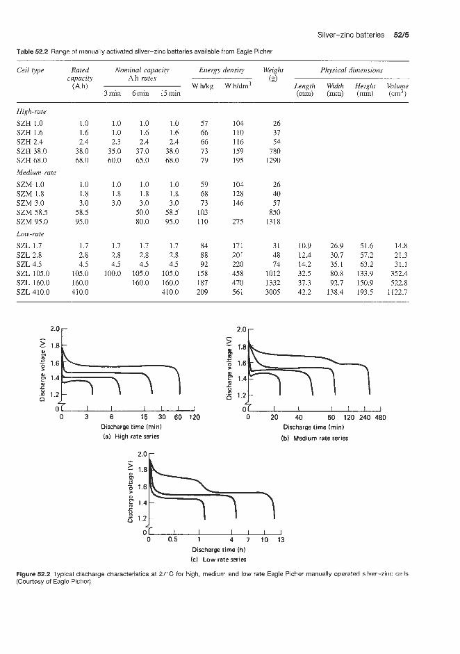
Silver-zinc batteries 52/5
Table 52.2 Range of manually activated silver-zinc batteries available from Eagle Picher
Cell type .Rated Nominal capacity Energy density Weight Physical dimensions ~ capacity A h rates (€9 Wh/kg wh/drn3 Length Width Height Volume
3min 6min 15min (mm) (mm) (m) (cm3) (Ah)
High-rate SZH 1.0 SZH 1.6 SZH 2.4 SZB 38.0 SZH 68.0 Medium-rate SZM 1.0 SZM 1.8 SZM 3.0 SZM 58.5 SZM 95.0 Low-rate SZL 1.7 SZL 2.8 SZL 4.5 SZL 105.0 SZL 160.0 SZL 410.0
1.0 1.0 1.0 1.0 57 1.6 1.0 1.6 1.6 66 2.4 2.3 2.4 2.4 66
38.0 35.0 37.0 38.0 73 68.0 60.0 65.0 68.0 79
1.0 1.0 1.0 1.0 59 1.8 1.8 1.8 1.8 68 3.0 3.0 3.0 3.0 73
58.5 50.0 58.5 103 95.0 80.0 95.0 110
1.7 1.7 1.7 1.7 84 2.8 2.8 2.8 2.8 88 4.5 4.5 4.5 4.5 92
105.0 100.0 105.0 105.0 158 160.0 160.0 160.0 187 410.0 410.0 209
104 110 116 159 195
104 128 146
275
171 20 1 220 45 8 470 561
26 37 54
780 1290
26 40 57
850 1318
31 10.9 26.9 51.6 14.8 48 12.4 30.7 57.2 21.3 74 14.2 35.1 63.2 31.1
1012 32.5 80.8 133.9 352.4 1332 37.3 92.7 150.9 522.8 3005 42.2 138.4 193.5 1122.7
I I I I I 0 3 6 15 30 80 120
Discharge time (min) (a) High rate series
2.0 r
1.8
1.6
1.4
1.2
0 f 0 20 40 60 120 240 480
Discharge time (min)
(b) Medium rate series
3 - 1.8
-$ 1.6 m u
ay 1.4
x t! 5 1.2 4
4 7 10 13 0 0.5 1
Discharge time (h) (c) Low rate series
Figure 52.2 Typical discharge characteristics at 27°C for high, medium and low rate Eagle Picher manually operated silver-zinc cells (Courtesy of Eagle Picher)

0- 2 Table 52.3 Union Carbide Eveready primary silver-zinc cells and 6 V battery 1.
8 Buttery Suggested Service Service Maximum Number and Typical use Weight Terminals Approximate Voltage number current capacity capacity dimensions (mm) size of cells of volume of taps
capacity
(in order of range (mA h) rated at buttery battery increasing (mA) (mA) Diameter Height (g) (cm3)
1.5 V batteries 384 0-0.06 35 0. 10 7.87 3.63 S312 0-5 38 1 .OO 7.87 3.56 S312E 0-5 38 1 .OO 7.87 3.56 392 0-5 38 0.10 7.87 3.56 309 0-0.1 60 0.10 7.87 5.33 SI3 0-5 15 1.07 7.87 5.33 S13E 0-5 15 1.07 7.87 5.33 393 0-5 75 0.10 7.87 5.33 301 0-0.1 100 0.10 11.60 4.06 S41 0-10 120 1.60 11.60 4.19 S41E 0-10 120 1.60 11.60 4.19 386 0- 10 120 0.25 11.60 4.19 303 0-0.24 165 0.25 11.60 5.59 S76 0-10 190 2.56 11.60 5.36 S76E 0-10 190 2.56 11.60 5.36 351 0-10 I90 0.25 11.60 5.36 355 0-10 210 0.25 15.50 4.83 6V battery 544 0-to 190 2.50 13.00 25.20
1 x 7-31141 I x 6-31141 1 x 6-31141 1 x 6-31142 1 x 7-31201
1 x 6-31201 1 x 6-31202 1 x 7-45161 1 x 6-45161 1 x 6-45161
I x 7-45215 1 x 6-45201 1 x 6-45201 I x 6-45202 I x -
1 x 6-31202
1 x 6-45163
Watches Transistor applications Hearing-aids Watches Watches Transistor applications Hearing-aids Watches Watches Microminiature lamps Hearing-aids Watches Watches Transistor applications Hearing-aids Watches Watches
4 x 6-45201 Electronic shuttcr and light meter
0.57 0.57 0.57 0.57 1.13 1.13 1.13 1.13 I .70 1.70 1.70 1.70 2.55 2.30 2.30 2.30 3.69
14.20
Flat contacts Flat contacts Flat contacts Flat contacts Flat contacts Flat contacts Flat contacts Flat contacts Flat contacts Flat contacts Flat contacts Flat contacts Flat contacts Flat contacts Flat contacts Flat contacts Flat contacts
Flat contacts
0.13 -, +1.5 0.16 -, +1.5 0.16 -, +1.5 0.16 -, +1.5 0.21 -, +1.5 0.18 -, +1.5 0.18 -, +1.5 0.18 -, +1.5 0.38 -, +1.5 0.33 -, +1.5 0.33 -, +1.5 0.33 -, +1.5 0.51 -, 11.5 0.48 -, +1.5 0.48 -, +1.5 0.48 -, +1.5 0.90 -, +1.5
2.80 -, +6
~
To provide thc best contact to thc terminals of silvcr oxidc batteries, it is recommended that the device contacts he made of a spring material such as phosphor bronze or beryllium copper, which will maintain a contact force of at least 50 g for an extended period of time. The contacts should be plated with about 50.8 pm nickel (continuous) followed by a minimum ol' 5.08 pm gold. The reliability of the contact can be further increased by subdividing the main contact member into two, three or more individual points or prongs snch as the tines of a fork

Table 52.4 Union Carbide Eveready silver-zinc cells
Eveready Voltage type No. (V)
544 (four 6.0 6-45201 cells) 355
357
S76E ana ,576 303
386
SHE and S41
SH301
393
S13E and S13
309
392
S312E and S312 384
1 .5
1.5
1.5
1.5
1.5
1.5
1.5
1 .5
1 .5
1.5
I .5
1 .5
1 .5
Suggested Designation Average current service range ANSI IEC capucity (mA) (mA h)
- 190 to 3.6V 0 to I O -
rated at 2.5mA 0 to 10 - - 210 to 1.3V at
6500 Q
0 to 10 - SR44 190 to 0.9V at 6500 S2
rated at 2.56 mA
6500 Q
0 to 10 515 - 190 to 0.9V
0 to 0.24 WS16 SR47 16.5 to 1.3V at
0 to 10 WSlO SR43 120 to 0.9V at
0 to 10 S10 ~ 120 to 0.9V 6500 0
rated at I .6 mA
0 to 100 WSlO SR43 100 to 1.3V at 15 000 n
0 to 5 WS5 - 75 to 0.9V at
0 to 5 S5 SR48 75 to 0.9V 15000n
rated at 1.07 mA
0 to 0.1 WS5 SR48 60 to 1.3V at 15 000 n
0 to 5 - SR41 38 to 0.9V at 15 000 n
0 to 5 S4 SR41 38 to0.9V rated at 1 mA
0 to 0.06 - SR41 35 to 1.3V at 15 000 n
Schedule Starting Load Cut-off (May) drain (n) voltage
(VI
Estimated average Impedance sewicp at 35°C (or 21°C $stated)
24 246 pA 6500 0.9 1.3
24 246 pA 6500 1.3
16 1.6 mA 1000 1.3 16 2.5 mA 625 1.3 24 17 pA 94000 0.9
17 pA 94000 1.3 24 246 pA 6500 0.9
246 pA 6500 1.3 24 2 4 0 d 6500 1.3
16 1.6 mA 100 1.3 16 2.56 mA 625 1.3
24 10.6 pA 150000 0.9 10.6 pA 150000 1.3
24 107 pA 15000 0.9 107 pA 15000 1.3
24 104 LLA 15000 1.3
16 1.07 mA 1.500 1.3 16 1.6 mA 1000 1.3
24 107 pA 15000 1.3 5.9 uA 270000 1.3
24 104 LA 15000 1.3
16 1.0 mA IS00 1.3 1.5 mA 1000 1.3
24 104 pA 15000 0.9 104 pA 15000 1.3 3.1 pA 500000 0.9 3.1 pA 500000 1.3
60 (21°C)
915 905 810
Less than 4 Q on open circuit at 1OOOHz
80 (21°C) 3-12Q over 40-5000Ez 117 (21°C) 13 months
12.8 months 700 685 510
at current drains quoted
80 (21°C) 50 (21°C)
Opcn circuit 3- 12 Q over 40-5000 Hz at current drains quoted
12.5 months estimated 12 months estimated
10.50 1000 725
74 (21°C) 52 (21°C)
Open circuit 8-20 S2 over 40-5000 Hz at current drains quoted
600 Approximate open- SL! - 14 months estimated circuit impedance at C
lOOOHz, 35 C2 4 E. 370 3
38 (21°C) 22 (21°C)
370 360 -
Open circuit at 1000Hz, ' approximately 65 0 e
4 15 months estimated

52/8 Silver batteries
Table 52.5 Mallory Duracell silver-zinc cells and 6 V battery
Nominal Nominal Type Maximum Maximum Weight voltage capacity diameter height (g)
(VI (mA h) (mm) (-)
1.50 1.50 1.50 1.50 1.50 1.50 1.50 1.50 1 .50 1.50 1.50 1.50 1.50 1.50 6.00
36' 38' 10' 70' 15' 83* 85'
115* 120' 120'
180' 200* 250' 180
MS312H 10L125 10L122 MS13H 10L123 ws12 10L120 WSll 10L124 MS41H 1OL14 MS76H WS14 10L129 PX28
1.15 1.15
11.56 7.75 1.15
11.56 11.56 11.56 11.56 11.56 11.56 11.56 11.56 15.49 12.95
3.56 3.58 2.19 5.33 5.33 3.43 3.48 4.19 4.19 4.07 5.33 5.33 5.59 4.83
25.2
0.57 0.8 1 .0 1 .o 1 .0 1.4 1.3 1 .I 1.7 2.0 2.2 2.9 2.2 3.5
11.0
* Low-rate cell 10L125, 10L123, 10L120, 10L124, 10L129, 10L14 all for low-rate applications requiring high-rate pulses on demand
1.7-
m 1.5 mA 1.0mA c - 10003 150OD
z 1.2 > 1000 n
0.9 - 1 .o
I I 1 1 I I Service time (h) 0.7 (C)
2 l.l 0 10 20 30 40 50 60 70 80
0 10 20 30 40 50 60 (a) Service time (h)
1.6 mA 8 1.2 625 D 1000 51
1 .o 1 .o 0 20 40 60 80 100 120 0 20 40 60 80 100 120 140
(b) Service time (h) (d) Service time (h)
Figure 52.3 Union Carbide silver-zinc cell voltage discharge curves. Estimated hours of service at 21 "C against voltage at stated starting drains (average drains in (a)) and loads and on a 16 h/day schedule. (a) S312 and S312E, 38 rnAh to 0.9V, rated at 1 rnA; (b) 541 and S41E, 120rnAhto0,9V,ratedat 1.6rnA;(c) S13EandS1375mAhto0.9V, ratedat 1.07rnA;(d)S76E190rnAhto0.9V, ratedat2.56rnA (Courtesy of Union Carbide)
Vurtu
Varta produce a range of 1.55V silver-zinc cells in the capacity range 45-l75mAh and a 6 V battery of capacity 170mAh (Table 52.7). These are used mainly in calculators, hearing-aids and photographic applications.
Varta also produce a range of 1.5 V low-drain sil- ver-zinc cells for electric and electronic watches with analogue or LCD display; these are in the capacity range 50-180mAh (Table 52.8).
Varta produce 1.5 V high-drain silver-zinc cells in the 38-190mAh capacity range for use in solid-state watches with LED or LCD display with backlight (Table 52.9).
Yuusa
Yuasa also supply button design and cylindrical primary and rechargeable silver-zinc cells and batter- ies. Data in their range of 1.5 V watch cells are quoted in Table 52.10 and data on batteries of up to 9 V are
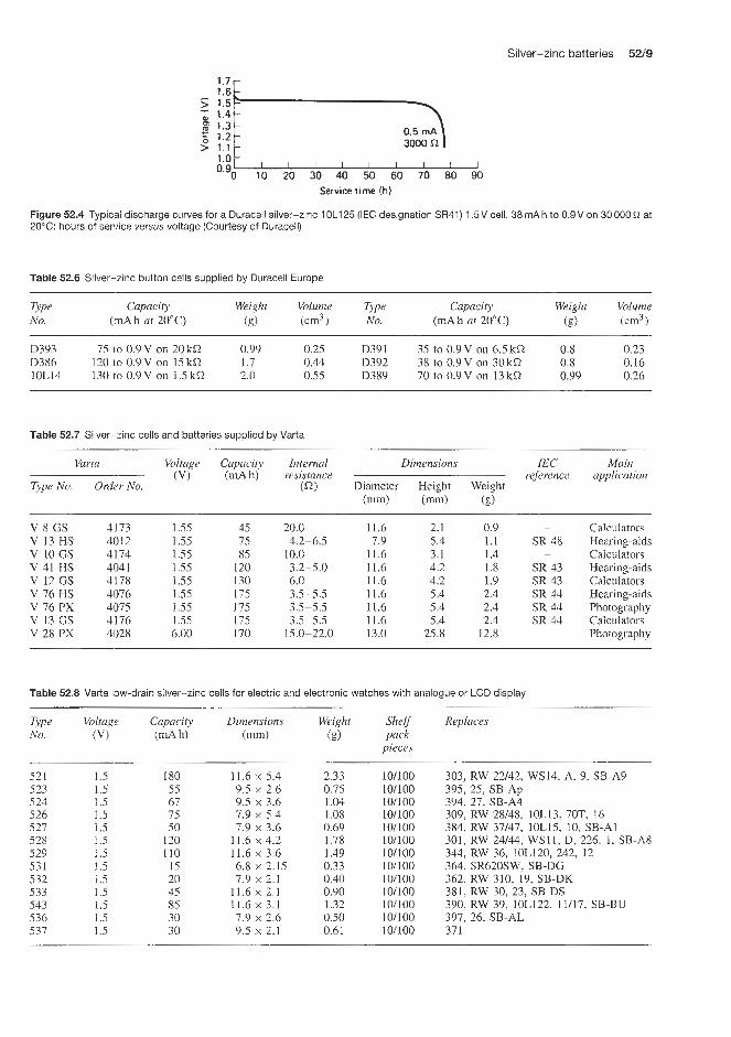
Silver-zinc batteries 5Z9
1.7r 1.6 1.5 1.4 1.3 1.2 1 1 i ;o t - , , I I , , I I ~
10 20 30 40 50 60 70 EO 90 0.go
Service time Ih)
Figure 52.4 Typical discharge curves for a Duracell silver-zinc 1OL125 (IEC designation SR41) 1 . 5 V cell, 38 rnA h to 0.9V on 30 000 20°C: hours of sepiice versus voltage (Courtesy of Duracell)
at
Table 52.6 Silver-zinc button cells supplied by Duracell Europe
Type Capacity Weight Volume Type Capacity Weight Volume No. (mA h at 20°C) (g) (cm3 No. (mA h at 20°C) (g) (cm3)
D393 75 I O 0.9V on 20kQ 0.99 0.25 D391 35 to 0.9V on 6SkQ 0 8 0.23 D386 120 lo 0.9V on 15kQ 1.7 0.44 D392 38 to 0.9V on 30kQ 0 8 0.16 10L14 130 LO 0.9V on 1.5kQ 2.0 0.55 D389 70 to 0.9V on 13 kQ 0.99 0.26
Table 52.7 Silver-zinc cells and batteries supplied by Varta
Varta Voltage Capacity Internal Dimensions IEC Main (V) (mA h) resistance reference application
Type No. Qrd<?r No. (Q) Diameter Height Weight (mm) (mm) (g)
V 8 GS V 13 HS v 10 GS V 41 HS V 12 GS V 76 HS V 76 PX V 13 GS V 28 PX
4173 1.55 4012 1.55 4174 1.55 404 1 1.55 4178 1.55 4076 1.55 4075 1.55 4176 1.55 4028 6.00
45 75 85
120 130 175 175 175 170
20.0 4.2-6.5
10.0 3.2-5.0 6.0 3.5-5.5 3.5-5.5 3.5-5.5
15.0-22.0
11.6 2.1 0.9 7.9 5.4 1.1
11.6 3.1 1.4 11.6 4.2 1.8 11.6 4.2 1.9 11.6 5.4 2.4 11.6 5.4 2.4 11.6 5.4 2.4 13.0 25.8 12.8
-
SR 48
SR 43 SR 43 SR 44 SR 44 SR 44
-
-
Calculators Hearing-aids Calculators Hearing-aids Calculators Hearing-aids Photography Calculators Photography
Table 52.8 Varta low-drain silver-zinc cells for electric and electronic watches with analogue or LCD display
Type Voltage Capaciv Dimensions Weight SheEf Replaces No. (VI (mA h) (mm) (g) pack
pieces
521 523 524 526 527 528 529 531 532 533 543 536 537
1.5 1.5 1.5 1.5 1.5 1 .5 1.5 1.5 1 .5 I .5 1.5 1.5 1.5
180 55 67 75 50
120 110 15 20 45 85 30 30
11.6 x 5.4 2.33 9.5 x 2.6 0.75 9.5 x 3.6 1.04 7.9 x 5.4 1 .os 7.9 x 3.6 0.69
11.6 x 4.2 1.18 11.6 x 3.6 1.49 6.8 x 2.15 0.33 7.9 x 2.1 0.40
11.6 x 2.1 0.90 11.6 x 3.1 1.32 7.9 x 2.6 0.50 9.5 x 2.1 0.61
101100 101100 101100 101100 101100 101100 10/100 10/100 10/100 101100 101100 101100 101100
303, RW 22142, WS14, A, 9, SB-A9 395, 25, SB-Ap 394. 27, SB-A4 309. RW 28/48, 10L13, 70T, 16 384. RW 37/47, 10L15, 10, SB-A1
344, RW 36, 10L120, 242, 12 301. RW 24144, WS11, D, 226. 1, SB-A8
364. SR620SW, SB-DG 362, RW 310, 19, SB-DK
390, RW 39, 10L122, 11/17, SB-BU 397, 26, SB-AL
381, RW 30, 23, SB-DS
37 1

52/10 Silver batteries
Table 52.9 Varta silver-zinc high-drain cells for solid-state watches with LED or LCD display
Type No.
54 1 546 547 548 549 553 554
Dimensions (m)
Weight Shelf (g) pack
pieces
Replaces
1.5 190 1.5 75 1.5 38 1.5 130 1.5 100 1.5 45 1.5 85
11.6 x 5.4 7.9 x 5.4 7.9 x 3.6
11.6 x 4.2 11.6 x 3.6 11.6 x 2.1 11.6 x 3.1
2.33 10/100 1 .os 10/100 0.69 10/100 1.78 10/100 1.40 10/100 0.90 10/100 1.32 10/100
357, RW 22/42, 10L14, J, 228, 7, SB-B9 393, RW 28/48, 10L123, F, 255, 15 392, RW 27/47, 10L125, K, 247, 2, SB-B1 386, RW 24/44, 10L124, H, 260, 6, SB-B8 10L120, 14 391, RW 40, lOL130, 31, SB-BS 189, RW 49, 10L122, 17, SB-BU
Service at 20 "C (h)
Figure 52.5 Yuasa silver-zinc cells: hours of service at 20°C versus voltage for various 1.5V cells (Y301, Y384, Y386, Y392) and a 9V battery (Y76) (Courtesy of Yuasa)
Table 52.10 Yuasa 1.5V watch silver-zinc cells
Number Voltage Current Starting Cut-off Capacity Diameter Height Weight (VI range drain voltage (mA h) (mm) (m) (g)
(mA) (mA) (VI
Y384 G33 Y392 G3 Y309 G55 Y393 G5 Y301 G12 Y386 G12 Y303 G514 Y357 G13 Y389
1.5 1.5 1.5 1.5 1.5 1.5 1.5 1.5 1.5
0.1 5.0 0.2 5.0 0.25
10.0 0.5
10.0 0.25
0.06 0.1 0.1 0.1 0.1 0.23 0.23 0.23 0.1
1.3 1.3 1.3 1.3 1.3 1.3 1.3 1.3 1.3
35 38 60 75
100 120 165 190 70
7.9 7.9 7.9
11.6 11.6 11.6 11.6 11.6 11.6
3.6 3.6 5.4 5.4 4.2 4.2 5.6 5.4 3.0
0.7 0.7 1.1 1.1 1.7 l.? 2.? 2.? l .?
Table 52.11 Yuasa 1.5-9V silver-zinc cells and batteries
Number Voltage Current Starting Cut-off Capacity Diameter Height Weight (VI range drain voltage (d h) (mm) (mm) (g)
( U P to (d) (VI d)
Y312 1.5 5.0 1 .o 0.9 38 7.9 3.6 0.7
Y41 G12 1.5 10.0 1.6 0.9 120 11.6 4.2 1.7 Y76 G13 1.5 25.0 2.5 0.9 190 1.6 5.4 2.5 Y542 2G13 3.0 25.0 2.5 1.8 190 12.9 14.7 6.5
6Y76 6G13 9.0 25.0 2.5 5.4 190 13.4 34.7 17.5
Y13 G5 1.5 5.0 1 .o 0.9 75 7.9 5.4 1.1
Y544 4G13 6.0 25.0 2.5 3.6 190 12.9 24.8 12.1

Silver-zinc batteries 52/11
quoted in Table 52.11. Service life data on Yuasa cells and batteries prlesented in Figures 52.5 and 52.6 show the effect of ambient temperature on percentage capa- city retention of Yuasa silver-zinc cells and batteries.
Other suppliers
Other manufacturers' products equivalent to some of the Mallory silver-zinc Duracell range are quoted in Table 52.12. A recent compilation of suppliers of primary mono- valent silver oxide-zinc and divalant silver oxide- zinc cells for watch and calculator applications is given below,
Country Company Capacity range available (mA h)
Japan
USA/Europe
Seiko
Maxell
Toshiba
Panasonic
Sony
Rayovac (US) Eveready (US) Duracell (Europe) Wenata (Switzerland) Varta (Germany)
9.5-16.5 low rate 24- 180 high rate 5.5-165 low rate 26-165 high rate 7.5-160 low rate 24- 160 high rate 10-170 low rate 25 - 180 high rate 11.5-165 low rate 24-85 high rate 317-397 low rate 361-399 high rate 317-395 low rate 361-399 high rate 301-751 low rate 386-399 high rate 5-110 low rate 45-110 high rate 8 - 160 low rate 18-55 high rate
52.1.2 Remotely activated silver oxide-zinc batteries Silver-zinc primary batteries can be remotely activ- ated for single use within seconds or fractions of a second even afi:er long-term storage, by inserting the electrolyte under pressure. In addition to a unit contain- ing dry charged plates they also contain an electrolyte vessel from which the cells are filled by electrical or mechanical means. Pile batteries are a new develop- ment of remotely activated primary batteries, which consist of bipolar electrodes that confer a very high density on the battery. Such batteries are available from Silberkraft (Table 52.13) and are recommended
120 r
I I 1 I
-20 0 20 40 60 Temperature ("C)
Figure 52.6 Effect of temperature on percentage capacity reten- tion of Yuasa silver-zinc cells and batteries: (a) 1.5V, 35 mAh cell on 6.5 kO load; (b) 9 V, 190 mA h battery on 100 R load (Courtesy of Yuasa)
for use in aerospace, torpedoes and pyrotechnic igni- tion applications.
Eagle Picher also supply remotely activated primary silver-zinc batteries. In this cell design a vented sys- tem enhances the rapid clearing of the manifold and eliminates excessive intercell leakage paths. The bat- tery has no moving parts. It has an extended shelf life. It can be activated directly into a load or in parallel with a mains system. The open-circuit volt- age of this battery is 1.6-1.87V with a working voltage of 1.20- 1.55 V. The battery operating tem- perature is -29 to +71"C, and, with water assis- tance, -48 to f71"C. Unnts are available in the weight range 0.14-135 kg. Typical performance pro- files at 27°C for the Eagle Picher remotely activ- ated battery are shown in Figure 52.7. The dry stor- age charge retention characteristics of this battery are excellent.
Eagle Picher supply gas-generating pyrotechnic devices, which can be used for the activation of remotely activated batteries by transferring electrolyte from a reservoir to the battery cells. Eagle Picher have developed over 70 gas-generator configurations with capabilities ranging from 20 to 200 000 cm3 (standard condition gas output), many of which have been used in a majority of missile/spacecraft systems.
The Chloride of Silver Dry Cell Battery Co. of Baltimore supply a silver-zinc battery with a mild acid electrolyte containing silver chloride as a depol- arizer. This battery is recommended as a power unit in test instruments such as blasting galvanometers, circuit testers, volt-ohmmeters and clocks. Multi-cell batteries for B-voltages and bias are available for use in elec- tronic circuits, electromedical instruments and other specialized low-drain uses where constant voltage and open life are important. The battery has an open-circuit voltage of 1.05 V. Under load, termind voltage drops in proportion to load, but holds constant throughout

Table 52.12 Equivalents in silver-zinc cells
Duracell System Nominul Nominal Height Diameter IEC National Ray-o-Vuc Ucur varta (Mallory) voltage capacily (mm) (mm)
(VI (mA h)
WSl l WS12 10L14 10L120 10L122 10L123
10L124 1OL125
IOL129
WS14 MS76H MS13H MS41H
Silver oxide Silver oxide Silver oxide Silver oxide Silver oxidc Silver oxide
Silver oxide Silver oxide
Silver oxide
Silver oxide Silver oxide Silver oxide Silver oxide
1.5 1.5 1.5 1 .5 1 .5 1.5
1.5 1.5
1 .5
1.5 1.5 1.5 1.5
1 I5 83
85 70 75
120 38
250
-
200 180 I0
120
4.19 3.43 5.33 3.48 2.79 5.33
4.19 3.58
4.83
5.59
11.56 11.56 11.56 1 1.56 11.56 1.15
11.56 1.75
15.49
11.56
SR43 WSll RW14. RW34
SR44 wL14 RW22, RW42
SR48 WS6 RWl 8, RW28 RW28, RW48
SR43 WLI 1 RW24, RW44 SR4 1 WSllWLl RW27, RW37
RW41 RW15, RW25 RW35
WS14 RWI 2, RW32
301 528 529
351 541 549
309, 393 546
386 548 384, 392 521, 547
355
303 EPX I1 521 1301 7306 7308

Silver-zinc batteries 52/13
Table 52.13 Rerriotely activated primary silver-zinc batteries (Silberkraft)
Voltage Discharge Discharge Weight Volume (VI current time (kg) (Crn3)
(fin)
Torpedo battev
150PA/110/ 20PA/29 I16PA/60/ 20PA/7 150PA 120
Rockets and missiles
21PA9 20PA3, 514 PA3, 5 22PA30
Pyrotechnic ignition andfuse battery
21PAB0, 19LS
210.0 28.0
156.0 28.0
210.0
30.5 33.6 31.5
30.0
480 40
480 40
480
35 30
260
1.5
13 400 285.0 45
6.5 196 124.3 25 13 399 265.0
5 14.5 9.5 3 5.6 2.9 5 33.0 21.5
0.18 0.042 0.02
the useful section of the discharge curve. Shelf life is several times longer than that of ordinary dry cells at room temperalhre. However, tlie cells should not be stored below C I T . Shelf life is 6 months under correct storage condit:ions and this may be extended by cold storage.
0 15 30 1 5 10 15' +-------5 - min 4
(b) For wet stand
Figure 52.7 Eagle Picher remotely activated primary silver-zinc battery: typical performance profile at 27'C (Courtesy of Eagle Picher)
52.1.3 Secondary batteries
Yardney
The extremely low internal resistance of silver-zinc batteries permits discharges at rates as high as 30 times the ampere hour capacity rating, and its flat voltage characteristic enables highest operational efficiency and dependability. Cells have been built with capacity ranging from 0.1 to 20000Ah. A recent advance using new separators patented by Yardney enabled their silver-zinc batteries to provide more than 400 cycles in special applications.
Yardney standard rechargeable silver-zinc batteries are available in two types; as a high-rate unit for applications where total energy must be delivered within 1 h, and as a low-rate unit where discharge rates are lower and are required for longer time periods.
The cells are leakproof and spillproof. The assem- bled cells can be enclosed in sturdy lightweight cases for special mechanical and environmental conditions. Batteries can also be designed and built to meet the most stringent requirements.
The data below indicate, in brief, the performance capabilities achieved with existing models of Yardney Silvercels showing the requirements which can be met.
1. Vibration 30-40 sinusoidal vibration. 2. Random Gaussian vibration 5-2000Hz band,
with as high as 60g r.m.s. equivalent in both non-operational and operational conditions: hard mounted unit.
3. Shock 4. Acceleration
Tested up to 200g in all directions. l00g in all directions of sustained
acceleration, except in the direction of the vent for vented cell systems.
From f70 to -50°C and repeated, with stabilization occurring at each temperature.
5. Thermal shock

52/14 Silver batteries
6. Altitude Successful activation and operation at a simulated altitude of 60km for a period of 1 h without pressurization; with pressurization there is no limit.
The electrical characteristics of the full available range of 1.45-1.5V Silvercels are given in Table 52.14 (low rate) and Table 52.15 (high rate). It will be noted that high-rate Silvercels are available in the capacity range 0.1-200Ah and the low- rate versions in the range 0.5-525 Ah. High-rate cells are recommended where requirements demand maximum energy density and voltage regulation at high discharge rates through a cycle life period of 4-6 months. Low-rate cells are recommended where requirements demand maximum energy density and voltage regulation at low discharge rates through a cycle life period of 6-18 months.
Figure 52.8 shows the effect of discharge rate in terms of C nominal 1 h discharge rate on energy per unit weight and energy per unit volume for Sil- vercels in the 0.1-300 A h capacity range. The distinct improvement in the energy per unit weight or volume of silver-zinc over nickel-cadmium, nickel-iron and lead-acid battery systems is very apparent.
Figure 52.9 shows the charging curve for both types of Silvercel. Figure 52.10 shows the typical effect of
2 1.4-
J 1.0
0.6 0.4 0.2
8 1.2
5 0.8 -
132 n Nickel-cadmium (max.)
- - - - -
L 1 I 1 I ' I ' 1 1 I ' I 1 l I I I 1 1 l l -
w i c k e l - i r o n (max.) Lead-acid (max.1
c 22---
I ~ ~-
I I I I I I 0 C 2C 3C 4C 5C 6C
Discharge rate
(a 1
305
5 244
2 183
- rn
8
z c .- E 122 'c1 > p 61 m E W
Nickel-cadmium (max;)
Nickel-iron (max.) Lead-acid (max
0 C 2C 3C 4C 5C 6C Discharge rate
(bl
Figure 52.8 Effect of discharge rate on energy output: Yardney Silvercel rechargeable silver-zinc battery (m21-300A h capa- city, m0.1-20Ah capacity) compared with other battery types (Courtesy of Yardney)
10 h rate
20 min rate
10 min rate
-20 -10 0 10 20 30 Temperature ("C)
Figure 52.10 Effect of battery temperature on energy per unit volume for a Yardney Silvercel rechargeable silver-zinc battery operated without heaters (Courtesy of Yardney)
temperature on the energy obtained per unit weight for Silvercels operated without heaters. As would be expected, energy per unit weight decreases somewhat with a lowering of battery temperature.
Yardney also supply modular battery packs of Sil- vercels; the Silvercel Pac. These are available in nom- inal capacities between 3 and 80Ah (Table 52.16). These batteries are between 2.8 and 15.8V and have equivalent energy densities of about 100 W f i g , which exceeds the energy of a nickel-cadmium battery by four times and a lead-acid battery by five times. The silver-zinc batteries are, of course, more expensive than nickel-cadmium or lead-acid batteries, but for many applications the space and weight savings they offer would make them a very attractive alternative.
Silberkraj?
Silberkraft manufacture silver-zinc cells and bat- teries in West Germany under licence to Yardney. They offer a range of silver-zinc cells and bat- teries in the capacity range 0.1-750Ah, covering

Table 52.14 Characteristics of low-rate Yardney silver-zinc cells
Cell Nominal Charging Typical application data (at 21°C) Max. Overall Overall Height Width Depth Terminal type capacity rate filled volume height less (mm) (mm) threads
(Ah) (A) 10h rate discharge I h rate discharge weight (1m3) (im) terminals (6) (mn)
Discharge Ah Average Power; Power; Discharge k h Average rate output* voltage weight volume rate output* voltage (A) (V) ratio ratio' (A) (VI
(ww4 ( W W h 3 )
LR-05
LR-2
LR-4 LR-5 LR-10 LR-15
LR-2L LR-40 LR-58
LR- 1
LR-3
LR-20
LR-60 LR-70 LR-90 LR- 100 LR- 130
LR-525 LR-200
0.5 0.05 1 0.07 2 0.15 3 0.20 4 0.30 5 0.30
10 0.50 15 1 .OO 20 1.50 20 1.50 40 2.00 60 2.50 60 3.00 70 4.00 90 4.00
I00 4.00 130 5.00 200 8.00 525 30.00
0.05 0.10 0.20 0.30 0.40 0.50 1 .OO 1.50 2.00 2.00 4.00 6.00 6.00 7.00 9.00
10.00 13.00 20.00 60.00
1 .o 2.0 3.6 4.0 6.0 7.5
13.0 20.0 30.0 30.0 46.0 90.0 75.0 80.0
145.0 110.0 170.0 225.0 640.0
I .50 66 1.50 95 1.52 84 1.50 70 1.53 90 1 .52 88 1.50 84 1.52 107 1.50 112 1.53 103 1.52 108 1.52 145 1.52 121 1.50 106 1.52 134 1.51 132 1.52 145 1.50 119 1.52 95
102 1 50 126 126 168 134 134 I98 180 198 186 264 204 242 246 216 288 252 198
0.5 0.75 1.38 1.0 1.75 1.35 2.0 3.00 1.50 3.0 3.50 1.46 4.0 5.00 1.46 5.0 6.50 1.44
10.0 12.0 1.44 15.0 18.0 1.40 20.0 25.0 1.40 20.0 27.0 1.43 40.0 43.0 1.40 60.0 80.0 1.40 60.0 55.0 1.36 70.0 70.0 1.36 90.0 135.0 1.45
100.0 100.0 1.40 130.0 150.0 1.34 200.0 210.0 1.36
Do not discharge at I h rate
22 31 64 84
101 126 230 280 392 434 644 890 812
1120 1599 I232 1758 2940
10080
14.9 19.3 42.0 47.5 54.2 78.4
135.5 149.7 249.3 228.0 374.0 490.0 475.0 526.0 815.0 756.0 882.0
1341 .O 4854.0
39.6 51.3 64.2 72.6 85.3 73.9
122.0 125.0 109.0 191.0 180.0 184.0 114.0 159.0 179.0 102.0 166.0 278.0 428.0
30.5 42.9 54.8 63.2 76.2 63.2
109.0 107.0 92.4
174.0 162.0 161.0 98.0
141.0 162.0 113.0 149.0 257.0 393.0
27.4 13.7 5-40 274 13.7 5-40
43.7 15.0 10-32
52.8 20.0 10-32 58.9 18.8 114.28 58.7 20.3 5/16.24 52.0 43.9 Y16.24 58.4 20.3 5/16.24 82.5 25.1 5A6.24 82.5 32.2 U4.28 69.3 59.9 5h6.24 92.4 35.8 Y16.24 82.8 54.8 5/16.24 87.3 70.6 5116.24 83.2 63.5 7/16.20
106.0 45.4 7/16.20 106.0 106.0 3/4.16
43.7 15.0 10-32
43.7 15.0 10-32
* To a final voltage of 1. I V Calculated using overall volume

(I, T 4 % 3. W
rr
Table 52.15 Characteristics of high rate Yardney silvered zinc cells
Cell Nominal Charging Typical application dum (ai 21°C) Mu. Overall Overall Height Width Ueplh Terminal type capacity rate filled volume height less (mm) (mm) th7ead.r
weight (mm3) (mm) fer- (Ah) (A) 60 min rate disrharge 20 mm rate discharge IOmin rate discharge (SI X l O l minals
Discharge A h Averuge Power/ Puwer/ Discharge A h Average Time Discharge A h Average Time (iiun) rate outpuP vultuge weight volume rute uutput voltujie limif' rute output vultrige limit' (A) (V) mtiu rnfiut (A) (VI (ncIC (A) (V)
(W hkg) (W hldm?)
FIR-OI HR-02 HR-05 HR-I HF-1.5 HF-2 m - 3 HR-4 HR-5 HR- 10 HR- 1 5 HR- 18 HR-21 1%-40 HR-58 HR-60
HR 80 HR-85 HR-90 NR-I00 HR-140 HK-160 HR-200
m - 7 n
0. I 0.2 0.5 1 .O 1.5 2.0 3.0 4.0 5.0
10.0 15.0 18.0 21.0 40.0 60.0 60.0 70.0 80.0 85.0 90.0
100.0 140.0 160.0 200.0
0.01 0.02 0.07 0.10 0.15 0.20 0.30 0.30 0.35 0.75 1 .oo 2.00 2.00 3.00 4.00 4.00
6.00 6.00 6.00 6.00
10.00 10.00 10.00
4.50
0.1 0.2 0.5 1 .o I .5 2.0 3.0 4.0 5.0
10.0 15.0 18.0 20.0 40.0 60.0 60.0 70.0 80.0
100.0 90.0
100.0 140.0 160.0 100.0
0.175 0.22 1.30 1.75 2.50 3.30 5.00 6.00 7.50
12.00 18.50 20.00 30.00
75.00 74.00 75.00 95.00
120.00 110.00 100.00 180.00 200.00 290.00
49.00
1.45 55 1.48 50 1.50 86
1.50 95 1.51 73 1.50 84 1.50 86 1.42 81 1.44 75 1.48 97 1.48 79 1.50 101 1.45 90 1.48 123 1.47 117 1.45 97 1.50 110 1.48 108
1.46 114 1.45 114 1.45 150 1.47 143
1.x 84
1.m 108
78 72
126 132 I62 114 156 162 132 126 180 130 192 1 86 222 228 204 204 202 19R I92 234 312 312
0.3 0.6 1.5 3.0 4.5 6.0 9.0
12.0 15.0 30.0 45.0 55.0 60.0
120.0 180.0 180.0 210.0 240.0 300.0
300 0 420.0 480.0 200.0
270.0
0.15 0.21 1.10 I .60 2.00 3.00 4.70 5.40 5.90
10.50 16.50 18 00 27.00 43.50 55 00 61.00
70.0C 97.00
l00.00
155.00
250.00
62.110
93 no
170.00
1.40 16 I35 15 1.45 20
I40 20 1.46 20 1.46 20 1.49 20 1.36 20 1.33 18 1.44 15 140 15 1.44 17 1.36 18 1.36 12 1.39 12 1.35 14 1.38 10 1.40 12 1.42 12 141 15 1.35 10
1.40 60
1.44 20
1.32 20
0.6 1.2 3.0
9.0 12.0 18.0 24.0 30.0 60.0 90.0
100.0 120.0 240.0 360.0 360.0 420.0 480.0 600.0 540.0 600.0 840
380.0
6.n
6nn.n
0.12 0.17 0.94
1.50 2.40 4.20 4.80 5.20 8.00
13.00 16.00 23.00 39.00 40.00 46.00 52.00 60.00 80.00 90.00 90.00
110.00 140.00 170.00
I .4n
1.32 6 1.25 5 1.35 8 1.35 8 1.32 8 1.40 8 1.37 8 1.40 8 1.26 6 1.26 5 1.30 5 1.30 5 1.34 6 1.20 5 1.21 5 1.28 5 1.81 5 1.25 4 1.30 5 1.29 5 1.20 6 1.20 5 1.26 10 1.25 20
4.54 6.53
22.7 31.2 39.8 68.1 90.9
105.1 130.6 232.9 284.0 372.0 440.2 7 10.0 903.1 937.2
1136.0 1363.0 1647.0 1534.0 1278.0 2272.0
2982.0 19si.n
3.11 4.43
14.70 19.30 22.10 42.00 47.50 54.30 78.40
149.70 249.30 228.00 373.90 4YO.O 476.8 526.4 685.5 187.0 815.1 756.0
1102.0 912.0
1341.0
135.40
35.0 4Y .2 37.6 51.3 58.9 64.2 72.6 85.3 73.9
125.5 178.0 171.0 180.0 184.0 114.0 159.0 216.0 240.0 179.0 122.0 183.0 164.0 278.0
122.0
30.5 42.9 30.5 42.9 50.3 54.9 63.2 72.6 63.2
109.0 107.0 159.0 174.0 162.0 161.0 98.0
141.0 198.0 220.0 162.0 113.0 167.0 148.0 257.0
16.0 5.6 16.0 5.6 27.4 13.7 27.4 13.7 27.4 13.7 43.7 15.0
43.7 15.0 52.8 20.0 58.9 18.8 58.7 20.3 53.8 20.6 58.4 20.3 82.5 25.1 82.5 32.2 69.3 59.9 92.4 71.4 71.4 44.4 71.4 46.0 82.8 54.8 87.3 70.6 82.5 72.4 75.4 73.4
106.0 45.4
43.7 15.0
1-72 1-72 5-40 5-40 5-40 10-32 10-32 10-32 10-32 114.28 511 6.24 5116.24 5116.24 511 6.24 7116.24 5116.24 5116.24 318.24 318.24 5116.24 5116.24 7116.24 318.24 318.24
* To a final voltage of 1.1 V
* Calculaied using maximum vulume Fur a maximurn recyclability, observe discharge lime specilicd in ballery inslruclioiis
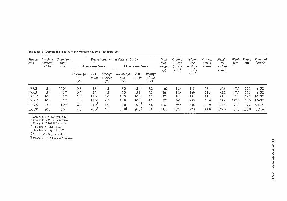
Table 52.16 Characteristics of Yardney Modular Silvercel Pac batteries
Module Nominal Charging Typical application data (at 21°C) Max. Overall Volume Overall Height Width Depth Terminal type capacity rute filled volume less height less (mm) (mm) threads
(Ah) ('4) 10 h rate discharge 1 h rate discharge weight (mm3) lerminals (mm) terminals (g) x103 (mm3) (mm)
Discharge A h Average Discharge Ah Average x 103 rate output voltage rute output voltuge (A) (VI (A) (VI
LR3/3 3.0 15.0* 0.3 3.31 4.5 3.0 3.0t 4.2 162 129 118 73.1 66.8 47.5 37.3 6-32 LR3/5 5.0 0.25* 0.5 5.5-1 4.5 5.0 5.1.1 4.3 261 180 169 101.5 95.2 47.5 37.3 6-32 LR2/10 10.0 0.5** 1.0 11.03 3.0 10.0 10.0+ 2.8 284 144 134 101.5 93.4 42.9 33.3 10-32 LR3110 10.0 OS** 1.0 11.0-1 4.5 10.0 10.O.l- 4.2 528 261 239 99.0 91.4 142.0 20.3 10-32 LR4122 22.0 1.0*** 2.0 24.0s 6.0 22.0 20.05 5.6 1181 590 558 110.0 101.5 71.1 77.2 3/4.28 LR4180 80.0 6.0 8.0 90.03 6.1 55.04[ 80.03 5.8 4317 2074 270 181.0 167.0 84.3 136.0 5/16.24
* Charge to 5.9-6.0V/module ** Charge to 3.95-4.0 V/module
*** Chargc to 7.9-8.0V/module To a filial voltage of 3.3 V
+ To a final voltagc of 2.2V 5 TO a final voltage of 4 . 4 ~ 3 Dischargc for 85 min at 55 A rate

52/18 Silver batteries
Table 52.17 Characteristics of Silberkraft secondary silver-zinc cells and batteries meeting NATO Standard VG No. 95284
Nominal Nominal Filled capacity voltage weight
(Ah) (VI (kg)
Length (mm)
Width (mm)
Height (mm)
For propulsion batteries for submarines, tolpedoes, combat vehicles, rockets, emergency power supplied for radio transmitters
02100 SHV 20 1.5 0.380 04200 SHV 40 1.5 0.770 6500 SHU 60 1.5 1.005 09000 SHU 90 1.5 1.540 012000 SHU 120 1.5 1.860 HR 36DC 36 1.5 0.890
Propulsion battery for torpedo U/K 53 90 90.0 125.000
80 80 80 83 80 82
162
85 35 35 55 68 32
406
90 178 184 179 184 152
402
Table 52.18 Characteristics of Silberkraft standard secondary silver-zinc cells
Type Nominal capacity
(Ah)
Mean discharge
(VI
Charging current
(A)
Weight Length jilled (mm)
(g)
Width (mm)
Height including terminals
(mm)
050 S 050 SHV 0100 s 0100 SHV 0300 S 0300 SHV 0500 S 0500 SHV 0700 S 0700 SHV 0800 s 0800 SHV 01000 s 01000 SHV 01500 S 01500 SHV 02000 s 02000 SHV 04000 S 04000 SHV 05000 SHV 06000 S 06000 SHV 09000 S 09000 SHV 9200 S 9200 SHV
0.5 0.5 1 .o 1 .o 3.0 3.0 5.0 5.0 7.0 7.0 8.0 8.0
10.0 10.0 15.0 15.0 20.0 20.0 40.0 40.0 50.0 60.0 60.0 90.0 90.0
120.0 120.0
1.50 1.50 1.50 1.50 1.50 1.50 1.50 1.45 1.50 1.48 1.50 1.48 1.50 1.46 1.50 1.50 1.50 1.50 1.50 1.50 1.50 1.50 1.48 1.50 1.50 1.50 1.50
0.05 0.07 0.07 0.10 0.20 0.30 0.30 0.35 0.50 0.60 0.60 0.70 0.70 0.80 1 .oo 1.30 1.40 2.00 2.00 4.00 4.00 4.00 5.00 4.00 6.00
10.00 10.00
25 28 25 28 35 28 37 28 70 35 70 35
105 35 105 35 150 35 150 35 160 43 160 43 215 50 215 50 310 43 310 59 440 62 380 80 750 83 770 80 900 77 910 83
1005 80 1540 83 1540 83 1920 80 1920 80
16 16 16 16 21 21 21 21 21 21 23 23 23 23 43 21 43 35 25 35 35 32 35 55 55 68 68
38 38 52 52 62 62 82 82
117 117 100 100 114 114 105 125 105 90
180 178 170 184 185 179 179 185 185
several types of application which meet the NATO AQAPI specification. These types include the VG 95284 range of rechargeable secondary cells suitable for the propulsion of torpedoes, submarines, com- bat vehicles, rockets and emergency power for radios (Table 52.17). In addition, standard secondary sil- ver-zinc batteries and cells for general use are avail- able (Table 52.18).
Characteristic data for the cells and batteries in Table 52.18 are as follows:
1. Type S for a 2-10h discharge, electrodes not charged.
2. Type SHV for a discharge time of 2 h down to a few minutes, with dry charged electrodes: discharge of cell can be performed in 24 h after filling with electrolyte.
3. Cycle life: Type S 80-120 cycles in filled condi- tion 1-2 years. Type SHV 5-50 cycles, depending on load and ambient temperature, 0.5-1 year in filled condition.

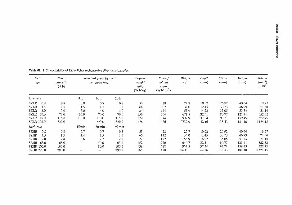
Table 52.19 Characteristics of Eagle Picher rechargeable silver-zinc batteries
Cell Rated Nominal capacity (Ah) Power/ Power/ Weight Depth Width Height Volume type capacity at given rates weight volume (g) (mm) (mm) (mm) (mm3)
(Ah) ratio ratio io3 (W Wkg) (W W d d )
Low rate SZLR 0.8 SZLR 1.5 SZLR 3.0 SZLR 70.0 SZLR 115.0 SZLR 320.0 High rate SZHR 0.8 SZHR 1.5 SZHR 2.8 SZHR 65.0 SZHR 100.0 SZHR 290.0
0.8 1.5 3.0
70.0 115.0 320.0
0.8 1.5 2.8
65.0 100.0 290.0
4h 0.8 1.5 3.0
65.0 110.0
15 min 0.7 1.4 2.6
-
10h 0.8 1.5 3.0
70.0 110.0 290.0 30 min
0.7 1.5 2.7
50.0 80.0 -
20h 0.8 1.5 3.0
70.0 115.0 320.0 60 min
0.8 1.5 2.8
65.0 100.0 290.0
53 66 84
156 172 176
53 66 77
152 158 165
78 102 144 294 324 426
78 112 132 270 282 438
22.7 34.0 53.9
671.8 997.9
2732.9
22.7 34.0 53.9
640.7 952.5
2608.1
10.92 12.45 14.22 32.51 37.34 42.16
10.92 12.45 14.22 32.51 37.34 42.16
26.92 30.73 35.05 80.77 92.71
138.43
26.92 30.73 35.05 80.77 92.71
138.43
40.64 46.99 53.34
121.41 139.45 181.10
40.64 46.99 53.34
121.41 139.45 181.10
13.27 21.30 31.14
352.32 522.75
1124.15
13.27 21.30 31.14
352.32 522.75
1124.15

Table 52.20 Characteristics of Yardney Silcad rechargeable silver-cadmium batteries
Cell Nominul Charging Ma. Typical application data (at 21°C) Max. Overall Volume Overall Height Width Depth Terminal type capacity rate continuous jilled volume 1es.s height less (mm) (mm) threuds
(Ah) (A) discharge Discharge Discharge A h Average Power/ Power/ weight (m1n3) terminrr1.s (mm) terminals rule rate time output voltuge weight volume (8) x103 (mm3) (mm) (A) (A) (h) (V) ratio ratio x 103
(W hkg) (W Wdm’)
YS-01 YS-05 YS-1 YS-2 YS-3 YS-5 YS-10 YS-18 YS-20 YS-40 YS-60 YS-70 YS-85 YS-100 YS-150 YS-300
0.1 0.007 0.5 0.035 1.0 0.070 2.0 0.140 3.0 0.200 5.0 0.300
10.0 0.500 18.0 1.000 20.0 1.500 40.0 3.000 60.0 3.000 70.0 4.000 85.0 5.000
100.0 4.000 150.0 8.000 300.0 20.000
0.1 0.05 2.70 0.5 0.05 15.00 1.0 0.10 15.00 2.0 0.20 14.00 3.0 0.30 13.30 5.0 0.50 14.60
10.0 1.00 11.50 18.0 2.00 10.00 60.0 2.00 1.30 40.0 4.00 12.00 60.0 6.00 1.25 70.0 7.00 11.50
100.0 7.00 14.30 100.0 10.00 11.50 120.0 30.00 5.50 150.0 30.00 12.00
0.14 0.75 I .50 2.80 4.00 7.30
11.50 20.00 26.00 48.00 75.00 80.00
100.00 115.00 165.00 360.00
1 .ox 1.10 1.10 1.10 1.08 1.10 1.10 1.08 1.10 1.10 1.10 1 .ox 1.08 1.06 1.07
1.10 29 40 48 48 48 55 48 59 64 70 68 75 62 84 56 75
46 55 84 72 90 96 90
108 114 138 168 162 132 162 132 132
5.1 I
34.10 65.30 90.90
142.00 261.00 369.00 429.00 746.00
1207.00 1193.00 1732.00 1505.00 3095.00 5197.00
21.30 3.1 I
14.20 19.30 42.10 47.90 78.30
135.30 198.40 249.30 372.30 475.50 526.40 793.80 754.40
1309.00 2148.00
2.19 11.50 16.10 35.90 41.00 67.10
120.50 178.70 211.50 337.80 406.70 467.40 713.40 700.30
1215.00 2017.00
35.0 30.5 16.0 39.3 30.5 27.4 51.3 42.9 27.4 64.2 54.8 43.7 72.6 73.9
122.0 178.0 109.0 179.0 114.0 159.0 240.0 122.0 272.0 432.0
63.2 43.7 63.2 52.8
109.0 58.9 159.0 54.1 92.4 43.9
161.5 82.5 98.0 69.3
141.0 92.4 216.0 71.4 113.0 70.6 227.0 106.0 419.0 106.0
5.6 13.7 13.7 15.0 15.0 20.0 18.7 20.6 52.0 25.1 59.9 35.8 45.9 87.3 45.2 25.4
1-72 5-40 5-40
10-32 10-32 10-32 114.28 5116.24 5116.24 5116.24 5116.24 5116.24 318.24 5116.24 318.24 318.24

52/22 Silver batteries
2.0
1.5
0.5 ''O
- Discharge 10 h rate (21 "c) Charge 20 h rate (21 "C)
/ -
- y s c h a r g e - l - \ \
I ~ I ~ I ~ I ~ I ~ I ~ I ~ I ~ I ~ I ~ I ~ J
52.2 Silver-cadmium (secondary) batteries Yardney
The Yardney Silcad silver-cadmium battery com- bines in one system the high energy and excellent space and weight characteristics of the silver-zinc bat- tery with the long life, low-rate characteristics with some resistance to overcharge characteristic of the nickel-cadmium batteries. It provides high efficiency, an extended shelf life in charged or uncharged condi- tions, level voltage and mechanical ruggedness. Energy densities are two to three times greater than for a com- parable nickel-cadmium battery.
The electrical characteristics of these batteries are given in Table 52.20. Figure 52.12 shows typical charge and discharge curves for a Silcad battery.
Yardney also supply a range of Silcad batteries made up into modular packs (Table 52.21) giving a versatile compact power source for industrial and commercial battery uses.
3 m " L m a -
Silberkraji
Silberkraft supply silver-cadmium batteries in the 0.1-300 A h range providing a voltage of approxi- mately 1.4 or 1.1 V. These have a high cyclic life
-
I I I I I I h I
High rate cells
0 15 30 45 60 70 80 Discharge time (rnin)
(a)
y N 1'21 High rate
c 0
Figure 52.12 Typical charge and discharge characteristics of a Silcad silver-cadmium cell (Courtesy of Eagle Picher)
and a slightly lower energy density and voltage than silver- zinc batteries. They are also suitable for use at low discharge rates. These batteries have been used in satellites for up to 6000 cycles with a depth of dis- charge of 50%.
Eagle Picher
Eagle Picher supply silver-cadmium batteries in the nominal capacity range 0.5- 175 Ah. The electrical characteristics of some batteries in this range are given in Table 52.22. The batteries are available in high-rate and low-rate versions.
Low rate cells b.' 1.
2 1.
% 1.
7
N 4-
> 1
c - : 0. P 2 0. .- 0
0 30 1 5 8 1 1 14 ~ m i n ~ - - - h - ~
Discharge time
(b)
1 . 1 -
a L7
0 I l l I I I 1 -40 -30 -20 -10 0 10 20 30 40
Temperature ("CI
(d)
Figure 52.13 Characteristics of Eagle Picher high- and low-rate rechargeable silver-cadmium batteries (Courtesy of Eagle Picher)

Table 52.21 Characteristics of Yardney rechargeable modular Silvercel Pac batteries
Module Nominal Charging Typical application data (at 21 “ C ) Max. Overall Volume Overall Height Width Depth Terminal rype capacity rate ,filled volume less height less (mm) (mm) thread,?
(Ah) (A) 10 h rate discharge 1 h rale discharge weight (mm3) terminals terminals (g) x103 (mm3) (mm)
Discharge Ah Average Discharge Ah Averuge io3 rate output voltage rate output voltage (A) (VI (A) (VI
BD-312 2.01 0.2 0.2 2.4 3.3 2.0 2.1 3.1 15.9 130 118 73.1 66.8 47.5 37.3 6-32 High rdte BD-3/3 3.0 0.15 0.3 3.2 3.2 3.0 3.1 3.0 16.7 130 118 73.1 66.8 47.5 37.3 6-32 Low rate BD-3/4 4.0 0.4 0.4 4.5 3.3 4.0 4.1 3.1 27.2 180 168 101.0 95.2 47.5 37.3 6-32 High rate BD-3/5 5.0 0.2 0.5 5.5 3.25 5 .o 5.3 3.0 29.5 180 168 101.0 95.2 47.5 37.3 6-32 Low rate
(I, BD-8/5.5 5.5 0.4$ 5.5 6.0* 8.4 5.5 5.0* 8.0 105.6 640 640 100.0 100.0 79.2 80.5 Plug T
BD-3/10 10.0 O S 1 .0 11.0 3.2 10.0 10.0 3.1 48.8 261 230 Low rdte
* To a final voltagc of 2.7 V
Low ratc 4
3 5
Charge to 4.65-4.76V/module m
2 3.
99.0 91.4 142.0 20.3 10-32 Q
h rn 0
a. 91
Charge to 12.4-12.7 V/module

52/24 Silver batteries
Table 52.22 Characteristics of Eagle Picher rechargeable high-rate and low-rate silver-cadmium batteries
Cell Rated Nominal capacity (Ah) Gravimetric Volumetric Max. Depth Width Height Overall type capacity energy energy $fled (mm) (mm) (mm) volume
(Ah) density density weight (m3 ( W W 9 (WWdm3) (g) io3
Low rate
SCLR 0.7 SCLR 1.1 SCLR 2.2 SCLR 45.0 SCLR 70.0 SCLR 175.0 High rate
SCHR 0.5 SCHR 1.0 SCHR 2.0 SCHR 17.0 SCHR 31.0 SCHR 55.0
0.7 1.1 2.2
45.0 70.0
175.0
0.5 1 .o 2.0
17.0 31.0 55.0
l h rate 0.7 1.1 2.2
35.0 50.0 NA* 15 min rate 0.5 1 .o 2.0
16.5 28.0 28.0
4h rate
0.7 1.1 2.2
40.0 65.0
150.0 30 min rate
0.5 1 .o 2.0
16.8 30.0 40.0
10h rate
0.7 33 1.1 33 2.2 40
45.0 64 70.0 68
175.0 73 60 min rate
0.5 24 1 .o 31 2.0 37
17.0 44 31.0 51 55.0 57
51.0 55.8 78
138 144 168
36 48 72 78 96
114
22.7 36.9 59.6
78 1 1136 2655
22.7 37 60
434 690
1045
11.4 12.4 14.2 32.5 37.3 42.1
11.4 12.4 14.2 28.7 32.5 37.3
26.9 30.7 35.0 80.8 92.7
138.0
26.9 30.7 35.0 71.4 80.0 92.7
40.6 47.0 53.3
121.0 139.0 181.0
40.6 47.0 53.3
107.0 121.0 139.0
14.8 21 31
352 523
1125
14.8 21 31
244 352 523
* Not applicable
The major application for the high-rate series is for service conditions where maximum energy density and voltage regulation at high rates of discharge are required throughout a cycle life of 6-18 months. The system also has an exceptional ability to retain its charge during long periods of wet storage.
The major application for the low-rate series is for service conditions in which maximum energy density and voltage regulation at low rates of dis- charge are required throughout a cycle life of 12-36 months. The system also has an exceptional abil- ity to retain its charge during long periods of wet storage.
The cell cases are fabricated in styrene-acrylonitrile, nylon or acrylonitrile-butadiene- styrene and the bat- tery cases in stainless steel, magnesium, titanium, fibreglass or polyvinyl chloride. Optional battery heaters are available. Although the theoretical energy density of the silver-cadmium battery is 310Wh/kg, the actual energy density of practical Eagle Picher batteries is in the range 24-73 W h/kg as cells and 18 -44 W h/kg as batteries.
The practical volumetric energy density is 36- 171 Wh/dm3 as cells and 24-122Wh/dm3 as bat- teries. The batteries have a working voltage of 0.9-1.12V/cell and require voltage regulation of f 5 % under fixed conditions. The operating temperature is
-40 to +71"C, or to -54°C with a heater. Batter- ies can be stored at -54 to + 5 1 T dry or -40 to +38"C wet. A shelf life of 2.5 years when dry and 1.3 years when wet is to be expected. Above 90% charge retention is claimed after 6 months at 21°C. Up to 3000 cycles are claimed. Constant-current charging is recommended, with a charge rate of one-tenth nominal capacity to 1.65 V/cell or 1.55 V/cell minimum. Alter- natively, constant-potential charging can be adopted with an input of 1.65 k 0.02V. With constant poten- tial charging, the current is limited to one-fifth nominal capacity charging to the trickle charge rate.
Figure 52.13 shows typical capacity and voltage characteristics for high- and low-rate silver-cadmium batteries. Discharge characteristics at various rates and the effect of temperature on discharge voltage are also shown.
52.3 Silver-hydrogen secondary batteries Eagle Picher (US) supply silver-hydrogen batteries
52.4 Silver-iron secondary batteries Eagle Picher (US) supply silver-iron batteries.
AI kali ne manganese dioxide batteries


Table 53.1 Union Carbide Eveready alkaline manganese cells and batteries: estimated service time at 21°C
Service time (h) Height Length Suggested Designation Voltage Weight Volume Number Schedule Starting Load at cut-off voltage (mm) (1m)
Type (g) (cm3) ofcells (Nday) drain (a)
(d) ANSI TEC current
range (mA)
EPX82.5 (Button)
E90 (Cylinder)
E189 (Cylinder) 537 (Cylinder)
539 (Cylinder)
0 to 10 - ~ 1.5 6.9 2.0 1 Continuous
0 to 85 - - 1.5 9.9 2.8 I 16 4
0 to 85 - - 1.5 11.3 4.4 1 16 4
0 to 10 - - 6.0 14.2 3.3 4 Continuous
0 to 100 - - 6.0 31.0 16.4 4 4 1 2
520 0 to 1300 - -
(Rectangular)
10.0
6.0 37.5
10.0 12.0
2.5
18.0 60.0
180.0
0.8 V 150 17
0.15 V 250 - 40 21
150 83 250 63
2400 31
0.9 V
3.6 V
3.3 v 333 30.5 100 8.7 33.3 2.3
3.2V
1.2v 7 5.19 22.9
0.9 V 120 180 11.7 30.2
27.6 14.3
4.6 V 18.3 4 0.6 4.0V 4.4V
6.0 1130.0 883.0 4 24 30.0 200 775 560 505 3000.0 2 5 2.8 0.6
4.2V 5.4V (D
- 0 to 100 - 9.0 45.0 21.0 6 4 18.0 500 33 28 8 (Rectangular) 2 60.0 150 9 9 n z. I 522
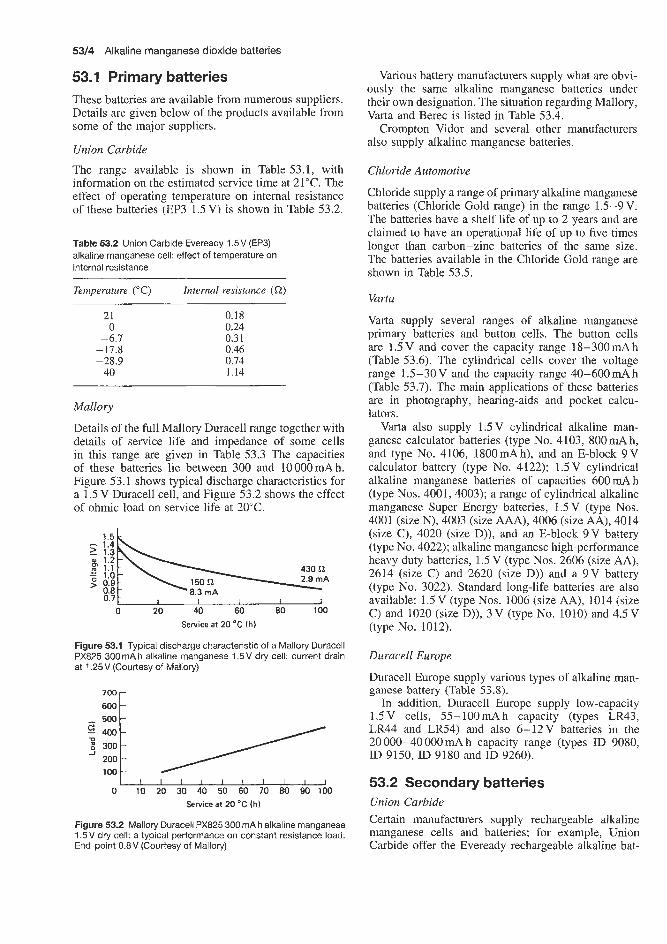
53/4 Alkaline manganese dioxide batteries
53.1 Primary batteries These batteries are available from numerous suppliers. Details are given below of the products available from some of the major suppliers.
Union Carbide
The range available is shown in Table 53.1, with information on the estimated service time at 21°C. The effect of operating temperature on internal resistance of these batteries (EP3 1.5 V) is shown in Table 53.2.
Table 53.2 Union Carbide Eveready 1.5V (EP3) alkaline manganese cell: effect of temperature on internal resistance
Temperature (“C) Intern1 resistance (a) 21 0
-6.7 -17.8 -28.9 -40
0.18 0.24 0.31 0.46 0.74 1.14
Mallory
Details of the full Mallory Duracell range together with details of service life and impedance of some cells in this range are given in Table 53.3 The capacities of these batteries lie between 300 and 10000mAh. Figure 53.1 shows typical discharge characteristics for a 1.5 V Duracell cell, and Figure 53.2 shows the effect of ohmic load on service life at 20°C.
Service a t 20 ‘C (hl
Figure 53.1 Typical discharge characteristic of a Mallory Duracell PX825 300mAh alkaline manganese 1.5V dry cell: current drain at 1.25V (Courtesy of Malloly)
300 200 100
0 10 20 30 40 50 60 70 80 90 100 Service a t 20 ‘C (h)
Figure 53.2 Mailory Duracell PX825 300 mA h alkaline manganese 1.5V dry cell: a typical performance on constant resistance load. End-point 0.8V (Courtesy of Mallory)
Various battery manufacturers supply what are obvi- ously the same alkaline manganese batteries under their own designation. The situation regarding Mallory, Varta and Berec is listed in Table 53.4.
Crompton Vidor and several other manufacturers also supply alkaline manganese batteries.
Chloride Automotive
Chloride supply a range of primary alkaline manganese batteries (Chloride Gold range) in the range 1.5-9 V. The batteries have a shelf life of up to 2 years and are claimed to have an operational life of up to five times longer than carbon-zinc batteries of the same size. The batteries available in the Chloride Gold range are shown in Table 53.5.
Varta
Varta supply several ranges of alkaline manganese primary batteries and button cells. The button cells are 1.5V and cover the capacity range 18-300mAh (Table 53.6). The cylindrical cells cover the voltage range 1.5-30V and the capacity range 40-600mAh (Table 53.7). The main applications of these batteries are in photography, hearing-aids and pocket calcu- lators.
Varta also supply 1.5V cylindrical alkaline man- ganese calculator batteries (type No. 4103, 800mAh, and type No. 4106, 1800mAh), and an E-block 9V calculator battery (type No. 4122); 1.5V cylindrical alkaline manganese batteries of capacities 600mAh (type Nos. 4001, 4003); a range of cylindrical alkaline manganese Super Energy batteries, 1.5V (type Nos. 4001 (size N), 4003 (size AAA), 4006 (size AA), 4014 (size C), 4020 (size D)), and an E-block 9 V battery (type No. 4022); alkaline manganese high-performance heavy duty batteries, 1.5 V (type Nos. 2606 (size AA), 2614 (size C) and 2620 (size D)) and a 9 V battery ( t y e No. 3022). Standard long-life batteries are also available: 1.5V (type Nos. 1006 (size AA), 1014 (size C) and 1020 (size D)), 3 V (type No. 1010) and 4.5 V (type No. 1012).
Duracell Europe
Duracell Europe supply various types of alkaline man- ganese battery (Table 53.8).
In addition, Duracell Europe supply low-capacity 1.5V cells, 55-100mAh capacity (types LR43, LR44 and LR54) and also 6-12V batteries in the 20000-40000mAh capacity range (types ID 9080, ID 9150, ID 9180 and ID 9260).
53.2 Secondary batteries Union Carbide Certain manufacturers supply rechargeable alkaline manganese cells and batteries; for example, Union Carbide offer the Eveready rechargeable alkaline bat-

Table 53.3 Mallory Duracell alkaline manganese dry cells and batteries
Type IEC Voltage Weight Volume Number Capacity Service life (h) at 20°C Height Width Impedance ( Q ) designation (V) (g) (cm3) ojcells (mAh) at 20"c Starting Loud Cut-off (mm)
drain ( Q ) voltage und
0.8 v 32
100 0.8 V
13
1.0v 15 50
1.ov 10 39 60
1 .ov
PX825 LR53 1.5 7 2.4 I (button)
MN9100 LRI 1.5 9.6 3.1 1 (cylinder)
300 to 0.8 V on 430 L?
700 to 0.8 V on 83Q
8.3 150 2.9 430
50 25 15 83 10 125
5.9 23 -
30.2 4.5 0.7 at l0Hz 0.6 at 1OOOHz 0.4 at 100 000Hz
Average of 15% of discharge on 83 Q at 20°C
47 68
0.8 V 18 35 57
3.2V 10 20 50
4.8 V 10 20 50
4.8 V 10 20 50
4.8 V 10 20 50
MN2400 LR03 1.5 13 3.6 1 (cylinder)
800 to 0.8 v on 83 C2
50 25 25 60 15 83
50 100 25 200 10 500
50 150 25 300 10 750
13 28
44.5 10.5 0.8 at lOHz 0.6 at l000Hz 0.4 at 100 000Hz
3.2 at lOHz 1.3 at 1OOOHz 0.9 at 100000Hz
3.5 at lOHz 2.0 at 10OOHz 1.4 at 100 000 Hz
48.3 x 35.6 x 9.0
125.7 x 19.3 x 7.0
Average of 15% of discharge on 83 Q at 20°C
Averagc of 15% of discharge on 300 C2 at 20°C
Average of 15% of discharge on 500 a at 20°C
48 4.0 V
8 16 42
6.0 V 8
16 42
6.0 V 8
16 42
6.0V 8
18 42
7K67 - 6.0 34 15 4 (rectangular)
500 to 3.2V on 250 Q
51365 - 9.0 64 21.3 6 (rectwgular)
500 to 4.8 V on 375Q
5K69 - 9.0 63 21.5 6 (rectangular)
500 to 4.8 V on 375 i2
48.2 x 51.0 x 9.0 3.5 at ~ O H L 2.0 at 1OOOHz 1.4 at 100 000 HL
3.5 at 10Hz 2.0 at 1OOOHz 1.4 at 100 000 Hz
48.5 x 26.5 x 17.5
Average of 15% of discharge on 500 s2 at 20°C
$ Average of 15% of discharge on 0
SOOQ at 2 0 " ~ 2 3 Q
50 150 25 300 10 750
50 150 25 300 10 750
MN 1604 - 9.0 51 21 6 (rectangular)
500 to 4.8 V on 750 Q
b b Outline u
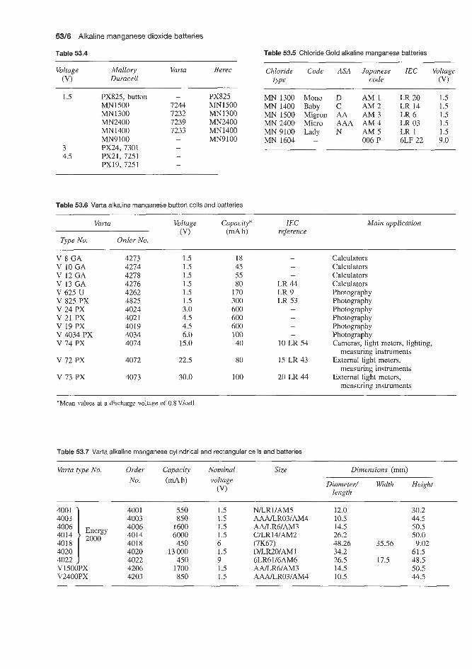
53/6 Alkaline manganese dioxide batteries
Table 53.4 Table 53.5 Chloride Gold alkaline manganese batteries
Voltage Malloiy Varta Berec (VI Duracell
~~ ~
Chloride Code ASA Japanese IEC Voltage type code (VI
1.5 PX825, button MN1500 MN1300 MN2400 MN1400 MN9 100
3 PX24,7301 4.5 PX21, 7251
PX19, 7251
- PX825 7244 MN1500 7232 MN1300 7239 MN2400 7233 MN1400 - MN9 100
MN 1300 Mono D AM 1 LR 20 1.5 MN 1400 Baby C AM 2 LR 14 1.5 MN 1500 Migron AA AM 3 LR 6 1.5 MN 2400 Micro AAA AM 4 LR 03 1.5 MN 9100 Lady N AM 5 LR 1 1.5 MN 1604 - - 006 P 6LF 22 9.0
Table 53.6 Varta alkaline manganese button cells and batteries
Varta Voltage Capacity* IEC Main application (VI (mA h) reference
Type No. Order No.
V 8 GA V 10 GA V 12 GA V 13 GA V 625 U V 825 PX V 24 PX v 21 PX V 19 PX V 4034 PX v 74 PX
v 72 PX
v 73 PX
4273 4274 4278 4276 4262 4825 4024 4021 4019 4034 4074
4072
4073
1.5 1.5 1.5 1.5 1.5 1.5 3.0 4.5 4.5 6.0
15.0
22.5
30.0
18 45 55 80
170 300 600 600 600 100 40
80
100
- LR 44 LR 9 LR 53
- -
- -
10 LR 54
15 LR 43
20 LR 44
Calculators Calculators Calculators Calculators Photography Photography Photography Photography Photography Photography Cameras, light meters, lighting,
External light meters,
External light meters,
measuring instruments
measuring instruments
measuring instruments
*Mean values at a discharge voltage of 0.8 Vlcell
Table 53.7 Varta alkaline manganese cylindrical and rectangular cells and batteries
Varta type No. Order No.
Capacity h)
Nominal voltage
(VI
Size Dimensions (mm)
Diameter/ Width Height length
4001 4003 4006 4014 4018 4020 4022 V1501 V2401
400 1 4003 4006 4014 } 2ooo 4018
Energy
4020 4022 4206 4203
J 1PX 3PX
550 850
1600 6000 450
13 000 450
1700 850
1.5 1.5 I .5 1.5 6 1.5 9 1.5 1.5
~ ~~
N/LRI/AM5 AAALRO3lAM4 M R 6 l A M 3 C/LR14/AM2 (7K67) D/LR2O/AM 1 6LR61/6AM6 AAJLR6JAM3 AAALR03lAM4
12.0 10.5 14.5 26.2 48.26 34.2 26.5 14.5 10.5
30.2 44.5 50.5 50.0
35.56 9.02 61.5
17.5 48.5 50.5 44.5

Secondary batteries 5317
compared with nickel-cadmium cells, are of para- mount importance.
Present types of Eveready battery available from Union Carbide include 4.5 and 7.5V batteries using D-size cells, and 6, 13.5 and 15V batteries composed
tery range. These batteries use a unique electro- chemical system, are maintenance free, hermetically sealed and will operate in any position. They have been designed for electronilc and electrical applica- tions where low initial costs and low operating costs,
I I I I I I I I 0 10 20 30 40 50 60 70
Number of cycles
(a) 4.5 V, No. 563
m0.4 A
:3
:2
1
I I I I I 0 10 20 30 40 50 60 70
Number of cycles
(c) 7.5 V, No. 560
* '5 1; .- e l j
P - 0 :3
J 4
:2 1
ID 10 20 30 40 50 60 70 Numlber of cycles
(e) 15.0 V, No. 561
-
, 0 10 20 30 40 50 60 70
Number of cycles
(b) 6.0 V, No. 565
l2 r
. y l , , .- I I I ,
E 2 1
0 10 20 30 40 50 60 70 Number of cycles
(d) 13.5 V, No. 564
~~ ~
Discharge cycle Charge cycle'
Through Voltage Limiting Time resistance Time limit resistance
Figure (h) (a) (h) (V I (a) [a) 4 5.76 16 5.25 2.4
IC) 4 9.6 16 8.75 4.0 [d) 4 8.64 16 15.75 3.6 (e) 4 9.6 16 17.5 4.0
'Voltage limited taper current charge, filtered regulated power supply with 1% regulation
(b) 4 3.84 16 7 1.6
Figure 53.3 herage performance characteristics, voltage versus cycles at 21 .I "C, of Eveready rechargeable alkaline manganese dioxide batteries, 4.5-1 5 V (Courtesy of Union Carbide)

53/8 Alkaline manganese dioxide batteries
Table 53.8 Duracell alkaline manganese batteries
Voltage (V)
1.5 1.5 1.5 1.5 1.5 1.5 9 1.5 1.5 9 9 6 3 4.5 4.5 6 6 6
12
Button Cylindrical Button Cylindrical Cylindrical Cylindrical Rectangular Rectangular Cylindrical Rectangular Rectangular Rectangular Cylindrical Cylindrical Flat Rectangular Rectangular Rectangular Rectangular
LR 54 LR 43 LR 44 MN 1300 MN 1400 MN 1500 MN 1604 MN 2400 MN 9100 5K 65 5K 69 7K 67 9K 62 PX 21 MN 1203 ID 9080 ID 9150 ID 9180 ID 9260
Capacity at 20°C (mA h)
55 85
100 10000 5 500 1800
500 800 650 400
400 400 580
4 400 20 000 20 000 40 000 20 000
400 - 500
of G-size cells. Specifications are listed in Tables 53.9 and 53.10 and average performance characteristics are shown in Figure 53.3.
The discharge characteristics of the rechargeable alkaline manganese dioxide battery are similar to those exhibited by primary batteries; the battery voltage decreases slowly as energy is withdrawn from the bat- tery. The shape of this discharge curve changes slightly as the battery is repeatedly discharged and charged. The total voltage drop for a given energy with- drawal increases as the number of dischargekharge cycles increases. Coupled with this is the fact that the available energy per cell lessens with each dis- chargekharge cycle even though the open-circuit volt- age remains quite constant. When a rechargeable bat- tery of the alkaline manganese dioxide type is dis- charged at the maximum rate for a period of time to remove the rated ampere hour capacity and then recharged for the recommended period of time, the complete dischargekharge cycle can be repeated many times before the battery voltage will drop below 0.9Vkell in any discharge period, depending on cell size. Decreasing either the discharge current or the total ampere hour withdrawal, or both, will increase the cycle life of the battery by a significant percent- age. Conversely, if the power demands are increased to a point where they exceed the rated battery capa- city, the cycle life will decrease more quickly than the increase in power demand. During the early part of its cycle life there is a very large power reserve in the Eveready rechargeable alkaline manganese dioxide battery. In these early cycles, the battery terminal voltages may measure 1 .O- 1.2 V/cell after the battery has delivered its rated ampere hour capacity. If it is discharged beyond its rated capacity, however, total
battery cycle life will be reduced. Nevertheless, this reserve power can be used in situations where maxi- mum total battery life can be sacrificed for immediate power. During the latter part of cycle life, there is little or no reserve power and the terminal voltage of the battery will fall to between 1.0 and 0.9V/cell at end of discharge.
These charge-retention characteristics also apply during the charge/discharge cycling of the battery. With this type of battery it is necessary to discharge it to its rated capacity before it will be capable of standing any overcharge.
The recommended method for charging alkaline sec- ondary batteries is the use of voltage-limited taper current charging. This method offers the maximum cycle life and consequently the lowest battery oper- ating costs. Cycle life can be as much as twice that obtained with other methods of charging. Although constant-current charging can be used with conse- quent loss of cycle life, it is recommended that careful enquiries be made before such charging methods are contemplated.
Batteries should not be charged continuously after the charge current has returned 120% of the ampere hours removed on previous discharge or float charged for extended periods.
A rechargeable alkaline manganese dioxide battery must not be discharged completely. For best results, the rated capacity of the battery should not be exceeded on discharge. During deep discharge a secondary elec- trochemical reaction takes place. This reaction is not reversible and will seriously reduce the battery cycle life. To avoid possible complaints of short battery ser- vice, it is therefore desirable that the device using the battery contain some provision against excessive dis- charge of the battery.
Where voltage-limited taper current charging is used, the charger will replace the energy needed to recharge the battery, and a timer or ampere hour control is unnecessary to monitor the charging time. However, the battery should be removed from the charger after completion of the charge. Also, to prevent deep cell discharge, a timer would provide effective control over the energy withdrawn from the cell during any cycle.
With constant-current charging, a d.c. timer or ampere hour counter is needed to control both the dis- charge and charge cycles. A system of this sort would be adjustable to permit removal of the rated ampere hour capacity from the battery and thereby ensure max- imum battery service life.
Voltage-limited taper current charging involves use of an inexpensive voltage regulator added to the basic constant-current type transformer-rectifier circuit with a current-limiting resistor between the battery and the regulated output voltage, which removes the burden of adjusting charge time to discharge time and provides automatic current control. Although the regulator cir- cuit is somewhat more expensive than other common
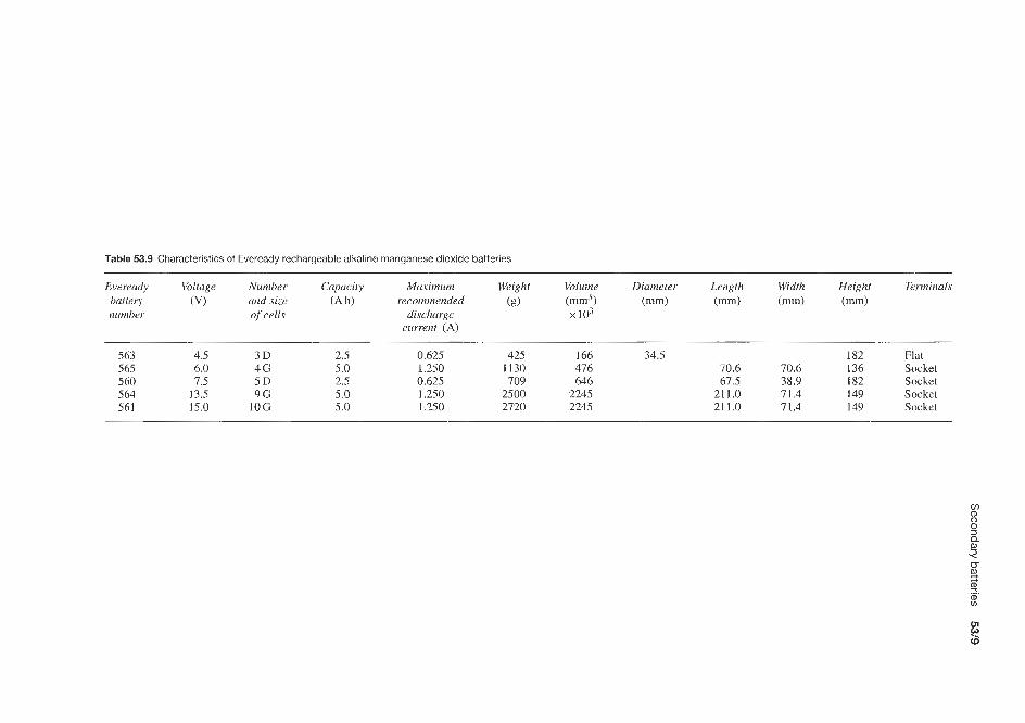
Table 53.9 Characteristics of Eveready rechargeable alkaline manganese dioxide batteries ~~
Eveready Voltage Number Capacity Maximum Weight Volume Diameter Length Width Height Terminals battery (VI and size (A h) recommended id imm3 ) imm) imm) (mm) i1m)
number of cells discharge x 103 current (A)
563 4.5 3 D 2.5 0.625 425 166 34.5 182 Flat 565 6.0 4G 5.0 1.250 1130 416 70.6 70.6 136 Socket 5 60 7.5 5 D 2.5 0.625 709 646 67.5 38.9 182 Socket 5 64 13.5 9G 5.0 1.250 2500 2245 211.0 71.4 I49 Socket 561 15.0 10 G 5.0 1.250 2720 2245 211.0 71.4 149 Socket
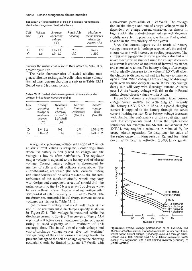
53/10 Alkaline manganese dioxide batteries
Table 53.10 Characteristics of cells in Eveready rechargeable alkaline to manganese dioxide batteries
Cell Voltage Average Rated Ah Maximum size (V) operating capacity recommended
voltage discharge (VI current (A)
5 15-
E 14-
- W
c -
D 1.5 1.0-1.2 2.5 0.625 G 1.5 1 .o- 1.2 5.0 1.250
circuits the initial cost is more than offset by 50-100% greater cycle life.
The basic characteristics of sealed alkaline man- ganese dioxide rechargeable cells when using voltage- limited taper current charging are given in Table 53.1 1 (based on a 6 h charge period).
Table 53.11 Sealed alkaline manganese dioxide cells under voltage-limited taper current charging
Cell Average Maximum Current Source size operating initial limiting voltage
voltage at charging resistance limit maximum cur re^ at (Wcell) (V/cell)
current 1.3 %ell (VI (A)
D 1.0-1.2 0.6 0.8 1.70- 1.75 G 1.0-1.2 1.12 0.4 1.70-1.75
A regulator providing voltage regulation of 2 or 3% at low current values is adequate. Poorer regulation when the battery is first placed on charge and the voltage is low is often satisfactory. The regulator output voltage is adjusted to the battery end-of-charge voltage. Correct battery voltage is determined by number of cells and cell voltages given above. The current-limiting resistance (the total current-limiting resistance consists of the series resistance plus inherent resistance of the regulator circuit, which may vary with design and component selection) should limit the initial current to the 4-6 h rate at start of charge when battery voltage is low. Typical starting voltage after withdrawal of rated capacity is 1.30- 1.35Vkell. The maximum recommended initial charge currents at these voltages are shown in Table 53.11.
The minimum voltage that a cell will reach at the end of the recommended discharge capacity is shown in Figure 53.4. This voltage is measured while the discharge current is flowing. The curves in Figure 53.4 represent cell behaviour at maximum discharge current rating to rated capacity and a minimum of 16h recharge time. The initial closed-circuit voltage and end-of-discharge voltage curves give the ‘working’ voltage range of the cell at various discharge levels. To prevent damage to the cell on charge cycle the charging potential should be limited to about 1.7 V/cell, with
a maximum permissible of 1.75 Vkell. The voltage rise on the charge and end-of-charge voltage value is dependent on charge current character. As shown in Figure 53.4, the end-of-charge voltage will decrease slightly as cycle life progresses, as the result of gradual change in the reversibility of the system.
Since the current tapers as the result of battery voltage increase or is ‘voltage responsive’, the end-of- charge current will increase as cycling progresses. The current will equilibrate at some specific value but will never reach zero or shut-off since the voltage decreases as current is reduced as the result of internal resistance and chemical reaction. The battery voltage after charge will gradually decrease to the value of 1.5 V/cell when the charger is disconnected and the battely remains on opencircuit. When changing from charge to discharge cycle with no time delay between, the battery voltage decay rate will vary with discharge current. At rates near 1 A the battery voltage will fall to the indicated initial closed-circuit values within 5 min.
Figure 53.5 shows a voltage-limited taper current charge circuit suitable for recharging an Eveready 561 battery (15V, 5 A h in 16h). A tapered charging current is supplied to the battery through the series current-limiting resistor & as battery voltage increases with charge. The performance of the circuit may vary with the components used. Often the replacement transistors, for example the SK3009 replacement for 2NI304, may require a reduction in value of R3 for proper circuit operation. To determine the value of the series current-limiting resistor, R4, and for initial circuit adjustment, a voltmeter (10 OOO Q or greater
181-
End-of-charge voltage 1 6 1
” 1 I I I I 1
10 20 30 40 50 Number of cycles
Flgure53.4 Typical voltage performance of an Eveready 561 15V rechargeable alkaline manganese dioxide battery on voltage- limited taper current charge. (Discharge cycle 4 h through 9.6 a. Charge cycle 16h, voltage limit 17.5V, filtered regulated power supply 7 % regulation with 4.052 limiting resistor) (Courtesy of Union Carbide)

Secondary batteries 5311 1
120
R4 UCC Patent 3 281 639
Stancor FIT 201 (input ax . to terminals 1 and 7; connect terminals 3 and 6) (secondary connections to bridge 8 and 11; connect terminals 9 and I O ) 2A50 Solitron Devices, Inc. (or equivalent) 500 pF. 50 V d.c. 1!4 M12 2 (Motorola) in 9638 TI or int. rec. 2N1304 RCA, TI or equivalent 2N1557 Motorola, 2N514 TI 4700 QO.5 w 390 Q. 0.5 ‘W lmn, 1 uw 4 n . 1 o w
1 . 4 ~
13 74 15 16 17 18 Battery voOtage (V)
Figure 53.6 Suggested and actual linear taper currents obtained during 16h voltage-limited taper current charging of a 15V, 5 A h Eveready 561 alkaline manganese dioxide battery (Courtesy of Union Carbide)
per volt) is placed across R3 (no battery connected) and R3 adjusted to obtain the indicated source voltage limit. A voltage source equivalent to 1.3 V/cell for the battery to be charged is connected and Rq selected to limit the charge current to recommended values. The battery should. be disconnected from the charger when the charge circuit is not energized, to prevent discharge through resistance R3.
The suggested linear taper current for the 561 battery and actual cilirrent characteristic obtained with the
Figure 53.5 Voltage-limited taper current charger circuit suitable for charging a 15V, 5 A h Eveready 561 alkaiine manganese dioxide battery in 16h (Courtesy of Union Carbide)
1.2 Recommended linear
1 .o
- 4: 0.8
E 0.6
0.4
0.2
0 13 14 15 16 17 18
Preferred limits
- *-’
Battery voltage (VI
Figure 53.7 Permissibie deviations of charge current of 16 h voltage-limited taper current charge of 15 V, 5 Ah Eveready 561 alkaline manganese dioxide battery (Courtesy of Union Carbide)
circuit of Figure 53.5 are shown in Figure 53.6. The current characteristic can be tailored by selection of components. The curves shown were obtained with the use of component values shown in Figure 53.5. The permissible deviation of charge current from that indicated suggests that linear taper varies somewhat with application and usage pattern. Where the application requires repetitive discharge to rated capacity, the charge current values should fall within the shaded area of Figure 53.7, with charge time adjustment for circuit tolerance should operation fall in the ‘minimum’ area relative to linear character.
Rayovac
In 1993 Rayovac introduced its Renewal range of 1.5 V reusable zinc-manganese dioxide cells. These batteries are also produced by Pierce Energy Battery Company (Canada), and the Alcava range by the Young Poong Corporation (Korea).

Carbon -zinc batteries (primary) and carbon-zinc chloride batteries

Carbon-zinc batteries (primary) and carbon-zinc chloride batteries 54/3
Crompton Vidor (UK) Union Carbide
Union Carbide produce a vast range of carbon-zinc dry ceils and batteries (see Table 54.1). This range covers from single 1.5V cells with current ranges between 0.06 and 1500mA to a multi-cell 510V bat- tery with a curreint range of 0-2.5 mA; typical applica- tions for these various types are given in Table 54.1.
Average service life data for a selection of these various types of cells and batteries are listed in Table 54.2 (1.5-9V) and Table 54.3 (12-51OV) for different test schedules.
Carbon-zinc cells (1.5V) come in a variety of standard sizes covered by the ANSI designation. The type numbers of Union Carbide Eveready 1.5 V cells available under each ANSI designation are listed in Table 54.4 (see also Table 54.1).
Eveready transistor batteries (see Table 54.1) exhibit exceptional current drain carrying capabilities. Bat- tery impedance is low and essentially constant even to low-voltage cut-offs. Shelf life characteristics are excellent. Battery capacity is nearly constant at with- drawal rates of 2-6htday. The construction used in Eveready transistor batteries perform well in the fol- lowing abuse tests: 1. Continuous short-circuit. 2. Continuous discharge. 3. High-temperature storage. 4. High-temperature high-humidity storage. 5. Shock and vibration. 6. Temperature cycling from -28.9 to +60"C.
The ampere hour capacity of a carbon-zinc dry battery is not a fixed value. It varies with current drain, operating schedule, cut-off voltage, temperature and storage period of the battery before use. Approximate service capacity for each cell used in the batteries shown in the specification listing for carbon-zinc batteries is given in Table 54.5 for two different current drains. The values given are for fresh batteries at 21°C; the operating schedule is 2hlday; and the cut- off voltage is 0.8V per 1.5V cell for all of the cells, which is consistent with the n o d cut-off voltages of the cells in service. The data in Table 54.5 are based on starting drains and fixed resistance tests. From the voltage of the battery and the total number of cells, the number of 1.5 Y cells in series and in parallel may be determined. Service capacity is given for single 1.5 V cells. If a battery uses cells in parallel, dividing the current drain which the battery is supplying by the number of parallel strings of cells and looking up this value of current will give the service life.
Table 54.6 shows the most widely used batteries, in typical applications, and details of applicable loads, voltages and amperage readings for testing.
Ever Ready (Berec) (UK) The Ever Ready range of carbon-zinc dry cells and batteries covering 1.5-90V supplied is given in Table 54.7.
Crompton Vidor supply dry cells and batteries suitable for the operation of road warning lights, lighting, radio, burglar alarm and fire alarm systems. Other examples are the V22, a 15V layer stack battery, which was uniquely designed by Vidor to power the transformertcapacitor-generated spark in an electronic cigarette lighter, and the L120-1196, a high- voltage unit in use with mass spectrometers and wherever a stable-high-voltage low-noise power source is required.
The L12-1470 12V battery weights approximately 1.14kg and is recommended for intruder and fire alarm systems, portable fluorescent lighting, small d.c. motors, portable television receivers and toys.
The HP992 Hi-Power 6V battery was made spe- cially for the alarm industry, having:
1. High power capability. 2. Screw terminals with insulated nuts for ease and
flexibility of connection. 3. All plastics construction, which is resistant to leak-
age and ingress of moisture.
Applications include alarm systems, such as door alarm locks, road counting meters, marine hand-lamps, toys and laboratory power sources.
The L12-150 12V battery weights approximately 1.05 kg and is stated to have good shelf life and an internal enclosed cell block resistant to ingress of moisture, and can be used for longer periods at higher current drains. Applications include intruder and fire alarm systems, portable fluorescent lighting, small d.c. motors, portable television receivers and toys.
Varta (West Germany)
Varta produce the range of carbon-zinc cells and batteries shown in Tables 54.8 and 54.9. They also supply 1.5 V zinc chloride cells (Super Dry 280, 281 and 282). Their cell type 246 is a 1.5V carbon-zinc button cell.
Yuasa (Japan)
Yuasa supply two ranges of carbon-zinc dry cells, the Golden G Hi Capacity series and the Standard Diamond series. Table 54.10 gives the range available, with Union Carbide, Ever Ready (Berec) and Ray-o- Vac equivalents.
Figure 54.1 shows a comparison of service life under various conditions between Yuasa's UM-I standard cell and their SUM-IG Hi Capacity cell of the same dimensions. The improvement in life of the Hi Capacity cell is very apparent in both continuous and intermittent use applications.
The carbon-zinc batteries discussed above are rep- resentative of the various types available. There are, of course, many other suppliers of this type of battery and they are listed under Suppliers of primary batteries.

Table 54.1 Union Carbide carbon-zinc Eveready Leclanche dry cells and batteries
rn
P
n
e
Battery Suggested Typical use Maximum dimensions (mm) Cells Battely Terminals Approx. Voltage taps $ order of range increasing
capacity
number in current weight volume 3
Diameter Length Width Height Number Size (g) battery !. (mA) body 0
service (cm’) U
%
i
3
i. 1 .5 V batteries 201 E340E 904 812 912 815 HS15 915 1015 1215 T35 835 HS35 935 1035 1235 T50 850 HS50 950 1050 HS150 1150 1250 w353 711 742 735 HS6 IF6 IS6 IS6T EA6F EA6 EA6ljT EA6ST 3 V batteries 750 W356 w357
0 to 0.06 0 to 20 0 to 20 0 to 20 0 to 20 0 to 25 0 to 25 0 to 25 0 to 25 0 to 25 0 to 1 0 to 80 0 to 80 0 to 80 0 to R0 0 to 80 0 to 1 0 to 150 0 to 150 0 to 150 0 to 150 0 to 150 0 to 150 0 to 150 0 to 500 0 to 500 0 to 1000 0 to 1000 0 to 1500
0 to 1500 0 to 1500 0 to 1500 0 to 1500 0 to 1500 0 to 1.500
o to 1500
Electronic watch Nearing-aid Flashlight, toys Photo-flash Flashlight Photo-flash Flashlight Flashlight Transistor radio General-purpose (heavy duty) Electric clock Photo-flash Flashlight Flashlight Transistor radio General-purpose Electric clock Photo-flash Flashlight Flashlight Transistor radio Industrial flashlight Industrial flashlight Gencrd-purposc (heavy duty) Portable A Glo-plug ignition Portable A Instruments, hobbies Industrial general-purpose General-purpose General-purpose General-purpose General-purpose Alarm Alarm Alarm
0 to 250 Flat flashlight 0 to 500 Radio 0 to 1000 Telephone
11.3 11.3 11.3 10.3 10.3 14.3 14.3 14.3 14.3 14.3 26.2 26.2 26.2 26.2 26.2 26.2 34.1 34.1 34.1 34.1 34.1 34.1 34.1 34.1
66.7 66.7 66.7 66.7 66.7 66.7 66 7 66.7
3.3 I 30.0 1 30.0 1 44.5 1 44.5 1 50.0 1 50.0 1 50.0 1 50.0 1 50.0 1 49.2 I 49.2 1 49.2 1 49.2 1 49.2 1 49.2 1 61.1 1 61.1 1 61.1 1 61.1 1 61.1 1 61.1 1 61.1 1 61.1 1
65.9 34.9 106.0 2 66.7 33.3 102.0 2 66.7 66.7 97.6 4 66.7 66.7 110.0 4
168.0 1 172.0 1 168.0 1 166.0 1 172.0 1 166.0 1 172.0 1 166.0 1
31.0 15.9 67.5 2 66.7 66.7 116.0 4 96.0 68.3 148.0 8
103 N N AAA AAA AA AA AA AA AA C C C C C C D D D D 0 D D D F F F F 6 6 6 6 6 6 6 6
AA F F
1.39 Flat contact 6.24 Flat contact 6.24 Flat contact 8.50 Flat contact 8.50 Flat contact
17.00 Flat contact 14.80 Flat contact 14.80 Flat contact 17.00 Flat contact 15.80 Flat contact 39.7 Flat contact 39.7 Flat contact 41.0 Flat contact 41 .O Flat contact 39.7 Flat contact 45.6 Flat contact 93.6 Flat contact 93.6 Flat contact 85.1 Flat contact 85.1 Flat contact 85.1 Flat contact 85.1 Flat contact 85.1 Flat contact 93.6 Flat contact
354.0 Socket 340.0 Knnrlcd nut and screw 624.0 Socket 652.0 Knurled nut and screw 907.0 Knurled nut and screw 907.0 Fahnestock 907.0 Knurled nut and screw 907.0
964.0 Brass knurls 964.0 One Fahnestock, one wire 964.0 One brass knurl. one wire
One brass knurl, one wire 1020.0 Fahnestock
56.7 Spring 624.0 Knurled nut and screw
1250.0 Fahnestock
0.31 2.62 2.62 3.28 3.28 7.87 7.87 7.87 7.87 7.87
24.9 24.9 24.9 24.9 24.9 24.9 52.0 52.0 52.0 52.0 52.0 52.0 52.3 52.0
243.0 203.0 434.0 434.0 480.0 480.0 480.0 480.0 480.0 480.0 480.0 480.0
ci, -, +1.5 h
-, f1.5 -, f1.5 -, +1.5 -, +1.5 -, +1.5
-, f1.5 2. 2 3. 9
-, f1.5 e -, f1.5 U -, f1 .5 2 -, +1.5 N. -, +1.5 -, f1.5 0 -, + I S z -, +1.5 2. -, + I S CD -, +IS u
2 -, f1.5
3. -, f1.5
8 -, +1.5 -, + I S - , + I S -, f1.5 -, +1.5 -, +1 .5 -, +1.5 -, +1.5 -, f1.5
Q 0
3 0
Q
.-I.
-, +1.5 -, +1.5 -, +1.5 -, f1.5 -, + I S -, +1.5 -, +I 5 -, f1.5
26.6 -, +3 459.0 -, +3 895.0 -, f 3
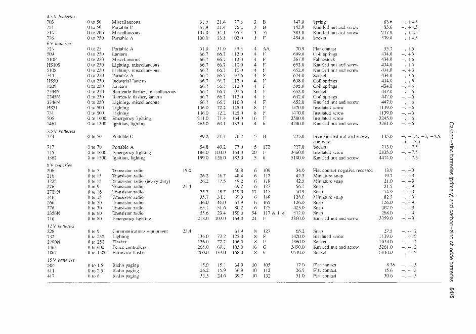
4 5 V Batterm 703 78 1 714 736 6 V D a ~ e r m 724 509 510F HSlOS 510s 744 HS90 I209 2744N 2745N 2746N HS31 731 706 1461 7 5 V batferies 773
717 715 1562 VV batterre, 206 216 1222 226 2709N 246 266 276 2356N 716 12V hutterm 228 732 2780N 1463 1862 15 V butteries 504 411 411
0 to 50 0 to 50 0 to 200 0 to 250
0 to 25 0 to 250 0 to 250 0 to 250 0 to 250 0 to 250 0 to 250 0 to 250 0 to 250 0 to 250 0 to 250
0 to 500 0 to 1000 0 to 1500
0 to 50
0 to 70 0 to 1000 0 to 1500
0 to 7 0 t o 15 0 to 15 0 to 9 0 to 16 0 to 15 0 to 20 0 to 30 0 to 80 0 to 80
0 to 9 0 to 250
0 tu 600
0 to 500
0 LO 250
0 to ison
0 1 0 1 5 O t o 2 5 0 to 6
Miscellancoos Portahle C Misccllancous Portable A
Portable A Lantern Miscellaneous Lighting, miscellaneous Lighting, miscellaneous Portable A Industrial lantern Lantern Barricadc flasher, niiscellaneous Barricadc flashcr, lantern Lighting, inisccllancous Lighting Lighting Emergency lighting Ignition, lighting
Poitahlc C
Portable A Emergency lighting Ignition, lighting
Transiskir radio Transistor radio Transistor radio (heavy duty) Transistor radio Transistor radio Transistor radio Transistor radio Transistor radio Transistor radio Emergency lighting
Communications equipment Lighting Flasher Fence controllei-s Barricadc flashcr
Radio paging Kadic paging Radio paging
61.9 61.9
101.0 100.0
31.0 66.7 66.7 66.7 66.7 66.7 66.7 66.7 66.7 66.7 66.7
136.0 136.0
265.0
99.2
54.8 184.0 199.0
21 1.0
19.0 26.2 26.2
35.7 35.7 46.0 65.1 55.6
218.0
25.4
25.4 136.0 136.0 265.0 260.0
15.9 26.2 33.3
21.4 77.8 21.4 76.2 34.1 95.3 33.3 102.0
31.0 59.5 66.7 112.0 66.7 112.0 66.7 110.0 66.7 110.0 66.7 97.6 66.7 112.0 66.7 112.0 66.7 97.6 66.7 112.0 66.7 110.0 72.2 125.0 72.2 125.0 71.4 164.0 69.1 183.0
21.4 76.2
49.2 77.0 103.0 164.0 126.0 183.0
50.8 16.7 48.4 17.5 49.2
49.2 18.7 119.0 34.1 69.9 46.0 61.9 51.6 80.2 29.4 159.0
103.0 164.0
61.9 72.2 125.0 72.2 106.0 69.1 183.0
133.0 16X.0
15.1 34.9 15.9 36.9 24.6 39.7
3 B 3 B 3 55 3 F
4 AA 4 F 4 F 4 F 4 F 4 F 4 F 4 F 4 F 4 F 4 F 8 F R F
16 F 4 6
5 B
5 172 20 F 5 6
6 109 6 117 6 118 6 127
12 117 6 148 6 165 6 175
142.0 142.0 383.0 454.0
70.9 609.0 567.0 652.0 652.0 624.0 638.0 595.0 652.0 652.0 652.0
1470.0 1470.0 2580.0 4200.0
225.0
227.0 3460.0 5100.0
34.0 42.5 42.5 56.7 70.9
128.0 126.0 425.0
54 117& 118 312.0 24 F 3860.0
8 127 65.2 8 F 1420.0 8 F 1360.0
16 G 3490.0 8 6 9530.0
10 105 17.0 10 112 26.9 I0 132 51.0
Spring 83.6 Knurled nut and screw 83.6 Knurled nut and scrcw 277.0 Socket 339.0
Flat contact Coil springs Fdhnestock Knurled nut and screw Knurled nut and screw Socket Coil springs Coil springs Sockct Coil springs Knurled nut and screw Jnsnlated screw Insulatcd scrcw Insulatcd scrcw ICnurled nut and screw
55.7 434.0 434.0 434.0 434.0 434.0 434.0 434.0 447.0 447.0 447.0
I 139.0 11390 2245.0 3261.0
Five knurled nut and screw, 135.0 one wire Socket 213.0 Insulated screw 2835.0 KnLuled nut and screw 4474.0
Flat contact ncgativc recessed Miniature snap Miniaturc snap Snap Snap Miniature snap Snap Snap Snap Knurled nut and screw
13.9 19.7 21.0 21.5 74.9 82.3
126.0 267.0 288.0
3359.0
Snap 27.5 Insulated screw 1139.0 Socket 1034.0 Knurled nut and scrcw 3261.0 Socltct 5834.0
Flat contact Flat contact Flat contact
8.36 15.6 30.6
-, f4.5 -, +4.5 -, +4.5 -, +4.5
-, +6 -, +6 -, +6 -, +6 -, +6 -, +6 -, +6 -, +6 -, +6 -, +6 -, +6 -, +6 -, +6 -, +6 -, +6
+, -1.5, -3, -4.5, 5 -6, -7.5 1 -, +7.5 -, t 7 .5 0
-, +7.5
s. -, +9 -, +9 h
-, +9 -, +9 -, +9 -, +9 -, +9 -, +9 -, +9 -, +9
E.
U
3. Q 0
0
-, -1-12 -. N
-, -1-12 0 -, +12 -, +12 2. -, +12
3
0 Zr - Q
-, +I5 -, + I5 - ,+ I5
ffl
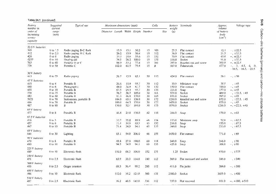
Table 54.1 (continued)
Battery Suggested Typical u ~ e Maximum dimensions (mm) Cells Battery Tenninuls number in current weight order of range Diumeter Length Width Height Number Size (g) increasing (n1A) service capacity
Approx. Voltage tups volume
of battery body (cin’)
22.5 V batteries 505 412 420 425P 763 778
30V battery 413 45 V batteries 415 460 455 738 482 7625: 484 487 63 V battery 477 67.5 V batteries 416 457 467 69V battery 646 90 V batteries 479 490 225 V battery 489 240 V battwy 491 300V battery 493 450 V battery 496 510 V battery 497
0 to 1.5 0 to 2.5 0 to 6 0 to 10 0 to 40 0 to 50
0 to 25
0 to 4 0 to 6 0 to 10 0 to 25 0 to 40 0 to 70 0 to 70 0 to 80
0 to 8
0 to 3 0 to 6 0 to 10
0 to 30
0 to 8 0 to 10
0 to 10
0 to 2.5
0 to 2.5
0 to 10
0 to 2.5
Radio paging B-C flash Radio paging B-C flash Radio paging Hearing-aid Portable B or C Portable C
Radio paging
Portable B Photographic Portable B Portable B Portable B Instruments, portable B Portable B B
Portable B
Portable B Portable B Portable B
Lighting
Portable B Portable B
Electronic flash
Electronic flash
Geiger counters
Electronic flash
Electronic flash
15.9 26.2 33.3 34.5 88.9
102.0
26.2
26.6 48.0 67.5 76.2 91.3
104.0 100.0 130.0
48.8
33.7 71.4 71.4
65.1
48.8 94.5
110.0
65.9
68.3
172.0
76.2
15.1 50.2 15.9 50.8 24.6 55.6 26.2 100.0 53.2 77.8 61.9 19.4
15.9 65.1
15.9 93.7 34.9 61.7 25.4 93.7 58.7 105.0 46.8 139.0 65.1 138.0 64.3 135.0 52.4 184.0
27.0 138.0
25.0 88.9 34.9 63.5 34.9 94.1
54.0 206.0
27.0 190.0 34.9 94.1
68.3 106.0
33.3 114.0
56.4 99.2
76.2 127.0
40.5 143.0
15 15 15 15 15 15
20
30 30 30 30 30 30 30 30
42
46 45 45
46
60 60
152
160
200
300
336
1 05 112 132 135 161 B
112
112 132 135 AA 165 172 172 175
118
114 132 135
155
118 135
135
112
112
135
112
25.5 Flat contact 36.9 Flat contact 70.9 Flat contact
116.0 Socket 397.0 Knurled nut and screw 567.0 Fahnestock
454.0 Flat contact
70.9 150.0 221.0 539.0 851.0
1250.0 1420.0 1870.0
Miniature snap Flat contact Snap Socket Socket Knurled nut and screw Socket Socket
244.0 Snap
113.0 Miniature snap
340.0 Snap 216.0 snap
1450.0 Flat contact
340.0 Snap 425.0 Snap
1.25 Socket
369.0 Flat recessed and socket
411.0 Pin jacks
2380.0 Socket
737.0 Flat recessed
12.1 21.5 43.6 91.0
303.0 477.0
26.1
38.5 100.0 157.0 469.0 597.0 872.0 875.0
1256.0
179.0
72.9 155.0 233.0
721.0
246.0 308.0
810.0
246.0
384.0
1655.0
441.0
01
5 c 5 0 3 1 E. 3 0 m % -, +22.5
-, +22.5 3. -, Jr22.5 m -, +22.5 h
-, Jr22.5 5.
3.
v)
+, -3, -4.5, -6, -9, 3 -10.5, -16.5, -22.5
-, +30 m 3 Q 0
-, +45 $ 5
3 2.
-, +45 -, +45 -, +22.5, +45 -, +45 0
-, +22.5, f45 -- +45 -, +22.5, +45
N 3 _.
-, +63
-, +67.5 -, +67.5 -, +67.5
-, +69
-, +90 -, f 9 0
-, +225
-, +240
-, +300
-, +450
-, +180, +510

Table 54.2 Estimated average service life at 21 “C for a selection of Union Carbide Eveready carbon-zinc Leclanche dry cells and batteries, voltage range 1.5-9V
> 0-250
Eveready Batten! Schedule (Wday) Starting butlrry voltage drain number (VI (InA)
Load (Q) Service time (h) a f Suggested cut-off voltage ciirren1
range ( i d )
1215
I235
H550 1050
750
703 and 78 I
5 IOS, HS105, 510F, 509
2744N, 2745N, 2746N
I209
773
717
266
276
2356N
716
1.5 1.5 1.5 I .5 1 5 1.5
3.0
4.5 4.5
6
6
6
7.5 7.5
7.5 7.5
9 9
9 9
9 9
9 9
2 2
2 2
Dischargc 100 ms/s, 24 Nday, 7days/week, 10% ‘on’ timc Safety flasher Lest
Discharge 100rns/s, 24Wday, 7days/week, 10% ‘on’ lime Safety flasher test
Discharge 100 ms/s, 24 h/day, 7days/week, 10% ‘on’ time Safety flashcr tcst
2 2
2
2
2 2
37.5 60.0 37.5 60.0 60.0 18.0
5.0 50.0
5.0 100.0
-
-
-
5.0 100.0
10.0 80.0
0.5 80.0
5 50
15 36
80 1200
40.0 25.0 40.0 25.0 25.0 83.3
600.0 60.0
900.0 45.0
Load is RCR (resistor-capacitor-resistor) nctwork, Components chosen to provide initial peak pulse of 5000 mA (at 6 V) in 20 ms and remaining at this level Tor remainder of 1OOins pulse (to simulate lamp characteristics) l ~ ~ a d is RCR network. Compcinenls chosen to provide initial pcak pulsc of 500mA (at 6V) in 20 ins and remaining at this level for remainder of 100 ins polsc (to simnlatc lamp characteristics) Load is RCR network. Components chosen to provide initial peak pulse of 500mA (at 6V) in 20ms and remaining at this level for remainder of 100 ms pulse (to simulatc lamp characteristics)
1500.0 75.0
750.0 94.0
18.0 112.5
I800 180
600 250
112.5 7.5
0.75 V 33 20 97 59 113 440 1.6V 265 14 2.4 V 420 14.5 3.6 V 825
875
975
4.0 V 420 14.5 4.0 v 485 50 4.8 v 2400 14.5 4.8 v 920 110 4.8 v 305 125 4 8 V 490 23
0 9 V 11 18 91 55 100 400 2 0 v 240 I0 3 0 v 340 9 4 0 V
5 ov 340 9 5 ov 350 32 6 0V 1950 8 6 0 V 800 80 6V 290 115 6 0 V 410 18
2.4 V 145 3.8 3.6 V 250 4.5 4.4v
6.0 V 250 4.5 6.0V 240 10 7.2 V 1400 1.3 7.2V 600 38
7.2 v 310 6.8 __
0-25
0-25
0-25
0-50
0-70
0-20
0-30
0-80
0-1000

54/8 Carbon-zinc batteries (primary) and carbon-zinc chloride batteries
Table 54.3 Estimated average service life at 21°C for a selection of Union Carbide Eveready carbon-zinc dry batteries, voltage range 12-51OV
Evereadq battery number
228
1463
504
417
778
412
413
484 and 7628
415
477
416
467
646
479
490
489
49 1
493
496
497
Battery Schedule Starting Load Service time (h) at Suggested voltage @/day) drain (Q) cut-off voltage current
(VI (mA) range (mA)
12
12
15 15
15 15
22.5
22.5
30
45
45
43
67.5
67.5
69
90
90
225
240
300
450
510
2
24
2 2
2 2
2
2 2
4 4
2 2
2 2
4
2 2
2 2
4 4
4
2
2
2
2
2
2
12.0
20.0
1 .o 5.0
0.5 20.0
5.0 100.0
0.1 5.0
0.2 5.0
10.0 80.0
0.1 5.0
8.4
3.37 6.75
0.5 35.0
19.0 78.0
9.0
0.5 35.0
0.5 35.0
0.1 5.0
0.1 5.0
0.5 35.0
0.1 5.0
1000
600
150000 3 000
30 000 750
4 500 225
225 000 4 500
150 000 6 000
4 500 562
450 000 9 000
7 500
20 000 10 000
135 000 1929
3 630 885
10 000
180 000 2 570
450 000 6 430
2.4 x lo6 48 000
3 x 10⁶ 60 000
900 000 129 000
5.1 x lo6 102 000
5.6V 59
4 v 2300
8V 1010 11.4 8V 720 7.5
1 2 v 420 14.5 1 2 v 1300
24 16V 760 23
24 V 485
50 24 V 1300
24 45 v
49 30 V
57 25
36 V 920
7 36.9 V
195 20
48 V 60
48 V 920
7 121.6V
920 7
128 V 1300
24 160 V 1300
24 240 V
920 7
269 V 1300
24
7.2 V 52
7.2 V 1750 1 o v 930
I 1 o v 630 4.5
15 V 340
9 15 V 1210
18 20 v 660
19 30 V 350 32
30 V 1210
18
45 v 50 16
45 v 850 5.4
46 V 140 15
60 V 51
60 V 850 5.4
152V 850 5.4
160 V 1210
18 200 v 1210
18 300 V
850 5.4
336 V 1210
18
8.8V 37
12 v 820 3.8
12 v 460 0.8
18 v 250 4.5
18 v 1100
5 24 V 570
13 36 V 240
10 36 V 1100
5
51 V 42
9 54 v 730 0.8
55.2V 105 7.5
72 V 730 0.8
182.4 V 730 0.8
192V 1100
5 240 V 1100
5 360 V
730 0.8
403 V 1100
5
0-90
0-6000
0.1-1.5
0-6
0-50
0-2.5
0-2.5
0-70
0-4
0-8
0-3
0-10
0-30
0-8
0-10
0-10
0-2.5
0-2.5
0-10
0-2.5

Carbon-zinc batteries (primary) and carbon-zinc chloride batteries 5419
Application
F lash1 ights
Transistor
Service life (assuming the service life o f UM- 1 as 700%)
Y//////'// mm- Y// radios ~~ e
/ / A 1 00%
/ / A 1 00% 220%
220%
Electric 150% shavers
UM-1
SUM-1 6, continuous use
= SUM-1 G,, intermittent use
Figure 54.1 Comparison of service life between Yuasa standard and Hi Capacity carbon-zinc cells of the same dimensions (Courtesy of Yuasa)
Table 54.4 Type numbers of Union Carbide carbon-zinc Leclanche dry cells available under various ANSI designations
Table 54.5 Service capacity of Union Carbide carbon-zinc Leclanche cells
Union Carbide Voltage Suggested Cell Starting Service Cell Starting Service drain capacity drain capacity
(h) designation (V) current
(m.4) (h) (mA) type number
range (A)
HS6, llF6, IS6, TS6T, EA6F, EA6, EA6FT, EA6ST HS150, HS50, 1150, 8500001, T50, 1050, 950, 1250* HS35, 935, T35, 835, 1035, 1235" HS15, 815, 915, 1015, 1215! 904 20 1 812, 912 E340E
6
D
C
AA N wo AAA N
1.5 0-1.50
1.5 0-0.15
1.5 0-0.08
1.5 0-0.025 1.5 0-0.02
1.5 0-0.02 1.5 0-0.06
1.5 0-0.02
* Zinc chloride cells
N
AAA
AA
B
C
D
F
G
6
55
105
109
112
1.5 15.0 2.0
20.0 3.0
30.0 5.0
50.0 5.0
50.0 10.0
100.0 15.0
150.0 15.0
150.0 50.0
500.0 15.0
150.0 0.4 4.0 0.6 6.0 0.7 7.0
3 20 20
350 21
450 32
420 32
520 53
525 57
630 60
950 78
750 95
635 61
210 8
710 75
210 12
114 0.7 7.0
117 0.8 8.0
118 0.8 8.0
127 1 .o 10.0
132 1.3 13.0
135 1.3 13.0
148 2.0 20.0
155 5.0 30.0
161 3.0 30.0
165 3.0 30.0
172 5.0 50.0
175 5.0 50.0
300 25
475 49
525 54
475 72
275 16
550 52
610 60
620 74
500 55
770 90
780 90
1000 110

54/10 Carbon-zinc batteries (primary) and carbon-zinc chloride batteries
Table 54.6 The most widely used carbon-zinc Leclanche cells and batteries: typical applications, load, voltage under load, amperage reading for testing
ANSI Application designation
Load (a) Voltage under load Amperage (A) for (5% of applied
voltage shown on cell or battery label)
usable cell or battery (test for an instant only)
AAA Penlights
AA
C
C
AA Toys, clocks, flashlights, movie cameras
Transistor radios
Toys, clocks, flashlights, movie cameras
Transistor radios
D
D
N
Toys, clocks, flashlights, movie cameras
Transistors
Penlights
Lanterns
Transistor radios
AAA Photo
AA Photo
C Photo
D Photo
3.0
2.25
10.0
2.25
10.0
2.25
10.0
3.0
5.0
250.0
0.01 (entire resistance, lead-to-lead of tester)
0.01 (entire resistance, lead-to-lead of tester)
0.01 (entire resistance, lead-to-lead of tester)
0.01 (entire resistance, lead-to-lead of tester)
0-61% replace; 61-71% weak; 72-105% good
0-61% replace; 61-71% weak; 72-105% good
0-61% replace; 61-71% weak; 72-105% good
0-61% replace; 61-71% weak; 72-105% good
0-61% replace; 61-71% weak; 72-105% good
0-61% replace; 61-71% weak; 72-105% good
0-61% replace; 61-71% weak; 72-105% good
0-61% replace; 61-71% weak, 72-105% good
0-61% replace; 61-71% weak; 72-105% good
0-61% replace; 61-718 weak; 72-105% good
1-3.8
3-6.5
4-9
10-13.5
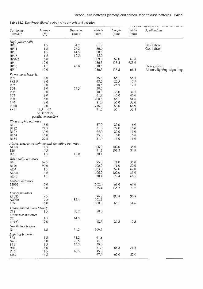
Carbon-zinc batteries (primary) and carbon-zinc chloride batteries 5416 1
Table 64.7 Ever IReady (Berec) carbon-zinc dry cells and batteries
Catalogue Voltage Diameter Height Length Width Applications number (VI (mm) (mm) (mm) (mm)
34.2 High-power cells HP2 1.5 HPll 1.5 26.2 HP7 1.5 14.5 HP16 1.5 10.5 HP992 6.0 HP1 12.0 HP16 1.5 45.0 HP1 12.0 Power pack batleries PP 1 6.0 PP3-P 9.0 PP3 9.0 PP4 9.0 25.5 PP6 9.0 PP7 9.0 PP8 6.0 PP9 9.0 PPl0 9.0 PP11 4.5 + 4.5
(in series or parallel externally)
Photographic batteries E121 15.0 B122 22.5 B123 30.0 B154 15.0 B155 22.5 Alarm, emergency lighting and signalling batteries AD28 4.5 126 D23
4.5 1.5
Valve radio batt,zries BlQl 67.5 B126 90.0 AD4 1.5 AD28 4.5 AD55 1.5 Lantern batteries P5996 6.0 99 1 6.0 Fencer batteries
12.0
R1585 7.5 A0300 7.2 182.4 PP8 6.0 Transistorized clock battery c11 1.5 26.2 Calculator batteries c 7 1.5 14.5 PP3-c 9.0 Gas lighter battery U14 1.5 51.2 Lighting batteries SP2 1.5 34.2 No. 8 3.0 21.5 SPl1 1.5 26.2 800 3.0 U16 1.5 10.5 1289 4.5
61.8 Gas lighter 50.0 Gas lighter 50.5 45.0
109.0 67.0 67.0 136.5 133.5 683.0
136.5 133.5 68.3 Alarms, lighting, signalling 10.5 Photographic
55.6 65.1 55.6 48.5 26.5 17.5 48.5 26.5 17.5 50.0 70.0 36.0 34.5 61.9 46.0 46.0
200.8 65.1 51.6 81.0 66.0 52.0
226.0 66.0 66.0 91.3 65.1 52.4
37.0 27.0 16.0 51.0 27.0 16.0 65.0 27.0 16.0 35.0 16.0 16.0 51.0 16.0 16.0
106.0 102.0 35.0 91.3 103.2 34.9 30.1
95.0 71.0 35.0 100.0 71.0 50.0 103.0 67.0 67.0 106.0 102.0 35.0 38.1 79.4 66.7
102.0 67.0 67.0 125.4 135.7 72.2
196.8 198.4 96.8 193.7 200.8 65.1 51.6
50.0
48.5 26.5 17.5
109.5
61.8 74.0 50.0 81.0 68.3 36.5 45.0 67.0 62.0 22.0

54/12 Carbon-zinc batteries (primary) and carbon-zinc chloride batteries
Table 54.8 Varta carbon-zinc dry cells and batteries
Designation Voltage Equivalent Designation Voltage Equivalent Eveready size Eveready size
Single power (SP) 21 1 212* 213* 214 25 1 20 1 259 430 (PJ430) High power (HP) 232* 233* 244
1.5 1 .5 1.5 1 .5 1.5 4.5 3.0 6.0
1.5 1.5 1.5
u 2 SP2 SP11 u11 u12 1289 No. 8 996 (PJ996)
HP2 HPll HP7
245 434 14 12* 28 29*
438* 439* 489
High drain 222* 236 239
1 .5 6.0
15.0 22.5 9.0 9.0 9.0 9.0 9.0
1 .5 1 .5 1 .5
D23 PX23 E154 E122 PP6 PP4 PP3 PP9 PP7
-
-
HP16
* Steel clad
Table 54.9 Varta carbon-zinc cells and batteries
Varta type order No. Capacity Nominal Size Dimensions (mm) (mA h) voltage
(VI Diameter/ Width Height length
900 1.5 AAR6AJM-3 14.5 50.5 Standard 1800 4.5 3R12 62.0 22.0 67.0
2200 1.5 C/R 14AJM-2 26.2 50.0 4500 1.5 D/R20/UM- 1 34.2 61.5 1000 1.5 AAlR61SUM-3 14.5 50.5
Super 925 3.0 2R10 21.8 74.6 High 2000 4.5 3R12 62.0 22.0 67.0 Performance 2650 1.5 C/R I4/SUM-2 26.2 50.0
6000 1.5 D/R20/SUM- 1 34.2 61.5 300 9.0 6F22 26.5 17.5 48.5
1100 1.5 AAR6lSUM-3 14.5 50.5 2300 4.5 3R12 62.0 22.0 61.0
Super Dry 8000 1.5 C/R14/SUM-2 26.2 50.5 350 1.5 DIR20ISUM-1 34.2 61.5 350 9.0 6F22 26.5 17.5 48.5
1 1006 1012 1014 1020 2006, 2606 2010 2012 2014, 2614 2020, 2620 2022, 2622 3006 3012 3014 3020 3022
I Table 54.10 Yuasa carbon-zinc dry cells
Type Nominal voltage
Wl
Dimensions (mm)
Diameter Height
Jacket material
IEC Equivalent batteries
Ray-o-Vac Eveready Ever Ready (Union Carbide) (Berec)
Standard Diamond series UM- 1 1.5 UM-2 1 .5 UM-3 1.5 006P 9.0 Hi capacity Golden G series SUM-1G 1.5 SUM-2G 1.5 SUM-3G 1 .5 SUM-4G 1.5
33 60 26 49 14 50 17 49
33 60 26 49 14 50 10 44
Metal Metal Paper Metal
Metal Metal Metal Paper
R20 R14 R6 6F22
R20 R14 R6 R03
2D 1c IR 1604
13 14 15 400
950 935 915 216
1050 1035 1015 912
u2, PLU2 u11 u12 PP3
HP2, PP12 HP11, PP13 H97, PP14 U16

Mercury batteries


Mercury-zinc (primary) batteries 55/3
be encountered (and for instrumentation and sci- entific applications). The 1.4V cells (a mixture of manganese dioxide and mercnric oxide depolariza- tion), or batteries made up of these cells, are used for commercial applications of all types other than those just mentioned. The 1.4V cells or batteries should be used for long-term continuous low-drain applications if a very flat voltage characteristic is not needed.
Stabilized battery characteristics are unaffected by high temperatures. The mercuric oxide cell has good high-temperature characteristics. It can be used up to 65-70"C, and operation at 145°C is possible for a few hours. In general, mercuric oxide batteries do not perform well at how temperatures. However, recent developments have produced several popular cell sizes, which have good low-temperature characteristics. For the mercuric oxide batteries not in this group, there is a severe loss of capacity at about 4.4"C, and near 0°C the mercuric oxide cell gives very little service except at light current drains.
The life curve (Figure 55.1) shows typical perfor- mance of the cylindrical mercuric oxide battery, E12, over the temperature range of -23 to + 7 1 T for cur- rent drains encountered in many applications. Success- ful operation at temperatures above 120°C for short periods has been reported, but it is recommended that 70°C is not exceeded. Voltage depression is slight at low temperatures when drains are 1OOpA or less, in the large cell types, or when intermittent drains of this order are used with smaller cells.
Union Carbide supply a range of Eveready mer- cury-zinc cells and batteries with voltages between 1.35 and 97.2V and capacities from 16 to 28Ah. These batteries are of the button cell or cylindrical design and the electrical and dimensional specifica- tions together with information on typical usages for some of these batteries are given in Table 55.3. Further information on the electrical specification including
55.1 Mercury-zinc (primary) batteries Union Carbide and Mallory are two of the major pro- ducers of mercury-zinc cells and batteries. There are, of course, other important producers such as Berec (UK), Crompton-Parkinson (Hawker Siddeley) (UK) and Varta (West Germany). Table 55.1 tabulates the type numbers of equivalent cells, which meet a given International Electrochemical Commission (IEC) des- ignation as produced by Union Carbide, Mallory, Berec and Varta. In many instances equivalent cells are available from more than one manufacturer. In such instances, comparative cost quotations would be of interest to the intending purchaser.
Both Union Carbide and Mallory use a vented construction, which renders their products leak-proof and free from bulging under all normal working conditions. Self-venting occurs automatically if, for example, excessive gas is produced within the cell under sustained short-circuit conditions. Both manu- facturers assemble cells in a wide variety of structures to provide batteries of varying size, voltage and capa- city. A wide range of purpose-built batteries can also be obtained. For maximum reliability, inter-cell con- nection is by spot-welded strips of nickel-plated steel. Outer containers are made from materials ranging from cardboard to metal.
Union Carbide
These batteries can be stored for periods of up to 3 years; it is not, however, good practice to store them for long penods.
Mercuric oxide batteries are available with two for- mulations designed for different field usage. In gen- eral the Il.35.v' cells (that is, 100% mercuric oxide depolarization) or batteries using these cells are re- commended for voltage reference sources (that is, high degree of voltage stability) and for use in applica- tions where higher than normal temperatures may
120 110
100 90 80
r 70 1 - E m F 50
40 30
20 10
0
40 9 , 31 rnA at 1.25 V
30 9 . 4 2 mA at 7.25 V
25 9. 50 mA at 1.25 V
15 R. 83 rnA at 1.25 V 10 9, 125 rnA at 1.25 V
5 9 , 2 5 0 mA at 1.25 V
- 20 0 10 20 32 43 55 65 76 Temperature ("C)
Figure 55.1 Mercury-zinc cell life versus temperature (E12 type, 3.6A h capacity) (Courtesy of Union Carbide)

5514 Mercury batteries
Table 55.1 Some equivalent mercury-zinc cells from different manufacturers
IEC Designation
MR41 MR08
NR48 MR48
NR08 MR42 NR43 MR43 MR07 NR07
MR44 MR9
MR52 NR52 MR1
MR50
MR7
NR50 NR1 MR17 NR6 MR6
MR5 1
Union Carbide Eveready Mallory Duracell Varta Beret Ever Ready
No. Voltage Capacity No. Voltage Capacity No. Voltage No. Voltage (VI ( d h ) (VI ( d h ) (VI (VI
325 E400N E400
E138, E13E 323
343
354 EPX675
313 E625 E630 E625N EPX625 EPX 13
E401N E401, E401N
EPXl El
E3
E502E E9 E502
1.35 1.35 1.40
1.40 1.35
1.35
1.35 1.35
1.35 1.40 1.40 1.35 1.35 1.35
1.35 1.40
1.35 1.40
1.35
1.40 1.40 1.35
50 80 80
85 95
120
150 220
220 350 350 250 250 250
800 800
1000 1000
2200
2400 2500 2400
RM13H 1.40 85 7106 1.40 RM13H 1.40 WH6 1.35 95
RM575H 1.40 100 7109 1.40 RM575H 1.40 WH12NM 1.35 110 RM4 1 1.40 150
PX675 1.35 210 7001 1.35 MP675H 1.40 210 7103 MP6754 1.40 SP675 1.40 230 WH3 1.35 220
PX625 1.35 250 7002 1.35 PX625 1.35 RM625N 1.35 350 RM625N 1.35 PX640 1.35 500 RM640H 1.40 500
RMlN 1.35 1000 PX 1 1.35 1000
RM1 1.40 1000 MP401 1.40 1000
ZM9C 1.40 2400
RMlN 1.35 PX1 1.35
ZM9C 1.40
RM12R 1.35 3600 RM675H 1.40 7101 1.40 RM675H 1.40 RM625 7102 1.40 RM312H 7107 1.40 RM41H 7108 1.40 PX825 7201 1.50
RMlH 1.40 RM401H 1.40
capacity and estimated hours service at 21°C under various conditions for a range of these cells is given in Table 55.2 (1.35 and 1.4V cells) and Table 55.4 (2.7 to 12.6 V batteries). Typical discharge curves at 21°C for a typical Eveready cell are reproduced in Figure 55.2.
Mallory
The voltage, capacity and physical characteristics of some of the Mallory Duracell range of mercury-zinc cells and batteries are shown in Tables 55.5 and 55.6. Battery types 304116 (12.6V) and TR431 (11.2V)

Table 55.2 Union Carbide Eveready zinc-mercuric oxide cells, 1.35 and 1.40V
Eveready Voltage Suggested Designation Average Estimated sewice life at 21°C Average number (VI current service impedance
range ANSI IEC capacq Schedule Starting Load Cut-08 Service life at 1OOOHz (mA) (mA h) W a y ) drain (Q) voltage (h) (Q)
h A ) (V
E21 2E 1.35
325 1.35
388 1.35
387 1.35
E502E 1.40
E9 1.40
E12 1.40
E42 1.40
0- 1
0-0.1
0-0.07
0-0.1
0-200
0-200
0-250
0-1000
M4
wM5
-
-
M55
M55
M70
MlOO
16 to 0.9V at 0.9 mA 50 to 1.2V at 13 000 Q load 65 to 1.2 V at 20 000 Q load 80 to 0.9V at 13 000 Q load 2400 to 9V at 48 mA
2500 to 9 V at 50 mA
3800 to 9 V at 83 mA
14 000 to 9V at 280 mA
24 0.9000 1.1000
24 0.1040 24 0.0054 24 0.0675
24 0.1040
24 17.0000 24 17.0000 24 54.0000 24 54.0000 24 16.9000 24 16.9000 24 56.0000 24 56.0000 24 44.0000 24 44.0000 24 140.0000 24 140.0000 24 318.0000 24 318.0000
1120.0000 24 1120.0000 24
1500 1250
13 000 25 000 20 000
13 000
83 83 26 26 83 83 25 25 32 32 10 10 4.4 4.4 I .25 1.25
0.9 0.9 1.2 1.2 0.9 1.2 1 .0
0.9 1.1 0.9 1.1 0.9 1.1 0.9 1.1 0.9 1.1 0.9 1.1 0.9 1.1 0.9 1.1
20 16
14 months 540 65
1000 980 800
174 154 51.2 42.1
180 175 55 52
100 91 33 28 60 29 7.5 1

55/6 Mercury batteries
Table 55.3 Range of Union Carbide Eveready mercury-zinc batteries
Battery No. Suggested Service Service Maximum dimensions (mm) Number (in order of current capacity capacity of cells increasing range (mA h) (Ah) Diameter Length Width Height
A h capacity) (m'A.1 rated at (mA)
1.35 and 4.0 V batteries E212E 0-1.0 E312 0-5.0 E312E 0-5.0 E42 0- 1000 42N 0-1000
E30265 1 0- 1000 E302157 0-2000
2.7 and 2.8 V batteries EPX14 0-5
E152 0-30 E132 0-100
E132N 0-100 E302702 0-60
4.05 and 4.2 V batteries EPX29 0- 1
EPX25 0-5
E233 0-60
E233N 0-60
5.4 and 5.6 V batteries EPX23 0-10 EPX32 0-50 E164 0-50 E30235 1 0-60 E302904 0-80
6.75 and 7 V batteries E175 0-10
E115N 0-20
16.2 and 16.8 V batteries E302362 0-20
E303314 0-250
27 V battery E302580 0-80
29.7 V battery E302579 0-20
47.25 V battery E302465 0-100
97.2 V battery E302462 0- 100
16 45 45
14000 14000
14000 28000
250
350 1000
1000 2200
160
250
2200
2200
110 500 500
2200 3400
180
250
250
2200
3400
250
1000
1000
0.75 0.85 0.85
280.00 280.00
250.00 500.00
5.00
5.00 20.00
20.00 42.00
1 .oo
5.00
42.00
42.00
2.00 10.00 10.00 42.00 63.00
2.20
5.00
5.00
50.00
63.00
5.00
30.00
30.00
5.72 7.87 7.87
30.40 30.40
33.30
16.90
12.30 16.80
16.80 28.60
12.10
16.80
26.00
26.00
15.20 17.20 16.80 27.00 34.10
12.60
16.80
19.10
54.00
3.30 3.56 3.56
60.70 60.70
61.90 63.50 34.90 108.00
15.40
28.90 32.90
32.90 41.30
17.30
21.50
50.60
50.60
20.00 44.90 44.30 66.70 74.60
27.80
33.50
80.20
72.40 71.40 33.50
69.10 69.10 99.20
35.70 19.10 8 1 .oo
95.30
71.40 38.90 163.00
1 1 1 1 1
1 2
2
2 2
2 2
3
3
3
3
4 4 4 4 4
5
5
12
12
20
22
35
72

Mercury-zinc (primary) batteries 5517
Cell size Application (g)
Weight Terminals (cm3 taps
Volume Voltage
212 4-31141 4-31 141 42D 42D
42D 42D
625
450 1
1 3
675
625
3
3
575 640 640 3 4
675
625
625
15 AA low temperature cell
4
625
1
Hearing-aids Instruments Hearing-aids Instruments Instruments (voltage
reference) Instruments Radiation equipment
Photographic (with cadmium sulphide cell)
Instruments Transistor applications,
Transistor applications Geophysical
hearing-aids
Electric eye (movie
Electric eye (movie
Radio
camera)
camera)
Instruments
B-C flash Camera Radio Fire alann Meter
Radio
Instruments
Radiation equipment transceiver
Instruments
Test equipment
Geophysical
Transmitter B
0.28 0.85 0.85
167.00 167.00
174.00 383.00
8.50
11.30 26.70
26.70 56.70
7.25
13.90
89.30
89.30
7.25 31.20 34.00
128.00 170.00
11.90
20.00
51.00
363.00
953.00
142.00
482.00
907.00
Flat contact Flat contact Flat contact Flat contact Flat contact
Special leads Socket
Flat contacts
Flat contacts Flat contacts
Flat contacts Wire leads
Flat contact
Flat contact
Flat contact negative recessed
Flat contact
Flat contact Flat contact Flat contact Flat contact Wire lead
Flat contact negative recessed
Flat contact
Wire lead
Recessed flat contact
Socket
Wire lead
Wire lead
Wire lead
0.08 0.13 0.13
47.50 47.50
47.50 220.00
3.28
3.10 6.50
6.50 21.30
1.81
4.59
26.20
26.20
3.44 10.00 10.00 37.70 59.00
3.60
7.20
18.50
156.00
472.00
47.50
198.00
420.00
-, $1.35 -, +1.40 -, +1.40 -, $1.40 -, +1.35
-, +1.35 -. +1.35
-, $2.70
-, +2.80 -, +2.80
-, 12.80 -, +2.70
-, $4.05
-, +4.05
-, $4.20
-, +4.05
-, $5.60 -, $5.60 -. +5.60 -, +5.40 -, +5.40
-, +7.00
-, +6.75
-, f16.20
-, +16.80
-, +27.00
-, +29.70
-, +47.25
-, +97.20

55/8 Mercury batteries
Table 55.4 Union Carbide Eveready zinc-mercuric oxide cells, 2.7 and 12.6V
Eveready Voltage Suggested Average service capacity Estimated average hours service at 21°C number (V) current h)
range Schedule Starting Load Cut-off Service (mA) (hlday) drain (a) voltage life
(V) (h)
EPX14
E152
E133N
E163
E164N
EPX23
E135N
E175
E136N
E146X
E177
E289
2.7
2.8
4.05
4.2
5.4
5.6
6.75
7.0
8.1
8.4
9.8
12.6
0-5
0-30
0-100
0-50
0-50
0-10
0-100
0-10
0-100
0-30
0-10
0-50
250 to 1.8V rated at 5mA
350 to 1.8 V rated at 7 mA
1000 to 2.7V rated at 20mA
500 to 2.7V rated at lOmA
500 to 3.6V rated at lOmA
110 to 3.6V rated at 2 mA
1000 to 4.5 V rated at 20mA
180 to 4.5 V rated at 2.2 mA
1000 to 5.4V rated at 20mA
575 to 5.4 V rated at 15 mA
215 to 6.3 V rated at 2.05 mA
750 to 8.1 V rated at 15 mA
24
24
24
24
24
24
24
24
24
24
2
4
24
0.98 5.40 5.60 5.60
22.40 22.40 22.50 22.50 37.50 37.50 11.20 11.20 28.00 28.00 10.80 10.80 27.00 27.00
1.70 1.70 5.60 5.60
22.50 22.50 37.50 37.50 2.30 2.30
22.50 22.50 37.50 37.50 11.00 11.00 28.00 28.00 5.40 5.40 9.80 9.80
17.50 17.50 56.00 56.00
2750 500 500 500 125 125 180 180 108
375 375 150 150 500 500 200 200
3340 3340 1000 1000 300 300 180 180
3000 3000 360 360 216 216 750 750 300 300
1800 1800 1000 1000 720 720 225 225
1.8 2x0 1.8 58 1.8 75.8 2.2 74.7 1.8 12.8 2.2 10.5 2.7 52.6 3.3 42 2.7 31.7 3.3 18 2.7 50.8 3.3 46.5 2.7 22 3.3 8.1 3.6 51 4.4 46 3.6 15.8 4.4 7.5 3.6 66.3 4.4 61.7 3.6 16.5 4.4 15 4.5 52.6 5.5 42 4.5 31.7 5.5 18 4.5 87 5.5 86 5.4 52.6 6.6 42 5.4 31.7 6.6 18 5.4 60 6.6 44 5.4 19 6.6 5 4.2 44 6.6 42 4.2 25 6.6 21 0.9 51.5 1.1 41.5 0.9 12 1.1 4.6
~
(Table 55.6) are recommended as smoke alarm cen- tre batteries. Mallory recommend that, for the best contact to the terminals of mercuric oxide batteries, the device contacts be made of a spring material such as phorphor-bronze or beryllium copper, which will maintain a contact force of at least 50g for an extended
period of time. The contact should be plated with about 5 0 . 8 ~ nickel (continuous) followed by a minimum of 0.508pm gold. The reliability of the contact can be further increased by subdividing the main contact member into two, three or more individual points or prongs such as the tines of a fork.

Mercury-zinc (primary) batteries 551'9
1.5
1.3
1.1
0.9
0.7.
1.6 1.5
5 1.4 - 1.3 g 1.2 5 1.1 > 1.0
0.9 mA (starting)
7 0.9 0.8
I I I I I I
- 2500 !2\
- 0.5 mA -
I I 1 I I I 1 1 I 1 1 I 1 1 1 I I I
0 5 10 15 20 25 30 Service at 21 "C (h)
Figure 55.2 Unilon Carbide 212E mercury-zinc cell, 1.35V (1 6 mA h to 0.9 V at 0.9 mA, load 1500 Q). Voltage discharge curve, estimated average service at 21°C versus voltage (Courtesy of Union Carbide)
Table 55.5 Mallory Duracell single-cell mercury-zinc cells
Nominal Nominal Type Max. Max. Weight voltage capacity diameter height (g)
(VI ( d h ) (mm) (mm)
1.35 1.35 1.35 1.35 1.35 1.35 1.35 1.35 1.35 1.35 1.3.5 1.35 1.35 1.40 1.40 1.40 1.40 1.40 1.40 1.40 1.40 1.40 1.40 1.40 1.40 1.40
45 RM312 50* WH1 62" lORl0 80* PX400 80* W2 95* WH6
110* WH12NM 120* WH8 ?,IO* PX675 220* WH3 2i50 PX625
13 000 RM2550R 14000 RM42R
16 RM212H 75 RM400H 85 RM13H
100 RM575H 210 MP675H 230 SP675 500 RM640H 600 RM660 800 RM401
1000 MP401 1000 RM1 2400 ZM9C 3600* ZM12
7.75 7.80 8.84
11.60 11.56 7.75
11.58 11.56 11.60 11.56 15.60 65.00 34.00 5.59
11.60 7.87
11.60 11.60 11.60 15.90 17.40 12.00 12.00 16.40 14.50 16.26
3.56 0.6 3.60 0.8 3.30 0.9 3.43 1.1 3.55 1.4 5.33 1.2 3.60 1.4 3.84 1.6 5.40 2.6 5.40 2.9 6.20 4.0
13.97 178.0 60.70 167.0 3.10 0.32 3.43 1.1 5.34 1.0 3.50 1.4 5.40 2.6 5.40 2.6
11.20 7.9 7.57 7.6
29.00 11.0 30.20 13.0 16.80 12.0 50.00 30.0 49.71 40.0
*Low-rate cell
Voltage discharge curves for representative cells and batteries in the Duracell range are shown in Figure 55.3 These curves show the estimated average service life at 20°C to be expected at various current drains on constant-resistance load for various Duracell 1.35 and 1.4V cells, for cells with nominal capacities in the range 80-85 mA h.
Mallory produce special mercury cells based on the wound-anode constructioin principle, which are particularly suitable for use at lower temperatures than
Service a t 20 "C (h) (a) PX400
1 . 5 c 1.4 1.3 1.2 1.1 1 .o 0.9
0 35 70 105 140 175
Service a t 20 "C (h)
(b) RM13H
Figure 55.3 Mallory Duracell mercury-zinc cells and batteries, voltage discharge curves: estimated average service at 21°C versus voltage. Current drains at 1.25V. (a) 1.35V, 80mAh to 0.9V on 25000C2 at 20°C; (b) 1.4V, 85rnAh to 0.9V on 1250Q at 20°C; impedance (average at 15% discharge) 7.6Q at IOHz, 7.0 C2 at 1000 Hz, 6.0 Q at 100 000 Hz (Courtesy of Maliory)
those recommended for normal mercury cells. Thus Mallory types RM1438, RM1450R and RM2550W operate efficiently at a temperature 15°C lower than the standard mercury cells.
Diirucell Europe
Duracell Europe supply a selection of the mer- cury-zinc batteries produced by Mallory under the same type number. These are listed in Table 55.7, together with the table numbers from which details concerning these batteries can be obtained.
Crornpton-Parkinson
This company, under the trade name of Vidor, sup- plies a 13.4V mercury-zinc battery (K13-4-1499) in which the cells are encapsulated in epoxy resin to pro- duce a solid block, resistant to all forms of damage. It is recommended for use in electronic equipment, transceivers and rocket sondes and as a secondary standard voltage source. This battery is 59 x 40 x 59 mm and weighs 285 g. The battery terminal open voltage is 13.56V at WC, 13.57 V at 20°C and 13.58 V at 30°C. At a constant discharge of l0mA the battery has a life of approximately 2 years at temperatures between -10 and +2WC, decreasing towards 1 year at temperatures outside this range. Typical discharge characteristics for this cell at temperatures between -10 and +2WC and on constant resistance loads are shown in Figure 55.4. The discharge characteristics are little affected by whether the duty is continuous or intermittent.
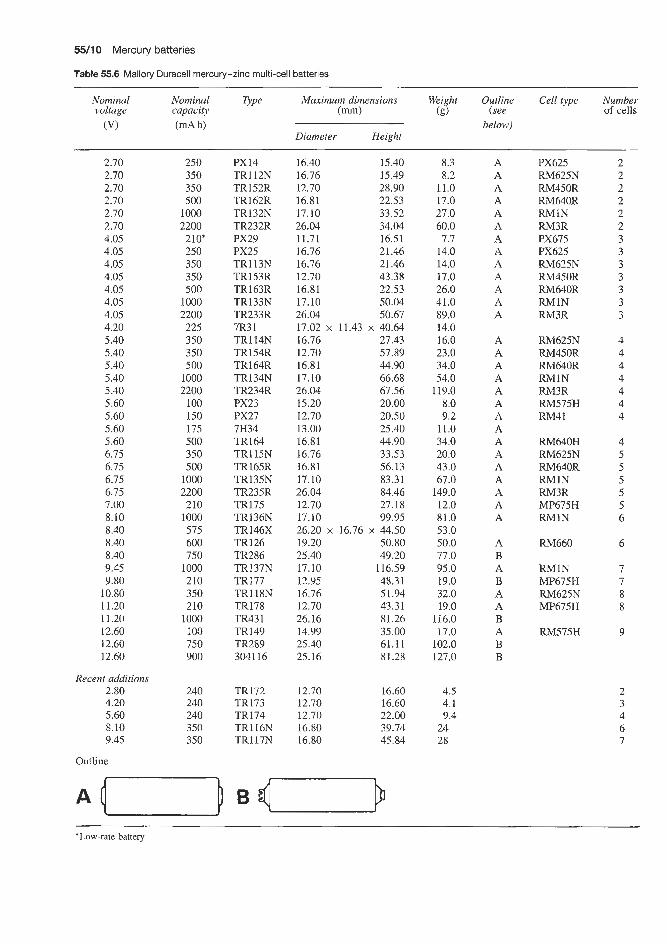
55/10 Mercury batteries
Table 55.6 Mallory Duracell mercury-zinc multi-cell batteries ~ ~~
Nominal Nominal Type Maximum dimensions Wei ht Outline
below) voltage capacity (m) (8 (see
Diameter Height (VI (mA h)
Cell type Number of cells
2.70 2.70 2.70 2.70 2.70 2.70 4.05 4.05 4.05 4.05 4.05 4.05 4.05 4.20 5.40 5.40 5.40 5.40 5.40 5.60 5.60 5.60 5.60 6.75 6.75 6.75 6.75 7.00 8.10 8.40 8.40 8.40 9.45 9.80
10.80 11.20 11.20 12.60 12.60 12.60
Recent additions 2.80 4.20 5.60 8.10 9.45
Outline
250 350 350 500
1000 2200 210* 250 350 350 500
1000 2200 225 350 350 500
1000 2200
100 150 175 500 350 500
1000 2200 210
1000 575 600 750
1000 210 350 210
1000 100 750 900
240 24.0 240 350 350
PX14 TRl12N TR152R TR162R TR132N TR232R PX29 PX25 TR113N TR153R TR163R TR133N TR233R 7R3 1 TR114N TR154R TR164R TR134N TR234R PX23 PX27 7H34 TR164 TR115N TR165R TR135N TR235R TR175 TR136N TR146X TR 126 TR286 TR137N TR177 TRl18N TR178 TR43 1 TR149 TR289 304116
TR172 TR173 TR174 TR116N TR117N
16.40 15.40 16.76 15.49 12.70 28.90 16.81 22.53 17.10 33.52 26.04 34.04 11.71 16.51 16.76 21.46 16.76 21.46 12.70 43.38 16.81 22.53 17.10 50.04 26.04 50.67 17.02 x 11.43 x 40.64 16.76 27.43 12.70 57.89 16.81 44.90 17.10 66.68 26.04 67.56 15.20 20.00 12.70 20.50 13.00 25.40 16.81 44.90 16.76 33.53 16.81 56.13 17.10 83.31 26.04 84.46 12.70 27.18 17.10 99.95 26.20 x 16.76 x 44.50 19.20 50.80 25.40 49.20 17.10 116.59 12.95 48.31 16.76 51.94 12.70 43.31 26.16 81.26 14.99 35.00 25.40 61.11 25.16 81.28
12.70 16.60 12.70 16.60 12.70 22.00 16.80 39.74 16.80 45.84
8.3 A 8.2 A
11.0 A 17.0 A 27.0 A 60.0 A 7.7 A
14.0 A 14.0 A 17.0 A 26.0 A 41.0 A 89.0 A 14.0 16.0 A 23.0 A 34.0 A 54.0 A
119.0 A 8.0 A 9.2 A
11.0 A 34.0 A 20.0 A 43.0 A 67.0 A
149.0 A 12.0 A 81.0 A 53.0 50.0 A 77.0 B 95.0 A 19.0 B 32.0 A 19.0 A
116.0 B 17.0 A
102.0 B 127.0 B
4.5 4.1 9.4
24 28
PX625 2 RM625N 2 RM450R 2 RM640R 2 RMlN 2 RM3R 2 PX675 3 PX625 3 RM625N 3 RM450R 3 RM640R 3 RMlN 3 RM3R 3
RM625N 4 RM450R 4 RM640R 4 RMlN 4 RM3R 4 RM575H 4 RM41 4
RM640H 4 RM625N 5 RM640R 5 RMlN 5 RM3R 5
5 MP675H RMlN 6
RM660 6
RMlN 7 MP675H 7 RM625N 8 MP675H 8
RM575H 9
*Low-rate battery

Mercury-zinc cardiac pacemaker batteries 55/11
In addition, Varta produce a range of low-drain cells for electric and electronic watches with analogue display (Table 55.9).
Other producers of mercuric oxide-zinc hearing aid button cells include Rayovac (55-12OOmA h capa- city), Eveready (3-270 mA h capacity), and Panasonic (60-1100mAh capacity).
- - 12 01 12- I 1 E IO 8 9 9
Varta
Varta produce a wide range of mercuric oxide batteries and button ce.ils in the voltage range 1.35-5.6V and the capacity range 40-1000mAh (Table 55.8). These batteries are mainly used in photographic and hearing- aid applications.
11-
10% I
Table 55.7 Mercury-zinc batteries supplied by Duracell (See also Table 55.5)
9 P @ Voltuge Capacity ut N O . (VI 20°C (mA h)
RMlN RM13H MP40 1 PX625 RM625N PX640 MP675H SP675 PX23 PX27 TR132N TR133N TR134N TR162 TR163 TR164
1.35 1.4 1.4 1.35 1.35 1.35 1.4 1.4 5.6 5.6 2.1 4.05 5.4 2.7 4.05 5.4
1000 85
1000 250 350 500 210 240
80 150
1000 1000 1000 500 500 500
14 13 12 1 1 10 9 0 10 20 30 40 50 60 70
Discharge (h)
(a) Medium loads, +20 "C
55.2 Mercury-zinc cardiac pacemaker batteries The first pacemaker batteries were produced in about 1973, and since then many improvements have been made in their design.
The type I battery has a nominal voltage of 1.35V and a nominal capacity of 1OOOmAh defined for a load of 1250 Q, with a cut-off voltage of 0.9 V. For lighter loads, tests on early production batteries have given the results shown in Table 55.6.
The values in Table 55.6 are to be considered as minima. It is clear that reducing the drain does not result in a proportional increase of life. To meet the demand for longer service life, Mallory have devel- oped a new type RM 2cell. Its construction differs from the earlier one in a number of respects. Its nom- inal capacity is 1800mAh: and a capacity realization of 93% over 28 months' discharge is claimed. The service life of this battery is likely to be less than 5 years.
14 1 > 13 - & 12 3 1 1 8 10
9 0 5 10 15
Discharge (h)
(d) Heavy loads, +20 "C
3 14L 13
Discharge (h)
(b) Medium loads, 0 "C 14 13 12 11 10 9 - 0 10 20 30 40 50 60 70
Discharge (h) ( c ) Medium load, -10 'C
Discharge (h)
(e) Heavy loads, 0 O C
1 4 r
g. 1 0 1 9 I I I I l i I I 1 0 10 20 30 40 50 60 70 80 90 100
Discharge (h)
(f) Cyclic load, f20 OC
Figure 55.4 Vidor K13-4-1499 mercury-zinc dry battery: typical cyclic discharge characteristics on 1 min at l00mAfollowed by 9 rnin at 10 mA, at temperatures between -1 0 and +20"C (constant resistance load). Typical voltages at the end of each 100 mA cycle have been plotted (Courtesy of Vidor)

55/12 Mercury batteries
Table 55.8 Mercury-zinc button cells and batteries supplied by Varta
Type No. Voltage Capacity* Internal Dimensions Weight IEC Main Order (VI (mA hj resistance (mmj (g) reference application No.
Diameter Height (a)
0.80 - > - 0.60 - e - -
2 0.40
V 400 PX V 675 PX V 625 PX V 640 PX v 1 PX V 312 HM V 13 HM V 575 HM V41 HM V 675 HM V 675 HP V 625 HM V 14PX V 164 PX V 23 PX V 27 PX
-
-
-
1.35 1.35 1.35 1.35 1.35 1.40 1.40 1.40 1.40 1.40 1.40 1.40 2.70 5.40 5.60 5.60
80 230 350 500
1000 40 95
100 1 50 180 250 350 350 500 100 150
-
2.5 to 4.5 1.5 to 2.2
-
-
9.0 to 14.0 7.0 to 12.0 3.4 to 5.0 2.5 to 4.0 3.6 to 5.4 1.8 to 3.5 1.8 to 2.7 3.0 to 4.5
14.0 to 20.0 10.0 to 16.0
-
11.6 3.6 1.1 11.6 5.4 2.7 16.0 6.2 4.6 15.9 11.2 7.9 16.4 16.8 12.0 7.9 3.6 0.78 7.9 5.4 1.2
11.6 3.6 1.5 11.6 4.2 1.8 11.6 5.4 2.6 11.6 5.4 2.6 16.0 6.2 4.6 16.8 16.0 10.0 16.8 44.9 34.0 15.2 20.0 12.0 12.85 20.5 10.2
- MR 07 MR 9 MR 52 MR 50 NR 41 NR 48 NR 08 NR 43 NR 07 NR 07 NR 9
-
-
- -
Photography Photography Photography Photography Photography Hearing-aids Hearing-aids Hearing-aids Hearing-aids Hearing-aids Hearing-aids Hearing-aids Photography Photography Photography Photography
4400 4677 4625 4640 4002 4312 4013 4575 4042 4676 4675 4627 4015 4164 4023 4027
* Mean values at a discharge voltage of 0.9 V/cell
Table 55.9 Varta low-drain mercury-zinc cells for electric and electronic watches with analogue displays
Type N O .
Voltage (VI
Weight (g)
501 502 503 506 507 508 509
1.35 1.35 1.35 1.35 1.35 1.35 1.35
230 11.6 x 5.4 90 11.5 x 3.6 70 8.5 x 3.15 95 7.9 x 5.4 50 7.9 x 3.6
1 50 11.6 x 4.2 110 11.6 x 3.6
2.69 1.05 0.92 1.24 0.78 2.05 1.63
Shelfpack pieces
10/100 10/100 10/100 10/100 10/100 101100 10/100
Replaces
313, RW 52, WH3, 13 387, RW 51, W2, 214 388, 10 R 10, 221 323, RW 58, WH6, C, 8, SB-C3 325, RW 52, WHI, 6UDC, 5, SB-C1 354, RW 54, 10 R 11,4, SB-C8 343, RW 56, WH8, B, 218, 3
55.3 Other types of mercury battery Mercuric oxide-indium-bismuth and mercury-cadmium (primary) batteries supplied by Crompton-Parkinson
Crompton-Parkinson supply mercuric oxide-indium- bismuth and mercuric oxide-cadmium batteries. These are alkaline systems recommended for applications in which high reliability in particularly onerous long- term storage and use conditions is a prime require- ment.
Operating characteristics for a 0.6 A h mercury- cadmium cell are shown in Figure 55.5.
Mercury-cadmium batteries supplied by Mallory
Mallory supply a mercury-cadmium battery in their Duracell range. This battely (No. 3041 16) is of 12.6 V
1 . O O r
0.0 0.1 0.2 0.3 0.4 0.5 0.6 0.7 Capacity ( A h )
Figure 55.5 Operating characteristics for 0.6Ah mercury oxide-cadmium cell at various temperatures. Hourly discharge rate is 2% of capacity (i.e. C/50) (Courtesy of Mallory)

Other types of mercury battery 55/13
with a capacity of 6.30 mA h to an end-point of 10.3 V or a capacity of 900 mA h to an end-point of 7.0 V, both on 13 000 Q at 20°C. This cylindrical battery weighs 237 g and occupies a volume of 40.5 cm3. Typical two- step discharge characteristics for this battery are shown
14 13
- I2 2 1 1
13000 51 in Figure 55.6. 0.884 mA
Mercury-cadmium batteries supplied by Varta
Varta supply 0.9V, 3200 and 2000mAh mercury- cadmium cells (types 4910 and 491 1 respectively).
9 10
2 9 -
8 7
0 200 400 600 800 loo0 1200 Setvice at 20 "C (h)
Figure 55.6 Malory No. 3041 16 12.6V mercuric oxide-cadmium battery: two-stage discharge curve. Current drain at 11.5V (Courtesy of Mailory)

Lithium batteries


Lithium-sulphur dioxide (primary) battenes 56/3
6-8g. The operating temperature range is -29 to +49"C and the cells have a projected storage capability of more than 20 years. Both reserve and non-reserve type lithium-vanadium pentoxide batteries are avail- able from Honeywell.
Eagle Picher are a major supplier of lithium- vanadium pentoxide cells.
56.1 Lithium-vanadium pentoxide (primary) batteries The excellent storage characteristics of this type of battery are illustrated in Figure 56.1. Honeywell can supply small lithium-vanadium pentoxide cells with capacities up to 100 nnA h, glass ampoule reserve cells with capacities up to 500 mA h, cylindrical button, prismatic and flexible cell configurations, and a range of active cells. Details of some of these cells are given in Table 56.1.
Honeywell have recently developed a high-integrity crimp-sealed lithium-vanadium pentoxide cell. It has an open-circuit voltage of 3.42 V and a voltage under load of more than 3.0 V. The (33093 model has a rated capacity of 100mAh, and the G3094 of 100mAh, both under the rated load. The cells have energy dens- ities of 180-300Wh/dm3 and 132Whkg. The cells are 2 9 m in #diameter, 25-50mm thick and weigh
56.2 Lithium-sulphur dioxide (primary) batteries Honeywell
Honeywell use two types of cell construction: jelly- roll electrodes in crimp-sealed or hermetically sealed cylindrical cells, and large 20- 100 A h 12 V fat-plate electrodes in large reserve batteries. It is a relatively high-pressure system and cells must have safety vents
3.5
- > m
3.0
0 c - = 2.5 5
0 50 100 Percentage of rated capacity
Figure 56.1 Honeywell lithium-vanadium pentoxide cell: discharge performance after 1 and 2 years storage at 24"C, current density = 0.4mNcm'. Average voltage: baseline, 3.26V; storage, 3.21 V (Courtesy of Honeywell)
Table 56.1 Characteristics of Honeywell lithium-vanadium pentoxide cells
P/N description Diameter Length Thickness Volume Weight CapaciQ Rated or width (mm) (mm) (cm3) (g? (Ah? load
(mm? (mA)
Reserve cells 62659 glass ampoule G2664' G2665 glass ampoule G2666 glass ampoule Representative active cells G2682 cylinder DD 63005 cylinder A G2655 f in. button 62692 t in. button G2679 prismatic G3003 flex cell G3025 0.625 button G3004 flex cell
15.2 25.4 15.2 12.7
34.0 16.0 51.7 50.8 20.0 26.2 15.9 38.1
25.4 18.4 55.9 20.3
128.0 71.1 12.7 6.3
50.0 63.5 11.0 25.4
5.1 9.5
11.1 2.6
108.8 12.5 32.3
10.0
2.3 1.6
-
-
10 23 25 6
287 38.5 79
28
6 4
-
-
0.18" 0.75" 0.50* 0.10*
30.0 4.00 3.50* 1.20" 1.00 0.12 0.20" 0.12
0.25 50.0 5.3 1.0
15.0 10.0
250.0 10.0 10.0 10.0
1.0 10.0
* To a 2.5 V cut-off + Uses a throwawa:y activator; parameters given are for cell less activator Capacities given are to a 2 V cut-off at rated load at room temperature. Those rated to a 2.5 V cut-off will deliver 50- 100% more capacity under reduced load when discharged to 2 V

56/4 Lithium batteries
to avoid explosion in the event of accidental incin- eration. Standard cylindrical cells are available in low, medium and high rate configurations. Honey- well estimate that these batteries should store for 12 years at room temperature. A typical energy density is 420 W Mdm3 or 260 W hkg.
The lithium-sulphur dioxide system is versatile and relatively inexpensive. The battery has excellent stor- age characteristics. The batteries can be supplied either as reserve batteries with capacities between 20 and lOOAh or as active (non-reserve) batteries in the 0.7-20 Ah range (Table 56.2).
Mallory
Mallory supply hermetically sealed lithium-sulphur dioxide organic electrolyte cells in the capacity range 1.1 - 10 Ah with a nominal voltage of 3.00 V. Further details are given in Table 56.3.
Discharge and performance on constant resistance load curves for this range of batteries are given, respec- tively, in Figures 56.2 and 56.3.
Mallory claim that their lithium cells offer gravimet- ric energy densities of up to 330 Whkg, nearly three times that of mercury cells and four times that of alkal- ine manganese cells. The volumetric energy density is 50% greater than that of alkaline manganese cells.
The manufacturers also claim that their batteries operate efficiently between -40 and +70"C. They retain 75% initial capacity after 5 years storage at 21°C.
In 1975 Mallory introduced their new glass-to-metal hermetic seal to reduce sulphur dioxide losses from the cell and consequently reduce capacity loss on stor- age and inhibit corrosion effects. Such cells have been stored for 1.75 years at 21°C and 4 months at 72°C
Table 56.2 Honeywell lithium-sulphur dioxide batteries
without leakage. The excellent high-rate properties of the lithium sulphur dioxide system have been con- firmed in the hermetic D-size cell. Results covering the current range lOmA to 1 A and the temperature range +60 to -23°C are quoted in Table 56.4. Full capacity is realized at 24°C regardless of load, and at lOmA load full capacity is realized regardless of temperature.
The estimated current and temperature limits for the hermetic D-size cell for 80, 90 and 100% capacity realization are shown in Figure 56.4.
Silberkraft
Data on various types of lithium-sulphur dioxide bat- teries in the 500-30 000 mA capacity range available from Silberkraft are given in Tables 56.5 and 56.6.
These cells and batteries are claimed to have a particularly good shelf life. Silberkraft claim that the low self-discharge rate of Eterncells gives them a shelf life of 10 years, and that during this period the cells are ready for immediate use. These products conform to the NATO temperature requirements and also to MIL standards.
Silberkraft have recently introduced a revised G range of lithium-sulphur dioxide batteries, which are characterized by improved low-temperature discharge- ability (see Table 56.7).
Figure 56.5 shows typical discharge curves for a lithium-sulphur dioxide 3V cell supplied by Sil- berkraft. Load-capacity and load-voltage plots for the same battery are reproduced in Figure 56.6. The GO6 and G32 cells (see Table 56.7) and the GO3 cell are particularly recommended for power supply for CMOS back-up applications. With these cells, simply by diode
PAI description Diameter Length Thickness Volume Weight Capacity Rated Open-circuit or width (mm) (mm) (cm3) (g) (Ah) load voltage
(mm) (mA/cm2) (VI
Reserve batteries (metal bellows) 20Ah 97.7 60Ah 157.5 IOOAh 20.3 Active cells and batteries G3033 SO2 DD cell 39.0 G3008 SO2 D cell 39.0 G3058 SO2 half D cell 39.0 G2686 SO2 CC cell 26. I G3039 SO2 long C cell 26.1 G3010 SO2 C cell 26.1 G3024 SO2 C cell 26.1 G3029 SO2 A cell 16.0 G3018 SO2 short A cell 16.0 G3028 SO2 AA cell 13.4 G3041 SO2 short AA cell 13.4 G3042 SO2 9V battery 26.1
- - 20.0 - 60.0 - 100.0
152.0 - 152.0 - 152.0 -
- -
129.0 60.9 30.5 99.8 60.9 49.8 49.8 49.8 33.0 49.7 25.4 48.5
- 107.4 185 20.0 - 52.9 94 10.0 - 25.7 48 4.8 - 49.8 85 7.6
30.2 55 4.8 24.4 45 4.6 24.4 45 3.7 9.5 18 1.7 6.4 13 1.2 7.4 14 1.2 3.6 9 0.7
16.7 19.5 50 0.7
- - - - - - -
0.1 0.1 0.1
1000 350 175 700 350 250 350 125 70
100 15 15
12.0 12.0 12.0
2.9 2.9 2.9 2.9 2.9 2.9 2.9 2.9 2.9 2.9 2.9 8.7

Lithium-sulphur dioxide (primary) batteries 56/5
3.0
2.8
2.6
- 2.4
al 2.2 m
= 2.0 ' 1.8
1.6
1.4 1.2
L
01.0 0.1 0.2 0.3 0.5 1 2 5 10 20 50
H o u r s of Service at 21 "C
(a) L0.32, 1.1 A h
3.0
2.8
2.6
7 2.4
2.0
I
g) 2.2
' 1.8
m
1.6
1.4
1.2 0.0 0.1 0.2 0.3 0.5 1 2 5 10 20 50 loo
H o u r s of service at 21 "C
(b) L0.28, 3.9 A h
Figure 56.2 Mallory primary lithium-sulphur dioxide cells: typical discharge characteristics (Courtesy of Mallory)
30 and 152 "C -30 and t 5 2 'C
Service (h) !a) L0.32, 1.1 A h
-30 and f52 "C 60 50 40 30 20 I0 0
1 2 3 4 5 6 7 8 9 1 0 20 30 50 70 100 Service !h)
!b) L0.28. 3.!3 A h
60 - 50 5 40 m 30
20 10 0
V
0 Service (h)
(c) L0.29. 4.4 A h "C
24 I 20
16
J 8 4 0
{ 12
1 2 3 4 5 6 7 8 9 1 0 20 30 405060 100 Service (hi
(d) L0.27, 5.8 A h
Figure 56.3 Mallory primary lithium-sulphur dioxide cells: typical performance on constant-resistance load. End-point voltage 2.QV (Courtesy of Mallory)

56/6 Lithium batteries
Table 56.3 Specification of Mallory lithium-sulphur dioxide primary cells
Type Nominal capacity Maximum Maximum Weight Volume to 2V at 21°C diameter height (€9 (cm3
(Ah) (mm) (mm)
LO32 1.1 on 120Q 16.5 34.3 12 7.0 LO28 3.9 on 36 R 24.4 49.5 43 23.1 LO29 4.4 on 32 R 25.9 49.5 48 26.1 LO27 5.8 on 24 R 25.9 59.9 58 31.5 LO30 7.5 on 18Q 25.9 59.7 62 42.0 LO26 10.0 on 14R 33.8 59.7 85 53.4 Recent additions L0285HX 27.0 24.6 61.3 38 L0295X 3.5 26.0 51.3 40 L0305H 4.3 28.7 60.4 62 L032S 0.85 15.9 35.2 12
~~~
Because of the high-rate capability of the lithium-sulphur dioxide system, precautions must be taken to prevent a short-circuit of the cells. Mallory supply this system only in complete assemblies using an internal fuse or other form of protection
Table 56.4 High-rate discharge performance of Mallory lithium-sulphur dioxide hermetic D-size cell (test performed on resistive loads after 6 months' storage at 20°C)
Nominal discharge temperatures current
Capacity (Ah) at various discharge
-23°C 0°C 24°C 49°C 60°C
1A 3.7 5.8 9.7 6.9 6.8 250 mA 7.1 8.3 10.0 8.2 8.8 50 mA 9.7 9.7 10.1 8.9 9.5 l0mA 10.1 10.3 10.2 10.5 10.5
separation from the operating voltage, a constant volt- age of not greater than 2.2V is able to maintain the memory circuit. The reverse current from the cell may amount to 30 pA maximum.
Duracell International
Duracell International produce a range of lithium-sul- phur dioxide primary batteries. This company manu- factures lithium-sulphur dioxide cells in a variety of cylindrical cell sizes, ranging in capacity from 0.45 to 21 A h. Larger cells are under development but cur- rently not available on a commercial basis. A number of the cells are manufactured in standard ANSI (Amer- ican National Standards Institute) cell sizes in dimen- sions of popular conventional zinc primary cells. While these single cells may be physically interchangeable, they are not electrically interchangeable because of the high cell voltage of the lithium cell (3.0V for lithium, 1.5 V for conventional zinc cells).
Table 56.8 lists the cells currently available and gives their major physical and electrical characteris- tics. The cells are classified in two categories: standard cells (Mallory S designation) and high-rate cells (Mal- lory SH designation). The standard cell is optimized to deliver high-energy output over a wide range of
10 ow
1 wo - 6 E
e - - 2
100
10
continuous operation ( 2 h rate)
-20 0 20 40 60 Temperature ("C)
Figure 56.4 Mallory hermetic D-size lithium-sulphur dioxide cell: current and temperature limits for various capacity realizations (Courtesy of Mallory)
3.0 - 2.6 > - g 2.2
1.8
' 1.4
1 .a 5 10 50100 0.1 0.5 1
Operating time at 21 "C (h)
Figure 56.5 Silberkraft type 440 (renumbered 932) lithium- sulphur dioxide 3V, 0.8Ah cell typical discharge curves (Courtesy of Silberkraft)
discharge loads and temperatures. The high-rate cell is designed with longer and thinner electrodes than the standard cell and delivers more service at a high

Lithium-sulphur dioxide (primary) batteries 5617
Table 56.5 Types and applications of [primary lithium-sulphur dioxide batteries obtainable from Silberkraft
Type Nominal Dimensions Weight voltage (mm) (g)
W)
Application
BA5590/U BA5568KJ BA5598KJ BA584 BA5 1 OO/U BA5567KJ BA5585KJ BA5842KJ BA5574/U BA5841KJ SK660Li PE3.440Li
24 (2 x 12 14.413 14.413 6 3 4 6 6
18 28
8.4
12) 63 x 112 x n27 28 dia. x 77.5 120 x 92 x 54 242 x 92 x 54 39 dia. x 60 26.5 dia. x 21 112 x 89 x 62.5 70 x 37 x 180
53.5 dia. x 143 242 x 92 x 54 62 x 39 x 18
-
1025 85
680 1300
85 20
795 568 46
285 1300
75
XM-8 VINSON MX-9331 wire-line chemical alarm ANPRC-90
ANPRC 77lANPRC 25 Night vision devices Night vision devices Future development Raft light SDU 5E AN/RTIO PRC 660 Battery for pyrotechnic ignition
ANPRC 77lKY-38 ANIGRA-114lANPPS-15
Table 56.6 Cylindrical types of lithium-sulphur dioxide batteries (0.52-30A capacity range) supplied by Silberkraft
Type Nominal Nominal Dimensions (mm) Weight Nominal Comments capacit)i current (g) voltage (mA h) (d) Diameter Height (VI
400-5 446) Li440 FS 400 AA 440-2 660-2 660-C 660-3 550-D 660-50 660-4 660-5 660-5A 400-9
525 1000 1000 1200 2000 2400 3000 3800 8000 9000
IO000 25000 30000
525
11 14.5 15 16.5 12 23.0 24 14.5 75 16.5 50 25.0
100 25.0 125 25.0 250 34.0 250 25.0 250 42.0
1000 42.0 1000 42.0
11 48.5 x 26.51
25.0 34.0 43.0 51.5 58.5 41.0 51.5 60.5 61.0
130.0 50.5
115.0 140.0
x 17.5
7.5 11.5 22.0 13.0 20.0 33.0 40.0 48.0 83.0 95.0
100.0 228.0 280.0
25.0
2.8 $ AA size 2.8 2.8 2.8 2.8 2.8 C size 2.8 2.8 1: C size 2.8 2.8 2.8 2.8 2.8 8.4
AA size IEC R 6 (Mignon)
C size, IEC R 14 (Baby)
D size, IEC R 20 (Mono)
9 V Transistor. IEC 6 F 22
Table 56.7 Revised G range Silberkraft lithium-sulphur dioxide cells
New Previous
Rated capacity
(Ah)
Rated current (m.4
Moximum dimensions (mm)
Diameter Height
Weight (€9
Rated Notes on design voltage
(VI
*GO3 "400-5s *632 "440s *GO6 "400s *G50 660-2s "652 *660S *620 *%OS 670 1500-2s 658 660-4s G60 660-5s
*G62 *660-5 AS
*0.35 "0.8 *1.0 2.4
*3.0 *7.0 8.5 9.5
22.5 *27.5
* 14 *30 *45 100
* 125 *300 350 400 900
* 1100
*14.5 '25 * 17 *35 *14.5 "50.5 26 42
'26.2 *50 '34.2 "61.5 39 53 42 51 42 115
*42 " 140
*7 * 14 * 14 38
* 46 * 85 90
105 228
"290
*2.8 * h AA size *2.8 *2.8
*2.8 *2.8 2.8 2.8 2.8
*2.8
*AA size, IEC R 6 (Mignon)
*e size, IEC R 14 (Baby) *D size, IEC R 20 (Mono)
2.8 ? C size

56/8 Lithium batteries
Room temperature 1 .o
.c 0.8
, 0.6
- a
4 0.4
J 0.2
1
4- .- Q
0 0.050.1 0.5 1 Load (A)
Room temperature
0.05 0.1 0.5 1 Load (A)
Figure 56.6 Silberkrafl type 440 (renumbered 932) lithium- sulphur dioxide 3V, 0.8Ah cell load capacity and load voltage curves (same battery as in Figure 56.5) (Courtesy of Silberkraft)
Table 56.8 Duracell lithium-sulphur dioxide cells
Duracell Part Rated Weight Diameter Height cell type No. capacity* ( g ) (mm) (mm)
(Ah)
L034S 331018 0.95 11.75 25.4 19.0 L037S 331050 0.45 6.5 13.7 24.0 L032S 331035 0.90 12.0 16.3 34.5 L036SX 331051 0.65 13.0 24.0 18.4 L030SK 331079 5.4 62.0 29.1 59.6 LO45SX 331074 6.3 75.0 31.5 57.1 LO26SX 331061 8.0 85.0 33.8 59.6 LO25SX 331075 8.5 95.0 38.7 49.8 LOSOSX 331036 21.0 207.0 38.7 114.0 L027SHX 331078 3.6 47.0 25.7 59.6 L030SH 331034 4.3 62.0 29.1 59.6 L026SH 331029 6.4 85.0 33.8 59.6
* Rated capacity: S and SK cells at 30h rate, SH and SHX cells at 2h rate
discharge rate (higher than the 10 h rate) and at low temperatures. At lower discharge rates, the service life of the high-rate cell is less than that delivered by the standard cell.
In addition, Duracell manufacture a lithium-limited (or balanced) cell (designation SX). The cell is designed with a stoichiometric ratio of lithium to sulphur dioxide of the order of 1:l rather than the excess of lithium used in the other designs. The lithium-limited feature ensures the presence of sulphur dioxide throughout the life of the cell to protect the lithium from chemically reacting with the other cell components. This design has been found successfully to withstand extended reverse discharge below 0 V at rated loads. In addition, these cells do not produce the toxic chemicals that form when standard cells are fully discharged, thus simplifying disposal procedures. The lithium-limited cell does, however, deliver lower capacity compared with the standard cell at low discharge rate (below the 5 h rate).
Other suppliers of lithium-sulphur dioxide prim- ary cells include: Eagle Picher (US); Power Conversion Inc. (US) (0.5-35 A h capacity); SAFT
(US) (0.5-8 A h capacity); Ballard Battery Sys- tems (Canada) (0.8-7.6 A h capacity) and Crompton Eternacell (UK).
56.3 Lithium-thionyl chloride batteries Honeywell
The types of lithium-thionyl chloride reserve and active (non-reserve) cells currently available from Honeywell are shown in Tables 56.9 and 56.10. These include cells with capacities up to 17 000 Ah.
Table 56.9 Types of lithium-thionyl chloride reserve and active cells available from Honeywell
PLV Diameter Length Height Capacity Rated description or width (mm) (mm) (Ah) load
(m) (A) ~ _ _ _ _ _ _ _ _
Reserve G2659B1 16.0 25.4 - 0.36 0.025 Active
16.0 30.7 - 1.3 0.80 G3013C G3037 91.0 109.0 137 381.0 3.00 G3038 58.4 106.0 127 160.0 50.00 G3059 92.2 107.0 156 517.6 3.00
Cell construction techniques similar to those of lithium-sulphur dioxide and vanadium pentoxide cells
SAFT
SAFT supply the LS range of lithium-thionyl chloride cells and batteries (see Table 56.11). The batteries are available in 3.65 and 7.3 V with capacities between 0.5 and 18Ah. The discharge curves exhibit a very flat voltage plateau. The cells are manufactured without any initial internal gas pressure and, because the discharge reaction generates only a limited amount of gas, the need for venting is eliminated. Cells operate between -55 and +71"C, and a shelf life of up to 10 years can be expected because of the negligibly low self-discharge rate of these cells. The energy density of the SAFT lithium-thionyl chloride cell is 800 W h/dm3 compared to 400 W h/dm3 for zinc-mercury, 200 W h/dm3 for carbon-zinc and 300 W Wdm3 for alkaline manganese dioxide. (The corresponding W h/kg data for the four types of cells are 420, 100, 80 and 100.)
Typical discharge curves for the SAFT LS210, 3.5V, 5OOmAh cell are shown in Figure 56.7. Figure 56.8 shows the capacity-current drain relation- ship for the same battery.
Figure 56.9 shows the effect of shelf storage tem- peratures between 25 and 70°C on percentage capacity retention: 80% of capacity is retained after 10 years at 25°C or about 1 year at 70°C.

Table 56.10 Honeywell hermetically sealed lithium-thionyl chloride re lk
TYPE Desig- Open- Voltage Rated capacity Energy density Diameter Length Height Weight Volume Operational Projected
Wh/cm3 W h k g (mm) range (“C) capability or width (mm) (mm) (g) (cm3) temperature storuge
(VI ut 23°C
nation circuit under load (Ah) voltage
(Years)
Active G3013C
G3102
G3103 G3066
Active G3038 spacecraft A battery
Active G3037 spacecrakt B battery
Activc 63059 spacecraft B battery
3.63
3.62
3.62 3.62
3.63
3.63
3.63
(40 S2 load) 3.4
3.4
3.4 >3.0
(0.2 S2 load) 3.3
(9 Q load) 3.6
3.6
1.6 to 2 V cut-off into an 82mA load at 23°C 16 under rated load (17 Ah) limited capacity 17 000 under rated load >50000 W h/cell
166 to 2V cut-off into average 18 A load at 23°C 50 A pulse capacity
400 to 2 V cut-off into average 0.4 A load at 23°C 15 A pulse capability 500A to 2V cut-off into average 0.4 A load at 23°C 15A pulse capability
0.8 301 16 30.7 18 6.7 -40 to 74 2 5
0.94 418 29.9 36.3 53.6 130 58 -40 to41 115
1.1 635 381 381 381 91000 55300 -40 to 41 >15 0.94 418 29.9 36.3 63.0 130 58 -40 to41
0.7 334 58 107 130 1639 808 0 to 60 short >5 voltage delay of 1200ms after 1 month at 60°C
5 3: 5 1.1 592 91 107 140 2429 1362 -40 to 60 2 5

Table 56.11 Characteristics of lithium-thionyl chloride cylindrical cells supplied by SAFT
TYP Nominal capacity (mA h) Open- Nominal voltage Maximum Weight Operating Storage Diameter Height a1 20°C current (VI recommended (6) temperuture temperuture (mm) (mm)
voltage current drain range ("C) range ("C) (VI rate (mA)
LS 210 LS 3 LSH 274 LS 120 LS 6LS6 LSH 14 LSH 14.2 LSH 20 LSH 20.2 LS 622
500 to 2V at I m A drain 850 to 2V at I mA drain
1000 to 2 V at 15 mA drain 1100 to 2V ai 2mA drain 1800 to 2 v 5000 to 2.5 v 9000 to 2.5 V
10000 to 2.5v 18 000 to 2.5 V
1100 to 5V at 2mA drain
3.67 3.5 at 1 mA drain 3.67 3.5 at 1 mA drain 3.67 3.5 at 15mA drain 3.67 3.5 at 2mA drain 3.67 3.5 at 5mA drain 3.67 3.5 3.67 3.5 3.67 3.5 3.67 3.5 7.34 7.0
3 50
500 50
100 600
1500 4000 2000
50
11 8.5
25 10.5 15.5 56
1 05 120 180 30
-40 to 75 -40 to 75 -40 to 75 -40 to 75 -40 to 75 -40 to 75 -40 to 75 -40 to 75 -40 to 75 -40 io 75
-55 to 75 -55 to 75 -55 to 75 -55 to 75 -55 to 75 -55 to 75 -55 to 75 -55 to 75 -55 to 7s -55 to 75
21.2 14.5 26.2 12.5 14.5 26.2 26.2 33.5 33.5 26 x 17 (rectangular)
9.6 25.0 18.7 42.0 50.5 50.0
100.0 61.6
123.0 49.0

Lithium-thionyl chloride batteries 5WIl
3
2
(= 6.5 mA) (3 2.5 mA)
I I I I I A I I 5 10 15 20 25 '90 120 150 '400 600 EM)
Time (h)
I A I I I
Figure 56.7 Discharge curve at 20°C for a SAFT LS210, 3.5V, 500 mAh lithium-thionyl chloride cell (Courtesy of S A W
0.5
0.4
._ 2 0.3
a J 0.2
0.1
- 5 0
I I l l 0.2 0.3 0.4 0.6 0.8 1 2 3 4 5 6 8
Current drain (mA)
Figure 56.8 SAFl- LS210, 35V, 500rnAh lithium-thionyl chloride cell: capacity versus current dram chart at 2O"C, discharge to 2 v (Courtesy of SAFl)
s 0 5 10
Years
i t Figure 56.9 S A R LSL6 3 5 V , 1800rnA h lithium-thionyl chloride battery. Effect of shelf life in storage on percentage capacity retention (Courtesy of SAFT)
SAFT lithium-thionyl chloride cells exhibit a highly stable service voltage and a far greater capacity than conventional zinc-manganese dioxide and carbon-zinc cells of the same size and configuration.
Safety characteristics Figure 56.10 shows a curve obtained for a SAFT type h S622 llOOmAh, 7.34V battery short-circuited at room temperature. The total
0 5 10 15 20 Time (min)
Figure 56.10 Thermal behaviour on total short-circuit of a SAFT type LS622 11 00 rnA h, 7.34V battery (Courtesy of SAFT)
short-circuit results in only a moderate temperature (40°C) with no adverse effects.
Eagle Picher
The range of lithium-thionyl chloride Keeper PI bat- teries available from Eagle Pjcher is tabulated in Table 56.12. These comprise 3.5 V cells in the capacity range 750- 1600 mA h and 7 V batteries with capacities of 750 and 1600mAh. Operating temperature ranges

56/12 Lithium batteries
Table 56.12 Lithium-thionyl chloride hermetically sealed cells and batteries available from Eagle Picher (Keeper II batteries)
Type Open On load Capacity Length Width Thickness Weight Operating circuit voltage at 350h (mm) (mm) (mm) (g) temperature voltage (VI rate range (“C)
(VI (mA h)
LTC-7PMS* LTC-7PMPt LTC-7PN LTC-7P LTC- 12P LTC- 16P LTC- 16P9 LTC-20P
~
7.30 3.65 3.65 3.65 3.65 3.65 7.30 3.65
~
7.00 3.50 3.50 3.50 3.50 3.50 7.00 3.50
750 1500 750 750
1200 1600 1600 1600
38.1 38.1 25.4 30.5 25.4 36.5 45.7 49.2
30.5 30.5 16.5 17.8 13.5 13.5 28.6 13.5
8.4 8.4 6.35 8.4
13.5 13.5 17.5 13.5
19.0 19.0 6.8 9.0
12.0 16.0 25.0 24.0
-40 to 125 -40 to 125 -40 10 125 -40 to 125 -40 to 93 -40 to 93 -40 to 93 -40 to 93
* Two LTC-7PN cells in series ’ Two LTC-7PN cells in parallel
are exceptionally good with this type of battery; from -40 to 93°C or, in some cases, from -40 to 125°C.
Reserve batteries Gas-activated lithium-thionyl chloride reserve batteries are now supplied by Eagle Picher. It will be recalled that Honeywell supply lithium- sulphur dioxide and lithium-thionyl chloride gas-activated reserve batteries. Some of the advantages claimed for this battery design concept are as follows:
1. The batteries provide long-term inactive storage followed by instantaneous high power delivery.
2. Electrolyte storage design allows minimal capacity loss, requires no maintenance and is insensitive to temperature fluctuations.
3. Increased safety is inherent in reserve battery design.
4. The design allows use of features that improve power capability.
5. Reserve batteries prevent the operation of the device until desired.
6. Higher energy density is available than with any other electrochemical system.
7. Costs are lower because no expensive raw mater- ials are used and because the higher cell voltage allows the use of fewer cells and brings reduced labour costs.
8. There are longer activated life and stand capabil- ity because there is no inherent electrochemical process that limits activated life.
9. Voltage delays are eliminated by the use of reserve configuration.
10. Batteries can be activated and operated in any orientation.
11. Both prismatic and cylindrical shapes are avail- able.
12. Cells can be configured so that moulded single-cell cavities nest together to form a cell stack with an integral manifold.
13. The activation input signals can be electrical, mechanical or pressure signals.
14. The electrolyte reservoirs can be spheres, cylinders with pistons or coil tubing.
15. Low-temperature operation can be achieved with electrical heaters, using external power, or chem- ical heaters that require no external power.
16. Multi-section or multi-tap cell stacks are available. 17. Options include removable electrolyte reservoirs
and designs that allow reservoirs and cell stacks to be physically separated and mounted in different locations.
18. Batteries can be designed to be sealed, vented or delay vented.
19. The reserve configuration eliminates most safety concerns associated with lithium-thionyl chloride active batteries.
20. Design emphasis is placed on preventing inadver- tent activation due to mechanical failure or abusive conditions.
21. No-load conditions can be safely tolerated by lithium-thionyl chloride reserve batteries.
22. Hundreds of batteries have been tested by Eagle Picher and no safety incidents have arisen.
23. Electrodes can be designed for the specific application; cathode or anode limited.
24. Internal parasitic loads can be included to safely discharge the battery in the event that the discharge cycle is not completed.
25. Electrical and thermal fuses can be used to prevent accidental battery activation.
26. Removable electrolyte reservoir and valves between the reservoir and cell stack can be used to prevent inadvertent battery activation.
Eagle Picher develop and manufacture reserve batter- ies for a wide range of both military and aerospace applications. Eagle Picher lithium-thionyl chloride reserve batteries have found applications in mines, missiles, and re-entry vehicles where high-power, high energy density and multi-section, multi-tap configura- tions are required.

Lithium-manganese dioxide batteries 56/13
Other suppliers of lithium-thionyl chloride cells include: resene type: Yardney (US), Philips USFA BV (Holland), Power Conversion Ltd (US), SAFT, Silberkraft, (Germany) and Sonnenschein, (Germany); active type: Battery Engineering Co. (US), Crompton Eternacell (UK.), Electrochemical Industries (Japan), Hitachi Maxell (Japan), Power Conversion Ltd (US), Tadiram (Korea), Yardney (US) and Eveready (US).
56.4 Lithiuim-manganese dioxide batteries Duracell
These batteries are claimed to perform well at tem- peratures between -20 and +50"C. In some designs, up to 70% of the rated 200°C capacity is delivered at 20°C. The shelf life is limited by the amount of solvent diffusing through the seal. Negligible capacity loss occurs after 3 years' storage at 20°C. Projections from this suggest that 85% of the initial capacity will be available after storage for 6 years at 20°C.
The cell types available from Duracell are listed in Table 56.13. The cells are manufactured in a variety of button and cylindrical cell designs ranging in capacity from30mAhto 1Ah.
Discharge characteristics of Duracell cylindrical and low-rate button lithium-manganese dioxide cells are shown, respectively, in Figures 56.11 and 56.12.
SAFT (France)
SAFT supply a range of 3 V button cells. These cells have an energy density of 400-500 W h/dm3
3.6 r 3 2.8
& 2.0
0 1.2 >
- m I -
0.4 A
0 40 80 120 160 200 240 280 Service a t 2 1 "C (h)
Figure 56.11 Discharge characteristics of a Duracell DL AN, 3V, 160 rnA h cylindrical lithium-manganese dioxide cell. Current at 2.7V (Courtesy of Duracell)
3.6 r I 2.8
Q 2.0
s 1.2
> - c -
0.4
0 50 100 150 200 Hours of service at 21 "C
Figure 56.1 2 Discharge characteristics of a Duracell DL 1620,3 V, 50 mA h low-rate lithium-manganese dioxide button cell. Current at 2.7V (Courtesy of Duracell)
(120-150 Whkg) and an annual self-discharge rate of 2-3% at 20°C. The capacities range from 200mAh (type LM 2425) through 90 mA h (type LM 2020) to 5OmAh (type LM 2016). Operating temperatures are, again, in the range -20°C to + W C .
Table 56.13 Lithium-manganese dioxide cells and batteries supplied by Duracell
Duracell type No.
IEC type Nominal Rated Weight Diameter No. voltage capacity (g) (mm)
(V) (mAh)
Height
Low-rate cells
DL-1620 DL-1220
DL-2016 DL-2025 DL-2420 DL-2032 DL-2430 High-rate cells DL-2016H DL-2025H DL-2420H DL-2032H DL-2430H Cylindrical cells DL-l/3N DL-2N Batteries PX-28L
CR-1220
CR-2016
CR-2420
CR-2430
CR-1620
CR-2025
CR-2032
CR-20 16H CR-2025H CR-2420H
CR-2430H
CR-l/3N
CR-2032H
CR-2N
2-CR-l/3N
3 3 3 3 3 3 3
3 3 3 3 3
3 3
6
30 0.8 50 1.2 50 2.0
120 2.5 120 3.0 170 3.0 200 4.0
50 2.0 100 2.4 100 3.0 130 2.8 160 4.0
160 3.0 1000 13.0
160 8.8
12.5 16.0 20.0 20.0 24.5 20.0 24.5
20.0 20.0 24.5 20.0 24.5
11.6 12.0
13.0
2.0 2.0 1.6 2.5 2.0 3.2 3.0
1.6 2.5 2.0 3.2 3.0
10.8 60.0
25.2
175 h on 15 kS2 to 1.4V at 21°C 106h on 5.6kS2 to 1.4V at 21°C 106h on 5.6kR to 1.4V at 21°C 143 h on 2.7 kS2 to 1.4V at 21°C 118h on 2.7kQ to 1.4V at 21°C 194h on 2.7kS2 to 1.4V at 21°C 22811 on 2.7kS2 to 1.4V at 21°C
59h on 1 kS2 to 1.4V ab 21°C 20h on 25kS2 to 1.4V at 21°C
59 h on 2kS2 to 2.8 V ai 21°C
Ratings: low-rate cell, C/200 h rate; high-rate cell, C/30 h rate; cylindrical cell, C/30 h rate

56/14 Lithium batteries
SAFT have recently introduced a battery to match the requirement of the microelectronics industry for a battery to provide standby power for RAM mem- ory applications and other integrated circuits. This battery (Memoguards LH and LF) has similar charac- teristics (3.0 V nominal voltage, 200 mA capacity) to the LM2425. However, as shown in Table 56.14, the Memoguard battery has superior operating and storage temperature characteristics.
Table 56.14 Operating and storage temperatures of SAFT lithium-manganese dioxide cells
LM 2425 Memoguard LH and LF
Operating temperature range ("C) -20 to 50 -40 to 70 Storage temperature range ("C) -20 to 50 -40 to 70
The Memoguard battery has a life expectancy of more than 10 years at room temperature and a failure rate comparable with those of other electronic com- ponents. The electrical characteristics of these batteries are shown in Figure 56.13.
3.0
I > m - 2.5
- 0)
-2"
2.1
(b)
200
- S
2 150 - > V c .- E s
100
PA--A--tl Current drain
1 10 100 1 10 -PA m A -4
Current drain
Varta (Germany)
Varta supply 3 V button cells ranging in capacity from 3 to 1400mAh (see Tables 56.15 and 56.16).
Figure 56.14 shows discharge curves for one of the Varta series carried out at discharge temperatures between -20 and 50°C.
Figure 56.15 shows the discharge performance at 20°C obtained for the same cell when the discharge is carried out in the impulse mode, consisting of a 1.25 s discharge followed by a 5 min rest period.
0 200 400 600 800 1000 1200 Time (h)
Figure 56.14 Effect of discharge temperature on discharge performance of a Varta CR 2430, 3V, 200mAh low-rate lithium-manganese dioxide button cell under 15 kO load (Courtesy of Varta)
c - 8 2.4 - 2.2
2.0 1.8 -
0 1200 2400 3600 4800 6000
- - -
I I I I I +
(C) Service time (h)
-20 Oci I t70 "c\
Figure 56.13 Electrical characteristics of SAFT Memoguard LH and LF and of type LM 2425 lithium-manganese dioxide button cells, 3 W 2.00 mA h. (a,b) Discharge to 2.0V. (c) Discharge under 90 kQ (x30 pA) (Courtesy of SAFT)

Lithium-manganese dioxide batteries 56/15
Table 56.15 Lithium-manganese dioxide batteries supplied by Varta
Type Order N(s. Diameter Height Weight Nominal Capacity (mm1 (-1 (d voltage (mA h)
W)
Cylindrical CR-fN
CR-2NP
CR 1220 CR 1620 Lowrate button CR 2016 CR 2025 CR 2032 CR 2420 CR 2430
CR-2N
2CR- f N
6131 140401 6201 140401 6202 140 401 6231 140401 6220 140 401 6620 140 401
6016 140 401 6025 140 401 6032 140 401 6420 140 401 6430 140 401
1 1.6 12.0 12.0 13.0 12.5 16.0
20.0 20.0 20.0 24.5 24.5
10.8 60
2.0 2.0
1.6 2.5 3.2 2.0 3.0
3.0 13.0 13.0 8.8 0.8 1.2
2.0 2.5 3.0 3.0 4.0
3 3 3 6 3 3
3 3 3 3 3
160 1000 1400 160 30 50
60 120 170 120 200
Table 56.16 Lithium-manganese dioxide batteries supplied by Varta
Product Manufacturer Model Batteries
Pocket calculators Sanyo CX-1270, CX-1272, CX 1254, CX-7232M CX-1251, CX-723 lM, CX-8 18 1L CX-7211T, CX-8178L, CX-8183L, CX-8185LR, cx-1212, cx-1221, CX-7215T, CX-1252, CX-7214, CX-1214
Sharp
Giko Towa Sanitron Canon
Commodore
Toshiba
CX-8176L, CX-8176LM, CX-8 179L, CX-8 179LG, CX-8 18OTL, LX-8 182L, LX-7250H, CZ-8114, CZ-O125;L, CZ- 1201, cz-1205 EL-8150, EL-8154, EL-1116. EL-819 EL-8062 LCD-480 V-006LC LC-906 LC-7, LC-7T LC-61T. LC-6T, LC-5T, LC-6, LC-SlS, LC-51, LC-52, R-Q1. F-53, F-54, F-72 LC-5 F-52, F-62 CIL- 100 CQ-alarm LC-851
Type
CR 1620
CR 2016
CR 2032
CR2430
CR 2016
CR 2025 CR 2016 CR 2016 CR 2016 CR 2016 CR 2032
CR 2420 CR 2430 CR 2032 CR 2430 CR 2420
Sanyo No. Varta order No
6620
LF- $ V 6016
LF- f V 6032
LF- f W 6430
LF- 4V 6016
6025 LF- 4 6016 LF- t 6016 LF- t 6016 LF- 4 LF- 1 6032
LF- 4 6420 LF- 4 6430 LF- 4 6032 LF- 4 6430 LF- f 6420
Battery life
2000-8000 h
2000-5000 h
2000- 10 OOGh
1000-5000 h
1000h
i year 3000 h
3000 h 1200h 4000 h 2000-4000 h
2000 h 2000 h 2000 h 2000 h 2000 h

56/16 Lithium batteries
Table 56.16 (Continued)
Product Manufacturer Model Batteries Battery life
Type Sanyo No. Varta order No.
Watches Texas Instruments Sanyo
Clock radio Sanyo Radio with cassette recorder Sanyo Fishing equipment Novel
Daiwa
Olympic Yuasa
Alarm systems
Pace setter
Glanville Reid Meta system Telonics Taouer Maging
S tarburst
DO 371-11 SBB
MR-A 110
DO 371-11 GBC,
WM-6800
E-L 121 E-L 101 LR 10, LR 20, LR 30, LR 40, LR 40S, LR 50, LR 60 EF-504 Lithium No. 1, No. 3, No. 6
Jogger’s Pace Setter ~
4L-
0 10000 20000 30000 40000 50000 60000 Number of impulses
Figure 56.15 Impulse discharges of Varta CR 2430,3V, 200 mA h low-rate lithium-manganese dioxide button cells at 20°C. Discharge 1.25s on, 5.0 min off; load 220 S2 (Courtesy of Varta)
Eagle Picher (US) are also major suppliers of lithium-manganese dioxide cells. Sanyo (Japan) has licensed production of lithium-manganese dioxide cells to the following companies:
(Japan) Matsuchita Microbattery Co.,Hitachi Max- well Ltd, Toshiba Battery Co., Sony Energytec Inc., Fuji Electrochem Co. Ltd, Toyotakasago Dry Battery Co. Ltd and Yuasa Battery Co.; (US) Rayovac Inter- national Co. and Eveready Battery Co.; (UK) Berec; (Switzerland) Renata (SA).
56.5 Lithium-silver chromate batteries SAFT supply a range of these 3.1 V cells with capaci- ties in the range 130-3100 mA h (cylindrical cells) and 2090-2450 mA h (rectangular cells) (Table 56.17).
CR 2032 CR 2420
CR 2032 CR 2032 CR 333 CR 772 CR 333
CR 772 CR 772
CR 772 CR 772 CR 772 CR 772 CR 2430
LF-1/2V LF- 113w
LF-1RV LF- 1/2v LR 333 LR-bH LR 333
LR-bH LR-bH
LR-bH LR-bH LR-bH LR-bH LF-112W
6032 5 years 6420 5 years
6032 2years 6032 2years 6333 20h 6772 20h 6333 20h
6772 20h 6772 20h
6772 6772 6772 6772 6430 lOOOh
The special features of these cells are a high reli- ability (better than 0.7 x lo-’), indication of end of life through a second plateau voltage, a dis- charge capability up to 100pA and low internal impedance.
Varta also supply a lithium chromate cell, type ERt AA, which is a 3 V cylindrical cell with a capacity of 900 mA h. It weighs 10 g, and is of 14.5 mm diam- eter x 25mm height. These cells are designed for 10 year life applications where voltage level is critical. Typical voltages in excess of 3.5Vkell are claimed. A typical discharge curve for this cell is shown in Figure 56.16.
Eagle Picher (US) also supply lithium-silver chro- mate cells.
Table 56.17 Lithium-silver chromate cells supplied by SAFl
Cell Diameter Height Capacity Energy type (mm) (mm) (mAh) density
(W h/dm3)
LI 114 11.6 5.4 130 550-750 LI210 21.0 9.2 810 550-750 LI273 27.3 7.9 1220 550-750
LI335110 35.5 6.0 3100 550-750
LIR 132 45 x 8 32.0 2450 550-750
LI33516 35.5 6.0 1750 550-750
LIR 123 45 x 8 23.0 2090 550-750

Lithium-polycarbon monofluoride batteries 56/17
5.6 ki2 (- 0.58 mA) 4.0
> 3.5 - - g 3.0 5 2.5 > 2.0
1.5
m
102 103 104 Time (In)
Figure 56.16 Discharge characteristics of Varta type R 1/2AA, 3 V, 900 mA h Cylindrical lithium chromate cell (Courtesy of Varta)
c 2.5,
56.6 Lithium-copper oxide batteries SAFT claim a 10 year shelf life and an ability to operate at temperatures between -20°C and +50”C for these batteries, and a volumetric capacity of 750Ah/dm3. The self-discharge rate is 2-3% per annum at 20°C.
SAFT supply battery packs containing groups of cells connected in series/parallel. Cylindrical 1.5 V bat- teries are available in 3.6Ah (type LCOl), 1.6Ah (type LC02), 0.5 A h (type LC07), 3.3 A h (type LC06), lOAh (type LCH14) and 20Ah (type LCH20). Fur- ther details concerning these batteries are supplied in Table 56.18.
Typical discharge curves for the LC07 are shown in Figure 56.17.
Bobbin and cylindrical cell formats are available from Saft. Other suppliers of lithium-copper oxide cells include Eagle Picher and Sanyo (Japan) (button cells).
56.7 Lithium-lead bismuthate batteries SAFT
SAFT supply cells with a nominal voltage of 1.5V. These cells have an energy density of 400-500 W h/dm3 (90- 150 W hkg). The annual self- discharge rate is 2-396 at 20°C. An operating
4.8 kQ
1.2 kSl
0 5 10 15 20 25 30 35 40 45 50 55 60 65 Time (days)
Figure 56.17 SAFT lithium-copper oxide cells, LC07, 1.5V, 0.4A h. Typical discharge curve at 20°C and stated ohmic loads (Courtesy of SAFT)
Table 56.18 Characteristics of lithium-copper oxide cells supplied by Varta
temperature of -10 to + 4 5 T is claimed. The cells have a discharge pulse capability up to 500 PA.
SAFT supply 1.5 V button cells at three capacities: 185mAh(typeLP1154), llOmAh(typeLP1136) and 5OmAh (type LP1121).
Virtu
Varta also supply two 1.5V lithium-lead bismuthate button cells; type DR 991, with a capacity of 35mAh, and type DR 926 with a capacity of 48 mA h.
Eagle Picher (US) also supply lithium-lead bis- muthate cells.
56.8 Lithium-copper oxyphosphate cells The cylindrical cells supplied by SAFT have an open- circuit voltage of 2.8 V and a nominal voltage of 2.8 V, as opposed to the 1.5 V nominal voltage available from lithium-copper oxide cells. These cells are designed to operate at temperatures up to 175°C with high reliability. Details of the available range of these cells are supplied in Table 56.19.
56.9 Lithium-polycarbon monofluoride batteries These cells were invented by Matsushita (Japan), the parent company of Panasonic Industrial Company. Matsushita license production of this cell to other
Type Nominal Open Nominal Maximum Weight Diameter Height Operating Storage capacity circuit voltage recommended (g) (mm) (mm) temperature temperature (Ah)* voltage (V)t drain current range (“C) range (“C)
(V) (mA)t
LC07 0.4 2.4 1.5 8 4.5 14.0 12.5 -20 to 55 -20 to 55 LC02 1.4 2.4 1.5 20 7.3 14.0 25.0 -20 to 55 -20 to 55 LC06 3.3 2.4 1.5 40 17.4 14.0 50.0 -40 to 70 -40 to 70 LCH14 10.0 2.4 1.5 600 56.0 25.5 50.0 -40 to 60 -40 to 60 LCH20 20.0 2.4 1.5 1000 110.0 34.2 61.5 -40 to 60 -40 to 60
to 0.9 V at 1 mA drain at 20°C
to recover 75% of nominal capacity in continuous discharge at 20°C ’ at 1 mA drain at 20°C

56/18 Lithium batteries
Table 56.19 SAFT LCP series lithium-copper oxyphosphate cells
LCP 6 LCP 6HT LCP 14HT
Nominal capacity
Open circuit voltage (V) Nominal voltage Max. recommended drain current
Weight (8) Diameter (mm) Height (mm) Operating temperature
Storage temperature ("C) ("C)
2.3 A h to 1 V at 1 mA drain at 20°C 2.8 2.4V at 1 mA drain at 20°C 40mA to recover 75% of nominal capacity in continuous discharge at 20°C
17 14 50 -40 to 70
-40 to 70
1 .9Ahto lVa t15mAdra in at 150°C 2.8 2.4V at 15mA drain at 150°C 50mA to recover 75% of nominal capacity in continuous discharge at 150°C 18 14 50.5 0 to 175
-40 to 70
5 A h to 1 V at 40mA drain at 150°C 2.8 2.4V at 40mA drain at 150°C 120mA to recover 75% of nominal capacity in continuous discharge at 150°C
55 25.5 50 0 to 175
-40 to 70
Table 56.20
Battery No. Working Capacity at Length Width Thickness Weight voltage 350 h rate (-1 (-1 (mm) (g)
(VI (mA h)
LDFS-5PN 2.8 500 25.4 16.5 6.35 6.8 LDFS-5P 2.8 500 30.5 17.8 8.4 9.0 LDFS-5PMP 2.8 1000 38.1 30.5 8.4 19.0 LDFS-5PMS 5.6 500 38.1 30.5 8.4 19.0
companies throughout the world, one of which is Eagle Picher (US).
Eagle Picher supply four types of this battery, as shown in Table 56.20.
The LDFS-5PN and LDFS-5P cells are supplied hermetically sealed in a stainless steel case. The LDFS- 5PMS 6 V battery consists of two LDFS-5PN cells connected in series hermetically sealed in a plastic module. The LDFS-5PMP 3 V battery consists of two LDFS-5PN cells connected in parallel in a hermetically sealed plastic module.
All cells in the series have an operating temperature range of -73 to 93°C; storage temperatures up to 150°C are permitted. Operating lives of up to 10 years are claimed for these batteries. Voltage characteristics remain flat throughout battery life. The battery design is non-pressurized, allowing for its use in non-vented applications.
Figure 56.18 shows discharge curves for LDFS-5PN cells at various discharge rates between 25hA and 3 m A at 75, 20 and -40°C.
Figure 56.19 compares the capacity retention at 20°C and 75°C of lithium-polycarbon monofluoride batteries (type LDFS) with that of thionyl chloride batteries (type LTC), both produced by Eagle Picher. Figure 56.20 compares the effect of discharge rate on
projected battery life at 25°C for the same two types of battery, which show a very similar performance in this respect.
These micropower source batteries are suitable for use in applications that require high-rate pulses of power, low-current continuous drain applications, or a stable long-term performance voltage. They provide a high energy density. They are applicable in airborne instrumentation, underseas communications, mineral exploration, remote site monitoring, safety controls, security, space, defence and CMOS-RAM retention applications.
56.10 Lithium solid electrolyte batteries Duracell supply these batteries, which are basically a 2 V system capable of supplying currents up to a few hundred microamps at room temperature. An ability to withstand discharge temperatures up to 125°C with- out deterioration in performance is claimed for these batteries. The cell may be stored at temperatures up to 200°C without serious losses. A projected storage life of 15-20 years at 20°C is believed to be possible. Duracell solid electrolyte batteries are currently avail- able in a button or circular disc configuration, with a nominal 25.4mm diameter, and rated at 350mAh.

Lithium-iodine batteries 56/19
3.51
Table 56.21 Duracell solid electrolyte batteries
I
2 3.0 W W
0 - 2 2.5
75 2.0
1.5
- V
1 2 3 4 6 8 1 2 3 4 6 8 1 2 3 4 6 8 1 2 3 4 6 6 1
10 1 00 1000 10000 Discharge time (h )
( a ) 7 5 "C
3.5
3.0 m = 2.5 = 2.0
1.5
x
W
: - V
1 2 3 4 6 8 1 2 3 4 6 8 1 2 3 4 6 8 1 2 3 4 6 8 1
10 100 1000 10000 Discharge time ( h )
(b) 2 0 ° C
I
- 3.0 > 2.5
1
c - p 2.0
d - -
i .5 1 2 3 4 6 8 1 2 3 4 6 8 1 2 3 4 6 8 1 2 3 4 6 8 1
10 100 1000 10000
Discharge time (h l
(c) -40°C
Figure 56.18 Discharge characteristics of Eagle Picher lithium- polycarbon monomfluoride cells, LDFS-5PN series, Z B V , 500 mA h (Courtesy of Eagle Picher)
s
3 1 2 3 4 5 6 7 E 9 10 years
Duracell type No.
305127 305159
Nominal voltage (V) 2.0 4.0 No. of cells 1 .o 2.0 Rated capacity (mAh)* 28.9 * 0.13 29.7 f 0.13,
Dimensions -0.05
Diameter (mm) 2.54 i. 0.25, 5.84 =k 1.8
Height (mm) Volume (cm3) 1.44 4.04
-0.13
Weight (g) 7.25 15.85
' Rated at 1 pA discharge at 21°C
Details of two particular types of Duracell lithium solid electrolyte batteries are given in Table 56.21.
Lithium-vanadium pentoxide solid state battery
The lithium-vanadium pentoxide solid state battery, designed with applications in vehicle propulsion, satel- lite power and portable equipment in mind, is being developed by Harwell UK Ltd, the former British Atomic Energy Research Establishment.
Lithium- y-aluminium-lithium iodide solid state battery
This type of battery is produced by P.R. Mallory (now Duracell).
Lithium titanium disulphide secondary solid state battery
This type of battery was being produced by P.R. Mal- lory (now Duracell) but production has been ceased due to lack of durability.
The solid state cell introduced by P.R. Mallory incorporating vitreous inorganic LiULi8P400.25 Si13.75 electrolyte has now reached a semi-commercial stage.
56.1 1 Lithium-iodine batteries Since 1972, Catalyst Research Corporation has been the supplier of lithium-iodine batteries for cardiac pacemakers and other medical implantable devices and, more recently, for other applications of these batteries.
0 1 2 3 months
Operating time
Figure 56.19 Capacity retention of Eagle Picher lithium- polycarbon monofluoride (LDFS) and lithium-thionyl chloride (LTC) batteries (Courtesy of Eagle Picher)
56.11.1 Pacemaker batteries
A full specification of the Model 802/23 battery is given in Table 56.22 para. Eagle Pichers Projected electrical performance of various types of Catalyst
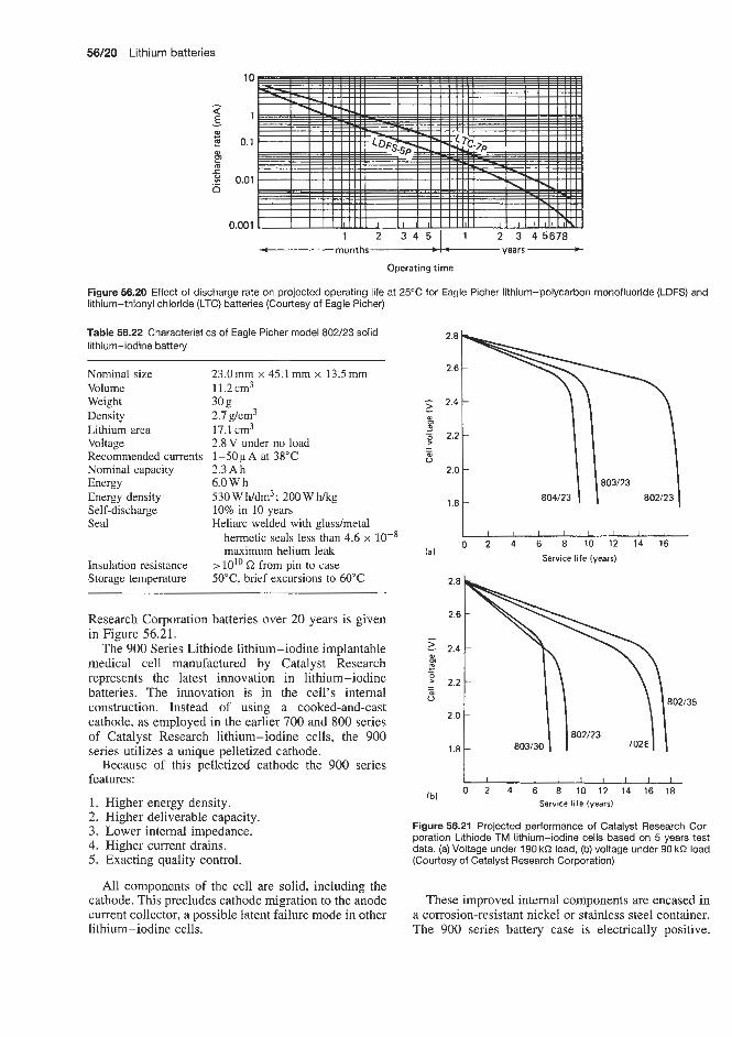
56/20 Lithium batteries
1 2 3 4 5
10
1 2 3 4 5 6 7 8 -
Nominal size Volume Weight Density Lithium area Voltage Recommended currents Nominal capacity Energy Energy density Self-discharge Seal
Insulation resistance Storage temperature
23.0mm x 45.1 mm x 13.5 mm 11.2 cm3 30 g 2.1 g/cm3 17.1 cm3 2.8 V under no load 1 - 5 0 ~ A at 38°C 2.3Ah 6.0 W h 530Wh/dm3; 200Whkg 10% in 10 years Heliarc welded with glasdmetal
hermetic seals less than 4.6 x lo-* maximum helium leak
z 1 0 ' ~ from pin to case 50"C, brief excursions to 60°C
Research Corporation batteries over 20 years is given in Figure 56.21.
The 900 Series Lithiode lithium-iodine implantable medical cell manufactured by Catalyst Research represents the latest innovation in lithium-iodine batteries. The innovation is in the cell's internal construction. Instead of using a cooked-and-cast cathode, as employed in the earlier 700 and 800 series of Catalyst Research lithium-iodine cells, the 900 series utilizes a unique pelletized cathode.
Because of this pelletized cathode the 900 series features:
1. Higher energy density. 2. Higher deliverable capacity. 3. Lower internal impedance. 4. Higher current drains. 5. Exacting quality control.
All components of the cell are solid, including the cathode. This precludes cathode migration to the anode current collector, a possible latent failure mode in other lithium - iodine cells.
0 2 4 6 8 10 12 14 16 Service life (years)
(a)
(b) 0 2 4 6 8 10 12 14 16 18 Service life (years)
Figure 56.21 Projected performance of Catalyst Research Cor- poration Lithiode TM lithium-iodine cells based on 5 years test data. (a) Voltage under 190 kQ load, (b) voltage under 90 kS2 load (Courtesy of Catalyst Research Corporation)
These improved internal components are encased in a corrosion-resistant nickel or stainless steel container. The 900 series battery case is electrically positive.


56/22 Lithium batteries
60.00
52.00
5 44.00-
E 36.00
,E 28.00-
- I
m
m
= 20.00
12.00
4.00
Figure 56.23 Catalyst Research lithium-iodine 2.8V cells. Voltage versus capacity relationship. Model 902,2.8V, 2.1 Ah (single anode) (Courtesy of Catalyst Research Corporation)
r -
- d.c. resistance a
-
-
-
- - - ,.+- l ~ l ~ l . l ~ l . l
1.50 1 1.301, ~, , I , I , I , , , , , I , I , , ,
0.10 0.50 0.90 1.30 1.70 2.10
(a) Single anode, type 909 2.8 V, 3.1 A h Capacity (A h)
r
3.0 60
2.9 55
2 8 50
2 7 45
2.6 40 - c:
5 2 4 30 E 5 B
2 3 25
2.2 20
2.1 15
2 0 10
1.9 5
1 8 0
I
$ 2 5 35 Y D)
0 300 600 900 1200 1500 1800 2100 Capacity (mA hl
30.00
- 15.00
(u
C
impedance
0.00 0.40 1.20 2.00 2.80 3.60 (b) Capacity (A h)
Capacity (A h) Figure 56.25 Resistance-capacity relationship for Catalyst Research lithium iodine 2.8V cells (a) types 909 (single anode) and (b) 920 (double anode) (Courtesy of Catalyst Research Corporation)
(b) Double anode, type 920,2.8 V. 2.8 A h
Figure 56.24 Voltage-capacity relationship for Catalyst Research lithium iodine 2.8V cells (a) types 909 (single anode. and (b) 920 (double anode) (Courtesy of Catalyst Research Corporation)

Lithium-iodine batteries 56/23
Also available is the model CRC Li D 2.8 D-type cell (2.8V) with a capacity of 14Ah at 25°C and an operating temperature of -20 to +50"C. The battery weighs 80 g and has a height of 33.8 mm and a width of 57.1 mm. This cell suffers a capacity loss of less than 5% in 10 years at 25°C and can withstand substantial shock, vibration and short-circuiting at temperatures up to 150°C without venting, leaking, swelling or exploding. The cell continues operating at 2.8 V (25'C) for 18 months (1mA) and 2.7-2.8V for about 8 months (2mA).
Catalyst Research Corporation supply the Lithiode range of disc-shaped lithium-iodine power sources with PC bound mounting for CMOS-RAM as standby power sources and for reference voltage sources and other low-current applications where the cell is the main power source.
These cells can be recharged at currents up to 10 FA at room temperature. This is particularly useful in memory back-up applications where a small current (about 1kA) can be used to trickle charge the cell whenever main power is available. Then, when the cell is called upon in the standby mode, it will be in a fully charged condition.
Four types of 2.8V Lithiode cell are supplied by Catalyst Research (Table 56.25). Figure 56.28 shows the discharge curve of one of these cells. The depen- dence of maximum current on cell temperature for the same cell is shown in Figure 56.29.
Catalyst Research, Inc. are the only suppliers of industrial (non-medical) types of lithium batteries. No dramatic improvements in performance or capabil- ity or energy density are expected in the near future. Costs are expected to decrease with a correspond- ing growth in demand. Cells are available in button (200-650 mA h) and rectilinear (400- l0OOmAh) con- figurations. Three Companies, Catalyst Research, Inc., Medronics Ltd and Wilson Greatback Ltd, supply med- ical type pacemaker lithium-iodine cells in the follow- ing capacity ranges:
series are two cells (types 920 and 921) having double, as opposed to single, anodes. Figure 56.24 illustrates the increase in power for a double anode cell (type 920) as compared with a single anode cell of comparable size (type 909). Approximately 80% of the capacity of type 920 is achieved below a 2 kQ level of resistance, and more than 90% of capacity is achieved below a 5 kR level of resistance. Figure 56.25 illustrates the resistance-capacity relationship for these two cells.
Table 56.24 Catalyst Research Corporation non-medical CRC range of lithium-iodine batteries
SP19-10 19 3.0 s so* SP19-20 19 3.0 120 S23P-15 23 1.5 s20* S27P-15 27 1.5 140* S27P-20 27 3.0 250 DP27P-20 27 2.0 260t
* Single sided. only one face of lithium exposed to iodine ' Double sided, hence can support higher currents owing to increased surface area
56.11.2 Other applications
Figure 56.26 gives performance characteristics of the S-23P-15 button cell. The largest button cell in the range is the D27P-20 (Table 56.24). This performance is shown in Figure 56.27. This has a capacity of Q.26Ah and has applications in digital watches and calculators; 460 mA h (type 2736) and 870 mA h (type 3740) button cells are also available. A 7.5 A h oil well logging battery model 407220 D cell is also available. This is housed in a 38 mm x 57 mm circular container and is hermetically welded with a glass-metal com- pression seal. It has a voltage of 2.8V (open-circuit 2.8 V), a maximum operating temperature of 150°C and a self-discharge rate of about 5% in 10 years at 25°C. The prcitotype D 34 cell maintains its voltage of 2.8V during 6 weeks of continuous operation at l0mA constant current at 130°C.
Catalyst Research 900 series 1-2.8Ah 9000 series 1.1-3.4Ah
Medenics 1.1-2.7 A h
Table 56,25 Types of non-medical CMOS-RAM 2.8V lithium-iodine cell available from Catalyst Research Corporation
Type Voltage Capacity Current Sev- Operating Diameter Height Weight No. (V) h) capability discharge temperature (mm) (mm) (g)
at 25°C (Ah )in (" C) (A) loyears
at 25°C
11620 2.8 40 100 11.6 2.0 2.4 1935 2.8 200 above 2V at 600kR at 25°C 15 0.01 -55 to 70 19 3.5 4.8 2736 2.8 350 above 2V at 5OOkR at 25°C 15 0.02 -55 to 125 27 3.6 7.1 3440 2.8 700 above 2V at 250kR at 25°C 30 0.04 -55 to 125 34 4.0 17.8

56/24 Lithium batteries
(2 PIC'S.)
23.00 mm diameter diameter
diameter
Case: positive
Weight: 4.25 g
Voltage: 2.8 V, no load
Current: 0-20 pA at 25 'C pulsing allowable up to several hundred microamperes
Nominal capacity: 100 mA h
Self discharge (measured by microcalorimetry): 0.01 A h maximum in 10 years at 25 O C
Construction: Laser welded 304 stainless steel case, glass to metal terminal seal
Operating temperature: 0-50°C nominal, -10 'C at reduced drain rates
r
I I I I I I I 0 1 2 3 4 5 6
Service time (years)
Figure 56.26 Projected performance of Catalyst Research Corporation Model S23P-1.5 lithium-iodine cell (0.1 Ah) at 25°C (Courtesy of Catalyst Research Corporation)
56.12 Lithium-molybdenum disulphide secondary batteries Mali Energy Ltd (US) are a major producer of lithium-molybdenum disulphide batteries. They
2.5
2.4 > 5.0pA 2.5pA a t 25 "C 1.0pA
f I I I I I I 5 10 15 20 25 30
Time (years)
Figure 56.27 Projected performance of Catalyst Research Cor- poration D27P-20 cell (23 rnm diameter x 2 mm thick, 250 mA h), based on 5 years' test data (Courtesy of Catalyst Research Cor- poration)
started production of type AA sized cells in 1986. Rechargeable lithium-molybenum batteries are also supplied by Eagle Picher (US).
Future developments in this cell are expected to include increased energy density and cyclic life, and also improvements in low temperature performance and safety in use.
56.13 Lithium-iron disulphide primary batteries Coin cells
These have not achieved the hoped for commercial success because of swelling of cells due to expansion of iron disulphide and a much lower rate capability than that achieved in alkaline electrolyte-based systems such as silver oxide zinc.
Lithium-iron disulphide cylindrical cells have proven to be commercially successful. Thus the

Lithium alloy-iron sulphide secondary batteries 56/26
I I I I I 1 I I I 0 1 2 3 4 5 6 7 8 9 10
Time (years)
Figure 56.28 Projected discharge curves at 25°C of Lithiode lithium-iodine cell (type 3440,2.8 V, 700 mA h) supplies by Catalyst Research (Courtesy of Catalyst Research Corporation)
-60 -20 0 20 60 100 140
Temperature ("C)
Figure 56.29 Lithiode lithium-iodine cell (type 3440, 2.8 V, 700 mA h) supplied by Catalyst Research Corporation. Dependence ot projected maximum continuous current of fresh cells on cell temperature (Courtesy of Catalyst Research Corporation)
Venture Technology (US) type AAA cell has been technically well received for the application envisaged, namely paging applications. However, due to high selling price and low production rate, they are not competitive with other types of cells. Similar comments apply to the Eveready Superplus AA cells.
Eagle Picher (US) also supply lithium-iron disul- phide primary batteries.
56.14 Lithium alloy-iron sulphide secondary batteries
Development programmes on these batteries are in progress at the following companies Rockwell Inter- national (US), Eagle Picher, Inc., Joplin, Missouri (US), Gould, Inc. (in 1989 Westinghouse Oceanic Division, Chardon, Ohio and Electric Power Research Institute, Pal Alto, California, took over from Gould, Inc.), SAFT, Rockeysville, Maryland (US).
Development programmes are also under way in the United Kingdom, Japan, Korea, Germany and Russia.

Manganese dioxide-magnesium perchlorate (primary) batteries

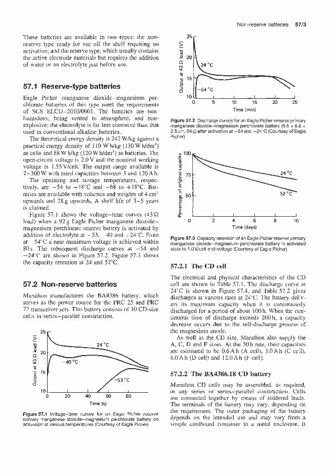
Non-reserve batteries 5763
These batteries are available in two types: the non- reserve type ready for use off the shelf requiring no activation; and the reserve type, which usually contains the active electrode materials but requires the addition of water or an electrolyte just before use.
57.1 Reserve-type batteries Eagle Picher manganese dioxide-magnesium per- chlorate batieries of this type meet the requirements of SCS ELCD-2010/0001. The batteries are non- hazardous, being vented to atmosphere, and non- explosive; the electrolyte is far less corrosive than that used in conventional alkaline batteries.
The theoretical energy density is 242 W k g against a practical energy density of 110 W h k g (130 WWdm3) as cells and 88 W h k g (120 W h/dm3) as batteries. The open-circuit voltage is 2.0 V and the nominal working voltage is 1.55 Vkell. The output range available is 2-300 W wi.th rated capacities between 3 and 120 Ah.
The operating and storage temperatures, respec- tively, are -54 to f18"C and -68 to +18"C. Bat- teries are available with volumes and weights of 4 cm3 upwards and 28g upwards. A shelf life of 3-5 years is claimed.
Figure 57.1 shows the voltage-time curves (43 C2 load) when a 92g Eagle Picher manganese dioxide- magnesium perchlorate reserve battery is activated by addilion of electrolyte at -53, -40 and +24"C. Even at -54°C a near maximum voltage is achieved within 80s. The subsequent discharge curves at -54 and +24"C are shown in Figure 57.2. Figure 57.3 shows the capacity retention at 24 and 52°C.
on-reserve batteries Marathon manufactures the BA4386 battery, which serves as the power source ffor the PRC 25 and PRC 77 transceiver sets. This battery consists of 10 CD-size cells in seriles-parallel construction.
25 > - P €2 -O 20 m U I
5 15 a
0 "
10 L I 1 / ! I 0 20 40 60 $0
Tiime (5)
Figure 57.1 Voltage-time curves for an Eagle Picher reserve primary manganese dioxide-magnesium perchlorate battery on activation at various temperatures (Courtesy of Eagle Picher)
10 u I I I I I 0 5 10 15 20 25
Time (min)
Figure 57.2 Discharge curves for an Eagle Picher reserve primary manganese dioxide-magnesium perchlorate battery (6.6 x 6.6 x 2.5 cm, 949) after activation at -54 and +2PC (Courtesy of Eagle Picher)
0 uL-LL-2 0 2 4 6 8 PO
Time (days)
Figure 57.3 Capacity retention of an Eagle Picher reserve primary manganese dioxide-magnesium perchlorate battery in activated state to 1 .OV/cell end-voltage (Courtesy of Eagle Picher)
57.2.1 The CD cell The electrical and physical characteristics of the CD cell are shown in Table 57.1. The discharge curve at 24°C is shown in Figure 57.4, and Table 57.2 gives discharges at various rates at 24°C. The battery deliv- ers its maximum capacity when it is continuously discharged for a period of about 100 h. When the con- tinuous time of discharge exceeds 200h, a capacity decrease occurs due to the self-discharge process of the magnesium anode.
As well as the CD size, Marathon also supply the A, C, D and F sizes. At the 50 h rate, their capacities are estimated to be 0.6Ah (A cell), 3.QAh (C cell), 6.0 A h (D cell) and 12.0 A h (F cell).
57.2.2 The BA4386.18 CD battery
Marathon CD cells may be assembled, as required, in any series or series-parallel construction. Cells are connected together by means of soldered leads. The terminals of the battery may vary, depending on the requirement. The outer packaging of the battery depends on the intended use and may vary from a simple cardboard container to a metal enclosure. It

57/4 Manganese dioxide-magnesium perchlorate (primary) batteries
Table 57.1 Electrical and physical characteristics of Marathon magnesium CD cell
Table 57.3 Electrical and physical characteristics of Marathon magnesium battery type EA4386
Electrical Nominal operating voltage 1.5 V Nominal capacity 6 A h Energy density
per unit weight 132Whkg per unit volume 2 10 w wdm3
Shelf life at 20°C 5 years at 71°C 3 months
Physical Maximum height 83.8mm Maximum diameter 22.8 mm Case material magnesium alloy Maximum weight 58.1 g
Table 57.2 Marathon CD cell capacity versus discharge rate at 24°C
Discharge Life Capacity Capacity as % rate (A) (h) (Ah) of 100 h rate
0.060 100 6.0 100 0.16 28 4.5 75 0.40 5.5 2.2 38 0.80 1.9 1.5 25
is customary to pot the cells of a multi-cell battery with an asphalt compound to prevent movement and to ensure a mechanically strong package. Proper design of the battery package enables it to meet the most rigid vibration and shock tests as well as conditions of high humidity.
The electrical and physical characteristics of this battery are given in Table 57.3.
Field experience has shown that shelf life is an outstanding characteristic of Marathon batteries. After 18 months storage at room temperature, magnesium
Electrical The BA4386 battery consists of two sections, both of which are made up of CD-size cells: section A1 yields 3 V and section A2 yields 14.1 V
Nominal voltage Load
End-voltage Performance
Physical Maximum height Maximum width Maximum length Weight Number of cells Battery case material Terminal Cell size
Section AI Section A2 3 v* 14.4 V 6.75 R, 2min; 14.2 R, 2min; open-circuit 291 R, l8min voltage, 18 min 2.12v 1 o v 60 h at room temperature to 55 h after 7 days' storage at 71°C
53.97 mm 92.07 mm 24.13mm 1.36 kg 18% Electrolyte-resistant cardboard Five-hole socket CD
* With dropping resistor in series ' 18 cells in series-parallel arrangement (section A1 plus section A2)
batteries have yielded 90% of their initial capa- city; 90 days at 55°C has shown that the battery still retains 85% of its initial capacity; and after storage at 71°C for 30 days the capacity reten- tion is 85%. The shelf life of BA4386 batteries is demonstrated in Figure 57.5 for conditions in which the batteries were discharged under transmit-receive conditions after storage at temperatures between 21 and 71°C.
Under intermittent conditions of use the realizable capacity of the magnesium battery depends on factors such as the magnitude of off-time period, the rate of discharge, the frequency of discharge intervals and the ambient temperature. The effect of each of these and
I I I I I I I 1 2 3 4 5 6
Capacity (A hl
Figure 57.4 Marathon CD-size magnesium cell constant-current discharge curves at 23°C (Courtesy of Marathon)
I I I I 1 I
O 1 2 3 4 5 6 Capacity (A h)
Figure 57.5 Marathon CD-size magnesium EA4356 battery constant-current discharge curve at 71 "C (Courtesy of Marathon)

Non-reserve batteries 57/5
theiir intenelationship makes it difficult to predict the capacity of the battery unless the mode of application is completely defined. In general, intermittent usage at heavy discharge drains is a favourable condition for optimum performance. This battery performs better at higher operating temperatures than at 21T, especially
at the higher drains. This is readily seen by comparing the family of curves in Figure 57.5 (discharged at 71°C) with those of Figure 57.4 (discharged at 23°C). Its performance diminishes when discharged at lower temperatures. However, the battery operates at temper- atures as low as -18"C, especially at light drain rates.


Magnesium-organic electrolyte batteries


Metal-air cells


Zinc-air primary batteries 59/3
Large zinc air batteries
There are eight major producers of larger zinc-air batteries:
Eveready Battery Co. (US) Rayovac Corporation (US) McGraw Edison, Inc. (US) SAW Batteries, Inc. (US) Edison Batteries, Inc. (US) Panasonic Batteries (Japan) Eagle Picher, Inc. (US) Varta (Germany)
Zinc-air primary batteries Small Zinc-air batteries (50-950 mA h range)
The following range of zinc-air hearing aid button cells are available:
Rayovac Corporation 60-540 mA h Activair 90- 520 mA h Duracell 50-950 mA h Eveready Battery Co 13-675 mAh Panasom 50--540 mA h Vmta 70-400 mA h
God$ and IBerec market zinc-ak button cells in the UK.
An example of the Varta hearing aid battery is the 1.4'4 type V4600 with a capacity of 300mAh. This cell has a specific energy density of 650- 800 mW h / ~ r n - ~ . Its operating temperature range is -10 to 60°C.
The Varta V675 HPA hearing aid battery has a capa- city of 260 rnA h. Duracell produce a 400 mA h, 1.4 V hearing aid button cell (type DA675). The storage life is estimated at 2.5 years in the sealed state. When the seal is broken the cell has a usable life of up to 3 months. Typical discharge characteristics of the DA675 are shown in Figure 59.1. This cell has a life of 195 h on 625Q load at 20°C. It weighs 1.63g and has a volume of 0.56 cm3.
Varta
Varta produce rectangular zinc-air batteries of capac- ities 85Ah (types 441, 459, 445, 461 and 465) and 53 A h (type 446).
Eagle Picher
Eagle Picher supply a range of primary expendable zinc-air batteries in the capacity range 4-50Ah at 25 V, equivalent to 95- 1250 W (0.7-5.5 kg). It is claimed that larger sizes with watt hour efficiencies up to 330Wh/kg are feasible with the larger types. Eagle Picher supply primary expendable one-shot bat- teries and also mechanically rechargeable types (anode
1.5
1.4
1.3
1.2
1.1
1 .0 0.9 0.8
0 12 24 36 48 60 72 84 96 108 120 132 144 156 168 180 192 204 216 Service a t 20 "C (h)
1.7 1.6 1.5
1.4
1.3 1.2
1.1
1 .O 0.9 0.8
0 40 80 120 160 200 240 280 320 360 400 440 480 Service a t 20 "C (h)
Figure 59.6 Typical discharge characteristics of a Duracell type 675 zinc-air button celi. Current at 1.3 V (Courtesy of Duracell)

5914 Metal-air cells
replacement), but do not supply electrically recharge- able types on the grounds that these have not yet been developed to a satisfactorily high standard.
Mechanically rechargeable secondary batteries are available from Eagle Picher in the 88-22OWMcg capacity range. Their output is 5- 150 A h; between 50 and 125 cycles are to be expected. On particular discharges of 11 -0.75 A service, some 50 cycles life is to be expected. Storage life in the inactivated state is about 5 years, and in the activated state it is 36 h. Some specific characteristics of this type of battery are listed in Tables 59.1 and 59.2.
Table 59.1 Characteristics of Eagle Picher mechanically rechargeable secondary batteries
Load at steady state Temperature Nominal rating (A) ("C) (Ah)
1 1 2.5
21 30 -40 24 -40 20
Table 59.2 Characteristics of Eagle Picher mechanically rechargeable secondary batteries
~
Load in service Load ratio Nominal rating (Ah)
3.4 to 1.6A 1:9 27.5 11A to 0.75A 1:9 25.0 11 A to 0.75 A 1:9 10-12 at -40°C
McGraw Edison
McGraw Edison supply the Carbonaire range of zinc-air cells and batteries listed below.
Types ST-22 and ST-33 (navigational aids) These are, respectively, two- and three-cell types, housed in trans- parent acrylic plastics cases and lids. The batteries as supplied are contained in plastics bags to pre- vent deterioration of the zinc anode during storage by ingress of air and moisture. The batteries are activated simply by topping up with water. Individual cells can be connected in series or in parallel with external con- nections. Normally ST Carbonaires require no routine maintenance or inspection for the first year. Should the service period run we11 over a year, an annual visual inspection of battery solution levels is desirable. The transparent case permits the user to see when each battery is ready for replacement.
McGraw Edison supply 1100-3300 A h versions of these batteries with voltages between 6 and 22.5 V.
Type Y This consists of a single 2800 Ah, 1.25 V cell sealed in a moulded hard rubber case. This battery will give up to 3 years' active life in many services and will operate at temperatures down to - 18°C electrolyte
temperature. It is recommended for use in aids to navigational services.
Type BY-301 This 3000 Ah, 1.25 V cell in a hard rub- ber case is designed for the operation of navigational signal aids, both visible and audible. The size and shape of the battery will permit it to replace lead storage cells now widely used in this application. Spe- cial disposable battery racks are currently available for buoys with 559 or 610mm battery pockets. These racks are furnished completed with the proper number of BY Carbonaires and the entire unit is prewired at the factory.
The problem of electrolyte spillage is eliminated by the use of a spillproof valve, which is applied after the battery is activated. Depending on the electrical energy requirements, one set of BY-301 Carbonaires will give up to 2 years' continuous service.
Type TR This 3300Ah, 1.25V cell is housed in a hard rubber case. It is designed for the operation of railway d.c. track circuits. The TR cell has the straight- line voltage characteristic so essential to satisfactory track circuit operation. Figure 59.2 illustrates this nar- row voltage range throughout the entire service life of the TR Carbonaire, using the maximum recommended continuous current of 1 .O A at 23.9"C and 0.500 A at -3.9"C battery solution temperatures.
Another advantage of using the TR Carbonaire is the ease with which it can be carried. Using the specially designed Edison Carbonaire Carrier, two batteries can be carried at once in a natural carrying position that minimizes accidental electrolyte spillage from activ- ated batteries.
Type F This is a twin single cell (mounted in series) 1300Ah, 2.5V battery intended for railway signalling services. This battery has an extremely uniform voltage. In general, the F Crystalaire can be continuously discharged to full rated capacity at any rate up to 0.150A. Under favourable oper- ating conditions a higher continuous current than 0.050A may be sustained. In very low temperature ranges, maximum recommended continuous current may vary considerably, depending on actual service conditions encountered.
z 1'401 1.0 Aop > 1.30 23.9 'C Q 1.20 P r 1.10 9 1.001 -3.9 "C
0.90 ' I ' ' I ' I " " ' I ' 400 800 1200 1600 2000 2400 2800 3200
Capacity ( A h )
Figure 59.2 Voltage curves: McGraw Edison zinc-air batteries, type TR (Courtesy of McGraw Edison)
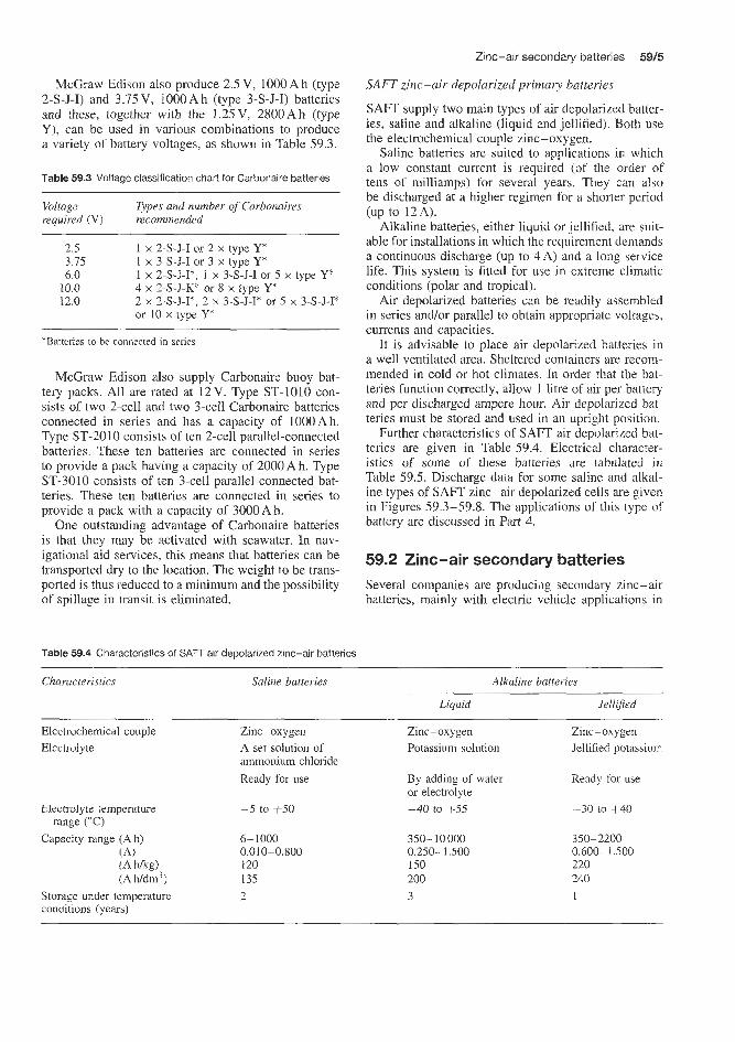
Zinc-air secondary batteries 5915
SAFT zinc-air depolarized primary batteries
SAFT supply two main types of air depolarized batter- ies, saline and alkaline (liquid and jellified). Both use the electrochemical couple zinc-oxygen.
Saline batteries are suited to applications in which a low constant current is required (of the order of tens of milliamps) for several years. They can also be discharged at a higher regimen for a shorter period (up to 12A).
Alkaline batteries, either liquid or jellified, are suit- able for installations in which the requirement demands a continuous discharge (up to 4A) and a long service life. This system is fitted for use in extreme climatic conditions (polar and tropical).
Air depolarized batteries can be readily assembled in series and/or parallel to obtain appropriate voltages, currents and capacities.
It is advisable to place air depolarized batteries in a well ventilated area. Sheltered containers are recorn- mended in cold or hot climates, In order that the bat- teries function correctly, allow 1 litre of air per battery and per discharged ampere hour. Air depolarized bat- teries must be stored and used in an upright position.
Further characteristics of SAFT air depolarized bat- teries are given in Table 59.4. Eiectrical character- istics of some of these batteries are tabulated in Table 59.5. Discharge data for some saline and alkal- ine types of SAFT zinc-air depolarized cells are given in Figures 59.3-59.8. The applications of this type of battery are discussed in Part 4.
McGraw Eclison also produce 2.5 V, 10OOAh (type 2-S-J-I) and 3.75 V, iO0OAh (type 3-S-J-I) batteries and these, together with the 1.25V, 2800Ah (type Y), can be used in various combinations to produce a variety of battery voltages, as shown in Table 59.3.
Table 59.3 Voltage classification chart for Carbonaire batteries
Voltage required (V) recommended
Types and number of Carbonaires
2.5 3.15 6.0
10.0 12.0
1 x 2-S-J-I or 2 x type Y* 1 x 3-S-J-I or 3 x type Y* 1 x 2-S-J-I*, I x 3-S-J-I or 5 x type Y* 4 x 2-S-J-K* or 8 x type Y* 2 x 2-S-J-I*, 2 x 3-S-J-I* or 5 x 3-S-J-I* or 10 x type Y*’
*Batteries to be connected in series
McGraw Edison also supply Carbonaire buoy bat- tery packs. All are rated at 12V. Type ST-1010 con- sists of two 2-cell and two 3-cell Carbonaire batteries connected in series and has a capacity of 1OOOAh. Type ST-2010 consists of ten 2-cell parallel-connected batteries. These ten batteries are connected in series to provide a pack having a capacity of 2000 Ah. Type ST-3010 consists of ten 3-cell parallel-connected bat- teries. These ten batteries are connected in series to provide a pack with a capacity of 3000Ah.
One outstanding advantage of Carbonaire batteries is that they may be activated with seawater. In nav- igational aid services, this means that batteries can be transported dry to the location. The weight to be trans- ported is thus reduced to a minimum and the possibility of spillage in transit is eliminated.
59.2 Zinc-air secondary batterie Several companies are producilg secondary zinc-air batteries, mainly with electric vehicle applications in
Table 59.4 Characteristics of SAFT air depolarized zinc-air batteries
Characteristics Saline batteries Alkaline batteries
Liquid Jelellifed
Electrochemical couple Electrolyte
Zinc-oxygen A set solution of ammonium chloride Ready for use
Electrolyte temperature
Capacity range (Ah) range (“C)
(A) (A a g ) (A h/drn3)
Storage under temperature conditions (years)
-5 to +50
6-1000 0.010-0.800 120 135
Zinc-oxygen Potassium solution
~~
Zinc-oxygen Jellified potassium
By adding of water or electrolyte -40 to t55
350-10 000 0.250-1.500 150 200 3
Ready for use
-30 LO f40
350-2200 0.600-1.500 220 240 1 2

Table 59.5 Electrical characteristics at 20°C of air depolarized batteries available from SAFT
Types Open Rated End-point Average Resistance Maximum Intermittent Pulse Maximum Length Width Height Diumeter Weight circuit capacity voltage current (a) continuous discharge, discharge, hourly (mm) (mn) with (mm) (kg) voltage (Ah) (Y) (A) discharge rate 5 1 min rate 5 1 s cupacity, terminals
(VI (A) (A) (A) intermittent (mm) or pulse
(Ah)
Saline batteries AD 517.4 1.45 1000 0.8 0.800 0.800 1.200 4.000 12.000 0.600 212 212 195 - 9.2 AD 517 1.45 270 0.8 0.200 5 0.300 1.000 3.000 0.150 106 106 195 - 2.3 AD 524 1.4.5 145 0.8 0.100 10 0.200 0.500 1.500 0.100 86 86 195 - 1.5 AD 2-519 2.90 130 1.6 0.100 20 0.150 0.500 1 .so0 0.070 106 110 195 2.45 AD 2-522 2.90 70 1.6 0.080 20 0.100 0.200 0.500 0.050 89 87 185 - 1.75
Alkaline butteries Liquid AD 600 1.45 10000 0.9 1.500 0.8 2.000 3.500 4.500 1.100 306 306 520 - .65” AD308;, 1.45 2000 0.9 I .000 1.1 1.500 2.000 2.500 0.800 210 210 310 - 14* Jellified AD 810 1.45 2200 0.9 1.500 0.75 2.000 3.500 4.600 1.000 - - 285 212 10.11. AD 820 1.45 1200 0.9 1.200 1 2.000 3.000 4.000 1.000 200 104 216 - 5 AD 840 1.45 350 0.9 0.500 2.5 1.000 1 ,500 2.000 0.500 85 85 200 - 1.7
*( After filling with water + Cylindrical
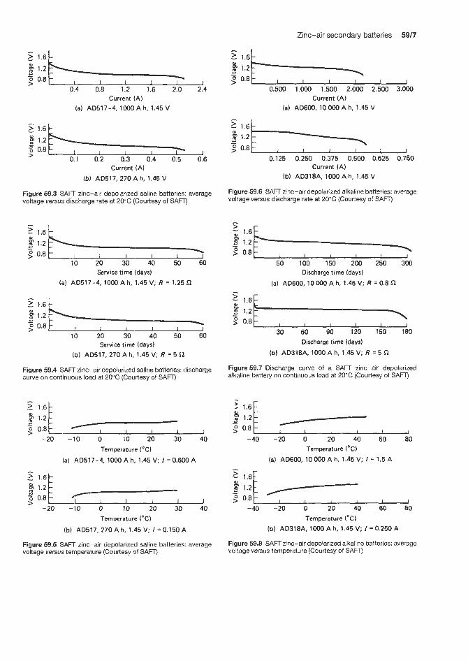
Zinc-air secondary batteries 59/7
p 1.2 c - o 0.8 > 1
0.4 0.8 1.2 1.6 2.0 2.4
p 1.2 c - o 0.8 > - I I 1 1
Current (A) (a) AD517-4. l00OA h, 1.45 V
5 - 1 . 6 1
p 1.2 e z 0.8
0.1 0.2 0.3 0.4 0.5 0.6 >
Current (A) Ib) AD517, 270 A h, 1.45 V
Figure 59.3 SAFT zinc-air depolarized saline batteries: average voltage versus discharge rate at 20°C (Courtesy of SAFT)
0
c P 1.2 2 0.8 -
10 20 30 40 50 60 Service time (days)
( a ) AD517-4, 1000 Ah, 1.45 V; R = 1.25 Cl
p 1.2 c - 2 0.8
10 20 30 40 50 60
(lo) AD517, 270 Ah, 1.45 V; R = 5 Sl Service time (days)
Figure 59.4 SAFT zinc-air depolarized saline batteries: discharge curve on continuous load at 20°C (CoLirtesy of SAFT)
-20 -10 0 10 20 30 40 Temperature ("CI
(a) AD517-4, 1000 A h, 1.45 V; I = 0.600 A
-20 -10 0 10 20 30 40 Temperature ("C)
(b) AD517, 270 Ah, 1.45 V; I = 0.150 A
Figure 59.5 SAFT zinc-air depolarized saline batteries: average voltage versus temperature (Courtesy of SAFT)
1.2
2 0.8 0.500 1.000 1.500 2.000 2.500 3.000
Current (A) (a) AD600, 10 000 Ah, 1.45 V -
2 1.6 0 1.2
0.8
0
c -
0.125 0.250 0.375 0.500 0.625 0.750 Current (A)
(b) AD318A, lo00 Ah, 1.46 V
Figure 59.6 SAFT zinc-air depolarized alkaline batteries: average voltage versus discharge rate at 20°C (Courtesy of SAFT)
- 5 ; 1.6
0.8 - B 1.2
50 100 150 200 250 300 Discharge time (days)
(a) AD600, 10 000 A h, 1.45 V; R = 0.8 Sl
5 - 1.6
1.2 9 0.8 -
30 60 90 120 150 180 Discharge time (days)
(b) AD318A. lo00 A h, 1.45 V; R = 5 $2
Figure 59.7 Discharge curve of a SAW zinc-air depolarized alkaline battery on continuous load at 20°C (Courtesy of SAFT)
2 0.8 -40 -20 0 20 40 60 80
Temperature I"C)
(a) AD600, 10 000 A h, 1.45 V; I = 1.5 A - 2 1.6F
2 0.8 -40 -20 0 20 40 60 80
Temperature ("C)
(b) AD318A, 1000 A h, 1.45 V; I = 0.250 A
Figure 59.8 SAFT zinc-air depolarized alkaline batteries: average voltage versus temperature (Courtesy of SAFT)
59/8 Metal-air cells
mind. These include CGF (France), the prototype AER Energy Resources Inc. battery (US), Edison (Italy) and Electric Fuel Ltd (Israel). The latter company has produced a battery achieving an energy density of 200 Wh/kg-' and a vehicle range of 300km.
59.3 Aluminium-air secondary batteries Eltech Corporation (US) are developing a lOOV alu- minium-air traction battery. Alcon Corporation (US) are developing a battery system comprising eight lead-acid batteries for use in electric vehicles. The aim is to produce a power unit for a small hatchback electric vehicle with a range of 105 miles at a speed of 30 mph.
Alupower Chloride Ltd have commercialized an aluminium-air telecommunications battery which delivers 25 V at 30 kW h over 50 hours. The output of this battery is 600 W.
59.4 Iron-air secondary batteries
This is another possible candidate for electric vehicle traction. Matsushita Battery Industry Co. (Japan) and the Swedish National Development Co. have both developed this type of battery. These batteries have given an energy density of 8OWh/kg-I at CI5 and 200 cycles at 60% depth of discharge. Westinghouse (US) and Siemens (Germany) are also working on the development of this battery.

Thermally activated batteries


Thermally activated batteries 60/3
power output is approximately 25% greater than that of conventional thermal battery systems. Performance data on this battery are given in Table 60.3.
Catalyst Research Corporation also produce a high- voltage thermal battery designed to meet the need for high-voltage low-current power supplies. Typical specifications for such units are shown in Table 60.4.
Catalyst Research Corporation thermal batteries are capable of operation at temperatures between -54 and +73"C, at accelerations up to 2500g lateral, under a shock of up to 200g and vibration of 30g, and a h at spin rates of 400 reds.
Activation of the battery by ignition or an internal heat source can be achieved by several methods:
Catalyst Research Corporation (US)
Table 60.1 shows current-life parameters for a wide variety of general-purpose thermal batteries produced by Catalyst Research Corporation. The height of the batteries is determined by the power required of the battery. The same power output can be achieved in a number of case diameters, by using different intercell connections (series, parallel or series-parallel) to pro- vide the desired voltage-current parameters. A thermal battery is a low-impedance device; much higher cur- rents than indicated may be drawn for shorter periods of time.
Catalyst Rlesearch Corporation also supply fast- activation thermal batteries. These are to meet the needs of applications requiring battery power to fire squibs, electric matches, dimple motors, explosive bolts, etc., aft'er battery activation.
Table 60.1 Generai-purpose thermal batteries from Catalyst Research Corporation
Nominal case diameter (mm)
Current (A) for life shown
60 s 120 s 180 s
31.7 38.1 41.1 50.8 57.1 76.2 95.2
0.9 0.3 0.1 1.5 0.5 0.3 1.9 0.6 0.4 2.8 0.9 0.5 3.8 1.3 0.7 5.7 2.0 1.3 9.2 3.0 1.9
Table 60.2 presents size and performance data for some typical units supplied in the three categories of fast-start batteries: A, high current pulse; B, medium life; and C, high current. These may be used to ripple fire squibs under 20Q load, 50ms on, 50ms off, 0.7 R load.
Catalyst Research Corporation have also designed and developed a high-efficiency electrochemical sys- tem for use in high current density applications. This Power Cell system has the flexibility for use in both short- and long-life battery requirements. Available
Table 60.3 'Power Cell' thermal batteries from Catalyst Research Corporation
Diameter Height Voltage Current Lqe Average (mmj (mmj (V) (A) (minj power
output (W)
~
35.5 58.9 25 +4 0.7 5.0 - 53.3 76.2 5 0 f 7 15.6 0.6 780 53.3 76.2 45 * 5 45.0 0.25 2025 88.9 88.9 28 1 4 5.7 15.0 I44 88.9 149.8 28 h 4 16.7 11.5 426*
152.9 101.6 28 454 20.0 14.0 492"
*Operated at 25°C
Table 60.4 High-voltage thermal batteries from Catalyst Research Corporation
Diameter Height Voltage Current Life (mm) (mm) output (A) (SI
(VI
45.1 31.7 140 h 4 0.014 30 0.40 30 1.4 f 0.1
8.2 f 0 . 3 0.07 30 55.3 55.3 276 f 13 0.001 30
5 6 + 8 0.030 30 76.2 86.8 356 f 24 0.120 30
Table 60.2 Fast-activation thermal batteries from Catalyst Research Corporation
6 : p e Nominal Nominal Nominal Activation Activation Life diameter height voltage current time (SI
(mm) (mm) (V) (A) (SI
A 12.7 19.0 10-20 5 0.01 0.5 A 41.1 38.1 20-32 40 0.03 5.0 A 41.1 33.2 12-19 17-19 0.20 0.5 A 41.1 69.8 24-42 15-25 0.10 5.0 B 31.1 31.7 12-16 1 .o 0.05 30.0 C 88.9 165.1 28-36 3 -4 0.50 105.0

60/4 Thermally activated batteries
1. Electrical High- and low-energy matches and squibs with wire bridges are available. Firing energies of two of the units are shown in Table 60.5.
Table 60.5 Firing energies
No-fire All-fiue
Match 0.25 A 0.50 A 5 s 50 ms
Igniter 1 A 3.5 A 5 min 20 ms
2. Mechanical An M42G primer similar to that in a .38 calibre bullet, with a modified charge, has been used extensively in thermal batteries. Spring or explosive-driven firing pins are used to deliver the 1800cmg of energy required for primer firing. A second method of mechanical initiation uses a self-contained inertial starter, which is activated by forces of 300-600g imposed on the battery.
Eagle Picher (US)
Eagle Picher are major suppliers of thermal bat- teries. The batteries are available in a variety of configurations. Sizes range from 1.25 mm diameter x 12.5mm length to multi-cell battery packs of up to 99 mm diameter x 127 mm length. Fast activation and high amperage pulse power are available from the smaller units. Regulated power up to 4min duration is available from larger units. Battery voltages from 2.5 to 450 V are available from existing designs.
The batteries have an open-circuit voltage of 2.3-3.0Vlcell and voltages available of 2.3-5OOV. Voltage regulation is within 10% of nominal under constant resistive load. The battery operation range covers the interval 1-300 s. A typical discharge curve for an Eagle Picher thermal battery is shown in Figure 60.1. Performance and other characteristics of these batteries are:
1. 2. 3. 4. 5. 6.
7. 8. 9.
High-rate capacity: 10A for 60s. Low-rate capacity: 250 mA for 300 s. Activation time: 100 ms to 3.5 s. Operating temperature: -54 to +93"C. Storage temperature: -54 to +74"C. Storage life: up to 10 years at the recommended storage temperature. Vibration: withstands 300g all areas. Shock: withstands 3000 g longitudinal. Acceleration: withstands 450 g longitudinal.
The characteristics of some of the wide range of thermal batteries available from Eagle Picher are shown in Table 60.6.
The EAP-6273 12V battery based on the calcium chromate-calcium system was specifically designed to
0.1 0.2 0.40.6 1 2 4 6 810 20 40 60 100 Discharge time (rnin)
Figure 60.1 Typical discharge curves of Eagle Picher thermal batteries. (Courtesy of Eagle Picher)
Table 60.6 Characteristics of Eagle Picher thermal batteries
EAP-6266: 101.6 mm diameter, five-cell stacks Voltage 2 7 f 3 V Life at 71"C, 221 s
at 24"C, 366 s at -54"C, 317 s
Load 33 A nominal Size 121 mm diameter x 193 mm long Weight 5.2kg Watt hours 89.1 (= 17.2Whkg) EAP-6230: 101.6 mm diameter five-cell stacks, DEB type Voltage 28.5 + 3.5 V Life at 3S°C, 24min
at 5"C, 16min Load 4.3 A nominal Size 122 mm diameter x 104 mm long Weight 2.86 kg Watt hours 48.3 (= 16.9 Whkg)
EAP-6251: 76 mm diameter, parallel stacks Voltage 2 1 f 3 V Life at 71T, 110s
at 24"C, 200 s at -4o"C, 140s
Load 23 A nominal Size 94 mm diameter x 145 mm long
Watt hours 31 (= 10.4Whkg) EAP-6261: 76 mm diameter, parallel stacks
Weight 3 ks
Voltage +33 2z 5.5 v -33 * 5.5v
Life at 71"C, 170s at 24"C, 200s at -56"C, 135s
89 mm diameter x 117 mm long
20.4 = 8.1 W h/kg (138.6 x 2 sections)
Load 4.2 A each section Size Weight 1.9 kg Watt hours EAP-62 73 Voltage 12rt3V Life at 24" C, 350 s Load 500A nominal Size 177.Smm diameter x 406mm long Weight 20.4 kg Watt hours 583.3 = 28.6 Whkg
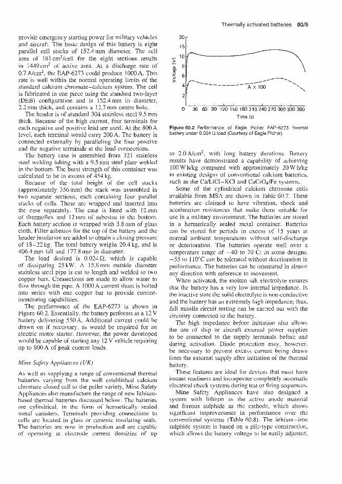
Thermally activated batteries 60/5
provide emerglacy starting power for military vehicles and aircraft. The basic design of this battery is eight parallel cell stacks of 152.4nm diameter. The cell area of 181 cm2/cell for the eight sections results in 1449cm' of active area. At a discharge rate of 0.7 A/cm2, the EAP-6273 could produce 10OOA. This rate is well within the normal operating limits of the standard calcium chromate-calcium system. The cell is fabricated in one piece using the standard two-layer (DEB) configuration and is 1 5 2 . 4 m in diameter, 2.2 mm thick, and contains a 12.7 m centre hole.
The header is of standard 304 stainless steel 9.5 rnm thick. Because of the high current, four terminals for each negative and positive lead are used. At the 800A level, each terminal would cany 200 A. The battery is connected externally by paralleling the four positive and the negative terminals at the load connections.
The battery case is assembled from 321 stainless steel welding tubing with a 9.5 m steel plate welded in the bottom. The burst strength of this container was calculated to be in excess of 454 kg.
Because of the total height of the cell stacks (approximately 356 mm) the stack was assembled in two separate sections, each containing four parallel stacks of cells. These are wrapped and inserted into the case sepaEately. The case is lined with 12mm of thermoflex and 12mm of asbestos in the bottom. Each battery section is wrapped with 3.8mm of glass cloth. Filler asbestos for the top of the battery and the header insulation are added to obtain a closing pressure of 18-22kg. The total battery weighs 20.4kg, and is 406.4 mm tall and 177.8 mm in diameter.
The load (desired is 0.024Q which is capable of dissipating 25kW. A 15.8mm outside diameter stainless steel pipe is cut to length and welded to two copper bars. Connections are made to allow water to flow through the pipe. A 1OQOA current shunt is bolted into series with one copper bar to provide current- monitoring capabilities.
The performance of the EAP-6273 is shown in Figure 60.2. Essentially, the battery performs as a 12V battery delivering 550A. Additional current could be drawn on if necessary, as would be required for an electric motor starter. However, the power developed would be capable of starting any 12 V vehicle requiring up to 800A o'f peak current loads.
Mine Safety Appliances (UK)
As well as supplying a range of conventional thermal batteries varying from the well established calcium chromate closed cell to the pellet variety, Mine Safety Appliances also manufacture the range of new lithium- based thermal batteries discussed below. The batteries are cylindrical, in the form of hermetically sealed metal canisters. Terminals providing connections to cells are located in gIass or ceramic insulating seals. The batteries are now in production and are capable of operating at electrode current densities of up
2o r
'F L I I I I i , I I 1 I I ,
0 30 60 90 120 150 180 2102402703O0330360 Time ( s )
Figure 60.2 Performance of Eagle Picher EAP-6273 thermal battery under 0.024 R load (Courtesy of Eagle Picher)
to 2.0A/cm2, with long battery durations. Battery results have demonstrated a capability of achieving 100 W h/kg compared with approximately 20 W h k g in existing designs of conventional calcium batteries. such as the CaLiCl-KC1 and CaCrOdFe systems.
Some of the cylindrical calcium chromate cells available from MSA are shown in Table 60.7. These batteries are claimed to have vibration, shock and acceleration resistances that make them suitable for use in a military environment. The batteries are stored in a hermetically sealed metal container. Batteries can be stored for periods in excess of 15 years at normal ambient temperatures without self-discharge or deterioration. The batteries operate well over a temperature range of -40 to 70°C; in some designs, -55 to 110°C can be tolerated without deterioration in performance. The batteries can be orientated in almost any direction with reference to movement.
When activated, the molten salt electrolyte ensures that the battery has a very low internal impedance. In the inactive state the solid electrolyte is non-conductive and the battery has an extremely high impedance; thus, full missile circuit testing can be carried out with the circuitry connected to the battery.
The high inipedance before initiation also allows the use of ship or aircraft external power supplies to be connected to the supply terminals before and during activation. Diode protection may, however, be necessary to prevent excess current being drawn from the external supply after initiation of the thermal battery.
These features are ideal for devices that must have instant readiness and incorporate completely automatic electrical check systems during test or firing sequences.
Mine Safety Appliances have also designed a system with lithium as the active anode material and ferrous sulphide as the cathode, which shows significant improvements in performance over the conventional systems (Table 60.8). The lithium-iron sulphide system is based on a pile-type construction, which allows the battery voltage to be easily adjusted.

D Table 60.7 Technical specifications of cylindrical calcium-calcium chromate types of thermal battery supplied by MSA F?
3. MSA output Maximum Minimum Activation Durution Operating Weight Height Diameter part (A) voltage voltage time (s) temperature ( g ) (mm) (mm) No. (VI (VI 6) ("C)
270072
270046
270086 270085 270036-2 290050 290070 270095 270028 279608 270027 290027
27961 1
1.27 at 23 V 1.24 at 6V 0.033 at 42V 0.002 at 26V 1 at 12.25V 2A pulses at 5 V 11.06 at 25 V 2.7 at 27V 1 at 21.6V 12 at 22V 43.5 at 1 l V 5 at 21V 0.147 at 22V 3.45 at 26V 3.05 at 23V 0.2 at 4V
30.5 8.3
64.0 289.0
15.75 13.0 28.7 33.0 26.4 33.0 23.0 35.0 31.0 32.0
15.0
23.0 6.0
42.0 263.0
12.25 5.0
25.0 27.0 21.6 22.0 17.0 27.0 22.0 26.0 23.0 4.0
1.5
5
1.8 0.35 1.8
<1.9 <2 to 21.6V <4 to 30.75 v
1 to 17V <2.2 to 27 V
1 s to 2 2 v 2
0.4
15
33
27 23.5
140 293 >41.6 to 21.6V >60 to 22V
70 to 17V 241.5
70s to 22V 155
10
-30 to 70
-10 to 50
-10 to 60 -40 to 105 -20 to 60
0 to 40 -10 to 50 -17 to 34 -40 to 60 -37 to 85 -40 to 60 -20 to 55
-39 to 83
213
304
132 100
2800 879 400
I240 95
1457 I42
2041
54
98
57
153 51
23 1 66 68
116 34
116 47
186
22
32
51
79 32 76 76 51 76 31 76 38 76
31
Initiator type: electrical

Table 60.8 Technical specifications of cylindrical lithium-iron disulphide types of thermal batteries supplied by MSA
MSA Output Maximum Minimum Activation Duration Initiator Operating Weight Height Diameter part (A) voltuge voltage time VP" temperature (g) (mm) (mm) N O . (VI (V) (SI ("C)
279694 279649 279655 279678 279682
279687 279693 279651 279651 279683 279659
2 7 2 2 1.25 1.9 3
35.5 3.5 6A at 28V
23 A at 26V 5
SO A at 25 V
22 16 32 24 27 21 22 16 26.6 19 26.6 19 11.2 8 75 45 84 52 39.5 28 37.5 26 32.5 26 32 25
10.3 t 5 t0 .6 <0.3 <1.5
< 10 <1 <2.5 t2 .5 t2 .5 <1
>60 s >20min >so s r 6 0 s >50 s
>8 min 1180 s r600 s >400 s >IOOS > 180 s
Electrical Electrical Fuse Electrical Percussion
Electrical Electrical Electrical Electrical Electrical Electrical
-40 to 70 -23 to 6 -55 to 75 -40 to 70 -40 to 70
0 to 30 -30 to 60 -20 to 40 -20 to 55 -25 to 75 -40 to 70
70 3.500 275 100 230
3800 470
2000 3400 1200 3100
40 25 114 114 68 14.9 37 31 65 38
234 98 100 14.3 137 89 21 0 89
85 77 165 89
r!

60/8 Thermally activated batteries
by varying the number of series cells, to meet different application requirements.
Quite large sized thermal batteries of this type are being produced one battery weighs 3.8kg and consists of 30 series cells housed in a container 89 mm in diameter by 236mm long. This battery shows smooth discharges, free from electrical disturbance, for average current densities varying from 0.3 to 1.86A/cm2. To 80% of the peak voltage, durations ranged from 3 to 21 min. It is also noteworthy that the cell capacity is very constant at 275A minimum over this range of discharge rates, although there are indications of some reduction at the highest current density. For this capacity of lithium-iron sulphide cell, the current density performance is at least 15 times better than with calcium-calcium chromate systems for discharge densities of over 2-3min, and analysis of the discharge curves also shows that the energy density achieved by the cell (including pyrotechnic) is 113 Wh/kg, and 63 W h/kg for the battery. The volumetric energy density from the battery is 113Wh/dm3.
A further battery design gave a duration of 7min, a short activation time and a low internal resistance for good voltage regulation for a wide range of current drains. It uses two parallel stacks of 75mm nominal diameter cells, housed in a container 89mm in diameter and 190mm long. The battery weight is 2 . 9 1 . At an average discharge current of 20A
(0.23 Ncm2 electrode current density), 8 min discharge duration was obtained to 80% of the maximum voltage for both conditioning temperatures. The battery internal resistance remains constant for the discharge duration to 80% of mean voltage, with a value of 0.09-0.11 a. The batteries tested after initial conditioning at +50"C activated in approximately 1.6 s giving 12.8A at 25.5V, and those conditioned at -30°C activated in approximately 3.0 s. The battery design used anodes with excess coulombic capacity (380 A minimum), and considerable improvement in activation time is possible if these are matched to the rated cathode capacity of 200 A minimum.
Other suppliers
Other suppliers of lithium-iron disulphide thermal batteries include:
Power Conversion Ltd, 280 Midland Avenue, Saddle
SAFT America Ltd, 107 Beaver Court, Locheysville,
SAFT, 156 Avenue de Metz, Roumainville (France) SAFT UK Ltd, Station Road, Hampton, Middle-
LeclanchC SA, 48 Avenue de Grandson, Yverdon
Brook, New Jersey (US)
Maryland (US)
sex (UK)
(Switzerland).

Zinc- halogen batteries


Zinc-bromine secondary batteries 61/3
Zinc-bromine secondary batteries This type of battery has not yet been commercially produced. It is hoped to have batteries commercially realized for load levelling and electric vehicle applica- tions by the late 1990s.
Electric vehicles
Exxon Research and Engineering Co. (US), who car- ried out earlier work on electric vehicle batteries, have now transferred this activity to three other companies, namely, Johnson Controls Ltd (US), Meidensha Elec- tric Co. (Japan) and SEA GnibH H (Austria). John- son Controls and SEA GmbH H envisage achieving energy densities of 70-85Wh/kg-l (against a the- oretical of 430 W h/kg-'). Earlier prototype batteries are, however, only achieving 15-25 Whkg-'. SEA are currently carrying out trials on a 45 kW h electric
vehicle battery. Limited electric vehicle trials car- ried out more recently have given energy densities in the range 67-72Wmg-I and vehicle ranges of 125-135 miles. Up to 3000 charge-discharge cycles have been achieved for small single cells. However, only 400-600 cycles have been achieved for larger cells. This is due to hardware problems, not difficulties in the basic electrochemistry of the system.
Loud levelling applications
Gould, Inc. (US) utility load levelling activity has now been acquired by Energy Research Corporation (US).
Utility load levelling batteries are still at the concep- tional design stage. Up to 50 MW h layouts are under consideration. Meidensha (Japan) intended to complete by 1992 a 4MWh demonstration load levelling cell. This cell is intended to have a plateau voltage of 1.5 tQ 1.6V, during the whole discharge with 88% coulom- bic efficiency.


Sodium-sulphur batteries

Sodium-sulphur batteries 62,'s
3000 miles of track driving has been achieved with this van.
Internation collaborative development programmes are now being carried out in the US, Europe and Japan in attempts to expedite the commercialization of sodium-sulphur batteries, particularly for electric vehicle applications.
Chloride Silent Power (UK)
This company have constructed a number of cells with energies from 20 to 1300Wh. Tubular and flat plate bipolar electrodes were studied.
Argonne National Laboratiories (US) have exam- ined for Chloride Silent Power a 960 cell electric vehicle battery. They carried out 240 cycles at dif- ferent rates of discharge and various driving pro- files. This battery consistently gave 240Ah when discharged to 80% depth of discharge. The Chlor- ide Silent Power CM Griffon van battery gave a range of 165 miles at 35mph and 120 miles at 50mph. These ranges exceed those obtained using a lead-acid battery by a factor of three. More than
General Electric Company (US)
This company has fabricated a sodium-sulphur battery based on a large tube configuration. Individual cells have been tested for more than 7000 discharge-charge cycles during 7 years of testing. Batteries made up from these cells have been tested for more than 500 cycles. The faradic efficiency of these cells was 100%. Eagle Picher are working on the development of sodium-sulphur batteries.
Yuasa (Japan)
Yuasa have constructed a 400 kW h 50 kW unit battery for stationary applications and are now working on a 1 MW 8 MW h unit for stationary testing.
At the present rate of progress sodium-sulphur batteries should be commercially realized for some applications by the end of the millennium.

Water-activated batteries

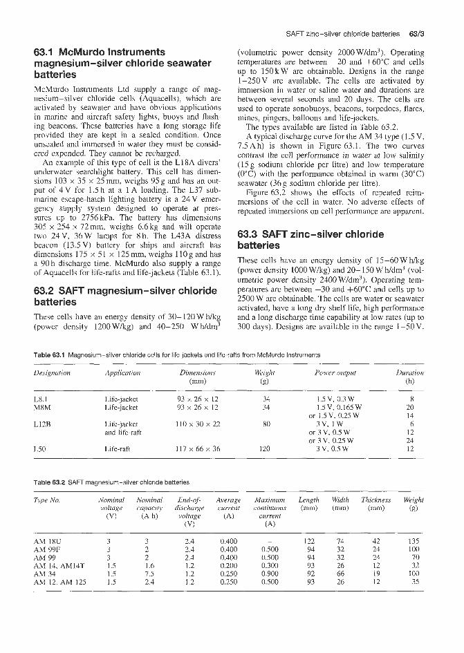
SAFT zinc-silver chloride batteries 6313
ClWUrdo Instruments magnesium-silver chloride seawater batteries McMurdo Instruments Ltd supply a range of mag- nesium-silver chloride cells (Aquacells), which are activated by seawater and have obvious applications in marine and aircraft safety lights, buoys and flash- ing beacons. These batteries have a long storage life provided they are kept in a sealed condition. Once unsealed anad immersed in water they must be consid- ered expended. They cannot be recharged.
An example of this type of cell is the L18A divers' underwater searchlight battery. This cell has dimen- sions 103 x 35 x 25 mm, weighs 95 g and has an out- put of 4 V for 1.5 h at a 1 A loading. The L37 sub- marine escaqe-hatch lighting battery is a 24V emer- gency supply system designed to operate at pres- sures up to 2756kPa. The battery has dimensions 305 x 254 x 72 mm, weighs 6.6 kg and will operate ~ W Q 24 V, 36 W lamps for 8 h. The L43A distress beacon (13SV) battery for ships and aircraft has dimensions 175 x 51 x 125 mm, weighs l l 0 g and has a 90h discharge time. McMurdo also supply a range of Aquacells for life-rafts and life-jackets (Table 63.1).
.2 SAlFT magnesium-silver chloride batteries These cells have an energy density of 30- 120 W h/kg (power density 1200Wkg) and 40-250 Wh/dm3
(volumetric power density 2000 W/dm3). Operating temperatures are between -20 and +60"C and cells up to 150kW are obtainable. Designs in the range 1-250V are available. The cells are activated by immersion in water or saline water and durations are between several seconds and 20 days. The cells are used to operate sonobuoys, beacons, torpedoes. flares, mines, pingers, balloons and life-jackets.
The types available are listed in Table 63.2. A typical discharge curve for the AM 34 type (1.5 V,
7.5Ah) is shown in Figure 63.1. The two curves contrast the cell performance in water at low salinity (1 5 g sodium chloride per litre) and low temperature (0°C) with the performance obtained in warm (30°C) seawater (36 g sodium chloride per litre).
Figure 63.2 shows the effects of repeated reim- mersions of the cell in water. No adverse effects of repeated immersions on cell performance are apparent.
63.3 SAFT zinc-silver chloride batteries These cells have an energy density of 15-60 W h k g (power density 1000 Wkg) and 20- 150 W Ndm3 (vol- umetric power density 2400 W/dm3). Operating tem- peratures are between -30 and +60"C and cells up to 2500 W are obtainable. The cells are water or seawater activated, have a long dry shelf life, high performance and a long discharge time capability at low rates (up to 300 days). Designs are available in the range 1-50V.
Table 63.1 Magnesium-silver chloride cells for life-jackets and life-rafts from McMurdo Instruments
Duration Designation Application Dimensions Weight Power output (mm) (g) (h)
L8.1 Life-jacket 93 x 26 x 12 34 1.5 V, 0.3 W 8 M8M Life-jacket 93 x 26 x 12 34 1.5V, 3.165 W 20
14 L12B Life-jacket 110 x 30 x 22 80 3 v , I W 6
and life-raft or 3 V, 0.5 W 12 24
L50 Life-raft 117 x 66 x 36 120 3 V, 0.5 W 12
or 1.5 V, 0.25 W
or 3 V, 0.25 W
Table 63.2 SAFT magnesium-silver chloride batteries
Type No. Nominal Nominal End-of- Average Maximum Length Width Thickness Weight voltage capacity discharge current continuous (mm) (mm) (mm) (E)
(VI (Ah) voltage (A) current (VI (A)
~~ ~
AM 18U 3 3 2.4 0.400 - 122 74 42 135 AM 99F 3 2 2.4 0.400 0.500 94 32 24 100 AM 99 3 2 2.4 0.400 0.500 94 32 24 70 AM 14, AM14T 1.5 1.6 1.2 0.200 0.300 93 26 12 :32 AM 34 1.5 7.5 1.2 0.250 0.900 92 66 19 100 AM 12, AM 125 1.5 2.4 1.2 0.250 0.500 93 26 12 35

6314 Water-activated batteries
1.5 - 1.4 2 1 . 3 F 8 1.2 3 1.1 9 1.0
- -
- 2.5 5 n -
-
0 1 2 3 4 5 10 15 20 25 Time ( h )
(b) 30 OC. 36 g NaCI/I
Figure 63.1 SAFT AM34, 1.5 V, 7.5A magnesium-silver chloride seawater-activated batteries: influence of salinity and temperature on cell discharge performance (Courtesy of SAFT)
Immersion First Second + reimmersion reimmersion I t
4 t. t
I I I I I I I I l *
0 1 2 3 4 5 6 7 8 9 10 Time ( h )
Figure 63.2 SAFTAMI 8,3.0V, 30A h magnesium-silver chloride seawater-activated batteries: effect of repeated immersions in seawater (329 NaCVl) on discharge performance at 20°C (Courtesy of SAFT)
The cells are used in balloons, oceanographic buoys, military power systems, communications equipment and portable electronic devices.
63.4 SAFT magnesium-cuprous chloride batteries These cells have an energy density of 20-90 W hkg and 18- 150 Wh/dm3. They operate in the temperature range -20 to +60"C and are available with up to 50 W output. Designs in the 1-100V range are available. These cells are water or seawater activated. They have durations from seconds to many hours and are used in balloons, beacons, flares, sonobuoys, pingers and oceanographic equipment.
0 1 2 3 4 5 6 7 8 9 1 0 1 1 1 2 Time ( h )
(a) 21 "C, 32 g NaCI/I
& 1.3 3 1.2
0 1 2 3 4 5 6 7 8 9 1 0 1 1 1 2
(b) 30 "C, 36 g NaCI/I
Time ( h )
- 1 . 5 k 2. 1.4
0 1 2 3 4 5 6 7 8 9 1 0 1 1 1 2 Time (h)
(c) 0 OC, 15 g NaCI/I
Figure 63.3 SAFT CIM 120, 1.4V, 1.8Ah magnesium-copper iodide seawater-activated primary batteries: discharge curves (Courtesy of SAFT)

Eagle Picher water-activated primary batteries 63/5
Table 63.3 SAFT magnedum-copper iodide primary batteries
Type Nominal Nominal End-of- Average Maximum Length Width Thickness Weight No. voltage capacity discharge current continuous (mm) (mm) (mm) (g)
(VI (A h) voltage (A) current (VI (A)
CILM 990 2.8 1.5 2.4 0.150 0.200 94 32 24 80 CIM 120 1.4 1.8 1.2 0.180 0.200 93 26 12 40
63.5 SAFT magnesium-copper iodide seawater-energized primary batteries primary batteries
63.6 Eagle Picher water-activated
The types available are listed in Table 63.3. Typical Eagle Picher supply a range of water-activated discharge curves at different cell temperatures and salinities are shown in Figure 63.3.
batteries.


Suppliers of primary and secondary batteries


Belgium
Chloride Belgium NV, Groenstraat 31, Mortsel 2510 Primary batteries, zinc-alkaline manganese dioxide; secondary batteries, nickel-cadmium, lead-acid.
Varta SA, Rue Uyttenhove 49-51, B-1090 Brussels Primary batteries, zinc-alkaline manganese dioxide, mercury-zinc, carbon-zinc, LeclanchC, magnesium types, lithium types, silver oxide-zinc, zinc chloride LeclanchC. zinc -air.
Suppliers of primary and secondary batteries 3
Germany
Akkumulatorenfabrik Sonnenschein GmbH, 64-70 Budingen Secondary batteries, sealed lead-acid, lithiurn- sulphur dioxide, lithium-thionyl chloride.
Chloride Batteries GmbH, Otto Hahn Strasse 1, 6084 Gerscheim Secondary batteries, nickel-cadmium.
Diamon Werke GmbH, Sellerstrasse 14, 1000 Berlin 65; also 5000 Koln 50, Ossendorf; Kohlstrasse 37, Cologne 36; Postlach 3 000 420 and Selterstrasse 14, 1000 Berlin 65 Primary batteries, zinc-alkaline manganese dioxide; secondary batteries, nickel-cadmium.
Duracell Deutschland Technical Division, D-5020 Frechen, Hermann-Seger-Strasse 13 Primary batteries, mercury-zinc, silver-zinc, lith- ium solid electrolyte types.
Friemann Wolf Silberkraft, Leichtakkumulatoren, 41 Duisburg 1, Meidericher Strasse 6-8, Post- schliesstfach 100703 Primary batteries, silver-zinc and silver chlor- ide-magnesium seawater batteries; secondary hax- teries, nickel-cadmium, silver-zinc, silver- cadmium, lithium-sulphur dioxide, lithium-thionyl chloride.
Gottfried Hagen AG, Rolshoverstrasse 95/101, Post- fach 91 01-10-D5 Secondary batteries, nickel-cadmium.
Nife Jungner GmbH, Nicholstrasse 2-6, 1800 Berlin 46; also Blucherstrasse 33-35, 2000 Hamburg; Benrotherstrasse 7, 4000 Dusseldorf 13; Ostwalt- strasse 48, 6000 Frankfurt; Nockherstrasse 50, 8100 Munich 90 Secondary batteries, nickel-cadmium, alkaline.
Varta Batterie AG, Leineufer 51, Postfach 210 540, 3000 Hanover 21; also Postfach 63,7090 Ellwargen, Jagst Primary batteries, zinc-alkaline manganese dioxide, mercury-zinc, carbon-zinc LeclanchC, magnesium types, silver oxide-zinc, zinc chloride LeclanchC, zinc-air; secondary batteries, alkaline, nickel-iron, nickel-cadmium, silver-zinc, sealed lead-acid; zinc-air, nickel-metal hydride secondary, lithium- manganese dioxide, lithium-silver chromate, lit- hium-lead bismuthate.
FRIWO, Nickel-cadmium.
Canada
Chloride Industries Battery Ltd, 7480 Bath Road, Mississauga, L4T 1L2 Ontario Primary batteries, zinc-alkaline manganese dioxide; secondary batteries, nickel-cadmium.
Pure Energy Battery Co. Secondary zinc-manganese dioxide.
Varta Batteries ktd, 4 Lansing Square, Suite 237, Willowdale, Ontario, M2J 1T1 Primary batteries, zinc-alkaline manganese dioxide, mercury-zinc, carbon-zinc LeclanchC, magnesium types. lithium types, silver oxide-zinc, zinc chloride LeclanchC, zinc-air.
Denmark
Chloride Scandinavia AS, Literbuen 9- 11, 2740 Skovlunde Primary batteries, zinc-alkaline manganese dioxide; secondary batteries, nickel-cadmium, lead-acid.
France Chloride France SA, 18 Place de la Seine, Zone
Industrielle de la Silic, 94563 Rungis, BP Silic 194 Primary batteries, zinc-alkaline manganese dioxide; secondary batteries, nickel-cadmium, lead-acid.
Duracell France Technical Division, 5 Rue Chantecoq, F-92801 Puteaux Primary batteries, mercury-zinc, silver-zinc, lith- ium solid electrolyte types.
La Pile LeclanchC, Department Piles de SAFT, 156 Avenue de Metz, Romainville 93239 Primary batteries, zinc-alkaline manganese di- oxide, c;lrbon-zinc LeclanchB, lithium types (lithium-Head bismuthate, lithium-silver chromate).
SAFT SociCtC des Accumulateurs, Fixes et de Trac- tion, 156 Avenue de Metz, 93230 Romainville Secondary batteries, nickel-hydrogen, cuprous chloride, nickel-cadmium, lithium-manganese di- oxide; th'ermal cells, nickel-metal hydride sec- ondary, sodium-nickel chloride secondary. See also SAFT (UK) and SAFT (US). (Chloride Alkad is now part of SAFT).
Israel Tadiron Israel Electronics Industries Ltd, Derech
Hashalon, Tel Aviv 6100 Primary batteries, carbon-zinc LeclanchC, mag- nesium types, lithium types, silver oxide-zinc; secondary batteries. nickel-cadmium, silver-zinc, silver-cadmium, sealed lead- acid.
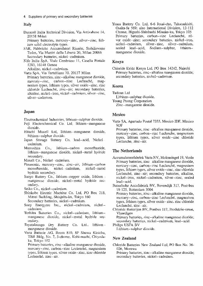
4 Suppliers of primary and secondary batteries
Italy
Duracell Italia Technical Division, Via Arrivabene 14, 20158 Milan Primary batteries, mercury-zinc, silver-zinc, lith- ium solid electrolyte types.
FAR, Fabbriche Accumulatori Riunite, Stabilimento Tudor, Via Martiri della Liberta 20, Milan 20066 Secondary batteries, nickel-cadmium.
Nife Italia SPA, Male Cembrano 11, Casella Postale 1283, 16148 Genoa Alkaline, nickel-cadmium.
Primary batteries, zinc-alkaline manganese dioxide, mercury-zinc, carbon-zinc LeclanchC, mag- nesium types, lithium types, silver oxide-zinc, zinc chloride LeclanchC, zinc-air; secondary batteries, alkaline, nickel-iron, nickel-cadmium, silver-zinc, silver - cadmium.
Varta SPA, Via Tertulliano 70, 20137 Milan
Japan
Electrochemical Industries, lithium- sulphur dioxide. Fuji Electrochemical Co. Ltd, lithium-manganese
dioxide. Hitachi Maxell Ltd, lithium-manganese dioxide,
lithium- sulphur dioxide. Japan Storage Battery Co, lead-acid, Nickel-
cadmium. Matsushita Co., lithium-carbon monofluoride,
lithium-manganese dioxide, nickel-metal hydride secondary.
Maxell Co., Nickel-cadmium. Panasonic, mercury-zinc, zinc-air, lithium-carbon
monofluoride, nickel-cadmium, nickel-metal hydride secondary.
Sanyo Battery Co., lithium-copper oxide, lithium- manganese dioxide, nickel-metal hydride sec- ondary.
Seiko Co., nickel-cadmium. Shinkobe Electric Machine Co. Ltd, PO Box 218,
Mitsui Building, Shinjuku-ku, Tokyo 160 Secondary batteries, nickel-cadmium.
Sony Energytec Inc., nickel-cadmium, nickel- cadmium.
Toshiba Batteries Co., nickel-cadmium, lithium- manganese dioxide, nickel-metal hydride sec- ondary.
Toyatakasago Dry Battery Co. Ltd., lithium- manganese dioxide.
Varta Batterie AG, Room 810, 8F Shuwa Kioichu, TBR Bldg, No. 7, 5-chome, Kohi-machi, Chiyoda- ku, Tokyo 102 Primary batteries, zinc-alkaline manganese dioxide, mercury -zinc, carbon-zinc LeclanchC, magnesium types, lithium types, silver oxide-zinc, zinc chloride LeclanchC, zinc-air.
Yuasa Battery Co. Ltd, 6-6 Josai-cho, Takatsukishi, Osaka-fu 569; also lntemational Division, 12-1 12 Chome, Higashi-Shinbashi Minako-ku, Tokyo 105 Primary batteries, carbon-zinc LeclanchC, sil- ver oxide-zinc; secondary batteries, nickel-iron, nickel -cadmium, silver -zinc, silver - cadmium, sealed lead-acid, Sodium-sulphur, lithium- manganese dioxide.
Kenya
Chloride Exide Kenya Ltd, PO Box 14242, Nairobi Primary batteries, zinc- alkaline manganese dioxide; secondary batteries, nickel-cadmium.
Korea Tadiran Ltd
Young Poong Corporation Lithium-sulphur dioxide.
Zinc-manganese dioxide.
Mexico
Varta SA, Apartado Postal 7355, Mexico IDF, Mexico 9DF Primary batteries, zinc-alkaline manganese dioxide, mercury - zinc, carbon - zinc Leclanche, magnesium types, lithium types, silver oxide-zinc chloride Leclanche. zinc-air.
The Netherlands
Accumulatorefabriek Varta NV, Molensingell9, Venlo Primary batteries, zinc-alkaline manganese dioxide, mercury - zinc, carbon - zinc LeclanchC, magnesium types, lithium types, silver oxide-zinc, zinc chloride LeclanchC, zinc-air; secondary batteries, alkaline, nickel-iron, nickel-cadmium, silver-zinc, sealed lead-acid.
Bataafsche Accufabriek BV, Bovendijk 3 17, Post-bus 10 125, Rotterdam 3004 Primary batteries, zinc-alkaline manganese dioxide, mercury-zinc, carbon-zinc LeclanchC, magnesium types, lithium types, silver oxide-zinc, zinc chloride LeclanchC, zinc-air.
Chloride Batterijen BV, Postbus 117, Produktie-straat, Vlaardigen Primary batteries, zinc-alkaline manganese dioxide; secondary batteries, nickel-cadmium, lead-acid.
Lithium-sulphur dioxide. Philips USFA BV
New Zealand Chloride Batteries New Zealand Ltd, PO Box No. 36-
026, Morewa Primary batteries, zinc-alkaline manganese dioxide; secondary batteries, nickel-cadmium.

Suppliers of primary and secondary batteries 5
Duracell UK Technical Division, Duracell House, Gatwick Road, Crawley RHlO 2PA Primary batteries, mercury-zinc, silver-zinc, lithium solid electrolyte types, nickel-cadmium, lithium- sulphur dioxide, lithium-manganese diox- ide, zinc-air. See also Duracell (US)
Ever Ready Holdings Ltd (Berec), Ever Ready House, 1255 High Road, Whetstone, London N20 OEJ; also Ever Ready House, Wishart Street, Glasgow El ; Ever Ready House, Dewhurst Street, Manchester 8; Ever Ready House, Coneygree Industrial Estate, Burntree, Tipton, Staffs.; Ever Ready House, Nar- roways Road, Bristol 2; Ever Ready House, Sta- tion Approach, North Coulsdon, Surrey; Ever Ready Ca. (Holdings) Ltd, Central Laboratories, St Ann's Road, London N15 3TJ Primary batteries, zinc-alkaline manganese dioxide, mercury-zinc, carbon-zinc LeclanchC, zinc-air, nickel-cadmium, lithium-manganese dioxide
Gamela Batteries Ltd, Chequers Lane, Dagenham; Essex RM9 6PX Primary batteries, zinc-alkaline manganese dioxide.
General Electric Company (Chloride Gates) fully sealed lead-acid.
Gould UK zinc - air.
Hawker Siddeley Electric Export Ltd, PO Box 72, Crompton House, Aldwych, London WC2B 4JH; also Crompton-Parkinson Vidor Works, River Drive, South Shields, Tyne and Wear NE33 2TR; 32 Duke Street, London SW1 Primary batteries, zinc-alkaline manganese dioxide, carbon-zinc LeclanchC.
Radenite Batteries Ltd, 21 Bayton Road, Exhall. Coventry CV7 9EL, UK Secondary batteries, lead-acid.
McMurdo Instrument Co. Ltd, Rodney Road, Portsmouth PO4 8SS Primary batteries, silver oxide-zinc seawater batteries, copper-type seawater batteries.
Mallory Batteries Ltd, Gatwick Road, Crawley RHl@ 2PA Primary batteries, zinc-alkaline manganese dioxide, mercury -zinc, carbon-zinc ZeclanchC, magnesiua types, lithium types, silver oxide-zinc: secondary batteries, alkaline, nickel-iron, mercury-cadmium.
Mine Safety Appliances Co. Ltd, Blairtummock Road, Queenlie Industrial Estate, Glasgow G33 4BT. Primary batteries, thermal batteries, lithmm-iodine.
lithium-sulphur dioxide.
House, 97 St Mary Street, Cardiff Primary batteries, carbon-zinc.
Sogea (SAFT) Batteries Ltd, Castle Works, Station Road, Hampton, Middlesex Primary batteries, zinc-alkaline manganese dioxide, carbon-zinc LeclanchC, lithium types (lithium-lead bismuthate, lithium-silver chromate): secondary
Power Conversion Ltd
Ray-o-Vac International Corporation, Westminster
Norway
Norsk Chloride A/S, Ostre Aker vei 203, Oslo 9, Norway Primary baltteries, zinc-alkaline manganese; sec- ondary batteries, lead-acid, nickel-cadmium.
Portugal
Accumuladores Autosil SARL, Avenida 24 de Julho 26-B, Lisbon Secondary batteries, alkaline.
South Africa
Raylite Batteq Pty Ltd, Cor Apex and Detroit Streets, Apex Ind. Sites, PO Box 166, Benoni 1500, Transvaal Secondary batteries, nickel-iron, nickel-cadmium.
Spain
Nife Espana .SA, Hermosilla IIF, Madrid 9 Secondary batteries, nickel-cadmium.
Sweden
Nordiska Akkumulatorfabriker, NOACK AB, Kom- mendorsgatan 16, Box 5317, S-10246 Stockholm Primary batteries, zinc-alkaline manganese dioxide, mercury-zinc, carbon-zinc LeclanchC, magnesium types, lithium types, silver oxide-zinc, zinc chloride LeclanchC, zinc-air.
Nife Jungner AB, 5572 01 Oskarshamm Secondary batteries, alkaline.
Chloride Branza A13, Lautvornsgaten 8, Box 260, 651 07, Karlstad Primary batteries, zinc-alkaline manganese dioxide; secondary batteries, lead-acid, nickel-cadmium.
Switzerland
Renata SA, Switzerland
Leclanche SA, 48 Avenue de Grandson, Yverdon, lithium-manganese dioxide, nickel-cadmium;
Switzerland Thermal cells.
United Kingdom
Chloride Batt'eries, Box 5 , Clifton Junction, Swinton, Manchester M27 2LR Secondary batteries, alkaline, nickel-cadmium, lead-acid.
Lead-acid, mercury-zinc, lithium- sulphur dioxide, mercury -indium bismith.
Crompton Parkinson Ltd
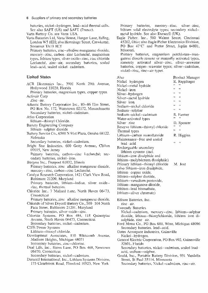
6 Suppliers of primary and secondary batteries
batteries, nickel-hydrogen, lead-acid thermal cells. See also SAFT (US) and SAFT (France).
Varta Battery Co. see Varta USA. Varta Batteries Ltd, Varta House, Hanger Lane, Ealing,
London W5 1EH; also Hermitage Street, Crewkerne, Somerset TA18 8EY Primary batteries, zinc-alkaline manganese dioxide, mercury - zinc, carbon - zinc LeclanchC , magnesium types, lithium types, silver oxide-zinc, zinc chloride LeclanchC, zinc-air; secondary batteries, sealed lead-acid. sealed nickel-cadmium.
United States ACR Electronics Inc., 3901 North 29th Avenue,
Hollywood 33020, Florida Primary batteries, magnesium types, copper types.
Activair Corp Zinc -air.
Atlantic Battery Corporation Inc., 80-86 Elm Street, PO Box No. 172, Watertown 02172, Massachusetts Secondary batteries, nickel-cadmium.
Atlas Corporation lithium-thionyl Chloride.
Battery Engineering Company lithium-sulphur dioxide
Battery Service Co., 6500 N 91st Plaza, Omaha 68122, Nebraska Secondary batteries, nickel-cadmium.
Bright Star Industries, 600 Getty Avenue, Clifton 07015, New Jersey Primary batteries, carbon-zinc LeclanchC; sec- ondary batteries, nickel-iron.
Primary batteries, zinc-alkaline manganese dioxide, mercury-zinc, carbon-zinc LeclanchC.
Catalyst Research Corporation, 1421 Clark View Road, Baltimore 21209, Maryland Primary batteries, lithium-iodine, silver oxide- zinc, thermal batteries.
Chloride Inc., 7 Mallard Lane. North Haven 06473, Connecticut Primary batteries, zinc-alkaline manganese dioxide.
Chloride of Silver Drycell Battery Co., 500-504 North Paca Street, Baltimore 21201, Maryland Primary batteries, silver oxide-zinc.
Avenue, North Haven 06473, Connecticut Secondary batteries, nickel-cadmium.
Lithium - thiony 1 chloride.
Madison Heights, Michigan 48071 Secondary batteries, zinc-chlorine.
06470, Connecticut Secondary batteries, nickel-cadmium.
Duracell International, Inc., Lithium Systems Division, 175 Clearbrook Road, Elmsford 10523, New York
Burgess Inc., Freepost 61032, Illinois
Chloride Systems, PO Box 484, 118 Quinnipiac
CITE Power Systems
Development Associates, 1 10 Whitcamb Avenue,
Dual Life, Inc., S inm Lane, PO Box 468, Newtown
Primary batteries, mercury-zinc, silver-zinc, lithium solid electrolyte types; secondary nickel- metal hydride. See also Duracell (UK).
Eagle Picher, Inc., 580 Walnut Street, Cincinnati 45202, Ohio; also Eagle Picher Electronics Division, PO Boc 47‘C’ and Porter Street, Joplin 64801, Missouri. Primary batteries, magnesium perchlorate-man- ganese dioxide remote or manually activated types, remotely activated silver-zinc, silver-seawater batteries, copper-seawater types; silver-cadmium, nickel-zinc, zinc-air types.
Also Product Manager Nickel-hydrogen R. Repplinger Nickel-metal hydride Nickel - iron
Silver-metal hydride Silver - iron Sodium-nickel chloride Sodium- sulphur Sodium-nickel - cadmium R. Farmer Water-activated types Silver-zinc D. Spencer Reserve lithium-thionyl chloride ” ”
Thermal types Lithium-carbon monofluoride R. Higgins Maintenance-free and sealed
lead-acid Rechargeable secondary
lithium systems (incl. lithium-iron disulphide and lithium-molybdenum disulphide) Primary lithium-thionyl chloride M. Jost (also lithium-iron disulphide, lithium-copper oxide, lithium-sulphur dioxide, lithium-vanadium pentoxide, lithium-manganese dioxide, lithium-lead bismuthate, lithium-silver chromate)
Edison Batteries, Inc.
Eveready Batteries
,> >>
,, 11
Silver-hydrogen ,, / /
I, 3,
,, >>
>t ’1
,> i,
,> >,
9 , > >
,I > ?
zinc-air .
Nickel-cadmium, mercury-zinc, lithium- sulphur dioxide, lithium-thionylchloride, lithium-iron di- sulphide, zinc-air.
Ford Motor Co., PO Box 600, Wixo, Michigan 48096 Secondary batteries, lead-acid.
Gates Aerospace Industries, Gainsville Nickel-hydrogen.
General Electric Corporation, PO Box 992, Gainesville 32601, Florida Secondary batteries, nickel-cadmium, sealed lead- acid, sodium-sulphur.
Gould, Inc., Portable Battery Division, 931 Vandalia Street, St Paul 55114, Minnesota Secondary batteries, Nickel-cadmium, zinc-air.

Suppliers of primary and secondary batteries 7
Sonatone Corporation Batery Division, Saw Mi13 River Road, Elmsford 10524, New York Secondary batteries, nickel-cadmium.
Southern California Edison Lead-acid (load levelling).
Union Carbide Corporation Consumer Products, 270 Park Avenue, New York 10017, New York Secondary batteries, nickel-cadmium, silver-oxide, sodium-nickel chloride secondary.
Union Carbide, Inc.; 270 Park Avenue; New York 10017, New York Primary batteries, zinc-alkaline manganese dioxide, mercury-zinc, carbon-zinc Leclanche, silver oxide-zinc, zinc chloride LeclanchC; secondary bat- teries, alkaline, nickel-cadmium, nickel met& hydride secondary.
Varta Batteries, Inc., 85 Executive Boulevard, Cross Westchester Executive Park, Elmsford 10523, New York Primary batteries, zinc-alkaline manganese dioxide, mercury-zinc, carbon-zinc LeclanchC, magnesium types, zinc chloride LeclanchC; secondary batteries, alkaline, nickel-iron, nickel-cadmium, silver-zinc, sealed lead-acid.
Ventrne Technology Lithium-iron disulphide
W. R. Grace & eo.; 7379 Route 32, Columbia, Mary- land 21044 Battery separator manufacturers.
Wilson Greatback Lithium iodine.
Wisco Division ESB, Inc., 1222 18th Street, Racine 53493, Wisconsin Secondary batteries, silver-zinc, lead chloride, cuprous chloride.
Yardney Electric Corporation, 82 Mechanic Street, Pawcatnck 02891, Connecticut. Primary batteries, magnesium types, lithium types; secondary batteries, silver - zinc, silver - cadmium, lithium-thionyl chloride, lithium-sulphur dioxide. nickel - zinc.
Yardney Electric Corporation, Power Sources Divi- sion, 3850 Olive Street, Denver 80207, Colorado Secondary batteries, nickel-hydrogen, silver-zinc, silver-cadmium. nickel-zinc,
Hawaiian Pacific Battery Corporation, 250N Clark Avenue, Pornona 91767, California also Hawai- ian Pacific Ba.ttery Corporation, 18103 Kahai Street, Honolulu 96819, Hawaii Primary batteries, zinc-alkaline manganese dioxide, mercury-zinc Leclanch6, magnesium types; sec- ondary batteries, nickel-cadmium.
Honeywell, Inc., Power Resources Centre, 104 Rock Road, Norsham 19044, Pennsylvania Primary battleries, lithium-sulphur dioxide, lithium thionyl chloride, lithium-vanadium pentoxide.
Hughes Aerospace Corp., EC Sefundo, USA Nickel - hydrogen.
Mallory Battery Corporation, South Broadway and Sunnyside Lane, Tarryiown 10591, New York Primary batteries, zin-alkaline manganese dioxide, carbon-zinc LeclanchC, magnesium types, lithium types, silver oxide-zinc.
Marathon Battery Co., PO Box 8233, Waco, Texas Secondary batteries, nickel-cadmium
McGraw Edison Corporation, Edison Battery Division, PO Box 28, Bloomfield 07003, New Jersey Primary batteries, zinc-air; secondary batteries, nickel -iron, nickel- cadmium, zinc -air.
Medronics Ltd Lithium-iodine.
Molecular Energy Corporation, 132T Floral Avenue, Murray Hill 07074, New Jersey Secondary batteries, silver-zinc, silver-cadmium.
Moli Engineerfhg Ltd, Lithium-molybdenum disulphide secondary.
Nife, Inc., BO Box 100, George Washington Highway, Lincoln 02865, Rhode Island Secondary b'atteries, alkaline, nickel-cadmium.
brook, New Jersey Lithium-sulphur dioxide, thermal cells.
Rayovac Corporation Nickel-cadmium, lithium-manganese dioxide, mercury-zinc, zinc-air.
SAFT Corporation of America, 50 Rockefeller Plaza, New York 10020, New York; also, 107 Beaver Court, Lockeysville, Maryland Primary batteries, zinc-alkaline, zinc-alkaline manganese dioxide, carbon-zinc LeclanchC, lithium types (1ithiLum-lead bismuthate, lithium-silver chromate); secondary batteries, nickel-cadmium, lithium-copper oxyphosphate, lithium-thionyl chloride, zinc-air, thermal-cells, water-activated batteries. See also SA.FT (UK) and SAFT (France).
Shigoto Indus?.ries, Inc., 350 Fifth Avenue, New York 10000, New York Primary batteries, zinc-alkaline manganese dioxide, mercury-zinc, carbon-zinc, LCclanche, magnesium types, copper types; secondary batteries, nickel- cadmium, silver-zinc.
Ovonic Battery eo., 280 Midland Avenue, Saddle-
Yugoslavia Jugometal, Deligradska 28/IX, Belgrade 11001
Secondary batteries, nickel-cadmium.
Zambia Chloride Zambia, PO Box 1892, Mitwe
Primary batteries, zinc-alkaline manganese dioxide: secondary batteries. nickel-cadmium.
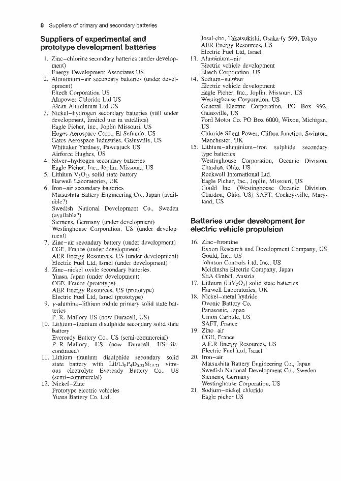
8 Suppliers of primary and secondary batteries
Suppliers of experimental and prototype development batteries 1. Zinc-chlorine secondary batteries (under develop-
ment) Energy Development Associates US
opment) Eltech Corporation US Alupower Chloride Ltd US Alcan Aluminium Ltd US
development, limited use in satellites) Eagle Picher, Inc., Joplin Missouri, US Huges Aerospace Corp., El Sefundo, US Gates Aerospace Industries, Gainsville, US Whittaker Yardney, Pawcatuck US Airforce Hughes, US
4. Silver-hydrogen secondary batteries Eagle Picher, Inc., Joplin, Missouri, US
5. Lithium V6013 solid state battery Harwell Laboratories, UK
6. Iron-air secondary batteries Matsushita Battery Engineering Co., Japan (avail- able?) Swedish National Development Co., Sweden (available?) Siemens, Germany (under development) Westinghouse Corporation, US (under develop- ment)
CGE, France (under development) AER Energy Resources, US (under development) Electric Fuel Ltd, Israel (under development)
8. Zinc-nickel oxide secondary batteries. Yuasa, Japan (under development) CGE, France (prototype) AER Energy Resources, US (prototype) Electric Fuel Ltd, Israel (prototype)
teries P. R. Mallory US (now Duracell, US)
10. Lithium-titanium disulphide secondary solid state battery Eveready Battery Co., US (semi-commercial) P. R. Mallory, US (now Duracell, US-dis- continued)
11. Lithium-titanium disulphide secondary solid state battery with LiULi8P4Do.25Si13.7j vitre- ous electrolyte Eveready Battery Co., US (semi - commercial)
Prototype electric vehicles Yuasa Battery Co. Ltd,
2. Aluminium-air secondary batteries (under devel-
3. Nickel-hydrogen secondary batteries (still under
7. Zinc-air secondary battery (under development)
9. y-alumina-lithium iodide primary solid state bat-
12. Nickel-Zinc
Josai-cho, Takatsukishi, Osaka-fy 569, Tokyo AER Energy Resources, US Electric Fuel Ltd, Israel
Electric vehicle development Eltech Corporation, US
Electric vehicle development Eagle Picher, Inc., Joplin, Missouri, US Westinghouse Corporation, US General Electric Corporation, PO Box 992,
13. Aluminium-air
14. Sodium-sulphur
Gainsville, US Ford Motor Co. PO Box 6000, Wixon, Michigan, us Chloride Silent Power, Clifton Junction, Swinton, Manchester, UK
15. Lithium-aluminium-iron sulphide secondary type batteries Westinghouse Corporation, Oceanic Division, Chardon, Ohio. US Rockwell International Ltd. Eagle Picher, Inc., Joplin, Missouri, US Gould Inc. (Westinghouse Oceanic Division, Chardon, Ohio, US) SAFT, Cockeysville, Mary- land, US
Batteries under development for electric vehicle propulsion
16. Zinc-bromine Exxon Research and Development Company, US Gould, Inc., US Johnson Controls Ltd, lnc., US Meidinsha Electric Company, Japan SEA GmbH, Austria
17. Lithium (LiV205) solid state batteries Harwell Laboratories, UK
18. Nickel-metal hydride Ovonic Battery Co. Panasonic, Japan Union Carbide, US SAFT, France
CGE, France A.E.R Energy Resources, US Electric Fuel Ltd, Israel
Matsushita Battery Engineering Co., Japan Swedish National Development Co., Sweden Siemens, Germany Westinghouse Corporation, US
21. Sodium-nickel chloride Eagle picher US
19. Zinc-air
20. Iron-air

Glossary


Glossary 3
capacity; usually expressed in ampere hours at a given discharge current.
Capacity, residual Capacity remaining at a par- ticular point in time after any set of operating conditions, usually including a partial discharge or long rest.
Capacity, restorable See Capacity, temporary loss of.
Capacity, temporary loss of Reduction in cell capacity that is recovered when cell is subjected to several reconditioning cycles. See also Failure, reversible.
Capacity, useful See Capacity, available. Capacity reconditioning See Reconditioning. Cathode An electrode at which a reduction reaction
(gain of electrons) occurs; in secondary cells either electrode may become the cathode, depending on the direction of current flow.
Cell Electrochemical device, composed of positive and negative plates, separator and electrolyte, that is capable of storing electrical energy; when encased in a container and fitted with terminals, it is the basic ‘building block’ of a battery.
Cell case See Container. Cell reversal Reversing of polarity of terminals of a
cell in a multi-cell battery due to overdischarge. Charge Return of electrical energy to a battery. Charge, state of Residual capacity of a cell
expressed in terms of the fully charged capacity. Charge rate The current at which a secondary cell
or battery is charged, expressed as a function of the cell or battery’s rated capacity; for example, the 20 h charge rate of a 10 Ah cell would be equal to Cl20 = 10120 = 0.5 A.
Charge retention The tendency of a charged cell to resist self-discharge.
Charger Device capable of supplying electrical energy to a battery.
Connector Electrical conductor which joins indi- vidual cells together in a battery.
Constant current Charging method in which cur- rent does not change appreciably in magnitude, regardless of battery voltage or temperature.
Constant potential Charging method that applies a fixed voltage to a cell; often abbreviated to CP.
Container Cell enclosure in which plates, separator and electrolyte are held; it consists of the cell jar and cover, which are permanently joined.
Contaminant Undesirable element, usually in the electrolyte, that reduces the capacity of the cell; in vented cells, contaminants can be introduced by use of tap water or operation without the vent cap.
Contraction The shrinkage of active material. Corrosion The oxidation of a metal electrode. Coulometer Electrochemical or electronic device,
capable of integrating current-time, used for charge control or measurement.
Counter electromotive force A voltage opposite to the applied voltage, also referred to as back e.m.f.
Activated stand life The period of time, at a specified temperature, that a secondary cell can be stored in the charged condition before its capacity falls below a specified level.
Activation The process of making a cell without electrolyte functional, either by introducing an electrolyte or by immersing the cell into an electrolyte. Activation of thermally activated reserve cells involves heating to melt a solid.
Active materials The substances of a positive or negative plate that react to produce current.
Ampere hours Product of current in amperes multiplied by time current is flowing; capacity of a cell or battery is usually expressed in ampere hours.
Anode An electrode at which an oxidation reaction (loss of electrons) occurs; in secondary cells either electrode may become the anode, depending on the direction of current flow.
Available capacity See Capacity.
Baffle A non-conductive barrier inserted in a vented cell above the plate pack and used as a reference for electrolyte level; it also protects the top edges of the plates from objects dropped into the vent cap hole.
Battery One or more cells connected to form one unit and having provisions for external connections.
Battery case Box or enclosure which contains the cells, associated connectors and hardware.
C, Effective parallel capacitance. C rate Discharge or charge current rate in amperes,
numerically equal to rated capacity of a cell in ampere hours, rated at the 1 h discharge rate.
C,, rate Charge or discharge current numerically equal to capacity, rated at the n h discharge rate.
XC, rate Charge or discharge current numerically equal to X times the capacity, rated at the n h discharge rate.
Cadmium electrode See Negative plate. Capacity Ampere hours available from a fully
charged cell or battery. Capacity, available Total capacity that may be
obtained at defined charge and discharge rates and their associated environmental conditions.
Capacity, deliverable See Capacity, available. Capacity, functional loss of Reduction in cell capa-
city due to non-standard charging or discharging parameters such as cell temperature, current, and discharge voltage cut-off. See also Failure, function.
Capacity, nameplate See Capacity, rated. Capacity, nominal See Capacity, rated. Capacity, permanent loss of Reduction in cell
capacity from ‘as new’ value, under standard rating conditions; not recoverable by reconditioning. See UZSQ Failure, permanent.
Capacity, rated A designation by the battery manufacturer which helps identify a particular cell model and also provides an approximation of

4 Glossary
Current density The amount of current per unit area passing from one plate to another (A/cm2).
Cut-off voltage Voltage at which a discharge or charge is terminated.
Cycle One sequence of discharge and recharge. Deep cycling requires that all the energy to an end-voltage established for each system is drained from the battery on each discharge; in shallow cycling the energy is partially drained in each discharge, that is, discharge up to 50% depth of capacity.
Cycle life In a secondary storage battery, the number of cycles the battery may experience before its capacity falls to a point considered a failure. See also Failure.
Cylindrical cell A cylinder-shaped sealed wound cell containing a high-pressure safety vent.
Dead band The range of temperatures between the point at which the thermostat opens and the point where it recloses (resets). If the temperature first exceeds the point at which the switch opens and then drops below this point, the switch remains open within the dead band until the temperature falls below the reset point.
Deep cycling See Reconditioning. Deep discharge The condition in which a cell is
discharged to 0.5V or less at low rate, that is, to below cut-off voltage or withdrawal of at least 80% of rated capacity.
Deionized water Water that has been freed of ions by treatment with ion-exchange resins.
Depolarizer A material to offset a polarizing effect of an electrode.
Depth of discharge (DOD) The percentage of rated capacity to which a cell or battery is discharged; for example, if 5 A h of capacity is discharged from a lOOAh battery, the depth of discharge is 5%.
Discharge Withdrawal of electrical energy to end- point voltage before the cell or battery is recharged.
Discharge rate See Rate. Discharge voltage The voltage of a battery during
discharge. Discharging The withdrawing of electrical energy
from a battery or cell. Distilled water Water that has been freed of ions
by a process of vaporization and subsequent condensation.
Drain Withdrawal of current from a cell or battery. Dry Indication that the electrolyte in a cell is
immobilized, being either in the form of a paste or gel or absorbed in the separator material, and/or that a cell may have insufficient electrolyte.
Dry, charged An electrochemical system in which the electrodes are in a charged state, ready to be activated by the introduction of electrolyte.
Dry, uncharged Indicates that a cell must be activated and receive initial formation cycles before it can be brought into use.
Dump timed charge (DTC) A charging method in which the cell is first discharged at a rate-time combination equal to or greater than the charge rate-time combination which immediately follows.
Duty cycle The condition and usage to which a battery is subjected during operation, consisting of charge, overcharge, rest and discharge.
Eo See Equivalent no-load voltage. Effective internal resistance, Re The apparent op-
position to current flow within a battery that manifests itself as a drop in battery voltage proportional to the discharge current; its value depends on battery design, state of charge, temperature and age.
Electrode Conducting body and the active materials in which the electrochemical reaction occurs.
Electrode potential The voltage developed by a single plate, either positive or negative; the algebraic difference in voltage of any two electrodes equals the cell voltage.
Electroformation The conversion of the material in both the positive and negative plates to their respective active material.
Electrolyte Fluid used in a cell as a medium for movement of ions.
End-of-charge voltage The voltage of the battery at termination of a charge but before the charge is stopped.
End-of-discharge voltage The voltage of the bat- tery at termination of a discharge but before the discharge is stopped.
End-point voltage Voltage below which connected equipment will not operate, or below which operation of a cell is not recommended frequently interchangeable with ‘cut-off voltage’.
Energy Output capability, ampere hours capacity times average closed-circuit discharge voltage, expressed as watt hours.
Energy density A figure of merit in common use with batteries, expressing the stored energy as a function of the weight or volume (Whlkg or W h/dm3); rate dependent.
Entrainment Process whereby gases generated in the cell carry electrolyte out through the vent cap.
Environmental conditions External circumstances to which a cell or battery may be subjected, such as ambient temperature, humidity, shock, vibration and altitude.
Equalization See Reconditioning. Equivalent circuit A circuit presented to simulate
the electrical behaviour of a cell. Equivalent internal resistauce See Effective inter-
nal resistance. Equivalent no-load voltage, Eo The numerical value
of the source voltage in the equivalent circuit.

Glossary 5
Opposition to direct current flow in a cell; this can be measured by dividing the difference between the open-circuit voltage and the voltage at a particular current, by that current. (Note: the internal resistance may vary with the current and state of charge.)
Internal resistance
Jar The bottom portion of the cell container which mates with the cell cover.
KOH See Potassium hydroxide.
Fading The long-range loss of capacity with use. Failure The condition in which a battery is unable
to perform satisfactorily. Failure, function Condition in which the battery has
caused the end-use device to fail to function at the performance level expected.
Failure, permanent A non-reversible condition that makes the battery essentially useless. There is no recognized standard method of rating or defining exactly when a cell has reached the end of its life; however, the end of useful life is defined as that condition when the cell cannot perform above 50% of its rated ampere hour capacity with all charging and discharging done at room temperature.
Failure, reversible A failure condition that may be corrected through the application of certain electrical procedures.
Failure, temporary See Failure, reversible. Fast-charge battery A battery that can be charged
at the fast-charge rate and that gives a suitable signal which can be used to terminate the fast-charge current without damage to the battery.
Fast charging Rapid return of energy to a battery at the C rate or greater.
Float charging The use condition of a storage battery wherein charge is maintained by a continuous, long-term constant-potential charge.
Flooded cell See Vented cell. Flooding Filling of pores of a porous electrode with
electrolyte solution, thereby minimizing access of gases to ellectrode surface.
Form factoir Battery configurations that may be created by interconnecting cells in various arrange- ments.
Function failure See Failure, function.
Gassing The liberation of hydrogen andlor oxygen
Grid The metallic part of a battery plate which
Group An assembly of positive or negative plates
gases from. a cell.
retains the active material.
which fit into a cell.
High-resistance short See Short-circuit. High-rate discharge Withdrawal of large currents in
short intervals of time, usually at a rate less than 1 h.
Imp See Maximum-power discharge current. Impedance An a.c. circuit's apparent opposition to
current; consists of reactance and ohmic resistance. For the equivalent phenomenon in a d.c. battery, see Effective internal resistance.
Initial drain Current that the cell or battery supplies when first placed on load.
Intermittent short See Short, intermittent. Internal impedance The opposition of a cell or
battery to an alternating current of a particular frequency, usually 60 Hz. (Note: the internal im- pedance may vary with the state of charge.)
Life The duration of satisfactory performance, measured as'usage in years or as the number of charge/discharge cycles.
Load The current drain through a fixed resistance to which the battery will be subjected.
Low-rate discharge Withdrawal of small currents for long periods of time, usually longer than 1 h.
Low-resistance short See Short, low-resistance.
Maintenance The care and procedures necessary to keep a battery in a usable condition, such as reconditioning and water addition to electrolyte of a vented cell.
Manufacturing variations Differences in perfor- mance characteristics between products of the same design, attributable to process deviations within expected tolerances.
Maximum-power discharge current, I , The discharge rate at which the terminal voltage is equal to one-half of Eo and at which maximum power (energy rate) is transferred to the external load.
Memory effect A phenomenon in which a nickel- cadmium battery, operated in successive cycles of identical depth of discharge, temporarily renders the rest of its capacity inaccessible at normal voltage levels.
Mid-point voltage The battery voltage at the halfway point in the discharge between the fully charged state and the fully discharged state of a cell.
Negative electrode See Negative plate. Negative plate The plate that has an electrical poten-
tial below that of the other plate during normal cell operation.
Nickel electrode See Positive plate. Nominal capacity See Capacity, rated. Nominal voltage The mid-point voltage observed
across a battery during discharge at a selected rate, usually at the 0.2C or 0.1C rate.
On-charge voltage Voltage of a cell while on charge. Open-circuit voltage The no-load voltage of a
cell or battery measured with a high-impedance voltmeter at about room temperature (21°C). It is also implied that, in the case of a primary, the cell is freshly manufactured, and, for a secondary, fully charged.

6 Glossary
Overcharge current The charging current flowing to the battery after all the active material has been converted into a dischargeable state.
Overcharging Continuing charge after the battery has accepted its maximum amount of charge. In a vented cell, a result will be decomposition of water in the electrolyte into hydrogen and oxygen gases. In a sealed cell, a result will be increased cell temperature.
Oxidation The release of electrons, by the cell’s active material, to the external circuit. During dis- charge, active material at the negative electrode is oxidized.
Oxygen recombination The electrochemical process in which oxygen generated at the positive plate during overcharge is reacted (reduced) with water at the negative plate at the same time, generating heat.
Parallel Electrical term used to describe the interconnection of batteries in which all the like terminals are connected together.
Permacell A registered trademark of the General Electric Corporation which designates a re- chargeable nickel-cadmium battery-charger system using sealed cylindrical cells; offered as an alternative to popular sizes of primary cell.
Permanent failure See Failure, permanent. Peroxide voltage Initial voltage observed when
current load is first applied to a fully charged cell; this voltage is normally higher than the plateau voltage.
Plaque A porous body of sintered metal used as a current collector and holder of electrode active materials.
Plate Common term for an electrode. Plateau voltage Level portion of discharge curve,
Polarization The increased internal resistance of a
Polarity Electrical term used to denote the relative
Positive electrode See Positive plate. Positive plate The plate that has an electrical
potential higher than that of the other plate during normal cell operation.
A chemical compound, sym- bol KOH, which, when mixed with pure water in the correct proportions, is the electrolyte solution used in nickel-cadmium cells and other alkaline cell sys- tems.
Powerup-15 battery The General Electric trade- mark for a nickel-cadmium battexy which permits charging at rates up to the 4C rate to at least 90% of rated capacity in 15 min at room temperature. As the battery reaches full charge, the fast-charge rate is switched by the charger to a lower, continuous over- charge rate by sensing either the battery voltage or temperature.
varying with discharge rate.
cell which occurs during discharge.
voltage relationship between two electrodes.
Potassium hydroxide
Primary cell A cell designed to be used only once, then discarded. It is not capable of being returned to its original charge state by the application of current.
Quick charge Charging rate that ranges from 0.2C to O X rate.
Quick-charge battery A battery that can be charged fully in 3-5 h by a simple, constant-current charger and is capable of continuous overcharge at this quick-charge rate.
Re See Effective internal resistance. Rate Amount of charge or discharge current,
frequently expressed as a fraction or multiple of the 1 h rate, C .
Rated capacity See Capacity, rated. Rating See Capacity. Recharge Return of electrical energy to a battery. Rechargeable Capable of being recharged; refers to
secondary cells or batteries. Recombination The chemical reaction of gases at
the electrodes to form a non-gaseous product. Reconditioning Maintenance procedure consisting
of deep discharge, short and constant-current charge used to correct ceil imbalance which may have been acquired during battery use.
Reduction The gain of electrons; in a cell, refers to the inward flow of electrons to the active material.
Relative density The ratio of the mass of a given volume of a substance to the mass of an equal volume of water at a temperature of 4°C.
Resealable In a cell, refers to a safety vent that is capable of closing after each pressure release, in contrast to the non-resealable one-shot vent.
Residual capacity See Capacity, residual. Resistance See Effective internal resistance. Reversal See Cell reversal. Reversible failure See Failure, reversible. Reversible reaction A chemical change that takes
place in either direction, as in the reversible reaction for charging or discharging a secondary battery.
Sealed cell A cell that is free from routine maintenance and can be operated without regard to position; all reactants are retained within the container.
Secondary battery A system that is capable of repeated use by using chemical reactions that are reversible; that is, the discharged energy may be restored by supplying electrical current to recharge the cell.
Self-discharge The spontaneous decomposition of battery materials from charged to discharged state. That rate at which a primary or secondary battery or cell loses service capacity when standing idle.
Semipermeable membrane A porous film that will pass selected ions.

Glossary 7
Temperature cut-off (TCO) A method of switching the charge current flowing to a battery from fast charge to topping charge by means of a control circuit in the charger that is activated by battery temperature.
Temporary failure See Failure, reversible. Terminals The external part of a cell or battery from
which current can be drained. Thermal runaway A condition whereby a battery
on constant-potential charge at elevated temperature will destroy itself through internal heat generation, which is caused by high overcharge currents in constant-potential charging.
Topping charge A reduced rate charge that completes (tops) the charge of a cell and can be continued in overcharge without damaging the cell.
Trickle charge See Standby charge. Trough voltage The instantaneous open-circuit
voltage of a battery that is charged by a pulsating current.
Separator Material which provides separation and electrolyte storage between plates of opposite
Series Electrical term used to describe the intercon- nection of cells or batteries in such a manner that the positive terminal of an individual cell is connected to the negative terminal of the next cell.
Shallow discharge A discharge of a battery equal to only a small part of its total capacity.
Shedding The loss of active material from a plate during cycling.
Shelf life A measure of the active life of a battery in storage.
Short, high-resistance A short measuring 20 S2 or more.
Short, intermittent A condition where the open- circuit voltage of a battery is unstable when mechanically shocked; an intermittent short can be either low or high resistance.
Short, low-resistance A short measuring less than 26) Q.
Short-circuit The condition in a battesy where two plates of opposite polarity make electrical contact with each other.
Sintered-plate electrode A sturdy plate formed by sintering (agglomerating metallic powders by heating). The resulting electrode has a porous structure with 2 large surface area containing active materials which are accessible to be charged and discharged at high rates.
Slow charge ‘Overnight’ return of energy to a battery at 0.05-0.1C rates.
Soak time That time required for the electrolyte to be absorbed into the active materials after activation.
Spalling The flaking off of active material from a plate or electrode.
Split rate charge A charging method in which the batteiy is charged at a high rate and then automatically reduced to a lower charge rate as the battery approaches full charge.
Stack Flat plates assembled in a parallel orientation. Standby charge A low overcharge current rate, of
the order of 0.01-0.03C, applied continuously to a vented-cell battery to maintain its capacity in a ready-to-discharge state. Often called ‘trickle’ char- ging.
Starved cell A cell containing little or no free fluid electrolytle solution; this enables gases to reach electrode surfaces readily, and permits relatively high rates of gas recombination. See Sealed cell.
Residual capacity of a cell expressed in terms of fully charged capacity.
polarity.
State of charge
Tab A battery terminal, often containing a hole for
Temperatuire, ambient The average temperature of
Temperature, cell The average temperature of the
wire connection.
the battery’s surroundings.
battery’s components.
Unactivated storage life The period of time, under specified conditions of temperature and environment, in which a dry-charged cell can stand before deteriorating below a specified capacity.
Undercharging Applying less than the amount of current required to recharge a battery.
Vent A normally sealed mechanism that allows the controlled escape of gases from within a cell.
Vent cap A device that contains a vent and fits on to the top of a cell; normally used on vented cells to allow access for electrolyte level adjustment.
Vented cell A heavy-duty cell design in which the vent operates at low pressure during the normal duty cycle to expel gases generated in overcharge. A vented cell plate pack contains flat plates separated by a gas barrier and separator, completely immersed in electrolyte. Often called a ‘flooded’ cell.
Voltage cut-off (VCO) A method of switching the charge current flowing to a battery from fast charge to topping charge by means of a control circuit in the charger that is activated by battery voltage.
Voltage limit In a charge-controlled battery, the limit beyond which battery potential is not permitted to rise.
Voltage-temperature cut-off (VTCO) A method of switching the charge current flowing to a battery from fast charge to topping charge rate by means of a control circuit in the charger that is activated by either battery voltage or temperature.
Wet Indicates that the liquid electrolyte in a cell is free flowing.
Wet charged stand Period of time a battery can stand in the wet charged condition while retaining a large percentage of its capacity.

8 Glossary
Wet formed discharge Indicates that a cell is Wound The interior cell construction in which plates activated, formed and discharged. The cell need only be recharged for use.
Wet shelf life Period Of time a battery Can s t a d in the wet discharged condition before losing charging capability.
are coiled into a spiral.
Yield The energy output of a battery.

Battery Standards


Battery Standards 3
BS 397: Primary Batteries Part 3: 1985. Specification for batteries not included in Parts 1 and 2. Specifi- cations for batteries manufactured in the UK which are not standardized internationally and therefore are not included in Parts 1 and 2 of this standard. Gives dimensions, discharge conditions and drawings and terminal details where applicable. No current stan- dard is superseded. 46 pages. Gr 7 (522.00).
BS 61 15, Sealed Nickel Cadmium Prismatic Recharge- able Single Cell Batteries.
The International Electrochernical Commission (IEC) have prepared a battery standards specification: EEC Publication ,86: Primary Cells and Batteries, Parts 1 and 2 , 1975. The relevant British Standard is BS 397. Both are available from the British Standards Institution, 2 Park Street, London W1A 2BS.
The American National Standard, ANSI C18.1 is available from ANSI, 1430 Broadway, New York 10018, NY, USA.
The Japanese Standards Association issues Standard J15 8501 Diy Cells and Batteries, J15 8508 Mercury Cells and Batteries, J15 8509 Alkaline-Manganese Dioxide Cells and Batteries, J15 8510 Silver Oxide Cells and Batteries, and J15 8511 Alkaline Prim- ary Cells and Batteries. All are available through Japanese Embassies or direct from the Japanese Stan- dards Associiation, 1-24 Atasak 4 Chome, Minato-ku, Tokyo, Japan.
British Staindards
AU 11 8 1965, Storage, Shipment and Maintenance of Lead Acid Batteries for Motor Vehicles. 4 pages. Gr 2 (57.00).
BS 1335: 1968, Air Depolarized Primary Cells- Dimensions of Containers. Dimensions, materials of electrodes for dry, wet, inert cells and batteries. Details of electrolyte for wet cells. Performance, test methods. 20 page A5 size. Gr 4 (E10.50).
BS 5932: 1980, SpecGcation for Sealed NickelLCad- mium Cylindrical Rechargeable Single Cells. Per- formance requirements, cell designation, termina- tions, marking, dimensions, charging requirements and methlods of test for low and high rate of dis- charge at normal and low temperature, charge reten- tion, overcharge, life cycle, mechanical and after storage. AMD 3418, May 1980. 4 pages. Gr 3 (E9.50).
BS 6260: 1982, SpeciJication for Open NickelLCad- mium Prismatic Rechargeable Single Cells. Speci- fies characteristics, technical requirements and test methods to be used for fhe type testing of open nickel-catdmium prismatic rechargeable single cells. AMD 4386, October 2983. (Gr l), 4 pages. Gr 3 (L13.70).
BS 397: Part 1: 1985, Specijcation for General Requirements. Applies to primary cells and batteries based on any electrochemical system, and aims to ensure the electrical and physical interchangeability of products from different manufacturers, to limit the numblbler of battery types and to define a standard of quality and provide guidance for its assessment. 20 pages. Gr 8 (531.00).
BS 397: Part 2: 1985, Speci$cation Sheets. Gives dimensions, drawings (where applicable), discharge conditions and applications of primary batteries approved for a standardization by the IEC. 137 pages. Gr 11 (544.00).
IEC Standards Primary batteries: applies to dry primary cell batteries with the object of enumerating the types corresponding to the most current needs, defining their characteris- tics, ensuring their interchangeability and limiting their number.
86-1 (1982) Part 1: General. (Fifth edition) 47 pages. Applies to primary cells and batteries on any elec- trochemical system. Specifies nomenclature, dimem- sions, terminals, marking, test conditions and service output requirements for each battery in order to:
1. Ensure interchangeability. 2. Limit the number of types. 3. Define a standard of quality. (E60.83)
Amendment No. 1 (1984), 5 pages. 86-2 (1982) Part 2: Speci3cation sheets. (Fifth Edition)
144 pages. Specifies dimensions together with outline drawings of batteries, conditions and minimum duration of discharges and applications. Defines three new coding letters: S = standard, C = high capacity, P = high power. Includes new accelerated application tests for clocks and automatic cameras. This is a loose-leaf publication and supplements, containing new and revised sheets, are issued from time to time. (&I 12.50).
86-2A (1984) First Supplement to Publication 86-2 (1982). 62 pages. Specifies dimensions together with outline drawings of batteries, conditions and minimum duration of discharges and applications. Defines three new coding letters: S = standard, C = high capacity, P = high power. This is a loose-leaf publication, and supplements containing new and revised sheets, to be inserted in Publication 86-2, are issued from time to time.
95: Lead Acid Starter Batteries. Applies to lead-acid accumulator batteries with a rated voltage of 6 or 12V, used primarily as a source of starting and ignition current for internal combustion engines and also for the auxiliary installations of internal combustion engine vehicles.
95-1 (1980) Part 1: General Requirements and Meth- ods of Test. (Fourth edition) 29 pages. Defines inter- national specifications for several groups of batteries according to the general type of application and the climatic conditions. (527.50).

4 Battery Standards
95-2 (1984) Part 2: Dimensions of Batteries and Dimensions and Marking of Terminals. (Third edi- tion) 23 pages. Applies to lead-acid batteries used for starting, lighting and ignition of passenger auto- mobiles and light commercial vehicles with a nom- inal voltage of 12V fastened to the vehicles by means of ledges on the long sides of the battery case. Two alternative admissible means are specified in Section 3. It specifies:
standard series.
with respect to the fastening system.
teries.
1. The main dimensions of starter batteries of four
2. The location of the positive and negative terminals
3. The dimensions of tapered terminals of starter bat-
4. The marking of the polarity.
(E26.66). 254: Lead Acid Traction Batteries. 254-1 (1983) Part 1: General Requirements and Meth-
ods of Test. (First edition) 19 pages. Applies to lead-acid traction batteries intended for installation in electric traction vehicles or materials handling equipment and lays down, in general terms, their main characteristics and methods for their testing. (E24.16).
254-2 (1973) Part 2: Dimensions of Traction Battery Cells. (First edition) 10 pages. Gives the outer max- imum dimensions (overall) of all traction battery cells. (E13.33).
254-2A (1974) First Supplement. 2 pages. Gives addi- tional dimensions for extra-low cells.
285 (1983) Sealed Nickel-Cadmium Cylindrical Rechargeable Single Cells. (Second edition) 25 pages. Specifies tests and requirements for sealed nickel-cadmium cylindrical rechargeable single cells, suitable for use in any composition. (E28.33).
509 (1976) Sealed Nickel-Cadmium Button Recharge- able Single Cells. (First edition) 11 pages. Applies to elements suitable for use in any position, in electric or electronic appliances. Specifies the designation system, the electrical characteristics, marking and dimensions. (215.83).
622 (1978) Sealed Nickel-Cadmium Prismatic Re- chargeable Single Cells. (First edition) 11 pages. Establishes a system of designation of the cells. Defines the electrical characteristics and the relevant test methods, as well as the marking of the cells. (E13.33).
623 (1978) Open Nickel-Cadmium Prismatic Rech- argeable Cells. (Second edition) 21 pages. Gives the designation system of the cells, dimensions, electrical and mechanical tests as well as the marking applicable. (213.33).
428 (1973) Standard Cells (First edition) 23 pages. Applies to two kinds of standard cells used as elec- tromotive force references, namely saturated and unsaturated standard cells, and deals with test con- ditions relating to certification and requirements
for their electrical and mechanical characteristics. (E22.50).
The following is an extract from The IEC System of Battery Designation, prepared by E C Technical Committee No. 35.
Introduction
The last decade has seen a large expansion in the range of portable battery-operated consumer goods; often these are sold and used in countries other than those in which they were manufactured. During the same period the range of electrochemical systems available for battery use has multiplied and even within a system different application grades have appeared. These changes when coupled with the increase in travel between countries have led to the user being confused as to the correct type of replacement battery to purchase.
The battery purchaser requires a simple, unambigu- ous symbol which defines internationally the important Characteristics of the battery. These characteristics are:
(a) Dimensions and terminals (physical interchange-
(b) Voltage and electrical performance (electrical ability).
interchangeability).
At the present time there are three possible sources of such information.
The battery manufacturer publishes literature describing his products and sometimes includes recommendations for the battery to be used in specific equipment. In the nature of things this information is not complete.
The equipment manufacturer may include in the equipment a label stating the specific type of battery to be used, or the size required. Often a more detailed list of approved batteries is given in the equipment instruc- tion manual but again this is likely to be incomplete. Furthermore, the information may lead to frustration when the equipment originates in a different country from that in which the batteries are purchased.
Finally assistance may be given at the sales point by experienced and qualified technicians, although more usually the sales assistant is non-technical. It is apparent that the casual purchaser is rarely able to derive adequate benefit from the sources described above. In recognition of this, several attempts have been made to establish systems at a national level.
It is the aim of the IEC system to overcome the deficiencies described and the limitations imposed by national boundaries.
Examples
In the E C system fully described later and in Pub- lication 86, a series of numbers and letters are used to give a unique reference to each size of battery, its

terminals, voltage and electrochemical system. The fol- lowing examples illustrate the use of the E€ system.
(a) R6 (commonly used in small transistor radios), Figure I The letter R indicates that the battery is cylindrical and combined with the number 6 signifies a particular size with closely defined ter- minals. The absence of another letter shows that the electrochemical system is manganese dioxide- ammonium chloride, zinc chloride-zinc. This sys- tem has a nominal voltage of 1.5 V and since no preceding number is given the battery voltage is identical .with that of the electrochemical system, namely 1.5 V.
(b) LR6 (commonly used in cine-cameras), Figure 2 R6, as in the preceding example, defines the same shape, dimensions and terminals. The additional letter 6, indicates that the electrochemical system is manganese dioxide/alkali metal hydroxide/zinc having a nomind voltage of 1.45 V.
(c) 3RI2 (commonly used in pocket lamps), Figure 3 The complete symbol defines the size, terminals and volta,ge of the battery. As in Example (a) the electrochemical system is manganese dioxide/ ammonium chloride, zinc chloriddzinc but the presence of the number 3 denotes a battery voltage of three times the nominal voltage of the system, Le. 4.5 V.
(d) 6F22 (commonly used in pocket size transistor radios), Figure 4 As in Example (c) the complete symbol defines the size, terminals and voltage of the battery. The letter F denotes a flat cell construc- tion whiclh is convenient for compact multicell bat- teries. As in the preceding example the absence of an additional letter shows that the electrochemical
Figure 2
Figure 3
IR 6 1.5 v Terminals
Figure 1
Battery Standards 5
Terminals
Terminals
3R12 4.5 v
system is manganese dioxide/ammonium chloride, zinc chloride/zinc. The number 6 indicates that the battery voltage is six times 1.5V, Le. 9V.
(e) MR07 (commonly used in hearing-aids), Figure 5 The new feature in this example is the letter M which denotes that the electrochemical system is mercuric oxide/alkali metal hydroxiddzinc of 1.35 V nominal, which in this case is also the bat- tery voltage.
(f) MR44 (commonly used in watches), Figure 6 This battery is identical in all respects with the MRO? except that a closely controlled and precisely defined profile is mandatory. This ensures satisfac- tory fitment in the battery compartment of watches. For this reason the battery is defined in conjunc- tion with a profile gauge and is given a different number. The IEC system thus defines the battery
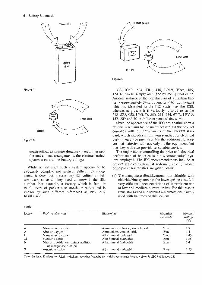
6 Battery Standards
Profile gauge
Figure 4
MR07
Figure 5
e e3 Terminals
construction, its precise dimensions including pro- file and contact arrangements, the electrochemical system used and the battery voltage.
Whilst at first sight such a system appears to be extremely complex and perhaps difficult to under- stand, it does not present any difficulties to bat- tery users since all they need to know is the IEC number. For example, a battery which is familiar to all users of pocket size transistor radios and is known by such different references as PP3, 216, R0603,438.
Table 1
MR44
Figure 6
Terminals
333, 006P 1604, TR1, 410, LPI-9, Tiber, 485, TM146 can be simply identified by the symbol 6F22. Another instance is the popular size of a lighting bat- tery (approximately 34mm diameter x 61 m height) which is identified in the IEC system as the R20, whereas at present it is variously referred to as the 212, SP2, 950, UMI, D, 250, 211, 734, 6TlL, LPV 2, 152, 209 and 70 in different parts of the world.
Since the appearance of the IEC designation upon a product is a claim by the manufacturer that the product complies with the requirements of the relevant stan- dad , which includes a minimum standard for electrical performance, the purchaser has the additional guaran- tee that batteries will not only fit the equipment but that they will also provide reasonable service.
The major factor controlling the price and electrical performance of batteries is the electrochemical sys- tem employed. The IEC recommendations include at present six electrochemical systems (Table l), whose principal characteristics are given below:
(a) The manganese dioxidelammonium chloride, zinc chloride/zinc system has the lowest prime cost. It is very efficient under conditions of intermittent use at low and medium current drains. For this reason transistor radios and torches are almost exclusively used with batteries of this system.
Letter Positive electrode Electrolyte Negative Nominal electrode voltage
(V)
- Manganese dioxide Ammonium chloride, zinc chloride Zinc 1.5 A Airo or oxygen Ammonium, zinc chloride Zinc 1.4 L Manganese dioxide Alkali metal hydroxide Zinc 1.45 M Mercuric oxide Alkali metal hydroxide Zinc 1.35 N Mercuric oxide with minor addition Alkali metal hydroxide Zinc 1.4
S Argentous oxide Alkali metal hydroxide Zinc 1.55 of manganese dioxide
~ ~~ ~ ~
Note: the letter K relates to nickel-cadmium secondary batteries for which recommendations are given in IEC Publication 285

Battery Standards 7
terminals, electrochemical system and the nominal voltage.
Cells
A cell is designated by a capital letter followed by a number. The letters F, R and S define flat (layer-built), round and square (or rectangular) cells respectively.
This letter, together with the following number pro- vide the reference to the appropriate entry in a table of approximate dimensions.
Each designation is related to a specific set of dimensions. There may however be more than one designation for any one set of dimensions. These cases arise due to differences of detail in profile QP polarity.
At the present time numbers are allocated sequen- tially.
Electrochemical system
With the exception of the manganese dioxide/ammo- nium chloride, zinc chloride/zinc system, the letter R, F or S is preceded by an additional letter which denotes the electrochemical system, as shown below.
Batteries
If the battery contains only a single cell, the cell designation is used.
In other cases each section of the battery is desig- nated separately, each designation being separated by an oblique stroke.
If a section contains more than one cell in series, their number precedes the cell designation.
If cells are connected in parallel, the number of parallel groups succeeds the cell designation, being attached to it by a hyphen.
(b) The air or oxygedammonium, zinc chloride/zinc system (letter reference A) is another low price system, suitable for applications requiring a high ampere-hour capacity under low current drain con- ditions, where the volume is unrestricted. Railway signalling and electric fence equipment employ this system.
zinc system (letter reference L) has a medium prime cost and is most suitable for applications requiring a medium current drain under semi- continuous conditions. Its capacity per unit volume is higher than that of the manganese dioxide/annmonium chloride, zinc chloride/zinc system. It is most commonly used in specialized motor-driven equipment.
(d) The mercuric oxidehlkali metal hydroxide/zinc system (letter reference M) has a high prime cost, a very high capacity per unit volume, and an almost constant voltage discharge characteristic. It finds applications in miniature electronic equipment, e.g. hearing-aids.
(e) Mercuric oxide with minor addition of manganese dioxide/alkali metal hydroxiddzinc system (letter reference N) is similar in all respects to the M system described above but has a slightly lower capacity per unit volume and a slightly lower cost.
(0 The argentous oxide/alkali metal hydroxide/zinc system (letter reference S) has a very high prime cost. It operates at the highest current drains and voltages of any of the systems under discussion and is used in miniature equipment.
(c) The manganese dioxide/alkali metal hydroxide/
Within each system (particularly the manganese dioxide/ammonium chloride, zinc chloride/zinc) dif- fering levels of electrical performance are possible, dependent upon the quality and quantity of the active materials used and therefore on prime cost. IEC is considering how best to indicate these differences in performance level.
For the IEC system to be successful it is essential that all countries support its use through the medium of their National Standards. Many countries have already done so.
It is regret-able that at present some battery manu- facturers do not use the IEC system on their products. It is hoped that the manufacturers will revise their pol- icy and participate in this International cooperation.
The LEC battery nomenclature defines unambigu- ously the physical dimensions, polarity and type of
Examples
R20 A battery consisting of a single R20 cell. 3R12 A battery consisting of three R12 cells con-
nected in series. R25-2 A battery consisting of two R25 cells con-
nected in parallel. 3R20-2 A battery consisting of two parallel groups of
cells, each group containing three R20 cells in series.
60F20 A battery of two sections in which one section 2R14-2 contains 60 FQO cells in series and the other
section contains two parallel groups, each of two R14 cells in series.


Battery journals, trade organizations and conferences


Battery journals Journal of the Electrochemical Society (monthly),
Electrochemical Society Inc., Box 2071, Princeton, New Jersey 0854, USA.
Battery Courrcil International, 11 1 East Wacker Drive, Chicago, lllinois 60601, USA publish an annual year book.
Independent Battery Manufacturers Association Inc., 100 Larchwood Drive, Largo, Florida 33540, USA publish an annual SL19 Buyers Guide (Battery main listing).
Electroanalytical Chemistrq. and integacial Chemistry, Elsevier Sequoia SA, Lausanne, Switzerland.
Journal of lMembrane Science (battery separators), Elsevier Science Publishers BV, Amsterdam, The Netherlands.
Batteries International USA, The Battery Man.
Battery journals, trade organizations and conferences
Conferences UK Brighton Power Sources Symposium, Brighton,
UK, every 2 years. Reprints of papers published by Pergamon Press, Oxford/New York and Oriel Press, Newcastle upon Tyne, UK Editor D. H. Collins.
3
France NATO Conference on Materials for Advanced Batter-
ies, Aussois, France, 1979. Murphy, D. W., Broadhead, J. and Steel, B. C. H.
(eds) (1980) Materials for Advanced Batteries. Plenum Press, New York. (NATO conference series. VI. Materials science: Vol. 2) Proceedings of a NATO conference on Materials for Advanced Batteries, held September 9- 14, 1979 in Aussois, France.
Canada Symposium on Zinc-Silver Oxide Batteries, Montreal, 1968.
USA Fleischer, A. and Lander, J. J. (eds) (1971) Zinc-
Silver Oxide Batteries. Wiley, New York. (The Electrochemical Society series). Held during the 1968 fall meeting of the Electrochemical Society and co-sponsored by the Battery Division of the Society and the Air Force Aero Propulsion Laboratory. Bibliography, pp. 505-526.
Independent Battery Manufacturers Association, 100 Larchwood Drive, Largo, Florida 33540, USA, Annual Battery Convention.
Battery Council International, 11 1 East Wacker Drive, Chicago, Lllinois 60601, Annual Battery Convention.
Trade organizations concerned with batteries Battery Council International, 1 11 East Wacker Drive,
Chicago, Illinois 60601 (annual meeting). Electrochemical Society, Inc., Box 2071, Princeton,
NJ 08540, USA (meetings twice annually). Canadian Battery Manufacturers Association, One
Yonge Street, Suite 1400, Toronto, Ontario, M5E UP, Canada.
Independent Battery Manufacturers Association, Inc., 100 Larchwood Drive, Largo, Florida 33540 (have an annual meeting).
Arthur D. Little, USA and UK. Periodic surveys of lead-acid and small batteries.


Bibliography

Bibliography 3
Branch, Signal Corps Engineering Laboratories, Fort Monmouth, NJ.
Bottone, S. R. (1902) Galvanic Batteries: n e i r The- o q Construction and Use, Comprising Primary, Single and Double Fluid Cells, Secondary and Gas Batteries (Whittaker’s Library of A r t s , Sciences and Industry) Whittaker, London.
Bubier, E. T. (1910) How to Make Electric Batteries, 3rd edn, Bubier Publishing Co., Lynn, Mass. Earlier editions are entitled How to Make Electric Batteries at Home.
Burgess Battery Co. (1958) Burgess Engineering Man- ual: Complete Data on Dry Batteriesfor the Design Engineer, Burgess Battery Co., Freeport, IL.
Cahoon, N. and Heise, G. W. (1976) The Primary Batteries, Vol. 2 (Electrochemical Society Series), Wiley Interscience, New York.
Carhart, H. S. (1891) Primary Batteries, Allyn and Bacon, Boston.
Carhart, H. S. (1920) Thermo-electromotive Force in Electric Cells, the Thermo-electromotive Force between a Metal and a Solution of one of its Salts, D. Van Nostrand Co., New York.
Codd, M. A. (1929) Practical Primary Cells, Pitman, London.
Collins, D. H. (1977) Batteries International Sympo- sium, 4th e&, Pergamon, Oxford.
Cooper, W. R. (1917) Primary Batteries: Their Theory, Construction and Use (The Electrician Series), The Electrician Printing and Publishing Co., New York.
Crane, 0. and Dale, A. (eds) (1975) Aviation Maintenance Publishers Aircraft Batteries Lead Acid and Nickel Cadmium (Aviation Technician Training Series), Aviation Maintenance Publishers.
Crompton, T. R. (1983) Small Batteries, Primary Cells, Vol. 2, Halsted Press, New York.
Dart, H. F. (1921) Generation of Electromotive Force, International Textbook Company, Scranton, Pa.
Dixon, M. (1977) Batteries, Bulbs and Circuits (Let’s Do Science Series), Edward Arnold, London.
DOE Technical Information Centre (1978) Electric Batteries: A Bibliography, Department of the Envi- ronment, London.
Electric Storage Battery Co. (1914) Manual of ‘Exide’ Batteries in Electric Vehicles, The Electric Storage Battery Co., Philadelphia, Pa.
Electric Vehicle Council (1980) World Guide to Battery Powered Road Transportation, Edison Electric.
Falk, S. U. and Salkind, A. J. (1969) Alkaline Storage Batteries (Electrochemical Society Series), Wiley Interscience, New York.
Frost, 0. and Sullivan, F. (1985) Industrial Batteries and Fuel Cells (Europe).
Gabano, J. B. (ed.) (1983) Lithium Batteries, Aca- demic Press, London.
Graham, R. W. (1978) Primary Batteries - Recent Advances (Chemical Technology Review 105.
Arrance, F. C., Greve, R. and Rosa, A. (1968)Znor- ganic Separator for a High Temperature Silver-Zinc Battery. National Aeronautics and Space Admin- istration, Washington, DC. For sale by the Clear- inghouse for Federal Scientific and Technical Information, Springfield, Va. NASA contractor report, NASA CR-965, prepared under contract No. NAS 3-7639 by Douglas Aircraft Company, Newport Beach, Calif. for Lewis Research Center, National Aeronautics and Space Administration.
Austin, F. E. (1873) Examples in Battery Engineering. Hanover, NH.
Bagotskii, V. S. and Skundin, A. M. (1980) Chemical Power Sources (trans. 0. Giebov and V. Kisin), Academic Press, London.
Bagshaw, N. E. (1983) Batteries on Ships (Battery Applications Series), Wiley, Chichester.
Barak. M. (ed.) (1980) Electrochemical Power Sources: Primary and Secondary Batteries (IEE Energy Series, No. 1). E E , London.
Barak, M. (ed.) (1980) Electrochemical Power Sources: Primary and Secondary Batteries (IEE Energy Series: 1) Peter PeregrinusRnstitution of Electrical Engineers, Stevenage.
Dry Batteries (1970) Key Note Publishers. Batteries and Bulbs (1971) (Macdonald Starters
Series), Macdonald. Battery Powered Road Transportation World Guide
(1970) bdcGraw-Hill, Maidenhead. Battery Powered Vehicles: Electrical Equipment in
Market Analysis and Forecast for Western Europe (1972) Electrical Research.
Battery Powered Vehicles: Electric Vehicles in Western Europe (1970) Electrical Research.
Batteries Selection and Application of Conference Pro- ceedings (1978) Electrical Research.
Bechtel National Inc. (1982) Photovoltaic Power Systems: Handbook for Battery Energy Storage. Includes solar energy information.
Benjamin, P. (1893) The Voltaic Cell, its Construc- tion and Its Capacity, 1st edn, Wiley, New York. Includes bibliography of the voltaic cell.
Bode, N. (1977) Lead Acid Batteries (trans. H. Bode and 0. Kordesch), Electrochemical Society, USA/ Wiley International, New York.
Bogenschiitz, A. (1968) Fachworterbuchfu’r Batterien und ~nergie-Dire~~mwavld2wzg (Dictionaq of Bat- teries and Energy Transformation) Brand-stetter. A German-English dictionary.
Bogenschiitz, A. (ed.) (1968) Technical Dictionary for Butteries and Direct Energy Conservations, Brand- stettermeyden.
Bolen, M. N. and Wed, B. H. (1948) Literature Search on Dry Cell Technology with Special Reference to Manganese Dioxide and Methods for its synthe- sis (Georgia State Engineering Experiment Station, Atlanta Special Report No. 27) State Engineering Experiment Station, Georgia Institute of Technol- ogy, Atlanta, Georgia. Sponsored by the Battery

4 Bibliography
Energy Technology Review 25) Noyes Data Corporation, Park Ridge, NJ.
Graham, R. W. (4.) (1980) Rechargeable Batteries: Advances Since 1977 (Energy Technology Review Set, No. 55; Chemical Technology Review Set, No. 160), Noyes Data Corporation, Park Ridge, NJ.
Graham, R. W. (ed.) (1981) Electrochemical Cell Technology: Advances Since 1977 (Chemical Technology Review Set, No. 191), Noyes Data Corporation, Park Ridge, NJ.
Grevich, J. D. (1972) Testing Procedures for Automo- tive AC and DC Charging Systems, McGraw-Hill, Maidenhead.
Gross, S . (ed.) (1978) Battery Design and Optimization Symposium of 1978, Proceedings (Electrochemical Society Proceedings Series, Vol. 79.1).
Guthe, K. E. (1903) Laboratory Exercise with Primary and Storage Cells, G. Wahr, Ann Arbor, Mich.
Harrison, N. J. (1962) RCA Battery Manual for Indus- tiial and Consumer-Product Applications. Radio Corporation of America Electron Tube Division.
Hehner, N. E. (1976) Storage Battery Manufacturing Manual, 2nd edn, IBMA Publications.
Heise, G. W. and Cahoon, N. C. (eds) (1971) The Primary Battery, Vol. 1 (Electrochemical Society Series) Wiley, New York. Includes bibliography.
Himy, A. (1985) Silver-Zinc Battery, Phenomena and Design Principles, Vantage.
Jasinski, R. (1967) High-Enevgy Batteries, Plenum Press, New York.
Jones, E. E. (ed.) Electric Primary Batteries: a Prac- tical Guide to their Construction and Use, Cassell, London.
Kordesch, K. V. (ed.) (1974) Batteries, Vol. 1, Man- ganese Dioxide, Marcel Dekker, New York. Includes bibliographical references.
Kordesch, K. V. (ed.) (1977) Batteries: Lead Acid Bat- teries and Electric Vehicles, Vol. 2, Batteries, Mar- cel Dekker, New York.
Lincoln, N. E. S. (1945) Primary and Storage Batter- ies (The Essential Modem Electrical Series) Duell, Sloan and Pearce, New York.
Linden, D. (1983) Handbook of Batteries and Fuel Cells, McGraw-Hill, Maidenhead.
Mantell, C. L. (1970) Batteries and Energy Systems, McGraw-Hill, New York. Includes bibliographies.
Mantell, C. L. (1983) Batteries and Energy Systems, 2nd edn, McGraw-Hill, Maidenhead.
Marsh, K. (ed.) (1981) Battery Book One: Lead Acid Traction Batteries, Curtis Instruments.
Memell, J. P. (1875) Lecture on Galvanic Batteries and Electrical Machines, as used in Torpedo Opera- tions, US Torpedo Station, Newport, RI.
Mueller, G. A. (1973) The a u l d Battery Handbook, 1st edn, Gould, Mendota Heights, Minn.
Murphy, D. W. et al. (eds) (1981) Materials for Advanced Batteries, Vol. 2 (NATO Conference Series VI-Materials Science) Plenum Press, New York.
National Electrical Manufacturers (1984) Safety Recommendations for Lead Acid Industrial Stor- age Buttevies for Railway and Marine Starting Application, National Electrical Manufacturers.
National Electrical Manufacturers (1984) Safety Recommendations for Lead Acid Industrial Stor- age Batteries Used for Motive Power Service, National Electrical Manufacturers.
Niaudet, A. (1890) Elementary Treatise on Electric Batteries, 6th edn (trans. L. M. Fishback) Wiley, New York.
Nicholas, K. F. (1914) Bright Way, the Use anddbuse, Punton-Reed Publishing Co., Kansas City, Mo.
Rechangeable Batteries, Application Handbook, EDN Sences For Design Engineers, Butterworth-Heme- wang. Bosten (1992). Sealed Nichel- Cadmium batteries Characteristics, Chapter 3, p. 15 discharge characteristics, Chap- ter 3.1, pp. 39-65 changing, Chapter 3.2, pp. 66-104 storage, Chapter 3.3, pp. 105-108 Life, Chapter 3.4, pp. 109-116 testing, Chapter 3.6, pp. 140-148 Safety, Chapter 3.7, pp. 149-151.
Sealed lead-acid batteries Characteristics, Chapter 4, p. 153 discharge characteristics, Chapter 4.1, pp. 157-177 changing, Chapter 4.2, pp. 178-201 stor- age, Chapter 4.3, pp. 202-206 life, Chapter 4.4, pp. 207-214 testing, Chapter 4.6, pp. 224-231 Safety, Chapter 4.7, pp. 232-235.
Richards, T. W., Williams, J. H. and Garrod-Thomas, R. N. (1909) Electrochemical lnvestigation of Liquid Amalgams of Thallium, Indium, En, Zinc, Cadmium, Lead, Copper and Lithium. Carnegie Institution of Washington, Washington, DC.
Ruben, S. (1978) The Evolution of Electric Bat- teries on Response to Industrial Needs, Dor- rance, Philadelphia.
Sanders, D. R. et al. (eds) (1984) Radial Keratotomy, Slack Inc.
Sandia National Laboratories (1986) Design and Development of a Sealed 100-Ah Nickel Hydrogen Battery. Includes solar energy information.
Schneider, N. H. (ed.) (1904) Dry Batteries - How to Make and Use Them (The Model Library, Vol. 1, No. 3). Spon and Chamberlain, New York. Carnegie Institution of Washington Publication No. 118. Con- tributions from the Chemical Laboratory of Harvard College. Gives full detailed instructions for the man- ufacture of dry cells of any shape and size, espe- cially adapted for automobile, launch and gas engine work, by a dry battery expert.
Schneider, N. H. (1905) Modern Primary Batteries: Their Construction, Use and Maintenance, Spon and Chamberlain, New York. Includes batteries for tele- phones, telegraphs, motors, electric lights, induction coils, and for all experimental work.
Shaw, M., Paez, 0. A. and Ludwig, F. A. (1969) Electrochemical Characterization of Nonaqueous Systems for Secondary Battery Application, National Aeronautics and Space Administration, Washington,

Bibliography 5
Union Carbide Corporation, Union Carbide Consumer Products Company (1965) Eveready Battery AppEi- cations and Engineering Data, Union Carbide, New York.
Varta Sealed Nickel Cadmium Batteries (1982) Bat- terie, VDI, W. Germanymeyden.
Vinal, G. W. (1950) Primary Batteries, Wiley, New York.
Vinal, G. W. (1955) Storage Batteries: A General Treatise on the Physics and Chemistry of Secondary Batteries and Their Engineering Applications, 4th edn, Wiley Interscience, New York.
Vincent, C. A. (1976) Modern Batteries, Edward Arnold, London.
Waterford, V. (1985) The Complete Battery Book, TAB Books.
White, R. (ed.) (1984) Electrochemical Cell Design, Plenum Press, New York.
DC. For sale by the Clearinghouse for Federal Scientific and Technical Information, Springfield, Va. NASA contractor report, NASA CR-1434, prepared under contract No. NAS 3-8509 by Whittaker Corporation, Sari Diego, Calif. for Lewis Research Center.
Sittig, M. (1970) Battery Materials (Electronics Materials, Review, No. 10) Noyes Data Corporation, Park Ridge, NJ. Based on US patent literature since 1960.
Small Batteries Secondary Cells, Vol. 1, Halsted Press, New York.
The Batteq Market (Industrial Equipment and Sup- plies Set) Business Trends.
Tucker, A. E. (ed.) (1984) Cylinders and Accumula- tors, Vol G, Fluid Power Standards, National Fluid Power.
Union Carbide Chemicals Company (1963) Eveready Battery Applications and Engineering Data, Union Carbide. New York.


Index
Accelerated c-c charging, 4719 Activity of electrolyte, 1/18, 1157-58 Activity coefficient of electrolyte, 1/21-22 Aircraft batteries, 3316, 51/56-59 Airport power, 33/4-5 Alkaline manganese, primary
applications, 3513-4, 5314 cell voltage, 2/4, 216, 2/15, 613-14 characteristics; 613-4. 5314 comparison with carbon zinc, 3611 -5 design and theory, 2113 operation temperature, 214, 216, 613, 916,
performance evaluation. 3013 shelf life, 216, 2111, 30116-17 suppliers, 5314.
Alkaline manganese. secondary characteristics, 6/3-5, 5314-1 1 charging, 4613-5, 53/8-11 design and theory, 2113 energy density. 214-6, 2115, 2/17-18,
suppliers, 53/&8
30113- 14
9/10. 9/12
All polymer solid state cells, 1613 Aluminium air secondary, 1214. 2614-5,
Applications of 4015, 4317. 5918
alkaline manganese. primary, 3513-4,
aluminium air secondary, 4015 carbon zinc, primary, 218, 3613-6, 5413,
iron air secontiary, 4318 iron nickel secondary, 4318 lead acid, secondary electric vehicle,
partially recombining secondary,
sealed, secondary, 32110- 11 standby, secondary, 50113-15 SLI secondary, 32/10-11 traction, secondary. 3217-10
lithium (aluminium) iron sulphide
lithium carbon monofluoride, primary,
lithium copper oxide, primary, 38/4t
5314
54110-1 I.
4313 - 5
32/10-- 11
secondary, 3819
3815. 56118
lithium iron sulphide, primary, 27/10-11,
lithium iodine, primary, 56/19 lithium vanadium pentoxide, primary,
3818, 4315-7
912 1 pacemaker, primary, 24112-13
lithium lead bismuthate, primary, 9113,
lithium manganese dioxide, primary,
lithium molybdenum disulphide
lithium silver chromate, primary, 9/13,
lithium solid electrolyte, primary, 3815 lithium sulphur dioxide, primary, 3813 lithium thionyl chloride, primary, 3813:
56/2-12 lithium vanadium pentoxide, primary,
3813 magnesium cuprous chloride, primary,
1113, 4213, 6314 magnesium silver chloride, primary, 1713,
4213, 6313 manganese dioxide magnesium
perchlorate, primary, 3913, 5713-5 mercury cadmium, primary. 2/8, 3713 mercury indium bismuth, primary, 218,
mercury zinc, primary, 218, 2314-5, 3713,
nickel cadmium, open, secondary, 3313,
sealed, secondary, 3313-6, 5113-40
3815
3814, 56/14-16
secondary, 3819
3815
3713
5511-4, 5513-11
51/42-63
nickel hydrogen, secondary, 3318 nickel iron, secondary, 3318, 4315 nickel metal hydroxide, 3318, 4318, 51163 nickel zinc, secondary, 3316-8, 4315 silver cadmium, primary, 3414-5 silver cadmium, secondary, 3414-5,
silver zinc, primary, 3413 52120, 52123
secondary, 2015, 3413-4, 5218, 52113,
sodium nickel chloride, secondary, 3318,
sodium sulphur, secondary, 4317-8 thermally activated, primary, 4113
5211 8
4318
zinc air, primary, 218, 4013-4, 5913 zinc air, secondary, 4014, 4318, 5918 zinc silver chloride, primary, 1713, 4213,
6313-4 zinc bromine, 4317
Automative batteries, Suppliers, 5011 7 - 19
Battery selection, primary batteries dry cells, 2/1-14, 2121-22 miniature cells, 211 1 portable in use cells, 211 I - 14
cadmium air, 2/14-17, 2119 lead acid, 2114-18 nickel cadmium, 2114-19 nickel zinc, 2\14-19 silver zinc, 2/14-19 silver cadmium, 2/14-19 zinc air, 2114-22
Battery selection, secondary batteries
Cadmium air, secondary characteristics of, 1213-4 cell voltage, 214, 216; 2119, 1213-4 energy density, 2/19, 1213-4
applications, 218, 3613-6. 5414, 54110-11 cell voltage, 214, 216 characteristics, 713-4, 5414-12 comparison with alkaline manganese,
design and theory, 2213 energy density, 214, 216, 2117-18, 9110 operating temperatures, 216; 2110, 916,
3015-6, 30114 performance evaluation, 3015-6, 30/14,
30/20-21 shelf life, 216, 2110, 1013 suppliers, 5414
Carbon zinc chloride, primary cell voltage. 214, 216 characteristics of, 714 design and theory, 2213-4 energy density, 214, 216 operating temperature. 30114 performance evaluation, 30114- 15 shelf life, 216
Carbon zinc, primary
3613-5
1

2 Index
Camera batteries, 35/3-4, 36/6 Capacity, calculation of, 1/29-30 Capacity, current drain curves, 30/20-22 Capacity, retained - discharge current
Capacity returned - discharge rate curves,
Capacity returned - temperature curves,
Capacity returned - terminal voltage curves,
Castability, lead alloys, 18/13-14 Cells in parallel, theory, 1/34-40 Cells in series, theory, 1/34-40 Cell layout, theory, 1/34-40 Cell reactions
curves, 31/13-15
31/8
31/8-10
31/10-12
lead acid, 1813, 18/6 lithium iodine, 24/12-13 lithium solid electrolyte, 24/10- 12 lithium sulphur dioxide, 24/3, 2415 lithium thionyl chloride, 24/8 manganese dioxide perchlorate, 25/3 mercury zinc, 23/3 nickel cadmium, 19/3-4 nickel zinc, 19/20 silver zinc, 20/3 thermal batteries, calcium type, 27/3
lithiurn ferrous sulphide, 27/8 Cell voltage
alkaline manganese, 214, 216, 2/15, 613-4 cadmium air, 2/19-20, 12/3-4 carbon zinc, 2/4, 2/6 cuprous chloride, water activated, 2/4 lead acid, 2/15-17, 3114-5 lithium carbon monofluoride, 9/7 lithium chlorine, 2/15-16 lithium copper fluoride, 9/5 lithium copper sulphide, 9/5 lithium ferrous sulphide, 9/8 lithium iodine, 13/4 lithium lead iodide, 9/7 lithium manganese dioxide, 9/7, 9/12 lithium molybdenum troxide, 9/5 lithium polycarbon monofluoride, 2/12 lithium silver chromate, 9/5 lithium sulphur, 2/15-16 lithium sulphur dioxide, 2/4, 2/11-12,
lithium thionyl chloride, U4, 9/3-7, 9/9 lithium vanadium pentoxide, 2/4, 9/3-6,
magnesium organic electrolytes, 2/4 manganese dioxide magnesium
perchlorate, 2/4, 10/3 mercury cadmium, 2/4, 815 mercury cadmium bismuth, 214 mercury zinc, 2/4, 2/6, 8/3-4, 23/3 nickel cadmium, 2/15-17, 2/20, 4/7-8,
nickel hydrogen, 2/15-17 nickel iron, 4/13, 19/21, 51/63 nickel metal hydride, 19/20 nickel zinc, 2/15-17, 2/20, 5/3, 31/7 silver cadmium, 2/15-17, 2/20, 5/5-6,
silver hydrogen, 2/15-17 silver zinc, 2/4, 2/6, 2/15-17, 2/20,
sodium nickel chloride, 19/21 sodium sulphur, 2/15- 16, 15/3 thermal cells, 2/4, 13/3 zinc air, 2/4, 2/15-16 zinc chloride, 2/4, 2/6, 2/15-16
9/3-6, 918
9/11, 9/21
31/5-I, 31/15
31/7
5 / 4 4 20/4
Characteristics oE alkaline manganese, primary, 6/3, 53/7 alkaline manganese, secondary, 6/3-5,
aluminium air secondary, 1214 cadmium zinc, primary, 7/1-4, 54/3- 11 carbon zinc chloride, primary, 7/4 fast ion conducting systems, 16/3-5 lead acid, non-spill, secondary, 3/3
open type, secondary, 3/3 recombining, secondary, 3/3-5 lithium (aluminium) iron monosulphide
secondary, 9/18-19
53/4
lithium copper oxide, primary, 9 / 1 4 ,
lithium copper oxyphosphate, 56/17 lithium iodine, primary, 9 / 1 4 9/17,
lithium iron disulphide primary, 9/19-20 lithium lead bismuthate, primary, 9 / 1 4 ,
lithium manganese dioxide, primary, 9 / 1 4 , 9/12, 56/13-16
lithium molybdenum disulphide secondary, 9/17-18, 56/24
lithium polycarbon monofluoride, primary, 9/1-8, 9/14, 56/17-18
lithium silver chromate, primary, 9 / 1 4 , 9/13, 56/18-19
lithium solid electrolyte, primary, 9 / 1 4 , 9/14-16, 56/18-19
lithium sulphur dioxide, primary, 9 /14 . 5611-8
lithium thionyl Chloride, primary, 9 / 1 4 , 9/10-11, 56/8-13
lithium vanadium pentoxide, primary, 9/1-8, 9/10-12, 9/20, 56/3
magnesium cuprous chloride, water activated primary, 17/3, 63/4
magnesium organic electrolyte, primary, 1111-3, 58/1
magnesium silver chloride, water activated, primary, 17/3, 63/3
manganese dioxide - magnesium perchlorate, primary, 10/3, 5713-5
mercury cadmium, primary, 55/12-13 mercury indium bismuth, primary, 8/3-5,
mercury zinc, primary, 8/1-3, 55/3-12 nickel cadmium, comparison with lead
9/12, 56/17
56/19-24
9/12, 56/13-16
55/12
acid, 4/10-13 secondary. 4/3-13, 51/41-63 secondary, button, 4 / 7 4 secondary, cylindrical, 4/3-7 secondary, low maintenance, 4/3-7,
secondary, rectangular, 4/9- 10 secondary, sealed, 4/4-7, 51/3-41
nickel hydrogen, secondary, 4/15-16 nickel iron, 51/63, 33/8 nickel iron, secondary, 4/13-14, 19/21,
nickel metal hydroxide, 19/20-21, 33/8 nickel zinc secondary, 4/14- 15 silver cadmium, secondary, 5 / 5 4 , 5215 silver zinc, primary, 5/3-4, 52/3-13
remotely activated, 5/3-4, 52/13-14 secondary, 5/4-5, 52/14-20
sodium nickel hydroxide, 19/21, 33/8 sodium sulphur, secondary, 15/3 thermally activated calcium type,
primary, 13/3-4, 60/1-8
51/40-41
51/63
lithium type, primary, 1313-4, 60/5-8
zinc air primary, 12/3, 59/3-5 secondary, 12/3, 59/5, 59/8
zinc bromine secondary, 14/4 zinc chlorine, secondary, 1413 zinc silver chloride, water activated,
primary, 17/3, 6313-4 Charging (cp = constant potential,
cc = constant current) accelerated cc charging, 47/9 constant current, 47/1-24 constant potential, 45/3-6 controlled cc rapid charging, 47/9- 11,
fast charging, 47 /74 float cc, 47/13-15, 49/4 float cp, 4515-6, 50/5 fully self-compensating chargers, 48/3 low temperature cc, 47/12-13 normal cc rate charging, 47/8-9 opportunity charging, 48/5 -6 preprogrammed chargers, 48/4-5 standard potential, 1/25 shallow cycle, cp, 45/5 taper, 48/3-6 transformer cc, 47/17-21 transformerless cc, 47/21-24 trickle charging, 49/4 two step cc, 47/15 two step cyclic voltage float, 45/6 ultrarapid cc, 47/11 - 12 uncontrolled rapid cc, 47/12- 13 voltage limited tap current charging,
47/17
4613-5 Constant potential charging, 45/3-6 Controlled rapid charging, 47/9- 11, 47/17 Criteria of spontaneous reaction, 1/58-60
Daniel1 cell, 1/11, 1/59-60 Design and theory
alkaline manganese, primary, 21/3
aluminium air secondary, 26/4-5 carbon zinc, primary, 223 carbon zinc chloride, primary, 22/3-4 fast ion conducting, 29/3-5 lead acid, open, secondary, 18/1-5
recombining maintenance free,
secondary, 21/3
18/5-10 lithium (aluminium) iron mono-sulphide
lithium copper oxide primary, 24/14 lithium carbon monofluoride primary,
lithium iodine, primary, 24/12-13 lithium iron sulphide, primary, 27/10- 11 lithium manganese dioxide, primary,
24/13 - 14 lithium molybdenum disulphide
secondary, 24/14-15 lithium solid state primary, 24/10-12 lithium sulphur dioxide, primary, 2 4 / 1 4 lithium thionyl chloride, primary,
24/8-10 lithium vanadium pentoxide, primary,
24/10- 11 manganese dioxide magnesium
perchlorate, primary, 293 mercury zinc, primary, 23/3-4 nickel cadmium, low maintenance
secondary, 19/4-6, 19/11-15
secondary, 24/15- 16
24/14
secondary, 19/3-15 secondary, button, 19/5-6 secondary, cylindrical, 19/6-7

Index 3
secondary, rectangular, 19/7- 10 secondary, vented, 19/7- 10
nickel hydrogen, 19/15-20 nickel iron, 19/21 nickel metal hydride, 19/20 nickel zinc, 19/20, 4315 silver cadmium. secondary, 20/5 silver hydrogen, secondary, 19/15-19 silver zinc, primary, 20/3-4
secondary. 2015 remotely activated, 2014-5
sodium nickel chloride. 19/21 sodium sulphur., 29/3-5 thermally activated, calcium, primary,
27/3 - 8 lithium, primary, 2718- 13
zinc air, primary. 26/3-4 zinc chlorine, 28/3
Delayed action emf, 10/3 Discharge curves, theory, 31/3 Discharge rate capacity curves, 31/13-15 Discharge rate - end point voltage curve,
Discharge rate energy density curves,
Discharge rate - performance, 1/44-47 Discharge rate - terminal voltage curves,
31/15
31/15-16
31/15
Electric bus batteiies. 43/3-4 Electric vehicle batteries, 43/3-8
aluminium air secondary, 43/1 iron air, 43/8 iron nickel, 43/8 lead acid, 32/11. 43/3-5 lithium (aluminium) iron monosulphide
secondary, 4315 -7 lithium iron sulphide, 4315-7 lithium solid state primary, 4317 nickel cadmium secondary, 43/5 nickel hydrogen, 3318 nickel iron, 43/5 nickel metal hydride. 4Y8 nickel zinc, 33/6-7, 43/5 silver zinc, 34/4 sodium nickel chloride, 4318 sodium sulphur, 43/7-8, 6212-3 zinc air, 43/8 zinc bromine secondary, 4317, 6113 zinc chlorine. 61/2
Electrical energy - energy content relationship, 1/12-13
Electrolyte temperature, emf, 1/27-28 Electrolytes. immobilized, 18/6 Electrolyte volume, calculation of, 113 1-32 Eiectromotive force, 1/3- 10 Emergency power, 3213-7, 3313-5 End of charge emf, 1/26-27 End of discharge emf, 1/26-27 Energy changes in cell reactions, 1/14-15 Energy density of cells, 1/42-44 Energy density
alkaline manganese. 2/4, 2/6, 2/15,
aluminium air, 59/8 cadmium air. 2/21. 12/3-4 carbon zinc, 2/4, 2/6, 2/17-18, 9/10 dependence on discharge rate, 31/15-16 dependence on temperature, 30121 -22 iron--air secondary, 12/4, 43/8, 59/8 iron nickel secondary, 43/8 lead acid, 2/15. 2/17-18. 2/20-21, 314,
2/17-18, 9/10, 9/12
14/3
lithium carhon monofluoride, 917 lithium chlorine, 2/15, 2/17-18 lithium copper oxide, 9/12 lithium ferrous sulphide, 9/8 lithium iodine. 2/4, 917, 24/13, 56/19-24 lithium iron disulphide, 1614 lithium lead bismuthate, 9/13-14 lithium lead dioxide, 9/7 lithium manganese dioxide. 9/7. 9/12,
lithium silver chromate primary, 9/13 lithium solid electrolyte, 9/14- 15 lithium sulphur, 2/15, 2/17-18 lithium sulphur dioxide. 2/4, 2/11 - 12,
56/13-16
9/3, 9/6, 9/8-9, 9/12-13, 24/3, 56/3 - 8
9/10, 56/8-13 lithium thionyl chloride. 2/4, 9/3, 916-7.
lithium titanium disulphide, 16/3 lithium vanadium pentoxide. 2/4, 9/3,
magnesium cuprous chloride, 214, 1713,
magnesium dry cell, 2/3 magnesium organic electrolyte, 2/4, 11/3 manganese dioxide - magnesium
perchlorate, 2/3, 2/4, 10/3, 576 mercury cadmium, 214 mercury cadmium bismuth, 214 mercury indium bismuth, 8/5 mercury zinc, 2/3, 214, 216, 2/11-12,
2/17-18, 9/9, 9/12 nickel cadmium, 2/15, 2/17-18, 2/20,
2/21, 4/7, 5/4, 51/34 nickel hydrogen, 2/15, 2/17 nickel iron, 2/17-18, 4/14, 19/21, 3318 nickel metal hydride. 19/21, 33/8, 43/8 nickel zinc, 2/15, 2/17, 2/21, 51160-61 primary batteries. 2/11 - 14 secondary batteries, 2/14-22 silver cadmium, 2/15, 2/17-18, 2/20-21,
silver hydrogen, 2/15, 2/17 silver zinc, 2/3-4, 2/6, 2/15, 2/17-18,
200-21, 5/4-5, 20/5, 5215, 52/18- 19
9/11-12, 9/21, 56/3
6314
5/5, 52/25
sodium nickel chloride, secondary, 4318 sodium sulphur, 2/15, 2/17-18, 1513 thermal batteties - calcium, 13/3, 6015,
60/8 lithium, 27/8
thermal cells, 2/4 zinc air, 244, 2/15, 2/17-18, 12/3, 4318,
59/1-I zinc bromine secondary, 14/3, 6113 zinc chlorine, 2/15, 2/17-18, 1413 zinc dry cell, 2/3
Energy - temperature curves, 30121 -22 Equalizing charge, 48/5
Fast ion conducting systems characteristics, 16/3 - 5 design and theory, 2913-5
Flat plate cells, lead acid, 3213-4, 50/10-16 Float cc charging, 47/13-15, 49/3-4 Float cp charging. 4 9 - 6 , 5013 Float life, 31/18-19 Float life cumes, lead acid secondary,
31/18-19 Free energy change, 1/12-14 Fully self-compensating chargers, 4813
Gelled electrolytes, 314 Gibbs-Helmholtz equation, 1/12- 14,
1/28-29, 1/45, 1/47-48, 1/53-55
Heating effects of cells, 1/47-53
Internal resistance of discharge curves,
Ionic concentratlon - electrode potential, 30/19
1/22-24
Joule heating in cells, 1/39-44, 1/49-58 Iron air secondary batteries
applications, 43/8 characteristics, 12/4, §9/8 energy density, 43/8 suppliers, 43/8
Iron nickel secondary applications, 43/8
Lead acid and nickel cadmium comparison,
Lead acid battery grids 4/10-12
mechanical strength, 18110- 13 castability of, 18/13- 14
Lead acid, open, secondary castability of alloys, 18/13-14 cell reactions, 1813, 1816 cell voltage. 2/15- 17, 2/20, 31/4-5 characteristics, 3/1-3, 50/4-16 charging, 45/3-5, 48/3, 5W3-10 design and theory, 1811-5 energy density, 2/15. 2/17-18, 2/20-21,
float life curves. 31/18-19 lead alloy development, 18/4-18 mechanical strength of alloys, 18/10- 13 operating temp, 2/20, 31/8-13,
31/17-19, 4/12-13 performance evaluation, 31/4- 18 self discharge, 31/16-18 separators, 18/16-18, 50/11-13 standby batteries, 5013- 17 SLI batteries, 50/7-25 suppliers, 50/1-33 traction batteries, 32/7- 10
3/5, 5/4, 14/3
Lead acid, recombining, maintenance free, secondary
applications, 32/10- 11 calcium lead alloys, 18/5-10 characteristics, 3/3-5 design and theory, 18/5-10 immobilized electrolyte, 1816 separators, 1817- 10 suppliers, 50/19- 33
Lead acid SLI suppliers, 50/17-19 Lead acid stationary. secondary, lead alloy
development, 18/14- 16 Lead acid motive, secondary. suppliers,
50/3-33 Lead acid, non-spill, secondary
applications, 32/3-11, 50/11-12 characteristics, 313-5 coinparison with nickel cadmium.
19/1O- 11 suppliers, 50/19-33
Lead alloy developments, standby batteries,
Leclanche ceil, 1/10-11 Lithium (aluminium) iron monosulphide
Lithium carbon monofluoride primary, 9/14.
18/14-18
secondary, 9/18-19, 24/15-16, 38/9
24/14. 38/5

4 Index
Lithium chlorine cells cell voltage, 2/15-16 energy density, 2/15, 2/17-18
Lithium copper fluoride cells, voltage, 9/5 Lithium copper oxide, primary
applications, 38/4 characteristics, 9/1-8, 9/12-13, 56/17 energy density, 9/12-13 operating temperature, 9/12-13, 30/21 performance evaluation, 30/10 shelf life, 30/10 suppliers, 56/17
characteristics, 56117 suppliers, 56/17
Lithium copper oxyphosphate cells
Lithium copper sulphide cells, voltage, 9/5 Lithium iodine, primary
applications, 24/12-13, 38 /54 , 56/19 - 24
cell reactions, 24/13 cell voltage, 2/4, 9/7, 24/13 characteristics, 9/1-8, 9/17, 56/19-24 comparison with nickel cadmium, 3 8 / 6 4 design and theory, 24/12 energy density, 2/4, 9/17 operating temperature, 9/17 suppliers, 56/19-24
Lithium iron disulphide cells, 16/4 Lithium iron disulphide primary, 9/19-20,
Lithium iron sulphide primary thermal cells 24/16, 3819
applications, 27/8-13, 43/5-7 cell voltage, 9/8 cell reactions, 27/8 design and theory, 24/14-15, 27/8-13 energy density, 9/8, 16/4 operating temperature, 27/9
Lithium lead bismuthate, primary applications, 9/13-14, 38/5 cell voltage, 9/13 characteristics, 9/13-14, 56/18 energy density, 9/13-14 shelf life, 9/14, 56/17 suppliers, 56/17
Lithium lead dioxide cells, energy density.
Lithium lead iodide cells, voltage, 9/7 Lithium manganese dioxide, primary
9/7
applications, 38/4, 56/13-15 cell voltage, 9/7 characteristics, 9/1-8, 9/12, 56/13 design and theory, 24/13-14 energy density, 9/7: 9/12, 56/13 operating temperature, 9/12 performance evaluation, 30/9- 10, 30/18 shelf life, 9/12, 30/18, 56/13 suppliers, 56/13-15
Lithium molybdenum cells, voltage, 9/5 Lithium molybdenum disulphide secondary,
Lithium polycarbon monofluoride, primary 9/17-18. 24/14-15, 38/9
applications, 38/5, 56/17-18 cell voltage, 2/11 - 12, 9/7 characteristics, 9/1-8, 9/14, 56/17-18 energy density, 9/7 shelf life, 56/18 suppliers, 56/17-18
applications, 9/13 cell voltage, 9/5, 9/13 characteristics, 911-8, 9/13, 56/17 shelf life, 56/16 suppliers, 56/16
Lithium silver chromate, primary
Lithium solid electrolyte, primary applications, 38/5, 4317 cell reactions, 24/11 cell voltage, 9/15 characteristics, 9/1-8, 9/4-16, 43/7,
56/18-24 energy density, 9/15 operation temperature, 9/14- 16 shelf life, 9/14-16, 56/18 suppliers, 56/18-24 theory and design, 24/11 - 12
Lithium sulphur cells cell voltage, 2/15 energy density, 2/15, 2/17-18
Lithium sulphur dioxide primary applications, 38/3 cell reactions, 24/3, 2415 cell voltage, 2/4, 2/12, 9/3-6, 9/8 characteristics, 9/1-8, 56/34! design and theory, 24/1-8 energy density, 214, 2/12, 9/3, 9/6, 9/8-9,
operating temperature, 2/10, 9/6, 9/8,
performance evaluation, 30/6-8, 30/11,
suppliers, 56/3-8
applications, 38/3. 56/12 cell reactions, 2418
voltage, 2/4, 9/3-7, 9/10 characteristics, 9/1-8, 9/10-11, 56/8-13 design and theory, 24/8-10 energy density. 2/4, 9/3, 9/6-7. 9/10,
operating temperature, 2/10, 9/10, 30/13 performance evaluation, 30/9, 30/13 shelf life, 9/10 suppliers, 5618- 13
Lithium titanium disulphide cells cell voltage, 2/15-16, 15/3 energy density, 16/3
Lithium vanadium pentoxide, primary applications, 38/3, 9/20 cell voltage. 2/4, 9/3-6, 9/11-12 characteristics, 9/1-12, 9/20 design and theory, 24/10 energy density, 2/4, 9/3, 9/6, 9/11-12,
operating temperature, 2/10, 9/6, 9/10-11 shelf life, 9/6-7, 9/11, 9/20, 56/3 suppliers, 5613
56/3 - 8
30/6-8, 30/11-12, 30/20
30/18
Lithium thionyl chloride primary
56/8-13
56/3
Load levelling batteries, 32/11, 33/7-8, 56/3 Load profiles, 32/5-6 Low temperature cc charging, 47/12-13
Magnesium copper iodide cell energy density, 63/5 suppliers, 63/5
Magnesium cuprous chloride water
applications, 17/3, 42/3, 63/4 cell voltage, 2/4 Characteristics, 17/3, 63/4 energy density, 2/4, 17/3, 63/4 operating temperature, 17/3 suppliers, 63/4
cell voltage, 2/4 characteristics, 58/1 energy density, 2/4, 11/3 suppliers, 58/1
activated, primary
Magnesium organic electrolyte, primary
Magnesium silver chloride water activated, P?mluy
applications, 42/3, 63/3 characteristics, 1713, 63/3 energy density, 2/4, 17/3 operahng temperature, 1713 suppliers, 63/3
Manganese dioxide magnesium perchlorate, Primary
applications, 3913, 57/3-4 cell reactions, 25/3 cell voltage, 2/4, 10/3 characteristics, 10/3, 57/3-5 design and theory. 25/3 energy and density, 2/3-4, 10/3, 57/3 operating temperature, 10/3, 30/10,
performance evaluation, 30110, 30/14-15,
shelf life, 10/3, 30/19, 57/3-4 suppliers, 57/3-4
30/14-15
30/18-19, 30122
Mechanical strength, lead alloys, 18110-13 Memory effect, nickel cadmium batteries,
Memory support cells, 51/20-21, 51/13,
Mercury cadmium, primary applications, 2/8, 3713 cell voltage, 2/4 characteristics, 55/12-13 energy density, 2/4 operating temperature, 2/10 shelf life, 2/11, 9/6 suppliers, 55/12-13
cell voltage, 2/4 energy density, 2/4
Mercury indium bismuth, primary applications, 2% 37/3 characteristics, 8/3-5, 55/12 energy density, 8/5 operating temperature, 2/10, 8/3 shelf life, 2/10 suppliers, 55/12
Mercury zinc, primary applications, 2/8, 2314-5, 5513-4 cell reactions, 23/3 cell voltage, 2/4, 2/6, 813-5, 23/3 characteristics, 8/3-5, 55/3-4 design and theory, 23/3-4 energy density, 2/3-4, 2/6, 2/12,
2/17-18, 9/8-9, 9/12 operating temperature, 2/6, 2/10, 8/3-5,
30/6, 30/8, 30/11 pacemaker batteries, 23/4-5 performance evaluation, 30/6-8, 30/11 shelf life, 2/6, 2/10, 30/6, 30/17 suppliers, 55/3 -4
Motive power batteries charging, 48/3-6 suppliers, 50/3
Nerst theory, 1 / 5 4 Nickel cadmium, low maintenance and
19/11 - 12, 51/25
51/18, 56/14
Mercury cadmium bismuth, primaq
sealed, secondary characteristics, 4/3-7, 51/3-42 charging, 51/30-34 design and theory, 19/4-6, 19/11-15 memory effect, 19/11-12 recent developments, 19/12-15 suppliers, 51/3-63
Nickel cadmium, secondary applications, 33/1-6, 51/29, 51/56 cell reactions, 19/3-4

Index 5
Permanent cc charging, 47/13- 15 Plante cells, lead acid. 3213, 5013-10 Plateau voltage-temperature curves, 3117 -8 Pre-programmed chargers, 4814-5 Pressure development in cells, 1/61 -64
cell voltage, 2/15-17, 2/19, 418-9, 3115-7, 31115
characteristics, 51/3-63 charging, 4514, 4711 -24, 49/3-6,
51130-34, 51/42 comparison with lead acid, 4/10-13 design and theory, 1913-4 energy density, 2/15, 2/17-18, 2/20, 2/21,
operating temperature, 2/20, 4/5, 4/12,
performance evaluation, 3113- 19 self-discharge, 31/16-18, 51/21 shelf life. 4/6 standby cells, 32,/3 suppliers. 5H3-153
characteristics, 418-9 design and theory, 19/5-6 performance evaluation, 31/5-7, 31/9,
31/11-12. 31/15, 31/17-18 suppliers, 51/5-11, 51/20
characteristics, 4,/8-10 design and theory, 1915-6 performance evaluation, 31/5-6. 31/11,
suppliers, 51/5-17, 51/21
characteristics, 4!/?- 10 design and theoiy. 19/7- 11 suppliers, 51/11
comparison with lead acid, 19110-11 design and theory, 19/7-10 suppliers, 51/41-56
Nickel hydrogen, secondary applications, 3318 cell voltage, 2/15-17 characteristics, W 6 - 17 design and theoiy, 19/15-20 energy density. 2/15, 2/17 suppliers, 51/6i
applications. 3318, 4315 cell voltage, 4/13. 51/63 characteristics, 33/8, 51/63 energy density, 2/17-18, 4/13, 33/8,
51/63. 9/21 performance evaluation, 31/16 suppliers, 51463 theory, 19121
Nickel metal hydroxide secondary applications, 338, 43/8, 51/63 cell voltages, 19/20 characterization. 33/8 energy density, 89/21, 33/8, 4318 suppliers, 51/63 theory, 19/20
characteristics, 3318 suppliers, 33/8
Nickel zinc, secondary applications, 3316-8, 43/5 cell reactions, 19/20 cell voltage, 2/15-17. 4/15, 3117, characteristics, ,405 - 16, 50160-6 1,
W60-63 charging, 50/60-61 design and theory, 19/20 energy density, 2/15, 2/17-21, 51160-61 operating temperature, 2/20, 4/16
417, 51/34
3119-1 1
Nickel cadmium, secondary, button
Nickel cadmium, secondary, cyiindrical
31/14-19
Nickel cadmium. secondary, rectangular
Nickel cadmium, secondary. vented
Nickel iron, secondary
Nickel sodium chloride secondary
performance evaluation, 31/7, 3111 I - 12 suppliers, 51/60-61
Normal rate cc charging, 47/8-9
Operating theatre power, 3314 Opportunity charging. 48/5-6 Operating temperature alkaline manganese,
2/6, 2/10, 6/3, 9/6, 30/11, 30113 carbon zinc, 2/6, 2/10, 9/6, 30/5. 30114 carbon zinc chloride, 2/6, 30/14 lead acid; 2/20, 4/12, 3118-9 lithium copper oxide, 9/12-13. 30121 lithium iodine, 9/17 lithium iron sulphide. 27/8- 13 lithium manganese dioxide, 9/12 lithium solid electrolyte, 9/14- 16 lithium sulphur dioxide, 2/9-10, 9/6, 9%
30/6-8, 30/11. 30/12, 30120 lithium thionyl chloride, 2/9-10. 9/9-10,
30/13 lithium vanadium pentoxide, 2/9- 10, 916,
9/10-11 magnesium cuprous chloride, 17/3 magnesium silver chlorate, 17/3 manganese dioxide magnesium
mercury cadmium, 2/10 mercq - indium bismuth: 8/3 mercury indium cadmium, 2/10 mercury zinc, 215-6, 8/3. 30/6, 3018,
nickel cadmium, 2/20, 4/6: 4/12, 31/9-11 nickel zinc, 2/20, 4/16 silver cadmium, 2/20, 5/3-5, 31/12 silver zinc. 2/6, 2/19-20, 30/12, 31/12 thermal batteries (calcium), 13/3-4 zinc air, 2/10, 12/3, 30/16
perchlorate. 10/3, 30110, 30114-15
30/11
Overuoltage, 1/61 -64
Pacemaker batteries general, 913 lithium iodine, 24/12-13, 3815-6,
56/19-23
Performance evaluation mercury zinc, 23/4-5, 55/11
alkaline manganese dioxide, primary.
carbon zinc, primary, 30/3-6, 30/13,
carbon zinc chloride, primary, 30114-15 lead acid, secondary, 3114-5, 31/8-9,
lithium copper oxide, primary, 3W10 lithium manganese dioxide. primary.
lithium sulphur dioxide, primary, 30/9,
lithium thionyl chloride, primary, 30/9,
manganese dioxide magnesium
30/3, 30/11, 30/17, 30/19
30/20-21
31/10-11, 31/14, 31/7
30/9-11, 30/19
30/11-13, 30/18-20
30/13
perchlorate, primary, 30/10, 30114-15, 30/18-19, 30/22
mercury zinc, primary, 3016-8, 3011 1-12 nickel cadmium secondary. button,
3116-7, 31/9-10 cylindrical, 31/5-6, 31/11, 31/15-19
nickel iron, secondary, 31/16 nickel zinc, secondary, 3117, 31/12 silver cadmium, secondary, 31/7. 31/12 silver zinc, primary. 3013, 30/12, 30/17 secondary, 31/1, 31/12, 31/16 zinc air primary, 30/16-17
Raolt’s Law, electrolytes. 1/18-19 Reaction isotherm, 1/58 Remotely activated silver zinc. 2014-5 Reserve batteries
general, 10/3, 13/3-4 lithium sulphur dioxide, 5613 lithium thionyl chloride. 5418. 56/12 manganese dioxide magnesium
perchlorate, 39/3, 5313 Reversible cells, 1/10-1 I Reversible electrodes. 1/11 - 12 Rubidium silver iodide cells, 1513
Satellite batteries, 1911 1, 19/14, 338, 3 4 4 Sealed batteries, suppliers, 50119-34 Seawater batteries, 40/4-5, 4213 Selenium lead alloys. 50/11 Self discharge, 31/16-18 Self discharge curves
lead acid secondary, 31/17 nickel cadmium secondary. 31/7. 51/21
general, 12/3 lead acid. 18/7-10, 18/16-18 manganese dioxide, magnesium
perchlorate, 25/3 nickel cadmium, 19/12-15
Separators
Service life atomic load curves, 3011 Service life temperature curves, 3011 1 - 14 Service time voltage curves, 30/3-I 1 Shallow cycle cp charging, 4% Shelf life
air depolarized, 2/10 alkaline manganese, 2/6, 2/10. 30117 carbon zinc. 2/6. 2/10, 1013 curves, 31/17-18 lithium copper oxide, 30/11, 56/17 lithium lead bismuthate, 9/13. 54/17 lithium manganese dioxide, 9/12, 30118.
lithium polycaxbon monofluoride.
lithium silver chromate, 56/16 lithium solid electrolyte, 9/14- 16,
lithium sulphur dioxide, 2/10, 916-7
lithium thionyl chloride, 919- 10 lithium vanadium pentoxide, 916-7. 911 1.
manganese dioxide magnesium
mercury cadmium. 2/10 mercury indium bismuth. 2/10 mercury zinc, 216, 2/10, 3016 nickel cadmium, 416 silver zinc, 2/10, 514-5. 30117. 5213 thermally activated, 60/4-5 zinc air, §9/3
301 16 - 19
5611 3 - 16
56/17-18
56/18- 19
30118
9/21, 56/3
perchlorate, lW3, 30/18- I?, 5713-4
Shelf life 4 capacity retained curves,
Silver cadmium, secondary applications, 34/4-5. 52/23 cell voltage, 2/15-17. 2/20, 516, 31/7.
characteristics, 515-6 design and theory, 20/5
31/12

6 Index
Silver cadmium, secondary (cont.) energy density, 2115-18, 2/20, 2/21, 5/6,
operating temperature, 2/20, 5/5-6, 31/12 performance evaluation, 31/7, 31/12 suppliers, 52/20-25
52/25
Silver hydrogen secondary, 19115- 19, 52/25 Silver iron secondary, 52/25 Silver zinc, primary
applications, 34/3 cell reactions, 2013 cell voltage, 2/4, 2/6, 2/15-17, 2/20 characteristics, 5/3-4, 5213-13 design and theory, 20/3-4 energy density, 2 / 3 4 , 2115, 2/17-18,
performance evaluation, 30/3-5, 30/12,
shelf life, 216, 2/10, 513, 30/16-19, 59/5 suppliers, 52/3- 13
applications, 20/4-5 characteristics of, 5/3-4, 52/13-14 design and theory, 20/3-4 suppliers, 52/13-14 operating temperature, 2/6, 2110, 30/12
Silver zinc, secondary applications, 34/3-4, 5218, 52/13, 52/18 cell voltage, 5/4-5, 20/3, 31/7 characteristics, 5/4-5, 52/14-20 design and theory, 20/3-5 energy density, 2/3-4, 216, 2/15,
2120-21, 20/4, 52/3, 52/5, 52/20
30/17
Silver zinc, remotely activated
2/17-18, 2120, 2/21, 9 4 , 20/3-5, 52/3, 52/5, 52/20
operating temperature, 5/5, 31/12 performance evaluation, 31/7, 31/12,
suppliers, 52/13, 51/14-20 Silver hydrogen, secondary
cell voltage, 2/15-17 energy density, 2/15, 2/17 5/8 design and theory, 19115-19
Single electrode potentials, 1/15- 18 Sodium nickel chloride secondary
31/16
applications, 43/8 cell voltage, 19/21 energy density, 4318 Suppliers, 43/8, 51/63 Theory, 19/21
Sodium sulphur, secondary applications, 4317-8, 62/3 characteristics, 193, 43/7-8, 62/2-3 design and theory, 29/3-5 energy density. 2/15, 2/17-18, 15/3
Spillproof batteries, suppliers, 50119-34 Spontaneous reaction in cells, 1156-60 Standby batteries, lead acid
charging, 32/6-7 characteristics, 32/1-4 lead alloy development, 18/14- 16 separators, 50/11- 13 suppliers, 50/3-7
Standby batteries, nickel cadmium, 32/3 Standard oxidation potentials, 1/18 Submarine batteries, 34/4 Suppliers
alkaline manganese, 53/1-11 aluminium air, 59/8 iron air, 43/8, 59/8 carbon zinc, 43/3-12 lead acid motive power, 50/1-3
non-spill, 50/19-34 sealed, 50/19-34 SLI, 50/1-19 stationary, 50/3-16
lithium carbon monofluoride, 56/17- 18 lithium copper oxide, 56/17 lithium copper oxyphosphate, 56/17 lithium iodine, 56/19-24 lithium lead bismuthate, 56/17 lithium manganese dioxide, 56/13- 17 lithium silver chromate, 56/16 lithium solid electrolyte, 56/18- 19 lithium sulphur dioxide, 56/3-8 lithium thionyl chloride, 56/8- 13 lithium vanadium pentoxide, 56/3 magnesium copper iodide, 63/5 magnesium cuprous chloride, 63/4 magnesium silver chloride, 63/3 manganese dioxide magnesium
perchlorate, 57/3-4 mercury cadmium, 55/12-13 mercury indium bismuth, 55/12 mercury zinc. 55/3- 12 nickel cadmium, 51/3-59 nickel hydrogen, 51/60 nickel iron, 51163 nickel metal hydride, 51/63 nickel zinc, 51/60-61 silver cadmium, 52/20-25 silver iron, 52/25 silver zinc, 52/3-20 sodium nickel chloride, 33/8, 43/8, 51/63 thermally activated, 60/1-8 zinc air, 40143, 43/8 zinc manganese dioxide, 53/11 zinc silver chloride, 63/3-4
Taper charging, 48/3-6 Temperature coefficient of voltage, 1/28 Terminal voltage, discharge time curves,
Thermally activated calcium type, primary 31/4-9
applications, 41/3 cell reactions, 27/3 cell voltage, 2/4, 13/3 characteristics, 13/3-4, 60/1-8 design and theory, 2 7 / 3 4 energy density, 214, 13/3-4, 27/8-9,
operating temperature, 13/3 shelf life, 60/4-5 suppliers, 60/3-8
applications, 41/3
60/5, 60/8
Thermally activated, lithium type, primary
cell voltage, 2/4, 13/3 characteristics, 1313-4, 60/1-8 design and theory, 27/7-8, 27/8-13 energy density, 2/4, 27/8
Thermal mnaway, 1155-57 Traction lead acid cells, 32/7 Transformer cc charging, 47/17-21 Transformerless cc charging, 47/21 -24 Trickle charging, 49/4, 50/3 Tubular cells lead acid, 32/4 Two step cc charging, 47/15 Two step cycle voltage float cp charging,
496
Ultra rapid cc charging, 47/11-12 Uncontrolled cc rapid charging, 47/12
Voltage capacity curves, 30/14-16 Voltage delay, 9/9 Voltage limited constant current, 46/3-5
Withdrawable capacity - temp. curves,
Withdrawable capacity terminal voltage
Work function of metals, 1/8-9
Zinc, air, primary
31/8-10
curves, 31/12
applications, 2/8, 40/3 -4, 59/3 cell voltage, 2/4, 2/8-9 design and theory, 26/3-4 energy density, 2/4, 2/15, 2/17-18, 12/3,
59/3 operating temperature, 1/28-29, 2/9- 10,
12/3 performance evaluations, 30/16 shelf life, 59/3 suppliers, 59/3-5
Zinc air, secondary applications, 40/4, 43/8 cell voltage, 2/4, 2/8-9 characteristics, 12/3 design and theory, 26/4 energy density, 2/15, 2/17-18, 43/8, 59/8 operating temperature, 2/9- 10 suppliers, 40/4, 43/8, 59/8
Zinc bromne secondary, 14/3-4, 43/7 Zinc chlorine. secondary
cell voltage, 2/15-16 characteristics, 14/3 design and theory, 28/3 energy density, 2/15, 2/17-18, 1413
Zinc manganese dichloride, suppliers, 53/11
Zinc silver chloride, water activated,
applications, 17/3, 42/3, 6313-4 cell voltage, 2/4 characteristics, 17/3, 6313-4 energy density, 17/3, 63/3-4 operating temperature, 17/3 suppliers, 63/3-4
Primary


ELECTRICAL ENGINEERING
'oiwiation and (lata on ;ill classes of battery in an
until Battery Reference Book b ' olleagues, hat1 II 'ling to re-
ailabk.1, and many of my I tiianufacturers' data sheets.'
U
L
'('( 1
i and sli Ind systc
yf) Newnes
&end for designers of all lattery manufacturers, and
"hicians who use batteries in
I 1
ISBN 0-7506-4625-X
I 9 780750 646253 I