Piling Engineering, Third Edition - IQY Technical College
407
-
Upload
khangminh22 -
Category
Documents
-
view
0 -
download
0
Transcript of Piling Engineering, Third Edition - IQY Technical College


Piling Engineering


Piling Engineering
Third Edition
Ken Fleming, Austin Weltman,Mark Randolph and Keith Elson

First published 1985 by Kluwer Academic Publishers
Second edition published 1992 by Blackie & Son Ltd
This edition published 2009 by Taylor & Francis2 Park Square, Milton Park, Abingdon, Oxon OX14 4RN
Simultaneously published in the USA and Canadaby Taylor & Francis270 Madison Avenue, New York, NY 10016, USA
Taylor & Francis is an imprint of the Taylor & Francis Group,an informa business
© 2009 Austin Weltman, Mark Randolph, Keith Elson and the estate ofKen Fleming
All rights reserved. No part of this book may be reprinted or reproduced orutilised in any form or by any electronic, mechanical, or other means, now knownor hereafter invented, including photocopying and recording, or in anyinformation storage or retrieval system, without permission in writing from thepublishers.
The publisher makes no representation, express or implied, with regard to theaccuracy of the information contained in this book and cannot accept any legalresponsibility or liability for any efforts or omissions that may be made.
British Library Cataloguing in Publication DataA catalogue record for this book is availablefrom the British Library
Library of Congress Cataloging-in-Publication DataPiling engineering / Ken Fleming … [et al.]. – 3rd ed.
p. cm.Includes bibliographical references and index.1. Piling (Civil engineering) I. Fleming, W. G. K.
TA780.P494 2008624.1′54–dc22 2007044205
ISBN10: 0-415-26646-7 (hbk)ISBN10: 0-203-93764-3 (ebk)
ISBN13: 978-0-415-26646-8 (hbk)ISBN13: 978-0-203-93764-8 (ebk)
This edition published in the Taylor & Francis e-Library, 2008.
“To purchase your own copy of this or any of Taylor & Francis or Routledge’scollection of thousands of eBooks please go to www.eBookstore.tandf.co.uk.”
ISBN 0-203-93764-3 Master e-book ISBN

Contents
1 Introduction 1
2 Site investigation for piling 7
2.1 Planning 72.2 Depth of exploration 82.3 Groundwater conditions 102.4 Sampling, in-situ testing and laboratory testing 122.5 Methods of exploration for various soil types 122.6 Backfilling site investigation boreholes 262.7 Piling working platforms 26
3 Basic piling methods 27
3.1 Pile types 283.2 Displacement piles 293.3 Methods of pile driving 493.4 Non-displacement piles 583.5 Continuous flight auger piles 763.6 Micro-piles 813.7 Corrosion 91
4 Design of single piles 95
4.1 Axial capacity of piles 954.2 Axial deformation of piles 1304.3 Lateral capacity of piles 1454.4 Deformation of single piles under lateral loading 1554.5 Piles in deforming soil 1684.6 Buckling of piles 177

vi Contents
5 Design of pile groups 181
5.1 Capacity of pile groups 1825.2 Deformation of pile groups 1885.3 Piled rafts 2075.4 Discussion of design principles 215
6 Retaining walls 219
6.1 General 2196.2 Soils and the data needed for wall design 2226.3 The basic design principles for bored pile or
diaphragm walls 2276.4 The treatment of groundwater conditions 2326.5 Earth pressures due to ground surcharges 2356.6 The use of berms 2366.7 Wall stability analysis 2396.8 Structural wall design 2456.9 Retaining wall deflection and associated soil movements 247
6.10 Lateral movements of embedded walls 2496.11 Measurement of the deflection of retaining walls 251
7 Problems in pile construction 253
7.1 Driven piles 2537.2 Bored piles 2627.3 Driven cast-in-place piles 2777.4 Continuous-flight auger piles 2777.5 Cast-in-place screw piles 2807.6 General comments and conclusions 281
8 Integrity testing 283
8.1 Introduction 2838.2 Types of integrity test 2858.3 Summary of methods 296
9 Pile testing 300
9.1 Introduction 3009.2 Static load testing of piles 3029.3 Dynamic testing of piles 3349.4 Statnamic testing 3459.5 Safety aspects of pile testing 348

Contents vii
10 Choice of piling method and economics of design 350
10.1 General 35010.2 Limitations on method choice imposed by
ground conditions 35110.3 Structural consideration of pile use 35410.4 Constructional consideration of pile use 36210.5 Cost considerations 37010.6 Legal disputes 374
References 376
Index 392


Chapter 1
Introduction
Since man first sought to establish secure dwellings and to cross streams and riverswhere fluctuating water levels gave an element of uncertainty to travel arrangements,the driving of robust stakes or piles in the ground has provided a means whereby thehazards of living could be reduced.
Various peoples in different parts of the world found it convenient to dwell by lakeshores where food, water and easy transport were readily to hand and where waterlevels remained reasonably constant. Evidence of piled settlements has been found onthe borders of lakes in, for example, Switzerland, Italy, Scotland and Ireland.
It is believed that some of these settlements were in use about 4000 years ago andthey were sometimes of considerable size, as on the shores of Lake Geneva oppositeMorges. In another settlement at Robenhausen, it has been estimated that over 100 000piles had been used. In this case the piles were beneath a covering of peat moss whichit is reckoned would have taken at least 2000 years to form. Recent archaeologicalexcavations elsewhere in Switzerland and in France have confirmed that piles wereused widely for housing along marshy lake shores.
At Lough Drumkeery in Co. Cavan, Ireland, about 30 000 ancient piles includingprimitive sheet piles were found in l863. These consisted of birch and oak, and theoak piles had been carefully pointed and driven to a depth of about 3 m.
The first historical reference to piling appears to be by Herodotus, the Greek writerand traveller who is sometimes referred to as the ‘father of history’ and who lived in thefourth century b.c. He records how a Thracian tribe, the Paeonions, lived in dwellingserected on lofty piles driven into a lake bed. The piles were driven under some kindof communal arrangement but after a time a law had been made that when a manwished to marry, he had first to drive three piles. Since the tribe was polygamous,the number of piles installed was considerable. This system provided a unique andpractical method of founding an expanding settlement.
One of the earliest uses of piling appears to have been by the Phoenicians whoused sheet piles for dock and shore constructions in connection with their expandingsea trade. In effect the sheet piles appear to have been derived from the skill of boatbuilders in the planking of ships.
The cedars of Lebanon were exported to the Egyptians who were great sailors andbuilders but were without suitable timber – soon cedar wood sheet piles were usedto enable them to sink wells. Indeed the sustained demand for cedar was such that intime the great cedar forests of the area were reduced to only small remnants.

2 Introduction
Greek and Roman engineers used piles for shore works at many places alongthe Mediterranean coast, but in this situation they encountered difficulties with thedestructive ‘teredo navalis’ so that few of their structures have survived in this envi-ronment to give archaeological evidence. In Britain, a Roman bridge spanned the Tyneat Corbridge, about 20 m west of Newcastle on Tyne, using piles to support the con-struction. These were discovered when an old bridge was taken down in 1771, andit was found that they were of black oak and about 3 m in length. Much evidenceexists elsewhere, testifying to the skill of the Romans in solving difficult foundationproblems. The Emperor Trajan built a bridge over the Danube, the foundations ofwhich were exposed during the eighteenth century. When examined it was said thatthe surface of the timber was petrified to a depth of about 20 mm, and that the timberbeneath this surface layer was completely sound. About a.d. 0 Vitruvius, a Romanarchitect, wrote a treatise De Architectura, and described in it a method of sheet pilingfor use in creating dams and other water-retaining structures, again testifying to theskills of his generation.
The city of Venice came into being, it is believed, as refugees began to seek securityon the islands of the Lagoon of Venice from the barbarian invaders who pillaged theremnants of the Roman Empire. The position of the city, in an easily defended location,was determined in the early eighth century and piles were driven for the support ofall the buildings which were gradually constructed as the city became more and moreprosperous.
Amsterdam, founded about 1000 years ago, was built almost entirely on piled foun-dations of 15 to 20 metres length; the piles in this case were sawn off level and cappedwith thick planks. The Romans by contrast often capped their piles with a mixture ofstone rubble and concrete.
It is of interest to note that Creasy (An Encyclopedia of Civil Engineering, 1861)says that in Holland piling and capping by planking was still in use, with rough stonesrammed between the planks, but that timber and stone used together did not produce‘solidity and duration’. He comments that pile driving has for its object the consolida-tion of a soil which is not sufficiently compact and he recommends the test loading ofpiles, with load being kept in place for long enough to remove any doubts about thesecurity of the piles.
Little progress in the art of driving piles seems to have been made between Romantimes and the beginning of the nineteenth century. The ‘Pile Engine’ of the early 1800scan have varied little from the Roman type. For a small engine a timber frame wasused to suspend the ‘ram’ which was actuated by a single rope, divided at its end intoas many small ropes or ‘tails’ as required. At each ‘tail’ a man worked and the methodwas known as the ‘whip ram’ method. Small rams would have a mass of about 120kg and often consisted of oak strongly hooped by iron. Coulomb stated that for thiskind of work a man’s effort was normally the equivalent of raising a 75 kg weightthrough a height of 1000 m in one day. For man operated piling frames in about a.d.1700 it was said that 20 men could operate a 360 kg ram, the procedure being to raisethe ram 25 or 30 times in succession over a period of about 1 min. There was then anequal rest period, and the ‘volley’ was repeated, but it was said (somewhat sadly) thata further minute was often wasted. Larger engines raised their heavier cast-iron rams,which could weigh up to 11
2 tonnes, by a winch, which might be powered by men orhorses. When the ram reached a prearranged height a scissor catch at the ram head

Introduction 3
compressed and disengaged it, so that it slid down its guide to produce the necessaryimpact.
At this time, as no doubt for hundreds of years previously, it was fully appreciatedthat timber piles subject to wetting and drying cycles were much less durable than pileswhich were permanently submerged. Where permanent submergence was not possible,the piles above water were often coated with tar. Iron shoes were also fitted to pileswhere driving involved penetration into stony layers.
It was in the nineteenth century that, as in many other engineering fields, big changesbegan to take place both in terms of materials and motive power. Metal piles, mostlyin the form of cast-iron pipes, became available in the mid-1830s and these were usedfor important structures on account of their durability. Screw piles were first usedfor the foundations of the Maplin Sands Lighthouse in the Thames Estuary in 1838,the inventor being Alexander Mitchell. In 1824 Joseph Aspdin patented his hydrauliccement, later known as Portland cement on the grounds that its appearance bore aresemblance to Portland stone. While in his initial patent he apparently withheld somemanufacturing details, by the middle of the century hydraulic cement had becomewidely available and before the end of the century Coignet and Hennebique, Frenchcompetitors, had introduced the successful reinforced concrete which was later to bebrought to Britain by L.G. Mouchel.
Steam power had first been applied to the driving of piles in Britain by John Renniein 1801 or 1802 at the Bell Dock at the entrance to the London Docks. The ramwas hoisted by an 8-hp engine, constructed by Boulton and Watt, and this engine, orone similar to it, was used again at Hull docks in 1804. In 1843, Nasmyth produceda radical departure from this type of machine, introducing a revolutionary type ofhammer. In this new hammer the ram was attached to the lower end of the piston rodand the whole weight of the steam cylinder acted on the pile. It achieved striking ratesof 80 blows per min and was used, for example, at the site of the Newcastle High-Level Bridge to drive 70-ton piles, the initial supervision of the works being carried outby Robert Stephenson. In 1846, a compressed-air hammer was proposed by Clarke,Freeman and Varley, and in 1849, Clarke and Motley produced a vacuum hammer.This was indeed an era of invention and engineering excitement.
In about 1870, a pile driver powered by gunpowder was launched upon the worldby a Mr Shaw of Philadelphia. The machine was claimed to have several advantagesover any other type available at the time, not least being that it required only a manand a boy to work it. A cast steel cap or ‘mortar’ rested on the pile head, in which wasformed a recess sufficient to contain a few ounces of gunpowder. Mounted on a frameabove this anvil or mortar was a steel dropweight with a projecting plunger, designedon falling to strike the gunpowder in the recess and cause an explosion. This actionthen threw the dropweight back up into its retainers ready for the next strike. Thefunction of the man was to pull a lever which released the dropweight, while the boyhung on a ladder adjacent to the pile head and threw in the charges of gunpowder asrequired. The operating rate achieved was 15 to 20 blows per minute, but if it becameany faster, the heat of the mortar became sufficient to cause premature explosions,which apparently were not good for the morale of the boy.
A machine of this type was brought to England to the Severn Tunnel works,but it proved unsuccessful in the sandy conditions which had previously baffled otherpiling machines. It was then brought to London to St. Katherine’s Dock to work for the

4 Introduction
East London Railway but here its use was again short-lived. After only three charges ofgunpowder had exploded, it caused such a state of alarm among the dock authoritiesthat they ordered its removal forthwith. The same, or a similar machine, was thenused to drive piles for the third bridge over the River Elbe at Dresden and was highlypraised for efficiency, economy and speed. Piles of 1.8 m to 2.5 m length were drivenat a rate of up to 30 per day using 60 gunpowder cartridges per pile. The cost per pilefor driving was reported as ‘8 shillings and 6 pence’.
In 1897, A.A. Raymond patented the Raymond pile system and was, it appears,the first person to develop a practical economical cast-in-place concrete pile. In 1903,R.J. Beale also developed a method of driving a steel pipe, plugged at its lower end,and of subsequently filling it with concrete and then withdrawing the tube, while in1908 E. Frankignoul, a Belgian, invented an early version of the Franki driven-tubepile which was later developed to provide expanded bases and which became widelyknown and successful throughout the world. At about the same time the first pre-castconcrete driven piles appeared and although the originator is not known, the earliestdrawings of precast concrete piles in the United Kingdom appear to have come fromthe Hennebique Company.
The use of steel I-beam piles originated in the United States before 1900, whenfabricated sections were used for highway bridges in Nebraska, but after 1908 theBethlehem Steel Co. produced rolled H-sections which quickly captured the marketfor this type of pile.
The use of steam-operated hammers continued throughout the first half of thiscentury for driving piles of all types but declined in the post-war period after 1946,and in-place diesel-operated hammers became popular. Drop hammers, operated fromdiesel winches and crane drums, have nevertheless remained to the present time becauseof the basic simplicity of the method. Now diesel hammers have lost some of theirformer popularity for environmental reasons, and it would appear that hydraulically-powered hammers are finding increased usage because of relative efficiency and easyvariable control.
Bored piles, formed by percussion boring tools, have certainly been known and usedin the United Kingdom since the early 1930s, but it would be wrong to think of boredpiling as a development of the twentieth century. Long before the term ‘bored pile’ wascoined, and before hydraulic cements came into common use, the ‘well foundation’was used in many countries for the support of major structures. Such foundationshave been dug in India for example for hundreds of years, with the stone foundationbeing carried up from the base of each excavation or boring. The Taj Mahal, whichwas built in the period 1632 to 1650, made extensive use of this type of foundation,and throughout the Mogul period from 1526 this type of support was used for manybridges across deep river beds where scour occurred.
The same technique proved particularly effective for railway bridges when therailways were first introduced into India and was equally successful in Englandwhere three railway bridges across the Thames in London at Charing Cross, CannonStreet and Victoria Station were founded on well-type foundations in the mid-nineteenth century, casting what were in effect large-diameter piles within hand-dugcaissons.
With the advent of hydraulic cements, however, it was no longer necessary to restrictthe dimensions of well foundations to those which would allow workers to descend

Introduction 5
and construct a pier from the bottom of the excavation upwards, since concrete couldbe mixed at the surface and poured in. This meant that for relatively light loads, small-diameter piles could be constructed by percussion boring equipment as used for wellsinking, and so the art of bored piling developed.
Bored piling offered certain advantages over driven types for at least part of themarket, since a small tripod machine could be used to suspend the boring tool andcould at the same time provide enough effort to enable relatively short lengths ofsteel tube, which were necessary to retain soft and unstable upper ground strata, tobe removed after concrete placing was complete. When compared with the relativelylarge machines of the same period needed to insert driven piles, the equipment wassmall and could readily operate on sites to which the larger machines could not gaineasy access.
In its early days, the method was probably a good deal less reliable than the methodsused to install driven piles, but as companies built up experience, reliability improved.Nevertheless it was still difficult to cope with water inflows at depth, and in orderto overcome this problem the ‘pressure pile’ was invented. In this system an airlockwas screwed on to the top of the steel lining tube which was used to stabilize thehole. This was done at the end of the excavation stage and, using appropriate airpressures within the tube, water was expelled from the boring. Concrete was thenplaced in batches through the airlock and thus the segregation which might haveoccurred had concrete been poured directly into water, or by means of an unreliablebottom-opening skip, was avoided. The method proved rather cumbersome and hasnow fallen into disuse. Instead concrete is now poured into water-filled boreholes usingtremie pipes.
Today, although small tripod or similar percussion boring equipment remains, themajority of bored piles are formed using rotary augering machines. This results fromrapid development of this type of plant since about 1950. Machines are now availableto bore a wide range of pile diameters from about 150 mm to over 2 m, while yetother equipment is designed to enable concrete or grout to be injected to form a pilethrough the hollow stem of a continuously flighted boring auger as the laden auger iswithdrawn from the soil.
At the same time driven piles have developed considerably and two main forms existfor land-based work, namely the pre-cast jointed pile and the cast-in-place pile. Theformer type of pile replaces to a large extent the long precast piles which were commonin the early part of this century and requires much smaller and lighter handling anddriving plant, while the latter offers a cheap and reliable pile where the pile penetrationrequired is not more than about 18 m.
Steel H piles and tubular steel piles are used for limited applications. The H sectionpile causes minimal soil displacement and can stand up to fairly heavy driving con-ditions while the tubular pile finds application in many shoreline works where bothdirect load and bending capacity are often needed. Very large and long tubular pilesare used extensively in major offshore works such as the founding of oil platforms atsea. The cost of steel is however such that these types of pile find only rather occasionalapplication for inland jobs.
The design of piles and pile groups has advanced steadily in recent times with muchof this work being carried out by engineers who specialize particularly in foundationengineering. Effective stress methods are being developed for individual pile designs,
6 Introduction
while computer-based techniques for assessing the settlement behaviour of large andcomplex pile groups are finding increasing application.
The construction of piles today is also carried out for the most part by specialistcontractors who exercise considerable skill in adapting methods of working to enablesound piles to be formed even in the most forbidding ground conditions, although itshould still be borne in mind that every technique used can encounter difficulties andunforeseen problems at times. The skill of a given contractor often depends on theirparticular experience and this is only gained over many years, perhaps using a rangeof methods.
In modern piling practice site investigation has become an essential precursor tomaking sensible decisions both regarding pile design and the choice of appropriateconstruction methods, and is all the more important because of the wide range ofmethods and equipment now available. Financial savings made at the investigationstage are often followed by the unwelcome discovery of adverse conditions which caneventually impose an extra burden of cost far exceeding the earlier savings which mayhave been made.
Clearly it is essential that, with ever-increasing pile stresses which are consequentupon the strong incentives which exist to use materials economically, piles must bemade both sound and durable. The integrity of different types of pile in a wide rangeof ground conditions has been investigated and presented in various ConstructionIndustry Research and Information Association reports (Healy and Weltman, 1980;Sliwinski and Fleming, 1984). The reports PG2 and PG8 give some insight into thepotential problems which can arise in certain circumstances. At the same time thedevelopment of integrity testing methods now provides a means for detection ofmajor pile construction problems, and this in turn implies that pile construction canreach higher standards than ever before (Thorburn and Thorburn, 1977; Weltman,1977).
Good specification of piling works is also important, and with reference to several ofthe common types of piling, information on this is provided in the Institution of CivilEngineers publication Specification for Piling and Embedded Retaining Walls (2007).This should at least be a standard reference work for those preparing such documentsfor any land-based contract. So much in piling depends on an exercise of judgment byan experienced engineer that those who undertake this type of work must remain bothwell informed and close to the realities of dealing with one of nature’s most variablematerials, the ground. Performance in the field equally requires alert supervision andsound understanding of the processes.
While the evaluation of methods and the advancement of engineering knowledgehave changed the piling industry in important ways throughout its history and whilethe pace of change has been particularly rapid in recent years, it should still be realizedthat whatever the equipment or methods employed, a great deal of reliance must beplaced on individuals whose skill, experience and honest endeavour eventually turnengineering concepts into dependable reality. It has ever been so.

Chapter 2
Site investigation for piling
2.1 Planning
The planning of a site investigation for piling works is essentially similar to that forshallow foundations, apart from the obvious requirement for greater depth of explo-ration. The main additional factors that should be considered are the practical aspectsof pile installation, including the potential need for a piling working platform, thedesign for which would be based on the properties of the shallow soils.
The first stage in planning a site investigation comprises a desk study of the avail-able information. This subject is comprehensively discussed by Dumbleton and West(1976), Weltman and Head (1983) and BS 5930 (BSI, 1999). It should also be notedthat the Eurocode 7 drafts which relate to site investigation are in preparation. Three ofthese, concerning the description of soil and also rock, are completed (BSI, 2002, 2003,2004). In some remote overseas locations little published information may be avail-able and in this instance, more emphasis must be placed on the exploratory work. Thesecond stage should include a site inspection in order to confirm, as far as is possible,the data collected during the desk study, and to make as many additional preliminaryobservations as possible.
The investigation should take into account details of the foundation design if known,including the tolerance of the structure to settlement, since this can dictate the extent ofthe investigation. Where these details are unknown it is important that the exploratorywork provides sufficient information to permit decisions concerning the type of foun-dation, as well as the actual foundation design, to be made. The major requirementof the investigation in terms of the design is to provide comprehensive informationover the full depth of the proposed foundations and well below any possible pile toelevel. This is necessary to permit flexibility in the pile design and to be certain that theanticipated strata thicknesses exist. Of equal importance is a thorough appraisal of thegroundwater conditions, including its occurrence and response during boring opera-tions. Advice on the depth and number of exploratory holes is given in Eurocode 7.
For the case of straightforward pile design in well-documented homogeneousdeposits, it is generally possible to make firm proposals for the number and depthof boreholes at the planning stage, although some aspects of the programme ofexploratory work, including the field and laboratory testing, can usually only be out-lined. As the complexity of the proposed piling works increases, however, a more flexibleapproach to the investigation has to be made to allow adequate feedback and analysisof information as it is obtained. This is particularly true where there are large variations

8 Site investigation for piling
in design loads for heavily loaded piles or for piles into rock-head which varies in levelor which has a weathered profile. For complex projects, a two-stage approach may bethe most cost effective. The second stage is then based on the preliminary findings of thefirst. Good communications must exist between the site investigation contractor andclient in order to tailor the exploration to the requirements of the foundation designand the practical aspects of pile installation vis-à-vis the prevailing soil conditions.Where a piled foundation is proposed for an extensive project, piling trials includingpile testing can be cost effective and should be included as part of the investigation.Reference may be made to the ICE publication Specification for Ground Investigationwith Bills of Quantities (1989) for additional guidance. Detailed information of theground conditions reduces the possibility of encountering unexpected problems dueto adverse soil or groundwater conditions. In this respect, it is essential that all theavailable factual information is passed on to the contractor at the tender stage sincethe offer to carry out the work will be made on the basis of the information provided.
Not uncommonly, soil deformation at and around a piled foundation is a criticalaspect of a foundation design. Soil stiffness (Young’s modulus, E, or shear modulus, G)is seldom measured by normal ground investigation methods and does not usuallyform part of an investigation. However, there has been a growing use of seismiccone penetration testing in recent years, where the small strain shear modulus, G0,may be estimated from the shear wave velocity in the soil. While G0 will need tobe reduced for application to foundation movements, it represents a relatively sim-ple method for assessing the soil stiffness in situ. When deformation is an aspect of adesign appraisal, special measures to assess this aspect of soil performance may need tobe considered. Alternatively, stiffness may be estimated from strength measurement,from accumulated data of foundation behaviour related to the specific or near identicalcircumstances, or from the back-analysis of well-executed pile tests, for example usingthe (Fleming, 1992) method.
Other specific aspects of the investigation may include matters such as the seismicrisk of the area, aggressive soil conditions (especially in fills) and the possibility ofaquifer pollution if piles are to penetrate contaminated ground. Consideration shouldalso be given to acceptable levels of noise for the area, the extent of existing foun-dations adjoining the site and the sensitivity of neighbouring structures and buriedservices to vibration and soil displacement. For piled foundations the investigationshould include comprehensive details of trafficability (which can vary with seasonalchanges in the weather) and access (including headroom) for heavy plant. Water sup-plies and the facilities for waste disposal and site drainage would also be relevant to theinvestigation, since the installation of deep foundations can produce large quantitiesof spoil and slurries.
In the following sections, only those aspects of site investigation that relate to pilingworks are discussed.
2.2 Depth of exploration
The extent of the exploration is not limited solely by the zone of influence caused bythe loaded piles, but is dependent on other factors such as considerations of generalstability, the necessity to understand the overall groundwater regime, highly hetero-geneous soil conditions or the effects of piling on adjacent structures. The zone of
Site investigation for piling 9
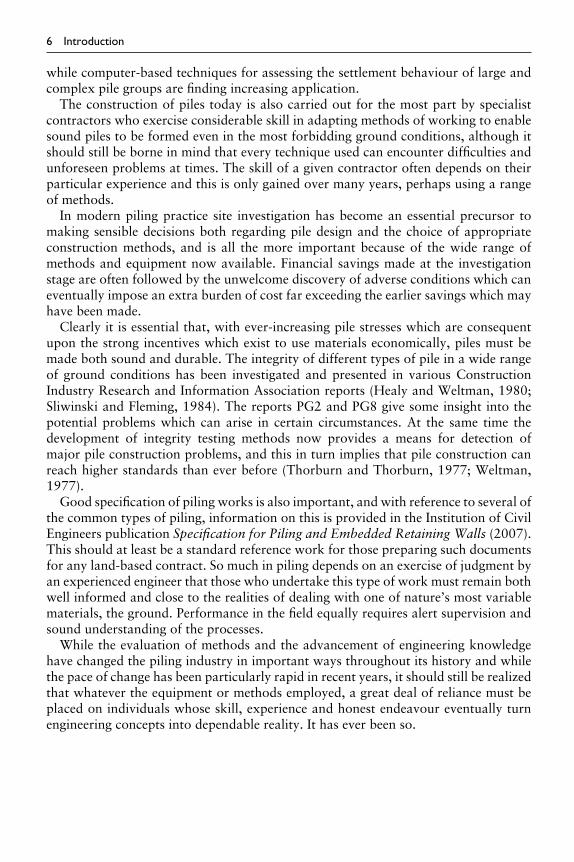
Figure 2.1 Vertical stress envelopes for piled raft.
influence is a good starting point, since it quantifies to some degree the lateral andvertical extent of the stressed zone. In the case of a piled raft, significant stressesare transferred to a considerable depth (see Figure 2.1), and it is recommended thatthe depth of exploration should be at least one and a half times the width of theloaded area. In the special circumstance where the geological conditions or rock-head level are well known, such depths may be reduced. As a general guide thedistance is measured below the base of the pile group, and the loaded area is cal-culated allowing a spread of one in the horizontal direction to four in the verticaldirection over the estimated length of the pile. For isolated pile groups (under asingle column for instance), the stressed zone based on the spread of load conceptis relatively much shallower (see Figure 2.2). Therefore a single proving boreholeshould be taken to a depth in excess of 2B in order to ensure that ‘punching’through a relatively strong stratum into a weaker stratum cannot occur. In addi-tion, the intensity of loading at the tip of end-bearing piles may be high, and arock-bearing stratum should be adequately investigated particularly where heavycolumn loads are to be transmitted to single or small groups of highly loadedpiles.

10 Site investigation for piling
Figure 2.2 Vertical stress envelopes for isolated pile group.
Where piles are to be founded in a bearing stratum of limited thickness (such asa gravel layer overlying clay) it is essential that a large number of bores or probingsare employed, possibly spaced on a close grid. These will determine whether the bear-ing stratum thickness and level is maintained over the proposed area of loading. Inthese cases, detailed exploration may be restricted to a limited number of locations,permitting the calibration of a lower cost penetration method that may be used toprovide the necessary coverage. It is important in this situation that the competence ofthe underlying stratum to sustain the transmitted stresses is established. Where pilesare to be founded in a rock-bearing stratum, the likely variability of rock-head levelshould be assessed from a geological point of view and the investigation should besufficient to establish rock-head contours in adequate detail and to obtain profiles ofstrength and weathering.
It should be noted that the strict geological definition of bedrock (and there-fore rock-head level) may not concur with the views of a piling specialist, andthis point should be made clear in the dissemination of information. In groundconditions that are known to be of a heterogeneous nature, a qualified geologistor engineering geologist should be involved with the work from an early stage.Even if piles are to be taken through heterogeneous soils to found in underlyingbedrock, variations in groundwater conditions, or the occurrence of lenses of silt,sand, large boulders or open work gravel may jeopardize the successful installa-tion of displacement or non-displacement piles and these conditions should be fullyinvestigated.
2.3 Groundwater conditions
The investigation of groundwater conditions is particularly pertinent to piling works.The findings may influence the choice of pile type and it is essential that the pilingcontractor has the data necessary to assess the rate of water inflow that may occurduring the installation of conventional bored piles.

Site investigation for piling 11
Observations of the ingress of water including the levels at which water seeps andcollects should be made and noted on the site investigation logs in such a way thatthey may be related to the casing and borehole depths. These water level observationswill be unlikely to reflect the true hydrostatic conditions, but the information is of useto piling contractors tendering for bored or drilled piles.
Some fine soils of low permeability permit fairly rapid boring and excavation withoutseepage of water for the period of time that the bore is open, although the groundwaterlevel may be near the ground surface. This is typical of silty clays, such as London Clay.However, the possibility of the occurrence of silt or fine sand lenses within these soilsshould be recognized and they should be detected if present, since such layers may resultin rapid accumulation of water in the bore. Where these conditions are anticipated,appropriate measures can be taken, but the contractor will require the information atthe tender stage.
In many situations pile bores in homogeneous clay may be similar in length to theclay layer thickness, and with natural variation in bed levels, there can be a risk of apile boring extending into underlying strata. The underlying beds may be permeable,and will probably be under a considerable head of water. The site investigation mustdelineate the interface between the clay and underlying beds with some accuracy, tominimize the risk of penetrating such aquifers during pile construction.
Where piles are bored through clays to penetrate more permeable strata with the rigsituated at a reduced ground level such as a basement, a hitherto shallow water tablemay effectively become artesian at the lower level. If this condition is not recognizedin the planning stage it could lead to an unprogrammed and costly revision to themethod of working especially concerning the casting of piles by tremie methods.
The heads of water recorded by observation in boreholes, or measurement of levelsin piezometers may be subject to seasonal variation, and ideally measurements shouldbe collected over a period of months where the levels are critical. The period shouldof course include the ‘wetter’ parts of the year. This is not always possible, but thetopography and geology of the surrounding area should enable an assessment of anypotential problem to be made. A special case concerns tidal variation. Accurate esti-mates of maximum groundwater levels may be essential if, for instance, piles are to beconstructed using polymer or bentonite mud, when a positive head of support fluid hasto be maintained during construction. Any tidal variation in groundwater level thatcan occur at the proposed location of the piles has therefore to be monitored duringspring tides in order to record the maximum potential level.
Whilst measures can be taken to combat erosion of the concrete in bored piles byflowing groundwater immediately after casting, the possibility of this occurrence mustbe known beforehand, and openwork, highly permeable gravels under a seepage head,should be detected. Their presence may be suspected in glaciated valleys for instance,where coarse granular material may be found in outwash fans. The situation couldalso arise in alluvial gravels if there is a marked absence of finer material. Simplepermeability tests can be useful in the assessment of this problem.
Chemical attack of steel or concrete piles may occur due to dissolved salts in acidicgroundwater. Groundwater samples should be taken from boreholes in such a way thatthey are uncontaminated or diluted by water added during boring or drilling. Specialsamplers may be required to obtain water samples at given levels. In made ground orbackfill such as quarry or mine waste, extremely corrosive conditions may be present

12 Site investigation for piling
and this situation should be adequately investigated. Industrial waste may also giverise to corrosive ground conditions and in built-up areas, the previous use of theground should be established. Chemical tests on soil samples may be carried out togive additional information with respect to the leachability of contaminants.
2.4 Sampling, in-situ testing and laboratory testing
In certain respects, decisions regarding the optimum programme of sampling and test-ing may only be made after some knowledge of the ground conditions at the site hasbeen gained, and some conclusions regarding the possible piling alternatives have beenreached. This situation emphasizes the need for a flexible approach and the value ofpreliminary studies to facilitate the initial assessment. In many cases, the selection ofa suitable pile type is controlled by external factors such as access conditions, cost,vibration or noise level, so that there is in general no simple way to relate a pile typeto the prevailing soil and groundwater conditions.
Guidelines are given in B5930, section 4.3, for sample spacing, the size of bulksamples, types of sampling equipment and the intervals between in-situ tests, andthese are applicable to the recommendations given in the following notes.
Some situations may arise where special tests may be required or the intensity ofsampling or testing may have to be increased to provide sufficient data on particularaspects. An example would be the estimation of rock modulus in a weak fissured orblocky rock, where, for instance, plate-bearing tests combined with intensive large-diameter rotary diamond coring and possibly other in-situ tests may be necessary.Such an approach would be very dependent on the costs involved in the additionalexploration compared with the costs of deeper, or larger (possibly over-conservative)pile foundations.
The usual forms of cable tool boring equipment and rotary drilling equipment areappropriate, but in view of the additional depth of boring likely to be necessary, largerthan usual starting diameters for boreholes and drillholes may be prudent. This permits‘stepping down’ at an intermediate depth in order to maintain a reasonable rate ofprogress. Normal sampling and testing methods suffice, but there is a bias towards in-situ static and dynamic penetration tests, especially the standard penetration tests (SPT)and (static) cone penetration test (CPT), since pile design by empirical methods can bebased directly on the results. Provided the ground does not contain cemented materialor large boulders, cone penetration testing may be preferred to the SPT, particularlyas many pile design methods are linked increasingly to the cone resistance. Table 2.1summarizes typical in-situ tests that may be carried out, and their application to piledesign.
2.5 Methods of exploration for various soil types
In the following sections, specific soil types are described with appropriate methodsof exploration. Whilst the ground conditions may well closely approximate thosedescribed, intermediate or mixed conditions are quite likely, and a combination ofmethods would then be employed. Pile design is related to the soil conditions, and ifestablished methods of design are to be employed, the investigation should provideappropriate parameters.

Site investigation for piling 13
Table 2.1 Typical in-situ tests and their application to pile design
In-situ test Application to pile design
Vane test For measurement of in-situ undrained strength in soft to firm clays.Results may be applied to the estimation of downdrag on a pileshaft. The re-moulded strength of sensitive clays may be relevantto overall stability problems associated with pile driving in softclays.
Standard penetration test(SPT)
Investigation of thickness of bearing strata. Direct application ofN value in empirical formulae for pile load capacity. Estimationof the angle of friction φ’, in granular deposits, for use in piledesign. Crude estimates of cohesion in stiff clays or matrix dom-inant fills. For estimation of approximate compressive strengthof very weak rock. A tentative relationship between N value andmodulus for use in pile/soil systems has been proposed.
Static cone test Direct application of sleeve friction and point resistance to thedesign of driven piles. Estimation of the shear strength of claysand production of detailed soil profiles.
Pressuremeter(including self drillingtypes)
Estimates of modulus of soil for possible application in pile design,but results may not be strictly appropriate. Estimates of shearstrength in weak rock.
Plate-bearing test(over a range of depths)
Gives shear strength and modulus in all soil types. The shearstrength parameters are highly relevant to pile design, as sim-ilar volumes of soil are stressed. The modulus values may not bequite so relevant as the pile installation can markedly influencethis parameter. Important that this test is done carefully.
Simple permeability tests For estimation of flow in permeable gravels or fissured rock. Thismay be a factor relevant to the selection of pile type. The testscan also be used in weak rock, to indicate highly fissured orfractured zones.
2.5.1 Stiff fissured clays
In these soils, bored cast-in-place piles or low-displacement driven piles are usuallyemployed. At the present time pile design is generally based on values of undrainedstrength obtained from triaxial compression tests on ‘undisturbed’ open-drive samples,using the ‘α’ adhesion factor method. Scattered shear strength values are usual as aresult of the fissures and of sample disturbance, and a sufficient number of tests shouldbe carried out to permit selection of a mean or upper and lower bound strength profileswithout too much guesswork.
In fissured clays, sample size and orientation influence the results of strength tests.If the ‘α’ method is employed, using the α values recommended by Skempton (1959),undrained triaxial tests should be carried out on 38 mm diameter specimens cut fromopen-drive U100 samples. Due care should be exercised to relate the strength obtainedfrom undrained tests to the mass behaviour of the soil below a pile base where theoperational strength will generally be lower than that obtained from laboratory tests.Estimates of modulus of deformation from laboratory tests are very approximate, andeven the results obtained from plate-bearing tests may not be wholly representative ofthe installed pile.

14 Site investigation for piling
In very stiff fissured clays with high silt contents, open-drive sampling becomesimpracticable and in-situ dynamic or static penetration tests such as the SPT or CPTmay be employed. Pile design from the results of these tests is highly empirical althoughit is generally adequate for a preliminary test pile. A number of correlations have beenproposed between the SPT ‘N’ value and the undrained shear strength of silt and hardclays. These are given below.
cu = 20N kN/m2 Meyerhof (1956)
cu = 13N kN/m2 Terzaghi and Peck (1967)
cu = 7N kN/m2 Reese, Touma and O’Neill (1976)
cu = 4 to 6N kN/m2 Stroud and Butler (1975)
[Note that modern nomenclature is to use su for undrained shear strength ratherthan cu, emphasizing the nature of shear strength in clays; however, for historicalreasons cu has been retained in this text].
Clearly the range of values is large, and the correlations should not be employedin isolation, but checked against any available field and laboratory test results forthe particular clay being investigated. Corroboration is particularly necessary for thehigher cu derivations. It should be noted that UK practice tends towards the useof lower ratios compared with typical US practice. This could have come aboutas a result of a number of factors, such as typical SPT field methods and maynot relate to differences in the soil. The relationship between ‘N’ and cu proposedby Stroud and Butler (1975) is frequently adopted for use in UK non-sensitiveclays where other measurements are not available. The Stroud and Butler N−curelationship is dependent upon the plasticity index of the clay (PI) as shown inFigure 2.4.
Where the static cone penetrometer is used to estimate soil strength, the undrainedshear strength, cu, may be predicted from the relationship
qc = Nkcu + p0
where qc denotes the loading on unit area of the cone (kN/m2).Nk denotes the cone factor.cu denotes the undrained shear strength (kN/m2).p0 denotes the total overburden pressure (kN/m2).
Estimation of shear strength by this method has been used extensively in North Seaglacial clays, where electrical cones are used (see Figure 2.3). Cone factors, Nk, of25 are recommended by Marsland (1976), who also noted that the ultimate bearingcapacities measured by the cone were greater by factors of between 1.2 and 3.0 thanthose obtained from plate-bearing tests. Further information on cone testing may befound in Meigh (1987) and Lunne et al. (1997).
Of the latest methods available for the determination of deformation and strengthparameters from in-situ measurements, there is the self-boring pressuremeter such as

Site investigation for piling 15
Figure 2.3 Cross-section of electric static cone. (Illustration courtesy of Fugro Ltd., HemelHempstead.)
the ‘Camkometer’ or the Marchetti spade dilatometer Powell and Uglow (1988).Further information on pressuremeter testing may be found in Mair and Woods(1987).
Where pile design is to be based on effective stress methods, the sampling pro-gramme should provide material for consolidated undrained tests, with measurementof pore-water pressure in order to estimate the effective strength parameters, in par-ticular the friction angle φ ′. For driven piles, ring shear tests can provide usefulinformation on the interface friction angle between pile and soil (Ramsey et al.,1998).

16 Site investigation for piling
Figure 2.4 Correlation of shear strength with SPT value (Stroud, 1974).
2.5.2 Glacial till
Tills vary in properties considerably and range from heavily over-consolidated claysto coarse grained granular deposits, where both types may contain extremely largeboulders. There should therefore be an increased awareness of the probability of sig-nificant soil variations, which could be of considerable importance in pile selection andinstallation. An understanding of the morphology of the terrain under investigationis of considerable assistance in providing an awareness of the likely range of glacialdeposits that may be encountered. Whilst progress in boring exploratory holes throughglacial soils may be slow, it is imperative that these deposits are investigated fully indepth, a common error being to mistake a large boulder for bedrock. To provide someassurance that bedrock rather than a boulder has encountered, hard deposits shouldbe proved for at least 3 m, and preferably deeper, and bedrock should not be assumedunless there is some corroborative evidence. When it is not possible to penetrate boul-ders by cable tool methods, rotary coring can be used although this may precludefurther soft ground sampling and some types of in-situ test.
Representative sampling of glacial tills is often difficult, and much guidance in thisrespect can be found in ‘Engineering in glacial tills’ (Trenter, 1999), but earlier workby McKinlay et al. (1974) presents some detailed information on sample recovery andtesting, both in the laboratory and in-situ. Open-drive sampling and in-situ testingbecome more difficult as the proportion of coarse elastic material in a till increases,i.e. as the till becomes Clast-dominant rather than Matrix-dominant, properties thatcan be reflected in the actual pile installation. In these situations, it is important toestablish a grading for the till, and particle size distribution tests on suitably sizedbulk samples should be considered. It is difficult to secure samples that are free fromsampling bias in a glacial soil of this type, unless the deposits are at shallow depth inwhich case an excavated trial pit may be considered. The depth of piled foundations

Site investigation for piling 17
usually precludes this approach and the advice of geologists or engineers familiar withthe local ground conditions should be sought.
The site investigation borehole logs should record chiselling time and the rate ofborehole and casing advance, since this may give valuable information regarding thedifficulties of installing small-diameter temporary casings for bored cast-in-situ piles.Resort may be made to rotary diamond coring using a suitable flushing medium,which may include air or drilling mud (Hepton, 1995), although these methods maybe extremely costly and core recovery may be poor. The static cone penetrometerhas proved a useful method of predicting shear strength in glacial tills in the specialenvironment of the North Sea. As discussed in section 2.5.1, a cone factor, Nk,of 25has been suggested by Marsland (1976). Other authors recommend factors of between15 and 30 (Toolan and Fox, 1977) and 15 and 20 (Kjekstad and Stub, 1978).
Less satisfactory, but more economical, is the SPT using a relationship between the‘N’ value and undrained strength as proposed by Stroud and Butler (1975) as describedin connection with stiff fissured clays. However, wide variations in this relationship(when applied to Matrix-dominant tills) are known to exist, with correlation coeffi-cients of between 2.5 and 10 being cited in published literature. The lower values canbe attributed to the presence of granular material in the till, but it is often difficult toavoid this occurrence and few SPT drives are likely to be within the till matrix materialalone. Where there is good knowledge of the undrained strength of a till from labo-ratory tests or back-analysis of the results of pile tests in the locality (Weltman andHealy, 1978; Fleming, 1992) a site-specific correlation may provide a more certainmeans of determining strength (or modulus) from the SPT.
Whilst in-situ tests overcome the difficulty of sampling in cohesive tills containinggranular material, the presence of the clastic components interferes with some of thetests, and every effort should be made to secure undisturbed samples for laboratorytests. If the recovered material is too mechanically disturbed for triaxial testing, mois-ture content, PL and LL determinations should be made. Note too that there is aminimum shear strength for re-moulded clays based on the Skempton–Northey plot(Skempton and Northey, 1952) of liquidity index against undrained shear strength(see Figure 2.5), which gives a lower bound to the strength of the material. Pointsrepresenting test results that fall below this line are probably from excessively dis-turbed samples, or from material that has dried out, the plot being for saturated clays.Envelopes for the undrained cohesion of matrix dominant tills for the ‘CL’ and ‘CH’Casagrande sub-group classification according to moisture content are presented inFigure 2.6. Estimates of the shear strength from various sources can be combined togive upper and lower bounds, and factors of safety selected accordingly.
The notes made in connection with the observation and recording of groundwaterconditions are especially pertinent in glacial soils, and great care should be taken torelate the observed conditions to the stratigraphy. To this end, a number of suitablydisposed piezometers should be installed to record the hydrostatic head in selectedstrata.
2.5.3 Fine-grained granular deposits
For the purpose of establishing parameters suitable for pile design, deposits of silts andsands are generally investigated by means of in-situ tests. Dynamic tests such as the SPT

1.2
1.1
1.0
0.9
0.8
0.7
0.6
0.5
0.4
0.3
0.2
0.1 0
12
34
56
78
910
20
Und
rain
ed c
ohes
ion
(kN
/m2 )
Pla
stic
lim
it
Liqu
id li
mit
Ske
mpt
on r
ange
of
valu
es fo
r re
mou
lded
clay
s
LI =
w −
PL
LL −
PL
Liquidity Index (LI)
3040
5060
7080
9010
020
030
040
050
060
070
080
090
0
−0.1
−0.2
−0.3
−0.4
Figu
re2.
5R
elat
ions
hip
betw
een
Liqu
idity
Inde
xan
dun
drai
ned
cohe
sion
show
ing
typi
calr
ange
ofva
lues
ingl
acia
ltil
l.C
IRIA
Surv
ey(1
977)
.(Ill
ustr
atio
nco
urte
syof
CIR
IA,L
ondo
n.)

Site investigation for piling 19
32
30
28
Casagrandesubgroup CH
Casagrandesubgroup CL
26
24
22
20
18
Moi
stur
e co
nten
t (%
)
16
14
12
10
8
6
4
2
010 20 30 40 50 60 70
Undrained cohesion (kN/m2)
80 90 100 200 300 400 5006007008001000
Figure 2.6 Relationship between undrained cohesion and moisture content for matrix-dominant till.(Illustration courtesy of CIRIA, London.)
are sometimes used and the resulting N values employed in estimating pile capacity.However the use of the static cone penetrometer test (CPT) is generally advantageousin thick deposits of silts or fine sands to give a more reliable ground profile. Themethod also overcomes difficulties which are commonly met in these soils where waterpressures cause piping into the base of open boreholes giving rise to low N values,although the SPT drive can be extended in such soils and the penetration recorded foreach 75 mm. Values of N derived in this way are not however strictly comparable tothose obtained in the normal way. For a given relative density, the N value is dependenton the effective overburden pressure, the over-consolidation ratio of the deposit, and,for derived parameters such as angles of internal resistance, the grading and shape ofthe particles. Of these potential influences, correction to the N value for the effectiveoverburden pressure has been given most attention by a number of researchers. Thisis discussed further in section 2.5.4 in connection with medium- and coarse-grainedgranular deposits.
The modern electric cone penetrometer has overcome the problem of rod friction,which was present with the mechanical type, and no correction is required forcumulative rod weight. The cone provides a measure of end resistance, qc, and sleevefriction, fs, which can be used for the design of driven piles. Where the static cone is

20 Site investigation for piling
Figure 2.7 Correlation of cone resistance with SPT value. 1, Meigh and Nixon; 2, Meyerhof; 3, Rodin;4, Schmertman; 5, Shulze and Knausenberger; 6, Sutherland; 7, Thorburn and McVicar.
employed, and a correlation is required with SPT N values (or vice versa), approximateconversion between the two parameters is possible using the relationship between coneresistance, qc, and N for soil according to particle size as proposed by a number ofauthors. These are summarized in Figure 2.7.
In fine-grained soils, the use of the CPT is particularly useful for assessing the appro-priate founding levels for driven piles and the reasonable length to which they may beinstalled. However in dense silts a high penetration resistance to driven piles duringdriving can occur, without the realization of correspondingly high bearing capacitiesand their presence should be adequately established. Accurate gradings of such depositsare not generally required for assessment of pile performance, and representative sam-ples are in any event difficult to secure. Water pressures should be known in suchstrata especially where bored piles might be employed, as severe loosening of thesematerials can occur during boring where there are seepage pressures. Loosening dur-ing continuous-flight auger (CFA) boring can be troublesome and special care may benecessary to prevent excessive loss of ground. Stand-pipes should be installed, or apiezometer used to monitor the water pressures, in specific strata.
2.5.4 Medium and coarse-grained granular deposits
Exploration for pile foundations in this type of material is often carried out using theSPT, but the heavier capacity static cone tests are equally suitable. In-situ permeability

Site investigation for piling 21
tests, and bulk sampling for grading analyses, provide useful and sometimes essentialadditional information. It is general practice to employ empirical methods of piledesign based on the results of penetration tests. Where the size range is large, andincludes a finer fraction (as may be the case in glacially derived materials) the resultsof penetration tests may be misleading, and care should be exercised in the selectionof representative values. In such soils, groundwater seepage pressures may cause loos-ening in the base of boreholes, and the penetration values may be affected if suitableprecautions are not taken. These would include topping up boreholes with water, theuse of small-diameter shells to clean out the base of the borehole and reducing therate of retrieval of the shell from the base of the borehole. Notwithstanding thesedevices, some reduction in N value may still occur. Whilst low values may lead toover-conservative design, it is also possible that unexpectedly heavy driving may beexperienced with displacement piles and full penetration may not be possible.
Correction to the N value for effective vertical stress at the depth of the test maybe carried out. This should not be applied to correct for poor field methods. Wheretests have been carried out in loosened ground for instance, it is recommended thatthe correction is only applied where consistent values have been obtained over a seriesof tests. A comprehensive review of the SPT by Skempton (1986) gives correctionsthat may be applied to N for the effective vertical overburden pressure. The test ascurrently carried out in the UK is also compared with the original test when Terzaghiand Peck (1948) proposed the relationship between N and relative density, Dr. Theoverburden pressure relates the N value of the test to a reference value at a stress levelof 100 kN/m2 (CN1), as shown in Figure 2.8. A revision to the relationship between theN value and relative density, using a standardized N60 value as given by the moderntest with an automatic trip hammer is provided in Figure 2.9, for (N1)60 values, thesebeing N60 values corrected for overburden pressure.
In terms of the parameters that may be derived from the N value, Stroud (1989)presents charts relating the angle of internal friction with (N1)60. Figure 2.10 showsa relationship between the effective angle of friction (φ′) less the constant volumeangle of friction (φ′
cv) for a range of relative density and Figure 2.11 gives a rela-tionship between the constant volume angle of friction and particle shape. Stroudadditionally considers the effects of over-consolidation ratio on the effective angle offriction.
These relationships enable a value of φ ′ to be derived from ‘N’ via the relativedensity, Dr.
Further causes of inaccurate N values occur in tests that are carried out in materialbelow the base of a borehole that is mechanically disturbed to an excessive depth byovershelling, or testing partially or totally within the borehole casing. Double rangetests, i.e. driving the tool an additional 300 mm, may reveal this occurrence, exhib-ited either as a marked increase in resistance over the final range, or a sudden drop,respectively. In dense granular soils, it is often impracticable to use the SPT shoe, asit is too easily damaged. In these particular soils, the SPT 60◦ cone can be substitutedwithout significantly influencing the results.
Chiselling depths and times should be recorded on the borehole logs (with the weightof the chisel) since this may be the only evidence available to provide an indication ofthe maximum boulder size present. If rotary diamond coring is used to penetrate a boul-der, there may be some difficulty drilling below the boulder in purely granular material.

22 Site investigation for piling
Figure 2.8 Correction for overburden pressure: (◦) fine sands fill; (●) fine sands NC; (�) finesands OC; (�) coarse sands NC. Shaded region indicates laboratory tests (Marcuson andBieganousky, 1977; Gibbs and Holtz, 1957); unshaded region indicates field test data. (AfterSkempton, 1986.)
A rock roller ‘tricone’ bit may permit progress, but at the expense of anything otherthan minimal geotechnical data. Every effort must be made to penetrate dense layersand to carry the investigation to the full depth to ensure that weaker or less denselayers at depth are fully explored. In order to install bored piles through, or intothese strata, the groundwater conditions should be thoroughly investigated as dis-cussed in section 2.3. The permeability of the deposits should be established by fieldpermeability tests and the values should be related to the particle size distribution asseepage conditions are particularly relevant if non-displacement piles are selected forthe foundation.
2.5.5 Normally consolidated clays
These clays are not employed as bearing strata but influence pile design as aresult of ‘downdrag’ or by the effects they may have on the construction of boredcast-in-situ piles. The magnitude of the downdrag may be estimated approximatelyfrom the undrained shear strength of the clay (using for example the results of field

Site investigation for piling 23
Figure 2.9 Effect of relative density, based on field data. (After Skempton, 1986.)
Figure 2.10 Variation of φ ′ − φcv ; with relative density: (◦) triaxial; (�) plane strain; mean effectivestress (p′) 150 to 600 kN/m2; φ′ measured as secant value. (After Bolton, 1986.)
vane shear tests, or from laboratory triaxial compression tests on carefully takenundisturbed samples). It is generally necessary to employ thin-walled piston samplesfor this purpose. Such samples may also be used for laboratory determination of theshear strength of the clay in terms of effective stress to permit the preferred calculationof downdrag by effective stress methods.

24 Site investigation for piling
Figure 2.11 Relationship between particle shape and φ ′ (after Youd, 1972) based on triaxial tests:(●) uniformly-graded quartz; (��) uniformly-graded feldspar or feldspar quartz mixtures;(×) well-graded.
Where the undrained strength of these clays is low, there is a possibility of producingground failure and deformed pile shafts under the head of concrete employed in theconstruction of bored cast-in-situ piles. Typically, ground failure occurs in the depthrange 2 to 4 m below ground level in very soft alluvial clays, especially at the time ofextracting any temporary casing where 2σ ′
v > cu > σ ′v. A sufficient number of in situ
tests or laboratory tests should be carried out to establish a strength profile so thatthis possibility may be examined.
2.5.6 Weak rocks
Some information relating to the strength/density of weak or weathered rock maybe obtained from static or dynamic penetration tests. The profiles may show broadchanges in rock strength and may be useful in estimating the penetration of driven piles.Pile design from the results of dynamic penetration tests is generally not straightfor-ward, especially in chalk and weak or weathered Triassic strata. In chalk, guidance onthe use of the SPT is given by Hobbs and Healy (1979) and also Lord et al. (2003).It is now generally recognized that the use of the 60◦ cone, rather than the shoe, cansignificantly affect the N values obtained, and the shoe should be used for correlationwith other work and to provide N values for use in empirical formulae. The sampleobtained from the SPT tool is not representative.
In many cases penetration results are insufficient on their own, and it will be nec-essary to carry out rotary diamond coring in a diameter large enough to ensure asclose to 100% core recovery as possible, even in weak friable rocks. Open-drive sam-ples (U100), even if possible to obtain, do not tend to yield representative material.

Site investigation for piling 25
Weathered sedimentary rocks frequently exhibit erratic strength profiles and weakzones below less weathered beds must be detected if they are present.
Percussive drilling combined with penetration resistance measurement may givesome guide to the driving resistance of driven piles, but significant zones may be missedand there is generally little substitute for adequately detailed logs prepared from drillcores in order to establish a rock grade. In variably weak rock core, laboratory testssuch as the point load test or unconfined compression tests tend to favour the strongerzones as the weakest material is often lost and therefore the results need to be care-fully interpreted to avoid drawing the wrong (and unsafe) conclusions about the rockstrength.
The results of tests carried out on rock cores in the field (e.g. point load tests) shouldbe interpreted in a similar way. Useful information on the in-situ rock mass mayhowever be obtained from permeability tests (packer tests for instance) which reflectthe fracturing, fissuring and jointing of the rock structure. Where detailed informationof in-situ rock condition or rock grades is required, especially in formations such aschalk or weak Triassic strata, a purpose-excavated shaft is recommended. Additionalinformation can be obtained by carrying out plate-bearing tests at selected horizonsas the shaft is excavated.
Settlement of piled foundations on rock may be estimated from in-situ modulusmeasurements using the pressuremeter or by plate-bearing tests carried out over arange of depths, though with adequate geological information, settlement may beshown to be too small to justify any extensive investigation. Pressuremeter testing iscomparatively cheap, but suffers the disadvantages of possible disturbance of the rockwhen drilling the pocket for the probe, and ‘sample’ size and orientation effects. Theplate-bearing test is costly, but is likely to give superior information.
It is however of critical necessity to recognize the presence of clay layers in rocks thatare vertically or near vertically fractured or jointed (i.e. ‘blocky’). Piles end bearingin such rocks may give a satisfactory blow count during driving, or may, if drilledor augered, appear to be within apparently satisfactory, massive strata. When loaded,poor load-settlement behaviour is obtained as a result of the toe load being transferredvia a column of blocks to the clay layers which compress, or may undergo lateral yield.It is essential that the local geology is understood at the time of the investigation ifthis condition is to be identified correctly and emphasis needs to be placed on gooddrilling to achieve high core recovery, combined with accurate and suitably detailedcore logging.
Adequate information relating to the groundwater conditions is particularly impor-tant for bored or drilled piles, and detailed notes should be made of water encounteredduring drilling operations. Some qualitative information may be obtained from thequantity of water/mud returns if a fluid flushing medium is being used, and waterlevels in drilled holes should be recorded if the borehole is left standing for any lengthof time. In continuous aquifers, simple standpipes may be adequate to establish thehydrostatic head, but in more complex ground, piezometers will be required to isolatewater pressures associated with a particular structure.
Limestone is a special case as it may contain large cavities that can transfer consider-able quantities of water with strong cross flows. Pile installation can be compromisedin such strata and grouting may not be a successful precursor to the piling. As withthe problem posed by clay layers in blocky rock, an understanding of the geology is a

26 Site investigation for piling
necessary adjunct to good quality fieldwork if these circumstances are to be properlyrecognized.
2.6 Backfilling site investigation boreholes
On sites likely to be piled, the backfilling of site investigation boreholes should becarried out with special care. This is particularly important in the case of bored pileswhere the loss of a pile shaft due to accidental connection to waterbearing strata viaa badly backfilled borehole may occur. This may be accompanied by loss of groundin granular deposits. In an under-reamed pile base, the likelihood of striking a siteinvestigation borehole is increased and the consequences of a collapse can be moreserious.
Where the risks associated with striking an open loosely backfilled borehole are highit may be necessary to employ a grouted weak cement backfill or, if suitable material isavailable, heavily compacted clay plugs may be formed at frequent intervals in a boreotherwise filled with arisings. For future reference, an accurate survey of the boreholesshould be carried out on completion of the work.
Special requirements relate to the boring/drilling of boreholes where contaminationof underlying aquifers can occur. In the United Kingdom, the Environment Agencywill need to be aware of any work where such an occurrence could take place, andspecial precautions may well be necessary, such as boring through a bentonite seal andbackfilling with cement/bentonite.
2.7 Piling working platforms
In the United Kingdom it is generally necessary that piling rigs (and indeed othertracked plant) operate from a granular platform of over-site fill that is compactedinto place in order to provide a safe working area. There are exceptions when a rig isoperating from an existing hard-standing or in certain situations ‘navvi’ mats can beemployed i.e. thick timber decking units that can be moved around the site. Such matsare not as effective as a properly designed and installed working platform and tendto slow down plant movement. They are only employed where a working platformis impracticable. The platform design is carried out using the recommendations ofthe Federation of Piling Specialists (FPS) and Building Research Establishment (BRE),Working platforms for tracked plant (2004).
In order to design a platform, it is necessary to know in detail the properties of thesite soils at shallow depth. Therefore considerably more effort needs to be expendedat the site investigation stage to provide an adequate coverage of shallow exploratorylocations (e.g. trial pits) and to extend the sampling and testing (including as appro-priate, in situ testing) to provide proper and representative information, particularlythe undrained shear strength or relative density profile and any variation across a site.As the upper site surface is quite likely to include made ground this may not be astraight-forward task but every effort needs to be made to satisfy these requirements.It is of course essential to thoroughly compact the backfill to any trial pits such theydo not create a new hazard.
It should be appreciated that together with the exploratory work, a thorough desk-study needs to be carried out to establish the location of potential backfilledexcavations for services or voids from basements, buried tanks, etc.

Chapter 3
Basic piling methods
In this chapter, the main pile types and methods of installing them are described, withdetails of currently available plant, pile types and proprietary methods. However, tomeet ever stricter environmental requirements and commercial pressures, piling plantand methods of pile installation are constantly changing so that the text should beregarded as an overview of the equipment and techniques in use. As with many fieldsof engineering, descriptions of the latest equipment and methods offered by particularmanufactures are available on appropriate web-sites and scrutiny of the relevant sitesis advised for the latest information.
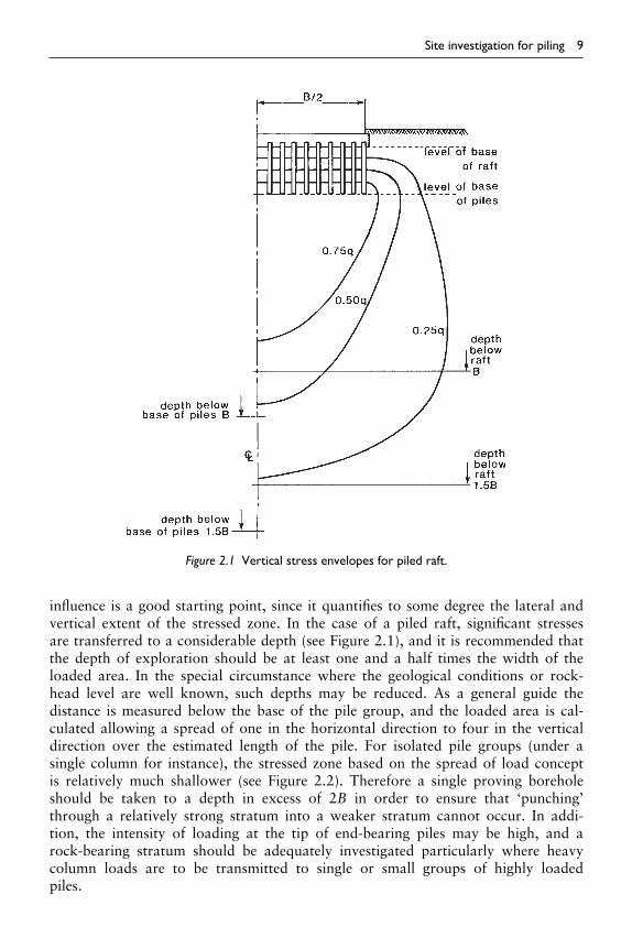
The two basic methods of installing piles are well known, namely driving them intothe ground, or excavation of the ground, usually by boring, and filling the void withconcrete. Other methods have evolved to cope with certain ground or groundwaterconditions, or to be more economic over particular (usually restricted) load capacities.Over the years, methods have also evolved to overcome the need for temporary casingduring boring. Continuous flight auger (CFA) rigs developed to achieve this are nowwell established. In this process the bore is supported by the spoil around the augerright to the base of the hole until fluid concrete is pumped down the stem of the augerto fill the bore as the auger is withdrawn. Some methods involve a combination ofdriven and bored techniques, where a casing is driven or rotated into the ground fol-lowed by in-situ concreting. There are also hybrid types of pile which bridge the gapbetween vibro-stone columns and concrete columns, a stone-cement mix being vibro-driven into the ground. Where the ground is amenable to boring by water jetting,grouted columns can be produced which can be considered as a form of pile. Withineach category, variations exist associated with the particular proprietary methodin use.
A major advance is the degree to which piling rigs have become instrumented.The piling operation is now, in general, highly monitored and some operations suchas concreting even carried out automatically where highly developed CFA rigs areemployed. This level of instrumentation raises the possibility of deciding on the pilelength as it is bored, i.e., the monitoring could eventually be sufficient to deter-mine soil profile to a point where the ultimate capacity of the pile is assessed at thedrilling stage.
In another development, rigs can be located with high precision over a pile positionusing GPS methods. The positioning of a rig with a high mast in this way requiresa different approach to the guidance of other mechanical plant, as a considerabledistance separates the receiving antenna on top of the (unstable) mast from the

28 Basic piling methods
intended pile position. In practice, the operator ‘sees’ a stable target pile positionon the in-cab display derived from the brief instants of time when the tall oscillatingmast is momentarily vertical. Hence the pile is located in the correct position with-out attempting to steady the rig to an unattainable degree∗ (Stent Piling – ‘SAPPAR’system). In a further advance of this system, the final positioning of the rig can becarried out automatically. Telemetry of one kind or another can also ensure that muchof the monitoring of the piling operation is available on-line in ‘real time’ whether inthe site office or back at a Company office.
3.1 Pile types
It used to be possible to categorize the various types of pile and their method ofinstallation, using a simple division into ‘driven’ or ‘bored’ piles. This is adequate inmany situations, but does not satisfactorily cope with the many different forms of pilenow in use. A more rigorous division into ‘displacement’ or ‘non-displacement’ pilesovercomes this difficulty to some extent, but some piles are installed by a combinationof these methods and their description may require qualification.
In the displacement (generally driven) pile, soil is displaced radially as the pile shaftpenetrates the ground. There may also be a component of movement of the soil inthe vertical direction. Granular soils tend to become compacted by the displacementprocess, and clay soils may heave, with little immediate volume change as the clay isdisplaced.
Piles of relatively small cross-sectional area, such as steel ‘H’ section piles or openpipe piles, are termed ‘low displacement piles’, and the effects of compaction or soilheave are reduced. This can be advantageous if long lengths of pile are to be driventhrough granular deposits, if the piles are at close centres, or if clay heave is a problem.
In the non-displacement (generally bored) pile, lateral stresses in the ground arereduced during excavation and only partly reinstated by concreting. Problems result-ing from soil displacement are therefore eliminated, but the benefit of compaction ingranular soils is lost and in all soils spoil is produced which may be costly to removefrom a site, especially if it is contaminated.
The displacement of the soil by a pile during installation is therefore a fundamentalproperty, and its recognition in any classification of pile type is clearly advantageous.Little-used types such as pre-formed screw piles can also be covered by the (low)displacement classification, whereas they could not be correctly termed ‘driven piles’.In a further development of the screw pile that is becoming more frequently employed,especially on contaminated sites where it reduces or eliminates the production of spoil,a hollow screw-form auger is rotated into the ground and the bore filled with concreteas it is back-rotated out or retracted without rotation.
The two main categories of pile types may be classified further according to whetherpre-formed units are used, and whether the pre-formed unit is used as temporarysupport for the ground and withdrawn during concreting or left in place. For non-displacement piles, factors such as pile diameter and underreaming are introduced tothe classification, as they have a bearing on the method of installation, and particularly
∗Original Patent by A Weltman 1995; transferred to BICC 1996.

Basic piling methods 29
in the type of plant employed. Forming the pile bore using a continuous flight augerto mix the soil into a supporting slurry and concreting the pile from the base-up asthe auger is withdrawn is a widely used method of pile installation. This type of pile(the ‘CFA’ pile) may be termed a ‘replacement’ pile.
A scheme of classification of bearing pile types is presented in Figure 3.1. A furtherdistinction is added in this scheme which relates to casting of concrete against thesoil, which can occur with both displacement and non-displacement piles. This factormay be significant when ground or groundwater conditions are aggressive to concrete,or where water flows through highly permeable ground and there is a possibility ofcement and fines removal from the fluid concrete.
3.1.1 Displacement piles in contaminated ground
It has been mentioned that in the use of non-displacement piles, the spoil from the pilebores needs special consideration if it is contaminated since its disposal may be costly.By using displacement piles, this problem is eliminated, and where ground is contami-nated it is generally considered that displacement piles are preferable. However, smallamounts of overlying materials can be dragged down around the shaft as the toe of adriven pile emerges from contaminated strata to enter deeper uncontaminated strata. Itis also possible that a very small plug of contaminated material could be driven aheadof a flat-bottomed displacement pile into previously uncontaminated soil. In general,these mechanisms are not considered to be capable of causing significant mixing, butshould always be taken into account. The risk imposed by an unusual contaminantwhich could behave in an atypical manner will require special evaluation, (e.g. metal-lic mercury inevitably finds its way to the base of any formed bore). Large diameterdisplacement piles will produce greater compaction of the surrounding soil and couldbe considered to be superior in the elimination of contaminant pathways along a pileshaft than low displacement piles. Screw piles are of intermediate displacement, andsome spoil may be produced, but with cast-in-place shaft formation, there should begood contact with the soil and the flow path is long thereby reducing the rate of anycontaminant transfer.
3.2 Displacement piles
Figure 3.1 includes the main types of displacement piles to comprise either totallypre-formed piles or piles in which a displacement method is used to form a void whichis then filled with concrete.
3.2.1 Totally pre-formed displacement piles
These piles comprise either tubular or solid sections which are driven (or sometimesscrewed) into the ground. The hollow tubular types may be formed from steel or con-crete, and the solid sections from steel, timber or concrete; the latter are pre-cast andmay also be pre-stressed. The use of reinforced plastics in the form of glass or car-bon fibre composites has entered use in soil-nailing applications, and this material ispotentially of use as a pile former. For pre-cast concrete piles, the ease of transporta-tion, handling on site and length adjustment has led to popularity of the jointed type.

TY
PE
S O
F B
EA
RIN
G P
ILE
DIS
PLA
CE
ME
NT
NO
N-D
ISP
LAC
EM
EN
T
TO
TA
LLY
PR
EF
OR
ME
DD
RIV
EN
CA
ST
-IN
-PLA
CE
A s
ectio
n, tu
bula
r or
oth
erw
ise,
isdr
iven
(or
scr
ewed
) in
to th
e gr
ound
.T
he s
ectio
n is
:
A tu
be is
driv
en in
to th
egr
ound
to fo
rm a
voi
d.T
he tu
be is
:
A b
ore
is fo
rmed
by
mea
nsof
a h
ollo
w-c
ente
red
cont
inuo
usfli
ght a
uger
. Gro
ut is
intr
uded
and
eith
er d
ispl
aces
or
mix
es w
ith th
e bo
re s
poil.
A b
ore
is fo
rmed
with
aho
llow
-ste
mm
ed c
ontin
uous
fligh
t aug
er. C
oncr
ete
ispu
mpe
d th
roug
h th
e st
emas
the
auge
r is
ext
ract
ed to
disp
lace
the
bore
spo
il.
Con
cret
e is
intr
oduc
ed d
own
the
vibr
oflo
t ste
m a
s it
isw
ithdr
awn.
An
enla
rged
bas
eca
n be
form
ed.
The
tube
is le
ft in
pos
ition
and
fille
d w
ith c
oncr
ete.
The
tube
is:
1) o
f con
stan
t cro
ss s
ectio
n2)
of t
aper
ed c
ross
sec
tion
The
bas
ic s
yste
m c
ompr
ises
driv
ing
a re
trie
vabl
e tu
be a
ndfo
rmin
g a
pile
with
or
with
out
an e
nlar
ged
base
.
Gro
ut-in
trud
edC
FA
Con
cret
e-in
trud
edC
FA
Hol
low
Sol
id
Con
cret
eS
teel
VC
C
Tim
ber
Ste
elS
teel
Con
cret
e
Pre
-cas
t rei
nfor
ced
Pre
-cas
t pre
-str
esse
dT
he tu
be is
:
Clo
sed-
ende
dO
pen-
ende
d
Con
cret
e
The
clo
sed-
ende
d tu
be is
fille
dw
ith c
oncr
ete
and
left
in p
ositi
on
Join
ed b
y sp
licin
gJo
ined
usi
ng a
prop
rieta
ry s
yste
m
A b
ore
is fo
rmed
in th
egr
ound
and
may
be
part
ially
or
fully
sup
port
ed b
y st
eel c
asin
gor
sup
port
flui
d (m
ud)
Pre
form
ed u
nits
are
grou
ted
in p
lace
(par
tially
pre
-for
med
pile
)
The
bor
e is
:
Per
cuss
ion
bore
dR
otar
y bo
red
Dril
led
Larg
e di
amet
erS
mal
l dia
met
er
Und
erre
amed
cast
-in-p
lace
(gen
eral
ly la
rge
diam
eter
)
Str
aigh
t-sh
afte
dca
st-in
-pla
ce
In th
ese
pile
s, c
oncr
ete
is c
ast a
gain
st th
e so
il(u
nles
s de
liber
atel
yis
olat
ed b
y a
mem
bran
e)
AU
GE
R S
CR
EW
PIL
ES
An
auge
r is
scr
ewed
into
the
grou
nd a
nd r
etrie
ved
durin
gco
ncre
ting
By
back
-scr
ewin
g to
leav
e a
helic
al (
scre
w)
shaf
ted
pile
form
edby
gro
ut o
r co
ncre
te in
trus
ion
via
the
auge
r st
em
Str
aigh
t ret
ract
ion
to le
ave
a fu
lldi
amet
er c
ylin
dric
al s
hafte
d pi
leby
gro
ut o
r co
ncre
te in
trus
ion
via
the
auge
r st
em
BO
RE
D C
AS
T-I
N-P
LAC
E
A v
ibro
flot i
s in
sert
edin
to th
e gr
ound
to th
ere
quire
d de
pth
disp
laci
ng th
e so
il
Figu
re3.
1C
lass
ifica
tion
ofbe
arin
gpi
lety
pes.

Basic piling methods 31
Some micro-piles are also included in this category. A summary of the main types ofpre-formed displacement pile is given below.
Totally pre-formed displacement piles
(a) Pre-cast concrete : full length reinforced (pre-stressed): jointed (reinforced): hollow (tubular) section
(b) steel : ‘H’ section: tubular section: other (e.g. screw-form piles)
3.2.2 Pre-cast reinforced concrete piles
Pre-cast concrete piles are now usually of the jointed type, unless a large contract witha more or less constant depth of piling makes it economical to pre-cast the piles onsite, thus overcoming a potential difficulty in transport. Pre-cast non-jointed piles aregenerally of square section and may be up to 600 × 600 mm to work at loads up toapproximetely 3000 kN in suitable ground. Typical sizes and capacities are given inTable 3.1. Extending pre-cast piles that do not have pre-formed joints is a lengthyprocess, involving breaking down the projecting pile head to provide a suitable lapfor the steel and casting concrete to form a joining surface. The pile sections arethen butted together in a steel sleeve using an epoxy cement, or joined by insertingsteel dowel bars into drilled holes and using an epoxy cement to fix them in place.Good alignment of the pile sections is required to prevent excessive bending stressesdeveloping on subsequent re-driving.
There are some benefits from pre-stressing concrete piles. Tensile stresses which canbe set up in a pile during driving are better resisted, and the pile is less likely to bedamaged during handling in the casting yard and when being pitched. Bending stresseswhich can occur during driving are also less likely to produce cracking. However, theultimate strength in axial compression is decreased as the level of pre-stress is increased,and pre-stressed piles are therefore more vulnerable to damage from striking obstruc-tions during driving. They are also difficult to shorten and special techniques have tobe employed. As a result they are most suitable for a constant-length application.
Table 3.1 Typical load capacities for pre-castconcrete piles for normal driving conditions
Square pilesection (mm)
Typical workingcapacity (kN)
200 × 200 400250 × 250 500275 × 275 750300 × 300 900350 × 350 1200
NoteCharacteristic strength of concrete 50 N/mm2 at28 days. Piles driven with a 4 to 5 tonne hammer.Courtesy of Teranto De Pol.

32 Basic piling methods
Figure 3.2 Detail of the ‘Stent’ pile joint. (Photographs courtesy of Stent Piling and Foundations.)
3.2.3 Jointed piles
Jointed piles are not pre-stressed, but as each unit is a shorter length, generally between5 and 14 m long, handling stresses are much lower, reducing the chance of damageat this stage. The piles are joined by various means; bayonet fittings or wedges beingtypical but can include the use of epoxy resin. The Stent Piling and Foundations pinnedtype of pile joint with a strength equivalent to that of the reinforced concrete part ofthe pile is illustrated above in Figure 3.2.
With a robust method of jointing, the joint is as strong as the pile, and is of similarmoment resistance. These criteria may not be met with the plain epoxy jointed pile,certainly not until the resin has hardened, and combined with the use of a singlereinforcement bar, this type of jointed pile needs to be employed with care.
In any jointed pile the fit of joints should be good, as energy is lost through them,and increased hammering is then required to drive the pile. Angularity produced by thejoints can lead to high bending stresses in the pile as it is loaded together with a highchance of damage during driving. Therefore any joints that could produce this effectshould be rejected, with an angular misalignment of 1 to 300 considered a permittedmaximum.
Jointed piles are usually of square section, but other forms, such as hexagonal oreven triangular sections have been produced. Typical capacities range from 700 to2500 kN with pile cross-sections usually in the range 250 × 250 to 400 × 400 mmalthough sizes above and below this range are sometimes employed. In suitable groundconditions, piles have been driven to depths of up to 100 m, whilst the vast majorityof typical applications do not exceed 30 m or so.
The units are cast from a high-cement-content mix with a water/cement ratio usuallyaround 0.4. The minimum compressive strength of cubes is generally around 60 N/mmat 28 days. Pile units with square cross-sections will usually have a main reinforcementbar at each corner; a 12 to 20 mm dia. deformed bar with a yield stress of 600 N/mmbeing typical. Transverse reinforcement in the form of 5 mm dia. wire ‘spiral’ con-trols longitudinal cracking, sometimes with additional bars near the pile ends. Thejoints are normally formed from a steel plate with integral starter bars projecting into

Basic piling methods 33
the pile. A fixture in the casting formwork sets the plate square to the pile, but strictquality control of the squareness of the plate and concrete strength are required toproduce successful jointed piles. Concrete cover should be the minimum to provideprotection from corrosion, as large thicknesses of cover can lead to spalling. Accuratepositioning of an adequate number of spacers is therefore an important aspect of cast-ing the pile units. Hard steel points can be fixed at the toe of jointed piles for limitedpenetration into weak rock. The piles are generally driven with a drop hammer of3 to 4 tonnes weight, although hydraulic hammers, vibrators or diesel hammers aresometimes used.
3.2.4 Hollow tubular-section concrete piles (cylinder piles)
Hollow concrete tube piles are generally of large diameters, typically in excess of600 mm and often nearer 1500 mm. Pile working loads may be in excess of 2000 kN.The concrete tubular sections are pre-tensioned and make efficient use of reinforcedconcrete, having twice the moment of resistance of a solid concrete pile of equivalentweight. Large-diameter tubular concrete piles are used in marine applications to takeheavy axial loads combined with significant bending loads or alternatively in thickdeposits of loose sand where great depth of driving is required but with good shaftand end bearing required in the final bearing stratum.
During driving, a point may be used to close the end of the pile for penetratinghard strata, but the pile may also be driven open-ended. In either condition, large soildisplacements occur, and the pile is not suitable for high-density application unless ina loose soil. In marine applications the corrosion resistance of the high-quality con-crete from which the piles are constructed is generally adequate, but in freeze-thawconditions, the long-term resistance may suffer. The piles have been driven to depthsof around 80 m, but because of difficulties in cutting off any excess lengths of pile,or the costs of extending them, they are best suited for driving to a pre-determinedlevel. Tubular concrete piles are not in common use at the present time except inthe Far-East where they are favoured for heavy load applications. To drive very longpiles, pile extension is typically achieved by welding together the steel plates thatrestrain the tensile reinforcement at the end of the pile sections. Tensile loads thatcan occur during easy driving conditions in soft soils could be troublesome if thesejoints are not sufficiently robust to accommodate stress reversals and under harddriving conditions, distress can occur in the concrete immediately behind the steelend plate.
3.2.5 Pre-formed steel piles
Totally pre-formed steel piles comprise ‘H’ and ‘I’ sections, screw sections and alsosome tubular sections which can be filled with concrete after driving. In addition,an ‘X’ section pile which can be jointed via plated end pieces has been available inScandinavia. Because of fears of rapid corrosion, there has been reluctance by someengineers to employ steel piles, but in natural, undisturbed ground, free from contam-inants, the corrosion rates of steel are low. The advantages of steel piles are (a) ease ofhandling, (b) little likelihood of over-stressing during lifting or pitching, and (c) easeof extension or reduction in length to cope exactly with variations in driven length.

34 Basic piling methods
b
Z
r
tw
tfZ
+
++
+
y dyh
Figure 3.3 Typical cross-section of an ‘H’ section pile. (Courtesy of Arcelor Commercial RPS UK Ltd.)
They are more suitable than concrete piles for driving through thin layers of harderstrata, or natural obstructions, but against this, slender steel piles such as ‘H’ sections(see Figure 3.3) may wander off line and this is exacerbated if the piles are joined bywelding. The tendency for slender piles of this type to wander off line during drivinghas been investigated by Hanna (1968). The uneven pressure distribution across thetoe of a pile as the soil is displaced from the pile base is implicated as the cause. Otherreasons, such as a form of dynamic instability, have also been cited. Length for length,steel piles tend to be more costly than concrete piles, but good load-carrying capacityfor a given weight of pile can reduce driving costs. Slender ‘H’ section piles have alow volume displacement which is a useful property for high-density piling in soilswhich tend to heave or become over-compacted. In some ground conditions, such aschalk or weak siltstones or sandstones, there may be a problem in achieving a suitableresistance with ‘H’ section piles. In chalk, this is believed to be the result of the shaftwhipping as it is driven (Hobbs and Healy, 1979). In the other rocks, George et al.(1977) recommend adding ‘wings’ to ‘H’ piles, i.e. welded-on steel plate ‘T’ sectionsto increase the surface area of the ‘H’ pile. Typical properties of ‘H’ section UniversalBearing piles are given in Table 3.2.
Screw piles in which steel screw sections are wound into the ground can pro-vide economical foundations in suitable circumstances but a balance has to be foundbetween the torque that can be safely applied during installation and the bearing resis-tance that can be developed. The shafts tend to be of small diameter limiting lateralcapacity but specialist concerns such as the GTL Partnership in the United Kingdomhave developed a screw pile with a relatively large diameter shaft to enhance the lateralresistance of the pile and the torque that can be used for installation. It is usual forscrew section piles to be fabricated. Early versions of the screw pile were cast iron andoften used in marine application to support, for example, seaside piers in Victoriantimes.

Tabl
e3.
2D
imen
sion
san
dpr
oper
ties
ofH
sect
ion
bear
ing
pile
s(A
rcel
orH
Ppi
les)
Sect
ion
h (mm
)b (m
m)
t w (mm
)t f (m
m)
Sect
iona
lare
a(c
m2 )
Mas
s*(k
g/m
)Pe
rimet
er(m
)M
omen
tofi
nert
iaE
last
icse
ctio
nm
odul
us
y-y
(cm
4 )z-
z(c
m4 )
y-y
(cm
3 )z-
z(c
m3 )
HP
220
×57
.221
022
511
1172
.85
57.2
1.26
557
2920
7954
5.6
185.
2H
P26
0×
7524
926
512
1295
.54
751.
493
1065
037
3385
5.1
281.
7H
P26
0×
87.3
253
267
1414
111.
287
.31.
505
1259
044
5599
4.9
333.
7H
P30
5×
8830
230
712
.312
.311
1.6
881.
782
1838
059
4912
1838
7.3
HP
305
×95
304
308
13.4
13.4
121.
795
1.78
820
170
6552
1328
425.
1H
P30
5×
110
308
310
15.4
15.4
140.
211
01.
800
2355
076
8015
3049
5H
P30
5×
126
312
313
17.7
17.7
161.
612
61.
813
2754
090
1917
6357
7.2
HP
305
×14
931
931
620
.720
.719
014
91.
832
3305
010
870
2075
688.
8H
P30
5×
180
327
320
24.8
24.8
229.
318
01.
857
4097
013
550
2508
847.
4H
P30
5×
186
328
321
25.6
25.6
237
186
1.86
142
580
1409
025
9487
9.3
HP
305
×22
333
832
530
.530
.528
523
21.
891
5284
017
590
3127
1081
HP
320
×88
.530
330
412
1211
2.7
88.5
1.75
218
740
5634
1237
370.
6H
P32
0×
103
307
306
1414
131
103
1.76
422
050
6704
1437
438.
2H
P32
0×
117
311
308
1616
149.
511
71.
776
2548
078
1516
3850
7.5
HP
320
×14
731
931
220
2018
6.9
147
1.80
032
670
1016
020
4865
1.3
HP
320
×18
432
931
725
2523
4.5
184
1.83
042
340
1333
025
7484
1.2
HP
360
×84
.334
036
710
1010
7.3
84.3
2.10
223
190
8243
1364
449.
2H
P36
0×
109
346
371
12.9
12.9
138.
910
92.
123
3062
010
940
1768
590.
7H
P36
0×
133
352
373
15.6
15.6
168.
513
32.
140
3773
013
540
2144
725.
3H
P36
0×
152
356
376
17.9
17.9
193.
815
22.
153
4395
015
810
2466
842.
3H
P36
0×
174
362
378
20.4
20.4
221.
717
42.
169
5102
018
400
2823
973.
5H
P36
0×
180
363
379
21.1
21.1
229.
518
02.
173
5304
019
140
2923
1011
HP
400
×12
234
839
014
1415
5.9
122
2.20
234
770
1385
019
9871
0.3
HP
400
×14
035
239
216
1617
8.6
140
2.21
440
270
1608
022
8882
0.2
HP
400
×15
835
639
418
1820
1.4
158
2.22
645
940
1837
025
8193
2.4
HP
400
×17
636
039
620
2022
4.3
176
2.23
851
770
2072
028
7610
47H
P40
0×
194
364
398
2222
247.
519
42.
250
5776
023
150
3174
1163
HP
400
×21
336
840
024
2427
0.7
213
2.26
263
920
2564
034
7412
82H
P40
0×
231
372
402
2626
294.
223
12.
274
7026
028
200
3777
1403

36 Basic piling methods
3.2.5.1 Hollow steel piles
Hollow steel piles are of cylindrical or box type sections. They overcome some of theproblems encountered with the flexibility of slender ‘H’ sections, although if the openend becomes plugged, i.e. soil partially enters the pile section but then moves downwith the pile (relatively rare during driving) they effectively become large displacementpiles. In that situation, heave of the ground and the possibility of over-compactinggranular deposits occurs so that piling becomes progressively more difficult. If pluggingoccurs, it may prove necessary to remove the internal soil plug and possibly pre-boreto some depth, provided there is no risk of instability. Whilst there has been muchdebate on whether or not open-ended tubular steel piles plug under driving, the viewof the authors is that in most circumstances driving such piles will occur with minimalplugging because of the high inertial resistance of the soil plug. By contrast, undermost conditions piles will tend to plug during static loading.
Hollow piles may be driven closed-ended through cohesive soil containing cobblesand small boulders, but some ground heave may then occur as for any large displace-ment pile. This type of steel pile performs well in resisting impact and bending loads,and the availability of large-diameter sections enables considerable loads to be carried.Such a combination of properties has led to their extensive use in marine structures,where long freestanding lengths of pile are common in, for example, jetties, piers andmooring dolphins.
Box section piles are typically formed by welding two or four standard ‘Z’ sectionor ‘U’ section sheet piles, edge-to-edge, to form a box. The properties of piles formedin this way, using Arcelor sheet piles are given in Table 3.3, with typical dimensionsidentified in Figure 3.4. Permitted maximum pile loads will be dependent on the gradeof steel employed, provided suitable ground reaction is present. Greater load-bearingcapacity may be obtained by using different combinations of standard sections. In apractical application, with extended lengths of pile above a sea bed for example, theloads may be limited by the slenderness ratio of the effective length of pile above thesupporting soil.
(a) (b)
b
Y
hh y
z
b
y
z
Figure 3.4 Typical cross-section of an Arcelor ‘CAZ’ box pile (a) and CAU box pile (b). (Courtesy ofArcelor Commercial RPS UK Ltd.)

Tabl
e3.
3aD
imen
sion
san
dpr
oper
ties
ofC
AZ
box
pile
s
Sect
ion
b (mm
)h (m
m)
Peri-
met
erSt
eel
sect
ion
Tota
lse
ctio
nM
ass*
(kg/
m)
Mom
ento
fint
ertia
Ela
stic
sect
ion
mod
ulus
Min
.rad
ius
ofgy
ratio
nCo
atin
gar
ea**
(cm
)(c
m2 )
(cm
2 )y-
y(c
m4 )
z-z
(cm
4 )y-
y(c
m3 )
z-z
(cm
3 )(c
m)
(m2 /
m)
CA
Z12
1340
604
348
293
4166
230
1256
1036
9510
4135
5295
20.7
3.29
CA
Z13
1340
606
349
320
4191
251
1368
5040
2270
4490
5765
20.7
3.29
CA
Z14
1340
608
349
348
4217
273
1487
7043
6260
4865
6255
20.7
3.29
CA
Z17
1260
758
360
305
4900
239
2050
4033
5880
5385
5105
25.9
3.41
CA
Z18
1260
760
361
333
4925
261
2229
3036
5500
5840
5560
25.9
3.41
CA
Z19
1260
762
361
362
4951
284
2422
1039
6600
6330
6035
25.9
3.41
CA
Z25
1260
852
376
411
5540
323
3430
0045
0240
8020
6925
28.9
3.57
CA
Z26
1260
854
377
440
5566
346
3668
2048
0410
8555
7385
28.9
3.57
CA
Z28
1260
856
377
471
5592
370
3921
7051
3050
9125
7820
28.9
3.57
CA
Z34
1260
918
392
516
5999
405
5078
9055
2570
1102
085
2031
.43.
73C
AZ
3612
6092
039
354
760
2643
053
7860
5852
0011
645
9030
31.4
3.73
CA
Z38
1260
922
393
579
6053
455
5688
4061
8770
1229
095
5031
.43.
73C
AZ
36–7
0014
0099
843
052
872
0941
462
7090
7012
5012
520
1001
531
.44.
10C
AZ
38–7
0014
0010
0043
156
372
3944
266
7260
7473
6013
295
1067
531
.44.
10C
AZ
40–7
0014
0010
0243
259
972
6947
070
7630
7934
7014
070
1133
534
.44.
10C
AZ
4611
6096
240
159
558
3146
764
5940
5275
9013
380
8825
32.9
3.81
CA
Z48
1160
964
402
628
5858
493
6811
9055
6070
1408
093
0032
.93.
81C
AZ
5011
6096
640
266
158
8451
971
6620
5845
6014
780
9780
32.9
3.81
*T
hem
ass
ofth
ew
elds
isno
tta
ken
into
acco
unt.
**O
utsi
desu
rfac
e,ex
clud
ing
insi
deof
inte
rloc
ks.

Tabl
e3.
3bD
imen
sion
san
dpr
oper
ties
ofC
AU
,CU
and
LPbo
xpi
les
Sect
ion
b (mm
)h (m
m)
Peri-
met
er(c
m)
Stee
lse
ctio
n(c
m2 )
Tota
lse
ctio
n(c
m2 )
Mas
s*(k
g/m
)M
omen
tofi
nter
tiaE
last
icse
ctio
nm
odul
usM
in.r
adiu
sof
gyra
tion
Coat
ing
area
**y-
y(c
m4 )
z-z
(cm
4 )y-
y(c
m3 )
z-z
(cm
3 )(c
m)
(m2 /
m)
CA
U14
–278
544
923
019
925
8415
5.8
5385
012
1300
2400
3095
16.5
2.04
CA
U16
–278
545
423
122
026
2017
2.5
6224
013
0380
2745
3325
16.8
2.04
CA
U17
–278
545
523
122
726
2617
8.1
6484
013
3330
2855
3400
16.9
2.04
CA
U18
–278
648
623
922
528
8817
7.0
7377
014
2380
3035
3625
18.1
2.14
CA
U20
–278
648
924
024
729
1019
3.8
8337
015
1220
3405
3850
18.4
2.14
CA
U21
–278
649
024
025
429
1619
9.3
8654
015
3990
3530
3920
18.5
2.14
CA
U23
–278
649
224
426
030
1320
4.2
9454
015
7900
3845
4020
19.1
2.19
CA
U25
–278
649
524
528
130
3422
0.8
1048
1016
6600
4235
4240
19.3
2.19
CA
U26
–278
649
624
528
830
4122
6.4
1082
6016
9510
4365
4315
19.4
2.19
CU
6–2
632
264
180
116
1315
91.2
1160
048
300
875
1530
10.0
1.55
CU
8–2
633
321
189
139
1569
109.
119
200
6000
011
9518
9511
.81.
63C
U12
–263
540
319
816
818
5013
2.2
3400
070
000
1685
2205
14.2
1.72
CU
1210
/10–
263
540
319
817
718
5013
9.2
3558
073
460
1765
2315
14.2
1.72
CU
18–2
635
473
212
196
2184
153.
858
020
7830
024
5524
7017
.21.
86C
U22
–263
649
422
021
923
4717
2.3
7374
088
960
2965
2800
18.3
1.94
CU
25–2
636
497
222
239
2450
187.
284
300
9700
033
9530
5018
.61.
97C
U32
–263
649
922
329
124
6122
6.3
1088
0010
9200
4360
3435
19.3
1.97
LP
3S
537
447
195
201
1748
157.
851
800
5710
023
2021
3016
.11.
67L
P4
S53
748
720
422
019
2717
2.4
6960
061
800
2860
2300
17.8
1.76
*T
hem
ass
ofth
ew
elds
isno
tta
ken
into
acco
unt.
**O
utsi
desu
rfac
e,ex
clud
ing
insi
deof
inte
rloc
ks.

Basic piling methods 39
Typical ratios of diameter (D) to wall thickness (t) are in the range 30 to 50 and suchpiles may be top-driven in the conventional way or bottom driven using an internalhammer and some means of closing the pile base. Short sections of pile may be weldedtogether or alternatively if they comprise thicker-walled cylindrical piles they can bescrewed together to achieve longer pile lengths. Once installed any internal soil plugcan be removed and the pile filled with concrete although it is more usual to leavethe soil plug in place. Where thin-walled piles are bottom driven they are unlikely tobe used as load-bearing piles without concrete infill as discussed under driven cast-in-place piles. Spirally welded tubular steel piles in diameters from around 200 to3000 mm are available with wall thicknesses from 10 mm up to 25 mm. At the otherend of the scale, small diameter steel piles (100 to 200 mm) with thin walls (typically3 mm) can be driven with a down-hole air hammer (‘Grundomat piles’). These mayhave working capacities of 20 to about 50 kN and are described in the section dealingwith micro-piles.
3.2.5.2 Steel piles as retaining walls
In retaining wall applications, various combinations of box and plain ‘U’ or ‘Z’ sectionpiles may be employed to greatly increase the bending resistance of the stand-alonesections. For additional stiffness, ‘H’ sections can be combined with sheet pile sections.The connections can be achieved with ‘ball and socket’ adaptors that can be weldedto the edge of the ‘H’ section flanges that will link up with the clutch of the sheetpile. At the same time, within limits, a degree of rotation can be introduced into thehorizontal wall alignment. Special interlock connectors permit corners to be formedas required, not necessarily at 90 degrees. Up to around 5 degrees of angular changecan be achieved with standard pile sections allowing circular cofferdams to be formedto diameters of around 15 m without special sections. When sheet steel piles are usedto form cofferdams in marine applications, water penetration through the pile jointsmay be significantly reduced or eliminated using sealants applied to the pile interlockspreferably prior to delivery to site. For sheet piled basements, permanent sealing againstgroundwater may be achieved by welding, using either with a bead of weld along theinterlock or with a separate steel plate over the exposed edge of the pile interlock.Horizontal sealing into a basement may be achieved by welding a horizontal steel ribonto the piles following installation which is then cast-into the basement floor slab.
3.2.6 Timber piles
For modest loads and piling depths of about 12 m, timber piles are quite suitable, pro-vided certain precautions are taken. They are infrequently used in the United Kingdom,although they are still in common use in Scandinavian countries and the United States.In Australia, treated hardwood piles are produced and installed by Koppers TimberPiles P/L who specialize in this type of pile and have developed a strong market forit. In general, working loads are unlikely to exceed 500 kN, partly because of diffi-culties in driving piles to give sets appropriate to greater working loads and partlybecause of the generally smaller cross-sections of timber piles and lower compressivestrengths. Stresses should be checked according to CP112 for compressive loads par-allel to the grain. Pile cross-sections are usually square although circular sections can

40 Basic piling methods
Table 3.4 Lengths of timber piles
Timber Square sectionside (mm)
Max. lengthapprox. (m)
Douglas fir (sw) 400 15Pitch pine (sw) 500 15Greenheart (hw) 475+ 18+Jarrah (hw) 250 9Okan (hw) 250 9Opepe (hw) 250 9
Notesw softwood.hw hardwood.
be used. Section sizes depend on the type of timber; BS 8004:1986 (BSI, 1986) quotesthe cross-sections and lengths given in Table 3.4. Note that pile lengths as pitched mayneed to generously exceed the expected installed lengths to allow sufficient up-standfor trimming after driving. Timber piles may be successfully subjected to CAPWAPtesting as employed for piles formed in concrete or steel.
3.2.6.1 Driving timber piles
Drop hammers are usual for driving timber piles or alternatively low-capacityair/hydraulic hammers may be employed. Damage through over-driving manifestsitself in ‘brooming’ of the pile head, cracking of the shaft and unseen damage to thepile tip. The driving process crushes and separates the fibres at the head of the pile –hence the ‘broom’ effect. A steel band around the pile head may restrict this damageto manageable proportions, but timber piles are not particularly suitable for drivingthrough dense strata, or strata with obstructions where they can disintegrate at theirtoe if driving is protracted and give the false impression of penetration. To mitigate thispotential problem a steel or cast-iron shoe is generally attached to the tip of the pile.Hammer weight should be approximately equal to the weight of the pile or as is some-times recommended, 50% more especially if heavy driving is expected. Particular careshould be taken to make sure that the pile heads are square, that the hammer blowsare axial to the pile, that the pile is properly set up in the leaders and not strainedto bring it vertical after a bad start to the drive. If damage occurs, and the hammerweight is suitable for the driving conditions, it may be necessary to de-rate the pile(i.e. reduce the design load of the pile), so that smaller drops and fewer blows can beused for its installation.
3.2.6.2 Preservative treatment
Both softwoods and hardwoods should be treated. Although some hardwoods suchas greenheart have slight inherent resistance to decay, it is not usual to rely on thisfor long-term protection. The procedures set out in British Standards 4072:1999,(BSI, 1999) or in the United States, the American Wood Preservers’ Association (whoregularly publish standards in this connection) should be followed. Note that if crack-ing of the pile shaft occurs, or there is damage at the head that extends below the

Basic piling methods 41
cut-off level, the preservative treatment will not be effective and the trimmed end ofthe pile should be re-treated. Where softwoods are used as bearing piles, it is nor-mal to trim these below the groundwater level (for the driest season) and extend theshaft as necessary with a concrete or possibly a suitably corrosion-protected steelsection.
3.2.6.3 Quality and tolerances
Timber for piles is specially selected for straightness of grain and should also be freefrom defects such as shakes which would weaken it and render it liable to fail duringdriving, or impair preservative treatment. Piles machined to a section should not beout of straightness by more than 25 mm over their length. Round piles may be out ofstraightness by up to 25 mm over a 6 m chord.
3.2.6.4 Marine conditions
Timber piles have long been favoured for construction of small jetties on account oftheir energy-absorbing qualities. They are, however, open to attack above the mudline from a variety of marine organisms, and the marine borers Limnoria and Teredoare usually mentioned in this context, for which arsenates and creosotes (if permitted)are recommended preservatives respectively. Greenheart has some natural resistanceto attack. In shallow, warm waters, pile attack is more rapid than in cold, rough waterconditions.
3.2.7 Driven cast-in-place displacement piles
Driven cast-in-place displacement piles are suitable for a wide range of loads have beenavailable for a great many years in the form of the Raymond pile. This type of pilemay be of two kinds, one employing a driven temporary tube to form the void whichis then filled with concrete as the tube is withdrawn, and the other employing a driventube to form a permanent casing (as in the Raymond pile). The former variation ismost commonly used in the lower load range, whilst the latter can be used to supportconsiderable loads in suitable ground conditions. As the load-supporting medium isgenerally the concrete infill, methods of driving have been evolved which do not over-stress the non-load-bearing forming tube. Thus this type of pile may be bottom drivenusing an internal hammer to reduce driving stresses on the tube which can then berelatively thin.
Typical working loads, pile sizes and hammer sizes for spirally welded tubular steelpiles are given in Table 3.5. Reinforcement for these piles is limited to starter barsat the top of the pile, unless large column stresses are to be resisted. Other formsincluding the Raymond pile employ a mandrel, which distributes the driving stressesto a tapered and spirally corrugated casing over a large area, and provides internalsupport to the tube. A previously popular version of this pile was the Westpile ‘Shell’pile in which hollow concrete ‘shell’ sections were top driven via a mandrel, but thisis no longer available.
In those piles in which the tube is retrieved, it is necessary either to bottom drivethe tube with a plug that may be driven out, or to top drive the tube and close off thebottom end of the pile with an expendable blanking plate or ‘shoe’. When the tube

42 Basic piling methods
Table 3.5 Sizes, drop hammer weights and normal design loads for cased piles driven with internaldrop hammer (From BSP data; now Tex Steel Tubes Ltd.)
Internal dia.of casing
Weight of internaldrop hammer
Design load (tonnes) Casingthickness
Welded plateshoe thickness
(mm) (tonnes) Ordinary soil ∗ Rock etc.† (mm) (mm)
254 0.75 15 20 3.3 9.5305 1.25 30 35 3.3 9.5
1.75 (40)§ 45356 2.0 40 50 3.3 12.5
2.75 (50)§ 65406 2.5 50 60 3.7 12.5
3.5 (60)§ 85457 3.0 65 80 4.0 16
4.0 (75)§ 100508 4.0 80 100 4.4 16
5.5 (90)§ 130559 5.0 100 125 4.8 19610 6.0 120 150 5.3 19
∗Ordinary soil; sand, gravel or very stiff clay.†Rock etc.; rock, very dense sand or gravel, very hard marl or hard shale.§ Subject to individual consideration.The above table is normally applicable for pile lengths up to about 15/18 m. If the piles are driven in two lengths,the upper length may be of lesser thickness. For longer piles an increased casing thickness will be required for thelower portion of the piles.
is withdrawn, the shoe remains at the base of the pile. In the former system, a plugof ‘earth’ dry concrete mix or gravel is compacted in the base of the tube using aninternal drop hammer. The hammer is then used to drive the tube into the ground viathe compacted plug. At the required depth the tube is restrained at ground surface, andthe plug driven out to form an enlarged base (‘basing out’). Alternatively, a heaviergauge tube can be used and the pile driven from the top. In this situation an expendableshoe closes the lower end of the pile.
The ‘Franki’ pile (Skanska/Cementation) typifies this type of ‘driven cast-in-place’where the temporary pile forming tube with an end plate is driven via an externalhydraulic hammer (see Figure 3.5).
Reinforcement is installed in the pile shaft before concreting. Where the pile is toresist compressive forces only, the reinforcement may be restricted to the upper section.A highly workable pumped concrete mix is employed with a suitable head of fluidconcrete being maintained in the temporary casing as it is vibrated out of the ground.Current rigs used for this type of work (e.g. Franki) are highly instrumented with pilepenetration logging and concrete volume monitoring.
Alternative methods of forming the shaft are to employ a pre-cast member, or apermanent casing, seated in an enlarged plug. These methods can be helpful whendowndrag forces or aggressive ground conditions are present. The plug would thenconsist of an inert aggregate, and the shaft suitably coated or wrapped to resistdowndrag forces or the adverse ground chemistry as appropriate.

Basic piling methods 43
1Driving the tubeusing an externaldriving hammer andexpendable shoe
Driving continueduntil the requireddepth is reached
Reinforcement cageis placed, and thetube filled withconcrete
The concrete iscompacted as thetube is withdrawnby vibrating the topof the tube.
Completed pile readyfor trimming
2 3 4 5
Figure 3.5 Sequence of installation of a top-driven Franki pile.
3.2.7.1 Concrete mixes for driven cast-in-place piles
The mixes used for driven cast-in-place piles vary with the type of compaction applied,as discussed in the previous section. The mixes should not however contain less than300 kg/m3 of cement. It is suggested in BS 8004:1986 that the mean compressive stressover the total cross-section of the pile under working load should not exceed 25%of the specified 28-day works cube strength. Some increase in working compressivestresses is possible with permanent steel casing.
3.2.7.2 Damage to adjacent piles during driving
Driven cast-in-place piles can be damaged by driving adjacent piles too close or beforethe concrete has reached a suitable strength. The piles may be damaged by lateral forcesor by tensile forces, as the ground heaves. When it is suspected that pile damage ofthis type has occurred it may be decided to carry out a pile load test or integrity test asa check. On a pile which is cracked by this means, a load test may yield an apparentlysatisfactory result but the long-term performance of the pile may be impaired if thesteel reinforcement is exposed via the cracks. To lessen the risk of cracking causedby soil movements, a minimum spacing of 5D, centre to centre is often employedwhen driving adjacent piles when the concrete is less than 7 days old. The use ofintegrity tests may be considered to provide sufficient information to modify this ruleif necessary.
During installation of cast-in-place piles with relatively thin bottom-driven perma-nent steel casing, collapse of the tube can occur from lateral soil displacement if thepiles are driven at centres that are too close. This has sometimes resulted in the lossof the hammer at the base of the pile, when the collapse occurs above the hammer asthe pile is driven. The occurrence is more likely, however, when driving piles inside

44 Basic piling methods
a coffer-dam. Where this problem is encountered, and there is no way to reduce thepiling density, pre-boring may be considered as a method of reducing the effect overthe upper part of the pile. At the design stage, if high-density piling is unavoidablein soils prone to heave such as stiff clays, a low displacement ‘H’ section pile may beselected as more suitable. Alternatively, the multi-tube technique described by Cole(1972) can be employed. All piles within 12 diameters of each other are considered toform a part of a group, and are driven (and if necessary, re-driven) to final level beforebasing out and concreting.
3.2.7.3 Driven expanded piles
Although currently not commercially available, a form of low displacement driven pile,the Burland ‘wedge pile’, was developed in the 1990s. It comprises a cruciform cross-section fabricated from four steel angle sections, tack welded back-to-back at theiredges, to form a closed sleeve. The sleeve is fitted with a shoe and driven (or jacked)into the ground to the required depth. A tapered cruciform expander mandrel is thenforced down the entire length of the sleeve, splitting the tack welds. An expansionof about 10% of the width of the pile occurs, which increases the shaft friction toa significant degree. The mandrel is then withdrawn, leaving a set of spacers behindthat maintain the pile in the expanded condition in order that it may be grouted forpermanence.
3.2.8 Screw cast-in-place displacement piles
Whilst the installation of this type of pile is effected by means of a type of auger,the process involves compaction rather than removal of the soil and, in this respect;the piles are of a displacement type. In forming the pile, a heavy-duty single-startauger head with a short flight is screwed into the ground to the required depth. Theauger head is carried on a hollow stem which transmits the considerable torque andcompressive forces required, and through which the reinforcement cage is insertedafter completion of the installation process. The end of the hollow stem is sealedwith a disposable tip. Following placement of the reinforcement, concrete is placedthrough this tube from a hopper at its head. As concrete filling takes place, the auger isunscrewed and removed, leaving behind a screw-threaded cast-in-place pile. By virtueof the combined rotation and controlled lifting applied at the extraction stage the‘threads’ are of robust dimensions. The sequence of pile construction is shown inFigure 3.6.
This method of forming a pile is known as the Atlas Piling System, and is marketedby Cementation Foundations: Skanska Limited in the United Kingdom, in associationwith N.V. Franki S.A of Belgium. A purpose-designed, track-mounted rig provideshydraulic power for auger rotation and the application of downward force and isfitted with a crane boom for handling reinforcement and concrete skips. For a givenpile size and volume of concrete, pile capacities are greater than for traditionally con-structed bored piles, although the restricted diameter of the reinforcement cage maybe a disadvantage if the pile is required to resist high bending stresses. The systemdoes however combine many of the advantages of a displacement pile with the lownoise and vibration characteristics of a bored pile. It will operate in most cohesive

Basic piling methods 45
Cohesive strata
Granular strata
Setting up the rig Screwing in thecompression auger head
Drilling down intothe bearing layer
and introduction of the steel cage
Fill the tube andits upper hopper
with concrete
Unscrewing andtube withdrawal as
the pile is filledwith concrete
Completed pile
Figure 3.6 Atlas piling system: installation process.
and granular strata to a maximum depth of 22 m, providing piles ranging in diameterfrom 360 to 560 mm. To achieve the torque of perhaps 250 to 350 kNm requiredat the auger, power requirements are relatively high. Whilst the pile is environmen-tally friendly in that it reduces the amount of potentially contaminated spoil thatneeds disposal, set against this there may be an increase in atmospheric pollution fromthe more powerful plant employed compared with a traditional auger pile machine.It has been found that when screw displacement augers are used in dense granulardeposits the rate of auger wear is high and in extreme cases this can make the pileuneconomical.
The Omega pile introduces a variation at the concreting and auger removal stage.After screwing the auger into the ground and displacing the soil to the full depthof the pile, the auger is rotated in the same direction on extraction as for instal-lation. This then leaves a straight-shafted pile of the diameter of the outer augerdiameter, but producing a small amount of spoil. Similarly, in the Fundex pile, aflighted casing is pulled vertically out of the bore at the time of concreting, leavinga straight shafted pile. In this pile, however, if required, the casing can be left inplace to give protection to the concrete shaft in aggressive ground conditions. In thepatented ‘Screwsol’ piling system by Bachy Soletanche, a fin extends from the mainhollow-stem auger to create a helically threaded pile that typically extends the central350 mm diameter shaft to 500 mm diameter across the threads with minimum spoilproduction.

46 Basic piling methods
Step 1: Positioning of rig
Step 2: Drilling of the displacementtool into the ground by rotating andpushing of the tool. The soil isloosened by the auger starter andthen pushed into the surroundingsoil by the displacement body.
Step 3: Installation depthcan be extended up to 10 mby using a Kelly extension.
Step 4: On reachingthe final depth thetool is extracted andconcrete is pumpedthrough the hollowstem of the tool. Step 5: Installation of
reinforcement cage intothe fresh concrete.
Figure 3.7 Installation sequence for a soil-displacement pile. (Illustration courtesy of CementationFoundations.)
Concreting of soil-displacement piles is carried out with computerized control ofthe rate of extraction, rotational speed and concrete feed. The installation sequencefor the Cementation Foundations’ type of soil-displacement pile is shown in Figure 3.7with the production log shown in Figure 3.8.
In a further variation, the continuous helical displacement (CHD) pile produced byRoger Bullivant employs a short flighted ‘bullet’ head with a disposable tip which isscrewed into the ground via a hollow auger stem to displace the soil laterally with-out the production of spoil at the surface (Figure 3.9). The pile shaft is formed bypumping concrete down the hollow stem as the bullet is back-screwed to produce asimple screw-form with the reinforcement cage added afterwards. Especially devel-oped for contaminated sites the system has been found to be cost-effective on othersites where the disruption caused by removal of spoil and noise and vibration is to beminimized.
Yet further development of this type of pile has led to a ‘bored displacement pile’by Rock and Alluvium Ltd in which a short tapered auger is drilled into the ground.Being of smaller diameter, the auger stem that follows the auger reduces the frictionagainst the soil and the auger can be more easily advanced as a result. At full depththe auger may be rotated out or raised without rotation for a straight shafted pile. Ineither case, concrete is pumped into the bore via the hollow auger stem to support andform the shaft.
In all these types of pile, comprehensive rig instrumentation is essential to ensurethat the pile shafts are suitably formed and where helical flanges are cast on the shaftof the pile, these need to be robust enough to resist pre-mature failure under load.

PRODUCTION LOG, SOIL DISPLACEMENT PILES
Jobsite:
Client:
Drilling Rig:I-No.:Operator:
Concrete:Grain size:Consistency:
Drilling start:Drilling end:Total time:
Start of concreting: 11:51:19End of concreting: 11:54:42
Concrete pressure [bar] Penetration Rate [min/m]Withdrawal Rate [min/m]
Number of rotations [U/min]Pile profile
0.0
1.13
2.25
3.38
4.5
5.63
6.75
7.88
9.0
10.13
Soil profile No.: CPT 4
Comments
Supervisor: Client: y X:0.00mm
Y:0.00mm−x x
−y
0.0
1.13
2.25
3.38
4.5
5.63
6.75
7.88
9.0
10.13
0.0
1.13
2.25
3.38
4.5
5.63
6.75
7.88
9.0
10.13
0.0
0.3
0.7
1.0
1.4
1.8
2.1
2.8
3.1
3.5
0.0
1.0
2.0
3.0
4.0
5.0
6.0
7.0
8.0
9.0
10.0
0 2 5 7 9 12 14 18 21 23
0.0
1.13
2.25
3.38
4.5
5.63
6.75
7.88
9.0
10.13
11:39:5011:50:4000:14:51
Test cube:Delivery note No.: . . . . . .
Cement:SFA:W/Z:
Yes
OP-BLEND46%0.55
Pile NO.:Plan NO.:Date:Diameter:Inclination:Elevation MSL:Nominal pile toe:Actual pile toe:Nominal pile length:Actual pile length:Empty bore length:Act. concrete consumpt.:Nom. concrete consumpt.Excess consumption:Reinforcementacc. to Plan No.:Vibrating aid:
TP420
07.11.2002420m m0°4 m−6m−6.13m10m10.13m0.00m1.8 cbm1.4 cbm0.4 cbm
4T25 FDNo
30 N/mm2
5 – 20 mm
Rotary Drive:I-No.:
BF18 H #443
David Tallintye
Clvde St
Cementation Foundation Skanska: Project NO.:
Figure 3.8 Production log from a soil-displacement pile installation. (Courtesy Cementation Founda-tions.)

48 Basic piling methods
Figure 3.9 CHD pile auger head. (Photograph courtesy of Roger Bullivant Limited.)
3.2.9 Vibrated Concrete Columns (VCCs)
A new form of displacement piling methods is the vibrated concrete column (VCC).This type of pile has similarities with vibro-displacement stone columns, but goes fur-ther than simply adding cement to the stone feed, as concrete is injected down thevibroflot stem once the design depth is reached. The installation is thus a displacementprocess; no spoil appears at the surface, and the final product is a pile with a concreteshaft and an enlarged base. A reinforcement cage can be installed into the wet concrete.Rigs for the installation of VCCs are typically instrumented with on-board computer-aided monitoring systems. The VCC pile is best suited to ground conditions whereweaker deposits overlie a dense gravel or possibly a weak rock. The vibroflot will notpenetrate a stiff clay to any great extent and therefore the VCC pile has become asso-ciated with the strengthening of alluvial deposits under embankments, for example,or the provision of support for geotextile reinforced granular rafts. For this type ofapplication, it is a simple matter to provide a ‘mushroom’ head to the VCC to givesome spread of load reaction. In suitable ground, the pile can however be used in

Basic piling methods 49
the traditional way for column bases, strip footings or slabs. Nominal shaft diame-ters range from about 400 to 750 mm, and with load capacities similar to those fortraditional piles.
3.3 Methods of pile driving
The methods of driving piles fall into the following categories:
(i) dropping weight(ii) explosion(iii) vibration(iv) jacking against a reaction.
With the exception of the installation of displacement piles by jacking methods, drivenpiling is an intrinsically noisy process. Today, as environmental issues become moreimportant, the need to develop silenced hammers and the use of noise shrouds formsan important aspect of the technology associated with this form of pile installation.In the following sections the various means of installation of displacement pile isdiscussed, but in any particular application, it should be borne in mind that thesuitability of a particular driving method can be strongly influenced by the envi-ronmental sensitivity of the site. In keeping with the trend towards instrumentation,modern piling rigs allow the operator to control the hammer input and such param-eters as hammer velocity, energy input and drop height can be monitored in thedriver’s cab.
3.3.1 Drop hammers
The dropping weight, or drop hammer, is the traditional method of pile drivingand is still employed. A weight approximately equal to that of the pile is raised asuitable distance in a guide and released to strike the pile head. For single tubu-lar piles a free-standing timber trestle support is sometimes employed to supportthe pile above ground, provided that an internal drop hammer can be used. Alter-natively, tubular guides (so called ‘chimney pots’) can serve to align piles duringdriving.
For most driven piling, purpose-made tracked rigs will hoist the pile into position,support it during driving and incorporate a guide for the drop hammer (Figure 3.10).
In the past, it was usual for a crane chassis to be employed as the base machinefor use with a drop hammer, with a pile guide frame, or ‘hanging leaders’ supportedfrom the crane jib and strutted from the base of the machine (Figure 3.11). This typeof rig is still used today especially for large driven piles and is almost as adaptableas a purpose-designed machine so that raking piles or piles of extreme length can behandled with relative ease. The rig may be winched on skids or rollers, or mountedon tracks.
In guiding the pile, a balance has to be struck between providing suitable directionalcontrol, and allowing some freedom for slight pile movement within the guides, par-ticularly at the base of the frame. Twist or slight lateral shifts often occur as a pileis driven. If this is prevented by a tight-fitting gate at the base of the pile frame,

50 Basic piling methods
Figure 3.10 Banut 850 piling rig, crawler-mounted, hydraulically operated machine with forward, back-ward and side-to-side raking facilities. Overall height of rig 25 m. (Photograph courtesy ofBanut.)
or worse, by inclining the guides after driving has started, the pile may be over-stressed in torsion or bending. The resultant pile damage may not be apparent atthe surface. Slight out-of-verticality rarely affects the pile performance, and a smalldeviation from a specified pile location can often be tolerated. A positional tol-erance of 75 mm and a maximum of 1 in 75 on axial line for vertical piles aretypically specified figures. A deviation from line of 1 in 25 is generally allowedfor raking piles. These tolerances accord with those given in the ICE Specifica-tion for Piling and Embedded Retaining Walls (2007). A check calculation should

Basic piling methods 51
Figure 3.11 Pile driving rig with hanging leaders. (Photograph courtesy of RDL Munro Piling.)
be made, or proof supplied by the piling contractor, that, at the maximum tol-erable inclination and eccentricity, the pile is not overstressed in bending whenunder load.
Drop hammer weights generally vary from 0.5 to 2 times the pile weight, withdrops usually in the range of 0.2 to 2 m. Since the peak stresses at the pile headcan be greatly increased if the hammer strikes the pile eccentrically, a long narrowhammer is preferable to a short large diameter one, as there is more chance of theblow being axial with the slender hammer and it has better impact characteristics.Some increase in hammer drop is usually required for raking piles, the driving energybeing reduced by approximately 10% for a 1 in 3 rake. Distress at the pile head ismore likely to be the result of using a hammer that is too light and hence needingan excessive drop, than using a hammer that is too heavy. The effect of increasingthe ratio of hammer weight to the pile weight on pile driving efficiency is shown in

52 Basic piling methods
Figure 3.12 Energy distribution during driving of a pre-cast reinforced concrete pile for varioushammer weights. (After Packshaw, 1951.)
Figure 3.12, for a 15.2 m long, 355 mm square-section concrete pile. In this examplethe pile weight is 4.7 tonne. The energy available from the hammer varies from afew percent at a hammer/pile weight ratio of 0.32 to almost 50% at a ratio of1.06. Inertia losses and the temporary compression losses are reduced as the ratioincreases to provide the increase in available energy. The maximum stresses at thetop of a pile may be calculated from the relationships given by Broms (1978), asfollows.
For a pre-cast concrete pile σh = 3√
he MN/m2
For a steel pile (with wooden packing) σh = 12√
he MN/m2
For a steel pile (without wooden packing) σh = 18√
he MN/m2
For a timber pile σh = 1.2√
he MN/m2
where σh denotes the maximum stress, and he (cm) denotes the equivalent height offree fall of the hammer. Note that the velocity of the hammer striking the pile head,v0, is given by
v0 = √2heg

Basic piling methods 53
The effect of the mass of the hammer is to alter the length of the stress wave producedin the pile. The length Lw of the stress wave is given approximately by the relationship
Lw = 3Wh
Wp/L
where Wh denotes the total weight of the hammer and Wp/L denotes the weight ofthe pile per unit length.
During driving, the ground conditions will dictate the way in which the compressivestresses produced at the pile head by the hammer blow are reflected from the pile tip.Under easy driving conditions, the compressive stress is reflected from the toe as atensile wave. When the pile length is somewhat greater than half the length of thestress wave, there is a likelihood of tensile stresses appearing towards the top of a pile.These can be damaging to pre-cast concrete piles, and when driving such piles in softground the hammer drop should be reduced, especially if using a light hammer to drivea long pile.
When heavy driving conditions are encountered, the initial compressive wave willbe reflected from the pile toe as a compressive wave. Depending on the dynamicsof pile/hammer contact, this compressive wave can be further reflected as a tensionwave at the pile head if the hammer is not in contact with the pile head at thetime the returning wave arrives. Tensile forces can therefore also occur under heavydriving conditions, which can be particularly damaging to concrete piles and maylead to a reduction in overall concrete modulus as a series of fine transverse crackscan be generated. Large compressive stresses occur at the pile toe and head whenobstructions or dense strata are encountered, which may be sufficient to causesteel piles to deform or, if driving is protracted, fatigue can occur with similarresults.
Variants of the simple winch-raised drop hammer include rams raised by steamor compressed air or as is most usual today, hydraulically. Hammers raised by fluidpressure may be free falling from the top of the stroke (single-acting hammers), butby applying fluid pressure on the down-stroke, double-acting or ‘differential-acting’hammers will apply more impact energy for a given hammer weight. Double-actingair hammers are not generally suitable for driving concrete piles. However, largesingle-acting hammers have been developed with maximum net hammer weightsapproaching 300 tonnes, producing rated energies of up to 2.5 MNm using steampressure (Vulcan 6300). By using a fluid cushion, the impact of the hammer is con-trolled in the larger pile hammers of the Hydroblok type, and a sustained push ratherthan a sharp peak of stress is transmitted to the pile at each blow. This type of hammerblow is better for driving through soils where the tip resistance of the pile is low asin clays.
Hydraulic hammers such as those manufactured by BSP, Junttan and Menck tendto be more efficient and quieter in operation than other types, and may be preferredto simple drop hammers and diesel hammers in many applications. The rated energies(as ram weight × stroke) are as high as 3 MNm. They are versatile and may be usedon a wide variety of bearing piles, including raking piles and usually with only slightmodification, may be used under water. They are also suitable for pile extraction.A typical hydraulic hammer is shown in Figure 3.13.

54 Basic piling methods
Figure 3.13 A Junttan hydraulic hammer driving steel piles. (Photograph courtesy of Junttan Oy.)
Approximate drop hammer and single-acting hammer sizes to drive various sizesof piles based on the design load of the pile are listed in Table 3.6 with the typicalcharacteristics of selected BSP hydraulic hammers given in Table 3.7.
3.3.2 Pile driving by diesel hammer
Early experiments in driving by the explosive energy of gunpowder are related inChapter 1. The modern equivalent is the use of the diesel hammer to produce rapid,controlled explosions. In operation, the diesel hammer employs a ram that is raisedby explosion at the base of a closed cylinder. Alternatively, in double-acting dieselhammer, a vacuum is created in a separate annular chamber as the ram moves upward.This assists in the return of the ram, almost doubling the output rate of the hammerover the single-acting type. The ram weight is less than that of a drop hammer, but

Basic piling methods 55
Table 3.6 Approximate minimum hammer sizes for driving bearing piles based on design load of pilefor drop hammers and single-acting hammers (BSP data)
Design load of pile (kN) Approximate minimum hammer mass
Steel piles (tonne) Concrete piles (tonne)
400 − 2600 2 38001 to 9002 3 4
1500 5 −2250 8 −3000 10 −1 Concrete pile.2 Steel pile.
Table 3.7 Typical characteristics of selected BSP hydraulic hammers
Hammer Designation Impact Energy Length Weight(kNm) (m) (kg)
CX 40 40 4.022 5200CX 50 51 4.022 6100CX 60 60 4.975 7600CX 75 71 4.975 8700CX 85 83 4.975 9800CX 110 106 5.475 12050
CG 180 180 7.00 17240CG 210 210 7.45 20430CG 240 240 7.75 22760CG 270 270 8.05 25110CG 300 300 8.35 27460
NoteCX range operates at 36 to 100 blows/minute. Generally suitable for steel sheet piles in pairs, tubular steel-bearingpiles, steel ‘H’ piles inc. combination piles, reinforced concrete piles, cast-in-place piles and timber piles.
CG range operates at 29 to 100 blows/minute. Generally suitable for tubular steel-bearing piles, steel ‘H’ piles,reinforced concrete piles, cast-in-place piles and timber piles.
the more rapid action can make up for this loss in efficiency. The action of a singleacting diesel hammer (e.g. Delmag, Mitsubishi, Vulcan or Kobelco type) is best suitedto driving piles which derive the greater part of their resistance at the pile tip, such asoccurs when driving through granular deposits. The diesel hammer is more versatilethan the drop hammer and for driving vertical piles it can be set on the top of a pilewithout guide rails (leaders) attached to the rig. This does not apply to the driving ofraking piles where the pile and hammer still require to be supported. A summary ofselected Delmag hammer specifications is given in Table 3.8.
Using pile-driving analyzers, it has been found that unless very carefully maintained,the energy delivered by a diesel hammer starting in good condition rapidly diminishes

56 Basic piling methods
Table 3.8 Summary specification for selected Delmag diesel hammers
Hammer type D6-32 D8-22 D12-42 D16-32 D19-42 D36-32 D62-22 D100-13 D200-42Ram wt. (kg) 600 800 1280 1600 1820 3600 6200 10000 20000Blows
(min/max)38/52 36/52 35/52 36/52 35/52 36/53 35/50 35/45 36/52
Max. Energy perblow (Nm)
18500 28000 46000 54000 60000 123000 224000 370000 670000
Hammer wt (kg) 2470 2670 3455 4045 4320 9770 12900 19900 57120Hammer length
(mm)3810 4699 4724 4724 4724 5283 5918 7366 8230
in use. It should be appreciated however that site conditions are not always conduciveto such levels of maintenance and lower than optimum efficiency frequently exists.
3.3.3 Vibratory methods pile driving
Vibratory hammers are electrically or hydraulically powered and consist ofcontra-rotating eccentric masses within a housing attached to the pile head.Power requirements are up to 250 kVA, for the electrically powered units and upto about 1000 HP for the hydraulically powered units, although usually in therange of 100 to 500 HP. One of the problems that can be encountered with largevibratory hammers is that of providing secure clamping to the pile so that the avail-able pile clamp force is an important specification parameter. The American PileDriving Corporation (APE) use a patented ‘Quad-Clamp’ system with four sepa-rate clamps of 125 tons clamp force each for driving tubular steel caissons of upto 5 m diameter using the APE ‘Super Kong’ vibro-driver with a 1000 HP engine.The power for vibratory pile drivers is usually supplied from a mobile generator orhydraulic power pack. The majority of pile vibrators run at low frequencies, typi-cally 20 to 40 Hz. At these frequencies, neither the exposed length of pile nor thesoil will be in resonance. Typical amplitudes (in terms of total undamped travel) arebetween 5 and 30 mm. Sound propagation is low, and in cohesionless soils good ratesof progress can be realized. During the driving progress, the granular soil immediatelyadjacent to the pile is effectively fluidized, and friction on the shaft is considerablyreduced.
In cohesive soils, fluidization will not occur, and vibratory pile driving methodsare not generally as effective. Recent developments in vibratory piling have beensummarized by Holeyman et al. (2002).
3.3.3.1 Resonance pile driving
If the frequency of vibration is increased up to perhaps 100 Hz, a pile will resonatelongitudinally, and penetration rates can approach 20 m/min in loose to moderatelydense granular soils, falling to 5 m/min or less in dense granular soils. At these fre-quencies non-cohesive soils are fluidized to the point where the frictional resistance onthe pile shaft is reduced to close to zero, and the pile driving energy is delivered to thepile toe.

Basic piling methods 57
This method of pile installation lacks thorough investigation. It is potentially veryeffective, but there is a tendency for the driving equipment to suffer from the damagingeffect of the severe vibration associated with the large energy inputs required to drivebearing piles and the results are to some extent unpredictable. Noise and vibrationpropagation can be high, leading to settlement in nearby structures. The method canbe used to good effect for pile extraction.
3.3.4 Jacking methods of pile installation
By jacking (usually hydraulically) against a reaction, lengths of pile, either in shortunits or in continuous lengths, may be forced into the ground. The method is wellsuited to micro-piling (see section 3.6), as the reaction loads can then provided by thestructure being underpinned. Other, portable reaction systems may be used in situ-ations other than underpinning. An early application was the ‘Taywood Pilemaster’system, in which sheet piles were forced into the ground against the reaction providedby adjacent piles. The Taywood Pilemaster is no longer available but is supersededby more modern systems typified by the Giken (Arcelor) (Figure 3.14) and the ‘StillWorker’ (Stent Piling). The system can in certain circumstances be extended to installtubular piles by using adjacent sheet piling which is likely be present within a cof-ferdam for reaction. Jacking methods are exceptionally quiet and vibration-free inuse and by monitoring the pressure in the hydraulic system an indication of the
REACTION PILES
PILE RESISTANCE
CHUCKING POINT
PRESS–IN FORCE
HYDRAULIC RAMS
SHEET PILEUPLIFT FORCE
CLAMPING POINT
Figure 3.14 Giken pile driver.

58 Basic piling methods
pile failure loads can be obtained during installation. The system is illustrated inFigure 3.14.
3.4 Non-displacement piles
With the excavation of a borehole in the ground, a pile can be produced by castingconcrete in the void. Some soils, such as stiff clays, are particularly amenable to the for-mation of piles in this way, since the borehole walls do not require support, except closeto the ground surface. In unstable ground, such as gravels, the ground requires tem-porary support, from casing, a bentonite slurry or a polymer fluid. Alternatively, thecasing may be permanent, but driven into a hole that is bored as the casing is advanced.A different technique, which is still essentially non-displacement, is to intrude a grout orfluid concrete from a continuous flight auger that is rotated into the ground, and henceproduce a column of concrete which can be reinforced. The three non-displacementmethods are therefore:
(i) bored (i.e. rotary or percussion formed) cast-in-place piles(ii) partially pre-formed piles(iii) continuous flight auger (CFA) piles.
Particularly in pile types (i) and (ii), little or even negative soil displacement occursduring boring, and indeed, granular deposits may be loosened by the boring action.This is in contrast to a displacement pile, which produces (sometimes beneficial) groundcompaction in granular deposits. On the other hand, the rough and irregular interfacebetween the pile and the soil which is formed during the boring action tends to improveload transfer, and the difference in skin friction between the two types is less than itmight be. In type (iii) the auger is usually made to run full throughout the process, andrelaxation of the walls of the bore may be inhibited.
3.4.1 Bored cast-in-place piles
The range of pile sizes and hence design loads is considerable for this form of pile.The excavation process generally (but not exclusively) produces a borehole of circularcross-section, and piles are referred to as small-diameter when less than 600 mm, andlarge-diameter when greater than this nominal size. In the past, tripod rigs employingpercussion methods were usually used to create the smaller diameter piles but today,it is usual to employ continuous flight auger (CFA) rigs for the smaller diameter piles.The larger sizes are generally bored with rotary or sometimes percussive methods.Nominal diameters (mm) for bored piles are as follows:
(i) 300, 350, 400, 450, 500, 550, 600 (small-diameter)(ii) 750, 900, 1050, 1200, 1350, 1500, 1800, 2100 (large-diameter).
3.4.2 Small-diameter percussion bored cast-in-place piles
Simple cable tool tripod rigs employing percussion methods were generally used inthe past to form small diameter pile bores even when significant lengths of temporary

Basic piling methods 59
casing were required. The method is however labour-intensive and in the larger diam-eters requires the manual handling of heavy screwed casing sections. Tripod rigs andboring tools for piling are essentially heavier versions of the rigs employed for siteinvestigation. Using tripod rigs, minimum pile diameters start at around 300 mm,which is about the maximum for a site investigation borehole. In cohesive soils, a‘clay cutter’ is used, often weighted to improve penetration. The winch for raising thecutter and spoil to the surface may be driven by a diesel or compressed air motor.The hole is advanced by repeatedly dropping the clay cutter in a cohesive soil andwinching the cutter to the surface with its burden of spoil. The cutters may consistof an open cylinder, with a hardened cutting edge or sometimes a cruciform section.Clay is extruded past the cutting ring, and adheres to the cruciform blades and may bepared away at the surface, or may pass into the body of the cylindrical type of cutter,and be shaken out at the surface. To assist the cutter in stiff clays, a little water may beadded to the borehole. It is unavoidable that some of this water will be drawn into thepore space in the clays as they swell on stress relief from the boring action. However,the reduction in soil strength does not appear to be significant from this cause and itis more important to bore and concrete the shaft rapidly.
Tripod rigs are light, easily transported and have been widely used for installingpiles in congested sites or even from inside buildings. Modified ‘short’ rigs can oper-ate in limited headroom with a slight loss in efficiency. Very little site preparation isrequired. Minimal soil disturbance occurs when boring through clays and piles canbe placed close to buried services. Care is however needed in granular soils belowthe water table (described below) because there is a possibility of removing materialfrom around the bore leading to undermining of adjacent footings. During boringfor a pile the temporary casing may be advanced to considerable depths althoughthe single line pull of the winch may then be inadequate to extract it. By a pulleysystem, the standard winch pull of around 20 kN may be increased to 80 kN or more.Even this may be insufficient to extract long lengths of casing driven into dense soils(especially if the casing has been in the ground for some time), and hydraulic jacksacting against a collar at the top of the casing sometimes need to be used to initiateextraction.
In granular soils, a ‘shell’ is used for boring. This comprises a heavy steel tubewith an open top and a flap valve at its base. The removal of soil by a shell relieson water being present. Dropping the shell into a granular soil below the water tablecauses the flap at the base to open, the flap then closes as the shell is raised. By work-ing the shell up and down, the granular soil is loosened by liquefaction as a lowpressure is produced under the shell as it is rapidly raised, and this material thenflows into the shell as it is dropped. Spoil from the shelling action is simply tippedout at the surface by up-ending the shell. There is a danger during shelling that thesoil may be over-loosened and material drawn from the sides of the bore, and inextreme cases, the shell may become buried below the casing. To prevent such over-break, the temporary casing is advanced by driving it into the ground as the boreholeadvances.
With a long length of heavy casing in loose sandy gravels, it is possible for rapidshelling action to so loosen the ground that the casing falls under its own weight.Whilst rapid progress is achieved, there is always a risk of over-break by this means,and the ground is loosened around the bore to a significant degree. It is important

60 Basic piling methods
that a positive head of water is kept in the pile bore when boring through granu-lar deposits to minimize the loosening effect and to prevent piping up the pile bore.Water may have to be added in order to achieve this. Obstructions, either natural orman-made, are cleared by the use of a heavy ‘I’ section chisel, with a hardened flatpoint or blade.
3.4.3 Large-diameter percussion bored piles
Large-diameter percussion bored piling equipment is well suited to the penetrationof hard strata, which may include weak sedimentary rock. Where casing is advancedas the drilling proceeds, unstable strata are supported and may be interspersed withharder strata without compromising the boring action.
An early method of forming large diameter piles in difficult ground using a form ofpercussion equipment was the ‘Benoto’ system. This employed a heavy rig to handlelarge diameter casing that was pressed into the ground using an oscillatory semi-rotarymovement with an internal grab to remove the soil.
The casing was sectional, but because of the semi-rotary driving action, was notscrewed together, but employed a flush quick-action circumferential joint within thetwin-walled casing thickness. The boring tube had a hardened cutting edge and washydraulically clamped in a collar that transmitted the semi-rotary action and ver-tical motion provided by hydraulic rams. In hard ground, rock jaws were fitted tothe hammer grab. The piles were reinforced and concreted in the usual way, thecasing being hydraulically jacked out of the ground during concreting. Typical work-ing loads were 2000 to 5000 kN in suitable ground for pile diameters of between670 and 1200 mm respectively. Pile lengths of up to 40 m were possible. Work-ing on a similar principle, but with the oscillatory movement and the down-thrustcarried out as separate processes, are the Bade and Hochstrasser-Weise systemswhich can give higher rates of progress. During the concreting stage of the lattersystem, compressed air is applied to the air-space in the upper part of the casingwhich is sealed off. This assists in lifting the casing that is oscillated as it is with-drawn but the air supply needs to be carefully controlled to prevent an unstablecondition.
More recently, semi-rotary down-hole percussive hammer rigs powered by com-pressed air, of the type used for well boring, have become available in sizes whichapproach those of large-diameter piles. Large quantities of compressed air are requiredto power these hammers and space is therefore needed on a site to house the com-pressors although the set-up is adaptable in its arrangement. Generally speaking, adown-hole hammer will require a separate reaming and casing operation from anattendant auger rig. However, the plant will bore through weak rock with little diffi-culty and in certain circumstances may be suitable for forming deep rock sockets (seeFigure 3.15). The Atlas Copco ‘Symmetrix’ system is a patented development of thedown-hole percussive method of drilling in which casing follows the bit and broadensthe scope of this type of hole boring. It is available for drilling piles into broken or hardstrata that may require temporary or permanent casing in diameters up to 914 mm.Further developments include the use of hydraulically powered down-hole hammersthat will work with drilling muds thereby combing the hole forming with a boreholewall support system.

Basic piling methods 61
Figure 3.15 Down-hole hammer bit. (Photograph courtesy of Ritchies.)
3.4.4 Rotary bored cast-in-place piles
The majority of large-diameter piles are bored using rotary methods, generally byaugers in the United Kingdom, although in other parts of the world, such as the USA,large-diameter drilling plant may be used to construct ‘caisson’ piles.
Augering rigs are usually crawler mounted, although truck mounted rigs are morecommon in the United States where they are manufacture by such companies asWatson or Bay Shore Systems. The truck mounted rigs have maximum ease of trans-port between sites and pile positions but there are limitations with respect to augerclearance height. Crawler mounted rigs are often purpose-built by manufactures suchas Bachy, Bauer, Casagrade, Soilmec or Wirth. Although the smaller rigs are generallydedicated machines, in the larger sizes, standard crane bases still tend to be used withan auxiliary power pack to drive a ring gear within a rotary drilling table fixed to thecrane base (Figure 3.16).
In operation, the auger is driven from the ring gear at the drilling table via a slidingsquare or keyed circular-sectioned Kelly bar, usually telescopic to enable the deep pilesto be bored. The auger and Kelly bar are suspended from the crane by a winch ropeand following ground penetration by the screw action of the auger, the spoil-ladenauger is raised and the spoil removed by ‘spinning off’ (see Figure 3.17). An attendant

62 Basic piling methods
Figure 3.16 Auger Rig with Kelly bar drive. (Photograph courtesy of Bachy-Soletanche.)
crane is generally necessary for handling temporary casing, boring equipment, etc.Some specially developed rigs, usually for the smaller diameter piles, can handle boringtools and casing from a second winch line running in a double cathead.
The usual crane-mounted auger will bore to a diameter of at least 3000 mm. Depthsof boring vary from around 25 m from cased auger rigs to as much as 60 m for the largercrane-based auger rigs, with telescopic, triple extension Kelly bars. Typical design loadsvary from 1000 to 20 000 kN, in suitable ground conditions. Although the auger rigscan bore raked piles at up to 1:3.5 (more usually 1 in 4), it is considered better practiceto take lateral and inclined loads on a suitably reinforced vertical pile of sufficientcross-section.
The augers fitted to this type of rig are usually of the ‘short’ flight type for largediameters. Alternatively, in ground that breaks up excessively after cutting, a bottom-opening toothed bucket may be used. Both augers and buckets can be equipped withhardened teeth for breaking up lightly cemented deposits. A slight, if irregular, increasein bore diameter can be obtained using reaming cutters attached to the periphery ofthe auger. Various items of auger equipment are illustrated in Figure 3.18.

Figure 3.17 Auger rig ‘spinning off’ spoil. (Photograph courtesy of Bauchy-Soletanche.)
Figure 3.18 Boring tools used in the construction of rotary bored cast-in-place piles. Foreground –heavy duty augers, background-drilling buckets. (Photograph courtesy of Carillion Piling.)

64 Basic piling methods
Figure 3.19 Heavy chisel for breaking obstructions. (Photograph courtesy of Carillion Piling.)
A heavy chisel for breaking obstructions is shown in Figure 3.19.Although not possible in flooded bores, a special feature of auger bored piles is the
possibility of creating an underream, which enables the bearing capacity of suitablestrata to be exploited by providing an enlarged base with a maximum diameter ofapproximately 6000 mm. The soil has to be capable of standing open unsupported toemploy this technique and therefore stiff to hard clays, such as the London Clay, areideal. An underreaming tool is shown in Figure 3.20. In its closed position it will fitinside the straight section of a pile shaft, and can then be expanded at the base of thepile to produce the underream.
The shaft and underream of such a pile would normally be inspected before con-creting is carried out. In the past this was usually carried out by lowering operativesin a man-carrying cage down the pile bore provided it had a diameter of 750 mm ormore. Safety precautions in this operation included the provision of an air line and arunning casing sleeve within the pile bore. Today, the inspection is more likely to becarried out by remotely operated cameras, thereby obviating the need for personnel to

Basic piling methods 65
Figure 3.20 An underreaming tool in the open or working position. (Photograph courtesy of StentPiling.)
enter the bore. It is however important that loose material does not remain at the piletoe and a suitable means of removing this is required if remote inspection is used. Thesequence of construction for a large diameter rotary bored pile with an underream isshown in Figure 3.21.
Although the sliding Kelly bar and fixed rotary table is a common arrangement,an hydraulically driven motor which slides in vertical guide rails can be mountedon the top of the drilling stem. Because of the weight of such a motor, this sys-tem is more popular in the smaller-diameter continuous flight auger (CFA) rigs (seesection 3.5).
At one time there was interest in a remotely controlled wire line-suspended rotarydrill in which a submersible electric drive motor is mounted directly over a triplecutting head. There is no torque to be resisted by the rig with this arrangement, and insuitable ground deep holes could be drilled without any drill stem handling or extensionproblems. The Tone Boring Co. Ltd. of Japan manufactured the drill (Figure 3.22).

66 Basic piling methods
Sequence of operations Using lorry or crane mount rig.
1 : After boringto sufficientdepth, steelguide case isinserted, using Vibratorwhen necessary.Boring continues tofounding depth
2 : Underreamingcommences
3 : Underreamingcompleted.Inspection capsulelowered to checkunderreaming.
4 : Reinforcing isinserted andconcrete pouringcommences
5 : Casing is withdrawnusing heavy liftingframe or Vibratorwhen necessary
Casingwithdrawn
Noncohesive
strata
Cohesive strata
Temporarycasing
Pla
tform
leve
lH
ardc
ore
top
Platform level
Hardcore top
Tops
oil
Telescopickelly bar.
Figure 3.21 Sequence of large-diameter rotary pile construction.
Recent improvements in the power of heavy auger rigs has meant that large diame-ter pile bores can be achieved in weak sedimentary rocks, whereas at one time, rotarydrilling methods with large core barrels or rock roller bits were employed. Thesedrills, which were mounted on heavy base cranes have all but disappeared. A fur-ther development of drilling methods is the use of air-lift drilling in diameters up toabout 4 m. For this procedure, top-drive rigs are employed where the rotary drive headis attached to the top of a casing which is pulled into the ground via hydraulic ramsas a rotary drill bit forms the bore ahead of the casing such as produced by WirthMaschinen.
3.4.4.1 Temporary ground support with casing
The upper portion of a pile bore is likely to be in loose or weak ground so that someform of temporary support becomes necessary. It is usual for a steel casing to beemployed for this, even when the remainder of the bore is made under the stabilizingaction of a bentonite suspension or polymer fluid, described in a later section. Thetemporary casing also seals off water below the water table in permeable ground.
Shallow, dry, granular deposits are loosened by the auger, and will generally standopen long enough for a short length of casing to be inserted. At the level of an imper-meable soil, such as a stiff clay, the casing can be forced into the ground to form a sealagainst entry of water by ‘crowding’, i.e. a downward force applied to the casing. The‘crowd’ force is applied via the Kelly bar by clamps gripping the casing and applyingan axial thrust via retracting hydraulic rams against the reaction of the rig. To advancethe bore further in granular soils, the auger can be used to loosen the soil, followed by

Basic piling methods 67
Figure 3.22 Tone RRC-U rope-suspended rotary drill for variable-diameter boreholes/pile shafts.(Photograph courtesy of Tone, Japan and Geo Publications Ltd., Brentwood.)
driving the casing with a drop hammer. Alternatively, the casing can be advanced withan hydraulic casing vibrator suspended from the attendant crane. The process can bemade more efficient in some instances by adding bentonite powder to the granular soil,and ‘mudding-in’. Water may also need to be added. The effect is to produce a columnof loosened soil within a stable bore through which the casing can be installed to depthsof about 10 m. A casing vibrator can increase the depth of insertion to around 25 m.Casagrande hydraulic casing oscillators provide an alternative means of installing cas-ing (Figure 3.23) and can be of use in freeing-up long lengths of casing at the start ofextraction.
3.4.5 Boring and concreting
Concreting in ‘dry’ bores is usually a straightforward procedure. On completion ofthe borehole, the reinforcement is placed with suitable spacers to locate it centrallyin the bore. During concreting, the casing is withdrawn, always maintaining a head

68 Basic piling methods
Figure 3.23 Casagrande hydraulic casing oscillator with diesel powered pump.
of concrete within the casing. When pouring concrete in a dry vertical bore, a hopperand tube is used to ensure that the mix is not directed towards the reinforcement. Inraking piles, a chute may be required or a first charge of grout placed.
Any sudden drop in concrete level as the casing is withdrawn would probably indi-cate a zone of over-break. Intermixing of soil, water and concrete can then take placeto create a defect in the pile shaft (see Chapter 7). This occurrence is sometimesaccompanied by a loss or distortion of pile reinforcement, the steel cage being car-ried downwards and outwards at the overbreak zone. To prevent this, boring aheadof the pile casing in unstable ground should be avoided. Once a zone of over-break hasbeen created, casing it off then leads to the conditions described above as the casing iswithdrawn during concreting. When such a defective shaft is examined, its occurrenceis sometimes mistakenly ascribed to the cross-flow of groundwater.
With a self-compacting mix, it is not necessary to vibrate the concrete, and a vibratorshould not be used inside the pile casing. It is sometimes considered beneficial to vibratethe top 1 to 2 m of a pile after the casing has been withdrawn, but this should not beoverdone, or soil mixing can occur.
In weaker soils, such as alluvial clays, it is possible for the fluid pressure of the wetconcrete in the pile bore to fail the soil, and a slump occurs with a bulge in the pileshaft. An undrained shear strength of around l5 kN/m2 or less has been observed to beassociated with this effect and where soils of such low strengths are present at depthstypically of between 3 to 5 m, a full head of concrete in a pile bore can fail the ground.Extracting temporary casing at a steady rate rather than pulling in short, rapid tugscan lessen the possibility of soil failure from this cause. The head of concrete in thecasing may therefore need to be limited, provided this can be done without risk of theconcrete slumping below the bottom of the casing in the bore.

Basic piling methods 69
3.4.5.1 Boring and concreting in water-bearing ground
In a stratigraphical succession in which water-bearing gravel overlies stiff clay, thetemporary casing is used to support the borehole through the gravel, and is thendriven a short distance into the clay in order to seal off the water. Boring then con-tinues under dry conditions. This may not always be possible, and the base of thepile may be in a granular deposit below the water table. The tremie method of con-creting is then employed. This is a practical method of forming a pile shaft providedcertain precautions are taken. It is essential that a total collapse slump mix is used(i.e. greater than 175 mm – see also CEN EN 15336 for European Standards), andthat the tremie pipe is always well below the water/concrete interface during con-creting. The tremie pipe and hopper connections should be watertight and in cleancondition to permit free flow of the concrete. A minimum internal diameter forthe tremie pipe of 150 mm is suggested for use with concrete having a maximumaggregate size of 20 mm, increasing for larger aggregates. A vermiculite or expandedpolystyrene plug should be used in the tube between the water and first batch ofconcrete, and immediately before placing the tremie pipe in the pile bore, a checkon sedimentation should be made, and any significant sediment should be air-liftedout. The procedure is illustrated in Figure 3.24. Where the pile cut-off level is aboveground, concrete should overflow from the pile head on completion. The upper partof the pile is composed of weak concrete from an excess of water and may alsobe contaminated from boring detritus. Where there is a deep cut-off, the concretelevel should be raised to allow for around 0.5 to 1.0 m for trimming off the weakconcrete.
1Reinforcement andTremie tube inserted inpile shaft at the startof the concretingoperation
Concreting startedwith water and thinslurry being displaced
Water discharging asconcreting proceeds
Withdrawingtemporary casing
Completed pile
Casing
Floating Plug
Tremie Tube
Temporary Casing
Pile Reinforcement
Slurry
Note.Any slurry should be removedby pump or air-lift prior toconcreting, especially ifend-bearing is significant
2 3 4 5
Figure 3.24 Placing concrete by the tremie method.

70 Basic piling methods
3.4.6 Concrete mixes for bored piles
The integrity of the pile shaft is of paramount importance, and the concreting mixesand methods that have evolved for bored piles are directed towards this, as opposedto the high-strength concrete necessary for pre-cast piles or structural work aboveground.
This prerequisite has led to the adoption of highly workable mixes, and the ‘totalcollapse’ mix for tremied piles has been mentioned. In order to ensure that the concreteflows between the reinforcing bars with ease, and into the interstices of the soil, a high-slump, self-compacting mix is called for. A minimum cement content of 300 kg/m3 isgenerally employed, increasing to 400 kg/m3 at slumps greater than 150 mm, witha corresponding increase in fine aggregate content to maintain the cohesion of themix. Three mixes recommended by the Federation of Piling Specialists are given inTable 3.9. However, these are now superseded by CEN EN 1534 European Standardswhich quote minimum cement contents of 325 kg/m3 under dry placement conditionsand 375 kg/m3 under submerged conditions, both at a water–cement ratio of 0.6. Otherrequirements are quoted with respect to slump according to the placing conditions,i.e. slumps between 130 to 180 mm and >180 mm depending on whether the concreteis placed in a dry bore or tremied.
3.4.7 Reinforcement for bored piles
For piles loaded in compression alone, it is generally only necessary to reinforce theshaft to a depth of 2 m greater than the depth of temporary casing, to prevent anytendency for concrete lifting when pulling the casing. Piles subject to tension or lat-eral forces and eccentric loading (possibly by being out of position or out of plumb)do however require reinforcement suitable to cope with these forces. Typical nominalreinforcement for piles in compression is shown for guidance in Table 3.10. The restric-tions that apply to the use of this table have to be carefully considered in any particularapplication.
It should be noted that the minimum amounts of reinforcement to comply withEuropean Standards are prescribed by CEN EN 1536. The assembled cage should besufficiently strong to sustain lifting and lowering into the pile bore without perma-nent distortion or displacement of bars and in addition bars should not be so denselypacked that concrete aggregate cannot pass freely between them. Hoop reinforcement
Table 3.9 Recommended concrete slumps for cast-in-place piles (based on Federation of PilingSpecialists’ Specification, for cast-in-place piling)
Piling mix Typicalslump (mm)
Conditions of use
A 125 Poured into water-free unlined bore. Widely spaced reinforcement leavingample room for free movement of the concrete between bars.
B 150 Where reinforcement is not spaced widely enough to give free movement ofconcrete between bars. Where cur-off level of concrete is within casing.Where pile diameter is < 600 mm
C >175 Where concrete is to be placed by tremie under water or bentonite in slurry.

Basic piling methods 71
Table 3.10 Guidance on the minimum reinforcing steel for bored cast-in-place piles
Pile diameter(mm)
Main reinforcement Secondary reinforcement
No Bar Bar Pitch (mm)
400 4 H12 H6 200450 5 H12 H6 225500 6 H12 H6 250600 6 H12 H8 300750 6 H16 H8 300900 8 H16 H10 300
1050 11 H16 H10 3001200 12 H16 H10 3001500 12 H20 H10 4001800 12 H20 H10 4002100 16 H20 H10 4002400 14 H25 H10 500
‘H’ steel denotes yield stress (fy ) 500 N/mm2.
Notes(a) The above guidelines are for ‘build-ability’ only. They are not appropriate where:
(i) BS5400 or associated Highways Agency codes of practice are specified (UK).(ii) piles are required to resist any applied tensile or bending forces – the reinforcement has to be designed
for the specific loading conditions.(iii) piles are required to accommodate positional and verticality tolerances, or where they are constructed
through very soft alluvial deposits (cu < 10 kN/m2). Specific reinforcement design is then necessary.
(b) Minimum depth of reinforcement is taken as 3 m below cut-off for simple bearing only. Any lateral loads ormoments taken by the pile will require reinforcement to extend to some depth below the zone subjected tobending forces. This zone may be determined from a plot of the bending moments with depth. Furthermore,the reinforcement would normally extend at least 1 m below the depth of any temporary casing.
(c) Even with the appropriate reinforcement care will still be required to prevent damage to piles by constructionactivities especially during cutting-down or in the presence of site traffic.
(for shear) is not recommended at closer than 100-mm centres. Concrete cover to thereinforcement periphery is generally a minimum of 75 mm.
It is frequently necessary to lap bars in long piles, and it is here that trouble can arise,with aggregate blocking at the laps and preventing concrete flowing to the boreholewalls. Such an occurrence results in a defective pile, but is sometimes not appreci-ated by designers. To over-design the steel reinforcement in a bored pile can lead topractical difficulties in formation of the pile shaft. Where large steel cross-sections areunavoidable, consideration can be given to staggering the laps, although this can bedifficult to arrange in pre-fabricated cages. If bar connectors are used, staggering isnot such a problem as the lengths involved are shorter, but these are designed for useeither in tension or alternatively in compression, and it is not generally possible topre-determine the orientation of the cage in the pile bore. Steel bars can be butt joinedby welding. Provided high-quality welds are used and the welding process carried outwith strict quality control, taking into account the type of steel employed, etc., thiscan be an effective solution. Finally, provided the cage can be oriented with certainty,maximum steel need only be placed over that part of the pile subjected to maximum

72 Basic piling methods
stress (if this is accurately known), and a reduced density can be used in the plane ofthe neutral axis.
3.4.8 Excavation using a bentonite suspension
A method of borehole wall support developed from slurry trench techniques is theuse of a bentonite suspension. Where pile bores are required to penetrate considerabledepths of unstable soil, the installation of long lengths of temporary casing is a time-consuming process.
By employing a bentonite suspension of around 6% by weight of bentonite, theborehole walls may be effectively supported, provided there is a positive head of ben-tonite slurry above the groundwater table of at least 1.5 m. In permeable (granular)soils, there is an initial flow of slurry into the borehole wall, where a ‘filter cake’rapidly builds up which then prevents further flow, and the excess hydrostatic pres-sure in the borehole supports the ground. An additional benefit is the holding insuspension of fine detritus from the boring operations. Before concreting, the ben-tonite in the pile bore is checked for contamination and if necessary is exchangedfor fresh bentonite. Bentonite slurry is returned to the surface for settling andde-sanding. Cleaned slurry may be re-used, with adjustment of bentonite content bythe addition of new bentonite or mains water as necessary. After some re-uses, thebentonite slurry may become too contaminated for effective cleaning, and it is thendiscarded.
Concreting is carried out by the tremie method, using concrete with a slumpin excess of 175 mm. With clean bentonite slurry in the bore, the suspension iseffectively scoured and displaced by the fluid concrete. No decrease in pile adhe-sion has been observed in properly constructed bentonite piles, whether the shaftsare in granular soils or cohesive clays. A full description of the constructionalmethod, and the results of many pile tests on bentonite piles, are given by Flemingand Sliwinski (1977). The process is illustrated in Figure 3.25. To comply withCEN EN 1536, longitudinal reinforcement for bores stabilized with bentonite shouldbe of ribbed bar.
3.4.9 Excavation using a polymer fluid
The use of a polymer fluid to stabilize a pile bore may be considered as an alternative tothe use of bentonite suspension although a polymer fluid is not as dense as a bentonitesuspension and therefore it is not suitable for pile bores with a water table less than2 m from the ground surface. Polymer support fluids are suitable in clays and granulardeposits except perhaps those that are the most permeable being poorly graded and/orof coarse particle size but they will work in salt water. In salt water approximately twicethe quantity of polymer will however be needed which could be a deciding factor aspolymer fluids are more expensive than bentonite muds. The polymer consists of longchain molecules that keep small particles of soil detritus in suspension and is generallybiodegradable. Polymer ‘threads’ can be seen in the spoil as it is spun off from anauger (Figure 3.26). The action of the polymer fluid is not the same as bentonite mud,as no filter cake is formed, but instead a high seepage gradient is maintained over thebore/soil surround.
Figu
re3.
25T
hebe
nton
item
etho
dof
pile
bore
form
atio
n.

74 Basic piling methods
Figure 3.26 Polymer strands attached to excavated spoil on an auger. (Photograph courtesy of CarillionPiling.)
The first stage of the polymer process is to bring the pH of the mixing water tankto an alkaline value of around 8 to 10, usually by the addition of sodium carbonate(‘soda-ash’) to the mixing tank. There is no benefit in raising the pH value furtherand the liberal use of caustic soda to achieve this is not recommended. The polymer,either as a granular solid or a ready mixed solution is then added to achieve a suit-able viscosity. Checks on the properties of the polymer need to be frequently carriedout and in a pile bore to say 20 m, the viscosity would be checked at each 5 m stageduring boring with density, sand content and pH finally checked just prior to con-creting. After use the polymer fluid can be treated with sodium hypochlorite (‘bleach’)to break it down to a harmless liquid that can be disposed of into a foul sewer orfollowing favourable results of chemical analyses, into water courses. It is possible forthe polymer to become contaminated with pollutants in the ground during the boringoperation and this can make disposal more difficult. In general however, the use ofpolymer fluid leads to cleaner sites with considerably less space being taken up withits production compared with bentonite mud.
Whilst polymer fluids have been in use for well drilling for some time, they arerelatively recent additions to the piling market and as yet, their long-term properties

Basic piling methods 75
in this application have not been fully established although no special problems areenvisaged. The skin friction of bored pile shafts formed with polymer fluids appearsnot to be reduced relative to bentonite mud supported bores although occasionallysome reduction in end bearing has been observed, sometimes ascribed to a perceivedinability of a polymer fluid to keep detritus in suspension. In this respect the cleaningof the toe of a pile needs to be thorough and may require the more aggressive actionof a sand-pump rather than relying on air-lift equipment. It is possible that theremay also be some slight reduction in the bond between the reinforcement and theconcrete and further research into this aspect of polymer use is required although aswith bentonite mud, ribbed longitudinal pile reinforcement is recommended. There ishowever evidence to suggest that with polymer fluid, the softening of clay does notoccur as rapidly as with support with bentonite mud so that pile bores formed withpolymers may be left over-night prior to concreting.
3.4.10 Base grouting of bored piles
Base grouting of bored piles via a grout pipe installed at the main concreting stageallows a form of shaft pre-stress to be applied, i.e. the direction shaft friction isreversed by the injection pressure and therefore when the pile is loaded, an enhancedload/settlement behaviour is achieved. It is of course necessary that sufficient shaftfriction is available for the procedure to work, but by this means, poor end bearingconditions can be improved as well as improving the stiffness of a pile in the earlypart of the loading curve. It should be noted however, that the procedure is not acure for excessive settlement of piles within a group that is the result of deep-seatedconsolidation of a compressible layer.
3.4.11 Diaphragm piers (barrettes)
A form of non-displacement piling suitable for exceptionally large working loads isthe diaphragm pier or ‘barrette’ which is in effect a short section of diaphragm walland is usually of rectangular cross-section. Excavation of barrettes is as for diaphragmwalls, i.e. grabbing methods, with trench support by bentonite slurry or polymer fluid(Figure 3.27). However, excavation in rock formations will generally require the useof rotating hard-faced cutters or rock roller bits (rock mills) rotating in a verticalplane at the base of a drive column (Figure 3.28). Barrettes may be formed in rockwith uniaxial compressive strengths of up to about 50 MN/m2 with rotating cutters,increasing to around 100 MN/m2 using rock mills. In practice, an excavation is madeto say 1.5 to 2 m depth and of slightly larger plan size than the required cross-sectionof the barrette. Guide walls are then formed by back-shuttering methods, generally toa size to suit the grab or cutter to be used. Excavation to final depth continues as fora normal diaphragm wall, with concreting by identical techniques. The advantages ofthe large cross-section of the units is best exploited in end-bearing (especially in rock),but support from the soil may be derived from a mixture of shaft friction and end-bearing, as for other piles. This type of pile is capable of supporting large lateral loadsand is therefore an attractive solution in land-slipped ground where ‘spill through’soil displacement is planned to occur around the barrette. In a recent application ofthis type in Cwm, Mid Glamorgan, barrettes support a viaduct across a post-glacial

76 Basic piling methods
Figure 3.27 Heavy diaphragm wall grab in use for barrette construction. (Photograph courtesy ofCarillion Piling.)
land-slip and are anchored back into the underlying rock within the hillside to increasetheir resistance to lateral forces.
3.5 Continuous flight auger piles
Whilst piles formed using continuous flight auger (CFA) rigs are essentially non-displacement bored piles, the method of hole formation and concreting is sufficientlydifferent to justify separate discussion.
3.5.1 Basic method of pile formation
CFA piles are now widely available in sizes up to 1000 mm diameter, and exceptionally1200 mm diameter. The commonly used diameters are 300, 450, 600, and 750 mm.These piles offer considerable environmental advantages during construction. Vibra-tion is minimal, and noise outputs are low. In permeable soils with a high water table,their use removes the need for concreting by the tremie method, and temporary supportfor the borehole walls using casing or bentonite slurry is not necessary. The methodof pile construction is suitable in sands, gravels and clays. The auger is full length

Basic piling methods 77
Figure 3.28 Milling rig for barrettes.
and has a hollow stem. With an hydraulic supply from the base machine which canbe a crane or purpose-built crawler unit, the auger is top driven and is guided bylong leaders suspended from the mast of the rig. A typical CFA rig is illustrated inFigure 3.29.
The piles are constructed by rotating the continuous-flight auger into the groundto the required depth, which is restricted to approximately 30 m. During this stage,the hollow stem of the auger is blanked off with a disposable plug. At the fulldepth, a highly workable concrete mix is pumped down the hollow auger stem tothe tip of the auger thereby displacing the blanking plug. The auger is then rotatedout of the ground as the concrete continues to be pumped down the central stemof the auger. Grout rather than concrete intrusion can be used for small diameterpiles carrying light loads (e.g. the Cemcore pile). Short lengths (say up to 10 m)

78 Basic piling methods
JunttanPM 26 Rig for CFA pileswith JD 40C rotary head
Figure 3.29 Continuous-flight auger rig (CFA). (Illustration courtesy of Junttan Oy.)
of reinforcing cage with suitable centralizing spacers attached can be installed bythe manual means of pushing the cage into the wet concrete, but longer cageswill require the use of a vibrator in which case it is essential that the reinforce-ment cages are welded. As high tensile steel is employed for the reinforcement,special measures are required to prevent embrittlement being caused by the weldingprocedure.
The construction process for the Cementation Foundations’ grouted ‘Cemcore’ pile,is shown in Figure 3.30. The more widespread use of a highly workable concrete mixrather than a cement grout does not alter the procedure.
In early attempts at using this method of construction, there was difficulty in control-ling the relative rates of auger extraction and concrete (grout) intrusion. There couldalso be difficulties in unfavourable sequences of hard and soft (or loose) strata. There-fore, an important feature in the formation of CFA piles is the use of comprehensiveinstrumentation to monitor the performance of the rig at the time of boring includ-ing auger rotation per unit depth, boring rate and the pressure in the rig hydraulicsystem. Once the auger is at a suitable depth, the concreting of the pile is similarlymonitored as the auger is withdrawn. The monitored parameters include the pressurein the concrete pumping main, the volume of concrete pumped per unit pile length andthe extraction rate of the auger. Data from the sensors monitoring these parameters

Figu
re3.
30C
onst
ruct
ion
ofgr
oute
d‘C
emco
re’
pile
byth
eC
FApr
oces
s.(Il
lust
ratio
nco
urte
syof
Cem
enta
tion
Pilin
gan
dFo
unda
tions
Ltd.
,Ric
kman
swor
th.)
Seq
uenc
e of
ope
ratio
ns
1 : H
ole
is b
ored
usin
g co
ntin
uous
fligh
t aug
er
2 : F
ound
ing
dept
his
rea
ched
. Gro
ut p
ipe
conn
ecte
d to
hea
dof
aug
er s
tem
befo
re it
isw
ithdr
awn
3 : T
he s
and/
cem
ent
grou
t is
inje
cted
and
the
auge
rst
em is
with
draw
n,ro
tatin
g sl
owly
.S
poil
is r
emov
eddu
ring
this
pro
cess
.
4 : O
n co
mpl
etio
n of
grou
ted
pile
the
rein
forc
emen
t cag
eis
low
ered
.
5 : F
inis
hed
Cem
core
pile
.
Pla
tform
Leve
lM
ixer
Pum
p
Fill
Gra
nula
rS
trat
a
Sof
tR
ock
Silo

80 Basic piling methods
Figure 3.31 Heavy-duty CFA rig with casing. (Photograph courtesy of Cementation Foundations.)
are fed to an on-line computer with a display in the cab such that the rig operatoris in full knowledge of the augering and shaft-forming process. In concreting such apile, a small excess over the theoretical column volume is applied to ensure full shaftformation. All the main UK piling contractors offering a CFA pile offer such a ser-vice, which is an extension of the early basic instrumentation provided by KvearnerCementation Foundations when the system was first introduced in 1981. Such rig-based instrumentation can be relayed directly to a Company office as well as the siteoffice and can include a link to the client as in the Stent Piling system (SIRIS). For afull discussion of CFA rig instrumentation, reference may be made to Unsworth andFleming (1990).
For secant piling with CFA rigs, heavy duty augers and high-torque motors arenecessary. Where the infill (male) piles partly intercept ‘hard’ concrete adjacent piles,a casing may be needed – see Figure 3.31.
3.5.2 Typical CFA pile loads
Concrete with a slump of about 150 mm is generally used with a crushing strength ofat least 30 N/mm2 at 28 days. If grout is employed, a typical grout mix is sand:cement

Basic piling methods 81
in a ratio of 1 to 11/2 or 1 to 2 (depending on the quality of the sand) by weight withpossibly an additive to improve workability. Crushing strength may be between 21and 30 N/mm2 at 28 days.
Typical pile diameters and pile loads are given below.
Pile diameter Design load (approx.)
mm kN300 350400 500450 500 to 750500 750 to 1000750 1000 to 2500
3.6 Micro-piles
The term ‘micro-pile’ is commonly used to denote piles of 250 mm in diameter orless although the alternative term ‘mini-pile’ is sometimes used. In BS EN14199(BSI, 2005), micro-piles are defined as having a maximum shaft diameter of 300 mmfor drilled piles and a maximum diameter of 150 mm for driven piles. Uses ofmicro-piles include the foundations of domestic properties or other lightly loadedstructures where settlement would be excessive using traditional shallow foundationsbut they also have a number of specific applications as described in the followingsections.
3.6.1 Uses of micro-piles
Three frequent uses of micro-piles can be identified, i.e. as bearing piles, for soil rein-forcement and to provide temporary lateral ground support in excavations of limiteddepth. Their use in these applications is outlined below. Whilst micro-piles can also beused in tension (with full length reinforcement), it should be noted that in this applica-tion their performance/economies may be unfavourable compared with anchors thatare specifically intended for tensile operation.
3.6.1.1 Bearing piles
Typical uses as bearing piles include:
(i) Light industrial or domestic dwellings in (a) weak soils, (b) swelling soils, (c)shrinkable soils (see Figure 3.32) or (d) to reduce differential settlement betweenold and new construction.
(ii) For underpinning combined with strengthening of the structure as necessary(see Figure 3.33).
(iii) For support of isolated machine bases (see Figure 3.34).

82 Basic piling methods
(iv) For support of floor slabs in industrial buildings combined with conventionalpiling for the structure. This is often carried out as a remedial measure (seeFigure 3.35).
(v) As ‘settlement reducers’.
Figure 3.32 Construction in shrinkable clay using micro-piled ring beam and suspended floor slab. Thebeam is isolated from the soil by compressible material. (Illustration courtesy of GroundEngineering.)
Figure 3.33 Retaining wall strengthened against settlement and overturning. Load is transferred to themicro-pile by grouting into the structure. The structure is reinforced and no pile cap isrequired. (Illustration courtesy of Ground Engineering.)

Basic piling methods 83
Figure 3.34 Support of isolated machine base using micro-piles. (Illustration courtesy of GroundEngineering.)
Figure 3.35 Support of floor slab with uniform load from storage racks, with micro-piles. (Illustrationcourtesy of Ground Engineering.)
3.6.1.2 Soil retaining and reinforcement
(i) To form a reinforced block of soil (see Figure 3.36).(ii) Stabilization of slopes (see Figure 3.37).(iii) Bored micro-pile wall (see Figures 3.38 and 3.39).(iv) Strengthening existing retaining structures (see Figure 3.33).

Figure 3.36 Micro-pile wall to provide resisitance against soil movement adjacent to an excavation.
Figure 3.37 Fondedile ‘Pali radice’ reticulated structure to provide resistance in unstable ground.(Illustration courtesy of New Civil Engineer.)

Basic piling methods 85
Temporary slope profile
In-situ r.c. capping beam
Anchor pile
Tension pile
Gravity piles
30°15°
10°
11
Figure 3.38 Cross section of Horsfall tunnel showing ground support with micro-piles. (Illustrationcourtesy of White Young Green Environmental.)
3.6.2 Installation methods
As for larger piles, there are two main methods of installation: non-displacement(i.e. drilling/boring cast-in-place methods) or displacement (e.g. driven) methods.
3.6.2.1 Non-displacement micro-pile installation
(i) Drilled or bored cast-in place methods. Such methods vary according to the typeof soils encountered. It is usual to employ a small crawler mounted rig whichhas a low mast and hydraulic rotary head although the motive power for thedrilling or boring (using an auger) may also be electric or pneumatic. Micro-pilerigs need to be versatile because of the variety of uses to which the piles may serve.Therefore rigs need to be capable of forming boreholes in diameters ranging fromaround 100 to 250 mm (or even 300 mm) though a variety of natural materialsin areas of confined space or limited headroom. Also however, materials suchas concrete, steel, timber or natural obstructions, may be encountered, and ifthe rig itself cannot form a hole through such obstructions, especially reinforcedconcrete forming an existing foundation, a diamond coring facility or a down-holepercussive rig will be needed as an adjunct. In stiff cohesive soils, continuous flight

86 Basic piling methods
Figure 3.39 Photograph of Horsfall tunnel showing ground support with micro-piles. (Photographcourtesy of Skanska UK Plc.)
augers can drill unsupported holes whilst in cohesionless soils a steel temporarycasing fitted with a cutting shoe at its leading edge is drilled-in using a drill fluid.The fluid is usually water, but can consist of a drilling mud. In a typical system, suchas that operated by Fondedile Foundations Limited, the fluid is transmitted downthe inside of the drill casing to return cuttings to the surface via an annulus that isformed between the casing and the soil. Casing is added as the drilling advances,often using short lengths as headroom is frequently limited in the applicationswhere micro-piles are employed.
At the required depth, the borehole is flushed clean and grouted with a sandcement mix and the tremie method is used to introduce the grout at the baseof the borehole. Reinforcement is added and the casing withdrawn with furthergrout being tremied into the bore to make up for the casing volume. In self-supporting cohesive soils, it is not necessary to employ a temporary casing anddrilling can be carried out using an auger or drag bit. Micro-piles can also beinstalled to bear into weak rock by using rock roller bits or down-hole hammersto advance the bore. The steps involved in this method of micro-pile formationare illustrated in Figure 3.40. When installing micro-piles through existing foun-dations, it may be necessary to step-down the temporary casing size as drilling

Basic piling methods 87
Figure 3.40 Method of installing typical drilled cast-in-place micro-piles. (a) Drilling with external flush-ing; (b) casing drilled to full depth, grout being introduced via a tremie pipe and displacingdrilling fluid; (c) reinforcement placed, and casing being withdrawn; and (d) completed pile.(Illustration courtesy of Ground Engineering. Thomas Telford Ltd., London.)
proceeds whilst proving protection from the flushing fluid to the soil immediatelybeneath.
(ii) Jet grouted methods. Using the jet grouting process, micro-piles can be formed bycombining the in-situ soil with an injected cement grout. In practice a jet grout pile,similar to a hollow drill rod but with exit ports over its lower section, is jetted downto the required depth of the pile using water under high pressure. At this depth thewater is exchanged for a fluid cement grout also under high pressure and the jetpipe is retracted to the surface at a controlled rate combined with some rotation.This forces the grout into the soil if granular or causes some displacement in morecohesive deposits, the net effect being to produce a grouted column of a diameterconsiderably greater than that of the jet pipe. There is scope for considerablevariation in hydraulic pressure, rates of installation and withdrawal, grout mixesnozzle configuration etc. and it is prudent to carry out trials in any soil to achieve asuitable and reliable process. Column strengths in excess of 5 MN/m2 can generallybe achieved without difficulty. Because the jet-grouted micro-piles can overlap,a frequent use of these piles is to produce a cut-off wall where there is confinedaccess and driven sheet piles cannot be employed.
3.6.2.2 Installation of displacement micro-piles
(i) Jacking methods. Micro-piles lend themselves to installation using hydraulicjacking. Using this method, a small diameter tube or pre-formed pile section

88 Basic piling methods
can be pressed into the ground in an almost vibration-free and quiet mannersometimes using the weight of the structure to be supported as reaction. If appro-priate instrumentation is provided, the micro-piles are effectively load-tested asthey are installed.
This type of system is available from companies such as Roger Bullivant inthe United Kingdom. In a displacement system evolved by Ménard TechniquesLtd., a tapered steel mandrel is driven into the ground by vibratory methods. Thepre-formed hole is then filled with a dry concrete mix and the mandrel re-driven.Some expansion of the pile occurs against the soil during this operation and a pile‘skin’ develops. Filling with concrete, and finally inserting the reinforcement cagecompletes pile installation.
(ii) Down-hole hammer methods. It is common practice to form micro-piles by drivingthin-walled steel tubes into the ground using a down-hole percussive hammer.Typical pile diameters for this form of pile installation range between 100 and250 mm, with wall thicknesses of 3 mm. A 2 or 3 m long tubular lead section witha crimped cruciform point is first set vertically at the pile location and plumbed intoposition with the down-hole hammer in place. No special guidance equipment isnecessary. The hammer is usually air operated from a small compressor and bearsonto a plug of dry-mix concrete in the base of the pile. The hammer is set into actionto advance the tube until a further open-ended length is added. Each tube is slightlyexpanded over a length about a diameter at the upper open end so that the nexttube can be lightly tapped inside and welded in place. The tubes may be left openor cement-grouted, in which case a structural steel section can be incorporated inorder to improve the bending resistance of the piles (see Figure 3.41).
Maximum lengths of driving are about 10 m and the pile can equally be employedat a raking angle. Unless the pile is simply driven to a prescribed depth, empiricalmeans of determining a suitable ‘set’ are employed, which may be in the form of amaximum penetration per timed interval, e.g. no more than 6 mm in 10 seconds. Thedown-hole system with permanent steel casing is referred to as the ‘Grundomat’ pile,and in the United Kingdom is operated by companies such as Systems GeotechniqueLimited and has proved an adaptable system that can be used in temporary works toprovide support for access platforms for heavier rigs or as lateral support to excava-tions in clays. In one application by the author, because of the simple means by whichGrundomat piles can be installed, thin-walled 100 mm diameter grouted micro-pileswere used as a means of installing inclinometers into a landslip where there was verydifficult rig access. The pile casing was not found to impede the mass movement ofthe soil and whilst it was accepted that a minor vertical displacement of the true shearzone could be recorded, a reliable record of the slip movement was achieved.
It should be noted that the installation of displacement micro-piles is not practicablein ground with significant obstructions. Where they are used in underpinning and inter-cept existing foundations, a hole in the footing has to be drilled as a separate process.
3.6.3 Sizes of micro-piles and load capacities
Many types of proprietary micro- and ‘mini-’ piles are available, in a range of sizes,from approximately 75 mm to (say) 300 mm in diameter. Design load capacities are

Basic piling methods 89
Figure 3.41 Small diameter (150 mm) Grundomat pile with hollow structural steel section centrallygrouted in place.
clearly difficult to state with any certainty, but generally fall in the range of 20 to500 kN. The systems are frequently specialized with respect to a particular contrac-tor, and each system requires careful consideration in respect of capacity, installationmethods and long-term performance before use. Some micro-pile installations are tai-lored to particular applications, such as underpinning, and may not be suitable inother situations. In general, individual micro-piles are not able to provide much lat-eral resistance, and large groups of piles or raking piles are usually necessary to dealwith horizontal forces.
3.6.4 Special considerations relating to micro-piles
Because micro-piles are frequently employed in combination with existing struc-tures or foundations, local effects of pile installation associated with the processare relatively more important than with conventional piling. Drilled micro-piles aregenerally most suited to installation where vibration or soil displacement is unaccept-able although unsuitable drilling methods could lead to loss of support to adjacentstructures if over-extraction of soil were to occur. Spoil is, however, produced and

90 Basic piling methods
if contaminated, can lead to expensive disposal. Displacement methods involvingjacked-in piles or pile sections create little vibration but produce lateral soil dis-placement and potentially, some heave. Therefore they should not be employedclose to the foundations of an adjacent structure sensitive to any lateral loads.The noise and vibration associated with driven micro-piles may be unacceptablein some locations and such piles have the common characteristic of causing lateraldisplacement.
Micro-piles do not have large end-bearing areas although they may be installedto depths comparable with piles of larger diameters. As a consequence, they workprimarily by shaft friction. However, should the shaft friction be fully developed,there will be relatively little base resistance to mobilize and unless a composite actionbetween a reinforced slab foundation and the piles is deliberately planned, settle-ments can be excessive. In non-cohesive soils or weak rock, higher than normal unitshaft resistance has been noted in the case of drilled grouted-in-place micro-piles,whilst displacement types may not develop resistances comparable with conventionalpiles as the volume displacement is less. It is, however, usual practice to adoptempirical methods of design for granular soils, modified in the light of experienceby the specialist contractor. Settlements are generally found to be similar to, orslightly less than, those associated with traditional friction piles where the piles areused in cohesive deposits. Cooke and Price (1978) report the magnitudes of strainsand displacements associated with small-diameter piles in London Clay. For end-bearing micro-piles, larger than usual settlements can occur, as working stresseswithin the shafts of such piles tend to be high, leading to relatively large elasticcompression.
Unless reinforced with a steel section, micro-piles are weak in shear. However, theability with which most micro-piles can be raked means that inclined loads can betaken axially, to obviate the need for shear resistance in many applications.
The costs of load testing to check design assumptions can be prohibitive for asmall number of micro-piles and some systems of integrity testing may be imprac-tical because of their small diameter. It is therefore particularly important that strictquality control is maintained and, according to the sensitivity of the project, gener-ous factors of safety applied. Those systems which are to some extent self-checking(i.e. instrumented jacked piles) and those employing a permanent former such as a tube,which can be inspected after installation may have an advantage over a drilled pilewhere concreting or grouting may take place under unfavourable conditions. How-ever there is no record of micro-piles being particularly prone to poor performanceand in general the workmanship of the established operators in this specialized fieldis good.
A further important factor to consider is that of corrosion, which can lead to seriousproblems more rapidly than in conventional piles in view of the small sizes of micro-piles. Because of this, small corrosion pits in a permanent steel casing could be ofsignificance relative to the wall thickness of the pile. In pre-cast or pre-formed piles,the shaft can be inspected prior to use and coatings can be applied to combat corrosion(or to reduce down-drag or heave effects). It is however common practice to employ acentral reinforcing tube or bar grouted in place so that the steel outer casing becomessacrificial.

Basic piling methods 91
3.7 Corrosion
3.7.1 Corrosion of steel piles
The corrosion of steel piles is most likely to be a serious problem in two situations:
(a) piles driven into disturbed ground (i.e. fill)(b) piles in a marine environment.
Steel piles and the reinforcement in reinforced concrete piles installed in undisturbedground are not generally subject to significant corrosion below the water table. Abovethe water table, or in a zone of alternate wetting and drying from tidal action, corrosionrates can be increased, depending on temperature, pH and chemistry of the aqueousenvironment.
Corrosion rates for steel piling are given in BS 8002:1994 (BSI, 1994) as shown inTable 3.11.
A recently reported occurrence is that of Accelerated Low Water Corrosion (ALWC),in which rapid corrosion of steel piles has taken place at the low-water line in marineenvironments. It is identified by a bright orange/brown discoloration on the pile thatconceals a thin layer of black ‘sludge’. Beneath the sludge is clean bright steel butwith corrosion pits such that complete penetration of a pile section can be presentlocally. Typically, different types of pile have a characteristic form of attack. It hasbeen observed that ‘Z’ profile Frodingham piles are corroded through in a circularpatch in the centre of the seaward pans whilst ‘U’ section Larssen piles are typicallyholed in elongated slits at the corners of the seaward pans. The cause of ALWC isnot fully understood but it is clear that its presence needs to be identified if failure byholing at the low water line is to be avoided in marine structures. The occurrence ofALWC is not of course limited to sheet piling but can occur in any tubular steel or ‘H’section steel piles, etc.
Table 3.11 Corrosion rates for steel piling in naturalenvironments (after BS 8004: 1994)
Pile environment Corrosion ratemm/side/year
Embedded in undisturbed soil 0.015 (maximum)Exposed to the atmosphere 0.035 (average)Immersed in fresh water < 0.035Exposed to a marine environment– below bed level 0.015 (maximum)– seawater immersion zone 0.035 (average)– tidal zone 0.035 (average)– low water zone 0.075 (average)– splash and atmospheric zones 0.075 (average)
NoteCorrosion rates for steel piles are prescribed in Eurocode EC3.

92 Basic piling methods
There are a number of measures which may be taken to combat corrosion in steelpiles as follows (Table 3.11).
1 The use of copper-bearing steel is effective against atmospheric corrosion only.2 The use of high-yield steel (Grade Fe 510A steel to BS EN 10025:1990 in a struc-
ture designed for mild steel at BS EN 10025:1990 Grade Fe 430A stresses) (BSI,2004) permits a greater loss of section before stresses become critical.
3 Increasing the steel thickness by using the next heavier section in the range(‘H’ section and tubular piles).
4 The use of a protective coating, which may be restricted to the exposed section ofthe pile. The coating may be of metallic type (e.g. metal spraying or galvanizing)or a paint system. A better coating can be achieved under workshop conditionsbut such coatings have to survive the pile installation process.
5 Cathodic protection of piles in soils below the water table or for marine piles. Thistype of protection is complex and tends to be costly.
6 Concrete encasement of steel piles above the waterline. The inherent impactabsorbing properties of the pile are lost by this method.
Experience in the use of low-alloy steels, containing 0.2 to 0.35% copper, is notwell established, but the method could be effective in reducing splash zone rates ofthickness loss. The danger in this method is that corrosion does not take place evenly,particularly after long periods of time, and deep corrosion pits can occur, locallyreducing the strength of the pile.
If it is considered necessary to use coatings to provide protection below ground levelthese should be able to resist abrasion during driving. Coal tar epoxies are consideredto be durable in marine conditions, and there is a view that isocyanate-cured pitchepoxy paints are especially effective. When such systems eventually fail, however, theycannot be replaced. The shaft friction of piles coated in this way may well be differentto that of untreated steel, and comparative pile tests should be carried out to investigatethis possibility. Strict control of the coating procedure will be necessary, and it maybe better that this is not performed on site.
If fill is to be placed around or against steel piles, mixing-in lime or using limestoneif available can beneficially increase the pH value of the ground. In permeable, low-pHfill, corrosion can be rapid, and some form of protection would be necessary.
3.7.2 Attack on concrete piles
Attack on both pre-cast and cast-in-place concrete piles can occur, in soils and ground-water having high sulphate and chloride concentrations and low pH. The degree ofconcrete attack is however a function of the availability of harmful chemicals in thegroundwater. The objective should be to provide a dense concrete for all piles in thisenvironment.
3.7.2.1 Sulphate attack
Attack on concrete by sulphates is well documented. Reaction between sulphate ionsin groundwater and Portland cement results in a chemical product of greater volume,

Basic piling methods 93
and hence cracking occurs, leading to spalling and an accelerated rate of attack. Inorder to cause corrosion, sulphates must be in solution, and therefore the solubilityof the particular sulphate in question has a considerable bearing on the severity ofattack. Groundwater mobility (and therefore soil permeability) is a relevant factor.The sulphates commonly encountered are those of calcium, magnesium and sodium.
Various standards are available for assessing the aggressiveness of the ground-water,based on its sulphate concentration. Commonly used guidance in the United Kingdomis that contained in BS 8500:2002. This document gives general guidance regardingthe sulphate resistance of buried concrete. The document has been augmented by BRESpecial Digest 1 Concrete in aggresive ground (SD1: 2005). The BRE Digest takesinto account the type of site (i.e. ‘Greenfield’ or ‘Brownfield’; Nixon et al., 2003) andwhether the groundwater is mobile or static. Analysis for magnesium, chloride, nitrateand total sulphur together with sulphate and pH will form part of the assessment. Dete-rioration of concrete by thaumasite is a form of particularly damaging sulphate attack.It is discussed by Crammond and Nixon (1993). Special considerations that may applyto buried concrete in the Middle East are discussed by Fookes and Collis (1975).
3.7.2.2 Chloride attack
Chlorides are encountered in particular in Middle Eastern soil conditions but couldwell also be present in industrial waste. Concrete itself is not usually subject to attackby chlorides in solution, but at even very low concentrations, chlorides can causeaccelerated corrosion of steel reinforcement with consequential bursting of the con-crete as the products of corrosion are formed. The corrosion can then progress at anenhanced rate. Protection of the reinforcement is therefore important, and increasingthe cover of dense concrete is one way of improving matters. Stainless steel, galvanizedor epoxy-coated reinforcement provide alternatives. A further measure is the use of theprotective membranes around the pile shaft. Bartholomew (1979) considers permanentsleeving of pile shafts is necessary under tropical conditions for chloride concentra-tions exceeding that of sea water (3% salt by mass). Further detailed discussion of thecorrosion of reinforcement steel in concrete (not specifically in piling applications) isavailable in the a publication by the ACI Committee 222, 1996, ‘Corrosion of Metalsin Concrete’.
3.7.2.3 Acidic groundwater
This condition, represented by a low-pH value, is most frequently met in peaty soils,but can also be present because of industrial contamination. In the former situation, thecondition may not be severe. Reinforced concrete piles extracted from peaty ThamesAlluvium at Littlebrook Power Station after approximately 40 years in the ground didnot exhibit any obvious deterioration (author’s observations). In the latter situation ofindustrial contamination, aggressive conditions can be extreme and localized, perhapsaffecting only a small number of piles. In this case the maximum likely concentra-tions should be determined, and an assessment made of the distribution and extentof the contamination which can then be assessed using the criteria in the BRE SpecialDigest 1 (loc. cit.). External protective measures to a pile shaft may be necessary andthe selection of the pile type may need to be carefully considered.

94 Basic piling methods
Table 3.12 Miscellaneous aggressive agencies that may cause attack of concrete
Agent Attack
Inorganic acids (e.g. sulphuric, nitric,hydrochloric acid)
Can dissolve components of concrete;severity depends on concentration.
Organic acids (e.g. acetic, lactic, formic,humic acid)
Can slowly dissolve concrete. The attack isgenerally slow.
Alkalis (e.g. sodium and potassium hydroxide) Alkalis such as these will dissolve concretewhen highly concentrated.
Plant and animal fats (e.g. olive oil, fish oil,linseed oil)
Bond strength may be reduced.
Mineral oils and coal tar distillates (e.g. light andheavy oils, paraffin)
If of low viscosity, these agents can degradeconcrete. Phenols and creosols corrode.
Organic matter (e.g. landfill refuse) Organic matter can degrade concrete ifhydrolysis results in lime removal.
3.7.2.4 Miscellaneous agencies aggressive to concrete
Nixon et al., (2003) lists various miscellaneous aggressive agencies that may causeattack of concrete (Table 3.12).
3.7.3 Protection of concrete piles
Although the provision of dense and impermeable concrete reduces the attack ofconcrete by aggressive agencies, other means that can be considered include the useof coatings on pre-cast piles but ultimately, for cast-in-place piles in highly aggressiveground, a permanent casing may provide the best alternative. The permanent casingor sleeve may be flexible or rigid (usually uPVC). The sleeve may be placed insidethe temporary casing, which has been advanced into the ground and may be fixed tothe reinforcing cage. Alternatively, a flexible sleeve may be attached to the outside ofthe temporary casing, and remains behind when the casing is withdrawn. In granularsoils, it is possible for the sleeve to tear, and a test drive of the system should be carriedout. A more certain measure, despite the cost, is to employ permanent stainless steelcasing for the upper part of a pile.

Chapter 4
Design of single piles
Although entitled ‘Design of single piles’, this chapter deals mainly with the analyticalmethods used in design, rather than with the actual design process. Practical andeconomic factors play an essential role in choosing the type and relative size of pilefor a given application. For each pile considered, analysis is then required in order toassess whether that pile will satisfactorily fulfill its function as a foundation element.This analysis will generally involve calculation of the ultimate capacity of the pileunder working load conditions, and an assessment of any other potential problems,for example, whether the pile can be installed with a given size of pile driving rig.
Analytical methods in pile design have advanced very rapidly over the last 25 years.This advance has enabled many of the traditional empirical approaches to be sub-stantiated, or in some cases replaced by more soundly based theory, particularly asregards estimating the likely deformations – vertical and horizontal displacements,and rotation – that a pile may undergo. Economic pressures have led to more efficientdesign of pile groups, with a greater emphasis on limiting deformations (particularlysettlement) to an acceptable level. This has led to an increasing trend towards piledraft foundations, where the design considers load transferred directly from the pile cap(or raft) in parallel with load transferred to the piles. The aim of the authors has beento present some of these newer methods of analysis, in a practical manner, with lessemphasis on more traditional methods that are adequately covered elsewhere.
The main sections of the chapter deal sequentially with methods of estimatingthe axial capacity and deformation of single piles, followed by lateral capacity anddeformation. In the later part of the chapter, specific problems that involve both axialand lateral response of the pile are considered. These include the use of raking piles,problems associated with piles in soil which is consolidating, and consideration of thebuckling potential of piles, both during driving and under static loading.
4.1 Axial capacity of piles
A pile subjected to load parallel to its axis will carry the load partly by shear generatedalong the shaft, and partly by normal stresses generated at the base of the pile (seeFigure 4.1). The ultimate capacity, Q, of the pile under axial load is equal to the sumof the base capacity Qb, and the shaft capacity Qs. Thus
Q = Qb + Qs = Abqb + Asτ s (4.1)

96 Design of single piles
Figure 4.1 Axially loaded pile.
where Ab is area of the pile base.qb is end-bearing pressure.As is area of the pile shaft.τ s is average limiting shear stress down the pile shaft.
The relative magnitude of the shaft and base capacities will depend on the geometryof the pile and the soil profile. Piles which penetrate a relatively soft layer of soil tofound on a firmer stratum are referred to as ‘end-bearing’ piles and will derive mostof their capacity from the base capacity, Qb. Where no particularly firm stratum isavailable to found the piles on, the piles are known as ‘friction’ or ‘floating’ piles. Incohesive soil, the shaft capacity is generally paramount, while in non-cohesive soil orwhere the pile base is underreamed, the overall capacity will be more evenly dividedbetween shaft and base. In cohesive soil, it is generally assumed that the shaft capacityin uplift is similar to that under downward loading, but it is now acknowledged thatthe shaft capacity in uplift for piles in non-cohesive soil is significantly less than thatin compression (see section 4.1.1).
The shaft capacity of a pile is mobilized at much smaller displacements of the pile(typically 0.5 to 2% of the pile diameter) than is the base capacity. The latter mayrequire displacements as large as 5 to 10% of the pile base diameter (even larger forlow-displacement piles in granular soil) in order to be fully mobilized. This differencebetween the load deformation characteristics of the pile shaft and that of the pilebase is important in determining the settlement response of a pile, and the sharing ofload between shaft and base, under working conditions. To illustrate this, Figure 4.2shows results from a load test on a bored pile, 0.8 m diameter by 20 m long. Themeasured response has been simulated numerically using a load transfer approach

Design of single piles 97
0
1
2
3
4
5
6
7
8
0 20 40 60 80 100
Load
(M
N)
Measured
Numerical: shaftNumerical: total
Numerical: base
Displacement (mm)
Figure 4.2 Idealized load settlement response.
(Randolph, 2003), and the separate response of the pile shaft and pile base is indicatedin addition to the total response. The shaft capacity of 4.1 MN is mobilized at adisplacement of less than 6 mm (0.75% of the pile diameter), while the base responseis still rising for displacements in excess of 80 mm (10% of the pile diameter).
The nominal ultimate capacity of the pile may be taken as 7 MN, of which 60% isprovided by the shaft. However, at a working load of say 3.5 MN, Figure 4.2 showsthat 95% of the load is carried by the pile shaft, with only 5% reaching the base.Choice of factor of safety for such a pile must be made in the light of the differentresponse of pile shaft and base. Once the pile shaft capacity has been fully mobilized(at a load of 4.1 MN), the ‘stiffness’ of the pile-soil system reduces to that of the pilebase, and the displacements start to increase rapidly. This type of consideration isof particular importance in the design of underreamed or partially end-bearing piles,where the base capacity is large. Settlements under working load conditions will belarger than for comparable straight-shafted friction piles.
The above example illustrates an important approach to the design of piles. In thefirst instance, unit values of ‘shaft friction’ (the limiting value of shear stress betweenpile and soil) and of end-bearing pressure must be estimated in order to calculate theshaft and base capacities. The same overall capacity may be achieved with a varietyof combinations of pile diameter and pile length. However, before the final geometryof the pile is determined, some consideration must be given to the load settlementcharacteristics of the pile – and also, of course, to other factors such as the economicsof installing piles of one size or another.
In general, long slender piles may be shown to be more ‘efficient’ than short stubbypiles, both as regards their capacity per unit volume installed, and also in terms of thestiffness of the pile (Randolph, 1983). Limitations on the slenderness of a pile comefrom economic reasons (since, once a large boring or pile driving rig is mobilized, therate of pile installation becomes largely independent of the pile diameter), and alsofrom considerations of its stability during driving (Burgess, 1976) and of the axial

98 Design of single piles
compressibility of the pile. In the extreme case, piles may be so long that no load atall reaches the base under working conditions. Working settlements will probably besufficient to mobilize full shaft friction in the upper part of the pile shaft (Randolph,1983), affecting the load settlement characteristics and bringing the possibility ofdegradation of the shear transfer between pile and soil.
The following sections discuss methods of estimating the ultimate capacity of piles indifferent soil types. In all cases, the capacity may be assumed to be the sum of shaft andbase capacities (see equation (4.1)). Methods of estimating values of the end-bearingpressure, qb, and the shaft friction, τs, will be broadly divided into two categories,those based on fundamental soil properties such as shear strength or angle of friction,and those based directly on in-situ measurements such as standard penetration tests(SPTs) or cone penetration tests (CPTs).
It should be emphasized that estimation of pile capacity is still largely based onempirical methods, derived from correlations of measured pile capacity with soildata of variable quality. There is generally a wide scatter in the correlations, anddifferent approaches suit different soil types better than others, albeit still with asignificant margin of error. Many soils do not fit neatly into the categories discussed inthe following sections of non-cohesive (implying free-draining, granular), or cohesive(implying less permeable, fine-grained) soil, and of rock. Pile design must thus be seenas a compromise, adopting the most appropriate method available for the particularsoil types and site conditions prevailing.
Where a pile penetrates layers of differing soil types, the shaft capacity in each layeris cumulative, with minimal ‘interaction’ effect between adjacent layers. However,experimental evidence from instrumented piles (Lehane et al., 1993; Jardine and Chow,1996) has demonstrated significant degradation in local values of shaft friction duringthe installation of jacked or driven piles. Hence the relative position along the pileshaft can have an important bearing on the design value of shaft friction.
In a given soil, design values of shaft friction and end-bearing pressure will varyfor different types of pile. While it is possible to identify trends of these parameterswith broad categories of construction technique (driven precast piles, bored piles,continuous flight auger (CFA) piles), the actual values will also be affected by the con-struction parameters for any given pile. Thus, excessive hard driving will lead to greaterdegradation of shaft friction, as will excessive auger-turns for a CFA pile (so-called‘overflighting’ resulting in overexcavation of soil). For bored piles constructed underbentonite, the shaft friction can be severely reduced if the quality of the bentonite isallowed to deteriorate, or if an excessive head of bentonite leads to caking of mudon the borehole wall. It is important, therefore, to ensure good quality control duringconstruction of piles.
4.1.1 Capacity in non-cohesive soils
4.1.1.1 End-bearing pressure
It might be expected that the end-bearing pressure beneath a pile in a uniform depositof non-cohesive soil would be directly proportional to the local vertical effective stress,and thus would increase approximately proportionally with depth. However, extensiveresearch by Vesic (1977) showed that the end-bearing pressure appeared to reach a

Design of single piles 99
limit, beyond which no further increase was observed with further penetration of thepile. This led to the introduction of limiting values of end-bearing pressure, with thelimit depending on the relative density and type of soil. Even for dense sand, limitingvalues as low as 11 to 12 MPa have been proposed (Tomlinson, 1977; AmericanPetroleum Institute, 1997), although Coyle and Castello (1981) quote measured end-bearing pressures of 15 MPa for piles in clean dense sand.
The design end-bearing pressure is normally taken as that mobilized within a limiteddisplacement, typically 10% of the pile diameter, rather than a true ultimate value(which might need displacements in excess of one diameter to mobilize). Even for asolid (or closed-ended) driven pile, the design value of end-bearing will be a fractionof the cone resistance obtained during continuous penetration.
Modern approaches to pile design have generally moved away from limiting valuesof end-bearing pressure, but accept that in a uniform sand deposit there will be agradually decreasing gradient of design end-bearing pressure with depth. Two effectscontribute to this: firstly the friction angle, φ′, decreases with increasing confiningpressure (Bolton, 1986); secondly, the rigidity index (ratio of shear stiffness to strength)decreases with increasing stress level. This latter aspect has been discussed by Kulhawy(1984), and Randolph et al. (1994).
Here, attention will be focused on the variation of friction angle, which has a domi-nant effect except in very loose soils. Bolton (1986) discusses the strength and dilatancycharacteristics of sand and shows that, when dense sand is sheared at high confin-ing stresses, the peak friction angle will be that associated with shearing at constantvolume. As will be shown in this section, the implication of this for bearing capacity isthat, as the embedded length of pile increases, values of end-bearing pressure increaseat a gradually decreasing rate, and, for practical pile lengths, appear to asymptotetowards values in the range 10 to 20 MPa, depending on the relative density of thesoil, and also the constant volume (or critical state), friction angle.
The end-bearing pressure, qb, may be expressed in terms of the effective verticalstress, σ ′
v, and bearing capacity factor, Nq, as
qb = Nqσ ′v (4.2)
Values of Nq quoted in the literature vary considerably, but those derived byBerezantzev et al. (1961) are used most widely for the design of deep circular founda-tions. Figure 4.3 shows the variation of Nq with friction angle φ′. It is then necessary tochoose an appropriate value of φ′ consistent with the type of non-cohesive material, itsrelative density, and the average stress level at failure. Following Bolton (1986), φ′ maybe related to the relative density of the sand, corrected for the mean stress level, p′,and a critical state angle of friction, φcv, which relates to conditions where the soilshears with zero dilation (i.e. at constant volume). The corrected relative density, IR,is given by
IR = ID
[5.4 − ln(p′/pa)
]− 1 (4.3)
where ID is the uncorrected relative density, and pa is atmospheric pressure (100 kPa).A lower limit of zero may be taken for IR at very high stress levels, while valuesof IR greater than 4 should be treated with caution. In a subsequent discussion,

100 Design of single piles
10
100
1000
25 30 35 40 45
f′o
Nq
Figure 4.3 Variation of Nq with φ′ (Berezantzev et al., 1961).
Bolton (1986) suggests restricting equation (4.3) to mean effective stress levels in excessof 150 kPa, below which the corrected relative density is taken as IR = 5ID − 1.
The appropriate value of φ′ may then be calculated from
φ′ = φcv + 3IR degrees (4.4)
The average mean effective stress at failure may be taken approximately as thegeometric mean of the end-bearing pressure and the ambient vertical effectivestress, i.e.
p′ ∼√
Nqσ ′v (4.5)
The end-bearing pressure, qb, may now be calculated, for given values of φcv, ID,and σ ′
v, by iterating between equations (4.3) to (4.5) and the chart for Nq shown inFigure 4.3. As an example, consider the case of φcv = 30◦, ID = 0.75 and σ ′
v = l00 kPa.Assuming an initial value of Nq of 50, equation (4.5) gives p′ = 707 kPa from whichφ′ may be calculated as 35◦. For this value of φ′, Figure 4.3 yields a new value of Nqof 75. Further iteration yields a final value of Nq = 66, and an end-bearing pressureof qb = 6.6 MPa.
Figure 4.4 presents charts of end-bearing pressure against ambient vertical effectivestress, for different values of φcv and ID The charts are plotted on logarithmic axes,which obscures the natural variation of qb with depth. This variation is non-linear,showing a gradually reducing rate of increase with depth, similar to that found frompile load tests. Only at great depths and for dense deposits of sand do end-bearingpressures exceed 20 MPa. Bolton quotes values φcv for different types of sand rangingfrom 25◦ for mica up to 40◦ for feldspar. In practice, presence of silt particles willmean that φcv for most deposits will rarely lie much above 30◦.

Design of single piles 101
Figure 4.4 End-bearing pressures in non-cohesive soil.
Strong experimental support for the approach outlined above has been reported byNeely (1988), from measurements on expanded base piles. In a database of 47 piletest results, the mean ratio of predicted to measured capacity was found to be 0.92,with a coefficient of variation of 0.32.
The end-bearing pressures shown in Figure 4.4 are considered to be reasonable forclosed-ended driven piles, in the absence of more specific information, such as fieldtests. Lower values are appropriate for conventional bored piles (including continuous

102 Design of single piles
flight auger piles), where design values of end-bearing will be 30 to 50% of thoseshown, and open-ended pipe piles where a reduction of 20% is recommended.
Lower values of end-bearing pressure should also be adopted in compressible soils,such as calcareous sands and very silty sands. Equally, certain dense sands may showend-bearing values much higher than those implied above, particularly if they arehighly overconsolidated or cemented in any way. In view of the potential for such vari-ations, it is strongly recommended that end-bearing pressures are assessed in relationto field penetration tests, as discussed below.
4.1.1.2 Correlations with penetration tests
Cone penetration testing allows design values of end-bearing pressures to be deter-mined with greater confidence, because of the obvious similarities between the coneand an axially loaded pile. However, adjustments to the cone resistance must be made,due to (a) scale effects, and (b) the limited displacements appropriate for pile design.Scale effects are allowed for by appropriate averaging of the cone resistance, ignoringhigh ‘spikes’ in the cone resistance that may be due to small-scale effects (particles ofgravel size or larger, or local variations of density of cementing).
Nordlund (1963) recommends taking an average value of qc over a depth range ofthree pile diameters above the pile base down to two diameters below the pile base(see Figure 4.5). Fleming and Thorburn (1983) recommend more detailed schemes foraveraging the cone readings, in order to put more weight on the minimum values.
Figure 4.5 Averaging of cone data to give end-bearing pressure.

Design of single piles 103
The range over which the average is taken is extended up to eight pile diameters abovethe level of the pile base. Thus, in homogeneous sand, the relevant cone resistance,qcdesign is estimated as (see Figure 4.5)
qcdesign = (qc1 + qc2 + 2qc3)/4 (4.6)
where qc1 = average cone resistance over two diameters below pile base.qc2 = minimum cone resistance over two diameters below pile base.qc3 = average of minimum values lower than qc1 over eight diameters
above pile base.
Design values of cone resistance must be reduced to allow for the limited dis-placements relevant for pile design. Adopting what is essentially a serviceabilitydisplacement limit of 10 % of the pile diameter, typical ratios of qb/qc recommendedfor closed-ended driven piles range from 0.2 (Jardine and Chow, 1996) to 0.5 (Kraft,1990) or higher. De Nicola and Randolph (1997) noted a decreasing trend of theratio qb/qc with depth, and suggested that qb/qc ratios may be taken as 0.5 at shal-low depths, decreasing to 0.3 for effective overburden stresses greater than 200 kPa.Randolph (2003) has pointed out that the magnitude of end-bearing pressure mobi-lized within displacements of 10% of the pile diameter will depend on the magnitude ofresidual stress locked into the soil below the pile base during installation, but proposeda design value of 0.4 for qb/qc unless high residual stresses could be demonstrated (seeFigure 4.6).
Further reduction values should be applied for other types of pile. For open-endeddriven piles, Foray et al. (1993) and Bruno (1999) suggest a 25% reduction relativeto a closed-ended pile. Lehane and Randolph (2002) have developed relationshipsfor the minimum end-bearing resistance that can be relied upon as a function of
0
0.1
0.2
0.3
0.4
0.5
0.6
0.7
0.8
0.9
1
0 0.2 0.4 0.6 0.8 1
Pile diameter (m)
q b/q
c
Vibro-driven
Suggested design value(diameter independent)
Jacked piles
Driven pile (suspect data point)
Residual loadcorrections
Data afterChow (1997)
Figure 4.6 Normalized end-bearing resistance for driven closed-ended piles. (Annotations byRandolph, 2003.)

104 Design of single piles
0
0.1
0.2
0.3
0.4
0 0.2 0.4 0.6 0.8 1
Relative density, ID
q b/q
c
Bored pile (Lee & Salgado, 1999)
Driven pileswb/d = 0.2
wb/d = 0.1
wb/d = 0.15
Figure 4.7 Normalized end-bearing pressures for driven open-ended piles and bored piles.
base displacement and relative density, as shown in Figure 4.7. Allowing for somedensification of the soil below the pile base and within the soil plug, a reasonabledesign limit of 0.2 for qb/qc is probably realistic. Figure 4.7 also shows a design curvefor bored piles (Lee and Salgado, 1999), which lies close to the curve for open-endeddriven piles at a similar normalized displacement.
Lehane et al. (2005) reviewed the capacity of driven piles with particular reference tooffshore design, and noted that more careful averaging of the cone resistance, allowingfor limited penetration into strong founding layers, led to an improved correlation,with an end-bearing ratio qb/qc of 0.6 for closed-ended piles, rather than the valueof 0.4 suggested by Figure 4.6. For open-ended piles, the end-bearing ratio reducedlinearly with effective area ratio, Ar (ratio of net to gross area of pile, but allowing forpartial plugging where this can be estimated) according to
qb = (0.15 + 0.45Ar)qc (4.7)
This gives an end-bearing ratio of 0.6 for closed-ended piles, reducing to 0.2 for typicalopen-ended steel piles with an area ratio of around 0.1.
Correlations have also been developed for estimating qb directly from the resultsof standard penetration testing. The ratio qb/N (or qc/N) where N is the numberof blows per 0.3 m penetration, varies with the composition of non-cohesive soil.As has been discussed in Chapter 2 (see Figure 2.7), there is an approximately linearrelationship between qc/N and average particle size of the soil, with the ratio varyingfrom as high as 0.8 MPa for medium-size gravel, down to 0.25 MPa for silt.
Values of end-bearing pressure estimated from results of standard penetration testsshould be assessed by means of equation (4.2), adopting estimated values of the varioussoil parameters where necessary, before being used in design. Correlations of resultsfrom standard penetration tests, with the relative density of the sand and effectiveoverburden stress, may be used for this purpose, as indicated in Chapter 2 (Figure 2.9).

Design of single piles 105
4.1.1.3 Shaft friction
The starting point for calculating values of shaft friction τs for piles in non-cohesivesoil is the expression
τs = σ ′n tan δ = Kσ ′
v tan δ (4.8)
where σ ′n is the normal effective stress acting round the pile shaft after installation, and
δ is the angle of friction between pile and soil. The latter quantity may be measuredin interface shear tests for the particular pile material. Kishida and Uesugi (1987)have reported a detailed study of the effects of surface roughness, and shown howthe interface friction angle may be related to the friction angle of the soil in termsof a normalized roughness coefficient, defined as the maximum roughness of the pilesurface (over a gauge length of D50 for the soil) normalized by the value of D50.For typical pile surfaces (oxidized mild steel or concrete), the normalized roughnesscoefficient will exceed 0.05, and the coefficient of friction at the interface will lie inthe range 0.75 to 1 times that for the soil itself. An alternative assumption, whereinterface shear data are not available, is to assume that the interface friction angle, δ,may be approximated as φcv, the critical state angle of friction. This may be justifiedon the basis that no dilation is to be expected between the sand and the wall ofthe pile.
The normal effective stress may be taken as some ratio K of the vertical effective stressσ ′
v, resulting in the second form of the expression in equation (4.8). The appropriatevalue of K will depend on (a) the in-situ earth pressure coefficient, K0, (b) the methodof installation of the pile and (c) the initial density of the sand.
For conventional bored piles it is common practice to adopt values of K of 0.7,while for piles bored with a continuous-flight auger, values of 0.9 (for sandy soils)down to 0.6 (for silts and silty sands) are taken. In general, the roughness of the holewill ensure that the full soil friction is mobilized at the pile edge. However, potentialloosening of the soil during the installation process maybe allowed for by taking thefriction angle δ between φ′ and φcv.
For driven cast-in-situ piles, while the value of K may be 1.2 or higher outside thecasing, some reduction in normal stress may occur during extraction of the casing.If wet concrete is placed, a value of K of 1.0 may be taken, while values up to 1.2 areappropriate where dry concrete is rammed into the pile shaft.
For continuous-flight auger piles, experience indicates that a value of K = 0.9 isappropriate in sands and gravels. Rather lower values, as low as 0.5 to 0.6, have beenfound with silts and silty sands, possibly due to entraining material from the sidesof the pile into the spoil during augering, thus reducing the horizontal stresses in theground. Close control is needed during construction in order to monitor the amountof material removed and the rates of concrete delivery and auger extraction as the pileis formed.
It should be noted that, particularly for relatively short piles, the shaft capacity ofbored piles may be less than half the long-term capacity of driven piles of the samenominal size, once excess pore pressures generated during installation have dissipated.This factor, together with potential difficulties in construction, renders bored pilesunattractive in soils with low shear strength. For driven piles in sand and other soilsof high permeability, it has long been realized that the magnitude of shaft friction at a

106 Design of single piles
given depth can reduce as the pile is driven further, with the net effect that the averagefriction along the pile shaft can reach a limit and even reduce as the pile embedmentincreases (Vesic, 1969, 1977). However, this effect has only recently been quantifiedthrough carefully instrumented pile tests undertaken by the research group at ImperialCollege (Lehane et al., 1993). The phenomenon of ‘friction degradation’ is illustratedin Figure 4.8 with profiles of shaft friction measured in the three instrument clustersat different distances, h, from the tip of a 6 m long, 0.1 m diameter, pile as it is jackedinto the ground. For comparison, the cone profile is plotted on the same scale, butwith qc factored down by 100. The shaft friction measured at h/d = 4, in particular,follows the shape of the qc profile closely, allowing for differences in cone and pilediameter. Comparison of the profiles from the instrument clusters at h/d = 4 andh/d = 25 shows that the friction measured at the latter position is generally less than50% of that measured close to the pile tip.
The physical basis for friction degradation is the gradual densification of soil adja-cent to the pile shaft under the cyclic shearing action of installation. This process isenhanced by the presence of crushed particles from the passage of the pile tip, whichgradually migrate through the matrix of uncrushed material (White and Bolton, 2002).The far-field soil acts as a spring, with stiffness proportional to G/d (where G is thesoil shear modulus), so that any densification close to the pile results in reduced radialeffective stress. The operative value of G will be high, since the soil is heavily over-consolidated having moved through the zone of high stress close to the pile tip duringinstallation and is being unloaded.
Different approaches to quantify the variation of the effective stress ratio, K = σ ′n/σ ′
v,have been proposed by Randolph et al. (1994) and by Jardine and Chow (1996),although Randolph (2003) has shown that both approaches yield similar profiles ofshaft friction. The former approach expresses K as an exponential function of h/d,
Local shear stress (kPa)
1000
1
2
3
Dep
th o
f ins
trum
ent (
m)
4
5
6
20 30 40 50 60
Cone resistanceqc/100
h/d = 25
h/d =14
h/d = 4
Figure 4.8 Measured profiles of shaft friction (Lehane et al., 1993).

Design of single piles 107
ranging between a maximum value, Kmax, at the pile tip, and a minimum value, Kmin,according to
K = Kmax − (Kmax − Kmin)e−μh/d (4.9)
where the rate of degradation is controlled by the parameter, μ, which may be takenas ∼ 0.05. Kmax may be estimated as a proportion of the normalized cone resistance,typically 2% of qc/σ
′v for closed-ended piles reducing to 1% for open-ended piles, and
Kmin lies in the range 0.2 to 0.4, giving a minimum friction ratio, τs/σ′v, of 0.1 to 0.25
(Toolan et al., 1990).Where data from a cone friction sleeve are available, the friction ratio may be used
to refine estimates of Kmax for closed-ended piles, provided an appropriate value forthe interface friction angle, δ between cone and soil is adopted. However, it shouldalso be noted that data from friction sleeves are very sensitive to wear of the sleeve,and may therefore underestimate Kmax.
Piles driven into loose to medium deposits of sand provide considerable compactiveeffect. As will be discussed in Chapter 5, the capacity of individual piles in sandtends to increase as neighbouring piles are driven in a group, due to this compactiveeffect. For dense deposits, the greater tendency of the sand to dilate will limit theamount of densification close to the pile shaft. Again, though, driving further pilesclose by will have a beneficial effect on the shaft capacity of a pile, due to vibratorycompaction.
On the basis of instrumented pile tests, some authors have recommended that shaftfriction for piles loaded in tension should be taken as half that for piles loaded incompression. However, many such pile tests took insufficient account of the residualstresses which exist after pile installation, and considerably underestimated the end-bearing capacity of the pile, thus overestimating the shaft friction in compression.Differences between shaft friction for piles loaded in tension and compression havebeen assessed by De Nicola and Randolph (1993), who noted two main effects. Thefirst of these is due to contraction or expansion of the pile shaft due to Poisson’sratio effects, while the second (which dominates for short piles) is due to differences ineffective stress changes in the soil as the pile is loaded in either direction. They proposedthe ratio of shaft capacity in tension to that in compression may be estimated from
(Qs
)tens(
Qs
)comp
≈(
1 − 0.2 log10
(100L/d
))(1 − 8η + 25η2
)(4.10)
where Qs is the shaft capacity and η = νp(L/d)(Gave/Ep) tan δ, with Gave,Ep and νpbeing respectively the average soil shear modulus, Young’s modulus of an equiva-lent solid pile and Poisson’s ratio for the pile. Although other effects, such as localstress changes due to dilation, will influence the shaft capacity ratio, the expressionin equation (4.10) provides a reasonable design basis for assessing the reduced shaftcapacity for loading in tension, compared with that for loading in compression, withtypical ratios in the range 0.7 to 0.85.
A simplified design approach linking the shaft friction of driven piles directly tothe cone resistance, qc, was suggested by Lehane et al. (2005) in their review of the

108 Design of single piles
capacity of driven offshore piles in siliceous sands. Their study led to an expressionfor the shaft friction of
τs = 0.03qcA0.3r
[max
(hd
,2)−0.5
]tan δ (4.11)
for compression loading, with the shaft friction reduced by 25% for loadingin tension.
The expressions given in this section for calculating the shaft capacity of drivenpiles should be used with caution in certain types of cemented sands where the in-situvoids ratio is high, or in sands containing crushable particles. Breaking down of thecementation and crushing of the soil particles during pile installation can lead to verylow effective normal stresses acting on the pile shaft, and values of shaft friction thatare less than 20% of those associated with silica sands possessing similar values of φ′.McClelland (1974) has recommended a maximum shaft friction of 20 kPa in suchsands. Detailed discussions of pile capacity in calcareous soil have been presented byMurff (1987) and Randolph (1988), who emphasize not only the low values of shaftfriction, but also the susceptibility of those values to cyclic loading. In general, bored(drilled and grouted) piles or post-grouted driven piles are to be preferred to drivenpiles in calcareous soils.
4.1.2 Capacity in cohesive soils
4.1.2.1 End-bearing pressure
The long-term, drained, end-bearing capacity of a pile in clay will be considerablylarger than the undrained capacity. However, the settlements required to mobilize thedrained capacity would be far too large to be tolerated by most structures. In addition,the pile must have sufficient immediate load-carrying capacity to prevent a short-termfailure. For these reasons, it is customary to calculate the base capacity of piles inclay in terms of the undrained shear strength of the clay, cu, and a bearing capacityfactor, Nc. Thus the end-bearing pressure is
qb = Nccu (4.12)
For depths relevant for piles, the appropriate value of Nc is 9 (Skempton, 1951),although due allowance should be made where the pile tip penetrates a stiff layer(underlying soft soil) by only a small amount. A linear interpolation may be madebetween a value of Nc = 6 for the case of the pile tip just reaching the bearing stratum,up to Nc = 9 where the pile tip penetrates the bearing stratum by three diametersor more.
4.1.2.2 Shaft friction
Most piles in clay develop a high proportion of their overall capacity along theshaft. Whereas the ratio of end-bearing pressure to shaft friction may be typically50 to 100 for piles in sand, the corresponding range is 10 to 20 for piles in clay.

Design of single piles 109
As such, considerably more effort has been devoted to developing reliable methods forestimating values of shaft friction for piles in clay, than has been the case for sand.Historically, the shaft friction around a pile shaft has been estimated in terms of theundrained shear strength of the soil, by means of an empirical factor, α (Tomlinson,1957) giving
τs = αcu (4.13)
The value of α deduced from pile load tests appears to reduce from unity or morefor piles in clay of low strength, down to 0.5 or less for clay of strength greater thanabout 100 kPa. Figure 4.9 shows measured values of shaft friction from driven piles,plotted against the shear strength of the soil, illustrating this. This large amount ofscatter apparent from the figure is a major cause for concern, and has prompted moresophisticated approaches. Two approaches are described here: the first is based onequation (4.11), but taking the parameter, α, as a function of the strength ratio, cu/σ ′
v;the second is a more fundamental approach based on estimating the effective stressstate around the pile shaft after installation.
4.1.2.3 Driven piles: total stress approach
Attempts to follow, theoretically, the full stress history of soil elements in the vicinityof a driven pile have shown that the appropriate value of shaft friction will dependnot only on the shear strength of the soil, but also on its past stress history and over-consolidation ratio (Randolph et al., 1979; Randolph and Wroth, 1981; Kraft, 1982).This is best reflected by the strength ratio, cu/σ ′
v, of the soil (Randolph and Wroth,1982). Thus either of the parameters, α = τs/cu or β = τs/σ
′v, should show a consistent
Figure 4.9 Variation of α with strength ratio.

110 Design of single piles
Figure 4.10 Comparison of calculated and measured pile capacities.
variation with the strength ratio for different soils. Figure 4.10 shows α, deduced fromload tests on driven piles (Randolph and Murphy, 1985), plotted against the averagein-situ strength ratio. The data fall in a band with a gradient of −0.5 at low values ofcu/σ ′
v, the gradient reducing to about −0.25 for cu/σ ′v greater than unity.
If it is assumed that the value of α should be unity for normally consolidated clay,then the value of α may be given for the general case by the two expressions
α = (cu/σ ′
v
)0.5nc
(cu/σ ′
v
)−0.5 (4.14)
for cu/σ ′v less than or equal to unity, and
α = (cu/σ ′
v
)0.5nc
(cu/σ ′
v
)−0.25 (4.15)
for cu/σ ′v greater than unity. The subscript nc in these expressions refers to the
normally consolidated state of the soil. Values of shaft friction may be deduced directlyfrom similar expressions:
τs = (cu/σ ′
v
)0.5nc
(cuσ ′
v
)0.5 (4.16)

Design of single piles 111
for cu/σ ′v less than or equal to unity, and
τs = (cu/σ ′
v
)0.5nc c0.75
u σ ′0.25v (4.17)
for cu/σ ′v greater than unity.
The above expressions contain no artificial parameters other than the assump-tion that τs equals cu for normally consolidated clay. Since pile installation willremould the soil, the strength ratio for normally consolidated clay should be that forremoulded material. This may be estimated with reasonable accuracy from a knowl-edge of the friction angle φ′ for the soil, using concepts of critical state soil mechanics(Schofield and Wroth, 1968). To within a few per cent, the strength ratio for nor-mally consolidated, remoulded clay with friction angle φ′, may be estimated as φ′/100(where φ′ is given in degrees). The square root sign means that the variation willbe small; for most soils (cu/σ ′
v)0.5 falls within the range 0.45 to 0.55. The value ofundrained shear strength, cu, occurs to the power of 0.5 or 0.75 in equations (4.16)and (4.17), thus reducing the sensitivity of the approach to accurate determination ofthis property.
In applying the above expressions, design profiles of cu and σ ′v with depth should
be determined, and then a profile of shaft friction with depth deduced. For most soils,apart from at shallow depths, the value of cu will be less than σ ′
v and equation (4.16)will apply, giving values of shaft friction that are proportional to the geometric meanof the shear strength and the effective overburden stress.
As an example of how the approach may be applied in practice, the capacity of adriven pile in stiff overconsolidated clay will be determined. Soil conditions and pileproperties are taken from a group of six papers published in Ground Engineering inNovember, 1979, and January and March, 1980, in particular Parry (1980), describingthe design of foundations for an offshore platform situated in the Heather Field inthe North Sea. The piles were 1.524 m in diameter, 63.5 mm wall thickness, drivenwith a driving shoe of internal diameter 1.346 m to a final penetration of 45 m.The piles were to carry maximum working loads of 29.5 MN in compression, witha cyclic component of ±21.2 MN. For a factor of safety of 1.5 (a typical figure forpiles where the amount of settlement is not critical), the required pile capacity shouldbe 44.3 MN.
Profiles of σ ′v, cu and cu/σ ′
v are shown in Figure 4.11. The site showed strong sandyclay deposits, with shear strengths ranging up to 750 kPa in the upper 10 m, whichwas very heavily overconsolidated. Parry (1980) has discussed the magnitude of thesestrengths, and a probable profile of the overconsolidation ratio. He quotes values ofφ′ for the soil of about 32◦ for depths between 5 and 50 m. In deducing a profileof shaft friction, the upper 5 m of soil (3.3 pile diameters) has been ignored dueto the likelihood of loss of shaft friction due to lateral loading (and resulting post-holing) of the pile. Below this depth, the relationships given above have been usedto obtain the profiles of α, β, and thus of the shaft friction, τs, which are shown inFigure 4.11.
It is interesting to compare the deduced cumulative shaft capacity of the pile with thatestimated by Parry (1980), using a different effective stress approach (see Table 4.1).At the design penetration of 45 m, the two approaches agree to within 5%. In addition

112 Design of single piles
Figure 4.11 Variation of strength and deduced skin friction for Heather Field.
to the shaft capacity, the base capacity of the pile may be estimated in terms of an end-bearing pressure of 9 times the shear strength of 300 kPa, giving a total of 4.9 MN(assuming the pile is fully plugged under static loading conditions). Thus the overallpredicted capacity is at least 48.1 MN.
Other approaches based on a correlation of shaft friction with undrained shearstrength and the strength ratio have also included an allowance of the slender-ness ratio of the pile. Semple and Rigden (1984) proposed the variation of α, and

Design of single piles 113
Table 4.1 Shaft capacity with depth
Cumulative shaft capacity, MN
Depth (m) Present approach Parry (1980)
5 0 1.310 5.6 4.915 10.8 10.720 16.3 17.625 22.9 24.030 28.4 29.735 33.1 35.040 38.0 40.245 43.2 45.650 48.6 51.2
Figure 4.12 Criteria for axial pile capacity (Semple and Rigden, 1984).
a multiplicative correction factor, F, shown in Figure 4.12. An alternative correlationhas been suggested by Kolk and van der Velde (1996), with the shaft friction given by
τs = 0.55c0.7u σ ′0.3
v
(40
L/d
)0.2
(4.18)
4.1.2.4 Driven piles: effective stress approach
Chandler (1968) described a more fundamental approach, considering the bondbetween pile and soil as purely frictional in nature, with the resulting shaft friction
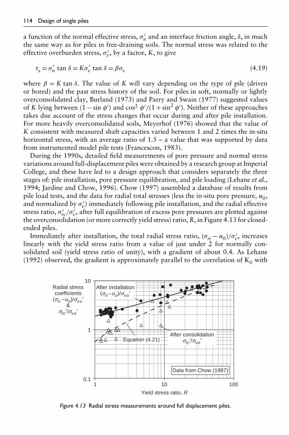
114 Design of single piles
a function of the normal effective stress, σ ′n and an interface friction angle, δ, in much
the same way as for piles in free-draining soils. The normal stress was related to theeffective overburden stress, σ ′
v, by a factor, K, to give
τs = σ ′n tan δ = Kσ ′
v tan δ = βσv (4.19)
where β = K tan δ. The value of K will vary depending on the type of pile (drivenor bored) and the past stress history of the soil. For piles in soft, normally or lightlyoverconsolidated clay, Burland (1973) and Parry and Swain (1977) suggested valuesof K lying between (1 − sin φ′) and cos2 φ′/(1 + sin2 φ′). Neither of these approachestakes due account of the stress changes that occur during and after pile installation.For more heavily overconsolidated soils, Meyerhof (1976) showed that the value ofK consistent with measured shaft capacities varied between 1 and 2 times the in-situhorizontal stress, with an average ratio of 1.5 – a value that was supported by datafrom instrumented model pile tests (Francescon, 1983).
During the 1990s, detailed field measurements of pore pressure and normal stressvariations around full-displacement piles were obtained by a research group at ImperialCollege, and these have led to a design approach that considers separately the threestages of: pile installation, pore pressure equilibration, and pile loading (Lehane et al.,1994; Jardine and Chow, 1996). Chow (1997) assembled a database of results frompile load tests, and the data for radial total stresses (less the in-situ pore pressure, u0,and normalized by σ ′
v) immediately following pile installation, and the radial effectivestress ratio, σ ′
rc/σ′v, after full equilibration of excess pore pressures are plotted against
the overconsolidation (or more correctly yield stress) ratio, R, in Figure 4.13 for closed-ended piles.
Immediately after installation, the total radial stress ratio, (σri − u0)/σ ′v, increases
linearly with the yield stress ratio from a value of just under 2 for normally con-solidated soil (yield stress ratio of unity), with a gradient of about 0.4. As Lehane(1992) observed, the gradient is approximately parallel to the correlation of K0 with
0.1
1
10
100101
Yield stress ratio, R
Radial stresscoefficients
(sri –uo)/svo′&
src′/svo′
Data from Chow (1997)
After installation(sri –uo)/svo′
After consolidationsrc′/svo′Equation (4.21)
Figure 4.13 Radial stress measurements around full displacement piles.

Design of single piles 115
overconsolidation ratio proposed by Mayne and Kulhawy (1982), with a radial totalstress ratio of 3 to 3.5 times K0.
The radial total stress (less the in-situ pore pressure) may be expressed as
σri − u0 = σ ′ri +umax = (
σ ′ri − p′
i
)+ p′0 +p (4.20)
where umax is the maximum excess pore pressure and p′0 and p′
i are respectively theoriginal in-situ mean effective stress and the value just after pile installation (adjacentto the pile shaft). The bracketed term has a relatively narrow range (negative, dueto the slight unloading strains next to the pile according to the strain path method(Baligh, 1986; Whittle, 1992), but limited in magnitude to the current undrained shearstrength, allowing for any remoulding that may have occurred as the pile is installed).The in-situ mean effective stress, p′
0, may be estimated through K0, but it has proveddifficult to estimate the increase in mean total stress, p, required to accommodatethe pile, although approaches based on cylindrical cavity expansion and the moresophisticated strain path method have been attempted.
During equilibration, the excess pore pressure reduces to zero and the radial effectivestress increases to a final value denoted by σ ′
rc. The data for the final radial effectivestress ratio, σ ′
rc/σ′v, in Figure 4.13 may be correlated with lines that lie nearly parallel
to the trend of the installation stresses, but are offset by varying amounts, dependingon the sensitivity of the clay (Lehane, 1992; Jardine and Chow, 1996), or fitted asshown by the expression (Randolph, 2003)
σ ′rc
σ ′v
≈ σ ′ri
σ ′v
+ R5
ln(
1 + 5R
umax
σ ′v
)(4.21)
The value of σ ′rc is affected to some degree by what assumption is made regarding
the radial effective stress immediately after installation, σ ′ri. The curve in Figure 4.13
was obtained assuming this quantity to increase from around 0.1σ ′v for normally con-
solidated soil, to σ ′v at a yield stress ratio of 10. For a given total radial stress (for
example, based on the upper curve in Figure 4.13), reducing σ ′ri leads to an increase
in umax and vice versa, and these adjustments partly compensate each other in theestimation of σ ′
rc from equation (4.21).The final stage to consider is what happens during loading of the pile. Data from the
Imperial College field experiments have suggested that the radial effective stress adja-cent to the pile shaft decreases by about 20% as the pile is loaded, giving σ ′
n ∼ 0.8σ ′rc
in equation (4.19). This value may be used, together with an interface friction anglethat is either measured directly, or estimated from correlations such as those presentedby Jardine and Chow (1996), in order to estimate the shaft friction.
Open-ended piles may be expected to generate lower radial stresses in the soil duringinstallation, assuming they are driven in an ‘unplugged’ manner (with the soil plugmoving progressively up the pile as it embeds). From cylindrical cavity expansiontheory, the reduction in total radial stress (or excess pore pressure), relative to a closed-ended pile in the same soil, would be
σri ≈ culn(ρ) (4.22)

116 Design of single piles
where ρ is the area ratio (ratio of annular area to total cross-sectional area). Forsteel piles, the ratio of diameter, d, to wall thickness, t, is typically around 40, cor-responding to an area ratio of 0.1. This would therefore lead to a reduction in σri of2.3cu, with a corresponding reduction in the overall extent of the excess pore pressurefield. However, while this approach gives reasonable adjustments for lightly overcon-solidated clays, leading ultimately to a reduction in shaft friction of 15 to 20%, itappears to give unreasonably low radial stresses and shaft friction for more heavilyoverconsolidated clays.
4.1.2.5 Bored piles
Turning to bored piles, assuming that no chemical bond develops between the pile andsoil, an effective stress approach is again more attractive than the empirical approachbased purely on the undrained shear strength of the soil. Provided the pile is formedpromptly after excavation of the shaft, little change in the in-situ effective stress statein the soil should occur, and equation (4.19) may be applied with K = K0. In heavilyoverconsolidated clay, where the value of K0 is large, some allowance for stress relax-ation should be made, reducing the value of K by 20%. Alternatively, the mean stressbetween the in-situ horizontal stress and that due to the concrete poured into the pileshaft may be taken, replacing K by (1 + K0)/2. It must be emphasized, however, thatdelays in pouring the concrete may reduce the in-situ horizontal effective stress consid-erably. Back analysis of tests of bored piles in heavily overconsolidated London Clayshow deduced values of K below unity, where delays have occurred between augeringand forming the piles (Fleming and Thorburn, 1983).
The question of what friction angle should be used in equation (4.19) is still sub-ject to debate. The surface of most bored piles will be sufficiently rough to ensurethat failure takes place in the soil immediately around the pile, rather than actu-ally on the interface. However, there have been suggestions (notably Burland andTwine, 1988) that a residual angle of friction is appropriate, at least for bored pilesin heavily overconsolidated clay. The friction angle mobilized on the (vertical) failuresurface at peak shear stress will depend on the complete stress state. Randolph andWroth (1981) have argued that, where the horizontal effective stress exceeds the ver-tical effective stress, the friction angle will be significantly lower than that obtainedfrom a triaxial compression test, and will be similar to that mobilized on horizontalsurfaces at failure in a simple shear test, conducted under appropriate normal stressconditions.
Adoption of the residual angle of friction in equation (4.19) (based on arguments ofslip-planes formed during the augering process) does not appear consistent with theassumption of failure within the clay (due to the roughness of the pile shaft). However,residual friction angles maybe appropriate where the augered shaft is relatively smooth,and failure occurs at the concrete-soil interface. Overall, a reasonable design approachseems to be to take the horizontal effective stress as 0.5(1 + K0)σ ′
v, and the frictionangle as that mobilized at failure in a simple shear test. Where the horizontal effectivestress is greater than the vertical effective stress (i.e. in heavily overconsolidated clays),the friction angle will lie in the range 15 to 20◦ (Randolph and Wroth, 1981).
For the design of bored piles in soil deposits where the profile of K0 with depth is notknown, either the approach for driven piles may be used with an appropriate factor to

Design of single piles 117
allow for stress relief on excavation of the pile shaft, or a direct ‘total stress’ approachmay be used. Assuming that little change in the in-situ effective stress state takes placeduring construction of the pile, Meyerhof’s (1976) observation of a K value close to1.5K0 would indicate that the shaft friction for a bored pile may be estimated as about70% of that for a driven displacement pile. This figure may be conservative for pilesin soil with low in-situ values of K0, since some increase in lateral stress may occurduring the process of casting the pile.
For bored piles in stiff, heavily overconsolidated clay, an α value of 0.45 was sug-gested in order to estimate the shaft capacity (Skempton, 1959). This approach isbased largely on experience in London Clay, with shear strengths measured on small(38 mm diameter) samples. In fissured clays, such as London clay, the shear strengthis affected by sample size and the modern use of 100 mm diameter samples leads tolower shear strengths, and thus a higher value of α will be appropriate. Recent reviewssuggest α values of 0.5 for conventional bored piles, and 0.6 for CFA piles, based onshear strengths determined from unconsolidated undrained triaxial tests on 100 mmdiameter samples. Care should be taken when applying the same value of α to clayswhere the strength ratio, cu/σ ′
v, is higher than for London Clay, since an effective stressapproach may well indicate substantially lower values of shaft friction than the totalstress approach based on α values in the range 0.5 to 0.6.
Weltman and Healy (1978) analyzed a number of pile tests in boulder clays andother glacial tills, and suggested values of α varying with the undrained shear strengthof the soil as shown in Figure 4.14. The ratio of values for bored and driven piles is justover 80%, but both curves are derived from data showing considerable scatter. Thefigure also shows a separate curve for very short, stubby piles driven into till overlainby soft clay. For such piles, the ratio of cu/σ ′
v will be high and the resulting low α
values are consistent with the effective stress approach outlined earlier.
4.1.2.6 Correlations with field tests
Comparisons of measured pile capacities with results of cone penetration or standardpenetration tests show a much greater scatter than for non-cohesive soils. The drainageconditions during a penetration test will be rather different from those existing duringa pile test, and this may account for some of the variation. The end-bearing pressure
Figure 4.14 Variation of α with shear strength of glacial till (Weltman and Healy, 1978).

118 Design of single piles
mobilized by a driven pile should, in principle, be comparable with that measuredduring a cone penetration test. However, effects of scale and of different rates oftesting combine to yield variations in the ratio qb/qc ranging from under 0.5 to over 2.Unless there is particular evidence to the contrary, it is suggested that the end-bearingpressure for driven closed-ended piles may be taken equal to that measured in a conepenetration test, with a reduction of 30% for open-ended or bored piles.
Estimates of the shaft friction for driven piles are often made from friction sleevemeasurements, taking τs = fc. However, caution should be exercised using thisapproach, owing to the sensitivity of the value of friction measured to the degree ofconsolidation in the soil (a) around the pile and (b) around the friction sleeve. Pile testsshow that the value of shaft friction measured during installation (a similar processto the continuous penetration of the cone and friction sleeve) may be as low as 20%of the long-term shaft friction (see section 4.1.5). Estimates of shaft friction directlyfrom the cone resistance, qc, offer a better guide. However, recommended correlationsrange from τs = qc/10 (Fleming and Thorburn, 1983) down to τs = qc/40 (Thorburnand McVicar, 1971). It is probably more reliable to deduce profiles of undrained shearstrength from the cone penetration tests and then to use the expressions given earlier,relating shaft friction to the undrained shear strength and to the effective overburdenstress.
As discussed in Chapter 2, results from standard penetration tests in medium tofirm clays and soft rocks may be used to estimate the shear strength of the soil, takinga ratio for cu/N of 4 to 5 kPa for clays of medium plasticity, rising to 6 to 7 kPafor plasticity indices less than 20 (see Figure 2.4). The values of shear strength maythen be used to provide estimates of end-bearing pressure and of shaft friction in thenormal way.
4.1.3 Capacity of piles in rock
Piles driven to refusal on firm or intact rock are often designed as purely end-bearingpiles ignoring any shaft capacity the pile might have, although, in practice, considerableshear transfer may occur in the upper layers of soil, at working loads. In many cases,the maximum design load for such a pile will be determined by the stresses in the pilematerial itself rather than the permitted bearing pressure on the rock.
Great care should be exercised where steel piles are driven to bedrock, to ensure thatgood sound rock contact is achieved. Pile driving may shatter the rock, and indeed it isgood practice to ensure that the piles penetrate a small distance into the rock. This willhelp to prevent the piles heaving and coming away from the bearing stratum duringdriving of subsequent piles. Alternatively, where access permits, each pile should bere-tamped at the end of installing the neighbouring piles, to ensure good contact withthe bearing stratum.
In weathered rock, careful monitoring of driving records is essential owing to thewide variability in strength exhibited by soft rocks such as chalk and marl in a weath-ered state. Refusal of the piles may not be achieved and the contribution of the pileshaft to its overall capacity may need to be relied upon. Accurate estimation of theshaft friction around a pile driven into soft rock is difficult owing to the disruption ofthe structure of the rock as the pile penetrates. The shaft friction will depend on themagnitude of the normal effective stress, which is liable to vary in a haphazard fashion.

Design of single piles 119
Recorded values of shaft friction for piles driven into low-grade chalk vary from aslow as 8 kPa (Hodges and Pink, 1971) up to 26 kPa (Hobbs and Robins, 1976) forsimilar pile penetrations.
4.1.3.1 End-bearing pressure
It has been customary for design codes to stipulate allowable bearing pressures on rocksof different types. Tomlinson (1986) presents an extensive list of allowable pressures,in terms of type, quality and joint spacing of the rock. In view of the great variabilityin strength (and allowable end-bearing pressure) of individual rock types, it appearsbest to express allowable bearing pressures for pile design in terms of the unconfinedcompressive strength of the rock. Theoretical (and experimental, where failure hasactually been achieved) values of ultimate end-bearing pressure are generally in excessof 10qu (where qu is the unconfined compressive strength). Large settlements wouldbe required to mobilize such values of end-bearing, and, in practice, a rather lower‘ultimate’ end-bearing pressure of about 3qu is often adopted (Rowe and Armitage,1987).
A rational design approach is to limit allowable bearing stresses to below that whichwould initiate crushing of the rock beneath the pile. Even where the joints are relativelyopen, this value will not fall below the unconfined compressive strength of the rock.Thus, allowable end-bearing stress, qba, may be expressed as (Rowe and Armitage,1987)
qba = qu (4.23)
The above value is rather higher than that of 0.3qu suggested by, for example, Poulosand Davis (1980). However, the higher value is supported by experimental evidenceand is consistent with a factor of safety of 3 applied to the (conservative) ultimatebearing pressure of 3qu discussed above.
A more extensive database has been presented by Zhang and Einstein (1998), whereend-bearing pressures mobilized at a displacement of 10% of the pile diameter werefound to be proportional to the square root of the unconfined compression strength,according to
qb
pa≈ 15
√qu
pa(4.24)
where pa is atmospheric pressure. This expression has been compared with results fromcone penetration tests and model pile tests in calcarenite by Randolph et al. (1998),as shown in Figure 4.15.
4.1.3.2 Shaft friction
Shear transfer along the shaft of a rock socket is a complex phenomenon that dependson the frictional characteristics of the interface, the degree of roughness of the socketand the strength properties of the host rock. Values of peak friction will dependstrongly on the normal stress along the shaft, and the amount of dilation that occurs

120 Design of single piles
1
10
100
0.01 0.1 1 10 100
Unconfined compressive strength, qu (MPa)
End
-bea
ring
capa
city
, qb
(MP
a)
End-bearing incalcarenite
CPT: zerooverburden
CPT: triaxial
CPT: withoverburden
pa
qu
pa
qb ≈15
pa
qu
pa
qc ≈ 60
End-bearing data fromZhang and Einstein (1998)
Figure 4.15 Correlations of end-bearing capacity for piles in rock and cone resistance in calcarenite(Randolph et al., 1998).
during shearing (Johnston and Lam, 1989). In practice, it has been customary tocorrelate measured values of shaft friction with the unconfined compressive strengthof the rock (Horvath et al., 1980; Williams and Pells, 1981; Rowe and Armitage,1987). While there are minor differences, most of these correlations show a trend ofshaft friction which is proportional to the square root of the compressive strength.However, traditional approaches show a major discontinuity in the transition zonebetween hard soils and soft rocks, as indicated in Figure 4.16 (based on Kulhawy andPhoon, 1993). The trend lines through the data are given by
τs
pa= ψ
(cu
pa
)0.5
or ψ
(qu/2pa
)0.5
(4.25)
where ψ = 0.5 for the clay data and 2 for the main soft rock data. Also shown on thefigure are data from laboratory grouted driven pile data, and laboratory and field testdata related to a soft limestone site at Overland Corner in South Australia (Randolphet al., 1998).
The discontinuity in the data, and the high shaft friction values found for soft rocks,relative to the unconfined compression strengths, is attributable to the high roughnessof bored sockets for the strength range between about 300 and 3000 kPa. Seidel andHaberfield (1995) have presented a detailed model for the shearing of rock-sockets,where combined shearing and bearing resistance of asperities at the borehole edgedetermine the limiting shaft friction. Their model is able to simulate the trends in thedata, provided appropriate assumptions (based on field measurements) are made inrelation to the asperity height and angles, (see Figure 4.17). Of particular note is theeffect of pile diameter, with shaft friction reducing as the diameter increases. For large

Design of single piles 121
GDP- EssoCNSRSGSTGrouted Anchor
Sandstone,limestone, marl
Shale, mudstone(rough socket)
ClayShale, mudstone
0.1
1
10
100
0.1 1 10 100 1000
Normalized shear strength, cu/pa, qu/2pa
Nor
mal
ized
sha
ft fr
ictio
n, t
s/p
aOverland Corner
y = 1
y = 2
y = 3
y = 0.5
Data from Kulhawy and Phoon
Laboratory grouteddriven pile data
Figure 4.16 Shaft friction data from piles in cemented materials (extended from Kulhawy and Phoon(1993) by Randolph et al. (1998)).
piles, the value of ψ is close to unity, which also gives a conservative bound to thedata in Figure 4.16. A check should also be made in any design, that the assumed shaftfriction is not greater than 5% of the concrete strength.
4.1.3.3 Correlations with SPT in chalk
Hobbs and Healy (1979) have presented an extensive review of the performance ofpiles in chalk, and have correlated shaft friction and end-bearing pressures for differentpile types with the SPT value of the chalk. For large displacement driven piles, theyrecommend using an effective stress approach for estimating the shaft capacity, takinga value for K of 0.06 N, and interface friction angles of 20◦ (for steel piles) to 24◦(for concrete piles). Higher values of K (up to 0.15 N) were recommended for drivencast-in-situ piles where high-slump concrete was compacted against the chalk, whilelower values of K (0.03 N) were suggested for low-displacement piles. End-bearingpressures were shown to correlate with N values with ratios of qb/N lying between0.2 and 0.25 MPa. Figure 4.18 shows summaries of measured values of shaft fric-tion and end-bearing pressure, plotted against SPT values, taken from Hobbs andHealy (1979).
For bored piles in chalk, where interlocking and possible chemical bonding occursbetween the pile and the chalk, Hobbs and Healy found that the shaft friction cor-related well with the compressive strength of the chalk, according to the relationshipgiven in equation (4.25) with ψ ∼ 1. The shaft friction of CFA piles has been reviewedby Lord et al. (2003) who suggest an effective stress approach, although the correla-tion of shaft friction with vertical effective stress is very poor. A direct correlation of

122 Design of single piles
0
5
100010 1000.1 1
10
0
5
10
15
20
15
Maximum roughness
Minimum roughness
Mea
n ro
ughn
ess
heig
ht (
mm
)
Mea
n ro
ughn
ess
angl
e (d
eg)
Normalized shear strength, su/pa, qucs/2pa
(a) Assumption regarding borehole roughness
Rocket:0.45 m dia.1.8 m dia.
0.01
0.1
1
0.1 1 10 100 1000
Normalized shear strength, su/pa, qucs/2pa
Adh
esio
n fa
ctor
a =
ts/s
u
2pa
qucsor ypa
susu
−0.5−0.5
=ytsa
y = 0.5 1
2
3
(b) Shaft friction ratios as function of strength (pa is atmospheric pressure, 100 kPa)
=
Figure 4.17 Predictions of rock-socket shaft friction from ROCKET (Seidel and Haberfield, 1995).
shaft friction and the SPT values reported at the level of the pile base shows a clearertrend, with the average shaft friction around 3Nbase kPa.
4.1.4 Driving formulae and dynamic estimates of pile capacity
In many instances, particularly in heavily stratified soil or rock of varying degrees ofweathering, the capacity of each pile installed needs to be checked from the drivingrecord. The capacity of the pile at the time of installation should represent a conserva-tive value. With time after installation, dissipation of excess pore pressures generatedduring the driving process leads to an increase in effective stresses around the pile, anda resulting increase in the pile capacity. For piles driven into clay, this increase may beas much as a factor of 5 to 6 (Vesic, 1977). Thus pile load tests aimed at assessing thelong-term capacity of a working pile should allow sufficient time for this capacity tobe achieved often a matter of 3 to 4 weeks (see section 4.1.5).

Figure 4.18 Correlations of skin friction and end-bearing pressures with SPT value, for piles in chalk(Hobbs and Healy, 1979). (Top) Ultimate shaft resistance against N value for all piles.(Bottom) Ultimate and bearing resistance for some driven piles. A, Driven cast-in-placepiles (fresh concrete in contact with the chalk). B, displacement piles (including preformedand cast-in-place types).

124 Design of single piles
4.1.4.1 Pile driving formulae
The most widespread method of estimating the dynamic capacity of piles is the useof some form of pile driving ‘formula’, relating the measured permanent displacement(or ‘set’) of the pile at each blow of the hammer, to the pile capacity. Driving formulaeare based on an energy balance between the (dynamic) input energy of the hammer, andthe (static) work required to move the pile permanently a small distance, s. As such,they offer a compromise (often rather a poor one) between the static and dynamiccapacities of a pile.
There is a variety of pile driving formulae in common use, many of which have beenreviewed by Whitaker (1975), who comments that, in some situations, pile capacitiespredicted by the different formulae may differ by a factor of 3. Rather than describeall the different approaches here, the basic approach will be outlined and some of themain variables discussed.
A simplified picture of the driving process, and variation of pile resistance withdisplacement is shown in Figure 4.19. This picture gives rise to the fundamental piledriving formula
R = ηWh(s + c/2)
(4.26)
where R is the pile resistance.η is the efficiency of the hammer (allowing for energy loss on impact).W is the weight of the hammer.
Figure 4.19 Schematic diagram of pile driving.

Design of single piles 125
h is the drop height.s is the permanent set of the pile.c is the elastic, or recoverable, movement of the pile.
This expression is widely used in the American continent, adopting a value of 0.8 to 1for η, and 0.1 in (2.5 mm) for c (giving the so-called Engineering News formula).In Europe, both η and c are chosen with regard to the type of hammer, the materialused as a cushion at the head of the pile, and the physical properties of the pile. Probablythe best known variant is that due to Hiley (1925), where the overall hammer efficiencyis given by
η =k(W + e2Wp
)W + Wp
(4.27)
where k is the output efficiency of the hammer (ratio of power delivered atthe cushion, to rated power).
Wp is the weight of the pile.e is the coefficient of restitution between the hammer and the pile
cushion (or top of pile if there is no cushion).
The recoverable movement, c, is taken as the sum of the cushion compression,cc = Rtc/(AEc) (where tc is the thickness and (AEc) the cross-sectional rigidity of thecushion), the elastic shortening of the pile (considered as a column), cp = Rl/(AE)p,and the recoverable movement (or ‘quake’) of the ground, cg. The last quantity maybe taken as 0.5% of the pile diameter. Table 4.2 shows commonly adopted values forthe quantities k, e and E depending on hammer type and cushion material.
It should be emphasized that the form of equation (4.24) is inherently inaccurate forassessing, by means of the measured set, s, whether a required pile resistance, R, hasbeen achieved. Uncertainties in the values of k and the various components of c can leadto wide variations in the deduced pile resistance. Over a period of a few hours driving,the characteristics of both the hammer and the cushion may alter significantly; thus
Table 4.2 Values of parameters for pile driving formulae
Type of hammer Power efficiency, k
Drop hammer (triggered fall) 1Steam or compressed air hammer 0.9Drop hammer (winch operated) 0.8Diesel hammer 0.6–0.8
Cushion type Coefficient ofrestitution, e
Young’s modulus,Ec (MN/m2)
Micarta plastic 0.8 3 × 10³
Greenheart oak 0.5 3 × 10²
Other timber 0.3 2 × 10²

126 Design of single piles
piles driven to a given set at the start and end of the period may have widely varyingcapacities.
4.1.4.2 Dynamic analysis of pile driving
A more rigorous assessment of the driving characteristics of a pile may be achievedby means of a proper dynamic analysis of the pile–soil system. The inertial effectsof the soil around the pile, and the viscous nature of the soil, may both be takeninto account by appropriate numerical techniques, such as the finite element method(Smith and Chow, 1982). A common simplification of the soil is as a massless mediumproviding frictional resistance alone, while the pile is modelled as a discrete assemblyof mass elements, interconnected by springs. This ‘one-dimensional’ model is discussedin detail in section 9.3 (Dynamic testing of piles).
At the design stage, the main objective of dynamic analysis of pile driving is toassess the ‘drivability’ of a pile in given soil conditions, and with a particular typeand size of hammer. This is commonly accomplished using one-dimensional waveequation programs, based on the method described in section 9.3. Probably the mostwidely used program is the WEAP program developed originally by Goble and Rausche(1976) for the Federal Highway Administration in North America. The program,now marketed as GRLWEAP has been updated over the years with improved userinterfaces, and other technical improvements (Goble and Rausche, 1986; Rauscheet al., 1988).
The main outcome of a drivability study is a series of curves that give the penetra-tion rate (or blow count) as a function of the assumed ‘static’ resistance of the pile.These curves may be used to choose an appropriate hammer, to assess the time andcost of installation of each pile and to provide a quality control on pile installation(in terms of required ‘set’ per blow for a given capacity). In addition, a drivabilitystudy will include assessment of the maximum tensile and compressive stresses in thepile during driving, maximum acceleration levels, and range of required (or permitted)hammer stroke. Limiting the range of hammer stroke may be particularly necessaryduring the early driving of concrete piles, in order to avoid excessive tensile stresses inthe pile.
4.1.5 Increase in capacity of piles with time
It is important to consider the effect of time on the axial capacity of piles, particularlydriven piles in clay, and also the effect of loading rate on the measured capacity.The design methods that have been described are based on observed performance ofpiles which have been load tested over a relatively short period (of tens of minutes orhours), usually a matter of a few days or weeks since installation. Except in particularcircumstances involving dynamic loading, piles must generally withstand their designloads for very long periods of time, and the question arises whether creep, or stressrelaxation, in the soil around the pile, may lead to reduced capacity. In soils which areknown to creep, some allowance may need to be made for these effects, although itshould be borne in mind that the stress level in the soil will generally be relatively low.It is unlikely that creep would lead to more than 5 to 10% reduction in the capacityof a pile.

Design of single piles 127
4.1.5.1 Pore pressure dissipation in clay
The question of the effect of time since installation is of much more consequence,particularly for displacement piles installed in soils of low permeability. Piles driveninto cohesive soil generate high excess pore pressures close to the pile. The pore pres-sures arise partly as a result of a decrease in effective stress, as the soil is sheared andremoulded, and partly due to the increase in total stress, as the pile forces soil out ofits path. Typically, the excess pore pressures may be as high as the effective overbur-den stress, and may extend out over a zone up to 10 times the diameter of the pile.Randolph et al. (1979) suggest that the excess pore pressure, u, close to a driven pilemay be estimated from the expression
u = 4cu −p′ (4.28)
where p′ is the change in mean effective stress due to shearing and remoulding thesoil. In normally or lightly overconsolidated clay, p′ will be negative and may be ashigh as 2 to 3cu for sensitive clays. In more heavily overconsolidated clay, p′ willbecome positive as the clay attempts to dilate on shearing. Figure 4.20 shows typicalfield measurements of excess pore pressures due to pile installation. The values reflectthe trend implied by equation (4.28).
After the pile is installed, the excess pore pressures will dissipate, primarily by radialflow of pore water away from the pile, and the soil will consolidate.During this pro-cess, the water content of the soil will decrease, and its shear strength increase. Seedand Reese (1955) report a decrease in water content of 7% close to a pile driveninto San Francisco Bay mud. This was accompanied by a threefold increase in theremoulded strength of the soil (measured from samples taken from close to the pile).A similar figure for the decrease in water content adjacent to a displacement pile hasbeen reported by Francescon (1983), from tests on model piles installed in soil ofvarying overconsolidation ratio.
The axial capacity of a driven pile will vary with time after installation, because ofthis consolidation process. Seed and Reese report a sixfold increase in pile capacity,over a period of 30 days. Similar increases in capacity have been discussed by Vesic(1977) and by Thorburn and Rigden (1980). Analytical studies of the stress changescaused by pile installation, and of the consolidation process, have shown that the shearstrength of the soil may increase by between 30 and 100% close to the pile, over a time
Figure 4.20 Field measurements of excess pore pressure.

128 Design of single piles
Figure 4.21 Variation of pile capacity with time.
period which is governed by the dimensionless group cht/d2, where ch is the coefficientof consolidation in a horizontal plane, t is the time since installation of the pile, andd is the diameter of the pile (Randolph et al., 1979; Randolph and Wroth, 1979).
Figure 4.21 shows the variation of pile capacity with time, for three piles driven intosoft silty clay. The time scale has been normalized by the square of the pile diameter.Other factors which will affect the rate of dissipation of excess pore pressures are(a) the consolidation coefficient, ch, and (b) the extent of the zone of excess porepressures. The latter will be a function of the rigidity index, G/cu, of the soil (whereG is the shear modulus), and the sensitivity of the soil. Also shown on Figure 4.21 is atheoretical curve of the change in excess pore pressure, normalized by the maximumvalue, with time. The curve is taken from Randolph and Wroth (1979), assuming thatthe excess pore pressures extend out to a distance of 10 pile radii from the axis of thepile. A value of 10 m2/year has been taken for ch, which is reasonable for silty claysunder conditions of horizontal drainage. The measured variations of pile capacityfollow the theoretical curve reasonably well. When piles are driven in a group, themagnitude of the excess pore pressures generated will be similar to that for a singlepile. However, the zone over which they extend will be considerably larger, and theresulting consolidation process will be more protracted.
The dissipation time will depend on the magnitude and extent of the excess pore pres-sure field generated around the pile, and will thus be much shorter for open-ended pilesthan for closed-ended piles. Dissipation curves for open-ended piles of different wall

Design of single piles 129
0
0.1
0.2
0.3
0.4
0.5
0.6
0.7
0.8
0.9
1
0.001 0.01 0.1 1 10
Teq = cht /deq2
Δu/Δ
u max Closed
d/t = 20
d/t = 40
d/t = 80
d/t = 160
SPM: Whittle
G/cu = 100
Figure 4.22 Pore pressure dissipation for open-ended and closed-ended piles.
thicknesses are shown in Figure 4.22 for lightly overconsolidated conditions, modelledas elastic-perfectly plastic material with G/cu = 100, corresponding to umax = 4.6cu
(Randolph, 2003). The time axis has been non-dimensionalized as Teq = cht/d2eq, where
deq is the equivalent diameter of a pile with the same solid volume as the open-endedpile in question. The equivalent diameter may be expressed in terms of the actualdiameter, d, area ratio, ρ, and wall thickness, t, as
deq = d√
ρ ≈ 2√
dt (4.29)
A comparison with a dissipation based on the strain path method (SPM) is also shown(Whittle, 1992). Note that the average dissipation curve in Figure 4.22 may be appliedto situations where the maximum excess pore pressure is greater or less than 4.6cu,by adjusting deq accordingly, on the basis of equations (4.22) and (4.29).
Pile installation in soft clay may temporarily reduce the stability of nearby buildingsor slopes. The remoulding of soil during pile driving may decrease the strength of asensitive clay sufficiently to cause a bearing capacity failure or slope instability (seeFigure 4.23(a)). Dissipation of the excess pore pressures generated during pile drivingmay allow pore pressures to rise in the vicinity of a slope, thus leading to failure of theslope, even where the soil has not been remoulded (see Figure 4.23(b)). However, ingeneral, the effects of pile installation will not extend beyond 10 to 15 pile diameters.Where there is danger of instability, consideration should be given to the use of non-displacement piling techniques, or to preboring a slightly undersize hole before drivingpiles – a technique commonly adopted in Scandinavia.
4.1.5.2 Effect of time for driven piles in sand
Recent studies have suggested that the shaft friction of steel piles driven in sand showssignificant increase with time (Chow et al., 1998), with gains of 50 to 100% possible.

130 Design of single piles
Figure 4.23 Potential problems due to pile driving.
Alternative explanations ranging from chemical changes (essentially corrosion) atthe pile–soil interface to relaxation of the arch of highly stressed sand surroundingthe pile have been put forward to explain these increases. Further work is neededbefore relying on increased shaft friction in design, particularly as the resulting shaftcapacity may prove somewhat brittle, reducing rapidly as the pile slips relative to thesurrounding sand.
4.2 Axial deformation of piles
The load deformation response of piles under axial load has been examined exten-sively, using numerical methods, particularly integral equation or boundary elementmethods (Poulos and Davis, 1968; Mattes and Poulos, 1969; Butterfield and Banerjee,1971a, b; Banerjee and Davies, 1977). Such methods enable charts to be developedshowing how the settlement of a pile depends on the various parameters of pile geome-try and stiffness, and soil stiffness. Poulos and Davis (1980) have compiled an extensivecollection of such charts, enabling the load settlement response of any given pile to be

Design of single piles 131
estimated readily. As an aid to understanding the manner in which a pile transfers loadto the soil under working conditions, an approximate solution is developed here forthe load settlement response of a pile in elastic soil. The solution leads to an expressionfor the pile stiffness (that is applied load divided by settlement) in closed form, whichmay be used as an alternative to charts.
In developing this solution, the manner in which load is transferred to the soil fromthe pile shaft, and from the pile base, will be examined separately, before combiningthe two to give the response of the complete pile. In the first instance, the soil will betreated as an elastic material, characterized by an appropriate secant value of elasticmodulus, varying in some fashion over the depth of interest. Choice of values of elasticmodulus for different soil types is discussed in Chapter 5.
Some discussion is appropriate concerning the geometric modelling of real piles.Analytical solutions for the response of piles have tended to treat the pile as a circularcylinder of diameter d (or radius r0) and length l. In practice, non-circular piles, suchas square or hexagonal precast concrete piles or H-piles, are common. Such piles maybe adequately represented as circular piles by taking a pile of equivalent (gross) cross-sectional area. Thus for an H-section pile of outer dimensions b×w (see Figure 4.24),a circular pile of diameter d may be taken, where πd2 = 4bw. It is also convenientto consider the pile as solid, with an appropriate Young’s modulus Ep, such thatthe rigidity is equivalent to that of the original pile. Thus, when considering axialdeformation, the equivalent pile modulus is
Ep = 4(EA)pπd2 (4.30)
where (EA)p is the cross-sectional rigidity of the actual pile.
4.2.1 Basic solution for a rigid pile
4.2.1.1 Pile shaft
Finite element and boundary element analyses of the response of friction piles (Frank,1974; Randolph, 1977) have shown that load is transferred from the pile shaft byshear stresses generated in the soil on vertical and horizontal planes, with little changein the vertical normal stress (except near the base of the pile). Schematically, a pile
b
wd
Figure 4.24 Idealization of H section pile.

132 Design of single piles
may be considered as surrounded by concentric cylinders of soil, with shear stresseson each cylinder. For vertical equilibrium, the magnitude of the shear stress on eachcylinder must decrease inversely with the surface area of the cylinder (Cooke, 1974;Frank, 1974). Writing the shear stress on the pile shaft as τ0, the shear stress at radius r(for a pile of radius, r0) is given by
τ = τ0r0
r(4.31)
Since the mode of deformation around a pile is primarily one of shear, it is morenatural to develop the solution in terms of the shear modulus G and Poisson’s ratio, v,rather than Young’s modulus, E (noting that the shear modulus may be related toYoung’s modulus by G = E/2(1+v)). The shear strain in the soil, γ , will thus be givenby γ = τ/G. Since the main deformation in the soil will be vertical, the shear strainmay be written approximately as
γ ∼ dwdr
(4.32)
where w is the vertical deflection.These relationships may be assembled and integrated to give
w =rm∫r
τ0r0
Grdr = τ0r0
Gln(rm/r
)(4.33)
A maximum radius, rm, has been introduced at which the deflections in the soil areassumed to become vanishingly small. Empirically, this radius has been found to beof the order of the length of the pile (Randolph and Wroth, 1978). The deflection ofthe pile shaft, ws, is given by
ws = ζτ0r0
G= ζ
τ0d2G
where ζ = ln(rm/r0
)= ln(2rm/d
)(4.34)
This approximate analytical derivation of the deflection of the pile shaft in terms of theaverage applied shear stress τ0 shows a number of important features of the responseof a pile to axial load.
1 Stress changes induced in the soil are primarily shear stresses, decreasing inverselywith distance from the pile axis; thus, only soil very close to the pile is ever highlystressed.
2 The resulting deflections decrease with the logarithm of distance from the pileaxis; thus, significant deflections extend some distance away from the pile (up toabout one pile length).
3 The deflection of the pile shaft, ws, normalized by the pile radius r0, is ζ times thelocal shear strain, γ0 = τ0/G, in the soil: the parameter ζ is found to vary between3 and 5, with an average value of about 4 (Baguelin and Frank, 1979).

Design of single piles 133
4 A load transfer stiffness, relating the load transferred at a given depth to the localdisplacement may be expressed as
k = πdτ0
ws= 2π
ζG (4.35)
Equation (4.34) is of particular importance in deducing the magnitude of deflectionnecessary to mobilize full shaft friction (see section 4.2.4). The theoretical basis forthe load transfer approach, and analytical expressions for the ratio k/G have beenexplored by Mylonakis (2001).
The overall load taken by the pile shaft is Ps = πd/τ0, where τ0 is the average shearstress mobilized at the pile shaft. Thus the load settlement ratio (or stiffness of thepile-soil system) is
Ps
ws= 2πL�G
ζ(4.36)
where �G is the average shear modulus of the soil over the embedment depth, L, ofthe pile.
4.2.1.2 Pile base
At the pile base, it is sufficient to ignore the pile shaft and surrounding soil, and treatthe base as a rigid punch acting at the surface of a soil medium (that, in reality, starts ata depth, z = L). The base stiffness is obtained from the standard solution (Timoshenkoand Goodier, 1970) as
Pb
wb= 2dbGb
(1 − ν)(4.37)
where the subscript b refers to the pile base.
4.2.1.3 Combining shaft and base
For a stiff pile, the base settlement and shaft settlement will be similar to the settlementof the pile head, wt. The total load, Pt, may thus be written as
Pt = Pb + Pt = wt
(Pb
wb+ Ps
ws
)(4.38)
In developing a general solution for the axial response of a pile, it is convenient tointroduce a dimensionless load settlement ratio for the pile. The pile stiffness is Pt/wtand this may be made dimensionless by dividing by the diameter of the pile and anappropriate soil modulus. It has been customary to use the value of the soil modulus at

134 Design of single piles
the level of the pile base for this purpose, written as GL. Thus equation (4.36) becomes(making use of equations (4.34) and (4.35))
Pt
wtdGL= 2
(1 − ν)db
dGb
GL+ 2π
ζ
�GGL
Ld
(4.39)
In order to obtain a feel for the relative importance of the terms in equation (4.39),the shear modulus variation with depth may be idealized as linear, according toG = G0 + mz (where z is the depth), with the possibility of a sharp rise to Gb below thelevel of the pile base (see Figure 4.25). Defining parameters ρ = �G/GL and ξ = GL/Gb,the constant ζ has been found to fit the expressions
ζ = ln{[
0.25 + (2.5ρ(1 − v) − 0.25)ζ]}
2L/d (4.40)
ζ = ln[5ρ(1 − v)L/d
]for ξ = 1 (4.41)
Figure 4.26 shows how the load settlement ratio varies with slenderness ratio L/d for arange of values of ρ and ξ , taking η = db/d = 1. It should be noted that the dependenceon v is small and the results in Figure 4.26 are all for v = 0.3. It may be seen that, asmight be expected, the stiffness of the pile increases nearly linearly with pile length,holding other factors constant. However, it must be borne in mind that this result isonly true of piles that may be considered rigid.
4.2.2 Pile compression
Most piles exhibit some shaft compression at working loads, and this should be allowedfor in estimating pile deflection. The axial strain at any level down the pile is
εz = −dwdz
= 4Pπd2Ep
(4.42)
(a) Floating pile (b) End-bearing pile
Depth Depth
L
L/2
L
L/2
GL
GL/2
GL/2 GL GL/2 GL Gb
r =GL
GL/2r =
Gb
GLx =
Shearmodulus
Shearmodulus
Figure 4.25 Assumed variation of soil shear modulus with depth.

Design of single piles 135
0
20
40
60
80
100
120
0 10 20 30 40 50
Pile slenderness ratio, L/d
r = 0.5
wtd
GL
Pt
Gb
GL = 1.0x =
Gb
GL = 3.0x =
Gb
GL = 1x =
r = 1
0.75
0.5
0.5
0.75
r = 1
0.75
1
n = 0.3h = 1rigid piles
Figure 4.26 Load settlement ratios for rigid piles.
taking Ep as the Young’s modulus of an equivalent solid pile (see equation (4.30)).The load P will vary down the pile as load is shed into the surrounding soil, so that
dPdz
= −πdτ0 (4.43)
Finally, ws and τ0 may be related by equation (4.33) to give
d2wdz2 = 8G
ζEpd2 w (4.44)
This differential equation may be solved to yield ws in terms of hyperbolic cosine andsine functions of z. Substituting in the appropriate boundary conditions at the pilebase yields an expression for the load settlement ratio of the pile head of
Pt
wtdGL=
2η(1−ν)ξ + 2πρ
ζ
tanh(μL)μL
Ld
1 + 8η
πl(1−ν)ξtanh(μL)
μLLd
(4.45)
where, summarizing the various dimensionless parameters
η = db/d (ratio of underream for underreamed piles)ξ = GL/Gb (ratio of end-bearing for end-bearing piles)ρ = G/GL (variation of soil modulus with depth)

136 Design of single piles
0
10
20
30
40
50
0 20 40 60 10080Pile slenderness ratio, L/d
l = 300
l = 1000
l = 3000
wtd
GL
Pt
x = η = 1n = 0.3
r = 1r = 0.75r = 0.5
Figure 4.27 Load settlement ratios for compressible piles.
l = Ep/GL (pile-soil stiffness ratio)ζ = ln(2rm/d) (measure of radius of influence of pile)μL = 2
√2/ζl(L/d) (measure of pile compressibility)
Figure 4.27 shows the variation of the load settlement ratio with slenderness ratio,L/d, for η = ζ = 1,v = 0.3.
The load at the pile base is given by
Pb
Pt=
η
(1 − ν)ξ1
cosh(μL)η
(1 − ν)ξ+ πρ
ζ
tanh(μL)μL
Ld
(4.46)
Figure 4.28 shows this ratio as a function of L/d for a range of values of ρ and l(again for η = ξ = 1, v = 0.3). It is clear that, under working conditions, very littleload reaches the base of long piles. The situation would be different for underreamed orfor end-bearing piles and also for groups of piles, where additional load is transferredto the base of the piles.
From Figures 4.27 and 4.28, it may be seen that there are combinations of slender-ness ratio, L/d, and stiffness ratio, l, beyond which very little load is transmitted tothe pile base. Further increase in pile length yields no corresponding increase in theload settlement ratio of the pile. This limiting behaviour is the converse of a stiff, rigidpile, and corresponds to the case where the pile starts behaving as if it were infinitelylong, with no load reaching the lower region.
The two limits may be quantified. Piles may be taken as essentially rigid where L/dis less than about 0.25
√Ep/GL and equation (4.45) then reduces to equation (4.39).
At the other extreme, for piles where L/d is greater than about 1.5√
Ep/GL, the value

Design of single piles 137
0
0.05
0.1
0.15
0.2
0.25
0.3
0 10 20 30 40 50
Pile slenderness ratio, L /d
l = 300, 1000 and 3000
x = h = 1n = 0.3r = 1
r = 0.75r = 0.5
Pt
Pb
Figure 4.28 Proportion of load taken by pile base.
of tanh(μL) approaches unity and equation (4.45) reduces approximately (exactly forρ = 1) to
Pt
wtdGL= πρ
√l2ζ
(4.47)
As expected, the load settlement ratio is now independent of the length of the pile(since no load reaches the lower end). The modulus GL should be interpreted as thesoil shear modulus at the bottom of the active part of the pile, that is at a depth thatcorresponds to z/d = 1.5
√Ep/GL, rather than at z = L.
The solution developed above is based on a linear variation of soil modulus withdepth, although it can be extended to layered profiles. An alternative solution for soilmodulus distributions expressed as G = mzn, where 0 ≤ n ≤ 1, has been presented byGuo and Randolph (1997).
In deriving the solution in equation (4.45), various simplifying assumptions had to bemade and more rigorous evaluation of the pile stiffness requires numerical analysis suchas described by Poulos and Davis (1980). Poulos and Davis write the load settlementratio of the pile in terms of a coefficient, I, where
I = wtdEL
Pt(4.48)
and EL is the Young’s modulus of the soil at pile tip level. The coefficient I is obtainedfrom the product of a number of other coefficients that reflect features such as thepile-soil stiffness ratio, the value of Poisson’s ratio for the soil and so forth. Thus
I = I0RkRhRv (4.49)

138 Design of single piles
where I0 is the value of I for a rigid pile in an infinitely deep homogeneousdeposit of incompressible soil (v = 0.5).
Rk allows for the compressibility of the pile.Rh allows for the finite depth of a layer of soil.Rv allows for values of Poisson’s ratio less than 0.5.
Comparison between the two approaches is generally reasonably good, consideringthe simplifying assumptions adopted in the solution developed here. For long com-pressible piles, the results from Poulos and Davis give higher values of pile stiffnessthan obtained using equation (4.45), but this may be partly due relatively coarse dis-cretization of the very long piles, leading to numerical inaccuracies in the boundaryelement solutions.
Two examples are included here to illustrate the approach described above.
Example 1Estimation of the working settlement of bored pile, 460 mm in diameter, founded ata depth of 16 m in stiff clay; the upper 2 m of soil is made ground, with no sheartransfer assumed. The strength of the clay increases uniformly from 70 kPa just belowthe made ground up to 200 kPa at the pile base, with an average value of 135 kPa. Thedesign load for the pile is 800 kN. Taking a shear modulus for the soil of G = 150cu(see section 5.2.4), with v = 0.2, and assuming the Young’s modulus for the pile isEp = 25 000 MPa, we obtain
GL = 30 MPa; ρ = 0.675; l = 833
For the lower 14 m of pile, L/d = 30.5, thus
ζ = ln(2rm/d
)= 4.4; μL = 2
√2ζl
Ld
= 1.42; tanh(μL)μL
Ld
= 19.1
Thus
Pt
wt= dGL ×
20.8
+ 2π × 0.6754.4
× 19.1
1 + 1πl
80.8
× 19.1= 269 kN/mm
The deflection at depth of 2 m, for the working load of 800 kN, is thus 800/269 =3.0 mm. In addition, 0.4 mm of compression will occur in the upper 2 m of the pile,giving an overall working settlement of 3.4 mm.
Example 2Estimation of the working settlement of a driven cast-in-situ pile, 510 mm in diameterand driven through low-grade chalk to bear on grade I/II chalk at a depth of 12 m.
Back analyses of earlier pile tests have indicated that the shear modulus for the upperchalk may be taken as increasing at a rate of 1 MPa for every metre of depth, taking

Design of single piles 139
v = 0.24. The shear modulus of the bearing chalk, allowing for disturbance due to pileinstallation, may be taken as G = 36 MPa (Lord, 1976). Young’s modulus of the pilesis Ep = 28 000 MPa.
The various parameters may be calculated as
GL = 12 MPa; ρ = 0.5; ξ = GL/Gb = 0.33; l = Ep/GL = 2333
L/d = 23.5; ζ = 3.1(from equation (4.40)); μL = 0.78; tanh(μL)μL
Ld
= 19.6
Thus
Pt
wt= dGL ×
20.76 × 0.33
+ 2π × 0.53.1
× 19.6
1 + 1πl
80.76 × 0.33
× 19.6= 157 kN/mm
For a working load of l000 kN, the settlement will therefore be 1000/157 = 6.4 mm.
4.2.3 Layered soil profiles
The solution described above may be extended or adapted to different conditions,such as to deal with step-tapered piles or piles that penetrate more than one soil type(with widely differing soil stiffnesses). Essentially each section of the pile shaft may betreated independently, retaining compatibility of displacement of the pile shaft betweeneach section (see Figure 4.29). Effectively, the load settlement ratio for the pile base
Figure 4.29 Modelling of pile in layered soil.

140 Design of single piles
(the term 2/(1 − v) in equation (4.45) is replaced by the load settlement ratio for thesection of pile below that which is currently being considered.
An example calculation will illustrate this. Consider a straight-shafted bored pile,0.6 m in diameter and 20 m long, with Young’s modulus of 25 × 103 MPa, whichpenetrates
(i) 20 m of stiff clay, with shear modulus reasonably constant at 40 MPa;(ii) the same stiff clay, but now overlaid by 8 m of a softer deposit with G varying
from 5 MPa at the surface up to 15 MPa at 8 m depth.
In the first case, straightforward substitution of the pile and soil parameters into equa-tion (4.45) results in η = ξ = ρ = 1, Ep/GL = 625,ζ = 4.76 (taking v = 0.3). Thusthe overall load settlement ratio is Pt(wtdGL) = 24.2, or Pt/wt = 581 kN/mm. Inthe second case, the lower 12 m of pile maybe treated in the normal way to givePt/wt = 540 kN/mm (surprisingly high considering how much shorter this section ofpile is than before). Now, the top 8 m of pile may be analyzed, substituting the appro-priate value of the load settlement ratio at the lower end instead of the terms 2/(1−v).In this example
Pb/wtdGL = 540/(0.6 × 15) = 60
and, taking ρ = 0.67, ζ = 3.44, the calculated stiffness is Pt/wt = 431 kN/mm.It is interesting to note that, in the second case, the average shear modulus over
the full depth of penetration of the pile is 28 MPa. If the pile were to be analyzedin a single step, then the parameter, ρ, would be 28/40 = 0.7 and the stiffness fromequation (4.45) for the full 20 m pile is calculated as Pt/wt = 444 kN/mm, only 3%higher than that given in the more precise calculation.
An alternative and elegant expression for the pile stiffness in homogeneous soil hasbeen given by Mylonakis and Gazetas (1998), who exploit the elastic load transferapproach for vertically loaded piles to evaluate interaction effects (see Chapter 5). Theexpression for the single pile stiffness is given here for completeness. Adopting a loadtransfer (or Winkler) stiffness, k, as defined previously in equation (4.35), the pile headstiffness is expressed as
K = (EA)p μ�+ tanh(μL)
1 +� tanh(μL)(4.50)
where
� = Pb
wb (EA)p μand μL =
√k
(EA)pL (4.51)
(noting this definition of μ is actually identical to that used previously). As in the aboveworked example, this solution may be used for segmented piles, or piles in multiple soillayers, by taking Pb/wb as the ‘base’ stiffness of the part of the pile currently underconsideration, although that stiffness may be derived from consideration of deepersections of the pile.

Design of single piles 141
4.2.4 Behaviour of long slender piles
It was shown earlier that as the length of a pile is increased, the stiffness of the pileresponse approaches a limiting value. If piles are being used to reduce settlements,it would clearly be illogical to design piles of such a geometry that this limit wasreached or even approached. However, there are many cases where piles are usedmainly to provide sufficient bearing capacity, for example, to support storage tankson soft ground, or for offshore oil production platforms. In these situations, it mayprove economically advantageous to use very long slender piles, and, in many cases,compression of the pile may be sufficient to cause relative slip between pile and soil inthe upper part of the pile, under working conditions.
The load level at which slip starts to occur between pile and soil close to the groundsurface may be estimated by combining equations (4.34) and (4.47). Thus, the localmovement of the pile to mobilize full shaft friction is obtained by substituting τs forτ0 in equation (4.34) to give
(ws)slip = ζdτs/2G (4.52)
The ratio G/τs varies from between 100 to 400 for piles in clay, to over 1000 for pilesin sand. Thus the movement for slip to occur will be 0.5 to 2% of the pile diameterin clay, and as low as 0.2% of the diameter in sand. Substitution of equation (4.52)into equation (4.47) leads to an expression for the pile load, Pslip at which slip startsto occur at ground level (where the pile movement is greatest), given by
Pslip/Qs = 1/μL =√
ζl2
d2L
(4.53)
where Qs is the ultimate shaft capacity of the pile, which equals πdLτ s. It is notuncommon for this ratio to be as low as 0.2, particularly for piles used offshore, inwhich case considerable slip will occur at working loads, where P/Qs may be of theorder of 0.5 to 0.6.
It is clear that an elastic solution for the pile load settlement ratio becomes inap-propriate at load levels greater than that given by the expression above. Estimation ofthe pile settlement must then allow for the region of slip between pile and soil. Thismay be accomplished in the same manner as for a pile in a layered soil profile, essen-tially treating the upper part of the pile (where full shaft friction has been mobilized)independently from the lower part. Some iteration will be required, since, for a givenapplied load at the pile head, the transition point between the two regions must beestimated initially. This procedure will be illustrated by an example, taken from pileload tests reported by Thorburn et al. (1983).
The two piles in question were precast concrete, 250 mm square, driven into siltyclay to penetrations of 29 m and 32 m. The shear strength varied with depth accordingto cu = 6 + 1.8z kPa (where z is the depth in m). Taking α = 0.9 for the clay, whichwas lightly overconsolidated, the shaft capacities of the two piles may be estimated as0.84 MN and 1.00 MN respectively. In calculating the load settlement ratio for thepiles, a cylindrical pile of radius 141 mm (giving the same cross-sectional area) will betaken. The short-term Young’s modulus of the piles was Ep = 26 500 MPa.

142 Design of single piles
The response of the piles to constant rate of penetration tests may be matched byadopting a shear modulus of G = 250cu = 1.5 + 0.45z MPa, taking Poisson’s ratioequal to 0.5. Equation (4.47) then gives the pile stiffness as Pt/wt = 90 kN/mm. Thelocal movement to mobilize full shaft friction may be estimated from equation (4.52)as 2.5 mm. Thus, slip between pile and soil will start at the top of the pile when theapplied load reaches 90×2.5 = 225 kN. Figure 4.30 gives the measured pile responses,showing both piles having the same initial stiffness, with an essentially linear responseup to loads of about 500 kN.
The complete load settlement curve may be estimated by calculating the load andcorresponding settlement for a given depth of slip between pile and soil. Thus, considerthe stage at which full shaft friction has been mobilized over the top l0 m of the pile.The load shed over the top 10 m may be calculated from the given profile of shearstrength, as 150 kN. For the bottom part of the pile, the load settlement ratio maybe calculated from equation (4.45) as P/w = 112 kN/mm. Thus the load level atthe transition point (where the settlement is 2.5 mm) is 280 kN. The overall load atthe pile head is then 280 + 150 = 430 kN. The pile compression over the top 10 mof the pile may now be calculated as 2.3 mm, giving an overall settlement at the pilehead of 4.8 mm.
The above process may be repeated for different depths of slip between pile andsoil to give the two estimated load settlement curves shown in Figure 4.30. In practice,adequate estimates of these curves may be obtained merely from the initial slopes of theload settlement curves, and estimates of the pile settlements when full shaft capacityhas been mobilized. Thus for the shorter pile, the compression of the pile for the shaft
Figure 4.30 Calculated and measured load settlement curves for two long piles.

Design of single piles 143
capacity of 838 kN is 9.3 mm. Together with 2.5 mm of settlement at the bottom of thepile (in order to mobilize full shaft friction there), the pile head movement is 11.8 mm.This corresponds reasonably well with the measured movement to peak load.
It should be noted that, for simplification, no allowance has been made in the abovecalculations for the small amount of load taken by the pile base. In addition, themeasured pile responses show clear evidence of strain softening, which will affectthe distribution of shaft friction down the pile at the point of failure of the pile (seefollowing discussion). The working loads for these piles were 440 kN and 550 kN,respectively, for the short and long piles. Maintained load tests at these load lev-els showed some creep movement, with final settlements of about 8 mm, of whichprobably about half reflected slip between the upper part of the pile and the soil.
As may be seen from the pile tests just discussed, large relative movement betweenthe pile shaft and the soil may lead to a reduction in shear transfer from a peak valueof shaft friction to a residual value. Such strain softening may be significant (a) inloose compressible sands (particularly calcareous sediments) and (b) in soft, lightlyoverconsolidated clays. Model pile tests in soft clay reported by Francescon (1983)and by Chandler and Martins (1982) indicate that the residual value, (τs)res, may beestimated from
(τs)res = K0σ ′v tan δres (4.54)
where δres is the residual interface friction angle. The model pile tests indicated thatshear transfer from the pile shaft may reduce by a factor of two or more after as little as30 mm of movement of the pile, particularly for cyclic relative displacements. Similarfindings have been reported from ring shear tests (Bishop et al., 1971; Lupini et al.,1981; Jardine et al., 2005). The consequences of this in the design of long slender pilesto anchor offshore platforms have been discussed by Randolph (1983).
The strain softening behaviour can also have consequences for the ultimate capacityof long piles, where a form of progressive failure becomes possible. At failure, thedisplacements at the head of a long pile may have been sufficient to reduce the shaftfriction to a residual value (see Figure 4.31). Thus the measured capacity will be lowerthan would be calculated from the profile of peak values of shaft friction. In orderto quantify this effect, a flexibility ratio, K, may be introduced (Randolph, 1983)given by
K = πdτsL2
(EA)p wres(4.55)
where wres is the relative movement needed between pile and soil for the valueof shaft friction to reduce from peak to residual. The flexibility ratio is similar tothe parameter π3, introduced by Murff (1980), but based on wres rather than themovement wslip to mobilize peak shaft friction initially. The flexibility ratio, K, may bethought of as the ratio of elastic shortening of the pile (treated as a column under the fullshaft capacity) to the relative movement wres to go from peak to residual conditions.
Figure 4.32 shows values of reduction factor, Rf , which should be applied to pileshaft capacities based on peak values of shaft friction, in order to allow for progres-sive failure of the pile. The different curves reflect different ratios of residual to peak

144 Design of single piles
Figure 4.31 Progressive failure of a long pile.
shaft friction. In general, land-based piles will have values of K which are greater thanunity, and the effect of strain softening will be small. However, piles used offshorefrequently have values of K in the range 2 to 4, and the effect may be significant. For aparticular situation, estimation of the reduction factor, Rf , will require an estimate ofthe ratio of (τs)res to (τs)peak, and also of the movement wres to cause the degradation.Ring shear, or direct shear box tests on the soil in question, will enable the value ofδres to be assessed, while wres may be taken, conservatively, as 30 mm. This value islikely to be largely independent of pile size, since the degradation is concentrated ina thin band close to the pile shaft, with re-orientation of soil particles responsible formost of the decrease in the angle of friction.
4.2.5 Rock sockets
The axial deformation of rock sockets deserves special consideration. Although rocksockets are generally relatively short, with typical length-to-diameter ratios of less than10, the high stiffness of the host rock compared with the pile stiffness results in therock socket behaving in a compressible fashion. As an example, consider a rock socketof length 10 m and diameter 1.4 m, embedded in soft rock with a shear modulus of

Design of single piles 145
Figure 4.32 Variation of reduction factor with pile stiffness ratio.
700 MPa. Assuming a Young’s modulus for the concrete of 25 000 MPa, the quantitythat controls the compressibility, μL, may be calculated as 1.9 (see equation (4.45)).The initial stiffness may be estimated approximately from equation (4.45) as P/w =7.3 MN/mm.
The relatively compressible nature of rock sockets, together with high base capacity,results in partial (or complete) slip along the pile shaft generally occurring under work-ing conditions. Analytical and numerical solutions for estimating settlement and loadtransfer in rock sockets under conditions of partial slip have been presented by Roweand Armitage (1987) and Carter and Kulhawy (1988). As slip occurs, the shaft frictionwill often decrease, as the cohesive or dilational component of the shaft friction willreduce to zero (Johnston and Lam, 1989). Since the shaft capacity is mobilized at muchsmaller displacements than the base capacity, the overall load-displacement responseof the rock socket may then show a decrease in capacity at intermediate displacements(due to strain softening of the shaft) prior to increasing again at larger displacementsas the base capacity is mobilized. Figure 4.33 shows schematically the different typesof rock socket response, depending on the rapidity of strain softening and the rate ofmobilization of the base capacity.
4.3 Lateral capacity of piles
Almost all piled foundations are subjected to at least some degree of horizontal loading.In many cases, the magnitude of the loads in relation to the applied vertical loadingis small, and no additional design calculations are necessary. For example, the piled

146 Design of single piles
Figure 4.33 Different types of rock socket responses.
foundation of a building of moderate height will easily withstand the small windshear loading that the building will be subjected to. In other cases, such as a piledearth retaining wall or a jetty, horizontal loading may prove critical in the design.Traditionally, piles have been installed at an angle to the vertical in such cases, provid-ing sufficient horizontal resistance by virtue of the component of the axial capacity ofthe pile that acts horizontally. However, it is very conservative to ignore the capacityof a pile to withstand lateral loading (i.e. loading applied normal to the pile axis). Thismay typically be an order of magnitude less than the axial capacity of a pile, but maywell be sufficient to obviate the need for so-called ‘raking’ or ‘battered’ piles, whichare more expensive to install.
Lateral loading of a pile may be divided broadly into the two categories of ‘active’loading, where external loads are applied to the pile, with the soil resisting the load,and ‘passive’ loading, where movement of the soil subjects the pile to bending stresses.This, and the subsequent section, are concerned primarily with the first category ofloading, although some of the features discussed (for example, the limiting pressurebetween pile and soil) are applicable to both categories. Passive loading of piles byconsolidating soil is discussed further in section 4.5.
As a pile is loaded laterally, normal stresses will increase in front of, and decreasebehind the pile. Displacements in the soil will tend to be radially away from the pilein front of the pile, and radially towards the pile behind it. At some stage, near theground surface, a gap will probably open up between the back of the pile and thesoil, with soil in front of the pile failing in a wedge type of mechanism, as shown inFigure 4.34. Further down the pile shaft, soil will eventually fail by flowing aroundthe pile, with no gap present. In calculating the distribution of limiting pressure which

Design of single piles 147
Figure 4.34 Deformation of pile under lateral load.
Figure 4.35 Variation of soil resistance along laterally loaded piles.
may be mobilized by the pile, these different types of failure mechanism in the soilmust be taken into account.
Collapse of the pile itself may occur in one of two modes. For short piles, or pileswith a large plastic moment, the pile will rotate essentially as a rigid body. The resultingprofile of resistance offered by the soil will be as shown schematically in Figure 4.35(a).

148 Design of single piles
Above the centre of rotation, passive pressures will develop in front of the pile, whilebelow the centre of rotation, passive pressures will develop behind the pile. For longerpiles, a plastic hinge will develop at some depth down the pile, and only the upperpart of the pile will undergo significant displacement (Figure 4.35(b)). Although thesoil will be subjected to loading below the plastic hinge, calculation of the failure loadwill only require knowledge of the limiting pressures acting over the upper part of thepile, above the plastic hinge.
Where a pile is embedded in a pile cap which is restrained from rotation, threedifferent collapse modes are possible, as shown in Figure 4.36. Short piles will translateas a rigid body with the pile cap, while progressively longer piles will first form a plastichinge at the level of the pile cap, and then a plastic hinge at some distance down thepile. In practice, the majority of piles encountered behave as long piles as regardslateral capacity. Failure will thus be by the mode shown in Figure 4.36(c).
In calculating failure loads, it is customary to treat the soil as a rigid plastic mate-rial, idealizing the profiles of limiting pressure as shown in Figure 4.35, with sharptransitions from full limiting pressure acting in front of the pile just above the hingepoint, down to zero at the hinge point and, for short piles, full limiting pressure actingbehind the pile just below the hinge point. The relevant equivalent forces, P, and theirappropriate lever arms, l, are shown in Figure 4.35 for an unrestrained pile. For shortpiles, the moment at point B is Pbc(lbc −h), where h is the depth of the hinge point, andthis must be less than the plastic moment for the pile section. Horizontal equilibriumthen gives
Hf = Pab − Pbc (4.56)
while moment equilibrium entails that
Hf (e + h) = Pab(h − lab) + Pbc(lbc − h) (4.57)
For a given profile of limiting pressure acting on the pile, Pab and Pbc may be evaluatedand these two equations solved to find Hf .
If the pile fails by forming a plastic hinge, this will occur at the point of maximumbending moment, and thus of zero shear force. In Figure 4.35(b), the moment at B
Figure 4.36 Failure modes for laterally loaded piles.

Design of single piles 149
may be set equal to the plastic moment, Mp, for the pile section, and the pressuresacting on the pile below point B may be ignored. For zero shear force at the hingepoint, Hf must equal Pab. Taking moments about B then gives
Hf
[e + h − (h − lab
]= Hf (e + lab) = Mp (4.58)
For the case of a pile where the head is restrained from rotating, the above equationsmay be used where one or two plastic hinges form, merely adding an extra term Mp tothe right-hand sides of equations (4.57) and (4.58) to allow for the hinge at the top ofthe pile. For short piles, where the whole pile translates laterally (Figure 4.36(a)), thefailure load may be calculated in a straightforward manner, by integrating the limitingpressure over the length of the pile. It should be noted that the bending moments atthe top of piles built in to a pile cap must be taken into account in the design of thepile cap itself.
The following sections discuss values of limiting pressure appropriate for differentsoil types.
4.3.1 Limiting lateral pressures in non-cohesive soils
At shallow depths (less than one diameter) a circular or square pile will appear tosoil elements in front of the pile as a long retaining wall. At failure, a wedge of soilwill be pushed ahead of the pile, and the limiting pressure acting on the pile (for non-cohesive soil) will be close to Kp times the local vertical effective stress, where Kp is thepassive earth pressure coefficient, equal to (1 + sin φ′)/(1 − sin φ′). At greater depths,however, much larger limiting pressures may develop, owing to the three-dimensionalnature of the problem. In front of the pile, the soil will be deformed much as in apressuremeter test, while behind the pile, the contact stresses will reduce until, in thelimit, the pile breaks away from the soil. From the results of pressuremeter tests insand (Hughes et al., 1977; Fahey and Randolph, 1984), pressures greater than l0times the effective overburden stress are typically required to increase the radius ofthe pressuremeter by 10%. No limiting pressure is normally reached, but rather thepressure increases proportionally with the cavity strain to some exponent. The valueof the exponent depends on the friction angle and rate of dilation of the soil (Hugheset al., 1977).
In practice, of course, the pile will fail at some stage, normally by the formationof a plastic hinge at some point down the pile. Lateral movement of the pile to causesuch failure will generally be in excess of 10% of the pile diameter, at which stage thepressuremeter analogy may no longer be accurate.
Although no analytical solution has been proposed, Broms (1964) suggested a netlimiting force per unit length of pile, Pu given by
Pu = 3Kpσ ′vd (4.59)
where d is the diameter or width of the pile. This expression furnishes average limit-ing pressures which will be slightly greater than the figure of 10σ ′
v mentioned above,for practical values of φ′. However, comparisons with field test results show a ten-dency for the measured capacities to be underestimated by about 30% using this

150 Design of single piles
expression (Poulos and Davis, 1980). Reese et al. (1974) postulated a wedge failuremechanism in front of the pile, which leads to a variation of Pu, with depth thatis initially proportional to Kp, but at greater depths becomes proportional to K3
p.This relationship has been incorporated in the API (1993) guidelines for offshore piledesign.
Brinch Hansen (1961) and Meyerhof (1995) also developed charts describing quitecomplex variations of the limiting lateral resistance with depth, while Barton (1982)found that her data from lateral pile tests could be matched sufficiently by the simplevariation given by
Pu = K2pσ ′
vd (4.60)
For almost all naturally occurring sand, Kp will be greater than 3, so that this expres-sion will give a better fit to results of load tests than did equation (4.59). For the densesand used by Barton (1982) the friction angle was φ′ = 43◦, giving Kp = 5.3, and thuslateral resistances some 75% greater than suggested by Broms (1964). These variousrelationships are compared in Figure 4.37.
Equations (4.59) and (4.60) are particular cases of the more general case where thesoil resistance is assumed to vary proportionally with depth according to Pu = ndz,where n is the gradient of the average ultimate pressure across the width of a pile ofdiameter, d. Thus for these two expressions, n would equal 3Kpγ ′ or K2
pγ ′ respectively.The general relationship may be used to derive charts giving the lateral capacity ofshort and long piles embedded in uniform soil with a given resistance gradient, as
0
2
4
6
8
10
12
14
16
18
20
0 50 100 150 200
Dep
th z
/D
f = 30°
API
Brinch HansenBarton, Broms
Pu /g„d2
Meyerhof
Figure 4.37 Variation with depth of normalized ultimate lateral force per unit length.

Design of single piles 151
L/d
0.1
1
10
100
1 10 202 4 6
e/d0
2
48
16
Restrained(no hinge)
Restrained(one hinge)
Mp/nd 4 200
20
100
50
−e
Mp /nd 4
Restrained(two hinges)
Factorof 2
1 10 100 10001
10
100
(a) Short (strong) piles
(b) Long (weak) piles
0
2 4 8 161e/d
e−
0
Hu
/nd
3H
u/n
d3
Figure 4.38 Design chart for laterally loaded piles in soil with resistance proportional to depth.
shown in Figure 4.38. For short piles, the curved dashed lines correspond to the failuremechanism in Figure 4.36(b).
4.3.2 Limiting lateral pressures in cohesive soils
For piles in cohesive soil, the limiting pressure exerted on the front of the pile by thewedge of soil near the ground surface may be taken as 2cu, where cu is the undrained

152 Design of single piles
shear strength of the soil. Reese (1958) and Matlock (1970) suggested taking a netlimiting pressure at shallow depths, given by
pu = Pu
d= 2cu +σ ′
v +αcuzd
(4.61)
where the factor α lies between 0.5 and 3. Randolph and Houlsby (1984) suggesttaking α = 1.5. (Note that σ ′
v should be replaced by σv where no free water is availableto flow in behind the pile.)
A more general failure mechanism has been explored by Murff and Hamilton (1993),comprising a one-sided or two-sided conical wedge where the radial velocities in thesoil vary in proportion to cos θ (see Figure 4.39). Apart from very transient loading,the conservative assumption is to assume a one-sided mechanism, with a gap openingbehind the pile.
The mechanism may be used as the basis of upper bound estimates of the limit-ing lateral resistance for a pile. Murff and Hamilton (1993) show that the resultingdistribution of limiting resistance may be expressed as
pu = Pu
d= Npcu +σ ′
v (4.62)
where Np is expressed as a function of depth, allowing for the variation of strengthwith depth. For the case of soil strength varying linearly with depth z according tocu = cu0 + kz, the variation of Np is
Np = Npl − (Npl − 2) e−ξz/d (4.63)
where
ξ = 0.25 + 0.05cu0
kd≤ 0.55 (4.64)
The quantity Npl is the limiting value of Np at depth, and can be taken either as 9,following Broms (1964), or using the solutions described below.
Centre of rotation
Deformationand self weight
Interface friction
Shaft friction
Flow past
Base friction
Flow past
(a) Components of resistance (b) Wedge mechanism
Loadingdirection
q
Figure 4.39 Collapse mechanism for upper bound calculation. (After Stewart, 1999.)

Design of single piles 153
4.3.2.1 Plasticity solution
Randolph and Houlsby (1984) describe an analytical solution for the flow of soilaround a cylindrical object. The solution was originally considered exact, within theconfines of the rigid plastic model of the soil, although subsequently it was discoveredthat the best upper bound lies slightly above the lower bound. The solution allows forlimiting friction, fs, at the pile–soil interface which is less than or equal to the shearstrength of the soil. Defining = sin−1(fs/cu), the lower bound for the limiting bearingfactor, Npl , is given by
Npl = Pu
cud= π + 2+ 4 cos
(π −
4
)(√2 + sin
(π −
4
))(4.65)
The variation of the limiting pressure with friction ratio fs/cu is shown in Figure 4.40.The value of Npl varies from 9.14 for a perfectly smooth pile, up to 11.94 for a perfectlyrough pile, with a mean value of about 10.5.
Figure 4.41 shows the failure mechanism for the case of fs/cu = 0.5.
9
9.5
10
10.5
11
11.5
12
0 0.2 0.4 0.6 0.8 1
Interface friction ratio, fs /cu
Npl
= P
u/c
ud
Lower bound
Upper bound
Figure 4.40 Variation of limiting lateral resistance with interface friction ratio (Randolph andHoulsby, 1984).
Figure 4.41 Flow mechanism for soil around laterally loaded pile.

154 Design of single piles
4.3.2.2 Pressuremeter analogy
Solutions based on rigid-plastic response of the soil may overestimate the true capacitywhere the plastic flow is confined. An alternative approach uses the analogy of thedeformation field around a pressuremeter, such as noted by Swain (1976) from testson deeply-embedded strip anchors. The geometry of the strip anchor is similar to thatof a pile loaded laterally, and the experimental results indicated a pattern of outwardradial movement of the soil in front of the strip anchor, and inward radial movementbehind the anchor.
For this pattern of deformation, it is reasonable to assume that the pressure exertedby soil in front of a laterally-loaded pile will approach the limiting pressure measuredin a pressuremeter test. Behind the pile, the lowest normal stress attainable will bea suction of the order of 100 kPa. If a gap forms, then this stress will increase tozero (in a dry hole) or to the ambient head of water if free water is available (such asfor offshore piles). In addition, at the sides of the pile, some friction may be presentbetween the pile and the soil. Typically, this friction may be estimated as cud, per unitlength of pile.
The limit pressure, pl , obtained from a pressuremeter test may be written
pl = σh + cu
[ln(G/cu) + 1
](4.66)
where σh is the (total) in-situ horizontal stress in the soil, and G is the shear modulus ofthe soil. In practice, for typical values of G/cu, this expression may be approximated(Marsland and Randolph, 1977) by pl ∼ σh + 6cu. Thus the net force per unit lengthacting on the pile lies between the limits
(σ ′h + 7cu)d ≤ Pu ≤ (σh + pa + 7cu)d (4.67)
where the lower limit corresponds to the case of the ambient head of water act-ing behind the pile, and the upper limit is where a suction develops behind the pile(pa denoting atmospheric pressure).
For normally or lightly overconsolidated clay, σ ′h/cu will be about 2, and the
lower limit in equation (4.67) corresponds to the result for a smooth pile obtainedfrom plasticity theory. For short-term loading, some suction will probably developbehind the pile, and the plasticity solution will give the lowest estimate of limit-ing force per unit length acting on the pile. For stiff, overconsolidated clay, theratio σ ′
h/cu will be considerably lower and may be as low as 0.5 at shallow depths.Even if suctions develop behind the pile, the limiting force per unit length may fallbelow 9cud.
4.3.2.3 General profile of limiting pressure
The discussion provides a theoretical background for choosing particular profiles oflimiting pressure for laterally loaded piles. In many cases, however, the suggestedvalues for Pu lead to a profile which increases from 2cud at the ground surfaceup to a value of about 9cud at a depth of 3 pile diameters, much as was origi-nally suggested by Broms (1964). (Broms conservatively took Pu equal to zero atthe ground surface, to allow for any gap which might be present around the head

Design of single piles 155
Figure 4.42 Idealized variation of limiting resistance with depth.
of the pile.) This profile of Pu is shown in Figure 4.42. The limit of 9cud at depthis likely to be conservative, except for the case of piles in stiff overconsoldiatedclay, particularly if there is free water readily available to flow into any gap behindthe pile.
Adopting the profile of limiting force per unit length shown in Figure 4.42, chartsmay be prepared giving the lateral capacity of a pile in terms of its geometry and limitingplastic moment. The charts, shown in Figure 4.43, are similar to those presented byBroms (1964), giving marginally higher failure loads as a result of taking Pu equal to2cud at the ground surface. Stewart (1999) has shown that the resulting pile capacitiesare also very close to those obtained using the approach of Murff and Hamilton (1993),with the conservative assumption of weightless soil.
For other calculated variations of Pu with depth, the expressions derived insection 4.3 may be used to produce similar sets of charts to those shown in Figure 4.43.For layered profiles, the procedure may involve some iteration choosing a value for thedepth of plastic hinge, following the principles described in section 4.3 to calculate avalue of Hf , and then checking that the position of the hinge corresponds to the pointof zero shear force in the pile.
4.4 Deformation of single piles under lateral loading
The deformation of a pile under lateral load is generally confined to the upper part ofthe pile, seldom extending beyond about 10 pile diameters below the ground surface.This has led to a common – though imprecise – idealization of laterally loaded piles interms of equivalent cantilevers. The pile is replaced by a cantilever, fixed at some depthdetermined by folklore and ignoring the soil support above that depth. The limitationsof this idealization are discussed further in section 4.4.3. More accurate modelling ofthe response of a pile to lateral load is obtained by allowing for the soil support overthe upper part of the pile. Two alternative approaches are possible, one where the soilis represented by discrete springs down the length of the pile, and one where a moreaccurate, continuum model of the soil is adopted. The two approaches are discussedin the following two sections.

Figure 4.43 Design chart for laterally loaded piles in cohesive soil.

Design of single piles 157
4.4.1 Subgrade reaction approach
Early analysis of the response of piles to lateral loading treated the soil as a series ofsprings down the length of the pile – the so-called Winkler idealization of soil (seeFigure 4.44). The spring stiffness, k, giving the load per unit length of pile induced forunit lateral deflection of the pile, is generally referred to as the coefficient of subgradereaction. If k is assumed constant down the length of the pile, then analytical solutionsare possible, giving the deflected shape of the pile, and the shear force and bendingmoment distribution down the pile (Matlock and Reese, 1960). For a pile of a givenbending rigidity, EIp, in soil with a coefficient of subgrade reaction, k, there is a criticallength beyond which the pile behaves as if it were infinitely long.
This critical length is given by
Lc = 4[(EI)p/k
]1/4 (4.68)
Thus, as for the case of long slender piles subjected to axial loading, the effects of loadapplied at the top of the pile die out at some depth down the pile. In fact the largemajority of piles encountered in practice behave as ‘flexible’ piles (i.e. longer than theircritical length). For such piles, the deflection, u, and rotation, θ , at ground level dueto applied load, H, and moment, M, are given by
u = √2
Hk
(Lc
4
)−1
+ Mk
(Lc
4
)−2
θ = Hk
(Lc
4
)−2
+√2
Mk
(Lc
4
)−3(4.69)
Similar expressions for the critical length and for the load deformation response maybe obtained for cases where the value of the coefficient of subgrade reaction varies withdepth, in particular where it is proportional with depth (Reese and Matlock, 1956).
Figure 4.44 Subgrade reaction model of soil around pile.

158 Design of single piles
For the coefficient of subgrade reaction varying proportionally with depth accordingto k = nz, the critical length may be estimated from
Lc = 4[(EI)p/n
]1/5(4.70)
and the corresponding ground level deformations are given by
u = 2.43Hn
(Lc
4
)−2
+ 1.62Mn
(Lc
4
)−3
θ = 1.62Hn
(Lc
4
)−3
+ 1.73Mn
(Lc
4
)−4(4.71)
Modern computer techniques have permitted the extension of this approach toinclude non-linear springs for representing the soil. In place of a coefficient of subgradereaction, a complete load transfer (or p (load per unit length of pile) – y (deflection))curve is specified. Finite difference modelling of the bending of the pile then allowsa complete load deflection curve to be obtained for the pile (Reese, 1977). Typicalforms for the p–y curves have been presented by Reese et al. (1974) for piles in sandand by Matlock (1970) and Dunnavant and O’Neill (1989) for piles in clay. In par-ticular situations, notably for offshore pile design, load transfer curve analysis of pilescan play an essential role in design, mainly with a view to assessing the effects ofcyclic loading. Software such as LPILE (Reese and Wang, 1993) or PYGMY (Stewart,1999b) incorporate standard algorithms for generating p–y curves and can be usedfor non-linear analysis of single piles. However, for onshore applications simple linearanalysis is often sufficient, particularly where piles are part of a group and interactioneffects need to be allowed for.
4.4.2 Elastic continuum approach
The main limitation in using subgrade reaction theory for lateral pile analysis liesin assessing an appropriate value of subgrade reaction coefficient, k, for the soil.Comparisons of the subgrade reaction approach with rigorous elastic analysis haveshown that the correct choice for k depends not only on the soil properties, but alsoon the pile stiffness and the form of loading (that is the eccentricity of the appliedlateral load). In addition, there is no rational way in which interaction effects can bequantified when a group of piles is loaded laterally.
In order to overcome these limitations, solutions based on finite element and bound-ary element modelling of the pile and soil continuum have been presented (Poulos,1971; Kuhlemeyer, 1979; Randolph, 1981). These solutions allow expressions simi-lar in form to those in equations (4.68) and (4.69), to be written for the critical pilelength and the ground level deformations. Dealing initially with piles that are longerthan their critical length, it is first necessary to consider the average soil stiffness overthe active length of the pile. In order to avoid needing different solutions for differentvalues of Poisson’s ratio, Randolph (1981) introduced a modulus G∗ defined by
G∗ = G(1 + 3v/4) (4.72)

Design of single piles 159
Modified shearmodulus, G*
Depth
Lc /2Gc = G*
Lc /2
rc = G*Lc /4/Gc
Lc /4
L
Lc
G*Lc/4
G*Lc /2
Figure 4.45 Definition of ρc and Gc .
Referring to Figure 4.45, a characteristic modulus, Gc, is defined as the averagevalue of G∗ over the active length of the pile. In addition a parameter, ρc, is introducedreflecting the degree of homogeneity in the soil stiffness. For the linear variation ofmodulus shown in Figure 4.45, ρc may conveniently be defined by
ρc = G∗Lc/4
G∗Lc/2
= G∗Lc/4
Gc(4.73)
It is helpful to cast the solution in terms of an equivalent solid pile of the same cross-sectional area and the same bending rigidity as the real pile. For an equivalent pile ofdiameter d, the appropriate Young’s modulus may be calculated as
Ep = (EI)pπd4/64
(4.74)
where (EI)p is the bending rigidity of the actual pile.The critical pile length is now defined by
Lc = d(Ep/Gc)2/7 (4.75)
The form of this equation is similar to equation (4.68), with an exponent of 2/7 insteadof 1/4. Also, since Ep for an equivalent pile is used instead of the bending rigidity (EI)p,it is possible to think in terms of a critical slenderness ratio, Lc/d, for the pile whichis deduced directly from the stiffness ratio, Ep/Gc.
It may seen from Figure 4.45 that the definition of Gc requires the knowledge ofthe critical length, Lc, which is in turn defined in terms of Gc. Thus some iteration isrequired except for the extreme cases of homogeneous soil (ρc = 1) and soil where G isproportional to depth (ρc = 0.5 and the critical length reduces to Lc = d(2Ep/m∗d)2/9,

160 Design of single piles
where m∗ is the rate of increase of G∗ with depth). For example, suppose that thevariation of shear modulus with depth, z, is approximated as
G = 10 + 4z MPa (z being the depth in m) (4.76)
For a pile of diameter 0.6 m, with equivalent modulus Ep = 30×103 MPa, a first guessfor the critical pile length might be 6 m (that is 10 pile diameters). Taking Poisson’sratio as 0.3, the characteristic modulus, Gc, is calculated as
Gc = (10 + 4 × 6/2)(1 + 3 × 0.3/4) = 27.0 MPa (4.77)
This gives a revised estimate of the critical pile length of
Lc = 0.6 × (3 × 104/27.0)2/7 = 4.45 m. (4.78)
Further iteration yields final values of Lc = 4.63 m, Gc = 23.6 MPa.The concept of a characteristic shear modulus, Gc, and a critical pile length, Lc,
may be used to write expressions for the ground level deformation of the pile. Thusthe lateral deflection, u, and rotation, θ , are given by
u =(Ep/Gc
)1/7
ρcGc
[0.27
HLc/2
+ 0.30M(
Lc/2)2]
θ =(Ep/Gc
)1/7
ρcGc
[0.30
H(Lc/2
)2 + 0.80√
ρcM(
Lc/2)3] (4.79)
These expressions have been derived by synthesizing a number of finite element analy-ses (Randolph, 1981). The similarity with those obtained from the subgrade reactionapproach (equations (4.69)) is evident.
Generalized profiles of deflection and bending moment down the pile may be drawnfor piles subjected to shear force loading, H, or moment loading, M. These profilesare shown in Figures 4.46 and 4.47. The maximum moment for a pile under a lateralload of H, occurs at a depth between Lc/4 (for homogeneous soil) and Lc/3 (for soilwith stiffness proportional to depth). The value of the maximum moment may beestimated as
Mmax = (0.1/ρc)HLc (4.80)
For piles within a group, the pile cap may prevent rotation of the head of the pile. Forsuch ‘fixed-headed’ piles, equations (4.79) may be used to find the fixing moment, Mf .Setting θ = 0, the fixing moment is given by
Mmax = −[0.1875/(ρc)
1/2]
HLc (4.81)

Design of single piles 161
0
0.2
0.4
0.6
0.8
1
0 0.2 0.4 0.6 0.8 1 1.2
z/L
c
z/L c
r = 0.5
M0 = 0 M0 = 0
r = 0.75r = 1
7/1
Gc
Ep
H
udGc⎟⎟⎠
⎞⎜⎜⎝
⎛
0
0.2
0.4
0.6
0.8
1
0 0.05 0.1 0.15 0.2
M/HLc
r = 0.5
r = 0.75r = 1
Figure 4.46 Generalized curves of lateral deflection and bending moment profile for force loading.
0
0.2
0.4
0.6
0.8
1
−0.5 0 0.5 1 1.5 2 2.5
z/L c
z/L c
r = 0.5
H0 = 0 H0 = 0
r = 0.75
r = 1
⎠⎝
3/7
Gc
Ep
M
ud2Gc⎟⎟⎞
⎜⎜⎛
0
0.2
0.4
0.6
0.8
1
0 0.2 0.4 0.6 0.8 1
M/M0
r = 0.5
r = 0.75
r = 1
Figure 4.47 Generalized curves of lateral deflection and bending moment profile for moment loading.
The resulting deflection of the pile head may then be calculated as
uf =(Ep/Gc
)1/7
ρcGc
(0.27 − 0.11√
ρc
)H
Lc/2(4.82)
This is approximately half what it would have been for a free-headed pile. Figure 4.48shows the generalized deflected profile and variation of bending moment down thepile for this case.
To illustrate the use of these solutions in design, consider the response of a steelpipe pile, 1.5 m in diameter, with 50 mm wall thickness, embedded in soft, normallyconsolidated clay with a shear strength that increases at a rate of 2.5 kPa/m. The

162 Design of single piles
0
0.2
0.4
0.6
0.8
1
0 0.1 0.2 0.3 0.4 0.5
z/L c
ρ = 0.5
q0 = 0 q0 = 0
r = 0.75
r = 1
1/7
Gc
Ep
HudGc
⎟⎟⎠
⎞⎜⎜⎝
⎛
0
0.2
0.4
0.6
0.8
1
−0.3 −0.2 −0.1 0 0.1
M/HLc
z/L c
r = 0.5
ρ = 0.75
r = 1
Figure 4.48 Generalized curves of lateral deflection and bending moment profile for force loading offixed head pile.
equivalent modulus of the pile may be calculated as
Ep = Esteel
[1 −
(di
d
)4]
= 50 600 MPa (4.83)
where di is the inner diameter of the pile and Esteel has been taken as 210 GPa. Takinga shear modulus for the soil of G = 100cu = 0.25z MPa, and Poisson’s ratio as 0.3,the critical pile length may be calculated as
Lc = d(2Ep/m∗d)2/9 = 23.1 m (4.84)
where m∗ = 0.25(1+0.75×0.3) = 0.306 MPa/m. The value of Gc is then 0.5×23.1×0.306 = 3.53 MPa, and ρc = 0.5.
Under a lateral load of 1 MN, with no rotation allowed at ground level, themaximum bending moment and ground level deflection may be calculated fromequations (4.81) and (4.82) respectively as
Mf = −6.1 MNm; uf = 21.3 mm (4.85)
Some comment is appropriate concerning the applicability of solutions for theresponse of piles to lateral load, based on elastic soil properties. Clearly, the largestrains that occur locally around the head of the pile will reduce the relevant secantmodulus to a low value. It is probable that idealization of the soil as a material withstiffness proportional to depth is a better idealization than as a homogenous mate-rial. Even with this idealization, however, choice of soil modulus will depend on themagnitude of movement expected. Centrifuge model tests on piles embedded in dense

Design of single piles 163
Figure 4.49 Variation of deduced soil modulus with pile deflection (Barton, 1982).
sand, reported by Barton (1982), show that the deduced stiffness of the soil decreasessharply as the head deflection of the pile increases. Taking a shear modulus for thesand which increases proportionally with depth, z, according to G = mz, the variationof the deduced value of m∗ = m(1 + 3v/4) with head deflection was as shown inFigure 4.49.
In practice, the critical design criterion will usually be the maximum bendingmoment down the pile rather than the head deflection. Equation (4.80) shows thatthis maximum moment will be relatively insensitive to the value of soil modulusadopted. Indeed, Barton’s centrifuge tests showed that the elastic solution gave areasonably good estimate of the position and magnitude of the maximum bendingmoment.
4.4.2.1 Short piles
For piles that are shorter than their critical length, the head deformation will belarger than given by equations (4.79). The increase in deflection is small until the

164 Design of single piles
pile length falls below about 0.8Lc. Carter and Kulhawy (1988) have presented asolution for essentially rigid piles in homogeneous soil (ρc = 1). For piles whereL/d ≤ 0.05(Ep/Gc)
1/2, the ground level deflection and rotation are given by
u = 0.32H
dGc
(Ld
)−1/3
+ 0.16M
d2Gc
(Ld
)−7/8
θ = 0.16H
d2Gc
(Ld
)−7/8
+ 0.25M
d3Gc
(Ld
)−5/3(4.86)
With such short piles, the design will normally hinge on the possibility of the pilefailing by rigid body movement through the soil. Analysis of this type of behaviourhas been discussed in section 4.3. Further charts giving the response of short piles tolateral loading may be found in Poulos and Davis (1980).
4.4.3 Cantilever idealization
The main shortcoming of the idealization of laterally loaded piles as cantilevers, fixedat some depth below ground surface, has been the lack of consideration of the roleof the relative pile and soil stiffnesses in determining an appropriate depth of fixity.Equations (4.79) may be rewritten in a form more familiar to engineers with a struc-tural background, by substituting for Gc in terms of Ep and the critical length, Lc
(see equation (4.73)) and then replacing Ep by (EI)p/(πd4/64). In most cases, it willbe appropriate to take ρc equal to 0.5, allowing for very low soil stiffness near theground surface, where the strain level in the soil is high. For this case, equations (4.79)transform to
u = 0.424HEI
(Lc
2
)3
+ 0.472MEI
(Lc
2
)2
θ = 0.472HEI
(Lc
2
)2
+ 0.887MEI
(Lc
2
) (4.87)
These equations are similar to those that would be obtained from a cantilever ide-alization of the pile, with a depth of fixity of Lc/2. In that case the three independentcoefficients on the right-hand sides would be 1/3, 1/2 and 1 respectively, instead of thevalues of 0.424, 0.472 and 0.887. Thus the errors involved in estimating pile defor-mations from a cantilever idealization will be small, providing the appropriate depthof fixity of Lc/2 is adopted.
The cantilever idealization is not suitable for estimating the profile of induced bend-ing moments. For example, in the simple case of a pile under force loading, H, only,equation (4.80) gives a maximum bending moment of 0.2HLc (taking ρc = 0.5), occur-ring at a depth of Lc/3. The cantilever approach would give a maximum bendingmoment at the base of the cantilever (a depth of Lc/2) of magnitude 0.5HLc.

Design of single piles 165
4.4.4 Layered soil profiles
The response of piles to lateral loading is greatly affected by the soil properties closeto ground level. The presence of a desiccated crust or a shallow layer of granu-lar material overlying softer cohesive soil, can have a significant beneficial effect,reducing both deflections and bending moments down the pile. General solutions forthe response of piles in a layered soil profile have been presented by Davisson andGill (1963) using a subgrade reaction approach, and by Pise (1982) for an elasticsoil continuum. The two approaches yield similar results which are best presentedin the form of modifications to the solution given in section 4.4.2. Thus, considera layer of soil of thickness, tl , whose stiffness is a factor, fl , greater than that ofthe underlying soil (see Figure 4.50). For given values of tl and fl , the deforma-tion of the pile at ground level may be compared with that for fl = 1 (that is, asingle layer). Similarly, the maximum bending moment induced in the pile will beaffected.
Figure 4.51 shows the effect of soil layering on the ground level deflection andbending moment for a fixed-headed pile subjected to lateral loading. The ratios uf /uf 1and Mf /uf 1 (where the subscript ‘f ’ denotes fixed-head, and the subscript ‘1’ denotesthe value for fl = 1) are plotted against the ratio tl/fl for different values of fl . Thesecurves may also be used with acceptable accuracy for free-headed piles. It is interestingto note that soil conditions over the upper 10% of the active length of pile are criticalin determining the lateral response of piles.
An alternative approach for analyzing the response of a pile in a layered soil profilemay be used where ground level deflections are high (10% or more of the pile diameter).For such cases, it is sufficient to assume that the limiting resistance is mobilized in thelayer. The pile deformation and bending moment distribution may then be obtainedby treating the pile as a cantilever in that region, while the lower part of the pile isanalyzed using the expressions presented in section 4.4.2.
Figure 4.50 Definition of notation for pile in two-layer soil.

166 Design of single piles
Figure 4.51 Effect of upper soil layer on pile deflection and bending moment (fixed-head piles).
4.4.5 Raking piles and effect of lateral loading onaxial capacity
The response of piles to inclined loading (i.e. combined axial and lateral loading) hasbeen discussed by various authors (Broms, 1965; Meyerhof and Ranjan, 1972; Poulosand Davis, 1980). In non-cohesive soil, it has been argued that the axial capacity of apile may be increased by small amounts of lateral load, owing to the increase in normalstress between pile and soil. This argument has only limited support from experimentaldata, except for very stubby, caisson-type piles. For most piles, the effects of lateralloading are confined to the upper few diameters of the pile. For small amounts of

Design of single piles 167
lateral load, the increase in normal stress in front of the pile will be at least partiallyoffset by a reduction in normal stress behind the pile.
In practical terms, the axial and lateral response of a pile may be treated indepen-dently, although Hanna and Nguyen (2003) found that the shaft capacity of rakingpiles in sand decreases slightly with increasing rake angle. The response of a rakingpile to load applied at a particular angle may then be assessed by taking the compo-nents of load parallel and normal to the axis of the pile. The overall capacity of apile will be determined by taking the axial and lateral components of the applied loadand comparing them with the respective capacities. Thus for the general case shownin Figure 4.52, where a pile raking at an angle ψ to the vertical is subjected to a loadinclined at θ to the vertical, axial failure will occur when
Q cos(θ −ψ) = Qa (axial failure) (4.88)
or when
Q sin(θ −ψ) = Ql (lateral failure) (4.89)
It may be seen that the maximum capacity will be achieved when both axial and lateralpile capacities are mobilized simultaneously. This occurs for
tan(θ −ψ) = Ql/Qa (4.90)
when the overall capacity will be
Q = (Q2a + Q2
l )1/2 (4.91)
Evangelista and Viggiani (1976) showed that the axial and lateral deformationresponse of a pile is virtually independent of the angle that the pile makes with theground surface, for angles of rake up to about 30◦. Thus, as for the calculation of thepile capacity, the deformation response may be assessed by considering the compo-nents of the applied load parallel and normal to the pile axis. For vertical piles, the
Figure 4.52 Oblique loading of a ranking pile.

168 Design of single piles
vertical and horizontal deformations may be written in terms of a flexibility matrix, F,and the applied load as⎡
⎢⎣w
u
θ
⎤⎥⎦=
⎡⎢⎣
FwP 0 0
0 FuH FuM
0 FθH FθM
⎤⎥⎦⎡⎢⎣
P
H
M
⎤⎥⎦ (4.92)
For a pile battered at an angle ψ to the vertical, the matrix F must be replaced by atransformed matrix, F′, where
F′ = TTFT (4.93)
and
T =⎡⎢⎣
cos ψ −sin ψ 0
sin ψ cos ψ 0
0 0 1
⎤⎥⎦ (4.94)
One aspect of the effect of lateral loading on axial capacity that deserves particularattention is the possibility of a gap opening up around the pile near ground level – a so-called ‘post-holing’ effect. Piles subjected to axial loading together with cyclic lateralloading generally fail at a point where the lateral component of load is zero, and thepile is then close to its neutral position. In the design of piles for offshore structures,it is generally recognized that load transfer into the soil close to the sea-floor (underaxial loading) should be ignored because of the risk of post-holing. The question is:to what depth will such post-holing occur?
Some estimate of the extent of any gap forming around the pile (particularly infine-grained soils) may be made by considering the lateral deflection at which yield inthe soil close to the pile will occur. Baguelin et al. (1977) have considered the case ofa circular disc moving sideways through elastic, perfectly plastic material, with shearmodulus, G, and shear strength, cu. They showed that the lateral movement is relatedto the normal stress change, σn, in front of and behind the disc, by
u/d ∼ σn/G (4.95)
The load deflection curve for the disc was essentially linear up to a normal stresschange of about 2cu. This would indicate that non-linear effects, and the possibilityof gapping around the pile, would start to occur at a normalized deflection of u/d ∼2cu/G. For a typical value of G/cu of 100, this would be about 2% of the pile diameter.
Thus, in assessing the extent of any post-holing, and loss of shaft friction, it isnecessary to estimate the depth down the pile at which the cyclic lateral movementsare less than about 2% of the pile diameter. Above this level, it would be imprudentto rely on significant shaft friction under axial loading.
4.5 Piles in deforming soil
There are many situations in which loads are induced in a pile by virtue of the defor-mation of the surrounding soil. The most common example is where piles are installed

Design of single piles 169
into, or through, a layer of soil that is consolidating, usually due to the recent placementof surface loading. Where the downward movement of the surrounding soil exceedsthe settlement of the pile, the pile resists the movement and load in excess of the exter-nal applied load will be transferred into the pile. The shear stresses on the pile shaftwill act in the reverse sense by comparison with the normal situation for a pile loadedin compression; accordingly, the term ‘negative friction’, or ‘downdrag’ is used (seeFigure 4.53(a)).
Piles may also be loaded laterally by soil movement, for example on a steeply slopingsite, where creep of the upper layers of soil may occur. Eccentric (vertical) loading ofthe ground surface adjacent to a piled foundation may also lead to significant lateralpressures on the piles, as the soil moves away from the loaded area (see Figure 4.53(b)).
4.5.1 Negative friction
Negative friction or downdrag of piles may occur wherever piles are driven through,or adjacent to, recently placed fill (Johanessen and Bjerrum, 1965). Such fill maymerely be to raise the existing ground level, or may be part of an embankment, for
Figure 4.53 Piles in consolidating soil.

170 Design of single piles
example, for a bridge approach. The problem is normally associated with soft, lightlyoverconsolidated deposits of clay. In some sensitive clays, remoulding of the soil duringdriving may lead to downdrag of the piles, even where no fill is placed (Fellenius, 1972).The settlement of the clay is then associated not with any long-term rise in the verticaleffective stress, but rather with a reduction in voids ratio and water content as theremoulded soil consolidates.
The starting point for any estimation of the effects of negative friction is an assess-ment of the likely free-field vertical movement of the soil. Where this movement exceedsthe estimated settlement of the pile, shear stresses acting in a reverse sense will beimposed on the pile shaft. The magnitude of the shear stresses may be determined fromthe amount of relative movement between soil and pile, with a limiting value reachedwhere downward slip of the soil occurs. The magnitude of relative movement neces-sary to cause slip has been discussed in section 4.2.4 (see equation (4.52)). For relativemovements greater than this limit, the mobilized shear stress may be estimated by
τs = Kσ ′v tan φ′ (4.96)
where, since the soil is consolidating, K should be taken as the appropriate value ofK0, the at-rest earth pressure coefficient corresponding to the current overconsolida-tion ratio. In most cases of practical interest, the consolidating soil will be normallyconsolidated, and K0 may be approximated by (1 − sin φ′).
For relative movements less than that to cause slip, the mobilized shear stress(positive or negative) may be taken as a linear proportion of the limiting shaft friction.Thus, for small relative movements, the local shear stress on the pile shaft is
τ0 = 2Gζd
(w0 − wsoil
)(4.97)
where w0 is the local settlement of the pile, and wsoil is the background consolidationsettlement of the soil (see section 4.2.1).
Assessment of negative friction for a given distribution of soil settlement necessitatessome iteration, since the profile of pile movement will depend on the distribution ofshear stress, τ0 down the length of the pile. The axial load at any depth, z, down thepile is given by
P = Pt −∫ z
0πdτ0dz (4.98)
where Pt is the applied (structural) load. The axial strain in the pile may then beintegrated to give the settlement of the pile at any depth, z, as
w0 = wb +∫ L
z
P(EA)p
dz (4.99)
where wb is the settlement of the pile base.From the calculated pile settlement profile, and the estimated profile of soil
settlement, the distribution of shaft friction may then be calculated. This approach

Design of single piles 171
Figure 4.54 Typical variations with depth of negative skin friction.
is similar to that described by Fellenius (1989). For end-bearing piles, the distributionof negative friction will generally increase steadily with depth, until a point close tothe pile base, where the soil movement is insufficient to mobilize full shaft friction(see Figure 4.54(a)). For a long friction pile, however, there will be a neutral point,generally some way above the mid-point of the pile, where pile and soil settlement areequal, and below which positive friction is mobilized to carry the load applied to thepile (see Figure 4.54(b)).
For single piles, the load transfer method may be used to assess pile responseunder combinations of loads applied at the pile head and external soil movements(for example, Randolph (2003)). A graphical method that illustrates the principles ofhow to establish the level of the neutral plane is shown in Figure 4.55. The externalapplied load, P0, and the load induced by negative friction, Pn, is balanced by the end-bearing resistance, Qb, and shaft capacity in the lower part of the pile, Qs. The neutralplane occurs where pile and soil settlement are equal, and the depth of the plane willrise as the external load increases. The ultimate pile capacity, Pu or Qu, is unaffected

172 Design of single piles
Depth
P0
ts
ts
qb
Pn
Qs
Qb
Po Pn
QsQb
Pu and Qu
Neutral plane
Settlement
Soil
Pile
Depth
Toedisplacement
Figure 4.55 Establishing the neutral plane for a floating pile in consolidating soil.
by negative friction, since at that stage (by definition of pile failure) the pile settlementwill exceed the soil settlement.
For end-bearing piles, parametric studies for single piles have been presented byPoulos and Davis (1980). The method of analysis has been extended to groups ofend-bearing piles by Kuwabara and Poulos (1989). This latter work has shown thatthe internal piles within a group are subjected to much lower downdrag loads thanthe peripheral piles, and that, for a given soil settlement, the average downdrag loadon the piles in a group is significantly lower than for a single isolated pile. Thus fora surface settlement varying linearly from 5% of the pile diameter at the surface,to zero at the bearing stratum, a typical single pile would attract over 90% of themaximum available load due to negative friction, while a square group of 25 pileswould attract less than 50% of the potential load. Numerical analysis of pile groupssubjected to downdrag has been reported by Lee et al. (2002), who show that themaximum downdrag loads are reduced by between 20 and 80% for edge piles andcentral piles in a 5 × 5 group.
The appropriate design philosophy to be adopted in situations where negative fric-tion may arise is a matter of some debate. If piles are designed so that they can take thefull negative friction (in addition to the load applied at ground level) without yielding,then the structure founded on the piles will not settle significantly. In such cases, thesoil surrounding the structure will settle and may cause as great a problem (with ser-vices, and distortion of paved areas adjacent to the building) as in the more commoncase of a building settling more than the surrounding soil. The problems can be par-ticularly severe if there are adjacent, unpiled, structures. These will settle with the soil,resulting in large differential settlements between the piled and unpiled structures.
In many cases, the optimum solution is for the piled structure to settle with thesurrounding soil. For this to be achieved, the piles should be designed to carry the loadsapplied by the structure, with a relatively low factor of safety, and with no allowance

Design of single piles 173
made for any negative friction. As the surrounding soil settles, negative friction willindeed drag the piles down, but, by its very nature, will not lead to bearing failure ofthe piles (provided they have been correctly designed for the given structural load).The low factor of safety ensures that the piles do not withstand too much negativefriction before settling with the consolidating soil.
The above approach may certainly work well with floating piles, since these havea low base capacity. The shaft resistance relies on relative motion between pile andsoil. Thus, if the soil settles around the piles, the pile must also settle in order to carrythe applied load. The same approach is more sensitive to apply for end-bearing piles,owing to uncertainties in the load settlement response of the pile base. However, unlessthere is a danger of breaking through a competent stratum into softer soil beneath(which might lead to failure of the piles under the structural load alone) the samegeneral philosophy of allowing the piles to settle with the consolidating soil shouldstill provide a satisfactory foundation.
In situations where it is essential to restrict the absolute movement of the pile foun-dation, measures may be taken to relieve the piles of negative friction by coating theshafts or by sleeving them, particularly in the upper regions. Claessen and Horvat(1974) discuss the use of bitumen coatings, and recommend that, where such coatingsare used, they should be omitted on the lower 10 diameters of the shaft, in order toensure that the full end-bearing capacity may be relied on. Coatings as thin as 1.5 mmmay be sufficient to eliminate nearly all negative friction (Walker and Darvall, 1973),provided that care is taken to ensure that the coating is not stripped off the pile duringinstallation.
4.5.2 Lateral movement of soil
Before considering the case of vertical piles loaded laterally by horizontal soil move-ment, it is worth noting that a common cause of foundation failure is due to the useof raking piles in soil that is still consolidating. Vertical settlement of the soil arounda raking pile can impose lateral pressures that are sufficient to break the pile. Rakingpiles should thus be avoided in situations where significant consolidation settlementof the soil may occur – including the case of piles being driven into sensitive clay, asmentioned at the start of section 4.5.1.
Eccentric loading of the ground around a piled structure, for example an embank-ment behind a piled bridge abutment, may generate sufficient horizontal soil movementto cause distress in the piles. This form of loading can also lead to significant movementof the structure. Cole (1980) reports the case of a piled bridge abutment, founded ona deep deposit of soft silty clay, which rotated away from the bridge (that is towardsthe retained embankment) due to lateral soil pressure below ground level.
A simple method of estimating the lateral pressure on piles close to a surcharged areahas been presented by De Beer and Wallays (1972). The method differentiates betweensurcharge loads (particularly embankments) which have factors of safety against col-lapse (without the piles) which are greater or less than 1.4. For the less stable situation,it is assumed that the full limiting pressure is mobilized against the pile (see section 4.3)throughout the depth of the soft deposit. For cases with higher factors of safety, thelateral pressure on the pile is taken as the surcharge pressure, factored by a parameterwhich depends on the geometry of the loaded area relative to the piles. Figure 4.56

174 Design of single piles
Figure 4.56 Piles subjected to lateral thrust near an embankment (De Beer and Wallays, 1972).
shows how the method would be applied for typical embankment geometries. Theactual embankment, of height H, is replaced by a fictitious embankment of materialof unit weight 18 kN/m3, of a height Hc, such that the vertical loading is the same.The lateral pressure on the piles is then taken as
ph = pv2α −φ′π −φ′ (4.100)
where pv is the applied surcharge pressure, and φ′ is the friction angle of the softlayer of soil. The angle α is defined in Figure 4.56.
In the above approach, no account is taken of the depth, or extent, of the soft layer,or even of its initial strength; the method is clearly very approximate. An approachbased on elastic interaction of the moving soil and the pile, but with allowance madefor the limiting pressure that the soil may exert on the pile, has been described byPoulos and Davis (1980). Their method relies on an initial estimate of the horizontalsoil movement. A boundary element analysis of the problem then allows calculationof the resulting loading in the piles. Charts were presented for some common profilesof soil movement.

Design of single piles 175
A design method for estimating the maximum bending moments and lateraldeflection of piles adjacent to embankment loading has been presented by Stewartet al. (1994a, b). The method is based on a series of centrifuge model tests wherethe piles penetrated through a soft clay layer of height, hs, to found in underlyingdense sand. An embankment was then constructed adjacent to the piles, applying asurcharge, q. A distinct threshold was noted where the surcharge pressure exceededabout three times the shear strength of the clay, with a rapid increase in the rateof increase of bending moments and lateral deflections with increasing surchargelevel.
Design charts are shown in Figure 4.57, with the pre-threshold and post-thresholdrates of change of maximum bending moment and lateral pile head deflection non-dimensionalized as
Mq = Mmax
qdL2eq
; yq = y(EI)pqdL4
eq; KR = (EI)p
Esh4s
(4.101)
where Es and hs are respectively the Young’s modulus and thickness of the soft claylayer, and Leq is an equivalent pile length allowing for the restraint condition atthe pile head, with Leq equal to L where the pile head is restrained from rotation,1.3L for a free-headed pile, and 0.6L where the pile head is pinned (Stewart et al.,1994b).
The data points have been extracted from a variety of field observations (triangularsymbols) and centrifuge model tests, with the open symbols denoting pre-thresholdrates of change (surcharge, q < 3cu) and the solid symbols are best estimates of post-threshold rates of change (Stewart et al., 1994a).
In cases where surcharge loading leads to excessive downdrag, or induced bendingmoments and lateral deflection in nearby piles, certain construction techniques may be
10−3
10−2
10−1
1
10
10−5 10−4 10−3 10−2 10−1 1
Post-threshold
range
Pre-thresholdrange
10−5 10−4 10−3 10−2 10−1 1
Esh4s
(EI)pKR =Esh4
s
(EI)pKR =
ΔqdL2eq
ΔMmax
ΔqdL4eq
Δy(EI)p
10−4
10−3
10−2
10−1
1
10
Post-thresholdrange
Pre-thresholdrange
Figure 4.57 Experimental and calculated pile response due to surcharge loading: (a) bending moments(MNm), (b) lateral pressure (kPa), (c) lateral deflection (mm). —.—.— experimental(surcharge 53 k Pa); ——— SLAP (surcharge 53 kPa); ------ experimental (surcharge93 kPa); ——— SLAP (surcharge 93 kPa).

176 Design of single piles
used to circumvent the problem. One technique, which may be relatively costly, isto shield the upper part of the piles using cylindrical caissons. An alternative solu-tion, particularly suitable for embankment approaches to bridge abutments, is theuse of piles beneath part of the embankment. This technique, known variously as‘embankment piling’ or ‘bridge approach support piling’ (Reid and Buchanan, 1983),is shown schematically in Figure 4.58. Widely-spaced piles (up to 10 diameters apart)are used, with small pile caps that typically occupy as little as 10% of the overall area.Arching action is relied on in order to shed most of the embankment load on to thepiles, but Reid and Buchanan recommend the use of a latticed fabric membrane overthe tops of the pile caps, in order to prevent cavities from forming. The membranewill carry a proportion of the embankment loading, and will thus aid the degree ofarching between the pile caps.
The performance of the pile support may be expressed in terms of an ‘efficacy’, E,which gives the proportion of the total embankment load carried by the pile caps.Figure 4.59 shows a detail of reinforcing membranes spanning pile caps, of side, a,and centre-line spacing, s.
For granular fill of height, H, and friction angle, φ′, overlying the pile caps, Hewlettand Randolph (1988) proposed a method of analysis based on the formation of archesspanning between the pile caps. Two alternative estimates of the average verticalpressure, pr, acting on the ground between the pile caps were arrived at, considering the
Figure 4.58 Typical section through embankment piling.
s
side a
s
transversereinforcing
strips
longitudinalreinforcing
sheet
Figure 4.59 Detail showing reinforcing membranes overlying pile caps.

Design of single piles 177
stress changes within the arch, and also limiting conditions at the pile caps. Definingδ = a/s, so that the pile caps occupy δ2 of the total area, the average pressure transmitteddirectly to the soil is estimated from the higher of either
pr =[(1 − δ)2(Kp−1)
(1 − s√
2HC)
+ s − a√2H
C]γ H (4.102)
or
pr = γ H(2Kp
Kp + 1
)[(1 − δ)(1−Kp) − (1 − δ)
(1 + δKp
)]+ (1 − δ2
) (4.103)
where
C = 2(Kp − 1)
2Kp − 3and Kp = 1 + sin φ′
1 − sin φ′ (4.104)
The first of the expressions for pr governs for large s/H (low embankment heightrelative to the pile spacing, while the second governs for low s/H (high embankmentsor closely spaced piles). This method has been found to give good agreement withmeasured data, such as the field studies reported by Reid and Buchanan (1983) whereover 80% of the surcharge loading was shed onto pile caps spaced such as to occupyonly 11% of the plan area. Reviews of this and other methods of analysis have beengiven by Russell and Pierpoint (1997) and Love and Milligan (2003).
The main advantages offered by embankment piling are:
(a) short-term stability of the embankment will be ensured, avoiding the need forstaged construction;
(b) long-term settlement of the embankment close to the bridge will be reduced, givinglower maintenance costs for the roadway; and
(c) lateral pressure on the piles for the bridge abutment will be significantly reduced.
4.6 Buckling of piles
There are two main areas where the axial stability of piles may be critical in design.The first of these is during installation by driving, where instability can lead to the piledeviating significantly from its proposed alignment. The other area is under workingconditions, where the axial load taken by a pile may be close to the critical bucklingload for the pile. This latter case is relatively rare, but can occur for end-bearing pilesdriven through relatively soft alluvial deposits.
4.6.1 Instability during driving
Burgess (1976) has given a detailed analysis of the stability of piles driven or jacked intosoil of uniform shear strength (see also Omar, 1978; Ly, 1980; Burgess, 1980). Twodifferent forms of instability occur; one is a buckling phenomenon, and the other is

178 Design of single piles
known as ‘flutter’. The latter may be viewed as directional instability at the advancingtip of the pile. Burgess’ analysis for the buckling instability, which involves lateralmovement of the pile, is based on a Winkler model for the response of the soil aroundthe pile shaft. The flutter instability is independent of the lateral response of the pile.
The results of the analysis, based on the assumption that the pile is guided until justabove ground level, indicate that the buckling mode of instability would rarely occurand, in any case, would always be preceded by flutter instability. The criterion forflutter to occur is shown in Figure 4.60. This figure is a dimensionless plot, essentiallyplotting the driving force, Q, against the proportion of that force that reaches the baseof the pile, (Qb/Q). The driving force is non-dimensionalized by the pile length, L,and the bending rigidity, EI, of the pile section, in the form
� = QL2/EI (4.105)
Burgess (1976) gives design curves for some typical pile cross-sections (see Figure 4.61),showing how the length of pile at which flutter would occur varies with the shearstrength of the soil. It has been assumed that the full shear strength of the soil is mobi-lized in shaft friction down the pile shaft during installation, and the shear strength, cu,should really be replaced by the estimated (average) shaft friction. The curves given inFigure 4.61 suggest that flutter may occur at relatively modest pile lengths.
4.6.2 Buckling under static loading
Buckling of piles under static loading will generally only be a problem where verysoft soil overlies the founding material, giving rise to a depth in which the pile isonly moderately supported laterally. The problem has been looked at by a number
Figure 4.60 Instability due to flutter (Burgess, 1980).

Design of single piles 179
Figure 4.61 Typical design curves for limiting stable length of driven piles (Burgess, 1976).
of workers (Davisson, 1963; Davisson and Robinson, 1965; Reddy and Valsangkar,1970). As might have been expected intuitively, analysis shows that buckling will beconfined to the critical length of the pile under lateral loading (see section 4.4). Thiswill be a region in the upper few diameters of the pile, and, for practical purposes, itis sufficient to ignore the variation of axial load in the pile over the length of interest.This will in any case furnish a conservative estimate of the load to cause buckling.
Figure 4.62 shows a general picture of the pile, with a length Lf of pile free-standingabove the ground surface. In order to calculate the buckling load, the stiffness of theembedded section of the pile under lateral force and moment loading must be known.It is sufficient to replace the embedded section of the pile by a cantilever of sucha length Le, that provides an equivalent stiffness. This cantilever idealization wasdiscussed in section 4.4, and it was shown that the equivalent length for the cantilevershould be taken as half the critical length, that is
Le ∼ Lc/2 = (Ep/Gc)2/7d/2 ∼ 2(EI/k)1/4 or 2(EI/n)1/5 (4.106)
where the parameters have been defined in section 4.4.With the pile now replaced by an equivalent length, Lf +Le, embedded at its lower
end, the buckling load may be calculated using the standard Euler equations. Thus,for boundary conditions at the upper end which allow lateral movement and rotation(a free end), the buckling load is
Pcr = π2EI
4(Lf + Le
)2 (4.107)

180 Design of single piles
Figure 4.62 Equivalent cantilever for buckling calculation for a partially embedded pile.
while for conditions at the upper end that prevent rotation, but still allow lateralmotion, the buckling load will be a factor of 4 times greater. This approach is consistentwith that of Davisson and Robinson (1965), although restricted to the practical caseof piles that are longer than their critical length under lateral loading.
It is interesting to compare the numerical values of the buckling load given byequation (4.107) with the condition for flutter to occur during installation shownin Figure 4.60. For a pile with no free-standing length above the ground (Lf = 0), theequivalent non-dimensional form of equation (4.107) would be
� = 2.5(L/Le)2 (4.108)
Typically, the critical length of a pile will be about 10 to 15 diameters, giving anequivalent length of 5 to 7.5 diameters. From the example curves shown in Figure 4.61,the pile length at which flutter becomes a problem will be 50 to 100 diameters. Thusthe non-dimensional parameter in equation (4.108) becomes about 250, well abovethat to cause flutter instability.
The conclusion, then, is that buckling of long piles driven into deep layers of soft soilwill be a secondary problem to that of actually installing them. However, end-bearingpiles, or piles with a significant length of free-standing section, which are installedthrough soft deposits, should be assessed for possible buckling under static load.

Chapter 5
Design of pile groups
The majority of piled foundations will consist not of a single pile, but of a groupof piles, which act in the dual role of reinforcing the soil, and also of carrying theapplied load down to deeper, stronger soil strata. As will be shown in this chapter,the effectiveness of a pile, in particular in respect of its stiffness, is generally reduced bythe proximity of other piles. In recognition of this, current trends are towards the useof fewer, more widely spaced piles, where the reinforcement role of piles is emphasized.Modern analytical techniques allow more realistic estimates to be made of the responseof pile groups under working loads, thus giving the designer more scope to optimizethe foundation layout.
In particular, two areas of progress may be singled out. The first concerns the designof pile groups to withstand horizontal loading (Elson, 1984). The traditional view ofpiles as pin-ended columns, incapable of withstanding loads applied normal to theiraxis, entailed much unnecessary use of raking piles – often with two or more rowsof piles aligned parallel to the resultant loading (Hambly, 1976) (see Figure 5.1(a)).The inefficiency of such a pile group as a means of reinforcing the soil is apparent.In addition, the horizontal component of load in most pile groups will generally con-tain a high time-varying component. Thus there will be periods when the maximumvertical load may be applied, but the horizontal load will be substantially less thanthe maximum designed for. Under such conditions, the raking piles are likely to be asseverely stressed in bending, as they would have been as vertical piles under the fullhorizontal load.
While raking piles might still be used in a modern design, in order to minimizeinduced bending moments, awareness of the lateral load-carrying capacity of pilesallows the piles to be spread more evenly through the soil (see Figure 5.1(b)). Computeranalysis of the pile group, making proper allowance for the soil support around thepiles, permits estimates of the resulting bending moments and deformations to be madewith some confidence.
The other area of progress concerns the use of piles in conjunction with a raftfoundation, rather than as an alternative. Where reasonably competent soil extendsto the ground surface, the decision to include piles in a foundation may be made onthe basis of excessive settlement of a raft foundation alone. The traditional approachhas then been to design the foundation solely on the basis of the piles, ignoring anycontribution of the pile cap (or raft) to the load-carrying capacity of the foundation.The illogicality of such an approach has been pointed out by Burland et al. (1977),who suggested the inclusion of a limited number of piles beneath a primarily raft

182 Design of pile groups
Figure 5.1 Piles as reinforcement for the soil.
foundation, in order to reduce settlements to an acceptable level. This approach isdiscussed further in section 5.3.
At the end of the chapter, there is a discussion of some of the main principles in thedesign of single piles and pile groups. The discussion includes comments on appropriatefactors of safety to use for piles in different circumstances, and reviews the potentialbenefits and hazards of using raking piles.
5.1 Capacity of pile groups
A group of piles may be viewed as providing reinforcement to a particular body ofsoil. Failure of the group may occur either by failure of the individual reinforcingmembers (the piles) or as failure of the overall block of soil. When considering failureof the individual piles, it must be remembered that the capacity of each pile may beaffected by the driving of subsequent piles in close proximity. This has been demon-strated experimentally by Vesic (1969) and Lo (1967), who showed that the shaftcapacity of piles driven into sand could increase by a factor of 2 or more. Physically,this may be attributed to higher normal effective stresses acting on piles driven in agroup, than on single piles. The beneficial effects of driving neighbouring piles maybe particularly noticeable in loose sands, where compaction of the sand can lead tovery low contact stresses around the pile shaft. Vibration and soil displacement dueto driving of subsequent piles is likely to reduce the tendency for the soil to archaround each pile, leading to higher contact stresses, and thus shaft capacities, than forsingle piles.
In other situations, the capacity of a pile within a group may be reduced by compar-ison with a single, isolated pile. In particular, for piles driven into sensitive clays, theeffective stress increase in the surrounding soil may be less for piles in a group, thanfor individual piles. This will result in lower shaft capacities.

Design of pile groups 183
Figure 5.2 Block failure of pile groups.
Instead of failure of the individual piles in a group, block failure may occur underaxial or lateral load. Soil between the piles may move with the piles, resulting infailure planes which follow the periphery of the group (or parts of the group) asshown in Figure 5.2. In general, block failure will be associated with close spac-ing of the piles. However, in certain cases, such as the axial failure of a pile groupwith a ground-contacting pile cap, block failure may be enforced at quite large pilespacings.
In the past, the difference between the capacity of a group of piles, and the sum of theindividual pile capacities, has been characterized by a group ‘efficiency’. This concepthas led to a certain amount of confusion. As stated above, the capacity of a pile withina group may be different from that of an equivalent isolated pile, and, in that sense,the pile may be thought of as more or less efficient when acting as part of a group.However, the block capacity of a group should not be confused with the sum of theindividual pile capacities by the use of an ‘efficiency’ factor. Independent calculationsshould be made of both the block capacity and the individual pile capacities, to ensurethat there is an adequate factor of safety against both modes of failure.
5.1.1 Axial capacity
The axial capacity of a pile group failing as a block may be calculated in a similarfashion to that for an individual pile, by means of equation (4.1), but now taking Abas the base area of the block and As as the block surface area. In general, the enclosingblock as shown in Figure 5.2(c) should be taken, but, where the pile spacing in onedirection is much greater than that in the perpendicular direction, the capacity of thegroup failing as shown in Figure 5.2(b) should be assessed. It should be noted that thesettlement needed to mobilize the base capacity of the block will usually be very large(for example, 5 to 10% of the width of the group).
Since the end-bearing pressure qb is much greater than the average skin friction τs,block failure only becomes more likely than the failure of individual piles where theincrease in base area, Ab, is offset by a much larger decrease in surface area, As.

184 Design of pile groups
Thus groups of a large number of long slender piles at a particular spacing are morelikely to fail as a block than groups consisting of a few, short stubby piles at the samespacing. By a similar argument, group failure is less likely for piles in sand (whereqb/τs is 50 to 200) than for piles in clay (where qb/τs is 10 to 20).
5.1.1.1 Non-cohesive soil
Calculation of the end-bearing pressure qb for block failure of a pile group innon-cohesive soil follows a similar procedure to that described for single piles insection 4.1.1, except that the bearing capacity term due to the self-weight of the soilbelow bearing level may now be more significant. Thus the end-bearing pressure shouldbe calculated from
qb = Nqσ ′ν + 0.4γ BNγ (5.1)
where B is the width of the pile group (assumed approximately square). Values ofthe bearing capacity factor Nγ may be obtained from standard texts (Terzaghi andPeck, 1967).
The average frictional resistance along the sides of the block failure may be calculatedon the basis of equation (4.7), taking K as the at-rest earth pressure coefficient, and δ
equal to the angle of friction, φ′. Thus
τs = K0σ ′ν tan φ′ (5.2)
For most pile groups in sand, the calculated block capacity will be well in excess of thesum of the individual pile capacities. For displacement piles, the capacity of each pilein the group will itself tend to be larger than for isolated piles, owing to the compactiveeffect of pile installation. This increase in capacity has generally been interpreted interms of a group efficiency, η, giving the ratio of group capacity to the sum of theindividual pile capacities, taken as isolated piles (Vesic, 1969; Lo, 1976). Figure 5.3shows group efficiencies reported by Vesic (1969). It may be seen that the base capacityof piles in a group is not affected by the neighbouring piles, but that the shaft capacitiesmay increase by a factor of up to 3.
Accurate quantification of the increased capacity of piles in a group is difficult.As a conservative approach in design, the axial capacity of a pile group in sand isusually taken as the sum of individual pile capacities, calculated as in section 4.1.1.An exception to this is where the pile cap is cast directly on the ground, in which casethe capacity of the pile group will correspond to that of the block. However, in thesecircumstances, the design of the pile group will probably hinge on the likely settlements.Factors of safety against overall failure will be high and accurate estimation of thegroup capacity will become less relevant.
5.1.1.2 Cohesive soil
For pile groups in cohesive soil, the block capacity may be calculated assuming end-bearing pressures given by equation (4.10), with an appropriate value of Nc, and

Design of pile groups 185
Figure 5.3 Pile group efficiencies in sand (Vesic, 1969).
assuming the full shear strength of the soil is mobilized round the periphery of theblock. The factor Nc may be estimated approximately (Skempton, 1951) from theexpression
Nc = 5(1 + 0.2Bg/Lg)[1 + 0.2(L/Bg)] (5.3)
where Bg and Lg are the breadth and length of the pile group in plan (Bg ≤ Lg) andL is the embedded pile length; a limiting value of 1.5 should be imposed on the second(square) bracketed correction factor.
In certain types of soil, particularly sensitive clays, the capacity of individual pileswithin a closely spaced group may be lower than for equivalent isolated piles. However,there is a paucity of field data allowing this to be quantified, and it is rarely taken intoconsideration in design. The effect is not likely to be large. A more common cause forconcern has been that the block capacity of the group maybe less than the sum of theindividual pile capacities, although evidence for this has largely been from small-scalemodel tests. De Mello (1969) summarized data for pile groups of up to 9 × 9 piles,showing that block failure of a pile group does not become pronounced until the pilespacing is less than 2 to 3 pile diameters.
With modern trends in pile group design for more widely spaced piles, the groupcapacity will rarely fall below that calculated from the sum of the individual pilecapacities. Full-scale tests on a 3 × 3 pile group in stiff clay (O’Neill et al., 1982)confirm that pile group capacity may be estimated with good accuracy as the sum

186 Design of pile groups
of the individual pile capacities. For piled foundations with a ground-contacting cap,the group capacity will correspond to that of the block enclosing the piles. However,as for groups in sand, settlement considerations will generally dominate such a designand the overall capacity will be of little relevance.
In summary, design calculations for a pile group should include an assessment of thecapacity both of the individual piles, and of the enclosing block. The former shouldgenerally be based on the capacity of equivalent isolated piles, only modified by theeffect of installation of the surrounding piles where reliable data are available to quan-tify the effect. Adequate, and independent factors of safety should be ensured againsteither mode of failure, but the two modes should not be confused by the use of empiricalgroup efficiency factors.
5.1.2 Lateral capacity
The lateral capacity of a pile group will rarely be critical in the design of the group.However, some discussion is appropriate concerning the limiting normal pressure thatpiles within a group may impose on the soil. The form of block failure relevant forlaterally loaded pile groups will generally be that shown in Figure 5.2(b), where theapplied load is parallel to the individual blocks. This mode of failure will govern whenthe shearing resistance of the soil between the piles is less than the limiting resistanceof an isolated pile. Referring to Figure 5.4, the limiting force per unit length on theback pile will be the lesser of Pu calculated in section 4.3.1 for single piles, and 2sτs,where s is the pile spacing and τs is the friction on the sides of the block of soil betweenthe two piles.
5.1.2.1 Non-cohesive soil
For non-cohesive soil, the limiting force per unit length for a single pile (at depth) maybe taken as Pu = K2
pσ ′vd. The limiting shear stress on the sides of the block of soil
shown in Figure 5.4 may be written
τs = Kσ ′v tan φ′ (5.4)
where the earth pressure coefficient K will lie between K0 and Kp. Thus block failurewill occur at pile spacings where
s/d <K2
p
2K tan φ′ (5.5)
Figure 5.4 Plan view of block failure under lateral load.

Design of pile groups 187
For most practical pile spacings, this condition will be satisfied, and the limiting forceper unit length, on piles that lie in the wake of another pile, may be estimated from
Pu = 2Kσ ′v tan φ′s (5.6)
The value to be assigned to the coefficient K remains open to question. The stress fieldwill vary over the space between the piles, but an average value of around unity maybe taken as a first approximation.
5.1.2.2 Cohesive soil
A similar approach may be adopted for cohesive soil, taking the limiting shear stress onthe sides of the soil block as the undrained shear strength, cu. Note that the failure modedepicted in Figure 5.4 is consistent with the Murff and Hamilton (1993) mechanismof a conical wedge failure ahead of the front pile, and either a gap or a collapsingwedge mechanism behind the trailing pile. Assuming a limiting force per unit lengthfor an individual pile of 9cud, block failure will occur at pile spacings less than 4.5diameters. The limiting force per unit length for piles in the wake of another pile isthen given by the lesser of 9cud and 2cus.
5.1.2.3 Failure mode of pile group
Failure of a pile group under lateral load will involve rotation of the group as well aslateral translation. Referring to Figure 5.5, piles behind the axis of rotation will fail byuplift, while those in front will fail in compression. The overall stability of the groupwill be determined by the axial capacity of the piles in addition to their lateral capacity.The concept of group efficiency is thus even less applicable than for axial loading, andmost pile groups will have efficiencies considerably greater than unity under lateralloading, due to the geometry of the group. The group capacity, and the mode of failure,may be determined from statical considerations, but taking due account of the lateralresistance of the soil.
Figure 5.5 Failure of pile group under lateral load.

188 Design of pile groups
In practice, the lateral capacity of a pile group will seldom be a critical feature ofa design. In situations where there is a large component of lateral load, it will benecessary to ensure that the maximum bending moments induced in the piles will notlead to failure of the piles. The maximum bending moments will generally be estimatedon the basis of one of the methods described in section 5.2.3, without considering thelateral capacity of the pile group directly.
5.2 Deformation of pile groups
Over the last two decades, advances in analytical techniques and careful experimentalresearch have combined to provide a much improved understanding of the mannerin which pile groups deform under load. The traditional approach of replacing thepile group by an equivalent raft foundation in order to estimate settlements, has beenreplaced by techniques where the group stiffness may be calculated in terms of the com-bined stiffness of the individual piles, making due allowance for interaction betweenpiles in the group.
Analysis of the response of pile groups became feasible with the growth of numericalmethods of analysis, in particular the integral equation, or boundary element method(Banerjee and Butterfield, 1981). Application of the numerical techniques to pile groupanalysis has been described in detail by Poulos and Davis (1980), who provide usefuldesign charts showing how the response of a pile group is affected by parameters suchas the number and size of piles, the relative stiffness of the piles and the soil and soforth. Butterfield and Douglas (1981) have produced a similar collection of chartsgiving the stiffness of common forms of pile groups under vertical and horizontalloading.
In practical terms, one of the most useful concepts to emerge from the analyticalwork is the use of interaction factors. An interaction factor, α, is defined as the frac-tional increase in deformation (that is deflection or rotation at the pile head) of apile due to the presence of a similarly loaded neighbouring pile. Thus, if the stiffnessof a single pile under a given form of loading is k, then a load, P, will give rise todeformation δ, given by
δ = P/k (5.7)
If two identical piles are each subjected to a load, P, then each pile will deform by anamount, δ, given by
δ = (1 +α)P/k (5.8)
The value of α will of course depend on the type of loading (axial or lateral), and onthe spacing of the two piles and the pile and soil properties.
The use of interaction factors may be regarded as equivalent to superimposing theseparate deformation fields that each pile would give rise to by itself, in order toarrive at the overall deformation. This approach, illustrated in Figure 5.6 for axialloading, has been justified experimentally from carefully conducted tests on instru-mented piles at field scale (Cooke et al., 1980), and also from model pile tests (Ghosh,1975; Abdrabbo, 1976). As pointed out by Mylonakis and Gazetas (1998), the final

Design of pile groups 189
Figure 5.6 Superposition of settlement profiles for group of piles.
interaction factor must also take account of how the presence of the second pile willmodify the deformation field imposed by the first pile.
The following sections describe how the stiffness of pile groups under axial andlateral loading may be evaluated from the stiffness of single piles and the use ofappropriate interaction factors.
5.2.1 Axial loading
Randolph and Wroth (1979) describe how the solution for the axial load deformationresponse for single piles may be extended to deal with pile groups. Theoretical inter-action factors are deduced from the form of the deformation field around a single pile,treating the pile shaft separately from the pile base. Under axial loading, the defor-mation field around the pile shaft varies approximately logarithmically with radius, r,according to
w = τod2G
ln(rm/r
)(5.9)
(see section 4.2.1). Thus the shaft interaction factor, αs, for a pile a distance s fromthe pile in question may be estimated as
αs ≈ ln(rm/s
)ζ
(5.10)

190 Design of pile groups
where ζ = ln(rm/r0) and αs ≥ 0. At the level of the pile base, the deformation field dueto the base load may be approximated by (Randolph and Wroth, 1979)
w = wbdb
πr(5.11)
giving rise to a base interaction factor, αb, for a pile at spacing s, of
αb ≈ db
πs(5.12)
For groups of piles symmetrically placed around a pitch circle, where each pile respondsidentically, the load settlement response of the ith pile may now be estimated directlyfrom equation (4.43), but with the factor ζ replaced by ζ ∗ given by (Randolph, 1979)
ζ ∗ = ζ
n∑j=1
(αs
)ij (5.13)
where (αs)ii is taken as unity, and the factor η replaced by
η∗ = η/
n∑j=1
(αb
)ij (5.14)
Interaction of the deformation fields around the pile shafts is much greater thanaround the pile bases, because of the logarithmic decay with pile spacing (comparedwith 1/s for the pile base). This results in a greater proportion of the applied loadbeing transmitted to the base of piles in a group than for single piles, as confirmed bymodel pile tests (Ghosh, 1975).
For pile groups where the piles are not all subjected to the same load, for exampleunder a stiff pile cap, the above approach must be modified by evaluating an overallinteraction factor for each pair of piles in the group. The interaction factor must allownot only for the deformation field around the pile shaft, for example the logarithmicdecay around the pile shaft given by equation (5.10), but also the stiffening effect ofthe neighbouring pile.
Mylonakis and Gazetas (1998) have shown that the interaction factor in respect ofthe pile head response may be expressed as the product of two terms representing thelogarithmic decay and a ‘diffraction factor’, ξ , giving
α = ln(rm/s
)ζ
ξ (5.15)
For homogeneous soil conditions, ignoring the (relatively minor) interaction at thelevel of the pile bases, the diffraction factor, ξ , may be expressed in terms of thenon-dimensional quantities � and μL (see equations (4.49)), as
ξ = 2lL + sinh(2lL
)+�2[sinh
(2lL
)− 2lL]+ 2�
[cosh
(2lL
)− 1]
2 sinh(2lL
)+ 2�2 sinh(2lL
)+ 4� cosh(2lL
) (5.16)

Design of pile groups 191
0
0.2
0.4
0.6
0.8
1
0 0.5 1 1.5 2 2.5
Dimensionless pile length, mL
Diff
ract
ion
fact
or, ξ
End-bearing pile
Ω = 0
Ω = 1
Ω = 0.2
0.1
Ω = 0.05
Figure 5.7 Diffraction coefficient, ξ (Mylonakis and Gazetas, 1998).
The form of equation (5.16) is illustrated in Figure 5.7, where it may be seen that ξ
converges to 0.5 for long (or compressible) piles, is less than 0.5 for end-bearing piles(high �) and between 0.5 and 1 for most floating piles (low �).
Randolph (2003) has described how this approach may be extended to allow forpiles of the same length, but different diameters, d1 and d2 (and corresponding valuesof ζ , � and μL) in soil where the modulus varies linearly with depth. Indeed, the generalapproach of Mylonakis and Gazetas (1998) may also be extended to pile groups wherethe piles are of differing length.
The above approach has been used to evaluate the stiffness of square groups ofpiles, from 2 × 2 up to 30 × 30, for L/d = 25, Ep/GL = 1000, ρ = 0.75 and ν = 0.3.
The results are shown in Figure 5.8, where the pile group stiffness, Kg (ratio of totalapplied load to average settlement) has been normalized by GLB, where B is the widthof the pile group. Plotting the normalized stiffness against the normalized width, B/L,leads to an envelope of curves that tends to the stiffness of a surface raft as B/Lbecomes large. The stiffness envelope may also be matched closely by using an equiva-lent pier approximation of the pile group (Poulos and Davis, 1980; Randolph, 1994),demonstrating the robustness of calculations of pile group stiffness even with quiteapproximate models (Randolph, 2003).
From a practical viewpoint, it is also useful to link the average settlement of apile group to the dimension, B, of the foundation and the factor of safety againstultimate capacity. This has been explored by Cooke (1986) and more recently byMandolini (2003), who suggest that for fine-grained soils the average settlement istypically around 0.3 to 0.6% of the foundation width, B, for a factor of safety of 3.
For a given load per pile, piles in a group will settle more than a correspondingisolated pile. The increase in settlement may be quantified by a settlement ratio, Rs,giving the ratio of the flexibility of a pile in the group to that of an isolated pile (Poulosand Davis, 1980). An alternative way of quantifying the decreasing stiffness of eachpile due to interaction effects is by means of an efficiency, ηw, which is the inverseof Rs (Butterfield and Douglas, 1981). The stiffness, Kg, of the pile group (total load

192 Design of pile groups
0
2
4
6
8
10
12
14
16
18
20
0.1 1 10Normalized width of pile group, B/L
Gro
up s
tiffn
ess
Kg/
GLB
L/d = 25Ep/GL = 1000r = 0.75n = 0.3s/d = 2
s/d = 3
s/d = 5
s/d = 10
Raft stiffness
Figure 5.8 Normalized pile group stiffness for square groups of piles.
divided by average settlement) may be expressed as a fraction, ηw, of the sum of theindividual pile stiffnesses, k. Thus for a group of n piles
Kg = ηwnk (5.17)
Butterfield and Douglas showed that plotting the efficiency, ηw, against the number ofpiles in a group gave essentially straight lines on logarithmic axes. The precise layoutof the piles appeared to have little influence on the computed efficiency, rectangulargroups of piles having the same efficiency as square groups at the same pile spacing.
The results from Figure 5.8 have been replotted as efficiencies in Figure 5.9. Fortypical pile spacing of s/d ∼ 3 to 5, the resulting trends are linear in logarithmic space,and may be represented by
ηw ∼ n−e or Kg ∼ n1−ek (5.18)
with values of the exponent, e, typically in the range 0.5 to 0.6.The results in Figures 5.8 and 5.9 have been obtained using the program PIGLET
(see following section) for groups of up to 900 piles (30×30), based on the interactionapproach of Mylonakis and Gazetas (1998). For large pile groups, the efficiency ofeach pile falls to 0.05 and lower, indicating that each pile is only 5% as stiff as itwould be as an isolated pile. Thus a few widely spaced piles may be nearly as stiff asmany more closely spaced piles. For example, a group of 300 piles at s/d = 3 has anefficiency of 0.03, or an overall stiffness equivalent to 400×0.025 = 10 isolated piles.A group of 36 piles at s/d = 10 (covering approximately the same ground area) hasan efficiency of 0.1, or an overall stiffness equivalent to just under 4 isolated piles.Reducing the number of piles by an order of magnitude gives a group stiffness that isnearly 40% as high.
Natural soils exhibit non-linear response below yield, with the secant modulusreducing from a maximum value, G0, at small strains to much lower values at strain

Design of pile groups 193
0.01
0.1
1
1 10 100 1000
Number of piles in group
Effi
cien
cy
L/d = 25Ep/GL = 1000r = 0.75n = 0.3
s/d = 2
35
10
Figure 5.9 Efficiency ηω for square pile groups under axial load.
O
Displacement
Load
Single pile Group pile
Elastic: OC = RsOA
Non-linear: AB = CD
DA B C
Figure 5.10 Calculation of interaction with non-linear load transfer response.
levels relevant to most foundation design. This may be taken into account for pilegroups by basing elastic calculations of interaction on the initial (tangent) stiffnessof the single pile response. The group stiffness is then evaluated using an appro-priate settlement ratio, Rs, applied to the initial tangent stiffness, augmented bythe (unfactored) non-linear displacement for the given load level (see Figure 5.10).This approach was first proposed by Caputo and Viggiani (1984) and has also beendescribed by Randolph (1994). Mandolini and Viggiani (1997) back-analyzed the mea-sured vertical response of several large pile groups and concluded that the responsecould be predicted with good accuracy by assuming elastic soil response, and adopt-ing a shear modulus that is close to the small strain, or dynamic, modulus, G0.

194 Design of pile groups
Their conclusion was that, at typical working loads, the contribution to settlementfrom non-linear effects is essentially negligible compared to the reduction in stiffnessdue to interaction.
5.2.1.1 Load distribution
A consequence of the interaction between piles is that, for uniformly loaded pile groups,the central piles will settle more than the piles at the edge of the group, while, for pilesloaded though a stiff pile cap, the edge piles will take a higher proportion of theapplied load than the central piles. This feature has been demonstrated experimentallyby Cooke et al. (1980). Typical load distributions calculated for small pile groups(Poulos and Davis, 1980) show that corner piles may take up to 3 to 4 times as muchload as piles near the centre. A case history reported by Cooke et al. (1981) showedthat piles at the corner of a large pile group containing 351 piles took 2 to 3 times asmuch load as the central piles.
There has been some confusion among engineers as to how to react to these loaddistributions. There are a number of alternatives:
1 Lengthen the outer piles to ensure their stability under the higher loads.2 Abandon the central piles since they contribute little to the stiffness of the pile
group.3 Lengthen the central piles in order to attract more load to them, thus evening out
the load distribution among the piles.
The first alternative does not stand up to scrutiny since longer outer piles will attracteven more load to the edge of the foundation, giving rise to higher bending momentsin the pile cap or alternatively greater differential settlements. For the same reason, thesecond alternative is not attractive, unless the weight of the structure is concentratedat the edges of the foundation. In principle, the last alternative appears a possibleoption.
Assuming that the loading from the superstructure is reasonably uniformly dis-tributed, the aim of the foundation must be to transmit the load as uniformly aspossible to the soil. Ideally, bending moments in the pile cap and differential set-tlements should both be minimized. In general, this will require more support frompiles towards the centre of the foundation than towards the outside (to counteract thenatural tendency of a uniformly loaded region to dish in the centre). The approachbecomes particularly attractive where the upper soil layers are reasonably competent,and the pile cap may transmit some load directly to the ground. Padfield and Sharrock(1983) discuss such a design, where differential settlements of a raft foundation couldbe virtually eliminated by the use of a few piles beneath the centre of the raft. This isdiscussed in more detail in section 5.3.
In many cases, the stiffness of the structure above the pile cap will be such as to obvi-ate the need for concern over high loads in the peripheral piles. The simple approachof uniformly distributed piles will then be adequate, even if not the most efficient.The design should ensure that the pile material itself is not overstressed, and that dueaccount is taken of possible high bending moments induced at the edge and cornersof the pile cap.

Design of pile groups 195
5.2.1.2 Immediate and long-term settlements
The efficiency of piles in a group decreases as Poisson’s ratio becomes smaller. Thishas consequences for the ratio of immediate to long-term settlement of pile groups.The solution for a single pile is relatively insensitive to the value of Poisson’s ratio(for a given value of the shear modulus, G). Thus the immediate settlement of a singlepile typically accounts for 80 to 90% of the long-term settlement (Poulos and Davis,1980). However, for a group of piles, the immediate settlement is a smaller fractionof the long-term settlement. For wide pile groups (with overall width greater than thepile embedment), the stiffness becomes proportional to G/(1 − ν) and thus the long-term stiffness for ν ∼ 0.2 to 0.3 would be only 60 to 70% of the short term stiffness(ν = 0.5).
5.2.1.3 Underlying soft layers
The effect of different layers of soil over the depth of penetration of the piles in a groupmay generally be dealt with adequately by adopting suitable values of the average shearmodulus for the soil, and a value for the homogeneity factor, ρ, that reflects the generaltrend of stiffness variation with depth. However, particular attention needs to be paidto the case where a soft layer of soil occurs at some depth beneath the pile group, asshown in Figure 5.11. In assessing how much additional settlement may occur due tothe presence of the soft layer, the average change in vertical stress caused by the pilegroup must be estimated.
Implicit in the solution for the load settlement response of a single pile is the ideaof the transfer of the applied load, by means of induced shear stresses in the soil,over a region of radius rm. The average vertical stress applied to soil at the levelof the base of a group of piles may be estimated by taking the overall appliedload and distributing it over the area of the group augmented by this amount, asshown in Figure 5.11. Below the level of the pile bases, the area over which theload is assumed to be spread may be estimated assuming a spreading gradient of1:2 (Tomlinson, 1970).
Figure 5.11 Use of equivalent raft for calculating effect of soft layer underlying pile group.

196 Design of pile groups
5.2.1.4 Long piles
It was noted in section 4.2.4 that long slender piles may mobilize their full skinfriction over the upper part of each pile at working loads. In estimating the set-tlement of groups of such piles, allowance for slip between pile and soil must bemade. As discussed in respect of non-linear response, the settlement ratio, Rs (inverseof the efficiency, ηw), should only be applied to the ‘elastic’ component of the sin-gle pile settlement. An example of this has been given by Thorburn et al. (1983)in relation to long piles (0.25 m square by 30 m long) used to support a molassesstorage tank. A pile load test showed that a single pile would settle by 8 mm, atthe working load. Of this, some 4 mm was estimated as relative slip between theupper part of the pile and the soil. Analysis of the pile group indicated a groupsettlement ratio of Rs = 6.4. Thus the working settlement of the foundation wasestimated as 6.4 times the ‘elastic’ component of the single-pile settlement (4 mm)plus the ‘plastic’ settlement (4 mm), giving 30 mm, which agreed well with actualmeasured settlements. A straightforward factoring of the total single pile settlementof 8 mm would have given estimated settlements of over 50 mm, 60% greater thanmeasured.
5.2.2 Lateral loading
The response of pile groups to lateral loading involves not only the lateral load defor-mation characteristics of the individual piles, but also the axial characteristics. As thepile group tries to rotate, piles at the edges of the group will be loaded in tension andcompression, providing considerable rotational stiffness to the group. Computer-basedmethods such as those discussed in the following section are generally required for acomplete analysis of the group under such loading, although an approach suitable forhand calculations has been described, in relation to offshore pile groups, by Randolphand Poulos (1982).
As discussed in Chapter 4, a distinction should be drawn between external lateralloads applied to a pile group, and loads induced in the piles by soil movement belowground level. The situation of a piled bridge abutment (see Figure 4.53(b)) is a com-mon one, and due account must be taken of the effect of the embankment surchargeloading when estimating the deformation of the abutment and the load distributionin the piles.
For external load applied to the pile head, Poulos (1971) introduced four differentkinds of interaction factor for piles under lateral load, depending on the loading at thepile head and the type of deformation. These were
αuH : interaction for deflection of free-headed piles under force loading;αuM: interaction for deflection of free-headed piles under moment loading or
for rotation of free-beaded piles under force loading;αθM: interaction for rotation of free-headed piles under moment loading; andαuf : interaction for deflection of fixed-headed piles (restrained against rotation).
The last of these interaction factors is generally of most relevance in practice, since therotational stiffness of pile groups is usually high.

Design of pile groups 197
Randolph (1981) has shown that interaction factors for fixed-headed piles may beestimated from the expression
αuf = 0.3ρc
(Ep
Gc
)1/7ds
(1 + cos2 β
)(5.19)
where ρc and Gc are as defined in section 4.4.2, and β is the angle of departure thatthe piles make with the direction of loading (see Figure 5.12). At close pile spacings,this expression tends to overestimate the amount of interaction, and it is suggestedthat, where the calculated value of αuf exceeds 0.33, the value should be replaced by
αuf = 1 − 2√27αuf
(5.20)
The form of equation (5.19) shows that interaction under lateral loading decreasesmuch more rapidly with the spacing, s, than for axial loading. In addition, interactionof piles normal to the applied lateral load is only half that for piles in line with the load.
As discussed above, the lateral response of a pile group will depend on the axialstiffness of the piles in addition to their lateral stiffness, and general analysis of thegroup is necessary. Only if rotation of the pile cap (and thus axial movement of thepiles) is prevented, do the piles deflect purely horizontally. For this case, it is possibleto think in terms of a ‘deflection ratio’, Ru, defined in a similar way to the settlementratio, Rs for vertical loading. Thus Ru, is the ratio of the average flexibility of piles ina group, to that of a single pile, for lateral deflection under conditions of zero rotationat ground level. Figure 5.13 shows this ratio for square pile groups containing upto 121 piles at s/d = 3, for a range of pile stiffness ratios (represented by differentvalues of slenderness ratio Lc/d (see Chapter 4)). Typical values of deflection ratioare significantly lower than for vertical loading and decrease with decreasing stiffness(or slenderness) ratio. As for vertical loading, values for ρc = 0.5 are well below thosefor homogeneous soil (ρc = 1), reflecting the lower interaction between piles for soilwhere the stiffness is proportional to depth.
Limitations of the elastic approach to pile interaction under lateral loading havebeen revealed from model pile tests carried out on a centrifuge by Barton (1982).These tests showed that leading piles of groups embedded in sand carried a higherproportion of the overall applied load than the trailing piles. This arises out of theeffects discussed in section 5.1.2, whereby the limiting pressure on a pile lying in thewake of another pile is reduced. For pairs of piles at close spacing (s/d = 2), Bartonfound that the applied load was shared 60% to the front pile and 40% to the back pile.
Figure 5.12 Definition of departure angle, β .

198 Design of pile groups
1
5
9
13
17
1 3 5 7 9 11
Square root of number of piles
Ru
1
5
9
13
17
1 3 5 7 9 11
Square root of number of piles
Ru
Lc/d = 1510
5
Lc/d = 15
105
(a) Homogeneous soil (rc = 1) (b) Stiffness proportional to depth (rc = 0.5)
Figure 5.13 Deflection ratios for square fixed-head pile groups under lateral load.
In contrast, Matlock et al. (1980) report results of tests on pile groups in clay, wherea uniform sharing of the applied load was found. Clearly, the adequacy of the elasticapproach will depend on a number of factors such as the load level, soil type and pilespacing. However, at present there is little alternative for routine design work.
5.2.3 Computer programs for pile group analysis
The complexity of the problem of a pile-reinforced soil mass has necessitated the useof computer-based methods of analysis. In many cases, the results of the computationsare amenable to presentation in graphical, or equation form, and examples of thesehave been given in the preceding sections and in Chapter 4. However, estimation of thedeformations and bending moments induced in a group of piles under general loadingconditions will usually require computer analysis. Even the relatively simple problemof the axial response of a pile group may still require analysis by computer, if thegeometry of the group falls outside the range of charts such as those given in Poulosand Davis (1980).
It is important to allow for the axial and lateral support of the soil in the analysis ofthe pile group, even where the piles are primarily end bearing. The simplest approachis to use a standard (structural) frame analysis package, where the piles are replacedby equivalent cantilevers (Figure 5.14). Each cantilever is assumed to have the samebending rigidity as the pile it replaces, with the length chosen according to the criteriondiscussed in section 4.4.3 (approximately half the critical pile length under lateralloading). The cross-sectional stiffness of the cantilever is then chosen so as to givean appropriate axial stiffness (for example, by comparison with the axial stiffnesscalculated from equation (4.43)).
While the equivalent cantilever approach allows structural frame analysis packagesto be utilized, its main limitation is that no allowance is made for interaction betweenpiles. As discussed in section 4.4.3, the equivalent cantilever idealization will generallyoverestimate the maximum bending moments in the piles.
An alternative and preferable approach is to use purpose-written computer pro-grams, where the pile and soil properties may be input directly. While there are a host

Design of pile groups 199
Figure 5.14 Frame analysis of pile group with piles treated as fixed-ended struts.
of individual computer programs written for pile group analysis, mention will be madehere of three that are currently widely available, and for which some comparison ofresults has been undertaken. The three differ in the degree of rigour, and numericalcomplexity which is adopted and only a very brief description will be given here. Otherpiling software may be sourced through the Geotechnical and GeoEnvironmentalSoftware Directory (www.ggsd.com).
1 PGROUP. Originally written by Banerjee and Driscoll (1976), this program ismanaged by the Transport Research Laboratory, UK. It is based on a full boundaryelement analysis of the complete pile group. The soil is modelled as an elasticmaterial, and later versions of the program allow for variations of the soil moduluswith depth, treating the soil as a two-layer continuum. The effect of a pile capin contact with the ground may be analyzed and the piles may be raked in theplane of loading. This program is, in principle, the most rigorous of the threeprograms discussed, but needs considerable computing resources. The relativelycoarse discretizing of the piles can lead to questionable accuracy in the results,particularly for laterally loaded piles.
2 DEFPIG. Written by Poulos (1980), the program is based on integral equationtechniques for the analysis of single piles and the computation of interaction fac-tors between pairs of piles. For pile groups, these interaction factors are usedtogether with the single pile stiffnesses to yield an overall stiffness for the group.Variations in soil stiffness with depth, and allowance for yielding of the soil, arecatered for in an approximate fashion. Pile cap elements may be included for ver-tical loading, and piles may be raked in the plane of loading. Initial calculationof the individual pile stiffnesses and interaction factors involves a large amountof computing. Thereafter, groups of similar piles may be analyzed relativelyinexpensively.
3 PIGLET. Written by Randolph (1980), the program is based on the approximatesolutions for single piles, and expressions for interaction between piles, describedin this and the previous chapter. The soil is modelled as an elastic material, witha linear variation of stiffness with depth. Piles may be raked in any direction, andthe effect of any type of loading analyzed, including torsion of the group. Since theprogram uses previously derived solutions, computing time is insignificant, and theprogram has recently been extended to allow load redistribution away from heavilyloaded piles, by specifying maximum allowable axial loads on individual piles.

200 Design of pile groups
Figure 5.15 Pile group analyzed in comparative study.
A detailed comparison of the results computed by the latter two programs has beenpresented by Poulos and Randolph (1983) (some results obtained using PGROUP arealso included). As an illustration of the degree of agreement between the two programs,and also to show the type of parametric study which such programs may be used for,the effect of pile rake on a simple 3 × 2 pile group is presented here. The pile groupdetails are given in Figure 5.15, the angle of rake of the piles being denoted by ψ .A flexibility matrix for the group may be written⎡
⎢⎣wuθ
⎤⎥⎦=
⎡⎢⎣
FwP FwH FwM
FuP FuH FuM
FθP FθH FθM
⎤⎥⎦⎡⎢⎣
P/Gr0H/Gr0
M/Gr20
⎤⎥⎦ (5.21)
Since the group is symmetric, the terms in FwH , FwM and FθP will be zero. Also, fromthe reciprocal theorem, FuM must equal FθH , giving only four independent flexibilitycoefficients.
The variation of these coefficients with the angle of rake, ψ , is shown in Figure 5.16.Both programs give very similar results, the largest discrepancy being 18%. The moststriking effect of varying the angle of rake of the corner piles is the change in signof the group rotation under horizontal loading; groups of vertical piles rotate in thedirection of loading, but the inclusion of piles raked at even modest angles can reducethis rotation and even reverse the sense of it. The effect of double rake of the piles isrelatively small in the plane of loading.

Design of pile groups 201
Figure 5.16 Variation of group deflection influence factors with angle of rake Ψ .
5.2.3.1 Example application
An example application of pile group analysis is presented here, where the program,PIGLET, was used to evaluate the performance of piled foundations for the My ThuanBridge in Vietnam (Chandler, 1998; Randolph, 2003). The pile foundations for themain bridge towers comprised 16 bored piles, 2.4 m in diameter and extending some95 m below the pile cap (see Figure 5.17). The piles are grouped in two sets of 8 piles,beneath each of the legs of the tower. The critical design load cases were for shipimpact, either parallel with the flow of the river (the x-axis) or at 45◦ to the x-axis,under conditions where a scour hole had developed to a depth of 47 m below the pilecap. Static load tests on the piles had led to a design geotechnical ultimate capacity foreach pile under the scour conditions of 24.9 MN (Randolph, 2003).
Analysis of the pile group under the design load conditions leads to the distributionof loads among the piles shown in Figure 5.18. Assuming elastic response of the piles,3 piles under load case 1 and 6 piles under load case 2 exceed the design capacity of24.9 MN. In practice, non-linear response of the piles will reduce the extreme loads

202 Design of pile groups
5.5 m
2.4 m
x
V = 315 MNM ~ 320 MNmH ~ 20 MN
~ 60 m
95 m
Figure 5.17 Pile layout for tower foundations of My Thuan bridge.
−30 −20 −10 0 10 20 30
Distance from pile group centroid, m
Axi
al lo
ad, M
N
Upload Download
40
40
30
30
20
20
10
10
0
Load case 2:ship impact at 45°
Load case 1:ship impact at 0°
Elasticanalysis
Non-linear analysis axial limit: 22 MN
Figure 5.18 Computed axial loads for critical load cases.
predicted by elastic analysis in piles at the edges and corners of the pile group. Here,the analysis was repeated allowing redistribution of load away from the highly loadedpiles, imposing a notional design limit of 22 MN on the axial ‘capacity’ of any pile.The load distributions for this non-linear analysis are shown in Figure 5.18. For eachload case, only 4 piles remain with axial loads less than the imposed limit of 22 MN,suggesting that the pile group is close to failure in the sense of no longer being able tofind a load distribution in equilibrium with the applied loading.

Design of pile groups 203
0
5
10
15
20
25
30
35
0 0.05 0.1 0.15 0.2 0.25 0.3
Vertical displacement of pile group centroid, m
Ave
rage
axi
allo
ad, M
N
Elastic
Axi
al c
apac
ity,
MN
Loadcase 1
Load
case 2
Load
case 2 Load-displacementresponse with axialcapacity of 22 MN
Final displacement asfunction of axial
capacity
Figure 5.19 Non-linear response of pile group under design loads.
Figure 5.19 shows the development of vertical displacement at the pile groupcentroid for the non-linear analyses. The lower two curves are conventional load-displacement response for the two load cases, as the applied loads are factored upproportionally to their full values and with an imposed axial load limit of 22 MNon individual piles. Final displacements are 280 mm (load case 1) and 250 mm (loadcase 2), compared with the elastic value of 74 mm for both cases.
From a design perspective, more useful information is given by the upper two curvesin Figure 5.19, which give the final vertical displacements for different magnitudes ofthe limiting axial load. This shows the more critical nature of load case 2, wheredisplacements start to increase significantly once the axial load limit is reduced below28 MN. For the actual design limit of 24.9 MN, the vertical displacement is 140 mmfor this load case (and 76 mm for load case 1 – little more than the elastic value).
5.2.4 Elastic properties of soil
Elastic idealization of the non-linear stress-strain response of soil is a practical neces-sity for estimating the deformation of foundations under working load conditions.Provided appropriate secant values are chosen, and additional calculations are under-taken to ensure that failure, or relative slip between pile and soil, has not occurred,this approach should be satisfactory. The usefulness of the approach, however, restson the degree of accuracy with which values of soil modulus may be chosen.
Modern site investigation techniques such as the pressuremeter and the screw platetest enable much better estimates to be made of the in-situ stiffness of the soil thanthose generally obtained from laboratory triaxial tests. Where such test results arenot available, correlations must be relied upon, where the soil modulus is relatedto other properties or test results. However, the rapid development of geophysicalmethods, in particular the seismic cone, allows excellent evaluation of the small strain,or dynamic, shear modulus, G0. This provides another route to estimate appropriate

204 Design of pile groups
design values of shear modulus, by factoring down the small strain modulus accordingto strain levels expected in the soil. Typical shear strain levels around a single pile underworking conditions will be less than 0.5% adjacent to the pile, with the shear strainlevel decaying inversely with distance from the pile. Within a pile group, however,interaction of displacement fields will lead to a reduction in the average shear strainlevel, and a working range of 0.05 to 0.1% may be assumed typically. The appropriateshear modulus for consideration of settlements will therefore be close to the small strainmodulus, G0.
For clays, an early correlation of soil modulus with the undrained shear strength waspresented by Weltman and Healy (1978), who showed that the soil modulus applicablefor pile loads corresponding to an average axial stress in the pile of 5 MPa was veryhigh. A conservative fit to their data (expressed in terms of the shear modulus, G) gave
G ≈ 0.6 × 25(cu/pa) MPa (5.22)
where pa is atmospheric pressure (100 kPa). For cu in the range 100 to 150 kPa, G/cuwould increase from 150 to 500.
Jardine et al. (1986) report ratios of small strain modulus to shear strength whichrange from G0/cu = 500 to 1000. This range is consistent with data presented byKagawa (1992), who found that the initial shear modulus in normally and lightlyoverconsolidated clays was directly proportional to the consolidation (or yield) stress,with a typical ratio of G0/σ ′
y = 160. Assuming a strength ratio of cu/σ ′y = 0.25, the
implied rigidity index is G0/cu = 640. Other work has suggested a variation that varieswith effective stress level to a power less than unity, for example (Viggiani, 1991)
G0
pa≈ A (OCR)m
(p′pa
)n
(5.23)
with typical values of m close to 0.25, n ranging from 0.65 for low plasticity clay to0.85 for high plasticity clay, and corresponding modulus numbers, A, ranging from500 down to 200.
For sands, Carriglio et al. (1990) presented data that are consistent with arelationship of the form
G0
pa≈ 400
(1 + 2ID
)( p′pa
)0.5
(5.24)
where ID is the relative density, p′ is the mean effective stress and pa is atmosphericpressure (100 kPa). The value of the modulus number (400) and the exponent (0.5)will vary for different soils, with the exponent generally in the range 0.4 to 0.55, andthe modulus number decreasing with increasing silt content of the soil.
Correlations of small strain shear modulus with cone resistance, qc, and effectiveoverburden stress, σ ′
v0, have been given by Baldi et al. (1989) and Robertson (1991),
where the ratio G/qc is taken as a function of qc/
√paσ
′v0 as shown in Figure 5.20.
Correlations of shear modulus with SPT value, N, have also been proposed.Wroth et al. (1979) have discussed a range of correlations, based on the work of

Design of pile groups 205
Increasingcementationand/orageing
High compressibility
Low compressibility
0% A.C. Monteray1% A.C. Monteray2% A.C. MonterayAlabama residual soilUtah tailingsQuiouKiddMasseyAlaskaTicinoToyoura
10 100 1000
A.C. = Artificially cemented(% by weight)
60
10
1
G0/qc
qc1
qc1 =qc
pa
pa
s ′vo
Figure 5.20 Correlation of G0,qc and σ ′v0. (After Fahey, 1998.)
Ohsaki and Iwasaki (1973) and other workers, that may be expressed as
G0
pa≈ 120N0.8 (5.25)
For vertical loading, strain levels are such that the small strain modulus may be useddirectly in estimating settlements (Mandolini and Viggiani, 1997), or possibly reducedby up to 50% where fewer piles are used (such as in piled rafts).
For horizontal loading, higher strains will occur in the soil and lower shear modu-lus values will be appropriate, perhaps a factor of 2 lower than for vertical loading.Randolph (1981) has suggested the simple, but conservative, correlation of
Gpa
≈ 10N (5.26)
at working load levels, which is 15 to 20% of the G0 correlation in equation (5.25).Alternatively for laterally loaded piles, the soil shear modulus may be taken as varyingfrom zero at the ground surface (where the strains are highest) up to the full valuetaken for vertical loading, at a depth equal to the critical pile length.

206 Design of pile groups
Figure 5.21 Correlation of Young’s Modulus for chalk against SPT value: ● Borded piles category 4,� Driven piles category 3(a), ◦ Driven piles category 3(b), + Driven piles category 2(b)(West Shell Piles, Portsmouth), C–C Slope derived from calculations to obtain a reasonablerelationship between modulus, N value and depth.Numerical values are stress on base (MPa) at the end of linear (L) portion of these curves.(Hobbs and Healy, 1979).
In soft rocks, the appropriate stiffness will be greatly affected by the degree ofweathering, and by the method of pile installation. Hobbs and Healy (1979) havecorrelated values of soil modulus, back-analyzed from pile load tests in chalk, withthe SPT number, N. Their correlation is shown in Figure 5.21. There is consider-able scatter in the results, much of it reflecting varying amounts of disturbance dueto pile installation. Even with good quality chalk, pile driving can loosen the blockstructure and reduce the stiffness by an order of magnitude. Randolph and Wroth(1978) quote values of shear modulus, deduced from load tests on driven cast-in-situpiles end bearing on good quality chalk, which are as low as 36 MPa for grade I–IIchalk.

Design of pile groups 207
5.3 Piled rafts
As discussed at the start of this chapter, where competent soil exists close to the groundsurface, a combined pile and raft foundation may provide the most economic form offoundation. Early analytical work by Butterfield and Banerjee (1971) suggested that,although the proportion of load taken by the piles would drop, inclusion of a ground-contacting pile cap would have little effect on the stiffness of a pile group. This findinghas been substantiated by experimental work (Abdrabbo, 1976; Cooke et al., 1979).It is also true that, in order to increase the stiffness of a raft foundation significantly,piles need to penetrate to depths greater than the width of the raft, or to reach stratathat are substantially stiffer than the surface sediments.
Early numerical techniques for the detailed analysis of piled raft foundations,including assessment of bending moments and differential settlements, have beendescribed by Hain and Lee (1978) and also by Padfield and Sharrock (1983) (althoughtreatment of the piles in the latter approach is only approximate). Approximate treat-ments of mixed foundations are also available for rigid rafts using the programsPGROUP and DEFPIG, discussed in section 5.2.3. Over the last decade, however, avariety of analytical approaches of varying complexity have been developed specif-ically for piled rafts (Poulos, 1994, 2001; Clancy and Randolph, 1996; Frankeet al., 1994; Ta and Small, 1996; Russo, 1998; Katzenbach et al., 2000; Reul andRandolph, 2003).
Design strategies for pile groups and piled rafts have been discussed by Viggiani(2001) and Mandolini (2003). Viggiani (2001) has suggested that they may be dividedinto two main categories:
1 ‘Small’ pile groups, where the ratio or overall width B of the group to the pilelength L is less than unity. Piles are needed to ensure adequate bearing capacity,and the pile cap (or raft) can easily be made sufficiently stiff to eliminate differen-tial settlements. Even where the pile cap bears directly on the ground it will notcontribute significantly to the overall performance of the foundation.
2 ‘Large’ pile groups, with B/L > 1, where the pile cap alone will usually pro-vide sufficient margin against bearing failure, and will contribute significantly interms of transferring load directly to the ground. The design of such foundationshinges more on limiting the average and differential settlements to a acceptablelevel. Since for large rafts the flexural stiffness will be low, the location andlength of any pile support should be chosen in order to minimize differentialsettlements.
A simple approach to evaluating the overall stiffness of a piled raft, and assessingthe load sharing between pile group and cap, has been suggested by Randolph (1983).The approach is based on the use of average interaction factors, αrp between the pileand pile cap (or raft). Writing the raft stiffness as kr and the pile group stiffness as kp,
the overall foundation stiffness, kf , is obtained from
kf =kp + kr
(1 − 2αrp
)1 −α2
rpkr/kp
(5.27)

208 Design of pile groups
while the proportion of load carried by the raft, Pr and the pile group, Pp is given by
Pr
Pr + Pp=
kr
(1 −αrp
)kp + kr
(1 − 2αrp
) (5.28)
The stiffnesses of the pile cap and pile group may be evaluated conventionally,while the interaction factor, αrp, may be obtained from the approximate expression(Randolph, 1983)
αrp = ln(2rm/dr
)ln(2rm/d
) = 1 − ln(dr/d
)ζ
(5.29)
where rm is the radius of influence of the piles (see section 4.2.1) and dr is the effectivediameter of the element of raft associated with each pile. This may be calculated sothat, for a group of n piles, nπd2
r /4 equals the actual area of the raft. More rigorousanalyses reported by Clancy and Randolph (1993) show that, as the pile group sizeincreases, the value of αrp tends towards a constant value of about 0.8.
Figure 5.22 shows how the stiffness of a single pile under vertical load is increasedby the presence of a pile cap in contact with the ground. The approximate methodoutlined here is compared with results from Poulos and Davis (1980) and shows goodagreement. The results show that a small pile cap (dr/d ≤ 4) has very little effect onthe stiffness of the foundation, although a significant proportion of the overall loadmay be carried by the pile cap (see Figure 5.23). Comparison of the approximateanalysis with a more rigorous numerical analysis for the case of a 5 × 5 pile group
Figure 5.22 Effect of pile cap on single pile stiffness.

Design of pile groups 209
Figure 5.23 Proportion of load carried by pile cap.
shows good agreement in terms of overall stiffness (within 6%), but a tendency forthe approximate analysis to underpredict the amount of load carried by the raft by upto 30%, especially where the pile-soil stiffness ratio is low (Griffiths et al., 1991).
In recent years, there has been an increasing awareness that the pile support beneath(primarily) raft foundations may be optimized by the inclusion of a limited numberof piles beneath the central region of the raft only (Padfield and Sharrock, 1983;Randolph, 1994; Horikoshi and Randolph, 1998) In principle, central pile supportcan minimize both differential settlements and bending moments within the raft. Thekey design decisions in this approach are the number and size of piles, and the raftarea over which pile support is required.
5.3.1 Raft-soil stiffness ratio
For a raft foundation, it is important to assess initially what differential settlementsand bending moments would occur without pile support. The raft-soil stiffness ratio isa key factor in that regard. Horikoshi and Randolph (1997) have proposed a consistentdefinition of raft-soil stiffness ratio, Krs, defined as
Krs = 5.57Er
Es
1 − ν2s
1 − ν2r
(Br
Lr
)0.5( trLr
)3
(5.30)
where Er, νr and Es, νs are Young’s modulus and Poisson’s ratio for raft and soil,respectively, Br, Lr and tr are the breadth, length (Br ≤ Lr) and thickness of the raft.The factor 5.57 (or π1.5) provides consistency between circular and square rafts of thesame area, using the standard raft-soil stiffness ratio for circular rafts introduced byBrown (1969).

210 Design of pile groups
wavg
ΔwqL2
r
M
0
0.1
0.2
0.3
0.4
0.01 0.1 1 10 100
Relative raft-soil stiffness, Krs
Br /Lr = 0.1, 0.2 and 1
0
0.005
0.01
0.015
0.02
0.025
0.03
0.01 0.1 1 10 100
Relative raft-soil stiffness, Krs
Br /Lr = 1
Br /Lr = 0.2
Br /Lr = 0.1
Figure 5.24 Normalized differential settlements, �w/wavg, and normalized central bending moment,
M/qL2r .
The power of 0.5 in the Br/Lr term in equation (5.30) ensures similar normal-ized differential settlements, regardless of the aspect ratio of the raft, as shown inFigure 5.24(a). In addition, the variation with raft-soil stiffness ratio of the max-imum bending moment in the raft is qualitatively similar for rafts of differentaspect ratios, even though the limiting maximum moments for very stiff rafts differ(Figure 5.24(b)).
5.3.2 Optimized central pile support
Where a primarily raft foundation is planned, a few piles may be incorporated beneaththe central part of the raft, in order to reduce the differential settlements to anacceptable level (Burland et al., 1977). Such ‘settlement-reducing’ piles provide a mea-sure of reinforcement to the soil and help prevent dishing of the raft in the centre(see Figure 5.25). From a design point of view, they may be regarded as absorbingsome part of the overall load applied to the raft. Under working conditions, the fullshaft capacity of the piles may be mobilized over most of the length, excluding aregion just beneath the raft where the shear transfer will be reduced (Combarieu andMorbois, 1982).
Horikoshi and Randolph (1996) demonstrated the effectiveness of central pile sup-port by means of centrifuge model tests where a group of 9 piles was installed beneaththe centre of an extremely flexible raft foundation. The piles were successful in largelyeliminating differential settlements, although had relatively little effect on the averagesettlement. Since the raft alone will have sufficient bearing capacity in this type offoundation, the design question becomes not ‘how many piles are needed to carry theweight of the building’, but ‘how many piles are needed to reduce the (differential)settlements to an acceptable level – and where should they be positioned’?
The various geometry and other parameters that need to be resolved are shownschematically in Figure 5.26. Horikoshi and Randolph (1998) investigated this prob-lem in order to try and optimize the location and size of pile support, and indicatedthat under optimal conditions the absolute stiffness of the raft, kr, by itself should

Design of pile groups 211
Figure 5.25 Use of settlement-reducing piles to minimize differential settlement.
Raft: Stiffness, kr Area, A = BrLr = pdeq Load, Pt
Piles: Length, L; Area, Ag Stiffness, kp Capacity per pile, qp Actual load, Pg
Ratios: Kpr = kp/kr agr = Ag/A pgt = Pg/Pt Pt
∗ = Pt/nqp m = Pg/nqp
LZone of pile
support
Br
Lr
deq
2/4
Figure 5.26 Key geometric parameters for piled raft.
be similar to that of the pile group alone, kp, hence Kpr = kp/kr is close to unity. Formoderate-sized rafts, they found that the pile group is most effective if the pile length isbetween 1 and 2 times the equivalent diameter of the rectangular raft (L/deq ∼ 1 to 2).
Differential settlements were minimized by locating the pile support over the cen-tral 20 to 30% of the raft (agr ∼ 0.2 to 0.3). For that arrangement, the optimumdesign conditions to give essentially zero differential settlement are where the total pilecapacity, nqp, is 40 to 50% of the total applied load Pt. As shown in Figure 5.27, forthat load range, the piles are loaded to approximately 80% of their ultimate capacity(Pg/nqp ∼ 0.8) and the pile group as a whole carries some 30 to 40% of the totalapplied load (Horikoshi and Randolph, 1998).

212 Design of pile groups
Pro
port
iona
l pile
gro
uplo
ad, P
g/P
t
0
0.1
0.2
0.3
0.4
0.5
0.6
0 0.2 0.4 0.6 0.8 1
Pg/nqp = 1 0.8 0.6
0.16
0.25
0.36
agr = 0.09
L/deq = 1.5
Ratio of pile capacity to total load, nqp/Pt
0.16
0.25
0.36
Figure 5.27 Load sharing between raft and pile group.
These results have been confirmed by other parametric studies, which have consid-ered uniform loading of the raft (Prakoso and Kulhawy, 2001; Viggiani, 2001). Formany buildings, however, a significant proportion of the load is applied at the edgesof the raft through the outer walls of the building. Reul and Randolph (2004) (see alsoRandolph, 2003) have considered such a case, with a relatively extreme load distri-bution with 50% applied as a uniform line load around the edge of the raft, and theremaining load uniformly distributed over the central 25% of the raft (representingthe load applied by the central core of the building containing lift shafts, etc.). Evenfor that case, it was found that differential settlements (for thin rafts), or bendingmoments (for thick rafts) could be minimized using central pile support.
As an example, application of the approach outlined for a complete raft, the foun-dations for a 16-storey block of flats built on London Clay are considered. Thebuilding, at Stonebridge Park in the London borough of Brent, was founded on apile group consisting of 351 bored piles, each 0.45 m in diameter and 13 m long,capped by a pile cap in direct contact with ground (see Figure 5.28). The pile capand piles were extensively instrumented to measure contact stresses between the raftand the ground, and the loads going into typical piles in the group. Results of thefield study, and implications for the design of such foundations, have been presentedby Cooke et al. (1981). A numerical analysis has also been reported by Padfield andSharrock (1983).
The shear strength profile for the site may be approximated by the straight-linerelationship
cu = 100 + 7.2z kPa (5.31)
where z is the depth in m below foundation level (2.5 m below ground level). Adoptinga ratio for G/cu of 200 (Simpson et al., 1979) for the London Clay, the shear modulusprofile is given by
G = 20 + 1.44z MPa (5.32)

Design of pile groups 213
Figure 5.28 Plan and elevations of Stonebridge Park Flats (Cooke et al., 1981):(a) foundation plan (351 piles 450 mm diameter and 13 m long); (b) longitudinalsection x − x; (c) cross-section y − y.
The overall dimensions of the pile cap were 20.1 m by 43.3 m. Thus the averagestiffness of the cap, acting alone, may be estimated (Poulos and Davis, 1974) as
kr = 2GI (1 − ν)
√20.1 × 43.3 (5.33)
where the influence factor I is 0.85 for a raft of this aspect ratio. The value of G maybe taken as the value at a depth of B(1−0.5B/L), where B and L are the breadth andlength of the pile cap. This gives G = 42 MPa, and a cap stiffness (taking v = 0.1) ofkr = 3250 kN/mm.
The stiffness of the pile group by itself may be estimated, using programs suchas PIGLET, as kp = 5300 kN/mm (Randolph, 1983). The piles were laid out on arectangular grid, with spacing of 1.60 m by 1.63 m. Thus each pile had an area of

214 Design of pile groups
2.61 m2 of cap associated with it, from which the effective diameter of each cap elementmay be calculated as 1.82 m. The radius of influence of each pile is rm = 22.2 m (fromequation (4.39), taking v = 0.1). Equation (5.29) then gives αrp = 0.70. The overallstiffness of the foundation may then be calculated as kf = 5720 kN/mm with 24%of the load being carried by the pile cap (equations (5.27) and (5.28)).
Cooke et al. (1981) report an overall load on the foundation of 156 MN, from whichthe estimated average settlement may be calculated as 156/5.72 = 27 mm. The fieldmeasurements indicate a long-term settlement of about 25 mm, with the proportionof load carried by the pile cap dropping from an initial value of about 50%, downto a long-term value of 23%. These values compare well with the estimated valuesobtained above.
Randolph (1983) commented that the piles in this foundation design were only con-tributing about 5% of their possible stiffness as individual piles. Halving the numberof piles under the foundation would have reduced the pile group stiffness by only 13%,giving an estimated average settlement of 29 mm for the building, with some 31% ofthe load being taken by the pile cap.
Padfield and Sharrock (1983) discuss an alternative design of the foundation forStonebridge Park (see Figure 5.28) which uses 40 piles, situated near the centre ofthe raft, at a spacing of 3.2 m (7.1 pile diameters). Horikoshi and Randolph (1999)suggest even fewer piles, with a 18 piles on a 3 × 6 grid over the central 25% of theraft. The proposed piles were 0.5 m in diameter, penetrating 28 m below the raft,at a spacing of 3.5 to 4 m. Both of these schemes appear to eliminate virtually alldifferential settlements, even for a flexible raft.
An estimate of the average settlement of the foundation proposed by Horikoshiand Randolph (1999) is based on their pile group stiffness of kp ∼ 3000 MN/m (esti-mated by two independent calculations) and an interaction factor αrp of 0.66. Usingthe raft stiffness given above and the relationship in equation (5.27), the overallstiffness of the piled raft is calculated as kpr = 3710 MN/m. The average settle-ment of the piled raft is therefore estimated as 42 mm under the design load of156.6 MN.
This example serves to demonstrate that significant savings may be made in foun-dation design by eliminating piles that are not needed from a stability point of view.Relatively small increases in average settlement will occur due to the reduction inthe number of piles, but this is offset by a significant reduction in the differentialsettlements.
There are of course many considerations that come into the design of a piled founda-tion. Combined pile and raft foundations are only viable where the surface soil layersare reasonably competent, and even then the number and spacing of piles may wellbe determined by the spacing of the columns carrying the structural load. The use ofone pile beneath each column is a convenient way of minimizing bending momentsin the pile cap. However, the piles may still be designed to take only a proportion ofthe column loads, the remaining load being shed into a pile cap cast directly on theground. In other situations, the principle of concentrating the pile support in the cen-tral area of the raft may be followed by varying the pile length across the foundation.A good example of that has been reported recently by Liew et al. (2002), where pilesof lengths varying from 36 m towards the centre down to 24 m at the edges were usedto support a 20 m diameter oil tank on soft ground.

Design of pile groups 215
5.4 Discussion of design principles
Recent years have seen major advances in understanding the manner in which pilefoundations interact with the surrounding soil. This and the preceding chapter havepresented some of the modern analytical methods available, concentrating on thosethat may be used directly (that is without excessive computational effort) in designcalculations.
The choice of piles of sufficient axial capacity is still generally the key issue in piledesign. However, interpretation of the word ‘sufficient’ must be made in the light ofthe foundation requirements. In particular, settlement considerations now play a moredominant role in pile design. As will be discussed further below, the choice of what‘factor of safety’ is appropriate for pile foundations will depend to a large extent onhow much settlement may be tolerated.
Practical considerations, such as those discussed in Chapters 2 and 3, will play animportant part in pile design, particularly as regards choice of pile type, installationmethod and even the overall layout of the pile group. The role of analysis is thento optimize the foundation and to assess, through parametric studies, the effect ofuncertainties in assumed soil and other design parameters. It may be helpful to reviewhere some of the main advances in analytical methods that have been made over thelast decade or so.
1 In calculating the axial capacity of a pile simple ‘total stress’ methods have beenaugmented by a better understanding of the effective stress changes that occurduring and after pile installation. No complex pile design would now be completewithout an assessment of the effective stress state implied by a total stress calcu-lation of capacity. Quantifying the gradual degradation in shaft friction along thelength of piles driven into sand is a significant conceptual change from previousdesign methods based on a critical depth.
2 The concept of ‘group efficiency’, based on a comparison of the capacity of theindividual piles in a group with that of the surrounding block, is generally consid-ered inappropriate. Individual piles may be considered more or less efficient whenpart of a group, due to differences in the stress state around the pile. However, thisis a separate consideration. The two modes, of individual pile and block failure,should be appraised independently.
3 The concept of ‘efficiency’ of a group is more appropriately used in respect of thestiffness of the foundation. Conventionally designed large pile groups will haveefficiencies as low as a few percent, and this has highlighted the need to improvedesign methods for such groups, optimizing the quantity and location of the piles.
4 The lateral response of piles may be estimated simply using a consistent approach,treating the soil as a continuum. This approach avoids uncertainty in the choice ofcoefficient of sub-grade reaction, and enables group effects to be assessed withinthe same framework.
5 Computer methods of pile group analysis under general loading conditions arenow widely available. The methods take proper account of the lateral supportoffered by soil around the piles and enable more realistic estimates to be madeof the load distribution in the piles under working conditions. In particular,unnecessary use of raking piles to take any lateral component of load may beavoided.
216 Design of pile groups
5.4.1 Limit state design and Eurocode EC7
Modern design codes, such as Eurocode which is becoming mandatory in Europeancountries, are generally based on limit states design (LSD) with factoring of the loads,soil parameters and calculated resistances with different values, i.e. the ‘partial factors’.In this way they differ from traditional working stress design limits or the use of globalfactors of safety. With LSD there is scope for a variety of partial safety factors to beapplied. In this way the system is somewhat complex because to provide flexibilitywhilst at the same time retaining a codified approach, there are a number of pathsthat can be followed. Under the EC7, the relevant Eurocode for Geotechnics, eachpath is designated and the permitted combinations are limited. The codes have as faras possible been tailored to suit the design approaches appropriate to a particularproblem or reflect the methods that have been used successfully in the past, bearing inmind that design methods have evolved to suit the soil conditions and typical practicesin each county.
Design loads and soil strengths are represented by ‘characteristic values’ and thepartial factors are applied to these to obtain the ‘design values’. The problem is thenanalyzed to ensure that the total effect of all the factored actions that are applied doesnot exceed the available resistance calculated from the factored values of soil strength,ie the calculations use the ‘design values’. Partial factors of unity may be applied togiven characteristic values depending on the particular Eurocode Design Approachthat is adopted.
The effect of the EC7 approach on the outcome of typical calculations is somewhatvariable but there is in fact no major change in the result of a typical foundationdesign compared with the traditional methods. Shallow foundations are not signifi-cantly different in size for a given load and ground conditions. Pile design is potentiallymore economical as there is scope for reducing partial safety factors in relation toincreased pile testing, a feature that has become common in other codes aroundthe world.
There are three permitted design approaches designated DA1, DA2 and DA3. Thepartial factors that are applied to the various elements involved in design (i.e. theactions, materials and the resistances) are stipulated for each of these methods and aregiven in the National Annexes to the EC7 Eurocodes that vary from country to country.There is a further tier of values of permitted partial factors within a given DesignApproach. This is because the partial factors can be applied to the three elements ofdesign in different combinations. For example, the approach under DA1 to be adoptedin the United Kingdom stipulates that partial factors greater than 1 are applied to theactions or their effects and partial factors of unity are applied to the material strengths.Alternatively partial factors greater than 1 may be applied to the material strengthsand factors of unity applied to the actions or their effects. A further check is thencarried out to ensure that the serviceability limit state is satisfactory, and in this waydeflections (especially settlement) are controlled. It is only where a piled solution relieson full mobilization of pile resistance that there may be some inconsistency in the useof LSD methods.
Although the codes are fairly prescriptive, the actual method used for design is stilla free choice and there is no intention to stifle innovation. An engineer would usuallyapply judgement as to the soils parameters that might be used in a particular problem

Design of pile groups 217
and also the loads that would be likely to be applied. Limit state design codes arein effect endeavouring to quantify this process, with separate consideration of eachcomponent.
5.4.2 Factors of safety for working stress design
The question of what factor of safety should be applied in pile design deserves parti-cular consideration. Traditionally, it has been customary to design piles with ultimateaxial capacities between 2 and 3 times the required working load. For example, forbored piles, Burland and Cooke (1974) recommend the use of a factor of safety of 2.0on the combined shaft and base capacity, or, for underreamed piles, the use of partialfactors of unity on the shaft capacity and 3.0 on the base capacity.∗
In many areas of design, the size of the factor of safety reflects the confidence withwhich the ultimate capacity may be estimated. However, in many circumstances theallowable settlement of a pile foundation will be the overriding criterion in design,and the factor of safety against collapse will not be relevant. In general, it willbe found that a tight settlement criterion will lead to factors of safety that are inexcess of 3.
In situations where the settlement is not a key issue, for example where piles are usedto support storage tanks or other structures that may undergo substantial settlementwithout damage, there are strong arguments for adopting relatively low factors ofsafety. Maintained load tests on piles generally show that the creep or consolidationsettlement of the pile starts to increase significantly once the load reaches about 70% ofthe ultimate capacity. This finding may be used to advantage to control more preciselythe load distribution within a group of piles. Thus, by designing piles with a factor ofsafety of 1.5, higher loads in piles at the edge or corners of a group may be avoided,since the stiffness of such piles will start to decrease at higher load levels. This approachrelies on relatively uniform ground conditions.
In Sweden, there has been a move towards what is termed ‘creep piling’ (Hansboand Jenderby, 1983). In essence, piles are designed at the load at which they will startto ‘creep’ significantly, which corresponds to a factor of safety of about 1.5. It has beenfound that the load distribution among the piles in a foundation may be controlledmore precisely using this approach, giving resulting savings in the structural design ofthe pile cap.
In summary, then, it may be argued that the factor of safety should be determinedby the required settlement characteristics of the structure. Low factors of safety maybe used where large settlements may be tolerated, even to the extreme of a ‘factorof safety’ of close to unity, where piles are used as settlement reducers beneath aprimarily raft foundation (see section 5.3). For large groups of piles, the settlementcriterion will almost always dominate the design. Thus, provided there is a mini-mum factor of safety, which may be as low as 1.5, the design should be approachedin terms of satisfying the settlement criterion. For another possible approach, seesection 10.3.
∗A factor of safety of 2.0 is often deemed sufficient where test piles have been loaded to failure. However,a higher factor of safety, 2.5, is recommended where only proof loads are applied to working piles.

218 Design of pile groups
5.4.3 Use of raking piles
Raking piles are often used to provide the necessary support to structures which aresubjected to horizontal or inclined loads. The extent to which they are used is partlydue to early analytical methods for estimating the load distribution in pile groups(see section 5.2.3), which ignored any lateral support offered by the pile. Modernanalytical methods enable better estimates of the lateral performance of piles to bemade, and more sophisticated analyses are now available for groups of piles. Suchanalyses indicate that, in certain circumstances, particularly where the vertical com-ponent of load is relatively small, raking piles may be used to advantage to reducebending moments in the piles and to minimize horizontal deflections.
There are, however, certain circumstances where raking piles should be avoided.
1 Raking piles should not be used in soil that is consolidating, since verticalmovement of the soil may lead to overstressing the pile in bending.
2 Raking piles should be avoided in any structure that may undergo significantvertical settlement. Again, where raking piles are forced to move vertically, thelateral component of movement may lead to overstressing of the pile.
Where raking piles are used, it should be borne in mind that the standards of align-ment tolerance are generally lower than for vertical piles. Thus the centreline maydeviate from the design by up to 1:25, compared with 1:75 for a vertical pile, and theposition in plan of the pile will also be subject to a greater variation than for a verticalpile. The technical and practical difficulties in the use of raking piles are discussedfurther in section 10.3.2.

Chapter 6
Retaining walls
6.1 General
Although for many years sheet piles have provided the commonest way of supportingdeep excavations, there are many instances in which for reasons of vibration, noise,the sheer difficulty of driving, or because the piles can not be withdrawn for re-use,the use of sheet piling is less attractive than it might otherwise be.
The practical alternative solutions are to use contiguous reinforced concrete boredpile, secant pile, or diaphragm walls; the last-mentioned might in practice be regardedas a particular form of non-circular secant pile wall. The use of bored piles for aretaining wall often goes hand in hand with the use of bored piles for the support ofthe main structure on a site.
Contiguous piles are constructed in a line with a clear spacing between the piles of75 to 100 mm as a rule and in consequence cannot easily be used for water-retainingstructures. Their main use is in clay soils where water inflows are not a problem,though they have also often been used to retain dry granular materials or fills. Clearly,where water is not a problem the spacing of the piles can be adjusted so long as thegap between piles is such as to prevent soil collapse between them.
Secant piles are constructed so that there is an intersection of one pile with another,the usual practice being to construct alternate piles along the line of the wall leaving aclear space of a little under the diameter of the required intermediate piles. The exactspacing is determined by the attainable construction tolerances. These initially placedpiles do not necessarily have to be constructed to the same depth as the intermediatepiles which follow, depending on the way in which the wall has been designed andreinforced. The concrete will also usually be chosen to have a slower rate of strengthdevelopment in order to ease the problem of cutting one pile into another.
The intermediate piles are often formed through a heavy temporary casing whichcan be rotated by an oscillator device, the cutting edge of the casing being toothedin a way that enables the casing to cut into the concrete of the initial piles on eitherside. However, in recent years it has become common to install such walls using heavycontinuous flight auger equipment (augercast) and although this may offer less controlover tolerances of construction, the method is now widely accepted.
Obviously these piles can be used to form a continuous watertight wall or nearlywatertight wall, but this depends on the constant control of tolerances for plan positionand boring direction. A failure to ensure intersection will quickly make the wall non-watertight.

220 Retaining walls
The increasing use of continuous-flight augers over the last two decades has pro-vided yet another variant in the area of bored pile walls. Using this type of equipmentit is possible to construct ‘interlocking’ bored pile walls in much the same way asfor secant piles. The difference is that rotary bored ‘soft’ concrete piles, frequentlymade from concrete with the addition of a few per cent of hydrated bentonitemixed into it, are first installed. The strength of the soft material is generally inthe region of a few MPa at 7 to 14 days old, at which time the structural pilesare installed to intersect with them and form a continuous wall, which is capa-ble of retaining water and soil pressures. The permanence of such soft concrete isfrequently not accepted for long-term walls or those that will remain unlined bystructural concrete, mainly because under conditions of freezing and thawing or wet-ting and drying some disintegration takes place. However, because of the ability touse continuously flighted augers, the process is rapid and economical, but the maxi-mum available pile diameters may be more limited than for traditional secant boredpiles.
Recently there has been a growing use of concrete made using ground granulatedblast furnace slag for the ‘soft’ piles of secant or interlocking walls. These requirecareful design and good job planning but they offer better durability and may be usedwith success.
Guide walls are generally constructed to ensure the correct plan position of the topsof contiguous and secant bored pile walls, and in the construction of diaphragm wallsthey are essential.
In this latter form of diaphragm construction, a grab or cutting-mill is used toprepare a series of slots between a pair of parallel guide walls, set at just over thewall thickness apart. The guide wall depth is usually not less than 1 m and duringexcavation of each slot the stability of the ground is ensured by means of a bentoniteor polymer suspension. When the trench reaches the required depth a ‘stop end’ is
Figure 6.1 Types of retaining wall.

Retaining walls 221
placed at one end of it, or occasionally at both ends depending on the sequence ofworking. The function of this long element is that it can serve as a shutter and beremoved after concreting to leave a close contact face for the concrete of the nextadjacent panel (Sliwinski and Fleming, 1975).
When a panel has been completed and the concrete has set, the construction of thenext panel in the line may be commenced in exactly the same way.
The maximum depth to which contiguous bored piles may be constructed is inpractice about 18 to 20 m though in certain circumstances and particularly with widepile spacings, it can be more. Secant piles can be bored to depths of the order of 30 m butthe difficulties of construction greatly increase as pile depth goes below about 20 m andthis is especially so in soils where the piles cannot be made ‘dry’ during construction.Diaphragm walls can be constructed using heavy rope-operated grabs to depths of theorder of 50 m or more, though the difficulties of extracting very deep stop ends, wherethese are necessary, are considerable. This problem can to a large extent be overcomeby the installation of permanent precast concrete stop ends. Alternatively ‘peel off’stop ends are sometimes used, the stop end being peeled from the set concrete of acompleted panel by a lateral pull.
Clearly the practical section of a wall depends very much on whether it is requiredto retain water or not, and it is expensive to choose a watertight type of wall, includingperhaps the insertion of water barriers, when it is not required.
The reinforcement of all these types of retaining wall is conventionally by roundsteel reinforcing bars, but there are occasions, especially in secant piling, when the useof structural steel I-sections is preferred.
The way in which walls are used has a substantial influence on their dimensionsand cost. In practice the majority of cantilever walls are constructed using bored piles,but propping or tying the wall back by means of ground anchors may reduce pen-etration length, deflection and bending moments. However, props tend to obstructthe working area of a site, and when other operations such as excavation, pilingand slab construction have to be carried out with the prop in place, it is clear thatmany contractors would prefer to spend more on the wall and less on the followingworks.
This problem can be alleviated by the use of ground anchors, in which case a clearunobstructed working space can be given on the side of the wall where excavationhas to be carried out, but because of adjacent structures or services or because othercomplications arise, it is frequently not acceptable to use ground anchors.
As the required retained height of a wall increases various solutions present them-selves for strutting it, for example, by partially constructing each floor in a basementas the excavation is carried out, and using that section of floor as a stiff walingbeam around the site. Alternatively, flying shores across a site are also used quitefrequently.
The complications of strutting or tying back walls are such that the costs of deepretaining walls increase rapidly with the depth of wall required, and of course if thewall is of a diaphragm or secant type and is being used additionally as a water cut-off;the simple act of tying walls back or propping them may save nothing on the lengthof pile which has to be constructed in the ground.
Where the ground-embedded length of wall is in dense or medium-dense sands andgravels, in stiff clay, or in soft rocks, walls of up to about 10 m in retained height have

222 Retaining walls
been constructed as cantilevers, but this requires concrete walls of perhaps 1.2 m ormore in thickness. Commonly 500 mm or 600 mm diameter contiguous cantileveredpile walls can be used for retained heights of approximately 5 m.
Tied or propped walls may be essential where hard rock occurs at such a depthbelow the dredge or excavation level that the penetration of a cantilevered pile wall iseither impracticable or excessively expensive.
A special case arises with deep circular excavations, often used for pump housesfor example, and sometimes for car parks. In this case a diaphragm wall can be usedto surround the excavation and this can be constructed and excavated to substantialdepths without the need for internal props or ties, simply relying on the self-proppingaction of the continuous ring so formed for support and probably a capping beam toeven out non-uniformity of upper soils.
In terms of the performance of bored pile or diaphragm retaining walls it is evidentthat the requirements are related to some extent to the purpose for which the wallsare used. It is not possible to construct any retaining wall without some deflectionoccurring in the whole soil system as a result. The consequences of failure of a walldepend on its height, the dangers to life that would result, and the damage to adjacentproperty. Clearly the attention and care in design and construction has to be greater insome cases than in others, and a sound and adequate design depends on a fundamentalunderstanding of the soil mechanics of the problem and on experience of performancein similar circumstances.
The whole question of the design of such retaining walls is a matter whichhas received insufficient attention until recent years, and the complexities are suchthat at the present time a variety of different design methods are in use, eachwith its shortcomings. For major excavations, detailed analyses of the resultantsoil movements have been made using finite element computer programs, butthese only yield information of a quality corresponding to the input informa-tion. However, there seems little to be gained in the majority of cases by usingover-complex solutions, and the basic procedures outlined in this chapter are notintended to apply to those special cases where a number of solutions need tobe compared and evaluated in order to minimize damage in specially sensitivesurroundings.
6.2 Soils and the data needed for wall design
The point has been made that a first priority in every piling problem is a properunderstanding of the soil conditions, and in this respect the design of retaining wallsmakes its own special demands.
It is first of all necessary to appreciate fully the conditions of the site, its generaltopography and layout. If the site is one, that is basically unstable in the first place, thenthe installation of a retaining wall may be a waste of time and effort, or this factor mayinfluence the design so that a much stronger or different type of wall is used. Slopinghillsides, for example, at slopes of perhaps 10 degrees or more in stiff clay, may besubject to surface soil drift in the top 2 m or so, and a result can be that passive ratherthan active soil pressures apply near the wall head. The site may be close to a river andthe water levels in the ground may be dependent on the fluctuations in its level. Eventhe cutting down of trees in overconsolidated clays immediately beside a wall on the

Retaining walls 223
retained side may have significant effects on wall deflection and soil pressures in thatvicinity.
The geological conditions need to be appreciated – the wall may be requiredto retain overburden over a rock stratum, in which case the direction of dip isimportant. If in such a case the rock is so hard that bored piles cannot pene-trate it by a sufficient amount at reasonable cost, then a propped or tied wallmust be used. If for example the piles or diaphragm walls are to be constructedusing bentonite or polymer suspensions, the fluid could be lost, to great embar-rassment, in a cavernous rock formation. These are examples of situations, whichsometimes arise, where circumstances may control or dictate the type of solutionpossible.
The history of the site is also of interest – clearly it is very relevant to know if a sitewas excavated, part-excavated or filled in the past, or whether its ground has beenseverely contaminated by chemicals; perhaps it is underlain by old sewers or tunnels,or indeed it may have had old basements with heavy floors which, although no longerseen, would lead to extra expense in piling for new works.
In practice the fill that occurs on many sites is not examined in sufficient detail insite investigations, and yet for a retaining wall it may be one of the most importantfactors in deciding the basic dimensions of a wall and its cost. Soil testing is often noteasy in such conditions, but good descriptions can enable reasonable assumptions tobe made about the strength parameters that have to be used.
Most site investigations are concerned primarily with the bearing capacity of theground which that is to support a new structure, and are therefore concerned withthe immediate strength of the soils rather than the long-term strengths, which becauseof the compressive stresses are bound to be increased. The differences between short-and long-term strengths are really a function mainly of clay behaviour, and it is herethat the most important problems lie.
The strengths of clay soils depend mainly on their geological history, the amountof compression they have undergone in the past and any subsequent release or partialrelease of that compression. Normally consolidated clays are basically as laid down,whereas overconsolidated clays have been subject to a cycle or cycles of overburdenchange in the past.
In the type of problem for which bored pile or diaphragm walls can provide anappropriate solution, the piles are usually installed in the ground and the earth is thentaken away on one side. It is unusual, though not impossible, for the soil retained bysuch a wall to be placed after the construction of the wall, and setting this case aside,the effect of excavation in a clay is to release some of the applied vertical stress. Inconsequence, softening takes place on the passive side, with its most immediate effectsbeing near the excavated level. Likewise, the deflection of the wall, however small, hasa softening effect on the active side of the wall.
It is very unusual in the design of walls to choose to rely on passive pressure fromsoft normally consolidated clays in order to maintain the stability of a wall. In the firstplace the soil strengths are low and would require deep penetration, but in additionthe deflection of a wall in the long term in such conditions is likely to be larger thancan be tolerated.
A site investigation carried out before any excavation has been done and givingquick undrained strengths for a firm to stiff clay is not very relevant to the long-term

224 Retaining walls
stability of a wall after excavation. It is for this reason that most engineers now agreethat the design of retaining walls in overconsolidated clay soils should be carried outusing effective stress parameters derived either from undrained triaxial tests with porewater pressure measurements or from drained triaxial tests.
In carrying out such tests the strain rate should be slow enough to allow vir-tually all excess pore water pressures to equalize or dissipate in the sample asthe test proceeds. The strength parameters as defined by φ′, the frictional compo-nent, and c′, the cohesive component, will be obtained, and since c′ is a powerfulparameter in the calculation of earth pressures with significant influence on theresults, exaggerated values for this would lead to unsafe retaining wall designs.Such exaggerated values are obtained if the tests are made at too fast a rate ofstrain.
The choice of an appropriate stress level for testing in these clays is of some impor-tance. In the top of the passive zone in front of a wall after excavation the conditionsare such that the samples should be tested at low lateral stress levels, but in practiceit is not very satisfactory to test at confining pressures below about 50 kPa using stan-dard laboratory equipment. The range of confining pressures in which interest lies isgenerally between say 50 and 150 kPa, and a great deal of valuable reference data canbe obtained from specialist papers on soils such as Chalk, Barton Clay, Gault Clay,Glacial Tills, Mercia Mudstone, London Clay, Oxford Clay and the Upper Lias Clay(see Table 6.1).
A good deal of debate centres around the effective stress parameter c′, as statedabove, since it appears to be a parameter of transitory importance. Its value dependson the degree of over-consolidation, the stress level of the test, the degree of chemicalweathering to which the soil has been subjected, and the amount of sample swellingthat occurred before the test. A small part of the inferred value of c′ is due to realinter-particle bonds and these are destroyed by the dilation of the sample at strainsbeyond the peak value in the triaxial test.
This parameter is therefore one to be used with a degree of caution, but to eliminateit entirely from wall designs where the strains are small does not seem to be justified.In selecting parameters for wall design, c′ should be reduced below any measuredlaboratory values in those strata where the largest strains are to be expected, and this
Table 6.1 Reference sources for specialist papers in various geological formations
Chalk Hobbs and Healey (1979)Gault Clay Samuels (1975)Glacial Tills Gens and Hight (1979)
Skempton and Brown (1961)Vaughan et al. (1975)Weltman and Healy (1978)
Mercia Mudstone Chandler (1969)London Clay Bishop (1971)London Clay Bishop et al. (1965)
Skempton (1970)Skempton (1974)
Lower Oxford Clay Parry (1972)Lias Clay Chandler (1972)

Retaining walls 225
means appropriate reduction in the upper part of the passive zone and probably in theactive zone down to the dredge level. This practice has been successfully followed inmany designs in combination with appropriate selection of factors against wall failureby rotation.
It is suggested that on the passive side of a wall the value of c′ should be taken aszero at the dredge level where, in the case of both cantilever and propped walls, thestrain will be at its maximum value due to both swelling and wall movement, and thatit may gradually be increased to the peak laboratory value at the toe of the wall orover a depth of 1 to 2 m below the dredge level whichever is the lesser depth.
On the active side of the wall because of the wall deflection and consequent soften-ing, it is suggested that above the dredge level c′ should be reduced to about half itslaboratory value.
It is sometimes argued that for temporary works in stiff clay, the undrained triaxialtest results may be used in design, perhaps modified or reduced by some arbitraryfactors to take into account the partial reduction of strength with time. The rate ofchange of intergranular stress in the soil is dependent on the soil fabric: fine sandyor silty partings, fissures, laminations and joints. Failed cuttings and trenches in stiffclay are often seen to have a blocky appearance. The material beneath the surface of ablock may have a strength near that which would be measured in an undrained triaxialtest, so that comparatively small volumes of absorbed water only may be involved insoftening along joints, and yet a face has failed that would not have done so at normalundrained strengths. For this reason the time taken for the transition between short-and long-term strength is very unpredictable, and in designing walls for a temporarystate it seems wiser to use realistic long-term effective stress parameters together witha low factor on stability, rather than undrained strengths and a much higher butuncertain factor.
As in the case of soft clays, it is usually undesirable to rely on loose sands forwall support in the passive zone because of the large strains that may occur. In orderto arrive at an appropriate angle of internal friction for a sand, the current practiceis usually to carry out Standard Penetration Tests, bearing in mind the correctionsthat may be necessary in the N value for tests at shallow depth and for fine soils insubmerged conditions. The general quality and consistency of Standard PenetrationTests should also be considered bearing in mind possibilities of ‘blowing’ conditionsin boreholes or the presence of larger soil particles obstructing the test tool.
Various proposals have been made for shallow depth correction but it is suggestedthat the corrections given on Figure 2.8 are appropriate.
The correction of N for submerged conditions applies only to very fine sand or siltbelow the water table, and is due to the excess pore water pressures set up duringdriving of the sampler. In this case
Ncorrected = 15 + 12
(Nmeasured − 15) (6.1)
The approximate relationship given by Peck et al. (1974) may then be used to determinethe angle of internal friction φ′, but as this does not fully take into account variousfeatures of cohesionless soils it is probably better to use the system proposed by Stroud(1989) (Chapter 2, section 2.5.4).

226 Retaining walls
Having established the basic soils parameters φ′ and c′, the other parameters thathave to be considered apart from the physical geometry of the system are
• active side wall friction angle δa;• passive side wall friction angle δp; and• wall adhesion cw.
6.2.1 Wall friction and adhesion
Piles are frequently required to carry load by shaft friction and the existence of suchfriction is unquestionable in all manner of soils. In the case of a load-bearing pile itis the lateral stress that is locked in between the soil and the pile that gives rise to aforce acting through friction on the pile surface in the axial direction. Bored pile anddiaphragm-retaining walls have surfaces of similar roughness and are acted upon bylateral earth forces in the active and passive senses. Hence, provided there is differentialvertical motion between the wall and the soil, frictional forces must be mobilized whichaffect the stability of the wall, and these forces should be taken into account in walldesign.
Corresponding to the shear strength parameter φ′, the forces acting on a wall arerelated to the parameters δa for the active side, δp for the passive side, and correspond-ing to c′,cw as wall adhesion. To neglect these factors is certain to lead to uneconomicdesigns.
In order to justify the normal reduction of active, and the increase of passive, earthpressure due to these effects, it is first necessary to ensure that the movements of thesoil around the wall in any potential failure mechanism are directionally such as togive benefit.
The soil on the active or retained side of the wall has to move down relative to thewall as shown in Figure 6.2 in order to mobilize friction in the beneficial directionand, on the passive side, the displaced soil has to move upward. These conditionsarise naturally with most walls, but if the wall itself is going to suffer settlementunder sufficient vertically applied load, then δa will diminish; similarly if a heavy stripfooting is placed in front of the wall on top of the passive zone it may prevent upward
Figure 6.2 Directions of soil movement at failure.

Retaining walls 227
movement of this wedge and reduce δp. In this latter case, however, the surcharge ofthe footing would probably compensate for this effect on earth pressure, increasingthe resistance to failure.
The question of evaluating the parameters δa,δp and cw raises the problem thatthese forces have not been measured in practice but are derived rather by inference.Experience with load-bearing bored piles in granular soils suggests, from a good manyinstances of load testing, that the ratio δ/φ′ is unlikely to be less in practice less than 0.7.Current practice in virtually all soils is to take δa = 2/3φ′ and this leads to satisfactoryanalysis.
The most vital part of the soil mass from the point of view of both wall stabilityand deflection is the passive zone in front of the wall, and because errors on this sideare of much greater consequence than on the active side, it is current practice here totake δp = 1/2φ′.
There is no ready means of inferring values of cw in relation to c′ in clays, but byanalogy with adhesion factors α, which are used in pile design in stiff clay, where α
has values of the order of 0.5, so also the assumption is made that cw = 12c′. Because
c′ must be influenced by remoulding of the clay in the area immediately adjacentto the wall, it is felt that cw should be limited in stiff clay soils to a maximum ofabout 15 kPa.
6.2.2 Sensitivity analysis
Having determined the basic values of all the soil parameters to be used in a design,it is often useful to consider potential errors and mis-selection in these values in thespecific design in question, in order to ensure that in a worst credible situation thefactor against rotational instability of a wall exceeds unity. If, however, this practiceis taken to extremes and combinations of several concurrent worst credible situationsare applied simultaneously, then the result will be uneconomic walls.
6.3 The basic design principles for bored pileor diaphragm walls
Before the installation of any retaining wall commences, there exists a state of lateralstress in the ground at that location. In normally consolidated soils, expressing theratio of lateral effective earth pressure to vertically applied effective earth pressure atany point as K0, then K0 = 1− sinφ′ in cohesionless soils and is perhaps a little lowerin clay soils.
In overconsolidated clays, which have been subject to high overburden pressuresin the past, the value of K0 is related to the normally consolidated K0, and the over-consolidation ratio (OCR), as indicated in Figure 6.3. The OCR is expressed as themaximum vertical stress that the soil has experienced in the past divided by the presentvertical effective stress.
In practice the value of K0 in stiff clays may be as high as 3, but lower in thenear surface layers because these may have failed in a passive sense in the course ofoverburden removal, (i.e. K0 cannot exceed Kp, where Kp is the coefficient of passiveearth pressure).

228 Retaining walls
Figure 6.3 Values of K0 related to over-consolidation ratio for soils of varying plasticity. (After Brookerand Ireland, 1965.)
If, in the course of carrying out excavation in front of a retaining wall, steps aredeliberately and carefully taken to prevent movement of the wall, then the forcesthat would apply to that wall would correspond to the earth pressures at rest. Sucha case might arise, for example, in a deep circular excavation supported by ‘rigid’diaphragm walling panels, but in practice no system is so rigid as to fully maintainthis pressure state and estimates have to be made of wall stresses based on someintermediate assumption – ensuring that if the worst happens a collapse will not occur.Even in the circular diaphragm wall case, the very act of digging the trench will havehad significant reducing effects on the locked-in soil stresses.
In the majority of cases it is either impractical or uneconomical to resist movementsin the ground, and walls can happily be permitted to undergo small movements solong as these produce no unfortunate consequences in other structures adjacent toor connected with the wall. The economic design is one that permits movement butlimits it to the values necessary to develop active pressure conditions on the retainedearth side.
Considering an element of soil in the ground subject to an effective principal stress σ ′v,
this element may be failed either by reducing the horizontal stress σ ′−h acting on it to
a value where the Mohr Circle intersects the failure envelope as shown in Figure 6.4,or by increasing the effective stress until failure similarly occurs.
If this concept is applied to the earth in front of and behind a retaining wall thenthe soil fails in front of the wall in the passive mode and behind the wall in the activemode as shown in Figure 6.5 and where the cohesion intercept c′ = 0, then
active effective pressurevertical effective pressure
= Ka = 1 – sinφ′1 + sinφ′ = tan2
(45 − φ′
2
)

Retaining walls 229
Figure 6.4 Mohr diagram corresponding to active and passive failure states.
Figure 6.5 Smooth retaining wall mobilizing full active and passive pressures.
Likewise,
passive effective pressurevertical effective pressure
= Kp = 1 + sinφ′1 − sinφ′ = tan2
(45 + φ′
2
)
It will be observed that the influence of c′ > 0 is to increase the size of the Mohr Circles,to decrease active pressure, and to increase passive pressure. The decrease of activepressure due to change in c′ from zero is
2c′√
Ka = c′Kac
The increase of passive pressure is correspondingly
2c′√Kp = c′Kpc

230 Retaining walls
and the general expressions for earth pressure, as developed by Rankine, may beexpressed as
active earth pressure P′a = Ka(γ z − u) − Kac.c
′
passive earth pressure P′p = Kp(γ z − u) + Kpc.c
′
where γ is the soil bulk density, z is the depth below surface in a uniform soil and u isthe pore water pressure. While the Rankine method displays the principles involved,the method cannot readily be extended into particular cases where wall friction existson the faces contacting the plastic zones. Coulomb adopted a different and moreversatile approach to the same problem; analyzing the stability of a non-plastic activesoil wedge at the point of failure, as shown in Figure 6.6 for a smooth wall and for thelevel retained ground case, he obtained a solution identical to that of Rankine. Happilythe form of the active and passive pressure equations may be retained for cases whereinclined surfaces and wall friction are both taken into account.
The equations developed from the Coulomb approach and due to Mueller–Breslaushow that the active earth pressure coefficient for horizontal pressures, Ka, is
cosδa · sin2(α −φ′)
sin2 α · sin(α + δa)
{1 +
√sin(δa +φ′) · sin(φ′ −β)sin(α + δa) sin(α −β)
}2
and the passive earth coefficient for horizontal pressure and level ground on the passiveside, Kp, is
cosδp · sin2(α −φ′)′)
sin2 α · sin(α + δp)
{1 +
√sin(δp +φ′) · sin(φ′)sin(α + δp) · sinα
}2
where φ′ = angle of the internal friction.α = inclination of the wall to horizontal (frequently 90◦).δa = angle of wall friction on the active side of the wall (soil down drag).δp = angle of wall friction on the passive side of the wall (soil rising).β = angle of retained soil surface to horizontal.
Figure 6.6 Forces acting on Coulomb active wedge at failure.

Retaining walls 231
While the values of Ka calculated by the Coulomb method are widely accepted and,for α = 90◦ and β = 0◦, are very similar to values for Ka from other sources, the valuesof Kp have been shown to be significantly too high except in cases where δp = 0, andwork by Sokolovski has led to values of Kp which are as shown in Table 6.2.
The angle of the surface of soil in the passive zone, β, is expressed in Table 6.2 inrelation to the horizontal, being positive for soil and rising with increasing distancefrom the wall face. The coefficients, Kp, represent the coefficient of horizontal pressureon a vertical wall.
The reason for the need to calculate Kp by means other than the Coulomb wedgemethod is that as δp increases above 0◦, the lower boundary of the passive wedgebecomes curved and goes deeper into the soil – rather like a bearing capacity type offailure mechanism. This leads to a reduced value for Kp, the Mueller–Breslau valuefor Kp without any modification is substantially too optimistic where the value of φ′is above about 20◦ to 25◦.
The relationship between Ka and Kac and similarly between Kp and Kpc may beexpressed as in the Rankine method of analysis, but when wall adhesion is also presenta further modification has to be made.
Thus the values for the coefficients which refer to soil cohesion become
Kac = 2√
Ka
(1 + cw
c′)
Kpc = 2√
Kp
(1 + cw
c′)
With the respective values for Ka, Kac, Kp and Kpc known it is then possible to usethe vertical effective stress at any point adjacent to the wall to calculate the horizontallimit of active or passive earth pressure on that element.
However, in addition to considering earth and water pressures, pressures from otherimposed effects such as surcharges must be added to the problem before wall stabilitycan be examined. The methods of dealing with some of these features are outlined asfollows.
Table 6.2 Passive earth pressure coefficients (after Sokolovski, 1965)
βφ ′ 10◦ 20◦ 30◦ 40◦
δ 0◦ 5◦ 10◦ 0◦ 10◦ 20◦ 0◦ 15◦ 30◦ 0◦ 20◦ 40◦
−30◦ Kp 1.04 1.10 1.14 1.26 1.47 1.62 1.49 2.01 2.42 1.86 2.98 4.15−20◦ Kp 1.18 1.28 1.33 1.51 1.80 2.00 1.90 2.69 3.29 2.50 4.42 6.30−10◦ Kp 1.31 1.42 1.50 1.77 2.16 2.41 2.39 3.50 4.35 3.37 6.36 9.42
0◦ Kp 1.42 1.55 1.63 2.04 2.51 2.86 3.00 4.46 5.67 4.60 9.10 13.9+10◦ Kp 1.49 1.64 1.73 2.30 2.88 3.32 3.65 5.62 7.29 6.16 13.06 20.4+20◦ Kp 1.53 1.69 1.80 2.53 3.26 3.79 4.42 7.13 9.27 8.34 18.3 29.9+30◦ Kp 1.52 1.70 1.82 2.76 3.61 4.24 5.28 8.76 11.69 11.3 26.7 43.4

232 Retaining walls
6.4 The treatment of groundwater conditions
Although superficially water might appear to be easier to deal with than earth pressure,there are a number of problems associated with it that are difficult to quantify.
On many sites the best way of determining true groundwater levels is to use piezome-ters, rather than to rely on short-term borehole observations. This is especially so inthe case of clay soils.
The stability of a retaining wall depends not only on the earth pressures applied toit, but also on the groundwater regime that exists around it, and the installation of awall can itself influence and bring about changes in this. In the case where a wall isinstalled in a soil with a groundwater gradient, the wall, if it is impermeable, may actas a dam to produce a higher water level than existed prior to its installation and thisis a difficult condition to assess. In such cases it is usual to install drains behind thewall in order to collect and divert water that would otherwise overtop it, and this candefine the design condition on the ‘active’ pressure side. On the contrary, in the case ofa permeable contiguous bored pile wall, vertical drains are sometimes installed in thegaps between piles, leading to a toe drain, and the effective water level on the ‘active’and ‘passive’ sides will to all intents and purposes equalize.
To fully analyze the water pressures on a wall and their effects on the potential failuremechanism, it is proper to draw a flow net and, using the pore water pressures derivedfrom this, to analyze a series of active wedges, relating the shear stresses along theplanes to the net effective normal pressures. This rigorous procedure is rarely followedin practice because it would lead to complex and tedious analysis, particularly in caseswhere the soil is multi-layered, with strata of differing permeability. Two conditions aretherefore worth considering for computational convenience in the case of impermeablewalls:
1 It is assumed that the final water levels on the active and passive sides of the wallcan be defined, and the water pressure diagram is drawn as in Figure 6.7 Thiscondition would apply if at the toe of the wall as constructed there existed animpermeable stratum, but elsewhere above this the ground is considered to bepermeable. This reduces the groundwater to a simple model that is widely used.
2 It is assumed that the wall is surrounded by a soil of uniform permeability, inwhich case, with the water levels on the active and passive sides defined, a flownet can be drawn to indicate the long-term seepage around the wall (Figure 6.8).
Figure 6.7 Water pressure diagram on active and passive sides of the wall.

Retaining walls 233
Figure 6.8 Seepage around an impermeable wall in soil of uniform permeability.
Figure 6.9 Derivation of water pressure diagram.
Rather than become involved with analysis of this kind it is convenient to make anapproximation and to assume that the water head (H1 − H2) is dissipated uniformlyalong the surface length of the wall H1 + H2, so that a water pressure diagram asshown in Figure 6.9 is derived.
It will be observed that this now eliminates the water pressure jump that occurs atthe toe of the wall C, and the pressure at the wall toe on the active side CB equals thaton the passive side CD. The lines AF and EG represent the condition of the approachdescribed above. The net water pressure diagram now is represented by AHC whereasthe system outlined in (1) above would produce a net diagram AKLC. The total waterpressure applied to the active side of the wall is therefore significantly reduced.
However, it will also be observed that this is equivalent to reducing the bulk densityof water γ w on the active side of the wall and increasing it on the passive side, andthis in turn increases the soil bulk density on the active side of the wall and reduces iton the passive side. Thus because of upward seepage pressure the passive soil pressure

234 Retaining walls
Figure 6.10 Impermeable slab subject to uplift water pressure.
is reduced and because of downward seepage the active soil pressure is increased. Thequestion that arises therefore is one of how much difference these assumptions makein any particular design case.
It has also to be remembered, in the case of deep basements for example, that wherean impermeable slab is cast in the bottom, this slab may be subject to uplift pressuresin the long term unless provision is made for drainage. Thus seepage may cease andfull water pressure on both sides of the wall may return to its original active side levelas indicated in Figure 6.10.
Examination of cases involving cantilever walls in clay soils reveals that, where thedifference in water level is say 3 or 4 m between active and passive sides, the effectivedifference in the finally determined wall dimensions and bending moments betweenmethods (1) and (2) is negligible. Where the difference is say 6 m, the case (2) analysisleads to slightly deeper walls and slightly greater bending moments.
The difference in approach is probably of most concern in relation to walls thatare propped or tied back by ground anchors, which are generally of greater retainedheight than normal cantilever walls, and which are often subject to greater water dif-ferential pressures than cantilever walls. In this case toe penetration below the dredgeor excavation level may be relatively small depending on the selected position of thetie or anchor, and although the uplift seepage effect on the passive side may be small,it is prudent to recognize the sensitivity of penetration to this effect and to ensure thattoe penetration is adequate to deal with any uplift seepage pressure that may exist.
In general terms therefore method (1) above is widely used and for most walls provesto be a satisfactory way of dealing with water pressures, though the assumptions madeare far from rigorous.
In the case of contiguous bored pile walls, where the wall does not provide animpermeable barrier, and where high water pressures cannot normally exist on theactive side of the wall, it is usual only to take into account a small nominal differ-ence of water head between active and passive sides in the temporary state. It shouldbe recognized that in such cases, if the excavation is subsequently lined and waterrises to a higher level in the permanent state, then bending in the wall may be moresevere. In all cases both the temporary and permanent states of the wall need to beconsidered.

Retaining walls 235
6.4.1 Tension cracks
On many sites, there is overburden of fill or granular material on top of clay on theactive side of a retaining wall, or alternatively the area behind the wall has been builton or paved over. These features should prevent the formation of shrinkage or tensioncracks in the clay behind the wall in periods of dry weather. However, in some instancesthe surface of clay is exposed, and where a value of cohesion c′ is used in the design itis implied that a negative active earth pressure can exist in the vicinity of the wall head.This feature in these circumstances could lead to surface cracking in the clay and thecracks could fill with water, which would in turn cause local pressure correspondingto the head of water retained in the crack. The possibility of such cracks would seemmainly to be confined to cantilever walls rather than to propped or anchored wallswhere the position of the anchoring force is usually located at some distance belowthe wall head. In this case the deflected form of the wall is such as to produce a closureof any cracks so formed.
For reasons associated with the requirements of the old British Code of Practice forRetaining Walls (CP2), it has been common to stipulate in designs a minimum equiv-alent fluid pressure on the active side of retaining walls of 4.7 kPa/m depth, measuredbelow the wall head. While this feature is not of much other effect in wall designwhen using effective stress parameters, it does serve the useful purpose of providing areasonable positive-pressure condition where tension cracks might otherwise occur inthe immediate vicinity of the wall head.
A new British Code of Practice is now available (BS 8002) which does not specifya minimum equivalent pressure but on the other hand specifies over excavation andminimum surcharge on the retained soil. The effects may therefore be better directedto lateral increase of active soil pressure though in general they do not differ verymaterially.
6.5 Earth pressures due to ground surcharges
6.5.1 Uniform surcharges
A uniform surcharge acting on the active side of a wall produces a uniform verticalstress throughout the retained soil, and this is assumed to give rise to a lateral earthpressure equal to the surcharge multiplied by the active earth pressure coefficient orcoefficients on the whole of the active face of the wall.
Occasions arise in which, for example, a road extends across the width of the activesoil wedge, and in this case it is normally assumed that standard road loadings applyand these are taken as a uniform surcharge. In clay soils where the design parametersare chosen on a long-term basis, this approach may be rather too conservative andsome modified lesser surcharge may on occasions be justified.
6.5.2 Point loads and line loads
The presence of a point, line or strip load resting on or in the soil being retainedby a wall gives rise to additional lateral pressures on the wall. The usual meth-ods for assessing the lateral stresses due to these conditions are those of Boussinesq

236 Retaining walls
Figure 6.11 Lateral pressure distribution produced by point load Qp. Rigid unyielding wall leads todouble the value of σH .
and Terzaghi. The figures given by Terzaghi (1954) are in fact a modification, basedon some experimental work, of the Boussinesq method.
The Boussinesq theory is formulated to give the stresses in a semi-infinite elasticmedium due to the application of a load at the surface, and if the Boussinesq formulaeare used with reference to loads applied near a rigid boundary the effect is to constrainthe deformation of the elastic medium and to double the horizontal stresses acting onthe boundary. Thus for a point load, and taking a Poisson’s ratio of 0.5, the Boussinesqrelationship is as shown in Figure 6.11.
However, it is clear that the deformability of the wall and how it relates to elastictheory is dependent on the wall type. Thus a cantilever wall may deform much morethan a multi-strutted wall, and the section of an anchored wall above the top anchormay act very much as if it were rigid. It is therefore important, if using the Boussinesqmethod, to consider carefully how it should be applied.
The lateral soils pressures acting on a wall due to a point load and as calculatedby Terzaghi are shown in Figures 6.12 and 6.13; similarly the lateral pressures due toline loads are shown in Figure 6.14. Lateral pressures due to a strip load, based onthe Boussinesq method as modified by experiment and given by Teng, are shown inFigure 6.15.
6.6 The use of berms
The passive pressure acting on the embedded part of a wall is a function of the verticalsoil pressure acting in the potential failure zone near the wall, and this can be increasedsignificantly by leaving a berm against the foot of the wall at the excavation level.Since in retaining-wall design the temporary condition during construction is oftenworse than the permanent condition, and since berms can often be accommodated

Retaining walls 237
Figure 6.12 Lateral pressure due to point load (Boussinesq method modified by experiment). (AfterTerzaghi, 1954.)
Figure 6.13 Lateral pressure due to point load (Boussinesq equation modified by experiment). (AfterTerzaghi, 1954.)
Figure 6.14 Lateral pressure due to line load (Boussinesq method modified by experiment). (AfterTerzaghi, 1954.)

238 Retaining walls
Figure 6.15 Lateral pressure due to strip load (Boussinesq equation modified by experiment). (AfterTeng, 1962.)
at reasonable cost in that condition and can be removed either in short sections aspermanent work proceeds or at a stage when propping from the permanent works ispossible, they offer a valuable means of minimizing costs in certain instances.
There are various ways in which the effects of berms can be assessed, and whilelittle detailed research has been carried out into their behaviour, experience con-firms that the approximate methods used in design are adequate. It would in theorybe possible to analyze the passive failure mechanism for a wall including a bermby an iterative method involving a series of trials with an appropriate plastic fail-ure mechanism, but this would not remove all uncertainties regarding the stateof stress in the berm, effects of disturbance, softening, etc. and would lead to aprotracted method that would be inconvenient in everyday design. For this rea-son, several approximate methods are used in practice as indicated in the followingparagraphs.
1 An empirical method is to treat the berm as causing an increase in the effectiveground level on the passive side of the wall. In this method the height of the bermis treated as not more than 1/3x the berm width as shown in Figure 6.16, andthe effective ground level is then taken as half the maximum height of the berm atthe point where it contacts the wall. Any stable soil existing above the 1:3 slopemay then be treated as a surcharge acting on the effective ground surface over theapproximate width of the potential passive failure mechanism. While this methodis open to criticism on the grounds that it is highly empirical, it appears to yieldrelatively satisfactory and conservative results by comparison with other methods,both in terms of wall depth and of bending moment. Unless such a berm is wide,it is unwise to terminate any tied wall above or near to the final excavation levelon the passive side.
2 An alternative method of treating a berm is to convert it to an effective sur-charge acting on the potential passive failure zone. In this method the effectiveself-weight of the berm is calculated and is then distributed over the approximatewidth of the passive failure mechanism at the general final site excavation level (seeFigure 6.17), thus increasing the passive pressure available accordingly. In addition

Retaining walls 239
Figure 6.16 Relation of effective ground level to berm dimensions.
Figure 6.17 Treatment of berm as surcharge.
to the enhanced passive pressure, some shear forces must exist in the berm abovethe dredge level and these will contribute to the stability and to moment reductionin the wall. If the shear forces acting within the berm are not taken into account,and it is perhaps difficult to do so reliably because of softening of the materialinvolved in the berm, then this second method must be regarded as conserva-tive. Berms are usually and sensibly blinded with concrete in order to diminishthe risk of softening in clay soils and to inhibit erosion and damage in granularsoils.
6.7 Wall stability analysis
It is important to recognize that a wall can only be as stable as is the soil mass in whichit exists. If there is a possibility that, as a consequence of the excavation, the wholebody of soil in which a wall is installed can become unstable, then the solution to thisproblem becomes an overriding requirement and must be analyzed using normal slopestability methods. This potential failure mechanism is most likely to occur in cases ofshoreline or waterfront structures and with walls that are placed in sloping hillsides.For waterfront structures the possibilities of scour at the dredge level must also beborne in mind, since the construction of a wall may in itself give rise to water currents,which will erode the zone of passive resistance. In the case of large swift-flowing rivers,the effects may be dramatic.

240 Retaining walls
Having established the general stability of a site, it is then necessary to considerthe need to satisfy the equilibrium of the vertical, horizontal and rotational forces onthe wall.
Two basic concepts have been used in calculating the stability of walls, namely theso-called ‘free earth’ and ‘fixed earth’ methods. In the ‘free earth’ method the stabilityof a wall is considered without making the assumption that the deflected form of thewall is controlled by fixity in the ground. In the ‘fixed earth’ method it is assumedthat the rotation of the toe of a wall is constrained by fixity in the soil mass and aconsequence of this can be a reduction of moment in propped walls, but an increasein the embedment length. However, for such a wall there is no relevant mechanismthat may be used to analyze the condition of rotation about the prop, and the methodrelies on a pure empirical approach.
In a cantilever wall, equilibrium is not possible without involving a reaction force atthe wall toe and in practice the wall is lengthened after the basic analysis, in order toprovide this. Thus the analysis in this case involves ‘fixed earth’, but here a mechanismof failure can be postulated to accord with the rotation of the wall at some point belowthe excavated level.
The idealized and simplified soil pressure diagrams associated with the analysis ofcantilever and propped walls are as shown in Figures 6.18 and 6.19. In the initial stageof calculation this is simplified further (Figure 6.20).
The procedure adopted in the calculation of retaining wall stability is in generalto progressively increase the embedment of the wall, analyzing the disturbing andrestoring moments, until a state of stability is reached, at which point the equilib-rium of horizontal forces determines the value of the reaction R (in the case of a
Figure 6.18 Cantilever wall: idealized pressure diagram for rotation about point O.
Figure 6.19 Simplified pressure diagram at rotational failure.

Retaining walls 241
Figure 6.20 Anchored or propped wall: idealized pressure diagram for rotation about point O.
cantilever wall) or the reaction T (in the case of an anchored or propped wall). Thisprocedure establishes the penetration of the wall below excavation that represents anincipient failure condition. However, this is of passing interest in terms of the requiredwall penetration for stability and is used, for reasons to be described later, only in theestablishment of bending moments in the wall.
The procedure is then continued until some desired ratio is achieved between therestoring moment acting on the wall and the disturbing moment. This ratio is fre-quently described as a factor of safety, but for the reason that at this stage in designthe wall length has not finally been determined in the case of a cantilever, and becausethere are other ways in which this factor can be expressed in other methods of analysis,the term ‘factor of safety’ is not entirely satisfactory and hence it should be regardedrather as a method related ‘rotational stability factor’.
In practice this factor, Fp, can conveniently be introduced by simply dividing thepassive earth pressure at all levels by Fp, but of course the water pressures acting onthe passive side of the wall are not so treated.
Once the notional rotation point has been found in the case of a cantilever underthis condition, the force R is determined, and reversing the roles of active and pas-sive pressure, so that passive pressure appears on the active side below this point, anadditional length of wall is added to provide the balancing force R.
In the case of the anchored wall, the rotation point in the design is constrained to beat the anchor level, and hence the length of the wall can be determined simply usinga similar factor Fp applied to the passive earth pressure. Once this has been done, theforce in the prop or anchor is determined as before from the horizontal equilibriumconditions.
When using an effective stress method of design such as is outlined above, thevalues Fp that are applicable to both cantilever and anchored walls are necessarilyrelated to the soil properties; appropriate values for Fp are in the ranges shown inTable 6.3.
There are a number of limit state equilibrium programs that can deal with cantileverand single propped or tied retaining wall cases. Many of these have been developed bycompanies ‘in house’ but one which is generally available with a variety of options hasbeen developed by British Steel and Geocentrix Limited under the name REWARD.In addition to the normal limit state equilibrium method it has features that allowapproximate wall deflections to be calculated.

242 Retaining walls
Table 6.3 Values of rotational stability factor, Fp, for various angles of friction
Effective stress parameter Range of Fp values
φ ′ Temporary works Permanent works
40 2.0 2.2535 1.75 230 1.5 1.825 1.35 1.6520 1.2 1.5
where Fp is rotational stability factor.
6.7.1 Walls with two or more props or ties
While the sections above deal with the cases of cantilever walls, or walls that are inpart supported by a single prop or tie, it is frequently found that to reduce and makerealistic bending moment in walls it is necessary to insert more than one prop or tieas the excavation proceeds. This introduces a degree of redundancy into the problemand means that a simple statical analysis is no longer adequate.
Obviously, if a wall were allowed to rotate or translate to such a degree that fullactive and passive pressures were mobilized, the problem would resolve itself to thatof a beam on elastic foundations in conventional structural terms and the stiffness ofthe props would govern the bending moments in the wall and the prop forces.
However, some forms of construction such as that termed ‘top-down’, where floorsare inserted to prop the wall as downward excavation proceeds, preclude this degreeof movement, and indeed such movements would rarely be tolerable. Retained soilpressures, when sufficient movement to lead to active pressures is restrained, willlie somewhere between earth pressure at rest and active pressure, depending on thestiffness of the wall and the stiffness of the propping system.
It is for this reason that a number of computer programs have been developed,aiming to characterize the wall and props by their elastic properties and the soil asan elasto-plastic medium, with the limits of elasticity prescribed by the full active andpassive states.
Various computer programs have been developed specifically for the analysis ofretaining walls, and in addition there are a number of general purpose Finite Elementor Finite Difference codes, which may be used to analyze retaining structures. It shouldbe pointed out, however, that there are significant difficulties in defining accuratenumbers for all the stiffnesses, especially that of the soil. Some props themselves relyon soil reactions, and concrete materials also have time-dependent stiffnesses. The bestway to arrive at soil stiffnesses is to use back analysis of cases which closely resemblethe problem in hand and in which the bending and prop forces have been monitored.A selection of software is given below:
CRISP-90: This is a Finite Element program developed at Cambridge University withthe support of the British Transport and Road Research Laboratory. CRISP standsfor ‘Critical State Program’ and is approved by the Department of Transport for

Retaining walls 243
the analysis of geotechnical problems. It is written in American National StandardsInstitute Standard Fortran and requires any modern desk-top computer. It uses anincremental tangent stiffness approach and has a variety of other features.
FREW : This is a program in the OASYS suite, developed by Arup, London. A line ofnodal points and 3 stiffness matrices, relating nodal forces to displacements, representsthe wall. The soil may be described by any one of three methods:
1 a subgrade reaction method;2 stiffness matrices calculated by a Finite Element program; and3 the Mindlin method, representing the soil as an elastic solid – this method is
restricted to the case of constant stiffness with depth.
The program presents results for earth pressure, shear forces, wall-bending moments,strut forces and displacements. Full details are given by Pappin et al. (1986).
FLAC: This is a program for the solution of general geomechanical problems based ona Finite Difference method. The letters of the title stand for Fast Lagrangian Analysisof Continua and the program has been developed by ITASCA Consulting Group, Inc.,PO Box 14806, Minneapolis, Minnesota 55414. Amongst other uses, it is capable ofsolving a range of earth retention problems, and any type of non-linear soil stress/strainrelationship can be followed. It is suitable for the solution of retaining wall, tunnel-lining and rock bolting problems. It is claimed that the Finite Difference method isas flexible as the Finite Element method and requires less computational effort. Thepublished works of Wilkins (1963), Jaeger and Starfield (1974), Cundall (1976) andMarti and Cundall (1982), are relevant to this program.
WALLAP: This program is available from Geosolve, London and offers a limit equi-librium analysis for calculating ‘factors of safety’, and a Finite Element analysis forcalculating bending moments, displacements, and strut forces. The stability analy-sis is carried out only for cantilever or singly propped walls. The finite elementanalysis is elasto-plastic, with limits defined by active and passive states. Minimumeffective earth pressure can be prescribed as an equivalent fluid density in accor-dance with certain codes of practice and fluid pressure within tension cracks can bespecified.
PLAXIS: This program is available from Plaxis of Delft. It is a general geotechnicalengineering finite element package which is suitable for modelling retaining walls andother structures. It allows graphical input of soil layers, structures, construction stages,loads and boundary conditions. Special beam elements are used to model the bendingin retaining walls, tunnel linings and other slender structures and elasto-plastic springelements are used to model ground anchorages and struts. Pre-stressing of anchoragesand struts is permitted and various soil models and pore-water pressure distributionsmay be applied.
The output has enhanced graphical features. All displacement and strain graphscan be visualized. Graphs and tables are available for axial and shear forces and themoments in structural elements.

244 Retaining walls
It should be emphasized that the results obtained from such programs are verydependent on the relative stiffness of the chosen components of the model and thatsimple arbitrary rules for determining soil stiffnesses can lead to large variations.Depth, soil grading, and over-consolidation ratio can have considerable influence onthe stress/strain properties of soils and simple rules for arriving at these parametersshould be shunned in favour of proven experience. Programs, apart from needing tobe mathematically correct, also need to be calibrated against known case evidence.
Considerable experience has been gained through studies carried out at ImperialCollege, London where a close association has been maintained with a series of majorexcavations. Their experience can be utilized through the Imperial College FiniteElement Program (ICFEP).
Each stage of any multi-propped excavation must be studied, mimicking the stagesof excavation and propping as closely as possible. In this way envelopes of bendingmoment, prop force and required penetration can be derived for the purpose of calcu-lating, for example, reinforcement in reinforced concrete walls. Care should be takenin the matter of wall penetration below the excavation level, since upward seepagecan lead to significant reduction in passive pressure over the permanently embeddedlength of a wall, even in stiff clays. In several major cities the effective groundwatertable is rising due to the decline of industries that previously extracted water fromboreholes. This warrants consideration and a report has been produced on the subjectby the Construction Research and Information Association (CIRIA) mainly in relationto London.
It may be noted that, because there was a certain apparent divergence between mea-sured prop loads and those derived from design programs such as described above,Construction Industry Research and Information Association (CIRIA) members initi-ated a study to consider whether in many situations prop loads were being overstated.The study involved a considerable number of recorded cases and produced a FundersReport (Twine and Roscoe, 1996). Basically it applies a method similar to that of Peck(1943) based on some 81 cases and redefines methods for drawing the characteristicdistributed prop load diagrams.
Attention may be drawn to a general principle in multi-propped wall design. A wallcould be designed by dividing it into sections and placing a pin joint at each propexcept the top one. In this case the bending moment diagrams would be all simplepositive moments except for any cantilever part at the top. Prop loads would takeup the values depending on the load applied due to the soil pressures acting on thewall and generally active reinforcement would be close to the exposed wall face. Like-wise the wall might be designed with a pin joint at the centre of load applicationbetween each two props, again with the top prop being a special case. In this casethe wall is now a double cantilever developing maximum negative moment at eachprop position. The prop loads will take up values according to the earth pressuresapplied and generally the moments are negative and reinforcement would be requiredin the earth retained side of the wall. These are two different scenarios, but the earthpressure is effectively the same and the prop loads are not very much different. Themoral is that prop loads are very important, but bending moments can vary consider-ably with little consequence provided they account for the full anticipated pressureon the retained earth side of the wall. The solution from a given detailed analy-sis of moments in a wall based on stiffnesses of wall, prop and soil corresponding

Retaining walls 245
to prescribed assumptions, is but one of a number of possible solutions; there iscertainly room for readjustment of designs to balance moments within boundariesas indicated and particularly to accommodate sensibly adjusted reinforcement in theconcrete.
6.8 Structural wall design
6.8.1 General considerations
When a retaining wall has been analyzed for stability, it remains to design the structuralform of the wall, and at this stage appropriate bending moments and shear forces mustbe used. This aspect of design has an important influence on the economy of the designas a whole. Temporary and permanent states must be considered. For example, in thecase of many cantilever walls, a ground-bearing slab is cast to abut the wall and hasthe effect of propping the wall in the post-excavation stage. In many circumstances thiseffectively stops wall deflection and further moment development. In most instances,therefore, the temporary state proves to be the critical one. It is unusual to designsuch walls for pressures on the retained side other than the water pressure and the(effective stress) active pressure. Even in overconsolidated clays it would appear thatthe horizontal stresses in the soil mass, which are relieved at the excavation stage,do not become restored. The force lines in the soil mass almost certainly reorientatearound and beneath the excavation (Figure 6.21).
Experience with many walls in such circumstances in stiff clay appears to indicatethat wall bending moments in the slab vicinity do not in the long-term significantlyexceed those calculated at the excavation stage, when only active and passive soil statesare normally considered, although the position of maximum moment may change alittle.
6.8.2 Determination of bending moments and shear forcesin a cantilever wall
The conventional method of determining maximum bending moment in a cantileverwall is to consider the active and passive pressure diagrams as used in the
Figure 6.21 Force lines indicating redistribution of pressures on wall with time.

246 Retaining walls
stability calculations. The full ultimate passive pressure is used on the excavatedwall side, rather than any reduced value. This is because maximum passive pres-sure must be mobilized near the excavation level through wall rotation, and becauseexcavation will, by reduction of the vertical soil stresses at that level, have pro-duced an ultimate or near-ultimate passive state. Hence in practice maximumbending moment appears in most circumstances not far below the excavationlevel.
This means that from the head of the wall down to the point of maximum bendingmoment the design moments correspond most nearly to ultimate active and passiveconditions.
However below the point of maximum bending moment, because of the extensionof the wall to provide a rotational stability factor, the full ultimate pressures on thepassive side will no longer apply and, in consequence, if the ultimate passive state wereassumed here, the moments would be curtailed too rapidly and excessive shear forceswould be evident.
The method of determining moments below the maximum moment point is thereforeempirical and as shown in Figure 6.22. It should however be pointed out that where asignificant change in the stiffness of the soil occurs below the excavated surface level,for example, if a wall toe is embedded significantly into rock, then this simple methodmay have to be modified in the light of judgement and of the fixity that the rapidlyincreased stiffness may provide near the wall toe.
6.8.3 Determination of bending moments and shear forcesin tied or propped walls
For walls with a single prop or tie, the earth pressures and prop or tie force can be usedsimply to determine the bending moment and shear forces in the wall. It is commonlyassumed for the purpose of bending moment determination that full passive pressureacts on the wall below the excavation level, rather than some reduced pressure thatmight be derived because of the extension of the wall to provide a factor of safetyor rotational stability factor. This is because of the usually significant reduction of
Figure 6.22 Determining moments below the maximum point.

Retaining walls 247
effective overburden pressure at and below the final excavation level, which initiatesthe passive condition.
For multi-propped or tied walls, where the moments have been derived from oneof the available Finite Element or similar computer programs, the significant stiffnessdifference between anchor ties and, for example, floor props will already have beentaken into account and bending moments corresponding to the assumptions will beavailable. While steel reinforcement may be varied and curtailed to some extent inreinforced concrete walls, the temptation to believe in bending moments being exactlycertain in value at given levels should be resisted as discussed above, since very oftenthe variation of, say, the stiffness of one prop relative to another can alter the diagramsin a significant way. It is often the case, however, that the spacing between floors thatprop a wall in the final condition is less than the spacing between the props or ties inthe temporary state, and consequently bending moments and shear forces can be attheir most severe in the temporary state.
It will be noted that, for relatively flexible walls, pressures are increased at thepropping points and diminished midway between propping points, the soil effectivelyarching between the props. This feature will be apparent in the analysis if carried outby one of the appropriate computer programs.
Most reinforced concrete diaphragm walls are not designed in the structural sensein accordance with conventional codes applicable to above ground conditions. His-torically this is because concrete for use in piles and walls has to be very free flowingbecause, if stiff, it would not flow properly around steel reinforcement. Shear does notappear to be a problem in such cases. It is notable that to the authors’ knowledge,no case of shear failure in such walls has ever been reported. This may be becauseshear in a wall would pre-suppose shear in the soil behind it, and it would appearthat, in this respect, the soil and the wall may therefore act in a composite manner.Alternatively, and particularly in sandy soils, arching between props may mean thatsoil loads concentrate locally to prop positions with the result that shear elsewhere isdiminished.
6.9 Retaining wall deflection and associatedsoil movements
Although the act of excavation to install a bored pile or diaphragm wall panel mustin itself lead to some small ground deformation, it is the excavation that subsequentlytakes place adjacent to the wall, and the following changes in the general soil profile,which account for most of the movement that occurs.
When a deep excavation is carried out, this affects the stresses in the whole immediatearea, both within and without the plan area of the works involved. Such stress changeslead to general movements in the soil mass, and for large excavations, particularly inclay soils, this is a time-dependent and significant feature.
Secondly, relief of lateral pressure due to excavation adjacent to a retaining wall leadsto lateral wall movements, and the magnitude and timing of these are very dependenton soil properties, the way in which excavations are staged, the stiffness, position andtiming of installation of props or ties, the pre-stress if any that is provided in the lateralsupport system, the presence of berms and how and when they are removed, and thestiffness, general dimensions and plan arrangement of the wall.

248 Retaining walls
It is clear therefore that there is no single simple answer to the questions that maybe asked regarding predicted wall movements but at the same time there are avail-able methods of analysis which range from an advanced finite element type to simplereliance on extensive experience. However good and thorough the analysis, any failureto comply with the design concepts in final construction can completely invalidateconclusions that might have been drawn from calculation.
A simple model for assessing the magnitude of general ground movements due toexcavation may be based on the whole mass acting elastically. Movements may beestimated by treating the excavation as negative load as for an embankment withvertical sides (Poulos and Davis, 1974). The analysis will then be based on Young’smodulus E and Poisson’s ratio νu, the undrained parameters if short term conditionsare being considered, or E′ and ν′ where long-term analysis is sought.
It is useful to remember that where G is the shear modulus,
E′2(1 + ν′)
= G′ = Gu = Eu
2(1 + νu
)For undrained conditions νu = 0.5, whereas ν′ is in the range 0.1 to 0.33 and may betaken as about 0.2 for stiff clays.
In so far as the local movements in the vicinity of the wall are concerned the generalpattern of behaviour is as indicated in Figure 6.23.
The interaction between the soil and a retaining wall is complex. Rigorous analysisis not feasible at the present time. The conventional calculations for stability are basedon lumped ‘factors of safety’ and provide no explicit information regarding deflection.It has been shown by Bica and Clayton (1989) that there are some 25 variants on thenormal stability calculation method, so it is hardly surprising that deflection is difficultto determine even on an empirical basis.
Provided the deflected form of a wall can reasonably be established, either by cal-culation or experience of similar cases, then reasonable deductions may be madeconcerning the deformations that occur in the retained soil, using the method proposed
Figure 6.23 Local movements in the vicinity of (a) a cantilever wall, and (b) a propped wall.

Retaining walls 249
by Bransby and Milligan (1975) and Milligan (1983). This method predicts thatsignificant movements will occur within a zone bounded by a line at 45◦ from thebase of the wall to the ground surface, and that any point within that zone will haveequal displacement components in the vertical and horizontal directions. Hence thesoil surface deformation is a direct reflection of the deflected shape of the wall.
If the soil is not going to behave in an undrained manner, then the zones of defor-mation are reduced in extent, with the ratio of horizontal to vertical movement nearthe surface in the retained soil increasing to as much as 3 in the case of a cantileverwall and falling to as little as 1/3 behind a propped wall.
6.10 Lateral movements of embedded walls
Whereas the various finite element and finite difference programs now available allowdeflections of walls of all types to be calculated, there is always difficulty in having toestimate parameters and in particular soil stiffnesses. The necessary parameters maybe relatively uncertain unless back-figured from similar works in the same conditions.
An extensive survey of wall deflections has been carried out by Long (2001), con-taining some 300 records of ground movements associated with deep excavationsworldwide. It may be observed from his work, and that of other workers such as Fernieand Suckling (1996), that even with the stiffest wall systems, movement is inevitable.Controlling basal heave has a marked effect for all wall types. Prop positioning ratherthan fundamental prop stiffness appears to be more important in movement controland there is no discernible difference in the performance of propped or anchoredsystems. In stiff soils, changing the wall thickness (stiffness) has little effect, unlessthere is a significant structural change in section, say by providing diaphragm wallT-panels.
These findings appear to hold subject to workmanship and installation procedurebeing satisfactory and water flow not being a cause of ground movement. Deformationsin general appear to depend on the fact that the major earth movements around anexcavation are directly related to the ground unloading effect in front of the wallswhich in turn influences the lateral wall movements (as referenced by Poulos andDavis (1974) earlier).
The factor of safety against basal heave may be defined after Bjerrum and Eide(1956). This assumes that the unloading caused by excavation is analagous to theperformance of a single large footing at the final excavated level. In practice for aclay soil cu is taken as the undrained shear strength at this level and γ H is the totalstress removal. The factor of safety against basal heave would commonly be about7cu/γ H where H is the depth of typical excavation (the multiplier possibly varyingfrom 6 to 9). Base heave in cohesionless soils is in general not a problem unless thereis water inflow, but since deformation is primarily a matter of soil stiffness, it may beconsidered that a dense sand is equivalent to a stiff clay as a first approximation forthe purpose of deflexion assessment.
Clough and O’Rourke (1990) prepared a chart that has become widely used. Itrelates the maximum wall movement, as a percentage of excavation depth, to a systemstiffness number defined as (EI)/(γwh4
avg), where E = Young’s modulus, I = momentof inertia per unit length of wall, γw = unit weight of water, and h = the prop spacing.Alternatively it has been suggested by Addenbrooke (1994) from finite element analyses

250 Retaining walls
0
0.5
1
1.5
2
2.5
3
3.5
10
System stiffness (EI)/(γw havg4)
Max
wal
l mo
vem
ent/
Exc
avat
ion
dep
th (
%)
0.91.0
1.1
1.4
2.0
3.0
h
Sheet pile walls, h = 3.5 m
100 1000 10000
Increasing system stability
Factor of Safety against basal ground heave
1 m thick slurry walls, h = 3.5m
Figure 6.24 Normalized maximum wall movement as a function of system stiffness.
that walls with the same flexibility number, γ h4/(EI) will give rise to the same δhmax/h,δvmax/h and sum of the normalized prop forces, F/γ d2h, where d is the excavationdepth and h is the average prop spacing (or maximum spacing if significantly different)or in the case of a cantilever is the depth to an effective point of fixity.
It is concluded that in relation to the Clough and O’Rourke chart and for stiff soilswith a large factor of safety against excavation base heave:
1 Normalized maximum lateral movement values δhmax are frequently between0.05% H and 0.25% H where H is the excavation depth.
2 Normalized maximum vertical settlement values, δvmax are usually lower withvalues frequently between 0 and 0.2% H.
3 There is no discernible difference in the performance of propped, anchored ortop-down systems.
4 The values recorded are somewhat less than would be expected from the Cloughand O’Rourke (1990) chart, possibly because the soils are on average stiffer thanoriginally assumed by the authors.

Retaining walls 251
5 Deflection values seem relatively independent of system stiffness and areapparently more controlled by excavation base heave.
In the case of walls that retain significant thicknesses of soft soil (> 0.6H), where thereis stiff soil at the excavated level and below and there is a large factor of safety againstbase heave.
1 The δhmax and δvmax values increase significantly from the stiff soil cases.2 The values are close on average to those predicted by Clough and O’Rourke (1990).3 Addenbrooke’s (1994) flexibility number may be helpful for comparisons.
For retaining walls embedded in a stiff stratum but retaining a significant thicknessof soft soil (> 0.6H) and having soft material at the excavation level and also a largefactor of safety against base heave.
1 The δhmax and δvmax values increase significantly from those where stiff soil existsat the excavated level.
2 The Clough and O’Rourke (1990) charts considerably underestimate movements.
In cases where there is a low factor of safety against base heave, large movements(δhmax up to 3.2% H) have been recorded. It is not desirable to have soft soils in theupper passive zone of soil in front of a wall.
For cantilever walls:
1 For cantilever walls the normalized maximum lateral movements average about0.36% H.
2 They are surprisingly independent of excavation depth and system stiffnesspossibly because the basis of design usually adjusts wall depth and structuralrequirements together, although it is self-evident that reliance on embedment insoft soils is not desirable.
3 It appears that the inclusion of a cantilever stage at the beginning of a constructionsequence, can often lead to excessive movements.
The use of capping beams on cantilever walls, particularly where the plan shape of thewall involves changes of direction, is effective in restraining lateral and vertical deflec-tions and unifying wall behaviour, provided such beams are adequately reinforced forthe shears and tensions which arise.
It should also be noted that the use of berms and their removal just before castinga slab up to the wall can significantly reduce deflections of the wall in both the shortand the long term, and that increase of the embedment of walls below dredge level inthe case of tied walls helps to reduce the deflections near the bottom of the wall.
6.11 Measurement of the deflection of retaining walls
In recent years the availability of good-quality inclinometer instrumentation hasallowed many researchers to undertake detailed measurements of wall movementsduring following stages of construction. This has provided much worthwhile

252 Retaining walls
information relating to the back analysis of wall behaviour, and has improved thegeneral knowledge of how walls behave in practice.
In using modern inclinometers it is usual to install the necessary ducts with the rein-forcement cages during construction of the retaining wall, and it is essential to avoiddamage to these ducts thereafter. It is not always easy to ensure that duct heads willremain un-mutilated in following construction work, so the purpose of the duct mustbe explained clearly to those who may be concerned with its subsequent preserva-tion. Inclinometer ducts may also be placed in boreholes in the ground to measuremovements other than at the wall position.
It is then necessary to establish the true plan position of each duct with accuracy,bearing in mind that total deflections to be recorded may be no more than say 20 mm.Thus it is necessary to seek to achieve positional measurement accuracy within 1 or2 mm, which may necessitate a sturdy reference point close to the duct position that willremain accessible throughout the works. The use of a good-quality precise surveyingpractice is advisable.
The inclinometer consists of a pendulum arrangement within a watertight torpedo-shaped housing. The pendulum is strain gauged so that the output from the torpedopresents a record of the angle at which the pendulum is held. The instrument is sodesigned that the component of inclination is recorded in the plane defined by fourwheels on the torpedo, and the wheels are guided in vertical slots formed in the speciallyextruded duct tube. The wheels on the probe are lightly spring-loaded.
The gauge length of instruments may vary but is usually between 0.5 m and 1.0 m andthe probe is generally lowered one gauge length at a time so as to obtain a continuousand accurate measure of any duct deviations. Resolution is often of the order of 0.1 mmon the gauge length and it has been found that, with careful work, accuracies of about25 mm can be achieved over lengths of 300 m run. Errors can arise due to spirallingof the duct, lack of repeatability of inclinometer positions, temperature changes andoperator skill.
In the field, a check can be made on the accuracy by taking two sets of readings inthe same vertical plane, but separated by 180◦; the sum of these readings should beconstant if an error does not exist. When used in walls it is normally assumed that themovement of the wall is in a plane at right angles to the wall, so that the duct must becorrectly orientated.
Vertical movement of walls and of the soil around them is also of interest during theprocesses of excavation and thereafter. In order to measure vertical movements at ornear the surface, no more is required than well established reference points in the soil,preferably founded below the immediate surface, and good-quality surveying methods.If, however, it is required to measure vertical ground movements at various depthsbelow the surface, then magnet extensometers may be most suitable. These instrumentsconsist of a number of small ring magnets, secured at required positions in the groundby a combination of springs and grout, with an internal PVC tube passing throughthem. The position of each magnet is recorded by the operation of a reed switch that islowered down through the tube with a steel tape. The system and movements within itcan be related either to the surface survey or a deep magnet reference point as required.
It is fairly obvious that to fully instrument and record data for a large retainingwall is expensive, but quite apart from the improvement of knowledge that it maybring, it can be used to establish whether significant movements may have occurred inadjacent properties and this can sometimes help resolve or avoid contentious claims.

Chapter 7
Problems in pile construction
With any civil engineering work, care is necessary at all stages of design and construc-tion. In particular, workmanship and supervision is of prime importance. Constructionof piled foundations is a specialist activity, calling for considerable expertise and reli-able workmanship, the more so as the completed element can rarely be inspected fordefects. Remedial work to piling found to be wanting at a later date can be extremelytime consuming and expensive, if not well-nigh impossible.
Two main methods of installation of piles are in common use: driving using a pilehammer or boring. Each system has particular advantages and disadvantages, andselection of the correct pile type calls for considerable experience.
The various methods of constructing and installing piles are discussed in Chapter 3:each system gives rise to particular constructional problems.
7.1 Driven piles
Preformed driven piles take the form of prefabricated elements driven into the ground.Materials commonly used for the manufacture of piles include steel, concrete andtimber. This type of pile has the advantage that the pile element can be thoroughlyinspected before driving and that quality control is easy to organize and enforce.
7.1.1 Design and manufacture
The piles should be designed to withstand handling and driving stresses. Stresses arisingfrom these temporary conditions are usually more severe than the stresses in service.
During the manufacture of concrete piles adequate curing of the piles is necessary,and a continuous water spray is recommended. The formation of shrinkage crackscan lead to corrosion of the reinforcement. Similarly, premature lifting of the pile cancause cracking. Such defects are usually easy to detect. However it is rather subjectiveto decide when a crack is too wide. Piles with major cracks due to excessive bend-ing moments should be condemned. Experience and personal judgement are necessarywhen assessing the severity of cracking; the aggressiveness of the environment shouldalso be considered. It is not necessary to reject all cracked piles, and a series of trans-verse hair cracks of a width 0.15 to 0.3 mm (DIN 4026, BS 8110) may be consideredacceptable.
This chapter was written by the late Ken Fleming. The authors felt that it would be a fitting tribute to leaveit largely unchanged for this new edition.

254 Problems in pile construction
With segmental pile systems special precautions are necessary to ensure that theends of the segments are square. Out-of-squareness will cause difficulty in making thejoints and will cause eccentric transfer of load across the joints. A lack of fit of thejoints will rapidly become unacceptable on driving, owing to the slender geometry ofpile segments. It is suggested the limit on out-of-squareness should be less than 1 in300, in good practice. The first section driven determines the direction of pile motionand following sections must follow the same path. Unless the surrounding soil is veryweak the straightening of the pile caused by soil forces will cause cracks in the sectionadjacent to the joints.
The design and manufacture of steel H-piles is quite straightforward. If heavy drivingconditions are expected, the pile may be fitted with a shoe or a rock point. Prepara-tion of tubular or hexagonal piles may involve a considerable amount of welding.As far as possible, the weld should be carried out in the fabrication shop under thesupervision of suitably qualified personnel. Pile driving will subject the welds to highrepetitive stresses and any defects can easily lead to the propagation of brittle frac-tures. It is important that the pile sections are correctly aligned, as lack of straightnesswill cause problems on driving and result in high bending stresses being locked intothe pile.
Buckling of slender piles is not usually a critical design consideration, as even softalluvium provides sufficient lateral restraint to prevent buckling of the pile. However,the selection of unduly light sections can cause problems in handling and pitching ofthe piles.
Similarly there are few problems with the manufacture of timber piles, provided thecorrect species of wood is selected for the job in hand. The piles should be fitted witha steel or cast-steel shoe to protect the toe of the pile. A steel band is normally fittedto the head of the pile to prevent ‘brooming’ during driving.
7.1.2 Installation of driven piles
7.1.2.1 Pile driving
The most obvious cause of damage during driving of concrete piles is distortion orspalling of the head of the pile (Figure 7.1). Such damage is frequently the result ofinsistence on driving to a predetermined length. The driving of piles may be controlledby a specified final set, and driving to a length may entail the adoption of expedientssuch as jetting or pre-boring.
Depending on the soil profile, heavy driving may be necessary to penetrate thin denselayers. The piles selected should be capable of accepting this heavy driving, indeed itmay be considered necessary to drive test piles to check the performance of the pile inthis respect. Steel piles will accept heavy driving as they rarely break. However, severedistortion of the pile head may occur. Damage to the pile toe may also occur and a pilemay appear to be driving normally although the set may not build up as expected. Ifthis is suspected the piles should be load tested and/or extracted for examination (seeFigures 7.2 and 7.3).
It is not usually practicable to inspect the toe of a driven pile, except in the case oftubular piles. If there is any doubt as to the ability of the pile toe to penetrate the various

Problems in pile construction 255
Figure 7.1 Damage to head of precast concrete pile. (Photograph courtesy of W. A. Dawson Ltd.)
strata, a rock point should be fitted to assist penetration. Problems can be expectedwhen piles are driven through strata containing boulders or other obstructions. Insuch ground concrete piles may be broken and steel H-section piles deformed or split(Figure 7.3).
It is important that the designed geometry of the pile group is maintained. Positivecontrol is possible only at the ground surface, and piling frames should be set on stablefoundations. If guide trestles are used they should be of substantial construction, andpositive guides for the piles should be fitted. It is not possible to correct deviationsonce pile driving has started. Piles, particularly flexible piles, may wander off lineconsiderably below ground level. An extreme case of an H-pile turning through 180◦has been reported. However, a greater danger is that piles will collide in a closelyspaced group.
Misaligned piles will not generally reduce the bearing capacity of the group signifi-cantly. However, O’Neill et al. (1977) reported that the stiffness of experimental pilegroups was reduced by 30% over that of the designed geometry. Very little can bedone to prevent piles wandering, except to choose a stiff of pile section and possibly

256 Problems in pile construction
Figure 7.2 Buckling of sheet steel piling. (Photograph courtesy of CIRIA, London.)
experiment with different types of shoe. If obstructions in fill are causing the problem,pre-boring may be resorted to.
7.1.2.2 Control of final set
In some soil types difficulty may be experienced in achieving the desired set, andboth increases and decreases of the set some time after piling have been noted. Thepile driving process frequently results in an increase in pore-water pressures withina few diameters of the pile. Dissipation of these pressures leads to an increase inadhesion, and hence set, with time. If the set-up is rapid, cessation of driving to splicethe pile, etc., may cause difficulty in re-starting the pile. In extreme cases refusal canresult (Figure 7.4).
Piling into chalk or other soft carbonate rocks can present special problems,particularly with low-displacement piles, such as H-piles. Breakdown and lique-faction of a thin layer of rock around the pile may lead to very low drivingresistances. Table 7.1 shows the driving records for steel H-piles in Upper Chalkat Newhaven. Driving resistances were very low compared to the values expectedfrom the Standard Penetration Test results. Pile tests showed that the piles had an

Problems in pile construction 257
Figure 7.3 Buckling of steel H-pile driven into boulder clay. (Photograph courtesy of Sir RobertMcAlpine & Sons Ltd.)
Table 7.1 Pile driving records for typical steel H-pile: Denton Island Bridge, Newhaven, Sussex(Courtesy East Sussex County Council)
Date Depth (m) Driving resistance(blows/0.25 m)
Comments
29.3.83 12.5–27.5 3–5 Hammer: 4 tonne drop weight, fall about 1 m11.4.83 27.5–32.5 8–10 Soil profile: 0–30 m silty clay11.4.83 32.5–36.0 12–15 alluvium11.4.83 36.0–41.25 9–12 30 m—upper chalk SPTSs in top 6 m11.4.83 41.25–47.0 15–18 of chalk gave N = 35 to 50
47.25 68 blows/300 mm, i.e.47.5 59 Grade I material47.75 63 Below 36 m no data48.00 47
15.4.83 48.25 81 Design length of pile48.5 78 pile 36 m48.75 6849.00 43 Pile completed
inadequate bearing capacity at the designed length, when tested 14 days after driv-ing. The piles were lengthened by about 10 m, and re-testing proved them to besatisfactory.
In dense silts and some weathered rocks, the reverse effect may be observed. It ispostulated that negative pore-water pressure may be induced by pile driving, leading

258 Problems in pile construction
Figure 7.4 Driving records for two piles in the German North Sea (McClelland et al., 1969).
to a temporary increase in strength and driving resistance. Subsequent dissipation ofthe negative pore pressure is then reflected in a loss of set. Such an effect was recordedon Teesside, where tubular steel piles were driven into highly fractured hard MerciaMudstone. The problem was overcome by re-driving the piles after a few days. Insome cases several re-drives were necessary and the loss of set was eventually reduced.Unfortunately no pile load tests were undertaken in this case and the effect of thereduction in set on the bearing capacity could not be assessed.
Very occasionally, piles that have been driven into rock derive a suitable set buton load testing settle excessively. Where the founding strata is a blocky rock withthe potential presence of clay infill between the blocks, it has been suggested thatthe blocky rock acts as a pile extension during driving but on static loading the clayconsolidates or is squeezed out from between the blocks leading to settlement (seeFigure 7.5).

Problems in pile construction 259
Ground level
Clay overburden
Blocky mudstonewith clay infillbetween blocks
Effective pile extensionalong shear surfaceduring driving
Settlement under load is highbecause of squeezing out of the clay
Pile
Figure 7.5 Schematic of squeezing-out or consolidation of clay.
7.1.3 Associated ground movements
When large groups of displacement piles are to be driven, heave of the ground may bea significant factor. Careful levelling of the pile heads and the ground surface should beinstigated if significant heave is expected. Cases have been reported of heave reducingthe bearing capacity of piles, or in extreme cases inducing tensile failure in the shaft.Provided the pile shaft is not damaged, bearing capacity can usually be recoveredby re-driving the piles to an acceptable set. If tensile failure of the pile shaft occurs,repairs can be expensive and may involve drilling down the axis of the pile to groutthe fractures. The problem of heave can be alleviated by driving the centre piles ofa group first and working out to the perimeter piles, selecting a low displacementtype of pile, or pre-boring holes to remove a volume of soil equal to 50 to 100%of the volume of the piles. It should be noted that pre-boring can lead to a loss ofskin friction, although this may not be significant in large groups of closely spacedpiles.
The effects of heave may extend several metres beyond the perimeter of a pile groupand damage to adjacent structures has been recorded.
When piling close to sensitive structures it is usual to adopt low-displacement pilesto minimize heave.

260 Problems in pile construction
In sensitive clays heave is localized and the remoulded soil around the pile is extrudedat the ground surface. Reconsolidation of the soil in this situation may result in down-drag on the pile. Similarly, in loose sands and gravels little heave is recorded as the piledriving operation usually causes compaction of the deposit. Insensitive clays and siltsare the soil types most prone to heave, and the volume of the soil displaced is approx-imately equal to the volume of the piles. Based on a study of case histories, Hagertyand Peck (1971) suggested that the surface heave for such soils would be equivalent toone-half the displaced volume of soil, the remainder of the displaced volume causingground heave in the soil surrounding the pile group.
In particular circumstances lateral soil displacement may occur, leading to the dam-age of adjacent structures or the displacement of previously driven piles. The wallsto the Clyde Dry Dock at Greenock were overloaded and cracked when cast-in-placepiles were driven adjacent to the wall (Geddes et al., 1966). In this instance high porepressures were also thought to have been induced in the silty alluvium. Significantlateral soil displacement may also occur when piles are driven through river banks orother sloping sites.
In addition to soil displacement, heavy ground vibrations are transferred to the soilclose to the pile. In silty alluvium, substantial pore pressures may be developed asa result of pile driving. On one site, piezometers adjacent to the piling were seen tooverflow for a short period. Dissipation of the excess pore pressures may lead to thedevelopment of downdrag forces. In a recent case, pore pressures set up by pile drivingre-activated an old landslip, causing 600 mm displacement of the pile heads.
7.1.4 Noise and ground vibration
7.1.4.1 Noise from piling operations
Pile driving is an inherently noisy operation and severe environmental restrictions maybe included in the conditions of contract. Noise levels of over 85 decibels within 10 mof the piling plant are quite common. Typical data on noise levels produced by pilingoperations have been published by CIRIA (Report No. 64). These data are reproducedin Table 7.2.
Investigations into the sources of the noise have shown that a large proportionarises from secondary effects, rebound of the hammer, rope slap, engine noise, etc.Improved design of the components of the piling rig can considerably reduce thehigh-frequency components of noise. To dampen the noise sufficiently to be accept-able in urban situations, it may be necessary to enclose the hammer or the leadersin an acoustic chamber. Several piling companies have developed such chambers tosuit their particular piling machines. The use of such devices usually results in somereduction in the efficiency of the pile hammer and creates difficulties in handling andpitching piles.
Driving steel sheet piling is exceedingly noisy, as the driving cap usually involvessteel to steel contact. In areas where severe restrictions are placed on noise levels, noiseoutputs may be reduced by using an enclosure around the hammer, the use of piledriving vibrators or employing the Giken hydraulic pile driver. However alternativepile driving methods such as these involve the use of an auxiliary power unit whichmay, in itself, emit a high level of sound.

Problems in pile construction 261
Table 7.2 Noise data for different pile types (after CIRIA Report 64)
Pile type Dia. Method Size Dolly type Lw (A) Soil Leq (dB(A))(or with) and (dB(A)) at 10 m(m) condition (1 cycle)
Sheet steel 0.48 Dieselhammer
310 MN menergy
None 133 Clay 104
H-section steel 0.36square
Dieselhammer
620 MN menergy
None 125 Fill/clay/sandstone
96
Precast shell 0.535 dia. Drophammer
6 tonne,0.5 m drop
Wood(good)
124 Fill 83
Precastconcrete
0.275square
Drophammer
4 tonne,0.5 m drop
Wood(average)
116 Chalk/clay 87
Cast-in-placedriven casing
0.4 dia. Drophammer
4 tonne,0.5 m drop
Wood(good)
119 Fill/claysand-marl
89
Impact boredcast-in-place
0.5 dia. Tripodwinch
18 kW None 104 Rough fill/clay/limestone
76
Boredcast-in-place
0.75 dia. Crane-mountedauger
Crane engine99 kW
Donkey engine125 kW
None 117 Clay/silt 79
7.1.4.2 Ground vibration caused by piling
Related to noise is the potentially more serious problem of ground vibrations, andthe consequent hazard posed to adjoining structures. Many investigations have beenmade into the problem, firstly to predict the likely peak ground accelerations, velocityor displacements, and secondly to establish safe limits of ground vibrations for varioustypes of structure. To date, none of these investigations has proved very conclusive withrespect to piling operations. Prediction of peak-to-peak acceleration or velocity in realsituations is most complex. Firstly, the energy transfer to the soil is poorly understoodand attenuation of high-frequency components is rapid. Secondly, the response ofvarious forms of construction to the ground vibrations is difficult to predict, andsome structural details, e.g. floor spans which resonate, may lead to a considerablemagnification of the effect.
Several indices have been proposed as a measure of the intensity of ground vibrations(Geiger, 1959). The most widely accepted of these criteria are based on the peakparticle velocity or the energy intensity of the vibrations induced in the soil adjacentto the foundations of a building. Empirical guidelines have been drawn up using thesecriteria to define various levels of damage. One of the most popular of these is includedin the German Codes of Practice DIN 4150 (1970) (Table 7.3).
The recommendations in Table 7.3 have not been drawn up specifically for groundvibrations induced by piling, and it is considered that they are overly stringent. Forstructures which are not of great prestige or historical value it is considered that the lim-its in this table could well be doubled. When considering reasonable limits on groundvibrations, the background level of vibration should be assessed. In built-up areasheavy traffic can cause surprising intensities of vibration, and peak-to-peak velocitiesexceeding 3 mm/s have been recorded 10 m from a road.

262 Problems in pile construction
Table 7.3 Maximum allowable velocity, from DIN 4150
Class Description Max. velocity*(mm/s)
1 Ruins and buildings of great historic value 22 Buildings with existing defects (visible cracks in brickwork etc.) 53 Undamaged buildings in technically good condition except for minor cracks 104 Strong buildings, industrial buildings of R.C. concrete or steel 10–40
∗ Particle velocity in soil adjacent to foundations of structure.
The use of empirical limits on velocity or acceleration necessitates the use of fieldinstrumentation to observe the induced vibrations. Suitable equipment is expensive topurchase, and several levels of recording are possible. The simplest scheme is man-ual recording of peak-to-peak phenomena, and the most complex is a full record ofthe ground vibrations to enable a frequency analysis to be carried out. Siting of theaccelerometers is important, as amplitudes differing by a factor of 10 can easily occurdue to structural magnification. It is also highly desirable to use triaxial accelerom-eters, as it is not usually clear in which direction the most damaging vibrations willpropagate. The human body is extremely sensitive to vibrations and very low inten-sity shock waves may be detected. For this reason, people frequently conclude thatground vibrations are more severe than measurements show them to be. To limitunreasonable claims for damage to adjoining structures, it is highly desirable to carryout a detailed structural survey of the buildings. Good-quality photographs of sen-sitive areas or existing defects form useful records to counter or confirm particularassertions.
A common situation is for piles to be driven through a soft soil into a bearingstratum, with adjacent buildings founded on the soft material. Practical experience insuch situations suggests that the soft layer effectively damps the ground vibrations.As a crude rule little or no structural damage is likely to be experienced if the pileand rig is at least 5 m from an adjacent building. The occupants of such a buildingmay, however, suffer severe nuisance. Various expedients may be adopted to reducethe intensity of ground vibrations caused by pile driving. These include pre-boring,the use of low-displacement piles, or in particularly sensitive areas, the adoption ofalternative pile types (see also section 10.4.5).
7.2 Bored piles
7.2.1 Excavation of the pile bore
In favourable soil conditions, i.e. stiff clays, bored piles can be constructed withoutcasing, except for a short guide length. Under less satisfactory conditions temporaryor permanent casings may be used to support the pile, or bentonite drilling fluid maybe resorted to. Excavation of the soil is by augers, buckets, or a variety of grabs(Chapter 3). Continuous-flight auger equipment, which can place piles in many soilconditions without the use of any casing, is in common use.

Problems in pile construction 263
Figure 7.6 Bulbous projection on pile shaft caused by overbreak. (Photograph courtesy of CIRIA,London.)
7.2.1.1 Overbreak
The formation of cavities or overbreak outside the nominal diameter of the pile isa significant problem in cohesionless soils (Figure 7.6), particularly below the watertable. Under such conditions it is essential that a temporary steel casing is used andthat the cutting edge of the casing is driven below the base of the advancing bore. Ifthe casing is not at the base of the hole, slumping or washing of soil into the bore canoccur, with subsequent problems on concreting the pile. The cavities may or may notbe filled with water. Even with well-controlled drilling it is possible for the inflow ofwater through the base of the advancing bore to seriously loosen the surrounding soil,with a consequent loss of skin friction.
In very clean sands or rounded gravels, a soil arch may not form around the borehole,even in dry conditions. Under these circumstances collapse of soil into the bore willform large irregular cavities. However, the problem is easily overcome by the use of atemporary casing.
The problem may be alleviated by drilling under water and maintaining an excesswater head in the casing or by resorting to the use of a bentonite drilling mud orin appropriate circumstances, a polymer fluid. Alternatively the boreholes may bepermanently cased.
Severe boring problems may occur, with resultant overbreak in pile shafts, in boulderclay. In such heterogeneous materials it is very difficult to assess the maximum sizeof any rock fragments from site investigation data. It is frequently advantageous toadopt large-diameter piles, drilled with heavy equipment, to enable the largest boulderto be removed from the bore. The alternatives of chiselling to break up boulders or toredrill the pile at another position, can be expensive and serious delays to the pilingprogramme may result.

264 Problems in pile construction
Figure 7.7 Blocks of clay fallen from underream of pile. (Photographs courtesy of CIRIA, London.)
7.2.1.2 Base of boreholes
To develop the available end-bearing capacity it is necessary to ensure the base of thebore is clean and undisturbed. In clay soil the boreholes can be cleaned satisfactorilywith special tools, but, in stiff fissured clays with sand partings and perhaps withwater seepage, blocks of material may fall into the borehole. Underreamed piles areparticularly liable to this problem (Figure 7.7).
The base of boreholes should be inspected before concreting and any debris removed.High-intensity spot lamps now available may be used for this purpose. The importanceof cleaning the base of boreholes cannot be overstressed: cases of pile failure have beenattributed to neglecting this step.
In granular soils, loosening of the base is almost impossible to avoid, even whendrilling under water or bentonite. For piles founded in such deposits it may be wise toreduce the contribution of end bearing when computing the allowable capacity of thepile. Special measures may be adopted to consolidate the loosened soil. These usuallyinvolve placing a stone fill pack at the base of the borehole, followed by high pressuregrouting after the pile is concreted. The main effect of the grouted packing is to preloadthe pile and reverse the direction of the shaft friction. The overall load/settlementperformance of the pile is enhanced, but the technique has little effect on the ultimatebearing capacity of the pile. Sand or silt may accumulate at the base of a pile beforeconcreting, leading to the effect shown in Figure 7.8. The fines may arise from localseepages into the borehole, or from sediment falling from the drilling water or mud.
For piles deriving bearing capacity from a rock socket, cleaning the base in awater-filled hole is obviously crucial to the satisfactory behaviour of the pile. In suchcircumstances final cleaning may be effected by the use of an air-lift or by adoptingthe reversed-circulation drilling technique.

Figure 7.8 Toe of small-diameter pile filled with silt prior to concreting. (Photographs courtesy ofCIRIA, London.)

266 Problems in pile construction
Debris such as small tools, boots, bags and timber can easily fall down a boreholeand care should be taken to avoid this. A temporary steel casing projecting above theground should be used at the top of all holes. Empty bores should be covered at alltimes with a substantial cover to prevent personnel accidentally falling into the shaft.
7.2.1.3 Effects of water in boreholes
The ingress of small quantities of water into pile bores is not a serious problem.However, a build-up of water at the base of the hole can cause problems on concreting.A surprisingly small amount of water can result in segregation of the concrete at thetoe of a pile. Figure 7.9 illustrates the defects found in practice arising from this cause.
If water is seen to accumulate at the base of the borehole, the depth should bemeasured. For accumulations more than a few centimetres deep the water shouldbe removed before concreting, or alternatively a tremie pipe may be used to place theconcrete. Expedients sometimes adopted, such as placing a dry batch of concrete, arenot usually successful and should be discouraged. Water will cause softening of thesurface in clay soils, and for this reason piles should be concreted as soon after boringas possible. If concreting is delayed, slumping of softened soil from the shaft may occurin extreme cases, and low values of adhesion will certainly result.
7.2.2 Concreting the pile
Concreting cast-in-place piles is a special operation calling for considerable skill andthe correct design of the concrete mix. More problems are caused by using a mix whichis too stiff than by using one with too high a slump.
7.2.2.1 Quality of the concrete
The desirable properties of the concrete for forming cast-in-place piles are discussed inChapter 3. It is important to appreciate that the method of placing concrete in bored
Figure 7.9 Toe of pile after concreting with water in bore. (Photograph courtesy of CIRIA, London.)

Problems in pile construction 267
piles places severe restraints on the type of concrete that may be used. In general it ispreferable to ensure the pile shaft is free from defects by using a highly workable mix,than to specify one with a low water/cement ratio in the expectation of producing aconcrete of high durability. Using concrete with too low a workability is a major causeof defects in bored pile construction (Figure 7.10).
It is not practicable to vibrate concrete in a pile shaft, hence reliance is placed onthe energy of the falling stream of concrete to do this. The free-fall method of placingconcrete will result in the segregation of the concrete if the mix is unsuitable.
In general terms concrete suitable for constructing cast-in-place piles should be freeflowing yet cohesive; the mixes are designed to be ‘self-compacting’. The slump testis quite adequate to assess the former property; however, cohesiveness or resistanceto segregation is difficult to define. If available, rounded aggregates should be chosenand a reasonably high sand content adopted. Plasticizers may be used to improvethe workability of the mix with advantage. Experiments with super-plasticizers have
Figure 7.10 The effect of low slump concrete. (Photographs courtesy of CIRIA, London.)

268 Problems in pile construction
shown that these additives are not worthwhile owing to their high cost and the limitedtime for which the effect occurs. Similarly, air-entraining agents are not effective,except for concrete to be placed by tremie pipe, as the entrained air is lost on impactof the falling concrete.
The durability of the concrete is difficult to reconcile with the high workabilityrequired. Very few cases of deterioration of cast-in-place piles have been reported inthe literature, and no cases of failure are known. The site investigation should reveal thepresence of aggressive ground conditions. In aggressive conditions it is recommendedthat the cover to the steel is increased, and the outer 50 mm or so of the shaft maybe considered as a protective coating. Sulphate attack, the most common problem,may be overcome by using sulphate-resisting or suitably blended cements. Extremelyaggressive conditions may be encountered in sabka deposits of the Middle East, withhighly saline groundwaters. In these situations an expedient, albeit expensive, is to casethe pile with a permanent plastic sleeve, mainly to prevent chloride attack and steelcorrosion in that part of a pile which is near to or above the groundwater level. Thecombined presence of water, chlorides and oxygen can lead to rapid steel corrosion insuch an environment.
7.2.2.2 Placing concrete
Concrete is normally placed in the bore by allowing it to fall freely from the groundsurface. It is important to make arrangements to prevent the concrete impinging oneither the reinforcement or on the sides of the hole. Segregation and inclusion of soildebris can be the result. The concreting process should be continuous and he completedwithout a break.
If prolonged delays between batches occur, water and laitance bleeding from thepreviously placed concrete may cause a weakness in the pile shaft. This emphasizesthe need for good mix design.
Raking bored piles present special problems and it is suggested such piles should beconcreted using a tremie pipe or chute.
For boreholes filled with water or drilling mud, the tremie method of concreting isa necessity. Underwater bottom-discharge concreting skips are not normally acceptedbecause of the difficulty of ensuring complete discharge at each withdrawal of the skip.
7.2.2.3 Extracting temporary casing
After concreting, extraction of the temporary casing can create problems particularly ifdelays occur and partial separation of the pile shaft may result (Figure 7.11). Frictionbetween the concrete and the casing is obviously aggravated by the use of dirty ordented casings. With unsuitable mix designs, it is not unknown for the casing to bewithdrawn still filled with concrete. Difficulties arise in pulling the casing if a low-slumpconcrete is used, or if the aggregate is particularly angular. Insistence on vibrating theconcrete can lead to arching within the casing. However the use of external casingvibrators has been found to be beneficial.
Bleeding of mixing water from the joints of screwed casings may cause local consol-idation of the concrete, leading to disturbance of the reinforcement cage and difficultyin extracting the casing.

Problems in pile construction 269
Cavities outside the casing can lead to serious defects in the pile, particularly if theyare water filled. Figure 7.12 shows the mechanism of the formation of the defect andFigures 7.13 and 7.14 show examples of defective piles. If air-filled voids exist outsidethe casing, defects are not structurally as serious (Figure 7.15). Normally the concretein the shaft would slump to fill the cavity resulting in bulbous projections. There is a
Figure 7.11 Separation of pile shaft caused by extraction of casing. (Photograph courtesy of CIRIA,London.)
Figure 7.12 Schematic presentation of formation of water-filled cavities. (Illustration courtesy ofCementation Piling and Foundations Ltd., Rickmansworth.)

270 Problems in pile construction
Figure 7.13 Defect in pile shaft caused by water. (Photograph courtesy of CIRIA, London.)
Figure 7.14 The effect of a large water-filled cavity. (Photograph courtesy of CIRIA, London.)
danger that debris can be dragged into the pile shaft, particularly if large cavities exist.Dry voids may form where thin gravel layers exist or where piles are formed in fill.The formation of such voids can be reduced by the use of a vibrator to insert the pilecasing. Obviously, if there is any doubt that satisfactory pile shafts will be constructed,thin permanent casings should be used to support the soil.
Where slumping of concrete into voids has occurred, topping up the pile shaft withfresh material frequently leads to problems (Figure 7.16).
Debris may be dislodged by removal of the casing or by the placement of additionalconcrete and incorporated in the pile shaft.

Figure 7.15 Defect caused by concrete slumping into a dry cavity. (Photograph courtesy ofCIRIA, London.)
Figure 7.16 The consequence of ‘topping-up’ after extraction of casing. (Photograph courtesy ofCIRIA, London.)

272 Problems in pile construction
7.2.2.4 Problems in soft ground
A variety of defects may arise when forming cast-in-place piles in very soft alluviumexhibiting undrained shear strengths less than 15 or 20 kN/m2. These defects relateto the lateral pressure exerted by the fresh concrete, which in turn is dependent onthe workability of the mix. The lateral pressure of the concrete can easily exceed thepassive resistance of soft soils, and bulges on the pile shaft will almost certainly occur.Such defects may be detected by a close check on the volume of concrete used or bysonic integrity testing.
Near the head of the pile the lateral pressure of the concrete may be low, andfurther reductions in pressure can be caused by friction as the casing is removed. Insuch situations it is possible for soft soil to squeeze the pile section, leading to localwaisting of the concrete (Figure 7.17). Again, the likelihood of this type of defect maybe overcome by casting concrete to ground level or by the use of permanent light steelcasings.
These risks can be analyzed if reliable soils information is available and steps canbe taken to avoid them.
7.2.2.5 Effects of groundwater
The main effect of groundwater seepage, particularly in soils containing thin bands ofsilt, is to cause local slumping of the bore. The resulting debris may not be completelyremoved before concreting, or the material may become included in the body of theconcrete.
Leaching of cement from fresh concrete is most unusual as high water veloci-ties are required. Occasional cases of damage have been reported in made ground(Figure 7.18). A more common effect is illustrated in Figure 7.19, where the pile
Figure 7.17 Waisting of a cast-in-place pile. (Photographs courtesy of CIRIA, London.)

Problems in pile construction 273
Figure 7.18 Erosion of wet concrete by groundwater flow: pile in fill. (Photograph courtesy of CIRIA,London.)
Figure 7.19 Effect of water inflow at head at pile.
cut-off level is below the groundwater level. For this situation to develop, the waterpressure would have to exceed twice the head of the concrete at the base of the casing.The problem may easily be overcome by overfilling the pile or by filling the casingabove the pile with a little sand and topping it up with water.
If groundwater causes instability of the pile bore, drilling using a permanent casingor a supporting fluid such as bentonite slurry should be resorted to.

274 Problems in pile construction
Figure 7.20 Concrete retained by reinforcement cage in underreamed pile. (Photograph courtesy ofCIRIA, London.)
7.2.3 Design of pile reinforcement
A relatively common problem with the construction of cast-in-place piles is unsuitabledetailing of the reinforcing cage. In some instances the spacing of the bars may be soclose as to completely retain the concrete (Figure 7.20). Even if this is not so, free flowof the concrete may be sufficiently impeded to prevent complete embedment of thesteel. This problem is related to the workability of the concrete and is more likely tooccur with low-slump concrete. A few large-diameter bars are to be preferred, with aminimum spacing of at least 100 mm.
The lateral outward pressure on the main steel caused by the flowing concrete maybe considerable, and hoop steel should be adequate to restrain the main steel. Displace-ment of the reinforcement due to this cause has been observed; the defect is usuallyevidenced by the downward movement of the projecting bars at the pile head. Attemptsto compensate for a slumped cage by the insertion of individual free bars which arepushed into the wet concrete can result in the defect shown in Figure 7.21.
Where the pile shaft contains a large amount of steel, e.g. in tension piles, widelyspaced welded steel bands may be used instead of the normal helical binding. Suchwelded bands will also prevent twisting of a heavy cage which can occur when settingthe steel or concreting of the shaft. The use of steel bands is quite common practice insome European countries.
Experience has shown that reinforcement cages should extend at least 1 m belowthe level of any temporary casing. This will prevent movement of the cage caused bydrag as the casing is extracted.
7.2.4 Piles constructed with the aid of drilling mud
Excavation of bored piles with the aid of a bentonite-based drilling mud may result inparticular defects associated with the method of construction. The conditions underwhich such defects can occur are discussed in the following sections.

Problems in pile construction 275
Figure 7.21 Defects associated with displacement of reinforcement. (Photograph courtesy of CIRIA,London.)
Slurries with a concentration of bentonite clay in the range 4 to 6% are normally usedto support the borehole. The fresh slurry can become contaminated with soil arisingfrom the excavation, resulting in an increase in density and viscosity of the drillingfluid. The borehole is basically stabilized by the pressure exerted by the drilling mud.If this pressure is less than the active soil pressure, failure of the sides of the bore willresult. Such failures are most likely to occur near the head of the pile, especially if thewater table is high. Short guide casings should be used and the level of the drillingmud should be maintained at least 1 m, and normally 1.5 m above the groundwaterlevel to avoid problems of instability.
Excessive viscosity of the drilling fluid may occur with heavy contamination of soil.In this situation rapid movement of the drilling bucket may lead to a ‘piston effect’.On withdrawal of the bucket, significant reductions in pressure can occur and localcollapse of the borehole may result. Clearly control of the viscosity of the drilling fluidshould be enforced to avoid this problem and digging buckets should be provided witha fluid by-pass.
Cleaning the pile base should be carried out with extra care as it is not possible toinspect the base. Cleaning may be effected by means of a special bucket or with an airlift, and loosening of the base should be avoided. Fine sand and silt suspended in thebentonite slurry will gradually settle to the base of the pile, hence final cleaning of thehole should be carried out shortly before concreting.
An interesting example of bored piles constructed under bentonite slurry in Italywas quoted by Fleming and Sliwinski (1977). In this case several methods of con-struction were adopted and the piles were load tested. Details of the tests and thesoil strata penetrated are shown in Figure 7.22. It is clear from the test results that

276 Problems in pile construction
both bucket excavation and drilling of the bores developed a loosened layer of sandat the base. The maximum available performance was only achieved after groutingthe base of pile No. 6 to consolidate the loosened base soil and partially reversethe direction of shaft friction. The groundwater level was very high at this site andproblems with the stability of the excavation are the most likely cause of observedbehaviour.
For placing concrete under a bentonite drilling mud, the tremie method is used andit is important that a suitably designed mix is adopted. In other respects, concretingbentonite-filled holes gives rise to problems similar to those of concreting open bores(section 7.2.2).
It has been found that the process of forming a pile under bentonite suspensiondoes not materially reduce the shaft friction. Normally a very thin and weak filter-cake layer will form on the wall of a bore in any reasonably fine permeable soil, andthe rising column of concrete will largely remove this and any loose debris from thehole. However, if the bore is left filled with slurry for long periods, or if the bentonitesuspension is heavily contaminated with soil particles, an appreciable thickness offilter-cake may accumulate. The filter-cake may be strong enough to resist abrasionduring the placing of concrete, giving rise to a significant reduction in shaft frictionon the completed pile. In clay soils the concrete becomes contaminated with debris
Figure 7.22 Results of tests on piles bored with drilling mud at Porto Tolle, Italy. Maintained load test:(1) Pile dia. 800 mm, depth 42 m, bucket excavation(2) Pile dia. 1000 mm, depth 42 m, bucket excavation(3) Pile dia. 1000 mm, depth 42 m, bucket excavation(4) Pile dia. 1000 mm, depth 43.5 m, bentonite circulation(5) Pile dia. 1000 mm, depth 43 m, bentonite circulation(6) Pile dia. 1000 mm, depth 46 m, bucket excavation with grouted toe. (After Fleming
and Sliwinski, 1977.)

Problems in pile construction 277
and intermixed with slurry. It is therefore necessary to overfill the piles sufficiently toensure sound concrete is present at pile cut-off level. In practice, overfilling by about1 m has been found satisfactory.
These comments also apply in a general way to the use of polymer fluids but theexperience of use of these support fluids is not so extensive as with bentonite. Givenproper pH control, selection and mixing of the polymer the most likely problem relatesto inadequate cleaning of the pile toe. As has been mentioned in the section dealingwith the use of polymer fluids, aggressive cleaning of any solids collected at the piletoe is required, and air-lifting is unlikely to be sufficient.
7.3 Driven cast-in-place piles
There are many proprietary systems of constructing driven cast-in-place piles. In thosesystems which incorporate a permanent lining of steel or concrete, defects in placingconcrete are likely to be few, providing the lining system is watertight. Such piles arevery similar in behaviour to driven precast piles. Piling systems which use a driventemporary casing, basically to form a hole, may also suffer from some of the defectsassociated with bored cast-in-place piles. One of the major advantages of driven cast-in-place piles is that the driving records provide a valuable, if crude, check on thestiffness of the bearing stratum.
As discussed in section 7.1.3, driving steel casings for cast-in-place piles may resultin soil heave or lateral displacement of adjacent piles. Once the piles have been cast itis not possible to correct the effects of heave by re-driving the piles, and pre-boring orother measures may have to be adopted to alleviate the problem.
In some instances casings are driven by an internal drop hammer acting on a gravelor dry concrete plug at the base of the casing. If the dry mix is of the wrong consistency,driving may not cause the plug to lock in the casing. In this situation any end platewill be broken off, and ingress of soil and water into the casing cannot be preventedand the tube may have to be withdrawn and re-driven using a correct mix. Heavydriving with an internal hammer may result in bulging of the casing, or in extremecases, splitting of the steel if it is of inadequate thickness.
With some proprietary piling systems, the internal hammer is used to compact low-slump concrete as the casing is withdrawn. With this system the hammer may catchon the reinforcement and damage it, or over-vigorous compaction may cause the cageto spread. It is highly desirable to use a robust steel cage and to check the level of thereinforcement of such piles before and after concreting.
Concrete placed in driven cast-in-place piles is liable to suffer many of the problemsassociated with bored piles and the reader is referred to sections 7.2.2 and 7.2.3. Withthis type of pile it is recommended that concrete should be cast to ground level in orderto maintain a full pressure head and prevent contamination of the pile.
7.4 Continuous-flight auger piles
The main problem with continuous-flight auger piles is related to the matching ofconcrete supply with the withdrawal rate of the auger and it is desirable to over-supplyconcrete at all stages of pile construction to a limited degree. It is for this reason thatmajor specialists in the United Kingdom now fit instrumentation to all the machines

278 Problems in pile construction
used for this type of work. The items normally measured are the rotations of the auger,the concrete pressure at the auger head, the concrete volume being supplied and thedepth of auger penetration below ground. All of these items are measured against areal-time base and, on completion of any pile, a record of the main parameters can beprinted in the machine cab. The data are stored and can be analyzed in greater detailusing an office-based computer.
Pressure alone is not an adequate measure, since it is frequently lost when the augeris withdrawn to a shallow depth (say 7 or 8 m below ground), due to the considerablehead of concrete effective at the auger base and the relatively loose state of the soilwithin the auger flight at this stage.
Most of the problems which have occurred in the past with this type of pile arebelieved to be due to over-rapid extraction of the auger in the latter stages of con-struction. When concrete is seen to issue from the ground, wrongfully giving theimpression that all soil has been displaced, there is a tendency to extract the augertoo quickly. If this is done, soil may be carried back into the body of the pile by thereverse motion of concrete on the auger and the upper part of the pile can becomecontaminated.
Other problems which can occur are related to excessive rotation of the auger whenit encounters a hard stratum (‘over-flighting’) and particularly when the ground aboveconsists of water-bearing sands or silts. Slow excavation relative to the number ofrotations will cause the auger to start loading from the sides rather than from thebase, thus loosening the surrounding ground and, in some cases, creating water-filledcavities (shown diagrammatically in Figure 7.23). A great deal can be done to avoidthis situation by the selection of a drilling machine with sufficient power to drillthe harder strata at a steady and sufficient rate. A well-designed boring head is alsonecessary.
Care must be exercised when concrete placing commences so that the auger isnot lifted too rapidly in the initial stages. Failure to do this may result in signif-icant loss of end-bearing or possible segregation of the concrete in water-bearingground.
The use of integrity testing, coupled with good on-board instrumentation and anunderstanding of the process, provides a high level of assurance in this type of work.The monitoring of the concrete supply to ensure that concrete volume supplied alwaysexceeds the volume vacated in the ground by the auger, remains the most importantitem in the process. Where upper soils are very soft, it is possible to use short permanentcasings with this method, though this is rarely necessary.
This type of pile is usually constructed using a pumpable concrete with a slump inthe region of 150 mm. It is necessary to ensure that the supply pipe does not permitgrout leakage, if line blockages are to be avoided. Reinforcement cages should berobust and preferably welded or otherwise firmly fixed at bar intersections, main steelbars should be heavier than in conventional bored piles, depending on the depth towhich they have to be inserted, and lateral reinforcement or hoops should be reducedto a reasonable minimum except in the top 3 or 4 diameters of pile where shear dueto lateral loading may be an important consideration. A generous number of spacerwheels should be provided to ensure that the cage remains concentric in the pile.For long cages, say more than 10 m, it may be necessary to use a vibrator to assistinsertion.

(a)
Loos
ened
soi
l
Loos
ened
soi
l
(b)
Figure 7.23 Diagrammatical representation of normal CFA auger-filling (a) and the effect of ‘over-flighting’ (b).

280 Problems in pile construction
7.5 Cast-in-place screw piles
These piles share some of the potential problems that can occur with CFA pile in asmuch that the extraction of the auger is required at a controlled rate in order thatconcrete fills the void created by the screw auger completely and that the screw-formis created correctly. Unless the screw-form is properly formed it will not contribute tothe pile capacity. It is possible for the threads to be badly or partially formed and thesewill shear off from the pile shaft at low stresses. This is illustrated in Figure 7.24 whichshows severe pile necking likely to have been the result of poor control of extractionrate of the auger. It is interesting to note that ultra-sonic integrity testing did not revealthis fault.
Rig instrumentation is therefore essential to control the auger extraction and con-creting process. In those screw piles in which there is no attempt to form a thread byback-screwing in the original downward path cut by the auger, the soil is remouldedduring extraction and concreting and whilst the dimension of the pile is greater bythe outer screw diameter, cohesive soils are at a remoulded strength. Pile capacities
Figure 7.24 Necking of a screw pile shaft likely to have been the result of poor control of extractionrate of the auger.

Problems in pile construction 281
that are less than expected values based on measured of non-remoulded strengths aretherefore possible.
7.6 General comments and conclusions
Many piling systems are available and some of these systems have been developed todeal with particular ground conditions. It goes without saying that an adequate siteinvestigation should be carried out and that an experienced engineer’s advice be soughtas to the most suitable piling systems to be adopted. In a few marginal ground condi-tions often associated with organic soils, there is always a risk of defective constructionwith cast-in-place piles unless permanent casings are adopted. Similarly, problems maybe experienced with driven piles in boulder clays or other soils containing obstructions.
Piles are normally lightly reinforced, and damage to the head of the pile may occurdue to impact with or soil movement caused by heavy plant. Such damage can leadto protracted arguments between the main contractor and the piling subcontractor.Similarly, incautious excavation around the piles may lead to a slope failure withconsequent damage to the piles. Such a case was recorded during excavation for aconical sedimentation tank in soft alluvium. Piles previously cast to support the edgebeam were sheared when failure of the excavation occurred.
In practice, defects in piles are not very common, and it is hoped that as integritymethods of testing are more widely used, defects may be detected at an early stage.The wider use of such methods should also encourage higher standards of constructionand supervision of piling contracts. Piled foundations usually comprise a large array ofpiles, and defects in a few piles, although highly undesirable, will not have a significanteffect on the overall behaviour of the foundation. Failure of piled foundations as aconsequence of failure of the piles is extremely rare.
In the early 1980s, Cementation Piling and Foundation Ltd carried out a survey ofbored piles, using TNO sonic equipment. The results of the 1981 and 1982 surveysare given in Table 7.4. From this table it is evident that the major cause of defects wasdamage to the piles after construction as a consequence of incorrect breaking downor overloading by site traffic. Damage due to construction defects was about 0.5%.
Table 7.4 Results at bored pile surveys∗
1981 1982
Number of piles tested 5000 4550Number of piles to show faults 73 88FaultSoil contamination 0–2 m 24% 5%
2–7 m 9% 9%Poor-quality concrete 6% 3%Voids adjacent to pile shaft 3% 2%Damage subsequent to construction 58% 80%
Total percentage of piles with defects 1.5% 1.9%Percent failure due to construction defects 0.6% 0.4%
∗ Courtesy of Cementation Piling & Foundations Ltd.

282 Problems in pile construction
Obviously the experience of one contractor may not be representative of the industryas a whole. Nevertheless, such surveys contribute to confidence that quality of con-struction is high, and the accumulation of such data over a period should encouragea higher standard of workmanship. No such comprehensive data on the quality ofdriven piles is available, although defects in the pile body before installation are morereadily detected.
Construction of piled foundations is a skilled operation, and calls for a high level oftraining and experience on the part of the contractor. Inexperience on the part of theoperatives, incorrect specifications or wrong selection of pile type are the sources ofmany problems. Specialist contractors can avoid many of the pitfalls that lie in waitfor the unwary, and in difficult ground conditions advice from such firms should besought at the design stage.

Chapter 8
Integrity testing
8.1 Introduction
Over the past two decades, there has been a steady improvement in the quality of bothbored cast-in-place and displacement types of piling. This has been brought about by agradually increasing awareness of the ways in which defects in piles may occur, betterspecifications, a greater degree of supervision, and an interest by the leading pilingcontractors in improving methods and efficiency. The introduction of various integritytests may also have promoted self-imposed improvements in installation techniquesby piling contractors, although it should not be forgotten that certain leading pilingcontractors have been actively involved in the introduction and use of integrity testmethods.
The cost of rectifying defective piles discovered at a late stage in building construc-tion can be enormously high, and for this reason alone, an early indication of problemsfrom the use of a suitable integrity test is highly cost effective, and a strong incentivefor the development of straightforward and reliable tests.
Whilst established piling practice has improved, a number of newer methods ofpile installation have been developed in recent years. Concurrently there have beenadvances in rig automation and pile installation monitoring such that there has been ageneral improvement in quality and the likelihood of pile failure through poor instal-lation methods has to some extent diminished. However, pile integrity tests, providedthey are appropriate to the pile type and soil conditions, still have a role in providinga means of quality control.
Before the introduction of integrity testing, the only check on pile quality was toload-test a small proportion of the piles in a group. Exceptionally, a small group ofpiles would be tested in total, when, for example, the load/settlement performancewas critical. The cost in the latter case was high, and in the former case, the checkwas limited. If the proportion of defective piles in a group was high, the selection of asmall proportion for load test would be more likely to detect a defective pile, than ifonly a very small proportion were defective, as would perhaps be the normal situation.Therefore the primary purpose of a load test is to establish the settlement characteristicsof a pile. It is not a good method of quality control, except as an incentive to goodinstallation when it is known that piles are to be selected at random for load testing.Integrity testing on the other hand is primarily a quality check on a product that isfor the most part not accessible for visible inspection. The choice is between high-cost

284 Integrity testing
intrusive methods of inspection (such as coring a pile), and cheaper indirect methods(e.g. seismic methods) when all the piles in a group can be inspected at a modest cost.The intrusive methods can be more specific in their diagnosis of an integrity problemthan an indirect method, but many piles in a group would be left untested. It shouldalso be appreciated that despite the high cost of, for example, core drilling a pileshaft, this method of inspection is unlikely to detect defects such as lack of cover toreinforcement on the perimeter of a pile although it is appropriate for inspecting theconditions at a pile toe.
The statistical probability of detecting a faulty pile in a group with a given numberof defective units for various testing levels is shown in Table 9.1 (Chapter 9).
Today, low-cost methods of integrity testing applied to the entire pile group havebecome accepted as routine procedure. It is however important to be wholly satisfiedwith the skill of the testing operative and the equipment employed as there is anelement of interpretative skill involved in understanding the output from such teststhat is generally outside the experience of engineers engaged in civil engineeringconstruction.
In recent years a number of experiments have been carried out with artificial ‘faults’within piles. The results of the application of various methods of integrity test havebeen published. Whilst such experiments have a certain limited validity, decisionsabout the outcome of integrity tests are frequently facilitated by the study of a fam-ily of results. One or more anomalies lead to a search for the potential cause and itsimplications. This may involve pile head excavation, coring, and very particularly,a study of the ground conditions and construction equipment. Under these circum-stances, well-instrumented construction equipment and integrity testing can prove tobe a powerful and informative combination.
To apply these tests to the best advantage, the merits and limitations of the methodsof integrity test available need to be known in order to select a test appropriate tothe pile type and ground conditions. Where a particular type of defect is consideredmore likely than another, a test can be specific to this particular problem, be it trans-verse cracking in driven concrete piles, or lack of end bearing in bored cast-in-placepiles.
8.1.1 Occurrence of faults in piles
The occurrence of faults in piles is infrequent, but when they are discovered, perhapsin one pile, doubt is then likely to be cast on the other piles on a site. The result maybe delays to the contract, dispute as to causes and remedies, and probably an increaseof cost. As shown by Table 7.4, the largest single cause of damage is that inflicted onpile heads after completion of the pile.
It is wrong to imagine that modern integrity testing can discover each and every faultthat may exist in a pile. For example, cover to reinforcement, small zones of segregatedconcrete or small voids may be difficult to detect, but most of the successful systemscan give strong indications of the presence of serious problems. The consequences ofa major defect in an important pile are such that costs of remedial measures may farexceed the cost of an integrity survey, whereas early detection may lead to relativelyinexpensive repairs or indeed modification of the method used so as to obviate furtherdifficulties.

Integrity testing 285
8.2 Types of integrity test
In some kinds of integrity test, pre-selection of the pile(s) to be tested is necessary.For example, access tubes for sondes have to be cast-in. The cost of this operation isgenerally significant, and equipping all the piles in a foundation in this way is usuallyprohibitively expensive. A proportion of the piles is therefore selected, and while thisis usually a higher proportion than that usually selected for load testing, the selectionprocess carries with it the same disadvantages, i.e. a risk of missing a defective pile,and the possibility of greater care being taken with the installation of the piles to besubjected to testing. Therefore, the confidence that can be placed on the results of aparticular type of test does not depend on the technical merit of the system alone.
The tests which are generally recognized as ‘integrity tests’ are as follows:
(i) acoustic tests(ii) radiometric tests(iii) seismic (sonic echo tests)(iv) stress wave tests(v) dynamic response tests(vi) electrical tests.
Other, more straightforward, examination of the integrity of a pile can be made byexcavation around the pile head (or adjacent to a pile by excavation of a shaft),or exploratory drilling of the shaft, supplemented by a television inspection of thedrill-hole.
Whilst not an integrity test as such, the results of a pile load test do provide infor-mation that relates to the modulus of the pile shaft relative to the modulus of the soilin which the pile is installed. A back-analysis of the apparent modulus of a pile shaft,given some knowledge of the modulus of the supporting soil at an appropriate strainshould match the modulus of the pile shaft material. If a pile is cast-in-place or jointed,a lower than expected modulus can be indicative of cracking or joint opening. Suchan analysis would probably be computer aided, but might be considered where pileload test results are anomalous.
8.2.1 Acoustic tests
8.2.1.1 Single-hole test
In order to carry out this test, a sonde has to be traversed the length of the pile.A tube has either to be cast in the pile for this purpose, or a hole drilled in the pile.The sonde contains a transmitter of acoustic energy at one end, and a receiver at theother, with an acoustic isolator in-between. The dimension of a typical sonde is 55 mmdiameter by 2 m long (see Figure 8.1). The sonde is raised and lowered on an electricalcable which supplies power and also carries electrical signals. In order to obtain goodacoustic coupling to the pile shaft, the hole in the pile (which should be around 70 mmdiameter for the sonde as described), is fluid-filled. Water is suitable for this purpose,but may be subject to a high rate of leakage, and a drilling mud may then be moresuitable.

286 Integrity testing
Figure 8.1 Schematic diagram of a single-tube sonic logging apparatus.
The sonde is generally lowered to the base of a pile, and raised at a steady rate.Ultrasonic signals from the transmitter radiate in all directions, some arriving at thereceiver via the pile medium. If this is sound concrete, the delay time from transmittedpulse to the received signal is small. The compressive wave is received first, followed bythe shear wave. If there is a void, porous concrete or an inclusion of soil, the delay timeis increased. At the receiver, a transducer converts the pulses to electrical energy whichis received at the surface as an amplitude modulated (a.m.) voltage. For interpretation,the a.m. signal is used to produce a variation in intensity of an oscilloscope scan. A peakin amplitude of the signal corresponds to a brightening of the trace, and a trough to adarkening. A voltage which is proportional to the depth of the sonde is derived fromthe winch unit. The final display may appear as shown in Figure 8.2. In this example,defects are indicated at depths of 4 and 7.5 m, as signified by the increased time oftransmission. The profile from a sound pile shaft is also shown.
The cost of drilling access holes is high, and is approximately equivalent to the costof forming the original pile, metre for metre. The prior installation of an access tubein a cast-in-place pile is cheaper, but then a pre-selection has to be made. Steel tubesshould not be used, as steel is a better transmitter of acoustic energy than concrete.For the same reason the tube or drill hole should not be adjacent to a reinforcingbar. Plastic tubes can fail under the hydrostatic head of wet concrete combined withthe elevation of temperature that occurs in a massive concrete section as the concretehydrates. High quality ABS tubes may be necessary, rather than uPVC.

Son
ic p
rofil
e fr
om tw
in tu
be te
st
Sou
nd s
haft
defe
ct
defe
ct
Approximate depth in metres
0 2 4 6 8 10 12 14 16 18 20T
ime
in m
icro
sec
(a)
200
400
600
800
Approximate depth in metres
0 2 4 6 8 10 12 14 16 18 20
Tim
e in
mic
rose
c
(b)
200
400
600
800
Figu
re8.
2A
cous
ticte
st–
disp
lay
ofre
sults
.(Ph
otog
raph
sco
urte
syof
Tes
tcon
sult
Ltd.
)

288 Integrity testing
In the single-tube test, the radial extent of the zone of concrete examined increasesas the separation between the transmitter and receiver is increased. The resolutiondecreases however, and the limiting size of a detectable defect increases. With a spac-ing between the transmitter and receiver of 30 mm, Kennet (1971) quotes a verticalresolution of 50 mm. A number of traverses can be made at different separations toincrease the volume of concrete included in the inspection, enabling finer detail tobe detected in the zone immediately around the access hole. There is, however, somedoubt as to the actual volume of material effectively scanned in the single sonde test,and the method is not in common use.
8.2.1.2 Double-hole test
This test is essentially similar to the single-hole test, except that the transmitter andreceiver are traversed in individual holes, whilst being held level with each other,or obliquely. Defects which are present between the two tubes are well defined, butthere is no radial scanning as with the single-tube method. If the transducers are heldobliquely, additional information may be obtained, which can assist in the delineationof the extent of a zone of anomalous response.
For this test, holes are usually preformed with steel or plastic tubes, as it is unlikelythat a pair of holes could be drilled sufficiently parallel to each other over the lengthof a pile. The test arrangement is shown in Figure 8.3. Some errors can occur at thebase of the pile if the holes are not of the same depth, if the cables are not precisely
Figure 8.3 General arrangement of equipment for twin-tube acoustic test. Redrawn from materialprovided by Testconsult Ltd.

Integrity testing 289
paired in length, or if the tubes are of significantly larger diameter than the transmitteror receiver units.
8.2.1.3 3D testing
Representing the extent and form of a defect in 3D is a significant improvement on2D outputs from other forms of sonic logging and can be achieved by employing fourtubes within a pile shaft and producing six 2D profiles for the planes that exist betweenthe tubes. By combining the data a 3D image can be achieved with a good idea of itsextent and location across a pile shaft. The system has been developed in the UnitedKingdom by Tesconsult Ltd.
8.2.2 Radiometric tests
These test methods employ nuclear radiation techniques for the detection of variationsin density of the pile material, and hence the location of apparent defects.
In many respects, radiometric test methods are similar to those employed in acoustictests. Both generally require pre-selection, as access tubes require to be cast in the pilesfor test. As a probe traverses the pile, radiation is received and measured, either froma source mounted on the probe in the same tube, or from a source and detector inseparate tubes. The method can however be employed in fresh concrete. At the presenttime, radiometric methods are not commonly used in the United Kingdom.
8.2.2.1 Backscatter test (gamma-ray)
When a single tube is used (or a number of individual tubes in the same pile), the probeis constructed as shown in Figure 8.4. A probe of this type is described by Preiss andCaiserman (1975); overall dimensions of 48 mm diameter by 600 mm long are quoted.A 54 mm-diameter access hole is required. Such a hole could be drilled in a pile byrotary percussion; or more usually preformed with a steel tube.
The radioactive source produces gamma rays which travel into the concrete of thepile. A proportion of the rays emitted are scattered in the pile material and reflectedback towards a detector which is separated from the source by a lead shield within theprobe. The proportion of backscattered particles counted by the detector varies withthe density of the pile material. Low-density zones, such as may occur at an inclusionof soil, increase the count rate, as less radiation is adsorbed. A density profile withdepth can be produced in this way. The probe is lowered on a cable, and count rateobserved and recorded at the surface. With a probe of the dimensions described, a zonearound the access tube of approximately 100 mm radial extent is examined. In order tosatisfactorily examine the majority of the concrete in a large-diameter pile, a numberof parallel access holes would be required.
8.2.2.2 Neutron test method
A neutron source is employed for checking between pairs of tubes in a pile, as a gamma-ray source capable of being used in this way could pose a radiation hazard. Neutrontransmission varies with the moisture content of the material through which it passes.

290 Integrity testing
Figure 8.4 Gamma ray backscatter equipment for integrity testing.
This method is also suitable for detecting soil or water-filled/empty voids in a pileshaft. In order to carry out the test, the source and detector are raised simultaneouslyfrom the base of the pile, and a moisture content profile obtained from the traverse.
8.2.2.3 Precautions
The radiocative materials employed in these methods will require that the equipmentis used in accordance with the Ionising Radiations (Sealed Sources) Regulations, 1969.Further assistance may be obtained from the National Radiological Protection Board,Rowstock, Oxon.
8.2.3 Seismic test methods (sonic echo method)
A hammer blow struck at the top of a pile produces a low-strain stress wave which canbe detected by a surface-mounted accelerometer at the pile head. At the moment the pileis struck, the adjacent accelerometer first picks up the surface Rayleigh waves, and laterresponds to the wave which has traveled to the base of the pile (or a discontinuity) andhas been reflected back. A constant of proportionality (C) may be assumed between thevelocity of the surface waves, Vr, and the velocity of the longitudinal waves, Vl . Hencesurface wave measurements at the pile head may be used to deduce the longitudinalwave velocity, assuming that the concrete in the pile is consistent. This may not be

Integrity testing 291
the case as the concrete at the pile head in a cast-in-place pile may be less dense. Therelationship is given by Vl = C ×Vr, where C is approximately equal to 1.90. In somecircumstances, the surface waves are not well defined and Vl may be assumed to beof the order of 4000 m/s. The distance to the base of the pile or a discontinuity (l) isgiven by 2l = t × Vl , where t denotes the delay time.
The recording system comprises a triggering device to start the time trace, with theaccelerometer connected to an oscilloscope by way of an amplifying filtering system.Signals from the accelerometer are digitally processed such that background ‘noise’ isfiltered out and a clean trace, suitably amplified, may be obtained by striking thepile head a number of times with a small nylon-headed hammer. It is necessaryonly to remove loose or weak embedded material from the surface of the pile inorder to obtain an acceptable signal and therefore under ideal conditions, a singleoperator can test 200 to 300 piles per day. The analyzing equipment is compact,comprising a small robust portable data-logger and computer with an integral dis-play (Figure 8.5). For each pile tested, a fully-annotated record is produced whichrecords the estimated length of sound pile. Data recorded in the field can be down-loaded onto a PC operating Windows for further analysis. Equipment commonly inuse is that marketed by IFCO of the Netherlands, who are specialists in this form ofintegrity testing.
Whilst the travel time of the stress wave gives a measure of the length of the pileunder test, or the distance from the pile head to a distinct break, the form of thetrace provides information on the geometry of the pile, such as reductions or increasesin cross-section. Results of the test are either presented in the time domain or thefrequency domain. Both use the same pile response data and the difference is onlyin the method of presentation. Additional data is recorded in the frequency domainmethod of presentation only because it is necessary in this method to eliminate thecharacteristic components of the hammer/pile blow response from the plot. Typicaloutputs are shown in Figure 8.6. The test may be carried out after the concrete in thepile has cured for at least 4 days.
Figure 8.5 Seismic integrity test (sonic echo method) in operation.

292 Integrity testing
Figure 8.6 Result of integrity test on cast-in-situ pile carried out using TNO-FPDS equipment.(Illustration courtesy of Cementation Piling and Foundations Ltd.)
The method is not generally suitable for pre-cast jointed piles or piles with jointedpermanent casings. In dense soils the stress wave signal is attenuated more rapidly withdepth than in weaker soils and there is a limitation on depth of the order of 20 to 30 m.As piles are more likely to be damaged at the pile head than anywhere else, any defectsbelow this level would not be revealed as the pile response is obscured by the upperdefect. Whilst the interpretation of the pile ‘signature’ requires special expertise thereis now a considerable fund of experience to call upon both in the United Kingdom andabroad and it is feasible to distinguish between cracks, necking or bulging of the pileshaft.
8.2.4 Stress wave tests
In the stress wave (or dynamic) load test, the static behaviour of the pile is predictedfrom the results of the response of the pile to a dynamic impulse. This can be consideredas a form of integrity test, but is expensive as such. It is usually seen as a replacementfor static load testing but given the difficulties in interpretation, extreme caution isadvised in this respect, even if correlation with an actual static load test at the site inquestion is carried out.
The impulse applied to the pile has to be large enough to induce a significantdeflection of the pile, yet not so large the pile is damaged. A ‘stress wave’ is producedat the head of the pile by applying a force to the head of a pile (e.g. by the drop ofa pile hammer) or a purpose-made sliding mass as shown in Figure 8.7. The force atthe pile head is monitored by strain gauges and accelerometers on the pile, and thedisplacement is simultaneously measured using an electronic theodolite. Various theo-retical approaches have been developed to relate the dynamic response of the pile to itsstatic capacity. There are however major problems to be overcome in this transition.

Integrity testing 293
Figure 8.7 Arrangement of sliding mass (2000 kg) for stress wave integrity test. (Photograph courtesyof PMC Limited, Durham.)
The analysis of the progress of the compressive stress wave as it travels down the pileand its subsequent return as a tensile reflected wave, modified as it is by the restraintof the soil is complex. The difference between the upward force in a pile in free spaceand the actual upward force represents the soil restraint.
To obtain a realistic measure of this force, all the soil around the shaft has tosimultaneously attain the condition of ultimate resistance. Although this may be thesituation at the top of a pile when the blow is struck, it is unlikely to be so towardsthe base of the pile and at the toe. By creating a computer pile/soil model the actualdeflections and forces measured can be compared with the computer predictions, butbecause of time-dependent soil properties this is not straightforward. In the earlymethods (e.g. by the Case Organization in the United States and the Institute TNO) anempirical damping factor (J) is employed. Later workers (e.g. SIMBAT – Testconsult

294 Integrity testing
CEBTP Ltd.) have used the response of the pile to different strain rates employed in theimpact. The end result is a calculation of the pile capacity in terms of shaft adhesionand end bearing.
8.2.5 Dynamic response tests
In the vibration test, an electrodynamic vibrator is placed on the prepared pile head,and the pile is subjected to a continuous vibration over a broad frequency band.Although the method of pile excitation is different, the results of the dynamic responsetest are considered generally similar to those from the seismic (sonic echo) test. Bothtests provide similar information regarding the basic pile geometry. The differentiationbetween the tests lies largely in the electronics involved in the signal processing. Theresponse of the pile is monitored via a velocity transducer. Resonance peaks are pro-duced, which may be used to deduce the effective length of the pile and to revealapparent defects. The method was developed by CEBTP, and has been widely used.
A block diagram of the test arrangement is shown in Figure 8.8. The vibrator suppliesa constant-amplitude sinusoidal input over a frequency band of, say, 20 to 1000 Hz.The voltage from the velocity transducer is fed to the y axis of an x-y plotter whichis provided with a signal on the x axis proportional to the frequency, f . By dividingthe magnitude of the pile head velocity, v, by F0, the applied force, the mechanicaladmittance of the pile head is obtained. In the idealized response curve for a pileshown in Figure 8.9, the slope of the early part of the curve, m, is indicative of thestiffness of the pile–soil system as presented at the pile head. This may be related to thebehaviour of the pile under load, but an apparent relationship can occur for variousreasons unrelated to static conditions and absolute correlation is not to be expected.
Figure 8.8 Schematic diagram of the test arrangement for the vibration method of pile integrity testing.

Integrity testing 295
Figure 8.9 Idealized response curve from a vibration test.
The distance between resonance peaks at higher frequencies is related to the effectivepile length, l, by the expression:
f2 − f1 = Vc/2l
where Vc is the velocity of longitudinal wave propagation in concrete. Hence l, maybe estimated. A value for the cross-sectional area of the pile, Ac, may be obtained fromthe mean mechanical admittance of the pile head, N, over the higher frequency range,from the relationship
N = 1/pc × Vc × Ac
where pc is the average density of the pile concrete.A development of this test is to record the transient response of the pile to a single
blow, and to carry out a Fast Fourier Transform analysis of the waveform. A test ofthis type is now offered commercially by Testconsult Ltd.
An advantage of this type of test is that it can be carried out only 4 days aftercasting. The pile head is prepared 24 hours in advance of a test by rough levellingusing a mortar screed where necessary, and final levelling with a thermosetting resinjust prior to the test. It is usual to carry out the test with the pile head freely accessible,but in some soil conditions it may be possible to carry out the test from the pile cap.The advice of the specialist testing house should be sought if the cap has been cast andthe pile is to be tested in this condition. Expert interpretation of the results of the testsis required, but as with the seismic test, there is by now a great deal of experience inthe use of the test, to guide the interpretive process.
There are some soil type/pile length-diameter limitations with the test. In stiff clays,a minimum length to diameter ratio of 20:1 may be found, with a maximum of the

296 Integrity testing
order of 30:1. A general figure of 30:1 can be used, possibly extending to 50:1 wheresoft materials overlie a stronger founding strata. Both cast-in-place and driven pilesare suitable for testing, but jointed piles will give erratic results, depending on thefinal condition of the pile joints, i.e. whether they are in tension or compression.Major changes in the cross-section of a cast-in-place pile, whether by design (at anunderream) or accident (because of a defect), will produce resonance peaks and hencegiven an indication of their distance from the pile head.
It is however pointed out that because of the short duration of the test, little or noinformation is contained in the low-frequency part of the spectrum. The meaning ofthe initial slope of the frequency against v/F0 plot is speculative in this instance whenusing a single blow.
8.2.6 Electrical testing methods
Various methods of using the response to electrical inputs of a pile and/or the pile–soilsystem, or detection of electrical currents inherent in the pile–soil system are available.The following techniques are generally recognized:
(i) self-potential – measurement is made of the small potential present between thepile reinforcement and the soil;
(ii) resistivity testing – uses methods similar to those in geophysical exploration, withthe pile reinforcement as one of the electrodes;
(iii) resistance to earth – a known current is passed though the pile–soil system and anelectrode set some distance away. The potential difference between the pile andan intermediate electrode is then measured; and
(iv) induced polarization – a square-wave electromagnetic signal is supplied to a pileand an electrode in the soil. The decay of the signal with time measured via asecond electrode.
Of these, the methods based on measurement of resistance to earth have been mostpromising. A virtue of electrical methods is the lack of any special preparation ofthe pile, and the tests can be carried out on fresh concrete, although the results mayvary with the age of the concrete. In addition, electrical methods tend to be sensitiveto exposure of the pile reinforcement rather than to inclusions in the pile shaft forinstance. When pile reinforcement is exposed (as may occur in a voided pile), a pile isliable to fail in the long term, even if its immediate load-carrying capacity is adequate,and therefore electrical tests are potentially advantageous in this respect. Considerationmay be given to combining this form of testing with another test that is insensitive toexposure of the reinforcement, but gives good information on, say, pile length andthereby give a more complete coverage.
8.3 Summary of methods
The wide diversity of testing methods may make selection difficult. The criteria whichare applied may well include cost, whether or not pre-election can be tolerated, delayin testing before some methods may be used, and, in some cases, the possible type orlocation of a probable defect, which may render some tests more suitable than others.

Integrity testing 297
In common use are the double hole sonic test, the seismic (sonic echo) test and thedynamic reponse test. The first of these requires tubes to be installed in the pile, andis considerably more costly than the other two, which are carried out from the pilehead and require little preparation. Although tests carried out from the pile head donot quantify features within a pile which repeat with depth, such features may onlybe of academic interest if, for example, discontinuity is present at a high level.
A summary of the methods and the considerations discussed is given in Table 8.1,which also gives an indication of relative costs.

Tabl
e8.
1Su
mm
ary
ofm
etho
dsof
carr
ying
out
inte
grity
test
son
pile
s
Gen
eral
met
hod
Type
Rela
tive
cost
Adva
ntag
esD
isadv
anta
ges
Aco
ustic
(sec
tion
8.2.
1)Si
ngle
hole
ultr
ason
iclo
ggin
gH
igh
cost
ifin
spec
tion
hole
has
tobe
drill
ed
The
syst
emsc
ans
the
pile
conc
rete
radi
ally
for
adi
stan
ceof
appr
oxim
atel
y10
0m
mar
ound
the
drill
edho
leor
inst
alle
dtu
be.
The
met
hod
isre
lativ
ely
rapi
d,so
me
tens
ofte
sts
bein
gpo
ssib
leda
ily
Pre-
sele
ctio
nis
gene
rally
requ
ired
asit
isus
ualt
oin
stal
lpur
pose
mad
etu
bes
inth
epi
lefo
rth
eeq
uipm
ent.
Itis
nece
ssar
yto
empl
oypl
astic
tube
sfo
rth
ispu
rpos
e,w
ithth
eat
tend
ant
risk
ofco
llaps
e,st
eelt
ubes
bein
gun
suita
ble
for
singl
eho
lelo
ggin
g.T
hein
stal
latio
nof
the
tube
adds
toth
ere
info
rcem
ent
stee
lin
rest
rict
ing
free
conc
rete
flow
and
may
inits
elfl
ead
tode
fect
s.Po
orbo
ndin
gof
the
tube
toth
eco
ncre
tem
ayyi
eld
anan
omal
ous
resp
onse
.Unl
ess
aho
leis
drill
ed,i
tis
not
poss
ible
toin
spec
tri
ght
toth
eba
seof
api
leby
this
met
hod.
Spec
ialis
tin
terp
reta
tion
isge
nera
llyne
cess
ary
Tw
intu
beul
tras
onic
logg
ing
Med
ium
cost
,de
pend
ing
onex
pens
eof
cast
ing-
inin
spec
tion
tube
s
Byus
ing
asu
itabl
enu
mbe
rof
insp
ectio
nho
les,
the
maj
orpo
rtio
nof
api
leco
rem
aybe
insp
ecte
d.T
hein
spec
tion
may
beca
rrie
dou
tto
the
base
ofth
epi
le.S
peed
ofte
stin
gsi
mila
rto
sing
le-t
ube
met
hod
(per
trav
erse
)at
abou
t50
0to
1000
m/d
ay
As
for
sing
le-t
ube
met
hod
exce
ptth
atin
spec
tion
toth
eba
seof
the
pile
isro
utin
e.T
henu
mbe
rof
insp
ectio
ntu
bes
requ
ired
incr
ease
sw
ithpi
ledi
amet
er,a
ndm
ultip
letu
bes
are
usua
llyne
cess
ary
for
larg
e-di
amet
erbo
red
pile
sR
adio
met
ric
(sec
tion
8.2.
2)Si
ngle
-tub
era
diom
etri
clo
ggin
g;ba
cksc
atte
rte
chni
que
(gam
ma
ray
met
hod)
Med
ium
tohi
ghco
stif
hole
requ
ires
tobe
form
ed
The
syst
emm
aybe
used
onfr
eshl
yca
stpi
les
and
isfa
irly
sens
itive
tovo
ids
orin
clus
ions
.Alm
ost
the
full
dept
hof
the
pile
may
bein
spec
ted.
Azo
neap
prox
imat
ely
100
mm
radi
ally
from
the
insp
ectio
nho
leis
exam
ined
(not
unifo
rmly
).Fo
rth
eba
cksc
atte
rm
etho
d,th
era
dioa
ctiv
eso
urce
isw
eak,
and
nosp
ecia
lsaf
ety
prec
autio
nsar
ere
quir
ed.
The
met
hod
isra
pid
and
perm
itsa
larg
enu
mbe
rof
pile
sto
bech
ecke
din
one
day
Itis
usua
lto
use
cast
-intu
bes
with
the
disa
dvan
tage
ofpr
e-se
lect
ion
and
adde
dco
nges
tion
inth
epi
lein
the
pile
shaf
t.T
henu
mbe
rof
insp
ectio
nho
les
requ
ired
incr
ease
sw
ithpi
ledi
amet
er.S
peci
alis
tin
terp
reta
tion
isre
quir
ed

Tw
in-t
ube
radi
omet
ric
met
hod;
tran
smis
sion
tech
niqu
e(N
eutr
onm
etho
d)
Med
ium
tohi
ghco
stBy
usin
ga
suita
ble
num
ber
ofin
spec
tion
hole
s,th
em
ajor
port
ion
ofa
pile
core
may
bein
spec
ted.
The
insp
ectio
nm
aybe
carr
ied
out
toth
eba
seof
the
pile
.The
met
hod
issu
itabl
efo
rus
eon
fres
hly
cast
pile
s.T
hem
etho
dis
rapi
dan
da
num
ber
ofpi
les
may
bech
ecke
din
one
day
As
for
sing
le-t
ube
met
hod
with
the
adde
ddi
sadv
anta
geth
ata
high
erin
tens
ityga
mm
ara
yso
urce
isre
quir
edth
anw
ithth
eba
cksc
atte
rte
chni
que
requ
irin
gsp
ecia
lsaf
ety
prec
autio
ns
Seis
mic
(sec
tion
8.2.
3)So
nic
echo
Low
cost
Rap
idm
etho
dw
hich
does
not
requ
ire
pre-
sele
ctio
n.C
rack
sin
long
slen
der
pile
sde
tect
ed
Onl
ysu
itabl
efo
rco
ntin
uous
pile
si.e
.no
tjo
inte
dty
pes.
Con
cret
eca
st-in
-pla
cepi
les
shou
ldbe
atle
ast
1w
eek
old
Stre
ssw
ave
(sec
tion
8.2.
4)St
ress
wav
ete
stH
igh
cost
No
pre-
sele
ctio
nis
requ
ired
.An
appr
oxim
ate
estim
ate
ofth
ebe
arin
gca
paci
tyof
the
pile
may
beob
tain
ed
The
met
hod
may
requ
ire
spec
ial
prep
arat
ion
ofth
epi
lehe
adan
dm
aybe
rath
erco
stly
and
time
cons
umin
g.T
hem
etho
dis
not
wid
ely
used
inth
eU
K.E
xper
tin
terp
reta
tion
isre
quir
edD
ynam
icre
spon
se(s
ectio
n8.
2.5)
Vib
ratio
nte
stM
ediu
mto
low
cost
Met
hod
does
not
requ
ire
pre-
sele
ctio
n.T
hepi
lem
aypo
ssib
lybe
test
ed3
to4
days
afte
rca
stin
g.Fr
omth
ere
sults
itis
poss
ible
toco
mpu
tepi
lele
ngth
ordi
stan
ceto
am
ajor
disc
ontin
uity
.In
cert
ain
circ
umst
ance
s,pi
le/s
oils
tiffn
ess
atlo
wst
ress
esm
aybe
estim
ated
Som
epr
epar
atio
nof
the
pile
head
isne
cess
ary
24h
befo
reth
ete
st.T
hepi
lesh
ould
betr
imm
edle
velw
ithth
esu
rrou
ndin
ggr
ound
and
becl
ear
ofbl
indi
ngco
ncre
teor
othe
rex
tern
alst
ruct
ures
Tra
nsie
ntre
spon
sete
stM
ediu
mto
low
cost
Rap
idm
etho
d.O
ther
adva
ntag
esas
for
vibr
atio
nte
stT
here
are
limita
tions
onth
ege
omet
ryof
the
pile
tobe
test
edw
hich
vary
with
the
grou
ndco
nditi
ons.
Spec
ialis
tin
terp
reta
tion
isne
cess
ary
Elec
tric
al(s
ectio
n8.
2.6)
Self-
pote
ntia
lre
sist
ivity
test
ing
Not
appl
icab
leR
apid
met
hods
usin
gst
anda
rdge
ophy
sica
leq
uipm
ent
may
beus
edon
low
cut-
off
pile
san
dpo
ssib
lyon
fres
hly
cast
pile
s
Expe
rim
enta
lmet
hods
,not
inro
utin
eus
e.T
hem
etho
dsar
eun
suita
ble
for
pile
sre
info
rced
inth
eto
pfe
wm
etre
son
ly.S
peci
alis
tin
terp
reta
tion
requ
ired

Chapter 9
Pile testing
9.1 Introduction
Since the load testing of piles is expensive, the cost clearly needs to be carefully weighedagainst the reduction in risk and assurance of satisfactory behaviour that the piletest provides. Piles cannot be readily inspected once they have been constructed, andvariations in the bearing stratum are difficult to detect. Hence it is not easy for theengineer to be assured that the piled foundations comply with the specifications anddrawings. It goes without saying that a comprehensive site investigation is essential.
The pile test programme should be considered as part of the design and construc-tion process, and not carried out hurriedly in response to an immediate constructionproblem. Pile tests may be performed at various stages of construction; these are con-veniently separated into tests carried out prior to the contract and tests carried outduring construction. Pre-contract piles may be installed and tested to prove the suit-ability of the piling system and to confirm the design parameters inferred from the siteinvestigation. Normally the installation of piles, particularly of the driven pre-formedtypes, will involve disturbance or re-moulding of soils, and high pore water pressuresmay be induced in the immediate vicinity of the pile. The bearing capacity of a pile maytherefore increase or, occasionally, decrease with time after installation. It is commonpractice not to test piles immediately after placing but to specify a delay of perhaps1 to 3 weeks or even more, depending on soil type and experience.
Testing of contract piles may involve integrity testing to check the constructiontechnique and workmanship and load testing to confirm the performance of the pileas a foundation element.
The extent of the test programme depends on the availability of experience of pilingin a particular geologic environment and the capital cost of the works. It is thus dif-ficult to be specific as to the number of piles to be tested and the extent to which thepiles are instrumented. Pile testing may range from ‘spot checks’ on pile quality tocomprehensively instrumented piles bordering on a research exercise. For small con-tracts it may not be possible to justify the cost of any pile tests and the engineer mustrely heavily on his own or the piling contractor’s experience.
There are two main aspects of the pile quality to be considered:
1 the integrity of the pile and its ability to carry the applied loading as a structuralunit; and
2 the load bearing and deformation characteristics of the pile-soil system.

Pile testing 301
Table 9.1 Probability of selecting at least one defective pile from a group containing 100 piles
No. of piles not meeting No. of piles tested Probability of selectingspecification at least one low grade pile
2 2 0.04 (1 in 25)2 5 0.1 (1 in 10)2 10 0.18 (1 in 5.5)2 20 0.33 (1 in 3.0)
10 2 0.18 (1 in 5.5)10 5 0.41 (1 in 2.5)10 10 0.65 (1 in 1.5)
It is noted that the errors in the position and alignment of the piles within a pile groupmay significantly influence the behaviour of the completed foundation.
The selection of, and the number of, piles to be tested obviously greatly influences thereliability of any conclusions drawn from the test results. Table 9.1 illustrates the effectof sample numbers in the likelihood of detecting a defective pile. From this table it isevident that to achieve a reliable assurance of the satisfactory quality of the group ofpiles, a large number of piles have to be tested. In general, load testing is unsatisfactoryfor quality control on the grounds of cost. It is usual to select at least one ‘typical’ pilefor testing, together with any pile that, from its construction records, is thought to beunsatisfactory. Quality control of pile construction may be checked by adopting oneof the non-destructive testing techniques that are now available. A great deal of efforthas been put into the development of dynamic loading and integrity testing of piles; theformer to check, as reliably and simply as possible, the bearing capacity and the latterto confirm soundness and structural continuity. These methods are now sufficientlywell-developed to be considered useful tools in any quality control procedure.
The behaviour of a single test pile may well be very different from that of the pileworking in a group. The results of observations of load distribution down the shaftof a pile at a bridge in Newhaven, England, are shown in Figure 9.1 (Reddaway andElson, 1982). These results clearly demonstrate that under short-term test loading thesoil resisted a large proportion of the load as friction in the alluvium, in spite of abitumen slip coat which was applied to the upper 10 m of the pile. On completion ofthe bridge, the same pile (now working in a group of 32 piles), transmitted the entireloading to the underlying chalk. In such circumstances one would seriously questionthe usefulness of the pile test. Subsequent analysis of the situation, using an elasticcontinuum model, demonstrated that the observed behaviour was a function of thevery large difference in stiffness between the alluvium and the chalk. It should be notedthat the designers had, not unreasonably, assumed that friction would be developedin the gravel, which was moderately dense.
It is emphasized that any pile test programme should be carefully designed, andthat the purpose of each test should be clearly stated. A large amount of informationcan be obtained from carefully conducted loading tests on test piles. The data canbe further augmented by instrumentation of the pile. The information may well leadto refinements of the foundation design with a consequent possible cost saving, orcertainly greater assurance of the satisfactory performance of the foundation. On the

302 Pile testing
Figure 9.1 Newhaven Overbridge: axial load distribution in pile No. 122. Upper 10 m of pile slip coated.�, average of two active gauges; �, single gauge. Date of test 22 Nov 1976.
other hand, poor-quality test pile data may lead to an uneconomic design and areobviously wasteful of resources and money.
9.2 Static load testing of piles
9.2.1 General comments
Pile load testing, using the maintained load or the constant rate of penetration testprocedures, is the most commonly adopted method of checking the performance of apile, although dynamic testing of driven piles, using ‘wave equation’ analysis, is alsocommon. For offshore installations it is usually not possible to carry out static loadtesting and reliance is placed on dynamic analysis to predict the static ultimate loadcapacity from the measured driving resistance. Dynamic analysis is discussed in moredetail later in this chapter.
Any test pile and loading system should be properly designed, bearing in mind thelarge forces and high strain energy in the system under full load. The test pile should betypical in all respects of the piles in the foundation. This is particularly important forpre-contract piles, as small variations in construction procedure and workmanship can

Pile testing 303
cause disproportionate effects on the behaviour of the pile. An obvious disadvantageof pre-contract piles is that the main piling contract should perforce be awarded tothe pre-contract piling firm. Test piles that are not part of the permanent works,constructed and tested prior to the commencement of the main piling programme,avoid double mobilization charges. However, the purpose of a preliminary test pile isoften defeated if contract piling continues immediately after test pile installation andbefore the loading test can be carried out. Pile testing requires some considerable timeand engineering input to carry out and to interpret the results; this process should notbe rushed at the expense of quality of the data and reliability of the results.
It is important that the test piles are loaded in the way envisaged by the designer; inparticular it maybe necessary to sleeve the pile in any overburden. Such a free-standinglength should then be designed as a long column. Any instrumentation built into thepile should be designed to have a minimal effect on the pile stiffness and ultimateload carrying capacity. This is not always easy to arrange. Inclinometer ducts or rodextensometers may affect the axial and lateral stiffness of the pile shaft, and built-inload cells may form physical discontinuities which appreciably alter the behaviour ofthe pile-soil system.
The objectives of a preliminary pile test programme are usually to determine:
1 the ultimate bearing capacity of the piles, relating this to the design parameters;2 the relative magnitudes of shaft and end-bearing capacities;3 the stiffness of the pile-soil system at design load. A back analysis of this data will
enable the soil modulus to be evaluated, and hence the deformation of pile groupsmay be predicted with greatly increased confidence.
These various objectives will necessitate a carefully chosen test procedure and instru-mentation programme.
The preparation of a test pile will usually involve cutting down the pile to therequired level, exposing the reinforcement, and casting a small pile cap or bedding a25-mm thick steel plate directly on to the pile. The surface of the pile cap or plate shouldbe flat and should be perpendicular to the axis of the pile, to minimize eccentricity ofloading. In particular circumstances it may be necessary to extend the pile by casting orwelding on an additional length. Obviously the pile should be cut free of any blindingconcrete. If the pile is to be loaded to its ultimate capacity, it may be necessary toprovide additional reinforcement at the head of the pile to absorb eccentricities ofloading and prevent bursting of the head of the pile. If additional reinforcement isrequired it is obviously impracticable to select test piles at random.
A pile test arrangement is shown in Figure 9.2, and the components of the equipmentare discussed below.
9.2.2 Test equipment
9.2.2.1 Provision of a reaction
The ultimate load of a pile may range from a few tens of tonnes to as much 2500 tonnes,and provision of a reaction against which to generate the load requires careful consid-eration. The geometry of the pile-reaction arrangement should be such as to minimize

304 Pile testing
Figure 9.2 A 2500-tonne pile load test using tension piles to provide reaction. (Photograph courtesyof Cementation Piling and Foundations Ltd., Rickmansworth.)
interaction between the pile and the reaction, and to avoid movement of datum beamsused as references to measure settlement.
Kentledge is commonly used to provide reaction, and more or less any materialavailable in sufficient quantity can be used (Figure 9.3). Specially cast concrete blocksor pigs of cast iron may be hired and transported to site. The cost of transport toand from the site is a significant factor. Regular-shaped blocks have the advantagethat they may be stacked securely, and are unlikely to topple unexpectedly. Sheet steelpiling, steel rail, bricks or tanks full of sand or water have to be adopted as kentledgefrom time to time. The important criterion is that the mass of material is stable at alltimes during and after the test.
Clearance is required above the pile cap for the jack, load cell and reaction beam,and it is necessary to support the whole weight of the kentledge on a timber or otherappropriate cribbage. The area of the cribbage platform should be sufficient to avoidbearing failure, a severe problem on soft ground. The kentledge is usually supported ona deck of steel beams or a timber mattress. The cribbage should also be spaced at least3 or 4 diameters from the pile to avoid an unacceptably large interaction between thesoil and the pile as load is transferred to the pile. This spacing determines the minimumlength of the reaction beam required.
The reaction beam is subjected to high bending and buckling stresses and needs to bedesigned to carry the maximum load safely. The maximum safe load should be clearlymarked on the beam so that it is not inadvertently exceeded during a test. A thick

Pile testing 305
Figure 9.3 Test arrangement using kentledge. (Illustration courtesy of CIRIA, London.)
spreader plate is normally welded to the centre of the beam to disperse the point loadfrom the jack.
The whole system should be firmly wedged, cleated or bolted together to preventslipping of any member. Frequently the piling contractor or specialist testing concernwill have a ready-made set of equipment which is designed to suit their system ofworking. During the test it is important that none of the timber work or decking isunloaded completely, to avoid it becoming unstable. It is therefore usual to provideextra kentledge, and 20% above the ultimate load of the pile would be considered asatisfactory margin. Not so much overcapacity need be provided if the stack is built

306 Pile testing
carefully from regular units. Common sense dictates that the kentledge is stackeduniformly, and interlocked if possible, and that the centre of gravity of the mass is asnear as possible to the pile axis.
Raking piles are sometimes tested using kentledge as a reaction, provided the rakeis not too great. A steel wedge of the correct angle is bolted to the reaction beam toprovide a face parallel to the pile head. The horizontal reaction is provided by frictionand the mass of the kentledge should be increased accordingly. This system of testingraking piles is not very satisfactory and it is difficult to ensure that eccentric loads arenot applied to the pile head, leading to premature failure of the pile head.
Tension piles may be utilized to provide a satisfactory reaction, particularly forraking piles (Figure 9.4). It is obviously most convenient if adjacent permanent piles canbe used. If only two adjacent piles are suitable they would often have to be lengthenedto provide adequate pull-out resistance, and severe problems of lateral instability canoccur under load. Some specifications do not permit this, while others insist that if it bedone, uplift on the tension piles is measured and needs to be of very limited magnitude.
It is important that the spacing of the piles is as large as practicable, as significantinteraction between them can occur at spacings of less than 5 pile diameters. In practice,spacings of 3 to 4 diameters between the centres of the test pile and the reaction pilesare commonly adopted. The effect of the pile interaction is to reduce the observedsettlement of the pile, and it may be necessary to make corrections for this effectwhere close spacing is unavoidable. It is suggested that the pile layout is arranged tolimit the effect of pile interaction to an absolute maximum of 20% of the settlementof the test pile.
Various systems are in common use to connect the tension pile to crossheads. Thereinforcement of the anchor piles may be left projecting sufficiently to allow a weldedwasher connection to be used (Figure 9.5). The fillet weld should be designed to carrythe anticipated load and each weld should be carefully inspected before the system isloaded. High tensile steel reinforcement should not be extended by welding, and bentor distorted bars should be avoided. Accidental bending and subsequent straighteningof such bars can lead to brittle failures. Alternatively, straight, high tensile, McCallor Dywidag bars may be cast into the top of the piles, using patent anchor systemssupplied by these firms. Locking collars or nuts should be provided with such sys-tems to guard against slippage under high load. The top of the tension pile should beadequately reinforced against the stresses imposed by the anchors. The tension pilesshould normally be reinforced for the full depth of the pile, although the reinforcementin the pile may be reduced with depth taking into account the reduction in tensile stressalong the pile shaft towards the pile toe.
Connection to precast concrete anchor piles is not as easy as in the case of cast-in-place piles. It is necessary to break down the head of the pile to expose thereinforcement, and either cast on a special anchor block or extend the main steel usingsleeved connectors or welding. Connection to steel H-section piles is straightforward,and suitable cleats may be designed and fixed to the piles by welding or bolting.
The use of ground or rock anchors to provide a reaction is sometimes convenient,depending on the particular geology of the site. The installation of the anchors usuallyrequires the mobilization of a special drilling rig and its associated equipment. Themain disadvantages of ground anchors as a reaction system are the axial flexibility ofthe anchor tendons and the lack of lateral stability of the system.

Pile testing 307
Multiple ground anchor systems are to be preferred and each anchor should beproof tested to 130% of the maximum load before use. To reduce the extension of thecables during the test it is usual to pre-stress the anchors to as high a proportion ofthe maximum load as possible. Hence a suitable reaction frame and foundation mustbe provided to carry this load safely.
Figure 9.4 Test arrangement using tension piles. (Illustrations (a, b) courtesy of CIRIA, London.)

308 Pile testing
Figure 9.4 Continued
Figure 9.5 Detail of washer connection to reinforcement (dimensions in mm).
The tensile forces may be transmitted to the cross-head using a looped cable andsteel saddle, or individual wires in the cable may be locked separately in an anchorblock.
Owing to the high extensibility of the tendons, very large amounts of energy arestored in the system, creating a potentially hazardous situation. Thus each component

Pile testing 309
of the system should be designed and installed to avoid any risk of sudden loadreduction or over stress.
9.2.2.2 Load application and measurement
The application of the load to the test pile needs to be closely controlled, and a rangeof hydraulic jacks is readily available. Short, large-diameter low-pressure jacks are tobe preferred to the high-pressure type as they are more stable. The capacity of thejack is not particularly important provided it exceeds the maximum applied load by agenerous margin, and has sufficient travel of the ram (at least 100 mm). For very highloads it may be necessary to use a cluster of jacks. These should be set in a cradle toprevent relative movement of the jacks or uneven loading.
The jack may be actuated by a hand pump for loads up to approximately 300 tonnes.However, for very high loadings or constant rate of penetration tests, it is preferableto use a motorized pumping unit. Pressure gauges should be fitted to the system toallow the operator to check the load in the system at a glance, as he may be some wayfrom the test pile.
The line of action of the load should be co-axial with the pile and time is well spentsetting up the jack, load cell, etc., carefully (Figure 9.6). To take up slight misalignmentor lack of parallelism a large-radius spherical seating should be inserted under thereaction beam. Under load, spherical seatings lock and will not correct any eccentricityof load during the test. Small-diameter ball seatings tend to lead to instability of theloading trains and increase the likelihood of violent collapse of the train under load.If an angular misalignment of more than a few degrees is noted, the reaction systemshould be repacked to eliminate the error.
In general the pressure gauges fitted to the hydraulic jack are not suitable for measur-ing the load applied to the test pile. Test-quality gauges may be fitted and calibratedwith the jack in a compression loading frame. Such calibrated jacks may provideacceptable accuracy of load measurement for increasing load; however, the unloadingcycle is usually non-linear owing to friction within the hydraulic jack. A typical cali-bration is shown in Figure 9.7; note the jack and gauge must be clearly marked andused together.
Load measurement is preferably carried out using a load cell, and several types areavailable. Commonly adopted load measuring devices, in order of accuracy, are:
1 hydraulic load capsule, maximum capacity 450 tonne;2 load columns, maximum capacity 1000 tonne;3 proving rings, maximum capacity 200 tonne; and4 strain gauged load cells of various types, maximum capacity 200 tonne.
For very large loads an array (preferably at least three) of load columns orstrain-gauged load cells may be used. It is important that the load cell is calibratedregularly and that, for those devices sensitive to temperature, suitable corrections aredetermined.
Hydraulic load cell capsules are basically short, large-diameter hydraulic cylinders(Figure 9.8). The piston is bonded to the casing with a rubber element, sealing theoil-filled chamber. The oil pressure is measured with an accurate pressure gauge,

310 Pile testing
Figure 9.6 Details of load train. (Photograph courtesy of Sir Robert McAlpine & Sons Ltd, London.)
or a pressure transducer may be substituted. The pressure gauge may be fitted witha capillary tube for reading clear of the test system. The accuracy of these devices isprobably about ±1%.
Load columns are short columns of steel or aluminium which have a hole machinedin the central section to increase the deformation of the column (Figure 9.9). Defor-mation is measured using a sensitive dial indicator. The devices were developed by theNational Physical Laboratory, but are now manufactured commercially. The devicesare sensitive to changes in temperature; however, it should be possible to measure loadto an accuracy of ±1%.
Proving rings are machined from forgings of mild or high tensile steel (Figure 9.10).Deformations are measured with a dial indicator or a displacement transducer. Thedeformation of the device under load is quite large, hence the sensitivity to temperaturechanges is reduced. Loads may be measured to an accuracy of 0.5%. However, theslender proportions of the ring can lead to instability of the load train.
Strain gauged load cells are basically machined steel columns, fitted with bondedelectrical resistance strain gauges or vibrating wire strain gauges (Figure 9.11). The load

Pile testing 311
Figure 9.7 Typical calibration of hydraulic jack.
cells, particularly the electrical resistance type, should be environmentally protected.The load cell developed by the Mining Research Development Establishment has beenfound to be particularly satisfactory. Special readout units are required for the loadcells, although battery powered devices suitable for site observations are made byseveral firms. The overall accuracy of the system should be better than 0.5%. The loadcells are usually temperature compensated although extreme changes of temperatureshould be avoided.
9.2.2.3 Measurement of settlement
The measurement of deformation is perhaps the most difficult observation to makereliably. The use of dial gauges calibrated in 0.01 mm may give a false sense of accuracyto the observations. In practice, measurement to this precision is not necessary for piletesting and it is extremely difficult to maintain this degree of accuracy over a longperiod of time. The most commonly used systems of settlement measurement are nowelectronic displacement transducers, although dial test indicators or optical levellingmay also be used as a supplement.
Electronic displacement transducers, either of a potentiometer type with a slidingvoltage divider, or a linear variable differential transformer (LVDT), are the modernreplacement of dial gauges, and have the advantage of being able to be loggedcontinuously throughout a test, minimizing manual readings. The resolution of thedisplacement transducer should be around 0.01 mm.

Figure 9.8 Hydraulic load capsule. (Photograph courtesy of A. Macklow-Smith Ltd., Camberley.)
Figure 9.9 Load column. (Photograph courtesy of A. Macklow-Smith Ltd., Camberley.)

Figure 9.10 Proving ring.
Figure 9.11 Load cell.
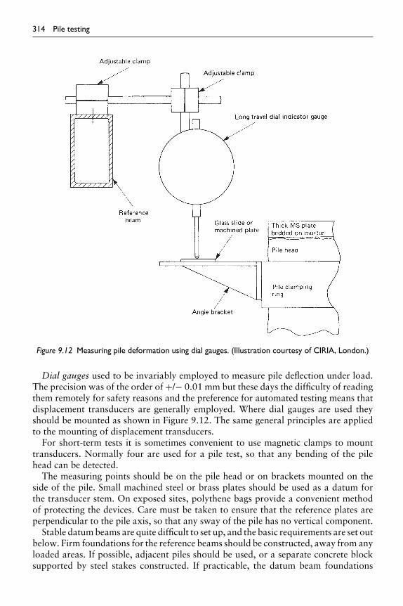
314 Pile testing
Figure 9.12 Measuring pile deformation using dial gauges. (Illustration courtesy of CIRIA, London.)
Dial gauges used to be invariably employed to measure pile deflection under load.The precision was of the order of +/− 0.01 mm but these days the difficulty of readingthem remotely for safety reasons and the preference for automated testing means thatdisplacement transducers are generally employed. Where dial gauges are used theyshould be mounted as shown in Figure 9.12. The same general principles are appliedto the mounting of displacement transducers.
For short-term tests it is sometimes convenient to use magnetic clamps to mounttransducers. Normally four are used for a pile test, so that any bending of the pilehead can be detected.
The measuring points should be on the pile head or on brackets mounted on theside of the pile. Small machined steel or brass plates should be used as a datum forthe transducer stem. On exposed sites, polythene bags provide a convenient methodof protecting the devices. Care must be taken to ensure that the reference plates areperpendicular to the pile axis, so that any sway of the pile has no vertical component.
Stable datum beams are quite difficult to set up, and the basic requirements are set outbelow. Firm foundations for the reference beams should be constructed, away from anyloaded areas. If possible, adjacent piles should be used, or a separate concrete blocksupported by steel stakes constructed. If practicable, the datum beam foundations

Pile testing 315
should be at least four pile diameters from the test pile. It is noted that a compromisemust frequently be made between a long beam prone to vibration and temperature-induced deflections, and a shorter beam with foundations in the zone of influence ofthe test pile or kentledge.
The reference beam should be a heavy steel section or a rectangular hollow sectiontube clamped at one end. The other end is free to slide, but should be restrained againstlateral and vertical movement (see Figure 9.13). Such a system will allow longitudinalmovement of the beam caused by changes in temperature. The beam should be shadedfrom direct sunlight, and in hot climates it may be necessary to carry out the test atnight when temperature fluctuations are less marked.
To check for gross errors in the observations or disturbance to the datum beams, itis good practice to carry out precise level checks of the test pile and datum beams atintervals throughout the test. If tension piles are being used to provide the reaction,these should also be levelled to check for undue movements.
The accuracy of any optical levelling system is poorer than that of displacementtransducers or dial gauges by a factor of at least 10. However the absolute accuracyof the system may be of a similar order, particularly in situations where it is difficultto establish a stable reference beam. Using optical methods it is difficult to arrange aconstant rate of penetration test or to check the cessation of movement under a load
Figure 9.13 Details of datum beam support. (Building Research Establishment: reproduced bypermission of the Controller, HMSO. Crown copyright.)

316 Pile testing
Pre-programmedData-Logger
Dis
plac
emen
tT
rans
duce
r
HydraulicPump
TestPile
Load
Cel
l H
ydra
ulic
Ram
MeasuredLoad Signal
Reaction
Load/UnloadSignal to
Hydraulic Pump
MeasuredDisplacement
Figure 9.14 Schematic diagram of basic method of computer control of a maintained load pile test.(Illustration courtesy of PMC Limited, Durham.)
increment owing to the coarseness of the least count. However, the optical system doespermit the instrument and reference point to be well outside the zone of disturbance.A precise levelling system is of suitable accuracy with a scale such that an overallaccuracy of ±0.2 mm is attainable.
Electrical load and displacement transducers allow automatic recording of the piletest data. However, care is required in setting up the equipment, particularly in respectof shielding them from adverse weather. Modern notebook computers incorporatingsuitable data acquisition software may be used to record all data, including load anddisplacement; indeed it is practicable to automate the whole of the test procedure,recognizing perhaps the need for human intervention in specific circumstances.

Pile testing 317
The degree of sophistication of the data-logging equipment provided depends tosome extent on the volume of data to be recorded and on the number of pilesto be tested. Some piling contractors and specialist pile testing companies such asPMC Limited have developed equipment, and the quality of the output can be sig-nificantly better than that achieved with conventional test methods. Specialized piletesting companies will use pre-programmed pile tests with automatic load mainte-nance and stage increases together with settlement recording and detection of cessationof pile movement. The basic elements of such a system are shown schematically inFigure 9.14.
To provide more information on the behaviour of the test pile, additional instru-mentation is occasionally deemed necessary. This type of instrumentation is describedin section 9.2.5.
9.2.3 Pile load test procedures
The pile loading test that is most commonly carried out is the maintained load testbut alternatively, the constant rate of penetration test is sometimes employed. Themaintained load test is convenient for testing end-bearing piles and for determiningthe load-settlement characteristics in clay soils. Usually, however, it is not as suitablefor determining the true ultimate capacity of a pile.
The constant rate of penetration test procedure is best suited to determining theultimate bearing capacity of a pile, as the method of testing is closely related to thetest procedures used to obtain the shear strength of the soil. In clay soils, rapid piletesting may approximate to undrained loading conditions, whilst a constant load forseveral days may be necessary to allow full dissipation of pore pressures.
9.2.3.1 Maintained load tests
The maintained load test requires careful specification of loading increments andperiods for which these increments are held constant. The ICE Specification for Pilingsets out a suitable minimum scheme (Table 9.2), and the ASTM Test DesignationD-1143 specifies a similar procedure. In addition, limits are placed on the rate ofmovement before the next load stage is added. The ICE Specification for Piling lim-its the rate of movement to 0.24 mm/h, provided the rate is decreasing, for pilehead displacements greater than 24 mm, but less than 0.1 mm/h for head displace-ments of less than 10 mm. Between these pile head displacement values, a rate ofless than 0.1% × pile head displacement/h is recommended. Some engineers pre-fer a limit of 0.1 mm/h, and a frequent requirement is to hold the load constantfor 24 h at design load. The ISO/DIS 22477-1 Draft document (2006) recommendsa cessation of movement criterion of 0.1 mm per 20 min and a time interval ofat least 60 min per loading step. It also permits a pre-load of 0.05Qmax to checkthe loading train and instrumentation, unloaded to a small residual value of theorder of 10 kN prior to starting the test proper. The particular details of the load-ing path followed are not of great significance, but it is important that the holdingtime at each load increment is the same so as to lead to the same degree of soilconsolidation.

318 Pile testing
Table 9.2 Suggested load increments and holding times
Load∗ Minimum time of holding load
25% DVL 30 min50% DVL 30 min75% DVL 30 min
100% DVL 1 h75% DVL 10 min50% DVL 10 min25% DVL 10 min0 1 h
100% DVL 6 h100% DVL + 25% SWL 1 h100% DVL + 50% SWL 6 h100% DVL + 25% SWL 10 min100% DVL 10 min75% DVL 10 min50% DVL 10 min25% DVL 10 min0 1 h
∗SWL denotes specified working load; DVL denotes design verification load.
To determine these slow rates of movement a sensitive settlement measuring systemis required. In granular soils or soft rocks the cessation of movement is easy to establish.However, in clay soils consolidation settlement will occur over an extended period.Plotting the results as the test proceeds is a useful way of resolving any ambiguities inthe results (see Figure 9.15).
The maintained load test may be used to test contract piles to check acceptancecriteria. Such piles are usually loaded to 100% of the design verification load (DVL)plus 50% of the specified working load to avoid overstressing the soil whilst stillproving an adequate reserve of strength in the pile-soil system. The use of the DVL wasintroduced to take into account items such as downdrag friction load, which will bein the reverse direction during a test to that which may exist under long-term loading,and the fact that piles on a site may not be tested from the same level as may pertainfor the piles in normal use. The ICE Specification also contains an extended proof loadprocedure which may be useful, particularly for piles bearing on cohesionless soil or onrock, and where further information may be desirable to verify design. On special testpiles that will not form part of the permanent works, loading can be increased to failure,enabling a check to be made on the design parameters (usually by the CRP method).
For particular projects special loading paths may be called for, for example, tosimulate repeated loading. Such loading paths may easily be arranged but carefulsupervision is a necessity. Short-period, cyclic or sinusoidal loading requires the useof sophisticated servo-controlled equipment.
9.2.3.2 Constant rate of penetration test
The constant rate of penetration (CRP) form of testing is confined to special test piles,and is usually carried out at the pre-contract stage (Whittaker and Cooke, 1961). Asthe name implies, the loading is strain controlled and a set rate of penetration of the

Figu
re9.
15T
ypic
alpi
lepr
oofl
oad
test
resu
lt.

320 Pile testing
pile load is specified. Rates of penetration between 0.5 and 2 mm/mm are commonlyused, the lower rate being used in clay soils.
Great care is required to maintain a steady rate of penetration, but this is difficultto achieve with manual pumping without some practice. If manual control is adoptedtime-penetration plots should be drawn as the test proceeds, so that deviations from therequired path are easily identified. For this type of testing it is much more satisfactoryto use a hydraulic power pact, and control the rate of penetration through softwarelinked to a displacement transducer. Control of the jack movement is achieved bymanual operation of the rate of oil flow. Fully automatic systems have been devisedbut are complex, and present difficulties in operation on site.
Loading of the CRP test should be continued to a deflection that goes to or beyondfailure of the pile. This may be, typically, until a constant load has been recorded oruntil the penetration is at least 10% of the pile diameter (see Figure 9.15).
For this test, large travel of the jack and deflection transducers should be allowed for.It may be necessary to reset the transducers during the test, or alternatively, machinedspacing blocks can be inserted under the gauge stems.
Once the equipment has been set up the test may be completed within an hour orso, and a rapid assessment of the ultimate capacity of the pile made. However, anexperienced team of three or four people is required to carry out the test efficiently.
Tension piles may be tested using a constant rate of uplift procedure, which is similarto the CRP test. The full tensile capacity of a pile is normally mobilized at a displace-ment of a few millimetres and the imposed rate of uplift should be correspondinglyreduced to say 0.1 to 0.3-mm per minute.
9.2.3.3 Recording the results
It is essential that all the relevant data are recorded and to this end it is useful touse a standard proforma (see Table 9.3). Similarly the load, settlement and time datashould be recorded clearly throughout the test. It is important that any problems orunexpected occurrences are reported in the test records, as this information is mostuseful when interpretation of the results is made.
It is customary to present load-time, settlement-time and load-settlement graphs ofthe results. It is important that these last two graphs are plotted during a maintainedloading procedure so that modifications to the test can be made if required.
Pile tests are relatively expensive and the results of such tests can have a considerableinfluence on the construction of the permanent works. It is therefore imperative thatan adequate number of qualified staff are available to set up and carry out the test withengineering supervision throughout the test period. In addition at least one technicianshould attend the tests, to control the hydraulic jack, etc. Similarly, interpretation ofthe results and preparation of a report on the test programme should not be stinted,and sufficient staff time should be allocated.
Special pile tests (including CRP tests), involving a higher level of instrumenta-tion generally involve a larger team to carry them out successfully. Setting up theinstrumentation should be carried out by experienced technicians or engineers. Stafftime involved in carrying such special pile tests can be considerable, and represents asignificant cost in the overall test programme.

Pile testing 321
Table 9.3 Essential information to accompany pile test sheets
Item Information needed
Dates Date pile was installed.Date of test.
Location Sufficient detail to permit the site to be located and also the position ofthe pile relative to the works. The pile number should always bestated.
Pile type Various categories of pile type are set out in Weltman and Little (1977)(undergoing revision).
Pile installation details If a bored pile (i.e. non-displacement), the depth of temporary casing,how much concrete, mix details, how placed (e.g. trémie or chuteinto dry bore), and any special circumstances, particularly regardinggroundwater. If driven (i.e. displacement), type of hammer, weight,drop, final set. The driving record should accompany pile test report.
Pile dimensions Nominal diameter (or section) weight per metre run as applicable. Sizeof underream, bulb, ‘wings’, etc. Length of the pile – include the entirepile length.
Installed level (driven)Concreted level(bored) Trimmedlevel and toe level
Give full data so that there is no doubt regarding the reduced level ofpile toe, the ground level at the time of the test and the level of the topof the pile either at the end of installation, after trimming or both(above or below ground level).
Orientation State whether vertical or raking (with degree of rake if applicable).Design Load of pile State Design Load or indicate on plot.Type of test set-up
and settlementmeasuring system
Whether kentledge or tension pile test. Leading plan dimensions of theset-up including reference system. Method of measuring settlement,subsidiary levelling of reference beams, temperature corrections.
Weather Brief comment on weather conditions and extremes of temperatureduring test.
Soil information It is not generally feasible to provide full soil information. If a reportexists, the name of the company who produced the report should begiven, together with a reference number. The position of relevant siteinvestigation boreholes should be given on the pile location plan.Summary logs of nearby boreholes with SPT N values and cohesionvalues alongside are useful. In some cases, a Bored Piling Contractorwill log the boring – such logs should be given with an indication oftheir source.
The reduced levels of boreholes must be given.
9.2.4 Interpretation of the results
A considerable amount of data may be computed from a pile test, and with moresophisticated instrumentation a greater understanding of the pile-soil interaction maybe achieved. As discussed in section 9.1, it is important that the designer is satisfiedthat the behaviour of an isolated test pile under relatively short-term loading stressesthe bearing stratum in a similar manner to the piles in the foundation. Interpretationof the pile test data may be carried out on several levels:
1 qualitative inspection of the load settlement curves;2 a check for compliance with load and deformation specifications; and

322 Pile testing
3 a back-analysis of the data to provide information on the soil stiffness and strengthcriteria.
9.2.4.1 Load settlement curves
Typical shapes of load settlement curves are given by Tomlinson (1977). In particularunusual load settlement curves should be thoroughly investigated as they may indicateunexpected geological problems, such as soft sensitive clay, defects in the pile shaft,or poor construction techniques.
From straightforward pile tests in which the load settlement characteristics of thehead of a pile are measured, there is as yet no satisfactory published method whichallows separation of the components of shaft friction or adhesion and end bearingwith a satisfactory degree of confidence. Randolph (1994) has discussed how the useof software based on load transfer curves for the shaft and base, and allowing for thecompressibility of the pile, may be used to fit the measured load-settlement response.In this way, estimates of the limiting shaft and base resistance may be made, togetherwith shear modulus values of the soil.
In the past it has generally been found that in order to study the division of loadbetween a pile shaft and base, it is necessary to install a system of strain gauges. Thiscan have the advantage of also providing guidance on the distribution of load alonga pile shaft and contributing to design knowledge, subject to adequate provision ofgauges. However, this requires considerable skill and care (see section 9.2.5).
9.2.4.2 Estimation of ultimate load
The ultimate load of a pile is usually not well defined; typical load-deformation curvesare shown in Figures 9.15 and 9.16. In practice an exact definition of the ultimate load
Figure 9.16 Results of a CRP test. (After Fellenius, 1980.)

Pile testing 323
is not all that important, provided an adequate factor of safety is clearly demonstrated.Two simple criteria which cover most situations are:
1 the load at which settlement continues to increase without further increase inload; and
2 the load causing a settlement of 10% of the pile diameter (base diameter). Thelatter limit is likely to give a low estimate of the ultimate load as it is unlikely thatgeneral yielding of the soil around the pile will have been initiated.
Other definitions of ultimate load are summarized by Tomlinson (1977), whileFellenius (1980) compares a number of methods of estimating the ultimate load. Unfor-tunately many of the proposed techniques are either empirical or are based on setdeformation criteria. Several of the methods are also sensitive to the shape of the load-deformation curve, and it is preferable to use a considerable number of load incrementsto define the shape clearly.
Two methods of estimating the ultimate pile load are shown in Figures 9.17 and9.18 after Chin (1970) and Brinch Hansen (1963). Chin’s method assumes the formof the load-deformation curve is hyperbolic and is an empirical method. However,it is useful in that if the results are plotted at the time of the test, deviations fromthe expected curve are easily seen and the test procedure can be checked. It mayin some cases be used to obtain an estimate of shaft or base load separately. BrinchHansen’s method is very simple to use, and in practice has been found to give consistentresults.
Figure 9.17 Chin’s method for estimation of ultimate load. (After Chin, 1970.)

324 Pile testing
Figure 9.18 Brinch Hansen’s 90% method. (After Brinch Hansen, 1963.)
9.2.4.3 Settlement criteria
Settlement limits at design load or 1.5 times the design load are frequently specified,on the basis of previous experience (e.g. a maximum of 10 mm settlement at designload). Such specified settlement limits should be realistic and take into account thelikely elastic compression of the pile shaft. It is sometimes difficult to discern how thespecified criteria for a single pile will relate to the behaviour of the pile group. A muchmore satisfactory approach is to use the pile test data to assess the stiffness of thesoil mass using the solutions outlined in Chapter 4. This data may then be applied tothe pile group to estimate the overall performance of the foundation under the designloads. This approach is particularly useful in the case of piled structures carrying highlateral loads, as the stiffness of the soil is difficult to establish and may well be affectedby the piling operation. However, a single pile will not stress the ground to a depthcomparable to the depth stressed by a pile group and some extrapolation of the resultswill generally be required.
Contract test piles are frequently loaded to 1.5 times the design load as a perfor-mance test. Such a load test should avoid significant permanent deformations in thesurrounding soil and the alteration of the load-deformation characteristics of the pileso tested. As these tests are not taken to failure it is sometimes difficult to assess theacceptability of the pile. In such situations it is useful to estimate the likely elasticsettlement of the pile and then to draw up a realistic and unambiguous specificationfor test pile performance. Such an assessment can quickly be made by summing thecompression of the shaft and settlement of the toe. For such calculations it is nec-essary to estimate the shaft adhesion from the site investigation data. In practice,

Pile testing 325
by making appropriate assumptions, upper and lower limits to the settlement may beestablished.
9.2.5 Special pile instrumentation
To obtain a greater understanding of the pile-soil behaviour, it is sometimes desirableto install further instrumentation in the test piles. It should be stressed that such instru-mentation demands significant investment in cost and manpower, if reliable results areto be obtained. In general, for site use simple robust equipment should be used to obtainthe necessary information, albeit with some loss of accuracy. There are several casehistories reported in the literature (Reese et al., 1975) for fully instrumented piles;these are really research projects and are not considered in detail here.
9.2.5.1 Distribution of load
Special high-capacity load cells were originally developed by the BRE (Whitaker,1963). The cells are steel multi-column devices, the strain being measured by elec-tric resistance strain gauges (Figure 9.19). Simpler modular load cell systems havesubsequently been developed by the BRE (Price and Wardle, 1983; Price et al., 2004).The load transducer comprises a steel tube fitted with an internal vibrating wire gauge.Load is transferred to the transducer, across a discontinuity in the pile formed by asoft rubber sheet, by steel bars bonded into the concrete. Load cells of the required
Figure 9.19 BRE pile load cells. (Building Research Establishment: reproduced by permission of theController, HMSO. Crown copyright.)

326 Pile testing
Figure 9.20 Modular pile load cell. (Building Research Establishment: reproduced by permission of theController, HMSO. Crown copyright.)
desired capacity may be made using an array of transducers (Figure 9.20). These cellsare robust and have the advantage that the structural collapse of the pile cannot occur,following corrosion of the transducer elements.
The measurement of base load in a driven pile is not as easy so easily accomplishedas for cast-in-place piles. Normally special load cells occupying the full cross-sectionof the pile are unsuitable, although with some segmental piles the load cell can beinserted at the joints. A more satisfactory technique is to cast vibrating wire straingauges into the pile (Figure 9.21). The gauge installation may be calibrated by load-testing a short length of pile. Stability of the system is reasonable for short-termloading, and the gauges should not be damaged by driving. Long-term load mea-surement requires correction for creep strains in the concrete, and a consequentuncertainty in the estimation of the pile load. Several gauges should be installed atany level to allow for inevitable losses. The cables should be continuous and may beled out through a duct below the head of the pile. If a segmental pile system is beingused, forming waterproof cable joints at each segment junction can be difficult toachieve.
A similar system may be used for bored piles (O’Riordan, 1982), but unfortunatelythe sensitivity of the system is reduced owing to lower stresses in the concrete. Variationof the modulus of the concrete will also add to the uncertainty in relating strain toload. Protecting gauges during concreting is difficult, and a considerable number ofgauges may be damaged. Successful installations of vibrating wire strain gauges aremuch easier to achieve at the head of bored piles, where concreting can be carefullymonitored.

Pile testing 327
Figure 9.21 Vibrating wire strain gauge installation. (Photograph courtesy of PMC Limited, Durham.)
An alternative, lower cost method to separate shaft and base resistance of a cast-in-place pile is to form a compressible base to the shaft. Although possessing a smallbut finite compressive strength, high-density polystyrene has been successfully used,and the pile is deformed sufficiently to compress the packing in the later stages of thetest to mobilize the base resistance. Water-filled rubber bags have been used to similareffect. A similar technique is to test two piles, one constructed with a void at the base.
Steel piles may be instrumented using vibrating wire or wire resistance strain gauges.With the latter system, the sealed gauges which can be welded to the steel are tobe preferred, and waterproof cabling needs to be used. The strain gauges effectivelyturn the steel pile into a load measuring column and computation of the pile load isstraightforward. With tubular piles the gauges may be fixed to the inside and sealedin. Further mechanical protection is not necessary except to restrain the cables duringdriving. With H-section piles the strain gauges and cables need to be protected withsteel ducts (a difficult operation which can seriously affect the stiffness of the pile andcause stability problems during driving).
In general, wire resistance strain gauges should be used only in situations where theycan be sealed into a dry compartment. With this system, small electrical voltages aremeasured and it is therefore necessary that cable earth leakage is small. Similarly, thereadout unit needs to be set up in a dry atmosphere, not an easy thing to arrange on acivil engineering site. If the dynamic response of piles to driving is to be investigated,this type of gauge is one of the few suitable systems.
9.2.5.2 Deformation measurement
Axial deformation of large-diameter piles may be measured using a simple rod exten-someter (Figure 9.22). Such extensometers should be free to move in the enclosingtubes, and care should be taken to exclude debris. Using the information providedby these devices a crude estimate of shaft adhesion and base resistance may be made.Similarly, magnetic ring extensometers may be cast into the pile.
Gross lateral deformation of piles may be measured by incorporating inclinometertubes into the pile and surveying these with a suitable instrument. The computed

328 Pile testing
Figure 9.22 Typical pile test using rod extensometers.
profile will be accurate to a few tens of millimetres, unfortunately not sufficientlyaccurate for bending stresses to be estimated. Strain gauges may be used in steelpiling to determine the variation of bending strain with depth and hence to com-pute stresses and deformations. Many sets of gauges are required to perform thisreliably, and such installations are used only for research purposes (Reese et al.,1975).
In lateral pile load tests it is desirable to measure rotation of the pile head. Thismay be accomplished by using a sensitive spirit level mounted on the pile, or by usingan electro-level. Such observations are also valuable if groups of piles are tested todetermine the global stiffness of the group.
Lateral deformations may be measured using a datum beam and dial gauges. Thesemeasurements suffer the same problems as for vertical measurements (section 9.2.2.3).For long-term observations on pile groups, optical methods are to be preferred. Suitabletargets are shown in Figure 9.23. A single second theodolite fitted with a parallel platemicrometer may be used for the observations. An accuracy of about ±0.2 mm maybe achieved using this system over a long period of time. However, reliable, stabledatum marks are a necessity and these may be difficult to establish, especially in areasunderlain by thick alluvial deposits. Geodetic levelling techniques may be used toobserve vertical deformation to a similar order of accuracy. The absolute accuracy ofsuch level surveys is again dependent on the establishment of a reliable, stable datum(Cheney, 1973).

Figu
re9.
23Su
rvey
targ
ets.
Not
es1
mat
eria
lsta
inle
ssst
eel;
2bu
llsey
eto
beta
rget
ofco
ncen
tric
groo
ves
1m
mw
ide
arou
nd1
mm
drill
edce
ntre
poin
t.T
heta
rget
tobe
the
end
ofst
anda
rdso
cket
for
BRE
type
stat
ion.

330 Pile testing
Osterbergcell(s)
Tell-talerod for displacement
measurements
Reference beam
Level of cell judged togive similar pile resistance
above and below cell
Figure 9.24 Schematic diagram of Osterberg cell method for pile load testing.
−60
Displacement (mm)
Load (MN)
Upper section
Base section
Combined(rigid pile)
Combined(with pile
compression)
A
A
A
B
B
B
0
10
30
40
50
A
B
00
60
−40 −20 0 20 40
Figure 9.25 Example load–displacement responses from single-cell Osterberg test.
9.2.6 Other forms of pile test
9.2.6.1 Osterberg cell
A novel method for testing large diameter bored piles was introduced in the 1980s byDr Osterberg (Osterberg, 1989). The method comprises hydraulically operated flat-jacks, referred to as ‘Osterberg cells’, which are built into the pile during construction,and are used to load the top and bottom section of the pile against each other (seeFigure 9.24). In this way, the pile resistance may be proven to (approximately) twicethe highest load applied by the jacks, which in turn is limited by the lower of the

Pile testing 331
capacities of pile sections above and below the jack. The jack is positioned at a levelwhere the shaft capacity of the pile above the jacks is approximately equal to thecombined shaft and base capacity below the jacks.
The expansion of the jack is measured through the volume of oil pumped and alsoby independent transducers that span across the jack. Tell-tale rods built into the pileallow determination of the upward movement of the top of the jack, and hence alsothe downward movement of the bottom. A more sophisticated arrangement of jacksis possible, for example, by installing two levels, which allows an intermediate lengthof pile shaft to be failed independently, thus giving a direct measurement of shaftfriction. An application using such a system of two levels of jacks has been describedby Randolph (2003).
For a single level of jacks, as shown in Figure 9.23, either the upper (shaft) or lower(base) section of the pile will reach failure first, and typical results may be as indicatedin Figure 9.26. In the standard method for interpreting an Osterberg cell pile test(assuming a single level of jacks), the load–displacement plots of the separate upperand lower sections of the pile are first plotted. Ignoring any compression of the pile,the total load–displacement response at the pile head is then estimated by summingthe separate loads mobilized in each section of the pile at equal displacements. This isillustrated above for typical points A (4 mm displacement) and B (7 mm displacement),where the total pile resistance is summed and plotted at the give displacement to givethe combined (rigid pile) curve.
An improved method makes approximate allowance for the compressibility of theupper section of the pile. For each displacement, the average load that would be mobi-lized in the upper section is first estimated (the simplest approach being to take theload from the lower section plus half the load from the upper section), and hence thecompression of the upper section of the pile is estimated. This compression is addedto the initial displacement for which the loads were evaluated. Considering point A,at a displacement of 4 mm, the upper and lower section loads are 19.5 and 23 MN,respectively. The average load that would then occur in the upper section for thoseconditions is therefore:
Paverage ∼ 0.5(Plower + (Pupper + Plower) = Plower + 0.5Pupper = 32.75MN
The estimated compression of the upper section is then w = PaverageL/EA =18.9 mm (taking L = 85 m, EA = 147 MN). The true pile head displacement is there-fore the sum of the original displacement, 4 mm, and the pile compression, 18.9 mm,giving a total of 22.9 mm. The corrected curve is shown for comparison with theuncorrected (rigid pile) case. The limitation of this approach is that the actual displace-ments in the upper section of the pile are much larger than the original displacement,and thus the load mobilized will be higher. A better approach is to undertake a fullload transfer model of each section separately, and then analyze the complete pilesubsequently.
While the Osterberg cell method of pile testing has some limitations, in particulardue to the different direction of loading of the upper part of the pile, and problemsassociated with creating a gap in the vicinity of the loading jacks, the system has thepotential for testing cast in situ piles of extremely high capacity.

Figu
re9.
26T
ensi
onpi
lete
st.

Pile testing 333
9.2.6.2 Tension pile tests
This test method is similar to compression testing of piles, and maintained load orconstant rate of uplift procedures may be used. The reaction system may be provided bya strong-back resting on adjacent piles or spread foundations. Such a test arrangementis shown diagrammatically in Figure 9.26. Two jacking points on either side of the pileare used to avoid bending the test pile, and care is required to load the jacks evenly.Some cracking of reinforced concrete tension piles is to be expected if loads are highunless the reinforcement is debonded except in the bottom section of pile.
9.2.6.3 Lateral load tests
For structures carrying major lateral loads it is desirable to carry out lateral loadtests to confirm the design assumptions. The applied loads are relatively small andit is convenient to use an adjoining pile as a reaction (Figure 9.27). Provision mustbe made for a stable datum for deformation measurement as for vertical tests. Iftwo identical piles are being tested it may be more convenient to measure the rela-tive movement between them using an extensometer. To increase the reliability of theback-analysis it is worthwhile measuring the rotation of the pile head. Foundationsare frequently subjected to lateral, vertical and moment loading. It is usually not pos-sible to arrange for the pile test to mimic such combined loads. Instead, applicationof a lateral load near to the ground-level existing at the time is often chosen for suchtests. Similarly it is difficult to simulate fixed head conditions. Data from such a sim-plified load test may be analyzed using the principles outlined in Chapter 4, and thecomputed soil parameters may then be used to predict the response of the pile or pilegroup to a more complicated loading regime. Bearing in mind the process of anal-ysis that has to be used in such circumstances, where possible the testing should be
Figure 9.27 Lateral pile load test. (Photograph courtesy of Westpile Ltd., Uxbridge.)

334 Pile testing
planned and loading levels arranged to give the minimum degree of extrapolation inthe analysis.
9.3 Dynamic testing of piles
The use of dynamic testing methods for estimating the ultimate capacity and integrityof piles is now widespread. Assessment of pile capacity during driving has been under-taken routinely by the use of empirical driving formulae such as those discussed insection 4.1.4. There are many limitations to such formulae, particularly in respectof uncertainties in the proportion of the available driving energy that is transmit-ted to the pile. The accuracy of dynamic methods of estimating pile capacity has beenimproved significantly using modern instrumentation and fast data acquisition systemsthat allow measurement of the dynamic force and velocity waves in the pile duringdriving. The data may be analyzed at different levels of sophistication, as described inthe following sections, to give estimates of the static pile capacity at time of driving.Similar techniques, with lower energy input, may be used to assess the integrity of piles(particularly cast-in-situ piles), as discussed in Chapter 8.
9.3.1 Wave equation analysis
The propagation of driving energy along a pile, allowing for interaction with thesurrounding soil, may be analyzed with sufficient accuracy using a ‘one-dimensional’idealization. In this idealization, only vertical (strictly speaking ‘axial’), displacementof the pile is considered, and the governing differential equation is
(AE)p∂2w∂z2 = (Aρ)p
∂2w∂t2 − f (9.1)
or
∂2w∂z2 = 1
c2
∂2w∂t2 − f
(AE)p(9.2)
where (AE)p is the cross-sectional stiffness of the pile.(Aρ)p is the mass per unit length of the pile.
c is the wave propagation speed in the pile (= √E/ρ).
w is the vertical displacement of the pile.z is the distance down the pile.t is the time variable.f is the mobilized soil resistance per unit length of pile.
Historically, this equation has been implemented using finite difference or finite ele-ment techniques, with the pile being modelled as a discrete assembly of mass pointsinterconnected by springs. This model, originating in the work of Smith (1960), formsthe basis of a range of computer programs for studying pile drivability.

Pile testing 335
Equation (9.2) may also be solved numerically by using the characteristic solutions,which are of the form
w = g(z − ct) + h(x + ct) (9.3)
where g and h are unspecified functions which represent downward (increasing z) andupward travelling waves respectively. Taking downward displacement and compres-sive strain and stress as positive, the force, F, and particle velocity, v, in the pile aregiven by
F = − (AE)p∂w∂z
= − (AE)p(g′ + h′) (9.4)
v = ∂w∂t
= −c(g′ − h′) (9.5)
where the prime denotes the derivative of the function with respect to its argument.The velocity and force can each be considered as made up of two components, one
due to the downward travelling wave (represented by the function g) and one due tothe upward travelling wave (represented by the function h).Using subscripts d and ufor these two components, the velocity is
v = vd + vu = −cg′ + ch′ (9.6)
The force F is similarly expressed as:
F = Fd + Fa = −(AE)pg′ − (AE)ph′ = Z(vd − vu) (9.7)
where Z = (AE)p/c and is referred to as the pile impedance. [Note, some authors havereferred to the pile impedance as Z = E/c, relating axial stress and velocity rather thanforce and velocity. The more common definition of pile impedance as Z = (AE)p/cwill be adopted here.]
The relationships given above may be used to model the passage of waves downand up piles of varying cross-section, allowing for interaction with the surroundingsoil. It is helpful to consider the pile as being made up of a number of elements, eachof length z, with the soil resistance acting at nodes at the mid-point of each element(see Figure 9.28). Numerical implementation of the characteristic solutions involvestracing the passage of the downward and upward travelling waves from one elementinterface to the next. The time increment, t, is chosen such that each wave travelsacross one element in the time increment (giving t = z/c).
Between nodes i and i +1, the soil resistance may be taken as Ti, the value of whichwill depend on the local soil displacement and velocity (see later). Taking Ti as positivewhen acting upwards on the pile (that is, with the soil resisting downward motion ofthe pile), the soil resistance will lead to upward and downward waves of magnitude
Fu = −Fd = Ti/2 (9.8)
These waves will lead to modification of the waves propagating up and down the pile.

336 Pile testing
Figure 9.28 Idealization of pile as elastic rod with soil interaction at discrete nodes.
The procedure for calculating new values of wave velocities at each node is shownschematically in Figure 9.29. Thus, consider the downward and upward waves atnodes i − 1 and i + 1, at time t. The new downward travelling wave at node i at timet +t is given by
(vd)i[t +t] = (vd)i−1[t]− Ti−1[t +t]/(2Z) (9.9)
while the new upward travelling wave fractionally above node i is
(vu)i[t +t] = (vu)i−1[t]− Ti−1[t +t]/(2Z) (9.10)
At the base of the pile, the downward travelling wave will be reflected, with themagnitude of the reflected wave dependent on the base resistance, Qb, offered by thesoil. The axial force in the pile must balance the base resistance, which leads to anexpression for the reflected (upward travelling) wave velocity of
(vu)n[t +t] = (vu)n[t +t]− Qb[t +t]/Z (9.11)
The base velocity (the nth node) is
vn = 2vu + Qb/Z = 2vd − Qb/Z (9.12)
where all quantities refer to time t +t.

Pile testing 337
Figure 9.29 Modification of downward and upward waves due to soil interaction. (After Middendorpand van Weele, 1986.)
For a force Fd arriving at the pile tip, equation (9.11) implies a reflected force of
Fu = −Zvu = Qb − Fd (9.13)
The magnitude of the reflected wave thus varies from −Fd,where the tip resistance iszero, to Fd,where the base velocity is zero and the base resistance is twice the magnitudeof the incident force (see equation (9.12).
It should be noted that the characteristic solutions of the wave equation may be usedto model the pile hammer assembly as well as the pile, in order to perform drivabilitystudies. The geometry and mass density of each component (ram, cushion, helmet) ismatched, and the ram is given an initial velocity to model the impact. As discussedby Middendorp and van Weele (1986), a relatively crude model of the hammer willgenerally suffice to give adequate results. Analytical solutions for hammer impact arealso available (Take et al., 1999).
9.3.1.1 Dynamic soil model along pile shaft
Accurate prediction of the performance of piles during driving requires modelling ofthe dynamic response of the soil around (and, for open-ended pipe piles, inside) thepile, both along the shaft and at the base. Following traditional approaches for theanalysis of machine foundations, the soil response can generally be represented by acombination of a spring and dashpot. However, it is also necessary to consider limitingvalues of soil resistance where, along the shaft, the pile will slip past the soil and, atthe tip, the pile will penetrate the soil plastically.
In the original work of Smith (1960), which still forms the basis of many commer-cially available pile driving programs, the soil response was modelled conceptually as a

338 Pile testing
(a) (b)
Figure 9.30 Soil models for dynamic response: (a) original soil model of Smith, 1960; (b) soil model ofRandolph and Simons, 1986.
spring and plastic slider, in parallel with a dashpot (Figure 9.30(a)). For such a model,the soil resistance (per unit length of pile) may be written as
T = Ts + Td = Kw + Cv (9.14)
where the subscripts s and d refer to static and dynamic resistances, respectively, andv is the local velocity. Smith (1960) simplified this response to
T = wQ
Tmax (1 + Jv) (9.15)
subject to the term outside the bracket being limited to Tmax, the limiting static resis-tance. The parameters Q and J are referred to as the ‘quake’ (the pile displacement forfull mobilization of the static resistance Tmax) and ‘damping constant’ (with units ofs/m or equivalent). Typical values for Q and J recommended by Smith (1960) are 2 to3 mm, and 0.1 to 0.2 s/m respectively.
A more sophisticated model, based on elastodynamic theory, has been introduced byRandolph and Simons (1986) (see also Randolph (1990)). As shown in Figure 9.30, themodel separates out inertial or radiation damping due to the surrounding soil (whichoperates prior to slip between pile and soil), from viscous damping that may lead to anincrease in the limiting resistance, Tmax. The spring constant, K, and inertial dashpotconstant, C, are related to the shear modulus, G, and mass density, ps of the soil, by
K = 2.75G (9.16)
C = πdGVs
= πd√
Gρs (9.17)
where Vs is the shear wave velocity in the soil and d is the pile diameter.

Pile testing 339
Any viscous enhancement of the static resistance is modelled by taking the limitingdynamic resistance as
Td = Tmax[1 +α(v/v0)β
](9.18)
where v0 = 1 m/s and v is the relative velocity between the pile and the soil. It ismore correct to use the relative velocity in this equation, rather than the absolute pilevelocity, since the main viscous effects will be confined to the zone of high shear strainrate immediately adjacent to the pile. Typical values for the viscous parameters maybe taken as β = 0.2 (following Gibson and Coyle (1968) and Litkouhi and Poskitt(1980)) and α in the range 0 for dry sand, up to 1 or possibly higher for clay coils.
9.3.1.2 Dynamic soil model at pile base
Suitable models for the dynamic response at the pile base have been discussed in detailby Deeks and Randolph (1995), building on the analogue model first proposed byLysmer and Richart (1966). The basic model is very similar to that in Figure 9.30(b),but with the addition of a lumped mass at the pile node. For undrained conditions(ν = 0.5), as appropriate for pile driving, the stiffness, damping and mass parametersare given by (Deeks and Randolph, 1995)
K = 2Gd1 − ν
(9.19)
C = 0.85d2
1 − ν
GVs
(9.20)
m = 0.16d3ρs (9.21)
where ρs is the density of the soil beneath the pile tip.In practice, the lumped mass makes little difference, as it represents only 60% of
the volume of a hemisphere (of diameter, d) of soil at the pile tip. Comparing themagnitudes of the stiffness and inertial dashpot terms for the pile shaft and base, itmay be seen that the relative contribution from the dashpot at the pile base is onlyabout 40% of that along the shaft. However, this still represents a significant increasein stiffness relative to static loading.
Further discussion and comparison of the original Smith formulations for dynamicpile-soil interaction, and those described above, may be found in Randolph (2000),where application to open-ended driven piles is also considered.
9.3.2 Dynamic stress wave data
Wave equation analysis, as described in the previous section, is used in determining thedrivability of piles, using commercially available software such as the WEAP family(Goble and Rausche, 1976, 1986; Rausche et al., 1988). However, a potentially moresignificant application lies in the interpretation of dynamic stress wave data measuredduring pile driving. The data form the basis of a dynamic pile test, which may obviatethe need for more costly static loading tests.

340 Pile testing
Measurement of stress wave data is achieved by the use of light-weight strain cellsand accelerometers that are attached to the pile a few diameters below the hammer.A description of the instrumentation, and one of the most widely used monitoringsystems (the Pile Driving Analyzer, or PDA) has been given by Likins (1984).
The first stage of interpretation of stress wave data is performed in real-time in thefield by equipment such as the Pile Driving Analyzer. Strain and acceleration data areprocessed, generally through electronic hardware, to obtain force and velocity data.From these data, various parameters may be derived. Thus, integration with time of theproduct of force and velocity up to the time at which the product becomes negativeleads to a figure for the maximum energy transmitted to the pile. This allows theoverall operating efficiency of the hammer to be assessed in terms of its rated energy.If additional information is available on the ram velocity at impact, then the energylosses may be subdivided into mechanical losses in the hammer, and losses in theimpact process due to inelasticity and bounce of the components.
In traditional pile driving formulae, one of the largest sources of error in esti-mating the overall pile capacity is uncertainty in the energy transmitted to the pile.Measurement of the actually transmitted energy allows use of simple pile driving for-mulae with increased confidence. Such formulae provide a means whereby informationobtained on instrumented piles may be extrapolated in order to assess the qualityof uninstrumented piles driven on the same site. Of course, for piles where stresswave data are obtained, more sophisticated techniques may be used to assess the pilecapacity.
The relationships presented in section 9.3.1 allow the dynamic and static soil resis-tance to be estimated from the stress wave data. Equation (9.8) implies that, as thestress wave travels down the pile, the magnitude of the force will decrease by halfthe total (dynamic plus static) shaft resistance, T. Thus, at the bottom of the pile, thedownward travelling force is
Fd = Fd0 − T/2 (9.22)
where Fd0 is the original value at the pile head. Similarly, equation (9.13) may be usedto obtain the upward travelling force, after reflection at the pile tip as
Fu = Qb − Fd = Qb + T/2 − Fd0 (9.23)
On the way back up the pile, provided the particle velocity at each position is stilldownwards, implying upward forces from the soil on the pile, the upward travellingwave will be augmented by half the shaft resistance, to give a final return wave of
Fur = Qb + T − Fd0 (9.24)
where the subscript r refers to the return (upward travelling) wave at a time 2l/c laterthan the time at which the value of Fd0 was obtained (l being the length of pile belowthe instrumentation point). The total dynamic pile capacity is then
R = Qb + T = Fd0 + Fur (9.25)

Pile testing 341
Equations (9.6) and (9.7) may be used to derive the upward and downwardcomponents of force from the net force and particle velocity at the instrumentationlevel, so that equation (9.25) may be re-written:
R = 0.5(F0 + Zv0) + 0.5(Fr − Zvr) (9.26)
where subscripts 0 and r refer to times t0 (generally close to the peak transmittedforce) and tr = t0 + 2l/c, respectively. This equation is the basis for estimating thetotal dynamic pile capacity directly from the stress wave measurements. A search maybe made for the value of to which gives the largest value of capacity.
9.3.2.1 Case method of analysis
Since the dynamic capacity will be greater than the current static capacity, a simplemethod is needed to estimate the static capacity in the field, without the need for a fullnumerical analysis of the pile. In the Case approach, which has gained widespreadacceptance, this estimate is made on the basis that all the dynamic enhancementof capacity occurs at the pile tip, with a dynamic component of resistance that isproportional to the pile tip velocity, vb. Thus the dynamic tip resistance is taken as
Qd = jcZvb (9.27)
where jc is the Case damping coefficient (Table 9.4). These simplifying assumptionslead to an expression for the static pile capacity, Rs
Rs = 0.5(1 − jc)(F0 + Zv0) + 0.5(1 + jc)(Fr − Zvr) (9.28)
The assumptions regarding the dynamic soil resistance are clearly an oversimplifica-tion, and the deduced static pile capacity can be very sensitive to the value adopted forthe damping parameter, jc. However, the above expression can provide useful guid-ance on the static pile capacity where it is possible to calibrate the parameter jc fora particular site. Where no static load tests are carried out, guidelines for jc as givenbelow may be adopted (Rausche et al., 1985).
Figure 9.31 shows example stress wave data, for a 300-mm square concrete piledriven with a 6-tonne hammer. In the early part of the blow, before any reflectionsfrom the soil resistance arrive at the instrumentation point, the force and velocity aredirectly proportional (F = Zv) since only a downward travelling wave component ispresent. As reflections from the soil arrive, the force curve separates from the velocity
Table 9.4 Suggested values for case damping coefficient
Soil type in bearing strata Suggested range of jc Correlation value of jc
Sand 0.05–0.20 0.05Silty sand/sandy silt 0.15–0.30 0.15Silt 0.20–0.45 0.30Silty clay/clayey silt 0.40–0.70 0.55Clay 0.60–1.10 1.10

342 Pile testing
Figure 9.31 Examples of stress wave data.
curve, with the separation showing the magnitude of the shaft resistance. At a time 2l/cafter impact (where l is the length of pile below the instrumentation point), reflectionfrom the pile tip occurs, and the forms of the force and velocity curves change. In thisparticular example (taken from a re-drive), little of the blow reaches the pile tip, andthe reflection from the base is minimal.
Implementation of equation (9.28) to give the Case estimate of pile capacity is shownin the latter part of the blow (after the return wave arrives back at the instrumentationpoint). While the total dynamic resistance (using jc = 0) reaches a peak of 2.67 MN,the use of jc = 0.75 gives an estimate of the maximum ‘static’ resistance of about1.73 MN.
9.3.2.2 Detailed matching of stress wove data
The Case formula (equation (9.28)) offers only an approximate estimate of pile capac-ity, and a more reliable estimate requires detailed matching of the stress wave data.This process is an iterative one, where the soil parameters for each element down thepile are varied until an acceptable fit is obtained between measurements and computedresults. In order to avoid uncertainties in modelling the hammer, either the measuredforce signal or the measured velocity signal is used as an upper boundary conditionin the computer model. The fit is then obtained in terms of the other variable. Theiterative process, with examples of the effect of varying different parameters, has beendescribed by Goble et al. (1980).
It is possible to automate the matching process, with the computer optimizing thesoil parameters in order to minimize some measure of the difference between mea-sured and computed response (Dolwin and Poskitt, 1982). However, it has been foundthat computation time can become excessive, particularly for long piles, unless thesearch zone for each parameter is restricted by operator intervention. It is rather more

Pile testing 343
straightforward to carry out the matching process manually. Experience soon enablesassessment of where values of soil resistance, damping or stiffness need to be adjustedin order to achieve an improved fit. A satisfactory fit may generally be achieved after5–10 iterations of adjusting the parameters and re-computing the response.
Limitations in the soil models used for pile driving analysis entail that the computersimulation will not exactly match the real situation. A consequence is that the finaldistribution of soil parameters should not be considered as unique, but rather as a bestfit obtained by one particular operator. Generally, the total static resistance computedwill show little variation provided a reasonable fit is obtained. However, the distribu-tion of resistance down the pile, and the proportion of the resistance at the pile base,may show considerable variation (Middendorp and van Weele, 1986).
An interesting investigation of operator dependence in the analysis of stress wavemeasurements has been reported by Fellenius (1988). Eighteen operators were givenfour sets of stress wave data to analyze, covering a range of pile types and soil con-ditions. One of the sets of data was from a re-drive of a pile that was subjected to astatic load test the following day. All the operators were using the same computer pro-gram, CAPWAP, which is one of the most widely utilized programs for such analyses,originating from the work of Goble and his co-workers (Goble and Rausche, 1979).
The study by Fellenius shows a good measure of agreement among the participantsin predicting the static pile resistance, with the coefficient of variation being under10% for three out of the four cases considered. For the one pile that was subjected toa static load test, the predictions spanned the measured static capacity.
An example of matching stress wave data is shown in Figure 9.31. The measuredforce has been used as input data, and measured and computed velocities are compared.The agreement is reasonably good. The fit has been obtained for a static shaft capacityof 1.78 MN, and assumed base capacity of 2.24 MN (giving 4.02 MN total capacity).However, the blow was not sufficient to mobilize the full base resistance. Analysisof the data showed a residual force at the pile base of 1.17 MN, and a maximumbase resistance during the blow of 1.50 kN. The minimum static pile capacity then liesbetween 1.78 + 1.17 = 2.95 MN, and 1.78 + 1.50 = 3.28 MN. In this case, withoutthe use of a heavier hammer, it is not possible to be more specific concerning theultimate capacity of the pile. Note, however, that the minimum pile capacity exceedsthe simple Case estimate, due to partial rebound of the pile during the return passageof the stress wave.
9.3.3 General comments
There are a number of different systems available commercially to undertake dynamicpile monitoring and interpretation. Probably the two most widely used are (1) the PileDriving Analyzer and CAPWAP program from Pile Dynamics Inc., USA, and (2) theTNO equipment (Figure 9.32) and TNO-WAVF program, from the Institute TNO forBuilding Materials and Building Structures, Holland.
Regardless of which system is used, there are a number of intrinsic limitations inassessing the static pile capacity from dynamic data:
1 The capacity of a driven pile generally increases with time following installation.This phenomenon, referred to as ‘set-up’, is generally attributed to dissipation

344 Pile testing
Figure 9.32 The TNO dynamic pile test equipment. (Photograph courtesy of Institute TNO, Delft.)
of excess pore pressures generated during installation. Case studies have shownthat, particularly in soft cohesive soil, the pile capacity may increase by a fac-tor of 4 to 5 following installation, over a time period of several weeks ormonths, depending on the consolidation characteristics of the soil and the pilediameter (Randolph et al., 1979). Where the pile capacity is to be estimatedfrom dynamic measurements, it is necessary to allow for such set-up. Thismay be achieved by ‘re-striking’ the pile after an appropriate time delay. It isimportant to ensure that the full pile capacity is mobilized in such a re-strikewithin the first few blows, so as not to reduce the long-term performance ofthe pile.
2 One of the major pitfalls to be avoided is trying to estimate the capacity fromhammer blows of insufficient energy to fail the pile. This is quite common duringre-drive tests and, in such cases, analysis of the data will only yield an estimate ofthe maximum static resistance mobilized during that blow.
3 Use of the Case formula to estimate the static capacity of the pile is notrecommended without a full numerical matching of the stress wave data as cor-roboration. Even where this has been done, and a reasonable estimate of dampingparameter, jc, is available, care should be taken to ensure that the conditionsassumed in deriving the relationship are met in practice. Two particular condi-tions are (a) that there are no major changes in cross-section (or impedance) of thepile along its length, and (b) that the pile velocity remains positive (downwards)over the major part of the return time of the stress wave. In many case, the lattercondition is not fulfilled, and the Case formula will underpredict the pile capac-ity. A correction may be made, taking account of the proportion of pile that wasrebounding during the return passage of the stress wave, and using the earlier partof the blow to estimate the soil resistance in that region.
4 The two main causes of differences between static and dynamic performance ofthe pile are (a) viscous damping and (b) inertial damping. The dynamic shaftcapacity of a pile may exceed the static capacity by a factor of 2 or more, due to

Pile testing 345
viscous effects. Similarly, the dynamic base capacity may exceed the static capacitysignificantly due to viscous effects. In both cases, differences between dynamic andstatic capacity are greater in soft cohesive soil, than in stiffer or coarser material.Allowance for damping is made by appropriate choice of damping parametersin the dynamic analysis. However, the deduced static capacity is relatively sen-sitive to the choice of damping constant, and it is clear that further research isneeded in order to provide better guidance on damping parameters for differ-ent soil types. It is strongly recommended that whenever possible at least onestatic load test be performed on a given site in order to calibrate the dynamicanalyses.
5 One area which has received insufficient attention is the different response ofH-section piles and open-ended pipe piles under dynamic and static conditions.It may be shown that both types of pile tend to drive in an ‘unplugged’ condition,with soil moving up the inside of the pipe, or filling the space between the flangesof the H-pile. However, during a static load test the reverse is true. The frictionalresistance of the soil plug is such that both types of pile will tend to fail as asolid body. Thus, during a dynamic test, these piles will show relatively high shaftfriction but low end bearing. By contrast, during a static test, the shaft capacitywill be just that on the outside of the pile, while the end-bearing resistance will actover the gross area of the pile. It is essential that estimates of the static capacityof such piles take account of differences in the failure modes during dynamic andstatic penetration.
6 Residual stresses acting down the length of the pile can have a significant effecton the calculated pile response under dynamic conditions. These stresses will gen-erally build up along the pile, with some locked in end-bearing stress, balancedby negative shear stresses acting along the pile shaft (particularly the lower part).Accurate assessment of pile capacity and, in particular, the relative shaft and basecapacity, necessitates modelling of the residual forces locked into the pile betweeneach blow.
Dynamic methods for estimating the static resistance of piles have evolved consid-erably over the last 20 years. However, it is still recommended that such methods arenot relied upon as the sole means of assessing the acceptability of piles, except in areaswhere the geology is similar and a large body of experience has been accumulated. Forgeneral applications, it is suggested that the dynamic methods should be calibratedagainst static load tests, before extensive testing of contract piles is undertaken. Usedin this way, dynamic monitoring of piles during driving can enable economies to bemade in the static pile testing programme, and allow a larger proportion of contractpiles to be tested, giving increased confidence in the foundation performance.
9.4 Statnamic testing
The Statnamic test was was developed by the Berminghammer Foundation Equipmentin Canada in the late 1980s as a means of testing high capacity piles without the needfor an expensive reaction system, and avoiding some of the problems associated withconventional dynamic pile testing (Bermingham and Janes, 1989). The test uses theprinciple of equivalence of action and reaction, with the action in this case comprising

346 Pile testing
Pressure chamber
PileFpile
M(g + a) = Fpile
Reaction mass, M(upward acceleration, a)
Figure 9.33 Schematic diagram of Statnamic pile test.
upward acceleration of a mass, M, by an acceleration, a (see Figure 9.33). The reaction(provided by the pile) is then
Fpile = M(g + a) (9.29)
where g is the acceleration due to gravity. The motive force is provided by a combustionchamber burning solid propellant fuel, leading to expanding high pressure gases thataccelerate the mass upward by 10 to 20 g. In this way, a reaction mass with weight (Mg)of only 5 to 10% of the required maximum pile load is needed.
The duration of loading, loading rate and maximum applied load may be controlledby the piston and cylinder size of the combustion chamber, mass of fuel and totalreaction mass. During the test, the load transferred to the pile is monitored by a load cellsituated immediately below the combustion chamber, and the pile head displacement ismeasured by a photo-voltaic laser sensor and a remote reference laser source. Velocityand acceleration at the pile head may be obtained by differentiating the displacementresponse. Test loads of up to 30 MN may be applied to the pile, and the techniquemay also be used to conduct lateral pile load tests.
Figure 9.34 shows a comparison of typical load, displacement and velocity profilesdown a pile during dynamic, Statnamic and static load tests. Whereas in a dynamic testthe stress-waves propagate up and down the pile within the time-scale of the appliedimpulse, for the Statnamic test the pile moves more as a rigid body. Although thevelocities are significantly higher than in a static test, so that corrections for viscousdamping are necessary, the in-phase motion of the pile obviates the need for a fulldynamic analysis.
The typical time-scale for the Statnamic impulse is 100 to 200 ms, compared with atypical travel time for a shock wave propagating down the pile of perhaps 6 to 10 ms.The ratio is referred to as the Wave Number, Nw (Middendorp and Bielefeld, 1995),and is typically 10 to 15 for a Statnamic test, compared with 1 to 2 for a dynamictest. For wave numbers greater than about 10, a dynamic analysis that treats the pileas a single degree of freedom system is sufficient since the pile is moving essentially inphase.

Pile testing 347
Load (tonnes)
00
10 Dynamic
Static
Statnamic
20
30
40
Dep
th (
m)
500 1000 1500 2000
Displacement (mm)
Statnamic
Static
Dynamic
00
10
20
Dep
th (
m)
30
40
2 4 6 8 10
Static
Dep
th (
m)
1.00.5
Statnamic
Dynamic
0
10
20
30
40
Velocity (m/s)
0.0−0.5
Figure 9.34 Profiles of load, displacement and velocity during dynamic, Statnamic and static testing.
The force and displacement signals from a Statnamic test will always show a peakforce reached prior to the peak displacement, as shown in Figure 9.35. The first step isto plot the total force against the displacement, and then to subtract the inertia term,Ma, where M is the pile mass and a is the acceleration (obtained by differentiating thedisplacement signal twice). The resulting response represents the combined static anddynamic soil resistance.
The next step is to adjust the soil response curve to allow for viscous dampingeffects. The simplest approach is to take the ‘unloading point’ (zero velocity) as thebest estimate of the maximum mobilized force during the test, and to evaluate thedamping coefficient, C, by comparing the force at that point (Fv=0) with the maximumsoil force, Fsoilmax. If the pile head velocity at the point of maximum soil force is v∗,then the damping coefficient is
C = Fsoilmax − Fv=0
v∗ (9.30)
Once C is evaluated, the ‘static’ load–displacement response may be deduced from
Fstatic = Fsoil − Cv (9.31)

348 Pile testing
ForceForce
Inertia
Time
Displacement Displacement
t2t1
Fmax
Fsoilmax
Fv=0
Damping
Figure 9.35 Force and displacement response during Statnamic test.
Alternative, more sophisticated, approaches have also been proposed by Matsumotoet al. (1994) and by Kusakabe and Matsumoto (1995).
9.5 Safety aspects of pile testing
This section summarizes some of the discussion of static load testing equipment fromsection 9.2.2, focusing on safety issues. Substantial loads are mobilized during a piletest and a large amount of strain energy is stored in the equipment. It is thereforeimperative that all parts of the pile testing apparatus are carefully designed and thatshort-cuts or poor workmanship are not entertained for what is after all a temporarystructure. Failures usually result in the explosive release of energy, for example thehead of a concrete pile may fly apart under the action of eccentric loads that couldthen lead to catastrophic failure of the loading system.
Major parts of the equipment should be clearly marked with the design load andcare should be taken not to overload the equipment. Reaction beams, in particular,should be used with the spreader plates, cross-heads, or grillage to support kentledgefor which they were designed, and grillage beams should be at the correct spacing. It isgood practice for working drawings of the test layout to be sent to site together withthe testing equipment.
Eccentricities of load can cause unexpected high bending moments in the pile andloading frame. They may, in extreme cases, lead to twisting and collapse of the loadcolumn, a very dangerous situation. Thus care should be taken to align the elements ofthe load column and ensure all surfaces mate properly. The reaction beam should becarefully levelled and set with the web vertical. To increase the stability of the systemit is better to use double beams.
Kentledge constitutes a heavy structure and stability of the stack is important.Cribbages should be soundly constructed and the timbers clipped together with dogsif necessary. Cribs should be of sufficient plan area to prevent bearing failure of thesoil. On soft ground timber mattresses may be used to spread the load. The ken-tledge should be carefully stacked and interlocked if possible. Stability of the outerblocks can be increased by suitably placed lacing. The stack should be symmetricalabout the pile and the mass of kentledge should exceed the test load by a reasonablemargin.

Pile testing 349
Tension piles are reasonably straightforward to design, and should be reinforced forthe full length of the shaft. High stresses in the concrete will occur at the heads of thepile around tie bar anchors so that the reinforcement for these areas should be carefullydesigned. Any splices in the reinforcement should be designed with a generous lap. Ifextended main steel is to be used as anchor straps, these should be in mild steel andany field welds should be designed properly and not left to ad hoc decisions by thewelder on site. During the test the heads of the tension piles should be levelled fromtime to time to check that soil failure is not occurring.
Ground anchors have little inherent stiffness against lateral movement, and testsshould be carried out with multiple anchors. Good alignment of the equipment isparticularly important for this type of reaction. When stressing the tendons care shouldbe taken to ensure that each strand carries an equal load.
High pressure jacks present a special problem, and checks should be made to ensurethat pressure lines are not frayed and that couplings do not leak. The hydraulic fluidshould be clean, and the various filters in the pumping system should be in place.
During the test all unnecessary personnel should keep clear of the test area, espe-cially when load is being increased. The hydraulic pump should be sited clear of theloaded area, and as little time as necessary should be taken to read the dial gauges butremotely read transducers are preferred. It is important that regular visual inspectionsare made of the equipment to check on its satisfactory performance. Obvious signs ofdistress are:
1 excessive deflection of beams2 yielding of tension bars of piles3 horizontal deflection of frames4 movement of kentledge blocks5 difficulty in maintaining load on the pile6 uplift movement of any tensile reaction.
The test should not be left unattended whilst under load. In some circumstances itmay be necessary to fence the area. Also, lighting should be adequate at night so thatoperatives and equipment can be moved safely, and the area should be kept tidy andfree from rubbish.

Chapter 10
Choice of piling method andeconomics of design
10.1 General
It is pertinent, before beginning to design a piled foundation, to contemplate theunderlying reasons why piles may be chosen as the supporting elements in that par-ticular case. Some of the reasons advanced are related to engineering requirements,but others are concerned more with convenience and speed of action. These issuesshould not be confused and sheer expediency should not be allowed to override validengineering requirements.
Engineering reasons are often expressed as a need to place foundations into firmground, below soils of great variability or doubtful long-term competence, or to placefoundations at such a level that settlements, and more particularly differential settle-ments, will be kept to acceptable values. In addition there is value in being able toprovide a foundation system that can be fairly readily tailored so as to match eachload concentration with a local support concentration, perhaps avoiding the use oflarge ground-bearing slabs that may be difficult to accommodate. It is also economi-cally advantageous, and from an engineering point of view desirable, to avoid wherepossible having to carry out deep excavations simply for the purpose of installing foot-ings of a conventional kind, perhaps below water or in circumstances where adjacentbuildings might be put at increased risk.
From the expediency point of view there are of course advantages in using a com-petent specialist service for work below ground, since the trade skills necessary at thefoundation stage do not match very well those necessary for structural work. Pilingcan often be used therefore to save time and to simplify the work of following tradesand there are in certain cases advantages to be gained where one specialist foundationcontractor can provide a combined service of piling, retaining wall construction andperhaps ground anchoring or other related works within a single contractual package.
All engineering design involves the choice of a solution to a particular problem thatis effective, practical and economic, and these objectives apply to piling as to anyother item.
To be effective the piles must carry the loads that the supported structure impartsto them, together with any additional forces that may result from deformations of thesoil mass in which they are embedded. They must also be sound, durable and free fromsignificant defects, and their design must recognize fully the properties of the groundand the implications of groundwater movements so that deformations or settlementswill not cause unacceptable strains in the supported or adjacent structures.

Choice of piling method and economics of design 351
To be practical, the piles must be of a type that will permit access for piling equipmentto the locations where they are required, the design must recognize the limits of whatis possible in current practice with regard to the equipment available, and the methodof construction must recognize and seek to minimize difficulties related to groundconditions that could impede proper construction.
To be economic, the design should maximize the bearing capacity of each pile whileat the same time providing for an adequate margin of safety against failure or excessivedeformation of either individual piles or pile groups. The materials of the pile needalso to be reasonably stressed and not used wastefully.
It is sometimes thought that, for any particular ground conditions and structuralapplication, there is but one best choice of pile type that will result in sound anddurable results. However it is more often than not the case that any one of a numberof methods could be employed to yield a satisfactory end product and the real choicemay rest on such items as access for equipment, environmental disturbance, or on theimportant consideration of overall cost. So many variables exist in practice, not leastbeing the detail of ground conditions, that it is not possible to produce a set of rulesthat will invariably lead to easy identification of a best solution.
It is clear that the factors involved in making a best choice require knowl-edge of ground conditions, equipment installation procedures, and materials, andthat several skills are needed on the part of both the designer and the contractorcarrying out the work. In so far as the usual practice of carrying out pile design,selection and the implementation of the work is concerned, several procedures areadopted. Some larger firms of consulting engineers with geotechnical skills carryout pile design within their own companies and frequently discuss their require-ments with specialist contractors in the process of formulating a solution. Otherstructural engineers set out guidelines for pile design, perhaps stipulating settle-ment or deformation requirements and occasionally specifying the type of pile thatthey consider appropriate. They then leave detailed design in the hands of specialistcontractors with a request for competitive quotations. Yet others provide a piledesign for the works, but leave specialist contractors the option of submitting analternative scheme based on any other proposal that will achieve the same ends.Each of these approaches can work satisfactorily in practice, but there is a needto recognize that certain skills and experience are necessary on the part of thoseinvolved, and full information to allow both proper design and construction mustbe made available to all those involved. Many contractual disputes centre aroundinappropriate site investigation, unfortunate pile type selection, bad specificationor ill informed supervision and the scene is set for difficulty at the very start ofthe work.
10.2 Limitations on method choice imposed byground conditions
10.2.1 Water and rocks
It is clear that a proper choice of piling method can only be based on adequate siteinvestigation and on a knowledge of the geology and history of use of the site inquestion. Without such an appreciation serious difficulties may be encountered at

352 Choice of piling method and economics of design
the construction stage or subsequently, perhaps entailing a change of method duringthe work, a requirement for a different type of plant, and in certain conditions evenremedial work. Some examples of items that can give rise to difficulties are outlinedin the following paragraphs.
The presence of groundwater and its possible fluctuations can be significant in certainconstruction procedures in relation to most bored piles and care should be taken toobtain as much relevant information as possible. It is particularly relevant to pile headcasting levels, lengths of temporary casing necessary to maintain bore stability, the useof stabilizing fluids such as bentonite or polymer suspensions, concrete quality and themethod of placing concrete.
Hard strata, such as dense granular soils and rocks, must be identified and theirproperties quantified. If for example a driven pile is chosen in circumstances whereconsiderable penetration of dense upper soils is required, then time and energy willbe consumed in achieving this and piles may be damaged during the driving process.It is not in general sensible to seek to achieve significant penetrations into hard rock-bearing strata by any straightforward driving process and the specification of verysmall sets and prolonged hard driving is often counterproductive and very expensive.In so far as bored piles are concerned, the costs of hard rock penetration are also high,and lack of adequate information may add considerably to the expense of the workbecause larger penetrations are called for than are necessary.
Boulder clays pose a particularly intractable problem because conventional siteinvestigation cannot easily lead to identification of either true boulder dimensions orfrequency, nor are Standard Penetration Tests capable of defining the true nature of thesoil. It has sometimes been recommended that, where practicable in such ground, large-diameter bore holes and direct inspection should be used rather than the small-diameterstandard investigation holes. Boulders can severely hinder many pile installation proce-dures and can exert a very important influence on the cost of piling. Piles, particularlypreformed types, can be damaged, and for all types of pile, delays in construction canoccur. In the presence of large quantities of boulders it is worth considering how theboring length in the difficult strata may be minimized.
It is not without reason that it has sometimes been said that most claims for extrapayment in piling result either from battles with adverse groundwater conditions orin seeking to penetrate rock or other hard strata.
10.2.2 Other ground-related difficulties
Other ground-related difficulties that can present a problem include down drag on pileswhich may be due to consolidation of upper soil layers after pile installation, or heavewhich may result from swelling of clays around piles when trees have been removedfrom a site prior to construction. A similar condition may arise because of a deepexcavation following pile installation and both these effects are often underestimatedin terms of the forces that are caused in the piles. It is frequently also not realized thatif attempts are made to improve pile performance by base grouting, and subsequentlythere is substantial removal of overburden around the pile heads, the effects of thebase grouting can be lost.
The forces resulting on piles in either conditions of down drag or heave may bereduced by providing a slip layer around the pile over the affected length, or the pile

Choice of piling method and economics of design 353
may be reinforced and lengthened if necessary to cater for the forces as they occur.In such circumstances, it is usually better to choose the simple solution of makingpiles longer and stronger than to experiment with more fragile slip-coating solutions.Where the heave is related to deep basement excavation only, these measures may notbe necessary, depending on analysis of the amount of movement expected, since somesmall degree of cracking in a finished pile may be acceptable.
The general stability of excavations or sloping ground surrounding a piling site canlead to slip failures and movements which produce large forces on the piles. Theseforces are sometimes difficult to quantify, but must be taken into consideration whenpreparing a pile design. Piles have little ability to resist the forces that result from majorslip failures in the soil around them, since these forces are often very large.
Large diameter piles may have their bases enlarged in stiff stable water-free groundby underreaming, but if there are severe water inflows or bands of cohesionless materialat the level chosen for the pile bases, then it may be impossible to ensure completelystable base excavations or a clean bearing surface. The conditions where instability islikely are often indicated by silt or sand seams in a clay or by significant reductions inmoisture content as compared with those of the general clay mass.
In the re-use of sites that have previously been occupied by chemical works or gasworks, it is frequently found that the ground contains residual chemicals which couldadversely affect the durability of one or several types of pile. Protective coatings may berequired in the case of preformed piles, or in the case of cast-in-place piles a protectivelining or sleeve may be needed.
It is clear from these few but important examples of difficulties which result fromparticular soil conditions that the means of avoiding or minimizing undesirable effectscan differ between one pile type and another and that in certain cases particular typesof pile maybe ruled out as unsuitable. In practice there are many ground-conditioninfluences that bear on the economy and proper choice of piles for any job and oneignores or underestimates the importance of carrying out a proper and appropri-ate site investigation at one’s peril. In general terms, the larger the job in question,the more dramatic and expensive the end consequences of insufficient informationbecome.
10.2.3 Pre-boring for driven piles
Pre-boring is a commonly referenced method for easing the passage of some drivenpiles into the ground. However, its use can also be misunderstood or misguided. Itis not a satisfactory way of overcoming significant obstructions to enable piles to bedriven because that which impedes the driven pile will also in general impede progressof the pre-boring tool.
Pre-boring in sand and gravel presents a problem because of the inherent instabilityof the soil through which the pre-bore passes. When such soil is dense, pre-bores maystand open temporarily because of arching and the influence of temporary pore watersuction. However, as soon as a piling tube or pile enters the bore and the hammerbegins striking, the upper granular soil collapses into the lower part of the bore. Thelower section of the bore will possibly not collapse in this circumstance at the initialdriving strokes because the soil is relatively more dense and the hammer influencemore remote. The result is frequently that because of re-compacted debris in the lower

354 Choice of piling method and economics of design
bore, piles will not drive back to the same depth as originally bored. Only if the boreis temporarily cased to prevent collapse, and if the casing is of large enough diameterto allow access for the final pile, can a satisfactory load bearing unit be inserted, albeitwith loss of potential friction resulting from loss of displacement effects and the needfor in-filling around the pile.
As an alternative to trying to form an open hole in sand soils, the pre-boring tool issometimes used simply to stir up the ground, leaving disturbed soil in position. Thismay be sufficient to deal with dense soil near ground level. However, if deep bores areattempted after this manner, again when a piling tube or pile is entered and drivingbegins, the loosened material is compacted down into the lower part of the bore andbecomes virtually indistinguishable from the original natural soil. Piles will frequentlynot drive back to the depth of the pre-bore or may behave inconsistently under appliedload.
It is therefore not generally satisfactory to use deep pre-bore methods in sands, forexample, for the purpose of ensuring that piles reach a deeper stratum such as rockunless special temporary casing methods are adopted.
Pre-boring sockets into rock or very hard soils for the supposed purpose of enhancingend bearing or reaching strong soil, where there are overlying fill, sand or clay layers,is also generally futile. For the same reasons as stated above, it will be found thatwithout guaranteed bore stability and measures to prevent soil from collapsing intothe socket, a satisfactory load bearing and consistent unit cannot be formed becauseof debris falling before the pile arrives.
Pre-bores are satisfactory only under specific circumstances:
1 To loosen dense upper crust soils and enable long piles to be driven withoutbreakage. Long piles struck at the head are really slender columns and so thepossibilities of buckling failure can be very real.
2 To make an open hole in stiff clays or similar cohesive soils into which a pile ispre-entered. The purpose in this instance is to avoid or diminish soil heave. If usingthe method for the purpose of eliminating ground heave, it is generally legitimateto choose the area of the bore so that the pile cross-sectional area is just slightlylarger.
Jobs with pre-boring are frequently associated with claims and cost overruns, partlybecause it is difficult to synchronize the activities of boring and driving machines withconsequent delay, and partly because, where the motivation is to achieve stringent‘sets’ this may be a major source of damage to equipment.
10.3 Structural consideration of pile use
Piling is used for the support of a wide range of structures and the choice of pile mustbe appropriate to the requirements of each type of structure. A major and prestigiousstructure, for example, will warrant perhaps the use of large and deep piles merely tokeep the possibilities of structural movements in the completed work to an absoluteminimum, whereas for some purely functional industrial structure, settlement may beof less consequence and simple bearing capacity may become the overriding feature.

Choice of piling method and economics of design 355
It is often not apparent at first sight how important the control of settlement anddifferential settlement may be. For example, fine tolerances are sometimes specifiedfor items such as machinery bases and automatic stacking systems in warehouses.In structures such as bridges, the sensitivity of the system may be very dependent onthe assumptions of deck design, whether it is a case of a simply supported span, spansin a continuous beam arrangement or integral spans with continuity to a supportingabutment.
It should be recognized that structural design and foundation design should not becarried out in isolation. The loads from the structure will lead to deformations of theground which depend on soil types, and these deformations will in turn lead to internalstress changes within the structure, thus changing the loads on the piles. Many casesexist where such considerations may be unimportant, perhaps where the structurerests on piles bearing onto hard rock, and it is therefore unnecessary to become tooinvolved in detailed analysis. However, cases also exist in plenty where soil/structureinteraction effects are important in terms of both the finished structure and adjacentexisting structures. These considerations may have a determining influence on theselection of pile types.
10.3.1 The use of piles for vertical load bearing
The majority of piles are designed to carry vertical loads and any secondary lateralloads to which they may be subjected may be small. Secondary loads derive in the mainfrom structures with a certain degree of redundancy and cannot by their nature be cal-culated exactly. Derived loads usually represent combinations of dead loads, live loadsand wind loads, and the final structure is usually designed on the worst loading con-dition, say for each column. It is important in considering real cases, and in particularprobable structural settlements, to take into account realistic conditions, althougheach pile must of course still be capable of carrying safely the required maximumstructural load.
The starting point of most structural engineering designs is an assumption of a non-deforming structure, although it is possible for simpler types of structure to incorporatethe concept of a settling foundation in order to assess how loads may change in sucha circumstance. This step in the procedure is then often followed by the acceptanceof some differential settlement of the foundations on a purely empirical basis. Suchempirical deformation criteria in relation to structural damage are discussed by a widevariety of authors, e.g. Sowers (1962), Skempton and McDonald (1956), Meyerhof(1947), Polshin and Tokar (1957), Bjerrum (1963) and Burland and Wroth (1975).Summary information is given on these methods by Lamb and Whitman (1969) andin Padfield and Sharrock (1983).
In order to satisfy the designer of a piled foundation who seeks the nearest possibleapproximation to a non-deforming foundation, a great deal of attention is devoted toensuring that the deformation of each individual pile, and of all the supporting pilesacting as a group, is minimized. The choice of depth required for piles, particularlywhere load is carried mainly by friction, is often based on this requirement, and ingeneral the deeper the piles are, the more likely is settlement restriction likely to beachieved. This means that in many cases factors of safety and costs are raised in orderto achieve this result.

356 Choice of piling method and economics of design
10.3.2 Pile raft and structure interactions
In the past it was common practice, in the case of piles which carried most of theirloads by friction or adhesion, to make all the piles on a site of the same length, butthis practice has largely been abandoned, provided piles in the same group are keptto similar lengths and that very large variations are avoided between adjacent pilesat close centre-to-centre spacing. It is necessary in such cases still to found all piles inthe same basic stratum, or at least in strata which have broadly similar deformationcharacteristics. Most driven piles carry a high proportion of load by end bearing ondense strata or rock, and the possibility of substantial length variations does not there-fore arise except where, perhaps because of underlying geological faults, the bearingstratum changes radically in level across a site.
The interaction between piles and rafts has been discussed in Chapter 5 (sections 5.2and 5.3) and it is clear that where ground conditions permit, advantage can be takenof load sharing effects to improve the economy of design. The piles may also be used assettlement reducers and substantial control is theoretically possible over the deforma-tion of the raft and the supported structure. The practice of using a raft and piles as acombined system has been used on a somewhat empirical basis on a small scale in thepast, but the possibilities of using this type of approach in a much more satisfactoryway are now worth consideration when the soils underlying the raft are competent.Naturally, if the ground beneath the raft is fill or is soft or otherwise inconsistent, suchideas are precluded.
An alternative approach to pile/structure interaction has been suggested byFleming (1984) in which the load/settlement characteristics of piles are regarded onlyas boundary conditions within which alterations to performance may be made byplacing a pile settlement control element on each pile head.
The principle involved is indicated in Figures 10.1 and 10.2. Figure 10.1 indi-cates the result of a load test on a single pile. If say a suitable rubber or otherwisedeformable block is placed on the pile head and load and settlement are thenmeasured at the upper surface of the block, the load/settlement relationship can bemodified. By selection of the thickness of the block, or its deformation behaviour, the
Figure 10.1 Structural settlement control cell.

Choice of piling method and economics of design 357
Figure 10.2 Deformation of piled structure on clay soil.
characteristic of the pile may be tuned to any suitable but similar form within theboundary.
In Figure 10.2 three representations of a structure are shown. The first dia-gram describes a ‘flexible’ building resting on a clay soil with equal load actingon each pile from a column. As the soil deforms or ‘dishes’, the structure willdeform without alteration of pile loads. The second diagram shows a ‘rigid’ build-ing in the same situation, but in this case, as the soil layers ‘dish’, the edges of thestructure and supporting piles are pushed more deeply into the soil mass. Hencethe load on external piles will go up and on internal piles will go down. Thestructure is now called upon to accept internal shear stresses, and it is these addi-tional stresses which place the design of the structure at greater risk. The thirddiagram shows how the desirable features of constancy of support which occur inthe flexible case can be combined with the presence of a rigid structure, minimiz-ing the internal stresses to which the structure may be subject as a result of forcedground distortion. The piles deform more or less as in the flexible case but therigid structure experiences the correct support loads corresponding to the designassumptions.
Since for many structures settlement (particularly in clays) is time-dependent, it maynot be possible to choose the stiffness of the blocks or control cells to place on thepile heads to cope exactly with the longer-term consolidation movements. A majorpart, perhaps of the order of 60% of the deformation of the soil mass around pilesin stiff clay, is settlement that occurs during construction and the deformation ofeach block will be more or less concurrent with the development of settlement, sothat there should be little problem in choosing stiffnesses up to this stage. Even inthe later consolidation stage when settlement increases but load stays constant, muchsmaller load shifts between piles would be necessary to ensure equal settlements atpile heads than would occur in any conventional structural support arrangement.Some compromise choice of stiffness might prove best – say basing deformation calcu-lations on immediate settlement plus half of the remaining consolidation settlement.

358 Choice of piling method and economics of design
It seems generally to be true, making reference to several papers in the ‘Settlementof Structures’ Conference (British Geotechnical Society, 1975) that settlement ofstructures on piles in clay soils occurs more rapidly than normal one-dimensionalconsolidation theory would imply and it has been suggested that this may at leastin part be due to the piles also acting as a vertical drainage system. This defor-mation control system has not been exploited but it could have clear advantagessince it does not seek the absolute minimization of pile settlements, could be advan-tageous for many particular types of structure and could be adapted to situationssuch as where tall buildings adjoin low level surrounding structures. Two factorshave inhibited use of the system, namely the precision with which calculation of set-tlement at each pile position could be carried out and the development of simple,durable and low-cost materials for the control cell medium. However, computer cal-culation methods are now available that enable the former problem to be solvedto an adequate degree of accuracy, and effective basic cell materials or compositesmay give the life and durability required. Such a system, properly used, would morenearly justify the structural engineer’s assumption of a non-differentially-deformingstructure, would place the problem of ensuring that this condition is met in thehands of the geotechnical engineer, and would remove to a large extent the needfor present empirical differential-settlement limiting criteria which relate to obser-vation of historical events rather than informed calculation of load shifts withinstructures.
It is clear that there is scope for the improvement of pile support systems in some ofthe ways discussed above, and that the engineer, albeit at some additional cost, maybe able to promote more economical structures.
10.3.3 The use of piles for lateral load bearing
The design of piles subject to lateral loading has been discussed in Chapters 4 and 5.In practice one has to make a choice between the use of vertical piles used singly orin groups to carry such loads or of groups incorporating at least some piles installedto an angle of rake. The capacity of a pile as a structural unit to carry shear loads atits head depends on the strength of the section, and when the forces become high, oneis impelled to find some structurally acceptable solution which keeps stresses withinreasonable limits.
However, in choosing the possible option of raking piles one should be aware ofthe problems and limitations that may be involved. Some of the factors involved areas follows:
1 Raking piles are usually more expensive than vertical piles. This is partly involvedwith extra time taken to set up and maintain the equipment in position, the lessefficient use of hammers in the case of driven piles, and the difficulties of concreteplacing in bored piles.
2 The standards of tolerance that can be maintained in the installation of raking pilesare not as good as for vertical piles. Most analyses of pile groups of this kind ignorethe effect of tolerances, but if tolerances are properly taken into account they canhave a significant effect on calculated pile loads, depending on pile grouping andnumbers, with small groups being usually most sensitive.

Choice of piling method and economics of design 359
3 Where the upper part of a raking pile is embedded in a soil that is likely to suffertime-dependent settlement, the pile will in due course be subject to bending stressesunrelated to the structural design load conditions. This may require increase ofstrength of the section, which is in turn reflected in costs.
4 Many machines used for pile installation carry the pile driving or forming equip-ment on a long mast, so that they become intrinsically less stable, particularlyas the line of the pile gets further from the vertical position. In certain cases,when working close to river banks or railway lines, for example, there is amajor limitation on how machinery can be positioned to produce the desired endresult.
5 Design of groups involving raking and vertical piles and with loads that are bothvertical and horizontal should have regard to the constancy of the relationshipbetween these. If, for example, the vertical load is near constant, but the horizontalforce varies greatly, then it is better to employ groupings with rakers balanced intwo opposed directions rather than to have an arrangement of vertical piles pluspiles raking in one direction only. This is simply to minimize the shears in theheads of the piles when horizontal load falls to a minimum value (see Chapter 5,section 5.4.2).
6 The use of raking piles to ‘spread’ load under vertically loaded foundations, wherethe piles are fully embedded in the soil mass and where the whole foundation isexpected to undergo significant consolidation/creep settlement, must lead to largebending stresses being developed in the piles. In certain cases this can lead to suchstress levels in the piles that the section will suffer damage, which may in turn leadto severe problems in the supported structure.
It should, however, be said that where groups of raking piles derive their axial capac-ity from strata that are hard and relatively non-deformable, they provide a stiffnessin terms of laterally applied forces which can be very desirable. The main issue indesign is to avoid large and unquantifiable secondary stresses, and provided this canbe achieved all will be well.
Where there are very heavy lateral loads to be carried and neither raking piles norsingle piles other than perhaps those of very large diameter are suitable, then diaphragmpiers or ‘barrettes’ have a useful potential application. They can be given high stiffnessin the direction of applied horizontal loading without fear of the problem of majorsecondary stresses.
10.3.4 Tolerances in the installation of piles and theirstructural effects
It is not possible to install piles consistently in the right position nor preciselyto the alignment, which is required by a design. The achievable tolerances arestrongly related to such factors as accurate setting up of the equipment, fixity inmachine parts, presence of obstructions in the ground and wide variations in theproperties of the soil especially near the point of entry of the pile into the sur-face, inclination of strata, and operator error. Tolerances that can normally andreasonably be achieved are quoted for example in the publication Specificationfor Piling and Embedded Retaining Walls (ICE, 2007). This publication is quite

360 Choice of piling method and economics of design
detailed, having sections on piles (and tolerances where appropriate) in the followingcategories:
(i) piling in general(ii) precast reinforced and prestressed concrete(iii) bored(iv) bored CFA (Augercast)(v) driven cast-in-place(vi) steel bearing(vii) timber(viii) friction reduction on piles(ix) non-destructive methods of testing(x) static load tests(xi) diaphragm walls(xii) secant and hard/soft secant(xiii) contiguous wall, etc.
It also contains sections on many other items including, support fluid, contractdocumentation and method of measurement.
It may be noted that a useful general commentary on this specification, prepared bythe Federation of Piling Specialists, is also available from the same publisher.
The proper positioning of the machine used to drive or bore the piles is a primaryrequirement, but once a pile or boring tool has penetrated some short way into thesoil, correction of an initial error becomes more and more difficult and eventually isvirtually impossible in the case of a driven pile and very costly and difficult in the caseof a bored pile.
If a single pile is installed to carry a single load, positional errors mean that theload is applied eccentrically, and if an additive alignment error also occurs and uppersoils are very weak, then the resulting bending moment applied at the pile head willincrease for some short distance below the pile head until soil constraints come intoeffect and prevent further increases. In the case of a rigidly capped pair of piles thesame will be true in the direction at right angles to the line joining pile centres, andfor positional and alignment errors in the same direction. However, for rigidly cappedgroups of 3 or more piles or where the error is in the direction of the long axis ofthe cap in the case of a pair of piles, the main effect is not to produce significantmoments in the piles but rather to adjust the vertical loads in the individual membersof the group.
Whereas in the case of driven precast concrete piles, reinforcement is often fairlysubstantial to cater for handling stresses, for bored cast-in-place piles it is often nominalonly and tolerance errors may require additional reinforcement, as will laterally appliedloads, heave, etc. One of the potential advantages of cast-in-place piles is that thereinforcement may be tailored to fit, though not on a pile-by-pile basis except wheresome deviation or oddity is discovered before concrete placing. The pile also startsits life in an unstressed state. Reinforcement specified is therefore often based on theachievement of standard tolerances.
It should be noted that the British Standard BS 8004: Foundations has beensuperceded by European CEN execution codes in regard to bored piles and diaphragm

Choice of piling method and economics of design 361
walls and that other codes for piles and ground engineering activities from the samesource will shortly follow. The Bored Pile code is now BS 1536 and the Diaphragm Wallcode is BS 1537. Because these new codes are related to construction only, the BS 8004is being revised and is to be re-issued when the necessary adjustments to bring aboutconformity have been made. One of the changes among others that this brings aboutis in terms of pile positional tolerances where there is a general increase from 75 mmto 100 mm. This may affect pile reinforcement unless the particular specifications areadjusted differently on a job-by-job basis.
It is evident, since tolerances are generally the same for piles of large or smalldiameter, that by far the most severe conditions are associated with piles of small cross-section. If steel reinforcement becomes large in quantity, the cost of piling will beincreased and the spacing of reinforcement bars within the section could be reduced tounacceptable values. It is generally held that the clear distance between bars or bundlesof bars should be maintained at 100 mm in cast-in-place piles if possible and it shouldnever be less than about 80 mm where normal high slump concrete is used with 20 mmaggregate.
Where lateral loads are applied to piles, the bending effects will add to the toleranceeffects, and reinforcement has to be provided for the combined moments and anyconsequent changes in axial load.
From a theoretical point of view the case of an axially loaded bent pile has beenconsidered in order to determine the maximum load that can be taken by the pilesection, the maximum bending moment in the pile, and the maximum lateral soilsreaction induced along the pile in relation to permissible values (Broms, 1963). It isapparent from this type of analysis that the possibility of overstressing really onlyappears with very slender piles in soft ground and with fairly severe deviations ofalignment. Work by Francis et al. (1965) bears out that a pile with initial align-ment imperfections has the same buckling load as a straight pile, though it maydeflect more.
The methods described in Chapter 4 (section 4.3) for the calculation of bendingmoments in laterally loaded piles may equally be used in the consideration of toler-ance effects, taking the eccentricity of load as applying a moment and a direct stressat the pile head, and resolving the forces in the axial and lateral directions for thealignment error.
The analysis of positional and alignment errors by a simple method has also beendescribed by Fleming and Lane (1971) and it has been used extensively in routine piledesign conditions. The method is based on the work of Broms (1964). Reinforcementfor the section is easily calculated using standard concrete design procedures.
The use of the methods demonstrates several noteable principles, as follows:
1 Maximum moments occur just below the top of the restraining stratum if theeffects of alignment deviation and eccentricity are additive. If the effects are inopposed direction, the maximum moment occurs nearer to the pile head.
2 Maximum effort should be devoted to ensuring that a pile that is not fixed inposition at the head is located accurately.
3 A higher standard of alignment accuracy is desirable in that part of the piles whichpasses through soft upper soils than at greater depths. Deviations near the pile baseare unimportant where the piles are reasonably long.

362 Choice of piling method and economics of design
4 Checking of pile positions prior to placing concrete in cast-in-place piles is highlydesirable where the piles are heavily reinforced. If an error is then detected, stepsmay still be taken to cater for extra bending stresses through the provision ofreinforcing steel.
In general tie beams between pile heads to minimize lateral deflections are onlynecessary where the upper ground is soft and the piles are slender, and if toleranceeffects have not been taken into account adequately at the pile design stage.
For large-diameter piles or for most conventional piles where the upper ground isfirm or dense, calculation indicates and experience shows that tie beams are generallyunnecessary. The fixing of pile heads into a stiff cap reduces moments to about halfof what they would be in a free-headed case.
Reinforcement may also be required in driven piles to cater for uplift forces wherepiles are driven into soils that heave as a result of volume displacement. This includesall clays and most other soils occurring in moderately dense to dense states.
The above considerations demonstrate how tolerances can have significance in rela-tion to the selection of pile type on any particular contract, and how they influencesubsequent structural work at ground level and the amount of the steel reinforcementthat is necessary.
10.4 Constructional consideration of pile use
10.4.1 Site access
The problems encountered in gaining access to sites are numerous, and many invi-tations to tender for piling work are accompanied by the sensible requirement thatbefore tendering the specialist contractor must visit the site and be satisfied as to themeans of getting in and out and that there is adequate working space.
Naturally if a small and inaccessible site is considered, perhaps in the basement ofan existing building, a machine that can work in those conditions will be required, andthis often means the selection of bored piling equipment rather than driven, becausesmall boring machines are more readily available. Some driven steel or iron piles areconstructed in this way or under such conditions, for example in Sweden, but thesystem does not appear to be used much elsewhere.
When working in enclosed areas it has to be remembered that if standard dieselengines are used the exhaust fumes must be ducted away to open air. Otherwise theequipment for such work can be powered either by remotely provided compressed air,electricity or hydraulic pumps.
Whatever the size of a piling site, the physical dimensions of entrances and of theslopes and stability of access ramps require consideration. Ramps should not in generalslope more steeply than about 1:10. It is rarely sensible to have to undertake a partialdismantling job on a piling machine just to get it into a site, but there are times whensuch action becomes necessary. Occasionally piling equipment is picked up bodily andlowered into deep basements by heavy cranes.
Several questions must be asked in relation to the disposition of piles within a site:
1 Is there enough space for all the equipment needed? This may include extracraneage, various materials that must be stored in readiness for use, and items

Choice of piling method and economics of design 363
of ancillary plant. It is not just a matter of fitting the equipment into the site, sincemanoeuvring space is needed, and double-handling materials as work proceeds inorder to make space is not economical. Inadequate working space constitutes asafety hazard.
2 Is the headroom adequate to allow the intended equipment to function? Roofs,overhead electrical cables and pipes, and overhangs on buildings all impose con-straints. Occasionally cut-down equipment is made for special low headroomcircumstances, but this nearly always results in some other functional penaltywhich is reflected in a lower rate of output than normal and a higher price.
3 Are the clearances from existing structures sufficient to allow pile construction?There are many types of equipment, each with its own dimensional characteristics,but as a generalization the centres of piles must lie no closer to adjacent walls thanabout 0.75 m, although a few machines can work closer than this. It is particularlydifficult to work into the corners of a site, where buildings surround the corneron each side, and minimum distance from each wall in such a case may have tobe 1.0 m to the pile centre or perhaps a little more. This kind of information isreadily available from specialist contractors.
4 Is the site surface sufficient to bear the weight of the piling equipment? Many pilingmachines have self-weights in the range 35 to 100 tonnes or more, including theself-weight of the base unit upon which equipment is mounted. With constant andheavy usage, undrained and badly prepared site working platforms can quicklybecome quagmires. This in turn delays pile installation and can endanger thestability of the machines. Particular care should be exercised to ensure that oldexcavations are properly backfilled for the same reason. To attempt to work onpoorly prepared, waterlogged or unsafe ground is false economy and is dangerous.In general a carpet of hardcore is laid to enable piling to be carried out withouthindrance and more and more this is becoming a designed item rather than anexpression of opinion by a site supervisor. Machine loadings under all workingconditions, previous excavation history, sub-surface soils and carpet materials areall required to be assessed and calculations presented before work is permittedto start. The design of such granular platforms is covered in detail by the BREdocument ‘Working platforms for tracked plant’, (BRE 2004) prepared under acontract let by the Federation of Piling Specialists (FPS) in the United Kingdom.
Sloping site surfaces are not generally satisfactory to work on except for the smallestand lightest types of equipment. Traditional tripod percussive boring equipment islight and adaptable and may be used in cases where no alternative may be possible.Small diameter rotary drills of the kind used for rock drilling may also be appropriate,working from designed platforms.
10.4.2 Contract size
In the case of cast-in-place piles, when a site is large enough and where the numberof piles to be installed justifies it, several machines may be used to speed the work.The order of working has always to be thought about because it may be unwise toconstruct immediately adjacent piles in sequence. The risk is that the installation ofa pile nearby may damage an already-cast pile, either by displacement in the case of

364 Choice of piling method and economics of design
a driven pile or by allowing concrete to flow between piles in the case of a boredpile, up until the time when the concrete in the first pile has achieved an initialset. Attempts to use too many machines on a site that is really too small for themwill lead to logistical difficulties, problems with spoil removal and concrete supply,and the complications may grow, bearing in mind that on large jobs a main con-tractor may be seeking to follow up piling as closely as possible with cap and beamconstruction.
The selection of a piling method for a particular site is to some extent governed bythe size of the job to be carried out. Transportation cost is a function of piling machinesize and the distance to be travelled to reach the site. Small machines are far less costlyto transport than large machines, and if there are not many piles to be constructed,they begin with a distinct advantage in terms of overall cost. Economy implies thatsmall equipment and small numbers of piles go together, though such a convenientarrangement is not always possible. In the United Kingdom regulations govern themovement of heavy loads by road and in certain cases up to seven days’ notice mustbe given of impending travel. Rapid changes of intention for whatever reason generallyinvolve delays and, as would be expected, cost is increased.
Large contracts do, however, offer a piling specialist contractor continuity of useof expensive equipment and some freedom from plant time loss in moves. They aretherefore in general competitively priced and every effort is made to keep output high.Hence, just as small machines are best for small jobs, so large machines are mostappropriate for large jobs.
10.4.3 Limitations on various types of piling equipment
Every piling machine is designed to operate within certain limits of pile length andcross-sectional area, and the power of machines varies to cater for the heaviest workthat may correspondingly be expected. Table 10.1 indicates approximately the normalrange of lengths available for a selection of types of pile often used for work on land-based sites. Wise clients will always seek to establish clearly the ranges of operation ofmachines provided to carry out work, particularly with regard to depth, before placing
Table 10.1 Normal range of pile lengths typically available
Pile type Normal maximum length (m)
Steel ‘H’ 30–50∗Steel pipe 30–40∗Precast concrete 30 m without join∗Precast concrete—joined sections 30–40 m∗∗Driven cast-in-place—permanent concrete shell 25–30 m∗Driven cast-in-place—withdrawn tube 20–30 mBored—tripod small-diameter 20–25 m∗Bored—rotary small-diameter 25–30 m∗Bored—rotary large-diameter 50–60 mBored—continuous-flight auger 25–30 m
Note∗exceptionally longer.∗∗very exceptionally much longer.

Choice of piling method and economics of design 365
Table 10.2 Typical design load ranges for different pile types and sizes
Pile type Size (mm) Typical design load (kN)
Steel ‘H’ up to 350 × 400 600–4400Steel pipe up to 900 400–7300Precast concrete 200–600 sq 600–2000Precast concrete— up to 300 sq 550–1500jointed sections up to 390 hex. 700–2000Driven cast-in-place—permanent concrete 400–750 500–2000 shell
shell or light steel casing 600–2500 light steel casingDriven cast-in-place, withdrawn tube 275–550 350–2000Bored small-diameter (tripod or rotary) 150–600 100–1500Bored—large-diameter 750–2100 2000–30000+Bored—continuous-flight auger 300–750 400–2600
orders, just in case ground conditions are found to require piles that are longer thanthe equipment can provide. This is an embarrassing condition, which arises all toooften. A prudent client will also have the pile design checked, irrespective of whereresponsibility for it may theoretically lie.
Similarly, maximum load bearing capacity varies with the pile cross-sectional area,subject to the ground being of sufficient competence. Some examples of approximatemaximum capacities are summarized in Table 10.2, and fuller details of pile dimensionsand appropriate loadings will be found in Chapter 3. Precast concrete piles, which areformed of lengths jointed together by proprietary jointing systems, usually employhigh strength concrete and have joints that are designed to provide similar or greaterstrength in all respects to the main body of the pile. It should however be noted that itis more difficult to accommodate bending stresses in piles when the concrete is stressedto a level near the maximum permissible values than in the case of piles with loweraxial stresses.
In normal usage, the term ‘small-diameter’ as applied to bored piles includes piles upto 600 mm diameter, and the term ‘large-diameter’ refers to piles of larger diameter. Inthe large-diameter range, the sizes generally on offer range from 750 mm diameter ris-ing in stages of 150 mm to 1500 mm diameter and thereafter rising in stages of 300 mm.
10.4.4 Pile base enlargement and equipment
In stiff clay soils, or in soft rock such as chalk, marl or soft mudstones in dry conditions,bases may be enlarged by underreaming to approximately three times the shaft diam-eter when required, but in the United Kingdom bases of more than 5400 mm diameterhave rarely been used. Underreaming is not generally permitted in any water-bearingsoil. Large underreams have been known to collapse in stiff clays with sand seams orwhere there are sand/silt seams of low natural moisture contents.
For large-diameter piles, the larger sizes in the available range require powerful andsubstantial machines, fitted with appropriate robust augers or drilling buckets. Thechanging of these tools when required is relatively simple and quick, so that piles ofseveral diameters may be selected to match the loading variations of any one site.However, if every available size should be chosen, many boring tools and temporary

366 Choice of piling method and economics of design
casings might be required so that not only would on-site establishment costs rise, buta great deal of storage space would be needed.
Advancement of bores into hard rock, for example to provide frictional sockets, maycall for special equipment. Aggressive augers with special teeth are most commonlyused for this purpose, but core barrels, down-the-hole hammers, heavy chisels and,unusually, rock roller bits may be employed. There is only a limited range of sizesavailable for down-the-hole hammers and rock-roller bits, and for both rock roller bitsand core barrel use, a direct or reverse circulation technique is usual. The enlargementof pile bases in medium hard to hard rocks can be done, but requires very specialequipment and is very expensive and would be relevant only in very special cases.
Penetration of rotary bores into boulder-laden clays may be obstructed by largeboulders which will not pass into the drilling tool, and these are usually dealt withby chiseling; in general terms the heavier the chisel the more effective it will be. Largeand powerful boring equipment, which may carry a range of versatile ancillary tools,is expensive to transport, maintain and operate but it often has limitations for smallsites which can be quite important. Enlargement of pile bases in glacial boulder ladenclays is not advised.
The bases of certain driven cast-in-place piles may also be enlarged within limitsin certain systems, notably in the case of the traditional based Franki pile. This pilecan frequently be used to provide piles of required capacity at a higher level on acohesionless bearing stratum, for example, that would otherwise be possible with anycomparable straight shafted solution. It may be noted that, although the Franki basedpile is very effective as a load bearing unit, the enlargement is mainly restricted to alimited range of cohesionless ground conditions, the reasons being that the maximumcapacity is mostly governed by the shaft stress and that its production rates are of theorder of one half of those available from a conventional straight shafted pile, evenwhen using hydraulic hammers for the shaft drive of both.
It should be pointed out that although the maximum lengths given in Table 10.1are possible, ground conditions often mean that such lengths are neither possible nornecessary.
10.4.5 Production and efficiency
The time taken to complete a contract is an important consideration in most instances,and this in turn depends on the type of pile selected and the equipment used in instal-lation. On large contracts driven piling can be very rapid where upper soils are softdown to a good bearing stratum, with output from efficient equipment being sev-eral hundreds of metres per day. In general hydraulic hammers, being heavier, havinggreater efficiency and a higher striking rate, can produce about twice the daily outputof simple drop hammers of the same general weight. However, care should be takennot to ‘overdriving’ precast concrete piles, particularly when passing through a strongcrust or upper layer into weaker ground, since large tensile reflected waves can cracksuch piles or lead to breakage.
A new and rapid feature of pile driving that has become very useful is the deve-lopment of automatic logging introduced by Cementation Skanska. It permits a fullautomatic driving log to be produced for each and every pile installed. The record thenallows direct comparison of all piles installed, and also direct comparison of the logs

Choice of piling method and economics of design 367
with Dutch Cone penetration records; this in turn allows the results to be associatedeffectively with well conducted static load tests. Using the TIMESET, CEMSOLVE,CEMSET suite of programs for static load test analysis the system can be highlyeffective as a control system.
Likewise, in ideal conditions and where very little temporary casing is needed tostabilize soft soils near the ground surface, rotary boring of small diameter piles canbe very rapid.
However, driving piles through relatively stiff cohesive strata, or boring piles tosubstantial depths through soft and unstable strata where long temporary casingsare needed, leads to reduced output and therefore increased costs. Fortunately theconditions that slow down bored piling are often those in which driven piling thrivesand vice versa, so that economic choice becomes fairly obvious.
In the case of large bored piles, there is a slowing down of the processes as thediameter increases, but the use of long temporary casings is probably the factor ofgreatest influence in production. These casings may be installed relatively quickly ifthey are short, and a ‘mudding in’ process, which involves creating a slurry column ofsoil in bentonite suspension, may be used to aid insertion down to a depth of about10 m. To place much longer casings through cohesionless soils, a large vibrator maybe attached to the casing and by this method casings of the order of 25 m have beeninserted. However, the effectiveness of such vibrators diminishes rapidly in the presenceof clay soils and their use for situations where interbedded layers of cohesive andcohesionless soils occur is strictly limited. Therefore, if large bored piles are required togo to great depths in unstable soils, bentonite or polymer suspensions remain the mostpractical way to sustain an open bore hole throughout the process of pile formation. Itis clear that the more elaborate the method becomes, the more plant will be requiredand in general the slower the process will become.
The continuous-flight auger method (CFA), with grout or concrete injection throughthe stem of the auger as it is withdrawn, represents a neat way of using bored piles toavoid casing problems and in circumstances where, but for environmental considera-tions, a driven pile would be used. It provides a rapid installation rate, perhaps just alittle slower than for a comparable solution using driven piles.
The use of on-board computers to monitor the construction of continuous-flightauger (Augercast) piles is now common among major specialist contractors in theUnited Kingdom following their introduction by Cementation Skanska. Full recordsof construction can be printed on-site and analyzed off-site by a central computerusing a program designed to scan for such items as under-supply of concrete inrelation to auger lift and other possible untoward events. It is believed that this pro-cedure can aid considerably in the production of reliable piles. More recently it hasproved possible to carry out the concreting of piles automatically and this is gen-eral practice on Cementation contracts. Further, automatic pile excavation is alsopossible under well defined ground conditions in such a way that rotations of theauger are minimized and risk of draw-in of surrounding soils is minimized (Fleming,1995 + discussion). An additional development in this field has been the wider useof automatic auger cleaners for safety reasons, though this is still an area of furtherdevelopment.
Rotary displacement, or screw, piles have been available in a limited way formany years, the Atlas system of Franki in Belgium being a good example. In the last

368 Choice of piling method and economics of design
few years there has been renewed development in this field and many displacementtools have been developed, all working on the same basic soil displacement princi-ples but aiming for greater construction speed. Some of the difficulties encounteredare related to knowing exactly how far piles may be driven in given circumstancesand also because quite severe wear is experienced on the boring/displacement heads.On the other hand, the piles appear to perform well as load bearing units. Thistype of pile is likely to develop its own area of the piling market corresponding tocertain defined ground conditions but it requires reasonably powerful machines toprovide the necessary torque and the heavy wear problems remain to be addressedmore fully.
The main advantages of this latter type of pile lies in relatively low noise emissionand the reduced volume of cart-away soil from the site. This may be particularly usefulwhere the ground is contaminated and where there are high disposal costs.
Advice on production rates for all types of pile is always best sought from anexperienced specialist contractor who is in possession of the full facts of the job inquestion.
10.4.6 Environmental factors
Increasing attention has been directed to this subject in recent years and some dis-cussion has been included in Chapter 7 (section 7.1.4) with regard to driven piles.Although the duration of a piling contract may be short in comparison with the wholecontract period, noise and vibration perception may be more acute during the pilingphase.
In the United Kingdom, the Control of Pollution Act (1974) provides a legislativeframework for, amongst other things, the control of construction site noise. The Actdefines noise as including vibration and it provides for the publication and approvalof Codes of Practice, the approved code being British Standard 5228. A section of theCode (Part 4) deals specifically with piling noise.
Because some of the traditionally noisy methods of piling have become unacceptablein many urban and suburban locations, plant manufactures have responded by seekingquieter alternative techniques.
The noise from pile driving displays high peaks associated with each hammer blow,and some manufactures concerned with sheet pile driving have for example enclosedthe hammer in an acoustic box. This leads to some appreciable noise reduction butcan affect the efficiency of the process of installation. Another development is thatquieter hydraulic hammers have been devised and tested and are likely to appear inthe market shortly.
In the case of bored piling equipment, much of the noise emanates from the engineproviding the power, and it is possible to reduce the steady noise level by improving thesoundproofing qualities of the engine enclosure, but this does increase the difficultiesof routine maintenance. Some of the noise is associated with the driving and extractionof temporary casings and this is not easy to reduce. However, continuous flight augerequipment does not involve a casing process and therefore this equipment is currentlythe quietest method available for pile installation.
Driven cast-in-place piling can be made less noisy by the use of an internal drophammer acting on a plug at the bottom of the driving tube and by attention to the

Choice of piling method and economics of design 369
sound-proofing of the machine’s engine enclosure, but the process is generally slowerthan using a top hammer configuration and therefore is more costly.
Excessive noise presents a health hazard by inducing premature deafness, althoughthis is more a problem for the site operatives than for neighbouring residents (Noiseat Work Regulation, 1989). Operatives now wear ear defenders as a matter of routineon sites.
It is widely recognized that noise and vibration, although related, are not amenableto similar treatment. In the main, noise from site is airborne and consequently theprediction of noise levels is relatively straightforward, given the noise characteristicsand pattern of use of the equipment. On the other hand, the transmission of vibrationis largely determined by site soil conditions and the particular nature of the struc-tures involved. There are cases cited in which vibrations have not materially affectedimmediately adjacent structures, but have affected structures at a greater distance fromthe source. Some general guidance may be derived from the study of case histories ofsimilar situations (Construction Research and Information Association, in prepara-tion; Attewell and Farmer, 1973). Useful references on the whole subject of groundvibrations are provided also by Skipp (1984) and by Building Research EstablishmentDigest No. 353 (1990).
Piling processes produce vibrations of two basic types, namely free and forced vibra-tions. Free vibrations are normally associated with impact loading, such as whena hammer strikes a pile or a steel casing, and the frequency is then determined bythe pile, soil and structure characteristics. Forced vibrations occur when a vibratorytool, such as a heavy casing vibrator, is used to produce continuous vibrations withwell defined frequency characteristics. Continuous forced vibrations are more likelyto set up resonant conditions in structural members of certain dimensions, whichin consequence may vibrate at much greater amplitudes than other non-resonantmembers.
In general human perception of vibrations occurs at levels that are low in comparisonwith thresholds of risk for structural damage. The British Standards Institution hasissued a ‘Guide to the evaluation of human exposure to vibration in buildings (1 Hz to80 Hz)’ (BS 6472 : BSI (1992)) which sets out acceptable criteria for vibration levelsin various different types of accommodation. The vast majority of piling processescurrently in use would give rise to vibrational energy within the stated 1 to 80 Hzfrequency range.
The International Standards Organization is working on criteria for structuraldamage caused by vibration, measured at foundation level in terms of peak particlevelocities, for various categories of structure, above which there is initially a risk ofarchitectural damage in the form of minor cracks in plaster, etc. Compliance withthe proposed criteria can normally be achieved, and where structural damage occursbelow the relevant thresholds, it is usually because some other cause is also present.It is frequently feared by adjacent building occupiers that vibrations caused by pilingwill adversely affect computer operation on their premises. This matter is dealt within an article by Boyle (1990).
Apart from the direct effect of transmitted vibrations, it is also possible to initiatesettlement of the ground by reason of the compaction effect on loose soils such asfine sands or silty sands. However other materials also deform as a result of repeatedloading.

370 Choice of piling method and economics of design
Various methods of reducing vibration transmission from piling have beenadvocated with conflicting claims as to their success. It may for example help to uselow-displacement piles rather than piles of large displacement, but in the last resortit may be necessary to change the piling equipment and adopt a different piling tech-nique. This is a costly exercise when the problems of the particular site are discoveredtoo late.
The incidence of damage due to piling vibrations in the United Kingdom is verylow, but it is clear that because of human sensitivity, many people confronted withthe problem for the first time become understandably fearful for the safety of theirproperty. Confidence will often be restored by undertaking a programme of monitoringand programming work so as to minimize the periods of annoyance.
One of the main considerations in recent years particularly in the United Kingdomhas been the disposal of arisings associated with non-displacement piling and costsassociated with its removal to landfill sites. If pile bore arisings are in any way con-taminated the costs dramatically escalate. This has led to soil displacement pilingmethods becoming more popular and development of piling plant to install piles bydisplacement means (other than simple pile driving). These generally involve screw-ing an auger into the ground rather than using the auger to remove soil in forminga pile bore. There may be a slight increase in environmental damage from the plantgenerally necessary to install a screw type of pile of comparable capacity as it will usemore power and produce more emissions but this is not particularly significant andin balance is probably less if the transport of spoil from an augered pile and its sub-sequent handling is taken into account. As an aside, the disposal of bentonite slurriesused in temporary support of pile bores is also becoming more problematic and theuse of polymer muds has advantages in this respect.
10.5 Cost considerations
It must be obvious that there are so many variations of pile type, ground conditions,structural requirements and other factors involved, that there is no simple way of deter-mining cost effectiveness in a particular case, apart from competitive price comparisonsand perhaps several trial designs.
In the United Kingdom the piling market is fairly evenly divided between drivenor displacement piles and bored or replacement types, although the ground condi-tions of some areas favour one type more than another. Elsewhere in the world muchdepends on areas with predominating ground conditions and even with traditionalpiling processes.
Where soft strata overlie a definite granular or rock stratum and there is a welldefined depth at which substantial end bearing capacities can be achieved, a drivenpile will usually prove most attractive for conventional uses, provided environmentalor other unusual circumstances do not intervene. If the bearing stratum is within say25 m of ground surface, then a simple unlined concrete cast-in-place type of pile isoften the least expensive choice, and although it increases cost, some systems of thiskind make provision for possible base enlargement. Expansion of the pile foot is oftennot necessary, but where it is effective, it can sometimes lead to significant saving inpile length and hence overall economy may be improved if there is a stratum within asuitable depth range.

Choice of piling method and economics of design 371
If the bearing stratum is at a greater depth, say normally down to 40 m, then asegmental jointed precast pile has much to commend it. A balance has to be struckbetween the segment length, joint cost, and driving time in order to make best use ofthe system.
Where the depth of pile required becomes much greater, or where harder drivingcan be expected on the way to a deeper founding stratum, driven steel ‘H’ sectionsmay prove economic. They can easily be raked and have high tensile as well as com-pressive bearing capacity. In work in ports and harbours steel box piles are frequentlyused, since they are compatible with sheet pile driving and have similar durability.The ‘H’ pile, because of its low displacement volume, can be used to minimize heaveproblems which might otherwise result from the use of larger-section piles, but to beused efficiently they need to be stressed to high levels.
It is of interest to note that engineers are now beginning to think in environmentalterms in particular with a view to the recovery and/or re-use of piles which have servedone life and which may now be extracted and either re-used or re-smelted. In this sensesteel piles have an advantage in that they are easy to withdraw in most circumstances.By comparison with most concrete piles, which are difficult and costly to extract, itmay be that H piles and tubes will find new uses in city centre areas but this may takea long time to happen. The recovery of the reinforced concrete piles and indeed ofrendering the ground in which they were originally formed re-usable, is unlikely tobe far from simple but of course the value of city sites may still be a powerful factorinfluencing such considerations as will the costs of trying to obtain re-insurance onpiles installed by others under a different contract.
Tubular piles are used mainly for port and harbour works. They may be drivenopen-ended or closed-ended depending on whether there is a suitable stratum fromwhich a closed-ended system can take benefit. They have good characteristics withregard to multi-directional lateral loading conditions. Open-ended tubes can plugduring driving subject to their diameter and the specific ground conditions but greatcare is required if it is decided to clean out upper soil from the plug and replaceit with concrete. If, for example, a clay is grabbed out and then underlying sandis allowed to blow into the tube, even in the slightest degree, it can change thebearing capacity of the pile dramatically so that considerable re-driving will benecessary.
Pile plug inducers are occasionally used, offering a partially plugged section thatwill readily drive through clays but are sufficient to cause a full blocking mechanismwhen the inducer enters medium dense to dense sand. The reason such devices are notwell known is probably because they are appropriate for some conditions; but not all.For example, clays may plug open ended piles relatively easily; closed ended piles willstop generally close to the top of a cohesionless stratum, but piles with plug inducershave the objective of trying to secure a pre-set penetration. Such inducers are generallyaimed at stopping the pile in a medium dense to dense cohesionless soil but at the sametime giving a total penetration which may, for example, mainly be aimed at resistinglateral load.
Intrinsically steel is an expensive material and therefore steel piles are mainly usedfor the special purposes as described.
Permanently lined cast-in-place piles formed in steel tubes are invariably more expen-sive than piles of similar size without such linings, but piles formed within concrete

372 Choice of piling method and economics of design
shells can sometimes be competitive with the simpler forms of driven cast-in-placepile. The use of such shells is now infrequent but they can be treated appropriately inaggressive ground or where down-drag is anticipated, and they may be manufacturedin short lengths, thus permitting low headroom conditions.
In so far as conventional bored piles are concerned, in general they find their best usein clay soils where open bore holes can be formed without the use of long temporarycasings. In terms of cost per metre, they can seldom achieve the low prices of standarddriven cast-in-place piles of similar diameter, when the driven pile is used in its idealconditions. They are less efficient than driven piles as load transfer units but theycan be installed rapidly, they are efficient in terms of installation energy use, they arerelatively vibration-free particularly when a rotary system is used, and they have theadvantage that the soil is at least seen and its properties can be appreciated during theprocess of installation.
As the length of casing needed to stabilize upper soft soils increases, so also doesthe cost of any given diameter of pile, and where there is a need for very deep casingsor in those circumstances where casing has to be abandoned in favour of bentonite orpolymer suspension, the cost per metre run of pile will rise rapidly to perhaps twicethe cost of the simplest unlined similar pile.
Piles bored by percussion methods cannot generally be constructed as fast as whenrotary boring equipment is used, and are therefore more expensive per metre of com-parable size, but nevertheless these piles still find substantial use on small sites. Thelarge-diameter version of the percussion bored pile had merit in the construction ofsecant walls when required but equipment for this purpose has now become rare. Ithad good characteristics for producing truly vertical piles in particular.
In the United Kingdom continuous flight auger (CFA) piling has become a dominantforce in the market for normal land based piling. Its use is generally regulated bythe ICE Specification for Piling and Embedded Retaining Walls (1996) which is nowwidely applied. Specifically this calls for electronic monitoring in a detailed way andalthough certain of its requirements may need minor amendment in the light of thecommentary provided by the Federation of Piling Specialists, it has been a great forcefor good in the production of better quality work. In this field of work it should berecognized that small diameter piles and machines of generous power involve muchless risk than machines of meagre power attempting to construct piles on which theystruggle. A key issue is to restrict the auger turns per metre of depth advanced to asnear a minimum as possible, particularly if the auger has passed through upper sandysoils, avoiding rotating augers unnecessarily and drawing sand laterally onto the augerwith associated loosening effects. Well constructed continuous flight auger piles canstill be constructed rapidly, are sensibly predictable in performance and are relativelyinexpensive.
There is therefore a wide range of pile prices that cannot be generalized because ofthe different circumstances of use. Any variation from standard procedures in the con-struction of piles in general increases the cost. Raking piles are notably more expensivethan vertical piles, permanently lined piles than unlined piles, and heavily reinforcedthan nominally reinforced piles.
As stated previously, the costs of establishing large equipment on site are muchgreater than for small equipment, and the choice of plant depends very much on thevolume of work to be carried out. However, having chosen the best equipment and

Choice of piling method and economics of design 373
method there are still several factors that are of strong influence on the price of thecontract.
Load tests on piles are expensive, especially if required to have elaborate instrumen-tation; but they are sometimes a requirement of a local controlling authority. As analternative to such testing, engineers from time to time negotiate with local authoritieson the basis of avoiding a test by providing a higher factor of safety in design calcula-tions where the ground is well known. This is particularly sensible on small contractsand where there is an extensive history of similar work in similar ground. In suchcases, not only does the cost of a load test become an inordinately large fraction oftotal cost, but the physical act of carrying out a pile test may disrupt and delay work byobstructing the site for perhaps several weeks, depending on acceptable curing timesfor concrete. On sites where large-diameter piles are used it is often simply impracticaland unreasonably costly to apply a load test to the larger piles, and subject to previoushistory of use, a similar procedure to avoid testing may be adopted or a pile may betested to half scale (not scaling the depth).
On the other hand where sites are large enough or circumstances otherwise justifyload tests that are perhaps rather more than ordinary, then it is better to carry out thetests to a high standard rather than to substitute some inferior but uncertain alternative.This is not however to advocate fully instrumented tests at every opportunity, thoughthere may be appropriate occasions. A well conducted static test, carried out underfull and accurate computer load control and with all data fully processed, is capable ofproviding good quality information about ultimate shaft friction, ultimate end bearing,soil stiffnesses and a good deal more besides without instrumentation within the pilebody. While good testing has some noticeble cost implications, the kind of informationavailable has a quality and reliability that can never be matched by any rapid testingsystem and with current computer control systems there are potentially significant costsavings to be made.
Integrity testing is inexpensive, and is now sufficiently well established in the handsof experienced companies to provide good indications of major defects in piles with-out the great cost of load testing. The information is not in any way equivalent toresults from proper static load testing. To take most advantage of its use on large andpotentially troublesome sites, it is best to start testing early in a contract rather than toleave all testing to the end. The statistical chance of finding a faulty pile by a randomload test on any site is usually very small indeed, because of the small percentage ofpiles that can be tested at any reasonable and acceptable cost. On the other hand ithas always to be realized that what is measured in an integrity test is only an acousticproperty and that a load bearing problem in a pile may only be inferred from it inany case, if present. The system works but is subject to mis-interpretations from timeto time.
Another cost to be considered directly with piling is the cost of cutting back pilesto a final trimmed level, and it is here that a great deal of damage can be done by theuse of crude methods. Various improvements in this process are currently appearingand these include the use of hydraulic fracturing equipment placed in holes drilled ineach pile head at appropriate positions or the use of non-explosive demolition agentssuch as ‘Bristar’. In the case where the latter process is used, holes are formed ineach pile head at suitably chosen positions and subsequently filled or part-filled witha mixture of an inorganic silicate compound and an organic compound. This sets in

374 Choice of piling method and economics of design
the hole after a short time and then expands to shatter surrounding concrete. Thesemethods may appear to be more costly than other simpler procedures, but when thedamage that can be caused to pile/structure connections from using unrefined methodsis fully appreciated, they may in the end provide a good and economic solution to thisproblem. The specific detail of any proposal along these lines needs to be consideredand proof of success provided.
The cost of pile caps and beams is closely related to the early design decisions ina contract. A large-diameter pile may be used instead of numbers of smaller piles,and it is then necessary to consider the combined cost of the piles and any cappingarrangements in assessing the cost effectiveness of one solution as opposed to the other.Large-diameter piles rarely need substantial caps nor ground restraint arrangementsat the pile head. Some useful notes on the design of pile caps are provided by Whittleand Beattie (1972).
Outside the normal limits of site costs, there are certain risk factors that must beevaluated and against which insurances will normally afford some protection. Theseinclude the problems of damage to services and to adjacent structures. Although acontractor may be insured against such unfortunate occurrences, it should not beforgotten that when the unforeseen event occurs, it absorbs a great deal of time andeffort, which is costly to the contractor and the other parties to the contract, and it isunlikely that these costs can ever fully be recovered.
Unforeseen ground conditions represent perhaps the most common source of claimfrom specialist contractors on piling contracts and these are sometimes inevitable andinvariably unwelcome. It is very difficult to choose a piling method in the first place thatwould minimize such claims, but when something does go wrong, the most importantfactor operating in the case is often delay. Promptness in isolating the cause of aproblem and providing a remedy should be a primary objective.
10.6 Legal disputes
However one may seek to avoid legal disputes, they do from time to time occur, oftenoriginating from delays and disputed ground conditions. Many disputes are howevercentred in the conditions of contract and misunderstandings of what is really speci-fied or required. Those administering contracts are often without detailed technicalknowledge and if and when they seek advice may not recognize if the advice is goodor bad. Legal disputes are time consuming, costly and frequently are resolved beforethey come to court, with financial loss on both sides. Costs often exceed anything thatis likely to be obtained in damages and a sudden understanding of the situation at astage when the law case is well developed, does not promote happiness.
A first rule when difficulties arise is to seek expert help from perhaps more than onesource so that there can be some confidence in the real causes of the event. At this stageif it is clear that there is wrong information supplied, bad specification, unsuitable piledesign choice or some problem within the operation of the contract, such as havingsupervision in the hands of the wrong people, then steps should be taken to rectify theerror without delay. If a contractor has made a mistake, then the sooner it is recognizedand corrected the better.
There is an unfortunate, but natural, tendency to imagine that once a job is underway, the problems are commonly of the making of the other side. The thought of

Choice of piling method and economics of design 375
taking radical evasive action is then often seen as a display of weakness, which is noteasy to accept.
Such contract disputes frequently come to rely on correspondence, meeting minutesand construction records. For this reason alone, if a contract begins to develop seriousproblems, it is essential to record every action and have it agreed at the time when itis carried out.
The costs of delay escalate rapidly. A primary objective must be to return the jobquickly to providing the solution required and as near to its original target productionas possible.
Legal costs can rapidly develop to the point where they rival the cost of the job asa whole. More often than not some early common sense would settle the issues.

References
Abdrabbo, C.M. (1976) A Model Scale Study of Axially Loaded Pile Foundations, Ph.D. Thesis,University of Southampton.
Addenbrooke, T.I. (1994) A flexibility number for the displacement controlled design of multipropped retaining walls, Ground Engineering, September: 41–45.
American Petroleum Institute (1997) Recommended practice for planning, designing andconstructing fixed offshore platforms – Load and resistance factor design, API-RP-2A,21st edn.
API (1993) RP-2A: Recommended Practice for Planning, Designing and Constructing FixedOffshore Platforms, Washington, DC: American Petroleum Institute.
Attewell, P.B. and I.W. Farmer (1973) Attenuation of ground vibrations from pile driving,Ground Engineering, 6(4): 26–29.
Baguelin F., R. Frank and Y.H. Said (1977) Theoretical study of lateral reaction mechanism ofpiles, Géotechnique, 27(3): 405–434.
Baguelin, F. and R. Frank (1979) Theoretical studies of piles using the finite element method,Int. Conf. on Numerical Methods in Offshore Piling, London: ICE, pp. 33–91.
Baldi, G., R. Bellotti, V.N. Ghionna, M. Jamiolkowski and D.C.F. Lo Presti (1989) Modulusof sands from CPTs and DMTs, Proc. 12th Int. Conf. on Soil Mech. and Found. Eng.,Rio de Janeiro, Brazil, Vol. 1, pp. 165–170.
Baligh, M.M. (1986) Undrained deep penetration, Géotechnique, 36(4): 471–485; 487–501.Banerjee, P.K. and R. Butterfield (1981) Boundary Element Method in Engineering Science,
Maidenhead: McGraw-Hill.Banerjee, P.K. and T.G. Davies (1978) The behaviour of axially and laterally loaded single piles
embedded in nonhomogeneous soils, Géotechnique, 28(3): 309–326.Banerjee, P.K. and R.M.C. Driscoll (1976) Program for the analysis of pile groups of any
geometry subjected to horizontal and vertical loads and moments, PGROUP, (2.1). HECB/B/7,Department of Transport, HECB, London.
Barry, D.L. (1983) Material durability in aggressive ground. CIRIA Report RO98M, London.Bartholomew, R.F. (1979) The protection of concrete piles in aggressive ground conditions:
an international appreciation, Proc. Conf. Recent Piling Developments in the Design andConstruction of Piles, pp. 131–141.
Barton, Y.O. (1982) Laterally Loaded Model Piles in Sand: Centrifuge Tests and Finite ElementAnalyses, Ph.D. Thesis, University of Cambridge.
Berezantzev, V.C., V. Khristoforov and V. Golubkov (1961) Load bearing capacity anddeformation of piled foundations, Proc. 5th Int. Conf. on Soil Mech. and Found. Eng., Paris,Vol. 2, pp. 11–15.
Bermingham, P. and M. Janes (1989) An innovative approach to load testing of high capacitypiles, Proc. Int. Conf. on Piling and Deep Foundations, London, pp. 409–413.

References 377
Bica, A.V.D. and C.R.I. Clayton (1989) Limit equilibrium design methods for free embeddedcantilever walls in granular materials. Proc. Instn. Civ. Engrs., London, Part 1, October,pp. 879–898.
Bishop, A.W. (1971) Shear strength parameters for undisturbed and remoulded soil specimens,in R.H.G. Parry and G.T. Foulis (eds), Stress Strain Behaviour of Soils (Proc. Roscoc Mem.Symp.), Blackie Publishing Group, Cambridge, London. pp. 3–58.
Bishop, A.W., D.L. Webb and P. I. Lewin (1965) Undisturbed samples of London Clay from theAshford Common Shaft: Strength – effective stress relationships, Géotechnique, 15(1): 1–31.
Bjerrum, L. (1963) Allowable settlement of structures (discussion), Proc. 3rd Euro Conf. onSoil Mech. and Foundn. Engng., Wiesbaden. Vol. 2, pp. 135.
Bjerrum, L. and O. Eide (1956) Stability of strutted excavations in clay, Géotechnique, 6(1):32–47.
Bolton, M.D. (1986) The strength and dilatancy of sands, Géotechnique, 36(1): 65–78.Boyle, S. (1990) The effect of piling operations in the vicinity of computing systems, Ground
Engineering, June: 23–27.Bransby, P.L. and G.W.E. Milligan (1975) Sail deformations near cantilever sheet pile walls,
Géotechnique, 25(2): 175–195.BRE (2004) Working Platforms for Tracked Plant, Watford: BRE Bookshop.Brinch Hansen, J. (1961) The ultimate resistance of rigid piles against transversal forces,
Copenhagen: Geoteknisk Institut. Bull. No. 12.Brinch Hansen, J. (1963) Discussion: hyperbolic stress-strain response cohesive soils, ASCE
J. Soil Mech. and Found. Div., 89(SM4): 241–242.British Geotechnical Society (1975) Settlement of Structures. London: Pentech Press.Broms, B.B. (1963) Allowable bearing capacity of initially bent piles, ASCE Journal of Soil
Mechanics, 89(SM5): 73.Broms, B.B. (1964) Lateral resistance of piles in cohesionless soils, ASCE J. Soil Mech. and
Found. Div., 90(SM3): 123–156.Broms, B.B. (1964) Lateral resistance of piles in cohesive soils, ASCE J. Soil Mech. and Found.
Div., 90(SM2): 27–63.Broms, B.B. (1965) Discussion to paper by Y. Yoshimi, ASCE J. Soil Mech. and Found. Div.,
91(SM4): 199–205.Broms, B.B. (1978) Precast Piling Practice. Balken Piling Ltd.Brooker, E.W. and H.O. Ireland (1965) Earth pressures at rest related to stress history,
Can. Geotech. J., 2(1): 1–15.Brown, P.T. (1969) Numerical analyses of uniformly loaded circular rafts on elastic layers of
finite depth, Géotechnique, 19(2): 301–306.Bruno D. (1999) Dynamic and Static Load Testing of Driven Piles in Sand, Ph.D. Thesis, The
University of Western Australia.BSI (1986) Code of Practice for Foundations. BS 8004:1986. London: British Standards
Institution.BSI (1992) Guide to Evaluation of Human Exposure to Vibration in Buildings (1 Hz to 80 Hz).
BS 6472:1992. London: British Standards Institution.BSI (1994) Code of Practice for Earth Retaining Structures. BS 8002:1994. London: British
Standards Institution.BSI (1999) Copper/Chromium/Arsenic Preparations for Wood Preservation. BS 4072:1999.
London: British Standards Institution.BSI (2002) Concrete Complimentary British Standard to BS EN 206-1: 2000 Concrete Specifi-
cation, Performance, Production and Conformity. BS 8500:2002. London: British StandardsInstitution.
BSI (2003) Geotechnical Investigation and Testing. Identification and Classification of Rock.BS EN ISO:14689-1. London: British Standards Institution.

378 References
BSI (2004) Geotechnical Investigation and Testing – Identification and Classification of Soil. Prin-ciples for a Classification. BS EN ISO: 14688-2:2004. London: British Standards Institution.
BSI (2004) Hot Rolled Products of Structural Steels. General Technical Delivery Conditions.BS EN 10025:2005. London: British Standards Institution.
BSI (2005) Execution of Special Geotechnical Works. Micropiles. BS EN 14199:2005. London:British Standards Institution.
Building Research Establishment Digest 353 (1990) Building Research Establishment, Watford.Burgess, I.W. (1976) The stability of slender piles during driving, Géotechnique, 26(2): 281–292.Burgess, I.W. (1980) Reply to discussion by Ly B.L., Géotechnique, 30(3): 322–323.Burland, J.B. (1973) Shaft friction of piles in clay – a simple fundamental approach, Ground
Engineering, 6(3): 30–42.Burland, J.B., B.B. Broms and V.F.B. de Mello (1977) Behaviour of foundations and structures,
Proc. 9th Int. Conf. on Soil Mech. and Found. Eng., Tokyo, Vol. 2, pp. 495–546.Burland, J.E. and R.W. Cooke (1974) The design of bored piles in stiff clays, Ground
Engineering, 7(4): 28–30; 33–35.Burland, J.B. and D. Twine (1988) The shaft friction of bored piles in terms of effective
strength, Proc. 1st Int. Geot. Sem. on Deep Foundations on Bored and Auger Piles, Ghent,pp. 411–420.
Burland, J.B. and C.P. Wroth (1975) Settlement of buildings and associated damage, Proc Conf.Settlement of Structures, Cambridge: Pentech Press, pp. 611.
Butterfield, R. and P.K. Banerjee (1971a) The elastic analysis of compressible piles and pilegroups, Géotechnique, 21(1): 43–60.
Butterfield, R. and P.K. Banerjee (1971b) The problem of pile group – pile cap interaction,Géotechnique, 21(2): 135–142.
Butterfield, R. and R.A. Douglas (1981) Flexibility coefficients for the design of piles and pilegroups. CIRIA Technical Note 108.
Caputo, V. and C. Viggiani (1984) Pile foundation analysis: a simple approach to non linearityeffects, Rivista Italiana di Geotecnica, 18(2): 32–51.
Carriglio, F., V.N. Ghionna, M. Jamiolkowski and R. Lancellotta (1990) Stiffness and penetra-tion resistance of sands versus state parameter, ASCE Journal of Geotechnical Engineering,116(6): 1015–1020.
Carter, J.P. and F.H. Kulhawy (1988) Analysis and design of drilled shaft foundations socketedinto rock. Report to Electric Power Research Institute, California, Project RP1493–4, ReportEL-5918.
Chandler, B.C. (1998) My Thuan bridge: update on bored pile foundations. Proc. AustralasianBridge Conference, Sydney.
Chandler, R.J. (1968) The shaft friction of piles in cohesive soils in terms of effective stresses,Civ. Eng. Public Wks. Rev. 63: 48–51.
Chandler, R.J. (1969) The effect of weathering on the shear strength properties of Keuper Marl,Géotechnique, 19(3): 321–334.
Chandler, R.J. (1972) Lias clay: weathering processes and their effect on shear strength,Géotechnique, 22(3): 403–431.
Chandler, R.J. and J.P. Martins (1982) An experimental study of skin friction around piles inclay, Géotechnique, 32(2): 119–132.
Cheney, J.E. (1973) Techniques and equipment using the surveyors level for accuratemeasurement of building movement, Proc. Symp. Field Instrumentation in Geotech. Eng.,Butterworth, London.
Chin, F.K. (1970) Estimation of the ultimate load of piles not carried to failure, Proc. 2nd S.E.Asia Conf. on Soil Eng. pp. 81–90.
Chow, F.C. (1997) Investigations in the Behaviour of Displacement Piles for OffshoreFoundations. Ph.D Thesis, Imperial College, UK.

References 379
Chow, F.C., R.J. Jardine, F. Brucy and J.F. Nauroy (1998) Effects of time on capacity of pipepiles in dense marine sand, ASCE J. Geotech. and Geoenv. Eng. Div, 124(3): 254–264.
Claessen, A.I.M. and E. Horvat (1974) Reducing negative friction with bitumen slip layers,ASCE J. Geotech. Eng. Div., 100(GT8): 925–944.
Clancy, P. and M.F. Randolph (1993) An approximate analysis procedure for piled raftfoundations, Int J. Num. and Anal. Methods in Geomechanics, 17(12): 849–869.
Clancy, P. and M.F. Randolph (1996) Simple design tools for piled raft foundations,Géotechnique, 46(2): 313–328.
Clough, G.W. and T.D. O’Rourke (1990) Construction induced movements of in situ walls.Proc. ASCE Conf. on Design and Performance of Earth Retaining Structures, Geotech SpecialPublication No 25, ASCE, New York, pp. 439–470.
Cole, K.W. (1972) Uplift of piles due to driving displacement, Civ. Eng. Public Wks. March,pp. 263–269.
Cole, K.W. (1980) The South abutment of Kessock Bridge. Scotland, Proc. IABSE Conf.,Vienna.
Combarieu, O. and A. Morbois (1982) Fondations mixtes semelle-pieux. Annales de lInst. Tech.du Bat. et des Trav. Pub., No. 410, December.
Cooke, R.W. (1974) Settlement of friction pile foundations, Proc. Conf. on Toll Buildings,Kuala Lumpur, pp. 7–19.
Cooke, R.W. (1986) Piled raft foundations on stiff clays: a contribution to design philosophy,Géotechnique, 36(2): 169–203.
Cooke, R.W., D.W. Bryden Smith, M.N. Gooch and D.F. Sillet (1981) Some observations ofthe foundation loading and settlement of a multi-storey building on a piled raft foundationin London clay, Proc. ICE, 107(1): 433–460.
Cooke, R.W. and G. Price (1978) Strains and displacements around friction piles. BuildingResearch Station CP 28/78, October.
Cooke, R.W., G. Price and K.W. Tarr (1979) Friction piles under vertical working loadconditions – load transfer and settlement, Géotechnique, 29(2): 113–147.
Cooke, R.W., G. Price and K.W. Tarr (1980) Jacked piles in London clay: interaction and groupbehaviour under working conditions, Géotechnique, 30(2): 449–471.
Coyle, H.M. and R.R. Castello (1981) New design correlations for piles in sand, ASCEJ. Geotech. Eng. Div., 107(GT7): 965–986.
Crammond, N.J. and P.J. Nixon (1993) Deterioration of concrete foundation piles as a result ofthaumasite formation. Sixth International Conference on the Durability of Building Materials,Japan, E & F SPM, Vol. 1: 295–305.
Cundall, P.A. (1976) Explicit finite difference methods in geomechanics, in Numerical Methodsin Engineering, Proc. EF Conference on Numerical Methods in Geomechanics, Blacksburg,VA, Vol. 1: 132–150.
Davisson, M.T. (1963) Estimating buckling loads for piles, Proc. 2nd Pan-Amer. Conf. on SoilMech. and Found. Eng., Brazil, Vol. 1: 351–371.
Davisson, M.T. and H.L. Gill (1963) Laterally loaded piles in a layered soil system, ASCEJ. Soil Mech. and Found. Div., 89(SM3): 63–94.
Davisson, M.T. and K.E. Robinson (1965) Bending and buckling of partially embedded piles,Proc. 6th Int. Conf. on Soil Mech. and Found. Eng., Vol. 2: 243–246.
De Beer, E.E. and M. Wallays (1972) Forces induced in piles by unsymmetrical surcharges onthe soil around the piles, Proc. 5th Eur. Conf. on Soil Mech. and Found. Eng., Madrid, Vol. 1:325–332.
De Mello, V.F.B. (1969) Foundations of buildings on clay, State of the Art Report, Proc. 7thInt. Conf. on Soil Mech. and Found. Eng., Vol. 1: 49–136.
De Nicola, A. and M.F. Randolph (1993) Tensile and compressive shaft capacity of piles insand, ASCE J. Geot. Eng. Div., 119(12): 1952–1973.

380 References
De Nicola, A. and M.F. Randolph (1997) The plugging behaviour of driven and jacked piles insand, Géotechnique, 47(4): 841–856.
Deeks, A.J. and M.F. Randolph (1995) A simple model for inelastic footing response to transientloading, Int. J. Num. and Anal. Meth. in Geom., 19(5): 307–329.
Dolwin, J.D. and T. Poskitt (1982) An optimisation method for pile driving analysis, Proc. 2ndInt. Conf. on Num. Methods in Offshore Piling, Austin, 91–106.
Dumbleton, M.J. and G. West (1976) Preliminary sources of information for site investigationin Britain. Department of the Environment, Transport and Road Research Laboratory ReportLR403, revised edition.
Dunnavant, T.W. and M.W. O’Neill (1989) Experimental p-y model for submerged, stiff clay,ASCE Journal of Geotechnical Engineering, 115(1): 95–114.
Elson, W.K. (1984) Design of laterally loaded piles. CIRIA Report 103, London.Evangelista, A. and C. Viggiani (1976) Accuracy of numerical solutions for laterally loaded
piles in elastic half-space, Proc. 2nd Int. Conf. on Numerical Methods in Geomechanics,Blacksburg, Vol. 3: 1367–1370.
Fahey, M. (1998) Deformation and in situ stress measurement, Proc. 1st Int. Conf. On SiteCharacterisation – ISC 98, Atlanta, Vol. 1: 49–68.
Fahey, M. and M.F. Randolph (1984) Effects of disturbance on parameters derived from self-boring pressuremeter tests in sand, Géotechnique, 34(1): 81–97.
Fellenius, B.H. (1972) Down drag on piles in clay due to negative skin friction, Can. Geotech. J.,9(4): 323–337.
Fellenius, B.H. (1980) The analysis of results from routine pile load tests, Ground Engineering,6(Sept): 19–31.
Fellenius, B.H. (1988) Variation of CAPWAP results as a function of the operator, Proc. 3rdInt. Conf. on Application of Stress-wave Theory to Piles, Ottawa, pp. 814–825.
Fernie, R. and T. Suckling (1996) Simplified approach for estimating lateral wall movementof embedded walls in UK ground, in Mair and Taylor (eds), Geotechnical Aspects ofUnderground Construction in Soft Ground, Rotterdam, Balkema.
Fleming, W.G.K. (1984) Discussion on State of the Art paper, Advances in Piling and GroundTreatment for Foundations Conference, London: ICE.
Fleming, W.G.K. (1992) A new method for single pile settlement for prediction and analysis,Géotechnique, 42(3): 411–425.
Fleming, W.G.K. (1995) The understanding of continuous flight auger piling, its monitor-ing and control, Proceedings, Institution of Civil Engineers Geotechnical Engineering,Vol. 113, July: 157–165. Discussion by R. Smyth-Osbourne and reply, Vol. 119, Oct.,1996: 237.
Fleming, W.G.K. and P.F. Lane (1971) Tolerance requirements and construction problems inpiling, Conf. on Behaviour of Piles, London: ICE, pp. 175–178.
Fleming, W.G.K. and S. Thorburn (1983) Recent piling advances, State of the Art Report, Proc.Conf. on Advances in Piling and Ground Treatment for Foundations, London: ICE.
Fleming, W.K. and Z.J. Sliwinski (1977) The use and influence of bentonite in bored pileconstruction. D.O.E/CIRIA Piling Development Group Report PG 3.
Fookes, P.G. and L. Collis (1975) Cracking and the Middle East, Concrete, 1176,10(February): 14–19.
Foray, P., J.L. Colliat and J.F. Nauroy (1993) Bearing capacity of driven model piles in densesands from calibration tests, Proc. 25th Annual Offshore Technology Conference, Houston,Paper OTC 7194, pp. 655–665.
Francescon, M. (1983) Model Pile Tests in Clay: Stresses and Displacements Due to Installationand Axial Loading. Ph.D. Thesis, University of Cambridge.
Francis, A.J., L.K. Stevens and P.J. Hoadley (1965) Paper to Symposium of Soft GroundEngineering. Brisbane: Institution of Engineers Australia.

References 381
Frank, R.A. (1974) Etude theorique du comportement des pieux sous charge verticale:Introduction de la dilatance, Dr-Ing-Thesis, Universite Pierre et Marie Curie (Paris VI), alsoRapport de Recherche No 46, Laboratoire Central des Ponts et Chausses, Paris.
Franke, E., B. Lutz and Y. El-Mossallamy (1994) Measurements and numerical modelling of highrise building foundations on frankfurt clay. Proc. Conf. on Vertical and Horizontal Deforma-tions of Foundations an Embankments, Texas, ASCE Geotechnical Special Publication No.40(2):1325–1336.
Geddes, W.G.N., G.P. Martin and D.D. Land (1966) Clyde dry dock project, Greenock.Proc. ICE. 33: 615.
Geiger, J. (1959) Estimating the risk of damage to buildings from vibrations. Bauingenieur,34, 1959.
Gens, A. and D.W. Hight (1979) The laboratory measurement of design parameters for a glacialtill, Proc. 7th European Conf. on Soil Mech. and Found. Eng., Vol. 2: pp. 57–65.
George, A.B., F.W. Sherrell and M.J. Tomlinson (1977) The behaviour of steel H-piles in slatymudstone, Proc. Conf. on Piles in weak rock, London: ICE, pp. 95–104 (also CIRIA TechnicalNote 66, May 1976).
Ghosh, N. (1975) A Model Scale Investigation of the Working Load Stiffness of Single Piles andGroups of Piles in Clay Under Centric and Eccentric Vertical Loads, Ph.D. Thesis, Universityof Southampton.
Gibbs, H.J. and W.G. Holtz (1957) Research on determining the density of sands by spoonpenetration testing. Proc. 4th Int. Conf. on Soil Mech. and Found. Eng., London, Vol. 1,pp. 35–39.
Gibson, G.C. and H.M. Coyle (1968) Soil damping constants related to common soil propertiesin sands and clays, Report No.125-1, Texas Transport Institute, Texas A and M University,Houston.
Goble, G.G. and F. Rausche (1976) Wave equation analysis of pile driving – WEAP pro-gram, US Department of Transportation, Federal Highway Administration, ImplementationDivision, Office of Research and Development, Washington D.C. 20590.
Goble, G.G. and F. Rausche (1979) Pile drivability predictions by CAPWAP, Proc. Int. Conf.on Numerical Methods in Offshore Piling, London: ICE, pp. 29–36.
Goble, G.G., F. Rausche and G.E. Liking (1980) The analysis of pile driving – A state-of-the-art,Proc. Int. Conf. on Stress-Wave Theory on Piles, Stockholm, pp. 131–161.
Goble, G.G. and F. Rausche (1986) WEAP86 Program Documentation in 4 Vols. FederalHighway Administration, Office of Implementation, Washington DC.
Griffiths, D.V., P. Clancy and M.F. Randolph (1991), Piled raft foundation analysis by finiteelements, Proc. 7th Int. Conf. on Num. Methods in Geom., Cairns, Vol. 2, pp. 1153–1157.
Guo, W.D. and M.F. Randolph (1997) Vertically loaded piles in non-homogeneous media.Int. J. Num. and Anal. Methods in Geomechanics, 21(8): 507–532.
Hagerty, D. and R.B. Peck (1971) Heave and lateral movements due to pile driving.ASCE J. Soil Mech. and Found. Div., (SM 11) (Nov.):1513–1531.
Hain, S.J. and I.K. Lee (1978) The analysis of flexible pile raft systems, Géotechnique, 28(1):65–83.
Hambly, E.G. (1976) A review of current practice in the design of bridge foundations. Reportfor the Department of the Environment, Building Research Establishment, UK.
Hanna, A. and T.Q. Nguyen (2003) Shaft resistance of single vertical and batter piles driven insand, ASCE J. Geot. And Geo Envir. Eng., 129(7): 601–607.
Hanna, T.H. (1968) The bending of long H-section piles, Canadian Geotech. J., 5(3): 150–172.Hansbo, S. and L. Jenderby (1983) A case study of two alternative foundation principles:
conventional friction piling and creep piling, Vag-och Vattenbyggaren, 7(8): 29–31.Healy, P.R. and A.J. Weltman (1980) Survey of problems associated with the installation of
displacement piles. CIRIA Report PG8, Storeys Gate, London.

382 References
Hepton, P. (1995) Deep rotary cored boreholes in soils using wireline drilling. Proc. Int. Conf.on Advances in Site Investigation Practice, London: Thomas Telford, pp. 269–280.
Hewlett, W.J. and M.F. Randolph (1988) Analysis of piled embankments, Ground Engineering,22(3): 12–18.
Hiley, A. (1925) A rational pile-driving formula and its application in piling practice explained.Engineering (London) 119, 657, 721.
Hobbs, N.B. and P.R. Healy (1979) Piling in Chalk DOE/CIRIA Piling Development GroupReport PG. 6. CIRIA, London.
Hobbs, N.B. and P. Robins (1976) Compression and tension tests on driven piles in chalk,Géotechnique, 26(1): 33–46.
Hodges, W.G.H. and S. Pink (1971) The use of penetrometer soundings in the estimation of pilebearing capacity and settlement for driven piles in highly weathered chalk, in Parry, R.H.G.,G.T. Foulis (ed.), Stress Strain Behaviour of Soils (Proc. Roscoc Mem. Symp.), (BlackiePublishing Group) pp. 693–723.
Holeyman, A., J.-F. Vanden Berghe and N. Charue (2002) Vibratory Pile Driving and DeepSoil Compaction, Lisse: Zwets and Zeitlinger, p. 233.
Horikoshi, K. and M.F. Randolph (1996) Centrifuge modelling of piled raft foundations onclay, Géotechnique, 46(4): 741–752.
Horikoshi, K. and M.F. Randolph (1997) On the definition of raft-soil stiffness ratio,Géotechnique, 47(5): 1055–1061.
Horikoshi, K. and M.F. Randolph (1998) A contribution to optimum design of piled rafts,Géotechnique, 48(3): 301–317.
Horikoshi, K. and M.F. Randolph (1999) Estimation of piled raft stiffness, Soils andFoundations, 39(2): 59–68.
Horvath, R.G., W.A. Trow and T.C. Kenney (1980) Results of tests to determine shaft resistanceof rock-socketed drilled piers. Proc. Int. Conf. on Structural Foundations on Rock, Sydney,Vol. 1, pp. 349–361.
Hughes, J.M.O., C.P. Wroth and D. Windle (1977) Pressuremeter tests in sand, Géotechnique,27(4): 455–477.
ICE (2007) Specification for Piling and Retraining Walls, 2nd edn, London: Thomas Telford.Jaeger, J.C. and A.M. Starfield (1974) An Introduction to Applied Mathematics (2nd Edn).
Oxford: Clarendon Press.Jardine, R.J. and F.C. Chow (1996) New design methods for offshore piles. Marine Technology
Directorate, London, Publication No. 96/103.Jardine, R.J., F.C. Chow, R.F. Overy and J.R. Standing (2005) ICP design methods for driven
piles in sands and clays, UK: Thomas Telford.Jardine, R.J., D. Potts, A.B. Fourie and J.B. Burland (1986) Studies of the influence of non-linear
stress-strain characteristics in soil-structure interaction, Géotechnique, 36(3): 377–396.Johanessen, I.J. and L. Bjerrum (1965) Measurement of the compression of a steel pile to rock
due to settlement of the surrounding clay, Proc. 6th Int. Conf. on Soil Mech. and Found.Eng., Vol. 2, pp. 261–264.
Johnston, I.W. and T.S.K. Lam (1989) Shear behaviour of regular triangular concrete/rockjoints – Analysis, ASCE J. Geot. Eng. Div., 115(GT5): 711–727.
Kagawa, T. (1992) Moduli and damping factors of soft marine clays, ASCE J. Geot. Eng. Div.,118(9): 1360–1375.
Katzenbach, R., U. Arslan and C. Moormann (2000) Piled Raft Foundation Projects inGermany. Design Applications of Raft Foundations. London: Thomas Telford, pp. 323–391.
Kennet, R. (1971) Geophysical borehole logs as an aid to ground engineering, GroundEngineering, 4(5).
Kishida, H. and M. Uesugi (1987) Tests of interface between sand and steel in the simple shearapparatus, Géotechnique, 37(1): 46–52.

References 383
Kjekstad, O. and F. Stub (1978) Installation of the Elf TCP2 Condeep platform at the Friggfield. Proc. Eur. Offshore Petroleum Conf. and Exhibition, London, Vol. 1, pp. 121–130.
Kolk, H.J. and E. van der Velde (1996) A reliable method to determine friction capacity of pilesdriven into clays. Proc. Offshore Technology Conf., Houston, Paper OTC 7993.
Kraft, L.M. (1990) Computing axial pile capacity in sands for offshore conditions, MarineGeotechnology, 9: 61–92.
Kraft, L.M. (1982) Effective stress capacity model for piles in clay, ASCE J. Geotech. Eng. Div.,108(GT11): 1387–1404.
Kuhlemeyer, R.L. (1979) Static and dynamic laterally loaded floating piles, ASCE J. Geotech.Eng. Div., 105(GT2): 289–304.
Kulhawy, F.H. (1984) Limiting tip and side resistance: Fact or fallacy, in Proc. of Symp. onAnalysis and Design of Pile Foundations, ASCE Spec. Conf., San Francisco, pp. 80–98.
Kulhawy, F.H. and K.K. Phoon (1993) Drilled shaft side resistance in clay soil to rock,Geotechnical Special Publication No. 38, Design and Performance of Deep Foundations,ASCE, New York, 172–183.
Kusakabe, O. and T. Matsumoto (1995) Statnamic tests of Shonan test program with review ofsignal interpretation, Proc. 1st Int. Statnamic Seminar, Vancouver, Canada, pp. 113–122.
Kuwabara, F. and H.G. Poulos (1989) Downdrag forces in groups of piles, ASCE J. Geot. Eng.Div., 115(GT6): 806–818.
Lamb, T.W and R.V. Whitman (1969) Soil Mechanics. New York: John Wiley and Sons Inc.,pp. 199.
Lee, C.J., M.D. Bolton and A. Al-Tabbaa (2002) Numerical modelling of group effect on thedistribution of dragloads in pile foundations, Géotechnique, 52(5): 323–335.
Lee, J.H. and R. Salgado (1999) Determination of pile base resistance in sands, ASCE J. Geotech.and Geoenv. Eng., 125(8): 673–683.
Lehane, B.M. (1992) Experimental Investigations of Pile Behaviour Using Instrumented FieldPiles, Ph.D Thesis, Imperial College, London.
Lehane, B.M., R.J. Jardine, A.J. Bond and F.C. Chow (1994) The development of shaft frictionon displacement piles in clay, Proc. 13th Int. Conf. on Soil Mech. and Found. Eng., New Dehli,Vol. 2, pp. 473–476.
Lehane, B.M., R.J. Jardine, A.J. Bond and R. Frank (1993) Mechanisms of shaft friction in sandfrom instrumented pile tests, ASCE J. Geot. Eng. Div., 119(1): 19–35.
Lehane, B.M. and M.F. Randolph (2002) Evaluation of a minimum base resistance for drivenpipe piles in siliceous sand, ASCE J. Geotech Eng. Div., 128(3): 198–205.
Lehane, B.M., J.A. Schneider and X. Xu (2005) A review of design methods for offshore drivenpiles in siliceous sand. Research Report Geo:05358, Geomechanics Group, The University ofWestern Australia.
Liew, S.S., S.S. Gue and Y.C. Tan (2002) Design and instrumentation results of a reinforcedconcrete piled raft supporting 2500 tonne oil storage tank on very soft alluvium. Proc. 9thInt. Conf. On Piling and Deep Foundations, Nice.
Likins, G.E. (1984) Field measurements and the pile driving analyser, Proc. 2nd Int. Conf. onApplication of Stress Wave Theory, Stockholm, pp. 298–305.
Litkouhi, S. and T.J. Poskitt (1980) Damping constant for pile driveability calculations.Géotechnique, 30(1): 77–86.
Lo, M.B. (1967) Discussion to paper by Y.O. Beredugo, Can. Geotech. J., 4: 353–354.Long, M. (2001) Database for retaining wall and ground movements due to deep excavations,
ASCE Journal of Geotechnical and Geoenvironmental Engineering, 127(3): 203.Lord, J.A. (1976) A comparison of three types of driven cast-in-situ pile in chalk. Géotechnique,
26(1): 73–93.Lord, J.A., T. Hayward and C.R.I. Clayton (2003) Shaft friction of CFA piles in chalk. CIRIA
Project Report 86.

384 References
Love, J.P. and G. Milligan (2003) Design methods for basally reinforced pile-supportedembankments on soft ground. Ground Engineering, March, pp. 39–43.
Lunne, T., P.K. Robertson and J.J.M. Powell (1997) Cone Penetration Testing in GeotechnicalEngineering. London: Blackie Academic and Professional.
Lupini, J.F., A.E. Skinner and P.R. Vaughan (1981) The drained residual strength of cohesivesoil, Géotechnique, 31(2): 181–213.
Ly, B.L. (1980) Discussion of Burgess, I.W., Géotechnique, 30(3): 321–322.Lysmer, T. and F.E. Richart (1966) Dynamic response of footing to vertical loading, ASCE
J. Soil Mech. and Found. Eng. Div., 98: 85–105.Mair, R.J. and D.M. Woods (1987) Pressuremeter Testing, Methods and Interpretation.
London: CIRIA and Butterworth.Mandolini, A. (2003) Design of piled raft foundations: practice and development. Proc. 4th Int.
Sem. On Deep Foundations on Bored and Auger Piles, BAP IV, Ghent, pp. 59–80.Mandolini, A. and C. Viggiani (1997) Settlement of piled foundations, Géotechnique, 47(4):
791–816.Marcuson, W.V. and WA. Bieganousky (1977) SPT and relative density in coarse sands, ASCE
J. Geotech. Eng. Div., 103(GTII): 1295–1309.Marsland, A. (1976) In-situ and laboratory tests on glacial clays at Redcar Building Research
Establishment Current Paper CP 65/76 HMSO (London).Marsland, A. and M.F. Randolph (1977) Comparison of the results from pressuremeter tests
and large in situ plate tests in London clay, Géotechnique, 27(2): 217–243.Marti, J. and P.A. Cundall (1982) Mixed discretization procedure for accurate solution of
plasticity problems, Int. J. Num. Methods in Eng., 6: 129–139.Matlock, H.S. (1970) Correlations for design of laterally loaded piles in soft clay, 2nd Annual
Offshore Technology Conf., Houston.Matlock, H., W.B. Ingram, A.E. Kelley and D. Bogard (1980) Field tests of the lateral-load
behaviour of pile groups in soft clay. Proc. 12th Annual Offshore Technology Conf., Houston,pp. 163–174.
Matlock, H.S. and L.C. Reese (1960) Generalised solutions for laterally loaded piles, ASCEJ. Soil Mech. and Found. Div., 86(SM5): 63–91.
Matsumoto, T., M. Tsuzuki and Y. Michi (1994) Comparative study of static loading test andStatnamic on a steel pipe pile driven into a soft rock, Proc. 5th Int. Conf. on Piling and DeepFoundations, Bruges.
Mattes, N.S. and H.G. Poulos (1969) Settlement of single compressible pile, ASCE J. Soil Mech.and Found. Div., 95(SM1): 198–207.
Mayne, P.W. and F.H. Kulhawy (1982) Ko-OCR relationships in soils, ASCE J. Geotech. Eng.Div., 108(GT6): 851–872.
McClelland, B. (1974) Design of deep penetration piles for ocean structures, ASCE J. Geotech.Eng. Div., 100(GT7): 705–747.
McClelland, B., J.A. Focht and W.J. Emrich (1969) Problems in design and installation ofoffshore piles, ASCE J. Soil Mech. and Found. Div., 6: 1491–1513.
McKinlay, D.G., M.J. Tomlinson and W.F. Anderson (1974) Observations on the undrainedstrength of glacial till, Géotechnique, 24(4): 503–516.
Meigh, A.C. (1987) Cone Penetration Testing, Methods and Interpretation. London: CIRIAand Butterworth.
Meyerhof, G.G. (1947) The settlement analysis of building frames, Structural Engineer,25(9): 369.
Meyerhof, G.G. (1956) Penetration tests and bearing capacity of cohesionless soils, ASCE J.Soil Mech. Found. Div., 82 (SM1): 1–19.
Meyerhof; G.G. (1976) Bearing capacity and settlement of pile foundations, ASCE J. Geot.Engng. Div., 102(GT3): 197–228.

References 385
Meyerhof, G.G. (1995) Behaviour of pile foundations under special loading conditions:R.M. Hardy keynote address, Canadian Geotechnical Journal, 32(2): 204–222.
Meyerhof, G.G. and G. Ranjan (1972) The bearing capacity of rigid piles under inclined loads insand: I – Vertical piles, Can. Geotech. J. 9(4): 430–446 (see also Can. Geotech. J. 10(1):71–85for Part II).
Middendorp, P. and M.W. Bielefeld (1995) Statnamic and the influence of stress-wavephenomena. Proc. 1st Int. Statnamic Seminar, Vancouver, Canada, pp. 1–30.
Middendorp, P. and A.F. van Weele (1986) Application of characteristic stress wave methodin offshore practice, Proc. 3rd Int. Conf. on Num. Methods in Offshore Piling, Nantes,Supplement, 6–18.
Milligan, G.W.E. (1983) Soil deformations near anchored sheet pile walls, Géotechnique, 33(1):41–55.
Murff, J.D. (1980) Pile capacity in a softening soil, Int. J. Num. and Anal. Methods inGeomechanics, 4: 185–189.
Murff, J.D. (1987) Pile capacity in calcareous sands: State of the Art, ASCE J. Geot. Eng. Div.,113(GT5): 490–507.
Murff, J.D. and J.M. Hamilton (1993) P-Ultimate for undrained analysis of laterally loadedpiles, ASCE Journal of Geotechnical Engineering, 119(1): 91–107.
Mylonakis, G. (2001) Winkler modulus for axially loaded piles, Géotechnique, 51(5):455–461.
Mylonakis, G. and G. Gazetas (1998) Settlement and additional internal forces of grouped pilesin layered soil, Géotechnique, 48(1): 55–72.
Neely, W.J. (1988) Bearing capacity of expanded-base piles in sand, ASCE J. Geotech. Eng.Div., 116(GT1): 73–87.
Nixon, P.J., Longworth, T.I. and Matthews, J.D. (2003) New UK guidance on the use of concretein aggressive ground, Cement and Concrete Composites, 25(8): 1177–1184.
Nordlund, R.L. (1963) Bearing capacity of piles in cohesionless soils, ASCE J. Soil Mech andFound Eng. Div., 89(SM3): 1–35.
Ohsaki, Y. and R. Iwasaki (1973) On dynamic shear moduli and Poissons ratio of soil deposits,Soils and Foundations, 13(4): 61–73.
Omar, R.M. (1978) Discussion of Burgess IW., Géotechnique, 28(2): 234–239.O’Neill, M.W., O.I. Ghazzaly and H.B. Ha (1977) Analysis of three dimensional pile groups
with non-linear soil response and pile-soil-pile interaction. Proc. 9th Offshore Tech. Conf.,Vol. 2, pp. 245–256.
O’Neill, M.W., R.A. Hawkins and L.J. Mahar (1982) Load transfer mechanisms in piles andpile groups, ASCE J. Geotech. Eng. Div., 108(GT12): 1605–1623.
O’Riordan, N.J. (1982) The mobilisation of shaft adhesion down a bored, cast-in-situ pile inthe Woolwich and Reading beds, Ground Engineering, 15(3): 17–26.
Osterberg, J. (1989) New device for load testing driven piles and drilled shafts separatesfriction and end-bearing, Proc. Int. Conf. On Piling an Deep Found., London, Vol. 1,pp. 421–427.
Packshaw, S. (1951) Pile driving in difficult conditions. ICE Introductory Note.Padfield, C.J. and M.J. Sharrock (1983) Settlement of structures on clay soils, CIRIA Special
Publication 27, London: CIRIA.Pappin J.W., B. Simpson, P.J. Felton and Raison, C. (1986) Numerical analysis of flexible
retaining walls. Symposium on Computer Applications in Geotechnical Engineering. TheMidland Geotechnical Society, UK.
Parry, R.H.G. (1972) Some properties of heavily overconsolidated lower Oxford clay at a sitenear Bedford, Géotechnique, 22(3): 485–507.
Parry, R.H.G. (1980) A study of pile capacity for the Heather platform, Ground Engineering,13(2): 26–28, 31, 37.

386 References
Parry, R.H.G. and C.W. Swain (1977) Effective stress methods of calculating skin friction ofdriven piles in soft clay, Ground Engineering, 10(3): 24–26.
Peck, R.B. (1943) Earth pressure measurements in open cuts, Chicago (ILL) Subway,Transactions Amer. Soc. Civ. Eng., 108: 1008–1036.
Peck, R.B., W.E. Hanson and T.H. Thornburn (1974) Foundation Engineering, New York:John Wiley and Sons.
Pise, P.J. (1982) Laterally loaded piles in a two-layer soil system, ASCE J. Geotech. Eng. Div.,108(GT9): 1177–1181.
Polshin, D.E. and R.A. Tokar (1957) Maximum allowable non-uniform settlement of structures,Proc. 4th Int. Conf. on Soil Mech. and Foundn. Engng., London, Vol. 1, pp. 402.
Poulos, H.G. (1971) Behaviour of laterally loaded piles: I – single piles, ASCE J. Soil Mech. andFound. Div., 97(SM5): 711–731.
Poulos, H.G. (1971) Behaviour of laterally loaded piles: II – pile groups, ASCE J. Soil Mech.and Found. Div., 97(SM5): 733–751.
Poulos, H.G. (1980) Users guide to program DEF PIG – deformation analysis of pile groups.School of Civil Engineering, University of Sydney.
Poulos, H.G. (1994)An approximate numerical analysis of pile-raft interaction, Int. Journal forNumerical and Analytical Methods in Geomechanics, 18: 73–92.
Poulos, H.G. (2001) Piled-raft foundation: design and applications, Géotechnique,51(2): 95–113.
Poulos, H.G. and E.H. Davis (1968) The settlement behaviour of single axially loadedincompressible piles and piers, Géotechnique, 18: 351–371.
Poulos, H.G. and E.H. Davis (1974) Elastic Solutions for Soil and Rock Mechanics. New York:John Wiley and Sons.
Poulos, H.G. and E.H. Davis (1980) Pile Foundation Analysis and Design. New York:John Wiley and Sons.
Poulos, H.G. and M.F. Randolph (1983) Pile group analysis: a study of two methods, ASCEJ. Geotech. Eng., 109(3): 355–372.
Powell, J.J.M. and I.M. Uglow (1988) The interpretation of the Marchetti dilatometer test inUK clays, ICE Proc. Conf. Penetration Testing in the UK.
Prakoso, W.A. and F.H. Kulhawy (2001) Contribution to piled raft optimum design, ASCEJ. of Geotech. and Geoenv. Engrg., 127(1): 17–24.
Preiss, K. and F. Caiserman (1975) Non-destructive integrity testing of bored piles by gammaray scattering, Ground Engineering, 8(3): 44–46.
Price, G. and I.F. Wardle (1983) Recent developments in pile/soil instrumentation systems, inProc. Conf. Field Measurements in Geomechanics, Zurich.
Price, G., I.F. Wardle and N.G. Price (2004) The increasing importance of monitoring the fieldperformance of foundations to validate numerical analysis. Proc. The Skempton Conference –Advances in Geotechnical Engineering. London: Thomas Telford, Vol. 2, pp. 1131–1142.
Ramsey, N., R.J. Jardine, B.M. Lehane and A.M. Ridley (1998) A review of soil-steel interfacetesting with the ring shear apparatus. Proc. Conf. on Offshore Site Investigation andFoundation Behaviour, Soc. for Underwater Technology, London, pp. 237–258.
Randolph, M.F. (1977) A Theoretical Study of the Performance of Piles, Ph.D. Thesis, Universityof Cambridge.
Randolph, M.F. (1979) Discussion in Proc. of Conf. on Recent Developments in the Designand Construction of Piles, London: ICE, pp. 389–390.
Randolph, M.F. (1980) PIGLET: A Computer Program for the Analysis and Design of Pilegroups Under General Loading Conditions. Cambridge University Engineering DepartmentResearch Report, Soils TR 91.
Randolph, M.F. (1981) Piles subjected to torsion, ASCE J. Geotech. Eng. Div., 107(GT8):1095–1111.

References 387
Randolph, M.F. (1981) The response of flexible piles to lateral loading, Géotechnique, 31(2):247–259.
Randolph, M.F. (1983) Design considerations for offshore piles, Proc. Conf. on Geotech.Practice in Offshore Engng., ASCE, Austin, pp. 422–439.
Randolph, M.F. (1983) Design of piled raft foundations, Proc. Int. Symp. on RecentDevelopments in Laboratory and Field Tests and Analysis of Geotechnical Problems,Bangkok, pp. 525–537.
Randolph, M.F. (1983) Settlement considerations in the design of axially loaded piles, GroundEngineering, 16(4): 28–32.
Randolph, M.F. (1988) The axial capacity of deep foundations in calcareous soil, Proc. Int.Conf. on Calcareous Sediments, Perth, Vol. 2, pp. 837–857.
Randolph, M.F. (1990) Analysis of the dynamics of pile driving, in P.K. Banerjee andR. Butterfield (eds), Developments in Soil Mechanics IV: Advanced Geotethoical Analyses.London: Elsevier Applied Science Publishers Ltd.
Randolph, M.F. (1994) Design methods for pile groups and piled rafts, Proc. 13th Int. Conf.on Soil Mech. and Found. Eng., New Delhi, 5, 61–82.
Randolph, M.F. (2000) Pile-soil interaction for dynamic and static loading, KeynoteLecture, Proc. 6th Int. Conf. On Application of Stress–Wave Theory to Piles, Sao Paulo,Appendix: 3–11.
Randolph, M.F. (2003) 43rd Rankine Lecture: Science and empiricism in pile foundation design,Géotechnique, 53(10): 847–875.
Randolph, M.F. (2003) RATZ – Load transfer analysis of axially loaded piles. User manual,University of Western Australia, Perth.
Randolph, M.F., J.P. Carter and C.P. Wroth (1979) Driven piles in clay – the effects ofinstallation and subsequent consolidation, Géotechnique, 29(4): 361–393.
Randolph, M.F., J. Dolwin and R.D. Beck (1994) Design of driven piles in sand, Géotechnique,44(3): 427–448.
Randolph, M.F. and G.T. Houlsby (1984) The limiting pressure on a circular pile loaded laterallyin cohesive soil, Géotechnique, 34(4): 613–623.
Randolph, M.F., H.A. Joer and D.W. Airey (1998) Foundation design in cemented sands, 2ndInt. Seminar on Hard Soils, Soft Rocks, Naples, 3: 1373–1387.
Randolph, M.F. and B.S. Murphy (1985) Shaft capacity of driven piles in clay, Proc. 17thOffshore Technology Conf., Houston, Paper OTC 4883, pp. 371–378.
Randolph, M.F. and H.G. Poulos (1982) Estimating the flexibility of offshore pile groups, Proc2nd Int. Conf. on Numerical Methods in Offshore Piling, Austin, pp. 313–328.
Randolph, M.F. and D.A. Simons (1986) An improved soil model for uni-dimensional piledriving analysis, Proc. 3rd Int. Conf. on Num. Methods in Offshore Piling, Nantes, pp. 1–17.
Randolph, M.F. and C.P. Wroth (1978) A simple approach to pile design and the evaluation ofpile tests, in R. Lundgren (ed.), Behaviour of Deep Foundations, ASTM STP 670, pp. 484–499.
Randolph, M.F. and C.P. Wroth (1978) Analysis of deformation of vertically loaded piles, ASCEJ.Geotech Engng. Div., 104(GT12): 1465–1488.
Randolph, M.F. and C.P. Wroth (1979) An analysis of the vertical deformation of pile groups,Géotechnique, 29(4): 423–439.
Randolph, M.F. and C.P. Wroth (1979) An analytical solution for the consolidation around adriven pile, Int. J. Num. and Anal. Methods in Geomechanics, 3: 217–229.
Randolph, M.F. and C.P. Wroth (1981) Application of the failure state in undrained simpleshear to the shaft capacity of driven piles, Géotechnique, 31(1): 143–157.
Randolph, M.F. and C.P. Wroth (1982) Recent developments in understanding the axialcapacity of piles in clay, Ground Engineering, 15(7): 17–25, 32.
Rausche, F., G.G. Goble and G.E. Likins (1985) Dynamic determination of pile capacity, ASCEJ. Geot. Eng. Div., 111: 367–383.

388 References
Rausche, F., G.G. Goble and G.E. Likins (1988) Recent WEAP developments, Proc. 3rd Int.Conf. on Application of Stress Wave Theory to Piles, Ottawa, pp. 164–173.
Reddaway, A.L. and W.K. Elson (1982) The performance of a piled bridge abutment atNewhaven. CIRIA Technical Note 109, London.
Reddy, A.S. and A.J. Valsangkar (1970) Buckling of fully and partially embedded piles, ASCEJ. Soil Mech. and Found. Div., 96(SM6): 1951–1965.
Reese, L.C. (1958) Discussion of paper by B. McClelland and J.A. Focht, Trans. ASCE, 123:1071–1074.
Reese, L.C. (1977) Laterally loaded piles: program documentation, ASCE J. Geotech. Eng. Div.,103(GT4): 287–305.
Reese, L.C. and H.S. Matlock (1956) Non-dimensional solutions for laterally loaded piles withsoil modulus proportional to depth, Proc. 8th Texas Conf. on Soil Mech and Found. Eng.,pp. 1–41.
Reese, L.C. and S.T. Wang (1993) LPILE 4.0, Ensoft Inc, Austin, Texas.Reese, L.C., W.R. Cox and F.D. Koop (1974) Analysis of laterally loaded piles in sand, 6th
Annual Offshore Technology Conf., Houston, OTC 2080, Vol. 2, pp. 473–485.Reese, L.C., W.R. Cox and F.D. Koop (1975) Field testing and analysis of laterally loaded piles
in stiff clay, Proc. 7th Offshore Tech. Conf., Vol. 2, pp. 671–690.Reese, L.C., F.T. Touma and M.W. O’Neill (1976) Behaviour of drilled piers under axial loading,
Proc. J. Geotech. Eng. Div., ASCE, 102 (GT5): 493–510.Reid, W.M. and N.W. Buchanan (1983) Bridge approach support piling, Proc. Conf. on
Advances in Piling and Ground Treatment for Foundations, London: ICE.Reul, O. and M.F. Randolph (2003) Piled rafts in overconsolidated clay – Comparison of in-situ
measurements and numerical analyses, Géotechnique, 53(3): 301–315.Reul, O. and M.F. Randolph (2004) Design strategies for piled rafts subjected to non-uniform
vertical loading, ASCE J. Geotech. and Geoenv. Eng. Div, 130(1): 1–13.Robertson, P.K. (1991) Estimation of foundation settlements in sand from CPT, Proc. of
Geotech. Eng. Congress, Geotech. Eng. Div. ASCE, Boulder, Colorado, pp. 764–775.Rowe, R.K. and H.H. Armitage (1987) A design method for drilled piers in soft rack, Canadian
Geotechnical Journal, 24(1): 126–142.Russell, D. and N. Pierpoint (1997) An assessment of design methods for piled embankments,
Ground Engineering, 30(11): 39–44.Russo, G. (1998) Numerical analysis of piled rafts, Int. J. Anal. and Num. Methods in
Geomechanics, 22(6): 477–493.Samuels, S.G. (1975) Some properties of the Gault Clay from the Ely-Ouse Essex Water Tunnel.
Géotechnique, 25(2): 239–264.Schofield, A.N. and C.P. Wroth (1968) Critical State Soil Mechanics. Maidenhead:
McGraw-Hill.Seed, H.B. and L.C. Reese (1955) The action of soft clay along friction piles, Proc. ASCE, 81,
Paper 842.Seidel, J. and C.M. Haberfield (1995) The axial capacity of pile sockets in rocks and hard soils,
Ground Engineering, 28(2): 33–38.Semple, R.M. and W.J. Rigden (1984) Shaft capacity of driven piles in clay, Proc. ASCE National
Convention, San Francisco.Simpson, B., G. Calabresi, H. Sommer and M. Wallays (1979) Design parameters for stiff clays.
Proc. 7th Eur. Conf. on Soil Mech. and Found. Eng., Brighton, Vol. 5, pp. 91–125.Skempton, A.W. (1951) The Bearing Capacity of Clays, in Building Research Congress. London:
ICE, pp. 180–189.Skempton, A.W. (1959) Cast in situ bored piles in London clay, Géotechnique, 9: 153–173.Skempton, A.W. (1970) First time slides in over consolidated clays, Géotechnique, 20(3):
320–324.
References 389
Skempton, A.W. (1974) Slope stability of cuttings in brown London Clay. Special Lecture, 9thInt. Conf. on Soil Mechanics and Found. Eng., Tokyo, Vol. 3.
Skempton, A.W. (1986) Standard penetration test procedures and the effects in sandsof overburden pressure, relative density, particle size, ageing and overcansolidation,Géotechnique, 36(2): 425–447.
Skempton, A.W. and J.D. Brown (1961) A landslide in boulder clay at Selset, Yorkshire,Géotechnique, 11(4): 280–293.
Skempton, A.W. and D.H. MacDonald (1956) The allowable settlements of buildings, Proc.ICE, 5(Dec.): 727–767. (discussion ICE, 5(3): 724–784)
Skempton, A.W. and R.D. Northey (1952) The sensitivity of clays, Géotechnique, 3: 30–53.Skipp, B.O. (1984) Dynamic ground movements – man-made vibrations, in P.B. Attewell and
R.K. Taylor (eds), Ground Movements and their Effects on Structures, Glasgow and London:Blackie, pp. 381–434.
Sliwinski, Z.J. and W.G.K. Fleming (1975) Practical Considerations Affecting the Constructionof Diaphragm Walls, Diaphragm Walls and Anchorages, London: ICE.
Sliwinski, Z.J. and W.G.K. Fleming (1984) The Integrity and Performance of Bored Piles.Advances in Piling and Ground Treatment for Foundations, London: ICE.
Smith, E.A.L. (1960) Pile driving analysis by the wave equation, ASCE J. Soil Mech. and Found.Div., 86(SM4): 35–61.
Smith, I.M. and Y.K. Chow (1982) Three-dimensional analysis of pile drivability, Proc. 2ndInt. Conf. on Numerical Methods in Offshore Pilling, Austin, pp. 1–10.
Sokolovski, V.V. (1965) Statics of Granular Media, Oxford: Pergamon Press.Sowers, G.F. (1962) Shallow foundations, G.A. Leonards (ed.), Foundation Engineering,
New York: McGraw-Hill, pp. 525.Stewart, D.P. (1999a) Reduction of undrained lateral pile capacity in clay due to an adjacent
slope, Australian Geomechanics, 34(4): 17–23.Stewart, D.P. (1999b) PYGMY user manual, version 2.1, School of Civil and Resource
Engineering, The University of Western Australia.Stewart, D.P., M.F. Randolph and R.J. Jewell (1994a) Recent developments in the design of
piled bridge abutments for loading from lateral soil movements, FHWA Conf. on Design andConstruction of Deep Foundations, Florida, Vol. 2, pp. 992–1006.
Stewart, D.P., R.J. Jewell and M.F. Randolph (1994b) Design of piled bridge abutments on softclay for loading from lateral soil movements, Géotechnique, 44(2): 277–296.
Stroud, M.A. (1974) The standard penetration test in insensitive clays and soft rocks, Proc. Eur.Symp. on Penetration Testing, Stockholm, Vol. 2.2, pp. 367–375.
Stroud, M.A. (1989) The standard penetration test – its application and interpretation.ICE Conf. Penetration Testing, Birmingham: Thomas Telford, London.
Stroud, M.A. and F.G. Butler (1975) The standard penetration test and the engineeringproperties of glacial materials, in Proc. Symp. on the Engineering Behaviour of GlacialMaterials, University of Birmingham.
Swain, A. (1976) Model Ground Anchors in Clay, Ph.D. Thesis, University of Cambridge.Ta, L.D. and J.C. Small (1996) Analysis of piled raft systems in layered soil, Int. J. Num. and
Anal. Methods in Geomech., 20(1): 57–72.Take A., A.J. Valsangkar and M.F. Randolph (1999) Analytical solution for pile drivability
assessment, Computers and Geotechnics, 25(2): 57–74.Teng, W.C. (1962) Foundation Design, New Jersey: Prentice-Hall Inc.Terzaghi, K. (1954) Anchored bulkheads. Trans. ASCE, 119.Terzaghi, K. and R.B. Peck (1948) Soil Mechanics in Engineering Practice, New York:
John Wiley and Sons.Terzaghi, K. and R.B. Peck (1967) Soil Mechanics in Engineering Practice, New York:
John Wiley and Sons.

390 References
Thorburn, S., C. Laird and M.F. Randolph (1983) Storage tanks founded on soft soils reinforcedwith driven piles, in Proc. Conf. on Recent Advances in Piling and Ground Treatment forFoundations, London: ICE, pp. 157–164.
Thorburn, S. and R.S.L. MacVicar (1971) Pile load tests to failure in the Clyde alluvium (seealso Discussion to Session A), Proc. Conf. on Behaviour of Piles, London: ICE, pp. 1–7;53–54.
Thorburn, S. and W.J. Rigden (1980) A practical study of pile behaviour. Proc. 12th AnnualOffshore Technology Conf., Houston.
Thorburn, S. and J.Q. Thorburn (1977) Review of problems associated with the constructionof cast in place piles. CIRIA Report PG2, Storeys Gate, London.
Timoshenko, S.P. and J.N. Goodier (1970) Theory of Elasticity (3rd edn.), New York:McGraw-Hill.
Tomlinson, M.J. (1957) The adhesion of piles driven in clay soils, Proc. 4th Int. Conf. on SoilMech. and Found. Eng., Vol. 2, pp. 66–71.
Tomlinson, M.J. (1970) Adhesion of piles in stiff clay. CIRIA Report 26, London.Tomlinson, M.J. (1977) Pile Design and Construction Practice. London: Viewpoint
Publications.Tomlinson, M.J. (1986) Foundation Design and Concrete. 5th edn. London: Longman Scientific
and Technical.Toolan, F.E. and D.A. Fox (1977) Geotechnical planning of piled foundations for offshore
platforms, Proc. ICE, 62(1): 221–244.Toolan F.E., M.L. Lings and U.A. Mirza (1990) An appraisal of API RP2A recommendations for
determining skin friction of piles in sand, Proc. 22nd Offshore Technology Conf., Houston,OTC 6422, pp. 33–42.
Trenter, N.A. (1999) Engineering in glacial tills. CIRIA Publication C504, London: Storeys Gate.Twine, D. and H. Roscoe (1996) Prop loads: guidance on design. CIRIA Research Project
RP 526, CIRIA, London: Storeys Gate.Unsworth, J.M. and W.G.K. Fleming (1990) Continuous flight auger piling instrumentation. In
Geotechnical Instrumentation in Practice, London: Thomas Telford.Vaughan, P.R., H.T. Lovenbury and P. Horswill (1975) The design, construction and
performance of Cow Green Embankment Dam, Géotechnique, 25(3): 555–580.Vesic, A.S. (1969) Experiments with instrumented pile groups in sand. ASTM STP 444,
pp. 177–222.Vesic, A.S. (1977) Design of Pile Foundations, National Co-operative Highway Research
Program, Synthesis of Highway Practice No 42, Transportation Research Board, NationalResearch Council, Washington D.C.
Viggiani, G. (1991) Dynamic measurement of small strain stiffness of fine grained soils in thetriaxial apparatus. Experimental Characterization and Modelling of Soils and Soft Rocks,University of Naples, 75–97.
Viggiani, C. (2001) Analysis and design of piled foundations. First Arrigo Croce Lecture, RivistaItaliana di Geotecnica, 35(1): 47–75.
Walker, L.K., P. Darvall and P. Le (1973) Dragdown on coated and uncoated piles, Proc. 8thInt. Conf. on Soil Mech. and Found. Eng., Vol. 2.1, pp. 257–262.
Weltman, A.J. (1977) Integrity testing of piles: a review. CIRIA Report PG4, Storeys Gate,London.
Weltman, A.J. and J.M. Head (1983) Site Investigation Manual. DoE /CIRIA Special Publication25, CIRIA, London.
Weltman, A.J. and P.R. Healy (1978) Piling in boulder clay and other glacial tills. DoE /CIRIAReport PG 5, London.
Weltman, A.J. and J.A. Little (1977) A review of bearing pile types DoE /CIRIA PilingDevelopment Group Report PG. 1.

References 391
Whitaker, T. (1963) Load cells for measuring the base loads in bored piles and cylinderfoundations. BRS Current Paper, Engineering Series No.11.
Whitaker, T. (1975) The Design of Piled Foundations (2nd edn.), Oxford: Pergamon.White, D.J. and M.D. Bolton (2002) Observing friction fatigue on a jacked pile, in
S.M. Springman (ed.), Centrifuge and Constitutive Modelling: Two extremes, Rotterdam:Zwets and Zeitlinger, pp. 347–354.
Whittle, R.T. and D. Beattie (1972) Standard pile caps I, Concrete, 6(1): 34–36.Whittle, R.T. and D. Beattie (1972) Standard pile caps II, Concrete, 6(2): 39–41.Whittle, A.J. (1992) Assessment of an effective stress analysis for predicting the performance of
driven piles in clays, Proc. Conf. on Offshore Site Investigation and Foundation Behaviour,Society for Underwater Technology, Kluwer, 28: 607–643.
Wilkins, M. (1963) Calculation of elastic–plastic flow. Lawrence Radiation Laboratory ReportUCRL 7322.
Williams, A.F. and P.J.N. Pells (1981) Side resistance of rock sockets in sandstone, mudstoneand shale, Can. Geotech. J., 18: 502–513.
Wroth, C.P., M.F. Randolph, G.T. Houlsby and M. Fahey (1979) A review of the engineeringproperties of soils, with particular reference to the shear modulus. Cambridge UniversityResearch Report, CUED/D-Soils TR 75.
Youd, T.L. (1972) Compaction of sands by repeated shear straining, ASCE Journal of SoilMechanics, 98(SM7): 709–725.
Zhang, L. and H.H. Einstein (1998) End bearing capacity of drilled shafts in rock, ASCE J. ofGeot. and Geoenvironmental Engineering, 124(7): 574–584.

Index
Figures in Bold, Tables in Italics
adhesion factor, 13 (see also pile capacity)anchor(s)
pile, 81, 85, 306–7, 349pile testing, 306–7, 349retaining walls, 221, 234strip, 154, 221, 234–36, 241, 241,
243, 249Atlas piling system, installation process,
44, 45auger rig, 62, 62, 63, 78
barrettes, 75–6base grouting, 30, 75, 352bedrock, 10, 16, 118 (see also rock)bentonite, 11, 26, 58, 66–67, 69, 70, 72, 73,
74, 75–76, 98, 220, 262, 274–77, 276,277, 352, 367, 372
bits, 22, 61, 61, 66, 67, 75, 86,254, 366
bored pilesbase overbreak of, 263, 263concrete, 70, 70, 75, 98, 266–74design, 116–18, 227excavation for, 5, 58, 262–66, 274fault rate of, 281history of, 4percussion, 60reinforcement for, 70–72safety factors for, 217underreams, 64 (see also pile(s):
underreaming)water-bearing ground, 10–11, 20,
22, 26, 64, 69, 278 (see alsogroundwater)
See also non-displacement pilesboreholes
backfilling of, 26bases of, 264bentonite suspension, 69, 72, 73 (see also
bentonite)
deterioration of, 21drilling, 85polymer fluids, 72–75, 76
(see also polymer fluids)sampling from, 11, 252water in, 266, 268
boring (see pile drilling)box piles (see steel piles: hollow)Burland ‘wedge pile’, 44
calcarenite, 119, 120CAPWAP, 40, 343Casagrande hydraulic casing oscillator,
67, 68, 71casing
bored, 60, 65, 70, 80, 88corrosion protection by, 94driven, 27, 41, 42, 261, 263, 277extraction, 24, 45, 59–60, 67–68, 73, 86,
105, 268–70, 271, 272, 274ground support from, 66–67, 70oscillator, 67, 68permanent, 41–43, 58, 88, 90, 94, 262,
273, 292temporary, 27, 42, 45, 59, 62, 66, 68–69,
69, 72, 86, 94, 219, 263, 268, 277,354, 367, 372
Cemcore piles, 77–78, 79cement piles (see concrete piles)CFA piles. See continuous flight auger
(CFA) pileschiselling
depth, 21obstructions, 60, 64, 366time, 17, 21
clayboring in, 11, 58–59, 69, 72, 76, 263–64fissured, 13–16, 117groundwater, 11, 69

Index 393
London, 11, 64, 90, 116–17, 212,224, 224
normally consolidated, 22–24,110–11, 223
overconsolidated, 16, 111, 114, 116–17,127, 143, 154, 204, 218, 222–24,227, 245
pile design for, 13, 108–11, 126, 352pile driving in, 130, 258, 259
(see also pile driving)pore pressure dissipation in, 127–29in rock, 25shaft friction, 108–9, 121shrinkable, 82silt content of, 14squeezing out of, 259strength ratio, 111undrained shear strength of, 14vane test in, 13See also soil
computer programsCAPWAP, 40, 343CRISP-90, 242–43DEFPIG, 199, 201, 207FLAC, 243FREW, 243PGROUP, 199–200, 201, 207PIGLET, 192, 199, 201, 213for pile analysis, 198–203, 199, 215, 222,
242, 247PLAXIS, 243WALLAP, 243
concrete mixes. See concrete piles: concretemixes for
concrete piles, 3casing for, 268–71, 269 (see also casing)concrete mixes for, 42–43, 70, 70, 88,
266–68, 266, 267 (see also concreting)corrosion, 11, 35, 89, 92–93, 94driving, 52, 55, 254, 255, 368groundwater, 69, 269–70, 269, 270, 271,
272–73, 272, 273, 274hollow tubular-section, 33placement of, 268precast reinforced, 31, 31stresses, 52, 341, 348See also displacement piles: driven
cast-in-placeconcreting
automatic, 27, 46, 367dry bores, 67gauge protection, 326monitoring during, 78reinforcement for, 42 (see also casing)tremie method for, 69, 72, 268, 276, 321
in water bearing ground, 11, 69–70, 75,76, 266, 266, 276, 321 (see alsoconcrete piles: groundwater)
See also concrete pilescone penetration test (CPT), 8, 12, 14, 20,
98, 102–4, 118–19, 120, 121–22, 123,322 (see also cone penetrometer)
cone penetrometer, 14, 15, 17, 19(see also cone penetration test)
constant rate of penetration test, 142, 302,318, 320
Construction Industry Research andInformation Association, 6, 244
continuous flight auger (CFA) pilesboring for, 20, 29–30, 58, 86, 105, 220,
367, 372loads for, 80–1methods for, 76–78, 79, 80problems with, 277–79, 279rigs for, 27, 65, 76, 78, 80See also non-displacement piles
continuous helical displacement (CHD) pile,46, 47
contractors, 6, 80, 221, 282, 317, 351, 367contracts, 300, 363–64, 366, 373–74corrosion
acid groundwater, 93chloride, 11, 93–94, 268concrete piles, 33, 89, 92–93, 94, 253resistance, 33, 41steel piles, 91–92, 91sulphate, 92–93
cribbages, 304, 348
DEFPIG, 199, 201, 207diaphragm piers, 75diaphragm walls, 75, 76, 77, 219, 223,
226–28, 247, 249, 359–61displacement piles
categorization of, 28, 30concrete (see concrete piles; concreting)contaminated ground, 29design and manufacture of, 253–54driven cast-in-place, 41–44, 277installation of, 43, 45, 46, 46, 47, 254–59jointed, 32, 32–33preboring for, 353–54production log for, 46, 47screw cast-in-place, 44–46, 280, 280–81specifications for, 42, 71steel H (see steel piles)stress, 109–16totally preformed, 29, 30, 31vibrated concrete column (VCC), 48–49
displacement transducers, 310–11,314–16, 320

394 Index
drill bits. See bitsdrilling. See pile drillingdriven piles. See displacement pilesdowndrag. See pile(s): downdrag ondrop hammers
guides for, 49–51noise from, 261 (see also pile driving:
noise from)use of, 4, 40, 49–54, 50, 51, 67, 125, 261,
277, 366, 368weight, 33, 42, 51, 52, 55, 55
FLAC, 243Frankipile, 43FREW, 243
glacial till, 16–18, 18, 117granular deposits
auger wear, 45boreholes in, 26, 58, 60fine-grained, 17–20, 19, 20glacial till, 16 (see also glacial till)medium and course-grained, 20–22overcompaction of, 36standard penetration test in, 13 (see also
standard penetration test)gravel, 13, 20, 59, 353groundwater
acid, 93artesian, 11boring, 25, 69, 272, 352concreting, 69, 269–70, 269, 270, 271,
272–73, 272, 273, 274corrosion, 92–94, 268investigation of, 7, 10–12level variation, 11, 244, 350retaining walls, 232, 232–35seepage, 11, 21timber piles, 41 (see also timber piles)
groutingbase, 75, 352jet, 87
hydraulic jacks, 59, 87–88, 309, 311, 320
integrity testing. See pile testingI section steel piles, 4, 33–39, 60, 221
(see also steel piles)
Kelly bar drive, 61–62, 65–66
legal issues, 374–75liquidity index, 17, 18load settlement curves, 142, 142, 321–22
Mohr circles, 229, 229
non-displacement pilesbored cast-in-place, 30, 51, 58, 60–67, 65,
66, 71, 85–86, 87, 261, 277, 283, 360boring for, 67–68 (see also bored piles;
pile drilling)casing support for, 63–64 (see also casing)categorization, 30concreting, 67–68 (see also concreting)definition of, 28diaphragm (barrette), 75, 76, 77, 359jet grouting for, 85–87micro-piles, 31, 81, 82, 83, 84, 85,
85–90, 86See also pile drilling
oil platforms, 5Omega piles, 45optical leveling system, 315
particle shape, 21, 24permeability test, 11, 13, 21–22, 24, 25PGROUP, 199–200, 201, 207PIGLET, 192, 199, 201, 213pile(s)
base enlargement of, 365–66bored (see bored piles)capacity (see pile capacity)compression (see pile compression)concrete (see concrete piles)corrosion of (see corrosion)cost considerations, 370–74 (see also pile
driving: costs)deformation (see pile deformation)design (see pile design)diffraction coefficient, 191downdrag on, 13, 22–23, 42, 169–70,
172, 175, 260, 318, 352drilling for (see pile drilling)driven (see displacement piles; pile driving)driving (see pile driving)failure (see pile failure)fault frequency in, 284, 301groups (see pile group(s))history of, 1–4legal disputes, 374–75length, 27, 40, 53, 60, 134, 136, 141–44,
159–60, 162, 164, 175, 178, 180, 185,191, 198, 205, 207, 211, 295, 364, 364
load, 137, 209, 365, 365monitoring, 27, 42, 48, 118, 283, 340,
345, 349production and efficiency of, 366–68quality, 300–1 (see also pile testing)rafts (see pile rafts)raking (see raking piles)Raymond system of, 4, 41

Index 395
reinforcement for, 70, 71, 274, 275retaining walls (see retaining wall(s))safety factors for, 216–17site investigation for (see site investigation)specifications for, 6, 50, 301, 306,
317–18, 324, 372stress (see pile stress; stress wave(s))testing of (see pile testing)timber (see timber piles)tolerances (see pile(s): specifications for;
pile design: tolerances)types, 27, 30 (see also bored piles;
Cemcore piles; concrete piles;continuous flight auger (CFA) piles;continuous helical displacement (CHD)piles; non-displacement piles; Omegapiles; raking piles; screw piles; secantpiles; steel piles; timber piles)
underreaming, 365–66working platforms, 26, 26, 363
pile capacityaxial, 95–98, 95, 113bored piles, 116–17, 117calculated vs. measured, 110in cohesive soils, 108–18depth, 113driving formulae, 122–26, 334dynamic estimates of, 122–26,
340–41, 344end-bearing pressure, 98–102, 100, 101,
102, 104, 108, 119, 120, 123, 294end-bearing resistance, 103field tests, 19, 98, 117–18lateral, 145–55, 151, 186–88, 358–59in non-cohesive soils, 98–108penetration tests, 102–4, 121–22, 123pile group, 212 (see also pile group(s))pore pressure dissipation, 127, 127, 129in rock, 118–22rock sockets, 144, 146shaft friction, 105–8, 106, 108–9, 109,
112, 119–21, 121, 122, 171static, 334, 341, 343stress, 109–16, 110, 114time from installation, 126–30, 128
pile compression, 134–39, 136, 137,141–44, 142, 144, 145, 330. See alsopile deformation
pile deformationaxial, 130–34, 189–90, 327buckling, 178–80, 180cantilever idealization of, 164elastic continuum, 158–64, 159,
161, 162flutter, 178, 178–80
lateral, 147, 152, 155, 156, 157, 160,173–77, 174, 175, 196–98, 198, 310,328, 358–59
layered soil profiles, 165, 165–66, 166measurement of, 95–96, 198, 303,
310–11, 314, 316, 322, 327–28negative friction, 169, 169–73, 171pile design, 355, 357pile groups, 188–207short piles, 163–64soil modulus, 163, 163 (see also soil:
deformation)static load, 178structure interaction, 357, 357–58subgrade reaction, 157, 157–58tolerances, 359–62See also pile compression; pile failure
pile designcapacity (see pile capacity)Eurocode, 7, 216–17geology, 351–53 (see also
groundwater)load settlement, 25, 75, 97, 98, 130–31,133–34, 135, 136, 136–37, 140–42,
142, 173, 190, 264, 283, 317, 320,322, 356
principles, 215–18, 351–54safety factors, 217structural considerations, 354–62tolerances, 41, 359–62, 50, 218, 219,
354, 358–62See also computer programs
pile drillingdrilling mud, 274–77, 276history of, 1–6pile instability during, 177–78percussive, 25, 56, 60, 86, 88, 363tripod rigs, 58–59by water jetting, 27, 254See also bored piles; boreholes
pile driver(s), 3, 56, 57. See also drophammers;
pile drivingcompressive wave, 53, 286costs, 4–6, 10, 12, 25, 34, 126, 221, 286,
297, 298, 352, 360, 369diesel hammer, 53–55, 56, 125, 261drop hammer (see drop hammers)dynamic analysis of, 126energy distribution, 52environmental factors, 368–70formulae, 124, 124–26, 125, 340history of, 12–13hydraulic jacking, 54, 57–58, 87–88
(see also hydraulic jacks)

396 Index
pile driving (Cont’d)noise from, 8, 12, 44, 46, 56, 76, 89, 219,
260–62, 261, 262, 368–69percussive hammer, 60, 88pile damage during, 43, 254–56, 255,
256, 257power requirements for, 45, 56resonance (see pile driving: vibratory)site access for, 362–63soil deformation, 8, 168–69, 259–60
(see also soil: deformation)soil quality, 256–59 (see also soil)stress waves (see stress wave(s))timber, 40 (see also timber piles)tolerances, 359–62vibration from, 12, 44, 46, 49, 56, 76, 89,
219, 260–62, 368–69vibratory, 55–56, 87
pile failure, 130, 148, 148, 152, 152, 172,183, 186–88, 187, 264. See also pilecompression; pile deformation
pile group(s)axial capacity of, 182–86, 189–94, 193computational approach to, 198–203, 200
(see also computer programs)deflection ratios for, 197, 198deformation, 188, 255, 303, 351 (see also
pile group(s): settlementgeometry, 255group efficiency, 215lateral loading of, 196–98load, 9, 194, 202, 203, 211, 212long piles, 196settlement, 188, 188, 195, 195, 209, 210soil reinforcement, 181, 182stiffness, 191, 192testing, 284, 324 (see also pile testing)
pile rafts, 207–9, 208, 209, 211, 356pile stress
on base, 133–34, 134, 135on shaft, 131–34, 134, 135total, 113–16, 114waves (see stress wave(s))
pile testingacoustic, 285–89, 286, 287, 288, 298anchors for, 306–7, 349 (see also
anchor(s))Case analysis, 341, 341–42, 342, 344constant rate of penetration test, 142,
302, 318, 320costs, 298–299, 339, 373deformation, 327–28dynamic, 334–45dynamic response, 50, 294–96, 294, 295,
299, 327, 337–39dynamic stress wave data in, 339–43, 342
electrical, 296, 299equipment for, 303, 304, 305, 311, 315,
316, 326, 328, 330, 330–31, 333, 344history of, 283–84hydraulic load capsule, 309, 312, 313interpretation of, 292, 295, 320–25,
339–49kentledge for, 304, 305, 306, 315, 348–49of load, 302–3, 309–11, 317–18, 318,
319, 323, 323, 325–27, 325, 330, 333,333–34, 356
plate bearing,12, 13, 14, 25radiometric, 289–90, 290, 298recording, 320, 321safety, 348seismic (sonic echo), 203, 272, 284,
290–92, 291, 292, 294, 295, 299selection for, 300–1settlement, 311, 324–25statnamic, 345–48, 346, 347, 348stress wave, 292–94, 293, 299survey targets, 328, 329tension piles, 85, 274, 304, 306, 307–8,
331–33, 333, 349wave equation analysis, 302, 334–39,
336, 337piling (see pile(s))plate bearing test, 12, 13, 14, 25PLAXIS, 243polymer fluids, 58, 72–75, 74, 263, 277pressuremeter test, 13, 14–15, 25, 149,
154, 203production log, 46, 47
raft foundationcentral pile support for, 210–14piles for, 95, 207–9, 208, 209raft-soil stiffness ratio, 209–10settlement, 181, 194, 211 (see also pile
group(s): settlementSee also pile rafts
raking piles, 49–51, 55, 67, 166–68, 167,173, 181, 218, 306, 358–59
Raymond pile, 4, 41retaining wall(s)
berms, 236–39bored pile for, 227–31cantilever, 240, 240, 245, 245–46,
246, 248continuous flight augers, 220costs, 221–23design of, 82, 146, 220–22, 245–47diaphragm, 227–31, 228failure of, 226, 226, 229, 230, 240, 240friction and adhesion of, 226–27

Index 397
groundwater conditions, 232, 232–35,233, 234
loads on, 235–36, 236 (see also retainingwall(s): failure of)
movements of, 247–52, 250propped, 240, 241, 242, 244,
246–47, 248soils, 222–27stability of, 239–45steel piles as, 39 (see also steel piles)tension cracks, 235types of, 220uniform surcharges on, 235uses for, 81
rockanchors (see also anchor(s))deformation, 144-head, 8, 10modulus, 12pile design, 118–20, 120, 122, 318,
351–52, 356, 370pile installation, 42, 75, 223, 256–57,
363, 366pile location, 9–10, 13, 16, 118–19point, 254 (see also bits)sockets, 60, 119–20, 121, 122, 144–45,
146, 264, 354, 366weak, 24–25, 33, 48, 60, 86
rotary diamond coring, 12, 17, 21, 24
safety factors, 216–17sand
cone penetrometer testing in, 19, 20,22, 23
pile design, 17, 33, 99, 100, 104–5,108–9, 141, 149–50, 163, 167, 175,184, 185, 197, 204, 215, 339–41
pile installation, 59, 73, 76, 79, 86,129–30, 182, 225, 247, 260, 261,263–64, 278, 353–54, 365
screw piles, 3, 28–29, 30, 34, 44–46secant piles, 219–21, 280, 367shear modulus (G), 8, 106–7, 128, 132–34,
134, 137–40, 144, 154, 159, 160,162–63, 193, 195, 203–6, 248,322, 338
siltclay, 11, 128, 141, 173, 257cone penetrometer testing in, 19, 20pile design, 14, 17, 100, 104–5,
204, 225pile installation, 11, 257, 260, 261, 264,
265, 272, 275, 278, 365site investigation
boreholes, 26 (see also boreholes)exploration depth, 8–9
groundwater (see groundwater)planning, 7–8testing, 8, 12, 13 (see also test(s))
soilboring, 58 (see also bored piles;
non-displacement piles)cohesive, 108–18, 151–55, 184–86, 187consolidating, 171, 172contaminated, 29deformation, 8, 13–14, 158, 168–69, 203,
236, 249, 259–60, 355, 357dynamic model of, 337–39, 338 (see also
pile testing: dynamic)elasticity, 203–6, 205, 206flow, 153, 153fluidization, 56lateral movement of, 173–77, 174, 175layered, 139, 139–40,165, 165–66, 166non-cohesive, 98–108, 149–51, 184,
186–87pile capacity, 108–18retaining walls, 222–27stiffness, 8, 163, 163, 209–10 (see also
shear modulus; soil: elasticity; Young’smodulus
tests, 12, 13 (see also test(s))See also clay; glacial till; gravel; sand; silt
Specification for Piling and Retaining Walls(ICE, 1996), 6, 50, 359, 372
standard penetration test (SPT), 12, 13, 16,98, 104, 117, 225, 352
static cone penetrometer (see conepenetrometer)
static cone test, 13, 20steel (see steel piles)steel piles
corrosion of, 91–92, 91 (see alsocorrosion)
cost of, 5deformation of, 53, 256, 258design, 104, 116, 121, 129driving, 57, 118, 254 (see also pile driving)hollow, 5, 36, 36, 37, 38, 39, 39, 41,
258, 369H section, 3–5, 28, 31, 33–34, 34, 35, 36,
39, 44, 55, 71, 91, 131, 131, 254–56,257, 257, 261, 306, 327, 345, 364,365, 371
I section, 4, 33–39, 60, 221preformed, 33reinforcing, 51, 71retaining walls, 39 (see also retaining
wall(s))tubular (see steel piles: hollow)X section, 33
stress. See pile stress; stress wave(s)

398 Index
stress wave(s)calculation of, 53production of, 290–92testing, 285, 292–94, 293, 299,
339–44, 342
telemetry, 28test(s)
anchors, 306–7, 349cone penetration (see cone
penetration test)constant rate of penetration, 142, 302,
318, 320permeability, 11, 13, 21, 22, 24, 25pile (see pile testing)pile group, 284, 324plate bearing, 12, 13, 14, 25pressuremeter, 13, 14–15, 25, 149,
154, 203site investigation, 8, 12, 13standard penetration (see standard
penetration test)static cone, 13, 20
stress wave (see stress waves(s): testing)vane, 13, 23
testing. See pile testingtimber piles
characteristics of, 39–41, 40, 52driving, 40, 52, 125history of, 1–3
tripod rigs, 58–59
undrained cohesion, 17, 18, 19
vane test, 13, 23vertical stress envelope, 9, 9, 10vibrated concrete column (VCC)
displacement piles, 48–49
WALLAP, 243wooden piles. See timber piles
Young’s modulus (E), 8, 107, 125, 131–32,135, 137–41, 175, 206, 248–49
zone of influence, 8–9, 315