DUAL SPECIES ECONOMEX ROTA-ROD Instruction Manual ...
20
0207-003M (Rev. 09/30/02) DUAL SPECIES ECONOMEX ROTA-ROD Instruction Manual 0207-003M Columbus Instruments Mailing Address 950 North Hague Avenue Columbus, Ohio 43204-2121 U.S.A. Telephone : (614) 276-0861 Fax : (614) 276-0529 Website : www.colinst.com E-Mail : [email protected]
-
Upload
khangminh22 -
Category
Documents
-
view
0 -
download
0
Transcript of DUAL SPECIES ECONOMEX ROTA-ROD Instruction Manual ...

0207-003M (Rev. 09/30/02)
DUAL SPECIES ECONOMEXROTA-ROD
Instruction Manual
0207-003M
Columbus InstrumentsMailing Address
950 North Hague Avenue Columbus, Ohio 43204-2121 U.S.A.
Telephone : (614) 276-0861 Fax : (614) 276-0529 Website : www.colinst.com E-Mail : [email protected]


i
Contents
Chapter 1 - IntroductionSystem Overview .......................................................................................................................... 1Specifications ............................................................................................................................... 2
Chapter 2 - Unpacking the EconomexUnpacking the Economex ............................................................................................................. 3Economex Assembly..................................................................................................................... 4
Chapter 3 - OperationTimers ........................................................................................................................................... 8Sensitivity Trigger......................................................................................................................... 9Motor Operating Instructions........................................................................................................ 9
Chapter 4 – Animal Preparation for TestingIntroduction................................................................................................................................... 10Procedure ...................................................................................................................................... 11Conditioning & Training............................................................................................................... 11
Chapter 5 –Height Adjustment ProcedureMajor Parts for Mouse and Rat Height Adjustment ..................................................................... 12Height Adjustment Procedures ..................................................................................................... 12
Chapter 6 - Cleaning and MaintenanceGeneral Cleaning........................................................................................................................... 16Lubrication of Rota-Rod ............................................................................................................... 16


1
Chapter 1 - Introduction
System Overview
The Columbus Instruments’ Dual Species Economex is a low cost, less equipped, analog version of ourmicro-processor based DR-1 Rotamex. The Economex offers a digital controlled stepper motor forsmooth and accurate rotation control, and (4) individually controlled, dual mode, lane timers. Each timeris capable of counting up from “0”, or down to “0” from a preset time.
The sensors on each lane allow detection of a fallen animal. The smooth 1 - 99 rpm Digital ControlledStepper Motor driver is superior to using a linear controlled device. Two thumb wheel switches,providing a new standard of accuracy for these measurements, control the motors speed andacceleration.
The Economex is supplied with (1) spindle of your choice, either a Rat Spindle or a Mouse Spindle. Anadditional rod(s) may be ordered as an extra option. The Economex also offers the option of anacceleration control that will increase the rod’s speed of rotation from 0.0-9.9 RPM per second inaddition to the rods primary rpm setting. The pictures below show (Fig. A) Mouse Spindle and (Fig. B)Rat Spindle.
(FIG. A) MOUSE SPINDLE
(FIG. B) RAT SPINDLE

2
Specifications
Base Model Features
CONTROLLER:Fall Detection Timer: ManualIndividually Controlled Dual Mode Lane Timers:
1) Count up range: from 0 seconds to 99 minutes, 59 seconds.2) Count down range: from 99 minutes, 99 seconds to 0 seconds.
Motor Speed Rate: 00 RPM – 99 RPM
Motor Speed without AccelerationDrive method: Digital Controlled Stepper MotorPower Requirements: 110V/220V 50-60HzWeight: 9 lbs. (19.8 Kg).Overall Dimensions: 20.5”L × 17″W × 3.5″H. (521mm x 432mm x 89mm)
ENCLOSURE:Adjustable Height positions from fop of Rota-Rod to the bottom of the tray:
1) Upper (Rat) position: 25-1/4”. (642mm)2) Lower (Mouse) position: 15-11/32”. (398.78mm)
Enclosure Exterior/ Interior: Gray PVCEnclosure Trays: 4 each Gray PVCIndividual Clear Top Lane LidsFront Removable Clear Shield/DoorWeight: 40.5 lbs. (89.1 Kg)Overall Dimensions with Motor: 31.5”H × 23″W × 14″D. (801mm x 585mm x 521mm)
Total Dimensions w/ controller & enclosure assembled: 31.5”H × 23″W × 20.5″D. (801mm x 585mm x521mm)Total Weight, w/Rat Spindle 52 lbs. (115 Kg)
Additional Available Optional Features
CONTROLLER:Fall Detection Timer option: Automatic
Motor Speed Option:With Motor Acceleration: 0.0 RPM - 9.9 RPM per Second Acceleration
ENCLOSURE:Mouse Rota-Rod Option:Includes Mouse Rota-Rod Spindle: Gray PVC 1-1/2” diameter x 16-9/16” x 1.5 lbs.Includes Mouse Lane Dividers: 5 each Gray PVC 30-1/2” x 11-7/8” x 3/32”Includes Mouse lane spacers: 4 each Gray PVC 11-7/8” x 6-1/4” x 3/32”
Rat Rota-Rod option:Includes Rat Rota-Rod Spindle: Gray PVC 2-7/8” diameter x 15-5/8” x 2.5 lbs.Includes Rat Lane Dividers: 5 each Gray PVC 30-1/2” x 11-7/8” x 3/32”
3
Chapter 2 – Unpacking and Assembly of the Economex
Each Economex is shipped in two (L – 40”, W – 24”, H – 20”) boxes, with the PVC enclosure portionassembled but detached from the controller. This is done to reduce the chance of damage to theinstrument during shipping. For guidance on assembling the Economex, follow the steps in theEconomex Assembly section of chapter two.
UnpackingCarefully unpack the Economex controller and its contents from the shipping carton. Compare the partsto the inventory check sheet provided and inspect them for shipping damage.The standard parts will include:Major Assemblies:1 Controller1 Enclosure Assembly (shown with motor and rod assembly and sensor panel installed)
Controller is on the left and the Enclosure is on the right.
Enclosure major subassembly:4 Gray PVC trays4 Sensor pins1 Lexan protective hinged shield1 Motor assembly (includes cable, motor pulley and mounting plate)1 Sensor transition cable16 Thumb screw nuts (for attaching Motor assembly and Idle Rod mounting plates)
Left: Shield, tray, sensor pin, sensor cable. Center: Motor assembly. Right: Idle Rod Mounting Plate.
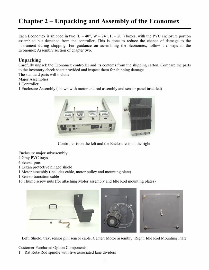
Customer Purchased Option Components:1. Rat Rota-Rod spindle with five associated lane dividers
4
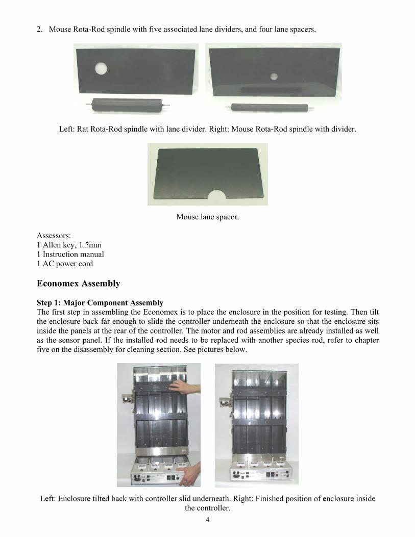
2. Mouse Rota-Rod spindle with five associated lane dividers, and four lane spacers.
Left: Rat Rota-Rod spindle with lane divider. Right: Mouse Rota-Rod spindle with divider.
Mouse lane spacer.
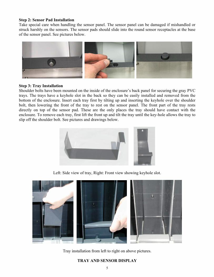
Assessors:1 Allen key, 1.5mm1 Instruction manual1 AC power cord
Economex Assembly
Step 1: Major Component AssemblyThe first step in assembling the Economex is to place the enclosure in the position for testing. Then tiltthe enclosure back far enough to slide the controller underneath the enclosure so that the enclosure sitsinside the panels at the rear of the controller. The motor and rod assemblies are already installed as wellas the sensor panel. If the installed rod needs to be replaced with another species rod, refer to chapterfive on the disassembly for cleaning section. See pictures below.
Left: Enclosure tilted back with controller slid underneath. Right: Finished position of enclosure insidethe controller.
5
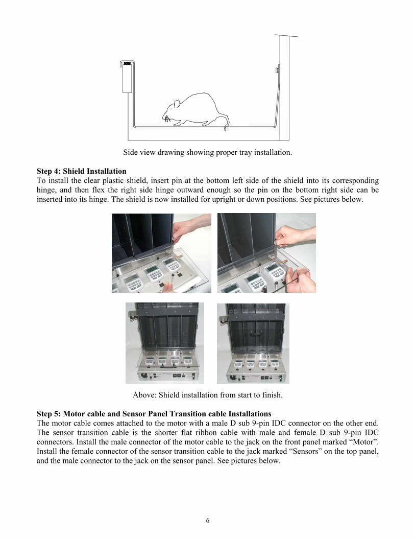
Step 2: Sensor Pad InstallationTake special care when handling the sensor panel. The sensor panel can be damaged if mishandled orstruck harshly on the sensors. The sensor pads should slide into the round sensor receptacles at the baseof the sensor panel. See pictures below.
Step 3: Tray InstallationShoulder bolts have been mounted on the inside of the enclosure’s back panel for securing the gray PVCtrays. The trays have a keyhole slot in the back so they can be easily installed and removed from thebottom of the enclosure. Insert each tray first by tilting up and inserting the keyhole over the shoulderbolt, then lowering the front of the tray to rest on the sensor panel. The front part of the tray restsdirectly on top of the sensor pad. These are the only places the tray should have contact with theenclosure. To remove each tray, first lift the front up and tilt the tray until the key-hole allows the tray toslip off the shoulder bolt. See pictures and drawings below.
Left: Side view of tray, Right: Front view showing keyhole slot.
Tray installation from left to right on above pictures.
TRAY AND SENSOR DISPLAY
6
Side view drawing showing proper tray installation.
Step 4: Shield InstallationTo install the clear plastic shield, insert pin at the bottom left side of the shield into its correspondinghinge, and then flex the right side hinge outward enough so the pin on the bottom right side can beinserted into its hinge. The shield is now installed for upright or down positions. See pictures below.
Above: Shield installation from start to finish.
Step 5: Motor cable and Sensor Panel Transition cable InstallationsThe motor cable comes attached to the motor with a male D sub 9-pin IDC connector on the other end.The sensor transition cable is the shorter flat ribbon cable with male and female D sub 9-pin IDCconnectors. Install the male connector of the motor cable to the jack on the front panel marked “Motor”.Install the female connector of the sensor transition cable to the jack marked “Sensors” on the top panel,and the male connector to the jack on the sensor panel. See pictures below.

7
Left: Motor cable. Right: Sensor transition cable.
The final assembly is to install the power cable. When the power cable is installed, electrical power isavailable to the power switch located under the motor cable connector on the front panel.
8
Chapter 3 – Operation Instructions
Timers
The Stop/Reset button that’s located on each of the 4 timers must be pressed before using theinstrument because the timers will occasionally start with random #’s on their display. There is a GlobalReset button located on the front panel of the unit, which resets and starts all of the timers at the sametime.
*Note: The instructions pertain to the timers and how they count and have no bearing on the motorstarting, stopping, or rotational speed.
Setting timers for elapsed time
To start the lane counters counting elapsed time starting at “0”, depress the black push button locatedbelow each lane counter and release it. This resets the lane sensor to “0” and turns the led on to showthat the sensor is active. When, or if the animal falls from the rod the timer will stop counting.
Setting timers with a preset start time
1. If you require the counters to count down from a preset time (Ex: screening a control group to run forat least 30 sec.) this is also possible. A few additional steps must be followed:
a. Depress the black reset button below the lane being set. This will reset the lane sensorthe LED will light and the timer will begin to count up.
b. Depress the stop/reset button located on the timer keypad 2 times, the first will stopthe timer and the second will reset the display to “0”.
c. Enter the preset time you wish to start from, on the timer keypad.d. Depressing the start button on the timer will start the countdown to “0”.e. When the animal falls from the rod, the sensor light will goes off and the timer stops.f. If the timer reaches “0” before an animal falls, a beeping alarm will sound.
Depressing the stop/reset will turn the alarm off.g. To set all timers with a preset #, repeat the steps starting at step 1a.
*Note: The lane sensor light must be off for the black reset button to reset the timer. If the sensor light isnot off, the black button will only pause the counter when depressed and will continue counting once thebutton is released. To turn off the sensor, lightly touch the lane tray to trip the sensor.

9
Lane Trigger Sensitivity Dial
This feature is used to adjust the trigger point for the lane sensors. The Lane Trigger affects all lanesequally; you cannot set individual lane sensitivity. With 0 being the least sensitive and 10 being themost sensitive. For smaller rodents the sensitivity should be set so that the sensor that’s in the same laneas the fallen rodent is triggered, but the adjoining lanes are not. The animal falling into the adjoiningwall and bumping the next sensor may cause a faulty trigger. For larger animals the sensitivity should beset lower to achieve the same results.
Motor Operating Instructions
Entering the desired rotational speed with the Motor Speed thumb switch on the front of the unit sets themotor’s speed. The Start Motor switch is depressed to begin the rods rotation, and the Stop Motorswitch stops rotation.
To determine the spindle rpm @ the time animal fallsMotorSpeed
AccelerationDial setting
TotalAcceleration
20 rpm 1.0 rpm/sec 20 + #elapsed seconds *1.020 rpm 2.0 rpm/sec 20 + #elapsed seconds * 2.020 rpm 3.0 rpm/sec 20 + #elapsed seconds * 3.020 rpm 4.0 rpm/sec 20 + #elapsed seconds * 4.020 rpm 5.0 rpm/sec 20 + # elapsed seconds * 5.020 rpm 6.0 rpm/sec 20 + # elapsed seconds * 6.020 rpm 7.0 rpm/sec 20 + # elapsed seconds * 7.020 rpm 8.0 rpm/sec 20 + # elapsed seconds * 8.020 rpm 9.0 rpm/sec 20 + # elapsed seconds * 9.0
The Acceleration Switch (if the option is purchased) is used to augment the motor’s base rotationalspeed. The chart above shows the formula used to determine the rpms at the time the animal falls fromthe rod. The #elapsed seconds refers to the amount of time that the acceleration is on. The accelerationoption increases the rpms by the selected amount every second. An example would be having themotor speed set at 20 rpms and the acceleration set at 5. After 1 second the speed would be 25 rpm, after2 seconds it would be 30 rpm, and after 3 seconds the speed would be 35. The formula would be20 + 3 * 5 = 35 rpm.
MOTOR SPEED CONTROLS

10
Chapter 4 – Animal Preparation For Testing
PROCEDURE FOR TESTING AND CONDITIONINGOF ANIMALS
ECONOMEX ROTA-ROD
Test for Motor Coordination and Motor Performance inLaboratory Animals
* Capabilities of testing 4 rats or mice simultaneously.
* Acceleration and constant speed options.
* Adjustable speed (0-99 rpm) in the range.
* Adjustable pressure sensitive detection of animal fall.
* Durable plastic construction.
* Removable feces tray for easy cleaning.
The ECONOMEX Rota-Rod is a device to test the motor performance, performance time, partial orcomplete ataxia, and the motor co-ordination in laboratory animals (e.g. rat, mouse etc). The principle ofthis system is to measure the time each animal manages to maintain its balance on the moving rod.Several drugs that cause muscular relaxation will interfere with this co-ordination and agility causing theanimal to fall from a safe height.
The mouse rod has the capacity to test one to four animals at a time and can be further expanded for anadditional four animals. The researcher has the option to select an accelerating or constant speed modeof operation. Four large digital displays keep track of the time animals are able to maintain balance onthe Rota-Rod. There are two different diameters of rotating rods: one for mice (35 mm) and another forrats (75 mm). The rods are interchangeable and in order to accommodate different size of animals, thedividing flanges have adjustable spaces that allow the researcher to change the width of the lane for eachanimal.
The instrument has the capability to rotate the rod at either constant or a slightly accelerated rate. To runthe instrument in constant rate, pick the rpm value desired and start the experiment. To test withacceleration you must have the acceleration option installed. This option will accelerate the unit inprecise increments from the rpm value selected until the unit reaches its maximum acceleration. Theelapsed time measured by the instrument is reported on its display.
11
SCOPE OF APPLICATION
1. Assess motor skill performance impairment of animals.
2. To determine the performance time in animals.
3. To evaluate the coordinated motor response in animals.
4. To determine the muscular weakness and ataxia in animals.
PROCEDURE
When a rat or mouse is first placed on the ECONOMEX it is quite likely to fall off in sheerignorance of what it is supposed to do. Each animal needs to be trained and conditioned to theapparatus, before performing any tests.
CONDITIONING & TRAINING:
1. Animals are required to perch on the stationary rod for 30 sec. to accustom themselves to theenvironment. During this time if any animal falls, they are to be placed back on the rod.
2. The animals that are comfortable in staying on the stationary rod for 30 sec. are to be allowed torun with a constant speed of 5 rpm for 90 sec. If any animal falls off during this trial, they are tobe used for another trial at the same speed for 90 sec. Animals that fall off after three trials withconstant low speed rotation (5 rpm) are to be removed from the experiment.
3. After 30 min. of the last trial, all animals are to be placed back on the rod and be allowed to runwith faster accelerations. The animals can be classified by the speeds at which they maintainbalance on the rod.
DRUG TESTING:
Conditioned animals are to be injected with the testing drugs. The dose is to be selected from the dose-response curve. After allowing some time for the drug to take effect, the animals are to be placed on therod. The performance time and the speed at which animals fall off from the rod are to be recorded forevaluating the effects of whatever drug is being tested.

12
Chapter 5 – Height Adjustment Procedure
Major Parts for Mouse and Rat Height Adjustment
1. There are only two height configurations for the Dual Species Economex. The upper Rota-Rodheight position (pictured on the left) is used for testing rats. The lower Rota-Rod height position(pictured on the right) is used for testing mice.
2. The major parts for both configurations are shown below. The major parts for the upper (rat)configuration, (pictured on the left) are the rat rod spindle and five lane dividers. The major parts forthe lower (mouse) configuration, (pictured on the right) are the mouse rod spindle and five lanedividers.
3. The motor and pulley assemblies are used for both Rota-Rod spindles.
Height Adjustment ProceduresThe following is a step by step procedure for changing Rota-Rod positions on the enclosure. (For clarityof the procedure, the change used will be from the upper (rat) position to the lower (mouse) position.1. First step is to turn “OFF” the power and unplug the ac power cord from the Economex controller.2. Unplug the motor cable from the jack on the controller front panel.3. Remove the thumb screw nuts that hold the motor assembly to the side of the enclosure. (Be sure to
support the motor assembly so it will not fall off the mounting screws).4. With one hand supporting the rat Rota-Rod, slowly pull the motor assembly away from the side of
the enclosure, the motor assembly and Rota-Rod spindle will now pull freely from the enclosure.

13
5. Lay the motor assembly with the attached rat Rota-Rod spindle on a flat surface and remove bothpulley belts from the Rota-Rod spindle pulley.
6. Using an 1/16” diameter Allen wrench, loosen the socket set screw(s) in the pulley until the pulley isfree to pull off the spindle axle. NOTE: some pulleys may have two set screws opposite each other.See above.
7. With one hand grasp the spindle pulley and with the other hand pull the rat Rota-Rod spindle awayfrom the motor assembly and pulley.
8. Before installing the mouse Rota-Rod, apply lubricant either to both ends of the Rota-Rod axle or tothe axle holes of the Motor and Idle Rod mounting plates.
9. Install the mouse Rota-Rod spindle into the motor assembly by sliding the axle of the Rota-Rodspindle partway through the hole of the motor assembly mounting plate. Next slide the pulley ontothe axle before sliding the axle of the Rota-Rod spindle all the way into the motor assembly. NOTE:wipe off any excess lubricant from the axle.
14
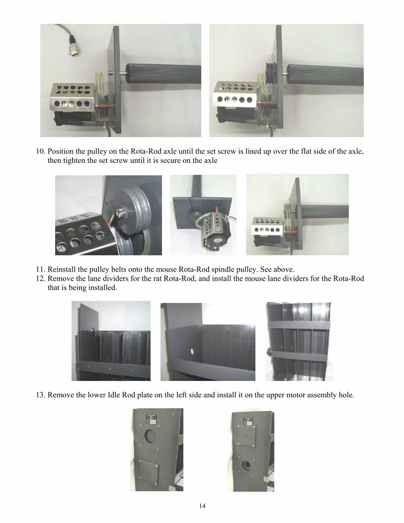
10. Position the pulley on the Rota-Rod axle until the set screw is lined up over the flat side of the axle,then tighten the set screw until it is secure on the axle
11. Reinstall the pulley belts onto the mouse Rota-Rod spindle pulley. See above.12. Remove the lane dividers for the rat Rota-Rod, and install the mouse lane dividers for the Rota-Rod
that is being installed.
13. Remove the lower Idle Rod plate on the left side and install it on the upper motor assembly hole.
15
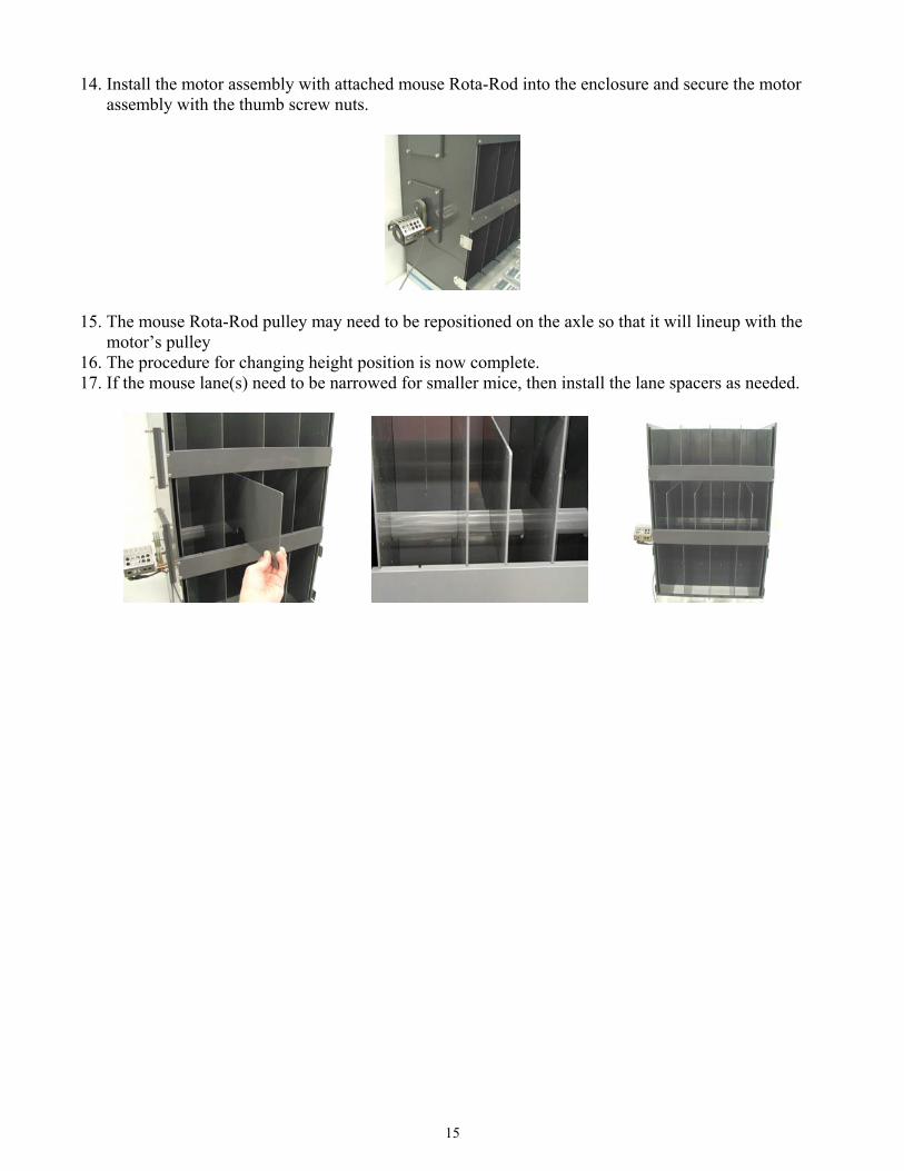
14. Install the motor assembly with attached mouse Rota-Rod into the enclosure and secure the motorassembly with the thumb screw nuts.
15. The mouse Rota-Rod pulley may need to be repositioned on the axle so that it will lineup with themotor’s pulley
16. The procedure for changing height position is now complete.17. If the mouse lane(s) need to be narrowed for smaller mice, then install the lane spacers as needed.

16
Chapter 6 – Cleaning and Maintenance
General Cleaning
The Economex is designed for extremely low maintenance; occasionally wipe down the entire enclosureand controller with a damp cloth. Make sure that the unit is unplugged before cleaning! Do not turnthe unit on until it is completely dry.
However, if a more intensive cleaning is needed the enclosure may be taken apart. The interior enclosureand the tray inserts are completely removable. They are easy to wipe clean with a damp cloth and mildsoap. A 2% bleach solution in water is recommended if surface sterilization is required.
The trays may also be put into a dishwasher for additional ease of cleaning and sterilization.
Lubrication of Rota-Rod
1. The Rota-Rod may need to be re-lubricated depending upon the usage of the Economex instrument.The lubricant used is a silicone based compound. As a reference for selecting lubricants, the DowCorning 111 Valve Lubricant and Sealant compound or an equivalent is recommended.
2. The pictures below show where to apply the lubricant. The lubricant can be applied to the Rota-Rodaxle as shown in figure 1 or to the axle mounting hole in the Idle Rod mounting plate as shown infigure 2.
Figure 1 Figure 2
3. Apply the lubricant on the axle or inside the mounting hole, and spread the lubricant until the entirecontact surface of the axle or mounting hole has a sufficient coat of lubricant applied. When theRota-Rod and mounting plates are remounted to the enclosure, wipe off the excess lubricant from theaxle and mounting plates.
4. Both side of the Rota-Rod need to be lubricated, so repeat the process for the pulley side of the Rota-Rod.