
Photovoltaic Generation System with MPPT Control Using ANFIS
Upload
khangminh22Category
view
1download
0
Engineering Science and Technology, an International Journal 19 (2016) 1771–1780
brought to you by COREView metadata, citation and similar papers at core.ac.uk
provided by Elsevier - Publisher Connector
Contents lists available at ScienceDirect
Engineering Science and Technology,an International Journal
journal homepage: www.elsevier .com/ locate / jestch
Full Length Article
Dual MPPT algorithm for dual PV source fed Open-End WindingInduction Motor Drive for pumping application
http://dx.doi.org/10.1016/j.jestch.2016.07.0082215-0986/� 2016 Karabuk University. Publishing services by Elsevier B.V.This is an open access article under the CC BY-NC-ND license (http://creativecommons.org/licenses/by-nc-nd/4.0/).
⇑ Corresponding author.E-mail address: [email protected] (S. Padmanaban).
Peer review under responsibility of Karabuk University.
Sachin Jain a, Chinthamalla Ramulu a, Sanjeevikumar Padmanaban b,⇑, Joseph Olorunfemi Ojo c,d,Ahmet H. Ertas e
aDepartment of Electrical Engineering, National Institute of Technology, Warangal, Telangana 506004, IndiabDepartment of Electrical and Electronics Engineering, University of Johannesburg, Auckland Park, South AfricacCenter for Energy System Research, Department of Electrical & Computer Engineering, Tennessee Technological University, Cookeville, 38505-Tennessee, United Statesd Eskom Centre of Excellence in HVDC Engineering, University of KwaZulu-Natal, Durban, South AfricaeDepartment of Biomedical Engineering, Engineering Faculty, Karabuk University, Turkey
a r t i c l e i n f o
Article history:Received 23 June 2016Revised 14 July 2016Accepted 15 July 2016Available online 25 July 2016
Keywords:Decoupled PWMDual-inverterDual MPPTOpen-End Winding Induction MotorPhotoVoltaics (PV)Water pump
a b s t r a c t
This paper presents a single-stage solution for a dual Maximum Power Point Tracking (MPPT) techniquefor a solar Photovoltaic (PV) fed water pumping system. The proposed solar PV fed pumping system usesa three-phase Open-End Winding Induction Motor (OEWIM) coupled to a centrifugal water pump. TheOEWIM is connected via two time tested two-level three-phase inverters powered by two independentsolar PV arrays. These two PV arrays can be configured independently and the employed dual MPPT algo-rithm operate the two PV sources at or near maximum power point (MPP) irrespective of its configura-tion. Usage of different array configurations may help in attaining more number of levels (greater than orequals to three) in the inverter output voltage (OEWIM phase voltage). Furthermore, the system is oper-ated using decoupled PulseWidth Modulation (PWM) technique with V/f control along with the proposeddual MPPT technique. The maximum power extracted by the dual MPPT algorithm from two PV sources isoptimally utilized by the OEWIM. This can be supported by the low slip value at all the operating condi-tions. The detailed analysis of proposed system and the simulation results are presented.� 2016 Karabuk University. Publishing services by Elsevier B.V. This is an open access article under the CC
BY-NC-ND license (http://creativecommons.org/licenses/by-nc-nd/4.0/).
1. Introduction
Today to meet the never ending and increasing demand of elec-trical energy, most of the research is diverted towards the utiliza-tion of renewable sources such as solar PhotoVoltaic (PV), wind,fuel cells, thermo-generator etc. Among these sources, solar PVtechnology is considered as the most viable solution to meet theelectrical energy demand. Noiseless operation, low maintenanceand zero pollution further adds to the popularity of solar PV source,which directly converts the solar energy into the electrical energy.The solar PV system can be used either in electric power grid-tiedmode or in the stand-alone mode. In grid-tied application [1–3] thePV source feeds the high quality ac power into the grid. Whereas instand-alone systems, the generated PV power could drive thestand-alone loads [4–8] like water pumps, air compressors, house-hold etc using additional power sources like battery, fuel cell etc.
However, for stand-alone loads like solar fed water pumpingapplications [7,8] used in agriculture, industries, hydro powerplant and residential buildings gives the option of storing solarPV energy without using additional power sources. The solar PVenergy can be stored in the form of potential energy by storingwater in the tank [9], dam etc at the required height above groundlevel. The stored energy or water, then can be utilized with respectto demand or requirement. Thus, in such systems additional powersources for storing the electrical energy may not be required and italso gives the option of continuously operating solar PV array at ornear MPP. Thus, the system effectively utilizes the solar PV powerfor all the environmental conditions. Some of the solutions for thePV fed water pumping systems were introduced since 1980s,where a dc motor coupled to a centrifugal pump is directly pow-ered from the PV source [10–12] and with a converter for MPPtracking [13]. The use of dc motor may be overruled because ofits high cost and continuous maintenance [14]. The other optionto replace a dc motor could be the brushless dc (BLDC) motor[15,16]. Presently, the use of BLDC motor in a PV pumping systemmay not be a feasible solution because of its high cost and therequirement of complex control circuitry. So, the use of 3-U,

1772 S. Jain et al. / Engineering Science and Technology, an International Journal 19 (2016) 1771–1780
induction motor could be a feasible and better solution for PV fedwater pumping system.
The use of 3-U induction motor in the PV fed water pumpingsystem has been reported in the literature [17–19]. Most of theresearch work includes the use of conventional induction motorwith the two or single power conversion stage. The two-stage sys-tem [20–22] includes a dc–dc converter and an inverter in betweenthe solar PV source and the induction motor as shown in Fig. 1(a).The dc-dc converter in two-stage PV system is used to boost thevoltage and helps in tracking maximum power from the PV source.And the inverter is used to provide the required ac power to themotor-pump load. The other solution includes the single-stage sys-tem [23–28] where a single inverter is used as shown in Fig. 1(b). Itis an integrated solution in which the Maximum Power pointTracking (MPPT) and motor control, both are governed by a singleinverter.
Most recently, the advantage of a single-stage system alongwith the benefits of Open-End Winding Induction Motor (OEWIM)[29–35] is incorporated in a PV pumping system and the work isreported in [26,27]. The given solution uses a single solar PV arrayto drive OEWIM through the dual-inverter giving only three-leveloutput as shown in Fig. 1(c). Also, the usage of single PV arrayincreases the risk of shading issues in the PV array configuration.This risk/probability of shading in the PV array increases withthe increase in the size or power rating of the PV array. Further,the operation under partially shaded condition deteriorates theperformance of the PV system. This is because of the presence ofmultiple local peaks and a global peak in the p–v (power versusvoltage) characteristics of the PV array. The presence of local peaks
DC/AC + Low DC-bus voMPPT + Two-level inversion
DC/AC + Low DC-bus voMPPT + Two-level inversion
Three-level or m
DC/AC + Low DC-bus voMPPT + Two-level inversion
DC/AC + Low DC-bus voMPPT + Two-level inversion
Three-level or m
PV1
PV2
PV
DC/AC +High DC-bus voltinverter O/p +SinglePV
DC/AC + Low DC-bus voltage + Distr
DC/AC + Low DC-bus voltage + Distr
PV1
PVm
DC/AC + Low DC-bus voltage + Distr
DC/AC + Low DC-bus voltage + Distr
PV(m+1)
PV(m+n) ((m+n)+1)-lev
DC/DC +Low PV array voltage +Single MPPT
DC/A+T
Three-lev
PV
Three-lev
DC/AC + Low DC-bus Two-level inversion + V/f
DC/AC + Low DC-bus Two-level inversion + V/f
Fig. 1. Block diagram of (a) two-stage single PV source powered centrifugal water pumpsingle PV source powered OEWIM-pump (d) proposed single-stage dual PV source pow
in the p–v characteristic affects the performance of the MPPT algo-rithm which further effects the overall performance of the system.Further, there is no option for dual or multiple configurations forPV arrays to minimize shading problem. One solution could bethe usage of dual or distributed Maximum Power Point Tracking(MPPT) [36–42] at dc–dc converter stage in case 2-stage system.However, this would increase the cost and complexity of the sys-tem with the increased number of dc–dc converters. Thus, thereis a need for the single-stage system with simple control whichhas the option of dual or distributed MPPT.
Thus, it is apparent that there is a need for low cost, high perfor-mance single-stage low PV array voltage water pumping systemwith dual/distributed solar PV arrays arrangement for minimizingeffect of shading problem. It should also have three or more num-ber of levels in the phase voltage, wide band-width of PV sourceoperating voltage and should have the option of dual/distributedMPPT. This paper introduces a PV pumping system which usesOEWIM-pump powered by two electrically isolated PV sourcesthrough two two-level inverters as shown in Fig. 1(d). The OEWIMwith two two-level inverters provide the three-level output volt-age which improves the system performance when compared toconventional two-level solutions in terms of torque ripple, powerripple etc. Also, the number of levels in the output voltage can bemore than three if the asymmetrical PV array configurations areutilized i.e., by using solar PV arrays with different size or powerratings.
Most importantly, the implementation of dual/distributedMPPT algorithm (limited to dual MPPT in this case) is made possi-ble with the proposed system for PV pumping application. The dual
(d)
ltage + Distributed + V/f control
ltage + Distributed + V/f control
OEWIM-Pump
ore
ltage + Distributed + V/f controlf
ltage + Distributed + V/f controlf
ore
(a)
age+Two-level MPPT
IM-Pump(b)
OE
WIM
-Pump
ibuted MPPT + V/f control
ibuted MPPT + V/f control
ibuted MPPT + V/f control
ibuted MPPT + V/f controlel or more (e)
C +High DC-bus volatge wo-level inverter O/p IM-Pump
(c)
OEWIM-Pump
el el
voltage + MPPT + control
voltage + MPPT + control
(b) single-stage single PV source powered centrifugal water pump (c) single-stageered OEWIM-pump drive with dual MPPT (e) extended version for (d).
S. Jain et al. / Engineering Science and Technology, an International Journal 19 (2016) 1771–1780 1773
MPPT helps in the effective tracking of maximum power from boththe PV sources separately. Furthermore, the proposed configura-tion can be extended to have multiple PV sources (m+n) as shownin Fig. 1(e) with distributed MPPT technique given by Sonti et al.[42]. This helps in the generation of ‘m+n+1’ or higher number oflevels in the output voltage [43]. However, the work presented inthis manuscript is limited to the basic two isolated solar PVsources.
Rest of the paper is organized as follows. In Section 2, the math-ematical modeling of all the major equipment used in the proposedsystem is described. Section 3 consists of the detailed operationand control strategy used for the proposed system. Simulationresults are presented in Section 4, whereas the fifth section con-cludes the paper.
2. Modeling of the proposed system
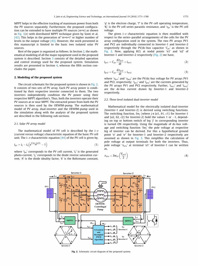
The circuit schematic for the proposed system is shown in Fig. 2.It consists of two sets of PV array. Each PV array power is condi-tioned by their respective inverter connected to them. The twoinverters independently condition the PV power using theirrespective MPPT algorithm’s. Thus, both the inverters operate theirPV sources at or near MPPT. The extracted power from both the PVsources is then used by the OEWIM-pump. The mathematicalmodel of PV array, dual-inverter and the OEWIM-pump used inthe simulation along with the analysis of the proposed systemare described in the following sub-sections.
2.1. Solar PV array model
The mathematical model of PV cell is described by the i–v(current versus voltage) characteristic equation of the basic PV cellunit. The i–v characteristic equation [44] of the PV cell is given by,
ipv ¼ iL � io eqðvpvþipv RsÞ
AkT � 1� �
ð1Þ
where ‘ipv’ corresponds to the PV cell current, ‘iL’ is the generatedphoto-current, ‘io’ corresponds to the diode reverse saturation cur-rent, ‘A’ is the diode ideality factor, ‘k’ is the Boltzmann constant,
2Cpv
O
ic1
2Cpv
Vpv1
2
a1
b1
S11
S14 S16 S12
S15S13
iinv1
Swc1
ia1sa2sSwa1
Swb1
ipv1
ib1sb2s
ipv1
vpv1 ma1 m
vpv2
vpv1
n1
OEWIMCentrifug
Pump
PV1
Inverter-1
V/f control and
Decoupled PWM
Algorithm
O1
23
5
4
6
8
α
P1
Inverter-1
c1
7
Vpv1
2
MPPT1
a1s
b1s
c1s c2ic1sc2s
Fig. 2. Schematic circuit diagra
‘q’ is the electron charge, ‘T’ is the PV cell operating temperature,‘Rs’ is the PV cell series parasitic resistance, and ‘vpv’ is the PV cellvoltage.
The given i–v characteristic equation is then modified withrespect to the series–parallel arrangements of the cells for the PVarray configuration used in the system. The two PV arrays PV1and PV2 are individually connected to Inverter-1 and Inverter-2respectively through the PV/dc-bus capacitor ‘Cpv’ as shown inFig. 2. Now, applying KCL at nodal points ‘n1’ and ‘n2’ ofInverter-1 and Inverter-2 respectively (Fig. 2) we have,
ipv1 ¼ Cpvdvpv1
dtþ iinv1 ð2Þ
ipv2 ¼ Cpvdvpv2
dtþ iinv2 ð3Þ
where ‘vpv1’ and ‘vpv2’ are the PV/dc-bus voltage for PV arrays PV1and PV2, respectively; ‘ipv1’ and ‘ipv2’ are the currents generated bythe PV arrays PV1 and PV2 respectively. Further, ‘iinv1’ and ‘iinv2’are the dc-bus current drawn by Inverter-1 and Inverter-2respectively.
2.2. Three-level isolated dual-inverter model
Mathematical model for the electrically isolated dual-inverter(Inverter-1 and Inverter-2) is derived using switching functions.The switching function, Swj (where j e {a1, b1, c1} for Inverter-1and {a2, b2, c2} for Inverter-2) hold the values 1 or �1, depend-ing on top or bottom switch of leg ‘j’ in corresponding inverteris turned ON respectively. Using the magnitude of dc-bus volt-age and switching function ‘Swj’ the pole voltage at respectiveleg of inverter can be derived. For this a hypothetical groundpoint ‘o’ and ‘o0’ for Inverter-1 and Inverter-2 respectively areassumed as shown in Fig. 2. This simplifies the calculation ofpole voltage at output terminals for both the inverters. Thus,pole voltage ‘va1o’ at terminal ‘a1’ of Inverter-1 can be writtenas,
va1o ¼ Swa1Vpv1
2
� �ð4Þ
==
Swc2
S22
S23
S26
S21
S24
S25
Swa2
Swb2
a2b2
c2
O'
Vpv2
2
Vpv2
2
2Cpv
2Cpv
ipv2
vpv2
a2
n2 ipv2
ic2
iinv2
-al
PV2
Inverter-2
ToInverter-2
ToInverter-1
MPPT2
S11
S13
S15
S21
S23
S25
O' 1'
'3 '2
4'
5' 6'
8'
7'
180o+α
P2
Inverter-2
O' 1'
'3 '2
4'
5' 6'
8'
7'
180o+α
P2P
a2s
b2s
s
m of the proposed system.
1774 S. Jain et al. / Engineering Science and Technology, an International Journal 19 (2016) 1771–1780
Similarly, the pole voltages ‘vjo’ for Inverter-1 and ‘vjo’’ forInverter-2 can be derived for both the inverters. Once the pole volt-ages are known, the common mode voltage of the Inverter-1 (von)and Inverter-2 (vo’n) are given by,
von ¼ 13ðva1o þ vb1o þ vc1oÞ ð5Þ
vo0n ¼ 13ðva2o0 þ vb2o0 þ vc2o0 Þ ð6Þ
where ‘n’ represents a hypothetical ground point of the OEWIM.Now, using pole voltage and common mode voltage, the voltage‘va1a2’ between terminals ‘a1’ and ‘a2’ can be calculated as,
va1a2 ¼ Vpv1
223
� �Swa1 � 1
3ðSwb1 þ Swc1Þ
� �
� Vpv2
223
� �Swa2 � 1
3ðSwb2 þ Swc2Þ
� �ð7Þ
This also represents the stator phase voltage ‘va1sa2s’ of OEWIMat phase ‘a1sa2s’ (see Fig. 3). Similarly, the other stator phase volt-ages ‘vb1sb2s’ and ‘vc1sc2s’ of the OEWIM at ‘b1sb2s’ and ‘c1sc2s’respectively can be derived. Once the phase voltages applied toOEWIM are known, then the respective phase currents ‘ia1sa2s’,‘ib1sb2s’ and ‘ic1sc2s’ can be calculated using motor dynamic modelas described in the next sub-section. The derived phase currentscan be used for the calculation of the inverter current ‘iinv1’ and‘iinv2’ of both Inverter-1 and Inverter-2 respectively, as given below,
iinv1 ¼12ðSwa1þ1Þðia1sa2sÞþ1
2ðSwb1þ1Þðib1sb2sÞþ1
2ðSwc1þ1Þðic1sc2sÞ
ð8Þ
iinv2 ¼ 12ðSwa2 þ 1Þð�ia1sa2sÞ þ 1
2ðSwb2 þ 1Þð�ib1sb2sÞ þ 1
2ðSwc2
þ 1Þð�ic1sc2sÞ ð9Þ
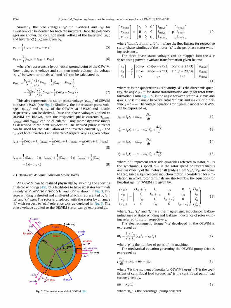
2.3. Open-End Winding Induction Motor Model
An OEWIM can be realized physically by avoiding the shortingof stator windings [45]. This facilitates to have six stator terminalsnamely ‘a1s’, ‘a2s’, ‘b1s’, ‘b2s’, ‘c1s’ and ‘c2s’ as shown in Fig. 3. Therotor winding is shorted and unaltered which is represented by ‘ar’,‘br’ and ‘cr’ axes. The rotor is displaced with the stator by an angle‘dr’ with respect to ‘a1s’ reference axis as depicted in Fig. 3. Thephase voltage applied to the OEWIM stator can be expressed as,
Stator
Rotor
as-axis
bs-axis
cs-axis
ar-axis
br-axis
cr-axis
q-axis
d-axis
Air gap
γ
a2s
c2s
b2s
a1s
b1s
c1s
δ δr (Ref axis)
Fig. 3. The machine model of OEWIM [26].
va1sa2s
vb1sb2s
vc1sc2s
264
375 ¼
rs 0 00 rs 00 0 rs
264
375
ia1sa2sib1sb2sic1sc2s
264
375þ p
ka1sa2skb1sb2skc1sc2s
264
375 ð10Þ
where ‘ka1sa2s’, ‘kb1sb2s’, and ‘kc1sc2s’ are the flux-linkage for respectivestator phase windings of the motor; ‘rs’ is the per phase stator wind-ing resistance.
The three-phase stator voltages can be mapped into the d–qspace using power invariant transformation given below:
vq
vd
vo
264
375 ¼ 2
3
cosu cosðu� 2p=3Þ cosðuþ 2p=3Þsinu sinðu� 2p=3Þ sinðuþ 2p=3Þ1=2 1=2 1=2
264
375
va1sa2s
vb1sb2s
vc1sc2s
264
375ð11Þ
where ‘q’ is the quadrature axis quantity, ‘d’ is the direct axis quan-tity, the angle / = ‘d’ for stator transformation and ‘c’ for rotor trans-formation. From Fig. 3, ‘d’ is the angle between stator ‘a1s’ axis andq-axis, ‘c’ is the angle between rotor ‘ar’ axis and q-axis, or other-wise c = d � dr. The voltage equations for dynamic model of OEWIMcan be expressed as,
vqs ¼ iqsrs þxkds þ dkqsdt
ð12Þ
v 0qr ¼ i0qrr
0r þ ðx�xrÞk0dr þ
dk0qrdt
ð13Þ
vds ¼ idsrs �xkqs þ dkdsdt
ð14Þ
v 0dr ¼ i0drr
0r � ðx�xrÞk0qr þ
dk0drdt
ð15Þ
where ‘‘ ’ ” represent rotor side quantities referred to stator, ‘x’ isthe synchronous speed, ‘xr’ is the rotor speed or instantaneousangular velocity of the motor shaft (rad/s). Here ‘v’qr’, ‘v’dr’ are equalto zero, since a squirrel cage induction motor is considered for sim-ulation, in which rotor terminals are shorted.Now the equations forflux-linkage for OWEIM are given by,
kqskdsk0qrk0dr
0BBB@
1CCCA ¼
Lm þ Lls 0 Lm 00 Lm þ Lls 0 LmLm 0 Lm þ L0lr 00 Lm 0 Lm þ L0lr
0BBB@
1CCCA
iqsidsi0qri0dr
0BBBB@
1CCCCA ð16Þ
where, ‘Lm’, ‘Lls’ and ‘Lꞌr ’ are the magnetizing inductance, leakageinductance of stator winding and leakage inductance of rotor wind-ing referred to stator respectively.
The electromagnetic torque ‘md’ developed in the OEWIM isexpressed as
md ¼ 32p2LmLs
ðkqsi0dr � kdsi0qrÞ ð17Þ
where ‘p’ is the number of poles of the machine.The mechanical equation governing the OEWIM-pump drive is
expressed as
Jdxr
dtþ Bxr þmL ¼ md ð18Þ
where ‘J’ is the moment of inertia for OEWIM (kg-m2), ‘B’ is the coef-ficient of centrifugal load torque, ‘mL’ is the centrifugal pump loadtorque given by,
mL ¼ Kwx2r ð19Þ
where ‘Kw’ is the centrifugal pump constant.

S. Jain et al. / Engineering Science and Technology, an International Journal 19 (2016) 1771–1780 1775
3. Operation and control strategy used for the proposed system
The proposed system uses dual MPPT algorithm which is assim-ilated with the decoupled PWM technique along with V/f control.Since, the proposed system uses two isolated PV sources, the gen-erated maximum power from these sources can be extracted sep-arately using two independent MPPT algorithms (dual MPPT). Asthe proposed system is a single-stage and uses two independentMPPT algorithms, there is a challenge involved in the assimilationof the dual MPPT algorithm along with the motor control. The dualMPPT algorithm generates two different values of modulationindices ‘ma1’ and ‘ma2’ for both the PV sources PV1 and PV2 respec-tively. These two values of modulation indices ‘ma1’ and ‘ma2’ indi-vidually controls the operating voltages of two PV sources or trackMPP for two PV sources individually. Further, the two modulationindices ‘ma1’ and ‘ma2’ values are again used by the decoupled PWMtechnique for the determination of common frequency of the mod-ulating wave. In decoupled PWM technique, the reference outputvoltage vectors of both the inverters are added. This may also helpin increasing the operating voltage range for the PV array. Also, theusage of decoupled PWM technique with OEWIM gives the optionof using two sets of PV arrays with low PV/dc-bus voltage [46]. Thisreduces the voltage rating of dc-bus capacitor and semiconductordevices. As the system uses independently two individual sets ofPV array configurations, this helps in minimizing the shading prob-lem. This can be supported by the usage of two independent MPPTalgorithms for the two sets of PV array. Thus, the proposed systemalso facilitates the usage of different combinations of modules orgroups for the two sets of PV array. In other words, it distributesthe MPPT between the two sets of PV array configuration whereeach source tracks MPP individually. Thus, dual/distributed MPPTalgorithm ensures the maximum utilization of both the PV arrays.The maximum power extracted by using individual MPPT algo-rithm, is then given to the motor-pump set via a dual-inverter.
In addition to the decoupled PWM technique, the usage of sim-ple V/f control strategy in motor control, further ensures the highperformance of OEWIM-pump set. This can be attributed to thefact that V/f control maintains the rated flux which helps in retain-ing the rated torque capability of the motor. Thus, it effectively uti-lizes the PV power by maintaining optimum torque with respect topower generated at the PV sources. Details of the implementationof dual MPPT algorithm along with the inverter and motor controltechnique is described below.
The simple and robust Perturb and Observe (P and O) algorithmwas employed in the proposed system to extract the maximumpossible power from both the PV sources (see Fig. 4). The proposedsystem consists of two sets of PV arrays and each array is con-nected to an individual MPPT controller namely MPPT1 and MPPT2as shown in Fig. 2. The dual MPPT algorithm modifies or decide thecorresponding modulation index (‘ma1’ and ‘ma2’) for the isolateddual-inverter. The algorithm requires the average value of voltagesand currents of the two PV sources employed in the system. Thus,the algorithm first senses the average value of the PV voltages(Vpv1), (Vpv2), and currents (Ipv1), (Ipv2) from two sets of PV arraysPV1 and PV2 respectively. Then the individual PV power ‘Ppv1’and ‘Ppv2’ for PV arrays PV1 and PV2 respectively are calculated.The calculated individual PV power and sensed voltage are thencompared with their previous values for determining the sign ofthe slope of the p–v curve for both the PV sources separately. Withrespect to the sign of the slope (+ve or �ve) the values of modula-tion indices ‘ma1’ and ‘ma2’ are modified (decreased or increased)by a small constant value (Dma). The modified values of modula-tion indices ‘ma1’ and ‘ma2’ for the individual inverters are furtherprocessed with the operating voltage of the PV array for the calcu-
lation of resultant reference phase output voltage vector ‘V!
sr ’ as
given in (20). This is done because, the value of PV operating volt-ages for both the sources are not equal and constant. So, the effectof change in ‘Vpv1’ and ‘Vpv2’ together could be taken care by thealgorithm to get effective tracking of maximum power. Further,as the decoupled PWM is employed, the resultant three-phasevoltage vector across the windings of the motor is the sum of thetwo vectors ‘OP1’ and ‘O’P2’ (Fig. 2) as given below,
jV!
srj ¼ ðma1 � Vpv1 þma2 � Vpv2Þ ¼ jV!
sr1j þ jV!
sr2j ð20ÞThus, the challenge associated with the operation of single-
stage system with dual MPPT along with the motor control issolved with the consideration of resultant vector. In other words,the problem of common modulating frequency for both the invert-
ers can be resolved by using ‘V!
sr ’ in calculating ‘fmod’ for bothinverters as described below.
fmod ¼ jV!
srj � f rated
jV!
srðratedÞjð21Þ
where ‘V!
srðratedÞ’ is the maximum output phase voltage of the OEWIMoperating in the linear modulation region and ‘frated’ is the fre-quency of the rated voltage at rated power output in the linearmodulation region. For a peak phase voltage of 325 V, from the
dual-inverter configuration system, V!
srðratedÞ is calculated as follows:
V!
srðratedÞ ¼ffiffiffi3
p
2
!� Vdc ¼
ffiffiffi3
p
2
!� 564 � 488 V ð22Þ
where 564 V is the total required PV/dc-bus voltage to maintain thepeak phase voltage of 325 V in the linear modulation range for theproposed PWM technique. So, to implement the V/f control for theproposed system the modulating frequency ‘fmod’ is calculated using(21) and (22). The calculated value of ‘fmod’ is then used by thedecoupled PWM algorithm of the individual inverters for the gener-ation of required PWM pulses. The position angle ‘a’ (see Figs. 2 and4) of the output voltage vector for Inverter-1 and Inverter-2 is cal-culated based on ‘fmod’ and sampling time period, ‘Ts’. DecoupledPWM then uses the reference voltage space vector ‘|Vsr|\a’ that isto be synthesized from the electrically isolated dual-inverter sys-tem. This vector ‘|Vsr|\a’ is resolved into two opposite components‘|Vsr1|\a’ (OP1 in Fig. 2) and ‘|Vsr2|\(180� + a)’ (O’P2 in Fig. 2). Thedecoupled components OP1 and O’P2 are then given as the refer-ence voltage vectors for Inverter-1 and Inverter-2 respectively.These vectors are then used by the carrier based space vectorPWM technique [47] to generate the required gating pulses forthe power semiconductor devices of the dual-inverter.
4. Simulation results
To study the performance of the proposed system operated withdual MPPT, simulation is performed using MATLAB/Simulink soft-ware. The simulation is done using the 48 samples per cycle ofthe applied fundamental phase voltage irrespective of the magni-tude of the resultant three-phase voltage vector across the wind-ings of the motor ‘Vsr’. Specifications considered in the simulationfor the PV system and the OEWIM motor are given in Table 1. Toverify the performance of the dual MPPT algorithm, asymmetricalconfigurations for the two PV arrays (PV1 and PV2) are consideredas indicated in Table 1. Also, to study the dynamic behavior of thesystem, four different environmental conditions were considered.Fig. 5(a) and (b) show the insolation and temperature respectivelyat which both the PV arrays are operated. Also, it can be observedfrom subplots (c) and (d) of Fig. 5 that the value of PV currentincreases with the corresponding decrease in its voltage. This

Start
Initialize ma1,Vpv1,prev , Ppv1,prev
Calculate Ppv1 and carry Vpv1
Calculate ΔPpv1 = Ppv1 – Ppv1,prev and ΔVpv1= Vpv1 – Vpv1,prev. Update Ppv1,prev,Vpv1,prev
If ΔPpv1 / ΔVpv1>0
Decrease ma1by ∆ma
Increase ma1 by ∆ma
Read Vpv1 ,Ipv1
Yes No
ma1
MPPT1
Decrease ma2by ∆ ma
Increase ma2 by ∆mama2
If ΔPpv2 / ΔVpv2>0Yes No
Calculate ΔPpv2 = Ppv2 – Ppv2,prev and ΔVpv2 = Vpv2 – Vpv2,prev .Update Ppv2,prev,Vpv2,prev
Calculate Ppv2 and carry Vpv2
Initialize ma2,Vpv2,prev , Ppv2,prev
MPPT2Read Vpv2 ,Ipv2
DECOUPLED PWM
Calculate reference voltage space vector,|Vsr| =Vpv1×ma1+Vpv2×ma2
Calculate modulating frequency fmod & the sampling time period Ts
Calculate |Vsr1|∟α Calculate |Vsr2|∟1800+α
Calculate vα2s, vβ2s and transformback to a,b,c quantities
Calculate vα1s, vβ1s and transformback to a,b,c quantities
Using SVPWM algorithm Calculate Tj1s Using SVPWM algorithm Calculate Tj2s
Determine Tmax2, Tmin2 and hence calculate Teff2 , Tzero2 and Toffset2 [47]
Determine Tmax1, Tmin1 and hence calculate Teff1 , Tzero1 and Toffset1 [47]
Calculate Tgj1 = Tj1s + Toffset1where j=a,b,c
Calculate Tgj2 = Tj2s + Toffset2where j=a,b,c
Generate firing pulses for the switches in Inverter-1
Generate firing pulses for the switches in Inverter-2
Read ma1, ma2,Vpv1 and Vpv2 from MPPT algorithm
V/f control
Fig. 4. Flow chart of the dual MPPT and decoupled PWM algorithm used in the proposed system.
Table 1Parameters of solar PV system and OEWIM.
PV module@ STC [44] OEWIM
Voc 21.0 V Rated voltage(L–L) and power 400V, 4 kWIsc 3.74 A Rated speed, Nr 1430 rpmVMPP 17.1 V Stator winding resistance, rs 1.405XIMPP 3.5 A Leakage reactance, xls = xlr 1.8344XPMPP 59.9 W Supply frequency, f 50 HzPV1 array 22 � 2 No. of poles, P 4PV2 array 11 � 2 Rotor winding resistance, rr 1.395X
1776 S. Jain et al. / Engineering Science and Technology, an International Journal 19 (2016) 1771–1780
nearly confirms the PV array characteristics. Another observation isthat by changing the insolation (G) and temperature (T), there iscorresponding change in the PV variables like current and voltageof both the PV arrays. Furthermore, it can be observed from thesimulation results shown in Fig. 5 that modulation indices ‘ma1’
and ‘ma2’ for the individual inverter (Inverter-1 and Inverter-2) fol-lows the respective PV power generated. Lower the value of PVpower, lower is the value of respective modulation index‘mah’(where h � (1,2)) at MPP, and vice versa. Thus, an increase ordecrease in PV power leads to the respective increase or decreasein the value of corresponding modulation index ‘mah’. This justifiesthat modulation indices ‘ma1’ and ‘ma2’controls or tracks MPP forthe two PV sources individually. This can be observed from simu-lation results in subplots (e) and (f) of Fig. 5.
Another useful observation from Fig. 5 is that the operatingvoltage of PV arrays passes through optimum (MPP) voltage forevery step increase in insolation and temperature. Also, the smalloscillations in modulation indices (‘ma1’ and ‘ma2’) clearly indicateoperation of both the PV sources near MPP. This can also be con-cluded by the matching values of peak power during transienttracking and steady-state near MPP as given in the PV power

0
0.5
1
0
4
8
0
200
400
0
1000
2000
3000
0
0.5
1
0 5 10 15 20 25 30 35 400
50
60
40
20
PV1 Insolation, ‘G1’ (Suns)
PV2 Insolation, ‘G2’ (Suns)
PV1 Temperature, ‘T1’ ( � C)
PV2 Temperature, ‘T2’ (� C)
PV2 Current, ipv2 (A)
PV1 Current, ipv1 (A)
PV1 voltage, vpv1 (V)
PV2 voltage, vpv2 (V)
ma1
ma2
PV2 power, ppv2 (W)
PV1 power, ppv1 (W)
fmod (Hz)
Time (s)
Matching PV power
Oscillations near MPP
(a)
(b)
(c)
(d)
(e)
(f)
(g)
Suns
˚CA
mp
volts
wat
tsH
z
Fig. 5. Simulation results for the proposed system showing waveforms at PV source side.
S. Jain et al. / Engineering Science and Technology, an International Journal 19 (2016) 1771–1780 1777
subplot (e) of Fig. 5. Low ripple content in PV power and matchingwith peak PV power at transient and steady-state for both arraysconfirms the effectiveness of the dual MPPT algorithm. Further, itcan be noted that PV voltage waveform shows a sudden rise or fallin its value during the step increase or decrease in insolation andtemperature. This can be attributed to charging and dischargingof PV capacitor ‘CPV’ with excess or deficit PV power during tran-sient condition. Last subplot of Fig. 5 shows the waveform for themagnitude of modulating frequency, ‘fmod’. Effect of oscillationsand increase or decrease in value of modulation indices(‘ma1’ and ‘ma2’) can be observed in the magnitude of modulatingfrequency ‘fmod’. Also, the time interval between the change inthe values of modulation indices (‘ma1’ and ‘ma2’) increases withthe decrease in the value of ‘fmod’. This can be attributed to syn-chronization of MPPT with V/f control.
Fig. 6 show the simulation results for motor-side parameters atfour different environmental conditions as shown in subplots (a)and (b) of Fig. 5. Variations in the peak value of the motor phasevoltage can be observed in subplot (a) of Fig. 6. This is mainlydue to the corresponding variations in the resultant PV array volt-age. The voltage of each individual PV sources with their corre-sponding modulation index defines the reference voltage vector‘Vsr1’ and ‘Vsr2’ for Inverter-1 and Inverter-2 respectively as shownin subplot (b). The other plot in (b) is of ‘Vsr’ which is the resultantof ‘Vsr1’ and ‘Vsr2’. The magnitude of the output reference voltagevector for each inverter defines the power contribution of the
respective PV source. Thus, an increase or decrease in the valueof inverter reference voltage vector will lead to respective increaseor decrease in the corresponding PV power. This can be verifiedwith subplots (e) of Fig. 5 and (b) of Fig. 6. Further, an interestingobservation is that the nature of ‘fmod’ (subplot (g) of Fig. 5) and ‘Vsr’(subplot (b) of Fig. 6) waveforms is same. This can also be attribu-ted to the working of V/f control strategy.
The OEWIM is coupled to centrifugal water pump load, wheredeveloped torque and output power are directly proportional tosquare and cube of the motor speed respectively. Thus, any changein the motor speed will directly affect the motor torque and theoutput power. If the system performs effectively then change inPV power should be reflected on the speed of the motor-pump.This can be verified from the subplot (e) of Fig. 5 and subplots(d), (e) and (f) of Fig. 6. This can also be observed from the peakvalue of the motor phase current. The value of motor phase currentincreases or decreases with respect to the torque requirements.Thus, an increase or decrease in the torque value results in corre-sponding increase or decrease in the phase current. Another wayto measure the system performance is with respect to the slipvalue and slip power. The values of slip and slip power increasesor decreases with the respective increase or decrease in the valueof developed torque or generated PV power. This can be attributedto the fact that slip value is mainly controlled by developed torque.Increase in the value of developed torque will result in the corre-sponding increase in slip value and therefore the slip power. This

-500
0
500
-20
0
20
0
20
40
0500
10001500
0
2000
4000
0
100
200
0
300500
Motor phase voltage, va1sa2s (V)
Vsr (V)
Vsr2 (V)Vsr1 (V)
Motor phase current, ia1sa2s (A)
Torque, md (N-m)
Speed, Nr (rpm)
Mechanical power output, Pmech (W)
Slip power (W)
(a)
(b)
(c)
(d)
(e)
(f)
(h)
0 5 10 15 20 25 30 35 400
50
100Efficiency (%)
(i)
0
0.05
Slip ‘s’(g)
Time (s)
volts
volts
Am
psN
-mrp
mw
atts
wat
ts%
Fig. 6. Simulation results for the proposed system showing waveforms at motor-pump side.
1778 S. Jain et al. / Engineering Science and Technology, an International Journal 19 (2016) 1771–1780
can also be observed in Table 2 which summarizes the simulationresults obtained at four different environmental conditions. High-est value of slip near rated PV power is 4.00% as given in Table 2.Low value of slip (below 5%) as can be observed from subplot (g)of Fig. 6 confirms the high performance of the motor with low slippower losses. Last subplot of Fig. 6 show the efficiency curve ofmotor power with respect to the input PV power. At steady state,efficiency of the motor is near to 90% for various environmentalconditions as can be observed from Table 2.
Fig. 7 shows the expanded view of the motor phase voltage andcurrent waveform from the subplots (a) and (c) of Fig. 6 respec-
Table 2Summary of simulation results for the proposed system.
G1(Suns)/T1 (�C)
G2(Suns)/T2 (�C)
PVPower(W)
g (%) Speed(rpm)
Torque(N-m)
Slip(%)
SlipPower(W)
0.3/30 0.2/25 1018 87.85 863.00 09.90 2.61 23.350.6/40 0.5/35 2176 90.16 1121.75 16.70 3.41 66.880.8/45 0.7/40 2941 90.29 1241.00 20.43 3.79 100.601.0/50 0.9/40 3686 90.26 1338.40 23.74 4.00 134.40
tively. More than three-level operation can easily be observed inthe waveform of the motor phase voltage. This helps in reducingthe current ripple and improves the THD of the current waveformcompared to three-level operation. Diminution in phase currentripple helps in reducing the torque and power ripple and whichin turn improves the motor performance. High magnitude of ripplecontent in the current waveform at lower insolation can be attrib-uted to larger magnitude of high frequency harmonics in the FastFourier Transform (FFT) plot of the phase voltage. This can beobserved from FFT plots of the motor phase current and voltagein Fig. 7. It can also be observed that the THD of the phase voltageimproves with increase in the value of modulating frequency ‘fmod’or output power. Thus, the magnitude of ripple content and theTHD value in current waveform decreases with the increase inmodulating frequency ‘fmod’ or output power.
5. Conclusion
The solution for two independent PV source fed OEWIM forwater-pump load is presented in this paper. The proposed systemis operated using dual MPPT algorithmwhere the maximum powerfrom both the sources are extracted separately. This improves the

6.32 6.34 6.36 6.38 6.4 6.42 6.44 6.46 6.48 6.5-400
-200
0
200
400va1a2 (V)
Time (s)
Phas
e vo
ltage
(V)
0 500 1000 1500 2000 2500 3000 3500 4000 4500 50000
20406080
100 THD= 28.45%
Mag
nitu
de in
% o
f fu
ndam
enta
l
Frequency (Hz)
Time (s)
(b)
(a)
0 500 1000 1500 2000 2500 3000 3500 4000 4500 50000
20406080
100 THD= 4.19%
Frequency (Hz)
6.32 6.34 6.36 6.38 6.4 6.42 6.44 6.46 6.48 6.5-10
-50
5
10
Phas
e cu
rren
t(A
)
ia1a2 (A)
Voltage harmonic spectrum
Mag
nitu
de in
% o
f fu
ndam
enta
l
Current harmonic spectrum
Fig. 7. Motor phase voltage (va1a2) and current (ia1a2) with their FFT plot at steady state (a) at low insolation and (b) at high insolation condition.
S. Jain et al. / Engineering Science and Technology, an International Journal 19 (2016) 1771–1780 1779
performance of the PV water pumping system, since, maximumpower canbe extracted effectively fromboth thePV sources. In addi-tion, the operation at low value of the slip using V/f control justifies
efficient operation of themotor. High performance of the system fordifferent values of insolation and temperature can be observed inTable 2. Another advantage of the proposed system is it gives more

1780 S. Jain et al. / Engineering Science and Technology, an International Journal 19 (2016) 1771–1780
than three-levels in the phase voltage for asymmetrical configura-tion with ratio of 2:1 dc-bus voltages for the two PV sources of theOEWIM. This reduces the motor torque ripple content. Thus, itimproves the performance of the system. Therefore, a high perfor-mance water-pump solution is proposed which utilizes both thePV source and the motor efficiently. The given solution can also beextended for multiple PV sources as given in Fig. 1(e).
References
[1] Kamel Barra, Djamel Rahem, Predictive direct power control for photovoltaicgrid connected system: an approach based on multilevel converters, EnergyConvers. Manage. 78 (2014) 825–834.
[2] Kamal Himour, Kaci Ghedamsi, El Madjid Berkouk, Supervision and control ofgrid connected PV-Storage systems with the five level diode clamped inverter,Energy Convers. Manage. 77 (2014) 98–107.
[3] Necmi Altin, Saban Ozdemir, Three-phase three-level grid interactive inverterwith fuzzy logic based maximum power point tracking controller, EnergyConvers. Manage. 69 (2013) 17–26.
[4] S. Lalouni, D. Rekioua, T. Rekioua, E. Matagne, Fuzzy logic control of stand-alone photovoltaic system with battery storage, in: J. Power Sources 193(2009) 899–907.
[5] Tamer Khatib, Ibrahim A. Ibrahim, Azah Mohamed, A review on sizingmethodologies of photovoltaic array and storage battery in a standalonephotovoltaic system, Energy Convers. Manage. 120 (2016) 430–448.
[6] P.E. Campana, H. Li, J. Zhang, R. Zhang, J. Liu, J. Yan, Economic optimization ofphotovoltaic water pumping systems for irrigation, Energy Convers. Manage.95 (2015) 32–41.
[7] Ceyda Olcan, Multi-objective analytical model for optimal sizing of stand-alone photovoltaic water pumping systems, Energy Convers. Manage. 100(2015) 358–369.
[8] Belkacem Bouzidi, New sizing method of PV water pumping systems,Sustainable Energy Technol. Assess. 4 (2013) 1–10.
[9] Yahia Bakelli, Amar Hadj Arab, Boubekeur Azoui, Optimal sizing ofphotovoltaic pumping system with water tank storage using LPSP concept,Sol. Energy 85 (2011) 288–294.
[10] Abdelmalek Mokeddem, Abdelhamid Midoun, D. Kadri, Said Hiadsi, Iftikhar A.Raja, Performance of a directly-coupled PV water pumping system, EnergyConvers. Manage. 52 (2011) 3089–3095.
[11] J. Appelbaum, Starting and steady-state characteristics of dc-motors poweredby solar cell generators, IEEE Trans. Energy Convers. 1 (1986) 17–25.
[12] A. Boutelhig, Y. Bakelli, I. Hadj Mahammeda, A. Hadj Arab, Performances studyof different PV powered DC pump configurations for an optimum energy ratingat different heads under the outdoor conditions of a desert area, Energy 39(2012) 33–39.
[13] Ahmed M. Kassem, MPPT control design and performance improvements of aPV generator powered DC motor-pump system based on artificial neuralnetworks, Electr. Power Energy Syst. 43 (2012) 90–98.
[14] S.S. Chandel, M. Nagaraju Naik, Rahul Chandel, Review of solar photovoltaicwater pumping system technology for irrigation and community drinkingwater supplies, in: Renewable Sustainable Energy Rev. 49 (2015) 1084–1099.
[15] A. Terki, A.Moussi, A. Betka,N. Terki, An improvedefficiency of fuzzy logic controlof PMBLDC for PV pumping system, Appl. Math. Model. 36 (2012) 934–944.
[16] S.A.KH. Mozaffari Niapour, S. Danyali, M.B.B. Sharifian, M.R. Feyzi, BrushlessDC motor drives supplied by PV power system based on Z-source inverter andFL-IC MPPT controller, in: Energy Convers. Manage. 52 (2011) 3043–3059.
[17] Vilas R. Vimal Chand Sontake, Kalamkar, Solar photovoltaic water pumpingsystem – a comprehensive review, in: Renewable Sustainable Energy Rev. 59(2016) 1038–1067.
[18] Kamlesh Yadav, O.S. Sastry, R. Wandhare, N. Sheth, M. Kumar, B. Bora, RashmiSingh, Renu, A. Kumar, Performance comparison of controllers for solar PVwater pumping applications, Sol. Energy 119 (2015) 195–202.
[19] D. Mezghanni, R. Andoulsi, A. Mami, G. Dauphin-Tanguy, Bond graphmodelling of a photovoltaic system feeding an induction motor-pump,Simul. Model. Pract. Theory 15 (2007) 1224–1238.
[20] S.R. Bhat, A. Pittet, B.S. Sonde, Performance optimization of induction motor-pump system using photovoltaic energy source, IEEE Trans. Ind. Appl. 23(1987) 995–1000.
[21] M.N. Eskander, A.M. Zaki, A maximum efficiency photovoltaic induction motorpump system, J. Renewable Energy 10 (1997) 53–60.
[22] J.V.M. Caracas, G. Farias, L. Teixeira, L. Ribeiro, Implementation of a high-efficiency, high-lifetime and low-cost converter for an autonomousphotovoltaic water pumping system, IEEE Trans. Ind. Appl. 50 (2014) 631–641.
[23] Chergui Moulay-Idriss, Bourahla Mohamed, Application of the DTC control inthe photovoltaic pumping system, Energy Convers. Manage. 65 (2013) 655–662.
[24] Y. Yao, P. Bustamante, R.S. Ramshaw, Improvement of induction motor drivesystems supplied by photovoltaic arrays with frequency control, IEEE Trans.Energy Convers. 9 (1994) 256–262.
[25] T.P. Corrêa, S.I. Seleme Jr., S.R. Silva, Efficiency optimization in stand-alonephotovoltaic pumping system, J. Renewable Energy 41 (2012) 220–226.
[26] S. Jain, A.K. Thopukara, R. Karampuri, V.T. Somasekhar, A single-stagephotovoltaic system for a dual-inverter-fed open-end winding inductionmotor drive for pumping applications, IEEE Trans. Power Electron. 30 (2015)4809–4818.
[27] S. Jain, R. Karampuri, V.T. Somasekhar, An integrated control algorithm for asingle-stage PV pumping system using an open-end winding induction motor,IEEE Trans. Ind. Electron. 63 (2016) 956–996.
[28] Saban Ozdemir, Necmi Altin, Ibrahim Sefa, Single stage three level gridinteractive MPPT inverter for PV systems, Energy Convers. Manage. 80 (2014)561–572.
[29] G. Grandi, P. Sanjeevikumar, Y. Gritli, F. Filippetti, Experimental investigationof fault-tolerant control strategies for quad-inverter converters, Conf. Proc.IEEE Intl. Conf. on Electrical System for Aircraft, Railway and Ship Propulsion,IEEE-ESARS’12, Bologna (Italy), 2012, pp. 1–8. 16-18 Oct.
[30] G. Grandi, P. Sanjeevikumar, Y. Gritli, F. Filippetti, Fault-tolerant controlstrategies for quad-inverter induction motor drives with one failed inverter,in: Conf. Proc. IEEE 20th Intl. Conf. On Electrical Machines, IEEE-ICEM’12,Marseille (France), 2012, pp. 957–964. 2–5 Sept.
[31] G. Grandi, P. Sanjeevikumar, D. Casadei, Preliminary hardware implementationof a six-phase quad-inverter induction motor drive, in: Conf. Proc. The 14thIEEE European Power Electron. And Appl., IEEE-EPE’11, Birmingham (UnitedKingdom), 2011, pp. 1–9. 30 Aug.-1 Sept.
[32] G. Grandi, P. Sanjeevikumar, D. Ostojic, C. Rossi, Quad-inverter configurationfor multi-phase multi-level ac motor drives, in: Conf. Proc., Intl. Conf.Computational Technologies in Elect. And Electron. Engg., IEEE-SIBIRCON’10,Irkutsk Listvyanka (Russia), 2010, pp. 631–638. 11-15 Jul.
[33] P. Sanjeevikumar, G. Grandi, Frede Blaabjerg, Patrick Wheeler, Olorunfemi Ojo,Analysis and implementation of power management and control strategy forsix-phase multilevel AC drive system in fault condition, Eng. Sci. Technol. Int. J.19 (1) (2016) 31–39.
[34] P. Sanjeevikumar, G. Grandi, Olorunfemi Ojo, Frede Blaabjerg, Direct vectorcontrolled six-phase asymmetrical induction motor with power balancedspace vector PWMmultilevel operation, in: International Journal of Power andEnergy Conversion, vol. 7, Inderscience Publications, 2016, pp. 57–83. No. 1.
[35] P. Sanjeevikumar, G. Grandi, Frede Blaabjerg, Olorunfemi Ojo, Patrick Wheeler,Power sharing algorithm for vector controlled six-phase AC motor with fourcustomary three-phase voltage source inverter drive, in: Engineering Scienceand Technology: An International Journal (JESTECH), vol. 19, Elsevier JournalPublications, 2016, pp. 31–39. No. 1.
[36] Yang Du, Dylan Dah-Chuan Lu, Battery-integrated boost converter utilizingdistributed MPPT configuration for photovoltaic systems, Sol. Energy 85(2011) 1992–2002.
[37] J. Solórzano, M.A. Egido, Automatic fault diagnosis in PV systems withdistributed MPPT, Energy Convers. Manage. 6 (2013) 925–934.
[38] J. Solorzano, M.A. Egido, Hot-spot mitigation in PV arrays with distributedMPPT (DMPPT), in: Sol. Energy 101 (2014) 131–137.
[39] M. Muthuramalingam, P.S. Manoharan, Comparative analysis of distributedMPPT controllers for partially shaded stand alone photovoltaic systems,Energy Convers. Manage. 86 (2014) 286–299.
[40] Marco Balato, Massimo Vitelli, A new control strategy for the optimization ofDistributed MPPT in PV applications, Electr. Power Energy Syst. 62 (2014)763–773.
[41] Rosario. Carbone, PV plants with distributed MPPT founded on batteries, Sol.Energy 122 (2015) 910–923.
[42] V. Sonti, S. Jain, S. Bhattacharya, Analysis of Modulation Strategy for theMinimization of Leakage Current in the PV Grid Connected Cascaded Multi-Level Inverter, accepted for publication in IEEE Trans. Power Electron.
[43] B. Venugopal Reddy, V.T. Somasekhar, Y. Kalyan, Decoupled space-vector PWMstrategies for a four-level asymmetrical open-end winding induction motordrive with waveform symmetries, IEEE Trans. Ind. Electron. 58 (2011) 5130–5141.
[44] G. Walker, Evaluating MPPT converter topologies using a MATLAB PV model, J.Elect. Eng. 21 (2001) 49–56.
[45] H. Stemmler, P. Guggenbach, Configurations of high-power voltage sourceinverter drives, Proc. EPEA (1993) 7–12.
[46] V.T. Somasekhar, E.G. Shivakumar, K. Gopakumar, A multi level voltage spacephasor generation for an open-end winding induction motor drive using a dualinverter scheme with asymmetrical DC-link voltages, J. Eur. Power Electron. 12(2002) 59–77.
[47] Dae-Woong Chung, Joohn-Sheok Kim, Seung-Ki Sul, Unified voltagemodulation technique for real-time three-phase power conversion, IEEETrans. Ind. Appl. 34 (1998) 374–380.
Copyright © 2022 FDOKUMEN