MPPT Algorithms (PSO, FA, and MFA) for PV System Under ...
11
INTERNATIONAL JOURNAL of SMART GRID A. Ismael Nusaif, A. Lateef Mahmood, Vol.10, No.3, September, 2020 MPPT Algorithms (PSO, FA, and MFA) for PV System Under Partial Shading Condition, Case Study: BTS in Algazalia, Baghdad Aman Ismael Nusaif * , Anas Lateef Mahmood ** * Electronic and communications engineering department, College of engineering, Al-Nahrain university, Baghdad, Iraq. **Electronic and communications engineering department, College of engineering, Al-Nahrain university, Baghdad, Iraq. ([email protected], [email protected]) ‡ Corresponding Author; Second Author, Tel: +9647703921810, [email protected] Received: 13.09.2020 Accepted:30.09.2020 Abstract- A photovoltaic (PV) system may be subjected to several local maximum power points (MPP) under partial shading conditions (PSC). The Classical maximum power point tracking (MPPT) techniques, developed for uniform solar radiation on PV arrays such as P&O algorithm sometimes, are unable to discriminate between local and global maximum power points. Therefore, this research under partial shading condition (PSC) is aimed for enhancing the efficiency of the PV system by using modernistic techniques such as Particle Swarm Optimization (PSO), Firefly Algorithm (FA), and Modified Firefly Algorithm (MFA). The main function of each algorithm is to find the optimal duty cycle for the DC-DC converter in order to increase the output power and efficiency. A BTS in Algazalia, Baghdad with 2.288 kW electrical load power take as a case study in this paper. The suggested methods are analysed and simulated using MATLAB/Simulink software package. Two scenarios were taken in this paper for partial shading, non-uniform at fixed time irradiation and variable irradiations along time. The two scenarios show that the P&O algorithm is not efficient in finding the global maximum power point of the PV system, especially in the second scenario. Also the P&O algorithm shows larger convergence time with high oscillation as compared with the other three algorithms which showed success in finding and tracking the GMPP, especially the last algorithm (MFA), as it was characterized by its speed, efficiency and convergence in finding the GMPP compared to the previous algorithms. The ripple in MFA in steady-state conditions is lower than P&O, PSO, and FA methods. For the four different partial shading conditions that are taken in this paper, the average efficiency achieved by using PSO, FA, and MFA are 97.07%, 98%, and 98.5% respectively. For MFA, the average convergence time was 1.925% faster than for FA and 5.05% faster than for PSO. Keywords - PV system, optimization, maximum power point tracking, partial shading conditions, modified firefly algorithm. 1. Introduction Currently, mobile networks have become a principal society need; they are used for communications and the internet so they are almost involved in every single human activity. International Telecommunication Union (ITU) says that the number of mobile network users reaches 7500 million in 2016 worldwide, and it is predicted to become 9000 million by the end of 2020 [1], but supply power to the system in remote areas has many difficulties. Presently, for solving the power problem, these areas often depend on using diesel generators. However, with the rising high of fossil fuels and ecological worry of their usage, there is raising interest in renewable energy sources especially photovoltaic (PV) sources that are used in many applications as they have the benefits of being clean and low maintenance [2][3]. To
-
Upload
khangminh22 -
Category
Documents
-
view
2 -
download
0
Transcript of MPPT Algorithms (PSO, FA, and MFA) for PV System Under ...
INTERNATIONAL JOURNAL of SMART GRID A. Ismael Nusaif, A. Lateef Mahmood, Vol.10, No.3, September, 2020
MPPT Algorithms (PSO, FA, and MFA) for PV System Under Partial Shading Condition, Case
Study: BTS in Algazalia, Baghdad
Aman Ismael Nusaif*, Anas Lateef Mahmood**
*Electronic and communications engineering department, College of engineering, Al-Nahrain university, Baghdad, Iraq.
**Electronic and communications engineering department, College of engineering, Al-Nahrain university, Baghdad, Iraq.
([email protected], [email protected])
‡ Corresponding Author; Second Author, Tel: +9647703921810,
Received: 13.09.2020 Accepted:30.09.2020
Abstract- A photovoltaic (PV) system may be subjected to several local maximum power points (MPP) under partial shading conditions (PSC). The Classical maximum power point tracking (MPPT) techniques, developed for uniform solar radiation on PV arrays such as P&O algorithm sometimes, are unable to discriminate between local and global maximum power points. Therefore, this research under partial shading condition (PSC) is aimed for enhancing the efficiency of the PV system by using modernistic techniques such as Particle Swarm Optimization (PSO), Firefly Algorithm (FA), and Modified Firefly Algorithm (MFA). The main function of each algorithm is to find the optimal duty cycle for the DC-DC converter in order to increase the output power and efficiency. A BTS in Algazalia, Baghdad with 2.288 kW electrical load power take as a case study in this paper. The suggested methods are analysed and simulated using MATLAB/Simulink software package. Two scenarios were taken in this paper for partial shading, non-uniform at fixed time irradiation and variable irradiations along time. The two scenarios show that the P&O algorithm is not efficient in finding the global maximum power point of the PV system, especially in the second scenario. Also the P&O algorithm shows larger convergence time with high oscillation as compared with the other three algorithms which showed success in finding and tracking the GMPP, especially the last algorithm (MFA), as it was characterized by its speed, efficiency and convergence in finding the GMPP compared to the previous algorithms. The ripple in MFA in steady-state conditions is lower than P&O, PSO, and FA methods. For the four different partial shading conditions that are taken in this paper, the average efficiency achieved by using PSO, FA, and MFA are 97.07%, 98%, and 98.5% respectively. For MFA, the average convergence time was 1.925% faster than for FA and 5.05% faster than for PSO.
Keywords - PV system, optimization, maximum power point tracking, partial shading conditions, modified firefly algorithm.
1. Introduction
Currently, mobile networks have become a principal society need; they are used for communications and the internet so they are almost involved in every single human activity. International Telecommunication Union (ITU) says that the number of mobile network users reaches 7500 million in 2016 worldwide, and it is predicted to become
9000 million by the end of 2020 [1], but supply power to the system in remote areas has many difficulties. Presently, for solving the power problem, these areas often depend on using diesel generators. However, with the rising high of fossil fuels and ecological worry of their usage, there is raising interest in renewable energy sources especially photovoltaic (PV) sources that are used in many applications as they have the benefits of being clean and low maintenance [2][3]. To

INTERNATIONAL JOURNAL of SMART GRID A. Ismael Nusaif, A. Lateef Mahmood, Vol.10, No.3, September, 2020
101
gain high PV efficiency, maximum power point tracking (MPPT) is a key technology because the PV power has low diversion efficiency of electric power. So, MPPT is employed to optimize the usage of PV systems and to extract the maximum power produced by the solar panels under alter climatic conditions [4].
There is a unique maximum power point (MPP) in the (P-V) curve when the radiations falling on PV are uniform, however, the P-V curve displayed many local MPP and there is only one-point appears the global MPP when one or further modules in the PV string are lower radiated than the other modules or cloudy [5, 6]. In order to recognize the global power point among the local maximum power points, different types of MPPT algorithms have been elaborated by researchers. Some of these MPPT algorithms are traditional MPPT techniques such as incremental conductance (Inc. Coned) [7], perturbation and observation (P&O), and the other are the bio-inspired MPPT algorithms like particle swarm optimization (PSO) [8], firefly algorithm, and modified firefly algorithm [9] Under the impact of partial shading condition, the traditional techniques are highly futile for finding the GMPP, while the bio-inspired methods evidence many superior results in GMPP tracking. In this paper, P&O, PSO, FA, and MFA based MPPT are proposed. Moreover, a comparative study is executed between these algorithms at different patterns of partial shading and different irradiation along time. The results showed that the PSO and FA are powerful and reliable in tracking the GMPP. Furthermore, the MFA method is more reliable and more efficient than the PSO and FA methods.
2. Equivalent Circuit and model of solar PV module
The equivalent circuit of PV module is a real diode in parallel with a current source. The configuration of the PV module is shown in figure 1. To describe the electrical behavior of the PV module, the four components are utilized; where a light produced a current source is represented by Iph [10] [11]. An ideal diode is connected in parallel with Iph. The Rs and Rsh represented the series and shunt resistances [12] as seen in figure 1.
Figure 1 Equivalent circuit of PV solar module.
Table1 shows the electrical specifications of the PV module used in this paper.
Table 1 PV panel specification.
Model LG Electronics LG265S1C - A3
Maximum Power 265.737 W
Maximum Voltage 31.3 V
Maximum Current 8.49 A
Open circuit voltage 38.3 V
Open circuit current 9.11 A
According to [13], the economic calculations are presented and the amount of power required is studied to supply outdoor BTS in Algazalia / Baghdad by standalone hybrid solar energy diesel generator system. Table 2 shows the calculations of the electrical load that is taken as a case study in this paper.
Table 2 The electrical load for Algazalia site.
Appliance Power
(W) Quantity Working
time (h)
Energy consumption
(Wh/day)
CFL lamp 13 W 2 1 26
Modern 15 W 1 24 360
Fan unit 180 W 1 24 4320
Microwave cell
equipment (RBS2206)
230 W 1 24 5520
Microwave cell
equipment (RBS2206)
230 W 1 24 5520
Microwave cell
equipment (RBS2206)
230 W 1 24 5520
Air conditioner
1690 W 1 6.5 10985
Total 2288 W 32.25 KWh
The total number of PV modules (M) required in designing the PV array is:
(1)
INTERNATIONAL JOURNAL of SMART GRID A. Ismael Nusaif, A. Lateef Mahmood, Vol.10, No.3, September, 2020
102
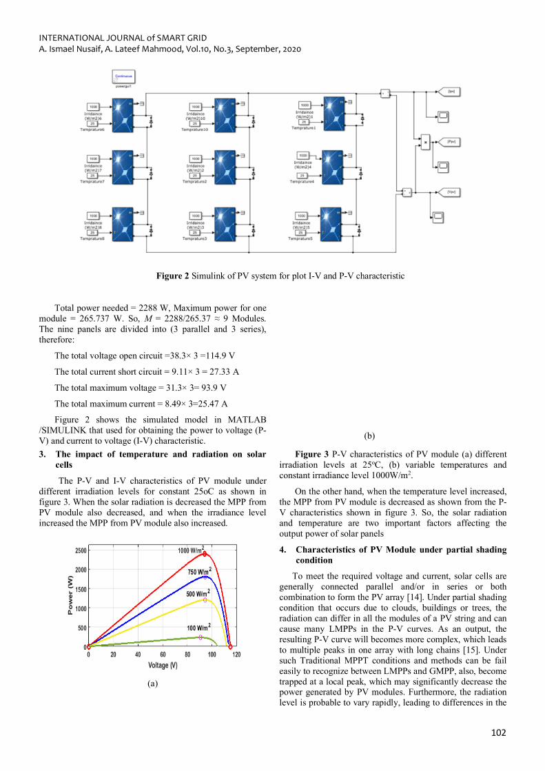
Figure 2 Simulink of PV system for plot I-V and P-V characteristic
Total power needed = 2288 W, Maximum power for one module = 265.737 W. So, M = 2288/265.37 ≈ 9 Modules. The nine panels are divided into (3 parallel and 3 series), therefore:
The total voltage open circuit =38.3× 3 =114.9 V
The total current short circuit = 9.11× 3 = 27.33 A
The total maximum voltage = 31.3× 3= 93.9 V
The total maximum current = 8.49× 3=25.47 A
Figure 2 shows the simulated model in MATLAB /SIMULINK that used for obtaining the power to voltage (P-V) and current to voltage (I-V) characteristic.
(b)
3. The impact of temperature and radiation on solar cells
The P-V and I-V characteristics of PV module under different irradiation levels for constant 25oC as shown in figure 3. When the solar radiation is decreased the MPP from PV module also decreased, and when the irradiance level increased the MPP from PV module also increased.
(a)
(a)
Figure 3 P-V characteristics of PV module (a) different irradiation levels at 25oC, (b) variable temperatures and constant irradiance level 1000W/m2.
On the other hand, when the temperature level increased, the MPP from PV module is decreased as shown from the P-V characteristics shown in figure 3. So, the solar radiation and temperature are two important factors affecting the output power of solar panels
4. Characteristics of PV Module under partial shading condition
To meet the required voltage and current, solar cells are generally connected parallel and/or in series or both combination to form the PV array [14]. Under partial shading condition that occurs due to clouds, buildings or trees, the radiation can differ in all the modules of a PV string and can cause many LMPPs in the P-V curves. As an output, the resulting P-V curve will becomes more complex, which leads to multiple peaks in one array with long chains [15]. Under such Traditional MPPT conditions and methods can be fail easily to recognize between LMPPs and GMPP, also, become trapped at a local peak, which may significantly decrease the power generated by PV modules. Furthermore, the radiation level is probable to vary rapidly, leading to differences in the
INTERNATIONAL JOURNAL of SMART GRID A. Ismael Nusaif, A. Lateef Mahmood, Vol.10, No.3, September, 2020
103
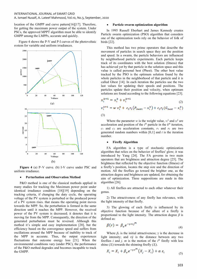
location of the GMPP and curve pattern[16][17]. Therefore, for getting the maximum power output of the system. Under PSCs, the approved MPPT algorithm must be able to identify GMPP among the LMPPs, accurate and quickly.
Figure 4 shows the P-V and P-I curves of the photovoltaic system for variable and uniform irradiances.
(a)
(b)
Figure 4 (a) P–V curve. (b) I-V curve under PSC and uniform irradiance.
• Perturbation and Observation Method
P&O method is one of the classical methods applied in many studies for tracking the Maximum power point under identical irradiance condition [18][19] depending on the tracking criteria, if changing the duty cycle, the operating voltage of the PV system is perturbed or the produced power of a PV system rises. that means the operating point moves towards the MPP. So, the perturbation is formed in the same direction until it reaches the MPP. However, the received power of the PV system is decreased; it denotes that it is moving far from the MPP. Consequently, the direction of the generated perturbation must be reversed. Although this method it’s simple and easy implementation [20], but the efficiency based on the convergence speed and suffers from oscillations around the MPP because of inability to track of the MPP in accurate. Thus, the output experiences fluctuations that outcome energy loss [21]. When the environmental conditions vary (under PSC), the performance of the P&O method degrades and becomes incapable to track the GMPP.
• Particle swarm optimization algorithm
In 1995 Russell Eberhart and James Kennedy creates Particle swarm optimization (PSO) algorithm that considers one of the optimization tools rely on the behavior of folk of birds [22].
This method has two prime operators that describe the movement of particles in search space they are the position and speed. In a swarm, the particle behaviors are influenced by neighborhood particle experiments. Each particle keeps track of its coordinates with the best solution (fitness) that has achieved yet by that particle in the solution space and this value is called personal best (Pbest). The other best value tracked by the PSO is the optimum solution found by the whole particles in the neighborhood of that particle and it is called Gbest [14]. In each iteration the particles use the two last values for updating their speeds and positions. The particles update their position and velocity, when optimum solutions are found according to the following equations [23].
(2)
(3)
Where the parameter w is the weight value, vik and xik are acceleration and position of the ith particle in the kth iteration, c1 and c2 are acceleration constants, r1 and r2 are two generated random numbers within [0,1] and t is the iteration number.
• Firefly Algorithm
FA algorithm is a type of stochastic optimization algorithm that relies on the behavior of fireflies' glow; it was introduced by Yang [24]. The FA governs in two main operators that are brightness and attraction degree [25]. The brightness that reflected by the objective function (fitness) of a firefly’s position, locates the step size and the direction of motion. All the fireflies go toward the brighter one, as the attraction degree and brightness are updated, for obtaining the aim of optimization. Three suppositions are made in this algorithm [26].
1) All fireflies are attracted to each other whatever their genus.
2) The attractiveness of any firefly has relevance, with the light intensity of that firefly.
3) The glowing of each firefly is influenced by its objective function because of the allure of a firefly is proportional to the light intensity. The attraction degree β is defined as:
(4)
Where βo is the initial attractiveness; γ is the decrease in light intensity; and rij is the distance between any two fireflies i and j. m is the motion of the ith firefly with less shine (Xi) towards the shinning firefly (Xj).
(5)
INTERNATIONAL JOURNAL of SMART GRID A. Ismael Nusaif, A. Lateef Mahmood, Vol.10, No.3, September, 2020
104
Where, the second expression determined the attraction, the third expression (α εi) is the randomizer parameter, α is the coefficient of randomizer parameter between 0 and 1and εi is a random vector composing of numbers formed from a Gaussian or uniform distribution.
• Modified Firefly Algorithm
In general, the population size for PSO and FA is constant. A larger population is beneficial to the global search process, but it increases tracking time. On the other hand, [27] a low population decreases the tracking time of research, but might a trip to the local MPP instead of the global MPP. The modified firefly algorithm (MFA) is proposed [28], Where the main point behind this algorithm is an adaptation of population size [29], so, the coefficients of the algorithm (α, βo) [14] are updated in each iteration, to obtain poise between convergence speed and the tracking efficiency. α and βo are defined as follows:
(6)
(7)
Where iter is the iteration number and Max,iter presents the maximum number of iterations. As can be seen in Eq. (5), the value of the parameter α is large at the first iteration, then, it is lowered in the next iterations for accelerating the convergence and decreasing the tracking time this lead to lower the chance of trapping in the local optimums [24]. Furthermore, when βo reduced at each iteration, the convergence speed raises.
5. The steps of MFA algorithm to MPPT
1-Set the initial parameter of MFA such as randomization parameter and attractiveness.
2- Suppose population size.
3- Simulate the Simulink module.
4- extract the output power that's specified the brightness of the firefly.
5- Update the duty cycle value that's represented by the position of firefly depending on the optimization technique that's applied.
6- Check the restrictions and run the best solution.
6. Simulation Results
Three different MPPT algorithms PSO, FA, and MFA were selected to trial their ability in tracking the GMPP with an overall comparison is achieved with the help of the conventional P&O method, under uniform and non-uniform shadow patterns. To simulate the MPP, the four algorithms code is programmed within MATLAB Simulink software. The nine PV modules connected in series and parallel that's equipped with a DC-DC converter. The prime goal for PSO, FA, and MFA technologies is for obtaining the optimum duty cycle in which GMPP is performed. The program begins with giving an initial vector of duty cycles feed to the DC converter. The output power of the PV system is calculated
after a specific time, and then a new duty cycle enters the circuit. This process is repeated several times and updated depending on PSO, FA, and MFA algorithm until the duty cycle is found and access GMPP. The input inductor of the back-boost converter is 20µH, the switching frequency is f = 25 kHz, the output capacitor is 0.038f and the output resistance load is 0.9634 Ω with load 2288W.
The variables studied are as follows:
For MFA method, the variables studied are: βomax = 2.5, βomin = 1.5, αmax = 0.6, αmin = 0.1, γ = 1 and the number of iterations is 5.
For FA method βo = 2.5, α = 0.6, γ = 1 and the number of iterations is 6.
For the PSO method, C1 = C2 = 1.5389, w = 0.754, and the number of iterations is 12.
For the P&O algorithm, the 𝝙d= 10-7, Dintial = 0.35, Dmin = 0.2, Dmax = 0.9.
These parameter values were obtained empirically by simulation.
These methods were examined in different conditions of partial shading in terms of convergence speed, tracking time, fluctuation around MPP point, and tracking efficiency.
• Case study A: Non-uniform irradiation
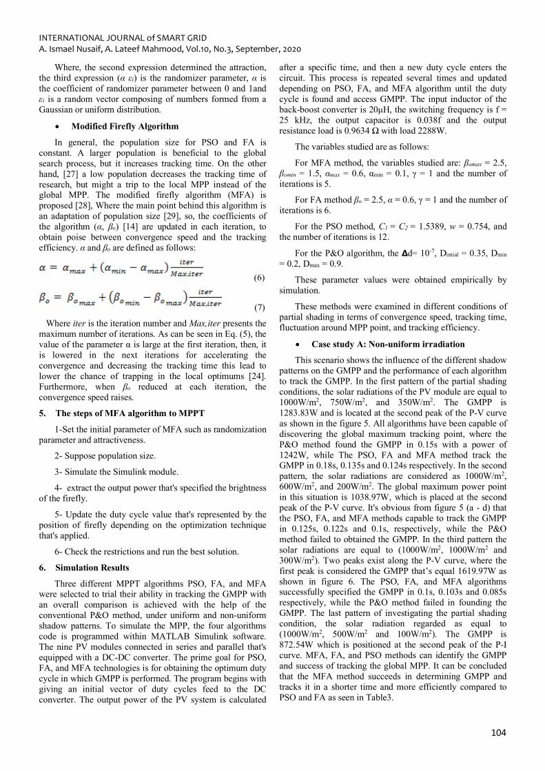
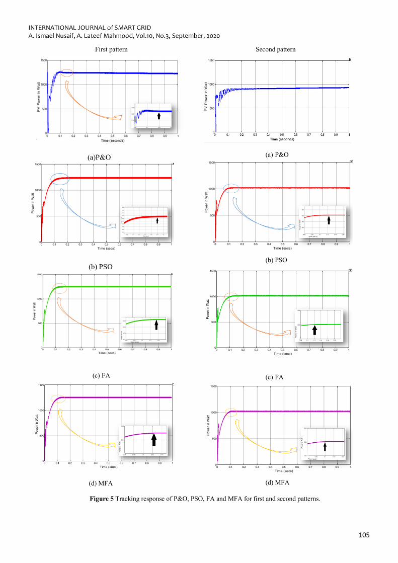
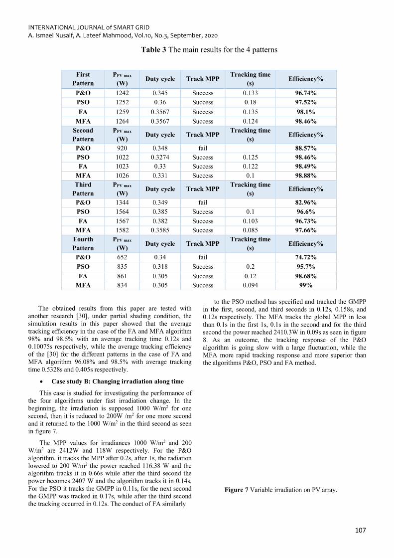
This scenario shows the influence of the different shadow patterns on the GMPP and the performance of each algorithm to track the GMPP. In the first pattern of the partial shading conditions, the solar radiations of the PV module are equal to 1000W/m2, 750W/m2, and 350W/m2. The GMPP is 1283.83W and is located at the second peak of the P-V curve as shown in the figure 5. All algorithms have been capable of discovering the global maximum tracking point, where the P&O method found the GMPP in 0.15s with a power of 1242W, while The PSO, FA and MFA method track the GMPP in 0.18s, 0.135s and 0.124s respectively. In the second pattern, the solar radiations are considered as 1000W/m2, 600W/m2, and 200W/m2. The global maximum power point in this situation is 1038.97W, which is placed at the second peak of the P-V curve. It's obvious from figure 5 (a - d) that the PSO, FA, and MFA methods capable to track the GMPP in 0.125s, 0.122s and 0.1s, respectively, while the P&O method failed to obtained the GMPP. In the third pattern the solar radiations are equal to (1000W/m2, 1000W/m2 and 300W/m2). Two peaks exist along the P-V curve, where the first peak is considered the GMPP that’s equal 1619.97W as shown in figure 6. The PSO, FA, and MFA algorithms successfully specified the GMPP in 0.1s, 0.103s and 0.085s respectively, while the P&O method failed in founding the GMPP. The last pattern of investigating the partial shading condition, the solar radiation regarded as equal to (1000W/m2, 500W/m2 and 100W/m2). The GMPP is 872.54W which is positioned at the second peak of the P-I curve. MFA, FA, and PSO methods can identify the GMPP and success of tracking the global MPP. It can be concluded that the MFA method succeeds in determining GMPP and tracks it in a shorter time and more efficiently compared to PSO and FA as seen in Table3.
INTERNATIONAL JOURNAL of SMART GRID A. Ismael Nusaif, A. Lateef Mahmood, Vol.10, No.3, September, 2020
105
First pattern
(a)P&O
(b) PSO
(c) FA
(d) MFA
Second pattern
(a) P&O
(b) PSO
(c) FA
(d) MFA
Figure 5 Tracking response of P&O, PSO, FA and MFA for first and second patterns.
INTERNATIONAL JOURNAL of SMART GRID A. Ismael Nusaif, A. Lateef Mahmood, Vol.10, No.3, September, 2020
106
Third pattern
(a) P&O
(b)PSO
(c) FA
(d) MFA
Fourth pattern
(a) P&O
(b) PSO
(c) FA
(d) MFA
Figure 6 Tracking responses of P&O, PSO, FA and MFA for third and fourth pattern.
INTERNATIONAL JOURNAL of SMART GRID A. Ismael Nusaif, A. Lateef Mahmood, Vol.10, No.3, September, 2020
107
Table 3 The main results for the 4 patterns
The obtained results from this paper are tested with another research [30], under partial shading condition, the simulation results in this paper showed that the average tracking efficiency in the case of the FA and MFA algorithm 98% and 98.5% with an average tracking time 0.12s and 0.10075s respectively, while the average tracking efficiency of the [30] for the different patterns in the case of FA and MFA algorithm 96.08% and 98.5% with average tracking time 0.5328s and 0.405s respectively.
• Case study B: Changing irradiation along time
This case is studied for investigating the performance of the four algorithms under fast irradiation change. In the beginning, the irradiation is supposed 1000 W/m2 for one second, then it is reduced to 200W /m2 for one more second and it returned to the 1000 W/m2 in the third second as seen in figure 7.
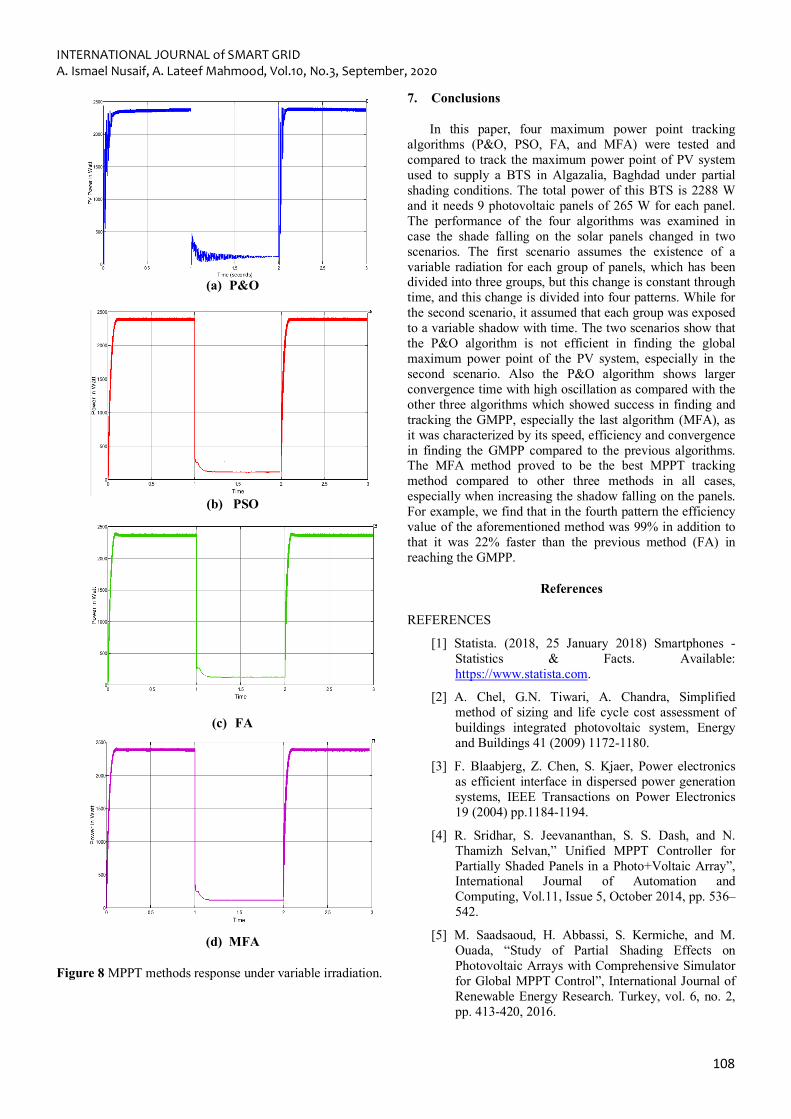
The MPP values for irradiances 1000 W/m2 and 200 W/m2 are 2412W and 118W respectively. For the P&O algorithm, it tracks the MPP after 0.2s, after 1s, the radiation lowered to 200 W/m2 the power reached 116.38 W and the algorithm tracks it in 0.66s while after the third second the power becomes 2407 W and the algorithm tracks it in 0.14s. For the PSO it tracks the GMPP in 0.11s, for the next second the GMPP was tracked in 0.17s, while after the third second the tracking occurred in 0.12s. The conduct of FA similarly
to the PSO method has specified and tracked the GMPP in the first, second, and third seconds in 0.12s, 0.158s, and 0.12s respectively. The MFA tracks the global MPP in less than 0.1s in the first 1s, 0.1s in the second and for the third second the power reached 2410.3W in 0.09s as seen in figure 8. As an outcome, the tracking response of the P&O algorithm is going slow with a large fluctuation, while the MFA more rapid tracking response and more superior than the algorithms P&O, PSO and FA method.
Figure 7 Variable irradiation on PV array.
Efficiency% Tracking time (s)
Track MPP Duty cycle PPV max (W)
First Pattern
96.74% 0.133 Success 0.345 1242 P&O 97.52% 0.18 Success 0.36 1252 PSO 98.1% 0.135 Success 0.3567 1259 FA 98.46% 0.124 Success 0.3567 1264 MFA
Efficiency% Tracking time (s)
Track MPP Duty cycle PPV max (W)
Second Pattern
88.57% fail 0.348 920 P&O 98.46% 0.125 Success 0.3274 1022 PSO 98.49% 0.122 Success 0.33 1023 FA 98.88% 0.1 Success 0.331 1026 MFA
Efficiency% Tracking time (s)
Track MPP Duty cycle PPV max (W)
Third Pattern
82.96% fail 0.349 1344 P&O 96.6% 0.1 Success 0.385 1564 PSO 96.73% 0.103 Success 0.382 1567 FA 97.66% 0.085 Success 0.3585 1582 MFA
Efficiency% Tracking time
(s) Track MPP Duty cycle PPV max
(W) Fourth Pattern
74.72% fail 0.34 652 P&O 95.7% 0.2 Success 0.318 835 PSO 98.68% 0.12 Success 0.305 861 FA
99% 0.094 Success 0.305 834 MFA
INTERNATIONAL JOURNAL of SMART GRID A. Ismael Nusaif, A. Lateef Mahmood, Vol.10, No.3, September, 2020
108
(a) P&O
(b) PSO
(c) FA
(d) MFA
Figure 8 MPPT methods response under variable irradiation.
7. Conclusions
In this paper, four maximum power point tracking algorithms (P&O, PSO, FA, and MFA) were tested and compared to track the maximum power point of PV system used to supply a BTS in Algazalia, Baghdad under partial shading conditions. The total power of this BTS is 2288 W and it needs 9 photovoltaic panels of 265 W for each panel. The performance of the four algorithms was examined in case the shade falling on the solar panels changed in two scenarios. The first scenario assumes the existence of a variable radiation for each group of panels, which has been divided into three groups, but this change is constant through time, and this change is divided into four patterns. While for the second scenario, it assumed that each group was exposed to a variable shadow with time. The two scenarios show that the P&O algorithm is not efficient in finding the global maximum power point of the PV system, especially in the second scenario. Also the P&O algorithm shows larger convergence time with high oscillation as compared with the other three algorithms which showed success in finding and tracking the GMPP, especially the last algorithm (MFA), as it was characterized by its speed, efficiency and convergence in finding the GMPP compared to the previous algorithms. The MFA method proved to be the best MPPT tracking method compared to other three methods in all cases, especially when increasing the shadow falling on the panels. For example, we find that in the fourth pattern the efficiency value of the aforementioned method was 99% in addition to that it was 22% faster than the previous method (FA) in reaching the GMPP.
References
REFERENCES
[1] Statista. (2018, 25 January 2018) Smartphones - Statistics & Facts. Available: https://www.statista.com.
[2] A. Chel, G.N. Tiwari, A. Chandra, Simplified method of sizing and life cycle cost assessment of buildings integrated photovoltaic system, Energy and Buildings 41 (2009) 1172-1180.
[3] F. Blaabjerg, Z. Chen, S. Kjaer, Power electronics as efficient interface in dispersed power generation systems, IEEE Transactions on Power Electronics 19 (2004) pp.1184-1194.
[4] R. Sridhar, S. Jeevananthan, S. S. Dash, and N. Thamizh Selvan,” Unified MPPT Controller for Partially Shaded Panels in a Photo+Voltaic Array”, International Journal of Automation and Computing, Vol.11, Issue 5, October 2014, pp. 536–542.
[5] M. Saadsaoud, H. Abbassi, S. Kermiche, and M. Ouada, “Study of Partial Shading Effects on Photovoltaic Arrays with Comprehensive Simulator for Global MPPT Control”, International Journal of Renewable Energy Research. Turkey, vol. 6, no. 2, pp. 413-420, 2016.
INTERNATIONAL JOURNAL of SMART GRID A. Ismael Nusaif, A. Lateef Mahmood, Vol.10, No.3, September, 2020
109
[6] M.Valan Rajkumar, P.S.Manoharan, Modeling and Simulation of Three-phase DCMLI using SVPWM for Photovoltaic System, Springer Lecture Notes in Electrical Engineering, under the volume titled “Power Electronics & Renewable Energy Systems", Volume 326, Chapter No 5, pp. 39-45, January 2015.
[7] Safari Azadeh, and Mekhilef Saad. Simulation and hardware implementation of incremental conductance MPPT with direct control method using cuk converter.IEEE Trans Ind Electron, Vol.58, pp.1154-61, 2011.
[8] P.Selvapriyanka and G.Vijayakumar, “Partical swarm optimization based MPPT for PV system under partial shading conditions”, IJIRSET Inter. Conf. on Eng. Tech. and Science,Vol. 3 , pp.856-861, Jan.2014.
[9] D.F Teshome, C.H.Lee, Y.W.Lin, and K.L.Lian “A Modified Firefly Algorithm for Photovoltaic Maximum Power Point Tracking ControlUnder Partial Shading”, presented in journal of engineering and selected topics in power electronics IEEE, pp. 1-24, 2016.
[10] L. N. Rao and S. Gairola, “PV system analysis under partial shading usinga sine model,” International Journal of Renewable Energy Research (IJRER), vol. 8, no. 1, pp. 280–290, 2018.
[11] Y. Liu, Z. Lu and F. Yang, "The investigation of solar PV models," 2018 IEEE Power & Energy Society Innovative Smart Grid Technologies Conference (ISGT), Washington, DC, 2018, pp. 1-5.
[12] Elewa, A., Elkholy, M. M., & El-arini, M. (2017). Adaptive MPPT for PV systems under partial shadow condition and different loads using advanced optimization techniques. 2017 Nineteenth International Middle East Power Systems Conference (MEPCON), 2017.
[13] Jasim. K, Abdul-Hussain. M, " Optimization of Hybrid PV/Diesel Power Systemfor Remote Telecom Station", International Journal of Application or Innovation in Engineering & Management (IJAIEM), vol. 5, issue 3, pp.39-46,2016.
[14] Farzaneh, J., Keypour, R., & Khanesar, M. A. (2018). A New Maximum Power Point Tracking Based on Modified Firefly Algorithm for PV System Under Partial Shading Conditions. Technology and Economics of Smart Grids and Sustainable Energy.
[15] Sadegh Hesari, “Design And Implementation Of Maximum Solar Power Tracking System Using Photovoltaic Panels” International Journal of Renewable Energy Research, Vol. 6, No 4 (2016), pp. 1221-1226
[16] A. Singh, “MATLAB / SIMULINK Simulation of PV System based on MPPT in Variable Irradiance
with EV Battery as Load,” 2017 IEEE Int. Conf. Comput. Intell. Comput. Res., no. 2, pp. 4–7, 2017.
[17] D. Pera, J. A. Silva, S. Costa and J. M. Serra, "Investigating the impact of solar cells partial shading on photovoltaic modules by thermography," 2017 IEEE 44th Photovoltaic Specialist Conference (PVSC), pp. 1979-1983, 2017.
[18] Numan. B, Mahmood. A, “Power Load Optimization for a Remote Area BTS Site Using MPPT Algorithms,” J.Information Sciences and Computing Technologies (JISCT), Vo 4, issue 2, pp.318-325, August. 2015.
[19] D. Haji and N. Genc, “Fuzzy and P&O Based MPPT Controllers under Different Conditions”, 7th International Conference on Renewable Energy Research and Applications (ICRERA), Paris, France, pp. 649-655, 14-17 Oct. 2018.
[20] D. Sera, R. Teodorescu, and P. Rodriguez, “PV panel model based on datasheet values,” Proc of IEEE ISIE, 2007, no. 4.
[21] Mohapatra, A., Nayak, B., & Saiprakash, C. (2019). Adaptive Perturb & Observe MPPT for PV System with Experimental Validation. 2019 IEEE International Conference on Sustainable Energy Technologies (ICSET).
[22] Renaudineau H et al (2015) A PSO-based global MPPT technique for distributed PV power generation. IEEE 7Trans Ind Electron 62(2):1047–1058.
[23] Kermadi, Mostefa, Berkouk EM. A hybrid PSO-PI based maximum power point tracking algorithm using adaptive sampling time strategy. In: Proceedings of the 4th int conf electr eng (ICEE, 2015); 2015. p. 1–6.
[24] X. S. Yang, “Firefly algorithms for multimodal optimization,” Stochastic Algorithms Foundations & Applications (SAGA) (Springer, 2009), Vol. 5792, pp.169–178.
[25] E. Mostafa, N.K. Bahgaat, “A Comparison Between Using A Firefly Algorithm and A Modified PSO Technique for Stability Analysis of a PV System Connected to Grid”, International Journal of Smart GridijSmartGrid. Vol. 1, pp. 1-8, December 2017.
[26] Naidu, K., Mokhlis, H., & Bakar, A. H. A. (2013). Application of Firefly Algorithm (FA) based optimization in load frequency control for interconnected reheat thermal power systems. Proceedings of IEEE jordan conference on Applied Electrical Engineering and Computing Technologies(AEECT 2013). Amman,1-5. doi:10.1109/AEECT.2013.6716461
[27] T. Niknam, R. Azizipanah-Abarghooee, and A. Roosta, “Reserve constrained dynamic economic

INTERNATIONAL JOURNAL of SMART GRID A. Ismael Nusaif, A. Lateef Mahmood, Vol.10, No.3, September, 2020
110
dispatch: A new fast self-adaptive modified firefly algorithm,” IEEE Syst. J. 6(4), 635–646 (2012).
[28] J.Ying Shi, F.Xue, Z.J.Qin, L.T.Ling, T.Yang, Y.Wang, and J.Wu,”Tracking the Global maximum power point of a photovoltaic system under partial shading conditions using a modified firefly algorithm”,J.Renewable sustainable energy 8, 2016, pp.033501-13.
[29] Farzaneh, J. (2019). "A Hybrid Modified FA-ANFIS-P&O Approach for MPPT in Photovoltaic Systems under PSCs", International Journal of Electronics. doi:10.1080/00207217.2019.1672808.
[30] Huang, Y.-P., Ye, C.-E., & Chen, X., “A Modified Firefly Algorithm with Rapid Response Maximum Power Point Tracking for Photovoltaic Systems under Partial Shading Conditions,” Energies, 11(9), 2284. doi:10.3390/en11092284, 2018.