Hybrid, Optimal, Intelligent and Classical PV MPPT Techniques
25
CSEE JOURNAL OF POWER AND ENERGY SYSTEMS, VOL. 7, NO. 1, JANUARY 2021 9 Hybrid, Optimal, Intelligent and Classical PV MPPT Techniques: A Review Ratnakar Babu Bollipo, Suresh Mikkili , Senior Member, IEEE, and Praveen Kumar Bonthagorla, Member, IEEE Abstract—Renewable energy-based solar photovoltaic (PV) generation is the best alternative for conventional energy sources because of its natural abundance and environment friendly characteristics. Maximum power extraction from the PV system plays a critical role in increasing the efficiency of the solar power generation during partial shading conditions (PSCs). Therefore, a suitable maximum power point tracking (MPPT) technique to track the maximum power point (MPP) is of high need, even under PSCs. This paper presents an organized and concise review of MPPT techniques implemented for the PV systems in literature along with recent publications on various hardware design methodologies. Their classification is done into four categories, i.e. classical, intelligent, optimal, and hybrid depending on the tracking algorithm utilized to track MPP under PSCs. During uniform insolation, classical methods are highly preferred as there is only one peak in the P-V curve. However, under PSCs, the P-V curve exhibits multiple peaks, one global maximum power point (GMPP) and remaining are local maximum power points (LMPP’s). Under the PSCs, classical methods fail to operate at GMPP and hence there is a need for more advanced MPPT techniques. Every MPPT technique has its advantages and limits, but a streamlined MPPT is drafted in numerous parameters like sensors required, hardware implementation, cost viability, tracking speed and tracking efficiency. This study provides the advancement in this area since some parameter comparison is made at the end of every classification, which might be a prominent base-rule for picking the most gainful sort of MPPT for further research. Index Terms—GMPP, MPPT classification, MPPT techniques, partial shading conditions (PSCs), photovoltaic system. I. I NTRODUCTION A significant proliferation of the enormous electricity-based appliances in this generation triggered the usage of the best alternative renewable energy. Photovoltaic (PV) en- ergy becomes a promising alternative among these renewable sources as it is omnipresent, freely available, environment- friendly, and has less operational and maintenance costs. This energy became dominant among all remaining renewable Manuscript received November 6, 2019; revised March 15, 2020; accepted May 23, 2020. Date of online publication August 19, 2020; date of current version August 10, 2020. This work was supported by the Science and Engineering Research Board (SERB), Department of Science & Technology, Government of India under the Grant No. ECR/2017/000316. R. B. Bollipo, S. Mikkili (corresponding author, e-mail: mikkili.suresh @nitgoa.ac.in; ORCID: https://orcid.org/0000-0002-5802-3390), and P. K. Bonthagorla are with Department of Electrical and Electronics Engineering, National Institute of Technology Goa, FARMAGUDI, Ponda, Goa 403401, India. DOI: 10.17775/CSEEJPES.2019.02720 sources due to its inherent characteristics like economically attractive in the long run, driving an increasing load with greenhouse source and technologically expanding in its ma- terial usage. But, these renewable energy sources have the drawback of storing the energy and tapping of power. Due to the lacking of storage mechanism, there is a high need for extraction of this abundant energy, especially during day- time. The high yield from these renewable energies is obtained only when researchers able to enhance the efficiencies in both outstanding parameters like conversion and energy storage. Solar PV systems are being controlled with many maximum power tracking techniques (MPPT), in order to optimize the power from the PV array. This output power mainly depends on the parameters like cell temperature (T ), irradiation (G) and load connected to it [1]. Because of these merits in this renewable energy, the Gov- ernment of India made an agreement in Paris climate change conference, targeting to achieve 450 GW of renewable energy capacity by 2022. The installed capacity of India by 2020 as per the Ministry of New and Renewable Energy (MNRE), GoI, is about 175 GW which includes 100 GW of solar power, 60 GW from wind power, 9 GW from biomass power, 5 GW from small hydro-power, and 1 GW from waste-to-power as shown in Fig. 1. 35,000 37% 45% 12% 5.8% 0.2% Mega Watt Peak (MWp) 30,000 25,000 20,000 15,000 10,000 5,000 0 Wind power Solar power (grounded and roof top) Small hydro power Waste to power Bio-power Grid interactive renewable power capability (MWp) in India, January, 2020. Fig. 1. Renewable energy share in India, 2020. The dynamic nature of solar radiation results in unstable power generation throughout the day. Also, the integration of renewables with these power electronic devices and partial shading of panels leads to many losses which are prominent enough to consider in the design stage itself for driving 2096-0042 © 2019 CSEE
-
Upload
khangminh22 -
Category
Documents
-
view
7 -
download
0
Transcript of Hybrid, Optimal, Intelligent and Classical PV MPPT Techniques

CSEE JOURNAL OF POWER AND ENERGY SYSTEMS, VOL. 7, NO. 1, JANUARY 2021 9
Hybrid, Optimal, Intelligent and Classical PVMPPT Techniques: A Review
Ratnakar Babu Bollipo, Suresh Mikkili , Senior Member, IEEE, and Praveen Kumar Bonthagorla, Member, IEEE
Abstract—Renewable energy-based solar photovoltaic (PV)generation is the best alternative for conventional energy sourcesbecause of its natural abundance and environment friendlycharacteristics. Maximum power extraction from the PV systemplays a critical role in increasing the efficiency of the solar powergeneration during partial shading conditions (PSCs). Therefore,a suitable maximum power point tracking (MPPT) techniqueto track the maximum power point (MPP) is of high need, evenunder PSCs. This paper presents an organized and concise reviewof MPPT techniques implemented for the PV systems in literaturealong with recent publications on various hardware designmethodologies. Their classification is done into four categories,i.e. classical, intelligent, optimal, and hybrid depending on thetracking algorithm utilized to track MPP under PSCs. Duringuniform insolation, classical methods are highly preferred asthere is only one peak in the P-V curve. However, under PSCs, theP-V curve exhibits multiple peaks, one global maximum powerpoint (GMPP) and remaining are local maximum power points(LMPP’s). Under the PSCs, classical methods fail to operate atGMPP and hence there is a need for more advanced MPPTtechniques. Every MPPT technique has its advantages and limits,but a streamlined MPPT is drafted in numerous parameterslike sensors required, hardware implementation, cost viability,tracking speed and tracking efficiency. This study provides theadvancement in this area since some parameter comparisonis made at the end of every classification, which might be aprominent base-rule for picking the most gainful sort of MPPTfor further research.
Index Terms—GMPP, MPPT classification, MPPT techniques,partial shading conditions (PSCs), photovoltaic system.
I. INTRODUCTION
A significant proliferation of the enormous electricity-basedappliances in this generation triggered the usage of
the best alternative renewable energy. Photovoltaic (PV) en-ergy becomes a promising alternative among these renewablesources as it is omnipresent, freely available, environment-friendly, and has less operational and maintenance costs.This energy became dominant among all remaining renewable
Manuscript received November 6, 2019; revised March 15, 2020; acceptedMay 23, 2020. Date of online publication August 19, 2020; date of currentversion August 10, 2020. This work was supported by the Science andEngineering Research Board (SERB), Department of Science & Technology,Government of India under the Grant No. ECR/2017/000316.
R. B. Bollipo, S. Mikkili (corresponding author, e-mail: [email protected]; ORCID: https://orcid.org/0000-0002-5802-3390), and P. K.Bonthagorla are with Department of Electrical and Electronics Engineering,National Institute of Technology Goa, FARMAGUDI, Ponda, Goa 403401,India.
DOI: 10.17775/CSEEJPES.2019.02720
sources due to its inherent characteristics like economicallyattractive in the long run, driving an increasing load withgreenhouse source and technologically expanding in its ma-terial usage. But, these renewable energy sources have thedrawback of storing the energy and tapping of power. Dueto the lacking of storage mechanism, there is a high needfor extraction of this abundant energy, especially during day-time. The high yield from these renewable energies is obtainedonly when researchers able to enhance the efficiencies in bothoutstanding parameters like conversion and energy storage.Solar PV systems are being controlled with many maximumpower tracking techniques (MPPT), in order to optimize thepower from the PV array. This output power mainly dependson the parameters like cell temperature (T ), irradiation (G)and load connected to it [1].
Because of these merits in this renewable energy, the Gov-ernment of India made an agreement in Paris climate changeconference, targeting to achieve 450 GW of renewable energycapacity by 2022. The installed capacity of India by 2020as per the Ministry of New and Renewable Energy (MNRE),GoI, is about 175 GW which includes 100 GW of solar power,60 GW from wind power, 9 GW from biomass power, 5 GWfrom small hydro-power, and 1 GW from waste-to-power asshown in Fig. 1.
35,000 37%
45%
12%
5.8%
0.2%Meg
a W
att
Pea
k (
MW
p)
30,000
25,000
20,000
15,000
10,000
5,000
0
Wind power Solar power (grounded and roof top)
Small hydro power Waste to powerBio-power
Grid interactive renewable power capability
(MWp) in India, January, 2020.
Fig. 1. Renewable energy share in India, 2020.
The dynamic nature of solar radiation results in unstablepower generation throughout the day. Also, the integrationof renewables with these power electronic devices and partialshading of panels leads to many losses which are prominentenough to consider in the design stage itself for driving
2096-0042 © 2019 CSEE

10 CSEE JOURNAL OF POWER AND ENERGY SYSTEMS, VOL. 7, NO. 1, JANUARY 2021
a particular load [2]. Owing to all these limitations, theefficiency lies still in the range of 14%–16%. The solar losspercentage accounts nearly to 25% when a university of Tokyosurveyed over 71 Japanese PV systems [3].
Figure 2 shows a schematic diagram of a PV systeminterfaced with the load. The framework is made out of asolar-based PV array, a unidirectional DC/DC converter andDC/AC converter.
Ipv
Vpv V
IPV module
DC-DCconverter
=/=
MPPTcontroller
Inverter=/~
Gate drive
Load
Fig. 2. MPPT controller - solar PV block diagram.
In some provinces, where the wind is not adequate toproduce the required amount of electrical energy, either wind-solar hybrids or stand-alone solar systems are used [4]. X.Kong, et al. [5] gives the novel control approach, especiallyfor controlling stand-alone wind/solar systems namely hierar-chical distributed model predictive control (HDMPC). Y. Chenet al. [6] gives the details of solar module efficiency accordingto the material used, and it predicted that cadmium telluride(CdTe) and copper gallium indium diselenide (CIGS) wouldhave the average module efficiency of 17.9% and 16.4%,respectively. In reference [7], E. Koutroulis, et al. modifiedtwo parameters in real-time, to harness maximum power. Inorder to harness optimized power, both control parameters Dand the switching frequency of the converter has to be altered.As the power generated from the PV panel is low, it has toincrease to some ratio. The DC-DC converter will do this.Also, these converters will make an uncontrolled DC sourceto a regulated one. M. Das and V. Agarwal in [8] coined newhigh gain converter for 3 φ PV stand-alone system, whichreduces partial shading and parasitic capacitance effects onPV source. DC-DC converters can be utilized as changingmode controllers to change over an unregulated dc voltageto a regulated dc yield voltage. Generally, during uniformirradiance conditions, just a single most extreme power point iscreated on a P-V curve of a PV module where the PV moduledelivers its most significant yield power. Thus, to accomplishthis most extreme productivity for PV frameworks, some mostsignificant maximum power point tracking (MPPT) algorithmsare utilized. Under partial shaded conditions (PSCs), the P-Vcurve of the PV module displays various most extreme powerpoints due to the bypass diodes, which are utilized to avert hot-spots on PV modules. M. Dhimish, et al. [9] provides the novelhot-spot mitigation technique using MOSFET’s connectedpanel, and forward-looking infrared (FLIR) i5 thermal camerais used to observe these hot-spots. The power loss due tothe hot-spot effect by these diodes has a prominent effect
to consider. Because of different LMPP’s, it is tough for thetraditional MPPT’s to distinguish the GMPP on the P-V curve.Thus, to accomplish this most extreme productivity from PVframeworks, some best MPPT algorithms are utilized [10]. Thepoint where classical/traditional techniques were falling shortis the significant oscillations around the MPP point. The majordisadvantage of not precisely locating the GMPP along withthese oscillations makes the scope of classical techniques abit narrower. To mitigate these limitations, especially in PSCs,analysts have proposed a few strategies and techniques in theliterature. In reference [11], M. A. Ghasemi et al. introduced atwo-step methodology based on the GMPP tracking algorithmin which the proposed algorithm tracks more effectively thanparticle swarm optimization (PSO) algorithm in PSCs. C.Huang et al. [12] introduced a methodology which predictsthe MPP at a very faster rate based on a natural cubic-spline-based prediction model and this proposed algorithm isincorporated into the iterative search process. R. F. Coelhoet al. [13] gives the new temperature based MPPT sensor,which is sophisticated in design aspects. This method utilizesthe fact that the module voltage directly depends on the PVpanel surface temperature. In reference [14], N. Karami etal. detailed at least 40 methods, includes advanced classicalmethods like three-point weight comparison method, parasiticcomparison, β method, intelligent, and optimized techniques.However, this paper only confined to comparing the fiveparameters, mainly on algorithm tracking. A.K. Podder, etal. [15] made a comparison depending upon the trackingnature. Nearly 50 techniques are reviewed, stating their meritsand demerits. Comparison of different mathematical calcula-tion/meta heuristic-based MPPT is made by [16]. Choosingan MPPT for a particular application is important during thedesign process. References [17], [18] distinguished some ofthe MPP parameters in the literature. However, the reviewpapers mentioned above lack the real-time implementationprocedures of these MPPT techniques. Subsequently, thisstudy expects to survey and order different utilized MPPTprocedures in the literature. In this examination, favourablecircumstances and disadvantages of the discussed techniquesare abridged, and a general correlation table for each subjectof the utilized techniques has been detailed.
The rest of the paper is organized into five sections:Section II details the MPP classification based on classicalmethods. Section III details the MPP classification basedon intelligent algorithms. Section IV briefs about the MPPclassification based on optimization algorithms. Section Vdetails the hybrid classification with necessary comparisonparameters. At last, the paper concludes in Section VI.
II. MPPT METHODS FOR FINDING GMPP
The dynamic nature of generating different power and volt-age according to the environmental conditions is the challeng-ing factor in the field of this solar energy. These parametersinclude conditions like wind velocity, shading, and angle ofsolar insolation. As a result, the generation of maximum poweris not guaranteed at all electrical loads [19], [20]. MPPTtechniques are equipped with proper controllers to extract

BOLLIPO et al.: HYBRID, OPTIMAL, INTELLIGENT AND CLASSICAL PV MPPT TECHNIQUES: A REVIEW 11
maximum available power from PV configurations. There arevarious types of MPPT techniques used to run PV modules onmaximum power. Nevertheless, the efficiency of the particulartechnique depends on its tracking ability in instantaneouslychanging weather conditions. So, depending on the trackingnature under PSCs, these techniques are classified. Discussionis done on all classified techniques [18], [21] and categorizedinto the following classification, as shown in Fig. 3.
• Classical PV MPPT.• Intelligent PV MPPT.• Optimization PV MPPT.• Hybrid PV MPPT.
For classical MPPT [21], [22], the techniques includeconstant voltage (CV), incremental conductance (InC), open-circuit voltage (OCV), short circuit current (SCC), hill climb-ing (HC), perturb and observe (P&O), improved P&O, adap-tive reference voltage (ARV), ripple correlation control (RCC),and lookup table method. These techniques are easily im-plemented because of their less complexity in the algorithm.They are most efficient for uniform irradiation conditions asthe PV will generate only one GMPP in these conditions.Nevertheless, these algorithms have rapid oscillations aroundthe MPP, which results in the loss of power. Furthermore,above all these classical strategies neglecting the effect ofpartial shading conditions results in failing of tracking thegenuine MPP.
Intelligent-based techniques [21], [23] include fuzzy logiccontrol (FLC), artificial neural network (ANN), sliding modecontrol (SMC), Fibonacci series based MPPT, and Gauss-newton approach based MPPT. These techniques are intendedfor dynamic weather changing conditions with utmost highaccuracy. Their tracking efficiencies, as well as trackingspeeds, are so high. These methods also suffer from hugecontrol circuit complexity and big data processing for thetraining of the system beforehand. FLC is a striking technique,
which does not require the system knowledge for the MPPTimplementation. ANN is a faster tracking technique but needsa huge amount of data (for training) to enhance the accuracy oftracking. It uses dynamic irradiation and temperature as inputand stores them as data sets. SMC is the advanced technology,though implementation is easier with tracking speeds at higherrates. Fibonacci and Gauss-Newton are two methods, emergingat a faster rate because of their intelligence in tracking MPPby updating the searching range instantaneously.
Optimization-based techniques [21], [24] include cuckoosearch based, particle swarm optimization (PSO), gray wolfoptimization (GWO), ant-colony optimization (ACO), andartificial bee colony (ABC). These methods tend searching trueMPP in dynamic environment conditions also. PSO methodis a faster tracking algorithm with reduced steady-state os-cillations. Moreover, the implementation of these techniquesis easier with the help of low-cost microcontrollers. GWOcan search for optimum point of working at a faster as iflike wolf continuously searching for its prey. This GWO isthe best evolutionary technique with independence on systemknowledge. Cuckoo search based MPPT is also a bio-inspiredalgorithm using the nature of brood parasitism and therebyimplementing levy flight methodology to obtain optimum MPPpoint. ACO and ABC are two methods that also utilize theevolutionary methodologies, and can track GMPP withoutrequiring the temperature and irradiation sensors.
Hybrid based MPPT techniques [25] are the combinationof classical MPPT’s with intelligent or optimal MPPT’s.Some hybrid techniques also include the best combination ofintelligence and optimization. The tracking methodology inthese combined MPPT is done in two steps: estimation ofMPP at the first stage and fine-tuning of that MPP by usingadvanced methodologies in the second step. First, classical orconventional methods are utilized to locate the MPP on theP-V curve. This stage is all about making the setpoint close to
MPPT Techniques
Classic Intelligent Optimization Hybrid
Constant Voltage (CV)Adaptive Reference Voltage
(ARV) Short Circuit Current (SCC)
Open Circuit Voltage (OCV)Hill Climbing (HC)
Perturb &Observe (P & O)Improved P & O
Incremental Conductance
(InC)
Ripple Correlation Control
(RCC)
Lookup table based MPPT
Fuzzy Logic Controller (FLC)Artificial Neural Network (ANN)Sliding Mode Control (SMC)Guass Newton TechniqueFibonacci series based MPPT
Cuckoo Search (CS)
Particle Swarm Optimization
(PSO)
Grey Wolf Optimization
(GWO)
Ant Colony Optimization
(ACO)Artificial Bee Colony (ABC)
Fuzzy Particle Swarm
Optimization (FPSO)
Adaptive Neuro Fuzzy
Inference System (ANFIS)
GWO-P & O
PSO-P & O
HC–ANFIS
Fig. 3. Basic classification of tracking techniques.

12 CSEE JOURNAL OF POWER AND ENERGY SYSTEMS, VOL. 7, NO. 1, JANUARY 2021
MPP. Secondly, the setpoint is made to reach the actual MPPusing the advanced techniques. The hybrid methodologieselaborated in this paper include FPSO, ANFIS, GWO-P&O,PSO-P&O, and HC-ANFIS.
III. CLASSICAL MPPT TECHNIQUES
A. Constant Voltage (CV) Based MPPT Technique
The method is simple, fast and easy to implement butshows limited precision. In order to make the PV power tooperate near the MPP, the controlling methodology involvesthe comparison of this PV voltage with a fixed referencevoltage equivalent to the VMPP. This technique of CV used foruniform irradiation conditions and neglects the effect of bothinsolation and temperature. This CV technique estimates MPPpoint a bit far away from the genuine MPP. Thus, the workingpoint is not coordinating the MPP, and consideration ofdifferent topographical positions is necessary for the optimumreference voltage to decrease the error value. The schematicblock diagram of the CV MPPT technique is shown in Fig. 4.
Vpv
Vmpp
D
++
−−
Fig. 4. Schematic block diagram of CV MPPT technique.
In this method, the required sensors are limited to one,i.e., for voltage measurement in order to have the PV modulevoltage VPV to get the proper D for the converter [26]. Thistechnique requires to measure the Voc at regular intervals.Moreover, this technique applies to the condition where tem-perature variation is less [27]–[29]. H. Wang, et al. [30]has done the practical implementation of the novel MPPTalgorithm using CVCC (constant voltage constant current) DC-DC converter, which is enabling the researchers to find theoptimum point precisely. This algorithm uses FM80-150VDCfrom OutBack Power Systems as a commercial product tocheck the effectiveness of this MPPT.
B. Adaptive Reference Voltage (ARV)-based MPPT Technique
The ARV methodology considers the climatic conditions,unlike the CV MPPT. It estimates the T and G levels utilizingtwo additional sensors than the traditional CV system andone extra sensor than P&O method makes this system a bitcostly. However, the increase in efficiency compensated thiscost factor. ARV-based MPPT system is the extension strategyto constant voltage technique as it has the flexibility to operatein changing weather conditions. The deliberate radiation andtemperature levels adjust the RV (reference voltage) for MPPT.The schematic block model of ARV MPPT method is givenin Fig. 5. The working scope of the radiation at a given tem-perature is separated into several divisions, and the comparingRV is recorded off-line in a truth Table. The error between thereference and assessed PV voltages is compensated using thecorresponding proportional-integral (PI) controller to generate
Vpv
Vmpp
DG
T
+
−−
+
Fig. 5. Schematic block diagram of ARV MPPT technique.
a reasonable D proportional to the fitting converter that is used.M. Lasheen et al. [31] gives the simulation comparison of thismethod with the CV technique. The efficiencies came almostsimilar (> 99.7%) for both techniques in constant radiation(near to 1000 W/m2) conditions. However, for CV efficiencyfalls to 98.3% when irradiation falls to 400 W/m2 whereasthis ARV technique holds the same efficiency in all variableradiation conditions.
C. Short Circuit Current MPPT (SCC)
This method utilizes the current of the PV module todetermine the optimum operating current for harnessing themaximum power output. This offline MPPT technique ap-peared to be simple in its algorithm implementation. Usually,it happens that current at MPP (Impp) appears at the proximityof short circuit current Isc under some random environmentalconditions [32]. The current at MPP can be calculated by using(1).
Impp = Ki ∗ Isc (1)
where factor Ki ranges between 0.75 and 0.9.Above condition uncovers that this strategy is just an
approximation, and consequently, it does not work at definiteMPP. The implementation of this technique is shown inFig. 6. This technique is appropriate for low current andhigh voltage applications. Besides, the whole day operationrequires irregular estimations of Isc, resulting in the loss ofpower. A novel hybrid method of SCC with Perturb andObserve (P&O) method is explained in reference [33]. Thiscombination enhances the overall tracking efficiency, i.e., gives93.4% and 91.93% during normal and dynamic weather condi-tions, respectively. This technique is advanced by connectingdSPACE DS1104 embedded card directly to the Simulinkenvironment and without using the irradiation sensor also.
Vmpp
VpvD
KiIsc
−
−
++
Fig. 6. Block diagram of SCC MPPT method.
D. Open Circuit Voltage MPPT (OCV)
This OCC MPPT, also another Off-line technique, measuresan off-line parameter, open circuit voltage Voc, which will benearer to the (Vmpp). The relation between (Vmpp) and Voc is

BOLLIPO et al.: HYBRID, OPTIMAL, INTELLIGENT AND CLASSICAL PV MPPT TECHNIQUES: A REVIEW 13
given by (2).
Vmpp = Kv ∗ Voc (2)
Practically determined Kv value lies in the range of 0.7 and0.8 [18], [20] and can be known with the help of the data-sheetprovided by the manufacturer. As found in the above condition,this strategy is based on estimation. The implementation of thistechnique is shown in Fig. 7.
Vpv
Voc
D
Vmpp
Kv
−
+−
+
Fig. 7. Block diagram of OCV MPPT method.
It is most appropriate for low voltage, high current applica-tions as it is mostly based on the rule of approximation. Thedrawback in this method will be the irregular measurement ofVoc, which results in unnecessary usage of power. After gettingthe approximated value of Vmpp, a closed-loop controller isused to reach the desired voltage. Since the connection isjust an estimation, the PV array, in fact, never works atthe MPP. A. Frezzetti, et al. [34] coined an improved OCVtechnique named “smart timer”, which can able track MPPin PSCs also. This smart timer estimates the frequency ofthe sample and hold circuit. The hardware implementationof this technique is done, and effectiveness is compared withconventional OCV. This technique holds good for low powerconsumption applications, so had an area of broader scope. Ituses the LTC1440 Estimator, DG412 Estimator, NSL-19M51Smart timer for the sampling and holding the values that it istracking.
E. Hill Climbing Methods (HC)
This HC method incorporates both D (for perturbing thepower converter) and voltage (perturbing the operating volt-age) as the parameter variables used for the perturbation.The basic working principle of this method starts with theappropriate initial guess to the solution, most likely to be anarbitrary point. Then the search goes towards the best solutionwith the steps of incremental change to the solution obtained.If the obtained solution yields another best optimum point,then the search will be repeated with the same increments. Thisprocess will continue until there were no more improvementsin the solution. The fundamental way of working procedure ofthese sort of strategies appeared in Table I and is same for theremaining techniques, but the calculations/algorithm differs forevery one of them. Two techniques are usually found in thiscategory [35], i.e., perturb and observe (P&O) and incrementalconductance (InC). A. Ahmed, et al. [36] gives a detailedanalysis of selecting the initial step of the perturbation, whichnecessarily should be taken care of, for faster convergenceof optimal working point. W. J. A. Teulings, et al. [37] gavethe implementation of this technique with the microcontrollerAnalog-Digital (A-D) converters. The main contrast between
P&O and HC is the perturbation variable. The working ofInC mainly depends on the slope of the power-voltage (P-Vcurve), whereas the P&O has voltage as a control variable.HC technique has a D as the perturbation variable. This HCmethod is the best and simple technique implemented in anymicrocontroller. Also, it requires neither sensors for irradiationand temperature nor the solar PV knowledge. The limitationof these techniques lies in the oscillations around the MPP andunable to differentiate the power change, whether it occurreddue to change in G or change in D.
TABLE ITHE PROBABILISTIC VARIATION OF DIRECTION OF HILL
CLIMBING METHODOLOGY
∆P ∆V Direction of perturbation variable+ − ++ − −− + −− − +
Note: ∆P , ∆V − Change in power and voltage respectively,+ Increment, − Decrement.
F. Perturb and Observe (P&O) MPPT
Simplest in its algorithm and easy to implement on any mi-crocontroller makes this P&O MPPT a user friendly, allowingmost authors to implement for their applications. Literaturesurvey reveals that this technique relies upon the trial anderror method in searching and following the MPP [22], [32],[38]. P&O calculation compares the power obtained in twopoints on a P-V curve and then compares the position ofvoltage. Then the voltage is updated accordingly (either toleft or right of P-V curve) in order to track the MPP. Blockdiagram representation of this P&O technique is shown inFig. 8. Fundamentally, this strategy checks for the change inPV cell power (dP ), then checks for the sign of PV cell voltage(dV ). According to the values obtained, D is perturbed. P-Vcurve data is used to analyze the actual movement of theoperating point. Depending on the curve, if the (dP/dV ) ispositive, then the actual point seems to be in the left half of theMPP; else in negative half. Moreover, this process proceedsuntil (dP/dV ) equivalents to zero.
Vpv
Ipv
DP(t)
P(t−1)
−
−
++
Fig. 8. Conventional P&O with fixed perturbation step.
The algorithm flow chart is shown in Fig. 9. At the extremepoint of any P-V curve, MPP is given by (3). The position ofMPP (either left or right) is determined by using (4), (5).
dPPV
dVPV= 0 = MPP (3)
dPPV
dVPV> 0 Left side of MPP (4)
dPPV
dVPV< 0 Right side of MPP (5)

14 CSEE JOURNAL OF POWER AND ENERGY SYSTEMS, VOL. 7, NO. 1, JANUARY 2021
Delta=0
Delta>0
True
True
False
False
False False TrueTrue
Start P&O MPPTalgorithm
Read PV voltage,current and
temperature values
P(t)=V(t)*I(t)Delta=P(t)−P(t−1)
IncreaseV(t)
DecreaseV(t)
Decrease V(t) Increase V(t)
Update new PVvoltage and current
Maximum powerpoint found
V(t)>V(t−1)V(t)>V(t−1)
Fig. 9. Flowchart of P&O algorithm.
Micro-controller based execution environment is completedwith the usage of two sensors in order to read both voltage andcurrent of PV cell. Referring to the paper written by D. Sera,et al. [39], it is revealed that time taken for reaching to trackthe MPP is 2.5 sec, and its tracking efficiency is about 97.6%.The setup consists of Simulink to hardware interfacing DSpace1103 controller board with Texas Instruments TMS320F335controller board. The results obtained are maintaining the EN50530 standards for efficiencies in both static and dynamicconditions. A. Pandey and S. Srivastava [40] gives the latestimprovements in this technique.
G. Improved Perturb and Observe Method
In this technique, unnecessary following of GMPP isavoided like in conventional P&O. The proposed algorithmgives the chance of shorter effort to follow the true MPP.This method is the improved version for the conventionalP&O [41]–[44]. The reference voltage (Vref) is set at about0.8*Voc where Voc is the open-circuit voltage of the array.In their two modes of operation, i.e., voltage search modeand MPP search mode, the former one drives the operatingpoint to come almost nearer to the MPP, and the latter onehelps to calculate the exactness of MPP. The peak is trackedfirst by applying variable/modified P&O computation. TheGMPP is tracked when there is a high chance of partialshading. Y. Jiang, et al. [45] gave a clear explanation ofdifferent types of adaptive P&O algorithms and coined newMPPT algorithm named load-current adaptive step-size andperturbation frequency (LCASF) MPPT algorithm. Finally
compared the LCASF MPPT with conventional P&O. Theanalysis gives that when perturbation of step size is small(e.g., 1%) then both algorithms are nearly tracking with thesame speed and efficiency. However, when the perturbation ishigh (e.g., 4%), the LCASF algorithm has the efficiency of91% compared to 88% of conventional P&O. So, the LCASFgives the better results with faster tracking and best efficiencyby utilizing hardware with less cost and size. S. K. Kollimallaand M. K. Mishra [46] gave the novel adaptive P&O byimproving the factors causing losses in classical P&O. N.Khaehintung, et al. [47] done the hardware implementationby using FPGA based dSPACE30F2010 microcontroller toprovide control signals for the forward converter. The systemconsists of PV module Solar MSX-60 connected to forwardconverter operating with switching frequency set to 40 kHz.The LV-25 and Hall sensor LA100 are the two sensors usedto sense both voltage and current from the PV panel. Bythis advancement in this conventional system, the efficiencyis raised to 96%.
H. Incremental Conductance (InC) MPPTThis strategy essentially utilizes the same way from P&O
to reach MPP, however, utilizes the unique relationship ofthe I-V curve (current-voltage curve). This calculation un-derstands current and voltage estimations of PV cell andmeasures derivative of PV cell current (dI) and PV cell voltage(dV ) [48]–[50]. The PV current-voltage curve is utilized to de-cide the trajectory of the working point. Because of its mediumunpredictability and better subsequent execution as per P&Otechnique, it has all the qualities of being the most wellknown one in the literature for uniform conditions [51]–[53].The InC strategy depends on the way that the derivative ofthe output power P with respect to the panel voltage V isequivalent to zero at the MPP. The execution strategy of InCthrough the flowchart is shown in Fig. 10. Here in this method,all the data will be intended to use the slope of the P-Vcurve of the system and tracks the MPP with that data. Ifthe slope of the P-V curve or the derivative of the PV arraypower (dP/dV ) is zero, then only the process of trackingis accomplished. Whenever the atmospheric conditions arechanging rapidly, tracking of MPP will be harder, and therate of tracking also decreases in exponential rate due tothe consistent change of the P-V curve. It is not very easyto maintain the operating point in those conditions. Manyadaptive step size techniques are introducing to extract MPPwithout oscillations.
The mathematical approach for calculating the position ofMPP on the P-V curve is given by (6)–(12).
P = V ∗ I (6)dP
dV=
d(V I)
dV(7)
At peak power point,dP
dV= 0,
I
V+
dI
dV= 0 (8)
If the operating point is to the right of the curve, thendP
dV< 0, then if

BOLLIPO et al.: HYBRID, OPTIMAL, INTELLIGENT AND CLASSICAL PV MPPT TECHNIQUES: A REVIEW 15
True
TrueTrue
False
False
False False
False
dI=0
dI>0
Start Inc.Cond.MPPT Algorithm
Read PV Voltage,Current and
Temperature Values
dI=I(t)*I(t−1)dV=V(t)−V(t−1)
dV=0
dI/dV=−I/V
dI/dV>−I/V
IncreaseV(t)
IncreaseV(t)
DecreaseV(t)
DecreaseV(t)
Update new PVVoltage and Current
Maximum PowerPoint Found
Fig. 10. Flowchart of the InC algorithm.
I
V+
dI
dV< 0, V is decreased, (9)
ifI
V+
dI
dV> 0, V is increased. (10)
If the operating point is to the left of the curve, then
dP
dV> 0, then if
I
V+
dI
dV> 0, V is increased, (11)
ifI
V+
dI
dV< 0, V is decreased. (12)
As detailed in reference [27], this strategy implemented oncontroller board can reach MPP in 2.3 sec, and its efficiencyis approx. 98.5%. The bigger the increments of the system,the higher is the tracking efficiency. However, the system willoscillate around the MPP with the higher increments, whichalso results in inefficient yielding of MPP. The references [54],[55] and [56] gives the modified InC technique methodologies.P. Sivakumar, et al. [57] gives the hardware implementationof the improved InC method in the TMDS SOLAR EXPKIT (Solar explorer kit) C2000 microcontroller environment.Results show that the non-linear loading problem is alsoattended and tracking is done in those conditions by whichMPPT give accurate results. Both conventional and improvedmethods are compared when connected to the grid.
I. Ripple Correlation Control (RCC)
Usage of ripple content, that was produced in the PV systemfor the MPP methodology is an advancement in this field.The high-frequency ripple current, voltage, or power from the
power electronic devices connected to the PV system is usedby the RCC technique. MPP is tracked in no time withoutcompromising the accuracy by this control method with theuse of the basic analogue controller. The basic methodologyis to find the voltage derivative of power dP/dV , which isthe main parameter in finding the MPP. The power converterconsists of a voltage and current controller, which has thecapability of sensing the voltages from the inverter in orderto generate a reference signal. The RCC technique makesuse of ripples to do the task of tracking the MPP point.RCC corresponds to the time derivative of the variable PVpower with the time derivative of the time-varying PV arraycurrent or voltage to drive the power slope to zero. Thus theway of tracking the MPP is accomplished. In this technique,the values of PV voltage and current are sensed using twosensors. Besides the low efficiency of the PV system, theaddition of power converters will increase the ripple content.The switching actions of the converter will also make thissituation a little worse. These all conditions will add up tothe ripple content increase, thereby directly affecting the PVsystem output power [22], [58]–[60]. C. Boonmee and Y.Kumsuwan [61] implemented the grid-connected photovoltaicsystem (GCPVS) by the help of this RCC technique, and thesetup consists of two interface components like a dSPACEDS1104 controller board with TMS320F240 slave processorand I/O interface board CP1104. This method shows good re-sults for controlling the grid current by utilising P-Q controller.Furthermore, THD is well within the IEEE and IEC standardswith the value of 4.6% in the grid current produced by thegrid inverter. This technique utilises the pyranometer modelNovalynx Corporation/240-8101/2 to measure the irradiationduring experimental testing.
J. Lookup Table Method (LUT)
The strategy to reduce the computational time of the controlcircuit leads to this offline technique named LUT. All the dataof required values is stored beforehand and fetched from thestatic memory. In this strategy, the calculated values of thePV voltage and current are compared, with previously storedvalues which in turn makes the idea of reaching the MPP point.In this method, the database will have particular value for allthe corresponding data of solar insolation, temperature and theMPP point for those values will be there [14]. Nevertheless,accessing this much amount of data is also a block for usingthis technique. Moreover, in order to get the highest accuratetracking, the operating conditions have to be increased, whichindeed need more storage data. Thus, a trade-off between theaccuracy and the bulk data is necessary. In this method, Pmax
is a function depending on two parameters characterised in(13).
VPV × IMPP = f(Pmax) (13)
The methodology representation in block model is given inFig. 11.
In this technique, a PID type controller alters the D of theDC-DC converter. If the current IMPP and power Pmax of thePV source is zero, which will be equal to the predeterminedreference value, then the zero error is reached. This tracking

16 CSEE JOURNAL OF POWER AND ENERGY SYSTEMS, VOL. 7, NO. 1, JANUARY 2021
D
Vmpp
Vpv
IpvImpp
G
T
PIDLookuptable
−+
Fig. 11. Lookup table MPPT block diagram.
scheme is specific for array; thus, the implementation isquite complex. For the enhancement of tracking speed, higherbit Analog - Digital (A-D) converters are used. V. R. Kotaand M. N. Bhukya [68] implemented the 2-D lookup tablemethodology by using the data of P&O P-V MPP data curve.Experimental results obtained show that this technique is wellefficient than conventional P&O technique. M. Aref, et al. [69]
also implemented this method on a microcontroller AurdinoNano. This Arduino Nano uses the stored MPPT values andfor the particular insolation values generates the appropriateD by adjusting by implementing sine pulse width modulation(SPWM).
The comparison of various parameters in this classificationis given in Tables II and III. Table IV gives the contributionof different classical MPPT techniques based on literature.
IV. INTELLIGENCE MPPT TECHNIQUES
A. Fuzzy Logic Controller (FLC)
The whole process of tracking has to be improved inorder to raise efficiency especially while tracking during
TABLE IICOMPARISON OF MPPT TECHNIQUES BASED ON CLASSICAL ALGORITHM [10], [18], [22], [32]
Parameter CV ARV SCC OCV HC P&O ImprovedP&O InC RCC Lookup table
Tracking speed Slow Medium Slow Slow Medium Slow Medium Slow Fast FastTrackingaccuracy Low Medium Medium Low Medium Medium High Medium High High
Control strategy InC SM InC InC SM SM SM SM InC InCSensedparameters V V&C C V V&C V&C V&C V&C V&C G&T
Complexity Simple Simple Simple Simple Simple Moderatelycomplex
Complex Complex Complex Simple
Parameter tuning Yes Yes Yes Yes No No No No Yes Yes
Stability No No No No Yes No Yes Yes Very stable Based onmemory
A/D A A,D A,D A,D D A,D D D D DGrid integration No No No No No No No No No NoCost INEX INEX INEX INEX INEX Affordable EX EX EX INEXAbility to trackunder PSCs
No No No No No No No No Yes No
Efficiency 72.80% [62] 98% [31] 93.4% [32] 92.4% [32] 54.12% [62] 97.8% [22] 96% [47] 98.5% [22] 96.4% [22] 98.4% [32]
Note: V – Voltage, C – Current, G – Irradiance, T – Temperature, A – Analog, D- Digital, EX – Expensive, INEX – Inexpensive, SM – SamplingMethod.
TABLE IIICLASSICAL MPP TRACKING TECHNIQUES: MERITS, DE-MERITS, APPLICATION, AND COMMERCIAL PRODUCTS [63]
Technique Merits De-merits Application Commercialproducts
CV MPPT Best implies where temperature variesvery little.
Oscillations around the MPP and slow trackingspeed.
Stand-alone
BP-MSX120module.
ARV MPPTThe tracking time is less whencompared to CV and with feweroscillations.
Costly due to use of the additional sensor. Stand-alone
BP-MSX120data-sheet at STC.
SCC MPPT Simple and accurate with lesshardware computation.
Short circuit current must be periodically measured,and high power loss will occur during dynamicweather conditions.
Stand-alone −
OCV MPPT Requires less no. of sensors andcomplexity of the circuit is less. Higher power loss under PSCs. Stand-
alone −
HC MPPTThis is the most simple andinexpensive method and tracks MPP ata faster rate.
Less accurate and needs periodic tuning ofparameters.
Stand-alone −
P&OIt has very high tracking capability,less Complex, easy Implementation,and performs fast dynamic nature.
Oscillations around the MPP, unable to track exactMPP under PSCs and steady-state power loss ishigh.
Stand-alone
Genasun, USA GVBoost chargecontroller withMPPT.
ImprovedP&O
Convergence speed is faster thanP&O, true MPP is reached with betteraccuracy.
Microcontroller of higher advancement is necessaryfor hardware implementation.
Stand-alone −
InC Oscillations around the MPP is low. Variable step size requires complex and costlycontrol circuits.
Stand-alone −
RCCAs the ripple is naturally available byusing a switching converter, noartificial perturbation is required.
Rigorous mathematical calculations are required. Stand-alone −
Lookup tablemethod Very simple logic in methodology. Operation is limited as the PV array operational
values are not known under PSCs.Stand-alone −

BOLLIPO et al.: HYBRID, OPTIMAL, INTELLIGENT AND CLASSICAL PV MPPT TECHNIQUES: A REVIEW 17
TABLE IVCLASSICAL MPPT TECHNIQUES-PREVIOUS WORK DONE
Ref. No. Year MPPT G I Controlparameter
DC-DCconverter Observations
[30] 2016 CV No Arrayvoltage
Boostconverter
The proposed algorithm’s working is compared with a companymanufactured high efficient MPPT, namely solar charger with advancedMPPT function, FM80-150VDC from OutBack Power Systems.
[31] 2017 ARV No Voltage Boost This method is an improvement to CV, and this ARV based MPPT ismodelled and done simulation against conventional P&O and CV MPPTs.
[32] 2017 OCV No Voltage andcurrent Boost In this paper, intelligent novel OCV connected fractional order incremental
conductance (FOINC) is coined, and operation is done in Matlab.
[32] 2017 SCC No Voltage andcurrent Boost
In this paper, a novel hybrid SCC with P&O method is performed ondSPACE DS1104-based experimental setup, and the initial guess of aproportional constant is selected in an intelligent way such that irradiancesensor is not required.
[22] 2017 P&O No Voltage andcurrent Boost
PV system is simulated using variable irradiance and temperature. However,due to fixed-step perturbation, huge oscillations are present, which reducesoverall efficiency.
[64] 2018 ImprovedP&O Yes Voltage Boost
(LPF)In this, MPP is achieved by using an efficient methodology of variable stepP&O (VSPO) algorithm.
[36] 2012 HC No Voltage orcurrent
Boostconverter
The essential factor of the initial guess for the perturbation variable isdemonstrated with numerical analysis.
[65] 2015 InC Yes Voltage orcurrent
Boostconverter
Thermoelectric generators (TEGs) are connected as the load to the systemwhere InC with boost converter supplied the load. The performance of thisInC has compared with P&O also.
[66] 2016 RCC Yes Voltage andcurrent
Boostconverter
The RCC technique is utilized with Fuzzy based MPPT, and the PV systemis integrated into the grid. As the Ripple is always present in the converter,there is no need for separate perturbation variable.
[67] 2013 Lookuptable No Voltage Boost
converter
Both reference irradiances and temperatures are directly obtained from a 2-Dlookup Table. As the process of searching is not there for perturbationvariable, it is very fast in tracking GMPP.
Note: G I - Grid Integration, LPF - Low Pass Filter
dynamically changing weather conditions. For the controllerdesign, the PV system has to be modelled into mathematicalform. Modelling of the controller is easier for the uniformirradiation conditions. Nevertheless, the problem gets criticalwhen it comes to design for the PSCs as the system willbe overly complicated. So an intelligent technique came intolimelight, which does not require the mathematical modellingof the system. Trackers dependent on fuzzy are consideredas intelligent since the controller achieves the high efficiencyirrespective of information is certain or not. Fuzzy controllersneed not bother with a precise scientific model of the PVsystem. This FLC is advantageous over other techniques intwo ways mainly: 1) It does not require the exact mathematicalmodel of the system, 2) The way of controller design isin the hand of humans only. Human expertise is utilised indesigning the fuzzy rules, which is one primary componentout of three. In general, fuzzy technique comprises of threestages, namely fuzzification, rule base query table (fuzzyrules), and defuzzification [70], [71]. The implementation ofthis technique for a solar PV system is represented in Fig. 12.
PV module
IPV
Cdc
IPV VPV
Dn
Z−1
Z−1
VPV(n)
PPV(n)
PPV(n−1)
VPV(n−1)
Load
FLCMPPT
DC-DCconverter
Fig. 12. Block diagram of FLC MPPT technique.
In fuzzification, the inputs of PV parameters are transformedinto the linguistic variables, i.e., crisp quantity is convertedinto fuzzy quantity (fuzzy set). Mainly if-then rules are de-signed to give linguistic variables input and output relationalparameters by utilizing the human knowledge to design forappropriate application need. Defuzzification is an inversionprocess to fuzzification, where mathematical relations are usedto extract linguistic or crisp inputs. In this process mainlymaximum membership function, centroid method, weightedaverage methods are utilized for computation. In the defuzzi-fication procedure, the FLC output is changed over from alinguistic variable to a numerical variable, and this will begiving as an analog signal to the converter used. The rulebase table is the core part of the FLC, where the tuning of thetechnique to our application is made. The working of FLCslies in the continuous change of the D in the converter fromthe information of change in error and the voltage error withthe aim of panel voltage will be equivalent to the maximumvoltage (Vmpp). With the comparison of instantaneous PVarray voltage with the reference voltage, the voltage error iscalculated. In contrast, the reference voltage is the maximumvoltage of the module at that instant of solar radiation. Inthis way, the most significant voltage and reference voltagechanges as indicated by sun powered irradiance.
The inputs to an MPPT fuzzy logic controller are usuallyan error E and a change in error ∆E is expressed in (14)and (15).
E(n) =∆P
∆V
=VPV(n) ∗ IPV(n)− VPV(n− 1) ∗ IPV(n− 1)
VPV(n)− VPV(n− 1)(14)

18 CSEE JOURNAL OF POWER AND ENERGY SYSTEMS, VOL. 7, NO. 1, JANUARY 2021
∆E(n) = E(n)− E(n− 1) (15)
When ∆E and E are determined and changed over to thephonetic factors, the output of the fuzzy controller, which isthe adjustment in the converter’s duty cycle ∆D [72], [73].The block-level implementation of FLC is shown in Fig. 13.FLC is proven best to work in dynamic changing atmosphericconditions. S. Syafaruddin, et al. [74] coined the neuro-fuzzytechnique which explains the importance of hybrid techniquealong with distributed MPPT. The converters are placed foreach array in the 4*3 solar PV configurations. This techniqueis tracking the MPP at a faster rate in PSCs, and accuracy isalso very high but suffers from the factor of higher costs due tothe converter placement at every array. FLC efficiency dependson choosing best membership functions to get the error valuedown to zero, and the rule base table also finds its promi-nence in this MPPT technique effectiveness. N. Priyadarshi,et al. [75] gave the hybrid ANFIS (Artificial Neural FuzzyInference System) methodology for the improvement in bothtracking speed and efficiency of the system. It uses dSPACEas the interfacing element for the code in the controller. T. L.Kottas, et al. [76] gives the novel MPPT technique with fuzzycognitive networks.
X
ΔEZ−1
ΔD DE
ΔP=P(n)–P(n−1)
ΔV=V(n)–V(n−1)
Fuzzification Inference
Rule base
De-fuzzification +
+
Fig. 13. Control block diagram of fuzzy logic controller.
B. Artificial Neural Network (ANN)
The best alternative to solve the most complex solutionswill be done by this intelligence-based ANN. These ANNapplications will require no detailed information about thesystem and mathematical modelling. This is the way they canhandle quite more complex problems by properly mappingthe input-output of the system. ANN is the intelligence-basedadvanced MPPT technique, due to its inherent nature of thelearning process and biological nature of neurons. Fundamen-tally, the ANN can be represented by a directed chart wherethe nodes and the edges will be the neurons and the synapsesrespectively [77], [78]. One of the simple class of functioncan be represented by radial basis function networks (RBF).These RBF network connecting with the radial function, whichconsists of a single layer is shown in Fig. 14. The networkconsists of n component of input vector x feeds forward to mbasis functions. The weights are increased up to these basicfunctions according to the
∑mj=1 wj and these weights will
act linearly to get the respective output function f(X).This output equation which consists of activation function
(AF) is given by the (16).
f(X) =
m∑j=1
wj ∗ hj(X) (16)
w1wj
wm
x1
f (X)
h1(X) hj(X)hm(X)
xi xn
Fig. 14. Formulation of neural network - AF.
and x1, x2, . . . , xn are the n incoming signals, w1, w2, . . . , wm
are the related synapses weights and hj(X) represents thehidden layers in the whole network.
Generally, AF is a converter of a linear function to non-linear function, consists of hyperbolic tangent sigmoid, andLog-sigmoid. The ANN with its main building blocks withthree layers i.e., input, hidden and output layers are includedwithin a multi-layer feed-forward system. The input to thistechnique can be the PV module parameters like VOC and ISC,the environmental information like irradiance and temperature,or any combination of these two. And the output will bethe VMPP or Vref or GMPP. The process is done in the mostessential hidden layer, adjusts the weights and bias to estimatethe best-targeted value, i.e., GMPP with the available inputsets. It will yield the D signal that drives the converter tofollow the MPP dependent on the calculation utilized in thatlayer.
The capability of this technique (ANN) to effectively dis-tinguish the genuine GMPP relies upon the learning procedureas well as on the ANNs structure. The more the quantity ofdata sets (VPV, IPV) at which the P-V curve is assessed themore chances of the P-V curve approaches the GMPP. Theneurons of ANN have the capability of parallel processing,unlike in other techniques. Weights are updated according tothe function utilized in the hidden layers. Moreover, all theweights are re-initialized at a time, which gives rapid responses(faster in the process). However, the technique accuracy restson the quantity of data itself. In literature, ANN is mainlyapplied to uniform conditions [79] only due to its dependencyon the PV characteristics like module, configurations, andshading. So, if the configuration is altered, then the ANN hasto re-trained for the system. However, research is continuing tomake this ANN work in PSCs. S. Syafaruddin, et al. [74] givesthe ANN implementation to PSCs considering various shadingconditions with different configurations. This technique iscompared with the conventional techniques like P&O and InC,and ANN is giving better results in those PSCs. References[80], [81] details the factors to be considered while designingthe ANN for PSCs. The detailed implementation of ANN isshown in Fig. 15. T. Himaya, et al. [82] demonstrates theselection of PV panels for the efficient use of this ANNtechnique in order to foresee the real-time problems. M. A.Younis, et al. [83] coined the improved MPPT techniqueusing the ANN methodology. A. K. Rai, et al. [84] gives the
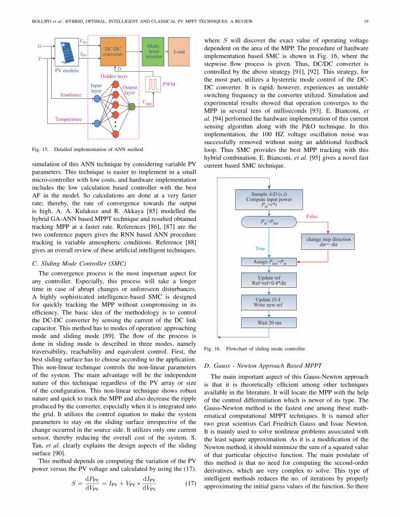
BOLLIPO et al.: HYBRID, OPTIMAL, INTELLIGENT AND CLASSICAL PV MPPT TECHNIQUES: A REVIEW 19
DC-DCconverter
PV module
G
T
Vmpp
VPV
IPVLoad
Inputlayer
Hidden layer
OutputlayerIrradiance
Temperature
PWM
D
Multi-level
inverter
Fig. 15. Detailed implementation of ANN method.
simulation of this ANN technique by considering variable PVparameters. This technique is easier to implement in a smallmicro-controller with low costs, and hardware implementationincludes the low calculation based controller with the bestAF in the model. So calculations are done at a very fasterrate; thereby, the rate of convergence towards the outputis high. A. A. Kulaksız and R. Akkaya [85] modelled thehybrid GA-ANN based MPPT technique and resulted obtainedtracking MPP at a faster rate. References [86], [87] are thetwo conference papers gives the RNN based ANN proceduretracking in variable atmospheric conditions. Reference [88]gives an overall review of these artificial intelligent techniques.
C. Sliding Mode Controller (SMC)
The convergence process is the most important aspect forany controller. Especially, this process will take a longertime in case of abrupt changes or unforeseen disturbances.A highly sophisticated intelligence-based SMC is designedfor quickly tracking the MPP without compromising in itsefficiency. The basic idea of the methodology is to controlthe DC-DC converter by sensing the current of the DC linkcapacitor. This method has to modes of operation: approachingmode and sliding mode [89]. The flow of the process isdone in sliding mode is described in three modes, namelytraversability, reachability and equivalent control. First, thebest sliding surface has to choose according to the application.This non-linear technique controls the non-linear parametersof the system. The main advantage will be the independentnature of this technique regardless of the PV array or sizeof the configuration. This non-linear technique shows robustnature and quick to track the MPP and also decrease the rippleproduced by the converter, especially when it is integrated intothe grid. It utilizes the control equation to make the systemparameters to stay on the sliding surface irrespective of thechange occurred in the source side. It utilizes only one currentsensor, thereby reducing the overall cost of the system. S.Tan, et al. clearly explains the design aspects of the slidingsurface [90].
This method depends on computing the variation of the PVpower versus the PV voltage and calculated by using the (17).
S =dPPV
dVPV= IPV + VPV ∗
dIPV
dVPV(17)
where S will discover the exact value of operating voltagedependent on the area of the MPP. The procedure of hardwareimplementation based SMC is shown in Fig. 16, where thestepwise flow process is given. Thus, DC/DC converter iscontrolled by the above strategy [91], [92]. This strategy, forthe most part, utilizes a hysteretic mode control of the DC-DC converter. It is rapid, however, experiences an unstableswitching frequency in the converter utilized. Simulation andexperimental results showed that operation converges to theMPP in several tens of milliseconds [93]. E. Bianconi, etal. [94] performed the hardware implementation of this currentsensing algorithm along with the P&O technique. In thisimplementation, the 100 HZ voltage oscillation noise wassuccessfully removed without using an additional feedbackloop. Thus SMC provides the best MPP tracking with thishybrid combination. E. Bianconi, et al. [95] gives a novel fastcurrent based SMC technique.
False
True
Sample A/D (v,i)Compute input power
Pin=v*i
Pin>Plast
change step directiondir=−dir
Assign Plast=Pin
Update refRef=ref+0.4*dir
Update D/AWrite new ref
Wait 20 ms
Fig. 16. Flowchart of sliding mode controller.
D. Gauss - Newton Approach Based MPPT
The main important aspect of this Gauss-Newton approachis that it is theoretically efficient among other techniquesavailable in the literature. It will locate the MPP with the helpof the centred differentiation which is newer of its type. TheGauss-Newton method is the fastest one among these math-ematical computational MPPT techniques. It is named aftertwo great scientists Carl Friedrich Gauss and Issac Newton.It is mainly used to solve nonlinear problems associated withthe least square approximation. As it is a modification of theNewton method, it should minimize the sum of a squared valueof that particular objective function. The main postulate ofthis method is that no need for computing the second-orderderivatives, which are very complex to solve. This type ofintelligent methods reduces the no. of iterations by properlyapproximating the initial guess values of the function. So there

20 CSEE JOURNAL OF POWER AND ENERGY SYSTEMS, VOL. 7, NO. 1, JANUARY 2021
should be a trade-off between the computation/memory Vs No.of iterations while selecting these algorithms for unconstrainedminimization [18], [96] and [97]. Coming to the gauss-newtonapproximation, the goal is to disintegrate the objective functionf = l ? m into two types mainly
• Vector based model or regression function.• Scalar valued loss (such as the sum squared variation
between anticipated output and the target value (l)).The objective function is therefore represented using the
mathematical analysis with the help of (18), (19), and (20).
mi = yi − r(ti, X) (yi, ti) i = 1, 2, . . . , P (18)
f(x) = 1/2 ∗P∑i=1
((yi − r(ti, X))2 (19)
i.e
l =∑(
(mi)2)
(20)
This method is beneficial for applying to non-linear systems.By the help of this method, very complex equations aresolved efficiently, and their calculations improvements aregiven in [98]. A. M. Farayola, et al. [99] done the extensivesimulations using this Gauss-Newton approach and compar-ison of CGSVM (coarse-Gaussian support vector machine).The novel method is compared with the three types of MPPTtechniques (ANN, ANFIS, and ANN-P&O) is done.
E. Fibonacci Series Based MPPT
Unnecessary tracking of the MPP through the whole searcharea results in increasing the computational time and large datastorage problem. This is greatly dealt with this Fibonacci basedtracking algorithm which reduces the searching time signifi-cantly by reducing the operating range. This intelligent itera-tive method, confines its search then moves to look throughthe range to get an optimum working point. The direction towhich it has to shift is depending upon the two approximatepoints V1, V2 in the range of Vmin and Vmax. This technique islike a divide and conquers approach, continually changing itsoperating range by the use of the previous iteration. Fibonacciseries is modeled in this numerical approach given in (21) and(22).
Rn+2 = Rn+1 +Rn(n = 1, 2, 3, 4, . . .) (21)R1 = R2 = 1
The sequence is calculated as
R3 = 2, R4 = 3, R5 = 5, R6 = 8, R7 = 13 . . . (22)
Those Fibonacci numbers represented in Fig. 17, gives therequired steps for the computation of MPP by setting theoperating length with them.
This intelligent algorithm always decreases the rangemaking sure that the optimal point always lies inside therange. Two points V1, V2 are selected and the functionf(= P ) i.e.,f(V1), f(V2) is used to locate the maximumpoint by the use of the searching algorithm. If this conditionf(V1) < f(V2), then maximum point must occur in between[V1, Vmax] where V1 = Vmin, Vmax = Vmax. Then the search
P
V
v1 v2 v3
3 5
3 3222 1
1 1 1Vmin Vmax
5
f (v1)f (v2)
f (v3)
Fig. 17. Search process of Fibonacci series based MPPT.
FalseTrue
True
False
C
C
False
True
Start FS MPPTAlgorithm
Initialize conditioni=1
Set the Upper andLower limits(V3,V4)
Generate two FibonacciNumbers V1,V2
Measure of Power P
Measure the power valuesat V1,V2 i.e,f (V1) & f (V2)
IsP~=Po
Isf (V1)>f (V2)
Measure the powervalues f (V1) & f (V2)
Isf (V1)>f (V2)Po=P (x1)
V3(i+1)=V1
(i)
V1(i+1)=V2
(i)
V4(i+1)=V4
(i)
V2(i+1)=V3
(i)+F(n−1)/F(n)*(V4–V3)
V4(i+1)=V2
(i)
V2(i+1)=V1
(i)
V3(i+1)=V3
(i)
V1(i+1)=V4
(i)+F(n−1)/F(n)*(V4–V3)
Fig. 18. Flowchart for Fibonacci search based MPPT.
process is adjusted to new range [Vmin, Vmax]. Otherwise, iff(V1) > f(V2), then maximum point must occur in between[Vmax, V2] where then range will change to Vmin = Vmin, andV2 = Vmax.
The downside of this search methodology is that the rangeof search will be reversed if the insolation change happensdrastically. So choosing the best operating range at the ini-tialization will be the solution for this so that the operatingrange will not go out of the limit [100]. So, R. Ramaprabha,et al. [101] comes with a solution to this problem by adjustingthe power ripple and widening the search range by accu-rately approximating at the time of initialization. ImprovedFibonacci search algorithm flow process is shown in Fig. 18.Experimentation is done with this technique to track GMPP in

BOLLIPO et al.: HYBRID, OPTIMAL, INTELLIGENT AND CLASSICAL PV MPPT TECHNIQUES: A REVIEW 21
PSCs, and it is easily capable of tracking. This method is fast,accurate, and it neither requires sensors to estimate irradiationand temperature nor accurate system model. Reference [102]is the conference paper of this Fibonacci series based MPPTtechnique.
The comparison of various parameters of this particular In-telligent based MPPT Techniques is given in Tables V and VI.
The contribution of different Intelligent MPPT techniquesbased on literature is given in brief in Table VII.
V. OPTIMIZATION BASED MPPT
meta-heuristic algorithms for dealing with all types of PVsystems in dynamic changing weather conditions. Moreover,the literature survey included of these techniques will be a
TABLE VCOMPARISON OF MPPT TECHNIQUES BASED ON INTELLIGENT ALGORITHMS [70], [74], [88], [89], [96]
Technique FLC ANN SMC Gauss Newton Fibonacci seriesTracking speed Fast Medium Very fast Fast Very fastTracking Accuracy High High Medium Medium High
Control strategy Fuzzy inferencesystem. Back propagation. Current sensing. Reduction in mean square error. Continuous
range updation.Sensed parameters V&C G&T V&C V&C V&CComplexity less Medium More More lessParameter tuning Yes Yes No No YesStability Very stable Very stable Very stable Stable Very stableAnalog/Digital Digital Digital Digital Digital DigitalGrid integration Yes Yes Yes Yes YesCost Affordable Expensive Expensive Affordable AffordableAbility to track under PSCs Yes Yes Yes No YesEfficiency 97.87% [71] 98% [28] – – –
Note: V- Voltage, C- Current, G- Irradiation, T- Temperature, V&C- Voltage and Current, G&T- Irradiation and Temperature.
TABLE VIINTELLIGENT MPP TRACKING TECHNIQUES: MERITS, DE-MERITS, APPLICATION, AND COMMERCIAL PRODUCTS [25]
Technique Merits De-merits Application Commercial products
FLC MPPTNo need of mathematical model of thesystem, fewer oscillations near the Noneed of PV system knowledge.
FLC presents the tuning difficulty ofmembership function, scaling factorand control rules. The operation rangeselection is a bit difficult.
Grid Integrated
Morning star-TrackstarMPPT charge controller,Solar Electric Supply(USA).
ANN MPPT Once trained with inputs sets, can ableto track any PSC, fast in tracking.
Need PV system information fortraining, storage of enormous datamakes the technique a bit costly, andParameter tuning.
Grid integrated -
SMC MPPTVery precise in tracking due to theperfect mathematical model, wellapplicable for non-linear systems.
Performance of the SMC is greatlyinfluenced by the choice of the slidingsurface.
Grid integrated Ashapower solar MPPTcharge controller 12/24V.
Gauss NewtonMPPT
Tracking is accurate with less time, noneed for PV system knowledge. Complex calculation. Grid integrated -
Fibonacciseriesbased MPPT
Quickly tracks global peak among localpeaks. Complex calculation.
For simpleapplication andexperimentalstudy.
-
TABLE VIIINTELLIGENT MPPT TECHNIQUES - PREVIOUS WORK DONE
Authors Ref. No. Year MPPT IP OP Observations
X. Li, et al. [103] 2019 FLC Ppv,Vpv
Vref
A novel β parameter based FLC is coined with three input and one output,and the hardware implementation is done, and the this β method will reducethe no. of membership functions.
L.M.Elobaid, etal.
[87] 2012 ANN Tamb,Isc
Pmax,Vmpp
The ANN is trained using a Levenberg Marquardt (LM) activation function(AF) function with the trainlm training function and the ANN-based MPPTalgorithm is tested under two dynamic variations in the MATLABenvironment. Results show that ANN is well able to track the MPP in thosePSCs also. Data is acquired from 35 P-V curves.
A. Kihal, etal. [104] 2018 SMC Vpv,
Ipv
Vmpp,Vref
A novel VO - MPPT (Voltage Oriented MPPT) for the standalone system isproposed with the end goal of dynamic fast-tracking under PSCs. Thismethod uses the AIDSM (Adaptive Integral Derivative Sliding Modecontroller for the full tracking to the optimum point.
M. Q. Yu [96] 2018Gauss-NewtonMPPT.
V, I Vmax
The parameters which are modified for the PV system are modelled by thisGauss-newton method, and improved method, namely PGN (ProposedGauss-Newton) is developed and simulated in Matlab platform.
J.H. Zhang,et al. [105] 2019
FibonaccibasedMPPT
T, P Pmax
Under the uniform illumination environment (UIE), and Non - uniformillumination environment (NIE), the working this method is validated andimproved Fibonacci method is utilized for decreasing the search range.
Note: IP – Input Parameters, OP – Output Parameters.

22 CSEE JOURNAL OF POWER AND ENERGY SYSTEMS, VOL. 7, NO. 1, JANUARY 2021
striking analysis for the particular application and this studygives the procedure demonstration for some techniques whichare feasible to implement along with their merits, demerits,and parameter-based characteristics.
A. Cuckoo Search (CS) based Global MPPT
All these optimization techniques emerged out of biologicalsearch procedures of animals or birds. In particular, the CS-based MPP technique can be outlined as cuckoo orientedbrood parasitism. Cuckoo’s nature is used as a metaphor forthe representation of choosing the best solution during theprocess of MPP tracking. The analogy is given X. Yangand S. Deb [106] will give a clear demonstration for thetracking procedure. The cuckoo’s egg is the new best solutionwhile the eggs already in the nest are the solutions. By theutilization of proper fitness function, the poor solution (oldegg) is iteratively taken off and replaced by the best solution(cuckoo’s egg). CS methodology is implementation is doneby using these three rules: 1) Each cuckoo lays each egg inturn, and dump its egg in arbitrarily picked home; 2) The bestquality of eggs within that nest will persist to the followinggenerations; 3) The quantity of accessible host homes is fixed,and the egg laid by a cuckoo is found by the host bird witha probability of [0, 1]. For this situation, the host bird caneither discard the egg or relinquish the home, and constructa new home. For effortlessness, this conclusive presumptioncan be approximated by the homes and are supplanted by newhomes (with new irregular arrangements). Whenever the birdfind out’s the egg is not of his own, it will destroy the eggvia levy flight. Reference [107] elaborates this process moreprecisely.
For the fitness function (F), two variables such as PV arrayoperating voltage and step size α (for fine-tuning of GMPP)is used. It is given by (23).
F = f(V ) and V t+1i = Vi + α⊕ levy(λ) (23)
where V is the PV voltage and α is the step size for theprocess of searching the MPP. J. Ahmed and Z. Salam [108]studied this technique characteristics by implementing simu-lation and comparing the obtained results with P&O method.The results show that it takes 45 ms for P&O, whereas cuckoomethodology tracks within 22 ms itself. Also, it senses onlyvoltage and current, so two sensors are enough, thereby it isbetter in economic aspects also. D. A. Nugraha, et al. [109]recently gives the novel approach to improve this technique bycascading with the golden section search (GSS) technique. Theprocess is like the first CS technique will track the area nearerto MPP, and then the GSS is used iteratively for searchingthe exact GMPP. By this novel hybrid methodology, GMPP isapproached at a very faster rate without reducing the trackingspeed.
B. Particle Swarm Optimization (PSO) based MPPT Tech-nique
This PSO also a bio-inspired algorithm is taken from theanalogy of bird flocking. It takes a few or fewer assumptionsfor the process of obtaining the best solution. The main ideabehind this bio-process will be each PV array or module is
seen as the molecule and MPP is seen as the target objectiveto track. Along these lines, all PV modules are slaves for onemaster module, and every module is communicating with itsmaster controller to track the required MPP [28], [110].
Firstly, it considers a population of individual swarms,which represents individual solution and these particles willpursue a movement around the search space. They will followthe tracking of neighboring particles and its very own trajec-tory. The position of a particle is, in this manner, affected bythe best particle in an area Pbest just as the best arrangementfound by every one of the particles in the whole populationGbest. The position of a particle is, in this way, impacted bythe best molecule in an area Pbest just as the best arrangementfound by every one of the particles in the whole populationGbest. The particle position xi is balanced utilizing the (24).
xk+1i = xki + Ψk+1
i (24)
where the velocity part Ψi represents the progression size. Thevelocity is determined by the (25).
ψk+1i = wψk
i + c1r1[Pbest − xki
]+ c2r2
[Gbest − xki
](25)
where w is the inertia weight, c1 and c2 are the increasingspeed coefficients, r1, r2, U ∈ (0, 1), Pbesti is the individualbest position of molecule i, and Gbest is the best position ofthe particles in the whole population. The objective functionis characterized as given in (26).
P(dki)> P
(dk−1i
)(26)
The flowchart is given in Fig. 19, gives the overall strategyworking operation. Since the PSO strategy deals with the basisof the search method, the GMPP can be tracked with notrouble. Some literature clarifies the following of MPP pointwith improved PSO technique bringing about decreasing thesteady-state oscillations. The particles can be instated effec-tively around the MPP to keep away from both unnecessaryand excess searching, and a circumstance in which the swarmeffectively looks the zone turns out to be too little which returnthe genuine MPP in lesser time. Robustness to control param-eter is the main postulates of this technique. M. Abdulkadirand A. H. M. Yatim [111] gave the improvised technique bycascading this PSO with InC methodology and the systemis well able to track the GMPP than a conventional one. Ittakes 1 s to track at the starting whereas the conventionalone took 2 s to reach the MPP. At time t = 4 s, variableinsolation makes the system to search for MPP again, andit took 0.1 s, and at t = 8 s, this hybrid combination tookjust 0.1 s to track the GMPP. The overall efficiency of thesystem is getting increased by this novel combination ofPSO-InC. A. Badis, et al. [112] made a similar attempt bycascading PSO with GA (genetic algorithm), and it decreasesthe complexity to some extent. K. Ishaque, et al. [113] alsocoined an improved PSO, which will decrease the steady-stateoscillations. M. A. Ghasemi, et al. [11] well explained theimproved PSO methodology in both simulation and hardwareplatforms (Atmel AVR ATMEGA16A microcontroller) andresults gave the optimum efficiency by realising the circuitwith the low-cost controller itself. Thus, both cost viability and

BOLLIPO et al.: HYBRID, OPTIMAL, INTELLIGENT AND CLASSICAL PV MPPT TECHNIQUES: A REVIEW 23
True
FalseFalse
TrueEnd
Start PSO MPPTalgorithm
Initialize group ofparticles
Evaluate Pbest forthe each particle
Current position isbetter than Pbest
Update Pbest
Assign Pbest to Gbest
Compute velocityof the particle
Update particleposition
Target reached
Fig. 19. Flowchart of PSO algorithm.
efficiency of the system are acquired by this technique. Manypapers provide the PSO technique operation under PSCs.References [114], [115] are the two recent conference papers,and their contribution is also helpful to know the performanceof this technique.
C. Grey Wolf Optimization (GWO)
GWO is another nature-inspired algorithm used in an op-timal way of tracking MPP especially when the problem isunformatted/incomplete. The GWO calculation based MPPTprocedure gives the idea of leadership attribute depicts theleadership hierarchy and chasing mechanism of grey wolvesproposed by S. Mirjalili, et al. [116]. Grey wolves are viewedas at the top of the natural food chain, and they want to livein a pack. Alpha (α), beta (β), delta (δ) and omega (ω) arefour sorts of grey wolves that are utilized to duplicate theadministration property among themselves. To scientificallyshow the social pecking order of wolves while planning GWO,alpha (α) is considered the fittest among others. Thus, thesecond and third best arrangements are named as beta (β)and delta (δ), separately.
The remainder of the competitor arrangements is thoughtto be omega (ω). The hierarchical representation of thesegroups is given Fig. 20. It even has an application in the fieldof robotic scheduling and image thresholding. The standardmethodologies used are of searching, revolving around, andimportantly, searching until the upgraded result is chased. Forevaluation wellness factor is resolved, and utilitarian stream-lining agents are utilized as benchmark work. S. Mohanty,et al. [117] made an extensive comparison between the P&O,IPSO (Improved PSO) and GWO techniques. Hardware imple-
α
β
γ
ω
Fig. 20. Social hierarchy of grey wolves.
mentation is done with interfacing platform of dSPACE1104along with the TMS320F240 DSP and inorder to sense bothvoltage and current, a hall effect sensor is used in order to feedto the controller with real-time data. The hybrid techniqueof GWO with P&O is given by S. Mohanty, et al. [118],deals with the challenging issues of obscure hunt spaces.GWO is demonstrated to be the best calculation in light of itseffortlessness, flexibility, independent system and local optimaavoidance [18].
D. Ant Colony Optimization (ACO)-based MPPT
ACO technique modelled from the behaviour ant movementespecially while searching for food [119].
Three main steps are involved in this strategy which includesgreedy search algorithm, positive feedback mechanism anddistributed computing. ACO has a reliable capacity to searchthrough the ideal solution. The greedy search algorithm rapidlylocates an acceptable solution and improves the effectivenessof the system. The positive feedback mechanism guaranteesthat the ACO detects the best optimal solution. Distributedcomputing encourages ACO to stay away from prematureconvergence. This procedure of hunting is executed iterativelyand the new variable is again initialized depends on theparticular weather conditions for the optimum working. In thisMPPT algorithm, the parameters required to be decided by theuser include the number of ants (M), the size of the solutionarchive (K), convergence speed constant (ξ), and the localityof the search process (Q). The performance of convergencespeed and efficient optimization will be achieved by the highernumber of ants. Higher the number of ants gives a way oftracking in all environmental conditions but leads to highercomputational time (transferring all ants into the GMPP).Besides, fewer ants give a better convergence speed, but theycan quickly become trapped in one of the local power peaks.The size K of the solution archive should not be smaller thanthe dimension of the problem. The flow of an implementa-tion of this technique, including parameters to be consideredinitially is given in Fig. 21. L. L. Jiang, et al. [120] givesthe comparative analysis among the classical methods withACO method. ACO-based MPPT algorithm provides betterperformance to find the global MPP under various shadingconditions. As a result, it ensures to abstract more power fromthe PV arrays. K. Sundareswaran, et al. [121] done the real-time implementation of this technique with P&O. A case studyis being implemented on the solar power plant (1MW) whichis integrated to the grid at Sivaganga, Tamilnadu, India. Fourmethods, namely ACO, PSO, P&O and ACO-P&O methodsare compared for their efficient tracking with convergencespeeds under pre-defined eight shading patterns. The proposedhybrid technique achieves faster convergence speeds in allshading conditions.

24 CSEE JOURNAL OF POWER AND ENERGY SYSTEMS, VOL. 7, NO. 1, JANUARY 2021
True
False
False
False
Initialize the solutions inthe archive,set
parameters.
Sense V(k),I(k);compute powerfor each ant
Flag_ant=Flag_ant+1;store power for each ant;generate a new solution
Flag_ant>M
Rank M+K solutions and keepbest K solutions in the archive;
Flag_Iter=Flag_Iter+1;Flag_ant=1;
Reintialize solutionsin the archive
Flag_Iter>MaxIteror power remains
unchanged
Keep operating point at the MPP;
Sudden change inirradiance or
timer interrupt.
Fig. 21. Flowchart of ACO-based MPPT algorithm for PV systems.
E. Artificial Bee Colony (ABC) MPPT
It is another meta-heuristic methodology which gives theMPPT application inspired by the efforts of honey bees fortheir food by their proper cooperation. The application of thistechnique to PV MPPT is done by considering the analogy ofhoney bees. These honey bees live in the colonies, search forfood by dividing themselves into groups. Likewise, the bestMPP is also searched by the assigning the process of trackingprocedure individually. Honey bees are broadly classified intothree types, mainly employed, onlooker, and scouts. Theprocedure is started by the food information gathered by theemployed honey bees. This information is followed to theonlooker honey bees in a systematic mathematical approach.At the same time, alternate food is searched by the scouts.
The end objective is to gather information regarding the mostabundant food source. If the number of employed bees ismore abundant in the group, the better the performance, thealgorithm has. This process of food searching is well employedto PV systems for searching the optimum point by using theproper activation function (AF). By this technique, one GMPPpoint where maximum power is available is tracked at a fasterrate.
With the help of this nature of MPP searching, K. Sun-dareswaran, et al. [122] gave the ABC based MPPT technique,and results of ABC are compared with the PSO and EnhancedP&O (EPO) methods. The efficiency of the ABC technique isalmost 99.99%. The interesting thing is the tracking speeds,which are as follows, i.e. 4.234 s, 9.375 s, and 1.425 sfor ABC, PSO and EPO methods respectively. However, theefficiencies are falling when the shading patterns are changedinstantaneously. S. Padmanaban, et al. [123] recently coinednew hybrid ANFIS - ABC technique which is the best tech-nique so far. The hardware implementation of this technique isdone in the DSP platform. The system is grid integrated one,and results show the efficiency is 98.39% while keeping gridvoltage and current THD 2.3% and 2.5% is well in limits. N.Li et al., [124] is also recently ABC implemented conferencepaper, which compares this technique with the other threetechniques in terms of tracking speed and efficiency.
The comparison of various parameters of this particularOptimized based MPPT techniques is given in Table VIIIand Table IX. The contribution of different OptimizationMPPT techniques based on literature is given in brief inTable X. Novel methodologies in this optimization techniqueis explained in references [125]–[127].
VI. HYBRID MPPTA. FPSO MPPT
Hybrid MPPT techniques are advanced in their performanceto increase the tracking efficiency and lower computationalburden of hardware [25]. As the problem of precisely trackingthe GMPP out of many LMPPs is not well achieved by theintelligent or optimization techniques individually, then coinedthis hybrid method of fuzzy particle swarm optimization(FPSO). The reason behind choosing this combination is lessparameter adjustment, mathematical computation reduction.These two control parameters, which are building blocks in
TABLE VIIIOPTIMIZATION BASED MPP TRACKING TECHNIQUES: IMMENSE CLASSIFICATION [11], [23], [28], [118], [121]
Parameters Cuckoo search PSO GWO ACO ABCTracking speed High High Medium High HighTracking accuracy High Medium High Medium MediumControl strategy Bio-inspired Particle tracking Bio-inspired Bio-inspired Bio-inspiredSensed parameters V and C V and C V V&C V&CComplexity Simple Medium Simple Simple MediumParameter tuning No Yes Yes Yes NoStability Very stable Stable Stable Stable StableAnalog/Digital Digital Digital Digital Digital DigitalGrid integration Yes Yes Yes No YesCost Very expensive Affordable Affordable Affordable ExpensiveAbility to track under PSCs High High High High HighEfficiency 99.89% [117] 99.91% [117] – 99.97% [109] 99.78% [122]
Note: PSCs – Partial shading conditions, V – Voltage, C – Current, V&C – Voltage and Current.

BOLLIPO et al.: HYBRID, OPTIMAL, INTELLIGENT AND CLASSICAL PV MPPT TECHNIQUES: A REVIEW 25
TABLE IXOPTIMIZATION BASED MPP TRACKING TECHNIQUES: MERITS, DE-MERITS, APPLICATION, AND COMMERCIAL PRODUCTS [25]
Technique Merits De-merits Application Commercial products
Cuckoosearch MPPT
High convergence speed along with higherefficiency, bulk randomization, more robust inperformance with lesser variables (tuningparameters).
Levy flight methodology fortracking and Compositemathematical modelling.
Gridconnected –
PSO MPPTBio-inspired nature of tracking is helpful foraccurate tracking of GMPP, Fast-tracking invariable conditions.
The objective function is bitcomplex as it depends on thevelocity of particle.
Grid-connected
Morning star-Trackstar MPPTcharge controller, SolarElectric Supply (USA).
GWO MPPTDecrement in both transient and steady-stateoscillations, robust with better trackingefficiency and along with fewer variables.
Higher cost, higher computationaltime due to the large search space.
Gridconnected -
ACO MPPTConvergence is independent of initial sampleposition, simple control strategy, low cost, canhandle the various PSCs due to robustness.
Simultaneous optimization of fourvariables is to be at a time which isa tough task for the controller,complex estimations
Grid-connected.
Morningstar SS-MPPT-15LSunSaver 15 Amp MPPTSolar Charge Controller.
ABC MPPT Uses fewer control parameters, initial conditionsare neglected during convergence process.
Slow tracking, complex, traps forLMPP due to less controlparameters.
Gridconnected
Morningstar SG-4 SunGuard4.5 Amp PWM ChargeController 12 V.
TABLE XCOMPARISON OF DIFFERENT GLOBAL OPTIMIZATION BASED MPPT APPROACHES FROM PREVIOUSLY WORKS.
Authors Ref. Year MPPT technique Grid Control DC-DC Controller Contributionintegration parameter Converter
K. H. Chao,et al. [128] 2015 Improved particle
swarm optimization No Duty cycle Boost PICmicrocontrollers
Cognition, the inertia weight of eachparticle in PSO and social learning factorsdecreases or increases exponentially.
H. Fathabadi,et al. [129] 2016 Unified algorithm Yes Duty cycle Boost Microcontroller
MC68HC11E9 MPPT can be designed without sensors.
P. Kofinas,et al. [130] 2015 Big bang-big crunch
(BB-BC) with ANN No Current Buck DSPThe training for the ANN is done by theemerging (BB-BC) learning basedmethodology.
J. Ahmed, etal. [108] 2013 Cuckoo search No Voltage
buck-boostconverter
Matlabsimulation
Cuckoo Search based algorithm issimulated in Matlab and compared withP&O. Results are CS is fast convergingthan P&O.
J. Ahmed, etal. [131] 2014 Cuckoo search & PSO Off-grid Voltage
buck-boostconverter
Matlabsimulation
The overall working performance of CSmethodology is studied and analysed byMatlab in normal (uniform), step andabrupt (dynamic) changing weatherconditions.
H. Rezk, etal. [132] 2017 Teaching-learning-based
optimization (TLBO) No Duty cycle Boost Matlabsimulation
The performance of this new optimizationbased algorithm (TLBO) is analysed andevaluated.
A. Fathy, etal. [133] 2016 Mine blast optimization
(MBO) No Duty cycle Boost Matlabsimulation
This Nature inspired technique (MBO)taken analogy from the mine blast isanalysed.
S. M.Mirhassani,et al.
[134] 2015 Improved particleswarm optimization No Duty cycle Boost DSP
Conventional PSO is modified to track theMPP at a faster rate using the variablesampling strategy.
the construction of membership functions (MFs), give thebest MF distribution. In order to get the optimized solution,the fuzzy-PSO MPPT, designing of these MFs is crucial towork under PSCs. The fuzzy rules are designed in orderto overcome any non-linearity in the system. The Mamdanibased fuzzy MFs optimize the D of the converter used, whichresults in the high convergence of output at a fast rate [135],[136] and [137]. Also, this converter considers all weatherconditions, giving the maximum power even under dynamicinsolation conditions. The flowchart representation of thishybrid methodology is given in Fig. 22.
As the PSO method efficiency mainly depends on theparticle velocity, selection of optimum value for the initialposition is necessary. Equation (27) gives the evaluation factor.
EF =
∫ TF
0
[PPeak(T )− PPV(T )]2
dT (27)
TF is the total time period, PPeak is the peak power of PVat STC. Fitness function is controlling parameter, is usedto evaluate the precise functionality of the whole system.Equation (28) gives this function in terms of the deviationof frequency (df ).
Fitness Function (FF) =
∫|df |dT (28)
In reference [138], PSO is hybridized with the FLC todesign simplified MFs with small and optimized base rules.Simplifies the PSO design with the use of algorithm CMex S-function. This hybrid method is used to integrate the PV to thegrid, and this effectively tracks the GMPP with the THD limitswell within the IEEE standards. The system reaches a steady-state in approximately 0.7 s. Injected grid current power factorof the system is close to 99.79% with a THD of 6.14%. Allthe simulations run at the sampling frequency of Ts = 10 s.

26 CSEE JOURNAL OF POWER AND ENERGY SYSTEMS, VOL. 7, NO. 1, JANUARY 2021
End
True
False
Start PSO MPPT algorithm
Generalization of particle’s initial position
Membership function parameters calculation
Run FLC using Matlab
Fitness function calculation
Updation of position and velocitybased on global best location
Maximum iteration found
Fig. 22. Flowchart of FPSO algorithm.
In reference [139], N. Priyadarshi, et al. gives the broad ideaof integration of PV system with grid utilizing most advancedSVPWM technique by this hybrid FPSO methodology.
B. ANFIS MPPT
The extraction of GMPP from PV array under PSC isquickly done by this advanced method which is based onadaptive neuro-fuzzy inference system (ANFIS). The ANFISMPPT is utilized for the approximation of the solution ef-ficiently by using the hybrid methodology. This MPPT alsoused to design the proper MF distribution. Perfect shape andlocation of MFs have to adjust adaptively according to theinputs supplied. This process consists of mapping inputs withoutputs, designing and distribution of MFs, and setting fuzzyrules using FLC and ANN. The trial and error procedurewill give information about the design pattern of MFs. N.Priyadarshi, et al. [75] recently utilized this hybrid methodand analyzed this technique prominence in various parameters.Nevertheless, the ANN will come into the process by tremen-dously reducing the error and optimizing those parameters.Whereas, FLC acts on the non-linear inputs without therequirement of system knowledge. The main advancement ofthis technique is the inherent adaptive learning capabilitiesirrespective of the deviation of the training data. Both FLC andANN postulates are included in this algorithm. Moreover, thistechnique can be applied to any system with any configurationunder PSC’s that is making adaptive. Also, this system hasless mathematical computation making more straightforwardin design with prominent efficiency.
The ANFIS MPPT architecture, which includes six layers,is shown in Fig. 23. It consists of six layers with two inputparameters. These input parameters have three MFs, trainedrigorously by the ANFIS method. After mapping both inputand output, nine fuzzy rules are derived in order to produce themaximum output power. The working methodology includes
the two inputs I1 and I2, which are base-widths for triangularMF distribution (or) half base-width of the MF distribution.As the inputs are consisting of three neurons each, they willbe resulting in 9 fuzzy rules [140].
2
1
3
4
5
6
π
π
π
π
π
π
π
π
π
N
N
N
N
N
N
N
N
N
W1
W2
W3
W4
W5
W6
W7
W8
W9
1
2
3
4
5
6
7
8
9
W1out
W2out
W3out
W4out
W6out
W7out
W8out
W9out
y9y8y7
y6
y5y4
y3
y2y1
W5out
ƩO
Inputs
I1
I2
V11
V12
V13
V24
V25
V26
Layer-1Neurons
Layer-2If-part
Layer-3 Rules+Norms Layer-4 Layer-5Then-part
Layer-6
Fig. 23. Architecture of ANFIS MPPT.
Equation (29) represents First-order Takagi and Sugeno’smodel of FLC, which gives the overall output as
yi = aiI1 + biI2 + ci (29)
where i = 1, 2, 3, . . . , 9 (Fuzzy rules), ai, bi and ci are thecoefficients of output equation.
The connecting weights between these layers is the normal-ized value V1 avg, which lies in the range of [0,1] and mainlydepends on the base width of triangular membership functiondistribution. This is given by the (30)
V1 avg =V11 + V12 + V13
3, V2 avg =
V24 + V25 + V263
(30)
where V11 is the weight which is connecting the 1st node inlayer 1 with 1st node in layer 2, V12 is the weight which isconnecting the 1st node layer 1 with 2nd node in layer 2, V24is the weight which is connecting the 2nd node in layer 1 with4th node in layer 2, and so on.
Among all available fuzzy rules, the best-optimized valueof rule is selected or fired, which is represented by wn = firingstrength. N is the particular node, where normalization takesplace. The normalized value of firing strength w1out is givenin the (31)
w1out =w1
(w1 + w2 + . . .+ w9)(31)
Performance depends on the membership function distri-bution of input variables. ai, bi, and ci to be optimal valuesof parameters, selected precisely, so ANFIS work in optimalscenario. So, prediction also is made as accurately as possible.This method has excellent dynamic responses, especially whenthe PV system is integrated to grid maintaining its stability.References [141]–[145] includes the novel ANFIS methodolo-gies for making the computational procedures more simpler bykeeping efficiency in the maximum extent.

BOLLIPO et al.: HYBRID, OPTIMAL, INTELLIGENT AND CLASSICAL PV MPPT TECHNIQUES: A REVIEW 27
C. GWO - P&O MPPTThe hybridization of Optimized techniques with classical
methodologies [25] has the great advantage of decreasingcomputational burden on the GWO. This hybrid MPPT isthe attempt made to decrease the search space of GWO.The main process of MPPT targets to share the trackingmechanism in two stages. During the process of tracking, theinitial stage is tracked by the GWO and P&O comes into theprocess at the later stage for GMPP fast convergence. Thebio-inspired methodology of searching for food by wolves istaken into consideration and their position while hunting theprey is given as the proper D to the converter. ConventionalPI controllers usage has been eliminated in this technique. Al-though the system became bulkier with the cascading process,the drawbacks can be neglected when compared with hightracking ability, efficiency and faster convergence. Positionof the wolf is the duty-cycle of the converter. With theincrease in the wolf number, accuracy will increase, but thesystem complexity increases at the same time. So, a trade-off between the accuracy and complexity is made dependingon the application. S. Mohanty, et al. [118], gives hardwareimplementation is done in the dSPACE 1104 environment.The MPPT for the pulse generation utilizes 8-ADC and 8-DAC channels, which is based on the 603 power PC floatingpoint processor and DSP subsystem. For the sensing of voltageand current, a hall sensor PEC16DSMO1 is used. Y. Wan, etal. [146] gives the novel GWO methodology, which is nature-inspired well able to track under PSCs.
D. PSO - P&O MPPTThe classical techniques fall short to track the MPP under
PSCs. This lead a way to design more efficient techniquesto overcome this problem [25]. Nevertheless, these advancedmethodologies also fell into the trap of the multiple LMPP. So,a design of most efficient hybrid technique which mitigates alldrawbacks is of high need. As it is clear from the optimizationtechniques section, these methods suffer from the highercomputational burden with the process of the mathematicalcalculations in order to perform the tracking mechanism.So, a combination of this PSO with P&O will lead a morestraightforward mechanism and faster tracking algorithm. Thismethodology also confirms the maximum output yield in thePSCs also [147]. The P&O method is mainly used becauseof its simple algorithm and higher tracking efficiency. In thismethodology also, initially, first LMPP is detected by theP&O, and then final GMPP is obtained with the help of PSO.Moreover, in order to minimize the computational difficulty,only fixed-step P&O is used, and this is only enough forthis particular hybrid method. K. Sundareswaran, et al. [148]with the change in two types of configurations, i.e., 6S (6series) and 3S2P (3 series and two parallel), achieved theMPP with tracking efficiency nearly equal to 100%. Theinherent ability of swarm optimization to track the GMPPand the confirm convergent performance of the P&O makesthis combination a promising one. This methodology achievesbetter transient performance than the conventional method. M.Mao, et al. [149] well explained this process in real-time byimplementing it to the self-made rooftop PV system in both
uniform and PSCs. The method can maintain its GMPP in allvariable insolation conditions.
E. HC-ANFIS MPPT
The integration of both classical and intelligent techniquesis to get away with the drawbacks of the individual method-ologies. These off-line and online techniques are combinedto enhance the performance of the whole system. Thesehybrid techniques record higher efficiency as they utilize theprecise accuracy of off-line techniques and speed of the onlinetechniques. In this HC-ANFIS technique, the additional tuningof the PI controller is eliminated by directly adjusting the D.The block model representation is given in Fig. 24, where thetwo-step process of tracking is clearly shown.
ANFISHC
technique
Set point calculations Fine tuning
DestimatedG
T
VPV IPV
Dout
Input variables Sensors
MPPT controller
Fig. 24. Block model of HC - ANFIS MPPT.
In reference [150], M. Lasheen, et al. considered bothtemperature (T) and radiation (G) as inputs and D as theoutput. Moreover, the relation of G, T with D is a uni modalcurve. Therefore, proper training makes the ANFIS to quicklyestimate the initial value for D, even under PSCs. The valueof D is obtained by training in the off-line environment inthe Simulink environment. The data is obtained from the PVsystem by applying variable D to the converter utilized andchecking for the PV power Ppv until it reaches the maximumpower Pmax and thereby recording the corresponding Dout.This data is given in an array with three columns (G, T and D)to be usable in ANFIS editor. In the second stage, the processof fine-tuning is done by the HC MPPT. The obtained Destimatedis refined rigorously with HC as this MPPT has excellentcharacteristics. This process starts with the estimation of PVvoltage VPV and current IPV and has the initial searchingfor the appropriate Dout (D corresponding to the MPP) withsmall perturbation step. This advanced searching makes thewhole tracking process very faster with fewer oscillationswhich consist of a small and more straightforward trackingsystem. The flow process is given in Fig. 25, where φ1, φ2are given as the threshold parameters, which gives the errorestimation between the present and previous values of the inputparameters.
All simulations show that the energy gain factor is increasedby 20% while compared to conventional methods, keepingthe tracking speed not greater than 15 ms. The comparisonof various parameters of this particular Hybrid based MPPTtechniques is given in Tables XI and XII. The contribution ofdifferent Hybrid MPPT techniques based on literature is givenin brief in Table XIII.

28 CSEE JOURNAL OF POWER AND ENERGY SYSTEMS, VOL. 7, NO. 1, JANUARY 2021
True
False
False
True
Initialization
Measure T,G,Vpvand Ipv
|Tnew–Told|=Φ1
|Gnew–Gold|=Φ2
Run hill climbingRun ANFIS
+Hold
Optimum duty ratio Dout
Fig. 25. Flow process representation of HC - ANFIS MPPT.
TABLE XIHYBRID BASED MPP TRACKING TECHNIQUES: IMMENSE CLASSIFICATION [149]
Parameters FPSO ANFIS GWO-P&O PSO-P&O HC-ANFISTracking speed High High Medium High HighTracking accuracy High Medium High Medium HighControl strategy FIS and bio-inspired Sampling mode Bio-inspired Fine tuning of D Two step processSensed parameters V&C V&C V V&C V&CComplexity Simple Medium to complex Medium Medium to complex SimpleParameter tuning No Yes Yes Yes NoStability Very stable Stable Stable Stable Very stableAnalog/Digital Digital Digital Digital Digital DigitalGrid integration Yes Yes Yes Yes YesCost Very expensive Expensive Affordable Affordable ExpensiveAbility to track under PSCs High High High High HighEfficiency – 99.562% [152] 99.77% [118] 100% [148] –
Note: PSCs-Partial shading conditions, V-Voltage, C-Current, V&C-Voltage and Current, FIS - Fuzzy Inference System.
TABLE XIIHYBRID BASED MPP TRACKING TECHNIQUES: MERITS, DE-MERITS, APPLICATION, AND COMMERCIAL PRODUCTS [152]
Technique Merits De-merits Application Commercial products
FPSO MPPT
Switching losses are prominentlydecreased. PSO avoids the conventionalusage of PI controller by tuning themembership functions and control rulesby itself.
A portion of approximation andtrial and error has to be includedwhile designing the fuzzy rulesand rule base by humanintelligence.
Grid-connected –
ANFIS MPPTApplicable to any non-linear system,highly efficient and stable output powerunder PSCs.
Tedious calculations and complexin algorithm-based.
Grid-connected
Morning star-TrackstarMPPT charge controller,Solar Electric Supply (USA).
GWO-P&O MPPT
Faster convergence speed, no oscillationsand very high efficiency. This hybridcombination neglects the process oftuning and its process complexity.
High level of mathematicalcomputations is the only drawbackin this MPPT combination.
Gridconnected
PIC16F876AMicrocontroller.
PSO-P&O MPPT Much simpler in algorithm modellingand their hardware implementation. More oscillations around the MPP. Grid
connectedSimulator (SAS), Agilent(E4360A).
HC-ANFIS MPPTBetter tracking speed within simplecircuit logic. No need for mathematicalmodelling of the system.
Membership function design is abit complex. ANN training istedious.
Gridconnected
Morningstar SG-4 SunGuard4.5 Amp PWM ChargeController 12 V.

BOLLIPO et al.: HYBRID, OPTIMAL, INTELLIGENT AND CLASSICAL PV MPPT TECHNIQUES: A REVIEW 29
TABLE XIIIHYBRID MPPT TECHNIQUES - PREVIOUS WORK DONE
Authors Ref.No. Year MPPT Input
parametersOutputparameter Observations
N. Sa-ngawong, etal. [151] 2015 FPSO Vpv, Ipv
Pmax,Vmpp
This hybrid methodology based on Fuzzy and PSO gives the best relationbetween the membership function by inherently adjusting the fuzzy rulesmaking system adaptive in order to generate the D to control the converter.
A. S. Mahdi,et al. [152] 2020 ANFIS Vpv, Ipv Vref
In the reference, MSX-64 PV module and boost DC–DC converter are usedfor simulation and modeling the MPPT system. ANFIS controller has showna dynamic response to weather changes. The performance of ANFIS undervariable shading (25% and 50%) is analysed, and comparative analysis isdone with classical techniques.
S. Mohanty, etal. [118] 2017 GWO-
P&O Vpv, Ipv Vmpp, Vref
The individual optimization technique like GWO, hybrid PSO-P&O andGWO –P&O is simulated in different shading patterns like 3S (3 series) and3S2P (3 series and two parallel) and their performance parameters isanalyzed. This hybrid MPPT achieved 100 % efficiency in 3S shading pattern.
K. Sun-dareswaran, etal. [148] 2015 PSO-
P&O Vpv, Ipv DHybrid method is validated in two shading configurations i.e., 6S (6 series)and 3S2P (3 series and 2 parallel). The performance is superior to PSO andP&O methods individually.
M. Lasheen,et al. [150] 2018 HC-
ANFIS V, I Vmax
The extra computational process of tuning the PI control is eliminated by thisadvanced hybrid MPPT. This method takes irradiance and temperature inreal-time and predicts the maximum voltage accordingly.
VII. CONCLUSION
This study gives a thorough review of four types of MPPTtechniques like hybrid, optimization, intelligent, and classical,which is new of its type, especially in this research area. Exten-sive literature survey is presented for various MPPT techniqueswith the consideration of specific parameters. Moreover, it isinferenced from the literature that the utilization of the MPPTcontrollers is the best way to track the MPP under PSCs,which paved a way to enormous research. The current reviewcomprises of detailed explanation of working procedures alongwith the process of flow representation for each MPPT tech-nique. In this review, out of all MPPT techniques available,some efficient techniques are chosen and classified into fourgroups depending upon the tracking algorithm utilized to trackMPP under PSCs. In order to apply the MPPT technique forthe PV system, some parameters knowledge is beneficial forthe design aspects. Some parameters considered are algorithmcomplexity, sensed parameters, converters used, the ability ofgrid integration, tracking speed, ability to track MPP in PSCs,control parameter and required sensors. Merits and De-meritsof these techniques are also discussed and ordered them in ta-bles. Moreover, in the literature available so far, the hardware-implemented platforms of these MPPT techniques are barelydiscussed. So, an attempt is made to study and discuss bothsoftware and hardware platforms for these techniques. Theirefficiencies are enlisted along with their tracking speeds.To be precise, all classical algorithms are most reliable foruniform irradiation condition with less algorithm complexityand tracking speed is low compared with other techniques.Intelligent techniques are gaining momentum in this era asthey are best techniques for MPP tracking in different radiationconditions with the increment in speed of tracking, sensingand storing enormous data, making system simpler with non-dependency of mathematical calculations. Furthermore, Op-timization techniques are best compatible with any systemwithout the knowledge of PV panel parameters. The bestthing about this technique is that they are utilizing bio-inspired algorithms and can be applied to any PV systemswithout previously knowing their nature. Modernized Hybrid
techniques are included in this review, which is highly efficientin tracking and decreasing the computational burden to asignificant extent. And, the recent complicated applications arecontrolled with these Hybrid techniques due to their fast andutmost precision. To conclude, this study will be a valuablereference for a researcher to pick the advantageous MPPT thatis suitable for specific applications.
REFERENCES
[1] P. Sharma and V. Agarwal, “Exact maximum power point tracking ofgrid-connected partially shaded PV source using current compensationconcept,” IEEE Transactions on Power Electronics, vol. 29, no. 9, pp.4684–4692, Sep. 2014.
[2] D. Sera, T. Kerekes, R. Teodorescu, and F. Blaabjerg, “Improved MPPTalgorithms for rapidly changing environmental conditions,” in 200612th International Power Electronics and Motion Control Conference,Portoroz, 2006, pp. 1614–1619.
[3] K. Kurokawa, et al., “Sophisticated verification of simple monitoreddata for Japanese field program,” in 2nd World Conference andExhibition on Photovoltaic Solar Energy Conversion, Vienna, Austria,1998, pp. 1941–1946.
[4] D. B. N. Nnadi, “Environmental/climatic effect on stand-alone solarenergy supply performance for sustainable energy,” Nigerian Journalof Technology, vol. 31, no. 1, pp. 79–88, Mar. 2012.
[5] X. B. Kong, X. J. Liu, L. L. Ma, and K. Y. Lee, “Hierarchicaldistributed model predictive control of standalone wind/solar/batterypower system,” IEEE Transactions on Systems, Man, and Cybernetics:Systems, vol. 49, no. 8, pp. 1570–1581, Aug. 2019.
[6] Y. F. Chen, P. P. Altermatt, D. M. Chen, X. L. Zhang, G. C. Xu, Y.Yang, Y. Q. Wang, Z. Q. Feng, H. Shen, and P. J. Verlinden, “Fromlaboratory to production: learning models of efficiency and manufac-turing cost of industrial crystalline silicon and thin-film photovoltaictechnologies,” IEEE Journal of Photovoltaics, vol. 8, no. 6, pp. 1531–1538, Nov. 2018.
[7] E. Koutroulis, N. Sason, and V. Georgiadis, “Combined tracking of themaximum power and maximum efficiency operating points for real-time maximization of the energy production of PV systems,” IEEETransactions on Power Electronics, vol. 34, no. 9, pp. 8634–8645, Sep.2019.
[8] M. Das and V. Agarwal, “Novel high-performance stand-alone solar PVsystem with high-gain high-efficiency DC-DC converter power stages,”IEEE Transactions on Industry Applications, vol. 51, no. 6, pp. 4718–4728, Nov. /Dec. 2015.
[9] M. Dhimish, V. Holmes, P. Mather, and M. Sibley, “ Novel hot spotmitigation technique to enhance photovoltaic solar panels output powerperformance,” Solar Energy Materials and Solar Cells, vol. 179, pp.72–79, Jun. 2018.

30 CSEE JOURNAL OF POWER AND ENERGY SYSTEMS, VOL. 7, NO. 1, JANUARY 2021
[10] N. A. Kamarzaman and C. W. Tan, “A comprehensive review ofmaximum power point tracking algorithms for photovoltaic systems,”Renewable and Sustainable Energy Reviews, vol. 37, pp. 585–598, Sep.2014.
[11] M. A. Ghasemi, H. M. Foroushani, and M. Parniani, “Partial shadingdetection and smooth maximum power point tracking of PV arraysunder PSC,” IEEE Transactions on Power Electronics, vol. 31, no. 9,pp. 6281–6292, Sep. 2016.
[12] C. Huang, L. Wang, R. S. C. Yeung, Z. J. Zhang, H. S. H. Chung,and A. Bensoussan, “A prediction model-guided Jaya algorithm forthe PV system maximum power point tracking,” IEEE Transactions onSustainable Energy, vol. 9, no. 1, pp. 45–55, Jan. 2018.
[13] R. F. Coelho, F. M. Concer, and D. C. Martins, “A MPPT approachbased on temperature measurements applied in PV systems,” in 2010IEEE International Conference on Sustainable Energy Technologies(ICSET), Kandy, 2010, pp. 1–6.
[14] N. Karami, N. Moubayed, and R. Outbib, “General review and clas-sification of different MPPT Techniques,” Renewable and SustainableEnergy Reviews, vol. 68, pp. 1–18, Feb. 2017.
[15] A. K. Podder, N. K. Roy, and H. R. Pota, “MPPT methods for solar PVsystems: a critical review based on tracking nature,” IET RenewablePower Generation, vol. 13, no. 10, pp. 1615–1632, Jul. 2019.
[16] H. Rezk, A. Fathy, and A. Y. Abdelaziz, “A comparison of differentglobal MPPT techniques based on meta-heuristic algorithms for photo-voltaic system subjected to partial shading conditions,” Renewable andSustainable Energy Reviews, vol. 74, pp. 377–386, Jul. 2017.
[17] P. Bhatnagar and R. K. Nema, “Maximum power point tracking controltechniques: State-of-the-art in photovoltaic applications,” Renewableand Sustainable Energy Reviews, vol. 23, pp. 224–241, Jul. 2013.
[18] B. Subudhi and R. Pradhan, “A comparative study on maximumpower point tracking techniques for photovoltaic power systems,” IEEETransactions on Sustainable Energy, vol. 4, no. 1, pp. 89–98, Jan. 2013.
[19] D. Verma, S. Nema, A. M. Shandilya, and S. K. Dash, “Maximumpower point tracking (MPPT) techniques: Recapitulation in solar pho-tovoltaic systems,” Renewable and Sustainable Energy Reviews, vol.54, pp. 1018–1034, Feb. 2016.
[20] M. A. S. Masoum, H. Dehbonei, and E. F. Fuchs, “Theoreticaland experimental analyses of photovoltaic systems with voltage andcurrent-based maximum power-point tracking,” IEEE Transactions onEnergy Conversion, vol. 17, no. 4, pp. 514–522, Dec. 2002.
[21] R. Ahmad, A. F. Murtaza, and H. A. Sher, “Power tracking techniquesfor efficient operation of photovoltaic array in solar applications- Areview,” Renewable and Sustainable Energy Reviews, vol. 101, pp. 82–102, Mar. 2019.
[22] M. A. G. de Brito, L. Galotto, L. P. Sampaio, G. D. A. e Melo, and C.A. Canesin, “Evaluation of the main MPPT techniques for photovoltaicapplications,” IEEE Transactions on Industrial Electronics, vol. 60, no.3, pp. 1156–1167, Mar. 2013.
[23] M. Seyedmahmoudian, B. Horan, T. K. Soon, R. Rahmani, A. M. T. Oo,S. Mekhilef, and A. Stojcevski, “State of the art artificial intelligence-based MPPT techniques for mitigating partial shading effects on PVsystems-A review,” Renewable and Sustainable Energy Reviews, vol.64, pp. 435–455, Oct. 2016.
[24] H. Islam, S. Mekhilef, N. B. M. Shah, T. K. Soon, M. Seyedmah-mousian, B. Horan, and A. Stojcevski, “Performance evaluation ofmaximum power point tracking approaches and photovoltaic systems,”Energies, vol. 11, no. 2, pp. 365, Feb. 2018.
[25] A. Mohapatra, B. Nayak, P. Das, and K. B. Mohanty, “A reviewon MPPT techniques of PV system under partial shading condition,”Renewable and Sustainable Energy Reviews, vol. 80, pp. 854–867, Dec.2017.
[26] T. Esram and P. L. Chapman, “Comparison of photovoltaic arraymaximum power point tracking techniques,” IEEE Transactions onEnergy Conversion, vol. 22, no. 2, pp. 439–449, Jun. 2007.
[27] A. Pandey, N. Dasgupta, and A. K. Mukerjee, “A simple single-sensorMPPT solution,” IEEE Transactions on Power Electronics, vol. 22, no.2, pp. 698–700, Mar. 2007.
[28] R. Faranda, S. Leva, and V. Maugeri, “MPPT techniques for PVsystems: Energetic and cost comparison,” in 2008 IEEE Power andEnergy Society General Meeting - Conversion and Delivery of Electri-cal Energy in the 21st Century, Pittsburgh, PA, 2008, pp. 1–6.
[29] G. J. Yu, Y. S. Jung, J. Y. Choi, and G. S. Kim, “A novel two-mode MPPT control algorithm based on comparative study of existingalgorithms,” Solar Energy, vol. 76, no. 4, pp. 455–463, Apr. 2004.
[30] H. Q. Wang, L. Vinayagam, H. Jiang, Z. Q. Cai, and H. Q. Li, “NewMPPT solar generation implemented with constant-voltage constant-
current DC/DC converter,” in 2016 51st International UniversitiesPower Engineering Conference (UPEC), Coimbra, 2016, pp. 1–6.
[31] M. Lasheen, A. K. A. Rahman, M. Abdel-Salam, and S. Ookawara,“Adaptive reference voltage-based MPPT technique for PV applica-tions,” IET Renewable Power Generation, vol. 11, no. 5, pp. 715–722,Jan. 2017.
[32] V. R. Kota and M. N. Bhukya, “A novel linear tangents based P&Oscheme for MPPT of a PV system,” Renewable and Sustainable EnergyReviews, vol. 71, pp. 257–267, May 2017.
[33] H. A. Sher, A. F. Murtaza, A. Noman, K. E. Addoweesh, K. Al-Haddad,and M. Chiaberge, “A new sensorless hybrid MPPT algorithm basedon fractional short-circuit current measurement and P&O MPPT,” IEEETransactions on Sustainable Energy, vol. 6, no. 4, pp. 1426–1434, Oct.2015.
[34] A. Frezzetti, S. Manfredi, and A. Suardi, “Adaptive FOCV-based con-trol scheme to improve the MPP tracking performance: an experimentalvalidation,” IFAC Proceedings Volumes, vol. 47, no. 3, pp. 4967–4971,Jan. 2014.
[35] K. Ishaque and Z. Salam, “A review of maximum power point trackingtechniques of PV system for uniform insolation and partial shadingcondition,” Renewable and Sustainable Energy Reviews, vol. 19, pp.475–488, Mar. 2013.
[36] A. Ahmed, R. Li, and J. Bumby, “Perturbation parameters designfor hill climbing MPPT techniques,” in 2012 IEEE InternationalSymposium on Industrial Electronics, Hangzhou, 2012, pp. 1819–1824.
[37] W. J. A. Teulings, J. C. Marpinard, A. Capel, and D. O’Sullivan, “Anew maximum power point tracking system,” in Proceedings of IEEEPower Electronics Specialist Conference, Seattle, WA, USA, 1993, pp.833–838.
[38] N. Femia, G. Petrone, G. Spagnuolo, and M. Vitelli, “Optimization ofperturb and observe maximum power point tracking method,” IEEETransactions on Power Electronics, vol. 20, no. 4, pp. 963–973, Jul.2005.
[39] D. Sera, L. Mathe, T. Kerekes, S. V. Spataru, and R. Teodorescu, “Onthe perturb-and-observe and incremental conductance MPPT methodsfor PV systems,” IEEE Journal of Photovoltaics, vol. 3, no. 3, pp.1070–1078, Jul. 2013.
[40] A. Pandey and S. Srivastava, “Perturb & observe MPPT technique usedfor PV system under different environmental conditions,” InternationalResearch Journal of Engineering and Technology, vol. 6, no. 4, Apr.2019.
[41] L. Piegari and R. Rizzo, “Adaptive perturb and observe algorithm forphotovoltaic maximum power point tracking,” IET Renewable PowerGeneration, vol. 4, no. 4, pp. 317–328, Jul. 2010.
[42] R. Alik and A. Jusoh, “Modified Perturb and Observe (P&O) withchecking algorithm under various solar irradiation,” Solar Energy, vol.148, pp. 128–139, May 2017.
[43] A. Manmohan, A. Prasad, R. Dharavath, S. P. Karthikeyan, and I. J.Raglend, “Up and down conversion of photons with modified perturband observe MPPT technique for efficient solar energy generation,”Energy Procedia, vol. 117, pp. 786–793, Jun. 2017.
[44] M. A. A. M. Zainuri,, M. A. M. Radzi, A. C. Soh, and N. A. Rahim,“Development of adaptive perturb and observe-fuzzy control maximumpower point tracking for photovoltaic boost dc-dc converter,” IETRenewable Power Generation, vol. 8, no. 2, pp. 183–194, Mar. 2014.
[45] Y. C. Jiang, J. A. Abu Qahouq, and T. A. Haskew, “Adaptive stepsize with adaptive-perturbation-frequency digital MPPT controller for asingle-sensor photovoltaic solar system,” IEEE Transactions on PowerElectronics, vol. 28, no. 7, pp. 3195–3205, Jul. 2013.
[46] S. K. Kollimalla and M. K. Mishra, “A novel adaptive P&O MPPTalgorithm considering sudden changes in the irradiance,” IEEE Trans-actions on Energy Conversion, vol. 29, no. 3, pp. 602–610, Sep. 2014.
[47] N. Khaehintung, T. Wiangtong, and P. Sirisuk, “FPGA implementationof MPPT using variable step-size P&O algorithm for PV applications,”in 2006 International Symposium on Communications and InformationTechnologies, Bangkok, 2006, pp. 212–215.
[48] A. Safari and S. Mekhilef, “Simulation and hardware implementationof incremental conductance MPPT with direct control method usingcuk converter,” IEEE Transactions on Industrial Electronics, vol. 58,no. 4, pp. 1154–1161, Apr. 2011.
[49] G. C. Hsieh, H. I. Hsieh, C. Y. Tsai, and C. H. Wang, “Photovoltaicpower- increment-aided incremental-conductance MPPT with two-phased tracking,” IEEE Transactions on Power Electronics, vol. 28,no. 6, pp. 2895–2911, Jun. 2013.
[50] R. Faraji, A. Rouholamini, H. R. Naji, R. Fadaeinedjad, and M. R.Chavoshian, “FPGA-based real time incremental conductance maxi-

BOLLIPO et al.: HYBRID, OPTIMAL, INTELLIGENT AND CLASSICAL PV MPPT TECHNIQUES: A REVIEW 31
mum power point tracking controller for photovoltaic systems,” IETPower Electronics, vol. 7, no. 5, pp. 1294–1304, May 2014.
[51] E. Kandemir, N. S. Cetin, and S. Borekci, “A comprehensive overviewof maximum power extraction methods for PV systems,” Renewableand Sustainable Energy Reviews, vol. 78, pp. 93–112, Oct. 2017.
[52] H. P. Desai and H. K. Patel, “Maximum power point algorithm inPV generation: an overview,” in 2007 7th International Conference onPower Electronics and Drive Systems, Bangkok, 2007, pp. 624–630.
[53] V. Salas, E. Olıas, A. Barrado, and A. Lazaro, “Review of the maximumpower point tracking algorithms for stand-alone photovoltaic systems,”Solar Energy Materials and Solar Cells, vol. 90, no. 11, pp. 1555–1578, Jul. 2006.
[54] D. C. Huynh and M. W. Dunnigan, “Development and comparison ofan improved incremental conductance algorithm for tracking the MPPof a solar PV panel,” IEEE Transactions on Sustainable Energy, vol.7, no. 4, pp. 1421–1429, Oct. 2016.
[55] A. Loukriz, M. Haddadi, and S. Messalti, “Simulation and experimentaldesign of a new advanced variable step size Incremental ConductanceMPPT algorithm for PV systems,” ISA Transactions, vol. 62, pp. 30–38, May 2016.
[56] K. S. Tey and S. Mekhilef, “Modified incremental conductance algo-rithm for photovoltaic system under partial shading conditions and loadvariation,” IEEE Transactions on Industrial Electronics, vol. 61, no. 10,pp. 5384–5392, Oct. 2014.
[57] P. Sivakumar, A. A. Kader, Y. Kaliavaradhan, and M. Arutchelvi,“Analysis and enhancement of PV efficiency with incremental con-ductance MPPT technique under non-linear loading conditions,” Re-newable Energy, vol. 81, pp. 543–550, Sep. 2015.
[58] G. Spiazzi, S. Buso, and P. Mattavelli, “Analysis of MPPT algorithmsfor photovoltaic panels based on ripple correlation techniques inpresence of parasitic components,” in 2009 Brazilian Power ElectronicsConference, Bonito-Mato Grosso do Sul, 2009, pp. 88–95.
[59] D. Casadei, G. Grandi, and C. Rossi, “Single-phase single-stagephotovoltaic generation system based on a ripple correlation controlmaximum power point tracking,” IEEE Transactions on Energy Con-version, vol. 21, no. 2, pp. 562–568, Jun. 2006.
[60] C. S. Moo and G. B. Wu, “Maximum power point tracking withripple current orientation for photovoltaic applications,” IEEE Journalof Emerging and Selected Topics in Power Electronics, vol. 2, no. 4,pp. 842–848, Dec. 2014.
[61] C. Boonmee and Y. Kumsuwan, “Modified maximum power pointtracking based-on ripple correlation control application for single-phase VSI grid-connected PV systems,” in 2013 10th InternationalConference on Electrical Engineering/Electronics, Computer, Telecom-munications and Information Technology, Krabi, 2013, pp. 1–6.
[62] S. Jain and V. Agarwal, “Comparison of the performance of maximumpower point tracking schemes applied to single-stage grid-connectedphotovoltaic systems,” IET Electric Power Applications, vol. 1, no. 5,pp. 753–762, Sep. 2007.
[63] D. Rekioua, “Storage in hybrid renewable energy systems,” in HybridRenewable Energy Systems: Optimization and Power ManagementControl, D. Rekioua, Ed. Cham: Springer, 2019, pp. 126–138.
[64] M. Abdel-Salam, M. T. El-Mohandes, and M. Goda, “An improvedperturb-and-observe based MPPT method for PV systems under vary-ing irradiation levels,” Solar Energy, vol. 171, pp. 547–561. Sep. 2018.
[65] R. I. Putri, S. Wibowo, and M. Rifa’i, “Maximum power point track-ing for photovoltaic using incremental conductance method,” EnergyProcedia, vol. 68, pp. 22–30, Apr. 2015.
[66] C. L. S. Srinivas and E. S. Sreeraj, “A maximum power pointtracking technique based on ripple correlation control for single phasephotovoltaic system with fuzzy logic controller,” Energy Procedia, vol.90, pp. 69–77, Dec. 2016.
[67] S. Malathy and R. Ramaprabha, “Maximum power point tracking basedon look up table approach,” Advanced Materials Research, vol. 768,pp. 124–130, Sep. 2013.
[68] V. R. Kota and M. N. Bhukya, “A simple and efficient MPPT schemefor PV module using 2-Dimensional Lookup Table,” in 2016 IEEEPower and Energy Conference at Illinois (PECI), Urbana, IL, 2016,pp. 1–7.
[69] M. Aref, I. Ahmed, V. Oboskalov, A. Mahnitko, and A. Gavrilovs,“Microcontroller look-up table of digital control MPPT of PV system,”in 2018 IEEE 59th International Scientific Conference on Power andElectrical Engineering of Riga Technical University, Riga, Latvia,2018, pp. 1–5.
[70] A. R. Reisi, M. H. Moradi, and S. Jamasb, “Classification and com-parison of maximum power point tracking techniques for photovoltaic
system: A review,” Renewable and Sustainable Energy Reviews, vol.19, pp. 433–443, Mar. 2013.
[71] R. Rajesh and M. C. Mabel, “Efficiency analysis of a multi-fuzzy logiccontroller for the determination of operating points in a PV system,”Solar Energy, vol. 99, pp. 77–87, Jan. 2014.
[72] B. J. Choi, S. W. Kwak, and B. K. Kim, “Design and stability analysisof single-input fuzzy logic controller,” IEEE Transactions on Systems,Man, and Cybernetics, Part B (Cybernetics), vol. 30, no. 2, pp. 303–309, Apr. 2000.
[73] A. K. Gupta and R. Saxena, “Review on widely-used MPPT techniquesfor PV applications,” in 2016 International Conference on Innovationand Challenges in Cyber Security, Noida, 2016, pp. 270–273.
[74] Syafaruddin, E. Karatepe, and T. Hiyama, “Artificial neural network-polar coordinated fuzzy controller based maximum power point track-ing control under partially shaded conditions,” IET Renewable PowerGeneration, vol. 3, no. 2, pp. 239–253, Jun. 2009.
[75] N. Priyadarshi, F. Azam, A. K. Sharma, and M. Vardia, “An adaptiveneuro- fuzzy inference system-based intelligent grid-connected photo-voltaic power generation,” in Advances in Computational Intelligence,S. K. Sahana and V. Bhattacharjee, Eds. Singapore: Springer, 2020, pp.3–14.
[76] T. L. Kottas, Y. S. Boutalis, and A. D. Karlis, “New maximumpower point tracker for PV arrays using fuzzy controller in closecooperation with fuzzy cognitive networks,” IEEE Transactions onEnergy Conversion, vol. 21, no. 3, pp. 793–803, Sep. 2006.
[77] A. B. G. Bahgat, N. H. Helwa, G. E. Ahmad, and E. T. El Shenawy,“Maximum power point traking controller for PV systems using neuralnetwork,” Renewable Energy, vol. 30, no. 8, pp. 1257–1268, Jul. 2005.
[78] M. Balzani and A. Reatti, “Neural network based model of a PVarray for the optimum performance of PV system,” in Research inMicroelectronics and Electronics, 2005 PhD, Lausanne, Switzerland,2005, pp. 123–126.
[79] A. Mellit and A. M. Pavan, “A 24-h forecast of solar irradiance usingartificial neural network: Application for performance prediction of agrid-connected PV plant at Trieste, Italy,” Solar Energy, vol. 84, no.5, pp. 807–821, May 2010.
[80] F. Giraud and Z. M. Salameh, “Analysis of the effects of a passingcloud on a grid-interactive photovoltaic system with battery storageusing neural networks,” IEEE Transactions on Energy Conversion, vol.14, no. 4, pp. 1572–1577, Dec. 1999.
[81] V. V. Ramana and D. Jena, “Maximum power point tracking of PVarray under non-uniform irradiance using artificial neural network,” in2015 IEEE International Conference on Signal Processing, Informatics,Communication and Energy Systems (SPICES), Kozhikode, 2015, pp.1–5.
[82] T. Hiyama, S. Kouzuma, and T. Imakubo, “Identification of optimaloperating point of PV modules using neural network for real timemaximum power tracking control,” IEEE Transactions on EnergyConversion, vol. 10, no. 2, pp. 360–367, Jun. 1995.
[83] M. A. Younis, T. Khatib, M. Najeeb, and A. M. Ariffin, “An improvedmaximum power point tracking controller for PV systems using arti-ficial neural network,” Przeglad Elektrotechniczny (Electrical Review),vol. 88, no. 3b, pp. 116–121, Jan. 2012.
[84] A. K. Rai, N. D. Kaushika, B. Singh, and N. Agarwal, “Simulationmodel of ANN based maximum power point tracking controller forsolar PV system,” Solar Energy Materials and Solar Cells, vol. 95, no.2, pp. 773–778, Feb. 2011.
[85] A. A. Kulaksız and R. Akkaya, “A genetic algorithm optimized ANN-based MPPT algorithm for a stand-alone PV system with inductionmotor drive,” Solar Energy, vol. 86, no. 9, pp. 2366–2375, Sep. 2012.
[86] H. Kato and K. Yamauchi, “Quick MPPT microconverter using alimited general regression neural network with adaptive forgetting,”in 2015 International Conference on Sustainable Energy Engineeringand Application, Bandung, 2015, pp. 42–48.
[87] L. M. Elobaid, A. K. Abdelsalam, and E. E. Zakzouk, “Artificialneural network based maximum power point tracking technique for PVsystems,” in 38th Annual Conference on IEEE Industrial ElectronicsSociety, Montreal, QC, 2012, pp. 937–942.
[88] Y. H. Liu, J. H. Chen, and J. W. Huang, “A review of maximumpower point tracking techniques for use in partially shaded conditions,”Renewable and Sustainable Energy Reviews, vol. 41, pp. 436–453, Jan.2015.
[89] C. Cabal, L. Martınez-Salamero, L. Seguier, C. Alonso, and F. Guin-joan, “Maximum power point tracking based on slidingmode control foroutput-series connected converters in photovoltaic systems,”IET PowerElectronics, vol. 7, no. 4, pp. 914–923, Apr. 2014.

32 CSEE JOURNAL OF POWER AND ENERGY SYSTEMS, VOL. 7, NO. 1, JANUARY 2021
[90] S. C. Tan, Y. M. Lai, and C. K. Tse, “General design issues ofsliding-mode controllers in DC-DC converters,” IEEE Transactions onIndustrial Electronics, vol. 55, no. 3, pp. 1160–1174, Mar. 2008.
[91] D. G. Montoya, C. A. Ramos-Paja, and R. Giral, “Improved designof sliding-mode controllers based on the requirements of MPPT tech-niques,” IEEE Transactions on Power Electronics, vol. 31, no. 1, pp.235–247, Jan. 2016.
[92] I. S. Kim, M. B. Kim, and M. J. Youn, “New maximum powerpoint tracker using sliding-mode observer for estimation of solar arraycurrent in the grid-connected photovoltaic system,” IEEE Transactionson Industrial Electronics, vol. 53, no. 4, pp. 1027–1035, Jun. 2006.
[93] M. Zhang, J. Wu, and H. Zhao, “The application of slide technology inPV maximum power point tracking system,” in Fifth World Congresson Intelligent Control and Automation, Hangzhou, China, 2004, pp.5591–5594.
[94] E. Bianconi, J. Calvente, R. Giral, E. Mamarelis, G. Petrone, C.A. Ramos-Paja, G. Spagnuolo, and M. Vitelli, “Perturb and observeMPPT algorithm with a current controller based on the sliding mode,”International Journal of Electrical Power & Energy Systems, vol. 44,no. 1, pp. 346–356, Jan. 2013.
[95] E. Bianconi, J. Calvente, R. Giral, E. Mamarelis, G. Petrone, C. A.Ramos-Paja, G. Spagnuolo, and M. Vitelli, “A fast current-based MPPTtechnique employing sliding mode control,” IEEE Transactions onIndustrial Electronics, vol. 60, no. 3, pp. 1168–1178, Mar. 2013.
[96] M. Q. Yu, “Parameter identification of photovoltaic cell model basedon perturbation and observation and modified Gauss-Newton method,”in 2018 37th Chinese Control Conference (CCC), Wuhan, 2018, pp.6127–6131.
[97] W. D. Xiao, W. G. Dunford, P. R. Palmer, and A. Capel, “Application ofcentered differentiation and steepest descent to maximum power pointtracking,” IEEE Transactions on Industrial Electronics, vol. 54, no. 5,pp. 2539–2549, Oct. 2007.
[98] Y. H. Hu and L. Fang, “Two modifications of efficient newton-typeiterative method and two variants of Super-Halley’s method for solvingnonlinear equations,” Journal of Computational Methods in Sciencesand Engineering, vol. 19, no. 1, pp. 13–22, Jan. 2019.
[99] A. M. Farayola, A. N. Hasan, and A. Ali, “Efficient photovoltaic MPPTsystem using coarse Gaussian support vector machine and artificialneural network techniques,” International Journal of Innovative Com-puting, Information and Control, vol. 14, no. 1, pp. 323–339, Feb.2018.
[100] H. H. Tumbelaka and M. Miyatake, “Simple integration of three-phase shunt active power filter and photovoltaic generation system withFibonacci-search-based MPPT,” in 2010 IEEE Symposium on IndustrialElectronics and Applications (ISIEA), Penang, 2010, pp. 94–99.
[101] R. Ramaprabha, M. Balaji, and B. L. Mathur, “Maximum powerpoint tracking of partially shaded solar PV system using modifiedFibonacci search method with fuzzy controller,” International Journalof Electrical Power & Energy Systems, vol. 43, no. 1, pp. 754–765,Dec. 2012.
[102] M. Miyatake, T. Inada, I. Hiratsuka, H. Y. Zhao, H. Otsuka, and M.Nakano, “Control characteristics of a fibonacci-search-based maximumpower point tracker when a photovoltaic array is partially shaded,” inThe 4th International Power Electronics and Motion Control Confer-ence, Xi’an, 2004, pp. 816–821.
[103] X. S. Li, H. Q. Wen, Y. H. Hu, and L. Jiang, “A novel beta param-eter based fuzzy-logic controller for photovoltaic MPPT application,”Renewable Energy, vol. 130, pp. 416–427, Jan. 2019.
[104] A. Kihal, F. Krim, A. Laib, B. Talbi, and H. Afghoul, “An improvedMPPT scheme employing adaptive integral derivative sliding modecontrol for photovoltaic systems under fast irradiation changes,” ISATransactions, vol. 87, pp. 297–306, Apr. 2019.
[105] J. H. Zhang, X. Y. Wei, L. Hu, and J. G. Ma, “A MPPT method basedon improved fibonacci search photovoltaic array,” Tehnicki Vjesnik, vol.26, no. 1, Feb. 2019.
[106] X. S. Yang and S. Deb, “Cuckoo search: State-of-the-art and opportu-nities,” in 2017 IEEE 4th International Conference on Soft Computing& Machine Intelligence, Port Louis, 2017, pp. 55–59.
[107] X. S. Yang and S. Deb, “Cuckoo Search via Levy flights,” in2009 World Congress on Nature & Biologically Inspired Computing(NaBIC), Coimbatore, 2009, pp. 210–214.
[108] J. Ahmed and Z. Salam, “A soft computing MPPT for PV systembased on Cuckoo Search algorithm,” in 4th International Conferenceon Power Engineering, Energy and Electrical Drives, Istanbul, 2013,pp. 558–562.
[109] D. A. Nugraha, K. L. Lian, and Suwarno, “A novel MPPT methodbased on cuckoo search algorithm and golden section search algorithm
for partially shaded PV system,” Canadian Journal of Electrical andComputer Engineering, vol. 42, no. 3, pp. 173–182, 2019.
[110] M. Miyatake, F. Toriumi, T. Endo, and N. Fujii, “A Novel maximumpower point tracker controlling several converters connected to pho-tovoltaic arrays with particle swarm optimization technique,” in 2007European Conference on Power Electronics and Applications, Aalborg,2007, pp. 1–10.
[111] M. Abdulkadir and A. H. M. Yatim, “Hybrid maximum power pointtracking technique based on PSO and incremental conductance,” in2014 IEEE Conference on Energy Conversion (CENCON), JohorBahru, 2014, pp. 271–276.
[112] A. Badis, M. N. Mansouri, and A. Sakly, “PSO and GA-basedmaximum power point tracking for partially shaded photovoltaic sys-tems,” in 2016 7th International Renewable Energy Congress (IREC),Hammamet, 2016, pp. 1–6.
[113] K. Ishaque, Z. Salam, M. Amjad, and S. Mekhilef, “An improvedparticle swarm optimization (PSO)-based MPPT for PV with reducedsteady-state oscillation,” IEEE Transactions on Power Electronics, vol.27, no. 8, pp. 3627–3638, Aug. 2012.
[114] M. Merchaoui, A. Sakly, and M. F. Mimouni, “Improved fast particleswarm optimization based PV MPPT,” in 2018 9th InternationalRenewable Energy Congress (IREC), Hammamet, 2018, pp. 1–7.
[115] S. Fahad, A. J. Mahdi, W. H. Tang, K. C. Huang, and Y. Liu, “Particleswarm optimization based DC-link voltage control for two stage gridconnected PV inverter,” in 2018 International Conference on PowerSystem Technology (POWERCON), Guangzhou, 2018, pp. 2233–2241.
[116] S. Mirjalili, S. M. Mirjalili, and A. Lewis, “Grey wolf opti-mizer,”Advances in Engineering Software, vol. 69, pp. 46–61, Mar.2014.
[117] S. Mohanty, B. Subudhi, and P. K. Ray, “A new MPPT design usinggrey wolf optimization technique for photovoltaic system under partialshading conditions,” IEEE Transactions on Sustainable Energy, vol. 7,no. 1, pp. 181–188, Jan. 2016.
[118] S. Mohanty, B. Subudhi, and P. K. Ray, “A grey wolf-assisted perturb& observe MPPT algorithm for a PV system,” IEEE Transactions onEnergy Conversion, vol. 32, no. 1, pp. 340–347, Mar. 2017.
[119] M. Dorigo, V. Maniezzo, and A. Colorni, “Ant system: optimization bya colony of cooperating agents,” IEEE Transactions on Systems, Man,and Cybernetics, Part B (Cybernetics), vol. 26, no. 1, pp. 29–41, Feb.1996.
[120] L. L. Jiang, D. L. Maskell, and J. C. Patra, “A novel ant colonyoptimization-based maximum power point tracking for photovoltaicsystems under partially shaded conditions,” Energy and Buildings, vol.58, pp. 227–236, Mar. 2013.
[121] K. Sundareswaran, V. Vigneshkumar, P. Sankar, S. P. Simon, P. S. R.Nayak and S. Palani, “Development of an improved P&O algorithmassisted through a colony of foraging ants for MPPT in PV system,”IEEE Transactions on Industrial Informatics, vol. 12, no. 1, pp. 187–200, Feb. 2016.
[122] K. Sundareswaran, P. Sankar, P. S. R. Nayak, S. P. Simon, and S.Palani, “Enhanced energy output from a PV system under partialshaded conditions through artificial bee colony,” IEEE Transactionson Sustainable Energy, vol. 6, no. 1, pp. 198–209, Jan. 2015.
[123] S. Padmanaban, N. Priyadarshi, M. S. Bhaskar, J. B. Holm-Nielsen,V. K. Ramachandaramurthy, and E. Hossain, “A hybrid ANFIS-ABCbased MPPT controller for PV system with anti-islanding grid pro-tection: experimental realization,” IEEE Access, vol. 7, pp. 103377–103389, Jul. 2019.
[124] L. Nie, M. X. Mao, Y. H. Wan, L. C. Cui, L. Zhou, and Q. J.Zhang, “Maximum power point tracking control based on modifiedABC algorithm for shaded PV system,” in 2019 AEIT InternationalConference of Electrical and Electronic Technologies for Automotive(AEIT AUTOMOTIVE), Torino, Italy, 2019, pp. 1–5.
[125] H. Rezk, M. AL-Oran, M. R. Gomaa, M. A. Tolba, A. Fathy, M.A. Abdelkareem, A. G. Olabi, and A. H. M. El-Sayed, “A novelstatistical performance evaluation of most modern optimization-basedglobal MPPT techniques for partially shaded PV system,” Renewableand Sustainable Energy Reviews, vol. 115, pp. 109372, Nov. 2019.
[126] F. K. Abo-Elyousr, A. M. Abdelshafy, and A. Y. Abdelaziz, “MPPT-based particle swarm and cuckoo search algorithms for PV systems,” inModern Maximum Power Point Tracking Techniques for PhotovoltaicEnergy Systems, In: A. E. Eltamaly and A. Y. Abdelaziz, Eds. Cham:Springer, 2020.
[127] B. Yang, L. E. Zhong, X. S. Zhang, H. C. Shu, T. Yu, H. F. Li, L. Jiang,and L. M. Sun, “Novel bio-inspired memetic salp swarm algorithmand application to MPPT for PV systems considering partial shading

BOLLIPO et al.: HYBRID, OPTIMAL, INTELLIGENT AND CLASSICAL PV MPPT TECHNIQUES: A REVIEW 33
condition,” Journal of Cleaner Production, vol. 215, pp. 1203–1222,Apr. 2019.
[128] K. H. Chao, Y. S. Lin, and U. D. Lai, “Improved particle swarmoptimization for maximum power point tracking in photovoltaic modulearrays,” Applied Energy, vol. 158, pp. 609–618, Nov. 2015.
[129] H. Fathabadi, “Novel highly accurate universal maximum powerpoint tracker for maximum power extraction from hybrid fuelcell/photovoltaic/wind power generation systems,” Energy, vol. 116,pp. 402–416, Dec. 2016.
[130] P. Kofinas, A. I. Dounis, G. Papadakis, and M. N. Assimakopoulos, “AnIntelligent MPPT controller based on direct neural control for partiallyshaded PV system,” Energy and Buildings, vol. 90, pp. 51–64, Mar.2015.
[131] J. Ahmed and Z. Salam, “A Maximum Power Point Tracking (MPPT)for PV system using Cuckoo Search with partial shading capability,”Applied Energy, vol. 119, pp. 118–130, Apr. 2014.
[132] H. Rezk and A. Fathy, “Simulation of global MPPT based on teaching-learning-based optimization technique for partially shaded PV system,”Electrical Engineering, vol. 99, no. 3, pp. 847–859, Sep. 2017.
[133] A. Fathy and H. Rezk, “A novel methodology for simulating maximumpower point trackers using mine blast optimization and teaching learn-ing based optimization algorithms for partially shaded photovoltaicsystem,” Journal of Renewable and Sustainable Energy, vol. 8, no.2, pp. 023503, Mar. 2016.
[134] S. M. Mirhassani, S. Z. M. Golroodbari, S. M. M. Golroodbari,and S. Mekhilef, “An improved particle swarm optimization basedmaximum power point tracking strategy with variable sampling time,”International Journal of Electrical Power & Energy Systems, vol. 64,pp. 761–770, Jan. 2015.
[135] N. Priyadarshi, S. Padmanaban, P. Kiran Maroti, and A. Sharma,“An extensive practical investigation of FPSO-based MPPT for gridintegrated PV system under variable operating conditions with anti-islanding protection,” IEEE Systems Journal, vol. 13, no. 2, pp. 1861–1871, Jun. 2019.
[136] M. Datta and T. Senjyu, “Fuzzy control of distributed PV invert-ers/energy storage systems/electric vehicles for frequency regulationin a large power system,” IEEE Transactions on Smart Grid, vol. 4,no. 1, pp. 479–488, Mar. 2013.
[137] M. Datta, T. Senjyu, A. Yona, and T. Funabashi, “A fuzzy based methodfor leveling output power fluctuations of photovoltaic-diesel hybridpower system,” Renewable Energy, vol. 36, no. 6, pp. 1693–1703, Jun.2011.
[138] L. K. Letting, J. L. Munda, and Y. Hamam, “Optimization of a fuzzylogic controller for PV grid inverter control using S-function basedPSO,” Solar Energy, vol. 86, no. 6, pp. 1689–1700, Jun. 2012.
[139] N. Priyadarshi, S. Padmanaban, M. S. Bhaskar, F. Blaabjerg and A.Sharma, “Fuzzy SVPWM-based inverter control realisation of gridintegrated photovoltaic-wind system with fuzzy particle swarm optimi-sation maximum power point tracking algorithm for a grid-connectedPV/wind power generation system: hardware implementation,” IETElectric Power Applications, vol. 12, no. 7, pp. 962–971, Apr. 2018.
[140] F. Belhachat and C. Larbes, “Global maximum power point trackingbased on ANFIS approach for PV array configurations under partialshading conditions,” Renewable and Sustainable Energy Reviews, vol.77, pp. 875–889, Sep. 2017.
[141] R. K. Kharb, M. F. Ansari, and S. L. Shimi, “Design and implemen-tation of ANFIS based MPPT scheme with open loop boost converterfor solar PV module,” International Journal of Advanced Research inElectrical, Electronics and Instrumentation Engineering, vol. 3, no. 1,pp. 6517–6524, Jan. 2014.
[142] M. A. Abido, M. S. Khalid, and M. Y. Worku, “An efficient ANFIS-based PI controller for maximum power point tracking of PV systems,”Arabian Journal for Science and Engineering, vol. 40, no. 9, pp. 2641–2651, Sep. 2015.
[143] A. Iqbal, H. Abu-Rub, and S. M. Ahmed, “Adaptive neuro-fuzzyinference system based maximum power point tracking of a solar PVmodule,” in 2010 IEEE International Energy Conference, Manama,2010, pp. 51–56.
[144] H. Abu-Rub, A. Iqbal, and S. M. Ahmed, “Adaptive neuro-fuzzyinference system-based maximum power point tracking of solar PVmodules for fast varying solar radiations,” International Journal ofSustainable Energy, vol. 31, no. 6, pp. 383–398, Dec. 2012.
[145] H. Abu-Rub, A. Iqbal, S. Moin Ahmed, F. Z. Peng, Y. Li, and B. M. Ge,“Quasi-Z-source inverter-based photovoltaic generation system withmaximum power tracking control using ANFIS,” IEEE Transactionson Sustainable Energy, vol. 4, no. 1, pp. 11–20, Jan. 2013.
[146] Y. H. Wan, M. X. Mao, L. Zhou, Q. J. Zhang, X. Z. Xi, andC. Zheng, “A novel nature-inspired maximum power point tracking(MPPT) controller based on SSA-GWO algorithm for partially shadedphotovoltaic systems,” Electronics, vol. 8, no. 6, pp. 680, Jun. 2019.
[147] K. L. Lian, J. H. Jhang, and I. S. Tian, “A maximum power pointtracking method based on perturb-and-observe combined with particleswarm optimization,” IEEE Journal of Photovoltaics, vol. 4, no. 2, pp.626–633, Mar. 2014.
[148] K. Sundareswaran, V. Vignesh Kumar, and S. Palani, “Application of acombined particle swarm optimization and perturb and observe methodfor MPPT in PV systems under partial shading conditions,” RenewableEnergy, vol. 75, pp. 308–317, Mar. 2015.
[149] M. X. Mao, L. Zhou, Z. R. Yang, Q. J. Zhang, C. Zheng, B. Xie, andY. H. Wan, “A hybrid intelligent GMPPT algorithm for partial shadingPV system,” Control Engineering Practice, vol. 83, pp. 108–115, Feb.2019.
[150] M. Lasheen and M. Abdel-Salam, “Maximum power point tracking us-ing Hill Climbing and ANFIS techniques for PV applications: A reviewand a novel hybrid approach,” Energy Conversion and Management,vol. 171, pp. 1002–1019, Sep. 2018.
[151] N. Sa-ngawong and I. Ngamroo, “Intelligent photovoltaic farms for ro-bust frequency stabilization in multi-area interconnected power systembased on PSO-based optimal Sugeno fuzzy logic control,” RenewableEnergy, vol. 74, pp. 555–567, Feb. 2015.
[152] A. S. Mahdi, A. K. Mahamad, S. Saon, T. Tuwoso, H. Elmunsyah, andS. W. Mudjanarko, “Maximum power point tracking using perturb andobserve, fuzzy logic and ANFIS,” SN Applied Sciences, vol. 2, no. 1,pp. 89, Jan. 2020.
Ratnakar Babu Bollipo graduated in Electrical andElectronics Engineering (EEE) from Sir C. R ReddyCollege of Engineering, affiliated to Andhra Uni-versity (AU), Eluru, India, in 2016. He is presentlypursuing Post-Graduation in Power Electronics andPower Systems (PEPS) from National Institute ofTechnology Goa (NIT Goa), India, from 2018 on-wards. His areas of interests are Power Systems,Renewables, Microgrids, and Artificial Intelligence(AI) application to the power systems. He is cur-rently doing research on AI based MPPT techniques
for grid connected PV system.
Suresh Mikkili (M’16–SM’19) received the B.Tech.degree in Electrical and Electronics Engineering(EEE) from S.I.T.E, T.P. Gudem, India, in 2006. Hereceived the M.Tech and Ph.D. degrees in ElectricalEngineering from the National Institute of Technol-ogy, Rourkela, India, in 2008 and 2013, respectively.He is currently working as an Assistant Professorin the department of EEE at National Institute ofTechnology Goa (NIT Goa), India. He has beenHead of the EEE department at NIT goa from June2014 to November 2015. Since, September 2015, he
is the Dean, Student welfare at NIT Goa. His research interests include powerquality improvement issues, active filters, power electronics applications topower systems, applications of soft computing techniques and renewableenergy sources. He has authored a book entitled “Power Quality Issues:Current Harmonics,” published in CRC Press, Taylor & Francis Group,August 2015, ISBN 9781498729628. He has reported results of his research(60+ articles) in reputed international journals (SCI/SCI-E) and conferences(Annual/Bi-Annual/Bi-ennial).
Praveen Kumar Bonthagorla (M’19) received theB.Tech. degree in Electrical and Electronics Engi-neering from Bapatla Engineering College Guntur,India, in 2012 and the M.Tech. degree in Electricaland Electronics Engineering from the AnnamacharyaInstitute of Technology and Sciences, Hyderabad,India, in 2015. He is currently working towardsthe Ph.D. degree in Electrical and Electronics En-gineering at National Institute of Technology Goa,India. His research interests include applications ofrenewable energy sources, DC-DC converters, soft
computing techniques.