Review of the Best MPPT Algorithms for control of PV Sources ...
8
HAL Id: hal-01966867 https://hal-amu.archives-ouvertes.fr/hal-01966867 Submitted on 30 Dec 2018 HAL is a multi-disciplinary open access archive for the deposit and dissemination of sci- entific research documents, whether they are pub- lished or not. The documents may come from teaching and research institutions in France or abroad, or from public or private research centers. L’archive ouverte pluridisciplinaire HAL, est destinée au dépôt et à la diffusion de documents scientifiques de niveau recherche, publiés ou non, émanant des établissements d’enseignement et de recherche français ou étrangers, des laboratoires publics ou privés. Review of the Best MPPT Algorithms for control of PV Sources RUCA Tracking Algorithm Nacer M’Sirdi, Abdelhamid Rabhi, Bechara Nehme To cite this version: Nacer M’Sirdi, Abdelhamid Rabhi, Bechara Nehme. Review of the Best MPPT Algorithms for control of PV Sources RUCA Tracking Algorithm. ICINCO 2017- International Conference on Informatics in Control, Automation and Robotics, Jul 2017, Madrid, Spain. hal-01966867
-
Upload
khangminh22 -
Category
Documents
-
view
0 -
download
0
Transcript of Review of the Best MPPT Algorithms for control of PV Sources ...
HAL Id: hal-01966867https://hal-amu.archives-ouvertes.fr/hal-01966867
Submitted on 30 Dec 2018
HAL is a multi-disciplinary open accessarchive for the deposit and dissemination of sci-entific research documents, whether they are pub-lished or not. The documents may come fromteaching and research institutions in France orabroad, or from public or private research centers.
L’archive ouverte pluridisciplinaire HAL, estdestinée au dépôt et à la diffusion de documentsscientifiques de niveau recherche, publiés ou non,émanant des établissements d’enseignement et derecherche français ou étrangers, des laboratoirespublics ou privés.
Review of the Best MPPT Algorithms for control of PVSources RUCA Tracking Algorithm
Nacer M’Sirdi, Abdelhamid Rabhi, Bechara Nehme
To cite this version:Nacer M’Sirdi, Abdelhamid Rabhi, Bechara Nehme. Review of the Best MPPT Algorithms for controlof PV Sources RUCA Tracking Algorithm. ICINCO 2017- International Conference on Informatics inControl, Automation and Robotics, Jul 2017, Madrid, Spain. hal-01966867
Review of the Best MPPT Algorithms for control of PV SourcesRUCA Tracking Algorithm
Nacer K. M’Sirdi1, Abdelhamid Rabhi2 and Bechara Nehme1
1Aix Marseille Universite, CNRS, ENSAM, Universite de Toulon, LSIS UMR 7296, 13397, Marseille France2MIS, Laboratory of Modeling Information and Systems, Picardie Jules Vernes University, Amiens, France
Keywords: Maximum Power Point Tracking, Perturb and Observ algorithm (PO), IncCond, Hill Climbing, Boostconverter, Robust Unified Control Algorithm (RUCA).
Abstract: Renewable energies, has generated more and more interest of research in control of the HyRES. Thousand ofpapers deal with MPPT (Maximum Power Point Tracking) to optimize harnessing solar energy. The intent ofthis paper is to review the most interesting Algorithm and to propose a Robust Unified Tracking Algorithm.
1 INTRODUCTION
The conversion systems of renewable energysources, as they include commutations and discon-tinuities, are VSAS (Variable Structure AutomaticSystems) and highly dependent on variations in cli-mate parameters, such as temperature and irradiation(Schaefer, 1990).
A great variety of MPPT methods have been pro-posed by the researchers and competition betweenthe algorithms to be implemented continues. A goodclassification will help future applications in PV sys-tems and give a convenient reference on the requiredsystem features.
In this paper, we present a review of the existingmethods, propose a classification and try to find thebest of them. Three categories of MPPT schemesexist: open loop, closed loop and hybrid methods;They can also be classified with regard to model basedmethods or robust optimisation. Then we proposea new technique which unify and robustify the al-gorithms. The Robust Unified Control Algorithm isproposed to track the maximum power point (VSAS-MPPT) based on Variable Structure Automatic Sys-tems approach.
The purpose of this study is also to analyzeand compare execution efficiency for the proposedRUCA-MPPT algorithms to well known power con-trol type MPPT methods, including Perturbation andObservation (P&O), Incremental Conductance (In-Cond) and Hill Climbing (HC) methods, simulatedin Matlab/Simulink environment in order to comparetheir performance (Yu and Shen, 2009; Tavares et al.,2009).
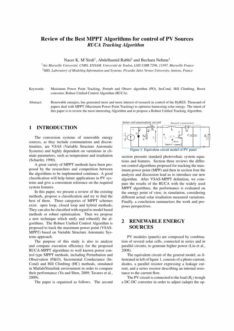
The paper is organized as follows. The second
Figure 1: Equivalent circuit model of PV panel
section presents standard photovoltaic system equa-tions and features. Section three reviews the differ-ent control algorithms proposed for tracking the max-imum power point (MPP) and then in section four theanalysis and discussion lead us to introduce our newalgorithm. After VSAS-MPPT definition, we com-pare the results of the RUCA with the widely usedMPPT algorithms; the performance is evaluated onthe energy point of view, in simulation, consideringdifferent actual solar irradiation measured variations.Finally, a conclusion summarizes the work and pro-poses perspectives.
2 RENEWABLE ENERGYSOURCES
PV modules (panels) are composed by combina-tion of several solar cells, connected in series and inparallel circuits, to generate higher power (Liu et al.,2008).
The equivalent circuit of the general model, as il-lustrated in left of figure 1, consists of a photo-current,diodes, a parallel resistor expressing a leakage cur-rent, and a series resistor describing an internal resis-tance to the current flow.
The PV circuit is connected to the load (RL) trougha DC-DC converter in order to adjust (adapt) the op-
erating voltage and current of the PV panel at optimalvalues to maximize the harnessed power. The controlof the boost has to tracks the Maximum Power Point(figure 2).
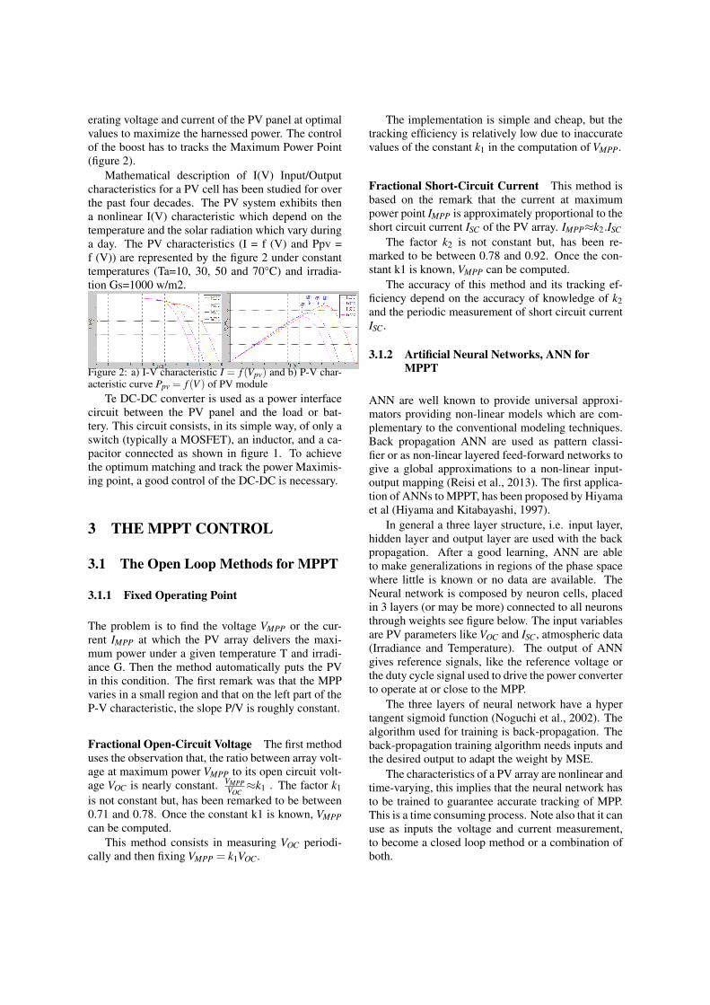
Mathematical description of I(V) Input/Outputcharacteristics for a PV cell has been studied for overthe past four decades. The PV system exhibits thena nonlinear I(V) characteristic which depend on thetemperature and the solar radiation which vary duringa day. The PV characteristics (I = f (V) and Ppv =f (V)) are represented by the figure 2 under constanttemperatures (Ta=10, 30, 50 and 70°C) and irradia-tion Gs=1000 w/m2.
Figure 2: a) I-V characteristic I = f (Vpv) and b) P-V char-acteristic curve Ppv = f (V ) of PV module
Te DC-DC converter is used as a power interfacecircuit between the PV panel and the load or bat-tery. This circuit consists, in its simple way, of only aswitch (typically a MOSFET), an inductor, and a ca-pacitor connected as shown in figure 1. To achievethe optimum matching and track the power Maximis-ing point, a good control of the DC-DC is necessary.
3 THE MPPT CONTROL
3.1 The Open Loop Methods for MPPT
3.1.1 Fixed Operating Point
The problem is to find the voltage VMPP or the cur-rent IMPP at which the PV array delivers the maxi-mum power under a given temperature T and irradi-ance G. Then the method automatically puts the PVin this condition. The first remark was that the MPPvaries in a small region and that on the left part of theP-V characteristic, the slope P/V is roughly constant.
Fractional Open-Circuit Voltage The first methoduses the observation that, the ratio between array volt-age at maximum power VMPP to its open circuit volt-age VOC is nearly constant. VMPP
VOC≈k1 . The factor k1
is not constant but, has been remarked to be between0.71 and 0.78. Once the constant k1 is known, VMPPcan be computed.
This method consists in measuring VOC periodi-cally and then fixing VMPP = k1VOC.
The implementation is simple and cheap, but thetracking efficiency is relatively low due to inaccuratevalues of the constant k1 in the computation of VMPP.
Fractional Short-Circuit Current This method isbased on the remark that the current at maximumpower point IMPP is approximately proportional to theshort circuit current ISC of the PV array. IMPP≈k2.ISC
The factor k2 is not constant but, has been re-marked to be between 0.78 and 0.92. Once the con-stant k1 is known, VMPP can be computed.
The accuracy of this method and its tracking ef-ficiency depend on the accuracy of knowledge of k2and the periodic measurement of short circuit currentISC.
3.1.2 Artificial Neural Networks, ANN forMPPT
ANN are well known to provide universal approxi-mators providing non-linear models which are com-plementary to the conventional modeling techniques.Back propagation ANN are used as pattern classi-fier or as non-linear layered feed-forward networks togive a global approximations to a non-linear input-output mapping (Reisi et al., 2013). The first applica-tion of ANNs to MPPT, has been proposed by Hiyamaet al (Hiyama and Kitabayashi, 1997).
In general a three layer structure, i.e. input layer,hidden layer and output layer are used with the backpropagation. After a good learning, ANN are ableto make generalizations in regions of the phase spacewhere little is known or no data are available. TheNeural network is composed by neuron cells, placedin 3 layers (or may be more) connected to all neuronsthrough weights see figure below. The input variablesare PV parameters like VOC and ISC, atmospheric data(Irradiance and Temperature). The output of ANNgives reference signals, like the reference voltage orthe duty cycle signal used to drive the power converterto operate at or close to the MPP.
The three layers of neural network have a hypertangent sigmoid function (Noguchi et al., 2002). Thealgorithm used for training is back-propagation. Theback-propagation training algorithm needs inputs andthe desired output to adapt the weight by MSE.
The characteristics of a PV array are nonlinear andtime-varying, this implies that the neural network hasto be trained to guarantee accurate tracking of MPP.This is a time consuming process. Note also that it canuse as inputs the voltage and current measurement,to become a closed loop method or a combination ofboth.
3.1.3 Fuzzy logic method (FL)
Fuzzy logic controllers offer the advantage of work-ing capability with imprecise inputs, and do not needan accurate mathematical model. They can han-dle nonlinearities, and have fast convergence. Theirlearning ability and accuracy depend on the numberon the fuzzy levels and the the membership functions.The decision-making uses rules specified by a set ofIF–THEN statements to define the control which pro-duce the desired behavior. The defuzzification stage,operates the reverse function to get numerical vari-ables for analog control using the membership func-tion.
In order to track MPP, the error is computed basedon irradiance and temperature or instantaneous valuessuch as power and voltage (Algazar et al., 2012). Theoutput signal is either the duty cycle itself, or VMPPand IMPP reference to generate the duty cycle.
The membership function associated with fuzzi-fication and defuzzification, as well as the antecedentand the consequent fuzzy rules are determined by trialand error. This can be time-consuming. This methodcan be used in open loop or in closed loop when us-ing as feedback (in real time) the output variables likecurrent, voltage and the power.
3.2 The Closed Loop MPPT
3.2.1 Perturb and Observe Methods
The most commonly used MPPT algorithm is the Per-turbation and Observation (P&O) due to its easy im-plementation. It uses the P-V characteristics Ppv =f (V ) of the PV module shown in figure 3 (b). Notethat the point of maximum power P(n)=V(n)I(n) is ob-tained when the condition dP
dV = 0 is accomplished, re-gardless of the sun irradiance magnitude (Kim et al.,2001). In actual experiments, the system oscillates ar-roumd the MPP. To minimize the oscillations ampli-tude, we can reduce the perturbation step size. How-ever, small step size slows down the convergence ofthe MPPT.
The Modified Enhanced Perturb and Observe(MEPO) algorithm uses and adaptive step adjustmentgain and simplify the implementation using on com-mutation functions. This algorithm have been revis-ited, its rationale behind have been clarified and thenimplementation obviated using commutation func-tions (Msirdi and Nehme, 2015).
3.2.2 Incremental Conductance Methods
The incremental conductance (IncCond) (Femia et al.,2004), method is based on the fact that the slope (or
the PV conductance G = dIdV ) of the PV array, in the
power curve is zero at the MPP and it is positive (con-stant) on the left of the MPP. The slope becomes neg-ative on the right of th MPP.
3.2.3 Hill Climbing Method
The basic idea of the HC (Hill Climbing) method isthe same as P&O method. It tests if P(n) is greaterthan P(n-1) or not, to reach MPP. The PO method usesinstead a test on dP/dV to determine whether the max-imum power point has been found or not. However,the HC method uses a test condition on P(n)-P(n-1).
3.2.4 Extremum Seeking Control method (ESC)
Krstic et al. (Ariyur and Krstic, 2003), from au-tomatic control community interested on robust andadaptive control techniques, proposed an adaptiveESC methodology which has been proved to be ro-bust against parametric uncertainties for non lineardynamic uncertain systems. It is based on theoriesnamely averaging theory, adaptive control and singu-lar perturbation techniques. This real-time optimiza-tion ESC method has been successfully applied in var-ious systems and has been specifically adapted for PVsystems in order to track MPP (?; ?). Extension toESC by Newton Like optimisation has been also con-sidered and compared to other ESC based methods(Zazo et al., 2012). The objective of ESC is to rapidlyreach the MPP despite uncertainties and disturbanceson the PV panel and the load.
The reference current is perturbed by a sinusoidalmodulation. The power got at the output of the PVsystem is high pass filtered, to get only effect ofthe perturbation (4P(t)) on the obtained power P(t).Then, after the ripple demodulation to get the pro-duced power perturbation observed (ξ(t)), integrationwith an adaptive gain C(p) of this effect gives the ref-erence current. The adaptation gain C(p) is adjustedby a theoretical study to get fast convergence to theoptimum power (MPP). The controller will, therefore,adjust the reference current until MPP is reached.
The main advantages of ESC are that the poweroptimization is got by a dynamic adaptation-basedfeedback for a sinusoidal perturbation and conver-gence to the MPP is guaranted. This approach doesnot require any parametrization or structural formal-ization of the modeling uncertainty. The disadvantageof ESC is its complexity and the implementation dif-ficulties regard to PO and MEPO.
3.2.5 RSMCA: Robust Sliding Mode ControlAlgorithm
A lot of algorithms have been proposed based onSliding Mode. The most of them are not very pre-cise when defining the objective of the algorithm andchosing the sliding surface. They simply has been de-velop as alternative to use of a standard regulator likePID controller. This reduces the efficiency of the Slid-ing Mode Approach and does not tackle the robustnesproblem. The most of them use a sliding surface toreach the MPP. The best choice seems to be given bythe proposed criteria in equations (1 and 2).
In the following we propose an MPPT based onthe VSAS and the Lyapunov theory which general-izes all the previous algorithms. The desired objectiveto get is that the MPP reached when the maximumpower is obtained dP
dt = 0.Note that the optimization is done versus time be-
cause P varies during time in function of the voltageV and the current I. Only if current I (respectivelythe voltage V) is maintained constant we can considerP(V) (respectively P(I)) characteristic. Note also thatin real weather condition the Operating Point do notmoves on a unique (P-V) characteristic. If the irradia-tion or the temperature changes the MPP varies fromone curve to another one.
Then as P(t) =V (t).I(t) = f (V, I, t), the power isfunction of the voltage, the current and time, then therequired Maximum Power Point to Track is really de-fined by the following objective function which wepropose to take as the generic sliding surface:
dPdt
=dV Idt
= IdVdt
+VdIdt
= 0 (1)
Let us consider the control in case of discretetime, like do all the above presented algorithms,with the previously defined variables (see equation5) the fetched MPPT may be defined by ∆P(k) = 0,then as dP
dt = 0 can be approximated by ∆P(k) =(I(k)∆V (k)+V (k)∆I(k)).4t
The objective function that we propose in(M’Sirdi et al., 2014) becomes then:
∆P(k) = I(k)∆V (k)+V (k)∆I(k) = 0 (2)
The control variable is either, in the first case,u1(k) = 4V (k), which means that the voltage per-turbed and the current is fixed u2(k) = 4I(k) = 0,or in the second case, the control variable is u2(k) =4I(k), the current is pertubed and the voltage is fixedu1(k)=4V (k)= 0. In control context, the previouslypresented MPPT controllers use only one controlvariable u1 or u2 and impose the second to zero. Let
us consider the MPP reaching condition dP(t)dt = 0 and
note that the maximum power is always Pmax ≥ P(t)every where and at any time. We can choose as Slid-ing Surface s(t) = Pmax−P(t) which goes to zero (orat least to its minimum) when P(t) = Pmax (Msirdiand Nehme, 2015). We can also take zero instead of apositive constant Pmax = 0.
Let us then consider the Lyapunov like functionW (t) = s2 = [Pmax−P(t)]2 > 0 which is strictly pos-itive every where except at the MPP where it goes tozero. Lyapunov based control design is well knownto give robust algorithms.
The derivative of this Lyapunov function W (t) =s2 > 0, is W = ss =− [Pmax−P(t)] . dP(t)
dt .
This term is negative when − dP(t)dt = −I dV
dt −V dI
dt <0. This equation is similar to the proposed Slid-ing Surface equations (1 2 ??). Please note also thesimilarity with the InCond equation (??). This meansobviously that we only need, from control, to makedP(t)
dt > 0, to reach the MPP.as we impose dI
dt = 0, we get W =−I dVdt
It can be made negative by choosing the appro-priate control laws u1(k) = 4V (k) and u2(k) = 0.Note that this can be reached by choosing the signof u1(k) =V (k), such as to get W < 0.
Choosing u1(k) = 4V (k) =4P(k).α.sign(4V (k)) and knowing that weimpose u2(k) = 4I(k) = 0 like in the con-trol algorithm, we have previously proposedMEPO (Msirdi and Nehme, 2015). This gives us4W = −α.4P(k).sign(4V (k))I(k). If the gainparameter α is positive constants, we then get anegative derivative
4W =−α.∆V (k).sign(4V (k))I2(k)< 0 (3)
This method, called MEPO (Modified EnhancedPerturb and Observ) gives an enhanced and variablestep size algorithm. The step size is adjusted in pro-portionally to the power variation produced in the pre-vious step. The step adjustment gain K = α.4P(k) isused for weighting this adjustment step. It may beuseful for oscillation avoidance and noise sensitivity.
This proves, theoretically the convergence of theRSMC algorithm and shows that Robust SlidingMode Control is equivalent to the MEPO algorithmgot by enhancement of the P&O.
We propose, as a modified PO Algorithm whichwill be more robust, the reference voltage is given by
V re f =V k+α.4P.sign(4V ) (4)
The algorithms have been tested under various oper-ating conditions. The obtained results have proven
that the MPPT is tracked even under sudden changeof irradiation level.
3.2.6 RUCA: Robust Unified Control Algorithm
VSAS (Variable Structure Automatic Systems) con-trol methodology was applied to clarify the rationalebehind Maximum Power Point Tracking and get thebest optimization algorithm. We have seen previouslythat the control is either on voltage or on current in-put or both. For the proposed RUCA algorithm, bothcontrols can be used if we look for adjusting both vari-ables (V and I), either at each control step or alterna-tively.
Two new algorithms can be developed, using thisapproach, the Modified and Enhanced Perturb andObserve Algorithm (MEPO) if the control input ison the voltage or the Modified Enhanced InCond(MEInCond) if the control input is on the current.
For the MEPO and the RSMC, we take for esti-mation of the power variation ∆P(k) = I(k)∆V (k), thecurrent is assumed constant.
For the Modified Enhaced InCond (MEInCond),we consider the current as the only input control andwe take ∆P(k) = V (k)∆I(k), the voltage is assumedconstant.
The Robust Unified Control Algorithm (RUCA)will do both of them alternatively. Note that the hard-ware have to be considered in consequence. Com-pared to the other algorithms like Perturb and Observe(PO), Hill Climbing, Incremental Conductance (In-Cond) The RSMC approach it is proven more efficientand faster despite using low frequency commutation.
It can be noticed that all the previous algo-rithms can be considered as particular cases of thisone (RUCA), when simplifying the proposed controlmethod.
The implementation of the proposed RUCA con-troller can be summarised as follows:
1. The reference voltage is set be equal to the PVopen circuit voltage.
2. Measurement of the of input signals (PV voltage,PV current and Load voltage).
3. Estimate the PV power at the sample time k :PPV (k) = Ipv(k)Vpv(k)
4. Calculate the PV current and the power incre-ments.
∆I = IPV (k)− IPV (k−1)∆V =VPV (k)−VPV (k−1)∆P = PPV (k)−PPV (k−1)PPV (k) =VPV (k).IPV (k)
(5)
The reference voltage Vre f (k) is calculated as below,where α is the perturbation variation step (controlgain). Note that ∆Vre f = α.sign(∆P∆V ) produces ex-atly the same result as the classical PO algorithm witha much more simple implementation (one formula in-stead of an algorithm chart).
Recall that the system equations have been usedalso to define the classical Sliding Mode based algo-rithms by means of choosing a commutation (sliding)surface s. The proposed MPPT has several advan-tages: simplicity, high convergence speed and is in-dependent on PV array characteristics. In conclusionlet us say that RUCA enhances and generalizes allthe best algorithms presented in litterature and sug-gest new algorithmes like MEPO and MEInCond.
3.3 Hybrid Tracking Methods HTM
It is well known that combination of OLM (OpenLoop Method) for anticipation with robust feedback(CLM: Closed Loop Method) gives the best wayto control and track trajectories of uncertain andtime varying systems. In HTM, the control sig-nal associates OLM, determined according to atmo-spheric conditions temperature and irradiance, andCLM based on feedcback control to track MPP. In ahybrid method consisting of two loops is proposed.In the first loop MPP is estimated based on the opencircuit voltage at a constant temperature. Several au-thors use Neural Networks or Fuzzy Logic or combineNeuro Fuzzy Logic to anticipate on temperature andradiation effects. Tina et al proposed to use a simpli-fied model used to evaluate the MPP power in (Tinaand Scrofani, 2008). It seems to be the most efficientway to predict the MPP.
4 COMPARATIVE STUDY
In this section we present simulations based com-parison between different MPPT algorithms. Severalalgorithms are compared the classical P&O (Perturband Observe), the MEPO (Modified Enhanced Per-turb and Observe), IncCond (Incremental Conduc-tance), RUCA (Robust Unified Control Algorithm),and NL-ESC (Newton-Like Extremum Seeking Con-trol).
The first step, for validation of the implementa-tion, uses the same simulated model as in the paperof Zazo et al (Zazo et al., 2012) to compare the dif-ferent algorithms. The second step is simulation withthe PSIM software of the model of the experimentalsetup.
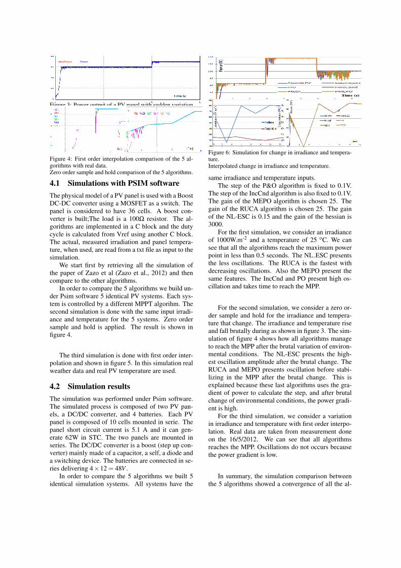
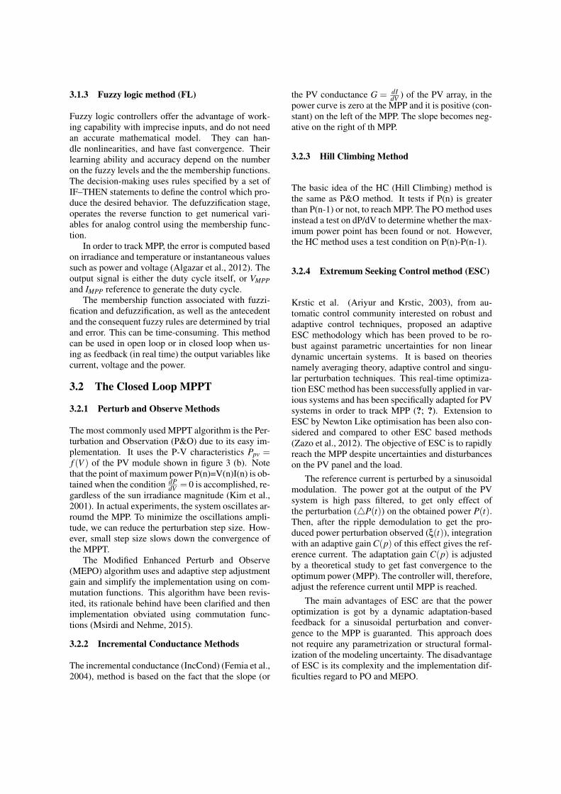
Figure 3: Power output of a PV panel with sudden variationin irradince controlled with the NL-ESC algorithm.
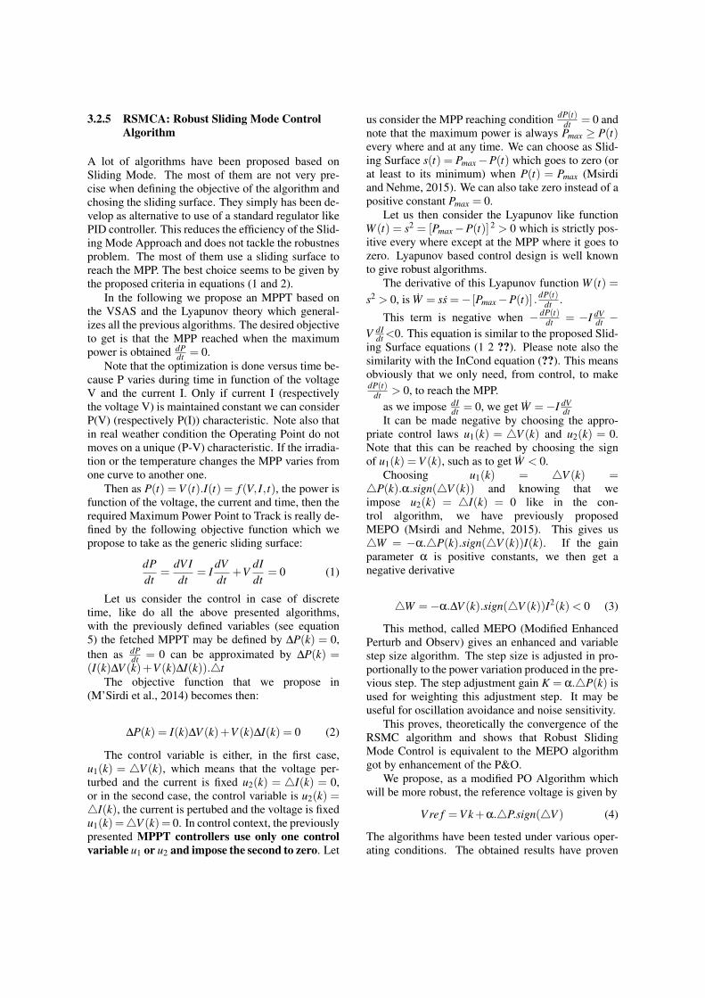
Figure 4: First order interpolation comparison of the 5 al-gorithms with real data.Zero order sample and hold comparison of the 5 algorithms.
4.1 Simulations with PSIM softwareThe physical model of a PV panel is used with a BoostDC-DC converter using a MOSFET as a switch. Thepanel is considered to have 36 cells. A boost con-verter is built;The load is a 100Ω resistor. The al-gorithms are implemented in a C block and the dutycycle is calculated from Vref using another C block.The actual, measured irradiation and panel tempera-ture, when used, are read from a txt file as input to thesimulation.
We start first by retrieving all the simulation ofthe paper of Zazo et al (Zazo et al., 2012) and thencompare to the other algorithms.
In order to compare the 5 algorithms we build un-der Psim software 5 identical PV systems. Each sys-tem is controlled by a different MPPT algorihm. Thesecond simulation is done with the same input irradi-ance and temperature for the 5 systems. Zero ordersample and hold is applied. The result is shown infigure 4.
The third simulation is done with first order inter-polation and shown in figure 5. In this simulation realweather data and real PV temperature are used.
4.2 Simulation resultsThe simulation was performed under Psim software.The simulated process is composed of two PV pan-els, a DC/DC converter, and 4 batteries. Each PVpanel is composed of 10 cells mounted in serie. Thepanel short circuit current is 5.1 A and it can gen-erate 62W in STC. The two panels are mounted inseries. The DC/DC converter is a boost (step up con-verter) mainly made of a capacitor, a self, a diode anda switching device. The batteries are connected in se-ries delivering 4×12 = 48V .
In order to compare the 5 algorithms we built 5identical simulation systems. All systems have the
Figure 5: Brutal change in irradiance and temperature.
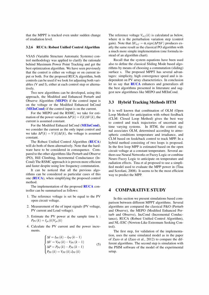
Figure 6: Simulation for change in irradiance and tempera-ture.Interpolated change in irradiance and temperature.
same irradiance and temperature inputs.The step of the P&O algorithm is fixed to 0.1V.
The step of the IncCnd algorithm is also fixed to 0.1V.The gain of the MEPO algorithm is chosen 25. Thegain of the RUCA algorithm is chosen 25. The gainof the NL-ESC is 0.15 and the gain of the hessian is3000.
For the first simulation, we consider an irradianceof 1000W.m-2 and a temperature of 25 oC. We cansee that all the algorithms reach the maximum powerpoint in less than 0.5 seconds. The NL ESC presentsthe less oscillations. The RUCA is the fastest withdecreasing oscillations. Also the MEPO present thesame features. The IncCnd and PO present high os-cillation and takes time to reach the MPP.
For the second simulation, we consider a zero or-der sample and hold for the irradiance and tempera-ture that change. The irradiance and temperature riseand fall brutally during as shown in figure 3. The sim-ulation of figure 4 shows how all algorithms manageto reach the MPP after the brutal variation of environ-mental conditions. The NL-ESC presents the high-est oscillation amplitude after the brutal change. TheRUCA and MEPO presents oscillation before stabi-lizing in the MPP after the brutal change. This isexplained because these last algorithms uses the gra-dient of power to calculate the step, and after brutalchange of environmental conditions, the power gradi-ent is high.
For the third simulation, we consider a variationin irradiance and temperature with first order interpo-lation. Real data are taken from measurement doneon the 16/5/2012. We can see that all algorithmsreaches the MPP. Oscillations do not occurs becausethe power gradient is low.
In summary, the simulation comparison betweenthe 5 algorithms showed a convergence of all the al-
gorithms. Algorithms based on fixed step as P&O andIncCond must run at high frequency in order to reachthe MPP. Algorithms based on the power gradient asMEPO and RUCA can operate at lower frequencies.MEPO, RUCA, and NL-ESC present oscillations infront brutal variation of irradiance and temperature.
5 ConclusionThe best MPPT algorithms of the litterature have
been reviewed and analyzed in this work. This com-parison allowed us to select five of them to be com-pared in simulations and experimental application.The simulations was performed under PSIM softwareto use realistic physical models.
The analysis has shown the rationale behindMPPT and the generalization leading to a unifiedframework RUCA, as a Robust Unified Control Algo-rithm. The well known algorithms can be viewed asparticular cases of the RUCA. The proposed approachRUCA generalizes the PO, the InC, the ESC and theSliding Mode Control schemes to non linear systemswith commutations. The proposed MPPT has severaladvantages: simplicity, high convergence speed, andis independent on PV array characteristics. The ob-tained results have proven that the MPPT is trackedeven under sudden change of irradiation level or tem-perature.
The algorithms are tested under various operatingconditions. Realistic simulations are used to showease of implementation of our new algorithm, and tocompare its execution efficiency and accuracy to thethe studied MPPT methods.
In summary the best algorithms are those designedusing the SASV-MPPT approach and Lyapunov de-sign method considering that the PV system can movefrom one characteristic to another. The proposed al-gorithms are the most efficient despite using low fre-quency commutation. They are the faster converging.
REFERENCES
Algazar, M. M., El-Halim, H. A., Salem, M. E. E. K.,et al. (2012). Maximum power point tracking usingfuzzy logic control. International Journal of Electri-cal Power & Energy Systems, 39(1):21–28.
Ariyur, K. B. and Krstic, M. (2003). Real-time optimizationby extremum-seeking control. John Wiley & Sons.
Femia, N., Petrone, G., Spagnuolo, G., and Vitelli, M.(2004). Optimizing duty-cycle perturbation of p&omppt technique. In Power Electronics SpecialistsConference, 2004. PESC 04. 2004 IEEE 35th Annual,volume 3, pages 1939–1944. IEEE.
Hiyama, T. and Kitabayashi, K. (1997). Neural networkbased estimation of maximum power generation frompv module using environmental information. IEEETransactions on Energy Conversion, 12(3):241–247.
Kim, T.-Y., Ahn, H.-G., Park, S. K., and Lee, Y.-K. (2001).A novel maximum power point tracking control forphotovoltaic power system under rapidly changing so-lar radiation. In Industrial Electronics, 2001. Proceed-ings. ISIE 2001. IEEE International Symposium on,volume 2, pages 1011–1014. IEEE.
Liu, F., Kang, Y., Zhang, Y., and Duan, S. (2008). Com-parison of p&o and hill climbing mppt methods forgrid-connected pv converter. In Industrial Electronicsand Applications, 2008. ICIEA 2008. 3rd IEEE Con-ference on, pages 804–807. IEEE.
Msirdi, N. and Nehme, B. (2015). The vsas approach givesthe best mppt for solar energy sources. RenewableEnergy and Sustainable Development, 1(1):60–71.
M’Sirdi, N., Nehme, B., Abarkan, M., and Rabbi, A.(2014). The best mppt algorithms by vsas approachfor renewable energy sources (res). In EnvironmentalFriendly Energies and Applications (EFEA), 2014 3rdInternational Symposium on, pages 1–7. IEEE.
Noguchi, T., Togashi, S., and Nakamoto, R. (2002). Short-current pulse-based maximum-power-point trackingmethod for multiple photovoltaic-and-converter mod-ule system. IEEE Transactions on Industrial Electron-ics, 49(1):217–223.
Reisi, A. R., Moradi, M. H., and Jamasb, S. (2013). Clas-sification and comparison of maximum power pointtracking techniques for photovoltaic system: A re-view. Renewable and Sustainable Energy Reviews,19:433–443.
Schaefer, J. (1990). Review of photovoltaic power plantperformance and economics. IEEE Transactions onEnergy Conversion, 5(2):232–238.
Tavares, C. A., Leite, K. T., Suemitsu, W. I., and Bellar,M. D. (2009). Performance evaluation of photovoltaicsolar system with different mppt methods. In Indus-trial Electronics, 2009. IECON’09. 35th Annual Con-ference of IEEE, pages 719–724. IEEE.
Tina, G. and Scrofani, S. (2008). Electrical and thermalmodel for pv module temperature evaluation. In Elec-trotechnical Conference, 2008. MELECON 2008. The14th IEEE Mediterranean, pages 585–590. IEEE.
Yu, T.-C. and Shen, Y.-T. (2009). Analysis and simulationof maximum power point tracking for photovoltaicsystems. In Proceedings of the 30th ROC Symposiumon Electrical Power Engineering, Taoyuan, Taiwan,pages 92–96.
Zazo, H., Del Castillo, E., Reynaud, J. F., and Leyva, R.(2012). Mppt for photovoltaic modules via newton-like extremum seeking control. Energies, 5(8):2652–2666.