Control Transition Mode from Voltage Control to MPPT for PV ...
35
1 Control Transition Mode from Voltage Control to MPPT for PV Generators in Isolated DC Microgrids V. Fernão Pires 1,3,4 , Armando Cordeiro 2,3,4 , Daniel Foito 1,4,5 , J. Fernando Silva 3,6 1 ESTSetúbal, Instituto Politécnico de Setúbal, Setúbal, Portugal 2 ISEL, LCEC, Instituto Politécnico de Lisboa, Lisboa, Portugal 3 INESC-ID Lisboa, Portugal 4 Sustain.RD, Instituto Politécnico de Setúbal, Setúbal, Portugal 5 Uninova - Universidade Nova de Lisboa, Lisboa 6 Instituto Superior Técnico - Universidade de Lisboa, Lisboa Corresponding Author: Professor Daniel Foito Electrical Engineering Department ESTSetúbal, Instituto Politécnico Setúbal Campus do IPS - Estefanilha 2914-761 Setúbal, PORTUGAL Tel: +351-265 790 000 (ext. 4315) email: [email protected] Abstract - The integration of photovoltaic (PV) power sources on a large scale into grid-tied and islanded solutions is now a reality. Despite the fluctuating characteristics of solar energy, the direct current (DC) nature of PV sources is highly compatible with DC microgrids compared with AC solutions. However, as more PV sources are being installed, challenges related to the control of DC microgrids are also increasing, especially for islanded applications. To ensure an appropriate transition from the maximum power point to DC bus voltage regulation of DC microgrids, novel control strategies must be designed, and this aspect is particularly critical when these grids operate without energy storage systems. We therefore propose a new control strategy for a PV generator for islanded DC microgrids without storage systems. Our approach allows for smooth switching from the maximum power point mode to the voltage control regulation mode (V control) when the available PV power is excessive, thus limiting the generated PV power and returning to maximum power point operation when all the available power is required. This allows us to control a DC microgrid without a storage system and provides a new alternative that offers a cost-effective solution for rural and deprived regions. Our solution combines the maximum power point tracking algorithm with a proportional integral compensator for V control and minimises undervoltage/overvoltage problems in the DC bus. The behaviour of the isolated DC microgrid under different conditions, for example in the case of transitions, perturbations, and different types of loads, is also studied and verified. The performance of the proposed control strategy is confirmed by several simulation and experimental tests.
-
Upload
khangminh22 -
Category
Documents
-
view
0 -
download
0
Transcript of Control Transition Mode from Voltage Control to MPPT for PV ...

1
Control Transition Mode from Voltage Control to
MPPT for PV Generators in Isolated DC Microgrids
V. Fernão Pires1,3,4
, Armando Cordeiro2,3,4
, Daniel Foito1,4,5
, J. Fernando Silva 3,6
1 ESTSetúbal, Instituto Politécnico de Setúbal, Setúbal, Portugal
2 ISEL, LCEC, Instituto Politécnico de Lisboa, Lisboa, Portugal
3 INESC-ID Lisboa, Portugal
4 Sustain.RD, Instituto Politécnico de Setúbal, Setúbal, Portugal
5 Uninova - Universidade Nova de Lisboa, Lisboa
6 Instituto Superior Técnico - Universidade de Lisboa, Lisboa
Corresponding Author:
Professor Daniel Foito
Electrical Engineering Department
ESTSetúbal, Instituto Politécnico Setúbal
Campus do IPS - Estefanilha
2914-761 Setúbal, PORTUGAL
Tel: +351-265 790 000 (ext. 4315)
email: [email protected]
Abstract - The integration of photovoltaic (PV) power sources on a large scale into grid-tied and islanded
solutions is now a reality. Despite the fluctuating characteristics of solar energy, the direct current (DC) nature
of PV sources is highly compatible with DC microgrids compared with AC solutions. However, as more PV
sources are being installed, challenges related to the control of DC microgrids are also increasing, especially for
islanded applications. To ensure an appropriate transition from the maximum power point to DC bus voltage
regulation of DC microgrids, novel control strategies must be designed, and this aspect is particularly critical
when these grids operate without energy storage systems. We therefore propose a new control strategy for a PV
generator for islanded DC microgrids without storage systems. Our approach allows for smooth switching from
the maximum power point mode to the voltage control regulation mode (V control) when the available PV power
is excessive, thus limiting the generated PV power and returning to maximum power point operation when all
the available power is required. This allows us to control a DC microgrid without a storage system and provides
a new alternative that offers a cost-effective solution for rural and deprived regions. Our solution combines the
maximum power point tracking algorithm with a proportional integral compensator for V control and minimises
undervoltage/overvoltage problems in the DC bus. The behaviour of the isolated DC microgrid under different
conditions, for example in the case of transitions, perturbations, and different types of loads, is also studied and
verified. The performance of the proposed control strategy is confirmed by several simulation and experimental
tests.

2
Keywords - Photovoltaic systems, maximum power point tracking, constant power, quadratic Boost converter,
DC microgrids.
I. INTRODUCTION
Over recent years, the increasing development and integration of new small-scale renewable energy sources (RES) in
the context of electrical distribution networks has given rise to the related concept of microgrids. Microgrids have been
highlighted as a very promising future solution [1] that will allow for the high penetration of RES into AC grids. From the
perspective of distributed generation (DG), microgrids have several interesting characteristics, such as distributed power
system management, advanced monitoring and diagnostics, optimisation/self-optimisation capabilities, operation in both
grid-connected and islanded modes, and demand response/energy management support [2]. The study and development
of microgrids have focused not only on AC but also on DC distribution networks. Microgrids based on DC distribution
networks usually allow for the simple integration of RES and offer improved efficiency and direct connection to
community energy storage (CES) systems like such as supercapacitors and/or batteries [3, 4].
The concept of DC microgrids based on RES, especially using photovoltaic (PV) generators, has evolved significantly
over the last few years. In DC microgrids supplied by PV generators, several design concepts are typically involved, such
as the DC - DC power converter topology, voltage regulation and control of the DC bus. Many DC - DC converters have
been proposed, studied, and implemented in order to interconnect PV generators with a DC bus. Boost converters [5-9]
are one of the most widely adopted topologies for such applications. These converters offer suitable characteristics , such
as a high input-output voltage gain and a continuous input current, which is essential to extend the lifetime of PV
generators. The boost topology, which is associated with the SEPIC converter [10], has also been extended to bipolar DC
microgrids. However, due to inductor and semiconductor losses, the input -output voltage gain of the boost converter is
usually limited to around four in practice [5]. Several modified topologies to increase the voltage gain of this converter
have been proposed: some have been based on the integration of two classical DC - DC converters [11-15], while others
have included the use of switched-capacitor or switched-inductor structures to extend the voltage gain [16-20]. One of the
most interesting solutions that achieves high-voltage gain while preserving the simplicity of the boost converter is the
quadratic boost converter [21-27]; this topology is based on the classic boost converter with only one active
semiconductor and can provide continuous input current and quadratic gain. Since PV generators are characterised by a
relatively low output voltage, this converter may be an interesting solution for interfacing PV generators with DC
microgrids. However, these converters have non-minimum phase dynamic characteristics, meaning that it is difficult to
develop a controller using only the output voltage for feedback purposes [28]. Two-loop current mode controllers are
therefore typically applied for regulation of these converters , and the converter output voltage is regulated via the control
3
of the inductor current [29]. A variety of control methods have been proposed with the purpose of regulating the output
voltage, such as current programmed control [30], robust control based on the Hammerstein identification [31],
loop-shaping [32], and sliding mode control (SMC) [33-35]. Controllers based on the simplified parallel-damped
passivity-based approach have also been proposed [36]. The authors of [37] presented a modified voltage-mode control
law for the regulation of a quadratic boost converter, which employed an integral action based on the normalised output
voltage error. All these methods demonstrate the importance of voltage control for these converters.
As mentioned above, another important issue associated with the use of DC microgrids is voltage regulation of the DC
bus, and this problem has been investigated for networks with several RES and CES. Two main approaches for
controlling the DC bus voltage have been proposed: the master-slave and the droop control methods [38, 39]. In the
master-slave technique, a master unit such as a large storage system is responsible for controlling the DC bus voltage.
The disadvantage of this approach is that the stability of the system is highly dependent on the performance of this master
unit [40, 41]. In contrast, the droop control technique is based on the detection of the current or output power [42].
Despite certain advantages, this technique has some limitations when used with different power sources, such as PV,
wind, and storage systems with different sets of state-of-charge (SoC) parameters [43]. An alternative control technique
approaches have therefore been proposed in [44, 45]. Another problem arises if the microgrid is mainly supplied by RES
such as PV generators without storage systems. In this situation, it is necessary to significantly curtail the generation of
PV power, meaning that the PV generators often operate well below their maximum power point (MPP). Several works
have explored the control of PV generators operating at the MPP or another specific power point below the MPP [46],
and a range of strategies have been proposed, for example constant power generation (CPG) based on a power control
method [47], CPG based on a current limit method [48] and CPG based on the perturb and observe (P&O) algorithm
[49]. It should be clarified that most proposed DC microgrids consist of multiple power sources, meaning that a primary
control element is always required, such as a mechanism for load power sharing within the microgrid [47]. In addition,
most studies in the literature [38]-[50] have been carried out in the context of DC microgrids connected to AC grids
where there is a limit on the active power injected into the AC grid.
Although several works have been presented regarding the transition between, for example, CPG and MPPT, solutions
for isolated DC microgrids that are supplied only by PV generators (without storage systems) have rarely been
investigated. Another aspect that has been almost overlooked in studies in this area relates to the behaviour of this type of
isolated network supplied by only PV generators. To demonstrate such limitations regarding these issues several relevant
works were examined in the literature [51-55], showing in this way, the opportunity for additional developments in the
control of PV generators in isolated DC microgrids. In future, the proposed solution could be used in rural and deprived

4
regions; storage systems are very expensive, meaning that this could be a very economical solution in regions that often
do not require a permanent supply of electrical energy. There are several rural applications in which energy is only
required during the day, namely for water pumping and small loads that can be connected to small facilities (small
support houses or warehouses). There are also other situations in which this can be a reality. For example, when the
network is supplied by a diesel or biofuel generator. Concerning this conventional source, seen as backup power for
small-scale microgrids, the diesel generator is mostly used due to its several advantages, such as low investments, ease of
move and compatible combination with other energy sources. However, by one side its response speed is slow and the
starting time lasts several seconds to reach stable output power. Therefore, due to the slow dynamic behaviour of the
generator, the compensation for sudden load power changes must be ensured by the PV generator. On the other side, to
avoid wasting energy, during the day the diesel may not be operated in continu ous-running mode. Finally, situations in
which there is a failure or maintenance in the storage systems and is intend to maintain the system operating only with the
PV generator. Hence, there is a need for a control system with a different approach, i.e. one that requires voltage control
of the DC microgrid in normal mode but can also operate in MPPT mode during transitions and perturbations. In this
context, the novel contribution of the current work relates to the DC bus voltage control of DC microgrids solely supplied
by a unique PV generator, operating in islanded mode and without the use of energy storage systems. For this kind of DC
microgrid, the transition from voltage control to MPPT mode to regulate the bus voltage of the DC microgrid has rarely
been investigated. We explore the problem of DC bus voltage control in a DC microgrid supplied solely by a PV
generator, investigate the inner control loops related to the transitions between voltage control and MPPT operation for
this kind of DC microgrid, and propose a new control strategy. The proposed controller takes into consideration the
transition between the maximum available power of the PV panels and the voltage control regulation that is necessary to
maintain the DC voltage bus at the rated value, for an islanded DC microgrid without an energy storage system. The
design of the controller also focuses on the fact that the PV generators must work not only at their MPP, but also below
this point when necessary, according to the load demand. Associated with the PV generator, there is a quadratic boost
converter with the high voltage gain required to provide the necessary voltage variation. A study of the behaviour of this
isolated network under several conditions, such as transitions, perturbations , and different types of loads, is also
presented. The performance of the proposed control strategy is verified through several simulation and experimental tests.

5
II. TRANSITION FROM VOLTAGE CONTROL MODE TO MPPT FOR PV
GENERATORS IN ISOLATED DC MICROGRIDS
Although many studies have been carried out on isolated DC microgrids supplied by PV generators, these have
typically assumed that storage systems are used to support the isolated microgrid, in order to mitigate the voltage
variations and load demand. In this context, the transition from voltage control to MPPT operation and vice versa is not
usually very problematic since the storage systems can provide support for the dynamic changes in the isolated DC
microgrid. Nevertheless, for several reasons, there are some cases in which DC microgrids do not have support from
storage systems, and the transition between the two modes of operation then becomes critical. In practice, storage
systems are usually very expensive [56], meaning that some applications may not be able to use them. Other
circumstances are associated with malfunction or end-of-life of the storage systems [57, 58]. Cases in which a DC
microgrid needs to operate without support from storage systems include:
Small installations in remote locations in which the loads are minimal, such as pumps, and other small loads
like lighting and small appliances ;
Houses with PV generators when in islanded mode. Under these conditions, instead of simply disconnecting
the PV generator, it could still operate if the generated power is sufficient to supply the load. Even in a
situation where the required load power is higher than the generated power, the PV system could continue to
operate by using a load shedding system [59, 60]. In this case, an overload may exist for a moment without
disconnecting the PV generator. Although a temporary overload may exist, the system will react by
disconnecting some non-critical loads, meaning that there will be a decrease in the associated load demand
to a level that can be stably supported by PV generation during operation in this emergency mode;
Other isolated small DC microgrids without storage systems but with support from a load shedding system
[60] for non-critical loads;
Installations operating in islanded mode but in a situation where the storage system suffers a malfunction or
is in the end-of-life stage [57, 58].
Regarding this application two different situations may arise in which an islanded DC microgrid is used without an
energy storage system. The first is where the DC microgrid is supplied by one, while the second one is supplied by
multiple PV generators. When multiple PV generators are used, an element of primary control is always required, i.e., a
mechanism for load power sharing within the microgrid [50]; this is not the case with a single PV generator, since the

6
load is supplied by a unique power source. However, in both situations, inner control loops are always required for the
transition between voltage control operation and MPPT operation since each power source must be able to switch
between these two modes.
Although this type of system can be useful in several situations, as described above, some limitations may affect its
optimum use. These arise in the case where the load power is higher than the maximum available generated power. Under
these conditions, the system can only work in the context of an isolated DC microgrid if there is a load shedding system
that can maintain the total power load below the maximum power generated (although this could be higher in the
transient mode until some non-critical loads are disconnected). Another problem associated with this condition is the use
of electronically controlled loads with no limit on the converter input current. In this situation, the converter may fail, and
consequently the stability of the DC microgrid will be affected. Hence, these loads should be equipped with this type of
protection (which they normally have).
To ensure the operation of an isolated DC microgrid without support from storage systems, the PV generators must
include a controller that will allow them to operate in MPPT or voltage control mode. Several works have explored both
modes of operation, although in most cases applications have been related to PV generators connected in grid mode, and
the switch between the two modes of operation has been simply achieved by changing the setpoint reference [46]. There
have been few studies of transition mode control from voltage regulation to MPPT operation for PV generators in isolated
DC microgrids without storage systems, and some of the solutions that have been presented can be adapted to DC
microgrids without storage systems , despite having been developed in the context of a generator with a storage system.
For example, the authors of [61, 62] proposed methods for the two modes of operation (MPPT and voltage control). In
these approaches, the transition is established by a reference signal sent from a supervisory controller to switch between
the modes. Other studies of these two operation modes have also been presented in [63, 64]. However, some transition
problems remain, since a specific controller is required to ensure a smooth transition. Other strategies in which this aspect
of the MPPT or voltage control were considered under independent deployment of PV and the battery were also proposed
in [65, 66]. However, a solution to control the transition between the two operating modes is also required instead of an
independent integration which could affect the desired performance. A different study in which both modes were
integrated was proposed in [67]; a controller method was presented that unified MPPT and DC bus voltage regulation by
using the same control configuration. In this way, the need for an additional controller reconfiguration during the
transition between different operating modes was avoided. However, this control method has a weakness in the result of
the dP/dV calculation when there is no voltage variation producing an error in the denominator. The method proposed
here is similar to that presented in [67], since it considers the integration between the voltage regulator and MPPT

7
operation, and there is an interconnection between them in order to provide a smooth transition over the two modes of
operation. The proposed method is also fully decentralised and does not rely on a communication system. The weakness
due to the dP/dV calculation is also avoided. Another aspect of the proposed approach is that it can easily be implemented
in DC-DC converters with high voltage gain, which are usually required for this kind of application. Table 1 presents a
comparison between the proposed approach and those presented in the studies described above.
Table 1 - Comparison between the proposed approach and those presented in the literature.
Proposed solutions
Integration of voltage
control and MPPT mode
Communication required
Bypass storage required
The solution can produce
errors in the control
calculations
[61] [62] No Yes No No
[63] [64] No No Yes No
[65] [66] No No No No
[67] Yes No No Yes
Proposed method Yes No No No
III. POWER ARCHITECTURE OF THE ISOLATED DC MICROGRID
The work presented in this study considers an isolated microgrid supplied by a single PV generator (see Fig. 1). The
DC microgrid supplies a set of DC loads that typically change throughout the day. The available PV power also changes
over the course of the day. Due to the variability in the load and power generation, the PV generator must be controlled to
ensure that the generated power is equal to the absorbed power at the rated DC voltage.
DC
DC
DC
Load 1
DC
Load N
PV Panel
DC Bus
Fig. 1: Conceptual design of the isolated DC microgrid.
Since single PV modules generally have low output DC voltages, it is usually necessary to use a DC-DC boost
converter with a high voltage gain in order to be able to supply loads of around 400V. As mentioned above, one of the
most well-known power converters with this characteristic is the quadratic boost converter [21-27]. Thus, the scheme

8
proposed in this paper uses a quadratic boost converter to demonstrate the validity of the developed control strategy.
Fig. 2 shows the proposed converter topology for a PV module supplying an isolated DC microgrid.
TVPH
D2
L2
VCo
D1 i0
DC BusPV Panel
D3L1
C1 CoVC1
iL1 iL2iD1
iD2
iD3
iT
Fig. 2: DC-DC quadratic boost converter for PV panels supplying an isolated DC microgrid.
Based on the assumption of ideal semiconductors and reactive components, the static input-output voltage gain of the
quadratic boost DC-DC converter is a function of the square of the duty cycle (), ϵ ]0,1[, as shown in the following
expression [21]:
PHCo VV
21
1
(1)
To obtain a dynamic model of the quadratic boost DC-DC converter, we consider a binary variable that is related to
the ON-OFF state of the controlled power semiconductor (T). This variable can be expressed as:
OFFisTif
ONisTif
0
1 (2)
The control variable has a value of one when T is ON and zero when T is OFF (Eq. 2). The following state-space
dynamic equations (3) are derived based on the assumption of an ideal and conservative quadratic boost circuit (where
the output power equals the input power) using , and considering continuous conduction mode (CCM) for the converter:
oo
Lo
Co
CoCL
LLC
PHCL
iC
iCdt
dV
VL
VLdt
di
iC
iCdt
dV
VL
VLdt
di
11
11
11
11
2
11
1
2
21
11
1
11
1
1
(3)

9
These equations relate the dynamics of the DC-DC power converter to the control variable and will be used to
develop the proposed controllers.
IV. CONTROLLER DESIGN
To ensure the stability and fast regulation of a microgrid DC bus supplied by a PV DC-DC boost converter, a
closed-loop control is the best approach. The converter shown in Fig. 2 only has the capability to directly control the
switching state of the single switch using the control variable . To operate the PV module, either in MPP or in voltage
control mode, it is straightforward to control the quadratic boost input current to track a given input current reference
value. In order to guide the DC output voltage (V control) to its rated value, we exploit the fact that the dynamics of the
DC output voltage is much slower than the dynamics of the input current, and the DC voltage controller is designed as an
external loop that enforces slow variation in the reference value of the input current. The full control structure with the
controllers connected in cascade is shown in Fig. 3; this structure consists of an outer voltage controller that defines the
reference value for an inner current controller.
Voltage
Controller
VCo_ref
VCo
iL1_ref
iL1
Current
Controller
Power
ConverteriL1
VCo
Fig. 3: Cascade structure of the voltage and current controllers used to control the quadratic converter.
To control the input current of the quadratic boost converter (the inner loop controller), a nonlinear current controller is
used. In accordance with the state space model of the DC-DC converter presented in Eq. (3), we verify that the input
current has a strong relative degree of one [68] (as the first-time derivative of the input current contains the control
variable ). Based on the strong relative degree of the variable , and considering the feedback error as the state variable,
the sliding surface ensuring the robustness of the closed loop system [69] is given by:
111 LrefLi iieL
(4)
Since the converter is a discrete system with a reduced number of states and a limited switching frequency, the input
current will show some ripple, meaning that the difference between the reference refLi 1 and the input current 1Li values

10
will not be zero at every time instant. This ripple causes a difference or error 1Li
e that is within a certain range 1Li /2,
as shown in Eq. (5):
2, 1
1111
Liiii
ie
LLLL
(5)
The convergence of the system for a reference value is assured by the following stability condition [62]:
01
1 dt
dee Li
L (6)
To meet the condition in Eq. (4), a hysteresis comparator with width 2 can be used to control the control variable .
From Eqs. (3) and (6), the state of the controlled power switch is:
00
10
1111
1111
1
1
dt
diiiie
dt
diiiie
LLLrefLi
LLLrefLi
L
L
(7)
Regarding the development and design of the outer loop voltage controller, the dynamics of the converter output is
given in the last expression in Eq. (3) and is dependent on the iL2 current (the control input). Based on the assumption of
an ideal converter, the relationship between the diode current average value ID3 and the input current IL1 can be expressed
as shown in Eq. (8). Given the fourth-order dynamics of the quadratic boost and considering the order reduction of the IL1
current controller, the internal dynamics of ID3 and IL1 can be approximated by a first order transfer function with a time
constant Td. This approximation is made based on an ideal (and therefore conservative) converter and allows us to obtain
Eq. (8), where KG is the steady-state quadratic current gain of the converter which relates the output diode D3 current and
the input inductor current. However, the variation in the input current is not instantaneous, and is a function of the small-
time constants associated with the inductors and the capacitor. Since these time constants are very small compared to the
output voltage dynamics, we can use a single time constant Td that is the sum of all of the smaller time constants. In this
way, the dynamics of the current ID3 in diode D3 can be represented as (1
1sTd
). The relationship between the diode
current ID3 and the input current IL1 is then as shown in Eq. (9):
113 LGLCo
PHD IKI
v
vI (8)
13 1L
d
GD I
sT
KI
(9)
11
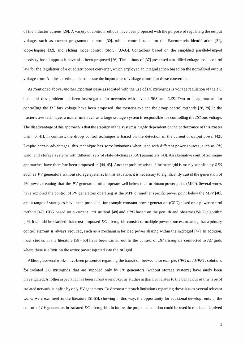
The relationship between the output voltage, the output average current IO and the diode current average value ID3 is
given by:
oDCo IIsVsCo
3
)(
(10)
Using Eqs. (9) and (10), the transfer function for the converter output voltage for a given input current can be written
as shown in Eq. (11).
o
o
L
do
Go i
sCI
ssTC
Kv
112
(11)
In Eq. (11), the control input is the current IL1. However, an unknown load current io appears as an input disturbance
in the output integrator. Hence, to avoid steady-state errors in the DC output voltage, a compensator with integral
action, called the proportional integral (PI) compensator, is used. This compensator has a zero at - Tz and a pole at origin
with integral gain at KI = 1/Tp (Eq. 12). The proportional gain is then KP = Tz/Tp (Eq. 12). Fig. 4 shows a block diagram
of the output voltage closed loop controller.
p
zP
pI
T
TK
TK and
1
(12)
VCo_ref
i0
KI
KPsCo
1
s
1
1sT
K
d
G
Fig. 4: Block diagram of the power converter output voltage controller.
From Eq. (12) and the block diagram in Fig. 4, we obtain the final transfer function of the system in the closed loop as:
opd
G
opd
zG
d
o
od
dGLG
opd
z
refC
C
CTT
Ks
CTT
TKs
Ts
sICT
sTsKsIK
CTT
sT
sV
sV
o
o
23 1
111
(13)
To calculate the parameters of the PI compensator, the symmetrical optimum criterion will be used, since the
parameters will not appear as a function of the load [70, 71]. The open loop transfer function, including the PI
compensator, has three poles: two at the origin and a third at −1/Td, where Td is the sum of the relatively small delays due
to the nonlinear internal dynamics of the quadratic converter associated with the C1 L2 components. The PI zero cannot be

12
used to compensate for the −1/Td equivalent pole, since the resulting system, with two poles at the origin plus neglected
dynamics, would be unstable. To maximise the phase margin M, we use the fact that the angle criteria gives the
frequency ωd of the maximum M, zdd TT/1 , which is the frequency of the geometric mean of the equivalent pole
1/Td and the PI compensator zero 1/TZ. The parameter a, which represents the symmetrical distance between 1/TZ and
ωd and between 1/Td and ωd, is then calculated to obtain a design value for M, as MMa sin1/sin1 . For a
design value of M ≈ 36.9º, we obtain a symmetrical optimum value of a = 2. For a = 2, we also have the best disturbance
rejection behaviour, although the damping factor ζ = (a−1)/2 is on the low side (ζ =0.5). For a value of M of around
53.1º, a = 3, the damping factor is ζ =1 and the disturbance rejection decreases (the value of a is usually between two and
four). The parameter a is also useful to write the terms of the closed loop characteristic third-order polynomial in Eq. (13)
in the form bk2 = abk-1bk+1, where bk are the polynomial terms (b3s
3+b2 s
2+ b1 s+ b0, b0=1). By writing the criteria for b1 (
20
2
1 babb ) and for b2 (31
2
2 babb ), two equations are obtained that can be solved to give the PI gains:
Gd
o
p
ZP
Gd
o
Z
IKaT
C
T
TKand
KTa
C
TK
23
1 (14)
In DC microgrids, the reference value of the DC bus is fixed. However, since the microgrid is supplied by the PV
quadratic boost, the PI controller should be joining to the MPPT controller. In fact, there are several issues that must be
considered, as follows:
• To maintain the stability of the grid voltage, the power available from the PV generator must be equal to or higher
than the load power. This means that in normal mode, the PV generator should feed the load with a power that is
lower than the available MPP. Alternatively, for fast and stable regulation during transient load changes, the PV
converter often needs to work at the MPP. Hence, the PI compensator cannot operate independently, otherwise
operation at the MPP would be at risk;
• The PI controller gives the reference value for the current controller, which should not be higher than the MPP of
the PV generator. However, saturation at the output of the controller does not ensure the fulfilment of this
condition, since the available MPP is a function of several factors such as the irradiance and temperature (the
MPP can only be obtained using one MPPT algorithm);
• To overcome these issues, the PI controller should be combined with the MPPT controller. However, when the
two controllers are combined, the iL1ref current must be selected from only one of them (Fig. 5). This means that
the PI integral, if not conditioned, will undergo windup and saturate, creating a rough transition when the PI is

13
re-selected to give the value of iL1ref. This creates disturbances and may cause large signal instabilities. Hence,
when the system MPPT algorithm is in use, the PI controller should be driven in such a way as to track the value
of MPPT iL1ref, to avoid transient oscillations when re-selected.
Based on the above considerations, the MPPT and the PI controller should be combined in an interactive way, as
illustrated in Fig. 5. This system includes a switch to perform the transition between the PI controller and the MPPT. The
figure also shows the interaction of the iL1ref current between PI controller and the MPPT algorithm (since the output of
the PI controller forms one of the inputs to the MPPT).
The transition between the two controllers is a function of the DC voltage bus: if this voltage is near the reference
value, then the converter will be controlled by the PI controller, but if it drops below a defined threshold value CoV , the
reference switch will select the MPPT controller. The selection of one of the two controllers can be expressed as in
Eq. (15).
CoorefoMPPT
CoorefoI
PCoCorefrefL
VVVi
VVVs
KKVV
i
_
_1
when
when (15)
where iMPPT is the current established by the MPPT algorithm and VCo is the lower margin for operation of the PI
controller.
Vo_ref
KI
KP
s
1
MPPT
Current
Controller
Vo
VPV
IPV
IL1_ref
IL1_ref
Fig. 5: Block diagram of the combined voltage and MPPT controllers.
The proposed MPPT algorithm is based on the P&O principle [72], but also includes the iL1ref current as shown in the
flowchart in Fig. 6. In the MPPT mode, the algorithm computes the current reference value for the converter current
controller. However, as mentioned above, this algorithm cannot work independently when the system is controlled by the
PI controller. In the PI controller mode (voltage control mode), the MPPT algorithm provides the same reference current
as that given by the PI controller. This will ensure a soft transition when the global controller changes from the PI mode

14
to the MPPT mode. The MPPT will therefore have an extra input, which is the current reference given by the PI
controller (Figs. 5 and 6).
A further problem arises in relation to the PI controller in the MPPT mode. To avoid instabilities , the MPPT algorithm
should also interact with the PI controller in the MPPT mode. When the reference switch (Eq. 15) changes to the MPPT
mode, the PI ceases to control the output voltage, and the integrator will undergo windup. Then, when the reference
switch (Eq. 15) returns to the PI mode, there will be a sudden change in the reference current. This can lead to significant
oscillations, and even to large signal instabilities. To overcome this problem, we propose a new global control system, as
shown in Fig. 7, in which an anti-windup system is added to the PI controller and is connected between the two
controllers. If the system is in the PI mode, then the difference between those controllers is zero, since the MPPT gives
the same value as the PI controller. In this way, the anti-windup block is deactivated in this mode. If the controller
switches to the MPPT mode, the anti-windup block will ensure that the PI controller converges to the same value of the
MPPT, despite the disturbance in the proportional gain.
The anti-windup gain kW is given in Eq. (16), where the parameter KP is defined as in Eq. (12).
PW
KK
1 (16)
This global control scheme allows for a smooth and stable transition between the MPPT and the voltage controller (and
vice versa), and also improves the response time to disturbances due to load changes in the DC micro-grid.

15
Start
Measure
IPV(i) and VPV(i)
Calculate Power
PPV(i) = IPV(i) x VPV(i)
V = VPV(i) - VPV(i-1)
P = PPV(i) - PPV(i-1)
P = 0
P > 0
Yes
No
V > 0 V < 0
IL1_ref (i):= IL1_ref (i-1)- Istep IL1_ref (i):= IL1_ref (i-1)+ Istep
Yes
Yes
No
No
Yes No
Return
From PV
Measure
IL1_ref
From Current
ControllerMPPT
Mode
Yes
No
IL1_ref (i):=IL1_ref
Return
Fig. 6: Proposed MPPT algorithm.
Vo_ref
KI
KP
s
1
MPPT
Vo
Kw
Current
Controller
VPV
IPV
IL1_ref
IL1_ref
Fig. 7: Proposed global control system.
V. SIMULATION TESTS
The behaviour of the system using the proposed controllers was tested via several simulations, which were carried out
using MATLAB/Simulink software. Models from the Simscape-Power System toolbox were used for the power converter
and loads. The control strategy, MPPT algorithm and PV module were implemented using blocks from the classical
MATLAB/Simulink library. The PV model was based on the single-diode model [73], and the time step used in the

16
simulations was 1 s. The DC microgrid configuration shown in Fig. 1 was used in the simulation tests . The PV panel
was connected to the DC-DC quadratic boost converter (Fig. 2) supplying the microgrid DC bus, and the loads were
connected and disconnected from the DC bus. The parameters of the quadratic boost converter are given in Table 2. A
rated or reference voltage of 400 V was set for the DC bus. The PV panel contained two strings in parallel, each of which
had two modules connected in series. The characteristics of each PV module (based on a multicrystal KYOCERA
KD325GX PV module) are summarised in Table 3. The perturbation step size (Istep) used in the MPPT algorithm was
0.001. For the PI controller parameters, we used the values of KI = 1.78 and KP = 0.07, which were obtained from
Eq. (14).
Table 2 - Parameters of the quadratic boost converter
Switching frequency 12 kHz
Inductance of input inductor L1 1 mH
Inductance of input inductor L2 2.2 mH
Capacitance of input capacitor C1 150 F
Capacitance of output capacitor Co 150 F
Table 3 - Characteristics of the KYOCERA KD325GX PV panel
Electrical performance under STC
Maximum power 325 W
Maximum power voltage (VMPP) 40.3 V
Maximum power current (IMPP) 8.07 A
Open circuit voltage (VOC) 49.7 V
Short circuit current (ISC) 8.69 A
The first test was carried out with an initial load with an equivalent resistance of 310 . At t = 1 s, an additional
resistance load of 650 was suddenly connected, and at t = 1.5 s, this load was disconnected. The dynamic response of
the system can be seen in Fig. 8a, which shows the transient waveform of the DC voltage bus. The results show that after
each connection/disconnection of the load (disturbance), the microgrid recovered to the rated DC value of 400 V. The
voltage in the intermediate capacitor appears to remain stable (Fig. 8b). The current from the PV panels can be seen in
Fig. 8c. As expected, there is an increase in the current with an increase in the load. In this case, the required current is
lower than the maximum power current of the PV panels (IMPP), and the controller does not shift to the MPPT mode.
The power generated by the PV panels can be seen in Fig. 8d, which shows the tracking of the required load power.

17
a)
b)
c)
d)
Fig. 8: Simulation results for the proposed controller with a change in the load from 310 to 210 (310 // 650 and return to
310 (a) DC bus voltage; (b) intermediate capacitor voltage in the converter; (c) current of the PV array; d) power generated by the
PV array.

18
A second simulation test was performed in which the sudden connection of a load required the system to shift from the
PI mode to the MPPT mode and back again. In this test, the initial load was equivalent to a resistance of 310 and at
t = 1 s an additional load of 300 was abruptly connected. The dynamic response of the DC microgrid is illustrated in
Figs. 9a and 9b, which show the transient waveforms for the DC bus voltage and the generated PV power, respectively.
The results show that the controller reacts by compensating the disturbance and maintaining the output voltage at the
reference value. However, it should be noted that in this situation, the control system shifts from the PI mode to the
MPPT mode under the transient conditions . After connection of the 300 load, the output voltage decreases to a value
that requires a current higher than the IMPP current to quickly track the output reference voltage. The controller therefore
shifts to the MPPT mode to ensure the maximum possible power. This is shown in Fig. 9b, where it can be seen that after
connection of the load, the generated PV power increases to the MPP, and the controller is then in the MPPT mode.
a)
b)
Fig. 9: Simulation results for the proposed controller with a change in the load from 310 to 152 (310 // 300 (a) DC bus voltage; (b) power generated by the PV array.
A further simulation test was also performed in which a load was suddenly connected that required a higher power
than the maximum available from the PV panels. In this test, the initial load had an equivalent resistance of 310 , and at

19
t =1 s, an additional load of 180 was connected. This extra load was then suddenly disconnected at t = 1.5 s, and at the
same time, another 300 load was connected. The response of the system in terms of the output voltage, intermediate
converter capacitor voltage and PV power generated is shown in Figs. 10a–c. It can be seen that when the second load is
connected, the maximum PV power generated is insufficient to ensure that the output voltage recovers to the reference
value. The control system therefore shifts to the MPPT mode to deliver the MPP, which is insufficient to increase the DC
voltage bus to the required value. Thus, a steady-state error appears as the PV generator cannot operate above its
maximum. However, after disconnection of the second load at t = 1.5 s, the controller returns to the PI mode and the DC
voltage bus recovers to the reference value (Fig. 10a). The intermediate capacitor voltage is shown in Fig. 10b, and it can
be observed that it remains stable even in this situation. Notice that the ripple in the generated power is not the same,
since it is a function of the ripple in the current imposed by the converter and controller. The controller ensures that the
current is within the hysteretic reference band. This hysteresis defines the limits of the maximum switching frequency of
the power switch of the converter. However, due to the characteristics of the PV panels, a positive variation in their
current causes a negative variation in the voltage through, thus the power ripple will be attenuated. Hence, if the system is
in MPPT mode and near the vertical zone of the V-I characteristic of the solar cell, this means that variations in the
current in that point will cause high variations the voltage (lower PV power ripple). However, if the current from the PV
panel is reduced (since the load does not require all of the generated power from the PV system) then it will be near the
horizontal zone of the V-I characteristic of the solar cell, in which variations of the current in this new point will imply
lower variations of the voltage (higher PV power ripple).
a)

20
b)
c)
Fig. 10: Simulation results for the proposed controller with a change in load from 310 to 114 (310 //180 and then to 152
(310 // 300 a) DC bus voltage; (b) intermediate converter capacitor voltage; (c) power generated by the PV array.
Similar tests were also performed with electronically controlled loads. These loads show different behaviour from
classical linear loads (resistors), since the design ensures that a certain power is supplied to the load as required. Hence, if
the supplied voltage is reduced, the input current increases , and vice versa. This may affect the behaviour of the controller
during the transition between the two modes of operation. To assess this behaviour, an initial test was performed using an
electronically controlled load of 520 W. At t = 1 s, an additional electronically controlled load of 245 W was suddenly
connected, and at t = 1.5 s, this additional load was disconnected again. The dynamic response of the system can be seen
in Fig. 11a, which shows the transient waveform of the DC bus voltage. The results show that after each load is
connected/disconnected (creating a disturbance), the microgrid recovers to the rated DC value of 400 V, thus
demonstrating the stability of the system even under this type of load. Although the power for these loads was similar to
that for the linear loads, it can be seen that due to their characteristics, a shift is required from the PI mode to MPPT
mode and back again, as shown in Fig. 11.

21
a)
b)
Fig. 11: Simulation results for the proposed controller for a change in the electronically controlled loads from 520 W to 765 W and
back to 520 W (a) DC bus voltage; (b) power generated by the PV array.
In the next simulation test, an electronically controlled load was suddenly connected that required a higher power from
the PV generator. In this situation, the problem of instability may arise when the generated power is lower than the load
power. In this case, if there is no limitation on the input current of the electronically controlled load, the current will
continuously increase, and the bus voltage will collapse to 0 V. However, these loads usually impose a limitation on the
input current, typically with the aim of protecting the equipment. We therefore imposed a current limitation of 20%
above the nominal value in this test. An initial load of 400 W was applied; at t = 1 s, an extra load of 900 W was
introduced, and the total load was finally reduced to 930 W at t = 1.5 s. The response of the system with regard to the
output voltage and PV power generated is shown in Figs. 12a and 12b. It can be seen from these figures that when the
second load is connected, the maximum PV power generated is not sufficient to ensure that the output voltage recovers to
the reference value. The control system therefore shifts to the MPPT mode to deliver the MPP, which is insufficient to
increase the DC bus voltage to the required value. However, after the load is reduced at t = 1.5 s, the controller returns to
the PI mode and the DC voltage bus recovers to the reference value. We can therefore conclude that even in this situation
the system maintains its stability.

22
a)
b)
Fig. 12: Simulation results for the proposed controller for a change in the electronically controlled load from 400 W to 1300 W and
then to 930 Wa) DC bus voltage; (b) power generated by the PV array.
The next test involved a PV generator with a battery system, where the mode of operation of the PV interface was
based mainly on the SoC of the battery. Initially, the battery controlled the bus voltage, but at t = 0.9 s it reached a state of
full charge, and the bus voltage began to be controlled by the PV generator. Connected to the bus there is an
electronically controlled load with 600 W of power was connected to the bus , meaning that the load power was below the
maximum available PV power. The response of the system in terms of the output voltage and PV power generated is
shown in Figs. 13a and 13b. Initially, the PV generator is in MPPT operation, with the excess energy being transferred to
the storage system. However, when the battery is fully charged, the PV generator changes to voltage control, and the
generated power is reduced. At t = 1.6 s, an additional electronically controlled load is connected, giving a total load of
1500 W. Since this power is higher than the maximum available from the PV generator, there is a change from voltage
control to MPPT mode, and the battery starts to discharge its energy to supply the load. The power generated by the PV
system reverts to the maximum capability (Fig. 13 b).

23
a)
b)
Fig. 13: Simulation results for the proposed controller for a PV + battery system a) DC bus voltage; (b) power generated by the PV
array.
VI. EXPERIMENTAL TESTS
To validate the simulation cases studied in the previous section, several additional experimental tests were performed.
The parameters used for the experimental DC-DC converter are given in Table 2. A PV simulator was used for the PV
panels that consisted of a remotely controllable EA Elektro-Automatik EA-PS 8160-60 DC power supply, which was
controlled by a DS1104 R&D controller board (with a sampling time of 1 s) into which the characteristics of the PV
panel were programmed using four modules (Table 3). The perturbation step size (Istep) used in the MPPT algorithm was
0.001. The experimental tests were similar to those in the simulations.
In the first test, an initial load with a resistance of about 310 was considered. An additional load of 650 was
suddenly connected followed by disconnection after 500 ms. The results of this experiment can be seen in Figs 14a–d.
Fig. 14a shows the response of the DC bus voltage to the variation in load, and it can be seen that after each disturbance
the controller compensates for the disturbances and returns to the steady state. In this situation it also recovers the rated
value of the DC voltage. The rejection is fast enough to minimise the effect of the disturbances. The intermediate
capacitor voltage is shown in Fig. 14b, and it can be observed that it remains stable even in this situation. Fig. 14c shows
that the PV current changes to a higher value almost instantly after the connection of the load , to track the DC reference

24
voltage. After disconnection of the load, the PV current returns to the initial value. Fig. 14d shows the generated PV
power. The power extracted from the PV panels is not fixed and tracks the required load power; the PV panels do not
achieve their MPP even in the transient state, and the control system does not shift to the MPPT mode. These
experimental results are very similar to the simulation results.
a)
b)

25
c)
d)
Fig. 14: Experimental results for the proposed controller for a change in load from 310 to 210 (310 // 650 and return to
310 (a) DC bus voltage (100 V/div); (b) intermediate converter capacitor voltage (100 V/div); (c) PV array current (3A/div); (d)
power generated by the PV array (200 W/div).
A second experiment was then performed with the same initial load (310 A second load (of nearly 300 )was
then connected in order to cause the controller to shift from the PI mode to the MPPT mode. The dynamic response of the
system in this test is illustrated in Figs. 15a and 15b, which show the transient waveforms of the DC bus voltage and the
generated PV power. Figs. 15a shows that after connection of the 300 load, the DC bus voltage falls with the
disturbance, but that the controller quickly reacts to the disturbance, ensuring the return of the DC voltage to its reference
value. To do this, the controller increases the power of the PV array to a higher value after the 300 load is connected.
The increase is limited to the MPP of the PV array (Fig. 15 b) and is achieved through a shift in the controller from the
voltage PI to the MPPT control mode.

26
a)
b)
Fig. 15: Experimental results for the proposed controller for a change in load from 310 to 152 (310 // 300) (a) DC voltage
bus (100 V/div); (b) power generated by the PV array (200 W/div).
In the next experimental test, a load was suddenly connected that required a higher power than the maximum available
from the PV panels. The initial load had an equivalent resistance of 310 and an extra load of 180 was connected at
t = 1 s and disconnected after 500 ms, while another 300 load was connected at the same time. The response of the
system in terms of the output voltage, intermediate converter capacitor voltage, PV array current and generated PV power
is shown in Figs. 16a–d. From an analysis of these figures, we can verify that when the second load is connected, the
maximum PV power generated is insufficient to ensure that the output voltage recovers to the reference value. The
control system therefore shifts to the MPPT mode to deliver the MPP, which is also insufficient to increase the DC bus
voltage to the required value. However, after disconnection of the second load at t = 1.5 s, the controller returns to the PI
mode and the DC voltage bus recovers to the reference value. The voltage in the intermediate capacitor remains stable
(Fig. 16b).

27
a)
b)
c)
Fig. 16: Experimental results for the proposed controller for a change in load from 400 to 124 400 // 180 and then to
171 400 // 300 (a) DC bus voltage (100 V/div); (b) intermediate converter capacitor voltage (100 V/div); (c) power
generated by the PV array (200 W/div).

28
VII. CONCLUSIONS
This work has proposed a new control system for a PV generator supplying energy to an islanded DC microgrid. The
quadratic boost DC-DC converter used to interface the PV generator provides the necessary high voltage gain that is
typically needed in these applications. The controller was designed with a particular focus on the transition from the
MPPT mode to the PI voltage control mode and vice versa, and the importance of this critical aspect was highlighted in
the text. The proposed MPPT plus PI voltage controller has a cascaded structure consisting of an inner input current
controller and outer output voltage controller. A PI controller was proposed for control of the output voltage, while a
MPPT algorithm was devised to achieve the MPP. Our MPPT plus PI voltage controller undergoes smooth transitions
between the PI controller and the MPPT algorithm, due to the interactivity when computing the reference current in both
modes. It must be mentioned that this work presents a different approach regarding the ones that addressed the transition
from the maximum power point to DC bus voltage regulation of PV generators. In this case the problem of DC bus
voltage control in a DC microgrid exclusively supplied by a PV generator was solved. In this context, it was also
investigated the inner control loops related to the transitions between voltage control and MPPT operation for this kind of
DC microgrid, and propose a new control strategy. The proposed control system was verified and tested through several
simulation studies. These simulations were confirmed through the use of a laboratory setup, which gave experimental
results that demonstrated the good performance and behaviour of the proposed control system, without instabilities
between the PI (voltage control) and MPPT modes. We were able to test the system under several conditions, by
changing the loads and analysing the system as the PV generator shifted from voltage control mode to MPPT and back
again. Transients in the output voltage were kept below ±10%, while the response times were around 10 ms. In the results
obtained for linear and electronically controlled loads, there was a small degradation in the system response due to the
different behaviour of the electronic load, which is usually designed to ensure the required power to the load. This can be
problematic when the power from the PV generator is insufficient to supply the load. However, since electronic loads are
typically designed with a limitation on the input current for their protection, we showed that under these conditions, the
system maintains the stability of the DC voltage.
ACKNOWLEDGMENT
This work was supported by national funds through FCT – Fundação para a Ciência e a Tecnologia, under project
UIDB/50021/2020 and UIDB/00066/2020.

29
REFERENCES
[1] M. J. Ghadi, A. Rajabi, S. Ghavidel, A. Azizivahed, Li J. Zhang, ―From active distribution s ystems to decentralized
microgrids: A review on regulations and planning approaches based on operational factors‖, Applied Energy, vol
253, Issue 4, November 2019, pp. 1-16.
[2] T. Strasser, F. Andrén, J. Kathan, C. Cecati, C. Buccella, P. Siano, P. Leitão, G. Zhabelova, V. Vyatkin, P. Vrba, V.
Mařík, ―A Review of Architectures and Concepts for Intelligence in Future Electric Energy Systems‖, IEEE
Transactions on Industrial Electronics, vol 62, Issue 4, April 2015, pp. 2424-2438.
[3] J. Justo, F. Mwasilu, J. Lee, J. Jung, ―AC-microgrids versus DC-microgrids withy distributed energy resources: A
review,‖ Renewable and Sustainable Energy Reviews, vol. 24, August 2013, pp. 387–405.
[4] S. K. Kollimalla, M. K. Mishra, A. Ukil, and H. Gooi, ―DC grid volt- age regulation using new HESS control
strategy,‖ IEEE Transactions on Sustainable Energy, vol. 8, no. 2, Apr. 2017, pp. 772–781.
[5] A. Amir, A. Amir, H. Che, A. Elkhateb, N. AbdRahim, ―Comparative analysis of high voltage gain DC-DC
converter topologies for photovoltaic systems‖, Renewable Energy, vol. 136, June 2019, pp. 1147-1163.
[6] S. Sitbon, S. Schacham, T. Suntio, A. Kuperman, ―Improved adaptive input voltage control of a solar array
interfacing current mode-controlled boost power stage‖ Energy Conversion and Management, vol. 98, July 2015,
pp. 369–375.
[7] O. Garcia, P. Alou, J. Oliver, D. Diaz, D. Meneses, J. Cobos, A. Soto, E. Lapena, J. Rancano, ―Comparison of
Boost-Based MPPT Topologies for Space Applications,‖ IEEE Transactions on Aerospace and Elect ronic Systems,
vol. 49, no. 2, April 2013, pp. 1091-1107.
[8] M. Mirhosseini, J. Pou, V. Agelidis, ―Single- and two-stage inverter- based grid-connected photovoltaic power
plants with ride-through capability under grid faults,‖ IEEE Transactions on Sustainable Energy, vol. 6, no. 3,
July 2015, pp. 1150–1159.
[9] W. Li, X. He, ―Review of Nonisolated High-Step-Up DC/DC Converters in Photovoltaic Grid-Connected
Applications,‖ IEEE Transactions on Industrial Electronics, vol. 58, no. 4, April 2011, pp. 1239-1250.
[10] P. Prabhakaran, V. Agarwal, ―Novel Boost-SEPIC type Interleaved DC- DC Converter for Mitigation of Voltage
Imbalance in a Low Voltage Bipolar DC Microgrid‖, IEEE Transactions on Industrial Electronics,
DOI 10.1109/TIE.2019.2939991.
[11] V. Pires, D. Foito, F. Batista, J. Silva, ―A photovoltaic generator system with a DC/DC converter based on an
integrated Boost-Cuk topology‖, Solar Energy, vol. 136, October 2016, pp. 1-9.

30
[12] D. Zhou, A. Pietkiewicz, S. Cuk, ―A three-switch high-voltage converter‖, IEEE Transactions on Power
Electronics, vol. 14, no 1, January 1999, pp. 177–183.
[13] M. Ferrera, S. Aranda, J. Márquez, ―A Converter for Bipolar DC Link Based on SEPIC-Cuk Combination,‖ IEEE
Transactions on Power Electronics, vol. 30, no. 12, December 2015, pp. 6483–6487.
[14] A. Sabzali, E. Ismail, H. Behbehani, ―High voltage step-up integrated double Boost-Sepic DC-DC converter for
fuel-cell and photovoltaic applications‖, Renewable Energy, vol. 82, October 2015. pp. 44-53.
[15] K. Nathan, S. Ghosh, Y. Siwakoti, T. Long, ―A New DC-DC Converter for Photovoltaic Systems:
Coupled-Inductors Combined Cuk-SEPIC Converter,‖ IEEE Transactions on Energy Conversion, vol. 34, no. 1,
March 2019, pp. 191-201.
[16] F. Tofoli, D. Pereira, W. Josias de Paula, D. Oliveira Júnior, ―Survey on non-isolated high-voltage step-up dc–dc
topologies based on the boost converter,‖ IET Power Electronics, vol. 8, no. 10, October 2015, pp. 2044–2057.
[17] B. Axelrod, Y. Berkovich, and A. Ioinovici, ―Switched -capacitor/ switched-inductor structures for getting
transformerless hybrid DC-DC PWM converters,‖ IEEE Trans. Circuits Syst. I, Reg. Papers, vol. 55, no. 2,
March 2008, pp. 687–696.
[18] G. Wu, X. Ruan, Z. Ye, ―Nonisolated high step-up DCeDC converters adopting switched-capacitor cell‖, IEEE
Transactions on Industrial Electronics, vol. 64, no. 4, April 2017, pp. 3012–3022.
[19] S. Sathyan, H. Suryawanshi, M. Ballal, A. Shitole, ―Soft- switching DC-DC converter for distributed energy sources
with high step-up voltage capability,‖ IEEE Transactions on Industrial Electronics, vol. 62, no. 11, November 2015,
pp. 7039-7050.
[20] Y. Tang, T. Wang, D. Fu, ―Multicell switched-inductor/switched-capacitor combined active-network converters‖,
IEEE Transactions on Power Electronics, vol. 30, no 4, April 2015, pp. 2063–2072.
[21] D. S. Wijeratne, G. Moschopoulos, "Quadratic Power Conversion for Power Electronics: Principles and Circuits,"
IEEE Trans. Circuits and Systems – I: Regular Papers, vol. 59, no. 2, 2012, pp. 426-438.
[22] S. H. Chincholkar and C. Y. Chan, ―Design of fixed-frequency pulsewidth modulation-based sliding-mode
controllers for the quadratic boost converter,‖ IEEE Transactions Circuits Syst. II, Exp. Briefs, vol. 64, no. 1,
January 2017, pp. 51 - 55.
[23] V. F. Pires, A. Cordeiro, D. Foito, J. F. Silva, ―High Step-Up DC–DC Converter for Fuel Cell Vehicles Based on
Merged Quadratic Boost–Ćuk‖, IEEE Transactions on Vehicular Technology, vol. 68, Issue 8, August 2019,
pp. 7521-7530.

31
[24] J. Leyva-Ramos, M. G. Ortiz-Lopez, L. H. Diaz-Saldierna, and J. A. Morales-Sandana, ―Switching regulator using a
quadratic boost converter for wide DC conversion ratios,‖ IET Power Electron., vol. 2, no. 5, Sep. 2009,
pp. 605-613.
[25] W. Jiang, S. Chincholkar, C. Y. Chan, ―Modified voltage-mode controller for the quadratic boost converter with
improved output performance,‖ IET Power Electronics, vol. 11, no. 14, 2018, pp. 2222-2231.
[26] O. Lopez-Santos, L. Martinez-Salamero, G. Garcia, H. Valderrama-Blavi, D. Zambrano-Prada, ―Steady-State
Analysis of Inductor Conduction Modes in the Quadratic Boost Converter,‖ IEEE Transactions on Power
Electronics, vol. 32, no. 3, March 2017, pp. 2253–2264.
[27] V. Pires, D. Foito, A. Cordeiro, ―A DC-DC Converter with Quadratic Gain and Bidirectional Capability for
Batteries/Supercapacitors‖, IEEE Transactions on Industry Applications, vol 54, Issue 1, January/February 2018,
pp. 274-285.
[28] S. H. Chincholkar, C. Chan, "Investigation of current-mode controlled cascade boost converter systems: dynamics
and stability issues," in IET Power Electronics, vol. 9, no. 5, pp. 911-920, April 2016.
[29] O. Lopez-Santos, L. Martinez-Salamero, G. Garcia, H. Valderrama-Blavi, T. Sierra-Polanco, "Robust Sliding-Mode
Control Design for a Voltage Regulated Quadratic Boost Converter," in IEEE Transactions on Power Electronics,
vol. 30, no. 4, pp. 2313-2327, April 2015.
[30] J. A. Morales-Saldaña, R. Loera-Palomo, E. Palacios-Hernández, J. L. González-Martínez, "Modelling and control
of a DC-DC quadratic boost converter with R2P2," in IET Power Electronics, vol. 7, no. 1, pp. 11-22, January 2014.
[31] F. Alonge, R. Rabbeni, M. Pucci, G. Vitale, "Identification and Robust Control of a Quadratic DC/DC Boost
Converter by Hammerstein Model," in IEEE Transactions on Industry Applications , vol. 51, no. 5, pp. 3975-3985,
September-October 2015.
[32] J. Leyva-Ramos, R. Mota-Varona, M. G. Ortiz-Lopez, L. H. Diaz-Saldierna, D. Langarica-Cordoba, "Control
Strategy of a Quadratic Boost Converter With Voltage Multiplier Cell for High -Voltage Gain," in IEEE Journal of
Emerging and Selected Topics in Power Electronics, vol. 5, no. 4, pp. 1761-1770, December 2017.
[33] M. R. Mojallizadeh, M. Badamchizadeh, S. Khanmohammadi, M. Sabahi, ―Chattering free full-order terminal
sliding-mode control for maximum power point tracking of photovoltaic cells,‖ IET Renewable Power Generation.,
vol. 11, no. 1, pp. 85–91, January 2017..

32
[34] J. Leyva-Ramos, R. Mota-Varona, M. G. Ortiz-Lopez, L. H. Diaz-Saldierna, D. Langarica-Cordoba, "Control
Strategy of a Quadratic Boost Converter With Voltage Multiplier Cell for High-Voltage Gain," in IEEE Journal of
Emerging and Selected Topics in Power Electronics, vol. 5, no. 4, pp. 1761-1770, December 2017.
[35] S. H. Chincholkar, C.-Y. Chan, ―Design of fixed-frequency pulsewidth-modulation-based sliding-mode controllers
for the quadratic boost converter,‖ IEEE Transactions on Circuits and Systems II, Express Briefs, vol. 64, no. 1, pp.
51–55, January 2017.
[36] Hugo Valderrama-Blavi, Ezequiel Rodríguez-Ramos, Carlos Olalla, Xavier Genaro-Muñoz, "Sliding-Mode
Approaches to Control a Microinverter Based on a Quadratic Boost Converter," Energies, vol. 12, no. 19, pp. 1-24,
October 2019.
[37] W. Jiang, S. H. Chincholkar, C. Chan, "Modified voltage-mode controller for the quadratic boost converter with
improved output performance," in IET Power Electronics, vol. 11, no. 14, pp. 2222-2231, November 2018.
[38] X. Li, Member, Li Guo, S. Zhang, C. Wang, Y. W. Li, A. Chen, Y. Feng, ―Observer-Based DC Voltage Droop and
Current Feed-Forward Control of a DC Microgrid,‖ in IEEE Transactions on Smart Grid, vol. 9, no. 5,
September 2018, pp. 5207–5216.
[39] Y. Liu, X. Zhuang, Q. Zhang, M. Arslan, H. Guo, ―A novel droop control method based on virtual frequency in DC
microgrid,‖ in International Journal of Electrical Power & Energy Systems, Vol. 119, 105946, pp. 1-10, 2020.
[40] M. Kumar, S. Srivastava, S. Singh, ―Control strategies of a DC microgrid for grid connected and islanded
operations,‖ in IEEE Transactions on Smart Grid, vol. 6, no. 4, July 2015, pp. 1588–1601.
[41] A. M. dos Santos Alonso, D. I. Brandao, T. Caldognetto, F. P. Marafão, P. Mattavelli, ―A selective harmonic
compensation and power control approach exploiting distributed electronic converters in microgrids,‖ in
International Journal of Electrical Power & Energy Systems, Vol. 115, 105452, pp. 1-15, 2020.
[42] Y. Mohamed, E. El-Saadany, ―Adaptive decentralized droop controller to preserve power sharing stability of
paralleled inverters in distributed generation microgrids,‖ in IEEE Transactions on Power Electronics, vol. 23, no. 6,
November 2008, pp. 2806–2816.
[43] N. Diaz, T. Dragievi, J. Vasquez, J. Guerrero, ―Intelligent distributed generation and storage units for dc microgrids
a new concept on cooperative control without communications beyond droop control,‖ IEEE Transactions on Smart
Grid, vol. 5, no. 5, September 2014, pp. 2476–2485.
[44] H. Kakigano, Y. Miura, T. Ise, ―Distribution voltage control for dc microgrids using fuzzy control and
gain-scheduling technique,‖ IEEE Transactions on Power Electronics, vol. 28, no. 5, May 2013, pp. 2246–2258.

33
[45] Y. Dai, L. Zhang, G. Liu, C. Yang, D. Zhang, X. Huang, ―Prescribed -performance based finite-time adaptive fuzzy
control for PV inverter in islanded systems,‖ in International Journal of Electrical Power & Energy Systems,
Vol.133, 107254, pp. 1-10, 2021.
[46] A. Sangwongwanich, Y. Yang, F. Blaabjerg, H. Wang, ―Benchmarking of Constant Power Generation Strategies for
Single-Phase Grid-Connected Photovoltaic Systems‖, IEEE Transactions on Industry Applications, vol. 54, no. 1,
January/February 2018, pp. 447-457.
[47] C. Rosa, D. Vinikov, E. Romero-Cadaval, V. Pires, J. Martins, ―Low- power home PV systems with MPPT and PC
control modes,‖ in Proc. Int. Conf. Workshop Compat. Power Electron, June 2013, pp. 58–62.
[48] Y. Chen, C. Tang, Y. Chen, ―PV power system with multi-mode operation and low-voltage ride-through
capability,‖ IEEE Transactions on Industrial Electronics, vol. 62, no. 12, December 2015, pp. 7524–7533.
[49] M. Mirhosseini, J. Pou, V. Agelidis, ―Single- and two-stage inverter- based grid-connected photovoltaic power
plants with ride-through capability under grid faults,‖ IEEE Transactions on Sustainable Energy, vol. 6, no. 3,
July 2015, pp. 1150–1159.
[50] J. M. Guerrero, J. C. Vasquez, J. Matas, L. G. de Vicuna and M. Castilla, "Hierarchical Control of Droop -Controlled
AC and DC Microgrids—A General Approach Toward Standardization," in IEEE Transactions on Industrial
Electronics, vol. 58, no. 1, pp. 158-172, Jan. 2011.
[51] S. Batiyah, R. Sharma, S. Abdelwahed, N. Zohrabi, ―An MPC-based power management of standalone DC
microgrid with energy storage,‖ in International Journal of Electrical Power & Energy Systems, Vol. 120, 105949,
pp.1-14, 2020.
[52] H. Armghan, M. Yang, M.Q. Wang, N. Ali, A. Armghan, ―Nonlinear integral backstepping based control of a DC
microgrid with renewable generation and energy storage systems,‖ in International Journal of Electrical Power &
Energy Systems, Vol. 117, 105613, pp. 1-12, 2020.
[53] W. Xing, H. Wang, L. Lu, S. Wang, M. Ouyang, ―An adaptive droop control for distributed battery energy storage
systems in microgrids with DAB converters,‖ in International Journal of Electrical Power & Energy Systems,Vol.
130, 106944, pp. 1-19, 2021.
[54] R. Bakhshi-Jafarabadi, J. Sadeh, E. Rakhshani, M. Popov, ―High power quality maximum power point tracking -
based islanding detection method for grid-connected photovoltaic systems,‖ in International Journal of Electrical
Power & Energy Systems, Vol. 131, 107103, pp. 1-11, 2021.

34
[55] H. Xiao, G. Liu, J. Huang, S. Hou, L. Zhu, ―Parameterized and centralized secondary voltage control for
autonomous microgrids,‖ in International Journal of Electrical Power & Energy Systems, Vol. 135, 107531, pp. 1-8,
2022.
[56] Fernando M. Camilo, Rui Castro, M.E. Almeida, V. F. Pires, ―Economic assessment of residential PV systems with
self-consumption and storage in Portugal‖, Solar Energy, vol. 150, pp. 353–362, July 2017.
[57] Florian Wankmüller, Prakash R. Thimmapuram, Kevin G. Gallagher, Audun Botterud, ―Impact of battery
degradation on energy arbitrage revenue of grid-level energy storage‖, Journal of Energy Storage, vol. 10, pp. 56–
66, April 2017.
[58] S. Longo, V. Antonucci, M. Cellura, M. Ferraro, ―Life cycle assessment of storage systems: the case study of a
sodium/nickel chloride battery‖, in Journal of Cleaner Production, vol. 85, pp. 337–346, December 2014.
[59] S. Wen, S. Wang, G. Liu and R. Liu, "Energy Management and Coordinated Control Strategy of PV/HESS AC
Microgrid During Islanded Operation," in IEEE Access, vol. 7, pp. 4432-4441, December 2018.
[60] J. Justo, F. Mwasilu, J. Lee, J. Jung, ―Microgrid and load shedding scheme during islanded mode: A review,‖
Renewable and Sustainable Energy Reviews, vol. 71, May 2017, pp. 161-169.
[61] A. Ahmed, L. Ran, S. Moon and J. Park, "A Fast PV Power Tracking Control Algorithm With Reduced Power
Mode," in IEEE Transactions on Energy Conversion, vol. 28, no. 3, pp. 565-575, September 2013.
[62] Y. Yang, H. Wang, F. Blaabjerg, T. Kerekes, "A Hybrid Power Control Concept for PV Inverters With Reduced
Thermal Loading," IEEE Transactions on Power Electronics, vol. 29, no. 12, pp. 6271-6275, December 2014.
[63] R. G. Wandhare and V. Agarwal, "Advance control scheme and operating mo des for large capacity centralised PV-
grid systems to overcome penetration issues," 37th IEEE Photovoltaic Specialists Conference, pp. 002466-002471,
June 2011.
[64] G. C. Konstantopoulos, A. T. Alexandridis, "Non-linear voltage regulator design for DC/DC boost converters used
in photovoltaic applications: analysis and experimental results," IET Renewable Power Generation, vol. 7, no. 3, pp.
296-308, May 2013.
[65] H. Mahmood, D. Michaelson, J. Jiang, "Strategies for Independent Deployment and Autonomous Co ntrol of PV and
Battery Units in Islanded Microgrids," in IEEE Journal of Emerging and Selected Topics in Power Electronics, vol.
3, no. 3, pp. 742-755, September 2015.

35
[66] H. Liu, P. C. Loh, X. Wang, Y. Yang, W. Wang, D. Xu, "Droop Control with Improved Disturbance Adaption for a
PV System With Two Power Conversion Stages," in IEEE Transactions on Industrial Electronics, vol. 63, no. 10,
pp. 6073-6085, October 2016.
[67] H. Cai, J. Xiang, W. Wei and M. Z. Q. Chen, "V – dp/dv Droop Control for PV Sources in DC Microgrids," in IEEE
Transactions on Power Electronics, vol. 33, no. 9, pp. 7708-7720, September 2018.
[68] W. Gao, J. Hung, ―Variable structure control of nonlinear systems: A new approach,‖ in IEEE Transactions on
Industrial Electronics, vol. 40, pp. 45–44, February 1993.
[69] W. Gao, J. Hung, ―Variable structure control: A survey,‖ in IEEE Transactions on Industrial Electronics, vol. 40, pp.
2–22, February 1993.
[70] J. F. Silva, S. F. Pinto, ―Advanced Control of Switching Power Converters‖, in Mu hammad Rashid et al, editors:
Power Electronics Handbook 3ed, Vol Chennai: Butterworth Heinemann, 2011, chapter 36, pp. 1037-1141.
[71] Ogata. Kafsutuko, ―Modern Control Engineering‖, Fourth Edition, 1997.
[72] Bidyadhar Subudhi, Raseswari Pradhan, ―A Comparative Study on Maximum Power Point Tracking Techniques for
Photovoltaic Power Systems,‖ IEEE Transactions on Sustainable Energy, vol. 4, no. 1, January 2013, pp. 89 - 98.
[73] M. G. Villalva, J. R. Gazoli, E. R. Filho, "Comprehensive Approach to Modeling and Simulation of Photovoltaic
Arrays," IEEE Transactions on Power Electronics, vol. 24, no. 5, May 2009, pp. 1198-1208.