
An improved efficiency of fuzzy logic control of PMBLDC for PV pumping system
11
An improved efficiency of fuzzy logic control of PMBLDC for PV pumping system A. Terki ⇑ , A. Moussi, A. Betka, N. Terki Electrical Engineering Department, University of Biskra, Algeria article info Article history: Received 27 January 2011 Received in revised form 25 May 2011 Accepted 11 July 2011 Available online 23 July 2011 Keywords: Photovoltaic system Brushless DC motor Hysteresis controller Speed control Optimization abstract This paper presents an analysis by which the dynamic performances of a permanent mag- net brushless DC (PMBLDC) motor is controlled through a hysteresis current loop and an outer speed loop with different controllers. The dynamics of the photovoltaic pumping drive system with (PI) and a fuzzy logic (FL) speed controllers are presented. In order to optimize the overall system efficiency, a maximum power point tracker is also used. Sim- ulation is carried out by formatting the mathematical model for photovoltaic source, MPPT, motor and pump load. The results for such complicated and nonlinear system, with FL speed controller show improvement in transient response of PMBLDC drive over conven- tional PI. The effectiveness of the FL controller is also demonstrated. Ó 2011 Elsevier Inc. All rights reserved. 1. Introduction It is well known that the sun provides almost all the energy needed to support life. On average the earth receives about 1.2 10 15 KW of solar power. The challenge for sustainable future is to tap a tiny fraction of this energy to supply the relative modest demands of human activities. Probably the most elegant way known to do this is to convert it straight into electricity using solar cells. Due to the initial installation price, one has to properly size and optimize the system operation. Most of research work concentrate on the optimal use of the photovoltaic generators which exhaust about 60–80% of the global price depending on whether storage means are used or not. The PV systems can be operated as a stand-alone, hybrid or grid connected sys- tem. The first schemes found a wide application in remote regions to meet small, but essential electric power requirement such as water pumping systems [1,2]. Early studies have concentrated on ways of sizing, matching and adapting PV pumping systems since a proper match be- tween the installed capacity with the insolated load is essential to optimize such installations. Various studies have been done on the choice of the drive system, which suits PV source, types of pumps to use and ways to control and optimize the whole system [3]. This was firmly related to the existing technologies. At the early stage, only DC motors were used to drive pumps. Direct coupling of series, shunt, and separately exited DC motor PV pumping systems were studies [4,5]. It was found that the overall performances are totally different from those obtained when these motors are connected to a constant voltage source. Recent implementation showed that the PM motors are well suited for PV pumping [6,8]. They feature high level dynam- ics, fast response, and high efficiency which lend them naturally pumping systems mainly for low power. 0307-904X/$ - see front matter Ó 2011 Elsevier Inc. All rights reserved. doi:10.1016/j.apm.2011.07.042 ⇑ Corresponding author. E-mail address: [email protected] (A. Terki). Applied Mathematical Modelling 36 (2012) 934–944 Contents lists available at ScienceDirect Applied Mathematical Modelling journal homepage: www.elsevier.com/locate/apm
Transcript of An improved efficiency of fuzzy logic control of PMBLDC for PV pumping system
Applied Mathematical Modelling 36 (2012) 934–944
Contents lists available at ScienceDirect
Applied Mathematical Modelling
journal homepage: www.elsevier .com/locate /apm
An improved efficiency of fuzzy logic control of PMBLDCfor PV pumping system
A. Terki ⇑, A. Moussi, A. Betka, N. TerkiElectrical Engineering Department, University of Biskra, Algeria
a r t i c l e i n f o
Article history:Received 27 January 2011Received in revised form 25 May 2011Accepted 11 July 2011Available online 23 July 2011
Keywords:Photovoltaic systemBrushless DC motorHysteresis controllerSpeed controlOptimization
0307-904X/$ - see front matter � 2011 Elsevier Incdoi:10.1016/j.apm.2011.07.042
⇑ Corresponding author.E-mail address: [email protected] (A. Terki).
a b s t r a c t
This paper presents an analysis by which the dynamic performances of a permanent mag-net brushless DC (PMBLDC) motor is controlled through a hysteresis current loop and anouter speed loop with different controllers. The dynamics of the photovoltaic pumpingdrive system with (PI) and a fuzzy logic (FL) speed controllers are presented. In order tooptimize the overall system efficiency, a maximum power point tracker is also used. Sim-ulation is carried out by formatting the mathematical model for photovoltaic source, MPPT,motor and pump load. The results for such complicated and nonlinear system, with FLspeed controller show improvement in transient response of PMBLDC drive over conven-tional PI. The effectiveness of the FL controller is also demonstrated.
� 2011 Elsevier Inc. All rights reserved.
1. Introduction
It is well known that the sun provides almost all the energy needed to support life. On average the earth receives about1.2 � 1015 KW of solar power. The challenge for sustainable future is to tap a tiny fraction of this energy to supply the relativemodest demands of human activities. Probably the most elegant way known to do this is to convert it straight into electricityusing solar cells.
Due to the initial installation price, one has to properly size and optimize the system operation. Most of research workconcentrate on the optimal use of the photovoltaic generators which exhaust about 60–80% of the global price dependingon whether storage means are used or not. The PV systems can be operated as a stand-alone, hybrid or grid connected sys-tem. The first schemes found a wide application in remote regions to meet small, but essential electric power requirementsuch as water pumping systems [1,2].
Early studies have concentrated on ways of sizing, matching and adapting PV pumping systems since a proper match be-tween the installed capacity with the insolated load is essential to optimize such installations. Various studies have beendone on the choice of the drive system, which suits PV source, types of pumps to use and ways to control and optimizethe whole system [3]. This was firmly related to the existing technologies.
At the early stage, only DC motors were used to drive pumps. Direct coupling of series, shunt, and separately exited DCmotor PV pumping systems were studies [4,5].
It was found that the overall performances are totally different from those obtained when these motors are connected to aconstant voltage source.
Recent implementation showed that the PM motors are well suited for PV pumping [6,8]. They feature high level dynam-ics, fast response, and high efficiency which lend them naturally pumping systems mainly for low power.
. All rights reserved.
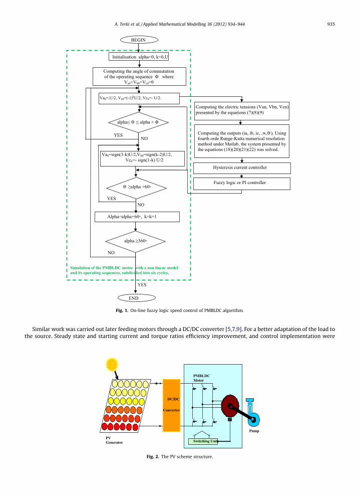
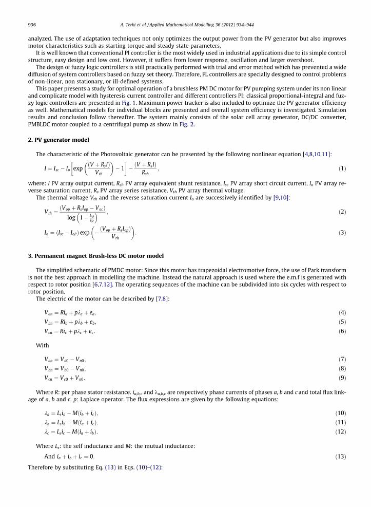
Fig. 1. On-line fuzzy logic speed control of PMBLDC algorithm.
A. Terki et al. / Applied Mathematical Modelling 36 (2012) 934–944 935
Similar work was carried out later feeding motors through a DC/DC converter [5,7,9]. For a better adaptation of the load tothe source. Steady state and starting current and torque ratios efficiency improvement, and control implementation were
Capteur
PMBLDC Motor
PV Generator Switching Unit
Pump
DC/DC
Converter
Fig. 2. The PV scheme structure.
936 A. Terki et al. / Applied Mathematical Modelling 36 (2012) 934–944
analyzed. The use of adaptation techniques not only optimizes the output power from the PV generator but also improvesmotor characteristics such as starting torque and steady state parameters.
It is well known that conventional PI controller is the most widely used in industrial applications due to its simple controlstructure, easy design and low cost. However, it suffers from lower response, oscillation and larger overshoot.
The design of fuzzy logic controllers is still practically performed with trial and error method which has prevented a widediffusion of system controllers based on fuzzy set theory. Therefore, FL controllers are specially designed to control problemsof non-linear, non stationary, or ill-defined systems.
This paper presents a study for optimal operation of a brushless PM DC motor for PV pumping system under its non linearand complicate model with hysteresis current controller and different controllers PI: classical proportional-integral and fuz-zy logic controllers are presented in Fig. 1. Maximum power tracker is also included to optimize the PV generator efficiencyas well. Mathematical models for individual blocks are presented and overall system efficiency is investigated. Simulationresults and conclusion follow thereafter. The system mainly consists of the solar cell array generator, DC/DC converter,PMBLDC motor coupled to a centrifugal pump as show in Fig. 2.
2. PV generator model
The characteristic of the Photovoltaic generator can be presented by the following nonlinear equation [4,8,10,11]:
I ¼ Isc � Io expV þ RsIð Þ
Vth
� �� 1
� �� ðV þ RsIÞ
Rsh; ð1Þ
where: I PV array output current, Rsh PV array equivalent shunt resistance, Isc PV array short circuit current, Io PV array re-verse saturation current, Rs PV array series resistance, Vth PV array thermal voltage.
The thermal voltage Vth and the reverse saturation current Io are successively identified by [9,10]:
Vth ¼ðVop þ RsIop � VocÞ
log 1� Iop
Isc
� � ; ð2Þ
Io ¼ ðIsc � IoPÞ exp �ðVop þ RsIopÞVrh
� �: ð3Þ
3. Permanent magnet Brush-less DC motor model
The simplified schematic of PMDC motor: Since this motor has trapezoidal electromotive force, the use of Park transformis not the best approach in modelling the machine. Instead the natural approach is used where the e.m.f is generated withrespect to rotor position [6,7,12]. The operating sequences of the machine can be subdivided into six cycles with respect torotor position.
The electric of the motor can be described by [7,8]:
Van ¼ Ria þ pka þ ea; ð4ÞVbn ¼ Rib þ pkb þ eb; ð5ÞVcn ¼ Ric þ pkc þ ec: ð6Þ
With
Van ¼ Va0 � Vn0; ð7ÞVbn ¼ Vb0 � Vn0; ð8ÞVcn ¼ Vc0 þ Vn0: ð9Þ
Where R: per phase stator resistance. ia,b,c and ka,b,c are respectively phase currents of phases a, b and c and total flux link-age of a, b and c. p: Laplace operator. The flux expressions are given by the following equations:
ka ¼ Lsia �Mðib þ icÞ; ð10Þkb ¼ Lsib �Mðia þ icÞ; ð11Þkc ¼ Lsic �Mðia þ ibÞ: ð12Þ
Where Ls: the self inductance and M: the mutual inductance:
And ia þ ib þ ic ¼ 0: ð13Þ
Therefore by substituting Eq. (13) in Eqs. (10)–(12):
A. Terki et al. / Applied Mathematical Modelling 36 (2012) 934–944 937
ka ¼ iaðLs þMÞ; ð14Þkb ¼ ibðLs þMÞ; ð15Þkc ¼ icðLs þMÞ: ð16Þ
From the electrical equations (4)–(6), the following system is obtained
Van
Vbn
Vcn
264
375 ¼
R 0 00 R 00 0 R
264
375
ia
Ib
Ic
264
375þ p
Leq 0 00 Leq 00 0 Leq
264
375
ia
Ib
Ic
264
375þ
ea
ea
ec
264
375: ð17Þ
With Leq = LS + MFrom this system, the decoupled phase equations are obtained and the explicit current equations are given by:
pia
ib
ic
264
375 ¼
1=Leq 0 00 1=Leq 00 0 1=Leq
264
375
Van
Vbn
Vcn
264
375�
R 0 00 R 00 0 R
264
375
ia
Ib
Ic
264
375�
ea
ea
ec
264
375
264
375: ð18Þ
The mechanical part is expressed by the following equation:
JdXdtþ BX ¼ Te þ Tr : ð19Þ
With: Te: electromagnetic torque. Tr: Load torque. X: speed. J: moment of inertia. B: viscose friction coefficient.Neglecting the frictional coefficient and taking X ¼ W
P where P is the pole pairs number, (19) can written as:
dWdt¼ PðTe � TrÞ=J: ð20Þ
The developed torque can be expressed by:
Te ¼ ðeaia þ ebib þ ecicÞ=W: ð21Þ
And the angular position is expressed by:
dhdt¼W: ð22Þ
4. Speed control
4.1. Classical PI controller
PI speed controller is widely used in industry due to its ease design and simple structure. The rotor speed W(k) is com-pared with the reference speed Wref(k) and the resulting error is estimated at the nth sampling instant as:
eðkÞ ¼WðkÞ �Wðk� 1Þ; ð23Þ
DeðkÞ ¼ eðkÞ � eðk� 1Þ: ð24Þ
The value of the torque reference is given by [1]:
Tref ðkÞ ¼ Tref ðk� 1Þ þ KpDeðkÞ þ KieðkÞ: ð25Þ
Where e(k�1) is the speed error of previous interval, e(k) is the speed error of working interval. Kp and Ki are speed con-troller gains.
4.2. Fuzzy Logic Controller
Fuzzy logic permits to define control laws of any process starting from linguistic description of the control strategy to beadopted. Fuzzy logic using controller is a rule-based controller; it consists of an input, processing, and output stages. Theinput or fuzzification stage maps instead of numerical variable linguistic ones, which are variables whose values (fuzzy sub-sets) are labels or sentences in a natural or artificial language[13,14].
In a basic configuration of a fuzzy logic controller as show in Fig. 3:
4.2.1. FuzzificationFuzzification or linguistic coding of in put variables, which transforms a given set of numerical inputs into fuzzy linguistic
variables set composed of fuzzy subsets called also membership functions. The most common shape of membership func-tions is triangular, although trapezoids and bell curves are also used see Fig. 4.
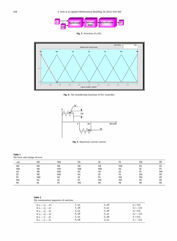
Fig. 3. Structure of a FLC.
Fig. 4. The membership functions of FLC controller.
Fig. 5. Hysteresis current control.
Table 1The Error and change of error.
eDe NB NM NS ZE PS PM PB
NB NB NB NB NB NM NS ZENM NB NM NM NM NS ZE PSNS NB NM NS NS ZE PS PMZE NB NM NS ZE PS PM PBPS NM NS ZE PS PM PM PBPM NS ZE PS PM PM PB PBPB ZE PS PM PB PB PB PB
Table 2The commutation sequences of switches.
Si ia < ði�a � DIÞ T1 on T4 off Va = U/2Si ia > ði�a þ DIÞ T1 off T4 on Va = �U/2Si ib < ði�b � DIÞ T2 on T5 off Vb = U/2Si ib > ði�b þ DIÞ T2 off T5 on Vb = �U/2Si ic < ði�c � DIÞ T3 on T6 off Vc = U/2Si ic > ði�c þ DIÞ T3 off T6 on Vc = �U/2
938 A. Terki et al. / Applied Mathematical Modelling 36 (2012) 934–944

Fig. 6. Overall system configuration.
0 0.01 0.02 0.03 0.04 0.05 0.06 0.070
50
100
150
200
250
300
350
Times (sec)
Spee
d (ra
d/se
c)
0 0.01 0.02 0.03 0.04 0.05 0.06 0.070
0.5
1
1.5
2
2.5
3
Times (sec)
Torq
ue (N
.m)
0 0.01 0.02 0.03 0.04 0.05 0.06 0.07-6
-4
-2
0
2
4
6
Times (sec)
Cur
rent
(A)
Fig. 7. Simulation results with out regulation under loading condition.
A. Terki et al. / Applied Mathematical Modelling 36 (2012) 934–944 939

940 A. Terki et al. / Applied Mathematical Modelling 36 (2012) 934–944
4.2.2. Inference fuzzy rulesInference fuzzy rules which contains a set of fuzzy rules in linguistic form as well as database which is a collection of
expert control knowledge allowing the achievement of fuzzy control objectives. This control rules base can be set up usingIF-THEN rules, based on expert experience and or engineering knowledge, and learning fuzzy rule-based system which haslearning capabilities. There are several different ways to define the result of a rule, but one of the most common and simplestis the ‘‘max–min’’ inference method, in which the output membership function is given the truth value generated by the pre-mise Fig. 3. The look up table for the input and output rules defined for seven linguistic variables (NB, NM, NS, ZE, PS, PM, PB)that stand for negative big, negative medium, negative small, zero, positive small, positive medium and positive big respec-tively is given in Fig. 1.
4.2.3. DefuzzificationDefuzzification of the inference engine, which evaluates the rules based on a set of control actions for a given fuzzy inputs set.
This operation converts the inferred fuzzy control action into a numerical value at the out- put. The results of all the rules that
0 0.01 0.02 0.03 0.04 0.05 0.06 0.070
50
100
150
200
250
300
350
Times (sec)
Spee
d (ra
d/se
c)
0 0.01 0.02 0.03 0.04 0.05 0.06 0.07-10
-8
-6
-4
-2
0
2
4
6
810
Times (sec)
Torq
ue (N
.m)
0 0.01 0.02 0.03 0.04 0.05 0.06 0.07-6
-4
-2
0
2
4
6
8
10
12
14
Times (sec)
Cur
rent
(A)
Fig. 8. Simulation results with PI speed and hysteresis current controllers regulation under loading condition.
A. Terki et al. / Applied Mathematical Modelling 36 (2012) 934–944 941
have fired are ‘‘defuzzified’’ to a crisp value by one of several methods. There are dozens in theory, each with various advantagesand drawbacks. The ‘‘centroid’’ method is very popular, in which the ‘‘center of mass’’ of the result provides the crisp value. An-other approach is the ‘‘height’’ method, which takes the value of the biggest contributor. The centroid method favors the rulewith the output of greatest area, while the height method obviously favors the rule with the greatest output value.
5. Current control
Several techniques can be used to control the phase current of the brushless PM DC motor. In this paper a hysteresis currentcontroller is used. It has the major advantage of not requiring machine parameters to be known. However the commutationfrequency is not constant [3,13]. It depends on many factors such as the applied voltage, the back e.m.f, hysteresis band Dl...etc.Maximum value of commutation frequency is obtained at starting and is given by [15]:
Fmax ¼ U=8LsDI: ð26Þ
The commutations are obtained by comparing actual currents ia.b.c to a rectangular reference i⁄a.b.c and by keeping them inhysteresis band I is given in Fig. 5. Table 1.
The commutation sequences of switches are summarised in the following table, Table 2.
0 0.01 0.02 0.03 0.04 0.05 0.06 0.070
50
100
150
200
250
300
350
Times (sec)
Spee
d (ra
d/se
c)
0 0.01 0.02 0.03 0.04 0.05 0.06 0.070
24
6
810
12
14
16
18
20
22
Times (sec)
Torq
ue (N
.m)
0 0.01 0.02 0.03 0.04 0.05 0.06 0.07-6
-4
-2
0
2
46
810
12
14
Times (sec)
Cur
rent
(A)
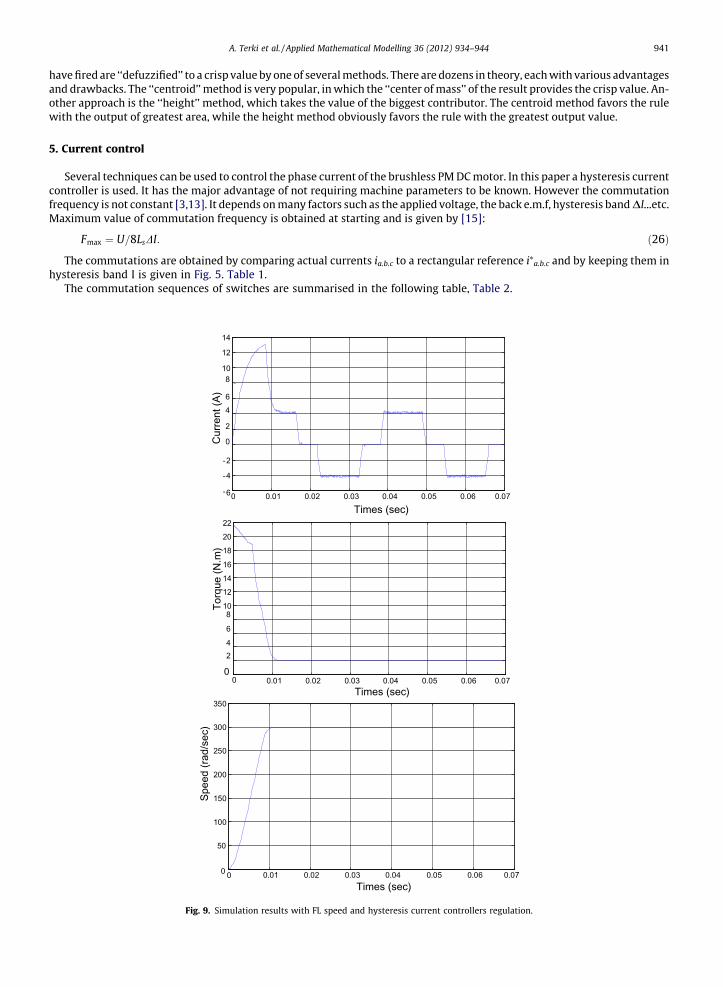
Fig. 9. Simulation results with FL speed and hysteresis current controllers regulation.
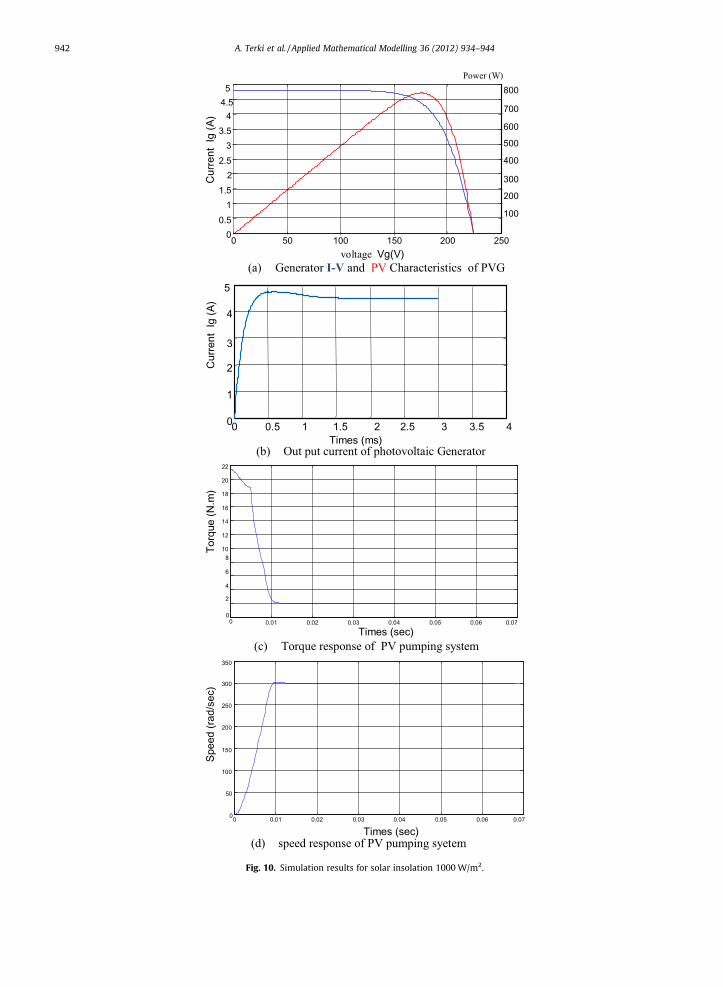
(a) Generator I-V and PV Characteristics of PVG
(b) Out put current of photovoltaic Generator
(c) Torque response of PV pumping system
(d) speed response of PV pumping syetem
350
0 0.01 0.02 0.03 0.04 0.05 0.06 0.070
50
100
150
200
250
300
Times (sec)
Spee
d (ra
d/se
c)
0 0.01 0.02 0.03 0.04 0.05 0.06 0.070
2
4
6
810
12
14
16
18
20
22
Times (sec)
Torq
ue (N
.m)
Cur
rent
Ig
(A)
Times (ms)0 0.5 1 1.5 2 2.5 3 3.5 40
1
2
3
4
5
100
200
300
400
500
600
700
800Power (W)
voltage Vg(V)
Cur
rent
Ig
(A)
0 50 100 150 200 25000.5
11.5
22.5
33.5
44.55
Fig. 10. Simulation results for solar insolation 1000 W/m2.
942 A. Terki et al. / Applied Mathematical Modelling 36 (2012) 934–944

A. Terki et al. / Applied Mathematical Modelling 36 (2012) 934–944 943
6. Pump model
The pump used is of centrifugal type which can be described by an aerodynamic load which is characterised by the fol-lowing load equation[16]:
T1 ¼ AW2; ð27Þ
where A is the pump constant.
6.1. Simulation results
Using fourth order Runge–Kutta numerical resolution method under Matlab, the overall system shown in Fig. 6 was sim-ulated. The system was first simulated without the hysteresis current controller and speed controllers. and then using themin order to see the effectiveness of this controller. Fig. 7:a-b shows the simulation results without regulation, The phase cur-rent and torque high ripples are clearly seen. The torque pulsation is more than 15% of the average value. The source currentis highly discontinuous and the speed presents an overshot in addition to its moderate response. After, the speed and currentregulations are introduced, results are shown in Fig. 8 (regulation with PI controller) and Fig. 9(regulation with FL controller)the response current and torque ripples are distinctly reduced, The speed following the reference with overshot in PI con-troller, so with FL controller, the speed converges to the reference value very quickly without any overshot and with zerosteady state error. It is shown that the proposed drive with FL controller is also capable of following the reference speedat best time response, zero steady state error and almost without any overshot.
Fig. 10 show a PV generator I-V and P-V characteristics, the generator output current, the drive speed and motor torque forsolar insolation of 1000 W/m2. It is seen that the maximum power is efficiently tracked, and motor performance are quiet good.At the start the current rises to the short circuit value of 4.82 A with a time constant which depends on motor electrical param-eters and decreases at the value of 4.41 A corresponding to optimal current and optimal voltage of 175 V. The correspondingmaximum power of the PV generator is 772 W. The final steady state speed of 300 rad/s is reached with no overshot.
7. Conclusion
Performances of fuzzy logic controller applied to the brushless PMDC motor connected to photovoltaic array and driving acentrifugal pump is investigated. The PV system was first studied without regulation then with a hysteresis controller andtwo types of speed controllers: classical PI and fuzzy logic (FL) at no load and under loading conditions. The dynamic behav-iours of the drive system with both controllers were presented and compared. It was proved that for such complicated andnonlinear control system, the FL controller ensures much better dynamical properties.
Appendix A
The PV generator, motor and pump used in this study have the following parameters:
PV generator Modules AEG-40.(Temperature T = 25 �C and solar insolation E = 1000 W/m2.)
Open circuit voltage
22.40 V Short circuit current 2.410 A Series resistance 0.450 X Current temperature coefficient 0.06%/�C Voltage temperature coefficient 0.40%/�CCentrifugal pump
Rated speed 3000 rev/min Rated power 521 W Flow rate 2.597 l/s Head 14.11 m Efficiency 69%Brushless DC motor
Rated power 690 W Rated speed 3000 rev/min Rated voltage 200–220 V Rated current 4.8 A Per phase resistance 1 X Per phase inductance 5 mH Poles number 6 E.m.f constant 0.47
944 A. Terki et al. / Applied Mathematical Modelling 36 (2012) 934–944
References
[1] G.B. Shrertha, L. Goel, A study on optimal sizing of stand alone photovoltaic stations, IEEE Trans.EC 13 (1998) 373–377.[2] K. Kalaitzakis, Optimal PV system dimensioning with obstructed solar radiation, Renew. Energ. 7 (1996) 51–56.[3] T. Hiyama, Neural network based estimation of maximum power generation from PV modules using environmental information, IEEE Trans. EC 12
(1997) 241–247.[4] Z. Zinge, Optimum operation of a combined system pf a solar cell array and a DC motor, IEEE Trans. PAS 100 (1981) 1193–1197.[5] J. Appelbaum, M.S. Sarme, The operation of permanent magnet DC motors powered by a common source of solar cells, IEEE Trans. EC 4 (1989) 635–642.[6] S. Singer, Starting characteristics of direct current motors powered by solar cells, IEEE Trans. EC 8 (1993) 47–52.[7] V.C. Mummadi, Steady state and dynamic performances analysis of PV supplied DC motors fed from intermediate power converter, Sol. Energ. Mater.
Sol. Cells 61 (2000) 365–381.[8] Yahia Bakelli et al, Optimal sizing of photovoltaic pumping system with water tank storage using LPSP concept, Sol. Energ. 85 (2011) 288–294.[9] M.M. SAIED, Matching of DC motor to photovoltaic generator for maximum daily gross mechanical energy, IEEE Trans. EC 3 (1988) 465–471.
[10] J. Samin et al, Optimal sizing of photovoltaic systems in varied climates, Sol. Energ. 6 (1997) 97–107.[11] S. Ould-Amrouche et al, Modelling photovoltaic water pumping systems and evaluation of their CO2 emissions mitigation potential, Appl. Energ. 87
(2010) 3451–3459.[12] S.R. Bhat et al, Performance optimization of induction motor-pump system using photovoltaic energy source, IEEE Trans. IA 23 (1987) 995–1000.[13] T.F. Wu et al, A fuzzy-logic-controlled single-stage converter for PV-powered lighting system application, IEEE Trans. IE 47 (2000) 287–296.[14] K. Benlarbi, A fuzzy global efficiency optimization of photovoltaic water pump system, Sol. Energ. 77 (2004) 203–216.[15] C.L.P. Swamy et al, Dynamic Performance of a permanent magnet brushless DC motor powered by a PV array for water pumping, Sol. Energ. Mater. Sol.
Cells 36 (1995) 187–200.[16] A. Betka, A. Attali, Optimization of a photovoltaic pumping system based on the optimal control theory, Sol. Energ. 84 (2010) 1273–1283.