appendix-d---sewer-pumping-station-guideline-specifications ...
73
TOC - 1 Board of Water and Sewer Commissioners of the City of Mobile, Alabama Update of Standard Specifications Section 13 – Appendix D Sewer Pumping Station Guideline Specifications Updated February 2020
-
Upload
khangminh22 -
Category
Documents
-
view
0 -
download
0
Transcript of appendix-d---sewer-pumping-station-guideline-specifications ...
TOC - 1
Board of Water and Sewer Commissioners
of the
City of Mobile, Alabama
Update of Standard Specifications
Section 13 – Appendix D
Sewer Pumping Station Guideline Specifications
Updated February 2020

TOC - 1
APPENDIX “D”
SECTION 13
SEWAGE PUMPING STATION GUIDLINE SPECIFICATIONS
TABLE OF CONTENTS
STANDARD FORMS AND SPECIFICATION SHEETS
FORCE MAIN PRESSURE AND LEAK TEST ............................................................................. D-1
FINAL INSPECTION PUNCH LIST .............................................................................................. D-2
GUIDE TO MAWSS PUMPING SPECIFICATIONS .................................................................... D-3
SUBMERSIBLE PUMP SPECIFICATION SHEET ....................................................................... D-4
ENGINE DRIVEN STAND-BY PUMP SPECIFICATION SHEET ............................................... D-7
GUIDE TO MAWSS PIPING SPECIFICATIONS ....................................................................... D-16
SAMPLE PIPING SPECIFICATION SHEETS ............................................................................. D-17
PIPING SPECIFICATION SHEET (A-2) ...................................................................................... D-18
PIPING SPECIFICATION SHEET (A-4) ...................................................................................... D-19
PIPING SPECIFICATION SHEET (B-1) ...................................................................................... D-21
PIPING SPECIFICATION SHEET (B-5) ...................................................................................... D-22
PIPING SPECIFICATION SHEET (C-1) ...................................................................................... D-23
PIPING SPECIFICATION SHEET (D-1A) ................................................................................... D-24
PIPING SPECIFICATION SHEET (D-2A) ................................................................................... D-26
PIPING SPECIFICATION SHEET (D-3B) ................................................................................... D-28
PIPING SPECIFICATION SHEET (D-3C) ................................................................................... D-30
PIPING SPECIFICATION SHEET (G-1A) ................................................................................... D-32
PIPING SPECIFICATION SHEET (G-1B) ................................................................................... D-33
PIPING SPECIFICATION SHEET (G-2) ...................................................................................... D-34
PIPING SPECIFICATION SHEET (G-4) ...................................................................................... D-35
PIPING SPECIFICATION SHEET (G-9) ...................................................................................... D-36
PIPING SPECIFICATION SHEET (G-12) .................................................................................... D-37
PIPING SPECIFICATION SHEET (U-1) ...................................................................................... D-39
GUIDE TO MAWSS VALVE SPECIFICATIONS ....................................................................... D-40
SAMPLE VALVE SPECIFICATION SHEETS ............................................................................ D-41
VALVE SPECIFICATION SHEET (V-101) ................................................................................. D-42
VALVE SPECIFICATION SHEET (V-104) ................................................................................. D-43
VALVE SPECIFICATION SHEET (V-200) ................................................................................. D-44
VALVE SPECIFICATION SHEET (V-203) ................................................................................. D-45
VALVE SPECIFICATION SHEET (V-235) ................................................................................. D-46
TOC - 2
VALVE SPECIFICATION SHEET (V-240) ................................................................................. D-48
VALVE SPECIFICATION SHEET (V-241) ................................................................................. D-49
VALVE SPECIFICATION SHEET (V-513) ................................................................................. D-50
VALVE SPECIFICATION SHEET (V-516) ................................................................................. D-51
WET WELL AND MANHOLE LINING SYSTEM SPECIFICATIONS ..................................... D-52
SECTION 09748 URETHANE WET WELL AND MANHOLE LINING SYSTEM.................. D-53
SECTION 09749 CALCIUM ALUMINATE CEMENTITIOUS WET WELL AND MANHOLE
LINING SYSTEM .......................................................................................................................... D-62
TYPICAL SEWAGE PUMPING STATION DRAWINGS AND DETAILS
PS-101 DUPLEX SUBMERSIBLE PUMPING STATION WITH EMERGENCY BY-PASS PUMP
CONNECTIONS – PLAN VIEW AND SECTIONAL ELEVATION
PS-102 DUPLEX SUBMERSIBLE PUMPING STATION WITH EMERGENCY BY-PASS PUMP
CONNECTIONS – SECTIONS AND DETAILS
PS-103 DUPLEX SUBMERSIBLE PUMPING STATION WITH EMERGENCY BY-PASS PUMP
CONNECTIONS – DETAILS
PS-104 DUPLEX SUBMERSIBLE PUMPING STATION WITH EMERGENCY BY-PASS PUMP
CONNECTIONS – DETAILS
GP-101 CETRIFUGAL AND SEMI-POSITIVE DISPLACEMENT GRINDER PUMPING STATION
DETAILS
SF-101 SITE FENCING AND PAVED ACCESS DRIVE DETAILS
SF-102 ACCESS DRIVE GATE DETAILS
Form FMP&L
APPENDIX D - 1
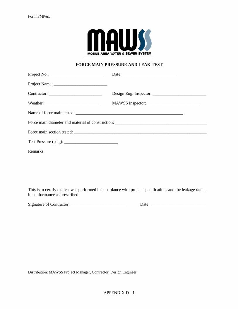
FORCE MAIN PRESSURE AND LEAK TEST
Project No.: _________________________ Date: _________________________
Project Name: _________________________
Contractor: _________________________ Design Eng. Inspector: _________________________
Weather: _________________________ MAWSS Inspector: _________________________
Name of force main tested: __________________________________________________
Force main diameter and material of construction: ___________________________________________
Force main section tested: ______________________________________________________________
Test Pressure (psig): _________________________
Remarks
This is to certify the test was performed in accordance with project specifications and the leakage rate is
in conformance as prescribed.
Signature of Contractor: _________________________ Date: _________________________
Distribution: MAWSS Project Manager, Contractor, Design Engineer
APPENDIX D - 2
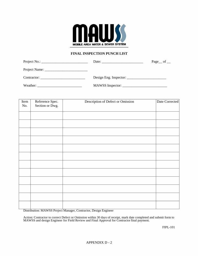
FINAL INSPECTION PUNCH LIST
Project No.: __________________________ Date: _______________________ Page__ of __
Project Name: ________________________
Contractor: _________________________ Design Eng. Inspector: ______________________
Weather: _________________________ MAWSS Inspector: _________________________
Item
No.
Reference Spec.
Section or Dwg.
Description of Defect or Omission Date Corrected
Distribution: MAWSS Project Manager, Contractor, Design Engineer
Action: Contractor to correct Defect or Omission within 30 days of receipt, mark date completed and submit form to MAWSS and design Engineer for Field Review and Final Approval for Contractor final payment.
FIPL-101
APPENDIX D - 3
GUIDE TO MAWSS PUMPING SPECIFICATIONS
The design engineer shall prepare a Pump Specification Sheet for each sewage pumping station based on
the MAWSS Standard Pump Specification Sheets attached. The Sheet may be revised to suit special
conditions or specific pumps required for an installation. The Pump Specification Sheets shall be revised
upon completion of the project as part of the “Record Drawings” process to indicate only the pump(s)
installed. The “Design Performance” shall be revised to indicate actual in-field performance delivered.
ENGINEERING STANDARD
APPENDIX D - 4
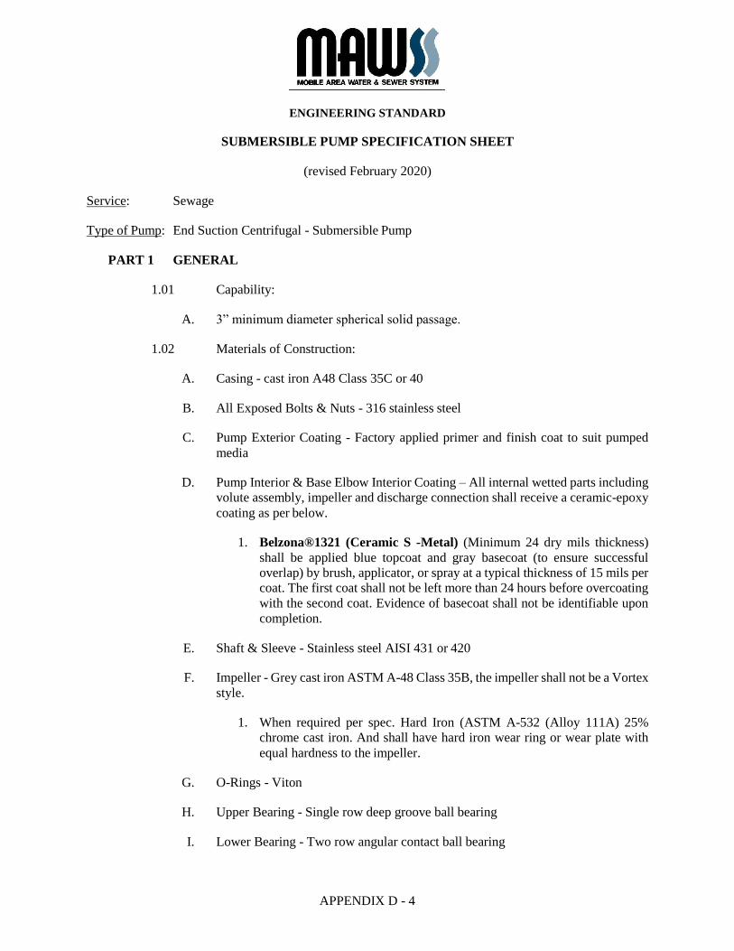
SUBMERSIBLE PUMP SPECIFICATION SHEET
(revised February 2020)
Service: Sewage
Type of Pump: End Suction Centrifugal - Submersible Pump
PART 1 GENERAL
1.01 Capability:
A. 3” minimum diameter spherical solid passage.
1.02 Materials of Construction:
A. Casing - cast iron A48 Class 35C or 40
B. All Exposed Bolts & Nuts - 316 stainless steel
C. Pump Exterior Coating - Factory applied primer and finish coat to suit pumped
media
D. Pump Interior & Base Elbow Interior Coating – All internal wetted parts including
volute assembly, impeller and discharge connection shall receive a ceramic-epoxy
coating as per below.
1. Belzona®1321 (Ceramic S -Metal) (Minimum 24 dry mils thickness)
shall be applied blue topcoat and gray basecoat (to ensure successful
overlap) by brush, applicator, or spray at a typical thickness of 15 mils per
coat. The first coat shall not be left more than 24 hours before overcoating
with the second coat. Evidence of basecoat shall not be identifiable upon
completion.
E. Shaft & Sleeve - Stainless steel AISI 431 or 420
F. Impeller - Grey cast iron ASTM A-48 Class 35B, the impeller shall not be a Vortex
style.
1. When required per spec. Hard Iron (ASTM A-532 (Alloy 111A) 25%
chrome cast iron. And shall have hard iron wear ring or wear plate with
equal hardness to the impeller.
G. O-Rings - Viton
H. Upper Bearing - Single row deep groove ball bearing
I. Lower Bearing - Two row angular contact ball bearing
ENGINEERING STANDARD
APPENDIX D - 5
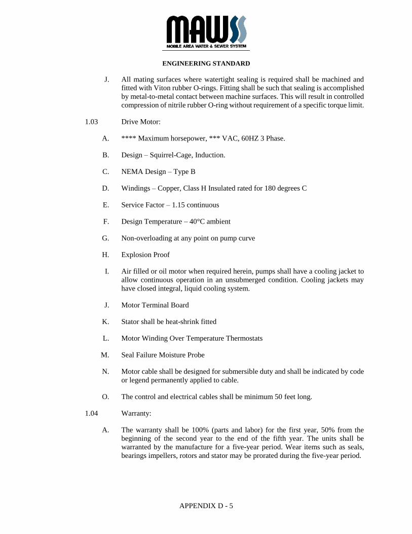
J. All mating surfaces where watertight sealing is required shall be machined and
fitted with Viton rubber O-rings. Fitting shall be such that sealing is accomplished
by metal-to-metal contact between machine surfaces. This will result in controlled
compression of nitrile rubber O-ring without requirement of a specific torque limit.
1.03 Drive Motor:
A. **** Maximum horsepower, *** VAC, 60HZ 3 Phase.
B. Design – Squirrel-Cage, Induction.
C. NEMA Design – Type B
D. Windings – Copper, Class H Insulated rated for 180 degrees C
E. Service Factor – 1.15 continuous
F. Design Temperature – 40°C ambient
G. Non-overloading at any point on pump curve
H. Explosion Proof
I. Air filled or oil motor when required herein, pumps shall have a cooling jacket to
allow continuous operation in an unsubmerged condition. Cooling jackets may
have closed integral, liquid cooling system.
J. Motor Terminal Board
K. Stator shall be heat-shrink fitted
L. Motor Winding Over Temperature Thermostats
M. Seal Failure Moisture Probe
N. Motor cable shall be designed for submersible duty and shall be indicated by code
or legend permanently applied to cable.
O. The control and electrical cables shall be minimum 50 feet long.
1.04 Warranty:
A. The warranty shall be 100% (parts and labor) for the first year, 50% from the
beginning of the second year to the end of the fifth year. The units shall be
warranted by the manufacture for a five-year period. Wear items such as seals,
bearings impellers, rotors and stator may be prorated during the five-year period.
ENGINEERING STANDARD
APPENDIX D - 6
1.05 Submittals:
A. Manufacturer’s literature, specifications, and engineering data including
dimensions, material, size and weight. Performance data and curves showing pump
efficiencies, flow rate, head, brake HP, motor HP, speed and shut-off head.
B. Operation and maintenance manuals including complete installation, operation and
maintenance data including installation and wiring diagrams.
C. A complete parts list and exploded view diagram of the pump.
1.06 Manufacturer(s):
A. Acceptable manufactures include:
1. Flygt
2. KSB
3. Wilo
B. Manufacturer shall provide a certified pump curve for each pump provided in
accordance with the Board’s Standard Specifications.
END OF SECTION
ENGINEERING STANDARD
APPENDIX D - 7
ENGINE DRIVEN STAND-BY PUMP SPECIFICATION SHEET
(revised February 2020)
Service: Sewage
Type of Pump: Engine Driven, Fully Automatic Dry Priming, Vacuum Assisted, Run Dry, Heavy Duty
Solids Handling, Horizontal Self-Priming Pump
PART 1 GENERAL
1.01 REFERENCES
A. The following is a list of standards which may be referenced in this section:
1. American Bearing Manufacturers' Association (ABMA).
2. Hydraulic Institute Standards.
3. National Electrical Manufacturer's Association (NEMA): MG 1, Motors
and Generators.
4. Occupational Safety and Health Administration (OSHA).
1.02 DEFINITIONS
A. Terminology pertaining to pumping unit performance and construction shall
conform to the ratings and nomenclature of the Hydraulic Institute Standards.
1.03 SUBMITTALS
A. Action Submittals
1. Shop Drawings:
a. Make, model, weight, and horsepower of each equipment
assembly.
b. Complete catalog information, descriptive literature,
specifications, and identification of materials of construction.
c. Performance data curves showing head, capacity, horsepower
demand, and pump efficiency over entire operating range of pump
from shutoff to maximum capacity. Indicate separately the head,
capacity, horsepower demand, overall efficiency, and minimum
submergence required at guarantee point.
ENGINEERING STANDARD
APPENDIX D - 8
d. Detailed structural, mechanical, and electrical drawings showing
equipment dimensions, size, and locations of connections and
weights of associated equipment.
e. Power and control wiring diagrams, including terminals and
numbers. Include all signal interfaces with the site RTU as shown
on the Drawings.
f. Complete motor nameplate data, as defined by NEMA, motor
manufacturer.
g. Factory finish system data sheets.
h. Power requirements for the battery charger and the jacket water
heaters associated with the portable pump. Physical dimensions,
enclosure type, and location for the battery charger and associated
batteries.
i. Operation, Service & Parts manuals for the Pump, Engine &
Control Panel included with wiring diagrams and schematics for
the Pump, Engine and Control Panel.
B. Informational Submittals
1. Factory Functional Test Reports.
2. Manufacturer's Certificate of Compliance, in accordance with Section 01
61 00, Common Product Requirements, that factory finish system is
identical to the requirements specified herein.
3. Special shipping, storage and protection, and handling instructions.
4. Manufacturer's printed installation instructions.
5. Suggested spare parts list to maintain the equipment in service for a period
of 1 year and 5 years. Include a list of special tools required for checking,
testing, parts replacement, and maintenance with current price
information.
6. List special tools, materials, and supplies furnished with equipment for use
prior to and during startup and for future maintenance.
7. Operation and Maintenance Data: As specified in Section 01 7823,
Operation and Maintenance Data.
8. Manufacturer's Certificate of Proper Installation, in accordance with
Section 01 43 33, Manufacturers' Field Services.

ENGINEERING STANDARD
APPENDIX D - 9
1.04 EXTRA MATERIALS
A. Furnish for each pump
1. Operation and Maintenance Manual.
2. Impeller.
3. Impellers wear ring/wear plate.
PART 2 PRODUCTS
2.01 GENERAL
A. Coordinate pump requirements with drive manufacturer and be responsible for
pump and drive requirements.
B. Where adjustable speed drives are required, furnish a coordinated operating system
complete with pump, drive, and speed controller.
C. The portable by-pass pump specified will be used to pump raw sewage.
D. The pump manufacturer shall supply the pump and specified accessories.
E. The only acceptable manufacturers shall be:
1. Cornell
2. Pioneer
3. Godwin
F. Design Requirements
1. Max Flow XXX GPM
2. Minimum Solid Handling Size 3 Inches
3. Max TDH XX TDH Add In
4. Minimum Suction Lift 20 Feet
5. Suction Connection X” 150# ANSI B16.5
6. Discharge Connection X” 150# ANSI B16.5
G. The bid item shall be delivered to the owner within 8 weeks of issuance of order
and order to proceed as per bid specifications.
ENGINEERING STANDARD
APPENDIX D - 10
2.02 SUPPLEMENTS
A. Some specific requirements are attached to this section as supplements.
2.03 COMPONENTS
A. The pump shall be fitted with fully automatic priming system and full flow
discharge check valve. The priming system shall be capable of priming the pump
from a completely dry pump casing, and by design will not discharge pumpage
into the atmosphere. The pump must be capable of running totally dry for periods
of up to 24 hours, then re-priming and returning to normal pumping volumes.
Priming systems that require manual water additions to facilitate pump priming are
not acceptable. A demonstration of the pumps ability to repeatedly cycle from dry
suction/pump/snore/pump shall be required. This will necessitate the draining of
all residual water from the pump case to initiate dry suction starting conditions.
B. The sound attenuation enclosure shall be critical grade. Noise level 69DBA at 30
feet.
C. The pump shall be capable of station suction lifts to 20 vertical feet. It shall also
be capable of operation using extended suction lines.
D. The unit shall have a thermostatically controlled 110V ac block heater. The
electrical ratings of the heater shall not exceed 500W.
E. The equipment shall include a 12V battery, and associated battery charger, to allow
for remotely starting the equipment at any time. The battery and battery charger
shall be included in a weatherproof enclosure to protect them from direct exposure
to the elements. The battery charger shall operate on 120V single-phase ac and the
electrical demand shall not exceed 20A.
F. Casing, suction cover, separation tank: Pump castings shall be ductile iron ASTM
A536 Grade 80- 55-06. Pump design shall incorporate a direct suction flow path
that is in axial alignment with the impeller eye. There shall be no turns, chambers
or valves between the suction flange and the impeller eye.
G. Impeller: The pump impeller shall not be macerating type and fabricated from
Stainless Steel or Cast Chromium Steel and shall be Brinell 220 HB or equivalent.
H. Wear Plates: Shall be fully replaceable and adjustable, fabricated of ASTM A48
Class 30 material. Wear plate clearances shall have no relationship to the ability of
the pump to achieve
I. Bearings and shafts: Pump shall be fitted with bearing bracket to contain the shaft
and bearings. Bearings shall be open single row bearings of adequate size to
withstand imposed loads for sustained pumping at maximum duty points.
Minimum ISO LIO bearing life to be 100,000 hours. Impeller shafts shall be
fabricated of 1144 stress proof steel.
ENGINEERING STANDARD
APPENDIX D - 11
J. Seals: Seals shall be high pressure, mechanical self-adjusting type with silicon
carbide faces capable of withstanding suction pressure to 100 psi. The mechanical
seal shall be cooled and lubricated in an oil bath reservoir, requiring no
maintenance or adjustment. Pump shall be capable of running dry, with no damage
for periods up to 24 hours. All metal parts shall be of stainless steel. Elastomers
shall be Viton. Pump should be equipped with oil site glass for level indication.
K. Pump suction and discharge fittings: Fittings shall be flanged fittings in accordance
with Section 40 27 01, Process Piping Specialties. The manufacture shall provide
(2) two Cam-Lock fittings. The size will be determined by suction and discharge
size of the pump.
L. Pump gaskets: Gaskets shal1 be compress fiber and/or Teflon.
M. Drive unit: The drive unit shall be a diesel water-cooled engine. The engine shall
drive the pump by use of direct connected intermediate drive plate. Starter shall be
12-volt electric with a battery charger. Safety shut down switches for low oil
pressure and high temperature shall be provided. Battery shall have l80-amp hour
rating. Unit shall include a tachometer and hour meter. The engine shall be
complete with a primary fuel filter and JIC fittings on the fuel lines. The unit shall
have an engine coolant reservoir. The unit shall include oil and coolants drain
service hoses.
N. Exhaust: Exhaust system shall include muffler and anti-rain flapper device.
2.04 INSTRUMENTATION AND CONTROLS
A. Automatic Engine/Pump Controller: Fully programmable microprocessor engine
control system allowing for inputs from level, flow, pressure transducers or float
switches. Manual, automatic, and remote state functions. Programmable relays
with selectable features including pump running failure. RS-232 and RS-485
communication ports for communication with SCADA and alarm equipment. Unit
shall be capable of auto throttling engine RPM in response to changing
pressure/leve1f1ow transducer signals. Maintains event history of all warning
alarms up to 32 signals. User pre-set for engine RPM to maintain flow and head
parameters when running unattended. Unit shall track oil and filter usage and alter
operator when replacement is recommended. Diesel engine warm up and cool
down cycle. And shall be programmable for weekly scheduled auto starts.
B. Input/Output with the site control system.
1. Accept the following discrete input, which will be an unpowered contact.
a. When this contact is received, engine shall run. When contact
opens, engine shall not run.
2. Provide the following discrete outputs. Each output shall be SPDT, Form
C and rated for 30Vdc at 10 max.

ENGINEERING STANDARD
APPENDIX D - 12
a. Engine Running.
b. Common Alarm.
3. Accept the following analog input, which will be a 4 -20 mAdc signal.
a. Speed adjusts command. At 4 mAdc, adjust pump speed to
minimum RPM. At 20 mAdc, adjust pump speed to maximum
RPM. Between 4 and 20 mAdc, linearly adjust engine speed in
proportion to current.
2.05 WARRANTY
A. The manufacturer shall furnish the following to the owner: a copy of the engine
manufacturer's parts and labor warranty, a 2-year parts and labor warranty issued
by the manufacturer on the portable by-pass pump system. This warranty must
cover all pump parts, including the mechanical seal.
2.06 ACCESSORIES
A. Equipment Identification Plate: 16-gauge stainless steel with I14-inch die stamped
equipment tag number securely mounted in a readily visible location.
B. Lifting Lugs: Equipment weighing over 100 pounds.
C. OSHA-approved coupling guard for direct coupled or belt driven pumps.
D. Enclosure: The enclosure shall be Type 316 stainless steel or heavy powder coat
finish and include the following capabilities and components: adjustable rear
jack(s), lifting ports, lockable enclosure battery box, lockable enclosed control
panel, lockable enclosed engine housing, and internal 24 hour fuel source. There
shall be no plastic components and all wall panels shall be reinforced with cross
beams and ridged.
E. Trailer: The unit shall be mounted on a trailer suited for highway travel at 50 mph
and wired for over the road usage per applicable DOT standards. The pump and
engine shall be trailer mounted with a Pintle type trailer hitch. Tires and torsional
flex type axels adequately sized for the required load range ratings. Trailers shall
be equipped with fenders made of the same metallic material as the enclosure
panels or a greater thickness, electric brakes, and front and rear support stands,
lifting bar safety chains and side and rear reflectors. Trailer design shall be in
compliance with applicable DOT regulations.
F. Governor: Governor shall be a mechanical type. Engine speed shall be adjustable
to operate the pump between maximum and minimum design operation speeds.
ENGINEERING STANDARD
APPENDIX D - 13
G. Two permanently mounted twist lock pigtails coming from the controller mounted
to the exterior of the enclosure with dust caps. The mating pigtails shall also be
provided.
1. “A” shall be for the control floats.
2. “B” shall be for the SCADA outputs.
H. Murphy Type Engine Controller
I. Trimax Type Locking Wheel Lock
J. On/Off & High Level Floats
2.07 FACTORY FINISHING
A. Prepare, prime, and finish coat in accordance with Section 099000, Painting and
Coating. The surface color shall be Traffic Blue.
2.08 SOURCE QUALITY CONTROL
A. Factory Inspections: Inspect control panels for required construction, electrical
connection, and intended function.
B. Factory Tests and Adjustments: Test an equipment and control panels actually
furnished.
C. Factory Test Report: Include test data sheets, curve test results, certified correct by
a registered professional engineer.
D. Functional Test: Perform manufacturer's standard, motor test on equipment.
Include vibration test, as follows:
1. Dynamically balance rotating parts of each pump and its driving unit
before final assembly.
2. Limits:
a. Driving Unit Alone: Less than 80 percent of NEMA MG 1 limits.
b. Complete Rotating Assembly Including Coupling, Drive Unit,
and Motor: Less than 90 percent of limits established in the
Hydraulic Institute Standards.
E. Performance Test:
1. Conduct on each pump.
2. In accordance with Hydraulic Institute Standards.
ENGINEERING STANDARD
APPENDIX D - 14
3. Adjust, realign, or modify units and retest in accordance with Hydraulic
Institute Standards if necessary.
F. Hydrostatic Tests: Pump casing(s) tested at 150 percent of shutoff head. Test
pressure maintained for not less than 5 minutes.
PART 3 EXECUTION
3.01 FIELD FINISHING
A. Finish equipment as specified in Section 09 90 00, Painting and Coating.
3.02 FIELD QUALITY CONTROL
A. Functional Tests: Conduct on each pump.
1. Alignment: Test complete assemblies for correct rotation, proper
alignment and connection, and quiet operation.
2. Vibration Test:
a. Test with unit installed and in normal operation, and discharging
to the connected piping systems at rates between low discharge
head and high discharge head conditions specified, and with actual
building structures and foundations provided shall not develop
vibration exceeding 80 percent of the limits specified in HIS 9.6.4.
b. If units exhibit vibration in excess of the limits specified adjust as
necessary. Units which cannot be adjusted or modified to conform
as specified shall be replaced.
3. Flow Output: Measured by instrumentation and storage volumes.
B. Performance Test:
1. Conduct on each pump.
2. Perform under simulated operating conditions.
3. Test for a continuous I-hour period without malfunction.
4. Test Log: Record the following:
a. Total head.
b. Capacity.
c. Horsepower requirements.
ENGINEERING STANDARD
APPENDIX D - 15
d. Flow measured by factory instrumentation and storage volumes or
flowmeters on discharge piping.
e. Average distance from suction well water surface to pump
discharge centerline for duration of test.
f. Pump discharge pressure converted to feet of liquid pumped and
corrected to pump discharge centerline.
g. Calculated velocity head at the discharge flange.
h. Field head.
i. Driving motor voltage and amperage measured for each phase.
5. Adjust, realign, or modify units and retest in accordance with Hydraulic
Institute Standards if necessary at Contractor's sole expense.
3.03 MANUFACTURER'S SERVICES
A. Manufacturer's Representative: Present at Site designated by Owner
1. 1/2 person-day for installation assistance and inspection
END OF SECTION
APPENDIX D - 16
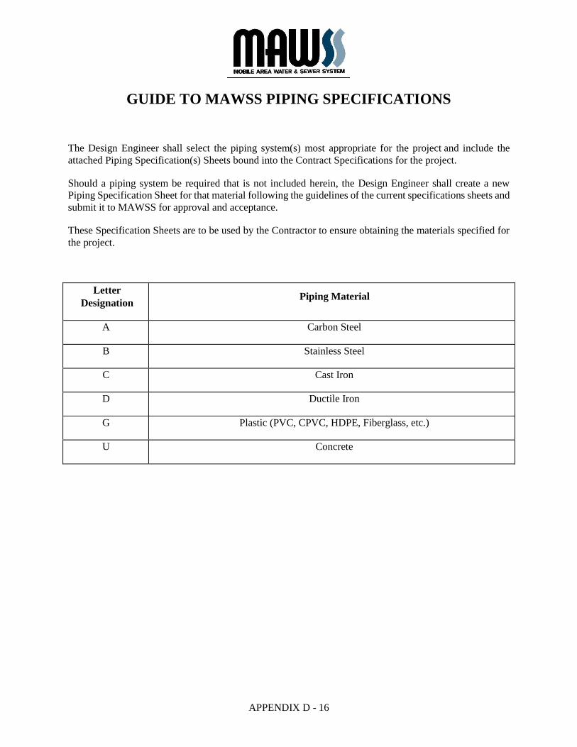
GUIDE TO MAWSS PIPING SPECIFICATIONS
The Design Engineer shall select the piping system(s) most appropriate for the project and include the
attached Piping Specification(s) Sheets bound into the Contract Specifications for the project.
Should a piping system be required that is not included herein, the Design Engineer shall create a new
Piping Specification Sheet for that material following the guidelines of the current specifications sheets and
submit it to MAWSS for approval and acceptance.
These Specification Sheets are to be used by the Contractor to ensure obtaining the materials specified for
the project.
Letter
Designation Piping Material
A Carbon Steel
B Stainless Steel
C Cast Iron
D Ductile Iron
G Plastic (PVC, CPVC, HDPE, Fiberglass, etc.)
U Concrete
APPENDIX D - 17
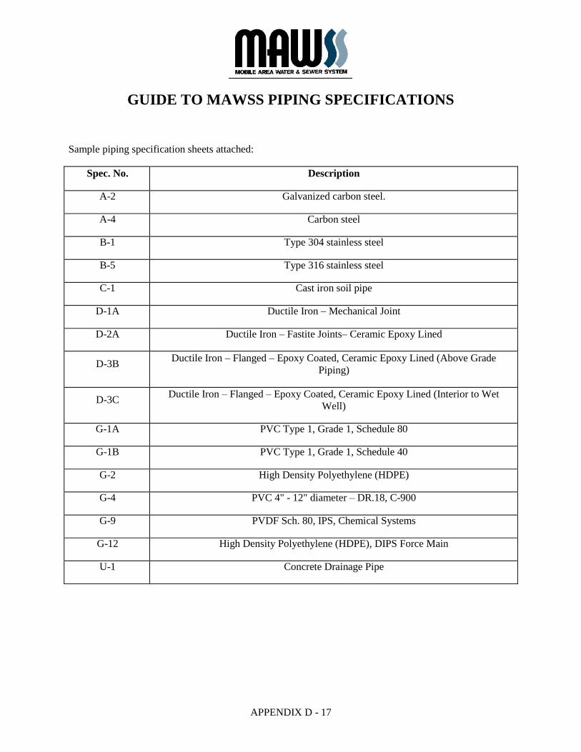
GUIDE TO MAWSS PIPING SPECIFICATIONS
Sample piping specification sheets attached:
Spec. No. Description
A-2 Galvanized carbon steel.
A-4 Carbon steel
B-1 Type 304 stainless steel
B-5 Type 316 stainless steel
C-1 Cast iron soil pipe
D-1A Ductile Iron – Mechanical Joint
D-2A Ductile Iron – Fastite Joints– Ceramic Epoxy Lined
D-3B Ductile Iron – Flanged – Epoxy Coated, Ceramic Epoxy Lined (Above Grade
Piping)
D-3C Ductile Iron – Flanged – Epoxy Coated, Ceramic Epoxy Lined (Interior to Wet
Well)
G-1A PVC Type 1, Grade 1, Schedule 80
G-1B PVC Type 1, Grade 1, Schedule 40
G-2 High Density Polyethylene (HDPE)
G-4 PVC 4" - 12" diameter – DR.18, C-900
G-9 PVDF Sch. 80, IPS, Chemical Systems
G-12 High Density Polyethylene (HDPE), DIPS Force Main
U-1 Concrete Drainage Pipe

ENGINEERING STANDARD
APPENDIX D - 18
PIPING SPECIFICATION SHEET A-2
(revised February 2020)
Service 150 psig to 450°F corrosive atmosphere
Pipe 1/8" to 4” dia.: Schedule 40 galvanized welded carbon steel. ASTM
A53, Grade B, threaded ASME/ANSI B1.20.1 STPT
2 1/2" dia. and larger: Schedule 40 galvanized carbon steel seamless.
ASTM A106, Grade B. threaded ASME/ANSI B1.20.1.
Fittings 150# rating in accordance with ANSI B16.3, Class 150 galvanized
malleable iron threaded ANSI B1.20.1 Standard Tapered Pipe Thread.
Pipe Connections 150 lb. rated threaded coupling in accordance with ANSI B16.3
galvanized malleable iron with ANSI B1.20.1 Standard Tapered Pipe
Threads.
Connections at Valves and
Pumps
1” to 4” - 125 psi cast iron flanges meeting ASTM A-126, and ANSI
B16.1 threaded ANSI B1.20.1 Standard Tapered Pipe Threads.
Gaskets To suit service
Bolting American Standard stud bolts, ASTM A307 Grade B, with semi-
finished heavy nuts, galvanized.
Remarks Specification A-2 is:
Normally used in areas of specific corrosion conditions in the outside
environment in compressed air service.
Underground piping shall be coated and wrapped in accordance with
the latest revision of AWWA C203.
Unless otherwise noted, all above grade exterior piping shall be
insulated and protected in accordance with the contract specifications.
END OF SECTION

ENGINEERING STANDARD
APPENDIX D - 19
PIPING SPECIFICATION SHEET A-4
(revised February 2020)
Service 200 psig max. at 100°F
Pipe 2" and smaller - Schedule 80, carbon steel, threaded and coupled,
seamless, ASTM A106, Grade B.
2 1/2" through 10" - Schedule 40, carbon steel, bevel end, seamless,
ASTM A106, Grade B.
12" and larger - Standard weight, carbon steel, bevel end, seamless,
ASTM A106, Grade B.
Fittings 2" and smaller - elbows, tees, etc. - 150 lb., malleable iron, black,
threaded, banded, ASTM A197.
Unions - 300 lb., malleable iron, threaded, ground joint, brass to iron
seat.
Threadolets, elbolets - 3000 lb., forged steel.
Reductions - extra heavy, seamless, carbon steel, swagged nipple.
Nipples - extra heavy, seamless, carbon steel.
Couplings - 3,000 lb., forged steel, threaded.
2 1/2" and larger - forged carbon steel, standard weight, buttweld,
ASTM A234, Grade WB.
Flanges 2" and smaller - 150 lb. ANSI standard, forged steel, raised face,
threaded, ASTM A181, Grade I.
2 1/2" and larger - ANSI B 16.1, Class 125 standard, forged steel,
raised face, slip-on, ASTM A181, Grade I.
Weld neck flanges may be used at buttweld fittings.
Bolting American Standard stud bolts, ASTM A307, Grade B, with semi-
finished heavy hex nuts.
Gaskets To suit service
Gaskets - Underground 1/8" thick, 150 lb. ANSI standard, red rubber, full face.
ENGINEERING STANDARD
APPENDIX D - 20
Remarks Underground piping shall be coated and wrapped in accordance with
the latest revision of AWWA C203
END OF SECTION
ENGINEERING STANDARD
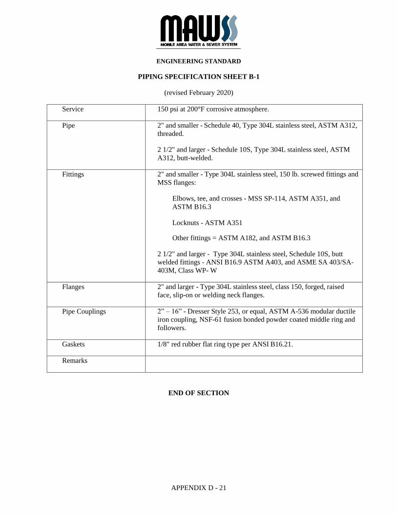
APPENDIX D - 21
PIPING SPECIFICATION SHEET B-1
(revised February 2020)
Service 150 psi at 200°F corrosive atmosphere.
Pipe 2" and smaller - Schedule 40, Type 304L stainless steel, ASTM A312,
threaded.
2 1/2" and larger - Schedule 10S, Type 304L stainless steel, ASTM
A312, butt-welded.
Fittings 2" and smaller - Type 304L stainless steel, 150 lb. screwed fittings and
MSS flanges:
Elbows, tee, and crosses - MSS SP-114, ASTM A351, and
ASTM B16.3
Locknuts - ASTM A351
Other fittings = ASTM A182, and ASTM B16.3
2 1/2" and larger - Type 304L stainless steel, Schedule 10S, butt
welded fittings - ANSI B16.9 ASTM A403, and ASME SA 403/SA-
403M, Class WP- W
Flanges 2" and larger - Type 304L stainless steel, class 150, forged, raised
face, slip-on or welding neck flanges.
Pipe Couplings 2” – 16” - Dresser Style 253, or equal, ASTM A-536 modular ductile
iron coupling, NSF-61 fusion bonded powder coated middle ring and
followers.
Gaskets 1/8" red rubber flat ring type per ANSI B16.21.
Remarks
END OF SECTION
ENGINEERING STANDARD
APPENDIX D - 22
PIPING SPECIFICATION SHEET B-5
(revised February 2020)
Service 150 psi at 200°F corrosive atmosphere.
Pipe 1 1/2" and smaller - Schedule 40, Type 316 stainless steel, ASTM
A312, threaded.
2" and larger - Schedule 10S, Type 316L stainless steel, ASTM A312,
butt- welded.
Fittings 1 1/2" and smaller - Type 316 stainless steel, 150 lb. screwed fittings
and MSS flanges:
Elbows, tee, and crosses - MSS SP-114, ASTM A351, and
ASTM B16.3
Locknuts - ASTM A351
Other fittings - ASTM A182, and ASTM B16.3
2" and larger - Type 316L stainless steel, Schedule 10S, butt welded fittings - ANSI B16.9 ASTM A403, and ASME SA 403/SA-403M, Class WP- W
Flanges 2" and larger - Type 316L stainless steel, class 150, forged, raised face,
slip-on or welding neck flanges.
Pipe Couplings 2” – 16” - Dresser Style 253, or equal, ASTM A-536 modular ductile
iron coupling, NSF-61 fusion bonded powder coated middle ring and
followers.
Gaskets 1/8" red rubber flat ring type per ANSI B16.21.
Remarks For use within sewage manholes, wet wells, or other submerged
applications.
END OF SECTION
ENGINEERING STANDARD
APPENDIX D - 23
PIPING SPECIFICATION SHEET C-1
(revised February 2020)
Service Gravity flow at ambient temperature. Non-corrosive, sanitary sewer
within buildings and under floor slabs (ANSI A112.5.1, Southern
Standard Plumbing Code).
Pipe (below grade) 2”–15”, SV, ASA Group 021, Cast iron soil pipe, ASTM A74, hub x plain end, with ring joint gaskets.
Pipe (above grade) 2”-15”, No-Hub, ASA Group 022, cast iron pipe and fittings in
accordance with ASTM A 888 with stainless steel banded and
protected elastomeric sleeve type couplings in accordance with ASTM
C 1277 and CISPI 301
Fittings (below grade) 2”-15” SV, ASA Group 021, Cast Iron, ASTM A74, with ring joint
gaskets.
Joints (below grade) Hub x plain end; with elastomeric ring joint rubber gasket. Special
fittings with spigot end; neoprene sealing sleeve with stainless steel
sleeve and stainless-steel clamps. Screwed; joint cement or lubricant
shall be used only on male threads.
END OF SECTION
ENGINEERING STANDARD
APPENDIX D - 24
PIPING SPECIFICATION SHEET D-1A
(revised February 2020)
Service Collection or Distribution – water, wastewater or other liquids - 200
psig to 150°F maximum. Below Grade Piping Installations
Pipe 4" dia. and smaller - ductile iron - minimum thickness Class 52.
6" through 54" dia. - ductile iron - minimum thickness Class 52, Grade
- 60,000 psi tensile, 42,000 psi yield, 10% elongation, ANSI/AWWA
C151/21.51 (see Note 2 - Remarks).
Pipe Joints Gasketed push-on bell and spigot in accordance with AWWA
C111/A21.11
Fittings 4" - 48" = ductile iron - mechanical joint, grade 70-50-05, 250 PSI
pressure rated in accordance with ANSI/AWWA C110/A21.10 or 4" -
24" 350 PSI pressure rated in accordance with ANSI/AWWA
C153/A21.53 ductile iron compact fittings.
All fittings shall be complete with gaskets, follower glands, alloy steel
tee bolts and hex nuts. 54" - 64" ductile iron Fastite* bell and spigot
joint-grade 70-50-05, 150 PSI pressure rated in accordance with
ANSI/AWWA C153/A21.53.
Gaskets The gasket shall be manufactured from styrene butadiene copolymer
(SBR) and shall be a product of the pipe manufacturer and supplied
with the pipe along with joint lubricant. The gasket shall meet all
requirements of ANSI/AWWA C111/A21.11.
Bolting To be of type recommended by pipe supplier of material with
minimum 45,000 psi tensile, with semi-finished heavy nuts in
accordance with ANSI/AWWA C111/A21.11.
Coating The exterior surfaces of all pipe and fittings shall have a layer of zinc
applied to a mass of 200 g/m2 of pipe surface area which shall
conform to ISO 8179.
Lining The interior surfaces of all pipe and fittings shall receive a shop
applied ceramic epoxy lining similar to Tnemec Series 431 Perma-
Shield PL or Permox CTF.
Plastic Encasing Unless noted otherwise on the drawings or indicated in the specifications, the prescribed pipe and fittings shall be installed within polyethylene encasement. The encasement shall be in accordance with
ENGINEERING STANDARD
APPENDIX D - 25
ANSI/AWWA C105/A21.5 and in conjunction with the Ductile Iron Pipe Research Association brochure "Polyethylene Encasement."
Marking Each piece of pipe and all fittings shall be marked with the weight,
class or nominal thickness, mark identifying year of manufacture, the
letter "D.I." and manufacturers name.
Laying Conditions Unless otherwise indicated, this piping shall be installed utilizing
Type 2 laying condition in accordance with ANSI/AWWA
C150/A21.50 and ANSI/AWWA C151/A21.51. For cover depths
greater than 10' - 0" refer to ANSI/AWWA C151/A21.5.
Accessories All piping accessories required to complete the project, including
tapping saddles, sleeves, bosses, retainer glands, etc., shall be the
product of the pipe manufacturer or meet the approval of the pipe
manufacturer for installation as part of this project.
END OF SECTION
ENGINEERING STANDARD
APPENDIX D - 26
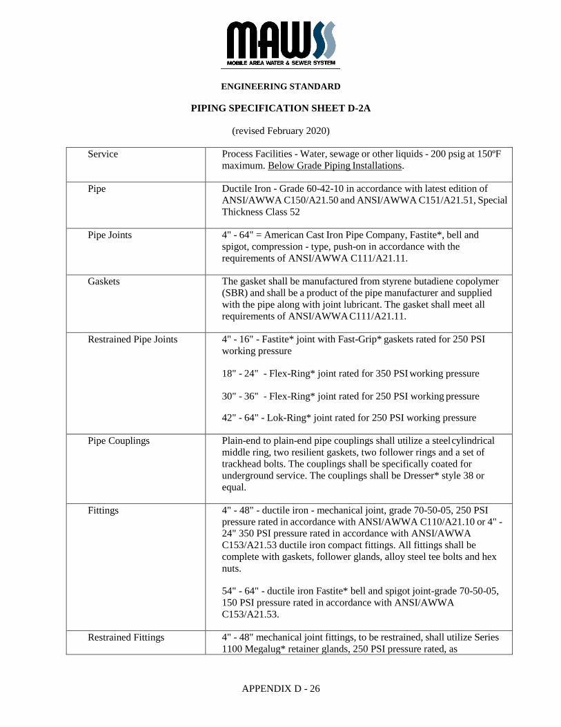
PIPING SPECIFICATION SHEET D-2A
(revised February 2020)
Service Process Facilities - Water, sewage or other liquids - 200 psig at 150ºF
maximum. Below Grade Piping Installations.
Pipe Ductile Iron - Grade 60-42-10 in accordance with latest edition of
ANSI/AWWA C150/A21.50 and ANSI/AWWA C151/A21.51, Special
Thickness Class 52
Pipe Joints 4" - 64" = American Cast Iron Pipe Company, Fastite*, bell and
spigot, compression - type, push-on in accordance with the
requirements of ANSI/AWWA C111/A21.11.
Gaskets The gasket shall be manufactured from styrene butadiene copolymer
(SBR) and shall be a product of the pipe manufacturer and supplied
with the pipe along with joint lubricant. The gasket shall meet all
requirements of ANSI/AWWA C111/A21.11.
Restrained Pipe Joints 4" - 16" - Fastite* joint with Fast-Grip* gaskets rated for 250 PSI
working pressure
18" - 24" - Flex-Ring* joint rated for 350 PSI working pressure
30" - 36" - Flex-Ring* joint rated for 250 PSI working pressure
42" - 64" - Lok-Ring* joint rated for 250 PSI working pressure
Pipe Couplings Plain-end to plain-end pipe couplings shall utilize a steel cylindrical
middle ring, two resilient gaskets, two follower rings and a set of
trackhead bolts. The couplings shall be specifically coated for
underground service. The couplings shall be Dresser* style 38 or
equal.
Fittings 4" - 48" - ductile iron - mechanical joint, grade 70-50-05, 250 PSI
pressure rated in accordance with ANSI/AWWA C110/A21.10 or 4" -
24" 350 PSI pressure rated in accordance with ANSI/AWWA
C153/A21.53 ductile iron compact fittings. All fittings shall be
complete with gaskets, follower glands, alloy steel tee bolts and hex
nuts.
54" - 64" - ductile iron Fastite* bell and spigot joint-grade 70-50-05,
150 PSI pressure rated in accordance with ANSI/AWWA
C153/A21.53.
Restrained Fittings 4" - 48" mechanical joint fittings, to be restrained, shall utilize Series
1100 Megalug* retainer glands, 250 PSI pressure rated, as

ENGINEERING STANDARD
APPENDIX D - 27
manufactured by EBBA Iron Sales, Inc.*, or equal.
54" - 64" Fastite* joint fittings, to be restrained, shall utilize American
Lok- Ring* assemblies.
Wall Pipe Wall pipes shall be integrally cast with wall collars or shall be shop
fabricated with full length penetration weld-on collars. All wall pipes
shall be designed for use in thrust and load bearing conditions.
Bolting Shall be of type and materials recommended by pipe supplier as
suitable for buried services and shall have a minimum of 45,000 PSI
tensile strength with semi-finished heavy hex nuts in accordance with
ANSI/AWWA C111/A21.11.
Coating The exterior surfaces of all pipe and fittings shall have a layer of zinc
applied to a mass of 200 g/m2 of pipe surface area which shall
conform to ISO 8179.
Lining The interior surfaces of all pipe and fittings shall receive a shop
applied ceramic epoxy lining similar to Tnemec Series 431 Perma-
Shield PL or Permox CTF.
Plastic Encasing When noted on the drawings or indicated in the specifications, the
prescribed pipe and fittings shall be installed within polyethylene
encasement. The encasement shall be in accordance with
ANSI/AWWA C105/A21.5 and in conjunction with the Ductile Iron
Pipe Research Association brochure "Polyethylene Encasement."
Marking Each piece of pipe and all fittings shall be marked with the weight,
class or nominal thickness, mark identifying year of manufacture, the
letter "D.I." and manufacturers name.
Laying Conditions Unless otherwise indicated, this piping shall be installed utilizing
Type 2 laying condition in accordance with ANSI/AWWA
C150/A21.50 and ANSI/AWWA C151/A21.51. For cover depths
greater than 10' - 0" refer to ANSI/AWWA C151/A21.5.
Accessories All piping accessories required to complete the project, including
tapping saddles, sleeves, bosses, retainer glands, etc., shall be the
product of the pipe manufacturer or meet the approval of the pipe
manufacturer for installation as part of this project.
END OF SECTION
ENGINEERING STANDARD
APPENDIX D - 28
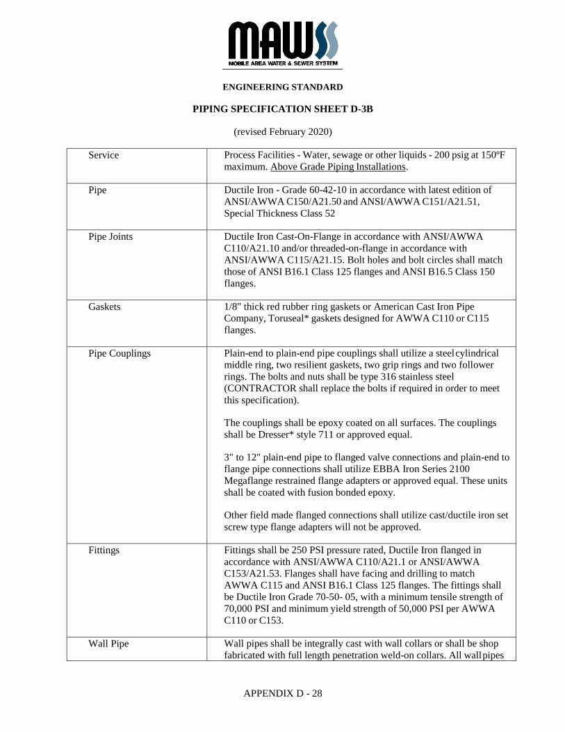
PIPING SPECIFICATION SHEET D-3B
(revised February 2020)
Service Process Facilities - Water, sewage or other liquids - 200 psig at 150ºF
maximum. Above Grade Piping Installations.
Pipe Ductile Iron - Grade 60-42-10 in accordance with latest edition of
ANSI/AWWA C150/A21.50 and ANSI/AWWA C151/A21.51,
Special Thickness Class 52
Pipe Joints Ductile Iron Cast-On-Flange in accordance with ANSI/AWWA
C110/A21.10 and/or threaded-on-flange in accordance with
ANSI/AWWA C115/A21.15. Bolt holes and bolt circles shall match
those of ANSI B16.1 Class 125 flanges and ANSI B16.5 Class 150
flanges.
Gaskets 1/8" thick red rubber ring gaskets or American Cast Iron Pipe
Company, Toruseal* gaskets designed for AWWA C110 or C115
flanges.
Pipe Couplings Plain-end to plain-end pipe couplings shall utilize a steel cylindrical
middle ring, two resilient gaskets, two grip rings and two follower
rings. The bolts and nuts shall be type 316 stainless steel
(CONTRACTOR shall replace the bolts if required in order to meet
this specification).
The couplings shall be epoxy coated on all surfaces. The couplings
shall be Dresser* style 711 or approved equal.
3" to 12" plain-end pipe to flanged valve connections and plain-end to
flange pipe connections shall utilize EBBA Iron Series 2100
Megaflange restrained flange adapters or approved equal. These units
shall be coated with fusion bonded epoxy.
Other field made flanged connections shall utilize cast/ductile iron set
screw type flange adapters will not be approved.
Fittings Fittings shall be 250 PSI pressure rated, Ductile Iron flanged in
accordance with ANSI/AWWA C110/A21.1 or ANSI/AWWA
C153/A21.53. Flanges shall have facing and drilling to match
AWWA C115 and ANSI B16.1 Class 125 flanges. The fittings shall
be Ductile Iron Grade 70-50- 05, with a minimum tensile strength of
70,000 PSI and minimum yield strength of 50,000 PSI per AWWA
C110 or C153.
Wall Pipe Wall pipes shall be integrally cast with wall collars or shall be shop
fabricated with full length penetration weld-on collars. All wall pipes
ENGINEERING STANDARD
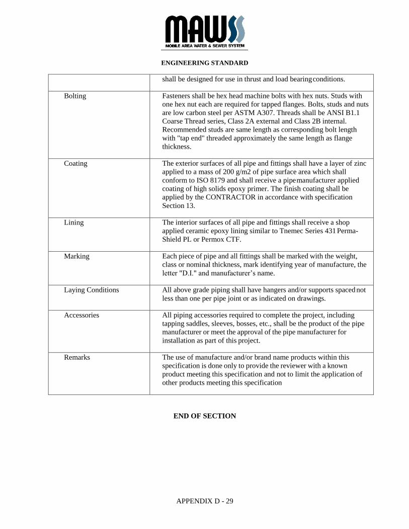
APPENDIX D - 29
shall be designed for use in thrust and load bearing conditions.
Bolting Fasteners shall be hex head machine bolts with hex nuts. Studs with
one hex nut each are required for tapped flanges. Bolts, studs and nuts
are low carbon steel per ASTM A307. Threads shall be ANSI B1.1
Coarse Thread series, Class 2A external and Class 2B internal.
Recommended studs are same length as corresponding bolt length
with "tap end" threaded approximately the same length as flange
thickness.
Coating The exterior surfaces of all pipe and fittings shall have a layer of zinc
applied to a mass of 200 g/m2 of pipe surface area which shall
conform to ISO 8179 and shall receive a pipe manufacturer applied
coating of high solids epoxy primer. The finish coating shall be
applied by the CONTRACTOR in accordance with specification
Section 13.
Lining The interior surfaces of all pipe and fittings shall receive a shop
applied ceramic epoxy lining similar to Tnemec Series 431 Perma-
Shield PL or Permox CTF.
Marking Each piece of pipe and all fittings shall be marked with the weight,
class or nominal thickness, mark identifying year of manufacture, the
letter "D.I." and manufacturer’s name.
Laying Conditions All above grade piping shall have hangers and/or supports spaced not
less than one per pipe joint or as indicated on drawings.
Accessories All piping accessories required to complete the project, including
tapping saddles, sleeves, bosses, etc., shall be the product of the pipe
manufacturer or meet the approval of the pipe manufacturer for
installation as part of this project.
Remarks The use of manufacture and/or brand name products within this
specification is done only to provide the reviewer with a known
product meeting this specification and not to limit the application of
other products meeting this specification
END OF SECTION
ENGINEERING STANDARD
APPENDIX D - 30
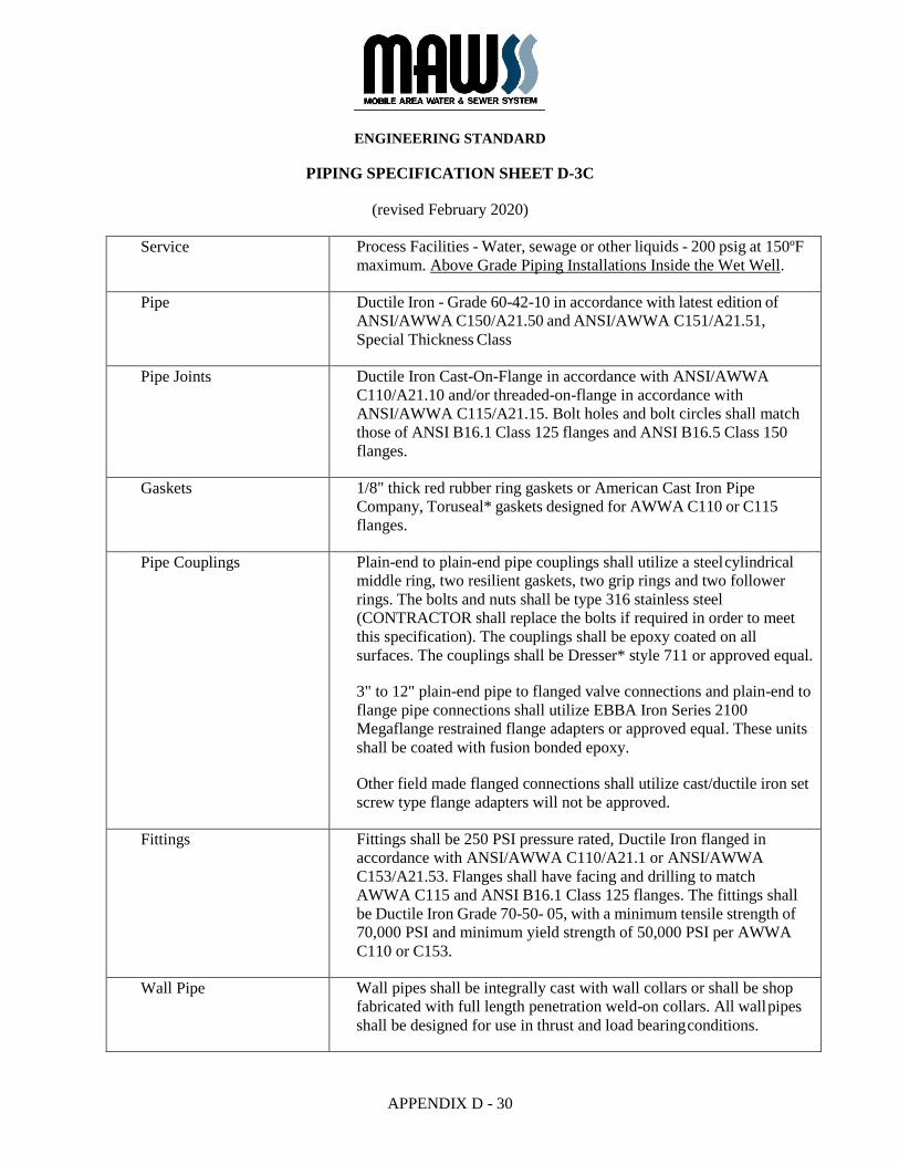
PIPING SPECIFICATION SHEET D-3C
(revised February 2020)
Service Process Facilities - Water, sewage or other liquids - 200 psig at 150ºF
maximum. Above Grade Piping Installations Inside the Wet Well.
Pipe Ductile Iron - Grade 60-42-10 in accordance with latest edition of
ANSI/AWWA C150/A21.50 and ANSI/AWWA C151/A21.51,
Special Thickness Class
Pipe Joints Ductile Iron Cast-On-Flange in accordance with ANSI/AWWA
C110/A21.10 and/or threaded-on-flange in accordance with
ANSI/AWWA C115/A21.15. Bolt holes and bolt circles shall match
those of ANSI B16.1 Class 125 flanges and ANSI B16.5 Class 150
flanges.
Gaskets 1/8" thick red rubber ring gaskets or American Cast Iron Pipe
Company, Toruseal* gaskets designed for AWWA C110 or C115
flanges.
Pipe Couplings Plain-end to plain-end pipe couplings shall utilize a steel cylindrical
middle ring, two resilient gaskets, two grip rings and two follower
rings. The bolts and nuts shall be type 316 stainless steel
(CONTRACTOR shall replace the bolts if required in order to meet
this specification). The couplings shall be epoxy coated on all
surfaces. The couplings shall be Dresser* style 711 or approved equal.
3" to 12" plain-end pipe to flanged valve connections and plain-end to
flange pipe connections shall utilize EBBA Iron Series 2100
Megaflange restrained flange adapters or approved equal. These units
shall be coated with fusion bonded epoxy.
Other field made flanged connections shall utilize cast/ductile iron set
screw type flange adapters will not be approved.
Fittings Fittings shall be 250 PSI pressure rated, Ductile Iron flanged in
accordance with ANSI/AWWA C110/A21.1 or ANSI/AWWA
C153/A21.53. Flanges shall have facing and drilling to match
AWWA C115 and ANSI B16.1 Class 125 flanges. The fittings shall
be Ductile Iron Grade 70-50- 05, with a minimum tensile strength of
70,000 PSI and minimum yield strength of 50,000 PSI per AWWA
C110 or C153.
Wall Pipe Wall pipes shall be integrally cast with wall collars or shall be shop
fabricated with full length penetration weld-on collars. All wall pipes
shall be designed for use in thrust and load bearing conditions.
ENGINEERING STANDARD
APPENDIX D - 31
Bolting Fasteners shall be hex head machine bolts with hex nuts. Studs with
one hex nut each are required for tapped flanges. Bolts, studs and nuts
are low carbon steel per ASTM A307. Threads shall be ANSI B1.1
Coarse Thread series, Class 2A external and Class 2B internal.
Recommended studs are same length as corresponding bolt length
with "tap end" threaded approximately the same length as flange
thickness.
Coating The exterior surfaces of all pipe and fittings shall have a layer of zinc
applied to a mass of 200 g/m2 of pipe surface area which shall
conform to ISO 8179 and shall receive a pipe manufacturer applied
coating of high solids epoxy primer. The finish coating shall be
applied by the CONTRACTOR in accordance with specification
Section 13.
Lining The interior surfaces of all pipe and fittings shall receive a shop
applied ceramic-epoxy lining per specification Section 13.
Marking Each piece of pipe and all fittings shall be marked with the weight,
class or nominal thickness, mark identifying year of manufacture, the
letter "D.I." and manufacturer’s name.
Laying Conditions All above grade piping shall have hangers and/or supports spaced not
less than one per pipe joint or as indicated on drawings.
Accessories All piping accessories required to complete the project, including
tapping saddles, sleeves, bosses, etc., shall be the product of the pipe
manufacturer or meet the approval of the pipe manufacturer for
installation as part of this project.
Remarks The use of manufacture and/or brand name products within this
specification is done only to provide the reviewer with a known
product meeting this specification and not to limit the application of
other products meeting this specification.
END OF SECTION
ENGINEERING STANDARD
APPENDIX D - 32
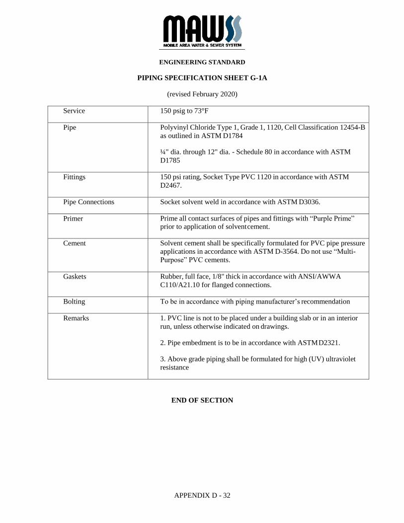
PIPING SPECIFICATION SHEET G-1A
(revised February 2020)
Service 150 psig to 73°F
Pipe Polyvinyl Chloride Type 1, Grade 1, 1120, Cell Classification 12454-B
as outlined in ASTM D1784
¼" dia. through 12" dia. - Schedule 80 in accordance with ASTM
D1785
Fittings 150 psi rating, Socket Type PVC 1120 in accordance with ASTM
D2467.
Pipe Connections Socket solvent weld in accordance with ASTM D3036.
Primer Prime all contact surfaces of pipes and fittings with “Purple Prime” prior to application of solvent cement.
Cement Solvent cement shall be specifically formulated for PVC pipe pressure
applications in accordance with ASTM D-3564. Do not use “Multi-
Purpose” PVC cements.
Gaskets Rubber, full face, 1/8" thick in accordance with ANSI/AWWA
C110/A21.10 for flanged connections.
Bolting To be in accordance with piping manufacturer’s recommendation
Remarks 1. PVC line is not to be placed under a building slab or in an interior
run, unless otherwise indicated on drawings.
2. Pipe embedment is to be in accordance with ASTM D2321.
3. Above grade piping shall be formulated for high (UV) ultraviolet
resistance
END OF SECTION
ENGINEERING STANDARD
APPENDIX D - 33
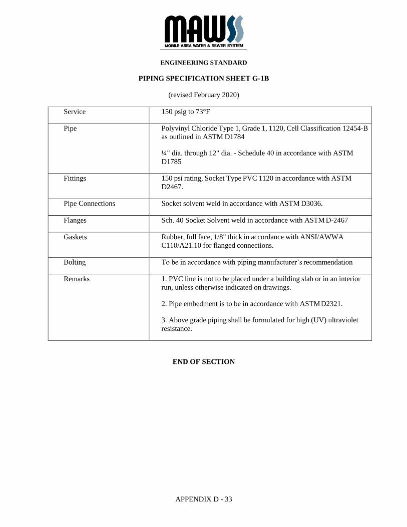
PIPING SPECIFICATION SHEET G-1B
(revised February 2020)
Service 150 psig to 73°F
Pipe Polyvinyl Chloride Type 1, Grade 1, 1120, Cell Classification 12454-B
as outlined in ASTM D1784
¼" dia. through 12" dia. - Schedule 40 in accordance with ASTM
D1785
Fittings 150 psi rating, Socket Type PVC 1120 in accordance with ASTM
D2467.
Pipe Connections Socket solvent weld in accordance with ASTM D3036.
Flanges Sch. 40 Socket Solvent weld in accordance with ASTM D-2467
Gaskets Rubber, full face, 1/8" thick in accordance with ANSI/AWWA
C110/A21.10 for flanged connections.
Bolting To be in accordance with piping manufacturer’s recommendation
Remarks 1. PVC line is not to be placed under a building slab or in an interior
run, unless otherwise indicated on drawings.
2. Pipe embedment is to be in accordance with ASTM D2321.
3. Above grade piping shall be formulated for high (UV) ultraviolet
resistance.
END OF SECTION
ENGINEERING STANDARD
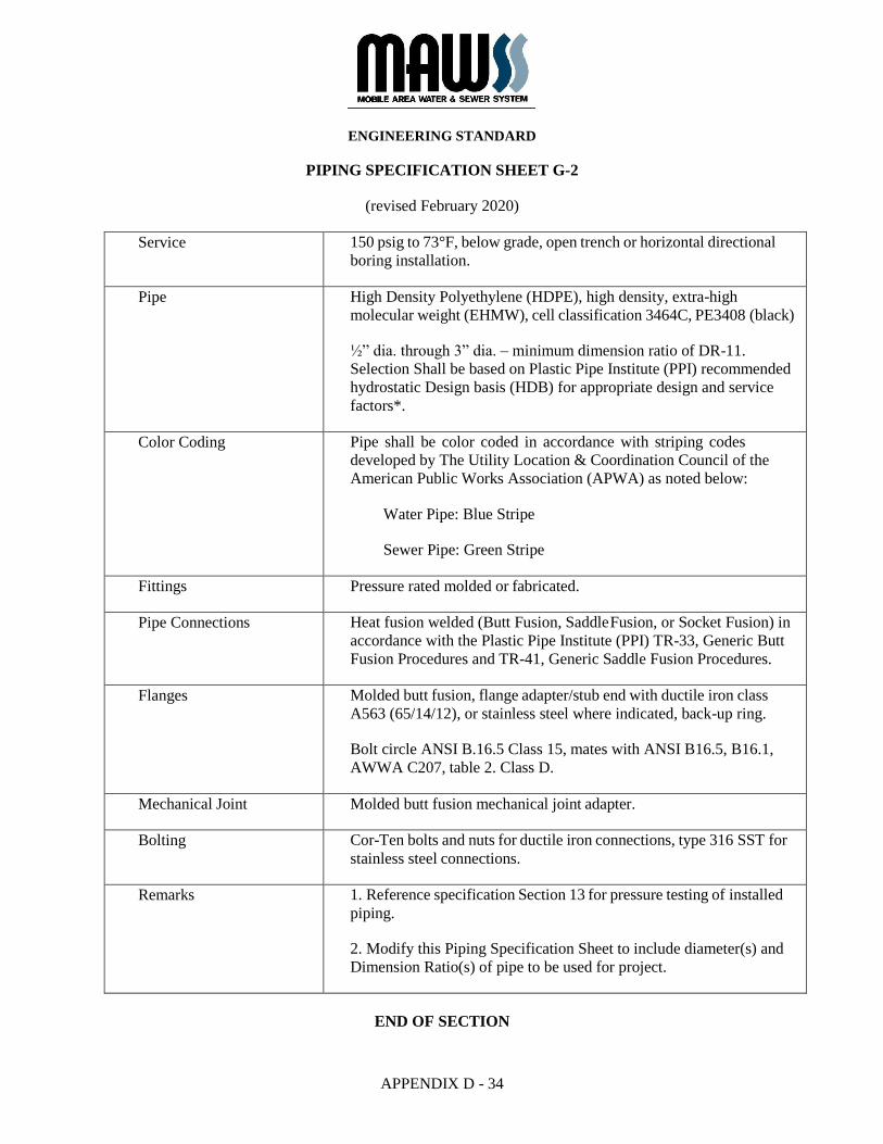
APPENDIX D - 34
PIPING SPECIFICATION SHEET G-2
(revised February 2020)
Service 150 psig to 73°F, below grade, open trench or horizontal directional
boring installation.
Pipe High Density Polyethylene (HDPE), high density, extra-high
molecular weight (EHMW), cell classification 3464C, PE3408 (black)
½” dia. through 3” dia. – minimum dimension ratio of DR-11.
Selection Shall be based on Plastic Pipe Institute (PPI) recommended
hydrostatic Design basis (HDB) for appropriate design and service
factors*.
Color Coding Pipe shall be color coded in accordance with striping codes
developed by The Utility Location & Coordination Council of the
American Public Works Association (APWA) as noted below:
Water Pipe: Blue Stripe
Sewer Pipe: Green Stripe
Fittings Pressure rated molded or fabricated.
Pipe Connections Heat fusion welded (Butt Fusion, Saddle Fusion, or Socket Fusion) in
accordance with the Plastic Pipe Institute (PPI) TR-33, Generic Butt
Fusion Procedures and TR-41, Generic Saddle Fusion Procedures.
Flanges Molded butt fusion, flange adapter/stub end with ductile iron class
A563 (65/14/12), or stainless steel where indicated, back-up ring.
Bolt circle ANSI B.16.5 Class 15, mates with ANSI B16.5, B16.1,
AWWA C207, table 2. Class D.
Mechanical Joint Molded butt fusion mechanical joint adapter.
Bolting Cor-Ten bolts and nuts for ductile iron connections, type 316 SST for
stainless steel connections.
Remarks 1. Reference specification Section 13 for pressure testing of installed
piping.
2. Modify this Piping Specification Sheet to include diameter(s) and
Dimension Ratio(s) of pipe to be used for project.
END OF SECTION
ENGINEERING STANDARD
APPENDIX D - 35
PIPING SPECIFICATION SHEET G-4
(revised February 2020)
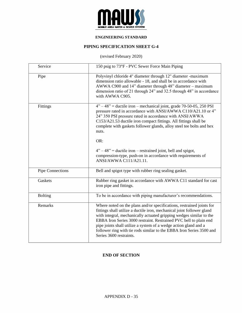
Service 150 psig to 73°F - PVC Sewer Force Main Piping
Pipe Polyvinyl chloride 4" diameter through 12" diameter -maximum
dimension ratio allowable - 18, and shall be in accordance with
AWWA C900 and 14” diameter through 48” diameter – maximum
dimension ratio of 21 through 24” and 32.5 through 48” in accordance
with AWWA C905.
Fittings 4” – 48” = ductile iron – mechanical joint, grade 70-50-05, 250 PSI
pressure rated in accordance with ANSI/AWWA C110/A21.10 or 4”
24” 350 PSI pressure rated in accordance with ANSI/AWWA
C153/A21.53 ductile iron compact fittings. All fittings shall be
complete with gaskets follower glands, alloy steel tee bolts and hex
nuts.
OR:
4” – 48” = ductile iron – restrained joint, bell and spigot,
compression-type, push-on in accordance with requirements of
ANSI/AWWA C111/A21.11.
Pipe Connections Bell and spigot type with rubber ring sealing gasket.
Gaskets Rubber ring gasket in accordance with AWWA C11 standard for cast
iron pipe and fittings.
Bolting To be in accordance with piping manufacturer’s recommendations.
Remarks Where noted on the plans and/or specifications, restrained joints for
fittings shall utilize a ductile iron, mechanical joint follower gland
with integral, mechanically actuated gripping wedges similar to the
EBBA Iron Series 3000 restraint. Restrained PVC bell to plain end
pipe joints shall utilize a system of a wedge action gland and a
follower ring with tie rods similar to the EBBA Iron Series 3500 and
Series 3600 restraints.
END OF SECTION
ENGINEERING STANDARD
APPENDIX D - 36
PIPING SPECIFICATION SHEET G-9
(revised February 2020)
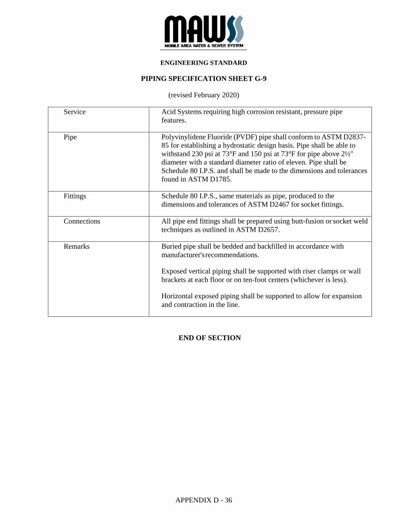
Service Acid Systems requiring high corrosion resistant, pressure pipe
features.
Pipe Polyvinylidene Fluoride (PVDF) pipe shall conform to ASTM D2837-
85 for establishing a hydrostatic design basis. Pipe shall be able to
withstand 230 psi at 73°F and 150 psi at 73°F for pipe above 2½"
diameter with a standard diameter ratio of eleven. Pipe shall be
Schedule 80 I.P.S. and shall be made to the dimensions and tolerances
found in ASTM D1785.
Fittings Schedule 80 I.P.S., same materials as pipe, produced to the
dimensions and tolerances of ASTM D2467 for socket fittings.
Connections All pipe end fittings shall be prepared using butt-fusion or socket weld
techniques as outlined in ASTM D2657.
Remarks Buried pipe shall be bedded and backfilled in accordance with
manufacturer's recommendations.
Exposed vertical piping shall be supported with riser clamps or wall
brackets at each floor or on ten-foot centers (whichever is less).
Horizontal exposed piping shall be supported to allow for expansion
and contraction in the line.
END OF SECTION
ENGINEERING STANDARD
APPENDIX D - 37
PIPING SPECIFICATION SHEET G-12
(revised February 2020)
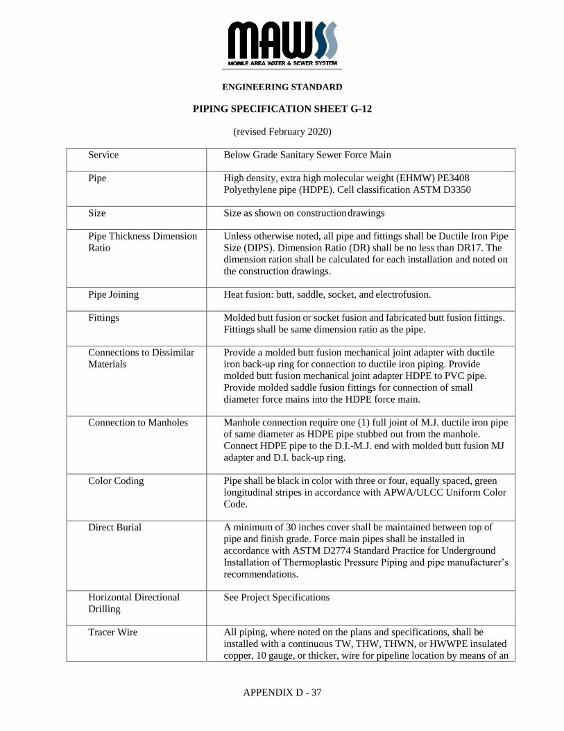
Service Below Grade Sanitary Sewer Force Main
Pipe High density, extra high molecular weight (EHMW) PE3408
Polyethylene pipe (HDPE). Cell classification ASTM D3350
Size Size as shown on construction drawings
Pipe Thickness Dimension
Ratio
Unless otherwise noted, all pipe and fittings shall be Ductile Iron Pipe
Size (DIPS). Dimension Ratio (DR) shall be no less than DR17. The
dimension ration shall be calculated for each installation and noted on
the construction drawings.
Pipe Joining Heat fusion: butt, saddle, socket, and electrofusion.
Fittings Molded butt fusion or socket fusion and fabricated butt fusion fittings.
Fittings shall be same dimension ratio as the pipe.
Connections to Dissimilar
Materials
Provide a molded butt fusion mechanical joint adapter with ductile
iron back-up ring for connection to ductile iron piping. Provide
molded butt fusion mechanical joint adapter HDPE to PVC pipe.
Provide molded saddle fusion fittings for connection of small
diameter force mains into the HDPE force main.
Connection to Manholes Manhole connection require one (1) full joint of M.J. ductile iron pipe
of same diameter as HDPE pipe stubbed out from the manhole.
Connect HDPE pipe to the D.I.-M.J. end with molded butt fusion MJ
adapter and D.I. back-up ring.
Color Coding Pipe shall be black in color with three or four, equally spaced, green
longitudinal stripes in accordance with APWA/ULCC Uniform Color
Code.
Direct Burial A minimum of 30 inches cover shall be maintained between top of
pipe and finish grade. Force main pipes shall be installed in
accordance with ASTM D2774 Standard Practice for Underground
Installation of Thermoplastic Pressure Piping and pipe manufacturer’s
recommendations.
Horizontal Directional
Drilling
See Project Specifications
Tracer Wire All piping, where noted on the plans and specifications, shall be
installed with a continuous TW, THW, THWN, or HWWPE insulated
copper, 10 gauge, or thicker, wire for pipeline location by means of an
ENGINEERING STANDARD
APPENDIX D - 38
electronic line tracer. The wire shall be installed along the top face of
the piping for the entire length.
END OF SECTION
ENGINEERING STANDARD
APPENDIX D - 39
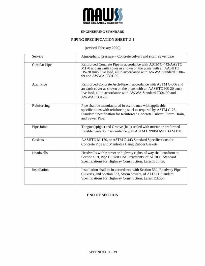
PIPING SPECIFICATION SHEET U-1
(revised February 2020)
Service Atmospheric pressure – Concrete culvert and storm sewer pipe
Circular Pipe Reinforced Concrete Pipe in accordance with ASTM C-443/AASTO M170 and an earth cover as shown on the plans with an AASHTO HS-20 truck live load, all in accordance with AWWA Standard C304- 99 and AWWA C301-99.
Arch Pipe Reinforced Concrete Arch-Pipe in accordance with ASTM C-506 and
an earth cover as shown on the plans with an AASHTO HS-20 truck
live load, all in accordance with AWWA Standard C304-99 and
AWWA C301-99.
Reinforcing Pipe shall be manufactured in accordance with applicable
specifications with reinforcing steel as required by ASTM C-76,
Standard Specification for Reinforced Concrete Culvert, Storm Drain,
and Sewer Pipe.
Pipe Joints Tongue (spigot) and Groove (bell) sealed with mortar or preformed
flexible Sealants in accordance with ASTM C 990/AASHTO M 198.
Gaskets AASHTO M-170, or ASTM C-443 Standard Specifications for
Concrete Pipe and Manholes Using Rubber Gaskets.
Headwalls Headwalls within street or highway rights-of way shall conform to
Section 619, Pipe Culvert End Treatments, of ALDOT Standard
Specifications for Highway Construction, Latest Edition.
Installation Installation shall be in accordance with Section 530, Roadway Pipe
Culverts, and Section 533, Storm Sewers, of ALDOT Standard
Specifications for Highway Construction, Latest Edition.
END OF SECTION
APPENDIX D - 40
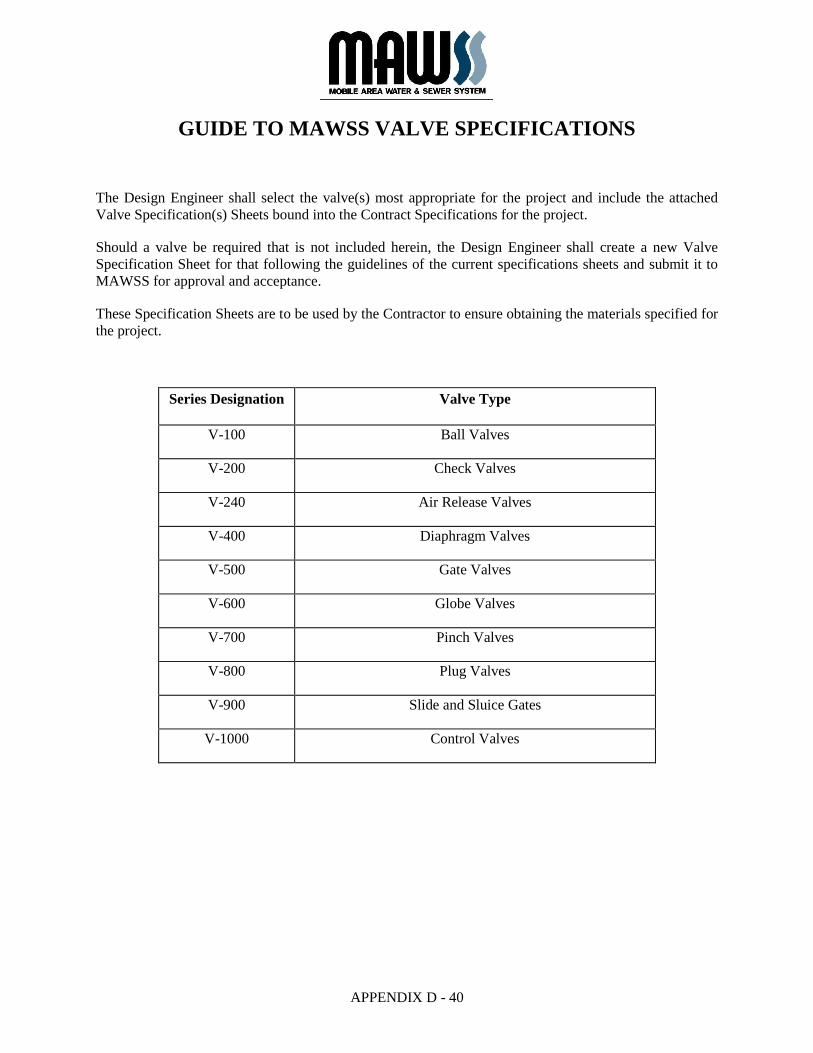
GUIDE TO MAWSS VALVE SPECIFICATIONS
The Design Engineer shall select the valve(s) most appropriate for the project and include the attached
Valve Specification(s) Sheets bound into the Contract Specifications for the project.
Should a valve be required that is not included herein, the Design Engineer shall create a new Valve
Specification Sheet for that following the guidelines of the current specifications sheets and submit it to
MAWSS for approval and acceptance.
These Specification Sheets are to be used by the Contractor to ensure obtaining the materials specified for
the project.
Series Designation Valve Type
V-100 Ball Valves
V-200 Check Valves
V-240 Air Release Valves
V-400 Diaphragm Valves
V-500 Gate Valves
V-600 Globe Valves
V-700 Pinch Valves
V-800 Plug Valves
V-900 Slide and Sluice Gates
V-1000 Control Valves

APPENDIX D - 41
GUIDE TO MAWSS VALVE SPECIFICATIONS
Sample valve specification sheets attached:
Spec. No. Description
V-101 True-Union, PVC Ball Valve, Socket Weld
V-104 Two-Piece, Bronze Ball Valve, Threaded Ends
V-200 Flanged, AWWA C508 Check Valve
V-203 PVC Ball Check, Socket Weld
V-235 Flanged, Cushion Controlled, Check Valve
V-240 Combination Air and Vacuum Release Valve
V-241 Automatic Air Release Valve
V-513 Resilient Seated Gate Valve, NRS, Mechanical Joint
V-516 Resilient Seated Gate Valve, NRS, Flanged
ENGINEERING STANDARD
APPENDIX D - 42
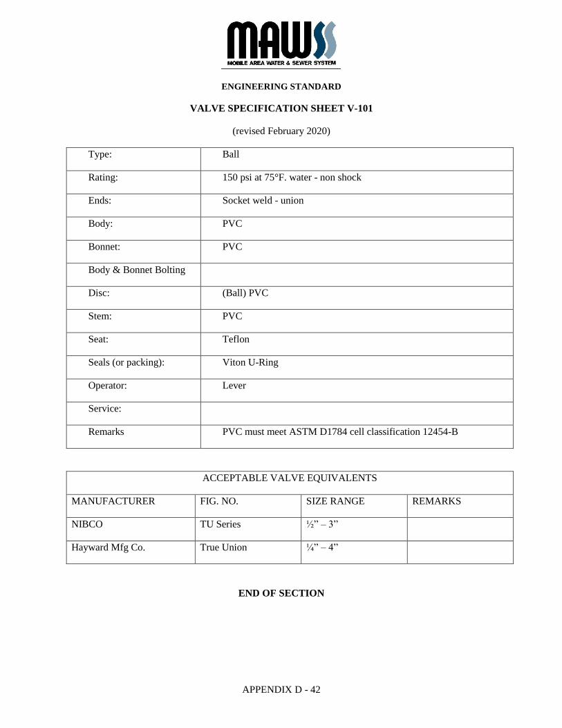
VALVE SPECIFICATION SHEET V-101
(revised February 2020)
Type: Ball
Rating: 150 psi at 75°F. water - non shock
Ends: Socket weld - union
Body: PVC
Bonnet: PVC
Body & Bonnet Bolting
Disc: (Ball) PVC
Stem: PVC
Seat: Teflon
Seals (or packing): Viton U-Ring
Operator: Lever
Service:
Remarks PVC must meet ASTM D1784 cell classification 12454-B
ACCEPTABLE VALVE EQUIVALENTS
MANUFACTURER FIG. NO. SIZE RANGE REMARKS
NIBCO TU Series ½” – 3”
Hayward Mfg Co. True Union ¼” – 4”
END OF SECTION
ENGINEERING STANDARD
APPENDIX D - 43
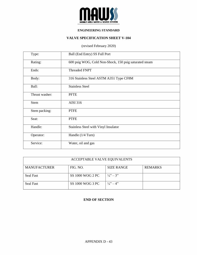
VALVE SPECIFICATION SHEET V-104
(revised February 2020)
Type: Ball (End Entry) SS Full Port
Rating: 600 psig WOG, Cold Non-Shock, 150 psig saturated steam
Ends: Threaded FNPT
Body: 316 Stainless Steel ASTM A351 Type CF8M
Ball: Stainless Steel
Thrust washer: PFTE
Stem AISI 316
Stem packing: PTFE
Seat: PTFE
Handle: Stainless Steel with Vinyl Insulator
Operator: Handle (1/4 Turn)
Service: Water, oil and gas
ACCEPTABLE VALVE EQUIVALENTS
MANUFACTURER FIG. NO. SIZE RANGE REMARKS
Seal Fast SS 1000 WOG 2 PC ¼” – 3”
Seal Fast SS 1000 WOG 3 PC ¼” – 4”
END OF SECTION

ENGINEERING STANDARD
APPENDIX D - 44
VALVE SPECIFICATION SHEET V-200
(revised February 2020)
Type: Swing Check AWWA C508
Rating: 2” – 12” = 150 psi Water
Ends: Flanged, F.F., 125# ASME/ANSI B16.1
Body: Cast Iron ASTM A126, Class B
Bonnet: (Cover) Cast Iron, ASTM A126, Class B
Body & bonnet
bolting
ASTM A307, Gr. B
Disc: Cast Iron, ASTM A126, Class B with bronze busing
Stem: (Clapper Arm Shaft) Bronze, Aluminum Bronze, or Stainless Steel
Seat: Bronze, renewable
Seals (or packing): “O” Ring, Buna-N
Operator: Outside weight and lever
Remarks: Horizontal or vertical installation
ACCEPTABLE VALVE EQUIVALENTS
MANUFACTURER FIG. NO. SIZE RANGE REMARKS
American Flow Control Series 52-SC 3” – 12”
McWane (Kennedy/Clow)
Style 1106 LW 2” – 12”
Mueller A-2600-6-01 2 ½” – 12”
END OF SECTION
ENGINEERING STANDARD
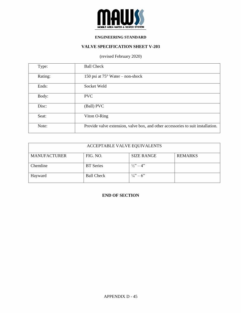
APPENDIX D - 45
VALVE SPECIFICATION SHEET V-203
(revised February 2020)
Type: Ball Check
Rating: 150 psi at 75° Water – non-shock
Ends: Socket Weld
Body: PVC
Disc: (Ball) PVC
Seat: Viton O-Ring
Note: Provide valve extension, valve box, and other accessories to suit installation.
ACCEPTABLE VALVE EQUIVALENTS
MANUFACTURER FIG. NO. SIZE RANGE REMARKS
Chemline BT Series ½” – 4”
Hayward Ball Check ¼” – 6”
END OF SECTION
ENGINEERING STANDARD
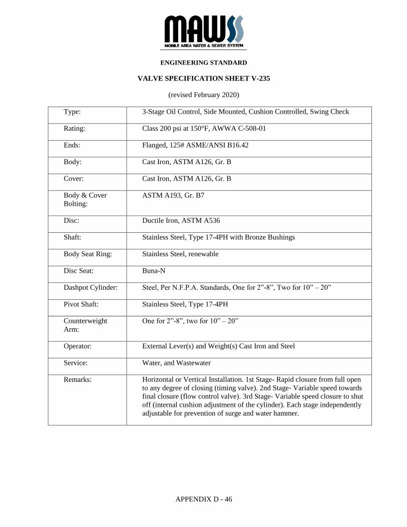
APPENDIX D - 46
VALVE SPECIFICATION SHEET V-235
(revised February 2020)
Type: 3-Stage Oil Control, Side Mounted, Cushion Controlled, Swing Check
Rating: Class 200 psi at 150°F, AWWA C-508-01
Ends: Flanged, 125# ASME/ANSI B16.42
Body: Cast Iron, ASTM A126, Gr. B
Cover: Cast Iron, ASTM A126, Gr. B
Body & Cover
Bolting:
ASTM A193, Gr. B7
Disc: Ductile Iron, ASTM A536
Shaft: Stainless Steel, Type 17-4PH with Bronze Bushings
Body Seat Ring: Stainless Steel, renewable
Disc Seat: Buna-N
Dashpot Cylinder: Steel, Per N.F.P.A. Standards, One for 2”-8”, Two for 10” – 20”
Pivot Shaft: Stainless Steel, Type 17-4PH
Counterweight
Arm:
One for 2”-8”, two for 10” – 20”
Operator: External Lever(s) and Weight(s) Cast Iron and Steel
Service: Water, and Wastewater
Remarks: Horizontal or Vertical Installation. 1st Stage- Rapid closure from full open
to any degree of closing (timing valve). 2nd Stage- Variable speed towards
final closure (flow control valve). 3rd Stage- Variable speed closure to shut
off (internal cushion adjustment of the cylinder). Each stage independently
adjustable for prevention of surge and water hammer.
ENGINEERING STANDARD
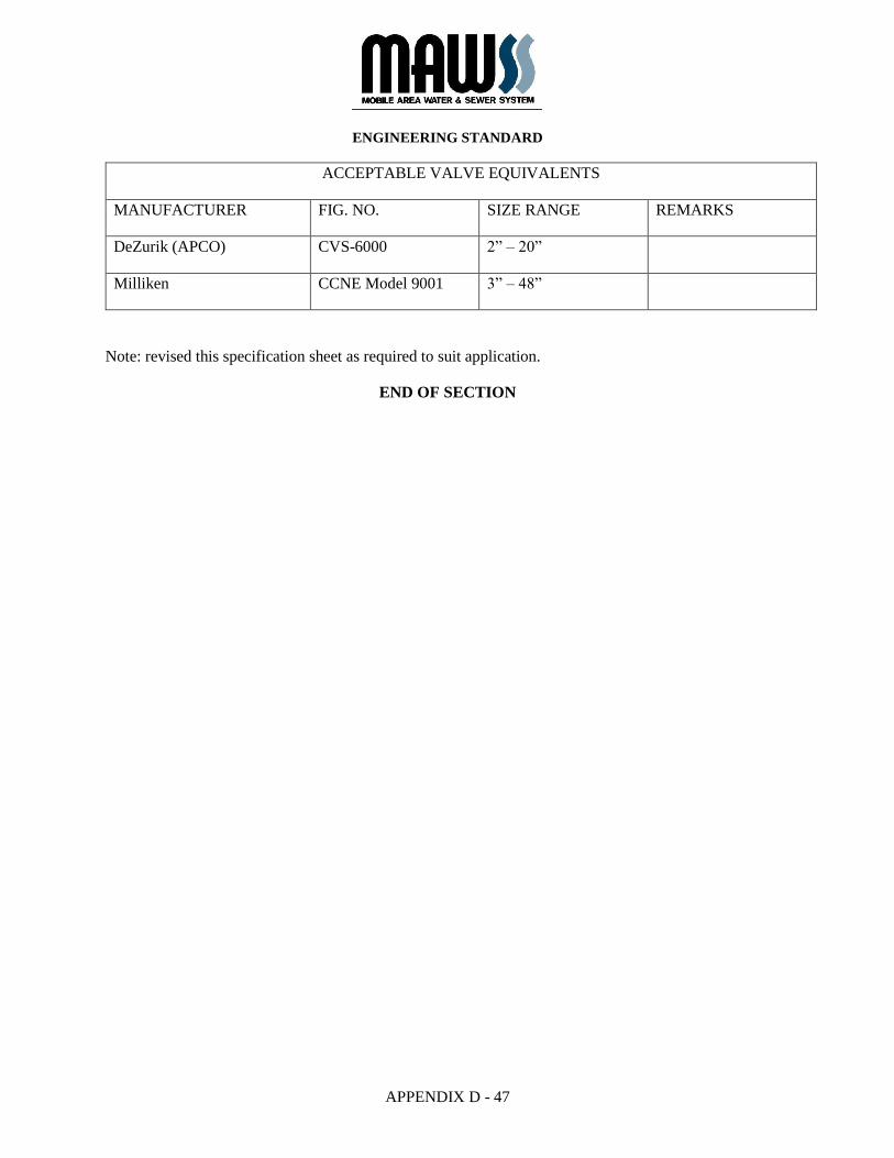
APPENDIX D - 47
ACCEPTABLE VALVE EQUIVALENTS
MANUFACTURER FIG. NO. SIZE RANGE REMARKS
DeZurik (APCO) CVS-6000 2” – 20”
Milliken CCNE Model 9001 3” – 48”
Note: revised this specification sheet as required to suit application.
END OF SECTION
ENGINEERING STANDARD
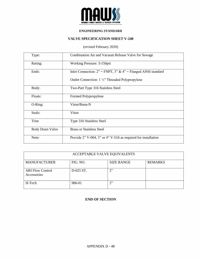
APPENDIX D - 48
VALVE SPECIFICATION SHEET V-240
(revised February 2020)
Type: Combination Air and Vacuum Release Valve for Sewage
Rating: Working Pressure: 3-150psi
Ends: Inlet Connection: 2” = FNPT, 3” & 4” = Flanged ANSI standard
Outlet Connection: 1 ½” Threaded Polypropylene
Body: Two-Part Type 316 Stainless Steel
Floats: Formed Polypropylene
O-Ring: Viton/Buna-N
Seals: Viton
Trim Type 316 Stainless Steel
Body Drain Valve Brass or Stainless Steel
Note: Provide 2” V-004, 3” or 4” V-516 as required for installation
ACCEPTABLE VALVE EQUIVALENTS
MANUFACTURER FIG. NO. SIZE RANGE REMARKS
ARI Flow Control
Accessories
D-025 ST. 2”
H-Tech 986-01 2”
END OF SECTION
ENGINEERING STANDARD
APPENDIX D - 49
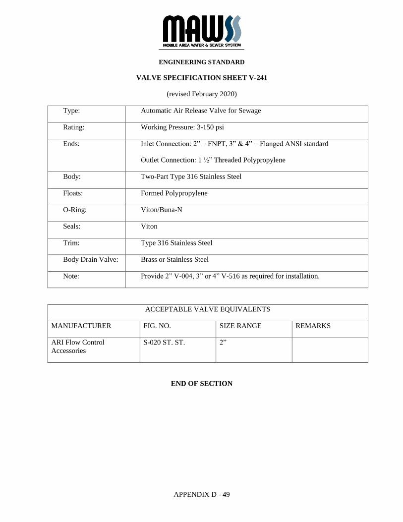
VALVE SPECIFICATION SHEET V-241
(revised February 2020)
Type: Automatic Air Release Valve for Sewage
Rating: Working Pressure: 3-150 psi
Ends: Inlet Connection: 2” = FNPT, 3” & 4” = Flanged ANSI standard
Outlet Connection: 1 ½” Threaded Polypropylene
Body: Two-Part Type 316 Stainless Steel
Floats: Formed Polypropylene
O-Ring: Viton/Buna-N
Seals: Viton
Trim: Type 316 Stainless Steel
Body Drain Valve: Brass or Stainless Steel
Note: Provide 2” V-004, 3” or 4” V-516 as required for installation.
ACCEPTABLE VALVE EQUIVALENTS
MANUFACTURER FIG. NO. SIZE RANGE REMARKS
ARI Flow Control
Accessories
S-020 ST. ST. 2”
END OF SECTION
ENGINEERING STANDARD
APPENDIX D - 50
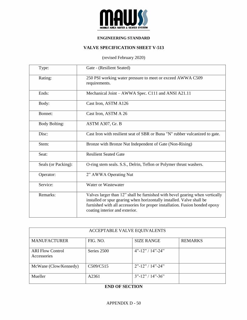
VALVE SPECIFICATION SHEET V-513
(revised February 2020)
Type: Gate - (Resilient Seated)
Rating: 250 PSI working water pressure to meet or exceed AWWA C509
requirements.
Ends: Mechanical Joint – AWWA Spec. C111 and ANSI A21.11
Body: Cast Iron, ASTM A126
Bonnet: Cast Iron, ASTM A 26
Body Bolting: ASTM A307, Gr. B
Disc: Cast Iron with resilient seat of SBR or Buna "N" rubber vulcanized to gate.
Stem: Bronze with Bronze Nut Independent of Gate (Non-Rising)
Seat: Resilient Seated Gate
Seals (or Packing): O-ring stem seals. S.S., Delrin, Teflon or Polymer thrust washers.
Operator: 2” AWWA Operating Nut
Service: Water or Wastewater
Remarks: Valves larger than 12” shall be furnished with bevel gearing when vertically
installed or spur gearing when horizontally installed. Valve shall be
furnished with all accessories for proper installation. Fusion bonded epoxy
coating interior and exterior.
ACCEPTABLE VALVE EQUIVALENTS
MANUFACTURER FIG. NO. SIZE RANGE REMARKS
ARI Flow Control
Accessories
Series 2500 4”-12” / 14”-24”
McWane (Clow/Kennedy) C509/C515 2”-12” / 14”-24”
Mueller A2361 3”-12” / 14”-36”
END OF SECTION

ENGINEERING STANDARD
APPENDIX D - 51
VALVE SPECIFICATION SHEET V-516
(revised February 2020)
Type: AWWA C-509 Gate - (Resilient Sealed)
Rating: 250 PSI working water pressure to meet or exceed AWWA C509
requirements.
Ends: Flanged, F.F., 125# ANSI B16.1
Body: Ductile Iron, ASTM A536
Bonnet: Ductile Iron, ASTM
Body Bolting: ASTM A307, Gr. B
Disc: Ductile Iron encapsulated with EPDM rubber
Stem: Bronze, non-rising
Seat: Resilient Seated Gate
Seals (or Packing): O-ring stem seals. S.S., Delrin, Teflon or Polymer thrust washers.
Operator: Handwheel unless otherwise shown on Plans
Service: Water or Wastewater
Remarks: Valves larger than 12” shall be furnished with bevel gearing when vertically
installed or spur gearing when horizontally installed. Valve shall be
furnished with all accessories for proper installation. Fusion bonded epoxy
coating interior and exterior.
ACCEPTABLE VALVE EQUIVALENTS
MANUFACTURER FIG. NO. SIZE RANGE REMARKS
ARI Flow Control
Accessories
Series 2500 4”-12” / 14”-24”
McWane (Clow/Kennedy) C509/C515 2”-12” / 14”-24”
Mueller A2361 3”-12” / 14”-36”
END OF SECTION

APPENDIX D - 52
WET WELL AND MANHOLE LINING SYSTEM
SPECIFICATIONS
The following specifications are for MAWSS approved wet well and manhole lining system products and
applications to ensure a standardized quality of materials and performance.
Manufacturers and applicators of other products must receive written approval from MAWSS prior to
submitting a bid for this Work.
Lining and coating system manufacturers and applicators may submit their products for review by the
MAWSS Engineering Department. Approval of reviews is based on “or equal” or similar products that
meet or exceed the performance characteristics of the products specified.
The Design Engineer shall select the lining system(s) most appropriate for the pumping station wet well
and include the attached specification(s) bound into the Contract Specifications for the project.
SECTION 09748
URETHANE WET WELL AND MANHOLE LINING SYSTEM
APPENDIX D - 53
PART 1 GENERAL
1.01 SCOPE
A. Description of Work
1. CONTRACTOR shall provide all labor, materials, tools and equipment
necessary to field apply a 100% solids, rapid cure, two component
modified urethane coating/lining system to all exposed interior concrete
surfaces of the wet well.
2. The coating/lining system shall be applied to exposed surfaces of the pump
discharge piping and fittings within the wet well. Do not coat the pump,
or pump matting surfaces of the discharge elbow, or any non- ferrous
metals such as pump guide rails, etc.
3. The minimum dry film thickness shall be 125 mils for manholes and 250
mils for lift station wet wells.
1.02 REFERENCES
A. Referenced Standards
1. ASTM D638, Tensile Properties of Plastics
2. ASTM D4541, Pull-off Strength of Coatings Using a Portable Adhesion
Tester
3. ASTM D2584, Volatile Matter Content
4. ASTM D2240, Durometer Hardness, Type D
5. ASTM D543, Resistance of Plastics to Chemical Reagents
6. ASTM - The published Standards of the American Society for Testing and
Materials.
7. NACE - The published Standards of National Association of Corrosion
Engineers (NACE International)
1.03 SUBMITTALS
A. Shop Drawings and Manufacturer’s Literature
1. Submit shop drawings or manufacturer’s “cut” of all material for this work
in accordance with MAWSS Section 13.1.07, Construction Submittals.
SECTION 09748
URETHANE WET WELL AND MANHOLE LINING SYSTEM
APPENDIX D - 54
2. A copy of the executed ten (10) year warranty shall be submitted for
approval prior to the installation of any products. Failure to submit
warranty is grounds for rejection of all coating/linings system submittals.
1.04 QUALITY ASSURANCE
A. Applicator shall initiate and enforce quality control procedures consistent with
applicable ASTM and NACE Standards.
B. Applicator shall use an adequate number of skilled workmen who are thoroughly
trained and experienced in the necessary crafts. These workmen shall be
completely familiar with the specified requirements and the methods needed for
proper performance of the work of this Section.
C. Applicator shall use approved specialty equipment adequate in size, capacity, and
number sufficient to accomplish work of this Section in a timely manner.
1.05 QUALIFICATIONS AND RESPONSIBILITY OF APPLICATOR
A. The Applicator shall apply the system and be responsible for the complete
performance of the system, including materials, application and quality control.
The Applicator shall provide documentation that Applicator is an approved
installer and licensed by the monolithic coating/lining system manufacturer and
specialized equipment supplier for the installation of the material.
1.06 DELIVERY, STORAGE AND HANDLING
A. Materials are to be kept dry, protected from weather and stored under cover and
stored between 50 degrees F and 100 degrees F. Materials should not be stored
near flame, heat or strong oxidants.
B. Protective coating materials are to be handled according to their material safety
data sheets.
1.07 ENVIRONMENTAL CONDITIONS
A. The CONTRACTOR shall provide and maintain safe working conditions for all
employees. Fresh air ventilation shall be provided to continuously remove fumes
from working spaces through the combined use of existing openings, forced-draft
fans and temporary ducts to the outside. Respi- rators shall be used for spraying
type operations. Fumes shall, if possible, be exhausted to the outside from the
lowest level in the confined space. Electrical fan motors shall, if located in the
working space, be explosion proof. No smoking or open fires will be permitted in
the working space.
1.08 SCAFFOLDING AND PROTECTION
A. Furnish, maintain and remove all scaffolding, ladders and planks required for this
work and all drop cloths for the protection of concrete walks, floors, pre-finished
materials, building fixtures, etc. Finished surfaces subject to damage or defacement
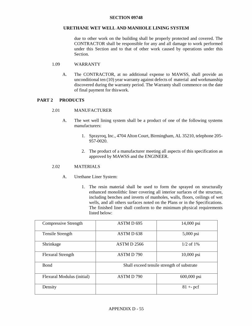
SECTION 09748
URETHANE WET WELL AND MANHOLE LINING SYSTEM
APPENDIX D - 55
due to other work on the building shall be properly protected and covered. The
CONTRACTOR shall be responsible for any and all damage to work performed
under this Section and to that of other work caused by operations under this
Section.
1.09 WARRANTY
A. The CONTRACTOR, at no additional expense to MAWSS, shall provide an
unconditional ten (10) year warranty against defects of material and workmanship
discovered during the warranty period. The Warranty shall commence on the date
of final payment for this work.
PART 2 PRODUCTS
2.01 MANUFACTURER
A. The wet well lining system shall be a product of one of the following systems
manufacturers:
1. Sprayroq, Inc., 4704 Alton Court, Birmingham, AL 35210, telephone 205-
957-0020.
2. The product of a manufacturer meeting all aspects of this specification as
approved by MAWSS and the ENGINEER.
2.02 MATERIALS
A. Urethane Liner System:
1. The resin material shall be used to form the sprayed on structurally
enhanced monolithic liner covering all interior surfaces of the structure,
including benches and inverts of manholes, walls, floors, ceilings of wet
wells, and all others surfaces noted on the Plans or in the Specifications.
The finished liner shall conform to the minimum physical requirements
listed below:
Compressive Strength ASTM D 695 14,000 psi
Tensile Strength ASTM D 638 5,000 psi
Shrinkage ASTM D 2566 1/2 of 1%
Flexural Strength ASTM D 790 10,000 psi
Bond Shall exceed tensile strength of substrate
Flexural Modulus (initial) ASTM D 790 600,000 psi
Density 81 +- pcf
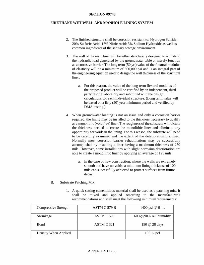
SECTION 09748
URETHANE WET WELL AND MANHOLE LINING SYSTEM
APPENDIX D - 56
2. The finished structure shall be corrosion resistant to: Hydrogen Sulfide;
20% Sulfuric Acid; 17% Nitric Acid; 5% Sodium Hydroxide as well as
common ingredients of the sanitary sewage environment.
3. The wall of the resin liner will be either structurally designed to withstand
the hydraulic load generated by the groundwater table or merely function
as a corrosive barrier. The long term (50 yr.) value of the flexural modulus
of elasticity will be a minimum of 500,000 psi and is an integral part of
the engineering equation used to design the wall thickness of the structural
liner.
a. For this reason, the value of the long-term flexural modulus of
the proposed product will be certified by an independent, third
party testing laboratory and submitted with the design
calculations for each individual structure. (Long term value will
be based on a fifty (50) year minimum period and verified by
DMA testing.)
4. When groundwater loading is not an issue and only a corrosion barrier
required, the lining may be installed to the thickness necessary to qualify
as a monolithic (void free) liner. The roughness of the substrate will dictate
the thickness needed to create the monolithic liner and eliminate any
opportunity for voids in the lining. For this reason, the substrate will need
to be carefully examined and the extent of the deterioration disclosed.
Normally most corrosion barrier rehabilitations may be successfully
accomplished by installing a liner having a maximum thickness of 250
mils. However, some installations with slight corrosion deterioration are
able to create a monolithic liner by applying an average of 125 mils.
a. In the case of new construction, where the walls are extremely
smooth and have no voids, a minimum lining thickness of 100
mils can successfully achieved to protect surfaces from future
decay.
B. Substrate Patching Mix
1. A quick setting cementitious material shall be used as a patching mix. It
shall be mixed and applied according to the manufacturer’s
recommendations and shall meet the following minimum requirements:
Compressive Strength ASTM C 579 B 1400 psi @ 6 hr.
Shrinkage ASTM C 590 60%@90% rel. humidity
Bond ASTM C 321 150 @ 28 days
Density When Applied 105 +- pcf
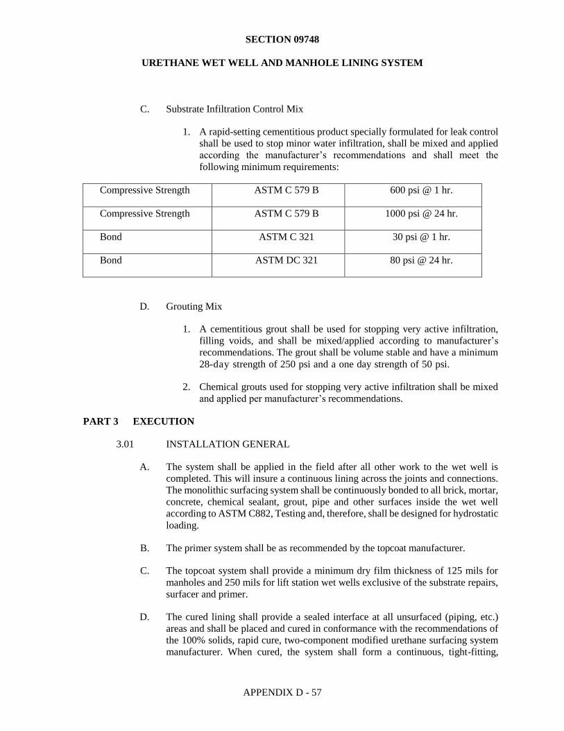
SECTION 09748
URETHANE WET WELL AND MANHOLE LINING SYSTEM
APPENDIX D - 57
C. Substrate Infiltration Control Mix
1. A rapid-setting cementitious product specially formulated for leak control
shall be used to stop minor water infiltration, shall be mixed and applied
according the manufacturer’s recommendations and shall meet the
following minimum requirements:
Compressive Strength ASTM C 579 B 600 psi @ 1 hr.
Compressive Strength ASTM C 579 B 1000 psi @ 24 hr.
Bond ASTM C 321 30 psi @ 1 hr.
Bond ASTM DC 321 80 psi @ 24 hr.
D. Grouting Mix
1. A cementitious grout shall be used for stopping very active infiltration,
filling voids, and shall be mixed/applied according to manufacturer’s
recommendations. The grout shall be volume stable and have a minimum
28-day strength of 250 psi and a one day strength of 50 psi.
2. Chemical grouts used for stopping very active infiltration shall be mixed
and applied per manufacturer’s recommendations.
PART 3 EXECUTION
3.01 INSTALLATION GENERAL
A. The system shall be applied in the field after all other work to the wet well is
completed. This will insure a continuous lining across the joints and connections.
The monolithic surfacing system shall be continuously bonded to all brick, mortar,
concrete, chemical sealant, grout, pipe and other surfaces inside the wet well
according to ASTM C882, Testing and, therefore, shall be designed for hydrostatic
loading.
B. The primer system shall be as recommended by the topcoat manufacturer.
C. The topcoat system shall provide a minimum dry film thickness of 125 mils for
manholes and 250 mils for lift station wet wells exclusive of the substrate repairs,
surfacer and primer.
D. The cured lining shall provide a sealed interface at all unsurfaced (piping, etc.)
areas and shall be placed and cured in conformance with the recommendations of
the 100% solids, rapid cure, two-component modified urethane surfacing system
manufacturer. When cured, the system shall form a continuous, tight-fitting,
SECTION 09748
URETHANE WET WELL AND MANHOLE LINING SYSTEM
APPENDIX D - 58
flexible, impermeable surfacing that is suitable for domestic wastewater system
service and chemically resistant to any chemicals, bacteria, or vapor normally
found in domestic wastewater. The system shall be compatible with the thermal
conditions of the existing surfaces.
3.02 PROTECTIVE COATING APPLICATION EQUIPMENT
A. Application of the primer shall be by standard airless spray equipment meeting the
specifications of the product manufacturer.
3.03 PRE-COAT INSPECTION
A. The applicators vehicles and equipment must be able to access the structures to be
coated under their own power.
B. All surfaces, including benches, inverts, joints, lift holes, and walls shall be made
smooth and suitable for application of the interior surfacing system. All benches
and inverts shall be in place and complete.
C. Active flows shall be dammed, plugged, or diverted as required to ensure that the
liquid flow is maintained below the surfaces to be coated.
D. Installation of the protective coating shall not commence until the concrete
substrate has properly cured.
3.04 SURFACE PREPARATION
A. Applicator shall inspect and test all surfaces specified to receive the lining system
prior to surface preparation in accordance with lining manufacturer's requirements
and industry standard practices. Applicator shall notify ENGINEER of any
noticeable disparity in the surfaces that may interfere with the proper preparation
or application of the monolithic surfacing system.
B. All concrete that is not sound, or has been damaged by chemical exposure, shall
be restored to a sound concrete surface. All contaminants including: all oils, grease,
incompatible existing coatings, waxes, form release, curing compounds,
efflorescence, sealers, salts, or other contaminants shall be removed.
C. Surface preparation method(s) shall be based upon the conditions of the substrate
and the requirements of the lining system manufacturer.
D. New concrete shall be cured a minimum of 28 days at 75 degrees Fahrenheit or
equivalent prior to coating application.
E. Check for excess moisture in accordance with ASTM C 4263 – Standard Test
Method for Indicating Moisture in Concrete by the Plastic Sheet Method.
F. Remove all oil, grease, dirt, water or other contaminants in accordance with ASTM
D 4258 and SSPC-SP-1.
SECTION 09748
URETHANE WET WELL AND MANHOLE LINING SYSTEM
APPENDIX D - 59
G. Abrasive grit blast, wet abrasive blast or high pressure water blast all surfaces to
be coated, to remove all laitance, efflorescence, surface hardness, curing
compounds, old coatings, and loose concrete, in accordance with SSPC-SP-
13/NACE No. 6 or ASTM D 4259. A surface texture similar to that of medium-
coarse sandpaper should be attained.
1. The compressed air supply shall be completely free of all oil, water and
other contaminants and provide the required volume of air at 100 psi or
greater.
2. Abrasives used shall be clean, a uniform grade and of an appropriate size
to obtain the finish and profile required. DO NOT use contaminated
abrasives.
3. Water used with high-pressure water blasting or wet abrasive blasting shall
be clean potable water and shall be applied at sufficient pressure to obtain
a clean textured surface in accordance with above applicable standards.
H. Thoroughly clean all blasted surfaces to remove all dust and debris after dry
blasting, or remove all water, sludge and debris after wet blasting.
I. Repair or remove or fill all cracks, voids, honeycombs, fins and other surface
irregularities using a patching method recommended by the finish coating
manufacturer.
J. Grind all form ties or other metallic protrusions below the surface, then patch or
fill.
K. All expansion joints and moving cracks which have opened to a width of 1/16” or
greater must be repaired with elastomeric caulking material per the caulking
manufacturer’s instructions.
L. Immediately prior to the application of the concrete surfacer or primer, thoroughly
vacuum clean all surfaces to be coated, effectively removing all remaining dust.
1. Vacuum cleaning a roughened concrete surface is the only known
effective method of removing dust from deep pits, cracks, crevices, bug
holes, etc. and is considered a mandatory procedure.
3.05 APPLICATION OF FIELD APPLIED MONOLITHIC SURFACING SYSTEM
A. Application procedures shall conform to the recommendations of the two- part
modified urethane monolithic coating/lining system manufacturer, including
material handling, mixing, safety, equipment and environmental controls during
application.
B. Newly constructed below or at grade concrete walls and slabs that will be internally
coated must have a sheet or coating vapor barrier installed on the unprotected side
of the concrete.
SECTION 09748
URETHANE WET WELL AND MANHOLE LINING SYSTEM
APPENDIX D - 60
C. To minimize outgassing problems, all coating should be applied when the surface
temperature of the concrete is declining.
D. Due to the inconsistent nature of concrete, surface porosity can vary greatly so a
surfacer should always be used to reduce the occurrence of outgassing and
pinholes. Extreme cases of surface porosity may require multiple coats of the
surfacer or primer.
E. Specially designed plural component equipment designed to proportion the two
components utilizing airless spray guns shall be used to apply each coat of the
system.
F. Once the material is applied, the structure must be returned to active water service
within 60 minutes to minimize sewer backup and lessen the likelihood of
residential or commercial damage. This must be accomplished without damaging
the newly applied resin.
3.06 TESTING AND INSPECTION
A. All testing and inspection of the liner system shall be done in accordance with the
manufacturer's specifications and/or the following requirements, whichever is
more stringent. During application, the Applicator shall pay particular attention to
the volume/time ratio of the application to ensure a monolithic coating and uniform
thickness during application of a minimum thickness of 125 mils for manholes
and 250 mils for lift station wet wells. After a minimum of 24 hours following
completion, the ENGINNER may direct the CONTRACTOR to perform a series
of 1” diameter core drills to provide verification of lining thickness throughout the
applied liner system. A maximum of one core drill per 100 square feet will be
required.
1. Lining thickness at each core drill shall be collected.
2. All lining thicknesses will be added together, then, divided by the number
of core drills to provide an average thickness.
3. If the lining system thickness proves to be below that specified, the
averaged thickness will be used to prorate payment for the applicator’s
services based on the Bid Item B111 “Urethane Wet Well Lining
System” as shown in the Proposal. Payment will be reduced by a similar
percentage as calculated on the actual applied thickness compared to the
specified thickness.
4. No additional payment will be made for this test or for repair of the
lining system.
B. After a minimum of 24 hours following completion, the lining system shall be
spark tested to ensure a pinhole-free lining. Defects must be patched per the
manufacturer’s instructions. The test voltage shall be a minimum 6,000 volts. The
holiday detector shall be a Tinker Razor Model AP/W or an approved equal. The
SECTION 09748
URETHANE WET WELL AND MANHOLE LINING SYSTEM
APPENDIX D - 61
Applicator may enlist the services of an independent certified NACE inspector if
desired.
C. The ENGINEER and the Applicator shall make a final visual inspection. Any
deficiencies in the finished system shall be marked and repaired by the applicator
according to the procedures set forth herein and in accordance with the liner
manufacturers requirements.
3.07 REPAIRS
A. All damaged areas, faulty areas, and pinholes found during testing and inspection
shall be repaired by the CONTRACTOR in accordance with the procedures
recommended by the coating/lining system manufacturer.
B. All core drilled holes shall be cleaned, primed, repaired and coated in accordance
with liner system manufacturer’s recommendations in order to maintain the system
integrity and ten (10) year warranty.
C. The complete monolithic coating/lining system, including the repaired areas shall
be inspected and tested in accordance with Section 3.6 of these specifications. The
CONTRACTOR shall repeat Section 3.7 until no further defects are detected.
3.08 FINAL INSPECTION, PAYMENT AND WARRANTY
A. The monolithic coating/lining system shall be considered complete and accepted
subject to passing the inspection criteria listed under Sections 3.06 and 3.07.
B. Payment for this item of work shall be made when work is complete in accordance
with this specification and after clean-up of all associated construction debris,
empty containers, etc.
C. The CONTRACTOR shall warrant this work for a period of ten (10) years. During
this time period, the CONTRACTOR shall make all repairs to the monolithic
coating/lining system at no expense to the MAWSS.
END OF SECTION

SECTION 09749
CALCIUM ALUMINATE CEMENTITIOUS
WET WELL AND MANHOLE LINING SYSTEM
APPENDIX D - 62
PART 1 GENERAL
1.01 SCOPE
A. Description of Work
1. CONTRACTOR shall provide all labor, material, tools and equipment
necessary to field apply a calcium aluminate cementitious coating/lining
system to all exposed interior concrete surfaces of the wet well.
2. The coating/lining system shall not be applied to exposed surfaces of the
pump discharge piping and fittings within the wet well. Do not coat the
pump, or pump matting surfaces of the discharge elbow, or any non-
ferrous metals such as pump guide rails, etc.
3. All non-ferrous metals, including discharge piping, within the wet well
shall be painted in accordance with specification Section 09900 Painting.
1.02 REFERENCES
A. Referenced Standards
1. ASTM D638, Tensile Properties of Plastics
2. ASTM D4541, Pull-off Strength of Coatings Using a Portable Adhesion
Tester
3. ASTM D2584, Volatile Matter Content
4. ASTM D2240, Durometer Hardness, Type D
5. ASTM D543, Resistance of Plastics to Chemical Reagents
6. ASTM - The published Standards of the American Society for Testing and
Materials.
7. NACE - The published Standards of National Association of Corrosion
Engineers (NACE International)
1.03 SUBMITTALS
A. Shop Drawings and Manufacturer’s Literature
1. Submit shop drawings or manufacturer’s “cut” of all material for this work
in accordance with MAWSS Section 13.1.07, Construction Submittals.
SECTION 09749
CALCIUM ALUMINATE CEMENTITIOUS
WET WELL AND MANHOLE LINING SYSTEM
APPENDIX D - 63
2. A copy of the executed five (5) year warranty shall be submitted for
approval prior to the installation of any products. Failure to submit
warranty is grounds for rejection of all coating/linings system submittals.
1.04 QUALITY ASSURANCE
A. Applicator shall initiate and enforce quality control procedures consistent with
applicable ASTM and NACE Standards.
B. Applicator shall use an adequate number of skilled workmen who are thoroughly
trained and experienced in the necessary crafts. These workmen shall be
completely familiar with the specified requirements and the methods needed for
proper performance of the work of this Section.
C. Applicator shall use approved specialty equipment adequate in size capacity and
number sufficient to accomplish work of this Section in a timely manner.
1.05 QUALIFICATIONS AND RESPONSIBILITY OF APPLICATOR
A. The Applicator shall apply the system and be responsible for the complete
performance of the system, including materials, application and quality control.
The Applicator shall provide documentation that Applicator is an approved
installer and licensed by the monolithic coating/lining system manufacturer and
specialized equipment supplier for the installation of the material.
1.06 DELIVERY, STORAGE AND HANDLING
A. Materials are to be kept dry, protected from weather and stored under cover and
stored between 50 degrees F and 100 degrees F. Materials should not be stored
near flame, heat or strong oxidants.
B. Protective coating materials are to be handled according to their material safety
data sheets.
1.07 ENVIRONMENTAL CONDITIONS
A. The CONTRACTOR shall provide and maintain safe working conditions for all
employees. Fresh air ventilation shall be provided to continuously remove fumes
from working spaces through the combined use of existing openings, forced-draft
fans and temporary ducts to the outside. Respirators shall be used for spraying type
operations. Fumes shall, if possible, be exhausted to the outside from the lowest
level in the confined space. Electrical fan motors shall, if located in the working
space, be explosion proof. No smoking or open fires will be permitted in the
working space.
1.08 SCAFFOLDING AND PROTECTION
A. Furnish, maintain and remove all scaffolding, ladders and planks required for this
work and all drop cloths for the protection of concrete walks, floors, pre-finished
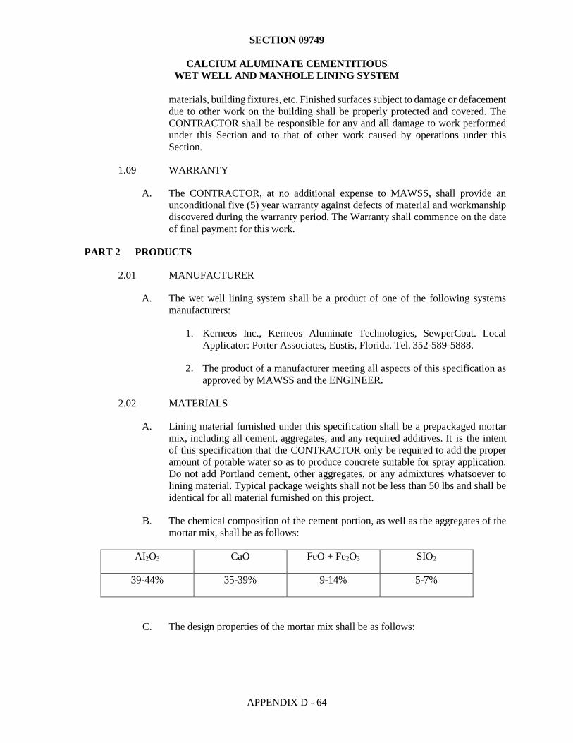
SECTION 09749
CALCIUM ALUMINATE CEMENTITIOUS
WET WELL AND MANHOLE LINING SYSTEM
APPENDIX D - 64
materials, building fixtures, etc. Finished surfaces subject to damage or defacement
due to other work on the building shall be properly protected and covered. The
CONTRACTOR shall be responsible for any and all damage to work performed
under this Section and to that of other work caused by operations under this
Section.
1.09 WARRANTY
A. The CONTRACTOR, at no additional expense to MAWSS, shall provide an
unconditional five (5) year warranty against defects of material and workmanship
discovered during the warranty period. The Warranty shall commence on the date
of final payment for this work.
PART 2 PRODUCTS
2.01 MANUFACTURER
A. The wet well lining system shall be a product of one of the following systems
manufacturers:
1. Kerneos Inc., Kerneos Aluminate Technologies, SewperCoat. Local
Applicator: Porter Associates, Eustis, Florida. Tel. 352-589-5888.
2. The product of a manufacturer meeting all aspects of this specification as
approved by MAWSS and the ENGINEER.
2.02 MATERIALS
A. Lining material furnished under this specification shall be a prepackaged mortar
mix, including all cement, aggregates, and any required additives. It is the intent
of this specification that the CONTRACTOR only be required to add the proper
amount of potable water so as to produce concrete suitable for spray application.
Do not add Portland cement, other aggregates, or any admixtures whatsoever to
lining material. Typical package weights shall not be less than 50 lbs and shall be
identical for all material furnished on this project.
B. The chemical composition of the cement portion, as well as the aggregates of the
mortar mix, shall be as follows:
AI2O3 CaO FeO + Fe2O3 SIO2
39-44% 35-39% 9-14% 5-7%
C. The design properties of the mortar mix shall be as follows:
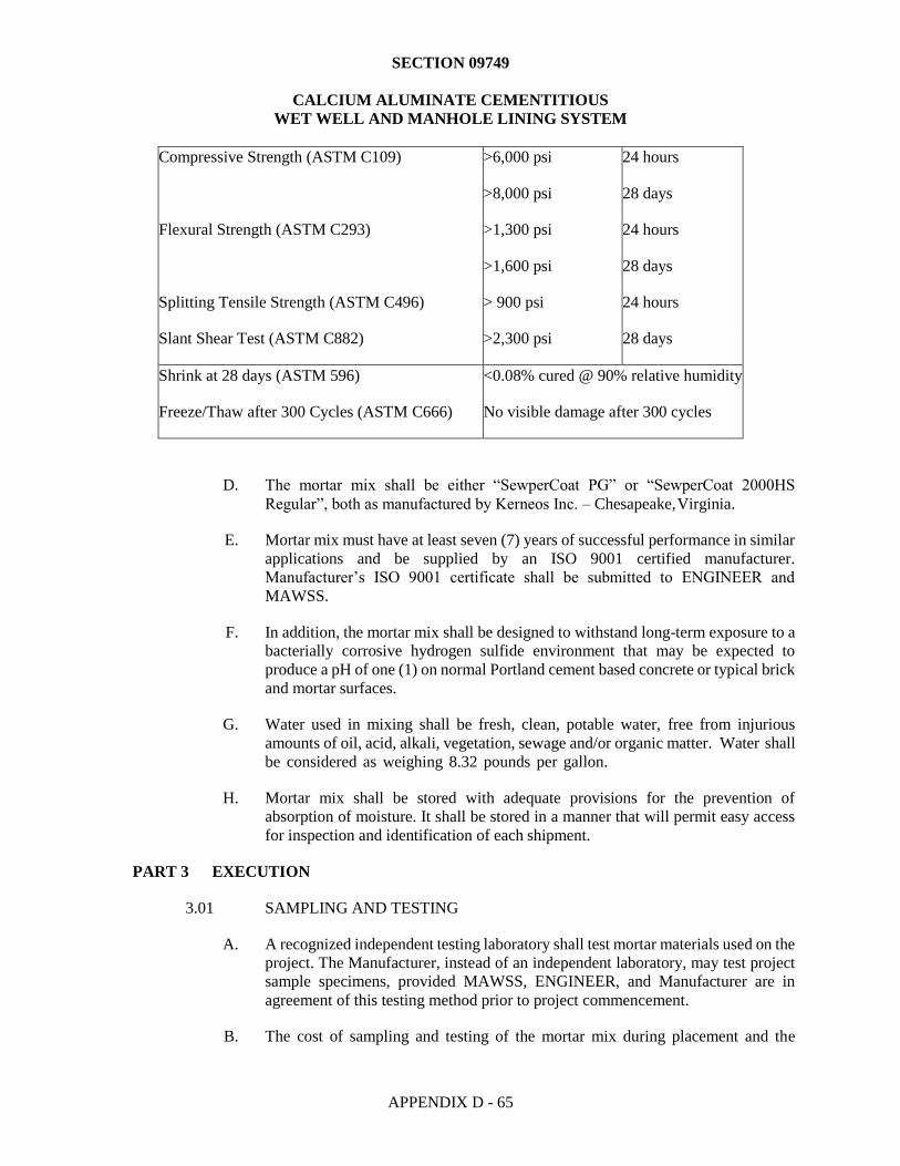
SECTION 09749
CALCIUM ALUMINATE CEMENTITIOUS
WET WELL AND MANHOLE LINING SYSTEM
APPENDIX D - 65
Compressive Strength (ASTM C109) >6,000 psi 24 hours
>8,000 psi 28 days
Flexural Strength (ASTM C293) >1,300 psi 24 hours
>1,600 psi 28 days
Splitting Tensile Strength (ASTM C496) > 900 psi 24 hours
Slant Shear Test (ASTM C882) >2,300 psi 28 days
Shrink at 28 days (ASTM 596)
Freeze/Thaw after 300 Cycles (ASTM C666)
<0.08% cured @ 90% relative humidity
No visible damage after 300 cycles
D. The mortar mix shall be either “SewperCoat PG” or “SewperCoat 2000HS
Regular”, both as manufactured by Kerneos Inc. – Chesapeake, Virginia.
E. Mortar mix must have at least seven (7) years of successful performance in similar
applications and be supplied by an ISO 9001 certified manufacturer.
Manufacturer’s ISO 9001 certificate shall be submitted to ENGINEER and
MAWSS.
F. In addition, the mortar mix shall be designed to withstand long-term exposure to a
bacterially corrosive hydrogen sulfide environment that may be expected to
produce a pH of one (1) on normal Portland cement based concrete or typical brick
and mortar surfaces.
G. Water used in mixing shall be fresh, clean, potable water, free from injurious
amounts of oil, acid, alkali, vegetation, sewage and/or organic matter. Water shall
be considered as weighing 8.32 pounds per gallon.
H. Mortar mix shall be stored with adequate provisions for the prevention of
absorption of moisture. It shall be stored in a manner that will permit easy access
for inspection and identification of each shipment.
PART 3 EXECUTION
3.01 SAMPLING AND TESTING
A. A recognized independent testing laboratory shall test mortar materials used on the
project. The Manufacturer, instead of an independent laboratory, may test project
sample specimens, provided MAWSS, ENGINEER, and Manufacturer are in
agreement of this testing method prior to project commencement.
B. The cost of sampling and testing of the mortar mix during placement and the
SECTION 09749
CALCIUM ALUMINATE CEMENTITIOUS
WET WELL AND MANHOLE LINING SYSTEM
APPENDIX D - 66
surface to which it is applied shall be born by the CONTRACTOR. Other testing
required showing conformance with these specifications shall be the responsibility
of the CONTRACTOR. Certified test reports and certificates, when so directed,
shall be submitted in duplicate to the ENGINEER and to such other agencies or
persons the ENGINEER may designate.
C. Any materials failing to meet the requirements of these specifications shall not be
incorporated into the work plan.
3.02 QUALIFICATION OF WORK CREW
A. The lining material Manufacturer shall maintain a listing of competent
CONTRACTORS that have demonstrated requisite skill and training to be
qualified applicators of their materials.
B. Prior to project commencement, the CONTRACTOR must satisfy the ENGINEER
that all CONTRACTOR’s work crew personnel have performed satisfactory work
in similar capacities elsewhere for a sufficient period of time to be fully qualified
to properly perform the work in accordance with the requirements of the related
specifications.
C. Foreman shall have at least 4 years experience with similar work and project
conditions.
D. Nozzlemen shall be qualified by having had similar work experience.
E. Work Crew responsibilities prior to application of lining material shall include the
following:
1. Surface preparation as discussed in Section 3.4.
2. Ensure the operating air pressure is uniform and provides adequate nozzle
velocity for proper compaction.
3. Continuously regulate the water content so that the applied materials
consistently achieve proper compaction with a low percentage of rebound
and no visible “sag.”
4. Ensure that the installation equipment nozzle is held at the proper distance
away from and as nearly perpendicular to the prepared sub- surface as the
working conditions will permit to secure maximum material compaction
with minimum rebound and no visible “sag”.
5. Follow a sequence routine that will fill corners with adequately compacted
material applied at a maximum practicable layer thickness.
6. Determine necessary operating procedures for placement in confined
spaces, extended distances or around unusual obstructions where
placement velocities and mix consistency may need to be adjusted.
SECTION 09749
CALCIUM ALUMINATE CEMENTITIOUS
WET WELL AND MANHOLE LINING SYSTEM
APPENDIX D - 67
7. Direct the crew as to when to start and stop the flow of materials during
installation and to immediately stop all work when material is not arriving
uniformly at the nozzle.
8. Ensure that slough pockets are removed and prepared for installation of
replacement material.
9. Bring the installed materials to established finished elevations in a neat
and timely manner and within established tolerances.
F. Applicator’s job foreman shall operate the mixing/placing equipment and direct
the work of mixing crew personnel. Applicator’s work crew shall also maintain
proper line pressures throughout the mixing/placing equipment to ensure the
necessary consistent nozzle velocity. Applicator’s work crew shall further see that
all material fed to the nozzle is uniformly fed through this equipment.
3.03 EQUIPMENT
A. Equipment shall be of spray type and approved by the material manufacturer.
Alternate equipment may be utilized provided it meets the performance
requirements of the specification. All equipment must be kept in operating
condition and good repair.
3.04 SURFACE PREPARATION
A. Ensure all sub-surfaces are clean and free of laitance, loose material, residue and
all existing coating and lining materials. See Section 3.7 for Inflow and Infiltration
Prevention. For detailed explanation of the required surface preparation see ACI
RAP-3 “Spall Repair by Low Pressure Spraying” page 2. ACI 546R “Concrete
Repair Guide”, chapter 2 also provides a good reference for important
considerations for repairing concrete surfaces using mortar.
B. Sub-surfaces shall be thoroughly saturated with water prior to the application of
the lining materials. In no instance shall shotcrete be applied in an area where
running water exists. It is the intent of this specification that the existing surface
be saturated and free of any running water just prior to installation – or SSD,
“saturated surface dry condition.” To achieve this condition, it may be necessary
to presoak the sub-surface for at least 24 hours.
3.05 OPERATIONS
A. The CONTRACTOR shall provide all equipment necessary to individually gauge,
control, and monitor the actual amounts of all component materials necessary to
complete the lining installation. The type of equipment and methods used to gauge,
control, and monitor component materials shall be subject to approval by the
ENGINEER and Manufacturer.
B. All lining materials shall be thoroughly mixed by mechanical means to ensure all
agglomerated particles are reduced to original size or removed prior to placement
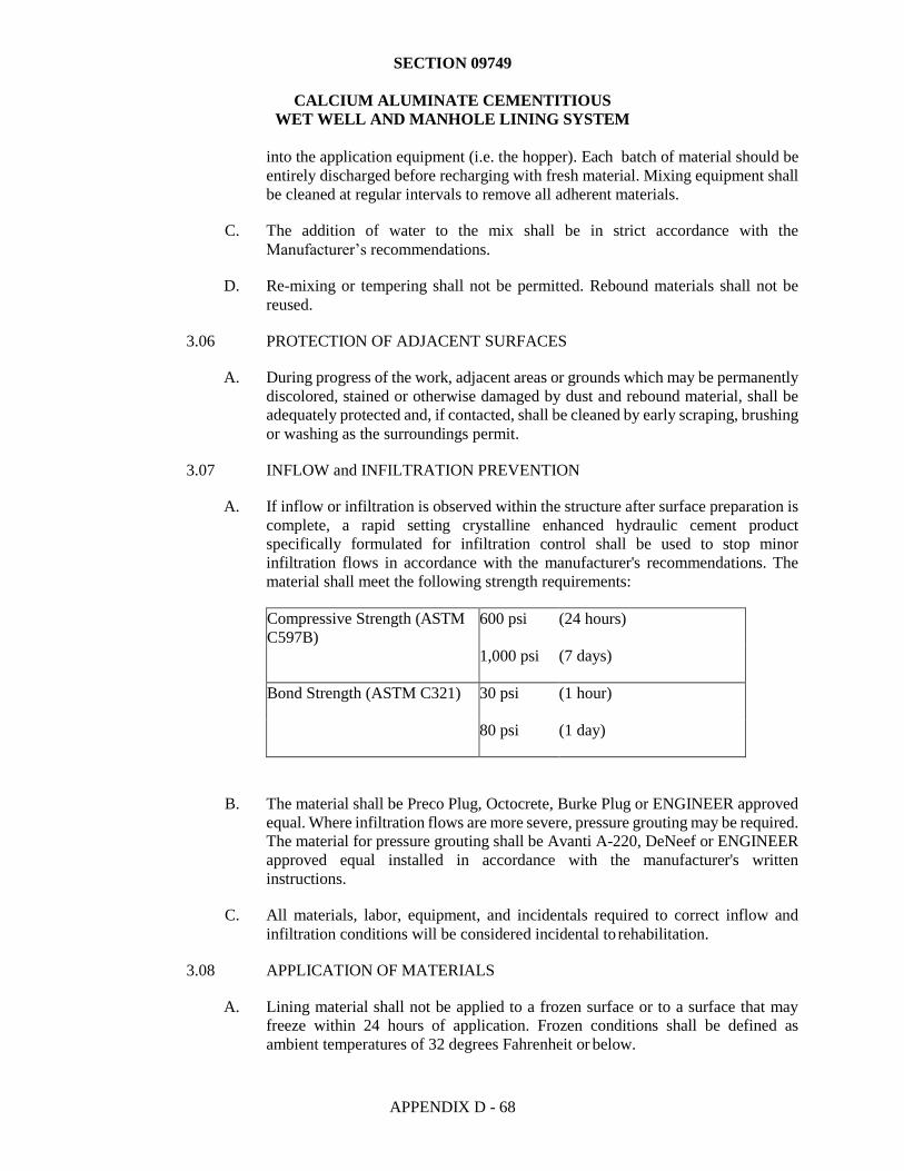
SECTION 09749
CALCIUM ALUMINATE CEMENTITIOUS
WET WELL AND MANHOLE LINING SYSTEM
APPENDIX D - 68
into the application equipment (i.e. the hopper). Each batch of material should be
entirely discharged before recharging with fresh material. Mixing equipment shall
be cleaned at regular intervals to remove all adherent materials.
C. The addition of water to the mix shall be in strict accordance with the
Manufacturer’s recommendations.
D. Re-mixing or tempering shall not be permitted. Rebound materials shall not be
reused.
3.06 PROTECTION OF ADJACENT SURFACES
A. During progress of the work, adjacent areas or grounds which may be permanently
discolored, stained or otherwise damaged by dust and rebound material, shall be
adequately protected and, if contacted, shall be cleaned by early scraping, brushing
or washing as the surroundings permit.
3.07 INFLOW and INFILTRATION PREVENTION
A. If inflow or infiltration is observed within the structure after surface preparation is
complete, a rapid setting crystalline enhanced hydraulic cement product
specifically formulated for infiltration control shall be used to stop minor
infiltration flows in accordance with the manufacturer's recommendations. The
material shall meet the following strength requirements:
Compressive Strength (ASTM
C597B)
600 psi (24 hours)
1,000 psi (7 days)
Bond Strength (ASTM C321) 30 psi (1 hour)
80 psi (1 day)
B. The material shall be Preco Plug, Octocrete, Burke Plug or ENGINEER approved
equal. Where infiltration flows are more severe, pressure grouting may be required.
The material for pressure grouting shall be Avanti A-220, DeNeef or ENGINEER
approved equal installed in accordance with the manufacturer's written
instructions.
C. All materials, labor, equipment, and incidentals required to correct inflow and
infiltration conditions will be considered incidental to rehabilitation.
3.08 APPLICATION OF MATERIALS
A. Lining material shall not be applied to a frozen surface or to a surface that may
freeze within 24 hours of application. Frozen conditions shall be defined as
ambient temperatures of 32 degrees Fahrenheit or below.
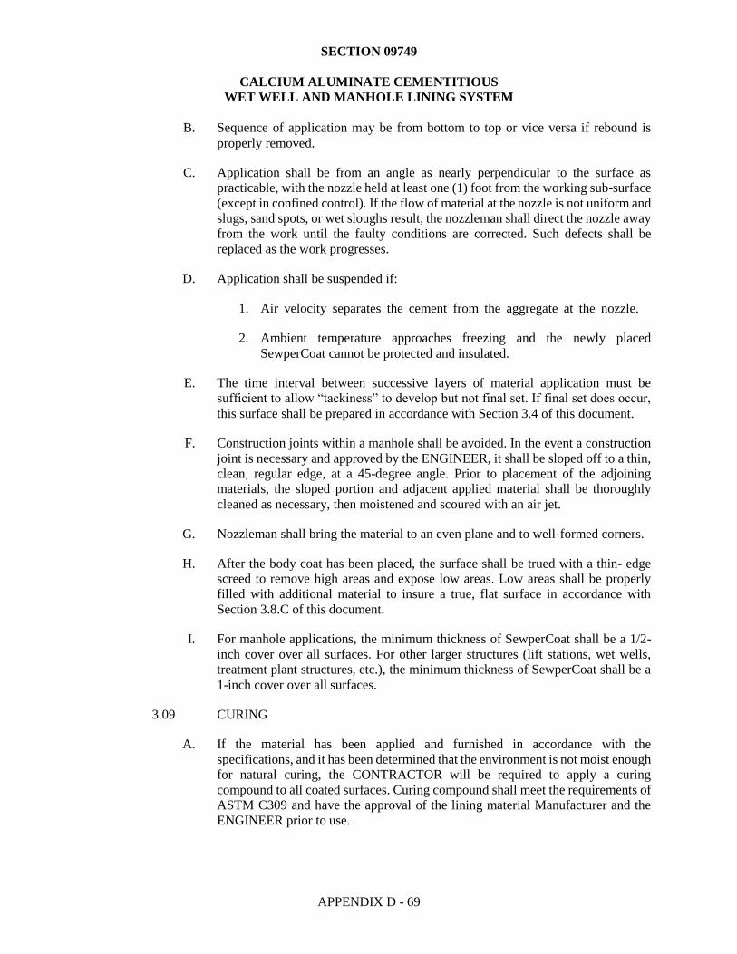
SECTION 09749
CALCIUM ALUMINATE CEMENTITIOUS
WET WELL AND MANHOLE LINING SYSTEM
APPENDIX D - 69
B. Sequence of application may be from bottom to top or vice versa if rebound is
properly removed.
C. Application shall be from an angle as nearly perpendicular to the surface as
practicable, with the nozzle held at least one (1) foot from the working sub-surface
(except in confined control). If the flow of material at the nozzle is not uniform and
slugs, sand spots, or wet sloughs result, the nozzleman shall direct the nozzle away
from the work until the faulty conditions are corrected. Such defects shall be
replaced as the work progresses.
D. Application shall be suspended if:
1. Air velocity separates the cement from the aggregate at the nozzle.
2. Ambient temperature approaches freezing and the newly placed
SewperCoat cannot be protected and insulated.
E. The time interval between successive layers of material application must be
sufficient to allow “tackiness” to develop but not final set. If final set does occur,
this surface shall be prepared in accordance with Section 3.4 of this document.
F. Construction joints within a manhole shall be avoided. In the event a construction
joint is necessary and approved by the ENGINEER, it shall be sloped off to a thin,
clean, regular edge, at a 45-degree angle. Prior to placement of the adjoining
materials, the sloped portion and adjacent applied material shall be thoroughly
cleaned as necessary, then moistened and scoured with an air jet.
G. Nozzleman shall bring the material to an even plane and to well-formed corners.
H. After the body coat has been placed, the surface shall be trued with a thin- edge
screed to remove high areas and expose low areas. Low areas shall be properly
filled with additional material to insure a true, flat surface in accordance with
Section 3.8.C of this document.
I. For manhole applications, the minimum thickness of SewperCoat shall be a 1/2-
inch cover over all surfaces. For other larger structures (lift stations, wet wells,
treatment plant structures, etc.), the minimum thickness of SewperCoat shall be a
1-inch cover over all surfaces.
3.09 CURING
A. If the material has been applied and furnished in accordance with the
specifications, and it has been determined that the environment is not moist enough
for natural curing, the CONTRACTOR will be required to apply a curing
compound to all coated surfaces. Curing compound shall meet the requirements of
ASTM C309 and have the approval of the lining material Manufacturer and the
ENGINEER prior to use.
SECTION 09749
CALCIUM ALUMINATE CEMENTITIOUS
WET WELL AND MANHOLE LINING SYSTEM
APPENDIX D - 70
B. Moist curing may also be used in lieu of curing compound. If moist curing is
selected, it should be implemented just after the notice of uniform heat generation
of the installed lining. Moist curing can consist of the use of soaker hoses, water
sprinklers, or vapor/misting machines. Regardless of delivery method, moist
curing should continue for a minimum of 18 hours.
END OF SECTION