JIPSD 2016 Sanitary Sewer System Design Construction ...
220
-
Upload
khangminh22 -
Category
Documents
-
view
0 -
download
0
Transcript of JIPSD 2016 Sanitary Sewer System Design Construction ...


Table of Contents - i
TABLE OF CONTENTS
1. INTRODUCTION
2. ADMINISTRATION
A. JAMES ISLAND PUBLIC SERVICE DISTRICT B. DEVELOPER’S DESIGN ENGINEER
3. SUBMITTALS AND APPROVALS
A. GENERAL B. PRELIMINARY APPROVAL C. FINAL APPROVAL D. SHOP DRAWINGS E. OPERATION AND MAINTENANCE MANUALS F. PROJECT COMPLETION AND TAKEOVER G. PERMIT TO CONSTRUCT APPLICATION H. PROJECT REVIEW CHECKLIST I. O & M ACCEPTANCE CHECKLIST J. AS-BUILT DRAWING CHECKLIST K. JIPSD CLOSEOUT PACKAGE CHECKLIST
4. EASEMENTS
5. GRAVITY SANITARY SEWER SYSTEM DESIGN STANDARDS
A. GENERAL B. GRAVITY SEWER SYSTEM DESIGN CRITERIA C. CAPACITY DESIGN D. INFILTRATION E. SEWER PIPES F. SEPARATION OF WATER MAINS AND SEWERS G. COVER H. DUCTILE IRON PIPE LOCATIONS I. MANHOLES
6. GRAVITY SANITARY SEWER MATERIALS FOR CONSTRUCTION
A. GENERAL B. PIPE AND FITTINGS C. MANHOLES D. PIPE AND MANHOLE FOUNDATION AND BACKFILL MATERIALS
E. CASING, SPACERS AND END SEALS FOR UTILITIES 7. GRAVITY SANITARY SEWER SYSTEM CONSTRUCTION PROCEDURES
A. HANDLING OF MATERIALS B. PIPE CUTTING C. LOCATING

Table of Contents - ii
D. INSTALLATION E. MANHOLES F. MANHOLE COATINGS G. CONNECTIONS TO EXISTING SYSTEM H. SERVICE LATERALS I. INSPECTIONS AND TESTING J. GENERAL K. TRENCH EXCAVATION L. TRENCH BACKFILL M. INSTALLATION OF CASING, SPACERS, AND END SEALS
8. FORCE MAIN DESIGN STANDARDS
A. GENERAL B. FORCE MAIN DESIGN CRITERIA C. AIR RELEASE VALVES D. PLUG VALVES E. FORCE MAINS ENTERING MANHOLES F. SEPARATION OF FORCE MAINS AND WATER MAINS G. COVER H. DUCTILE IRON PIPE LOCATIONS
9. FORCE MAIN MATERIALS FOR CONSTRUCTION
A. GENERAL B. PIPE AND FITTINGS C. RESTRAINED JOINT PIPE AND FITTINGS D. AIR RELEASE AND VACUUM VALVES E. CASING, SPACERS, AND END SEALS FOR UTILITIES
10. FORCE MAIN CONSTRUCTION PROCEDURES
A. HANDLING OF MATERIALS B. PIPE CUTTING C. LOCATING D. ALIGNMENT OF PIPE E. PLACING AND LAYING F. INSTALLATION OF AIR RELEASE VALVES G. INSPECTIONS AND TESTING H. INSTALLATION OF CASING, SPACERS, AND END SEALS I. TRENCH EXCAVATION J. TRENCH BACKFILL
11. SANITARY SEWER PUMP STATION DESIGN STANDARDS
A. GENERAL B. GENERAL PUMP STATION DESIGN C. SUBMERSIBLE PUMP STATION

Table of Contents - iii
D. PUMPS AND MOTORS E. PUMP STATION PIPING F. WETWELL DESIGN CRITERIA G. ELECTRICAL H. PUMP STATION SITE I. SPARE PARTS FOR SUBMERSIBLE PUMP STATION
12. SANITARY SEWER PUMP STATION MATERIALS FOR CONSTRUCTION
A. WETWELLS B. SUBMERSIBLE PUMP STATION C. GRINDER STATIONS D. LEVEL CONTROL SYSTEM E. CUSHIONED SWING CHECK VALVES F. PLUG VALVES
13. SANITARY SEWER PUMP STATION CONSTRUCTION PROCEDURES
A. GENERAL B. SUBMERSIBLE SEWAGE PUMPS C. REMOTE TELEMETRY UNIT (RTU)
14. ALTERNATIVE WASTEWATER COLLECTION SYSTEMS (AWCS) DESIGN STANDARDS
15. SAND, OIL AND GREASE INTERCEPTOR 16. FORCE MAINS INSTALLED BY HORIZONTAL DIRECTIONAL DRILLING (HDD) 17. AWCS MATERIALS AND CONSTRUCTION PROCEDURES 18. JIPSD CLOSEOUT DOCUMENTS
A. AFFIDAVIT OF TITLE B. AFFIDAVIT OF PROPERTY TRANSFER FEE C. BILL OF SALE D. CONTRACTOR GUARANTY AND WARRANTY E. CONTRACTOR’S AFFIDAVIT AND FINAL WAIVER OF LIEN F. GRANT OF PERPETUAL AND CONSTRUCTION EASEMENT G. JIPSD PROJECT COMPLETION ENGINEER QUESTIONNAIRE H. MAINTENANCE OF AGREEMENT SEWER I. TITLE TO REAL ESTATE

Table of Contents - iv
19. STANDARD DRAWINGS DWG # DETAIL NAME
1 VALVE AND VALVE BOX 2 CONCRETE VALVE MARKER
3 JACK AND BORE 4 FORCE MAIN TIE-IN MANHOLE FOR 4” & 6” FORCE MAINS 5 AIR RELEASE VALVE MANHOLE 6 STANDARD MANHOLE 7 EXTERIOR DROP MANHOLE 8 FLAT TOP MANHOLE (SHALLOW MANHOLE) 9 TYPICAL TRENCH SECTION 10 TRENCH SECTION IN SCDOT RIGHT-OF-WAY 11 SEWER SERVICE WITH ELDER VALVE 12 TYPICAL PUMP STATION SITE PLAN 13 TYPICAL PUMP STATION TOP PLAN 14 TYPICAL PUMP STATION TOP PLAN (ALT.) 15 TYPICAL PUMP STATION SECTION 16 TYPICAL PUMP STATION VENT DETAIL 17 TYPICAL PUMP STATION FENCE WOODED FENCE 18 OPTION CHAIN LINK PUMP STATION FENCE 19 TYPICAL PUMP STATION CONTROL PANEL 20 PUMP STATION DUPLEX PUMP CONTROL PANEL 21 CONTROL PANEL INFORMATION PLATES 22 PRESSURE TRANSDUCER STILLING WELL 23 PUMP STATION PIPING AIR RELEASE VALVE 24 PUMP STATION FLOW METER 25 TYPICAL PUMP STATION ASPHALT DRIVEWAY SECTION 26 1,000 GALLON GREASE TRAP 27 HORIZONTAL DIRECTIONAL DRILLING (HDD) FORCE MAIN
SECTION 28 HDPE TRANSITION 29 THRUST BLOCKING 30 GRINDER PUMP 31 TYPICAL GRINDER PUMP INSTALLATION 32 GRINDER PUMP SEPTIC TANK INTERCEPT 33 GRINDER PUMP SERVICE CONNECTION 34 LOW PRESSURE FORCE MAIN END-OF-LINE FLUSHING
20. JIPSD APPROVED MATERIAL MANUFACTURERS

1.
INTRODUCTION

SECTION 1
INTRODUCTION
An increase in development in Charleston County and rapid expansion of the sanitary sewer systems for the James Island Public Service District (hereinafter referred to as District) have resulted in the need for a quality standard for those systems being deeded to or constructed for the District. The benefits of standardization for the District include:
• A reduction in overall cost of operations and maintenance. • A reduction in the total inventory of spare or replacement components. • Familiarity with systems resulting in reduced down time during emergencies.
These standards have been adopted by the District and shall be incorporated into
the design of all sanitary sewer system design and construction. The District realizes that there are occasions when extenuating circumstances occur, and these standards will not work in all situations. Developers wishing to deviate from the standards are to contact the following and clearly discuss the reasoning for a deviation prior to proceeding with any project:
James Island Public Service District PO Box 12140 1739 Signal Point Road James Island SC 29412
(843) 795-9060 Wastewater Superintendent
For very complex situations a meeting can be scheduled to discuss any deviations.
Copies of the “SANITARY SEWER SYSTEM DESIGN AND CONSTRUCTION
STANDARDS” and “STANDARD DRAWINGS” can be obtained from the District’s website www.jipsd.org.
These standards will be subject to updates on a periodic basis.
If you have any comments concerning these standards, please feel free to contact the District.
The District will only consider for operation and maintenance of sanitary sewer systems installed:
1. Within the boundaries of the District service area.
1-1

2. In accordance with plans and specifications approved by the District and then only following the procedures outlined in these standards.
3. Prior to any project’s approval the Developer must make the necessary
arrangements with the District of the commitment of sanitary sewer system capacity. Projects cannot be submitted to the South Carolina Department of Health and Environmental Control (SCDHEC) until such commitments are obtained.
This Standard is intended to provide for the orderly design, permitting and construction of wastewater Projects within the James Island Public Service District. Each Project will be required to meet the material quality, design, and construction standards required by the District to ensure that wastewater facilities will allow cost-effective maintenance by the District and assure uninterrupted service to all wastewater customers in newly developed areas of the District. This Standard is intended to be applicable to most new wastewater extensions for new development but may not be applicable, in part or whole, in every case. The District representative or District engineer will have the authority to interpret this Standard where specific, sufficient guidance is not provided. The District reserves the right to make changes to this Standard at anytime.
1-2

2.
ADMINISTRATION

2-1
SECTION 2
ADMINISTRATION
The following is a general description of the responsibilities of the parties
involved with the design, review and approval of projects for the District. A. JAMES ISLAND PUBLIC SERVICE DISTRICT
1. The District will review plans and specifications submitted and grant approval after all requested revisions, if any, have been completed.
2. The District will reserve the right to request changes in the work that is not in
accordance with the District’s Design and Construction Standards or if work is being performed in an improper manner that may result in incorrect installation of the sanitary sewer system.
3. All work rejected by the District shall be removed and redone to the
satisfaction of the District. 4. The District reserves the right to request any work be uncovered if the work
was covered contrary to the District’s request, if defective work is suspected or to correct defects discovered during the District’s inspections.
5. The District reserves the right to disallow work from an Engineer or Developer
who consistently does not comply with the District’s Design and Construction Standards.
6. The District reserves the right to request revisions to the Developer’s or to the
Developer’s Design Engineer’s plans for any discrepancies found during construction that may have been overlooked during review of the plans and specifications.
B. DEVELOPER’S DESIGN ENGINEER
1. The Developer’s Design Engineer is the Engineer hired by a Developer or property owner to prepare a set of plans and specifications and/or an Engineer hired by a Developer who is responsible for construction administration of a project from plans and specifications prepared by another Engineer.
2. The Developer’s Design Engineer will:
a. Prepare plans and specifications in accordance with the District’s
Design and Construction Standards, South Carolina Department of Health and Environmental Control Regulations and all other local, state and federal regulations pertaining to the project.

2-2
b. Submit plans and specifications for review to the District.
c. Make revisions necessary for the plans and specifications to comply
with the District’s Design and Construction Standards.
d. Review all phases of the work in progress during construction. Conduct required testing of systems with the District’s field representative.
e. Promptly furnish the District with pertinent information concerning any
changes which may be necessary during the progress of the work. No changes shall be performed without the prior written approval of the District.
f. Obtain final approval from the District and applicable state and federal
agencies. g. Comply with all applicable Final Approval and District acceptance
requirements pursuant to Section 3.

3.
SUBMITTALS AND APPROVALS

3-1
SECTION 3
SUBMITTALS AND APPROVALS
In order to expedite the approval process of new sanitary sewer collection systems,
the District has divided the process into the following: Preliminary Approval, Final Approval,
Shop Drawings, Operation and Maintenance Manuals and Project Completion and Takeover.
The submittals required for each part are described herein:
A. GENERAL
1. Developers shall prepare all necessary permits for any projects that are submitted to
the District office for review. Copies of permits shall be forwarded to the District for
final approval and signature.
2. All connections to the existing District sanitary sewer system must be approved and
inspected by the District’s personnel.
3. No sanitary sewer system shall be placed in operation until the Permit to Operate
issued by the South Carolina Department of Health and Environmental Control
(SCDHEC) is received by the District.
4. If a meeting is necessary between the Developer, the Developer’s Design Engineer,
and the District, an appointment should be made by calling the District’s Wastewater
office at (843) 762-5258.
6. Submittal packages are to be sent to the District as follows:
Wastewater Superintendent
James Island Public Service District
PO Box 12140
1739 Signal Point Road
James Island SC 29422-2140
B. PRELIMINARY APPROVAL
1. Developers, Designers, Planners, Engineers and others associated with
implementing projects should meet with the District’s Wastewater Superintendent to
review plans and specifications and coordinate proposed projects with the District.
2. The Developer’s Design Engineer shall submit a preliminary review package to the
District. The package shall include the following:

3-2
a. Two (2) sets of Plans and supporting documents shall include:
i. Complete system design including a tabulation of increased
wastewater loading upon existing wastewater facilities that will
transport wastewater generated by the proposed project; wastewater
loading computations shall include peak flow rates and Average
Daily Flow at Build-Out.
ii. Location and width of all the District’s easements
iii. Indicate all rights-of-way as either public or private. Plans should
also indicate ownership of existing roadways (Town, City, County or
State). Indicate the agency to operate and maintain proposed
roadways. Show all easements and rights-of-way and their
ownership (SCE&G, Bell South, etc.)
iv. Draft copies of applicable SCDOT, Charleston County, City of
Charleston, and/or Town of James Island encroachment permit
applications for all work to be performed within public rights-of-way.
v Preliminary copies of all required sewer easement plats for
easements to be dedicated to the District.
vi. For all commercial developments, location of all proposed water and
sewer services and size
vii. County Tax Map Reference Number of Property
b. Two (2) sets of typed and bound, or stapled, Specifications.
c. Two (2) copies of all design notes to include flow and Equilevent Residential
Unit (ERU) calculations.
d. Engineers estimate of total construction cost.
3. The District will return to the engineer:
a. Written design change comments and/or if applicable one (1) set of
plans/specifications, which will indicate corrections if necessary or if none,
written approval.
b. Notification of any required: encroachment applications, certifications,
permits, or easements.
c. Request for any other required information pertinent to the proposed project.
d. Request a meeting with the engineer to review comments.
C. FINAL APPROVAL
1. Once preliminary approval is received the Developer’s Design Engineer is to submit
the following:

3-3
a. Two (2) complete sets of Plans, Specifications, and design computations
reflecting corrections requested by the District. These will be checked by the
District before any approval letters, willing and able letters or any permits or
signed by the District.
b. Two (2) additional copies of the Site Layout Plan to be used by the District.
c. All applicable SCDHEC, SCDOT, Municipal, and other required permit
applications completed and ready for final approval and signature. All
agency approved construction permits must be received by the District prior
to obtaining final approval.
d. Proposed construction schedule and notification in writing of
commencement of work seven (7) days prior to starting construction.
Construction inspection requirements shall be coordinated in advance with
the District’s Wastewater Superintendent.
e. A pre-construction conference shall be held with the District. The District will
require copies of the Contractor’s safety training certifications and insurance
certificates. A draft copy of the pre-construction agenda shall be provided to
the District for review and comment fourteen (14) days prior to the
coordinated conference date approved by the District. The Developer’s
Engineer shall provide an attendance list and minutes of the conference
within seven (7) days following the conference date.
D. SHOP DRAWINGS
1. The District will review material and equipment shop drawings in compliance with
the District’s approved plans and specifications and the District’s Design and
Construction Guidelines. Provide two (2) sets for approval at the District’s request.
2. Where applicable, shop drawings shall be accurately drawn to a scale and
sufficiently large to show all pertinent aspects of the item and its method of
connection to the Project.
3. Where contents of submittal literature from manufacturers include data not pertinent
to the submittal, clearly show which portions of the contents are being submitted for
review.
E. OPERATION AND MAINTENANCE MANUALS
1. Prior to start-up, provide the District with operation, maintenance, and service
manuals (O&M Manuals) for each piece of equipment.
2. Prepare and submit three (3) copies of O&M Manuals for each piece of equipment.
3. The O&M Manuals will be prepared in the format that follows:
a. Manuals shall be specific to the equipment supplied.

3-4
1) Manuals applicable to many different configurations and which
require the operator to selectively read portions of the instructions will
not be accepted.
2) The equipment model that the manual applies to shall be indicated
by an arrow.
b. Table of Contents specific to each manual.
c. At the beginning of each manual, provide a description of the equipment to
include model numbers, purchase order numbers, serial numbers, motor
information, and performance and design criteria.
d. Correlate manuals with approved shop drawings and include the following
minimum information:
1) Parts list, including recommended spare parts list.
2) Guarantees and warranties.
3) Recommended maintenance instructions.
4) Recommended lubricants and lubrication instructions.
5) Address and telephone numbers of the source for repairs, spare
parts, and service.
6) Detailed description of operating procedures for the item of
equipment specifically written for this installation, including start-up
and shut-down procedures.
7) Equipment performance specifications, including certified pump
curves and start-up reports.
8) Results of start-up and any further recommendations resulting from
start-up.
e. Provide a maintenance and lubrication schedule to be a summary of all
preventative maintenance and lubrication, including the following
information:
1) Title
2) Type of activity (inspection, adjustment, oil changes, etc.)
3) Brief description of activity
4) Type of lubricant
5) Frequency (daily, weekly, etc.)
f. Provide clear and legible copies. Type parts lists, etc.
3-5
g. Layout and detail drawings shall be reduced to a maximum size of 11" x 17",
unless written approval is received from the District prior to submittal of
manuals.
h. Provide a clearly labeled three-ring binder for manuals having thickness
greater than ¼”.
1) Provide sheet lifters.
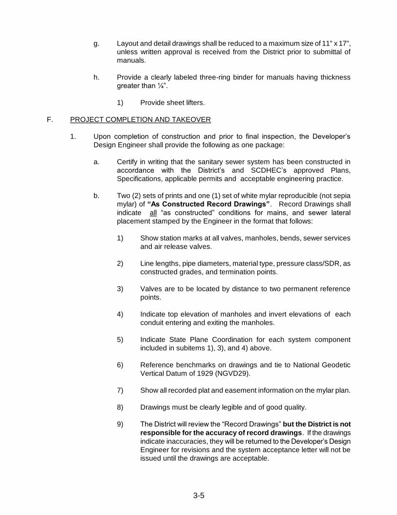
F. PROJECT COMPLETION AND TAKEOVER
1. Upon completion of construction and prior to final inspection, the Developer’s
Design Engineer shall provide the following as one package:
a. Certify in writing that the sanitary sewer system has been constructed in
accordance with the District’s and SCDHEC’s approved Plans,
Specifications, applicable permits and acceptable engineering practice.
b. Two (2) sets of prints and one (1) set of white mylar reproducible (not sepia
mylar) of “As Constructed Record Drawings”. Record Drawings shall
indicate all “as constructed” conditions for mains, and sewer lateral
placement stamped by the Engineer in the format that follows:
1) Show station marks at all valves, manholes, bends, sewer services
and air release valves.
2) Line lengths, pipe diameters, material type, pressure class/SDR, as
constructed grades, and termination points.
3) Valves are to be located by distance to two permanent reference
points.
4) Indicate top elevation of manholes and invert elevations of each
conduit entering and exiting the manholes.
5) Indicate State Plane Coordination for each system component
included in subitems 1), 3), and 4) above.
6) Reference benchmarks on drawings and tie to National Geodetic
Vertical Datum of 1929 (NGVD29).
7) Show all recorded plat and easement information on the mylar plan.
8) Drawings must be clearly legible and of good quality.
9) The District will review the “Record Drawings” but the District is not
responsible for the accuracy of record drawings. If the drawings
indicate inaccuracies, they will be returned to the Developer’s Design
Engineer for revisions and the system acceptance letter will not be
issued until the drawings are acceptable.

3-6
c. Provide two copies of CCTV video of all new gravity lines on CD. Contact
the District for current rates and availability to perform the video inspection.
d. Digital Data Submission:
1) The District has adopted geographic information systems (GIS)
technologies to store, manage, and maintain spatially-related
(geographic) data. The land development, engineering, and
surveying communities have also embraced digital technologies in
their respective professional communities. Because development
plans are now created using computer aided design and drafting
(CAD), it is the goal of The District to leverage such advanced
techniques to expedite the design and plan review processes within
the District. For such an effort to succeed, standards must be
implemented to allow CAD data to be integrated into the District GIS
while preserving the referential and positional accuracy of the original
measurements.
2) Contact the District for the latest standards for digital data
submission.
e. The Developer shall provide the District with a Bill of Sale and Affidavit of
Title, conveying the constructed system to the District’s system and shall
thereafter be owned, operated, and maintained by the District. Contact the
District for standard forms.
f. As part of the conveyance, the Developer and/or the Developer’s Design
Engineer shall furnish the District with two (2) prints and two (2) recordable
white mylars of each required easement plat.
1) Each must have original signature and seal (do not use sepia mylar
or plats larger than 22" x 34") as prepared in accordance with
requirement set by the District and the RMC Office.
2) Each easement plat shall be accompanied by a right-of-way
easement instrument of conveyance.
3) The Developer will record all easements and plats. The District will
not accept compiled maps as land surveys.
4) The width of the easements for sewer mains shall be a minimum of
twenty (20) feet.
5) All sewer mains within the easement shall be platted so as to provide
equal distance on each side of the as-construction location of the
main.
6) Plats shall not be accepted unless the five (5) requirements
stated above are met.
g. The Developer shall furnish Certified Contractor’s Affidavit and Final Waiver
of Lien.
2. Following complete submission and acceptance of the above items by the District,
an on-site final inspection shall be scheduled with the District’s Wastewater
Superintendent to ensure that all construction complies with applicable District

3-7
requirements and standards and all project related wastewater facilities and
appurtenances are operable.
3. When the above items are completed to the District’s satisfaction, the District will
issue an acceptance letter to SCDHEC with copies to all involved parties. Until such
time as this letter is provided and SCDHEC’s permit allowing the new wastewater
facilities to be placed into operation has been received, WASTEWATER
DISCHARGE INTO THE DISTRICT’S EXISTING WASTEWATER FACILITY
SHALL NOT BE PERMITTED.

3-8
G. APPLICATION FOR PERMIT TO CONSTRUCT
APPLICATION FOR PERMIT TO CONSTRUCT
WASTEWATER COLLECTION AND TRANSMISSION FACILITIES
JAMES ISLAND PUBLIC SERVICE DISTRICT
1739 SIGNAL POINT ROAD PHONE: (843) 762-5258
CHARLESTON, SC 29412 FAX: (843) 762-5252
1. Project Name:
2. Location (street address and TMS Number):
3. Parent Tract Plat/Deed Ref. (RMC Book/Page):
4. Application is hereby made, on behalf of the Developer whose name appears below, for a
Permit to Construct (describe):
5. Developer’s name, address, telephone and FAX numbers:
6. Name, address, telephone and FAX numbers of Project Engineer/Authorized Agent:
7. Total ADF Wastewater Loading generated by this Project shall not exceed:
GPD Maximum Peak Discharge Flow Rate
GPM
8. Is this part of a phased project? No Yes_______ Phase of
9. Is this project a revision to a previously permitted project? No______ Yes
Project name (if different from this project):
JIPSD Permit Number: Date:
SCDHEC Permit Number: Date:
10. Type of wastewater generated by project (Check one):
Domestic Process (Industrial)
11. A Complete Permit Application Package shall include the following items, as applicable:
A. Application Fee; Ref. current JIPSD Fee Schedule.
B. Transmittal letter detailing the submittal package.
C. Copy of SCDHEC Application for Permit to Construct.
D. Two (2) copies of the plans and Specifications signed, sealed and dated by
the Project Engineer.
E. Two (2) copies of the Project Engineering Report including hydraulic loading,
pump station design calculations, pump curves, etc. The hydraulic loading
shall be based upon SCDHEC “Guidelines for Unit Contributory Loadings to
Wastewater Treatment Facilities” latest revision.

3-9
F. One (1) original and three (3) copies of all applicable sewer/force main
easement plats and (if applicable) fee simple pump station plats plus one (1)
original developer executed deed for each.
G. One (1) copy of each permit/certification required from each agency having
Project jurisdiction.
H. One (1) original and three (3) copies of each public Roadway Encroachment
Permit Application required indicating the District as Applicant; submittals will
be processed by the District and shall include Traffic Control Plans, HDD
CheckLists, and HDD Frac-Out Plans when applicable.
I. I hereby agree to invite JIPSD to the preconstruction conference for the
project.
J. I hereby agree that the JIPSD may issue a “stop work order” on the project if
excessive complaints are received or for non-compliance of these
guidelines.
K. I hereby certify my acceptance of responsibility for the design of these
wastewater facilities.
Engineer’s Name (Printed):
Signature:
S.C. Registration No.:
L. Prior to final District approval, I shall certify construction is complete in
accordance with approved plans and specifications, to the best of my
knowledge, information and belief as based upon periodic observations and
final inspection for design compliance.
Engineer’s Name (Printed):
Signature:
S.C. Registration No.:
M. I have read this application and agree to the requirements and conditions
stated herein. I hereby agree to allow project site access to District
personnel for the purpose of periodic construction observation. I also
hereby designate the Project Engineer as my Authorized Agent in all matters
pertaining to the design and construction of the Project wastewater facilities.
I understand that before the project can be finalized and ownership
transferred to the District, a cash bond must be paid in the amount of 10% of
the cost of project. Further I acknowledge that no connection to the public
sewer shall be made until the Equivalent Residential Unit (ERU) fees have
been paid.
Owner’s Name (Printed):
Owner’s Title:
Signature: Date:

3-10
H. PROJECT REVIEW CHECKLIST
JAMES ISLAND PUBLIC SERVICE DISTRICT
PROJECT REVIEW CHECKLIST FOR NEW DEVELOPMENT
JAMES ISLAND PUBLIC SERVICE DISTRICT PROJECT NUMBER:
LOCATION: DATE:
TMS#:
Project Engineer: Developer:
Phone #: Phone #:
Fax #: Fax #:
PRELIMINARY APPROVAL (IF REQUIRED): APPROVED DATE
A. 2 sets of Plans, Specifications and
Engineering Reports
B. Transmittal Letter
C. District Permit Application
APPROVAL TO CONSTRUCT
A. Plans and Specification approved
B. DHEC and other required agency
Approvals submitted to the District
C. Construction Schedule (If required)
D. Notification of Date construction
Will commence.
Date actually started:
E. Roadway Encroachment Permits Approved
F. Wastewater Contract prepared and
Submitted for execution
G. Payment of all applicable fees;
Impact Fees $
Tap Fees $
Administrative Fees $
H. Preconstruction Conference;
Date Scheduled:
I. Identity of Resident Inspector
24/7 Phone #:
J. Identity of Job Site Superintendent
24/7 Phone #:

3-11
I. O & M ACCEPTANCE CHECKLIST
JAMES ISLAND PUBLIC SERVICE DISTRICT
O&M ACCEPTANCE CHECKLIST FOR NEW DEVELOPMENT
APPROVED DATE
A. Project Engineer’s Request for District
and DHEC for Final Inspection.
Actual date:
B. Project Engineer’s Certification of
Completion and Acceptance.
C. “As-Built” Drawings furnished and accepted.
D. Instrument(s) of Conveyance furnished
To the District
E. Pump Station Site and/or Sewer Easements
F. Maintenance Bond (%of total cost $ ___________ ___________
G. Payment of all Outstanding District Fees;
Amount $
H. Contractor’s Affidavit and Final Waiver of Liens
I. Project Completion Questionnaire
J. All Special Conditions of District
and/or S.C. DHEC satisfied
K. District Final Inspection & Approval
Date:
L. S.C. DHEC Permit to Operate Submitted;
Date:
M. S.C. DOT/TOWN/COUNTY Encroachment
Permit Conditions Satisfied; Date:
N. Date District Assumed O&M
Responsibility: ___________

3-12
J. AS-BUILT DRAWING CHECKLIST
JAMES ISLAND PUBLIC SERVICE DISTRICT
AS-BUILT DRAWING CHECK LIST
James Island Public Service District Project Number:
Checked by: Date:
APPROVED DATE
1. Lot Number(s) Ref S/D Plat
2. TMS Designations for each lot
3. Street Name(s) & R/W widths
4. Manholes Identified & Locations As-Built *
5. Line invert and Top Elevations of Manholes
6. Manhole Stations As-Built
7. Service Fittings Stations on sewer mains *
8. Depth at R/W of Service Line Fittings
9. Main Station at R/W of Service Line Fittings *
10. Service Line Distances
11. Reach Distances As-Built
12. Profile Grades As-Built
13. Contractor’s I.D., Date Project Accepted
for O&M
14. “Record Drawings” or “As-Built”
15. Project Engineer Seal & Certification
16. Equipment Operating Manuals (if applicable)
17. Pump Station Spare Parts (if applicable)
18. Force Main junction fittings, junction valves, _____________ ____________
Bend angles, Air-Release Valves, and
Discharge manholes/structures *
Note: All items above indicated with an asterick (*) shall include State Plane Coordinates.

3-13
K. JIPSD CLOSEOUT PACKAGE CHECKLIST
Project
Name:________________________________________________________________
Engineering Firm:
____________________________________________________________
Date Closeout Package Submitted:
______________________________________________
Engineer’s written certification that the sanitary sewer system has been constructed in
accordance with the District’s approved plans, specifications, applicable permits and good
engineering practice
Two (2 sets of prints and one (1 set of Mylar reproducible (not sepia Mylar of “As
Constructed Record Drawings” (As Builts) in the format specified in section 3.F.b. in the
District’s Design and Construction Standards
Two (2) copies of video of all new gravity lines on CD
One (1) AutoCAD/State Plane disk
All original closeout documents with proper signatures and notarization including:
o Affidavit of Title
o Affidavit of Property Transfer Fee (if applicable
o Bill of Sale
o Contractor Guaranty and Warranty
o Contractor’s Affidavit and Final Waiver of Lien
o Grant of Perpetual and Construction Easement
o JIPSD Project Completion Engineer Questionnaire
o Maintenance of Agreement Sewer
o Title to Real Estate (if applicable
Four (4) prints and two (2) recordable white Mylars of the easement plats in the format
specified in section 3.F.f. in the District’s Design and Construction Standards
The Developer pays the District the cash bond in the amount of 10% of the Design
Engineer’s certified final construction cost of the wastewater facilities to be deeded to the
District
Completed and signed JIPSD Project Completion Engineer Questionnaire

4.
EASEMENTS

4-1
SECTION 4
EASEMENTS
1. Easements shall be conveyed to the District in a standard acceptable form.
2. The Developer will record all easements.
3. All sanitary sewer facilities shall be installed outside of pavement, curbing, and sidewalks unless approved otherwise by the District.
4. The width of the easements for sewer mains, and force mains shall be a
minimum of twenty (20) feet.
5. Widths of easements for gravity sewers greater than eight (8) feet in depth shall be a minimum of thirty (30) feet.
6. Widths of easements for facility access roads shall be a minimum of twenty-
five (25) feet.
7. All gravity sewers and force mains within easements shall be platted to provide equal distance on each side of the as-constructed utility.
8. Development related structures are not permitted within the easement.
9. Water and gravity sewers or force mains shall not be allowed in the same
easement unless approved in advance by the Wastewater Superintendent. When approved increase the width of the easement to comply with the “Recommended Standards for Water and Sewer Works” (“Ten States Standard”) with a distance from the edge of the easement to the sewer main not less than ten (10) feet.
10. Clear all easements of undergrowth and debris. The easement is to be
grassed unless other landscape and/or hardscape placement is specifically approved by the District. Adhere to all applicable County and Municipal tree ordinances.
11. AWCS pumps and small diameter force mains on private property shall
require applicable easements allowing the District to maintain the pump and force main.

5.
GRAVITY SANITARY SEWER
SYSTEM DESIGN STANDARDS

5-1
SECTION 5
GRAVITY SANITARY SEWER SYSTEM
DESIGN STANDARDS A. GENERAL
1. The following sanitary sewer system design guidelines are based on Federal, State and local health requirements and the District engineering design criteria.
2. These design guidelines are applicable to all developments including but not
limited to residential, commercial and industrial developments, subdivisions and/or parks requiring sanitary sewer service from the District.
B. GRAVITY SEWER SYSTEM DESIGN CRITERIA
1. Minimum main line size: 8".
2. Service lines:
a. Minimum size: 6".
b. 6" service line may be provided, for no more than two residential units and only upon specific approval from the District.
3. Absolute Minimum pipe slope:
a. Main lines:
1) 8-inch: 0.34% 2) 10-inch: 0.26% 3) 12-inch: 0.20% 4) 15-inch: 0.15% 5) 18-inch: 0.12% 6) 21-inch: 0.10% 7) 24-inch: 0.10%
b. Service lines:
1) 4-inch: 1.00% 2) 6-inch: 0.5%

5-2
c. Sewers and Service lines found o be installed at less than the absolute minimum slopes indicated above shall not be accepted by the District and shall be reconstructed to provide the required minimum slopes indicated on approved Drawings prior to consideration for acceptance.
C. CAPACITY DESIGN
1. Comply with the unit contributory loading criteria, Appendix A of the South Carolina District of Health and Environmental Control Standards for Wastewater Facility Construction: R.61-67.
D. INFILTRATION
1. Maximum infiltration: 200 gallons per inch of pipe diameter per mile per day. E. GRAVITY SEWER
1. Straight alignment, mandatory between manholes and/or cleanouts.
2. Depth adequate to receive wastewater from the lowest service and prevent freezing.
3. Slopes greater than 20%.
a. Anchor using approved concrete thrust blocking.
4. Where a smaller sewers discharge into manholes having larger
downstream sewers, match crown elevations of each.
5. Service laterals and clean-outs/Elder valves: Locate one (1) foot off-set from sideline property corner on the opposite corner from the water service meter and service line when feasible.
6. Locate sewer mains and manholes outside of paved roadway when feasible.
F. SEPARATION OF WATER MAINS AND SEWERS
1. Where possible, locate sewer pipe at least ten (10) feet away, horizontally, from water lines.
2. Should ten (10) feet separation not be practical, then when approved by the
Wastewater Superintendent, the sewer pipe may be located closer provided:
a. It is laid in a separate trench.

5-3
b. It is laid in the same trench with the water main located at one side on a bench of undisturbed earth.
c. In either of the above cases, crown elevation of the sewer pipe shall
be at least 18" below invert elevation of water line.
3. Where sewer pipes cross over or under water lines, maintain 18" minimum vertical clearance between outside edges of the two pipes and iron pipe may be required.
G. COVER
1. Provide suitable cover on all lines. Minimal cover depth as follows:
a. Less than 8" diameter: 36” unless DIP.
b. 8" and above: 36" unless DIP.
c. All piping located within the right-of-way of the South Carolina Department of Transportation shall have a cover of 48" below the crown of the road when installed within the limits of the paved roadway, 36" cover when installed in the shoulder of right-of-way and a minimum of 18" separation under the design invert of drainage structures. The greater dimension of the above shall dictate minimum depth where applicable.
d. Special conditions other than those listed above may be approved if
requested in writing from the District.
H. DUCTILE IRON PIPE LOCATIONS
1. Use ductile iron pipe as follows:
a. Where sewer lines cross over water mains, the sewer main shall transition to ductile iron pipe. A full length of ductile iron pipe shall be installed in the sewer main centered so that each joint is equidistant from the water main. Joint of ductile iron pipe water main shall also be installed so that each joint is equidistant from the ductile iron pipe section of the sewer main.
b. Crosses beneath storm drainage pipe with less than three (3) feet of
clearance.
c. Crosses above a storm drainage or other pipe with less than 18" of clearance.
d. Cover is less than the minimum 36” as in Part G above.

5-4
e. The District reserves the right to require ductile iron pipe in specific locations.
f. All ductile iron sewers and fittings shall be poly-wrapped and lined as
specified elsewhere.
I. MANHOLES
1. Maximum manhole spacing: 400 feet maximum.
2. Minimal angle between sewer mains intersecting at manhole: 90°.
3. All manhole Top Elevations (TE) shall be higher than or equal to the fifty (50) year flood elevation designated for their applicable location, unless watertight/flood-proof ring and cover castings are provided.
4. Use outside drop manholes where the difference in incoming and outgoing
pipe elevation is two (2) feet or greater. 5. Manhole materials and installations shall be in accordance with applicable
District Standard Detail Drawings. 6. Steps shall not be allowed in manholes.

6.
GRAVITY SANITARY SEWER
MATERIALS FOR CONSTRUCTION

6-1
SECTION 6
GRAVITY SANITARY SEWER
MATERIALS FOR CONSTRUCTION A. GENERAL
1. Unless otherwise noted or approved by the District all materials shall be manufactured in the United States.
B. PIPE AND FITTINGS
1. Pipe Size and Type Selections:
a. On depths of 1 feet to 3 feet, use DIP.
b. On depths of 3 feet to 12 feet, use PVC SDR-26 unless DR18 C900/C905 is required by the District.
c. On depths of 12 feet to 16 feet, use DR11 PVC C900/C905, or DIP. d. On depths greater than 16 feet, use DR9 PVC C900/C905, or DIP as
specified below.
2. Ductile-iron pipe and fittings (DIP):
a. Ductile Iron Pipe shall be manufactured in accordance with ASTM A-377, L.R. and shall be Pressure Class 350 (4” – 12”) or Pressure Class 250 (14” – 20”) pursuant to ANSI A21.50 with a standard outside coating of coal tar or asphalt base material and inside lining as defined below. Ductile Iron Pipe shall have restrained mechanical joints or flanged joints as required. Pipe joints including gaskets shall meet the requirement of ANSI A21.11 (AWWA C111).
b. Use wall thickness in accordance with Section 7 for depth and bedding
conditions.
c. Use fittings with pressure rating of 150 psi: ANSI/AWWA C110/A21.10 or C153/A21.53.88.b.
d. All bolts, tee-bolt and fasteners shall be 316 SS; all nuts shall be 304
SS to prevent galling.
e. Lining and Coatings:

6-2
1) Amine cured ceramic filled, Novalac Epoxy lining, 40 mils nominal thickness.
2) Acceptable products: a) Protecto 401 Ceramic Epoxy Vulcan Painters,
Birmingham, Alabama, Permite Permox 9430 Type II, PERMOX-CTF or District approved polyethylene lining having a minimum 40 mils nominal dry thickness.
3) Provide polyethylene encasement of all Ductile Iron pipe and
fittings. Minimum nominal thicknesses of 8 mils conform to AWWA C105.
f. When transition is required from PVC sewer main to ductile iron pipe
sewer main, restrained mechanical joint DI fittings shall be used. No Fernco couplings will be allowed.
g. All DIP gravity sewer installations shall also include the installation of
an electronically or magnetically detectable safety tape buried directly over the pipe 12" below the ground surface continuously.
1) The tape shall be at least 2" wide, be green on top, and be
boldly labeled every 18" to 32" as follows "CAUTION SEWER LINE BURIED BELOW".
2) The tape shall have a tensile strength of not less than 4000 psi,
a dart impact strength of not less than 120 grams per 1.5 mils, be not less than 0.0055" thick, and include sufficient metal to allow easy detection at the above stated depths.
3) The tape shall be designed to last as long as the pipe it is
installed over, even in adverse soils.
3. Polyvinyl chloride pipe and fittings (PVC):
a. PVC gravity sewer pipe and fittings shall have a maximum SDR of twenty-six (26) and a maximum allowable deflection of five (5) percent. PVC gravity sewer pipe shall be furnished and installed in standard lengths of twelve (12) feet, six (6) inches. All pipe, fittings and accessories shall be of the same manufacturer and have identical bell and spigot configuration as the pipe utilized, except that all fittings shall be monolithically manufactured.
1) Pipe and fittings shall exhibit homogeneous physical properties
throughout and free from cracks, holes, inclusions or other defects.

6-3
2) Pipe shall not exhibit evidence of splitting, cracking or breaking when flattened by sixty (60) percent of its exterior diameter between parallel plates and shall not flake or disintegrate when tested in accordance with ASTM Standard Specifications D-2444, latest revision.
3) Pipe identification and marking shall include size, manufacturer, use identification and other applicable requirements of ASTM Standard Specifications F-794, latest revision.
b. Where specifically required by the District, PVC gravity sewer
pipe/service lines and fittings shall conform to the requirements of ANSI/AWWA C900 Table 2, Pressure Class 150 and C905 Table 2, Pressure Class 165.
c. All PVC gravity sewer installations shall also include the installation of
an electronically or magnetically detectable safety tape buried directly over the pipe 12" below the ground surface continuously.
1) The tape shall be at least 2" wide, be green on top, and be
boldly labeled every 18" to 32" as follows "CAUTION SEWER LINE BURIED BELOW".
2) The tape shall have a tensile strength of not less than 4000 psi,
a dart impact strength of not less than 120 grams per 1.5 mils, be not less than 0.0055" thick, and include sufficient metal to allow easy detection at the above stated depths.
3) The tape shall be designed to last as long as the pipe it is
installed over, even in adverse soils. d. Provide polyethylene encasement of all Ductile Iron pipe and fittings.
Minimum nominal thicknesses of 8 mils conform to AWWA C105. 4. General Information
a. All materials used in the construction of sewers shall be new and
unused when delivered on-site and shall be suitable for installation and operation under the conditions for which they are to be used.
b. Casing pipes shall be installed at:
1) highway crossings, as directed by SCDOT, or; 2) as designated by the District.
c. No sewer line of any type shall be allowed to pass through any storm
drainage structure unless approved by the District.

6-4
C. MANHOLES
1. Use precast manholes: a. Comply with ASTM C478.
b. Portland cement: ASTM C150, Type II, 4,000 psi and absorption shall
not exceed 6%.
c. The minimum wall thickness of the manhole riser sections shall be:
4' Diameter 5" 5' Diameter 5" 6' Diameter 6"
Cone sections shall have a minimum wall thickness of 8" at their top.
d. Monolithic base slab with walls. Bottoms cast with invert and bench
are acceptable. Minimum thickness of bottom: 4' diameter 6" 5' and 6' diameter 8"
e. Flat slab top sections: HS-20 traffic loadings.
f. Suitable openings for inlet and outlet sewer pipe shall be cast into the
base sections and into riser sections for drop connections. These openings shall be circular, accurately made, and located as required for each manhole. Base riser sections shall be set on compacted #57 stone, 12” minimum thickness.
g. Provide flexible pipe boots conforming to ASTM C923m. Attach boot
to piping with dual stainless steel straps.
h. The manhole sections may be jointed with either O-ring seals or butyl rubber type sealer.
1) If O-rings are used, they shall conform to ASTM C443 and shall
be set in a rectangular groove cast into the tongue section of each manhole. O-rings shall be installed as recommended by the manhole manufacturer.
2) If butyl rubber sealer is used it shall be "Ram-Nek" joint sealer or equal. "Ram-Nek" shall be set on only clean and dry surfaces and placed as recommended by the manufacturer.
6-5
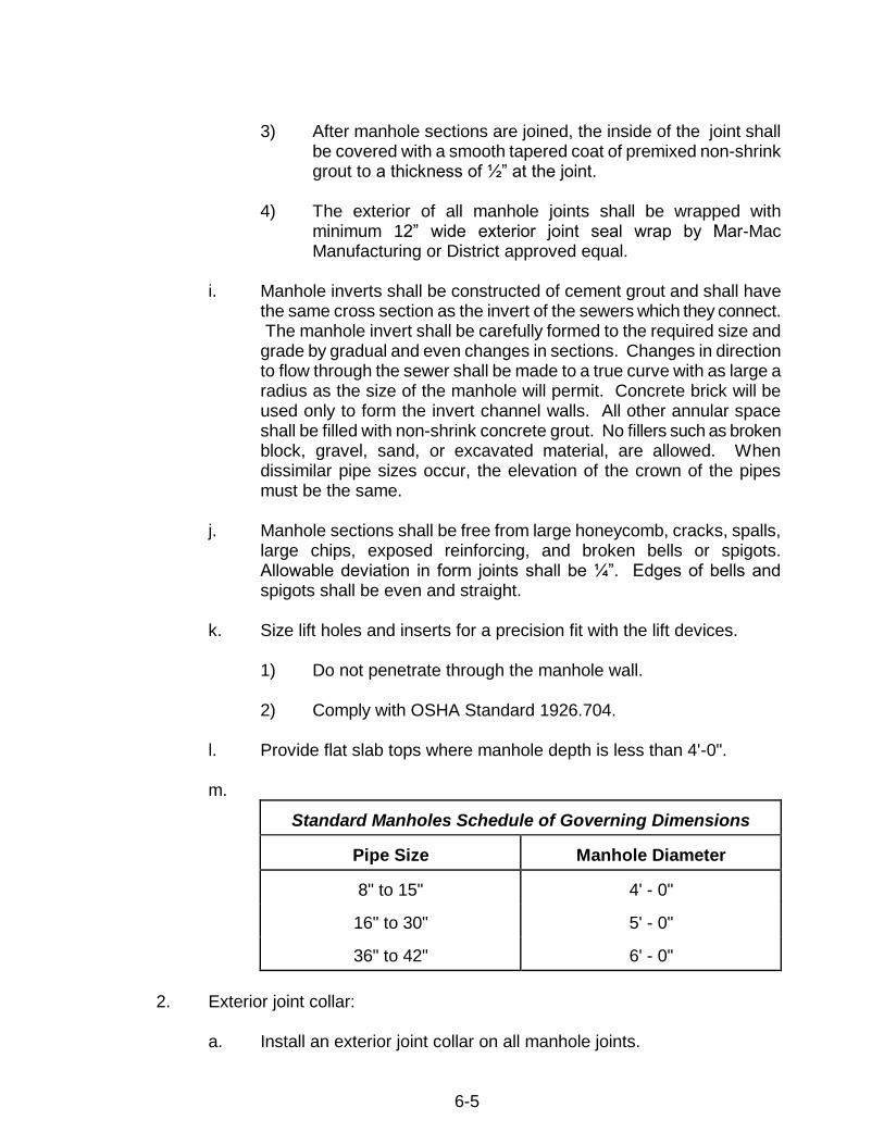
3) After manhole sections are joined, the inside of the joint shall be covered with a smooth tapered coat of premixed non-shrink grout to a thickness of ½” at the joint.
4) The exterior of all manhole joints shall be wrapped with
minimum 12” wide exterior joint seal wrap by Mar-Mac Manufacturing or District approved equal.
i. Manhole inverts shall be constructed of cement grout and shall have
the same cross section as the invert of the sewers which they connect. The manhole invert shall be carefully formed to the required size and grade by gradual and even changes in sections. Changes in direction to flow through the sewer shall be made to a true curve with as large a radius as the size of the manhole will permit. Concrete brick will be used only to form the invert channel walls. All other annular space shall be filled with non-shrink concrete grout. No fillers such as broken block, gravel, sand, or excavated material, are allowed. When dissimilar pipe sizes occur, the elevation of the crown of the pipes must be the same.
j. Manhole sections shall be free from large honeycomb, cracks, spalls,
large chips, exposed reinforcing, and broken bells or spigots. Allowable deviation in form joints shall be ¼”. Edges of bells and spigots shall be even and straight.
k. Size lift holes and inserts for a precision fit with the lift devices.
1) Do not penetrate through the manhole wall. 2) Comply with OSHA Standard 1926.704.
l. Provide flat slab tops where manhole depth is less than 4'-0". m.
Standard Manholes Schedule of Governing Dimensions
Pipe Size
Manhole Diameter
8" to 15"
4' - 0"
16" to 30"
5' - 0"
36" to 42"
6' - 0"
2. Exterior joint collar:
a. Install an exterior joint collar on all manhole joints.

6-6
b. Provide a 12" wide band.
c. Acceptable product: Seal Wrap Exterior Joint Sealer by Mar-Mac Manufacturing Company.
3. Frames and covers:
a. Manhole frames and covers shall be Class 400 ductile iron conforming to ASTMA 536-80 and also meet ASSHTO-H20 loading requirements.
1) The frame shall have a clear opening of 24” and shall be 4” high. Cover shall sit on a polyethylene gasket and lock automatically.
2) All castings shall be made accurately to the required
dimensions and pattern. The castings shall be sound, smooth, clean and free from blisters and other defects.
3) Castings which have been plugged or otherwise repaired shall
be unacceptable for use.
4) The contact surface between the cover and supporting ring shall be machined to make contact on the complete perimeter.
5) Watertight/flood-proof castings shall be required as specified in
subsection 5.I.3.
b. Frames and covers located within paved surfaces shall be heavy duty Ductile Iron Model USF 480 ring and RA-SSG cover as manufactured by US Foundry and Manufacturing or approved equal Manufacturers.
1) For manholes located within unpaved areas, frames, and
covers shall be Pamrex Model 621131 as manufactured by Certainteed, or approved equal.
2) Cast into the cover shall be the words "JIPSD SANITARY SEWER". Letters shall be 3" high.
c. Leveling and final grading of manhole frames and covers shall be
accomplished by using a maximum of two (2) 4" concrete grade rings or one (1) 6" grade ring.
1) Use cement brick for adjustments less than 4". The total
number of grade rings shall not exceed 8" in thickness.

6-7
2) Grade rings and cement brick shall be laid in a full bed of non-shrink grout and covered after laying with a smooth coating of non-shrink grout or hydraulic cement a minimum of ½” thick.
d. After the manhole has been set in its final position, the cast iron frame
for the cover shall be carefully set at the required finished grade and properly bonded to the masonry with non-shrinking cement grout or hydraulic cement.
1) Where manholes are constructed in paved areas, sidewalks,
etc., the top surface of the frame and cover shall be set at a profile slope to conform to the exact slope crown and grade of the existing or new pavement as applicable.
e. Provide circular cover with two (2) pulls for removing manhole cover,
spaced at 180 degrees and weighing not less than 120 pounds.
5. General
a. All manholes over 12' deep shall be reviewed during design with the District.
b. Where the difference in the invert elevation between an intersecting
sewer and a manhole is 2' or more, a drop manhole shall be constructed similar to the standard District manhole except that a drop connection of pipe and fittings of the proper size and material shall be constructed outside the manhole.
c. Where the work requires special tidal creek, river or other
extraordinary conditions, or where alternate types of construction that are not covered by these specifications, the materials and construction methods shall be submitted for approval to the District.
D. PIPE AND MANHOLE FOUNDATION AND BACKFILL MATERIALS
1. Pipe Bedding Materials
a. Compacted crushed stone complying with SCDOT Aggregate No. 57.
2. Backfill Materials
a. Reuse of existing excavated materials will be allowed provided the materials are compactable, dried or dampened to their optimum moisture content, are free from roots, large clods of clay, and are granular and non-cohesive in nature.
6-8
b. Select fill shall be non-cohesive USCS GW, GP, SW, or SP free from debris, roots, wood, scrap material and other vegetal matter with a maximum of 10% passing a wash #200 sieve when tested in accordance with ASTM D1140 and a maximum Liquid Limit of 10%.
3. Manhole Bedding Materials
a. Shall be crushed stone as noted in Section D.1.a.
E. ENCASED UTILITIES UNDER ROADWAY CROSSINGS
1. General
a. Provide Jack and Bore with casing for pipes larger than 2".
b. Casing pipe to be a minimum of 2" larger in diameter than the bell of
the carrier pipe based on the following:
1) Casing pipe to be a minimum of 2" larger than the largest outside diameter of the carrier pipe (joints and couplings) for carrier pipe less than 6" in diameter. When the diameter of the carrier pipe is 6" or larger, the diameter of the casing pipe shall be a minimum of 4" larger than the largest outside diameter of the carrier pipe (joints and couplings).
2) The end of casing pipe to extend a minimum of five (5) feet
from the edge of pavement/back of curb. Unless otherwise approved by the SCDOT permit.
3) The top of the casing pipe shall be a minimum of four (4) feet
below the crown of the finished asphalt roadway.
4) The top of the casing pipe shall be a minimum of two (2) feet below the design invert of roadside drainage ditches and pipes.
2. Casing pipe for dry bores
a. Steel complying with ASTM A139 for Grade B with minimum yield
strength of 35,000 psi.
b. Provide ends suitable for field welding.

6-9
b. Minimum wall thickness as follows:
Diameter of Casing
(Inches)
Minimum Wall Thickness
(Inches)
6 thru 14 1/4
16 and 18 5/16
20 and 22 3/8
24 and 26 7/16
28 thru 32 ½
34 thru 42 9/16
44 thru 48 5/8
50 thru 54 3/4
3. Pipeline casing spacers:
a. Provide pipeline casing spacers for piping installed in casing.
b. Provide a minimum of one spacer per ten linear feet of pipe for ductile
iron pipe and a minimum of one spacer per six linear feet for PVC pipe.
c. Provide spacer with shell of 14 gauge Type 316 stainless steel.
d. Provide shell liner of .090" thick PVC, 85-90 durometer.
e. Provide 5/16" stainless steel connecting bolts and lock nuts, minimum
three (3) per flange.
f. Runners from 2" wide ultra high molecular weight polymer with a high resistance to abrasion and a coefficient of friction of 0.11-0.13 in accordance with ASTM D-1894.
g. Support runners on 14 gauge reinforced Type 316 stainless steel
risers welded to shell.
h. All metal surfaces to be fully passivated.
i. The diameter as measured over the runners shall exceed the pipeline bell or coupling outside diameter.
j. Acceptable product: Cascade Manufacturing, Spider Manufacturing,
Inc. or approved equal. 4. End seals:
a. Provide 1/8" thick rubber end seal to seal each end of the casing.
b. Secure to casing and carrier pipe with T-304 stainless steel bands.

6-10
c. Acceptable manufacturers: Cascade Manufacturing, Pipeline Seal and Insulator, Inc. or approved equal.

7.
GRAVITY SANITARY SEWER
SYSTEM CONSTRUCTION
PROCEDURES

7-1
SECTION 7
GRAVITY SANITARY SEWER SYSTEM
CONSTRUCTION PROCEDURES
This section covers construction procedures normally required for work. It does not
cover any special construction procedures that may be encountered for abnormal
conditions. Special construction procedures are to be presented to the District by
the Developer’s Design Engineer. A. HANDLING OF MATERIALS
1. Storage and handling shall be in accordance with manufacturer’s recommendation.
2. Storage of PVC pipe:
a. Store in unit packages as received from manufacturer until just prior to
use.
b. Stack units to prevent deformation to pipe barrel and bells.
c. Protect from direct sunlight by covering with opaque material.
3. Avoid severe impact blows, gouging or cutting by metal surfaces or rocks.
4. Handle pipe so as to ensure delivery to the trench in sound, undamaged condition.
a. Carry pipe into position - do not drag.
b. Use pinch bars or tongs for aligning or turning the pipe only on the
bare end of the pipe.
c. Use care not to injure pipe linings.
5. Thoroughly clean interior of pipe and accessories before lowering pipe into trench. Keep clean during layout operations by plugging or other approved method.
6. Before installation, inspect each piece of pipe and each fitting for defects:
a. Replace material found to be defective before or after laying with
sound material meeting the specified requirements.

7-2
b. Inspect the lining date for all DIP lined with P-401 and reject all pipe and fittings with dates beyond the published 2- year lining “shelf or use-by” date.
7. Rubber gaskets: Store in a cool dark place until just prior to time of
installation. B. PIPE CUTTING
1. Cut pipe neatly and without damage to the pipe. Bevel pipe to ensure final homing of pipe without damage to gasket.
2. Unless otherwise recommended by the pipe manufacturer, cut pipe with
mechanical cutter only.
a. Use wheel cutters when practical.
b. Cut plastic pipe square and remove all burrs. C. LOCATING
1. Sewer lines in relation to water lines must conform to “Ten States Standards”.
2. Locate sewer pipe at least ten (10) feet away, horizontally, from water lines.
3. Should ten (10) foot separation not be practical, if approved by the Wastewater Superintendent, then the sewer pipe may be located closer provided:
a. It is laid in a separate trench.
b. It is laid in the same trench with the water main located at one side on
a bench of undisturbed earth.
c. In either of the above cases, crown elevation of the sewer shall be at least 18" below invert elevation of water line.
4. Where water lines cross over, maintain 18" minimum clearance between
crown of sewer and invert of water lines.
5. Where sewer lines cross over water mains, the sewer main shall transition to ductile iron pipe. A full length of ductile iron pipe shall be installed in the sewer main centered so that each joint is equidistant from the water main. Joint of ductile iron pipe water main shall also be installed so that each joint is equidistant from the ductile iron pipe section of the sewer main.

7-3
6. When it is impossible to obtain proper horizontal and vertical separation as stipulated above, the sewer shall be designed and constructed equal to water pressure pipe, and shall be pressure tested to assure water tightness prior to backfilling.
7. Water Supply Interconnections
There shall be no physical connections between a public or private potable water supply system and a sewer, or appurtenances thereto which would permit the passage of any sewage or polluted water into the potable supply. No water pipe shall pass through or come in contact with any part of a sewer manhole.
8. Relation to Water Works Structures
While no general statement can be made to cover all conditions, it is generally recognized that sewers shall meet the requirements of the appropriate reviewing agency with respect to minimum distances from public water supply wells or other water supply sources and structures.
D. INSTALLATION
1. Trench, backfill and compact for the work of this Section in strict accordance with pertinent provisions of these specifications, and the following requirement:
a. Gravity sewer trench widths, depths and bedding methods.
1) Install all sewers of the materials specified complying with
tables for depths of cut and class of bedding included hereinafter.
b. Ductile-iron pipe:
1) Ductile iron pipe shall only be installed where required as
specifically specified elsewhere herein or where directed by the District. Otherwise, AWWA C900/C905 PVC pipe shall be the default material required.
2) DIP shall also be installed pursuant to Section 10.C where applicable conditions exist.

7-4
c. Polyvinyl chloride pipe ASTM 3034 SDR-26 and ASTM (C900/C905):
MAXIMUM DEPTHS IN FEET
PIPE
SIZE
MAX.
TRENCH
WIDTH
Bedding Class B
TYPE 2*
ONLY
4" 8" 10" 12" 15" 18" 21"
2'0" 2'2" 2'4" 2'6" 2'10" 3'2"
3'6"
15 15 15 15 15 15
15
* Class B Bedding (Type 2) shall extend to the top of
the pipe.
d. Bedding and tamping:
1) Class B (Type 1) Bedding:
a) Shape bottom of trench to a level 2" below bottom of
pipe; bring bed to proper level by spreading and thoroughly tamping fine granulated moist earth and sand to conform accurately to one-fourth circumference of pipe barrel; provide suitable material if not available from trench excavation; lay pipe, backfill and hand tamp in thin layers to height three-fourths of pipe diameter, using material same as bedding material; complete trench backfill as specified in the guidelines.
b) In lieu of Class B (Type I) bedding for Ductile Iron Pipe,
Class B (Type 2) bedding may be used.
2) Class B (Type 2) Bedding:
a) Undercut 4" below pipe barrel, full width of trench; bring to grade with compacted crushed stone complying with SCDOT Aggregate No. 57. For all pipe, place granite aggregate (SCDOT No. 57) in 6” layers to the top of pipe, compacting by slicing with shovel.
b) Trench backfill complying with paragraph L under
Section 7.
c) Bedding shall be pursuant to the District’s standard Trench Section Drawing unless directed otherwise.

7-5
2. Pipe laying:
a. General:
1) Protect pipe during handling against shocks and free fall. Remove extraneous material from the pipe interior.
2) Adequate dewatering/well point system equipment shall be
provided to ensure a stable trench subgrade prior to placement of bedding aggregate.
3) Gravity sewer pipe installation must comply with ANSI/ASTM
D2321 as the minimum acceptable standard as well as any additional requirements as stated herein.
4) Before sewer pipe is placed in position in the trench the bottom
and sides to the trench shall be carefully prepared as per manufacturer’s specifications. Each pipe shall be accurately placed to the exact line and grade called for on the plans. Laser equipment shall be used in setting pipe in lieu of the batter board method.
5) Pipe shall be laid in a full bed of crushed stone (SCDOT
Aggregate No. 57). Pipe laying shall proceed upgrade, starting at the lower end of the grade and with the bells upgrade. Pipe shall be straight when placed in the trench. Trench bottoms found to be at incorrect grade after pipe laying operations have begun shall be corrected and brought to exact line and grade. Fill required shall be crushed stone.
6) After each line of pipe has been laid, it shall be carefully
inspected and all earth, trash, rags, and other foreign matter removed from the interior.
7) Each joint shall be laid so that it will form a close concentric
joint with adjoining pipe and so as to avoid sudden offsets.
8) All jointing of pipe and fittings shall be in accordance with the pipe manufacturer’s recommendations.
9) Any leaks or defects discovered at any time after completion of
the work shall be repaired immediately. All pipe in place shall be carefully protected from damage until the backfilling operations have been completed.

7-6
10) Water shall not be allowed to run through the pipe or stand in the trench.
b. Polyvinyl Chloride Pipe:
1) Use proper bedding as specified above.
2) Comply with ASTM D2321, except as otherwise specified
herein or indicated on standard District Detail Drawings.
c. Ductile-Iron Pipe:
1) Use proper bedding as specified above. 2) Comply with ANSI/AWWA C600, except as otherwise specified
herein. 3) Provide polyethylene encasement of all DI Pipe and DI fittings.
Minimum nominal thickness of 8 mils conform to AWWA C105. E. MANHOLES
1. Set bases level so that walls will be plumb.
2. Clean and inspect tongue and groove joints for damage.
3. Apply joint sealer, or ring gasket to wall section(s), set firmly in place to assure watertight joints.
4. Connect pipe boot to piping with dual stainless steel straps.
5. Grout lift holes from the outside using non-shrink grout.
6. Install exterior joint collar.
a. Follow manufacturer’s recommendations.
b. Clean the surface.
c. Remove the protective paper and place the band around the manhole,
mastic side to the manhole and spanning the joint. d. Interior manhole steps shall not be approved for use by the District.
For barrel sections having steps, remove same and fill all holes with approved non-shrink grout.

7-7
7. Form the invert channels directly in the concrete of the manhole base, with mortar and brick. Smooth the floor of the manhole outside the channels, and slope toward the channels at not less than 1" per foot or more than 2" per foot.
a. Shape the invert channels to be smooth and semi-circular, conforming
to the inside of the adjacent sewer section. Inverts shall be to crown of pipe.
b. Make changes in direction of flow with a smooth curve of as large a
radius as the size of the manhole will permit.
c. Make changes in size and grade of channels smoothly and evenly.
d. Slope invert uniformly from invert of inlet to invert of outlet.
8. Match manhole top to grade utilizing concrete grade rings or cement brick as specified, maximum height 8".
F. MANHOLE LININGS
1. Manholes shall be lined (new or existing) where directed by the District and, at a minimum, within all force main junction manholes and in the next three (3) manholes downstream.
2. The District reserves the right to require coatings in additional down stream
manholes and all manholes five (5) feet inside diameter and larger. a. Acceptable product for lining:
1) Coatings meeting ASTM Standards, F-2551-9, C307, C508, as
approved by the District. 2) Raven405, Strong-Seal HP 100% Calcium Aluminate or other
District approved lining.
b. Surface preparation:
1) Follow all manufactures’ recommendations for surface preparation for new or existing manholes.
G. CONNECTIONS TO EXISTING SYSTEM
1. Connections to existing manholes shall be made in the presence of the District. The Contractor shall notify the District 48 hours before starting a connection. All new holes in existing manholes shall be core drilled.
7-8
2. Construct new manhole over existing gravity main cutting upper half of existing pipe after base of manhole is completed so as not to obstruct flow of the existing pipe.
3. At existing manhole tie-ins, temporarily block and/or divert sewage flows,
provide by-pass pumping and perform other miscellaneous work.
a) Use high-early strength cement for mortar, forming proper channels with minimum interruption to service of the existing sewer.
H. SERVICE LATERALS
1. Service laterals shall be installed where required to provide a connection from the sanitary sewer to all lots.
2. Service laterals shall be six (6) inch diameter DIP or PVC, except as noted in
Item 3 below, and conform to the requirements of these guidelines. A service wye shall be installed at the end of each service lateral and plugged in a manner to allow for air testing. The depth of a service shall be a minimum of 36" below finished grade, and a maximum of 60".
3. All individual sewer services shall have 4” diameter Elder Valves and
approved PVC reducers installed during construction. The shut-off valve access pipe for the Elder Valve shall be cut off to match finished grade and capped as indicated on the District’s Standard service Connection detail
4. All services shall be supplied with a concrete collar.
5. Service laterals shall be connected at manholes whenever possible and
installed so the crown of the sewer exiting the manhole and the service lateral are the same elevation (match crowns) unless approved otherwise by the District.
6. Connect to street sewers using wye branches and ells.
7. Do not stack service lines vertically over the sewer main.
8. Comply with details in the Details Section.
9. Locate service lateral within one (1) foot off-set from property corner on
opposite corner of water service meter unless approved otherwise by the District.
10. Minimum cover required by SCDOT and the District of service lateral is 36".
SCDOT and the District may require concrete encasement under drainage ditch on an individual review.
7-9
I. INSPECTIONS AND TESTING
1. General:
a. The District will require that all sanitary sewer systems pass the following test prior to acceptance: (District shall be notified 48 hours before inspections).
2. Air Testing:
The Contractor shall conduct low pressure air tests on all completed sections of gravity sewer in accordance with ASTM F-1417.L.R., for all PVC pipe. The air test results will be used to evaluate construction methods on the sewer line sections.
The Contractor shall furnish an air compressor which will provide at least 300 cubic feet of air per minute at 100 psi, air hose, connection and other equipment necessary to conduct the air tests. Plugs in sewers 18" in size and larger shall be connected by cable for thrust reaction. The following provisions will be adhered to when conducting low pressure air tests:
3. Equipment
a. Plug Design
Either mechanical or pneumatic plugs may be used. All plugs shall be designed to resist internal testing pressures without the aid of external bracing or blocking. However, the Contractor should internally restrain or externally brace the plugs to the manhole wall as an added safety precaution throughout the test.
b. Singular Control
To facilitate test verification by the inspecting Engineer, all air used shall pass through a single, above ground control panel.
c. Equipment Controls
The above ground air control equipment shall include a shut-off valve, pressure regulating valve, input pressure gauge, and a continuous monitoring pressure gauge having a pressure range from 0 to at least 10 psi. The continuous monitoring gauge shall be no less than 4" in diameter with minimum divisions of 0.10 psi and an accuracy of ±0.04 psi.

7-10
d. Separate Hoses
Two separate hoses shall be used to: (1) connect the control panel to the sealed line for introducing low pressure air, and (2) a separate hose connection for constant monitoring of air pressure build-up in the line. This requirement greatly diminishes any chance for over-pressurizing the line.
e. Pneumatic Plugs
If pneumatic plugs are utilized, a separate hose shall also be required to inflate the pneumatic plugs from the above ground control panel.
4. Line Preparation
a. Laterals, Stubs, and Fittings
During sewer construction all service laterals, stubs, and fittings into the sewer test section shall be properly capped or plugged so as not to allow for air loss that could cause an erroneous air test result. It may be necessary and is always advisable to restrain gasketed caps, plugs, or short pipe lengths with bracing stakes, clamps and tie-rods, or wire harnesses over the pipe bells.
5. Test Procedure
a. Plug Installation and Testing
After a manhole to manhole reach of pipe has been backfilled to final grade, prepared for testing, and the specified waiting period has elapsed, the plugs shall be placed in the line at each manhole and secured.
It is advisable to seal test all plugs before use. Seal testing may be accomplished by laying one length of pipe on the ground and sealing it at both ends with the plugs to be checked. The sealed pipe should be pressurized to 9 psig. The plugs should hold against this pressure without bracing and without any movement of the plugs out of the pipe. No persons shall be allowed in the alignment of the pipe during plug testing.
It is advisable to plug the upstream end of the line first to prevent any upstream water from collecting in the test line. This is particularly important in high groundwater situations.

7-11
When plugs are being placed, the pipe adjacent to the manhole shall be visually inspected to detect any evidence of shear in the pipe due to differential settlement between the pipe and the manhole. A probable point of leakage is at the junction of the manhole and the pipe, and this fault may be covered by the pipe plug, and thus not revealed by the air test.
b. Line Pressurization
Low pressure air shall be slowly introduced into the sealed line until the internal air pressure reaches 4.0 psig greater than the average back pressure of any groundwater above the pipe, but not greater than 9.0 psig. Immediately before testing, if groundwater is present, the groundwater elevation must be determined by appropriate means.
c. Pressure Stabilization
After a constant pressure of 4.0 psig (greater than the average groundwater back pressures), is reached, the air supply shall be throttled to maintain that internal pressure for at least 2 minutes. This time permits the temperature of the entering air to equalize with the temperature of the pipe walls.
d. Timing Pressure Loss
When temperatures have been equalized and the pressure stabilized at 4.0 psig (greater than the average groundwater back pressure), the air hose from the control panel to the air supply shall be shut off or disconnected. The continuous monitoring pressure gauge shall then be observed while the pressure is decreased to no less than 3.5 psig (greater than the average back pressure of any groundwater over the pipe). At a reading of 3.5 psig, or any convenient observed pressure reading between 3.5 psig and 4.0 psig (greater than the average groundwater back pressure), timing shall commence with a stop watch or other timing device that is at least 99.8% accurate. A predetermined required time for a specified pressure drop shall be used to determine the lines acceptability. Traditionally, a pressure drop of 1.0 psig has been specified. However, other pressure drop values may be specified, provided that the required holding times are adjusted accordingly. If the specified pressure drop is 0.5 psig rather than the more traditional 1.0 psig, then the required test times for a 1.0 psig pressure must be halved. Specifying a 0.5 psig pressure drop is desirable in that it can reduce the time needed to accomplish the air test without sacrificing test integrity. Therefore, the following subsections contain provisions for both the traditional 1.0 psig

7-12
pressure drop and the more efficient 0.5 psig pressure drop. All requirements for a specified 0.5 psig drop are given in parentheses.
e. Determination of Line Passing
If the time shown in Table I (or Table II), for the designated pipe size and length, elapses before the air pressure drops 1.0 psig (or 0.5 psig); the section undergoing test shall have passed and shall be presumed to be free of defects. The test may be discontinued once the prescribed time has elapsed even though the 1.0 psig (or 0.5 psig) drop has not occurred.
f. Determination of Line Failure
If the pressure drops 1.0 psig (or 0.5 psig) before the appropriate time shown in Table I (or Table II) have elapsed, the air loss rate shall be considered excessive and the section of pipe has failed the test.
g. Line Repair or Replacement
If the section fails to meet these requirements, the Contractor shall determine at his own expense the source, or sources of leakage, and he shall repair or replace all defective materials and/or workmanship to the satisfaction of the District. The extent and type of repair which may be allowed, as well as results, shall be subject to the approval of District. The completed pipe installation shall then be retested and required to meet the requirements of the test.
h. Specified Time Tables
To facilitate the proper use of this recommended practice for air testing, the following tables are provided. Table I contains the specified minimum times required for a 1.0 psig pressure drop from a starting pressure of at least 3.5 psig greater than the average back pressure of any groundwater above the pipe’s invert. Table II contains specified minimum times required for a 0.5 psig pressure drop from a starting pressure of at least 3.5 psig greater than the average back pressure of any groundwater above the pipe’s invert. Both Tables also include easy to use formulas for calculating required test times for various pipe sizes and odd lengths.
i. Vacuum Testing for Precast Concrete Manholes
All new manholes shall be vacuum tested in accordance with ASTM C1244, L.R. Test procedures shall be coordinated with and approved by the District prior to testing mobilization.

7-13
6. Pipe Deflection
After backfilling trenches PVC sewer pipe shall be tested for initial diametric deflections by the use of a 5% mandrel which is acceptable to the District. The initial diametric deflection shall not exceed 5%. The mandrel pull shall be as described in the Ten States Standards. The Contractor shall not use any mechanical device in the Mandrel pull.
All PVC gravity sewer pipe, 8" diameter and larger, shall be tested after installation and backfill by the Contractor. Testing shall be performed at the Contractor’s expense using a 5% mandrel acceptable to the District to insure that initial deflection of pipe does not exceed 5%. All deflection testing shall be performed in the presence of the Engineer and District. Contractor shall notify the Engineer and the District in sufficient time to insure that the both will be present during deflection tests. Deflection test records shall identify the location and deflection amount at all points where deflection exceeds the specified limit. Such records shall be certified by the Contractor, and shall be furnished to the Engineer prior to acceptance and payment. Pipe with initial deflection exceeding the specified limit will be unacceptable, and shall be re-bedded to the correct deflection and retested for deflection, at the Contractor’s expense.
7. Visual Inspection
All gravity sewer manholes and pipelines shall be visually inspected by the District’s Inspector prior to acceptance. Gravity sewer manhole castings shall be set to final grade and in accordance with applicable roadway encroachment permit conditions, have no visible infiltration, contain properly formed and sloped inverts, and be properly coated and externally joint wrapped as specified elsewhere. Gravity sewer pipelines shall be of uniform slope with no portion holding water. Repairs to gravity sewer pipelines shall be performed in manner equivalent to new construction. Fernco style couplings or repair bands shall not be used.
8. Video Inspection
a. The District will require the Developer to perform a CCTV interior video inspection of all lines at the Developer’s expense. Two copies on CD’s will be required for review.
b. The Developer may elect to hire the District to perform the video
inspection at a rate defined in the District’s latest Use and Rate Ordinance.

7-14
9. At the discretion of the District, and in addition to air testing, pipe deflection test, and visual inspection, the District may require the following:
a. Leaking and Infiltration
All pipe joints shall be watertight. Infiltration of groundwater or other leakage into the sewer (including manholes) shall not exceed 200 gallons per inch of pipe diameter per mile per day in any section of the completed work.
b. The infiltration rate into each section of the sewer shall be measured
by the temporary installation of suitable metal or wooden weirs as authorized by the District. These weirs shall be furnished, installed, and removed by the Contractor. Any leaks into the sewer shall be located, repaired and corrected at the Contractor’s expense.
10.Soil Compaction Requirements and Warranty Repairs
a. All trenches suspected of not meeting the compaction requirements stated previously shall be tested at the Developer’s expense for conformance by a District approved testing lab and at the locations and depths requested by the District.
b. During the District’s warranty period, the Developer shall be required,
when notified, to make prompt repairs to both paved and unpaved surfaces disturbed by construction activities. Such repairs shall include, but not be limited to: regrading, soil compaction, grassing/sodding repairs, driveway, curb and sidewalk repairs, and drainage facility repairs caused by wastewater construction activities.
Table I
Specification time required for a 1.0 psig pressure drop for size and length of pipe indicated for
Q=0.0015
1 Pipe
Diameter (in)
2
Minimum Time
(min:sec)
3
Length for Minimum Time (ft)
4
Time for Longer
Length (sec)
Specification Time for Length (L) Shown (min:sec)
100 ft 150 ft 200 ft 250 ft 300 ft 350 ft 400 ft 450 ft
4
4:00
597
0.380L
4:00
4:00
4:00
4:00
4:00
4:00
4:00
4:00
6
5:40
398
0.854L
5:40
5:40
5:40
5:40
5:40
5:40
5:42
6:24
8
7:34
298
1.520L
7:34
7:34
7:34
7:34
7:36
8:52
10:08
11:24
10
9:26
239
2.374L
9:26
9:26
9:26
9:53
11:52
13:51
15:49
17:48
12
11:20
199
3.418L
11:20
11:20
11:24
14:15
17:05
19:56
22:47
25:38
15
14:10
159
5.342L
14:10
14:10
17:48
22:15
26:42
31:09
35:36
40:04
18
17:00
133
7.692L
17:00
19:13
25:38
32:03
38:27
44:52
51:16
57:41

7-15
21 19:50 114 10.470L 19:50 26:10 34:54 43:37 52:21 61:00 59:48 78:31
24
22:40
99
13.674L
22:47
34:11
45:34
56:58
68:32
79:46
91:10
102:33
27
25:30
88
17.306L
28:51
43:16
57:41
72:07
86:32
100:57
115:22
129:48
30
28:20
80
21.366L
35:37
53:25
71:13
89:02
106:50
124:38
142:26
160:15
33
31:10
72
25.852L
43:05
64:38
86:10
107:43
129:16
150:43
172:21
193:53
36
34:00
66
30.768L
51:17
76:55
102:34
128:12
153:50
179:29
205:07
230:46
Table II
Specification time required for a 0.5 psig pressure drop for size and length of pipe indicated for
Q=0.0015
1 Pipe
Diameter (in)
2
Minimum Time
(min:sec)
3
Length for Minimum Time (ft)
4
Time for Longer Length
(sec)
Specification Time for Length (L) Shown (min:sec)
100 ft 150 ft 200 ft 250 ft 300 ft 350 ft 400 ft 450 ft
4
4:00
597
0.190L
4:00
4:00
4:00
4:00
4:00
4:00
4:00
4:00
6
4:00
398
0.427L
4:00
4:00
4:00
4:00
4:00
4:00
4:00
4:00
8
4:00
298
0.760L
4:00
4:00
4:00
4:00
4:00
4:26
5:04
5:42
10
4:43
239
1.187L
4:43
4:43
4:43
4:57
5:56
6:55
7:54
8:54
12
5:40
199
1.709L
5:40
5:40
5:42
7:08
8:33
9:58
11:24
12:50
15
7:05
159
2.671L
7:05
7:05
8:54
11:08
13:21
15:35
17:48
20:02
18
8:30
133
3.846L
8:30
9:37
12:49
16:01
19:14
22:26
25:38
28:51
21
9:55
114
5.235L
9:55
13:05
17:27
21:49
26:11
30:32
34:54
39:16
24
11:20
99
6.837L
11:24
17:57
22:48
28:30
34:11
39:53
45:35
51:17
27
12:45
88
8.653L
14:25
21:38
28:51
36:04
43:16
50:30
57:43
46:54
30
14:10
80
10.683L
17:48
26:43
35:37
44:31
53:25
62:19
71:13
80:07
33
15:35
72
12.926L
21:33
32:19
43:56
53:52
64:38
75:24
86:10
96:57
36
17:00
66
15.384L
25:39
38:28
51:17
64:06
76:55
89:44
102:34
115:23
J. GENERAL
1. Wyes and Tees
a. Wye and tee branches shall be installed in sanitary sewer lines as required. If such branches are not to be used immediately they shall be capped as specified by manufacturer for the sewer pipe.
b. If the work consists of the construction of a sewer that is to replace an
existing sewer all of the existing service lines shall be connected to the new line by a method approved by the District prior to construction.

7-16
c. Wyes and tees shall be installed in sanitary sewers so as to properly serve each existing house and each vacant lot facing or abutting on the street or alley in which the sewer is being laid, and at such other locations as may be designated by District. The exact location of each connection shall be determined by the Engineer before backfilling.
d. Wyes and tees shall be of the same material and pressure class/rating
as the sewers on which they are installed.
2. Service Laterals
a. Service laterals shall be installed where required to provide a connection from the sanitary sewer to all existing and/or new separate buildable lots. In no case shall the clean-out be placed within 15 feet of structures being served.
b. Service laterals shall consists of 6" diameter DIP or PVC and
conform to the requirements of these guidelines. A service wye
shall be installed at the end of each service lateral and plugged
in a manner to allow for air testing. The depth of a service shall
be a minimum of 36" below finished grade, and a maximum of
60". Service laterals that exceed 75' in length shall be reviewed on an individual basis with the District. Elder cut-off valves shall be installed on all individual service lines pursuant to subsection H3 above.
3. Connections to Existing Sewers
a. Connections to existing manholes shall be made in the presence of the
District Inspector. The Contractor shall notify the District 48 hours before starting a connection. All new holes in existing manholes shall be core drilled.
4. Pipe Protection
a. Sewer pipe which, when completed, will have less than 3' of cover shall be constructed of ductile iron pipe.
b. Where foundation conditions are not satisfactory as determined by the
soil conditions, sewer pipe shall be either laid on a Class B concrete cradle, pipe foundation material, or constructed of ductile iron pipe, as approved in advance by District.
c. Where sewer pipe is laid under storm drainage pipe, there must be a
minimum of 18" of separation or more. If unable to obtain 18" of clearance, use concrete encasement centered under the drainage line.

7-17
5. Pipe storage and handling shall be in accordance with the pipe manufacturer’s requirements and DIP lining material requirements published where applicable. Pipe shall be stored on a smooth surface to avoid point loadings. Pipe shall be handled as required to prevent damage to the pipe and lining. Correct equipment should be used to load or unload pipe so as to eliminate dropping, etc.
6. All excavated areas, backfills, embankments, trenches and access roads,
grading and ditches shall be maintained by the Contractor in good condition at all times until final acceptance by the District. Where trench backfill has settled, trenches shall be brought back to grade.
K. TRENCH EXCAVATION
This section of the guidelines is provided to outline most types of laying conditions, but is not intended to cover all special laying conditions or the Engineer’s special requirements.
1. Trench excavation shall be made in open cut and true to the lines and grades
shown on the plans, unless boring is necessary or required. Banks of the trenches shall be cut in vertical, parallel planes equidistant from the pipe center line. The horizontal distance between such planes, or the overall width of trench, shall vary with the size of the pipe to be installed. The overall width of trench shall be as indicated on applicable JIPSD Trench Section Detail Drawings. When vertical banks for trench excavation are not practical to construct or create dangerous conditions to workmen, the banks may be sloped provided that such excavation does not damage adjacent structures. When trench banks are sloped, such banks shall be cut to vertical planes as specified above for that part of the ditch below the level of 12" above the top of the pipeline. The bottom of the trench shall be level in cross section and shall be cut true to the required grade of the pipe and pipe embedment materials.
2. Bell holes for bell-and-spigot pipe shall be excavated at proper intervals so
that the barrel of the pipe will rest for its entire length upon the bottom of the trench. Bell holes shall be large enough to permit proper installation of joints in the pipe.
3. When muck, quicksand, soft clay, organics or other material unsuitable for
foundations or sub-grade are encountered such material shall be removed and replaced with SCDOT No. 57 aggregate as specified elsewhere.
4. Remove all water, including rain water, encountered during trench excavation
to an approved location by pumps, drains, and other approved methods. Keep trenches and site construction area free from water.

7-18
5. After excavation, the area between the final pipe grade and the trench soil bottom shall be back-filled with specified aggregate bedding materials as required, compacted to proper grade, and made ready for pipe laying.
6. Debris encountered in trench excavation for sewers and other pipelines shall
be removed for the overall width of trench which shall be as shown on the plans. It shall be removed to a depth of 6" below the bottom of the pipe for pipes smaller than 24" in size; 8" below the bottom of the pipe for pipes 24" to 36" in size; and 12" below the bottom of the pipe for pipes larger than 36" in size, if debris extends to such depth.
7. In all cases, materials deposited shall be placed so that in the event of rain,
no damage will result to the work or create silted runoff into downstream drainage facilities.
8. The sides of all excavations shall be sheeted, shored and braced pursuant to
applicable OSHA requirements to prevent slides, cave-ins, settlements or movement of the trench banks and to maintain the excavation clear of obstructions. Wood or steel sheet piling of appropriate design and type shall be of sufficient strength and rigidity to withstand the pressures exerted and to maintain the walls of the excavation properly in place and protect all persons and property from injury or damage. Sheeting, shoring or bracing materials shall not be left in place unless as shown by the plans or permitted by the District. All trench sheeting and bracing shall be left in place until the trench has been backfilled one foot above the top of the pipe.
9. All excavation work shall comply with applicable OSHA requirements for
trenching and structure excavations. L. TRENCH BACKFILL
1. The backfilling of pipeline trenches shall be started immediately after the pipe work has been installed. The initial backfill material, placed to a height of one (1) foot above the top of the pipe, shall consist of approved backfill material free from organic matter and deleterious substances, containing no rocks or lumps over 2" in any dimension.
It shall be carefully placed and compacted through compaction of the entire area backfilled.
Backfill shall be deposited in 6" layers (before compaction) and thoroughly compacted with power tools to 95% of theoretical maximum density, modified Proctor ASTM-D-1557. Compaction test results shall be provided to the District within 40 hours after testing. No final grading or paving shall be allowed until satisfactory test results are available and provided to the District.

7-19
One compaction test shall be provided for every 300 linear feet of trench per compacted lift of backfill.
2. Where trenches are not under pavement, sidewalks, or in alleys, the backfill
material above pipe zone shall be compacted to a sufficient density to prevent settlement. Any deficiency in backfilling the trenches, or depressions caused by settlement, shall be repaired.
3. Where pipe trenches are cut across or along pavement, trenches shall be
backfilled with select fill material placed and compacted in 6" lifts. Replacement of Controlled Density Fill (CDF), base materials and asphalt surface course shall be in accordance with South Carolina District of Transportation (SCDOT) regulations and the general and special conditions contained in encroachment permits issued for the work.
4. Backfilling around structures shall be done in the manner specified above for
pipe trenches by power tamping for the full depth of cut from the bottom of the finished grade.
5. All backfilling shall be done in such a manner as will not disturb or injure the
pipe or structure over or against which it is being placed. Any pipe or structure injured, damaged or moved from its proper line or grade during backfilling operations shall be uncovered, repaired, and then re-backfilled as herein specified.
M. INSTALLATION OF CASING, SPACERS, AND END SEALS
1. Locate to avoid interference with traffic, adjacent structures, etc. to such extent possible.
2. Excavate to required depth, providing sheeting and shoring necessary for
protection of the work and for safety of personnel.
3. Maintain entry pits in dry condition by use of pumps, drains or other approved method.
4. Install casings by dry-boring through the casing while simultaneously jacking
the casing.
5. Any proposed alternate method shall be approved in writing by District.
6. Weld joints to provide a watertight joint.
7. Install casings for gravity sanitary sewer to grade, not varying more than 3/32" per foot of length from the indicated grade.

7-20
8. Installing pipe in casing:
a. Inspect carefully, insuring that all foreign material is removed from the
casing and the casing meets alignment criteria for the type of carrier pipe being used.
b. Install casing spacers on the carrier pipe per the manufacturer's
instructions.
c. For sanitary sewer provide spacer sizing and length necessary to obtain the pipe slope and elevations as shown on the plans.
d. Provide restrained configuration.
e. Install the carrier pipe in the casing insuring each joint is pushed
"home" before the joint is installed into the casing. 9. End seals: a. Provide 1/8" thick rubber end seal to seal each end of the casing.
b. Secure to casing and carrier pipe with T-304 stainless steel bands.
c. Acceptable manufacturers: Cascade Manufacturing, Pipeline Seal and
Insulator, Inc. or approved equal.
d. Brick and mortar end seals shall be allowed only with District prior approval.

8.
FORCE MAIN
DESIGN STANDARDS

8-1
SECTION 8
WASTEWATERFORCE MAIN
DESIGN STANDARDS A. GENERAL
1. The following force main system design guidelines are based on Federal, State and local health requirements and the District engineering design criteria.
2. These design guidelines are applicable to all developments including, but not
limited to, residential, commercial and industrial developments, subdivisions and/or parks requiring sewer service from the District.
B. FORCE MAIN DESIGN CRITERIA
1. Minimum pipe size: 4", unless for LPSS systems.
2. Design velocity.
a. Minimum: 2.5 feet per second.
3. Maximum pipe size:
a. Force main diameter shall maintain a minimum 2.5 feet per second velocity at the approved pump operating duty point.
C. AIR RELEASE VALVES (ARV)
1. Provide at all high points in the force main.
2. Design force main to minimize the number of air release valves. 3. Provide tapping saddles and lever operated ball check valves to allow ARV
removal. 4. ARV structures shall be constructed in accordance with applicable standard
District detail drawings. .5. All ARV Structures shall be lined as specified in subsection 7.F.
D. PLUG VALVES
1. For force mains greater than 3,000 feet in length, provide a plug valve at the half way point, and/or at 2,000 feet intervals, or as required by the District.

8-2
2. Where a force main is tying into an existing force main:
a. Provide one (1) plug valve at the tie-in location to isolate the lateral force mains connecting into existing, primary force mains.
3. All plug valves 8” in diameter and larger shall be gear operated. 4. See Section 12 for valve specifications.
E. FORCE MAINS ENTERING MANHOLES
1. No more than two (2) feet, vertically, above the receiving manhole’s flowline.
2. Line interior of Force Main junction manhole interior per Section 7. Unless approved otherwise, also line the next three (3) new and/or existing downstream manholes.
3. The District reserves the right to require a manhole vent where force
mains are entering manholes.
4. Where discharge rates exceed 300 GPM, the District may require a special discharge structure designed and constructed pursuant to District requirements.
5. Discharge rates from proposed new pump station force mains discharging into existing sewers shall not exceed 50% of the full flow rate of the receiving sewer unless specifically approved by the District.
F. SEPARATION OF FORCE MAINS AND WATER MAINS
1. Locate force main separation at least ten (10) feet pipe-to-pipe, horizontally, from water mains.
2. Should ten (10) foot separation not be practical, and approved by the
Wastewater Superintendent, then the force main may be located closer provided the three (3) following conditions are met:
a. It is constructed in a separate trench.
b. It is constructed in the same trench with the water main located at one
side on a bench of undisturbed earth.
c. In either of the above cases, the force main shall be at least 18" pipe-to-pipe separation below the bottom elevation of water main.
3. Where force mains cross under water lines, maintain 18" minimum vertical
pipe-to-pipe separation between the two pipes.

8-3
a. Use full length of force main pipe located so that the joints will be equal distance from the water main.
G. COVER
1. Provide suitable cover on all wastewater force mains. Minimal cover depth as follows:
a. 4" and larger: 36".
2. All force mains located within the right-of-way of the South Carolina
Department of Transportation shall have a minimum cover of 48" below the crown of the road when installed within the limits of the paved roadway, 36" cover when installed in the shoulder of right-of-way and a minimum of 18" separation under the design invert of drainage structures. The greater dimension of the above shall dictate minimum depth where applicable.
3. Force mains shall be installed consistent with SCDOT “Utility Accommodation
Manual” requirements. 4. Special conditions other than those listed above may be approved if
requested in writing from the District. H. DUCTILE IRON PIPE LOCATIONS
1. Use Ductile Iron Pipe for the following:
a. Ductile Iron Pipe for force mains shall be of the pressure classes specified in section 6.B.2.a and manufactured in accordance with ASTM A-377, L.R.
b. Where force mains cross over water mains, the force main shall
transition to ductile iron pipe. A full length of ductile iron pipe shall be installed in the force main centered so that each joint is equidistant from the water main. Joint of ductile iron pipe water main shall also be installed so that each joint is equidistant from the ductile iron pipe section of the sewer main.
c. Crosses beneath storm drainage pipe with less than three (3) feet of
pipe-to-pipe clearance.
d. Crosses above storm drainage pipe with less than 18" of pipe-to-pipe clearance.
e. Cover is less than the depth prescribed in Part G above.

8-4
f. Provide polyethylene encasement of all DI Pipe pipe and DI fittings. Minimum nominal thicknesses of 8 mils conform to AWWA C105.
g. The District reserves the right to require either Low DR (thick wall)
C900/C905 PVC in lieu of ductile iron pipe where aggressive soil conditions or high H2S concentration wastewater conditions exist.

9.
FORCE MAIN
MATERIALS FOR CONSTRUCTION

9-1
SECTION 9
FORCE MAIN
MATERIALS FOR CONSTRUCTION A. GENERAL
1. Unless otherwise noted or approved by the District all materials shall be manufactured in the United States. (American Iron and Steel Act compliant)
2. Ductile Iron Pipe shall be installed only where required and as specifically
specified elsewhere herein or where directed by the District. Otherwise, AWWA C900/C905 PVC pipe shall be the default material required.
B. PIPE AND FITTINGS
1. Ductile-iron pipe and fittings (DIP):
a. 4" - 12" pressure class 350.
b. 14" - 20" pressure class 250.
c. Flanged pipe shall be class 53 (minimum).
d. Use mechanical Restrained “Megaling” or equal ANSI/AWWA C111/A21.11 as modified by ANSI/AWWA C151/A21.51 with 316/304 SS bolts and nuts, respectively.
e. Use rubber gaskets and lubricant: ANSI/AWWA C111/A21.11.
f. Use fittings with pressure rating of 150 psi: ANSI/AWWA C110/A21.10
or C153/A21.53.88.b.
g. Lining:
1) Amine cured Novalac Epoxy polymeric lining, 40 mils nominal thickness. Protecto 401 by Vulcan Painters, Birmingham, Alabama 40 mils nominal thickness, Permox CTF 40 mills normal thickness, or approved equal polyethylene lining.
h. All DIP force main and house sewer installations shall also include the
installation of an electronically or magnetically detectable safety tape buried directly over the pipe 12" below the ground surface continuously. The tape shall be at least 2" wide, green in color, and boldly labeled every 18" to 32" as follows "CAUTION SEWER LINE

9-2
BURIED BELOW". The tape shall have a tensile strength of not less than 4000 psi, a dart impact strength of not less than 120 grams per 1.5 mils, be not less than 0.0055" thick, and include sufficient metal to allow easy detection at the above stated depths. The tape shall have a serviceable functional life equal to or exceeding the pipe over which it is installed, , irrespective of adverse soil conditions.
i. All DIP force main shall also include the installation of a continuous
metallic tracer wire laid 6" above the pipe. j. Provide polyethylene encasement of all Ductile Iron Pipe and Ductile
Iron fittings. Minimum nominal thicknesses of 8 mils conform to AWWA C105.
k. DIP force main shall only be used as indicated in Section 8 Part H or
as required by the District.
2. Polyvinyl chloride pipe and fittings (PVC):
a. Gaskets to comply with ASTM F477.
1) Natural rubber gaskets are not acceptable.
b. 4" - 12":
1) Comply with ANSI/AWWA C900, Table 2, Pressure Class 150, DR18 minimum thickness DIOD unless approved otherwise by the District.
c. 14" and larger:
1) Comply with ANSI/AWWA C905 Table 2, pressure class 165, DR18 minimum thickness DIOD unless approved otherwise by the District.
d. Plastic pipe 3" and smaller:
1) Comply with ASTM D2241 for PVC 1120, SDR 26.
e. Use integral bell or coupling type with elastomeric gaskets.
f. Factory-install gaskets integral with the pipe.
g. Use ductile iron fittings with pressure rating of 150 psi: ANSI/AWWA
C110/A21.10 or C153/A21.53.88.b.

9-3
1) Lining per Part B.1.h. above.
h. Provide adaptor glands, gaskets, etc. as required to accommodate any differences in pipe and fitting dimensions.
i. Couplings:
1) Ductile iron, pressure class 350, full length.
j. All PVC force main installations shall also include the installation of an electronically or magnetically detectable safety tape buried directly over the pipe 12" below the ground surface continuously. The tape shall be at least 2" wide, green in color, and boldly labeled every 18" to 32" as follows "CAUTION SEWER LINE BURIED BELOW". The tape shall have a tensile strength of not less than 4000 psi, a dart impact strength of not less than 120 grams per 1.5 mils, be not less than 0.0055" thick, and include sufficient metal to allow easy detection at the above stated depths. The tape shall have a serviceable, functional life equal to or exceeding the pipe over which it is installed, irrespective of adverse soil conditions.
k. All PVC force main installations shall also include the installation of a
continuous metallic tracer wire laid 6" above the pipe or attached to the pipe.
3. High Density Polyethylene (HDPE) Pipe:
a. High Density Polyethylene (HDPE) pipe shall be allowed for horizontal
directional drilling (HDD) within roadway rights-of-way or wetland and waterway crossings. All other uses of HDPE pipe shall be approved by the District.
b. Comply with AWWA C-906, DR 11, DIOD, and minimum working
pressure of 160 psi for all HDPE 4” nominal diameter and larger.
1) Smaller diameter HDPE pipe utilized for AWCS (Grinder Pump) force mains shall be IPS for compatibility with District approved AWCS fittings.
c. Specifications
1) All Standard Specifications, i.e., Federal, ANSI, ASTM, etc. made a portion of these Specifications by reference, shall be the latest edition and revision thereof.
2) All polyethylene (HDPE) pipe furnished under these Specifications shall conform to all applicable requirements in

9-4
the latest revision of the following standards, unless otherwise specified herein:
ASTM D-1248 Specification for Polyethylene Molding and
Extrusion Materials ASTM D-3350 Polyethylene Plastics (PE) Pipe and Fittings
Materials ASTM D-1693 Environmental Stress-Cracking of Ethylene
Plastics ASTM F-714 Polyethylene Plastic Pipe (SDR-PR)
Based on Outside Diameter
3) All pipe resin shall be manufactured by the same company that manufactures the pipe itself in accordance with these specifications to insure complete resin compatibility and total product accountability.
4) HDPE electrofusion weld fittings supplied pursuant to
specification requirements stated above shall be molded or manufactured from a polyethylene compound having a cell classification equal to or exceeding the compound used in the pipe. To insure compatibility of polyethylene resins, all fittings supplied under this specification shall be of the same manufacture as the pipe being supplied.
d. Materials:
1) Materials used for the manufacturer of polyethylene pipe and
fittings shall be high performance, high molecular weight, high density polyethylene pipe equal to Driscopipe 1000, as manufactured by Phillios Driscopipe Company, Inc., or Plexco PE 3408, as manufactured by Chevron Plexco Company, Inc. or approved equal product meeting the following requirements:
Property Unit Test Typical
Procedure Value
Material
Classification B D-1248 B
Cell
Classification B D-3350 345434C
Density gm/cm3
D-1505 0.955
Melt
Flow gm/10 min. D-1238 0.1

9-5
Flexural
Modulus psi D-790 133,000
Tensile
Strength psi D-638 3,500
ESCR Failure D-1693 Fa>5,000
% Hours
HDB psi D-2837 1,600
UV
Stabilizer Carbon D-1603 2 to 3
Black
Elastic Modulus psi D-638 100,000
Brittleness F D-746 -180
Temperature
Vicat Softening F D-1525 255
Temperature
Thermal Expansion in/in/F D-696 8 x 10 -5
Hardness Shore D D-2240 64
Molecular Weight
Category B B Extra High
Molecular Weight B GPC1 >250,000
HDB @ 73.4F psi D-2837 1,600
HDB @ 140F psi D-2837 800
1GPC = Gel Permeation Chromatography
2) All testing material compliance shall be as specified herein and
pursuant to applicable test procedures tabulated above. A certificate of compliance and report of each test shall be furnished by the manufacturer for all materials furnished. Pipe and fittings shall be rejected for failure to meet requirements specified herein.
e. Pipe and Fittings:
1. Pipe and fittings shall be manufactured from identical material meeting the requirements of Subsection d above. The manufacturer shall certify that samples of production pipe have been tested in-house in accordance with ASTM D-2837 and confirm to the latest revision of Plastic Pipe

9-6
Institute (PPI) TR-3. The Contractor shall certify that all pipe material and fittings supplied for the work meet or exceed all specified requirements of Subsection d above. The minimum hydrostatic design basic shall be certified by the manufacturer to be 1,600 psi at 73.4°F and 800 psi at 140°F. The pipe and fitting manufacturer shall have an independent PPI Material Listing in accordance with PPI TR-3 and TR-4.
2. Pipe and fittings shall be pressure rated using the certified HDB data pursuant to Subsection d above. Where certified HDB test data required pursuant to Subsection d above is not available, pipe and fittings shall be rejected.
3. Pipe shall be manufactured in accordance with ASTM F-714.
Dimensions and tolerances for outside diameter and minimum wall thickness shall be in accordance with Table 10, “Minimum Wall Thickness” for the DIPS Sizing Systems as specified in ASTM F-714.
4. Pipe Design: Pipe DR shall be determined in accordance
with the external hydrostatic load conditions and the tensile stress conditions encountered during pull-back and shall be a minimum thickness of DR 11 or lower (thicker) unless indicated otherwise on the Drawings.
f. Quality control:
1) The resin used for manufacture of the pipe shall be manufactured by the pipe manufacturer to insure maximized control of pipe quality. Pipe shall not contain recycled compound except those generated in the manufacturer’s own plant from resin of the same specification from the same raw material. Pipe shall be homogenous throughout, free of visible cracks, holes, foreign inclusions, or other deleterious defects and shall be identical in color, density, melt index, and other physical properties.
2) The polyethylene resin used shall contain all required
ingredients prior to extrusion of pipe; in-plant compound blending is not acceptable.
3) The District may request, as part of the quality control records
submittal, certification that the pipe produced is represented by the quality assurance testing. Additionally, test results from manufacturer’s testing or random sampling by the Engineer that do not meet appropriate ASTM standards or manufacturer’s

9-7
representation, may be cause for rejection of pipe represented by the testing. These tests may include density and flow rate measurements from samples taken at selected locations within the pipe wall and thermal stability determinations according to ASTM D 3350, 10.1.9. Certified lab data may be requested to verify the physical properties of the materials supplied under this specification or may take random samples and have them tested by an independent laboratory.
g. All HDPE pipe shall include the installation of metallic tracer wire
attached to the pipe as indicated on applicable standard District Detail Drawings.
h. Rejection:
1) The District reserves the right to reject any HDPE pipe and
fittings failing to meet any of the requirements of this specification.
i. Joints: All electrofusion joints to MJ DIP fittings shall be furnished with
316SS fasteners, backplates, and interior stiffener inserts.
C. RESTRAINED JOINT PIPE AND FITTINGS
1. Provide restrained joint pipe and fittings on all piping at each fitting, valve, and on the pipe joints for a minimum distance of thirty-six (36) feet minimum or three (3) pipe joints on each side of the fitting or valve for 12" piping and smaller and to a minimum distance of seventy-two (72) feet minimum or six (6) pipe joints on each side of the fitting or valve for piping over 12" as a minimum. Use the ductile iron pipe research association (DIPRA) procedure for calculating restrained joint lengths.
2. Provide for use with mechanical joint pipe and fittings.
3. Provide "MEGALUG" as manufactured by EBAA Iron Sales, Inc. of Eastland,
Texas on all mj fittings.
a. Use Snap-Lok by Griffin Pipe, Flex Ring by American Cast Iron Pipe Company, TR-Flex by U.S. Pipe, or Super-Lock by Clow for restrained joint pipe.
b. Use Fast Grip gaskets by American Cast Iron Pipe Company with
minimum 350 psi rating or push on pipe. 4. Concrete thrust blocking shall be required when directed by the District where
high pipe reaction forces and marginal soil conditions are anticipated.

9-8
5. Restrained joint pipe and thrust blocking shall be indicated clearly on the Drawings. The location and length of restrained joint pipe will be clearly marked on the Drawings at all points where the direction or cross-sectional area of the pipe changes as well as at all bends, reducers, offsets, tees, wyes and valves.
D. AIR RELEASE VALVES (ARV)
1. Single body universal type with compound lever system.
2. Internal float rod and offspring shall be constructed of stainless steel.
3. Capacity: At 10 lbs. working pressure, vent not less than 25 cfm of free air. Working pressure range 0.2 – 10 Bar.
4. Provide the following:
a. 2" inlet and outlet.
b. Air Release Only 2” discharge check valve option shall be included
unless specifically approved otherwise.
c. Quick disconnect back wash/flushing couplings.
d. Piping, nipples, plugs, etc.: Schedule 40, type 316 stainless steel.
5. Acceptable product: ARI Model D-025 or approved equal. 6. Use composite “short body” D-025 valves where height restricts the use of
long body D-025L valves.
7. ARV Manhole:
a. Use manhole wall sections as indicated on District Standard Detail Drawings.
b. Provide manhole frame and bolted, vented cover. c. Line all ARV manholes pursuant to Section 7.F.
E. CASING, SPACERS AND END SEALS FOR UTILITY ROADWAY UNDERCROSSINGS
1. General
a. Provide bore and jack with casing for pipes larger than 2".

9-9
b. Casing pipe to be 2" larger in diameter than the bell of the carrier pipe.
1) Casing pipe inside diameter (ID) shall be a minimum of 2" larger than the largest outside diameter (OD) of the carrier pipe (joints and couplings) for carrier pipe OD less than 6" in diameter. Where the largest OD of the carrier pipe is 6" or larger, the ID of the casing pipe shall be a minimum of 4" larger than the largest OD of the carrier pipe (joints and couplings).
2) The end of casing pipe to extend a minimum of six (6) feet from
the edge of pavement/back of curb.
3) The top of the casing pipe shall be a minimum of four (4) feet below the crown of the finished asphalt roadway.
4) The top of the casing pipe shall be a minimum of two (2) feet
below the design invert of roadside drainage ditches and pipes.
2. Casing pipe for dry bores
a. Steel complying with ASTM A139 for Grade B with minimum yield strength of 35,000 psi.
b. Provide ends suitable for field welding.
c. Minimum wall thickness as follows:
Diameter of Casing
(Inches)
Minimum Wall Thickness
(Inches)
6 thru 14 0.250
16 and 18 0.313
20 and 22 0.375
24 and 26 0.407
28 thru 32 0.500
34 thru 42 0.563
44 thru 48 0.625
3. Pipeline casing spacers:
a. Provide pipeline casing spacers for all piping installed in casing.
b. Provide a minimum of one spacer per ten linear feet of pipe for DIP pipe and one spacer per six linear feet of pipe for PVC pipe.
c. Provide spacer with shell of 14 gauge Type 316 stainless steel.
d. Provide shell liner of .090" thick PVC, 85-90 durometer.

9-10
e. Provide 5/16" stainless steel connecting bolts and lock nuts, minimum three (3) per flange.
f. Runners from 2" wide ultra high molecular weight polymer with a high
resistance to abrasion and a coefficient of friction of 0.11-0.13 in accordance with ASTM D-1894.
g. Support runners on 14 gauge reinforced Type 316 stainless steel
risers welded to shell.
h. All metal surfaces to be fully passivated.
i. The diameter as measured over the runners shall exceed the pipeline bell or coupling outside diameter.
j. Acceptable product: Cascade Waterworks Manufacturing or approved
equal. 4. End seals: a. Provide 1/8" thick rubber end seal to seal each end of the casing.
b. Secure to casing and carrier pipe with 14 gauge T-304 stainless steel
bands.
c. Acceptable manufacturers: Cascade Waterworks Manufacturing, Pipeline Seal and Insulation, Inc., or approved equal.
10.
FORCE MAIN
CONSTRUCTION PROCEDURES

10-1
SECTION 10
FORCE MAIN
CONSTRUCTION PROCEDURES
This section covers construction procedures normally required for work. It does not
cover any special construction procedures which may be encountered for abnormal
conditions.
Special construction procedures are to be presented to the District by the
Developer’s Design Engineer. A. HANDLING OF MATERIALS
1. Handle pipe so as to ensure delivery to the trench in sound, undamaged condition:
a. Carry pipe into position - do not drag.
b. Use pinch bars or tongs for aligning or turning the pipe only on the
bare end of the pipe.
c. Use care not to injure DIP linings.
2. Thoroughly clean interior of pipe and accessories before lowering pipe into trench. Keep clean during layout operations by plugging or other approved method.
3. Before installation, inspect each piece of pipe and each fitting for defects:
a. Replace material found to be defective before or after laying with
sound material meeting the specified requirements.
4. Rubber gaskets: Store in a cool dark place until just prior to time of installation.
B. PIPE CUTTING
1. Cut pipe neatly and bevel pipe end without damage to the pipe.
2. Unless otherwise recommended by the pipe manufacturer, cut pipe with mechanical cutter only.
a. Use wheel cutters when practicable.
b. Cut plastic pipe square and remove all burrs.

10-2
C. LOCATING
1. Locate force mains at least ten (10) feet away, horizontally, from water mains.
2. Should ten (10) foot separation not be practical, and approved by the Wastewater Superintendent, then the force main may be located closer provided:
a. It is laid in a separate trench.
b. It is laid in the same trench with the water main located at one side on
a bench of undisturbed earth.
c. In either of the above cases, crown elevation of the force main shall be at least 18" below invert elevation of water line.
3. Where force mains cross over or under water lines, maintain 18" minimum
clearance between outside edges of the two pipes.
a. Use full length of force main pipe located so that the joints will be equal distance from the water main.
D. ALIGNMENT OF PIPE
1. Pipe lines intended to be straight shall be so laid.
2. Where vertical or horizontal alignment requires deflection from straight lines or grade, do not exceed 75% of maximum deflection recommended by the pipe manufacturer.
3. If alignment requires deflection exceeding recommended limits, furnish bends
to provide angular deflections within the allowable limits. E. PLACING AND LAYING
1. General:
a. Lower pipe and accessories into trench by means of derrick, ropes, belt slings, or other equipment approved by the manufacturer.
b. Do not dump or drop any of the materials into the trench.
c. Except where necessary in making connections to other lines, lay pipe
with the bells facing in the direction of laying.

10-3
d. Rest the full length of each section of pipe solidly on the pipe bed, with recesses excavated to accommodate bells, couplings, and joints.
e. Remove and relay pipe that has the grade or joint disturbed after
laying.
f. Do not lay pipe in water, or when trench conditions are unsuitable for the work; keep water out of the trench until jointing is completed.
g. Securely close open ends of pipe, fittings, and valves when work is not
in progress.
h. Replace DIP pipe and fittings where any part of lining is damaged.
i. Lay pipe to the grades indicated on the plans. Avoid unplanned high points in the force main. Unplanned high points shall require placement of an Air Release Valve and structure at the Contractor’s expense.
j. After each line of pipe has been laid, it shall be carefully inspected and
all earth, trash, rags, and other foreign matter removed from the interior.
k. Each joint shall be laid so that it will form a close concentric joint with
adjoining pipe and so as to avoid sudden offsets.
l. All jointing of pipe and fittings shall be in accordance with the pipe manufacturer’s recommendations.
2. Ductile Iron Pipe and Fittings:
a. Restrained Mechanical and push-on joints, install in accordance with
ANSI/AWWA C600. See Section 9-5, subsection C.1 for minimum lengths of restrained MJ pipe each side of fittings and valves.
b. Gaskets: Handle, lubricate where necessary and install in strict
accordance with manufacturer’s recommendations.
3. PVC Pipe:
a. Install in accordance with ASTM D-2321, latest revision.
b. Clean gasket, bell or coupling interior, especially groove area.
c. Lubricate gasket as recommended by manufacturer.

10-4
d. Align spigot to bell, insert spigot into bell until it contacts gasket uniformly.
e. Use manufactures’ approved leverage bar to bell pipe.
1) Home line is to be clearly visible when pipe is joined.
4. Restrained joints:
a. Install in accordance with manufacturer’s instructions.
b. Tighten set screws to the manufacturer’s rated torque using a torque
wrench.
1) If twist-off nuts are provided, tighten screws until nut breaks loose.
F. INSTALLATION OF AIR RELEASE VALVES
1. Compact backfill thoroughly over pressure sewer.
2. Install gravel drainage bed.
3. Set valve plumb, use a 316 stainless steel nipple between pressure sewer and valve.
4. Install manhole wall sections plumb and level.
5. See Standard Detail Drawing for specific requirements. G. INSPECTIONS AND TESTING
1. General:
a. The District will require that all force mains pass the following test prior to acceptance: (the District shall be notified 72 hours before inspections).
b. Soil Compaction Test
All trenches suspected of not meeting the compaction requirements stated previously shall be tested for conformance by a District approved testing lab and at the locations and depths requested by the District.

10-5
c. Pressure Test
All force mains shall successfully pass a pressure test of one and one half times working pressure, but in no case less than 150 psi. The pressure test is to hold for two (2) hours.
The following AWWA formula of allowable pressure loss will determine if a force main is acceptable:
where, L = Allowable Leakage in gal/hr
S = Length of Pipe Tested in feet D = Nominal Diameter in inches P = Average Test Pressure in psig
H. INSTALLATION OF ROADWAY UNDERCROSSING CASING, SPACERS,
CARRIER PIPE, AND END SEALS
1. Locate to avoid interference with traffic, adjacent structures, etc. to such extent possible. Compliance with SCDOT, Charleston County, and Town of James Island Encroachment Permit Conditions, as applicable, shall be mandatory.
2. Excavate to required depth, providing sheeting and shoring necessary for
protection of the work and for safety of personnel.
3. Maintain entry pits in dry condition by use of pumps, drains or other approved method.
4. Install casings by dry-boring through the casing while simultaneously jacking
the casing.
5. Any proposed alternate method shall be approved in writing by the District.
6. Weld joints to provide a watertight joint.
7. Installing pipe in casing:
a. Inspect carefully, insuring that all foreign material is removed from the casing and the casing meets alignment criteria for the type of carrier pipe being used.
b. Casing deflection shall not exceed the maximum deflection
recommended by the carrier pipe.
133200
PSD=L

10-6
c. Install casing spacers on the carrier pipe per the manufacturer's instructions.
d. Provide centered or restrained configuration.
e. Install the carrier pipe in the casing insuring each joint is pushed
"home" before the joint is installed into the casing.
8. End seals: a. Provide 1/8" thick rubber end seal to seal each end of the casing.
b. Secure to casing and carrier pipe with T-304 stainless steel bands.
c. Acceptable manufacturers: Cascade Manufacturing, Pipeline Seal and
Insulator, Inc. or approved equal. I. TRENCH EXCAVATION
1. Trench excavation shall be made in open cut and true to the lines and grades shown on the plans, unless boring is necessary or required.
a. Banks of the trenches shall be cut in vertical, parallel planes
equidistant from the pipe center line. The horizontal distance between such planes, or the overall width of trench, shall vary with the size of the pipe to be installed. The overall width of trench shall be as recommended by the manufacturer.
b. When vertical banks for trench excavation are not practical to
construct or create dangerous conditions to workmen, the banks may be sloped provided that such excavation does not damage adjacent structures.
c. When trench banks are sloped, such banks shall be cut to vertical
planes as specified above for that part of the ditch below the level of 12" above the top of the pipeline.
d. The bottom of the trench shall be level in cross section and shall be
cut true to the required grade of the pipe and pipe embedment materials.
2. Bell holes for bell-and-spigot pipe shall be excavated at proper intervals so
that the barrel of the pipe will rest for its entire length upon the bottom of the trench. Bell holes shall be large enough to permit proper installation of joints in the pipe.

10-7
3. When muck, quicksand, soft clay, swampy or other material unsuitable for foundations or sub-grade are encountered such material shall be removed and replaced with crushed stone.
4. Remove all water, including rain water, encountered during trench excavation
to an approved location by pumps, drains, and other approved methods. Keep trenches and site construction area free from water.
5. After excavation, the area between the final pipe grade and the trench soil
bottom shall be filled with crushed stone materials as required, compacted to proper grade, and made ready for pipe laying.
6. Debris encountered in trench excavation for sewers and other pipelines shall
be removed for the overall width of trench for the required trench bottom as indicated on standard District Detail Drawings. It shall be removed to a depth of 12" below the bottom of the pipe for pipes smaller than 24" in size; 18" below the bottom of the pipe for pipes 24" diameter and larger.
7. In all cases, materials deposited shall be placed so that in the event of rain,
no damage will result to the work. Sedimentation and erosion control measures shall be in place and maintained pursuant to applicable regulatory authority.
8. The sides of all excavations shall be sufficiently sheeted, shored and braced
whenever necessary to prevent slides, cave-ins, settlements or movement of the banks and to maintain the excavation clear of obstructions.
a. Wood or steel sheet piling of ample design and type shall have
sufficient strength and rigidity to withstand the pressures exerted and to maintain the walls of the excavation properly in place and protect all persons and property from injury or damage.
b. Sheeting, shoring or bracing materials shall not be left in place unless
as shown by the plans or permitted by the District.
c. All trench sheeting and bracing shall be left in place until the trench has been backfilled one foot above the top of the pipe.
9. Compliance with all applicable OSHA guidelines for all sheeting, shoring, and
open-trench shall be mandatory..
J. TRENCH BACKFILL
1. The backfilling of pipeline trenches shall be started immediately after the pipe work has been installed. The initial bedding and haunching backfill material, placed to a height of one (1) foot above the top of the pipe, shall consist of

10-8
approved backfill material free from organic matter and deleterious substances, containing no rocks or lumps over 2" in any dimension and shall be compacted to 98% of maximum density, Modified Proctor, ASTM D-1557 Method A.
a. Backfill Material shall be carefully placed and compacted throughout
the entire area being backfilled.
b. Backfill placed above the initial one (1) foot above the top of the pipe shall be deposited in 6" layers (before compaction) and thoroughly compacted with power tools to 95% of maximum density, Modified Proctor ASTM-D-1557 Method A.
2. Where trenches are not under pavement, sidewalks, or in alleys, the backfill
material one (1) foot above the top of the pipe zone shall be compacted to 92% maximum density, Modified Proctor ASTM D-1557 Method A to prevent settlement. Any deficiency in backfilling the trenches, or depressions caused by settlement, shall be repaired.
3. Where pipe trenches are cut across or along pavement, trenches shall be
backfilled with select fill material placed and compacted in 6" lifts.
a. Replacement of road base and asphalt shall be in accordance with South Carolina Department of Transportation (SCDOT) regulations and shall require the placement of three (3) vertical feet of Controlled Density (CDF) Flowable Fill as Base Material prior to pavement placement.
b. Milling and overlay of repaired pavements shall be pursuant to SCDOT
permit conditions.
4. Backfilling around structures shall be done in the manner specified above for pipe trenches by power tamping for the full depth of cut from the bottom of the finished grade.
5. All backfilling shall be done in such a manner as will not disturb or injure the
pipe or structure over or against which it is being placed. Any pipe or structure injured, damaged or moved from its proper line or grade during backfilling operations shall be uncovered, repaired, and then re-backfilled as herein specified.
6. Where roadway open-trench crossings remove existing pavement markings,
centerlines, and/or edge fog lines, replacement shall match preconstruction material quality, color, and configuration. Thermoplastic shall be placed to match existing marking materials or as required pursuant to SCDOT permit conditions.

11.
SANITARY SEWER PUMP STATION
DESIGN STANDARDS

11-1
SECTION 11
SANITARY SEWER PUMP STATION
DESIGN STANDARDS A. GENERAL
1. The following sanitary sewer pump station design standards shall constitute the District’s mandatory engineering design criteria unless specifically approved otherwise.
2. These design standards are applicable to all developments including but not
limited to residential, commercial and industrial developments, subdivisions and/or parks requiring sewer service from the District.
3. Design standards for other than normal circumstances are to be presented to
the District for approval prior to preparation of plans and specifications.
4. The Project Engineer shall submit the following design calculations:
a. Station service area and ultimate loading at build-out.
b. Flotation calculation (weight of station without pumps vs. uplift).
c. Cycle time calculation shall be a maximum of six (6) and a minimum of three (3) cycles/hour unless otherwise authorized by the District.
d. Provide certification that motor and control circuit will permit a
minimum of twelve (12) starts /hour.
e. Motor run time shall be a minimum of three (3) minutes per cycle for the design cycle time pursuant to Item C above.
f. For pump stations requiring new force mains to manifold into existing
force main networks, the Project Engineer shall provide a detailed hydraulic network analysis model indicating the duty point and operating conditions of all proposed and existing pump stations in the network.
1) The design model shall include an analysis with one (1) pump
“On” at each station for the existing network without the proposed station in operation and then modeled with the proposed station in operation in addition to one (1) pump “On” at all existing stations in the network.

11-2
2) A separate model analysis will be required to indicate the Duty Point of the proposed pump station with all existing stations “Off”.
g. Where proposed pump stations will require new force mains to
discharge into existing gravity sewers, an impact analysis shall be required indicating that the proposed station discharge rate shall not exceed 50% of the full flow rate of the receiving sewer.
h. Where discharge of the proposed pump station exceeds 50% of the
full flow rate of the existing receiving sewer, the Project Engineer shall consult with the District to determine the extent of additional receiving system network analysis required.
B. GENERAL PUMP STATION DESIGN
1. Minimum of two (2) pumps of equal capacity, each capable of handling the design peak flow.
2. Capable of passing 3" diameter spherical solids, minimum.
3. Discharge piping: 4" diameter, minimum.
4. Peaking Factor: Minimum 2.5 or as determined by the District.
5. Wetwell level settings:
a. Distance between Pump “OFF” and Lead Pump “ON” shall be based on the cycle time as required pursuant to subsection A.4 above.
b. Distance between Lead Pump “ON” and Lag Pump “ON” shall be 1'-0",
minimum.
c. Distance between Lag Pump “ON” and Audible Alarm “ON” shall be 1'-0", minimum.
d. The Telemetry Alarm shall be set ten (10) inches below Audible Alarm.
e. Distance between Telemetry Alarm elevation and Inlet Invert Elevation
shall be: 6", minimum.
6. Provide a ball check valve and plug valve on each pump discharge line.
7. Pumps shall have an operating ”Duty Point” within 20% below or 10% above the Best Efficiency Point (BPE) of the selected pump unless otherwise approved by the District.

11-3
8. Pumps shall be non-overloading for all duty points.
9. Provide by-pass connection as indicated on applicable Standard Detail Drawings.
10. Provide receiving manhole on influent line within pump station fence for by-
pass pumping. 11. A Hydraulic network analysis shall be required for all new stations
connecting to existing District forcemain transmission networks. The network analysis model shall include, at a minimum output data for one (1) pump running at each simultaneously pump station in the forcemain network (worse case) and output data for one pump at each station running independently (solo condition).
12. Minimum pump efficiency shall be 70% at the design duty point unless
approved otherwise by the District. 13. All stations having VFD controlled pumps 20 HP and larger shall be equipped
with standardized District approved Rosemount inline flow metering, on-site display, and SCADA/RTU equipment.
C. SUBMERSIBLE PUMP STATION
1. Provide opposite opening, single or dual, lockable, flood-proof access hatches with safety grate systems.
2. Provide components of the pump station as indicated on applicable Standard
Detail Drawings. D. PUMPS AND MOTORS
1. Acceptable pump manufacturers for submersible pumps are: a. Flygt and ABS.
No other pump manufacturers shall be allowed.
2. Pumps shall be equipped as follows:
a. Pumps shall be designed to handle peak flow with largest pump out of
service.
b. Motors shall have a minimum NEMA MG 1 Part 31 Service Factor of 1.15 and shall be non-overloading over entire pumping range.

11-4
c. Motors shall have Class F (155°C) insulation and withstand Class B (130°C) temperature rise with a service factor of 1.15 at the efficient point of the curve.
d. Motor rpm shall not exceed 1800 rpms (8 pole). Motors larger than 20
rated horsepower shall be 6 pole (1,200 RPM) unless approved otherwise. Wire to water efficiency curves shall be submitted for approval.
e. Three (3) phase power operation shall be required for all pump
motors.
f. Unbalanced voltage on motors under load shall not exceed 1.0% when measured at the motor terminals. Voltage shall be read with an accurate digital voltmeter; and recorded as part of the final inspection; calculation shall be NEMA Standard MG1-1972 (See Vol. la-11, No. 1, Jan/Feb 1974 IEEE Transaction Industrial Application).
g. Power factor correction shall be required to 85%.
h. Lightning arresters are required for all services.
i. Pump and motor shall have a minimum of 400 series stainless steel
shaft on motors under 10 Hp, above 10 Hp motors can have a chrome plated steel shaft.
j. Impeller shall be keyed to shaft and be non–clog vane.
k. Pump volute shall have replaceable wear rings.
l. Lower seals shall be silicone carbide-to-silicone carbide unless
approved otherwise by the district.
m. B-10 bearing lift shall be a minimum of 50,000 hours.
n. Pump and motors shall have adequately sized 316 stainless steel lifting chain; length shall reach top of station plus an additional six (6) feet. Chain shall be 3/8” minimum welded hot-dipped 316 stainless steel link chain with a minimum safe working load four (4) times the weight of the largest pump.
Adequate designed lift chain hooks shall be imbedded into the side of the top slab and situated to facilitate easy removal of units.
p. All piping shall be Class 53 DIP and all fittings shall be Class 150 DIP.
All pipe and fittings shall be lined in accordance with Section 9.

11-5
q. Motor shall be equipped with moisture detection probe and have moisture detection indication lamp mounted on control panel. Moisture detection shall cause motor shut down.
r. Motor shall be equipped with overheat sensor and shall shut down the
motor. Control panel shall have separate indicator lamp for overheat shut down.
s. Motor shall be wired for lead-lag operation and shall be equipped for
alternate cycle operation.
t. Each motor shall have a separate run time totalizer
u. Pump and motor shall be shipped with non-wicking electrical power cable, overheat cable and seal failure cable, factory installed. Cut ends are to be sealed and tagged at the factory for shipping.
v. All pump motors less than twenty (20) HP shall be equipped with “soft
start” motor controllers unless specifically approved otherwise.
w. Motors twenty (20) rated horsepower and larger shall be equipped with Variable Frequency Drive (VFD) control.
x. Where three phase (3-Ph) electrical power is not available, the District
shall require VFD equipment to generate 3-Phase power from single phase electrical service.
y. Motors in excess of 25 rated horsepower with VFD control shall be
equipped with closed-loop cooling unless approved otherwise. E. PUMP STATION PIPING
1. All piping shall be arranged as shown in the detail section.
2. Each pump discharge line shall have a ball check valve and a plug valve. All fittings to be flanged.
3. Provide Air Release Valve as shown on applicable standard District Detail
Drawings.
4. All bolts, nuts and washers shall be 316 stainless steel.

11-6
F. WETWELL DESIGN CRITERIA
1. Size the wetwell based on the following::
a. Flow from proposed development and any associated future development. (Build-out Projection)
b. Capability to receive flows from surrounding areas as determined by
District.
c. Formula:
SSQ
TV
11
Where: V = Effective volume of wetwell (in gallons)
T = Total Cycle Time for one pump cycle (in minutes) Q = Pumping rate (GPM) S = Flow into wetwell (GPM)
d. “T (Total Cycle Time) will normally be fifteen (15) minutes, subject to subitem A.4 above, unless approved otherwise by the District.
e. Minimum allowable wetwell diameter shall be eight (8) feet. No
exceptions shall be allowed. 2. Normal operating volume shall prevent any one pump from starting more than
three (3) times per hour (maximum six (6) cycles per hour with alternating pumps after each cycle.).
a. Pump run time shall be a minimum of three (3) minutes per cycle.
3. Interior components:
a. Type 316 stainless steel all hardware including, but not limited to, the following:
1) Lifting chains
2) Anchor bolts
3) Bolts, nuts, and washers
4) Guide rails - to be compatible with Flygt Dual Guide Rail
System.

11-7
5) Rail guides
6) Cable holder
4. Primary Level pump control shall be by pressure transducer mounted as indicated on the applicable District standard Detail Drawing. Back-up pump control shall be by floats as indicated and specified elsewhere.
5. Locate back-up control floats where flow from the inlet pipe will not interfere
with normal operation of the floats at all operating levels.
6. Pump power and control cable length shall be as required for the longest cable run plus ten (10) feet. Provide a stainless steel hanger and strain relief sleeves for all power cables.
7. Line interior of wetwell with 125 mills of Raven 405 ultra-high build epoxy.
Coat all ferrous piping with the same epoxy material as specified for lining.
8. Locate to allow access with vacuum truck and boom truck.
9. Minimum 6” perimeter fillett on wetwell floor
10. Horizontal area of level bottom shall provide necessary area for proper installation and operation of the pumps or pump inlets.
11. Provide minimum 4" DIP with 180” vent cap with 316SS screen for venting
the wetwell extended 1’– 3” above the 100-year flood elevation.
12. The base section of the precast concrete wetwell shall be placed level, on a base of twenty four (24) inches minimum of compacted SCDOT No. 57 granite aggregate. All over-excavated areas deeper than 24" below the wetwell bottom shall be filled with compacted aggregate.
13. Steps should NOT be used in wetwells.
14. Influent line shall terminate a minimum of ½” inside the wetwell. Influent
penetrations shall be secured with dowel “Link-Seals” or approved equal.
15. All hatches shall be flood-proof aluminum with stainless steel hasp, hinge and safety grate system.
G. ELECTRICAL
1. Electrical design of pump station shall conform to current editions of NFPA 70 (National Electric Code) and NFPA 820 (Standard for Fire Protection in Wastewater Treatment and Collection Facilities). The Electrical Equipment

11-8
mounting Rack and all control cabinets shall provide minimum cleaness pursuant to applicable codes.
a. All electrical equipment, panels, Control Panels, and switch gear shall
be mounted 1.25 feet above the applicable FEMA Base Flood elevation.
b. District standard aluminum rack mounting or special District approved aluminum platform mounting shall be provided as required for the pump station site.
2. All areas designated as hazardous as defined by NFPA 820 shall be so
delineated on the contract documents.
3. Electrical service shall be designated to accommodate the ultimate capacity of the pump station. Coordinate three phase service with utility company prior to ordering pumps.
4. Coordinate location of meter pole with local utility and Owner. Install main
breaker with lightening arrestor on meter pole. Main breaker shall be NEMA 4X stainless steel, located a minimum of 1’-3” above the 100 year flood elevation gasketed with drip shield.
5. Pump stations without on-site emergency power generators, shall be
equipped with a double throw Manual Transfer Switch (MTS) sized to accommodate the calculated loads.
a. Transfer switch shall be stainless steel NEMA 4X, located a minimum
of 1’-3” above the 100 year flood elevation, gasketed with drip shield.
b. Provide a receptacle with reversed contacts for the District’s portable generator in accordance with the Table below.
DESCRIPTION HUB
SIZE
CROUSE HINDS
PART # WITH BACK
BOX
CROUSE HINDS PART
# RECEPTACLE
HOUSING ONLY
100 amp, 3 wire
4 pole
2" Area 10426 AR 1042-S22
200 amp, 3 wire
4 pole
2" Area 20426 AR 2042-S22
6. Provide adequately sized emergency generator and automatic transfer switch
(ATS) on all stations with 30 Hp and larger pumps. Contact the District for specifications on this equipment.

11-9
a. Emergency Generators shall be either natural gas (where available and required) or diesel powered with a minimum 72 hour tank running capacity and platform mounted 1.25 above the applicable FEMA Base Flood Elevation. Coordinate with the District prior to commencing final design for specific requirements for the equipment platform.
7. All electrical equipment shall be located outside of the hazardous areas, but
the conduit seals shall be located within ten (10) feet of the classification boundary.
8. All conduit shall be Schedule 80 PVC.
9. Provide support for electrical equipment in accordance with details.
10. Provide 35-watt LED floodlight with photo cell and weatherproof switch at
each site. Mount on top of control panel support structure to light wetwell.
11. Wetwell float switch hangers shall be located at the edge of the hatch.
12. Provide concrete pad for pump control panel only, when supported on legs to extend out three (3) feet from the face control panel.
13. All electrical equipment shall be located 1.25 feet above the 100-year Base
Flood Elevation in accordance with subitem 1.a above.
a. All electrical equipment located below 1.25 feet above the 100-year flood level shall be NEMA 6X.
14. Provide a complete addition to the District’s Supervisory Control and Data
Acquisition System (SCADA). Contact the District for specifications on this equipment.
H. PUMP STATION SITE
1. Minimum property size: fifty (50) feet square.
2. Site shall be serviced by a paved all weather road. Road and site drainage shall be included and approved by appropriate agency.
3. Access road: Vehicle & Equipment Apron.
a. Minimum 20 foot wide.
b. 8” GABC or FLBC and 2” SCDOT Type-C ACSC as indicated on
applicable standard District Detail Drawings.

11-10
4. Site Area: Pavement within pump station site perimeter fence as indicated on applicable standard District Detail Drawings:
a. 6" SCDOT No. 789 granite aggregate with applicable soil poisoning
and woven geotechnical fabric suitable as a vegetation barrier. 5. Fencing of Station Site
a. All pump stations shall have 8’-0” high Ground contact pressure
treated No. 1 SYP KDAT wooden vertical slat perimeter fencing as indicted on the District’s Standard Fencing Detail Drawing.
b. Alternative commercial grade chain link black vinyl coating fencing
materials and fence design may be considered on a case by case basis, provided the Developer or HOA/POA pays all additional costs required for structured fencing.
6. Minimum sixteen (16) feet wide opening, two (2) section heavy metal frame
and post gate to allow entrance of service trucks and vacuum truck without blocking the main roadway.
a. Single personnel gate shall also be required as indicated on the
District’s Standard fencing Detail Drawing.
7. Design site layout to allow access of service trucks and vacuum truck to the wetwell.
8. Power pole should be located outside the fence area and should be located in
such a manner so the electric meter can be easily read from outside the fenced area.
9. All electrical power cables within the site shall be underground. No overhead
power lines shall be allowed to cross the site. I. SPARE PARTS FOR SUBMERSIBLE PUMP STATION
1. Contractor shall furnish on or before final inspection spare parts identified in Section 12.

12.
SANITARY SEWER PUMP STATION
MATERIALS FOR CONSTRUCTION

12-1
SECTION 12
SANITARY SEWER PUMP STATION
MATERIALS FOR CONSTRUCTION A. WETWELLS
1. Use manhole sections complying with Section 6.
2. Wetwell structure.
a. Comply with JIPSD Standard Pump Station Detail Drawings for site layout and above grade equipment and piping configurations.
3. Wetwell vent:
a. Double Cast Iron FE 90
o Bends vent cap with stainless steel 1/16”
mesh screen.
b. Ductile iron connection piping, sized for adequate wetwell air volume exchange per pump cycle. (Minimum 4” DIP).
c. Painting and Lining:
1) Primer - one (1) coat of Tnemec Polyuraprime.
2) Paint - two (2) coats of Tnemec Epoxyl Polyurethane Series 66
or 69 high build epoxoline at 5 mils thickness. 3) DI Pipe shall be Epoxy lined as specified elsewhere.
4. Cable holders:
a. Use six (6) hooks, 316L stainless steel
b. Acceptable manufacturer: Halliday Metals.
5. Interior lining:
a. Provide 125 mills of Raven 405 Ultra High Build Epoxy Lining or
approved equal by the District.
6. Other pump station appurtenances.

12-2
a. Comply with JIPSD Standard Pump Station Detail Drawings. B. SUBMERSIBLE PUMP STATION
1. Acceptable pump manufacturer: Flygt and ABS.
2. Provide a qualified pump service technician for the following periods of time for each pump station.
a. Start-up and performance testing: One day - One trip.
3. Spare parts:
a. Provide the following minimum spare parts:
1) One set of wear rings.
2) One of each type relay.
3) One spare soft start or VFD as applicable.
4) One pump duplex controller manufactured by MPE.
5) One float switch with cable. 6) One pressure transducer by Contegra, Model SLX130, 4-20
MA. 7) One voltage phase monitor.
b. Two (2) complete sets of record drawings for wetwell, electrical,
electronic schematics (and three (3) copies and two (2) CD’s of O&M Manuals, with factory pump curves for pumps installed), copies of all certified test and inspection data, and a completed start-up report by the pump manufacturer.
c. Package in one container all spare parts and clearly identify on the
outside what the unit is for.
1) Seal tightly, properly protect for long term storage, and deliver to the District.
4. Warranty:
12-3
a. The pump manufacturer shall warrant the units being supplied against defects in workmanship and material for a period of five (5) years or 10,000 hours under the Municipal Wastewater Permanent Installation Warranty Policy under normal use, operating and service. The warranty shall be in printed form and apply to all similar units.
5. Pumps:
a. General:
1) ANSI 125 lb standard cast iron flange fitting or cast with volute.
2) Pump components: cast iron, ASTM A48, Class 30 or 35B.
3) All exposed fasteners and washers: Type 316L stainless steel.
4) Pump lift handle:
a) Type 316 stainless steel.
5) Coating:
a) All components coming into contact with sewage, except
stainless steel, with a sewage resistant coating.
b) Pump exterior: PVC epoxy primer and a chlorine rubber paint finish.
b. Impeller:
1) Single or double vaned, semi-opened, non-clog type, unless
approved otherwise. 2) Gray cast iron, Class 35B, balanced in accordance with ISO
1940/1 Grade G6.3.
3) Paint with one coat of alkyd resin primer.
4) Provide wear ring consisting of a replaceable stationary ring fitted to the volute inlet.
5) Sliding fit between the impeller and the shaft with one key and
locking bolt or nut with threads cut opposite to the direction of rotation.
12-4
6) All impellers shall be capable of passing a three (3) inch diameter solid sphere.
c. Volute:
1) Single piece, gray cast iron, Class 35B non-concentric design.
2) Minimum inlet dimaeter shall be four (4) inches.
3) Discharge flange seal design and base mounting shall be as
specifically approved by the District.
d. Shaft:
1) Less than 10 Hp ANSI Type 420 stainless steel.
2) 10 Hp and above chrome plated steel.
e. Bearings:
1) Two (2) permanently lubricated bearings.
2) L-10 bearing life of 100,000 hours unless approved otherwise.
3) Upper bearing: minimum single or double cylindrical roller bearing or approved equal.
4) Lower bearing: minimum two row angular contact ball bearing
or approved equal. Pumps of ten (10) Hp and larger shall have bearing design as specifically approved by the District.
f. Watertight seals:
1) Nitrile rubber O-rings or approved equal.
2) Fittings:
a) Accomplished sealing by metal-to-metal contact
between machined surfaces.
3) Gaskets, elliptical O-rings, grease or other devices are not acceptable.

12-5
g. Mechanical seals:
1) Tandem mechanical shaft seal system consisting of two totally independent seal assemblies.
2) Operate the upper of the tandem set of seals in an oil chamber
to provide hydro-dynamic lubrication to seal faces at a constant rate.
3) Upper seal set: one stationary Sintered Silicon Carbide (SSC)
or approved tungsten carbide ring soldered to a holder of stainless steel and one positively driven rotating carbon ring to function as an independent secondary barrier between the pumped liquid and the stator bearings.
4) Lower seal set: a stationary ring soldered to a holder of stainless steel and a positively driven rotating ring, both of “silicone carbide” or approved equal.
a) Hold each interface in contact by its own spring system.
5) Require neither maintenance nor adjustment, easily inspected
and replaced.
6) Provide all seal hardware of stainless steel. h. Motor Cooling:
1) Pump motors twenty (25) Hp and larger shall be provided with closed-loop glycol based cooling systems specifically approved by the District.
2) The use of open-loop cooling jacket systems utilizing the
pumped medium as a coolant shall not be allowed unless specifically approved by the District.
6. Pump motor:
a. General:
1) Submersible, explosion proof type, designed for continuous
duty, capable of sustaining a minimum of fifteen (15) starts per hour.
2) Integral motor and pump.

12-6
3) Air filled, squirrel cage induction, shell type design, Class H insulation system, Class H materials rated for continuous duty
in 40C (104F) liquids.
4) Cast iron motor frame and end shields.
5) Stainless steel hardware and shaft.
6) NEMA MG 1 Part 31 Service factor shall be 1.15 minimum.
7) Stator: a) Heat-shrink fitted to shaft.
b) Dip and bake in Class H varnish.
c) Do not use bolts, pins or other fastening devices
requiring penetration of the stator housing.
8) Aluminum rotor bars and short circuit rings. 9) Motor and pump shall be designed, manufactured, and
assembled by the same manufacturer. 10) Motor shall be protected by separate moisture detection and
overheat sensors each with separate shut-down and control panel alarm circuits and lamps.
b. Cable entry water seal system.
1) Single cylindrical elastomer grommet, flanked by stainless steel washers, all having a close tolerance fit against the cable outside diameter and the entry inside diameter and compressed by the entry body containing a strain relief function, separate from the function of sealing the cable.
2) Bear assembly against a shoulder in the pump top.
3) Separate the cable entry junction chamber and motor by a
stator lead sealing gland or terminal board to isolate the motor interior from foreign material gaining access through the pump top.
a) Do not use epoxies, silicones, or other secondary
sealing systems.

12-7
c. Provide pre-lubricated bearings:
1) Minimum B-10 life of 50,000 hours.
d. Thermal protection:
1) Motor rated thermally to NEMA MG1-12.42.
2) Three (3) thermostatic switches (one in each phase) in the stator windings.
e. Junction chamber:
1) Seal from the motor by elastomer compression seal (O-ring).
2) Connect between the cable conductors and stator leads with
threaded compressed type binding, post permanently affixed to a terminal board.
7. Pump Guide Rail Bracket:
a. Permanently installed discharge connection system.
b. Pump(s) automatically connected to the discharge connection elbow
when lowered into place.
1) Easily removed for inspection or service.
c. Accomplish sealing of the pump unit to the discharge connection elbow by a simple linear downward motion of the pump. Seal faces shall be machined or gasketed subject to District approval.
d. Pump guide rail bracket support shall be cast as an integral part of the
pump unit.
e. Guide the entire weight of the pumping unit by a dual rail system and press tightly against the discharge connection with an approved, mechanical elbow with metal-to-metal or approved rubber seal contact.
f. No portion of the pump to bear directly on the floor of the sump.
8. Discharge elbow (Flygt Only):
a. Gray cast iron: ASTM A48, Class 30 or 35B.

12-8
b. Vertical leg:
1) ANSI Class 125 lb. flange.
c. Provide integral cast iron base. d. If necessary, size elbow with a reducer to match discharge piping.
9. Guide Rails:
a. Guide rails shall be Schedule 40, Type 316 stainless steel pipe, of the
diameter as specified by the pump manufacturer. b. 316 stainless steel Flygt upper guide rail brackets.
10. Intermediate Guide Rail Support Brackets:
a. 316 Stainless Steel guide rail support brackets at intervals of no
greater than twenty (20) vertical feet of guide rail.
11. Lift chain:
a. Provide each pump and motor with adequately sized Type 316 stainless steel lifting chain.
1) Minimum 3/8” welded stainless steel link chain with a working
load no less than four (4) times the pump weight.
b. Length to reach top of station plus an additional six (6) feet.
c. Attach upper end of chain to wetwell access frame with Type 316 stainless steel clip and stainless steel eye nut.
d. Connect chain to pump using Type 316 stainless steel screw pin and
shackle. 12. Hardware:
a. All bolts, concrete anchors, machine screws, nuts, washers, and lock
washers for complete assembly of wetwell access cover, guide rails, and discharge elbow to be Type 316 stainless steel.

12-9
13. Wetwell Access Hatches:
a. Fabricate from welded aluminum to provide a minimum working load rating of 300 lbs. per square foot or H-20 live load, whichever is greater.
b. Provide dual hinged door lockable and cam-lock sealing clamps to
withstand a ten (10) feet water column.
c. Provide “Safety Orange” grate hinged system for all hatch openings 24 inches square and larger.
d. All hardware: Stainless steel.g.pe 316 stainless steel support bracing
with a self-locking hinge mechanism. e. Flood-proof hatches and safety grates shall be equipped with positive
locking hold-open latch mechanisms complete with compression spring activators.
14. Pump control panel:
a. Enclosure:
1) Code gauge 316L or 308 stainless steel as approved by the District: NEMA 4X, gasketed with drip shield and white powder coated exterior finish.
a) Provide for rack mounting with exterior flanges.
b) Provide leg stand kit for enclosures with a height greater
than 48".
2) Single 3-point locking latch.
a) Attach with stainless steel screws.
3) Removable aluminum inner swing panel.
a) Minimum thickness of 0.125".
b) Continuous stainless steel piano type hinge.
c) Minimum horizontal swing of 90°.
4) Use removable aluminum back panel.

12-10
a) 0.125" minimum thickness.
b) Attach to enclosure on collar studs.
c) Do not use self-tapping screws.
5) Engraved nameplates on door mounted hardware.
a) Attach with stainless steel screws.
b. Motor starting components:
1) NEMA rated “soft starts” or VFD motor contactor’s. Across-the-line magnetic starters shall not be allowed.
a) Provide phase failure, undervoltage release and
overload protection on all three phases.
i) Acceptable product: Allen Bradley 813S or Diversified SLA-230-ASA.
b) Variable Frequency Drives (VFD’s) shall be required for
pump motors greater than twenty (20) and greater HP or as directed by the District.
c) VFD motor controllers shall be provided to supply 3-
phase electrical power where the proposed pump station site cannot be reasonably served by 3-phase electrical power.
2) Circuit breaker and operating mechanism:
a) Provide thermal magnetic air circuit breaker having a
minimum symmetrical RMS interrupting rating of 10,000 amperes at 240V or 14,000 amperes at 480V.
b) Provide padlockable operating mechanism on each
motor circuit breaker. c) Locate mechanism operator handles on exterior of the
inner swing panel with interlocks which permit the panel to be opened only when circuit breakers are in the OFF position.
d) Manufacturer shall be Square D or approved equal.

12-11
c. Components: 1) Provide end mounted line voltage air conditioning units by
Hoffman, sized as approved by the District for all panels equipped with VFD’s for pump motors twenty (20) Hp and larger.
2) Provide the following components with the panel:
a) Push button resets for VFD’s.
b) Condensation heater.
c) High level alarm indication light.
d) Alarm bell silence.
e) GFI 20A duplex receptacle with stainless steel cover.
f) Weatherproof switch for flood lights.
g) Control relays.
h) Remote alarm terminals.
d. Pump alternator relay:
1) Provide electrical design.
a) Acceptable product: Model DUP-120-023P.
e. Provide the following components mounted on the back plate:
1) 120V control circuit transformer (open core and coil type) with
primary circuit breaker and secondary circuit breakers for:
a) Control.
b) Condensation heater.
c) Flood light (35 watt LED).
d) Remote telemetry unit (1200 watts minimum).
e) High Level alarm light and bell.

12-12
2) Lightning arrestor.
a) Acceptable product: Delta Type “LA”.
3) Provide power terminals and control terminals.
g. Design control sequence so that panel is functioning automatically again after a power failure and manual reset is not necessary.
h. Provide a terminal board for connection of line, level sensors and
remote power and alarms.
i. Provide elapsed time meters for each pump.
1) Six digit, non-resettable digital read-out.
2) Indicate total run time in hours and tenths.
j. Provide high water alarm activated by float switch.
1) Front panel mounted silence switch.
2) 120V AC.
3) Utilize standard 40 watt incandescent bulb or LED, vapor tight, alarm light with red globe, guard and mounting hardware.
a) Mount on side of panel.
b) Provide threaded type globe.
4) 120V AC alarm bell
a) Weatherproof housing
b) Mounting lugs
c) Conduit tap
d) Acceptable product: Edwards No. 340-4N5/348
5) Bell and light
a) Operate simultaneously under alarm conditions.

12-13
b) On at high level.
k. Control relays:
1) Heavy-duty industrial grade, tube base, plug-in type.
2) Silver cadmium oxide contacts and LED indicating light.
3) Acceptable products:
a) Allen Bradley, Bulletin 700, Type H.
b) Square D, Class 8501, Type K
l. Electrical schematic:
1) Provide a number indexed, laminated electrical schematic diagram of the pump controls including terminal board connections.
2) Permanently mount on the inside of the enclosure door.
m. Attachment screws.
1) 316 stainless steel.
n. Wiring:
1) Factory wired completely, except for power supply, motor,
temperature switches and moisture sensor, connections, and, float switches. Provide terminal strip for all exterior connections.
a) Comply with applicable standards of National Electric
Code.
b) Color code and number as indicated on factory wiring diagram.
c) Control wire: MTW 90°C #14 AWG.
2) Electrically ground all components to a common ground screw
mounted on the removable back panel.

12-14
3) Group all wiring in plastic wire troughs except wiring from the 14 gauge backplate to the door shall be done in separate bundled harnesses for control circuits.
o. Level control and motor power cable:
1) Provide power and control cables of the required length to
terminate in control panel without splicing unless directed otherwise by the District.
2) Minimum length of all cables as measured from the pump to the
Control Panel connection shall be equal to the installed length for the most remote pump plus ten (10) additional feet.
p. Remote alarm contacts and terminals to RTU:
1) Provide contacts for the following:
a) Generator on.
b) Generator off.
c) Power off.
d) High level.
e) Pump on (all pumps).
C. LEVEL CONTROL SYSTEM
1. The primary pump control system shall utilize a District approved pressure transducer as specified and indicated on the applicable Standard District Detail Drawing.
2. Use five (5) back-up float switches.
3. Floats
a. Single action mercury-free design.
b. Capable of withstanding water penetration under 25' of water.
c. 3 to 1 safety factor, minimum.

12-15
d. Use integrally weighted floats, do not use float switches that require pole mounting.
e. Acceptable product: Anchor scientific Type S normally open.
4. Provide for duplex operation:
a. Utilize “LEAD/LAG” principal with five (5) float switches.
1) One for “LEAD” “Pump On”.
2) One for “LAG” “Pump On.”.
3) One for a common “OFF” level.
4) One in high level (SCADA. Alarm) 5) One for “high” level alarm (Claxton and Light).
b. Design circuitry so that operation of the “LAG” pump start circuit is not
contingent on proper operation of the “LEAD” pump start circuit. 4. Switches:
a. Seal in a polypropylene housing.
b. No less than sixty (60) feet of cable; minimum length shall be as
required pursuant to subpart 14.0.2) above.
c. Polypropylene cord grips and mounting hardware. D. BALL CHECK VALVES
1. Furnish Ductile Iron bodied valves with flanged ends conforming to ANSI B16.1 Class 25.
2. Ball Check valves shall be as manufactured by HDL, Type 5087 unless
approved otherwise.
3. Provide hollow steel sinking valve balls with vulcanized nitrite rubber ball coating:
4. All bolts, nuts, and fasteners shall be 316 stainless steel.

12-16
5. Ball Check Valves shall only be vertically mounted and installed in above grade piping as indicated on Standard District Detail Drawings.
E. PLUG VALVES
1. General:
a. Provide non-lubricated, eccentric type plug valves having resilient faced plugs, complying with AWWA Standard C504 and other requirements specified herein.
b. Furnish flanged or mechanical joint end connections as indicated on
the Drawings.
c. Provide valves capable of drip-tight shutoff up to full rating with pressure in either direction. Pressure ratings shall be 150 psi for 4" through 12", 125 psi for 14" through 36", and 100 psi for 42" and larger.
d. Valve bodies shall be cast iron complying with ASTM A 126, Class B
and AWWA Standard C-504-80, Section 5.4.
e. All exposed nuts, bolts, springs, etc. shall be 316L stainless steel on all valves.
2. Port areas:
a. Four inch through ten (10) inch valves, shall be 80% ported.
b. Twelve (12) inch and larger valves shall be 100% ported unless
approved otherwise by the District.
3. Seats:
a. Provide corrosion resistant seats complying with AWWA Standard C507 and AWWA Standard C504,L.R..
4. Bearings:
a. Bearings to comply with AWWA Standard C507-73 and AWWA
Standard C504.
5. Resilient plug facing:
a. Provide neoprene plug facings vulcanized to the plug .
6. Actuators:
a. Manual valves to be provided with lever or gear actuators and tee wrenches, extension stems, floor stands, , etc., as indicated on the Drawings.
1) Provide a lever for each lever-operated valve.

12-17
2) Provide one tee wrench for every five valves utilizing the tee wrench operation.
b. Valves furnished for installation in a valve box to be provided with a 2"
square operating nut and extension within 18" of the top of the valve box.
c. Provide six (6) inch and larger valves with gear actuators.
1) Handwheel components manufactured in accordance with
AWWA Standard C504-74 Section 11.2.3. 2) Gear actuators, above grade service:
a) Provide valve position indicator and an adjustable stop
to set closing torque.
b) All exposed nuts, bolts and washers to be stainless steel.
5) Gear actuators, below grade and buried service:
a) Provide neoprene seals on all shafts and gaskets on actuator covers to prevent entry of water and dirt.
b) All exposed nuts, bolts and washers to be stainless
steel. c) Plug valves mounted below grade or intended for buried
service shall require suitable exterior epoxy coating protection specifically approved by the District.
7. Acceptable Manufacturer: DeZurik.

13.
SANITARY SEWER PUMP STATION
CONSTRUCTION PROCEDURES

13-1
SECTION 13
SANITARY SEWER PUMP STATION
CONSTRUCTION PROCEDURES
This section covers construction procedures normally required for work. It does not
cover any special construction procedures which may be encountered for abnormal
conditions.
Special construction procedures are to be presented to the District by the
Developer’s Design Engineer. A. GENERAL 1. An inspection of the rebar and electrical conduit by the District will be required
prior to the pouring of any concrete. 2. Contact the District to schedule an inspection. B. SUBMERSIBLE SEWAGE PUMPS
1. Use base plate as a template for drilling individual hole patterns.
a. Mount base plates using ¾” Type 316 stainless steel expansion anchors.
2. Set up 60° slope on both sides of wetwell using Portland cement grout.
3. Assemble guide rails to access frame and plumb the assembly.
4. Install float switch cable holder and pressure transducer drop pipes as
indicated on standard Detail Drawings:
a. Use Type 316 stainless steel anchors.
5. Install pumps and piping, plumbing assembly for proper alignment and fit.
6. Seal influent sewer inlet into wet well with two (2) sets of approved Link-Seals or District approved equal. Seal all above grade discharge piping penetrations of top slab with link-seals unless directed otherwise.
a. Pump risers and above grade piping 8” diameter and larger shall be
provided with District approved thrust flanges secured to the station top slab.

13-2
7. Install power cables using cable strain reliefs and cord grips (stainless steel).
8. Field wiring:
a. Extend grounding wire from control panel main ground screw to external ground as shown in details.
1) Comply with all applicable NEC and local municipal or county
electrical codes.
b. Make motor lead, float switch, temperature sensor, moisture sensor, and power supply connections.
c. Seal all conduits between junction box and control panel as shown in
details. 1) Comply with all applicable National Electric Code and local
municipal or county electrical code requirements.
d. Seal conduit terminations in control panel with duct seal.
e. Only properly licensed personnel shall install electrical equipment and wiring.
9. Pump testing:
a. Provide the following inspections and tests on each pump before
shipment from factory by the manufacturer:
1) Check impeller, motor rating and electrical connections for compliance to the customer’s purchase order.
2) Make a motor and cable insulation test for:
a) Moisture content.
b) Insulation defects.
3) Prior to submergence, “bump start” the pump dry to establish
correct rotation and mechanical integrity.
4) Run the pump for 30 minutes submerged, at a minimum of six (6) feet.
5) After operational test No. 4, perform the insulation test (No. 2)
again.

13-3
6) Supply a certified pump performance curve with a written report stating the foregoing steps have been performed for each pump two (2) weeks prior to shipment.
b. Provide the following tests after installation:
1) In presence of the Developer’s Engineer and the District:
a) Remove pump from wet well structure.
b) Replace, demonstrating proper alignment and operation
of mating parts and guide rail systems.
2) Operate pumps utilizing manual and automatic modes.
3) Demonstrate proper operational sequences, including alarm conditions.
4) Perform “clear water” start-up testing measuring and recording
amperage, voltage, and stabilized Duty Point (pumping rate and calculated Total Dynamic Head) for: a) Each pump operating separately.
b) Both pumps operating simultaneously. c) Pumps equipped with VFD control shall be started at the
lowest Hz level that will provide a minimum flow of 100 GPM then ramped up in 10 Hz increments to 60 Hz. Operation at each speed increment shall be stabilized and the duty point recorded before advancing to the next higher increment.
d) New pump stations discharging into existing force main
networks serving multiple stations shall require a coordinated shut-down of all other stations in the network during start-up testing.
5) The Developer’s Representative shall conduct testing of pump
station pumps and controls to verify operating parameters are met per design criteria. The Developer’s Representative shall be responsible for coordinating the pump manufacturers, the District representative, and the contractor for all start-up testing and commissioning.

13-4
6) The design engineer shall submit three (3) copies of final test report to the District.
7) The Developer’s Engineer shall include an annotated certified
pump curve for each pump installed indicating the measured duty point and Best Efficiency Point (BEP).
C. REMOTE TELEMETRY UNIT (RTU)
1. Install in strict accordance with the District’s recommended installation
procedures.
2. Upon completion of the installation an inspection shall be conducted of the installed equipment by a District Inspector.
3. Contact District for RTU specifications.

14.
ALTERNATIVE WASTEWATER
COLLECTION SYSTEMS (AWCS)
DESIGN STANDARDS

14-1
SECTION 14
JIPSD ALTERNATIVE WASTEWATER COLLECTION SYSTEMS (AWCS) DESIGN STANDARDS
Whenever possible, wastewater collection system extensions shall be constructed as conventional gravity sewer collection facilities and shall be built in accordance with the latest revision of the Wastewater Collection System Specifications adopted by James Island Public Service District (JIPSD).
A. New Subdivisions
To be considered for District approved AWCS sewer service, the Developer shall first submit a detailed feasibility report for JIPSD review and approval, to justify the technical necessity to utilize AWCS service. The report shall address hydraulic, construction, cost, and operational considerations. The following design criteria, or those mandated by South Carolina Department of Health and Environmental Control (SCDHEC) in Standards for Wastewater Facility Construction (R.61-67), shall apply. If a conflict exists, the more stringent requirements shall govern.
1. Individual grinder pump systems for designated lots within a proposed
subdivision shall only be allowed under the following circumstances:
a. Conventional gravity sewer service is not technically feasible for all lots within a proposed subdivision containing a maximum of ten (10) lots. Subdivisions containing more than ten (10) residential lots shall be required to provide sewer service by conventional methods including the construction of conventional, public owned and operated pump stations, forcemains, and appurtenances pursuant to JIPSD requirements.
b. The maximum number of lots allowable in any subdivision greater than 10 lots
to be sewered by AWCS service shall be four (4) lots or 40% (rounded down to the nearest whole number) of the total number of lots within a proposed subdivision, whichever is less.
c. The minimum lot size of any lot served by individual AWCS grinder pumps
shall be one third (1/3) of an acre irrespective of applicable minimum lot area zoning requirements.
2. Applications for consideration of AWCS service shall include a justification stating
and demonstrating why conventional gravity system is not feasible. Financial feasibility shall not be sufficient justification to allow AWCS service within a new subdivision.

14-2
3. All deeds and plats utilized for the sale or transfer of property within a subdivision containing AWCS lots shall clearly indicate which specific lots are serviced by AWCS in lieu of conventional gravity sewer service.
4. Each approved individual AWCS service shall be designed and constructed
pursuant to District requirements and deeded to the JIPSD for ownership, operation, and maintenance following final testing and approval.
a. Lots requiring AWCS service shall be specifically identified on the final, recorded subdivision plat.
b. A preliminary copy of the proposed subdivision plat identifying each lot to
be served by AWCS facilities shall be submitted to the District for review and approval.
c. Final, fully executed and recorded deeds dedicating all AWCS facilities to
the District shall be provided to the District prior to receipt of operational AWCS approval from the District.
B. New AWCS Residential and Commercial Customers
All new AWCS residential and commercial customers shall comply with the following requirements: 1. Individual AWCS components shall be designed, located and constructed in
accordance with applicable JIPSD standard specifications. Installations shall be performed by a utility/contractor licensed by the State of South Carolina and approved by the District.
2. It shall be the Applicant’s responsibility to obtain a SCDHEC Construction Permit
for each proposed AWCS service. The District shall be the applicant for all AWCS forcemain encroachment permits to be located within public rights-of-way. Multiple AWCS services within a single subdivision shall be permitted under a consolidated SCDHEC Construction Permit.
3. A SCDHEC Operating Permit for each separate AWCS service shall be provided
to the District prior to JIPSD accepting new AWCS facilities for ownership, operation, and maintenance.
4. All JIPSD fees shall be paid prior to construction of AWCS facilities. 5. AWCS pump and service force main installations located on individual lots shall
require applicable easements and granted rights-of-entry to allow District access to the grinder pump assembly, control panel, force main, service breaker disconnect, and appurtenances for the purpose of operating and maintaining these installations.

14-3
C. Existing Lots
If an existing, undeveloped lot exists within the JIPSD service area, the individual lot owner may be allowed to install one (1) AWCS service to provide sewer service to the property provided all of the following conditions are met: 1. The owner complies with all JIPSD Construction Standards.
2. Conventional gravity sewer service is not technically feasible.
3. Only one (1) building and one (1) customer per lot can utilize the AWCS.
4. The owner is responsible for all fees associated with the construction of the
AWCS.
5. The owner is required and is solely responsible for obtaining all SCDHEC, SCDOT and all other applicable permits. A copy of all approved permits shall be supplied to the JIPSD prior to construction.
6. All JIPSD fees must be paid prior to construction.
7. All applicable AWCS components shall be deeded to the District for ownership,
operation, and maintenance.
8. The individual lot owner shall pay all applicable fees and monthly service charges as set forth in Appendix A, “Wastewater Rates & Fees” of the JIPSD Wastewater Collection System Use and Rate Ordinance when a single AWCS unit discharges into a manhole.
9. See subsection B.5. above for required easements and rights-of-entry requirements to be granted to the District.
D. AWCS Equipment
1. Each AWCS installation shall consist of the District Standard E-One model
DH071-93 “packaged”, pre-wired, and pre-plumbed pump and wet well assembly installed as specified in Section 17 and pursuant to applicable standard District Detail Drawings.
2. AWCS electrical service shall provide, at a minimum, a 2-pole, 30 Amp, NEMA
3R, lockable service entry rated circuit breaker box located close to the electrical service meter base. a. An E-1 “Simplex Protect Plus” Control Panel shall be externally mounted
1.25 feet above the applicable FEMA Base Flood Elevation in close proximity to the circuit breaker box.

14-4
3. All electrical conduit, electrical equipment, and wiring shall be installed by a
properly licensed electrician in accordance with applicable electrical codes and subject to District approval.
4. On-site 1.25” HDPE force mains serving individual lots shall be installed as indicated on applicable standard District Detail Drawings from the E-1 AWCS pump assembly to the service connection located at the public roadway right-of-way or as directed by the District.
5. All piping, valves, electrical equipment, wiring, and AWCS equipment shall be inspected and approved by the District prior to the scheduled, coordinated “clear-water” start-up testing of the completed AWCS installation.
6. The services of a qualified E-1 grinder pump technician shall be provided at the start-up at no cost to the District.

15.
SAND, OIL AND GREASE
INTERCEPTOR
15-1
Section 15
Sand, Oil and Grease Interceptors
I PREFACE
Chapter 2 Section 2.8.5 of the current James Island Public Service District’s (JIPSD)
Use and Rate Resolution states, “Grease Traps shall be required for all Customers
having food service operations and/or operations which have the capability to produce
wastewater containing oil and grease in excess of 100 mg/1, substances which may
solidify or become viscous at temperatures between 32 and 150 degrees F or shredded
garbage particles greater than one-half (1/2) inch nominal diameter.”
Customers shall obtain a District permit prior to installation of Grease Traps, and District
inspection and approval shall be obtained prior to discharge into Public Sewers. Grease
Trap design and construction shall be as required by applicable building codes and
ordinances. All Grease Traps shall be installed and maintained at the Customer’s
expense.
It is the intent of this James Island Public Service District Grease Trap Standard to
provide for specific standards for grease trap location, design, installation, construction,
operation and maintenance so as to comply with the above requirements. It should be
noted that failure to comply with this Standard shall be considered a violation of
applicable sections of the existing Use and Rate Resolution and subject to applicable
penalties and/or denial or discontinuance of sewer service.
II. DEFINITIONS
All definitions shall be as currently supplied in the existing JIPSD Use and Rate
Resolution with the following additions:
A Food Service Establishment
1. Any commercial facility discharging kitchen or food preparation
wastewater including restaurants, motels, hotels, cafeterias, hospitals,
schools, bars, etc. and any other facility that in JIPSD’s opinion would
require a grease trap installation by virtue of its operation. Such definition
normally includes any establishment required to have a South Carolina
Department of Health and Environmental Control (SC DHEC) food
service license.
B. Grease Trap/Grease interceptor
1. The device that is utilized to affect the separation of grease and oils in
wastewater effluents from food service establishments. Such traps or
interceptors may be of the “outdoor” or underground type normally
referred to as large green interceptors, or the “under-the-counter”

15-2
package units normally referred to as the smaller grease traps. However,
for the purposes of this Standard the words “trap” and “interceptor” are
generally used interchangeably.
III. GENERAL REQUIREMENTS
The following administrative operational and other general requirements are applicable
to all food service establishments new or existing. Particular requirements for grease
trap/interceptor construction specifically pertaining to both new and existing food service
establishments can be found in Section IV of this Standard.
A. All food service establishments in JIPSD’s sewer service area shall have grease
handling facilities approved by JIPSD. Establishments whose grease-handling
facilities are not in accordance with this Standard shall be given a compliance
schedule with a deadline not to exceed three (3) months from the initial
notification date.
B. All food service establishment grease-handling facilities/operations shall be
subject to periodic review, evaluation and inspection by JIPSD representatives at
any time. Results of inspections will be made available to facility owners with
overall ratings assigned and recommendations for corrections/improvement (if
necessary) delineated.
C. The facility receiving three (3) consecutive unsatisfactory evaluations shall be
subject to penalties/restrictions provided in the JIPSD Use and Rate Resolution
for no compliance with the Resolution’s requirements.
D. Violations of this JIPSD Grease trap and Grease Interceptor Standard will be
considered grounds for discontinuance of sewer service.
E. Food service establishments whose operations cause or allow excessive grease
to discharge or accumulate in the sewer collection system are liable to JIPSD for
all costs related to JIPSD service calls for line blockages, line cleanings, line and
pump repairs, property damages, etc. including all labor, materials, equipment
and overhead. Failure to pay all service –related charges may be grounds for
sewer service discontinuance.
F. Maintenance
1. At the discretion of the JIPSD maintenance contracts and/or records of
grease removal frequencies for grease-handling facilities may be required
to be submitted periodically to ensure routine and adequate system
maintenance.
2. In maintaining grease interceptors the owner(s) shall be responsible for
the proper removal and disposal by appropriate means of the captured
materials and shall maintain on-site records of the dates and means of
15-3
disposal that are subject to review by the JIPSD. Any removal and
hauling of the collected materials not performed by owner’s personnel
must be performed by currently licensed waste disposal firms.
G. Any food service establishment whose effluent is suspected or perceived by the
JIPSD to contain a concentration of greater than 100/mg/l of oil and grease may
be required to routinely sample their grease trap effluent have it analyzed for oil
and grease at the expense of the owner and furnish a copy of the analysis to
JIPSD.
H. All grease traps/interceptors shall be designed, installed and located in
accordance with this Standard to allow for complete access for inspection,
maintenance, etc.
I. All grease traps/interceptors must be installed by properly licensed plumbing
contractors.
IV. CONSTRUCTION STANDARDS
A. New Food Service Establishments
1. All newly constructed (or newly located) food service establishments shall
be required to install a grease interceptor approved by the JIPSD.
Grease interceptors shall be sized at 20 gallons per food service seat and
providing not less than 1,000 gallons total capacity (unless such
interceptors are not feasible to install).
New food service establishments are to complete an initial grease trap
application to install a grease trap and to submit such application with
plans, specifications, plumbing diagrams, riser diagrams, etc. to JIPSD for
review.
2. All grease trap/interceptor plans and specifications must be reviewed and
approved by the JIPSD prior to installation. An approval letter for each
new trap will be issued by JIPSD prior to construction and/or installation.
3. The construction and location criteria for grease interceptors shall be in
accordance with Environmental Protection Agency (EPA) Guidance
Document, “On-site Wastewater Treatment and Disposal Systems”.
4. All grease interceptors whether singular or in series must be directly
accessible from the surface and must be fitted with an extended outlet
sanitary tee that terminates six (6) inches to 12 inches above the tank
floor. The minimum access opening dimensions shall be 18 inches x 18
inches or a minimum of 24 inches in diameter. Two access openings
(inlet and outlet) to underground traps are required and should be
removable with ease by one person.

15-4
5. All below ground grease interceptors must either be two-chambered or
individual tanks in series. If two-chambered the dividing wall must be
equipped with an extended elbow or sanitary tee terminating six (6)
inches to 12 inches above the tank floor. An extended outlet sanitary tee
must also be provided at the outlet of the second chamber. Both
chambers must be directly accessible from the surface.
6. Above criteria (one (1) thru five (5)) apply primarily to outdoor-type
(underground) grease trap units.
7. Maintenance of grease traps/interceptors must include thorough pump-
out and/or cleaning as needed with a minimum frequency of four (4) times
per year. Maintenance contracts may be required to be submitted to the
JIPSD as called for in Section III. Paragraph six (6) of this Standard. The
owner, however is ultimately responsible for the proper maintenance of
the grease trap facility(s).
8. New food service establishments shall not be allowed to initiate
operations until appropriate grease-handling facilities are installed and
approved by the JIPSD.
9. For cases in which underground-type grease interceptors are not feasible
to install new food service establishments will be required to install
adequate and approved “under-the-counter” grease traps for use on
individual fixtures including pot sinks, mop sinks, pre-rinse sinks, wok
ovens and other potential grease-containing drains. In such cases units
will be considered acceptable only if approved flow control fittings are
provided to the grease interceptor inlet to prevent overloading of the
grease trap and to allow for proper interceptor operation.
Approved manufactures included Zurn, Rockford, Thermaco or equal as
approved by JIPSD. JIPSD approval of flow control devices and grease
trap design must be given prior to installation. Dishwashers and garbage
grinders shall not be piped directly to underground-type grease traps
without prior JIPSD approval.
B. Existing Food Service Establishments
1. All existing food service establishments (or renovated or expanded
establishments) shall have grease-handling facilities approved by JIPSD.
Food service establishments without any grease-handling facilities will
be given a compliance deadline not to exceed three (3) months from date
of notification to have approved and installed grease-handling equipment
in compliance with this Standard. Failure to do so will be considered a
violation of the existing JIPSD Use and Rate Resolution and will subject
the establishment to penalties regarding sewer service discontinuance.

15-5
2. For cases in which “outdoor” units are feasible to install construction
requirements will be as specified in Section IV (A) of this Standard. i.e.,
New Facilities.
3. Sizing of “under-the-counter” grease trap units will be in accordance with
the EPA recommended ratings for commercial grease traps. The grease
retention capacity rating in pounds shall be at least two (2) times the
Gallons Per Minute (GPM) flow rate fixture that it serves.
4. Location of “under-the-counter” units must be as close to the source of
the wastewater as physically possible while remaining accessible for
maintenance.
5. Wastewater from dishwashers and garbage grinders shall not be
discharged into grease traps/interceptors unless specifically approved by
JIPSD in advance.
6. In maintaining existing grease traps/interceptors the owner(s) shall be
responsible for the proper removal and disposal by appropriate means of
the captured material and shall maintain records of the dates and means
of disposal that are subject to review by the JIPSD.
7. If an existing food service establishment’s grease-handling facilities are
either under-designed, substandard or poorly operated the owner(s) will
be notified in writing of the required improvements and given a
compliance deadline not to exceed three (3) months to comply with the
requirements of this Standard.
8. Exclusive use of enzymes or other grease solvents, emulsifiers, etc. in
lieu of physical cleaning is not considered acceptable grease trap
maintenance practice.
9. Grease-consuming bacteria may be considered for interim approval for
grease trap maintenance provided approval is obtained from JIPSD and
providing that this control method is considered effective and satisfactory
to JIPSD’s inspector. Exclusive use of bacteria (in lieu of physical
cleaning) may not be sufficient for long-term grease trap maintenance
especially for non-biodegradable waste fractions.
C. New Food Service Establishment in Existing Buildings
1. Where technically feasible, new food service establishments located in
existing buildings shall be required to comply with the Grease Trap
Standards applicable to new food service establishments, i.e., outdoor-
type grease trap units (minimum size 1,000 gallons) shall be installed
[Section IV (A)]

15-6
2. Where not technically feasible to install “outdoor” units, “under-the-
counter” units may be allowed as with existing food service establishment
provided prior approval of unit type, size, location, etc. is obtained from
the JIPSD. Flow control fittings and/or automatically-cleaned units will be
required in all cases. Maintenance contracts and/or clean-out records will
also be required [Section IV (B) Numbers 3 thru 8]
V. ENFORCEMENT
Enforcement of this Standard shall be in accordance with the provisions of the most
current JIPSD Use and Rate Resolution. Failure to comply with this Standard may be
grounds for penalty imposition and /or discontinuance of wastewater service.
Additionally, failure to comply may result in notification to the Charleston County Health
Department for request of enforcement actions that may lead to revocation of food
service permits.
For new food service establishments, JIPSD may elect to request from the appropriate
public building official that the Certificates of Occupancy be withheld until compliance
with JIPSD’s grease trap requirements are fully satisfied .

16.
FORCE MAINS INTALLED BY
HORIZONTAL DIRECTIONAL DRILLING
(HDD)

16-1
SECTION 16
FORCEMAINS INSTALLED BY DIRECTIONAL DRILLING
A. GENERAL
1. Horizontal Directional Drilling (HDD) shall not disturb existing roadways,
other adjacent existing utilities, landscaping, hardscape, or miscellaneous
utility structures which exist within the limits of construction.
2. All HDPE pipe and fittings shall be as specified in Section 9.B.3.
3. Acquire all HDD force main material from a single, District approved pipe
manufacturer.
4. HDD work shall be performed only by trained personnel who have a
minimum of three (3) years’ experience with horizontal directional drilling
(HDD) installations of the size and nature required for the scope-of-work
being performed.
a. A superintendent with a minimum of five (5) years’ experience in
horizontal directional drilling techniques and equipment shall be
present on the job site on a full-time basis during drilling activities.
5. References documenting the minimum experience requirements for the
proposed project shall be submitted for the District’s review and approval
before commencement of drilling.
6. Acceptance of HDD Force Mains and related Work
a. Acceptance will be on the basis of material and workmanship
compliance, material tests and inspection of the complete
installation. The quality of all materials used, the process of
manufacture, and all pipe materials and appurtenances shall be
subject to inspection by the District.
b. All materials rejected by the District shall be immediately removed
from the Project Site.
c. Post Pull-Back Hydrostatic Testing and internal TV inspection shall
be successfully completed and approved by the District before HDD
force mains shall be incorporated into the remainder of the project
under construction.

16-2
7. Submittals
a. The pipe manufacturer’s certificate shall be submitted to the District
indicating all pipe materials and fittings have been inspected and
tested of manufacture and meet the requirements specified in
Section 9.B.3.
b. The Project Engineer shall submit detailed pullforce calculations to
the District for the single longest HDD installation length required.
Calculations shall be prepared in accordance with applicable
industry standards and based upon the specific pipe material,
diameter, and Dimension Ratio (DR) to be installed. Calculations
shall indicate material properties for the applicable pipe material
and shall include iterations for both ballasted and empty
installations. Calculated pullforces shall not exceed 40% of the
maximum 12-hour material tensile strength for the specific pipe
material diameter and Dimension Ratio (DR).
c. The Project Engineer shall submit a planned borepath drawing for
each HDD indicating entry and exit angles, length of slope, radius
of bends, lengths of arcs, and depth and lengths of level segments
under wetlands, waterways, and/or roadways. Similar HDD
sections may be submitted as one borepath.
d. The Project Engineer shall submit a detailed drilling fluid
management and disposal plan including a description of
equipment required, fluid handling rates and capacities and a
detailed description of excess fluid disposal procedures including
identification of the disposal site and a letter granting permission for
drilling fluid disposal at the identified site.
B. HDD PIPE MATERIALS
1. Pipe shall be Ductile Iron Pipe Size (DIPS) High Density Polyethylene
(HDPE) as specified in Section 9.B.3 and as indicated on District
approved project.
2. Pipe shall be manufactured of new material meeting all applicable ASTM
and AWWA Standards and the material and workmanship requirements of
Section 9.B.3 for the pipe material indicated on the approved Drawings.

16-3
3. The type, diameter, and grade/class/DR of pipe material to be utilized
shall be as specified in Section 9.B.3 unless indicated otherwise on the
Drawings.
C. RIGHTS-OF-WAY, EASEMENTS, AND ENCROACHMENT PERMITS
1. Prior to commencing Work, provide the District final, approved copies of
all SCDOT rights-of-way and/or local municipal encroachment permits and
property easements.
2. Confine limits of Work as required to comply with permit and easement
requirements. All encroachments within public rights-of-way beyond
permitted limits shall be avoided.
3. HDD force mains shall be installed in strict compliance with all applicable
agency permit conditions.
D. HDD FORCE MAIN INSTALLATION
1. General Requirements
a. Force mains of the indicated sizes, lengths and material
requirements shall be directional drilled as indicated on the District
approved Drawings. Drill lengths shall not be increased without
prior approval by the Project Engineer.
b. Equipment used to pull pipe shall be documented to be sufficient
size for the work.
c. A suitable cutting head shall be used to bore the face of the
excavation. Overcut of the excavation shall be minimized.
d. The following parameters for the drilling shall not be violated for
force mains to be dedicated to the District.
1) Entrance Angle - 15° maximum from horizontal
2) Exit Angle - 15° maximum from horizontal
3) Vertical Entry and Ext Radius of Bend – No less than 150%
of the published manufacturer’s minimum Radius of
Curvature for the pipe material being installed.
2. Joining Pipe
a. HDPE pipe sections joined by heat fusion shall be joined by thermal
butt fusion as follows:

16-4
1) Both installers and joint inspectors shall be trained by the
manufacturer or his authorized representative. The Project
Engineer shall provide the District with the name of
installers, fusion welders and joint inspectors and applicable
documentation indicating appropriate training for each.
2) Butt fusion joining of unlike DR’s shall not be permitted.
Transition from one DR to another may be accomplished by
the use of mechanical couplings or a transition fitting (a short
length of the lower DR diameter with one end machined to
match the higher DR diameter).
3) Sections of HDPE pipe shall be assembled and heat fusion
joined on-site above ground and positioned for continuous,
uninterrupted pull-back.
4) All leaking joints shall be repaired or replaced and retested.
5) Initial air pressure testing of completed sections shall be in
accordance with Section 16.D.4 below.
b. HDPE pipe section joined by Ductile Iron fittings of other materials
shall be by means of electrofusion Mechanical Joint adaptors
complete with flanged connections (flange adapters and back-up
rings rated for the same pressure service as the piping) or
mechanical compression couplings designed for joining
polyethylene pipe to other DIPS piping materials.
1) Mechanical couplings shall be installed in accordance with
District approved fitting manufacturer’s published procedures.
2) All back-up rings, internal ring stiffeners, and fasteners shall be
AISI Type 316 stainless steel, except nuts may be AISI Type
304 stainless steel.
3. Layout and Pullback
a. The full length of pipe to be installed shall be laid out, fusion welded
and tested one complete unit before pulled back through the drilled
hole. Once started, pipeline pullback shall be continuous.
b. Pipe shall be continuously lubricated with a bentonite slurry or other
suitable techniques.
c. Pipe shall be laid on rollers or other apparatus to facilitate pullback
and prevent damage to pipe.

16-5
d. Water Ballasting shall be required as specified in Section 16.D.8
below.
4. Pressure Testing
a. Carefully inspect each fused pipe string immediately prior to pull-
back installation for damage and/or evidence of vandalism which
may have occurred after initial air testing. If there is any reason or
evidence to suspect that the fused pipe string has been
compromised by either damage or vandalism, the entire pipe string
shall be air tested again to 5.0 PSI for thirty (30) minutes
immediately prior to commencing pull-back installation.
b. The full-length of each pipeline to be installed shall be air tested at
5.0 PSI for thirty (30) minutes within seventy-two (72) hours before
insertion into the drilled hole for pull-back. After successful pull-
back installation, each pipeline shall be hydrostatically tested within
seventy-two (72) hours after installation as follows:
1) Expansion joints and expansion compensators shall be
temporarily restrained, isolated, or removed during pressure
testing. The temperature of the test liquid and the pipe test
section shall both be stabilized at ambient temperature.
2) Pressure testing may cause unknown material/workmanship
flaws to fail by leaking or rupture resulting in catastrophic
failure; rupture may result in the sudden, forcible,
uncontrolled movement of piping, fittings, and/or ancillary
components. Pipe sections and fittings under test shall be
restrained against sudden, uncontrolled movement from
catastrophic failure. Test equipment shall be examined
before pressure is applied to insure all components are
tightly connected. Take all applicable precautions to
eliminate hazards to personnel near sections being tested.
Keep all personnel a safe distance away from test sections
during testing.
3) Testing procedures shall conform to applicable requirements
of the latest editions of the following standards unless
specified otherwise:
a) ASME B 31.1 Power Piping, Section 137, Pressure
Tests
b) PPI TR-31, Underground Installation of Polyolefin
Piping, Section 7, System Testing

16-6
c) ASTM F 1417, Standard Test Method for Installation
Acceptance of Plastic Gravity Sewer Lines Using
Low-Pressure Air (only when this method has been
approved in writing by the District)
4) The minimum required test pressure of installed pipe shall
be 150 psig or 1.5 times the design Shut-Off Head
(pressure) specified for the largest pump discharging
through the force main network, whichever is greater.
5) The total test time including initial pressurization, initial
expansion and times at test pressure shall not exceed eight
(8) hours before restarting the test. If testing is not
completed due to leakage, equipment failure, etc.,
depressurize the test section for a minimum of eight (8)
hours restarting.
6) Testing using a hydrostatic medium shall be required
utilizing clean, potable water. The test section shall be
completely filled with liquid; bleed off all trapped air. Venting
at high points to purge trapped air shall be accomplished at
air release valves.
7) The test procedure shall consist of a separate expansion
phase and following test phase. During the initial expansion
phase, the test section shall be pressurized to the required
test pressure; make-up water shall be added each hour for
three (3) hours to return to the test section to the required
test pressure. The test phase shall follow immediately for
three (3) hours. At the end of the test period, the test section
shall be returned to the required test pressure by adding a
measured amount of (make-up) water.
8) Measured leakage (make-up water) shall not exceed five (5)
gallons per inch diameter per mile of HDPE Piping under test
per twenty-four (24) hours for the minimum, specified time of
three (3) hours. Test pressure drop shall not exceed 15% of
the required test pressure over the continuous three (3) hour
test period regardless of the amount of make-up required. A
pressure drop in excess of 15% or measured make-up water
in excess of that allowed shall constitute failure; see Item 5
above for retesting interval.

16-7
5. Television Inspection
a. Immediately following post pull-back hydrostatic pressure testing,
all HDD force mains six (6) inch nominal diameter and larger shall
be televised and internally inspected for their entire installed length
by District approved video equipment and procedures. Video
inspection shall be performed immediately after hydrostatic testing
and before final tie-in connections are completed.
b. Provide the District a NASSCO-(PACP) standard video, recorded in
MPEG-1 format and written to DVD video, of newly installed HDD
force mains utilizing a color, closed-circuit television inspection unit.
c. Televising shall be observed by the District’s inspector and the
Project Engineer as the camera progresses through the pipeline.
Abnormalities including, but not limited to, buckling,
cracked/defected pipe, and failed joints shall be grounds for
rejection of the pipeline.
d. Provide the District a DVD and logs of the televised inspection for
review.
e. The television unit shall have the capability of displaying in color, on
DVD, pipe inspection observations such as pipe buckling,
excessive deflection, failed joints, and any other relevant physical
damage. Each DVD provided to the District shall be permanently
labeled with the following:
1) Project Name/Project Number
2) Date of television inspection
3) Station to station location, material, diameter, and length
4) Name of Contractor
5) Date DVD submitted and DVD number
f. The Project Engineer shall provide the District a line diagram area
sketch and written log for each completed pipeline segment of DVD
describing the section being televised, camera direction, description
and location of failures, pipe condition, weather conditions, and
other significant observations
g. The television inspection equipment shall have an accurate footage
counter which displays on the monitor the exact distance of the
camera from the center of the starting manhole.

16-8
1) A camera with rotating and panning lens capabilities shall be
required.
2) For all “clear water” ballasted pipelines, lenses shall be
capable of providing undistorted, underwater images of
internal pipeline attributes. The camera height shall be
centered in the pipeline being televised.
3) The speed of the camera through the pipeline shall not
exceed 40 feet per minute.
h. The Contractor shall be required to have all materials, equipment,
and labor force necessary to complete all videotaping on the job
site prior to beginning videotaping operations.
6. Pipe Location
a. The actual location of the HDD pipe with respect to proposed line
and grade shall be continuously monitored and recorded for as-built
document preparation.
1) A “steering head” or other suitable method shall be used to
control the line and grade of the pipe to within three (3) feet
of indicated line and two (2) feet of indicated grade.
2) A magnetic guidance system shall continually monitor down
hole probe location.
3) A secondary locating system shall be established to provide
a backup and independent determination of pipeline location
comparable to Sharewell’s TruTracker System or approved
equal.
b. The District shall be kept informed of drilling process and allowed to
monitor the drilling process and actual pipe location. As-Built
information pertaining to the drilling and pipe location shall be
provided to the District as the work progresses.
c. Accurate As-Built location documentation shall be provided to the
District after completion of pull-back for approval before final testing
and acceptance of the HDD force main by the District.
7. Drilling Fluids and Excavated Material
a. The ability to remove, transport and dispose of excess drilling fluid
shall be sufficient to allow continuous pull-back without interruption

16-9
or delays precipitated by the lack of ability to remove drilling fluid
from the exit pit.
b. Drilling fluids and cuttings shall be contained within designated
work/construction areas. Excess fluids, cuttings and other related
materials shall be disposed of in a legal disposal site in accordance
with applicable agency/ municipal regulations. Fluids shall not be
allowed to enter existing public storm drainage facilities or flow onto
adjacent private property.
c. All drilling fluids and any additives shall be provided as needed to
accomplish the work.
d. Final, post pull-back clean-up and disposal of all drilling fluids,
cuttings and excess materials shall be fully completed as quickly as
possible.
e. Temporary imperviously lined, bermed containment areas may be
required within public rights-of-way before construction. Fluid
containment areas within public rights-of-way shall be permitted
and approved by the applicable regulatory authority before HDD
construction. Temporary containment areas shall be fully restored
to preconstruction conditions as applicable.
8. Water Ballasting
a. HDD single pulls of 500 feet or longer and ten (10) inches and
larger internal diameter (ID), and/or where steep entry/exit angles
are required, or where restrictive subsurface soil conditions are
either known or suspected to exist, shall require ballasting with
clear, potable water to reduce borehole friction and pull-back loads.
b. A suitable flexible PE or PVC “fill pipe” of appropriate diameter shall
be installed within the full internal length of the pipe being installed,
and shall be capable of delivering water at a rate equal to the
anticipated rate of pullback.
c. As the pipe line being installed “breaks” over the entry pit grade,
water shall be metered into the pipe being installed to insure that
the below grade pipe section shall remain full of water, but without
filling the portion of the pipe remaining above grade.

16-10
d. All materials, labor, piping, pumping equipment and clear, potable
water required to properly ballast the pipeline during pull-back shall
be on-site and available before pull-back commences.
9. Damages or Improperly Installed Pipe
a. If the pipe is damaged before installation or does not meet the
material specifications, it shall be rejected by the District. If the
pipe is damaged during installation, placed at the improper grade or
line, or cannot be advanced because of an unknown obstruction or
any related reason, it shall be abandoned in-place and filled with a
District approved grout. After abandoning a pipe, an alternate
installation location shall be selected and approved by the District.
b. A minimum of five (5) linear feet (minimum) of pipe shall be
provided above ground for the purpose of pipe inspection, testing
and connection to other force main components.
c. Final location As-Built documents shall be provided to the District
within three (3) days after pull back is complete.
d. End connections to pipe segments installed by directional drilling
shall not commence until a minimum of ten (10) consecutive days
after pull-back is completed.
10. Exit Point Tolerance
a. Exit point for the drilled hole shall be within three (3) feet laterally
and ten (10) feet longitudinally of where indicated on District
approved project Drawings.
b. Exception to this requirement will not be allowed unless approved
by the District and, if within public rights-of-way, by applicable
regulatory authority..

17.
AWCS MATERIALS AND
CONSTRUCTION PROCEDURES

17-1
SECTION 17
AWCS MATERIALS AND CONSTRUCTION PROCEDURES
A. GENERAL
1. General Description
a. Furnish and install complete factory-built and tested preassembled,
packaged Grinder Pump Stations, each consisting of a simplex
grinder pump suitably mounted in a basin constructed of high
density polyethylene (HDPE) for simplex stations with dimensions
and capacities as approved by the District complete with NEMA 6P
electrical quick disconnect (EQD), pump removal system, stainless
steel discharge assembly/shut-off valve, anti-siphon valve/check
valve, each assembled in the basin with a separate NEMA 4X
electrical control/alarm panel and all necessary internal wiring and
controls.
b. All components and materials shall be designed in accordance with
Section 14. All motor/grinder pump units shall be of identical type
and horsepower unless approved otherwise by the District.
2. Submittals
a. Furnish a minimum of two (2) Project Engineer approved sets of
shop drawings detailing the equipment to be furnished including
dimensional data and materials of construction.
b. Upon District approval of accepted shop drawings, proceed with
fabrication of the equipment.
3 Manufacturer
a. Grinder pump stations, complete with all appurtenances shall be
supplied by one grinder pump station manufacturer.
b. The Contractor shall submit manufacturer supplied detailed
installation and user instructions for the grinder pumps, submit
evidence of an established service program including complete
parts and service manuals.
c. District approved grinder pump units shall be model DH071-93 as
manufactured by Environment One Corporation unless approved
otherwise by the District.

17-2
4. Operating Conditions
a. Pumps shall be capable of delivering 15 GPM against a rated total
dynamic head of 0 feet (0 PSIG), 11 GPM against a rated total
dynamic head of 92 feet (40 PSIG), and 7.8 GPM against a rated
total dynamic head of 185 feet (80 PSIG).
b. Pump shall also be capable of operating at negative total dynamic
head without overloading the motor.
5. Warranty
a. The grinder pump Manufacturer shall provide a part(s) and labor
warranty on the complete station and accessories, including, but
not limited to, the panel for a period of 24 months after notice of
District’s acceptance, and 27 months after receipt of shipment.
b. Any manufacturing defects found during the warranty period will be
reported to the Manufacturer by the District and will be corrected by
the Manufacturer at no cost to the District.
6. Warranty Performance Certification
a. A Warranty Performance Certification statement executed by the
most senior executive officer of the grinder pump Manufacturer
shall be provided to the District certifying a minimum of a 24-month
warranty with detailed exclusions from the warranty or additional
cost items required to maintain the equipment in warrantable
condition, including all associated labor and shipping fees. The
Manufacturer shall also certify to bear all costs to correct any
original equipment deficiency for the effective period of the
warranty.
b. All preventive maintenance type requirements shall be included in
this form as exclusions. These requirements include, but are not
limited to, unjamming of grinder mechanism, periodic motor
maintenance, and periodic cleaning of liquid level controls.
c. A performance bond in lieu of the experience clause outlined above
may be acceptable to the District, and shall also be used as a
criterion to evaluate the Contractor performance over the warranty
period.

17-3
d. A Warranty Performance Certification must be completed and
submitted to the District prior to final approval for construction.
B. PRODUCT
1. Pump
a. The pump shall be a custom designed, integral, vertical rotor, motor
driven, solids handling pump of the progressing cavity type with a
single mechanical seal.
1) Double radial O-ring seals are required at all casting joints.
2) All pump castings shall be cast iron, fully epoxy coated to 8-
10 mil Nominal dry thickness, wet applied.
3) The rotor shall be through-hardened, highly polished,
precipitation hardened stainless steel.
4) The stator shall be of a specifically compounded ethylene
propylene synthetic elastomer suitable for domestic
wastewater service. Buna-N is not acceptable as a stator
material.
2. Grinder
a. The grinder shall be placed immediately below the pumping
elements and shall be direct-driven by a single, one-piece motor
shaft. The grinder impeller (cutter wheel) assembly shall be
securely fastened to the pump motor shaft by means of a threaded
connection attaching the grinder impeller to the motor shaft.
1) The grinder impeller shall be a one-piece, 4140 cutter wheel
of the rotating type with inductively hardened cutter teeth.
The cutter teeth shall be inductively hardened to Rockwell 50
– 60c for abrasion resistance.
2) The shredder ring shall be of the stationary type and the
material shall be white cast iron. The teeth shall be ground
into the material to achieve effective grinding. The shredder
ring shall have a staggered tooth pattern with only one edge
engaged at a time, maximizing the cutting torque.
b. The grinder assembly shall be dynamically balanced and operate
without objectionable noise or vibration over the entire range of
recommended operating pressures and constructed to minimize
clogging and jamming under all normal operating conditions

17-4
including starting. Sufficient vortex action shall be created to scour
the tank free of deposits or sludge banks.
c. The grinder shall be positioned in such a way that solids are fed in
an upward flow direction. The maximum flow rate through the
cutting mechanism must not exceed 4 feet per second.
1) The inlet shroud shall have a diameter of no less than 5
inches.
2) The impeller mechanism shall rotate at a nominal speed of
no greater than 1800 rpm.
d. The grinder shall be capable of reducing all components in normal
domestic sewage, including a reasonable amount of “foreign
objects,” such as paper, wood, plastic, glass, wipes and rubber into
finely-divided particles to pass freely through the passages of the
pump and the 1-1/4" diameter stainless steel discharge piping.
3. Electric Motor
a. The pump motor shall be a 1 HP, 1725 RPM, 240 Volt (unless
approved otherwise by the District) 60 Hz, 1 Phase, capacitor start,
ball bearing, air-cooled induction type with Class F installation, low
starting current not to exceed 30 amperes and high starting torque
of 8.4 foot pounds.
b. The pump motor shall be press-fit into the casting for better heat
transfer and longer winding life. Inherent protection against running
overloads or locked rotor conditions for the pump motor shall be
provided by the use of an automatic-reset, integral thermal overload
protector incorporated into the motor.
4. Mechanical Seal
a. The pump/core shall be provided with a mechanical shaft seal to
prevent leakage between the motor and pump.
b. The seal shall have a stationary ceramic seat and carbon rotating
surface with faces precision lapped and held in position by a
stainless steel spring.

17-5
5. Tank and Integral Accessway.
a. The tank shall be a Wetwell/Drywell design made of high density
polyethylene. Corrugated sections shall be a double wall
construction with the internal wall being generally smooth to
promote scouring.
b. All seams created during tank construction are to be thermally
welded and factory tested for leak tightness. The tank wall and
bottom shall be designed to withstand the pressure exerted by
saturated soil loading at maximum burial depth. All station
components must function normally when exposed to 150 percent
of the maximum external soil and hydrostatic pressure.
c. The tank shall be furnished with one EPDM grommet fitting to
accept a 4.50" OD DWV or Schedule 40 pipe.
d. The Drywell access way shall be an integral extension of the
Wetwell assembly and shall include a lockable cover assembly
providing low profile mounting and watertight capability. The
accessway design and construction shall enable field adjustment of
the station height in increments of 4" or less without the use of any
adhesives or sealants requiring cure time before installation can be
completed.
e. The station shall have all necessary penetrations molded in and
factory sealed. To ensure a leak free installation no field
penetrations will be acceptable.
f. All discharge piping shall be constructed of 304 stainless steel. The
discharge shall terminate outside the accessway bulkhead with a
stainless steel, 1-1/4” Female NPT fitting. The discharge piping
shall include a stainless steel ball valve rated for 235 psi WOG;
PVC ball valves or brass ball/gate will not be accepted. The
bulkhead penetration shall be factory installed and warranted by the
manufacturer to be watertight.
g. The accessway shall include a single NEMA 6P Electrical Quick
Disconnect (EQD) for all power and control functions, factory
installed with accessway penetrations warranted by the
manufacturer to be watertight.

17-6
1) The EQD will be supplied with Electrical Supply Cable (ESC)
of the length required for each required installation outside
the station, to connect to the alarm panel. The ESC shall be
installed in the basin by the manufacturer.
2) The EQD shall require no tools for connecting, seal against
water before the electrical connection is made, and include
radial seals to assure a watertight seal regardless of
tightening torque.
3) The EQD shall be so designed to be conducive to field wiring
as required. The accessway shall also include an integral 2-
inch vent to prevent sewage gases from accumulating in the
tank.
6. Check Valve
a. The pump discharge shall be equipped with a factory installed,
gravity operated, flapper-type integral check valve built into the
stainless steel discharge piping to provide a full-ported passageway
when open, and shall introduce a friction loss of less than 6 inches
of water at maximum rated flow.
b. Moving parts shall be made of a 300 Series stainless steel and
fabric reinforced synthetic elastomer to ensure corrosion
resistance, dimensional stability, and fatigue strength.
c. A nonmetallic hinge shall be an integral part of the flapper
assembly providing a maximum degree of freedom to assure
seating even at a very low back-pressure.
d. The valve body shall be an injection molded part made of an
engineered thermoplastic resin and rated for continuous operating
pressure of 235 psi.
7. Anti-Siphon Valve
a. The pump discharge shall be equipped with a factory-installed,
gravity-operated, flapper-type integral anti-siphon valve built into
the stainless steel discharge piping. Moving parts shall be made of
300 Series stainless steel and fabric-reinforced synthetic elastomer
to ensure corrosion resistance, dimensional stability, and fatigue
strength. A nonmetallic hinge shall be an integral part of the flapper
assembly.
17-7
b. The valve body shall be injection-molded from an engineered
thermoplastic resin.
c. The anti-siphon port diameter shall be no less than 60% of the
inside diameter of the pump discharge piping.
8. Core Unit
a. The grinder pump station shall have a cartridge type, easily
removable core assembly consisting of pump, motor, grinder, all
motor controls, check valve, anti-siphon valve, level controls,
electrical quick disconnect and wiring. The core unit shall be
installed in the basin by the Manufacturer.
b. The core unit shall seal to the tank deck with a stainless steel latch
assembly. The latch assembly must be actuated utilizing a single
quick release mechanism requiring no more than a half turn of a
wrench.
c. The watertight integrity of each core unit shall be established by a
100 percent factory test at a minimum of 5 PSIG.
9. Controls
a. All necessary motor starting controls shall be located in the cast
iron enclosure of the core unit secured by stainless steel fasteners.
The wastewater level sensing controls shall be housed in a
separate enclosure from motor starting controls.
b. The level sensor housing shall be sealed via a radial type seal. The
level sensing control housing shall be integrally attached to pump
assembly.
c. The level sensing housing shall be a high-impact thermoplastic
copolymer over-molded with a thermo plastic elastomer.
d. All fasteners throughout the assembly shall be 300 Series stainless
steel. Closure of the high-level sensing device shall energize an
alarm circuit as well as a redundant pump-on circuit.
e. Each core shall be equipped with a factory installed equalizer
diaphragm that compensates for any atmospheric pressure or
temperature changes.

17-8
f. The grinder pump will be furnished with a 6 conductor 14 gauge,
type SJOW cable, pre-wired and watertight to meet UL
requirements with a factory installed NEMA 6P EQD half attached
to it.
10. Control Panel
a. Each grinder pump station shall include a NEMA 4X, UL-listed E-1
“Simplex Protect Plus” control panel suitable for wall or pole
mounting. The NEMA 4X enclosure shall be manufactured of
thermoplastic polyester to ensure corrosion resistance. The
enclosure shall include a hinged, lockable cover with padlock,
preventing access to electrical components, and creating a secured
safety front to allow access only to authorized personnel. The
enclosure shall not exceed 10.5" W x 14" H x 7" D, or 12.5" W x 16"
H x 7.5" D if certain options are included.
b. The control panel shall contain one 15-amp, double-pole circuit
breaker for the pump core’s power circuit and one 15-amp, single-
pole circuit breaker for the alarm circuit. The panel shall contain a
push-to-run feature, an internal run indicator, and a complete alarm
circuit. All circuit boards in the alarm panel are to be protected with
a conformal coating on both sides and the AC power circuit shall
include an auto resetting fuse.
c. The control panel shall include the following features: external
audible and visual alarm; push-to-run switch; push-to-silence
switch; redundant pump start; and high level alarm capability. The
alarm sequence is to be as follows when the pump and alarm
breakers are on:
1) When liquid level in the sewage wet-well rises above the
alarm level, the contacts on the alarm pressure switch
activate, audible and visual alarms are activated, and the
redundant pump starting system is energized.
2) The audible alarm may be silenced by means of the
externally mounted, push-to-silence button.
3) Visual alarm remains illuminated until the sewage level in the
wet-well drops below the “off” setting of the alarm pressure
switch.

17-9
d. The visual alarm lamp shall be inside a red, oblong lens at least
3.75" L x 2.38" W x 1.5" H. Visual alarm shall be mounted to the top
of the enclosure in such a manner as to maintain NEMA 4X rating.
e. The audible alarm shall be externally mounted on the bottom of the
enclosure, capable of 93 dB @ 2 feet. The audible alarm shall be
capable of being deactivated by depressing a push-type switch that
is encapsulated in a weatherproof silicone boot and mounted on the
bottom of the enclosure (push-to-silence button).
f. The control panel, as manufactured shall include the following
equipment:
1) Generator Receptacle and Auto Transfer – The alarm panel
shall include a 20 amp, 250 VAC generator receptacle with a
spring-loaded, gasketed cover suitably mounted to provide
access for connection of an external generator while
maintaining a NEMA 4X rating.
2) An automatic transfer switch shall be provided, which
automatically switches from AC power to generator power.
3) Power shall be provided to that control panel through the
generator receptacle whenever power is present at the
receptacle, allowing the audible and visual alarms to function
normally in generator mode.
11. Serviceability
a. The grinder pump core, including level sensor assembly, shall have
two lifting hooks complete with lift-out harness connected to its top
housing to facilitate easy core removal when necessary.
b. Each EQD half shall include a water-tight cover to protect the
internal electrical pins while the EQD is unplugged. A pump push-
to-run feature will be provided for field trouble shooting.
c. The push-to-run feature shall operate the pump even if the level
sensor assembly has been removed from the pump assembly.
d. Motor control components shall be mounted on a readily
replaceable bracket for ease of field service.
17-10
12. Safety
a. The grinder pump shall be free from electrical and fire hazards as
required in a residential environment.
b. The completely assembled and wired grinder pump station shall be
listed by Underwriters Laboratories, Inc. and appropriate for the
intended use.
c. The grinder pump shall meet accepted standards for plumbing
equipment for use in or near residences, shall be free from noise,
odor, or health hazards.
d. The grinder pump shall bear the seal of NSF International. Third-
party testing to NSF standard is not acceptable.
C. EXECUTION
1. Factory Test
a. Each grinder pump shall be submerged and operated for 1.5
minutes (minimum). Included in this procedure will be the testing of
all ancillary components such as, the anti-siphon valve, check
valve, discharge assembly and each unit’s dedicated level controls
and motor controls.
1) All factory tests shall incorporate each of the above listed
items.
2) Actual appurtenances and controls which will be installed in
the field shall be particular to the tested pump only.
b. Certified test results shall be available upon request showing the
operation of each grinder pump at two different points on its curve.
c. Additional validation tests include: integral level control
performance, continuity to ground and acoustic tests of the rotating
components.
2. Certified Service Program
a. The grinder pump Manufacturer shall provide a program
implemented by the Manufacturer’s personnel as described in this
specification to certify the service company as an authorized
serviced center.

17-11
b. The Manufacturer’s Service program shall include, as a minimum:
1) Pump Population Information — The service company shall
maintain a detailed database for the grinder pumps in the
territory that tracks serial numbers by address.
2) Inventory Management — The service company shall
maintain an appropriate level of inventory (pumps, tanks,
panels, service parts, etc.) including regular inventory review
and proper inventory labeling. Service technicians shall
maintain appropriate parts inventory and spare core(s) on
service vehicles.
3) Service Personnel Certification — Service technicians shall
maintain their level-specific certification annually.
4) Service Documentation and Records — Start up sheets,
service call records, and customer feedback will be recorded
and available by the service company.
5) Shop Organization — The service company shall keep its
service shop organized and pumps will be tagged with site
information at all times. The shop will have all required
equipment, a test tank, and cleaning tools necessary to
service pumps properly.
3. Delivery
a. All grinder pump units will be delivered to the job site 100 percent
completely assembled, including testing, ready for installation.
4. Installation
a. Earth excavation and backfill are specified elsewhere and as
indicated on the Drawings.
b. Work under this section shall include any necessary sheeting and
bracing.
1) Control all ground water to provide a firm, dry subgrade for
the structure, and shall guard against flotation or other
damage resulting from general water or flooding.
2) The grinder pump stations shall not be set into the
excavation until the installation procedures and excavation
have been approved by the District.

17-12
c. Remove packing material. User’s instructions shall be provided to
the District for each unit. Hardware supplied with the unit, if
required, will be used at installation. The basin will be supplied with
a standard 4" inlet grommet (4.50" OD) for connecting the incoming
sewer line. Appropriate inlet piping must be used. The basin may
not be dropped, rolled or laid on its side for any reason.
d. Installation shall be accomplished so that 3" to 6" of access way,
below the bottom of the lid, extends above the finished grade line.
The finished grade shall slope away from the unit. The diameter of
the excavated hole must be large enough to allow for the concrete
anti-flotation collar.
e. A 6" inch (minimum) layer of SCDOT No. 789 granite aggregate
shall be used as bedding material under each unit.
f. A concrete anti-flotation collar shall be required and shall be pre-
cast to the grinder pump or poured in place.
1) If precast, each grinder pump station pre fitted with a pre-
cast anti-flotation collar shall have a minimum of three lifting
eyes for loading and unloading purposes.
2) If the concrete is poured in place, the unit shall be leveled,
and filled with water, to the bottom of the inlet, to help
prevent the unit from shifting while the concrete is being
poured. Concrete shall be manually vibrated to ensure there
are no voids.
g. Furnish and install all 4-inch SCH 40 PVC pipe for connection to
the influent wastewater service line.
h. The electrical enclosure shall be furnished, installed and wired to
the grinder pump station to provide a complete operable unit. Alarm
devices shall be mounted on the Control Panel or as specified
elsewhere. Coordinate the optimum location for the Control Panel
and mount the alarm device in a conspicuous, District approved,
readily accessible exterior location, pursuant to applicable national
and local codes.
1) The control panel shall be connected to the grinder pump
station by a length of 6-conductor type TC cable as shown
on the District approved shop drawings. The power and
alarm circuits shall be on separate power circuits.

17-13
2) The grinder pump stations will be provided with electrical
supply cable of the required length to connect the station to
the control panel. This cable shall be supplied with a factory
installed EQD half to connect to the mating EQD half on the
core.
5. Backfill Requirements
a. The method of backfilling shall surround the unit to grade using
Class I or Class II backfill material as defined in ASTM 2321 latest
revision.
b. Backfill shall be compacted in lifts not to exceed one foot to reach a
minimum Modified Proctor Density of 90 percent.
c. District approved backfill material shall be thoroughly compacted in
lifts not exceeding 12". The finish grade line shall be 3" to 6" below
the bottom of the lid, and final grade shall slope away from the
grinder pump station.
d. Each residential AWCS installation shall be complete in all
respects, including, but not limited to, repairs and/or replacement of
sidewalks, driveways, landscaping, sodding and seeding, and
restoration of hardscape damaged by construction.
6. Start-Up and Field Testing
a. The pump Manufacturer shall provide the services of qualified
factory trained technician(s) who shall inspect the placement and
wiring of each station, perform field tests as specified herein, and
instruct District personnel in the operation and maintenance of the
equipment before the stations are accepted by the District.
b. All equipment and materials necessary to perform testing shall
include, at a minimum, a portable generator and power cable (if
temporary power is required), “clear water” shall be provided
sufficient in quantity for all functional test requirements (filled to a
depth sufficient to verify the high level alarm is operating), and
opening of all valves in the system. These steps shall be completed
prior to the qualified factory trained technicians arrival on site.
c. The services of a trained factory-authorized technician shall be
provided for two (2) hours minimum for each AWCS installation.

17-14
d. Upon completion of the installation, the authorized factory
technician shall perform the following test on each station in the
presence of District personnel:
1) Confirm that the discharge shut-off valve in the station is fully
open.
2) Turn ON the alarm power circuit and verify the alarm is
functioning properly.
3) Turn ON the pump power circuit. Initiate the pump operation
to verify automatic “on/off” controls are operative. The pump
should immediately turn ON.
4) Consult the pump Manufacturer’s Service Manual for
detailed start-up procedures.
e. Upon completion of the start-up and testing, the Manufacturer shall
submit to the District the start-up authorization form for each
separate AWCS installation describing the results of the tests
performed for each grinder pump station.
1) Final acceptance of the system by the District shall not occur
until authorization forms have been received for each pump
station installed and any installation deficiencies corrected.
2) The occupants of each residential unit or commercial
property sewered by an individual AWCS installation shall be
thoroughly briefed regarding the operational characteristics
of the installation and provided with District approved contact
information for 24/7 District personnel responsible in the
event of failure of the AWCS pumping unit.

18.
JIPSD CLOSEOUT DOCUMENTS
18-1
SECTION 18
JIPSD CLOSEOUT DOCUMENTS
A. AFFIDAVIT OF TITLE B. AFFIDAVIT OF PROPERTY TRANSFER FEE (IF APPLICABLE) C. BILL OF SALE D. CONTRACTOR GUARANTY AND WARRANTY E. CONTRACTOR’S AFFIDAVIT AND FINAL WAIVER OF LIEN F. GRANT OF PERPETUAL AND CONSTRUCTION EASEMENT G. JIPSD PROJECT COMPLETION ENGINEER QUESTIONNAIRE H. MAINTENANCE OF AGREEMENT SEWER I. TITLE TO REAL ESTATE (IF APPLICABLE)

18-2
STATE OF SOUTH CAROLINA )
) AFFIDAVIT OF TITLE
COUNTY OF CHARLESTON )
______________________________________ , being duly sworn,
deposes and says:
1. That ____________________ , a duly organized corporation
under the laws of the State of South Carolina, is the sole owner of the property described in the
Bill of Sale to which this Affidavit is attached and that it is the same entity which executed the
Bill of Sale to which this Affidavit is attached.
2. That said business has full right to transfer title to the above-described property.
3. That such property is free and clear of all security interest, liabilities, obligations
and encumbrances.
4. That there is no judgment against ____________________ in any
court of the State of South Carolina or the United States and there are no replevins, attachments,
executions, or other writs against said business; that it has not filed any petition in bankruptcy,
nor has any petition in bankruptcy been filed against said business; and that it has not been
adjudicated a bankrupt.
By:_________________________________
SWORN to before me this _________ day of ___________________________, 20_____.
__________________________ (SEAL)
Notary Public for South Carolina
My Commission Expires:_____________

18-3
STATE OF SOUTH CAROLINA )
) AFFIDAVIT
COUNTY OF CHARLESTON )
PERSONALLY appeared before me the undersigned, who being duly sworn, deposes and
says:
1. I have read the information on this Affidavit and I understand such information.
2. The property is being transferred by _______________________ to the James
Island Public Service District on ________________________________, 20___.
3. Check one of the following: The DEED is
(a)____________ subject to the deed recording fee as a transfer for consideration
paid or to be paid in money or money’s worth.
(b)____________ subject to the deed recording fee as a transfer between a
corporation, a partnership, or other entity and a stockholder, partner, or owner of
the entity, or is a transfer to a trust or as distribution to a trust beneficiary.
(c)_____________ EXEMPT from the deed recording fee because (exemption
#___) Explanation if required, (If exempt, please skip items 4-6, and go to item 8
on this affidavit).
4. Check one of the following if either item 3(a) or item 3(b) above has been
checked.
(a)_____________ The fee is computed on the consideration paid or to be paid in
money or money’s worth in the amount of $_________________.
(b)_____________ The fee is computed on the fair market value of the realty
which is $_______________.
(c)_____________ The fee is computed on the fair market value of the realty as
established for property tax purposes which is $__________________.
5. Check YES ________ or NO _________ to the following: A lien of encumbrance
existed on the land, tenement, or realty before the transfer and remained on the
land, tenement, or realty after the transfer. If “YES”, the amount of the
outstanding balance of this lien or encumbrance is ($________________).
6. The DEED Recording Fee is computed as follows:

18-4
(a)$____________ the amount listed in item 4 above.
(b)$____________ the amount listed in item 5 above (no amount place zero).
(c)$____________ Subtract Line 6(b) from Line 6(a) and place the result.
7. As required by Code Section 12-24-70, I state that I am a responsible person who
was connected with the transaction as: Grantor, Grantee or Legal Representative.
8. I understand that a person required to furnish this affidavit who willfully furnishes
a false or fraudulent affidavit is guilty of a misdemeanor and, upon conviction,
must be fined not more than one thousand dollars or imprisoned not more than
one year, or both.
__________________________________________
Grantor, Grantee, or Legal Representative
connected with this transaction (sign here)
Sworn to before me this _____ day
of ____________________, 20___.
__________________________________________
(Print or Type name here)
_______________________________
Notary Public for South Carolina
My Commission Expires:___________
(NOTARY AFFIX SEAL)

18-5
STATE OF SOUTH CAROLINA )
) BILL OF SALE
COUNTY OF CHARLESTON )
KNOW ALL MEN BY THESE PRESENTS, that __ _______
for and in consideration of the sum of _________________ and other valuable consideration, to
it in hand paid, at and before the sealing and delivery of these presents by the James Island
Public Service District (“District”), the receipt of which is hereby acknowledged, have bargained
and sold, and by these Presents do bargain, sell and deliver to the said District, the following
described property, to-wit:
All pipes, manholes, and appurtenances associated with the sanitary sewer system
installed at Seller’s expense within those areas designated as “Sewer Easements” or located
within the right-of-ways of any street on the plat of __________________________________ by
_____________________________, dated ______________, and all other installed sanitary
sewer system components installed subsequent to the date of said plat, through this date.
To have and to hold the same unto the said District, its successors and assigns forever.
And the Seller does hereby bind its successors, heirs, and assigns, to warrant and forever
defend all and singular the said bargained property unto the said District, its successors, heirs,
and assigns, against Seller and its successors, heirs and assigns and all persons lawfully claiming
or to claim the same, or any part thereof.
IN WITNESS WHEREOF Seller has hereunto set its hand and seal on the _____ day of
________________, 20____.
Sealed and Delivered in the Presence of:
_____________________________ By:______________________________________
Witness
_____________________________
Witness
SWORN to before me this ______ day of
____________________, 20____.
_________________________________
Notary Public for:__________________
My Commission Expires:____________

18-6
CONTRACTOR GUARANTY
WHEREAS, the James Island Public Service District Commission (herein called the
District), as ultimate Owner and operator of the _______________________________________
(project name) wastewater facilities located on __________________________ (street address, lot
and block or tract) requires tangible assurance as to the quality of materials and workmanship used
on the aforementioned project; and
WHEREAS,__________________________________________________ (Contractor), as
the duly licensed and responsible contractor having constructed and/or supervised the construction
of the aforementioned project, desires to assure the District that the quality of materials and
workmanship meet applicable regulatory agency and District standards, plans and specifications, and
requirements governing the construction of such utilities.
THEREFORE, it is hereby agreed that neither final payment for the work, nor any provision
in the contract with the Developer, and no partial or entire use of the constructed utility
improvements by the District or the public shall constitute an acceptance of work not performed in
accordance with approved plans, specifications, standards or requirements, or relieve the Contractor
of liability or responsibility for faulty materials or workmanship. It is further agreed that the
Contractor shall promptly remedy any defects in the work, with the exception of damages construed
as acts of God, at his own expense, and pay for any damage to other work resulting therefrom which
shall appear within a period of twenty-four (24) months from the date of acceptance, subject to the
guaranty conditions expressed here, of the wastewater facilities by the District.
IN WITNESS WHEREOF, this instrument of GENERAL GUARANTY is hereby executed.
(Signatures on next page)

18-7
Attest: ________________________________
(Authorized Signature of Contractor)
For: ________________________________
(Company Name)
________________________________
(Address)
________________________________
SWORN to before me this ____ day of
______________________, 20_____.
________________________________(SEAL)
Notary Public for South Carolina
My Commission Expires:____________
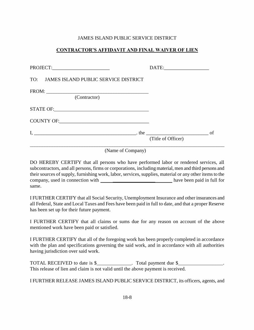
18-8
JAMES ISLAND PUBLIC SERVICE DISTRICT
CONTRACTOR’S AFFIDAVIT AND FINAL WAIVER OF LIEN
PROJECT:_______________________ DATE:__________________
TO: JAMES ISLAND PUBLIC SERVICE DISTRICT
FROM: _________________________________________
(Contractor)
STATE OF:______________________________________
COUNTY OF:____________________________________
I, _________________________________________. the _________________________ of
(Title of Officer)
______________________________________________________________________________
(Name of Company)
DO HEREBY CERTIFY that all persons who have performed labor or rendered services, all
subcontractors, and all persons, firms or corporations, including material, men and third persons and
their sources of supply, furnishing work, labor, services, supplies, material or any other items to the
company, used in connection with _________________ have been paid in full for
same.
I FURTHER CERTIFY that all Social Security, Unemployment Insurance and other insurances and
all Federal, State and Local Taxes and Fees have been paid in full to date, and that a proper Reserve
has been set up for their future payment.
I FURTHER CERTIFY that all claims or sums due for any reason on account of the above
mentioned work have been paid or satisfied.
I FURTHER CERTIFY that all of the foregoing work has been properly completed in accordance
with the plan and specifications governing the said work, and in accordance with all authorities
having jurisdiction over said work.
TOTAL RECEIVED to date is $______________. Total payment due $__________________.
This release of lien and claim is not valid until the above payment is received.
I FURTHER RELEASE JAMES ISLAND PUBLIC SERVICE DISTRICT, its officers, agents, and

18-9
employees, and Owner(s) from any and all claims arising under or by virtue of said contract or any
modification of change thereof.
IN WITNESS WHEREOF, I have hereunto affixed my signature this _______ day of
____________________, 20____.
________________________________________
(NAME OF COMPANY)
________________________________________
(SIGNATURE OF OFFICER)
SWORN to before me this ____ day
of ______________________, 20___.
_______________________________________
NOTARY PUBLIC FOR SOUTH CAROLINA
My Commission Expires:___________________

18-10
STATE OF SOUTH CAROLINA )
) GRANT OF PERPETUAL AND
COUNTY OF CHARLESTON ) CONSTRUCTION EASEMENT
WHEREAS, the JAMES ISLAND PUBLIC SERVICE DISTRICT (hereinafter called the
District) is a body politic and corporate under the laws of the State of South Carolina and
requires the easements hereinafter described and granted in connection with the construction of
wastewater collection and transmission facilities; and
WHEREAS, the ________________________________________ (hereinafter called the
Grantor) is minded to grant such easement to the District for the consideration and upon the
terms and conditions hereinafter set forth.
NOW, THEREFORE, KNOW ALL MEN BY THESE PRESENTS that the Grantor, in
consideration of the sum of $_____________ to him in hand paid for the perpetual easement
granted hereunder and in further consideration of the sum of $______________ to him in hand
paid for the additional easement during construction granted hereunder, at and before the sealing
and delivery of these presents, by the District, the receipt whereof is hereby acknowledged, has
granted, bargained, sold and released and by these presents does grant, bargain, sell and release
unto the District, its successors and assigns forever, the following easement:
1. A perpetual easement for the construction, location, installation, operation,
maintenance, repair and replacement of wastewater facilities over, under and upon the following
described property:
______________________________________________________________________________
TOGETHER with the right of ingress into and egress therefrom over and upon the

18-11
remaining property of the Grantor.
2. An additional easement during the construction of the said wastewater facilities
over, under and upon area more fully described as follows:
______________________________________________________________________________
The easement during construction shall exist during construction and will continue until
one (1) year after the date that the aforesaid wastewater facilities have been accepted by the
District.
IT IS UNDERSTOOD AND AGREED that the easement above described is granted and
accepted upon the following terms and conditions, to wit:
(a) The Grantor will make no use of the area occupied by said easements which is
inconsistent with the uses and the purposes for which the easements have been granted, and
without limiting the generality of this provision, the Grantor agrees that no permanent structures
such as buildings, sheds and other structures shall be placed upon the easement area described in
paragraph 1 at any time, nor upon the easement area described in paragraph 2 until such time as
construction has been completed and until one (1) year after the aforesaid wastewater facilities
have been accepted by the District.
(b) The District agrees that upon the completion of the construction aforesaid, it will
promptly restore the surface of the area described in easement number 2, to the extent
practicable, by leveling and rough grading the surface; but nothing herein contained shall be
construed to require the District to replace any shrubbery or trees unless specifically delineated
as follows:

18-12
______________________________________________________________________________
(c) The District agrees that upon completion of construction, the surface of the area
described in easement number 1 will, to the extent practicable, be leveled and rough graded, and
further that, in the event that it becomes necessary in the future to disturb the surface, in order to
effect maintenance, repair or replacement, it will to the extent practicable level and rough grade
the surface, but nothing herein contained shall be constructed to require the District to replace
any shrubbery or trees unless specifically delineated as follows:
______________________________________________________________________________
TO HAVE AND TO HOLD, all singular, the easement rights and privileges above
described unto the JAMES ISLAND PUBLIC SERVICE DISTRICT COMMISSION, its
successors and assigns.
And the Grantor does hereby bind himself and his successors, heirs, administrators and
executors to warrant and forever defend all and singular the said premises unto the said JAMES
ISLAND PUBLIC SERVICE DISTRICT, its successors and assigns every person whomsoever
lawfully claiming or to claim the same or any part thereof.
IN WITNESS WHEREOF, the Grantor has hereunto set his Hand and Seal, this ______
day of _______________________, 20_____.
WITNESS: (SEAL)
________________________________ By:________________________________
________________________________ Its_________________________________
18-13
STATE OF SOUTH CAROLINA )
)
COUNTY OF CHARLESTON )
PERSONALLY appeared before me the undersigned witness and made oath that (s)he
saw the within named _______________________ by ________________________, its sign
seal and as his act and deed, deliver the within written instrument: and that (s)he with the other
witness witnessed the execution and delivery thereof.
____________________________________
SWORN to before me this ____ day
of ___________________, 20_____.
_______________________________
Notary Public of South Carolina
My Commission Expires:___________

18-14
JIPSD PROJECT COMPLETION ENGINEER QUESTIONNAIRE
Project Name:
TMS #:
Contractor:
SCDHEC Permit #:
Number Lots Served:
Number of Services Available:
No. of Standard Manholes
No. of Drop Manholes
No. of Air Valves
Total cost of construction of the sanitary sewer system is: $______________
Size of Sanitary Sewer Number of Feet
Size of Pumps Force Main Number of Feet
Is there a pump station? Yes No If yes, value? $__________ Is there industrial waste from this project? Yes No Is there hazardous waste from this project? Yes No Signature of Engineer: _____________________________ Date: __________
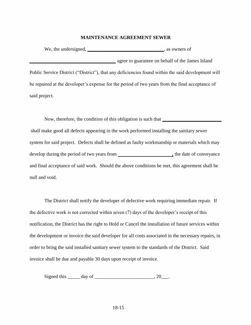
18-15
MAINTENANCE AGREEMENT SEWER
We, the undersigned, _______________________________, as owners of
___________________________________ agree to guarantee on behalf of the James Island
Public Service District (“District”), that any deficiencies found within the said development will
be repaired at the developer’s expense for the period of two years from the final acceptance of
said project.
Now, therefore, the condition of this obligation is such that ________________________
shall make good all defects appearing in the work performed installing the sanitary sewer
system for said project. Defects shall be defined as faulty workmanship or materials which may
develop during the period of two years from , the date of conveyance
and final acceptance of said work. Should the above conditions be met, this agreement shall be
null and void.
The District shall notify the developer of defective work requiring immediate repair. If
the defective work is not corrected within seven (7) days of the developer’s receipt of this
notification, the District has the right to Hold or Cancel the installation of future services within
the development or invoice the said developer for all costs associated in the necessary repairs, in
order to bring the said installed sanitary sewer system to the standards of the District. Said
invoice shall be due and payable 30 days upon receipt of invoice.
Signed this _____ day of ________________________, 20___.

18-16
By: ______________________________ _____________________________
Witness
Its: ______________________________ _____________________________
Witness
SWORN to before me this _____ day of
_____________________, 20____.
_____________________________________
Notary Public for _______________________
My Commission Expires:_________________

18-17
STATE OF SOUTH CAROLINA )
) TITLE TO REAL ESTATE
COUNTY OF CHARLESTON )
KNOW ALL MEN BY THESE PRESENTS that Grantor, _____________
in the State aforesaid, in consideration of the sum of FIVE AND NO/100 ----($5.00)---- Dollars,
to the grantor(s) in hand paid at and before sealing of the presents by the grantee(s) (the receipt
whereof is hereby acknowledged), have granted, bargained, sold and released, and by these
presents do grant, bargain, sell and release unto the said JAMES ISLAND PUBLIC SERVICE
DISTRICT (hereinafter “District” or “Grantee”).
ALL that lot, piece or tract of land in County of Charleston and State aforesaid, as shown
on that certain plat entitled “ _____________________ dated __________
prepared by ______________________ , R..S., and recorded in the RMC Office for
Charleston County in Plat Book _______, Page ______, and more fully delineated as follows:
Commencing at a pin in the southwestern corner of said parcel of land and running
_________ for a distance of ______ feet; thence running in an easterly direction ___________
for a distance of _____ feet; and thence running in a southerly direction _____________ for a
distance of _____ feet; and thence running in a westerly direction ______________ for a
distance of ______ feet to the point of beginning.
BEING A PORTION OF THE SAME PROPERTY conveyed to ____________
by Deed of ____________________ , dated _______________, and recorded in the RMC
Office for Charleston County on ________________, in Book ________, Page ______.
TMS No.:______________________
GRANTEE(S) ADDRESS: Post Office Box 12140, James Island, SC 29422-2140
TOGETHER with all and Singular the Rights, Members, Hereditaments and
Appurtenances to the said premises belonging, or in anywise incident or appertaining
TO HAVE AND TO HOLD and all singular the said Premises before mentioned unto the
grantee(s) hereinabove named, and grantee’s(s) Heirs, Successors, and Assigns forever.
And the grantor(s) do(es) hereby bind the grantor(s) and the grantor’s(s) Heirs,
Successors, Executors and Administrators to warrant and forever defend all and singular the said
premises unto the grantee(s) here in above named, and the grantee’s (s’) Heirs, Successors, and
Assigns against the grantor(s) and the grantor’s(s’) Heirs, Successors, and against every person
whomsoever lawfully claiming or to claim the same or any part thereof. Witness the grantor’s(s’)
hand(s) and seal(s) this ____ day of ____________ in the year of our Lord Two Thousand and
________.
Signed, Sealed and Delivered in the Presence of:

18-18
_____________________________ L.S.
(1) Signature of Witness _____________________________ L.S.
(2) Signature of Witness _____________________________ L.S.
STATE OF ___________________ )
) ACKNOWLEDGMENT
COUNTY OF _________________ )
I, ______________________ Notary Public for the State of ___________________, do
hereby certify that GRANTOR’S NAME, by ________________________ its
_________________, personally appeared before me this day and acknowledged the due
execution of the foregoing instrument.
SWORN to before me this _____ day
of __________________, 20____.
______________________________________
NOTARY PUBLIC FOR SOUTH CAROLINA
My Commission Expires:__________________

19.
STANDARD DRAWINGS
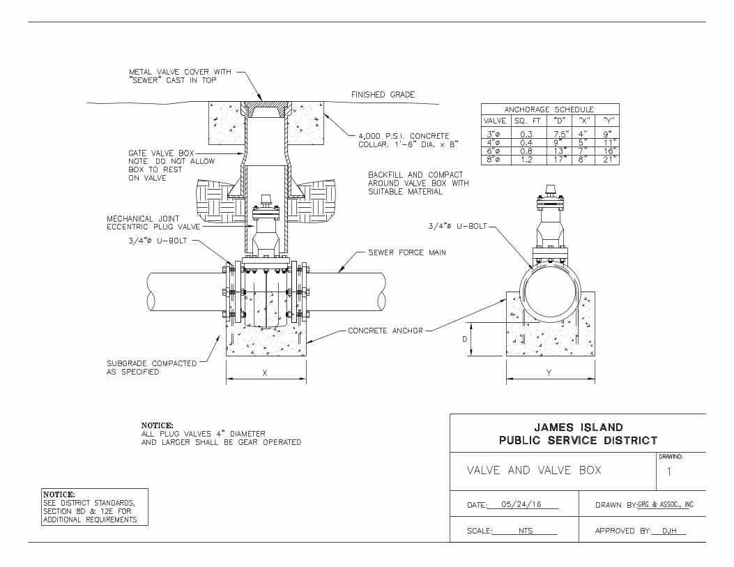
AutoCAD SHX Text
DATE:%%U
AutoCAD SHX Text
SCALE:%%U NTS
AutoCAD SHX Text
DRAWN BY:%%U
AutoCAD SHX Text
APPROVED BY:%%U DJH
AutoCAD SHX Text
JAMES ISLAND
AutoCAD SHX Text
PUBLIC SERVICE DISTRICT
AutoCAD SHX Text
DRAWING:
AutoCAD SHX Text
VALVE AND VALVE BOX
AutoCAD SHX Text
1
AutoCAD SHX Text
05/24/16
AutoCAD SHX Text
GRG & ASSOC., INC
AutoCAD SHX Text
CONCRETE ANCHOR
AutoCAD SHX Text
ON VALVE
AutoCAD SHX Text
BOX TO REST
AutoCAD SHX Text
NOTE: DO NOT ALLOW
AutoCAD SHX Text
SUITABLE MATERIAL
AutoCAD SHX Text
AROUND VALVE BOX WITH
AutoCAD SHX Text
BACKFILL AND COMPACT
AutoCAD SHX Text
GATE VALVE BOX
AutoCAD SHX Text
8"%%c
AutoCAD SHX Text
6"%%c
AutoCAD SHX Text
4"%%c
AutoCAD SHX Text
21"
AutoCAD SHX Text
16"
AutoCAD SHX Text
11"
AutoCAD SHX Text
9"
AutoCAD SHX Text
"Y"
AutoCAD SHX Text
8"
AutoCAD SHX Text
7"
AutoCAD SHX Text
5"
AutoCAD SHX Text
4"
AutoCAD SHX Text
"X"
AutoCAD SHX Text
17"
AutoCAD SHX Text
13"
AutoCAD SHX Text
9"
AutoCAD SHX Text
7.5"
AutoCAD SHX Text
"D"
AutoCAD SHX Text
1.2
AutoCAD SHX Text
0.8
AutoCAD SHX Text
0.4
AutoCAD SHX Text
0.3
AutoCAD SHX Text
SQ. FT.
AutoCAD SHX Text
3"%%c
AutoCAD SHX Text
VALVE
AutoCAD SHX Text
ANCHORAGE SCHEDULE
AutoCAD SHX Text
D
AutoCAD SHX Text
Y
AutoCAD SHX Text
X
AutoCAD SHX Text
COLLAR, 1'-6" DIA. x 8"
AutoCAD SHX Text
4,000 P.S.I. CONCRETE
AutoCAD SHX Text
"SEWER" CAST IN TOP
AutoCAD SHX Text
METAL VALVE COVER WITH
AutoCAD SHX Text
AS SPECIFIED
AutoCAD SHX Text
SUBGRADE COMPACTED
AutoCAD SHX Text
FINISHED GRADE
AutoCAD SHX Text
SEWER FORCE MAIN
AutoCAD SHX Text
ECCENTRIC PLUG VALVE
AutoCAD SHX Text
MECHANICAL JOINT
AutoCAD SHX Text
3/4"%%C U-BOLT
AutoCAD SHX Text
3/4"%%c U-BOLT
AutoCAD SHX Text
ALL PLUG VALVES 4" DIAMETER
AutoCAD SHX Text
AND LARGER SHALL BE GEAR OPERATED
AutoCAD SHX Text
NOTICE:
AutoCAD SHX Text
NOTICE:
AutoCAD SHX Text
SEE DISTRICT STANDARDS,
AutoCAD SHX Text
SECTION 8D & 12E FOR
AutoCAD SHX Text
ADDITIONAL REQUIREMENTS

AutoCAD SHX Text
DATE:%%U
AutoCAD SHX Text
SCALE:%%U NTS
AutoCAD SHX Text
DRAWN BY:%%U
AutoCAD SHX Text
APPROVED BY:%%U DJH
AutoCAD SHX Text
JAMES ISLAND
AutoCAD SHX Text
PUBLIC SERVICE DISTRICT
AutoCAD SHX Text
DRAWING:
AutoCAD SHX Text
CONCRETE VALVE MARKER
AutoCAD SHX Text
2
AutoCAD SHX Text
05/24/16
AutoCAD SHX Text
GRG & ASSOC., INC
AutoCAD SHX Text
M
AutoCAD SHX Text
V
AutoCAD SHX Text
EXISTING GROUND
AutoCAD SHX Text
PRECAST CONC. POST
AutoCAD SHX Text
(4,000 PSI)
AutoCAD SHX Text
4-#3 RE-BAR
AutoCAD SHX Text
4" SQ.
AutoCAD SHX Text
BRASS MARKER PLATE
AutoCAD SHX Text
3/4" CHAMFER @
AutoCAD SHX Text
EACH CORNER
AutoCAD SHX Text
2" BRASS MARKER
AutoCAD SHX Text
PLATE W/ ANCHOR
AutoCAD SHX Text
NOTE:
AutoCAD SHX Text
MAIN LINE VALVE MARKERS SHALL BE
AutoCAD SHX Text
PAINTED AS FOLLOWS:
AutoCAD SHX Text
FEDERAL SAFETY GREEN (SEWER LINES)
AutoCAD SHX Text
AND MARKED AS FOLLOWS:
AutoCAD SHX Text
MV - MAIN VALVE
AutoCAD SHX Text
AV - AIR RELEASE VALVE
AutoCAD SHX Text
FEDERAL SAFETY GREEN (SEWER LINES)
AutoCAD SHX Text
AND MARKED AS FOLLOWS:
AutoCAD SHX Text
MV - MAIN VALVE
AutoCAD SHX Text
AV - AIR RELEASE VALVE
AutoCAD SHX Text
4'
AutoCAD SHX Text
2'-0"
AutoCAD SHX Text
2'-6"

AutoCAD SHX Text
DATE:%%U
AutoCAD SHX Text
SCALE:%%U NTS
AutoCAD SHX Text
DRAWN BY:%%U
AutoCAD SHX Text
APPROVED BY:%%U DJH
AutoCAD SHX Text
JAMES ISLAND
AutoCAD SHX Text
PUBLIC SERVICE DISTRICT
AutoCAD SHX Text
DRAWING:
AutoCAD SHX Text
JACK AND BORE
AutoCAD SHX Text
3
AutoCAD SHX Text
05/24/16
AutoCAD SHX Text
GRG & ASSOC., INC
AutoCAD SHX Text
CARRIER BRACES, TYP
AutoCAD SHX Text
316 STAINLESS STEEL
AutoCAD SHX Text
STEEL CASING, DIA., Wt,
AutoCAD SHX Text
%%USECTION VIEW
AutoCAD SHX Text
45%%D
AutoCAD SHX Text
45%%D
AutoCAD SHX Text
AND LENGTH AS SPECIFIED
AutoCAD SHX Text
AT 10.0' CENTERS FOR DIP PIPE AND
AutoCAD SHX Text
316 STAINLESS STEEL CARRIER BRACES
AutoCAD SHX Text
STEEL CASING, SEE
AutoCAD SHX Text
DISTRICT STANDARDS
AutoCAD SHX Text
AT 6.0' CENTERS FOR PVC PIPE
AutoCAD SHX Text
DIAMETER (ID)
AutoCAD SHX Text
2"-4"
AutoCAD SHX Text
INSIDE DIAMETER (ID)
AutoCAD SHX Text
2" GREATER THAN LARGEST OUTSIDE
AutoCAD SHX Text
DIAMETER (OD) OF CARRIER PIPE
AutoCAD SHX Text
CARRIER INSIDE
AutoCAD SHX Text
CASING
AutoCAD SHX Text
6" OR LARGER
AutoCAD SHX Text
4" GREATER THAN LARGEST OUTSIDE
AutoCAD SHX Text
DIAMETER (OD) OF CARRIER PIPE
AutoCAD SHX Text
BORING DISTANCE
AutoCAD SHX Text
PAVED TRAVELWAY
AutoCAD SHX Text
STEEL CASING
AutoCAD SHX Text
3' MIN.
AutoCAD SHX Text
3' MIN.
AutoCAD SHX Text
MIN. COVER BASED UPON PERMIT CONDITIONS
AutoCAD SHX Text
36' MIN (SEE *)
AutoCAD SHX Text
EDGE OF THE TRAVELWAY THAN ITS DEPTH BELOW THE
AutoCAD SHX Text
*THE NEAR EDGE OF THE PIT CAN BE NO CLOSER TO THE
AutoCAD SHX Text
SURFACE OF THE TRAVELWAY UNLESS BULKHEADED.
AutoCAD SHX Text
%%UBORING PIT LOCATION
AutoCAD SHX Text
%%UJACK AND BORE STEEL ENCASEMENT
AutoCAD SHX Text
NOTE:
AutoCAD SHX Text
SHALL CONFORM TO ALL APPLICABLE SCDOT AND
AutoCAD SHX Text
DEPTH OF CASING AND LOCATION OF BORE PITS
AutoCAD SHX Text
MUNICIPAL PERMIT CONDITIONS
AutoCAD SHX Text
SECTION 6E FOR WALL
AutoCAD SHX Text
THICKNESS
AutoCAD SHX Text
NOTICE:
AutoCAD SHX Text
SEE DISTRICT STANDARDS,
AutoCAD SHX Text
SECTION 6E & 7M FOR
AutoCAD SHX Text
ADDITIONAL REQUIREMENTS
AutoCAD SHX Text
CASING PIPE SHALL BE THE MINIMUM THICKNESS AS SPECIFIED (OR GREATER IF REQUIRED FOR JACKING) SEAMLESS,
AutoCAD SHX Text
WELDED, COLD TAR COATED, STEEL CASING OR APPROVED EQUAL. FIELD JOINTS SHALL BE "PERMALOCK" PUSH-ON
AutoCAD SHX Text
MACHINED JOINTS OR APPROVED EQUAL. BOTH ENDS OF CASING SHALL BE SEALED WITH A DISTRICT APPROVED
AutoCAD SHX Text
1/8" THICK RUBBER END SEAL. STEEL CASING SHALL MEET ASTM A-139 L.R. REQUIREMENTS FOR GRADE B, WITH
AutoCAD SHX Text
MINIMUM YIELD OF 35,000 PSI & MINIMUM TENSILE STRENGTH OF 60,000 P.S.I.

AutoCAD SHX Text
DATE:%%U
AutoCAD SHX Text
SCALE:%%U NTS
AutoCAD SHX Text
DRAWN BY:%%U
AutoCAD SHX Text
APPROVED BY:%%U DJH
AutoCAD SHX Text
JAMES ISLAND
AutoCAD SHX Text
PUBLIC SERVICE DISTRICT
AutoCAD SHX Text
DRAWING:
AutoCAD SHX Text
FORCE MAIN TIE-IN MANHOLE
AutoCAD SHX Text
4
AutoCAD SHX Text
05/24/16
AutoCAD SHX Text
GRG & ASSOC., INC
AutoCAD SHX Text
ECCENTRIC CONE, MINIMUM
AutoCAD SHX Text
8" THICKNESS AT TOP
AutoCAD SHX Text
4'-0" INSIDE DIAMETER PRE-
AutoCAD SHX Text
CAST REINFORCED CONCRETE
AutoCAD SHX Text
MANHOLE RISER AS REQUIRED
AutoCAD SHX Text
5" MINIMUM
AutoCAD SHX Text
WALL THICKNESS
AutoCAD SHX Text
4'-0" INSIDE DIAMETER PRE-
AutoCAD SHX Text
CAST REINFORCED CONCRETE
AutoCAD SHX Text
KOR-A-SEAL FLEXIBLE MANHOLE
AutoCAD SHX Text
SLEEVE OR APPROVED EQUAL,
AutoCAD SHX Text
3/8" MIN. THICKNESS, TYPICAL
AutoCAD SHX Text
12" MINIMUM CRUSHED
AutoCAD SHX Text
COMPACTED STONE AS
AutoCAD SHX Text
SLOPE INVERT SHELF
AutoCAD SHX Text
2" PER FOOT MINIMUM
AutoCAD SHX Text
EXTEND GRAVEL 6"
AutoCAD SHX Text
BEYOND MANHOLE
AutoCAD SHX Text
APPLY NON-SHRINK GROUT
AutoCAD SHX Text
AROUND ENTIRE PERIMETER
AutoCAD SHX Text
OF GRADE RINGS AND
AutoCAD SHX Text
CASTING FRAME
AutoCAD SHX Text
CONSTRUCT CHANNEL WITH
AutoCAD SHX Text
CEMENT GROUT AND CONCRETE
AutoCAD SHX Text
BRICK UP TO TOP OF PIPE.
AutoCAD SHX Text
SHAPE ALL INVERTS AND
AutoCAD SHX Text
12"
AutoCAD SHX Text
6"
AutoCAD SHX Text
ADJUST CASTING TO FINISHED GRADE
AutoCAD SHX Text
USING POURED OR PRECAST CONCRETE
AutoCAD SHX Text
GRADE RINGS (MAXIMUM OF 2 RINGS,
AutoCAD SHX Text
EACH NOT TO EXCEED 6" THICKNESS).
AutoCAD SHX Text
24"
AutoCAD SHX Text
8"
AutoCAD SHX Text
PAVED
AutoCAD SHX Text
AREAS
AutoCAD SHX Text
GRASSED
AutoCAD SHX Text
AREAS
AutoCAD SHX Text
FINISHED GRADE
AutoCAD SHX Text
ASPHALT
AutoCAD SHX Text
BASE COURSE
AutoCAD SHX Text
4"MIN.
AutoCAD SHX Text
GRAVITY SEWER
AutoCAD SHX Text
FORCE MAIN INLET
AutoCAD SHX Text
45%%D M.J.-P.E.
AutoCAD SHX Text
45%%D M.J.-P.E.
AutoCAD SHX Text
D.I.P. ELBOW
AutoCAD SHX Text
D.I.P. ELBOW
AutoCAD SHX Text
SET DISCHARGE ELBOW INVERT
AutoCAD SHX Text
ELEV. NO LOWER THAN CROWN
AutoCAD SHX Text
MECHANICAL JOINT
AutoCAD SHX Text
REQUIRED
AutoCAD SHX Text
LAST 4'-0" D.I.P.
AutoCAD SHX Text
PROVIDE P.E.-M.J.
AutoCAD SHX Text
AS INDICATED.
AutoCAD SHX Text
"LINK-SEAL" WALL SEAL OR
AutoCAD SHX Text
APPROVED EQUAL AS INDICATED.
AutoCAD SHX Text
JIPSD APPROVED MANHOLE FRAME & COVER AS
AutoCAD SHX Text
MANUFACTURED BY, U.S. FOUNDRY & MANUFACTURING
AutoCAD SHX Text
CORP., USF 480 RING AND RA-SSG COVER.
AutoCAD SHX Text
MANHOLE BASE, TYP.
AutoCAD SHX Text
DISCHARGE
AutoCAD SHX Text
SPECIFIED
AutoCAD SHX Text
BASE
AutoCAD SHX Text
TROWEL SMOOTH
AutoCAD SHX Text
ELEVATION OF GRAVITY
AutoCAD SHX Text
GROUT AS INDICATED.
AutoCAD SHX Text
PAVEMENT
AutoCAD SHX Text
MECHANICALLY COMPACTED
AutoCAD SHX Text
GRANULAR MATERIAL
AutoCAD SHX Text
PROJECTED PIPE CENTERLINES
AutoCAD SHX Text
ARE TO INTERSECT AT CENTER
AutoCAD SHX Text
OF MANHOLE UNLESS
AutoCAD SHX Text
APPROVED OTHERWISE BY THE
AutoCAD SHX Text
FLEXIBLE RUBBER
AutoCAD SHX Text
MANHOLE SLEEVES
AutoCAD SHX Text
FLOW
AutoCAD SHX Text
SLOPE INVERT SHELF
AutoCAD SHX Text
2" PER FOOT MINIMUM
AutoCAD SHX Text
FLOW
AutoCAD SHX Text
SHAPE ALL INVERTS
AutoCAD SHX Text
AND TROWEL SMOOTH
AutoCAD SHX Text
CONSTRUCT CHANNEL WITH
AutoCAD SHX Text
CONCRETE (GROUT FILLED
AutoCAD SHX Text
BRICKWORK SIDES). CHANNEL
AutoCAD SHX Text
SHALL CONFORM TO FULL PIPE
AutoCAD SHX Text
FORCE MAIN
AutoCAD SHX Text
GRAVITY SEWER
AutoCAD SHX Text
DISCHARGE DIA.
AutoCAD SHX Text
AS INDICATED
AutoCAD SHX Text
180%%D %%P 30%%D MAX.
AutoCAD SHX Text
INLET DIA.
AutoCAD SHX Text
ENGINEER
AutoCAD SHX Text
AS INDICATED
AutoCAD SHX Text
CROSS-SECTION UP TO
AutoCAD SHX Text
SPRINGLINE
AutoCAD SHX Text
OR PIPE CONNECTIONS,
AutoCAD SHX Text
TYPICAL
AutoCAD SHX Text
AS SPECIFIED
AutoCAD SHX Text
%%UPLAN VIEW
AutoCAD SHX Text
%%UELEVATION VIEW
AutoCAD SHX Text
O-RING SEAL OR BUTYL RUBBER
AutoCAD SHX Text
SEALANT. COVER EXTERIOR TONGUE &
AutoCAD SHX Text
GROOVE JOINT WITH 12" WIDE BAND OF
AutoCAD SHX Text
SEAL WRAP EXTERIOR JOINT SEALER,
AutoCAD SHX Text
BY MAR-MAC MANUFACTURING COMPANY
AutoCAD SHX Text
OR APPROVED EQUAL.
AutoCAD SHX Text
%%UFOR MANHOLES INSTALLED IN PAVED SURFACE
AutoCAD SHX Text
JIPSD APPROVED MANHOLE FRAME & COVER AS
AutoCAD SHX Text
MANUFACTURED BY, CERTAINTEED
AutoCAD SHX Text
PAMREX MODEL 62113 1
AutoCAD SHX Text
%%UFOR MANHOLES INSTALLED IN GRASSED SURFACE
AutoCAD SHX Text
LINE INTERIOR OF MANHOLE WITH
AutoCAD SHX Text
125 MILS RAVEN 405 EPOXY
AutoCAD SHX Text
NOTICE:
AutoCAD SHX Text
1.
AutoCAD SHX Text
BE VERIFIED DURING PROJECT DESIGN.
AutoCAD SHX Text
FOR FORCE MAINS 8" DIAMETER AND LARGER, JIPSD SHALL
AutoCAD SHX Text
ADEQUATE HYDRAULIC CAPACITY OF DOWNSTREAM SEWERS SHALL
AutoCAD SHX Text
2.
AutoCAD SHX Text
REQUIRE SPECIAL JUNCTION STRUCTURES OF PROJECT-SPECIFIC
AutoCAD SHX Text
DESIGN.
AutoCAD SHX Text
FOR 4" & 6" FORCE MAINS
AutoCAD SHX Text
NOTICE:
AutoCAD SHX Text
SEE DISTRICT STANDARDS,
AutoCAD SHX Text
SECTION 6C FOR ADDITIONAL
AutoCAD SHX Text
REQUIREMENTS
AutoCAD SHX Text
FORCE MAIN IE. AT WALL ENTRY
AutoCAD SHX Text
SHALL BE ONE (1) PIPE DIAMETERS
AutoCAD SHX Text
MINIMUM BELOW IE AT DISCHARGE
AutoCAD SHX Text
ELBOW.
AutoCAD SHX Text
DISCHARGE SEWER.
AutoCAD SHX Text
NOTICE:
AutoCAD SHX Text
NO STEPS ALLOWED

AutoCAD SHX Text
DATE:%%U
AutoCAD SHX Text
SCALE:%%U NTS
AutoCAD SHX Text
DRAWN BY:%%U
AutoCAD SHX Text
APPROVED BY:%%U DJH
AutoCAD SHX Text
JAMES ISLAND
AutoCAD SHX Text
PUBLIC SERVICE DISTRICT
AutoCAD SHX Text
DRAWING:
AutoCAD SHX Text
AIR RELEASE VALVE MANHOLE
AutoCAD SHX Text
5
AutoCAD SHX Text
05/24/16
AutoCAD SHX Text
GRG & ASSOC., INC
AutoCAD SHX Text
FORCE MAIN
AutoCAD SHX Text
PLAN VIEW
AutoCAD SHX Text
AND COVER LOCATION
AutoCAD SHX Text
MANHOLE FRAME
AutoCAD SHX Text
(SEE DETAIL)
AutoCAD SHX Text
AIR RELEASE VALVE
AutoCAD SHX Text
FOOTING
AutoCAD SHX Text
4000 PSI CONCRETE
AutoCAD SHX Text
MANHOLE RISER
AutoCAD SHX Text
4'-0" INSIDE DIAMETER PRE-
AutoCAD SHX Text
CAST REINFORCED CONCRETE
AutoCAD SHX Text
NO. 57 STONE, AS SPECIFIED
AutoCAD SHX Text
12" MINIMUM CRUSHED COMPACTED
AutoCAD SHX Text
1'-6"
AutoCAD SHX Text
5'-0"
AutoCAD SHX Text
2'-0"
AutoCAD SHX Text
NOT TO SCALE
AutoCAD SHX Text
FOR FORCE MAIN SYSTEM
AutoCAD SHX Text
AIR RELEASE VALVE DETAIL
AutoCAD SHX Text
316L STAINLESS STEEL MATERIALS
AutoCAD SHX Text
THE CONNECTION USING HEAVY DUTY
AutoCAD SHX Text
NECESSARY FITTINGS TO COMPLETE
AutoCAD SHX Text
CONTRACTOR SHALL PROVIDE ALL
AutoCAD SHX Text
NOTICE:
AutoCAD SHX Text
SEE DISTRICT STANDARDS,
AutoCAD SHX Text
SECTION 6C AND 9D FOR
AutoCAD SHX Text
ADDITIONAL REQUIREMENTS
AutoCAD SHX Text
SECTION VIEW
AutoCAD SHX Text
FORCE MAIN
AutoCAD SHX Text
EACH WAY
AutoCAD SHX Text
#4 REBAR @ 6" O.C.
AutoCAD SHX Text
4000 PSI CONCRETE
AutoCAD SHX Text
3"
AutoCAD SHX Text
9-1/2"
AutoCAD SHX Text
10"
AutoCAD SHX Text
12" MINIMUM CRUSHED
AutoCAD SHX Text
COMPACTED NO. 57 STONE,
AutoCAD SHX Text
AS SPECIFIED
AutoCAD SHX Text
4'-0" INSIDE DIAMETER PRE-
AutoCAD SHX Text
CAST REINFORCED CONCRETE
AutoCAD SHX Text
NO. 57 STONE TO
AutoCAD SHX Text
VARIES
AutoCAD SHX Text
WARNING:
AutoCAD SHX Text
SEE DISTRICT STANDARD SPECIFICATIONS
AutoCAD SHX Text
FOR GRADE/FINAL ELEVATION REQUIREMENTS.
AutoCAD SHX Text
PRECONSTRUCTION SHOULDER ELEVATION
AutoCAD SHX Text
ADJUST TOP ELEVATION TO MATCH
AutoCAD SHX Text
ISOLATING VALVE, AS SPECIFIED
AutoCAD SHX Text
(SEE DETAIL)
AutoCAD SHX Text
AIR RELEASE VALVE, AS SPECIFIED
AutoCAD SHX Text
TOP OF EXISTING FORCE MAIN
AutoCAD SHX Text
OUTLET
AutoCAD SHX Text
SADDLE WITH 2" THREADED
AutoCAD SHX Text
DOUBLE STRAPPED SERVICE
AutoCAD SHX Text
O-RING SEAL OR BUTYL RUBBER
AutoCAD SHX Text
SEALANT. COVER EXTERIOR
AutoCAD SHX Text
TONGUE & GROOVE JOINT WITH
AutoCAD SHX Text
12" WIDE BAND OF SEAL WRAP
AutoCAD SHX Text
EXTERIOR JOINT SEALER BY
AutoCAD SHX Text
COMPANY OR APPROVED EQUAL.
AutoCAD SHX Text
MAR-MAC MANUFACTURING
AutoCAD SHX Text
JIPSD APPROVED MANHOLE FRAME & COVER AS
AutoCAD SHX Text
MANUFACTURED BY, U.S. FOUNDRY & MANUFACTURING
AutoCAD SHX Text
CORP., USF 480 RING AND RA-SSG COVER.
AutoCAD SHX Text
%%UFOR MANHOLES INSTALLED IN PAVED SURFACE
AutoCAD SHX Text
JIPSD APPROVED MANHOLE FRAME & COVER AS
AutoCAD SHX Text
MANUFACTURED BY, CERTAINTEED
AutoCAD SHX Text
PAMREX MODEL 62113 1
AutoCAD SHX Text
%%UFOR MANHOLES INSTALLED IN GRASSED SURFACE
AutoCAD SHX Text
24"
AutoCAD SHX Text
AND SCDOT ENCROACHMENT PERMIT
AutoCAD SHX Text
SEE PLAN VIEW ABOVE GRADE PIPING
AutoCAD SHX Text
FOR DIAMETER OF PIPE
AutoCAD SHX Text
SERVICE SADDLE MUELLER
AutoCAD SHX Text
MOD. DR2A, OR APPROVED
AutoCAD SHX Text
EQUAL
AutoCAD SHX Text
SADDLE TO FOREMAN
AutoCAD SHX Text
STRAPS AND BOLTS TO SECURE
AutoCAD SHX Text
USE 316 STAINLESS STEEL
AutoCAD SHX Text
NEOPRENE SERVICE SADDLE GASKET
AutoCAD SHX Text
2" S.S. THREADED PIPE (N.P.T)
AutoCAD SHX Text
VALVE LEVER OPERATED, SS
AutoCAD SHX Text
2" S.S. NPT AWWA 316 SS BALL
AutoCAD SHX Text
SHAFT & BALL
AutoCAD SHX Text
2" S.S. THREADED PIPE (N.P.T)
AutoCAD SHX Text
VERIFY CLEARANCE 12" MIN.
AutoCAD SHX Text
AIR RELEASE VALVE, MANUFACTURED BY ARI, MODEL D-025 AUTOMATIC AIR RELEASE VALVE WITH 2" NPT INLET SIZE. BACKWASH FITTINGS AND BALL VALVES REQUIRED.
AutoCAD SHX Text
%%UNOTE:
AutoCAD SHX Text
VALVE SHALL BE EQUIPPED ARI
AutoCAD SHX Text
CHECK VALVE FOR AIR RELEASE
AutoCAD SHX Text
ONLY
AutoCAD SHX Text
LINE INTERIOR OF ARV MANHOLE
AutoCAD SHX Text
WITH 125 MILS RAVEN 405 EPOXY
AutoCAD SHX Text
NOTICE:
AutoCAD SHX Text
NO STEPS ALLOWED
AutoCAD SHX Text
2'-0"

AutoCAD SHX Text
DATE:%%U
AutoCAD SHX Text
SCALE:%%U NTS
AutoCAD SHX Text
DRAWN BY:%%U
AutoCAD SHX Text
APPROVED BY:%%U DJH
AutoCAD SHX Text
JAMES ISLAND
AutoCAD SHX Text
PUBLIC SERVICE DISTRICT
AutoCAD SHX Text
DRAWING:
AutoCAD SHX Text
STANDARD MANHOLE
AutoCAD SHX Text
6
AutoCAD SHX Text
05/24/16
AutoCAD SHX Text
GRG & ASSOC., INC
AutoCAD SHX Text
SLEEVES, 3/8" MIN.
AutoCAD SHX Text
MANHOLE (TYP)
AutoCAD SHX Text
A MAX. OF 18" FROM INSIDE FACE OF
AutoCAD SHX Text
FIRST P.V.C. OR D.I.P. JOINT SHALL BE
AutoCAD SHX Text
ECCENTRIC CONE, MINIMUM
AutoCAD SHX Text
8" THICKNESS AT TOP
AutoCAD SHX Text
O-RING SEAL OR BUTYL RUBBER SEALANT.
AutoCAD SHX Text
COVER EXTERIOR TONGUE & GROOVE JOINT
AutoCAD SHX Text
WITH 12" WIDE BAND OF SEAL WRAP EXTERIOR
AutoCAD SHX Text
4'-0" INSIDE DIAMETER PRE-CAST
AutoCAD SHX Text
REINFORCED CONCRETE MANHOLE
AutoCAD SHX Text
RISER AS REQUIRED.
AutoCAD SHX Text
5" MINIMUM
AutoCAD SHX Text
WALL THICKNESS
AutoCAD SHX Text
REINFORCED CONCRETE MANHOLE
AutoCAD SHX Text
KOR-A-SEAL FLEXIBLE MANHOLE SLEEVE
AutoCAD SHX Text
OR APPROVED EQUAL, 3/8" MINIMUM
AutoCAD SHX Text
THICKNESS, TYPICAL
AutoCAD SHX Text
12" MINIMUM CRUSHED
AutoCAD SHX Text
COMPACTED STONE AS
AutoCAD SHX Text
SLOPE INVERT SHELF
AutoCAD SHX Text
1" PER FOOT MINIMUM
AutoCAD SHX Text
EXTEND GRAVEL 6"
AutoCAD SHX Text
BEYOND MANHOLE BASE
AutoCAD SHX Text
APPLY NON-SHRINK
AutoCAD SHX Text
GROUT AROUND ENTIRE
AutoCAD SHX Text
PERIMETER OF GRADE
AutoCAD SHX Text
RINGS AND CASTING
AutoCAD SHX Text
CONSTRUCT CHANNEL WITH
AutoCAD SHX Text
CEMENT GROUT (GROUT
AutoCAD SHX Text
FLEXIBLE RUBBER MANHOLE
AutoCAD SHX Text
12"
AutoCAD SHX Text
6"
AutoCAD SHX Text
ADJUST COVER TO GRADE WITH
AutoCAD SHX Text
POURED CONCRETE OR PRE-CAST
AutoCAD SHX Text
CONCRETE RINGS,(MAXIMUM OF 2
AutoCAD SHX Text
24"
AutoCAD SHX Text
8"
AutoCAD SHX Text
PAVED
AutoCAD SHX Text
AREAS
AutoCAD SHX Text
GRASSED
AutoCAD SHX Text
AREAS
AutoCAD SHX Text
FINISHED GRADE
AutoCAD SHX Text
ASPHALT PAVEMENT
AutoCAD SHX Text
BASE COURSE
AutoCAD SHX Text
MATCH CROWNS OF
AutoCAD SHX Text
DISSIMILAR PIPE SIZES
AutoCAD SHX Text
4" MIN.
AutoCAD SHX Text
4,000 P.S.I. CONCRETE, TYP.
AutoCAD SHX Text
JOINT SEALER, BY MAR-MAC MANUFACTURING
AutoCAD SHX Text
BASE (SIDE AND BOTTOM SHALL
AutoCAD SHX Text
NOTE: PIPE SHALL NOT
AutoCAD SHX Text
EXTEND MORE THAN 2"
AutoCAD SHX Text
BEYOND INSIDE MANHOLE
AutoCAD SHX Text
RINGS, EACH NOT TO EXCEED 4"
AutoCAD SHX Text
COMPANY OR APPROVED EQUAL.
AutoCAD SHX Text
BE MONOLITHIC)
AutoCAD SHX Text
FACE OF CONCRETE
AutoCAD SHX Text
NOTE:
AutoCAD SHX Text
THICKNESS). GROUT JOINT 1/2"
AutoCAD SHX Text
MIN. THICKNESS.
AutoCAD SHX Text
UNLESS APPROVED
AutoCAD SHX Text
OTHERWISE
AutoCAD SHX Text
SPECIFIED
AutoCAD SHX Text
THICKNESS, TYP.
AutoCAD SHX Text
FILLED BRICKWORK SIDES)
AutoCAD SHX Text
FRAME
AutoCAD SHX Text
MECHANICALLY COMPACTED
AutoCAD SHX Text
GRANULAR MATERIAL
AutoCAD SHX Text
PROJECTED PIPE
AutoCAD SHX Text
INTERSECT AT CENTER
AutoCAD SHX Text
OF MANHOLE UNLESS
AutoCAD SHX Text
APPROVED OTHERWISE
AutoCAD SHX Text
FLEXIBLE RUBBER
AutoCAD SHX Text
OR PIPE CONNECTIONS,
AutoCAD SHX Text
RADII SHALL BE NO
AutoCAD SHX Text
LARGER THAN
AutoCAD SHX Text
NECESSARY TO
AutoCAD SHX Text
FLOW
AutoCAD SHX Text
SLOPE INVERT SHELF
AutoCAD SHX Text
1" PER FOOT MINIMUM
AutoCAD SHX Text
FLOW
AutoCAD SHX Text
FLOW
AutoCAD SHX Text
SHAPE ALL INVERTS
AutoCAD SHX Text
AND TROWEL SMOOTH
AutoCAD SHX Text
CONSTRUCT CHANNEL WITH
AutoCAD SHX Text
CONCRETE (GROUT FILLED
AutoCAD SHX Text
BRICKWORK SIDES).
AutoCAD SHX Text
TO FULL PIPE CROSS-
AutoCAD SHX Text
FLOW
AutoCAD SHX Text
AS SPECIFIED
AutoCAD SHX Text
CHANNEL SHALL CONFORM
AutoCAD SHX Text
SECTION UP TO
AutoCAD SHX Text
SPRINGLINE
AutoCAD SHX Text
MANHOLE SLEEVES
AutoCAD SHX Text
TYPICAL
AutoCAD SHX Text
CENTERLINES ARE TO
AutoCAD SHX Text
PROVIDE A SMOOTH
AutoCAD SHX Text
OF FLOW
AutoCAD SHX Text
CHANGE IN DIRECTION
AutoCAD SHX Text
%%UPLAN VIEW
AutoCAD SHX Text
%%UELEVATION VIEW
AutoCAD SHX Text
JIPSD APPROVED MANHOLE FRAME & COVER AS
AutoCAD SHX Text
MANUFACTURED BY, U.S. FOUNDRY & MANUFACTURING
AutoCAD SHX Text
CORP., USF 480 RING AND RA-SSG COVER.
AutoCAD SHX Text
%%UFOR MANHOLES INSTALLED IN PAVED SURFACE
AutoCAD SHX Text
JIPSD APPROVED MANHOLE FRAME & COVER AS
AutoCAD SHX Text
MANUFACTURED BY, CERTAINTEED
AutoCAD SHX Text
PAMREX MODEL 62113 1
AutoCAD SHX Text
%%UFOR MANHOLES INSTALLED IN GRASSED SURFACE
AutoCAD SHX Text
NOTICE:
AutoCAD SHX Text
SEE DISTRICT STANDARDS,
AutoCAD SHX Text
SECTION 6C FOR ADDITIONAL
AutoCAD SHX Text
REQUIREMENTS
AutoCAD SHX Text
LINE INTERIOR OF MANHOLE WITH
AutoCAD SHX Text
125 MILS RAVEN 405 EPOXY
AutoCAD SHX Text
WHEN REQUIRED BY THE DISTRICT
AutoCAD SHX Text
NOTICE:
AutoCAD SHX Text
NO STEPS ALLOWED

AutoCAD SHX Text
DATE:%%U
AutoCAD SHX Text
SCALE:%%U NTS
AutoCAD SHX Text
DRAWN BY:%%U
AutoCAD SHX Text
APPROVED BY:%%U DJH
AutoCAD SHX Text
JAMES ISLAND
AutoCAD SHX Text
PUBLIC SERVICE DISTRICT
AutoCAD SHX Text
DRAWING:
AutoCAD SHX Text
EXTERIOR DROP MANHOLE
AutoCAD SHX Text
7
AutoCAD SHX Text
05/24/16
AutoCAD SHX Text
GRG & ASSOC., INC
AutoCAD SHX Text
ASTM D2321, TABLE 1
AutoCAD SHX Text
AGGREGATE AS SPECIFIED IN
AutoCAD SHX Text
12" MINIMUM CLASS IA
AutoCAD SHX Text
ON EXISTING MANHOLES AS APPLICABLE.
AutoCAD SHX Text
EXTERIOR DROP CONNECTIONS SHALL ALSO BE CONSTRUCTED
AutoCAD SHX Text
NOTICE
AutoCAD SHX Text
3X DIA.
AutoCAD SHX Text
L
AutoCAD SHX Text
C
AutoCAD SHX Text
I.D. OUTLET SEWERS AND LARGER
AutoCAD SHX Text
MANHOLE FACE OF CONCRETE
AutoCAD SHX Text
MORE THAN 2" BEYOND INSIDE
AutoCAD SHX Text
NOTE: PIPE SHALL NOT EXTEND
AutoCAD SHX Text
(SIDE AND BOTTOM SHALL BE MONOLITHIC)
AutoCAD SHX Text
4,000 P.S.I. CONCRETE, TYP.
AutoCAD SHX Text
4" MIN.
AutoCAD SHX Text
DIAMETERS UNLESS APPROVED OTHERWISE
AutoCAD SHX Text
MATCH CROWNS OF DIFFERENT PIPE
AutoCAD SHX Text
BASE COURSE
AutoCAD SHX Text
ASPHALT PAVEMENT
AutoCAD SHX Text
FINISHED
AutoCAD SHX Text
AREAS
AutoCAD SHX Text
GRASSED
AutoCAD SHX Text
AREAS
AutoCAD SHX Text
PAVED
AutoCAD SHX Text
8"
AutoCAD SHX Text
24"
AutoCAD SHX Text
6" THICKNESS). GROUT AS INDICATED.
AutoCAD SHX Text
(MAXIMUM OF 2 RINGS, EACH NOT TO EXCEED
AutoCAD SHX Text
POURED OR PRECAST CONCRETE GRADE RINGS
AutoCAD SHX Text
ADJUST CASTING TO FINISHED GRADE USING
AutoCAD SHX Text
6"
AutoCAD SHX Text
12"
AutoCAD SHX Text
ALL INVERTS AND TROWEL SMOOTH
AutoCAD SHX Text
CONCRETE BRICK UP TO TOP OF PIPE. SHAPE
AutoCAD SHX Text
CONSTRUCT CHANNEL WITH CEMENT GROUT AND
AutoCAD SHX Text
FRAME
AutoCAD SHX Text
PERIMETER OF GRADE RINGS AND CASTING
AutoCAD SHX Text
APPLY NON-SHRINK GROUT AROUND ENTIRE
AutoCAD SHX Text
BEYOND MANHOLE BASE
AutoCAD SHX Text
EXTEND GRAVEL 6"
AutoCAD SHX Text
SHELF 1" PER
AutoCAD SHX Text
SLOPE INVERT
AutoCAD SHX Text
THICKNESS, TYPICAL
AutoCAD SHX Text
OR APPROVED EQUAL, 3/8" MINIMUM
AutoCAD SHX Text
KOR-A-SEAL FLEXIBLE MANHOLE SLEEVE
AutoCAD SHX Text
REINFORCED CONCRETE MANHOLE BASE
AutoCAD SHX Text
WALL THICKNESS
AutoCAD SHX Text
5" MINIMUM
AutoCAD SHX Text
REQUIRED. 5'-0" I.D. REQUIRED FOR 12"
AutoCAD SHX Text
REINFORCED CONCRETE MANHOLE RISER AS
AutoCAD SHX Text
4'-0" INSIDE DIAMETER PRE-CAST
AutoCAD SHX Text
8" THICKNESS AT TOP
AutoCAD SHX Text
ECCENTRIC CONE, MINIMUM
AutoCAD SHX Text
BRICK DAM/ BLOCKING
AutoCAD SHX Text
TO 0.4 x DIAMETER
AutoCAD SHX Text
4000 PSI CONCRETE
AutoCAD SHX Text
ENCASEMENT, TYP.
AutoCAD SHX Text
PVC PIPE RISER SECTION,
AutoCAD SHX Text
LENGTH AS REQUIRED
AutoCAD SHX Text
PVC TEE
AutoCAD SHX Text
PVC 90%%D BEND
AutoCAD SHX Text
UPPER INLET I.E.
AutoCAD SHX Text
LOWER INLET I.E.
AutoCAD SHX Text
UNDISTURBED SOIL
AutoCAD SHX Text
#4 REBAR U-TIE BARS, SET "U"
AutoCAD SHX Text
BEND I.D. TO PIPE O.D. PLUS 6",
AutoCAD SHX Text
EPOXY GROUT DOWEL INTO
AutoCAD SHX Text
6" MIN
AutoCAD SHX Text
ALL SIDES
AutoCAD SHX Text
8"O.C.
AutoCAD SHX Text
TYP.
AutoCAD SHX Text
EPOXY GROUT, 3"
AutoCAD SHX Text
MIN. EMBEDMENT, TYP.
AutoCAD SHX Text
MANHOLE WALL.
AutoCAD SHX Text
JIPSD APPROVED MANHOLE FRAME & COVER AS
AutoCAD SHX Text
MANUFACTURED BY, U.S. FOUNDRY & MANUFACTURING
AutoCAD SHX Text
CORP., USF 480 RING AND RA-SSG COVER.
AutoCAD SHX Text
%%UFOR MANHOLES INSTALLED IN PAVED SURFACE
AutoCAD SHX Text
JIPSD APPROVED MANHOLE FRAME & COVER AS
AutoCAD SHX Text
MANUFACTURED BY, CERTAINTEED
AutoCAD SHX Text
PAMREX MODEL 62113 1
AutoCAD SHX Text
%%UFOR MANHOLES INSTALLED IN GRASSED SURFACE
AutoCAD SHX Text
GRADE
AutoCAD SHX Text
O-RING SEAL OR BUTYL RUBBER SEALANT.
AutoCAD SHX Text
COVER EXTERIOR TONGUE & GROOVE JOINT
AutoCAD SHX Text
WITH 12" WIDE BAND OF SEAL WRAP EXTERIOR
AutoCAD SHX Text
JOINT SEALER, BY MAR-MAC MANUFACTURING
AutoCAD SHX Text
COMPANY OR APPROVED EQUAL.
AutoCAD SHX Text
FOOT MINIMUM
AutoCAD SHX Text
NOTICE:
AutoCAD SHX Text
SEE DISTRICT STANDARDS,
AutoCAD SHX Text
SECTION 6C FOR ADDITIONAL
AutoCAD SHX Text
REQUIREMENTS
AutoCAD SHX Text
LINE INTERIOR OF MANHOLE WITH
AutoCAD SHX Text
125 MILS RAVEN 405 EPOXY
AutoCAD SHX Text
WHEN REQUIRED BY THE DISTRICT
AutoCAD SHX Text
NOTICE:
AutoCAD SHX Text
NO STEPS ALLOWED

AutoCAD SHX Text
DATE:%%U
AutoCAD SHX Text
SCALE:%%U NTS
AutoCAD SHX Text
DRAWN BY:%%U
AutoCAD SHX Text
APPROVED BY:%%U DJH
AutoCAD SHX Text
JAMES ISLAND
AutoCAD SHX Text
PUBLIC SERVICE DISTRICT
AutoCAD SHX Text
DRAWING:
AutoCAD SHX Text
FLAT TOP MANHOLE
AutoCAD SHX Text
8
AutoCAD SHX Text
05/24/16
AutoCAD SHX Text
GRG & ASSOC., INC
AutoCAD SHX Text
(SHALLOW MANHOLE)
AutoCAD SHX Text
ECCENTRIC FLAT TOP, 8"
AutoCAD SHX Text
TOP THICKNESS, MINIMUM
AutoCAD SHX Text
5" MINIMUM
AutoCAD SHX Text
WALL THICKNESS
AutoCAD SHX Text
4'-0" INSIDE DIAMETER
AutoCAD SHX Text
PRECAST REINFORCED
AutoCAD SHX Text
12" MINIMUM CRUSHED COMPACTED
AutoCAD SHX Text
STONE AS SPECIFIED
AutoCAD SHX Text
SLOPE INVERT SHELF
AutoCAD SHX Text
1" PER FOOT MINIMUM
AutoCAD SHX Text
EXTEND COMPACTED AGGREGATE
AutoCAD SHX Text
BASE 12" MIN. BEYOND
AutoCAD SHX Text
APPLY NON-SHRINK GROUT
AutoCAD SHX Text
AROUND ENTIRE PERIMETER
AutoCAD SHX Text
OF GRADE RINGS AND CASTING
AutoCAD SHX Text
FRAME
AutoCAD SHX Text
CONSTRUCT CHANNEL WITH CEMENT
AutoCAD SHX Text
GROUT AND CONCRETE BRICK UP TO
AutoCAD SHX Text
TOP OF PIPE. SHAPE ALL INVERTS
AutoCAD SHX Text
AND TROWEL SMOOTH
AutoCAD SHX Text
12"
AutoCAD SHX Text
6"
AutoCAD SHX Text
ADJUST CASTING TO FINISHED GRADE
AutoCAD SHX Text
USING POURED OR PRECAST CONCRETE
AutoCAD SHX Text
GRADE RINGS (MAXIMUM OF 2 RINGS,
AutoCAD SHX Text
EACH NOT TO EXCEED 6" THICKNESS).
AutoCAD SHX Text
24"
AutoCAD SHX Text
PAVED
AutoCAD SHX Text
AREAS
AutoCAD SHX Text
GRASSED
AutoCAD SHX Text
AREAS
AutoCAD SHX Text
FINISHED
AutoCAD SHX Text
ASPHALT PAVEMENT
AutoCAD SHX Text
BASE COURSE
AutoCAD SHX Text
MATCH CROWNS OF DISSIMILAR PIPE
AutoCAD SHX Text
SIZES UNLESS APPROVED OTHERWISE
AutoCAD SHX Text
4" MIN.
AutoCAD SHX Text
FLOW
AutoCAD SHX Text
FLOW
AutoCAD SHX Text
4'-0"
AutoCAD SHX Text
MAX.
AutoCAD SHX Text
3/8" MIN. THICKNESS, TYP.
AutoCAD SHX Text
FLEXIBLE RUBBER
AutoCAD SHX Text
CONCRETE MANHOLE BASE
AutoCAD SHX Text
MANHOLE SLEEVES,
AutoCAD SHX Text
4'-0" INSIDE DIAMETER
AutoCAD SHX Text
PRECAST REINFORCED
AutoCAD SHX Text
CONCRETE MANHOLE RISER
AutoCAD SHX Text
REQUIRED FOR 12" I.D.
AutoCAD SHX Text
OUTLET SEWERS AND
AutoCAD SHX Text
AS REQUIRED. 5'-0" I.D.
AutoCAD SHX Text
LARGER.
AutoCAD SHX Text
GRADE
AutoCAD SHX Text
GROUT AS INDICATED.
AutoCAD SHX Text
FLEXIBLE RUBBER MANHOLE SLEEVES
AutoCAD SHX Text
OR PIPE CONNECTIONS, TYPICAL
AutoCAD SHX Text
FLOW
AutoCAD SHX Text
SLOPE INVERT SHELF
AutoCAD SHX Text
1" PER FOOT MINIMUM
AutoCAD SHX Text
FLOW
AutoCAD SHX Text
FLOW
AutoCAD SHX Text
SHAPE ALL INVERTS
AutoCAD SHX Text
AND TROWEL SMOOTH
AutoCAD SHX Text
FLOW
AutoCAD SHX Text
MECHANICALLY COMPACTED
AutoCAD SHX Text
GRANULAR MATERIAL
AutoCAD SHX Text
AS SPECIFIED
AutoCAD SHX Text
RADII SHALL BE NO
AutoCAD SHX Text
LARGER THAN
AutoCAD SHX Text
NECESSARY TO
AutoCAD SHX Text
PROVIDE A SMOOTH
AutoCAD SHX Text
OF FLOW
AutoCAD SHX Text
CHANGE IN DIRECTION
AutoCAD SHX Text
CONSTRUCT CHANNEL WITH
AutoCAD SHX Text
CONCRETE (GROUT FILLED
AutoCAD SHX Text
BRICKWORK SIDES).
AutoCAD SHX Text
TO FULL PIPE CROSS-
AutoCAD SHX Text
CHANNEL SHALL CONFORM
AutoCAD SHX Text
SECTION UP TO
AutoCAD SHX Text
SPRINGLINE
AutoCAD SHX Text
PROJECTED PIPE
AutoCAD SHX Text
CENTERLINES ARE TO
AutoCAD SHX Text
OF MANHOLE UNLESS
AutoCAD SHX Text
APPROVED OTHERWISE
AutoCAD SHX Text
INTERSECT AT CENTER
AutoCAD SHX Text
%%UPLAN VIEW
AutoCAD SHX Text
%%UELEVATION VIEW
AutoCAD SHX Text
JIPSD APPROVED MANHOLE FRAME & COVER AS
AutoCAD SHX Text
MANUFACTURED BY, U.S. FOUNDRY & MANUFACTURING
AutoCAD SHX Text
CORP., USF 480 RING AND RA-SSG COVER.
AutoCAD SHX Text
%%UFOR MANHOLES INSTALLED IN PAVED SURFACE
AutoCAD SHX Text
JIPSD APPROVED MANHOLE FRAME & COVER AS
AutoCAD SHX Text
MANUFACTURED BY, CERTAINTEED
AutoCAD SHX Text
PAMREX MODEL 62113 1
AutoCAD SHX Text
%%UFOR MANHOLES INSTALLED IN GRASSED SURFACE
AutoCAD SHX Text
MANHOLE BASE
AutoCAD SHX Text
O-RING SEAL OR BUTYL RUBBER
AutoCAD SHX Text
SEALANT. COVER EXTERIOR
AutoCAD SHX Text
TONGUE & GROOVE JOINT WITH
AutoCAD SHX Text
12" WIDE BAND OF SEAL WRAP
AutoCAD SHX Text
MAR-MAC MANUFACTURING COMPANY
AutoCAD SHX Text
OR APPROVED EQUAL.
AutoCAD SHX Text
EXTERIOR JOINT SEALER, BY
AutoCAD SHX Text
NOTICE:
AutoCAD SHX Text
SEE DISTRICT STANDARDS,
AutoCAD SHX Text
SECTION 6C FOR ADDITIONAL
AutoCAD SHX Text
REQUIREMENTS
AutoCAD SHX Text
LINE INTERIOR OF MANHOLE WITH
AutoCAD SHX Text
125 MILS RAVEN 405 EPOXY
AutoCAD SHX Text
WHEN REQUIRED BY THE DISTRICT
AutoCAD SHX Text
NOTICE:
AutoCAD SHX Text
NO STEPS ALLOWED

AutoCAD SHX Text
DATE:%%U
AutoCAD SHX Text
SCALE:%%U NTS
AutoCAD SHX Text
DRAWN BY:%%U
AutoCAD SHX Text
APPROVED BY:%%U DJH
AutoCAD SHX Text
JAMES ISLAND
AutoCAD SHX Text
PUBLIC SERVICE DISTRICT
AutoCAD SHX Text
DRAWING:
AutoCAD SHX Text
TYPICAL TRENCH SECTION
AutoCAD SHX Text
9
AutoCAD SHX Text
05/24/16
AutoCAD SHX Text
GRG & ASSOC., INC
AutoCAD SHX Text
TOP COVER
AutoCAD SHX Text
AND/OR SCDOT PERMIT CONDITIONS
AutoCAD SHX Text
DENSITY FILL (CDF) IS REQUIRED BY LOCAL
AutoCAD SHX Text
KEYED TO PLAN VIEW WHERE CONTROLLED
AutoCAD SHX Text
INDICATED ON APPLICABLE SECTIONS
AutoCAD SHX Text
ROADWAY TRENCH REPAIRS SHALL BE AS
AutoCAD SHX Text
MATCH EXISTING THICKNESS, 2" MIN.
AutoCAD SHX Text
ASPHALTIC CONCRETE, AS SPECIFIED;
AutoCAD SHX Text
SPECIFIED
AutoCAD SHX Text
EQUAL LIFTS, AS
AutoCAD SHX Text
COMPACTED IN TWO
AutoCAD SHX Text
INITIAL BACKFILL
AutoCAD SHX Text
COMPACTION SHALL BE AS SPECIFIED IN SECTION 7L.
AutoCAD SHX Text
IN DISTRICT STANDARDS, SECTION 7D.
AutoCAD SHX Text
CLASS B (TYPE 2) AGGREGATE MATERIAL, AS SPECIFIED
AutoCAD SHX Text
PLUS 24" MAX.
AutoCAD SHX Text
PLUS 18" MIN.
AutoCAD SHX Text
PIPE DIAMETER
AutoCAD SHX Text
TRENCH EXCAVATION AND BACKFILL SHALL BE
AutoCAD SHX Text
PURSUANT TO DISTRICT STANDARDS, SECTION 7.
AutoCAD SHX Text
AS REQUIRED
AutoCAD SHX Text
FOUNDATION
AutoCAD SHX Text
SPRING LINE
AutoCAD SHX Text
BEDDING
AutoCAD SHX Text
HAUNCHING
AutoCAD SHX Text
12"
AutoCAD SHX Text
PAVED ROADWAY SURFACES
AutoCAD SHX Text
FOR DRIVEWAYS & OTHER NON-SCDOT
AutoCAD SHX Text
PAVEMENT
AutoCAD SHX Text
SAWCUT LINE
AutoCAD SHX Text
AS SPECIFIED, MATCH EXISTING THICKNESS,
AutoCAD SHX Text
STABILIZED AGGREGATE BASE COURSE,
AutoCAD SHX Text
(36" MIN. COVER, TYP.)
AutoCAD SHX Text
APPLICATIONS
AutoCAD SHX Text
GRASS AREA
AutoCAD SHX Text
ASPHALTIC CONCRETE PAVEMENT REPAIR
AutoCAD SHX Text
EXISTING ASPHALTIC
AutoCAD SHX Text
WARNING:
AutoCAD SHX Text
SHORING NECESSARY TO INSTALL SEWER.
AutoCAD SHX Text
TO INCLUDE ALL DEWATERING AND SHEETING &
AutoCAD SHX Text
OSHA AND OTHER GOVERNING SAFETY REGULATIONS
AutoCAD SHX Text
BE PERFORMED IN STRICT ACCORDANCE WITH
AutoCAD SHX Text
SIDEWALL STABILITY. TRENCH EXCAVATION SHALL
AutoCAD SHX Text
TO PREVENT CAVE-IN AND PROVIDE TRENCH
AutoCAD SHX Text
CONTRACTOR SHALL EXCAVATE REQUIRED TRENCH
AutoCAD SHX Text
DEPTH VARIES
AutoCAD SHX Text
(SEE WARNING)
AutoCAD SHX Text
TRENCH EXCAVATION
AutoCAD SHX Text
SPECIFIED BACKFILL MATERIAL
AutoCAD SHX Text
COMPACTED IN 6" LAYERS AT
AutoCAD SHX Text
95% MODIFIED PROCTOR, AS
AutoCAD SHX Text
SPECIFIED IN SECTION 7L.
AutoCAD SHX Text
FINISHED GRADE
AutoCAD SHX Text
DIA./MATERIAL AS INDICATED
AutoCAD SHX Text
EXTRA CLASS B (TYPE 2) FOUNDATION AGGREGATE
AutoCAD SHX Text
MATERIAL WHERE DIRECTED BY THE DISTRICT
AutoCAD SHX Text
TAPED TO PIPE
AutoCAD SHX Text
TRACER WIRE
AutoCAD SHX Text
NOTICE:
AutoCAD SHX Text
30°
AutoCAD SHX Text
PLACE SOD ON ALL
AutoCAD SHX Text
DISTURBED AREAS
AutoCAD SHX Text
NOT PAVED
AutoCAD SHX Text
(FORCE MAIN ONLY)
AutoCAD SHX Text
AND DIRECTED
AutoCAD SHX Text
8" MIN.
AutoCAD SHX Text
NOTICE:
AutoCAD SHX Text
SCDOT AND/OR DISTRICT MAY REQUIRE ACSC MILLING
AutoCAD SHX Text
AND OVERLAY OF ROADWAY SURFACE TO DIRECTED/PERMIT
AutoCAD SHX Text
SPECIFIED DISTANCES BEYOND SAW-CUT EDGES.

AutoCAD SHX Text
DATE:%%U
AutoCAD SHX Text
SCALE:%%U NTS
AutoCAD SHX Text
DRAWN BY:%%U
AutoCAD SHX Text
APPROVED BY:%%U DJH
AutoCAD SHX Text
JAMES ISLAND
AutoCAD SHX Text
PUBLIC SERVICE DISTRICT
AutoCAD SHX Text
DRAWING:
AutoCAD SHX Text
TRENCH SECTION IN SCDOT
AutoCAD SHX Text
10
AutoCAD SHX Text
05/24/16
AutoCAD SHX Text
GRG & ASSOC., INC
AutoCAD SHX Text
ROADWAY TRENCH REPAIRS SHALL BE
AutoCAD SHX Text
"CONTROLLED DENSITY FILL" (CDF)
AutoCAD SHX Text
BACKFILL PURSUANT TO SCDOT
AutoCAD SHX Text
3'-0" UNLESS INDICATED OR SPECIFIED OTHERWISE
AutoCAD SHX Text
SEE COVER NOTICE
AutoCAD SHX Text
EXISTING ASPHALTIC
AutoCAD SHX Text
PAVEMENT
AutoCAD SHX Text
AS REQUIRED IN SCDOT PERMIT
AutoCAD SHX Text
CONDITIONS
AutoCAD SHX Text
1-1/2" ASPHALTIC CONCRETE
AutoCAD SHX Text
SURFACE COURSE MIN. OR
AutoCAD SHX Text
EXISTING BASE
AutoCAD SHX Text
EXISTING BASE
AutoCAD SHX Text
TYPICAL OVERLAY SECTION
AutoCAD SHX Text
INDICATED ON PLAN VIEW.
AutoCAD SHX Text
CONDITIONS. APPLICABLE ONLY
AutoCAD SHX Text
PURSUANT TO SCDOT PERMIT
AutoCAD SHX Text
1 1/2" MIN. ASPHALTIC CONCRETE
AutoCAD SHX Text
TOTAL WIDTH (EDGE TO EDGE)
AutoCAD SHX Text
WHERE FULL OVERLAY LIMITS ARE
AutoCAD SHX Text
SCDOT TYPE "B" ROADWAY OVERLAY
AutoCAD SHX Text
TYPICAL REPAIR SECTION
AutoCAD SHX Text
SAW CUT LINE
AutoCAD SHX Text
30° NOMINAL
AutoCAD SHX Text
6" MIN.
AutoCAD SHX Text
DETECTION TAPE 12"
AutoCAD SHX Text
FROM FINISHED GRADE
AutoCAD SHX Text
FINISHED
AutoCAD SHX Text
GRADE
AutoCAD SHX Text
12"
AutoCAD SHX Text
DEPTH VARIES
AutoCAD SHX Text
(SEE WARNING)
AutoCAD SHX Text
TRENCH EXCAVATION
AutoCAD SHX Text
EXISTING ASPHALTIC
AutoCAD SHX Text
PAVEMENT
AutoCAD SHX Text
TACK COAT AS
AutoCAD SHX Text
SPECIFIED
AutoCAD SHX Text
FINISHED
AutoCAD SHX Text
GRADE
AutoCAD SHX Text
SPECIFIED
AutoCAD SHX Text
TACK COAT AS
AutoCAD SHX Text
APPROVED BACKFILL MATERIAL
AutoCAD SHX Text
COMPACTED IN 6" LIFTS,
AutoCAD SHX Text
AS SPECIFIED IN SECTION 7L
AutoCAD SHX Text
NOTICE:
AutoCAD SHX Text
WHERE FINAL COVER TO FINISHED GRADE IS
AutoCAD SHX Text
CDF TO SPRING LINE OF PIPE.
AutoCAD SHX Text
LESS THAN 36" FROM TOP-OF-PIPE, EXTEND
AutoCAD SHX Text
WARNING:
AutoCAD SHX Text
CONTRACTOR SHALL EXCAVATE REQUIRED TRENCH
AutoCAD SHX Text
SHORING NECESSARY TO INSTALL SEWER.
AutoCAD SHX Text
SIDEWALL STABILITY. TRENCH EXCAVATION SHALL
AutoCAD SHX Text
BE PERFORMED IN STRICT ACCORDANCE WITH
AutoCAD SHX Text
OSHA AND OTHER GOVERNING SAFETY REGULATIONS
AutoCAD SHX Text
TO INCLUDE ALL DEWATERING AND SHEETING &
AutoCAD SHX Text
TO PREVENT CAVE-IN AND PROVIDE TRENCH
AutoCAD SHX Text
NOTICE:
AutoCAD SHX Text
THIS SECTION SHALL BE APPLICABLE FOR ALL
AutoCAD SHX Text
EDGES OF EXISTING PAVED ROADWAY SURFACES
AutoCAD SHX Text
INCLUDING DRIVEWAYS WITHIN 3'-0" OF ROADWAY
AutoCAD SHX Text
PAVEMENT EDGES OR CURBS.
AutoCAD SHX Text
TRENCH EXCAVATIONS EXTENDING 3'-0" BEYOND
AutoCAD SHX Text
RIGHT-OF-WAY
AutoCAD SHX Text
STANDARD SPECIFICATIONS SECTION 210
AutoCAD SHX Text
NOTICE:
AutoCAD SHX Text
SCDOT AND/OR DISTRICT MAY REQUIRE ACSC MILLING
AutoCAD SHX Text
AND OVERLAY OF ROADWAY SURFACE TO DIRECTED/PERMIT
AutoCAD SHX Text
SPECIFIED DISTANCES BEYOND SAW-CUT EDGES.

AutoCAD SHX Text
DATE:%%U
AutoCAD SHX Text
SCALE:%%U NTS
AutoCAD SHX Text
DRAWN BY:%%U
AutoCAD SHX Text
APPROVED BY:%%U DJH
AutoCAD SHX Text
JAMES ISLAND
AutoCAD SHX Text
PUBLIC SERVICE DISTRICT
AutoCAD SHX Text
DRAWING:
AutoCAD SHX Text
SEWER SERVICE WITH
AutoCAD SHX Text
11
AutoCAD SHX Text
05/24/16
AutoCAD SHX Text
GRG & ASSOC., INC
AutoCAD SHX Text
ROADWAY SURFACE
AutoCAD SHX Text
R/W LINE
AutoCAD SHX Text
18" MAX.
AutoCAD SHX Text
6" MIN.
AutoCAD SHX Text
TYP.
AutoCAD SHX Text
PLUG,
AutoCAD SHX Text
FLOW
AutoCAD SHX Text
FLOW
AutoCAD SHX Text
CRUSHED STONE, MIN.
AutoCAD SHX Text
BOTTOM TRENCH 6"
AutoCAD SHX Text
BRANCH WYE OR
AutoCAD SHX Text
HARCO ASTM 3139
AutoCAD SHX Text
REQUIRED
AutoCAD SHX Text
PVC FITTING AS
AutoCAD SHX Text
GRASS AREA
AutoCAD SHX Text
APPLICATIONS
AutoCAD SHX Text
LENGTH AS REQUIRED
AutoCAD SHX Text
24" MINIMUM
AutoCAD SHX Text
THREADED CAP
AutoCAD SHX Text
CLEANOUT WITH
AutoCAD SHX Text
APPLICATIONS
AutoCAD SHX Text
PAVEMENT AREA
AutoCAD SHX Text
INDICATED OTHERWISE
AutoCAD SHX Text
6" DIAMETER D.I.P. UNLESS
AutoCAD SHX Text
45%%D LONG SWEEP ELBOW
AutoCAD SHX Text
FROM PVC TO D.I.P. RISER
AutoCAD SHX Text
PROVIDE TRANSITION GASKET
AutoCAD SHX Text
2-45%%D PVC ELBOWS OR
AutoCAD SHX Text
DIRECTED OTHERWISE.
AutoCAD SHX Text
FINISHED GRADE AT ROW UNLESS
AutoCAD SHX Text
AT MINIMUM 4.0' BELOW
AutoCAD SHX Text
SET SERVICE CONNECTION I.E.
AutoCAD SHX Text
PLAN VIEW
AutoCAD SHX Text
SECTION VIEW
AutoCAD SHX Text
R/W LINE
AutoCAD SHX Text
SIDE LOT LINE
AutoCAD SHX Text
COMMON
AutoCAD SHX Text
CONTRACTOR SHALL RESET ALL
AutoCAD SHX Text
DISTURBED/DISPLACED PROPERTY
AutoCAD SHX Text
MONUMENTS BY A DISTRICT
AutoCAD SHX Text
APPROVED P.L.S. AT NO
AutoCAD SHX Text
COST TO THE DISTRICT
AutoCAD SHX Text
LOCATION.
AutoCAD SHX Text
TOP FOOT EXPOSED AND
AutoCAD SHX Text
PAINTED GREEN AT END
AutoCAD SHX Text
OF CLEANOUT TO
AutoCAD SHX Text
SYP. 0.8 CA-B TREATED
AutoCAD SHX Text
SET 4'-4"x4" NO. 2
AutoCAD SHX Text
36" MIN. COVER FOR PVC BELOW
AutoCAD SHX Text
ELEVATION OF ROADWAY AND DITCH
AutoCAD SHX Text
WHERE APPLICABLE
AutoCAD SHX Text
6" PVC SERVICE LATERAL
AutoCAD SHX Text
LAID AT 0.50% GRADE UNLESS
AutoCAD SHX Text
APPROVED OTHERWISE
AutoCAD SHX Text
SEWER
AutoCAD SHX Text
30%%D ELBOW
AutoCAD SHX Text
DISTRICT APPROVED
AutoCAD SHX Text
C900 x C900 CIOD
AutoCAD SHX Text
SEWER MAIN
AutoCAD SHX Text
AT POINT OF SERVICE
AutoCAD SHX Text
PVC PLUG TYP.
AutoCAD SHX Text
NOT SHOWN
AutoCAD SHX Text
ELDER VALVE
AutoCAD SHX Text
FOR CLARITY
AutoCAD SHX Text
45°,TYP.
AutoCAD SHX Text
MAIN
AutoCAD SHX Text
TIMBER POST SET WITH
AutoCAD SHX Text
IDENTIFY SERVICE FITTING
AutoCAD SHX Text
ELDER VALVE
AutoCAD SHX Text
FOR NEW DEVELOPMENTS,
AutoCAD SHX Text
EQUAL
AutoCAD SHX Text
NOTICE:
AutoCAD SHX Text
SEE DISTRICT STANDARDS,
AutoCAD SHX Text
SECTION 7J FOR ADDITIONAL
AutoCAD SHX Text
REQUIREMENTS
AutoCAD SHX Text
NOTICE:
AutoCAD SHX Text
MATERIALS SHALL BE AS
AutoCAD SHX Text
SPECIFIED IN SECTION 6B
AutoCAD SHX Text
UNLESS INDICATED
AutoCAD SHX Text
OTHERWISE HEREON
AutoCAD SHX Text
FLOW
AutoCAD SHX Text
ELDER VALVE
AutoCAD SHX Text
UNIT
AutoCAD SHX Text
4" PVC
AutoCAD SHX Text
STANDPIPE
AutoCAD SHX Text
HOUSING
AutoCAD SHX Text
PVC CAP 3"
AutoCAD SHX Text
CONNECTION
AutoCAD SHX Text
SOUTHEASTERN DISTRIBUTORS, INC. MB-9 "LITTLE RHINO" BOX WITH CAST IRON LID LETTERED "SEWER CO". SET FLUSH WITH EXISTING GRADE.
AutoCAD SHX Text
S
AutoCAD SHX Text
E
AutoCAD SHX Text
W
AutoCAD SHX Text
E
AutoCAD SHX Text
R
AutoCAD SHX Text
C
AutoCAD SHX Text
O
AutoCAD SHX Text
SOUTHEASTERN DISTRIBUTORS, INC. MB-9 "LITTLE RHINO" BOX WITH CAST IRON LID LETTERED "SEWER CO". SET FLUSH WITH EXISTING GRADE.
AutoCAD SHX Text
ELDER VALVE, TYP. RESIDENTAL ONLY
AutoCAD SHX Text
GRASS AREA
AutoCAD SHX Text
APPLICATIONS
AutoCAD SHX Text
APPLICATIONS
AutoCAD SHX Text
PAVEMENT AREA
AutoCAD SHX Text
6" CRUSHED STONE
AutoCAD SHX Text
SOUTHEASTERN DISTRIBUTORS, INC. MB-9 "LITTLE RHINO" BOX WITH CAST IRON LID LETTERED "SEWER VALVE". SET FLUSH WITH EXISTING GRADE.
AutoCAD SHX Text
6" CRUSHED STONE

AutoCAD SHX Text
DATE:%%U
AutoCAD SHX Text
SCALE:%%U NTS
AutoCAD SHX Text
DRAWN BY:%%U
AutoCAD SHX Text
APPROVED BY:%%U DJH
AutoCAD SHX Text
JAMES ISLAND
AutoCAD SHX Text
PUBLIC SERVICE DISTRICT
AutoCAD SHX Text
DRAWING:
AutoCAD SHX Text
TYPICAL PUMP STATION
AutoCAD SHX Text
12
AutoCAD SHX Text
05/24/16
AutoCAD SHX Text
GRG & ASSOC., INC
AutoCAD SHX Text
SITE PLAN
AutoCAD SHX Text
PUBLIC ROADWAY
AutoCAD SHX Text
RIGHT-OF-WAY LINE
AutoCAD SHX Text
CONTROL PANEL
AutoCAD SHX Text
WETWELL
AutoCAD SHX Text
16' MIN. DOUBLE SWING GATE
AutoCAD SHX Text
ACCESS DRIVEWAY
AutoCAD SHX Text
PROPERTY LINE
AutoCAD SHX Text
MIN. RADIUS 20 FT.
AutoCAD SHX Text
UNLESS REQUIRED OTHERWISE
AutoCAD SHX Text
BY SCDOT OR MUNICIPAL
AutoCAD SHX Text
PERMIT CONDITIONS
AutoCAD SHX Text
SEE DRAWING 25 FOR MINIMUM PAVED
AutoCAD SHX Text
DRIVEWAY LIFT THICKNESS REQUIREMENTS
AutoCAD SHX Text
NOTICE:
AutoCAD SHX Text
SEE DISTRICT STANDARDS,
AutoCAD SHX Text
SECTIONS 11, 12, & 13 FOR
AutoCAD SHX Text
ADDITIONAL REQUIREMENTS
AutoCAD SHX Text
NOTICE:
AutoCAD SHX Text
PUMP STATION GRADING SHALL
AutoCAD SHX Text
PROVIDE POSITIVE DRAINAGE
AutoCAD SHX Text
SUBJECT TO DISTRICT REVIEW
AutoCAD SHX Text
AND APPROVAL
AutoCAD SHX Text
PAVEMENT REQUIREMENTS WITHIN
AutoCAD SHX Text
PUBLIC RIGHT-OF-WAY SHALL BE
AutoCAD SHX Text
PURSUANT TO APPLICABLE AGENCY
AutoCAD SHX Text
ENCROACHMENT PERMIT CONDITIONS
AutoCAD SHX Text
SEPARATE 4' PERSONNEL GATE
AutoCAD SHX Text
SITE PAVEMENT
AutoCAD SHX Text
SEE DRAWING 25 FOR MINIMUM PAVED
AutoCAD SHX Text
DRIVEWAY LIFT THICKNESS REQUIREMENTS
AutoCAD SHX Text
CONCRETE WET WELL TOP SLAB ON GRADE
AutoCAD SHX Text
PUMP STATION FENCE; SEE STANDARD DETAIL 17 OR 18 AS DIRECTED BY DISTRICT
AutoCAD SHX Text
NOTICE:
AutoCAD SHX Text
MAXIMUM SITE GRADING FROM WET WELL TOP SLAB
AutoCAD SHX Text
TO ASPHALT SURFACE PERIMETER SHALL BE 1%%%
AutoCAD SHX Text
UNLESS APPROVED OTHERWISE
AutoCAD SHX Text
EXTEND PAVEMENT TO FENCE LINE UNLESS
AutoCAD SHX Text
APPROVED OTHERWISE
AutoCAD SHX Text
1.
AutoCAD SHX Text
2.

AutoCAD SHX Text
DATE:%%U
AutoCAD SHX Text
SCALE:%%U NTS
AutoCAD SHX Text
DRAWN BY:%%U
AutoCAD SHX Text
APPROVED BY:%%U DJH
AutoCAD SHX Text
JAMES ISLAND
AutoCAD SHX Text
PUBLIC SERVICE DISTRICT
AutoCAD SHX Text
DRAWING:
AutoCAD SHX Text
TYPICAL PUMP STATION
AutoCAD SHX Text
13
AutoCAD SHX Text
05/24/16
AutoCAD SHX Text
GRG & ASSOC., INC
AutoCAD SHX Text
PLUG VALVE, TYP.
AutoCAD SHX Text
2" PVC DRAIN LINE
AutoCAD SHX Text
4,000 PSI REINFORCED CONCRETE PAD
AutoCAD SHX Text
VENT
AutoCAD SHX Text
TOP PLAN
AutoCAD SHX Text
CONTROL PANEL RACK
AutoCAD SHX Text
SEE DRAWING 19
AutoCAD SHX Text
NOTICE:
AutoCAD SHX Text
1.
AutoCAD SHX Text
FOR ADDITIONAL REQUIREMENTS
AutoCAD SHX Text
SEE DISTRICT STANDARDS SECTIONS 11, 12, & 13
AutoCAD SHX Text
2.
AutoCAD SHX Text
6" DIA. STATION PIPING. LARGER STATIONS WITH
AutoCAD SHX Text
PIPING LAYOUT INDICATED IS TYPICAL FOR 4" AND
AutoCAD SHX Text
8" DIA. AND LARGER PIPING SHALL BE SUBJECT
AutoCAD SHX Text
TO DISTRICT PRELIMINARY DESIGN REVIEW.
AutoCAD SHX Text
BALL CHECK
AutoCAD SHX Text
VALVE, TYP.
AutoCAD SHX Text
BYPASS CONNECTION
AutoCAD SHX Text
CAMLOCK QUICK
AutoCAD SHX Text
CONNECT WITH
AutoCAD SHX Text
REMOVABLE CAP
AutoCAD SHX Text
3.
AutoCAD SHX Text
DO NOT PAINT STAINLESS STEEL FASTNERS AND
AutoCAD SHX Text
AIR RELEASE VALVE MANUFACTURED BY ARI MODEL D-025 SEE DRAWING 23
AutoCAD SHX Text
TRUE WYE
AutoCAD SHX Text
PIPE STANSION, TYP.
AutoCAD SHX Text
NOTICE:
AutoCAD SHX Text
THE DISTRICT MAY REQUIRE REVISED PIPING LAYOUT TO ACCOMMODATE
AutoCAD SHX Text
A DISTRICT REQUIRED AND APPROVED FLOW METERING DEVICE WITH
AutoCAD SHX Text
LOCAL READOUT AND REMOTE SCADA/RTU MONITORING.
AutoCAD SHX Text
MIN. 1 FT
AutoCAD SHX Text
ALL ELECTRICAL EQUIPMENT AND APPURTENANCES
AutoCAD SHX Text
LOCATED BELOW 1.25 FEET ABOVE THE BASE FEMA
AutoCAD SHX Text
FLOOD ELEVATION SHALL BE NEMA 6X.
AutoCAD SHX Text
4.
AutoCAD SHX Text
ROSEMOUNT 8750WA MAGMETER FLOWTUBE SEE DRAWING 24
AutoCAD SHX Text
STAINLESS STEEL PIPING.

AutoCAD SHX Text
DATE:%%U
AutoCAD SHX Text
SCALE:%%U NTS
AutoCAD SHX Text
DRAWN BY:%%U
AutoCAD SHX Text
APPROVED BY:%%U DJH
AutoCAD SHX Text
JAMES ISLAND
AutoCAD SHX Text
PUBLIC SERVICE DISTRICT
AutoCAD SHX Text
DRAWING:
AutoCAD SHX Text
TYPICAL PUMP STATION
AutoCAD SHX Text
14
AutoCAD SHX Text
05/24/16
AutoCAD SHX Text
GRG & ASSOC., INC
AutoCAD SHX Text
BYPASS CONNECTION
AutoCAD SHX Text
CAMLOCK QUICK
AutoCAD SHX Text
VALVE, TYP.
AutoCAD SHX Text
LONG SWEEP
AutoCAD SHX Text
2" PVC DRAIN LINE
AutoCAD SHX Text
4,000 PSI REINFORCED CONCRETE PAD
AutoCAD SHX Text
VENT
AutoCAD SHX Text
BALL CHECK
AutoCAD SHX Text
VALVE, TYP.
AutoCAD SHX Text
90%%D BEND
AutoCAD SHX Text
PLUG
AutoCAD SHX Text
TOP PLAN (ALT.)
AutoCAD SHX Text
NOTICE:
AutoCAD SHX Text
1.
AutoCAD SHX Text
FOR ADDITIONAL REQUIREMENTS
AutoCAD SHX Text
SEE DISTRICT STANDARDS SECTIONS 11, 12, & 13
AutoCAD SHX Text
2.
AutoCAD SHX Text
TO ACCOMMODATE SPECIAL SPACE AND ACCESS
AutoCAD SHX Text
PIPING LAYOUT INDICATED ABOVE MAY BE UTILIZED
AutoCAD SHX Text
REQUIREMENTS SUBJECT TO DISTRICT APPROVAL
AutoCAD SHX Text
3.
AutoCAD SHX Text
6" DIA. STATION PIPING. LARGER STATIONS WITH
AutoCAD SHX Text
PIPING LAYOUT INDICATED IS TYPICAL FOR 4" AND
AutoCAD SHX Text
8" DIA. AND LARGER PIPING SHALL BE SUBJECT
AutoCAD SHX Text
TO DISTRICT PRELIMINARY DESIGN REVIEW.
AutoCAD SHX Text
CONTROL PANEL RACK
AutoCAD SHX Text
SEE DRAWING 19
AutoCAD SHX Text
CONNECT WITH
AutoCAD SHX Text
REMOVABLE CAP
AutoCAD SHX Text
AIR RELEASE VALVE MANUFACTURED BY ARI MODEL D-025 SEE DRAWING 23
AutoCAD SHX Text
4.
AutoCAD SHX Text
DO NOT PAINT STAINLESS STEEL BOLTS AND PIPING.
AutoCAD SHX Text
PIPE STANSION, TYP.
AutoCAD SHX Text
NOTICE:
AutoCAD SHX Text
THE DISTRICT MAY REQUIRE REVISED PIPING LAYOUT TO ACCOMMODATE
AutoCAD SHX Text
A DISTRICT REQUIRED AND APPROVED FLOW METERING DEVICE WITH
AutoCAD SHX Text
LOCAL READOUT AND REMOTE SCADA/RTU MONITORING.
AutoCAD SHX Text
ALL ELECTRICAL EQUIPMENT AND APPURTENANCES
AutoCAD SHX Text
LOCATED BELOW 1.25 FEET ABOVE THE BASE FEMA
AutoCAD SHX Text
FLOOD ELEVATION SHALL BE NEMA 6X.
AutoCAD SHX Text
5.
AutoCAD SHX Text
ROSEMOUNT 8750WA MAGMETER FLOWTUBE SEE DRAWING 24

AutoCAD SHX Text
DATE:%%U
AutoCAD SHX Text
SCALE:%%U NTS
AutoCAD SHX Text
DRAWN BY:%%U
AutoCAD SHX Text
APPROVED BY:%%U DJH
AutoCAD SHX Text
JAMES ISLAND
AutoCAD SHX Text
PUBLIC SERVICE DISTRICT
AutoCAD SHX Text
DRAWING:
AutoCAD SHX Text
TYPICAL PUMP STATION
AutoCAD SHX Text
15
AutoCAD SHX Text
05/24/16
AutoCAD SHX Text
GRG & ASSOC., INC
AutoCAD SHX Text
BASE FLOOD ELEVATION
AutoCAD SHX Text
PUMP UNITS OFF
AutoCAD SHX Text
LEAD PUMP ON
AutoCAD SHX Text
LAG PUMP ON
AutoCAD SHX Text
HIGH WATER SCADA/RTU
AutoCAD SHX Text
HIGH WATER LOCAL ALARM
AutoCAD SHX Text
SECTION
AutoCAD SHX Text
PRECAST WETWELL
AutoCAD SHX Text
4" DBL 90%%d VENT
AutoCAD SHX Text
WETWELL ACCESS
AutoCAD SHX Text
COVER WITH
AutoCAD SHX Text
3/4" CHAMFER
AutoCAD SHX Text
(TYP. ALL EXPOSED
AutoCAD SHX Text
CONCRETE SURFACES)
AutoCAD SHX Text
TOP OF WETWELL
AutoCAD SHX Text
LINE INTERIOR OF WETWELL WITH
AutoCAD SHX Text
125 MILS RAVEN 405 EPOXY
AutoCAD SHX Text
GRAVITY SEWER
AutoCAD SHX Text
316 S.S. GUIDE RAILS
AutoCAD SHX Text
316 S.S. LIFTING
AutoCAD SHX Text
SUBMERSIBLE PUMP
AutoCAD SHX Text
(TYP. 2 EA.)
AutoCAD SHX Text
316 ALL S.S. DRESSER COUPLING
AutoCAD SHX Text
8' DIA. MIN.
AutoCAD SHX Text
BALL CHECK
AutoCAD SHX Text
VALVE, TYP.
AutoCAD SHX Text
SAFETY GRATE
AutoCAD SHX Text
FLOODPROOF
AutoCAD SHX Text
NOTICE:
AutoCAD SHX Text
1.
AutoCAD SHX Text
2.
AutoCAD SHX Text
DOUBLE
AutoCAD SHX Text
LINK-SEALS
AutoCAD SHX Text
LINK-
AutoCAD SHX Text
SEALS, TYP.
AutoCAD SHX Text
REINFORCED CONCRETE
AutoCAD SHX Text
TOP SLAB, TYP.
AutoCAD SHX Text
NO. 57 AGGREGATE
AutoCAD SHX Text
NO. 57 AGGREGATE
AutoCAD SHX Text
FITTINGS AS
AutoCAD SHX Text
REQUIRED FOR
AutoCAD SHX Text
HATCH FRAME
AutoCAD SHX Text
CLEARANCE
AutoCAD SHX Text
WITH SS SCREEN
AutoCAD SHX Text
LINK SEAL
AutoCAD SHX Text
OR BOOT, TYP.
AutoCAD SHX Text
CHAIN
AutoCAD SHX Text
NOTICE:
AutoCAD SHX Text
THE DISTRICT MAY REQUIRE REVISED PIPING
AutoCAD SHX Text
LAYOUT TO ACCOMMODATE A DISTRICT
AutoCAD SHX Text
REQUIRED AND APPROVED FLOW METERING
AutoCAD SHX Text
DEVICE WITH LOCAL READOUT AND REMOTE
AutoCAD SHX Text
SCADA/RTU MONITORING.
AutoCAD SHX Text
PIPE STANCHION, TYP.
AutoCAD SHX Text
2" DIA. SCH-80 PVC
AutoCAD SHX Text
AIR RELEASE VALVE
AutoCAD SHX Text
SEE DRAWING 23
AutoCAD SHX Text
O-RING SEAL OR BUTYL RUBBER SEALANT. COVER
AutoCAD SHX Text
EXTERIOR TONGUE & GROOVE JOINT WITH 12" WIDE BAND
AutoCAD SHX Text
OF SEAL WRAP EXTERIOR JOINT SEALER BY MAR-MAC
AutoCAD SHX Text
MANUFACTURING COMPANY OR APPROVED EQUAL.
AutoCAD SHX Text
SEE DISTRICT STANDARDS SECTIONS 11,12 & 13 FOR
AutoCAD SHX Text
ADDITIONAL REQUIREMENTS
AutoCAD SHX Text
PIPING LAYOUT INDICATED IS TYPICAL FOR 4" AND 6"
AutoCAD SHX Text
DIA. STATION PIPING. LARGER STATIONS WITH 8" DIA.
AutoCAD SHX Text
AND LARGER PIPING SHALL BE SUBJECT TO DISTRICT
AutoCAD SHX Text
PRELIMINARY DESIGN REVIEW.
AutoCAD SHX Text
ALL ELECTRICAL EQUIPMENT AND APPURTENANCES
AutoCAD SHX Text
LOCATED BELOW 1.25 FEET ABOVE THE BASE FEMA
AutoCAD SHX Text
FLOOD ELEVATION SHALL BE NEMA 6X.
AutoCAD SHX Text
3.
AutoCAD SHX Text
ROSEMOUNT 8750WA MAGMETER FLOWTUBE SEE DRAWING 24
AutoCAD SHX Text
STILLING WELL
AutoCAD SHX Text
SEE DRAWING 22

AutoCAD SHX Text
1/8" MESH S.S. SCREEN
AutoCAD SHX Text
SECURED WITH NYLON ZIP-TIES
AutoCAD SHX Text
2-4" D.I.P. SHORT
AutoCAD SHX Text
RADIUS 90%%D BENDS
AutoCAD SHX Text
4" CORED HOLE
AutoCAD SHX Text
THROUGH TOP SLAB
AutoCAD SHX Text
316 S.S. WASHERS AND
AutoCAD SHX Text
304 NUTS ON WETWELL
AutoCAD SHX Text
CEILING SIDE.
AutoCAD SHX Text
4 EQUALLY SPACED 5/8" DIA.
AutoCAD SHX Text
316 S.S. BOLTS, DRILLED
AutoCAD SHX Text
THROUGH CONCRETE.
AutoCAD SHX Text
1/4" MASTIC
AutoCAD SHX Text
SEAL
AutoCAD SHX Text
DRILL ANCHOR BOLTS
AutoCAD SHX Text
TO FLANGE PATTERN
AutoCAD SHX Text
BEFORE 4" CORING.
AutoCAD SHX Text
NOTICE:
AutoCAD SHX Text
DATE:%%U
AutoCAD SHX Text
SCALE:%%U NTS
AutoCAD SHX Text
DRAWN BY:%%U
AutoCAD SHX Text
APPROVED BY:%%U DJH
AutoCAD SHX Text
JAMES ISLAND
AutoCAD SHX Text
PUBLIC SERVICE DISTRICT
AutoCAD SHX Text
DRAWING:
AutoCAD SHX Text
TYPICAL PUMP STATION
AutoCAD SHX Text
16
AutoCAD SHX Text
05/24/16
AutoCAD SHX Text
GRG & ASSOC., INC
AutoCAD SHX Text
VENT DETAIL
AutoCAD SHX Text
VENT DETAIL
AutoCAD SHX Text
FOR SLAB THICKNESS 10" OR GREATER
AutoCAD SHX Text
1/8" MESH S.S. SCREEN
AutoCAD SHX Text
SECURED WITH NYLON ZIP-TIES
AutoCAD SHX Text
2-4" D.I.P. SHORT
AutoCAD SHX Text
RADIUS 90%%D BENDS
AutoCAD SHX Text
DOUBLE LINK-SEALS
AutoCAD SHX Text
EPOXY LINED
AutoCAD SHX Text
CLASS 53
AutoCAD SHX Text
EPOXY LINED
AutoCAD SHX Text
VENT DETAIL
AutoCAD SHX Text
FOR SLAB THICKNESS LESS THAN 10"
AutoCAD SHX Text
EPOXY LINED
AutoCAD SHX Text
4" D.I.P.
AutoCAD SHX Text
CLASS 53
AutoCAD SHX Text
EPOXY LINED
AutoCAD SHX Text
4" D.I.P.
AutoCAD SHX Text
MINIMUM 2 COATES OF
AutoCAD SHX Text
APPROVED EXTERIOR PAINT
AutoCAD SHX Text
MINIMUM 2 COATES OF
AutoCAD SHX Text
APPROVED EXTERIOR PAINT

AutoCAD SHX Text
DATE:%%U
AutoCAD SHX Text
SCALE:%%U NTS
AutoCAD SHX Text
DRAWN BY:%%U
AutoCAD SHX Text
APPROVED BY:%%U DJH
AutoCAD SHX Text
JAMES ISLAND
AutoCAD SHX Text
PUBLIC SERVICE DISTRICT
AutoCAD SHX Text
DRAWING:
AutoCAD SHX Text
TYPICAL PUMP STATION FENCE
AutoCAD SHX Text
17
AutoCAD SHX Text
05/24/16
AutoCAD SHX Text
GRG & ASSOC., INC
AutoCAD SHX Text
8" x 8" CORNER
AutoCAD SHX Text
1" x 6" x 8' PICKET
AutoCAD SHX Text
2" x 4" RUNNERS
AutoCAD SHX Text
8" x 8" CORNER POST
AutoCAD SHX Text
1" x 6" x 8' PICKET
AutoCAD SHX Text
TOP VIEW
AutoCAD SHX Text
2" x 4" RUNNERS
AutoCAD SHX Text
NOTES: 1.ALL WOOD SHALL BE PRESSURE TREATED. ALL WOOD SHALL BE PRESSURE TREATED. 2.ALL HARDWARE SHALL BE GALVANIZED. ALL HARDWARE SHALL BE GALVANIZED. 3.ALL CORNER POSTS, LINE POSTS AND GATE POSTS SHALL BE SET IN 3000psi ALL CORNER POSTS, LINE POSTS AND GATE POSTS SHALL BE SET IN 3000psi CONCRETE FOOTINGS AS SHOWN. 4.GATE SHALL BE EQUIPPED WITH A PROP POST CENTER LATCH AND HASP ASSEMBLY. GATE SHALL BE EQUIPPED WITH A PROP POST CENTER LATCH AND HASP ASSEMBLY. A GROUND ANCHOR CAST IN CONCRETE SHALL BE PROVIDED. 5.4' EMPLOYEE ENTRANCE GATE SHALL BE INSTALLED ADJACENT TO 16' VEHICLE GATE. 4' EMPLOYEE ENTRANCE GATE SHALL BE INSTALLED ADJACENT TO 16' VEHICLE GATE. 6.VEHICLE GATE TO BE CENTERED WITH WETWELL OPENING.VEHICLE GATE TO BE CENTERED WITH WETWELL OPENING.
AutoCAD SHX Text
POST
AutoCAD SHX Text
4" x 4" LINE POST
AutoCAD SHX Text
SIGN-WITH 24 HOUR
AutoCAD SHX Text
WEATHER DURABLE
AutoCAD SHX Text
4" x 4" LINE POST
AutoCAD SHX Text
6"%%c GALVANIZED
AutoCAD SHX Text
PIPE (TYP. EA SIDE)
AutoCAD SHX Text
2"%%c GALVANIZED
AutoCAD SHX Text
PIPE (TYP.)
AutoCAD SHX Text
4' PERSONNEL ACCESS
AutoCAD SHX Text
GATE
AutoCAD SHX Text
FRONT (INSIDE) VIEW
AutoCAD SHX Text
EMERGENCY PHONE NUMBER
AutoCAD SHX Text
6"%%c GALV. PIPE
AutoCAD SHX Text
2"%%c GALV. PIPE
AutoCAD SHX Text
TO 2"%%c GALV. PIPE
AutoCAD SHX Text
2" x 4" RUNNERS BOLTED
AutoCAD SHX Text
TRUSS RODS
AutoCAD SHX Text
WOODEN FENCE
AutoCAD SHX Text
2" x 4" TOP BAND BOARD
AutoCAD SHX Text
2" x 4" TOP
AutoCAD SHX Text
BAND BOARD

AutoCAD SHX Text
DATE:%%U
AutoCAD SHX Text
SCALE:%%U NTS
AutoCAD SHX Text
DRAWN BY:%%U
AutoCAD SHX Text
APPROVED BY:%%U DJH
AutoCAD SHX Text
JAMES ISLAND
AutoCAD SHX Text
PUBLIC SERVICE DISTRICT
AutoCAD SHX Text
DRAWING:
AutoCAD SHX Text
OPTIONAL CHAIN LINK
AutoCAD SHX Text
18
AutoCAD SHX Text
05/24/16
AutoCAD SHX Text
GRG & ASSOC., INC
AutoCAD SHX Text
3 STRANDS OF
AutoCAD SHX Text
9'-0"
AutoCAD SHX Text
6'-0"
AutoCAD SHX Text
3'-0"
AutoCAD SHX Text
POST FOOTING
AutoCAD SHX Text
3" (MIN.) CLEAR
AutoCAD SHX Text
4,000 P.S.I. (MIN.)
AutoCAD SHX Text
CONCRETE ANCHOR
AutoCAD SHX Text
SELVAGE KNUCKLED
AutoCAD SHX Text
BARBED AND TWISTED BOTTOM
AutoCAD SHX Text
(SEE SPECS.) TOP SELVAGE
AutoCAD SHX Text
2" MESH CHAIN LINK FABRIC
AutoCAD SHX Text
1" WASH, TYP.
AutoCAD SHX Text
TURNBUCKLE
AutoCAD SHX Text
14" O.C.
AutoCAD SHX Text
1" BANDS @
AutoCAD SHX Text
ADJUSTABLE
AutoCAD SHX Text
TRUSS ROD
AutoCAD SHX Text
CORNER POST
AutoCAD SHX Text
BRACE RAIL
AutoCAD SHX Text
TENSION WIRE (BOTTOM ONLY)
AutoCAD SHX Text
7 GA. SPRING COIL
AutoCAD SHX Text
24" %%P CENTERLINES
AutoCAD SHX Text
11 GA. HOG RINGS ON
AutoCAD SHX Text
EXTENSION ARM
AutoCAD SHX Text
BRACE END
AutoCAD SHX Text
BRACE BAND
AutoCAD SHX Text
CENTERLINES
AutoCAD SHX Text
ON 14" %%P
AutoCAD SHX Text
LINE POST TIES
AutoCAD SHX Text
TENSION BAR
AutoCAD SHX Text
END POST
AutoCAD SHX Text
(SEE SPEC.)
AutoCAD SHX Text
POST TOP
AutoCAD SHX Text
x
AutoCAD SHX Text
x
AutoCAD SHX Text
x
AutoCAD SHX Text
x
AutoCAD SHX Text
x
AutoCAD SHX Text
x
AutoCAD SHX Text
x
AutoCAD SHX Text
x
AutoCAD SHX Text
x
AutoCAD SHX Text
x
AutoCAD SHX Text
x
AutoCAD SHX Text
x
AutoCAD SHX Text
x
AutoCAD SHX Text
x
AutoCAD SHX Text
x
AutoCAD SHX Text
x
AutoCAD SHX Text
x
AutoCAD SHX Text
x
AutoCAD SHX Text
x
AutoCAD SHX Text
x
AutoCAD SHX Text
x
AutoCAD SHX Text
x
AutoCAD SHX Text
x
AutoCAD SHX Text
x
AutoCAD SHX Text
x
AutoCAD SHX Text
x
AutoCAD SHX Text
x
AutoCAD SHX Text
x
AutoCAD SHX Text
x
AutoCAD SHX Text
x
AutoCAD SHX Text
x
AutoCAD SHX Text
x
AutoCAD SHX Text
x
AutoCAD SHX Text
x
AutoCAD SHX Text
x
AutoCAD SHX Text
x
AutoCAD SHX Text
x
AutoCAD SHX Text
x
AutoCAD SHX Text
x
AutoCAD SHX Text
x
AutoCAD SHX Text
x
AutoCAD SHX Text
x
AutoCAD SHX Text
x
AutoCAD SHX Text
x
AutoCAD SHX Text
x
AutoCAD SHX Text
x
AutoCAD SHX Text
x
AutoCAD SHX Text
x
AutoCAD SHX Text
x
AutoCAD SHX Text
x
AutoCAD SHX Text
x
AutoCAD SHX Text
x
AutoCAD SHX Text
x
AutoCAD SHX Text
x
AutoCAD SHX Text
x
AutoCAD SHX Text
x
AutoCAD SHX Text
x
AutoCAD SHX Text
x
AutoCAD SHX Text
x
AutoCAD SHX Text
x
AutoCAD SHX Text
x
AutoCAD SHX Text
x
AutoCAD SHX Text
x
AutoCAD SHX Text
x
AutoCAD SHX Text
x
AutoCAD SHX Text
x
AutoCAD SHX Text
x
AutoCAD SHX Text
x
AutoCAD SHX Text
x
AutoCAD SHX Text
x
AutoCAD SHX Text
x
AutoCAD SHX Text
x
AutoCAD SHX Text
x
AutoCAD SHX Text
x
AutoCAD SHX Text
x
AutoCAD SHX Text
x
AutoCAD SHX Text
x
AutoCAD SHX Text
x
AutoCAD SHX Text
x
AutoCAD SHX Text
x
AutoCAD SHX Text
x
AutoCAD SHX Text
x
AutoCAD SHX Text
x
AutoCAD SHX Text
x
AutoCAD SHX Text
x
AutoCAD SHX Text
x
AutoCAD SHX Text
x
AutoCAD SHX Text
x
AutoCAD SHX Text
x
AutoCAD SHX Text
x
AutoCAD SHX Text
x
AutoCAD SHX Text
x
AutoCAD SHX Text
x
AutoCAD SHX Text
x
AutoCAD SHX Text
x
AutoCAD SHX Text
x
AutoCAD SHX Text
x
AutoCAD SHX Text
x
AutoCAD SHX Text
x
AutoCAD SHX Text
x
AutoCAD SHX Text
x
AutoCAD SHX Text
x
AutoCAD SHX Text
x
AutoCAD SHX Text
x
AutoCAD SHX Text
x
AutoCAD SHX Text
x
AutoCAD SHX Text
x
AutoCAD SHX Text
x
AutoCAD SHX Text
x
AutoCAD SHX Text
x
AutoCAD SHX Text
x
AutoCAD SHX Text
x
AutoCAD SHX Text
x
AutoCAD SHX Text
x
AutoCAD SHX Text
x
AutoCAD SHX Text
x
AutoCAD SHX Text
x
AutoCAD SHX Text
x
AutoCAD SHX Text
x
AutoCAD SHX Text
x
AutoCAD SHX Text
x
AutoCAD SHX Text
x
AutoCAD SHX Text
x
AutoCAD SHX Text
x
AutoCAD SHX Text
x
AutoCAD SHX Text
x
AutoCAD SHX Text
x
AutoCAD SHX Text
x
AutoCAD SHX Text
x
AutoCAD SHX Text
x
AutoCAD SHX Text
x
AutoCAD SHX Text
x
AutoCAD SHX Text
x
AutoCAD SHX Text
x
AutoCAD SHX Text
x
AutoCAD SHX Text
x
AutoCAD SHX Text
x
AutoCAD SHX Text
x
AutoCAD SHX Text
x
AutoCAD SHX Text
x
AutoCAD SHX Text
x
AutoCAD SHX Text
x
AutoCAD SHX Text
x
AutoCAD SHX Text
x
AutoCAD SHX Text
10'-0" MAX. SPACING
AutoCAD SHX Text
2"%%P1"
AutoCAD SHX Text
TOP RAIL REQUIRED
AutoCAD SHX Text
NOTICE:
AutoCAD SHX Text
%%UNOTICE:
AutoCAD SHX Text
ALL FABRIC SHALL BE BLACK VINYL
AutoCAD SHX Text
COATED; ALL POSTS, PIPE RAILS AND
AutoCAD SHX Text
APPURTENANCES SHALL BE BLACK
AutoCAD SHX Text
VINYL COATED TO MATCH FABRIC
AutoCAD SHX Text
BARBED WIRE
AutoCAD SHX Text
GATE POSTS SHALL BE AS SPECIFIED UNLESS INDICATED OTHERWISE.
AutoCAD SHX Text
ALL FENCE MATERIAL SHALL BE CLASS I GALVANIZED COATED.
AutoCAD SHX Text
FENCING SPECIFICATIONS:
AutoCAD SHX Text
1.
AutoCAD SHX Text
2.
AutoCAD SHX Text
3.
AutoCAD SHX Text
5.
AutoCAD SHX Text
6.
AutoCAD SHX Text
7.
AutoCAD SHX Text
8.
AutoCAD SHX Text
4.
AutoCAD SHX Text
4' EMPLOYEE ENTRANCE GATE SHALL BE INSTALLED ADJACENT TO 16' VEHICLE GATE
AutoCAD SHX Text
9.
AutoCAD SHX Text
FABRIC.
AutoCAD SHX Text
FABRIC SHALL BE 6 FEET HIGH, ENDS BARBED, COMMERCIAL GRADE 9 GAUGE, 2" MESH WITH BLACK
AutoCAD SHX Text
VINYL COATED FABRIC EXCEPT AS NOTED ON PLAN VIEWS.
AutoCAD SHX Text
END, CORNER, PULL POSTS, AND ACCESSORIES SHALL GALVANIZED, BLACK VINYL COATED TO MATCH
AutoCAD SHX Text
FABRIC.
AutoCAD SHX Text
TOP RAIL, CORNER AND LINE POSTS SHALL BE SIZED AS SPECIFIED, GALVANIZED COATED, AND
AutoCAD SHX Text
VINYL COATED TO MATCH FABRIC.
AutoCAD SHX Text
BOTTOM TENSION WIRE SHALL BE 7 GAUGE SPRING COIL WIRE WITH GREEN VINYL OR GALVANIZED
AutoCAD SHX Text
COATING AND PAINTED TO MATCH FABRIC.
AutoCAD SHX Text
BARB WIRE SHALL BE 12.5 GAUGE GALVANIZED BARB; 14 GAUGE FOUR POINT PATTERN ON 5
AutoCAD SHX Text
INCHES CENTERS, THREE (3) ROWS OF OUTWARD FACING BARBED WIRE SHALL BE USED.
AutoCAD SHX Text
GATE SHALL BE OF THE WIDTH AND TYPE (SINGLE OR DOUBLE) AND AT THE LOCATIONS INDICATED.
AutoCAD SHX Text
GATE SHALL BE EQUIPPED WITH A PROP POST CENTER LATCH AND HASP ASSEMBLY. A GROUND
AutoCAD SHX Text
ANCHOR CAST IN CONCRETE SHALL BE PROVIDED. GATE SHALL BE FACTORY FABRICATED AND
AutoCAD SHX Text
EQUIPPED WITH GATE HOLDERS. ALL GATE MATERIALS SHALL BE PAINTED TO MATCH BLACK VINYL
AutoCAD SHX Text
VEHICLE GATE TO BE CENTERED WITH WETWELL OPENING.
AutoCAD SHX Text
10.
AutoCAD SHX Text
PUMP STATION FENCE

GROUND ROD AND CLAMP
BUZZER
SE
RV
IC
E
DIS
CO
NN
EC
T
PANEL BOX
A - A
B - B
B - B
C - C
C - C
D - D
D - D
A - A
LIGHT
AutoCAD SHX Text
DATE:%%U
AutoCAD SHX Text
SCALE:%%U NTS
AutoCAD SHX Text
DRAWN BY:%%U
AutoCAD SHX Text
APPROVED BY:%%U DJH
AutoCAD SHX Text
JAMES ISLAND
AutoCAD SHX Text
PUBLIC SERVICE DISTRICT
AutoCAD SHX Text
DRAWING:
AutoCAD SHX Text
TYPICAL PUMP STATION
AutoCAD SHX Text
19
AutoCAD SHX Text
05/24/16
AutoCAD SHX Text
GRG & ASSOC., INC
AutoCAD SHX Text
THERE SHALL BE NO PENETRATIONS
AutoCAD SHX Text
IN THE TOP OF ANY PANEL BOX
AutoCAD SHX Text
ALL ENCLOSURES SHALL BE NEMA 4X
AutoCAD SHX Text
T-316 STAINLESS STEEL, EXCEPT
AutoCAD SHX Text
AS NOTED BELOW
AutoCAD SHX Text
OPTIONAL:
AutoCAD SHX Text
PROVIDE MAIN AND
AutoCAD SHX Text
EMERGENCY CIRCUIT BREAKER
AutoCAD SHX Text
MECHANICALLY INTERLOCKED
AutoCAD SHX Text
IN MAIN CONTROL PANEL
AutoCAD SHX Text
ALUMINUM 6" STANDARD
AutoCAD SHX Text
CHANNEL,
AutoCAD SHX Text
ALL BOLTS, NUTS,
AutoCAD SHX Text
WASHERS, AND MISC,
AutoCAD SHX Text
HARDWARE SHALL BE
AutoCAD SHX Text
T-316 STAINLESS STEEL.
AutoCAD SHX Text
PVC CONDUIT MINIMUM 2" SCH 80, TYP.
AutoCAD SHX Text
TRANSFER SWITCH
AutoCAD SHX Text
%%UGENERAL NOTES:
AutoCAD SHX Text
1.
AutoCAD SHX Text
GUIDE RAILS AND OTHER FASTENERS SHALL BE T-316 STAINLESS STEEL.
AutoCAD SHX Text
2.
AutoCAD SHX Text
BE REMOVED.
AutoCAD SHX Text
3.
AutoCAD SHX Text
4.
AutoCAD SHX Text
5.
AutoCAD SHX Text
UTILITY METER AND CONTROL EQUIPMENT.
AutoCAD SHX Text
6.
AutoCAD SHX Text
37 WAT LED SECURITY FLOOD LIGHT
AutoCAD SHX Text
EYES EXS GAS TIGHT FITTINGS
AutoCAD SHX Text
ELECTRICAL
AutoCAD SHX Text
METER BASE
AutoCAD SHX Text
6" STANDARD
AutoCAD SHX Text
ALUMINUM CHANNEL
AutoCAD SHX Text
NOTICE:
AutoCAD SHX Text
ALL ELECTRICAL EQUIPMENT
AutoCAD SHX Text
AND APPURTENANCES
AutoCAD SHX Text
LOCATED BELOW 1.25 FEET
AutoCAD SHX Text
ABOVE THE FEMA BASE
AutoCAD SHX Text
FLOOD ELEVATION SHALL BE
AutoCAD SHX Text
NEMA 6X.
AutoCAD SHX Text
LOCATION OF CROSS -
AutoCAD SHX Text
SUPPORTS AS NEEDED,
AutoCAD SHX Text
BASED ON SIZE OF
AutoCAD SHX Text
ENCLOSURE.
AutoCAD SHX Text
6"
AutoCAD SHX Text
ALUMINUM 6" STANDARD
AutoCAD SHX Text
CHANNEL, ALL BOLTS,
AutoCAD SHX Text
NUTS, WASHERS, AND
AutoCAD SHX Text
MISC, HARDWARE SHALL
AutoCAD SHX Text
BE T-316 STAINLESS
AutoCAD SHX Text
STEEL. TIG WELDING
AutoCAD SHX Text
CONTINUOUS WELD
AutoCAD SHX Text
ALL SIDES
AutoCAD SHX Text
CHANNEL-TO-PLATE
AutoCAD SHX Text
6" ALUMINUM
AutoCAD SHX Text
CHANNEL, TYP.
AutoCAD SHX Text
12"x12"x1/2" ALUMINUM
AutoCAD SHX Text
BASE PLATE
AutoCAD SHX Text
9/16" DIA. ANCHOR
AutoCAD SHX Text
HOLE, TYP.
AutoCAD SHX Text
CONTINUOUS WELD
AutoCAD SHX Text
(NOT BOLTED)
AutoCAD SHX Text
6" CHANNEL
AutoCAD SHX Text
ALL HINGES, GUIDE HOLDERS, CHAINS HOLDERS, ALL NUTS, BOLTS, WASHERS,
AutoCAD SHX Text
ALL WETWELL HARDWARE SHALL BE MOUNTED SUCH THAT ANY COMPONENT CAN
AutoCAD SHX Text
WETWELL TO HAVE SEPARATE CONDUIT FOR FLOAT CABLES.
AutoCAD SHX Text
ALL WORK AND MATERIALS SHALL BE APPROVED BY THE DISTRICT.
AutoCAD SHX Text
A SERVICE DISCONNECT (NON-FUSED) SHALL BE PROVIDED BETWEEN ELECTRICAL
AutoCAD SHX Text
DESIGN OF CONTROL PANEL RACK TO BE SUBMITTED TO THE DISTRICT FOR
AutoCAD SHX Text
CONTROL PANEL
AutoCAD SHX Text
SEE DISTRICT STANDARDS SECTIONS 11,12 & 13 FOR ADDITIONAL REQUIREMENTS
AutoCAD SHX Text
OPTION ACCEPTABLE
AutoCAD SHX Text
APPROVAL PRIOR TO FABRICATION.
AutoCAD SHX Text
MANUAL
AutoCAD SHX Text
BASE FLOOD ELEVATION
AutoCAD SHX Text
1.25' MIN.
AutoCAD SHX Text
7.
AutoCAD SHX Text
8.
AutoCAD SHX Text
LARGER STATIONS WITH VFD MOTOR DRIVES AND LARGER/HEAVER PANELS
AutoCAD SHX Text
WILL REQUIRE 8" RACK FRAMING
AutoCAD SHX Text
SEE DRAWING 30
AutoCAD SHX Text
FOR CONTROL
AutoCAD SHX Text
PANEL DETAIL
AutoCAD SHX Text
GENERATOR PLUG (MALE) FOR 100 AMP STATIONS USE CROUSE HINDS AREA 10426 BOX AND CROUSE HINDS AR 1042-S22 RECEPTACLE

AutoCAD SHX Text
DATE:%%U
AutoCAD SHX Text
SCALE:%%U NTS
AutoCAD SHX Text
DRAWN BY:%%U
AutoCAD SHX Text
APPROVED BY:%%U DJH
AutoCAD SHX Text
JAMES ISLAND
AutoCAD SHX Text
PUBLIC SERVICE DISTRICT
AutoCAD SHX Text
DRAWING:
AutoCAD SHX Text
20
AutoCAD SHX Text
05/24/16
AutoCAD SHX Text
DUPLEX PUMP CONTROL PANEL
AutoCAD SHX Text
GRG & ASSOC., INC
AutoCAD SHX Text
PUMP STATION
AutoCAD SHX Text
NOTICE: 1.THE CONTROL PANEL EQUIPMENT AND CONFIGURATION INDICATED HEREON ARE JIPSD THE CONTROL PANEL EQUIPMENT AND CONFIGURATION INDICATED HEREON ARE JIPSD MINIMUM REQUIREMENTS FOR DUPLEX PUMP STATION OF NOMINAL SIZE. 2.ACTUAL EQUIPMENT REQUIREMENTS SHALL BE SIZED AND PROVIDED AS NECESSARY ACTUAL EQUIPMENT REQUIREMENTS SHALL BE SIZED AND PROVIDED AS NECESSARY FOR THE APPLICABLE PUMP HORSEPOWER. 3.THE COMPONENT MANUFACTURER AND BASIC MODEL SHALL BE AS INDICATED, BUT THE COMPONENT MANUFACTURER AND BASIC MODEL SHALL BE AS INDICATED, BUT SIZED AS REQUIRED FOR THE SPECIFIC PUMP INSTALLED. 4.PANELS FOR LARGER HORSE POWER VFD CONTROLLED PUMPS SHALL BE EQUIPPED PANELS FOR LARGER HORSE POWER VFD CONTROLLED PUMPS SHALL BE EQUIPPED WITH AN APPROPRIATELY SIZED, DISTRICT APPROVED SIDE-MOUNTED HOFFMAN AIR CONDITIONER UNIT.
AutoCAD SHX Text
ENCLOSED UL LISTED TYPE 4X WITH WHITE POWDER COATED EXTERIOR CONTROL PANEL WILL BE UL508A LISTED. TYPICAL DUPLEX CONTROL PANEL 230/120 VOLT 3 PHASE 4W FRONT ELEVATION & PANEL LAYOUT

AutoCAD SHX Text
DATE:%%U
AutoCAD SHX Text
SCALE:%%U NTS
AutoCAD SHX Text
DRAWN BY:%%U
AutoCAD SHX Text
APPROVED BY:%%U DJH
AutoCAD SHX Text
JAMES ISLAND
AutoCAD SHX Text
PUBLIC SERVICE DISTRICT
AutoCAD SHX Text
DRAWING:
AutoCAD SHX Text
CONTROL PANEL
AutoCAD SHX Text
21
AutoCAD SHX Text
05/24/16
AutoCAD SHX Text
GRG & ASSOC., INC
AutoCAD SHX Text
PUMP H.P.
AutoCAD SHX Text
CAPACITY GPM
AutoCAD SHX Text
TOTAL DYNAMIC HEAD
AutoCAD SHX Text
OPERATING RPM
AutoCAD SHX Text
IMPELLER NO.
AutoCAD SHX Text
VOLTS
AutoCAD SHX Text
AMPS (RUNNING/STARTING)
AutoCAD SHX Text
PHASE
AutoCAD SHX Text
MANUFACTURER
AutoCAD SHX Text
MODEL NO.
AutoCAD SHX Text
SIN #1
AutoCAD SHX Text
SIN #2
AutoCAD SHX Text
ALUMINUM PLAT WITH PUMP
AutoCAD SHX Text
INFORMATION STAMPED IN
AutoCAD SHX Text
PLATE TO BE ATTACHED TO
AutoCAD SHX Text
INSIDE OF CONTROL PANEL
AutoCAD SHX Text
DOOR IN PLAIN VIEW.
AutoCAD SHX Text
A SCHEMATIC FOR THE CONTROL PANEL COMPONENTS, LAMINATED ON BOTH SIDES,
AutoCAD SHX Text
SHALL BE PLACED IN A POCKET ATTACHED TO THE INSIDE OF THE PANEL DOOR.
AutoCAD SHX Text
THE ABOVE PUMP AND MOTOR INFORMATION PLATE SHALL BE PERMANENTLY
AutoCAD SHX Text
AFFIXED TO THE INSIDE OF THE PANEL DOOR.
AutoCAD SHX Text
INFORMATION PLATES
AutoCAD SHX Text
NOTICE:
AutoCAD SHX Text
CONTRACTOR
AutoCAD SHX Text
DATE

AutoCAD SHX Text
PUMP RISER PIPE
AutoCAD SHX Text
6" EXTENSION SPLIT PIPE CLAMP (FIG. B3198R) BY COOPER B-LINE OR APPROVED EQUAL.
AutoCAD SHX Text
1/2" 316 SS ALL-THREAD ROD LENGTH AS REQUIRED
AutoCAD SHX Text
HATCH OPEN EDGE
AutoCAD SHX Text
6" SCH-40 PVC STILLING WELL PIPE
AutoCAD SHX Text
NOT TO SCALE
AutoCAD SHX Text
PIPE BRACING
AutoCAD SHX Text
STILLING WELL
AutoCAD SHX Text
NOT TO SCALE
AutoCAD SHX Text
HOLE PATTERN
AutoCAD SHX Text
STILLING WELL
AutoCAD SHX Text
1" HOLES DRILLED @ 4" O.C. VERTICALLY ALTERNATING AT 12 & 6 AND 3 & 9 CLOCK POSITIONS
AutoCAD SHX Text
BOTTOM OF WETWELL
AutoCAD SHX Text
6" SCH-40 PVC STILLING WELL PIPE
AutoCAD SHX Text
%%UNOTICE:
AutoCAD SHX Text
PIPE CLAMPS SHALL BE COATED
AutoCAD SHX Text
WITH 60 MIL EPOXY AS SPECIFIED
AutoCAD SHX Text
IN SECTION 09910
AutoCAD SHX Text
DATE:%%U
AutoCAD SHX Text
SCALE:%%U NTS
AutoCAD SHX Text
DRAWN BY:%%U
AutoCAD SHX Text
APPROVED BY:%%U DJH
AutoCAD SHX Text
JAMES ISLAND
AutoCAD SHX Text
PUBLIC SERVICE DISTRICT
AutoCAD SHX Text
DRAWING:
AutoCAD SHX Text
PRESSURE TRANSDUCER
AutoCAD SHX Text
22
AutoCAD SHX Text
05/24/16
AutoCAD SHX Text
GRG & ASSOC., INC
AutoCAD SHX Text
STILLING WELL
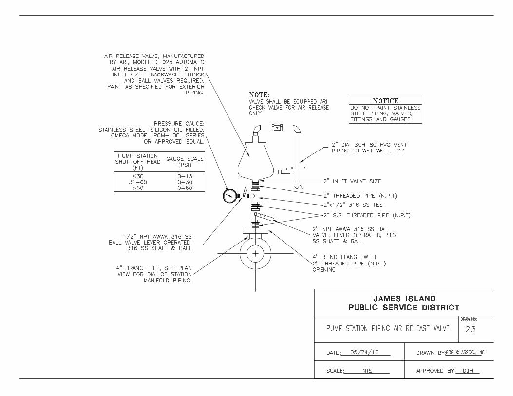
AutoCAD SHX Text
DATE:%%U
AutoCAD SHX Text
SCALE:%%U NTS
AutoCAD SHX Text
DRAWN BY:%%U
AutoCAD SHX Text
APPROVED BY:%%U DJH
AutoCAD SHX Text
JAMES ISLAND
AutoCAD SHX Text
PUBLIC SERVICE DISTRICT
AutoCAD SHX Text
DRAWING:
AutoCAD SHX Text
PUMP STATION PIPING AIR RELEASE VALVE
AutoCAD SHX Text
23
AutoCAD SHX Text
05/24/16
AutoCAD SHX Text
GRG & ASSOC., INC
AutoCAD SHX Text
%%UNOTE:
AutoCAD SHX Text
VALVE SHALL BE EQUIPPED ARI
AutoCAD SHX Text
CHECK VALVE FOR AIR RELEASE
AutoCAD SHX Text
ONLY
AutoCAD SHX Text
2" DIA. SCH-80 PVC VENT PIPING TO WET WELL, TYP.
AutoCAD SHX Text
2" INLET VALVE SIZE
AutoCAD SHX Text
2" S.S. THREADED PIPE (N.P.T)
AutoCAD SHX Text
316 SS SHAFT & BALL
AutoCAD SHX Text
BALL VALVE LEVER OPERATED,
AutoCAD SHX Text
2"x1/2" 316 SS TEE
AutoCAD SHX Text
2" THREADED PIPE (N.P.T)
AutoCAD SHX Text
DO NOT PAINT STAINLESS
AutoCAD SHX Text
NOTICE
AutoCAD SHX Text
STEEL PIPING, VALVES,
AutoCAD SHX Text
FITTINGS AND GAUGES
AutoCAD SHX Text
1/2" NPT AWWA 316 SS
AutoCAD SHX Text
4" BLIND FLANGE WITH 2" THREADED PIPE (N.P.T) OPENING
AutoCAD SHX Text
4" BRANCH TEE, SEE PLAN VIEW FOR DIA. OF STATION MANIFOLD PIPING.
AutoCAD SHX Text
AIR RELEASE VALVE, MANUFACTURED BY ARI, MODEL D-025 AUTOMATIC AIR RELEASE VALVE WITH 2" NPT INLET SIZE. BACKWASH FITTINGS AND BALL VALVES REQUIRED. PAINT AS SPECIFIED FOR EXTERIOR PIPING.
AutoCAD SHX Text
PRESSURE GAUGE: STAINLESS STEEL, SILICON OIL FILLED, OMEGA MODEL PGM-100L SERIES OR APPROVED EQUAL.
AutoCAD SHX Text
2" NPT AWWA 316 SS BALL VALVE, LEVER OPERATED, 316 SS SHAFT & BALL
AutoCAD SHX Text
PUMP STATION
AutoCAD SHX Text
SHUT-OFF HEAD
AutoCAD SHX Text
GAUGE SCALE
AutoCAD SHX Text
(PSI)
AutoCAD SHX Text
(FT)
AutoCAD SHX Text
30
AutoCAD SHX Text
0-15
AutoCAD SHX Text
31-60
AutoCAD SHX Text
0-30
AutoCAD SHX Text
>60
AutoCAD SHX Text
0-60
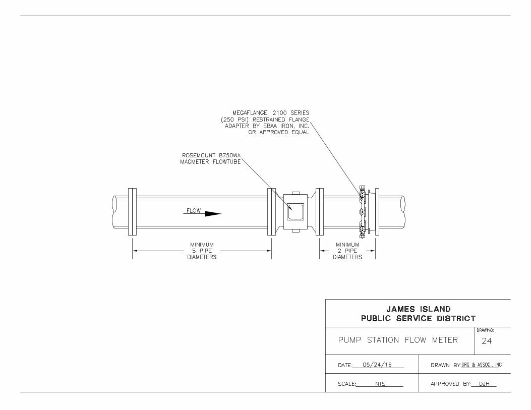
AutoCAD SHX Text
DATE:%%U
AutoCAD SHX Text
SCALE:%%U NTS
AutoCAD SHX Text
DRAWN BY:%%U
AutoCAD SHX Text
APPROVED BY:%%U DJH
AutoCAD SHX Text
JAMES ISLAND
AutoCAD SHX Text
PUBLIC SERVICE DISTRICT
AutoCAD SHX Text
DRAWING:
AutoCAD SHX Text
PUMP STATION FLOW METER
AutoCAD SHX Text
24
AutoCAD SHX Text
05/24/16
AutoCAD SHX Text
GRG & ASSOC., INC
AutoCAD SHX Text
MEGAFLANGE, 2100 SERIES (250 PSI) RESTRAINED FLANGE ADAPTER BY EBAA IRON, INC. OR APPROVED EQUAL
AutoCAD SHX Text
ROSEMOUNT 8750WA MAGMETER FLOWTUBE
AutoCAD SHX Text
FLOW

AutoCAD SHX Text
DATE:%%U
AutoCAD SHX Text
SCALE:%%U NTS
AutoCAD SHX Text
DRAWN BY:%%U
AutoCAD SHX Text
APPROVED BY:%%U DJH
AutoCAD SHX Text
JAMES ISLAND
AutoCAD SHX Text
PUBLIC SERVICE DISTRICT
AutoCAD SHX Text
DRAWING:
AutoCAD SHX Text
TYPICAL PUMP STATION
AutoCAD SHX Text
25
AutoCAD SHX Text
05/24/16
AutoCAD SHX Text
GRG & ASSOC., INC
AutoCAD SHX Text
6"
AutoCAD SHX Text
REMOVAL & REPLACEMENT OF UNSUITABLE
AutoCAD SHX Text
SUBGRADE MATERIAL AS SPECIFIED IN
AutoCAD SHX Text
SECTION 02200, EARTHWORK.
AutoCAD SHX Text
SUBGRADE COMPACTED TO 95% MAXIMUM
AutoCAD SHX Text
DRY DENSITY (MODIFIED PROCTOR).
AutoCAD SHX Text
ASPHALTIC CONCRETE SURFACE COURSE, TYPE C
AutoCAD SHX Text
AS SPECIFIED IN SECTION 402 & 403, SCDOT. STD.
AutoCAD SHX Text
SPEC., LATEST EDITION.
AutoCAD SHX Text
APPLY PRIME COAT, AS SPECIFIED IN
AutoCAD SHX Text
SECTION 305.4.6 SCDOT STD. SPEC., AT
AutoCAD SHX Text
AN APPLICATION RATE OF 0.10 - 0.15
AutoCAD SHX Text
GAL./SYD.
AutoCAD SHX Text
GRADED AGGREGATE BASE COURSE (MLBC),
AutoCAD SHX Text
AS SPECIFIED IN SECTION 305, SCDOT STD.
AutoCAD SHX Text
SPEC., LATEST EDITION, COMPACTED TO 98%
AutoCAD SHX Text
MAXIMUM DRY DENSITY (MODIFIED PROCTOR).
AutoCAD SHX Text
A.C.
AutoCAD SHX Text
8"
AutoCAD SHX Text
S.A.B.C.
AutoCAD SHX Text
2"
AutoCAD SHX Text
REGULAR DUTY
AutoCAD SHX Text
ASPHALT DRIVEWAY SECTION

AutoCAD SHX Text
DATE:%%U
AutoCAD SHX Text
SCALE:%%U NTS
AutoCAD SHX Text
DRAWN BY:%%U
AutoCAD SHX Text
APPROVED BY:%%U DJH
AutoCAD SHX Text
JAMES ISLAND
AutoCAD SHX Text
PUBLIC SERVICE DISTRICT
AutoCAD SHX Text
DRAWING:
AutoCAD SHX Text
1,000 GALLON GREASE TRAP
AutoCAD SHX Text
26
AutoCAD SHX Text
05/24/16
AutoCAD SHX Text
GRG & ASSOC., INC
AutoCAD SHX Text
3-6" DIA.
AutoCAD SHX Text
HOLES
AutoCAD SHX Text
6" %%c INLET
AutoCAD SHX Text
6" %%c OUTLET
AutoCAD SHX Text
TO GROUND SURFACE WITH
AutoCAD SHX Text
APPROVED MANHOLE FRAME
AutoCAD SHX Text
AND COVER
AutoCAD SHX Text
CLEANOUT AT GRADE
AutoCAD SHX Text
NOTICE:
AutoCAD SHX Text
1.
AutoCAD SHX Text
REQUIREMENTS.
AutoCAD SHX Text
SEE DISTRICT STANDARDS SECTIONS 15 FOR ADDITIONAL
AutoCAD SHX Text
2.
AutoCAD SHX Text
INSTALLATION SHALL ALSO BE IN ACCORDANCE
AutoCAD SHX Text
GREASE TRAP MATERIALS, CONSTRUCTION , AND
AutoCAD SHX Text
WITH APPLICABLE SCDHEC AND LOCAL PLUMBING
AutoCAD SHX Text
CODE REQUIREMENTS.
AutoCAD SHX Text
DISTRICT APPROVED
AutoCAD SHX Text
4,000 PSI CONCRETE
AutoCAD SHX Text
PRECAST GREASE TRAP
AutoCAD SHX Text
STRUCTURE
AutoCAD SHX Text
DISTRICT APPROVED RISER

AutoCAD SHX Text
EXISTING GRADE
AutoCAD SHX Text
BACK-OF-ROAD
AutoCAD SHX Text
L
AutoCAD SHX Text
MAIN C
AutoCAD SHX Text
R/W
AutoCAD SHX Text
LOCATOR WIRE SHALL BE ATTACHED TO PULLER HEAD AND PULLED WITH PIPE
AutoCAD SHX Text
DR-11 HDPE OR AS SPECIFIED
AutoCAD SHX Text
MAXIMUM
AutoCAD SHX Text
15' MINIMUM
AutoCAD SHX Text
VARIES SEE PROFILE FOR MINIMUM DEPTH
AutoCAD SHX Text
VARIES
AutoCAD SHX Text
VARIES SEE PLAN VIEW
AutoCAD SHX Text
VARIES
AutoCAD SHX Text
DATE:%%U
AutoCAD SHX Text
SCALE:%%U NTS
AutoCAD SHX Text
DRAWN BY:%%U
AutoCAD SHX Text
APPROVED BY:%%U DJH
AutoCAD SHX Text
JAMES ISLAND
AutoCAD SHX Text
PUBLIC SERVICE DISTRICT
AutoCAD SHX Text
DRAWING:
AutoCAD SHX Text
HORIZONTAL DIRECTIONAL DRILLING (HDD)
AutoCAD SHX Text
27
AutoCAD SHX Text
05/24/16
AutoCAD SHX Text
GRG & ASSOC., INC
AutoCAD SHX Text
FORCEMAIN SECTION

AutoCAD SHX Text
NOTICE:
AutoCAD SHX Text
HDPE DR-11 FORCE MAIN AS INDICATED.
AutoCAD SHX Text
PVC DR-18 C900/C905
AutoCAD SHX Text
MJ REDUCER
AutoCAD SHX Text
ALL DUCTILE IRON PIPE AND FITTINGS SHALL BE P-401 LINED AND ENCASED IN
AutoCAD SHX Text
POLYETHYLENE AS REQUIRED PURSUANT TO APPLICABLE PROJECT SPECIFICATIONS
AutoCAD SHX Text
AND IN ACCORDANCE WITH AWWA C105.
AutoCAD SHX Text
HDPE DIPS, DR-11 MJ FUSION ADAPTOR WITH STAINLESS STEEL STIFFENERS BY FUSION SUPPORT SERVICES, LLC
AutoCAD SHX Text
DATE:%%U
AutoCAD SHX Text
SCALE:%%U NTS
AutoCAD SHX Text
DRAWN BY:%%U
AutoCAD SHX Text
APPROVED BY:%%U DJH
AutoCAD SHX Text
JAMES ISLAND
AutoCAD SHX Text
PUBLIC SERVICE DISTRICT
AutoCAD SHX Text
DRAWING:
AutoCAD SHX Text
HDPE TRANSITION
AutoCAD SHX Text
28
AutoCAD SHX Text
05/24/16
AutoCAD SHX Text
GRG & ASSOC., INC
AutoCAD SHX Text
RESTRAINED JOINT

AutoCAD SHX Text
6"
AutoCAD SHX Text
8"
AutoCAD SHX Text
10"
AutoCAD SHX Text
12"
AutoCAD SHX Text
14"
AutoCAD SHX Text
16"
AutoCAD SHX Text
8"
AutoCAD SHX Text
6"
AutoCAD SHX Text
8"
AutoCAD SHX Text
3"
AutoCAD SHX Text
8"
AutoCAD SHX Text
8"
AutoCAD SHX Text
8"
AutoCAD SHX Text
10"
AutoCAD SHX Text
15"
AutoCAD SHX Text
12"
AutoCAD SHX Text
16"
AutoCAD SHX Text
19"
AutoCAD SHX Text
23"
AutoCAD SHX Text
26"
AutoCAD SHX Text
16"
AutoCAD SHX Text
22"
AutoCAD SHX Text
26"
AutoCAD SHX Text
29"
AutoCAD SHX Text
35"
AutoCAD SHX Text
38"
AutoCAD SHX Text
6"
AutoCAD SHX Text
8"
AutoCAD SHX Text
10"
AutoCAD SHX Text
12"
AutoCAD SHX Text
14"
AutoCAD SHX Text
16"
AutoCAD SHX Text
10"
AutoCAD SHX Text
12"
AutoCAD SHX Text
14"
AutoCAD SHX Text
16"
AutoCAD SHX Text
18"
AutoCAD SHX Text
20"
AutoCAD SHX Text
10"
AutoCAD SHX Text
13"
AutoCAD SHX Text
17"
AutoCAD SHX Text
21"
AutoCAD SHX Text
24"
AutoCAD SHX Text
27"
AutoCAD SHX Text
8"
AutoCAD SHX Text
10"
AutoCAD SHX Text
12"
AutoCAD SHX Text
14"
AutoCAD SHX Text
16"
AutoCAD SHX Text
9"
AutoCAD SHX Text
12"
AutoCAD SHX Text
14"
AutoCAD SHX Text
16"
AutoCAD SHX Text
19"
AutoCAD SHX Text
21"
AutoCAD SHX Text
10"
AutoCAD SHX Text
12"
AutoCAD SHX Text
14"
AutoCAD SHX Text
16"
AutoCAD SHX Text
18"
AutoCAD SHX Text
27"
AutoCAD SHX Text
24"
AutoCAD SHX Text
21"
AutoCAD SHX Text
17"
AutoCAD SHX Text
13"
AutoCAD SHX Text
10"
AutoCAD SHX Text
5"
AutoCAD SHX Text
6"
AutoCAD SHX Text
8"
AutoCAD SHX Text
10"
AutoCAD SHX Text
11"
AutoCAD SHX Text
6"
AutoCAD SHX Text
8"
AutoCAD SHX Text
10"
AutoCAD SHX Text
11"
AutoCAD SHX Text
12"
AutoCAD SHX Text
12"
AutoCAD SHX Text
9"
AutoCAD SHX Text
10"
AutoCAD SHX Text
11"
AutoCAD SHX Text
12"
AutoCAD SHX Text
13"
AutoCAD SHX Text
8"
AutoCAD SHX Text
10"
AutoCAD SHX Text
13"
AutoCAD SHX Text
16"
AutoCAD SHX Text
20"
AutoCAD SHX Text
24"
AutoCAD SHX Text
9"
AutoCAD SHX Text
11"
AutoCAD SHX Text
14"
AutoCAD SHX Text
16"
AutoCAD SHX Text
18"
AutoCAD SHX Text
10"
AutoCAD SHX Text
13"
AutoCAD SHX Text
16"
AutoCAD SHX Text
18"
AutoCAD SHX Text
22"
AutoCAD SHX Text
24"
AutoCAD SHX Text
12"
AutoCAD SHX Text
14"
AutoCAD SHX Text
16"
AutoCAD SHX Text
18"
AutoCAD SHX Text
20"
AutoCAD SHX Text
12"
AutoCAD SHX Text
16"
AutoCAD SHX Text
20"
AutoCAD SHX Text
24"
AutoCAD SHX Text
27"
AutoCAD SHX Text
30"
AutoCAD SHX Text
12"
AutoCAD SHX Text
14"
AutoCAD SHX Text
16"
AutoCAD SHX Text
18"
AutoCAD SHX Text
20"
AutoCAD SHX Text
10"
AutoCAD SHX Text
12"
AutoCAD SHX Text
14"
AutoCAD SHX Text
16"
AutoCAD SHX Text
18"
AutoCAD SHX Text
20"
AutoCAD SHX Text
20"
AutoCAD SHX Text
25"
AutoCAD SHX Text
30'
AutoCAD SHX Text
34"
AutoCAD SHX Text
38"
AutoCAD SHX Text
21"
AutoCAD SHX Text
29"
AutoCAD SHX Text
36"
AutoCAD SHX Text
41"
AutoCAD SHX Text
48'
AutoCAD SHX Text
54"
AutoCAD SHX Text
B
AutoCAD SHX Text
A
AutoCAD SHX Text
B
AutoCAD SHX Text
A
AutoCAD SHX Text
B
AutoCAD SHX Text
A
AutoCAD SHX Text
B
AutoCAD SHX Text
A
AutoCAD SHX Text
B
AutoCAD SHX Text
A
AutoCAD SHX Text
PLUGS
AutoCAD SHX Text
TEES
AutoCAD SHX Text
22%%dBEND
AutoCAD SHX Text
45%%dBEND
AutoCAD SHX Text
90%%DBEND
AutoCAD SHX Text
DIA.
AutoCAD SHX Text
2000 PSF
AutoCAD SHX Text
4000 PSF
AutoCAD SHX Text
MINIMUM SOIL BEARING CAPACITY
AutoCAD SHX Text
NOTE: FOR 2"-4" DIAMETER WATER LINES USE DIMENSIONS INDICATED FOR 6" MAINS
AutoCAD SHX Text
A
AutoCAD SHX Text
A
AutoCAD SHX Text
X
AutoCAD SHX Text
X
AutoCAD SHX Text
3000 PSI
AutoCAD SHX Text
CONCRETE
AutoCAD SHX Text
DO NOT COVER BOLTS
AutoCAD SHX Text
OR RETAINER GLANDS
AutoCAD SHX Text
WITH CONCRETE
AutoCAD SHX Text
BENDS - PLAN VIEW
AutoCAD SHX Text
TEE - PLAN VIEW
AutoCAD SHX Text
A
AutoCAD SHX Text
A
AutoCAD SHX Text
X
AutoCAD SHX Text
X
AutoCAD SHX Text
BENDS & TEES
AutoCAD SHX Text
PLUGS - PLAN & ELEVATION VIEW
AutoCAD SHX Text
SECTION X-X
AutoCAD SHX Text
B
AutoCAD SHX Text
B
AutoCAD SHX Text
45%%D
AutoCAD SHX Text
24" MIN. - 12" DIA. AND LARGER
AutoCAD SHX Text
18" MIN. - 10" DIA. AND SMALLER
AutoCAD SHX Text
C
AutoCAD SHX Text
D
AutoCAD SHX Text
(SQUARE)
AutoCAD SHX Text
18" MIN.
AutoCAD SHX Text
(SQUARE)
AutoCAD SHX Text
DATE:%%U
AutoCAD SHX Text
SCALE:%%U NTS
AutoCAD SHX Text
DRAWN BY:%%U
AutoCAD SHX Text
APPROVED BY:%%U DJH
AutoCAD SHX Text
JAMES ISLAND
AutoCAD SHX Text
PUBLIC SERVICE DISTRICT
AutoCAD SHX Text
DRAWING:
AutoCAD SHX Text
THRUST BLOCKING
AutoCAD SHX Text
29
AutoCAD SHX Text
05/24/16
AutoCAD SHX Text
GRG & ASSOC., INC

AutoCAD SHX Text
SEE GRINDER PUMP INSTALLATION DETAIL
AutoCAD SHX Text
FOR CONCRETE ANCHOR REQUIREMENT
AutoCAD SHX Text
GRADE MUST SLOPE AWAY FROM STATION
AutoCAD SHX Text
DATE:%%U
AutoCAD SHX Text
SCALE:%%U NTS
AutoCAD SHX Text
DRAWN BY:%%U
AutoCAD SHX Text
APPROVED BY:%%U DJH
AutoCAD SHX Text
JAMES ISLAND
AutoCAD SHX Text
PUBLIC SERVICE DISTRICT
AutoCAD SHX Text
DRAWING:
AutoCAD SHX Text
GRINDER PUMP
AutoCAD SHX Text
30
AutoCAD SHX Text
05/24/16
AutoCAD SHX Text
GRG & ASSOC., INC

AutoCAD SHX Text
1 1/4" DISCHARGE
AutoCAD SHX Text
4" PVC SERVICE
AutoCAD SHX Text
GRADE MUST SLOPE AWAY FROM STATION
AutoCAD SHX Text
MIN. 1' NO. 57 AGGREGATE
AutoCAD SHX Text
VARIES
AutoCAD SHX Text
VARIES"
AutoCAD SHX Text
CONCRETE ANCHOR SIZE VARIES BASED ON SOIL TYPE
AutoCAD SHX Text
3" TO 6" BELOW BOTTOM OF LID
AutoCAD SHX Text
COMPACTED BACKFILL
AutoCAD SHX Text
DATE:%%U
AutoCAD SHX Text
SCALE:%%U NTS
AutoCAD SHX Text
DRAWN BY:%%U
AutoCAD SHX Text
APPROVED BY:%%U DJH
AutoCAD SHX Text
JAMES ISLAND
AutoCAD SHX Text
PUBLIC SERVICE DISTRICT
AutoCAD SHX Text
DRAWING:
AutoCAD SHX Text
TYPICAL GRINDER PUMP
AutoCAD SHX Text
31
AutoCAD SHX Text
05/24/16
AutoCAD SHX Text
GRG & ASSOC., INC
AutoCAD SHX Text
INSTALLATION

AutoCAD SHX Text
EXISTING SEPTIC TANK
AutoCAD SHX Text
EXISTING HOUSE
AutoCAD SHX Text
NEW E/ONE
AutoCAD SHX Text
GRINDER PUMP
AutoCAD SHX Text
NEW 1-1/4" DR-11 HDPE FORCE MAIN
AutoCAD SHX Text
NEW 4" PVC
AutoCAD SHX Text
CAP EXISTING SERVICE LINE TO SEPTIC TANK
AutoCAD SHX Text
EXISTING SEWER SERVICE LINE, DIAMETER AND MATERIAL TO BE VERIFIED.
AutoCAD SHX Text
NEW 4" 45° BEND
AutoCAD SHX Text
NEW 4" WYE BEND
AutoCAD SHX Text
NEW 4" 45° BEND
AutoCAD SHX Text
SEE CLEANOUT DETAIL
AutoCAD SHX Text
DATE:%%U
AutoCAD SHX Text
SCALE:%%U NTS
AutoCAD SHX Text
DRAWN BY:%%U
AutoCAD SHX Text
APPROVED BY:%%U DJH
AutoCAD SHX Text
JAMES ISLAND
AutoCAD SHX Text
PUBLIC SERVICE DISTRICT
AutoCAD SHX Text
DRAWING:
AutoCAD SHX Text
GRINDER PUMP SEPTIC TANK
AutoCAD SHX Text
32
AutoCAD SHX Text
05/24/16
AutoCAD SHX Text
GRG & ASSOC., INC
AutoCAD SHX Text
INTERCEPT

AutoCAD SHX Text
LID ASSEMBLY WITH PENTAGON HEAD PLUG MATERIAL: CAST IRON
AutoCAD SHX Text
EXTENSION TYPE CURB BOX WITH ARCH PATTERN BASE BY E/ONE
AutoCAD SHX Text
AVAILABLE LENGTHS
AutoCAD SHX Text
18-30"
AutoCAD SHX Text
PB0930G01
AutoCAD SHX Text
30-42"
AutoCAD SHX Text
36-54"
AutoCAD SHX Text
42-66"
AutoCAD SHX Text
48-78"
AutoCAD SHX Text
60-102"
AutoCAD SHX Text
PART NUMBER
AutoCAD SHX Text
PB0930G02
AutoCAD SHX Text
PB0930G03
AutoCAD SHX Text
PB0930G04
AutoCAD SHX Text
PB0930G05
AutoCAD SHX Text
PB0930G06
AutoCAD SHX Text
ORDERED SEPARATELY USING PART NUMBER FROM ABOVE
AutoCAD SHX Text
NEW 1-1/4" DR 11 HDPE FORCE MAIN FROM GRINDER PUMP
AutoCAD SHX Text
1-1/4" MALE THREADED ADAPTER COMPRESSION FITTING
AutoCAD SHX Text
3" HDPE IPS DR-11 FORCE MAIN
AutoCAD SHX Text
3"x1-1/4" ROMAC INDUSTRIES, INC. 202N-H SERVICE SADDLE OR APPROVED EQUAL
AutoCAD SHX Text
1-1/4" STAINLESS STEEL UNI-LATERAL LATERAL VALVE BY E/ONE PART NUMBER NB018P01
AutoCAD SHX Text
2" HDPE IPS DR-11 FORCE MAIN
AutoCAD SHX Text
2"x1-1/4" ROMAC INDUSTRIES, INC. 202N-H SERVICE SADDLE OR APPROVED EQUAL
AutoCAD SHX Text
DATE:%%U
AutoCAD SHX Text
SCALE:%%U NTS
AutoCAD SHX Text
DRAWN BY:%%U
AutoCAD SHX Text
APPROVED BY:%%U DJH
AutoCAD SHX Text
JAMES ISLAND
AutoCAD SHX Text
PUBLIC SERVICE DISTRICT
AutoCAD SHX Text
DRAWING:
AutoCAD SHX Text
GRINDER PUMP SERVICE
AutoCAD SHX Text
33
AutoCAD SHX Text
05/24/16
AutoCAD SHX Text
GRG & ASSOC., INC
AutoCAD SHX Text
CONNECTION

AutoCAD SHX Text
HDPE DR-11
AutoCAD SHX Text
HDPE DR-11
AutoCAD SHX Text
END CAP
AutoCAD SHX Text
2" IPS
AutoCAD SHX Text
2" IPS
AutoCAD SHX Text
2" COMPRESSION FITTING
AutoCAD SHX Text
2" COMPRESSION FITTING
AutoCAD SHX Text
2" COMPRESSION FITTING
AutoCAD SHX Text
END CAP
AutoCAD SHX Text
2" COMPRESSION FITTING
AutoCAD SHX Text
2" COMPRESSION FITTING
AutoCAD SHX Text
2" COMPRESSION FITTING
AutoCAD SHX Text
BALL VALVE AND VALVE BOX
AutoCAD SHX Text
BALL VALVE WITH VALVE BOX.
AutoCAD SHX Text
DATE:%%U
AutoCAD SHX Text
SCALE:%%U NTS
AutoCAD SHX Text
DRAWN BY:%%U
AutoCAD SHX Text
APPROVED BY:%%U DJH
AutoCAD SHX Text
JAMES ISLAND
AutoCAD SHX Text
PUBLIC SERVICE DISTRICT
AutoCAD SHX Text
DRAWING:
AutoCAD SHX Text
LOW PRESSURE FORCE MAIN
AutoCAD SHX Text
34
AutoCAD SHX Text
05/24/16
AutoCAD SHX Text
GRG & ASSOC., INC
AutoCAD SHX Text
END-OF-LINE FLUSHING
AutoCAD SHX Text
THRUST BLOCK

20.
JIPSD APPROVED
MATERIAL MANUFACTURERS

SECTION 20
JIPSD APPROVED MATERIAL MANUFACTURERS
PART 1 – GENERAL
A. Ductile Iron Pipe and fittings:
1. American
2. US Pipe
3. Griffin
4. Clow
B. Ductile Iron Fittings:
1. Flange Fittings:
a. US Pipe (TR Flex series)
b. American
c. Tyler-Union
d. Star
e. Sigma
2. Mechanical Joint Fittings:
a. US Pipe (TR Flex series)
b. American
c. Tyler-Union
d. Star
e. Sigma
f. Griffin
C. Ductile Iron Lining:
1. Protecto-401
2. Permox CTF
D. Compression sleeve coupling:
1. Smith-Blair (411 Series with SS nuts and bolts)
2. Romac (Armor Series SS)
E. Transition Couplings:
1. Dresser (Style 62 with SS nuts and bolts)
2. Fernco (5000 Series with SS nuts and bolt clamps)
3. Smith-Blair (Style 413 with SS nuts and bolts)
F. Polyethylene encasement tape:
1. Kendall (Polyken 900)
2. 3M (Scotchrap 50)

G. Joint Restraint:
1. DIP:
a. Ebaa Iron 1100 Series Megalug
b. Ford Series 1400
c. Romac RomaGrip
d. Sigma ONE-LOK Series SLDE
e. StarGrip Series 3000
2. PVC:
a. Ebaa Iron 2000PV Series
b. Ford Series 1350, 1390, 1500
c. Romac RomaGrip for PVC
d. Sigma ONE-LOK Series SLCE
e. StarGrip PVC Series 4000
3. HDPE:
a. EBAA HDPE Joint Restraint
b. StarGrip Series 4000 Restrainer for HDPE
PART 2 – WASTEWATER
A. Force Main Valves:
1. Plug Valves:
a. Milliken Millcentric Series 600FP 100% Port
b. Milliken Millcentric Series 600
c. DeZurick PEF 100% Port
d. DeZurick PEC
e. Pratt Ballcentric 100% Port
f. Val-Matic Cam-Centric 100% Port
g. Clow Eccentric Plug Valve
2. Gate Valves:
a. Mueller A-2361
b. American Flow Series 2500
c. Clow Model2638
3. Check Valves:
a. Tideflex Red Valve Series 39
b. Wastop Inline Check Valve
c. Mueller Flexible Disc
d. Val-Matic Swing-Flex (VM-502A)
e. Crispin RF Series
f. American Flow Control Series 2100
B. Manhole:
1. Knights PreCast
2. Tindall Concrete G Series

C. Manhole Castings:
1. Castings in Vehicle Traffic Areas
a. US Foundry
b. East Jordan
2. Casting not in Vehicle Traffic Areas
a. Pamrex
b. East Jordan
PART 3 – PUMP STATIONS
A. Pumps:
1. Grinder
a. ABS Piranha
b. Environment One (E-1)
2. Centrifugal
a. Flygt
b. ABS
B. Valves:
1. Plug:
a. Milliken Milcentric Series 601FP 100% Port
b. Milliken Milcentric Series 601
c. DeZurick PEF 100% Port
d. DeZurick PEC
e. Pratt Ballcentric 100% Port
f. Val-Matic Cam-Centric 100% Port
g. Clow Eccentric Plug Valve
2. Gate:
a. Mueller A-2361
b. American Flow Series 2500
c. Clow Model 2638
3. Ball Check:
a. HDL Type 5087
b. Flowmatic Model 408
4. Inline Check:
a. Tideflex Red Valve Series 39
b. Wastop Inline Check Valve
c. American Flow Control Series 2100
C. Air Release Valves:
1. ARI Model D-020, D-023, D-025
2. ARI Automatic air release valve Model S-020
3. H-Tec Model 986-01

D. Access Hatch:
1. Halliday Series F1R Floodtight Hatch
2. East Jordan Floodproof Hatch
E. Riser Pipe Coupling:
1. Body (316 SS):
a. Dresser Style 38
b. Smith Blair 411
2. Gasket Compound:
a. Grade-42 Buna-N
F. Wall Seals:
1. Link-Seal Model Series LS
G. Pipe Supports/Hangers:
1. Grinnel
H. Inside Drop Connections:
1. Reliner Inside Drop Bowls
I. Wet Wells:
1. Knights
2. Tindall Concrete G Series
J. Coatings:
1. Raven 405 (60 mils minimum piping and 125 mils minimum concrete)
K. Linings:
1. Strong-Seal 100% Calcium Aluminate (minimum 0.50 inches)
L. Flow Meters:
1. Rosemount Series 8700 Flowtube & Series 871 Transmitter