City of Monterey Sewer System Management Plan
484
City of Monterey Sewer System Management Plan Certified April 2018 Revised May 2019
-
Upload
khangminh22 -
Category
Documents
-
view
3 -
download
0
Transcript of City of Monterey Sewer System Management Plan

City of Monterey Sewer System Management Plan
Certified April 2018
Revised May 2019

Contents
INTRODUCTION ............................................................................................................................................. 1
Sewer System Management Plan Requirements .......................................................................................... 2
Element 1: Goals ........................................................................................................................................... 3
Element 2: Organization ................................................................................................................................ 4
Element 3: Legal Authority ............................................................................................................................ 9
Element 4: Operations and Maintenance Program .................................................................................... 14
Element 5: Design and Performance Provisions ......................................................................................... 27
Element 6: Overflow Emergency Response Plan ........................................................................................ 29
Element 7: Fats, Oils, and Grease Control Program ................................................................................... 37
Element 8: System Evaluation and Capacity Assurance Plan ...................................................................... 51
Element 9: Monitoring, Measurement and Program Modifications ......................................................... 53
Element 10: SSMP Program Audits ............................................................................................................ 57
Element 11: Communication Program ....................................................................................................... 59
Appendices
Appendix 1: Waste Discharge Requirements Order No. WQ 2013‐0058‐EXEC and 2006‐0003‐DWQ
Appendix 2: Legally Responsible Official (LRO) Memo
Appendix 3: Organizational Chart (Public Works Dept. & Community Dev. Dept.)
Appendix 4: SSO Chain of Communication
Appendix 5: Monterey City Code Chapter 30 Sewers and Sewage Disposal
Appendix 6: M1W Ordinance No. 2008‐01
Appendix 7: Sewer System Map and Sewer System Map by Relative Install Date
Appendix 8: CCTV Inspection Program Summary
Appendix 9: Hot List Areas and Maintenance Schedules
Appendix 10: Sewer Root Foaming Map (2016)
Appendix 11: Sewer Line Creek Crossing Maps
Appendix 12: Sewer Lift Station Inventory Map, Data Table, Critical Parts, and M1W Maintenance Agreement
Appendix 13: City Sewer Critical Parts, Equipment, Vendors/Suppliers, and Mutual Aid Lists
Appendix 14: Standard Details for Sewer Improvements
Appendix 15: SSO Spill Response Protocol
Appendix 16: Fat, Oil, and Grease (FOG) Program Documentation
Appendix 17: Sewer Fee Study Update (1988)
Appendix 18: Sanitary Sewer Utility Fee Study (2011)
Appendix 19: Sewer Lift Station and Force Main Condition Assessment (2010)
Appendix 20: SSMP Update Log
Appendix 21: Operation & Maintenance SOPs

i
Acronyms and Abbreviations
BMP Best Management Practice
CalOES California Office of Emergency Services
CCTV Closed Circuit Television
CIP Capital Improvement Program
City City of Monterey
CIWQS California Integrated Water Quality System
EPA Environmental Protection Agency
FOG Fats, Oil, and Grease
FSE Food Services Establishment GIS Geographic Information System (GIS) GPS Global Positioning System
HMA Hot List Maintenance Area
I/I Inflow and Infiltration
LRO Legally Responsible Official
M1W (formerly MRWPCA)
Monterey One Water (new name of Monterey Regional Water Pollution Control Agency, formerly MRWPCA)
MCHD Monterey County Environmental Health Department
NSA Monterey U. S. Naval Support Activity Monterey
OES (or CalOES) Office of Emergency Services
O&M Operation and Maintenance
PLSD Private Lateral Sewage Discharge
POM U. S. Army Garrison Presidio of Monterey
ppm Parts per million
RWQCB Central Coast Regional Water Quality Control Board (Region 3)
SCADA Supervisory Control and Data Acquisition
SECAP Sewer Evaluation and Capacity Assessment Plan SOP Standard Operating Procedure SSMP Sewer System Management Plan
SSO Sanitary Sewer Overflow
SWRCB State Water Resources Control Board
WDRs SWRCB Waste Discharge Requirements (Used herein to reference regulations in Orders No. 2006‐0003‐DWQ & WQ 2013‐0058‐EXEC.)

ii
(THIS PAGE INTENTIONALLY LEFT BLANK.)
iii

City of Monterey Sewer System Management Plan May 2019 Update
1 | P a g e
INTRODUCTION_____________________________________________________________________________________
Legal Requirements
On May 2, 2006, the State Water Resources Control Board (SWRCB) enacted Order No. 2006‐0003‐DWQ
Statewide General Waste Discharge Requirements for Sanitary Sewer Systems. These WDRs were subsequently
amended with an updated Monitoring and Reporting Program under Order No. WQ 2013‐0058‐EXEC.
Collectively, the 2006 and 2013 regulations are referred to herein as WDRs, and are attached in Appendix 1.
Generally, the WDRs require the City of Monterey (City) to maintain and implement a Sewer System
Management Plan (SSMP) that provides a guide to properly manage, operate, and maintain all parts of its
sanitary sewer collection and conveyance system in order to help reduce and prevent sanitary sewer overflows
(SSOs), as well as mitigate any SSOs that occur. To facilitate proper funding and management of sanitary sewer
systems, each
Enrollee must develop and implement a system‐specific Sewer System Management Plan (SSMP). To be
effective, SSMPs must include provisions to provide proper and efficient management, operation, and
maintenance of
sanitary sewer systems, while taking into consideration risk management and cost benefit analysis. Additionally,
the SWRCB requires a SSMP to contain an SSMP must contain a spill response plan that establishes standard
procedures for immediate response to an SSO in a manner designed to minimize water quality impacts and
potential nuisance conditions.
The WDRs require any public agency that owns or operates a sanitary sewer system more than one mile in length
that collect and/or convey untreated or partially treated wastewater to a publicly owned treatment facility in
the State of California to comply with the terms of the requirements of the WDRs in order to reduce the number
of SSOs with particular notification and reporting requirements. Under the WDRs, agencies must electronically
report SSOs to the State Water Resources Control Board and develop a SSMP that describes how it operates,
maintains, and evaluates its sewer system.
The City of Monterey is an incorporated city in Monterey County, California. The city encompasses 8.6 square
miles of land and 3.47 square miles of water (in the Monterey Bay). Per the 2010 U.S. Census, the population of
the City of Monterey was 27,810 people. The City sewer infrastructure consists of 99 miles of gravity sewer
mains and 1.5 miles of force mains, 7 lift stations, and over 2,300 manholes, and structures located in City
easements on federally owned property at the U.S. Naval Support Activity Monterey (NSA Monterey) and the
U.S. Army Garrison Presidio of Monterey (POM). The POM sanitary sewer collection and conveyance system is
owned by the City of Monterey, but was traditionally a separate system.

City of Monterey Sewer System Management Plan May 2019 Update
2 | P a g e
SewerSystemManagementPlanRequirementsThe City has developed this SSMP per the requirements of the WDRs. This SSMP identifies how the City complies
or implements the following WDR‐prescribed SSMP Elements:
1. Goal
2. Organization
3. Legal Authority
4. Operation and Maintenance Program
5. Design and Performance Provisions
6. Overflow Emergency Response Plan
7. FOG Control Program
8. System Evaluation and Capacity Assurance Plan
9. Monitoring, Measurement, and Program Modifications
10. SSMP Program Audits
11. Communication Program
The City currently implements a variety of programs that meet the WDR objectives and are consistent with the
specific requirements of the SSMP. The sections of this SSMP are organized to correspond with the 11 elements
listed above. The SSMP integrates many on‐going City activities into this one formal document. Some of these
activities are described in greater detail in other documents that are referenced in the SSMP. Applicable
documents are kept at the Public Works Department Office located at City Hall, 580 Pacific Street, Room 7,
Monterey, CA. This SSMP is also available online to the public at Monterey.org.

City of Monterey Sewer System Management Plan May 2019 Update
3 | P a g e
SSMP ELEMENTS
Element 1: Goals WDR requirement: The goal of the SSMP is to provide a plan and schedule to properly manage, operate, and
maintain all parts of the sanitary sewer system. This will help reduce and prevent SSOs, as well as mitigate
any SSOs that do occur.
The City of Monterey (City) has the following goals for the management and maintenance of the sanitary sewer
collection system. These goals provide focus for City Staff to continue high‐quality work to operate and maintain
City facilities and to implement improvements for management of the collection system to prevent sanitary
sewer overflows (SSOs). The role of the SSMP in supporting these goals is discussed below. These goals will be
evaluated biennially as a part of Element 9: Monitoring, Measurement and Program Modification to assess the
City’s success in implementing and meeting the objectives of these goals.
Using the policies and procedures outlined in this SSMP, the City aims to achieve the following goals:
1. Reduce the occurrences of Sanitary Sewer Overflows (SSOs) and respond quickly to mitigate any impact
of the overflow.
2. Complete citywide Sanitary Sewer Collection System Rehabilitation Project construction in 2019;
3. Continue to identify and prioritize structural deficiencies and implement short‐term maintenance and
rehabilitation actions to address each deficiency.
4. Update and maintain standards and specifications for the installation of new sewer assets and
rehabilitated existing sewer assets.
5. Exercise preventative maintenance on the collection system as outlined in the Operation and
Maintenance Program to decrease SSOs.
6. Perform an on‐going Condition Assessment of collection system on a 10‐year cycle, with a goal of
completing 10% of the sewer collection system per year.
7. Continue to update inventory of FOG‐producing facilities and implement FOG inspection program as a
SSO reduction strategy.
8. Annually communicate with satellite sewer systems regarding the operation and maintenance of these
systems.

City of Monterey Sewer System Management Plan May 2019 Update
4 | P a g e
Element 2: Organization WDR requirement: The City’s SSMP must identify:
a) The name of the responsible or authorized representative;
The Legally Responsible Official (LRO) for the City of Monterey is Steve Wittry, Public Works Director. His duly authorized representative is Tricia Wotan, Environmental Regulations Manager. A table listing the City‐designated roles with the SWRCB and in the California Integrated Water Quality System (CIWQS) Online SSO Database is below, and a memo of the same information is in Appendix 2.
Name Title CIWQS SSO Database CIWQS
Party ID
CIWQS Start
Date
Steve Wittry Public Works Director Legally Responsible Official
(LRO)
549193 11/26/2014
Tricia Wotan Environmental
Regulations Mngr. Duly Authorized Rep. for LRO
546205 04/22/2014
Sara Myers Maintenance
Technician Data Submitter
563563 4/21/2017
Lucas Russell Harbor Security
Worker Data Submitter
549303 12/04/2014
Christopher Singh Street and Utilities
Supervisor Data Submitter
485279 09/12/2008
Also, an April 2018 Organizational Chart with lines of authority is contained in Appendix 3. b) The names and telephone numbers for management, administrative, and maintenance positions
responsible for implementing specific measures in the SSMP. Include lines of authority as shown in an
organization chart or similar document with a narrative explanation;
Name and Title SSMP Responsibilities Contact Information
City Council
Clyde Roberson
Mayor – Nov. 2018
Dan Albert
Councilmember – Nov. 2020
Timothy Barrett
Councilmember – Nov. 2018
The City Council directs the City Manager, Legal Counsel, and Public Works Director in the management of all eleven (11) SSMP Elements.
The Mayor and Council may be reached by contacting their Executive Assistant at:
Office: (831) 646–3760
Or, by completing a Citizen Comment Form online at Monterey.org

City of Monterey Sewer System Management Plan May 2019 Update
5 | P a g e
Name and Title SSMP Responsibilities Contact Information
Alan Haffa
Councilmember –
Nov. 2020
Ed Smith
Vice Mayor –
Nov. 2018
Hans Uslar
Interim City Manager
Bonnie Gawf
Interim Assist. City Manager
The City Manager or Assistant City Manager directs the management of all eleven (11) SSMP Elements, in coordination with the Public Works Director.
City Manager Office
(831) 646‐3760
Christine Davi
City Attorney
The City Attorney, in coordination with the Public Works Director, assists in the management of Element 3, Legal Authority.
City Attorney Office
(831) 646‐3915
Steve Wittry
Public Works Director
and
Tricia Wotan
Environmental Reg. Mngr.
The Public Works Director, in coordination with the Environmental Regulations Manager, is responsible for the overall management of the SSMP and specifically directs or manages the implementation of all 11 Goals:
Element 1 – Goal;
Element 2 – Organization;
Element 3 – Legal Authority;
Element 4 ‐ Operation and Maintenance Program;
Element 5 – Design and Performance Provisions;
Element 6 – Overflow Emergency Response Plan;
Element 7 – FOG Control Program;
Element 8 – System Evaluation and Capacity Assurance Plan;
Public Works Office:
(831) 646‐3921
Environ. Reg. Office:
(831) 646‐3895

City of Monterey Sewer System Management Plan May 2019 Update
6 | P a g e
Name and Title SSMP Responsibilities Contact Information
Element 9 – Monitoring, Measurement, and Program Modifications;
Element 10 – SSMP Audits; and
Element 11 – Communication Program
Bret Johnson
Fleet and Streets Operations Manager
Gaudenz Panholzer
Fire Chief, Fire Dept.
The Fleet and Streets Operations Manager, in coordination with the Public Works Director, is responsible for the management and implementation of:
Element 4 ‐ Operation and Maintenance Program; and
Element 6 – Overflow Emergency Response Plan.
[In emergencies, Fire Dept. may direct aspects of spill containment, support, and agency notifications.]
Streets and Utilities Office:
(831) 646‐3927
Fire Department Office:
(831) 646‐3900
Christopher Singh, and
Elmo Concalves,
Street and Utility Supervisors;
Sara Myers,
Maintenance Technician
John Haynes,
Harbormaster;
Lucas Russell,
Harbor Security Worker
Tricia Wotan, Environ. Reg. Manager;
Kevin Anderson,
Environ. Reg. Analyst
The Streets and Utilities Supervisors assist in the implementation of:
Element 4 ‐ Operation and Maintenance Program; and,
Element 6 – Overflow Emergency Response Plan.
Harbor staff assists with Element 6 – Overflow Emergency Response Plan as it relates to the Monterey Harbor.
Environmental Regulations staff assists with Elements 4 and 6, as well.
Streets and Utilities Office:
(831) 646‐3927
Harbormaster Office:
(831) 646‐3950
Environmental Reg. Office:
(831)646‐3746
John Kuehl,
Chief of Inspection Services/Building Official
Permits and Inspection Services, in coordination with the Public Works
Permits and Inspection Services Office: (831)646‐3891

City of Monterey Sewer System Management Plan May 2019 Update
7 | P a g e
Name and Title SSMP Responsibilities Contact Information
Kevin Anderson,
Environ. Reg. Analyst
Director and Environmental Regulations, assists in the implementation of:
Element 5 – Design and Performance Provisions;
Element 6 – Overflow Emergency Response Plan;
Element 7 – FOG Control Program.
Environmental Regs. Office:
(831)646‐3746
c) The chain of communication for reporting SSOs, from receipt of a complaint or other information,
including the person responsible for reporting SSOs to the State and Regional Water Board and other
agencies if applicable (such as County Health Officer, County Environmental Health Agency, and/or State
Office of Emergency Services (OES)).
SSO reports typically begin with a call from an observer to the City of Monterey or 911 dispatchers. During
business hours the City sewer spill telephone contact number is (831)646‐3921 or 911. After City business hours
the contact number is the City Non‐Emergency Number (831)646‐3914 or 911. This Chain of Communication
process is outlined in Appendix 4.
During the process of responding to a SSO, the following actions are taken as outlined in Appendix 4 and
described below to verify the report and ensure the safety of the public:
1. During business hours, Public Works Department Streets and Utilities Division receives calls from an observer or emergency services, obtains the location of concern, description of the problem, and responds to the location.
2. After hours, the Fire Department responds to the described location to verify the SSO report, and notifies the Public Works Streets and Utilities On‐Call response crew for sewer utility support.
3. The spill response plan contained in Element 6 is initiated.
4. Per the WDRs, City Fire or Public Works notifies California Office of Emergency Services (CalOES) within two (2) hours of the City becoming aware of a Category 1 SSO greater than or equal to 1,000 gallons discharged to a surface water or spilled in a location where it probably will be discharged to surface water.
CalOES notifies multiple agencies, including the Monterey County Health Department (MCHD), though City Fire or Public Works staff typically contacts MCHD directly, as well.
5. Upon completion of containment and clean‐up, the Public Works Streets and Utilities Supervisor or designee will initiate the draft SSO Report in CIWQS for LRP review and certification. Information is collected from field crew(s) to inform the CIWQS report, which may include a Fire Incident Report and/or Streets and Utilities Work Order.

City of Monterey Sewer System Management Plan May 2019 Update
8 | P a g e
The City’s detailed spill response protocol, which includes Chain of Communication, is attached as
Appendix 15.
Administration and maintenance positions responsible for implementing measures in the SSMP program are
detailed in each section of the plan. The activities required by the SSMP are primarily overseen by the Public
Works Department. The Fleet and Streets Operations Manager and any associated event Supervisors are the
lead for the crews responsible for the sewer collection system under the Public Works Director.
Within the Public Works Department, the Streets and Utilities Division oversees operation and maintenance of
the system with one (1) Fleet and Streets Operations Manager, two (2) Supervisors, and 12 maintenance
personnel. Streets Division staff respond to sewage spills seven days a week, 24 hours a day. The Engineering
and Environmental Regulations Divisions are generally responsible for system CCTV inspection, mapping, design,
analysis, and capital project programming. Sewer spill reporting is prepared by Public Works, and may be
completed in coordination with Fire Incident information when emergency services are involved.

City of Monterey Sewer System Management Plan May 2019 Update
9 | P a g e
Element 3: Legal Authority As required by the WDRs and any future amendments thereto, the City of Monterey has established existing
legal authorities for oversight of its sanitary sewer collection and conveyance system through ordinances and
agreements.
WDR requirement: Each Enrollee must demonstrate, through sanitary sewer system use ordinances, service
agreements, or other legally binding procedures, that it possesses the necessary legal authority to:
a) Prevent illicit discharges into its sanitary sewer system (examples may include I/I, stormwater, chemical
dumping, unauthorized debris and cut roots, etc.)
The City’s sewers and sewage disposal ordinance provides City staff with authority to enforce all of the above.
City Code Chapter 30 Sewers and Sewage Disposal (Appendix 5) governs sewers and sewage disposal in the City
of Monterey. Section 30‐1.5 which was incorporated by Ordinance 3284 (September 2000), specifically pertains
to maintenance of sewer laterals and requires that “the lateral shall be maintained in a manner that prevents
the entry of ground water or surface waters into the conveyance.” In the same manner, the City is required to
maintain its own system to control infiltration from inflow sources. Monterey One Water (M1W), formerly the
Monterey Regional Water Pollution Control Agency (MRWPCA), Ordinance 2008‐01 (Appendix 6) is incorporated
by reference into the City of Monterey City Code. M1W Ordinance 92‐02 section 2.03, entitled “Prohibitions
on Storm Drainage and Ground Water,” prohibits inflow through direct or indirect connections to the collection
system. In addition, City of Monterey Ordinance 3302 requires that property owners must remove any
abandoned sewer lateral, which does not serve a habitable property for a period of over three months. All
documents are available at Monterey.org and can be obtained from the Public Works Department and City Clerk
Office.
b) Require that sewers and connections be properly designed and constructed;
Sewers and connections are governed by the California Plumbing Code adopted by the City of Monterey. Also,
an approved project detail standard for a “Strap‐On‐Saddle for Connection to PVC or Cured‐In‐Place Pipe” is
available from Public Works (also see Appendix 14). Anyone who makes an excavation within the City right‐of‐
way is required to first obtain a permit from the Department of Plans and Public Works as per City Code Chapter
32 Article 6 “Street Excavations.” When a Street Opening Permit is obtained for the purpose of either
constructing or replacing a sewer lateral, City staff inspects the connection from the lateral to the City sewer
main as well as the trench backfill. The new lateral from the main to the property line is inspected by the City.
The design and construction of sewer laterals are governed by Chapter 7 of the California Plumbing Code.
Lateral work on private property is inspected by the City.
Sewer mains are typically designed by City Engineering staff or by consultants hired by the City. For
improvements within private subdivisions that will be turned over to the City, the design must be reviewed
and approved by City staff prior to construction. Public Works Inspectors inspect all sewers that are to be
dedicated to the City.

City of Monterey Sewer System Management Plan May 2019 Update
10 | P a g e
c) Ensure access for maintenance, inspection, or repairs for portions of the lateral owned or maintained by
the Public Agency;
Chapter 30‐1.5 of City code outlines that the responsibility for maintaining sewer laterals in a suitable manner
shall be the responsibility of the property owner served by the lateral. The City maintains access to the sewer
main from the upstream and downstream structures whether that is a manhole, cleanout, or lamphole.
In 2018, the City Council is considering the start of a new Private Sewer Lateral Inspection and Repair program
for implementation in 2019. If an Ordinance is adopted, this program will be added to a future SSMP update.
d) Limit the discharge of fats, oils, and grease and other debris that may cause blockages, and;
On July 5, 2005, the City of Monterey passed and adopted Ordinance No. 3357 C.S. adding Chapter 30 Article 3
of the City of Monterey Municipal Code Relating to the Installation, Maintenance, and Use of Grease Traps,
Grease Interceptors of Other Comparable Devices. This ordinance sets forth the requirements for installation
and maintenance of grease traps and grease interceptors for food service establishments in the City of
Monterey. The resulting City code from this ordinance and subsequent revisions includes M1W Regional Grease
Source Control Program codes by reference. This allows the City and M1W to work in conjunction to limit the
discharge of FOG/debris‐caused blockages through the entirety of the Monterey regional sewer system, from
the City’s collection and conveyance to the M1W regional treatment plant. Revisions to these codes may occur
by the Public Works Director and/or Community Development Director proposing ordinance amendments to
the City Council at public hearing, and M1W management proposing revisions to their Board.
e) Enforce any violation of its sewer ordinances.
Requirements of the national pretreatment program under 40 CFR 403.5 is included in M1W Ordinance 2008‐
01, Section 2.10.3 (Appendix 6); it specifies, “All National Categorical Pretreatment Standards upon their
promulgation shall apply in any instance where they are more stringent than those in this Ordinance”. M1W
also reserves the right to apply stricter standards than the national pretreatment program. The City of
Monterey has adopted M1W standards by reference in City code.
Legal authority will be periodically reviewed as changes to requirements or City policies warrant. This activity
will be initiated by Public Works and/or Community Development staff and will include consultation with the
City Attorney’s Office and any outside agencies necessary to assure proper legal authorities are in place to
implement and enforce this program.
Any violation of the City’s ordinance will be enforced by the City. Depending upon the nature of the violation,
the Chief Building Official, Public Works Director/City Engineer, Code Enforcement Officer, and/or the City
Attorney may be involved.
The table below outlines the mechanisms by which the City maintains the legal authorities required by WDR
D.13 (iii) for public and private sewer systems.

City of Monterey Sewer System Management Plan May 2019 Update
11 | P a g e
Summary of Legal Mechanisms for Public and Private Sewer System

City of Monterey Sewer System Management Plan May 2019 Update
12 | P a g e
WDR Requirement Monterey City Code or M1W (MRWPCA) 2008‐01 Ordinance Section
D.13(iii)(a) Prevent illicit discharges into its sanitary sewer system (examples may include Inflow & Infiltration (I/I), storm water, chemical dumping, unauthorized debris and cut roots, etc.).
City Codes:
Chapter 30, Section 30‐1.5. Maintenance of Sewer Laterals. Property Owner must prevent the entry of ground water, surface waters, or roots into the sewer conveyance.
Chapter 30, Section 30‐2. Most recent and applicable ordinance of M1W is adopted by the City.
M1W Ordinance No. 2008‐01:
Section 2.01: Prohibitions on Discharges
Section 2.02: Prohibitions on Toxic Pollutants
Section 2.03: Prohibitions on Storm Drainage and Groundwater into sewer conveyance system.
Section 2.04: Prohibitions on Unpolluted Water
Section 2.05: Prohibitions on Dilution as Substitute for Treatment
Section 2.06: Limitations of Radioactive Wastes
Section 2.07: Limitations on the Use of Garbage Grinders
Section 2.08: Limitations on Point of Discharge
Section 2.09: Holding Tank Waste
Section 2.10: Limitations on Wastewater Strength
D.13(iii)(b) Require that sewers and connections be properly designed and constructed;
City Codes:
Chapter 9, Articles 1.0 and 1.5 adopts the 2016 California Plumbing Code
Chapter 30, Section 30‐6.e Permittee required to construct, modify, improve, or enlarge any sanitary sewer collection facilities.
Chapter 30, Section 30‐8. All sewer connections shall be made in a manner satisfactory to the City Engineer and Chief of Inspection Services/Building Official.
Chapter 30, Section 30‐2. Most recent and applicable ordinance of M1W is adopted by the City.
M1W Section 2.11: Sewerage Design Requirements

City of Monterey Sewer System Management Plan May 2019 Update
13 | P a g e
D.13(iii)(c) Ensure access for
maintenance, inspection, or
repairs for portions of the
lateral owned or maintained
by the Public Agency;
City Codes:
Chapter 30, Section 30‐5.e. The City is granted the right, without
notice, to enter upon the real property in question, and to
disconnect such sewer at the cost and expense for the permittee,
whenever the City council revokes the permit for any reason.
Chapter 30, Section 30‐6. Inspection, connection and construction fees; annual charges; irrevocable permits.
Chapter 30, Article 3 Installation, Maintenance and Use of FOG Pretreatment Equipment. Section 30‐9.2. Authority to inspect.
Chapter 30, Section 30‐2. Most recent and applicable ordinance of M1W is adopted by the City.
M1W Section 4.07: Inspection and Sampling
D.13(iii)(d) Limit the
discharge of fats, oils, and
grease and other debris that
may cause blockages;
City Codes:
Chapter 30, Article 3. Installation, Maintenance, and Use of Fat, Oil, and Grease Pretreatment Equipment.
Chapter 30, Section 30‐9. Purpose. Sets implementation and enforcement policies, procedures, and requirements for food service establishments to install, maintain, and use grease traps, interceptors or other devices which represent the best technology available for fats, oil, and grease removal.
M1W Section 2.10.2(f): Limitations on Wastewater Strength
D.13(iii)(e) Enforce any
violation of its sewer
ordinances.
City Codes:
Chapter 30, Section 30‐1. Connections to City sewer system required. City Manager or designee has authority to enforce.
Chapter 30, Section 30‐1.7. City Engineer has authority to ensure that closure of Sewer Laterals is properly completed.
Chapter 30, Section 30‐2. Regulations and Standards; City Sewer System; Enforcement Authority. The M1W (Agency) or the city of Monterey are hereby authorized and empowered to administer and enforce said regulations within the City.
Chapter 30, Section 30‐9.1. Enforcement of Article 3, FOG Article. Provisions of Article 3 are enforced by any duly authorized employee or agent of the city or by the duly appointed representative of the M1W. Enforcement authority shall be as laid out in Section 30‐2.
M1W Article 6: Enforcement
M1W Article 7: Abatement

City of Monterey Sewer System Management Plan May 2019 Update
14 | P a g e
Element 4: Operations and Maintenance Program
The City of Monterey (City) is an incorporated city in Monterey County, California. The city encompasses 8.6
square miles of land and 3.47 square miles of water (in the Monterey Bay). The population of the City of
Monterey is approximately 27,810 people based on the 2010 Census. The City service area and sewer
infrastructure consists of 99 miles of gravity sewer mains and 1.5 miles of force mains, 7 lift stations, and over
2,300 manholes and structures located in City. This also includes sewer collection infrastructure on the federally‐
owned U.S. Army Garrison Presidio of Monterey (POM) and a few select sewer easements through the U.S. Naval
Support Activity Monterey (NSA Monterey) but does not include the majority of the collection system on NSA
Monterey properties. The POM sewer system is currently owned by the City of Monterey but was traditionally
a separate system.
The City began building the existing sanitary sewer collection system in 1910. Sewer pipelines have been installed
in phases as the City has expanded, beginning in 1910 and with the last major expansion in 1980. Rehabilitation
and replacement projects have been ongoing to identify and replace aging areas of the system identified as
deficient. A map of the City Sewer System, as well as a map identifying relative sewer system installation dates
for various portions of the City, are provided in Appendix 7.
A detailed City Sewer Collection System Map Book is available for review and/or use at multiple Public Works
Department Offices – Engineering, Environmental Regulations, and Streets and Utilities. Public Works main
office is located at City Hall, 580 Pacific Street Room 7, Monterey, California. Geographic Information System
(GIS) sewer system layers are also available from Public Works.
The City provides sanitary sewer collection and conveyance services for the City. The City of Monterey has an
intergovernmental services agreement with the POM. Through this agreement, the two agencies partner and
communicate daily on any needs related to Presidio infrastructure, including sanitary sewer flows, overflows,
operations, maintenance, and rehabilitation needs.
In addition, there are five (5) primary satellite sewer facilities inside and outside the City limits from which the
City sewer system receives wastewater flows. These facilities include NSA Monterey facilities (generally Naval
Postgraduate School, La Mesa Village Housing, and Fleet Numerical Meteorology and Oceanography Center),
Monterey Peninsula College, and Monterey Peninsula Airport District.
The NSA Public Works Department manages their infrastructure, though City of Monterey Fire Department and
Public Works Streets and Utilities Division may respond to and assist with NSA Monterey SSO incidents as
needed. The City also coordinates with NSA Monterey in relation to the operation, maintenance, and
rehabilitation of select City sanitary sewer collection pipes that run through NSA Monterey property via utility
easements.
City sewer system wastewater is collected and conveyed to a regional wastewater collection system and
treatment plant in Marina managed by Monterey One Water (M1W), formally known as Monterey Regional
Water Pollution Control Agency (formerly MRWPCA). Below is a map of the service area for M1W, which includes
wastewater from the City of Monterey among others.

City of Monterey Sewer System Management Plan May 2019 Update
15 | P a g e
M1W Service Area and M1W Pump Station Map (2015)
The City owns seven (7) lift stations with corresponding force mains. Lift stations are operated and maintained
under contract by M1W maintenance staff. The system includes sizes ranging from 6‐inch diameter to 36‐inch
diameter lines. The system is comprised primarily of VCP, with sections of PVC and HDPE pipe installed with
newer construction and rehabilitation and replacement projects. With the exception of lift stations, all
operations and maintenance activities are conducted by City Staff. This SSMP Element 4 outlines the work that
is conducted to accomplish the optimal operation and maintenance of the City’s collection system. The table
below shows an inventory of current wastewater conveyance pipelines.

City of Monterey Sewer System Management Plan May 2019 Update
16 | P a g e
Existing Pipeline Inventory by Diameter
Diameter (inches)
Length
Feet Miles
Type Gravity Force Main
Gravity Force Main
6 271,814.4 5,306.4 51.48 1
8 151,588.8 2,613.6 28.71 0.5
9 ‐ 18 62,726.4 0 11.88 0
19 ‐ 36 10,454.4 0 1.98 0
Unknown Diameter 26,136 0 4.95 0
Totals 522,720 7,920 99 1.5
System Total 530,640 100.5
WDR Requirement: The SSMP must include those elements listed below that are appropriate and applicable
to the Enrollees system:
a) Maintain an up‐to‐date map of the sanitary sewer system, showing all gravity line segments and
manholes, pumping facilities, pressure pipes, and valves, and applicable stormwater conveyance facilities;
The City of Monterey Public Works Department maintains Geographic Information System (GIS) data used for
a base map of the collection system. The spatial data is created using the City’s As‐Built drawings, digital aerial
orthophotos, and Global Position System (GPS). The geographic data is linked to information stored in Hansen
Asset Management Software. The database contains condition reports, work order history, and structural
information. The system map shows all gravity mains of the City‐owned collection system as well as pump
stations, force mains and manholes within the city limits. Data is projected into California State Plane zone IV
coordinate system and assembled into 86 map book pages scaled to 1” = 200’. The City of Monterey does not
maintain mapping of private laterals.
Corrections for Atlas Maps are noted and submitted to Public Works staff, who maintains a Master Atlas Map.
Once corrections are confirmed, Public Works staff integrates new data in GIS layers as data is captured.
Updated hard‐copy maps are re‐distributed to engineering and maintenance staff as appropriate and will
display a date‐stamp.
A general overview of the sanitary sewer collection and conveyance system is shown in the map below. Detailed
sanitary sewer system atlas maps are available at the Public Works Department Engineering Office for viewing.
Sewer system online mapping is also found at Monterey.org on the City GIS Maps and Data webpage.

City of Monterey Sewer System Management Plan May 2019 Update
17 | P a g e
Sanitary Sewer Collection and Conveyance System Map
The City owns 7 wastewater lift stations that are operated under contract with the Monterey One Water
(M1W). Lift Station locations are shown below.

City of Monterey Sewer System Management Plan May 2019 Update
18 | P a g e
Lift Station Overview Map
As stated above, the City owns and operates storm water conveyance facilities within the service area. Storm
water maps are maintained in the City’s GIS. GIS and hard copy maps are utilized by City maintenance staff in
the event of a Sanitary Sewer Overflow (SSO) to identify storm water inlets and outlets and isolate/capture
wastewater that may enter the storm drain system or surrounding water bodies.
A general overview of the storm water collection and conveyance system is shown below. A complete, detailed
storm water system atlas is located at the Public Works Department, Engineering Office for viewing. Storm
water drainage system mapping may also be viewed online at Monterey.org in the City GIS Maps and Data
webpage.

City of Monterey Sewer System Management Plan May 2019 Update
19 | P a g e
Storm Water Drainage System Map
b) Describe routine preventative operation and maintenance activities by staff and contractors, including a
system for scheduling regular maintenance and cleaning of the sanitary sewer system with more frequent
cleaning and maintenance targeted at known problem areas. The Preventative Maintenance (PM)
program should have a system to document scheduled and conducted activities, such as work orders;
The City uses Hansen Asset Management Software to track information pertaining to sewers. This software
tracks work order status, costs, and completion schedules. Hansen is also used to schedule recurring
maintenance and cleaning. The software keeps track of all work done on a particular line, inspection results,
and condition assessment data.
Preventative Maintenance
All routine preventative operations and maintenance (O&M) and repair work is managed by the Fleet and Streets
Operations Manager. Sewer Maintenance Staff is normally comprised of two full time Streets and Utilities
workers and additional staff who are available to support primary sewer staff in the event of an emergency or

City of Monterey Sewer System Management Plan May 2019 Update
20 | P a g e
when additional assistance is needed for sewer related work duties.
The City uses Hansen Asset Management Software to track information pertaining to sewers. This software
tracks work order status, costs, and completion schedules. Hansen is also used to schedule recurring
maintenance and cleaning. The software keeps track of work associated with sewer lines, manholes, tracking of
inspection results and condition assessment data, and is a centralized location to store and monitor data for
sewer related assets within the City’s system.
City Streets and Utilities staff are responsible for systems other than wastewater collection. The City’s routine
preventative O&M plan extends beyond the wastewater collection system. O&M procedures outlined in this
section are a summary of the City’s wastewater‐related O&M Program. A summary of Routine Preventative
Operations & Maintenance includes, but is not limited to, the following components.
Closed Circuit Television (CCTV) Inspection of Sewers
The City purchased a new CCTV vehicle and equipment in 2015. Public Works staff evaluate the lines using
NASSCO/PACP standards for any maintenance and structural observations noted during inspection. A summary
of City CCTV condition assessment program is found in Appendix 8. Lines with maintenance issues (roots, grease)
are submitted to maintenance crews for additional investigation. Lines that are found to have structural
deficiencies are submitted to Engineering Division to be put on a capital improvement list. The City has developed
a CCTV Condition Assessment Program goal to CCTV the entire system over the next ten (10) years.
Approximately 10% of the system is planned to be televised annually. CCTV work will begin in areas that have
not been televised since December 2006.
City staff conducts CCTV inspections on sewer lines once they have been cleaned. This provides a method of
quality assurance and quality control for the sewer line cleaning program in addition to providing an overall
condition assessment. CCTV assessments are also conducted to support maintenance staff in the field when an
investigation is requested to discover the source of sewer line restrictions or other observed anomalies during
routine maintenance activities.
Sewer Line Routine Cleaning
A significant function of the preventative maintenance program is routine jetting. Routine jetting includes a
biannual jetting of all lines in the City. The Streets and Utilities Division has 2 full time employees dedicated to
hydro jetting sewer lines year‐round. Line cleaning typically consists of jetting at the upstream branches of the
system, with the crew using a fork downstream to capture debris and tree roots by manual removal to prevent
it from flowing downstream. The operator carries a map book of the system and highlights each segment that is
cleaned at the end of each shift. The map book is submitted to Streets and Utilities Administrative staff at the
end of each week, and a work order is generated in the Hansen Asset Management System and closed for each
completed segment.
Manholes are inspected visually while jetting. If an infrastructure problem is identified, the Public Works
Streets/Utilities jet truck operator notifies the Public Works Environmental Regulations Division (Kevin Anderson)
and/or Engineering Division (Jeff Ray). A Structure Observation Form is updated noting any defects that were

City of Monterey Sewer System Management Plan May 2019 Update
21 | P a g e
identified. If a manhole is critically failing, a work order is issued to either Streets Division, or the current City on‐
call contractor to make immediate repairs. If the defect is minor, it is noted in the GIS for a future CIP project.
Hot List Maintenance Areas (HMAs)
The Hotlist jetting is a list of pipes that are maintained on a regular (i.e. weekly, monthly, or quarterly) basis by
the sewer jet crew for specific areas of the system that have experienced operational problems in the past. The
current list and schedule for maintenance of HMAs can be found in Appendix 9. HMA inspection and cleaning
results are documented on a City Sewer Atlas Map Book in the field and maintained by the Streets and Utilities
Division in Hansen Work Orders. An overview map of the City’s HMAs is shown below.
Hot List Maintenance Areas
Sewer Root Foaming
The City contracts with a firm to perform sewer root foaming to address lines that contain heavy roots noted
during routine jetting or CCTV inspection. During the process herbicidal foam is injected into the main to target
root masses. The City conducts root foaming on approximately 48,000 linear feet of sewer lines on an annual
basis for lines that are hard to access and prohibit routine line jetting or have a history of root intrusion. Root
foaming is funded through the City’s Capital Improvement Program. Historic maps of City root foaming areas

City of Monterey Sewer System Management Plan May 2019 Update
22 | P a g e
between 2006 and 2016 are available from the Public Works Department; the 2016 Sewer Root Foaming map
sample is contained in Appendix 10.
Manhole Inspections
City manholes are inspected in conjunction with annual sewer line cleaning activities. Public Works staff utilizes
the City Sewer Atlas Book for routine documentation of manhole conditions. When significant issues are
observed during these routine manhole inspections, a more detailed inspection and assessment is requested by
maintenance staff to the Engineering Department. Detailed manhole inspections are documented on a Structure
Observation Form or similar documentation (see example in Appendix 8). Relevant information from map sheet
notes and structure observation forms are planned for future incorporation into the City’s work history system
in development.
Sewer Line Creek Crossings
The City has multiple areas where sewer lines cross creeks or a lake. These areas are visually inspected on a semi‐
annual basis during routine sewer line cleaning. Any indications of structural defects are documented on the
City’s sewer system atlas and reported to administrative staff for the development of a work order to address
the observed defect. Sewer line creek crossings may also be inspected in the event of significant storms or other
natural disasters that may warrant more frequent or hazard‐based inspection to help ensure these pipes are
structurally sound and, in a condition, that may lead to a SSO. Map sheets identifying significant creek crossings
and or surface water crossings are provided in Appendix 11.
Lift Station Operation and Maintenance
Seven (7) lift stations are located in the City's service area and are owned by the City. The City contracts with
M1W to provide lift station inspection, cleaning, and routine maintenance. M1W also monitors the flows
through the lift stations and respond to alarms or service interruptions. City lift station information – lift station
map, data table, M1W critical parts/vendors/mutual aid list, and M1W maintenance agreement with the City ‐ is
found in Appendix 12.
Two of the City’s smaller lift stations (Mesa and Pebble Lift Stations) rely on a simplex pumping configuration
while the other five lift stations are provided with duplex pumping systems for redundancy and reliability. These
redundant systems allow for continued operation of a lift station in the event of pump failure. Six (6) of the City’s
lift stations are equipped with stationary standby generators and/or generator receptacles in the event of a
power failure. The City has one portable standby generator as a backup for continued lift station operations in
the event of a power or stationary generator failure. Stations are monitored remotely through a Supervisory
Control and Data Acquisition (SCADA) system monitored by M1W. Operational parameters and alarms for each
station can be adjusted remotely utilizing the SCADA system.
Lift stations are inspected by M1W staff weekly. Inspections consist of logging pump run times and performing
a general inspection of major critical components of the station, such as pump operation, station controls,
alarms, check valves and backup power supplies. The majority of these stations are equipped to operate under
emergency conditions utilizing emergency backup generators. Mesa and Laguna Grande Lift Stations do not have
permanent emergency power supplies on site. Mesa Lift Station is provided with a power receptacle for a

City of Monterey Sewer System Management Plan May 2019 Update
23 | P a g e
portable power supply and an auxiliary wet well overflow line in the event of an emergency. Laguna Grande has
no provision for emergency power; however, flows to this lift station are limited to a City restroom that may be
closed in the event of an emergency until necessary repairs to the station are completed.
Emergency power supplies for the five lift stations with permanent backup power are checked monthly. Regular
lift station inspection data is logged on a Lift Station Inspection Sheet by M1W. When routine or minor
maintenance is required, it is addressed and documented on weekly pump station logs. Minor maintenance
tasks found on these weekly logs are designated as Code 1 work tasks. Major maintenance tasks, such as
emergency response, significant system adjustments, repairs, and replacements, are identified as Code 2 work
tasks and recorded on a separate Code 2 form. M1W is contractually obligated to maintain and/or obtain
adequate parts and supplies to operate, maintain and respond to emergencies at the City’s Lift Stations.
Records are maintained by M1W and forwarded to the City as part of a quarterly billing invoice. M1W maintains
a preventative maintenance work order system to help ensure pump station components are running and
maintained based on industry and manufacturers recommendations. M1W is in the process of developing a
Computerized Maintenance Management System (CMMS) which will schedule and track requires operations
and maintenance activities at City lift stations. A map of City lift stations is found below. Detailed maps are
available in Public Works map books.
Lift Station Overview Map

City of Monterey Sewer System Management Plan May 2019 Update
24 | P a g e
c) Develop a rehabilitation and replacement plan to identify and prioritize system deficiencies and
implement short‐term and long‐term rehabilitation actions to address each deficiency. The program
should include regular visual and TV inspections of manholes and sewer pipes, and a system for ranking
the condition of sewer pipes and scheduling rehabilitation. Rehabilitation and replacement should focus
on sewer pipes that are at risk of collapse or prone to more frequent blockages due to pipe defects.
Finally, the rehabilitation and replacement plan should include a capital improvement plan that addresses
proper management and protection of the infrastructure assets. The plan shall include a time schedule
for implementing the short‐ and long‐term plans plus a schedule for developing the funds needed for the
capital improvement plan;
Engineering studies and assessments of the City’s sanitary sewer collection system performed between 2001
and 2010 provided results regarding the condition of the existing sanitary sewer collection system and identified
priority repair and replacement projects. Utilizing an A through F standard rating system for the sanitary sewer
collection system, sewer structures (sewer pipes, sewer manholes, and lift stations) were flagged for repair or
replacement based on their existing level of defect. Those structures that received a C, D, or F rating based on
the quantitative measure of structural defects have been planned for rehabilitation.
The proposed citywide sanitary sewer collection system rehabilitation project was estimated to cost
approximately $16.8 million. Toward this end, the City of Monterey acquired a low‐interest loan from the State
Water Resources Control Board, Clean Water State Revolving Fund (CWSRF) Program. The loan will be repaid
through a phased increase of City sewer charges and connection fees approved by City Council in August 2011,
following Proposition 218 procedures for sewer rate restructuring. The citywide sanitary sewer collection system
rehabilitation project is planned for completion in 2019.
Going forward, the City also designated a CIP budget line item for the City Fiscal Years 2017‐2019 biennial budget
to accomplish on‐going necessary sanitary sewer infrastructure inspection, repair, rehabilitation and
replacement. The sewer rate structure funds support sewer capital project needs and yearly operations and
maintenance expenses. Sewer funds will also support completing the new City goal of inspecting ten percent
(10%) of the City sanitary sewer collection/conveyance system each year, which allows for inspection of the
entire system over 10 years.
Consideration of a Sewer Lateral Inspection and Repair Program
The City is currently developing a draft Sewer Lateral Inspection and Repair Program and Ordinance to present
for public review and City Council consideration in 2018. The program is being developed to achieve several
objectives, with the primary goal being the reduction of private sewer lateral overflows and a reduction of
municipal sanitary overflows that may be caused by defective private sewer laterals. Pending the outcome, an
update of this program component will be provided in a future iteration.
d) Provide training on a regular basis for staff in sanitary sewer systems operations and maintenance, and
require contractors to be appropriately trained;
Streets and Utilities Division staff assigned to working on sewers receives training in collection system operations
and maintenance during twice monthly safety meetings and on the job training from supervisors. Training

City of Monterey Sewer System Management Plan May 2019 Update
25 | P a g e
programs include formal classroom training and on‐the‐job training. Training is facilitated by both City staff and
outside training workshops. On‐the‐job cross training is pursued to ensure staff has a proficient working
knowledge of the sanitary sewer system and that critical tasks can be performed without interruption.
Task proficiency is a requirement for all job positions and promotions. Operations and maintenance related
training is conducted on an ongoing and as needed basis. Operations and Maintenance Staff are initially trained
in the proper operation and maintenance of all new major mobile equipment and facilities by the respective
contractor or manufacturer. Written operation and maintenance manuals are used as resource material for
equipment start‐up training and new staff training. Training records are maintained by the Fleet and Streets
Operations Manager and located at the Streets and Utilities Office.
City staff skills knowledge and abilities to perform the essential functions of the job are evaluated during routine
on the job training and during annual performance evaluations. Job descriptions are utilized as one metric to
evaluate staff competencies. Job descriptions are available from City Human Resources and online at
Monterey.org.
In 2018, the City developed Standard Operating Procedures (SOPs) for routine operations and maintenance
activities conducted in the sewer collection and conveyance system. Draft SOPs are currently under
development at this time; The finalized SOPs for Preventative Maintenance Activities and Collection System
Training Requirements are located in Appendix 21 of this SSMP.
The City currently employs five (5) full time equivalent (FTE) staff for dedicated operation and maintenance of
the sanitary sewer system. Lift station operations and maintenance are contracted to M1W, allowing City staff
to primarily focus on sewer line cleaning, customer requests and inspections. Two (2) FTE additional staff are
available in the Streets and Utilities Department workforce as resources in the event of an emergency, when
specific projects require additional staffing and for afterhours stand‐by duty. Maintenance staff are directed and
supervised by a Streets and Utilities Supervisor for the majority of sewer related operations and maintenance
activities.
All contractors working on the City of Monterey’s sanitary sewer collection system are required to have a valid
Class A General Engineering or an appropriate Class C Specialty Contractor’s license. When performing work, all
contractors must follow the project‐specific standard specifications developed by the City for the contracted
work, including sewer work.
e) Provide equipment and replacement part inventories, including identification of critical replacement
parts.
The City of Monterey contracts maintenance of sewer pump station equipment to M1W. M1W is under
contract and responsible for maintaining lift stations and the equipment necessary for operations and
maintenance of these facilities. Critical spare parts and equipment are managed by M1W and available during
emergencies or for routine maintenance. M1W lift station equipment and parts list is found in Appendix 12.
The City owns a mobile emergency generator that may be utilized in the event of a stationary generator failure
at a City‐owned lift station.

City of Monterey Sewer System Management Plan May 2019 Update
26 | P a g e
A summary of City‐owned and operated equipment includes a sewer jet truck, combination Vactor truck, two
industrial sewer rodder units, CCTV inspection vehicle, two portable bypass pumps with 600 feet of hose,
various sewer plugs ranging from 4” – 14” diameter, various diameters and lengths of sewer pipe and other
equipment necessary for routine maintenance of sewer mains and spill response. The Streets and Utilities
Division is responsible for ensuring that equipment is kept in proper working condition and that backup
supplies are available. Any mechanical parts necessary to perform fleet maintenance are the responsibility of
the City’s Fleet Maintenance Operations. In the event of an emergency, local retailers and contractors are
available to supply additional equipment and parts on short notice. A copy of the City’s detailed list of sewer
critical parts, equipment, vendors, and mutual aid is located in Appendix 13.

City of Monterey Sewer System Management Plan May 2019 Update
27 | P a g e
Element 5: Design and Performance Provisions
The standards and specifications for new construction and repair of the existing sanitary sewer system described
in this SSMP Element are utilized to ensure a high quality, well designed, and functioning sanitary sewer system.
WDR Requirement: The SSMP must include:
a) Design and construction standards and specifications for the installation of new sanitary sewer systems,
pump stations and other appurtenances; and for the rehabilitation and repair of existing sanitary sewer
systems;
New Sanitary Sewer Systems
The City of Monterey has currently adopted the 2013 California Plumbing Code as our standard for installation
of all new sanitary sewer systems, lift stations, and other appurtenances, as well as rehabilitation and repair of
existing sewer systems. Also, the City uses well‐established design criteria from widely recognized authors and
sources such as Metcalf and Eddy’s Wastewater Treatment and Reuse, and Greenbook Standard Specifications
for Public Works Construction. Using universal documentation such as these promotes uniformity in public
works projects among the plans and specifications used by local public agencies.
Also, the City has the following Standard Details for Public Works Improvements (contained in Appendix 14)
that may also be found online at Monterey.org for Building and Public Works Permits:
Standard Detailed Drawing, Typical Trench Bottom,
Standard Detailed Drawing, Sewer Main Bedding & Wye, Detail No. 500 December 2006, and,
Strap‐On‐Saddle for Connection to PVC or Cured‐In‐Place Pipe.
Rehabilitation and Repair of Existing Sanitary Sewer Systems
Currently, design and construction standards and specifications for rehabilitation and repair of sewer systems
are developed on a project‐specific basis by the City Public Works Department. Examples of recent capital
improvement project technical specifications developed by the City for use were included in the following
projects (and also as listed in Appendix 14), whose detailed documentation is available for review and use at the
Public Works Department, Engineering Office:
April 2014 Specifications for Sanitary Sewer Rehabilitation Package 4 – Pump Station Upgrades.
September 2015 Specifications for Sanitary Sewer Rehabilitation Packages 3 and 5: D and F Rated Pipe Rehabilitation and Package 6: Manhole Rehabilitation.
The City plans to formalize and standardize an updated, complete set of design and construction standards and
specifications in FY 2018‐2019; once approved, these may be utilized and referenced in all applicable City
projects, and will be building from existing technical specifications developed in recent years for the
substantive citywide Sanitary Sewer Collection System Rehabilitation Project.

City of Monterey Sewer System Management Plan May 2019 Update
28 | P a g e
b) Procedures and standards for inspecting and testing the installation of new sewers, pumps, and other
appurtenances and for rehabilitation and repair projects
The City of Monterey Permit and Inspection Services Office (which is a division of the new Community
Development Department) and the Public Works Department are responsible for reviewing plans and
inspecting all phases of construction for compliance with local and State codes.
New buildings and renovations requiring a Building Permit must comply with Chapter 7 of the California
Plumbing Code. Chapter 7 addresses all of the requirements for a private sanitary sewer system including
requirements for sewerage within the building and outside to the property line. Section 710 addresses
installation of private ejector pump systems.
Permits for the installation, testing, and inspection of new and rehabilitated sewer laterals are obtained and
enforced through the City of Monterey Permits and Inspection Services Division. Private sewer laterals are
governed by Chapter 7 of the California Plumbing Code and require a permit for construction or rehabilitation.
Sewer mains are installed, tested and inspected according to industry standards used in City specifications.
Inspections are done by City Public Works Inspectors for work performed by City‐hired contractors. In‐house
repair work is often done by City Streets and Utilities maintenance personnel trained in proper construction
methods. Inspection of in‐house work is typically accomplished by CCTV video of the lines after the project is
completed.
Section 9‐2 of the Monterey City Code contains City‐specific amendments to the California Plumbing Code.
Section 710.1 has been amended by the City to require that any building whose lowest fixture is less than two
feet above the rim of the nearest uphill manhole must have a backwater valve, relief vent and cleanout
approved by the Permits and Inspections Services Office inspector. To this end, City Permtis and Inspection
Services provides a “Preventing Sewage Backups at Home” brochure online and at City Hall, as well as provides
a backwater valve look‐up tool on Monterey.org so residents may learn if City records indicate a back water
valve at their property.

City of Monterey Sewer System Management Plan May 2019 Update
29 | P a g e
Element 6: Overflow Emergency Response Plan
Sanitary Sewer Overflows (SSOs), or sewage spills, can occur due to unforeseen accidents, unusual equipment
failures, or other events not controllable by the City of Monterey. A SSO spill response protocol (contained in
Attachment 15) is maintained by the City Public Works Department in this SSMP for City personnel use in
responding to SSOs.
The City of Monterey responds to all reports of SSOs. Depending on the time of day, the first response may be
the Fire Department or Public Works Department Streets and Utilities Division. During regular business hours,
reports received are directed to the Public Works Streets and Utilities Division and routed to crews by the
Maintenance Technician, though 911 emergency services may also be called. After hours, calls are routed
through 911 or the City non‐emergency communications center. The first responder to an after‐hours event is
typically the Fire Department, which will begin spill containment. The Fire Department then requests the 24‐
hour on‐call Public Works Streets and Utilities team for staff and equipment response to identify and remedy
the sewer system issue to restore normal system flow and containment, identify affected areas, vactor
wastewaters (for return to sewer system) and clean affected area(s).
The SSO spill response protocol is summarized in this SSMP Element, and attached in Appendix 15. The
emergency response procedure addresses SSO response, detection, mitigation, clean up, investigation,
documentation, and reporting which are described later in this section. All media inquiries regarding SSOs are
fielded by the Public Works Director or designee.
WDR Order No. 2006‐0003‐DWQ Section D.13 (vi) requirement: Each Enrollee shall develop and implement
an overflow emergency response plan that identifies measures to protect public health and the environment.
At a minimum, this plan must include the following:
a) Proper notification procedures so that the primary responders and regulatory agencies are informed of
all SSOs in a timely manner;
The City of Monterey responds to all reports of sanitary sewer overflows that the agency receives notification.
During regular business hours, spill report calls go directly to Public Works, Streets and Utilities Division and
are routed to crews by the Maintenance Technician. For emergencies and after hours, calls are routed through
the emergency communications center. The first responder to an after‐hours event will typically be the Fire
Department, which will begin spill containment. The calls are then routed to the Public Works on‐call sewer
maintenance crew for response. SSO notification is also made to the Monterey County Health Department by
either Fire or Public Works staff (depending on who is leading the incident). For Category 1 SSOs equal to or
greater than 1,000 gallons discharged to surface water, or any volume of sewage spilled in a location where it
probably will be discharged to surface water, the City notifies the California Office of Emergency Services (Cal
OES) and obtains a control number. See table of outside agency phone numbers below:

City of Monterey Sewer System Management Plan May 2019 Update
30 | P a g e
Outside Agency Phone Number
California Office of Emergency Services (Cal OES)
(800) 852‐7550
Monterey County Environmental Health
Department (MCHD)
(831) 755‐4505 or
(831) 755‐4500
Other types of regulatory notifications are made by the City as required by the WDRs Notification and Reporting
guidelines of Order No. WQ 2013‐0058‐EXEC found in Appendix 1, which is also the basis for the City SSO
notification and reporting protocol included as Appendix 15.
b) A program to ensure an appropriate response to all overflows;
The City of Monterey Fire Department and/or Public Works Department responds to all reports of sanitary sewer
overflows. If a member from the public witnesses a SSO in the City, they can call the City of Monterey at 9‐1‐
1, 24 hours every day of the year. During business hours (Monday through Friday, 8:00 a.m.‐5:00 p.m.,
excluding City holidays), the public can also call the Public Works Department at (831) 646‐3921. SSOs reported
after hours (5:01 p.m. to 7:59 a.m.) are directed to call 9‐1‐1 or (831) 646‐3914 (City non‐emergency).
The Fire Department and/or Public Works Streets and Utilities staff are City First Responders. If additional
assistance is needed to respond to the SSO, the First Responder calls additional Streets and Utilities Division
stand‐by staff utilizing the 24‐hour Emergency Standby Contact List information found below.
In the event of a Lift Station SSO, Bret Boatman, M1W Maintenance Supervisor, should be contacted at (831)
883‐6183.
Sanitary Sewer Maintenance Staff Contact Information
Contact Method of Contact Phone Number
City Fleet and Streets Ops Manager or Supervisors
Bret Johnson, Manager Elmo Gonzales, Supervisor Chris Singh, Supervisor
(831) 646‐3927
City Streets/Utilities Staff ‐ After Hours Stand‐By Responders
Stand‐By 1 Nextel cellular phone (831) 760‐2208
Stand‐By 2 Nextel cellular phone (831) 760‐2210
Lift Station SSO: M1W Maintenance Supervisor
Eduardo Pastrano, M1W Field O&M Supervisor
(831) 883‐6116
Once a staff person is on scene, the first assessment made is the size and extent of the spill. The Streets and
Utilities Division typically starts the vactor truck collecting spill flows where feasible in the right‐of‐way and also
runs the sewer jet up the adjacent main line to determine whether the overflow occurred as the result of a
blockage in the city main line or the private lateral. If the spill occurs in the public right‐of‐way as the result
of a main line blockage, the Streets and Utilities Division responds by clearing the main line and cleaning the

City of Monterey Sewer System Management Plan May 2019 Update
31 | P a g e
spill area, and if County Health staff are on‐scene they provide input to City crews on cleanup. If any City
infrastructure deficiency is noted that requires further work, the Public Works Engineering and Environmental
Regulation Offices are notified for follow‐up, and as applicable, a Public Works work order is generated through
the Hansen Asset Management System for follow‐up.
c) Procedures to ensure prompt notification to appropriate regulatory agencies and other potentially
affected entities (e.g. health agencies, Regional Water Boards, water suppliers, etc.) of all SSOs that
potentially affect public health or reach the waters of the State in accordance with the MRP. All SSOs shall
be reported in accordance with this MRP, the California Water Code, other State Law, and other applicable
Regional Water Board WDRs or NPDES permit requirements. The SSMP should identify the officials who
will receive immediate notification;
The City ensures proper notification and reporting of SSOs, which occur in the City of Monterey sanitary sewer
system, in order to protect public and environmental health. An overview of the State of California notification
and reporting process is illustrated below. This overview is not inclusive of all of the notification and reporting
requirements and procedures. The following section of this SSMP Element corresponding to each SSO category
for notifications and reporting must be referenced and followed.
As is evident in the SSO Notification and Reporting Overview figure below, notification procedures vary based
on whether the SSO is classified as a Category 1, Category 2, Category 3, or Private Lateral Sewer Discharges
(PLSDs) as defined in the 2013 WDRs (Appendix 1, and also found in Appendix 15 SSO Spill Response Protocol).
Of highest priority are Category 1 SSOs, which include discharges of untreated or partially treated wastewater
of any volume resulting from an enrollee’s sanitary sewer system failure or flow condition that are not fully
recovered. Within two (2) hours of becoming aware of any Category 1 SSO discharge that is equal to or greater
than 1,000 gallons or spilled to location that may discharge to surface water, the City notifies Cal OES 1‐800‐
852‐7550 of the spill details as required by the WDRs. SSO Categories are defined in the 2013 WDRs and found
in the table below.

City of Monterey Sewer System Management Plan May 2019 Update
32 | P a g e
SSO Notification and Reporting Overview
Was there a SSO?
Was the SSO due to a problem or blockage within a privately owned
sewer lateral?
Did the SSO reach the City storm drain system, and was it not fully
captured and returned to the sewer system or disposed of properly?
Was the SSO ≥ 1000 gallons?
Did any volume of the SSO reach a surface water or drainage channel?
This is a PLSD.
Certify No Spills in CIWQS within 30 days of the end of
that month.
This is a No Spill.
Notification is voluntary. SWRCB encourages calling Cal OES at (800) 852‐7550 and
notifying them of PLSDs ≥ 1000 gallons with the potential to
reach a surface water.
Reporting is voluntary. SWRCB encourages reporting PLSDS ≥
1000 gallons in CIWQS. Certification is not required.
This is a Category 1 SSO.
Must call Cal OES at (800) 852‐7550 and notify them as soon as possible, but no later than 2 hours after being notified of
the SSO.
Confirm that the RWQCB received the SSO notification of by emailing
them at ([email protected]) within 3 business days of becoming
aware of the SSO.
Final Reports must be certified through CIWQS within 15
calendar days of the end date of the SSO.
This is a Category 2 SSO.
Notify County Health @ (831) 755‐4500 or (831) 755‐4505
Draft Reports must be submitted to CIWQS within 3 business days after becoming
aware of the SSO.
Final Reports must be certified through CIWQS within 15
calendar days of the end date of the SSO.
This is a Category 3 SSO.
Must be reported in CIWQS and certified within 30 calendar days after the end of the
calendar month in which the SSO occurred.
Yes
Yes
Yes
Yes
No
Yes
No
No
No
No
Draft Reports must be submitted to CIWQS within 3 business days after becoming
aware of the SSO.
CIWQS = California Integrated Water Quality System, an SSO online database for reporting sewage spills to the SWRCB and public.

City of Monterey Sewer System Management Plan May 2019 Update
33 | P a g e
SSO Types and Category Definitions
SSO Type Category Definition per 2013 WDRs (Appendix 1)
CATEGORY 1 Discharges of untreated or partially treated wastewater of any volume resulting from an enrollees sanitary sewer system failure or flow condition that:
Reach surface water and/or reach a drainage channel tributary to a surface water; or
Reach a municipal separate storm sewer system and are not fully captured and returned to the sanitary sewer system or not otherwise captured and disposed of properly. Any volume of wastewater not recovered from the municipal separate storm sewer system is considered to have reached surface water unless the storm drain system discharges to a dedicated storm water or ground water infiltration basin (e.g., infiltration pit, percolation pond).
CATEGORY 2 Discharges of untreated or partially treated wastewater of 1,000 gallons or greater resulting from an enrollee’s sanitary sewer system failure or flow condition that do not reach surface water, a drainage channel, or a municipal separate storm sewer system unless the entire SSO discharged to the storm drain system is fully recovered and disposed of properly.
CATEGORY 3 All other discharges of untreated or partially treated wastewater resulting from an enrollees sanitary sewer system failure or flow condition.
PLSD (Private Lateral Sewage
Discharges)
Discharges of untreated or partially treated wastewater resulting from blockages or other problems within a privately‐owned sewer lateral connected to the enrollee’s (City) sanitary sewer system or from other private sewer assets.
CIWQS reporting is handled by the Public Works Department with guidance from the SWRCB “Enrollee’s Guide
to the SSO Database” found online at www.waterboards.ca.gov. The City LRO, Public Works Director or his
authorized designee, Environmental Regulations Manager, review and certify CIWQS reports for the City. Both
may be contacted at Public Works Department 831‐646‐3921. With information from the incident and
responding teams, the LRO or designee investigates the cause of SSOs for accurate CIWQS reporting.
CIWQS Reporting
Understanding Spill Categories and their Definitions is important to spill response and reporting:
Category 1 SSO ‐ Submit draft report within three business days of becoming aware of the SSO and
certify within 15 calendar days of SSO end date.
Category 2 SSO ‐ Submit draft report within three business days of becoming aware of the SSO and
certify within 15 calendar days of the SSO end date.

City of Monterey Sewer System Management Plan May 2019 Update
34 | P a g e
Category 3 SSO ‐ Submit certified report within thirty calendar days of the end of month in which SSO
the occurred.
Private Lateral Sewage Discharge (PLSD) ‐ PLSDs that the enrollee becomes aware of may be voluntarily
reported to the California Integrated Water Quality System (CIWQS) Online SSO Database.
After drafting and certifying SSO Reports, the City keeps the SSO Identification Number and saves a copy of the
SSO Report. If the 2013 WDRs require a SSO Technical Report, it must be submitted within 45 calendar days after
the end date of any Category 1 SSO in which 50,000 gallons or greater are spilled to surface waters.
A “No Spill Certification” must be filed by the City in CIWQS if there are no SSOs during a calendar month. The
“No Spill” Certification is to be completed within thirty (30) calendar days after the end of the calendar month
in which there were no SSOs. If there are no SSOs during a calendar month, but the City reported a PLSD, the
City shall still certify a “No Spill” Certification statement for that month.
A “CIWQS Collection System Questionnaire” must be updated and certified in CIWQS every (12) months from
the last update.
d) Procedures to ensure that appropriate staff and contractor personnel are aware of and follow the
Emergency Response Plan and are appropriately trained;
Public Works Streets and Utilities Division are trained in SSO spill and emergency response including
appropriate notifications and cleanup procedures through on‐the‐job training. The City will maintain a log
when applicable training is completed. Updated training records will be located at the Public Works Streets
and Utilities office and maintained for a minimum of five (5) years.
e) Procedures to address emergency operations, such as traffic and crowd control and other necessary
response activities; and
Emergency operations related to overflow response are handled by the City of Monterey Fire Department
and Police Department, as necessary. The Fire Department is typically the first responder to an incident
after hours. Their first order of business is to secure the area so that no contact is made. Their second
task is to stop any flows from entering storm drains by containment of the spill if possible, until Public
Works staff and vactor and jet truck equipment arrive. If additional emergency operations are required,
the Police Department may be called in for backup.
f) A program to ensure that all reasonable steps are taken to contain and prevent the discharge of untreated
and partially treated wastewater to waters of the United States and to minimize or correct any adverse
impact on the environment resulting from the SSOs, including such accelerated or additional monitoring
as may be necessary to determine the nature and impact of the discharge.
As described previously, City Public Works Department responds to all calls received for sewer spills to mitigate
those spills. If the spill flows onto public property, City crews will perform cleanup operations and as directed by
Monterey County Health Department, if on scene. If the spill occurs on private property, the City will direct the

City of Monterey Sewer System Management Plan May 2019 Update
35 | P a g e
homeowner to contact a plumber to clean up and make necessary repairs. The Monterey County Health
Department is typically contacted for public health assistance, also. When calls go to 911 or emergency
communications, Fire Department responds as a first responder and calls Public Works to the scene. All personnel
are trained in the proper methods of spill containment, and response times are typically under 20 minutes.
Containment of SSOs is done by both Fire and Public Works Departments, depending on who may be first to
the scene. If possible, overflows are contained before they reach storm drains or surface waters. Once
contained and stopped, the area where the overflow has occurred is cleaned. Typically this is accomplished by
flushing and vacuuming any waste water for proper disposal, and using a sanitizing solution with a Hudson sprayer
to kill any bacteria on hard surfaces where public contact could occur.
If the overflow reaches a storm drain or surface water, there are two (2) surface water remediation strategies
that may be deployed ‐ block and divert, or natural attenuation. Whenever deemed feasible by responding
Fire or Streets field crews, wastewater will be contained and pumped back into the sewer. When conditions
do not allow diversion, natural attenuation will be used. Refer to the City’s Biological Remediation Protocol at
the end of Appendix 15 for more information. Once containment has occurred, City crews will follow the spill
downstream using Ammonia Test Strips to find the extent of the contamination. The City currently uses an
Ammonia “Quick Dip” aquarium test strip with a range of 0‐6.0 ppm. These strips are indicators of the presence
or absence of sewage. The level of ammonia that results in "unacceptable" effects on freshwater organisms
depends on water temperature and pH. From several years of dry weather season water quality monitoring,
the typical “background” ammonia levels are 0.5 ppm. The ammonia test strips indicate for freshwater that
anything over 0.5 parts per million (ppm) is in the “Stress” range.
When the maintenance crews monitor a surface water body with the ammonia test strips, they find the extent
of the elevated levels of ammonia and attempt to remove all contaminated water to that point. In a stream,
this would mean making a temporary earthen containment area and vacuuming all liquid upstream of that
point to the point of entry.
As specified in the 2013 WDRs, Category 1 Spills of 50,000 gallons or greater spilled to surface waters require
the City conduct water quality sampling. Currently, spills to the marine environment are tested by the
Monterey County Environmental Health Department, though can be sampled by the City. A spill which
reaches the ocean may also result in a beach closure per Monterey County Environmental County Health
determination or direction. Fresh water spills are handled on a case‐by‐case basis. The Health Department
may accompany City staff to sample spills when they are available on scene, or may collect samples
themselves.
The City of Monterey has an informal Mutual Aid agreement with the Seaside County Sanitation District to assist
with personnel and equipment in the event of an emergency. Their contact information follows:
Business Hours Contact: (831) 899‐6700 or 911
After Hours Contact: (831) 394‐6811 or 911

City of Monterey Sewer System Management Plan May 2019 Update
36 | P a g e
Additionally, in the event of an emergency where a SSO may be eminent or when one is occurring and the City
is in need of additional resources or services, outside vendors, contractors and neighboring municipalities are
contacted for assistance. A list of contractors, critical parts and equipment, vendors/suppliers, and regional
mutual aid contacts can be found in Appendix 13. This list will be updated as new contacts are established or
when existing contacts are no longer available.

City of Monterey Sewer System Management Plan May 2019 Update
37 | P a g e
Element 7: Fats, Oils, and Grease Control Program The City of Monterey consistently has over three hundred (300) food service establishments (FSEs) within its
jurisdiction that may generate fat, oil, and grease (FOG). The breakdown of types of FSEs is graphically portrayed
below, which is based on numbers of FSEs sorted by FSE type from 2015 to 2018. The primary goal of the City
of Monterey’s FOG Control Program is to decrease the amount of FOG entering the sanitary sewer system to
minimize the risk of SSOs. This program is found in City Code Chapter 30, Sewers and Sewage Disposal, Article 3
Maintenance and Use of Fat, Oil and Grease Pretreatment Equipment (Appendix 5).
Types of FSEs in the City of Monterey FOG Control Program
Background
In the early 2000’s under Waste Discharge Requirements Order No R3‐2002‐0078, City Public Works Engineering
Division worked with M1W (formerly MRWPCA) source control program staff to develop a source control
program for grease control locally. Grease from commercial sources was found to be an issue contributing to
blockages and overflows of the regional sanitary sewer system. The primary source of wastewater containing oil
and grease and contributing to SSOs was determined to be generated from commercial FSE sources, contributing
in the I,000's‐I 0,000's mg/L; whereas, on average, grease concentrations in residential wastewater flows were
found to range from 15‐250 mg/L. Consequently, early City and regional FOG efforts focused on commercial
FSEs.
In March 2005, the City entered into an agreement with M1W (formerly MRWPCA) to implement an inspection
and source control program, during which they sized and inspected all FSE grease control equipment in the City.
In April 2005, the City sent letters to 300 food service facilities introducing the grease program and upcoming
6%3%
23%
5%
2%
60%
Café/Bakery
School/Church/Gym/Hall
Grocery/Deli/Theater/IceCream/Coffee shop/Juice/Bar
Hotel/Catering
Live‐In Facility
Restaurant
City of Monterey Sewer System Management Plan May 2019 Update
38 | P a g e
inspections. This work was completed by M1W in 2005. In July 2005, the City subsequently developed and
adopted Ordinance 3357, establishing Code to address the installation, maintenance, and use of grease devices
in the City. This was one year before the adoption of the 2006 WDRs. By May 2006, M1W staff compiled all prior
City FSE FOG records for the City.
With the Council 2007 approval of Council Resolution 07‐078, the City Plans and Public Works Department in
coordination with M1W jointly administered the FSE source control and facility upgrade program until 2011. The
Council also subsequently approved Resolution 07‐079, setting a fee/surcharge for all FSEs granted a waiver
from having to install a grease interceptor; this action recognized that only installing a grease trap would cause
the City to incur grease inspection, sewer system grease maintenance and vehicular costs, as well as SSO clean‐
up costs.
In 2010 through Ordinance 3446, the City amended Chapter 30, to identify the California Plumbing Code in
addition to M1W codes for pre‐treatment equipment sizing, to clearly define when an exception to a waiver fee
may be granted, and other program refinements learned from implementation. From 2011 to 2016 the City
managed the FOG Program through the Plans and Public Works Department. In July 2016 per City Council
Resolution 16‐141, the City again funded a joint agreement with M1W Source Control Program to perform FOG
inspection services at FSEs. The City anticipates continuing this regional joint effort with M1W into the future to
effectively inspect FSEs within the City and assist with FOG program compliance.
FOG program documentation is found in Appendix 16, and includes a FSE Inspection Form, Grease Interceptor
Waiver Eligibility Checklist, FOG Program Exemption, Grease Trap Hardship Waiver, Grease Trap Waiver Fee
Exemption, and the M1W FY18‐19 MOU for regional education and outreach.
WDR Requirement: Each Enrollee shall evaluate its service area to determine whether a FOG control program
is needed. If an Enrollee determines that a FOG program is not needed, the Enrollee must provide justification
for why it is not needed. If FOG is found to be a problem, the Enrollee must prepare and implement a FOG
source control program to reduce the amount of these substances discharged to the sanitary sewer system.
This plan shall include the following as appropriate:
a) Implementation plan and schedule for a public education outreach program that promotes proper
disposal of FOG:
In 2005, the City of Monterey joined with other local agencies through the Southern Monterey Bay
Dischargers Group to develop a regional public education program for residential users of the system. The
Group currently maintains the clogbusters.org website, which features resources, information, and awareness
advertisements in English and Spanish. This program may be modified yearly as conditions warrant.
A Public Education and Outreach Program is implemented regionally by M1W for the ten partner entities:
1. City of Salinas
2. Seaside County Sanitation District
3. Marina Coast Water District
4. City of Monterey
5. City of Pacific Grove

City of Monterey Sewer System Management Plan May 2019 Update
39 | P a g e
6. Castroville Community Services District
7. California American Water
8. Pebble Beach Community Services District
9. Carmel Area Wastewater District
10. County of Monterey
The public education campaign has historically consisted of annual outreach, which has included and continues
to include television, local newspaper, and on‐line advertisements, a Facebook page, and the dedicated website
www.ClogBusters.org. Information is available to the public in English and Spanish, and some of those outreach
materials include:
Cooking Oil Recycling Information (GreenWaste Recovery Pickup and Monterey Regional Waste
Management District) location information;
How You can Help Prevent Sewer Clogs, screenshots
Put Your Sewer on a Fat‐Free Diet
Recycle Turkey Fryer Oil
Don’t Flush Clog‐Forming Material
Get Your Sewer Lateral Checked
Plant Trees Away from Sewer Lines
The contract and WDR Grease Public Outreach Plan is re‐negotiated by the City with M1W each fiscal year. A
copy of the regional memorandum of understanding and WDR Grease Public Outreach Plans are available from
the City Public Works Department or M1W.
The City also maintains a FOG webpage on the City website Monterey.org. Public FOG education and
outreach information available there includes the following.
Grease Pretreatment Program FAQ
Grease Trap and Interceptor Manufacturers/Suppliers, Installers, and Haulers
Grease Trap and Interceptor Maintenance Log
Grease Interceptor Sizing Matrix
How to Clean a Grease Trap
Grease Trap Operation
Grease Interceptor Operation
b) A plan and schedule for the disposal of FOG generated within the sanitary sewer system service area. This
may include a list of acceptable disposal facilities and/or additional facilities needed to adequately dispose
of FOG generated within a sanitary sewer system service area.
The City does not own or operate a FOG disposal facility; however, FOG is received locally for disposal at the
M1W regional treatment plant. Current contact information for the plant and liquid waste disposal rates are
found on the M1W website at montereyonewater.org.

City of Monterey Sewer System Management Plan May 2019 Update
40 | P a g e
FOG generated by the FSEs is required to be appropriately disposed of periodically at a frequency that meets
the City Municipal Code Chapter 30, Article 3, Section 30‐9 to 30‐11. This section of the code specifically requires
in Section 30‐11(k)(1):
Maintenance: Traps and interceptors shall be properly maintained in efficient operating condition by
periodic removal of accumulated grease. No collected grease shall be introduced into any public or
private drainage or sewerage piping.
One seasonal source of FOG is turkey fryer grease during the Thanksgiving and Christmas holidays. M1W
distributes flyers and communicates on the Clog Busters website with locations that will receive the turkey fryer
grease for proper handling and disposal. Contact information (address and phone numbers) for pumping and/or
waste hauling contractors in Monterey County that haul FOG to facilities’ such as M1W is available on the City
FOG website at monterey.org. Restaurants currently contract with a variety of grease haulers for removal of
both recyclable and unrecyclable materials.
c) The legal authority to prohibit discharges to the system and identify measures to prevent SSOs and
blockages caused by FOG;
The legal authority to prohibit discharges to the collection system and identify measures to prevent FOG‐caused
SSOs is a joint effort between the City of Monterey Municipal Code and the M1W Ordinances. The purpose of
Chapter 30, Article 3, Installation, Maintenance and Use of Fat, Oil, and Grease Pretreatment Equipment, is to
establish requirements which govern the installation, maintenance, and use of grease interception devices for
FSEs in the City.
City Code in Chapter 30 Section 30‐2, incorporates all the terms, conditions, and requirements of the M1W
Ordinance (i.e. 2008‐01) that governs the discharge of any wastewater in any part of the City. City Code Sections
30‐9.1 gives legal authority to both the City and M1W to administer and enforce M1W regulations within the
city. A copy of M1W Ordinance No. 2008‐01 is available in Appendix 6; it clarifies that it is an Ordinance
establishing regulations for the interception, treatment, and disposal of sewage and wastewater.
The table below summarizes where the City and M1W have jointly established the legal authorities to prohibit
FOG discharges and where measures are identified to prevent SSOs and blockages caused by FOG.
Summary of Grease Removal Device Design, Installation, and Maintenance Requirements
WDR Requirement
Monterey City Municipal Code Section or M1W
2008‐01 Ordinance Section
Specific Language
Definition of food service establishments
(FSEs)
City – Chapter 30, Section 30‐9.4(a)
Definitions
“Food Service Establishment” means an establishment that prepares and/or sells food for
consumption either on or off the premises or washes utensils or dishes on premises that would contribute
grease to the sewer system, including, but not

City of Monterey Sewer System Management Plan May 2019 Update
41 | P a g e
WDR Requirement
Monterey City Municipal Code Section or M1W
2008‐01 Ordinance Section
Specific Language
limited to, restaurants, sandwich shops, delicatessens, bakeries, cafeterias, markets, bed and
breakfast inns, motels, hotels, meeting halls, caterers, retirement and nursing homes or pizzerias. The term, as used in the chapter, does not refer to food stores or establishments that do not prepare food on premises and do not process food in a manner which contributes grease to the sewer
system.
Prohibit FOG discharges to collection
system – General Prohibition
City – Chapter 30, Section 30‐11(k)(1)
No collected grease shall be introduced into any public or private drainage or sewerage piping.
Prohibit FOG discharges to collection
system – Specific Prohibition to Sewer Collection System and
Waste Water Treatment Plant.
M1W – 2.10.2(f) No person shall discharge any wastewater: Containing oil and grease of animal, vegetable, petroleum or mineral origin in such quantities to
cause or to contribute significantly to: 1) disruptions in sewer lines and other collection system
components; 2) interference with treatment plant operations; or 3) exceedances for plant NPDES
permit limitations. Significant dischargers of oil and grease shall implement best practicable technologies
for reducing the oil and grease content of their discharges.
Prohibit FOG discharges to collection
system‐ Specific Prohibition, Dilute Oily
Wastes
M1W – 2.01.2.8 The following pollutants shall not be introduced to the Treatment Works or community sewer: any trucked or hauled pollutants (residential septage, chemical toilet wastes, dilute oily wastes, and salt brine solutions are accepted at the Treatment Plant and are jointly regulated under M1W Liquid Waste
Ordinance 2015‐01 and Ordinance 2008‐01.
Identify measures to prevent SSOs and
blockages caused by FOG
City – Chapter 30, Section 30‐10
Requirement for grease trap, grease interceptor, or other device. A food service establishment or any other business discharging grease, oil, or other
similar material shall have an operable grease trap, grease interceptor or other comparable device(s) as determined by M1W, the City Engineer, and/or the City’s Chief of Inspection Services/Building Official to
be an adequate substitute for a grease trap or grease interceptor.

City of Monterey Sewer System Management Plan May 2019 Update
42 | P a g e
WDR Requirement
Monterey City Municipal Code Section or M1W
2008‐01 Ordinance Section
Specific Language
Identify measures to prevent SSOs and
blockages caused by FOG
M1W – 2.01.2.3 Specific Prohibitions: 3. The following pollutants shall not be introduced into the Treatment Works or
community sewer: solid or viscous pollutants in amounts which will cause obstruction to the flow in the Treatment Works resulting in interference.
Identify measures to prevent SSOs and
blockages caused by FOG
M1W – 2.10.2.f No person shall discharge any wastewater: containing oil and grease of animal, vegetable, petroleum or mineral origin in such quantities to
cause or to contribute significantly to: 1) disruptions of sewer lines and other collection system
components; 2) interference with treatment plant operations; or 3) exceedances of plant NPDES
discharge limitations. Significant dischargers of oil and grease shall implement best practicable
technologies for reducing the oil and grease content of their discharges.
d) Requirements to install grease removal devices (such as traps or interceptors), design standards for the
removal devices, maintenance requirements, BMP requirements, record keeping and reporting
requirements:
The table below summarizes where the City and M1W have jointly established the legal authorities to meet the
above FOG Program requirements.
WDR Requirement
Monterey City Municipal Code
Chapter or M1W 2008‐01
Ordinance Section
Specific Language
FSE to Install Grease Removal Device
City Code Chapter 30‐10(a)
A food service establishment or any other business discharging grease, oil or other similar material shall have an operable grease trap, grease interceptor or other comparable device(s) as determined by M1W
and the City Chief Inspection Services/Building Official to be an adequate substitute for a grease
trap or grease interceptor. A properly sized interceptor or trap shall be considered first, in conformity with the sizing chart set forth in the M1W Regional Grease Program of M1W. Should
space limitations or other exceptional circumstances prevent their installation, M1W may

City of Monterey Sewer System Management Plan May 2019 Update
43 | P a g e
WDR Requirement
Monterey City Municipal Code
Chapter or M1W 2008‐01
Ordinance Section
Specific Language
grant exceptions to the requirement of grease traps or grease interceptors in this section.
Grease Removal Devices – Design
Standards
City Code Chapter 30‐9.3,
City Code Chapter 30‐10[c]
City Code Chapter
30‐11[e](4)
30‐9.3 Conflict between these provisions and California Plumbing Code or M1W Ordinances. In the event of any conflict between the provisions of this chapter and the California Plumbing Code or M1W Ordinances, the provisions of this chapter shall prevail. All provisions set forth by the Agency not in conflict with this chapter shall remain in full
effect.
30‐10[c] Sizing Formula. The size of a grease trap or grease interceptor shall be as determined by the M1W. Notwithstanding the foregoing, grease traps required by this chapter shall be no smaller than an 80‐gallon capacity trap unless otherwise approved by the Chief of Inspection Services/Building Official.
30‐11[e](4) General regulations and procedures. Location of Grease Traps and Grease Interceptors. If they are not designed in accordance with Uniform Plumbing Code (UPC) Section 711 and/or Appendix
H, they must be designed by a professional engineer, must be consistent with the standards of this chapter, and must be approved by City Chief
Inspection Services/Building Official.
Grease Removal Devices – Maintenance
City Code Chapter 30‐11(k)(1)
Maintenance. Traps and interceptors shall be maintained in efficient operating condition by periodic removal of the accumulated grease. No
collected grease shall be introduced into any public or private drainage piping.
Grease Removal Devices – Best
Management Practices (BMPs)
City Code Chapter
31.5‐12 (a) [excerpt]
31.5‐12 Prohibition of Discharges. (a) No person or entity shall discharge or cause to be discharged into the municipal storm drain system or waters of the state, any materials, including but not limited to
pollutants or waters containing any pollutants that may cause or contribute to a violation of applicable water quality standards, other than storm water… [examples of prohibited discharges include various wastewater types and leakage from food service
facilities and activites]

City of Monterey Sewer System Management Plan May 2019 Update
44 | P a g e
WDR Requirement
Monterey City Municipal Code
Chapter or M1W 2008‐01
Ordinance Section
Specific Language
City Code Chapter 31.5‐15(d)
City Code Chapter 31.5‐16
31.5‐15(d) Responsibility to Implement Best Management Practices. Notwithstanding the
presence or absence of requirements promulgated pursuant to subsections (a), (b) and (c) of this
section, any person or entity engaged in activities or operations, or owning facilities or property which
will or may result in pollutants entering storm water, the storm drain system, or waters of the state or U.S.
shall implement BMPs to the extent they are technologically achievable to prevent and reduce
such pollutants. The owner or operator of a commercial or industrial establishment shall provide reasonable protection from accidental discharge of
prohibited materials or other wastes into the municipal storm drain system, or waters of the state or U.S. Facilities to prevent accidental discharge of
prohibited materials or other wastes shall be provided and maintained at the owner or operator’s
expense.
31.5‐16 Requirement to Eliminate Illegal Discharges. Notwithstanding the requirements of §31.5‐22
herein, the Director may require by written notice that a person or entity responsible for an illegal discharge immediately, or by a specified date,
discontinue the discharge and, if necessary, take measures to eliminate the source of the discharge to prevent the occurrence of future illegal discharges.
Grease Removal Devices – Record
Keeping and Reporting
City Chapter 30, Section 30‐11(k)(3)
[March 2010]
All food service establishments or businesses required under this chapter to install and maintain a grease trap or grease interceptor shall maintain a maintenance record for the grease trap or grease interceptor. This record shall include the date, the name of the person who performed cleaning and the disposal site of the waste. The record shall be posted in a conspicuous location and be available for review by the City’s inspector or authorized representative at each routine inspection and at such other time as necessary for the City to
determine whether a particular establishment may be performing maintenance contrary to the
provisions of this chapter.

City of Monterey Sewer System Management Plan May 2019 Update
45 | P a g e
e) Authority to inspect grease producing facilities, enforcement authorities, and whether the Enrollee has
sufficient staff to inspect and enforce the FOG ordinance;
A summary of the current FOG program follows and also contains information on the program’s
inspection and enforcement legal authorities and staffing.
Commercial Program
The City of Monterey’s existing grease control program is managed jointly with the M1W Source Control
Program for FY 2016/17 and FY 2017/18. FSEs, which currently number 328, will all receive one inspection
by M1W source control inspectors by June 30, 2018.
The City Chief of Inspection Services/Building Official reviews plans for commercial establishments for
required grease control equipment upgrades any time a new business license is issued, an application for a
building permit for a remodel is received, or a change of ownership is filed. The City Engineer or Chief of
Inspection Services/Building Official determines the grease control equipment necessary for the facility, if any.
New Businesses and Change of Ownership
When a new food service facility applies for a business license, a copy of that license is automatically routed to
M1W so that they can update their records. The City of Monterey Revenue Division notifies M1W of all new
business licenses, including change of ownership of existing businesses.
Redevelopment (Additions and Remodels)
Any time a business applies for a Building Permit for a remodel or addition, the City Permits and Inspection
Services Division reviews the plans for potential upgrades to grease control equipment. The City then adds
any necessary requirements to the City Building Permit and inspects the business grease facilities for
compliance.
No Grease Control Equipment Installed
If during an inspection of a food service establishment, the City or M1W Source Control Inspectors find that
grease control equipment is not installed, the business is required to upgrade to current standards.
Businesses are not “grandfathered” under the existing M1W Regional Source Control Program. M1W
regulatory requirements under “Monitoring and Reporting Program Number R3‐2002‐0078 for Waste
Discharge Requirements for Sewage Collection Agencies Tributary to Monterey Regional Wastewater
Treatment Plant in Monterey County” Section VIII. A, requires the following:
“(A)The grease control program shall identify sections of the sewer system subject to grease blockages
and establish a cleaning maintenance schedule for each section; “
“(B) The program shall develop and implement source control measures, for all sources of grease and fats
discharged to the sewer system, for each section identified in (A) above. “

City of Monterey Sewer System Management Plan May 2019 Update
46 | P a g e
Under these requirements, the City of Monterey requires food services establishments with a reasonable
potential to discharge fats, oils, and grease (FOG) to install or upgrade grease removal equipment.
Grease interceptors will be the preferred method of source control. Interceptors must be installed within 360
days of receipt of a sizing letter from the City or M1W. If an interceptor installation is infeasible, a waiver may
be granted by the City. If a waiver is granted, the food service establishment will be required to pay a monthly
grease surcharge waiver fee (i.e. “waiver fee) to compensate the City for expenses related to FSE grease
abatement activities, such as jetting of hot list areas and grease outreach.
The City is responsible for enforcement as outlined by City Municipal Code, Chapter 30. The table below
summarizes where the City and M1W have jointly established the legal authorities to inspect grease producing
facilities. Beginning July 1, 2016 – June 30, 2018 FSEs identified by the City will receive an inspection.
Summary of FOG Control Program Inspection and Enforcement Legal Authorities
WDR Requirement
Monterey City Code Chapter or
M1W 2008‐01 Ordinance Section
Specific Language
Authority to inspect grease producing
facilities
City Code Chapter 30 Section 30‐2 and Section 30‐9.1
Chapter 30, Section 30‐2. Regulations and Standards; City Sewer System; Enforcement Authority. The M1W (Agency) or the city of Monterey are hereby authorized and empowered to administer and enforce said regulations within the City.
Chapter 30, Section 30‐9.1. Enforcement of Article 3, FOG Article. Provisions of Article 3 are enforced by any duly authorized employee or agent of the city or by the duly appointed representative of the M1W. Enforcement authority shall be as laid out in Section 30‐2.
M1W – Section 4.07 4.07 ‐ Inspection and Sampling – The Agency shall inspect the facilities of any user to ascertain whether the purpose of this Ordinance is being met and all requirements are being complied with. Persons or occupants of premises where wastewater is created or discharged shall allow the Agency's representative ready access at all reasonable times to all parts of the premises for the purposes of inspection or sampling or in the performance of any of their
duties. The Agency shall have the right to set up on the user's property such devices as are necessary to conduct sampling or metering operations. Where a

City of Monterey Sewer System Management Plan May 2019 Update
47 | P a g e
WDR Requirement
Monterey City Code Chapter or
M1W 2008‐01 Ordinance Section
Specific Language
user has security measures in force which would require proper identification and clearance before entry into their premises, the user shall make
necessary arrangements with their security guards, that upon presentation of suitable identification, personnel from the Agency will be permitted to
enter without delay for the purpose of performing their specific responsibilities.
Authority to enforce FOG Program Requirements
City Code Chapter 30 Section 30‐1, 30‐1.7, 30‐2, and 30‐9.1.
M1W 2008‐1 Article 6 and 7
City Municipal Codes:
Chapter 30, Section 30‐1. Connections to City sewer system required. City Manager or designee has authority to enforce.
Chapter 30, Section 30‐1.7. City Engineer has authority to ensure that closure of Sewer Laterals is properly completed.
Chapter 30, Section 30‐2. Regulations and Standards; City Sewer System; Enforcement Authority. The M1W (Agency) or the city of Monterey are hereby authorized and empowered to administer and enforce said regulations within the City.
Chapter 30, Section 30‐9.1. Enforcement of Article 3, FOG Article. Provisions of Article 3 are enforced by any duly authorized employee or agent of the city or by the duly appointed representative of the M1W. Enforcement authority shall be as laid out in Section 30‐2.
M1W Article 6: Enforcement
M1W Article 7: Abatement
Below are the contacts for City and M1W Staff involved in the City’s current FOG Control Program (FY 2016/17
and FY 2017/18) and outlines their FOG Program roles and responsibilities.
Summary of City FOG Program Staffing Name and Title FOG Program Responsibilities Contact Information
Steve Wittry
Public Works Director is responsible for implementation of the City FOG Program, as well as assisting the
(831) 646‐3921

City of Monterey Sewer System Management Plan May 2019 Update
48 | P a g e
Name and Title FOG Program Responsibilities Contact Information
Public Works Director/City Engineer
City of Monterey
Chief of Inspection Services/Building Official in determinations related to the FOG program.
John Kuehl
Chief of Inspection Services/Building
Official
City of Monterey
Chief of Inspection Services/Building Official is responsible for permitting, plan review/determining adequate grease facilities necessary, inspections, and enforcement per City Municipal Code and in coordination with the City Engineer, and M1W Source Control Supervisor
Inspecting newly installed grease traps and interceptors to ensure that the grease trap or interceptor is the correct size and is installed properly.
(831) 646‐3890
Kevin Anderson
Environmental Regulations Analyst
City of Monterey
The Environmental Regulations Analyst is responsible for receiving reports from the M1W Source Control Supervisor and/or the Source Control Inspector, and summarizing the results of the FOG program and inspections.
In coordination with the Public Works Director/City Engineer and Chief of Inspection Services/Building Official, FOG program outreach/education, preparing and sending Public Notification Letters for new FSE M1W inspection and scheduling, upcoming inspections for existing FSEs, and follow‐up with FSEs to ensure compliance with City and M1W requirements.
(831) 646‐3921
Bret Johnson
Fleet and Streets Operations Manager
City of Monterey
The Fleet and Streets Operations Manager is responsible for coordinating with the M1W Source Control Supervisor and/or Source Control Inspector to follow the City Municipal Code enforcement process.
The Fleet and Streets Operations Manager is responsible for the management of FOG High
(831) 646‐3927

City of Monterey Sewer System Management Plan May 2019 Update
49 | P a g e
Name and Title FOG Program Responsibilities Contact Information
Maintenance Areas if and when future FOG HMAs are identified.
Tamsen McNaire
Source Control Supervisor
Monterey One Water
The Source Control Supervisor is contractually responsible for:
Implementation of the contract between the City and M1W to conduct annual grease trap or interceptor inspection of all commercial properties and public education.
Assisting the City in the design, planning and setup of the FOG Program;
Updates to the FSE Business Location List;
Directing the Source Control Inspector in conducting initial, annual and compliance re‐inspections;
Notifying and resolving the City FOG Program Compliance issues by drafting violation letters, attending non‐compliance meetings, and updating the files for each FSE.
(831) 883‐1118
Juan Arreguin
Kevin Cunningham
Source Control Inspectors
Monterey One Water
The Source Control Inspectors are responsible for:
Conducting FSE initial, annual, and compliance re‐inspections.
Inspections include proper grease trap/interceptor cleaning and maintenance, and review of maintenance records/log sheets.
Answering FOG Program questions.
(831) 883‐6173
f) An identification of sanitary sewer system sections subject to FOG blockages and establishment of a
cleaning maintenance schedule for each section; and
Generally, the City cleans the entire collection system approximately twice per year. The City has identified
multiple high maintenance areas designated as ‘Hotlist’ in Appendix 9. Hotlist pipes are maintained on either a
weekly or monthly basis by the Public Works Streets and Utilities sewer jet crew, and as determined necessary
based on system conditions.
Eleven areas of the City require regular preventative maintenance due to heavy grease collection in the mains
in order to prevent sewer overflows. Of those areas, currently five require weekly “jetting”, one requires

City of Monterey Sewer System Management Plan May 2019 Update
50 | P a g e
biweekly jetting, and five require monthly jetting. The table below lists the areas that are currently cleaned
on a weekly, biweekly, and monthly basis by virtue of FOG buildup alone.
FOG Hot Spot Maintenance List
Hot List Area Jetting Frequency
# Food Service Facilities
Number In Compliance
1. Wharf I Weekly 11 7
2. Wharf II Weekly 3 2
3. Wave/Prescott Weekly 4 4
4. Cannery Row Weekly 20 18
5. Munras 2x monthly 8 8
6. North Fremont Monthly 17 14
7. Dela Vina/Encina Monthly 0 0
8. Olivier Monthly 1 1
9. Calle Principal Monthly 3 3
10. Abrego/Fremont Monthly 8 8
11. Alvarado Monthly 21 20
g) Development and implementation of source control measures for all sources of FOG discharged to the
sanitary sewer system for each section identified in (f) above.
The development and implementation of source control measures is developed by City Public Works, and the
City coordinates with M1W and implements additional FOG source control measures as recommended by M1W
inspectors. Further explanation as to City FOG source control measures is described in detail in subsections (a),
(c), and (e) above.

City of Monterey Sewer System Management Plan May 2019 Update
51 | P a g e
Element 8: System Evaluation and Capacity Assurance Plan
WDR Requirement: The Enrollee shall prepare and implement a capital improvement plan (CIP) that will
provide hydraulic capacity of key sanitary sewer system elements for dry weather peak flow conditions as
well as the appropriate design storm or wet weather event. At a minimum, the plan must include:
a) Evaluation: Actions needed to evaluate those portions of the sanitary sewer system that are experiencing
or contributing to an SSO discharge caused by hydraulic deficiency. The evaluation must provide
estimates of peak flows (including flows from SSOs that escape from the system) associated with
conditions similar to those causing overflow events, estimates of the capacity of key system components,
hydraulic deficiencies (including components of the system with limiting capacity) and the major sources
that contribute to the peak flows associated with overflow events;
Project‐specific collection system hydraulic capacity analyses are performed to evaluate the impact of residential,
commercial, and industrial wastewater flows on the City sanitary sewer collection system.
The last system‐wide capacity evaluation was completed in September 1988 and is titled, “Report of 1988 Sewer
Fee Study Update (1988 Study)” (Appendix 17). The 1988 Study performed an analysis of peak flows, hydraulic
deficiencies, and sources contributing to overflow events. The 1988 Study factored in “ultimate development”
based on General Plan projections through 2003. In the ensuing years, growth has been severely limited by water
supply issues, and population has decreased. The 1988 Study was based on a population per household of 2.32
people; the 2003 population per household decreased to 2.13 persons per household. For the period of 2012‐
2016, the U.S. Census Bureau reports 2.19 persons per household in the City of Monterey.
The City Engineering Department still utilizes the 1988 Study for understanding capacity of the City sewer system,
though with the recent sewer rehabilitation efforts, the City is planning to complete another capacity analysis.
The City FY 2017‐2019 CIP includes a funded Sewer Master Plan to update the sanitary sewer collection system
hydraulic capacity data for future use.
In 2010, the City retained Bartle Wells Associates to develop the ‘Sanitary Sewer Utility Fee Study’ (Appendix 18)
to develop a long‐range comprehensive wastewater financing plan and rate study to fund a low interest Clean
Water State Revolving Loan Fund (CWSRF) in the amount of $16.8M for a citywide sewer system rehabilitation
project, which is also described in Element 4 Operation and Maintenance. Part of that study incorporated
Winzler & Kelly’s 2010 Sewer Lift Station and Force Main Condition Assessment (Appendix 19), and included
recommendations for sewer collection system hydraulic capacity improvements that the City completed
construction on in 2017.
Starting in 2018, the City plans to conduct CCTV on 10% of sewer system annually, with a goal to complete the
entire system in 10 years, and has funded an update to the Sanitary Sewer Master Plan. CCTV data may assist in
the evaluation of future hydraulic capacity concerns by looking for or seeing evidence of surcharging in sewer
pipes or manholes.

City of Monterey Sewer System Management Plan May 2019 Update
52 | P a g e
b) Design Criteria: Where design criteria do not exist or are deficient, undertake the evaluation identified in
(a) above to establish appropriate design criteria;
In addition to criteria outlined in Element 5, Design and Performance Provisions of this SSMP, the City uses well‐
established design criteria from widely recognized authors and sources such as Metcalf and Eddy’s Wastewater
Treatment and Reuse, and Greenbook Standard Specifications for Public Works Construction. Using universal
documentation such as these the Greenbook promotes uniformity in public works projects among the plans and
specifications used by local public agencies.
Also, if designing new gravity sewers, the City practice is to utilize a flow rate adequate to assure self‐cleaning
velocities equal to two (2) feet per second and peak flow depth (d/D) equal to 0.5. Additionally, when evaluating
existing sewer force mains, surcharging may be permitted by the City as long as the maximum hydraulic grade
line does not enter into laterals and there is no less than three (3) feet of freeboard below all manhole lids.
c) Capacity Enhancement Measures: The steps needed to establish a short‐ and long‐term CIP to address
identified hydraulic deficiencies, including prioritization, alternatives analysis, and schedules. The CIP
may include increases in pipe size, I/I reduction programs, Increases and redundancy in plumbing capacity,
and storage facilities. The CIP shall include an implementation schedule and shall identify sources of
funding.
Currently, the City sewerage system is not experiencing overflow conditions nor approaching such conditions
even during wet weather periods per regular field observations by City maintenance crews. The City’s ongoing
sewer main and manhole rehabilitation efforts have reduced observed inflow and infiltration. Infiltration and
inflow will continue to be reduced once the sewer system rehabilitation project is completed.
d) Schedule: The Enrollee shall develop a schedule of completion dates for all portions of the capital
improvement program developed in (a)‐(c) above. This schedule shall be reviewed and updated
consistent with the SSMP review and update requirements as described in Section D. 14
Element 4, Operation and Maintenance Program, contains the schedule of the primary citywide Sanitary Sewer
Collection System Rehabilitation Project underway. This inspection, repair, rehabilitation and replacement
project started in 2014 and is scheduled for completion in 2019. The City also continuously communicates the
schedule of the project on the City Sanitary Sewer webpage located at Monterey.org. The City also proactively
maintains a map on Sewer webpage at Monterey.org that outlines sanitary sewer projects in process at any
given timeframe.

City of Monterey Sewer System Management Plan May 2019 Update
53 | P a g e
Element 9: Monitoring, Measurement and Program Modifications The City monitors the implementation of the SSMP elements in order to measure the effectiveness of the City’s
SSMP program in reducing SSOs. The manner in which each SSMP element is monitored and evaluated and the
schedule with which the City completes this monitoring and evaluation is described below.
WDR Requirement: The Enrollee shall:
(a) Maintain relevant information that can be used to establish and prioritize appropriate SSMP activities;
(b) Monitor the implementation and, where appropriate, measure the effectiveness of each element of the
SSMP;
The below table outlines the relevant information maintained by the City to establish and prioritize appropriate
sewer collection system activities and the title of staff in the City who are responsible for monitoring
implementation and measuring the effectiveness of each element when appropriate.
SSMP Implementation Management
SSMP Element SSMP Relevant Information Responsible Party
1. Goal Monitors City goals for the operation, maintenance, and management of the sanitary sewer collection system, which provide focus to reduce SSOs and mitigate SSOs that do occur.
Public Works Director
2. Organization Maintains a table containing names, job titles, roles, responsibilities, and contact information; keep this up‐to‐date allows the public, staff, and regulators to directly contact the person most knowledgeable for each aspect of the SSMP Program.
An organization chart shows lines of authority.
Public Works Director and City Manager
3. Legal Authority Maintain updated applicable Municipal Code and M1W Ordinance governing the sewer collection and conveyance system.
Public Works Director
and City Attorney
4. Operation and Maintenance Program
Oversees and performs sanitary sewer system operation and maintenance activities and actions, which are utilized to develop the City rehabilitation and replacement planning.
Public Works Director and Fleet and Streets Operations Manager
5. Design and Performance Provisions
Maintains and updates City sewer design standards and specifications
Public Works Director
6. SSO Response Oversees and directs SSO response for emergency operations, procedures, staff contact
Public Works Director, Fleet and Streets
Operations Manager, and

City of Monterey Sewer System Management Plan May 2019 Update
54 | P a g e
SSMP Element SSMP Relevant Information Responsible Party
information, field information for reporting, and response and mitigation activities.
Environmental Regulations Manager
7. FOG Control Program
Reviews and compiles summary report documenting FOG Program results (starting in 2018).
Public Works Director,
Chief Building Official,
and Env. Reg. Analyst
8. System Evaluation and Capacity Assurance Plan
Review of lift station and SSO data for any wet or dry weather capacity related issues.
Reviews future capacity studies developed for the City system.
Public Works Director and City Engineer
9. Monitoring, Measurement, and Program Modifications
Analyses SSOs and their causes over calendar years. This is the most important trend to document and the reason for the SSMP.
Public Works Director and Environmental Regulations Manager
10. SSMP Program Audits
SSMP Audit Reports will occur every two years and program improvements and/or SSMP updates made by the next audit timeframe.
Public Works Director and Environmental Regulations Manager
11. Communication Program
Compile examples of public outreach articles, flyers and pertinent City of Monterey efforts, as well as meeting agendas, reports or minutes with stakeholder input.
Public Works Director and Environmental Regulations Manager
(c) Assess the success of the preventative maintenance program;
The City’s Preventative Maintenance Program includes CCTV inspection, cleaning, visual manhole inspection, Lift
Station maintenance, FOG Control, and HMA identification and maintenance. The City will review these
operation and maintenance practices and compare them with SSO records. A summary of corrective actions for
operations and maintenance will be developed biennially to reduce the causes of SSOs occurring in the
associated calendar year.
(d) Update program elements, as appropriate, based on monitoring or performance evaluations;
The City will use the SSMP elements for management, training, planning and regular maintenance of
the collection system and program. As this 2018 SSMP is utilized and program implemented, any
deficiencies or discrepancies and/or update needs will be logged. Program elements will be updated
or modified as deemed necessary by the Public Works Director or designee based on performance
evaluations, organizational, operational, and maintenance changes, new regulatory requirements,
repairs, replacements, and as significant upgrades are made to the collection system.
Per the WDRs, the SSMP is meant to be reviewed and updated regularly, as necessary, and have a
substantial review and update at least every five years. The Public Works Director, in coordination with

City of Monterey Sewer System Management Plan May 2019 Update
55 | P a g e
the Environmental Regulations Manager, are responsible for SSMP updates. An update log in Appendix
20 will be maintained to track SSMP updates.
(e) Identify and illustrate SSO trends, including: frequency, location, and volume.
Trends in City SSOs for 2015 through 2017 are illustrated in the table below, and the percent of SSOs per spill
cause is illustrated below. The cause categories identified are the causes available for use in the SSO Report to
the SWRCB CIWQS online database. City staff is responsible for determining which cause category is appropriate
for each SSO when the SSO is reported in CIWQS.
Summary of City SSOs by Indicator per Year
Indicator 2015 2016 2017 2018 2019 Total
No. of SSOs 14 15 10 39
Locations with Multiple SSOs
0 0 0 0
Volume (gal)
Volume 4273 5030 12545 21848
Volume Recovered
2703 2270 1835 6808
Volume Reached Surface Water
1570 2780 11550 15900
Causes
Debris ‐ Construction
0 0 1 1
Debris – General 1 0 1 2
Debris – Rags 4 3 1 8
Flow Exceeded Capacity
0 0 0 0
FOG 1 2 0 3
Operator Error 0 0 0 0
Other 0 1 2 3
Pipe Structural Problem/Failure
0 2 2 4
Pump Station Failure
0 0 0 0

City of Monterey Sewer System Management Plan May 2019 Update
56 | P a g e
Indicator 2015 2016 2017 2018 2019 Total
Rainfall Exceeded Design
0 0 0 0
Root Intrusion 8 7 3 18
Vandalism 0 0 0 0
The City expects to identify and work towards strategies to reduce the number of SSOs experienced based on
the cause information identified above, which are over 80% operational, through changing Operations and
Maintenance practices and modifications in the City FOG and Root Control Program.

City of Monterey Sewer System Management Plan May 2019 Update
57 | P a g e
Element 10: SSMP Program Audits
WDR Requirement:
As part of the SSMP, the Enrollee shall conduct periodic internal audits, appropriate to the size of the system
and the number of SSOs. At a minimum, these audits must occur every two years and a report must be
prepared and kept on file. This audit shall focus on evaluating the effectiveness of the SSMP and the
Enrollee’s compliance with the SSMP requirements identified in this subsection (D.13), including
identification of any deficiencies in the SSMP and steps to correct them.
SSMP Audits are required to identify and correct deficiencies in the most current revision of the City’s SSMP
and provide a schedule to correct identified deficiencies. This SSMP Element outlines the audit process and
identifies City Staff responsible for conducting or participating in SSMP Audits and generating the required
SSMP Audit Report.
The Public Works Director, Environmental Regulations, or their designee is responsible for assuring the next
SSMP Audit is conducted and complete at least every two years, and continuously on a two year interval.
Audits should be conducted with cooperation of the Public Works Department, Community Development
Department, and Fire Department Staff. When conducting the SSMP Audit, City staff must evaluate the
effectiveness of each SSMP Element. A comprehensive, effective review of the City’s SSMP must be
documented in a SSMP Audit Report. A general summary of that process follows:
1. Gather applicable program documents and records.
2. Write an Audit Report referencing all documents reviewed and used as evidence of compliance with the
2006 WDR and most current WDRs as amended.
3. Evaluate the effectiveness of the City’s SSMP and compliance with each WDR requirement using a ranking
methodology, which may use the metrics found below or similar approach:
Ranking Basis for Ranking
In Compliance All requirements specified in the Element are met.
Substantial Compliance The majority of requirements in the Element are met.
Partial Compliance Half of the requirements in the Element are met.
Marginal Compliance Less than half of the requirements in the Element are met.
Out of Compliance None of the requirements in the Element are met.
4. Outline a plan for recommended updates and/or formal revisions to the SSMP based on changes in
operational strategies or deficiencies found in the SSMP, with a goal to make updates prior to the next
two‐year audit as City two‐year budget resources allow.

City of Monterey Sewer System Management Plan May 2019 Update
58 | P a g e
The next Audit Report must be signed and certified by the legally responsible official designated for the City
and/or as required by the WDRs. Per the WDRs, the SSMP Audit Reports must be kept on file. An SSMP Update
Log is found in Appendix 20.
Program effectiveness reviews and revisions will ensure operational practices and procedures are reflected in
the SSMP and help improve the program over time to aid in the prevention of SSOs to protect the environment.

City of Monterey Sewer System Management Plan May 2019 Update
59 | P a g e
Element 11: Communication Program
WDR Requirement: the Enrollee shall communicate on a regular basis with the public on the development,
implementation, and performance of its SSMP. The communication system shall provide the public the
opportunity to provide input to the Enrollee as the program is developed and implemented. The Enrollee
shall also create a plan of communication with systems that are tributary and/or satellite to the Enrollee’s
sanitary sewer system.
The purpose of the City sanitary sewer system communication program is to educate stakeholders, which include
residential, industrial, and commercial users of the collection system, about the SSMP.
Public awareness of different components of the City SSMP is accomplished through different mediums and they
may reach different audiences. The following tables shows activities that the City practices to increase awareness
and education about the importance of having a properly constructed, maintained, and operated sewer
collection system, sewer projects and efforts, contracts, agreements, etc.
Activity Frequency Stakeholders Year Implemented
2016 2017 2018 2019
City Website: www.monterey.org
Year‐round All X X X
City Council Meetings First and Third Tuesdays of each Month
All X X X
City Focus Newsletter One to four
issues per year All X X X
City and M1W FOG Control Program
Year‐round Residential, Commercial
X X X
Sewer Rehabilitation Program 2014 – 2019, Online Construction Updates
Weekly All X X X
Public Works Department Manager Meetings
Weekly All X X X
City Website
Information posted on the City of Monterey website www.monterey.org includes links to the Sanitary
Sewer Program, SSMP, FOG information, City meeting minutes and agendas, flyers, education material,
public service announcements, and City CIP. Various City of Monterey webpages speak to or provide
information regarding aspects of the City’s sewer program, projects, permits, and actions, and those

City of Monterey Sewer System Management Plan May 2019 Update
60 | P a g e
City webpages include but are not limited to:
City Meetings Calendar (for City Council meeting agendas, minutes, and resolutions)
Sanitary Sewer Program, SSMP, SSO Response, Sewer Rehab Projects, City Sewer Rate Study
Sanitary Sewer Rehabilitation Program, Fixing Sewers
Plans and Public Works Department
Engineering Office and Environmental Regulations Office
Streets and Utilities Office
City Permit and Inspection Services Office
City Focus Online Newsletter (for community/residents/business/visitors/public)
City Council Meetings are held on the first and third Tuesdays of each month in the council chambers. Sewer CIP
projects, SSMP updates, and other sewer‐related information are presented to the public during Council
meetings to receive public input on the projects, SSMP, or other City sewer efforts. The City website includes
information about “How to Participate in Council Meetings”.
FOG Control Program
As described in Element 7, the City and partners provide public FOG communication outreach in many forms.
Links to the City of Monterey FOG Control Program, ClogBusters, and M1W FOG Information which is available
at all times at the below websites:
City FOG Program – monterey.org
ClogBusters Information ‐ clogbusters.org
Monterey One Water FOG Program – montereyonewater.org
M1W Source Control Program – montereyonewater.org
Public outreach and education efforts to FSEs has been an on‐going City and regionally effort over the last ten
plus years, and has also included numerous presentations to the City Council since 2004 about code and program
updates, agreements, and budgeting.
Satellite Communication Program
The City is itself a satellite agency to the Monterey Regional Treatment Plant operated by Monterey One Water
(M1W). Accordingly the City is a member of the M1W Board of Directors, which is comprised of M1W and
appointtess from the following entities:
1. City of Pacific Grove,
2. City of Monterey,
3. City of Del Rey Oaks,
4. City of Seaside,
5. City of Sand City,
6. U.S. Army/Fort Ord,

City of Monterey Sewer System Management Plan May 2019 Update
61 | P a g e
7. Marina Coast Water District,
8. Castroville Community Services City,
9. Boronda County Sanitation District,
10. City of Salinas, and,
11. Monterey County.
This Board of Directors is designed to be a venue for communication and coordination between these agencies.
Meetings are held the last Monday of each month at the M1W Administration Office located at 5 Harris Court,
Bldg. D, Monterey, CA 93904. Meeting agendas and board packets are available to the public at
montereyonewater.org.
City Collection System Satellite Communication Program
The City collection system satellites are the following:
1. U. S. Naval Support Activity Monterey (NSA Monterey)
2. NSA Monterey La Mesa Village
3. NSA Monterey Fleet Numerical Meteorology and Oceanographic Center
4. Monterey Peninsula College
5. Monterey Regional Airport
The City of Monterey has an intergovernmental services agreement with the U.S. Army Garrison Presidio of
Monterey (POM). Through this agreement, the two agencies partner and communicate daily on any needs
related to Presidio infrastructure, including sanitary sewer flows, overflows, operations, maintenance, and
rehabilitation needs.
The NSA Monterey Public Works Department manages their infrastructure, and City of Monterey Fire
Department and Public Works Streets and Utilities Division may respond to and assist with NSA Monterey SSO
incidents, as needed. The City also coordinates with NSA Monterey in relation to the operation, maintenance,
and rehabilitation of select City sanitary sewer collection pipes that run through NSA Monterey property via
utility easements.
In 2018, the City plans to develop a formal sanitary sewer satellite communication program with the five (5)
satellite system entities that are tributary to the City sewer collection system.

Appendix 1: Waste Discharge Requirements
• SWRCB Order No. WQ 2013-0058-EXEC, Amending Monitoring and Reporting Program for Statewide General Waste Discharge Requirements for Sanitary Sewer Systems
• SWRCB Order No. 2006-0003-DWQ Statewide General Waste Discharge Requirements for Sanitary Sewer Systems

STATE OF CALIFORNIA WATER RESOURCES CONTROL BOARD
ORDER NO. WQ 2013-0058-EXEC
AMENDING MONITORING AND REPORTING PROGRAM FOR
STATEWIDE GENERAL WASTE DISCHARGE REQUIREMENTS FOR SANITARY SEWER SYSTEMS
The State of California, Water Resources Control Board (hereafter State Water Board) finds:
1. The State Water Board is authorized to prescribe statewide general Waste Discharge Requirements (WDRs) for categories of discharges that involve the same or similar operations and the same or similar types of waste pursuant to Water Code section 13263(i).
2. Water Code section 13193 et seq. requires the Regional Water Quality Control Boards (Regional Water Boards) and the State Water Board (collectively, the Water Boards) to gather Sanitary Sewer Overflow (SSO) information and make this information available to the public, including but not limited to, SSO cause, estimated volume, location, date, time, duration, whether or not the SSO reached or may have reached waters of the state, response and corrective action taken, and an enrollee's contact information for each SSO event. An enrollee is defined as the public entity having leg a! authority over the operation and maintenance of, or capital improvements to, a sanitary sewer system greater than one mile in length.
3. Water Code section 13271, et seq. requires notification to the California Office of Emergency Services (Cal OES), formerly the California Emergency Management Agency, for certain unauthorized discharges, including SSOs.
4. On May 2, 2006, the State Water Board adopted Order 2006-0003-DWQ, "Statewide Waste Discharge Requirements for Sanitary Sewer Systems"1 (hereafter SSS WDRs) to comply with Water Code section 13193 and to establish the framework for the statewide SSO Reduction Program.
5. Subsection G.2 of the SSS WDRs and the Monitoring and Reporting Program (MRP) provide that the Executive Director may modify the terms of the MRP at any time.
6. On February 20, 2008, the State Water Board Executive Director adopted a revised MRP for the SSS WDRs to rectify early notification deficiencies and ensure that first responders are notified in a timely manner of SSOs discharged into waters of the state.
7. When notified of an SSO that reaches a drainage channel or surface water of the state, Cal OES, pursuant to Water Code section 13271 (a)(3), forwards the SSO notification information2 to local government agencies and first responders including local public health officials and the applicable Regional Water Board. Receipt of notifications for a single SSO event from both the SSO reporter
1 Available for download at: http://www.waterboards.ca.gov/board decisions/adopted orders/water guality/2006/wgo/wgo2006 0003.pdf
2 Cal OES Hazardous Materials Spill Reports available Online at: http://w3.calema.ca.gov/operational/malhaz.nsf/$defaultview and http://w3.calema.ca.gov/operational/malhaz.nsf

Monitoring and Reporting Program Order No. WQ 2013-0058-EXEC Statewide Waste Discharge Requirements for Sanitary Sewer Systems
Page 2 of2
and Cal OES is duplicative. To address this, the SSO notification requirements added by the February 20, 2008 MRP revision are being removed in this MRP revision.
8. In the February 28, 2008 Memorandum of Agreement between the State Water Board and the California Water and Environment Association (CWEA), the State Water Board committed to redesigning the CIWQS3 Online SSO Database to allow "event" based SSO reporting versus the original "location" based reporting. Revisions to this MRP and accompanying changes to the CIWQS Online SSO Database will implement this change by allowing for multiple SSO appearance points to be associated with each SSO event caused by a single asset failure.
9. Based on stakeholder input and Water Board staff experience implementing the SSO Reduction Program, SSO categories have been revised in this MRP. In the prior version of the MRP, SSOs have been categorized as Category 1 or Category 2. This MRP implements changes to SSO categories by adding a Category 3 SSO type. This change will improve data management to further assist Water Board staff with evaluation of high threat and low threat SSOs by placing them in unique categories (i.e., Category 1 and Category 3, respectively). This change will also assist enrollees in identifying SSOs that require Cal OES notification.
10. Based on over six years of implementation of the SSS WDRs, the State Water Board concludes that the February 20, 2008 MRP must be updated to better advance the SSO Reduction Program4
objectives, assess compliance, and enforce the requirements of the SSS WDRs.
IT IS HEREBY ORDERED THAT:
Pursuant to the authority delegated by Water Code section 13267{f), Resolution 2002-0104, and Order 2006-0003-DWQ, the MRP for the SSS WDRs (Order 2006-0003-DWQ) is hereby amended as shown in Attachment A and shall be effective on September 9, 2013.
Date
3 California Integrated Water Quality System (CIWQS) publicly available at http://www. waterboards .ca.gov/ciwgs/publicreports.shtml
4 Statewide Sanitary Sewer Overflow Reduction Program information is available at: http://www.waterboards.ca.gov/water issues/proqrams/sso/

ATTACHMENT A
STATE WATER RESOURCES CONTROL BOARD ORDER NO. WQ 2013-0058-EXEC
AMENDING MONITORING AND REPORTING PROGRAM
FOR STATEWIDE GENERAL WASTE DISCHARGE REQUIREMENTS FOR
SANITARY SEWER SYSTEMS
This Monitoring and Reporting Program (MRP) establishes monitoring, record keeping, reporting and public notification requirements for Order 2006-0003-DWQ, “Statewide General Waste Discharge Requirements for Sanitary Sewer Systems” (SSS WDRs). This MRP shall be effective from September 9, 2013 until it is rescinded. The Executive Director may make revisions to this MRP at any time. These revisions may include a reduction or increase in the monitoring and reporting requirements. All site specific records and data developed pursuant to the SSS WDRs and this MRP shall be complete, accurate, and justified by evidence maintained by the enrollee. Failure to comply with this MRP may subject an enrollee to civil liabilities of up to $5,000 a day per violation pursuant to Water Code section 13350; up to $1,000 a day per violation pursuant to Water Code section 13268; or referral to the Attorney General for judicial civil enforcement. The State Water Resources Control Board (State Water Board) reserves the right to take any further enforcement action authorized by law. A. SUMMARY OF MRP REQUIREMENTS
Table 1 – Spill Categories and Definitions
CATEGORIES DEFINITIONS [see Section A on page 5 of Order 2006-0003-DWQ, for Sanitary Sewer Overflow (SSO) definition]
CATEGORY 1
Discharges of untreated or partially treated wastewater of any volume resulting from an enrollee’s sanitary sewer system failure or flow condition that:
Reach surface water and/or reach a drainage channel tributary to a surface water; or
Reach a Municipal Separate Storm Sewer System (MS4) and are not fully captured and returned to the sanitary sewer system or not otherwise captured and disposed of properly. Any volume of wastewater not recovered from the MS4 is considered to have reached surface water unless the storm drain system discharges to a dedicated storm water or groundwater infiltration basin (e.g., infiltration pit, percolation pond).
CATEGORY 2
Discharges of untreated or partially treated wastewater of 1,000 gallons or greater resulting from an enrollee’s sanitary sewer system failure or flow condition that do not reach surface water, a drainage channel, or a MS4 unless the entire SSO discharged to the storm drain system is fully recovered and disposed of properly.
CATEGORY 3
All other discharges of untreated or partially treated wastewater resulting from an enrollee’s sanitary sewer system failure or flow condition.
PRIVATE LATERAL SEWAGE DISCHARGE (PLSD)
Discharges of untreated or partially treated wastewater resulting from blockages or other problems within a privately owned sewer lateral connected to the enrollee’s sanitary sewer system or from other private sewer assets. PLSDs that the enrollee becomes aware of may be voluntarily reported to the California Integrated Water Quality System (CIWQS) Online SSO Database.

Monitoring and Reporting Program Order No. WQ 2013-0058-EXEC Page 2 of 11 Statewide Waste Discharge Requirements for Sanitary Sewer Systems
Table 2 – Notification, Reporting, Monitoring, and Record Keeping Requirements
ELEMENT REQUIREMENT METHOD
NOTIFICATION (see section B of MRP)
Within two hours of becoming aware of any Category 1 SSO greater than or equal to 1,000 gallons discharged to surface water or spilled in a location where it probably will be discharged to surface water, notify the California Office of Emergency Services (Cal OES) and obtain a notification control number.
Call Cal OES at: (800) 852-7550
REPORTING (see section C of MRP)
Category 1 SSO: Submit draft report within three business days of becoming aware of the SSO and certify within 15 calendar days of SSO end date.
Category 2 SSO: Submit draft report within 3 business days of becoming aware of the SSO and certify within 15 calendar days of the SSO end date.
Category 3 SSO: Submit certified report within 30 calendar days of the end of month in which SSO the occurred.
SSO Technical Report: Submit within 45 calendar days after the end date of any Category 1 SSO in which 50,000 gallons or greater are spilled to surface waters.
“No Spill” Certification: Certify that no SSOs occurred within 30 calendar days of the end of the month or, if reporting quarterly, the quarter in which no SSOs occurred.
Collection System Questionnaire: Update and certify every 12 months.
Enter data into the CIWQS Online SSO Database (http://ciwqs.waterboards.ca.gov/), certified by enrollee’s Legally Responsible Official(s).
WATER QUALITY MONITORING (see section D of MRP)
Conduct water quality sampling within 48 hours
after initial SSO notification for Category 1 SSOs in which 50,000 gallons or greater are spilled to surface waters.
Water quality results are required to be uploaded into CIWQS for Category 1 SSOs in which 50,000 gallons or greater are spilled to surface waters.
RECORD KEEPING (see section E of MRP)
SSO event records.
Records documenting Sanitary Sewer Management Plan (SSMP) implementation and changes/updates to the SSMP.
Records to document Water Quality Monitoring for SSOs of 50,000 gallons or greater spilled to surface waters.
Collection system telemetry records if relied upon to document and/or estimate SSO Volume.
Self-maintained records shall be available during inspections or upon request.

Monitoring and Reporting Program Order No. WQ 2013-0058-EXEC Page 3 of 11 Statewide Waste Discharge Requirements for Sanitary Sewer Systems
B. NOTIFICATION REQUIREMENTS
Although Regional Water Quality Control Boards (Regional Water Boards) and the State Water Board (collectively, the Water Boards) staff do not have duties as first responders, this MRP is an appropriate mechanism to ensure that the agencies that have first responder duties are notified in a timely manner in order to protect public health and beneficial uses.
1. For any Category 1 SSO greater than or equal to 1,000 gallons that results in a discharge to a surface water or spilled in a location where it probably will be discharged to surface water, either directly or by way of a drainage channel or MS4, the enrollee shall, as soon as possible, but not later than two (2) hours after (A) the enrollee has knowledge of the discharge, (B) notification is possible, and (C) notification can be provided without substantially impeding cleanup or other emergency measures, notify the Cal OES and obtain a notification control number.
2. To satisfy notification requirements for each applicable SSO, the enrollee shall provide the information requested by Cal OES before receiving a control number. Spill information requested by Cal OES may include:
i. Name of person notifying Cal OES and direct return phone number.
ii. Estimated SSO volume discharged (gallons).
iii. If ongoing, estimated SSO discharge rate (gallons per minute).
iv. SSO Incident Description:
a. Brief narrative.
b. On-scene point of contact for additional information (name and cell phone number).
c. Date and time enrollee became aware of the SSO.
d. Name of sanitary sewer system agency causing the SSO.
e. SSO cause (if known).
v. Indication of whether the SSO has been contained.
vi. Indication of whether surface water is impacted.
vii. Name of surface water impacted by the SSO, if applicable.
viii. Indication of whether a drinking water supply is or may be impacted by the SSO.
ix. Any other known SSO impacts.
x. SSO incident location (address, city, state, and zip code).
3. Following the initial notification to Cal OES and until such time that an enrollee certifies the SSO report in the CIWQS Online SSO Database, the enrollee shall provide updates to Cal OES regarding substantial changes to the estimated volume of untreated or partially treated sewage discharged and any substantial change(s) to known impact(s).
4. PLSDs: The enrollee is strongly encouraged to notify Cal OES of discharges greater than or equal to 1,000 gallons of untreated or partially treated wastewater that result or may result in a discharge to surface water resulting from failures or flow conditions within a privately owned sewer lateral or from other private sewer asset(s) if the enrollee becomes aware of the PLSD.

Monitoring and Reporting Program Order No. WQ 2013-0058-EXEC Page 4 of 11 Statewide Waste Discharge Requirements for Sanitary Sewer Systems
C. REPORTING REQUIREMENTS
1. CIWQS Online SSO Database Account: All enrollees shall obtain a CIWQS Online SSO Database account and receive a “Username” and “Password” by registering through CIWQS. These accounts allow controlled and secure entry into the CIWQS Online SSO Database.
2. SSO Mandatory Reporting Information: For reporting purposes, if one SSO event results in multiple appearance points in a sewer system asset, the enrollee shall complete one SSO report in the CIWQS Online SSO Database which includes the GPS coordinates for the location of the SSO appearance point closest to the failure point, blockage or location of the flow condition that caused the SSO, and provide descriptions of the locations of all other discharge points associated with the SSO event.
3. SSO Categories
i. Category 1 – Discharges of untreated or partially treated wastewater of any volume resulting from an enrollee’s sanitary sewer system failure or flow condition that:
a. Reach surface water and/or reach a drainage channel tributary to a surface water; or
b. Reach a MS4 and are not fully captured and returned to the sanitary sewer system or not otherwise captured and disposed of properly. Any volume of wastewater not recovered from the MS4 is considered to have reached surface water unless the storm drain system discharges to a dedicated storm water or groundwater infiltration basin (e.g., infiltration pit, percolation pond).
ii. Category 2 – Discharges of untreated or partially treated wastewater greater than or equal to 1,000 gallons resulting from an enrollee’s sanitary sewer system failure or flow condition that does not reach a surface water, a drainage channel, or the MS4 unless the entire SSO volume discharged to the storm drain system is fully recovered and disposed of properly.
iii. Category 3 – All other discharges of untreated or partially treated wastewater resulting from an enrollee’s sanitary sewer system failure or flow condition.
4. Sanitary Sewer Overflow Reporting to CIWQS - Timeframes i. Category 1 and Category 2 SSOs – All SSOs that meet the above criteria for Category 1
or Category 2 SSOs shall be reported to the CIWQS Online SSO Database:
a. Draft reports for Category 1 and Category 2 SSOs shall be submitted to the CIWQS Online SSO Database within three (3) business days of the enrollee becoming aware of the SSO. Minimum information that shall be reported in a draft Category 1 SSO report shall include all information identified in section 8.i.a. below. Minimum information that shall be reported in a Category 2 SSO draft report shall include all information identified in section 8.i.c below.
b. A final Category 1 or Category 2 SSO report shall be certified through the CIWQS Online SSO Database within 15 calendar days of the end date of the SSO. Minimum information that shall be certified in the final Category 1 SSO report shall include all information identified in section 8.i.b below. Minimum information that shall be certified in a final Category 2 SSO report shall include all information identified in section 8.i.d below.

Monitoring and Reporting Program Order No. WQ 2013-0058-EXEC Page 5 of 11 Statewide Waste Discharge Requirements for Sanitary Sewer Systems
ii. Category 3 SSOs – All SSOs that meet the above criteria for Category 3 SSOs shall be
reported to the CIWQS Online SSO Database and certified within 30 calendar days after the end of the calendar month in which the SSO occurs (e.g., all Category 3 SSOs occurring in the month of February shall be entered into the database and certified by March 30). Minimum information that shall be certified in a final Category 3 SSO report shall include all information identified in section 8.i.e below.
iii. “No Spill” Certification – If there are no SSOs during the calendar month, the enrollee shall either 1) certify, within 30 calendar days after the end of each calendar month, a “No Spill” certification statement in the CIWQS Online SSO Database certifying that there were no SSOs for the designated month, or 2) certify, quarterly within 30 calendar days after the end of each quarter, “No Spill” certification statements in the CIWQS Online SSO Database certifying that there were no SSOs for each month in the quarter being reported on. For quarterly reporting, the quarters are Q1 - January/ February/ March, Q2 - April/May/June, Q3 - July/August/September, and Q4 - October/November/December.
If there are no SSOs during a calendar month but the enrollee reported a PLSD, the enrollee shall still certify a “No Spill” certification statement for that month.
iv. Amended SSO Reports – The enrollee may update or add additional information to a certified SSO report within 120 calendar days after the SSO end date by amending the report or by adding an attachment to the SSO report in the CIWQS Online SSO Database. SSO reports certified in the CIWQS Online SSO Database prior to the adoption date of this MRP may only be amended up to 120 days after the effective date of this MRP. After 120 days, the enrollee may contact the SSO Program Manager to request to amend an SSO report if the enrollee also submits justification for why the additional information was not available prior to the end of the 120 days.
5. SSO Technical Report The enrollee shall submit an SSO Technical Report in the CIWQS Online SSO Database within 45 calendar days of the SSO end date for any SSO in which 50,000 gallons or greater are spilled to surface waters. This report, which does not preclude the Water Boards from requiring more detailed analyses if requested, shall include at a minimum, the following:
i. Causes and Circumstances of the SSO:
a. Complete and detailed explanation of how and when the SSO was discovered.
b. Diagram showing the SSO failure point, appearance point(s), and final destination(s).
c. Detailed description of the methodology employed and available data used to calculate the volume of the SSO and, if applicable, the SSO volume recovered.
d. Detailed description of the cause(s) of the SSO.
e. Copies of original field crew records used to document the SSO.
f. Historical maintenance records for the failure location.
ii. Enrollee’s Response to SSO:
a. Chronological narrative description of all actions taken by enrollee to terminate the spill.
b. Explanation of how the SSMP Overflow Emergency Response plan was implemented to respond to and mitigate the SSO.

Monitoring and Reporting Program Order No. WQ 2013-0058-EXEC Page 6 of 11 Statewide Waste Discharge Requirements for Sanitary Sewer Systems
c. Final corrective action(s) completed and/or planned to be completed, including a
schedule for actions not yet completed.
iii. Water Quality Monitoring:
a. Description of all water quality sampling activities conducted including analytical results and evaluation of the results.
b. Detailed location map illustrating all water quality sampling points.
6. PLSDs Discharges of untreated or partially treated wastewater resulting from blockages or other problems within a privately owned sewer lateral connected to the enrollee’s sanitary sewer system or from other private sanitary sewer system assets may be voluntarily reported to the CIWQS Online SSO Database.
i. The enrollee is also encouraged to provide notification to Cal OES per section B above when a PLSD greater than or equal to 1,000 gallons has or may result in a discharge to surface water. For any PLSD greater than or equal to 1,000 gallons regardless of the spill destination, the enrollee is also encouraged to file a spill report as required by Health and Safety Code section 5410 et. seq. and Water Code section 13271, or notify the responsible party that notification and reporting should be completed as specified above and required by State law.
ii. If a PLSD is recorded in the CIWQS Online SSO Database, the enrollee must identify the sewage discharge as occurring and caused by a private sanitary sewer system asset and should identify a responsible party (other than the enrollee), if known. Certification of PLSD reports by enrollees is not required.
7. CIWQS Online SSO Database Unavailability In the event that the CIWQS Online SSO Database is not available, the enrollee must fax or e-mail all required information to the appropriate Regional Water Board office in accordance with the time schedules identified herein. In such event, the enrollee must also enter all required information into the CIWQS Online SSO Database when the database becomes available.
8. Mandatory Information to be Included in CIWQS Online SSO Reporting All enrollees shall obtain a CIWQS Online SSO Database account and receive a “Username” and “Password” by registering through CIWQS which can be reached at [email protected] or by calling (866) 792-4977, M-F, 8 A.M. to 5 P.M. These accounts will allow controlled and secure entry into the CIWQS Online SSO Database. Additionally, within thirty (30) days of initial enrollment and prior to recording SSOs into the CIWQS Online SSO Database, all enrollees must complete a Collection System Questionnaire (Questionnaire). The Questionnaire shall be updated at least once every 12 months.
i. SSO Reports
At a minimum, the following mandatory information shall be reported prior to finalizing and certifying an SSO report for each category of SSO:

Monitoring and Reporting Program Order No. WQ 2013-0058-EXEC Page 7 of 11 Statewide Waste Discharge Requirements for Sanitary Sewer Systems
a. Draft Category 1 SSOs: At a minimum, the following mandatory information shall be
reported for a draft Category 1 SSO report:
1. SSO Contact Information: Name and telephone number of enrollee contact person who can answer specific questions about the SSO being reported.
2. SSO Location Name. 3. Location of the overflow event (SSO) by entering GPS coordinates. If a single
overflow event results in multiple appearance points, provide GPS coordinates for the appearance point closest to the failure point and describe each additional appearance point in the SSO appearance point explanation field.
4. Whether or not the SSO reached surface water, a drainage channel, or entered and was discharged from a drainage structure.
5. Whether or not the SSO reached a municipal separate storm drain system. 6. Whether or not the total SSO volume that reached a municipal separate storm
drain system was fully recovered. 7. Estimate of the SSO volume, inclusive of all discharge point(s). 8. Estimate of the SSO volume that reached surface water, a drainage channel, or
was not recovered from a storm drain. 9. Estimate of the SSO volume recovered (if applicable). 10. Number of SSO appearance point(s). 11. Description and location of SSO appearance point(s). If a single sanitary sewer
system failure results in multiple SSO appearance points, each appearance point must be described.
12. SSO start date and time. 13. Date and time the enrollee was notified of, or self-discovered, the SSO. 14. Estimated operator arrival time. 15. For spills greater than or equal to 1,000 gallons, the date and time Cal OES was
called. 16. For spills greater than or equal to 1,000 gallons, the Cal OES control number.
b. Certified Category 1 SSOs: At a minimum, the following mandatory information shall be reported for a certified Category 1 SSO report, in addition to all fields in section 8.i.a :
1. Description of SSO destination(s). 2. SSO end date and time. 3. SSO causes (mainline blockage, roots, etc.). 4. SSO failure point (main, lateral, etc.). 5. Whether or not the spill was associated with a storm event. 6. Description of spill corrective action, including steps planned or taken to reduce,
eliminate, and prevent reoccurrence of the overflow; and a schedule of major milestones for those steps.
7. Description of spill response activities. 8. Spill response completion date. 9. Whether or not there is an ongoing investigation, the reasons for the investigation
and the expected date of completion.

Monitoring and Reporting Program Order No. WQ 2013-0058-EXEC Page 8 of 11 Statewide Waste Discharge Requirements for Sanitary Sewer Systems
10. Whether or not a beach closure occurred or may have occurred as a result of the
SSO. 11. Whether or not health warnings were posted as a result of the SSO. 12. Name of beach(es) closed and/or impacted. If no beach was impacted, NA shall
be selected. 13. Name of surface water(s) impacted. 14. If water quality samples were collected, identify parameters the water quality
samples were analyzed for. If no samples were taken, NA shall be selected. 15. If water quality samples were taken, identify which regulatory agencies received
sample results (if applicable). If no samples were taken, NA shall be selected. 16. Description of methodology(ies) and type of data relied upon for estimations of
the SSO volume discharged and recovered. 17. SSO Certification: Upon SSO Certification, the CIWQS Online SSO Database will
issue a final SSO identification (ID) number.
c. Draft Category 2 SSOs: At a minimum, the following mandatory information shall be reported for a draft Category 2 SSO report:
1. Items 1-14 in section 8.i.a above for Draft Category 1 SSO.
d. Certified Category 2 SSOs: At a minimum, the following mandatory information shall be reported for a certified Category 2 SSO report:
1. Items 1-14 in section 8.i.a above for Draft Category 1 SSO and Items 1-9, and 17 in section 8.i.b above for Certified Category 1 SSO.
e. Certified Category 3 SSOs: At a minimum, the following mandatory information shall be reported for a certified Category 3 SSO report:
1. Items 1-14 in section 8.i.a above for Draft Category 1 SSO and Items 1-5, and 17 in section 8.i.b above for Certified Category 1 SSO.
ii. Reporting SSOs to Other Regulatory Agencies
These reporting requirements do not preclude an enrollee from reporting SSOs to other regulatory agencies pursuant to state law. In addition, these reporting requirements do not replace other Regional Water Board notification and reporting requirements for SSOs.
iii. Collection System Questionnaire
The required Questionnaire (see subsection G of the SSS WDRs) provides the Water Boards with site-specific information related to the enrollee’s sanitary sewer system. The enrollee shall complete and certify the Questionnaire at least every 12 months to facilitate program implementation, compliance assessment, and enforcement response.
iv. SSMP Availability
The enrollee shall provide the publicly available internet web site address to the CIWQS Online SSO Database where a downloadable copy of the enrollee’s approved SSMP, critical supporting documents referenced in the SSMP, and proof of local governing board approval of the SSMP is posted. If all of the SSMP documentation listed in this subsection is not publicly available on the Internet, the enrollee shall comply with the following procedure:

Monitoring and Reporting Program Order No. WQ 2013-0058-EXEC Page 9 of 11 Statewide Waste Discharge Requirements for Sanitary Sewer Systems
a. Submit an electronic copy of the enrollee’s approved SSMP, critical supporting
documents referenced in the SSMP, and proof of local governing board approval of the SSMP to the State Water Board, within 30 days of that approval and within 30 days of any subsequent SSMP re-certifications, to the following mailing address:
State Water Resources Control Board Division of Water Quality Attn: SSO Program Manager 1001 I Street, 15th Floor, Sacramento, CA 95814
D. WATER QUALITY MONITORING REQUIREMENTS:
To comply with subsection D.7(v) of the SSS WDRs, the enrollee shall develop and implement an SSO Water Quality Monitoring Program to assess impacts from SSOs to surface waters in which 50,000 gallons or greater are spilled to surface waters. The SSO Water Quality Monitoring Program, shall, at a minimum:
1. Contain protocols for water quality monitoring.
2. Account for spill travel time in the surface water and scenarios where monitoring may not be possible (e.g. safety, access restrictions, etc.).
3. Require water quality analyses for ammonia and bacterial indicators to be performed by an accredited or certified laboratory.
4. Require monitoring instruments and devices used to implement the SSO Water Quality Monitoring Program to be properly maintained and calibrated, including any records to document maintenance and calibration, as necessary, to ensure their continued accuracy.
5. Within 48 hours of the enrollee becoming aware of the SSO, require water quality sampling for, at a minimum, the following constituents:
i. Ammonia
ii. Appropriate Bacterial indicator(s) per the applicable Basin Plan water quality objective or Regional Board direction which may include total and fecal coliform, enterococcus, and e-coli.
E. RECORD KEEPING REQUIREMENTS:
The following records shall be maintained by the enrollee for a minimum of five (5) years and shall be made available for review by the Water Boards during an onsite inspection or through an information request:
1. General Records: The enrollee shall maintain records to document compliance with all provisions of the SSS WDRs and this MRP for each sanitary sewer system owned including any required records generated by an enrollee’s sanitary sewer system contractor(s).
2. SSO Records: The enrollee shall maintain records for each SSO event, including but not limited to:
i. Complaint records documenting how the enrollee responded to all notifications of possible or actual SSOs, both during and after business hours, including complaints that do not

Monitoring and Reporting Program Order No. WQ 2013-0058-EXEC Page 10 of 11 Statewide Waste Discharge Requirements for Sanitary Sewer Systems
result in SSOs. Each complaint record shall, at a minimum, include the following information:
a. Date, time, and method of notification.
b. Date and time the complainant or informant first noticed the SSO.
c. Narrative description of the complaint, including any information the caller can provide regarding whether or not the complainant or informant reporting the potential SSO knows if the SSO has reached surface waters, drainage channels or storm drains.
d. Follow-up return contact information for complainant or informant for each complaint received, if not reported anonymously.
e. Final resolution of the complaint.
ii. Records documenting steps and/or remedial actions undertaken by enrollee, using all available information, to comply with section D.7 of the SSS WDRs.
iii. Records documenting how all estimate(s) of volume(s) discharged and, if applicable, volume(s) recovered were calculated.
3. Records documenting all changes made to the SSMP since its last certification indicating when a subsection(s) of the SSMP was changed and/or updated and who authorized the change or update. These records shall be attached to the SSMP.
4. Electronic monitoring records relied upon for documenting SSO events and/or estimating the SSO volume discharged, including, but not limited to records from:
i. Supervisory Control and Data Acquisition (SCADA) systems
ii. Alarm system(s)
iii. Flow monitoring device(s) or other instrument(s) used to estimate wastewater levels, flow rates and/or volumes.
F. CERTIFICATION
1. All information required to be reported into the CIWQS Online SSO Database shall be certified by a person designated as described in subsection J of the SSS WDRs. This designated person is also known as a Legally Responsible Official (LRO). An enrollee may have more than one LRO.
2. Any designated person (i.e. an LRO) shall be registered with the State Water Board to certify reports in accordance with the CIWQS protocols for reporting.
3. Data Submitter (DS): Any enrollee employee or contractor may enter draft data into the CIWQS Online SSO Database on behalf of the enrollee if authorized by the LRO and registered with the State Water Board. However, only LROs may certify reports in CIWQS.
4. The enrollee shall maintain continuous coverage by an LRO. Any change of a registered LRO or DS (e.g., retired staff), including deactivation or a change to the LRO’s or DS’s contact information, shall be submitted by the enrollee to the State Water Board within 30 days of the change by calling (866) 792-4977 or e-mailing [email protected].

Monitoring and Reporting Program Order No. WQ 2013-0058-EXEC Statewide Waste Discharge Requirements for Sanitary Sewer Systems
Page 11 of11
5. A registered designated person (i.e., an LRO) shall certify all required reports under penalty of perjury laws of the state as stated in the CIWQS Online SSO Database at the time of certification.
CERTIFICATION
The undersigned Clerk to the Board does hereby certify that the foregoing is a full, true, and correct copy of an order amended by the Executive Director of the State Water Resources Control Board.
Date J nine Townsend erk to the Board

STATE WATER RESOURCES CONTROL BOARD ORDER NO. 2006-0003-DWQ
STATEWIDE GENERAL WASTE DISCHARGE REQUIREMENTS FOR
SANITARY SEWER SYSTEMS
The State Water Resources Control Board, hereinafter referred to as “State Water Board”, finds that:
1. All federal and state agencies, municipalities, counties, districts, and other public entities that own or operate sanitary sewer systems greater than one mile in length that collect and/or convey untreated or partially treated wastewater to a publicly owned treatment facility in the State of California are required to comply with the terms of this Order. Such entities are hereinafter referred to as “Enrollees”.
2. Sanitary sewer overflows (SSOs) are overflows from sanitary sewer systems of domestic wastewater, as well as industrial and commercial wastewater, depending on the pattern of land uses in the area served by the sanitary sewer system. SSOs often contain high levels of suspended solids, pathogenic organisms, toxic pollutants, nutrients, oxygen-demanding organic compounds, oil and grease and other pollutants. SSOs may cause a public nuisance, particularly when raw untreated wastewater is discharged to areas with high public exposure, such as streets or surface waters used for drinking, fishing, or body contact recreation. SSOs may pollute surface or ground waters, threaten public health, adversely affect aquatic life, and impair the recreational use and aesthetic enjoyment of surface waters.
3. Sanitary sewer systems experience periodic failures resulting in discharges that may affect waters of the state. There are many factors (including factors related to geology, design, construction methods and materials, age of the system, population growth, and system operation and maintenance), which affect the likelihood of an SSO. A proactive approach that requires Enrollees to ensure a system-wide operation, maintenance, and management plan is in place will reduce the number and frequency of SSOs within the state. This approach will in turn decrease the risk to human health and the environment caused by SSOs.
4. Major causes of SSOs include: grease blockages, root blockages, sewer line flood damage, manhole structure failures, vandalism, pump station mechanical failures, power outages, excessive storm or ground water inflow/infiltration, debris blockages, sanitary sewer system age and construction material failures, lack of proper operation and maintenance, insufficient capacity and contractor-caused damages. Many SSOs are preventable with adequate and appropriate facilities, source control measures and operation and maintenance of the sanitary sewer system.

State Water Resources Control Board Order No. 2006-0003-DWQ Page 2 of 20 Statewide General WDR For Wastewater Collection Agencies 5/2/06
SEWER SYSTEM MANAGEMENT PLANS
5. To facilitate proper funding and management of sanitary sewer systems, each Enrollee must develop and implement a system-specific Sewer System Management Plan (SSMP). To be effective, SSMPs must include provisions to provide proper and efficient management, operation, and maintenance of sanitary sewer systems, while taking into consideration risk management and cost benefit analysis. Additionally, an SSMP must contain a spill response plan that establishes standard procedures for immediate response to an SSO in a manner designed to minimize water quality impacts and potential nuisance conditions.
6. Many local public agencies in California have already developed SSMPs and implemented measures to reduce SSOs. These entities can build upon their existing efforts to establish a comprehensive SSMP consistent with this Order. Others, however, still require technical assistance and, in some cases, funding to improve sanitary sewer system operation and maintenance in order to reduce SSOs.
7. SSMP certification by technically qualified and experienced persons can provide a useful and cost-effective means for ensuring that SSMPs are developed and implemented appropriately.
8. It is the State Water Board’s intent to gather additional information on the causes and sources of SSOs to augment existing information and to determine the full extent of SSOs and consequent public health and/or environmental impacts occurring in the State.
9. Both uniform SSO reporting and a centralized statewide electronic database are needed to collect information to allow the State Water Board and Regional Water Quality Control Boards (Regional Water Boards) to effectively analyze the extent of SSOs statewide and their potential impacts on beneficial uses and public health. The monitoring and reporting program required by this Order and the attached Monitoring and Reporting Program No. 2006-0003-DWQ, are necessary to assure compliance with these waste discharge requirements (WDRs).
10. Information regarding SSOs must be provided to Regional Water Boards and other regulatory agencies in a timely manner and be made available to the public in a complete, concise, and timely fashion.
11. Some Regional Water Boards have issued WDRs or WDRs that serve as National Pollution Discharge Elimination System (NPDES) permits to sanitary sewer system owners/operators within their jurisdictions. This Order establishes minimum requirements to prevent SSOs. Although it is the State Water Board’s intent that this Order be the primary regulatory mechanism for sanitary sewer systems statewide, Regional Water Boards may issue more stringent or more

State Water Resources Control Board Order No. 2006-0003-DWQ Page 3 of 20 Statewide General WDR For Wastewater Collection Agencies 5/2/06
prescriptive WDRs for sanitary sewer systems. Upon issuance or reissuance of a Regional Water Board’s WDRs for a system subject to this Order, the Regional Water Board shall coordinate its requirements with stated requirements within this Order, to identify requirements that are more stringent, to remove requirements that are less stringent than this Order, and to provide consistency in reporting.
REGULATORY CONSIDERATIONS
12. California Water Code section 13263 provides that the State Water Board may prescribe general WDRs for a category of discharges if the State Water Board finds or determines that:
The discharges are produced by the same or similar operations;The discharges involve the same or similar types of waste; The discharges require the same or similar treatment standards; and The discharges are more appropriately regulated under general discharge requirements than individual discharge requirements.
This Order establishes requirements for a class of operations, facilities, and discharges that are similar throughout the state.
13. The issuance of general WDRs to the Enrollees will: a) Reduce the administrative burden of issuing individual WDRs to each
Enrollee;b) Provide for a unified statewide approach for the reporting and database
tracking of SSOs; c) Establish consistent and uniform requirements for SSMP development
and implementation; d) Provide statewide consistency in reporting; and e) Facilitate consistent enforcement for violations.
14. The beneficial uses of surface waters that can be impaired by SSOs include, but are not limited to, aquatic life, drinking water supply, body contact and non-contact recreation, and aesthetics. The beneficial uses of ground water that can be impaired include, but are not limited to, drinking water and agricultural supply. Surface and ground waters throughout the state support these uses to varying degrees.
15. The implementation of requirements set forth in this Order will ensure the reasonable protection of past, present, and probable future beneficial uses of water and the prevention of nuisance. The requirements implement the water quality control plans (Basin Plans) for each region and take into account the environmental characteristics of hydrographic units within the state. Additionally, the State Water Board has considered water quality conditions that could reasonably be achieved through the coordinated control of all factors that affect

State Water Resources Control Board Order No. 2006-0003-DWQ Page 4 of 20 Statewide General WDR For Wastewater Collection Agencies 5/2/06
water quality in the area, costs associated with compliance with these requirements, the need for developing housing within California, and the need to develop and use recycled water.
16. The Federal Clean Water Act largely prohibits any discharge of pollutants from a point source to waters of the United States except as authorized under an NPDES permit. In general, any point source discharge of sewage effluent to waters of the United States must comply with technology-based, secondary treatment standards, at a minimum, and any more stringent requirements necessary to meet applicable water quality standards and other requirements.Hence, the unpermitted discharge of wastewater from a sanitary sewer system to waters of the United States is illegal under the Clean Water Act. In addition, many Basin Plans adopted by the Regional Water Boards contain discharge prohibitions that apply to the discharge of untreated or partially treated wastewater. Finally, the California Water Code generally prohibits the discharge of waste to land prior to the filing of any required report of waste discharge and the subsequent issuance of either WDRs or a waiver of WDRs.
17. California Water Code section 13263 requires a water board to, after any necessary hearing, prescribe requirements as to the nature of any proposed discharge, existing discharge, or material change in an existing discharge. The requirements shall, among other things, take into consideration the need to prevent nuisance.
18. California Water Code section 13050, subdivision (m), defines nuisance as anything which meets all of the following requirements:
a. Is injurious to health, or is indecent or offensive to the senses, or an obstruction to the free use of property, so as to interfere with the comfortable enjoyment of life or property.
b. Affects at the same time an entire community or neighborhood, or any considerable number of persons, although the extent of the annoyance or damage inflicted upon individuals may be unequal.
c. Occurs during, or as a result of, the treatment or disposal of wastes.
19. This Order is consistent with State Water Board Resolution No. 68-16 (Statement of Policy with Respect to Maintaining High Quality of Waters in California) in that the Order imposes conditions to prevent impacts to water quality, does not allow the degradation of water quality, will not unreasonably affect beneficial uses of water, and will not result in water quality less than prescribed in State Water Board or Regional Water Board plans and policies.
20. The action to adopt this General Order is exempt from the California Environmental Quality Act (Public Resources Code §21000 et seq.) because it is an action taken by a regulatory agency to assure the protection of the environment and the regulatory process involves procedures for protection of the environment. (Cal. Code Regs., tit. 14, §15308). In addition, the action to adopt

State Water Resources Control Board Order No. 2006-0003-DWQ Page 5 of 20 Statewide General WDR For Wastewater Collection Agencies 5/2/06
this Order is exempt from CEQA pursuant to Cal.Code Regs., title 14, §15301 to the extent that it applies to existing sanitary sewer collection systems that constitute “existing facilities” as that term is used in Section 15301, and §15302, to the extent that it results in the repair or replacement of existing systems involving negligible or no expansion of capacity.
21. The Fact Sheet, which is incorporated by reference in the Order, contains supplemental information that was also considered in establishing these requirements.
22. The State Water Board has notified all affected public agencies and all known interested persons of the intent to prescribe general WDRs that require Enrollees to develop SSMPs and to report all SSOs.
23. The State Water Board conducted a public hearing on February 8, 2006, to receive oral and written comments on the draft order. The State Water Board received and considered, at its May 2, 2006, meeting, additional public comments on substantial changes made to the proposed general WDRs following the February 8, 2006, public hearing. The State Water Board has considered all comments pertaining to the proposed general WDRs.
IT IS HEREBY ORDERED, that pursuant to California Water Code section 13263, the Enrollees, their agents, successors, and assigns, in order to meet the provisions contained in Division 7 of the California Water Code and regulations adopted hereunder, shall comply with the following:
A. DEFINITIONS
1. Sanitary sewer overflow (SSO) - Any overflow, spill, release, discharge or diversion of untreated or partially treated wastewater from a sanitary sewer system. SSOs include:
(i) Overflows or releases of untreated or partially treated wastewater that reach waters of the United States;
(ii) Overflows or releases of untreated or partially treated wastewater that do not reach waters of the United States; and
(iii) Wastewater backups into buildings and on private property that are caused by blockages or flow conditions within the publicly owned portion of a sanitary sewer system.
2. Sanitary sewer system – Any system of pipes, pump stations, sewer lines, or other conveyances, upstream of a wastewater treatment plant headworks used to collect and convey wastewater to the publicly owned treatment facility. Temporary storage and conveyance facilities (such as vaults, temporary piping, construction trenches, wet wells, impoundments, tanks, etc.) are considered to be part of the sanitary sewer system, and discharges into these temporary storage facilities are not considered to be SSOs.

State Water Resources Control Board Order No. 2006-0003-DWQ Page 6 of 20 Statewide General WDR For Wastewater Collection Agencies 5/2/06
For purposes of this Order, sanitary sewer systems include only those systems owned by public agencies that are comprised of more than one mile of pipes or sewer lines.
3. Enrollee - A federal or state agency, municipality, county, district, and other public entity that owns or operates a sanitary sewer system, as defined in the general WDRs, and that has submitted a complete and approved application for coverage under this Order.
4. SSO Reporting System – Online spill reporting system that is hosted, controlled, and maintained by the State Water Board. The web address for this site is http://ciwqs.waterboards.ca.gov. This online database is maintained on a secure site and is controlled by unique usernames and passwords.
5. Untreated or partially treated wastewater – Any volume of waste discharged from the sanitary sewer system upstream of a wastewater treatment plant headworks.
6. Satellite collection system – The portion, if any, of a sanitary sewer system owned or operated by a different public agency than the agency that owns and operates the wastewater treatment facility to which the sanitary sewer system is tributary.
7. Nuisance - California Water Code section 13050, subdivision (m), defines nuisance as anything which meets all of the following requirements:
a. Is injurious to health, or is indecent or offensive to the senses, or an obstruction to the free use of property, so as to interfere with the comfortable enjoyment of life or property.
b. Affects at the same time an entire community or neighborhood, or any considerable number of persons, although the extent of the annoyance or damage inflicted upon individuals may be unequal.
c. Occurs during, or as a result of, the treatment or disposal of wastes.
B. APPLICATION REQUIREMENTS
1. Deadlines for Application – All public agencies that currently own or operate sanitary sewer systems within the State of California must apply for coverage under the general WDRs within six (6) months of the date of adoption of the general WDRs. Additionally, public agencies that acquire or assume responsibility for operating sanitary sewer systems after the date of adoption of this Order must apply for coverage under the general WDRs at least three (3) months prior to operation of those facilities.
2. Applications under the general WDRs – In order to apply for coverage pursuant to the general WDRs, a legally authorized representative for each agency must submit a complete application package. Within sixty (60) days of adoption of the general WDRs, State Water Board staff will send specific instructions on how to

State Water Resources Control Board Order No. 2006-0003-DWQ Page 7 of 20 Statewide General WDR For Wastewater Collection Agencies 5/2/06
apply for coverage under the general WDRs to all known public agencies that own sanitary sewer systems. Agencies that do not receive notice may obtain applications and instructions online on the Water Board’s website.
3. Coverage under the general WDRs – Permit coverage will be in effect once a complete application package has been submitted and approved by the State Water Board’s Division of Water Quality.
C. PROHIBITIONS
1. Any SSO that results in a discharge of untreated or partially treated wastewater to waters of the United States is prohibited.
2. Any SSO that results in a discharge of untreated or partially treated wastewater that creates a nuisance as defined in California Water Code Section 13050(m) is prohibited.
D. PROVISIONS
1. The Enrollee must comply with all conditions of this Order. Any noncompliance with this Order constitutes a violation of the California Water Code and is grounds for enforcement action.
2. It is the intent of the State Water Board that sanitary sewer systems be regulated in a manner consistent with the general WDRs. Nothing in the general WDRs shall be:
(i) Interpreted or applied in a manner inconsistent with the Federal Clean Water Act, or supersede a more specific or more stringent state or federal requirement in an existing permit, regulation, or administrative/judicial order or Consent Decree;
(ii) Interpreted or applied to authorize an SSO that is illegal under either the Clean Water Act, an applicable Basin Plan prohibition or water quality standard, or the California Water Code;
(iii) Interpreted or applied to prohibit a Regional Water Board from issuing an individual NPDES permit or WDR, superseding this general WDR, for a sanitary sewer system, authorized under the Clean Water Act or California Water Code; or
(iv) Interpreted or applied to supersede any more specific or more stringent WDRs or enforcement order issued by a Regional Water Board.
3. The Enrollee shall take all feasible steps to eliminate SSOs. In the event that an SSO does occur, the Enrollee shall take all feasible steps to contain and mitigate the impacts of an SSO.
4. In the event of an SSO, the Enrollee shall take all feasible steps to prevent untreated or partially treated wastewater from discharging from storm drains into

State Water Resources Control Board Order No. 2006-0003-DWQ Page 8 of 20 Statewide General WDR For Wastewater Collection Agencies 5/2/06
flood control channels or waters of the United States by blocking the storm drainage system and by removing the wastewater from the storm drains.
5. All SSOs must be reported in accordance with Section G of the general WDRs.
6. In any enforcement action, the State and/or Regional Water Boards will consider the appropriate factors under the duly adopted State Water Board Enforcement Policy. And, consistent with the Enforcement Policy, the State and/or Regional Water Boards must consider the Enrollee’s efforts to contain, control, and mitigate SSOs when considering the California Water Code Section 13327 factors. In assessing these factors, the State and/or Regional Water Boards will also consider whether:
(i) The Enrollee has complied with the requirements of this Order, including requirements for reporting and developing and implementing a SSMP;
(ii) The Enrollee can identify the cause or likely cause of the discharge event;
(iii) There were no feasible alternatives to the discharge, such as temporary storage or retention of untreated wastewater, reduction of inflow and infiltration, use of adequate backup equipment, collecting and hauling of untreated wastewater to a treatment facility, or an increase in the capacity of the system as necessary to contain the design storm event identified in the SSMP. It is inappropriate to consider the lack of feasible alternatives, if the Enrollee does not implement a periodic or continuing process to identify and correct problems.
(iv) The discharge was exceptional, unintentional, temporary, and caused by factors beyond the reasonable control of the Enrollee;
(v) The discharge could have been prevented by the exercise of reasonable control described in a certified SSMP for:
Proper management, operation and maintenance;Adequate treatment facilities, sanitary sewer system facilities, and/or components with an appropriate design capacity, to reasonably prevent SSOs (e.g., adequately enlarging treatment or collection facilities to accommodate growth, infiltration and inflow (I/I), etc.); Preventive maintenance (including cleaning and fats, oils, and grease (FOG) control);Installation of adequate backup equipment; and Inflow and infiltration prevention and control to the extent practicable.
(vi) The sanitary sewer system design capacity is appropriate to reasonably prevent SSOs.

State Water Resources Control Board Order No. 2006-0003-DWQ Page 9 of 20 Statewide General WDR For Wastewater Collection Agencies 5/2/06
(vii) The Enrollee took all reasonable steps to stop and mitigate the impact of the discharge as soon as possible.
7. When a sanitary sewer overflow occurs, the Enrollee shall take all feasible steps and necessary remedial actions to 1) control or limit the volume of untreated or partially treated wastewater discharged, 2) terminate the discharge, and 3) recover as much of the wastewater discharged as possible for proper disposal, including any wash down water.
The Enrollee shall implement all remedial actions to the extent they may be applicable to the discharge and not inconsistent with an emergency response plan, including the following:
(i) Interception and rerouting of untreated or partially treated wastewater flows around the wastewater line failure;
(ii) Vacuum truck recovery of sanitary sewer overflows and wash down water;
(iii) Cleanup of debris at the overflow site; (iv) System modifications to prevent another SSO at the same location; (v) Adequate sampling to determine the nature and impact of the release;
and(vi) Adequate public notification to protect the public from exposure to the
SSO.
8. The Enrollee shall properly, manage, operate, and maintain all parts of the sanitary sewer system owned or operated by the Enrollee, and shall ensure that the system operators (including employees, contractors, or other agents) are adequately trained and possess adequate knowledge, skills, and abilities.
9. The Enrollee shall allocate adequate resources for the operation, maintenance, and repair of its sanitary sewer system, by establishing a proper rate structure, accounting mechanisms, and auditing procedures to ensure an adequate measure of revenues and expenditures. These procedures must be in compliance with applicable laws and regulations and comply with generally acceptable accounting practices.
10. The Enrollee shall provide adequate capacity to convey base flows and peak flows, including flows related to wet weather events. Capacity shall meet or exceed the design criteria as defined in the Enrollee’s System Evaluation and Capacity Assurance Plan for all parts of the sanitary sewer system owned or operated by the Enrollee.
11. The Enrollee shall develop and implement a written Sewer System Management Plan (SSMP) and make it available to the State and/or Regional Water Board upon request. A copy of this document must be publicly available at the Enrollee’s office and/or available on the Internet. This SSMP must be approved by the Enrollee’s governing board at a public meeting.

State Water Resources Control Board Order No. 2006-0003-DWQ Page 10 of 20 Statewide General WDR For Wastewater Collection Agencies 5/2/06
12. In accordance with the California Business and Professions Code sections 6735, 7835, and 7835.1, all engineering and geologic evaluations and judgments shall be performed by or under the direction of registered professionals competent and proficient in the fields pertinent to the required activities. Specific elements of the SSMP that require professional evaluation and judgments shall be prepared by or under the direction of appropriately qualified professionals, and shall bear the professional(s)’ signature and stamp.
13. The mandatory elements of the SSMP are specified below. However, if the Enrollee believes that any element of this section is not appropriate or applicable to the Enrollee’s sanitary sewer system, the SSMP program does not need to address that element. The Enrollee must justify why that element is not applicable. The SSMP must be approved by the deadlines listed in the SSMP Time Schedule below.
Sewer System Management Plan (SSMP)
(i) Goal: The goal of the SSMP is to provide a plan and schedule to properly manage, operate, and maintain all parts of the sanitary sewer system. This will help reduce and prevent SSOs, as well as mitigate any SSOs that do occur.
(ii) Organization: The SSMP must identify:
(a) The name of the responsible or authorized representative as described in Section J of this Order.
(b) The names and telephone numbers for management, administrative, and maintenance positions responsible for implementing specific measures in the SSMP program. The SSMP must identify lines of authority through an organization chart or similar document with a narrative explanation; and
(c) The chain of communication for reporting SSOs, from receipt of a complaint or other information, including the person responsible for reporting SSOs to the State and Regional Water Board and other agencies if applicable (such as County Health Officer, County Environmental Health Agency, Regional Water Board, and/or State Office of Emergency Services (OES)).
(iii) Legal Authority: Each Enrollee must demonstrate, through sanitary sewer system use ordinances, service agreements, or other legally binding procedures, that it possesses the necessary legal authority to:
(a) Prevent illicit discharges into its sanitary sewer system (examples may include I/I, stormwater, chemical dumping, unauthorized debris and cut roots, etc.);

State Water Resources Control Board Order No. 2006-0003-DWQ Page 11 of 20 Statewide General WDR For Wastewater Collection Agencies 5/2/06
(b) Require that sewers and connections be properly designed and constructed;
(c) Ensure access for maintenance, inspection, or repairs for portions of the lateral owned or maintained by the Public Agency;
(d) Limit the discharge of fats, oils, and grease and other debris that may cause blockages, and
(e) Enforce any violation of its sewer ordinances.
(iv) Operation and Maintenance Program. The SSMP must include those elements listed below that are appropriate and applicable to the Enrollee’s system:
(a) Maintain an up-to-date map of the sanitary sewer system, showing all gravity line segments and manholes, pumping facilities, pressure pipes and valves, and applicable stormwater conveyance facilities;
(b) Describe routine preventive operation and maintenance activities by staff and contractors, including a system for scheduling regular maintenance and cleaning of the sanitary sewer system with more frequent cleaning and maintenance targeted at known problem areas. The Preventative Maintenance (PM) program should have a system to document scheduled and conducted activities, such as work orders;
(c) Develop a rehabilitation and replacement plan to identify and prioritize system deficiencies and implement short-term and long-term rehabilitation actions to address each deficiency. The program should include regular visual and TV inspections of manholes and sewer pipes, and a system for ranking the condition of sewer pipes and scheduling rehabilitation.Rehabilitation and replacement should focus on sewer pipes that are at risk of collapse or prone to more frequent blockages due to pipe defects. Finally, the rehabilitation and replacement plan should include a capital improvement plan that addresses proper management and protection of the infrastructure assets. The plan shall include a time schedule for implementing the short- and long-term plans plus a schedule for developing the funds needed for the capital improvement plan;
(d) Provide training on a regular basis for staff in sanitary sewer system operations and maintenance, and require contractors to be appropriately trained; and

State Water Resources Control Board Order No. 2006-0003-DWQ Page 12 of 20 Statewide General WDR For Wastewater Collection Agencies 5/2/06
(e) Provide equipment and replacement part inventories, including identification of critical replacement parts.
(v) Design and Performance Provisions:
(a) Design and construction standards and specifications for the installation of new sanitary sewer systems, pump stations and other appurtenances; and for the rehabilitation and repair of existing sanitary sewer systems; and
(b) Procedures and standards for inspecting and testing the installation of new sewers, pumps, and other appurtenances and for rehabilitation and repair projects.
(vi) Overflow Emergency Response Plan - Each Enrollee shall develop and implement an overflow emergency response plan that identifies measures to protect public health and the environment. At a minimum, this plan must include the following:
(a) Proper notification procedures so that the primary responders and regulatory agencies are informed of all SSOs in a timely manner;
(b) A program to ensure an appropriate response to all overflows;
(c) Procedures to ensure prompt notification to appropriate regulatory agencies and other potentially affected entities (e.g. health agencies, Regional Water Boards, water suppliers, etc.) of all SSOs that potentially affect public health or reach the waters of the State in accordance with the MRP. All SSOs shall be reported in accordance with this MRP, the California Water Code, other State Law, and other applicable Regional Water Board WDRs or NPDES permit requirements. The SSMP should identify the officials who will receive immediate notification;
(d) Procedures to ensure that appropriate staff and contractor personnel are aware of and follow the Emergency Response Plan and are appropriately trained;
(e) Procedures to address emergency operations, such as traffic and crowd control and other necessary response activities; and
(f) A program to ensure that all reasonable steps are taken to contain and prevent the discharge of untreated and partially treated wastewater to waters of the United States and to minimize or correct any adverse impact on the environment resulting from the SSOs, including such accelerated or additional monitoring as may be necessary to determine the nature and impact of the discharge.

State Water Resources Control Board Order No. 2006-0003-DWQ Page 13 of 20 Statewide General WDR For Wastewater Collection Agencies 5/2/06
(vii) FOG Control Program: Each Enrollee shall evaluate its service area to determine whether a FOG control program is needed. If an Enrollee determines that a FOG program is not needed, the Enrollee must provide justification for why it is not needed. If FOG is found to be a problem, the Enrollee must prepare and implement a FOG source control program to reduce the amount of these substances discharged to the sanitary sewer system. This plan shall include the following as appropriate:
(a) An implementation plan and schedule for a public education outreach program that promotes proper disposal of FOG;
(b) A plan and schedule for the disposal of FOG generated within the sanitary sewer system service area. This may include a list of acceptable disposal facilities and/or additional facilities needed to adequately dispose of FOG generated within a sanitary sewer system service area;
(c) The legal authority to prohibit discharges to the system and identify measures to prevent SSOs and blockages caused by FOG;
(d) Requirements to install grease removal devices (such as traps or interceptors), design standards for the removal devices, maintenance requirements, BMP requirements, record keeping and reporting requirements;
(e) Authority to inspect grease producing facilities, enforcement authorities, and whether the Enrollee has sufficient staff to inspect and enforce the FOG ordinance;
(f) An identification of sanitary sewer system sections subject to FOG blockages and establishment of a cleaning maintenance schedule for each section; and
(g) Development and implementation of source control measures for all sources of FOG discharged to the sanitary sewer system for each section identified in (f) above.
(viii) System Evaluation and Capacity Assurance Plan: The Enrollee shall prepare and implement a capital improvement plan (CIP) that will provide hydraulic capacity of key sanitary sewer system elements for dry weather peak flow conditions, as well as the appropriate design storm or wet weather event. At a minimum, the plan must include:
(a) Evaluation: Actions needed to evaluate those portions of the sanitary sewer system that are experiencing or contributing to an SSO discharge caused by hydraulic deficiency. The evaluation must provide estimates of peak flows (including flows from SSOs

State Water Resources Control Board Order No. 2006-0003-DWQ Page 14 of 20 Statewide General WDR For Wastewater Collection Agencies 5/2/06
that escape from the system) associated with conditions similar to those causing overflow events, estimates of the capacity of key system components, hydraulic deficiencies (including components of the system with limiting capacity) and the major sources that contribute to the peak flows associated with overflow events;
(b) Design Criteria: Where design criteria do not exist or are deficient, undertake the evaluation identified in (a) above to establish appropriate design criteria; and
(c) Capacity Enhancement Measures: The steps needed to establish a short- and long-term CIP to address identified hydraulic deficiencies, including prioritization, alternatives analysis, and schedules. The CIP may include increases in pipe size, I/I reduction programs, increases and redundancy in pumping capacity, and storage facilities. The CIP shall include an implementation schedule and shall identify sources of funding.
(d) Schedule: The Enrollee shall develop a schedule of completion dates for all portions of the capital improvement program developed in (a)-(c) above. This schedule shall be reviewed and updated consistent with the SSMP review and update requirements as described in Section D. 14.
(ix) Monitoring, Measurement, and Program Modifications: The Enrollee shall:
(a) Maintain relevant information that can be used to establish and prioritize appropriate SSMP activities;
(b) Monitor the implementation and, where appropriate, measure the effectiveness of each element of the SSMP;
(c) Assess the success of the preventative maintenance program;
(d) Update program elements, as appropriate, based on monitoring or performance evaluations; and
(e) Identify and illustrate SSO trends, including: frequency, location, and volume.
(x) SSMP Program Audits - As part of the SSMP, the Enrollee shall conduct periodic internal audits, appropriate to the size of the system and the number of SSOs. At a minimum, these audits must occur every two years and a report must be prepared and kept on file. This audit shall focus on evaluating the effectiveness of the SSMP and the

State Water Resources Control Board Order No. 2006-0003-DWQ Page 15 of 20 Statewide General WDR For Wastewater Collection Agencies 5/2/06
Enrollee’s compliance with the SSMP requirements identified in this subsection (D.13), including identification of any deficiencies in the SSMP and steps to correct them.
(xi) Communication Program – The Enrollee shall communicate on a regular basis with the public on the development, implementation, and performance of its SSMP. The communication system shall provide the public the opportunity to provide input to the Enrollee as the program is developed and implemented.
The Enrollee shall also create a plan of communication with systems that are tributary and/or satellite to the Enrollee’s sanitary sewer system.
14. Both the SSMP and the Enrollee’s program to implement the SSMP must be certified by the Enrollee to be in compliance with the requirements set forth above and must be presented to the Enrollee’s governing board for approval at a public meeting. The Enrollee shall certify that the SSMP, and subparts thereof, are in compliance with the general WDRs within the time frames identified in the time schedule provided in subsection D.15, below.
In order to complete this certification, the Enrollee’s authorized representative must complete the certification portion in the Online SSO Database Questionnaire by checking the appropriate milestone box, printing and signing the automated form, and sending the form to:
State Water Resources Control Board Division of Water Quality Attn: SSO Program Manager P.O. Box 100 Sacramento, CA 95812
The SSMP must be updated every five (5) years, and must include any significant program changes. Re-certification by the governing board of the Enrollee is required in accordance with D.14 when significant updates to the SSMP are made. To complete the re-certification process, the Enrollee shall enter the data in the Online SSO Database and mail the form to the State Water Board, as described above.
15. The Enrollee shall comply with these requirements according to the following schedule. This time schedule does not supersede existing requirements or time schedules associated with other permits or regulatory requirements.

State Water Resources Control Board Order No. 2006-0003-DWQ Page 16 of 20 Statewide General WDR For Wastewater Collection Agencies 5/2/06
Sewer System Management Plan Time Schedule
Task and Associated Section
Completion Date
Population >100,000
Populationbetween 100,000 and 10,000
Population between 10,000 and 2,500
Population < 2,500
Application for Permit CoverageSection C
6 months after WDRs Adoption
Reporting ProgramSection G
6 months after WDRs Adoption1
SSMP Development Plan and Schedule No specific Section
9 months after WDRs Adoption2
12 months after WDRs Adoption2
15 months after WDRs
Adoption2
18 months after WDRs
Adoption2
Goals and Organization Structure Section D 13 (i) & (ii)
12 months after WDRs Adoption2 18 months after WDRs Adoption2
Overflow Emergency Response Program Section D 13 (vi) Legal Authority Section D 13 (iii) Operation and Maintenance Program Section D 13 (iv)Grease Control ProgramSection D 13 (vii)
24 months after WDRs Adoption2
30 months after WDRs Adoption2
36 months after WDRs
Adoption2
39 months after WDRs
Adoption2
Design and PerformanceSection D 13 (v)System Evaluation and Capacity Assurance PlanSection D 13 (viii)Final SSMP, incorporating all of the SSMP requirements Section D 13
36 months after WDRs Adoption
39 months after WDRs Adoption
48 months after WDRs Adoption
51 months after WDRs Adoption

State Water Resources Control Board Order No. 2006-0003-DWQ Page 17 of 20 Statewide General WDR For Wastewater Collection Agencies 5/2/06
1. In the event that by July 1, 2006 the Executive Director is able to execute a memorandum of agreement (MOA) with the California Water Environment Association (CWEA) or discharger representatives outlining a strategy and time schedule for CWEA or another entity to provide statewide training on the adopted monitoring program, SSO database electronic reporting, and SSMP development, consistent with this Order, then the schedule of Reporting Program Section G shall be replaced with the following schedule:
Reporting ProgramSection G Regional Boards 4, 8, and 9 8 months after WDRs Adoption
Regional Boards 1, 2, and 3 12 months after WDRs Adoption
Regional Boards 5, 6, and 7 16 months after WDRs Adoption
If this MOU is not executed by July 1, 2006, the reporting program time schedule will remain six (6) months for all regions and agency size categories.
2. In the event that the Executive Director executes the MOA identified in note 1 by July 1, 2006, then the deadline for this task shall be extended by six (6) months. The time schedule identified in the MOA must be consistent with the extended time schedule provided by this note. If the MOA is not executed by July 1, 2006, the six (6) month time extension will not be granted.
E. WDRs and SSMP AVAILABILITY
1. A copy of the general WDRs and the certified SSMP shall be maintained at appropriate locations (such as the Enrollee’s offices, facilities, and/or Internet homepage) and shall be available to sanitary sewer system operating and maintenance personnel at all times.
F. ENTRY AND INSPECTION
1. The Enrollee shall allow the State or Regional Water Boards or their authorized representative, upon presentation of credentials and other documents as may be required by law, to:
a. Enter upon the Enrollee’s premises where a regulated facility or activity is located or conducted, or where records are kept under the conditions of this Order;
b. Have access to and copy, at reasonable times, any records that must be kept under the conditions of this Order;

State Water Resources Control Board Order No. 2006-0003-DWQ Page 18 of 20 Statewide General WDR For Wastewater Collection Agencies 5/2/06
c. Inspect at reasonable times any facilities, equipment (including monitoring and control equipment), practices, or operations regulated or required under this Order; and
d. Sample or monitor at reasonable times, for the purposes of assuring compliance with this Order or as otherwise authorized by the California Water Code, any substances or parameters at any location.
G. GENERAL MONITORING AND REPORTING REQUIREMENTS
1. The Enrollee shall furnish to the State or Regional Water Board, within a reasonable time, any information that the State or Regional Water Board may request to determine whether cause exists for modifying, revoking and reissuing, or terminating this Order. The Enrollee shall also furnish to the Executive Director of the State Water Board or Executive Officer of the applicable Regional Water Board, upon request, copies of records required to be kept by this Order.
2. The Enrollee shall comply with the attached Monitoring and Reporting Program No. 2006-0003 and future revisions thereto, as specified by the Executive Director. Monitoring results shall be reported at the intervals specified in Monitoring and Reporting Program No. 2006-0003. Unless superseded by a specific enforcement Order for a specific Enrollee, these reporting requirements are intended to replace other mandatory routine written reports associated with SSOs.
3. All Enrollees must obtain SSO Database accounts and receive a “Username” and “Password” by registering through the California Integrated Water Quality System (CIWQS). These accounts will allow controlled and secure entry into the SSO Database. Additionally, within 30days of receiving an account and prior to recording spills into the SSO Database, all Enrollees must complete the “Collection System Questionnaire”, which collects pertinent information regarding a Enrollee’s collection system. The “Collection System Questionnaire” must be updated at least every 12 months.
4. Pursuant to Health and Safety Code section 5411.5, any person who, without regard to intent or negligence, causes or permits any untreated wastewater or other waste to be discharged in or on any waters of the State, or discharged in or deposited where it is, or probably will be, discharged in or on any surface waters of the State, as soon as that person has knowledge of the discharge, shall immediately notify the local health officer of the discharge. Discharges of untreated or partially treated wastewater to storm drains and drainage channels, whether man-made or natural or concrete-lined, shall be reported as required above.
Any SSO greater than 1,000 gallons discharged in or on any waters of the State, or discharged in or deposited where it is, or probably will be, discharged in or on any surface waters of the State shall also be reported to the Office of Emergency Services pursuant to California Water Code section 13271.

State Water Resources Control Board Order No. 2006-0003-DWQ Page 19 of 20 Statewide General WDR For Wastewater Collection Agencies 5/2/06
H. CHANGE IN OWNERSHIP
1. This Order is not transferable to any person or party, except after notice to the Executive Director. The Enrollee shall submit this notice in writing at least 30 days in advance of any proposed transfer. The notice must include a written agreement between the existing and new Enrollee containing a specific date for the transfer of this Order's responsibility and coverage between the existing Enrollee and the new Enrollee. This agreement shall include an acknowledgement that the existing Enrollee is liable for violations up to the transfer date and that the new Enrollee is liable from the transfer date forward.
I. INCOMPLETE REPORTS
1. If an Enrollee becomes aware that it failed to submit any relevant facts in any report required under this Order, the Enrollee shall promptly submit such facts or information by formally amending the report in the Online SSO Database.
J. REPORT DECLARATION
1. All applications, reports, or information shall be signed and certified as follows:
(i) All reports required by this Order and other information required by the State or Regional Water Board shall be signed and certified by a person designated, for a municipality, state, federal or other public agency, as either a principal executive officer or ranking elected official, or by a duly authorized representative of that person, as described in paragraph (ii) of this provision. (For purposes of electronic reporting, an electronic signature and accompanying certification, which is in compliance with the Online SSO database procedures, meet this certification requirement.)
(ii) An individual is a duly authorized representative only if:
(a) The authorization is made in writing by a person described in paragraph (i) of this provision; and
(b) The authorization specifies either an individual or a position having responsibility for the overall operation of the regulated facility or activity.
K. CIVIL MONETARY REMEDIES FOR DISCHARGE VIOLATIONS
1. The California Water Code provides various enforcement options, including civil monetary remedies, for violations of this Order.
2. The California Water Code also provides that any person failing or refusing to furnish technical or monitoring program reports, as required under this Order, or

State Water Resources Control Board Order No. 2006-0003-DWQ Page 20 of 20 Statewide General WDR For Wastewater Collection Agencies 5/2/06
falsifying any information provided in the technical or monitoring reports is subject to civil monetary penalties.
L. SEVERABILITY
1. The provisions of this Order are severable, and if any provision of this Order, or the application of any provision of this Order to any circumstance, is held invalid, the application of such provision to other circumstances, and the remainder of this Order, shall not be affected thereby.
2. This order does not convey any property rights of any sort or any exclusive privileges. The requirements prescribed herein do not authorize the commission of any act causing injury to persons or property, nor protect the Enrollee from liability under federal, state or local laws, nor create a vested right for the Enrollee to continue the waste discharge.
CERTIFICATION
The undersigned Clerk to the State Water Board does hereby certify that the foregoing is a full, true, and correct copy of general WDRs duly and regularly adopted at a meeting of the State Water Resources Control Board held on May 2, 2006.
AYE: Tam M. Doduc Gerald D. Secundy
NO: Arthur G. Baggett
ABSENT: None
ABSTAIN: None
__________________________ Song Her Clerk to the Board

Appendix 2: Legally Responsible Official (LRO) memo

CITY OF MONTEREY PUBLIC WORKS DEPARTMENT
TO: Steve Wittry, Public Works Director / City Engineer FROM: Tricia Wotan, Environmental Regulations Manager DATE: 03/23/2018 SUBJECT: Authorized Representatives – Legally Responsible Official and other CIWQS roles For regulatory clarity, and per the below SWRCB Facility-At-A-Glance Report from the SWRCB California Integrated Water Quality System (CIWQS) database, the City of Monterey Sanitary Sewer Collection System is noted as having the following authorized personnel for CIWQS authorized use: Name City Title CIWQS Role Steve Wittry Public Works Director/City
Engineer Legally Responsible Official (LRO)
Tricia Wotan Environmental Regulations Manager
Duly Authorized Representative for LRO
Sara South (Myers) Maintenance Technician Data Submitter Chris Singh Street and Utilities Supervisor Data Submitter Lucas Russell Monterey Harbor-Security Data Submitter
Future changes to these roles shall be memorialized with the SWRCB and within CIWQS.

Appendix 3: Organizational Chart

City of Monterey (April 2018) - Organizational Chart / Lines of Authority for Public Works and Community Development Depts.
Guadalupe VazquezCustodian
Jesus GarciaSenior Custodian
VacantPublic Works Inspector
Chuck FinnellSenior Craftsworker(MCC 101-600-6232)
ADMINISTRATIVE SUPPORT
Steven LampmanBuilding Maintenance Craftsworker
CAMP ROBERTSBUILDING MAINTENANCE
Ed LeonBuilding Maintenance Craftsworker
Whalen RawlinsonSenior Craftsworker
Jessica EdwardsBuilding Technician
Cristobal CortezCustodian
George EadsSenior Locksmith
Santos GreenBuilding Maintenance Worker
Ramon LamasBuilding Maintenance Craftsworker
(MSC 101-500-5189)
Manuel QuaresmaBuilding Maintenance Supervisor
Julio TurciosCustodian
Dana SchlagheckInspector
Fernanda RoveriAssociate Planner
Kevin AndersonEnvironmental Regulations
Analyst
Dennis DeisPark Crafts Leadworker
URBAN FORESTRYPARKS MAINTENANCE
Justin ProutyGreenbelt Coordinator
Ethan CallihanStreet Maintenance Leadworker
Jonathan PriceBuilding Maintenance Supervisor
Juan GarciaSr. Street Maintenance Worker Anthony Pignone
Electrician
Stephen LangSr. Technician (HVAC)
VacantSenior Custodian
Dan WilliamsBuilding Maintenance Supervisor
Juan HernandezBuilding Maintenance Craftsworker
(MSC 101-500-5189)
Mike GentrySr. Street Maintenance Worker
Hector Fernandez-ValdezSr. Street Maintenance Worker
Miguel SantosCustodian
Ricardo YnequezBuilding Maintenance Craftsworker
Dominic CapitoLaborer
Jeff GlassSign Craftsworker
Sara SouthMaintenance Technician
Tom EneaPark Maintenance Worker
Frank GentryAutomotive Mechanic
George SanicoPark Maintenance Worker
Salomon Ortiz SolisLaborer
Christian AldacoLaborer
Todd HarrisPark Maintenance Worker
Tyler ThomasStreet Maintenance Worker
Tamar Kaufman-MeuselAdministrative Analyst
Darian WareBuilding Maintenance Worker
Rex Van Slyke Fleet Coordinator
Uli MarasSenior Parts Clerk
Fred PaganBuilding Maintenance Craftsworker
Anand Story Building Maintenance Craftsworker
Marshall MendezAutomotive Mechanic
Alina ShannonMaintenance Technician
Ubaldo HuizarLead Mechanic
Laura FisherAdministrative Assistant I
Robert AyoAutomotive Mechanic
VacantSenior Craftsworker
Marina FernandesAdministrative Assistant I
Nick WatsonLaborer
VacantAdministrative Assistant II
Enrique CardenasBuilding Maintenance Craftsworker
MECHANICAL
Thomas RyanBuilding Maintenance Craftsworker
Ricardo OrtizBuilding Maintenance Craftsworker
Ralph NikischerAssistant Urban Forester
VacantPark Maintenance Leadworker
Thys NortonPark Maintenance Worker
Chris MeixelspergerPark Maintenance Craftsworker
Tim BaileyPark MaintenanceWorker
Pedro Becerra MarquezParks Maintenance Worker
Kip JohnsonCemetery Maint. Worker
Ron GarciaPark Maintenance Worker
Eleazar MunozStreet Maintenance Worker
Daniel BonanfantStreet Maintenance Worker
Bart BartoliStreet Maintenance Worker Don Neal
Electrician
Robert HewlettBuilding Maintenance Craftsworker
Richard BerryPark Maintenance Worker
Albert LorenzoBuilding Maintenance Craftsworker
(Historic Facilities)
Matthew GoncalvesBuilding Maintenance Worker
Chris HallquistBuilding Maintenance Craftsworker
Abraham AnguianoElectrician
Umendra PrasadBuilding Maintenance Craftsworker
(MSC 101-500-5189)
Doyle ScrivnerSenior Craftsworker
VacantParts Clerk
Bonnie YoungField Assistant II
Gabe UribeAutomotive Mechanic
Steven RobersonBuilding Maintenance Craftsworker
(MSC 101-500-5189)
Steve GarciaSr. Park Maintenance Worker
ADMINISTRATIVE SUPPORT
Baltizar GarciaPark Maintenance Worker
Michael HornerPark Maintenance Worker
Robert TuscanySenior Craftsworker
VacantPark Maintenance Worker
Dionicio LunaCustodian
VacantCustodian
VETS PARK
Roy GenegabusSr. Street Maintenance Worker
GENERAL SERVICES
Louie MarcuzzoPark Operations Manager
Shay BalesteriSr. Street Maintenance Worker
VacantPark Maintenance Supervisor
Jose Bonilla-BonillaCustodian
Tom LevendowskiSenior Administrative Analyst
VacantSr. Park Maintenance Worker
Jerod BalthropElectrician
Paul DosscheSr. Park Maintenance Worker
CEMETERY
Gary HillstromBuilding Maintenance Craftsworker
John WilkesVeterans Park Attendant
VacantSenior Craftsworker
PARKS AND MAINTENANCE OPERATIONS STREETS and UTILITIES
PRESIDIOBUILDING MAINTENANCE
Bret JohnsonFleet & Streets Operations
Manager
Jon AndersonFacilities Maintenance Coordinator
Chris SinghStreet and Utilities Supervisor
Jaci AbadillaExecutive Assistant I
Scott ConnollyAccounting Specialist
John KuehlChief of Inspection Services/
Building Official
Karen LarsonSenior Administrative Analyst
CIP
Maximilian RieserAssociate Civil Engineer
Elmo GoncalvesStreet and Utilities Supervisor
CIP/ENGINEERING
Steve MortonUrban Forester
CITYBUILDING MAINTENANCE
GENERAL ENGINEERING/ DEVELOPMENT
Todd BennettSenior Associate Planner
KIM COLECOMMUNITY DEVELOPMENT DIRECTOR
Paul AbadillaInspector
Lisa FelicianoAdministrative Assistant II
ENVIRONMENTAL COMPLIANCE
Ted TerrasasSustainability Coordinator
PROPERTY MANAGEMENT
Janna AldreteProperty Manager
Alexandra DohertyAdministrative Assistant II
Kevin MorganInspector
Sandy BarajasAccounting Assistant
Andrea RennySenior Engineer
Antonio HernandezPublic Works Inspector
Robert TuckerBuilding Plans Examiner/
InspectorRegina TrinqueAdministrative Assistant I
Mary-Kathryn SalamehAdministrative Assistant II
Lori Lynn WilliamsonConstruction Project Manager
PLANNING
Elizabeth CarakerHousing & Community Development Manager
VacantSenior Planner
Megan BeckmanCapital Programs
Coordinator
Alyssa HuertaAdministrative Assistant II
ADMIN
VacantQuality Control Inspector
Jesus RiosEngineering Technician
ENVIRONMENTAL REGULATIONS
VacantCity Traffic Engineer
PMSA
VacantPrincipal Engineer
Richard LlanteroAssociate Civil Engineer
VacantAssociate Engineering Surveyor
CUSTODIAL SERVICES
Roberto SotoFacility Attendant
Thane WilsonHCD Coordinator - Projects &
Programs
David WrightCode Compliance Coordinator
Andreas BaerAssociate Mechanical
Engineer
Javier HernandezEngineering Assistant
TRAFFICCONSTRUCTION MANAGEMENT
Jeff RayPublic Works Inspector
Sabine Gordon Administrative Assistant II (RPT)
Elvie CamachoSenior Engineer
Jeff KrebsPrincipal Engineer
Thomas KormanSenior Engineer
Christopher SchmidtAssociate Planner
VacantAccounting Assistant
Justin GeorgeAssociate Civil Engineer
Laurie WilliamsonSenior Engineer
Tricia WotanEnvironmental Regulations
Manager
George HelmsGeneral Services Superintendent
Jenny LeinenAdministrative Assistant II
BONNIE GAWF, ASSIST. CITY MNGR.CHRISTINE DAVI, CITY ATTORNEY
HANS USLAR, CITY MANAGERMONTEREY CITY COUNCIL
Maryn LjubimowAdministrative Analyst
PERMIT AND INSPECTION SERVICES
STEVE WITTRYPUBLIC WORKS DIRECTOR
NIP HOUSING

Appendix 4: SSO Chain of Communication

City of MontereySanitary Sewer Overflow (SSO)
Chain of Communication
SSO Observ erreports spill to:
During Business Hours: Call 911
or Public Works (PW) ( 831) 646-3921
After Hours: Call 911
or City Non-Emerg. (831) 646-3914
PW On-Call Streets/Utility crew is contacted:
On-Call #1: (831) 760-2208 On-C all #2: (831) 760-2210
Fire and/or PW Streets/Utilitiescrew(s) respond to contain, and end spill event
PW Streets/Utilities crew
mitigates SSO
Fire or PW Streets/Utilities may call Fire comm. for
additional/regional resources
PW compiles CIWQS Report
Fire or PW performs incidient notifications to OES and/or County Health (as applicable for spill category) and follow-up City incident reporting
Response End SSO

Appendix 5: Monterey City Code Chapter 30 Sewers and Sewage Disposal

CHAPTER 30.SEWERS AND SEWAGE DISPOSAL (Ord. 3446, 03/2010)
Article 1. In General.§ 30-1. Connections to City sewer system required.§ 30-1.5. Maintenance of Sewer Laterals. (Ord. 3417, 09/2008)§ 30-1.7. Closure of Sewer Laterals.§ 30-2. Regulations and Standards; City Sewer System; Enforcement Authority.§ 30-2.1. Sewer Main Fund.
Article 2. Outside Connections to City Sewer System.§ 30-3. Permit to make connection -- authority to grant.§ 30-4. Permit to make connection -- application.§ 30-5. Permit to make connection -- terms and conditions.§ 30-6. Inspection, connection and construction fees; annual charges; irrevocable permits.§ 30-7. Payment of annual charges.§ 30-8. Plumbing requirements for connections.
Article 3. Installation, Maintenance and Use of Fat, Oil and Grease PretreatmentEquipment. (Ord. 3357, 07/2005)
§ 30-9. Purpose.§ 30-9.1. Enforcement of Article.§ 30-9.2. Authority to Inspect.§ 30-9.3. Conflict.§ 30-9.4. Definitions.§ 30-10. Requirement for grease trap, grease interceptor, or other device.§ 30-10.1. Applicability and penalty provision.§ 30-11. Grease regulations and procedures.§ 30-11.1. Grease pretreatment waiver fee.§ 30-11.2. Collection of waiver fees -- delinquency.
Article 4. Sewer Service Fee.§ 30-12. Sewer user fee.§ 30-13. User defined.§ 30-14. Fee.§ 30-15. Increased fees.§ 30-16. Collection of fees -- delinquency.§ 30-17. Agency authorized to collect fees.§ 30-18. Sewer connection fees.
The Monterey City Code is current through Ordinance 3558, and legislation passed through December 20, 2016.
Monterey City Code CHAPTER 30. SEWERS AND SEWAGE DISPOSAL (Ord. 3446, 03/2010) Page 1 of 12

ARTICLE 1.IN GENERAL.
Sec. 30-1. Connections to City sewer system required.It shall be unlawful and a nuisance for any person owning any real property within the City, whichproperty fronts upon a street in which there is laid a sewer or otherwise has reasonable access tosuch a sewer line, to maintain, keep or use, or permit to be maintained, kept or used, any privy, privyvault, cesspool, or septic tank, unless said privy, privy vault, cesspool, or septic tank is connected tosaid sewer line in a sanitary manner, except that when the City Manager or designee finds theexisting system to be adequately functioning in a sanitary manner and not constituting a health hazardto any person, said system shall be allowed to remain separate from the sewer system. If at any timesaid non-sewered system shall fail or cease to function in a sanitary manner, connection to the sewershall be mandatory.
No person shall occupy any lot, piece, or parcel of land within the City without an adequate andsanitary toilet or privy located thereon. (Ord. 3446 § 1, 2010; Ord. 3424 § 1, 2009)
Sec. 30-1.5. Maintenance of Sewer Laterals. (Ord. 3284; 09/2000; Ord. 3417; 09/2008)The responsibility for maintaining sewer laterals in a suitable manner shall be the responsibility of theproperty owner served by the lateral. The lateral shall be maintained in a manner that prevents theentry of ground water, surface waters, or roots into the conveyance, and in a manner that preventsany inappropriate escape or leakage of sewage from the conveyance or that causes harm to theCity’s sewerage system. For the purposes of this section, the term “sewer lateral” shall mean a pipedesigned to convey sewage from a property to a City-owned and accepted sewer main, including thepoint of connection, located within a public right-of-way or easement. At the discretion of the CityManager or designee, limited areas around trash compactors may be allowed to drain to the sanitarysewer system without excluding rain water. (Ord. 3446 § 1, 2010)
Sec. 30-1.7. Closure of Sewer Laterals.Property owners shall remove any abandoned sewer lateral as defined herein.
No sewer lateral shall remain in place, without serving an inhabitable building, for more than threemonths. Laterals that are not serving an inhabitable building shall be removed in their entiretyincluding removal of the connection to the sewer main and reestablishment of the main without a wyeor other connection in a manner acceptable to the City Engineer. In certain circumstances, such aswhere laterals lie under arterial streets, alternate means which ensure a water-tight, smooth andpermanent closure of the lateral at the main may be considered by the City Engineer. For thepurposes of this section, the term “sewer lateral” shall mean a pipe designed to convey sewage froma property to a City-owned and accepted sewer main located within a public right-of-way or easement.This requirement shall not apply to laterals abandoned before the effective date of the ordinancecodified in this chapter, unless determined that they are causing problems with the sewer main, asdetermined by the City Engineer. (Ord. 3446 § 1, 2010; Ord. 3302 § 1, 2002)
Sec. 30-2. Regulations and Standards; City Sewer System; Enforcement Authority.Except as otherwise modified herein, the most recent and applicable ordinance of the MontereyRegional Water Pollution Control Agency (hereinafter “Agency” or “MRWPCA”) currently entitled“Establishing Regulations for the Interception, Treatment and Disposal of Sewage and Wastewater;Providing for and Requiring Charges and Fees Therefore; and Fixing Penalties for the Violation ofSaid Regulations,” establishing certain standards for the interception, treatment and disposal of
The Monterey City Code is current through Ordinance 3558, and legislation passed through December 20, 2016.
Monterey City Code CHAPTER 30. SEWERS AND SEWAGE DISPOSAL (Ord. 3446, 03/2010) Page 2 of 12

Said Regulations,” establishing certain standards for the interception, treatment and disposal ofwastewater into the sanitary sewer system, is hereby adopted by reference herein, including any pastor future amendments made by the Agency to comply with State and/or Federal laws or regulations.Said regulations shall be applicable to all discharges into the sanitary sewer system of the City, andconsistent with the City’s current Sanitary Sewer Management Plan (SSMP). The Agency or the Cityof Monterey are hereby authorized and empowered to administer and enforce said regulations withinthe City.
The Board of Directors of the Agency is empowered to hear and determine all appeals from Agencyaction or enforcement pursuant to the “Appeals” section of the most recent MRWPCA ordinance,currently referenced as Section 6.05 of Ordinance No. 2008-01, and their determination shall be final.The City Council of the City of Monterey shall hear and determine all appeals from City action orenforcement pursuant to City and other regulatory requirements, and their determination shall be final.(Ord. 3446 § 1, 2010)
Sec. 30-2.1. Sewer Main Fund.All funds collected under former Monterey City Code Section 30-2.1 prior to December 15, 1988, shallcontinue to be deposited in the “Sewer Mains Fund” and used solely and exclusively for repairs,modifications, alterations and additions to the sanitary sewer system. (Ord. 3446 § 1, 2010)
The Monterey City Code is current through Ordinance 3558, and legislation passed through December 20, 2016.
Monterey City Code CHAPTER 30. SEWERS AND SEWAGE DISPOSAL (Ord. 3446, 03/2010) Page 3 of 12

ARTICLE 2.OUTSIDE CONNECTIONS TO CITY SEWER SYSTEM.
Sec. 30-3. Permit to make connection -- authority to grant.Persons owning premises outside the City may be granted a revocable permit to connect with thesanitary sewer system of the City, upon compliance with requirements and conditions contained inthis article. (Ord. 3446 § 1, 2010)
Sec. 30-4. Permit to make connection -- application.Applicants for permits to connect with the sanitary sewer system of the City pursuant to this articleshall file an application with the Permits and Inspection Services Office in writing, giving a particulardescription of the premises to be connected, the value thereof and the purpose for which suchpremises are to be used. (Ord. 3472 § 17, 2012; Ord. 3446 § 1, 2010)
Sec. 30-5. Permit to make connection -- terms and conditions.Outside sewer permits under this article shall be granted subject to the following conditions:
(a) They are revocable at the pleasure of the City Council at any time, without notice.
(b) The applicant shall execute and deliver to the City a written agreement granting to the City a lienagainst the real property being sewered to secure payment of any fees that may accrue during the lifeof the permit.
(c) Storm, flood or rain water shall not be allowed to pass into the sanitary sewer system of the City.
(d) For any violation of the permit, the same may be revoked by the City Council.
(e) The City is granted the right, without notice, to enter upon the real property in question, and todisconnect such sewer at the cost and expense of the permittee, whenever the City Council revokesthe permit for any reason. (Ord. 3446 § 1, 2010)
Sec. 30-6. Inspection, connection and construction fees; annual charges; irrevocable permits.In the event the City Council shall grant permits to connect with the City sewer system pursuant tothis article, the applicant shall pay the following fees and charges:
(a) Prior to connection, an inspection service fee in an amount to be set by resolution.
(b) Prior to connection, any connection fees which would be applicable if such properties were insidethe City.
(c) Twice the amount of any sewer service fees or charges which would be applicable if suchproperties were inside the City.
(d) Annual service fee calculated in accordance with the following schedule:
1. Dwellings, hotels, motels, apartments and other multiple dwelling units: an amount equal tothe total City taxes which would be levied if such property were within the City limits.
2. Commercial, industrial and all other properties not covered by subsections (d)(1) and (3) ofthis section: an amount established by the City Council but not less than an amount equal to thetotal City taxes that would be levied if such property were within the City limits.
The Monterey City Code is current through Ordinance 3558, and legislation passed through December 20, 2016.
Monterey City Code CHAPTER 30. SEWERS AND SEWAGE DISPOSAL (Ord. 3446, 03/2010) Page 4 of 12

3. Hospitals, churches, schools and other tax-exempt institutions of a quasi-public nature,including, but not limited to, such institutions hereinabove enumerated: an annual servicecharge, not based upon a theoretical assessed valuation, but directly related to the cost incurredby the City in providing the service to the institution at a premium rate at least twice the cost tothe taxpayers within the City. The Council may also find and determine that privately ownedinstitutions of similar character providing a quasi-public service should, for equitable reasons,pay service fees on substantially the same basis as tax-exempt institutions and may, therefore,establish the fees for such institutions pursuant to this section. Any basic rate established bythe Council under this subsection may be reviewed at least once every four years and thecontract shall so provide.
4. For purposes of this subsection, the tax rate shall be the annual City tax rate within thehighest district of the City, including both the general City tax rate and any amounts for bondredemption, but shall exclude special assessments. The assessed value shall be as shown onthe last equalized assessment roll of the county. For new structures, where the assessed valuehas not been established, the Finance Director shall estimate the assessed value and shalladjust the fees paid when such properties appear on the assessed roll. All annual fees shall bepaid on or before July 1st of each year. Connections made after July 1st of any year shall bepro-rated to the next July 1st.
(e) In addition to the above fees and charges, the City Council may require the permittee to construct,modify, improve or enlarge any sanitary sewer collection facilities, or pay a fee for such construction,modification, improvement or enlargement, where connection to the City system necessitates suchconstruction. The necessity and amount of such construction or payment of fees shall be determinedprior to the granting of any permit and shall be within the sole discretion of the City Council.
(f) Section 30-5(a) notwithstanding, the City Council may, due to the capital investment of thepermittee in collection facility improvements, determine that the permit shall be irrevocable for areasonable period of time; provided, however, that such agreement not to revoke the permit shall notaffect the City’s right to revoke the permit for nonpayment of fees or violation of other terms andconditions of the permit or of this article.
(g) In addition to the above fees and charges, require payment of monthly fees from businesses thatinclude food service pursuant to Fat, Oil and Grease Program requirements. (Resolution 07-079).(Ord. 3446 § 1, 2010)
Sec. 30-7. Payment of annual charges.The annual charge for outside sewer permits under this article shall be payable to the City annually inadvance, on or before the first day of July each year, and if payment be not made at such time, apenalty of 25 percent of such sewer charge shall be added to such charge for such delinquency;provided, that where a permit is granted after July 1st of any year, the permittee shall be required topay a proportionate part only of the charge, based on the remaining months of such fiscal year aftersuch permit has been granted. (Ord. 3446 § 1, 2010)
Sec. 30-8. Plumbing requirements for connections.All sewer connections pursuant to this article shall be made in a manner satisfactory to the CityEngineer and Chief of Inspection Services/Building Official.
The Monterey City Code is current through Ordinance 3558, and legislation passed through December 20, 2016.
Monterey City Code CHAPTER 30. SEWERS AND SEWAGE DISPOSAL (Ord. 3446, 03/2010) Page 5 of 12

No outside sewer permit shall be granted as to a new building or establishment unless the plumbingtherein, and in connection therewith, complies with the Plumbing Code of the City adopted by Chapter9, Articles 1.0 and 1.5; nor, in the case of an old building or establishment, unless the plumbingtherein, and in connection therewith, is approved by the Building Inspector. (Ord. 3446 § 1, 2010)
The Monterey City Code is current through Ordinance 3558, and legislation passed through December 20, 2016.
Monterey City Code CHAPTER 30. SEWERS AND SEWAGE DISPOSAL (Ord. 3446, 03/2010) Page 6 of 12

ARTICLE 3. (Ord. 3357, 07/2005)INSTALLATION, MAINTENANCE AND USE OF FAT, OIL AND GREASE PRETREATMENT
EQUIPMENT.
Section 30-9. Purpose.The purpose of this article is to set forth implementation and enforcement policies, procedures, andrequirements for food service establishments governing the installation, maintenance, and use ofgrease traps, grease interceptors or other comparable devices which represent the best practicablecontrol technology for fats, oil, and grease removal. (Ord. 3446 § 1, 2010)
Section 30-9.1. Enforcement of Article.The provisions of this Article shall be enforced by any duly authorized employee or agent of the Cityor by the duly appointed representative of the Monterey Regional Water Pollution Control Agency.Enforcement authority shall be as laid out in Section 30-2. (Ord. 3446 § 1, 2010)
Section 30-9.2. Authority to Inspect.Whenever necessary to make an inspection to enforce any provision of this article, or whenever theCity Engineer, Chief of Inspection Services/Building Official or designee for these roles has cause tobelieve that there exists, or potentially exists, in or upon any premises any condition whichconstitutes a violation of this article, the authorized representative may enter such premises at allreasonable times to inspect the same and to inspect and copy records related to grease sourcecontrol equipment maintenance. In the event the owner or occupant refuses entry after a request toenter and inspect has been made, the City is hereby empowered to seek assistance from any court ofcompetent jurisdiction in obtaining such entry. (Ord. 3446 § 1, 2010; Ord. 3424 § 1, 2009)
Section 30-9.3. Conflict.In the event of any conflict between the provisions of this chapter and the California Plumbing Code orMRWPCA ordinances, the provisions of this chapter shall prevail. All provisions set forth by theAgency not in conflict with this chapter shall remain in full effect. (Ord. 3446 § 1, 2010)
Section 30-9.4. Definitions.(a) “Food service establishment” means an establishment that prepares and/or sells food forconsumption either on or off the premises or washes utensils or dishes on premises that wouldcontribute grease to the sewer system, including, but not limited to, restaurants, sandwich shops,delicatessens, bakeries, cafeterias, markets, bed and breakfast inns, motels, hotels, meeting halls,caterers, retirement and nursing homes or pizzerias. The term, as used in this chapter, does not referto food stores or establishments that do not prepare food on premises and do not process food in amanner which contributes grease to the sewer system.
(b) “Grease interceptor” means a large preformed tank installed underground so constructed as toseparate and trap or hold oil and grease substances from the sewage discharged from a facility inorder to keep oil and grease substances from entering the sanitary sewer collection system.
(c) “Grease trap,” AKA hydromechanical grease interceptor, means a device placed under or in closeproximity to sinks or other facilities likely to discharge grease in an attempt to separate, trap or holdoil and grease substances to prevent their entry into the sanitary sewer collection system.
(d) “MRWPCA” means the Monterey Regional Water Pollution Control Agency. (Ord. 3446 § 1, 2010)
The Monterey City Code is current through Ordinance 3558, and legislation passed through December 20, 2016.
Monterey City Code CHAPTER 30. SEWERS AND SEWAGE DISPOSAL (Ord. 3446, 03/2010) Page 7 of 12

Section 30-10. Requirement for grease trap, grease interceptor, or other device.(a) A food service establishment or any other business discharging fats, oil, and grease, or othersimilar material, shall have an operable grease trap, grease interceptor or other comparable device(s)as determined by MRWPCA, the City Engineer, and/or the City’s Chief of InspectionServices/Building Official to be an adequate substitute for a grease trap or grease interceptor. Aproperly sized interceptor or trap shall be considered first, in conformity with the sizing matrix setforth by the MRWPCA. Should space limitations or other exceptional circumstances prevent theirinstallation, the City may grant waivers to the requirement for grease interceptors in this section.
(b) All drains from food preparation and cleanup areas including, but not limited to, pre-wash sinks,floor drains, pots and pans sinks, scullery sinks, dishwashers and garbage can wash areas shall beconnected to such interceptor. Food waste disposal units are only allowed where a grease interceptorhas been installed and must be connected to that interceptor.
(c) Sizing Formula. The size of a grease trap or grease interceptor shall be as determined by theMRWPCA. Notwithstanding the foregoing, grease traps required by this chapter shall be no smallerthan an 80-gallon liquid capacity trap unless otherwise approved by the Chief of InspectionServices/Building Official. (Ord. 3446 § 1, 2010; Ord. 3424 § 1, 2009)
Section 30-10.1. Applicability and penalty provision.(a) Existing food service establishments must not cause blockages of their own sanitary sewer lateralor City sewer mains which contribute to sanitary sewer overflows or increased maintenance of thesewer system. Food service establishments not otherwise required to upgrade their grease controlequipment or that have been granted a waiver pursuant to this article may be required to upgrade theirequipment in accordance with the Grease Source Control Program adopted by resolution by the Cityof Monterey.
(b) New construction of food service establishments shall be required to comply with Section 30-10(a)through (c) except that waivers will not be considered.
(c) Existing food service establishments shall install and/or upgrade grease source control equipmentconsistent with MRWPCA sizing matrix standards, the California Plumbing Code as applicable, andthe requirements of the Chief of Inspection Services/Building Official consistent with all applicablecodes and agreements.
(1) Food service establishments are required to:
(i) Install an interceptor sized according to MRWPCA’s Grease Equipment Sizing Matrix, or
(ii) At a minimum, install a grease trap sized according to inspection records, no smallerthan 80-gallon liquid capacity, unless a hardship can be proven and the Chief of InspectionServices/Building Official approves a smaller size.
(2) Food service establishments that choose to install a grease trap instead of an interceptor willbe required to pay a monthly grease pretreatment waiver fee as adopted by Resolution 07-079by the City of Monterey.
(3) Food service establishments that fail to install adequate grease pretreatment equipment by:
(i) September 1, 2010, or within one year of notification of requirement, will be charged
The Monterey City Code is current through Ordinance 3558, and legislation passed through December 20, 2016.
Monterey City Code CHAPTER 30. SEWERS AND SEWAGE DISPOSAL (Ord. 3446, 03/2010) Page 8 of 12

double the initial waiver fee; and
(ii) By September 1, 2011, or within two years of notification of requirement, will be chargedtriple the initial waiver fee.
(d) Existing food service establishments undergoing a facility remodel shall install and/or upgradegrease source control equipment consistent with the policies herein, the cost of which shall not beless than 15 percent of the total cost of remodel. (Ord. 3446 § 1, 2010)
Section 30-11. Grease regulations and procedures.(a) When waste treatment is required pursuant to this chapter, an approved grease trap or greaseinterceptor complying with the provisions of this chapter shall be installed in the waste line leadingfrom sinks, drains, and other fixtures or equipment.
(b) A plumbing permit shall be obtained from the Chief of Inspection Services/Building Official prior tothe installation of a grease trap or grease interceptor.
(c) Each trap, interceptor, or comparable device required by this chapter shall have an approvedvolume not less than that required by this chapter or by current standards adopted by MRWPCA.
(d) Toilets, lavatories, and other sanitary fixtures shall not be connected to any grease trap, greaseinterceptor, or comparable device.
(e) Location of Grease Traps, and Grease Interceptors.
(1) Grease Interceptors shall be located outside buildings, unless a finding is made by the Chiefof Inspection Services/Building Official or authorized representative that the location of thebuilding on the site or some other aspect of the use prevents an outside location and thatplacement within a building is not hazardous to public health and safety;
(2) They shall be located and maintained at all times so as to prevent the entrance of foreignmaterials, shall be easily accessible for cleaning, inspection, and removal of intercepted grease,and shall pose no hazard to public health or safety;
(3) They shall be located on private property. If this is found to be impracticable, the owner mustapply for approval from the Department of Plans and Public Works for an encroachment withinthe public right-of-way. All encroachment permits for grease interceptors located within thepublic right-of-way shall be recorded with the County Recorder’s Office prior to installation;
(4) If they are not designed in accordance with the California Plumbing Code, they must bedesigned by a professional engineer, must be consistent with the standards of this chapter, andmust be approved by the Chief of Inspection Services/Building Official or authorizedrepresentative.
(f) Related Equipment. Grease Interceptors shall be fitted with a minimum of two standard serviceaccess covers or manholes. Manholes shall be brought to grade and finished with standard manholecover and ring with H-20 traffic load bearing capacity.
(g) All discharging fixtures shall be individually trapped and vented in accordance with the UPC.
The Monterey City Code is current through Ordinance 3558, and legislation passed through December 20, 2016.
Monterey City Code CHAPTER 30. SEWERS AND SEWAGE DISPOSAL (Ord. 3446, 03/2010) Page 9 of 12

(h) Grease pretreatment equipment shall be constructed of durable materials and shall have a full-size gas-tight cover which can easily be removed.
(i) Grease pretreatment equipment shall not be installed until the type and/or model has beensubjected to, and has fully complied with, tests acceptable to the Chief of InspectionServices/Building Official. Where an existing grease trap or grease interceptor is found to becompliant with the adopted Grease Source Control Program, such equipment will be allowed to remainin use. Whenever a grease trap or grease interceptor does not comply with the provisions of thisarticle or the adopted grease control program, the Chief of Inspection Services/Building Official shallrequire corrective measures.
(j) Prohibited and/or Restricted Equipment.
(1) The installation and use of garbage grinders (food waste disposals) in commercial foodestablishments is prohibited, except where a grease interceptor is in use;
(2) The connection of dishwashers to a grease trap is prohibited;
(3) The use of enzymes or bacterial cultures designed to disperse grease is prohibited unlessspecifically approved in writing by the Monterey County Health Department and the MRWPCA.
(k) Maintenance.
(1) Traps and interceptors shall be properly maintained in efficient operating condition byperiodic removal of the accumulated grease. No collected grease shall be introduced into anypublic or private drainage or sewerage piping.
(2) Any grease trap or grease interceptor required by this chapter shall be readily accessible forinspection and properly maintained to assure that accumulations of grease or oil do not impairits efficiency or transport grease or oil into the sewer system.
(3) All food service establishments or businesses required under this chapter to install and keepa grease trap or grease interceptor shall maintain a maintenance record for the grease trap orgrease interceptor. This record shall include the date, the name of the person who performedcleaning and the disposal site of the waste. The record shall be posted in a conspicuous locationand be available for review by the City’s inspector or authorized representative at each routineinspection and at such other time as necessary for the City to determine whether a particularestablishment may be performing maintenance contrary to the provisions of this chapter.
(4) In the event the City determines that a food service establishment or business required toinstall and maintain a grease trap either fails to maintain the maintenance record required by thissection, or fails to maintain the grease trap as required by this section, the City may require theimmediate installation of a grease interceptor.
(l) Suspension or Termination of Health Permit. The City shall have the discretion to request theMonterey County Health Department (the City’s health officer) to terminate or cause to be terminatedthe health permit of any user if a violation of any provision of this chapter is found to cause acondition of contamination, pollution, nuisance, or other threat to public health or safety.
(m) Request for Ruling. If an applicant for a permit or the owner of a grease trap or grease interceptor
The Monterey City Code is current through Ordinance 3558, and legislation passed through December 20, 2016.
Monterey City Code CHAPTER 30. SEWERS AND SEWAGE DISPOSAL (Ord. 3446, 03/2010) Page 10 of 12

disputes the interpretation or application of this chapter, he/she may request a written ruling by theChief of Inspection Services/Building Official. The decision of the Chief of InspectionServices/Building Official shall be final for all purposes. (Ord. 3446 § 1, 2010; Ord. 3424 § 1, 2009)
Sec. 30-11.1. Grease pretreatment waiver fee.In addition to the penalty provisions of Section 30-10.1, a grease interceptor waiver fee (greasesurcharge fee) is to be charged to all FSEs that are granted a waiver from having to install a greaseinterceptor and instead install grease trap(s). Said fee is to commence no sooner than eight weeksafter notices have been sent to FSEs advising owner of the grease pretreatment requirements. If inthe opinion of the Chief of Inspection Services/Building Official an FSE is producing minimal greaseand all grease-producing fixtures are connected to a properly sized grease trap, an exception to thewaiver fee may be granted. (Ord. 3446 § 1, 2010)
Sec. 30-11.2. Collection of waiver fees -- delinquency.Fees charged pursuant to this article shall become due and payable quarterly. Any fee shall becomedelinquent if not paid within 30 days after mailing of notice thereof. Any fee that becomes delinquentshall have added to it a penalty charge equal to 10 percent of the fee that became delinquent. (Ord.3446 § 1, 2010)
The Monterey City Code is current through Ordinance 3558, and legislation passed through December 20, 2016.
Monterey City Code CHAPTER 30. SEWERS AND SEWAGE DISPOSAL (Ord. 3446, 03/2010) Page 11 of 12

ARTICLE 4.SEWER SERVICE FEE. (Ord. 2208, 5/78)
Sec. 30-12. Sewer user fee.There is hereby established and assessed against every user of the sanitary sewer system of theCity of Monterey a fee for the use of said sanitary sewer system in the amount set forth herein. (Ord.3446 § 1, 2010; Ord. 2208 § 1, 1978)
Sec. 30-13. User defined.“User” shall mean any person, firm or corporation who makes or maintains a connection to thesanitary sewer system of the City of Monterey. For the purpose of establishing liability for payment ofsaid fees, the user shall be rebuttably presumed to be the person, firm or corporation who hascontracted with the servicing public utility for water service. (Ord. 3446 § 1, 2010; Ord. 2208 § 2,1978)
Sec. 30-14. Fee.Sewer fees shall be established by resolution. (Ord. 3464 § 1, 2011; Ord. 3449 § 1, 2010; Ord. 3446§ 1, 2010; Ord. 3316 § 1, 2003; Ord. 3123 § 1, 1993; Ord. 2208 § 3, 1978)
Sec. 30-15. Increased fees.Rates to be set by resolution for equivalent dwelling unit fee. (Ord. 3464 § 2, 2011)
Sec. 30-16. Collection of fees -- delinquency.Fees charged pursuant to this article shall become due and payable at the same time and in the samemanner as the Agency fee. Any fee shall become delinquent if not paid within 30 days after mailing ordelivery of notice thereof. Any fee that becomes delinquent shall have added to it a penalty chargeequal to 10 percent of the fee that became delinquent. (Ord. 3446 § 1, 2010; Ord. 2208 § 5, 1978)
Sec. 30-17. Agency authorized to collect fees.The Monterey Regional Water Pollution Control Agency is hereby authorized, as a part of the City, tocollect the fees assessed by this article. The City Manager, or designee, is authorized to execute anagreement with the Agency to collect said fees and to pay the Agency its cost of collection. (Ord.3446 § 1, 2010; Ord. 2208 § 6, 1978)
Sec. 30-18. Sewer connection fees.Sewer connection fees shall be established by resolution. The criterion for the connection fee is asstated in Monterey Regional Water Pollution Control Agency Ordinance No. 2011-01 for capacitycharges, except the EDU is as determined in Section 30-14. (Ord. 3464 § 3, 2011)
The Monterey City Code is current through Ordinance 3558, and legislation passed through December 20, 2016.
Monterey City Code CHAPTER 30. SEWERS AND SEWAGE DISPOSAL (Ord. 3446, 03/2010) Page 12 of 12

Appendix 6: M1W Ordinance No. 2008-01


Appendix 7: Sewer System Map, and Sewer System Map by Relative Install Date


1 9 3 01 9 3 0
1 9 1 01 9 1 0
1 9 5 01 9 5 0
1 9 4 01 9 4 0
1 9 6 01 9 6 0
1 9 8 01 9 8 01 9 7 01 9 7 01 9 8 01 9 8 0
1 9 3 01 9 3 0
1 9 6 01 9 6 0
1 9 8 01 9 8 0
I-8I-6 I-9I-2 I-7
F-4F-3 F-6 F-9F-1 F-2 F-5 F-7 F-8
B-4B-3B-1 B-2 B-5 B-8
E-4
A-4A-3
E-3 E-6 E-9
A-2
E-1 E-2 E-5 E-7 E-8
H-4
C-4
D-4 D-5D-2D-1
C-8C-7C-5C-2C-1
H-9H-6H-3
D-9D-6D-3
C-9C-3
D-7 D-8
H-1 H-2 H-5 H-7 H-8
G-4G-3 G-6 G-9G-1 G-2 G-5 G-7 G-8
I-13I-12 I-14
F-11
E-11
F-10 F-12
H-11
E-10
G-11
H-12H-10 H-13
G-13G-12G-10
H-14
J-13 J-144
CITY OF MONTEREY
Legendmonterey.EDITOR1.sewer_main_feet
sewer grouped by install dateINSTALL_DATE
1910193019401950196019701980
SEWER MAIN GROUPED BY RELATIVE INSTALL DATEInstall Year footage total footage percent1910 193,107.13 536,515.84 35.99%1930 155,284.44 536,515.84 28.94%1940 50,795.44 536,515.84 9.47%1950 47,714.48 536,515.84 8.89%1960 41,662.41 536,515.84 7.77%1970 11,992.05 536,515.84 2.24%1980 37,123.83 536,515.84 6.92%
100.22%
Sewer Main Install by Relative Date
35.99%
28.94%
9.47%
8.89%7.77%
2.24% 6.92%
1910
1930
1940
1950
1960
1970
1980

Appendix 8: CCTV Inspection Program Summary

CityofMontereySanitarySewerConditionAssessmentProgram
Objectives: The primary objectives of this program are to perform closed‐circuit television (CCTV) inspections and structurally rate approximately 10 percent of sewer infrastructure each year (roughly 10 miles of pipeline). The televising will be prioritized to focus on those sewers with the most potential for repair needs. Maintenance history, past overflow records, sewer locations, and age will be some of the factors used to prioritize the televising schedule. Goals: Our goal is to improve the quality of the City’s sewer infrastructure. CCTV: The Department of Public Works has selected a digital video pipeline inspection system. This system allows for the most consistent and thorough collection of data. Under this system, a CCTV operator gathers video and data for each pipe segment to identify any deficiencies and review video logs to determine if the sewer facilities should be repaired or replaced immediately, or scheduled for future improvements. Benefits: This program utilizes state‐of‐the art digital video technology to inspect and identify the existing condition of the sewer collection system and to simplify a host of wastewater management tasks. This system allows for the most consistent and thorough collection of data and helps comply with new State Water Resources Control Board Waste Discharge Requirements for sewer collection system owners and operators. RatingSystem: This program uses the Pipeline Assessment and Certification Program (PACP) rating system, which was developed by the National Association of Sewer Service Companies (NASSCO). PACP requires CCTV operators to code defects either by infrastructure or maintenance defect. Each defect code is assigned a grade of 1 to 5 (or A to F). With 1 (A) being the least severe and 5 (F) being the most severe defect. These grades only consider the internal pipe conditions obtained from the televised inspection. After a sewer segment has been inspected, several grading systems can be applied to determine the most severe pipe segments. A detailed breakdown of the five possible defect grades and their estimated time to failure is as follows:
Grade Description Estimated Time to Failure
1 (A) EXCELLENT: Minor Defects Unlikely in the foreseeable future
2 (B) GOOD: Defects that have not begun to deteriorate 20 years or more
3 (C) FAIR: Moderate defects that will continue to deteriorate
10‐20 years
4 (D) POOR: Severe defects that will become grade 5 defects within the foreseeable future
5‐10 years
5 (F) IMMEDIATE ATTENTION: Defects requiring immediate attention
Has failed or will likely fail within the next 5 years

CCTVInspectionDataCollectionWorkflow
1. Collect data in field using Ipek pendant in PACP format. 2. Export PACP database to thumb drive. 3. Import PACP database into WinCan v8 software. 4. Review the video/inspection and add any post processing/QC if needed. 5. Update GIS attributes and geometry noted during inspection. Add PACP rating if C, D, or F rated. 6. Copy video + PDF of CCTV log + database onto external hard drive to archive. 7. Enter CCTV log into Hansen.
Collect data in field using Ipek
VisionControl Pendant
Export Ipek inspections (PACP) to thumbdrive
import PACP data into Wincan software
Post processing/QC in Wincan (if any). Rate Pipe, PDF Inspection
Update GIS if new features found in
field. Add PACP rating if C,D, or F pipe
Copy Video + PDF of CCTV log + database onto external drive
Enter CCTV log into Hansen

Tel: Fax:
E-mail:
City : monterey
Inspection ReportDate P/O. No. Weather Surveyor's Name Pipe Segment Reference Section No.
Certificate No. Survey Customer System Owner Preset : Pre-Cleaning Sewer Category
Street Use of Sewer Upstream MHCity Drainage Area Dowstream MHLoc. details Flow Control Dir. of SurveyLocation Code Length surveyed Section Length
Purpose of Survey Joint LengthYear Laid Dia./HeightYear Rehabilitated MaterialTape / Media No. Lining Method
Add. Information :
1/4/2016 and05 4
123 Jetting
aguajitomonterey
279.00 ft
f06-010f06-011Downstream279.00 ft
1000aguajito sewer spill
10 inchVitrified Clay Pipe
1:675 Position Observation Grade
aguajito sewer spill // Page: 1
0.00 Upstream Manhole, Survey Begins
145.80 Tap Saddle Active, at 02 o'clock, 4", within 8inches of joint: NO
244.00 M 3Roots Medium Joint, from 09 to 03 o'clock, 25 %,within 8 inches of joint: YESR
275.00 M 1Roots Fine Joint, from 09 to 03 o'clock, within 8inches of joint: YESR
279.00 M 3Roots Medium Connection, at 09 o'clock, 35 %,within 8 inches of joint: YES
279.00 Survey Abandoned
f06-010
0 FT
145.8 FT
244 FT
275 FT
279 FT
QSR QMR SPR MPR OPR SPRI MPRI OPRI0000 3211 0 7 7 0 2.33 2.33

Tel: Fax:
E-mail:
City : monterey
Inspection photosCity : Street : Date : Pipe Segment Reference : Section No :
monterey aguajito 4
aguajito sewer spill // Page: 2
Photo: 4_1A, VCR No.: aguajito sewer spill0FT, Upstream Manhole, Survey Begins
Photo: 4_2A, VCR No.: aguajito sewer spill145.8FT, Tap Saddle Active, at 02 o'clock, 4", within 8 inches of joint: NO
Photo: 4_3A, VCR No.: aguajito sewer spill244FT, Roots Medium Joint, from 09 to 03 o'clock, 25 %, within 8 inches of joint: YESR
Photo: 4_3A, VCR No.: aguajito sewer spill275FT, Roots Fine Joint, from 09 to 03 o'clock, within 8 inches of joint: YESR


Appendix 9: Hotlist Areas and Maintenance Schedules

P a c i f i c O c e a n
Sources: Esri, HERE, DeLorme, USGS, Intermap, increment P Corp., NRCAN, Esri Japan, METI, Esri China (Hong Kong), Esri (Thailand), TomTom,MapmyIndia, © OpenStreetMap contributors, and the GIS User Community
City of MontereyHotlist
LegendEA_FRIFIRST_THUFIRST_WEDFOURTH_WEDFOURTH_THUTHIRD_THUSECOND_THUMRWPCACity BoundarySewer Main
DESIGNED BY:
DRAWN BY:
CHECKED BY:
DATE:
PRINCIPAL ENGINEER REGIST. NO. DATE
APPROVED
REVISIONS DATE No. SCALE
DRAWING NAME
PROJECT NAMEK. ANDERSON
June 5, 2014 ¨

Count FromNode ToNode SHAPE_Leng
1 C04‐009 C04‐010 360.4
2 C04‐010 C04‐011 332.5
3 C04‐011 D04‐081 270.4
4 C04‐014 C04‐016L 76.2
5 C04‐015C C04‐014 19.9
6 C04‐017 C04‐010 164.2
7 C04‐029 D04‐081 174.6
8 D04‐067 C04‐010 399.9
9 D08‐003 D08‐004 206.9
10 D08‐004 D08‐005 454.3
11 D08‐012 E08‐043 525.8
12 D08‐015 D08‐016 336.3
13 D08‐016 D08‐017 186.4
14 D08‐017 D08‐019 125.5
15 D08‐018C D08‐017 260.1
16 D08‐019 D08‐020 511.6
17 E05‐040C E05‐041 227.3
18 E08‐036 E08‐037 592.8
19 E08‐037 E08‐038 307.4
20 E08‐038 E08‐039 278.0
21 E08‐039 E08‐040 207.0
22 E08‐040 E08‐041 44.6
23 E08‐041 E08‐042 152.7
24 E08‐043 E08‐032 122.1
25 E08‐043 D08‐003 258.8
TOTAL 6595.8
First WednesdayCount FromNode ToNode SHAPE_Leng
1 D05‐029 D05‐036 158.7
2 D05‐033 D05‐034 182.9
3 D05‐034 D05‐035 256.2
4 D05‐035 D05‐036 182.7
5 D05‐042 D05‐035 239.1
6 D05‐043 D05‐035 351.9
7 E02‐027 E02‐028 332.8
8 E02‐041 E02‐028 358.9
9 F03‐005 F03‐006 233.6
10 F03‐010 F03‐005 98.3
TOTAL 2395.2
Fourth Wednesday
HOT LIST MAINTENANCE SCHEDULE - PERFORMED EACH MONTH OF YEAR
1

Count FromNode ToNode SHAPE_Leng
1 C04‐009 C04‐010 360.4
2 C04‐010 C04‐011 332.5
3 C04‐011 D04‐081 270.4
4 C04‐014 C04‐016L 76.2
5 C04‐015C C04‐014 19.9
6 C04‐017 C04‐010 164.2
7 C04‐029 D04‐081 174.6
8 D04‐046 D04‐047 26.8
9 D04‐047 D04‐048 145.3
10 D04‐048 D04‐049 167.2
11 D04‐049 D04‐050 177.9
12 D04‐050 D04‐051 158.7
13 D04‐051 D04‐052 182.5
14 D04‐052 D04‐053 218.9
15 D04‐053 D04‐014 114.6
16 D04‐067 C04‐010 399.9
17 D04‐081 D04‐082 169.3
18 D04‐082 D04‐083 35.3
19 D04‐083 D04‐084 32.9
20 D04‐084 D04‐085 131.6
21 D04‐085 D04‐086 75.6
22 D04‐086 D04‐087 240.3
23 D04‐087 D04‐014 234.2
24 E04‐043C E04‐044 335.2
25 E04‐044 E04‐045 247.9
26 E04‐054 E04‐078 347.7
27 E04‐055 E04‐080 85.1
28 E04‐056 E04‐057 272.7
29 E04‐057 D04‐046 223.3
30 E04‐078 E04‐055 97.7
31 E04‐080 E04‐056 520.2
32 E05‐039C E05‐040C 323.3
33 E05‐040C E05‐041 227.3
34 PRIV E05‐041 188.8
TOTAL 6778.5
First Thursday
Count FromNode ToNode SHAPE_Leng
1 D05‐002 D05‐054 362.5
2 D05‐003 D05‐005 326.9
3 D05‐004 D05‐005 11.8
4 D05‐005 D05‐006 133.4
5 D05‐008 D05‐053 541.9
6 D05‐009 D05‐003 314.3
7 D05‐053 D05‐009 28.2
8 D05‐054 D05‐003 33.7
9 E06‐015 E06‐056 53.9
10 E06‐016 E06‐017 252.5
11 E06‐027 E06‐017 288.2
12 F03‐052 F03‐053 126.1
13 F03‐061 F03‐062 178.6
14 F03‐062 F03‐063 331.1
15 F03‐063 F04‐034 253.7
16 F03‐066 F04‐021 280.2
17 F04‐016 F04‐017 150.7
18 F04‐017 F04‐004 340.5
19 F04‐021 F04‐020 219.6
TOTAL 4227.8
Second Thursday
Count FromNode ToNode SHAPE_Leng
1 D05‐001 D04‐057 82.0
2 E04‐039 E04‐040 358.4
3 E04‐040 E04‐081 307.5
4 E04‐047 E04‐048 115.8
5 E04‐048 E04‐040 269.6
6 E04‐049 E04‐081 250.5
7 E04‐067C E05‐005 372.3
8 E05‐001 E05‐002 176.4
9 E05‐002 E05‐003 301.5
10 E05‐003 E05‐004 253.1
11 E05‐004 E05‐005 265.2
12 E05‐005 E05‐006L 280.1
13 H08‐064 H08‐050 321.4
TOTAL 3353.7
Third Thursday
2

Count FromNode ToNode SHAPE_Leng
1 C08‐016C C08‐012 186.8
2 D08‐043 C08‐012 450.8
3 D09‐003 D09‐004 549.3
4 D09‐004 D09‐005 276.5
5 D09‐010C D09‐011 172.8
6 D09‐011 D08‐043 552.5
7 E09‐041 E09‐049 117.2
8 E09‐049 E09‐034 171.2
TOTAL 2477.1
Fourth Thursday
Count FromNode ToNode SHAPE_Leng
1 A03‐023 A03‐006 462.0
2 A03‐038 A03‐023 500.5
3 A04‐004 A04‐013 6.0
4 A04‐004 A04‐003 262.8
5 A04‐005 A04‐015 255.0
6 A04‐007L A04‐006 458.9
7 A04‐011 A04‐006 511.3
8 A04‐015 A04‐004 249.2
9 C05‐001C C05‐002C 206.1
10 C05‐002C C04‐025 478.3
11 C05‐003C C05‐004C 346.9
12 C05‐004C C05‐005C 204.5
13 C05‐005C C05‐006 319.4
14 C05‐006C D05‐024C 326.4
15 C05‐025 C05‐026 59.1
16 D04‐037 E04‐025 570.0
17 E04‐028 E04‐025 295.5
TOTAL 5512.1
Each Friday
3

Appendix 10: Sewer Root Foaming Map (2016)

Sources: Esri, HERE, DeLorme, USGS, Intermap, increment P Corp., NRCAN, Esri Japan, METI, Esri China (Hong Kong), Esri (Thailand), TomTom, MapmyIndia, © OpenStreetMap contributors, and the GIS User Community
±
0 0.5 10.25Miles
LegendREMOVE FROM LIST (16)RECOMMEND ADDING (12)2016 PROPOSED (143)Sanitary Sewer
PROPOSED 2016 SEWERLINE ROOT FOAMING
This map is intended for reference purposes only. Consult Plans and Specs for a detailed list of rehabilitation. Locations are approximate. Contractor responsible to call USA 8-1-1 prior to digging.
UNITID UNITID2 NOTES DIAM_INCHE PIPE_TYPE LENGTH(FT)G03-105C G03-106 RECOMMEND ADDING 6 SDR 310.1G03-108 G03-009 RECOMMEND ADDING 6 246.3B03-063 B03-033 RECOMMEND ADDING 6 VCP 152.2D04-020C D04-021 RECOMMEND ADDING 6 VCP 230.0G02-035C G02-009 RECOMMEND ADDING 6 VCP 115.8 TOTAL 6"G03-016 G03-017 RECOMMEND ADDING 6 VCP 215.4 1269.9F02-029 F02-030 RECOMMEND ADDING 8 VCP 167.2 TOTAL 8"G02-015C G02-013 RECOMMEND ADDING 8 VCP 225.2 392.4F06-010 F06-011 RECOMMEND ADDING 10 VCP 458.6F06-011 F06-012 RECOMMEND ADDING 10 VCP 337.5 TOTAL 10"G06-003 F06-010 RECOMMEND ADDING 10 VCP 319.0 1115.1
UNITID UNITID2 NOTES DIAM_INCHE LENGTH(FT)B01-002 B01-001 6 312.3G03-028 G03-029 6 189.6G03-029 G03-030 6 208.1G03-040 G03-041 6 178.6A03-007C A03-006 6 113.8B02-013 B02-001 6 290.7B02-014 B02-015 6 497.9B02-015 B02-002 6 285.9B02-039 B02-047 6 247.6B02-047 B03-005 6 247.4C02-001 C02-002 6 444.8C02-002 C02-003 6 225.9C02-003 C02-004 6 274.0C02-004 B01-001 6 503.9C02-009 C02-010 6 478.9C02-010 B02-014 6 491.3C03-003 C03-004 6 249.8C03-004 C03-005C 6 254.2C03-005C D03-058 6 142.7C03-006 C03-007 6 310.1C03-007 C03-008 6 408.0C03-008 C03-009C 6 88.3D02-008 D03-001 6 67.9D02-010 E02-041 6 297.7D03-031 D03-035 6 238.5D03-032C D03-033 6 244.6D03-033 D03-034C 6 234.5D03-035 D03-036 6 200.0D03-036 D04-001 6 450.4D03-058 D03-059 6 270.1D03-059 D03-060 6 303.2D03-060 D03-061 DL39 OPEN CUT 6 0.0D03-061 D03-063 6 368.5D04-019C D04-018 6 250.1D08-012 E08-042 6 522.2D08-041 D08-042 6 428.0D09-009 D08-041 6 449.2E02-036 E02-037 6 199.2E02-037 E02-027 6 154.9E02-039C E02-040 6 89.1E02-040 D02-010 6 166.8E02-041 E02-028 6 358.9E02-058C E02-059 6 176.9E04-013 E04-004 6 186.9E05-028 E05-029 6 233.3E05-029 E05-030 DL78 PB 6 0.0E05-031 E05-011 6 214.4E05-032 E05-033 6 226.0E05-033 E05-034 6 205.4E05-034 E05-035 6 300.4E05-035 E05-036 6 98.3E05-036 E05-SLS8 6 109.6E08-045 E08-046 6 347.0E08-046 E08-047 6 450.5E08-047 D08-014 6 419.9E10-003 E10-002 6 155.7F02-034 F02-035 6 279.3F02-035 F02-011 6 81.4F03-013 F03-014 6 322.9F03-020 F03-021 6 134.6F03-021 F03-022 6 113.1F03-022 F03-023 6 64.6F03-024 F03-025 6 65.4F03-025 F04-018 6 60.4F03-034 F03-035 DL94 PB 6 0.0F03-036 F03-020 6 76.7F03-058 F03-052 6 344.6F03-059 F03-052 6 175.4F03-064 F04-032 DL99 PB 6 0.0F03-075L F03-076 FL24A PB 6 0.0F03-076 F03-077 FL24 PB 6 0.0F03-077 F03-096 DL104 PB 6 0.0F03-078 F03-021 6 139.0F03-096 F03-078 6 117.1F04-035 F04-060 6 150.0F04-036 F04-037 6 140.1F04-038 F04-039 DL109 PB 6 0.0F04-039 E04-013 DL110 PB 6 0.0F04-048 F04-049 6 401.6F04-049 F04-058 6 338.4F04-050 F04-051 DL112 PB 6 0.0F04-051 F04-052 6 224.0F04-058 F04-050 6 50.7F04-060 F04-036 6 150.4F05-004 F05-005 6 205.1F05-005 F05-006 6 206.0F05-006 F05-007 6 157.0F05-007 F05-008 6 282.7F05-008 F05-009 6 240.4F05-009 F05-010 6 159.9F05-010 F05-028 6 162.7F05-011 F05-012 6 268.3F05-012 E05-037 6 336.6F05-013L F05-014 6 239.4F05-014 F05-015 6 427.2F10-004 E10-003 6 301.4G02-001C G02-032 6 393.4G02-023 G02-024 6 213.4G02-024 G02-025 6 174.3G02-025 G02-026 6 142.6G02-026 G03-047 6 266.3G03-027 G03-028 6 180.0G03-030 G03-031 6 132.8G03-031 G03-032 6 104.0G03-041 G03-042 6 135.2G03-042 G03-043 6 211.8G04-025 F04-048 6 307.0H07-001 H07-002 6 246.1H07-003 H07-004 6 282.3H07-004 H07-005 6 430.4H07-005 H07-006 6 133.8H07-015 H07-016 6 134.8H07-016 H07-005 6 39.8H07-017C H07-018 6 173.9H07-018 H07-015 6 206.7H07-019C H07-015 6 160.0H07-020C I07-009 6 149.4I07-002 I07-003 6 135.1I07-003 I07-004 6 165.8I07-004 I07-005 DS56 PB 6 0.0I07-005 I07-006 6 212.0I07-006 I07-007 6 103.1I07-007 I07-008 6 68.8I07-009 I07-006 6 172.2I07-017C I07-018 6 205.2I07-018 I07-019 6 274.7I07-019 H07-001 6 229.5 6" TOTALPC04-010 PC04-027 6 53.0 27115.7D04-023C D04-024 8 190.7D08-037 D08-038 DS25 PB 8 0.0D08-038 D08-029 DL56 PB 8 0.0D08-039 D08-029 8 129.7F02-028C F02-029 8 227.2F02-032 F02-033 8 236.2F02-039 F02-040 8 160.2F02-049 F02-050 8 135.2F02-050 F02-051 8 139.5F02-051 F02-052 8 354.5F02-052 F02-053 8 272.0F02-055C F02-056 CIPP 2015 8 0.0F02-056 F02-057 8 134.2F02-060C F02-059 DL93 CIPP 8 0.0F04-018 F04-020 BURST IN 2010 8 0.0F06-019C F06-020 8 334.7F06-020 F06-021 8 340.2F06-021 F06-022 8 38.4 8" TOTALG02-032 G02-002 8 213.3 2906.2D03-063 D03-064 10 362.1D03-064 D04-004 10 359.1D04-004 D04-005 10 38.1D04-005 D04-006 10 328.9D04-006 D04-007 10 357.0D04-007 D04-008 10 352.0E05-014 E05-015 10 243.9PC04-007 PC04-008 10 457.3 10" TOTALPC04-008 PC04-009 10 210.8 2709.2F06-016 F06-017 12 143.9F06-017 F06-018 12 286.7F06-018 F06-031 12 74.7 12" TOTALPC04-009 PC04-055 12 286.5 791.8
RECOMMEND ADDING
PROPOSED 2016

Appendix 11: Sewer Line Creek Crossing Maps

!!2
!!2
$1
!!2
$1
!!2
!!2
!!2
!!2
!!2
!!2
!!2
!!2
!!2
!!2
!!2
!!2
!!2
!!2
!!2
!!2
!!2
!!2
!!2
!!2
!!2
!!2
!!2
!!2
!!2
!!2
!!2
!!2
!!2
!!2
$1
!!2
!!2
!!2 !!2
!!2
!!2
!!2
!!2
!!2
!!2
!!2
!!2
!!2
!!2
!!2
$1
!!2
!!2
!!2
!!2
!!2
!!2
!!2
!!2
!!2
!!2
!!2!!2!!2
!!2!!2
!!2
!!2
!!2
!!2$1
!!2
!!2
$1
!!2
$1
!!2
!!2
!!2
!!2
!!2!!2
!!2
!!2
!!2
!!2
!!2
!!2
!!2
!!2
!!2
$1
!!2
!!2
$1
!!2
!!2
!!2
!!2
!!2
!!2
!!2!!2
!!2
!!2!!2
!!2
!!2
!!2
!!2
!!2
!!2
!!2
!!2
!!2
!!2
!!2
!
!!
!!
!
!
!!!
!
! !
!
!
!
!
!
!
!
! !
!
!
!
!!!
!
!
! !
!!
!!
!
!
!!!
!
!
!!
!
!
!
!
!
!
!
!
!
!
!
!
!
!
!
!
!
!
!
!!
!
!
!
!
!!
!
!
!!
!
!
!
!
!
!
!
!
! !
!!
!
!
!!
!
!
!
!
!
!
!
!
!
!
!
!
!
!
!
! !
!!
!
079-0'
026-0'
059-0'
058-0'
028-0'
026-0'
065C-0'
011-0'
018-0'088
-'029-0'
078-0'
079-0'
081-0'
098N-'
060-0'
086C-10.4'
046-10.8'
021-10.8'
021-10.7'
090-10.6'
020-11.7'
020-12'
088-12.5'
075L-2.4'
036-2.8'
012-26.9'
096-3.1'
027-3.2'
055C-3.1'
066-3.3'
030-7'
031-7.4'
033-3.9'
035-5'
038-9.1'
039-5.1'
040C-5.5'
044-7.4'
045-5.7'
047-6.4'
048-6.6'
054-7.9'
061-4.6'
062-7.8'
064-5.3'
071-7.4'
080-4.6'
051-9.8'
053-8.5'
048-5.8'
046-5.6'
012-5.4'
032-6.9'
034-5.2'037C
-4'
043-8.4'
046-7.8'
056C-7.3'
055-6.7'
068-8.4'
067-9.2'
092-9.2'
080-4.6'
047-10'
034-5.8'
093-5.3'
001-6.8'
002-4.5'
003-5.4'
093-4.9'
010-5.2'
006-7.3'
007-4.4'
008-6.2'
009-8.3'
011-6.3'
013-6'
014-5.2'
015-6.3'
016-4.4'
017-4.3'
018-5'
019-6.4'
076-4.9'
077-3.6'
085-5.2'
049-5.2'
094-6.2'
042-5.2'
050-8.7'
095-6.3'
035-6.5'
045-7'
033-5.3'
034-4.9'
057C-6.9'
087-7.6'
097-7.4'
094-6.6'
082-5'
005-9.8'
004-4.6'
095-7.9'
054-7'
063-8.3'
084-5.3'
091-7.3'
083C-5'
089-8.8'
052-8.8'
025-4.5'
024-5.3'023
-5.3'
022-4.4'
020-3.8'
073-5.8'
071
096-8.9'
082-8'
069-11.2'
072-6.2'
070-7.3'
080-0'
086-4.8'
073-8.3'
074-0'
012-4.6'
034-8.1'
100-'
116-'
101-'
6IN
22.22 FT
6IN 57.75 FT
6IN
13
3 FT
6IN
64
FT
6IN
20
0 FT
6IN 145 FT
6IN 139 FT
6IN
62 FT
6IN 126 FT
6IN
58 FT
6IN 249 FT
6IN
77 FT
6IN
59 FT
6IN 135 FT
6IN 65 FT
6IN 60 FT6IN 122 FT
6IN 1
13 FT
6IN 65 FT
6IN 579 FT
8IN
49
7 FT
6IN 487 FT
6IN 476 FT
6IN
35
2 FT
6IN 345 FT
6IN 343 FT
6IN
34
2 FT
6IN
341
FT
6IN 340 FT
6IN 331 FT
6IN 328 FT
6IN 323 FT
6IN 312 FT
6IN 297 FT
6IN 295 FT
6IN 266 FT
6IN
264
FT
6IN 263 FT
6IN 261 FT
6IN 255 FT
8IN 248 FT
8IN 247 FT
8IN 246 FT
6IN 243 FT
6IN 236 FT
6IN 234 FT
8IN 232 FT
6IN 225 FT6IN 220 FT
6IN 220 FT
0IN 213 FT
6IN 212 FT
6IN 208 FT
6IN
20
1 FT
6IN 188 FT
6IN 1
86 FT
6IN
18
5 FT
6IN 179 FT
6IN 171 FT
8IN 165 FT
6IN
15
7 FT
6IN 154 FT
6IN 223 FT
6IN 227 FT
6IN
30
0 FT
6IN 280 FT
6IN 197 FT
8IN 457 FT
6IN 435 FT
6IN 339 FT
6IN 287 FT
6IN 276 FT
6IN 249 FT
6IN 234 FT
6IN
20
8 FT
8IN
19
6 FT
6IN 183 FT
6IN 180 FT
6IN 176 FT
6IN 1
76 F
T
6IN 175 FT
8IN 172 FT6IN 168 FT8IN 160 FT
6IN 153 FT
6IN 149 FT
6IN 148 FT
20IN 156 FT
8IN 142 FT
6IN 139 FT
6IN 138 FT
8IN 1
35 F
T
6IN
13
4 FT
8IN 134 FT
6IN 134 FT
6IN 130 FT
6IN 128 FT
8IN 1
25 FT
6IN 123 FT
6IN 121 FT
6IN 121 FT
6IN 118 FT
6IN 115 FT
6IN 112 FT
6IN
10
8 FT
6IN 101 FT
8IN 101 FT
6IN 98 FT
6IN 98 FT
6IN 86 FT
8IN
48
FT
6IN 23 FT
6IN 18 FT
6IN 149 FT
6IN 173 FT
6IN 294 FT
446 FT
152
FT
158 FT
169 FT
172FT
6IN 204.6 FT
6IN 318.8 FT
6IN 165.3 FT
6IN 182.0 FT
8IN 124.9 FT
6IN 141.4 FT
IN 429.5 FT
6IN 253.6 FT
6IN 225.8 FT
6IN 321.2 FT
6IN 213.1 FT
VIA GAYUBA
ALAMEDA STCOLTON ST
VIA VENTURA
VIA DESCANSO
VIA ENCANTO
AVE MARIA RD
VIA CIMARRON
VIA ENCINA
EL CAMINO
WELLINGS PL
WALTER COLTON DR
VIA A
RCER
OLO
BARTOLOMEA WAY
VIA ARBOLES
SAN BERNABE DR
MONTEREY CIRCLEGROVE ST
VIA GAYUBA
VIA PARAISO
")F-3SHEET NO.
CIT
Y O
F M
ON
TER
EY
SA
NIT
AR
Y S
EW
ER
MA
P0
100
200
300
400
50Fe
et1
inch
equ
als
200
feet
¯
LegendSewer Points$1 CLEAN OUT$1 SL[ÚSLS!!2 SMH
Proposed Sewer Rehab<all other values>C, RELINEC, SPOT REPAIRD, RELINED, SPOT REPAIRF, RELINEF, SPOT REPAIRINSP, ABANDONED SURVEYINSP, NO SURVEYREHAB, ABANDONED SURVEYREHAB, NO SURVEY
!( Private Sewer ManholesPrivate Sewer LinesSheet BoundaryParcelsCity LimitStreamLakes
! Storm PointsStorm Main
G-4G-3G-2
F-4F-2E-4E-3E-2
kanderso
Oval
kanderso
Oval
kanderso
Callout
F03-084-->F03-085
kanderso
Callout
F03-079-->F03-080

!!2
!!2
!!2
!!2
!!2
!!2
!!2
!!2
!!2
!!2
$1
!!2
!!2
$1
$1
!!2
!!2
!!2
!!2
!!2
!!2
$1
!!2
!!2
!!2
!!2
!!2
!!2
!!2
$1
!!2
!!2
!!2
!!2
!!2
!!2
!!2
!!2
!!2
!!2
!!2
!!2
!!2!!2
!!2
!!2
!!2
!!2
!!2
!!2
$1
!!2
!!2
!!2
!!2
!!2
!!2
!!2
!!2
!!2!!2
!!2
!!2
!!2
$1
!!2
!!2
!!2
!!2
!!2
!!2
!!2
$1
!(
!(
!(!(
!(
!(
!(
!(
!
!!
!
!
!!!!
!
!
!
!!
!
!
!
!
!
!
!
!
!
!!
!
!!
!
!
!
!
!
!
!!
! !
!
!
!
!
!
!
!
!
!!
!
!
!
!
!
!!
!!
!!
!
! !
!
!
!
!!
!
!
!
! !
!
!
!!
!
!
!
!
!!
!
!
!
!
!!
!!
!!
!
!
!
!!!
!
!
!
!!
!
!
!
!
!!
!
047L-0'
062-0'
036-0'
063-0'011
-0'
006-10.1'
054-12'
018-0'
098N-'
023-0'
029-1.5'
003-2'
021-10.7'
020-11.7'
020-12'
002-12.7'
001-13'
007-12.9'
023-3.3'
066-3.3'
016-3.4'
025-3.4'
061-4.6'
062-7.8'
064-5.3'
071-7.4'
057-8.8'
055-9.8'
050-8.8'
051-7.2'
052-6.4'
039-9.2'
055-6.7'
022-9.6'
037-7.2'
004-7.4'
042C-9'
043-5.4'
044-6.6'
045C-7.7'
038-6.7'
032-5.8'
035-7.7'
015-9.2'
014-5.8'
013C-6.6'
024-4.3'
026-5.9'
008-8'
030-6.8'
005-9.3'
022C-7.2'
048-6.5'
049-6.4'
056-7.7'
039-5.9'
025-7.7'
095-6.3'
003-6.9'
007-9.1'
060-8.7'
023-4'
094-6.6'
026C-5.9'
058-7.9'
017-4.8'
063-8.3'
014-6.3'
024-5.4'
025-4.5'
024-5.3'023
-5.3'
022-4.4'
021-7.4'
073-5.8'
071
072-6.2'
070-7.3'
002-6.8'
046-8.3'
027C-0'
028-4.5'
073-8.3'
074-0'
012-4.6'
064-'
034-8.1'
033-6.7'
010-4.9'
059C-5.7'
009-5.6'
6IN
64
FT
6IN
20
0 FT
6IN 65 FT
6IN 60 FT6IN 122 FT
6IN
60
9 FT
8IN
49
7 FT
6IN 487 FT
6IN
403
FT
6IN 4
02 FT
6IN 378 FT
8IN 366 FT
6IN 338 FT
6IN 331 FT
6IN
301
FT
6IN
29
9 FT
6IN 292 FT
8IN 2
77 F
T
6IN
26
7 FT
6IN 237 FT
8IN
23
6 FT
6IN 233 FT
8IN
231
FT
6IN
224
FT
6IN 223 FT
8IN 2
11 FT8IN 207 FT
8IN 196 FT
8IN 195 FT
6IN 1
86 FT
6IN 179 FT6I
N 1
73 F
T
6IN 151 FT
6IN 280 FT
6IN 4
40 FT
6IN 294 FT
6IN 443 FT
6IN 341 FT
6IN
307
FT
6IN 270 FT
6IN
262
FT
6IN 249 FT
6IN 234 FT
6IN 217 FT
6IN
20
8 FT
6IN 168 FT
6IN 150 FT
6IN 150 FT
20IN 156 FT
6IN 140 FT
6IN 139 FT
8IN 1
35 F
T
6IN 118 FT
8IN 113 FT
6IN 106 FT
6IN 92 FT
0IN 72 FT
6IN 51 FT
8IN
48
FT
6IN 18 FT
6IN 171 FT
8IN 1
65 FT
6IN 207 FT
158 FT
41 FT
454 FT
6IN 4
35.0
FT
6IN 123.3 FT
6IN 50.23 FT
6IN 1
92.6
FT6IN
124
.9 FT
6IN 165.3 FT
6IN 182.0 FT
8IN 124.9 FT
6IN 141.4 FT
6IN 3
42.5
FT
6IN 3
53.1
FT
6IN 253.6 FT
6IN 225.8 FT
6IN 321.2 FT
6IN 231.1 FT
8IN
48
8.3
FT
8IN
157.
1 FT
MUNRAS AVE
ALAMEDA ST
GROVE ST
ALTA M
ESA R
D
DOUD AVE
FOUNTAIN AVE
CARMELITO AVE
LOMITA ST
CARMELO ST
MAJOR S
HERMAN LA
NE
AVE MARIA RD
EL CAMINO
ALTA MESA CIRCLE
VISCAINO RD
BARTOLOMEA WAY
VIA ARBOLES
SAN BERNABE DR
VIA ROBLES
PUNTA PERDIDO CARMELO ST
")F-4SHEET NO.
CIT
Y O
F M
ON
TER
EY
SA
NIT
AR
Y S
EW
ER
MA
P0
100
200
300
400
50Fe
et1
inch
equ
als
200
feet
¯
LegendSewer Points$1 CLEAN OUT$1 SL[ÚSLS!!2 SMH
Proposed Sewer Rehab<all other values>C, RELINEC, SPOT REPAIRD, RELINED, SPOT REPAIRF, RELINEF, SPOT REPAIRINSP, ABANDONED SURVEYINSP, NO SURVEYREHAB, ABANDONED SURVEYREHAB, NO SURVEY
!( Private Sewer ManholesPrivate Sewer LinesSheet BoundaryParcelsCity LimitStreamLakes
! Storm PointsStorm Main
G-5G-4G-3
F-5F-3E-5E-4E-3
kanderso
Oval
kanderso
Oval
kanderso
Callout
F04-015-->F04-002
kanderso
Callout
F04-005-->F04-006
kanderso
Oval
kanderso
Callout
F04-029-->F04-008
kanderso
Oval
kanderso
Callout
F04-018-->F04-020

!!2
!!2
!!2
!!2
!!2
!!2
!!2
!!2
!!2
!!2
!!2
!!2
!
!
!
!!
!
!
!!
!
!
!
!
!
!
!
!
!
!
!
!
!
!!
!
!
!
!
!
!
!
!
!
!
! !
! ! !
!
!
!
!
!
023-0'
002-11.2'
001-13'
007-12.9'
027-9.6'
025-6.9'
015-8.1'
005-6'
003-7.3'
006-6.4'
001-6.6'
026-7.6'
004-7.3'
001-6.8'
15IN 708 FT
18IN 612 FT
15IN
57
9 FT
18IN 427 FT
18IN
383
FT
18IN 317 FT
12IN 324 FT
15IN 263 FT
15IN 246 FT
8IN 2
11 FT8IN 207 FT
8IN 196 FT
8IN 195 FT
15IN 158 FT
18IN 183 FT
DON DAHVEE LANE
BARNET SEGAL LANE
")G-5SHEET NO.
CIT
Y O
F M
ON
TER
EY
SA
NIT
AR
Y S
EW
ER
MA
P0
100
200
300
400
50Fe
et1
inch
equ
als
200
feet
¯
LegendSewer Points$1 CLEAN OUT$1 SL[ÚSLS!!2 SMH
Proposed Sewer Rehab<all other values>C, RELINEC, SPOT REPAIRD, RELINED, SPOT REPAIRF, RELINEF, SPOT REPAIRINSP, ABANDONED SURVEYINSP, NO SURVEYREHAB, ABANDONED SURVEYREHAB, NO SURVEY
!( Private Sewer ManholesPrivate Sewer LinesSheet BoundaryParcelsCity LimitStreamLakes
! Storm PointsStorm Main
H-6H-5H-4
G-6G-4F-6F-5F-4
kanderso
Oval
kanderso
Callout
G05-002-->G05-003

!!2
!!2
!!2
!!2
!!2
!!2
!!2
!!2
!!2
!!2
!!2
!(
!(
!(
!
!
!
!
006-0'
005P-0'
004-4.5'
003-4.5'
001-6.6'
010-5'
002-4.7'
001-4.5'
001-5.7'
002-5.5'
004-5.9'
003-4.8'
8IN 404 FT
8IN 401 FT
8IN
39
9 FT
8IN
39
6 FT
8IN 3
64 FT
8IN 316 FT
10IN 319 FT
8IN 205 FT
8IN 80 FT
8IN
55
FT
10IN 28 FT
415 FT
FARRAGUT RD
BERGIN DR
SPRU
ANCE
RD
HALS
EY DR
RICKETTS RD
MALLOWAY LANE MORE
ELL C
IRCL
E
DANA PL
FECHTELER DRMITTS LANE
LEAHY PL
LEIDIG CIRCLE
MORAN CIRCLE
BROW
NELL
CIRC
LE
DERKIN CIRCLE
LEAH
Y RD
")G-6SHEET NO.
CIT
Y O
F M
ON
TER
EY
SA
NIT
AR
Y S
EW
ER
MA
P0
100
200
300
400
50Fe
et1
inch
equ
als
200
feet
¯
LegendSewer Points$1 CLEAN OUT$1 SL[ÚSLS!!2 SMH
Proposed Sewer Rehab<all other values>C, RELINEC, SPOT REPAIRD, RELINED, SPOT REPAIRF, RELINEF, SPOT REPAIRINSP, ABANDONED SURVEYINSP, NO SURVEYREHAB, ABANDONED SURVEYREHAB, NO SURVEY
!( Private Sewer ManholesPrivate Sewer LinesSheet BoundaryParcelsCity LimitStreamLakes
! Storm PointsStorm Main
H-7H-6H-5
G-7G-5F-7F-6F-5
kanderso
Oval
kanderso
Callout
G06-005-->G06-001

!!2
!!2
!!2
!!2
!!2
!!2
!!2
!!2
!!2
$1
!!2
!!2
!!2
!!2
!!2
!!2
!!2
!!2
!!2
!!2
!!2
!(
!
!
!
!
!
!
!!
!
!
!
!
!
!
!
!
!
! !
!
!
!!
!
017C-0'
058-11.8'
010-12'
011-10.6'
003-13.9'
001-18.1'
013-14.8'
002-27.8'
057-7.2'
006-4.9'
008-7.3'
015-8.1'
004-9.9'
005-7.2'
006-7.3'
014-6.8'
016-8.2'
023-8.2' 016
-8.8'
011-4.5' 009C
-4.9'
016-4.7'
005-9.9'
007-7.6'
007-8.5'
008-5.5'
009-7.5'010
-7.5'
025-7.4'
026-7.5'
015-7.7'
10IN 626 FT
10IN 491 FT
8IN 349 FT
10IN 370 FT
6IN
322
FT
10IN 305 FT
6IN 252 FT
10IN 255 FT
8IN 231 FT
8IN 202 FT
10IN 209 FT
10IN 181 FT
6IN 3
35 FT
6IN 238 FT
12IN 221 FT
10IN 186FT
12IN 176 FT
8IN 146 FT
8IN 96 FT
8IN 81 FT
8IN 315.5 FT
8IN 408.5 FT
8IN 381.7 FT
8IN 604.6 FT
8IN 194.4 FT
8IN 338.6 FT
8IN 240.5 FT
8IN 348.4 FT
HWY 68
TWIN OAKS DR
BEAR DR
WAGON WHEEL DR
ANTELOPE LANE
OAK CREST
QUAIL HILL DR
")G-8SHEET NO.
CIT
Y O
F M
ON
TER
EY
SA
NIT
AR
Y S
EW
ER
MA
P0
100
200
300
400
50Fe
et1
inch
equ
als
200
feet
¯
LegendSewer Points$1 CLEAN OUT$1 SL[ÚSLS!!2 SMH
Proposed Sewer Rehab<all other values>C, RELINEC, SPOT REPAIRD, RELINED, SPOT REPAIRF, RELINEF, SPOT REPAIRINSP, ABANDONED SURVEYINSP, NO SURVEYREHAB, ABANDONED SURVEYREHAB, NO SURVEY
!( Private Sewer ManholesPrivate Sewer LinesSheet BoundaryParcelsCity LimitStreamLakes
! Storm PointsStorm Main
H-9H-8H-7
G-9G-7F-9F-8F-7
kanderso
Oval
kanderso
Callout
G07-006-->G08-016

$1
!!2!!2
!!2
!!2
!!2
!!2
!!2
!!2
$1
!!2
!!2
!!2
!!2
!!2
!!2
!!2
!!2
!!2
!!2
!!2
!!2
!!2
!!2
!!2
!!2
!!2
$1
!!2
!!2
$1
!!2
!!2
!!2
!!2
!!2
!!2
$1
!!2
!!2
!!2
!!2
!!2
$1
$1!!2
$1
$1
$1
!!2
!!2
!!2
$1
!!2
!!2
!!2
!!2
!!2
!!2
!!2
!!2
!!2
!!2
!!2
!!2
!!2
!!2
!!2
!
! !
!
!
!!
!
!
! !
!
!
!
!
!
!
!
!
!
!
!
!
!
!
!
!
!
!
!
!
!
!
!
!
!
!
!
!
!!
!
!
!
058-11.8'
038C-'
010-12'
003C-0'
005-12'
053-10.2'
032-10.2'
031-11.4'
014-11.3'
006-11.8'
030-12.3'
007-12.8'
062-12.5'
061-12.4'
001C-12.9'
064-12.8'
060-13.7'
051-14.1'
008-16'
050-15.5'
017C-2.4'
055C-3.1'
033-7.8'
022C-4.5'
047-8.2'
046-8.4'
045-8.1'
041-6.1'
044-5.2'
007-9.7'
011C-4.8'
010-4.8'
039-9.9'
037-5.8'
043-5.2'
004-4.6'
029-8.1'
042-6.1'
028-6.6'
003-7'
054-8.1'
018-4'
057-7.2'
021C-8.2'
056-9.8'
052-9.4'
034-8.2'
048-5.4'
063-8.6'
023-8.2' 016
-8.8'
011-4.5' 009C
-4.9'
012C-7.9'
040-6.2'
036L-6.6'
027L-9.3'
059-7.2'
022-7.7'
002-6.6'
013-4.9'
005-9.4'
049-6.8'
020-7.5'
015-7.9'
005-9.9'
019-6.8'
001C-4.4'
025-7.4' 024
-9.2'
035-5.2'
026-7.5'
6IN 438 FT
8IN 406 FT
8IN 330 FT
6IN
322
FT
6IN 3
21 F
T6I
N
302
FT
6IN
302
FT
6IN 293 FT
6IN 278 FT
6IN 274 FT
8IN 274 FT
8IN 273 FT
8IN 268 FT
8IN 264 FT
8IN 256 FT
6IN 245 FT
6IN 245 FT
8IN 239 FT
6IN
23
8 FT
6IN 233 FT
6IN 224 FT
6IN 211 FT
6IN 210 FT
8IN 203 FT
8IN 199 FT
8IN 199 FT
6IN 197 FT
8IN 194 FT
10IN 209 FT
6IN
19
0 FT
6IN 183 FT
8IN 176 FT
6IN 167 FT
8IN 161 FT
8IN 154 FT
6IN
15
2 FT
6IN 256 FT
6IN 512 FT
6IN 382 FT
6IN 380 FT
6IN 365 FT
6IN 333 FT
6IN 2
70 FT
6IN
24
9 FT
6IN 239 FT
6IN 238 FT
6IN 231 FT
8IN 228 FT
8IN 224 FT
8IN 219 FT
6IN 197 FT
6IN 194 FT
6IN 182 FT
6IN 1
75 F
T
6IN 168 FT
6IN 165FT
8IN 146 FT
6IN 141 FT
8IN 137 FT
6IN 134 FT
6IN 132 FT
6IN 132 FT
6IN
126
FT
6IN 123 FT
6IN 114 FT
6IN 1
07 F
T
8IN 101 FT
8IN 81 FT
6IN 295.3 FT
6IN 229.9 FT
8IN 138.3 FT 8IN 256.7 FT
8IN 338.6 FT
8IN 240.5 FT
JACKS RD
ELK RUN
FAW
N LA
NE
VIA ISOLA
MARSALA CIRCLE
AUGUSTA PL
VIA TAORMINA
MULE DEER WAY
DEER
FORE
ST D
R
ANTELOPE LANE
DEER STALKER PATH
VIA MARETTIMO
CARIBOU COURT
ANTLER PL
SAN VITO CIRCLE
WHITE TAIL LANE
QUAIL HILL DR
TRAPANI CIRCLE
MESSINA PL
STAG LANE
ETNA PL
BLACK TAIL LANE
")H-8SHEET NO.
CIT
Y O
F M
ON
TER
EY
SA
NIT
AR
Y S
EW
ER
MA
P0
100
200
300
400
50Fe
et1
inch
equ
als
200
feet
¯
LegendSewer Points$1 CLEAN OUT$1 SL[ÚSLS!!2 SMH
Proposed Sewer Rehab<all other values>C, RELINEC, SPOT REPAIRD, RELINED, SPOT REPAIRF, RELINEF, SPOT REPAIRINSP, ABANDONED SURVEYINSP, NO SURVEYREHAB, ABANDONED SURVEYREHAB, NO SURVEY
!( Private Sewer ManholesPrivate Sewer LinesSheet BoundaryParcelsCity LimitStreamLakes
! Storm PointsStorm Main
I-9I-8I-7
H-9H-7G-9G-8G-7
kanderso
Oval
kanderso
Callout
H08-035-->H08-024

!!2
!!2
$1
$1
$1
!!2!!2
!!2
$1
!!2!!2 !!2
!!2!!2$1
!!2
!!2
!!2!!2
!!2
!!2
! !
!
!
!
!!!
!
!
!
!
!
!!
!
009-0'
020C-0'
004-0'
001C-0'
012C-10.3'
010C-11.3'
014C-11.6'
012-8.6'
011-6.5'
001-7'
017C-4.3'
002-7.3'
003-8.5'
005-4.3'
013-4.6'
015-4.6'
018-4.3'
019-4.4'
016-5.6'
007-5.6' 006
-7.5'
008-4.5'
8IN
37
5 FT
6IN 275 FT
6IN265 FT
6IN 251 FT
6IN 251 FT
6IN246 FT
6IN 213 FT
6IN 205 FT
6IN
17
2 FT
0IN
14
9FT
6IN 212 FT
6IN 230 FT
6IN 291 FT
6IN 166 FT
6IN 157 FT
6IN 135 FT 6IN 132 FT
6IN
126
FT
6IN 103 FT 6IN 93FT
6IN 69 FT
6IN 2
4 FT
MANOR RD
ABINANTE WAY
HOOPER LANE
")I-7SHEET NO.
CIT
Y O
F M
ON
TER
EY
SA
NIT
AR
Y S
EW
ER
MA
P0
100
200
300
400
50Fe
et1
inch
equ
als
200
feet
¯
LegendSewer Points$1 CLEAN OUT$1 SL[ÚSLS!!2 SMH
Proposed Sewer Rehab<all other values>C, RELINEC, SPOT REPAIRD, RELINED, SPOT REPAIRF, RELINEF, SPOT REPAIRINSP, ABANDONED SURVEYINSP, NO SURVEYREHAB, ABANDONED SURVEYREHAB, NO SURVEY
!( Private Sewer ManholesPrivate Sewer LinesSheet BoundaryParcelsCity LimitStreamLakes
! Storm PointsStorm Main
I-8I-6H-8H-7H-6
kanderso
Oval
kanderso
Callout
I07-007-->I07-008
kanderso
Typewritten Text
MONHOLLAN
kanderso
Typewritten Text
kanderso
Typewritten Text

Appendix 12: Lift Stations Map, Data Table, Critical Parts List, and M1W Maintenance Agreement

!!2
!!2
!!2
!!2
!!2
!!2
!!2
P a c i f i c O c e a n
MESAE05-SLS8
MYERSC08-SLS4
218/68H12-SLS1
DLI 1PD01-SLS2
DLI 2PD02-SLS5
PEBBLED03-SLS7
LAGUNA GRANDED09-SLS9
Sources: Esri, HERE, DeLorme, USGS, Intermap, increment P Corp., NRCAN, Esri Japan, METI, Esri China (Hong Kong), Esri (Thailand), TomTom,MapmyIndia, © OpenStreetMap contributors, and the GIS User Community
City of MontereyInventory of Sewer Liftstations
LegendMRWPCACity BoundarySewer Main
!!2 Liftstations
DESIGNED BY:
DRAWN BY:
CHECKED BY:
DATE:
PRINCIPAL ENGINEER REGIST. NO. DATE
APPROVED
REVISIONS DATE No. SCALE
DRAWING NAME
PROJECT NAMEK. ANDERSON
June 5, 2014 ¨
COUNT SHORT NAME HANSEN CODE ASSET_TYPE1 MESA E05-SLS8 SLS2 PEBBLE D03-SLS7 SLS3 DLI 2 PD02-SLS5 SLS4 DLI 1 PD01-SLS2 SLS5 MYERS C08-SLS4 SLS6 218/68 H12-SLS1 SLS7 LAGUNA GRANDE D09-SLS9 SLS

City of Monterey Lift Station Data: 2018
Lift Station Name
Address Installed
or Upgraded
Remaining Service Life
No. of Pumps
Discharge Rate
Single pump
Wet Well Containment
Capacity
Pump Manufacturer
Pump Model/HP
Emergency Power and/or Containment
DLI no. 1 (POM LS1)
Halleck Road,
Monterey 2015 20 yrs 2 260 gpm 2647 gal Smith &
Loveless 4B2A/15H
P
Diesel Gen Set, 6284 gal
containment curb
DLI no. 2 (POM LS2)
Mason Road,
Monterey 2015 20 yrs 2 570 gpm 2753 gal Smith &
Loveless 4C3/30HP
Diesel Gen Set, 4294 gal
containment curb
Mesa 193 Mesa
Road, Monterey
2004 7 yrs 1 114 gpm N/A Gravity Overflow Flygt
Serial # 3102.090-0440044
No Gen Set: 150 gpm gravity overflow pipe,
No containment
Meyers
Myers Street &
Del Monte Blvd. ,
Monterey
2015 20 yrs 2 300 gpm 669 gal Flygt NP3085/3 HP
Natural Gas Gen Set, No containment
Laguna Grande
422 Virgin Street ,
Monterey (Across Street)
2015 20 yrs 2 168 gpm 953 gal Flygt NP3085/3 HP
No Gen Set (low flow), No containment
Pebble
998 Madison Street,
Monterey
2015 20 yrs 1 100 gpm 501 gal Flygt NP3102,
MT-3-484/5HP
Diesel Gen Set, No
Containment
HWY 218/68
425 Canyon Del Rey Blvd, Del Rey
Oaks
2015 20 yrs 2 545 gpm 2859 gal Smith & Loveless
4D4A/60HP
Diesel Gen Set, No
Containment – low flow w/
oversized wet well

M1W Lift Station Critical Parts and Equipment List 2018Equipment ID Equipment Text NPDES Required Risk Status Equipment Type Location Site Area/Structure Installed Date Manufacturer Model Serial Number
8D1-ATS-001 Automatic Transfer Switch FALSE 0 Operational
Automatic
Transfer Switch DLI #1 DLI #1 ASCO D00300B30200N1XF
8D1-CB-001 Breaker, Sewage Pump #1 FALSE 0 Operational Circuit Breaker DLI #1 DLI #1 Westinghouse EMB3040L
8D1-CB-002 Breaker, Sewage Pump #2 FALSE 0 Operational Circuit Breaker DLI #1 DLI #1 Westinghouse EMB3040L
8D1-CP-001 Control Panel, Force Run FALSE 0 Operational Control Panel DLI #1 DLI #1
8D1-EDP-001 Electrical Dist. Panel FALSE 0 Operational
Electrical
Distribution Panel DLI #1 DLI #1 Square D
8D1-FILTER-001 Filter, Seal Water Supply FALSE 0 Operational Filter DLI #1 DLI #1
8D1-FLOAT-001 Float, Alarm/ Control FALSE 0 Operational Float DLI #1 DLI #1
8D1-GEN-002
Generator, Emergency
Standby FALSE 0 Operational Generator DLI #1 DLI #1 Kohler 5ORE2JD SGM323MX2
8D1-GRNDS-001 Grounds, Area FALSE 0 Operational Ground DLI #1 DLI #1
8D1-MCB-001 Main Circuit Breaker, Station FALSE 0 Operational
Main Circuit
Breaker DLI #1 DLI #1 Siemens FXD63B200
8D1-MCB-002 Main Circuit Breaker, Mcc FALSE 0 Operational
Main Circuit
Breaker DLI #1 DLI #1 Square D JGP36200
8D1-MCC-001
Motor Control Center, In
Drywell FALSE 0 Operational
Motor Control
Center DLI #1 DLI #1
8D1-MCC-002
Electrical Mcc'S And
Panelboards FALSE 0 Operational
Motor Control
Center DLI #1 DLI #1
8D1-MOT-001 Motor, Sewage Pump #1 FALSE 0 Operational Electric Motor DLI #1 DLI #1
Smith &
Loveless 09G120Y34466, 50HP
8D1-MOT-002 Motor, Sewage Pump #2 FALSE 0 Operational Electric Motor DLI #1 DLI #1
Smith &
Loveless 09G120Y34466, 50HP
8D1-MTS-001 Manual Transfer Switch FALSE 0 Operational
Manual Transfer
Switch DLI #1 DLI #1 SSB
8D1-PIPING-001 Piping, Discharge FALSE 0 Operational Piping DLI #1 DLI #1
8D1-RVSS-001
Reduced Votage Soft Start,
Sewage Pump #1 FALSE 0 Operational
Reduced Voltage
Soft Start DLI #1 DLI #1 Cutler-Hammer EMM18/ 92EAMA4006
8D1-RVSS-002
Reduced Votage Soft Start,
Sewage Pump #2 FALSE 0 Operational
Reduced Voltage
Soft Start DLI #1 DLI #1 Cutler-Hammer EMM18/ 92EAMA4006
8D1-STRUCT-001 Pump Station, Drywell FALSE 0 Operational Dry Well DLI #1 DLI #1
Smith &
Loveless Sta# 08.8147
8D1-STRUCT-002 Pump Station, Drywell FALSE 0 Operational Dry Well DLI #1 DLI #1
Smith &
Loveless Sta# 08.8149
8D1-TNKSD-001 Fuel Tank, Generator FALSE 0 Operational
Tank - Storage,
Above Ground
Diesel DLI #1 DLI #1
8D1-VLVCK-001
Valve, Sewage Pump #1,
Check, 4X6",False" 0 Operational Valve, Check DLI #1 DLI #1 FALSE
Smith &
Loveless
8D1-VLVCK-002
Valve, Sewage Pump #2,
Check, 4X6",False" 0 Operational Valve, Check DLI #1 DLI #1 FALSE
Smith &
Loveless
8D1-VLVCK-003
Valve, Pump Around, Check,
6",False" 0 Operational Valve, Check DLI #1 DLI #1 FALSE APCO
8D1-VLVPL-001
Valve, Sewage Pump #1,
Suction, 6",False" 0 Operational Valve, Plug DLI #1 DLI #1 FALSE DeZurik
8D1-VLVPL-002
Valve, Sewage Pump #2,
Suction, 6",False" 0 Operational Valve, Plug DLI #1 DLI #1 FALSE DeZurik

8D1-VLVPL-003
Valve, Sewage Pump #1
Discharge, 6",False" 0 Operational Valve, Plug DLI #1 DLI #1 FALSE APCO
8D1-VLVPL-004
Valve, Sewage Pump #2,
Discharge, 6",False" 0 Operational Valve, Plug DLI #1 DLI #1 FALSE APCO
8D1-VLVPL-005
Valve. Pump Around, Gate,
6",False" 0 Operational Valve, Plug DLI #1 DLI #1 FALSE DeZurik
8D1-WW-001 Wet Well FALSE 0 Operational Wet Well DLI #1 DLI #1
8D2-ATS-001 Automatic Transfer Switch FALSE 0 Operational
Automatic
Transfer Switch DLI #2 DLI #2 ASCO D00300B30200N1XF 392732-002
8D2-CB-001 Breaker, Sewage Pump #1 FALSE 0 Operational Circuit Breaker DLI #2 DLI #2 Wilken/Zurns EHB3090
8D2-CB-002 Breaker, Sewage Pump #2 FALSE 0 Operational Circuit Breaker DLI #2 DLI #2 Westinghouse EHB3090
8D2-CMPR-021 Compressor, Bubbler FALSE 0 Operational Compressor DLI #2 DLI #2 Thomas TA-1061
8D2-CP-001 Control Panel, Plc FALSE 0 Operational Control Panel DLI #2 DLI #2
8D2-CP-002 Control Panel, Force Run FALSE 0 Operational Control Panel DLI #2 DLI #2
8D2-EDP-001 Electrical Dist. Panel FALSE 0 Operational
Electrical
Distribution Panel DLI #2 DLI #2
8D2-FILTER-001 Filter, Seal Water Supply FALSE 0 Operational Filter DLI #2 DLI #2
8D2-FLOAT-001 Float, Alarm/ Control FALSE 0 Operational Float DLI #2 DLI #2
8D2-GEN-002
Generator, Emergency
Standby FALSE 0 Operational Generator DLI #2 DLI #2 Kohler 5ORE2JD
8D2-GRNDS-001 Grounds, Area FALSE 0 Operational Ground DLI #2 DLI #2
8D2-LIT-001
Level Indicating Transmitter,
Bubbler FALSE 0 Operational
Level Indicating
Transmitter DLI #2 DLI #2
8D2-MCB-001 Main Circuit Breaker, Station FALSE 0 Operational
Main Circuit
Breaker DLI #2 DLI #2 Siemens FXD63B200
8D2-MCB-002 Main Circuit Breaker, Station FALSE 0 Operational
Main Circuit
Breaker DLI #2 DLI #2 Square D JGP36200
8D2-MCC-001
Electrical Mcc'S And
Panelboards FALSE 0 Operational
Motor Control
Center DLI #2 DLI #2
8D2-MOT-001 Motor, Sewage Pump #1 FALSE 0 Operational Electric Motor DLI #2 DLI #2
Smith &
Loveless 10H465X612G1
8D2-MOT-002 Motor, Sewage Pump #2 FALSE 0 Operational Electric Motor DLI #2 DLI #2
Smith &
Loveless 10H465X612G1
8D2-PIPING-001 Piping, Discharge FALSE 0 Operational Piping DLI #2 DLI #2
8D2-RVSS-001
Reduced Votage Soft Start,
Sewage Pump #1 FALSE 0 Operational
Reduced Voltage
Soft Start DLI #2 DLI #2 Eaton Cat# EMM18
8D2-RVSS-002
Reduced Votage Soft Start,
Sewage Pump #2 FALSE 0 Operational
Reduced Voltage
Soft Start DLI #2 DLI #2 Eaton Cat# EMM18
8D2-VLVCK-001
Valve, Sewage Pump #1,
Check, 4X8",False" 0 Operational Valve, Check DLI #2 DLI #2 FALSE Speakman
8D2-VLVCK-002
Valve, Sewage Pump #2,
Check, 4X8",False" 0 Operational Valve, Check DLI #2 DLI #2 FALSE
Smith &
Loveless
8D2-VLVCK-003
Valve, Pump Around, Check,
6",False" 0 Operational Valve, Check DLI #2 DLI #2 FALSE APCO
8D2-VLVPL-001
Valve, Sewage Pump #1,
Suction, 8",False" 0 Operational Valve, Plug DLI #2 DLI #2 FALSE Millican
8D2-VLVPL-002
Valve, Sewage Pump #2,
Suction, 8",False" 0 Operational Valve, Plug DLI #2 DLI #2 FALSE Millican
8D2-VLVPL-003
Valve, Sewage Pump #1
Discharge, 8",False" 0 Operational Valve, Plug DLI #2 DLI #2 FALSE Millican

8D2-VLVPL-004
Valve, Sewage Pump #2,
Discharge , 8",False" 0 Operational Valve, Plug DLI #2 DLI #2 FALSE Millican
8D2-VLVPL-005
Valve. Pump Around, Gate,
6",False" 0 Operational Valve, Plug DLI #2 DLI #2 FALSE DeZurik
8D2-WW-001 Wet Well FALSE 0 Operational Wet Well DLI #2 DLI #2


Appendix 13: City Sewer Critical Parts, Equipment, Vendors/Suppliers, and Mutual Aid Lists

CITY OF MONTEREY – CRITICAL PARTS AND EQUIPMENT LIST
Parts/Equipment Manufacturer/Model# Location Quantity
Bypass
Portable Bypass Pumps Stanley Hydraulic Trash Pumps
Model TP08 Ryan Ranch Corp Yard 2
Flexible Bypass Hose Spiraflex 4” flexible hose Ryan Ranch Corp Yard 600 ft
Inflatable Sewer Plugs Various sizes: ranging from 4” to 16” Ryan Ranch Corp Yard 2 each
Gravity System
Pipe Various Lengths SDR 35 Sewer Pipe: 4-20 ft
lengths used to support contractor repairs Ryan Ranch Corp Yard Varies
Miscellaneous
Manhole Covers Ryan Ranch Corp Yard Varies
Concrete Risers Ryan Ranch Corp Yard Varies
Manhole Frames/Risers Ryan Ranch Corp Yard Varies
Maintenance Equipment
Vactor 2100 Truck 2009 Sterling Cab Vactor 2100
Serial # 10-02V-12052
Ryan Ranch Corp Yard 1

CITY OF MONTEREY – CRITICAL PARTS AND EQUIPMENT LIST
Parts/Equipment Manufacturer/Model# Location Quantity
Jetter Truck
2016 Freightliner Service Company of America Sewer Jet Truck
Model # MM106042S/M2106 Engine: Cummins ISB6.7L 250 Serial # ENG#CGEXH0408BAP
Ryan Ranch Corp Yard 1
Rodder 1981 SRECO Sewer Rodder Ryan Ranch Corp Yard 2
CCTV Equipment
2015 Ford 250 Van IPEK Pipeline Inspection
Model: Rover X Manufacturer: Envirosight
Serial #: 5681122
Ryan Ranch Corp Yard 1
Misc Equipment
Sandbags N/A Ryan Ranch Corp Yard Varies
Cones N/A Ryan Ranch Corp Yard Varies
Traffic Signs N/A Ryan Ranch Corp Yard Varies

City of Monterey Vendors: Critical Parts and Equipment and Services
The following vendors and contractors are utilized for critical parts, equipment and services not normally maintained by the City:
Lift Station Parts and Service
Monterey One Water (M1W), Formally Monterey Regional Pollution Control Agency (MRWPCA): Services - Contracted for Lift Station Operation and Maintenance with the City of Monterey 5 Harris Court, Building D Monterey, CA 93940 (831) 372-3367 (831) 422-1001
Sewer Parts and Equipment
Ferguson (Familian Plumbing Supply): Services - Pipe, Valve, Fittings and miscellaneous plumbing supplier 666 Redwood Avenue Sand City, CA 93955 (831) 899-4500
Rain for Rent: Services – Sewer Bypass Pump Rental 469 El Camino Real Salinas, CA 93908 (831) 422-7813
Grainger Industrial Supply: Services – Plumbing Supplies, Tools, Equipment 1334 Dayton Street Salinas, CA 93901 (831) 757-0991
WECO Industries Services – Jetter and VacCon Supplies, CCTV Equipment, Rodding Supplies, Manhole Parts, Sewer Plugs, Miscellaneous Sewer Parts & Equipment 4971 Allison Parkway, Suite A Vacaville, CA 95688 (800) 677-6661

Haaker Equipment Services - CCTV Equipment and Parts 2070 N. White Avenue La Verne, CA 91750 (602) 266-8214
Owen Equipment Services - VacCon Supplies and Parts 1085 Horizon Drive Fairfield, CA 94533 (510) 612-5572
Emergency Equipment and Service
Don Chapin Company: Services – Pumper Trucks, Emergency Services 560 Crazy Horse Canyon Road Salinas, CA 93907 (831) 449-4273
Mutual Aid Agreements
Seaside County Sanitation District: Services - The City of Monterey has an informal agreement with the Seaside County Sanitation District to assist with personnel and equipment in the event of an emergency. Business Hours Contact: (831) 899-6700 After Hours: (831) 394-6811

Appendix 14: Standard Details for Sewer Improvements

DKI$l t t TO DE R G U M U P IN LIFTS NW COMPPCkW, INWIVIWU/4.- LIP75 I?E -CUT PAVE ME NT I ' TO et NO GREP;~R m~ I EPIM, NATIVE DP\CWILL SWL et U%W O~ILY D K K PkOM mNCM WIM ME WPROVPL OP ME C U , COMPPCT TO 95 %OP RLATIVE MPXIMIIM, %El? DKKPILL
SlEET PlLL ZONE
COhlhlECTlON
CLEM PlLL GR SNW WIM 95 % COMPAC4'ION
I 4"MIN - 6"-20" PIPE 6"MIN - 24" PlPE h l W LKGER
N E S : I - PGR UNSTPiIXE SOIL, ENGINEER WILL EERMINE E P M
Of EMOVA- N W S IE Of: PGUNWAflON REPILL MeERIPL 2- NAIVE DKWlLL MUST DE WPROVEW DY INYECTOR PGR EU% 3- PIPE INSTALLED MGRE TYIPS\12O1 DELGW G P m MUST Ef
ENGINEFEW ANW ~ ~ ~ M I T E W TO CITY FOR WPFOVA-
LIEYAK'I'MEN'I' OF PUBLIC WOKRS ENGINEERING DIVISION CITY OF MONTEREY
1 STANDARD DETAIL FOR SEWER IMPROVEMENTS DESIONED B E
STAFF DRAWN BY:
A. B. CHECKED BY:
mE: SEWER MAIN BEDDING & WYE APPROVED:
L&-&-~-%- -- -- - - - - - - /z/&/ds -- - -- - - - - - - - T R n ~ m
DETAIL NO.
500


(intentionally left blank)

TABLE OF CONTENTS
PART I.NOTICE TO CONTRACTORS ................................................................................................. 1-3
PART II.PROPOSAL.............................................................................................................................. 4-22
Proposal Schedule of Quantities and Prices ..................................................................... 4Bid Item Descriptions (Scope) ........................................................................................... 8Declaration of Bidder: License Qualifications ....................................................................15Subcontractor Information………………………………………………………………………..17Noncollusion Affidavit.........................................................................................................18Debarment and Suspension Certification………………………………………………………19Local Hiring Requirement ..................................................................................................20Certification of Good-Faith……………………………………………………………………….21
PART III.GENERAL PROVISIONS…………………………………………………………………………….23-35
Proposal Requirements ..................................................................................................... 23Contract.............................................................................................................................. 24Scope of Work (General) ................................................................................................... 25Control of Work .................................................................................................................. 26Control of Materials ............................................................................................................ 29Prosecution and Progress.................................................................................................. 29Measurement and Payment............................................................................................... 31Legal Responsibilities and Relations to the Public ............................................................ .32
PART IV.SPECIAL PROVISIONS………………………………………………………………………………36-52
General .............................................................................................................................. 36Plans and Specifications.................................................................................................... 36Regulations ........................................................................................................................ 36Time Limits......................................................................................................................... .36Liquidated Damages .......................................................................................................... 37Licenses and Permits......................................................................................................... 37Site Inspection.................................................................................................................... 37Payment ............................................................................................................................. 38Indemnification and Hold Harmless ................................................................................... 38Insurance ........................................................................................................................... 38Public Safety and Protection of the Work .......................................................................... 40Construction Procedure ..................................................................................................... 40Traffic Control..................................................................................................................... 40Underground Utilities.......................................................................................................... 41Utility Company Coordination ............................................................................................ 41Preconstruction Meeting .................................................................................................... 41Construction Quality Control .............................................................................................. 41Contract Plans and Specifications ..................................................................................... 43Protection of Private Property ............................................................................................ 44Lines & Grades .................................................................................................................. 44

Project Signs ...................................................................................................................... .44Dust Control ....................................................................................................................... .44Environmental/Pollution Prevention Requirements ........................................................... .44Tree Protection Requirements ........................................................................................... .46Mitigation Measures…………………………………………………………………………….....47Work Constraints………………………………………………………………………………......48Hours of Work……………………………………………………………………………….….….51Right-of-Entry on Private Property………………………………………………………….…...51Contractor Staging Area…………………………………………………………………….….…51Geotechnical Report…………………………………………………………………………..…..51State Water Resources Control Board Requirements…………………………………........ .51
TECHNICAL SPECIFICATIONS……………………………………………………………………53-156
Section 01000: Contractor Submittals……………………………………………………………53Section 01100: Mobilization and Demobilization….……….…………………………………...62Section 01300: Trenching Excavation, Shoring and Backfill………………………………….64Section 01350: Bypass Pumping…………………………………………………………………79Section 02500: Asphalt Concrete and Striping………………………………………………….82Section 02501: Concrete Pavement…………………………………………………….............89Section 02701: Manhole and Wet Well Construction………………………………………......93Section 02702: Adjust Utility Frames and Covers……………………………………………....96Section 02800: Civil & Mechanical………………………………………………………………..97
Part 1 – General ....................................................................................................... ..97Part 2 – Pump Station .............................................................................................. .101Part 3 – Installations................................................................................................. .115
Section 16010: Electrical …………………………………………………………………………117Section 16210: Diesel Generators……………………………………………………………....127Section 16250: Automatic Transfer Switch……………………………………………………..146
ATTACHMENTS
Attachment 1: Permit to Enter Presidio of MontereyAttachment 2: City of Monterey Sanitary Sewer Overflow Response PlanAttachment 3: Sanitary Sewer System Rehabilitation Project Mitigation MeasuresAttachment 4: Presidio’s Spill Control and Countermeasure Plan and Red Plan
Attachment 5: SWRCB Requirements, Instructions and Forms Attachment 6: Electrical Test Forms Attachment 7: Raw Existing Station Runtime and Flow Data
Attachment 8: Applicable City Standard Details


Appendix 15: SSO Spill Response Protocol

City of MontereySanitary Sewer Overflow (SSO)
Chain of Communication
SSO Observ erreports spill to:
During Business Hours: Call 911
or Public Works (PW) ( 831) 646-3921
After Hours: Call 911
or City Non-Emerg. (831) 646-3914
PW On-Call Streets/Utility crew is contacted:
On-Call #1: (831) 760-2208 On-C all #2: (831) 760-2210
Fire and/or PW Streets/Utilitiescrew(s) respond to contain, and end spill event
PW Streets/Utilities crew
mitigates SSO
Fire or PW Streets/Utilities may call Fire comm. for
additional/regional resources
PW compiles CIWQS Report
Fire or PW performs incidient notifications to CalOES and/or County Health (as applicable for spill category) and follow-up City incident reporting
Response End SSO
Other guidance information attached herein: --Notification & Reporting Flow Chart --SSO Volume Estimate Guide --SWRCB WQ Order 2013-0058-EXEC, with Notification, Reporting, Monitoring, and Record Keeping Requirements
CalOES: (800)852-7550MCHD: (831)755-4505, or, (831)755-4500

City of Monterey Sanitary Sewer Overflow (SSO) or “Sewage Spill”
State Notification and Reporting Overview
Was there a SSO?
Was the SSO due to a problem or blockage within a privately owned
sewer lateral?
Did the SSO reach the City storm drain system, and was it not fully
captured and returned to the sewer system or disposed of properly?
Was the SSO ≥ 1000 gallons?
Did any volume of the SSO reach a surface water or drainage channel?
This is a PLSD.
--No individual spill reporting.--If no SSOs in 1 month, then complete "No Spill Certification" in CIWQS within 30 days of end of that month.
This is No Spill.
Notification is voluntary. SWRCB encourages calling Cal OES at (800) 852-7550 and
notifying them of PLSDs ≥ 1000 gallons with the potential to
reach a surface water.
Reporting is voluntary. SWRCB encourages reporting PLSD ≥ 1000 gallons in CIWQS. Certification is not required.
This is a Category 1 SSO.
Must call Cal OES at (800) 852-7550 and notify them as soon as possible, but no later than 2
hours after being notified of the SSO.
Confirm that the RWQCB received the SSO notification of by emailing
them at ([email protected]) within 3 business days of becoming
aware of the SSO.
Final Reports must be certified through CIWQS within 15 calendar days of the end
date of the SSO.
This is a Category 2 SSO.
Notify County Health: (831) 755- 4500 or
(831) 755-4505
Draft Reports must be submitted to CIWQS within 3 business days after becoming
aware of the SSO.
Final Reports must be certified through CIWQS within 15
calendar days of the end date of the SSO.
This is a Category 3 SSO.
Must be reported in CIWQS and certified within 30 calendar
days after the end of the calendar month in which the
SSO occurred.
Yes
Yes
Yes
Yes
No
Yes
No
No
No
No
Draft Reports must be submitted to CIWQS within 3 business days after becoming aware of SSO.
CIWQS = California Integrated Water Quality System, an SSO online database for reporting sewage spills to the SWRCB and public

Collection System Collaborative Benchmarking Group Best Practices for Sanitary Sewer Overflow (SSO)
Prevention and Response Plan
Attachment D - Sample Templates for SSO Volume Estimation
Disclaimer: This sanitary sewer overflow table was developed by Ed Euyen, Civil Engineer, P.E. No. 33955, California, for County Sanitation District 1. This table is provided as an example. Other Agencies may want to develop their own estimating tables.
TABLE 'A'ESTIMATED SSO FLOW OUT OF M/H WITH COVER IN PLACE
24" COVER 36" COVERHeight of Min. Sewer Height of Min. Sewer
spout above S S O FLOW size in which spout above S S O FLOW size in whichM/H rim Q these flows M/H rim Q these flows
H in inches in gpm in MGD are possible H in inches in gpm in MGD are possible 1/4 1 0.001 1/4 1 0.002 1/2 3 0.004 1/2 4 0.006 3/4 6 0.008 3/4 8 0.0121 9 0.013 1 13 0.019
1 1/4 12 0.018 1 1/4 18 0.0261 1/2 16 0.024 1 1/2 24 0.0351 3/4 21 0.030 1 3/4 31 0.044
2 25 0.037 2 37 0.0542 1/4 31 0.045 2 1/4 45 0.0652 1/2 38 0.054 2 1/2 55 0.0792 3/4 45 0.065 2 3/4 66 0.095
3 54 0.077 3 78 0.1133 1/4 64 0.092 3 1/4 93 0.1343 1/2 75 0.107 3 1/2 109 0.1573 3/4 87 0.125 3 3/4 127 0.183
4 100 0.145 4 147 0.2114 1/4 115 0.166 4 1/4 169 0.2434 1/2 131 0.189 4 1/2 192 0.2764 3/4 148 0.214 4 3/4 217 0.312 6"
5 166 0.240 5 243 0.3505 1/4 185 0.266 5 1/4 270 0.3895 1/2 204 0.294 5 1/2 299 0.4305 3/4 224 0.322 6" 5 3/4 327 0.471
6 244 0.352 6 357 0.5146 1/4 265 0.382 6 1/4 387 0.558 8"6 1/2 286 0.412 6 1/2 419 0.6036 3/4 308 0.444 6 3/4 451 0.649
7 331 0.476 7 483 0.6967 1/4 354 0.509 7 1/4 517 0.7447 1/2 377 0.543 7 1/2 551 0.7947 3/4 401 0.578 8" 7 3/4 587 0.845 10"
8 426 0.613 8 622 0.8968 1/4 451 0.649 8 1/4 659 0.9498 1/2 476 0.686 8 1/2 697 1.0038 3/4 502 0.723 8 3/4 734 1.057
9 529 0.761 9 773 1.113

Collection System Collaborative Benchmarking Group Best Practices for Sanitary Sewer Overflow (SSO)
Prevention and Response Plan
The formula used to develop Table A measures the maximum height of the water coming out of the maintenance hole above the rim. The formula was taken from hydraulics and its application by A.H. Gibson (Constable & Co. Limited).
Example Overflow Estimation:
The maintenance hole cover is unseated and slightly elevated on a 24” casting. The maximum height of the discharge above the rim is 5 ¼ inches. According to Table A, these conditions would yield an SSO of 185 gallons per minute.
This sanitary sewer overflow drawing was developed by Debbie Myers, Principal Engineering Technician, for Ed Euyen, Civil Engineer, P.E. No. 33955, California, of County Sanitation District 1.
FLOW OUT OF M/H WITH COVER IN PLACE
Height to be measured

Collection System Collaborative Benchmarking Group Best Practices for Sanitary Sewer Overflow (SSO)
Prevention and Response Plan
Disclaimer: This sanitary sewer overflow table was developed by Ed Euyen, Civil Engineer, P.E. No. 33955, California, for County Sanitation District 1. This table is provided as an example. Other Agencies may want to develop their own estimating tables.
TABLE 'B'ESTIMATED SSO FLOW OUT OF M/H WITH COVER REMOVED
24" FRAME 36" FRAMEWater Min. Sewer Water Min. Sewer
Height above S S O FLOW size in which Height above S S O FLOW size in whichM/H frame Q these flows M/H frame Q these flowsH in inches in gpm in MGD are possible H in inches in gpm in MGD are possible
1/8 28 0.04 1/8 49 0.07 1/4 62 0.09 1/4 111 0.16 3/8 111 0.16 3/8 187 0.27 6" 1/2 160 0.23 1/2 271 0.39 5/8 215 0.31 6" 5/8 361 0.52 8" 3/4 354 0.51 8" 3/4 458 0.66 7/8 569 0.82 10" 7/8 556 0.8 10"1 799 1.15 12" 1 660 0.95 12"
1 1/8 1,035 1.49 1 1/8 1,035 1.491 1/4 1,340 1.93 15" 1 1/4 1,486 2.14 15"1 3/8 1,660 2.39 1 3/8 1,951 2.811 1/2 1,986 2.86 1 1/2 2,424 3.49 18"1 5/8 2,396 3.45 18" 1 5/8 2,903 4.181 3/4 2,799 4.03 1 3/4 3,382 4.871 7/8 3,132 4.51 1 7/8 3,917 5.64 21"
2 3,444 4.96 21" 2 4,458 6.422 1/8 3,750 5.4 2 1/8 5,000 7.2 24"2 1/4 3,986 5.74 2 1/4 5,556 82 3/8 4,215 6.07 2 3/8 6,118 8.812 1/2 4,437 6.39 2 1/2 6,764 9.742 5/8 4,569 6.58 24" 2 5/8 7,403 10.662 3/4 4,687 6.75 2 3/4 7,972 11.48 30"2 7/8 4,799 6.91 2 7/8 8,521 12.27
3 4,910 7.07 3 9,062 13.053 1/8 9,604 13.833 1/4 10,139 14.63 3/8 10,625 15.3 36"3 1/2 11,097 15.983 5/8 11,569 16.663 3/4 12,035 17.333 7/8 12,486 17.98
4 12,861 18.524 1/8 13,076 18.834 1/4 13,285 19.134 3/8 13,486 19.42

Collection System Collaborative Benchmarking Group Best Practices for Sanitary Sewer Overflow (SSO)
Prevention and Response Plan
The formula used to develop Table B for estimating SSO’s out of maintenance holes without covers is based on discharge over curved weir -- bell mouth spillways for 2” to 12” diameter pipes. The formula was taken from hydraulics and its application by A.H. Gibson (Constable & Co. Limited).
Example Overflow Estimation:
The maintenance hole cover is off and the flow coming out of a 36” frame maintenance hole at one inch (1”) height will be approximately 660 gallons per minute.
This sanitary sewer overflow drawing was developed by Debbie Myers, Principal Engineering Technician, for Ed Euyen, Civil Engineer, P.E. No. 33955, California, of County Sanitation District 1.
FLOW OUT OF M/H WITH COVER REMOVED (TABLE "B")
Height to be measured

Collection System Collaborative Benchmarking Group Best Practices for Sanitary Sewer Overflow (SSO)
Prevention and Response Plan
Note: This chart is based on a 7/8 inch diameter pick hole
Disclaimer: This sanitary sewer overflow table was developed by Ed Euyen, Civil Engineer, P.E. No. 33955, California, for County Sanitation District 1. This table is provided as an example. Other Agencies may want to develop their own estimating tables.
TABLE 'C'ESTIMATED SSO FLOW OUT OF M/H PICK HOLE
Height of SSO Height of SSOspout above FLOW spout above FLOWM/H cover Q M/H cover QH in inches in gpm H in inches in gpm
1/8 1.0 5 1/8 6.2 1/4 1.4 5 1/4 6.3 3/8 1.7 5 3/8 6.3 1/2 1.9 5 1/2 6.4 5/8 2.2 5 5/8 6.5 3/4 2.4 5 3/4 6.6 7/8 2.6 5 7/8 6.61 2.7 6 6.7
1 1/8 2.9 6 1/8 6.81 1/4 3.1 6 1/4 6.81 3/8 3.2 6 3/8 6.9 Unrestrained1 1/2 3.4 6 1/2 7.0 M/H cover will1 5/8 3.5 6 5/8 7.0 start to lift1 3/4 3.6 6 3/4 7.11 7/8 3.7 6 7/8 7.2
2 3.9 7 7.22 1/8 4.0 7 1/8 7.32 1/4 4.1 7 1/4 7.42 3/8 4.2 7 3/8 7.42 1/2 4.3 7 1/2 7.52 5/8 4.4 7 5/8 7.62 3/4 4.5 7 3/4 7.62 7/8 4.6 7 7/8 7.7
3 4.7 8 7.73 1/8 4.8 8 1/8 7.83 1/4 4.9 8 1/4 7.93 3/8 5.0 8 3/8 7.93 1/2 5.1 8 1/2 8.03 5/8 5.2 8 5/8 8.03 3/4 5.3 8 3/4 8.13 7/8 5.4 8 7/8 8.1
4 5.5 9 8.24 1/8 5.6 9 1/8 8.34 1/4 5.6 9 1/4 8.34 3/8 5.7 9 3/8 8.44 1/2 5.8 9 1/2 8.44 5/8 5.9 9 5/8 8.54 3/4 6.0 9 3/4 8.54 7/8 6.0 9 7/8 8.6
5 6.1 10 8.7

Collection System Collaborative Benchmarking Group Best Practices for Sanitary Sewer Overflow (SSO)
Prevention and Response Plan
The formula used to develop Table C is Q=CcVA, where Q is equal to the quantity of the flow in gallons per minute, Cc is equal to the coefficient of contraction (.63), V is equal to the velocity of the overflow, and A is equal to the area of the pick hole.2 If all units are in feet, the quantity will be calculated in cubic feet per second, which when multiplied by 448.8 will give the answer in gallons per minute. (One cubic foot per second is equal to 448.8 gallons per minute, hence this conversion method).
Example Overflow Estimation:
The maintenance hole cover is in place and the height of water coming out of the pick hole seven-eighths of an inch in diameter (7/8") is 3 inches (3”). This will produce an SSO flow of approximately 4.7 gallons per minute.
This sanitary sewer overflow drawing was developed by Debbie Myers, Principal Engineering Technician, for Ed Euyen, Civil Engineer, P.E. No. 33955, California, of County Sanitation District 1.
2 Velocity for the purposes of this formula is calculated by using the formula h = v squared / 2G, where h is equal to the height of the overflow, v is equal to velocity, and G is equal to the acceleration of gravity.
FLOW OUT OF VENT OR PICK HOLE (TABLE "C")
Height to be measured

Collection System Collaborative Benchmarking Group Best Practices for Sanitary Sewer Overflow (SSO)
Prevention and Response Plan
Flow Estimation Pictures


STATE OF CALIFORNIA WATER RESOURCES CONTROL BOARD
ORDER NO. WQ 2013-0058-EXEC
AMENDING MONITORING AND REPORTING PROGRAM FOR
STATEWIDE GENERAL WASTE DISCHARGE REQUIREMENTS FOR SANITARY SEWER SYSTEMS
The State of California, Water Resources Control Board (hereafter State Water Board) finds:
1. The State Water Board is authorized to prescribe statewide general Waste Discharge Requirements (WDRs) for categories of discharges that involve the same or similar operations and the same or similar types of waste pursuant to Water Code section 13263(i).
2. Water Code section 13193 et seq. requires the Regional Water Quality Control Boards (Regional Water Boards) and the State Water Board (collectively, the Water Boards) to gather Sanitary Sewer Overflow (SSO) information and make this information available to the public, including but not limited to, SSO cause, estimated volume, location, date, time, duration, whether or not the SSO reached or may have reached waters of the state, response and corrective action taken, and an enrollee's contact information for each SSO event. An enrollee is defined as the public entity having leg a! authority over the operation and maintenance of, or capital improvements to, a sanitary sewer system greater than one mile in length.
3. Water Code section 13271, et seq. requires notification to the California Office of Emergency Services (Cal OES), formerly the California Emergency Management Agency, for certain unauthorized discharges, including SSOs.
4. On May 2, 2006, the State Water Board adopted Order 2006-0003-DWQ, "Statewide Waste Discharge Requirements for Sanitary Sewer Systems"1 (hereafter SSS WDRs) to comply with Water Code section 13193 and to establish the framework for the statewide SSO Reduction Program.
5. Subsection G.2 of the SSS WDRs and the Monitoring and Reporting Program (MRP) provide that the Executive Director may modify the terms of the MRP at any time.
6. On February 20, 2008, the State Water Board Executive Director adopted a revised MRP for the SSS WDRs to rectify early notification deficiencies and ensure that first responders are notified in a timely manner of SSOs discharged into waters of the state.
7. When notified of an SSO that reaches a drainage channel or surface water of the state, Cal OES, pursuant to Water Code section 13271 (a)(3), forwards the SSO notification information2 to local government agencies and first responders including local public health officials and the applicable Regional Water Board. Receipt of notifications for a single SSO event from both the SSO reporter
1 Available for download at: http://www.waterboards.ca.gov/board decisions/adopted orders/water guality/2006/wgo/wgo2006 0003.pdf
2 Cal OES Hazardous Materials Spill Reports available Online at: http://w3.calema.ca.gov/operational/malhaz.nsf/$defaultview and http://w3.calema.ca.gov/operational/malhaz.nsf

Monitoring and Reporting Program Order No. WQ 2013-0058-EXEC Statewide Waste Discharge Requirements for Sanitary Sewer Systems
Page 2 of2
and Cal OES is duplicative. To address this, the SSO notification requirements added by the February 20, 2008 MRP revision are being removed in this MRP revision.
8. In the February 28, 2008 Memorandum of Agreement between the State Water Board and the California Water and Environment Association (CWEA), the State Water Board committed to redesigning the CIWQS3 Online SSO Database to allow "event" based SSO reporting versus the original "location" based reporting. Revisions to this MRP and accompanying changes to the CIWQS Online SSO Database will implement this change by allowing for multiple SSO appearance points to be associated with each SSO event caused by a single asset failure.
9. Based on stakeholder input and Water Board staff experience implementing the SSO Reduction Program, SSO categories have been revised in this MRP. In the prior version of the MRP, SSOs have been categorized as Category 1 or Category 2. This MRP implements changes to SSO categories by adding a Category 3 SSO type. This change will improve data management to further assist Water Board staff with evaluation of high threat and low threat SSOs by placing them in unique categories (i.e., Category 1 and Category 3, respectively). This change will also assist enrollees in identifying SSOs that require Cal OES notification.
10. Based on over six years of implementation of the SSS WDRs, the State Water Board concludes that the February 20, 2008 MRP must be updated to better advance the SSO Reduction Program4
objectives, assess compliance, and enforce the requirements of the SSS WDRs.
IT IS HEREBY ORDERED THAT:
Pursuant to the authority delegated by Water Code section 13267{f), Resolution 2002-0104, and Order 2006-0003-DWQ, the MRP for the SSS WDRs (Order 2006-0003-DWQ) is hereby amended as shown in Attachment A and shall be effective on September 9, 2013.
Date
3 California Integrated Water Quality System (CIWQS) publicly available at http://www. waterboards .ca.gov/ciwgs/publicreports.shtml
4 Statewide Sanitary Sewer Overflow Reduction Program information is available at: http://www.waterboards.ca.gov/water issues/proqrams/sso/

ATTACHMENT A
STATE WATER RESOURCES CONTROL BOARD ORDER NO. WQ 2013-0058-EXEC
AMENDING MONITORING AND REPORTING PROGRAM
FOR STATEWIDE GENERAL WASTE DISCHARGE REQUIREMENTS FOR
SANITARY SEWER SYSTEMS
This Monitoring and Reporting Program (MRP) establishes monitoring, record keeping, reporting and public notification requirements for Order 2006-0003-DWQ, “Statewide General Waste Discharge Requirements for Sanitary Sewer Systems” (SSS WDRs). This MRP shall be effective from September 9, 2013 until it is rescinded. The Executive Director may make revisions to this MRP at any time. These revisions may include a reduction or increase in the monitoring and reporting requirements. All site specific records and data developed pursuant to the SSS WDRs and this MRP shall be complete, accurate, and justified by evidence maintained by the enrollee. Failure to comply with this MRP may subject an enrollee to civil liabilities of up to $5,000 a day per violation pursuant to Water Code section 13350; up to $1,000 a day per violation pursuant to Water Code section 13268; or referral to the Attorney General for judicial civil enforcement. The State Water Resources Control Board (State Water Board) reserves the right to take any further enforcement action authorized by law. A. SUMMARY OF MRP REQUIREMENTS
Table 1 – Spill Categories and Definitions
CATEGORIES DEFINITIONS [see Section A on page 5 of Order 2006-0003-DWQ, for Sanitary Sewer Overflow (SSO) definition]
CATEGORY 1
Discharges of untreated or partially treated wastewater of any volume resulting from an enrollee’s sanitary sewer system failure or flow condition that:
Reach surface water and/or reach a drainage channel tributary to a surface water; or
Reach a Municipal Separate Storm Sewer System (MS4) and are not fully captured and returned to the sanitary sewer system or not otherwise captured and disposed of properly. Any volume of wastewater not recovered from the MS4 is considered to have reached surface water unless the storm drain system discharges to a dedicated storm water or groundwater infiltration basin (e.g., infiltration pit, percolation pond).
CATEGORY 2
Discharges of untreated or partially treated wastewater of 1,000 gallons or greater resulting from an enrollee’s sanitary sewer system failure or flow condition that do not reach surface water, a drainage channel, or a MS4 unless the entire SSO discharged to the storm drain system is fully recovered and disposed of properly.
CATEGORY 3
All other discharges of untreated or partially treated wastewater resulting from an enrollee’s sanitary sewer system failure or flow condition.
PRIVATE LATERAL SEWAGE DISCHARGE (PLSD)
Discharges of untreated or partially treated wastewater resulting from blockages or other problems within a privately owned sewer lateral connected to the enrollee’s sanitary sewer system or from other private sewer assets. PLSDs that the enrollee becomes aware of may be voluntarily reported to the California Integrated Water Quality System (CIWQS) Online SSO Database.

Monitoring and Reporting Program Order No. WQ 2013-0058-EXEC Page 2 of 11 Statewide Waste Discharge Requirements for Sanitary Sewer Systems
Table 2 – Notification, Reporting, Monitoring, and Record Keeping Requirements
ELEMENT REQUIREMENT METHOD
NOTIFICATION (see section B of MRP)
Within two hours of becoming aware of any Category 1 SSO greater than or equal to 1,000 gallons discharged to surface water or spilled in a location where it probably will be discharged to surface water, notify the California Office of Emergency Services (Cal OES) and obtain a notification control number.
Call Cal OES at: (800) 852-7550
REPORTING (see section C of MRP)
Category 1 SSO: Submit draft report within three business days of becoming aware of the SSO and certify within 15 calendar days of SSO end date.
Category 2 SSO: Submit draft report within 3 business days of becoming aware of the SSO and certify within 15 calendar days of the SSO end date.
Category 3 SSO: Submit certified report within 30 calendar days of the end of month in which SSO the occurred.
SSO Technical Report: Submit within 45 calendar days after the end date of any Category 1 SSO in which 50,000 gallons or greater are spilled to surface waters.
“No Spill” Certification: Certify that no SSOs occurred within 30 calendar days of the end of the month or, if reporting quarterly, the quarter in which no SSOs occurred.
Collection System Questionnaire: Update and certify every 12 months.
Enter data into the CIWQS Online SSO Database (http://ciwqs.waterboards.ca.gov/), certified by enrollee’s Legally Responsible Official(s).
WATER QUALITY MONITORING (see section D of MRP)
Conduct water quality sampling within 48 hours
after initial SSO notification for Category 1 SSOs in which 50,000 gallons or greater are spilled to surface waters.
Water quality results are required to be uploaded into CIWQS for Category 1 SSOs in which 50,000 gallons or greater are spilled to surface waters.
RECORD KEEPING (see section E of MRP)
SSO event records.
Records documenting Sanitary Sewer Management Plan (SSMP) implementation and changes/updates to the SSMP.
Records to document Water Quality Monitoring for SSOs of 50,000 gallons or greater spilled to surface waters.
Collection system telemetry records if relied upon to document and/or estimate SSO Volume.
Self-maintained records shall be available during inspections or upon request.

Monitoring and Reporting Program Order No. WQ 2013-0058-EXEC Page 3 of 11 Statewide Waste Discharge Requirements for Sanitary Sewer Systems
B. NOTIFICATION REQUIREMENTS
Although Regional Water Quality Control Boards (Regional Water Boards) and the State Water Board (collectively, the Water Boards) staff do not have duties as first responders, this MRP is an appropriate mechanism to ensure that the agencies that have first responder duties are notified in a timely manner in order to protect public health and beneficial uses.
1. For any Category 1 SSO greater than or equal to 1,000 gallons that results in a discharge to a surface water or spilled in a location where it probably will be discharged to surface water, either directly or by way of a drainage channel or MS4, the enrollee shall, as soon as possible, but not later than two (2) hours after (A) the enrollee has knowledge of the discharge, (B) notification is possible, and (C) notification can be provided without substantially impeding cleanup or other emergency measures, notify the Cal OES and obtain a notification control number.
2. To satisfy notification requirements for each applicable SSO, the enrollee shall provide the information requested by Cal OES before receiving a control number. Spill information requested by Cal OES may include:
i. Name of person notifying Cal OES and direct return phone number.
ii. Estimated SSO volume discharged (gallons).
iii. If ongoing, estimated SSO discharge rate (gallons per minute).
iv. SSO Incident Description:
a. Brief narrative.
b. On-scene point of contact for additional information (name and cell phone number).
c. Date and time enrollee became aware of the SSO.
d. Name of sanitary sewer system agency causing the SSO.
e. SSO cause (if known).
v. Indication of whether the SSO has been contained.
vi. Indication of whether surface water is impacted.
vii. Name of surface water impacted by the SSO, if applicable.
viii. Indication of whether a drinking water supply is or may be impacted by the SSO.
ix. Any other known SSO impacts.
x. SSO incident location (address, city, state, and zip code).
3. Following the initial notification to Cal OES and until such time that an enrollee certifies the SSO report in the CIWQS Online SSO Database, the enrollee shall provide updates to Cal OES regarding substantial changes to the estimated volume of untreated or partially treated sewage discharged and any substantial change(s) to known impact(s).
4. PLSDs: The enrollee is strongly encouraged to notify Cal OES of discharges greater than or equal to 1,000 gallons of untreated or partially treated wastewater that result or may result in a discharge to surface water resulting from failures or flow conditions within a privately owned sewer lateral or from other private sewer asset(s) if the enrollee becomes aware of the PLSD.

Monitoring and Reporting Program Order No. WQ 2013-0058-EXEC Page 4 of 11 Statewide Waste Discharge Requirements for Sanitary Sewer Systems
C. REPORTING REQUIREMENTS
1. CIWQS Online SSO Database Account: All enrollees shall obtain a CIWQS Online SSO Database account and receive a “Username” and “Password” by registering through CIWQS. These accounts allow controlled and secure entry into the CIWQS Online SSO Database.
2. SSO Mandatory Reporting Information: For reporting purposes, if one SSO event results in multiple appearance points in a sewer system asset, the enrollee shall complete one SSO report in the CIWQS Online SSO Database which includes the GPS coordinates for the location of the SSO appearance point closest to the failure point, blockage or location of the flow condition that caused the SSO, and provide descriptions of the locations of all other discharge points associated with the SSO event.
3. SSO Categories
i. Category 1 – Discharges of untreated or partially treated wastewater of any volume resulting from an enrollee’s sanitary sewer system failure or flow condition that:
a. Reach surface water and/or reach a drainage channel tributary to a surface water; or
b. Reach a MS4 and are not fully captured and returned to the sanitary sewer system or not otherwise captured and disposed of properly. Any volume of wastewater not recovered from the MS4 is considered to have reached surface water unless the storm drain system discharges to a dedicated storm water or groundwater infiltration basin (e.g., infiltration pit, percolation pond).
ii. Category 2 – Discharges of untreated or partially treated wastewater greater than or equal to 1,000 gallons resulting from an enrollee’s sanitary sewer system failure or flow condition that does not reach a surface water, a drainage channel, or the MS4 unless the entire SSO volume discharged to the storm drain system is fully recovered and disposed of properly.
iii. Category 3 – All other discharges of untreated or partially treated wastewater resulting from an enrollee’s sanitary sewer system failure or flow condition.
4. Sanitary Sewer Overflow Reporting to CIWQS - Timeframes i. Category 1 and Category 2 SSOs – All SSOs that meet the above criteria for Category 1
or Category 2 SSOs shall be reported to the CIWQS Online SSO Database:
a. Draft reports for Category 1 and Category 2 SSOs shall be submitted to the CIWQS Online SSO Database within three (3) business days of the enrollee becoming aware of the SSO. Minimum information that shall be reported in a draft Category 1 SSO report shall include all information identified in section 8.i.a. below. Minimum information that shall be reported in a Category 2 SSO draft report shall include all information identified in section 8.i.c below.
b. A final Category 1 or Category 2 SSO report shall be certified through the CIWQS Online SSO Database within 15 calendar days of the end date of the SSO. Minimum information that shall be certified in the final Category 1 SSO report shall include all information identified in section 8.i.b below. Minimum information that shall be certified in a final Category 2 SSO report shall include all information identified in section 8.i.d below.

Monitoring and Reporting Program Order No. WQ 2013-0058-EXEC Page 5 of 11 Statewide Waste Discharge Requirements for Sanitary Sewer Systems
ii. Category 3 SSOs – All SSOs that meet the above criteria for Category 3 SSOs shall be
reported to the CIWQS Online SSO Database and certified within 30 calendar days after the end of the calendar month in which the SSO occurs (e.g., all Category 3 SSOs occurring in the month of February shall be entered into the database and certified by March 30). Minimum information that shall be certified in a final Category 3 SSO report shall include all information identified in section 8.i.e below.
iii. “No Spill” Certification – If there are no SSOs during the calendar month, the enrollee shall either 1) certify, within 30 calendar days after the end of each calendar month, a “No Spill” certification statement in the CIWQS Online SSO Database certifying that there were no SSOs for the designated month, or 2) certify, quarterly within 30 calendar days after the end of each quarter, “No Spill” certification statements in the CIWQS Online SSO Database certifying that there were no SSOs for each month in the quarter being reported on. For quarterly reporting, the quarters are Q1 - January/ February/ March, Q2 - April/May/June, Q3 - July/August/September, and Q4 - October/November/December.
If there are no SSOs during a calendar month but the enrollee reported a PLSD, the enrollee shall still certify a “No Spill” certification statement for that month.
iv. Amended SSO Reports – The enrollee may update or add additional information to a certified SSO report within 120 calendar days after the SSO end date by amending the report or by adding an attachment to the SSO report in the CIWQS Online SSO Database. SSO reports certified in the CIWQS Online SSO Database prior to the adoption date of this MRP may only be amended up to 120 days after the effective date of this MRP. After 120 days, the enrollee may contact the SSO Program Manager to request to amend an SSO report if the enrollee also submits justification for why the additional information was not available prior to the end of the 120 days.
5. SSO Technical Report The enrollee shall submit an SSO Technical Report in the CIWQS Online SSO Database within 45 calendar days of the SSO end date for any SSO in which 50,000 gallons or greater are spilled to surface waters. This report, which does not preclude the Water Boards from requiring more detailed analyses if requested, shall include at a minimum, the following:
i. Causes and Circumstances of the SSO:
a. Complete and detailed explanation of how and when the SSO was discovered.
b. Diagram showing the SSO failure point, appearance point(s), and final destination(s).
c. Detailed description of the methodology employed and available data used to calculate the volume of the SSO and, if applicable, the SSO volume recovered.
d. Detailed description of the cause(s) of the SSO.
e. Copies of original field crew records used to document the SSO.
f. Historical maintenance records for the failure location.
ii. Enrollee’s Response to SSO:
a. Chronological narrative description of all actions taken by enrollee to terminate the spill.
b. Explanation of how the SSMP Overflow Emergency Response plan was implemented to respond to and mitigate the SSO.

Monitoring and Reporting Program Order No. WQ 2013-0058-EXEC Page 6 of 11 Statewide Waste Discharge Requirements for Sanitary Sewer Systems
c. Final corrective action(s) completed and/or planned to be completed, including a
schedule for actions not yet completed.
iii. Water Quality Monitoring:
a. Description of all water quality sampling activities conducted including analytical results and evaluation of the results.
b. Detailed location map illustrating all water quality sampling points.
6. PLSDs Discharges of untreated or partially treated wastewater resulting from blockages or other problems within a privately owned sewer lateral connected to the enrollee’s sanitary sewer system or from other private sanitary sewer system assets may be voluntarily reported to the CIWQS Online SSO Database.
i. The enrollee is also encouraged to provide notification to Cal OES per section B above when a PLSD greater than or equal to 1,000 gallons has or may result in a discharge to surface water. For any PLSD greater than or equal to 1,000 gallons regardless of the spill destination, the enrollee is also encouraged to file a spill report as required by Health and Safety Code section 5410 et. seq. and Water Code section 13271, or notify the responsible party that notification and reporting should be completed as specified above and required by State law.
ii. If a PLSD is recorded in the CIWQS Online SSO Database, the enrollee must identify the sewage discharge as occurring and caused by a private sanitary sewer system asset and should identify a responsible party (other than the enrollee), if known. Certification of PLSD reports by enrollees is not required.
7. CIWQS Online SSO Database Unavailability In the event that the CIWQS Online SSO Database is not available, the enrollee must fax or e-mail all required information to the appropriate Regional Water Board office in accordance with the time schedules identified herein. In such event, the enrollee must also enter all required information into the CIWQS Online SSO Database when the database becomes available.
8. Mandatory Information to be Included in CIWQS Online SSO Reporting All enrollees shall obtain a CIWQS Online SSO Database account and receive a “Username” and “Password” by registering through CIWQS which can be reached at [email protected] or by calling (866) 792-4977, M-F, 8 A.M. to 5 P.M. These accounts will allow controlled and secure entry into the CIWQS Online SSO Database. Additionally, within thirty (30) days of initial enrollment and prior to recording SSOs into the CIWQS Online SSO Database, all enrollees must complete a Collection System Questionnaire (Questionnaire). The Questionnaire shall be updated at least once every 12 months.
i. SSO Reports
At a minimum, the following mandatory information shall be reported prior to finalizing and certifying an SSO report for each category of SSO:

Monitoring and Reporting Program Order No. WQ 2013-0058-EXEC Page 7 of 11 Statewide Waste Discharge Requirements for Sanitary Sewer Systems
a. Draft Category 1 SSOs: At a minimum, the following mandatory information shall be
reported for a draft Category 1 SSO report:
1. SSO Contact Information: Name and telephone number of enrollee contact person who can answer specific questions about the SSO being reported.
2. SSO Location Name. 3. Location of the overflow event (SSO) by entering GPS coordinates. If a single
overflow event results in multiple appearance points, provide GPS coordinates for the appearance point closest to the failure point and describe each additional appearance point in the SSO appearance point explanation field.
4. Whether or not the SSO reached surface water, a drainage channel, or entered and was discharged from a drainage structure.
5. Whether or not the SSO reached a municipal separate storm drain system. 6. Whether or not the total SSO volume that reached a municipal separate storm
drain system was fully recovered. 7. Estimate of the SSO volume, inclusive of all discharge point(s). 8. Estimate of the SSO volume that reached surface water, a drainage channel, or
was not recovered from a storm drain. 9. Estimate of the SSO volume recovered (if applicable). 10. Number of SSO appearance point(s). 11. Description and location of SSO appearance point(s). If a single sanitary sewer
system failure results in multiple SSO appearance points, each appearance point must be described.
12. SSO start date and time. 13. Date and time the enrollee was notified of, or self-discovered, the SSO. 14. Estimated operator arrival time. 15. For spills greater than or equal to 1,000 gallons, the date and time Cal OES was
called. 16. For spills greater than or equal to 1,000 gallons, the Cal OES control number.
b. Certified Category 1 SSOs: At a minimum, the following mandatory information shall be reported for a certified Category 1 SSO report, in addition to all fields in section 8.i.a :
1. Description of SSO destination(s). 2. SSO end date and time. 3. SSO causes (mainline blockage, roots, etc.). 4. SSO failure point (main, lateral, etc.). 5. Whether or not the spill was associated with a storm event. 6. Description of spill corrective action, including steps planned or taken to reduce,
eliminate, and prevent reoccurrence of the overflow; and a schedule of major milestones for those steps.
7. Description of spill response activities. 8. Spill response completion date. 9. Whether or not there is an ongoing investigation, the reasons for the investigation
and the expected date of completion.

Monitoring and Reporting Program Order No. WQ 2013-0058-EXEC Page 8 of 11 Statewide Waste Discharge Requirements for Sanitary Sewer Systems
10. Whether or not a beach closure occurred or may have occurred as a result of the
SSO. 11. Whether or not health warnings were posted as a result of the SSO. 12. Name of beach(es) closed and/or impacted. If no beach was impacted, NA shall
be selected. 13. Name of surface water(s) impacted. 14. If water quality samples were collected, identify parameters the water quality
samples were analyzed for. If no samples were taken, NA shall be selected. 15. If water quality samples were taken, identify which regulatory agencies received
sample results (if applicable). If no samples were taken, NA shall be selected. 16. Description of methodology(ies) and type of data relied upon for estimations of
the SSO volume discharged and recovered. 17. SSO Certification: Upon SSO Certification, the CIWQS Online SSO Database will
issue a final SSO identification (ID) number.
c. Draft Category 2 SSOs: At a minimum, the following mandatory information shall be reported for a draft Category 2 SSO report:
1. Items 1-14 in section 8.i.a above for Draft Category 1 SSO.
d. Certified Category 2 SSOs: At a minimum, the following mandatory information shall be reported for a certified Category 2 SSO report:
1. Items 1-14 in section 8.i.a above for Draft Category 1 SSO and Items 1-9, and 17 in section 8.i.b above for Certified Category 1 SSO.
e. Certified Category 3 SSOs: At a minimum, the following mandatory information shall be reported for a certified Category 3 SSO report:
1. Items 1-14 in section 8.i.a above for Draft Category 1 SSO and Items 1-5, and 17 in section 8.i.b above for Certified Category 1 SSO.
ii. Reporting SSOs to Other Regulatory Agencies
These reporting requirements do not preclude an enrollee from reporting SSOs to other regulatory agencies pursuant to state law. In addition, these reporting requirements do not replace other Regional Water Board notification and reporting requirements for SSOs.
iii. Collection System Questionnaire
The required Questionnaire (see subsection G of the SSS WDRs) provides the Water Boards with site-specific information related to the enrollee’s sanitary sewer system. The enrollee shall complete and certify the Questionnaire at least every 12 months to facilitate program implementation, compliance assessment, and enforcement response.
iv. SSMP Availability
The enrollee shall provide the publicly available internet web site address to the CIWQS Online SSO Database where a downloadable copy of the enrollee’s approved SSMP, critical supporting documents referenced in the SSMP, and proof of local governing board approval of the SSMP is posted. If all of the SSMP documentation listed in this subsection is not publicly available on the Internet, the enrollee shall comply with the following procedure:

Monitoring and Reporting Program Order No. WQ 2013-0058-EXEC Page 9 of 11 Statewide Waste Discharge Requirements for Sanitary Sewer Systems
a. Submit an electronic copy of the enrollee’s approved SSMP, critical supporting
documents referenced in the SSMP, and proof of local governing board approval of the SSMP to the State Water Board, within 30 days of that approval and within 30 days of any subsequent SSMP re-certifications, to the following mailing address:
State Water Resources Control Board Division of Water Quality Attn: SSO Program Manager 1001 I Street, 15th Floor, Sacramento, CA 95814
D. WATER QUALITY MONITORING REQUIREMENTS:
To comply with subsection D.7(v) of the SSS WDRs, the enrollee shall develop and implement an SSO Water Quality Monitoring Program to assess impacts from SSOs to surface waters in which 50,000 gallons or greater are spilled to surface waters. The SSO Water Quality Monitoring Program, shall, at a minimum:
1. Contain protocols for water quality monitoring.
2. Account for spill travel time in the surface water and scenarios where monitoring may not be possible (e.g. safety, access restrictions, etc.).
3. Require water quality analyses for ammonia and bacterial indicators to be performed by an accredited or certified laboratory.
4. Require monitoring instruments and devices used to implement the SSO Water Quality Monitoring Program to be properly maintained and calibrated, including any records to document maintenance and calibration, as necessary, to ensure their continued accuracy.
5. Within 48 hours of the enrollee becoming aware of the SSO, require water quality sampling for, at a minimum, the following constituents:
i. Ammonia
ii. Appropriate Bacterial indicator(s) per the applicable Basin Plan water quality objective or Regional Board direction which may include total and fecal coliform, enterococcus, and e-coli.
E. RECORD KEEPING REQUIREMENTS:
The following records shall be maintained by the enrollee for a minimum of five (5) years and shall be made available for review by the Water Boards during an onsite inspection or through an information request:
1. General Records: The enrollee shall maintain records to document compliance with all provisions of the SSS WDRs and this MRP for each sanitary sewer system owned including any required records generated by an enrollee’s sanitary sewer system contractor(s).
2. SSO Records: The enrollee shall maintain records for each SSO event, including but not limited to:
i. Complaint records documenting how the enrollee responded to all notifications of possible or actual SSOs, both during and after business hours, including complaints that do not

Monitoring and Reporting Program Order No. WQ 2013-0058-EXEC Page 10 of 11 Statewide Waste Discharge Requirements for Sanitary Sewer Systems
result in SSOs. Each complaint record shall, at a minimum, include the following information:
a. Date, time, and method of notification.
b. Date and time the complainant or informant first noticed the SSO.
c. Narrative description of the complaint, including any information the caller can provide regarding whether or not the complainant or informant reporting the potential SSO knows if the SSO has reached surface waters, drainage channels or storm drains.
d. Follow-up return contact information for complainant or informant for each complaint received, if not reported anonymously.
e. Final resolution of the complaint.
ii. Records documenting steps and/or remedial actions undertaken by enrollee, using all available information, to comply with section D.7 of the SSS WDRs.
iii. Records documenting how all estimate(s) of volume(s) discharged and, if applicable, volume(s) recovered were calculated.
3. Records documenting all changes made to the SSMP since its last certification indicating when a subsection(s) of the SSMP was changed and/or updated and who authorized the change or update. These records shall be attached to the SSMP.
4. Electronic monitoring records relied upon for documenting SSO events and/or estimating the SSO volume discharged, including, but not limited to records from:
i. Supervisory Control and Data Acquisition (SCADA) systems
ii. Alarm system(s)
iii. Flow monitoring device(s) or other instrument(s) used to estimate wastewater levels, flow rates and/or volumes.
F. CERTIFICATION
1. All information required to be reported into the CIWQS Online SSO Database shall be certified by a person designated as described in subsection J of the SSS WDRs. This designated person is also known as a Legally Responsible Official (LRO). An enrollee may have more than one LRO.
2. Any designated person (i.e. an LRO) shall be registered with the State Water Board to certify reports in accordance with the CIWQS protocols for reporting.
3. Data Submitter (DS): Any enrollee employee or contractor may enter draft data into the CIWQS Online SSO Database on behalf of the enrollee if authorized by the LRO and registered with the State Water Board. However, only LROs may certify reports in CIWQS.
4. The enrollee shall maintain continuous coverage by an LRO. Any change of a registered LRO or DS (e.g., retired staff), including deactivation or a change to the LRO’s or DS’s contact information, shall be submitted by the enrollee to the State Water Board within 30 days of the change by calling (866) 792-4977 or e-mailing [email protected].

Monitoring and Reporting Program Order No. WQ 2013-0058-EXEC Statewide Waste Discharge Requirements for Sanitary Sewer Systems
Page 11 of11
5. A registered designated person (i.e., an LRO) shall certify all required reports under penalty of perjury laws of the state as stated in the CIWQS Online SSO Database at the time of certification.
CERTIFICATION
The undersigned Clerk to the Board does hereby certify that the foregoing is a full, true, and correct copy of an order amended by the Executive Director of the State Water Resources Control Board.
Date J nine Townsend erk to the Board

City of Monterey
Spill and Enforcement Response Plan
Supporting Materials for
Phase II Permit Sections E.9.e and E.6.c
June 2014 (Updated April 2015 and October 2017)

Spill and Enforcement Response Plan
Table of Contents Background and Objectives………………………………………………………………….. 1 Illicit Discharges……………………………………………………………………………… 2 Spills…………………………………………………………………………………………… 2 Municipal Facilities…………………………………………………………………………… 3 Policy………………………………………………………………………………………….. 4 Reporting Procedures……………………………………………………………………….. 4 Roles and Responsibilities…………………………………………………………………… 8 Cleanup Procedures………………………………………………………………………….. 8
List of Tables Table 1: Municipal Facilities and Associated Activities……………………………………. 3 Table 2: Local/City Resources –Contacts/Telephone Reference………………………... 9 Table 3: Other Contacts/Telephone Resources…………………………………………… 10
Attachments Attachment 1: Corporation Yard Business Response Plan Attachment 2: Harbor and Marina Business Response Plan Attachment 3: Map Showing Municipal Facilities Attachment 4: Illicit Discharge/Connection Reporting Form Attachment 5: Reporting a Sanitary Sewage Spill SOP
Page | 1

Spill and Enforcement Response Plan
Background In 1972 the Federal Water Pollution Control Act (known as the Clean Water Act) was amended to effectively prohibit discharge of pollutants to “waters of the United States” from any point source unless the discharge is in compliance with an NPDES Permit. The United States Environmental Protection Agency (USEPA) has delegated administration of the NPDES Program within California to the State of California. California’s Porter Cologne Act gives the State Water Resources Control Board (SWRCB) and the nine Regional Water Quality Control Boards (Regional Boards) the authority to administer the NPDES Program. The 1987 amendments of the Clean Water Act added Section 402(p), which established the framework for regulating discharges of pollutants via storm water from industrial activities and MS4s. Section 402(p) required the USEPA to develop permitting regulations for storm water discharges from MS4s and from industrial facilities, including construction sites.
Under the NPDES Program, the City of Monterey operates its storm drainage system through regulatory coverage gained from the statewide Phase II Small MS4 storm water permit (Permit). The City also collaborates regionally on some shared, region-wide permit efforts, such as public education and outreach, public participation and involvement, and water quality monitoring with the Cities of Carmel, Del Rey Oaks, Pacific Grove, Seaside, Sand City, and Monterey County. Collectively, this group is referred to as Monterey Regional Storm Water Management Program (MRSWMP).
The purpose of this Spill and Enforcement Response Plan is to set forth policies and procedures for responding to reports of illegal discharges, illicit connections, sewer, hazardous materials, and other types of spills that may discharge to the storm water systems as outlined in Section E.9.e of the Phase II Small MS4 General Permit.
Objectives Spills and leaks, if not properly controlled, can adversely impact the storm drain system and receiving waters. The overall goal of this initiative is to raise awareness of spill management issues and ensure effective measures are implemented to monitor, control and prevent harmful substances from entering our watersheds and the waterfront.
This Spill and Enforcement Response Plan aims to outline the following:
• Definition of an illicit discharge and a hazardous spill • Location of key municipal facilities and their associated activities • Who to contact in the event of a spill • Agency roles and responsibilities in responding to spills • Illicit Discharge Detection and Elimination Program • Procedures for responding to complaints • How investigations are to be conducted • How clean up is initiated or conducted • How reporting is completed and what information is required
Page | 1

Spill and Enforcement Response Plan
Illicit Discharges An illicit discharge is an unlawful act of disposing, dumping, spilling, emitting, or other discharge of any substance other than storm water into the storm water drainage system. The storm water drainage system includes streets, ditches, catch basins, drain inlets, lakes and streams, and outfalls to the ocean that do not receive treatment from a wastewater treatment plant. Illicit connections may be intentional or may be unknown to the business owner and often are due to the connection of floor drains to the storm sewer system. Additional sources of illicit discharges can be:
• Illegal dumping practices • Improper disposal of sewage from recreational practices such as boating or camping • Changing oil or antifreeze over or near a storm structure • Paint being poured into or near the storm drain system • Washing dumpster pads and allowing the runoff to drain into the storm drain system.
The City of Monterey has an illicit discharge detection and elimination program designed to prevent contamination of storm water by illicit discharges or illegal connections through monitoring, inspection and removal of these illegal non-storm water discharges. An essential element of this program is an ordinance (ORD 3224 C.S.) granting the authority to inspect properties suspected of releasing contaminated discharges into the storm drain system. Violations of this Article may be remedied using the procedures set forth in Article 2 of Chapter 1 of the Monterey City Code, known as the Administrative Remedies Ordinance. These remedies include the issuance of Administrative Citations (Monterey City Code § 1-9 et seq.) and utilization of the Administrative Orders process (Monterey City Code § 1-10 et seq.).
Spills A spill or release of a hazardous material can pose a significant threat to local water quality. Prompt recognition and response to a spill or release incident can minimize the threat to receiving waters and the environment. Planning and preparation are critical to effective execution of emergency response actions and should, at a minimum, address the types of incidents which may occur, procedures for communications and spill response, and staff training needs as appropriate.
Various types of incidents may cause a spill or release of hazardous materials. Some examples of these incidents include:
• An overturned or leaking tanker truck containing fuel oil, gasoline, or any other hazardous chemicals.
• Large vehicle fires or accidents involving fire department wash down. • A leaking underground storage tank. • A sanitary sewer line break. • A fire or accidental release at a facility which uses, produces, or stores hazardous
materials. • Hazardous or toxic materials deposited in or near a watercourse (pesticides, leaking
chemical containers, etc.)
Page | 2

Spill and Enforcement Response Plan
Municipal Facilities Due to the type of work or the materials involved, many activities that occur either at a municipal facility or as a part of municipal field programs have the potential for accidental spills and leaks. Proper spill response planning and preparation can enable municipal employees to effectively respond to problems when they occur and minimize the discharge of pollutants to the environment. Table 1 below represents a list of municipal facilities and their associated activities. Attachment 3 contains a map of these municipal facilities.
Table 1: Municipal Facilities and Associated Activities Municipal Facility Activities of Concern Conducted
Corporation Yards, including equipment, transit, maintenance, public works, fleet maintenance, and parks and recreation equipment yards.
Loading, unloading, handling, and storage of anti-freeze, asphalt, batteries, chemicals, concrete, diesel wastes, emulsions, fertilizer, fuel, green wastes, hazardous materials, new and used oil, paint products, pesticides, scrap metal, solvents, trash and debris, and wash water Filling aboveground and underground storage tanks (ASTs and USTs) with fuel or oil Dispensing of fuels to equipment and portable fuel containers Vehicle and equipment parking and storage Vehicle , equipment, and material washing and steam cleaning Leak and spill cleanup Landscape, garden, and general maintenance and cleaning
Fire and Police Stations
Filling of AST's and USTs with fuels Dispensing of fuels to vehicles, equipment, and portable fuel containers Vehicle equipment parking and storage Vehicle washing Leak and spill cleanup
Hazardous Materials Storage Facilities
Loading, unloading, handling, and storage of potentially hazardous materials Spill and leak cleanup
Parks Landscape maintenance, paving, painting, solid waste management, fertilizer and pesticide application
Monterey Sports Center Storage and use of chemicals, including chlorine Filter maintenance and backwashing Landscape, garden, and general maintenance and cleaning
Harbor and Marina
Sewage pump out and handling Solid waste collection and handling
Loading, unloading, handling, and storage of potentially hazardous materials Spill and leak cleanup Dispensing of fuels to boats, equipment, and portable fuel containers Filling aboveground and underground storage tanks (ASTs and USTs) with fuels
El Estero Lake Pumps Filling UST's Tunnel Pumps Filling UST's
Page | 3

Spill and Enforcement Response Plan
POLICY Article 2 of chapter 31.5 of Municipal Code, also known as “Urban Storm Water Quality Management and Discharge Control Ordinance”, outlines the responsibility of the City to control illegal discharges to the municipal Storm Drain System or waters of the state, as well as adopts by reference the latest, applicable regulations for small municipalities mandated by the State Water Resource Control Board. In the event that a discharge of pollutants is taking place or has occurred which will result in or has resulted in Pollution of Storm Water, the Storm Drain System, or water of the U.S., the Public Works Director may require by written notice to the owner of the property and/or the responsible person or entity that the pollution be remediated and the affected property restored within a specified time frame. Violations may be remedied using the procedures set forth in Article 2 of Chapter 1 of the Monterey City Code, known as the Administrative Remedies Ordinance. These remedies include the issuance of Administrative Citations and utilization of the administrative orders process. These remedies shall be in addition to all other legal remedies, criminal or civil, which may be pursued by the City to address any violations. Persons that will be investigating reports of illegal discharges and illicit connections, and persons that will be inspecting the categories of businesses listed above, will be trained in the methods and procedures for performing such work.
REPORTING PROCEDURES Reports and observations of illicit discharges, illegal connections, and other types of improper discharges to the storm drainage system may be in the form of reports received from the general public and by observations made by members of the City's staff. Each such report or observation will be logged and investigated, and documented using Attachment 4 Illegal Discharge/Illicit Connection Reporting and Response form, or a functionally equivalent form.
The following steps are followed when investigating a reported or observed incident of illegal discharge. These steps have been implemented by the City of Monterey through its original Monterey Regional Storm Water Management Plan (MRSWMP) since 2006 and are used today.
Step 1-Determine Whether or not the Reported Incident is valid: Using information provided by the reporting party, inspect the location of the reported incident to check for signs of improper discharges. Signs of illicit connections or illegal discharges can include: • Abnormal water flows during the dry season • Unusual flows in sub drains used for dewatering • Pungent odors • Discoloration or oily substances in the water, or stains and waste residue in ditches,
channels, or drain boxes If during inspections, any of these signs are observed, the inspector should (1) estimate the volume of the flow data and take photographs and (2) begin storm drain investigations by tracing the flow upstream using storm drain maps and by inspecting up-gradient manholes. Sampling and testing of water at the manhole or outfall where it is first detected is generally not
Page | 4

Spill and Enforcement Response Plan
considered necessary, if the water appears to be "clear" but, if deemed appropriate, can be performed using field kits or taking grab samples for analysis in a lab. In addition to visual inspections the following may be implemented:
• Inspect premises to see if signs of illicit discharges exist (such as looking for stains, smelling odors, seeing improperly stored hazardous materials products or wastes).
• Dye testing of building sewer drains with downstream inspection of storm drains to determine if illicit connections exist.
• CCTV inspection of storm drains to discover signs of sewage. • Smoke testing of storm drains to see if signs of cross connections exist (such as smoke
coming from sewer vents). • Visual inspection of buildings to discover apparent sources of sewage.
If the investigation reveals no indication that an illegal discharge occurred, and/or that no illicit connection exists, attach the results of the field investigation to the Illegal Discharge, illicit Connection Reporting and Response form, and close the action.
If the investigation reveals that an illegal discharge has occurred or an illicit connection exists, proceed to Step 2.
Step 2-If it is Determined that an Illegal Discharge has Occurred and/or that an Illicit Connection Exists:
Once the origin of flow is established, immediately notify the responsible party of the problem, and require the responsible party to conduct all necessary corrective actions to eliminate the non-storm water discharge within 72 hours of notification. Also inform the responsible party at this time that if the discharge continues enforcement procedures will be implemented. If appropriate provide the responsible party with information on alternative disposal options. If the discharge is believed to be from the sanitary sewer system or may be an immediate threat to human health or the environment, immediately report this to 9-1-1 and the Monterey County Department of Health.
Upon being notified that the discharge has been eliminated, conduct a follow-up investigation, and field screening if necessary, to verify that the discharge has been eliminated using BMPs or some other corrective action.
If the illegal discharge was a onetime incident, and if the discharger has taken appropriate action to prevent a recurrence, include the results of the field investigation in the Illegal DischargelI1licit Connection Reporting and Response form, and close the action.
If the illegal discharge or illicit connection appears to be an ongoing activity, require the discharger to apply BMPs and/or to make mechanical and/or structural modifications to prevent a recurrence of the incident. Once this has been done, as verified by the City's inspector, include the results of the field investigation in the reporting documentation and close the action.
For sewer spills, or private lateral spills, consult Attachment 5 for standard operating procedure for reporting a sanitary sewage spill to the State and County Health.
Page | 5

Spill and Enforcement Response Plan
TAKING ACTION AGAINST VIOLATORS
If the City determines that enforcement action is necessary and appropriate; it will determine what action(s) to take for each violation on a case-by-case basis, taking into consideration such things as prior history of violations and severity of pollution impact. The City will follow a phased approach to enforcement similar to that described below, including issuance of a warning or administrative action or legal action. The City has the authority to initiate any enforcement action deemed appropriate for the violation, and may modify the approach described below to avoid conflicts with other existing policies and requirements.
Depending on the circumstances of the event, fines or other penalties may be levied for first time violators, at the discretion of the City, and the cost of cleanup may be levied against the violator.
• Warning. For first time, minor violations a warning will be given in either written or verbal form, with the intent of achieving voluntary compliance. The warning will specify the nature of the violation and the required corrective action. A time frame to correct the identified problem will be specified based on the severity or complexity of the problem. First time warnings will generally be issued by field staff.
• Administrative Action. Similar to a warning except a more formal notice and a structured process, but which does not assess a fine. The notice will be in the form of a written Notice of Violation. The written notice will clearly specify the nature of the violation, describe the required remedial measures to be taken, establish a time schedule for accomplishing these, describe the penalties that will be assessed if the notice is not complied with, and the timeframe for appeal of the notice.
• Administrative Action with Fine and/or Cost Recovery. Same as above with the addition that, as provided for in Article 2 of Chapter 1 of the Municipal Code, payment of compensation to cover administrative and remediation costs and/or payment of a fine as determined by action of the City Council may also be imposed.
• Legal Action. Includes any actions taken by the City that brings the facility into the court system (e.g., citation, court action, etc.) This enforcement protocol is based on the assumption that the City escalates the level of enforcement until compliance is achieved. An objective of the legal action will often include asking the court to impose daily financial penalties for each day the violation remains uncorrected. For intentional and flagrant violations the City may pursue criminal prosecution, under which each day of violation may constitute a separate offense, and can result in fines and imprisonment. As part of the legal action the City may also seek to recover its costs of abatement of the violation when the City remedies the violation or conducts cleanup, as well as its associated administrative costs. If awarded, the judgment may constitute a property lien if not paid within a prescribed timeframe. The City's department responsible for management of its storm water program will consult with the City's legal counsel in connection with pursuing legal action
NPDES PERMIT REFERRALS
Starting in Permit Year 3 (after July 1, 2015), the City will follow required NPDES permit referral processes for construction projects or industrial facilities subject to the State's Construction General Permit (CGP) or Industrial General Permit (lGP), and as outlined below:
Page | 6

Spill and Enforcement Response Plan
1. Refer non-filers (i.e., those facilities that cannot demonstrate that they obtained permit coverage) to the Central Coast Regional Water Board within 30 days of making that determination, or file a complaint on the State Water Board's website: http://www.dtsc.ca.gov/database/CalEPA_Complaint/index.cfm. In making such referrals, the City will at a minimum include the following documentation:
a) Construction project or industrial facility location. b) Name of owner or operator. c) Estimated construction project size or type of industrial activity, including the
Standard Industrial or the North American Industry Classification. (if known). d) Records of communication with the owner or operator regarding filing requirements.
2 Refer ongoing violations to the Regional Water Board, provided that the City has made a good faith effort of progressive enforcement to achieve compliance with its own ordinances. At a minimum, the City's good faith effort will include documentation of two follow-up inspections and two warning letters, corrections, and Red Tag or Notices of Stop Work. In making such referrals, the City will include, at a minimum, the following information:
a) Construction project or industrial facility location b) Name of owner or operator c) Estimated construction project size or type of industrial activity (including
Standard Industrial Classification or North American Industry Classification System if known)
d) Records of communication with the owner or operator regarding the violation, including at least two follow-up inspections, two warning letters or Notices of Violation, and any response from the owner or operator
e) Enforcement Tracking -Track instances of non-compliance via hardcopy files or electronically. The enforcement tracking documentation will include, at a minimum, the following:
1) Name of owner/operator 2) Location of construction project or industrial facility 3) Description of violation 4) Required schedule for returning to compliance 5) Description of enforcement response used, including escalated responses if
repeat violations occur or violations are not resolved within the time specified in the enforcement action.
6) Accompanying documentation of enforcement response (e.g., notices of noncompliance, notices of violations, etc.)
7) Any referrals to different departments or agencies
RECIDIVISM REDUCTION
The City will identify chronic violators of any provision of these policies and procedures, as identified necessary, and will work to reduce the rate of noncompliance recidivism. The City may develop incentives, disincentives, or increase inspection frequency to address this issue.
Page | 7

Spill and Enforcement Response Plan
Roles and Responsibilities The Director of Plans and Public Works (PPW) (“Director”) for the City shall administer, implement, and enforce the provisions of Chapter 31.5, Article 2 of municipal code: Urban Storm Water Quality Management and Discharge Control. Any powers granted or duties imposed upon the Director may be delegated to persons or entities acting in the beneficial interest of or in the employ of the City.
The departments and office that are notified will respond to the incident and coordinate the actions at the scene of the incident to ensure that the policies and procedures contained in this Spill and Enforcement Response Plan are carried out. Typical responding departments and/or offices may include Fire Department, Streets/Utilities, Permits, Harbor, or Engineering. If appropriate to the nature of the incident, i.e. sanitary sewer discharge or imminent threat to public health or the environment, the responding personnel will notify the Monterey County Health Department and California Office of Emergency Services, as necessary by reportable quantities and/or location.
Illicit discharge issues relating to active, permitted construction sites are handled through the Permits Office/Building Official enforcement steps and mechanisms (corrections, red tags/stop work orders, etc.). Sanitary Sewer Overflow (SSO) reporting follows the response and notification steps required by the SWRCB SSO Reduction Program, and are reported through the California Integrated Water Quality System Project (CIWQS).
All other public or staff reports related to illicit discharges or illegal connections are handled through Environmental Compliance staff. Daily contacts are the Environmental Regulations Analyst or Environmental Regulations Manager for follow-up investigation and reporting. Environmental Compliance staff collects necessary information to complete the Illegal Discharge or Illicit Connection Incident Response form (see Attachment 4, Illicit Discharge/Connection Reporting Form) and maintains these incident report files in Engineering.
Cleanup Procedures Upon arrival at the scene, a first responder is expected to recognize the presence of dangerous substances, protect oneself and the public, secure the area, and call for the assistance of trained personnel as soon as conditions permit. Scene management will be the responding individual’s responsibility until relieved by Monterey Fire Department, Harbormaster, Streets Supervisor, or other qualified party. Clean up should be performed only by emergency response units which are appropriate trained to handle the material in question. Determine the location and severity of the release, and notify the appropriate division from the phone list to initiate cleanup. If the spill or discharge represents an immediate threat to the public or environment, notify 9-1-1.
Page | 8

Spill and Enforcement Response Plan
Table 2: Local/City Resources – Contacts/Telephone Reference Type of Discharge, or Location Who to Notify Contact #
Time to Notify or Available
Any spill or discharge, which could constitute a threat to human health, welfare or the environment
Emergency Services
Non-Emergency Dispatch
911
(831)646-3914 24-Hours
Sewer spill/overflow (See Attachment 5 - Reporting Sanitary Sewer Spill SOP)
Streets Division (831)646-3927 Regular business hours
Streets Division Standby (831)760-2208 or (831)760-2210 Weekends and Evenings
Sewer Liftstation Failure Bret Boatman, MRWPCA Maintenance Supervisor (831)883-6183 Regular business hours
Ryan Ranch Corporation Yard (See Attachment 1 - Ryan Ranch Business Response Plan)
Bret Johnson, Streets & Utilities Manager (831)646-3927 Regular business hours
Streets Division Standby (831)760-2208 or (831)760-2210 Weekends and Evenings
Firestation #1 Fuel Station
Fleet Services - Rexford VanSlyke (831)646-3956 Regular business hours
Lake Estero Generator/Pumps
Fleet Services - Rexford VanSlyke (831)646-3956 Regular business hours
Tunnel Deisel Tank (Olivier St)
Fleet Services - Rexford VanSlyke (831)646-3956 Regular business hours
Harbor or Marina (See Attachment 2 - Harbor and Marina Business Response Plan)
Harbor Division, Steve Scheiblauer (831)646-3950 Regular business hours
Harbor Security (831)594-7760 Weekends and Evenings
Monterey Sports Center Center Manager, Jeff Vierra (831)646-3736 Regular business hours
City Parks Parks Division, Louie Marcuzzo (831)646-3860 Regular business hours
Runoff to Pacific Grove City of Pacific Grove Public Works Department (831)648-5722 Regular business hours
Runoff to Seaside City of Seaside Public Works Dept (831)899-6828 24 Hours
Runoff to Del Rey Oaks City of Del Rey Oaks Public Works Dept (831)394-1182 Regular business hours
Runoff to Sand City City of Sand City Public Works Dept (831)394-1386 Regular business hours
Runoff to Presidio of Monterey
Presidio of Monterey - Directorate Public Works (831)242-7925 Regular business hours
Page | 9

Spill and Enforcement Response Plan
Table 3: Other Contacts/Telephone Resources
Type of Spill or Incident Who to Notify Contact #
All Emergency Center (Monterey Countywide Dispatch)
911
County: Hazardous Materials, Sanitary Sewer Spills
Monterey County Health Department, Division of Environmental Health
(831)755-4511
State: Hazardous Materials or Sanitary Sewer Spills, at reportable quantities
California Office of Emergency Services (CAL OES)
(800)852-7550
Local: Non-Emergency, Police Dept. City of Monterey Police Dept.
(831)646-3914
Local: Non-Emergency, Fire Dept. City of Monterey Fire Dept.
(831)646-3914
Federal: Marina/Wharf/Spills in Bay Coast Guard National Response Center (NRC)
(800)424-8802
Federal: Marina/Wharf/Spills in Bay US Coast Guard Group Monterey (831)647-7300
Federal: Affecting Marine Sanctuary NOAA Hotline, or, Monterey Bay National Marine Sanctuary, Law Enforcement
(800)853-1964, or, (831)647-4203
State: Marine spills or negligence California Department of Fish and Wildlife - Local Office
(831)649-2870
State: Discharges to Waters of State or US, at reportable quantities
Central Coast Regional Water Quality Control Board (Region 3)
(805)549-3147
State: Discharges that may impact Fish/Wildlife
California Department of Fish and Wildlife (Sacramento Dispatch), or, Region 4 – Central Region, Fresno
(888)334-2258, or, (559) 243-4005 ext. 151
Federal: Discharges that may impact Fish/Wildlife
US Fish & Wildlife Service, Pacific Southwest Region, Ventura Office
(805) 644-1766
Highway Incidents Only Chemtrec (Highway incidents only) (800)424-9300
Poison Poison Control Center (800)662-9886
Injury, Emergency Hospital Community Hospital of the Monterey Peninsula
(831)624-5311
Injury, Non-Emergency Clinic Monterey Bay Urgent Care, 245 Washington St., Monterey
(831)372-2273
City Contractors for Site Cleanup Clearwater Environmental Management
(800)499-3676
Evergreen Environmental Services (800)972-5284
Bayside Oil (800)433-7425
Tom's Septic and Green Line (831)316-9570 Green Line Liquid Waste Haulers (831)240-0459
Page | 10

Ryan Ranch Business Response Plan
CityofMonterey
HAZARDOUSMATERIALS
BUSINESSRESPONSEPLANForRyanRanchCorporationYard,FuelStationatFireStation#1,Cemetery
CorporationYard,LighthouseTunnelandElEsteroPumpstation
SupportingMaterialsfor
PhaseIIPermitSectionsE.11.d
Updated June 2019

Business Response Plan
Page | i
TableofContentsIntroduction……………….………………………………………………………………….. 1 Hazardous Material Incidents………………………………………………………………… 1 Releases to be Reported (TBR)…………………………………………………………….. 2 Responsibilities……………………………………………………………………………….. 2 Notification Procedures……………………………………………………………………… 2 Evacuation Plan………….…………………………………………………………………… 4 BMPs 4 Training…………….………………………………………………………………………….. 7
ListofTablesTable 1: Municipal Facilities and Associated Activities……………………………………. 8 Table 2: Local/City Resources –Contacts/Telephone Reference………………………... 9 Table 3: Checklist for Emergency Response 10 Table 4: Other Contacts/Telephone Resources…………………………………………… 11
Attachments
Attachment 1: Site Map Showing Municipal Facilities Attachment 2: Map of Ryan Ranch Corporation Yard Attachment 3: Map of Fire Station #1 Fuel Pumps Attachment 4: Map of Cemetery Corporation Yard Attachment 5: Map of El Estero Pumpstation Attachment 6: Map of Lighthouse Tunnel Pumpstation Attachment 7: E-11-c Facility Assessment Form

Business Response Plan
Page | 1
Introduction This Plan is designed to minimize hazards to employees, the public or the environment from fires, explosions, or any unplanned sudden or non-sudden release of hazardous materials, hazardous waste or hazardous constituents to air, soil, surface water or groundwater. The Plan is designed to set procedure for reporting all releases or threatened releases of hazardous materials.
This plan is designed to include the City corporation yard at 27 Ryan Ranch Road, Parks Corporation yard at El Estero Cemetery, the underground diesel tank located at Lake El Estero Pumpstation, underground storage tank at Lighthouse Avenue Tunnel, and the Fueling Station located at Firestation #1 (see table 1, Municipal Facilities and Associated Activities).
The Monterey County Health Department Environmental Health Division will be notified within 30 days after a change to the Plan or change of inventory. This Plan will be recertified every two years from initial date of submission. The Monterey County Health Department will be notified immediately on all releases or threatened releases of hazardous materials
HazardousMaterialsIncidentsa) FIRES
Sound the fire alarm.
Advise that hazardous materials are involved.
Call 911 ‐ Monterey County Emergency Operations Coordinator and the Monterey County Health Department.
Notify Business Emergency Coordinator. Assist in implementing Evacuation Plan.
b) DRAINAGE OR WATERWAY INCIDENTS
Notify the Business Emergency Coordinator.
When there is a potential for hazardous material of any type to enter drainage ditches or waterways, call 911 and give full particulars, they will make notifications.
c) NATURAL GAS LEAKS
Leaks may occur in large transmission lines, in the secondary mains, in the lines connecting mains to the building, or within buildings. P.G.& E. will respond to all such incidents, either on public or private property.
In the event of breaks or leaks, or smell of gas is reported, call 911. Fire departments will be dispatched, and in the event of major incidents, a Scene Management Officer will be required, as in other hazardous material incidents.
d) OTHER SPILLS OR LEAKS
Notify 911 and the Monterey County Health Department (755‐4511).

Business Response Plan
Page | 2
ReleasesToBeReported(TBR)a) This business will, upon discovery, immediately report any release or threatened release of a
hazardous material to the Monterey County Health Department, and to the Office of Emergency Services. This business will provide all State, City, County, Fire or Public Health or Safety Personnel and emergency rescue personnel with access to the facility.
b) Release is defined as spilling, leaking, pumping, pouring, emitting, emptying, discharging, injecting, escaping, leaching, dumping, or disposing into the environment, unless permitted or authorized by a regulatory agency.
c) Threatened Release means a condition creating a substantial probability of harm when the probability and potential extent of harm make it reasonably necessary to take immediate action to prevent, reduce, or mitigate damage to persons, property, or the environment.
Responsibilitiesa) It’s the responsibility of the Business Emergency Coordinator to respond to all Hazardous
Materials Incidents; ensure that the necessary notifications to emergency response agencies are made; manage the scene until relieved by agencies who have jurisdictional responsibility for coordination of the scene. He has the responsibility to complete the necessary reports of the incident and make them available to the Facility Manager or his designee.
b) It is the responsibility of all employees to conduct his/her job in a safe manner and in accordance with safety rules designated to protect employees, public health and the environment.
c) Current inventory information on hazardous materials/hazardous waste handled and stored on site in addition to a current business response plan will be maintained on file with the County Health Department.
d) A current facility map will be maintained on file with the County Health Department indicating locations where hazardous materials are normally stored.
e) A current copy of the business response plan and a facility map shall be sent to the local fire agency or fire district in which the business is located.
f) This information is to be made available to all employees and public agencies at all times.
NotificationProceduresFacilities will be accessible to the County's designated emergency response personnel. When a release is observed or anticipated, the following steps will be taken:
a) INITIALLY, determine the existence or potential existence of hazardous material. Where unidentified substance or vapors are involved in these incidents, it is always prudent to assume they are toxic or hazardous until determined otherwise.
b) IMMEDIATELY ascertain the location of any incident involving hazardous materials and contact the Business Emergency Coordinator and make the appropriate dispatch of emergency equipment.

Business Response Plan
Page | 3
c) THE BUSINESS EMERGENCY COORDINATOR, or his designee, will contact 911 and the Monterey County Health Department who will initiate the emergency response plan. The Emergency Coordinator is to notify neighbors on all sides if necessary.
d) SCENE MANAGEMENT shall be the responsibility of the Emergency Coordinator until the arrival of public safety response personnel. In such instance, the Business ∙Emergency Coordinator will cooperate with and support the lawfully designated Scene Manager.
e) PROTECTION OF SCENE ‐ It is imperative to protect responders and by‐standers from injury or contamination. Personnel first on the scene should immediately take steps to secure the area and establish perimeter control at a safe distance until such time as agency personnel, e.g., Police or Fire, arrive and assume this responsibility.
f) EVACUATION ‐ The Scene Management Officer must determine if there is any potential danger to individuals in the area and take appropriate steps to notify and evacuate the business and neighbors. In major incidents, County and/or City Disaster Officials will be involved. Evacuation, reception and care will be followed as described in the County Major Disaster Plan.
g) CLEAN‐UP RESPONSIBILITY is determined by the cause of the incident. If caused by this company, this company has the responsibility to clean‐up (either by company personnel or approved contractor).
h) DECONTAMINATION ‐ Appropriate steps must be taken to decontaminate all victims and response personnel. Local hospitals have facilities to assist in this procedure. Care must be taken to avoid spread of contamination by response vehicles leaving the scene. Victims are to be de‐contaminated before transport by ambulance or emergency personnel notified that victim’s may be contaminated.
i) EMERGENCY MEDICAL RESPONSE ‐ When needed the Business Emergency Coordinator or his designee should contact the business physician and appropriate hospitals and other medical services if transported by (company employees). If 911 is called, County Communications will be responsible for dispatching all necessary ambulances and coordinating reception of victims at appropriate hospitals. They will follow normal prescribed procedures and supplement with specific exchange of information if contamination is involved.
j) IDENTIFICATION ‐ As requested, County Communications will relay information between the response units at the scene and certain other agencies. In all incidents, follow procedure in order as listed in this Plan. Use supplemental information as required. Use pre‐established and current call lists.
k) All questions regarding requirements of Business Plans ‐ call the Division of Environmental Health, Monterey County Health Department.

Business Response Plan
Page | 4
EvacuationPlanResponse to Fire, Explosion, Spill or Major Hazardous Material Emergency Incident.
a) Purpose ‐ to evacuate employees, contractors and other personnel to a safe location in an orderly manner in the event of an emergency.
b) Notification ‐ Call 911.
c) Alarm ‐The person who notices the emergency will spread the alarm verbally.
d) Supervisory Personnel ‐ Division supervisors or lead workers will secure the area and order evacuation as necessary.
e) Evacuation Signal ‐ The order to evacuate will be given verbally.
f) Exit Routes ‐ Personnel will exit buildings by the shortest, safest routes.
g) Assembly ‐ Personnel will assemble in the southwest portion of the employee parking closest to yard gate.
CorporationYardBMP’sThe following sections describe general BMPs and activity specific BMPs that are used at the corporation yards and fueling stations to minimize the discharge of pollutants in stormwater to the maximum extent practicable and to effectively prohibit non-stormwater discharges.
GeneralGoodHousekeepingBMPsGood housekeeping, such as maintaining a clean and orderly facility, is practiced at the corporation yard in order to minimize the risk of contributing litter and other pollutants to stormwater. In addition, pollution prevention practices are used at the corporation yard to prevent pollutants from coming in contact with stormwater runoff. Examples of good housekeeping and pollution prevention practices employed include the following BMPs:
A clean and orderly corporation yard is maintained. Materials that have the potential to discharge pollutants to stormwater are covered prior
to predicted rains and during rainfall events if these materials cannot be stored permanently under a roofed or covered area.
Container lids are closed when not in use. Storm drain inlet labels are maintained. A sufficient number of covered litter receptacles are provided at the corporation yard and
they are cleaned out frequently enough to prevent overflow and spillage. Materials and wastes that may be spilled or mobilized by stormwater are stored as far
away from storm drain inlets as practical. Vehicles and equipment are maintained to minimize drips and leakage. Drip pans or absorbent pads are used under leaking vehicles and equipment to capture
fluids. Spill cleanup occurs promptly. Spill containment kits are stored in locations that have the potential for spills.

Business Response Plan
Page | 5
Washwaters and other non-stormwater discharges disallowed by the MRP are prevented from being discharged to the storm drain system.
Maintenance staff who work at the corporation yard have been trained on the use of these general good housekeeping BMPs.
The corporation yard is inspected weekly to make sure BMPs are being appropriately used.
ActivitySpecificBMPsThe following BMPs or their equivalent are implemented at the facilities included in this document.
VehicleandEquipmentWashing1. Vehicle and equipment washing activities are located at a dedicated wash rack and
plumbed to the sewer. 2. There is an outdoor equipment washing area that has the following characteristics: The
area is paved and surrounded by berms or graded to prevent washwaters from flowing off and stormwater from adjoining areas from flowing onto the wash area. The wash area is sloped for washwater collection. Washwaters drain to a dead-end sump or to an oil-water separator and the sanitary sewer.
3. The wash area is adequately sized to minimize drag-out from washed vehicle so that there is no flow to storm drain inlets and to allow the washing of large vehicles entirely within the wash area containment system.
4. All vehicle washing systems are maintained and cleaned out on a regular schedule. 5. A trash container is provided in or nearby the wash area. 6. Staff responsible for washing vehicles and equipment have been trained on proper
cleaning and wash water disposal procedures and refresher training occurs on a regular basis.
VehicleandEquipmentMaintenanceandRepair1. Vehicle and equipment maintenance and repair activities are conducted indoors
whenever feasible. 2. Maintenance activity areas are kept clean, well organized, and equipped with clean up
supplies. 3. Vehicles and equipment are maintained to minimize drips and leakage. 4. Used fluids are promptly transferred to the proper waste or recycling drums/containers.
Drain and drip pans or open containers are not left lying around. 5. Dry cleanup methods, such as sweeping, vacuuming, and/or a damp mop, are used.
Vehicle equipment and maintenance and repair areas are never hosed down unless all of the washwater is collected and disposed to the sanitary sewer.
6. The vehicle and equipment maintenance and repair area is swept at least weekly. 7. Drip pans are used under leaky vehicles and equipment, and absorbent pads and
materials are used as appropriate. 8. Used absorbent material from cleaning small spills is promptly and properly removed. 9. All fluids from wrecked vehicles are drained immediately using a drain or drip pan that is
adequately sized. 10. Outdoor vehicle and equipment maintenance are not performed during rain events
unless required by emergency conditions.

Business Response Plan
Page | 6
11. If temporary work must be conducted outdoors, a tarp, ground cloth, or drip pan is placed under the vehicle or equipment to capture spills and drips.
12. Staff responsible for vehicle and equipment maintenance and repair has been trained on the use of these BMPs and refresher training occurs on a regular basis.
FuelDispensing1. The fueling area is paved with Portland cement concrete (or an equivalent smooth,
impervious surface) with a 2 to 4% slope to prevent ponding, and it is separated from the rest of the site by a grade break that prevents run-on of stormwater to the extent practicable.
2. Signs are posted to remind employees not to top of the fuel tank. 3. The fuel dispensing area is kept clean using dry cleanup methods, such as sweeping or
vacuuming to remove litter and debris and rags or absorbents to spot clean leaks and drips.
4. Spill containment kits are kept readily accessible in the fueling area. 5. A current spill response plan is maintained for fueling operations. 6. The fueling area is inspected daily during use and any deficiencies found are corrected. 7. Staff responsible for fueling has been trained on the use of these BMPs.
MunicipalVehicle,HeavyEquipment,andEmployeeParking.1. Parking lots are kept clean and orderly. Litter and debris are removed in a timely fashion. 2. Trash receptacles are provided in the parking lot to discourage littering. 3. Parking lots are swept weekly to prevent the accumulation of litter and debris. 4. When surface cleaning is needed, MontereySEAs1 “Stormwater Pollution Prevention”
BMPs are used. 5. Paving and other equipment that have the potential to drip have drip pans or absorbent
materials placed under the equipment to contain any leaks or spills. 6. Heavy equipment is inspected for leaks during each work day and repairs are made as
soon as possible. 7. Drip pans or absorbent material are used under leaking vehicles and equipment to
capture fluids until repairs can be made. 8. Parking lots are inspected at least weekly to assure compliance with these BMPs. 9. Staff who park municipal vehicles, heavy equipment, and private vehicles at the
corporation yard have been trained on the use of these BMPs.
WasteandRecyclingStorage1. Waste collection and recycling areas are kept clean. 2. Dumpster and waste recycling areas are inspected, swept, and picked up daily during
work days. 3. Rubbish and recyclables that have been collected from streets and storm drains are
stored under a roof or cover, if possible. Dumpsters and recycling containers are not overfilled, and lids are kept closed when not in use.
4. Street sweeping wastes and materials removed during storm drain cleaning are stored on a concrete or asphalt pad in a contained area as far away from storm drain inlets as
1 Monterey Stormwater & Education Alliance http://montereysea.org/docs/commercial_washers/Pressure%20washer%20booklet%2008_08.pdf

Business Response Plan
Page | 7
practical. Water, including decanted water from vactor trucks, drains to the sanitary sewer or is allowed to evaporate so that it does not flow to storm drain inlets.
5. Hazardous wastes are stored in compliance with hazardous waste regulations including the use of appropriate containers constructed of compatible materials with the lids securely closed when not in use.
6. An ample supply of appropriate spill cleanup materials is located near waste storage areas.
7. In the event of a spill, dry clean up methods are used. 8. Staff responsible for waste storage has been trained on the use of these BMPs, and
refresher training occurs on a regular basis. [Modify as needed to tailor for your corporation yard.]
OutdoorMaterialStorage1. To the extent feasible raw materials are stored inside. 2. To the extent feasible materials that must be stored outside are stored in a roofed area
that is bermed to prevent contact with stormwater. 3. Stockpiles of raw materials that cannot be stored under a roof are kept covered when
the material is not being used. Temporary waterproof covering may be made of polyethylene, poly propylene or hypalon.
4. If stockpiles are so large that they cannot feasibly be stored under a roof or covered, erosion control BMPs are used at the perimeter of the stockpile and at any storm drain inlet to prevent erosion of stockpiled material off site.
5. Fluids are stored within secondary containment to prevent accidental release. 6. Caution and control are used when transferring liquids to minimize potential spills. 7. Container lids, caps, and openings are kept closed when not in use. 8. Containers are kept out of pooled or standing water, and storage areas are kept clean. 9. Storage area pavements have sufficient slope to avoid pooling of water in areas where
materials, such as compost and wood chips, may leach pollutants into stormwater. 10. Tanks are surrounded by berms that provide secondary containment. 11. Regular inspections of storage areas are conducted to detect leaks and spills. 12. Spill containment kits are kept in outdoor material storage areas. 13. Staff responsible for raw material storage and handling outdoors has been trained on the
use of these BMPs including spill clean up procedures, and refresher training occurs on a regular basis.
Traininga) Familiarization with this Plan, evacuation signal and assembly point. b) Safety rules of your business, including procedures for safe handling of hazardous
materials, emergency response responsibilities, and use of emergency response equipment and supplies. A syllabus of each subject is to be written and maintained on site. Documentation of training for each employee is to be maintained on site.
c) Annual Inspections. Each facility outlined in this document will be inspected annually by City Staff using the checklist created for section E‐11‐c of Water Quality Order 2013‐001 DWP (See Attachment 7).
d) Annual refresher training.

Business Response Plan
Page | 8
1) Initially provide employees with copies of the Business Response Plan. Annually review the plan during monthly tailgate safety meetings.
2) Employees will be familiarized with safety rules, hazardous material training procedures, and emergency response responsibilities through video, in‐house training and monthly tailgate meetings.
3) Employees will be given annual and monthly refresher training through the use of video, in‐ house, and Monterey Fire Department training seminars.
Note: It is required that training records be kept on each employee in order to be prepared
for emergencies and reduce your liability. Training records are required of Hazardous Waste Generators by law.
Table 1: Municipal Facilities and Associated Activities Covered in This Document Municipal Facility Activities of Concern Conducted
Corporation Yard at 25, 26, & 27 Ryan Ranch
Loading, unloading, handling, and storage of anti‐freeze, asphalt, batteries, chemicals, concrete, diesel wastes, emulsions, fertilizer, fuel, green wastes, hazardous materials, new and used oil, paint products, pesticides, scrap metal, paints, solvents, trash and debris, and wash water
Filling underground storage tank (UST) with used oil, collection and pump out
Storage and dispensing of fuels to equipment with portable fuel containers
Vehicle and equipment parking and storage
Vehicle , equipment, and material washing and steam cleaning
Leak and spill cleanup
Fire Station #1 Fuel Station (351 Madison St.)
Filling of AST's and USTs with fuels
Dispensing of fuels to vehicles, equipment, and portable fuel containers
Vehicle equipment parking and storage
Vehicle washing (Fire vehicles only)
Leak and spill cleanup
Public recycling collection
Sand stockpile for public use
Cemetery Corporation yard (El Encinal Cemetary at Pearl St.)
Loading, unloading, handling, and storage of green waste, landscape, garden, maintenance and cleaning materials
Vehicle and equipment parking and storage
Storage and dispensing of fuels to equipment with portable fuel containers
Leak and spill cleanup
El Estero Pump Station (912 Del Monte Ave) Filling 600 gallon underground storage tank (UST) with diesel fuel
Tunnel Pumps at Lighthouse Avenue Filling 60 gallon diesel storage tank for backup generator.

Business Response Plan
Page | 9
Table 2: Local/City Resources – Contacts/Telephone Reference
Primary Contacts
Name Title Contact # Time to Notify or Available
Bret Johnson Fleet & Street Operations
Manager (831)646‐8761 Regular business hours
Rex Van Slyke Fleet Coordinator (831)760‐2094 Regular business hours
Emergency Center Monterey County 9‐1‐1 24 Hours
Alternate Contacts
Name Title Contact # Time to Notify or Available
Louie Marcuzzo Parks Operations
Manager (831)596‐8957 Regular business hours
Chemtree Highway incidents only 1‐800‐262‐8200 Regular business hours
Poison Control Center Poison and prevention 1‐800‐222‐1222 Regular business hours
Community Hospital of the Monterey Peninsula
Medical Emergency (831)624‐5311 Regular business hours
Doctors on Duty 501 Lighthouse Ave (831)649‐0770 Regular business hours
Ambulance Medical Emergency 9‐1‐1 24 Hours
California Highway Patrol Highway related incidents 9‐1‐1 24 Hours
Sheriff County roads 9‐1‐1 24 Hours
Local Police City Streets 9‐1‐1 24 Hours
County Agricultural Commissioner
Pesticide related incidents (831)759‐7325 Or 9‐1‐1
24 Hours
List of Contractors for Site Clean Up
Safety Kleen (888)375‐5336 Regular business hours
Dispose Hazardous Waste Salinas, CA (888)557‐9670 Regular business hours
Ashbury Environmental (800)727‐2879 Regular business hours
Clearwater Environmental Management
(800)499‐3676 Regular business hours
Evergreen Environmental Services
(800)972‐5284 Regular business hours
Bayside Oil (800)433‐7425 Regular business hours
Tom’s Septic and Green Line
(831)316‐9570 Regular business hours
Green Line Liquid Waste Haulers
(831)240‐0459 Regular business hours

Business Response Plan
Page | 10
Table 3: Checklist for Emergency Response Actual or Anticipated Spill/Release
Action Person Responsible
1. Recognize spill, release or potential hazard. Person observing
2. Notification of personnel in immediate Vicinity. Person observing
3. Immediate action to prevent or neutralize. Business Emergency Action Team
4. Notification of City/County Emergency Responders.
Business Emergency Action Team
5. Evacuation of persons from area, if deemed necessary.
Business Emergency Action Team
6. Notify CHEMTREC. If applicable, furnish material safety data sheets for material involved.
Business Emergency Action Team or County
7. Assign knowledgeable business representative to incident commander.
Business Emergency Action Team
8. Complete clean-up. Business Emergency Action Team
9. Complete final report. Business Emergency Action Team

Business Response Plan
Page | 11
Table 4: Other Contacts/Telephone Resources
Type of Spill or Incident Who to Notify Contact #
All Emergency Center (Monterey Countywide Dispatch)
911
County: Hazardous Materials, Sanitary Sewer Spills
Monterey County Health Department, Division of Environmental Health
(831)755‐4511
State: Hazardous Materials or Sanitary Sewer Spills, at reportable quantities
California Office of Emergency Services (CAL OES)
(800)852‐7550
Local: Non‐Emergency, Police Dept. City of Monterey Police Dept.
(831)646‐3914
Local: Non‐Emergency, Fire Dept. City of Monterey Fire Dept.
(831)646‐3914
Federal: Marina/Wharf/Spills in Bay Coast Guard National Response Center (NRC)
(800)424‐8802
Federal: Marina/Wharf/Spills in Bay US Coast Guard Group Monterey (831)647‐7300
Federal: Affecting Marine Sanctuary NOAA Hotline, or, Monterey Bay National Marine Sanctuary, Law Enforcement
(800)853‐1964, or, (831)647‐4203
State: Marine spills or negligence California Department of Fish and Wildlife ‐ Local Office
(831)649‐2870
State: Discharges to Waters of Stateor US, at reportable quantities
Central Coast Regional Water Quality Control Board (Region 3)
(805)549‐3147
State: Discharges that may impact Fish/Wildlife
California Department of Fish and Wildlife (Sacramento Dispatch), or, Region 4 – Central Region, Fresno
(888)334‐2258, or, (559) 243‐4005 ext. 151
Federal: Discharges that may impactFish/Wildlife
US Fish & Wildlife Service, Pacific Southwest Region, Ventura Office
(805) 644‐1766
Highway Incidents Only Chemtrec (Highway incidents only) (800)424‐9300
Poison Poison Control Center (800)662‐9886
Injury, Emergency Hospital Community Hospital of the Monterey Peninsula
(831)624‐5311
Injury, Non‐Emergency Clinic Monterey Bay Urgent Care, 245 Washington St., Monterey
(831)372‐2273
Site Cleanup Services Clearwater Environmental Management
(800)499‐3676
Evergreen Environmental Services (800)972‐5284
Bayside Oil (800)433‐7425
Tom's Septic and Green Line (831)316‐9570
Green Line Liquid Waste Haulers (831)240‐0459

Business Response Plan
Page | 12

Sources: Esri, DeLorme, NAVTEQ, USGS, NRCAN, METI, iPC, TomTom
LegendOtherPublic_Works_YardsFueling_StationsCity Boundary
¯1 inch = 3,684 feetDESIGNED BY:
DRAWN BY:
CHECKED BY:
DATE:
CITY OF MONTEREY
SENIOR ENGINEER REGIST. NO. DATE
APPROVED
REVISIONS DATE No. SCALE
DRAWING NAME
PROJECT NAME Att. 1Hazardous Materials
Business Response PlanSite Map
Fire Station #1Fuel Pumps
Cemetery Corporation Yard
Lighthouse Ave. Tunnel
Ryan Ranch Corporation Yard
Lake El Estero Pumpstation
Attachment 1-RR Corp Yard Business Response Plan

"?B
"?B
"?B
"?B
"?B"?B
"?B
"?B
"?B
"?B
"?B
"?B
"?B
"?B
"?B
"?B"?B
"?B
"?B
"?B"?B
"?B
"?B
RYAN RANCH
23
25
27
LegendStreams
"?B CITY STORM POINTSCITY STORM DRAINOtherPublic_Works_YardsFueling_StationsCity Boundary
¯1 inch = 144 feetDESIGNED BY:
DRAWN BY:
CHECKED BY:
DATE:
CITY OF MONTEREY
SENIOR ENGINEER REGIST. NO. DATE
APPROVED
REVISIONS DATE No. SCALE
DRAWING NAME
PROJECT NAME Att. 2Ryan Ranch Corporation Yard
25 Ryan Ranch Rd.
Attachment 2-Ryan Ranch Corp Yard

"?B
"?B"?B
"?B
"?B
"?B
"?B
"?B"?B
"?B
"?B
"?B
"?B
"?B
"?B
"?B
"?B
"?B
"?B
"?B
"?B
"?B
"?B
"?B
"?B
"?B
MADISON
PACI
FIC
VAN
BURE
N
DUTR
A
CALL
E PRIN
CIPAL
580520
600
610
590
700
500
643
653
670
674
555 525
614
650
666
668
678
698
675
669
651
637
619
613
499
399351
232
559587
450424
593
598
676 681
634
625
590
580
LegendStreams
"?B CITY STORM POINTSCITY STORM DRAINOtherPublic_Works_YardsFueling_StationsCity Boundary
¯1 inch = 100 feetDESIGNED BY:
DRAWN BY:
CHECKED BY:
DATE:
CITY OF MONTEREY
SENIOR ENGINEER REGIST. NO. DATE
APPROVED
REVISIONS DATE No. SCALE
DRAWING NAME
PROJECT NAME
Fire Station #1Fuel Pumps
600 Pacific St. Att. 3
Attachment 3-FS1 Fuel Pumps

"?B
"?B
"?B
"?B"?B
"?B
"?B
"?B"?B
"?B"?B
"?B
"?B
"?B
"?B
"?B
"?B
"?B
"?B"?B
"?B
"?B
"?B "?B
"?B
"?B
"?B
"?B
"?B "?B
"?B
"?B
"?B
"?B"?B
"?B
"?B
"?B
"?B"?B
"?B
"?B
PARK
PEARL
FIFTH
OCEAN
THIRD
SIXTH
FOURTH
SEVENTH
CAMINO AGUAJITO
FREMONT
SECOND LegendStreams
"?B CITY STORM POINTSCITY STORM DRAINOtherPublic_Works_YardsFueling_StationsCity Boundary
¯1 inch = 200 feetDESIGNED BY:
DRAWN BY:
CHECKED BY:
DATE:
CITY OF MONTEREY
SENIOR ENGINEER REGIST. NO. DATE
APPROVED
REVISIONS DATE No. SCALE
DRAWING NAME
PROJECT NAME
Cemetery Corporation YardEl Encinal Cemetery Att. 4
Attachment 4-Parks Corp Yard
kanderso
Callout
Pumpstation

"?B
"?B
"?B
"?B
"?B
"?B
"?B
"?B
"?B
"?B
"?B
"?B
"?B
"?B
"?B
"?B "?B
DEL MONTE
LAKE
CAMINO AGUAJITO 55
999
1042
LegendStreams
"?B CITY STORM POINTSCITY STORM DRAINOtherPublic_Works_YardsFueling_StationsCity Boundary
¯1 inch = 100 feetDESIGNED BY:
DRAWN BY:
CHECKED BY:
DATE:
CITY OF MONTEREY
SENIOR ENGINEER REGIST. NO. DATE
APPROVED
REVISIONS DATE No. SCALE
DRAWING NAME
PROJECT NAME Att. 5Lake El Estero
Pumpstation
Attachment 5-Estero Pumpstation
kanderso
Callout
Tunnel Pumps (6)

A. Facility InformationFacility Name: Date:Facility Location: Inspector(s):Facility Description: Receiving Water:B. Vehicle and Equipment Operations N/A (skip to part C )B1. Types of vehicles/equipment: Fleet Maintenance Heavy equipment Other B2. Approximate number of vehicles/equipment: / B3. Vehicle Activities (check all that apply ): Maintained Repaired Fueled Washed StoredB4. Are vehicles/equipment stored outside? Y NAre vehicles/equipment covered and drip pans used where needed? Y NB5. Are vehicles repaired outside? Y NB6. Is there evidence of spills/leakage from vehicles/equipment? Y NB7. Is fuel storage or a fueling area present? Y NB8. If there are fueling areas, are they covered? Y NB9. If there are fueling areas, are they directly draining to storm drains or a waterbody? Y NB10. If there are fueling areas, is there a spill response kit close by and clearly marked? Y NB11. Are vehicles and equipment cleaned outside? Y NAre they cleaned in designated areas that are contained and drain to the sanitary sewer? Y NC. Outdoor Materials Storage N/A (skip to part D )
D. Waste Management N/A (skip to part E )D1. Types of waste: Garbage Construction materials Hazardous materials GreenD2. Is the dumpster properly maintained? Y N If No, check any that apply: No cover/Lid is open Damaged/poor condition Leaking or evidence of leakage (stains on ground) OverflowingD3. Is the dumpster near a storm drain inlet or waterbody? Y NIf yes are there runoff diversion methods (berms curbs)? Y N
C1. Are materials loading/unloading operations present? Y NC2. Is there a spill response kit close by and clearly marked? Y NC3. Are hazardous materials stored outside? Y NAre they covered and have secondary containment? Y NC4. Are storage containers missing labels or in poor condition? Y NC5. Are bulk materials storage or stockpiles present? Y NAre the storage bins or stockpiles covered and bermed? Y N
MCSTOPPP Municipal Facility Assessment Sheet
C6. Is cold patch stored onsite? Y N Is it covered? Y N
(0-4)
(5-9)
If yes, are there runoff diversion methods (berms, curbs)? Y N
Potential Hotspot - Review current BMPs and Good Housekeeping procedures. Consider implementing additional BMPs to improve the facility. A reassessment is recommended but not required for this Permit term. This facility will not be considered a Hotspot at this time.
F4. Is loose trash present? Y NF5. Are there bare soil areas that could discharge sediment to a storm drain or a watercourse? Y NG. Storm Drain System N/A (skip to part H )G1. Is there any debris in the catch basins? Y N If so, what? Trash Sediment Leaf debris Rate the Accumulation (Low, Medium, High) for each: Trash Sediment Leaf Debris G2. Is there any non-stormwater discharging to the catch basins? Y NWhat is the source? Groundwater Exempt discharge Over-irrigation Illicit dischargeH. Site Assessment ScoringH1. Add up total number of of circles filled in from the previous pageH2. Results based on number of circles filled in
Non-Hotspot - Continue to implement Best Management Practices (BMPs) and Good Housekeeping procedures. This facility will not require any further assessments for this Permit term.
E3. Is the parking area routinely swept and/or maintained? Y NF. Turf/Landscaped Areas N/A (skip to part G )F1. Are turf/landscape areas managed under an IPM Program? Y NF2. Is there permanent or non-target irrigation? Y N Are there signs of over-irrigation/runoff? Y N
F3. Do landscaped areas drain to the storm drain system or a watercourse? Y N
D4. Is hazardous waste collected or generated at this site? Y N If yes, is it properly stored and disposed of (covered, secondary containment, HHW drop-off)? Y ND5. Is there a green waste pile? Y NIf yes, are there runoff diversion methods (berm, covered)? Y NE. Parking Areas N/A (skip to part F )E1. Parking surface material (check all that apply ): Asphalt/Concrete Gravel Permeable Condition of surface? Clean Stained Dirty Breaking upE2. Is loose trash present? Y N
Attachment 1-RR Corp Yard Business Response Plan

(10-15)
(15+)
Confirmed Hotspot - Review current BMPs and Good Housekeeping procedures. Consider implementing additional BMPs to improve the facility. An annual reassessment is strongly recommended for this Permit term. This facility will require a SWPPP in Year 4 unless there is an existing Hazardous Materials Business Plan, Spill Prevention Plan, or other equivelant document. Year 5 quarterly and annual inspections will also required.
Severe Hotspot - Review current BMPs and Good Housekeeping procedures. Implement additional BMPs to improve the facility immediately and reassess. An annual reassessment is strongly recommended for this Permit term. This facility will require a SWPPP in Year 4 unless there is an existing Hazardous Materials Business Plan, Spill Prevention Plan, or other equivelant document. Year 5 quarterly and annual inspections will also required.
I. Assessment Scoring Guidelines - Fill in the circles on the Assessment Sheet if the following applyB.VehicleandEquipmentOperationsB1.Nocircle‐Justcheckallthatapply.Othermayincludethingslikeportablepumps,generators,golfcarts,etc.B2.Nocircle‐Justfillinapproximatenumbersforbothvehiclesandequipment:/B3.IfanyoftheboxesarecheckedB4.Ifvehicles/equipmentstoredoutsidedon'thavecoversordrippansbutshowsignsofneedingthemB5.IfYesB5.IfYesB7.IffuelstorageorafuelingareapresentfillincircleanddesignatefacilityasaHotspotB8.IfNoB9.IfYesB10.IfNoB11.IfYes,butNo,theyaren'tcleanedindesignatedareasthatarecontainedanddraintothesanitarysewerC.OutdoorMaterialsStorageC1.IfYesC2.IfNoC3.IfYes,butNo,theyarenotcoveredorhavenosecondarycontainmentC4.IfYesC5.IfYes,butNo,thestoragebinsorstockpilesarenotcoveredandbermedC6.IfYes,butNo,ItisnotcoveredD.WasteManagementD1.IfanyoftheboxesarecheckedD2.IfNo,andanyoftheboxesarecheckedD3.IfYes,butNo,therearenorunoffdiversionmethods(berms,curbs)D4.IfYes,butNo,itisnotproperlystoredanddisposedof(covered,secondarycontainment,HHWdrop‐off)D5.IfYes,butNo,therearenotrunoffdiversionmethods(berm,covered)E.ParkingAreasE1.IftheparkingareasurfacematerialisAsphalt/ConcreteandtheconditionisStained,Dirty,orBreakingupE2.IfYesE3.IfNoF.Turf/LandscapedAreasF1.IfNoF2.IfYes,andYes,therearetheresignsofover‐irrigation/runoffF3. If Yes F4. If Yes F5. If YesF3.IfYesF4.IfYesF5.IfYesG.StormDrainSystemG1.IfYes,andtheaccumulationforTrashorSedimentisMediumorHigh,orifLeafDebrisisHighG2.IfYes,andthesourceiscomingfromOver‐irrigationoranIllicitdischarge
Attachment 1-RR Corp Yard Business Response Plan

Business Response Plan
City of Monterey Harbor and Marina Foot of Washington Street
Monterey, CA 93940 (831) 646-3950 Fax 646-5674
Mailing Address
City of Monterey Harbor Office 250 Figueroa St
Monterey, CA 93940
Primary Contact: Harbormaster, John Haynes (831) 646-3951 Alternate Contacts: Harbor Coordinator, Brian Nelson (831) 646-3950
After Hours (5:00 P.M. to 8:00 A.M.) Contact: Harbor Security (831) 594-7760 This plan is designed to minimize hazards to employees, the public or the environment from releases of hazardous materials or hazardous waste into the air, soil, ground or water, fires and explosions.
Revised 7/22/2019

2
INDEX Page Overview-----------------------------------------------------------------------------------------------3 Boater’s Waste Collection ---------------------------------------------------------------------3 Boater’s Waste Collection Point Containers ---------------------------------------------4 Spill Response -------------------------------------------------------------------------------------4 Spill Notification -----------------------------------------------------------------------------------6 Other Contact Numbers -------------------------------------------------------------------------7 Spill Clean-Up Materials ------------------------------------------------------------------------7 Fire Response --------------------------------------------------------------------------------------9 Fire Fighting Equipment In the Marina -----------------------------------------------------9 Marina Evacuation -------------------------------------------------------------------------------10 Personnel Protection Equipment (PPE) --------------------------------------------------10 Compressed Gas Cylinders ------------------------------------------------------------------11 Responsible Personnel ------------------------------------------------------------------------11 Training ---------------------------------------------------------------------------------------------14 Business Plan Updates ------------------------------------------------------------------------14 Checklist for Emergency Response ------------------------------------------------------15 Map of the Marina ------------------------------------------------------------------------------Appendix A Facility Site Plan UPC Forms --------------------------------------------------------------------------------------Appendix B

3
Overview The City of Monterey, Office of the Harbormaster oversees the Monterey Harbor. The Monterey Harbor includes all of the waters and facilities from the mean higher highwater line along the shore of Monterey between the Jetty at the south end of Cannery Row, Municiple Wharf #2, and a straight boundry line between the outermost ends of the Jetty and Wharf #2. Also included are the Harbormaster’s Office, the Boater’s Waste Collection shed adjacent to the Harbormaster’s Office, and the Dry Storage Yard at the base of Wharf #2. Municiple Wharf #2 and Old Fisherman’s Wharf have resturaunts and retail stores, a boaters guest dock, and loading for charter boat and cruise ship passengers. Wharf #2 has resturaunts, fish processing facilities and retail fish markets, a Boater’s Waste Collection shed, and vehicle parking. The Harbormaster’s office administers 413 wet berths in the City Marina at the south end of the Harbor and up to 120 moorings in the Outer Harbor. There are up to 30 moorings outside the harbor on the east side of Wharf #2 from April 1st through October 31st that are administered by the Harbor Office. Breakwater Cove Marina and Monterey Bay Boatworks also operate a marina, boatyard, and boat fueling facility within the Monterey Harbor. Breakwater Cove and Monterey Bay Boatworks have their own Business Response Plans. Harbor Maintenance Staff utilize a building at 417 Figueroa St that stores compressed gas cylinders, various tools, some chemicals, and overstock hazardous materials containment and clean-up supplies. Boater’s Waste Collection: The City of Monterey will accept waste streams generated from the normal operation of our customer’s boats. Monterey Marina hosts and supports a free sewage pump out station in the Marina. It is located
inside the Marina on A-Tier extension. A-Tier extension runs parallel to Wharf 2 between the A-Tier ramp and the Sandbar and Grill Restaurant. The pump-out systems discharge into the City sewage line under Municipal Wharf #2
Solid Waste (non-hazardous) is collected in dumpsters located by the Harbor Office and on Wharf #2 just inside the A-Tier security gate.
There are two drop off points for routine operating waste generated by boats in the Harbor and Marina. These two Boater’s Waste Collection Stations are located on the northwest side of the Harbor Office and the West side of Wharf 2 just shoreward of the warehouse building. Access is through a locked gate or door with the same key used for Marina gates. Waste streams accepted are:
Used Oil Used Diesel Fuel Oily Water Used Oil/Fuel Filters Anti-freeze Used Sorbant Pads “Sludge” (oil contaminated clay media, heavy grease etc.) Our customer’s boats generate the waste collected at our stations, which are not intended to receive waste from other sources, or large quantities of waste generated by boat overhaul projects, large projects on the exterior of the vessel or projects appropriate for Boatyards. Only incidental amounts of waste are generated by routine Harbor Maintenance activities. We do not accept paints, solvents or gasoline. Customers with these waste materials are directed to the Marina Landfill for proper disposal of household hazardous waste. Lead acid batteries dropped off at the collection stations are transported to a recycling center.

4
Boater’s Waste Collection Station Containers Used Oil is collected in 140-gallon double wall tanks at each Boater’s Waste Station. All other liquid waste, sludge and sorbent pads/booms are collected in 55-gallon drums at the Stations. The 55-gallon collection drums rest on containment pallets with sumps designed to contain leaks and spills. Pick up is by a licensed Hazardous Waste Hauler, typically Bayside Oil, and Environmental logistics. Inc. scheduled when a container is approaching its capacity or within 180 days of the accumulation start date. These waste contractors have instructions from us to recycle or incinerate waste stream materials whenever possible, even if the process would be more expensive than other options. Spill Response (Note: See Personal Protection Equipment) Occasional small Fuel or Oil Spills in the Marina waters are the most common type of spill and initiate an immediate notification and clean up response. The Harbor Staff investigates to verify that a spill has occurred. During working hours the responding employee will notify the Harbor Office personnel and identify the source and type of spill if known. Office personnel will make calls to emergency response agencies and maintenance staff. After Hours, Monterey Fire Department and a Harbor Coordinator will be notified by the responding employee via cell phone. The responding employee will take steps to secure the area from the public. Scene Management will be the responding individual’s responsibility until relieved by Monterey Fire Department, the Harbor Coordinator, or Harbormaster. Scene management includes making sure that responding or evacuating personnel do not spread the contamination. Once the source is identified, appropriate steps will be taken to eliminate or isolate the source and contain the material. For highly flammable or unidentified spills, Monterey Fire Department will initiate the clean up with appropriate support from the Harbor Staff as requested. Marina sorbent booms, pads and collection drums are sufficient to clean up spills to 100 gallons of oil or diesel. Additional material resources are available at the local Coast Guard Station where Coast Guard MSO San Francisco has pre-staged a spill response trailer. If known the owner of the property originating a spill will be notified and, if they respond, clean up will be turned over to his personnel or his contractor. The responsible party will be reminded to make the required spill notifications. Spills on land are easier than water spills to contain and clean up. It would be unusual for quantities of material spilled in the waterfront to meet reporting requirements unless they reach ground water (spills on dirt) or the ocean (storm drains.) For land spills that do not reach the water but meet or exceed the reporting quantity, in addition to Monterey Fire Department contact Cal OES and County Health (see Spill Notification.) The spill must be contained to prevent the material from entering Harbor waters or storm drains. Oil and fuel may be contained and cleaned up with sorbent pads/booms. Anti-Freeze spills may be cleaned up with rags and buckets. If the spilled material cannot be identified, Harbor Personnel will notify the Fire Department, secure the scene and keep everyone from approaching the spill, especially from downwind. If possible while staying clear of the spill, the materials will be contained on concrete or asphalt with booms, clay media or dirt berms until Monterey Fire Department personnel respond. Harbor Staff will provide support as directed by Fire Department Personnel. All contaminated materials shall be collected, and handled as Hazardous Waste. Unidentified materials will always be handled by Monterey Fire Department.

5
Spill Notifications: A spill of any size in the water that produces a sheen or sludge must be reported. Contact the Harbor Coordinator or the Harbormaster who will make the appropriate release notifications. For gasoline or unidentified spills in the water, Monterey Fire Department must be immediately notified via Monterey Center on the cell phone at 646-3914, the office phone at 3914 or via the security radio. Harbor Personnel are not trained for these releases and do not have the necessary Personnel Protection Equipment (PPE.) Monterey Fire Department is a valuable resource and should be contacted and informed whenever a clean-up effort is initiated. Additional notifications for spills in the water are made to the Coast Guard National Response Center (NRC) (1-800-424-8802) and California Office of Emergency Services (CAL OES) (1-800-852-7550.) These agencies will assign tracking numbers to the incident, which must be recorded, logged and referenced in subsequent reports. Cal OES will contact the County Health Department (647-7654) but County Health should also be called. After hours they may be contacted through Monterey Center, (646-3914) California Department of Fish and Game (Sacramento Dispatch 1-888-334-2258) is also notified by OES. The local Fish and Game office (649-2870) may be contacted for large spills or when negligence is suspected and law enforcement may be interested in prosecution. Fish and Game will cite and prosecute violators. Notify the Monterey Bay Sanctuary Office (647-4201) of spills that may jeopardize sanctuary resources or water quality. Other Contact Numbers: Chemtrec (Truck incidents) 1-800-424-9300 Poison Control Center 1-800-662-9886 Community Hospital of the Monterey Peninsula 625-4900 County Agricultural Commissioner (pesticides) (408) 759-7325 Bayside Oil 1-800-433-7425 Evergreen Environmental Services (510) 795-4400 Spill Clean Up Materials Clean up resources available in the Marina include 3” and 5” diameter containment boom sections and sorbent pads. Pads and plastic bags are staged in the Harbor Office Break Room. 3” and 5” boom material is located in a locker under the South Tier Ramp. Additional boom and pads are located in the locker at the top of the A-Tier Ramp. 1000’ of hard boom is staged under cover at the end of “K” dock for use on large spills. Boat Hooks and poles for manipulating booms and pads are located in the Wharf 2 Bathroom Utility Space the Harbor Office Break Room in the City Boats and the A-Tier locker. Additional sorbent materials and plastic bags are available in the Figueroa Street Shop with 55-gallon drums for disposal packaging. The Harbor’s Hazardous Waste Stations are sized for receiving small “maintenance” quantities of oil, fuel and sorbent pads. In the event of a large spill, temporary containment will be set up at the City Industrial Yard at 417 Figueroa Street (Figueroa Street Shop) until a licensed hazardous waste transporter can pick up the contaminated clean up materials. A separate EPA I.D. number has been

6
established for the Figueroa Street shop for occasions when the capacities of the receiving stations are overwhelmed. Clay media is available in small quantities at the Figueroa Street Shop and the two Boater’s Waste Collection Stations. Buckets and rags are available at the Figueroa street shop and the Harbor Office break room. A sorbent pad wringer assembly that attaches to the top of a 55-gallon drum is also available at the Figueroa Shop. The wringer can be set up at the spill site and allows oil to be wrung out of pads and booms into the 55-gallon drum. The pads and booms can then be re-used. Hazardous Waste Labels for containers are available at the Harbor Office break room. All contaminated materials are collected in 55-gallon drums, labeled and pick up scheduled with a licensed Hazardous Waste Contractor (see Other Contact Numbers.) If the source of the spill is known, all clean up and disposal costs will be billed to the generator. Fire Response Immediately report fires to Fire Communications (755-5100), or Monterey Center on the cell phone at 646-3914, the office phone at 3914 via the security radio, or calling 911. Priorities in order are: Notify Center Sound the Alarm Secure the Scene Meet responding Monterey Fire Department personnel; provide a contact briefing of location and
circumstances. Assist with Marina evacuation as directed. Assist with utility/water isolation as directed. Harbor Personnel do not have the proper PPE and will not participate in Fire Fighting. Initial response (after reporting the fire) to a small fire easily extinguished with a fire extinguisher or water hose, such as a small trash can, may be an exception. Monterey Fire Department will respond and manage the fire. Our primary responsibility is to make the notification, sound the alarm, secure the scene and assist with Marina evacuation as directed. Fire Fighting Equipment in the Marina Located throughout the Marina on the docks are fire stations containing fire extinguishers. Standpipes for the Fire Departments use are installed throughout the marina. The installed system is a wet system. Pre-staged at the South Tier ramp by the Monterey Fire Department is a hand truck with two 5-gallon cans of fire fighting foam concentrate and an inline foam proportioner. In the locker at the top of the A-Tier ramp is another can of pre-staged foam concentrate. Marina Evacuation The Alarm for Emergencies is accomplished by voice on the Marina Public Address system. Our customers should be informed of the nature of the emergency and directed to evacuate the Marina in an orderly manner. Direct personnel isolated from the exit to the Tier End ties where a boat pick up may be accomplished with the Harbor work boat. Always direct customers away from involved areas. Inform Monterey Fire Department or other emergency response personnel of the status of the evacuation and what actions have been, or remain to be taken, removing isolated personnel from the end ties. If you have reason to believe that there are individuals in the Marina who have not responded to the evacuation order, or may be incapacitated, this should also be included in the brief to the Fire Department’s on scene coordinator.

7
Personal Protection Equipment (PPE) Proper PPE and good hygiene practices are required for handling all hazardous materials and hazardous wastes. PPE consisting of disposable nitrile gloves, eye protection (glasses, chemical goggles and face shields), rubberized rain suits and rubber boots. These are available at the Harbor Office and the Figueroa Street Shop. Tyvek suits with attached booties and hoods, gloves and goggles are pre-staged at the A-Tier ramp locker and Harbor Office break room. These items are sufficient for materials routinely handled in the Marina. Personnel must be appropriately protected for the materials involved in the spill. If uncertain, review the representative MSDS for the material such as Diesel Fuel, Lubricating Oil, and Hydraulic Oil etc. before handling. If respiratory protection is required, or the substance cannot be identified, wait for Monterey Fire Department personnel who will have the appropriate level of protection. Tyvek suits, gloves and goggles are disposable and may be discarded with other contaminated clean up materials to keep contamination from spreading outside the affected area. Compressed Gas Cylinders The Maintenance Staff maintains two oxygen/acetylene cutting and brazing outfits at the Figueroa Street shop, one fixed and one portable. The fixed and portable systems are located in the rear of the shop. The fixed system consists of a 280 cubic foot capacity oxygen tank and a 55 cubic foot capacity acetylene tank. The portable system consists of a 145 cubic foot capacity oxygen tank and a 30 cubic foot capacity acetylene tank on a wheeled hand truck. There are two spare acetylene tanks (30 CF) and two spare oxygen tanks (145CF) for the portable system. Responsible Personnel Harbormaster Final approval and oversight of the Harbor Business Plan and Training Program. In the absence of the Harbor Coordinator, respond to the emergency, coordinate Harbor resources
and make notifications. Harbor Coordinator Review and update the Harbor Business Plan. Monitor Training Program for compliance with the plan. Ensure proper response materials and PPE are available and appropriately staged. Supervise and monitor Security and Office Staff personnel for level of training and use of safety
procedures. Respond in emergencies to the Harbor, assess and coordinate Harbor resources with other
responding agencies. Make spill notifications as required by Law and the Business Plan. Act as Harbor Office Point of Contact for Local, State and Federal agencies after the emergency. Evaluate response, and recommend necessary changes in policy or procedure to the Harbormaster Document expended materials and man-hours for billing of responsible party, when known. Order
replacement response materials. Harbor Maintenance Craftsworker Ensure Material Safety Data Sheets are updated and available to responding personnel Inventory response material and PPE on a regular schedule. Report deficiencies to the Harbor
Coordinator for re-ordering. Supervise and monitor Harbor Maintenance personnel for level of training and use of safety
procedures. Respond in emergencies to the Harbor, assess and coordinate Harbor resources with other
responding agencies. Make recommendations to the Harbormaster for improvements in the Business Plan or Training. Supervise Maintenance Personnel during on site response to emergencies.

8
Security Staff Initial response, provide on site evaluation of emergency. Initiate calls for emergency response providing details to party called Sound the Alarm. Meet emergency response personnel. Provide facility access as necessary, brief and update
responding personnel on situation. Take action as directed within limitations of training, experience and capabilities of PPE. Assist as directed by response agency. Provide after action summary including man-hours and materials dedicated to the emergency. Office Staff During business hours (0800-1600 M-F) assume duties of Security Staff. Take action as directed within limitations of training, experience and capabilities of PPE. Training All personnel involved in spill response shall read and understand the requirements, as listed in the Business Plan and on the Material Safety Data Sheets, for safe handling of the hazardous materials routinely encountered in the Marina. These Hazardous Materials/Hazardous Waste include Gasoline, Diesel Fuel, Transmission Fluid/Hydraulic Fluid, Lubricating Oil and Sewage. Harbor personnel shall be familiar with, and receive training on, the location and use of response equipment, materials and PPE. Training on the entire Harbor Business plan shall be conducted at least annually. Interim training to be conducted at monthly safety meetings. Training on the Business plan shall be completed for new personnel within 30 days of hiring. All training will be documented in the local personnel file at the Harbor Office. Updates The Marine Operation Supervisor shall perform an annual review and biannual recertification of the Harbor Business Plan. The Business Plan shall also be reviewed and updated when there are changes to the procedures, facilities, resources or hazardous materials included in the plan. Updates will be provided to Monterey County Health Department and the Monterey Fire Department within 30 days of any changes. Training on the Business Plan will be held as soon as practical after every update.
Checklist for Emergency Response Actual or anticipated Spill/Release
1. Recognize spill, release or potential hazard. Person observing
2. Notification of personnel in immediate Investigating
vicinity. Employee
3. Immediate action to prevent or neutralize. Investigating Employee
4. Notification of City Responders. Investigating Employee
5. Evacuation of persons from area, if deemed Investigating necessary. Employee
Monterey Fire Department

9
6. Knowledgeable harbor representative Investigating briefs M.F.D. incident commander. Employee Harbor Coordinator or Harbormaster
7. For large land/road spills notify CHEMTREC. Monterey Fire If applicable, furnish material safety Department
data sheets for material involved. Harbor Coordinator Notify County Health. Harbormaster
8. For water spills notify Cal OES, NRC, Harbor Coordinator and County Health. Harbormater
9. Complete clean up. Harbor Staff
Monterey Fire Department or Contractor
10. Complete final report. Harbor Coordinator

Attachment 1: Harbor Map
Attach2_Harbor Business Response Plan

1 of 3 Rev. 05-2010
Monterey Regional Storm Water Management Program State Water Resources Control Board
Water Quality Order No. 2003 – 0005 – DWQ NPDES General Permit No. CAS000004
Central Coast RWQCB Resolution No. R3-2006-0076
Compliance Inspection Checklist for Boat Marinas
Facility Name Inspection Date:
Facility Address
Facility Telephone Tel: Fax:
Facility Contact Person Title:
Inspector’s Name
NOTE: This checklist may include BMPs that are not installed at the inspection site. In this case, put a check in the “N/A” column for any such BMPs.
SITE BMPS
YE
S
NO
N/A
COMMENTS
Spill Protection
Does the facility have adequate spill response equipment that is easily accessible and clearly marked?
Does the facility have a spill recovery plan for oil and hazardous material?
Is the fire department and/or other likely spill response agencies familiar with the spill recovery plan and associated equipment?
Disposal of Petroleum and Other Products
Are there one or more separate containers (NOT a dumpster) for the disposal of used petroleum products (waste oil, fluids, contaminated fuel, etc.), batteries, antifreeze, paint cans, mineral spirits, and other solvents readily accessible to boaters?
Is there a container designated for the disposal of used oil filters?
Are there berms around these containers to contain spills and leakage?
Attachment 2 - Harbor Inspection Form
Attach2_Harbor Business Response Plan

MRSWMP Compliance Inspection Checklist for Boat Marinas
2 of 3 Rev. 05-2010
SITE BMPS
YE
S
NO
N/A
COMMENTS
Fueling Areas and Activities
Are automatic shut-off nozzles used on fueling hoses?
Sewage and Bilge Water Pump Out Facilities Is there a pump out facility to accept bilge water and sewage from marine sanitation devices conveniently located within the marina?
Are there signs clearly directing boaters to the location of the pump out facility?
Is it available for use at all hours, and is the cost to use it low enough to encourage its use?
Is the facility regularly inspected and maintained for proper operation?
Public Education and Signage Are educational signs/posters prominently displayed, addressing the following topics:
Recycling of oil, oil-absorbing pads, and oil filters?
Using fuel/air separators on fuel tank filling lines, as well as oil-absorption materials in bilges and when fueling?
Proper disposal of used petroleum products?
Proper fish cleaning procedures?
Advising against the use of TBT-based paint?
Using biodegradable, phosphate-free detergents and cleaning compounds for washing boats?
The prohibition of discharge from marine sanitation devices, and the fines associated with violation of this prohibition?
General Source Control
Are engine repair areas kept clean of spills and leaks?
Is abrasive blasting performed inside spray booths or with tarp enclosures to prevent residue from being carried into surface waters or the storm drain system?
Is debris and residue from outdoor maintenance work cleaned up and properly disposed of, so it doesn’t enter surface waters or the storm drain system?
Are vacuum sanders used when sanding boat hulls?
Attachment 2 - Harbor Inspection Form
Attach2_Harbor Business Response Plan

MRSWMP Compliance Inspection Checklist for Boat Marinas
3 of 3 Rev. 05-2010
SITE BMPS
YE
S
NO
N/A
COMMENTS
Are solid waste storage containers covered to keep materials from blowing out and into surface waters or the storm drain system?
Are there an adequate number of trash receptacles so it is convenient for boats to use them, and are they emptied regularly so they don’t overflow?
Are there designated fish cleaning areas, and do they drain to the sanitary sewer?
Do outside contractors who perform work within the marina have to sign off on a form or contract indicating they understand and agree to comply with appropriate storm water pollution prevention practices?
ACTIONS TAKEN FOLLOWING INSPECTIONS
Responsible party requested to correct any deficiencies noted above? (Include the date notice was sent.)
Site re-inspected following corrective action by responsible party? (Include date of re-inspection.)
Deficiencies found to be corrected during re-inspection?
Further action taken or necessary following re-inspection? (Describe.)
Is the responsible party being requsted to correct the deficiencies listed below? Yes No
COMMENTS, RECOMMENDATIONS, AND/OR FOLLOW-UP ITEMS: DUE DATE:
1)
2)
3)
4)
Inspector Signature: Date:
Facility Representative Signature: Date:
Attachment 2 - Harbor Inspection Form
Attach2_Harbor Business Response Plan

1. Add and initial date when action is completed. Attach additional pages or supplemental information if needed.
E11e – City of Monterey Municipal HotSpot Facility Quarterly Visual
I. General Information a. Date and Time of Observations: b. Name of Staff Conducting Observations (Please
Print): c. Facility Number: d. Facility Name:
e. Photos Taken: Yes No If yes, provide photo reference IDs and attach copies to the report.
f. Weather at Time of Inspection: Clear Overcast Rain
II. Non-Stormwater Discharge Point Observations (discharge points identified in SWPPP)
a. Were any non-stormwater discharges observed? Yes No
b. If Yes, identify source of the non-stormwater discharge and identify correction action in Section IV.
Source of Discharge:
c. Identify if the discharge contained any of the following: Floating or Suspended Material ...............................Yes No NA (if no discharges) Oil Sheen.................................................................Yes No NA (if no discharges) Discoloration............................................................Yes No NA (if no discharges) Turbidity...................................................................Yes No NA (if no discharges) Odor ........................................................................Yes No NA (if no discharges) Did discharge enter storm drain drop inlets?............Yes No NA (if no discharges)
III. Hot Spot Facility Visual Observations
a. Any surface stains? ........................................................................................... Yes No b. Evidence of sediment, sand, mud on pavement? .............................................. Yes No c. Evidence of trash or litter? ................................................................................. Yes No d. Evidence of improperly stored materials that may release pollutants? ............... Yes No e. Evidence of potential or actual discharge of pollutants?..................................... Yes No f. Evidence of missing or inadequate BMPs?......................................................... Yes No
IV. Corrective Actions If any of the above is yes, describe and identify the corrective action and date action is completed.
Issue Correction Action Planned Date Completed1
Attachment 3: Hot Spot Quarterly Visual Inspection
Attach2_Harbor Business Response Plan

E-11e City of MontereyMunicipal Hot Spot Facility Annual Comprehensive Inspection
I. General Information
a. Date and Time of Assessment: b. Name of Staff Conducting Assessment (Please Print):
c. Facility Number: d. Facility Name:
II. Review Hot Spot Facility SWPPP
III. Review Quarterly Observation Records
IV. Conduct Walk-through Inspection
A. Document observations on a Quarterly Observation Form
B. Document observations on a Hot Spot Facility Annual Inspection Form
V. BMP and SWPPP Assessment
a. Are corrective actions or maintenance required for the BMPs?
b. If Yes, identify the BMP and needed maintenance.
c. Were any activities or potential sources of pollutant observed that were not identified in the SWPPP?
d. If Yes, identify source activity or source.
e. Are any other SWPPP updates needed?
f. If Yes, identify updates.
If SWPPP updates or corrective actions are required complete the implementation plan in the reverse side.
Attachment 4: Hot Spot Facility Annual Comprehensive Inspection
Attach2_Harbor Business Response Plan

1. Add and initial date when action is completed.
MCSTOPPP Municipal Hot Spot FacilityAnnual Comprehensive Assessment Checklist
VII. SWPPP Updates and Corrective Action Plan
Issue Update or Action Planned Date Scheduled for Completion
Date Completed1
Attachment 4: Hot Spot Facility Annual Comprehensive Inspection
Attach2_Harbor Business Response Plan

[Ú
[Ú
[Ú
[Ú
[Ú
[Ú
[Ú
Ryan Ranch Corporation Yard
Harbor/MarinaTunnel Pumps
FS #1 Fueling Station
El Estero Pumps
Monterey Sports Center
P a c i f i c O c e a n
Sources: Esri, DeLorme, NAVTEQ, USGS, Intermap, iPC, NRCAN, Esri Japan, METI, Esri China (Hong Kong), Esri (Thailand), TomTom, 2013
City of MonteryMunicipal Facilities
Legend
[Ú LIFTSTATION
STREAMS_UpdatesParks_OpenSpaceFederal, State, & School District Parcelsmonterey.MRY.city_boundary
0 0.5 10.25Miles
DESIGNED BY:
DRAWN BY:
CHECKED BY:
DATE:
PRINCIPAL ENGINEER REGIST. NO. DATE
APPROVED
REVISIONS DATE No. SCALE
DRAWING NAME
PROJECT NAMEK. ANDERSON
June 5, 2014 ¨
Attachment 3-Municipal Facilities Map

Attachment 4-IDDE Report Form

STATE OF CALIFORNIA WATER RESOURCES CONTROL BOARD
ORDER NO. WQ 2013-0058-EXEC
AMENDING MONITORING AND REPORTING PROGRAM FOR
STATEWIDE GENERAL WASTE DISCHARGE REQUIREMENTS FOR SANITARY SEWER SYSTEMS
The State of California, Water Resources Control Board (hereafter State Water Board) finds:
1. The State Water Board is authorized to prescribe statewide general Waste Discharge Requirements (WDRs) for categories of discharges that involve the same or similar operations and the same or similar types of waste pursuant to Water Code section 13263(i).
2. Water Code section 13193 et seq. requires the Regional Water Quality Control Boards (Regional Water Boards) and the State Water Board (collectively, the Water Boards) to gather Sanitary Sewer Overflow (SSO) information and make this information available to the public, including but not limited to, SSO cause, estimated volume, location, date, time, duration, whether or not the SSO reached or may have reached waters of the state, response and corrective action taken, and an enrollee's contact information for each SSO event. An enrollee is defined as the public entity having leg a! authority over the operation and maintenance of, or capital improvements to, a sanitary sewer system greater than one mile in length.
3. Water Code section 13271, et seq. requires notification to the California Office of Emergency Services (Cal OES), formerly the California Emergency Management Agency, for certain unauthorized discharges, including SSOs.
4. On May 2, 2006, the State Water Board adopted Order 2006-0003-DWQ, "Statewide Waste Discharge Requirements for Sanitary Sewer Systems"1 (hereafter SSS WDRs) to comply with Water Code section 13193 and to establish the framework for the statewide SSO Reduction Program.
5. Subsection G.2 of the SSS WDRs and the Monitoring and Reporting Program (MRP) provide that the Executive Director may modify the terms of the MRP at any time.
6. On February 20, 2008, the State Water Board Executive Director adopted a revised MRP for the SSS WDRs to rectify early notification deficiencies and ensure that first responders are notified in a timely manner of SSOs discharged into waters of the state.
7. When notified of an SSO that reaches a drainage channel or surface water of the state, Cal OES, pursuant to Water Code section 13271 (a)(3), forwards the SSO notification information2 to local government agencies and first responders including local public health officials and the applicable Regional Water Board. Receipt of notifications for a single SSO event from both the SSO reporter
1 Available for download at: http://www.waterboards.ca.gov/board decisions/adopted orders/water guality/2006/wgo/wgo2006 0003.pdf
2 Cal OES Hazardous Materials Spill Reports available Online at: http://w3.calema.ca.gov/operational/malhaz.nsf/$defaultview and http://w3.calema.ca.gov/operational/malhaz.nsf
Attachment 5-SWRCB SSO Reporting Notification

Monitoring and Reporting Program Order No. WQ 2013-0058-EXEC Statewide Waste Discharge Requirements for Sanitary Sewer Systems
Page 2 of2
and Cal OES is duplicative. To address this, the SSO notification requirements added by the February 20, 2008 MRP revision are being removed in this MRP revision.
8. In the February 28, 2008 Memorandum of Agreement between the State Water Board and the California Water and Environment Association (CWEA), the State Water Board committed to redesigning the CIWQS3 Online SSO Database to allow "event" based SSO reporting versus the original "location" based reporting. Revisions to this MRP and accompanying changes to the CIWQS Online SSO Database will implement this change by allowing for multiple SSO appearance points to be associated with each SSO event caused by a single asset failure.
9. Based on stakeholder input and Water Board staff experience implementing the SSO Reduction Program, SSO categories have been revised in this MRP. In the prior version of the MRP, SSOs have been categorized as Category 1 or Category 2. This MRP implements changes to SSO categories by adding a Category 3 SSO type. This change will improve data management to further assist Water Board staff with evaluation of high threat and low threat SSOs by placing them in unique categories (i.e., Category 1 and Category 3, respectively). This change will also assist enrollees in identifying SSOs that require Cal OES notification.
10. Based on over six years of implementation of the SSS WDRs, the State Water Board concludes that the February 20, 2008 MRP must be updated to better advance the SSO Reduction Program4
objectives, assess compliance, and enforce the requirements of the SSS WDRs.
IT IS HEREBY ORDERED THAT:
Pursuant to the authority delegated by Water Code section 13267{f), Resolution 2002-0104, and Order 2006-0003-DWQ, the MRP for the SSS WDRs (Order 2006-0003-DWQ) is hereby amended as shown in Attachment A and shall be effective on September 9, 2013.
Date
3 California Integrated Water Quality System (CIWQS) publicly available at http://www. waterboards .ca.gov/ciwgs/publicreports.shtml
4 Statewide Sanitary Sewer Overflow Reduction Program information is available at: http://www.waterboards.ca.gov/water issues/proqrams/sso/
Attachment 5-SWRCB SSO Reporting Notification

ATTACHMENT A
STATE WATER RESOURCES CONTROL BOARD ORDER NO. WQ 2013-0058-EXEC
AMENDING MONITORING AND REPORTING PROGRAM
FOR STATEWIDE GENERAL WASTE DISCHARGE REQUIREMENTS FOR
SANITARY SEWER SYSTEMS
This Monitoring and Reporting Program (MRP) establishes monitoring, record keeping, reporting and public notification requirements for Order 2006-0003-DWQ, “Statewide General Waste Discharge Requirements for Sanitary Sewer Systems” (SSS WDRs). This MRP shall be effective from September 9, 2013 until it is rescinded. The Executive Director may make revisions to this MRP at any time. These revisions may include a reduction or increase in the monitoring and reporting requirements. All site specific records and data developed pursuant to the SSS WDRs and this MRP shall be complete, accurate, and justified by evidence maintained by the enrollee. Failure to comply with this MRP may subject an enrollee to civil liabilities of up to $5,000 a day per violation pursuant to Water Code section 13350; up to $1,000 a day per violation pursuant to Water Code section 13268; or referral to the Attorney General for judicial civil enforcement. The State Water Resources Control Board (State Water Board) reserves the right to take any further enforcement action authorized by law. A. SUMMARY OF MRP REQUIREMENTS
Table 1 – Spill Categories and Definitions
CATEGORIES DEFINITIONS [see Section A on page 5 of Order 2006-0003-DWQ, for Sanitary Sewer Overflow (SSO) definition]
CATEGORY 1
Discharges of untreated or partially treated wastewater of any volume resulting from an enrollee’s sanitary sewer system failure or flow condition that:
Reach surface water and/or reach a drainage channel tributary to a surface water; or
Reach a Municipal Separate Storm Sewer System (MS4) and are not fully captured and returned to the sanitary sewer system or not otherwise captured and disposed of properly. Any volume of wastewater not recovered from the MS4 is considered to have reached surface water unless the storm drain system discharges to a dedicated storm water or groundwater infiltration basin (e.g., infiltration pit, percolation pond).
CATEGORY 2
Discharges of untreated or partially treated wastewater of 1,000 gallons or greater resulting from an enrollee’s sanitary sewer system failure or flow condition that do not reach surface water, a drainage channel, or a MS4 unless the entire SSO discharged to the storm drain system is fully recovered and disposed of properly.
CATEGORY 3
All other discharges of untreated or partially treated wastewater resulting from an enrollee’s sanitary sewer system failure or flow condition.
PRIVATE LATERAL SEWAGE DISCHARGE (PLSD)
Discharges of untreated or partially treated wastewater resulting from blockages or other problems within a privately owned sewer lateral connected to the enrollee’s sanitary sewer system or from other private sewer assets. PLSDs that the enrollee becomes aware of may be voluntarily reported to the California Integrated Water Quality System (CIWQS) Online SSO Database.
Attachment 5-SWRCB SSO Reporting Notification

Monitoring and Reporting Program Order No. WQ 2013-0058-EXEC Page 2 of 11 Statewide Waste Discharge Requirements for Sanitary Sewer Systems
Table 2 – Notification, Reporting, Monitoring, and Record Keeping Requirements
ELEMENT REQUIREMENT METHOD
NOTIFICATION (see section B of MRP)
Within two hours of becoming aware of any Category 1 SSO greater than or equal to 1,000 gallons discharged to surface water or spilled in a location where it probably will be discharged to surface water, notify the California Office of Emergency Services (Cal OES) and obtain a notification control number.
Call Cal OES at: (800) 852-7550
REPORTING (see section C of MRP)
Category 1 SSO: Submit draft report within three business days of becoming aware of the SSO and certify within 15 calendar days of SSO end date.
Category 2 SSO: Submit draft report within 3 business days of becoming aware of the SSO and certify within 15 calendar days of the SSO end date.
Category 3 SSO: Submit certified report within 30 calendar days of the end of month in which SSO the occurred.
SSO Technical Report: Submit within 45 calendar days after the end date of any Category 1 SSO in which 50,000 gallons or greater are spilled to surface waters.
“No Spill” Certification: Certify that no SSOs occurred within 30 calendar days of the end of the month or, if reporting quarterly, the quarter in which no SSOs occurred.
Collection System Questionnaire: Update and certify every 12 months.
Enter data into the CIWQS Online SSO Database (http://ciwqs.waterboards.ca.gov/), certified by enrollee’s Legally Responsible Official(s).
WATER QUALITY MONITORING (see section D of MRP)
Conduct water quality sampling within 48 hours
after initial SSO notification for Category 1 SSOs in which 50,000 gallons or greater are spilled to surface waters.
Water quality results are required to be uploaded into CIWQS for Category 1 SSOs in which 50,000 gallons or greater are spilled to surface waters.
RECORD KEEPING (see section E of MRP)
SSO event records.
Records documenting Sanitary Sewer Management Plan (SSMP) implementation and changes/updates to the SSMP.
Records to document Water Quality Monitoring for SSOs of 50,000 gallons or greater spilled to surface waters.
Collection system telemetry records if relied upon to document and/or estimate SSO Volume.
Self-maintained records shall be available during inspections or upon request.
Attachment 5-SWRCB SSO Reporting Notification

Monitoring and Reporting Program Order No. WQ 2013-0058-EXEC Page 3 of 11 Statewide Waste Discharge Requirements for Sanitary Sewer Systems
B. NOTIFICATION REQUIREMENTS
Although Regional Water Quality Control Boards (Regional Water Boards) and the State Water Board (collectively, the Water Boards) staff do not have duties as first responders, this MRP is an appropriate mechanism to ensure that the agencies that have first responder duties are notified in a timely manner in order to protect public health and beneficial uses.
1. For any Category 1 SSO greater than or equal to 1,000 gallons that results in a discharge to a surface water or spilled in a location where it probably will be discharged to surface water, either directly or by way of a drainage channel or MS4, the enrollee shall, as soon as possible, but not later than two (2) hours after (A) the enrollee has knowledge of the discharge, (B) notification is possible, and (C) notification can be provided without substantially impeding cleanup or other emergency measures, notify the Cal OES and obtain a notification control number.
2. To satisfy notification requirements for each applicable SSO, the enrollee shall provide the information requested by Cal OES before receiving a control number. Spill information requested by Cal OES may include:
i. Name of person notifying Cal OES and direct return phone number.
ii. Estimated SSO volume discharged (gallons).
iii. If ongoing, estimated SSO discharge rate (gallons per minute).
iv. SSO Incident Description:
a. Brief narrative.
b. On-scene point of contact for additional information (name and cell phone number).
c. Date and time enrollee became aware of the SSO.
d. Name of sanitary sewer system agency causing the SSO.
e. SSO cause (if known).
v. Indication of whether the SSO has been contained.
vi. Indication of whether surface water is impacted.
vii. Name of surface water impacted by the SSO, if applicable.
viii. Indication of whether a drinking water supply is or may be impacted by the SSO.
ix. Any other known SSO impacts.
x. SSO incident location (address, city, state, and zip code).
3. Following the initial notification to Cal OES and until such time that an enrollee certifies the SSO report in the CIWQS Online SSO Database, the enrollee shall provide updates to Cal OES regarding substantial changes to the estimated volume of untreated or partially treated sewage discharged and any substantial change(s) to known impact(s).
4. PLSDs: The enrollee is strongly encouraged to notify Cal OES of discharges greater than or equal to 1,000 gallons of untreated or partially treated wastewater that result or may result in a discharge to surface water resulting from failures or flow conditions within a privately owned sewer lateral or from other private sewer asset(s) if the enrollee becomes aware of the PLSD.
Attachment 5-SWRCB SSO Reporting Notification

Monitoring and Reporting Program Order No. WQ 2013-0058-EXEC Page 4 of 11 Statewide Waste Discharge Requirements for Sanitary Sewer Systems
C. REPORTING REQUIREMENTS
1. CIWQS Online SSO Database Account: All enrollees shall obtain a CIWQS Online SSO Database account and receive a “Username” and “Password” by registering through CIWQS. These accounts allow controlled and secure entry into the CIWQS Online SSO Database.
2. SSO Mandatory Reporting Information: For reporting purposes, if one SSO event results in multiple appearance points in a sewer system asset, the enrollee shall complete one SSO report in the CIWQS Online SSO Database which includes the GPS coordinates for the location of the SSO appearance point closest to the failure point, blockage or location of the flow condition that caused the SSO, and provide descriptions of the locations of all other discharge points associated with the SSO event.
3. SSO Categories
i. Category 1 – Discharges of untreated or partially treated wastewater of any volume resulting from an enrollee’s sanitary sewer system failure or flow condition that:
a. Reach surface water and/or reach a drainage channel tributary to a surface water; or
b. Reach a MS4 and are not fully captured and returned to the sanitary sewer system or not otherwise captured and disposed of properly. Any volume of wastewater not recovered from the MS4 is considered to have reached surface water unless the storm drain system discharges to a dedicated storm water or groundwater infiltration basin (e.g., infiltration pit, percolation pond).
ii. Category 2 – Discharges of untreated or partially treated wastewater greater than or equal to 1,000 gallons resulting from an enrollee’s sanitary sewer system failure or flow condition that does not reach a surface water, a drainage channel, or the MS4 unless the entire SSO volume discharged to the storm drain system is fully recovered and disposed of properly.
iii. Category 3 – All other discharges of untreated or partially treated wastewater resulting from an enrollee’s sanitary sewer system failure or flow condition.
4. Sanitary Sewer Overflow Reporting to CIWQS - Timeframes i. Category 1 and Category 2 SSOs – All SSOs that meet the above criteria for Category 1
or Category 2 SSOs shall be reported to the CIWQS Online SSO Database:
a. Draft reports for Category 1 and Category 2 SSOs shall be submitted to the CIWQS Online SSO Database within three (3) business days of the enrollee becoming aware of the SSO. Minimum information that shall be reported in a draft Category 1 SSO report shall include all information identified in section 8.i.a. below. Minimum information that shall be reported in a Category 2 SSO draft report shall include all information identified in section 8.i.c below.
b. A final Category 1 or Category 2 SSO report shall be certified through the CIWQS Online SSO Database within 15 calendar days of the end date of the SSO. Minimum information that shall be certified in the final Category 1 SSO report shall include all information identified in section 8.i.b below. Minimum information that shall be certified in a final Category 2 SSO report shall include all information identified in section 8.i.d below.
Attachment 5-SWRCB SSO Reporting Notification

Monitoring and Reporting Program Order No. WQ 2013-0058-EXEC Page 5 of 11 Statewide Waste Discharge Requirements for Sanitary Sewer Systems
ii. Category 3 SSOs – All SSOs that meet the above criteria for Category 3 SSOs shall be
reported to the CIWQS Online SSO Database and certified within 30 calendar days after the end of the calendar month in which the SSO occurs (e.g., all Category 3 SSOs occurring in the month of February shall be entered into the database and certified by March 30). Minimum information that shall be certified in a final Category 3 SSO report shall include all information identified in section 8.i.e below.
iii. “No Spill” Certification – If there are no SSOs during the calendar month, the enrollee shall either 1) certify, within 30 calendar days after the end of each calendar month, a “No Spill” certification statement in the CIWQS Online SSO Database certifying that there were no SSOs for the designated month, or 2) certify, quarterly within 30 calendar days after the end of each quarter, “No Spill” certification statements in the CIWQS Online SSO Database certifying that there were no SSOs for each month in the quarter being reported on. For quarterly reporting, the quarters are Q1 - January/ February/ March, Q2 - April/May/June, Q3 - July/August/September, and Q4 - October/November/December.
If there are no SSOs during a calendar month but the enrollee reported a PLSD, the enrollee shall still certify a “No Spill” certification statement for that month.
iv. Amended SSO Reports – The enrollee may update or add additional information to a certified SSO report within 120 calendar days after the SSO end date by amending the report or by adding an attachment to the SSO report in the CIWQS Online SSO Database. SSO reports certified in the CIWQS Online SSO Database prior to the adoption date of this MRP may only be amended up to 120 days after the effective date of this MRP. After 120 days, the enrollee may contact the SSO Program Manager to request to amend an SSO report if the enrollee also submits justification for why the additional information was not available prior to the end of the 120 days.
5. SSO Technical Report The enrollee shall submit an SSO Technical Report in the CIWQS Online SSO Database within 45 calendar days of the SSO end date for any SSO in which 50,000 gallons or greater are spilled to surface waters. This report, which does not preclude the Water Boards from requiring more detailed analyses if requested, shall include at a minimum, the following:
i. Causes and Circumstances of the SSO:
a. Complete and detailed explanation of how and when the SSO was discovered.
b. Diagram showing the SSO failure point, appearance point(s), and final destination(s).
c. Detailed description of the methodology employed and available data used to calculate the volume of the SSO and, if applicable, the SSO volume recovered.
d. Detailed description of the cause(s) of the SSO.
e. Copies of original field crew records used to document the SSO.
f. Historical maintenance records for the failure location.
ii. Enrollee’s Response to SSO:
a. Chronological narrative description of all actions taken by enrollee to terminate the spill.
b. Explanation of how the SSMP Overflow Emergency Response plan was implemented to respond to and mitigate the SSO.
Attachment 5-SWRCB SSO Reporting Notification

Monitoring and Reporting Program Order No. WQ 2013-0058-EXEC Page 6 of 11 Statewide Waste Discharge Requirements for Sanitary Sewer Systems
c. Final corrective action(s) completed and/or planned to be completed, including a
schedule for actions not yet completed.
iii. Water Quality Monitoring:
a. Description of all water quality sampling activities conducted including analytical results and evaluation of the results.
b. Detailed location map illustrating all water quality sampling points.
6. PLSDs Discharges of untreated or partially treated wastewater resulting from blockages or other problems within a privately owned sewer lateral connected to the enrollee’s sanitary sewer system or from other private sanitary sewer system assets may be voluntarily reported to the CIWQS Online SSO Database.
i. The enrollee is also encouraged to provide notification to Cal OES per section B above when a PLSD greater than or equal to 1,000 gallons has or may result in a discharge to surface water. For any PLSD greater than or equal to 1,000 gallons regardless of the spill destination, the enrollee is also encouraged to file a spill report as required by Health and Safety Code section 5410 et. seq. and Water Code section 13271, or notify the responsible party that notification and reporting should be completed as specified above and required by State law.
ii. If a PLSD is recorded in the CIWQS Online SSO Database, the enrollee must identify the sewage discharge as occurring and caused by a private sanitary sewer system asset and should identify a responsible party (other than the enrollee), if known. Certification of PLSD reports by enrollees is not required.
7. CIWQS Online SSO Database Unavailability In the event that the CIWQS Online SSO Database is not available, the enrollee must fax or e-mail all required information to the appropriate Regional Water Board office in accordance with the time schedules identified herein. In such event, the enrollee must also enter all required information into the CIWQS Online SSO Database when the database becomes available.
8. Mandatory Information to be Included in CIWQS Online SSO Reporting All enrollees shall obtain a CIWQS Online SSO Database account and receive a “Username” and “Password” by registering through CIWQS which can be reached at [email protected] or by calling (866) 792-4977, M-F, 8 A.M. to 5 P.M. These accounts will allow controlled and secure entry into the CIWQS Online SSO Database. Additionally, within thirty (30) days of initial enrollment and prior to recording SSOs into the CIWQS Online SSO Database, all enrollees must complete a Collection System Questionnaire (Questionnaire). The Questionnaire shall be updated at least once every 12 months.
i. SSO Reports
At a minimum, the following mandatory information shall be reported prior to finalizing and certifying an SSO report for each category of SSO:
Attachment 5-SWRCB SSO Reporting Notification

Monitoring and Reporting Program Order No. WQ 2013-0058-EXEC Page 7 of 11 Statewide Waste Discharge Requirements for Sanitary Sewer Systems
a. Draft Category 1 SSOs: At a minimum, the following mandatory information shall be
reported for a draft Category 1 SSO report:
1. SSO Contact Information: Name and telephone number of enrollee contact person who can answer specific questions about the SSO being reported.
2. SSO Location Name. 3. Location of the overflow event (SSO) by entering GPS coordinates. If a single
overflow event results in multiple appearance points, provide GPS coordinates for the appearance point closest to the failure point and describe each additional appearance point in the SSO appearance point explanation field.
4. Whether or not the SSO reached surface water, a drainage channel, or entered and was discharged from a drainage structure.
5. Whether or not the SSO reached a municipal separate storm drain system. 6. Whether or not the total SSO volume that reached a municipal separate storm
drain system was fully recovered. 7. Estimate of the SSO volume, inclusive of all discharge point(s). 8. Estimate of the SSO volume that reached surface water, a drainage channel, or
was not recovered from a storm drain. 9. Estimate of the SSO volume recovered (if applicable). 10. Number of SSO appearance point(s). 11. Description and location of SSO appearance point(s). If a single sanitary sewer
system failure results in multiple SSO appearance points, each appearance point must be described.
12. SSO start date and time. 13. Date and time the enrollee was notified of, or self-discovered, the SSO. 14. Estimated operator arrival time. 15. For spills greater than or equal to 1,000 gallons, the date and time Cal OES was
called. 16. For spills greater than or equal to 1,000 gallons, the Cal OES control number.
b. Certified Category 1 SSOs: At a minimum, the following mandatory information shall be reported for a certified Category 1 SSO report, in addition to all fields in section 8.i.a :
1. Description of SSO destination(s). 2. SSO end date and time. 3. SSO causes (mainline blockage, roots, etc.). 4. SSO failure point (main, lateral, etc.). 5. Whether or not the spill was associated with a storm event. 6. Description of spill corrective action, including steps planned or taken to reduce,
eliminate, and prevent reoccurrence of the overflow; and a schedule of major milestones for those steps.
7. Description of spill response activities. 8. Spill response completion date. 9. Whether or not there is an ongoing investigation, the reasons for the investigation
and the expected date of completion.
Attachment 5-SWRCB SSO Reporting Notification

Monitoring and Reporting Program Order No. WQ 2013-0058-EXEC Page 8 of 11 Statewide Waste Discharge Requirements for Sanitary Sewer Systems
10. Whether or not a beach closure occurred or may have occurred as a result of the
SSO. 11. Whether or not health warnings were posted as a result of the SSO. 12. Name of beach(es) closed and/or impacted. If no beach was impacted, NA shall
be selected. 13. Name of surface water(s) impacted. 14. If water quality samples were collected, identify parameters the water quality
samples were analyzed for. If no samples were taken, NA shall be selected. 15. If water quality samples were taken, identify which regulatory agencies received
sample results (if applicable). If no samples were taken, NA shall be selected. 16. Description of methodology(ies) and type of data relied upon for estimations of
the SSO volume discharged and recovered. 17. SSO Certification: Upon SSO Certification, the CIWQS Online SSO Database will
issue a final SSO identification (ID) number.
c. Draft Category 2 SSOs: At a minimum, the following mandatory information shall be reported for a draft Category 2 SSO report:
1. Items 1-14 in section 8.i.a above for Draft Category 1 SSO.
d. Certified Category 2 SSOs: At a minimum, the following mandatory information shall be reported for a certified Category 2 SSO report:
1. Items 1-14 in section 8.i.a above for Draft Category 1 SSO and Items 1-9, and 17 in section 8.i.b above for Certified Category 1 SSO.
e. Certified Category 3 SSOs: At a minimum, the following mandatory information shall be reported for a certified Category 3 SSO report:
1. Items 1-14 in section 8.i.a above for Draft Category 1 SSO and Items 1-5, and 17 in section 8.i.b above for Certified Category 1 SSO.
ii. Reporting SSOs to Other Regulatory Agencies
These reporting requirements do not preclude an enrollee from reporting SSOs to other regulatory agencies pursuant to state law. In addition, these reporting requirements do not replace other Regional Water Board notification and reporting requirements for SSOs.
iii. Collection System Questionnaire
The required Questionnaire (see subsection G of the SSS WDRs) provides the Water Boards with site-specific information related to the enrollee’s sanitary sewer system. The enrollee shall complete and certify the Questionnaire at least every 12 months to facilitate program implementation, compliance assessment, and enforcement response.
iv. SSMP Availability
The enrollee shall provide the publicly available internet web site address to the CIWQS Online SSO Database where a downloadable copy of the enrollee’s approved SSMP, critical supporting documents referenced in the SSMP, and proof of local governing board approval of the SSMP is posted. If all of the SSMP documentation listed in this subsection is not publicly available on the Internet, the enrollee shall comply with the following procedure:
Attachment 5-SWRCB SSO Reporting Notification

Monitoring and Reporting Program Order No. WQ 2013-0058-EXEC Page 9 of 11 Statewide Waste Discharge Requirements for Sanitary Sewer Systems
a. Submit an electronic copy of the enrollee’s approved SSMP, critical supporting
documents referenced in the SSMP, and proof of local governing board approval of the SSMP to the State Water Board, within 30 days of that approval and within 30 days of any subsequent SSMP re-certifications, to the following mailing address:
State Water Resources Control Board Division of Water Quality Attn: SSO Program Manager 1001 I Street, 15th Floor, Sacramento, CA 95814
D. WATER QUALITY MONITORING REQUIREMENTS:
To comply with subsection D.7(v) of the SSS WDRs, the enrollee shall develop and implement an SSO Water Quality Monitoring Program to assess impacts from SSOs to surface waters in which 50,000 gallons or greater are spilled to surface waters. The SSO Water Quality Monitoring Program, shall, at a minimum:
1. Contain protocols for water quality monitoring.
2. Account for spill travel time in the surface water and scenarios where monitoring may not be possible (e.g. safety, access restrictions, etc.).
3. Require water quality analyses for ammonia and bacterial indicators to be performed by an accredited or certified laboratory.
4. Require monitoring instruments and devices used to implement the SSO Water Quality Monitoring Program to be properly maintained and calibrated, including any records to document maintenance and calibration, as necessary, to ensure their continued accuracy.
5. Within 48 hours of the enrollee becoming aware of the SSO, require water quality sampling for, at a minimum, the following constituents:
i. Ammonia
ii. Appropriate Bacterial indicator(s) per the applicable Basin Plan water quality objective or Regional Board direction which may include total and fecal coliform, enterococcus, and e-coli.
E. RECORD KEEPING REQUIREMENTS:
The following records shall be maintained by the enrollee for a minimum of five (5) years and shall be made available for review by the Water Boards during an onsite inspection or through an information request:
1. General Records: The enrollee shall maintain records to document compliance with all provisions of the SSS WDRs and this MRP for each sanitary sewer system owned including any required records generated by an enrollee’s sanitary sewer system contractor(s).
2. SSO Records: The enrollee shall maintain records for each SSO event, including but not limited to:
i. Complaint records documenting how the enrollee responded to all notifications of possible or actual SSOs, both during and after business hours, including complaints that do not
Attachment 5-SWRCB SSO Reporting Notification

Monitoring and Reporting Program Order No. WQ 2013-0058-EXEC Page 10 of 11 Statewide Waste Discharge Requirements for Sanitary Sewer Systems
result in SSOs. Each complaint record shall, at a minimum, include the following information:
a. Date, time, and method of notification.
b. Date and time the complainant or informant first noticed the SSO.
c. Narrative description of the complaint, including any information the caller can provide regarding whether or not the complainant or informant reporting the potential SSO knows if the SSO has reached surface waters, drainage channels or storm drains.
d. Follow-up return contact information for complainant or informant for each complaint received, if not reported anonymously.
e. Final resolution of the complaint.
ii. Records documenting steps and/or remedial actions undertaken by enrollee, using all available information, to comply with section D.7 of the SSS WDRs.
iii. Records documenting how all estimate(s) of volume(s) discharged and, if applicable, volume(s) recovered were calculated.
3. Records documenting all changes made to the SSMP since its last certification indicating when a subsection(s) of the SSMP was changed and/or updated and who authorized the change or update. These records shall be attached to the SSMP.
4. Electronic monitoring records relied upon for documenting SSO events and/or estimating the SSO volume discharged, including, but not limited to records from:
i. Supervisory Control and Data Acquisition (SCADA) systems
ii. Alarm system(s)
iii. Flow monitoring device(s) or other instrument(s) used to estimate wastewater levels, flow rates and/or volumes.
F. CERTIFICATION
1. All information required to be reported into the CIWQS Online SSO Database shall be certified by a person designated as described in subsection J of the SSS WDRs. This designated person is also known as a Legally Responsible Official (LRO). An enrollee may have more than one LRO.
2. Any designated person (i.e. an LRO) shall be registered with the State Water Board to certify reports in accordance with the CIWQS protocols for reporting.
3. Data Submitter (DS): Any enrollee employee or contractor may enter draft data into the CIWQS Online SSO Database on behalf of the enrollee if authorized by the LRO and registered with the State Water Board. However, only LROs may certify reports in CIWQS.
4. The enrollee shall maintain continuous coverage by an LRO. Any change of a registered LRO or DS (e.g., retired staff), including deactivation or a change to the LRO’s or DS’s contact information, shall be submitted by the enrollee to the State Water Board within 30 days of the change by calling (866) 792-4977 or e-mailing [email protected].
Attachment 5-SWRCB SSO Reporting Notification

Monitoring and Reporting Program Order No. WQ 2013-0058-EXEC Statewide Waste Discharge Requirements for Sanitary Sewer Systems
Page 11 of11
5. A registered designated person (i.e., an LRO) shall certify all required reports under penalty of perjury laws of the state as stated in the CIWQS Online SSO Database at the time of certification.
CERTIFICATION
The undersigned Clerk to the Board does hereby certify that the foregoing is a full, true, and correct copy of an order amended by the Executive Director of the State Water Resources Control Board.
Date J nine Townsend erk to the Board
Attachment 5-SWRCB SSO Reporting Notification
Dudek 725 Front St, Suite 400
800.450.1818 Santa Cruz, California 95060
Biological Remediation Protocol For Sanitary Sewer Overflows
Prepared for:
City of Monterey City Hall
580 Pacific St
Monterey, CA 93940 Contact: Tricia Wotan
May 2019

Dudek 725 Front St, Suite 400
800.450.1818 Santa Cruz, California 95060
INTENTIONALLY LEFT BLANK

Biological Remediation Protocol for SSOs Page i
Table of Contents SECTIONS
Biological Remediation Protocol ........................................................................................................................................................ i
Table of Contents ................................................................................................................................................................................. i
1 Introduction ..................................................................................................................................................................................1
2 SSO Response and Assessment ...............................................................................................................................................2
2.1 Description of Potential SSO Types ...................................................................................................................................2
2.2 Standard SSO Response .....................................................................................................................................................2
2.3 SSO Surface Water Remediation Assessment Process .................................................................................................3
2.3.1 SSO Size ...............................................................................................................................................................3
2.3.2 SSO Location .......................................................................................................................................................3
2.3.3 Weather Conditions ............................................................................................................................................4
2.3.4 Background Surface Water Characteristics ....................................................................................................4
3 Surface Water Remediation Options ........................................................................................................................................5
3.1 General Discussion of Remediation Strategies ...............................................................................................................5
3.1.1 Surface Water Remediation Strategy: Block and Divert ................................................................................5
3.1.2 Surface Water Remediation Strategy: Natural Attenuation ..........................................................................6
3.2 City of Monterey Surface Water Remediation Scenario Description ............................................................................6
3.3 Site-Specific Remediation Protocols .................................................................................................................................6
3.3.1 Scenario 1 Protocol – SSO to Creek .................................................................................................................6
3.3.2 Scenario 2 Protocol – SSO to Lake or Pacific Ocean .....................................................................................7
4 Summary………………………………………………………………………………………………………………………………………………………… 9
5 Works Cited……………………………………………………………………………………………………………………………………………………... 9
TABLES
2-1 SSO Classification ................................................................................................................................................................2
FIGURES
2-1 SSO Surface Water Remediation Assessment Process .................................................................................................3

Biological Remediation Protocol for SSOs Page ii
APPENDICES
A Local Surface Waters
B Sewer System Assets
C Information on SSO Biological Impacts
D SSO to Creek Protocol Logic Flowchart
E Regulatory Agency Contact Information

Biological Remediation Protocol for SSOs Page 1
1 Introduction This document outlines a Biological Remediation Protocol for Sanitary Sewer Overflows (SSOs) for the City of
Monterey (City) sanitary sewer collection system. The protocol contributes to the suite of activities the City is
performing to reduce and address SSO releases to surface waters.
The City Biological Remediation Protocol was developed based on information about receiving water
characteristics within City jurisdiction (Appendix A), the City’s sanitary sewer system (Appendix B), typical SSO
pollutants and a summary of potential SSO impacts to receiving waters (Appendix C). This document provides an
assessment process to determine the applicability of potential SSO remediation strategies and protocols for
strategies that can be employed by the City to remediate SSOs that reach surface waters.

Biological Remediation Protocol for SSOs Page 2
2 SSO Response and Assessment This section discusses categories of SSOs based on size of spill and fate of spill material in the environment. The
City’s current SSO response actions and procedures are presented and a process to assess remediation
techniques is also outlined.
2.1 Description of Potential SSO Types
For purposes of reporting sewer spills, regulatory agencies have used a category-based classification system to
define characteristics of SSOs. Criteria used to differentiate the SSO types include size of spill and fate of spill
material in the environment. A general summary of the category-based classification system is presented in Table
2-1.
Table 2-1: SSO Classification
CATEGORY GENERAL DEFINITIONS
1 Discharges of untreated or partially treated wastewater of any volume that:
Reach surface water and/or reach a drainage channel tributary to a surface water; or
Reach a municipal separate storm sewer system (MS4) and are not fully captured
o Any volume of wastewater not recovered from the MS4 is considered to have reached surface water
2 Discharges of untreated or partially treated wastewater of 1,000 gallons or greater that do not reach surface water, a drainage channel, or a municipal separate storm sewer system unless the entire SSO discharged to the storm drain system is fully recovered and disposed of properly.
3 All other discharges of untreated or partially treated wastewater
Source: Order No. WQ-2013-0058-EXEC [1]
2.2 Standard SSO Response
The City’s Sewer System Management Plan (SSMP) includes procedures and protocols (SSMP Appendix 15 [2])
that form an Overflow Emergency Response Plan (OERP) which standardizes the City’s response actions to the
report of a possible sanitary sewer overflow or spill.

Biological Remediation Protocol for SSOs Page 3
2.3 SSO Surface Water Remediation Assessment Process
The extent of needed surface water remediation resulting from an SSO depends on numerous factors such as:
Size of spill
Location of spill
Weather conditions (wet or dry)
Background water constituents in water body receiving SSO
A graphical representation of the City’s SSO Surface Water Remediation Assessment Process is presented in
Figure 2-1. Details of the specific assessment components to determine the proper SSO remediation strategy to
use to remediate the environmental impacts of the spill are presented below.
Figure 2-1: SSO Surface Water Remediation Assessment Process
2.3.1 SSO Size
The flowrate and duration of the spill will determine the volume of sewage discharge to surface waters. Larger
spills are more likely to impact waterbodies, especially water bodies with small flowrates or volumes such as
creeks. SSO size will also determine the time required for the process of natural attenuation to remediate
affected waters.
2.3.2 SSO Location
The location of the spill will determine how long it will take for the City staff to arrive at the spill location and
correct the spill. Safety is of primary importance to City operations. City staff will perform a preliminary
assessment of general aspects related to safety in response to reported SSOs including, but not limited to: traffic,
topography, access, flowing water and other hazards. The location will also determine which surrounding areas
will most likely be impacted by the spill. An SSO release to larger receiving water bodies such as a lake or the
Pacific Ocean could lessen the potential for impacts and increase the possibility of natural attenuation
remediation benefits.
SSO Surface Water
Remediation Strategy
SSO Size
SSO Location
Weather Conditions
Background Water
Constituents

Biological Remediation Protocol for SSOs Page 4
2.3.3 Weather Conditions
Wet weather conditions will dilute the concentration of the SSO release and generally serve to mix receiving
waters during storm conditions. Wet weather can also increase the flow rate of creeks. In some cases, wet
weather conditions may improve natural attenuation processes. In addition, urban runoff conveys pollutants such
as metals, bacteria, nutrients, and trash to receiving waters during wet weather events. The combination of SSO,
urban runoff, and receiving water volumes will make up the final compilation of water in the receiving waters
during wet weather. Ultimately, wet or dry weather conditions will impact the feasibility of certain remediation
actions.
2.3.4 Background Surface Water Characteristics
Water bodies within the City’s jurisdictional area may have flow, analytical chemistry, residence time and other
surface water characteristic data that may be used to assess the extent and magnitude of potential SSO impacts
to surface waters. For example, the Pacific Ocean tides and water temperatures can be gauged by National
Oceanic and Atmospheric Administration (NOAA) station ID 9413450, located near the outlet of the Monterey
Harbor.
If historical water quality monitoring data is available, it may used to determine whether the relative levels of
impact pollutants in the water body are from the sewage spill or from other sources. It should be noted that
bathymetric, access, and tidal flushing conditions are anticipated to limit the feasibility and effectiveness of
potential lake and Pacific Ocean aeration efforts.
Once the City has implemented the OERP, the SSO Surface Water Remediation Assessment Process will be used
to assess the need for a general approach for surface water remediation strategies based on the size, location,
weather conditions, safety, and surface water characteristics specific to the SSO.

Biological Remediation Protocol for SSOs Page 5
3 Surface Water Remediation
Options This section outlines remediation strategies, various SSO scenarios within the City’s area, and site-specific
remediation protocols.
3.1 General Discussion of Remediation Strategies
Two (2) remediation strategies were identified as potentially feasible options to remediate SSO releases to
surface waters within City jurisdiction. The options include: to block and divert flow in isolated drainages during
baseflow conditions, and natural attenuation of the SSO in high volume and/or tidal surface waters. A summary
of the two (2) remediation strategies are listed below.
At any point of remediation, certain instances may require outside consultants (e.g. biological monitors) to assist
the City in monitoring the situation and provide guidance as to what actions should be taken.
3.1.1 Surface Water Remediation Strategy: Block and Divert
The “block and divert” remediation strategy involves installing a temporary physical dam (e.g. sandbags) in an
isolated surface water such as a creek area to block flow and then divert blocked flow with pumps to nearby
sanitary sewer. Implementation of this strategy will be dependent on the results of the SSO Surface Water
Remediation Assessment Process to determine the feasibility and estimated effectiveness of blocking and
diverting flows based on the size, location, weather conditions, safety, and, if available, surface water
characteristics adjacent and downstream of the SSO entry location.
Factors that should be considered to determine whether the “block and divert” remediation strategy is feasible to
implement and will provide a meaningful reduction of impacts to surface waters include:
Safety of crews for the installation of temporary barriers,
City owned vactor trucks have a maximum tank capacity of 1,200 gallons,
Proximity of SSO to allow pumps to safely and expediently dispose of spill directly to sewer infrastructure,
and
Large magnitude spills may be challenging to isolate with a temporary barrier.
In addition, an appropriate location downstream that allows for adequate access, minimal biological disturbance
from the creation of the blockage area, and does not create traffic or other safety hazards must be identified. If
during the SSO Surface Water Remediation Assessment Process, the spill has been found to have fully seeped
into the creek soil, the “block and divert” remediation strategy will not be used. Based on evaluation of these
factors, the City will determine if the “block and divert” remediation strategy is applicable and will provide
meaningful reductions to biological or other impacts from the SSO.
It is recognized that implementation of this option may require authorization from applicable resource agencies to
allow for placement of “temporary fill” in the creek bed, depending on substrate and other factors. As the need to

Biological Remediation Protocol for SSOs Page 6
implement the “block and divert” remediation strategy is determined, the City will determine if any emergency
action necessitates other regulatory agency emergency notifications. Potential regulatory agencies that might
need to be notified of the implementation of the “block and divert” remediation strategy are listed in Appendix E.
The City Public Works Environmental Regulations Office will assist with these determinations.
3.1.2 Surface Water Remediation Strategy: Natural Attenuation
The natural attenuation remediation strategy relies on natural processes such as ultraviolet light disinfection from
sunlight, settling of materials into the bottom soil, biological uptake and tidal mixing to clean up or attenuate
pollution in soil and waterbodies. Implementation of this strategy will be dependent on the results of the SSO
Surface Water Remediation Assessment Process that determine the size, location, weather conditions and
surface water characteristics adjacent and downstream of the SSO entry location. A number of environmental
factors influence the rate and extent of natural attenuation processes. Specific to surface waters within City
jurisdiction, in general wet weather flows can provide a high level of dilution in creek and lake areas. Importantly,
tidal flushing of the Pacific Ocean results in residence times of less than one week. By implementing OERP, the
City will limit the volume of SSOs that reach surface waters. For SSOs to surface waters in which 50,000 gallons
or greater are spilled to surface waters, the City will perform water quality monitoring as required per Order No.
WQ 2013-0058-EXEC [1], or as these State regulations are amended thereto.
3.2 City of Monterey Surface Water Remediation Scenario
Description
Given the local waterbodies relationship to the City service area and assets, two (2) representative scenarios were
identified for the purposes of planning potential remediation activities for SSOs that reach surface waters. The
scenario selection was based on the two (2) most probable scenarios that would result in an SSO release to
surface waters. The two (2) scenarios include:
Scenario 1: An SSO to a creek, and
Scenario 2: An SSO to a lake or the Pacific Ocean.
Protocols for implementation of remediation strategies for the two (2) scenarios are detailed in Section 3.3. An
illustrative logic flow chart of the SSO to Creek Protocol (Scenario 1) protocol can be seen in Appendix D.
3.3 Site-Specific Remediation Protocols This section details protocols for implementation of remediation strategies for the two (2) surface water
remediation scenarios identified in Section 3.2.
3.3.1 Scenario 1 Protocol – SSO to Creek
Step 1: Begin implementation of the SSO Spill Response Protocol or Overflow Emergency Response Plan (OERP)
outlined in Appendix 15 of the City’s SSMP [2]. During this response, perform the SSO Surface Water Remediation
Assessment Process outlined in Section 2.3 of this document.
Step 2: After the SSO Surface Water Remediation Assessment Process has been completed, use the spill size and
location to determine how much of the spill entered the creek.

Biological Remediation Protocol for SSOs Page 7
Step 3: Verify the notification and water quality monitoring requirement per Order No. WQ-2013-0058-EXEC [1]
are met (see i and ii bullets below).
i. If the volume spilled into the creek is 1,000 gallons or greater, verify that the California Office of
Emergency Services (CalOES) has been notified per Order No. WQ 2013-0058-EXEC [1].
ii. If the volume spilled into the creek is 50,000 gallons or greater, water quality monitoring per Order No.
WQ 2013-0058-EXEC [1] or as amended by the State thereto must be performed.
Step 4: Per the SSO Surface Water Remediation Assessment Process, determine if the spill volume to the creek is
visible (i.e. the spill has not fully seeped into the creek bed soil) and an appropriate location downstream of the
original spill location (i.e. a location with adequate access, minimal biological disturbance during the creation of
the blockage area, and no creation of a traffic or other safety hazard) can be identified.
Step 5: If through Step 4, it is determined that the “block and divert” remediation strategy is feasible to
implement and will provide a meaningful reduction of negative impacts, continue to Step 6.
If “block and divert” remediation strategy is not feasible or will not provide a meaningful reduction of
negative impacts, a reasonable effort to collect floatables and rake solids should be made and then allow
natural attenuation to remediate the spill (do not continue to Step 6).
Step 6: Notify City Public Works Environmental Regulations Office of the spill and the location that the “block and
divert” strategy will be used. As applicable, the City Public Works Environmental Regulations Office may notify the
agencies necessary (Appendix E) to obtain permits to place of “temporary fill” in the creek bed.
Step 7: An appropriate temporary barrier structure will be installed at the downstream end of this impacted area
of the stream to stop and contain the spread of the spill. The temporary barrier should be implemented in an
accessible area that provides minimal biological impact and will not cause or contribute to traffic or other safety
hazards.
Step 8: Once contaminated creek flow has been successfully blocked by the temporary barrier, vactor trucks or
other pumping devices will be used to divert the blocked contaminated flow to nearby sanitary sewer. This
process is continued until the volume of water estimated to have been affected by the SSO is diverted to the
sanitary sewer.
Step 9: Once the estimated SSO volume and affected creek flow has been diverted to the sanitary sewer, the
temporary barrier will be removed and the area repaired to ambient conditions. Proper disposal of impounded
material and potential mitigation for biological impacts of the placement material will follow requirements of the
local municipal jurisdiction and/or applicable regulatory permits. When needed, walking paths and walkways
adjacent to the affected area will be sanitized.
3.3.2 Scenario 2 Protocol – SSO to Lake or Pacific Ocean
Step 1: Begin implementation of the SSO Spill Response Protocol or Overflow Emergency Response Plan (OERP)
outlined in Appendix 15 of the City’s SSMP [2]. During this response, perform the SSO Surface Water Remediation
Assessment Process outlined in Section 2.3 of this document.
Step 2: After the SSO Surface Water Remediation Assessment Process has been completed, use the spill size and
location to determine the volume of SSO release to the lake or Pacific Ocean.

Biological Remediation Protocol for SSOs Page 8
Step 3: Verify the notification and water quality monitoring requirement per Order No. WQ-2013-0058-EXEC [1]
are met (see i and ii bullets below). Notification to the City Harbormaster must be made for any SSO releases to
the Monterey Harbor per the Harbor Business Response Plan in Appendix 15 of the City SSMP [2]. The City
Harbormaster will notify the Coast Guard National Response Center (NRC) and the California Office of Emergency
Services (CalOES) for spills in Monterey Harbor.
i. If the volume spilled into the creek is 1,000 gallons or greater, verify that CalOES has been notified per
Order No. WQ 2013-0058-EXEC [1].
ii. If the volume spilled into the creek is 50,000 gallons or greater, water quality monitoring per Order No.
WQ 2013-0058-EXEC [1] or as amended by the State thereto must be performed.
It should be noted that some local surface waters (see Appendix A of this document) have existing
background levels of pollutants that are not caused by an SSO. For example, El Estero Lake has historical
high background levels of bacteria and therefore, high levels of bacteria measured in El Estero Lake do not
necessarily mean an SSO has created these high bacteria levels. High bacteria levels may be caused by
the presence of migratory birds in El Estero Lake.
Step 4: Where feasible, remove floatables and then allow natural attenuation to remediate the spill.
In general, the physical characteristics of the lake and Pacific Ocean limit the applicability of the “block and divert”
remediation strategy. The City will rely on various natural attenuation processes to limit SSO impacts to the lake or
Pacific Ocean. Natural processes within the lake or Pacific Ocean include:
Ultraviolet disinfection from sunlight
Soil attenuation
Tidal mixing (Pacific Ocean only)
Fresh water dilution from creeks (during wet weather)
Biological uptake and degradation

Biological Remediation Protocol for SSOs Page 9
4 Summary This document presents a summary of the City sewer system surrounding local surface waters (Appendix A),
service area, assets and operation maintenance procedures (Appendix B). Typical pollutants and impacts from
SSOs are also presented (Appendix C). The City’s OERP provides a framework for operational response to SSOs to
minimize SSO releases to surface waters. The SSO Biological Remediation Protocol is based on an assessment
process to determine the size, location, weather conditions and surface water characteristics adjacent to and
downstream of an SSO. Two (2) remediation protocols for SSO releases to surface waters are presented.
The City recognizes the difficulty of implementing feasible and meaningful remediation measures for SSOs that
release to surface waters. The City has invested in a number of redundant systems and infrastructure at facilities
to prevent sewer spills. These improvements include stand-by backup pumps and emergency generators
designed to prevent SSOs from occurring. Importantly, the City also recognizes that prevention of SSOs through
ongoing regular maintenance, proactive asset management, and assessment, and effective implementation of
the SSMP and OERP are likely the most effective remediation measures available.
5 Works Cited
[1] State of California Water Resources Control Board, Order No. WQ 2013-0058-EXEC, 2013.
[2] City of Monterey, Sewer System Management Plan, 2018.

Appendix A Local Surface Waters

9647.0011
1 April 2019
This appendix lists typical waterbodies within the City of Monterey (City) boundary and the pollutants found in them
as listed on the 303(d) list.
1 Local Surface Waters
There are three (3) distinct types of waterbodies within the City boundary (as seen in the Figure 1.1 below):
1. Ephemeral Creeks: Creeks that are mostly dry unless a significant rain occurs.
2. Lakes: Two freshwater lakes.
El Estero Lake: A lake under City Jurisdiction that has serves as habitat for migratory birds and
has historically has high levels of bacteria.
Del Monte Lake: A lake under the jurisdiction of the U.S. Navy1.
3. Pacific Ocean: The saltwater Pacific Ocean contains Monterey Harbor. Monterey Harbor is within the
jurisdiction of the Environmental Protection Agency (EPA) and the State of California2.
Section 303(d) of the Federal Clean Water Act (CWA) and 40 Code of Federal Regulations (CFR) Section130.7
require states to identify water bodies that do not meet water quality standards and are not supporting their
beneficial uses. Such waters are placed on the Section 303(d) List of Water Quality Limited Segments, generally
referred to as the 303(d) List. This list was reviewed as part of the assessment of receiving water conditions within
City jurisdiction.
There were two (2) local waterbodies that were listed on the 303(d) list:
1. Majors Creek: An ephemeral creek listed with E. coli, copper, lead, and zinc impairments.
2. Monterey Harbor: A portion of the Pacific Ocean listed with Polychlorinated biphenyls (PCBs), arsenic,
copper, toxicity, and dissolved oxygen impairments.
1 Note: Since this Del Monte Lake is not within City Jurisdiction, the City is not required to perform remediation actions within this lake. 2 The City Harbormaster coordinates with the Coast Guard National Response Center (NRC) and the California Office of Emergency Services (CalOES) for spills to the Pacific Ocean per the Harbormaster Business Plan in Appendix 15 of the April 2018 City of Monterey Sewer System Management Plan.

9647.0011
2 April 2019
Figure 1-1: City of Monterey Stormdrain and Waterways

Appendix B Sewer System Assets

9647.0011
1 April 2019
This appendix describes the condition and emergency equipment used to prevent spills at the City of Monterey’s
(City’s) most vulnerable collection system assets, lift stations, and highlights where to find descriptions operations
and maintenance of the City’s other sewer collection system assets.
1 Lift Stations
The City owns seven (7) lift stations (shown in Figure 2-1 below and described in Appendix 12 of the City’s 2018
SSMP1) that are operated and maintained by Monterey One Water (M1W). All seven (7) of these list stations were
rehabilitated between 2014 and 2016. Mesa lift station has a gravity overflow to handle emergency flow when its
single pump is not running. Pebble lift station has an emergency generator to keep its single pump running during
a power outage. The other five (5) of the lift stations have two pumps; one duty pump and one standby pump. If the
duty pump fails, the standby pump will run while repairs or maintenance is performed on the duty pump. Therefore,
every lift station is in good condition and has a backup operation plan in the case of an emergency to prevent SSOs
occurring at lift stations.
2 Other Sewer Collection System Assets
More information about the City’s sewer collection system assets and how they are operated and maintained can
be found in the City’s 2018 SSMP1.
1 City of Monterey, Sewer System Management Plan, 2018

9647.0011
2 April 2019
Figure 2-1: City of Monterey Sewer Collection System Assets

Appendix C Information on SSO Biological Impacts

9647.0011
1 April 2019
This appendix highlights typical wastewater pollutants, the possible impacts of those pollutants to waterbodies, and
a summary of factors that may affect the extent of those impacts.
1. Pollutants
General water quality pollutants commonly found in a SSO discharge include:
Microbial pathogens
Oxygen depleting substances (measured as BOD5)
Total Suspended Solids (TSS)
Toxics
Nutrients
Floatables
Pollutants concentrations in SSOs can vary depending on spill location and recent system inputs prior to the spill.
For example, spills occurring closer to industrial dischargers are more likely to have higher concentrations of toxic
metals and during flu season, the sewer is more likely to contain microbial pathogens because of inputs from sick
individuals. Additional information related to SSO discharge pollutants is presented below.
1.1 Microbial Pathogens
Microbial pathogens are microorganisms that at high concentrations can cause disease. The three (3) major
categories of microbial pathogens present in SSOs are bacteria, viruses, and parasites. In the natural environment,
various processes can inactivate pathogens, turning them into non-pathogenic organic matter. These natural
processes include ultraviolet light from sunlight, heat, and predation by microbial predators.
Bacteria
Bacteria are microscopic, unicellular organisms. Two broad categories of bacteria are associated with wastewater:
indicator bacteria and pathogenic bacteria. The presence of indicator bacteria is used to indicate the likely presence
of disease-causing, fecal-borne microbial pathogens that are more difficult to detect. Enteric (intestinal) bacteria
commonly used as indicators include total coliform, fecal coliform, E. Coli, and enterococci.
Pathogenic bacteria are also common in human waste and are capable of causing disease. Examples of pathogenic
bacteria associated with SSOs are Campylobacter, Salmonella, Shigella, Vibrio cholera, and Yersina.
Viruses
Viruses are submicroscopic infectious agents that require a host in which to reproduce. More than 120 enteric
viruses may be found in sewage (National Academy of Sciences (NAS), 1993). Examples of viruses associated with
SSOs include poliovirus, infectious hepatitis virus, and coxsackie virus.
Parasites
Parasites are organisms that live in and obtain nutrients from a host organism of another species. The common
parasites of human health concern in untreated wastewater are parasitic protozoa and helminths.

Memorandum
Subject: Information on SSO Biological Impacts
9647.0011
2 April 2019
1.2 Oxygen Depleting Substances
Oxygen-demanding substances in water or wastewater are usually organic matter. The amount of oxygen-
demanding organic matter in water or wastewater is measured as biological oxygen demand or BOD5.The organic
matter in sewage is a mix of human excreta, kitchen waste, and other substances discharged into sewer systems.
1.3 Total Suspended Solids
Total Suspended Solids (TSS) is a measure of the small particles of solid pollutants that are in water or wastewater
that can be trapped by a filter. TSS in wastewater includes materials such as decaying plant and animal matter and
silt. TSS is naturally removed from waters by settling or flushing into other waterways.
1.4 Toxics
Toxics are chemicals or chemical mixtures that, under certain circumstances of exposure, present an environmental
or human health risk. Toxics include metals, hydrocarbons, and synthetic organic chemicals. These toxics can be
naturally removed from water by adsorption, as well as biological and photochemical decomposition.
1.5 Nutrients
Nutrients in untreated wastewater are nitrogen and phosphorus. Wastewater nitrogen usually comes from human
excreta (urea) and from food wastes. Wastewater phosphorus usually comes from certain soaps or detergents.
Nitrogen leaves water by being assimilated into organisms or as nitrogen gas. Phosphorus leaves water by being
assimilated into organisms or through settling.
1.6 Floatables
Floatables is the term used to describe the trash, debris, and other visible material discharged when sewers
overflow. Possible floatables in SSOs include sanitary products and other wastes commonly flushed down a toilet.
Floatables are difficult to remove from water, but some floatables are able to degrade when exposed to the natural
elements.

Memorandum
Subject: Information on SSO Biological Impacts
9647.0011
3 April 2019
2 Potential Impacts
This section explains how typical SSO pollutants could cause biological impacts.
2.1 Microbial Pathogens
Pathogens can cause disease in aquatic biota and illness in humans. Some pathogens only harm specific types of
organisms. Cross-contamination of pathogens from a non-susceptible species to a species that is susceptible to
infection by the pathogens is possible. Methods of cross-contamination include consumption of the non-susceptible
species and contact with the non- susceptible species by the susceptible species.
While indicator bacteria indicate the likely presence of microbial pathogens and are not necessarily harmful
themselves, pathogenic bacteria can cause human health impacts; most often gastrointestinal illness, but also
pneumonia, bronchitis, and swimmer’s ear.
When viruses reproduce inside of their host, whether animal, plant, or human, the reproduction process can
manifest in illness in a variety of forms (EPA, 1999).Generally, viruses destroy host cells causing the host to become
ill.
Parasitic protozoa such as Giardia, Cryptosporidium, and Entamoeba are known to cause acute and chronic
diarrhea in humans (National Academy of Sciences (NAS), 1993).
Through receiving nourishment from their host, helminths disrupt their hosts’ nutrients absorption, causing
weakness and possibly disease.
2.2 Oxygen Depleting Substances
When significant amount of BOD5 are discharged into a waterbody, dissolved oxygen is usually depleted through
the uptake of oxygen by bacteria that utilize decaying organic matter. The depletion of dissolved oxygen in water
bodies can be harmful or fatal to aquatic life and cause impacts such as fish kills. These harmful impacts can be
lessened by natural dilution and mixing. By distributing the oxygen depleting substances throughout a large volume
of water, oxygen consuming bacteria will be in a less concentrated area and dissolved oxygen levels will remain
within the range required for aquatic life.
2.3 Total Suspended Solids
High concentrations of TSS in waterbodies can harm aquatic life; clog fish gills, reduce growth rates, decrease
resistance to disease, impair reproduction and larval development, and reduce the volume of aquatic habitat
through deposition.
2.4 Toxics
The environmental effects of toxics can be chronic (long-term) or acute (short-term). Chronic effects are subtle and
difficult to identify, but can be observed by lower productivity and biomass (number of organisms), bioaccumulation
of chemicals, or reduced biological diversity. Acute effects can be observed as immediate fish kills or severely
reduced biologic diversity.

Memorandum
Subject: Information on SSO Biological Impacts
9647.0011
4 April 2019
2.5 Nutrients
Excess amounts of nutrients can cause rapid growth of algae and nuisance plants, as well as eutrophic conditions
that lead to oxygen depletion.
2.6 Floatables
Floatables can harm wildlife through entanglement or ingestion. Floatables can also impact recreational beneficial
uses of surface waters.
3 Factors that Affect Extent of Impacts
Multiple factors need to be understood to determine the biological impacts that are caused from SSOs. Pollutant
concentrations in SSOs vary in both space and time. Pollutant levels in an individual SSO are dependent on
discharge characteristics into the sewer system, time of spill, as well as the amount and type of Infiltration/Inflow
(I/I) in the subject sewer system. I/I is generally higher in wet weather.
Along with pollutant concentrations in the SSO, other factors that affect the likelihood that an organism will be
adversely impacted by a pollutant. These other factors include how much of the SSO volume reaches a waterbody,
the concentration of pollutants already in the receiving waterbody, the volume of water and residence time in the
receiving waterbody, the duration of contact between the pollutant and the organism, the type of contact (skin
contact versus ingestion), and the immune system of the organism.
Depending on the factors listed above, an SSO may or may not result in an exceedance of water quality objectives
in the receiving water. Recent modeling efforts by the EPA, presented in Table 3-1, have predicted how stream
flowrate (which is related to waterbody volume) and percentage of a medium strength wastewater (10,000,000
CFU/ 100 mL) spill that is delivered to the stream affects the likelihood that the wastewater spill would cause a
water quality standard violation.
Table 3-1: Estimated Percentage of Time SSOs Would Cause Water Quality Standard Violation
Flow rate of stream
[cfs]
Small Volume
10% delivery
Medium Volume
50% delivery
Large Volume
100% delivery
100 36% 58% 68%
1,000 13% 27% 36%
10,000 3% 9% 13%
Source: Adapted, EPA (2004) (Environmental Protection Agency , 2004)
This table displays how increased natural mixing and flushing (higher flowrates) as well as dilution (smaller spill
volumes in larger stream volumes) reduce the adverse impacts caused by SSOs. Also illustrated in Table 3-1 is the
fact that the likelihood that an SSO will cause adverse water quality and biological impacts varies greatly due to a
suite of incident-specific and environmental variables.

Memorandum
Subject: Information on SSO Biological Impacts
9647.0011
5 April 2019
4 Works Cited
Environmental Protection Agency . (2004). Impacts and Control and CSOs and SSOs. EPA. (1999). Review of Potential Modeling Tools and Approaches to Support the BEACH Program.
Office of Science and Technology. National Academy of Sciences (NAS). (1993). Managing Wastewater in Coastal Urban Areas.
Washington DC: National Academies Press.

Appendix D SSO to Creek Protocol Logic Flowchart

De�nitions
Enviro Reg Office = Environmental Regulations Office
SSO = Sanitary Sewer OverflowCalOES = California Office of Emergency Services
City of MontereySSO to Creek Protocol Logic Flowchart
Start
Determine SSO size, locations,weather conditions, and
backgroundwater constituents
Is spill to creek 1,000 gallons
or greater?
Has spill fullyseeped into creekbed
soil?
Notify City Fire or Public Works, who will contain spill until
Public Works Streets/UtiltitiesCrew can implement “block and
divert” as applicable
Implement temporary barrier anddivert affected flow to
sanitary sewer
After volume of water affected bySSO has been diverted, removetemporary barrier, and properly
dispose of any impounded material in accordance with
jurisdictional agencies
Notify City Fire or Public Works (911)
City Responding Department,Fire or Public Works, notify
CalOES at 800.852.7550
Is spill to creek50,000 gallons
or greater?City will perform water quality
monitoring
A reasonable effort to collect floatables and rake solids
should be made before allowing natural attention process
to occur
Yes
No
No
Yes
No
Yes
Notify Public Works - EnviroRegs Office to determine if other
regulatory agency emergencynotifications are necessary

Biological Remediation Protocol for SSOs Page 14
Appendix E Regulatory Agency Contact Information

Agency District Phone No. Address
Regional Water Quality Control Board (RWQCB) Region 3 805-549-3147 895 Aerovista Pl, Suite 101, San Luis Obispo, CA 93401
California Department Fish and Wildlife (CDFW) Region 4 559-243-4005 ext. 151 1234 E. Shaw Ave, Fresno, CA 93710
United States Army Corp of Engineers (USACE) San Francisco District
415-503-6702 (general)
415-503-6773 (permit)
415-503-6771
(enforcement)
450 Golden Gate Ave, 4th floor, San Francisco, CA 94102
1455 Market Street, 16th floor, San Francisco, CA 94103
California Coastal Commission (CCC) Central Coast District 831-427-4863 725 Front Street #300, Santa Cruz, CA 95060
Appendix 16: Fat, Oil, and Grease (FOG) Program Documentation
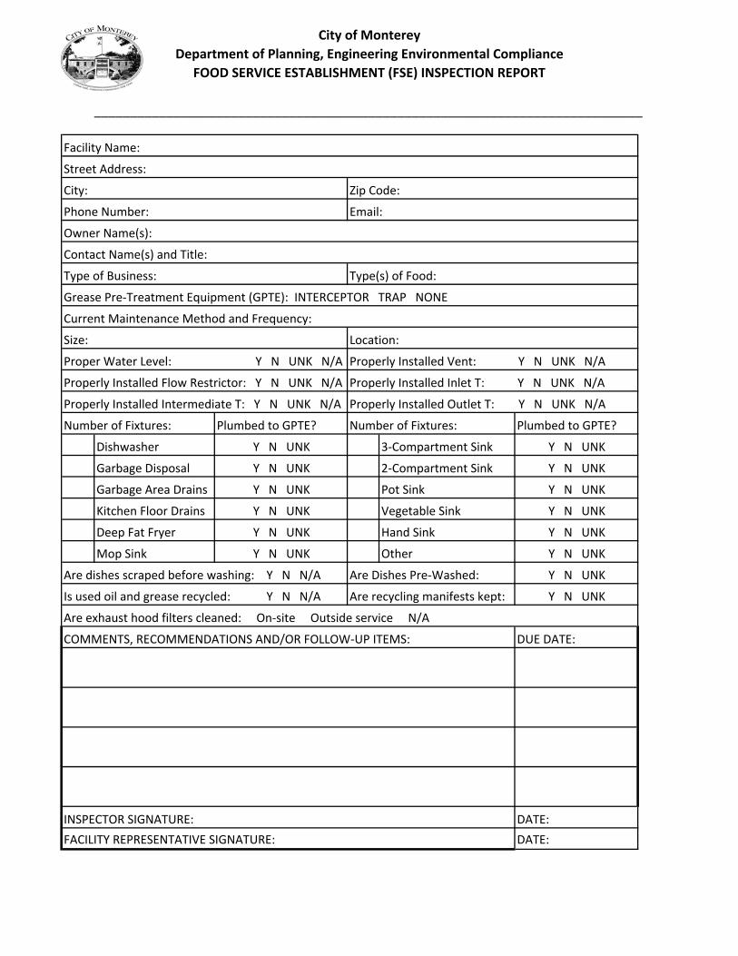
City of Monterey
Department of Planning, Engineering Environmental Compliance
FOOD SERVICE ESTABLISHMENT (FSE) INSPECTION REPORT
____________________________________________________________________________
Properly Installed Flow Restrictor: Y N UNK N/A
Properly Installed Intermediate T: Y N UNK N/A
Number of Fixtures: Plumbed to GPTE? Number of Fixtures: Plumbed to GPTE?
Dishwasher 3‐Compartment Sink
Garbage Disposal 2‐Compartment Sink
Garbage Area Drains Pot Sink
Kitchen Floor Drains Vegetable Sink
Deep Fat Fryer Hand Sink
Mop Sink Other
COMMENTS, RECOMMENDATIONS AND/OR FOLLOW‐UP ITEMS:
Y N UNK
Y N UNK Y N UNK
Y N UNK
Y N UNK
Proper Water Level: Y N UNK N/A Properly Installed Vent: Y N UNK N/A
Properly Installed Inlet T: Y N UNK N/A
Properly Installed Outlet T: Y N UNK N/A
Y N UNK
Y N UNK
Y N UNK
Y N UNK Y N UNK
Y N UNK
Y N UNK
Are dishes scraped before washing: Y N N/A Are Dishes Pre‐Washed:
Are exhaust hood filters cleaned: On‐site Outside service N/A
DUE DATE:
Y N UNK
Y N UNKAre recycling manifests kept:
DATE:
Is used oil and grease recycled: Y N N/A
Current Maintenance Method and Frequency:
Facility Name:
Street Address:
City: Zip Code:
Phone Number: Email:
FACILITY REPRESENTATIVE SIGNATURE:
Size: Location:
DATE:INSPECTOR SIGNATURE:
Owner Name(s):
Contact Name(s) and Title:
Type of Business: Type(s) of Food:
Grease Pre‐Treatment Equipment (GPTE): INTERCEPTOR TRAP NONE

City of Monterey Department of Plans and Public Works
Fat, Oil & Grease (FOG) ProgramMailing Address: 580 Pacific Street, Rm. #7, Monterey, CA 93940
Phone: (831)646‐3921, Fax: (831)647‐3405
Grease Interceptor Waiver Eligibility Checklist
The following checklist will help you decide if your facility may be eligible to qualify for a variance or a conditional waiver. Please mark all activities that apply to your food service facility and contact the Plans and Public Works Department with any further inquiries before applying.
Level 1: The food service facility does not contribute FOG to the sewer system ___ will sell only prepackaged foods. ___ will warm prepackaged food with a microwave (in the package). ___ will sell drinks only. ___ uses less water than a single family dwelling (must submit proof of water usage) ___ uses only disposable dishware
Level 2: The food service facility will serve/prepare… ___ Ready-to-eat foods with no preparation other than warming. ___ Cold sandwiches prepared on site ___ Scoop-only ice cream. ___ Popcorn. ___ Uncooked or unbaked food or meals that will be taken from the facility to be cooked and/or baked. ___ Small baked goods (such as cookies or pretzels) prepared on site. ___ The food service facility will engage in a limited amount of ware washing. ___ The food service facility will have a hot dog roller.
Level 3 The food service facility will use the following kitchen equipment: ___ Dishwasher ___ Garbage Disposal ___ Deep fat fryer ___ Griddle ___ Wok ___ George Foreman type grill ___ Flat top ___ Other device that uses fats, oil or grease
If you marked level 1 items ONLY, you may be eligible to be exempt from the grease pretreatment requirement.
If you marked level 1 and/or 2 items ONLY, you may be eligible for a Conditional Waiver to the grease interceptor requirement, and be permitted to downsize to a CPC compliant grease trap.
If you marked level 3 items, you will most likely be required to have an exterior grease interceptor.

City of Monterey Department of Plans and Public Works
Fat, Oil & Grease (FOG) Program:Mailing Address: 580 Pacific Street, Rm. #7, Monterey, CA 93940
Phone: (831)646‐3921, Fax: (831)647‐3405
Fat, Oils & Grease Program Exemption
The City of Monterey has required that the food preparing facility listed below install an exterior grease interceptor. Special circumstances may sometimes allow for downgrade of the requirement to an 80 gallon grease trap installation. The facility listed below, however, has requested that no grease pretreatment be required at its business location and that all grease trap and grease interceptor requirements be waived because there is either no food preparation on site or any food preparation that occurs does not generate any fat, oil or grease as defined by Section 30‐9.4a of City of Monterey Municipal Code.
CONTACT NAME & TITLE:
BUSINESS NAME:
BUSINESS ADDRESS:
PHONE NUMBER:
Signature required
I certify that future plans for the facility do not include any food preparation that will generate an
oil/grease discharge from the facility.
I agree that in the event planning begins for food preparation on site that would generate an oil/grease
discharge, I will contact the City of Monterey Permits & Inspection Division (831)646‐3890 for approval.
I understand that if this facility changes to include food preparation or handling that will generate
oil/grease, properly sized grease pretreatment equipment would be required at that time by the City of
Monterey Grease Program (Chapter 30, Article 3 of the City of Monterey Municipal Code).
Business Representative’s Signature Date
This waiver is approved by the City of Monterey Chief of Inspection Services/Building Official or City
Engineer.
City of Monterey Representative’s Signature Date

City of Monterey Department of Plans and Public Works
Fat, Oil & Grease (FOG) Program:Mailing Address: 580 Pacific Street, Rm. #7, Monterey, CA 93940
Phone: (831)646‐3921, Fax: (831)647‐3405
Grease Trap Hardship Waiver
The City of Monterey has required that the food preparing facility listed below install an exterior grease interceptor. Special circumstances may sometimes allow for downgrade of the requirement to an 80 gallon grease trap installation. The facility listed below, has requested a hardship waiver, and that a smaller than 80 gallon grease trap be permitted if allowed by California Plumbers Code; pursuant to Section 30‐10.1c of City of Monterey Municipal Code.
CONTACT NAME & TITLE:
BUSINESS NAME:
BUSINESS ADDRESS:
PHONE NUMBER:
SIZE TRAP REQUESTED:
EXPLANATION OF HARDSHIP: (Attach supporting docs if needed)
Signature required
I agree that in the event planning begins for facility remodel/renovation, I will contact the City of
Monterey Permits & Inspection Division for approval, and properly sized grease pretreatment
equipment may be required at that time by the City of Monterey Grease Program (Chapter 30, Article 3
of the City of Monterey Municipal Code). If for any reason this equipment proves to be inadequate, the
business may be required to upgrade.
Business Representative’s Signature Date
This waiver is approved by the City of Monterey Chief of Inspection Services/Building Official or City
Engineer.
City of Monterey Representative’s Signature Date
KAnderso
Typewritten Text

City of Monterey Department of Plans and Public Works
Fat, Oil & Grease (FOG) Program:Mailing Address: 580 Pacific Street, Rm. #7, Monterey, CA 93940
Phone: (831)646‐3921, Fax: (831)647‐3405
Grease Trap Waiver Fee Exemption
The City of Monterey has required that the food preparing facility listed below install an exterior grease interceptor. Special circumstances may sometimes allow for downgrade of the installation of a grease trap. The facility listed below, however, has requested to be removed from the Grease Trap Waiver Fee billing list on the grounds that it is a minimal producer of grease, and all grease producing fixtures are plumbed to an adequately sized trap as defined by Section 30‐11.1 of City of Monterey Municipal Code.
CONTACT NAME & TITLE:
BUSINESS NAME:
BUSINESS ADDRESS:
PHONE NUMBER:
CURRENT GREASE TRAP SIZE:
Signature required
I certify that future plans for the facility do not include any food preparation that will generate an
oil/grease discharge from the facility.
I agree that in the event planning begins for food preparation on site that would generate an oil/grease
discharge, I will contact the City of Monterey Permits & Inspection Division (831)646‐3890 for approval.
I understand that if this facility changes to include food preparation or handling that will generate
oil/grease, properly sized grease pretreatment equipment would be required at that time by the City of
Monterey Grease Program (Chapter 30, Article 3 of the City of Monterey Municipal Code).
Business Representative’s Signature Date
This waiver is approved by the City of Monterey Chief of Inspection Services/Building Official or City
Engineer.
City of Monterey Representative’s Signature Date


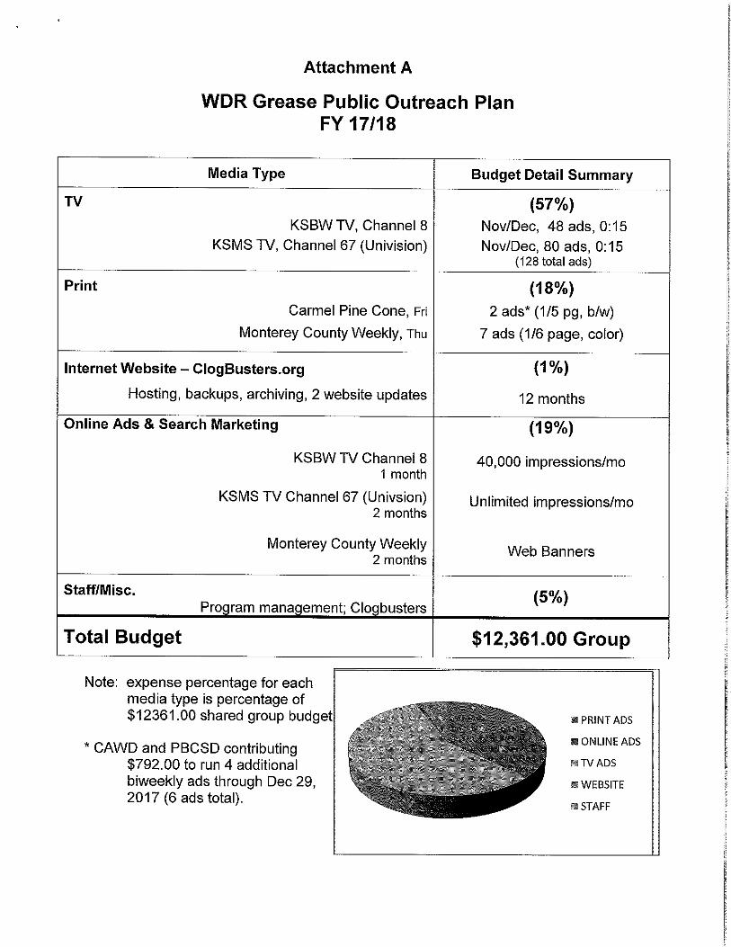


Appendix 17: Sewer Fee Study Update (1988)

3 000 5.5 DElo I . Ur" ervuwitcriurria
MAINTENANCE CITY OF MONTEREY
SEP 23 88
Ato, DIRECTOR DEP. DM. ADM. Pan SPEC. PROL writ SUPT. PW INSP.
MY ENO.
PO. aura
ACT. A
um NM OMB
MIN owe SIM MIN
MI SIM woo pus OM
MS SIMI
111 .111111 On
FILE
,REPORT OF
088 SEWER FEE STUDY UPDATE
FOP THE CITY OF'MONTEREY
DEPARTMENT OF ENGINEERING & MAINTENANCE
Fred Meurer, Director D.S...Gorman, City Engineer
PREPARED BY:
William T. Courtillet, P.E. 177 Webster Street, #A-252 Monterey, California 93940
(408) 373-6245

PREPARED BY:
William T. Courtillet, P.E. 177 Webster Street, #A-252 Monterey, California 93940
(408) 373-6245
REPORT OF
1988 SEWER FEE STUDY UPDATE
FOR THE CITY,' OF MONTEREY
DEPARTW1NT OF ENGINEERING & MAINTENANCE
Fred Meurer, Director D.S. Gorman, City Engineer
d e e
Revised September 23, 1988

EXECUTIVE SUMMARY OF CONCLUSIONS AND RECOMMENDATIONS
This study update of the City of Monterey's sewer main connection fees program indicates the following:
1. Subsequent to the previous sewer fee studies made in 1971 and 1977, a number of significant changes have occurred to the physical sewer system itself, as well as to land use factors, which collectively have had a positive effect on the ability of the City's sewer system to provide for future capacity demands.
2. All high priority recommendations made in the two previous studies for sewer main enlargements have been implemented by the city.
3. Construction of a new inter-City trunk line from Pacific Grove through Monterey has been completed by the Monterey Regional Water Pollution Control Agency (mRWPCA).
4. Five of the nine City Pumping plants in operation at the time of the previous studies have either been physically eliminated with construction of the new MRWPCA trunk line or have become facilities maintained and operated within the MRWPCA system.
5. Although the number of dwelling units and the general population have been increasing over the past 17 years, the population per household density factor in Monterey has been decreasing from 3.70 persons in 1971
. to 2.32 persons currently.
6. Projections for annexations and development to the east of the City along Highway 68 have been reduced in size and extended in time.
7. No existing or potential sanitary sewer flow capacity deficiencies were found in any of the four remaining pumping plants in the City maintained system.
8. It is recommended that the existing 10" pipe segment in North Fremont Street near the Travelodge Motel (approximately 190 feet long between manholes) be replaced with a 12" pipe within five years with funds already collected under the current sewer main connection fees program (preliminary cost estimate is $15,000).
9. It is recommended that the current sewer main connection fees program be discontinued until the next study update, which should be made at least every five years.
(a)

TABLE OF -CONTENTS --
Page EXECUTIVE SUMMARY
(a)
INTRODUCTION .... 1
SCOPE OF WORK ... 2
- Primary Objective - Study Area and Design Period - Facilities Studied - Focus of Technical Analysis
METHOD OF ESTIMATING FLOWS
4
- Accuracy - Technical Factors - Existing Flows • - Potential Flows - Maximum Allowable Land Use Densities
ANALYSIS OF FLOWS •
10 - Determination of Service Areas - Sewer Data Spread Sheets
PUMPING PLANTS
13
- Summary Analysis
CONCLUSIONS AND RECOMMENDATIONS 15
- Significant Changes - Analysis Results - Recommendations
- Reference Materials List - City Interdepartmental Memo
(Highway 68 Sewer Service Planning) - Map of Locations of Sewer Mains Studied - Sewer Data Spread Sheets

------^,-;-- ---*4,*AbAttaktmwM340,4444TWOAPieggOtMatArinsfiwowtomIkmavr
LIST OF TABLES AND FIGURES
Page
TABLE 1. Average Daily Sewage Production Rates 6 TABLE 2. Existing Pumping Plants Within The City of Monterey Sanitary Sewer System 14
FIGURE 1. Peak Flow Pipe Sizes (Slope vs. Equivalent Homes) 7-A
FIGURE 2. Sanitary Sewer Service Areas Map 10-A
Map of Locations of Sewers Studied (See Appendix)
• ■ • • .r.•• •

INTRODUCTION
The last comprehensive sanitary sewer study made for the City of Monterey's sewer system was in 1.971 which was reviewed for updating in 1977, followed by annual adjustments of the sewer main connection fees for
• inflation. Subsequent to the previous studies, some major changes in the provision of sanitary sewer service have occurred in the Monterey area. Construction of a new trunk line by the Monterey Regional Water Pollution Control. Agency (MRWPCA) has been completed from Pacific Grove through Monterey to the Monterey Wastewater Treatment -Plant. Also, five of the nine City pumping plants in 'operation at the time of the previous studies have either been physically eliminated with construction of the new MRWPCA trunk line or have become facilities maintained and operated within the MRWPCA system. These changes have had a significant effect on the, sewer fee rate zone boundaries established in:the previous studies arvwell as on the individual fe,e,-rates theMselves, and have prompted the need for a sewer yél itudy„.update, This report is intended to document the methodand •eSults of a study update made between June and WierOberof . 1988.
1

SCOPE OF wORK
Primary Objective
The primary objective of this study was to review the City's existing, sanitary sewer system to determine the need for any changes in the sewer main connection fees, and to recommend what changes should be made. The sewer main connection fees are based upon estimated construction costs of larger sewer facilities within the City of Monterey system required to serve new developments and higher density land usages. The sewer main connection fees do not provide for maintenance or operational costs.
Study Area and Design Period
All existing lots and undeveloped areas within the City limits have been analyzed for existing and potential sanitary sewer flows, as well as those unincorporated parcels immediately adjacent to the City limits that would logically be served by City sewers. The Design Period for this study is 15 years, ‘41iich'is based upon the City of Monterey community Development Department study projections. and the City of Monterey General Plan which project ultimate development to occur by the year 2003.
Annexation and development of unincorporated areas to the east and along Highway 68 is not likely for the next 20 yaara according to current interpretation of the Highway 68' Area Plan (see Appendix 7-City Interdepartmental Memo dated August 9, 1988) which prohibits urban development until the existing highway is brought up to level of service "C". Also, the City of Monterey's Engineering and Maintenance staff is currently updating a report prepared by Creegan & D'Angelo, Consulting Engineers, in 1981 entitled, "Monterey II - Trunk Sewer System". The primary purpose of this update is to determine if it is economically more feasible to route all potential Highway 68 Study Area flows into the City's existing system at Olmstead and Garden Roads, rather than along Canyon Del Rey Boulevard, through the Cities of Del Rey Oaks and Seaside to the Seaside Treatment Plant, as intended in the 1981 Creegan & D'Angelo report. The routing alternatives are being reevaluated due to the significant reduction in the study area assumptions (approximately 70%) since the 1981 study was made. Therefore, since the current time projection for annexation and development is beyond the design period of this sewer fee study update, and also due to the uncertainty of the routing of flows; these areas to the east and along Highway 68 have not been included in the study area for thisCurrent sewer fee study update. When the reevaluation of routing alternatives and costs is completed, and when theme

3
'uw,PAIVAIRVI
areas should ever annex and develop_within_tha_City, onetime or phased sewer connection fee should be determined as a part of the annexation approval or prezoning process.
Facilities Studied
The following facilities have been investigated in this study:
1. Local colleciors'(6" mains) with 300 or more potential service connections (equivalent homes);
2. All major collectors (mains greater than 6");
3. City maihtained pumping plants, trunk lines and force mains,
Focus of Technical Analysis
The technical analysis of this study has focused solely on investigating the, existing City maintained sewer facilities to determine future construction needs requited to adequately handld the increased sanitary sewer flows directly related to new land use developments. Since the primary objective of this study was to convert the cost of these future construction needs into sewer main connection fees, no maintenance or operations costs have been included in this study. No maintenance or operational problems have been analyzed or incorporated into this study.

METHOD OF ESTIMATING FLOWS
Accuracy
The existing and potential sanitary sewer flows established in this study have all been calculated. The engineering formulas and technical factors used in the calculatIons are consistent with current engineering publications and practice. Where field measured flow data was readily available and directly applicable, it has been used (e.g., water-use rates for existing laundromats, car washes, restaurants and motels). Otherwise, the effort to obtain data of a design/construction accuracy is not warranted in a study having a primary objective to focus on potential sanitary sewer capacity needs 15 years into the future.
The pipe capacity range between consecutive pipe sizes increases from 300 equivalent homes between a 6" and 8" pipe, to 2,000 equivalent homes between an 18" and 21" pipe. This margin of tolerance provided in pipe sizing is greater than the difference between calculated and measured sanitary sewer flows. The existing sanitary sewer flows calculated in this study have been validated by comparing against City-wide measured flows made at key locations in the existing system by CH2M Hill, engineering consultants, as noted in their report entitled, "City of Monterey, Infiltration/Inflow Evaluation, October 1986." (It should be noted, that this report is part of a study, still in progress, which is being made for maintenance and operational related deficiencies. No final submittals nor recommendations have been made for this study to date. Data available from this study, although preliminary in nature and outside the scope of work of this sewer fee study update, has been found useful only as a gauge against which to compare sanitary sewer flows.) The calculated potential flows in this study are based upon population and land usage projections and assumptions consistent with current planning studies and zoning regulations used by the City of Monterey Community Development Department.
Technical Factors
The following technical factors were used in the calculations made for estimating the existing and potential flows:
1. One hundred (100) gallons per capita day (g.p.c.d.) was used as the average number of gallons per day per person in a single-family dwelling environment. Although this study is for the entire City of Monterey consisting of a mix of land usages, the majority of land usage in Monterey is residential. Therefore, the single-family dwelling and 100 g.p.c.d. was chosen as
4

the basis for establishing a common -unit for •
converting all other land usages.
2. A single-family dwelling consisting of 2.32 persons was used in this study. This figure has been developed by the State of California, Department of Finance, Population Research Unit (Population and Housing Estimates for California Cities and Counties, Summary Report E-5, May 7, 1987), based upon current trends in the City of Monterey, and is currently being used by planning consultants and the City of Monterey Community Development Department.
3. One Equivalent Home is equal to 100 g.p.c.d x 2.32 persons per single-family dwelling which equals 232 gallons per day. This is the common unit chOsen for converting all other land usages into, and used in flow calculations to provide for the mix in land usages - both existing and potential.
4. Average Daily Sewage Production Rates in gallons per day were compiled for various land usages and converted to equivalent homes (see Table No. 1). Most of the base data (gal/day) for the individual usages was obtained from technical engineering publications.

232 1.0 186 0.80 93 0.40 70 0.31 140/unit 0.60
100/room . 0.43/room
0.08/seat
687/machine 3.0/machine
. 20/employee 0.08/employee
70.0
37.0/acre
13.0/acre
251/bed 16/employee
119/resident 16/employee
30/student
106/student
12/vehicle
26/seat
8/customer 13/employee
4/seat
53/person
1.08/bed 0.07 employee
0.51/resident 0.07/employee
0.13/student
0.46/student
0.06/vehicle
0.11/seat
0.30/customer 0.06/employee
0.02/seat
0.23/person
6
2/parking space 0.009/parking rnace 13/customer 0.06/customer 13/employee 0.06/employee
TABLE NO. 1
AVERAGE DAILY SEWAGE PRODUCTION RATES (1988 SEWER FEE STUDY UPDATE)
Equivalent Homes
Single-family dwelling (BASE) 232
1.0
pal/Dav
Apartments: 3 Bedroom 2 Bedroom 1 Bedroom Studio Unknown Mix
Motels and Hotels
Restaurants
Laundromats
Offices and Stores
Car Wash
Light Industry 0
Misc. Commercial
Shopping Center
Hospital, Medical
Rest Home
School, Day
School, Boarding
Automobile Service Station
Cocktail Lounge
Coffee Shop
Theater
Trailer Park

5. Peak Flow Factors were calculated by use of the following formula:
PFF = 4+
Where P equals population in thousands. Use of this formula is appropriate for this study where flows are estimated and not measured. It provides a comprehensive peaking factor by providing for a mix of land usages in small areas. Xlso, it provides for flow variations in systems where water use and nominal extraneous flow are the governing factors. (ASCE Manual No. 37, prepared by a Joint Committee of the American Society of Civil Engineers and the Water Pollution Control Federation, 1976, pages 32-33; Wasterwater Engineering: Treatment, Disposal, Reuse, second edition, by Metcalf & Eddy, Inc., 1979, pages 29-30; Water Supply and Sewerage, fifth edition by Steel and McGhee, 1979, pages 23-24.)
6. Peak Flows in cubic feet per second were calculated for various numbers of equivalent homes by the following formula:
Equivalent Homes x 232 gal/day x PFF x 1.547 QP
10 6
7. The theoretical slopes for various sizes of pipes required to maintain full flow within the pipes without an entrance head (surging in the manholes) were calculated by the following
5= Qp x n
k x d8/3
OP x 0.028078) 2
8/3
(n = 0.013; k = 0.463; d = diameter of pipe in .feet; Qp = peak flow in cubic feet per second; S = slope of pipe flowing full in feet per foot)
8. Slope vs. Equivalent Homes curves were plotted for various pipe sizes using the data calculated in the above sections (see Figure 1). It should be noted that these curves resulting from the above calculations have peak flow factors "built into" them, thus allowing the direct use of equivalent number of homes which represent average flows. Additional calculations were made to find the minimum required slopes for the various pipe sizes to maintain a cleansing
7

e.3 Vs Fp
'net t) A..r. A 7fIc4-syir--
,8
I it
OrMARI
FIGURE 1
PEAK FLOW PIPE SIZES ( SLOPE VS. EQUIV. HOMES)
MIIIIIIIIIIIMIIINIIIIIIIIIIIIIIIIIIMIIIIIIIIIIIIIIII MIIIIINA1111•101111111•111111 MUM WAMM IR WailIIIIWINOIffilISIMIONOINF, 111•111111.11111.MIMIUMNIM MIMI ran=
NEMO INI2111111151111111111V
emenomummutrammumuniglIMIIIMIIMMIIIIMIIIIIIIIVIIIIIIIIIIIAINIIVAUWA 11111111111111111111111 11111,41•111111111117A1111111111K1111111:1111•11/411111111/41NINPAIIVAN MUM•111111;11111111111111111111111E1111111011111rammummirma
IIIVAINIIIIIMINIIIIIIIIIIMEMIIMAMBffillillIA
111511111WAIWAIVAIVAI1
Fr PKII :ii,1 :
EVAIII511111111FAIIFAVAM 111111111111111-111111113111FRWA.
r ywit :: III TA AM .41/aluingzimocaurrAirtassamammin
. Fir FA 111 A iiii - 1 - - ' MIMI iso wims • MIIIIIIWARINIVAIMMIUMEN --:
IIIWAilana■na lininiara laril inSiginrar Illigra•IIMMIFIUMETAIIIIIMMI . F.411111101111111141111M1=1=1111117111111111: MUM arinumummeirimormerrammulmmunim
• FilitiniiiiiiVAMPFAiriMMEMENERNIM WillilliffilliWilliffillirdlIMPAROMMIIII
IrAINNWAlliiffiiiitiVANIVAIWAMMNIMEMIE WAINI
Fr PA EFIRI
Allilirallifirellitirdi
15111Lrarirriairmuseamii991 MIN 17111111111111111=========M liffit arararmramon
a Allirligra=11111116 A EU 0====.4="rimu
itimphomminamimmil=-5.--Eniii MINIVAWAIMENUMNIEMMIlli
. MING rillIVAIEWAIMIZEINIONMW-=zEMENWON
A PT , AM . .
_ ...._. as BrAi iin WANNIMMffiriiiiiMMPEMTAral
•
A._ Fr A
Ill Mr nresradiEWW*Fism=x1V51 INA" dralininERtir4145511
14,4
gpeu
EQUIVALEAlt . /00
I 3 al 5 6 89 10
9
/40.0 21103Mth

velocity of two feet per second. The minimum slope for maintaining a cleansing Velocity 'of 'two' feet per second was also plotted on the curves. These curves were used in the analysis of flows, which is explained later in this report under the section entitled Analysis of Flows.
Existing Flows
Existing sanitary sewer flows were determined by converting all existing land usages into equivalent homes. Current land usage maps were obtained from the City of Monterey Community Development Department which show existing land usage on each lot arid block, as well as vacant and undeveloped areas, for the entire City. By use of the Average Daily Sewage Production Rates (see Table No. 1), the existing land usages were converted to the amount of sewage produced from each block, expressed in equivalent homes. These flows were then assigned to the applicable segment of existingAanitary sewer main to which the lots and blocks are now physically connected.
Potential Flows
Potential flows for this study refer to those sanitary sewer flows estimated to occur at buildout. Buildout, or ultimate development, occurs if and when an area is developed to the maximum densities allowable under current zoning regulations. Potential flows were determined for each lot, block and undeveloped areas in the study area. Current zoning designations (City of Monterey Zoning Map, revised to 6-1-88) were converted to maximum number of equivalent homes as allowed under the regulations for the various zoning designations. Existing land use densities were compared with the maximum allowable, adjusted accordingly (see below for explanation), and converted into flows, expressed in equivalent homes, by use of the Average Daily Sewage Production Rates (see Table No. 1). These potential flows were then assigned to the applicable segment of existing sanitary sewer main to which the existing lots and blocks are now physically connected, or to which undeveloped areas will be connected.
Maximum Allowable Land Use Densities
The mechanics of- "adjusting accordingly" referred to above, between existing land usage densities and the maximum allowable, required in some areas of the City a judgmental analysis prior to making the calculations to obtain potential flows. The larger portion of the City required obvious and direct adjustments, such as a vacant lot within a residential subdivision or a single-family residence on a lot within a block undergoing conversion to and zoned for multiple-family units. Tim areas of the City
8
I . '
that did not lend themselves to this straightforward process were primarily centered around Garden Road, North •
Fremont Street, and Foam Street. The areas in question can generally be described as having some vacant, undeveloped, or underdeveloped lots within non-residential zonings.
The range of allowable land usages in these areas translates into a considerable range of sewage production rates. In the previous sewer fee studies, these areas were assigned the maximum sewage production rate within the range of allowable land usages. However, since the time that these studies were made (1971 and 1977), a considerable amount of in-fill development and land use conversion trends has occurred. In short, more data, information and history on development within the City of Monterey is available. Consequently, the need for a judgmental analysis was determined to be more realistic than to simply tabulate the maximum sewage production rates
within the range of allowable land usages.
The factors considered in. the analysis for each lot and block within these areas were the following:
1. Length of time of existing usage;
2. Usages of adjacent lots;
3. Usage conversion trends;
4. Size Of lot;
5. Current zoning of lot and block;
6. Design , Period of this study update (15 years).
In summary, it is believed that an analysis based upon the above considerations is more realistic and consistent with
the Land Use element of the City of Monterey's General Plan, because it focuses on the most probable land use based upon current trends, goals, and policies.
9

ANALYSIS OF FLOWS
Determination of Service Areas
The determination of service areas within the City'r sanitary sewer system is the most significant step in developing a sewer main connection fee program. A service area physically represents the direct relationship between users (existing sandpbtential) and the service provided. Service areas &re the basis for an equitable process of segregating gnd apportioning estimated construction costs for larger facilities required to serve new developments and higher density land usages. The determination of 'service areas requires the identification of those sanitary sewer facilities which are shared in common and exclusively by all users within a defined portion of the City.
This update study shows that the City of Monterey's existing sanitary sewer system consists of eight service areas (see Figure No. 2). A service area is a physically identifiable poktion of the. City's sanitary system in which all of the sanitary sewer users (existing and potential) contribute flows through a common and exclusive network of collection pipes to an exclusive terminal connection with the MRWPCA facilities. The two studies previous to this current update (1971 and 1977) identified three service areas (referred,to az "zones" in those studies) for the entire City.
The reason for the difference in the number of service areas between the previous studies and this current update is due to the elimination of pumping plants and the construction of the new MRWPCA inter-City trunk line. Included in this trunk line construction were six gravity flow terminal connections for the City of Monterey's system, which accounts for six of the eight service areas determined by this current update. (Each service area has one terminal connection with the MRWPCA facilities.) The remaining two service areas determined in this update, are located ln the Dunes area between the Monterey Wastewater Treatment Plant and the Monterey Beach Hotel (formerly the Holiday Inn). These last two service areas were not included in the previous studies because the flows from these areas did not::depend upon any of the then existing pumping plants, btitrather were able to gravity flow directly to the nearby Monterey Wastewater Treatment Plant.
The three service areas in the previous studies were referred to as "Zone 7", "Zone 5", and "Zone 4", the numbers corresponding with those assigned to the major pumping plants to which each of the three service areas ("zones") contributed flows. Identifying those portions of
10

• F
: r
,Er":7"
14
-7
p-7
1,
7 "P-1
•
Ctrf
wir.-"V
P
E

Iffy •g, -Leihminforr 1140 0.404 *NOW
Illt“N 1111/111110
4
SIN%
naltielorToaLlotrantanNOODI Amami maim NOT TO Milt
SANITARY SEWER -Jilk _ I 1
-
11,111111 • I / 1 41,4 MI1 11.1'1410711
1.114 I u Nopevta- wean, now mum onlootEr- MONT1 na1110 aLa MON 1,414 412)
ALTA NW- CAR 0010a MN III WO
BM E
''' — • -1L.A.d.11...a1111•111•1011•11M11 INIKLIMII 1111M11•11
LA IIITZITA41411Cont 4,541 son
r nimitmpl run- rosotwri• ow. monri mno o 0'4 wow aigClin ORINILtii Di
1,140 5.1411
not atonal (SUCH TOLICTI 1st Li twit WOO oat
Nam 10.-IxIonalgO IN KaortoujaoT Mat 41.1t
lc 100 411C11 • 1 a0uovaLfal NOW. (a-uct.trogs hamper impolospAA
amnion' CONKCCnON. la-a441.10041 MAIM Timer ruts MM
or m• woo ninon orriLormor. to—rl0000to USC PORN. ITOSTOPOOLIOTE
&CUM all mu HE mow MOM 00ologra01411 WITOI laa.W.1110.A. Pailut
'°!of e4:J
_ril■
r .r
,
FIGURE NA 2
g 017. 1 'THE UMW aoal ValL101VOL neTWORO1 `MOM 1113.
leilade 1114
1988
SANITARY SEWER FEE
STUDY UPDATE
SANITARY SEWER SERVICE AREAS MAP
. couit,...t ,
..
1 OF 1

the City which contributed flows to one of these three pumping plants was the basis for determining service areas in the previous sewer main connection fee studies. Due to the construction of a new trunk line with six City gravity flow terminal connections, and the elimination of major pumping plants from the City's maintained system, the basis for identifying service areas has changed, making it necessary to determine new service areas.
By use of the 1"=300' scale "City of Monterey Storm Drains and Sanitary Facilities" Map, eight service areas were identified for this study by locating the terminal connections with the MRWPCA facilities and tracing the network of collection pipes to their uppermost extremities. All the lots and blocks physically connected (or which will be connected when developed) and contributing flows to this common networK, of collection pipes, were determined to form a service arek. ' Eight such service areas were identified in this current study. (It should be noted, that the Presidio and the Naval Postgraduate School are not included in any of these eight service areas because they each have exclusive networks of collection pipes.)
Sewer Data Spread Sheets
As stated earlier in the Scope of Work - Facilities Studied section of this report, all local collectors (6" mains) with 300 or more potential services, and all major collectors (mains greater than 6") were investigated in this study. The minimum slope specified in the construction of a 6" sanitary sewer main for providing a minimum cleansing velocity, is also adequate for peak sanitary flows up to 300 equivalent homes. The sewer mains investigated in this study were analyzed for adequacy of pipe size and slope under both existing and potential peak sanitary flows. The data required for this analysis, as well as the results, were tabulated in a spread sheet fashion (see Appendix for. Sewer Data Spread Sheets and Map of Locations of Sewer Mains Studied).
For each manhole to manhole segment of sanitary sewer main analyzed, the existing slope and size of pipe were tabulated with ttle calculated sanitary flows (existing and potential) expressed in equivalent number of homes. The existing pipe sizes and slopes were then "tested" for hydraulic adequacy (ability to transport the flows at or above the minimum velocity required for cleansing, and to accept the flows into the pipe without a surging of flows above the pipe entrance within the manhole). This "testing" was done by use of the Slope vs. Equivalent Homes curves developed specially for this study described earlier in the Methoc rajila_i ws- Technical Factors section of This method of testing
11

adequacy of existing pipe sizes by graphically performing hydraulic calculations was used for each sewer main investigated in each of the eight service areas of the City of Monterey's sanitary sewer system. The results of this testing have been tabulated on the spread sheets, copies of which are in the Appendix section of this report. Also, the results and recommendations are discussed in the final section of this report entitled, "Conclusions and Recommendations".
12

' eir"lea
PUMPING PLANTS
Summary Analysis
Of the original nine pumping plants within the City's sanitary sewer system, four have been physically eliminated with construction of the new MRWPCA trunk line, and one is part of the facilities maintained and operated within the MRWPCA's system. This change occurred subsequent to the previous sewer fee studies made in 1971 and 1977. Table No. 2 tabulates the four remaining pumping plants currently maintained within the City of Monterey's system. Also tabulated are the pumping capacities and the existing and potential capacity demands. As indicated in Table No 2, neither the existing nor the potential capacity demands exceed the single pump rated capacities of any of the four remaining pumping plants. These pumping plants are classified as minor" pumping plants because they function as local lift stations. Consequently, only a summary review and analysis was requiredfor this sewer fee study update.
r
13
AWARMONW

TABLE NO. 2
EXISTING PUMPING PLANTS WITHIN THE CITY OF MONTEREY SANITARY SEWER SYSTEM (1988 SEWER FEE STUDY UPDATE)
PUMPING PLANT NO. LOCATION
SINGLE PUMP CAPACITY IN GPM (1)
EXISTING POTENTIAL CAPACITY CAPACITY DEMAND DEMAND (EQUIV. (EQUIV. HOMES) HOMES)
IN OPM_12i IN GPM (2)
#2 Fremont and
875
(227)
(253) Mesa Road . 145
161
#3 Del Monte Ave. 100 (56) (152) and Seaside
38 99 City Limits
(See Note 3)
#8 Stephens Place 160
(12)
(12) and Via Del
8
8 Pinar .
#9 Madison and
160
(28) Pebble
6
19
Notes:
(1) Manufacturer's rated capacities. (2) Equivalent Homes represents average flows; gpm's have been calculated for peak flows.
(3) Includes potential services from undeveloped adjacent lots in the City of Seaside (34 gpm).
14
t, f-o.ri,ftAiwo..orp- 4,;,11 -Y2WATI44000,409601

CONCLUSIONS AND RECOMMENDATIONS
Significant Changes
A number of significant changes have occurred since the two previous sewer fee studies were made in 1971 and 1977, not only in the facilities maintained by the City, but also in land use factors which directly affect the calculations for estimating future facility needs. The changes to the facilities have consisted of the implementation by the City of all the high priority recommendations made in the previous study reports for sewer main enlargements, and also construction by the MRWPCA of a new inter-City trunk line 'with the elimination of pumping plants. The land use factor changes have pertained to a,37% reduction in the population per household density factor (from 3.70 persons to 2.32 persons), and extended time projections for annexations and development to the east of the City along Highway 68. These changes collectively have had a significant effect on the City's sewer system with regard to its ability to provide future service without the need to continue a sewer main cqnnection fee program for facility enlargements within this Study Update Design Period of 15 years.
Analysis Results
As a result of the analysis made-for this Sewer Fee Study Update, no existing or potential sanitary sewer flow capacity deficiencies were found in the four pumping plants in the City maintained system, and only marginal capacity deficiencies were notedat two locatioha in the sewer mains. One of the sewer main marginal deficiencies is in a 387'4- long segment of 21" pipe located in Cannery Row between the Chart House Restaurant (manhole no. 15) and the Monterey Plaza Hotel (manhole no. 9). This deficiency is considered marginal because it consists of a 0.4'+ surging in the upstream manhole estimated to occur during future peak flows. However, due to the depth of this pipe (15'+), this deficiency is determined to be insignificant with no potential adverse impact on any lateral connections. The second location is in a 190'+ long segment of 10" pipe in North Fremont Street near the Travelodge Motel between . manholes no. 328 and no. 323. The deficiency in this pipe segment is also considered marginal due to a 0.5'+ surging estimated to occur in the upstream manhole during future peak flows. Since the depth of this pipe is only 5.5L+, this marginal deficiency is determined to be significant in having a potential adverse impact on any lateral connections, and it is therefore recommended that it be replaced within the next five years with a 12" pipe.
15

Recommendations
Based upon the changes that have occurred since the previous studies were made in 1971 and 1977, and the analysis results of this current Sewer Fee Study Update, the following recommendations are made:
1. The current sewer main connection tees program be discontinued until the next sewer fee study is made. 2. The next sewer fee study be made within five years. 3. The existing 10" pipe in North Fremont Street near the Travelodge Motel between manholes no. 328 and no.323 be replaced with a 12" pipe within five years with funds already collected for Zone 4 under the current sewer main connection fees program (preliminary construction cost estimate is $15,000).
4. The sewer data spread sheets developed for this study update be entered into the Engineering and Maintenance Department's computer files to facilitate future updates and individual project impact analysis.
16

APPENDIX
- Reference Materials List
- City Interdepartmental Memo . (Highway 68 Sewer. Service Planning)
- Map of Locations of Sewer Mains Studied
- Sewer Data Spread Shec:tti

REFERENCE MATERIALS LIST
1. City of Monterey City-Wide Commercial Zoning Study Technical Report, City of Monterey Community Development Department, March 22, 1988.
2. City of Monterey Old Town Working Paper 01 Background Information, city of Monterey Community Development Department, October 1987.
3. Estimates of Housing and Employment at BUildout within the Monterey Peninsula Water Management District, EIP Associates, April 1988
4. Wastewater Engineering: Treatment, Disposal, Reuse -- second edition by Metcalf & Eddy, Inc., 1979.
5. Water Supply and Sewerage -- fifth edition by E.W. Steel and Terence,J; McGhee, 1979.
P
6 .. Design and Construction of Sanitary and Storm Sewers, ASCE Manuals and Reports on Engineering Practice, No. 37, 1976.
7. Handbook of Hydraulics --.sixth edition by Ernest F. Brater and Horace Williams King, 1976.
•
4.toviofm.krogiltom400M041010We '1

* CITY OF MONTEREY
To: Engineering and Maintenance Director
From: Planning Services Manager (Advance)
Onto: August 9, 1988
Subject: HIGHWAY 68 SEWER SERVICE PLANNING
I have reviewed your June 2, 1988, memo to the Community Development Director. My comments follow:
1. I can find no evidence the City has an agriament with the developers "...to provide sewer service for the proposed office park..." at Laguna Seca Ranch. The attached March 18, 1986, City Council minutes 'show that the City Council granted a policy exception to allow Laguna Seca No. 1 and York School to con-nect . to city sewer lines. They specifically denied annexation to the office park, and they excluded the:office park from the policy exception. So, the office park has no City' agreement for sewer service.
2. The attached July 10,4986, memo from Carol Foulkes to the Community Develop-ment Director reports on the status of the proposed package plant. It notes that the package plant would have enough capacity to serve the proposed of-fice park, Estates 1 and 2, and York School. If such a package plant were developed with enough capacity, the,developer would not need to connect Laguna Seca 1 and'York School to city hewer lines. HowaVer, the City Council granted policy exception of March 18, 1986, stands. The developer could still request connection to city sewer lines. for Laguna Seca 1 and York School, and the City Council could consider reversing their previous policy exception.
3. The last paragraph of page 1 states that construction of Highway 68 improve-ments could take approximately ten years "...with lead time necessary for voter approvals..." No voter approvals would be required to improve Highway 68 in- compliance with the Highway 68 Area Plan. Any changes to the plan would require voter approvals. Those changes could include the current City interpretation of the plan prohibiting urban development until the existing highway is brought my to level of service "C." That sentence in the memo would be correct if it read: "Since planning and and construction of a proj-ect to improve Highway 68 would take approximately ten years, and any change to the plan (which would include current interpretation) with feed time nec-essary for voter approvals and the like, it does not seem likely that the City will be encouraging development in these areas for the next 20 years."
If you have any questions or need clarification; please feel free to call me.
-rD;tM d Bill Fell
BF:rm
Attachment
c: Community Development Director
DEFT. OF ENCMtNCI & MAINTENANC:
CITY CF t.P.CNTZ;
AUG 3' '88
7717777117717 Mi. VA,
....I VII, 410•It, SST.
! "la = ter,
NSA. ,r f.
••••■■••■•••■•••..W.1.10.1■.4101•1•••■•■■•■
LENI•mj.wma*

- (7 Mar Ch 18, 1986
. 291 Watson Street - Anpeal of Planning Coemassion deniai- of Use Permit or two unit addition to singie.family dwelling and Variance to exceed allowable Floor Area Ratio
Following staff presentation, Mayor Roberson opened the Public Hearing.
Mrs. Mary Tringali and Mr. Michael AIbov spoke in favor of the project. There were ma further speakers and the matter was returned to the council for discussion.
A !motion by Albert to grant the appeal died for lack at A second.
On notionby Rdberson, seconded by Vreeland and Carried by the following Roll . Call vote, it was moved to deny the appeal and uphold the Planning.Coveission decision tid in addition, request the applicant and Planning Chemission to work together to work toward converting the basement area to storage, and reducing the total Floor Area Ratio to 35t maximum. Councilmember Outzen pointed out that although the Tringali family may not plan to rent out the basement area a future owner may with to do so, thereby creating a City enforcement problem. Mayor Roberson said there seemed to be no justification for the increased Floor Area Ratio, especially when the basement playroom/bath/ storage area must be included in the calculations. Councilmember Albert.felt'that thsTAR.otthe basement area should not be included in the calculations.
AYES: COUNCILMEMBERS: CAEVA, OMEN: VREELAND, ROBERS00
NOES u COUNCILMEMBERS: ALBERT
ABSENT: COUNCTLMEMBERS: NONE Appeal Denied
Mayor Roberson recessed the meeting at MO p.m. and again called the meeting to order at 9:10 p.m.
Mayor Roberson opened the Public Hearing, asking for new information only.
Mr. Thomas Jamison represented the applicants, Mr. Ray Charlson explained the Highway 68 Cheadttee • considerations, Mr. William Kipp and Mr. Tom Rowley expressed traffic concerns; Mr. Jerry Hondo defined CalTrans' position, and Mr. Carl Larsen spoke on - traffic concerns. There were no further speakers and the matter was returned to the Council for discussion. •
On motion by Canepa; seconded by Roberson and carried by the following Roll Call vote, it was moved to deny the tentative map for the office park, and deny the preaming 01 Western Laguna Seca. Cnuncilmember Canape explained that it is not true that Laguna Seca #1 must annex in order to health problem, more commercial area is not needed, stated that the City of Monterey does not have sufficient water
10 3/18/S6
• mormobb ■•• ••■

(
March 18, ,1986
•
011,
to annex this area: and that one more development alto; Highway 68 will overload the road. Councilmember Vreeland pointed out the Highway 68 Plan has designated this parcel for an office park. Countilmember Albert said the Highway 68 Plan has been approved by the voters for implementation. He said that to have the area developed Le the County would not be in Monterey's best interests. Mayor Roberson said the office perk is too big, and perhaps the City COuncil should reevaluate the area and take it back to the voters. Councilmember Outzen stated that the office area is not needed at this time
AYES: ODUNCIIMEMBERS: NEPA, CUTZEN, ROBERSON
NOES: COUMLIPEEMBERSI ALBERT, VREELAND
ABSENT: COULCILMEMBERS: NONE
On motion by Roberson, seconded by Chnepa and carried by the following Roll Call vote, it was mcved to place on the ballot an amendment to the Highway 68 Plan stating that "no building permit shall be issued until the level of service on Highway 68 is Level C. The service level shall be determined by CalTrans using their standard engineering procedures. If any portion of Highway 68 between its connection with Highway 1 off-ramp and the eastern boendary of the Highway 68 Plan is below service Level C, than the entire Highway 68 shall be considered below service Level C for the purposes of this section.
AYES: COUNCIIMEMBERS: CANEPA; OUTZEN; ROBERSM
NOES: COUNCILMEMBERS: ALBERT, VREELAND
Tentative Map and Prezcning Wia
ABSUAT: COUNCILMEMBERS: NONE Approved Placing of Ballot )4easure reearding Highway 68
rvice, Ryan Ranch
Mayor Roberscn recessed the meeting at 10:25 p.m. and again called the meeting to order at 10:40 p.m.
On motion by Chnepa, seconded by Roberson; and carried by Laguna Seca the following Roll Call vote; it was moved to approve the continuation of work with Monterey County to solve health problems of Laguna Seca #1 and York Schcca 4 and to make a policy exception to allow these areas to connect to City sewer lines

p&t.i......cc_rmat .y.7.7msentoallowah\oo ; guna Seca or 1 to connect to City sewer Lines aporoved
Ciottiaer-Emellina-grefi Consiaer removal from Zonine'... Ordinance
aon,
thia Parham,
Approved:
ee
12 3/18/86
—
(7 . marth 18, 1986-
•••••-
• AYES: COUNCLEXEMBERS: MEM, CUTZEN, ROBERSON
NOES: COUVOIIMEMBMISI ALBERT, VREELA/40
ABM/r: COUNCELMEMBERS: NONE
F011owing staff presentation, Mayor Roberson opened the Public Hearing.
Mr. Charles Milazzo explained BOusing SubdOemittees views. Mts. Ruth Menmuir spoke in favor øf Cottage Dwellings. Mt. Warren Lockwood spoke in opposition. There were no farther speakers and the matter was. returned to the Council for discussion.
A motion by Roberson; seconded by Canepa to amend the Ordinance was withdrawn.
On motion by Roberson, seconded by Canepa and carried by the following Roll Call vote, it was moved *to pass to print an Ordinance deleting Cottage Dwellings from the Zoning Ordinance.
AYES: COUNCLUIDIBERS:" CANEPA, CUTZEN, ROBERSON
NOES: COUNCILMEMBERS: ALBVRT, RE:ELAM
ABSENT: OCUNOILMEMEERS: . NONE
There being no farther business; the Meeting was Adjourned.
Respectfully submitted,
. Passed to Print
ADJOURNMDIT
11:10 P.M.
AktoMatiOribRIONSVE

; : C04.1104C•ii .1 1.4, r104..• • • • .• •••.• -.ono
CLITY 4011/ mcpamorr • lb
• •••
To Community Developmeni Director
Rem Assistant Planner
Nees July 10, 1986
Sebieee Laguna Seca Office 'Park - Status Report
The use permit for the Laguna Seca _Office Park sewage treatment plant was
approved by the Monterey County Planning Cannission at their regularmeeting on
June 25, 1986. The use permit allows for a 70,000 gpd maxi/nun plant operation,
which is adequate capacity to serve the proposed office project and Laguna Secs
Estates fl and *2 and York School, should they choose to connect to the
treatment plant.
Laguna Seca Ranch. Estates fl and f2 and York Sthool are currently operating with
inadequate on-site septic systems. As a condition of project approval, the
design of the Laguna Seca office Park sewer treatment system was required
to have adequate capacity to serve Laguna Seca Ranch Estates .1 and f2 and York
School in addition to the office park itself. in addition, Laguna Secs Ranch
'Estates #1 and York School have the option of connecting to the City of
Monterey's sewer system without annexation. This is a result of City Council
approval on Mey 6, 1986 in response to a request hen', the .Monterey County Public
Works Director. .
Approval of the use permit for the sewage treatment plant has been the last
major hurdle far the Laguna Seca Office Park project, as a condition of the
Tentative Map approval for subdiviiion Which was grantee by the MentemCounty
Planning Camnission in 1984. The condition required that the sewer treatment
plant be relocated closer to Highway 68, away from the landfill area on the
site. This was the only site plan revision required, and all Tentative Mp
approvals are now complete.
For Final map approve', the project will have to comply With 40 conditions. One
of the conditiens requires the project proponent to Obtain a waste discharge
permit tram the Regional Water Quality Control Board, prior to issuance of any
County Health Department permits. According to Lynn Meunday of the Monterey
County Planning Staff, the project proponent is expected to go before the
Regional Neter Quality Control Board this September (1986). TWo other
conditions involve improvements to Highway 68. Condition #21 states that should'
the County ever adopt an ordinance with a fee structure for Highway 68
improvements, the project shall have to comply. Condition *26 requires $141,000
for intersectioe improvements at ,Highway 68 and York toad.
Cluzhe Carol M: Foulkes
CtIEP:na

ZW
AP
"•••
•..
-- sz.
-- I
A
;--
.-- .... ....
..... .N.
., _
f....1
1 114
If--
- -..1
-: .
ir
„ Fle
,. ....,:ii .v
.L.,,,, o
v -Lil
it .
.f ,----
4
"fm ..,.
‘-fi -
lim
a il I
tli
.77
..-- ..-V
., -.77ti
llf-A
. r if
-11 - If
:t- i
A
lifF
ir ir
iii- II
u
j
(ii
'
'Sk■';:
.il l
ti iii i
i ii i- i
t -1;
1 ::
i gii i i
ii it li v
in
9 frr
if: IE
. 111
046:
-it
\<-
it ,
Jr. ,:. .iii-
.
,,,r,
-% I
... . . 7
., ,
4, ;7
' ,/
, ■*-
!`.1
.7....
,
'/ ,
-1
.•)f
2
•s
: - //
.-d
1ZA
en
n
rri
!,;

• 11114111,60000
.■•• .1■1•••••••■■••■1■••=.11.w.M..10
a* ■••
04.
1988
SEWER FEE STUDY UPDATE
MRWPCA POINT OF CONNECTION 631 fl CITY PUMPING STATION
SEWER DATA SPREAD SHEET NO. . LOCATIONS OF SEWERS STUDIED

L
, 1,
L....
1 _I
OP
1.1
0.•
CIT
Y O
F M
ON
TS
RE
Y
SA
NIT
AR
Y S
EW
ER
ST
UO
Y #
c2z
/fee o
pp
47eaF
5t5z
ileg
• .t
-1,4
/#1
cau
.i..l
aa'7
1441
p' j if
ki. 1
i&
p ru
L- -7
,,
• 7•‘-
`-=.-•
a."
"-
• ""
A/R
h/P
GA
"7
-erh
vie
Li/1
Z
(.1 5
KR
. N
O.
ELEV
. ft:
u15
M.A
. V
tiS A
M.
O.
ELEV
r.t
..." W
S M
M.
LEN
IGN
FT
. SL
OPS
P
r/F
r 'P
OPS
zix.
S.
IN._
EmSn
i.rs
V...
PoL
ES
77.4
64c
ruat
rort
prro
m.
141401st
ow
oC
IS
MU.
1 71
.2w
.rta
nj
=A
D P
ws -
541.4
;47
4 e•
ki-Ir
Af-c
:"::S
n..
-70 P
S Z
-z-
5'7
5'
.060/t
2-
1
/94-
.3
18
.1.0
7_3
/e 1
-7
s i1
1.3
1
8
' 1.a
4c
3g
2.-t
..o..s
351
2/
I.
I g
lo' 5.
A fe
e-11-
fizA
d 7b
Oak
g.
/5-
ft. 4
9
/1.3
-- 1
..;.6
7-t
..9.0
7.4,
1 F.
.1,
7--/
1 1,
P*2
/ .-4
M--
L4
A0) 7
72 Z
S., /.
.1,-,. e
t..ezr.
/ 7
i p. 9
. i /
5-
1/.4
231,
.1.-
. op
2/7
I zj
4 l
O1F
, id
-T
h M
c c
-i-S.
24,
i '
, ../6
/2
.5
/7
/f•
-,,,.•
• 0
0 5
I z/
is /"
...
1 .
1 p
Afs
.sco
rr
m
,Lio
c"4,
41,/
' V
1/3
,5
/8
/2,5
5,0
,± .
00ln
3) ./
J
/5
1 o
7
/8
I "2/5
m.'
'''- --
!
..07
- 7-
gi
I/3-5
,
1 .
1 - ,
1
zo
-, to 11
----1"
/8
, /1
363
z31 2
88
8 /
1(4
S 1if
S' i
141
5°Z
tic
2 -
I IW
A V 8
"7- rarirlsgY
go u
i 24
22:4
2z-
/177
'Z74
6"
.0525
/2
/gZ
t.
:,3' I Z
817
ito
F-W
A.+
AA, T
A, I
NA
,,S
27144.
Z6 •
Z
9.4
V
30
,d53
2.
/2-
/794
g
I 1740
/,,
1 55
Gb
3
27
44.9
1 Z
SG
•1
7573
/2
/7
2,/
6' I 24,4
z
/a 1
A
t.,
4-1
4 a
t 1. - .
c n
i5E
- "--
; 7:
0 iz
z:g-
cco-
r"7-
1
12
70-6
.5
0
41-
3 1
2:3
3 . 0
/86
- 1Z
/n
o
Ao
24-7
6,
za 1
1/
4:41
7-1-1
0".z)
..z.1.4
.-f L
i.1;;
7.- A
bas
8 33
76'4
.0
z
7E0.
6.
3/6
• D
m a
/Z
. 171 0
/0
2474
/0 1
Z
A W
ert
," A
rw 7
1.1
og
o.P.
5.
48
5)14
6
5
. 74-3
.3
00
-0529
/2-'
/5
54-
8'
2179
1 ,9
;
....rz
..k,./
€ 3'
1:
i •
A4
lay .._
.- m
il
. -4
-.8
48
-4.,o
/Z
4
...0
0..5
-/Z
. 14
40
0
1 4-9
_50
/0‘.6
fis
- .9
. /0
4-9
74.8
/7
4.4
290
/AO
.0
424
G9,0
/2-
/2--
/429
/350
ef
6
fm
/73,3
,0
I
I?
-5. 1
virc
..5-s
e -
sci-
DE
U
7
.0
• 50
s.
- .1
-if
.,04
- /2
. / Z
.ts
.,::
/673
8
, 11.1
7ct:5
rc
) .."-
Ce.
A.E
8/ 3
1/5 0
24
/50-5
a&
/8
% C
I -
7
a?
:E
V
ea
/14.9
_
/50.5
Jae.1
J7.4
8
ZS
* 2s1-
3 z
/24-.
274
.A577
, 6641-,
. D
5 9t
t .6
437
/2.
12-
,53
1159
110Z
-
/0
97
/2.
8
8
8
1370
/33/ .
/326
8 I
8 I
a
i
P/A
/A"
727
Alec
ht4.
.g
Fr.,'
In
2,4
0../
_ 1
)(15
7.
2/
/5 5
Zo
W - r
,fiE
- sA
.,P
E g
ra V
ulizE
D T
a•
AlA
tair
et/
ig,
A
c*L
EA
vig
olic V
Z‘s
acrr
i, e
vp
- .2
F:1
45.
4604.e
w.4
-n
ra p
ep
= 'f 7
7115 F
i /W
V S
oir
GA
.0 7
1d
E
#460114,1
6.5
14410-0
-
IW-s
gvT
A
coA
s S
US
SA
ti4:
-CA
-0 -- •
"

••■
CIT
Y O
F m
oNT
eRaY
S
kN
1T
AR
Y 5
:SW
2R
ST
UD
Y
fAie
/ro
e a
m-Ix
- 40F
5sw
a-g
co,t4
s16--
770id
FE
,,,,..
...._
,....c
---
A
jcW
Aib
A/7
.6.
7"
1714-r
--It
--;-- •`
"
iviR
tA).7
f_e,
"7
7 1
Z. ./
A/4
.-_
c- O
A/
1 .
5 M
a E
LE
V. ft
fla
S
11.1
1.
NO
. u/
s P.
t.1.1
. 1
O.
. $
ELtiu
t.
. IS
/4.$
4.
I.E.A
.IGTA
pr
. '
I .
S
LO
PS
F
Tie
er
PiP
S
tris
.rw
s sm
s xp
ecE
S IN
.
rim
cru
rvi P
arEs
illik
u RE
M) P
rei s
lAvi
ctS
i ri
.V. r
um
1 ac
t) al
m '
-rn
en
Y S
63 in
4 I
9c)
ii
c
Z70
0437
1 /0
97
- 19
.1/J
2.6
a
.%-_.
:1-- :
),ti
To
e,A
Ja
_3 1
2o
/97.4
g
.40 .4117/1
23
99
e,
a
/Z03
8
Zm
y 7
27 iti
7s0.1
la
4
V4.8
I M
3
2.Q
3.3
256)
. arf.
.01
8 •
I 9
73
6
ilzo
60-
cV
A46
55
Z/z
_i
/.5.-
f-17
91
/e l:
Z/4
S
..41,e)
- o/z
9r1
•
I 05z
6,
/04_
3 Fi
zma,
e6.
77,
c' ,./ .
2.s
• /
1Z
25-3
1 /1
.'-'
-7-1
- 7
246
1 .40
o81
. ..r
. 1
78
- '' 6
a
--
7.‘
eV.
255 ,O
Gzo
g
I
,:,.3-
-- r&
rIg:e
. 7a G
A; _A
c6
I /Z
9.
Z4 -
11$ 3
z4
1./
Z. S
.6"
-al g
51
8
.'51
I, I
8 / 3
45
7 AR
ced.
_ To
--1-
4-Re
93
26o
.5
- Z
44.0
Z
40 .02
igi
.1 -6
/3
I 6
1 7
445
8
LYAI
:7w
./ "7-
'A e
c.t
. 93
I 2o
-5 -
Z7a .0Z
5.4
e3
o
zo
Z
eg_9
7 A
uce 7
27 z
ym
oo
il
6
I 49/
i
7--m
izoi
t ---
/-c. A
LIc
E .
/44
/V
z&
7.z
1/3
Z ' 2
574L
245
- -0400
4-11
29
/.8
/41 Z
47:2
1 z
oo
.0%
41-
g=3
341
t
I ilo
/ 6
Z07-7
7
-7-,
774 I'
Ze_)g
/5
7-.
. 107 0
1 /44 lz
kii-e
-2.-6
.060
° e I
215
6
Z‘Z
‘
I-0
" 5
- 31
7.0
I 52 I-.
..0
z.
so
.o
+0a
47;
54
/61 7
S
5S
r€
To
Lo
305
144
FP
-0 /.
59 .1317.0
z5o
.0560
8
?_3
4 //Z
6
rx0 5
Ar4
eo 7
S
7.16
5/4
/70
;50,4
Aci
. 331.0
29Z
:- .0
‘C4
e
31
‘
.3.5
‘
1 _
.0. /
Ar-
c5ro
e A
vE)
t.),,
"Ili
cAm
iszi
, Ebv
r 1
1.■
90
/67 9 i• /
2-
221 0
4*
Jig
.3s2.
MI-
Z'
6
721
, 1
G
6
eg T
e, c
.A.m
./ER
Y
P.ct
..t.?
7
41.2
jf
ea
.73.
, h
at
Dbi
.- /V
290
6,
6
4/5
C
i
. -

1._
1 C
A
°L
.J
L__
J
CIT
Y O
F M
ON
TS
P.E
.Y
SA
N M
AR
Y S
EW
2 R
ST
UD
Y
FA
R m
ote
toP
OA
7„e"
F
cio.
adea
rire
a
RE
AC
H
fjz4
1)4ij
a 5 7
7- ,4
f//Z
TO
M
RW
FC
A
-7-ie
uAV‹
GAZ
E'
1) /5
M.A
. NO
. eu
sv f
t u/s
ra.11
. Di's
:4.1
4.
NO.
EIS
; t.
Di
r5
M.A
. LE
NIGTA
F
. SL
OPS
FT
/FT
116 5
7:
sm
s
IN
Exi
sTo4
G
x.por
sj ra
httr
uroC
crtt
IcIA
I. P.
Stlo
Po'S
sut
oct$
sr
a..1
71.V
.-1.c
ci
041:
P1M
sm
S
I :5
0 2
;
5/- Al r
, ,t .-
:. rv
ii -
7/4
, I.
. 00/9
1
24"
3434-
/8°
1443
2.
/81/
,i.-4.
)--.1-
<,-:-
:.-i-.
-- i•
ft.i
1 i
735
,O0/9
Z
4
;452.
/On
4Z
.3o
ie
ql
t i
oa.A
40.4
7.-r--_.
Ar
z-c-,
i--7.-
:.
,1
tii 7
, gut
70
" 205 I
. ea
f7
or
, 13
4-0
jew
I 1
I '
255
". '
04/4
1 1 71
;P
G.
/0"
40,5
6 .
Z1
om
2 %
,:136 i,
'°^'
Z' i
cr
.30
6 1
• 1.1
111.1
11 .
./50
- a
a 57
1:
/..5"
2.
721
a •
/0
E'
iti •
Z--5
EZ
gzA
,;'.7,-.
"',24 ,
-':A4g
.-r
1,6:
Z M
in
n
LT
H
zt.t
. ,z
'I
zaZ
z'
4.4.
5 1-
:c.,..AC
: v '
7:
11-
'-- A
T 11
111
1111
11
1111
1111
1111
1111
1.11
A.G
. 5
's' I 0
,e3
" a/
/0#
• 455
- /16
,4-%
1Zim
's
.1
MIN
E111
.111
1111
1111
.111
1111
1111
1111
1111
1.1E
MI
RE
M
../4./ E
-44' ,i
k-4.
1.• 2
5.z -
AT
"' 11
1111
1M11
1111
1111
1111
1111
1111
1111
1.111
1111
.1111
1.111
.111
.;.0
• OW
35Z
-t .0
45
-t
.o
8"
43"
1/
ID
•G
. "
6*
IIM
IM
IF
EI
1/7
5
EIN
EM
74,..
P D t ia
P 511
5/11
111
1111
1111
1111
111•1
1111
1011
1111
1111
1111
1111
1111
1111
6'0
ef'
111 • m
464 '
A 'cwf
„ Al"'"
" / .i—
A A
T M
IN -
.40
mr-
r k
57:-.
A7-
.
I
• o
a ,,
z - 7 •
4- 5
7 Z
r;fg
e lfa
W. 7
: •
140.
44
mil
-4.6
-6. (1
.4.1
7inc
i: -
• 4,/
. rr
...-rm
Rlir
_ 23
a.
4._
. ‘e
-le•
• "
we.
S
.”

LE
M=
SL
OP
S
PT
. FT
/F
T
PIP
E
£X
Sfl
iJ
si
%X
vIcZ
5 m
kt<
vs...
wo;
?S
TU
MM
. R
etro
Pir
ri S
tRze
S
i=
?=.2
4..7
tco
I a4
1".•
vrz
.S I
Ciit
OF
MO
NT
S:R
AY
SA
NIT
AR
Y S
EW
ER
ST
UD
Y fi
ze
&er
a op
aik -
rE. s
euie
g m
i■ td
czw
gEeT
PA
I F
EE
'
RE
AC
O
C.E
-Akt
Pit
a S
"1
:1AP
U C
tE7 T
a•
.544
-;•tf
oc.5
771
2;4"
#44
.44
Cie
"C
.CE
SC
,CaL
rol ,
WA
e.F
A'!.
.1FA
, 14,
4e:IN
,"
ta;c
: s-r:
r-gt
a:e.
./.44
/ A
rc
t//5
VU
. eL
ev. c
tito/
s m
.x.le
tav
NO
. w
s M
.I.
No
. W
S M
AL
1--.5
151
455
A
/2-
I 17?4-
/745
I/N v
or/
C 5
. P
ea" k
[fA
1 455C
455B
...
_
:
::::..
- ::ii
45
4-A
I
?•4
5.--
1 .
•„
i - re_
rre.
ea.s
.1
7 . 5
4.,
= 1
4,-
- a --.E.
-":",:
tin
: 45..5A
( ' i4
54A
1141.)
15t3
14 7
-;
..7.7
7Str-
i=: -
SC- . '.0
.1-4
,S
OL
Cil
76
MA
V (
.0.ti
4-
51 A
40
A
177 4
O
k5.1
Ae
, I 1745 /Z
-
/O
1 /945 /01
.
.010
±
/Z
/2
8z1
a/Z
"A
o
453A
115
2A
I i z
1 1
751.
1 .P
1d±
/2. 1737,
/Z 1
776
/Z
1 /A
50
7,,
SG
D 0
AA
P. C
.1
4-3/
A 1
14
27.A
1 9
‘.5
-1 e! Y
4/ i
oo p
c eT
L
A it
-f0A
• 14
74A
19
-75A
14
77A
476 A
..m
•■••
••••
•
• .4

CIT
Y O
F m
ON
TE
RM
Y
SAN
ITA
RY
S
SW
ER
ST
UD
Y
/7,9
e?
opricrE
or
SE
11J5
g* 1
.9,4
/Ai
FE
_
RE
AC
R
OC
44 A
/ P
/Al -€
5
.1.W
42 V
Y
4 /
Ala-
'P
zo.;,
.1=7c
-'44,/-1
%Z
: - A
l. C4
A2tz.
) ,
(C
-0 a
-
)
VA
MA
N
O.
e...ev
. ft
: D
P5 M
M.
ws IC
H.
No
. EL
EV
DIS
MM
. L
EN
IGN
Fr
. sto
PS
F
T/F
r P
IPS
S
1Z.S
. IN
.
EA
lsnu
o 5e
gvt
as •
"rst
,Kru
rillP
tirtg
-am
. ItS
CrO
MS
. ste
al C
U
foi r
-S.:
?JAI
. 71.
= n
al;
P‘11
4r
4S.
1 _
i / likl
SA
il g.
.e.::
e A/A
:-;;-5
.- .
I I
I -1
at
•••
1..
./54
7L, '
it-f.
.4A
".77
, 41
-74
- I
- 5 .
.o o
I
(e.;
I - 7
-
73o i
- O
A/
Y/4
'A
l./tA
gts
t. 1
I .
1 A
'- I
7-0/
:IL
cif
l ,7
•7..'
.014
g5:
-ra
. 4c
. 4-
73A
I - .
.- A
.6
ol -
1 e
1 /
g
7z4
t.I
.e
mi E
iv.p
. !
Zoi V
. 971
P..40.
,..7s
477
-A I
1473
A
.9io
±-
1 e
7/3
A
z4
_7
g
I1
VIA
I9A
gA
lSe.
7:, u
srE
i ;./.
P.
4-7
/- I
1+72
A
-00-
1-- 1
3
707
6
7/ 8
1 6
/ -
■ .1
z 1.9
:1 To
- ,,
e' 4
454
' 4
2-P
-I t
1/76
' ./o
-t
r8
I .0
41
6 V
/si O
f.'L
P
;4.€
-7-3 .
' ri)
. 'P
A f
ikit
oa 4
70
I 5-
-t9'
47 D
A
/Z9'
.10
9
674
' 4
‘g‘
.51,W
ilm g
t P.
ftmie
'To
11A
PEL
'I 4
49
I tez
L
476,
•z
53.?
zzo
t . gs:
G4-
7 t
I ‘ 68 .
ttli.
com
a E
fri --e
k.tc
To
Z aro
* 5 _?
-12.
8 46P
2.
197
4 410
?-- .
(g,0
-_-,
‘47
I A
- 4 -
61
C
0.4
1-7
E..e C
-oir
ail)
I I
1 -
I 37
z. 19
1 I 3
41.o
51
7 .0
71
6
1 .5
29
4
5381
.7.5
. 1
7Z.0
to
6
.075
it 6
Li
4o5.
0
I 87-5
/G
o
: 11Z
-4
it
If
4 .
[45/
.8
I4o.
cJ
/97
43#
01. 4
4.
11■ 0,1
1,
.■

LA
IL
A
ILA
3
L__.1
FR
:1
PP
IA
Ei!
Mr_e
g_T
1ca
CIT
Y O
F
moN
Ts.p
.-aY
S
XM
ITA
RY
SF. ,.
.\N
ER
ST
UD
Y
R EA
C,4
4 ...
. ,
0 s
i4 c
fr .A
,=-
ocgA
ki
ig-v
A./5
--P
m ;
.., .,.
...,--
, .-
,--.E
65
,
-,77
S<
I/L
/A.,
S.. - V
t•L
ive-
) c.c.,
V/
57
! iv,
AIZ
' :4
. . p
.7 y
c.,m
5:<-,..-
-.2,
J/5
him
N
O.
. av.
rt-I
DIS
:A
.A.
Ws
m.1
4.1
No
. I
Me
i 4
. - W
S M
A
LE.\1
6i}:
F
. SL
OPS
F
T/F
r P
PE
stz
e
IN.
sxis
swG
W
Av:
(15
......
...__
__, =A
N ri.
1101
I Parp
olim
. IW
O P
UPS
su
en(t
s sm
e.
1 ra
wat
ecil
MC
D m
pg
stza
',..:
;,:k
'--.4:.
"L
igA
.) N
I A IQ
• ,A
1)
-
• 1
1
:%14"-
--/ric.
-7.-, -7
6 /-
*/..c
z r.
,c .,
--4:;
c
..-
N
I J
I C
o 4
1 7
: -
• I
I
- •
IA.:
4 .1 -
7-7
/Z.
P.1_,)
/ -
-n•/
/
1483
471
46/.
''it
• aco
g
5419
60
91
6
463•r
" /4
4
.08
-5
6
I 7O
- -
4-97
.5:4
Z5
6-
.04.5
9
8
1 3
70
9
1 3
77
g
. p.a
. „-,
i,).
p5 -
50).
45
4?7,5
4
>1.9
6 • o
Zo
g
itg
I S
la
6
I .;
77
I 6
i 1
1 1
d
Y c
e.,
IMM
IIIIIM
IMIIIIIIE
IIIII
541 •
• zo
0
Zzi
5
270
1191
11=
N11
6
• .
I /3
.5-
-Gy.
zr3
35
-0
6 I 3
59I
30.0
9 5/g
.5i 155
.0610
8
1 ggz
C
23
51
• .I
I 510.0
7
Do
.0 v
o
6
23
•
1A
, /-
1A
g v
i)
. No
AAA
553.7
3
/..Z
, ,5
45:io
./14o
Z1
4:
67
2/7
6 N
i'l
,7
. ..7-0
mii
1
6-53
..:13
I Z
oo
.17
7/
2./4
. z1
-7 ‘
CI
Skutt/A
i= •
erlis
•
.
IMIE
MII
MM
4-3.
04H
.
8
6,47.,
.-
4-4-.
.o
4-4
8
,6
zg
a
g /1
4-
Ats
6
/...
t
,. IN
6.•
I-4
•
flO
vi A
l. F
; ef,"
ew
,r p
m
_ 64
1.0
5 A
.R0
- 1 ..s
'761
• a 0
41-
8
/45
1,ft1
[
•
1 -4
5
Ei
Nin
•%
4L-I
t Chi
N14
\
m
••••
■■•■
■•■
■■
••■
••••■
■-..
. •••
■•••■
•■••
■•■
......
m.
•=1.
■••■
A
I •
.= •■
••
vie
* •1
10.
!.

- vtv
ir44414
, "%
Iowa
Mri
fia
L., t
L
Li ii L
i.
L_L
) U
se
. 1.•
a
57
7 1157-
/1396.
1/_
?)t 2
. 5,5
128.0
/ 05
4--
I ir
c
CIT
Y O
F M
oN
TS
RE
N
SA
NIT
AR
Y S
EW
ER
ST
UD
Y
hat
vag
LEN[
GTH
Fr.
N
I.J.L
IELE
v. t.
•lois
:4.A
.19-
st
?A
NO
. 1.d
s .A
. N
o. W
s M
.H.
"Av
•, 44e
7:A
A 44.7
‘7/z
1 4
46
71
1 •0
z.Fe
I e
3o8
1 th
ia,
/-11.
427 -
4V
n',4
e7;A
A 4
47 6
- '7.7
4 44
81 4
:e...
6-11
C-
01-7
.5
7.s
i S
to
n P
PE
EX
1 tr
iii0
'MA
K P
teri
r Is
alIK
TT
AI.
T
UX
Ilt
an
I -
F
r /F
T" S
i Z
S "
MIX
ES
RU
M P
IM
3 W
I ['
CS
MA
ra r
wi 1
IN
. 5.
4-.4.•
3rz
li
-.
1 t
_
1
RE
AC
H
. .P
AC
JFR
r
77.1
.V
AlA
g77A
1
/./.4„;
.-; 4
16 . 2
8 4
47147/A
109 .837/
g
,:t
C;e
a, -
73
a XJ
' oz. /
L
8 z
5 4
95 .0 4
41 a
162-
Ii
.55
- 90 V
o5.5
41 4
4-5
. /4
1 2-3
/ /5
5 •
oz
9 3
01-
1300'1
:5. fs
-4,2)
,/E. 7
5 04
15: E
iisx.
5
59Q
/8
5:54
Z
O4
-02
761
'&
I19
6 I
?c,
syz
,4
te:b
-om
I8 1
z58 •
6
1 ..0
1 1
/Go±
:L0081.-
g 8
8
PaKti
I,Z.41.4
.c-D
A 7
0 V
igc.
- Abs
lo
.57z
.6
9_3
6-- zz
a
• OD OM
It71
VA
A: ?
r1-11
-7:17
71'
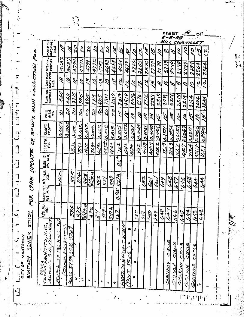
-
•■••!
. I.
11:1
1 C
.-4 1
_71 L
.L1 t
It
-4 14E
i
LJ c. L
C
CIT
Y Ø
F A
tION
TE-R
MY
SAN
rix
RN
' SE
W
ST
UD
Y
Fo
g /
a 9
/P
DA
7
_O
f S
E 1,
1/R
/P
M IA
/ ca/1
.417/
-
REA
CA
.
..,_
45 N
IA.
CA
, -1
0 A
GO
A.:
Trr
o.) M
r c
-,
NO
lb
sPri:
-
ELS1
f. it
'll:4
s :4
.14.
tws
i.4.1
4.1
NO
. 1
• .
az, r 't
ILE
NGTA
1)
/5
M.1
4. i 1
P.
sw
pS
F
T /F
r P
IPS
E
xis
twG
liz%
W
.:v{4
Pa
IN.
I I
e-r.ii
4s r
unsl
ossl
.wrI
AL,
7c
itS
10 in
ri S
SIW
ICIS
n
au P
iPa
l %
MS
'.1 c
--A
-7
-0 r
ez
ie %
,,r -
-7-r.-
. LA
Lt
.- e
Al
0.6
05
2.1
AM
// I
a
. 56;t971 /67
. , 1 C.
.e....
.1m
in, ./
LA Zr
t -7-
o .%1
,
1 I
, I
5z1
j 39.
- 1z
.9.31
: 10
.4,.7
. I
Z'
zo
4.4
//
/6 7
- -1
.5‘8
1
/61
s 27
_-_f
-' .5 1
2-__--
,. 7.
.-P-7
7
I _5,
4c
i.j-
,; 7/
5'
ig 1
4792
z 0 1
0
./
1 9:
ct.
1 S_
'-fgt
i 1 •
Z.
I Z
eiI
/
d 79
2- I
Za -
I i.
. '
I 'I'
ao
-±
10.4
07...
Z
o
'/5-
/8
4792 I O
a
i/ -
3 '
I /.
• ty
,/
M. s
C e
t 0 D
OS
- 1
39z
44c94 ...40z
i 0
I -th-
-- /8
1
' 9A
zo
i
i 4
. 0 I 3
7/5
- ' /
23
I , 7
92-
' I
ZO
1
„ -
. -
o,P --
• -
I _,./
,,. 4
,92.
i zo
I 3519
le
I4-G
3
ga
, -
3,57
A
I .3_
5?
. ,Z
‘41 "
9/5
I
1 zo
1 3
8 1
?l /
o. 1
4649
1 zs
- /,
. s7
i •
ga 7A
I
- I
. /3
1: 4
.010
/5 I 1
S /9
2-
1649
•31 t..5
1
1611A
7 .-
770
- r4.
...-
- 7
- ,/, -7
...-f-e.
I i
4.4
17Z
1:
341 I.31/ 9 /
•
h 1.
11.1
1111
1111
11 I
I I 1
1 ff
ZEI..
.0 /
a R
ICIIN
ZI
a
I32g
M
a
h9
I 275
76
/Z.
32 6
41
\ *
. -
v. -
I I
I I 9
io J..
.- 7.
,o/4
( -
6"/
I I 65 Z
- 492.7
0.0
0g/
X.-3
I z
3/4
Z
. z871 /...s
-
1 1
.)
1 6.
..--/
•
1 4.
o?. 4
- a e
o.)
/8 I g
t.f.57
/5
j777
/5.
. I G
4 L
i ‘5
-el
0-2-5
: z la
v5(t.
, /.5 I It
/9
8
z7 7
91 A
O
' 1
4 4-
g ,s-r.
...,_....5
vPia
!c..:_
,..5
.,I 647
chec
L6
16
4-6
I
dit
y ,f..-
3 .
6 4
-7
1
- 1
. 3
/47 7
4,
sw
. g
. a-5
-50
A 0
. 4524
/5-
_5-
/5'
I 211
9 g
2171
2119
1
41:
• ' g
f •
Z?79
27 7
cf
g
r r 8
r • 1
0 i
ce
z-c.
J.4)
90- r
- - .i
er..
, '
[445
' 1
'44-
4 7 z
tosL
I 4 15 . Z
z /9
1
5
2779
/42
,.:-:--.7,.1i.w
ei
Co
k-4.
6._
- 4
2.4
,/ V
109.
9 .0:
he -
40f:
1405
. 44-4
715 1
-
. 7/3
,4t-
d.D
zifj
/.6-
j 2
i34
/o
2494
/0 I
/ 4;
i'..A
d 3 ',
- 0.6
1°6*
/46,-
ZO
O,
J1._
z6
G4
/5 1
, 11
1111
11M
1111
1111
,531
AP.5
/8:
964
2344 /-z
-
• II
thra
•■••
■••
•■■ ••
• ■•
••••
•

L .
1 C
I- L
4
1LJ
U U
ii71.3
) L
1.
C
ITY
OF
M
orel
's
aY
si
l,Nrr
x R
N, S
EW
SR
ST
UD
Y p
r z
/g
ee p
itr
z o
p ,,e
2. c
./Eg
dcf
4m, c
a,41
,g./e
c-n
citj
r
D
1-1
E-L
,47..
..e...
, C.9
.66-
s. r.I
3-5
iC.,
...e_
.
. Z
(C
Cht/
79
.
RC
R
. _
45 /E
LE
V. It
I W
S 1
4.1
1.1
8S
.V f
t- L
EN
= 'R
CM
P
IPE
L
AIr
etu
G 7
" -AP
C r
ur0
11'a
rism
AL
CIA
K A
ar I
C .-
.AA
/#40
p.6
LA
:77
7-4
iv:N
IR-.
4....
N
O.
WS
04.1
.1?I
O
. IT
I/S M
.H.
F.
FT
/Fr
'SIM
SE
rvita
i 11-
SID
Pal
slu
efic
t1 I
RIA
Z, '
MI
IN.
Sttr
.. St
7..S.
I
11 i
640.1
1 6
/,1)
44:&
5.1
/.;
/‘
- 1
/4
7-/v
1 /
2-
I64-
I 1 G
.iL
l 553.5
.0/1
41 /
,'-
11z9
/iv' 1 7
18 7
1 ,z
59 1
,-
-pto
73.5
:8 .d0501
8
/629
/7--
- I
Zia
. I
/2-
1/5
:61-4
az3i
l(P
- /4
Z? 1
/5
-
Tzl'c
l /6
-.I
c-
ebvs
tAi
.r.-
e5 c
-AA
./X
,,I.
R.P
. .o
g7 1
1615
11-3
-51. 001 1
/.-
/an
,,I4o
V
971 A
O f
25Z
Z1 1
.01761 ./.
5-
/6271
/a 1
/7,5
±1
,
•
. 1
• i
44.5
6 1 Z
5Z
. 71:
0/
i 5 1
/b--
I /
6 Z
1
/0 I
:754-
1
/a 1
454'
. 6g5
i eK
8 0
48;
/Z-- 1
/4z7
iz I
/751 /
2- I
.
, 5
, '
a .0Z
-461 l
e)
-1/4
z?)
/o 1
nP
54-1
/0
14 -
.8 . 6
+ ,4'
a I
i‘z?
•-,5
3.
/9M
'-
'0
, -
z-
I ,,z1.o
lt9
a
I
PS
731111111105211
• I
370-±
.025
i
/4/4
z53 1
/7371
e›.
,J
o 1
101A
I
I R
io:.
.492±
/2
.. 1
/444
je,
/7371 /
z-
- -
1
1 6
30 I
-
I•4030-
/6
Ii
gl-
8
17/9
1
8
' 29 A
1
6
1 -
1%
.oas%
/.
5. I/4
14 E
MI 1
3-(
/- I
Ji.
6.-2
8 A
G
z9A
3-7
G i
o4ie
. •
/5" , 1
414
8
/7357
8
,L4
9A
.5
... ..v..al
lA 0
O.
1 626A
50±
04%
5'
el?
1 a
t+
L1 9
031
6
I WA
7.1
1IFt
75 s
azuew
I
.41c4 0
.04,
4' 1 5
781
6
15?1
6
1
.1
1
513t
4-6
7
1 5
70
6
5751
4 .
II
feca p
.a 7
8
sfc75L
t7I
C "
--
1
75
.1 1
'I
' 105
-t- '
0,0
1,3!
5
575
6
si
6 1
r o - t
h.s..
•4, • - A
lr '71 .',
_s • -
-A L
1 '
allia
liall1
1111
111=
1.11
1.1.
1111
011
.

IL(
U
4LJ L
..-1
4) L_
__J
L.
A?
1 cr
ry O
P M
ON
EY
SA
N IT
XR
Y S
Z-IW
SR
S
TU
DY
FO
R 1
76363 U
PD
AT
E O
f E
W
mA
riti
. e0A
/A/4
--i-A
14/
RE
AC
H
. -
l.//5 M
..11.
NO
. azy.
ft ID
'S P
L14
. 1.
)/5
nt. -4
..1
O.
1
el-S
V
it.
WS
M.1
4.
LEA
IGTA
F
. S
LO
PE
P
iPS
F
T h
e r
/its
i N .
Exi
st"
uG
1&,..n
vIc ,
Es
...529
0
ra.v
cru
ryilm
tsm
Ac.
R
Eac
t Plg
l str
ed/C
tS
S47-
2. 9
I 77a
71.V
.Pu
01
act
, m
ini
3124
,
9 I
m
vI4
fIli
-',1
44
4 Z
,i.7
1 ‘Z
IA
veLy
I A
o0- ±
p..d
a9t1
a
(//A
gyE
AL,
1;, /s
7-A
) la
b-
tig4 l‘a
. -
2413 Im
e,
..62-
C41
8
56
10
6' I
774
0
44
1-
1 21
7? 1
4C5
1-16
4 a/
1.0
2/I_ 1
a
5 7
5
6. 1
7
7/1
8
- 66
3 -
Z
24.8
I C
C 4.
71
7-9
f.'..Z
?'
' 575
- 6
77/
8-
f •
.,:, e.: 7
‘ 4 /
775'.
14
sl%
7--!
441
214-.
8
2z57
'1.7
-- ..410
,?
"
1 8
Obil
- d:W
gr
. 8
575
- ii
79,
/ 57
-C
8 757
3
! g
• S
o 4
.-e4
'.4:3
:P
. ■ ...
/c
66o
22? , 41 G
al
22.7
. 17-
- 00
65-
1-
5
--
9-
I
, 1
731
8
1 23A
7 ,
4.- C.
3 I Z
Z. 6 i A
f-5
.0087 I
.545
.." I
78/
6 5
-5
z32.2
1 6 5
L5
0. 9
- 3
o es
-1
8 -
565
6
1 674
1 Mil 1
I VA I
I 2 M
r"
ii
47
I /4
2Z-
g
I Ir .
,
fz
1.1 I I
M 1 KA
I PA I
I I I IN
I ral
e K1 W
ill I E
l I r id
I gli E
l 12 E
l I El
I Er4 6
3 I JJf'
57: -
SO
8
///g
3.5
7
a.7
8I 3,5
7 2 •
006
-1
/z-
so7
a. D
O
5'0
,3
ii-/
3 1 ;6411.6
9z2
./2
•
/743
/2.
IAl..
.2.:Z
. /z
5) 6
/-0
. ‘51
61,7
/Z
-90
I 2- -:
:7) . 0
1/
i 2-
/24-5
/0
/-3
t2Z
- A
.syz
.7/7
.o
.-C_ , ,t
,. ,
lc tiw
45
if 4
.--• z.A-
-7-
A-3
17 -1
7.., /,F
..... .--.
0 r
I
545
1/5:
071
ZI. C
o
6-ex
. •
2.6
5
5'0
5. /5
- .0?
sgs
_046
27
/2-
-161 0
6
464
/0
/24
- /
417 N
EM
=
2:7
7
6
%.
tk
..•
...r.27
,0 30
.31
- 09
21.6
0
.e.c.,
5- :
04Z
5
- /0
z7
7
I 4c
> a
l•
. %
I "
.6- ir
;z
.41
sio
3c
),-;1
_3
41
01)6
0
/0
. 0074
la
Z77
CI
1 4°4
27
7 1
6
402
a
it14
' IA
B
r%
st
1.1
___-
4.- / i-
135,
17
57/ •
;2.4
1
7a 7
.....
•
v.
,. I.
2-
- s
• 0
2 0
2W5
e
6
ec
- 5,
'
3.3
s/4
5
.41 .
_P
ail A
O
.t.
5/6
55, 8
575-
-0
0174
/D
I,
4
IN
C
101,
%I
i
.57
30 .
.005?
47219

LL1
L.
L_2
1 ti
i - L
i U
EL
I
•
CIT
Y O
F M
ON
T.'
(
SA
Nn
- AR
y sn
my
Ao
R /
57
,10
. a
pjy
ArE
- 5;
Ekv
a,ct
NA
/A,
ca,„
/ean
coi
-flew
RE
AC
I4
..
,..,
45 t
IEL
SV
. it
iDis
IA
A l
etzs
r t.
A 4
-71A
.7"/
70
/WA
D
No.
U/S
MM
.! gO
. 'I
DA
F
AA
.
.1,6
. tA
S5A
)E
rG.
" 1
LENI
GTR
F.
st.c
ps
riv
er
I PS
I' a
sme
04.
I E
in
irtA
tt ru
jPgr
rem
rt
friAt
e sl
41zy
Z I
ttir
o W
I wart
etS A
I. M
.4b
mPa
Si
zZ.
SMS
I
A(5
V.A
.777 0
(P
, M
A R
I( 'n
40
10
51
''.:6
0.1E
1 A
C Z
.61_
5275
1 /5
05
1 /4
4 1
.0og
l 1 /
2
. 9,6
41
/D
f/'2
01
/0 I
z.
a
6
1.-- 42
.01
/a
62'2
1 1
D-60
1-6W
91 /7
- 70
171
oic.
.7I
/c)
'32,
8
I 913
6 a
' 50
/ - 1
22.2
015'
0 Z
12
9.6
0
57‘
.0481 /0
1 7
1Z
g
7,1g
1 .5
- -
.foo
.1 Zh
. 93
1 .5
"-I)
1 z2
. zo
54Z
. 2.
.01i-1 /0
yr
gi
ti 7
5c
g 1
a
- -
137-
.5"-?
1.6---a
a .91
3 328
1 ,026
I
-/a
I 932
. 8
72g
a.
8
I 478
41.5
e-1
497
.
• 3 4
- -iz
olk
fl aI
-ill
40
/1
a
• 4
9 -
146
.851
- 94
9 50
1 .1
6'
. . 5
1
ID
34
4 ri
fili
rffi
nff
i I
/071
6
. 495
48-7
1 4
?
.024
51
e9•
..6-3
•
494 I 5
46 4
95 1
48.
'2 8
.0
tez
g 1
5
:6
/a
:‘
-
493
58.4
• 5
4-.1
4 Z
zo .0
1- 5
E
l .5
:3
' G
/07
-G
12
- svozurA
IIM
MI
11.1
1.11
1111
1111
1111
111.
111
64- 4
0 11
1111
1111
1111
1.11
.1.1
1111
1111
1 1111
1111
1.11
1111
.1.1
1111
1111
111
5',IL
4.0e
) -0
19
1111
11=1
1111
.111
1.11
1111
11
,;,11
M11
11M
1 4,
I
D
I
C.
ME
M
' •
-

3z1
z3 1
1;z
1 L
L
12o
rA)
I
3Z
9'
II h
'
ii
AID
ft
if
U
I • =
1•1■
1=■
•
It
P..e
liffG
go
cJA
JD
RO
AD
"31
LZ
- 5 c.
iszt
%of'
. gle
e
L.;;
; L
L.1
L.J
I
LL
11
LJ
J . O
rrY
OF
MO
NT
EM
E.Y
S
AM
ITN
RY
SS
WG
IR
STU
DY
rpee_ifee
, ..010
,0A
7-
pr
.'&14.I
ER
, M
A m
., c
eo.fra
cc.7
*40.1
fE
E
1
.RE
AC
I4
-ro
RO
AD
c/ -7
- / +
/v.
-- ro
SLO
PS
I P
IPS
Fr/F
r S
izS
IN
.
a6'o
fzl
2.
icA
lt P
LaW
I kt
riP
iTrA
t. IF
:MC
P-C
.11
. ;t
wo
Ara
i Suv
a ct
SZo
riva
l Ss
74- Z
1146
01
MA.
NO
. EL
EV. F
L U
IS
M.4
. D
is
ELV
er:
No.
DI
5 1.E
.:4GT
A F
r.
1 1
319
3'z
o
fiiz
A
fiel9
3/9
I
1 13
7 oto
:3 1
51 1
/401
A060 /z. /0
771
/0 I
itz
.1
: 6 I/7
51
F2S
-F-S
vPLY
C
7:
/21
93
'.a55 /Z
/067
/355! •
:-.ej
8
/837
i le
, i7
02_4
:1e.
a74.
3 /4
1 2
971
±e{tt
1
iii-
/2
-
1 8
97
'L‘Z
I 1/3
-"t1,6
teva
l /Z
- 2971
897
0°. -
4 :4±
21"
: s91
el /‘41
S.
0
, mA
8
-,m
461
IP I 07i
it'
/46A
1
/0-
/3
2-
I 2
Ira
/0
6/-
42-0
/E
t.
5.5
•IIIM
MI.•
••■••
••••
••••
••• '
OP
••■■
••••
•
1402
/01
i
Q.,0
1-23
yAwm
4)1_
_F
Rere
vA
motio R
EA
LA
ceos-t
aA
rr
tz.11
L
a/ 7
7:10
*/ M
VE
Se4
0C5
Fo
ips A
4Aff
.40)
/ C
r,41
4-e7
E10
11.
41.0
4e
771
Cag
oA
vr
. sfi
zaz_
hm
id_aeg
t_ter.
7744
1 F
EE
5 1, 4
02*4
4,4
:

-
Mg
IIIIII •
INIIU
MIIII
. _ iv
el
. z
12,
ti vac
,' 05c
• 1,2
92 9
I
li? 51
-kir
fair
9
6110', •t-t-
221
E- z9
-- z/
5100 f
-
. /2
-1
VS
14,51470 flu 12 9*
7" F
t-7-1119
te -z/
a00
-0 .9z.s
029
0
/ 1 171, 48
= 7 §37 lirra
-0 *0
5s•
6/
a
:Q/
14.V3
El -Z
4Z
L
E
EN
V
-7Zg
. - g
lic
,a/
I Z/
III8S
".
Z a
1
/
zoop 8
Z1
i ay
1 W
1 #Z4 g
rtzf :1
z/
cEct•o
vz_z
7/,
L&
j I I/
I - 14.6 19
LZ 5'.
7/
go V
292? I
, s
-/P
?/P
0 -
6fr.
1
- zit
zepf'1
9 5
2/
- / 5
- 9.
i Av
t , .
.1r- I
' 0 . - , o
v
a/
Z
gi 1
. 0/'.1
21170 aZ
g
0/
16, 9 4 16
1 12d 7 f
o/
c7/
I-t- U7 I g
15g
5 - I 0/ : • V
iia.nq
le
;
1/ I
/7i"
0/,
. //
. v
5s-.5.' I (7/.
iiery
0 z
9t--•
&: 2d7
(1/ so,
•••,1 ‘..r
jp/
14.z.v
g
.....ss
% 0
/ 1
V
7..4•fr
la
pvz.i-/
9
5.g
_g
1 . 6
7/ • Ig.Z6-0
a8
,- 1 R
Ir? 2.7 1 9
.6, s-s. 1
a/ 1
1,z
o•0
orI
Lo
v
I 0
/ Ifrzs
v I
.5...g•
i 0/
izio
-0.
471
, L
/ 7
.55.5. o/
c;, 44? e O
p-* -- 75%;•=3
....go
, .,
--ircp
7
I
Stir
1$‘e am
I
nSwirris I
-.7.. is O
DA, g
uitn
r
• HI
1- 21 5. d 1 d
..3.4/.13 341015
' Id
Iti9N31
*try4 SA
1
4. ATS13 " ON
'KV
Sit
- ;•
S/n
KW
743 A
re 0N
-trw sin
(.! rig
a)
CL•ctoz if:3-_:: 3 v'.
cZ
e-. 3
0.2
:,-,:fitaW
. /1
.7..
. - IiD
V-3t1
p.o
s:L.3
prfia
riryw
zwrig
o
dev _
7Lye
le/1
7' g
ed/ tn
y A
GO
IS z3
BW
its Kav1.1
Nv3
Ravs_L
tiovl a0 A
2.1,
r-- 1 7-
1 r
---1

RE
AC
14
. -
PA
LO V
S:C
DS
7,: "5
77
75
58
40
t1
e.-2/1
,14/
0.A
1
1i
I tx
j,ja
n4 s
Lo
ps p
ips
ix o
nLi
4 -
4
7761
1R
ave
Port
.sal
m. M
x ?w
ell .
F
r.
Fr
/lei-
1
. 124
sm
tas
0.54
.0 A
ral S
3113
3ric
tS
ac'D
Pop
al
3N.
st=
Si
T-S
/V1--
t Ia1
0411
70 1
77.
3 1
10
•••
SLO
PS I
PtPs
t. FT
.s
.a.0
3N
.
pis
;AA
.Say
Ft:
LE
.:+iG
IN
1 O
. D
/5 M
.A. F
r.
1 ii
"
/0 I
'AL
() V
eL
s.
57
8 I
74Z
- P
AL
E>
/a
'
a- o
ssE
r-V
AI
,CAM
A
ral 5
42
I sa g
I IZ
I4
- re
ar g
- 1
49
T I
154 D
.0151 8
14991
54
Z-
,r
L..2
L C
ITY
O
F
pn
oN
Ta
Y
LiL
J- 1
•ta
.A
SAN
IT A
, S
ZE
W I
R S
TU
D'(
F,o
R _
/g
ee
op
DA
- rE
c5
F
5614/E
R M
AiiJ C
40,4
4.M
. G70i4
/ _ F
EE
u/s
Nul
at... e
v. N
O. u
/s
AS
- e.9
6.
PfS
LO
G.
AV
E.!
pa
Ao.
0421
z/
e 4
-so
Z3
1
/45
L
at,
e14
1
15
74
1
. 1
7..6 -
.
I/.o
s t
D._p
atiP
1 .1
.21
57
4
I 4 1
0-o
7_3/
1 /
2-
I
57z.
I 1 5
743 •
1 /
7 l
e7
-00
7-J
/ Z
1 a
5
7/j
77
? I
5 7
2-
en:I.e
y
-.-
o.o
ai'zi /2
1
74 1
1
57
/ _
I 'Z
oo
0.0
/24 /.0
1
( A
ov.s
zr.f._
_st
o
1 1
fa
ii
8 I
/I
/29
569
54
5
570 •
54
9
/11 -1-
0-4
W
1 /
3/
aP
o9
2
■• I
e•
11
49
.a
ri9
/e
t 1
8.0
1771
AO
I
ze'i8
9 •
e, 1
te.0
55
. /.
41
feaP
6er,
v 1
5o
F
RE
-eu
/A
cR
Ossirl
547.
--
54
3
1 4
tZ-
#0
! il
J -
..
Ast_
wA
V
GRox
--7.1
4—
1 5
41
562-
115:a
t 0.
0e6"
-r-
0
7
. /0
a
/e)
.1.1
.1.•
"-
N
•

;=E',7
40c"4
.0.~
4.:*CW
4'w-x
iel-w
44
• 1-
1_1
S.
cm
y O
F m
oN
TE
,RM
Y
-SA
C TA
RY
saw
EIR
ST
UDY
"s
uge 0
PD
A-r
a--- e
ap s
Eukr
z ez
avAJ
Ec-ri
emi
RZEA
CI4
..
45 M
.A. az/
. F
t F
as
pt.1
4.
z3)
L
m 0 s
-.1 -r
e -
.„'s,3
c", )
5-./.4
7j53.1
NO
. uis
m.14
,1 No
. V
. A
V.E.
GZA
N; —
A V
S • !
.. -Ar.
..A A
VF
..
ELSY
Pe
t W
S M
.R.
LENI
GT1.1
FT
. st
cPS
rr
jr-r
• P
IPS
ex
ISflu
a slr
.e
1=v1
0ES
mi.
MAK
an,
011
Pn
IsT
rAl.
its;r
0 P
risi
uonc
ts
uza
. n
Alt
PA
II I
aCZ
rIP
II 3r
t...S
j
,-5-4
c7A/
7".±-
1D
N)
341
,&_
A0457
c/.6"e
61
925i
27
' (Z'
F...L
1.4
0 ti--
-_-7
. A
v.)
1
1 1
I I
. I
I him
f. F5 1
D
A4
36
- O
F 0.
DO
1
- -&-
- oo
15
1 A
is
•
- pm
341
10",
5
. 240
- 00
3 1
/5-•
/MI
15 z
i6
/5:1
•
l'
- P
m 7
5i
I D
i'43'3r
384
el. a
oy
I /5
17
721
/b-
27451
. ' I
pm
fl
- I I
1 piC
4 33
1 g
- '6'
"14-
7- p
d-c
o,
4-0
0z i
/..
I /-
-
15741
/Z
1/9
3,1
x5
- 1
/6"
I
/5-
1 /5
-
. I 0
-1 5
1 1
- -1
0-,4
5z.,
iZz/)
/Z
1 /59/1
•
Wm
30 I
1 D.
451
I ,o.
Op
2-1
/5-
/Z'8
. /Z
-1 /561
Om
z9
1 rfr
i4 3
0 .
24-g
• D
.eia
? -1
/3--
20-
/2-1
/541
•
• ;1
O
N12
.91
1 P
iA
1) 2.
0
'z3 6
a e
aL
.406
Z
/5
/2o3I
:is-
/5471
/b---
/2
0
-. /z.
.5
41
/5-
ys
- ›-:_
i_ lu
c+
.1 r
E e.
E•J
OLi
sY A
VE
. D
M f
f.,
PM
27
. I
Z.5
6 •
..eoz
/5-
I /1
97
/2-
1 /54/
@R
es.-
U5/1
AV
E)
. D
z 1
I
424
iz.I /
/31
/a
/3711 lz
A
IL' .
_-_-1
,-- C
e ,;(1
i; - .
Atfi --:
- 215 IS
I I
vz I
2:53
- 10.0
1
450 p
aw
()
/z_
1 /
21
a
/3701 /a
6:F
AN
7 A
VE. .
.. /P..-
C45
A00
V A
21
I
1 1
- -2
701 .041
• 2
- e95
z‘i
/Z
2/f
ZIO
7.i8
5
0.0
119
-/0
590
I ‘.
-e9
g
6eetir
. - A
, .
P
- €3:-/k
i 57
: 1 2
22 A
20
thae, ,
a
4863
0
54-3
221
szeA
Zzi
-
/og±
0.0
079
Mat 14.4
252
/ 2
/a I 4
e,'
I I 4471
..d
zo
o
i A
mo o
./A
• vE
• •
Z30
52,0
0.
01G
2..
43/
• .
_ _
228
I Z
9
4-5
3-
4.e
05
; 37
- :
4i2.i
c

.;--
, ,
..•
I 1:
1_
' L_
__J
';1 C
M, O
g m
ou
r-S
SE
Y
SA
NIT
AR
Y5W
ST
UD
Y g
z2R
/756 v
pD
A-r
E- e
r 5g
1fi
g m
ivA
l c401E
cr,
4I/ F
EE
R
SA
CI4
.
r:76.
e.M
ot-
17-4-7
_ A
VE
.) E
4/q
Z/S
41
alk,..e
.E.
•-• e.4
47--
Avt
-:.
5 Km
. N
o.
Etz
t. f
t,
u/s
M.A
. oh
a.g
. N
o.
612-
V ;1.
: D
A M
.A.
t.E.V
Gin
F
T.
;LO
S
Fr/F
r
PIP
S
Exi
sTur
a sm
s
Xxv
1(.2
.4
IN.
gra
uri
rs
StI
UL
=A
A r
tealf
trtm
TIA
L.
I7C
M
I 71
.411
sw
eiri
cts.
1=
•uri
Pa
317.
S.
i 1 4.
.. &
0 A
i -7'
. 1
1 I
I -.
. IF
A iv
9 i f,
e1
A
I Z
Z7
I ZZ
9 1
1 453 0
,626
,7
.6
322
22
6
1 3
57i 6
zz-4
. '1
4
i.00g
• ,
I 21?
6
, z4
I
:.... 1
amo
ntA
,
Fr E
N\0
t-I 7
- 225
I 224
347 0
.00151
I,'1
Z-g
, 6
zs-
-- 1
5
1
. / e
A
A N
OV
A A
VE
,
..
_
1381
,141
111
1131
1.10
1:62
101.
1141
E0I4
EIN
VAIE
011:
41.3
".41
11,1
4FA
I401
2:
1 1 i
I I
450 a
a=
0
474
I 4371
a
go,‘
7-0
?
- 4.5
0
D.0.
0571
g3
. 4-
5.6
0 I
z
1 8
2.95
I
A-6
I 450 0
.00 -
:
;;,` .d
' ' I
' 8 I
a.c.
---I
r 19
9 205'
4-5
0 0
.051
d
415 I
13 I
581
• -15,
I -
- 94
1 4-9-
6
g fi,e
pis
o,v
7-
/97
1 /re
i
I •.7
6.
exPe
5 63
377
R
4541
,e,
9 ,g
( i
04)
, 7
/4e.
...va
, , ) ,:
ru:, ,
-IP
J93-
I /9
6 .
I 575 p
.018
6,
761
e 103
6
1-4
- i,P
5
50 a
I d
.a2o
/ • a
-
6 I
zog
6

Appendix 18: Sanitary Sewer Utility Fee Study (2011)


Appendix 19: Sewer Lift Station and Force Main Condition Assessment (2010)

ENGINEERING REPORT
Sewer Lift Station and Force Main Condition Assessment
Monterey, California
Prepared for: City of Monterey
Plans and Public Works Department Monterey, CA
Prepared by:
1735 North First Street, Suite 301 San Jose, CA 95112
(408) 451-9615
OCTOBER 28, 2010

ENGINEERING REPORT SEWER LIFT STATION AND FORCE MAIN CONDITION ASSESSMENT CITY OF MONTEREY, CALIFORNIA Job No. 122781001 Prepared for: City of Monterey Plans and Public Works Department Attn: Mr. Jeff Krebs, P.E. 580 Pacific Street Monterey, CA 93940-2806 Prepared by: Anthony LaMarca, PE Reviewed by: Rod Houser, PE 1735 North First Street, Suite 301 San Jose, CA 95112 (408) 451-9615 October 28, 2010
Reviewed by:__________
Date:__________

12278-10-0001 i Winzler & Kelly
Table of Contents 1.0 Executive Summary .......................................................................................................... 1
2.0 Introduction ....................................................................................................................... 4
2.1 Scope of Work .......................................................................................................... 4
3.0 Condition Assessments ..................................................................................................... 5
3.1 Lift Stations ............................................................................................................... 5
3.1.1 Pump Capacity .................................................................................................. 5
3.1.2 Pump Service Life ............................................................................................. 6 3.1.3 Pump Condition................................................................................................. 6
3.1.4 Wet Wells and Dry Wells .................................................................................. 7
3.1.5 Wet Well Capacity Analysis ............................................................................. 8
3.1.6 Pump Station Risk Assessment ....................................................................... 13
3.2 Force Mains ............................................................................................................ 16 3.2.1 Hydraulics ....................................................................................................... 16
3.2.2 Force Main Service Life .................................................................................. 17
3.2.3 Force Main Risk Assessment .......................................................................... 17
Figures Figure 1 - DLI No.1: SSO Reaction Time Given Variable Inflow ............................................... 10 Figure 2 - DLI No.2: SSO Reaction Time Given Variable Inflow ............................................... 10 Figure 3 - Myers: SSO Reaction Time Given Variable Inflow .................................................... 11 Figure 4 - Laguna Grande Park: SSO Reaction Time Given Variable Inflow ............................. 11 Figure 5 - Pebble: SSO Reaction Time Given Variable Inflow.................................................... 12 Figure 6 - 218/68: SSO Reaction Time Given Variable Inflow ................................................... 12 Tables Table 1 - Pump Station Loading and Capacity ............................................................................... 5 Table 2 - Remaining Service Life for the Pumps at Each Pump Station ........................................ 6 Table 3 - Max Pump Cycle Time and Max Starts/Hour ................................................................. 8 Table 4 - Pump Station Risk Assessment Category Importance Factors ...................................... 13 Table 5 - Pump Station Risk Assessment Summary ..................................................................... 13 Table 6 - FM Diameter, Existing Max Flow Rate, and Max Velocity ......................................... 16 Table 7 - Winzler & Kelly's Recommendations to Increase FM Flow Velocity .......................... 16 Table 8 - Remaining Service Life for Each Force Main ............................................................... 17 Table 9 - Force Main Risk Assessment Category Importance Factors ......................................... 18 Table 10 - Force Main Risk Assessment Summary ...................................................................... 18 Appendices Appendix A – Pump Station Site Visit Observations, As-Built Data, and Assessment Information Appendix B – Force Main Site Visit Observations, As-Built Data, and Assessment Information

12278-10-0001 1 Winzler & Kelly
1.0 EXECUTIVE SUMMARY
This report was prepared by Winzler & Kelly for the City of Monterey. It presents findings from inspections of the City’s seven wastewater pump stations, which occurred on August 10, 2010. The purpose of the inspections was to assess the condition of the structural, mechanical, electrical and control systems, in addition to the force mains. Ultimately, this condition assessment will be used as the basis for developing a lift station and force main capital improvement program (CIP). This CIP will be combined with an existing CIP for the sanitary sewer collection system for purposes of determining a suitable rate structure. The lift station and force main CIP will be issued in a separate document after the condition assessment has been approved by the City.
All of the pump stations were found to be operating normally, and most are in reasonably good condition. The following items present the major findings of the inspections at each pump station:
1. General Findings: a. All of the existing wet wells showed some signs of surface decay on the interior wall
surfaces, possibly due to hydrogen sulfide buildup. All of the wet well interior wall surfaces should be lined with a high-build coating to extend the useful life of these structures.
b. All of the pump stations appear to be adequately sized to accommodate the estimated peak wet weather flows.
c. All of the pump stations have modern control systems with redundant communication capability.
d. None of the pump stations have run-time metering. Run-time metering should be added at all 7 installations.
e. None of the pump stations have pressure gauges. Pressure gauges should be added at all 7 installations.
f. None of the pump stations except for 218/68 have pump bypass capabilities. Pump bypass capabilities should be added to all pump stations except Laguna Grande.
2. DLI Nos. 1 and 2 a. Existing pumps and motors are over 26 years old and are due for a detailed inspection
and rebuild. b. Minor coating defects were observed in the dry well interiors. Coating defects should
be spot repaired. c. Existing engine generators do not meet current air-quality standards, and produce
excessive noise. Generators should be replaced. d. The force main for DLI No. 2 has had one known failure, which was repaired in 1999 or
2000. e. DLI No.2 does not have adequate maintenance vehicle access. The existing access road
needs to be chip sealed and the concrete pad adjacent to the wet well needs to be extended to improve accessibility to the wet well for a vacuum truck.
f. The discharge velocity for DLI No.2 is too low. The pump control logic should be modified to run both pumps simultaneously once per day to achieve adequate pipeline cleansing velocities.

12278-10-0001 2 Winzler & Kelly
3. Mesa a. The existing facility does not have a standby pump, but it does have an emergency
overflow pipe that can divert sewage to a separate part of the collection system. A spare pump should be procured and made available to minimize station downtime if the duty pump fails.
b. The reported pump starts per hour is 14, which is much too high and will likely reduce the life of the pumps. A soft starter should be installed to minimize wear on the pump motor.
4. Myers a. Existing pump discharge piping inside the wet well is severely corroded and should be
replaced as soon as possible. b. Both pumps are very close to the end of their useful life. Recommend replacing with
larger pumps to increase the force main velocity. c. Pump check valves are located in Del Monte Boulevard and are very difficult to access
for maintenance. Valves should be relocated to a new vault that would be installed under the sidewalk next to the wet well.
d. Existing engine generator housing is severely corroded and is over 15 years old. Recommend replacing the natural gas generator with new diesel generator.
5. Laguna Grande Park a. No significant deficiencies were observed at this facility.
6. Pebble a. The existing facility does not have a standby pump or overflow prevention/containment
facilities and therefore does not meet industry standards for redundancy and reliability. Existing pump should be replaced with two submersible units to improve reliability and guiderail assemblies for convenient retrieval.
b. The existing force main is exposed over a length of approximately 20 feet, and is vulnerable to landslides. Recommend replacing the entire force main at an adequate depth to ensure the pipeline is protected.
7. 218/68 a. The motor on Pump No. 1 is over 18 years old and is due for a detailed inspection and
rebuild. b. The vehicle gate is located in a position that makes it dangerous for maintenance trucks
to access. The gate should be reconfigured in a way that allows vehicles to be completely off the highway while opening and closing the gate.
c. Power quality problems at this site cause occasional nuisance alarms. Recommend conducting an engineering study to diagnose electrical problems.
d. Portions of the existing force main have very little vertical cover and are exposed to heavy freeway traffic. Recent road construction in the vicinity of the freeway caused a failure of the force main. The force main should be replaced in this area so it has additional cover.

12278-10-0001 3 Winzler & Kelly
Additional findings and an assessment of the remaining useful service life of each facility are described in the body of the report. Appendix A and B provide a summary of the observations made during the site visits for the pump stations and force mains respectively.

12278-10-0001 4 Winzler & Kelly
2.0 INTRODUCTION
The City of Monterey is in the process of updating its sewer rate structure to provide sufficient revenue to offset the costs of providing reliable service to its rate payers. The City prepared a Capital Renewal and Replacement Program (CRRP) in 2000, which was based on a condition assessment of the sewer mains and manholes. As of October 2010, some of these projects have been completed. However, that program did not address the seven sewer lift stations and force mains that are also an integral part of the collection system. Thus, the purpose of this condition assessment is to:
• Develop a capital improvement program for the lift stations and force mains; and • Estimate the remaining service life of the lift stations and force mains.
Ultimately, the condition assessment will be combined with the existing capital improvement program for the sewers and manholes. The comprehensive improvement program will be presented in the next deliverable, which will also include the following information:
• Annual operations and maintenance costs for the sewer collection system, including the lift stations;
• Replacement costs for the sewer lift stations and force mains; • Cash-flow projections that will be used to establish an equitable rate structure.
2.1 Scope of Work
The scope of work for the lift station and force main condition assessment consisted of the following efforts:
• Estimate firm-capacity requirement (See Table 1); • Perform flow tests to determine existing firm-capacity (See Appendix A-2); • Perform visual inspection of dry well, valves, instrumentation, SCADA system, fuel system,
electrical gear and safety equipment (See Appendix A-2); • Estimate wet well capacity (See Appendix A-1) and pump cycle-times (See Table 3); • Assess lift station failure risk (See Figures 1-6 and Tables 4-5); • Evaluate force main velocities (See Table 6-7); • Estimate remaining service life of lift stations and force mains (See Tables 2 and 8); • Review force main alignment and profile to identify potential high-risk areas (See Table 10);
and • Compare generator nameplate data with pump power requirements (See Appendix A-2);

12278-10-0001 5 Winzler & Kelly
3.0 CONDITION ASSESSMENTS
3.1 Lift Stations
3.1.1 Pump Capacity
In general, all of the lift stations have adequate pumping capacity to accommodate estimated peak wet weather flows. However, the Pebble lift station does not have a standby pump or an overflow bypass, so it does not meet generally accepted standards for redundancy and reliability. Table 1 below summarizes the PWWF and capacity for each pump station. Refer to Appendix A – Pump Station Site Visit Observations, As-Built Data, and Assessment Information for additional pump station information not shown.
Table 1 - Pump Station Loading and Capacity
Pump Station NamePDWF3
(gpm)
Peaking
Factor5
Estimated Firm
Capacity2
(gpm)
Estimated
PWWF1
(gpm)Safety Factor
DLI No.1 18 1.52 222 27 8.3DLI No.2 38 1.52 271 58 4.6
Mesa6
25 1.26 114 32 3.6Myers 21 1.60 149 33 4.5
Laguna Grande Park4
0.5 1.60 168 0.8 209.6
Pebble7
5 1.60 37 8 4.7218/68 27 1.62 233 44 5.3
Notes/Assumptions:
1. This is the estimated peak wet weather flow, which is determined using dry weather flow data multiplied by a peaking factor
2. From tested drawdown rate using a single duty pump.
3. Determined from the Pump Run-time records provided by the City using the drawdown rates determined in the field
4. The PDWF at the Laguna Grande Park pump station was too small to register so it will be assumed that the PDWF is 0.5gpm. 0.5gpm = (1 toilet flushed every 10 minutes) x (5 gallons/flush) / (60sec/min). This is approximated based on estimated peak hour use during the weekend.
5. Peaking Factors (PF) were provided by the City on 8-23-10. The PF were based on historical energy usage data or the 1986 I&I Study.
6. This pump station does not have a standby pump. However, it has a 6 inch gravity bypass pipe to prevent sanitary sewer overflows.
7. This pump station does not have a standby pump.

12278-10-0001 6 Winzler & Kelly
3.1.2 Pump Service Life
The expected useful service life of a wastewater pump is usually 15 to 25 years. The service life can vary depending on number of starts per hour, type of starter, maintenance schedule, and other factors. For purposes of this assessment, a pump service life of 20 years was selected.
The table below summarizes the remaining service life for the pump(s) at each pump station based on the pump installation or replacement date.
Table 2 - Remaining Service Life for the Pumps at Each Pump Station
Pump Station Date Installed or Replaced Service Life Remaining (Years)DLI No.1 1984 -6DLI No.2 1984 -6Mesa 2004 14Myers 1995 5Laguna Grande Park 1999 9Pebble 2006 16218/68 1992 2
3.1.3 Pump Condition
• DLI No.1 and DLI No.2 Existing pumps and motors are approximately 26 years old. There are no known problems with the existing pumps, however they are 26 years old and due for a detailed tear down, inspection, and rebuild, which should extend the life of the pumps for another 20 years.
• Mesa Existing duty pump is 6 years old and there are no know problems with it. Existing facility does not have a standby pump and therefore does not meet industry standards for redundancy and reliability. However, the pump station has an overflow pipe that is plumbed to an adjacent sewer manhole. Winzler & Kelly recommends purchasing a spare pump to minimize downtime in the event of pump failure.
• Myers There are no known problems with the existing pumps that are approximately 15 years old, however there appears to be a severe sulfide attack on the wet well interior and piping, therefore Winzler & Kelly recommends that the piping be replaced. Also, the check valves are currently located in the middle of a busy road (Del Monte Blvd.); therefore, Winzler & Kelly recommends that new check valves be installed in a new vault located in the sidewalk. We recommend replacing the pumps at the same time the valve and piping modifications are done because they are very close to the end of their useful life. The new pumps should be upsized so the Firm capacity is at least 265gpm to increase force main velocities for cleansing purposes.
• Laguna Grande Park Existing pumps are approximately 11 years old. There are no known problems with the existing pumps.
• Pebble Existing facility does not have a standby pump and therefore does not meet industry standards for redundancy and reliability. The existing duty pump is difficult to maintain

12278-10-0001 7 Winzler & Kelly
because it is not installed on a guiderail assembly and a retrofit would be difficult. Winzler & Kelly recommends installing two new submersible pumps with guiderail assemblies to improve reliability and improve access for pump maintenance. The new pumps should be upsized so the Firm capacity is at least 118gpm to increase force main velocities for cleansing purposes.
• 218/68 Existing pumps are approximately 18 years old. The seals on both pumps were replaced in 2003. The motor on pump no.1 is 18 years old and is due for an inspection and rebuild. The motor on pump no.2 is 7 years old and has no known problems.
3.1.4 Wet Wells and Dry Wells
• DLI No. 1 The concrete wet well was constructed in 1984. The interior surface shows evidence of decay possibly caused by hydrogen sulfide gas. Winzler & Kelly recommends the wet well be lined with a high build epoxy or other equivalent lining system. Minor coating defects were noticed on the dry well interior. Winzler & Kelly recommends spot repairs be performed.
• DLI No.2 The concrete wet well was constructed in 1984. The interior surface shows evidence of decay possibly caused by hydrogen sulfide gas. Winzler & Kelly recommends the wet well be lined with a high build epoxy or other equivalent lining system. Minor coating defects were noticed on the dry well interior. Winzler & Kelly recommends spot repairs. The foundation under the dry well has been undermined possibly due to a force main failure in 1999 or 2000. Winzler & Kelly recommends that the voids be pressure grouted.
• Mesa The concrete wet well was constructed in 1938. The interior surface shows evidence of decay possibly caused by hydrogen sulfide gas. Winzler & Kelly recommends the wet well be lined with a high build epoxy or other equivalent lining system. Six to twelve inches of standing water was observed in the dry well, however this does not interfere with normal operations and maintenance activities in the pump station.
• Myers The concrete wet well was constructed in 1952. The interior surface shows evidence of decay possibly caused by hydrogen sulfide gas. The grout on the grade ring has decayed resulting in bricks and debris falling into the wet well. In addition, the steel hatch has been deformed due to excessive vehicle loads. Winzler & Kelly recommends that the top three feet of the wet well be rebuilt and the hatch replaced. Winzler & Kelly recommends the wet well be lined with a high build epoxy or other equivalent lining system.
• Laguna Grande Park The concrete wet well was constructed in 1981. The interior surface shows evidence of decay possibly caused by hydrogen sulfide gas. The hatch is not traffic rated. Winzler

12278-10-0001 8 Winzler & Kelly
& Kelly recommends the wet well be lined with a high build epoxy or other equivalent lining system.
• Pebble The concrete wet well was constructed in 1956. The lid on the existing wet well will not accommodate a guide rail assembly for removal of the pumps. The interior surface shows evidence of decay possibly caused by hydrogen sulfide gas. Winzler & Kelly recommends the top portion of the wet well be reconfigured to accommodate a larger hatch. In addition, Winzler & Kelly recommends the wet well be lined with a high build epoxy or other equivalent lining system. The original dry well is now being used as a valve vault; however the existing piping arrangement makes it difficult to access the valves for maintenance. Winzler & Kelly recommends that the piping be reconfigured so it is closer to the surface and the bottom of the dry well be filled with crushed rock.
• 218/68 The concrete wet well was constructed in 1992. The interior surface shows evidence of decay possibly caused by hydrogen sulfide gas. In addition, signs of groundwater intrusion were apparent. Winzler & Kelly recommends the wet well be lined with a high build epoxy or other equivalent lining system. The dry well is in good condition.
3.1.5 Wet Well Capacity Analysis
The volume of the wet well above the pump high water alarm level determines the amount of time available after a pump failure before an SSO occurs. In addition, the volume of the wet well between the pump start and stop set points determines how frequently the pumps run. All of the wet wells appear to be adequately sized to accommodate anticipated flows. However, run-time records for the Mesa and Myers lift stations indicate that the pumps are over-cycling (14 and 10 starts/hour respectively). Excessive cycling of the pumps can shorten the life of the motors and may lead to premature failure and overflows. It appears that the level switches used to control the pumps may be spaced too close together. Table 3 below presents a summary of the wet well analysis.
Table 3 - Max Pump Cycle Time and Max Starts/Hour
Pump Station NameNo. of Pumps
Estimated Pump
Discharge
Rate5
(gpm)
Actual Max
Starts per
Hour1
Wet Well Design
Working
Volume2
(gal)
Theoretical Max Cycle
Time
(min./cycle)3
Theoretical Max Starts
per Hour4
Recommended Max Starts per
Hour DLI No.1 2 222 2 635 23 3 6DLI No.2 2 271 4 1483 44 2 6Mesa 1 114 14 215 8 8 6Myers 2 149 10 245 13 5 6
Laguna Grande Park5
2 168 0 159 8 8 6Pebble 1 37 2 329 36 2 6218/68 2 233 3 1042 36 2 6
Notes/Assumptions:

12278-10-0001 9 Winzler & Kelly
1. Per the pump Run-time records provided by the City, which is based on data recorded on July 27, 2010. The max starts per hour is the max recording of either pump because the five installations with duplex pumps are set to alternate. 2. As derived from as-built data. The lead pump start/stop set points were estimated for Pebble PS. 3. Max Cycle Time = (4 x Wet Well Working Volume) / Pump Discharge Rate. This occurs when QIN = (1/2)QOUT. 4. Max Starts per Hour = (Max Cycle Time / 60 minutes) 5. From tested drawdown rate, which is based on the discharge rate of the lead pump only
Wet well geometry is examined for purposes of estimating the amount of time it would take for the wet well to overflow. In three cases, the upstream manhole has a rim elevation that is lower than the top of the wet well, which is where the overflow would occur at that facility. This occurs at DLI No.1, DLI No.2, and 218/68. The manholes with lower rim elevations than the wet well rim elevation are as follows:
• For DLI No.1, the lowest manhole rim elevation upstream of the wet well is SMH D01-009. • For DLI No.2, the lowest manhole rim elevation upstream of the wet well is SMH D01-030. • For 218/68, the lowest manhole rim elevation upstream of the wet well is SMH H12-006.
The Mesa Pump Station has an overflow bypass pipe that would prevent an overflow from occurring. Figures 1 thru 6 show the amount of time before an overflow would occur for varying rates of influent.

12278-10-0001 10 Winzler & Kelly
Figure 1 - DLI No.1: SSO Reaction Time Given Variable Inflow
Note: SMH D01-009 is the overflow point, which is lower than the rim at the wet well for DLI No.1
Figure 2 - DLI No.2: SSO Reaction Time Given Variable Inflow
Note: SMH D01-030 is the overflow point, which is lower than the rim at the wet well for DLI No.2
PWWF=26.9gpmT=99min
0
100
200
300
400
500
600
5 9 13 17.7 26.9 92 157 222
High Water W
arning
Tim
e Be
fore SSO
Occurs (m
in)
Rate of Wastewater Inflow (gpm)
High Water to SSO Reaction Time Given Variable Inflow
PWWF=58.4gpmT=47min
0
50
100
150
200
250
300
10 19 29 38.4 58.4 129 200 270.8
High Water W
arning
Tim
e Be
fore SSO
Occurs (m
in)
Rate of Wastewater Inflow (gpm)
High Water to SSO Reaction Time Given Variable Inflow

12278-10-0001 11 Winzler & Kelly
Figure 3 - Myers: SSO Reaction Time Given Variable Inflow
Figure 4 - Laguna Grande Park: SSO Reaction Time Given Variable Inflow
PWWF=33.3gpmT=20min.
0
20
40
60
80
100
120
140
160
5 10 16 20.8 33.3 72 110 149.0
High Water W
arning
Tim
e Be
fore SSO
Occurs (m
in)
Rate of Wastewater Inflow (gpm)
High Water to SSO Reaction Time Given Variable Inflow
PWWF=0.8gpm,T=1191min
0
500
1000
1500
2000
2500
0.5 0.8 2 5 10 20 75 167.7
High Water W
arning
Tim
e Be
fore SSO
Occurs (m
in)
Rate of Wastewater Inflow (gpm)
High Water to SSO Reaction Time Given Variable Inflow

12278-10-0001 12 Winzler & Kelly
Figure 5 - Pebble: SSO Reaction Time Given Variable Inflow
Figure 6 - 218/68: SSO Reaction Time Given Variable Inflow
Note: SMH H12-006 is the overflow point, which is lower than the rim at the wet well for 218/68
PWWF=7.9gpmT=63min
0
100
200
300
400
500
600
1 2 4 4.9 7.9 18 27 37.0
High Water W
arning
Tim
e Be
fore SSO
Occurs (m
in)
Rate of Wastewater Inflow (gpm)
High Water to SSO Reaction Time Given Variable Inflow
PWWF=44gpmT=65min.
0
100
200
300
400
500
600
700
5 12 20 27.2 44.0 107 170 233.0
High Water W
arning
Tim
e Be
fore SSO
Occurs (m
in)
Rate of Wastewater Inflow (gpm)
High Water to SSO Reaction Time Given Variable Inflow

12278-10-0001 13 Winzler & Kelly
3.1.6 Pump Station Risk Assessment
Tables 4 and 5 below present a qualitative assessment of risk at each facility. This risk assessment, which is based on several factors, will be used to prioritize capital improvement projects.
Table 4 - Pump Station Risk Assessment Category Importance Factors
Assessment Category
Relative Importance of Assessment
Category (5-20)
Service Area Risk 20Environmental Risk 10Flow Factor Risk 15Wet Well Capacity Risk 5Secondary Containment Risk 5Pump Failure Risk 20Power Outage Risk 10Security Risk 5Safety Risk 5Maintenance Risk 5Jurisdiction Boundary Risk 10Risk Score 110 Table 5 - Pump Station Risk Assessment Summary
Assessment CategoryDLI No.1
DLI No.2 Mesa Myers
Laguna Grande
Park Pebble 218/68Service Area Risk1 High High High High Minimal Minimal High
Environmental Risk2 Medium Medium High High High High Medium
Flow Factor Risk3Minimal Minimal Minimal Minimal Minimal Minimal Minimal
Wet Well Capacity Risk4Minimal Minimal Medium Minimal Minimal Minimal Minimal
Secondary Containment Risk5Minimal Minimal Minimal Minimal High High High
Pump Failure Risk6High High Medium Minimal High Medium Medium
Power Outage Risk7Medium Medium High Medium High Minimal Minimal
Security Risk8Minimal Minimal Medium High Medium High Medium
Safety Risk9Medium Medium Medium High Minimal Minimal Medium
Maintenance Risk10Minimal Minimal Minimal Minimal Minimal High Medium
Jurisdiction Boundary Risk11High High Minimal High Medium Minimal High
Risk Score1268 66 73 66 75 86 71
Risk Ranking135 7 3 6 2 1 4

12278-10-0001 14 Winzler & Kelly
Notes and Assumptions1. Service Area Risk Classifications:
• Minimal = Services residential area only. • Medium = Services residential and some small commercial facilities. • High = Services large commercial facilities, hotels, hospitals, nursing homes, schools, or
correctional facilities. 2. Environmental Risk Classifications:
• Minimal = An overflow would not likely reach the Pacific Ocean. • Medium = An overflow would result in an overflow to a creek or drainage facility NOT directly
tributary to the Monterey Bay or the Pacific Ocean. • High = An overflow would result in an overflow to a creek or drainage facility directly
tributary to the Monterey Bay or the Pacific Ocean. 3. Flow Factor Risk Classifications: A flow safety factor was determined using the result of the firm pumping station capacity that is available when only one pump is in service divided by the PWWF (See Table 1). They have been classified as follows:
• Minimal = Safety Factor greater than 3. • Medium = Safety Factor between 2 and 3. • High = Safety Factor lower than 2.
4. Wet Well Capacity Risk: The wet well capacity is defined as the volume of the wet well as determined by the difference in elevation from the rim elevation to the high water alarm elevation. Using this emergency capacity divided by the PWWF, the time before an overflow occurs can be approximated (See Table 3). The risk has been classified as follows:
• Minimal = Emergency Capacity exceeded after 60 minutes. • Medium = Emergency Capacity exceeded between 30 and 60 minutes. • High = Emergency Capacity exceeded in less than 30 minutes.
5. Secondary Containment Risk: Secondary containment provides another level of protection against SSO's. When secondary containment features were provided, the storage volume was calculated. Using the PWWF, this backup containment duration was determined. The secondary containment risk has been classified as follows:
• Minimal = Secondary Containment Capacity sufficient for at least 30 minutes. • Medium = Secondary Containment Capacity sufficient for 10-30 minutes. • High = Secondary Containment Capacity exceeded in less than 10 minutes or no secondary
containment exists. 6. Pump Failure Risk: This risk assessment takes into consideration two questions. What is the age of the pumps vs. the estimated useful life? Does the pump station have a standby pump? The pump failure risk has been classified as follows:
• Minimal = Has a standby pump and the pumps have at least 20% of useful life left. • Medium = No standby pump or dual pump setups have less than 20% of useful life left. Single
pump has at least 50% of useful life left. • High = No standby pump. Single pump has less than 50% of useful life left. Duplex
installations have exceeded their useful life. 7. Power Outage Risk Classifications:
• Minimal = Has a permanent backup generator that is in good condition. • Medium = Has a permanent backup generator that is in bad condition or is not sized properly to
satisfy the power requirements of the lead pump. Single pump has at least 75% of useful life left.
• High = Has no backup generator.

12278-10-0001 15 Winzler & Kelly
8. Security Risk: This assessment takes into account security fencing, adequate lighting, generator in enclosure, controls in enclosure, and locks where applicable. The security risk has been classified as follows:
• Minimal = Has all of these features where applicable and all are in good condition. • Medium = Either is missing one or more security features if should be applicable OR the
security features are inadequate or in poor condition. • High = Is both missing security features and has security features that are inadequate or in poor
condition. 9. Safety Risk: This assessment takes into account station features that could potentially create unsafe conditions for operators and maintenance staff. Examples include: appropriate signage, adequate fall protection provisions, hearing protection, and adequate parking and/or space to maneuver maintenance vehicles. The safety risk has been classified as follows:
• Minimal = No station features create an unsafe working environment. All features are in good condition.
• Medium = Only two station features create an unsafe working environment. • High = More than two station feature creates and unsafe working environment.
10. Maintenance Risk: This assessment takes into account environmental features that could potentially decrease the useful life of equipment. Examples are overhead tree canopies, overgrown vegetation nearby, and exposed items that are not adequately protected from corrosion. The maintenance risk has been classified as follows:
• Minimal = No environmental features create a maintenance risk. • Medium = Only one environmental feature creates a maintenance risk. • High = More than one environmental feature creates a maintenance risk.
11. Jurisdiction Boundary Risk: This assessment takes into account political impacts associated with thejurisdictional boundary. The jurisdictional boundary risk has been classified as follows:
• Minimal = A SSO would not likely flow into another jurisdiction. • Medium = A SSO would likely flow into another jurisdiction. • High = A SSO has a very high likelihood of flowing into more than one jurisdiction.
12. Risk Score: The risk score is the product of the assessment category importance and the assessment rating. Each assessment category was assigned an importance. The importance is the maximum "score" any one pump station can get for that category. The amount of points per category is determined using a ratio based on the risk assessment.
• A High risk ranking yields the lowest score, which is 1/3 of the total allowable points for that category.
• A Medium risk ranking yields 2/3 of the allowable points • A Minimal risk ranking yields 3/3 or all of the allowable points.
Thus the higher the score means there is less risk associated with that pump station. A perfect score would be 110. 13. Risk Ranking: The results of the risk score. Rank 1 is the least risky pump station. Rank 7 is the riskiest pump station.

12278-10-0001 16 Winzler & Kelly
3.2 Force Mains
3.2.1 Hydraulics
Hydraulic calculations were performed to evaluate pipeline velocity and self-cleaning properties. In general it is desirable for velocities to be above 3ft/sec at least once per day to minimize solids accumulation in the force main. The list below summarizes the pipeline velocities based on the flow tests performed during our site visit and information retrieved from record drawings. Refer to Appendix B – Force Main Site Visit Observations, As-Built Data, and Assessment Information for additional force main information not shown.
Table 6 - FM Diameter, Existing Max Flow Rate, and Max Velocity
FM Diameter (in)
Discharge Rate (gpm)
Max Velocity (ft/sec)
DLI No.1 4 222 5.7DLI No.2 8 271 1.7Mesa 6 114 1.3Myers 6 149 1.7Laguna Grande Park 4 168 4.3Pebble 4 37 0.9218/68 8 233 1.5
The force main velocities for DLI No.1 and Laguna Grande Park are adequate to prevent solid deposition in the pipe. In contrast, force mains for the other five pump stations are below 3ft/sec, which may cause a gradual reduction in effective pipeline diameter and hydrogen sulfide generation. Winzler & Kelly recommendations are provided in the following table.
Table 7 - Winzler & Kelly's Recommendations to Increase FM Flow Velocity
W&K Recommendation to Increase Velocity
DLI No.1 Do nothing. Existing velocity is adequateDLI No.2 Modify pump control logic to run both pumps simutaniously once per dayMesa Do nothing. Force main is only 12ft long and low velocities are not a concernMyers Replace the pumps. Upsize with pumps capable of a discharge rate of 265gpmLaguna Grande Park Do nothing. Existing velocity is adequatePebble Replace the pumps. Upsize with pumps capable of a discharge rate of 118gpm218/68 Modify pump control logic to run both pumps simutaniously once per day

12278-10-0001 17 Winzler & Kelly
3.2.2 Force Main Service Life
The expected useful service life of a force main varies widely. It is usually a function of the pipe material, but also depends on techniques used during installation, septicity of the sewage being pumped, exposure to cyclic pressure fluctuations, and other factors. For purposes of this study, pipeline material and maintenance records were used as the basis for estimating service life. Pressure ratings for the force mains were not available for this study. Based on previous studies and manufacturers’ recommendations the expected service life for the pipelines is summarized below.
• Transite 65 Years • Cast Iron 100 Years • PVC 100 Years
In cases where there is history of pipeline failure, the expected service life has been adjusted downward by 50%. The table below summarizes the remaining service life for each force main based on these criteria.
Table 8 - Remaining Service Life for Each Force Main
Pump Station Material No. of Failures Service Life Remaining (Years)DLI No.1 Transite 0 39DLI No.2 Transite 1 20Mesa Cast Iron 0 28Myers Cast Iron 0 42Laguna Grande Park Transite 0 36Pebble Cast Iron 0 46218/68 PVC 2 41
3.2.3 Force Main Risk Assessment
Tables 9 and 10 below present a qualitative assessment of risk for each force main. This risk assessment, which is based on several factors, will be used to prioritize capital improvement projects.

12278-10-0001 18 Winzler & Kelly
Table 9 - Force Main Risk Assessment Category Importance Factors
Assessment Category
Relative Importance of Assessment
Category (5-20)
Service Area Risk 10Environmental Risk 10Flow Quantity Risk 10Discharge Frequency Risk 5FM Pipe Failure Risk 15Length Risk 15Minimum Pipe Cover Risk 15Location/Alignment Risk 5Past Known Failure Risk 15Jurisdiction Boundary Risk 10Pipe Repair Hazard Risk 10Risk Score 120
Table 10 - Force Main Risk Assessment Summary
Assessment CategoryDLI No.1
DLI No.2 Mesa Myers
Laguna Grande
Park Pebble 218/68Service Area Risk1
High High High High Minimal Minimal High
Environmental Risk2Medium Medium High High High High Medium
Flow Quantity Risk3Medium High High High Minimal Minimal High
Discharge Frequency Risk4Medium Minimal High High High Minimal Minimal
FM Pipe Failure Risk5Minimal Medium High Medium Medium Medium Medium
Length Risk6High High Minimal Medium Minimal Minimal High
Minimum Pipe Cover Risk7Minimal Minimal Medium Minimal Medium High Medium
Location/Alignment Risk8Medium Medium Minimal Minimal High High Minimal
Past Known Failure Risk9Minimal Medium Minimal Minimal Minimal Minimal High
Jurisdiction Boundary Risk10High High Minimal High Medium Minimal High
Pipe Repair Hazard Risk11High High Minimal Minimal High Medium High
Risk Score1280 68 81 83 90 91 60
Risk Ranking135 6 4 3 2 1 7
Notes and Assumptions: 1. Service Area Risk Classifications:
• Minimal = Services residential area only. • Medium = Services residential and some small commercial facilities. • High = Services large commercial facilities, hotels, hospitals, nursing homes, schools, or
correctional facilities.

12278-10-0001 19 Winzler & Kelly
2. Environmental Risk Classifications: • Minimal = An overflow would not likely reach the Pacific Ocean. • Medium = An overflow would result in an overflow to a creek or drainage facility NOT directly
tributary to the Monterey Bay or the Pacific Ocean. • High = An overflow would result in an overflow to a creek or drainage facility directly
tributary to the Monterey Bay or the Pacific Ocean. 3. Flow Quantity Risk: The flow based risk factor was determined using the PWWF coming into each pump station. If there was a force main failure, then higher inflow would result in more wastewater being discharged to the surrounding environment. They have been classified as follows:
• Minimal = PWWF < 10gpm. • Medium = 10gpm < PWWF < 30gpm. • High = PWWF > 30gpm.
4. Discharge Frequency Risk: A pump that discharges more frequently results in a discharge force main conveying wastewater flows more frequently. During a force main failure more pump starts would give response crews less time to mitigate the problem before the wastewater is discharged. The risk has been classified as follows:
• Minimal = Pump cycle time greater than 30 minutes. • Medium = Pump cycle time between 30 and 15 minutes. • High = Pump cycle time less than 15 minutes.
5. FM Pipe Failure Risk: The force main (FM) pipe will be more likely to fail if it has exceeded the estimated service life of the pipe material. The FM failure risk has been classified as follows:
• Minimal = Has at least 60% of the service life remaining. • Medium = Has between 60% and 30% of the service life remaining. • High = Has less than 30% of service life remaining.
6. Length Risk: The longer the FM the higher the probability of failure. The force main failure risk has been classified as follows:
• Minimal = The force main is shorter than 200ft. • Medium = The force main is between 200ft and 1000ft in length. • High = The force main is greater than 1000ft in length.
7. Minimum Pipe Cover Risk Classifications: • Minimal = Cover is greater than 3ft. • Medium = Cover is less than 3ft. • High = Cover is less than 1ft.
8. Location/Alignment Risk Classification: • Minimal = FM is located under a paved surface with no trees nearby. • Medium = FM is located under a paved surface for the majority of the alignment and has trees
nearby. • High = Is not located under a paved roadway for the majority of the alignment and comes in
close proximity to trees, thereby exposing it to potential root damage. 9. Past Known Failure Risk Classification:
• Minimal = No past known failures or necessary repairs. • Medium = Has only one known past known failure or necessary repair. • High = More than one known past failure or necessary repairs.
10. Jurisdiction Boundary Risk Classification: This assessment takes into account political impacts assowith respect to a jurisdictional boundary. The jurisdictional boundary risk has been classified as follows
• Minimal = A SSO would not likely flow into another jurisdiction.

12278-10-0001 20 Winzler & Kelly
• Medium = A SSO would likely flow into another jurisdiction. • High = A SSO has a very high likelihood of flowing into more than one jurisdiction.
11. Pipe Repair Hazard Risk Classification: • Minimal = The pipe material presents no environmental or health risks. • Medium = The pipe material presents either an environmental or heath risk. • High = The pipe material presents both an environmental and health risk.
12. Risk Score: The risk score is the product of the assessment category importance and the assessment rating. Each assessment category was assigned an importance. The importance is the maximum "score" any one force main can get for that category. The amount of points per category is determined using a ratio based on the risk assessment. A High risk ranking yields the lowest score, which is 1/3 of the total allowable points for that category. Similarly, a Medium risk ranking yields 2/3 of the allowable points and the Minimal risk ranking yields 3/3 or all of the allowable points. Thus the higher the score means there is less risk associated with that force main. A perfect score would be 120. 13. Risk Ranking: The results of the risk score. Rank 1 is the least risky force main. Rank 7 is the riskiest force main.

Appendix A Pump Station Site Visit Observations, As-Built
Data, and Assessment Information

DLI No.1 DLI No.2 Mesa MyersLaguna Grande Park Pebble 218/68
General Information
Pump Station AddressHalleck Rd, Monterey, CA 93944
Mason Rd, Monterey, CA 93944
913 Mesa Rd, Monterey, CA 93940
Myers St & Del Monte Blvd, Monterey, CA 93940
422 Virgin St, Monterey, CA 93940 (Across the street)
998 Madison St, Monterey, CA 93940
425 Canyon Del Rey Boulevard, Del Rey Oaks, CA 93940 (Across Street)
Latitude 36°36'1.58"N 36°36'8.84"N 36°35'41.70"N 36°36'20.65"N 36°36'8.34"N 36°35'58.02"N 36°34'52.97"NLongitude 121°55'36.04"W 121°55'9.68"W 121°53'19.55"W 121°51'32.16"W 121°51'21.51"W 121°54'17.50"W 121°49'39.03"WYear Built 1984 1984 1938 1952 1981 1956 1992
Pump Station Configuration Dry Well / Wet Well Dry Well / Wet Well Dry Well / Wet Well Wet Well Only Wet Well Only Dry Well2 / Wet Well Dry Well / Wet WellType of Flows Serviced Classroom Classroom / Food Service Hotel / Commercial Hotel / Commercial Park Restroom Single Family Residential Industrial / Commercial
Pump InformationNo. of Pumps 2 2 1 2 2 1 2Pump Manufacturer Smith and Loveless Smith and Loveless Flygt Flygt Flygt Unknown Smith & LovelessType of Pumps Centrifugal Centrifugal Dry Pit Submersible Submersible Submersible Submersible Centrifugal
Pump Impellar Type - -Type N - Semi-open self-cleaning impeller -
Type C - Shrouded Single or Multi-channel Impellers - -
Type of InstallationPermanent, Dry - Dry well/dry pit
Permanent, Dry - Dry well/dry pit
Permanent, Dry - Dry well/dry pit
Semi Permanent, Wet - Installed on twin guide rails
Semi Permanent, Wet - Installed on twin guide rails
Semi Permanent, Wet - No guide rails
Permanent, Dry - Dry well/dry pit
Pump Serial Number 08.8147 08.8149 3102.090-0440044 - CP-3085 - -Year Pump(s) were Installed / Replaced 1984 1984 2004 1995 1999 2006 1992Approximate Useful life of Pump(s) 20 20 20 20 20 20 20% of Useful Life Remaining -30% -30% 70% 25% 45% 80% 10%
Power Rating (Horsepower) Unknown9 Unknown9 3.7 Unknown10 3 Unknown9, 10 60Duty Rating (ft of head / GPM) 57' of Head / 260gpm 101.5' of Head / ___ gpm 35.9' of Head / 100gpm Unknown Unknown Unknown UnknownPump Suction Inlet Dia (in) 6 10 3 4Suction Piping Dia (in) 4 6 4 NA NA NA 6Station Base Elevation (ft) 400.0 440.0 31.0 1.0 8.0 178.9 98.8Discharge Pipe Dia. (in) 4 8 6 6 4 4 8
Pump Power Requirements (W) Unknown9 Unknown9 2800 Unknown10 2200 Unknown9, 10 Unknown9
Wet Well InformationInside Dia. or Dimensions (ft) 6 6 4x4 4 6 4 6Unit Volume (Cu. Ft/Ft) 28.3 28.3 16.0 12.6 28.3 12.6 28.3Unit Volume (Gal./Ft) 211.8 211.8 119.7 94.1 211.8 94.1 211.8Lowest Rim Elevation (ft) 415.5 455.5 40.5 13.9 14.0 188.8 120.0Base Elevation (ft) 397.0 432.0 31.0 1.0 8.0 178.9 99.5Lead Pump Start (ft) 402.0 441.0 33.8 4.9 9.0 182.8 105.92Lead Pump Stop (ft) 399.0 434.0 32.0 2.3 8.25 179.3 101.00Follow Pump Start (ft) 402.5 442.0 NA 5.5 ? NA 106.25Follow Pump Stop (ft) 399.5 435.0 NA 2.3 ? NA 100.75High Water Alarm Level (ft) 403.0 442.5 NA -- Gravity Overflow 6.8 9.5 183.5 106.50Inlet Pipe 1 - Dia. (in) 8 8 6 8 4 4 8Inlet Pipe 1 - Invert EL (ft) 408.98 444.78 33.83 5.06 11.50 182.80 106.25Inlet Pipe 2 - Dia. (in) 8 NA 6 NA NA 6 1.25'' from sump pumpInlet Pipe 2 - Invert EL (ft) 410.05 NA 34 NA NA 183.5 119
Wet Well Containment (Gal)72,647 2,753 NA -- Gravity Overflow 669 953 501 2,859
Wet Well Working Volume (Gal) 635 1,483 215 245 159 329 1,042
A‐1

DLI No.1 DLI No.2 Mesa MyersLaguna Grande Park Pebble 218/68
Pump Field Test InformationTest Date 8/10/2010 8/10/2010 8/10/2010 8/10/2010 8/10/2010 8/10/2010 8/10/2010Approximate Test Time 7:45am 9:00am 10:00am 10:30am 11:00am 11:45am 12:30amRun Up Duration (Min) 21 19 16 3 NA NA NARun up water EL rise (ft) 1.0 1.3 1.9 1.5 NA NA NA
Run Up Rate (GPM) 10 15 14 45 NOT TESTED3 NOT TESTED3 NOT TESTED3
Drawdown Duration (Min) 1 2 1 2 2 7 4Drawdown water EL change (ft) 1.0 2.4 0.8 2.2 1.6 2.8 4.4Drawdown Rate (GPM) 222 271 114 149 168 37 233
Pump Station Site AssessmentDid it have security fencing? Yes Yes No Yes No No YesFence Condition (Poor, Avg, Good) Good Good NA Poor NA NA Good
Type of Gate Access Double Door Swing Double Door Swing NA Single Door Swing NA NA Single Door Swing4
Can a vehicle enter the gated area? No. Containment Curb No. Containment Curb NA NA. Enclosure too small NA NA Yes
Waste vacuume truck access Average Poor Good Good Average Good Average5
Sufficient Safe Parking Space Good Good Poor Good Good Good Poor
Type of Site Lighting Single Pole Mounted Single Pole Mounted On Bldgs across the StreetFrom Bldg Store Sign and Street lights in median
Exterior light mounted to bathroom bldg wall None Street light 170ft away
Site Lightning (Poor, Avg, Good) Good Good Poor Average Average Poor Poor
Wastewater Containment?8Yes Yes 6'' Gravity Overflow Pipe1 No No No No6
Approx. Containment Volume (Gal) 6,284 4,294 See Note 1 NA NA NA NAFuel Containment Volume 250 250 NA NA NA 49 NADry Well (Poor, Avg, Good) Avg (Spot Repair Coatings) Poor Avg (Spot Repair Coatings) Avg (Spot Repair Coatings) Avg (Spot Repair Coatings) Avg (Spot Repair Coatings) Avg (Spot Repair Coatings)Wet Well (Poor, Avg, Good) Poor Poor Poor Poor Poor Poor PoorValves (Poor, Avg, Good) Good Good Good Good Good Good GoodForce Main Connection for Pump Bypass? No No No No No No Yes
Instrumentation2FM, Level XMTR, PG FM, PG FM, PG FM, PG FM, PG, B, Level XMTR FM, PG, Level XMTR FM, PG
SCADA System (Poor, Avg, Good) Good Good Good Good Average Good GoodFuel System (Poor, Avg, Good) Good Good NA Poor NA Good GoodElectrical Gear (Poor, Avg, Good) Good Good Good Poor Good Good PoorSafety Equipment (Poor, Avg, Good) Average Average Poor Poor Average Average AverageSafety Signs & Stickers (Poor, Avg, Good) Poor Average NA Average NA Average Average
Backup Generator General and Assessment InformationBackup Power Supply Type / Condition Diesel Generator / Avg Diesel Generator / Avg None / NA Natural Gas Generator / Poor None / NA Diesel Generator / Good Diesel Generator / GoodApprox. Age of Generator (Years) 26 26 NA 27 NA 7 18Make Newage Stamford Newage Stamford NA Cummins Onan NA Airman PowerPro25 KohlerModel Number SC334AS SC334AS NA - NA SDG25S 80REOZJSerial Number J917973 J917973 NA A830647113 NA 1236A70653 284966Portable Generator Connection Point? Yes Yes No Yes No Yes YesBackup Power Supply Rating (kW) 100 100 NA 13 NA 14 80
Minimum Required Gen-Set Rating (kW)128 42 1 4 1 4 68
Are the (E) Generators Adequately Sized? Yes Yes NA Yes NA Yes YesApproximate Useful life of Generator 20 20 NA 20 NA 20 20Remaining Useful Life (Years) -6 -6 NA -7 NA 13 2
A‐2

Notes and Assumptions:1. This gravity overflow pipe should be able to convey 150gpm, which is based on a 6'' pipe sloped at 0.5% flowing full2. The missing components are noted in this table. Abbreviations: B = Bubbler, FM = Flow Meter, PG = Pressure Gauge, Level XMTR = Level Transmitter. 3. The inflow was not great enough to allow a wet well run up field test to be conducted in a timely manner.4. This gate is too close to the state right-of-way. Also, the gate rubs the pavement because it swings the same direction as the increasing pavement grade. This gate is a safety issue.5. The hammerhead configuration is not adequate to properly facilitate large vehicle movements.6. This pump station was designed to handle a major future development that was not approved by the voters. This pump station is oversized, which provides additional protection from SSO's.7. Volume is determined using the difference in elevation from the high water alarm level to the rim elevation. If the inflow rate is known, an allowable response time can be determined.8. This refers to containment features that are above grade such as continuous concrete curbs, berms, etc.9. Winzler & Kelly contacted the Smith and Loveless customer representative via email and phone more than four times and was unable to get any help10. Winzler & Kelly contacted the local Flygt Pump sales representative and they did not have any information on these installations.11. Winzler & Kelly was unable to determine because the pump power requirement is unknown. The manufacturers did not have the information.12. This is the minimum power requirement needed to power a pump that is adequately sized to produce a minimum discharge velocity of 3ft/sec in the existing force main. The DLI No.1 and Laguna Grande Park pumps are adequately sized.
A‐3

Appendix B Force Main Site Visit Observations, As-Built
Data, and Assessment Information

DLI No.1 DLI No.2 Mesa MyersLaguna Grande Park Pebble 218/68
General Information
Approximate Location Where the FM EndsHalleck Rd, Monterey, CA 93944
Mason Rd, Monterey, CA 93944
913 Mesa Rd, Monterey, CA 93940
English Ave & Del Monte Ave, Monterey, CA 93940
416 Virgin St, Monterey, CA 93940
998 Madison St, Monterey, CA 93940
2856 Salinas Hwy, Monterey, CA
Latitude at End Point 36°36'4.61"N 36°36'14.15"N 36°35'41.84"N 36°36'16.91"N 36°36'9.01"N 36°35'59.84"N 36°34'55.39"NLongitude at End Point 121°55'21.42"W 121°55'0.91"W 121°53'19.61"W 121°51'38.37"W 121°51'23.60"W 121°54'16.81"W 121°50'30.28"WYear Built 1984 1984 1938 1952 1981 1956 1992
Description of Pipe Location
In the traveled way of Halleck Rd, which is paved and tree lined
In the traveled way of Mason Rd, which is paved and tree lined.
In the traveled way of Mesa Rd adjacent to Fremont St.
In the traveled way of Del Monte Ave westbound lane
Through a City park adjacent to 4 very mature trees
Up a residential street then up a steep hill adjacent to mature trees and brush. Pipe is partially exposed.
Along northern EP of Highway 68
Force Main InformationMaterial Transite Transite Cast Iron Cast Iron Transite Cast Iron PVC C900 CL150Nominal Diameter (in) 4 8 6 6 4 4 8
Minimum Pipe Cover (ft)24 4 2.5 3 2 0 2.5
Approx. Length (LF) 1590 1010 12 630 183 195 4557Change in EL. Over Length of FM (ft) 47 83 0 8 7 32 132Change in EL. from Pump Discharge to FM (ft) 13 18 5.5 6.5 2.8 4.5 16.8Total Static Lift (ft) 60 101 6 15 10 36 149
Estimated Discharge Velocity per Tests (fps)35.66 1.73 1.29 1.69 4.27 0.94 1.48
Average Service Life of Pipe Material (Years) 65 65 100 100 65 100 100Estimated Service Life Remaining (Years) 39 19.5 28 42 36 46 41Percent of Service Life Remaining 60% 30% 28% 42% 55% 46% 41%
Failure HistoryNo. of Failures Reported 0 1 0 0 0 0 2
Type of Failure
FM Cracked in 2000, which undermined the pump station foundation
The FM was damaged during construction because of insufficient cover
Notes and Assumptions:1. The cover requirement was not detailed in the original construction drawings, but the top of pipe is shown at the original ground elevation as runs up the hillside. The pipe is exposed for at least 20ft.2. The cover is assumed to be the distance from the top of pipe to the finished grade elevation whether it be pavement or landscaping3. V=Q/A, where V=Velocity Q=Pump Discharge Rate A=Area of Pipe
B‐1

Appendix 20: SSMP Update Log

SSMP Update Log
Date DOCUMENT or ELEMENT
Action Notes
Nov. 2005 City SSMP Updated SSMP City under WDR Order No. R3-2002-OO78 at this time; submitted with Annual Report to RWQCB January 30, 2006.
Jan. 2008 City SSMP Updated SSMP Revised SSMP. First revision identified after approval of SWRCB Order No. 2006-0003-DWQ (May 2006).
March 2013 City SSMP Updated SSMP City Council Resolution No. 13-034 adopts updated SSMP.
April 2018 City SSMP Updated SSMP City Council adoption proposed for April 2018.
December 2018 SSMP Element 4 Finalize O&M SOPs SOP’s added to Appendix 21: 1. Preventative Maintenance Program 2. Collection System Cleaning 3. GIS Mapping & Sewer Mapbook
Updates 4. Underground Service Alert (USA)
Marking 5. Collection System CCTV 6. Sewer Connection Request 7. Routine Traffic and Crowd Control 8. Costumer Contact Reporting 9. Training Requirement and Staff
Assessments 10. WDR Tracking and Training
Dec 2018- March 2018
SSMP Element 4 Training Training to SOPs 1. – 8. (various dates)
May 2019 OERP Element 6 Incorporate Biological
Remediation Protocols
Incorporated Biological Remediation Protocols to end of attachment 15.

Appendix 21: Standard Operating Procedures (SOPs)

ID No.: SS-SOP-01
Rev. No.: 0
Date: 11/4/2018
Page: 1 of 7
SOP#1:PreventativeMaintenanceProgram
1. Health and Safety Warnings
1. All O&M activities must be conducted in a safe and efficient manner that protects City Staff, the City’s contractors, and the public.
2. Employees are required to follow the City’s or contractor’s safety practices and procedures, whichever is more stringent. These procedures must establish guidelines in compliance with the:
a. Occupational Health and Safety Administration (OSHA); b. California Division of Occupational Safety and Health (Cal/OSHA); c. City of Monterey’s Illness and Injury Prevention Program (IIPP); and d. City of Monterey requirements and standards.
3. Multiple hazards exist in the performance of preventative O&M activities. The following are some of the more common hazards to be aware of:
a. Traffic in the vicinity of O&M activities b. Distracted drivers c. Members of the public interested in O&M activities d. Slips, trips, and falls e. Falling objects f. Infections and disease g. Poisonous/toxic gases h. Strains and back injuries i. Bites (insects, bugs, rodents, etc.) j. Drowning k. Fire l. Electric Shock m. Noise n. Weather conditions
2. Cautions
1. Equipment must be used as directed by City SOPs and manufacturers’ instructions. 2. All O&M activities must be thoroughly documented to provide evidence that the
activities were completed.
3. Personnel Qualifications and Responsibilities
1. Streets and Utilities Manager a. Responsible for monitoring the implementation of this SOP. b. Responsible for ensuring that all City Staff and contractors responsible for
O&M activities are trained on this SOP. 2. Streets and Utilities Supervisor
a. Responsible for the implementation of this SOP. b. Responsible for training City Staff responsible for implementing O&M
activities on this SOP. c. Responsible for revising this procedure if deficiencies are found or program
changes occur.

ID No.: SS-SOP-01
Rev. No.: 0
Date: 11/4/2018
Page: 2 of 7
d. Required to train on this SOP. 3. Field Staff
a. Required to train on this SOP.
4. Equipment and Supplies
1. Personal Protective Equipment (PPE): a. All PPE listed in SOPs #1-9 necessary for O&M Training and should be
readily available. 2. Equipment:
a. All equipment listed in SOPs #1-9 necessary for O&M Training and should be readily available.
3. Manual on Uniform Traffic Control Devices (MUTCD) Traffic Control Handbook 4. City’s SOPs 5. Cell Phone 6. Pen
5. Procedure
The guiding documents in the City’s Preventative Maintenance Program consist of the activities outlined in the following ten (10) SOPs:
1. SS-SOP-01: Preventative Maintenance Program 2. SS-SOP-02: Annual Sewer Collection System Cleaning and Hotlist
Maintenance Area Cleaning and Reporting 3. SS-SOP-03: GIS Mapping and Sewer Atlas Updates 4. SS-SOP-04: Underground Service Alert: USA Marking 5. SS-SOP-05: CCTV Inspection 6. SS-SOP-06: Sewer Connection Requests 7. SS-SOP-07: Routine Traffic and Crowd Control 8. SS-SOP-08: Customer Contact and Complaints 9. SS-SOP-09: Collection System Training Requirements 10. SS-SOP-10: GWDR & SSMP Tracking and Training
Operations and Maintenance Procedures #1 - 9 give direction for actions required during O&M activities. City Staff are required to train on, review, and revise these procedures regularly in order to ensure Staff has a thorough understanding of these SOPs and that they are applicable to preventative O&M of the City’s collection system. O&M activities are grouped into three categories:
1. Routine Preventative Maintenance 2. Unscheduled Preventative Maintenance 3. Emergency Maintenance

ID No.: SS-SOP-01
Rev. No.: 0
Date: 11/4/2018
Page: 3 of 7
Each of these categories is discussed below. Specific SOPs are referenced in italics as a reference for each activity. Routine Preventative Maintenance The City’s routine preventative maintenance consists of recurring maintenance that City Staff regularly plans for and schedules. The City uses internal staff to complete collection system CCTV inspections, line cleaning, and manhole inspections. The City has a goal to clean the entire gravity collection system semi-annually. Hotlist areas are cleaned on a weekly and monthly schedule based on observed conditions in the field and historic problems in the system. Manhole inspections are conducted in conjunction with scheduled and hotlist line cleaning activities.
Associated SOP: SS-SOP-02: Annual Collection System Cleaning, Hotlist Area Cleaning and Reporting
USA marking requests are received by the Streets and Utilities Department, and Staff adds the USA marking request to their daily work duties and schedules.
Associated SOP: SS-SOP-04: Underground Service Alert (USA) Marking Some O&M activities are completed on a sidewalk, easement or in a public road, which requires the site to be cordoned off from the public. City Staff is responsible for traffic and crowd control but can request assistance from the Police and or Fire Department if there is a large event and additional staffing support is needed.
Associated SOPs: SS-SOP-07: Routine Traffic and Crowd Control Public and private improvements to portions of the sewer system are installed, rehabilitated or replaced. City staff is responsible for documenting these changes and channeling them to the City’s GIS department for regular update of sewer maps and GIS.
Associated SOP: SS-SOP-03: Maps and Geographic Information System (GIS) Updates
City Staff are required to annually train on the SOPs associated with the tasks they complete for the City. The Streets and Utilities Manager, Streets and Utilities Supervisor and supporting Maintenance Staff are responsible for reviewing the SOPs annually and evaluating whether the SOPs are effective or if any revisions or updates are needed to

ID No.: SS-SOP-01
Rev. No.: 0
Date: 11/4/2018
Page: 4 of 7
improve the ease and adequacy of their implementation. Staff assessments are conducted during annual training, on the job and during annual performance evaluations to help assure they have the proper skill sets to safely and effectively perform tasks in accordance with their job descriptions and field responsibilities.
Associated SOP: SS-SOP-09: Collection System Training Requirements and Staff Assessments
Sewer connection requests are generated through a City pre-permit site review and inspection process for new construction, remodel, or when a sewer lateral is replaced. City Building Department: Permits and Inspection staff receives and processes the sewer connection requests, the City Building Plans Examiner/Inspector approves the sewer connection request and issues a permit. The contractor requesting the sewer connection permit constructs the sewer connection. The sewer connection must be inspected by the City’s Building Inspector prior to backfill.
Associated SOPs: SS-SOP-06: Sewer Connection Requests
CCTV Inspections are conducted by City staff to assist the City in the following capacities:
a) To identify the condition of sewer pipes and manholes throughout the City system as part of an overall sewer system condition assessment that may be utilized for future CIP and Rehabilitation and Replacement Projects. CCTV, b) To assess sewer line cleaning activities, c) To determine the cause of a SSO or to investigate conditions observed in the field identified as problematic by maintenance staff, d) To assist in location of sewer assets such as sewer laterals and manholes.
Associated SOPs: SS-SOP-05: CCTV Inspections
Customer Contact and Complaints are routinely handled by City Streets and Utilities staff. These interactions should be documented through the use of a City Customer Contact Report. Contact Reports are used to document contact with the public for sewer related issues and to assist in the collection of data when a member of the public makes contact with City staff regarding a sewer complaint, general sewer inquiry or to collect initial data for a call related to a Sanitary Sewer Overflow (SSO). Additional fields are also available on this form to document public contact for other City related issues.
Associated SOPs: SS-SOP-08: Customer Contact and Complaints Unscheduled Preventative Maintenance

ID No.: SS-SOP-01
Rev. No.: 0
Date: 11/4/2018
Page: 5 of 7
The City’s unscheduled preventative maintenance consists of maintenance activities, which are not anticipated as routine or scheduled by City Staff. Unscheduled preventative maintenance can consist of activities such as; point repairs, structural maintenance or emergency collection system cleaning.
Associated SOPs: SS-SOP-02: Annual Collection System Cleaning, Hotlist Cleaning and Reporting
SS-SOP-03: Maps and Geographic Information System (GIS) Updates SS-SOP-04: Underground Service Alert (USA) Marking SS-SOP-05: CCTV Inspections SS-SOP-07: Routine Traffic and Crowd Control
Emergency Maintenance
Emergency maintenance is performed unexpectedly and immediately. When an emergency situation occurs, the Streets and Utilities Supervisor, Maintenance Staff or first responder informs the City Streets and Utilities Manager of the situation and proceeds with corrective actions to address the emergency. Corrective actions could include activities, such as line or critical part replacements. If the emergency is a SSO, reference the City’s Overflow Emergency Response Plan (OERP) and emergency operating procedures (EOPs), which are included in the City’s SSMP, Element 6: Overflow Emergency Response Plan.
Associated SOPs: SS-SOP-02: Annual Collection System Cleaning, Hotlist Cleaning and Reporting
SS-SOP-04: Underground Service Alert (USA) Marking
SS-SOP-07: Routine Traffic and Crowd Control The City maintains an inventory of critical and replacement parts, but if the City does not have a comprehensive inventory of parts or equipment in the event of emergency, local retailers and contractors are available to supply additional, needed equipment, services and parts on short notice. These vendors and contractors can be contacted using the following information: Lift Station Parts and Service

ID No.: SS-SOP-01
Rev. No.: 0
Date: 11/4/2018
Page: 6 of 7
Monterey One Water (M1W) - Formally Monterey Regional Pollution Control Agency (MRWPCA): Contracted for Lift Station Operation and Maintenance with the City of Monterey 5 Harris Court, Building D Monterey, CA 93940 (831) 372-3367 (831) 422-1001
Sewer Parts and Equipment Ferguson (Plumbing Supply): Services - Pipe, Valve, Fittings and miscellaneous plumbing supplier 666 Redwood Avenue Sand City, CA 93955 (831) 899-4500
Rain for Rent: Services – Sewer Bypass Pump Rental 469 El Camino Real Salinas, CA 93908 (831) 422-7813 Grainger Industrial Supply: Services – Plumbing Supplies, Tools, Equipment 1334 Dayton Street Salinas, CA 93901 (831) 757-0991
WECO Industries Services – Jetter and VacCon Supplies, CCTV Equipment, Rodding Supplies, Manhole Parts, Sewer Plugs, Miscellaneous Sewer Parts & Equipment 4971 Allison Parkway, Suite A Vacaville, CA 95688 (800) 677-6661 Envirosight 111 Canfield Ave., Unit B3 Randolf, NJ 07869 (973)252-1176 Owen Equipment VacCon Supplies and Parts 1085 Horizon Drive Fairfield, CA 94533 (510) 612-5572

ID No.: SS-SOP-01
Rev. No.: 0
Date: 11/4/2018
Page: 7 of 7
Emergency Equipment and Service Don Chapin Company: Services – Pumper Trucks, Emergency Services 560 Crazy Horse Canyon Road Salinas, CA 93907 (831) 449-4273 Green Line Liquid Waste Haulers Salinas, CA (831)422-2298 Mutual Aid Agreements Seaside County Sanitation District: Services - The City of Monterey has a verbal agreement with the Seaside County Sanitation District to assist with personnel and equipment in the event of an emergency. Business Hours Contact: (831) 899-6700 After Hours: (831) 394-6811

ID No.: SS-SOP-02
Rev. No.: 0
Date: 11/4/2018
Page: 1 of 5
SOP#2:CollectionSystemCleaning
1. Cautions
1. Prior to leaving shop, inspect equipment using a systematic approach. 2. Verify that equipment is in good operating condition. 3. Verify Mapping of area to be cleaned. 4. Note any special instructions for use of low pressure, roots present, surcharging or
blowback to reduce risk of damaging property or equipment. 5. Constantly verify water level in tanks, never run pump dry as damage to pump will
occur. 6. Limit the contents of the debris tank in order to stay within the Gross Vehicle
Weight Rating as listed on vehicle. Limit the amount of water stored on the vehicle when transporting a full tank of debris. Drain the debris tank of excess water before traveling to the dump or other work site.
2. Personnel Qualifications and Responsibilities
1. Streets and Utilities Manager a. Responsible for monitoring the implementation of this SOP. b. Responsible for ensuring that all City Staff responsible for collection system
cleaning are adequately trained on this SOP c. Responsible for reviewing and approving updates and revisions to this SOP.
2. Streets and Utilities Supervisor a. Responsible for the implementation of this SOP. b. Responsible for training City Staff responsible for implementing collection
system cleaning on this SOP. c. Responsible for revising this procedure if deficiencies are found or program
changes occur. d. Required to train on this SOP
3. Streets and Utilities Workers a. Required to train on this SOP
3. Equipment and Supplies
1. Personnel - two crew members 2. Personal Protective Equipment (PPE):
a. Gloves b. Steel Toe Safety Shoes c. Respiratory Protection d. Rubber Boots e. Safety Glasses f. Hearing Protection g. Flashlights

ID No.: SS-SOP-02
Rev. No.: 0
Date: 11/4/2018
Page: 2 of 5
h. Safety Vest i. Gas Detector j. Hard Hat
3. Equipment: a. VacCon Truck b. Tiger Tail c. Cleaning Nozzles d. Grease Gun e. Debris Catcher – clam shovel f. 5 Gallon Bucket g. Hydrant Key h. Manhole Pick i. Sledge Hammer j. Orange Cones and Delineators k. Handheld Traffic Signs l. Signage, such as “Work Ahead” and “Road Closed m. Sewer and Strom Drain Map Books n. Pen o. Cel phone
4. Procedure
City Streets and Utilities staff are responsible for; collection system cleaning and manhole inspections. The entire gravity collection system is cleaned semi-annually (2 times per year). Hotlist areas are inspected and cleaned weekly or specified intervals depending on their classification. Routine manhole inspections are conducted in conjunction with line cleaning activities. All collection system cleaning activities are documented in the City’s Hansen Asset Management Software. A map and list of Hotlist Areas is attached to this SOP.
Cleaning – Sewer Jetting: All equipment should be inspected at the start of the work day to ensure that it is in safe working order. In addition to routine inspections, special attention should be given to the high-pressure hose. Areas where the outer surface of the hose has been cut or abraded should be replaced using couplings that are compatible with the specific hose in use. The hose should be pressure tested to its full rated operating pressure following any repair. A device to protect the pressure hose should be used at all times. Prior to leaving shop check tools, supplies and equipment. Do a walk around of the Vac Con & check the tires lights & condition of this unit. Check that PPE is either on your person or in the truck. Verify on map area to be cleaned and note any special instructions; use of low pressure, roots present, residential blowback potential, etc…. Check water level in the Vac Con and fuel level. Utilizing the City Sewer Mapbook staff will proceed to each location and clean each section of line. Lines should be cleaned beginning with the outlying sections of the system, working back toward the each trunk line or Lift Station. Lines are cleaned, by a

ID No.: SS-SOP-02
Rev. No.: 0
Date: 11/4/2018
Page: 3 of 5
two person crew, a basin at a time, starting at the top or highest point and working down toward the bottom of the basin.
Line cleaning should be conducted as follows; beginning at the downstream manhole send the jetter nozzle forward to nearest upstream manhole. Begin jetting from the upstream manhole back to the downstream manhole catching any debris that returns as a result of cleaning activities. See Specific directions below for operation of sewer jetter: Standard Jetting
Step 1: Position hose guide roller over manhole and shift the truck from "ROAD" mode to "WORK" mode
Refer to in cab instruction for shifting the truck mode Step 2: Note footage of line to be cleaned Step 3: Select the most appropriate nozzle to clean line Step 4: Attach the selected nozzle (with slider, if applicable) to the lead hose and lower into manhole with nozzle pointing upstream in channel Step 5: In case of a drop manhole, use a hook with pipe extension to position nozzle in drop manhole. Hold the slider with the hook while lowering the hose. When the nozzle is lined up with the drop manhole, push it into the pipe. Pull up on the tiger tail rope and tie it off to hold the hose in place Step 6: In some applications the tiger tails rope can be wrapped once around the nozzle and used align nozzle with drop manhole Step 7: When the nozzle is lined up with the drop manhole activate the nozzle pump. This should allow the hose to successfully travel past the vertical drop and up the sewer line while preventing the nozzle from propelling itself out of the manhole, or down the vertical drop where it might become stuck
CAUTION Do not raise throttle pressure until the nozzle starts to move up the line.
Step 8: Set footage counter to zero
NOTE
Use lower pressure when cleaning 6" or shallow sewer line.
Step 9: Turn on nozzle pump, increase throttle, and adjust to desired water pressure Step 10: Push reel control lever away from you to pay out hose

ID No.: SS-SOP-02
Rev. No.: 0
Date: 11/4/2018
Page: 4 of 5
Step 11: Observe footage counter and reduce reel speed as nozzle nears the end of line. CAUTION
If the reel continues to rotate after the hose stops traveling, a "Rat's Nest" will occur. Step 12: When nozzle reaches desired footage, pull reel control lever towards you and retract hose at approximately 2ft/sec. Heavy cleaning of a sewer line should be performed as a gradual “step process”. Clean 50-75 feet and pull back, then up to 150 feet and pull back, then 250 feet and pull back, and so on until the entire line is cleaned. Step 14: Pay attention to footage and stop retracting hose when lead hose reaches manhole NOTE
Watch for debris and remove as needed.
Perform multiple passes until debris is no longer present while pulling back the line and the operator feels confident through visual observations that the line is clean.
Step 14: Reduce throttle and shut of nozzle pump
Allow water flow to stop, it may take several seconds Step 15: Retract and secure hose for travel Step 16: Switch truck from "WORK" mode to "ROAD" Step
If problems occur during cleaning that indicate structural or other problems that may require CCTV inspection, note these conditions on the City’s Sewer Map Book. Once line is clean, wash interior of manhole bench and barrel and replace manhole insert (if applicable) and cover.
Write down all line cleaning and manhole observation information for specific line segments and manholes onto the appropriate page of the City’s Sewer Map Book. Mark areas cleaned on sewer atlas and submit to Streets and Utilities Administrative staff for completion of a Work Order in the Hansen Asset Management system.
If structural or other defects are observed with the manhole where cleaning activities are occurring, note the need for further inspection utilizing the City’s Sewer Map Book.

ID No.: SS-SOP-02
Rev. No.: 0
Date: 11/4/2018
Page: 5 of 5
5. Data and Records Management
1. All required records shall be maintained for a minimum of five (5) years and shall be made available for review by the SWRCB and RWQCB during an onsite inspection or through an information request.
2. Records documenting compliance with all provisions of the WDR and MRP including any required records generated by contractors performing work on the sanitary sewer system or assisting in SSO response.
3. Annual and hotlist sewer line cleaning data and records are maintained in the City’s Hansen Work Order system. Each section of line will be identified using unique manhole ID #s on the Collection System Maintenance Record. Observed line cleaning information will be tracked in the field on the City Sewer Mapbook by City Streets and Utilities staff and entered into the City’s Hansen Asset Management System.
6. Quality Control and Quality Assurance
1. Line cleaning and manhole inspection work order and work history data is reviewed by the City Streets and Utilities Manager or their designee. Any discrepancies or issues that are identified are corrected by the Streets and Utilities Manager or their designee.
7. References
1. SS-SOP-07: Routine Traffic and Crowd Control
8. Attachments
1. Hotlist Map and List,

P a c i f i c O c e a n
Sources: Esri, HERE, DeLorme, USGS, Intermap, increment P Corp., NRCAN, Esri Japan, METI, Esri China (Hong Kong), Esri (Thailand), TomTom,MapmyIndia, © OpenStreetMap contributors, and the GIS User Community
City of MontereyHotlist
LegendEA_FRIFIRST_THUFIRST_WEDFOURTH_WEDFOURTH_THUTHIRD_THUSECOND_THUMRWPCACity BoundarySewer Main
DESIGNED BY:
DRAWN BY:
CHECKED BY:
DATE:
PRINCIPAL ENGINEER REGIST. NO. DATE
APPROVED
REVISIONS DATE No. SCALE
DRAWING NAME
PROJECT NAMEK. ANDERSON
June 5, 2014 ¨
Appendix 9: Hotlist

Count FromNode ToNode SHAPE_Leng
1 A03‐023 A03‐006 462.0
2 A03‐038 A03‐023 500.5
3 A04‐004 A04‐013 6.0
4 A04‐004 A04‐003 262.8
5 A04‐005 A04‐015 255.0
6 A04‐007L A04‐006 458.9
7 A04‐011 A04‐006 511.3
8 A04‐015 A04‐004 249.2
9 C05‐001C C05‐002C 206.1
10 C05‐002C C04‐025 478.3
11 C05‐003C C05‐004C 346.9
12 C05‐004C C05‐005C 204.5
13 C05‐005C C05‐006 319.4
14 C05‐006C D05‐024C 326.4
15 C05‐025 C05‐026 59.1
16 D04‐037 E04‐025 570.0
17 E04‐028 E04‐025 295.5
TOTAL 5512.1
Each Friday
Appendix 9: Hotlist

Count FromNode ToNode SHAPE_Leng
1 C04‐009 C04‐010 360.4
2 C04‐010 C04‐011 332.5
3 C04‐011 D04‐081 270.4
4 C04‐014 C04‐016L 76.2
5 C04‐015C C04‐014 19.9
6 C04‐017 C04‐010 164.2
7 C04‐029 D04‐081 174.6
8 D04‐046 D04‐047 26.8
9 D04‐047 D04‐048 145.3
10 D04‐048 D04‐049 167.2
11 D04‐049 D04‐050 177.9
12 D04‐050 D04‐051 158.7
13 D04‐051 D04‐052 182.5
14 D04‐052 D04‐053 218.9
15 D04‐053 D04‐014 114.6
16 D04‐067 C04‐010 399.9
17 D04‐081 D04‐082 169.3
18 D04‐082 D04‐083 35.3
19 D04‐083 D04‐084 32.9
20 D04‐084 D04‐085 131.6
21 D04‐085 D04‐086 75.6
22 D04‐086 D04‐087 240.3
23 D04‐087 D04‐014 234.2
24 E04‐043C E04‐044 335.2
25 E04‐044 E04‐045 247.9
26 E04‐054 E04‐078 347.7
27 E04‐055 E04‐080 85.1
28 E04‐056 E04‐057 272.7
29 E04‐057 D04‐046 223.3
30 E04‐078 E04‐055 97.7
31 E04‐080 E04‐056 520.2
32 E05‐039C E05‐040C 323.3
33 E05‐040C E05‐041 227.3
34 PRIV E05‐041 188.8
TOTAL 6778.5
First Thursday
Appendix 9: Hotlist

Count FromNode ToNode SHAPE_Leng
1 C04‐009 C04‐010 360.4
2 C04‐010 C04‐011 332.5
3 C04‐011 D04‐081 270.4
4 C04‐014 C04‐016L 76.2
5 C04‐015C C04‐014 19.9
6 C04‐017 C04‐010 164.2
7 C04‐029 D04‐081 174.6
8 D04‐067 C04‐010 399.9
9 D08‐003 D08‐004 206.9
10 D08‐004 D08‐005 454.3
11 D08‐012 E08‐043 525.8
12 D08‐015 D08‐016 336.3
13 D08‐016 D08‐017 186.4
14 D08‐017 D08‐019 125.5
15 D08‐018C D08‐017 260.1
16 D08‐019 D08‐020 511.6
17 E05‐040C E05‐041 227.3
18 E08‐036 E08‐037 592.8
19 E08‐037 E08‐038 307.4
20 E08‐038 E08‐039 278.0
21 E08‐039 E08‐040 207.0
22 E08‐040 E08‐041 44.6
23 E08‐041 E08‐042 152.7
24 E08‐043 E08‐032 122.1
25 E08‐043 D08‐003 258.8
TOTAL 6595.8
First Wednesday
Appendix 9: Hotlist

Count FromNode ToNode SHAPE_Leng
1 D05‐029 D05‐036 158.7
2 D05‐033 D05‐034 182.9
3 D05‐034 D05‐035 256.2
4 D05‐035 D05‐036 182.7
5 D05‐042 D05‐035 239.1
6 D05‐043 D05‐035 351.9
7 E02‐027 E02‐028 332.8
8 E02‐041 E02‐028 358.9
9 F03‐005 F03‐006 233.6
10 F03‐010 F03‐005 98.3
TOTAL 2395.2
Fourth Wednesday
Appendix 9: Hotlist

Count FromNode ToNode SHAPE_Leng
1 C08‐016C C08‐012 186.8
2 D08‐043 C08‐012 450.8
3 D09‐003 D09‐004 549.3
4 D09‐004 D09‐005 276.5
5 D09‐010C D09‐011 172.8
6 D09‐011 D08‐043 552.5
7 E09‐041 E09‐049 117.2
8 E09‐049 E09‐034 171.2
TOTAL 2477.1
Fourth Thursday
Appendix 9: Hotlist

Count FromNode ToNode SHAPE_Leng
1 D05‐001 D04‐057 82.0
2 E04‐039 E04‐040 358.4
3 E04‐040 E04‐081 307.5
4 E04‐047 E04‐048 115.8
5 E04‐048 E04‐040 269.6
6 E04‐049 E04‐081 250.5
7 E04‐067C E05‐005 372.3
8 E05‐001 E05‐002 176.4
9 E05‐002 E05‐003 301.5
10 E05‐003 E05‐004 253.1
11 E05‐004 E05‐005 265.2
12 E05‐005 E05‐006L 280.1
13 H08‐064 H08‐050 321.4
TOTAL 3353.7
Third Thursday
Appendix 9: Hotlist

Count FromNode ToNode SHAPE_Leng
1 D05‐002 D05‐054 362.5
2 D05‐003 D05‐005 326.9
3 D05‐004 D05‐005 11.8
4 D05‐005 D05‐006 133.4
5 D05‐008 D05‐053 541.9
6 D05‐009 D05‐003 314.3
7 D05‐053 D05‐009 28.2
8 D05‐054 D05‐003 33.7
9 E06‐015 E06‐056 53.9
10 E06‐016 E06‐017 252.5
11 E06‐027 E06‐017 288.2
12 F03‐052 F03‐053 126.1
13 F03‐061 F03‐062 178.6
14 F03‐062 F03‐063 331.1
15 F03‐063 F04‐034 253.7
16 F03‐066 F04‐021 280.2
17 F04‐016 F04‐017 150.7
18 F04‐017 F04‐004 340.5
19 F04‐021 F04‐020 219.6
TOTAL 4227.8
Second Thursday
Appendix 9: Hotlist

ID No.: SS-SOP-03
Rev. No.: 0
Date: 11/4/2018
Page: 1 of 4
SOP#3:GISMapping&SewerMapbookUpdates
1. Interferences
Staff must ensure that all structural changes that occur within the sewer system are accompanied by record drawings and a general description of work performed. When these records are received they must be logged in an annual index for review prior to the annual update to ensure all record drawings are available for integration into GIS.
2. Personnel Qualifications and Responsibilities
City Engineering staff, the Design Engineer of record, Contractor providing improvements or City staff who make visual or CCTV observations will provide record drawings or other data to the City GIS Specialist for incorporation into the City GIS mapping system. The person or entity providing record information will depend on the type of project. The City Environmental Regulations Analyst or City Building Official will be responsible for the collection of this data from the potential sources mentioned above and submit the data to the City GIS Specialist.
1. City Public Works Director a. Responsible for monitoring the implementation of this SOP. b. Responsible for ensuring that all City Staff responsible for maintaining or
updating the City’s GIS database are adequately trained on this SOP
2. The City GIS Specialist is responsible for uploading information shown on record drawings into the City GIS mapping system, showing all changes made to sewer assets.
3. Equipment and Supplies
1. Storm drain structure reports 2. Record drawings to be incorporated into City GIS. 3. CCTV or other field data to be incorporated in to City GIS.
4. Procedure
Public Improvement Projects: City GIS Maps are continually reviewed for accuracy and updated. Any discrepancies or updates are addressed as needed.

ID No.: SS-SOP-03
Rev. No.: 0
Date: 11/4/2018
Page: 2 of 4
Private Sewer Connections: The City requires new construction and remodels for residential and commercial projects requiring sewer connection to apply for a project permit. As part of the permit process, sewer lateral connections are reviewed, conditioned, and approved by the City of Monterey Permit and Inspections Services. The Permit and Inspections Services receives record drawings showing the location of the projects sewer lateral connection to the sewer main. Field Observations: During field work such as CCTV inspections or maintenance work, City Staff may observe deviations from information contained in the most recent GIS maps or master sewer atlas plans. Wherever possible, the observer should obtain accurate documentation of the corrections and update Using a stormdrain structure report. Data Collection: When sewer asset improvements or replacements take place in the City, an electronic record drawing must be created to identify the location and all changes made to the specific asset. Information may be provided using the following options:
1. A spreadsheet with the same “object id” identifier for each line of the original sewer system created for the Atlas. 2. A digital CAD or Shapefile with the same “object id” identifier for each line 3. A hard copy or digital image with redlines of modified areas, labeled with the “object id” and list of modifications made to that line.
4. Utilizing a contact person and City approved method of data modifications. 5. Construction as-build drawings 6. Sewer structure report
GIS Updates: The Environmental Regulations Analyst upon receipt of the above-mentioned data will update data to the City GIS map, assigning object identifiers to all assets that have been rehabilitated, upgraded or recently discovered and incorporate background information regarding physical changes to the asset. In addition to providing general location mapping, the electronic map is updated as changes are made to the City’s collection system to include precise information relating to the general characteristics of the system components. This information includes installation dates, pipe types, pipe diameters, segment lengths, slopes, grade elevations, invert elevations, and CCTV data.

ID No.: SS-SOP-03
Rev. No.: 0
Date: 11/4/2018
Page: 3 of 4
Figure 4-1: Sewer System Overview
Figure 4-2: GIS Atlas
5. Data and Records Management
The City Environmental Regulations Analyst will be responsible for the collection of data to be used for GIS updates, and managing this data in the GIS database and documenting changes on the Sewer Map Revision Record, attached to this SOP.

ID No.: SS-SOP-03
Rev. No.: 0
Date: 11/4/2018
Page: 4 of 4
6. Quality Control and Quality Assurance
Mapping and GIS data are reviewed continuously by the City Environmental Regulations Analyst, Public Works Inspectors, and Streets Maintenance Personnel to assess the accuracy of the GIS Atlas and mapping system.

ID No.: SS-SOP-04
Rev. No.: 0
Date: 11/4/2018
Page: 1 of 8
SOP#4:UndergroundServiceAlert(USA)Marking
1. Cautions
1. Improper sewer field markings may result in damage to the City’s assets.
2. Interferences
1. The accuracy of the City’s GIS database and Atlas Maps may directly impact the accuracy of the field markings completed by the City.
3. Personnel Qualifications and Responsibilities
1. Streets and Utilities Manager a. Responsible for monitoring the implementation of this SOP. b. Responsible for ensuring that all City Staff responsible for completing field
markings are trained on this SOP. 2. Streets and Utilities Supervisor
a. Responsible for the implementation of this SOP. b. Responsible for training City Staff responsible for field markings on this SOP. c. Responsible for revising this procedure if deficiencies are found or program
changes occur. d. Required to train on this SOP.
3. City Staff Responsible for Field Markings a. Required to train on this SOP.
4. Equipment and Supplies
1. Personal Protective Equipment (PPE): a. Safety Glasses b. Safety Vest
2. Equipment: a. Orange Cones and Delineators b. Handheld Traffic Signs c. Signage, such as “Work Ahead” and “Road Closed” d. DigAlert Ticket e. Green Utility Marking Paint f. Green Whiskers or Flags g. Measuring Wheel
3. SS-SOP-07: Routine Traffic and Crowd Control 4. Cell Phone
5. Procedure
Field Marking Process
1. Receiving the DigAlert Ticket a. DigAlert tickets are received at the Streets and Utilities Department Office by
City administrative staff.

ID No.: SS-SOP-04
Rev. No.: 0
Date: 11/4/2018
Page: 2 of 8
i. DigAlert Tickets are auto-forwarded to the Streets and Utilities Supervisor.
1. The City has two days to complete the request. 2. Prior to Completing Field Marking
a. Field Maintenance staff must check the City’s sewer atlas for the specific locations of the sewer assets, which need to be marked, prior to completing the field marking.
3. Sewer Field Marking a. General Practices
i. White markings are used for excavation delineation. 1. Areas requiring field marking will be outlined in white paint and
labeled “USA”. ii. Substructure or asset markings are marked in a specific color.
1. Sewer is green. 2. Appropriate color codes are provided below in “Field Marking
Colors and Abbreviations” on pg. 8-9, per the DigAlert. iii. Substructure or asset markings are marked with common
abbreviations. 1. Sanitary Sewer is SS. 2. Common abbreviations are provided below in “Field Marking
Colors and Abbreviations” on pg. 8-9. iv. Changes in Direction and Lateral Connections
1. Clearly indicate at the point where the change in direction or connection occurs with an arrow indicating the path of the facility.
a. An example of how to mark a lateral connection is provided in Figure 5-2.
Figure 5-1: Lateral Connection Example
2. A radius is indicated with marks describing the arc as shown in Figure 5-3.

ID No.: SS-SOP-04
Rev. No.: 0
Date: 11/4/2018
Page: 3 of 8
Figure 5-2: Radius Example
3. When providing offset markings with paint or stakes, show the direction of the facility and distance of the facility from the markings as illustrated in Figures 5-4 and 5-5, respectively.
Figure 5-3: Painted Offset Example

ID No.: SS-SOP-04
Rev. No.: 0
Date: 11/4/2018
Page: 4 of 8
Figure 5-4: Staked Offset Example
v. Termination Points or Dead Ends 1. Termination points or dead ends are to be indicated as
illustrated in Figure 5-5.
Figure 5-5: Marking Termination Points
b. Marking in Paved Areas i. Avoid excessive or oversized marking, especially if marking outside
the excavation area. ii. Conditions permitting, use spray chalk paints, water based paints, or
equivalent, less permanent type marking. iii. Limit length, height, and interval of marks to those recommended.
1. Letters and numbers should not exceed 3-inches to 6-inches in height.
2. Marks in green are to be approximately 12-inches to 18-inches in length and 1-inch in width and separated by approximately 4 feet to 50 feet in distance.
c. Marking in Non-Paved Areas i. When paint is not used, use green stakes, lath, pennants, or chalk
lines. 1. Select marker types that are most compatible to the purpose
and marking surface: flags, stakes, or whiskers. ii. Adhere to paved area marking suggestions to the extent practical.
d. Single Facility Marking i. When a facility can be located or toned separately from other facilities
of the same type, it is marked as a single facility.

ID No.: SS-SOP-04
Rev. No.: 0
Date: 11/4/2018
Page: 5 of 8
ii. Marks are placed over the approximate center of the facility or over the approximate edges with a line connecting the two horizontal lines as shown in Figures 5-7 and 5-8, respectively.
Figure 5-6: Single Facility Marking Over the Approximate Center of the Facility
Figure 5-7: Single Facility Marking Over the Approximate Outside Edge of the Facility
e. Multiple Facility Marking i. Used to mark multiple facilities of the same type, where separation
does not allow for a separate tone for each facility but the number and width of the facilities is known.
ii. Marks are placed over the approximate center of the facilities and indicate the number and width of the facilities as shown in Figure 5-9.
1. This example indicates four plastic facilities that are 4-inches in diameter (4/4” PLA).
Figure 5-8: Multiple Facility Marking Over the Approximate Center of the Facilities
f. Structures

ID No.: SS-SOP-04
Rev. No.: 0
Date: 11/4/2018
Page: 6 of 8
i. Structures, such as vaults, inlets, and lift stations, that are physically larger than obvious surface indications are to be marked so as to define the parameters of the structure as shown in Figure 5-10.
Figure 5-9: Structure Marking Example
g. No Conflict i. When there is no conflict with the excavation, complete one or more
of the following; 1. Mark the area “NO MONTEREY” in green. 2. Place a clear plastic (translucent) flag that states “No Conflict”
in a location that can be observed by the excavator. a. If it can be determined through maps or records that
the proposed excavation is obviously not in conflict with the City’s sewer lines, City Staff may notify the excavator by phone, fax, or email that there is no conflict with the City’s sewer assets.
b. When the excavation is delineated by the use of white markings, place the “No Conflict” markings or flags in or as near as practical to the delineated area.
4. After Completing Field Marking a. Streets and Utilities Staff, who completed the field marking, initials and dates
the DigAlert ticket after marking the sewer assets and returns the copy of the ticket to the Streets and Utilities administrative staff. Administrative staff documents the completed USA ticket as a completed work order in the Hansen Asset Management System.
b. The initialed and dated DigAlert ticket is kept on file at the Streets and Utilities Department.
Field Marking Colors and Abbreviations
1. APWA Uniform Color Code
White Proposed Excavation Red Electric Power Lines, Cables, Conduit, and Lighting Cables Orange Communication, Alarm or Signal Lines, Cables, or Conduit Purple Reclaimed Water, Irrigation, or Slurry Lines Pink Temporary Survey Markings

ID No.: SS-SOP-04
Rev. No.: 0
Date: 11/4/2018
Page: 7 of 8
Yellow Gas, Oil, Steam Petroleum, or Gaseous Materials Blue Potable Water Green Sewer or Drain Lines
2. Facility Identifier
CH Chemical E Electric FO Fiber Optic G Gas LPG Liquefied Petroleum Gas PP Petroleum Products RR Railroad Signal S Sewer SD Storm Drain SS Storm Sewer SL Street Lighting STM Steam SP Slurry System TEL Telephone TS Traffic Signal TV Television W Water W Reclaimed Water “Purple”
3. Underground Construction Descriptions
C Conduit CDR Corridor D Distribution Facility DB Direct Buried DE Dead End JT Joint Trench HP High Pressure HH Handhole MH Manhole PB Pullbox R Radius STR Structure (i.e., Vaults, junction boxes, inlets, lift stations) T Transmission Facility
4. Infrastructure Material
ABS Acrylonitrile – Butadiene – Styrene CI Cast Iron CML Cement Mortar Lined CMP Corrugated Metal Pipe CWD Creosote Wood Duct

ID No.: SS-SOP-04
Rev. No.: 0
Date: 11/4/2018
Page: 8 of 8
MTD Multiple Tile Duct RCB Reinforced Concrete Box RF Reinforced Fiberglass STL Steel ACP Asbestos Cement Pipe CMC Cement Mortar Coated CPP Corrugated Plastic Pipe CU Copper HDPE High Density Polyethylene PLA Plastic (conduit or pipe) RCP Reinforced Concrete Pipe SCCP Steel Cylinder Concrete Pipe VCP Vitrified Clay Pipe
6. Data and Records Management
1. Copies of completed tickets are maintained in the DigAlert binder at the Streets andUtilities Department.
2. All required records shall be maintained for a minimum of five (5) years and shall bemade available for review by the SWRCB and RWQCB during an onsite inspectionor through an information request.
3. Records documenting compliance with all provisions of the WDR and MRP includingany required records generated by contractors performing work on the sanitarysewer system.
7. Quality Control and Quality Assurance
1. The City Streets and Utilities Supervisor reviews all DigAlert summaries versestickets received daily.
8. References
1. SS-SOP-07: Routine Traffic and Crowd Control2. DigAlert website: www.digalert.org3. APWA Uniform Color Code

ID No.: SS-SOP-05
Rev. No.: 0
Date: 11/4/2018
Page: 1 of 4
SOP#5:CollectionSystemCCTV
1. Health and Safety Warnings
1. Arrow Lights, flashers, and traffic cones are to be used whenever CCTV van is operated in the public right-of-way.
2. A second employee must be used whenever traffic density requires extra control.
2. Cautions
1. The validity of reported results depends on the quality and extent of the documentation taken and maintained by City Staff.
2. Ensure that all CCTV investigations are completed correctly as outlined in the City’s SOPs, NASSCO PAPC specifications and CCTV equipment manuals.
3. Interferences
1. Flow patterns within the sewer system may require “scheduling” in order to complete a comprehensive evaluation of a specific pipeline segment or manhole. Flow patterns may be higher or lower at certain times of day in specific areas of the system. High flows may impact the ability to make visual observations and record adequate data within any given line segment.
4. Personnel Qualifications and Responsibilities
1. Environmental Regulations Manager & Streets and Utilities Manager a. Responsible for the overall management of the CCTV program b. Responsible for inclusion of CCTV data that may be utilized for future CIP
2. City Staff and Contractors Responsible for Collection System CCTV Activities
a. Required to be trained and certified per NASSCO PACP requirements. Required to participate in initial and reoccurring training on this SOP as needed.
5. Equipment and Supplies
1. Personal Protective Equipment (PPE): a. Safety Glasses b. Safety Vest c. Gloves
2. Equipment: a. Orange Cones and Delineators b. Handheld Traffic Signs c. Traffic Beacons d. Signage, such as “Work Ahead” and “Road Closed” e. Green Utility Marking Paint f. Measuring Wheel

ID No.: SS-SOP-05
Rev. No.: 0
Date: 11/4/2018
Page: 2 of 4
g. Manhole Lifter h. Flashlight i. CCTV Van and Equipment
3. SS-SOP-07: Routine Traffic and Crowd Control 4. Cell Phone
6. Procedure
The purpose of this procedure is to standardize the method used by City staff when conducting CCTV (Closed Circuit Television) inspections. It is intended to ensure operation, maintenance, and data collection for the Collection System owned and operated by City staff are accomplished in a consistently safe and efficient manner. Upon arrival at each manhole:
1) Set up traffic signs in work area.
2) Turn on traffic control arrow board and select to desired direction.
3) Position rear of truck over manhole.
4) Stay in truck for about a minute to observe the traffic flow and the overall safety of the location.
5) Carefully review the work order, sewer atlas map or other data to determine if manhole and line segment have any significant historical issues.
6) Step out of truck; set up traffic control cones around work area and make final check of traffic pattern and neighborhood.
7) Coordinate work and safety activities with co-worker, if assigned.
8) Verify street address and the location for the work order are correct. Note line segment length.
9) Open manhole cover carefully and observe manhole conditions. Verify if manhole has been lined. Observe condition of lining.
10) Lower camera into manhole using proper technique.
11) Commence CCTV Inspection.
12) Record all observations in CCTV inspection report per NASCO PACP specifications. Note any additional observations that seem “exceptional”, including odor, type and quantity of debris or other pipeline/manhole defects on inspection report.

ID No.: SS-SOP-05
Rev. No.: 0
Date: 11/4/2018
Page: 3 of 4
13) Verify that line segment length is correct based upon the footage meter and manholes, mainline cleanouts and private laterals are documented on sewer system map.
14) If serious conditions are observed that have the potential to cause a Sanitary Sewer Overflow (SSO), contact the City Streets and Utilities Department immediately to clear the observed defect of restriction (Phone# (831) 646-3921).
15) If sewer assets (manholes, cleanouts and laterals) are found to be missing from sewer system map, send information to GIS Specialist for inclusion on system map. Updated map information should be forwarded to staff in the Streets and Utilities Department for future use in the field.
Data Collection The following is a summary of the steps necessary to collect and transfer CCTV data:
Step 1: Collect data in field using Ipek pendant in PACP format. Step 2: Export PACP database to thumb drive. Step 3: Import PACP database into WinCan v8 software. Step 4: Review the video/inspection and add any post processing quality control if needed. Step 5: Update GIS attributes and geometry noted during inspection. Add PACP rating if C, D, or F rated. A description of these ranking criteria is listed in Table 1 below.
Table 1: PACP Ranking Matrix
Grade Description Estimated Time to Failure
1 (A) EXCELLENT: Minor Defects Unlikely in the foreseeable future
2 (B) GOOD: Defects that have not begun to deteriorate 20 years or more
3 (C) FAIR: Moderate defects that will continue to deteriorate
10-20 years
4 (D) POOR: Severe defects that will become grade 5 defects within the foreseeable future
5-10 years
5 (F) IMMEDIATE ATTENTION: Defects requiring immediate attention
Has failed or will likely fail within the next 5 years

ID No.: SS-SOP-05
Rev. No.: 0
Date: 11/4/2018
Page: 4 of 4
Step 6: Copy video + PDF of CCTV log + database onto external hard drive to archive. Step 7: Enter CCTV log into Hansen Asset Management System.
CCTV Data Assessment Lines with maintenance issues such as roots or grease should be submitted to maintenance crews. Lines with structural deficiencies should be submitted to Engineering Division for additional review, assessment and ranking. This data will be utilized to generate a work order for repair, or to develop future Capital Improvement Plans and Rehabilitation and Replacement Projects.
7. Data and Records Management
1. All records must be kept in the City’s Hansen Asset Management System. 2. All required records shall be maintained for a minimum of five (5) years and shall be
made available for review by the SWRCB and RWQCB during an onsite inspection or through an information request.
8. Quality Control and Quality Assurance
1. The City’s Environmental Regulations Analyst is responsible for all final GIS/Mapping updates.
9. References
1. National Association of Sewer Service Companies (NASSCO) Pipeline Assessment and Certification Program (PACP)
2. CCTV Software and Equipment Manuals

ID No.: SS-SOP-06
Rev. No.: 0
Date: 1/23/2019
Page: 1 of 3
SOP#6:SewerConnectionRequests
1. Personnel Qualifications and Responsibilities
Connection request inspections should be carried out as a joint effort between City of Monterey Building Department and the Public Works Department: Permits and Inspection Services staff will issue the plumbing/encroachment/street opening permit, and inspect that portion of the lateral from the house to the street Right-Of-Way (ROW). A Public Works Inspector will be assigned to inspect that portion from the street ROW to the point of connection at the City main. City Streets Maintenance Division may be called upon to hydro-test the connection to the main to ensure it is water tight. Inspectors as described above are responsible for completing all inspection related paperwork and submitting into Hansen/Infor, the City permits and inspection work order module.
1. City Building Official a. Responsible for permit oversight. b. Responsible for ensuring that Building Department Staff are trained on this
SOP. 2. City Engineer
a. Responsible for monitoring the implementation of this SOP. b. Responsible for ensuring that all Public Works Inspectors are trained on this
SOP.
2. Equipment and Supplies
1) Safety Vest 2) Project Plan Set 3) City Sewer Lateral Standards
3. Procedure
Sewer connection requests are generated to address two types of projects: 1) City Public Works permit related projects (New Construction or Remodel) 2) Replacement of a sewer laterals to correct deficiencies New Construction or Remodel: Sewer connections for new construction or remodel are reviewed as part of the City’s pre-permit site review and inspection process, which occurs by submittal to the City Building Department: Permits and Inspection Services Office.

ID No.: SS-SOP-06
Rev. No.: 0
Date: 1/23/2019
Page: 2 of 3
Development projects that have integrated sewer connection requests are forwarded to City of Monterey Building Department: Permits and Inspection Services staff, or their designee are responsible for design review and/or revisions. Prior to approval for construction; the City assigns conditions to the project which are attached to the building permit and are required to be implemented before project sign off.
The City requires an inspection by the Building Department Inspector of the lateral installation from the house to the street Right-Of-Way.
The City requires inspection and approval by the City Public Works Inspector for all sewer connection Improvements within the street Right-Of-Way to the point of connection at the City Main.
The City Building and Public Works Inspectors will receive a request for inspection from the project contractor 48 hours prior to the date of inspection. Once this request is received, staff proceeds with the inspection to ensure City standards for installation or replacement of the sewer lateral have been followed.
Only a properly licensed, bonded contractor may install lateral sewers in the public right-of-way and connect the same to city sewer lines.
All connections to the public sewer shall be made under the direction of the City inspector and in accordance with the rules, regulations, ordinances, and codes of the city. Prior to backfilling, City Streets Crew may be called to hydrojet the new connection to test for leaks.
All connections, clean-outs, backwater valves, access vaults, and laterals are to be installed in conformance with standards and details adopted by the City standards and specifications and City Municipal Code Chapter 30, Article 2: Connections to City Sewer System.
Prior to final project sign-off, the Contractor shall provide as-built information to the City Building or Public Works Plans Examiner or designee for approval. The as-built information shall include the location by centerline station and depth of all sewer laterals as well as the manhole and cleanout locations for the purpose of providing the engineer with a basis for record drawings.
Any existing sewer service laterals that will not be used by the new project shall be removed and abandoned (capped) at the property line or back of sidewalk, unless otherwise approved by the City Engineer. The Contractor is responsible to notify the City with the location and size of lines to be abandoned prior to final sign off.
Sewer Lateral Replacement (unrelated to new connection): Sewer laterals are occasionally replaced due to structural or other problems that do not allow the lateral to perform as designed. Contractors replacing or rehabilitating these sewer laterals are required to give 48-hour notice to obtain a City inspection. City Inspection Standards and Specifications must be adhered to for these replacements. City inspection of these laterals should be documented, outlining the observations and determinations associated with the replacement and inspection. Inspection Reports are completed by the assigned inspector and entered into the Hansen permit inspection module.

ID No.: SS-SOP-06
Rev. No.: 0
Date: 1/23/2019
Page: 3 of 3
4. Data and Records Management
1. All required records shall be maintained for a minimum of five (5) years and shall be made available for review by the SWRCB and RWQCB during an onsite inspection or through an information request.
2. Records documenting compliance with all provisions of the WDR and MRP including any required records generated by contractors performing work on the sanitary sewer system or assisting in SSO response.
5. Quality Control and Quality Assurance
1. The City Building Plans Examiner/Inspector reviews all incoming connection requests. If any portion of that work lies within the street ROW, the Construction Manager will be notified to assign a Public Works Inspector where applicable.
2. The Public Works Inspector notifies the City Engineer or designee of any issues or irregularities with the connection work.
6. References
City of Monterey Municipal Code Chapter 30: Sewers and Sewage Disposal City of Monterey Standard Details: Sewer Main Bedding and Wye Detail & Sewer
Lateral Detail
7. Attachments
City of Monterey Standard Details: Sewer Main Bedding and Wye Detail & Sewer Lateral Detail

6.1 Att_01_Sewer Detail

6.1 Att_01_Sewer Detail

ID No.: SS-SOP-07
Rev. No.: 0
Date: 11/5/2018
Page: 1 of 3
SOP#7:RoutineTrafficandCrowdControl
1. Personnel Qualifications and Responsibilities
1. Streets and Utilities Manager and Street and Utilities Supervisors
a. Responsible for training all City Staff responsible for activities that require traffic and crowd control measures.
b. Responsible for working with City Traffic Engineer when necessary to review Traffic Control Plans submitted by contractors (http://monterey.org/Portals/0/Policies-Procedures/PWorks/Traffic-Control-Plan-Quick-Reference.pdf ) for projects within the City.
c. Responsible for ensuring that all contractors under contract with the City and that conduct traffic and crowd control measures are adequately trained on this SOP.
d. Responsible for managing, maintaining, and updating this SOP. 2. City Staff and Contractors Responsible for SSO Response
a. Required to be adequately trained on SS-EOP-07, SSO Traffic and Crowd Control.
3. Police and Fire Departments a. Responsible for backing Streets Division in traffic and crowd control as
needed. b. Responsible for ensuring that their Staff is trained on and employs all of the
health and safety requirements and precautions during traffic and crowd control activities.
2. Equipment and Supplies
1. California Manual on Uniform Traffic Control Devices (MUTC), Latest Revision 2. Personal Protective Equipment (PPE):
a. Gloves b. Safety Glasses c. Flashlights d. Safety Vest
3. Traffic and Crowd Control Equipment: a. Orange Cones and Delineators b. Handheld Traffic Signs c. Traffic Beacons d. Caution Tape e. Signage, such as “Work Ahead” and “Road Closed.”
4. Cell Phone

ID No.: SS-SOP-07
Rev. No.: 0
Date: 11/5/2018
Page: 2 of 3
3. Procedure
Traffic control measures vary based on the type of operation, the event, and its location. When appropriate, local police, fire department and other city personnel should be notified and requested to assist in traffic and crowd control.
Traffic and Crowd Control
1. City of Monterey Staff follows the 2014 California Manual on Uniform Traffic Control Devices (MUTC), Latest Revision for all traffic control.
2. Operational activities that occur in or impact a street or roadway require the initiation of the following general traffic control measures in order of priority:
a. Protect yourself and your fellow employees. b. Protect the public. c. Protect the environment. d. Protect private property.
3. Establish a work zone.
a. This is commonly done by using your truck to block the road and restrict access to the area you are working in.
b. Turn on the maintenance vehicle’s flashing beacon lights for greater visibility. c. If it is necessary to close a traffic lane or the entire road for safety, follow the
procedures outlined in the 2014 California Manual on Uniform Traffic Control Devices (MUTC), Latest Revision.
d. Deploy road work/closure signage, and station flaggers to direct traffic. e. Ensure that supervisorial staffs are aware of any lane closures or detours.
4. Public access must be restricted in areas where operational activities are occurring.
Once traffic control measures are in place, if necessary, diversions for pedestrian and bicyclist must be put in place.
a. Staff must restrict access to areas that fit this description whenever it is safe to do so, directing the public to the nearest safe route of travel away from the impacted area.
b. If crowd control is needed, the Street and Utilities Supervisor calls contacts City Dispatch (831) 646-3914 for the Police and Fire Departments, and requests support for crowd control.
5. If maintenance operations will be occurring near bicyclist and pedestrian travel
routes, use safety cones, caution tape, and warning signs to divert pedestrians and bicyclists and restrict access to your work area. Where feasible, provide a safe alternative route or detour for bicyclists and pedestrians away from vehicular traffic lanes.
6. If a special event, such as a concert or festival, will be occurring at a time when maintenance work must occur, additional staff and public safety personnel may be

ID No.: SS-SOP-07
Rev. No.: 0
Date: 11/5/2018
Page: 3 of 3
required to assist with traffic and or crowd control. Pre-plan maintenance activities with local law enforcement, so adequate traffic and crowd control assistance is available.
4. Quality Control and Quality Assurance
1. If deficiencies are found in the performance of this SOP, the Street and Utilities Supervisor will revise this procedure and train Staff on the revised procedure.
2. The Streets and Utilities Manager is responsible for reviewing and approving revisions to this procedure and ensuring that Staff is trained on those revisions.
5. References
1. California Manual on Uniform Traffic Control Devices (MUTC), Latest Revision. See website: http://www.dot.ca.gov/trafficops/camutcd/
2. City of Monterey Contractor Traffic Control Plan submittal requirements: http://monterey.org/Portals/0/Policies-Procedures/PWorks/Traffic-Control-Plan-Quick-Reference.pdf

ID No.: SS-SOP-08
Rev. No.: 0
Date: 11/5/2018
Page: 1 of 2
SOP#8:CustomerContactReporting
1. Personnel Qualifications and Responsibilities
All City staff responsible for logging customer calls should be adequately trained on completing Customer Contact Reports.
2. Equipment and Supplies
City of Monterey Customer Contact Report
3. Procedure
The City utilizes a customer contact form shown in Figures 2.1 and 2.2 to document customer requests and complaints. Requests and complaints from the public are received during normal business hours through the City Streets and Utilities Office at (831) 646-3927. Requests and complaints from the public are logged in the City’s Asset Management Program in the form of a work order. Staff investigates and completes associated sewer related tasks in response to these requests and complaints as appropriate. City staff calls the Streets and Utilities Administrative Maintenance Technician with the details of the complaint or request using the Contact Report Form as a prompt. This form is also utilized by the Administrative Maintenance Technician to intake initial SSO complaints when they are reported by members of the public via telephone. Completed customer contact forms are kept on file at the City’s Streets and Utilities Department Office. If staff investigations result in significant discoveries in the field (ex: sewer line restriction or SSO) additional relevant data will be logged into the City Hansen work history database to alert the City to issues in a specific section of the collection system.
All SSO Forms, Customer Contact Reports, and related O&M records are required to be maintained and available for review for a period of five years from the date of each SSO. A Customer Contact Report must be filled out when receiving a call or responding to any sewer related concern or incident in which you are interacting with members of the public. The Customer Contact Report is a two-page document. Page one is for general information to document the issue being investigated or reported. Page two is used to record initial information required to document calls from the public regarding Sanitary Sewer Overflows (SSOs).

ID No.: SS-SOP-08
Rev. No.: 0
Date: 11/5/2018
Page: 2 of 2
When filling out this report, make sure to enter all requested data applicable to the issue being investigated, discussed or addressed:
o Date o Time o Name of Contact o Address o Phone Number o Reason for Call o Staff Issuing Report
A summary of communications and comments should be filled in as appropriate to reflect how the issue was discussed and handled. If additional space is required, attach a separate additional page to this report to continue any required details. Attach additional info such as photos to this report as necessary. Check the appropriate box identifying who this information should be routed to.
When report is complete, a copy is forwarded to the Streets and Utilities Supervisor with an original filed at the City Streets and Utilities Department office. This data is recorded as a work order as applicable.
4. Data and Records Management
1. See SS-EOP-00 for SSMP and SSO Record Keeping Requirements.
5. Quality Control and Quality Assurance
The Streets and Utilities Manager reviews all Customer Contact Reports. If deficiencies are found in reporting and documentation activities, the Streets and Utilities Supervisor will provide additional training on this procedure. If revisions are necessary, the Streets and Utilities Manager will draft revisions to this procedure and train staff accordingly.
6. References
Statewide General Waste Discharges Requirements for Sanitary Sewer Systems; and State Water Resources Control Board Order No. WQ 2013-0058-EXEC, Amended Monitoring and Reporting Requirements for Statewide General Waste Discharge Requirements for Sanitary Sewer Systems
7. Attachments
1. City of Monterey Customer Contact Report

City of Monterey Customer Contact Report
Route To: Engineering Streets and Utilities Manager Streets and Utilities Supervisor
Streets and Utilities Staff Environmental Regulations Administrative Maintenance Tech
Date: _________________ Time: _____________
Name of Contact: __________________________________
Address: ______________________________ Mailing Address: _______________________
Phone Number: _________________________ Account Number:_______________________
___ Sewer Inspection ___ Backflow Required ___ Sewer Spill (See back of Contact Report)
___ Sewer Connection ___ CCTV Request ___ Other
___ Sewer Lateral Investigation ___ Odor Complaint
Reason for Call: ____________________________________________________________________________________________________________________________________________________________________________________________________________________________________________________________________________________________________________________________________________________________________________________________________________________________________________________________________________________________________________________________________________________ ____________________________________________________________________________
Office Comments: ________________________________________________________________________________________________________________________________________________________________________________________________________________________________________________________________________________________________________________
Supervisors Comments: ________________________________________________________________________________________________________________________________________________________________________________________________________________________________________________________________________________________________________________ ____________________________________________________________________________ Staff Generating Report:______________________________________________ Problem Corrected? _________ Inspected By:__________________________ Date:______ Follow Up Activities: _____________________________________________________________ _____________________________________________________________________________ _____________________________________________________________________________ Correspondence sent out? ________ Dated:___________
Attachment 8.1: Customer Contact Report

City of Monterey Customer Contact Report: Sewer Spill Contact Information
SPILL START TIME NOTES Caller Interview: Is sewage spilling? Yes N If Yes, From: Manhole PLCO Two-Way C/O
Inside Building Wet Well Time Caller noticed spill: _______:_______ AM PM N/A
Comments: ____________________________________________________________________________________________________________________________________________________________________________________________________ If spill is Yes: Last time Caller observed NO Spill occurring: ______:______ AM PM Date: ____/____/____
Comments: ____________________________________________________________________________________________________________________________________________________________________________________________________
Ask Caller to describe spill: ________________________________________________________________________________________________________________________________________________________________________________________________________________________________________________________________________________________________________________________________________________________________________________________________________ Suggested Questions: Is it currently spilling? How would you compare it to a garden hose running full? How big would you say the wet stain is – compared to your driveway? What else can you tell me? Arrival Time: ______:______ AM PM SSO Discovery ______:______ AM PM On Site Interview 1: Name/Address: __________________________________________________________________________________________________ Observation Description: __________________________________________________________________________________________________ ________________________________________________________________________________________________________________________________________________________________________________________________________________________________________________________________________ Time Observed Spill: ______:______
AM PM N/A On Site Interview 2: Name/Address: __________________________________________________________________________________________________ Observation Description: __________________________________________________________________________________________________ _______________________________________________________________________________________________________________________________________________________________________________________________________________________________________________________________________ Time Observed Spill: ______:______
AM PM N/A
Attachment 8.1: Customer Contact Report

ID No.: SS-SOP-09
Rev. No.: 0
Date: 11/5/2018
Page: 1 of 2
SOP#9:TrainingRequirementsandStaffAssessments
1. Interferences
1. Each Department responsible for implementing any part of the SSMP shall also be responsible for reviewing and training of that material biennially, in conjunction with the SSMP biennial review and audit.
2. Schedule training when City Staff schedules are relatively free in order to ensure that training exercise can be completed with minimal or no interruptions.
3. Require contractors responsible for assisting the City with collection system operation and maintenance (O&M) activities to be trained on the activities they are completing as part of their contracts and agreements with the City.
2. Personnel Qualifications and Responsibilities
1. Streets and Utilities Manager and LRO a. Responsible for the overall management of the training program b. Responsible for ensuring that the Streets and Utilities Supervisor is
implementing the training program. c. Responsible for maintaining all training records and documents. d. Responsible for managing and maintaining all required records and
documents. e. Responsible for ensuring that all required records are available upon request
or inspection by SWRCB, RWQCB, or EPA. f. Responsible for managing, maintaining, and updating this SOP. g. Required to be regularly trained on this SOP as needed.
2. City Staff and Contractors Responsible for Collection System O&M Activities
a. Required to be regularly trained on this SOP as needed.
3. Equipment and Supplies
1. The City’s SOPs 2. Equipment and Supplies listed in each SOP required to perform training on each task
4. Procedure
Annual training will be conducted during the months of October and November each year. If additional training is required, it will be conducted on an as needed basis. Annual training is a minimum requirement for compliance with the SSSWDRs and City’s SSMP. Training must cover the following activities identified in the City’s Collection System O&M SOPs found below. City staff is required to receive training follows each SOP in italics: a) Preventative Maintenance Program (SS-SOP-1) Streets and Utilities Staff
b) Annual Collection System and High Maintenance Area Cleaning and Reporting (SS-SOP-2) Streets and Utilities Staff

ID No.: SS-SOP-09
Rev. No.: 0
Date: 11/5/2018
Page: 2 of 2
c) GIS Mapping and Sewer Atlas Updates (SS-SOP-3) Environmental Regulations Staff d) Underground Service Alert: USA Marking (SS-SOP-4) Streets and Utilities Staff e) CCTV Inspection (SS-SOP-5) Environmental Regulations Staff f) Sewer Connection Requests (SS-SOP-6) Building Department: Permit and Inspection Services Staff/Engineering: Construction Management Staff
g) Routine Traffic and Crowd Control (SS-SOP-7) Streets and Utilities Staff h) Customer Contact Complaints (SS-SOP-8) Streets and Utilities and Administrative Staffs
i) Collection System Training Requirements (SS-SOP-9) Streets and Utilities Staff
Individual Standard Operating Procedures (SOPs) must be read by staff and discussed to insure these procedures are thoroughly understood. Each procedure should be physically demonstrated to ensure the mechanics of current procedures and practices are still applicable. City staff skills knowledge and abilities to perform the essential functions of the job are evaluated during routine on the job training, SOP training and during annual performance evaluations. Job descriptions and understanding of City standard operating procedures are utilized as metrics to evaluate staff competencies.
5. Data and Records Management
1. All training records must be kept by its respective Department. 2. All required records shall be maintained for a minimum of five (5) years and shall be
made available for review by the SWRCB and RWQCB during an onsite inspection or through an information request.
6. Quality Control and Quality Assurance
1. The City’s SSMP is evaluated as outline in SSMP Element 9: Monitoring, Measurement, and Program Evaluations.
2. Procedures are evaluated by City Staff during training sessions and after being implemented.
a. They are updated if there are any deficiencies. 3. Procedure updates may be completed by the Streets and Utilities Manager, Streets
and Utilities Supervisor, City Public Works Director, or LRO and must be approved by the City Public Works Director or LRO.
7. References
1. O&M SOPs #1-10 2. Equipment Manuals 3. City’s SSMP 4. WDR: Order No. 2006-0003-DWQ 5. Adopted Amended MRP for the WDR: Order No. WQ 2013-0058-EXEC

ID No.: SS-SOP-10
Rev. No.: 0
Date: 11/5/2018
Page: 1 of 2
SOP#10:GWDRTrackingandTraining
1. Cautions
1. Ensure that all training activities are documented. 2. Review SWRCB and RWQCB records requirements annually in order to ensure the
required information, documents, and records are being maintained by the City. 3. Ensure that all equipment is used correctly and as outlined in the City’s SOPs and
equipment manuals.
2. Interferences
1. Schedule training when City Staff schedules are relatively free in order to ensure that training exercise can be completed with minimal or no interruptions.
2. Establish and implement procedural training for contractors responsible for assisting the City with implementing aspects of the SSMP.
3. Personnel Qualifications and Responsibilities
1. City Public Works Director and LRO a. Responsible for the overall management of the training program b. Responsible for ensuring that the Streets and Utilities Manager is
implementing the training program. c. Responsible for maintaining all training records and documents. d. Responsible for managing and maintaining all required records and
documents. e. Responsible for ensuring that all required records are available upon request
or inspection by SWRCB, RWQCB, or EPA. f. Responsible for managing, maintaining, and updating this MP. g. Required to be trained biennially.
2. City Staff Responsible for Activities Required by the WDR a. Required to be trained biennially.
4. Equipment and Supplies
1. The City’s SSMP 2. The City’s O&M SOPs 3. WDR: Order No. 2006-0003-DWQ 4. Adopted Amended MRP for the WDR: Order No. WQ 2013-0058-EXEC
5. Procedure
1. Training must cover the following activities at a minimum: a. Staff review of WDR: Order No. 2006-0003-DWQ (General Waste Discharge
Requirements: Sanitary Sewer Systems) i. Additional training must be held if any amendments are made to the
WDR. b. Staff review of Amended MRP for the WDR: Order No. WQ 2013-0058-EXEC

ID No.: SS-SOP-10
Rev. No.: 0
Date: 11/5/2018
Page: 2 of 2
i. Additional training must be held if any amendments are made to the MRP.
c. Staff review of Elements in Sewer System Management Plan (SSMP) that are specific to their areas of responsibility. (Ex: Streets and Utilities Staff should be familiar with Elements 1: Goals, 4: O&M Program & 6: Overflow Emergency Response Plan.)
d. Staff review of all eleven (11) SSMP Elements and their supporting documents
i. SSMP training provides City Staff with the opportunity to comment on and provide recommendations for revising the City’s SSMP.
ii. Additional training must be held if updates or revisions of the SSMP are completed.
2. All training must be documented and tracked in a training log sheet. 3. All records, including reports, photographs, supporting information, documents, or
calculations associated with the implementation of the City’s SSMP or activities complying with the WDR or MRP must be maintained with their associated SSMP Element.
6. Data and Records Management
1. All training records must be kept in the City’s training binder, which is kept in the City Streets and Utilities office, and filed electronically with the Environmental Regulations office.
2. All required records shall be maintained for a minimum of five (5) years and shall be made available for review by the SWRCB and RWQCB during an onsite inspection or through an information request.
3. The Preventative Maintenance Program and the City’s SSMP Element 4: Operation and Maintenance Program must be kept current in relation to each other. If revisions are made to either document, the other document must be checked to ensure that it does not need to be revised or updated due to the completed revisions.
7. Quality Control and Quality Assurance
1. The City’s SSMP is evaluated as outlined in SSMP Element 9: Monitoring, Measurement, and Program Evaluations.
2. Procedures are evaluated by City Staff during training sessions and after being implemented.
a. They are updated if there are any deficiencies. b. Procedure updates are completed by the Public Works Director, Streets and
Utilities Manager, Streets and Utilities Supervisor, or LRO and must be approved by the City Public Works Director or LRO.
3. Public Works Director to review the City’s training records annually to ensure all required staff are up-to-date on training requirements.
8. References
1. City’s SSMP (2018) 2. WDR: Order No. 2006-0003-DWQ 3. Adopted Amended MRP for the WDR: Order No. WQ 2013-0058-EXEC