ACCEPTANCE TESTING FOR SANITARY SEWERS 02732-1 ...
22
ACCEPTANCE TESTING FOR SANITARY SEWERS THE CITY OF GALVESTON 02732-1 SECTION 02732 ACCEPTANCE TESTING FOR SANITARY SEWERS PART 1 G E N E R A L 1.1 SECTION INCLUDES A. Acceptance testing criteria and procedures for sanitary sewers below are mandatory: 1. Visual inspection of sewer pipes. 2. Mandrel testing for flexible sewer pipes. 3. Leakage testing of sewer pipes. 4. Leakage testing of manholes. 5. Smoke testing of point repairs. 6. Post Cleaning and Television Inspection of rehabilitated sanitary sewer (See Section 02733) B. Tests listed in this Section are required on this Project. Required test is named in other Sections which refer to this Section for testing criteria and procedures. 1.2 UNIT PRICES A. No payment will be made for Acceptance Testing for Sanitary Sewers under this section. Payment for work performed as described under this section shall be included in the unit price bid for applicable work items. 1.3 PERFORMANCE REQUIREMENTS A. Gravity flow sanitary sewers are required to have a straight alignment and uniform grade between manholes. B. Flexible pipe, including “semi-rigid” pipe, is required to show no more than 5 percent deflection. Test pipe no sooner than 30 days after backfilling of a line segment but prior to final acceptance using a standard mandrel to verify that installed pipe is within specified deflection tolerances. C. Maximum allowable leakage for infiltration or exfiltration.
-
Upload
khangminh22 -
Category
Documents
-
view
0 -
download
0
Transcript of ACCEPTANCE TESTING FOR SANITARY SEWERS 02732-1 ...

ACCEPTANCE TESTING
FOR SANITARY SEWERS THE CITY OF GALVESTON
02732-1
SECTION 02732
ACCEPTANCE TESTING FOR SANITARY SEWERS
PART 1 G E N E R A L
1.1 SECTION INCLUDES
A. Acceptance testing criteria and procedures for sanitary sewers below are mandatory:
1. Visual inspection of sewer pipes.
2. Mandrel testing for flexible sewer pipes.
3. Leakage testing of sewer pipes.
4. Leakage testing of manholes.
5. Smoke testing of point repairs.
6. Post Cleaning and Television Inspection of rehabilitated sanitary sewer (See Section 02733)
B. Tests listed in this Section are required on this Project. Required test is named in
other Sections which refer to this Section for testing criteria and procedures.
1.2 UNIT PRICES
A. No payment will be made for Acceptance Testing for Sanitary Sewers under this section. Payment for work performed as described under this section shall be included in the unit price bid for applicable work items.
1.3 PERFORMANCE REQUIREMENTS
A. Gravity flow sanitary sewers are required to have a straight alignment and uniform
grade between manholes.
B. Flexible pipe, including “semi-rigid” pipe, is required to show no more than 5 percent deflection. Test pipe no sooner than 30 days after backfilling of a line segment but prior to final acceptance using a standard mandrel to verify that installed pipe is within specified deflection tolerances.
C. Maximum allowable leakage for infiltration or exfiltration.

ACCEPTANCE TESTING
FOR SANITARY SEWERS THE CITY OF GALVESTON
02732-2
1. The total exfiltration, as determined by a hydrostatic head test, shall not exceed 50 gallons per inch diameter per mile of pipe per 24 hours at a minimum test head of 2 feet above the crown of the pipe at the upstream manhole or 2 feet above the groundwater elevation, whichever is greater.
2. When pipes are installed more than 2 feet below the groundwater level, an
infiltration test shall be used in lieu of the exfiltration test. The total infiltration shall not exceed 50 gallons per inch diameter per mile of pipe per 24 hours. Groundwater elevation must be at least 2 feet above the crown of the pipe at the upstream manhole.
3. Refer to Table 02732-1, Water Test Allowable Leakage, at the end of this
Section, for measuring leakage in sewers. Perform leakage testing to verify that leakage criteria are met.
D. Perform air testing in accordance with requirements of this Section and the Texas
Commission on Environmental Quality requirements. Refer to Table 02732-2, Time Allowed for Pressure Loss from 3.5 psig to 2.5 psig, Table 02732-3, Minimum testing Times for Low Pressure Air Test, and Table 02732-4, Vacuum Test Time Table, at the end of this Section.
1.4 SUBMITTALS
A. Submittals shall conform to all provisions and sections of these specifications.
B. Test Plan: Before testing begins and in adequate time to obtain approval through the
submittal process, prepare and submit a test plan for approval by Owner’s Representative Include testing procedures, methods, equipment, and tentative schedule. Obtain advance written approval for deviations form the Drawings and Specifications.
C. Test Reports: Submit test reports for each test on each segment of sanitary sewer
within 7 days after testing on that segment as performed.
1.5 GRAVITY SANITARY SEWER QUALITY ASSURANCE
A. Remove and replace, and retest manholes or sections of pipe which fail to meet specified requirements when tested.
B. Provide testing reports within 7 days after completion.
1.6 SEQUENCING AND SCHEDULING

ACCEPTANCE TESTING
FOR SANITARY SEWERS THE CITY OF GALVESTON
02732-3
A. Perform testing as work progresses. Schedule testing so that no more than 1000 linear feet of installed sewer remains untested at any one time.
B. Coordinate testing schedules with The Owner’s Representative. Perform testing
under observation of the Owner’s Representative.
PART 2 P R O D U C T S
2.1 DEFLECTION MANDREL
A. Mandrel Sizing. The rigid mandrel shall have an outside diameter (O.D.) equal to 95 percent of the inside diameter (I.D.) of the pipe. The inside diameter of the pipe, for the purpose of determining the outside diameter of the mandrel, shall be the average outside diameter minus two minimum wall thicknesses for O.D. controlled pipe and the average inside diameter for I.D. controlled pipe. Dimensions shall be per appropriate standard. Statistical or other “tolerance package” shall not be considered in mandrel sizing.
B. Mandrel Design. The rigid mandrel shall be constructed of a metal or a rigid plastic
material that can withstand 200 psi without being deformed. The mandrel shall have nine or more “runners” or “legs” as long as the total number of legs is an odd number. The barrel section of the mandrel shall have a length of at least 75 percent of the inside diameter of the pipe. The rigid mandrel shall not have adjustable or collapsible legs which would allow reduction in mandrel diameter during testing. A proving ring shall be provided and used for verifying each size mandrel.
C. Proving Ring. Furnish a “proving ring” with each mandrel. Fabricate the ring of 2-
inch-thick, 3-inch-wide bar steel to a diameter 0.02-inches larger than approved mandrel diameter.
D. Mandrel Dimensions (5% allowance). Average inside diameter and minimum
mandrel diameter are specified in Table 02732-5, Pipe vs. Mandrel Diameter, at the end of this Section. Mandrels for higher strength, thicker wall pipe or other pipe not listed in the table may be used when approved by the Owner’s Representative.
2.2 EXFILTRATION TEST
A. Test Equipment:
1. Pipe plugs.
2. Pipe risers where the manhole cone is less than 2 feet above highest point in
pipe or service lead.

ACCEPTANCE TESTING
FOR SANITARY SEWERS THE CITY OF GALVESTON
02732-4
2.3 INFILTRATION TEST
A. Test Equipment:
1. Calibrated 90° V-notch weir.
2. Pipe plugs.
2.4 LOW PRESSURE AIR TEST
A. Minimum Requirement for Equipment:
1. Control panel.
2. Low-pressure air supply connected to control panel.
3. Pneumatic plugs: Acceptable size for diameter of pipe to be tested; capable of withstanding internal test pressure without leaking or requiring external bracing.
4. Air hoses from control panel to:
a. Air supply
b. Pneumatic plugs
c. Sealed line for pressuring
d. Sealed line for monitoring internal pressure
B. Testing Pneumatic Plugs: Place a pneumatic plug in each end of a length of pipe on
the ground. Pressurize plugs to 25 psig; then pressurize sealed pipe to 5 psig. Plugs are acceptable if they remain in place against the test pressure without external aids.
2.5 GROUND WATER DETERMINATION
A. Equipment: Pipe probe or small diameter casing for ground water elevation
determination.
2.6 SMOKE TESTING
A. Equipment:
1. Pneumatic plugs.
ACCEPTANCE TESTING
FOR SANITARY SEWERS THE CITY OF GALVESTON
02732-5
2. Smoke generator as supplied by Superior Signal Company, or an approved equal.
3. Blowers producing 2500 scfm minimum.
PART 3 E X E C U T I O N
3.1 PREPARATION
A. Provide labor, equipment, tools, test plugs, risers, air compressor, air hose, pressure meters, pipe probe, calibrated weirs, or any other device necessary for proper testing and inspection.
B. The selection of test methods and pressures for gravity sanitary sewers shall be
determined based on ground water elevation. Determine ground water elevation using equipment and procedures conforming to Section 01563-Control of Ground Water and Surface Water.
3.2 VISUAL INSPECTION OF GRAVITY SANITARY SEWERS
A. Check pipe alignment visually by flashing a light between structures. Verify if
alignment is true and no pipes are misplaced. In case of misalignment or damaged pipe, remove and re-lay or replace pipe segment.
3.3 MANDREL TESTING FOR GRAVITY SANITARY SEWERS
A. Perform deflection testing on flexible and semi-rigid pipe to confirm pipe has no
more than 5 percent deflection. Mandrel testing shall conform to ASTM D 3034. Perform testing no sooner than 30 days after backfilling of line segment, but prior to final acceptance testing of the line segment.
B. Pull the approved mandrel by hand through sewer sections. Replace any section of
sewer not passing the mandrel. Mandrel testing is not required for stubs.
C. Retest repaired or replaced sewer sections.
3.4 LEAKAGE TESTING FOR GRAVITY SANITARY SEWERS
A. Test Options:
1. Test gravity sanitary sewer pipes for leakage by either exfiltration or infiltration methods, as appropriate, or with low pressure air testing.

ACCEPTANCE TESTING
FOR SANITARY SEWERS THE CITY OF GALVESTON
02732-6
2. Test new or rehabilitated sanitary sewer manholes with water or low-pressure air. Manholes tested with low-pressure air shall undergo a physical inspection prior to testing.
3. Leakage testing shall be performed after backfilling of a line segment, and
prior to tie-in of service connections.
4. If no installed piezometer is within 500 feet of the sewer segment, Contractor shall provide a temporary piezometer for this purpose.
B. Compensating for Ground Water Pressure:
1. Where ground water exists, install a pipe nipple at the same time sewer line is
placed. Use a ½ - inch capped pipe nipple approximately 10 inches long. Make the installation through manhole wall on top of the sewer line where line enters manhole.
2. Immediately before performing line acceptance test, remove cap, clear pipe
nipple with air pressure, and connect a clear plastic tube to nipple. Support tube vertically and allow water to rise in the tube. After water stops rising, measure height in feet of water over invert of the pipe. Divide this height by 2.3 feet/psi to determine the ground water pressure to be used in line testing.
C. Exfiltration test:
1. Determine ground water elevation.
2. Plug sewer in downstream manhole.
3. Plug incoming pipes in upstream manhole.
4. Install riser pipe in outgoing pipe of upstream manhole if highest point in
service lead (house service) is less than 2 feet below bottom of manhole cone.
5. Fill sewer pipe and manhole or pipe riser, if used, with water to a point 2-1/2 feet above highest point in sewer pipe, house lead, or ground water table, whichever is highest.
6. Allow water to stabilize for one to two hours. Take water level reading to
determine drop of water surface, in inches, over a one-hour period, and calculate water loss (1 inch of water in 4 feet diameter manhole equals 8.22 gallons) or measure the quantity of water required to keep water at same level. Loss shall not exceed that calculated from allowable leakage according to Table 02732-1 at the end of this section.

ACCEPTANCE TESTING
FOR SANITARY SEWERS THE CITY OF GALVESTON
02732-7
D. Infiltration test: Ground water elevation must be not less than 2.0 feet above highest point of sewer pipe or service lead (house service).
1. Determine ground water elevation.
2. Plug incoming pipes in upstream manhole.
3. Insert calibrated 90° V-notch weir in pipe on downstream manhole.
4. Allow water to rise and flow over weir until it stabilizes.
5. Take five readings of accumulated volume over a period of 2 hours and use
average for infiltration. The average must not exceed that calculated for 2 hours from allowable leakage according to the Table 02732-1 at the end of this Section.
E. Low Air Pressure Test: When using this test conform to ASTM C 828, ASTM C 924,
or ASTM F 1417, as applicable, with holding time not less than that listed in Table 02732-2.
1. Air testing for sections of pipe shall be limited to lines less than 36-inch
average inside diameter.
2. Lines 36-inch average inside diameter and larger shall be “joint” tested at each joint. The minimum time allowable for the pressure to drop from 3.5 pounds per square inch gauge to 2.5 pounds per square inch during a joint test shall be 10 seconds, regardless of pipe size. “Joint Test” shall be conducted as follows:
a. Each joint shall be tested successfully.
b. Joint Tester shall be set over joint to be tested so that the two inflation
tubes straddle the joint.
c. Inflate “inflation tubes” to 25 psig to seal off joint to be tested.
d. Apply air pressure into void between inflation tubes until pressure reaches 4 psig.
e. After pressure has stabilized, bleed air pressure back to 3.5 psig.
f. Record time required for pressure to drop from 3.5 psig to 2.5 psig.
g. If the time in seconds for the air pressure to decrease from 3.5 psig to
2.5 psig is greater than 10 seconds, the joint shall be presumed to be free from defect. When the time is less than 10 seconds pipe breakage,

ACCEPTANCE TESTING
FOR SANITARY SEWERS THE CITY OF GALVESTON
02732-8
joint leakage or leaking tester seals are indicated and an inspection must be made to determine the cause. The contractor shall effect such repairs as may be required to accomplish a successful air joint test.
h. The joint shall be air tested before the pipe has been backfilled. Air
testing shall be performed as pipe installation progresses.
3. For pipe sections less than 36-inch average inside diameter:
a. Determine ground water level.
b. Plug both ends of pipe. For concrete pipe, flood pipe and allow 2 hours to saturate concrete. Then drain and plug concrete pipe.
c. After a manhole-to-manhole section of sanitary sewer main has been
sliplined and prior to any service lines being connected to new liner, plug liner at each manhole with pneumatic plugs.
d. Pressurize pipe to 4.0 psig. Increase pressure 1.0 psi for each 2.3 feet
of ground water over highest point in the system. Allow pressure to stabilize for 2 to 4 minutes. Adjust pressure to start at 3.5 psig (plus adjustment for ground water table). See Table 02732-2 at the end of this Section.
e. To determine air loss, measure the time interval for pressure to drop to
2.5 psig. The time must exceed that listed in the Table 02732-2 at the end of this Section for pipe diameter and length. For sliplining, use diameter of carrier pipe.
F. Retest: Any section of pipe which fails to meet requirements shall be repaired and
retested.
3.5 TEST CRITERIA TABLES
A. Exfiltration and Infiltration Water Tests: Refer to Table 02732-1, Water Test Allowable Leakage, at the end of this Section.
B. Low Pressure Air Test:
1. Times in Table 02732-2, Time Allowed for Pressure Loss From 3.5 psig to 2.5
psig, at the end of this Section, are based on the equation from Texas Commission on Environmental Quality (TCEQ) Design Criteria 317.2(a)(4)(B).

ACCEPTANCE TESTING
FOR SANITARY SEWERS THE CITY OF GALVESTON
02732-9
T = 0.0850 (D) (K)/ (Q)
where:
T = time for pressure to drop 1.0 pounds per square inch gauge in
seconds
K = 0.000419 DL, but not less than 1.0
D = average inside diameter in inches
L = length of line of same pipe size in feet
Q = rate of loss, 0.0015 ft3/min./sq. ft. internal surface
2. Since a K value of less than 1.0 shall not be used, there are minimum testing times for each pipe diameter as given in Table 02732-3, Minimum Testing Times for Low Pressure Air Test.
3. Notes:
(a). When two sizes of pipe are involved, the time shall be computed by the ratio of lengths involved.
(b). Lines with 27-inch average inside diameter and larger
may be air tested at each joint.
(c). Line with an average inside diameter greater than 36 inches must be air tested for leakage at each joint.
(d). If the joint test is used, a visual inspection of the joint
shall be performed immediately after testing.
(e). For joint test, the pipe is to be pressurized to 3.5 psi greater than the pressure exerted by groundwater above the pipe. Once the pressure has stabilized, the minimum times allowable for the pressure to drop from 3.5 pounds per square inch gauge to 2.5 pounds per square inch gauge shall be 10 seconds.
3.6 LEAKAGE TESTING FOR MANHOLES

ACCEPTANCE TESTING
FOR SANITARY SEWERS THE CITY OF GALVESTON
02732-10
A. After completion of manhole construction, wall sealing, or rehabilitation, but prior to backfilling, test manholes for water tightness using hydrostatic or vacuum testing procedures.
B. Plug influent and effluent lines, including service lines, with suitably sized pneumatic
or mechanical plugs. Ensure plugs are properly rated for pressures required for test; follow manufacturer’s safety and installation recommendations. Place plugs a minimum of 6 inches outside of manhole walls. Brace inverts to prevent lines from being dislodged if lines entering manhole have not been backfilled.
C. Vacuum Testing:
1. Install vacuum tester head assembly at top access point of manhole and adjust
proper seal on straight top section of manhole structure. Following manufacturer’s instructions and safety precautions, inflate sealing element to the recommended maximum inflation pressure; do not overinflate.
2. Evacuate manhole with vacuum pump to 10 inches mercury (Hg), disconnect
pump, and monitor vacuum for the time period specified in Table 02732-4, Vacuum Test Time Table.
3. If the drop in vacuum exceeds 1 inch Hg over the specified time period
tabulated above, locate leaks, complete repairs necessary to seal manhole and repeat test procedure until satisfactory results are obtained.
D. Hydrostatic Exfiltration Testing: Hydrostatic exfiltration testing shall be performed as
follows:
1. Seal wastewater lines coming into the manhole with an internal pipe plug. Then, fill the manhole with water and maintain it full for at least one hour.
2. The maximum leakage for hydrostatic testing shall be 0.025 gallons per foot
of manhole diameter per foot of manhole depth per hour.
3. If water loss exceeds amount tabulated above, locate leaks, complete repairs necessary to seal manhole and repeat test procedure until satisfactory results are obtained.
3.7 SMOKE TEST PROCEDURE FOR POINT REPAIRS
A. Application: Perform smoke test to:
1. Locate points of line failure for point repair.

ACCEPTANCE TESTING
FOR SANITARY SEWERS THE CITY OF GALVESTON
02732-11
2. Determine if point repairs are properly made.
3. Determine if service connections have been reconnected to the rehabilitated sewer.
4. Check integrity of connections to newly replaced service taps to liners and to
existing private service connections.
B. Limitations: Do not backfill service taps until completion of this test. Test only those taps in a single manhole section at any one time. Keep the number of open excavations to a minimum.
C. Preparation: Prior to smoke testing, give written notice to area residents no fewer than
2 days, nor more than 7 days, prior to proposed testing. Also give notice to City’s Police and Fire Departments 24 hours prior to actual smoke testing.
D. Isolate Section: Isolate manhole section to be tested from adjacent manhole sections
to keep smoke localized. Temporarily seal the annular space at manhole for sliplined sections.
E. Smoke Introduction:
1. Operate equipment according to manufacturer’s recommendation and as
approved by Owner’s Representative.
2. Conduct test by forcing smoke from smoke generators through sanitary sewer main and service connections. Operate smoke generators for a minimum of 5 minutes.
3. Introduce smoke into upstream and downstream manholes as appropriate.
Monitor the tap/connection for smoke leaks. Note sources of leaks.
F. Repair and Retest: Repair and replace any taps or connections noted as leaking and then retest. Taps and connections may be left exposed in only one manhole section at a time. If repair or replacement, testing or retesting, and backfilling of the excavation is not completed within one workday, properly barricade and cover each excavation as approved by Owner’s Representative.
G. Service Connections: On houses where smoke does not issue from plumbing vent
stacks to confirm reconnection of sewer service to the newly installed liner pipe, perform a dye test to confirm reconnection. Introduce dye into the service line through a plumbing fixture inside the structure or a sewer cleanout immediately outside the structure and flush with water. Observe flow at service reconnection or downstream manhole. Detection of dye confirms a reconnection.
ACCEPTANCE TESTING
FOR SANITARY SEWERS THE CITY OF GALVESTON
02732-12
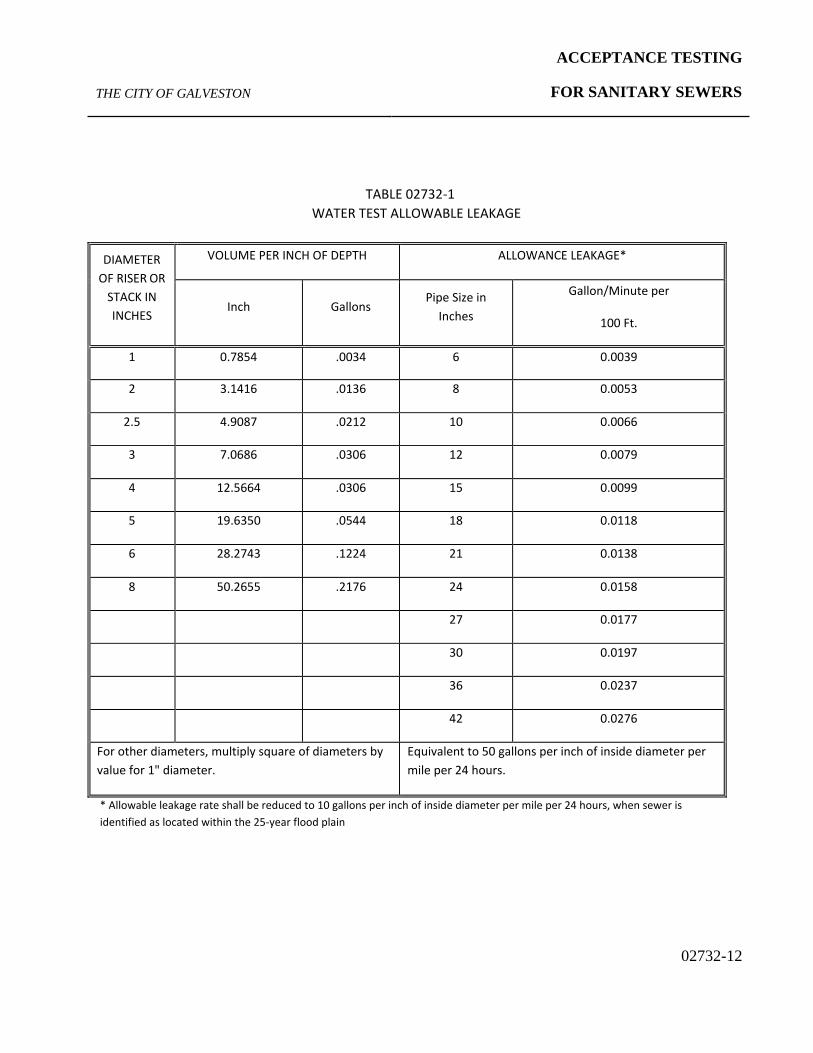
TABLE 02732-1 WATER TEST ALLOWABLE LEAKAGE
DIAMETER
OF RISER OR STACK IN INCHES
VOLUME PER INCH OF DEPTH ALLOWANCE LEAKAGE*
Inch
Gallons
Pipe Size in Inches
Gallon/Minute per
100 Ft.
1 0.7854 .0034 6 0.0039
2 3.1416 .0136 8 0.0053
2.5 4.9087 .0212 10 0.0066
3 7.0686 .0306 12 0.0079
4 12.5664 .0306 15 0.0099
5 19.6350 .0544 18 0.0118
6 28.2743 .1224 21 0.0138
8 50.2655 .2176 24 0.0158
27 0.0177
30 0.0197
36 0.0237
42 0.0276
For other diameters, multiply square of diameters by value for 1" diameter.
Equivalent to 50 gallons per inch of inside diameter per mile per 24 hours.
* Allowable leakage rate shall be reduced to 10 gallons per inch of inside diameter per mile per 24 hours, when sewer is identified as located within the 25-year flood plain

ACCEPTANCE TESTING
FOR SANITARY SEWERS THE CITY OF GALVESTON
02732-13
TABLE 02732-2
TIME ALLOWED FOR PRESSURE LOSS FROM 3.5 PSIG TO 2.5 PSIG
Pipe
Diamete
r (in)
Minimum
Time
(min. sec)
Length for
Minimum
Time (ft)
Time for
Longer
Length
(sec/ft)
Specification Time for Length (L) Shown (min. sec)
100 ft.
150 ft
200 ft
250 ft
300 ft
350 ft
400 ft
450 ft
500 ft
550 ft
600 ft
6 5:40 398 0.8548 5:40 5:40 5:40 5:40 5:40 5:40 5:42 6:25 7:07 7:50 8:33
8 7:33 298 1.5196 7:33 7:33 7:33 7:33 7:36 8:52 10:08 11:24 12:40 13:56 15:12
10 9:27 239 2.3743 9:27 9:27 9:27 9:54 11:52 13:51 15:50 17:48 19:47 21:46 23:45
12 11:20 199 3.4190 11:20 11:20 11:20 14:15 17:06 19:57 22:48 25:39 28:30 31:20 34:11
15 14:10 159 5.3423 14:10 14:10 17:48 22:16 26:43 31:10 35:37 40:04 44:31 48:58 53:25
18 17:00 133 7.6928 17:00 19:14 25:39 32:03 38:28 44:52 51:17 57:42 64:06 70:31 76:56
21 19:50 114 10.4708 19:50 26:11 34:54 43:38 52:21 61:05 69:48 78:32 87:15 95:59 104:42
24 22:40 99 13.6762 22:48 34:11 45:35 56:59 68:23 79:47 91:10 102:34 113:58 125:22 136:46
27 25:30 88 17.3089 28:51 43:16 57:42 72:07 86:33 100:58 115:24 129:49 144:14 158:40 173:05
30 28:20 80 21.3690 35:37 53:25 71:14 89:02 106:51 124:39 142:28 160:16 178:05 195:53 213:41
33 31:10 72 25.8565 43:06 64:38 86:11 107:44 129:17 150:50 172:23 193:55 215:28 237:01 258:34

ACCEPTANCE TESTING
FOR SANITARY SEWERS THE CITY OF GALVESTON
02732-14
TABLE 02732-3
MINIMUM TESTING TIMES FOR LOW PRESSURE AIR TEST
PIPE DIAMETER
(inches)
MINIMUM TIME
(seconds)
LENGTH FOR MINIMUM TIME
(feet)
TIME FOR LONGER LENGTH
(seconds)
6 340 398 0.855 (L)
8 454 298 1.520 (L)
10 567 239 2.374 (L)
12 680 199 3.419 (L)
15 850 159 5.342 (L)
18 1020 133 7.693 (L)
21 1190 114 10.471 (L)
24 1360 100 13.676 (L)
27 1530 88 17.309 (L)
30 1700 80 21.369 (L)
33 1870 72 25.856 (L)

ACCEPTANCE TESTING
FOR SANITARY SEWERS THE CITY OF GALVESTON
02732-15
TABLE 02732-4
VACUUM TEST TIME TABLE
DEPTH IN FEET TIME IN SECONDS BY PIPE DIAMETER
48" 60" 72"
4 10 13 16
8 20 26 32
12 30 39 48
16 40 52 64
20 50 65 80
24 60 78 96
∗(Τ)∗ 5.0 6.5 8.0
* Add T times for each additional 2-foot depth.
(The values listed above have been extrapolated from ASTM C 924-85)

ACCEPTANCE TESTING
FOR SANITARY SEWERS THE CITY OF GALVESTON
02732-16
TABLE 02732-5
PIPE VS. MANDREL DIAMETER
Material and Wall Construction Nominal Size(Inches) Average I.D. (Inches) Minimum Mandrel Diameter
PVC-Solid (SDR 26) 6 5.764 5.476 8 7.715 7.329 10 9.646 9.162 PVC-Solid (SDR 35) 12 11.737 11.150 15 14.374 13.655 18 17.629 16.748 21 20.783 19.744 24 23.381 22.120 27 26.351 25.033 PVC-Truss 8 7.750 7.363 10 9.750 9.263 12 11.790 11.201 15 14.770 14.032 PVC-Profile (ASTM F 794) 12 11.740 11.153 15 14.370 13.652 18 17.650 16.768 21 20.750 19.713 24 23.500 22.325 27 26.500 25.175 30 29.500 28.025 36 35.500 33.725 42 41.500 39.425 48 47.500 45.125 HDPE-Profile 18 18.000 17.100 21 21.000 19.950 24 24.000 22.800 27 27.000 25.650 30 30.000 28.500 36 36.000 34.200 42 42.000 39.900 48 48.000 45.600 54 54.000 51.300 60 60.000 57.000 Fiberglass-Centrifugally Cast (Class SN 12 12.85 11.822 18 18.66 17.727 20 20.68 19.646 24 24.72 23.484 30 30.68 29.146 36 36.74 34.903 42 42.70 40.565 48 48.76 46.322 54 54.82 52.079 60 60.38 57.361

ACCEPTANCE TESTING
FOR SANITARY SEWERS THE CITY OF GALVESTON
02732-17
Mandrel Test Data Sheet City of Galveston, Texas
Date: Project:
Material: Sheet #: Max Allowed Deflection:
Upstream MH Sta. # Downstream MH Sta. # Pipe Dia. (inches) Length (feet Pass or
Fail
Inspector: Date:
(Signature)
Contractor: Date:
(Signature)

ACCEPTANCE TESTING
FOR SANITARY SEWERS THE CITY OF GALVESTON
02732-18
PIPE VS. MANDREL DIAMETER
Material and Wall Construction
Nominal Size
(Inches)
Average I.D> (Inches)
Minimum Mandrel Diameter (Inches)
PVC-Solid (SDR 26)
6 5.764 5.476 8 7.715 7.329
10 9.646 9.162
PVC-SOLID (SDR 35)
12 11.737 11.150 15 14.374 13.655 18 17.629 16.748 21 20.783 19.744 24 23.381 22.120 27 26.351 25.033
PVC-Truss
8 7.750 7.363 10 9.750 9.263 12 11.790 11.201 15 14.770 14.032
PVC-Profile (ASTM F 794)
12 11.740 11.153 15 14.370 13.652 18 17.650 16.768 21 20.750 19.713 24 23.500 22.325 27 26.500 25.175 30 29.500 28.025 36 35.500 33.725 42 41.500 39.425 48 47.500 45.125
HDPE-Profile
18 18.000 17.100 21 21.000 19.950 24 24.000 22.800 27 27.000 25.650 30 30.000 28.500 36 36.000 34.200 42 42.000 39.900 48 48.000 45.600 54 54.000 51.300 60 60.000 57.000
ACCEPTANCE TESTING
FOR SANITARY SEWERS THE CITY OF GALVESTON
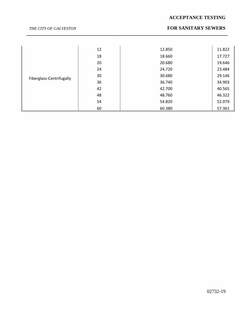
02732-19
Fiberglass-Centrifugally
12 12.850 11.822 18 18.660 17.727 20 20.680 19.646 24 24.720 23.484 30 30.680 29.146 36 36.740 34.903 42 42.700 40.565 48 48.760 46.322 54 54.820 52.079 60 60.380 57.361

ACCEPTANCE TESTING
FOR SANITARY SEWERS THE CITY OF GALVESTON
02732-20
Leakage Testing for Sanitary Sewer Lines City of Galveston, Texas
Project: Sheet #: Location:
Inspector: Date: Contractor:
Line Test Log
Test #
Manhole
UP
Manhole
Down
Line
Length
Line
Diameter
Avg. Depth
of Line
Avg. Depth
of Ground-
water
Start Air Pressure
End Air
Pressure
Time
Elapsed
Time Allowed
(per table*)
Pass
or Fail
Inspector
Contractor
1
2
3
4
5
6
7
8
9
10
11
12
13
14
15

ACCEPTANCE TESTING
FOR SANITARY SEWERS THE CITY OF GALVESTON
02732-21
TIME ALLOWED FOR PRESSURE LOSS FROM 3.5 PSIG TO 2.5 PSIG
Pipe Dia. (in)
Min. Time (min. sec.)
Length for Min. Time (ft)
Time for
Longer Length (sec/ft)
Specification Time for Length (L) Shown (min. sec.)
100 ft. 150
ft.
200 ft.
250 ft.
300 ft.
350 ft.
400 ft.
450 ft.
500 ft.
550 ft.
600 ft.
6 5:40 398 0.8548 5:40 5:40 5:40 5:40 5:40 5:40 5:42 6:25 7:07 7:50 8:33
8 7:33 298 1.5196 7:33 7:33 7:33 7:33 7:36 8:52 10:08 11:24 12:40 13:56 15:12
10 9:27 239 2.3743 9:27 9:27 9:27 9:54 11:52 13:51 15:50 17:48 19:47 21:46 23:45
12 11:20 199 3.419 11:20 11:20 11:20 14:15 17:06 19:57 22:48 25:39 28:30 31:20 34:11
15 14:10 157 5.3423 14:10 14:10 17:48 22:16 26:43 31:10 35:37 40:04 44:31 48:58 53:25
18 17:00 133 7.6928 17:00 19:14 25:39 32:03 38:28 44:52 51:17 57:42 64:06 70:31 76:56
21 19:50 114 10.7408 19:50 26:11 34:54 43:38 52:21 61:05 69:48 78:32 87:15 95:59 104:42
24 22:40 99 13.6762 22:48 34:11 45:35 56:59 68:23 79:47 91:10 102:34 113:58 125:22 136:46
27 25:30 88 17.3089 28:51 43:16 57:42 72:07 86:33 100:58 115:24 129:49 144:14 158:40 173:05
30 28:20 80 21.369 35:37 53:25 71:14 89:02 106:51 124:39 142:28 160:16 178:05 195:53 213:41
33 31:10 72 25.8565 43:06 64:38 86:11 107:44 129:17 150:50 172:23 193:55 215:28 237:01 258:34

ACCEPTANCE TESTING
FOR SANITARY SEWERS THE CITY OF GALVESTON
02732-22
END OF SECTION