UPGRADATION OF BHANDUP INFLUENT PUMPING ...
415
MUNICIPAL CORPORATION OF GREATER MUMBAI MUMBAI SEWAGE DISPOSAL PROJECT UPGRADATION OF BHANDUP INFLUENT PUMPING STATION & CARRYING CAPACITY OF RISING MAIN TO DESIGN PFF CAPACITY OF 461 MLD PART III - DESCRIPTION OF WORK & TECHNICAL SPECIFICATIONS SEPTEMBER 2019 Chief Engineer Mumbai Sewage Disposal Project 2 nd Floor, Worli Engineering Hub Near Worli Naka, E Moses Road Worli, Mumbai – 400018
-
Upload
khangminh22 -
Category
Documents
-
view
0 -
download
0
Transcript of UPGRADATION OF BHANDUP INFLUENT PUMPING ...

MUNICIPAL CORPORATION OF GREATER MUMBAI
MUMBAI SEWAGE DISPOSAL PROJECT
UPGRADATION OF BHANDUP INFLUENT PUMPING
STATION & CARRYING CAPACITY OF RISING
MAIN TO DESIGN PFF CAPACITY OF 461 MLD
PART III - DESCRIPTION OF WORK & TECHNICAL SPECIFICATIONS
SEPTEMBER 2019
Chief Engineer
Mumbai Sewage Disposal Project
2nd Floor, Worli Engineering Hub
Near Worli Naka, E Moses Road
Worli, Mumbai – 400018

Bhandup Influent Pumping Station General Specifications
165
PART – III
DESCRIPTION OF WORKS AND TECHNICAL SPECIFICATION

Bhandup Influent Pumping Station General Specifications
166
CIVIL SPECIFICATIONS

Bhandup Influent Pumping Station Municipal Corporation of Greater Mumbai
167
INDEX
SECTIONS NO. OF PAGES
Section 01000 – General Requirements ...........................................................................................5
Section 01001 – Summary of Work ..................................................................................................3
Section 01002 – Alternatives ............................................................................................................1
Section 01003 – Co-ordination .........................................................................................................3
Section 01004 – Field Engineering ...................................................................................................1
Section 01005 – Regulatory Requirements ......................................................................................2
Section 01006 – Project Meeting ......................................................................................................1
Section 01007 – Submittals .............................................................................................................8
Section 01008 – Quality Control .......................................................................................................5
Section 01009 – Temporary Facilities and Controls ..........................................................................5
Section 01010 – Safety Requirements .............................................................................................3
Section 01011 – Environmental Protection and Control ....................................................................4
Section 01012 – Project Signboard ..................................................................................................1
Section 01013 – Material and Equipment .........................................................................................3
Section 01014 – Commissioning of the Works .................................................................................4
Section 01015 – Operation and Maintenance ...................................................................................5
Section 01016 – Construction Contract Closeout .............................................................................4
Section 01017 – Reference Forms ................................................................................................. 33
Section 01020 – Civil Design Requirement ..................................................................................... 19
Total Pages in This Division ...................................................................................................... 110

Bhandup Influent Pumping Station Municipal Corporation of Greater Mumbai
Division -1 General Requirement 168 Section 01000- General Requirements
SECTION 01000- GENERAL REQUIREMENTS
PART 1 -GENERAL
1.01 Reference:
A. These Specifications form an integral Division of the Contract Documents.
B. Refer also to all other parts of the Contract Documents to determine their effect on the work of each Division of these Specifications.
C. The requirements of this Division 1 apply to and govern the work under other Divisions – Division 2 to Division 16 and their sections.
D. All instructions, unless otherwise indicated are addressed to the Contractor and included in the scope of work.
E. For definitions refer to the Conditions of Contract.
PART 2 - PRODUCTS
2.01 Products:
A. There are no Products in this Section.
PART 3 - EXECUTION
3.01 Mobilization and Demobilization:
A. Supply and erect signs, barricades, flashers, delineators, and provide flag persons, and such other protection as may be required to protect the public during construction.
B. Provide temporary fence to define Contractor’s working area when working adjacent to another Contractor / adjacent to existing plant.
C. Provide security protection for Contractor’s/ Engineer’s office, plant and stored materials.
D. Move onto site and set up Contractor’s/ Engineer’s office, storage facilities, and plant including sanitary facilities, temporary fencing, water, electricity and telephone.
E. Provide necessary access to the project including haul roads as required and restoration of surfaces to original condition after haul roads are removed.
F. Use locally available materials to reduce emissions due to transportation. Ensure that at least 10% of civil construction materials by value, such as concrete, steel, tiles, glass etc are sourced within a radius of 400km from project site.
G. Remove temporary Contractor’s/ Engineer’s office, temporary storage facilities and other temporary work after completing the work and leave site clean and tidy.
3.02 Examination:
A. Examine the site and any work on which the work of each Division depends. Check all dimensions and if any discrepancies or defects are found, notify the Engineer.
B. Before commencing work obtain from MCGM a list of designated substances on site in accordance with Public Health Safety Act and Regulations and other utility requirements.
C. Thoroughly examine the site and confirm the location of designated substances before commencing work.
D. Inform workers and sub-contractors of the locations of designated substances on site before commencing work.

Bhandup Influent Pumping Station Municipal Corporation of Greater Mumbai
Division -1 General Requirement 169 Section 01000- General Requirements
E. Commencement of the work implies acceptance by the Contractor of dimensions, conditions and surfaces.
3.03 Work to Conform:
A. During design, ensure that future expansion of the facility can be accommodated with a minimum cost and environmental impact and with minimum disruption to the pumping facility.
B. During construction and upon completion, ensure that all work conforms to the Contract during its progress and on its completion, true to the lines, levels and grades shown on the approved by MCGM during detailed engineering. Ensure that the work is built in a thoroughly substantial and workmanlike manner, in accordance with the Drawings and Specifications, subject to such modifications and additions as may be deemed necessary by the Engineer.
C. Confirm to applicable codes and standards including, but not limited to, those listed in Section 01005 and also as specified in other sections
3.04 Maintenance of Documents on Site:
A. Maintain at the job site, one copy of each of following:
1. Latest, revised Drawings, without any mark ups.
2. Employer’s Requirement & Specifications.
3. Addenda.
4. Reviewed drawings.
5. Change orders.
6. Other modifications to the Contract.
7. Field test records.
8. Codes and standards.
B. Maintain documents in a clean, dry, legible condition.
C. Make documents available at all times for inspection by the Engineer.
D. Make available on site, one copy of each workmanship standard called for in the Specifications.
E. Maintain record of approved documents and drawings as follows:
1. Two sets of white prints for record purposes.
3.05 Access to Site:
A. The Engineer will authorize access to the construction site. Construct and maintain temporary roads required for the work in a proper and safe condition.
B. Maintain proper and safe access to the existing facility at all times. Ensure that MCGM personnel at any existing facility have full access at all times to all areas required by normal operations.
C. Repair promptly any damage to existing access roads, to the satisfaction of the Engineer.

Bhandup Influent Pumping Station Municipal Corporation of Greater Mumbai
Division -1 General Requirement 170 Section 01000- General Requirements
3.06 Access to Work:
A. The Engineer may at any time and for any purpose enter upon the work and premises used by the Contractor. Provide proper and safe facilities for access. Others, such as regulatory and permitting agencies, may also, when authorized by the Engineer, enter upon the work and premises used by the Contractor for purposes that may be required by their agencies.
B. Provide proper facilities by means of walkways, ladders or otherwise, to secure convenient safe access to all parts of the work as may be required by the Engineer.
C. Place materials so that free access may be maintained at any time to all parts of the work and facilities.
3.07 Work Areas:
A. Work areas are defined on the Drawings or as designated by the Engineer. Confine operations to the designated areas.
3.08 Protection of Construction and Equipment:
A. Protect new construction from damage. Do not overload any Division of a structure, falsework, formwork or scaffolding. Rebuild to the satisfaction of the Engineer damaged portions of the work.
B. Take precautions to protect structures and equipment until completion.
C. Protect equipment supplied and/or installed, from damage, dust, dirt, etc., to the satisfaction of the Engineer. If required, supply temporary housing for equipment or items supplied.
3.09 Protection of Existing Plant and Personnel:
A. Do not endanger in any way the personnel, equipment, plant and existing structures. Exercise caution to keep the existing facilities free from damage due to the Contractor’s work. If the measures employed by the Contractor are not considered sufficient, the Engineer may order additional precautions to be taken at no additional cost to MCGM.
3.10 Protection of Existing Utilities:
A. Contact the MCGM concern utility department for any information with regard to the location of underground utilities. Exercise the necessary care in construction operations and take other precautions as necessary to safeguard the utilities from damage. Bear the cost of repairing damaged utilities.
B. Conduct utility surveys.
C. Provide support and protection for existing utilities.
3.11 Protection of Survey Markers:
A. Preserve survey markers while the work is in progress. Replace survey markers damaged or removed by construction activities, to the satisfaction of the Engineer.
3.12 Protection of Adjacent Property:
A. Do not cause damage to adjacent property. Any damage caused shall be repaired in the manner directed by, and to the satisfaction of, the Engineer at no additional cost to MCGM.

Bhandup Influent Pumping Station Municipal Corporation of Greater Mumbai
Division -1 General Requirement 171 Section 01000- General Requirements
3.13 Protection against Flotation:
A. Control surface and ground water to prevent damage to pipes or structures due to water uplift pressure during and after construction and until the completed works are accepted. Contractor to submit details of the measures proposed to be taken to the satisfaction of the Engineer.
3.14 Working Hours:
A. Observe working hours from 08:00 to 18:00, six days a week except as required for shut down purposes. Request the Engineer's approval before scheduling work outside these hours on weekdays. With the exception of emergency work, do not perform work on Sunday and holidays unless approved by the Engineer.
3.15 Metric Equipment:
A. Where materials are not available in metric units, equivalent imperial units will be acceptable.
B. Where metric and imperial types of equipment are to be installed under the same Contract, be satisfied that mating of metric and non-metric equipment is possible. Provide shop drawings of proposed transition couplings etc to the Engineer before assembly. Provide transition couplings, adapters etc as required for mating of metric and non-metric equipment.
3.16 Photographs and Video:
A. Provide, to the Engineer digital photographs showing progress of the work on a monthly basis.
B. The Engineer reserves the right to take photographs and videos of the work at any time.
3.17 MCGM's Interest in Equipment and Materials:
A. Ensure that construction plant, temporary facilities and materials, when brought to the site, are exclusively intended for the construction and completion of the work. Do not remove same or any Division thereof, except from one Division of the site to another, without the consent of the Engineer.
B. Observance of the above item does not necessarily imply approval by the Engineer of the plant, work or materials as the Engineer may reject such items at any time.
3.18 Deleted
3.19 Interpretation of Drawings and Specifications:
A. The Drawings, Specifications and Datasheets are complementary to each other and what is required by any one document is as required by all documents
B. Where the quality of workmanship or materials is not specifically stated, provide the best quality available.
C. The location of un-dimensioned fixtures, outlets, conduits, piping etc, as shown on the drawings are approximate. Make actual locations to suit job conditions.
D. Except where specific dimensions are shown on the Drawings, locate equipment, fixtures, piping, conduits, etc to create the minimum interference with pedestrian access, machinery, traffic and headroom.
E. Although the Drawings have been divided into various categories, they shall be read as a complete package. Details applicable to one category may appear on Drawings pertaining to another category or categories.
F. Although the Specifications or requirements have been divided into Divisions, read it as a complete package.

Bhandup Influent Pumping Station Municipal Corporation of Greater Mumbai
Division -1 General Requirement 172 Section 01000- General Requirements
3.20 Geotechnical Investigations:
A. A geotechnical investigation of the project site needs to be carried out by a awarded contractor.
3.21 Deleted
3.22 Explosives:
A. Do not use explosives on this project without permission of the Engineer and explosives certifying Government authorities.
B. Do not use powder-activated tools on any Division of the work unless written approval for their specific use is obtained from the Engineer. Ensure that workers using powder-activated tools are properly trained in their use and all safety rules are adhered to.
3.23 Protection against Termites and Corrosion:
A. Protect all structures, piping, sewers and equipment that may be exposed or buried in the ground during the construction period until the project is completed and accepted. Include such protective measures as anti-termite and anti-corrosion treatments in the Contract price and correct any damage sustained, to the satisfaction of the Engineer.
B. In keeping with the above requirements, submit to the Engineer in writing, before construction begins an outline of specific protection measures to be implemented on this project. Be responsible for the proper implementation of such protection measures and damages arising from corrosiveness and termite effects regardless of the review by the Engineer of the protection measures.
3.24 Patent and License Fees:
A. Be responsible for design and execution and payment of all applicable patent, copyright or license fees and royalties relating to equipment or processes incorporated into the works.
B. Protect MCGM from damages and costs that may arise from patent infringements.
3.25 Deleted
3.26 Assistance:
A. Provide reasonable assistance to the Engineer’s representative during execution of the work.
END OF SECTION 01000

Bhandup Influent Pumping Station Municipal Corporation of Greater Mumbai
Division -1 General Requirement 173 Section 01001-Summary of Work
SECTION 01001- SUMMARY OF WORK
PART 1 -GENERAL
1.01 Reference:
A. Section 01000, applies to and governs the work of this Section.
1.02 Work Covered by the Contract:
Civil Works
A. Supply, Laying, Installation & Commissioning of 2200 mm diameter rising main in addition to existing 1500 mm diameter rising main from Bhandup IPS to Bhandup WwTF & its allied works.
B. Steelwork, ladders and chequered plating and grating as required for the equipment.
C. Repairs / Modifications / Providing new foundations for the newly installed equipment & Machinery as per specifications including demolition of existing one.
D. Construction of Room for Variable Frequency Drive Panels.
E. Refurbishment & Face Uplifting of Bhandup IPS Building & Sub-Office Building.
F. Reinstatement of 1500 m long road from Eastern Express Highway to Bhandup WwTF
PART 2 -PRODUCTS
2.01 Construction Schedule:
A. Prepare and submit a construction schedule, in accordance with Section 01007 and as specified but not limited to followings.

Bhandup Influent Pumping Station Municipal Corporation of Greater Mumbai
Division -1 General Requirement 174 Section 01001-Summary of Work
2.02 Bhandup Influent pumping station:
1. Identify and relocate existing utilities interfering with construction of the units
and internal Roads.
2. Excavation.
3. Refurbishment of screen chamber, wet well and dry well structures.
4. Lay MS Rising main pipeline from IPS to WwTF
5. Construct new transformer yard and VFD room.
6. Complete area development including paving and plant trees
7. Clear the site of all debris, temporary structures and leave the site clean.
8. Submit to the Engineer any further As-built Drawings, and any other
documents as required by the Contract.
END OF SECTION 01001.

Bhandup Influent Pumping Station Municipal Corporation of Greater Mumbai
Division -1 General Requirement 175 Section 01002-Alternatives
SECTION 01002- ALTERNATIVES
PART 1 -GENERAL
1.01 Reference:
A. Section 01000 applies to and governs the work of this Section.
PART 2 - EXECUTION
2.01 Equivalents:
A. Where one or more makes or suppliers are specified in the Contract Documents, base the tendered price on using one of these makes or suppliers.
B. Provide equipment from the approved manufacturers/suppliers.
C. No alternative manufacturers/ suppliers are accepted unless “or equal” is specified.
D. No substitutions or alternatives are allowed for equipment unless “or equivalent” is specified.
E. Be responsible for ensuring the proper fit, installation and matching of selected equipment or material.
F. In all cases except Raw Sewage Pumps where a substitution or alternative is proposed other than the approved makes/suppliers, provide written justification to the Engineer indicating the reasons for the substitution (e.g. significant delay in delivery, strikes, unavailability, improved quality or field service, significant contract cost reduction) along with sufficient descriptive and technical information and demonstrate that the alternative proposed is better than the specified product. Failure to comply with this requirement to the Engineer's satisfaction may result in rejection of the request due to insufficient information or time to evaluate it.
G. Engineer’s decision for acceptance/rejection of an alternative will be final.
H. The Contractor will be allowed to make applications and submissions related to substitutions/ alternatives. Sub-contractors applications will not be considered.
I. Bear all liabilities and additional costs that may subsequently arise as a result of the proposed substitution/alternatives having been accepted by the Engineer. Cost reduction for adopting equivalent, will be reduced from the contract value.
J. Optional and/or substituted equipment requiring changes in details or dimensions required to maintain all structural, mechanical, electrical, control, operating, maintenance or design features incorporated in these Specifications and Drawings shall be made at no additional cost. In the event that the equipment proposed varies from that shown, produce detailed calculations and drawings showing proposed revisions and submit same for approval. Coordinate all changes required and pay any additional charges incurred.
END OF SECTION 01002.

Bhandup Influent Pumping Station Municipal Corporation of Greater Mumbai
Division -1 General Requirement 176 Section 01003-Coordination
PART 1 - GENERAL
1.01 Reference:
A. Section 01000 applies to and governs the work of this Section.
PART 2 - EXECUTION
2.01 Supervision:
A. Maintain on the site at all times a Resident Construction Engineer having full authority to take decisions regarding the execution of the project who is fully qualified to properly direct the progress of this Contract continuously, including the co-ordination and work of sub-contractors. During periods when work on this project is not being carried out, maintain protective fencing or competent security personnel on the site to guard the site and works and the properties and possessions thereon of the Contractor and his sub-contractors as well as those of the MCGM.
2.02 Sub contractors:
A. Various Divisions of these volume have not necessarily been segregated into sub-contractors or sub-contracts. Define the scope of work of each sub-contractor and apportion it, with special attention directed toward items or materials that are to be built into concrete, masonry etc.
B. Coordinate architectural, structural, mechanical, electrical and instrumentation work for the equipment being installed.
C. No extra payment will be considered due to difference in interpretation of the Specifications.
D. Should alternative equipment proposed by the Contractor be accepted, coordinate all required changes to other divisions including civil, mechanical, electrical and control works associated with that equipment and bear the extra expense for such changes.
2.03 Co-ordination of Construction with Storm Water Department and Sewage Operation:
A. For the tie-in of the new facilities with existing facilities on the sites, coordinate construction activity under this contract with the SWD/SO Department.
B. Submit a list of services requiring shut-down, anticipated shut-down times and their maximum duration. Tie-in points not limited to following:
1. Incoming sewer line
2. Bypass connection to existing bypass or storm water net work
3. Re-routing of existing sewer lines, rising mains, bypass if required to keep existing pumping station in operation
C. Provide a detailed schedule indicating each phase of the shut-down and start-up of each portion of the works.
D. Provide written procedures for each shut-down and start-up activity.
E. Submit prior written notice as required by the concerned department of MCGM and the Engineer where a shut-down is necessary to facilitate construction. Have the proposed timing of such construction reviewed by the MCGM prior to initiation of the work related to the shut-down.
F. Obtain the written permission of the Engineer in advance of each shut-down.
2.04 Co-ordination of Construction with Utilities Departments:

Bhandup Influent Pumping Station Municipal Corporation of Greater Mumbai
Division -1 General Requirement 177 Section 01003-Coordination
A. For the existing utilities which may interfere in the pumping station site and in the way of laying piping, coordinate construction activity under this Contract with the respective utility providers.
1. Water department
2. Telephone department
3. Gas department
4. Fire department
5. Electricity
6. Other utilities providers.
B. Submit a list of utilities requiring shut-down, anticipated shut-down times and their maximum duration.
C. Provide a detailed schedule indicating each phase of the shut-down and start-up of each portion of the existing works.
D. Provide written procedures for each shut-down and start-up activity.
E. Submit prior written notice as required by the concerned department of MCGM and the Chief Engineer where a shut-down is necessary to facilitate construction. Have the proposed timing of such construction reviewed by the MCGM prior to initiation of the work related to the shutdown.
F. Obtain the written permission of the affected utility providers and the Engineer in advance of each shut-down.
2.05 Co-ordination with Power Supply Company:
A. For obtaining the power for construction, testing, commissioning and operating the new pumping stations, coordinate these activities with the Power Supply Company.
B. Have the proposed timing of such activities reviewed by the concern and obtain any necessary written permission from these concerns prior to initiation of the work. Submit copy of the correspondence to Engineer.
2.06 Cutting, Fitting and Patching:
A. Complete the necessary cutting, fitting and patching to ensure the various parts of the work fit properly to complete the work. Complete cutting, fitting and patching as may be required to connect the work with that of any other contractor.
B. Do not endanger any existing work by cutting, digging or any other construction operation.
C. Do not cut load-bearing members without the written permission of the Engineer.
D. Be responsible for costs due to wrongly scheduled work and be responsible for minimum down time.
E. Prior to cutting into existing concrete, in order to avoid damage to any encased piping, conduits etc in the vicinity, ensure that:
1. The locations and the extent of cutting required are coordinated with sub- contractors involved and are accurately and carefully marked out.
2. The walls or slabs are X-rayed prior to drilling openings to determine the location of existing services concealed in and/or behind the structure to be drilled.
3. Permission is received and shop drawings applicable to the affected area have been approved.

Bhandup Influent Pumping Station Municipal Corporation of Greater Mumbai
Division -1 General Requirement 178 Section 01003-Coordination
2.07 Location of Fixtures:
A. The location of undimensioned fixtures, apparatus, outlets etc shown or specified are approximate. Finalize the actual locations as directed and required to suit conditions at the time of installation and as is reasonable.
B. Before installation, inform the Engineer of the impending installation and consult with him for location details.
END OF SECTION 01003.

Bhandup Influent Pumping Station Municipal Corporation of Greater Mumbai
Division -1 General Requirement 179 Section 01004-Field Engineering
SECTION 01004- FIELD ENGINEERING
PART 1 - GENERAL
1.01 Reference:
A. Section 01000 applies to and governs the work of this Section.
PART 2 - EXECUTION
2.01 Construction Layout:
A. Be responsible for design and laying out the work, based on the benchmark and reference lines shown on the Drawings or established by the Engineer.
B. Erect a permanent bench mark at each site with x, y, z co-ordinates.
C. Be responsible for the accuracy of levels and layout during the construction period and of the finished work.
2.02 Vertical and Horizontal Control:
A. Erect stakes, sight lines and batter boards so that they will not be disturbed during excavation. Protect and preserve reference points during construction.
B. The Engineer may check the layout and point out discrepancies. There is no obligation upon the Engineer to check the Contractor's work. Be responsible for lines and grades regardless of the Engineer’s action or lack of action in checking same.
C. Report immediately to the Engineer any discrepancies seen in the drawings.
2.03 Field Measurements and Tests:
A. Measure field dimensions required for the proper execution of the work. Carry out field measurements of critical items such as piping specials required to fit into confined spaces and between equipment before fabrication and show on the shop drawings.
B. Field verify the locations and elevations of existing structures and existing services that are to be connected to or that affect lines to be installed or structures to be connected.
2.04 Pre-construction Inspection:
A. Prior to construction, undertake an inspection of buildings involved in or in the vicinity of the proposed construction. Have the pre-construction inspection documented in writing, in photographs and videos as appropriate, noting surface finish conditions of structures and possible cracks. Be responsible for repairing damage to existing structures caused by construction.
B. Provide to the Engineer two copies of the report documenting the pre-construction inspection including photographs.
END OF SECTION 01004.

Bhandup Influent Pumping Station Municipal Corporation of Greater Mumbai
Division -1 General Requirement 180 Section 01005-Regulatory Requirements
SECTION 01005- REGULATORY REQUIREMENTS
PART 1 -GENERAL
1.01 Reference:
A. Section 01000 applies to and governs the work of this Section.
1.02 Codes and Standards:
A. Where applicable, ensure that materials, equipment etc confirm to the Standards listed in the Divisions and their Sections.
B. Perform work in accordance with the requirements contained in the latest editions of the following statutes and codes:
1. Safety Manual - Central Water and Power Commission, Ministry of Irrigation and Power, Government of India
2. National Building Code of India -2005
3. All regulations, codes and ordinances of the Govt of India, Govt. of Maharashtra and Municipal Corporation for Greater Mumbai regarding safety.
4. Indian Electricity Rules – 1956
5. Fire Safety Act – 1986
6. The Indian Contract Act, 1872.
7. The Workmen’s Compensation Act, 1923.
8. The Minimum Wages Act, 1948.
9. The Contract Labour (Regulation & Abolition) Act, 1970.
10. The Indian Arbitration Act (1940)
11. Indian Factories Act- 1948
12. Maharashtra Factory Rules- 1963
C. Contractor for this project will assume the responsibility set out in the above mentioned Acts and its regulations.
D. The Contractor shall indemnify the MCGM, consultant and other supervising authority for any accident during contract period.
1.03 Statutory Regulations:
A. The Design and construction of the works and the operations connected therewith are subject to the approval, inspection, by-laws, and regulations of municipal, state and central government authorities and organizations concerned with roads, streets, railways, telephones, electrical supplies, gas supplies and other public services having jurisdiction in respect to any matter embraced in this Contract.
PART 2 - EXECUTION
2.01 Approvals and Permits:
A. Apply for, obtain and pay for permits required for the project, including but not limited to:
1. Tree cutting and plantation permit
2. Plumbing permit
3. Electrical Safety Authority

Bhandup Influent Pumping Station Municipal Corporation of Greater Mumbai
Division -1 General Requirement 181 Section 01005-Regulatory Requirements
4. Power Supply Authority
5. Road Authority
6. Police Authority
7. Fire Safety permit
8. Building Construction permit
9. Disposal of excess excavated material and debris from construction and demolition
10. Other permits and regulation requirements as may be applicable.
B. Submit copies of all permits to the Engineer.
C. MCGM will assist in obtaining permission and approvals by providing recommendation letters or letters on MCGM letterhead to be written to various authorities as may be necessary.
D. Arrange for regular inspections as required by authorities having jurisdiction and the required final inspections.
E. Provide to the Engineer, on a monthly basis, a report of inspections.
2.02 Permit to Take Water:
A. A Permit to Take Water is required if pumping ground water is likely to be involved. Comply with the MCGM’s requirements and obtain Permit to Take Water before commencing dewatering operations.
B. Contractor shall be responsible for any delays or costs that may arise from obtaining the permit from the respective authorities.
END OF SECTION 01005

Bhandup Influent Pumping Station Municipal Corporation of Greater Mumbai
Division -1 General Requirement 182 Section 01006-Project Meeting
SECTION 01006- PROJECT MEETING
PART 1 -GENERAL
1.01 Reference:
A. Section 01000 applies to and governs the work of this Section.
PART 2 - EXECUTION
2.01 Kick-off Meeting:
A. A kick-off meeting will be arranged by the Engineer within 15 days of issue of letter of acceptance. The purpose of this meeting will be to initiate the work under this Contract, to acquaint the Contractor's and the Engineer's designated personnel with each other and to discuss the work procedures and preliminary scheduling. Ensure that a senior Contractor's representatives in charge of each designated site are in attendance, along with the following:
1. Bar chart for design document submission, work & detailed mobilization chart.
2. Sequencing – procedure of work to be executed
3. Safety Plan.
4. Quality Assurance Plan.
5. Required guarantees.
6. Site organization with names and qualification.
7. Biodata of key persons
8. Subcontractors list.
2.02 Progress Meetings:
A. Attend progress meetings as required by the Engineer or Engineer’s designated person. Such meetings to be held monthly or more frequently should the Engineer or engineer’s designated person deem it necessary. Ensure the attendance of responsible persons who have the required authority to execute decisions reached at the meeting. Subcontractors, vendors and others must attend as and when requested by the Engineer.
B. Meeting notes will be prepared and circulated by the Engineer or Engineer’s designated person.
END OF SECTION 01006

Bhandup Influent Pumping Station Municipal Corporation of Greater Mumbai
Division -1 General Requirement 183 Section 01007-Submittals
SECTION 01007- SUBMITTALS
PART 1 -GENERAL
1.01 Reference:
A. Section 01000 applies to and governs the work of this Section.
1.02 Work Included:
A. Submittals covered by these requirements include, but are not necessarily limited to:
1. Design calculations, documents and drawings
2. Construction methodology
3. Construction schedule
4. Certificate of Insurance
5. Design document submittal schedule and regular updates of its approval
6. drawings/ catalogues and documents as specified in each division
7. Other specific documents as requested in other sections.
8. Instructions for storage / warehousing of materials and equipment.
9. Instruction for installation and commissioning of equipment.
10. List of special tools for installation & maintenance.
11. Quality Control Records as Specified in Section 01008.
12. Commissioning procedures and documents as specified in Section 01014.
13. Operation and Maintenance Manuals as specified in Section 01015.
14. “AS BUILT” drawings/documents as specified in Section 01016.
15. Safety Plan.
16. Environmental and Emission data list
17. List of Permits with copies of each permit
18. Shipping documents with release notes
19. Conformity /non-conformity reports
20. Other documents as requested by Engineer
21. Shoring, strutting, shuttering, scaffolding designs and calculations.
22. Bar bending schedules
23. Concrete insert schedules including locations.
24. Plan for locating temporary facilities including site offices with toilet facilities and 24 hour water supply, cement and other material godown, toilet block for workers with sewage disposal line.
25. Measures proposed to be taken to prevent damage to the structure due to floatation during construction and till completion of work.
1.03 Categories of Submittals:
A. Prepare a document submittal schedule indicating dates and categories within three weeks from Award of Contract or Letter of Intent for the Engineer’s approval.
B. Submittals fall into three categories: submittals for review and comment, submittals for information and submittals for record.

Bhandup Influent Pumping Station Municipal Corporation of Greater Mumbai
Division -1 General Requirement 184 Section 01007-Submittals
C. Intent is not to provide complete list but a guide to decide the categories of document.
D. Submittals that are primarily for information only are not subject to submittal review procedures and will be provided as part of the work under this Contract.
E. The Engineer will retain these documents for information, however upon review he may provide comments if any. The following documents can be classified in the “For Information” category:
1. Instructions for storage / warehousing,
2. List of special tools for installation & maintenance,
3. Instructions for installation/ commissioning,
4. Commissioning/Mandatory Spare parts list,
5. Certificates of insurance,
6. Safety plan,
7. Test procedures, test results, certificates and manufacturers’ / suppliers’ instructions,
8. Commissioning procedures,
9. Operations and maintenance manuals and
10. Similar documents
F. Submittals for review and comment are specified in the Contract Documents and include, but are not limited to, design and detailed engineering documents & drawings, shop drawings, construction schedules, samples, coordination drawings, and construction coordination and sequencing plans. The Engineer will review the submittals and may provide comments. The Engineer’s review and comments, or lack of comments, will not relieve the Contractor of his responsibilities under the Contract. Structure modeling, analysis and design calculations (Microsoft Excel, Staad Pro etc.) files shall be submitted in editable format through emails or in CD.
G. Submittals for record are specified in the Contract Documents and include, but are not limited to, “AS-BUILT” drawings, vendor/suppliers data/records/Instructions etc in separate volumes, operation and maintenance manuals, test records, reports, certificates etc.
1.04 Contractor’s Responsibilities:
A. Provide submittals to the Engineer as specified.
B. Be responsible for the accuracy and completeness of the information contained in each submittal and ensure that the material, equipment or method of work is as described in the submittal. Verify that features of products confirm to the specified requirements. Edit submittal documents to indicate only those items, models or series of equipment that are being submitted for review. Cross out or otherwise obliterate extraneous information. Coordinate submittals among the sub-contractors and suppliers and ensure there is no conflict. Notify the MCGM in each case where a submittal may affect the work of other contractors of the MCGM. Carry out any relocation/ modification of work due to lack of coordination at no additional cost to the MCGM.
C. Verify that the materials and equipment to be furnished and method of work comply with the provisions and the intent of the Contract.
D. Verify and guarantee that features and characteristics of materials, equipment and other items to be incorporated into the work, and for which no submittals are required, conform to the Contract requirements.
E. Submissions to include design calculation, design documents, drawings, erection details, co-ordination issues, phasing, assessment of problem issues.

Bhandup Influent Pumping Station Municipal Corporation of Greater Mumbai
Division -1 General Requirement 185 Section 01007-Submittals
F. Coordinate submittals with the work so that work will not be delayed. Coordinate and schedule different categories of submittals, so that one will not be delayed for lack of coordination with another. No extension of time will be allowed because of failure to properly schedule submittals.
G. Do not proceed with work related to a submittal until the submittal approval and review process is complete. This requires that submittals for review and comment are returned to the Contractor stamped "REVIEWED" or " REVIEWED AS NOTED".
H. Stamp, date and sign /initial each submittal to certify that the Contractor has verified the submittal, field conditions, and compliance with the Contract Documents.
I. The Engineer’s review of submissions does not relieve the Contractor of responsibility for correctness, adequacy, engineering and compliance with the Contract.
J. Arrange a meeting with the supplier and the Engineer with regard to a submittal whenever requested. These dealings are limited to contract interpretations to clarify and expedite the work.
1.05 Effect of Review of Contractor's Submittals:
A. Submittals provide information concerning features and characteristics of materials, equipment and methods of operation selected based on the Contractor's judgment of their conformance to the specified requirements. Review of submittals does not extend to means, methods, techniques, sequences or procedures of construction, or to verifying quantities, dimensions, weights or gauges, or fabrication processes, except where specifically indicated or required by the project requirements or to safety precautions or programmes incident thereto. Review of a separate item, as such, will not indicate approval of the assembly in which the item functions.
B. The review of methods of work, or information regarding materials or equipment the Contractor proposes to provide, shall not relieve the Contractor of his responsibility for errors therein and shall not be regarded as an assumption of risks or liability by the MCGM, or by any representative officer, employee or agent thereof. The Contractor shall have no claim under the contract on account of the failure, or partial failure, of the material, or equipment so reviewed.
C. The review of detailed engineering documents and drawings or shop drawings shall not relieve the Contractor of his responsibility for errors therein, and shall not be regarded as assumption of risks or liability by the MCGM, or by any representative officer, employee or agent thereof. The Contractor shall have no claim under the contract on account of the failure, or partial failure, of the material, or equipment in the drawings so reviewed. A mark of "REVIEWED" or "REVIEWED AS NOTED" shall mean that the MCGM has no objection to the Contractor, upon his own responsibility, providing the materials or equipment proposed.
D. The Engineer will review detailed engineering documents and drawings for general arrangement, design calculations and design basis report. Revised drawings shall be submitted by clouding at the location with latest revision number and also the history of revisions shall be provided in a table format above the title block.
E. The Engineer will review drawings for general arrangement only. The Contractor shall be responsible for checking dimensions, quantities, proper fitting and construction of the work, and for furnishing materials or doing work required by the Contract Documents, which may not be indicated on drawings when reviewed.
1.06 Detailed Drawing and Document Review Procedure:

Bhandup Influent Pumping Station Municipal Corporation of Greater Mumbai
Division -1 General Requirement 186 Section 01007-Submittals
A. Unless otherwise specified, within fifteen (15) business days after the Engineer receives a detailed drawing or a design document submittal for review and comment, the Engineer shall review the submittal and return one (1) copy of the marked-up drawing or document bearing the Review Status stamp. The returned submittal shall indicate one of the following actions:
1. If the review indicates that the design document or drawing or calculation complies with the Contract Documents, the submittal will be marked "APPROVED AS SUBMITTED". In this event, the Contractor may proceed for fabrication or construction.
2. If the review indicates limited corrections are required, the submittal will be marked “APPROVED SUBJECT TO COMMENTS NOTED”. The Contractor may proceed for fabrication or construction covered by the submittal in accordance with the noted corrections. Provide six copies of a corrected design document / drawing / calculation with corrections.
3. If the review reveals that the submittal is insufficient or contains incorrect data, the submittal will be marked "RESUBMIT AS NOTED". Make the changes to the design document or drawing or calculation that the Engineer may require. Identify changes on resubmissions and indicate the revision dates. Accept all risks associated with undertaking work covered by this submittal until it has been revised, resubmitted and returned marked either "APPROVED AS SUBMITTED".
4. If the review indicates that design document / drawing / calculation do not comply with the Contract Documents, the submittal will be marked "RETURNED WITHOUT REVIEW”. Accept all risks associated with undertaking the work covered by such submittals until a new submittal is made and returned marked either “APPROVED AS SUBMITTED" or "APPROVED SUBJECT TO COMMENTS NOTED".
B. Claims for additional compensation in time or funds due to delays in re-submissions and review of design document / drawing / calculation will not be allowed.
1.07 Shop Drawing Review Procedure:
A. Unless otherwise specified, within fifteen (15) business days after the Engineer receives a shop drawing submittal for review and comment, the Engineer shall review the submittal and return one (1) copy of the marked-up shop drawing bearing the Shop Drawing Review stamp. The returned submittal shall indicate one of the following actions:
1. If the review indicates that the material, equipment or work method complies with the Contract Documents, the submittal will be marked “APPROVED AS SUBMITTED". In this event, the Contractor may begin to incorporate the material or equipment covered by the submittal into the work.
2. If the review indicates limited corrections are required, the submittal will be marked "APPROVED SUBJECT TO COMMENTS NOTED”. The Contractor may begin incorporating the material or equipment covered by the submittal in accordance with the noted corrections. Provide six copies of a corrected shop drawing for incorporation in the operations and maintenance data.

Bhandup Influent Pumping Station Municipal Corporation of Greater Mumbai
Division -1 General Requirement 187 Section 01007-Submittals
3. If the review reveals that the submittal is insufficient or contains incorrect data, the submittal will be marked "RESUBMIT AS NOTED". Make the changes to the shop drawings that the Engineer may require. Identify changes on resubmissions and indicate the revision dates. Accept all risks associated with undertaking work covered by this submittal until it has been revised, resubmitted and returned marked either "APPROVED AS SUBMITTED" or "APPROVED SUBJECT TO COMMENTS NOTED".
4. If the review indicates that the material or equipment does not comply with the Contract Documents, the submittal will be marked "RETURNED WITHOUT REVIEW”. Accept all risks associated with undertaking the work covered by such submittals until a new submittal is made and returned marked either "APPROVED AS SUBMITTED" or" APPROVED SUBJECT TO COMMENTS NOTED ".
B. Claims for additional compensation in time or funds due to delays in re-submissions and review of shop drawings will not be allowed.
PART 2 - PRODUCTS
2.01 Construction Schedule:
A. Submit a construction schedule showing the contract starting date and the commencement and the completion of each substantial or key portion of the work. Provide the schedule to the Engineer for review within fourteen (14) days after the award of contract. Include in the schedule the work of any sub-contractor, submission dates for shop drawings and the project completion date.
B. Indicate in the Construction Schedule the Critical Path of the work including, but not limited to, the following:
1. Identification and listing in chronological order of all construction, demolition and removal activities required to complete the Work, such as mobilization and other activities; all subcontractor work; major equipment design, fabrication, factory testing, and delivery dates; equipment system testing and start-up activities; project closeout, cleanup and site restoration; and specified work sequences, constraints, and milestones, including Substantial Completion dates.
2. Identify timeframe, duration, early start and completion for each activity and sub-activity, and any critical activities.
3. Sub-schedules, such as Staging Plans and Sequencing Plans as required, to further define portions of the Work.
4. Shop drawing submission dates related to equipment or activity on the schedule.
2.02 Shop Drawings:
A. Submit shop drawings, bar bending schedules, piping arrangements, support/anchors, fabrication and erection drawings, design calculations etc where applicable, for all work in this Contract.
B. Submit shop drawings for all temporary works that control the dimensions of any part of the structures to be constructed under this Contract, or which impose loads on parts of the completed permanent works.
C. Ensure that shop drawings of mechanical and electrical equipment show details of construction, accurate dimensions, capacities and performance characteristics, including wiring, conduits and piping isometrics, and instrumentation etc.
Bhandup Influent Pumping Station Municipal Corporation of Greater Mumbai
Division -1 General Requirement 188 Section 01007-Submittals
D. Ensure that shop drawings clearly show exposed fastenings and, where applicable, installation details, relationship to the building structure and/or finishes.
E. Manufacturer's standard schematic drawings, catalogue sheets, diagrams, schedules, performance charts, illustrations and other standard descriptive data may be accepted in-lieu of shop drawings, if they:
1. Supplement standard information to provide additional information applicable to the project.
2. Show dimensions and clearances required.
3. Show performance characteristics and capacities.
4. Show wiring diagrams and controls.
Any non-applicable information to be deleted.
F. Submit shop drawings in SI metric units. Shop drawings in Imperial units only will be returned by the Engineer without review.
2.03 Coordination Drawings:
A. Prepare Coordination Drawings for areas of potential conflict, where interference may be caused by uncoordinated use of available space by the various subcontractors, clearly show on the same drawing the proposed works of all disciplines, such as process piping, plumbing and drains, air ducts, electrical cable trays and conduits, including valve orientation and access.
B. Show piping and other services that are to be cast into concrete.
C. Submit Coordination Drawings for review as specified prior to commencement of the work.
D. Update and resubmit the Coordination Drawings when changes and relocations are to be made.
E. Carry out any relocation of work due to interference.
2.04 Construction Coordination and Sequencing:
A. Submit a detailed Staging Plan outlining the steps to be taken to construct the works. Review the proposed Staging Plan and discuss timing and constraints with the MCGM’s operations staff. Both the MCGM and the Engineer reserve the right to request revisions to either the stages and or the timing. Do not proceed with the work until the Staging Plan has been reviewed and accepted by the MCGM.
B. Prepare and submit, to the Engineer, Sequencing Plans where interferences exist and where a specific work sequence is required to avoid or minimize operational interruptions of the existing facilities. Tie the Sequencing Plans to the project schedule.
2.05 Other Submittals:
A. Submit promptly, all other items required to be submitted in accordance with various Sections of the Specifications including but not limited to:
1. Test reports of concrete and materials, proposed to be used in concrete mix design, by concrete supplier.
2. Manufacturers cement test report for each batch from each supplier.
3. Batch report with each truck of ready mixed concrete.

Bhandup Influent Pumping Station Municipal Corporation of Greater Mumbai
Division -1 General Requirement 189 Section 01007-Submittals
4. Lab test report for reinforcement weight and grade for each lot supplied.
5. Manufacturer test certificate for all reinforcement diameter bars for each lot supplied.
6. Electrical Coordination Study in accordance with Division 16.
7. Warrantees and Guarantees
8. Summary list of loose items and spare parts in a tabular form with columns indicating Specification Section, Item Number, Description, Number of Units, and Expected Date of Delivery.
PART 3 - EXECUTION
3.01 Transmittal Procedure for Submittals:
A. When the Contract Documents require a submittal, submit the specified information as follows:
1. Six copies of all submitted information for review and comment, unless specified otherwise.
2. One Electronic Copy of the same submission document in PDF.
B. Have each submittal accompanied by Form 01300-A Submittal Transmittal Form included in Section 01017. Apply a unique number, sequentially assigned, on the transmittal form. Original submittal numbers to have the following format: "XXX"; where "XXX" is the sequential number assigned by the Contractor. Re-submittals to have the following format: "XXX-Y"; where "XXX" is the originally assigned submittal number and "Y" is a sequential letter assigned for re-submittals, i.e., A, B, or C being the 1st, 2nd, and 3rd re-submittals, respectively. Submittal 25B, for example, is the second re-submittal of submittal 25.
C. On the transmittal form, clearly identify Contract, Contract No, Contractor, Pertinent Drawing No, Specification Sheet No, and Article No, as applicable, for the submittal.
D. Use a separate transmittal form for each specific item, class of material, equipment, and items specified in separate, discrete sections, for which the submittal is required. Submittal documents common to more than one piece of equipment to be identified with all the appropriate equipment numbers. Make submittals for various items with a single form when the items taken together constitute a manufacturer's package or are so functionally related that expediency indicates checking or review of the group or package as a whole.
E. Submittals for operation and maintenance manuals, information and data are to be accompanied by Form 01700-A, Operation and Maintenance Transmittal Form included in Section 01017. Refer to Section 01016 for additional requirements.
3.02 Submittal Completeness:
A. Submittals that do not have all the information required to be submitted, including acknowledgement of deviations, are not acceptable and will be returned without review.
B. Bear the cost of any delay or cost implications arising from the improper submittals.
3.03 Drawing Transmittal Procedure:
A. Check drawings before submission to the Engineer for review to coordinate the activities on the project and intercept errors and omissions.
B. Failure to complete and submit with the drawings by Form 01300-A, in particular in the Contractor’s certification section, shall be sufficient for rejection of the entire submittal with no further consideration.
Bhandup Influent Pumping Station Municipal Corporation of Greater Mumbai
Division -1 General Requirement 190 Section 01007-Submittals
C. Include in every drawing submission, a copy of the relevant specification section, with addendum updates included, and all referenced and applicable sections, with addendum updates included. Check-mark each paragraph to indicate compliance with the specification or mark otherwise to indicate requested deviations from
specified requirements. Check marks () denote full compliance with a paragraph in its entirety. If deviations from the specifications are indicated, underline each point of deviation and denote by a number in the margin to the right of the identified paragraph. The remaining portions of the paragraph not underlined will signify compliance with the specified requirements. Provide in the submittal a detailed, written justification for each deviation.
D. Failure to include a copy of the marked-up specification sections, along with justifications for any requested deviations to specified requirements, with the submittal shall be sufficient cause for rejection of the entire submittal with no further consideration.
3.04 Construction Schedule:
A. Update the progress schedule when requested by the Engineer. As a minimum, distribute, four days prior to site meetings, monthly updates to the construction schedule.
B. If an activity is not completed by its latest scheduled completion date and this failure may extend the Contract Time (or may affect the project critical path), within seven days of such failure, submit a written statement as to how the non-performance will be corrected and the original schedule will be maintained.
C. Regardless of the schedule or schedules submitted by the Contractor, the Engineer reserves the right to direct the Contractor by employing whatever means necessary, to expedite the work.
D. Be responsible for duties and responsibilities under the Contract, regardless of submissions to, and review by the Engineer of schedules or construction programs or any particulars thereof.
END OF SECTION 01007

Bhandup Influent Pumping Station Municipal Corporation of Greater Mumbai
Division -1 General Requirement 191 Section 01008-Quality Control
SECTION 01008- QUALITY CONTROL
PART 1 -GENERAL
1.01 Reference:
A. Section 01000 applies to and governs the work of this Section.
1.02 Work included:
A. Be responsible for maintaining quality and to keep necessary QA/QC records. Ensure that sub contractors and suppliers maintain the same quality requirements.
B. Contractor to select vendors, who are ISO 9000 certified or who maintain equivalent ISO 9000 quality procedures/records and will submit suppliers’ Quality Assurance Plan and Quality Control procedure for the Engineer’s approval.
C. If required, the Engineer may select a third party for quality control.
D. Ensure that materials, fixtures, fittings, appliances and equipment and appurtenances provided under this Contract are new, suitable for the application and free from any defects; to the satisfaction of the Engineer.
E. Inspection and testing as specified in this section and other sections of the Contract Documents.
F. Inspection and testing required by law, ordinances, rules, regulations or orders of public authorities.
1.03 Submittals:
A. Submit documents, not limited to the following, to maintain quality in accordance with Section 01007.
1. Method statements for various activities including sequence, procedure, inspection & working, checking & Quality Assurance method etc.
2. Inspection and test plans and procedures,
3. Quality records – ISO 9000 certificates,
4. QC dossier / code data books/ record book,
5. Welding procedure specifications,
6. Welding procedure qualification records,
7. Welder qualification records,
8. Weld map,
9. NDE /Radiography procedures,
10. NDE /Radiography reports,
11. NDE /Radiography operator qualifications,
12. Test reports (all types),
13. Pressure test certificates,
14. Material certificates,
15. Inspection reports including sub-vendors,
16. Concrete testing,
17. Compaction tests,
18. Painting / galvanising inspection reports,
19. Construction / installation quality control plans,
20. Equipment calibration certificates,

Bhandup Influent Pumping Station Municipal Corporation of Greater Mumbai
Division -1 General Requirement 192 Section 01008-Quality Control
21. Certificates of conformity,
22. Non-conformity reports (internal & sub-vendor),
23. Shipping releases and
24. Others as required.
B. Neatly assemble and submit quality records in accordance with Section 01016.
PART 2 - PRODUCTS
There is no product in this section.
PART 3 - EXECUTION
3.01 Inspection and Testing:
A. For day- to-day activities requiring checking and approval by the Engineer or Engineer’s designated person for next stage, the Contractor must notify the Engineer by providing a weekly programme of the following week only in case of emergencies a minimum 24 hour notice shall be provided.
B. Adhere to the provisions of the Contract, especially with regard to the quality of the workmanship and materials.
C. Perform work under the Contract to the satisfaction of the Engineer. Immediately execute orders given by the Engineer relating to quality of material or workmanship.
D. The Engineer may stop the work entirely if there is not a sufficient quantity of suitable and approved material on the site to carry on the work properly, or for any good and sufficient reason.
E. The Engineer may have any worker suspended for incompetence, substance abuse, negligence or the disregard of orders. Ensure that any worker so suspended is removed from the site promptly.
F. The Engineer or Engineer’s designated person may inspect and test materials/ equipment and the process of preparation/ manufacturing of materials/ equipment at any time. The Contractor will submit inspection call to Engineer for witnessing the inspection and testing of materials/ equipment. If these do not meet quality standards, he may reject material or equipment.
G. In case of materials or equipment which, as specifically stated in the Contract, are required to be tested or inspected in the presence of the Engineer or Engineer’s designated person, the Contractor must notify the Engineer in writing at least fifteen days in advance, the time and place of proposed preparation / manufacture of such material or equipment so that the Engineer or Engineer’s designated person may be present.
H. Do not deliver to the site, until authorized to do so in writing by the Engineer, any material or equipment, which is required by the Contract or by the Engineer, to be inspected and/or tested by the Engineer at the place of preparation or manufacture.
I. Do not use material or equipment required by the Contract or by the Engineer to be inspected or tested until the required inspection or testing has been carried out to the satisfaction of the Engineer or Engineer’s designated person.
J. Provide and ensure that suppliers/sub-contractors and those carrying out the process of preparation or manufacture provide required documents/facilities, access and co-operation to the Engineer or Engineer’s designated person during inspection and testing.
Bhandup Influent Pumping Station Municipal Corporation of Greater Mumbai
Division -1 General Requirement 193 Section 01008-Quality Control
K. Be responsible for the obligations under the Contract regardless of the approval by the Engineer or waiver of an inspection. Do not interpret action or lack of action of the Engineer as being an acceptance of defective or improper work or material. Remove and replace properly or otherwise rectify such work or material to the satisfaction of the Engineer.
L. If it is required by the Contract, local laws / by-laws, or by the Engineer, to have any part of the works to be inspected by others, give the Engineer and the other concerned parties, reasonable notice of the time and place proposed for the inspection.
M. Where required by the Engineer, supply samples and certified copies of test reports pertaining to materials to be used in the construction of the works, indicating that materials comply with the Specifications. Ensure that such tests are carried out by testing companies/agencies approved by the Engineer.
N. Any and all materials or manufactured products may be tested. As directed, provide test samples for testing of materials or manufactured products being used or proposed for use in the work. Provide adequate time in the project schedule for testing as specified.
O. Immediately remove from the site materials whose test specimens fail to meet specified requirements and those materials that are rejected upon inspection.
P. Where test specimens fail to meet specified requirements or where re-testing is required to verify the quality of work previously tested, provide additional test specimens and pay for the additional testing until satisfactory test results are obtained.
Q. Quality control inspections, as required, other than those noted above will be carried out by inspectors or inspection services under the direction of the Engineer. Provide clear access to work areas to be inspected and assist as required by providing safety equipment, ladders, materials etc, for these inspections.
R. Expenditure on any and all tests required to be carried out shall be borne by the Contractor.
3.02 Receipt and Acceptance of Materials:
A. During the process of unloading any material etc, inspect it for loss or damage in transit in the presence of the Engineer. Notify the agent of the carrier of any loss or damage to the shipment and to the insurance company.
B. The Engineer may reject materials supplied by the Contractor if found faulty or defective. Replace such faulty or defective materials. Be responsible for removing faulty or detective materials and replacing same with good materials regardless of when the defects are discovered.
3.03 Mandatory Tests for Building Materials:
A. Carry out specified optional tests or other tests, as requested by the Engineer, for specialized works or important structures.
B. In case of non-IS materials, it shall be the responsibility of the Contractor to establish the conformity of material with relevant IS and this specification by carrying out necessary tests.

Bhandup Influent Pumping Station Municipal Corporation of Greater Mumbai
Division -1 General Requirement 194 Section 01008-Quality Control
The mandatory tests shall include, but are not limited to, the following:
No. Activity Name of Test Frequency of Test Field/Lab.
Test Remarks
1 Water a Suitable for Conc. Start & Change of Source Laboratory IS 3025
2 Soil Compaction a Initial Soil Test Start & Change of Source Laboratory
b OMC Proctor Test 2 tests for 50 sqm Field/Lab IS 12175
c Backfill Soil Start & Change of Source Laboratory IS 2720
3 Concrete a Pour Card before each pour Field
b Slump Test One For Each Transit Mixer or 5 m3 of Site Mix Field IS1199
c Crushing Strength See Note Laboratory IS 516
d Concrete Mix Design Start & Change of Source Laboratory For All Grade
4 Ready Mix Conc. a Pour Card Before Each Pour Field
b Supplier Mix Design Before Start Of Work Laboratory
c (Balance As Above)
5 Sand a Silt Content Each Truck Field IS 383
b Bulkage On Day of Conc. Field
c Moisture Content On Day of Conc. Field
d Sieve Analysis Each Truck Laboratory/Field
e Specific Gravity Start &Change of Source Laboratory
f Particle Size & Distri. For Every 40 m3 Field IS 383
g Foreign /Clay/Organic Material Each Truck Field IS 383
6 Aggregate a Size/Type/Colour For Every 40 m3 Field IS 2386
b Particle Size Every 40 m3 Field/Lab.
c Impact Value Start & Change of Source Laboratory
d Flakiness Each Truck Field
e Specific Gravity Start & Change of Source Laboratory
f Bulk Density Start & Change of Source Laboratory
g Sieve Analysis Start & Change of Source Field
h Soundness Start & Change of Source Laboratory
i Alkali Test Start & Change of Source Laboratory
7 Reinforcement a Manufacturer Cert. Each Lot Field
Steel b Unit Weight Each Lot Field
c Bend Rebend Test Each Lot Factory IS 11786
d 0.2% Yield Stress Each Lot Laboratory IS 11786
e % Elongation Each Lot Laboratory IS 11786
f Chemical Composition Each Lot Laboratory IS 11786
g Bend, Rebend Test Each Lot Laboratory
h Coating Manuf. Cert. with each Lot At Factory
8 Cement a Date & Manuf. Report Each batch Field
b Weight of Bag 5% from each Truck Field
c Make Every Truck Field
d Compressive Strength Each batch Laboratory IS 4031
e Physical Condition Every Truck Field
f Setting Time Each batch Laboratory IS 4031
g Soundness Each batch Laboratory IS 4031
h Fineness Each batch Laboratory IS 4031
Age Of Cement Bags Reject More then 60days Field
9 Structural Steel a Manufacturer Cert. Every Truck Laboratory
b Tensile Stress Start & Change of Source Laboratory
c % Elongation Start & Change of Source Laboratory

Bhandup Influent Pumping Station Municipal Corporation of Greater Mumbai
Division -1 General Requirement 195 Section 01008-Quality Control
No. Activity Name of Test Frequency of Test Field/Lab.
Test Remarks
d Yield Stress Start & Change of Source Laboratory
e Chemical Start & Change of Source Laboratory
f Unit Weight Start & Change of Source Laboratory
g Straight/Warping Every Truck Field
h Rusting/Scaling Every Truck Field
10 Bricks a Broken Edges Every Truck Field
b Shape and Size Every Truck Field IS 3495
c Soundness Every Truck Field
d Drop Test Every Truck Field
e Water Absorption Every 50000 Laboratory IS 3495
f Crushing Strength Every 50000 Laboratory IS 3495
11
Aluminium Windows and Doors a Size & Weight Each Section Field
b Warping Each Section Field
c Glass Thickness Each Lot Field
d Glass Make Each Lot Field
e Scratches Each Lot Field
f Anodic coating Rs.20000/ or More Value Laboratory IIS 5523
12 Tiles a Make Each Lot Field
b Size Each Lot Field
c Corners Each Lot Field
d Warping Each Lot Field
e Colour/Shade/Finish Each Lot Field
f As Per Sample Each Lot Field
g Tests As Per Is Specs. Every 30000 Tiles Laboratory
h Sample Panel At Start of Work Field EACH TYPE
13 Paint a Manufacturer Cert. Each Lot Field
b Type Each Lot Field
c Colour Each Lot Field
d Sample Panel At Start Of Work Field EACH TYPE
e Manuf. Date Each Can Field
f Condition Each Lot Field
g As Per Sample Each Lot Field
14 Pipes a Manufacturer Cert. Each Lot Field
b Pressure Testing Each Length Of Laying Field
C. During the process of unloading any material etc, inspect it for loss or damage in transit in the presence of the Engineer or Engineer’s designated person. Notify the agent of the carrier of any loss or damage to the shipment and to the insurance company.
END OF SECTION 01008

Bhandup Influent Pumping Station Municipal Corporation of Greater Mumbai
Division -1 General Requirement 196 Section 01009-Temporary Facilities & Controls
SECTION 01009- TEMPORARY FACILITIES AND CONTROLS
PART 1 -GENERAL
1.01 Reference:
A. Section 01000 applies to and governs the work of this Section.
1.02 Work Included:
A. The work under this Section includes, but is not limited to, provision of:
1. Access to the site and the work.
2. Access to the existing facility.
3. Temporary facilities including site and building enclosures, storage areas, shelters, sanitary facilities, Engineer’s field office, drinking water requirements.
4. Temporary utilities.
5. Temporary controls, including fire protection, first aid, security, traffic control.
PART 2 - PRODUCTS
2.01 Temporary Site Enclosures:
A. Provide and erect temporary site enclosures to prevent accidents as required and directed by Engineer.
2.02 Storage Areas:
A. Storage areas shall be as approved by the Engineer. Store materials properly to ensure and preserve their quality and fitness for the work. Store materials on wooden platforms or other hard, clean surfaces off the ground or in a watertight storage shed of sufficient size for the storage of materials that might be damaged by storage in the open. Provide the shed with a wood floor raised a minimum of 150 mm clear of the ground.
B. Locate stored materials to facilitate prompt inspection.
2.03 Engineer’s Field Office:
A. Provide temporary offices for the Engineer or Engineer’s designated person, separate from those of the Contractor.
B. Provide, for the sole use of the Engineer or his representatives, at each Site, a field office of at least 20 m2.
1. Supply and maintain the offices, satisfactory to the Engineer, for the exclusive use of the Engineer for the duration of the Contract.
2. The office to be set up in approved location within fifteen days of notification to commence work or actual work commencement whichever occurs first.
3. Locate the office within the work area as approved by the Engineer, physically separated from any other structure.
4. Provide a windproof, weather tight structure having a floor area of not less than 20 m2 and minimum 2.4 m ceiling height.
5. Provide doors with suitable locks. Locate exterior doors on the same side of the office.
6. Provide at least two standard sized windows, on the opposite wall in which the door is located.
7. Provide potable water and washroom facilities for the sole use of the Engineer.
8. Provide janitorial services and all washroom supplies.

Bhandup Influent Pumping Station Municipal Corporation of Greater Mumbai
Division -1 General Requirement 197 Section 01009-Temporary Facilities & Controls
9. Equip the office with:
a) One standard office desk (with drawers) and chair;
b) One legal-size, 4 drawer file cabinet with lock and key;
c) Eight additional chairs of the stacking type for use during meetings;
d) Fire extinguisher and first aid kit;
e) Shelves, plan racks and a storage cabinet, for storing instruments and clothing;
f) Window shades and screens.
g) Air-conditioner.
10. Provide and maintain electrical service connections.
11. Provide photo copying facilities.
12. Provide laptop of following configuration at each site. Laptop to have scanner and internet facilities for exclusive use of the Engineer and its representative:
a) Operating system installed – 64 bit Windows 10
b) Processor family - Intel Core i7
c) 4 GB RAM
d) Internal drives - 1TB
e) Display size (diagonal) – not less than 15.0”
f) Latest graphic media accelerator
g) 8 GB pen drive -2 Nos
13. Provide one digital camera with the following components and characteristics each site for the exclusive of the Engineer:
a) 8.0 Megapixel resolution or higher;
b) 2 GB compact flash card;
c) Camera case;
d) USB cable with software.
14. Take every reasonable precaution to protect the office and its contents against fire and theft, or other damage. Indemnify the Engineer and its agents against loss by fire, theft and injury to the building, to the office or its contents.
15. Maintain the field offices along with all office equipment on each site at least until the successful completion of the respective 30 day trial run.
PART 3 - EXECUTION
3.01 Access:
A. Provide access to the site and work as required, in a proper and safe fashion.
B. Provide and maintain access to the existing pumping station in proper and safe fashion.
C. Illuminate the full site during the night.
D. Provide and maintain access roads, walkway crossings, ramps and construction runways as may be required for access to the work. Obtain approval from the Engineer before constructing temporary roads.
E. Provide construction warning signs along travelled roads as required or as requested by the Engineer.
F. Provide for mud removal and dust suppression, as required during the construction period.
G. Promptly repair damage to existing roads, walkways and other existing facilities.
H. Provide necessary warning sign boards for safety purposes.
Bhandup Influent Pumping Station Municipal Corporation of Greater Mumbai
Division -1 General Requirement 198 Section 01009-Temporary Facilities & Controls
3.02 Location of Temporary Facilities:
A. Coordinate the location of temporary facilities with the existing pumping station operations staff to the satisfaction of the Engineer.
3.03 Installation and Removal:
A. Provide temporary utilities including to the Engineer’s office and equipment, facilities and controls to execute the work expeditiously.
B. Remove temporary utilities, facilities and controls after the successful completion of the respective 30 day trial run, unless otherwise directed by Engineer.
3.04 Storage of Material and Equipment:
A. Provide weather tight storage sheds with raised floors for the storage of equipment, as approved by the Engineer and/or equipment manufacturers. Supply to the Engineer all storage instructions from equipment suppliers well in advance of the scheduled delivery dates.
B. Handle and store products in a manner to prevent damage, adulteration, deterioration and soiling and in accordance with manufacturer’s instructions.
C. Provide gates for both operational staff requirements as well as the Contractor’s requirements.
D. Store products subject to damage from weather in weatherproof enclosures.
E. Store cementitious products clear of earth or concrete floors and away from walls.
F. Keep sand, when used for grout or mortar materials, clean and dry. Store sand on wooden platforms and cover with waterproof tarpaulins during inclement weather.
G. Store sheet materials, lumber etc on flat, solid supports and keep clear of ground. Slope to shed moisture.
H. Store and mix paints in a ventilated room. Remove oily rags and other combustible debris from the site daily. Take every precaution necessary to prevent spontaneous combustion.
I. Remove and replace damaged products to the satisfaction of the Engineer.
J. Do not use private property for storage purposes without the written permission of the MCGM. Pay rental charges and damages associated with occupying private lands.
3.05 Temporary Site Enclosures:
A. Provide temporary weather tight enclosures and protection for exterior openings until permanent sash and glazing, exterior doors, louvers etc are installed.
B. Provide temporary enclosures for the work as required for weather protection.
C. Erect enclosures to allow accessibility for installation of materials and working inside the enclosure.
D. Keep temporary buildings in a clean and sanitary condition at all times and do not permit to become a health hazard or a nuisance to adjoining properties.
3.06 Temporary Shelter and Sanitary Facilities:
A. Provide and properly maintain in clean condition, a suitable privy or water closet for the Contractor’s personnel as required by the Construction Safety Act.
B. Provide all required toilet supplies.
C. Provide and maintain drinking water and washing facilities as required by Construction Safety Act.
D. Provide shelter for workers.
E. Hutments for construction workers will not be permitted on site.
3.07 Water Consumption during construction stage and during Operation

Bhandup Influent Pumping Station Municipal Corporation of Greater Mumbai
Division -1 General Requirement 199 Section 01009-Temporary Facilities & Controls
B. Install water flow fixture namely taps, faucets, showers not exceeding a maximum flow of 10 litres per minute.
C. Install low flow urinals, not exceeding a consumption of 2 litres/flush
D. Install drip/sprinkler irrigation systems as appropriate, to avoid usage of open –ended hoses for landscape irrigation within project site.
E. Install temporary water bodies to capture 5% of rainwater which fall within site, which can be used for construction activities such as curing, dust control, landscaping purpose etc.
3.08 Temporary Fire Protection:
A. During the entire construction period, provide fire extinguishers in each construction shed and temporary office, as well as in other locations reasonably required, and all other fire protection necessary to protect the project and to comply fully with the requirements of insurance underwriters for the project and state authorities.
3.09 Temporary First Aid Facilities:
A. Provide and maintain the necessary first aid items and equipment as required.
B. Designate employees who are properly instructed to be in charge of first aid. Ensure that at least one such employee is always available on the site while work is being conducted. Comply with the Construction Safety Act and Regulations for Construction Projects.
3.10 Temporary Utilities:
A. Make arrangements for the supply of water, electrical power, gas, sanitary facilities and any other temporary services required during construction. Be responsible for all fees, permits and charges, including arrangements for all necessary applications, incurred throughout the construction period until after the successful completion of the respective 30 day trial run, unless otherwise directed by Engineer.
B. Permanent utilities installed under this Contract may be used for construction requirements provided that no guarantees are affected thereby. Make good any damage.
C. Operate equipment according to the requirements of the Construction Safety Code and Regulations for Construction Projects.
D. Arrange, pay for and maintain temporary electrical power supply as follows:
1. Temporary facilities for power, where required outside the plant, such as pole lines and underground cables with the approval of the local utility company.
2. Connection to the existing power supply system in accordance with the Electrical Safety Code. Provide meters and switchgear as required by the power supply company.
3. Electrical power and lighting system as installed under this Contract may be used for construction requirements provided that no guarantees are affected thereby. Make good any damage and replace all lamps which have been used for three months or longer.
4. If power is not made available by the authority, the Contractor shall make his own arrangement at his cost.
E. Arrange and pay for water required
1. Arrange and pay for water required for construction and other purposes (toilets, drinking etc.) from either the nearest municipal water main or other municipal source at the charged rates fixed by MCGM. The adequacy of water shall not be guaranteed by MCGM.

Bhandup Influent Pumping Station Municipal Corporation of Greater Mumbai
Division -1 General Requirement 200 Section 01009-Temporary Facilities & Controls
2. Make alternative arrangement for water with the approval of Engineer.
F. Pay the costs of temporary ventilation used during the course of construction, including costs of installation, operation, maintenance and removal of equipment. Provide temporary ventilation in enclosed areas, to:
1. Facilitate progress of work.
2. Protect work and products against dampness.
3. Prevent moisture condensation on surfaces.
4. Provide ambient temperatures and humidity levels for storage, installation and curing of materials.
5. Provide adequate ventilation to meet health regulations for safe working environment.
6. Prevent hazardous accumulation of dust, fumes, mist, vapours or gases.
7. Prevent harmful accumulation of hazardous substances into the atmosphere.
8. Ensure that the disposal of exhaust materials will not result in harmful exposure to persons or the environment.
9. Ventilate storage spaces containing hazardous or volatile materials.
10. Ventilate temporary sanitary facilities.
11. Remove harmful elements following the work processes.
G. Maintain strict supervision of operation of temporary ventilating equipment, to:
1. Enforce conformance with applicable codes and standards.
2. Enforce safe practices.
3. Prevent abuse of services.
4. Prevent damage to finishes.
3.11 Security:
A. Contractor to provide 24 hour security for his construction materials, equipment, tools and temporary facilities if full coordination with the MCGM staff.
3.12 Traffic Control and Parking:
A. Observe load and truck route restrictions on the access roads and streets to be used.
B. Provide flagging and signage as necessary for traffic control.
C. Provide secure, rigid guardrails and barricades around deep excavations, open shafts, open stairwells, open edges of floors and roofs, as required by governing authorities.
3.13 Removal and Restoration of Temporary Facilities and Controls:
A. Remove temporary facilities and controls from the site on completion of the works, or as otherwise ordered in writing by the Engineer. Unless specifically stated otherwise in the Contract Documents, maintain MCGM’s ownership over the temporary facilities including furnishings.
B. As each portion of the work is completed, as determined by the Engineer, restore disturbed areas, roadways, fences, building, etc. equal to or better than the initial condition and clean up the construction area as instructed by the Engineer.
C. Leave clean and in good order, roads, parking areas, walkways, turfed, seeded and other areas disturbed by the construction. Failure to make satisfactory progress in the execution of this work within forty-eight hours of receipt of written notice from the Engineer may result in the Engineer having the surplus material removed, or re-grading any area or performing any work necessary to leave the site in a satisfactory condition and having the costs deducted from payments due under the Contract.

Bhandup Influent Pumping Station Municipal Corporation of Greater Mumbai
Division -1 General Requirement 201 Section 01010-Safety Requirements
SECTION 01010- SAFETY REQUIREMENTS
PART 1 - GENERAL
1.01 Reference:
A. Section 01000 applies to and governs the work of this Section.
1.02 Construction Safety Measures:
A. Observe and enforce construction safety measures required by the latest edition of the following documents: Indian Standard Safety Codes, the National Building Code, 2005, Maharashtra Factory Act 1948 and Rules 1963 and their amendments, other applicable safety regulations and Municipal statutes and authorities.
B. In the event of conflict between any provisions of the above authorities, the most stringent provision governs.
PART 2 - PRODUCTS
2.01 There are no products in this section.
PART 3 - EXECUTION
3.01 General Requirements:
A. Provide a sign board indicating work in progress, hard hat area and restricted entrance at all entrance gates.
B. Provide access to existing facility at all times so that MCGM can run the existing facility during construction period of new pumping stations.
C. Mark hazardous areas as NO SMOKING ZONE.
3.02 Excavation:
A. Cordon off excavated areas by providing reflective tape.
B. Ensure that workers working in excavated areas wear hard hats.
C. Stockpile excavated material sufficiently away from edges of excavations so that caving does not take place. Ensure that heavy equipment is parked away from edge of excavations.
D. For excavation exceeding 600 mm in depth must be sloped at 45o or else shoring to be provided to support sides.
E. If the required side slopes cannot be maintained, vertical excavation can be done by providing shoring and strutting. The shoring must be designed by a competent engineer and submitted to the Engineer for approval prior to excavation.
F. While dewatering, water must be discharged sufficiently away from the excavated area to avoid unsafe conditions and to the satisfaction of the Engineer.
3.03 Construction:
A. Ensure that workers, supervisors and engineers working at site wear hard hats.
B. Ensure that staff working at height wear suitable fall arrest equipment.
C. Ladders used must be of sufficient strength to take up to 125kg load. For further precaution the pitch at which a floor ladder is used shall be 1 horizontal: 4 vertical.
D. Walk ways on all floors must be clearly marked and must always be kept free of materials.
E. All openings on higher floors must be barricaded.
F. While lifting materials ensure area beneath is kept clear of people.

Bhandup Influent Pumping Station Municipal Corporation of Greater Mumbai
Division -1 General Requirement 202 Section 01010-Safety Requirements
G. Supports below slabs must be checked for verticality, rigidity and bracing if height is more than 3.0m.
H. Temporary scaffolds erected for brick work, plaster etc must be adequate to take load of bricks, mortar and workmen. Overloading is not permitted.
I. For plastering on external surfaces, double scaffolding shall be erected and properly braced with the building.
J. Contractor shall provide guardrails, gang planks, railings, barriers, lights, signs and other equipment or materials that are required for the safety of people who are working in project area.
K. The site must be kept clean at all times; debris to be removed on a daily basis.
L. Nominate safety engineer to assist in implementing safety precautions.
M. Light entire site when working at night.
N. Safety engineer must hold periodical safety meetings with workers and field supervisors to guide workers about necessity of safety.
O. Fire fighting drills and safety kit must be used as per section 01009.
P. Any accident occurring at site must be reported to the Engineer within 24 hrs of its occurrence and the insurance company informed.
Q. When working on public roads, the Contractor shall provide personnel for helping police in traffic management.
R. During the period when construction is in progress on roads, the Contractor to provide barricades to ensure no unauthorized person enters the area of excavation.
S. Provide warning lights at night to warn vehicles regarding excavation and provide proper security.
T. Provide medical kits at site level upon mobilization and identify nearby ambulance call-services to meet any emergency requirements.
3.04 Fabrication and Erection:
A. All welders must use safety glass and other safety gear.
B. Lifting ropes, chains and slings must be tested with double the loads it is intended to lift.
C. Safety belts must be used by riggers.
D. Wire ropes with broken strands must not be used.
3.05 Electrical:
A. All cables used during construction must be flexible and insulated.
B. All sockets, switches and cutouts to be weather proof.
C. Connection to all moving equipment such as vibrators, pumps etc must be properly insulated with double earthing.
D. Main switches to be housed in waterproof box.
E. Frayed and joined wire and cables to be removed from site immediately.
F. Over loading in all cases to be avoided.
G. Shield and mark live plant “live 415 volts” or with appropriate voltage.
3.06 Fire Safety:
A. All timber waste, oil rags and other such fire hazardous material to be disposed of daily from site.

Bhandup Influent Pumping Station Municipal Corporation of Greater Mumbai
Division -1 General Requirement 203 Section 01010-Safety Requirements
B. Arrange mock fire safety drills at each site every six months and arrange and communicate evacuation procedures.
3.07 Hazardous Areas:
A. Clearly demarcate hazardous areas.
B. All authorized persons entering the area to have proper protective gear.
C. Before entering manholes or wet wells, take proper precautions by ventilating the area or providing oxygen masks.
D. Use only non-sparking tools in potentially explosive areas.
END OF SECTION 01010

Bhandup Influent Pumping Station Municipal Corporation of Greater Mumbai
Division -1 General Requirement 204 Section 01011- Environmental Protection & Control
SECTION 01011- ENVIRONMENTAL PROTECTION & CONTROL
PART 1 -GENERAL
1.01 Reference:
A. Section 01000 applies to and governs the work of this Section.
1.02 Work Included:
A. The Contract shall responsible for taking all required Environmental Measures to meet or exceed the requirements of environmental legislation and regulations or revailidation, including amendments in force during the contract period. The Contractor shall not be entitled to claim for any expenses incurred and for extension of time for completion of the project.
B. Construct this project in accordance with construction and restoration guidelines established by the Ministry of Environment and Maharashtra Pollution Control Board through Work Permit Regulations.
C. In case of conflict or discrepancy in the regulatory requirements, the more stringent requirements will be applied.
1.03 Protection of Environment:
A. Take all reasonable steps to protect the environment on and off the site and to avoid damage or nuisance to persons or to property of the public or others resulting from pollution, noise or other causes arising as a consequence of the work.
B. Abide at all times by all existing and future enactments, rules made there under, regulations, notifications and by-laws of the State or central government, or local authorities.
C. Salient features of some of the major laws that are applicable are given below:
1. The Water (Prevention and Control of Pollution) Act, 1974.
Prevention and control water pollution and maintain and restore wholesomeness of water in accordance with this Act
The Contractor shall not release to surface waters anything which is harmful or injurious to public health or to domestic, commercial industrial, agricultural or other legitimate uses, or to the life and health of animals or plants or of aquatic organisms.
2. The Air (Prevention and Control of Pollution) Act, 1986.
Protect and improve the environment and for matters connected therewith, and the prevention of hazards to human beings, other living creatures plants and property.
3. The Public Liability Insurance Act, 1991.
Provide public liability insurance for the purpose of providing immediate relief to any persons affected by accident occurring while handling hazardous substances and for matters connected herewith or incidental thereto. Under the Environment (Protection) Act 1986 and other applicable laws, and exceeding such quantity as may be specified by notification by the central / state/ Government/ local authority.
PART 2 - PRODUCTS
A. Provide equipment and materials required to protect the environment.
PART 3 - EXECUTION
3.01 Enforcement:

Bhandup Influent Pumping Station Municipal Corporation of Greater Mumbai
Division -1 General Requirement 205 Section 01011- Environmental Protection & Control
A. Protection of the environment is of great importance during the work.
B. Progress payments will not be made to the Contractor while any requirements for environmental protection are outstanding.
C. Take immediate action to correct environmental deficiencies at the direction of the Engineer.
D. In the event that deficiencies are not corrected in a timely manner, the Engineer may take the necessary corrective action and may deduct the cost thereof from payments otherwise due under the Contract.
3.02 Disposal of Water:
A. Provide temporary ditches and/or sedimentation ponds of sufficient capacity to contain site run-off and truck wash water. Provide ditches and ponds with silt traps, silt fences, straw bales and rock check dams as required.
B. Discharge settled water though storm water drains in the premises to prevent water logging in the area or the water may be stored in a water tank temporarily for settlement and reuse for washing, settling of dust etc.
C. Do not pump or drain water containing deleterious materials into waterways and sewers. Intercept concentrated run-off from un-stabilized areas and divert to a temporary ditch or other areas under sheet flow conditions. Pump water from excavations to an upstream location in any temporary ditch to allow maximum settling prior to discharging to a natural watercourse.
3.03 Pollution Control:
A. Maintain temporary erosion and pollution control features installed under this contract.
B. Control emissions from equipment such as diesel generators etc to local authorities’ emission requirements.
C. Cover or wet down dry materials and rubbish to prevent blowing dust and debris. Provide dust control for temporary roads.
D. Maintain construction equipment properly to minimize exhaust emissions.
E. Clean construction equipment prior to entering public roadways to avoid spilling of construction debris and mud. Collect construction debris in a designated area for ultimate disposal off site.
3.04 Adjacent to Waterways:
A. Do not operate construction equipment in waterways.
B. Do not dump excavated fill, waste material or debris in waterways.
C. Design and construct temporary crossings to minimize erosion to waterways.
D. Do not float logs or construction materials across waterways.
E. Avoid spawning beds when constructing temporary crossings of waterways.
3.05 Dust and Mud Control:
A. Take such steps as required to prevent dust and mud nuisances resulting from construction operations within the site. Carry out dust control practices at all locations on site and on adjacent roads.
B. Transport excessively dusty materials in covered vehicles.
C. Where the work requires saw-cutting of asphalt or saw-cutting or grinding of concrete, use blades and grinders of the wet type together with sufficient water to prevent the incidence of dust.

Bhandup Influent Pumping Station Municipal Corporation of Greater Mumbai
Division -1 General Requirement 206 Section 01011- Environmental Protection & Control
D. Ensure that all debris and mud upon travelled roadways resulting from construction operations or the delivery of materials to the site are removed at the end of each day’s operation.
3.06 Noise Control:
A. Ensure that vehicles and equipment are equipped with efficient muffling devices to minimize noise levels in the project area. Provide noise barriers as required to limit the noise level at site boundaries in accordance with local by-laws.
B. Establish and maintain site procedures consistent with the objective that noise levels from the construction area be minimized and in accordance with local by-laws.
C. During construction ambient noise levels should conform to residential standards as prescribed in the relevant code both during day and night. Incremental pollution loads on the ambient air and noise quality should be closely monitored during construction phase. Adequate measures should be made to reduce ambient air and noise level during construction phase so as to conform to the stipulated standards by CPCB/MPCB.
3.07 Construction Wastes:
A. Provide sufficient suitable refuse containers throughout the site to receive and control construction wastes. Keep containers closed to prevent contents from blowing around site.
B. Install colour coded waste bins in all public areas to enable segregation of waste, such as paper, plastic, organic etc. within the site.
3.08 Equipment Maintenance and Refueling:
A. Undertake a detailed review of the construction site to plan access routes and fuelling areas. Do not refuel or maintain equipment in or adjacent to watercourses. Establish suitable fuelling and maintenance areas subject to the approval of the Engineer and restrict maintenance and fuelling to these areas.
B. Submit procedures for the interception, rapid clean-up and disposal and reporting of any spillages that do occur to the Engineer for review prior to starting work. Keep materials required for clean up of fuel spillages readily accessible on site.
C. Generators, cranes, backhoes or shovels may be fuelled at other than the designated fuelling areas. However, do not refuel equipment within 30 metres of any watercourse. This requirement may be relaxed at the discretion of the Engineer if no-spill fuelling facilities are used.
3.09 Non-Maintenance Related Spills:
A. Non-maintenance related spills include those that occur due to mishandling of fuels during the fuelling process, failure of hoses or other components on equipment.
B. Submit a contingency plan for dealing with such occurrences to the Engineer for approval.
C. The plan must describe in detail the action to be taken and the persons and the agencies to be notified in the event of such a spill, including a spill reporting procedure.
3.10 Fires:
A. Do not light fires or burn rubbish on the sites.
3.11 Tree Protection:
A. Protect trees and shrubs on the site, which are not specifically designated to be removed. Isolate trees from the construction area with protective fences erected along the tree drip line.

Bhandup Influent Pumping Station Municipal Corporation of Greater Mumbai
Division -1 General Requirement 207 Section 01011- Environmental Protection & Control
B. Do not pile excavated material around the base of trees.
C. Repair any limbs removed or any scars caused by machinery and paint with approved dressings.
3.12 Cleaning and Disposal of Wastes:
A. Dispose of all waste and rubbish off site. Do not bury waste on site.
B. Do not dispose of waste into waterways or sewers.
C. Clean the sites during the course of the work, before the start-up of a part of the works, and at completion, as required to the satisfaction of the Engineer.
D. Conduct cleaning and disposal operations to comply with local ordinances and pollution control laws.
E. Store volatile wastes in covered containers which if kept open may create hazardous conditions.
F. Prevent accumulation of wastes which may create hazardous conditions.
G. Maintain the project site and adjoining public properties free from accumulation of waste materials and rubbish.
H. Provide on-site dump containers for collection of waste materials and rubbish.
I. Provide adequate ventilation at all times when volatile or noxious substances are used.
J. Construction debris to be disposed at disposal sites provided by MCGM after taking necessary permission. Cost to be borne by the Contractor.
K. During construction allocate dedicated area for segregation and storage of construction waste material. Reuse 50%(by volume or weight) of such waste either in-situ or ex-situ. Identify and sell or donate, segregated construction waste for recycle or reuse.
END OF SECTION - 01011

Bhandup Influent Pumping Station Municipal Corporation of Greater Mumbai
Division -1 General Requirement 208 Section 01012-Project Signboards
SECTION 01012- PROJECT SIGNBOARDS
PART 1 -GENERAL
1.01 Reference:
A. Section 01000 applies to and governs the work of this Section.
PART 2 - PRODUCT
2.01 Construction Signs:
A. Construction signs at each site: 1.2 m x 2.4 m, of wood frame and minimum 20 mm plywood construction painted with exhibit lettering produced by a professional sign painter.
B. Indicate on signs:
1. The name of MCGM with Logo of the MCGM in colour
2. Project Name and other information of a design style established by the MCGM.
3. Main Contractor Name and Contact Information
PART 3 - EXECUTION
A. Produce and deliver to the sites, one project sign board for each pumping station. Erect sign boards in the locations designated by the Engineer, within one month of signing the Contract.
B. Maintain sign boards in good condition for the duration of the work. Clean periodically to the satisfaction of the Engineer.
C. Ensure that no other signs or advertisements, other than warning signs, are displayed on site.
D. Remove project sign boards at the end of the Contract or when directed by the Engineer.
END OF SECTION 01012

Bhandup Influent Pumping Station Municipal Corporation of Greater Mumbai
Division -1 General Requirement 209 Section 01013-Material and Equipment
SECTION 01013 - MATERIAL AND EQUIPMENT
PART 1 -GENERAL
1.01 Reference:
A. Section 01000 applies to and governs the work of this Section.
1.02 Work Included:
A. This Section specifies the requirements for material and equipment to be incorporated in the works.
B. The requirements specified in other sections of these Specifications modify some of the items of this Section for that particular application.
1.03 Quality:
A. Provide materials, products and equipment of the quality specified.
B. Defective products, whenever identified prior to the completion of the work, will be rejected, regardless of previous inspections. Inspection does not relieve responsibility, but is a precaution against oversight or error. Remove and replace rejected products and be responsible for delays and expenses caused by rejection.
C. Damaged Products
1. The Contractor shall notify the Engineer in writing in the event that any equipment or material is damaged.
2. Repairs to damaged products shall not be made without prior approval by the Engineer.
D. In case of any dispute arising to the quality or fitness of products, the decision rests strictly with the Engineer based upon the requirements of the Contract Documents.
PART 2 - PRODUCTS
2.01 Fastenings - General:
A. Provide metal fastenings and accessories in the same texture, color and finish as the base metal in which they occur, unless specified otherwise. Prevent electrolytic action between dissimilar metals. Use non-corrodible, stainless steel fasteners, anchors and spacers for securing exterior work, unless other material is specified.
B. Anchors shall be within limits of load bearing or shear capacity and ensure that they provide positive, permanent anchorage. Wood plugs are not acceptable.
C. Keep exposed fastenings to a minimum, space evenly and lay out neatly.
D. Fastenings which may cause spalling or cracking of material to which anchorage is made are not acceptable.
2.02 Fastenings - Equipment:
A. Use fastenings of standard commercial sizes and patterns with material and finish suitable for service.
B. Use heavy hexagon heads, semi-finished unless otherwise specified. Use AISI Type 304 stainless steel for exterior areas. Use AISI 316 Type stainless steel for items in contact with chemicals or sewage.
C. Bolts may not project more than one diameter beyond nuts.
D. Use plain-type washers on equipment, sheet metal and soft gasket lock-type washers where vibration occurs and resilient washers with stainless steel.
2.03 Lubricants and Charts:

Bhandup Influent Pumping Station Municipal Corporation of Greater Mumbai
Division -1 General Requirement 210 Section 01013-Material and Equipment
A. Provide lubricants and maintenance charts as required, for a complete, operational system.
B. Provide hot-plasticized charts suitable for wall mounting.
2.04 Special Tools and Templates:
A. Provide templates and special tools required for the installation and operation of any part of the system. Provide such templates and tools complete with a detailed list thereof. Hand over templates and tools to the MCGM at the end of the O&M period.
B. Provide special tools required for the routine maintenance of equipment items supplied under this Contract.
PART 3 - EXECUTION
3.01 General:
A. The Contractor shall be responsible for ensuring that products supplied under the Contract comply with the requirements of the Contract. Ensure that suppliers of products comply with the specified requirements. If a supplier fails to comply with specified requirements, be responsible for ensuring that the requirements of the Contract have been fulfilled.
B. Where equivalent is acceptable, give preference to equivalent products of local suppliers who meet the requirements.
C. Use only new products and material of suitable quality unless otherwise specified, and suitable for the specific service. At the request of the Engineer, provide evidence as to type, source and quality of products to be supplied.
D. Have the equipment conform to the requirements of the applicable standards.
E. If there is question as to whether any product or system is in conformance with applicable standards, the Engineer reserves the right to have such products or systems tested to prove or disprove conformance.
F. When material or equipment is specified to a standard or performance specifications, at request of the Engineer, obtain from the manufacturer an independent laboratory testing report stating that the material or equipment meets or exceeds the specified requirements
G. Provide ancillary parts, fittings, connections, piping, nuts and bolts, gaskets, wiring, and other items necessary to properly install the component and equipment into a complete system.
H. Refer to Divisions 11, 13, 14, 15 and 16.
3.02 Availability:
A. Immediately upon signing the Contract, review product delivery requirements and anticipate foreseeable supply delays for any items, including those items supplied by the MCGM. Notify the Engineer of potential or real delays in supply of products, in order that substitutions or other remedial action may be authorized in ample time to prevent delay in performance of the Work.
B. In the event of failure to notify the Engineer at commencement of the Work and should it subsequently appear that the Work may be delayed for such reason, the Engineer reserves the right to substitute more readily available products of similar character, at no increase in contract price.

Bhandup Influent Pumping Station Municipal Corporation of Greater Mumbai
Division -1 General Requirement 211 Section 01013-Material and Equipment
3.03 Delivery and Storage:
A. Store and maintain materials in accordance with suppliers' instructions. Provide copies of storage instructions to the Engineer prior to delivery.
B. Inspect material and equipment upon delivery in the presence of the Engineer, for loss or damage in transit and notify the agent of the carrier of any loss or damage to the shipment per Section 01008.
C. Leave intact all manufacturers’ labels and seals.
D. Prevent damage, adulteration and soiling of materials during delivery, handling and storage.
E. Immediately remove rejected materials from the site.
3.04 Manufacturer's Instructions:
A. Unless otherwise indicated in the Specifications, install or erect products in accordance with manufacturer's instructions.
B. Provide cores, through walls and floors, for new piping and appurtenances, based on approved equipment shop drawings and field measurement. Do not rely on labels or enclosures provided with products. Obtain written instructions directly from manufacturers.
C. Notify the Engineer, in writing, of conflicts between the Specifications and manufacturer's instructions, so that the Engineer may establish the course of action.
D. If products are installed or erected without complying with the manufacturer’s requirements or the Specifications, remove and reinstall products properly and to the satisfaction of the Engineer.
END OF SECTION 01013

Bhandup Influent Pumping Station Municipal Corporation of Greater Mumbai
Division -1 General Requirement 212 Section 01014-Commissioning of Worksof Works
SECTION 01014- COMMISSIONING OF WORKS
PART 1 -GENERAL
1.01 Reference:
A. Section 01000 applies to and governs the work of this Section.
1.02 Work Included:
A. The work included in this section covers – Pre-commissioning and commissioning activities not limited to following:
1. Supply of consumables for commissioning
2. Cleaning and visual Inspection
3. Leak test for water retaining structures
4. Preparation of check list and completion
5. Testing of mechanical and electrical equipment
6. Hydro test of pipelines
7. Flushing of pipe lines
8. Pipe disinfection for drinking water supply
9. Operability test
10. Start-up procedures
11. Commissioning
12. Trial runs
B. The pumping stations shall be considered successfully commissioned after trouble free operation of all equipment for at least 30 days.
PART 2 - PRODUCT
2.01 Equipment Identification Tags:
A. Ensure that all items of equipment identified with a bubble or a code name on the process and instrumentation diagram including flow meters, automatic valves, switches, level sensors, analyzers, manually operated equipment and other items of equipment identified on the process, mechanical and electrical drawings are identified with a tag.
PART 3 -EXECUTION
3.01 Consumables for Commissioning:
A. Provide all lubricants required for the equipment. Provide initial fills of consumables to conduct testing, trial run and commissioning including 30 days operation of the pumping station.
3.02 Cleaning and Visual Inspection:
A. Before start-up, ensure that civil structures, equipment, piping conduits etc are properly cleaned and all debris and foreign matter removed. Clean, brush, flush with water as required to provide clean work.
B. Vacuum clean interior building areas when ready to receive finish painting, and continue vacuum cleaning on an as-needed basis.
C. Schedule cleaning operations so that dust and other contaminants resulting from cleaning process will not fall on wet, newly painted surfaces.
D. Use only cleaning materials recommended by the manufacturer of the surface to be cleaned and as recommended by cleaning material manufacturer.

Bhandup Influent Pumping Station Municipal Corporation of Greater Mumbai
Division -1 General Requirement 213 Section 01014-Commissioning of Worksof Works
3.03 Leak Test for Water Retaining Structures:
A. In addition to the structural test of structures, as given in 21.3 of IS: 456-1964*, the tanks shall also be tested for water tightness at full supply level as described in 10.1.1, 10.1.2 and 10.1.3 of IS 3370 (Part I – 1965).
1. In the case of tanks whose external faces are exposed such as elevated tanks, the requirements shall be deemed to be satisfied if the external faces show no signs of leakage and remain apparently dry over the period of observation of seven days after allowing a seven day period for absorption after filling.
2. In the case of tanks whose external faces are submerged and are not accessible for inspection, such as underground tanks, the tanks shall be filled with water and after the expiry of seven days after the filling, the level of the surface of the water shall be recorded. The level of the water shall be recorded again at subsequent intervals of 24 hours over a period of seven days. The total drop in surface level over a period of seven days shall be taken as an indication of the water tightness of the tank. The engineer shall decide on the actual permissible nature of this drop in the surface level, taking into account whether the tanks are open or closed and the corresponding effect it has on evaporation losses. For many purposes, however, underground tanks whose top is covered may be deemed to be water-tight if the total drop in the surface level over a period of seven days does not exceed 40 mm.
3. If the structure does not satisfy the conditions of test, and the daily drop in water level is decreasing, the period of test may be extended for a further seven days and if specified limit is then reached, the structure may be considered as satisfactory.
B. Conduct leakage test prior to the commencement of lining/painting and backfilling operations.
C. Repair leaks and retest as required in 10.1.3 of IS 3370 (Part I – 1965).
3.04 Preparation of Reference Forms and Completion:
A. After the majority of installation work is complete, the Contractor will prepare and submit the relevant Reference Forms in accordance with Section 01017.
B. These forms shall be submitted not later than four weeks prior to the commencement of commissioning.
C. The Contractor to ensure that the Reference Forms are completed to the Engineer’s satisfaction.
3.05 Testing of Mechanical and Electrical Equipment:
A. Test mechanical equipment, including valves, gates, plumbing units etc for proper operation, leaks etc and adjust, as required, in advance of the main commissioning of the pumping stations.
B. Test pumps, motors and other machinery for proper function within the respective sub-systems in which they operate. Demonstrate to the Engineer or its representative that the systems function as specified.
C. Check rotating equipment and test for noise and vibration as specified.
D. Test and adjust ventilation and air conditioning systems as specified in division 15.
E. Test and adjust electrical systems as required by applicable codes and as specified in division 16.

Bhandup Influent Pumping Station Municipal Corporation of Greater Mumbai
Division -1 General Requirement 214 Section 01014-Commissioning of Worksof Works
F. Test and adjust the instrumentation and control system in conjunction with the equipment supplier, including all pressure switches, sensors, level detectors etc and adjust as required.
3.06 Hydro Test of Pipe Lines:
A. Do not pressure test piping against existing or new valves. Provide blind flanges.
B. Do not install in-line instruments/device during hydro test.
C. Hydro test piping system for pressure and leakage as specified in divisions 2 and 15 of these Specifications.
3.07 Flushing of Pipelines:
A. Before operating a piping system, thoroughly flush with water to remove construction debris and dirt from the system to the satisfaction of the Engineer. Be responsible for the satisfactory disposal of water used in flushing in accordance with Section 01011.
3.08 Pipe Disinfection for Drinking Water Supply:
A. Disinfect potable water piping in accordance with the AWWA 651-99, Disinfection of Water Mains, referred to by the Safe Drinking World Health Organisation Water Standards.
B. The standard also applies to existing mains opened by design or accident, furnish required materials, labour, temporary connections, etc and arrange for bacteriological testing after final flushing and pressure testing. If bacteriological testing shows incomplete disinfection, repeat the procedure.
C. Do not dispose of the disinfection water to streams or sewers until the total residual chlorine is reduced to 0.002 mg/l.
3.09 Operability Test:
A. Where specified, direct each equipment supplier to check installation and assist in commissioning of their respective equipment before it is operated.
B. Ensure that factory-trained technical representative provides the services stated in the relevant specification. Ensure that each supplier furnishes to the Engineer, a letter or certificate stating that the qualified representative has found the installation to be to their satisfaction.
C. Ensure that the supplier provides the services for a period as required to commission the said equipment. Ensure the equipment operates to his satisfaction. Submit the certificate to indicate the tests performed and the results to Engineer.
D. If the equipment is operated before the supplier has commissioned it, be responsible for any damage caused to the equipment by such premature operation.
E. The Engineer may require full field testing of any item of equipment. Contractor shall comply with this requirement at no cost to the MCGM.
F. Notify the Engineer at least 48 hours in advance of planned start up of any equipment to allow the Engineer and other representatives of the MCGM to attend. Failure to do so may result in a second start up at the Contractor’s expense.
G. All equipment shall be operated with water for minimum 24 hrs before taking sewage in the pumping station.
3.10 Start –up Procedure:

Bhandup Influent Pumping Station Municipal Corporation of Greater Mumbai
Division -1 General Requirement 215 Section 01014-Commissioning of Worksof Works
A. Submit copies of the proposed Start-up and Commissioning Schedules for equipment units and systems in accordance with section 01007, four weeks prior to the start of the related testing for approval by the Engineer. Revise the schedule based on the Engineer’s review and resubmit copies of the approved schedule in accordance with Section 01007.
B. Include in the Start-up Commissioning Schedule including the following items as a minimum:
1. Time and date of each test
2. A list of equipment to be tested and parties to be present.
3. Tests that will be performed for each related piece of equipment.
4. Test procedure
5. Test plan
C. Begin testing on time based on the approved test schedule.
D. For start-up activities in confined space locations, provide at least two Contractor staff that are trained and certified in confined space entry procedures. Provide necessary confined space entry equipment.
E. Before starting processes or equipment, notify the Engineer, and ensure that isolation valves etc are properly adjusted to prevent inadvertent and /or improper operation. Also, observe proper precautions not to create excessive surges, water hammer overflows, and vibrations to the detriment of the works.
F. Have all required personnel on site, including manufacturers and instrumentation controls supplier’s representatives as and when requested by the Engineer.
G. Check equipment for soundness and for correctness of setting, alignment and relative arrangement of various parts of the systems. Provide additional start-up tests as specified in specific equipment sections.
H. Continue start-up procedure until each individual component item or system demonstrates all operational features and until controls function while in automatic modes.
3.11 Commissioning of Pumping Stations:
A. Initiate commissioning by taking sewage in the pumping station and be responsible for the mechanical, electrical and instrumentation and control work.
B. Operate the entire pumping station for a period of thirty (30) calendar days to the satisfaction of Engineer. Continuous 30 day operation is required as part of completion of commissioning, before the issuance of the Trail Run Certificate for the completion of the particular pumping station.
C. The Engineer and the MCGM will only provide assistance during this period. Ensure that all required staff from each discipline are present during commissioning period and available on call as required to rectify any discrepancies or omissions to the satisfaction of the Engineer. Note that the MCGM or the Engineer will not offer nor be responsible for any manpower or advice to the Contractor during this period except as noted above. Any major breakdown of any part of the plant that affects the process will require the re-start for 14 day period.
D. Correct deficiencies found during the 30 days operation. Make correction and adjustments to equipment operation to the satisfaction of the Engineer.
3.12 Trial Run:
A. In the 30 day commissioning period, there shall be trial run for each item of equipment for minimum 72 hrs.
B. During trial run, operate equipment at design flow/ design condition.

Bhandup Influent Pumping Station Municipal Corporation of Greater Mumbai
Division -1 General Requirement 216 Section 01016-Contract Closeout
SECTION 01016 - CONTRACT CLOSEOUT
PART 1 -GENERAL
1.01 Reference:
A. Section 01000 applies to and governs the work of this Section.
1.02 Works Included:
A. This section details the requirements that the Contractor shall fulfill prior to the issue of the Inspection and Taking-Over Certificates. Each pumping station shall necessarily be taken over in various stages as follows:
1. On the approval of the relevant O&M documents and on successful commissioning and 30-day trial operation of the pumping stations to the satisfaction of the Engineer. The Engineer shall issue Train Run Certificate and the Contractor’s 2 years operation and maintenance period shall commence.
2. On successful completion and commissioning of the remaining works including further demolition works, site-works, further construction works, landscaping and planting, the Engineer shall issue a Certificate for the works not included in the pumping station Trail Run Certificate.
3. On the successful completion of the operation and maintenance period, including training of the Employer’s staff, the completion of a 72 hour demonstration. The pumping station Final Taking-Over Certificate will be issued.
B. The Contractor shall provide all Operation and Maintenance documentation including the As-Built Drawings covering all the items prior to the issue of the relevant Taking -Over Certificate.
C. The Contractor shall provide all spare parts for all the items prior to the issue of the Taking-Over Certificate.
1.03 Submittals:
A. Prior to the issue of each Inspection Certificate, the following documents shall be submitted for all the Works included in the Inspection Certificate:
1. As-Built Drawings,
2. Operation & Maintenance manuals,
3. Manufacturer's data in separate volumes for mechanical equipment, electrical equipment and instrumentation & control equipment,
4. Inspection and Test reports,
5. Performance Test reports,
6. All originals of permits with fee receipts,
7. Warrantees and guarantees in the name of the Employer,
8. Training manuals,
9. Other documents as required by the Engineer under the contract.
PART 2 - PRODUCT
A. There are no products in this section.
PART 3 - EXECUTION
3.01 General:
A. Prior to each Inspection Certificate being issued, the Works in question shall be subjected to the following actions:

Bhandup Influent Pumping Station Municipal Corporation of Greater Mumbai
Division -1 General Requirement 217 Section 01016-Contract Closeout
1. Ensure all light fittings are fully functional.
2. Clean all areas to the satisfaction of the Engineer using only cleaning materials recommended by the manufacturer for the surfaces to be cleaned and as recommended by cleaning material manufacturer.
3. Remove waste materials and rubbish from the project site.
4. Vacuum all control and instrumentation panels.
5. Conduct final inspection of exposed interior and exterior surfaces and of concealed spaces in the presence of the Engineer.
6. Remove grease, dust, dirt, stains, labels, fingerprints and other foreign materials from interior and exterior finished surfaces open to view, including glass and other polished surfaces and mechanical accessories and electrical fixtures.
7. Broom clean paved surfaces and rake clean planted areas.
8. Remove debris and surplus materials from roofs, tanks downspouts and gutters etc.
9. Replace used ventilation and air conditioning filters.
10. Repair any cracks observed in buildings.
11. Replace any broken glass panes, tiles, electrical switches, sockets etc.
12. Paint or polish, as appropriate, all buildings to look new to the satisfaction of the Engineer.
13. Repair pathways and roads damaged during construction or the O & M period.
14. All water / sewage line faucets and fittings to be replaced if damaged.
15. Ensure all fire extinguishers are fully functional.
3.02 Removal of Temporary Facilities:
A. The Contractor shall remove all temporary facilities from site. All temporary facilities and all waste material shall be removed prior to the issue of the final Taking-Over Certificate.
3.03 Operation and Maintenance Data:
A. Not later than two weeks prior to the start of the initial 30 day pumping station operation period, the Contractor shall submit to the Engineer one draft copy of the manuals containing complete instructions for operation and maintenance of the equipment and materials supplied. Following the Engineer’s approval, submit six copies of the final version of the manuals.
B. Not later than two weeks prior to the commissioning of the remainder of the Works, the Contractor shall submit to the Engineer one draft copy of the manuals containing complete instructions for operation and maintenance of the equipment and materials supplied. Following the Engineer’s approval, submit six copies of the final version of the manuals.
C. The manuals shall be bound in expanding barlock binders with dividers and drawing pockets. The front and the spine of each binder shall be embossed with the following information:
1. Employer’s name.
2. Project name.
3. Date of completion.
4. Volume number
5. Set number
D. Refer to Section 01007 and Section 01017 for additional submittal requirements.

Bhandup Influent Pumping Station Municipal Corporation of Greater Mumbai
Division -1 General Requirement 218 Section 01016-Contract Closeout
E. Operation and Maintenance Manuals shall be prepared for each pumping station including a complete explanation of operating principles and sequences of each process and/or item of equipment, daily and periodic checks, start-up, normal, shut-down and emergency procedures, trouble-shooting, safety requirements, confined space entry procedures, lubrication schedules and procedures, preventive maintenance etc.
The Operation and maintenance Manuals shall include the details of a routine operational procedure in which the pumps shall be controlled in such a manner as to provide a flushing flow to the downstream system. The details of the procedure (frequency, flushing volume, degree of manual control required) to be agreed with MCGM.
F. The Contractor shall organize the manufacturer’s data and manuals and other documents in separate volumes in an easily accessible, logical manner. The volumes will include the following information:
1. Manufacturer's data on operation, maintenance, replacement parts lists, lubrication charts and recommended inspection intervals for all equipment including valves, plumbing fixtures, lighting, controls, cranes, switches, heating and ventilating equipment etc. The manufacturer's data shall include a maintenance schedule for the equipment including a list of required activities and the recommended frequency for each activity.
2. Instructions for the care and maintenance of the building components including the care of tiled and other types of floor finishes, wall and other surface finishes.
3. Vibration data on major items of rotating equipment .
4. Contact persons, companies, names, mail and e-mail addresses and telephone and facsimile numbers of sub-contractors and suppliers.
5. Copy of hardware and paint schedules.
6. Guarantee commencement date and duration of guarantees. Copies of all product and equipment guarantees.
7. A complete list of instructions and the names of products to be used for the cleaning and maintenance of finished building surfaces.
8. Instructions for installation, adjustment, operation, lubrication and maintenance of each item of equipment.
9. Complete spare parts list with catalogue numbers and equipment, valve and hardware schedules.
10. Copies of signed inspection and installation reports.
11. Balancing reports, vibration studies, coordination studies, electrical wire resistance test reports etc.
12. A final version of the process control narrative.
13. A final version of the instrument data sheets.
14. CDs of the instrument ladder logic drawings.
15. Certificates and instructions for equipment.
16. As-constructed room finishes schedule.
3.04 Certificates and Instructions for Equipment:
A. Submit the following to the Engineer two weeks prior to the start of any plant operation:

Bhandup Influent Pumping Station Municipal Corporation of Greater Mumbai
Division -1 General Requirement 219 Section 01016-Contract Closeout
1. Complete inspection reports of tests done and results signed by the manufacturers or accredited agents of the equipment incorporated into the works, stating that their qualified representatives have tested the equipment which they supplied and have found it to be satisfactorily installed in all respects, and in proper working order.
2. An electrical inspection certificate from the Electric Safety Authority from Public Works Department of the State Government having jurisdiction, stating that its representative has inspected the electrical installations in the works and is satisfied that they are in accordance with the code requirements.
3. Provide six copies of the report on rotating equipment vibration analyses carried out, including graphical vibration signatures of all rotating equipment.
B. Before the end of the Defects Notification Period, submit six copies of a second report of rotating equipment vibration, showing that the equipment remains in proper operating condition to the Engineer,.
3.05 Warranty and Maintenance:
A. The Warranty and Guarantee periods shall commence following successful commissioning.
B. The Contractor shall promptly correct any defects during the Defects Notification Period.
C. The Contractor shall be responsible for extended warranties and guarantees as detailed in the various sections of the Specifications.
D. The Contractor shall submit the required guarantee certificates and documentation as specified.
END OF SECTION 01016

Bhandup Influent Pumping Station Municipal Corporation of Greater Mumbai
Division -1 General Requirement 220 Section 01017-Reference Forms
SECTION 01017- REFERENCE FORMS
PART 1 - GENERAL
1.01 Reference:
A. Section 01000 applies to and governs the work of this Section.
1.02 General:
A. Use the forms listed below as applicable.
B. Prepare similar forms as required for items not covered below and submit to the Engineer for approval.
C. Each Form shall have the MCGM name, Project No., Project Name, Contractor Name, Name of equipment/material, Specification number, Tag number, location, name of persons who perform test and /or inspection, dates etc information/ detailed.
Form No. Title
01300-A Submittal Transmittal Form 01700-A Operation and Maintenance Transmittal Form 11000-A Equipment Test Report Form 11000-B Manufacturer's Installation Certification Form 11000-C Manufacturer's Instruction Certification Form 11005-A Motor Data Form 13000-A Loop Wiring and Insulation Resistance Test Data Form 13000-B Control Circuit Piping Leak Test Form 13000-C Controller Calibration Test Data Form 13000-D Panel Indicator Calibration Test Data Form 13000-E Recorder Calibration Test Data Form 13000-F Signal Trip Calibration Test Data Form 13000-G Field Switch Calibration Test Data Form 13000-H Transmitter Calibration Test Data Form 13000-I Miscellaneous Instrument Calibration Test Data Form 13000-J Individual Loop Test Data Form 13000-K Loop Commissioning Test Data Form 16000-A Wire and Cable Resistance Test Data Form 16000-B Installed Motor Test Data Form 16000-C Dry Transformer Test Data Form 16000-D Motor Control Centre Test Form 16000-E Medium Voltage Motor Starter Test Form 16000-F Medium Voltage Switchgear Test Form 16000-G Protective Relay Test Form 16000-H Low Voltage Switchgear Test Form 16000-I Medium Voltage Load Interrupter Switch Test Form 16000-J Liquid-Filled Transformer Test Form 16000-K Automatic Transfer Switch Test Form 16000-L Neutral Grounding Resistor Test

Bhandup Influent Pumping Station Municipal Corporation of Greater Mumbai
Division -1 General Requirement 221 Section 01017-Reference Forms
01300 - A SUBMITTAL TRANSMITTAL FORM: Submittal Description: Submittal No:1 Spec Section:
Routing Issued Received
OWNER: MCGM Contractor/Engineer
PROJECT: Engineer/Contractor
CONTRACTOR:
We are sending you Attached Under separate cover via ______________
Design Documents / Drawings Shop Drawings Submittals for review and comment Submittals for information only Remarks:
Item Copies Date Section
No. Description Review actiona
Reviewer initials
Review comments attached
aNote: APPROVED AS SUBMITTED = No exceptions taken; APPROVED SUBJECT TO COMMENTS NOTED = Make corrections noted;
RESUBMIT AS NOTED = Amend and resubmit; RETURNED WITHOUT REVIEW = Rejected (Attach additional sheets if necessary)
Contractor Certify either A, B or C: A We have verified that the design or material or equipment contained in this submittal meets all the
requirements, including coordination with all related work, specified (no exceptions). B We have verified that the design, material or equipment contained in this submittal meets all the
requirements specified except for the attached deviations. No. Deviation
C For shop drawings submission, we have indicated compliance with Contract requirements and deviations
from Contract requirements through the inclusion of marked-up specification(s).
1See Section 01007, Transmittal Procedure for Submittals.
Certified by:
Contractor's Signature

Bhandup Influent Pumping Station Municipal Corporation of Greater Mumbai
Division -1 General Requirement 222 Section 01017-Reference Forms
01700 - A OPERATION AND MAINTENANCE TRANSMITTAL FORM:
Date: Submittal No:
To: Contract No:
Spec. Section:
Submittal Description:
From:
Attention:
Contractor
Checklist Satisfactory N/A
1. Table of contents
2. Equipment record forms
3. Manufacturer information
4. Vendor information
5. Safety precautions
6. Operator prestart
7. Start-up, shutdown, and post-shutdown procedures
8. Normal operations
9. Emergency operations
10. Operator service requirements
11. Environmental conditions
12. Lubrication data
13. Preventive maintenance plan and schedule
14. Troubleshooting guides and diagnostic techniques
15. Wiring diagrams and control diagrams
16. Maintenance and repair procedures
17. Removal and replacement instructions
18. Spare parts and supply list
19. Corrective maintenance man-hours
20. Parts identification
21. Warranty information
22. Personnel training requirements
23. Testing equipment and special tool information
Remarks: Contractor's Signature

Bhandup Influent Pumping Station Municipal Corporation of Greater Mumbai
Division -1 General Requirement 223 Section 01017-Reference Forms
11000 - A EQUIPMENT TEST REPORT FORM: Page 1 of 4 NOTE: This example equipment test report is provided for the benefit of the Contractor and is not
specific to any piece of equipment to be installed as a part of this project. The example is furnished as a means of illustrating the level of detail required for the preparation of equipment test report forms for this project.
SAMPLE Client Name - Municipal Corporation of Greater Mumbai Project Name - Design, Build and Operate Contract for Versova Influent Pumping Stations Mumbai Sewage Disposal Project-Stage II
Name of Contractor: xxxxxx
EQUIPMENT TEST REPORT Equipment Name: XXXX Equipment Number: XXXXXXX Specification Ref: XXXXXX Location: XXXXXXX
Contractor Engineer Verified Date Verified Date
PRE-OPERATIONAL CHECKLIST Mechanical
Lubrication
Alignment
Anchor bolts
Seal water system operational
Equipment rotates freely
Safety guards
Valves operational
Hopper purge systems operational
Sedimentation tank/hopper clean
O&M manual information complete
Manufacturer's installation certificate Complete.

Bhandup Influent Pumping Station Municipal Corporation of Greater Mumbai
Division -1 General Requirement 224 Section 01017-Reference Forms
11000 – A EQUIPMENT TEST REPORT FORM (continued): Page 2 of 4
Contractor Engineer Verified Date Verified Date
Electrical (circuit ring-out and high-pot tests)
Circuits: Power to MCC Control to HOA Indicators at MCC:
Red (running) Green (power) Amber (auto)
Indicators at local control panel
Wiring labels complete Nameplates:
MCC Control station Control panel
Equipment bumped for rotation Piping Systems
Cleaned and flushed: Suction Discharge
Pressure tests Temporary screens in place
Instrumentation and Controls
Flow meter calibration
Calibration Report No.__________ Flow recorder calibrated against transmitter VFD speed indicator calibrated against independent reference Discharge overpressure shutdown switch calibration Simulate discharge overpressure Shutdown

Bhandup Influent Pumping Station Municipal Corporation of Greater Mumbai
Division -1 General Requirement 225 Section 01017-Reference Forms
11000 - A EQUIPMENT TEST REPORT FORM (continued): Page 3 of 4
Contractor Engineer Verified Date Verified Date
FUNCTIONAL TESTS Mechanical
Motor operation temperature satisfactory
Pump operating temperature Satisfactory
Unusual noise, etc? Pump operation:
Measurement: Flow Pressure _______________ Test gage number _______________
Alignment hot
Dowelled in
Remarks: Electrical
Local switch function: Runs in HAND No control power in OFF Timer control in AUTO
Overpressure protection switch PS2502C functional in both HAND and AUTO Overpressure protection switch PS2502C set at 75 psig PLC 2500 set at 24-hour cycle, 25 min ON
OPERATIONAL TEST 48-hour continuous test. Pump cycles as specified, indicators functional, controls functional, pump maintains capacity, overpressure protection remains functional, hour meter functional

Bhandup Influent Pumping Station Municipal Corporation of Greater Mumbai
Division -1 General Requirement 226 Section 01017-Reference Forms
11000 - A EQUIPMENT TEST REPORT FORM (continued): Page 4 of 4 RECOMMENDED FOR BENEFICIAL OCCUPANCY Contractor Date ACCEPTED FOR BENEFICIAL OCCUPANCY MCGM's Representative Date

Bhandup Influent Pumping Station Municipal Corporation of Greater Mumbai
Division -1 General Requirement 227 Section 01017-Reference Forms
11000 – B MANUFACTURER'S INSTALLATION CERTIFICATION FORM: Contract No: Specification section:
Equipment name:
Contractor:
Manufacturer of equipment item:
The undersigned manufacturer of the equipment item described above hereby certifies that he
has checked the installation of the equipment and that the equipment, as specified in the project manual, has been provided in accordance with the manufacturer's recommendations, and that the trial operation of the equipment item has been satisfactory. Comments: Date Manufacturer
Signature of Authorized Representative Date Contractor
Signature of Authorized Representative

Bhandup Influent Pumping Station Municipal Corporation of Greater Mumbai
Division -1 General Requirement 228 Section 01017-Reference Forms
11000 – C MANUFACTURER'S INSTRUCTION CERTIFICATION FORM: Contract No: Specification section: __________________
Equipment name:
Contractor:
Manufacturer of equipment item:
The undersigned manufacturer certifies that a service engineer has instructed the influent
pumping station operating personnel in the proper maintenance and operation of the equipment designated herein. Operations Check List (check appropriate spaces)
Start-up procedure reviewed Shutdown procedure reviewed Normal operation procedure reviewed
Others:
Maintenance Check List (check appropriate spaces)
Described normal oil changes (frequency) Described special tools required Described normal items to be reviewed for wear Described preventive maintenance instructions Described greasing frequency
Others:
Date Manufacturer
Signature of Authorized Representative Date Signature of MCGM’s Representative Date Signature of Contractor’s Representative

Bhandup Influent Pumping Station Municipal Corporation of Greater Mumbai
Division -1 General Requirement 229 Section 01017-Reference Forms
11005 - A MOTOR DATA FORM: Equipment Name Equipment No.(s) Site Location Nameplate Markings Mfr Mfr Model Frame KW Volts Phase RPM Service factor FLA LRA Freq Amb temp rating ______degrees C Time rating Design letter
(NEMA MG1-10.35) (NEMA MG-1.16)
KVA code letter Insulation class The following information is required for motors:
A. Approved by UL for installation in Class _____, Div _______ B. UL frame temperature code ______; Group _______ Atmosphere
(NEC Tables 500-2 and 500-2(b)) The following information is required for all motors 1/2 horsepower and larger:
A. Guaranteed minimum efficiency (Part 2 of Section 11005)
B. Nameplate or nominal efficiency Data Not Necessarily Marked on Nameplate
Type of enclosure Enclosure material
Temp rise degrees C (NEMA MG1-12.41,42)
Space heater included?_______ Yes _______ No; if Yes, ______watts ______volts
Type of motor winding over-temperature protection, if specified:
Use the space below to provide additional information on other motor modifications, if specified:

Bhandup Influent Pumping Station Municipal Corporation of Greater Mumbai
Division -1 General Requirement 230 Section 01017-Reference Forms
13000 - A LOOP WIRING AND INSULATION RESISTANCE TEST DATA FORM: Loop No.: List all wiring associated with a loop in table below. Make applicable measurements as indicated after disconnecting wiring. Continuity Resistance a Insulation Resistance b Wire Panel Field Cond./ Cond./ Shield/ Shield/ Cond./ Shield/ No. Tie TB Cond. Shield Gnd. Cond. Gnd. Shield A -- (A/SH) B (A/B) -- C (A/C) -- D (A/D) -- etc. a. Continuity Test. Connect ohmmeter leads between wires A and B and jumper
opposite ends together. Record resistance in table. Repeat procedure between A and C, A and D, etc. Any deviation of +2 ohms between any reading and the average of a particular run indicates a poor conductor, and corrective action shall be taken before continuing with the loop test.
b. Insulation Test. Connect one end of a 500 volt megger to the panel ground bus
and the other sequentially to each completely disconnected wire and shield. Test the insulation resistance and record each reading.
CERTIFIED Date
Contractor's Representative WITNESSED Date
MCGM's Representative

Bhandup Influent Pumping Station Municipal Corporation of Greater Mumbai
Division -1 General Requirement 231 Section 01017-Reference Forms
13000 - B CONTROL CIRCUIT PIPING LEAK TEST DATA FORM: Loop No.: List tubing associated with loop in table below. Make applicable measurements after isolating any air consuming pilots from circuit.
Tube No.
Tubing Equivalent Length of 6mm
Coppera Test Period (seconds)
Permitted Pressure Drop (kPa)b
Measured Pressure Drop
(kPa) A B C D Etc.
a. Convert actual tubing and air motor volume to equivalent 6 mm copper tubing. b. Pressure drop shall not exceed 20 kPa per hundred metres 6 mm tubing per 5 seconds. CERTIFIED Date
Contractor's Representative WITNESSED Date
MCGM's Representative

Bhandup Influent Pumping Station Municipal Corporation of Greater Mumbai
Division -1 General Requirement 232 Section 01017-Reference Forms
13000 - C CONTROLLER CALIBRATION TEST DATA FORM: Tag No. and Description: Make and Model No.:________________________________ Serial No.:_______________ Input:_________________________________ Process Variable (PV) Scale: ____________ Output:________________________________ Output Scale: _________________________ PV Scale Calibration Expected Actual
% of Range Input Reading Reading % Deviation
0 50 100
% Deviation Allowed: Connect output to PV for following tests:
Set Point (SP) Indicator Accuracy Output Meter Accuracy Controller Accuracy
SP PV
Reading Expected % Dev.
Actual Reading
Expected Reading
Actual % Dev.
Output Output % Dev.
(0%) (50%) (100%)
%Dev. Allowed: __________ % Dev. Allowed:___________ % Dev.
Allowed:___________ CERTIFIED Date
Contractor's Representative WITNESSED Date
MCGM's Representative

Bhandup Influent Pumping Station Municipal Corporation of Greater Mumbai
Division -1 General Requirement 233 Section 01017-Reference Forms
13000 - D PANEL INDICATOR CALIBRATION TEST DATA FORM: Tag No. and Description: Make and Model No.: Serial No.: Input: Scale: Range: PV Scale Calibration
Expected Actual % of Range Input Reading Reading % Deviation
0 50 100
% Deviation Allowed:
CERTIFIED Date
Contractor's Representative WITNESSED Date
MCGM's Representative

Bhandup Influent Pumping Station Municipal Corporation of Greater Mumbai
Division -1 General Requirement 234 Section 01017-Reference Forms
13000 - E RECORDER CALIBRATION TEST DATA FORM: Tag No. and Description: Make and Model No.:_____________________________ Serial No.: _____________________ Input:____________________________________ Chart: _______________________________ Scale:____________________________________ Range:_______________________________ Expected Actual % of Range Input Scale Reading Scale Reading % Deviation 0 50 100 % Deviation Allowed:____________________ CERTIFIED Date
Contractor's Representative WITNESSED Date
MCGM's Representative

Bhandup Influent Pumping Station Municipal Corporation of Greater Mumbai
Division -1 General Requirement 235 Section 01017-Reference Forms
13000 - F SIGNAL TRIP CALIBRATION TEST DATA FORM: Tag No. and Description: Make and Model No.:_____________________________ Serial No.: _____________________ Input:____________________________________ Scale:____________________________________ Range:_______________________________ Set Point(s):_______________________________ After setting set point(s), run signal input through entire range and calculate deadband. Incr. Input Decr. Input Calc. Required Set Point Trip Point Trip Point Deadband Deadband CERTIFIED Date
Contractor's Representative WITNESSED Date
MCGM's Representative

Bhandup Influent Pumping Station Municipal Corporation of Greater Mumbai
Division -1 General Requirement 236 Section 01017-Reference Forms
13000 - G FIELD SWITCH CALIBRATION TEST DATA FORM: Tag No. and Description: Make and Model No.:__________________________ Serial No: _____________________ Input:______________________________ Range:_____________________________ Set Point(s):_________________________ Simulate process variable (flow, pressure, temperature, etc.) and set desired set point(s). Run through entire range of switch and calculate deadband. Incr. Input Decr. Input Calc. Required Set Point Trip Point Trip Point Deadband Deadband CERTIFIED Date
Contractor's Representative WITNESSED Date
MCGM's Representative

Bhandup Influent Pumping Station Municipal Corporation of Greater Mumbai
Division -1 General Requirement 237 Section 01017-Reference Forms
13000 - H TRANSMITTER CALIBRATION TEST DATA FORM: Tag No. and Description: Make and Model No.:__________________________________ Serial No.: _______________ Input:__________________________________ Output:________________________________ Range:_________________________________ Scale: ___________________________ Simulate process variable (flow, pressure, temperature, etc.) and measure output with appropriate meter. Expected Actual % of Range Input Output Output % Deviation 0 50 100 % Deviation Allowed:________________________ CERTIFIED Date
Contractor's Representative WITNESSED Date
MCGM's Representative

Bhandup Influent Pumping Station Municipal Corporation of Greater Mumbai
Division -1 General Requirement 238 Section 01017-Reference Forms
13000 - I MISCELLANEOUS INSTRUMENT CALIBRATION TEST DATA FORM: (For instruments not covered by any of the preceding test forms, the Contractor shall create a form containing all necessary information and calibration procedures.) CERTIFIED Date
Contractor's Representative WITNESSED Date
MCGM's Representative

Bhandup Influent Pumping Station Municipal Corporation of Greater Mumbai
Division -1 General Requirement 239 Section 01017-Reference Forms
13000 - J INDIVIDUAL LOOP TEST DATA FORM: Loop No.: Description: (Give complete description of loop's function using tag numbers where appropriate.) P&ID No.: (Attach copy of P&ID.) a. Wiring tested: (Attach test form 13000-A) b. Instrumentation tubing/piping tested: (Attach test form 13000-B) c. Instruments calibrated: (Attach test forms 13000-C through I) d. List step-by-step procedures for testing loop parameters. Test loop with instruments,
including transmitters and control valves, connected and functioning. If it is not possible to produce a real process variable, then a simulated signal may be used with the Engineer's approval.
CERTIFIED Date
Contractor's Representative WITNESSED Date
MCGM's Representative

Bhandup Influent Pumping Station Municipal Corporation of Greater Mumbai
Division -1 General Requirement 240 Section 01017-Reference Forms
13000 - K LOOP COMMISSIONING TEST DATA FORM: Loop No.: a. Loop tested: (Attach test form 13000-J) b. Controlled or connected equipment tests confirmed: c. Give complete description of loop's interface with process. d. With associated equipment and process in operation, provide annotated chart trace of
loop response to changes in set points for verification of performance. This chart should demonstrate 1/4-amplitude damping as output adjusts to set point change. Show set points, starting and finishing times on chart, as well as any other pertinent data.
Connect 2-pen recorder to process variable (PV) and to controller output. Use 1 inch/second chart speed.
Pen 1 - PV - Connections: Pen 2 - Output - Connections:
CERTIFIED Date
Contractor's Representative WITNESSED Date
MCGM's Representative

Bhandup Influent Pumping Station Municipal Corporation of Greater Mumbai
Division -1 General Requirement 241 Section 01017-Reference Forms
16000 - A WIRE AND CABLE RESISTANCE TEST DATA FORM: Wire or Cable No.: Temperature, o C
Insulation resistance,
Location of Test megohms 1. 2. 3. 4. 5. 6. 7. CERTIFIED Date
Contractor's Representative WITNESSED Date
MCGM's Representative

Bhandup Influent Pumping Station Municipal Corporation of Greater Mumbai
Division -1 General Requirement 242 Section 01017-Reference Forms
16000 - B INSTALLED MOTOR TEST FORM: Motor Equipment Number Date of test Equipment Driven MCC Location
Ambient temp _______o C Resistance:
Insulation resistance phase-to-ground megohms:
Phase A , Phase B , Phase C Current at Full Load:
Phase Current, amps
Phase Current, amps
Phase Current, amps Thermal Overload Device: Manufacturer/catalog # Amperes Circuit breaker (MCP) setting: Motor Nameplate Markings:
Mfr Mfr type __ Frame ______ KW_____
Volts _______ Phase _______ RPM _______ **Service factor ________
Amps ______ Freq ______ Ambient temp rating _______ oC
Time rating **Design letter (NEMA 1-10.35) (NEMA MG-1.16)
Code letter Insulation class **Required for 3-phase squirrel cage induction motors only.
CERTIFIED Date Contractor's Representative
WITNESSED Date
MCGM's Representative

Bhandup Influent Pumping Station Municipal Corporation of Greater Mumbai
Division -1 General Requirement 243 Section 01017-Reference Forms
16000 - C DRY TRANSFORMER TEST DATA FORM: Equipment No. Temperature Location Winding: Primary Secondary
A. INSULATION-RESISTANCE TEST:
The test shall be made with a megohmmeter at the test voltage for a period of 1 minute.
Test results (megohms) Voltage rating Test voltage Phase Phase 0-600 1000 A-GRD A-B ____ 601-5000 2500 B-GRD B-C ____ 5000+ 5000 C-GRD C-A ____
Resistance readings less than the manufacturer's recommended value or less than 12 megohms shall be brought to the attention of the Engineer.
B. DIELECTRIC-ABSORPTION TEST:
The test shall be made with a megohmmeter at the test voltage for a period of 10 minutes.
1. TEST RESULTS: Phase Phase (megohms) A-GRD A-B _____ B-GRD B-C _____ C-GRD C-A _____
2. POLARIZATION INDEX:
(from paragraph "A" above) Phase Phase A-GRD A-B ____ B-GRD B-C ____ C-GRD C-A ____ Polarization index values less than 2 shall be brought to the attention of the Engineer. CERTIFIED Date
Contractor's Representative WITNESSED Date
MCGM's Representative
index onpolarizati = reading minute 1
reading minute 10

Bhandup Influent Pumping Station Municipal Corporation of Greater Mumbai
Division -1 General Requirement 244 Section 01017-Reference Forms
16000 - D MOTOR CONTROL CENTER TEST FORM: Equipment No. Ambient room temperature Location
A. MECHANICAL CHECK: All bolted connections either bus to bus or cable to bus shall be torqued to the manufacturer's recommendations.
B. ELECTRICAL TESTS: 1. Measure insulation resistance of each bus section phase to phase and phase to
ground for 1 minute using a megohmmeter at 1000 volts.
Test results (megohms) Phase Phase A-GRD A-B B-GRD B-C C-GRD C-A 2. Set the circuit breaker in the starter unit to comply with the requirements of NEC,
Article 430-52 and Table 430-152. 3. Motor overload heater elements shall be sized and installed based on the actual
nameplate full load amperes of the motor connected to the starter.
CERTIFIED Date
Contractor's Representative WITNESSED Date
MCGM's Representative

Bhandup Influent Pumping Station Municipal Corporation of Greater Mumbai
Division -1 General Requirement 245 Section 01017-Reference Forms
16000 - E MEDIUM VOLTAGE MOTOR STARTER TEST FORM: Equipment No. Location Room Temperature
The protective devices shall be set in accordance with the specification before the tests are performed. 1. Measure contact resistance (micro-ohms) Phase: A B C _______ Contacts shall be replaced if resistance exceeds 50 micro-ohms. 2. Perform an insulation resistance test (1000 volts DC for 1 minute). Phase A B C
Pole to ground megohms
Across open pole megohms
Pole to pole AB______ BC______ CA______ megohms
3. Perform minimum pickup voltage tests on trip and close coils. 4. Test motor RTDs by using a hot oil bath. Record the temperature at which the
sensor trips for each RTD. 5. The Contactor shall be tripped by operation of each protective device.

Bhandup Influent Pumping Station Municipal Corporation of Greater Mumbai
Division -1 General Requirement 246 Section 01017-Reference Forms
16000 - F MEDIUM VOLTAGE SWITCHGEAR TEST FORM: Equipment No. Location Room Temperature
The protective devices shall be set in accordance with the specification before the tests are performed.
1. Measure contact resistance (micro-ohms) Phase: A B C _____ Contacts shall be replaced if resistance exceeds 50 micro-ohms.
2. Perform an insulation resistance test (1000 volts DC for 1 minute). Phase A B C
Pole to ground megohms
Across open pole megohms
Pole to pole AB BC CA megohms
3. Perform minimum pickup voltage tests on trip and close coils. 4. Verify the instrument transformer ratios. Check the transformer's polarity
electrically. 5. The Contactor shall be tripped by operation of each protective device.

Bhandup Influent Pumping Station Municipal Corporation of Greater Mumbai
Division -1 General Requirement 247 Section 01017-Reference Forms
16000 - G PROTECTIVE RELAY TEST FORM: Location Switchgear Breaker No. Protective Relay Description The protective relays shall be tested in the following manner: 1. Each protective relay circuit shall have its insulation resistance tested to ground. 2. Perform the following tests on the specified relay setting: a. Pickup parameters on each operating element. b Timing test shall be performed at three points on the time dial curve. c. Pickup target and seal-in units. The results shall be recorded and signed. A copy shall be given to the Engineer.
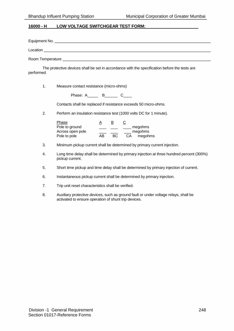
Bhandup Influent Pumping Station Municipal Corporation of Greater Mumbai
Division -1 General Requirement 248 Section 01017-Reference Forms
16000 - H LOW VOLTAGE SWITCHGEAR TEST FORM: Equipment No. Location Room Temperature
The protective devices shall be set in accordance with the specification before the tests are performed.
1. Measure contact resistance (micro-ohms)
Phase: A_____ B______ C____ Contacts shall be replaced if resistance exceeds 50 micro-ohms. 2. Perform an insulation resistance test (1000 volts DC for 1 minute).
Phase A B C Pole to ground megohms Across open pole megohms Pole to pole AB BC CA megohms
3. Minimum pickup current shall be determined by primary current injection. 4. Long time delay shall be determined by primary injection at three hundred percent (300%)
pickup current. 5. Short time pickup and time delay shall be determined by primary injection of current. 6. Instantaneous pickup current shall be determined by primary injection. 7. Trip unit reset characteristics shall be verified. 8. Auxiliary protective devices, such as ground fault or under voltage relays, shall be
activated to ensure operation of shunt trip devices.

Bhandup Influent Pumping Station Municipal Corporation of Greater Mumbai
Division -1 General Requirement 249 Section 01017-Reference Forms
16000 - I MEDIUM VOLTAGE LOAD INTERRUPTER SWITCH TEST FORM: Equipment Number Location Date
1. Measure switch blade resistance (micro-ohms).
Phase: A_____ B_____ C_____
Contacts shall be replaced if resistance exceeds 50 micro-ohms.
2. Perform an insulation resistance test (1000 volts DC for 1 minute).
Phase A B C
Pole to ground megohms
Across open pole megohms
Pole to pole AB BC CA megohms
The results shall be recorded and signed. A copy shall be given to the Engineer. CERTIFIED Date
Contractor's Representative WITNESSED Date
MCGM's Representative

Bhandup Influent Pumping Station Municipal Corporation of Greater Mumbai
Division -1 General Requirement 250 Section 01017-Reference Forms
16000 - J LIQUID-FILLED TRANSFORMER TEST FORM: Equipment Number Location Date/Weather Conditions A. Perform the "Insulation-Resistance Test" and "Dielectric Absorption Test" using Form
16000-C, Dry Transformer Test Data Form. B. Perform an applied voltage (low frequency dielectric) test in accordance with ANSI
C57.12.90, paragraph 10.5, Applied Voltage Test. Applied voltage levels shall be 75 percent of recommended factory test levels or recommended test levels of ANSI C57.12.00, Table 5.
C. Insulating oil shall be sampled and shall be laboratory tested for the following: 1. Dielectric strength. 2. Acid neutralization. 3. Interfacial tension. 4. Color. 5. Power factor. D. Perform a turns ratio test between the windings for all tap positions. E. The temperature and pressure switches shall be tested using a hot oil bath and air pump. The results shall be recorded and signed by the Contractor and Engineer. A copy shall
be given to the Engineer. Any readings which are abnormal to ANSI industry standards shall be reported to the Engineer.

Bhandup Influent Pumping Station Municipal Corporation of Greater Mumbai
Division -1 General Requirement 251 Section 01017-Reference Forms
16000 - K AUTOMATIC TRANSFER SWITCH TEST FORM: Equipment Number Location Date
1. Perform an insulation resistance test (1000 volts DC for 1 minute):
Phase
A B C
Pole to ground megohms
Pole to pole AB BC CA megohms
2. Perform the following operations and initial:
a. Manual transfer ________________
b. Loss of normal power; sec delay
c. Return to normal power; sec delay
The results shall be recorded and signed. A copy shall be given to the Engineer. CERTIFIED Date
Contractor's Representative WITNESSED Date
MCGM's Representative

Bhandup Influent Pumping Station Municipal Corporation of Greater Mumbai
Division -1 General Requirement 252 Section 01017-Reference Forms
16000 - L NEUTRAL GROUNDING RESISTOR TEST: Equipment No. Location
The pickup and time delay setting on the ground fault relay shall be set in accordance with Section 16431. 1. The transformer neutral insulation resistance shall be measured with and without
the grounding resistor connected to insure no parallel ground paths exist. 2. The protective relay pickup current shall be determined by injecting test current
into the current sensor. The pickup current should be within 10 percent of the dial setting. Record the dial setting and actual pickup tie.
3. The relay timing shall be tested by injecting 150 and 300 percent of pickup
current into the current sensor. The relay timing shall be in accordance with the manufacturer's published time-current characteristic curves. Record the relay timing at 150 and 300 percent of pickup current.
4. The circuit interrupting device shall be operated by operating the relay.
The results shall be recorded and signed by the Contractor and Engineer. A copy shall be given to the Engineer.
END OF SECTION 01017

Bhandup Influent Pumping Station Municipal Corporation of Greater Mumbai
Division -1 General Requirement 253 Section 01020-Civil Design Requirement
SECTION 01020- CIVIL DESIGN REQUIREMENT
PART 1 -GENERAL
1.01 Reference:
A. Section 01000, applies to and governs the work of this Section.
1.02 General:
A. This section sets out the particular requirements for the civil engineering and building works and site services at the SPS Site required by the Contract unless stated otherwise elsewhere in the Contract.
B. Design Requirements
In designing the Works the Contractor shall comply with the following requirements:
• The Works shall utilise a minimum area, within the Site, consistent with safe and reliable operation and maintenance;
• Means of access and egress for personnel above and below ground shall comply with safe and reliable procedures and all Indian regulations;
• ensure the design is consistent with relevant national and local legislation, guidelines and policies;
• all pipelines, ducts, mains and services shall be provided with flexible joints able to accommodate the differential movement that may occur between buildings and the surrounding soil;
• All pipelines, ducts, mains and services shall be provided with surface access chambers (including pipeline puddle flanges, dismantling couplings or adapters and rocker pipes) at bends over 30 degrees and at all connections including valves and meters;
• Buildings shall be designed in accordance with the current edition of the National Building Code of India / relevant latest editions of IS codes/ any other latest standards, codes, IRCs etc.
• All walkways, stairways and platforms shall have 1.2m clear spacing between the handrails.
1.03 Site Works
A. Site works consists of:
• Road works, grading, landscaping, etc. as required to prepare for the new works.
• Provision of temporary roads, grading, etc. as required to construct the new works.
• Provision of final grading, new site road works with under base(s) and asphalt topping suitable for heavy duty truck load condition.

Bhandup Influent Pumping Station Municipal Corporation of Greater Mumbai
Division -1 General Requirement 254 Section 01020-Civil Design Requirement
1.04 Loadings
A. All buildings shall be designed to withstand loads from; wind loads, earth pressures, seismic loads, water pressures, surcharges due to temporary or permanent conditions; dead load and imposed load in combination to comply with the relevant design codes and standards.
B. Wind loadings on structures shall be calculated in accordance with IS: 875 (Part 3).
C. The effects of air temperatures and fluctuations in air temperature shall be taken into account in the designs.
D. Earth and water pressures shall be determined by the Contractor and shall take into account the prevailing site conditions and the proposed construction methods.
E. The Contractor’s attention is drawn to the fact that the ground water table has been recorded in close proximity to the existing ground levels. Geotechnical investigations may not reflect this fact as they may have been carried out in dry weather. Water retaining structures shall be designed and constructed for uplift based on the external ground water table at ground level and the structure empty. Uplift shall be resisted by dead weight with a factor of safety of 1.2. Ground anchors and pressure relief valves as a means of dealing with uplift are not permissible. Structures shall also be designed to resist full internal water pressure with no external water pressure or earth pressure.
F. Dead loads shall be assessed by the Contractor using the proposed sizes and material densities.
G. Loads from overhead cranes comprise dead loads from crane bridges, gantry beams and hoists, live loads based on crane safe working loads and an allowance for dynamic effects. These loads shall be factored using the appropriate load factors.
H. Similarly plant dead and live loads shall be assessed including an allowance for pipe thrusts and dynamic effects in the design of base slabs and roof slabs. Plant loading shall not be taken into account in determining the factor of safety against flotation.
I. All loads used in the design, including those of mechanical and electrical plant shall be clearly indicated in the design calculations, which are to be included within the Contractor’s Documents.
1.05 Earthworks, Ground Improvements and Foundations
A. The work includes the refurbishment of existing Sewage pumping station. It includes Inlet chambers, screen chamber, Channel, Wet well, dry well & superstructure.
B. The Contractor has to conduct Structural auditing & report to be submitted to MCGM.
C. The Geotechnical investigation to be carried out along the pipeline for a depth of 10-12m.
D. Non-Destructive Testing to be done for structural components
E. Geotechnical information relating to the ground conditions at the garden is included in the Background Information.
F. The Contractor is wholly responsible for developing his approach to constructing the foundations for structures and dealing with any related issues such as differential settlement. The Contractor remains fully liable for the selection, design, construction and performance of the ground improvement measures he adopts.
G. The contractor is responsible for dewatering of sewage from pumping station before start of the work.

Bhandup Influent Pumping Station Municipal Corporation of Greater Mumbai
Division -1 General Requirement 255 Section 01020-Civil Design Requirement
H. Prior to commencing earthworks and foundation works whether as described above or using different techniques, the Contractor shall submit the geotechnical interpretive report, calculations for earthworks and foundations and a detailed construction method statement and programme relating to this work Influent Pumping Structures
I. Refurbishment of Sewerage Pumping station structures and foundations are to be constructed of cast-in-place reinforced concrete.
J. All interior faces of walls, exposed roofs of structures of above and below grade and exterior surfaces above finished grade shall have a smooth form finish in accordance with ACI 301 Surface Finish 3.0 (SF-3):
1. Patch voids larger than 1/2 inch wide or 1/2 inch deep.
2. Remove projections larger than 1/8 inch.
3. Patch tie holes.
4. Provide surface tolerance Class A in accordance with ACI 117.
K. All exterior walls below finished grade and other surfaces shall have an unworked finish free from substantial voids, honeycombing or other large blemishes, unless otherwise specified.
L. The external visible surfaces shall be painted.
M. Influent Pumping station structures are to be water tight without leaks.
N. The cement and chemical materials to be utilized in the concrete make-up are to be suitable for final use with wastewater and its potential aggressive conditions.
O. All wastewater retaining structure wall and slab thicknesses are to be designed to suit the load conditions.
P. Where the wet well is an integral part of an adjoining dry structure, the interior of the dry structure must be protected by water proofing the interior surface area of the wet well / Break Pressure Tank adjacent to that dry structure to a distance of 2 m beyond the limits of the adjoining dry area.
1.06 Administration Facilities
This section out the minimum requirements for administration facilities to be provided in the administration building at the Site by the Contractor.
In designing the Works the Contractor shall provide the following minimum facilities in the administration building:
Shared Facilities
i) Lobby area ≥35m2 (suitable for a lobby area and receptionist desk);
ii) Visitor’s Information Centre ≥ 100m2. The Employer’s Representative will specify the fit-out of this room during the Design-Build Period;
iii) Meeting/Presentation room ≥50m2. The Employer’s Representative will specify the fit-out of this room during the Design-Build Period;
iv) Mess/Amenity/Canteen room ≥80m2 equipped with sink, countertop surfaces, and
eating area including tables and chairs for 20 persons;
v) Shower/toilet/changing/locker facilities for male at≥ 25m2 and female at ≥ 12m2.
For the sole use of the Contractor:
i) Office Nr.1 > 20m2 for the Operation Service Period of the Contract
For the sole use of the Employer or Employer’s support staff:

Bhandup Influent Pumping Station Municipal Corporation of Greater Mumbai
Division -1 General Requirement 256 Section 01020-Civil Design Requirement
i) Office Nr.2 > 20m2 for the Operation Service Period of the Contract, equipped with PC and the office equipment specified for operational phase of Works;
ii) Double Office Nr.3 >20m2 for the Operation Service Period of the Contract, equipped with the PCs and office equipment specified for the operational phase of Works.
1.07 Architectural Design
A. Externally the buildings shall be visually aesthetically pleasing demonstrating a high quality and sensitivity to the local setting. However the design shall also be up-to-date and comply with the current international philosophy of design, and maintain clean and simple lines. The Contractor’s attention is drawn to the architectural renderings provided in the volume entitled Background Information. The Contractor shall ensure that a similar high standard of architectural and landscaping is provided in his design.
B. The design approach for buildings and structures shall be to achieve a safe, functional and durable facility. Materials and their colours for external surfaces shall be selected for their visual qualities and proven durability to withstand all the local climatic conditions likely to be experienced, ease of maintenance and reasonable cost. The civil engineering and building works design shall provide working conditions and facilities entirely suitable for the Works, that are conducive to its efficient operation and to ensure that maintenance during the life of the Works is minimised.
C. Local materials shall be used when possible with regards to quality and reasonable cost.
D. Effective methods of rainwater disposal shall be provided so that no roof or overhang water is left to run down the face of the building. Effective drip stops shall be incorporated in all overhanging elements.
E. The Contractor shall allow in his design for the climatic conditions and the high humidity in some of the processes involved. In this respect, the Contractor shall endeavour through his design to minimise energy consumption by improving system efficiencies, insulation, draught stripping, humidity control, heat recovery and controls.
1.08 Materials
A. The design and selection of Materials for all buildings shall be guided by the need to ensure that various elements have long, trouble free operational lives and that the requirements for building maintenance are reduced to a minimum.
Steelwork: Internal steelwork shall have a protection system in line with the requirements of ISO 12944. The protection system shall be suitable for a frequently damp and wet interior and shall have a life to first maintenance of 15 years or more.
External steelwork shall be either stainless steel, aluminium or have a protection system with a life to first maintenance of 10 years or more.
All galvanising shall be undertaken after the manufacture of the steelwork.
Tanks: Steel tanks shall be glass coated or stainless steel and shall be suitable for an aggressive internal atmosphere and the containment of sludge.
Windows: Where provided windows shall be consistent with ensuring maximum security.
Floors: Floor slabs shall be designed to cater for plant loading, together with basic floor live loading.

Bhandup Influent Pumping Station Municipal Corporation of Greater Mumbai
Division -1 General Requirement 257 Section 01020-Civil Design Requirement
Suspended floor slabs shall, in addition to the above, be designed to carry all dead loads, including the ceiling loads, floor finishes etc as applicable.
Ground slabs shall be cast in situ concrete with a minimum thickness of 300 mm.
Doors: All external personnel doors shall be heavy duty and security duty.
Roller shutter and roller panel doors shall be manually operated with suitable gear arrangement to reduce man efforts and of aluminium construction with plastic / protective coating.
1.09 Internal Finishes
A. Internally the buildings shall be functional but smart in appearance and based on a colour co-ordinated design to include all Plant and Materials.
B. The Contractor shall ensure that all areas of walls, floors and ceilings are provided with protective finishes suitable for normal operating conditions with a minimum durability of 15 years to first maintenance unless otherwise stated. When selecting Materials the Contractor shall consider the environment in which it is to be used, the substances to which it is to be exposed and the need to protect any equipment installed in the vicinity. The Contractor shall ensure that the Materials selected provide a safe working environment for the operations staff and are in accordance with all relevant health and safety regulations.
C. In all areas where any liquid or sludge spillage may occur the Contractor shall ensure that the floor is screeded and finished to provide drainage into the nearest suitable Site drainage collection system. The Contractor shall also seal the screed to prevent liquids percolating through to the structural concrete beneath. The Contractor shall ensure that the Materials provide a non-slip surface under all conditions.
D. Areas subject to washdown or splashing shall be protected to a suitable height with ceramic tiles or proprietary epoxy coating and be designed to prevent water retention in the building fabric.
E. Detailing shall allow for ease of replacement of panels that might become damaged and hidden structural panels shall be adequately protected.
1.10 General requirements for Areas to be Finished
A. The following are the minimum standards for finishes:
Schedule of Internal Finishes
Location Walls Floor Ceiling Skirtings
/Architraves
Offices/
reception area
/control rooms
Block work with
cement mortar
plaster, gypsum
plaster over
plastered surface
for smooth finish
with wipe down
paint finish
Vitrified glazed
tiles
Wipe down paint
finish or wipe
down suspended
ceilings
Vitrified glazed
tile skirting
Store rooms/
Switch room/
Workshop
building
Block work with
cement mortar
plaster with wipe
down paint finish
Power floated
concrete or
granolithic
screed with anti
dusting
hardener/
sealant
Wipe down paint
finish or wipe
down suspended
ceilings
None required

Bhandup Influent Pumping Station Municipal Corporation of Greater Mumbai
Division -1 General Requirement 258 Section 01020-Civil Design Requirement
Location Walls Floor Ceiling Skirtings
/Architraves
General process areas
Fair faced block
work, fair worked
concrete finish or
glazed tiles to
one metre above
water level in
proximity to
process units
Steel float finish
laid to falls as
appropriate with
anti-dusting
surface
hardener/
sealant
Self finished
profiled metal
lining sheets
Ceramic tiles to
one metre
above the top
of all process
units in splash
zones
Special
process areas,
chemical
handling
areas, sludge
handling
areas and
process areas
subject to
corrosive
attack
Two part epoxy
resin with non
slip aggregate (3
mm in thickness)
up to 300mm
height from floor
level.
Two part epoxy
resin with non
slip aggregate
(3 mm in
thickness)
Vehicle access areas
Sealed screed
to protect
structural
integrity of
floors, slabs to
be protected in
the event of oil,
petrol or
chemical
spillages
B. External Finishes of Buildings
The external finishes of the administration, pumping stations and other buildings shall have as a minimum either:
• aluminium curtain walling; or
• Plastered / rendered finish which shall be painted.
1.11 External Works
Roads and footpaths shall be suitable for their intended use and shall have at least the design standards set out in the specifications and the following requirements.
A. Treatment Facility Roads and Hard standing Areas
Geometric design of roads, junctions, turning circles etc. shall be in accordance with the national guidelines. They shall be designed to provide an adequate number of lay-bys, turning areas, parking spaces, etc. to enable sludge tankers, sludge cake lorries, chemical delivery wagons and other vehicles to discharge or pick up without causing obstructions to others. Hard standing areas for skips shall be of concrete construction. Junction radii shall be a minimum of 10m.

Bhandup Influent Pumping Station Municipal Corporation of Greater Mumbai
Division -1 General Requirement 259 Section 01020-Civil Design Requirement
Carriageway widths shall be adequate to accommodate all vehicles required to operate and maintain the Works and shall provide adequate manoeuvrability in accordance with accepted guidelines. Generally this shall be a minimum of 5m width, but shall be 6m width for roads utilized by sludge vehicles, chemical delivery trucks etc. All internal roads shall have adequate turning circles at bends and junctions so as to allow easy vehicular movement of the type and size of vehicles and loads anticipated to use the site.
Road drainage shall be provided. The roads shall be laid to falls and have adequate capacity to be free draining. Roads shall be sealed and paved in order to prevent soil loss.
Off road parking shall be provided for operational staff cars, maintenance vehicles etc. as determined by the Contractor but with a minimum space for at least 6 vehicles at the treatment facility. The Contractor shall also provide parking and turning capability for one coach and for 6 visitor’s cars at the treatment facility.
Footpaths of minimum 1.5m width shall be provided around all buildings, tanks and chambers and to all areas where equipment is provided.
B. Gates and Boundary
The Contractor shall construct new permanent anti-intruder palisade fences of minimum height 2.75 m around the whole of the Site to delineate the Site from all other areas.
The Contractor shall construct an appropriate new guardhouse and access gate with appropriate facilities for two guardsmen.
• Telephone linked to the guardhouse and security control room;
• CCTV camera linked to the centralised security system.
1.12 Site Drainage
A. Landscape and unpaved areas shall be finished and graded such that there are no undrained low spots or areas liable to ponding.
B. Surface water from the access road and Influent Pumping Station facility area shall be drained to a drainage system and not to the wastewater stream. The Contractor shall ensure that only uncontaminated surface water can drain to the surface water system. Surface water pipe work shall be designed by the Contractor using a rainfall intensity of 100mm/hr with no surcharging of any pipe work. The Contractor shall obtain consent from the Storm Water and Drain Department for the discharge of the storm water.
C. All road and hard standing areas with potential for contamination, wash waters and works drainage, shall be contained and returned upstream of the preliminary treatment works and downstream of the inlet flow measurement.
1.13 Services to the Site
A. General
The Contractor shall be responsible for provision of all services necessary for the Design Build and Operation Service of the Works. For clarity, the Contractor shall be responsible for the connection and continued provision of all necessary services (electricity, water, telecommunications, etc.) to the Site for the Design-Build Period, including commissioning, and for the provision of the Operation Service. The Contractor shall be responsible for the payment of all such service providers for such

Bhandup Influent Pumping Station Municipal Corporation of Greater Mumbai
Division -1 General Requirement 260 Section 01020-Civil Design Requirement
services for the entire Contract Period. The Contractor shall not assume that any connection can be made from the existing services being provided to the site.
The Contractor shall advise the Employer’s Representative in writing of all arrangements made with the public or private utilities and provide copies of all correspondence between themselves. The Contractor shall give the Employer’s Representative adequate notice of all meetings with the utility representatives so that the Employer’s Representative may attend. The Contractor shall minute all such meetings and provide the Employer’s Representative with copies.
Procedures shall be developed to cater for planned maintenance and for emergency failure of services, such that the performance standards are still met even in the event of such outages.
The Contractor shall determine on Site the exact position of all existing services that may affect or be affected by the Works prior to carrying out his design. He shall submit all details gathered to the Employer’s Representative.
B. Electricity Supply Cable Ducts
The Contractor shall provide the electricity supply to the Site, which shall follow the route of the main entrance to the Site and shall be underground in suitably sized ducts. Any new supply shall be underground within the Site and shall be in suitably sized ducts. The route of the electricity supply shall be agreed between the supply authority, planning authority, and Contractor. Where a looped supply or two supplies are proposed they shall be kept separated by a minimum 2,500mm.
The Contractor shall provide a means to connect an emergency source of power sufficient to operate the facility's essential service during a complete power failure of the electricity supplies and shall also facilitate the use of the power generated from bio-gas(optional) to be utilised. The Contractor designs must demonstrate how this is to be achieved. The facility shall be capable of safe shut down of all non-essential services and of safe start-up upon restoration of power. The Contractor shall develop procedures and demonstrate how these would be carried out in a safe manner.
The Contractor shall research the reliability of the power supplies and the plant through which it is supplied to the Works and demonstrate that the emergency power source will work for the duration of a power supply shutdown such that all of the water quality standards are met.
The Contractor will meet all of the supply authority charges relating to the Site from the Commencement Date.
Supply to the Employers staff quarters shall be maintained at all times whether the supply runs through the Contractors work site or common/shared access.
C. Potable Water
The Contractor shall provide a potable water supply to the Site. Wherever possible, the supply to the IPS Site shall be brought along the verge of the access road or entranceway to the Site. The pipe shall be sized for the flow required.
The Contractor shall be billed at Industrial water rates. The Contractor is encouraged to minimise clean water usage at the facility.
D. Telephone Supply
The Contractor shall provide a suitable number and specification of telephone cables. The route of the telephone cables shall follow the line of the access road.

Bhandup Influent Pumping Station Municipal Corporation of Greater Mumbai
Division -1 General Requirement 261 Section 01020-Civil Design Requirement
E. Spare Ducting
The Contractor shall provide two spare of minimum 150 mm dia ducts along the route of the access road to the Site, with draw pits suitably spaced for the drawing of control cables in the future.
F. Water Supply for Fire-Fighting
The Contractor shall supply suitable firefighting facilities to meet the requirements of the Chief Fire Officer, MCGM. The facilities shall use Tertiary Treated Effluent from a fire water storage tank and comprise:
• at least one electrical and one diesel and one jockey pump set,
• a pressurised ring main,
• hydrants,
• hoses,
• nozzles.
1.14 Reinforced Concrete
Reinforced concrete shall comply with Section 03000-Concrete.
Due to the severity of exposure of the site (sea water, high chlorides, high sulphates), the Contractor shall design suitable concrete mixes for the exposures anticipated. However, the Contractor’s mix designs shall meet. the following minimum concrete specification for all liquid retaining structures, structures in contact with water (including groundwater), superstructures of all buildings and tanks, load bearing members and foundations:
Minimum concrete requirements
Sr. No.
Structures and units Requirements
1
• Wall of pumping station
and screen chamber
• Base slab of pumping
station & screen
chamber
• Top slabs
• Chambers of all
type(underground)
• Framing arrangements
like beams at pumping
station substructure, etc.
• Pump & machine
foundation, etc
• All underground
structures
• All structures having
direct/indirect contact
with ground
water/sewage
• Grade of concrete : M35 as per IS 456
• Cementitious materials : Portland Slag
Cement (GGBS shall be between a
minimum of 25% and a maximum of 30% of
the cement content) as per IS455 and BS
6699
• Minimum cementitious content per m³ : 340
kg
• Maximum cementitious content per m³ : 380
kg
• Maximum water cement ratio : 0.45
2 • Pipe encasement • Grade of concrete : M25 as per IS 456

Bhandup Influent Pumping Station Municipal Corporation of Greater Mumbai
Division -1 General Requirement 262 Section 01020-Civil Design Requirement
• Pipe protection blocks
• PCC benching for profile
preparation
• Other structural
components at
superstructure above
pumping station and
support structures (not
having any contact with
ground water or sewage
for both superstructure
and support strucutre)
• Cementitious materials : Portland Slag
Cement (with GGBS content of 30%) as per
IS455
• Minimum cementitious content per m³ : 280
kg
• Maximum cementitious content per m³ : 360
kg
• Maximum water cement ratio : 0.40
3
• Walkway and
platforms outside
and around the
building/ unit
• Grade of concrete : M25 as per IS
456
• Cementitious materials : Portland
Pozzolana Cement / Ordinary
Portland Cement
• Minimum cementitious content per
m³ : 280 kg
• Maximum cementitious content per
m³ : 360 kg
• Maximum water cement ratio : 0.40
4
• Mud mat below
foundations,
plinth beams,
drains, trenches,
pits etc
• Plinth protection
work
• Grade of concrete : M15 as per IS 456
• Cementitious materials : Portland Pozzolana
Cement / Ordinary Portland Cement
• Minimum cementitious content per m³ : 240
kg
• Maximum cementitious content per m³ : 280
kg
• Maximum water cement ratio : 0.60
Super Plasticiser shall be provided where necessary to ensure necessary workability and wet curing is required.
The following are the minimum grades of concrete which may be used for particular non- structural application:
• M – 20: Pavements
• M – 15: Plinth protection work, Mud mat below foundations, plinth beams, drains, trenches, pits etc.
Reinforcing bars shall be of minimum grade Fe 500 CRS conforming to IS 1786.
The design of RCC structures shall be carried out by the ultimate limit state or the working stress method as per the provisions of IS 456. Concrete exposure shall be considered as severe for the purposes of the depth of cover to reinforcement.
Concrete tanks and other liquid retaining structures shall be designed either as un-cracked sections in accordance with the recommendation of IS 3370 or using limit state design for reinforced concrete in accordance with IS 3370 with a design crack width of 0.1mm. The design must also take into account cracking due to shrinkage,

Bhandup Influent Pumping Station Municipal Corporation of Greater Mumbai
Division -1 General Requirement 263 Section 01020-Civil Design Requirement
the amount, size and spacing of reinforcement must be adequate for strength and serviceability for shrinkage effects.
RCC walls shall include reinforcement on both faces for sections of 200mm or more, even if not required from a structural design consideration.
All concrete in liquid retaining structures shall include cement additives conforming to IS: 9103 to ensure a dense and watertight finished structure.
The following minimum structural thicknesses shall be used:
Table 14.3 – Minimum section thicknesses
Elements Minimum Thickness
Suspended RCC floors / slabs 200 mm
walkways 175 mm
Ground slab-on-grade 200 mm
Water retaining slabs/ walls 150 mm
Cable/ pipe trenches/ underground pits and base slabs 100 mm
From the fire resistance perspective, the minimum thickness of reinforced concrete members will be as per Figure 1 or Table 16A of IS 456 for at least 2 hour of fire resistance.
Note that these are the general minimum thicknesses employed. Structural elements shall be designed in accordance with the loads to be imposed.
All steel shall be procured from “original producers” who manufacture billets from iron ores and rolled the billets to produce steel confirming to IS 1786. No re-rolled material shall be accepted. If instructed by the Employer’s Representative, the Contractor shall submit the manufacturer’s test certificates for the steel. Random tests on steel supplied by the Contractor may be performed by the Employer as per relevant Indian Standards. Each steel bar shall be identified by the number duly moulded on the bar itself.
1.15 Liners to Concrete Material
A. Due to the potential for H2S corrosion in the wastewater containing structures, all Waste water retaining structures shall be lined with Polyurea/ Epoxy.
B. The following are the design requirements for all reinforced or plain concrete structures:
C. All blinding and levelling concrete shall be a minimum 100 mm thick in concrete grade M15
D. All physical and chemical properties of this Fe 500 CRS grade steel shall conform to IS: 1786-2008. Welded wire fabric shall conform to IS: 1566. All test results (including physical and chemical properties and salt spray tests) have to be produced for the respective bar diameter for each consignment of steel delivered at site and at a frequency of every 20 Metric Tons.
1.16 Design Philosophy
Following are the details are to be included in the general design philosophy;
• Design philosophy for Liquid Retaining Structures with various boundary conditions as applicable
• Design philosophy for buildings
• Design philosophy for all structures

Bhandup Influent Pumping Station Municipal Corporation of Greater Mumbai
Division -1 General Requirement 264 Section 01020-Civil Design Requirement
Design philosophy shall include material properties (grade, strength, unit weight etc.), development lengths, lap/splice lengths, Anchorage lengths under tension and compression, clear cover, water proofing specifications, legend used etc.
Reinforcement detail showing the development length at Column/Footing intersection, Column and Roof beam intersections, Walls and Base slab intersections; Walls and cover slab intersections
Detailing of the reinforcement for columns, beams, beam/column intersection, footing/column intersection, and Slabs as per relevant code provisions/requirements depending upon the assumptions made in the design as applicable.
Reinforcement detail for cut-outs in slabs and walls with maximum size of cut-outs
Reinforcement detail at top of RCC trench walls showing edge/seating angles
Pouring sequence of concrete and standard details for construction joints, expansion joints, contraction joints, etc.
Details of Manholes to be placed in the tank
A. Design Loadings
All buildings and structures shall be designed to resist the worst combination of the following loads/stresses under test and working conditions; these include dead load, live load, wind load, seismic load, stresses due to temperature changes, shrinkage and creep in materials, and dynamic loads:
B. Dead Load
This shall comprise all permanent construction including walls, floors, roofs, partitions, stairways, fixed service equipment and other items of machinery. In estimating the loads of process equipment all fixtures and attached piping shall be included, but excluding contents, shall be considered.
Dead loads shall be in general as per I.S. 875 Part (I). However, the following minimum loads shall be considered in design of structures:
Material densities
(i) Weight of water : 10 kN/m3
(ii)
Weight of soil (irrespective of strata available at site and type of soil used for filling etc). However, for checking stability against uplift, actual weight of soil as determined by field test shall be considered
:
20.00 kN/m3
(iii) Weight of concrete : 24.00 kN/m3
(iv) Weight of reinforced concrete : 25.00 kN/m3
(v) Weight of Brickwork(exclusive of plaster) : 20.00 N/m2 per mm thickness of brickwork
(vi) Weight of Solid Concrete Block work (exclusive of plaster)
: 24.00 N/m2 per mm thickness of block work
(vii) Weight of plaster to masonry surface : 18.00 N/m2 per mm thickness
(viii) Weight of granolithic terrazzo finish or rendering screed, etc.
: 24.00 N/m2 per mm thickness
(ix) Weight of MS chequered plates : 78.5 N/m2 per mm thickness of plates

Bhandup Influent Pumping Station Municipal Corporation of Greater Mumbai
Division -1 General Requirement 265 Section 01020-Civil Design Requirement
C. Live Load
Live Load (LL) shall include the superimposed loads due to the use/occupancy of the structure/building not including dead, wind or earthquake load. Live loads shall be in general as per I.S. 875 – 1987 Part (II). However, the following minimum live loads shall be considered in the design of structures:
i) Live load on roofs: 1.50 kN/m2
ii) Live load on floors supporting Equipment such as pumps, valves, Blowers, Compressors etc.: 10.00 kN/m2
iii) Live load on all other floors walkways, stairways and platforms: 5.00 kN/m2 (iv) Live load on Toilet areas: 2.00 kN/m2
iv) Live load Surcharge for Structures (Retaining walls): 10kN/ m2.
In the absence of any suitable provisions for live loads in BIS Codes or as given above for any particular type of floor or structure, assumptions made must receive the approval of the Engineer prior to starting the design work. Apart from the specified live loads or any other load due to material stored, any other equipment load or possible overloading during maintenance or erection/construction shall be considered and shall be partial or full whichever causes the most critical condition.
D. Wind Load
Wind loads shall be as per I.S. 875 - 2015 Part (III).
E. Earthquake Load
Seismic forces shall be as per I.S. 1893 - 2002.
F. Dynamic Load
Dynamic loads due to working of plant items such as pumps, blowers, compressors, switch gears, travelling cranes, etc. shall be considered in the design of structures.
G. Vehicular Wheel Load
For any structure or pipeline below the roads, Class A loading of IRC 6 shall be considered.
H. Joints
• Movement joints such as expansion joints, complete contraction joints, partial contraction joints and sliding joints shall be designed to suit the structure. However, contraction joints shall be provided at specified locations spaced not more than 7.5 m in both right angle directions for walls and rafts.
• Expansion joints of suitable gap at suitable intervals not more than 30 m shall be provided in walls, floors and roof slabs of liquid retaining structures.
• Construction joints shall be provided at right angles to the general direction of the member. The locations of construction joints shall be decided on convenience of construction. To avoid segregation of concrete in walls, horizontal construction joints are normally to be provided at every 2 m height. PVC water stops of 150 mm width shall be used for walls and 230 mm width for base slabs.
1.17 Detailed Design Calculations & Submission
Complete detailed design calculations of foundations and superstructure together with general arrangement drawings and explanatory sketches shall be submitted by the Contractor to the Engineer. Separate design calculations for foundations or superstructures submitted independent of each other shall be deemed to be incomplete and will not be accepted by the Engineer.

Bhandup Influent Pumping Station Municipal Corporation of Greater Mumbai
Division -1 General Requirement 266 Section 01020-Civil Design Requirement
• One (1) Copy of a Compact Disc (CD) containing electronic files relevant to the structure’s modelling, analysis and design calculations (Microsoft Excel, Staad Pro, etc.). Files submitted shall be in editable format.
• Print copy (6 Copies) of the contents as submitted in the Compact Disc.
• Good for Construction Drawings
• One (1) Copy of a Compact Disc (CD) containing AutoCAD files (Civil General Arrangement, Structural Dimensions and Reinforcement Details) pertaining to the structure. Files submitted shall be in editable format.
• Print copy (6 Copies) of the contents as submitted in the Compact Disc. Prints to be submitted on A1 Size Sheet as a minimum or A0 Size Sheet when required by the employer.
• Bar-bending schedule indicating the number, shape and size of the rebars shall be submitted as part of the Reinforcement Details
• Detailed drawing showing the location, number and depth of inserts shall be included for any structural steel inserts/Metal inserts in the structure such as rungs, bolted connections for ladders/railings, etc.
• Location of Construction Joints and pour sequence shall be included on the drawing for base slabs, walls and top slabs.
• Revised drawings shall be submitted by clouding at the location with the latest revision number and also show the history of revisions in a table format just above the title block.
• The design considerations described hereunder establish the minimum basic requirements of plain and reinforced concrete structures, masonry structures and structural steel works. However, any particular structure shall be designed for the satisfactory performance of the functions for which the same is being constructed. The Contractor shall also take care to check the stability of partly completed structures.
1.18 Design Criteria for Underground Liquid Retaining Structures
All underground or partly underground liquid containing structures shall be designed for the following conditions:
• Liquid depth up to full height of wall: no relief due to soil pressure from outside to be considered
• Structure empty (i.e., empty of liquid, any material, etc.): full earth pressure and surcharge pressure wherever applicable, to be considered
• If water table exists, earth pressure to be considered for submerged soil conditions with reference to the geotechnical recommendation
• Partition wall between dry sump and wet sump: to be designed for full liquid depth up to full height of wall
• Partition wall between two compartments: to be designed as one compartment empty and other full
Structures shall be designed for uplift in empty conditions with the water table as indicated in geotechnical report and minimum factor of 1.2 shall be ensured against uplift or floatation, by considering 0.9 times the characteristic dead load
Walls and bases shall be designed under operating conditions to resist earthquake forces from earth pressure mobilization and dynamic water loads (Hydrodynamic Impulsive Pressure and Hydrodynamic Convective Pressure)
For general retaining walls and large sized tanks where the walls are designed as retaining walls, sliding check shall also be performed along with over turning checks

Bhandup Influent Pumping Station Municipal Corporation of Greater Mumbai
Division -1 General Requirement 267 Section 01020-Civil Design Requirement
Overturning: The stability of a structure as a whole against overturning shall be ensured so that the restoring moment shall be not less than the sum of 1.2 times the maximum overturning moment due to the characteristic dead load and 1.4 times the maximum overturning moment due to the characteristic imposed loads. In cases where dead load provides the restoring moment, only 0.9 times the characteristic dead load shall be considered. Restoring moment due to imposed loads shall be ignored.
Sliding: The structure shall have a factor against sliding of not less than 1.4 under the most adverse combination of the applied characteristic forces. In this case only 0.9 times the characteristic dead load shall be taken into account.
As a design consideration to control crack, though general requirements of IS 3370 : 2009 & (Annexure F) IS: 456- 2000 shall be followed, All liquid retaining structures shall be designed based on the serviceability crack width limit state (i.e. 0.1 mm crack width) and other limit state requirements also to ensure an adequate degree of safety and serviceability.
In case of Large and Deep Underground Tanks such as Wet Wells, the analysis can be carried by Finite Element Method using STAAD.Pro V8i or any other equivalent software predominantly used and accepted in the industry.
1.19 Foundations
The minimum depth of foundations for all structures, equipment, buildings and frame foundations and load bearing walls shall be as per IS 1904 but in any case this shall not be less than 1.5 meter in the original soil.
Maximum safe bearing capacity of soil strata shall be taken as determined by the Contractor through his own independent investigations. Geotechnical reports of proposed STP sites covered under the contract are provided with the Bid Documents. It may be used by Contractor as part of, in addition to, or in lieu of such investigations at his own risk.
Care shall be taken to avoid the foundations of adjacent buildings or structure foundations, either existing or not within the scope of this Contract. Suitable adjustments in depth, location and sizes may have to be made depending on site conditions. No extra claims for such adjustments shall be accepted by the Employer.
Special attention is drawn to danger of uplift being caused by the ground water table. All underground structural slabs shall be designed for uplift forces due to ground water pressure.
EGL (Existing ground level) and FGL (Finished ground level) shall be marked on all drawings showing foundation/sub-structure details and related design documents.
Machine/static equipment foundations shall be separated from adjoining parts of buildings, other foundations and floor/pavement slabs. Joints at floor/pavement slabs shall be suitably sealed.
Foundations and structures for machines subject to vibrations shall be so proportioned that the amplitude and frequency of the foundation/structure are within the permissible limits as per relevant BIS codes (or as required by the machine vendor).
Machine foundations shall be designed and detailed as per IS: 2974. All appendages to such foundations shall be reinforced suitably to ensure integral action.
Foundations for plant structures in Swampy/Waterlogged areas, for lightly & medium loaded structures and relevant Ground Improvements shall be considered in compliance with the relevant Geotechnical Investigation Report recommendations as

Bhandup Influent Pumping Station Municipal Corporation of Greater Mumbai
Division -1 General Requirement 268 Section 01020-Civil Design Requirement
applicable. Also to enlist the services of an experienced & specialized agency for all related design aspects considerations, equipment specifications, and implementation methodology, etc., as an advice for the same.
1.20 Design Requirements
Reinforcement bars and structural steel to be procured only from Primary steel producers with Integrated Steel such as TATA/SAIL/RINL/JSW. No Re-rolled material/secondary steel will be accepted or allowed for any structural works.
Only those firms are eligible who are primary steel producer and should have integrated steel plant in single premises.
Certificate issued by ministry of steel of primary steel producer and integrated steel plant having infrastructure in single premises for producing sponge iron, billet and TMT reinforcement bars using iron ore as base material.
The steel manufacturing company should have latest ISO accreditation for Quality Management System.
The minimum amount of reinforcement in each of the two directions at right angles within each surface zone should be provided as per clause 8.1 of IS 3370 (Part 2):2009. Definition of surface zones is clearly shown in Figure 1 and Figure 2 of IS 3370 (Part 2): 2009. For slabs, minimum of 10 mm dia bars shall be used to avoid any deformation of lesser diameter bars under loads prior to construction.
All buildings shall have a minimum 1 meter wide, 100 mm thick plinth protection paving in M15 grade concrete or stone slabs/tiles. All plinth protection shall be supported on well compacted strata.
All pipes and ducts laid below the structural plinth and road works shall be surrounded with concrete of grade M15 having minimum 150 mm thick concrete or D/4 (D = outer dia. of pipe) thickness whichever is more.
Use of pressure relief valves to reduce uplift pressure due to ground water table shall not be allowed.
Detailing of the reinforcement shall be considered as per latest Indian code of practices and special publications as applicable.
Water tightness testing of water retaining structures shall be done in accordance with IS: 3370, (Part I) - 2009. The depth of water for testing shall be up to the soffit of the covering slab.
A. Standards
Materials and workmanship shall comply with the relevant Indian Standards (with amendments) current on the date of submission of the tender.
Where the relevant standard provides for the furnishing of a certificate to the Engineer, at his request, stating that the materials supplied comply in all respects with the standard, the Contractor shall obtain the certificate and forward it to the Engineer.
The specifications, standards and codes listed below are considered to be part of this specification.
All standards, specifications, codes of practices referred to herein shall be the latest editions including all applicable official amendments and revisions.
In case of discrepancy between the Specification and the Standards referred to herein, the Specification shall govern.

Bhandup Influent Pumping Station Municipal Corporation of Greater Mumbai
Division -1 General Requirement 269 Section 01020-Civil Design Requirement
1.21 Buildings and Structures
All the building and structure works shall generally comply with the following Employer’s Requirements unless otherwise specified elsewhere:
All external walls shall be in solid cement concrete blocks of concrete grade M15 and shall be provided as per IS: 2185 (Latest Revision) and shall be 200 mm thick.
All internal partition walls shall be in solid cement concrete blocks of concrete grade M15 and shall be provided as per IS: 2185 (Latest Revision). All internal walls shall be 200mm thick except for toilets. Toilet partition walls shall be in 100 mm thick solid concrete block.
Finishes to concrete liquid retaining structures shall be:
F1 - External surfaces, buried
F2 - External surfaces exposed and up to 300 mm below ground level
F2 - Internal surfaces
Finishes to other concrete structures shall be:
F1 - Buried
F1 - Exposed, where plastering is specified
F2 - Exposed
All internal masonry and ceiling surfaces finish shall have 12 mm thick plain faced cement plaster in cement mortar (1:4) with neat cement finish on top. The plastered surface shall made smooth by using cement based putty or gypsum for better architectural finish. Over this, one coat of primer and two coats of plastic emulsion paint of approved quality and shade shall be provided.
All external masonry and concrete with rough board finish shall have 20 mm thick sand faced cement plaster in two coats, base coat 12 mm thick in cement mortar 1:4 and finishing coat 8 mm thick in cement mortar 1:4. Waterproofing compound of approved make and quality shall be added to the cement mortar in proportions as specified by the manufacturer.
All external surfaces exposed and up to 300mm below ground level have one coat of primer and two coats of waterproof cement based paint of approved quality and shade. A coat of silicone water repellent paint shall also be applied thereon.
All staircases shall have 25 mm thick kota stone of approved quality and 150mm high skirting set in cement mortar in 1:4 to give an overall thickness of 50 mm.
Stairways shall be provided to permit access between different levels within buildings. Staircase shall be minimum 1500 mm wide, minimum Tread = 250 mm, maximum Riser = 175 mm and maximum 15 number of steps per flight unless specified otherwise. Staircases in general shall not be steeper than 40°. Staircases having space constraints may be steeper than 400. The maximum vertical run for a single flight of stairs shall be 3.0 M.
All roof tops and overhead tanks shall be made accessible with ladder provision. Vertical step ladders fitted with landing point extensions will be permitted where considered appropriate by the Engineer to access areas not frequently visited.
Steel staircases shall be constructed of standard channel stringers with M.S. grating treads 25mm thick with non skid nosing. Steel Ladders shall be minimum 600mm wide and shall not exceed 6m of straight run. The ladders shall be painted with epoxy paint.

Bhandup Influent Pumping Station Municipal Corporation of Greater Mumbai
Division -1 General Requirement 270 Section 01020-Civil Design Requirement
All hand railing shall be provided with Stainless steel SS-304(Schedule 10) with pipe diameter 50. The minimum height of hand railing shall be 1.2m and maximum spacing of verticals shall be 1.2 m. Number of horizontal rails shall be 3 (1 top, 1 intermediate and 1 bottom) with a 100 x 6 toe plate at the bottom.
Building plinth shall be minimum 450 mm above average finished ground level around building or high flood level whichever is more.
All concrete channels and ducts used for conveying liquid shall have inside finish of type F2. The width of concrete channels shall not be less than 500 mm. All open channels shall be provided with hand railings (3-rail) or concrete walls to a minimum height of 1.2 m from the access surface elevation. All concrete surfaces of structures conveying raw sewage or primary effluent upstream of the aeration tanks shall be protected from corrosion with a Polyurea / Epoxy lining.
Kerbs to be provided below the hand railing on the catwalks/pathways should be as per relevant sections of Factory Act. It shall not be less than 150mm.
All exposed surfaces of inserts embedded in concrete shall be painted with two coats of enamel paint over one coat of red oxide zinc chrome primer. Surfaces in contact with concrete shall not be painted.
All structural steel members shall be painted with two coats of enamel paint over one shop and one field coat of red oxide zinc chrome primer.
All rooms in the treatment plant buildings shall be provided with appropriate sign boards indicating the function of the rooms involved written in Marathi, Hindi and English Languages.
The design of buildings shall reflect the climatic conditions existing on site. Process buildings shall as far as is possible permit the entry of natural light, and the use of glazed paneling shall be kept to a minimum and preference given to wall openings protected by weather canopies.
Emergency exit doorways shall be provided from all buildings in order to comply with local and international regulations .Stairways and paved areas shall be provided at the exit points.
All concrete structures in contact with sewage and/or sludge shall be provided with full interior corrosion protection linings and/or coatings of appropriate material and thickness to be approved by MCGM.
To assess the compressive strength of concrete for existing structures. Carry out Non
Destructive Test as per IS-13311
Carry out rebound hammer tests for determining the estimated compressive strength
of concrete and uniformity of concrete in terms of surface hardness test as per
relevant IS / ASTM/BS as mentioned in scope matrix attached under Annexure I
and/or as directed by site in-charge
Carry out ultrasonic pulse velocity test for ascertaining the quality of concrete,
soundness and density of concrete, uniformity of concrete in terms of density, crack
depth and width, cause analysis of crack propagation as per relevant IS / ASTM/BS
as mentioned in scope matrix attached under Annexure I and/or as directed by site
in-charge
Carry out core compressive strength test by concrete extraction for evaluation of
exact in-situ compressive strength, grade and fck value of concrete as per relevant IS
/ ASTM/BS as mentioned in scope matrix attached under Annexure I and/or as

Bhandup Influent Pumping Station Municipal Corporation of Greater Mumbai
Division -1 General Requirement 271 Section 01020-Civil Design Requirement
directed by site in-charge. The scope shall also include filling of extracted portion of
structure back to its original condition using same or richer mix of the concrete.
If any structure during the sampling and testing process gets physically damaged, the
same is to be reinstated to its original condition at your own cost and nothing extra
would be paid on account of it
The detailed quantities and other specifications shall be as per ToR / Annexure I:
You will make your own arrangement for the water and electric supply required for
your operations as well as water required for potable use during the period of the field
works.
The cost for providing local transportation, accommodation and incidental expenses
for staff deployed for survey shall be borne by survey agency and are included in the
above fee. Thus, the fee for services indicated in Annexure I is all-inclusive fee and
no extra fee on any account shall be payable by TCE.
The quantities indicated in Annexure I are estimated quantities. It should be clearly
understood that the quantities to be actually executed may vary from those indicated
above. The agency should report any increase in quantity immediately to TCE and
seek approval before executing any extra work. TCE reserves the right to modify any
aspect of the scope of survey at any time till successful completion of the contract.
The work shall be carried out in such a way that existing utilities, cables etc are not
damaged. In case of any unintentional damage by way of working, the agency will
restore that to original condition at no extra cost to TCE.
A format shall be provided by TCE for capturing information and reporting findings
from each site.
All work/activity shall be done in consultation/approval of MCGM Maintenance team.
During the course of this scope of work, dewatering of trenches if required shall be
agency’s responsibility.
END OF SECTION 01020.

Bhandup Influent Pumping Station Municipal Corporation of Greater Mumbai
Division -2 Site Work 272 Section 02000-Site Work
INDEX
SECTIONS NO.OF PAGES Section 02000 – Site Work .......................................................................................................... 2 Section 02050 – Removals and Demolition ................................................................................. 3 Section 02100 – Site Clearing and Grading ......................................................................................3 Section 02150 – Chain Link Fencing ................................................................................................3 Section 02160 – Concertina wire Fencing ........................................................................................3 Section 02220 – Excavation .............................................................................................................7 Section 02221 – Backfilling and Filling ..............................................................................................5 Section 02400 – Sheeting, Shoring and Bracing...............................................................................7 Section 02480 – Landscaping ...........................................................................................................4 Section 02520 – Surface Drainage Systems ....................................................................................2 Section 02530 – Dewatering .............................................................................................................1 Section 02600 – Gravity Main and Bypass .......................................................................................5 Section 02610 – Sewer Connections ................................................................................................4 Section 02720 – Roads and Paving ................................................................................................ 11 Section 02730 – Block Paving ..........................................................................................................6 Section 02750 – Bituminous Concrete Roads ................................................................................ 29 Section 02800 – Anti-Termite Treatment … ................... ……………………………………….............4 Total Pages in This Division - ...................................................................................................... 99

Bhandup Influent Pumping Station Municipal Corporation of Greater Mumbai
Division -2 Site Work 273 Section 02000-Site Work
SECTION 02000- SITE WORK
PART 1 -GENERAL
1.01 Governing Conditions:
A. The General Conditions, Particular Conditions, Contract Forms and the requirements of Division 1 herein before specified, in addition to any and all Addenda, apply to and govern each Section of this Division.
B. This Section covers the general requirements for this Division and shall be read in conjunction with other Sections in this Division.
C. This Section governs the work of other Sections in this Division.
1.02 Work Included:
A. The work of this Division includes, but is not necessarily limited to, the provision of: all labour, materials, tools and equipment to carry out the following
1. Clearing and grubbing.
2. Removal and stockpiling of topsoil for future use.
3. Construction of site fencing.
4. Construction of access roads.
5. Excavation and backfilling for structures.
6. Sheeting, shoring and bracing of excavations, including dewatering as required.
7. Excavation and grading for roadways and parking areas, footings, foundations and slabs on grade and excavation for all piping, manholes and other services. The term excavation includes rock excavation.
8. Construction of temporary structures.
9. Construction of new pumping stations including finishing.
10. Construction of Administrative Buildings including finishing.
11. Installation of process piping, sanitary, storm and process drains, maintenance chambers, valve chambers, plumbing, sub-drains and other piping at the sites including appurtenances.
12. Demolition and disposal of existing structures, piping, grating, hand railing and other facilities designated for removal.
13. Supply, placement and compaction of approved fill to final grades.
14. Removal and disposal of excess or unsuitable material, including rock, and supply of suitable backfill material as required.
15. Removal and disposal of unstable or unsuitable material from below foundation elevations and supply and placement of concrete to support the RCC foundation.
16. Supply, placement and compaction of foundation bedding.
17. Supply, installation and removal of temporary fencing including gates as specified.
18. Construction of concrete and gravel driveways.
19. Restoration of seeded areas, asphalt and gravel driveways and parking lots.
20. Restoration of fine grading of areas disturbed by construction activities. Provision of positive drainage as well as satisfactory blending with the existing grades as required throughout the disturbed areas.

Bhandup Influent Pumping Station Municipal Corporation of Greater Mumbai
Division -2 Site Work 274 Section 02000-Site Work
1.03 Co-ordination:
A. Co-ordinate with the work of other Divisions before installing work included in this Division. If work is installed without co-ordination with other works, the Engineer may direct that such work be removed, relocated and/or modified as necessary. Comply promptly with the Engineer's requests. Complete any correction and/or additional work, as directed by the Engineers at no additional cost to the MCGM.
B. For coordination requirements refer to Section 01003.
1.04 Submittals:
A. Submit drawings in accordance with Section 01007 and AS-BUILT drawings as per Section – 01016
B. Identify and submit existing Utility Plans for Engineers review.
1.05 Codes and Standards:
A. The applicable standards established by the Bureau of Indian Standards govern the materials and workmanship employed in the manufacture of all equipment/items.
B. Where provisions of the pertinent codes and standards conflict with these Specifications, Drawings and Datasheets or with each other, comply with the more stringent provision.
C. Use the latest issue of Standards.
1.06 Definitions:
A. The term "utility", as used herein, includes services such as gas, electricity, water supply, drains, and sewers.
B. The term “Inter-Connecting Piping” as used herein includes piping between units and the first joint outside the face of building/unit
C. The term “Gravity Main/ Bypass” as used herein includes piping from the valve chamber structure to Balancing Chamber /Nullah/storm water drain as shown on the drawings.
PART 2 - PRODUCTS
2.01 General:
A. Comply with the product requirements outlined in the individual Sections.
B. Select other materials not specifically described but required for the proper completion of the work of this Division subject to the approval of the Engineer.
PART 3 - EXECUTION
3.01 General:
A. Comply with the execution requirements outlined in the individual Sections.
3.02 Setting Out:
A. Be responsible for the setting out of the work, with reference to a baseline and a benchmark provided by the Engineer, per Section 01004.
3.03 Environmental Constraints:
A. Adhere to the environmental constraints set out in Division 1.
3.04 Site Conditions:
A. Refer to Section 01000 for site conditions.

Bhandup Influent Pumping Station Municipal Corporation of Greater Mumbai
Division -2 Site Work 275 Section 02050-Removal & Demolition
SECTION 02050- REMOVAL & DEMOLITION
PART 1 -GENERAL
1.01 Reference:
A. Section 02000 applies to and governs the work of this Section.
1.02 Work Included:
A. Demolish structures within IPS site area and interfering with the construction of the new pumping stations ensuring that no utilities or buildings that are to remain in operation are disturbed. Be responsible for removing debris from site.
B. After successful commissioning of the new pumping stations and their successful operation for 30 days, all incoming sewage flows will be transferred permanently to the new pumping station.
C. The equipment and items shall be removed and disposed of off-site. The dry/wet well shall be drained, cleaned and sterilized before being demolished to 1.5 metres below existing or ground level.
D. Removals and Demolition includes, but is not necessarily limited to, the following:
1. Obtain permissions from the relevant authorities and follow their requirements for removal and disposal of mechanical, piping, electrical and instrument equipment etc.
2. Removal and disposal of concrete, masonry, structural steel, other metals and other unwanted materials off-site in accordance with MCGM requirements.
1.03 Related Work by other Divisions:
A. The following related work is covered elsewhere in the contract documents:
1. Division 1 - General Requirements
1.04 Alternatives:
A. This is not applicable in this section.
1.05 Submittals:
A. Prepare and submit to the Engineer, in accordance with Section 01007, a detailed execution plan for removals and demolition work, before commencing any demolition activity.
1.06 Codes and Standards:
A. The applicable standards established by the Bureau of Indian Standards govern the materials and workmanship employed.
1. IS 3696 Safety of scaffolds and ladders. Part-I and II
2. Safety Manual, Central Water and Power Commission
3. National Building Code of India-2005
4. IS 4130 - 1991 Safety Code for demolition of buildings (second revision)
5. I.S. 1200 - 1974 (Part III - 3rd Division) - Demolition and Dismantle.
B. Where provisions of the pertinent codes and standards conflict with these Specifications and Drawings or with each other, comply with the more stringent provision
C. Use the latest issue of Standards.

Bhandup Influent Pumping Station Municipal Corporation of Greater Mumbai
Division -2 Site Work 276 Section 02050-Removal & Demolition
PART 2 - PRODUCTS
A. These are no products in this section.
PART 3 - EXECUTION
3.01 General:
A. Before commencing demolition of any structure, ensure that demolition does not endanger safety of other structures.
B. Start demolition of the structures, with the approval of the Engineer, as per detailed execution plan for demolition and removals work, including the sequencing plan and schedule.
C. Before demolition of structures, all equipment, piping, fittings, instruments, electrical items must be listed and removed and disposed off by the Contractor. Ensure there is no fire hazard caused by hazardous gases or electrical short circuit.
D. Grant the MCGM the first right of refusal of items to be removed. Before proceeding with the demolition work, remove equipment and materials as designated by the Engineer to be retained by the MCGM. Clean the equipment and material to the satisfaction of the Engineer. Store the equipment and material in a manner and in a location satisfactory to the Engineer.
E. Remove and dispose of remaining items off-site, in accordance with the regulations, the requirements of the MCGM and as directed by the Engineer.
F. Provide final grading, placement of topsoil and seeding in accordance with Section 02480 Landscaping.
G. Fill depressions and excavated areas with approved fill, consolidate and grade as shown on the Drawings.
H. Clarification:
1. The Drawings do not intend to show every object existing on the project site.
2. Locate existing utility lines required to keep the existing plant running but that interfere with the execution of the construction of the new works. Either provide proper support or relocate the lines. After commissioning and the trial run of new pumping station, the redundant utilities to be dismantled and removed.
3.02 Temporary Fencing and Hoarding:
A. At the demolition working area, erect fencing to define such area. Agree with the Engineer on the extent of each working area.
B. Provide hoardings as per approved drawings/ and as required to protect the operations staff and the public.
3.03 Removal of Debris:
A. Remove and dispose of debris from the site and leave the site in a neat and orderly condition, to the satisfaction of the Engineer and in accordance with prevailing regulations.
B. Classify and dispose of wastes in accordance with applicable regulations under the Environmental Protection Act 1981 and the Air (Prevention and Control of Pollution) Act 1981
C. Do not burn debris on the project site.
3.04 Protection of the Environment:
A. Refer to Section 01010- Safety Requirements and Section 01011-Environmental Protection and Control.

Bhandup Influent Pumping Station Municipal Corporation of Greater Mumbai
Division -2 Site Work 277 Section 02050-Removal & Demolition
B. Take all reasonable steps to protect the environment both on and off the Site and to avoid damage or nuisance to persons or to property of the public or others resulting from pollution, noise or other causes arising as a consequence of methods of operation for demolishing the existing structures.
C. Abide at all times by all existing enactments on environmental protection and rules made there under, regulations, notifications and by-laws of the State or Central Government, or local authorities and any other law, by-law, regulations that may be passed or notification that may be issued in this respect in future by the State or Central Government or the local authority.
END OF SECTION 02050.

Bhandup Influent Pumping Station Municipal Corporation of Greater Mumbai
Division -2 Site Work 278
Section 02100-Site Clearing and Grading
SECTION 02100- SITE CLEARING AND GRADING
PART 1 -GENERAL
1.01 Reference:
A. Section 02000 applies to and governs the work of this Section.
1.02 Work Included:
A. Scope of Site Clearing and Grading work includes but is not limited to the following:
1. Clearing the site of all surface and subsurface structures, vegetation and debris.
2. Removal of trees as required.
3. Removal or relocation of existing utilities as required.
4. Excavation of unsuitable material.
5. Compaction of selected excavated materials or materials brought from elsewhere.
6. Disposal of surplus materials off the site including loading, transport, labour off-loading etc.
7. Grading of slopes, road relocations and preparation of sub-grades and drainage ways inclusive of constructing required embankments.
1.03 Related Work:
A. The following related work is covered elsewhere in the Contract Documents:
1. Backfilling and filling - Section 02221
2. Concrete - Division 3
3. Steelwork - Division 5
1.04 Alternatives:
A. Not applicable for this Section
1.05 Submittals:
A. Submit drawings and product data in accordance with Section 01007 and AS- BUILT drawings as per Section 01016.
B. Identify and submit Utility Plans to the Engineer for review.
1.06 Codes and Standards:
A. The applicable standards established by the Bureau of Indian Standards govern the materials and workmanship employed in the manufacture of all equipment/items.
B. Where provisions of the pertinent codes and standards conflict with these Specifications, Drawings and Datasheets or with each other, comply with the more stringent provisions.
C. Use the latest issue of Standards.
PART 2 - PRODUCTS
2.01 Materials:
A. Select materials not specifically described but required for the proper completion of the Work of this Section, subject to the approval of the Engineer.

Bhandup Influent Pumping Station Municipal Corporation of Greater Mumbai
Division -2 Site Work 279
Section 02100-Site Clearing and Grading
PART 3 - EXECUTION
3.01 Clearing Site of Large Trees, Structures etc.
A. Site Inspection:
1. Inspect the entire site carefully and obtain direction from the Engineer as to which loose items, if any, are to be removed and handed over to the Engineer before any work commences.
2. Locate existing utility lines and determine requirements for temporary supports, disconnecting and capping.
3. Locate existing active utility lines traversing the site and determine the requirements for their protection.
B. Clarification:
1. The Drawings do not intend to show every object or every tree, bush etc. existing on the project site.
2. Before starting any work under this Section, verify with the Engineer which objects, trees, bushes etc are to be removed and which objects to be preserved.
3. This include the removal of large trees, stumps and structures or parts thereof lying within the site of the Works as demarcated and shown on the Drawings with the prior permission of the concerned authority.
C. Demolition of existing concrete masonry or other structures to specified levels for site clearing shall be done but this work is covered in detail in Section 02050 – Demolition.
D. Blasting shall not be allowed.
3.02 Removal of Top Soil, Shrubs, and Other Vegetation, Refill and Re-compaction
A. All shrubs, vegetation and other plants shall be removed and cleared from the site. All debris and unsuitable material up to a depth of 30 cm shall be removed and the area refilled to correct grade with selected excavated material from the site or, if required, from approved borrow pits.
B. The quality and compaction of such fill or embankments shall be in accordance with the requirements of Section 02200.
C. Refill under roadways shall conform to the MCGM’s “Specifications for Road Works”.
D. Refill and compact any existing pits, wells, existing dry-wells or other areas as shown on the drawings where the levels are below the required grade.
3.03 Relocation of Existing Utilities, Roadways, Waterways etc.
A. Disconnection of Utilities:
1. Before starting site operations, divert or disconnect or arrange for the diversion/disconnection of utility services. Utilities to be directed in accordance with utility company or agency involved.
B. Protection of Utilities:
1. Preserve in operational condition active utilities traversing the site that are designated to remain in operation until the new facilities have been constructed and commissioned.
2. Provide support structures for the existing utilities, as required, for the duration of the construction.
3. Refer to Division 1 for additional requirements.

Bhandup Influent Pumping Station Municipal Corporation of Greater Mumbai
Division -2 Site Work 280
Section 02100-Site Clearing and Grading
C. All utilities known to exist within the site, such as water, storm and sewage mains, overhead or underground electric power cables, overhead or underground telephone wires or conduits, gas mains, etc., shall be shown on the Drawings by the Contractor. Remove and relocate such utilities necessary to be relocated permanently or temporarily after receiving permission from the Engineer.
D. In the case of utilities shown on the Drawings or discovered prior to commencement of the relevant portion of work, provide at least 7 clear days notice of the intention to start work at the site. In the case of any utility whose location is not shown on the Drawings or whose existence is unknown, but is encountered during the course of the work, immediately verify and inform the Engineer of such discovery and either relocate the utility or undertake to have it done with the consent of concerned authority.
E. Relocate or divert roadways or open drains as necessary within the site to the satisfaction of the Engineer.
3.04 Stockpiling Topsoil:
A. Strip topsoil that is clean, entirely free from debris and suitable for supporting vegetation, from the areas to be disturbed and stockpile for subsequent use. Agree with the Engineer on the suitability of topsoil for re-use.
B. Co-ordinate the stockpile locations with the Engineer who will designate stockpiling areas in the field.
C. Protect stockpiles from the effect of wind by covering with tarpaulins, as necessary and to the satisfaction of the Engineer.
3.05 Disposal of Surplus Material
A. Spread out the excavated top soil or save it for further use and dispose of trees, stumps, debris etc., off-sites at tipping sites, provided by MCGM. Obtain licenses etc. for use of such sites
B. Classify and dispose of wastes in accordance with applicable regulations, under the Environmental Protection Act.
C. Remove and dispose of solids and debris from the site in accordance with regulatory requirements.
D. Grade and level the site to provide adequate drainage and leave the site in a neat and orderly condition to the satisfaction of the Engineer and in accordance with prevailing regulations.
E. Do not burn debris on the project site.
3.06 Provision of Additional Selected Fill
A. If adequate, quantity of approved earth fill is not available at site, the contractor to procure the same from borrows pits approved by Engineer.
END OF SECTION 02100.

Bhandup Influent Pumping Station Municipal Corporation of Greater Mumbai
Division -2 Site Work 281 Section 02150-Chain Link Fencing
SECTION 02150- CHAIN LINK FENCING
PART 1 -GENERAL
1.01 Reference:
A. Section 02000 applies to and governs the work of this Section.
1.02 Work Included:
A. The work shall generally be carried out as per these specifications, relevant drawings and as directed by the Engineer.
B. The work of this section includes, but is not necessarily limited to, the provision of: all labour, materials, tools and equipment to carry out the following
1. Clearing and grubbing.
2. Removal and stockpiling of topsoil for future use.
3. Construction of site fencing.
1.03 Related Work:
A. Section 02220 - Excavation
B. Division 5 - Metal work
1.04 Alternatives:
A. Not Applicable for this section
1.05 Submittals:
A. Submit drawings in accordance with Section 01007 and AS-BUILT drawings as per Section – 01016
1.06 Codes and Standards:
A. The following are applicable standards established by the Bureau of Indian Standards govern the materials and workmanship of Work under this Section:
1. IS: 2721 : Galvanized Steel Chain Link Fence Fabric
B. Where provisions of the pertinent codes and standards conflict with these Specifications, Drawings and Datasheets or with each other, comply with the more stringent provision.
C. Use the latest issue of Standards.
PART 2 - PRODUCTS
2.01 General:
A. Comply with the product requirements outlined in this Section.
B. Select other materials not specifically described but required for the proper completion of the work subject to the approval of the Engineer.

Bhandup Influent Pumping Station Municipal Corporation of Greater Mumbai
Division -2 Site Work 282 Section 02150-Chain Link Fencing
2.02 Materials:
A. M.S. Posts and Struts
All the M.S. posts/struts shall be free from rust, scale, cracks, twists and other defects and shall be fabricated to the required shape and size out of the specified sections. The posts and struts shall be conforming to relevant specifications stipulated here-in-before under relevant sections. All the posts and struts shall be of sizes and lengths as specified in the Tender Schedule and Drawing. The posts and struts shall have split ends for proper fixing and shall be embedded in the cement concrete of mix. 1:3:6 or as specified in the schedule. The exposed surfaces of the posts and struts shall be painted with two coats of synthetic enamel paint of approved make and shade over a coat of approved primer.
B. R.C.C Posts and Struts
All the posts and struts shall be of standard size as specified in drawings and
schedule. These shall be casted on suitable places/platforms in cement concrete
1:2:4 (1 cement 2 coarse sand: 4 graded stone aggregate 10 mm. nominal size) as
per relevant specifications stipulated here-in-before. The reinforcement shall be
provided as shown in the drawings, as directed by the Engineer and specified here-
in-before under relevant sections. The posts and struts shall be free from
honeycombing, cracks and other defects.
After casting, the posts/struts shall be left at the same place and cured for a
minimum period of 7 days. After 7 days curing the same shall be shifted to a levelled
ground and stacked for further curing for 14 days. After 21 days of curing only, the
posts/struts shall be transported to work site without any damage, for fixing in
position.
PART 3 -EXECUTION
3.01 Spacing of the Posts and Struts:
A. The spacing of posts shall be 3 m. centre to centre unless otherwise specified or as directed by the Engineer, to suit the dimensions of the area to be fenced. Every 10th posts, last but one end posts, corner posts, and posts where the level of fencing changes in steps and end post when the fencing changes its direction shall be strutted on both sides, or as directed by the Engineer. End posts where barbed wire fencing is discontinued shall be strutted on one side only.
3.02 Fixing of M.S/R.C.C Posts and Struts:
A. Pits of size 45 x 45 x 45 cm. deep or of sizes mentioned in the drawings, shall first be excavated centrally in the direction of proposed fencing work, true to line and level to receive the posts. In case of struts, the pits shall be so excavated, as to receive minimum 15 cm. concrete cover at any point of the struts to suit its inclination or as shown in the drawing.
B. The pits shall be filled with a layer of 15 cm. thick cement concrete of specified mix. The posts and struts shall then be placed in the pits, the posts projecting to the specified height above ground level, true to line, plumb and position, by providing adequate supports temporarily, and cement concrete of specified mix shall then be filled-in so that the posts are embedded in cement concrete blocks of specified sizes. The concrete in foundation shall be watered for atleast 7 days to ensure proper curing.

Bhandup Influent Pumping Station Municipal Corporation of Greater Mumbai
Division -2 Site Work 283 Section 02150-Chain Link Fencing
3.03 Chain Link:
A. The chain link shall be of approved manufacture and of correct size, gauge etc. It shall be of M.S. or G.I. as specified of approved manufacture and of required size, gauge etc. The base materials of the wire shall be of good commercial quality mild steel. The wire shall be circular in section, free from rust, scale, cuts, welds and other defects and shall be uniformly galvanized if specified.
B. Chain link fencing should be of 10 gauge G.I. Wire with 50mm x 50mm square diamond pattern. The chain link fencing shall be fixed between angle framing and M.S flat bedding, bolted with 6mm dia bolts at 300mm c/c on all four edges.
3.04 Fixing of the Chain Link fencing to MS or CC post:
A. The chain link of specified height of fencing shall be fixed first to the end post with necessary G.I. approved type U clamps threaded at both the ends and G.I. nut, bolts, washers etc. and with 6 mm. dia. full height M.S./G.I. anchor bar. After fixing the chain link at the end post, it shall be stretched tightly and fixed to next post one after the other by the above mentioned clamps and bars etc. leaving 50 mm. clearance from the ground and 20 mm. clearance in the case of concrete coping at bottom to avoid rusting. The point at the change in level of the fencing top/bottom, necessary links shall be adjusted suitably as per the manufacturers specification or as directed by the Company Representative. The entire chain link fence shall be painted with two coats of synthetic enamel paint of approved make and shade over a coat of approved primer or as specified in the item/drawing.
3.05 Method of Measurement:
A. The work shall be measured in accordance to IS 1200 and in running metre length of fencing correct to a centimeter for the finished work from centre to centre of the posts.
END OF SECTION 02150.

Bhandup Influent Pumping Station Municipal Corporation of Greater Mumbai
Division -2 Site Work 284 Section 02160-Concertina Wire Fencing
SECTION 02160- CONCERTINA WIRE FENCING
PART 1 -GENERAL
1.01 Reference:
A. Section 02000 applies to and governs the work of this Section.
1.02 Work Included:
A. The work shall generally be carried out as per these specifications, relevant drawings and as directed by the Engineer.
B. The work of this section includes, but is not necessarily limited to, the provision of all labour, materials, tools and equipment to carry out Construction of site fencing.
1.03 Related Work:
A. Section 02220 - Excavation
B. Division 5 - Metal work
1.04 Alternatives:
A. Not Applicable for this section
1.05 Submittals:
A. Submit drawings in accordance with Section 01007 and AS-BUILT drawings as per Section – 01016
1.06 Codes and Standards:
A. The following are applicable standards established by the Bureau of Indian Standards govern the materials and workmanship of Work under this Section:
1. IS: 278 : Galvanized Steel Barbed Wire for Fencing
B. Where provisions of the pertinent codes and standards conflict with these Specifications, Drawings and Datasheets or with each other, comply with the more stringent provision.
C. Use the latest issue of Standards.

Bhandup Influent Pumping Station Municipal Corporation of Greater Mumbai
Division -2 Site Work 285 Section 02160-Concertina Wire Fencing
PART 2 -PRODUCTS
2.01 General:
A. Comply with the product requirements outlined in this Section.
B. Select other materials not specifically described but required for the proper completion of the work subject to the approval of the Engineer.
2.02 Materials:
A. M.S. Posts and Struts
All the M.S. posts/struts shall be free from rust, scale, cracks, twists and other defects and shall be fabricated to the required shape and size out of the specified sections. The posts and struts shall be conforming to relevant specifications stipulated here-in-before under relevant sections. All the posts and struts shall be of sizes and lengths as specified in the Tender Schedule and Drawing. The posts and struts shall have split ends for proper fixing and shall be embedded in the cement concrete of mix. M15 or as specified in the schedule. The exposed surfaces of the posts and struts shall be painted with two coats of synthetic enamel paint of approved make and shade over a coat of approved anticorrosive primer.
Bhandup Influent Pumping Station Municipal Corporation of Greater Mumbai
Division -2 Site Work 286 Section 02160-Concertina Wire Fencing
PART 3 -EXECUTION
3.01 Spacing of the Posts and Struts:
A. The spacing of posts shall be 3 m. centre to centre or otherwise as specified in drawings, to suit the dimensions of the area to be fenced. Every 10th posts, last but one end posts, corner posts, and posts where the level of fencing changes in steps and end post when the fencing changes its direction shall be strutted on both sides, or as directed by the Engineer. End posts where barbed wire fencing is discontinued shall be strutted on one side only.
3.02 Fixing of M.S Struts:
A. Pits of size 45 x 45 x 45 cm. deep or of sizes mentioned in the drawings, shall first be excavated centrally in the direction of proposed fencing work, true to line and level to receive the posts. In case of struts, the pits shall be so excavated, as to receive minimum 15 cm. concrete cover at any point of the struts to suit its inclination or as shown in the drawing.
B. The pits shall be filled with a layer of 15 cm. thick cement concrete of specified mix. The posts and struts shall then be placed in the pits, the posts projecting to the specified height above ground level, true to line, plumb and position, by providing adequate supports temporarily, and cement concrete of specified mix shall then be filled-in so that the posts are embedded in cement concrete blocks of specified sizes. The concrete in foundation shall be watered for atleast 7 days to ensure proper curing.
C. Wherever the posts and struts are to be fixed on brick/block work of compound wall it should be embedded at least 300mm below the top of the wall, with the size 300mm (D) x 300mm(L) x 230mm or thickness of the wall in concrete block of grade M-150 or as specified in drawings.
3.03 Concertina Coils:
A. Concertina barbed tape wire fencing of 600mm height to be provided on top of the compound wall.
B. Specifications of Concertina Barbed Tape Fencing:
Dia of coil - 600
Length of each coil - 9m
No. of spirals per coil - 80
Core Wire:
Dia of core wire - 2.5 +/-0.1mm
Tensile strength of core wire - 1500mPa(160Kg/Sqm)
Galvanising - 250 to 300 gms zinc per Sqm
Razor Blade:
Thickness of blade - 0.6 +/-0.05mm
Length of each blade - 30mm
Width of each blade - 20mm including reinforcing flange of 8mm thick
Galvanising - 160gms zinc per Sqm
Clips
Material - G.I
No. of clips - min. 3nos. per coil

Bhandup Influent Pumping Station Municipal Corporation of Greater Mumbai
Division -2 Site Work 287 Section 02160-Concertina Wire Fencing
C. The concertina fencing shall be supported by min. 3 nos. of reinforced barb tape wire passing through MS angle posts provided on top of the compound wall. The concertina fencing shall be coated with first quality synthetic enamel paint of approved colour.
3.04 Method of Measurement:
A. The work shall be measured in running metre length of fencing correct to a centimeter for the finished work from centre to centre of the posts.
B. The rate shall include the cost of labour and materials involved in all the operations described above including the cost of barbed wire, turn buckle, straining bolts, bolts and the nuts/U clamps including excavation and foundation concrete or as specified in item description for the work.
END OF SECTION 02160.

Bhandup Influent Pumping Station Municipal Corporation of Greater Mumbai
Division -2 Site Work 288 Section 02220-Excavation-Revised
SECTION 02220- EXCAVATION
PART 1 -GENERAL
1.01 Reference:
A. Section 02000 applies to and governs the work of this Section.
1.02 Work Included:
A. Excavation work required for this Contract includes, but is not necessarily limited to:
1. Excavation for footings, foundations, underground structures and slabs on grade
2. Trenching for interconnecting piping, rising mains, bypasses and electrical conduits
3. Excavation for manholes and miscellaneous chambers
4. Over-excavation to remove unsuitable material
5. Temporary excavation for shoring
6. Excavation for drainage and dewatering
7. Excavation of material from borrow site
8. Disposal of surplus and rejected excavated material and rock
9. Excavation of existing asphalt and concrete
10. Lighting for excavation
1.03 Related Work:
A. The following related work is covered elsewhere in the contract documents:
1. Section 02720 - Roads & Paving
2. Section 02100 - Site Preparation
3. Section 02221 - Backfilling and Filling
4. Section 02600 - Rising Main and By-Pass
5. Division 3 - Concrete Work
6. Division 15 - Pipes
7. Division 16 - Electrical
1.04 Alternatives:
A. Not applicable for this Section
1.05 Submittals:
A. Submit excavation plan in accordance with Section 01007
B. Provide laboratory test reports of backfill soil, including sieve analysis, specific gravity, plastic limit and optimum moisture content. Also submit testing schedule to ensure uniformity of material supplied.
1.06 Standards and Codes:
A. The applicable standards established by the Bureau of Indian Standards govern the materials and workmanship employed in the manufacture of all equipment/items.
1. IS: 3764 1992 - Safety Code for Excavation Work
2. IS: 6313 (Part 2) 2001 - Anti-Termite Measures in Buildings - Pre-Construction Chemical Treatment.
3. IS: 3385 - Code of Practice for measurement of Civil Engineering works

Bhandup Influent Pumping Station Municipal Corporation of Greater Mumbai
Division -2 Site Work 289 Section 02220-Excavation-Revised
4. IS: 2720 - Part II - Determination of Moisture Content
- Part VII - Determination of Moisture Content Dry Density relation using light compaction
- Part VIII - Determination of Moisture Content Dry Density using heavy compaction
- Part XXVIII - Determination of Dry Density of soils, in place, by the sand replacement method
- Part XXIX - Determination of Dry Density of soils, in place, by the core cutter method.
B. Where provisions of the pertinent codes and standards conflict with these Specifications, Drawings and Datasheets or with each other, comply with the more stringent provisions.
C. Use the latest issue of Standards.
1.07 Classification of Excavated Material:
A. The following general classification of excavated material applies to this Contract:
1. Topsoil - material overlying the silt, clay and silty clay strata. Topsoil contains organic substances.
2. Silt, Clay and Silty Clay - inorganic materials overlain by topsoil.
3. Silty Sand and Gravel - inorganic deposits overlying bedrock formation. May contain boulders large enough to be classified as Rock.
4. Rock - bedrock formation lying in solid horizontal or inclined beds, and boulders measuring 0.40 m3 or more in volume
5. Other Materials:
a) Soft or disintegrated rock, which can be loosened by picks or excavating machinery.
b) Debris such as construction materials, cinders, ashes, garbage, refuse, equipment, trees or tree stumps and other materials unsuitable for foundations.
c) Miscellaneous inclusions such as asphalt, concrete, bricks, steel, wood, etc.
PART 2 - PRODUCTS
2.01 General:
A. Provide sheeting or sheet-piling and shoring or bracing in open cut to the satisfaction of the Engineer as per Section - 02400.
B. Provide fences or barricades etc as required for safety.
C. The Engineer may order all or any part of the Work to be stopped until an acceptable material is furnished and the condemned material replaced.
PART 3 - EXECUTION
3.01 General:

Bhandup Influent Pumping Station Municipal Corporation of Greater Mumbai
Division -2 Site Work 290 Section 02220-Excavation-Revised
A. Complete excavations to the necessary depths as shown on the Drawings. Construct slabs and footings on undisturbed ground, unless otherwise required by field conditions or noted on the Drawings.
B. Slope earth banks created by excavating at sufficient angle to prevent sliding or caving in. If necessary to protect adjacent structures, for safety, for dewatering operations, to expedite the work or for other reasons as deemed necessary by the Engineer, supply and install caissons, cofferdams, sheet-piling, underpinning, well points and/or pumps to the satisfaction of the Engineer.
C. Provide, and maintain necessary fences and barricades before and during excavation work.
D. Remove water and material of any nature from the excavations that could interfere with construction work and safety.
E. Where the bearing value of the subgrade is determined by the Engineer to be unsuitable, over-excavate to the depths as directed by the Engineer.
3.02 Trench Excavation:
A. General:
1. Be responsible for maintaining the stability of the excavations by employing suitable construction methods including, but not limited to, sheeting, shoring, and dewatering.
2. Excavate for utilities by open trench unless otherwise specified or shown on the Drawings.
3. Contractor shall provide sufficient number of wardens to maintain smooth flow of traffic during execution of work for pipeline
4. No separate payment will be made for dewatering in trenches/excavation
5. Barricading shall be done as per the circular no.MGC/F/6342 dated 05.05.2018 or any revision thereof.
B. Maximum Length of Open Trench:
1. Except by permission of the Engineer, ensure that the maximum length of open trench is 30 metres or the distance necessary to accommodate the length of pipe installed in a single day, whichever is the greater. The distance is the collective length at any location and includes open excavation, pipe length and appurtenant construction and backfill that have not been completed.
C. Maximum and Minimum Width of Trench:
1. Unless otherwise shown on the Drawings or approved by the Engineer, ensure that the minimum and maximum width of pipe trench (except for corrugated metal pipe) permitted at the height of 300 mm above the top of the pipe is as follows:
a) Minimum trench width for a single pipe:
i. For pipes with inside diameter of 900 mm or less: allow 300 mm on each side of the outside diameter of the pipe or 760 mm, whichever is greater, plus allowance for any shoring.
ii. For pipes with inside diameter larger than 900 mm: allow 500 mm on each side of the outside diameter of the pipe, plus allowance for any shoring.

Bhandup Influent Pumping Station Municipal Corporation of Greater Mumbai
Division -2 Site Work 291 Section 02220-Excavation-Revised
b) Minimum trench width where multiple pipes are laid side by side: 300 mm between the trench wall and the edge of the pipe, closest to the trench wall, on both sides of the trench or 1000 mm, whichever is greater, plus allowance for any shoring. Allow a minimum distance of 300 mm between adjacent pipe walls.
c) Maximum trench width, including an allowance for shoring: 700 mm greater than the minimum width specified above, for pipes 450 mm diameter and larger; and 400 mm greater than the minimum width specified above for pipes 400 mm diameter and smaller.
2. If the maximum trench width, as measured at 300 mm above the top of the pipe, is exceeded, provide additional bedding, another type of bedding or a higher strength of pipe.
D. Depth of Trenches:
1. Excavate trenches to provide a uniform and even surface at the depth and in the shapes required for the foundations of the pipes, appurtenances and their bedding as shown on the Drawings and as specified. If the trench is excavated below the required level, fill the excavation to the correct level with approved fill, concrete or other approved material to the satisfaction of the Engineer.
2. Where, in the opinion of the Engineer, the soil at the bottom of the excavation does not afford a satisfactory foundation after dewatering as specified has been carried out, excavate the trench to such increased depth as the Engineer may direct and bring the bottom of the trench to the required level with an approved material to the satisfaction of the Engineer.
3.03 Lighting for Excavation:
A. In public areas, provide sufficient lighting at night for excavations, trenches, obstructions, materials etc taken, kept or deposited in connection with the work, in order to guard against any damage or danger to traffic. Take all precautions to keep all the lamps lit for the whole night for the guidance of traffic in the following manner:-
1. All lamps must be kept at a height of 1m to 1.25m.
2. Provide red lamps at the corners of excavations. Provide white or yellow lamps in other locations.
3. If the intermediate space happens to be at a junction of roads, use red lamps.
4. Space lamps across the direction of traffic at a distance of not more than 2.0 m apart.
5. Space lamps along the line of traffic at not more than 15m apart.
6. In case of a small excavation or pot-hole, place a barrel over the excavation or over the excavated portion with a red lamp on it.
7. To take such other measures as may be directed by the Engineer from time to time for the safety of traffic.
B. Excavations and other works in public areas shall be properly fenced to prevent inadvertent access.
3.04 Excavation for Structures:
A. Excavate for footings, foundations and basement walls, floor pits and other subsurface construction making due allowance for construction of formwork, bracing, shoring and supports and pumping and drainage systems.
B. Remove from the excavation material that the Engineer deems unsuitable for foundations, including material that sloughs off the sides of the excavation. Maintain the bottom of the excavation firm and dry and acceptable to the Engineer.

Bhandup Influent Pumping Station Municipal Corporation of Greater Mumbai
Division -2 Site Work 292 Section 02220-Excavation-Revised
C. Except where over excavation is specified (eg for removing unsuitable material), ensure that machine excavation for base slabs and footings does not extend closer than 50 mm to the finished sub grade. Trim the finished subgrade evenly and remove loose materials.
D. Fill voids between the limits of excavation and the neat lines of the underside of structures with fill concrete, except where otherwise specified. Be responsible for excavations that exceed the limits authorized by the Engineer.
E. Where the bearing value of the sub grade is determined by the Engineer to be unsuitable, excavate to the depth directed by the Engineer.
3.05 Protection of Structures and Utilities:
A. Take the necessary precautions to protect existing or newly constructed works. If undermining should occur, correct the undermining by breaking out and repairing the existing structure and/or replacing the disturbed foundation material with fill concrete, grout, sand, etc as may be directed by the Engineer. This applies also to electrical cables, piping and appurtenances already constructed in the area, whether above or below ground or which appear within the trench.
B. In case of damage of any kind, including settlement or lateral movement of adjacent structures, utilities or surface features as a result of the Work, immediately rectify such conditions and any resultant damage to the satisfaction of the Engineer.
3.06 Dewatering of Excavations:
A. Refer to Section - 02530 - Dewatering.
3.07 Stockpiling and Disposal of Excavated Materials:
A. Stockpiling:
1. Separate excavated materials into the following groups:
a) Approved topsoil
b) Approved silt-clay or sand-gravel materials
c) Approved fill
d) Rejected topsoil and rejected silt-clay or fill materials
e) Rock
f) Other material
2. Stockpile excavated materials separately in locations within the construction site to the approval of the Engineer.
3. Material excavated from trenches may be stockpiled beside the trench within the provisions herein set out. Deposit excavated material on one side of the trench only, unless otherwise directed. Remove, dump, spread and re-grade any excess material remaining after backfilling of trenches as directed by the Engineer.
4. Do not stockpile excavated material immediately adjacent to trenches if a safety hazard is created.
5. Control the stockpiling of material removed from trenches in such a manner that prevents water from flowing into the excavation.
6. Do not obstruct surface drainage. Provide means whereby storm and waste waters are diverted into existing gutters, other surface drains, or temporary drains.

Bhandup Influent Pumping Station Municipal Corporation of Greater Mumbai
Division -2 Site Work 293 Section 02220-Excavation-Revised
7. Stockpile contaminated soils and suspected contaminated soils separately from the soils to be re-used for backfill as directed by the Engineer. Stockpile contaminated soils on ground sheets and cover with tarpaulins as directed by the Engineer.
B. Disposal:
1. Dispose off site, waste rock, rejected excavated material and surplus excavated material that will not be required for be used in backfilling, spreading, repairing and restoration, except as noted otherwise in the Contract Documents, to the satisfaction of the Engineer.
2. The Engineer shall determine what material is suitable or unsuitable for re-use.
3. Dispose of rejected or contaminated soils off-site at properly licensed facilities in conformance with applicable regulations.
4. Any spills or deposits on public roads and other areas shall be promptly cleaned up.
3.08 Soil Investigations:
A. Where soil tests have been carried out, the soil boring logs are shown on the relevant drawings for guidance only.
B. The Contractor is explicitly warned that that the number of tests carried out are limited and any inferences drawn from the logs shown on the Drawings and the preserved samples together with any extension of the results obtained from one or more tests at any site to the entire site shall be deemed to be based on his own judgment and at his own risk.
3.09 Utilities Protection
A. All utility lines and structures not dealt with in Section 02100, whether indicated on the Drawings or not, which remain in service shall be protected by the Contractor from any damage likely to result from his operations.
B. Where damage is likely to result from his operations, a utility shall be relocated with the approval of the Engineer and the utility authority. If any utilities not shown on the Drawings are encountered, the Contractor shall immediately convey the information to the Engineer before proceeding further. Any damage to any utility resulting from the Contractor’s operations shall be repaired at the Contractor’s expense.
3.10 Joint Building Survey
A. Prior to the start of construction, carry out a joint survey of the conditions of the structures together with the Engineer and the occupiers of the structures or their authorised Engineer to prevent any dispute regarding the extent of damage and / or deterioration of the structures.
B. Carry out a joint survey of the same premises during the course of construction, to keep a vigil on the structures and observe the effect of site operations.
C. Make good any damage or deterioration of the structures caused by construction operations.
D. Carry out a final joint survey of the premises on the completion of the work. Any damage and/or deterioration of the structures or any elements of the same shall be made good by the Contractor. The Contractor shall indemnify and save the Corporation harmless from any claims, expenses etc arising out of the execution of the contracted work.
E. The survey shall be a detailed survey of each and every premises in the vicinity of the work site and shall include mapping of existing cracks, crevices, deterioration and deformation of individual structures.
Bhandup Influent Pumping Station Municipal Corporation of Greater Mumbai
Division -2 Site Work 294 Section 02220-Excavation-Revised
3.11 Excavation in Rock:
A. This includes material which is required to be excavated by use of pick axes, crow bars or by chiseling or by wedging or any other rock quarrying method including using pneumatic or hydraulic tools or breakers including hydraulic splitters. Blasting is not permitted.
3.12 Removing Surplus Excavated Material:
A. Surplus soil, stones, boulders and other materials shall be removed from site.
B. Surplus excavated material shall be cleared from public roads immediately so that the public are not inconvenienced in any way.
3.13 Anti Termite Treatment
A. Refer Section 02810.
END OF SECTION 02220.

Bhandup Influent Pumping Station Municipal Corporation of Greater Mumbai
Division -2 Site Work 295 Section 02221-Backfilling and Filling
SECTION 02221- BACKFILLING AND FILLING
PART 1 -GENERAL
1.01 Reference:
A. Section 02000 applies to and governs the work of this Section.
1.02 Work Included:
A. The backfilling and filling work includes, but is not necessarily limited to:
1. Backfilling for structures and filling to attain the grades indicated on the Drawings;
2. Backfill of demolished areas/structures;
3. Trench backfilling;
4. Rough and finish grading.
1.03 Related Work:
A. Section 02220 - Excavation
B. Section 02400 - Sheeting, Shoring and Bracing
C. Section 02480 - Landscaping
D. Section 02720 - Roads and Paving
E. Section 02600 - Rising Main and Bypass
F. Division 15 - Piping
G. Division 16 - Electrical
1.04 Alternatives:
A. Not Applicable for this section
1.05 Submittals:
A. Contractor proposes to use on site soils fill or backfill, have the soils tested for conformity to these specifications. Submit test results to the Engineer.
1.06 Codes and Standards:
A. The following are applicable standards established by the Bureau of Indian Standards govern the materials and workmanship of Work under this Section:
1. IS: 3764 : Safety code for Excavation Work
2. IS: 2720 : Part II - Determination of Moisture Content
: Part VII - Determination of Moisture Content Dry Density relation using light compaction
: Part VIII - Determination of Moisture Content Dry Density using heavy compaction.
B. Where provisions of the pertinent codes and standards conflict with these Specifications, Drawings and Datasheets or with each other, comply with the more stringent provision.
C. Use the latest issue of Standards.
PART 2 - PRODUCTS
2.01 General:

Bhandup Influent Pumping Station Municipal Corporation of Greater Mumbai
Division -2 Site Work 296 Section 02221-Backfilling and Filling
A. Ensure that fill material is free of rubbish, roots, wires, cans or debris of any sort including deleterious material. Boulders, rock or concrete fragments over 100 mm in size are not suitable backfill material. The fill material is subject to the approval of the Engineer.
2.02 Materials:
A. Approved fill: to consist of suitable soil or granular material that has been removed from the excavated areas, designated borrow areas, or that has been hauled from an approved off-site source. Ensure that this material is acceptably dry, free from roots, large stones, boulders or large broken rocks, refuse, vegetable matter, topsoil, silt or debris.
B. Approved Granular Fill: suitable granular material meeting the requirements of the standard specification and with a maximum stone size of 100 mm.
C. Other Materials: select all other materials, not specifically described but required for proper completion of the work of this Section, subject to the approval of the Engineer.
PART 3 - EXECUTION
3.01 General:
A. No foundation shall be permitted on backfilled soil. Wherever such foundation on backfill is unavoidable, the contractor shall obtain specific permission of the Engineer and carry out the work strictly according to his instructions
B. Place materials that are to be compacted in layers not thicker than 300 mm, loose depth, and of the proper moisture content before compacting, to facilitate obtaining the prescribed compaction.
C. Remove temporary planking, formwork etc as backfilling progresses to avoid formation of voids.
D. Ensure that excavated foundations are inspected and approved by the Engineer before proceeding with further work, including placing of skim coat, bedding, reinforcement steel etc.
E. Make grades and lines as indicated on the Drawings. The Engineer reserves the right to make minor adjustments to the lines and grades or revisions where necessary, to correct any discrepancy, accommodate piping runs, etc.
F. Slope areas to avoid pooling of water.
G. Repair damage and correct deficiencies that may result from the settlement of backfilled areas.
3.02 Foundation Bedding:
A. Unless otherwise specified, construct new concrete foundation floors and base slabs on the bedding as shown on the Drawings.
B. Compact the bedding material, except for clear crushed stone, by mechanical means at optimum moisture content to value of 98% Standard Proctor Maximum Dry Density (SPD) .
C. Where indicated on the Drawings, install perforated under drains with risers and flap gates in granular trenches, below the foundation bedding.
D. If required, backfilling may have to be carried out with local sand, the sand used shall be clean, sharp, angular, hard and durable, free of clay, mica and soft flaky pieces and free from other impurities. Sea sand shall not be used. All sands must be well washed and cleaned before use. Medium grain sand shall be used.

Bhandup Influent Pumping Station Municipal Corporation of Greater Mumbai
Division -2 Site Work 297 Section 02221-Backfilling and Filling
E. Sand shall be kept flooded with water for 24 hours to ensure maximum consolidation. Any temporary work required to contain sand under flooded condition shall be to the Contractor’s account. The surface of the consolidated sand shall be dressed to the required level or slope. Construction of floors or other structures on sand fill shall not be started until the Engineer has approved the fill.
F. Prior to placing of any foundation, the Contractor must carry out in-situ plate load test to demonstrate that the soil bearing capacity exceeds the value prescribed in the drawings to the satisfaction of the Engineer.
G. Dry Rubble Stone Packing for Foundation-
1. Rubble used for packing under floors, foundations etc shall be hard and durable rock, free from veins, flaws and other defects. The quality and size of the rubble shall be subject to the approval of the Engineer.
2. Rubble shall be hand packed as directed by the Engineer. They shall be laid closely in position on the sub-grade. All interstices between the stones shall be wedged in with smaller stones of suitable size, well driven to ensure tight packing and complete filling of interstices. Such filling shall be carried out simultaneously with the placing in position of rubble stones and shall not lag behind.
3. Interstices shall be filled with small stone chips and hard clean sand and well watered and rammed.
3.03 Backfilling against Walls:
A. Unless otherwise specified on the Drawings or approved by the Engineer, ensure that the period of time after which the Contractor may place backfill against or on top of any cast-in-place structures is greater than or equal to the time periods as shown in the table below:
Operation Location
Against Sides of Structures On Top of Structures
Placement of Loose Backfill 5 days 21 days
Compaction of Backfill 7 days 28 days
B. Observe any special backfilling requirements or materials, such as those for sub-drain and perimeter drain filters and insulation/expansion material where specified and/or shown on the Drawings.
C. Use approved granular fill, as specified, as backfill around the walls of the structures, to the extent as shown on the Drawings. Place the fill in maximum 150 mm layers loose depth and compact by mechanical means to a value of 100% SPD, unless otherwise indicated on the Drawings. Do not use heavy compaction equipment within 3 m of new walls. To achieve the specified degree of compaction, bring the moisture content of the material up to the optimum level and ensure that the moisture content does not exceed this optimum by more than 2%. Bring the backfill up to within 600 mm of finished grade elevation. For the remaining fill, use approved fill and topsoil, as required for site grading, unless otherwise specified. Place backfilling in road and paving areas to within 750 mm of the surface and then complete using road construction materials as specified.
D. Where walls are waterproofed on the exterior, or where expansion material has been placed, place backfill by hand against walls to prevent damage to the waterproofing membrane. Should any damage to waterproofing occur, re-excavate such areas and repair the membrane or coatings to the satisfaction of the Engineer.

Bhandup Influent Pumping Station Municipal Corporation of Greater Mumbai
Division -2 Site Work 298 Section 02221-Backfilling and Filling
E. Where fill is required on both sides of a wall, foundation or culvert, deposit it layer for layer at each side, alternately.
3.04 Backfilling of Piping and Electrical Conduit Trenches:
A. Proceed with backfilling of pipe and conduit trenches as specified in the Drawings, as soon as practicable. Do not backfill pipe that is to be tested, except for bracing purposes, until testing has been completed to the satisfaction of the Engineer. Where concrete thrust blocks are used, allow sufficient time for the concrete to obtain adequate strength before testing and backfill.
B. Backfill starts at the top of the bedding above the pipe or conduit. All materials below this elevation are considered as bedding. Refer to Section 02600.
C. Backfill for cast-in-place piping, appurtenances or structures such as manholes starts at the subgrade for the structure. Ensure that the backfill is brought up simultaneously and equally on all sides of the structure.
D. Exercise care during backfill operations to prevent damage or dislodging of pipe and conduit. Should any damage occur, correct damage or dislodging of pipe or conduit to the satisfaction of the Engineer.
E. Backfill trenches in the general site area (except in road, parking and walkway areas) using approved fill to the underside of the topsoil or finished grade as required in layers not exceeding 300 mm in loose depth. Compact in layers to 98% SPD.
F. Backfill buried electrical conduit and other utilities as indicated on the Drawings and similar to that specified for piping.
G. Where it has become necessary to excavate beyond the limits of normal excavation lines to remove previously unknown boulders or other interfering objects, backfill the remaining voids to the approval of the Engineer.
3.05 Roads and Paved Areas:
A. Refer to Section 02720
B. Bring the backfill in areas under roads and paved areas to the underside of the sub-base using approved granular fill. Compact in layers of 150 mm to 98% SPD. In areas adjacent to structures, thinner layers may be required to suit lighter compaction equipment.
C. In road cut sections, excavate unsuitable material (silt, humus, topsoil etc) and replace it to the level of the sub-base with approved granular fill. Ensure that the minimum excavation in cut sections extends to the depth of the road base as shown on the Drawings. Where directed by the Engineer, due to excessive thickness of unsuitable material, over-excavate in cut sections to a maximum depth of 900 mm or as otherwise directed.
3.06 Site Grading:
A. General:
1. Grade the site to the elevations indicated on the Drawings with due allowance for topsoil and turfing, or as directed by the Engineer. Ensure that the ground slopes away from structures in the immediate vicinity of structures.
2. Have the site grading approved by the Engineer before proceeding with landscaping. Provide drainage to an outlet point without ponding.
3. Place fill for site grading in 300 mm layers and compact to a value of 98% SPD.
B. Additional Fill for Site Grading:

Bhandup Influent Pumping Station Municipal Corporation of Greater Mumbai
Division -2 Site Work 299 Section 02221-Backfilling and Filling
1. Supply necessary additional fill material that may be required to raise the new site grades above the existing grades, as indicated on the Drawings.
2. Procure additional material required from the borrow site or other approved source and deliver to the site. Use approved fill as specified.
C. Ditches and Swales:
1. Trim, grade and slope ditches (normal trench) and swales (low tract of land when moist or marshy) as shown on the Drawings, to the satisfaction of the Engineer.
3.07 Settlement Repairs:
A. During the specified period of maintenance, make good damage to walkways, roads, turfed areas etc due to settlement of backfilled areas upon notification by the Engineer.
B. Should the Contractor fail to carry out any necessary remedial work within two working days after receiving written instruction from the Engineer, the MCGM may carry out the work and deduct the cost incurred from payments to the Contractor.
3.08 Compaction
A. The compaction of backfill shall be a controlled operation using the optimum moisture content as determined by the soil test reports and achieved where necessary by the addition or removal of water, followed by adequate mixing to ensure uniform moisture content. The dry density achieved shall not be less than 95% of the maximum dry density as determined by the Standard Proctor Test as per IS 2720 (Part VII) or a higher value if one is specified in particular circumstances.
B. Specification for compaction of fill in embankments constructed for particular functions are shown on the drawings.
END OF SECTION 02221.

Bhandup Influent Pumping Station Municipal Corporation of Greater Mumbai
Division -2 Site Work 300 Section 02400-Sheeting, Shoring & Bracing
SECTION 02400- SHEETING, SHORING & BRACING
PART 1 -GENERAL
1.01 Reference:
A. Section 02000 applies to and governs the work of this Section.
1.02 Work Included:
A. The provision of all materials, labour, tools and equipment necessary and all work done on and off the site to provide in a satisfactory, effective and workmanlike manner, all necessary sheeting, shoring and bracing indicated, required or ordered by the Engineer
B. Supply and install piling, diaphragm walls, bracing, shoring and dewatering systems (specified in section 02530) to adequately protect existing buildings and facilities and to maintain excavation required for the construction of facilities.
C. Responsible for the adequacy of the piling, diaphragm walls, bracing, shoring and dewatering of the site to maintain safety and prevent damage to existing buildings, facilities, excavation, and new construction. The configuration of the proposed shoring and bracing shall be reviewed by the Engineer. Such approval shall however signify only the acceptance of the methods proposed and the responsibility for their structural adequacy and the degree of safety provided shall remain with the Contractor.
1.03 Related Work:
A. Section 02200 - Excavation
B. Section 02221 - Backfilling
C. Section 02530 - Dewatering
D. Section 02600 - Rising Main
E. Division - 15
F. Division - 16
1.04 Alternatives:
A. Not Applicable for this section
1.05 Submittals:
A. Contractor shall submit to the Engineer a detailed construction procedure prior to commencement of work, along with the drawings of the proposed shoring, strutting and bracing.
B. Submit to the Engineer, every four weeks, a signed and sealed construction report detailing the load tests and changes/remedial work to shoring/piles.
1.06 Codes and Standards:
A. The following applicable standards established by the Bureau of Indian Standards govern the materials and workmanship of work under this Section:
1. IS 3764 - Safety code for Excavation Work
2. IS 1641 and 1642 - Fire Safety of Building Code of Practice
3. National Building Code - 2005
B. Where provisions of the pertinent codes and standards conflict with these Specifications, Drawings and Datasheets or with each other, comply with the more stringent provision.

Bhandup Influent Pumping Station Municipal Corporation of Greater Mumbai
Division -2 Site Work 301 Section 02400-Sheeting, Shoring & Bracing
C. Use the latest issue of Standards.
1.07 Quality Assurance:
A. Employ appropriately experienced personnel to direct field work.
B. Retain a professional engineer responsible for the shoring/sheet pile design to review the installation, maintenance and removal of the shoring/piles and provide a report to the Engineer on the findings.
1.08 Existing Conditions:
A. Boring logs of soil tests are supplied in good faith and are reasonably indicative of the conditions existing at the site of the tests.
B. Any conclusions drawn from the soil test reports however, shall be the responsibility of the Contractor.
C. Contractor shall be afforded the opportunity to inspect indexed samples preserved by the Engineer.
D. Ensure that all excavations exceeding 0.6m depth are supported or excavated with stable side slopes. Where conditions which are inconsistent with the safety of personnel required to work within the excavated area are encountered, such excavation shall be sheeted or shored as required to provide adequate safety.
E. If the Contractor fails to provide safety measures, the Engineer shall order the Contractor to provide same within the terms of the Contract, at no extra cost to the MCGM.
F. Damage to new or existing structures or utilities in place arising out of inadequate protection shall be repaired at the Contractor’s expense and to the approval of the Engineer.
G. The Contractor’s attention is specially drawn to the necessity for a thorough study of the site and soil conditions, groundwater levels and other relevant factors, particularly in the case of the wet wells, incoming sewer connections and force mains before deciding on the necessity or otherwise of sheeting, shoring and bracing and if provided, the adequacy of same.
H. The Contractor shall locate existing facilities in service, if any, and avoid sections that may interfere with driving sheeting. If such avoidance is not possible, the Contractor shall relocate the facility as required to clear the interference. Any action proposed in such circumstances shall have the prior approval of the Engineer.
I. Excavations shall be dewatered to the satisfaction of the Engineer in accordance with the requirements of Section 02530.
J. Take photographs and notes on the condition of the excavation before and after the shoring. Submit two sets of these records to the Engineer.

Bhandup Influent Pumping Station Municipal Corporation of Greater Mumbai
Division -2 Site Work 302 Section 02400-Sheeting, Shoring & Bracing
1.09 Design Parameters:
A. Design systems based on recognized geotechnical and structural theories and principles for all applicable lateral pressures from soil and groundwater, including unsymmetrical surcharge loads from construction operations. Coordinate the design of the sheet piling system with the design of the dewatering system.
B. Ensure that bracing is fully effective at all stages of construction. Pre-stress bracing, if required, to control deflection to limits specified.
C. Design temporary supports for existing structures and/or utilities to safely resist all loads including construction operations.
D. Use soil properties recommended in the geotechnical engineer’s report – refer to Section 02000.
1.10 Performance Requirements:
A. Construct a sufficiently watertight system suitable for the geotechnical conditions encountered.
B. Prevent destabilization of sub-grade, displacement and/or settlement of existing structures/foundations, or damage to any structure and/or works.
C. Prevent disturbance, displacement or damage, to sides and bottom of excavation, to new and existing structures, pipelines, utilities, roads, embankments, etc at any stage of construction of the works.
PART 2 - PRODUCTS
2.01 Steel Pilling and Shoring Materials:
A. Steel sheet piles shall conform to the requirements of IS 2314 and the steel for walls, struts braces and tie rods shall comply with IS 226. Any materials subsequently to be incorporated into the permanent works shall be new.
B. Piles shall be of the types and sizes indicated in the approved shop drawings and shall be of a design that provides continuous interlocking throughout their entire lengths.
C. Standard handling holes shall be provided located approximately 100 mm below the top of each pile unless otherwise specified. All nuts, bolts, high-strength bolts, rivets and welding shall comply with the relevant Indian Standards.
D. The minimum compressive strength of concrete in contiguous caisson walls: 20 MPa at 28 days.
E. Reinforcement to comply with IS 432 – 1982, IS 1786 – 1985.
2.02 Timber Shoring:
A. If the Contractor elects to use timber shoring for trench and structure excavations he shall provide details of the shoring he proposes to adopt, taking into consideration the nature and condition of the soil to be excavated and the depths to which the excavations are to be carried.
B. The quality and strength of the timber and the cross-sectional details and spacing of the shoring, walling and struts together with the calculations, where required or demanded by the Engineer, demonstrating the structural adequacy of the proposed shoring and timbering shall be included in the submittals.
C. Tie-back anchors are to be provided as required.
D. Select other materials not specifically described but required for the proper completion of the work under this Section.

Bhandup Influent Pumping Station Municipal Corporation of Greater Mumbai
Division -2 Site Work 303 Section 02400-Sheeting, Shoring & Bracing
PART 3 - EXECUTION
3.01 General:
A. Piling shall be accurately located and driven to the required depths.
B. Ensure that piles are plumb and true to line with each pile interlocking with the adjacent pile throughout its entire length.
C. Frames, temporary walls templates, guide-frame and bracing as are necessary shall be installed to guide and support the sheet piling in correct position and alignment.
D. The choice of specific construction procedure appropriate for any works or phase thereof shall be the Contractor’s responsibility.
E. The procedure adopted shall meet the requirement of the works and specific procedures adopted such as construction methods, shoring, sheet piling, bracing, dewatering etc. are at the option of the Contractor.
F. Be responsible for all setting out with reference to the site survey.
G. Be responsible for repairs to the adjacent properties as a result of damage caused by the installation of caissons, shoring, etc.
H. Install piles and lagging in accordance with the submitted layout and detail drawings and as directed by the engineer responsible for the shoring design. Ensure that soldier piles are continuous to the top of the excavation.
I. Ensure that the construction procedure detailed on the drawings determines the sequence of construction.
J. Ensure that splices in walers develop the full strength of the member in bending, shear and axial compression. Furnish walers with openings in web to suit diameter, as well as 25 mm diameter air relief holes at 600 mm. If bracing members such as walers etc are to be removed during construction, ensure that the timing and procedure of removal do not induce stresses in permanent structures or in steel sheet piling or bracing members in excess of those allowed by applicable codes.
K. Consolidate or remove loose material at the bottom of holes for soldier piles.
L. Use steel liners or bentonite slurry to prevent cave-ins during the installation of caissons.
M. Ensure that there are no cavities behind underpinnings.
N. Withdraw all temporary cribbing subjected to rot or deterioration before placing of the backfill.

Bhandup Influent Pumping Station Municipal Corporation of Greater Mumbai
Division -2 Site Work 304 Section 02400-Sheeting, Shoring & Bracing
3.02 Driving:
A. Piling shall be driven by approved methods in such manner as not to subject the piles to damage and to ensure interlocking throughout the length of each pile.
B. Pile hammers shall be of the size and type needed to achieve the required penetration with the minimum damage to the piles.
C. Hammers shall be maintained in proper alignment with the piles during driving by use of suitable leads or guides. A protective driving cap of approved design shall be used, as required, to minimize damage to tops of piles.
D. Unless with the Engineer’s approval, pile driving shall be done without jetting.
E. The piles shall be driven plumb and if the sheet piling goes progressively out of plumb, corrective steps shall be taken. If necessary, they shall be withdrawn and re-driven so that no part of any pile is more than 75 mm from the design location of the bulkhead alignment on completion of the work.
F. Piling shall be driven in stages. No sheet pile, or pair of piles if driven in pairs, shall be driven more than one-third its length before the adjacent sheet pile is set.
G. Replace piling that is damaged. Withdraw piling driven more than one third its length before the adjacent sheet pile is set. Piling that is damaged or driven without interlocking shall be withdrawn and re-placed.
H. The Engineer is empowered to order withdrawal if he has reasonable grounds to suspect damage. Any encroachment of piles upon plain concrete piles shall be sufficient grounds for withdrawal and replacement.
I. If obstructions are encountered during driving, the piles in question shall be driven at least to the specified refusal driving resistance after adjacent piles have been set and driven. However, the number of sheet piles permitted to be driven short of the required depths shall be limited in the field by the Engineer, and if so directed, the Contractor shall remove obstructions encountered by whatever means found necessary, at no extra expense.
J. Splices shall be avoided if practicable, but where unavoidable shall be designed to develop the full strength of the piling.
K. Detailed drawings of the proposed splices shall be approved prior to execution, extreme care shall be exercised to align the spliced sections so that the axis of the pile will be straight and that the interlocks of the piles shall form a straight, smooth and continuous groove.
3.03 Driving Resistance
A. Steam, air or diesel hammers shall be provided with a rated energy not less than the hammer manufacturer’s recommendation for the total weight of pile and the type of subsurface material to be encountered. The Engineer may require the Contractor to change the hammer in use to obtain the required minimum penetration.
B. Piling shall be driven to the specified depths as per the approved Shop Drawings to such depth as may be required to provide the degree of protection needed.

Bhandup Influent Pumping Station Municipal Corporation of Greater Mumbai
Division -2 Site Work 305 Section 02400-Sheeting, Shoring & Bracing
3.04 Pre-stressing Tie Rods
A. All tie rods shall be pre-stressed to minimum of 10 percent of their design load. The Contractor shall submit to the Engineer for his approval the proposed procedure for pre-stressing tie rods.
3.05 Site Drainage
A. If required the Contractor shall provide a drainage trench around the sheeting to carry away water collected therein.
3.06 Maintenance:
A. Maintain temporary shoring, sheet piles etc until no longer required.
B. Protect soil behind shoring, sheet piles etc from collapses.
C. Monitor shoring, sheet piles etc so that movement in any direction does not exceed 15 mm. If excessive movement occurs, carry out remedial work required to prevent further movement as directed by the Engineer at no additional cost to the MCGM.
3.07 Removal:
A. Remove temporary shoring, sheet piles etc when no longer required and permanent structures can support the design loads. Make good walls and slabs at the penetrations to match adjacent work.
B. Remove caisson walls, soldier piles and lagging a minimum of 1.2 m below the final grade elevation, as soon as the permanent structures can support the design loads.
3.08 Records:
A. Maintain accurate records of the design, construction and monitoring of the temporary shoring, sheet piles etc. Ensure that progress records are made available for review at the work site. Submit two copies of records to the Engineer at the end of the project.
B. The records for each soldier pile to include data on pile size, location and bottom elevation; splice details and location; any deviation and in what direction; and augured hole diameter and bottom elevation.
C. The records for each tie back anchor to include data on the size, anchor length, location, free length, maximum applied load, creep or failure under applied load and lock off load.
D. The records for the shoring to include data on design, location and bottom elevation; any deviation and in what direction; and remedial work (if any).
3.09 Monitoring:
A. Locate soldier piles from a reference line and accurately measure the vertical and lateral movements at the top and lower stress points of the piles to monitor the structural behaviour of the shoring system at the following times:
1. Prior to excavation.
2. Prior to installation of tie backs.
3. One day after stressing the tie backs.
4. At completion of the excavation.
5. At two week intervals following the completion of the excavation.

Bhandup Influent Pumping Station Municipal Corporation of Greater Mumbai
Division -2 Site Work 306 Section 02400-Sheeting, Shoring & Bracing
3.10 Tie-Back Anchor Load Test:
A. Before installing the tie-backs, install a special test tie-back with 33% less anchorage length or 50% stronger tendon and load test the anchor zone to twice the design bond stress. Apply load in six equal increments and maintain full test load for 12 hours before reducing to the working load. Record pile movements, tie-back elongation and creep loss for each increment of load and the creep during the 12 hours following full test load. The tested anchorages are considered adequate if they can maintain the test load without significant creep loss over 12 hours.
B. Properly calibrate jacks for preloading at the start of the work and at regular intervals to the satisfaction of the Engineer.
C. Proof load all tie-backs to 1.33 times the working load and hold for 15 minutes before reducing to working load and lock off. Notify the Engineer if a tie-back fails to hold the proof load or it creeps excessively.
D. Fill in remaining voids in the soil surrounding the anchor with grout after successfully preloading the tie-backs.
E. Promptly submit to the Engineer, the test results complete with the signature and seal of the licensed professional engineer responsible for the shoring design.
END OF SECTION 02400.
Bhandup Influent Pumping Station Municipal Corporation of Greater Mumbai
Division -2 Site Work 307 Section 02480-Landscaping
SECTION 02480- LANDSCAPING
PART 1 -GENERAL
1.01 Reference:
A. Section 02000 applies to and governs the work of this Section.
1.02 Work Included:
A. Landscaping includes, but is not necessarily limited to:
1. Fine grading and preparing sub-base to the elevations.
2. Supply and placement of topsoil and fertilizer.
3. Supply and application of seed.
4. Supply and planting of trees as specified herein or as required in the locations.
5. Removal, preservation (during construction period) and re-planting of any existing trees, shrubs and other plants, affected by the proposed work. The new location to be determined after final grading is completed.
B. Areas to be seeded:
1. Areas designated on the Drawings.
2. Areas outside of the specified work area disturbed by construction or regraded are to be seeded to the extent as decided by the Engineer.
1.03 Related Work:
A. The following related work is covered elsewhere in the Contract Documents.
1. Section 02220 - Excavation
2. Section 02100 - Site Clearing and Grading
3. Section 02221 - Backfilling
1.04 Alternatives:
A. Not Applicable for this section
1.05 Submittals:
A. Not Applicable for this section
1.06 Codes and Standards:
A. Not Applicable for this section.
1.07 Guarantee:
A. The Contractor shall be responsible for maintaining the landscaping and planting for the duration of the O&M period.
B. Following the O&M period, the MCGM will take over the landscaping works except that the Contractor shall replace any planting which is not in a healthy growing condition for the duration of the defects liability period.
C. Damage resulting from acts of vandalism is excluded from the guarantee.
PART 2 - PRODUCTS
2.01 Topsoil:

Bhandup Influent Pumping Station Municipal Corporation of Greater Mumbai
Division -2 Site Work 308 Section 02480-Landscaping
A. As far as practicable, topsoil shall be obtained from material generated from topsoil stripping in accordance with Section 02100 and separately stored in temporary spoil tips to the satisfaction of the Engineer. If, in the Engineer’s opinion, the Contractor cannot reasonably obtain sufficient topsoil of acceptable quality in this way, the Contractor shall, if so directed by the Engineer, provide extra material from an approved off-site source.
B. Preserve the top 6 to 8 inches fertile soil from the constructed area of the site and reuse such soil within the site (or) outside the site premises for landscaping.
2.02 Seeding:
A. Areas which have been covered with 300mm of topsoil shall be sown with an approved species of grass seed suitable for local conditions to the approval of the Engineer,
B. The rate of seed application for the Standard Roadside Mix seed is 1 kg/100 m2.
C. Water: potable and free of impurities that would inhibit germination.
D. The Contractor shall be responsible for maintaining grassed areas in good condition until the end of the Operation and Maintenance Period including all watering, rolling, fertilizing, weeding, cutting and re-sowing as necessary.
2.03 Fertilizer:
A. Apply fertilizer to the seeded areas and plantings at a rate and frequency as required to maintain healthy growth to the satisfaction of the Engineer.
B. Fertilizer: complete, commercial fertilizer of approved manufacture and granular form, dry, free flowing and free from lumps.
C. Ensure that fertilizers are clearly marked with the name of the manufacturer, contents, weight, and analysis.
D. Store fertilizers in a weatherproof storage place and in such a manner that they will stay dry and their effectiveness will not be impaired.
2.04 Tree Planting List:
A. Plant trees in the locations shown on the Drawings during landscaping work.
B. Trees shall be of a native species.
C. When trees are removed to facilitate construction and later replaced, select trees of the similar size to those removed.
D. The number and type of tree and shrub planting shall be as shown on the drawings.
PART 3 - EXECUTION
3.01 Preparation of Existing Grade:
A. Examine the prepared sub-grade and eliminate local depressions, ruts, ridges, lumps, rock exposures, debris, sub-soil contaminated with oil or petrol etc so that a positively drained visually smooth surface is created. Obtain the approval of the sub-grade from the Engineer prior to commencement of spreading of topsoil.
B. Verify that grades are correct. If discrepancies occur, notify the Engineer and do not commence work until instructed.
C. Remove stones, sticks, sub-soil lumps, or other debris in excess of 50 mm diameter, and surface litter and live weeds from the topsoil and dispose of off-site.
D. Compact sub-grade to 95% Standard Proctor Density.
E. Scarify the sub-grade to a depth of 50 mm.
3.02 Landscaping:

Bhandup Influent Pumping Station Municipal Corporation of Greater Mumbai
Division -2 Site Work 309 Section 02480-Landscaping
A. Work shall include the laying-out and stocking of flower beds and rockeries, planting of trees and shrubs and for the turfing of lawns.
B. Post –development, provide landscaping (vertical & horizontal), landscaped area being at least 20% of the site area (5% in addition to natural topography)
C. Landscape Species: Select drought tolerant/native/adaptive species by design for at least 20% of landscape area, which will result in reducing substantial water requirement.
3.03 Topsoiling:
A. Topsoil shall be evenly spread and trimmed over embankments/earthwork and other areas to the slopes and grades shown on the drawings. The depth after spreading and trimming shall be 300mm, measured perpendicular to the surface. All clods and lumps shall be broken up and any rubbish, large stones, roots and weeds shall be removed.
B. After the completion of the earthwork, cover with topsoil and sow with grass seed, all as specified hereafter.
3.04 Preparation of Surfaces for Seeding:
A. Examine the condition of the fine-graded and top-soiled slope prior to commencement of the work.
B. Obtain the Engineer’s approval of topsoil grade and depth before starting seeding.
C. Ten days after application of herbicide, cultivate soil to a depth of 25 mm (shallow tilling or disking). Fine grade free of humps and hollows and free of deleterious and refuse material. Seed immediately afterwards.
3.05 Hand seeding:
A. Commence seeding once the Engineer has collected labels from seed bags showing:
1. Seed composition and percentage of pure seed;
2. Weight (net mass);
3. Percentage germination;
4. Name and address of grower/supplier.
B. Hand seeding to be executed in two applications. Seed area with half amount of the seed mixture. Once area has been seeded, take the second half and spread it evenly across the same area, applying the mixture perpendicular to the first pass.
C. Rake seed mixture so that it is lightly covered with soil, 3 mm to 6 mm deep.
D. Roll site with a roller to firm the seed into the soil. Do not roll if soil is wet. Wait until the soil is dry to avoid unnecessary soil compaction.
E. Apply light covering of clean, weed-free mulch. Do not use field hay.
F. Blend applications into adjacent grass areas or into previous applications to form uniform surfaces.
G. Re-seed at two week intervals where germination has failed. This is a contractual requirement and no extras will be paid to the contractor for this requirement.
3.06 Seed Placement on Slopes:
A. Hydroseed and mulch the sloped surfaces and cover them with anchored erosion control blankets.
3.07 Acceptance of Seeded Areas:
A. Areas will be accepted by the Engineer provided that:

Bhandup Influent Pumping Station Municipal Corporation of Greater Mumbai
Division -2 Site Work 310 Section 02480-Landscaping
1. Seeded areas are properly established.
2. The Engineer has collected labels from seed mixture containers verifying seed mixture and quantities are as per contract documents.
3.08 Tree Planting:
A. Plant, wrap and prune trees specified and in conformance with the details shown on the Drawings.
B. Implement erosion control measures such as (i) temporary plantation, (ii) water spray for dust control during construction.
C. Plant atleast four saplings for every tree uprooted within the project site.
D. Preserve at least 15% of the natural topography of the site to encourage natural habitat.
E. Preserve or transplant 75% of the existing trees within the project site.
END OF SECTION 02480.

Bhandup Influent Pumping Station Municipal Corporation of Greater Mumbai
Division -2 Site Work 311 Section 02520-Surface Drainage System
SURFACE DRAINAGE SYSTEM
PART 1 -GENERAL
1.01 Reference:
A. Section 02000 applies to and governs the work of this Section.
1.02 Work Included:
A. The work under this section consists of providing materials, labour, equipment, tools and other accessories necessary to construct surface storm water drains within the pumping station sites.
B. The Drawings, Datasheets and Specifications are intended to set the acceptable minimum standard.
1.03 Related Work:
A. The following related work is covered elsewhere in the Contract Documents:
1. Division 3 - Concrete
2. Division 4 - Masonry
3. Division 9 - Finishes
1.04 Alternatives:
A. Not applicable for this section.
1.05 Submittals:
A. Submit drawings and product data in accordance with Section 01300 and AS-BUILT drawings as per section 01700.
B. Submit setting out line drawings for storm water drainage system.
C. Sample bricks shall be forwarded to the Engineer for approval.
D. Mix design of concrete shall be submitted to engineer.
1.06 Codes and Standards:
A. The following applicable standards established by the Bureau of Indian Standards govern the materials and workmanship for the work under this Section:
1. IS 269 Specification for 33 grade ordinary Portland cement
2. IS 8112 Specification for 43 grade ordinary Portland cement
3. IS 12269 Specification for 53 grade ordinary Portland cement
4. IS 455 Specification for Portland slag cement
5. IS 2212 Specification for bricks
B. Where provisions of the pertinent codes and standards conflict with these Specifications and Drawings or with each other comply with the more stringent provision.
C. Use the latest issue of Standards.
PART 2 - PRODUCTS
2.01 General:
A. All surface storm water drains shall be constructed to the correct sizes and shapes in accordance with the Drawings. The finished product shall be sound and shall have smooth top and inside surfaces. The system shall be in RCC type of construction.
2.02 Poured in Place Concrete Base:

Bhandup Influent Pumping Station Municipal Corporation of Greater Mumbai
Division -2 Site Work 312 Section 02520-Surface Drainage System
A. Refer to Division 3.
2.03 Common Bricks:
A. Refer to Section 04200-Masonry.
2.04 Plaster:
A. Where specified, plaster shall be rendered 20 mm thick in cement mortar consisting of one part cement to three parts of sand. Plasticizer may be used with cement with the approval of the Engineer.
PART 3 - EXECUTION
3.01 Centre Line:
A. The center lines shall be marked with stakes at not more than 15 metre intervals and at turning points and positions of manholes, with the lines and levels of cut for drain laying clearly set out.
3.02 Laying of Surface Storm Water Drains:
A. Surface drains shall be laid in trenches dug to correct levels and alignment and constructed to produce a neat even alignment and gradient. Over-excavation shall be made good by selected fill well compacted and to the satisfaction of the Engineer.
3.03 Concrete work:
A. Cement concrete shall be minimum of M20 grade.
B. Newly laid concrete shall be protected from the harmful effects of sunshine, rain and running surface water and shocks. Any work that is damaged shall be taken down and re-built to the approval of the Engineer.
END OF SECTION 02520.

Bhandup Influent Pumping Station Municipal Corporation of Greater Mumbai
Division -2 Site Work 313 Section 02530-Dewatering
SECTION 02530- DEWATERING
PART 1 -GENERAL
1.01 Reference:
A. Section 02000 applies to and governs the work of this Section.
1.02 Work Included:
A. Pump out any water collected in excavations or trenches etc and keep the site dry for laying the foundation of structures and pipe laying.
1.03 Related Work:
A. The following related work is covered elsewhere in the Contract
1. Documents: Section 02220 - Excavation
1.04 Alternatives:
A. Not applicable for this Section
1.05 Submittals:
A. Not applicable for this Section
1.06 Codes and Standards:
A. Not applicable for this Section
PART 2 - PRODUCTS
2.01 General:
A. Provide and work all pumps/ engines and machinery requisite to keep excavations pipes, drains or foundations and all other excavations clear of water, whether sub-surface water, or surface water including storm water, leakage from tanks, wells drains, sewers, water mains, tide water etc or pipes so that there may be no accumulation of such water and that, no masonry shall be laid, no concrete deposited, no joints made in standing water.
B. Continue pumping for as long as necessary. Where ground water is encountered or anticipated, provide sufficient pumps to handle the ingress of water and provide and maintain, in working order, standby pumping units to be available and employed in the event of mechanical failure of the duty equipment.
C. Arrange for continuous managing and operating of the pumps wherever necessary to ensure that at all times and weather the work may proceed without delay.
D. Do not allow any accumulation of water either from the discharge of the dewatering pumps or the water connections on the site of the Work. If an accumulation is unavoidable, it shall be treated with insecticides to the satisfaction of the Engineer.
END OF SECTION 02530.

Bhandup Influent Pumping Station Municipal Corporation of Greater Mumbai
Division -2 Site Work 314 Section 02600-Gravity main and bypass
SECTION 02600- GRAVITY MAIN AND BYPASS
PART 1 -GENERAL
1.01 Reference:
A. Section 02000 applies to and governs the work of this Section.
1.02 Work Included:
A. Scope of work for gravity mains and bypasses includes, but is not necessarily limited to:
1. Supply, installation, testing and commissioning of gravity mains, bypasses and pipe networks from the pumping stations or other structures from one metre beyond the outside face of the structure wall to the discharge point/balancing chamber.
2. The piping systems include expansion joints and the other pipe fittings.
3. The Drawings, Datasheets and Specifications are intended to set the acceptable minimum standard. Ensure that the installed system is trouble-free and meets performance requirements.
1.03 Related Work:
A. The following related wok is covered elsewhere in the Contract Documents:
1. Division 1 - General Requirements 2. Division 2 - Site work, excavation, Backfill, etc. 3. Division 3 - Concrete 4. Division 15 - Mechanical
1.04 Alternatives:
A. Not Applicable for this section.
1.05 Submittals:
A. Submit shop drawings and product data as specified in accordance with Section 01007- Submittals, and As-Built drawings as per Section 01016.
B. Submit existing utility drawing and crossing details.
C. Submit manufacturers test reports.
1.06 Codes and Standards:
A. The following applicable standards established by the Bureau of Indian Standards govern the materials and workmanship for the work under this Section:
1. IS 4111 (Part IV): 1968 - Code of practice for ancillary structures in sewerage system Part IV pumping stations and pumping mains (Rising main).
2. IS 8329:2000 - Centrifugally cast (spun) Ductile Iron pipes for Water, Gas and Sewage-Specifications.
3. IS 9523:2000 - Ductile iron fittings for pressure pipes for water, gas and sewage - specification
4. IS 14845:2000 -Air Release Valve
5. IS 5382:1985 -Rubber Gaskets for DI Pipes
6. IS 13620 -Fusion Bonded Epoxy Coating

Bhandup Influent Pumping Station Municipal Corporation of Greater Mumbai
Division -2 Site Work 315 Section 02600-Gravity main and bypass
B. Where provisions of the pertinent codes and standards conflict with these Specifications and Drawings or with each other, comply with the more stringent provision
C. Use the latest issue of Standards.
1.07 Protection:
A. Use appropriate means necessary to protect materials of this Section before, during and after installation and to protect objects designated to remain in operation during construction under this Contract.
B. In the event of damage, immediately make all repairs and replacements necessary, to the satisfaction of the Engineer.
PART 2 - PRODUCTS
2.01 General:
A. The following product specifications cover some products, which are not specifically required on this project. Actual pipe materials required are as noted on the Drawings /Specifications.
B. Where there are conflicts between specified products and those shown on the Drawings, the more stringent requirements govern.
2.02 Materials:
A. Ductile Iron Pipe:
1. Refer to Section 15064.
2. Centrifugally cast (spun) ductile iron pressure pipe confirming to IS: 8329/2000 (Latest Revision) suitable for Tyton (rubber gasket) jointing in Class K7/K9.
3. The pipes shall be internally cement mortar lined as per Annexure B of IS:8329/2000 and externally coated with metallic zinc as per Annexure A of IS:8329 with finishing layer of bituminous coating as per the Annexure C of IS:8329.
4. The styrene butadiene rubber (SBR) gaskets for use with DI pipes shall conform to IS:5382/1969 (or its latest revision).
5. Provide pipes with lay flat tubular polyethylene film wrap conforming to Annexure D of IS:8329/2000.
6. Restrain joints to be capable of withstanding the pipe design pressure without the use of blocking.
7. Approved Suppliers / Manufacturers of DI Piping.
a) M/s. Electro Steel Castings Ltd., Kolkata
b) M/s. Kejriwal Castings Pvt. Ltd, Kolkata
c) Or equivalent as approved.
B. Valves:
1. Valves to be provided in accordance with Section 15100.
C. Expansion Joints, Anchors and Guides:
1. Expansion joints anchors and guides to be provided in accordance with Section -15516.
2.03 Miscellaneous Appurtenances:

Bhandup Influent Pumping Station Municipal Corporation of Greater Mumbai
Division -2 Site Work 316 Section 02600-Gravity main and bypass
A. Provide the following miscellaneous appurtenances in accordance with the noted Division:
1. Division 3 - Concrete Thrust Blocks for Tees, Plugs and Horizontal Bends.
2. Division 3 - Concrete Thrust Blocks for Vertical Bends.
2.04 Corrosion Protection:
A. Protect ferrous valves, fittings, fasteners and bolted connections using Denso tape and paste wrap.
PART 3 - EXECUTION
3.01 General:
B. Install rising mains and bypasses as specified in this section.
C. Provide chambers with covers for combination air release/vacuum relief valves as required.
3.02 Bedding and Backfilling:
A. Earth Foundation:
1. Trim the bottom of the trench to conform to the lower portion of the pipe barrel for a width of at least 50% of the outer diameter and in such a manner that the pipes have a uniform bearing throughout their whole length.
2. Entirely surround the pipe to a height of at least 150 mm above the top of the
pipe and to the full width of the trench with compacted approved fill.
B. Bedding:
1. Full Concrete Cradle to Spring Line:
a) Where concrete bedding is specified or required due to trench conditions, construct the bedding to the dimensions shown on the Drawings. After the trench has been prepared, carefully lay the pipe to line and grade and support the pipe on precast concrete blocks.
b) After the pipe has been jointed and the pipe laying approved, place M20 concrete to the lines and grades shown on the Drawings. Take care to work the concrete under the pipe. To achieve this, place the concrete on one side of the pipe and work it under the pipe. Take care that the alignment and grade of the pipe are maintained. Place concrete on the other side of the pipe only after it has been worked completely under the pipe.
c) To ensure flexibility of the pipeline, a divider of fibre-board or other suitable material cut to shape shall be placed at each pipe joint to make a complete break in the continuity of the concrete protection.
d) Where it is deemed necessary by the Engineer, the concrete bedding may be placed in two pours. When the bedding is placed in two pours, do not place concrete until the initial slab poured has cured for a minimum of 24 hours. Key the two pours together.
e) Where the concrete cradle is poured to the sheathing of a trench, place at least one thickness of building paper between the sheathing and the concrete. Withdraw the sheathing without displacing or damaging the cradle.
f) Provide concrete thrust blocks on pressure lines on every bend as shown on the Drawings.

Bhandup Influent Pumping Station Municipal Corporation of Greater Mumbai
Division -2 Site Work 317 Section 02600-Gravity main and bypass
B. Backfilling:
1. Compact backfill using suitably sized compaction units. Hand tamping or light blade type mechanical tampers will be permitted within 300 mm above the pipe unless otherwise approved by the Engineer. Backfill shall be compacted to a minimum of 98% S.P.D.
3.03 Installation and Jointing:
A. Ensure that pipe, before being lowered into the trench is thoroughly cleaned of mud, stones, or other debris that has accumulated in or on the pipe. Examine the pipe for cracks, flaws or other defects. Do not use defective pipes in the work. Lower pipes into the trench, one length at a time, and rest firmly throughout its length on the pipe foundation. Ensure that each pipe length is truly butted against the previously laid pipe.
B. Ensure that trenches where pipe laying is in progress are kept dry and that no pipe is laid in water or upon wet bedding. Do not lay a length of pipe until the preceding length has been thoroughly embedded and secured in place to prevent any movement or disturbance of the finished joint. At the end of each working day, plug the open end of pipe securely to the satisfaction of the Engineer.
C. Perform cutting of pipe that may be required to the satisfaction of the Engineer.
D. Carry out the actual installation and jointing of the different types of pipe in accordance with the manufacturer's recommendations or as directed by the Engineer.
E. Lay the pipe true to line and grade with uniform bearing under the full length of the barrel of the pipe. Make suitable excavation to receive the bell or collar to ensure that these features do not bear upon the subgrade or bedding. Remove and relay any pipe that is not in true alignment or shows any undue settlement after laying.
F. Do not permit walking on or working over the pipe after it has been laid until there is at least 300 mm of cover over it, except as may be necessary in refilling the trench and compacting the backfill.
3.04 Protection from Settlement:
A. Provide a wide, flexible coupling where a pipe passes from a rigid structure to a buried earth condition.
B. Provide two couplings in tandem to allow for lateral displacement where shown on the Drawings. Install the first coupling 500 mm outside of the wall with a 500 mm spool piece between the couplings.
C. Ensure that all wetted, metal parts are of the same material or have been provided with the same corrosion protection as the pipes or are coated with fusion-bonded epoxy in accordance with IS 13620- Fusion Bond Epoxy Coating.
3.05 Restraining Pressure Mains:
A. Securely restrain plugs, caps, bends, tees etc against blow-outs. Repair damage caused by blow-outs etc that occurs in the mains that have been laid or re-laid under this Contract. Provide restraining in a manner prescribed on the Drawings or as directed in the field by the Engineer. Use thrust blocks in original ground and restrained joints in disturbed ground.
3.06 Valve Installation:
A. Install valves to the manufacturer’s recommendations at locations and with the valve stem orientation as indicated on the Drawings.

Bhandup Influent Pumping Station Municipal Corporation of Greater Mumbai
Division -2 Site Work 318 Section 02600-Gravity main and bypass
B. Support valves located in valve boxes or valve chambers by means of concrete, located between valve and solid ground. The bedding to be the same as for the adjacent pipe. Maximum length of pipe on each end of valve to be 1000 mm. Valves are not to be supported by the pipe.
3.07 Pipe Crossing or Exposure:
A. Support other utility pipes and other services that pass through the trench or excavation to the satisfaction of the Engineer.
3.08 Flushing:
A. Refer to Section 01650
3.09 Pipe Testing:
A. Refer to Section 01650 and 15060.
B. Pressure Pipe:
1. The test protocol: Apply a hydrostatic pressure of 150% of the maximum working pressure for the gravity main in question at the lowest point of the section under test for a period of at least 2 hours. The permissible leakage: not greater than 10 litres/100 mm diameter/100 m of pipe/day.
2. Leakage is defined as the quantity of water that must be supplied into the newly laid pipe to maintain the specified leakage test pressure after the air in the pipeline has been expelled and the pipe has been filled with water.
3. If any section under test discloses leakage in excess of the permissible amount specified, determine the cause and make required changes or repairs. Re-test that section, repeating the procedure until a satisfactory test result has been obtained.
4. Carry out pressure tests before backfilling, in the presence of the Engineer. The Engineer will document the tests. Repair visible leaks regardless of the results of the pressure/leakage test specified.
5. Provide labour, pumps, taps, bulkheads, drains, air valves, connections, gauges, fittings and other appurtenances necessary to carry out the leakage tests.
6. Ensure that proper arrangements are made for the disposal of water from the pipeline after completion of hydraulic testing.
END OF SECTION 02600.

Bhandup Influent Pumping Station Municipal Corporation of Greater Mumbai
Division -2 Site Work 319 Section 02610- Sewer Connections
SECTION 02610- SEWER CONNECTIONS
PART 1 -GENERAL
1.01 Reference:
A. Section 02000 applies to and governs the work of this Section.
1.02 Work Included:
A. Scope of work for interconnecting piping includes, but is not necessarily limited to, following:
1. Supply and installation of piping, fittings, manholes and appurtenances outside buildings and structures as specified herein after and as shown on the Drawings.
2. Site preparation as per Section 02100
3. Excavation of pipe trench as per Section 02220
4. Supply of material and backfill trench as per Section 02221
5. Reinstate existing road and pavement damaged during execution to original condition or better.
6. Supply and installation of RCC sewer pipe.
7. Pressure testing and flushing of pipes.
B. The Drawings, Datasheets and Specifications are intended to set the acceptable minimum standard. Ensure that the installed system is trouble-free and meets performance requirements
1.03 Related Work:
A. The following related work is covered elsewhere in the Contract Documents:
1. Division 3 - Concrete
2. Division 4 - Masonry
1.04 Alternatives:
A. Not Applicable for this section.
1.05 Submittals:
A. Submit drawings, product data and documents as required in accordance with Section 01007 and AS-BUILT drawings as per Section 01016.
B. Submit utility drawings, crossing details, special fittings and other products proposed to be used.
1.06 Codes and Standards:
A. The following applicable standards established by the Bureau of Indian Standards govern the materials and workmanship for the work under this Section.
1. IS 783: 1985 - Code of practice for Laying of Concrete Pipes
2. IS 456: 2000 - Code of practice for Plain & Reinforced Concrete
3. IS 13620 - Fusion Bonded Epoxy Coated Reinforcement
4. IS 458-2003 - RCC Spun Pipes NP2 class
5. IS 784-2001 - Prestressed RCC pipes

Bhandup Influent Pumping Station Municipal Corporation of Greater Mumbai
Division -2 Site Work 320 Section 02610- Sewer Connections
B. Where provisions of the pertinent codes and standards conflict with these Specifications and Drawings or with each other comply with the more stringent provisions.
C. Use the latest issue of Standards.
PART 2 - PRODUCTS
2.01 General:
A. The following product specifications cover some products, which are not specifically required on this project. Actual pipe materials required are as noted on the Drawings.
B. Where there are conflicts between specified products and those shown on the Drawings, the more stringent requirements govern.
2.02 Pipe Materials:
A. Concrete Gravity Sewer Pipe:
1. The pipes shall be RCC spun pipes NP2 class and shall be subject to the approval of the Engineer for soundness before incorporation in the work.
2.03 Corrosion Protection:
A. Protect ferrous valves, fittings, fasteners and bolted connections using Denso tape and paste wrap.
PART 3 - EXECUTION
3.01 Protection:
A. Use appropriate means necessary to protect materials of this Section before, during and after installation and to protect objects designated to remain in operation during construction under this Contract.
B. In the event of damage, immediately make all repairs and replacements necessary, to the satisfaction of the Engineer.
3.02 Laying of RCC Pipes
A. The laying of RCC spun pipes and accessories shall be executed in accordance with IS 783 and in accordance with the manufacturer's instructions.
B. Install bedding, surround and backfill as specified in section 02221 of the specification and as shown on the drawings.
C. Install appurtenant facilities on the pipeline such as manholes, chambers, inlet structures and catch basins as specified and shown on the drawings.
D. Lay pipes from downstream to upstream with the socket end at the upstream end of each pipe.
E. The pipeline shall be within 20mm of the specified line and the invert level shall be within 6mm of the specified value and shall be such that there is no back-fall at any point.
F. When a cut pipe is required, ensure that the cutting is done by a machine, leaving a smooth cut at right angles to the axis of the pipe.
G. When installing pipes, ensure the joint is cleaned and lubricated and that the rubber gasket is inserted in the groove of the socket end of the pipe. Align the spigot and insert home in the socket end. Use a metal feeler to check that the rubber gasket is correctly located. Spigot and socket flexible joints shall have the annular space between the pipe and socket sealed with an approved joint sealant to prevent the ingress of loose material or concrete. This sealing shall be carried out immediately on completion of a satisfactory initial hydraulic test prior to concreting or backfilling but not prior to the test.

Bhandup Influent Pumping Station Municipal Corporation of Greater Mumbai
Division -2 Site Work 321 Section 02610- Sewer Connections
H. Ensure that all pipes and fittings are sound and clean before laying. When pipe laying is not in progress, ensure that the pipe ends are at all times fitted with watertight plugs or caps. The plugs or caps shall only be removed for the purposes of making a connection of the pipe end or testing the pipeline. The plugs or cap shall be replaced immediately on completion of the test.
3.03 Joints
A. The joints between concrete pipes shall be spigot and socket with elastomeric joint rings. Caulked joints shall not be used.
3.04 Bedding and Backfilling:
A. General: bedding and backfilling to comply with Section 03300, Section 02221 and the Drawings.
3.05 Protection from Settlement:
A. Provide a wide, flexible coupling where a pipe passes from a rigid structure to a buried earth condition.
3.06 Pipe Crossings or Exposures:
A. Support any pipe or other utility that passes across the trench or excavation to the satisfaction of the Engineer.
3.07 Flushing:
A. Refer to Section 01650
3.08 Pipe Testing:
A. General:
1. Refer to Section 01650
B. Gravity Sewers and Drains:
1. Conduct infiltration/exfiltration tests as directed by the Engineer on gravity sewers and pipes under this Contract. Provide labour, tools and equipment necessary to carry out the infiltration/exfiltration tests. Ensure that the total infiltration/exfiltration does not exceed 30 litres/100 mm diameter/100 m of pipe/day. Make repairs as deemed necessary by the Engineer in order to reduce excess infiltration/exfiltration to the allowable limit.
3.09 Field Testing of Storm and Sanitary Piping:
A. Repair or replace pipes, pipe joints or bedding found defective.
B. When directed by the Engineer, draw a tapered wooden plug, with diameter of 50 mm less than the nominal pipe diameter, through the sewer pipe to ensure that it is free of obstructions.
C. Remove foreign materials from the pipe and related appurtenances by flushing with water.
3.10 Manholes:
A. Manholes are to be constructed wherever there is a change of direction of sewer gravity line. Sewer manholes are constructed in bricks and/or RCC as per the Drawings.
B. Brick manholes are either of rectangular shape or circular depending on depth of manhole. Up to depth of 1.5 m manholes are rectangular in shape and are constructed of 230 mm brick wall. For depth between 1.5 m to 3.0m they are circular in shape with 230 mm thick brick work. Depending upon depth greater than 3.0 m they are constructed with 350mm thick or 450mm thick masonry at bottom and top 2m of 230 mm thick masonry.

Bhandup Influent Pumping Station Municipal Corporation of Greater Mumbai
Division -2 Site Work 322 Section 02610- Sewer Connections
C. Manholes will have base of minimum 200mm thick concrete. Brick walls inside and outside will be plastered with water proof plaster. At bottom of manhole benching is constructed in M20 concrete as shown on Drawing
D. RCC manholes are constructed as shown in drawing
E. Provide CI. manhole cover.
END OF SECTION 02600.

Bhandup Influent Pumping Station Municipal Corporation of Greater Mumbai
Division -2 Site Work 323
Section 02720-Roads & Pavings
SECTION 02720- ROADS & PAVINGS
PART 1 -GENERAL
1.01 Reference:
A. Section 02000 applies to and governs the work of this Section.
1.02 Work Included:
A. Roads and paved areas required for this Contract include, but are not necessarily limited to, the construction of new roads, hardstanding areas and walkways as specified herein and as shown on the Drawings.
B. Scope of work also includes the reinstatement of existing roads and paved surfaces walkways and kerbs excavated or damaged during trenching and excavation.
C. The Drawings, Datasheets and Specifications are intended to set the acceptable minimum standard.
1.03 Related Work:
A. The following related work is covered elsewhere in the Contract Documents:
1. Section 02100 - Site Clearing and Grading
2. Section 02220 - Excavation
3. Section 02221 - Backfilling and filling
4. Section 02530 - Dewatering
5. Section 02600 - Rising Main
6. Division 3 - Concrete
7. Division 15 - Piping
8. Division 16 - Electrical
1.04 Alternatives:
A. Refer to Section 01002 for requirements pertaining to acceptance of alternative method.
1.05 Submittals:
A. Submit As- Built drawings as per Section 01016.
B. Submit to the Engineer a detailed construction procedure prior to commencement of work, along with the drawings of the layout of the proposed roads, hardstanding areas and walkways.
C. Submit to the Engineer, every four weeks, a construction report detailing the load tests.
1.06 Codes and Standards:
A. The following applicable standards established by the Bureau of Indian Standards govern the materials and workmanship for the work under this Section:
1 IS: 3764 Safety code for Excavation Work
2 IS: 2720 Part II Determination of Moisture Content
IS: 2720 Part VII Determination of Moisture content dry density relation using light compaction
IS: 2720 Part VIII Determination of Moisture content dry Density using heavy compaction.

Bhandup Influent Pumping Station Municipal Corporation of Greater Mumbai
Division -2 Site Work 324
Section 02720-Roads & Pavings
3 IS: 73 Specification for Paving Bitumen
4 IS: 215 Specification for Road Tar
5 IS: 217 Specification for Cutback Bitumen
6 IS: 454 Cutback Bitumen from waxy crude – Specification
7 IS: 460 Specification for Test Sieves (Parts 1 to 3)
8 IS: 1077 Specification for common burnt clay building bricks
9 IS: 1124 Method of test for determination of water absorption, apparent specific gravity and porosity of natural building stones.
10 IS: 1195 Specification for Bitumen Mastic for Flooring
11 IS: 1196 Code of Practice for Laying Bitumen Mastic Flooring
12 IS: 1834 Specification for Hot Applied Sealing Compounds for Joints in concrete.
13 IS: 2386 Methods of tests for aggregates for concrete. (Parts 1 to 8)
14 IS: 2720 Methods of Test for Soils - Part 5: Determination (Part 5)of Liquid and Plastic Limit
15 IS: 6241 Method of test for determination of stripping value of road aggregates
16 IRC: 16 Specification for priming of base course with bituminous primers
17 IRC: 17 Tentative specification for single coat bituminous surface dressing.
18 IRC: 19 Standard specification and code of practice for water bound macadam
19 IRC: 29 Specification for bituminous concrete (Asphaltic concrete) for road pavement
20 Ministry of Surface Transport (Roads Wing)
Specifications for road and bridge works
B. Where provisions of the pertinent codes and standards conflict with these Specifications, Drawings and Datasheets or with each other, comply with the more stringent provisions.
C. Use the latest issue of Standards.
PART 2 - PRODUCTS AND EXECUTION
2.01 Roads and Paving Areas:
A. Base and Sub-Base: As specified in Section 02221 and as shown on the Drawings.

Bhandup Influent Pumping Station Municipal Corporation of Greater Mumbai
Division -2 Site Work 325
Section 02720-Roads & Pavings
B. Asphalt Surface: Conform to Indian Standard Specifications for Hot Mix or Hot-Laid Asphalt and pre-mix top seal coat. The extent of asphalt paved areas is as shown on the Drawings and as affected by the construction.
C. Concrete: Material used for construction or restoration of concrete, roads, kerbs, gutters and/or sidewalks is as specified in Section 03300.
2.02 Other Materials:
A. Provide other materials and incidentals required for the proper completion of the work, but not specifically described in this Section subject to the Engineer's approval.
2.03 Excavation:
A. Excavation shall be completed generally in accordance with Section 02220.
2.04 Dewatering
A. Dewatering shall be completed generally in accordance with Section 02530
2.05 Filling and Backfilling:
A. Filling and backfilling shall be completed generally in accordance with Section 02221.
2.06 Preparation of Sub-grade:
A. Sub-grade shall be levelled approximately to the proper level and slope by filling depressions with excavated material and cutting off protuberances.
B. Sub-grade shall be prepared to have as uniform a bearing capacity as practicable and all hard spots to be properly excavated and refilled.
C. All soft and spongy parts of the subgrade shall be excavated and refilled with approved materials. layers for the same reason.
D. The subgrade shall be watered to the satisfaction of the Engineer at least 12 hours before being compacted.
E. Provide proper access for the roller to get to the sub-grade. Remove manhole frames and covers etc and replace them with plates whenever they interfere with the free rolling of the subgrade.
F. Trenches less than 600 mm. in depth may be filled with alternate layers of rubble and soil and properly consolidated without providing reinforcement on them.
G. After rolling, the camber, super elevation and longitudinal slope etc, the subgrade shall conform in shape to those of the finished road surface. This should be checked with the help of level stakes, strings and camber boards if necessary.
2.07 Stabilized Soil:
A. Approved soil with a CBR of not less than 10 (in soaked condition) shall be laid to the proper shape and camber to the required consolidated depth and satisfactorily rolled. Stabilized soil may be obtained by thoroughly mixing two or more soils, sand and stone dust or lime for the purpose. The mixed soil as prepared shall be made slightly moist before the same is spread and rolled.
B. The testing of the CBR values shall be done at the Contractor’s cost.
2.08 Kutcha Tough Metal (Inferior Quality Metal):
A. This metal shall be obtained from Kutcha tough rock. The Kutcha tough metal should stand rolling satisfactorily with a 10 tonne roller without getting crushed into powder. The metal shall be graded from 90 mm to 40 mm and spread over a prepared sub-base to a thickness of 120 mm and then compacted by a 10 tonne roller to a thickness of about 80mm.

Bhandup Influent Pumping Station Municipal Corporation of Greater Mumbai
Division -2 Site Work 326
Section 02720-Roads & Pavings
B. The rate of spreading frit/dust/sand/burnt brick powder etc shall not be less than 3.35 m3 per 100 m2 for each layer. All other operations such as rolling and watering shall conform to the specifications.
2.09 Rubble Packing:
A. Soil to camber shall be properly consolidated by rolling with a heavy roller of not less than 10 tonnes to receive the 250 mm thick rubble foundation. Rubble shall be large and flat bedded and regular in shape.
B. The stone for rubble soling shall be of suitable quality and of not less than 250 mm in size. The stones shall be sound angular, durable and free from flaws such as salts cavities, bends etc. No earthy, weathered, fractured, perishable or water-worn stones or boulders shall be used. The stones shall be obtained from quarries or from boulders as approved by the Engineer.
C. All stones shall be hand packed and all voids shall be filled with chips and hammered in well. The stones shall be set on their natural bed. The layer of the rubble shall be composed of large stones. The soling shall be carried out to the required camber and grade in regular line to contour of the surface and the surface will be rolled by a power roller weighing not less than 10 tonnes. Each rubble piece shall have a horizontal base and shall be set vertically. All such rubble pieces shall be set and packed close to each other.
D. Large stones will be kept at the edges of the roadway to enclose and protect the top layers on the sub-grade and the area of soling will be measured superficially.
E. If the packing is required for road work or other similar purposes, a layer of 55 mm metal 80 mm thick shall be evenly spread over the rubble and the same shall be rolled and well consolidated by rolling with a heavy roller of not less than 10 tonnes.
2.10 Water Bound Macadam:
A. 60 mm metal shall be spread over the prepared base to a thickness of 120 mm. The metal layer shall then be rolled and compacted by a 10 tonnes power roller. The thickness of the compacted layer after completing all the operations described below shall not be less than 80 mm.
B. Rolling shall start from the edge of the road and proceed towards the crown in longitudinal strips overlapping on successive strips by at least one half the width of the rear wheel of the roller. The operation shall continue until no visible settlement of the metal or movement under the roller is observed. The gradient and camber shall be checked by means of level, stakes, strings, camber boards, etc. Any depression of hump shall be corrected by completely replacing the metal layer in the affected area and compacting until a satisfactory result is achieved.
C. After the dry rolling is completed, grit, stone, dust, sand etc shall be spread. Moderate sprinkling of water and rolling shall be continued and stone dust shall again be spread, if required, until all the voids are completely filled and the movement of metal under the roller ceases. If there is excess powder, the same shall be removed by light brushing. The surface shall be checked for camber etc. The unevenness or undulations shall be rectified as required. The whole surface shall be then watered, extra powder added if required, brushed and rolled to obtain a mosaic surface. This type of surface shall be maintained until an upper layer is laid.
D. The rate of spreading fines shall not be less than 3 m3 per 100 m2. The first layer of fines shall not be spread over a wet metal layer.
2.11 Dressing of Stones:

Bhandup Influent Pumping Station Municipal Corporation of Greater Mumbai
Division -2 Site Work 327
Section 02720-Roads & Pavings
A. All faces of stones required to be dressed shall be true and without curved faces except where it is otherwise specified. The face of stones described as hammer dressed shall be as far as possible squared and levelled with a mason’s hammer by knocking off all protuberances and ridges. Where it is described as very rough, the protuberances and ridges shall be further reduced with a chisel leaving the face truly level though rough with depressions. These depressions shall not be more than 25 mm in depth and 2000 mm2 in area. Rough-dressed faces shall differ from those dressed very rough in having the depressions not more than 20 mm in depth and 1600 mm2 in area. Where the face is required to be medium dressed, the depressions shall not be more than 10 mm in depth and 1000 mm2 in area. In fair dressing the face shall be dressed fine but the chisel marks may be left visible in a few minute dimples not exceeding 6 mm in depth and 500 mm2 in area scattered over it. In the dressing, neither chisel marks nor any dimples whatsoever shall be left in the face.
2.12 Kerb Stones:
A. Kerb stones shall be of a good quality to the approval of the Engineer. The stones to be not less than 300 mm in length, 300 mm deep and tapering from 150 mm wide at the bottom to 100 mm at the top. The variation in depth to be not more than ± 25 mm. Stones to be uniform in texture and free from veins, foreign matter, bands, laminations or similar defects. A tolerance of 3 mm in the width of one kerb stone will be permitted for 25 percent of total quantity of stones provided. Kerb stones shall be free from all unsightly projections and hollows and be cut truly square. Stones to be medium dressed on the top and to a depth of 230 mm on its exposed face and to a depth of 160 mm on two sides. The kerb stone, when placed in position, shall rest evenly on its bed and be set in 1:2 cement mortar over a bed of 1:3:6 cement concrete, 230 mm wide and 160 mm thick.
B. The joints between two kerbs shall not be more than 20 mm wide and the same shall be pointed flush in cement mortar (1:2). The kerbs stones to be laid on the curves shall be dressed to the required curvature before being placed. The work for providing and laying kerb stones shall include the necessary excavation.
2.13 Water Tables (Gutters):
A. The water tables shall be prepared from the stones of appropriate quality from an approved quarry. Stones shall be of a uniform width of 300 mm on top and not less than 230 mm at bottom and 300 mm to 450 mm in length on top and not less than 230 mm to 375 mm at bottom; the variation in dimensions between top and bottom being not more than ± 40 mm. Each water table shall be fair dressed and properly squared on top so that all corners shall be right angled. The bottom and sides shall be rough dressed and the sides sloped properly to not have any projection beyond the faces of the stone nor in a way to form thin edges. The water table shall be bedded on cement concrete (1:3:6) 160 mm thick and set in cement mortar (1:2) with joints flush pointed in cement and sand (1:2). The joints between water tables shall not be more than 12 mm wide.
2.14 Seat-Stones:

Bhandup Influent Pumping Station Municipal Corporation of Greater Mumbai
Division -2 Site Work 328
Section 02720-Roads & Pavings
A. The seat-stones shall be prepared from appropriate quality stone from an approved quarry of blue trap stones. Stones shall be uniform in texture and free form veins, foreign matter, bands or laminations and other similar defects. Stones shall be 100 mm wide at the top and bottom, 160 mm to 230 mm in length and 160 mm in depth. The variations between the top and bottom widths and depth and between the lengths at the top and bottom shall not be more than 12 mm. Each set shall be properly dressed and squared on all its faces and shall be rectangular on the top and bottom and shall have its sides and ends cut truly square with the top surface. The tops shall be fair dressed and all the other faces including the bottom shall not have any depression exceeding 12 mm. The joints between the sets shall not be more than 12 mm wide.
2.15 Raising or Lowering Manholes, Chambers, Water – Entrances
A. Required level shall be achieved in brickwork. The thickness of joints shall not exceed 10 mm. In no case shall the frame be supported by stone chips or broken bricks or asphalt mix.
B. All manhole frames shall be kept flush with the surface of the road. Frames shall be bedded on cement mortar on brickwork with a splayed fillet all around.
C. Water-gully frames at the edge of a road shall be fixed 12 mm lower than the water-tables.
D. The area to be paved around hydrants or sluice boxes shall be 1.53 m x 1.53 m and for air valve chambers 1 m x 0.6 m, the longer dimensions being along the direction of the main.
2.16 Specifications of Road Metals:
A. All metal shall be clean and free from earth and dust or other extraneous matter
1. Kutcha tough metal shall be obtained from Kutcha tough rock. The size shall be between 90 mm and 40 mm.
2. 60 mm size metal shall be obtained by breaking hard blue rap stone which shall have sharp edges and will be retained on a 40 mm mesh screen. The metal shall be clean and free from earth and dust or any other extraneous matter.
3. 40 mm size machine crushed road metal
I.S. Sieve Designation Percentage passing 50 mm. 100 40 mm 85-100 20 mm 0-20 10 mm 0-5
4. 25 mm size machine crushed road metal
I.S. Sieve Designation Percentage passing 31.5 mm. 100 25 mm. 70-100 20 mm. 0-30 10 mm. 0-5
5. 12.5 mm size machine crushed road metal
I.S. Sieve Designation Percentage Passing 20 mm. 100

Bhandup Influent Pumping Station Municipal Corporation of Greater Mumbai
Division -2 Site Work 329
Section 02720-Roads & Pavings
12.5 mm. 70-100 10 mm. 0-30 4.75 mm. 0-10
6. Grit with dust shall be of approved quality and shall conform to the following grading:
I.S. Sieve Designation Percentage passing 6.3 mm. 100 4.75 mm 90-100 2.36 mm 60-85 1.18 mm 40-65 600 micron 30-50 300 micron 20-30 150 micron 10-20 75 micron 5-10
Limits for the Requirements of Aggregates:
Sr. No.
Test Limit for the aggregate to be used for road base and surfacing
Limit for the aggregate to be used for sub-base (Kutcha tough metal)
1 2 3 4 5 6 7 8
Specific Gravity Water Absorption Flakiness Index Elongation Index Aggregate Impact Value Or Aggregate crushing Value Los Angeles Abrasion Value Stripping Test (C.R.R.I)
Not less than 2.6 Not more than 2 per cent Maximum 25 per cent Maximum 40 per cent Not more than 30 percent Not more than 30 percent Not more than 30 percent Maximum 15 percent
Not less than 2.0 Not more than 5 per cent - - Not more than 40 percent. Not more than 40 percent. Not more than 50 percent -
2.17 Specification of Bitumen:
Sr. No.
Characteristic Requirement for Grade
Method of Test Reference to S 35 S 65
1. Specific gravity at 27C, Min. 0.99 0.99 IS : 1202
2. Water prevent by weight, Max. 0.2 0.2 IS : 1211
3. Flash point, Pensky Martens closed
type C, Min.
175 175 IS : 1209 (Method A)
4. Softening point, C 50 - 65 40 - 55 IS : 1205
5. Penetration, at 25C, 100 g, 5 sec in 1/100 cm
30 - 40 60 - 70 IS : 1203
6. Ductility at 20 C in cm, Min 50 75 IS : 1208

Bhandup Influent Pumping Station Municipal Corporation of Greater Mumbai
Division -2 Site Work 330
Section 02720-Roads & Pavings
7.(a) Loss on beating, percent by weight, Max.
1 1 IS : 1212
7.(b) Penetration of residue (expressed as percentage of item 5), Min
60 60 IS : 1203
8. Matter soluble in carbon disulphide, percent by weight, Min.
99 99 IS : 1216
2.18 Priming:
A. Asphalt primer coat of low viscosity cutbacks shall be applied to water bound macadam preparatory to any superimposed treatment or construction if a dustless stone mosaic surface cannot be obtained by cleaning. The rate of application shall be 195 kg per 100 m2. The primer shall be spread under capacity voids and to coat and bind surface dust, loose mineral particles etc and ensure a good adhesion between the old surface and the new bitumen film.
2.19 Specification for Premix (Hot Mix) Seal Coat:
A. 12 mm to 20 mm thick premix seal coat
B. Aggregate Grading
BS Sieve Designation
Percentage Passing
6 mm 5 mm No. 7
14 25 52
100 200
100 86-100 60-78 42-58 26-41 14-26 6-15 4-10
C. The lime filler shall not be less than 6% by weight of total mix.
D. Bitumen 60/70 penetration – 6.25 (+0.25) per cent by weight of total mix.
2.20 Specification for Tack Coat:
A. The entire surface of the existing concrete or bituminous base on which the treatment is to be superimposed shall be cleaned thoroughly with plastic brooms and wire brooms if necessary. No foreign matter shall remain on the surface. The surface shall then be swept clean with clean gunny bags. A tack coat of bitumen emulsion shall then be applied evenly to the entire surface with plastic brooms at the rate of 75 kg per 100 m2 leaving no part of the surface unpainted.
2.21 Specification for Providing and Laying Hot-Mix Asphaltic Concrete
A. Asphalt carpet shall conform to the BS 594 of 1958, BS 410, BS 598 and BS 812 or equivalent IS.
B. Unless otherwise shown, asphaltic concrete will be laid in two layers:
1. A binder (base) course laid to a thickness of 40 mm to 50 mm after consolidation.
2. A surface (wearing) course laid to a thickness of 40 mm after consolidation.
C. The bitumen to be used shall be of 60/70 penetration or as certified and shall have properties as per Table 4 of BS 594 or equivalent IS.
D. The filler added shall be dry and clean limestone powder or hydrated lime, having CaO content of not less than 60 percent and properties as per Table 4 of BS 594 or equivalent Indian Standard

Bhandup Influent Pumping Station Municipal Corporation of Greater Mumbai
Division -2 Site Work 331
Section 02720-Roads & Pavings
E. The sand shall consist of approved clean, hard, non-absorbent sand.
F. The coarse aggregate shall consist of clean trap stone of approved quality, free from dust and angular but not flaky.
G. The grading, composition and characteristics of the binder (base) course mix shall be as given below:
IS Sieve Designation Percentage Passing
25 mm. 20 mm
12.5 mm 10 mm 6.3 mm
2.36 mm. 1.18 mm.
600 micron 300 micron 150 micron 75 micron
100 75-100 50-75 40-62 30-50 18-35 12-27 8-20 5-17 3-12 0-8
Bitumen 5.25 to 5.75 per cent by weight of total mix. Voids 4 per cent to 7 percent by volume.
H. The grading composition and characteristics of the surface course mix shall be as given below:
IS Sieve Designation Percentage Passing
20 mm 12.5 mm 10 mm
4.75 mm 2.36 mm 1.18 mm.
600 micron 300 micron 175 micron 75 micron
100 80-100 70-90 50-70 35-50 26-38 18-29 13-23 8-16 4-10
Bitumen 6.25 to 6.75 per cent by weight of total mix Voids 3 per cent to 5 per cent by volume. Marshall Stability 15.0 minimum Flow 8-16
I. If, for any practical reason, grading stipulated earlier for the binder course and surface course cannot be adopted, written permission from the Engineer shall be obtained for any alternative grading for which the suitability should be established by laboratory tests.
J. Be responsible to see that the sub-grade is properly consolidated to give a uniform and adequate support to the asphalt carpet for the period of its useful life. A thin layer of sand or stone dust shall be spread over the compacted base and rolled before the asphaltic concrete carpet is laid where the base is water bound macadam, otherwise the concrete base shall be swept clean
K. The asphalt mix will be laid by a mechanical compactor and finisher, the final consolidation being by means of a tandem power roller weighing not less than 10 tonnes. In other respects the method of transporting hot mix, laying and compacting shall be in accordance with Clause 21 of BS 594. The cross falls from the crown to the water-tables or kerbs of the footpaths shall be between 1:40 to 1:50.

Bhandup Influent Pumping Station Municipal Corporation of Greater Mumbai
Division -2 Site Work 332
Section 02720-Roads & Pavings
L. If the surface course mix is laid without a base course on an existing asphalt surface, a tack of bitumen at the rate 75 to 97 kg per 100 m2 shall be applied to the existing surface.
M. Test the asphalt mixes daily and provide a copy of the test results shall be submitted to the Engineer for record. Tests shall include water absorption, stability flow, filler content, grading of aggregate, bitumen content, specific gravity and void content.
N. Provide access to all testing facilities at all times to the Engineer to inspect the testing.
O. Each lorry leaving the plant to be weighed on a weigh bridge and a challan must be issued in duplicate showing the weight of the material loaded in the lorry. When required by the Engineer, lorries shall be taken to another weigh bridge to check the weight of the materials stated on the challan.
P. During the progress of the work, further checks on the adequacy of the foundations by means of trial holes, plate bearing tests etc shall be made and any defects noted shall be brought to the attention of the Engineer. The Contractor shall submit his proposals for the necessary corrective action for the approval of the Engineer.
Q. Rectify defects in the asphalt paving to the satisfaction of the Engineer.
R. Defects in areas of asphalt pavement under guarantee shall, where they exceed the limits specified below be remedied immediately.
1. The limiting values of defects shall be as following:
a) Deformation by 25 mm in 3 metres
b) Cracks exceeding 1.5 metres in length or 3 mm in width
c) Disintegration of the surface exceeding 0.2 m2 in area or 12 mm depth.
2.22 Specification for Hot Mix Asphalt Macadam:
A. The specification for asphaltic concrete shall apply to asphalt macadam also as far as mixing, weighing, transportation, laying, rolling etc are concerned.
50 mm to 80 mm thick Asphalt Macadam Aggregate Grading
I.S. Sieve Designation Percentage Passing
40 mm. 25 mm.
12.5 mm. 6.3 mm. 1.18 mm. 75 micron
100 50-100 26-50 18-30 10-20 0-5
Bitumen (60/70 Penetration) content 4.00 to 4.50 per cent by weight of the total mix.
80 mm and above Aggregate Grading
I.S. Sieve Designation Percentage Passing
50 mm. 40 mm 20 mm
100 85-100 0-20
Bitumen (60/70 penetration) Content 2.25 to 2.75 percent
2.23 Specification for Asphalt Macadam with Premixed Seal Coat:

Bhandup Influent Pumping Station Municipal Corporation of Greater Mumbai
Division -2 Site Work 333
Section 02720-Roads & Pavings
A. Asphalt Macadam 62 mm thick after consolidation.
B. The bituminous macadam shall be laid by a mechanical compactor and finisher, the final consolidation being by means of power roller weighing not less than 10 tonnes. The finished surface shall not vary more than 12 mm above or below the designed level and the average thickness shall not be less than that specified.
C. The grading, composition and characteristics of the bituminous macadam shall be as follows:
I.S. Sieve Designation Percentage Passing
50 mm. 40 mm 25 mm 20 mm 63 mm
2.36 mm
100 60-100 30-70 20-60 10-20 0-5
Bitumen (60/70 penetration) content 3.5 to 4 percent by weight of the total mix.
D. The bituminous macadam shall be prepared in a hot mix plant or the bitumen shall be cut back with a suitable solvent so that the heated cut back bitumen may be mixed with the aggregate. In either case, mixing shall be carried out in a power driven pugmill mixer and shall be continued until all the aggregate is coated.
2.24 Concrete Roads
A. Concrete roads shall be laid on a well compacted water bound macadam base. The well compacted macadam must be brushed clean so that metal surface is exposed.
B. Remove all loose soil and wet the surface with water. Apply cement slurry before placing concrete. Concrete to be poured to the required depth and vibrated with creed vibrator.
C. The surface should be broom finished. The concrete to be poured in alternate panels. Ensure that proper slope or camber is maintained.
D. The concrete to be cured for a minimum period of 15 days. All construction joints to be cleaned and filled with bitumen.
E. Where manholes or other covers are located in the road, the rectangular or square concrete surrounds to be cast subsequently.
END OF SECTION 02720.

Bhandup Influent Pumping Station Municipal Corporation of Greater Mumbai
Division -2 Site Work 334 Section 02730-Block Paving
SECTION 02730- BLOCK PAVING
PART 1 -GENERAL
1.01 Reference:
A. Section 02000 applies to and governs the work of this Section.
1.02 Work Included:
A. Paved areas required for this Contract include, but are not necessarily limited to, the construction of new roads, hardstanding areas and walkways as specified herein and as shown on the Drawings.
B. Scope of work also includes the reinstatement of existing roads and paved surfaces walkways and kerbs excavated or damaged during trenching and excavation.
C. The Drawings, Datasheets and Specifications are intended to set the acceptable minimum standard.
1.03 Related Work:
A. The following related work is covered elsewhere in the Contract Documents:
1. Section 02100 - Site Clearing and Grading
2. Section 02220 - Excavation
3. Section 02221 - Backfilling and filling
4. Section 02530 - Dewatering
5. Section 02600 - Rising Main
6. Section 02720 - Roads
7. Division 3 - Concrete
8. Division 15 - Piping
9. Division 16 - Electrical
1.04 Alternatives:
A. Refer to Section 01002 for requirements pertaining to acceptance of alternatives.
1.05 Submittals:
A. Submit As- Built Drawings as per Section 01016.
B. Submit to the Engineer a detailed construction procedure prior to commencement of work, along with the drawings of the layout of the proposed block paving roads, hardstanding areas and walkways.
C. Submit to the Engineer, every four weeks, a construction report detailing the load tests.
1.06 Codes and Standards:
A. The following applicable standards established by the Bureau of Indian Standards govern the materials and workmanship for the work under this Section:
1 IS: 3764 Safety code for Excavation Work
2 IS: 2720 Part II Determination of Moisture Content
3 IS: 2720 Part VII Determination of Moisture content dry density relation using light compaction
4 IS: 2720 Part VIII Determination of Moisture content dry Density using heavy compaction.

Bhandup Influent Pumping Station Municipal Corporation of Greater Mumbai
Division -2 Site Work 335 Section 02730-Block Paving
5 IS: 460 Specification for Test Sieves (Parts 1 to 3)
6 IS: 1124 Method of test for determination of water absorption, apparent specific gravity and porosity of natural building stones.
7 IS: 2386 Methods of tests for aggregates for concrete. (Parts 1 to 8)
8 IS: 2720 Methods of Test for Soils - Part 5: Determination (Part 5)of Liquid and Plastic Limit
9 Ministry of Surface Transport (Roads Wing)
Specifications for road and bridge works
10 IS: 13801
B. Where provisions of the pertinent codes and standards conflict with these Specifications, Drawings and Datasheets or with each other, comply with the more stringent provisions.
C. Use the latest issue of Standards.
PART 2 - PRODUCTS AND EXECUTION
2.01 Paving Tiles:
A. Materials: Pre-cast concrete paving tiles with or without perforation shall be manufactured and tested in accordance with IS: 13801, except as described below, to the approval of the Engineer.
B. Pre-cast concrete paving tiles shall be manufactured to the dimensions, patterns, and colours indicated on the drawings or as otherwise approved by the Engineer. The tiles shall be either 250 mm or 300 mm x 100 mm rectangular or to another size and shape as shown on the drawings or instructed by the Engineer.
C. Pre-cast concrete paving tiles shall be hydraulically pressed using a coloured concrete topping not less than 8 mm thick. The pre-cast concrete paving tiles shall have a minimum thickness of 33mm and shall be laid to the pattern indicated on the drawings or as approved by the Engineer.
D. The tiles shall be manufactured using a minimum of 350 kg cement per cubic metre of mix.
E. All tiles shall be free from segregation, honey-combing, broken or damaged corners and imperfect plane surfaces. Correction of any defects by a method of polishing or grouting shall not be allowed.
F. Paver Blocks for Footpaths: Interlocking paver blocks to be used for pedestrian ways and footpaths shall be 60mm thick. The average tensile splitting strength shall not be less than 2.8 MPa with a provision that no individual block shall have a strength of less than 2.6 MPa.
2.02 Paver Blocks / Interlocking Concrete Block Pavement:
A. The concrete pavers shall have perpendiculars after release from the mould and the same should be retained until the laying. The surface should be of anti-skid and anti-glare type. The pave should have uniform chamfers to facilitate easy drainage of surface run off. The pavers should have uniform interlocking space of 2mm to 3mm to ensure compacted sand filling after vibration on the paver surface.
B. The concrete mix design shall be followed for each batch of materials separately and an automatic batching plant shall be used to achieve uniformity in strength and quality.

Bhandup Influent Pumping Station Municipal Corporation of Greater Mumbai
Division -2 Site Work 336 Section 02730-Block Paving
C. The pavers shall be manufactured in single layers.
D. Skilled labour shall be employed for laying blocks to ensure line and level for laying, desired shape of the surfaces and adequate compaction of the sand in the joints.
E. The pavers shall be skirted all round with kerbing refer to 02720 for kerb specification.
F. Refer to 03300 for sand specification.
G. Sampling and Testing Procedures for Paver Blocks:
1. Sample Size: Following are the sample sizes:
a) Internal: Average of minimum 3 samples per 5000 blocks – for paver block manufactures.
b) External: Minimum 9 Blocks per 5000 Blocks. Average of minimum 9 Blocks per site: for captioned contractors.
2. Comprehensive Strength: The average comprehensive strength of the 80mm thick paver blocks tested shall be 45 N/ mm2 and average comprehensive strength of the 60mm to 50mm thick paver blocks shall be 35 N/ mm2.
3. Water Absorption: Testing for water absorption shall be in accordance with IS:2185 : 1979 : Part I (Specifications for Concrete Masonry Blocks) Appendix C.
4. In the event of a failure of the test sample in the above test, the Contractor shall replace the entire lot of paver blocks from which the samples were taken. The samples of replaced lots shall be tested.
5. Tensile Splitting Test: (for blocks subject to vehicular traffic) – The mean tensile strength of eight blocks shall be not less than 3.9 MPa and no individual block shall have a tensile strength of less than 3.6 MP when tested as per Annex E of BS 6717:2001.
6. Abrasion Resistance (blocks subject to vehicular traffic): A set of three blocks tested as per Annex F of BS 6717: 2001 shall be more than 23mm.
7. Method for the determination of Water Absorption:
a) The test specimens shall be completely immersed in water at room temperature for 24 hours.
b) The specimens shall then be weighed, while suspended by a metal wire and completely submerged in water.
c) They shall be removed from the water and allowed to drain for one minute.
d) Visible surfaces water being removed with a damp cloth, and immediately weighed.
e) Subsequently to saturation, all specimens shall be dried in a ventilated oven at 100 to 115o C for not less than 24 hours and until two successive weighings at intervals of two hours show an increment of loss not greater than 0.2 percent of the previously determined mass of the specimen.
f) The absorption shall be calculated as follows
Where Absorption, Kg/m3 = A - B x 1000 A = wet mass of unit in kg A – C B = dry mass of unit in kg and
C = suspended immersed mass of unit in kg.
Absorption Percent = A – B x 100 B
H. Sampling of Paver Blocks:

Bhandup Influent Pumping Station Municipal Corporation of Greater Mumbai
Division -2 Site Work 337 Section 02730-Block Paving
1. Method of Sampling: Before laying paver blocks, each designated section comprising not more than 50,000 blocks, shall be divided into ten approximately equal groups. Nine blocks shall be drawn from each group.
2. Marking and Identification: All samples shall be clearly marked at the time of sampling so that the designated section and the consignment represented by the sample are clearly defined. The sample shall be dispatched to the approved test laboratory taking precautions to avoid damage to the paving in transit. The samples shall be stored in water at 20oC ± 5oC for 24 hours prior to testing.
I. Procedure for Testing of Compressive Strength for Paver Blocks:
1. Testing Machine: The testing machines shall be of suitable capacity for the test and capable of applying the load at the required rate.
2. Procedure: the sample specimens shall be tested in a wet condition after being stored for at least 24 hours in water maintained at a temperature of 20oC ± 5oC.
3. The plates of the testing machine shall be wiped clean and any loose grit or other material shall be removed from the contact faces of the specimen. Plywood, nominally 4mm thick, shall be used as packing between the upper and lower faces of the specimen and the machine plates. These boards shall be larger than the specimen by a margin of at least 5mm at all points. Fresh packing shall be used for each specimen tested. The specimen shall be placed such that the axes of the specimen are aligned and pressure applied gently then increased continuously at the rate of 15 N/mm2 per minute until no greater load can be sustained. The maximum load applied to the specimen shall be recorded.
4. Calculation of Corrected Strength: The Comprehensive strength of each block specimen shall be calculated by dividing the maximum load by full cross section area and multiplying by an appropriate factor.
Block Thickness (mm)
Correction Factors
Plain Block Chamfered Block
60 1.00 1.06
80 1.12 1.18
100 1.18 1.24
5. Compressive Strength Calculation: The average corrected compressive strength for the designed block section shall be calculated.
J. Laying of Interlocking Paver Blocks:
1. Paver blocks shall be laid in a herringbone pattern throughout. Once the laying pattern has been established, it shall continue without interruption over the entire pavement surface. The cutting of blocks, the use of infill concrete or discontinuities in the laying pattern shall not be permitted in other than approved locations.
2. Paver blocks shall be placed on an un-compacted, screeded sand bed to the nominated laying pattern. The first block shall be located next to an edge restraint. Specially manufactured edge paving blocks are permitted, or edge blocks may be cut using a power saw, a mechanical or hydraulic guillotine or another approved cutting machine.
3. Paver blocks shall be placed to achieve gaps nominally of 2 to 3 mm wide between adjacent paving joints. No joint shall be less 1.5 mm or more than 4mm. String lines shall be used to check the alignment, which shall be corrected prior to initial compaction and before further laying is proceeded with.

Bhandup Influent Pumping Station Municipal Corporation of Greater Mumbai
Division -2 Site Work 338 Section 02730-Block Paving
4. Full blocks shall be laid first in each row and closure blocks shall be cut and fitted subsequently. Such closer blocks shall be not less than 25% of a full block.
5. Edge gaps between 25mm and 50mm wide shall be filled with 45 N/ mm2 concrete with a nominal aggregate size not exceeding one-third of the smallest infill space. For smaller spaces dry packed mortar shall be used.
6. Except where it is necessary to correct any minor variations occurring in the laying, the paver blocks shall not be hammered into position. Where adjustment of paver blocks is necessary, care shall be taken to avoid premature compaction of the sand bedding.
K. Initial Compaction :
1. After laying the paver blocks, they shall be compacted to achieve consolidation of the sand bedding and brought to design levels and profiles by not less than two passes of a suitable plate compactor.
2. The compactor shall be a high-frequency, low amplitude mechanical flat plate vibrator having plate area sufficient to cover a minimum of twelve paving blocks. Prior to compaction all debris shall be removed from the surface.
3. Compaction shall proceed closely following laying and prior to any traffic. Compaction shall not be attempted within one metre of the laying face. Compaction shall continue until difference in level (lipping) has been eliminated between adjoining blocks. Joints shall then be filled and re-compacted.
4. All work further than one metre from the laying face shall be left fully compacted at the completion of each day’s laying.
5. Any blocks that are structurally damaged prior to or during compaction shall be replaced.
6. Sufficient plate compactors shall be maintained at the site for both bedding compaction and joint filling.
L. Joint Filling and Final Compaction :
1. After compaction and prior to the termination of work on that day or the acceptance of vehicular traffic, sand for joint filling shall be spread over the pavement.
2. The sand shall be brushed to fill the joints. Excess sand shall be removed from the pavement surface and the jointing sand shall be compacted with at least one pass by the plate vibrator. Joints shall be refilled with sand to the full depth. This procedure shall be repeated until all joints are completely filled with sand. No traffic shall be permitted to use the pavement until all joints have been completely filled with sand and compacted.
3. Both the sand and paver blocks shall be dry when sand is spread and brushed into the joints.
4. The lipping between adjacent blocks shall not exceed 3mm with not more than 1% in any 3m x 3m area shall exceed 2mm. Any areas which are outside these limits after final compaction shall be taken out and reconstructed to the satisfaction of the Engineer.
M. Edge Restraint:
1. Edge restraints shall be sufficiently robust to withstand override by the anticipated traffic, withstand thermal expansion and prevent loss of the material from beneath the surfaces course. The edge restraints shall present a vertical face down to the level of the underside of the laying course.
2. The surface course shall not be vibrated until the edge restraint and any bedding or concrete haunching has gained sufficient strength. Edge restraints shall be adequately secured.

Bhandup Influent Pumping Station Municipal Corporation of Greater Mumbai
Division -2 Site Work 339 Section 02730-Block Paving
N. Base and sub-base shall be as specified in Section 02221 and as shown on the Drawings.
O. Concrete used for construction or restoration of roads, kerbs, gutters and sidewalks shall be as specified in Section 03300.
2.03 Other Materials:
A. The Contractor shall provide other materials and incidentals required for the proper completion of the work, but not specifically described in this Section subject to the Engineer's approval.
2.04 Other Works
A. Other works required to be carried out incidental to the paving works such as excavation, dewatering, filling and backfilling, preparation of sub-grade, stabilized soil, dressing of stones, kerb stones, gutters, seat-stones, raising or lowering manholes etc shall be carried out in accordance with Section 02720.
END OF SECTION 02730.

Bhandup Influent Pumping Station Municipal Corporation of Greater Mumbai
Division -2 Site Work 340 Section 02750-Bituminous Concrete Roads
SECTION 02750- BITUMINOUS CONCRETE ROADS
PART 1 -GENERAL
1.01 Reference:
A. Section 02000 applies to and governs the work of this Section.
1.02 Work Included:
A. The Contractor shall provide all tools, plants, instruments, qualified supervisory personnel, labour, materials, and temporary works, consumables, any and everything necessary, whether or not such items are specifically stated herein, for completion of the Work. The Contractor shall carry out the survey of the site before excavation and set properly all lines and establish levels for various works such as earthwork in excavation for leveling, roads, drains, trenches, pipelines etc. Such survey shall be carried out by taking accurate cross sections of the area perpendicular to established reference/grid lines at 5 m intervals or nearer as determined by Engineer/Agency based on ground profile. These shall be checked by Engineer/Agency and thereafter properly recorded.
B. The area to be excavated / filled shall be cleared of fences, trees, plants, logs, slumps, bush, vegetations, rubbish slush etc. and other objectionable matter. If any roots or stumps of trees are found during excavation, they shall also be removed. The material so removed shall be burnt or disposed off. Where earth fill is intended, the area shall be stripped of all loose/soft patches, top soil containing deleterious matter / materials before fill commences.
C. All gold, silver, oil minerals archaeological and other findings of importance, all precious stones, coins, treasures, relics, antiquities and other similar things which may be found in or upon the site shall be the property of Employer and Contractor shall dully preserve the same to the satisfaction of Employer and from time to time deliver the same to such person or persons as Employer may from time to time authorise or appoint to receive the same.
D. Scope of work also includes the reinstatement of existing roads and paved surfaces walkways and kerbs excavated or damaged during trenching and excavation.
E. The Drawings, Datasheets and Specifications are intended to set the acceptable minimum standard.
1.03 Related Work:
A. The following related work is covered elsewhere in the Contract Documents:
1. Section 02100 - Site Clearing and Grading
2. Section 02220 - Excavation
3. Section 02221 - Backfilling and filling
4. Section 02530 - Dewatering
5. Section 02600 - Rising Main
6. Division 3 - Concrete
7. Division 15 - Piping
8. Division 16 - Electrical
1.04 Alternatives:
A. Refer to Section 01002 for requirements pertaining to acceptance of alternative method.
1.05 Submittals:

Bhandup Influent Pumping Station Municipal Corporation of Greater Mumbai
Division -2 Site Work 341 Section 02750-Bituminous Concrete Roads
A. Submit As- Built drawings as per Section 01007.
B. Submit to the Engineer a detailed construction procedure prior to commencement of work, along with the drawings of the layout of the proposed roads, hardstanding areas and walkways.
C. Submit to the Engineer, every four weeks, a construction report detailing the load tests.
1.06 Codes and Standards:
A. The following applicable standards established by the Bureau of Indian Standards govern the materials and workmanship for the work under this Section:
1 IS: 3764 Safety code for Excavation Work
2 IS: 2720 Part II Determination of Moisture Content
3 IS: 2720 Part VIII Determination of Moisture content dry Density using heavy compaction.
4 IS: 2720 Part XXVIII
Determination of dry density of soils, in-place by the sand replacement method.
5 IS: 2720 Part XXIX Determination of dry density of soils, in-place, by the core cutter method.
6 IS:2386 Methods of test for aggregates for concrete Parts I to VIII
7 IS: 73 Specification for Paving Bitumen
8 IS: 215 Specification for Road Tar
9 IS: 217 Specification for Cutback Bitumen
10 IS:383 Specification for coarse and fine aggregate from natural sources for concrete.
11 IS:458 Concrete pipes (with and without reinforcement)
12 IS: 460 Specification for Test Sieves (Parts 1 to 3)
13 IS: 2386 Methods of tests for aggregates for concrete. (Parts 1 to 8)
14 IRC: 16 Specification for priming of base course with bituminous primers
15 IRC: 17 Tentative specification for single coat bituminous surface dressing.
16 IRC: 19 Standard specification and code of practice for water bound macadam
17 IRC: 29 Specification for bituminous concrete (Asphaltic concrete) for road pavement
18 IRC: 48 Tentative specification for Bituminous Surface Dressing using Precoated Aggregates.
19 Ministry of Surface Transport (Roads
Specifications for road and bridge works

Bhandup Influent Pumping Station Municipal Corporation of Greater Mumbai
Division -2 Site Work 342 Section 02750-Bituminous Concrete Roads
Wing)
B. Where provisions of the pertinent codes and standards conflict with these Specifications, Drawings and Datasheets or with each other, comply with the more stringent provisions.
C. Use the latest issue of Standards.
PART 2 - PRODUCTS AND EXECUTION
2.01 General Requirements:
A. The Technical Specifications in accordance with which the entire work described hereinafter shall be constructed and completed by the Contractor shall comprise of the following:
1. Part-I: General Technical Specifications (MORT & H)
The General Technical Specifications shall be the "Specifications for road and bridge works" (Fourth Revision, August 2001, Reprint, November 2008), issued by the Ministry of Shipping, Road Transport & Highways, and Government of India and published by the Indian Roads Congress, henceforth called MOSRT&H Specifications.
2. Part-II: Supplementary Technical Specifications (MORT & H)
The Supplementary Technical Specifications shall comprise of various Amendments / Modifications / Additions to the "specifications for road and bridge works" referred to in Part-I above. A particular clause or a part thereof in "specifications for road and bridge works (Fourth Revision, August 2001, Reprint, November 2008)" referred in Part-I above, where Amended/Modified/Added upon, and incorporated in Part-II, referred to above, such Amendment/Modification/ Addition supersedes the relevant Clause or part of the Clause. When an Amended/Modified/Added Clause supersedes a Clause or part thereof in the said Specifications, then any reference to the superseded Clause shall be deemed to refer to the Amended/Modified/Added Clause or part thereof. In so far as Amended/Modified/Added Clause may come in conflict or be inconsistent with any of the provisions of the said MOSRT&H Specifications under reference, the Amended/Modified/Added Clause shall always prevail.
2.02 Earthwork in Box Cutting
A. Classification
Any earthwork will be classified under any of the following categories:
1. All kinds of soils
These shall include all kinds containing kankar, sand, silt, Murrum and/or shingle, gravel, clay, loam peat, ash, shale etc. which can generally be excavated by spade, pick-axe and shovel and which is not classified under soft and decomposed rock, and hard rock defined below. This shall also include embedded rock boulders not bigger than 1metre in any dimension and not more than 200 mm in any one of the other two dimensions.
2. Soft Rock

Bhandup Influent Pumping Station Municipal Corporation of Greater Mumbai
Division -2 Site Work 343 Section 02750-Bituminous Concrete Roads
This shall include rock, boulders, slag, chalk, slate, hard mica schist, laterite etc. which are to be excavated with or without blasting or could be excavated with picks, hammer, crow bars, wedges. This shall also include excavation in macadam and tarred roads and pavements. This shall also include rock boulders not bigger than 1 metre in any dimension and not more than 500 mm in any one of the other two dimensions Rubble masonry to be dismantled will also be measured under this item.
3. Hard Rock
This shall include rock which cannot be easily excavated with pick-axes, hammer, crow bars and wedges but has to be either heated where blasting is prohibited or has to be blasted or to be chiselled out with mechanical breakers. They shall be stacked separately for measurement. The earth work in excavation shall be done as per the drawings up to required depths and levels and alignments in all sorts of soils. The depth of the foundation will be as per the drawing or as per the Engineer’s instruction. The Contractor should do the lining work. Roots or trees met with during the excavation shall be cut and smeared with coal tar. Excavated earth shall be stacked at least 3 m away from the trenches or as per the Engineer’s instructions, so that it may not damage the sides of the excavated trenches. The maximum lead for stacking the earth shall be 50 M, unless otherwise categorically specified in the item description. In firm soil if the excavation is deeper than 2 M the sides of the trenches shall be made bigger by allowing steps of 30 cm on either side so as to keep the slope 0.25: 1. In loose soft or slushy soil the width of the step shall be suitably increased or the sides sloped or shoring and strutting may be done as per the Engineer 's instructions. For excavation for drain work, the sides and the bottoms should be to the required slope, shape and gradient. The cutting shall be done from top to bottom. Under no circumstances shall undermining or under cutting be allowed. The final surface shall be neatly levelled and well compacted. The earth from the cutting shall be directly used for filling either in plinth or on grounds. For excavation in trenches for pipes nothing extra shall be payable for the lift irrespective of the depth unless specifically mentioned otherwise in the Schedule of Quantities. If the trenches are made deeper than specified level due to oversight or negligence of the Contractor the extra depth shall be filled up by lean concrete of mix 1:5:10 (1 cement; 5 coarse sand and 10 coarse aggregate of nominal size 40mm) and if the trench is made wider than shown in the drawings the Contractor has to make good at his own cost. The foundation trenches shall be free from water and muck, while the foundation work is in progress. The trenches which are ready for concreting shall be approved by the Engineer. The excavated stacked earth shall be refilled in the trenches and sides of foundation in 250 mm layers and the balance surplus shall be first filled in layers in plinth and the remaining surplus shall be disposed off by uniform spreading within the site/ outside the site as directed by the Engineer . Adequate protective measures shall be taken by the Contractor to see that the excavation for the building foundation does not affect the adjoining structure's stability and safety. The Contractor will be responsible if he has not taken precaution for the safety of the people, property or neighbour's property caused by his negligence during the constructional operations. To the extent available, selected surplus spoils from excavated materials shall be used as backfill. Fill material shall be free from clods, salts,

Bhandup Influent Pumping Station Municipal Corporation of Greater Mumbai
Division -2 Site Work 344 Section 02750-Bituminous Concrete Roads
sulphates, organic & other foreign material. All clods of earth shall be broken or removed. Where excavated material is mostly rock, the boulders shall be broken into pieces not larger than 150 mm size, mixed with properly graded fine material consisting of Murrum or earth to fill up the voids and the mixture used for filling. As soon as the work in foundations has been accepted and measured, the spaces around the foundations, structures, pits, trenches etc. shall be cleared of all debris and filled with earth in layers 20 cm to 25 cm, each layer being watered, rammed and properly consolidated before the succeeding one is laid. Each layer shall be consolidated to the satisfaction of Engineer.
B. Method of measurement for Earth work in excavation including back filling
1. Lead
Lead for deposition/disposal of excavated material, shall be as specified in the respective item of work. If the lead is not specified in the respective item, a basic lead anywhere within the site battery limit shall be considered. Unless otherwise specifically mentioned in the BOQ Item. For the purpose of measurement of lead the area to be excavated or filled or area on which excavated material is to be deposited/disposed off shall be divided into suitable blocks and for each of the blocks, the distance between centrelines shall be taken as the lead which shall be measured, as far as practically possible, by the shortest straight line route on the plan and not the actual route taken by the Contractor. No extra compensation is admissible on the grounds that the lead including that for borrowed materials had to be transported over marshy or katcha land/route. All excavation shall be measured net. Dimensions for purpose of payment shall be reckoned on the horizontal area of the excavation at the base for foundations of the walls, columns, footings, tanks, rafts or other foundations structure to be built, multiplied by the mean depth from the surface of the ground in accordance with the drawings. Excavation for side slopes shall not be paid for. The Contractor may make such allowances in his rates to provide for excavation in side slopes keeping in mind the nature of the soil and safety of excavation. In soft/slushy soil or in firm soil if the excavation is deeper than 2m the sides of the trenches shall be made bigger by allowing steps of 50cm on either side so as to keep slope 0.25: 1. If concreting is proposed against the additional/extra excavation made by the Contractor shall be at his own cost. Back filling as per specification the side of foundations of columns, footings, structures, and walls, tanks rafts, trenches etc. with excavated materials will not be paid for separately unless otherwise specifically provided for in the Item description. It shall be clearly understood that the rate quoted for excavation including back filling shall include stacking of excavated material as directed, excavation/stacking of selected stacked material, conveying it to the place of final backfill, compaction etc. as specified. As a rule material to be back filled shall be stacked temporarily within the basic lead of 50 metres unless otherwise specified in the item. The rates quoted shall also include for dumping of excavated materials in regular heaps, bunds, prepare with regular slopes as directed by Engineer within the lead specified and levelling the same so as to provide natural drainage. Rock/soil excavated shall be stacked properly as directed by Engineer. As a rule, all softer material shall be laid along the centre of the

Bhandup Influent Pumping Station Municipal Corporation of Greater Mumbai
Division -2 Site Work 345 Section 02750-Bituminous Concrete Roads
heaps, the harder and more weather resisting materials forming the casing on the sides and the top. Excavated soft rock or hard rock shall be stacked separately. The bailing or pumping out of water from excavation trenches, pits, etc. shall also be executed by the Contractor at his own cost, ensuring the trenches, foundation pits, etc. can receive the foundation material / concrete etc. without damages by the water.
2.03 Selected Earth Filling / Murrum Filling
A. Materials
Only materials considered suitable by the Engineer shall be employed for the construction and that considered unsuitable shall be disposed off as directed by Engineer. The Contractor shall give the samples of earth proposed to he used for filling along with the following characteristics of the sample to Engineer, prior to use, for approval, in case filling material is brought from outside. Mechanical analysis or grain size analysis as per IS: 2720 part IV.
Liquid Limit as per IS: 2720 part V
Plastic Limit as per IS: 2720 part V
Moisture density relationship as per IS : 2720 part VIII. The material (soil) used for filling shall be free from boulders, lumps, tree roots, rubbish or any organic deleterious matter. Material (soil) having plasticity index less than 20 shall be used for filling purposes. Soil having laboratory maximum dry density of less than 95 lbs. per cubic ft. (1600 Kg/m3) shall not be used. Care shall be taken to see that unsuitable waste material is disposed off in such a manner that there is no likelihood of its getting mixed with the materials proposed to be used for filling. The work shall be so planned and executed so that the best available material (soil) is reserved for the top portion of embankments.
B. Procedure for Filling
The area where filling is to be placed must be cleared of all loose material and virgin soil must be exposed. Such exposed surface must be consolidated properly to obtain 90% of maximum laboratory dry density of the soil. All soft patches must be filled back and compacted. Payment for the removal of loose top soil as described in clause above shall be included in the item for earthwork in filling. No separate payment for consolidation of exposed ground surface will be made. The rate quoted for the earth fill shall be inclusive of the cost of clearing and stripping, consolidation, including watering, testing etc. of the exposed ground. Approved fill material shall be spread in uniform layers not exceeding 20 cms. in loose depth. All clods, lumps, etc. shall be broken before compaction.

Bhandup Influent Pumping Station Municipal Corporation of Greater Mumbai
Division -2 Site Work 346 Section 02750-Bituminous Concrete Roads
In general the soil shall be spread in uniformity over the entire width of embankment. For large embankments the spreading of soil shall be as directed by Engineer. Successive layers of filling shall not be placed until the layer under construction has been thoroughly compacted to satisfy the requirements laid down in this specification, and approved by the Engineer. Prior to rolling, the moisture content of material shall be bought to within plus or minus 2 % of the optimum moisture content as described in IS: 2720 part VIII. The moisture content shall preferably be on the wet side for potentially expansive soils. After adjusting the moisture content as described in clause the layers shall be thoroughly compacted by means of rollers till 95% of maximum laboratory dry density is obtained as per IS : 2720 part VIII. Each layer shall be tested in field for density and accepted by Engineer subject to achieving the required density before laying the next layer. The type of rollers that should be employed for compaction shall be as per direction of Engineer. If the layer fails to meet the required density, it shall be reworked or the material shall be replaced and method of construction altered as directed by Engineer to obtain the required density. The filling shall be finished in conformity with the alignment, levels, cross-sections and dimensions as shown in the drawings. Extra material shall be removed and disposed off as directed by Engineer.
C. Quality Control
The Contractor shall establish and maintain quality control for various aspects of the work, method, material and equipment used. The quality control operation shall include but not be limited to the following items of work:
Lines, Levels and Grades
Periodic survey
Establishment of marks, boards etc.
Filling Material and Compaction Soil suitable for consolidation under Optimum Moisture Content conditions should preferably have the following characteristics:
Grain Size Analysis
Percentage of Clay 15% to 25%
Percentage of Silt 30% to 45 %
Percentage of Sand 30% to 40 %
Percentage of Gravel 5% to 10%
Atterberg / Consistency Limits

Bhandup Influent Pumping Station Municipal Corporation of Greater Mumbai
Division -2 Site Work 347 Section 02750-Bituminous Concrete Roads
Liquid limit 20 % to 35 %
Plastic Limit 20 % to 25 %
Plasticity index should not more than 12 %
Shrinkage Limit 15 % and above
Free swelling Index 50 % Less than
Minimum Filling Material CBR
in soaking condition shall be Min. 7 %
Various tests required to be conducted on the borrow material with their recommended frequency are indicated below. The frequency of testing indicated refers generally to the minimum number of tests to be conducted. The rate of testing must be stepped up as found necessary depending upon the variability of the materials and compaction methods employed.
Gradation: At least one test for each kind of soil. Usual rate of testing 2 tests
per 8000m3 of soil.
Plasticity: At least one test for each kind of soil. Usual rate of testing 2 tests
per 8000m3 of soil.
Proctor Tests: At the rate of 1 per 800m8 of soil.
Deleterious Contents: As required.
D. Tolerance
Embankment for roads, units, etc. shall be carried to within a tolerance of 1.5 cm. from final lines but shall be to required grades and slopes.
E. Mode of Measurement - It shall be as per IS 1200
Measurement for filling shall be on cubic meter of volume calculated on the basis of cross sections plotted from the level of the ground surface prepared as described above, and from where filling is to be carried out and the levels reached after filling and the due consolidation. Rates for embankment or fill formation should include cost of earth, transportation, breaking clods, laying / spreading, watering, consolidation, testing apparatus and testing the degree of consolidation, providing and operating including POL and operator charges of necessary road rollers and other equipment, dressing and levelling of sides and top surfaces, etc., including taxes, royalties, etc.
2.04 Granular Sub Base - 260mm
A. Scope
This work shall consist of laying and compacting well-graded material on prepared
sub-grade in accordance with the requirements of these Specifications. The material
shall be laid in one or more layers as sub-base or lower sub-base and upper sub-
base (termed as sub-base hereinafter) as necessary according to lines, grades and
cross-sections shown on the Drawings or as directed by the Engineer.
B. Material specification
The material to be used for the work shall be natural sand, Murrum, gravel, crushed stone, or combination thereof depending upon the grading required. Materials like crushed slag crushed concrete, brick metal and kankar may be allowed only with the specific approval of the Engineer. The material shall be free from organic or other deleterious constituents and conform to one of the three grading given in Table 1-1.
While the grading in Table 1-1 are in respect of close-graded granular sub-base
materials, one each for maximum particle size of 75mm, 53mm and 26.5mm, the
corresponding grading for the coarse-graded materials for each of the three

Bhandup Influent Pumping Station Municipal Corporation of Greater Mumbai
Division -2 Site Work 348 Section 02750-Bituminous Concrete Roads
maximum particle sizes are given at Table 1-2. The grading to be adopted for a
project shall be as specified in the Contract.
1. Physical requirements
The material shall have a 10 percent fineness value of 50 KN or more (for
sample in soaked condition) when tested in compliance with BS:812 (Part III).
The water absorption value of the coarse aggregate shall be determined as
per IS:2386 (Part 3):; if this value is greater than 2 percent , the soundness
test shall be carried out on the material delivered to site as per IS:383. For
Grading II and III materials, the CBR shall be determined at the density and
moisture content likely to be developed in equilibrium conditions which shall
be taken as being the density relating to a uniform air voids content of 5 per
cent.
Table : Grading For Close-Graded Granular Sub-Base Materials
IS sieve Per cent by weight passing the IS sieve
Designation Grade I Grading II Grading III
75.0 mm 100 - -
53.0 mm 80-100 100 -
26.5 mm 55-90 70-100 100
9.50 mm 35-65 50-80 65-95
4.75 mm 25-55 40-65 50-80
2.36 mm 20-40 30-50 40-65
0.425 mm 10-25 15-25 20-35
0.075 mm 3-10 3-10 3-10
CBR Value (Minimum) 30 25 20

Bhandup Influent Pumping Station Municipal Corporation of Greater Mumbai
Division -2 Site Work 349 Section 02750-Bituminous Concrete Roads
Table : Grading For Coarse Graded Granular Sub-Base Materials
IS Sieve Percent by weight passing the IS Sieve
Designation Grading I Grading II Grading III
75.00 mm 100 - -
53.0 mm 100
26.5 mm 55-75 50-80 100
9.50 mm
4.75 mm 10-30 15-35 25-45
2.36 mm
0.425 mm
0.075 mm < 10 < 10 < 10
CBR Value (Minimum) 30 25 20
Note: The material passing 425 micron (0.425 mm) sieve for all the three grading when tested according to IS:2720 (Part 5) shall have liquid limit and plasticity index not more than 25 and 6 per cent respectively.
2. Strength of Sub-base
It shall be ensured prior to actual execution that the material to be used in the
sub-base satisfies the requirements of CBR and other physical requirements
when compacted and finished.
When directed by the Engineer, this shall be verified by performing CBR tests
in the laboratory as required on specimens remoulded at field dry density and
moisture content and any other tests for the “quality” of materials, as may be
necessary.
C. Construction Specifications
1. Preparation of sub grade
Immediately prior to the laying of sub-base, the sub grade already finished
shall be prepared by removing all vegetation and other extraneous matter,
lightly sprinkled with water if necessary and rolled with two passes of 80-100
KN smooth wheeled roller.
2. Spreading and compacting
The sub-base material of grading specified in the Contract shall be spread on
the prepared sub grade with the help of mechanical grader, of adequate
capacity, its blade having hydraulic controls suitable for initial adjustment and
for maintaining the required slope and grade during the operation or other
means as approved by the Engineer.
When the sub-base materials consist of combination of materials mentioned in
section 2.70 mixing shall be done mechanically by the mix-in-place method.
Manual mixing shall be permitted only where the width of laying is not
adequate for mechanical operations, as in small-sized jobs. The equipment
used for mix-in-place construction shall be a rotavator or similar approved
equipment capable of mixing the material to the desired degree. If so desired

Bhandup Influent Pumping Station Municipal Corporation of Greater Mumbai
Division -2 Site Work 350 Section 02750-Bituminous Concrete Roads
by the Engineer, trial runs with the equipment shall be carried out to establish
its suitability for the work.
Moisture content of loose material shall be checked in accordance with
IS:2720 (Part 2) and suitably adjusted by sprinkling additional water from a
truck mounted or trailer mounted water tank and suitable for applying water
uniformly and at controlled quantities to variable widths of surface or other
means approved by the Engineer so that, at the time of compaction, it is from
1 per cent above to 2 per cent below the optimum moisture content
corresponding to IS:2720 (Part 8). While adding water, due allowance shall be
made for evaporation losses. After water has been added, the material shall be
processed by mechanical or other approved means like disc harrows, rotavator
until the layer is uniformly wet.
Immediately thereafter, rolling shall start. If the thickness of the compacted
layer does not exceed 100 mm, a smooth wheeled roller of 80 to 100 KN
weight may be used. For a compacted single layer up to 225 mm. the
compaction shall be done with the help of vibratory roller of minimum 80 to 100
KN static weights with plain drum or pad foot drum or heavy pneumatic typed
roller of minimum 200 to 300 KN weight having a minimum tyre pressure of 0.7
MN/m2 or equivalent capacity roller capable of achieving the required
compaction. Rolling shall commence at the lower edge and proceed towards
the upper edge longitudinally for portions having unidirectional cross fall
(camber) and super elevation and shall commence at the edges and progress
towards the centre for portions having cross fall (camber) on both sides.
Each pass of the roller shall uniformly overlap not less than one-third of the
track made in the preceding pass. During rolling, the grade and cross fall
(camber) shall be checked and any high spots or depressions which become
apparent, corrected by removing or adding fresh material. The speed of the
roller shall not exceed 5 km per hour.
Rolling shall be continued till the density achieved is at least 98 per cent of the
maximum dry density for the material determined as per IS:2720 (Part 8). The
surface of any layer of material on completion of compaction shall be well
closed, free from movement under compaction equipment and from
compaction planes, ridges, cracks or loose material. All loose, segregated or
otherwise defective areas shall be made good to the full thickness of layer and
re-compacted.
3. Surface Finish and Quality Control of Work
The surface finish of construction shall conform to the requirements of Section
902 of MoSRT&H Specifications for Road and Bridge Works (IV Revision).
Control on the quality of materials and works shall be exercised by the
Engineer in accordance with Section 900 of MORT Specifications for Road and
Bridge Works (IV Revision).
4. Arrangement for Traffic
During the period of construction, the arrangement of traffic shall be done
accordingly, by providing proper diversions as per the directives of Engineer.

Bhandup Influent Pumping Station Municipal Corporation of Greater Mumbai
Division -2 Site Work 351 Section 02750-Bituminous Concrete Roads
5. Method of Measurements
Granular sub-base shall be measured as per the section of finished work in
position in m3.
The protection of edges granular sub-base extended over the full formation as
shown in the Drawing shall be considered incidental to the work of providing
granular sub-base and as such not extra payment shall be made for such
incidental works including diversions.
2.05 WMM (Wet Mix Macadam) Sub-Base / Base-250mm
A. Providing and laying WMM (wet mix macadam) Sub-base / base for required depth with black stone metal, size specified in detailed specification on sub base. Metal shall be mixed by approved mixing plant of suitable capacity having provision for controlled addition of water and forced / positive mixing arrangement like pug mill or pan type mixer of concrete batching plant, laying and spreading with mechanical spreader for required consolidated depth. Including rolling with 8 / 10 MT power roller to required slope and camber, etc. complete as per instruction of Engineer.
1. Scope
This work shall consist of laying and compacting clean, crushed, graded
aggregate and granular material, premixed with water to a dense mass on a
prepared sub-grade /sub-base / base or existing pavement as the case may be
in accordance with the requirements of these specifications. The material shall
be laid in one or more layers as necessary to lines, grades and cross-sections
shown on the approved drawings or as directed by the Engineer .
The thickness of a single compacted Wet Mix Macadam layer shall not be less
than 75mm. When vibrating or other approved types of compacting equipment
are used, the compacted depth of a single layer of the sub-base course may be
increased to 200 mm upon approval of the Engineer.
2. Materials specification
a. Aggregates
Physical requirements
Coarse aggregates shall be crushed stone. If crushed gravel / shingle are used,
not less than 90 percent by weight of the gravel / shingle pieces retained on
5.75 mm sieve shall have at least two fractured faces. The aggregates shall
conform to the physical requirements set forth in Table

Bhandup Influent Pumping Station Municipal Corporation of Greater Mumbai
Division -2 Site Work 352 Section 02750-Bituminous Concrete Roads
Table : Physical Requirements of Coarse Aggregates for Wet Mix Macadam for
Sub-Base / Base Courses
Test Test Method Requirements
1. *Los Angeles Abrasion value IS : 2386 (Part-4) 40 percent (Max)
OR
*Aggregate Impact value IS: 2386 (Part-4) or IS : 5640 30 percent (Max)
2. Combines Flakiness and Elongation Indices (Total)
IS : 2386 (Part-1) 30 percent (Max)
* Aggregate may satisfy requirements of either of the two tests.
If the water absorption value of the coarse aggregate is greater than 2 per cent, the soundness test shall be carried out on the material delivered to site as per IS: 2386 (Part-5)
Grading requirements:
The aggregates shall conform to the grading given in Table
Table: Grading Requirements of Aggregates for Wet Mix Macadam
IS Sieve Designation Per cent by weight passing the IS sieve
53.00 mm 100
45.00 mm 95-100
26.50 mm --
22.40 mm 60-80
11.20 mm 40-60
5.75 mm 25-40
2.36 mm 15-30
600.00 micron 8-22
75.00 micron 0-8
Materials finer than 425 micron shall have Plasticity Index (PI) not exceeding 6.
The final gradation approved within these limits shall be well graded from coarse to fine and shall not vary from the low limit on one sieve to the high limit on the adjacent sieve or vice versa.

Bhandup Influent Pumping Station Municipal Corporation of Greater Mumbai
Division -2 Site Work 353 Section 02750-Bituminous Concrete Roads
Frequency of tests for Subgrade, GSB and WMM
Section Type of Construction
Test Spec. Limits Frequency (min.)
1.4.1 Sub Grade Sand content - 2 tests / 3000 m3
Plasticity Index test
- 2 tests / 3000 m3
Density of Compacted Layer
97% 2 tests / 3000 m3
Deleterious content test
- Once per source
Moisture content test
- 1 /250 cum
C.B.R. test As specified in RFP 1 / 3000 cum
1.4.2 Granular sub base
Gradation MORTH Table no.400.1, grading– I
1 /200 cum
Atterberg Limit PI - < 6%, LL - <25% 1 /200 cum
Moisture Content Prior to compaction
+1%, -2% of the OMC
1 /250 cum
Density of compacted layer
97% 1 /500 cum
Water absorption of aggregate
2%, if water absorption more than 2% do soundness test as below
Initially one set of 3 representative specimen for each source of supply subsequently when warranted by changes in the quality of aggregates
Soundness (Magnesium & Sodium Sulphate)
Max.12%
Max.18%
Initially one set of 3 representative specimen for each source of supply subsequently when warranted by changes in the quality of aggregates
1.4.3 Wet Mix Macadam
Aggregate Impact value
Los Angeles abrasion value
Max 30%
Max 40%
Quality of Screening Material
LL max – 20%, PI – Max – 6%
Once per source
Shape and Size As per tech. spec. Once per source
Grading 1 test per 200 cum

Bhandup Influent Pumping Station Municipal Corporation of Greater Mumbai
Division -2 Site Work 354 Section 02750-Bituminous Concrete Roads
3. Construction Specifications
a. Preparation of base
As per clause 405.3.1 MoSRT&H specification.
b. Provision of lateral confinement of aggregates
While constructing wet mix macadam, arrangement shall be made for the lateral confinement of wet mix. This shall be done by laying materials in adjoining shoulders along with that of wet mix macadam layer and following the sequence of operations described in Clause 407.5.1 of MoSRT&H Specification.
c. Preparation of mix:
Wet Mix Macadam shall be prepared in an approved mixing plant of suitable capacity having provision for controlled addition of water and forced / positive mixing arrangement like pugmill or pan type mixer of concrete batching plant.
Optimum moisture for mixing shall be determined in accordance with IS: 2720 (Part-8) after replacing the aggregate fraction retained on 22.4 mm sieve with material of 5.75 mm to 22.4 mm size. While adding water, due allowance should be made for evaporation losses. However, at the time of compaction, water in the wet mix should not vary from the optimum value by more than agreed limits. The mixed material should be uniformly wet and no segregation should be permitted.
d. Spreading of mix:
Immediately after mixing, the aggregates shall be spread uniformly and evenly upon the prepared sub grade / sub-base / base in requirement quantities. In no case should these be dumped in heaps directly on the area where these are to be laid nor shall their hauling over a partly completed stretch be permitted. The mix may be spread either by a pavers finisher or motor grader. For portions where mechanical means cannot be used, manual means as approved by the Engineer shall be used. The motor grader shall be capable of spreading the material uniformly all over the surface. Its blade shall have hydraulic control suitable for initial adjustments and maintaining the same so as to achieve the specified slope and grade.
The paver finisher shall be self-propelled, having the following features:
Loading hoppers and suitable distribution mechanism.
The screed shall have tamping and vibrating arrangement for initial compaction to the layer as it is spread without rutting or otherwise marring the surface profile. The paver shall be equipped with necessary control mechanism so as to ensure that the finished surface is free from blemishes. The surface of the aggregate shall be carefully checked with templates and all high or low spots remedies by removing or adding aggregate as may be required. The layer may be tested by depth

Bhandup Influent Pumping Station Municipal Corporation of Greater Mumbai
Division -2 Site Work 355 Section 02750-Bituminous Concrete Roads
blocks during construction. No segregation of larger and fine particles should be allowed. The aggregates as spread should be of uniform gradation with no pockets of fine materials.
e. Compaction
After the mix has been laid to the required thickness, grade and cross fall / camber the same shall be uniformly compacted, to the full depth with suitable roller. If the thickness of single compacted layer does not exceed 100mm, a smooth wheel roller of 80 to 100 KN weight may be used. For a compacted single layer upto 200 mm, the compaction shall be done with the help of vibratory roller of minimum static weight of 80 to 100 KN or equivalent capacity roller. The speed of the roller shall not exceed 5 Km/hr In portions having unidirectional cross fall / super elevation, rolling shall commence from the lower edge the progress gradually towards the upper edge. Thereafter, roller should progress parallel to the centre line of the road, uniformly over-lapping each preceding track by at least one third width until the entire surface has been rolled. Alternate trips of the roller shall be terminated in stops at least 1 m away from any preceding stop. In portions in camber, rolling should begin at the edge with the roller running forward and backward until the edges have been firmly compacted. The roller shall then progress gradually towards the centre parallel to the centre line of the road uniformly overlapping each of the preceding tracks by at least one-third width until the entire surface has been rolled. Any displacement occurring as a result of reversing of the direction of a roller or from any other cause shall be corrected at once as specified and/or removed and made good. Along forms, kerbs, walls or other places not accessible to the roller, the mixture shall be thoroughly compacted with mechanical tampers or a plate compactor. Skin patching of an area without scarifying the surface to permit proper bonding of the added material shall not be permitted. Rolling should not be done when the sub grade is soft or yielding or when it causes a wave-like motion in the sub-base/base course or sub grade. If irregularities develop during rolling which exceed 12 mm when tested with a 3 meter straight edge, the surface should be loosened and premixed material added or removed as required before rolling again so as to achieve a uniform surface conforming to the desired grade and cross fall. In no case should the use of unmixed material be permitted to make up the depressions. Rolling shall be continued till the density achieved is at least 98 per cent of the maximum dry density for the material as determined by the method outlined in IS: 2720 (Part-8). After completion, the surface of any finished layer shall be well-closed, free from movement under compaction equipment or any compaction planes, ridges, cracks and loose material. All loose,

Bhandup Influent Pumping Station Municipal Corporation of Greater Mumbai
Division -2 Site Work 356 Section 02750-Bituminous Concrete Roads
segregated or otherwise defective areas shall be made good to the full thickness of the layer and re-compacted.
f. Setting and drying
After final compaction of wet mix macadam course, the road shall be allowed to dry for 24 hours.
g. Opening to Traffic
Preferably no vehicular traffic of any kind should be allowed on the finished wet mix macadam surface till it has dried and the wearing course laid.
h. Surface Finish and Quality Control of Work
Surface evenness:
The surface finish of construction shall conform to the requirements of Clause 902 of MoSRT&H specification.
Quality control:
Control on the quality of materials and works shall be exercised by the Engineer in accordance with Section 900 of MoSRT&H specification.
i. Rectification of Surface Irregularity
Where the surface irregularity of the wet mix macadam course exceeds the permissible tolerances or where the course is otherwise defective due to sub grade soil getting mixed with the aggregates, the full thickness of the layer shall be scarified over the affected area, re-shaped with added premixed material or removed and replaced with fresh premixed material as applicable and re-compacted in accordance with Clause 406.3 of MoSRT&H specification. The area treated in the aforesaid manner shall not be less than 5 m long and 2 m wide. In no case shall depressions be filled up with unmixed and un-graded material or fines.
j. Arrangement for traffic
During the period of construction, arrangement of traffic shall be done as per Clause 112 of MoSRT&H specification.
4. Method of Measurements
Wet mix macadam shall be measured as finished work in position in cubic meters.
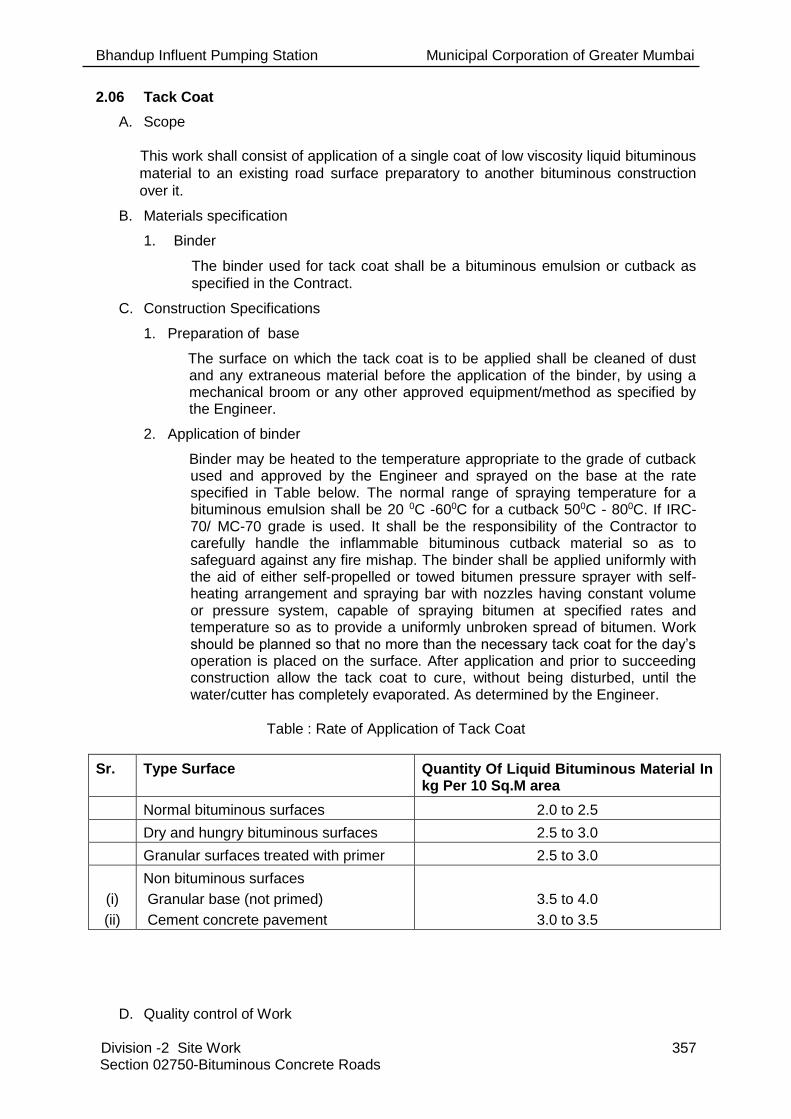
Bhandup Influent Pumping Station Municipal Corporation of Greater Mumbai
Division -2 Site Work 357 Section 02750-Bituminous Concrete Roads
2.06 Tack Coat
A. Scope
This work shall consist of application of a single coat of low viscosity liquid bituminous
material to an existing road surface preparatory to another bituminous construction
over it.
B. Materials specification
1. Binder
The binder used for tack coat shall be a bituminous emulsion or cutback as
specified in the Contract.
C. Construction Specifications
1. Preparation of base
The surface on which the tack coat is to be applied shall be cleaned of dust and any extraneous material before the application of the binder, by using a mechanical broom or any other approved equipment/method as specified by the Engineer.
2. Application of binder
Binder may be heated to the temperature appropriate to the grade of cutback used and approved by the Engineer and sprayed on the base at the rate specified in Table below. The normal range of spraying temperature for a bituminous emulsion shall be 20 0C -600C for a cutback 500C - 800C. If IRC-70/ MC-70 grade is used. It shall be the responsibility of the Contractor to carefully handle the inflammable bituminous cutback material so as to safeguard against any fire mishap. The binder shall be applied uniformly with the aid of either self-propelled or towed bitumen pressure sprayer with self-heating arrangement and spraying bar with nozzles having constant volume or pressure system, capable of spraying bitumen at specified rates and temperature so as to provide a uniformly unbroken spread of bitumen. Work should be planned so that no more than the necessary tack coat for the day’s operation is placed on the surface. After application and prior to succeeding construction allow the tack coat to cure, without being disturbed, until the water/cutter has completely evaporated. As determined by the Engineer.
Table : Rate of Application of Tack Coat
Sr. Type Surface Quantity Of Liquid Bituminous Material In kg Per 10 Sq.M area
Normal bituminous surfaces 2.0 to 2.5
Dry and hungry bituminous surfaces 2.5 to 3.0
Granular surfaces treated with primer 2.5 to 3.0
(i)
(ii)
Non bituminous surfaces
Granular base (not primed)
Cement concrete pavement
3.5 to 4.0
3.0 to 3.5
D. Quality control of Work

Bhandup Influent Pumping Station Municipal Corporation of Greater Mumbai
Division -2 Site Work 358 Section 02750-Bituminous Concrete Roads
Control on the quality of materials and works shall be exercised by the Engineer in
accordance with Section 900 of MoSRT&H Specifications for Road and Bridge Works
(III Revision).
E. Measurement for Payment
Tack coat shall be measured in terms of surface area of application in square meters.
2.07 Dense Bituminous Macadam- DBM 85mm
A. Scope
This work shall consist of construction in a single course of 50 to 100 mm thick base /
binder course to the following Specifications on a previously prepared base.
B. Materials specification
1. Bitumen
The bitumen shall be paving bitumen of Penetration Grade S65 or A 65 (60/70) as per Indian Standard Specifications for “Paving Bitumen” IS:73. In case of non-availability of bitumen of this grade, S90 (80/100) grade bitumen may be used with the approval of the Engineer. Guidance to selection of the grade of bitumen may be taken from Appendix 4 of MORT Specifications for Road and Bridge Works (III Revision).
2. Coarse aggregates
The coarse aggregates shall consist of crushed stone, crushed gravel / shingle or other stones. They shall be clean, strong, durable, of fairly cubical shape and free from disintegrated pieces, organic or other deleterious matter and adherent coating. The aggregates shall preferably be hydrophobic and of low porosity. If hydrophilic aggregates are to be used, the bitumen shall be treated with antis tripping agents of approved quality in suitable doses. The aggregates shall satisfy the physical requirements set forth in Table 13-10. If crushed gravel / shingle is used, not less than 90 per cent by weight of the gravel / shingle pieces retained on 4.75 mm sieve shall have at least two fractured faces. The portion of the total aggregate passing 4.75 mm sieve shall have a sand equivalent value of not less than 50 when tested in accordance with the requirement of IS:2720 (Part-37). The plasticity index of the fraction passing the 425 micron sieve shall not exceed 4.

Bhandup Influent Pumping Station Municipal Corporation of Greater Mumbai
Division -2 Site Work 359 Section 02750-Bituminous Concrete Roads
Table : Physical Requirements of Aggregates For Dense Bituminous Macadam
Sr. Test Test method Requirements
1. Los Angeles Abrasion* value IS:2386 (Part - 4) 40 per cent Maximum
2. Aggregate Impact value* IS:2386 (Part - 4) 30 per cent Maximum
3. Flakiness and Elongation Indices (Total)
IS:2386 (Part - I) 30 per cent Maximum
4. Coating and Stripping of Bitumen Aggregate Mixtures
AASHTO T 182 Minimum retained coating 95 per cent
5. Soundness
Loss with Sodium Sulphate
Loss with Magnesium Sulphate
IS:2386 (Part - 5)
5 cycles
5 cycles
12 per cent Maximum
18 per cent Maximum
6. Water absorption IS:2386 (Part - 3) 2 per cent Maximum
* Aggregates may satisfy requirements of either of the two tests.
3. Fine Aggregates
Fine aggregates shall be the fraction passing 2.36 mm sieve and retained on 75 micron sieve, consisting of crusher-run screening, gravel, and sand or a mixture of both. These shall be clean, hard, durable, uncoated, dry and free from any injurious, soft or flaky pieces and organic or other deleterious substances.
4. Filler
Filler shall consist of finely divided mineral matter such as rock dust, hydrated lime or cement as approved by the Engineer. The filler shall be free from organic impurities and have a Plasticity Index not greater than 4. The Plasticity Index requirement shall not apply if filler is cement or lime. When the coarse aggregate is gravel, 2 per cent by mass of total aggregate of Portland cement or hydrated lime shall be added and the percentage of fine aggregate reduced accordingly. Cement or hydrated lime is not required when the gravel is limestone.
Table : The filler shall be graded within the following limits:
IS Sieve Per cent passing by weight
600 micron 100
300 micron 95-100
75 micron 85-100
5. Aggregate gradation
The combined coarse and fine aggregates and filler (when used) shall produce a mixture of conform to the grading set forth in Table 8.12.3.

Bhandup Influent Pumping Station Municipal Corporation of Greater Mumbai
Division -2 Site Work 360 Section 02750-Bituminous Concrete Roads
Table : Aggregate Gradation for Dense Bituminous Macadam
Sieve Designation Percentage passing the sieve by weight
37.5 mm 100
26.5 mm 90-100
13.2 mm 56-80
4.75 mm 29-59
2.36 mm 19-45
300 micron 5-17
75 micron 1-7
The aggregate mix, as used in work, shall not vary from the low limit on one sieve to the high limit on the adjacent sieve but shall be well graded.
C. Mix Design
1. Requirement of mix
Apart from conformity with grading and quality requirements of individual ingredients, the mix shall meet the requirements set out in Table 8.12.4.
Table : Requirements of Dense Bituminous Macadam Mix
Sr. Description Requirements
1. Marshall Stability (ASTM Designation D-1559) determined on Marshall specimens compacted by 75 compaction blows on each end
820 kg (1800 lb)
2. Marshall flow (mm) 2-4
3. Per cent Air voids 3-5
4. Minimum voids in mineral aggregate (VMA) 10 per cent - 12 per cent
5. Per cent voids in mineral aggregates filled by bitumen (VFB)
65 - 75
6. Binder content per cent by weight of total mix Not less than 4.0 per cent
2. Binder content
The binder content shall be so fixed as to achieve the requirements of the mix set out in Table 8-12. Marshall method for arriving at the binder content shall be adopted, replacing the aggregates retained on 26.5 mm sieve by the aggregates passing 26.5 mm sieve and retained on 22.4 mm sieve.
3. Job mix formula
The Contractor shall intimate to the Engineer in writing, at least 20 days before the start of the work, the job mix formula proposed to be used by him for the work and shall give the following details:
Source and location of all materials
Proportions of all materials expressed as follows where each is
applicable:
Binder, as percentage by weight of total mix;

Bhandup Influent Pumping Station Municipal Corporation of Greater Mumbai
Division -2 Site Work 361 Section 02750-Bituminous Concrete Roads
Coarse aggregate/Fine aggregate/Mineral filler as percentage by
weight of total aggregate including mineral filler;
A single definite percentage passing each sieve for the mixed
aggregate;
The results of tests enumerated in Table 13-12 as obtained by the
Contractor;
Test results of physical characteristics of aggregates to be used;
Mixing temperature and compacting temperature.
While working out the job mix formula, the Contractor shall ensure that it is based on a correct and truly representative sample of the materials that will actually be used in the work and that the mix and its different ingredients satisfy the physical and strength requirements of these Specifications. Approval of the job mix formula shall be based on independent testing by the Engineer for which samples of all ingredients of the mix shall be furnished by the Contractors required by the former. The approved job mix formula shall remain effective unless and until modified by the Engineer. Should a change in the source of materials be proposed, a new job mix formula shall be established and got approved from the Engineer before actually using the materials.
4. Permissible variation from job mix formula
It shall be the responsibility of the Contractor to produce a uniform mix conforming to the approved job mix formula subject to the permissible various of the individual percentages of the various ingredients in the actual mix from the job mix formula to be used within the limits as specified in Table. These variations are intended to apply to individual specimens taken for quality control tests vide Section 900 of MoSRT&H Specifications for Road and Bridge Works (III Revision).
Table : Permissible Variations from the Job Mix Formula
Sr. Description of Ingredients Permissible variation by weight of total mix-in per cent
1. Aggregate passing 13.2 mm sieve and larger sieves 8
2. Aggregate passing 11.2 mm sieve and 5.6 mm sieve 7
3. Aggregate passing 2.80 mm sieve and 1.40 mm sieve 6
4. Aggregate passing 710 micron sieve and 1.35 mm sieve
5
5. Aggregate passing 180 micron sieve 4
6. Aggregate passing 90 micron sieve 2
7. Binder 0.3
8. Mixing temperature 10o C

Bhandup Influent Pumping Station Municipal Corporation of Greater Mumbai
Division -2 Site Work 362 Section 02750-Bituminous Concrete Roads
D. Construction Specifications
1. Weather and Seasonal Limitations
The work of laying shall not be taken up during rainy or foggy weather or when the base course is damp or wet, or during dust storm or when the atmospheric temperature in shade is 100C or less.
2. Preparation of base
The base on which Dense Bituminous Macadam is to be laid shall be prepared, shaped and conditioned to the specified lines, grades and cross sections in accordance with or as directed by the Engineer . The surface shall be thoroughly swept clean free from dust and foreign matter using mechanical broom and dust removed or blown off by compressed air. In portions where mechanical means cannot reach, other approved method shall be used. A priming coat where needed, shall be applied in accordance with above or as directed by the Engineer.
3. Tack coat
A tack coat over the base shall be applied as per Section 2.73.
4. Preparation of Mix
Dense Bituminous macadam mix shall be prepared in a hot mix plant of adequate capacity and capable of yielding a mix of proper and uniform quality with thoroughly coated aggregates. Hot mix plant shall be of suitable capacity preferably of batch mix type. Total system for crushing of stone aggregates and feeding of aggregate fractions in required proportions to achieve the desired mix, deployed by the Contractor must be capable of meeting the overall Specification requirements under stringent quality control. The plant shall have the following essential features:
A - General The plant shall have coordinated set of essential units capable of
producing uniform mix as per the job mix formula.
Cold aggregate feed system with minimum 4 bins having belt conveyor
arrangement for initial proportioning of aggregates from each bin in the
required quantities. In order to have free flow of fines from the bin, it is
advisable to have vibrator fitted on bin to intermittently shake it,.
Belt conveyors below each bin should have variable speed drive
motors. There should be electronic load sensor on the main conveyer
for measuring the flow of aggregates.
Dryer unit with burner capable of heating the aggregate to the required
temperature without any visible unburnt fuel or carbon residue on the
aggregate and reducing the moisture content of the aggregate to the
specified minimum.
The plant shall be fitted with suitable type of thermometric instruments
at appropriate places so as to indicate or record/register the
temperature of heated aggregate, bitumen and mix.
Bitumen supply unit capable of heating, measuring/metering and
spraying of bitumen at specified temperature with automatic
synchronisation of bitumen and aggregate feed in the required
proportion.
A filter system suitable to receive bagged or bulk supply of filter
material and its incorporation to the mix in the correct quantity
wherever required.

Bhandup Influent Pumping Station Municipal Corporation of Greater Mumbai
Division -2 Site Work 363 Section 02750-Bituminous Concrete Roads
A suitable built-in dust control system for the dryer to contain/recycle
permissible fines into the mix. It should be capable of preventing the
exhaust of fine dust into atmosphere for environmental control.
The plant should have centralized control panel/cabin capable of
presetting, controlling/synchronizing all operations starting from
feeding of cold aggregates to the discharge of the hot mix to ensure
proper quality of mix. It should have indicators for any malfunctioning
in the operation.
Every hot mix plant should be equipped with siren or horn so that the
operator may use the same before starting the plant every time in the
interest of safety of staff. B - For Batch Type Plant
Gradation control unit having minimum four deck vibratory screens for
accurate sizing of hot aggregate and storing them in separate bins.
This unit should be fully covered to reduce the maintenance cost and
for better environmental conditions.
Proper arrangement for accurate weighing of each size of hot
aggregate from the control panel before mixing.
Paddle mixer unit shall be capable of producing a homogeneous mix
with uniform coating of all particles of the mineral aggregate with
binder.
C - For Continuous Type Plant Gradation control unit having vibratory screens for accurate sizing of
hot aggregate and storing them in separate bins. This unit should be
fully covered to reduce the maintenance cost and for better
environment condition.
There should be appropriate arrangements for regulating and
volumetric control of the flow of hot aggregate from each bin to
achieve the required proportioning.
Paddle mixer unit shall be capable of producing a homogeneous mix
with uniform coating of all particles of the mineral aggregate with
binder. D - For Drum Mix Plant It is a prerequisite that only properly screened and graded materials
are fed to the bins. If required, vibratory screening unit shall be
installed at the plant site to ensure the same.
A primary 4- deck vibratory screening unit shall be installed before the
multiple bin cold feed system for screening the aggregates and
grading the same.
Belt conveyers below each bin should have variable speed drive
motors. There should be electronic load sensor on the main conveyor
for measuring the flow of aggregate.
There should be arrangement to measure moisture content of the
aggregate(s) to that moisture correction may be applied for working
out requirements of binder and filler.
The temperature of binder at the time of mixing shall be in the range of 1500C to 1630C and that of the aggregate in the range of 1550C - 1630C. Provided

Bhandup Influent Pumping Station Municipal Corporation of Greater Mumbai
Division -2 Site Work 364 Section 02750-Bituminous Concrete Roads
that the difference in temperature between the binder and aggregate at no time exceeds 140C. Mixing shall be thorough to ensure that a homogeneous mixture is obtained in which all particles of the aggregates are coated uniformly, and the discharge temperature of mix shall be between 1300C to 1600C. The mixture shall be transported from the mixing plant to the point of use in suitable tipper vehicles. The vehicles employed for transport shall be clean and be covered in transit if so directed by the Engineer. Any tipper causing excessive segregation of materials by its spring suspension or other contributing factors or that which shows undue delay shall be removed from the work until such conditions are corrected.
5. Spreading
The mix transported from the hot mix plant to the site shall be spread by means of a self-propelled paver with suitable screeds capable of spreading, tamping and finishing the mix to specified grade, lines and cross-section. Paver Finisher shall have the essential features as spelt out in the following paragraphs. However, in restricted locations and in narrow widths where the available equipment cannot be operated in the opinion of the Engineer, he may permit manual laying of the mix. Similarly for smaller jobs, mechanical paver may be used with the approval of the Engineer.
Loading hoppers and suitable distributing mechanism.
All drives having hydrostatic drive/control
The machine shall have a hydraulically extendable screed for
appropriate width requirements.
The screed shall have tamping and vibrating arrangement for initial
compaction to the layer as it is spread without rutting or otherwise
marring the surface. It shall have adjustable amplitude and variable
frequency.
The paver shall be equipped with necessary control mechanism so as
to ensure that the finished surface is free from surface blemishes.
The paver shall be fitted with an electronic sensing device for
automatic levelling and profile control within specified tolerances.
The screed shall have the internal heating arrangement.
The paver shall be capable of laying either 2.5 to 4.0 m width or 4.0 to
7.0 m width as stipulated in the Contract.
The paver shall be so designed as to eliminate skidding/slippage of
the tyres during operation
The temperature of mix at the time of laying shall be in the range of 1200C - 1600C. Mixes with a temperature of less than 1200C shall not be put into paver spreader. Longitudinal joints and edges shall be constructed true to the delineating lines parallel to the centre line of the road. Longitudinal and transverse joints shall be offset by at least 250 mm from those in the lower courses and the joint on the top most layer shall not be allowed to fall within the wheel path. All transverse joints shall be cut vertically to the full thickness of the previously laid mix with asphalt cutter and the surface painted with hot bitumen before placing fresh material. Longitudinal joints shall be preferably

Bhandup Influent Pumping Station Municipal Corporation of Greater Mumbai
Division -2 Site Work 365 Section 02750-Bituminous Concrete Roads
hot joints. Cold longitudinal joints shall be properly heated with joint heater to attain a suitable temperature of about 800C before laying of adjacent material.
6. Rolling
After spreading the mix by paver, it shall be thoroughly compacted by rolling with a set of rollers moving at a speed not more than 5 km/h, immediately following close to the paver. Generally the initial or breakdown rolling shall be done with 80-100 kN static weight smooth-wheeled roller. The intermediate rolling shall be done with 80-100 kN static weight vibratory roller or with a pneumatic tyred roller of 150-250 kN weight having a tyre pressure of at least 0.7 MPa. The finish rolling shall be done with 60-80 kN weight smooth wheeled tandem roller. All the compaction operations, i.e., breakdown rolling and intermediate rolling can be accomplished by using vibratory tandem roller of 80-100 kN static weight. During initial breakdown rolling and finish rolling, no vibratory compaction shall be resorted to. The exact pattern of rolling shall be established after trial compaction as approved by the Engineer. Any displacement occurring as a result of reversing of the direction of a roller or for many other cause shall be corrected at once as specified and/or removed and made good. The rollers shall not be permitted to stand on pavement which has not been fully compacted and where temperature is still more than 700C. Necessary precautions shall be taken to prevent dropping of oil, grease, petrol or other foreign matter on the pavement either when the rollers are operating or standing. The wheels of roller shall be kept moist to prevent the mix from adhering to them. But in no case shall fuel/lubricating oil be used for this purpose nor excessive water poured on the wheels. Rolling shall commence longitudinally from edges and proceed towards the centre, except that on the elevated and unidirectional cambered portions, it shall progress from the lower to upper edge parallel to the centre line of the pavement. The roller shall proceed on the fresh material with rear or fixed wheel leading so as to minimize the pushing of the mix and each pass of the roller shall overlap the preceding one by half the width of the rear wheel. Rolling shall be continued till the density achieved is at least 98 per cent of that of laboratory Marshall specimen and all roller marks are eliminated. Skin patching of an area that has been rolled will not be permitted. Rolling operations shall be completed in all respects before the temperature of the mix falls below 100oC.
E. Opening to Traffic
Traffic may be allowed after completion of the final rolling when the mix has cooled down to the surrounding temperature. The Dense Bituminous Macadam shall be provided with an appropriate wearing course as early as possible prior to regular opening to normal traffic and/or impending rain.
F. Surface Finish and Quality Control of Work
The surface finish of construction shall conform to the requirements of Section 902 of MORT Specifications for Road and Bridge Works (III Revision). Control on the quality of materials and works shall be exercised by the Engineer in accordance with Section 900 of MORT & H Specifications for Road and Bridge Works (III Revision)
G. Method of Measurements
Dense Bituminous Macadam shall be measured as finished work in m3 .
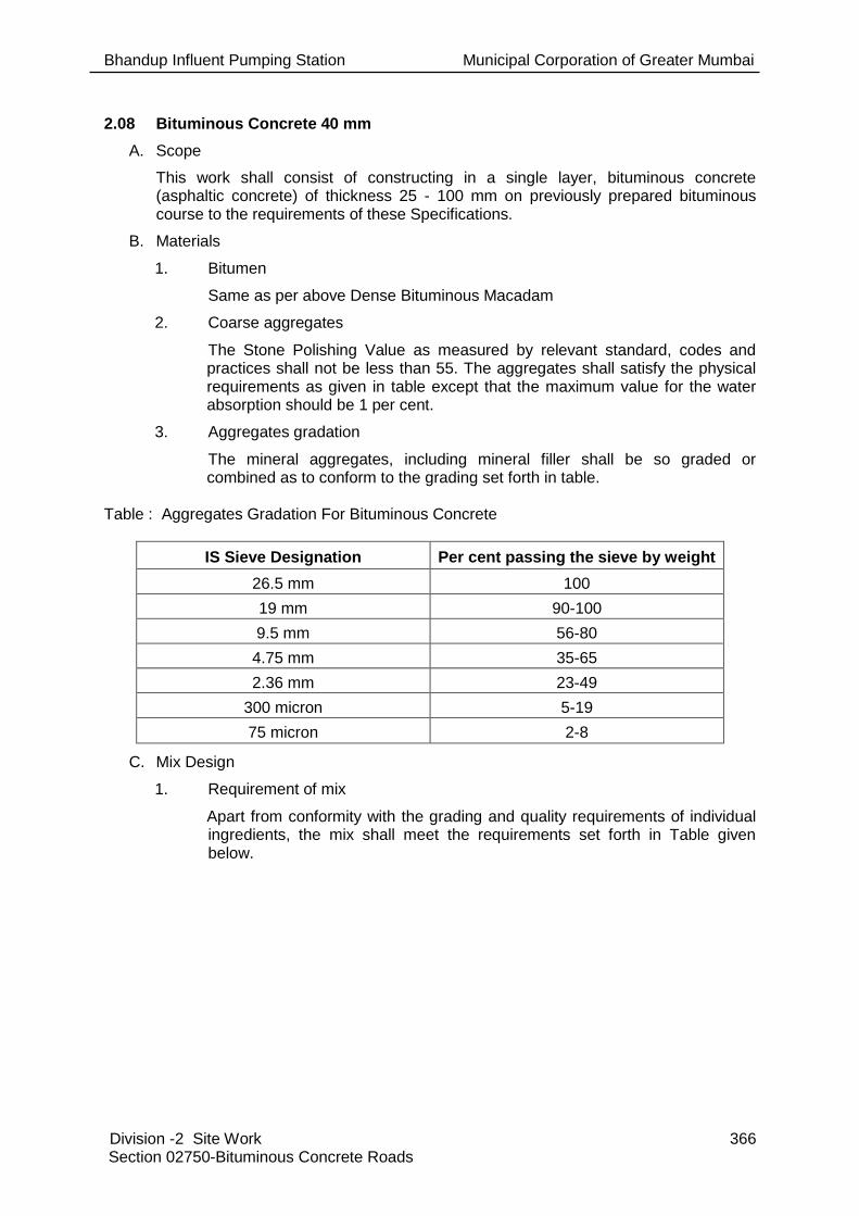
Bhandup Influent Pumping Station Municipal Corporation of Greater Mumbai
Division -2 Site Work 366 Section 02750-Bituminous Concrete Roads
2.08 Bituminous Concrete 40 mm
A. Scope
This work shall consist of constructing in a single layer, bituminous concrete (asphaltic concrete) of thickness 25 - 100 mm on previously prepared bituminous course to the requirements of these Specifications.
B. Materials
1. Bitumen
Same as per above Dense Bituminous Macadam
2. Coarse aggregates
The Stone Polishing Value as measured by relevant standard, codes and practices shall not be less than 55. The aggregates shall satisfy the physical requirements as given in table except that the maximum value for the water absorption should be 1 per cent.
3. Aggregates gradation
The mineral aggregates, including mineral filler shall be so graded or combined as to conform to the grading set forth in table.
Table : Aggregates Gradation For Bituminous Concrete
IS Sieve Designation Per cent passing the sieve by weight
26.5 mm 100
19 mm 90-100
9.5 mm 56-80
4.75 mm 35-65
2.36 mm 23-49
300 micron 5-19
75 micron 2-8
C. Mix Design
1. Requirement of mix
Apart from conformity with the grading and quality requirements of individual ingredients, the mix shall meet the requirements set forth in Table given below.

Bhandup Influent Pumping Station Municipal Corporation of Greater Mumbai
Division -2 Site Work 367 Section 02750-Bituminous Concrete Roads
Table : Requirements of Bituminous Concrete Mix
Sr. Description Requirements
1. Marshall stability (ASTM Designation : D-1559) determined on Marshall specimens compacted by 75 compaction blows on each end
820 kg (1800 lb)
Minimum
2. Marshall flow (mm) 2-4
3. Per cent air voids in mix 3-5
4. Per cent voids in mineral aggregate (VMA) Minimum 11-13 per cent
5. Per cent voids in mineral aggregates filled by bitumen (VFB)
65-75
6. Binder content, per cent by weight of total mix Minimum 4.5
7. Water Sensitivity (ASTM D1075) Loss of stability on immersion in water at 60oC
Min. 75 per cent retained strength
8. Swell Test (Asphalt Instt. MS-2, No. 2) 1.5 per cent Max.
2. Binder content
The binder content shall be so fixed as to achieve the requirements of the mix set forth in Table 8.15. Marshall method for arriving at the binder content shall be adopted.
3. Job mix formula
Section 2.75 shall apply except that the requirement of Bituminous Concrete mix shall be as per table.
4. Permissible variations from the job mix formula
The Contractor shall have the responsibility of ensuring proper proportioning of materials in accordance with the approved job mix formula and producing a uniform mix. The permissible variations of individual percentages of various ingredients in the actual mix from the job mix formula may be within the limits as specified in Table. These variations are intended to apply to individual specimens taken for quality control tests vide Section 900 of MORT specifications for Road and Bridge Works (III Revision).
D. Construction Specifications
1. Weather and seasonal limitations:
As per above specs shall apply.
2. Preparation of base
The base on which bituminous concrete is to be laid shall be prepared, shaped and conditioned to the specified levels, grade and cross fall (camber) in accordance with Section 2.75 or as directed by the Engineer . The surface shall be thoroughly swept clean free from dust and foreign matter using mechanical broom and dust removed by mechanical means or blown off by compressed air. In portions where mechanical means cannot reach, other approved method shall be used.
3. Tack coat
A tack coat complying as mentioned in section 2.73 shall be applied over the
base.
4. Preparation of mix
Section 2.74.4 shall apply.

Bhandup Influent Pumping Station Municipal Corporation of Greater Mumbai
Division -2 Site Work 368 Section 02750-Bituminous Concrete Roads
5. Spreading
As per 2.74.4.5.
6. Rolling
As per 2.74.4.6
E. Opening to Traffic
Traffic may be allowed immediately after completion of the final rolling when the mix has cooled down to the surrounding temperature.
1. Surface Finish and Quality Control of Work
The surface finish of construction shall conform to the requirements of Section 902 of MoSRT&H Specifications for Road and Bridge Works (IV Revision). Control on the quality of materials and works shall be exercised by the Engineer in accordance with Section 900 of MORT Specifications for Road and Bridge Works (IV Revision).
F. Method of Measurements
Bituminous concrete shall be measured as finished work in m3, or as specified in the relevant BOQ Item.
END OF SECTION 02750.

Bhandup Influent Pumping Station Municipal Corporation of Greater Mumbai
Division -2 Site Work 369 Section 02800-Antitermite Treatment
SECTION 02800- ANTITERMITE TREATMENT
PART 1 -GENERAL
1.01 Reference:
A. Section 02000 applies to and governs the work of this Section.
1.02 Work Included:
A. Provide labour, materials and other services to set up a chemical barrier against attack by termites while the buildings and other structures are under construction.
B. Uniform distribution and proper penetration of treating solution to foundations, walls, trenching for interconnecting piping, rising mains, bypasses and electrical conduits, basements, plinths, manholes and miscellaneous chambers.
C. The Drawings, Datasheets and Specifications are intended to set the acceptable minimum standard.
1.03 Related Work:
A. The following related work is covered elsewhere in the Contract Documents:
1. Section 02000 - Site Preparation
2. Section 02221 - Backfilling and Filling
3. Section 02220 - Excavation
4. Division 3 - Concrete
5. Division 4 - Masonry
1.04 Alternatives:
A. Refer to Section 01002 for requirements pertaining to acceptance of alternative equipment/ material.
1.05 Submittals:
A. Submit method of treatment proposed to be adopted for the approval of the Engineer in accordance with Section 01007 and AS-BUILT drawings as per Section 01016.
B. Upon completion of this work, submit a Pest Management Report, identifying target pest, type of operation, brand name and manufacturer of pesticide, formulation, concentration and rate of application used. Maintain daily records using Pest Management Maintenance Record and submit copies of records when requested by the Engineer.
C. Before commencing works, provide to the Engineer for approval, samples of chemicals from a reputable firm recommended by the Indian Pest Control Association (IPCA).
1.06 Codes and Standards:
A. The following applicable standards established by the Bureau of Indian Standards govern the materials and workmanship for the work under this Section.
1 IS: 6313 (Part I to III) 2001
Code of Practice of Anti Termite Measures in Buildings - Pre-constructional Chemical Treatment Measures
2 IS: 3385 Code of Practice for Measurement of Civil Engineering Works
B. Where provisions of the pertinent codes and standards conflict with these Specifications and Drawings or with each other comply with the more stringent provision

Bhandup Influent Pumping Station Municipal Corporation of Greater Mumbai
Division -2 Site Work 370 Section 02800-Antitermite Treatment
C. Use the latest issue of Standards.
PART 2 - PRODUCTS
2.01 General:
A. Provide the following chemicals conforming to relevant Indian Standards in water emulsion.
Chemicals Concentration by Weight Percentage
1 Chlorpyrifos Emulsifiable(IS: 8944 – 1978) 1.0
2 Heptachlor Emulsifiable Concentrate (IS: 6439 – 1978) 0.5
3 Chlordane Emulsifiable Concentrate (IS: 2682 – 1984) 1.0
B. Delivery Storage and Handling
1. Pesticides shall be delivered to the site in sealed and labelled containers in good condition as supplied by the manufacturer or formulator. The pesticides shall be stored, handled and used in accordance with manufacturer’s instructions. Labels shall bear evidence of registration as per the IS or appropriate regulations.
C. Safety Requirements
1. Formulate, treat and dispose of termiticides and their containers in accordance with the manufacturer’s directions. Draw water for formulating only from sites approved by the Engineer and fit the filling hose with a backflow preventer meeting local plumbing codes and standards. The filling operation shall be under the direct and continuous observation of a Contractor’s representative to prevent overflow. Secure pesticides and related materials under lock and key when unattended. Ensure that proper protective clothing and equipment are worn and used during all phases of termiticide application. Dispose of used pesticide containers outside the MCGM property in accordance with applicable legislation.
2.02 Approved Manufacturers /Suppliers:
A. M/s. Pest Control Corporation of India
B. Or equivalent as approved
PART 3 - EXECUTION
3.01 General:
A. Work shall be executed as specified in IS 6313 Part-II-1981 and as per approved specification of the applicable agencies.
B. Ensure that there is uniform distribution and proper penetration of treating solution to the satisfaction of the Engineer.
C. Soil treatment shall not be done when it is raining or when the soil is wet with rain or subsoil water. Once formed, the treated soil barrier shall not be disturbed.
3.02 Treatment of Column Pits, Wall Trenches and Basement Excavations:

Bhandup Influent Pumping Station Municipal Corporation of Greater Mumbai
Division -2 Site Work 371 Section 02800-Antitermite Treatment
A. In case of normal load bearing structures, column pits, wall trenches and basements, the treatment shall be at 5 l/m2 of surface area of the bottom and sides to a height of at least 300 mm. After the foundation work, the sides shall be treated at 7.5 l/m2 of vertical surface of substructure on each side. After the earth filling is completed, treatment shall be by rodding the earth at 150 mm centres close to the wall surface and spraying the chemical at a rate of 7.5 l/m2.
B. In the case of framed structures, the treatment shall start at a depth of 500 mm below ground level. From this depth the backfill around the columns, beams and RCC basement walls shall be treated at a rate of 7.5 l/m2 for the vertical surface and at 5 l/m2 for horizontal surfaces at the bottom of trenches/pits.
C. Treatment of Top Surface of Plinth Filling
1. The top surface of filled earth within plinth walls shall be treated with chemical emulsion at the rate of 5 l/m2 of the surface area before sub-base to floor is laid. If filled earth has been well rammed and the surface does not allow the emulsion to seep through, holes up to 50 to 75mm deep at 150 mm centres both ways shall be made with crow bars on the surface to facilitate saturation of the soil with the emulsion.
D. Treatment of Soil Surrounding Pipes and Conduits
1. Special care shall be taken at the points where pipes and conduits enter the building and the soil shall be treated for a distance of 150 mm and a depth of 75 mm at the point where they enter the building.
E. Treatment of Expansion Joints
1. The soil beneath expansion joints shall be supplemented by treating through the expansion joint after sub-grade has been laid at the rate of 2 l/m length of expansion joint.
F. Treatment at Junction of the Wall and the Floor
1. Special care shall be taken to establish continuity of the vertical chemical barrier on the inner wall surfaces from the finished ground level (or from level where the treatment has stopped) up to the level of the filled earth surface. To achieved this, a small channel 30 x 30 mm shall be made at all the junctions of wall/column with the floor (before laying sub-grade) and rod holes made in the channel up to the finished ground level at 150 mm spacings and the iron rod moved backward and forward to break the earth and the chemical emulsion shall be poured along the channel at 7.5 l/m2 of the vertical wall/column surfaces to soak the soil right up to the bottom. The soil shall be tamped back into place after this operation.
3.03 Acceptance Criteria
A. Provide a 10 year service guarantee in writing supplemented by a separate and unilateral guarantee from the specialized agency for the job to keep the building free of termites for the specified period.
3.04 Treatment Application
A. The Contractor shall apply termiticide to the soil material which will be covered by or lie immediately adjacent to the buildings and structures to provide a protective barrier against subterranean termites.
B. The termiticide shall be applied as a coarse spray and in such manner as to provide uniform distribution onto the soil surface. This treatment shall be applied prior to placement of a vapour barrier or waterproof membrane and prior to concrete pouring. Where treated soil or fill material is not to be covered with a vapour barrier or waterproof membrane, the Contractor shall exercise adequate precautions to prevent its disturbance.

Bhandup Influent Pumping Station Municipal Corporation of Greater Mumbai
Division -2 Site Work 372 Section 02800-Antitermite Treatment
C. The chemical emulsion will be applied uniformly by sprayers at the prescribed rates as detailed in all the stages of the treatment.
3.05 Warranty
A. Provide a three-year written warranty against infestations or re-infestations by termites of the buildings or building additions constructed under this Contract. Perform annual inspections of the building(s) or building addition(s). If live termite infestation or termite damage is discovered during the warranty period, and the soil and building conditions have not been altered in the interim: the Contractor shall:
1. Retreat the soil and perform other treatment as may be necessary for elimination of termite infestation.
2. Repair damage caused by termite infestation; and
3. Re-inspect the building approximately 180 days after the re-treatment.
END OF SECTION 02800.

Bhandup Influent Pumping Station Municipal Corporation of Greater Mumbai
Division -3 Concrete 373 Section 03000-Concrete
INDEX
SECTIONS NO. OF PAGES Section 03000 - Concrete ..................................................................................................... 3 Section 03100 - Formwork ..........................................................................................................5 Section 03200 - Reinforcement ..................................................................................................5 Section 03300 - Cast –In –Place Concrete ............................................................................... 18 Section 03370 - Cement Grouting ..............................................................................................2 Section 03372 - Non -shrink Grout, Mortar and Concrete ...........................................................2 Section 03373 - Epoxy Grout ......................................................................................................2 Section 03375 - Concrete Floor Toppings ..................................................................................2 Section 03376 - Epoxy Coating for UG Concrete Structures ......................................................2 Section 03400 - Precast Concrete ……………………………………………………….. ...............3
Total Pages In This Division - 44

Bhandup Influent Pumping Station Municipal Corporation of Greater Mumbai
Division -3 Concrete 374 Section 03000-Concrete
SECTION 03000- CONCRETE
PART 1 -GENERAL
1.01 Governing Conditions:
A. The General Conditions, Particular Conditions, Contract Forms, Instruction to Contractor and the requirements of Division 1 herein before specified, in addition to any and all Addenda, apply to and govern each Section of this Division.
B. This Section covers the general requirements for this Division and shall be read in conjunction with other Sections in this Division.
C. This Section governs the work of all other Sections in this Division.
1.02 Work Included:
A. Provide labour, material and equipment necessary to perform concrete work as indicated on the Drawings or specified herein, including but not necessarily limited to the following:
1. Formwork and falsework
2. Steel reinforcement
3. Spacer covers
4. Waterstops
5. Pre-cast Concrete
6. Cast-in-place concrete
7. Curing and finishing
8. Installation of inserts, anchors, cover blocks, spacers etc
9. Keys and recesses
10. Concrete topping and benching
11. Concrete bases for equipment and tanks.
B. The Drawings, Datasheets and Specifications are intended to set the acceptable minimum standard.
1.03 Co-ordination:
A. Co-ordinate with the work of other Divisions before installing work included in this Division. If work is installed without co-ordination with other works, the Engineer may direct that such work be removed, relocated and/or modified as necessary. Comply promptly with the Engineer's requests. Complete any correction and/or additional work, as directed by the Engineers at no additional cost to the MCGM.
B. For coordination requirements refer to Section 01003.
1.04 Submittals:
A. Submit shop drawings / product data/ documents for concrete work as required, not limited to following list, in accordance with Section 01007- submittals.
1. Deviations to technical specification
2. Concrete layout drawings and concrete detail drawings
3. Reinforcement detail drawings
4. Reinforcement bar drawings, bending schedules and bar lists

Bhandup Influent Pumping Station Municipal Corporation of Greater Mumbai
Division -3 Concrete 375 Section 03000-Concrete
5. Details of formwork and construction joints including shop drawings and design calculations
6. Cement and aggregate test reports
7. Concrete mix design
8. Concrete test report by MCGM approved testing laboratory.
B. Neatly assemble and submit test reports and AS BUILT drawings as per Section 01700- Construction Contract Close Out.
1.05 Codes and Standards:
A. The following applicable standards established by the Bureau of Indian standards govern the materials and workmanship for the work under this Division.
1 IS 456: 2000 Code of practice for plain and reinforced concrete.
2 IS 457: 1957 Code of practice for general construction of plain and Reinforced concrete for dams and other massive structures
3 IS432(Part I): 1982 Code of practice for mild steel or medium tensile steel bars for concrete or latest version reinforcement.
4 IS 1786:1985 Cold twisted steel bars for concrete reinforcement.
5 IS 1566:1982 Code of practice for fabric for concrete reinforcement, hard drawn steel or latest version wire welded wire mesh.
6 IS 516:1959 Code of practice for method of test for strength of concrete
7 IS 2062 Code of practice for steel for general structural purpose
8 IS 10262 Code of practice for recommended guidelines for concrete mix design
9 IS 3370:1965 Code of practice for concrete structures for the storage of liquids
10 IS 2751:1992 Recommended practice for welding of mild steel plain and deformed bars for reinforced construction.
11 IS 2502:1999 Code of practice for bending and fixing of bars for concrete reinforcement.
12 IS 2571:1970 Code of practice for laying in-situ cement concrete flooring.
13 IS 9103:1979 Admixtures
14 IS 4926-1976 Code of practice for ready mix concrete.
B. Where provisions of pertinent codes and standards conflict with these Specifications and Drawings or each other, comply with the more stringent provisions.
C. Use the latest issue of Standards.
PART 2 - PRODUCTS
2.01 General:
A. Comply with product requirements outlined in the individual Sections and as specified on the Drawings.

Bhandup Influent Pumping Station Municipal Corporation of Greater Mumbai
Division -3 Concrete 376 Section 03000-Concrete
B. Select all other materials, not specifically described but required for proper completion of the work of this Division.
2.02 Cast-In-Place Concrete:
A. Concrete Mixes and admixtures: Refer to Section 03300.
2.03 Fire Protection for materials and equipments:
A. All materials and equipments specified under this division shall be provided in accordance with NFPA 820 and the NEC-Area Electrical Classification details provided on the drawings.
B. Zones indicated in the drawings refers to divisions specified in NFPA 820
PART 3 - EXECUTION
3.01 General:
A. Comply with execution requirements outlined in the individual Sections and as specified herein.
3.02 Special Construction:
A. Water-tightness:
1. Base slabs and exterior walls below grade to be made watertight to prevent any groundwater seepage or leakage of water from inside to outside. Prior to backfilling perform a leakage test to water-retaining structures as specified in IS 3370. Repair all cracks which exhibit leakage to the satisfaction of the Engineer.
3.03 Field Quality Control:
A. Cube moulds in required quantity
B. Cube testing machine of 100 t capacity
C. Sieves for gravel and sand
D. Measuring glass for silt content
E. Laboratory oven
F. Slump cone with base plate and rod.
3.04 Schedule of Concrete Finishes:
A. Refer to Section 03300 for finish types.
END OF SECTION 03000.

Bhandup Influent Pumping Station Municipal Corporation of Greater Mumbai
Division -3 Concrete 377 Section 03100-Formwork
SECTION 03100- FORMWORK
PART 1 -GENERAL
1.01 Reference:
A. Section 03000 applies to and governs the work of this Section.
1.02 Work Included:
A. Design, supply and install required formwork for the construction of the structure.
B. Remove formwork after completion as specified.
C. Fixing of insert plates, pipes, pipe sleeves, bolts etc.
1.03 Related Work:
A. The following related work is covered elsewhere in the contract documents.
1. Division 2 - Site Work
2. Section 03200 - Reinforcement
3. Section 03300 - Cast-In-Place (In-Situ) Concrete
1.04 Alternatives:
A. Refer to Section 01030 for requirements pertaining to acceptance of alternatives.
1.05 Submittals:
A. Submit shop drawings, product data, and design calculations for vertical walls, roofs etc, and documents as specified in Section 03000 in accordance with Section 01300.
B. Provide, before commencement of fabrication, details of the materials and means proposed to adopt to obtain the required special finishes.
1.06 Codes and Standards:
A. The following applicable standards established by the Bureau of Indian Standards govern the materials and workmanship for the work under this Section.
1 IS 4990 Specification for plywood for concrete shuttering work.
2 IS 800 Code of practice for use of structural steel in general building construction.
3 IS 806 Code of practice for use of steel tube in general building construction.
4 ACI 301 Specification for Form Finish
B. Where provisions of the pertinent codes and standards conflict with these Specifications and Drawings or with each other comply with the more stringent provisions.
C. Use the latest issue of Standards.
PART 2 - PRODUCTS
2.01 Materials:
A. All formwork shall be constructed of timber, sheet metal, plywood or other approved material, capable of providing the type of finish specified. All materials used shall be dimensionally stable on exposure to the prevailing weather and conditions.

Bhandup Influent Pumping Station Municipal Corporation of Greater Mumbai
Division -3 Concrete 378 Section 03100-Formwork
2.02 Form Coating:
A. This shall be a non-grain raising and non-staining resin type coating or other suitable non-staining oil for formwork which will not leave residual matter on the surface of the concrete or adversely effect the bonding to concrete of paint, plaster, mortar, protective coatings, water proofings or other applied materials. The coatings shall not contain any mineral oils, paraffin, waxes or other non-drying ingredients, nor in the case of surfaces in contact with potable water, any toxic ingredients of any type whatsoever.
2.03 Metal Form Ties:
A. These shall be pre-fabricated rod, snap-off or threaded internal disconnecting type of adequate tensile strength to withstand all imposed loads. Ties shall leave no metal within 38 mm of concrete surface after removal. Snap-off type ties shall have integral washer spreaders of such diameters to fully close tie-holes in forms. Ties shall be fitted with an integral water-stop which remains in place in water retaining structures.
2.04 Metal Form
A. Metal formwork shall be true to detail in condition, clean, free from dents, bends, rust and oil or other defects likely to impair the specified finish.
2.05 Circular Column Forms:
A. Forms for circular columns shall be metal tubes of materials as described for metal forms, fibre glass reinforced plastic or other approved material.
2.06 Form Joint Sealers:
A. Effective precautions shall be taken to ensure that joints between form panels are sufficiently water tight to prevent honey combing resulting from the escape of mortar during the placing and vibration of concrete. The joints shall be sealed with resilient foam rubber strips, non-hardening plastic type caulking compound free from oil or other such material or such other compound as may be approved by the Engineer. Form tie holes shall be plugged with plastic caulking compound, tight fitting rubber plugs or equal.
2.07 Moulds:
A. Moulds as required for grooves, drips, rebates, profiles, chamfers and other similar items shown in the drawings shall be of a smooth-milled approved timber or standard extruded polymer plaster units of the required shapes.
B. Metal, plywood or forms of other approved material shall be used to provide a smooth finish. Special concrete finishes and requirements are described in Section 03300, if required in the works comprising this Contract. Column forms should be of materials specified above for a smooth finish.
C. Plywood or board forms of lesser quality may be used to provide rough finishes.
PART 3 - EXECUTION
3.01 Concrete Form Finish Types:
A. All concrete surfaces above and below grade shall have a smooth form finish in accordance with ACI 301 Surface Finish 3.0 (SF-3):
1. Patch voids larger than 1/2 inch wide or 1/2 inch deep.
2. Remove projections larger than 1/8 inch.
3. Patch tie holes.
4. Provide surface tolerance Class A in accordance with ACI 117.

Bhandup Influent Pumping Station Municipal Corporation of Greater Mumbai
Division -3 Concrete 379 Section 03100-Formwork
B. For slab finishes refer to section 03300.
3.02 Shoring and Formwork:
A. Shoring and formwork to be designed to distribute loads safely over the base area on which the shoring is erected. If the ground on which shoring is to be erected is loose, or may become loose when cleaning shuttering with water, adequate precaution must be taken to compact soil. Ensure stability of the formwork.
3.03 Alignment and Camber:
A. All forms to be constructed to produce the required lines, grades and camber as required, in the finished structure. The tolerance on line and level shall not exceed 3 mm. In the absence of any specific camber, the forms for soffits of beams to be constructed to provide an upward camber of 6 mm for every 3 metres of clear span.
B. Jacks, wedges or similar approved means shall be used to induce the required camber in the forms and to correct any settlement which may occur either before or during the placing of concrete.
C. Inspection:
1. Prior to commencing work of this Section, carefully inspect the installed work of others and verify that such work is complete to the point where this installation may properly commence.
D. Discrepancies:
1. In the event of any discrepancy, immediately notify Engineer.
2. Do not proceed with installation in areas of discrepancy until all such discrepancies have been fully resolved.
3.04 Construction:
A. Formwork shall be constructed to the exact shapes, sizes, lines and dimensions making provisions for openings, offsets, keyways, recesses, mouldings reglets, chamfers, blocking, joint screeds, bulkheads, anchorages and other required features.
B. Forms to be easily removable without hammering or damage to the concrete surfaces and be constructed to prevent sagging, leakage of mortar or displacement during or after pouring concrete.
C. Forms to be coated with specified materials prior to placing and tying reinforcement with precautions taken to prevent the coating from contaminating the reinforcement.
D. Temporary openings shall be provided in wall and column forms for inspection and cleaning. All inner surfaces of forms shall be cleaned before concrete is poured.
E. Relents and rebates to receive flashing, frames and other equipment shall be properly formed. Dimensions, details and precise positions of all such relents and rebates shall be ascertained from the suppliers of the flashings, frames or equipment, if supplied under a separate contract.
F. Form windows shall be provided as ordered or found necessary to provide access for placement and vibration of concrete. The windows shall be adequately sized to admit tremmies, chutes and vibrators and shall be spaced at 2 metre intervals. The windows shall be firmly closed and braced before placing concrete at higher levels.
G. Joints between forms shall be sealed with an approved compound as specified. Unless tie holes in the forms are fully sealed by form tie spreaders, leakage of mortar from around the ties shall be prevented by sealing as specified.
H. Chamfer all exposed edges and corners 20 mm x 20 mm, unless otherwise detailed on the Drawings.

Bhandup Influent Pumping Station Municipal Corporation of Greater Mumbai
Division -3 Concrete 380 Section 03100-Formwork
I. Arrange internal form ties so that when forms are removed, no metal is within 38 mm of any exposed surface.
J. Use outside forms as well as inside forms on all walls.
K. False work
1. Erect false work in accordance with the approved shop drawings.
2. Use hardwood wedges or screw jacks to adjust forms to the proper height to correct any settlement before or during the placing operation.
3. Set false work to give the camber indicated and to allow for shrinkage and settlement.
4. Support formwork on mudsills, concrete foundations or piles to adequately support any construction loads.
3.05 Inspection and Approval:
A. Prior to the pouring of concrete, the designer or his designated agent to inspect the formwork and false work and approve in writing that the work is in compliance with the design drawings. Provide a copy of the written approval to the Engineer.
B. The inspection of the formwork and false work by the Engineer during or after its erection, or any suggestion or assistance furnished by the Engineer, shall not be construed as relieving the Contractor of any part of the responsibility for the accuracy, sufficiency or safety of any formwork or false work, or for the satisfactory completion of the concreting operations.
3.06 Removal:
A. Forms or shoring shall not be removed until the concrete has attained sufficient strength to support its own weight and all constructional loads safely. Formwork of walls, sides of beams can be removed earlier than the formwork for the underside of slabs and beams, this in turn only if it is constructed to permit its removal while leaving the props in place.
B. Striking:
The striking of the formwork shall be done as approved by the Engineer. Unless instructed otherwise by the Engineer, the following table gives the minimum periods that must elapse before the formwork is removed, reckoned from the time the pouring of concrete was completed. Position of Formwork and Props Minimum Days for Removal
a. Walls 1
b. Sides of beams and columns 1
c. Slabs (props left under) 3
d. Props to slabs (spans not
exceeding 4 ½ metres) 7
e. Props to slabs (spans exceeding
4 ½ metres) 14
f. Beams Soffits (props left under) 7
Props to beams (spans upto 6 metres) 14
g. Props to beams (spans exceeding
6 metres) 21

Bhandup Influent Pumping Station Municipal Corporation of Greater Mumbai
Division -3 Concrete 381 Section 03100-Formwork
Note: -
i. If Pozzolona cement is used in any mixture, the above periods shall be modified to the approval of the Engineer.
ii. The contractor should provide the formwork which can be removed without removal of the props to ensure no sagging of the slabs and beams. For slabs, and walls contractor should use plastic coated marine ply.
C. Restrictions:
No permanent load or loads from construction equipment shall be imposed on columns, supported beams or supported slabs until the concrete has attained at least twice the compressive strength necessary to sustain the imposed loads.
D. Concrete Curing:
The concrete shall be thoroughly wetted as soon as the forms are first loosened and shall be kept wet during the removal operations until the curing compound is applied. Potable water with hoses shall be ready at each removal location when removal operations are commenced. In the absence of curing media the concrete shall be wet cured for 7 days or such longer period as directed by the Engineer.
END OF SECTION 03100.

Bhandup Influent Pumping Station Municipal Corporation of Greater Mumbai
Division -3 Concrete 382 Section 03200-Reinforcement
SECTION 03200- REINFORCEMENT
PART 1 -GENERAL
1.01 Reference:
A. Section 03000 applies to and governs the work of this Section.
1.02 Work included:
A. Supply and placing bar and mesh reinforcement for placed in-situ concrete including dowels for masonry work.
B. Provide reinforcement steel bars for masonry work.
C. Provide qualified person to be present at all times to direct and supervise the work, who shall be thoroughly familiar with the material standards and specific requirements of this Section.
1.03 Related Work:
A. The following related work is covered elsewhere in the contract documents:
1. Site Work - Division - 2
2. Form Work - Section 03100
3. Cast-In-Place (In-Situ) - Section 03300
Concrete
4. Masonry - Division - 4
1.04 Alternatives:
A. Not applicable for this section.
1.05 Submittals:
A. Submit shop drawings, bar bending schedules, product data and documents as specified in Section 03000, in accordance with Section 01007, and As-Built drawings as per Section 01016.
B. Be responsible for dimensions shown on submittals.
C. Do not proceed with work unless shop drawings are approved by the Engineer.
1.06 Codes and Standards:
A. The following applicable standards established by the Bureau of Indian Standards govern the materials and workmanship for the work under this Section.
1. IS 432 (Part I) - Mild steel or medium tensile steel bars for concrete reinforcement
2. IS 1786 - Cold twisted steel bars for concrete reinforcement.
3. IS 1139 - Deformed bars for concrete reinforcement, hot rolled mild steel or medium tensile steel.
4. I.S. 1566 - Fabric for concrete reinforcement, hard drawn steel wire welded wire mesh.
5. ASTM A.185 - Welded wire mesh.
B. Where provisions of the pertinent codes and standards conflict with these Specifications, Drawings and Datasheets or with each other, comply with the more stringent provisions.
Bhandup Influent Pumping Station Municipal Corporation of Greater Mumbai
Division -3 Concrete 383 Section 03200-Reinforcement
C. Use the latest issue of Standards.
PART 2 - PRODUCTS
2.01 Reinforcement Bars, Welded Fabric and Tie Wire:
A. Tie wire shall be of annealed steel, 16 gauge minimum.
B. All steel reinforcement shall be Fe 500 Corrosion Resistance steel conforming to IS 1786. No re-rolled material will be accepted. Submit the manufacturer’s test certificate for steel. Random tests on steel may be performed by the Employer as per relevant Indian Standards. Each steel bar shall be identified by the number duly moulded on the bar itself. The Contractor shall bear the costs pertaining to such tests and identification numbers.
C. Steel not confirming to the Specifications shall be rejected.
2.02 Supports and Accessories:
A. Support blocks shall be of concrete with embedded wire ties or dowels for placement on grade or on membranes. Plastic coated spacers or accurately dimensioned concrete blocks shall be used at all water-retaining surfaces, roofs of water-retaining structures and at all interior or exterior surfaces exposed to weather on completion of the structure.
B. The grade of concrete cover blocks shall be the same as the grade of concrete of the various structures.
2.03 Dowels:
A. Where so designated on the Drawings, dowels shall be provided in new work and for anchorage to existing concrete. Where anchorage to existing concrete is shown or required, a non-shrinking epoxy type grout or approved equal or deferred bolting devices shall be provided in each case, conforming to the relevant requirement specified in the Section for cast in-situ concrete.
2.04 Fabrication and Delivery:
A. Tagged reinforcement bundles which can be easily identified shall be stored at the site in sufficient quantities to enable uninterrupted progress of the work. These shall be stored in a manner to prevent damage or undue exposure to weather conditions.
1. Bending and Forming:
Bars shall be fabricated accurately to dimensions, forms and shapes indicated by methods that will not damage the bars. Heating for purposes of bending will not be permitted. Field-bending of bars that are partially embedded in concrete shall not be allowed unless such procedure is specifically indicated on the drawings or approved by the Engineer.
2. Reinforcement Bars for Masonry:
Bars required for this purpose and shown on drawings or schedules shall be generally fabricated at the shop and delivered to site for use by masons.
2.05 Corrosion Resistance
A. Reinforcement shall be of corrosion resistant thermo-mechanically treated steel.
2.06 Approved manufacturers for reinforcement steel bars
1. TISCO
2. SAIL

Bhandup Influent Pumping Station Municipal Corporation of Greater Mumbai
Division -3 Concrete 384 Section 03200-Reinforcement
3. Jindal
PART 3 -EXECUTION
3.01 Handling:
A. The bars shall be carefully handled in order to minimize damage. Do not drop them or rub them on hard surfaces or against one another while conveying, placing or stacking the fabricated bars. Use wooden packing battens.
B. Stack the bars off the ground on wooden members and with wooden members between rows of bars or bundles of such tied bars.
C. Workmen or trolleys shall not directly move on the placed bars but may use wooden planks placed on the bars.
3.02 Placing:
A. Placing and tying of reinforcement and welded fabric shall conform to the relevant
Indian Standards and where no coverage is made in such standards, according to the manufacturer’s standards, including placement tolerances. No reduction in the
specified concrete covers will be allowed for bars at surfaces of water-retaining
structures.
3.03 Cleaning:
A. Before placing reinforcement and again prior to concrete placement, the
reinforcement shall be cleaned of loose mill scale, rust, oil or other coating that would reduce strength or bond. Steps shall be taken to ensure that the reinforcement shall
not contact form coatings, release agents, bond breaker or curing compounds.
3.04 Concrete Cover:
A. Unless indicated otherwise on the Drawings, clear concrete cover for reinforcement
(exclusive of plaster or other plaster or other decorative finish) shall be as follows:
1. At each end of reinforcement bar, not less than 50 mm.
2. For a longitudinal reinforcement bar in a column, not less than 50 mm, nor less than the diameter of the bar. In case of columns of minimum dimension of 200mm or under, with reinforcement bars of 12 mm and less in diameter, a cover of 40 mm shall be used.
3. For longitudinal reinforcement bars in a beam, not less than 50 mm.
4. For tensile, compressive, shear or other reinforcement in a slab or wall, not less than 40 mm, nor less than the diameter of such reinforcement.
5. For footings and other principal structural members in which the concrete is deposited directly against the ground, cover to the bottom reinforcement shall be 75 mm.
6. For concrete surfaces exposed to the weather or the ground after removal of forms, such as retaining walls, grade beams, footing sides and top, etc., not less than 50 mm.
7. Increased cover thickness shall be provided, as indicated on the Drawings, for surfaces exposed to the action of harmful chemicals (or exposed to earth contaminated by such chemicals), acid, alkali, saline, atmosphere, sulphurous smoke, etc.

Bhandup Influent Pumping Station Municipal Corporation of Greater Mumbai
Division -3 Concrete 385 Section 03200-Reinforcement
8. For reinforced concrete members, totally or periodically immersed in sea water or subject to seawater spray, the cover of concrete shall be 50 mm more than those specified in (1) to (4) above.
9. For liquid retaining structures, the minimum cover to all steel shall be 50 mm or the diameter of the main bar, whichever is greater. In the presence of sea water and soils and water of corrosive character the minimum cover shall be increased by 25 mm.
10. Protection to reinforcement in case of concrete exposed to harmful surroundings may also be given by providing a dense impermeable concrete. In such a case, the extra cover in (7) and (8) above may be reduced by the Engineer.
11. The correct cover shall be maintained by cement mortar cubes or other approved means. Reinforcement for footings, grade beams and slabs on sub-grade shall be supported on pre-cast concrete blocks as approved by the Engineer. The use of pebbles or stones shall not be permitted.
12. The 28-day crushing strength of cement mortar cubes/pre-cast concrete cover blocks shall be at least equal to the specified strength of concrete.
3.05 Tying In Place:
A. The reinforcement shall be accurately placed and tied securely with rustproof hard
drawn steel tying wire at all points where bars cross. Stirrups shall be tied to bars at
both top and bottom. The loose ends of the tying wire shall be bent inwards to
prevent them projecting out of the concrete cover provided, taking special care at
surfaces where a form finish has been specified. Bars and fabric shall be supported
as described in Para 2.02.
3.06 Splices:
A. Unless otherwise specified on the Drawing or approved, splices shall be wired
contact lap splices. Unless a greater lap length has been specified, splices shall
conform to the relevant Indian Standard.
1. Vertical Bars
No splicing of vertical bars will be allowed except at specified or approved horizontal construction joints.
2. Horizontal Bars
Splices in horizontal bars shall be lapped with at least one continuous bar between adjacent splices. The minimum spacing of splices in any one run of bar shall be 6 metres. Slabs containing two layers of reinforcement, splices in opposite layers shall be offset at least 1.5 metres.
3.07 Testing:
A. Perform testing of materials as requested by the Engineer, and when so tested, results shall conform to the relevant standards. Tests may be made on bars and stirrups selected by the Engineer from material at site or from any place of distribution. Selection shall include at least two pieces each 500 millimetres long of each sampling.
B. Field Quality Control:
1. Appoint inspectors experienced in this specialty to make constant inspections of the reinforcement during cutting, bending, placing in position, tying and cleaning before pouring concrete. The inspectors shall effect any corrections or irregularities pointed out to him in this respect by the Engineer, as specified in Section 01400 for Quality Control.

Bhandup Influent Pumping Station Municipal Corporation of Greater Mumbai
Division -3 Concrete 386 Section 03200-Reinforcement
a. Inspection of Reinforcement – Covered in section: Cast-In-Place (In-
Situ) Concrete
b. Concreting operations:
Appoint the inspectors to be responsible for field quality control who shall inspect the reinforcement continuously during concrete placement to ensure that the bars remain in their correct positions.
c. Welding Inspection:
Inspect all shop and field welded reinforcement steel bars. Welding of reinforcement shall be permitted only with the approval of the Engineer, who shall be given the fullest opportunity to witness the welding operations or have them witnessed by his authorized representatives.
3.08 Welding:
A. Welding of reinforcement shall not be permitted unless indicated or approved in each instance. Welding as a substitute for tying cross bars in position will not be allowed. Where permitted, the bars shall be shop or field welded by experienced welders by the direct electric arc process, using low hydrogen electrodes. The completed weld shall develop a minimum strength of 125 percent of the bar yield strength.
1. Preparation
All surfaces close to the weld shall be cleaned free of loose mill scale or other foreign material. The same precautions shall be taken each time an electrode is charged. Chip burned edges shall be cleaned before new welds are deposited.
2. Characteristics of welds
When wire-brushed, completed welds shall exhibit uniform section, smoothness of welded metal, feather edges without undercuts or overlays, freedom from porosity and clinkers and good fusion, with penetration into base metal. Defective welds or parts of welds shall be cut out with a chisel and welded satisfactorily. Defective welds or parts thereof shall not be removed by using a cutting torch.
3.09 Additional Reinforcement:
A. Submit reinforcement detail at sleeves and openings for approval as per Section 01300 before commencing the work.
B. Additional reinforcement shall be provided at sleeves and openings as indicated or required. If this is not shown on the Drawings or Specifications, the Engineer’s attention shall be drawn to this fact and his instructions shall be carried out.
3.10 Welded Wire Mesh:
A. Welded fabric shall be placed on approved supports to hold it in place during concreting. The fabric shall be laid flat in one plane and bent as shown or required to fit the work. Laps shall be a minimum of one mesh unless otherwise detailed. At laps every other wire shall be tied with tying wire.
END OF SECTION 03200

Bhandup Influent Pumping Station Municipal Corporation of Greater Mumbai
Division -3 Concrete 387 Section 03300 Cast-In Place Concrete
SECTION 03300- CAST-IN PLACE CONCRETE
PART 1 -GENERAL
1.01 Reference:
A. This Section of the Specifications shall be read in conjunction with Section 03000 - Concrete, which shall apply to and govern the work of this Section.
1.02 Work Included:
A. Supply and place all cast-in-place concrete work shown on the Drawings, and other work related thereto.
B. The work includes but is not limited to:
1. Liquid-retaining structures;
2. Building works;
3. All foundations including bases for mechanical and electrical equipment;
4. Concrete footpaths and road works;
5. Manholes, ducts, trenches etc;
6. Concrete finishing, patching, grouting and repairs of cracks;
7. Embedded water stops for cast-in-place concrete;
8. Concrete curing;
9. Sealing of joints in liquid-retaining structures or as shown on the Drawings;
C. The Drawings, Datasheets and Specifications are intended to set the acceptable minimum standard.
1.03 Related Work:
A. The following related work is covered elsewhere in the Contract Documents:
1. Division 2 - Site Work
2. Section 03100 - Form Work
3. Section 03200 - Reinforcement
4. Section 03370 - Cement Grouting
5. Section 03372 - Non-Shrink Grout, Mortar and Concrete
6. Section 03375 - Concrete Floor Toppings
7. Section 03376 - Epoxy Coating for underground structures
8. Division 4 - Masonry
9. Division 9 - Finishing
1.04 Alternatives
A. Refer to Section - 01002 for requirements pertaining to acceptance of alternative methods.
1.05 Submittals:
A. Submit drawings, product data and documents as specified in Section 03000 in accordance with Section 01007 and AS BUILT drawings as per Section 01016.
B. Submit to the Consultant for review, design mixes for the various strengths of concrete required. (Refer to the Schedule of Concrete Mixes, Clause 2.02 A).
C. Have the design mixes prepared by the Concrete Supplier giving the exact proportions of all tested and approved materials including cement, water, fine and coarse aggregates, and specified admixtures.
D. Submit mix designs and preliminary test results to the Engineer for approval before commencement of concreting.

Bhandup Influent Pumping Station Municipal Corporation of Greater Mumbai
Division -3 Concrete 388 Section 03300 Cast-In Place Concrete
E. The contractor to submit a copy of letter of consent of approved ready mix concrete (RMC) supplier to the effect that they would be agreeable to do the RMC work for the said contract. The ready mix contractor to submit design mix for approval to engineer.
F. Manufacturers test report for cement with each supply.
G. The Contractor shall submit drawings indicating all proposed construction joints, both vertical and horizontal, including details of joints, to the Engineer at least three weeks prior to commencement of concreting.
1.06 Quality Assurance
A. Qualifications of Workmen:
1. Qualified staff shall be present at all times to direct and supervise the work and shall be thoroughly familiar with the materials standards, and specific requirements of this Section.
2. Mandatory Tests of materials required for concrete as specified in Section 01008
1.07 Codes and Standards.
A. The following applicable standards established by the Bureau of Indian Standards govern the materials and workmanship for the work under this Section:
Materials
1 IS 269 Specification for 33 grade ordinary Portland cement.
2 IS 8112 Specification for 43 grade ordinary Portland cement.
3 IS 12269 Specification for 53 grade ordinary Portland cement.
4 IS 455 Specification for Portland slag cement.
5 IS 12330 Specification for sulphate resisting Portland cement.
6 IS 1489 Specification for Portland Pozzolana cement (Part 1 & 2)
7 IS 4031 Methods of physical test for hydraulic cement. (Part 1- 15)
8 IS 650 Specification for standard sand for testing cement.
9 IS 383 Specification for coarse and fine aggregates from natural sources for concrete.
10 IS 2386 Methods of test for aggregates for concrete (Part 1 to 8)
11 IS 516 Method of test for strength of concrete.
12 IS 1199 Methods of sampling and analysis of concrete.
13 IS 2062 Steel for general structural purpose.
14 IS 3025 Methods of sampling and test (physical and chemical) (Parts 1 to 49) (physical and chemical) for water and wastewater.
15 IS 432 Specification for mild steel and medium tensile (Part 1 & 2) steel bars and hard-drawn steel wire for concrete reinforcement.

Bhandup Influent Pumping Station Municipal Corporation of Greater Mumbai
Division -3 Concrete 389 Section 03300 Cast-In Place Concrete
16 IS 1566 Specification for hard-drawn steel wire fabric for concrete reinforcement.
17 IS 4990 Specification for plywood for concrete shuttering work.
18 IS 2645 Specification for integral cement waterproofing compounds
19 BS 4449 Specification for carbon steel bars for the reinforcement of concrete.
20 IS 10262 Recommended guidelines for concrete mix design.
21 SP 23 Handbook on concrete mixes (based on Indian Standards)
22 IS 458 Specification for pre-cast concrete pipes (with and without reinforcement)
23 IS 1786 Specification for high strength deformed steel bars and wires for concrete reinforcement.
24 IS 13620 Fusion Bonded Epoxy coated reinforcing bars specification.
25 IS 1893 Criteria for Earthquake Resistance Design of Structures.
26 IS 13290 Code of Practice for Earthquake Resistance Design and Construction of Buildings.
27 IS 2430 Method for sampling of aggregates for concrete
Equipment
1 IS 1791 Specification for batch type concrete mixers.
2 IS 2438 Specification for roller pan mixer.
3 IS 2505 Specification for concrete vibrators-immersion type-general requirements.
4 IS 2506 Specification for general requirements for screed board concrete vibrators.
5 IS 2514 Specification for concrete vibrating tables.
6 IS 3366 Specification for pan vibrators.
7 IS 4656 Specification for from vibrators for concrete.
8 IS 2722 Specification for portable swing weigh batchers for concrete (single and double bucket type).
9 IS 2750 Specification for steel scaffoldings
Codes of Practice
1 IS 456 Code of practice for plain and reinforced concrete.

Bhandup Influent Pumping Station Municipal Corporation of Greater Mumbai
Division -3 Concrete 390 Section 03300 Cast-In Place Concrete
2 IS 1343 Code of practice for pre-stressed concrete.
3 IS 457 Code of practice for general construction of plain and reinforced concrete for dams and other massive structures.
4 IS 3370 Code of practice for concrete structures for the storage of (Parts 1 to 4) liquids.
5 IS 3935 Code of practice for composite construction.
6 IS 3201 Criteria for design and construction of pre-cast trusses and purlins.
7 IS 2751 Recommended practice for welding of mild steel plain and deformed bars for reinforced construction.
8 IS 9417 Recommendations for welding cold worked steel bars for reinforced concrete construction.
9 IS 2502 Code of practice for bending and fixing of bars for concrete reinforcement.
10 IS 3558 Code of practice for bending and fixing of bars for consolidating concrete.
11 IS 3414 Code of practice for design and installation of joints in buildings.
12 IS 4014 Code of practice for steel tubular scaffolding. (Part 1 & 2)
13 IS 2571 Code of practice for laying in-situ cement concrete flooring.
14 IS 4926 Code of practice for Ready Mix Concrete.
Construction Safety
1. IS 3696 Safety code of scaffolds and ladders (Part 1 & 2)
2. IS 7205 Safety code for erection of structural steel work
3. IS 3764 Safety code for excavation workS
B. Where provisions of the pertinent codes and standards conflict with these Specifications, Drawings and Datasheets or with each other, comply with the more stringent provisions.
C. Use the latest issue of Standards.
PART 2 - PRODUCTS
2.01 Materials:
A. Cement

Bhandup Influent Pumping Station Municipal Corporation of Greater Mumbai
Division -3 Concrete 391 Section 03300 Cast-In Place Concrete
1. The cement shall be Grade 53 Portland Slag Cement (GGBS shall be between a minimum of 25% and a maximum of 30% of the cement content) as per the IS 455 for use in concrete for pumping stations and related works. Tests shall be carried out as and when directed by the Engineer. The cement shall be tagged for identification at location for sampling.
2. The cement shall be stored in silos or in dry, weather proof and well ventilated structures, the floors of which shall be at least 450 mm above ground level with adequate precautions to prevent moisture absorption. The storage arrangements shall be subject to the approval of the Engineer and shall provide easy access for inspection. The different consignments shall be identifiable and shall be utilized in the order in which they are received at the site or as ordered by the Engineer.
3. Cement stored beyond 60 days from the date of manufacture shall not be used unless tested by approved laboratory and found to be acceptable to the Engineer.
B. Aggregates for Concrete
1. Aggregate for concrete shall be obtained from an approved source and shall conform to IS: 383. Aggregates shall be machine broken and graded aggregate and shall be washed clean at the site if so required by the Engineer.
2. In case of scarcity of natural river sand, machine made sand may be permitted by the Engineer only if it confirms to the quality as per IS 383.
3. The maximum percentages of permissible deleterious materials shall be as follows, subject to total combined impurities, limit of 5 percent by weight.
Impurity (%) Coarse Aggregate Uncrushed
Crushed Fine Aggregate Uncrushed
Crushed
Clay lumps 1.0 1.0 1.0 1.0
Soft fragments 3.0 - - -
Fine material passing through 75 micron sieve
3.0 1.0 3.0 3.0
Shale - - 1.0 -
Coal, lignite 1.0 1.0 1.0 1.0
4. The aggregate shall be stored so that different specified sizes are kept separate and protected against contamination by soil or other impurities. Adequate storage facilities to be provided to prevent the possibility of intermixing of the different types of aggregates.
5. The use of wet fine aggregate shall be permitted if the moisture content is uniform and after such content is accurately determined to adjust the batching and the water content of the proposed mix. Wherever possible, the fine aggregate shall be kept dry.
6. The aggregates shall be tested before and after the concrete mix is established and whenever there is a change of the source or character of the materials.

Bhandup Influent Pumping Station Municipal Corporation of Greater Mumbai
Division -3 Concrete 392 Section 03300 Cast-In Place Concrete
C. Concrete Mixes
1. Grades of Concrete:
a. The concrete used on the works of this project shall be of one of the following grades as indicated on the Drawings and as specified.
Grade Minimum Crushing Strength of 150 mm cube at 28 days. In N/mm2
Preliminary and Trial Mix Tests
Work Tests
M - 10 M - 15 M - 20 M - 25 M - 30 M – 35 M - 40 M - 50
13.5 20.0 26.0 32.0 38.0 44.0 52.0 65.0
10.0 15.0 20.0 25.0 30.0 35.0 40.0 50.0
b. All concrete used on the Work shall be dense, sound, homogeneous
and durable and free from air voids, bleeding, honeycombing and other allied defects. For grade M-10, an approved nominal mix may be used but for all other grades of concrete, submit mix designs to the Engineer for approval. Bear the costs of additional tests done by an independent Testing Laboratory, at the request of the Engineer. Mixes designed with ordinary cement shall be redesigned if Pozzolona or other cement is to be used. In any case, if Pozzolona or other cement is used or not, new mix designs shall be provided for each new source of supply of cement that is received.
c. To enable this, the cement stocks shall be stored to enable easy identification of different batches.
d. New mix designs will be required if the source of supply of aggregate is changed or a variation exceeding 10 percent in the sieve analysis is observed from the analysis of the aggregate used in the mix design.
2. Mix Designs.
a. Design different concrete mixes for strength, workability and durability of the concrete and strictly in compliance with the relevant standards. If it is found that an increase in the proportion of cement is necessary, the requisite adjustment shall be made at no additional cost. Batching shall be by weight and the combined aggregate shall have a continuous grading.
The mixes shall produce an average 28 day cube strength not less than that specified in clause 3.01 A for trial mix tests for the relevant grade. When admixtures are used, the mixes shall be redesigned with the test strengths conforming to those specified in clause 3.01 A. The workability of the mix shall permit satisfactory compaction with vibration, with no tendency to aggregate during handling, transporting and compaction. When tested in accordance with IS 1199 the consistency of the concrete shall be such that the maximum slump, unless otherwise specified or permitted by the Engineer do not exceed the following values.

Bhandup Influent Pumping Station Municipal Corporation of Greater Mumbai
Division -3 Concrete 393 Section 03300 Cast-In Place Concrete
b. In exceptional cases, where the reinforcement is so crowded that the compaction is difficult, the value of slump may be increased with the explicit approval of the Engineer, but in no case shall it exceed 150 mm. Any increase in the slump beyond the values given above shall be obtained by the use of additional cement in such quantities to restrict the water-cement ratio to the maximum specified values.
c. The following Table is intended as a basis of the Tender. The Contractor shall arrange for a pre-construction meeting with representatives of those involved with the concrete work and obtain consensus between the parties to achieve the best suited mix designs for the various conditions of cast in place concrete on this project. For the minimum cement contents for the different grades of concrete, refer to the following Table of Concrete Mixes.
Table of Concrete Mixes
Mix Type Mix. 400
Thk.<300mm
Mix. 400
Thk.>300mm
Mix. 350 Mix. 150 Mix. 100
Concrete Location As specified
in the drawings
As specified in the
drawings
As specified in the
drawings
As Specified in
the Drawings
As Specified
in the Drawings
Min. Comp. Strength at 28 days (MPa)
40 40 35 15 10
Cement material
Minimum (kg/m3)
360 360 340 240 220
Maximum w/c ratio 0.40 0.40 0.40 0.40 0.40
Coarse aggregate (mm)
20 30 20 20 20
Max.Shrinkage rate 0.04% 0.04% 0.04% 0.04% 0.04%
Water Reducing Agent (WRA)
HRWRA * HRWRA * HRWRA * HRWRA * HRWRA*
* HRWRA of RHEOBUILD 1125(UT) by BASF or equivalent as approved
3. Ready Mix Concrete (RMC):
a. The Contract requires using Ready Mix Concrete only of designated strength; procure the same from approved suppliers only. Refer to Section 03300 para 2.01- C-6
b. If small quantity of concrete (less than 10 cu.m) or if concrete is not to be used as structural concrete nominal mix of equivalent strength may be made on site by weigh batching with permission of Engineer.
c. Ready mix concrete prepared and transported will be as per IS 4926.
d. Do not add water to dry mix on site.
e. Ready mix concrete will be brought to the site from the RMC plant only by transit mixers (agitators).
f. Every transit mixer will carry a delivery ticket, noting the minimum following details for every load:
i. Name of Manufacturer and Depot
Bhandup Influent Pumping Station Municipal Corporation of Greater Mumbai
Division -3 Concrete 394 Section 03300 Cast-In Place Concrete
ii. Serial No. of Ticket.
iii. Date
iv. Truck No.
v. Name of Contractor to whom the RMC is being supplied
vi. Location of contract
vii. Time of loading -Time of receiving at site and time of leaving site
viii. Grade of concrete and batch sheet
ix. Specified workability
x. Cement content and grade of cement
xi. Quantity of materials mixed
g. When the truck arrives on site, the drum, shall always be run at about 10 to 15 rev/min, for at least 3 minutes, to make sure that the concrete is thoroughly mixed and uniform before discharge.
h. Testing of ready mixed concrete: The sampling and testing requirements for ready mixed concrete are the same as those for site mixed concrete.
i. After making sure that the concrete has been uniformly mixed, take a sample from the first 0.5 m3 of concrete discharge and do a slump test on the sample. If the result complies with the specified requirements, then the load shall be accepted. If the results are beyond limits, a further sample shall be taken from the second 0.5 m3 of the discharge, and if this is satisfactory, the load shall be accepted, if not, the concrete load shall be rejected, as the same is not as per the specification range.
j. A minimum of six cubes shall be cast at the plant as well as at the site, where the concrete is placed. Additional cubes to be cast as per IS 456.
k. Any admixture used shall conform to IS 9103.
l. It will be the sole right of the Engineer to reject or accept ready mix concrete. RMC plant based on distance of plant from the site of work, its reputation, number of works in hand etc.
m. Unreinforced Mass Concrete:
i. Mass concrete shall be one of three grades, designated as M-10, M-15 and M-20.
ii. The mass concrete mix shall be specified by volume. For cement which normally comes in bags and is used by weight, volume shall be calculated by taking 50 kg of cement as 0.035 m3 in volume. While measuring, aggregate volume, the aggregate shall not be shaken or compacted. Proportioning of sand shall be as per its dry volume and in case it is damp, allowance for bulking shall be made as per IS 2386.
n. Approved Supplier for Ready Mix Concrete are :
i. ACC

Bhandup Influent Pumping Station Municipal Corporation of Greater Mumbai
Division -3 Concrete 395 Section 03300 Cast-In Place Concrete
ii. Lafarge
iii. Godrej
Note: RMC manufacturer should be registered with MCGM at the time of execution of work.
D. Water:
1. Water for mixing concrete shall be clean and free from harmful impurities, such as silt, organic materials, acids, alkalis, salts and oils. The water used shall be of potable quality.
E. Admixtures:
1. The addition of admixtures to alter the properties of the concrete mix shall only be done with the approval of the Engineer in regard to quality, quantity and redesign of the mix, accompanied by separate preliminary tests.
a. High Range Water Reducing Agent (HRWRA)
F. Curing Compound
1. MASTERKURE 107i of BASF
2. or equivalent as approved.
G. Expansion and Movement Joint Materials:
1. Joint Filler: Joint Filler shall consist of proven bituminous compound. Application of the filler shall be strictly in accordance with the manufacturer’s instructions.
a. PCI Escutan TF by BASF
b. or equivalent as approved.
2. Water Stops: Water stops shall be extruded from an elastomeric polyvinyl chloride compound containing the plasticizers, resins, stabilizers and other ingredients needed to import the required characteristics or from synthetic rubber And shall have the following properties.
Characteristics Properties
Tensile Strength 116 kg/cm2 minimum (162 kg/cm2 minimum for rubber)
Ultimate Elongation 300% minimum (500% minimum for rubber)
Tear Resistance 49 kg/cm2 minimum
Stiffness in flexure 25 kg/cm2 minimum
Accelerated Extractions 105kg/cm2 minimum(150kg/cm2 Minimum for rubber)
Ultimate Elongation 250% minimum (350% minimum for rubber)
Effect of Alkali (7 days):
Weight Increase 0.25% maximum
Weight Decrease 0.10% maximum
Bhandup Influent Pumping Station Municipal Corporation of Greater Mumbai
Division -3 Concrete 396 Section 03300 Cast-In Place Concrete
Hardness change + 5 point
Effect of Alkali (28 days):
Weight Increase 0.40% maximum
Weight Decrease 0.30% maximum
Dimension Change + 1%
The water-stops shall be 230 mm wide and shall be serrated and have a 19 mm internal diameter centre bulb. The thickness shall depend on the pressure head to which the structure will be subjected at the joint and provide to the Engineer details of the thickness of the water-stop to indicate its adequacy to withstand the design pressures. All water-stop interactions such as ells, tees, crosses etc shall be fabricated by the manufacturer and shall have 61 cm long legs to permit field butt splicing.
3. Joint Sealers: These shall be of impermeable ductile material providing a water-tight seal through the full joint movement range. If the manufacturer recommends the use of a primer to improve adhesion, provide same.
2.02 Plum Concrete:
A. The proportion of plums should not exceed 50 per cent of total volume of plum concrete /plum masonry. The stone size to be used for plum shall be between 200 to 300 mm. The stone shall be basalt, trap or any other approved locally available stone with minimum crushing strength of 10 N/sq.mm obtained from quarries approved by Engineer.
B. The stone shall be hard durable and tough. The length of stone shall not exceed 3 time its height. It will be sufficient to make up the total volume with plums and fill all the interstices, which should not be less than 150cm, with cement concrete. The cement concrete shall be in M10 (cement, sand, coarse aggregate). The coarse aggregate shall be 25 mm down. The water cement ratio shall be adjusted at site to maintain the flowability of concrete to fill all the interstices properly.
C. The plums are laid in layers using the cement concrete as mortar. The plum shall be raised uniformly, and no part, at any time shall be raised more than 900 mm above adjoining work.
D. Double scaffolding shall be provided for construction and piercing of walls for scaffolding shall not be permitted. The contactor shall be responsible for any damage or injury resulting from poor scaffolding.
E. All plum concrete/ plum masonry shall be maintained wet for at least 7 days.Weep holes shall be provided by HDPE pipes buried in plum masonry. The end of the weep holes ,on the filled up side, shall be covered by geo-membrane and filled by gravels of sizes 40 mm. Form work shall be of ply wood or steel .
PART 3 - EXECUTION
3.01 Delivery, Storage and Handling

Bhandup Influent Pumping Station Municipal Corporation of Greater Mumbai
Division -3 Concrete 397 Section 03300 Cast-In Place Concrete
A. Deliver, store, and handle all materials in a manner which prevents contamination from foreign matter and damage to its fabricated form.
3.02 Preparation before Placing:
A. All excess water shall be removed from the forms before concrete is placed. No flow of water shall be admitted to the section being concreted. The interior faces of forms shall be cleaned and any hard concrete, debris or foreign material removed. The inner faces of the mixing and conveying equipment shall be similarly cleaned.
B. Reinforcement: All reinforcement shall be secured, inspected and approved in compliance with the relevant specifications and shall be inspected and approved by the Engineer before placing concrete. Embedded metal shall be clean and free of old mortar, oil, mill scale and other encrustations and coatings. Wheeled concrete handling equipment shall not run over reinforcement nor shall walkways be supported on reinforcement.
C. Wetting: Wooden forms shall be adequately wetted to tighten up cracks and reduce moisture absorption.
D. Earth Sub Grade: Any earth sub-grade on which concrete is to be deposited shall be wet lightly 24 hours in advance of concreting but not muddied. The sub-grade shall be re-rolled where necessary for a smooth surface and all loose materials removed.
E. Aggregate Fill Base: The same preparations shall be made as for earth sub grade except 30 mil plastic or other approved material sheet shall be placed on the base course to prevent the percolation of fines out of the concrete into the base course.
F. Rock Base: Where placement of concrete direct on rock base is permitted, the rock surface shall be cleaned and washed and loose material removed with air blower or hose before concreting. All standing water collected on the rock surface shall be removed before concreting.
G. Existing Concrete Surfaces: Where a bond between the old and new surfaces is required, the steps and precautions stipulated for Construction Joints shall be adopted. Where no bond is necessary, the existing surface shall be cleaned, removing any dirt or deleterious material which might interfere with the concreting.
H. Water-stops:
1. Water-stops conforming to clause 2.01 shall be provided in all construction joints where shown on the Drawings and in accordance with the manufacturer’s instructions. Water-stops shall be continuous in joints, following offsets and angles in joints until spliced to water-stops at intersections thereby completely sealing the structure. The flanges of water-stops shall be secured to the reinforcement with 18 gauge wire ties at a maximum spacing of 45 centimeters or with any PVC binding where that is specifically recommended by the water-stop manufacturer.
2. PVC water-stops shall be neat fused and synthetic rubber water-stops vulcanized at joints and connections unless explicitly otherwise specified by the manufacturer.
3.03 Joints in Concrete:
A. Expansion Joints:
Expansion joints and joints around equipment in concrete paving shall be as detailed in the drawing and shall be formed with an approved bitumen impregnated fibreboard. The upper 20 mm shall be sealed with an approved two part, Polysulphide, oil resistant sealant (H.C. grade) or hot applied bitumen sealing compound, applied strictly in accordance with the manufacturer's instructions.

Bhandup Influent Pumping Station Municipal Corporation of Greater Mumbai
Division -3 Concrete 398 Section 03300 Cast-In Place Concrete
The joint filler shall be fixed firmly to the first placed concrete before the adjoining concrete is placed. The concrete must be thoroughly compacted on both sides of the joint. The location and width of expansion joints shall be shown on the engineering drawings.
B. Construction Joints:
1. For normal structures
The number of construction joints shall be kept to the minimum necessary for the execution of the work. Their location shall be carefully considered and approved by Engineer before concrete is placed. Construction joints shall normally be at right angles to the general direction of the member. Concreting programme and its method of execution shall be approved from the Engineer before commencement of work. The concrete at the joint shall be bonded with that subsequently placed against it, without provision for relative movement between the two. When the work has to be resumed on surface which has hardened, such surface shall be roughened. It shall then be swept clean and thoroughly wetted. For vertical joint neat cement slurry shall be applied on the surface before it is dry. For horizontal joints the surface shall be covered with a layer of mortar about 10 to 15 mm thick composed of cement and sand in the same ratio as the cement and sand in concrete mix. This layer of cement slurry or mortar shall be freshly mixed and applied immediately before placing of the concrete. Where the concrete has not fully hardened, all laitance shall be removed by scrubbing the wet surface with wire brushes, care being taken to avoid dislodgement of particles of aggregate. The surface shall be thoroughly wetted and all free water removed. The surface shall then be coated with neat cement slurry. On this surface, a layer of concrete not exceeding 150 mm in the thickness shall first be placed and shall be rammed against old work, particular attention being paid to corners and close spots; work thereafter shall proceed in the normal way. The number, size and positions of props left under shall be able to carry safely. The dead load of the slab, beam or arch together with any live load likely to occur during curing or further construction. Cambers and chamfers, where ever shown in drawing shall be provided accordingly.
3.04 Conveying and Placing Concrete:
A. Concrete shall be poured or placed only after the forms and reinforcement have been inspected and approved by the Engineer. Provide the Engineer at least one day’s notice of the need for approval of the forms and reinforcement.
B. Do not use aluminum equipment in any operation where the equipment and concrete are likely to come in contact with each other, unless the aluminium surfaces have been adequately treated to prevent reaction and having harmful effect on the concrete.

Bhandup Influent Pumping Station Municipal Corporation of Greater Mumbai
Division -3 Concrete 399 Section 03300 Cast-In Place Concrete
C. Weather: No concreting shall be carried out during rains unless adequate steps have been taken to prevent damage to the concrete. Concrete placed in dry winds, low humidity, high temperatures or in other conditions conducive to rapid drying shall be initially cured with a spray of water immediately after the initial set and covered until final curing operations are begun. Other approved methods available shall also be taken to reduce concrete temperature and evaporation during concreting at high temperatures.
D. Conveying: Concrete shall not be released from a mixer, hopper, frame or other conveyance or device through a height exceeding one metre or through reinforcement, in a manner likely to cause segregation. Windows or tremies discharging close to the point of concreting shall be provided as required.
E. The use of chutes will be restricted to specific locations approved by the Engineer. Concrete shall be deposited directly into the conveyance device and from the conveyance device directly into the locations in the structure. Placement of concrete shall maintain a level surface throughout. Manual labour may be used for conveying and placing mixed concrete provided the above requirements are not contravened.
F. Placing Concrete: Concrete shall be placed in position and compacted within 30 minutes after the first addition of water to the mix and no concrete showing signs of initial set shall be used in any part of the works. Re-tampering of set concrete is prohibited. The acceptability of the concrete shall be at the sole discretion of the Engineer.
1. Lifts:
Concrete shall be poured into forms after mixing in a manner that will prevent segregation of the ingredients and in horizontal layers not exceeding 2000 mm thick.
a. Walls: Concrete for walls of water retaining structures, including tank
exterior walls, shall be poured, where practicable, as one continuous operation from footing to top of the wall. Each section shall be left in place at least seven days before the adjoining section in similarly concreted.
b. Slabs: Concrete between approved joints shall be poured in one continuous operation in checker-board fashion and shall be allowed to stand at least seven days before adjoining sections are concreted.
c. Concreting of beams and slabs shall be continuous and monolithic with the floor.
2. Pumping Concrete: No increase in the water-cement ratios or specified slumps will be permitted to pumped concrete. The minimum conveyance tube shall be minimum diameter of 100 mm and capable of maintaining the specified pour rates.
3. Pour Rules:
a. Vertical Elements: concrete shall be placed in lifts as specified at a rate that does not cause excessive stresses in the formwork or a hardening of the top layer before next lift is poured.
b. Slabs :Concrete shall be poured at an appropriate time that ensures that all new concrete poured is adjoined to concrete that is still plastic and before the initial set of the previous placing.
Bhandup Influent Pumping Station Municipal Corporation of Greater Mumbai
Division -3 Concrete 400 Section 03300 Cast-In Place Concrete
c. Construction Joints: Concreting adjoining a construction joint shall not be until the existing surface has been cured for at least seven days, unless otherwise approved by the Employer’s Representative.
3.05 Compaction:
A. Provide effective compaction of newly placed concrete by vibration, agitation, spading and rodding. At least two vibrators in dependable working condition shall be available before commencement of concreting and kept in working condition during the scheduled concreting period each in the charge of an experience workman at each point of concrete placement.
1. Vibration:
All concrete, excepting slabs of thickness 100 mm or less, shall be compacted with high frequency, mechanical vibrating equipment supplemented by hand spading and tamping. Concrete slabs of 100 mm or less in thickness shall be compacted by wood or metal tampers, spading and settling with a heavy leveling straight edged beam.
a. Vibrators: These shall be designed to operate with the vibrating
element having a frequency of not less than 7000 impulses per minute. The equipment shall, at all times, be adequate, in terms of units and power, to consolidate the poured concrete. Immersion, depending on the structure being concreted and the location of concreting.
b. Operation: the vibrators shall not touch the reinforcement. When vibrating a freshly placed layer, the vibrator shall be pushed down vertically into the preceding plastic layers and withdrawn gradually, producing a dense concrete free of set concrete. The intervals at which the vibrator should be immersed shall not exceed 2/3 of the apparent effective area of vibration of the unit used. Excessive vibration and segregation of aggregates shall be avoided.
c. Re-vibration of Set-Retarded Concrete: For concrete containing an approved set-retarding admixture for structural walls, each layer of concrete have been placed and compacted for at least 30 minutes before the next layer is placed. Bleed water on the surface of the concrete shall be removed before additional concrete is placed and the concrete in place shall be re-vibrated before the next lift. At the top of walls and columns, concrete containing excess water or fine aggregates caused by vibration shall be removed while still plastic and the space filled with compacted concrete of the correct proportion and vibrated into place.
3.06 Slabs:

Bhandup Influent Pumping Station Municipal Corporation of Greater Mumbai
Division -3 Concrete 401 Section 03300 Cast-In Place Concrete
A. Screeds shall be set at maximum 2.5 metre spacings. Centres and the correctness of elevations shall be checked with an instrument level. The concrete shall be compacted and tamped to bring 10 mm. of mortar to the surface, and wood floated to straight edges and screeds. The finished surfaces shall be level or sloped, as specified, the maximum deviation permissible being 6 mm from a 3m straight edge for exposed finishes. No steel or plastic floats shall be used for initial floating. Unless otherwise specified, special finishes shall be applied only after the surface has sufficiently hardened. All laitance and bleed water shall be removed as it appears.
1. Curing Formed Concrete:
The forms containing concrete shall be maintained in a thoroughly wet condition until they are ready for removal. The surface shall be kept moist with a fine fog spray until protected by curing materials. Curing shall be by use of water curing method or specified liquid membrane forming compound. The method proposed to be employed being subject to the Engineer’s approval.
2. Concreting In Hot Weather:
If concreting is carried out when the day temperature exceeds 35oC at any time within 24 hours of concreting, take special additional steps to the requirements of clause 3.05, as approved by the Engineer, to ensure adequate curing during such periods at no extra cost. No concreting shall be carried out when the day temperature exceeds 45oC.
3.07 Finishing Formed Concrete:
A. Projections and offsets on the surface of concrete shall be removed as soon as practical.
Voids shall be saturated with water and all voids shall be filled with mortar of the same proportions as present in the concrete, less the coarse aggregates and then cured. All pockets and damaged surfaces shall be cut to sound concrete, with edges square to surface and the back levelled. An epoxy or other approved concrete adhesive shall be applied to fill patched areas with mortar as specified for the voids. The mortar being allowed ½ an hour to temper before use. The patches shall be finished flush with the surrounding surface and cured in the same manner as concrete. For permanently concealed concrete, no other operations are needed.
B. Refer to section 3100 for concrete form finishes. All exposed interior and exterior formed concrete shall be rubbed while still green with cement and burlap or brick and water or both, to eliminate pockets and produce reasonably smooth surfaces suitable for painting, waterproofing and protective coating work. Similar finishes shall be provided on formed concrete surfaces of tank interiors and other water retaining surfaces in contact with water.
C. The following slab surface finishes shall be provided where specified or as shown on the Drawings or as specified by the Engineer.
1. Rough Slabs:
The surface of the slab shall be brushed after the initial set leaving the coarse aggregate slightly exposed. This is applicable to concrete surfaces intended to receive deferred concrete, grout or mortar and tops of footings for masonry.
2. Monolithic Trowel:

Bhandup Influent Pumping Station Municipal Corporation of Greater Mumbai
Division -3 Concrete 402 Section 03300 Cast-In Place Concrete
Provide monolithic trowel finish for all floor slabs and flat work surfaces unless otherwise specified. After the surface water disappears and the floated surface has hardened sufficiently and the initial set has taken place, that is, when the palm of the hand is placed on the surface, it does not leave an impression and no cement mortar adheres to the palm, trowel and re-trowel the concrete surface to a smooth uniform finish, free of trowel marks or other blemishes. Excessive trowelling that produces shiny areas shall be avoided.
3. Steel Float Finish:
The procedure is the same as for a monolithic trowel finish except that the second trowelling is omitted. This finish will usually be given to floor slabs, surface of water bearing structures and areas intended to receive resilient floor coverings.
4. Wood Float Finish:
The concrete is floated to screeds. When ready, the surface is finished with floats to a uniformly textured surface. This finish is given to exterior walking surfaces exceeding 1:10 slope unless otherwise specified.
5. Swirl Non-slip Furnish:
The surface is prepared as for a steel float finish and the final trowelling is with a circular motion to produce a uniform swirl non-slip finish matching the sample approved by the Engineer from 600 mm square sampler panels prepared by Contractor. Unless otherwise specified, exterior walking surfaces shall have a uniform coarse texture and interior walking surfaces a fine non-slip texture.
6. Abrasive Finish:
This is the same as the non-slip finish, except that just before final trowelling a specified abrasive aggregate shall be applied uniformly and locked into the cement matrix with final trowelling. This finish to be used on stair treads and landings.
3.08 Installation of Pipes, Electrical Conduits etc through Concrete Structures:
A. Wherever required, install in place before concreting, any pipe, electrical conduit or other special that passes through or terminates at any concrete wall. Obtain the prior approval of the Engineer of the shop drawing(s) and method statement, particularly if to leave an opening and install the special later.
B. Where the special is to be concreted in later, the opening shall be accurately fashioned to receive it. Pipes passing through walls or floors of water retaining or earth supporting structures shall be provided with welded thrust or puddle flanges and the opening provided shall be suitably sized.
1. The opening provided shall be of sufficient size to permit accurate final alignment of the embedded fitting without deflecting any part and allowing adequate space for satisfactory spacing where the pipe passes through openings so formed.
2. The boxes or cores shall be provided with continuous keyways to hold the concrete filling in place and ensure water-tightness.
3. The space left within the boxes or cores and around the special positioned in place shall be filled with non-shrink grout or non-shrunk concrete as approved by the Engineer.
3.09 Field Quality Control:

Bhandup Influent Pumping Station Municipal Corporation of Greater Mumbai
Division -3 Concrete 403 Section 03300 Cast-In Place Concrete
A. Continuous Inspection: All concreting shall be continuously supervised by an authorized representative of the Engineer. Provide at least 24 hours advance notice after approval of the formwork and reinforcement to the Engineer of proposed concrete placements. Any concreting done in the absence of a representative nominated by the Engineer or without the express permission of the Engineer is liable to rejection.
B. Tests: refer to Section 01008
1. All tests specified in the Indian Standards listed in clause 1.07 shall be regularly carried out together with any additional tests the Engineer may require to satisfy himself regarding the quality of the work done.
2. If the results of any tests indicate that the concrete in question is unsatisfactory in any respect, take steps as directed by the Engineer to rectify the same and if such rectification is not found to be satisfactory or adequate, the section in question shall be removed and re-concreted.
3. While all the tests stipulated in the Indian Standards are important, the carrying out of the field slump-tests and the making of the specified works test cubes from every batch of concrete or as otherwise specified by the Engineer shall be carried out without exception.
4. Sampling and testing shall be in accordance with IS 1199 and IS 516. Evaluation of the results and acceptance or rejection of the concrete will be done as described hereinafter at the sole discretion of the Engineer.
5. The minimum frequency of sampling of concrete of each grade shall be in accordance with IS: 456.
6. If a significant difference is noticed between the two sets of results, all further testing shall be done at the approved laboratory until the site equipment is rectified satisfactorily.
7. No reduction in the frequency or number of samples taken shall be made without the explicit approval of the Engineer, who may reduce the number or frequency of samples based on the consistency of good results achieved over an acceptable time period. Any deterioration in quality will result in the more rigorous schedule being re-imposed.
8. The standard deviation and coefficient of variation shall be computed for a set of any 10 consecutive tests. The probable minimum strength of the batch as calculated from the results of the 10 tests, based on failure probability of 1 in 10, shall then be compared with the specified minimum strength for the relevant grade of concrete.
a. If the calculated minimum strength exceeds the specified minimum strength by 10 percent or more, the concrete mix may be redesigned with a lower cement content if feasible.
b. If the calculated strength exceeds the specified minimum strength by not more than 10 percent, the mix design shall be used for subsequent batches of concrete.
c. If the calculated strength falls short of the minimum specified strength but by not more than 10 percent, the decision to accept or reject the representative batch of concrete will be at the sole discretion of the Engineer.

Bhandup Influent Pumping Station Municipal Corporation of Greater Mumbai
Division -3 Concrete 404 Section 03300 Cast-In Place Concrete
d. The location of the batch in the structure, the maximum stresses likely to occur therein, the calculated strength of the cubes and other relevant factors will be taken into consideration, but his decision, once given shall not be subject to question or dispute nor shall it be quoted as a precedent subsequently.
e. If the calculated strength falls short of the minimum design strength by more than 10%, the representative concrete is rejected. The said concrete will then be subjected to a non-destructive test or core test as specified in the IS specification.
f. All water-retaining structures shall be tested for water-tightness in conformance with the requirements of IS 3370 (Part I) – 1965, Section 10 to the satisfaction of the Engineer.
C. Alterations and Concreting Against Surfaces:
1. Existing concrete surfaces which are to receive new concrete shall be heavily sand-blasted to expose the coarse aggregate and produce a clean, coarse textured surface. Such prepared surfaces shall be coated with an epoxy bonding agent or other approved coating immediately prior to concreting.
D. Testing Facilities:
1. Provide at each Pumping Station site the following field testing equipment:
a. Weigh-batching for aggregates and cement for use at the Works.
b. Tests on fine and coarse aggregates moisture concrete.
c. Equipment for carrying out slump tests under controlled and field conditions.
d. Equipment for testing concrete cubes and cylinders of varying stages
e. Sieve analyses.
2. If required test Carried out on Field Results should be perform under supervision of Engineer and the Test result shall be submitted to the Engineer.
3.10 Repair work
A. If, in the opinion of the Engineer, any voids observed in the concrete structure are irreparable the same shall be dismantled and the structure reconstructed.
B. If, in opinion of the Engineer, any honeycombing observed in concrete is repairable, remove all loose concrete until hard concrete is observed. On confirmation from the Engineer, the honeycombing shall be repaired by using an approved epoxy compound. The repairs shall be carried out as instructed by the epoxy manufacturer. The surface shall be made smooth in line and level with the parent concrete
END OF SECTION 03300

Bhandup Influent Pumping Station Municipal Corporation of Greater Mumbai
Division -3 Concrete 405 Section 03370-Cement Grouting
SECTION 03370- CEMENT GROUTING
PART 1 -GENERAL
1.01 Reference:
A. Section 03000 applies to and governs the work of this Section.
1.02 Work Included:
A. Supply and place all cement grout as per approved drawings.
B. Drilling of grout holes and making all required grout connections.
C. Mixing and injecting cement grout material.
D. All re-drilling, flushing, pressure grouting and water pressure checking of grout holes.
E. Care and disposal of water and waste grout.
F. Patching the finished grout holes.
G. Care and disposal of drill cuttings.
1.03 Related Work:
A. The following related work is covered elsewhere in the contract documents.
1. Division 2 - Site Work
2. Section 03300 - Cast in Place (In Situ) Concrete
1.04 Alternatives:
A. Refer to Section 01002 for requirements pertaining to acceptance of alternative methods.
1.05 Submittals:
A. Submit proposed methods to be adopted for cement grouting and product data in accordance with Section 01007.
1.06 Codes and Standards:
A. The following applicable standards established by the Bureau of Indian Standards govern the materials and workmanship for the work under this section:
1 IS 269 Specification for 33 grade ordinary Portland Cement
2 IS 8112 Specification for 43 grade ordinary Portland Cement.
3 IS 12269 Specification for 53 grade ordinary Portland Cement.
4 IS 455 Specification for Portland slag cement
5 IS 6066-1971 Pressure Grouting of rock foundations
B. Where provisions of the pertinent codes and standards conflict with these Specifications, Drawings and Datasheets or with each other, comply with the more stringent provisions.
C. Use the latest issue of Standards.
PART 2 - PRODUCTS
2.01 Materials:

Bhandup Influent Pumping Station Municipal Corporation of Greater Mumbai
Division -3 Concrete 406 Section 03370-Cement Grouting
A. Cement and aggregates shall comply with material requirements of Section 03300.
2.02 Grout Mix:
A. Unless otherwise specified elsewhere or recommended by the manufacturer for the particular situation, the grout mix shall be (by volume):
1. 1 part Portland cement
2. 1 ¼ parts fine aggregate
3. 2 ½ parts coarse aggregate (10 mm to 5 mm size)
4. Admixture: 125 ml water reducing admixture/100 kg cement
5. Slump: 0 to 25 mm.
2.03 Approved Manufacturer/ Suppliers:
A. FOSROC
B. BASF
C. ROFF
D. SIKA
PART 3 -EXECUTION
3.01 Preparation:
A. Thoroughly roughen and clean surface of all laitance and dirt. Moisten before placing grout.
3.02 Placing, Finishing, Curing and Protection:
A. Refer section 03300.
END OF SECTION 03370.

Bhandup Influent Pumping Station Municipal Corporation of Greater Mumbai
Division -3 Concrete 407 Section 03372-Non Shrink Grout
SECTION 03372- NON SHRINK GROUT
PART 1 -GENERAL
1.01 Reference:
A. Section 03000 applies to and governs the work of this Section.
1.02 Work Included:
A. Supply and place non-shrink grout, mortar and concrete for base plates and bolts pockets of various machines foundations.
1.03 Related Work:
A. The following related work is covered elsewhere in the Contract Documents.
1. Division 2 - Site work
2. Section 03300 - Cast-In-Place Concrete.
3. Division 4 - Masonry
4. Division 9 - Finishes
1.04 Alternatives:
B. Refer to Section 01002 for requirements pertaining to acceptance of alternatives.
1.05 Submittals:
A. Submit specification, product data and samples in accordance with Section 01007 and as per Section- 01016.
1.06 Codes and Standards:
A. The applicable standards established by the Bureau of Indian Standards govern the materials and workmanship for work under this Section.
B. Where provisions of the pertinent codes and standards conflict with these Specifications and Drawings or with each other, comply with the more stringent provisions.
C. Use the latest issue of Standards.
PART 2 - PRODUCTS
2.01 Materials:
A. Proprietary non-shrink grout:
1. Non-shrink construction grout (premixed powder) of manufacturer approved by the Engineer.
B. The grout powder shall contain well-graded aggregates, cement and special chemical additives to enable achievement of high early strengths.
2.02 Approved Manufacturer/ Suppliers:
A. FOSROC
B. BASF
C. ROFF
D. SIKA

Bhandup Influent Pumping Station Municipal Corporation of Greater Mumbai
Division -3 Concrete 408 Section 03372-Non Shrink Grout
PART 3 -EXECUTION
3.01 Preparation:
A. Thoroughly roughen and clean surfaces of all laitance and dirt. Moisten surfaces before placing grout.
3.02 Proportioning:
A. Comply with manufacturer's recommendations.
B. Add the required quantity of water to maintain a water-powder ratio of 0.125.
3.03 Placing, Finishing, Curing and Protection:
A. Comply with manufacturer's recommendations.
B. Start placing the grout from one end of the pocket only. Do not pour from two sides. The material shall be quickly poured in order to avoid loss of workability.
C. Strike off the exposed areas during placement of the material.
D. Cure grout by placing wet Hessian cloth or use Kem Cure Aid 2 for controlled curing.
E. Do not use vibrators for compacting the material.
F. Finish grout surfaces to match adjacent concrete surfaces.
END OF SECTION 03372.
Bhandup Influent Pumping Station Municipal Corporation of Greater Mumbai
Division -3 Concrete 409 Section 03373-Epoxy Grout
SECTION 03373- EPOXY GROUT
PART 1 -GENERAL
1.01 Reference:
A. Section 03000 applies to and governs the work of this Section.
1.02 Work Included:
A. Supply and place epoxy grout for patching and thin overlays where good bonding is essential, and as directed by the Engineer.
B. The Drawings, Datasheets and Specifications are intended to set the acceptable minimum standard.
1.03 Related Work by other Divisions:
A. The following related work is covered elsewhere in the Contract Documents.
1. Division 2 - Site Work
2. Section 03300 - Cast-In-Place Concrete.
3. Division 5 - Metals
1.04 Alternatives:
A. Refer to Section 01002 for requirements pertaining to acceptance of alternatives.
1.05 Submittals:
A. Submit specifications, product data, documents and samples in accordance with Section 01007 and AS-BUILT Drawings as per Section - 01016
1.06 Codes and Standards:
A. The applicable standards established by the Bureau of Indian Standards govern the materials and workmanship for the work under this section.
B. Where provisions of the pertinent codes and standards conflict with these Specifications and Drawings or with each other, comply with the more stringent provisions.
A. Use the latest issue of Standards.
PART 2 - PRODUCTS
2.01 Materials:
A. Silica Sand
B. Bonder
C. Resin
2.02 Mixes:
A. Epoxy grout to be mixed as per manufacturer’s instructions.
2.03 Approved Manufacturer/ Suppliers:
A. FOSROC
B. BASF
C. ROFF
D. SIKA

Bhandup Influent Pumping Station Municipal Corporation of Greater Mumbai
Division -3 Concrete 410 Section 03373-Epoxy Grout
PART 3 -EXECUTION
3.01 Preparation:
A. Thoroughly clean surfaces to receive grout by wire brushing, sandblasting or chiselling. Wash with clean water under pressure. Blow off all free water prior to installation of grout.
3.02 Placing and Finishing:
A. Mix in accordance with manufacturer's recommendations. Place, consolidate and strike off to lines and grades as recommended by the manufacturer and as shown on the Drawings and as specified.
END OF SECTION 03373.

Bhandup Influent Pumping Station Municipal Corporation of Greater Mumbai
Division -3 Concrete 411 Section 03375-Concrete Floor Toppings
SECTION 03375 - CONCRETE FLOOR TOPPINGS
PART 1 -GENERAL
1.01 Reference:
A. Section 03000 applies to and governs the work of this Section.
1.02 Work Included:
A. Supply and place all floor toppings as detailed on the Drawings or as directed by the Engineer.
B. The drawings, data sheets and specifications are entered to set the acceptable minimum standard.
1.03 Related work by other Divisions:
A. The following related work is covered elsewhere in the contract documents:
1. Division 2 - Site Work
2. Section 03300 - Cast-In-Place (In-Situ) Concrete
3. Division 4 - Masonry
4. Division 9 - Finishes
1.04 Alternatives:
Refer to Section - 01002 for requirements pertaining to acceptance of alternatives.
1.05 Submittals:
A. Submit shop drawings, data sheets, documents and samples in accordance with Section 01007 and as per Section 01016.
1. Submit mix designs and preliminary test results to the Engineer for approval before commencing work.
2. Submit samples of admixtures and materials for cement, aggregates and water to the Engineer for approval.
3. Submit a copy of letter of consent from the MCGM approved ready mix concrete plant agreeing to supply the RMC for the said Contract, if the Contractor does not possess his own RMC plant approved by the M.C.G.M
1.06 Codes and Standards:
A. The applicable standards established by the Bureau of Indian Standards govern the materials and workmanship for the work under this Section.
B. Where provisions of the pertinent codes and standards conflict with these Specifications and Drawings or with each other, comply with the more stringent provisions.
C. Use the latest issue of Standards.
PART 2 - PRODUCTS
2.01 Materials:
A. Comply with material requirements of Section 03300.
2.02 Mix for Concrete Floor Toppings:
A. Refer to Schedule of Concrete Mixes in Section 03300.
2.03 Approved Suppliers for Ready Mix Concrete:

Bhandup Influent Pumping Station Municipal Corporation of Greater Mumbai
Division -3 Concrete 412 Section 03375-Concrete Floor Toppings
A. ACC
B. Lafarge
C. Godrej
PART 3 -EXECUTION
3.01 Preparation:
A. Refer to Section 03300.
B. Provide a bonding agent suitable for the conditions of service which will provide tensile bond strength with the base concrete in excess of 1.5 MPa. The base course shall be prepared in accordance with the manufacturer's instructions.
3.02 Placing:
A. Refer to section 03300.
3.03 Finishing:
A. Refer to Schedule of Concrete Finishes in Section 03300.
3.04 Curing:
A. Wet cure for a minimum of 10 consecutive days if no bonding agent has been used.
B. If a bonding agent has been used, utilize additional curing methods in accordance with the bonding agent manufacturer's recommendations.
3.05 Inspection and Acceptance:
A. Sixty days after the floor topping has been completed, it will be inspected to ensure that it meets the requirements of these Specifications.
B. Initial inspection to ensure proper bonding to the base concrete will be carried out by tapping the topping with a blunt metal object. Detection of a hollow sound in any area shall be reason to suspect inadequate bonding. Core each area as determined by the Engineer, to evaluate bonding adequacy. Carry out all coring as directed by the Engineer at no additional cost.
C. If delamination of the topping has taken place, remove the topping over the entire affected area and replace with new thoroughly bonded topping in accordance with these Specifications. All such remedial work to replace delaminated or poorly bonded topping shall be undertaken at no additional cost.
END OF SECTION 03375.
Bhandup Influent Pumping Station Municipal Corporation of Greater Mumbai
Division -3 Concrete 413 Section 03376-Epoxy Coating for UG Concrete Structures
SECTION 03376- EPOXY COATING FOR UG CONCRETE STRUCTURES
PART 1 -GENERAL
1.01 Reference:
A. Section 03000 - Concrete, applies to and governs the work of this Section.
B. Section 03300 – Cast-in-Place Concrete.
1.02 Work Included:
A. Supply and place epoxy coating material for protection of concrete structures below ground to the approval of the Engineer.
B. The Drawings and Specifications are intended to set the acceptable minimum standard.
1.03 Related Work by other Divisions:
A. The following related work is covered elsewhere in the contract documents.
1. Division 1 - General Requirement
2. Division 2 - Site work
3. Division 5 - Metals
1.04 Alternatives:
A. Refer to Section 01002 for requirements pertaining to acceptance of alternative materials.
1.05 Submittals:
A. Submit specification product data, documents and samples in accordance with Section 01007.
1.06 Codes and Standards:
A. The applicable standards established by the Bureau of Indian Standards govern the materials and workmanship employed in the manufacture of all equipment.
B. Where provisions of the pertinent codes and standards conflict with these Specifications and Drawings or with each other comply with the more stringent provision
A. Use the latest issue of Standards.
PART 2 - PRODUCTS
2.01 Materials:
A. Solvent free, pitch extended epoxy resin.
B. Bonder
C. The high build, pitch extended epoxy coating shall be a 100% solvent free, tough abrasion resistant protective coating. The product shall exhibit excellent bond strength with the substrate at least exceeding 2.5 MPa when tested as per ASTM D4541. The product shall be formulated to have high build thickness exceeding 150 microns per coat on average and shall be applied to achieve overall thickness of 300 microns in two coats. The product shall be formulated to resist exposure to the accelerated weathering test as per ASTM D4587 and shall not exhibit any flaking or blistering.
2.02 Approved Manufacturer/ Suppliers:
A. BASF

Bhandup Influent Pumping Station Municipal Corporation of Greater Mumbai
Division -3 Concrete 414 Section 03376-Epoxy Coating for UG Concrete Structures
B. or equivalent as approved.
PART 3 - EXECUTION
3.01 Surface Preparation:
A. Ensure concrete is at least 28 days old and sound. Oil, grease, mould release agent, curing membrane and such other contaminants must be removed by mild detergent and water and by thoroughly scrubbing with a soft brush.
B. If the wall surface is damp or water is seeping out the leak shall be repaired before coating.
C. Remove all unevenness such as blowholes, pin holes and other surface defects before application of coating.
3.02 Mixing :
A. Epoxy resin is supplied in pre-proportioned kits for complete mixing.
B. Properly stir each component separately before mixing together to ensure uniform consistency.
C. Combine hardener and base component in a suitably sized container.
D. Mix properly for 3 minutes with a slow-speed drill and wing style mixing paddle at 300-400 rpm until a homogeneous colour is achieved.
E. Keep the paddle below the surface to avoid entrapping air. Do not mix by hand.
3.03 Placing and Finishing:
A. Mix in accordance with manufacturer's recommendations. Place, consolidate and strike off to lines and grades as recommended by the manufacturer.
B. Epoxy coating can be applied using short nap roller, shorthaired brushes or by airless spray.
C. Apply in two coats, each at a WFT of 150 microns, the second coat applied after the first coat has dried (4-6 hours at 300C) and at right angles to it.
D. Should application of second coat be delayed, abrade the previous coat to give an adequate mechanical key and wipe with solvent before the application.
END OF SECTION 03376.

Bhandup Influent Pumping Station Municipal Corporation of Greater Mumbai
Division -3 Concrete 415 Section 03400-Precast Concrete
SECTION 03400-PRECAST CONCRETE
PART 1 -GENERAL
1.01 Reference:
A. Section 03000 applies to and governs the work of this Section.
1.02 Work Included:
A. Design, manufacture and install all precast concrete work indicated on the Drawings, including but not limited to the following:
1. Design of all pre-cast covers shown on the Drawings
2. Supply of all connection hardware to be cast in
3. Design of all precast concrete units not detailed on the Drawings
4. Fabrication
5. Erection/ Installation
6. Sealing
7. Cleaning
B. The Drawings, Datasheets and Specifications are intended to set the acceptable minimum standard.
1.03 Related Work:
A. The following related work is covered elsewhere in the Contract Documents.
1. Division 2 - Site work
2. Division 9 - Finishes
1.04 Alternatives:
A. Refer to Section 01002 for requirements pertaining to acceptance of alternatives.
1.05 Submittals:
A. Submit shop drawings/product data, documents installation drawings as specified in Section 03000, in accordance with Section 01300 and AS-BUILT Drawings as per Section – 01016.
B. Shop/Production drawings which include:
1. Elevation view of each member
2. Sections and details to indicate quantities and position of reinforcing steel, anchors, inserts etc.
3. Lifting and erection inserts
4. Dimensions and finishes
5. Prestress for strands
6. Design loads and calculations
7. Connections
C. Installation drawings which include:
1. Plans and/or elevations locating and defining all material furnished by the manufacturer
2. Sections and details showing connections, cast-in-items and their relation to the structure
3. Description of all loose, cast-in and field hardware
4. Erection sequences and handling requirements
D. Test Reports:

Bhandup Influent Pumping Station Municipal Corporation of Greater Mumbai
Division -3 Concrete 416 Section 03400-Precast Concrete
1. Submit copies of cylinder test reports.
1.06 Codes and Standards:
A. The following applicable standard established by the Bureau of Indian Standards govern the materials and workmanship for the work under this Section:
1. IS 456 - Code of Practice for Plain and Reinforced concrete
B. Where provisions of the pertinent codes and standards conflict with these Specifications and Drawings or with each other, comply with the more stringent provisions.
C. Use the latest issue of Standards.
PART 2 - PRODUCTS
2.01 Certificates:
A. Provide letters signed by the design engineer certifying the following:
1. That he has designed the precast units to the requirements of these Specifications.
2. That he has inspected the manufacture of the precast units and that the units have been manufactured in accordance with the design.
2.02 Materials:
A. Refer to Section 03200 for reinforcement requirements.
B. Refer to Section 03300 for concrete requirements.
2.03 Concrete Strength:
A. Provide concrete with a minimum strength of 350 Kg/cm2 unless a higher strength is required by the manufacturer or designer.
2.04 Manufacture:
A. General:
1. Refer to all pertinent requirements of IS Standards
2. Clearly mark lifting points and which side is up.
B. Finishes:
Refer to Section 03000 and Section 03100. Unless otherwise specified, use steel panel forms in order to achieve a very smooth and hard concrete finish without air bubbles or other blemish.
PART 3 - EXECUTION
3.01 Examination:
A. Inspection:
1. Before proceeding with any work under this Section, carefully inspect the installed work and verify that all such work is complete to the point where this installation may properly commence.
2. Verify that units will be erected in accordance with all pertinent codes and regulations, the reviewed shop drawings and the original design.
B. Discrepancies:
1. In the event of discrepancies, immediately notify the Engineer.
2. Do not proceed with installation in areas of discrepancy until all such discrepancies have been fully resolved.

Bhandup Influent Pumping Station Municipal Corporation of Greater Mumbai
Division -3 Concrete 417 Section 03400-Precast Concrete
3.02 Installation/Erection:
A. Refer to all pertinent requirements of relevant IS Standards.
3.03 Sealing:
A. Seal all joints in accordance with the details shown on the Drawings and as specified.
3.04 Cleaning:
A. Clean exposed faces of pre cast units after erection with fibre brushes, soap and water, then rinse with clean water to leave units in a first class condition.
3.05 Warranty:
A. Provide a warranty from the manufacturer that the precast concrete units will not leak or show evidence of visible cracking due to materials or workmanship for a period of 5 years after completion. Units showing such defects shall be replaced and all affected materials made good to the satisfaction of Engineer.
END OF SECTION 03400.

Bhandup Influent Pumping Station Municipal Corporation of Greater Mumbai
418 Division 4 Masonry Section 04000 masonry
INDEX
SECTIONS NO. OF PAGES
Section 04000 – Masonry ……………………………..……………………………………. 2 Section 04200 - Unit Masonry……………………….……………………………………… 7 Total Pages in this Division 9

Bhandup Influent Pumping Station Municipal Corporation of Greater Mumbai
419 Division 4 Masonry Section 04000 masonry
SECTION 04000 MASONRY
PART 1 -GENERAL
1.01 Governing Conditions:
A. The General Conditions, Particular Conditions, Bid Data Sheets Instruction to Contractor and the requirements of Division 1 herein before specified, in addition to any and all Addenda, apply to and govern each Section of this Division.
B. This Section of this Division shall be read in conjunction with and shall govern the work of other Sections in this Division.
1.02 Work Included:
A. The work covered by this Section includes, but is not necessarily limited to, the supply of all labour, material and equipment to carry out masonry work including the following:
1. General masonry procedures and practice,
2. Concrete blockwork,
3. Architectural blockwork,
4. Masonry reinforcing mortars
5. Other related work.
1.03 Co-ordination:
A. Co-ordinate with the work of other Divisions before installing work included in this Division. If work is installed without co-ordination with other works, the Engineer may direct that such work be removed, relocated and/or modified as necessary. Comply promptly with any Engineer's requests. Complete any correction and/or additional work, as directed by the Engineer.
B. For coordination requirements refer to Section 01003.
1.04 Submittals:
A. Submit product data, samples/documents as specified under each section of this Division in accordance with Section 01007 and As-Built Drawings as per Section 01016.
1.05 Codes and Standards:
A. The applicable standards established by the Bureau of Indian Standards govern the materials and workmanship for the work under this Division.
B. Where provisions of pertinent codes and standards conflict with these Specifications and Drawings or with each other, comply with the more stringent provisions.
C. Use the latest issue of Standards.
PART 2 - PRODUCTS
2.01 Materials:
A. General:
1. Comply with product requirements outlined in the individual Sections and/or as specified on the Drawings. Select all other materials, not specifically described but required for the proper completion of work under this Division, subject to approval of the Engineer.

Bhandup Influent Pumping Station Municipal Corporation of Greater Mumbai
420 Division 4 Masonry Section 04000 masonry
2.02 Fire Protection for materials and equipments:
A. All materials and equipments specified under this division shall be provided in accordance with NFPA 820 and the NEC-Area Electrical Classification details provided on the drawings.
B. Zones indicated in the drawings refers to divisions specified in NFPA 820
PART 3 - EXECUTION
3.01 General:
A. Comply with execution requirements outlined in the individual Sections and/or as specified on the Drawings.
END OF SECTION 04000.

Bhandup Influent Pumping Station Municipal Corporation of Greater Mumbai
421
Div 4 Masonary Section 04200 Unit Masonary
SECTION 04200 UNIT MASONARY
PART 1 -GENERAL
1.01 Reference:
A. Section 04000 applies to and governs the work of this Section.
1.02 Work Included:
A. Provide all labour, materials and equipment necessary to complete masonry work indicated on the Drawings including specified brick, stone masonry, integral waterproofing and damp-proofing where indicated, installation of inserts, lintels, anchors and all work specified herein and as shown on the Drawings.
B. The drawings, data sheets and specification are intended to set the acceptable minimum standard.
1.03 Related Work by Other Divisions:
A. The following related work is covered elsewhere in the Contract Documents:
1. Division 3 - Concrete
2. Division 8 - Doors and Windows
3. Division 9 - Finishes
1.04 Alternatives:
A. Not applicable
1.05 Submittals
A. Samples:
1. Before any masonry materials are delivered to the site, submit two samples of each proposed masonry unit to the Engineer for approval together laboratory test results in accordance with Section 01007 – Submittals.
B. Certification:
1. Prior to delivery of concrete masonry to the job site, provide to the Engineer, a letter from the manufacturers of the concrete masonry units, certifying that all such units delivered to the site are in strict conformance with the provisions of this Section. Also provide to the Engineer laboratory test certificates.
1.06 Codes & Standards:
A. The following applicable standards established by the Bureau of Indian Standards govern the materials and workmanship for the work under this Section:
1 IS: 1077 Specification for common burnt clay building bricks
2 IS: 2212 Code of practice for brickwork
3 IS: 2250 Code of practice for preparation and use of masonry mortars
4 IS: 597 Code of practice for construction of stone masonry. Part 1- Rubble stone masonry
5 IS: 3495 Method of test for burnt clay building bricks: Part 1 to 4
6 IS: 4832 Specification for acid resistant bricks

Bhandup Influent Pumping Station Municipal Corporation of Greater Mumbai
422
Div 4 Masonary Section 04200 Unit Masonary
7 IS: 4832 Specification for chemical resistant mortars (Part 2)
8 IS: 4860 Specification for acid resistant bricks
9 IS: 3812 Fly Ash
10 IS: 2116 Sand
B. Where provisions of the pertinent codes and standards conflict with these Specifications and Drawings or with each other comply with the more stringent provisions.
C. Use the latest issue of Standards.
PART 2 - PRODUCTS
2.01 Materials:
A. Bricks
1. Brick shall be well burnt clay bricks of designated class, satisfying the strength criteria and as approved by the Engineer before incorporation in the Work. The bricks shall be hand or machine moulded and shall be free from modules of free lime, visible cracks, flaws, warpage and organic matter.
2. Bricks shall be of a quality approved by the Engineer, free from grit, well burnt, hard, sound, square and with sharp and square edges and shall give a ringing sound when struck with a mallet.
3. Bricks shall be of a uniform size and shape. (229 x 114 x 70 mm). Permissible tolerance on dimension shall be not more than +/- 8%. After 24 hours immersion in water the bricks shall not absorb more water than 25 % of their weight. The bricks shall conform to IS 1077 common burnt clay building bricks.
B. Stone for Stone Masonry
1. Stone shall be selected from quarries approved by the Engineer. Stones shall be hard, durable and tough. Each stone to be laid in the Work in its quarry natural state. Dumb-bell shaped bond stones or headers shall not be used in the Work.
C. Water
1. Water shall be free from deleterious materials, clean and from the Municipal main for filtered water or any other source to the approval of the Engineer.
2. Storage for the water shall be of sufficient size. Arrange for sufficient water of specified quality required for the work. Sufficient water storage tanks to be provided so that two days of masonry work can be executed and then cured for 10 days.
D. Sand
1. Sand shall be sharp, coarse, clean river or pit sand, free from salt, earth, dust, silt or other impurities and subject to the approval of the Engineer.
2. Sand may be washed and or/screened to meet the required quality.
3. Crushed stone sand may be used subject to the approval of the Engineer.
E. Cement
1. Cement shall be Portland cement or Pozzolana cement of approved manufacture and shall comply with relevant Indian standards. Compression and tensile tests shall be made on cement-sand cubes.

Bhandup Influent Pumping Station Municipal Corporation of Greater Mumbai
423
Div 4 Masonary Section 04200 Unit Masonary
2. Cement shall be fresh when delivered. Cement shall be delivered in sound and properly secured bags. Barrels or other packages ready for immediate use and shall be used direct from bag or barrel.
3. Cement shall be stored in a weatherproof, well-ventilated and otherwise suitable shed or godown. The floor shall be not less than 450 mm above the ground level.
4. Maintain a sufficient stock of cement to ensure continuity of the work. Stack each consignment separately to permit easy access for inspection and identification.
5. Cement shall not be used after 90 days from date of manufacture.
2.02 Mortar:
A. Cement mortar shall be used in construction of masonry work as specified in this Section. The proportion of mortar shall be:
1. For building work. cement: sand ratio
a) Cement mortar for brick or blockwork masonry 1:5 b) Cement mortar for rubble masonry 1:6
2. For manhole work
a) Construction 1:3 b) Plaster 1:2
PART 3 - EXECUTION
3.01 Examination:
A. Do not start masonry operations without examining existing related works for any conflict with work done under this Division or any other division.
B. Coordinate with mechanical and electrical works where this affects masonry work. Refer section to 01003 Co-ordination.
3.02 Preparation:
A. Establish line levels and coursing and protect from disturbances.
1. Prepare for build-in of all items whether supplied and installed under this Section or another Division.
B. Mixing Cement Mortar:
1. Mix the mortar in watertight, mechanical mixers. Measure ingredients accurately by volume. Place half the volume of sand and the cement into the mixer and mix until a uniform colour is attained. Add the remainder of the sand and repeat. Then add just enough water to obtain the plasticity required. Operate mixer for at least 3 minutes or until all materials are homogenously blended. Clean the mixer after each batch.
2. All mortar prepared and not used within half hour shall be rejected and shall be removed from the Works. Work mortar over constantly with shovel until used up. Do not re-temper or try to use any mortar that has started to set.
C. Masonry Work:
1. Deliver and handle masonry units by methods that will guard against soiling or chipping. Stockpile masonry units on platforms or other approved supports to keep units free from ground contact. Secure a waterproof covering entirely over each stockpile when masonry work is not in progress. Protect stockpiles at all times from weather, dirt and damage.

Bhandup Influent Pumping Station Municipal Corporation of Greater Mumbai
424
Div 4 Masonary Section 04200 Unit Masonary
2. Stained or chipped masonry units and other materials affected by inadequate protection shall be replaced.
3. Embed dowels and anchor bolts to a minimum depth of 200 mm into solid masonry. Dowels should be encased in 1:2:4 concrete up to a depth of 250mm.
4. Provide lintels as shown on the Drawings over all openings including those required for process, mechanical and electrical works that may not be shown on structural or architectural drawings.
3.03 Stone Masonry:
A. Rubble Masonry
1. Rubble Masonry shall be of best quality blue basalt stone from a quarry approved by the Engineer and shall be constructed in courses not exceeding 450 mm in height.
2. The stones shall be large and carefully laid to break the joints, be flat bedded and laid flush in mortar.
3. No dry work or hollow spaces shall be allowed. Smaller stones shall be placed into the interstices between larger stones to avoid thick beds or joints of mortar.
4. The faces of masonry walls shall be kept plumb or, where batter has to be provided, it shall be uniform.
5. A minimum of fifty percent of stones shall be 0.03 cubic metres or more in volume and shall tail back and bind into the work. Twenty-five percent shall be headers tailing at least 380 mm into the work. One through stone shall be provided for every square metre of the facing in a staggered manner.
6. Quoin stones shall be neatly dressed with a hammer or chiselled to form the required angle and laid header and stretcher alternately. No quoin stone shall be less than 0.03 cubic metres in volume.
7. All work to be well watered until the mortar becomes hard and solid and to be well covered if fresh during the rains.
B. Ashlar or Cut Stone Masonry
1. Stones shall be of specified quality, of uniform colour and free from defects. All stone work shall be worked to such sizes and shapes as shown on the Drawings or as directed by the Engineer.
2. The stones shall be fine dressed or as required on face and to a depth of at least 75 mm from the face on the joints, and rough tooled on beds.
3. All stones shall be set in cement and fine sand and the joints shall not exceed 3 mm in thickness. In the case of non-homogeneous walls and ashlar facing, the stones shall break joint with masonry at the back and the joints shall be broken vertically not less than half the height of the course. The joints shall be properly supported by dovetailing, hooks and clamps etc attached to the steel or concrete frame.
4. All mouldings, cornices and enrichments shall be executed according to details supplied, with care being taken that the edges are sharp and clean. All mouldings and projections etc shall be carefully protected during the progress of the works.
3.04 Installation:
A. Brick Masonry:
1. Every brick shall be thoroughly soaked in water before use until bubbles cease to form. No broken bricks (bats) shall be used except as closures.
2. The courses shall be truly horizontal and plumb. Joints shall be broken vertically and they shall not exceed 12 mm in thickness.

Bhandup Influent Pumping Station Municipal Corporation of Greater Mumbai
425
Div 4 Masonary Section 04200 Unit Masonary
3. The brick work shall not be raised by more than 12 single courses per day.
4. The bricks shall be laid with their dents on the top side if the brick work is cement mortar.
5. Bricks shall be thoroughly bedded and flushed with mortar.
6. The walls shall be carried up evenly, not leaving any part more than one metre lower than another. When circumstances render it necessary to carry on the same section of a building in uneven courses, the bricks shall be raked back to maintain a uniform and effectual bond.
7. The work shall be well watered three times a day for seven days.
8. The brick work shall be protected from rain.
9. Scaffolding shall be provided on both sides of walls and work carried out by masons on both sides of walls of 230 mm or greater thickness. Half brick and brick edge partitions may be constructed by masons on just one side.
10. Scaffolding shall be constructed without runners piercing through the wall.
11. For all brick work in cement mortar, the joints of all surfaces which are to be finished in plaster shall be raked out to depth of 20 mm as the work progresses and before the cement mortar has set.
12. Obtain the Engineer’s permission for any openings, sleeves or slots considered necessary but not shown on the Drawings.
13. Lay all masonry true to line, straight and plumb to the tolerances specified. Lay masonry from the face side.
14. Solidly shore all lintels and other beams supporting masonry above before laying any masonry on them. Maintain shoring in place for not less than ten days.
15. Cut masonry accurately to fit snugly around pipes, conduits and ducts. Fill solidly and finish neatly all spaces around such work.
B. Control Joints:
1. Provide control joints in masonry in locations as specified and as shown on the Drawings. Locate control joints at intersecting non-load bearing walls, where non-load bearing walls abut load bearing walls, where walls abut vertical structural elements and in continuous walls at a spacing of not more than eight metres.
C. Damp-proof Course/Flashing:
1. Install damp-proof courses as detailed on the Drawings or if not shown, as follows.
2. Provide DPC on all walls of buildings, on top of plinth walls at least one course above grade.
a. Before laying the concrete of DPC, the brick layer top shall be plastered smooth with 1:3 CM and shall be treated by applying hot bituminous layer of specified grade and quantity and shall be allowed to set, to receive the concrete layer. Bitumen of penetration A 90 or equivalent where used shall be heated to a temperature of 160° ± 5°C. The hot bitumen shall be applied uniformly all over, so that no blank spaces are left anywhere. It shall not be paid for separately.
Bhandup Influent Pumping Station Municipal Corporation of Greater Mumbai
426
Div 4 Masonary Section 04200 Unit Masonary
b. Cement Concrete layer: This shall consist of cement concrete of specified proportions and thickness. Edge of damp poof course shall be straight, even and vertical. Side shuttering shall consist of steel forms and shall be strong and properly fixed so that it does not get disturbed during compaction and the mortar does not leak through. The concrete mix shall be of workable consistency and shall be compacted thoroughly to make a dense mass. When the sides are removed, the surface should come out smooth without honeycombing. Continuity shall be maintained while laying the cement concrete layer and laying shall be terminated only at the predetermined location where damp proof course is to be discontinued. There shall be no construction joint in the Damp Proof Course.
c. Curing: Damp proof course shall be cured for at least seven days, after which it shall be allowed to dry.
d. Application of Hot Bitumen on concrete surface: Where so directed, hot bitumen in specified quantity shall be applied over the dried up surface of cement concrete, properly cleaned with brushes and finally with a piece of cloth soaked in kerosene oil.
e. Water proofing Materials: Where so specified, water proofing material of ap-proved quality shall be added to the concrete mixture in accordance with the manufacturer’s specifications stating the quantity of water proofing material in litres or kg per 50 kg of cement and shall not be paid for separately.
D. Other Requirements:
1. Do not tap or shift bricks after mortar has taken initial set.
2. Take special care to prevent mortar and other substances from staining exposed masonry work or falling into cavity.
3. Make provision for cleaning out base of cavity upon completion.
4. Form exposed corners with bull nose units.
5. Install metal door frame in accordance with manufacturers’ instructions to present a rigid, true, plumb installation. Fill spaces between hollow metal frames and masonry walls with mortar.
6. Extend masonry partitions to underside of slab, deck or structural member above and secure thereto by approved method.
7. Co-operate with other works in the setting of buried conduits, plumbing, piping, anchor bolts, lintels, recesses, inserts etc.
8. Before placing bricks on floor, the floor should be chiseled to remove loose concrete and mortar. Brush clean with water to expose original concrete floor.
9. The surfaces to which bricks abut should be roughened so that there is proper bonding.
10. Special care to be taken in the construction of 115 mm thick masonry walls. For each 1.2 m height of masonry, an M15 concrete layer, 100 mm thick, over the full width shall be placed with two 8 mm dia reinforcement bars. For openings in walls, similar vertical bends with two 8 mm bars shall be provided.
3.05 Protection:
A. Protect the tops of all unfinished walls with weatherproof coverings at the end of each day or upon stoppage of the work for any reason.
B. Provide temporary support and bracing to all walls during construction to prevent damage due to wind load.
Bhandup Influent Pumping Station Municipal Corporation of Greater Mumbai
427
Div 4 Masonary Section 04200 Unit Masonary
3.06 Cleaning Masonry:
A. Surplus mortar shall be removed immediately from floors, walls and other locations.
B. At completion of pointing, remove all rubbish and surplus material and brush and clean all masonry with water and stiff fibre brush.
3.07 Clean-up:
A. Throughout the masonry operations, keep the site clean and free of unnecessary debris. Upon completion of masonry work and before final acceptance, remove all false work, rubbish and temporary buildings associated with masonry work.
END OF SECTION 04200.

Bhandup Influent Pumping Station Municipal Corporation of Greater Mumbai
428 Division 5 Metals Section 05000 Metals
INDEX
SECTIONS NO.OF PAGES Section 05000 - Metals ............................................................................................................... 2 Section 05120 - Structural Steel .......................................................................................................5 Section 05500 - Miscellaneous Metal Work ......................................................................................4 Section 05501 - Anchor Bolts ...........................................................................................................3 Section 05516 - Galvanized Iron Ladders and Rungs .......................................................................2 Section 05521 - Stainless Steel Railings...........................................................................................3 Section 05531 - Stainless Steel Gratings ..........................................................................................3 Section 05532 - Galvanized Iron Gratings ........................................................................................3 Section 05560 - Stainless Steel Hatches .........................................................................................3 Section 05561 - Stainless Steel Chequered Plate ...........................................................................2 Section 05562 - Galvanized Iron Chequered Plate ..........................................................................2 Total Pages in this Division ........................................................................................................ 32

SECTION 05000 – METALS
429 Division 5 Metals Section 05000 Metals
SECTION 05000 METALS
PART 1 -GENERAL
1.01 Governing Condition:
A. The General Conditions, Particular Conditions, Contract Forms, Instruction to Contractor and the requirements of Division 1 herein before specified, in addition to any and all Addenda, apply to and govern each Section of this Division.
B. This Section covers the general requirements for metal work and shall be read in conjunction with other Sections in this Division.
C. This Section governs the work of other Sections in this Division.
1.02 Work Included:
A. Supply and installation of manufactured items such as structural steel sections, joists, ladders, hatches and other miscellaneous steel, iron and aluminum work.
B. The protection of metalwork as specified, including shop and field painting, galvanizing, and coating of aluminum surfaces which are to be embedded in or in contact with concrete.
C. All shop and field cutting and connections as specified, including rivetting, bolting and welding and the provision of holes and inserts for the installation of other work.
D. Supply of all items and information required as the work progresses.
E. The Drawings, Datasheets and Specifications are intended to set the acceptable minimum standard.
1.03 Co-ordination
A. Co-ordinate with the work of other Divisions before installing work included in this Division. If work is installed without co-ordination with other works, the Engineer may direct that such work be removed, relocated and / or modified as necessary. Comply promptly with the Engineer's request. Complete any correction and/or additional work, as directed by the Engineer at no additional cost to the MCGM.
B. For coordination requirements refer to Section 01003.
1.04 Submittals:
A. Submit shop drawings, product data and documents for items as required, not limited to following list, in accordance with Section 01007 - Submittals and As-Built drawings in accordance with Section 01016.
1. Material certificates and test reports
2. Fabricator’s qualification record
3. Welding procedure specifications
4. Welding procedure qualification records
5. Welder qualification records
6. Weld map
7. Inspection reports (on sub-vendors) including painting/galvanizing
8. Construction/installation quality control plans
9. Product data sheets
10. Detailed shop drawings and erection drawings clearly showing thicknesses of metals, construction details, attachments and reinforcing for hardware and other pertinent information.
B. Do not proceed with ordering materials or fabrication until the respective drawings have been approved. Verify dimensions with site conditions before fabricating.

SECTION 05000 – METALS
430 Division 5 Metals Section 05000 Metals
1.05 Codes and Standards:
A. The applicable standards established by the Bureau of Indian Standards govern the materials and workmanship for the work under this Division.
B. Where provisions of the pertinent codes and standards conflict with these Specifications and Drawings or with each other comply with the more stringent provisions.
C. Use the latest issue of Standards.

SECTION 05000 – METALS
431 Division 5 Metals Section 05000 Metals
PART 2 - PRODUCTS
2.01 General:
A. Comply with product requirements outlined in the individual Sections and/or as specified on the Drawings.
B. Select all other materials, not specifically described but required for the proper completion of this Section, subject to the approval of the Engineer.
2.02 Approved suppliers
A. As stated under each Section of this Division.
PART 3 - EXECUTION
3.01 General:
A. Comply with execution requirements outlined in the individual Sections and/or as specified on the Drawings.
END OF SECTION 05000.

Bhandup Influent Pumping Station Municipal Corporation of Greater Mumbai
432 Division 5 Metalwork Section 05120 Structural Steel
SECTION 05120 STRUCTURAL STEEL
PART 1 -GENERAL
1.01 Reference:
A. Section 05000 - Applies to and governs the work of this Section.
1.02 Work Included:
A. Supply and install structural steel as specified herein and as indicated on the Drawings.
B. Design and detail all connections for the work of this Section.
C. The Drawings, Datasheets and Specifications are intended to set the acceptable minimum standard.
1.03 Related Work by Other Divisions:
A. The following related work is covered elsewhere in the contract documents:
1. Division 9 - Finishes
2. Division 11 - Equipment
3. Division 15 - Mechanical
4. Division 16 - Electrical
1.04 Alternatives:
A. Not Applicable for this Section.
1.05 Submittals:
A. Submit shop drawings / fabrication drawings, product data, documents for review prior to fabrication in accordance with Section 01007 and As-Built drawings as per Section – 01016.
1. Fabrication drawings giving all the information necessary for the fabrication of the component parts of the assembly including the location, type size, length and details of all welds, nuts and bolts, rivets etc shall be prepared in advance of commencement of the work under this Section.
2. Shop and field rivetting and welding shall be clearly distinguished. A diagram allotting distinct identification marks to each separate piece of steelwork shall be prepared on the fabrication drawings along with a materials quantity take-off table indicating the calculated weight of each item.
3. The fabrication drawings shall be adequate to ensure convenient and correct assembly and erection at site.
1.06 Codes and Standards:
A. The following applicable standards established by the Bureau of Indian Standards govern the materials and workmanship for the work under this Section:
1 IS: 226 Structural Steel (Standard quality)
2 IS: 961 Structural Steel (High Tensile)
3 IS: 1977 Structural Steel (ordinary) - Fe 410-0
4 IS: 2062 Structural Steel (Fusion Welding quality)

Bhandup Influent Pumping Station Municipal Corporation of Greater Mumbai
433 Division 5 Metalwork Section 05120 Structural Steel
5 IS: 1079 Specifications for light gauge structural quality hot rolled carbon steel sheet and strip.
6 IS: 1148 Rivet bars for structural purposes hot rolled.
7 IS: 1149 High Tensile rivet bars for structural purposes.
8 IS: 1367 Technical supply condition of threaded fasteners.
9 IS: 1030 Specifications for steel casting for general engineering purposes
10 IS: 3613 Acceptance tests for wire flux combination for submerged arc welding
11 IS: 1852 Specifications for rolling and cutting tolerances for hot rolled steel products
12 IS: 808 Dimension for hot rolled steel sections
13 IS: 1730 Dimension for steel plate, sheet and strip for structural and general engineering purpose
14 IS: 1732 Dimensions for sound and square steel bars for structural and general engineering purposes
15 IS: 800 Code of Practice for General Construction in Structural Steel
16 IS: 811 Specification for cold formed light gauge structural steel sections
17 IS: 6639 Hexagonal bolts for steel structures
18 IS: 5624 Foundation bolts.
19 IS: 6761 Countersunk-head screws with hexagon sockets
20 IS: 3757 High tensile friction grip bolts
21 IS: 6649 High tensile friction grip bolt washers
22 IS: 919 Recommendations for limits and fits for engineering
23 IS: 6572 Dimensions for pneumatic light rivet snap shanks
B. Where provisions of the pertinent codes and standards conflict with these Specifications and Drawings or with each other comply with the more stringent provisions.
C. Use the latest issue of Standards.
1.07 Quality Assurance:

Bhandup Influent Pumping Station Municipal Corporation of Greater Mumbai
434 Division 5 Metalwork Section 05120 Structural Steel
A. Qualification:
1. Work of this section to be carried out by an approved fabricator/installer of the material/product supplier specified herein. The fabricator/installer to possess a minimum of 5 years proven experience in this type of work.
B. Qualifications of Welders:
1. Use only certified welders for all welding performed in connection with the work of this Section.
PART 2 - PRODUCTS
2.01 Materials:
A. Rolled Sections
B. Arc and Resistance Welding electrodes and equipment
C. High Strength Bolts
D. Shop Paint Primer
2.02 Fabrication:
A. General:
1. Fabricate in accordance with relevant IS Codes
B. Connections:
1. Maintain connections within architectural finishes.
2. Continuously seal HSS connections using continuous welds. .
C. Shop Painting:
1. Thoroughly clean steel work.
2. Paint material under cover and protect until paint is thoroughly dry.
3. Portions of work to be welded or high tensile bolted (friction type) shall not be painted until after welding is completed or nuts have been completely tightened with torque wrench.
4. Portions of work to be encased in concrete shall not be painted, but shall be thoroughly cleaned.
5. Welds to be thoroughly cleaned of slag and other residues before painting.
D. Galvanizing:
1. Hot-dip galvanize exposed lintels in exterior walls and other sections detailed on the Drawings.
2.03 Approved Manufacturers/Suppliers:
A. TATA
B. SAIL
PART 3 -EXECUTION
3.01 General:
A. Conform to the requirements of IS.800 Code of practice for use of structural steel in general building construction.
B. Design:

Bhandup Influent Pumping Station Municipal Corporation of Greater Mumbai
435 Division 5 Metalwork Section 05120 Structural Steel
1. Ensure that structures, components and members of those items indicated on the drawings are designed by a qualified engineer. Design all connections in accordance with the Drawings and/or specified in the relevant Codes and Standards. Where connection details are not provided, design and provide connections with capacity to carry full reactions of members.
3.02 Delivery, Storage and Handling:
A. Protection:
1. Ensure the structural steel is protected from damage before, during and after installation. Protect the installed work and materials of other trades.
B. Replacements:
1. In the event of damage, immediately make all repairs and replacements necessary to the approval of the Engineer
3.03 Straightening:
A. All materials shall be straight and free from twists. If rectification is necessary it shall be effected by cold working and applying pressure, but not by hammering or any other method that will affect or damage the metal. Material with sharp kinks or bends shall be rejected.
3.04 Cutting:
A. Cutting shall be by shearing, sawing, cropping or gas cutting and shall be square and free from distortion with all burrs removed. If directed by the Engineer, the edges shall be ground afterwards.
B. For gas cutting high tensile steel, sufficient steel shall be left over beyond the required profile to enable all hardened metal to be removed later by machining.
C. Except where material is subsequently joined by welding, no load transmitting surface shall be gas cut.
D. Plate in built-up members shall be end edge planed, except where flats with square edges are used. Plates specified to be planed, milled or chipped, shall be cut in the first instance to a size to allow 3 mm to be planed, milled or chipped from the sides or ends.
E. Edges or gussets not exceeding 8 mm thickness may be sheared in a machine which can take the full side in one cut. Edges of thicker gussets shall be prepared by planing milling or grinding.
F. Edge preparation for welding of surfaces shall be carried out by grinding, planing or milling but not by shearing or cropping.
3.05 Examination:
A. Inspection and Testing:
1. Shop and field inspections shall be carried out by Engineer to ensure that materials and workmanship conform to these Specifications and approved drawings.
2. Prior to installation of the work of this Section, carefully inspect the installed work of others and verify that all such work is complete to the point where this installation may properly commence.
3. Verify that structural steel will be installed in strict accordance with all pertinent codes and regulations, the reviewed shop drawings and the original design.

Bhandup Influent Pumping Station Municipal Corporation of Greater Mumbai
436 Division 5 Metalwork Section 05120 Structural Steel
4. Inspection reports to include condition of material, progress of fabrication in the workshop and erection in field.
B. Discrepancies:
1. In the event of discrepancies, immediately notify the Engineer.
2. Do not proceed with installation in areas of discrepancy until all discrepancies have been fully resolved.
3.06 Erection:
A. Perform welding in accordance with applicable Indian Standards.
B. Touch-up bolts, welds, burned or scratched surfaces with shop primer after steel is erected.
C. Provide shim plates for adjusting the levels and alignments and grouting of the base plate.
3.07 Quality Control:
A. Refer to Section 01008 of Division 1.
B. All structural steel and other materials supplied shall be supported by a manufacturer’s test certificate conforming compliance with the relevant specifications. The Engineer may order further sampling and testing on any item brought to site. All costs of such sampling and testing, which shall be at an institution or laboratory acceptable to the Engineer, shall be borne by the Contractor.
C. The Engineer shall have free access at all reasonable times to the manufacturer’s fabrication shop or yard and shall be provided with all co-operation and facilities for inspection.
D. Inspection by the Engineer and testing by approved authorities will not relieve the Contractor of his responsibility to fulfill his contractual obligations.
3.08 Clean-up
A. Throughout operations, keep the site clean and free of debris.
3.09 Field Painting:
A. Paint in accordance with Section 09900 as applicable.
END OF SECTION 05120.

Bhandup Influent Pumping Station Municipal Corporation of Greater Mumbai
437 Division 5 metalwork Section 05500 Miscellaneous Metals
SECTION 05500 MISCELLANEOUS METALS
PART 1 - GENERAL
1.01 Reference:
A. Section 05000 - Applies to and governs the work of this Section.
B. Section 05120 - Structural Steel
1.02 Work Included:
A. Supply and install miscellaneous metalwork listed herein, or as specified in other Sections or as shown on the Drawings.
B. Include all anchoring and fastening devices for the work of this Section.
C. The Drawings, Datasheets and Specifications are intended to set the acceptable minimum standard.
1.03 Related Work:
A. The following related work is covered elsewhere in the Contract Documents.
1. Division 3 - Concrete
2. Section 05120 - Structural Steel
3. Division 8 - Doors and Windows
4. Division 10 - Specials
5. Division 11 - Equipment
6. Division 13 - Control and Instrumentation
7. Division 14 - Conveying System
8. Division 15 - Mechanical
9. Division 16 - Electrical
1.04 Alternatives
A. Refer to Section 01002 for requirements pertaining to acceptance of alternatives.
1.05 Submittals:
A. Submit shop drawings, fabrication drawings, installation drawings, product data/ documents prior to commencement of fabrication or the ordering of materials in accordance with Section 01007 and As-Built drawings as per Section - 01016.
B. Show the sizes and location of members and necessary details. Provide templates and show dimensions for setting anchor bolts, sleeves, frames and fastenings.
C. Submit material test and quality certification for each material used on site.
1.06 Codes and Standards
A. The applicable standards established by the Bureau of Indian Standards govern the materials and workmanship for the work under this Section.
B. Where provisions of the pertinent codes and standards conflict with these Specifications and Drawings or with each other comply with the more stringent provisions.
C. Use the latest issue of Standards.
1.07 Quality Assurance:

Bhandup Influent Pumping Station Municipal Corporation of Greater Mumbai
438 Division 5 metalwork Section 05500 Miscellaneous Metals
A. Qualification:
1. Work of this Section to be carried out by an approved fabricator/installer of the material/product supplier specified herein. The fabricator/installer to possess a minimum of 5 years proven experience in this type of work.
B. Qualifications of Welders:
1. Use only certified welders for all welding performed in connection with the work of this Section.
PART 2 - PRODUCTS
2.01 Materials:
A. General:
1. Conform to the latest edition of reference standards. Use all new materials and grades of metals and alloys to suit their application.
B. Steel:
1. In accordance with the latest IS. Code, except where otherwise specified on the Drawings and in specifications.
C. Aluminium:
1. Conform to the chemical composition and mechanical properties as outlined in the appropriate IS Specification. Supply aluminium as specified, except where otherwise specified on the Drawings.
D. Stainless Steel:
1. Conform to the chemical composition and mechanical properties as outlined in the appropriate IS Code Specification for the type of stainless steel required.
E. Concrete Anchors:
1. Adhesive type anchors, sizes as specified or to suit.
F. Fasteners:
1. As required to install equipment / items / material.
G. Primer Paint:
1. As specified in Section 09900.
H. Cold Galvanizing Compound:
1. ZRC (Zinc Compound Paint) Cold Galvanizing Compound.
I. Aluminium Portable Ladders:
1. Telescopic Industrial Ladders.
J. Stainless Steel Ladders:
1. As specified in Section 05515 and on the Drawings.
K. Stainless Steel Railing:
1. As specified in Section 05521 and on Drawingss.
L. Stainless Steel Gratings:
1. As specified in Section 05531 and on Drawings.
M. Stainless Steel Hatches and Chequer Plate:

Bhandup Influent Pumping Station Municipal Corporation of Greater Mumbai
439 Division 5 metalwork Section 05500 Miscellaneous Metals
1. As specified in Section 05560 and on Drawings.
N. Lifting Hooks:
1. As specified on the Drawings.
O. Steel Bollards:
1. As specified on the Drawings.
P. Stainless Steel Plate:
1. Provide stainless steel plate as shown on the Drawings. Plate shall be 316 stainless steel, 6.4 mm minimum thickness. Reinforce plate, where required, to ensure no warping or bending of the plate. Anchor plates to concrete with stainless steel anchors and provide neoprene gasket between plate and concrete.
Q. Other Materials:
1. All other materials not specifically described but required for a complete and proper installation of miscellaneous metals, shall be new, free from rust, appropriate quality of their respective kinds and subject to the approval of the Engineer.
R. General:
1. Fabricate the work true to dimensions, square, plumb, level and free of defects. Accurately fit joints and intersecting members with adequate fastening.
2. Construct the work free from distortion and defects detrimental to the appearance and performance.
3. Provide mechanical fastenings of the same material and finish as the base material on which they occur unless required otherwise for structural or safety reasons.
S. Welding:
1. Perform welding in conformance with IS Codes and by a fabricator approved by the Engineer.
2. Weld stainless steel according to IS Code standards using only certified welders.
3. All welds to be continuous.
4. Grind all welds smooth.
5. After welding, remove burnt slag and passivate the weld.
T. Galvanizing:
1. Hot-dip galvanize all miscellaneous metal work as specified, in accordance with the IS Code to a minimum coating weight of 600g/m2. Hot dipped galvanized steel to receive a paint finish shall be unpassivated.
2. Repair galvanized coatings damaged by welding during cutting, rough handling during shipping or erection or otherwise, in accordance with IS Code using zinc-rich paints. Dry film thickness on repairs shall exceed the original coating thickness by 25%.
PART 3 - EXECUTION
3.01 Delivery, Storage and Handling:
A. Deliver, store and handle all material in a manner which prevents damage to its fabricated form.
3.02 Site Conditions:

Bhandup Influent Pumping Station Municipal Corporation of Greater Mumbai
440 Division 5 metalwork Section 05500 Miscellaneous Metals
A. Give timely and accurate instructions to others for locations, levels, holes, connections and setting of anchor bolts, sleeves and frames.
B. Examine site conditions and take site measurements prior to fabrications to ensure an accurate and proper fit and an appropriate clearance between surrounding items.
3.03 Examination:
A. Inspection:
1. Before installing any work of this Section, carefully inspect the installed work and verify that all such work is complete to the point where this installation may properly commence.
2. Verify that miscellaneous metalwork may be installed in strict accordance with all pertinent codes and regulations, the reviewed shop drawings and the original design.
B. Discrepancies:
1. In the event of discrepancies, notify the Engineer immediately.
2. Do not proceed with installation in areas of discrepancy until all such discrepancies have been fully resolved.
3.04 Installation:
A. Install the work of this Section using skilled craftsmen in accordance with the best practice and according to manufacturers' recommendations where applicable.
B. Install the work plumb, level and structurally free from defects detrimental to the finished appearance.
C. Insulate, where necessary, to prevent electrolysis due to different metal to metal contact. For aluminium in contact with masonry or concrete apply two coats of an approved bituminous paint or butyl tape.
3.05 Clean-up:
A. On completion of the work of this Section, thoroughly clean all exposed surfaces.
END OF SECTION 05500.

Bhandup Influent Pumping Station Municipal Corporation of Greater Mumbai
441 Division 5 Metalwork Section 05501 Anchor Bolts
SECTION 05501 ANCHOR BOLTS
PART 1 -GENERAL
1.01 Reference:
A. Section 05000 - Applies to and governs the work of this Section.
1.02 Work Included:
A. Supply and install required anchor bolts complete with washers and nuts.
B. The Drawings, Data sheets and Specifications are intended to set the acceptable minimum standard.
1.03 Related Work:
A. The following related work is covered elsewhere in the Contract Documents:
1. Division 3 - Concrete
2. Division 4 - Masonry
3. Division 11 - Equipment
4. Division 14 - Conveying Systems
5. Division 15 - Mechanical – General Requirement
6. Division 16 - General Electrical Requirement
7. Section 05515 - Stainless steel Ladders & Rungs
8. Section 05521 - Stainless Steel Railings
1.04 Alternatives:
A. Refer to Section 01002 for requirements pertaining to acceptance of alternatives.
1.05 Submittals:
A. Submit shop drawings, product data/documents in accordance with Section 01007 and As-Built drawings as per Section – 01016.
B. The following information shall be provided for all bolt systems:
1. Data indicating load capacities.
2. Chemical resistance.
3. Temperature limitations.
4. Installation instructions.
5. Evaluation report for expansion and wedge type anchors.
C. Submit samples to Engineer for approval.
1.06 Codes and Standards:
A. The following applicable standards established by the Bureau of Indian Standards govern the materials and workmanship for the work under this Section.
1 IS 2062 Anchor Bolts
2 ASTM-A-320 Anchor Bolts

Bhandup Influent Pumping Station Municipal Corporation of Greater Mumbai
442 Division 5 Metalwork Section 05501 Anchor Bolts
3 ASTM-E-1512 SIESMIC qualification for bolts
B. Where provisions of the pertinent codes and standards conflict with these Specifications and Drawings or with each other comply with the more stringent provisions.
C. Use the latest issue of Standards.
PART 2 - PRODUCTS
2.01 General:
A. Anchor bolts shall be from 316 AISI type stainless steel.
B. Anchor bolt holes in equipment support frames shall not exceed the bolt diameters by more than 25 percent, up to a limiting maximum over-sizing of 6 mm.
C. Minimum anchor bolt diameter shall be 12 mm. Anchor bolts for equipment mounting and vibration isolation systems shall be provided as required.
D. Tapered washers shall be provided where the mating surface is not square with the nut.
E. Expansion, wedge or adhesive anchors set in holes drilled in concrete after the concrete is placed will not be permitted in substitution for anchor bolts except where otherwise specified.
2.02 Materials:
A. Anchor bolt materials shall be as specified in Table A.
Table A: Anchor Bolt Materials:
Material Specification
Stainless steel bolts, nuts, washers
ASTM A320, AISI Type 316
Expansion anchors
IS 2062 –Anchor Bolts
Wedge anchors
Adhesive anchors
2.03 Design:
A. Anchor bolts for equipment frames and foundations shall be designed in accordance with the project seismic zone requirements.
2.04 Approved Suppliers
A. HILTI Bolts, Mumbai
B. Or equivalent as approved.
PART 3 - EXECUTION
3.01 General:
A. Fieldwork, including cutting and threading, shall not be permitted on galvanized items.
B. Dissimilar metals shall be protected from galvanic corrosion by means of pressure tapes, coatings or isolators.

Bhandup Influent Pumping Station Municipal Corporation of Greater Mumbai
443 Division 5 Metalwork Section 05501 Anchor Bolts
C. Grout anchor bolts with non-shrink or epoxy grouts as required.
3.02 Cast-In-Place Anchor Bolts:
A. Anchor bolts to be embedded in concrete shall be placed accurately and held in the correct position while the concrete is placed or, if specified, recesses or box-outs shall be formed in the concrete and the metalwork shall be grouted in place in accordance with Section 03300.
B. The surfaces of metalwork in contact with concrete shall be thoroughly cleaned.
C. After anchor bolts have been embedded, their threads shall be protected by grease and the nuts screwed on.
3.03 Adhesive Anchor Bolts:
A. Use of adhesive or capsule anchors shall be subject to the following conditions:
1. Use shall be limited to locations where exposure, on an intermittent or continuous basis, to acid concentrations higher than 10 percent, to chlorine gas or to machine or diesel oils is extremely unlikely.
2. Use shall be limited to applications where exposure to fire or exposure to concrete or rod temperature above 50o C is extremely unlikely. Such anchors shall not be used in overhead applications.
3. Obtain approval from the Engineer for specific application and from supplier of equipment to be anchored, if applicable.
4. Anchor bolts shall be threaded or deformed for their full length of embedment and shall be free of rust, scale, grease and oils.
5. Embedment depth shall be as per manufacturer’s recommendations. Adhesive capsules of different diameters may be used to obtain proper volume for the embedment, but no more than two capsules per anchor may be used. When installing different diameter capsules in the same hole, the larger diameter capsule shall be installed first. No extension or protrusion of the capsule from the hole is acceptable.
6. All installation recommendations by the anchor system manufacturer shall be followed carefully.
7. Holes shall have rough surfaces.
8. Holes shall be cleaned with compressed air and be free of dust or water prior to installation.
9. Anchor bolts shall be left undisturbed and unloaded for the full adhesive curing period.
10. Concrete temperature (rather than air temperature) shall be compatible with curing requirements of adhesives.
11. The anchor bolt product shall have siesmic qualifications as per ASTM-E-1512 - SIESMIC qualification for bolts.
3.04 Expansion Anchors:
A. Provide to the Engineer independent current evaluation reports for the particular brand of expansion anchors to be used, duly certified by the manufacturer’s stamp.
END OF SECTION 05501.

Bhandup Influent Pumping Station Municipal Corporation of Greater Mumbai
444 Division 5 metalwork Section 05516 Galvanized Iron ladders & Rungs
SECTION 05516 GALVANIZED IRON LADDERS & RUNGS
PART 1 -GENERAL
1.01 Reference:
A. Section 05000 applies to and governs the work of this Section.
1.02 Work Included:
A. Supply and install Galvanized Iron access ladders, rungs, supports, S.S. fasteners and anchors as detailed for Valve chamber, Pipe Trench etc. on the Drawings and as specified.
B. Provide fall arrest systems and/or safety cages and landings as specified.
C. Comply with all pertinent requirements of Section 05500 including installation.
D. The Drawings, Datasheets and Specifications are intended to set the acceptable minimum standard.
1.03 Related Work:
A. The following related work is covered elsewhere in the Contract Documents:
1. Division 3 - Concrete
2. Division 4 - Masonry
3. Section 05120 - Structural Steel
4. Section 05500 - Miscellaneous Metals
5. Division 9 - Finishes
1.04 Alternatives:
A. Not Applicable for this Section.
1.05 Submittals:
A. Submit shop drawings of all products prior to fabrication in accordance with Section 01007 and As-Built drawings as per Section 01016.
1.06 Codes and Standards
A. The applicable standards established by the Bureau of Indian Standards govern the materials and workmanship for the work under this Section.
B. Where provisions of the pertinent codes and standards conflict with these Specifications and Drawings or with each other comply with the more stringent provisions.
C. Use the latest issue of Standards.
1.07 Quality Assurance:
A. Qualification:
1. Work of this Section to be carried out by an approved fabricator/installer of the material/product supplier. The fabricator/installer to possess a minimum of 5 years proven experience in this type of work.
B. Comply with the requirements of the Industrial Safety Requirements as per Section 01060 and Section 01008.
PART 2 - PRODUCTS
2.01 Materials:
Fasteners Stainless steel, AISI type 316

Bhandup Influent Pumping Station Municipal Corporation of Greater Mumbai
445 Division 5 metalwork Section 05516 Galvanized Iron ladders & Rungs
Concrete Anchors Stainless steel threaded rod and adhesives,
Side rails: 50 mm x 12 mm G.I. bars, drilled to receive ladder rungs, unless otherwise shown on drawings.
Ladder Rungs 20 mm OD G.I. bar which penetrate the vertical rails and are plug welded on the outside of the rail
Supports 75 mm x 12 m G.I. flat bars shaped, with one end welded to side rails and other end anchored to the wall as detailed on drawings.
Safety cages: 6 mm x 40 mm G.I. hoops spaced at 600 mm c/c, connected by 6 mm x 40 mm G.I. flats
Wall Rungs: 20 mm OD G.I. bar bent to shape and welded to 60 mm x 150 mm x 6 mm thk. G.I. mounting plate as detailed on drawings.
PART 3 -EXECUTION
3.01 Fabrication:
A. Be responsible for required accurate field measurements before fabrication.
B. Accurately cut, form and machine ladder components.
C. Grind all sharp edges / corners smooth.
D. All welds to be continuous.
1) All steel parts of the fabricate parts shall be hot dip galvanized in accordance with the IS Code 2629 to a thick coat of minimum 600 gms/m2.
2) Fully fabricated grating shall be hot dip galvanized and welding, cutting, drilling etc. shall not be allowed after galvanizing.
3) Repair galvanized coating, damaged during transport or erection, in accordance with I.S. Code using Zine-rich paints. Dry film thickness on repairs shall exceed the original coating thickness by 25%.
3.02 Installation:
A. Install ladders where indicated on the Drawings. Ladders longer than 4300 mm between landings shall be provided with either safety cages extending from the upper landing to within 2100 mm of the bottom landing, or a fall arrest system.
B. Ladder rungs shall extend 900 mm above the floor surface. Ladders not projecting above the floor surface shall be equipped with a pair of wall-mounted grab bars. If no wall is present, equip the ladder with a retractable safety handle extension.
END OF SECTION 05515.

Bhandup Influent Pumping Station Municipal Corporation of Greater Mumbai
446 Division 5 Metalwork Section 05521-Stainless Steel Railing
SECTION 05521-STAINLESS STEEL RAILING
PART 1 -GENERAL
1.01 Reference:
A. Section 05000 applies to and governs the work of this Section.
1.02 Work Included:
A. Design, fabricate, supply and install 316 stainless steel hand railings where indicated on the Drawings.
B. Comply with all pertinent requirements of Section 05500 including installation.
C. The Drawings, Data sheets and Specifications are intended to set the acceptable minimum standard.
1.03 Related Work:
A. The following related work is covered elsewhere in the Contract Documents:
1. Division 3 - Concrete
2. Division 4 - Masonry
3. Section 05120 - Structural Steel
4. Section 05500 - Miscellaneous Metals
1.04 Alternatives:
A. Not applicable for this Section.
1.05 Submittals:
A. Submit shop drawings products data/documents prior to fabrication in accordance with Section 01007 and As-Built drawings as per Section – 01016.
B. Submit material test certificate from the manufacturer.
C. Submit a sample of a welded x-cross connection between a post and intermediate rail.
1.06 Codes and Standards:
A. The following applicable standards established by the Bureau of Indian Standards govern the materials and workmanship for the work under this Section.
1. National Building Code of India.
2. BSEN 10025 GR S275 JR/BS 4360 Gr.43A - Material of Construction
B. Where provisions of the pertinent codes and standards conflict with these Specifications and Drawings or with each other comply with the more stringent provisions.
C. Use the latest issue of Standards.
1.07 Quality Assurance:
A. Qualification:
1. Work of this section to be carried out by an approved fabricator/installer of the material/product supplier. The fabricator/installer to possess a minimum of 5 years proven experience in this type of work.
2. Welder: Use only welders certified by the competent authority.
PART 2 - PRODUCTS
2.01 Materials:

Bhandup Influent Pumping Station Municipal Corporation of Greater Mumbai
447 Division 5 Metalwork Section 05521-Stainless Steel Railing
A. Stainless steel: Refer to Section 05500 for materials.
B. Fasteners: Stainless steel AISI 316 Type.
C. Horizontal rails: Schedule 40S 48.3 mm OD stainless steel pipe, 3.69 wall thickness, AISI 316 type, unless otherwise shown on the Drawings.
D. Vertical posts: Schedule 40S 48.3 mm OD stainless steel pipe, 3.69 wall thickness, AISI 316 type, unless otherwise shown on the Drawings.
E. Base plates: 10 mm thick x 252 mm x 120 mm stainless steel AISI 316 type, unless otherwise shown on the Drawings.
F. Concrete anchors: Hilti stainless steel threaded rod and adhesive type sizes as specified on the Drawings.
G. Expansion Joints: Provide tight fitting, semi-concealed internal stainless steel pipe sleeves.
H. Safety chains: Provide two sets of stainless steel safety chains at openings in handrails where shown on the Drawings. The chains shall be fixed to the handrail at one end and provided with a stainless steel safety snap at the other. Chain links shall be 19 mm long with 5 mm cross-section.
2.02 Fabrication:
A. General:
1. Verify dimensions on site prior to shop fabrication
2. Assemble items in the workshop to the greatest extent practicable to minimize field splicing and assembly. Disassemble units only as necessary for shipping and handling. Clearly mark units for reassembly and coordinated installation.
3. Make the clear distance between components of any handrail infill such that 100 mm diameter sphere cannot pass through opening.
B. Fabricate toe boards or kick plate of 125 mm high by 6 mm 316L stainless steel plate unless noted otherwise. Fasten to each vertical post with two full penetrating 6mm dia self-tapping SS screws. Provide overlap joints at handrail expansion joints.
C. Handrail:
1. Fabricate as indicated on the Drawings with continuous top rails and vertical posts with intermediate rails mitered in. Do not cut vertical posts.
2. Top rail height (top of round pipe) 1100 min/ 1200 max above floor level.
3. Posts: Equally spaced at maximum of 1500 mm c/c unless otherwise indicated.
D. Handrail at Stairways:
1. Fabricate as indicated on Drawings with continuous top rails and vertical posts with intermediate rails mitered in. Do not cut vertical posts.
2. Top rail height (top of round pipe) 1000 min above steps.
3. Vertical Posts: Equally spaced at maximum of 1400 mm c/c unless otherwise indicated.
4. Extend railings 300 mm plus one tread beyond bottom riser where not continuous.

Bhandup Influent Pumping Station Municipal Corporation of Greater Mumbai
448 Division 5 Metalwork Section 05521-Stainless Steel Railing
E. Handrail Joints: Continuous, welded mitered joints. Bolted or riveted connections are not acceptable.
F. Removable handrail: Provide where indicated and as detailed on the drawings. Provide each location with a complete rectangle, four ‘L’ shaped hooks and four 25Φ eyelets.
2.03 Approved Suppliers/Manufacturers
A. West Coast Engineering Works Pvt. Ltd,
B. Or equivalent as approved.
PART 3 - EXECUTION
3.01 Examination:
A. Examine conditions and proceed with Work in accordance with Section 01008.
B. Verify installation tolerances of items embedded in other work:
1. Spacing: +/- 10 mm.
2. Alignment: +/- 6 mm.
3. Plumbness: +/- 3 mm.
3.02 Preparation:
A. Coordinate drawings, diagrams, templates, instructions and directions for installation of anchorages, concrete inserts and anchor bolts.
3.03 Installation:
A. Install in accordance with approved Shop Drawings.
1. Fit exposed connections accurately to form tight, hairline joints. Make joints as strong and rigid as adjoining construction. Fully weld joints and seams and dress smooth where exposed.
2. Set posts plumb and align to within 6 mm in 4 m. Set rails horizontal or parallel to rake of steps or ramp to within 6 mm in 4 m.
3. Anchor posts with floor flange or fascia flange and fascia brackets to concrete with concrete adhesive anchors and to steel by bolting or field welding.
4. At stairways, install with minimum 55 mm clearance from inside face of handrail to finished wall surface.
5. Handrail Brackets at Walls: Provide at 150 mm from end and spaced equally at maximum of 1500 mm unless otherwise indicated on Drawings.
6. Railing Expansion Joints: Provide slip joint with internal sleeve extending 50 mm beyond joint on each side.
a) Fasten sleeve one side only. b) Locate expansion joints within 150 mm of post. c) Provide at intervals of maximum 6 m centres.
7. Railing on Top Parapet Walls: Provide a single row of 316 stainless steel handrail as specified for hand railing above, set at 300 above top of parapet. Vertical posts set equally apart at 1500 c/c max.
8. Field welding shall be carried out in accordance with the same procedures as shop fabrication requirements, ensuring weld slag is removed and passivated.
3.04 Cleaning and Protection
A. Perform immediately after erection.
END OF SECTION 05521.

Bhandup Influent Pumping Station Municipal Corporation of Greater Mumbai
449 Division 5 Metalwork Section 05531 Stainless Steel Gratings
SECTION 05531 STAINLESS STEEL GRATINGS
PART 1 -GENERAL
1.01 Reference:
A. Section 05000 applies to and governs the work of this Section.
1.02 Work Included:
A. Design, fabricate, supply and install stainless steel gratings.
B. Gratings are to be duly pickled and passivated.
C. Stainless steel grating shall be supported on mild steel galvanised intermediate beams and brackets with columns (as required) at an appropriate place as per layout drawings.
D. Comply with all pertinent requirements of Section 05500 including installation.
E. The Drawings, Datasheets and Specifications are intended to set the acceptable minimum standard.
1.03 Related Work:
A. The following related work is covered elsewhere in the Contract Documents:
1. Division 3 - Concrete
2. Division 4 - Masonry
3. Section 05120 - Structural Steel
4. Section 05500 - Miscellaneous Metals
1.04 Alternatives:
A. Not applicable for this Section.
1.05 Submittals:
A. Submit shop drawings product data, documents prior to fabrication in accordance with Section 01007 and As-Built drawings as per Section 01016.
B. Submit material test certificates from the manufacture.
C. Together with the grating shop drawings, submit a design table / schedule stamped / signed by a professional engineer. The table / schedule to include as minimum the following:
1. Name of each location/area of grating installation
2. Location / area size (L x W)
3. Design span to be used for each location indicating where intermediate beam supports are required.
4. Depth, size (L x W) and material thickness of grating at each location.
5. Allowable deflection of each location span based on specified maximum deflection.
6. Calculated deflection of each location.
D. Submit a sample of the proposed grating at time of shop drawing submittal.
1.06 Codes and Standards:
A. The following applicable standards govern the materials and workmanship for the work under this Section.

Bhandup Influent Pumping Station Municipal Corporation of Greater Mumbai
450 Division 5 Metalwork Section 05531 Stainless Steel Gratings
1. BS-4592 or NAAMM - Specification for fabrication of gratings and dimensional tolerance
B. Where provisions of the pertinent codes and standards conflict with these Specifications and Drawings or with each other comply with the more stringent provisions.
C. Use the latest issue of standards.
1.07 Quality Assurance:
A. Qualification:
1. Work of this section to be carried out by an approved fabricator/installer of the material/product supplier. The fabricator/installer to possess a minimum of 5 years proven experience in this type of work.
2. Welders - use only welders certified by the competent authority for the work of this Section.
PART 2 - PRODUCTS
2.01 Materials:
A. Stainless steel: Refer to Section 05500 for materials.
B. Fasteners: Stainless steel, AISI Type 316.
C. Concrete Anchors: Stainless steel threaded rod and adhesive, sizes to suit.
D. Design gratings to support a minimum uniform live load of not less than 750 Kg/m2 with a maximum deflection of 1/150 of the span.
1. All gratings shall be heavy duty design, removable type with properly designed anchor bolts, clamps and fixtures to ensure sturdy assemblies of platforms,trench covers and covers for chambers etc. without any warping.
2. The designed deflection shall not be greater than 5 mm for concentrated load of 500 kg/sq.m.
3. The size and number of panel shall be designed to suit length and breadth of area to be covered, as shown in drawings. All panels at one location should, so far as possible, be of same size.
E. Supports:
1. Concrete slab openings: Use equal leg stainless steel angles of 6 mm thickness, with a minimum bearing distance of 40 mm. Provide welded-on ‘L’ shaped anchors at 450 c/c for cast in place grating frames.
2. Openings at walls: Use unequal leg stainless steel angles of 6 mm thickness, with min. bearing distance of 40 mm. Provide vertical leg at least 100 mm long complete with drill-in anchors at 450 c/c.
2.02 Manufacture:
A. Fabrication of gratings to conform to BS 4592 or NAAMM specification.
B. Fabricate gratings from solid rectangular bars with minimum 3mm thickness and a minimum depth of 40 mm and as required to suit the design span. Fabricate the grating in a 41 x 100 grid layout, such that the main span load bearing bars are 41 mm apart and the interconnecting spacer bars are 100 mm apart. Positively interlock the main load bars and spacer bars via welding or mechanically. Provide the top of the main load bearing bars with a non-slip serrated profile. The serrated profile shall be in addition to the minimum grating depth of 40mm.
C. Maximum grating panel width in the non-span direction shall be 1000 mm.

Bhandup Influent Pumping Station Municipal Corporation of Greater Mumbai
451 Division 5 Metalwork Section 05531 Stainless Steel Gratings
2.03 Approved Suppliers / Manufacturers:
A. West Coast Engineering Pvt. Ltd.,
B. or equivalent as approved.
PART 3 - EXECUTION
3.01 Installation:
A. Install grating panels with carrier or spacer bars lined up to maintain a continuous appearance and fasten securely to supports.
B. Provide suitable stainless steel clips to prevent shifting and warpage.
C. Provide support members required to maintain the allowable deflection.
3.02 Internal Inspection:
A. All gratings will be checked for dimensional and visual quality. Dimensional tolerances shall be as per BS 4592.
END OF SECTION 05531.

Bhandup Influent Pumping Station Municipal Corporation of Greater Mumbai
452 Division 5 Metalwork Section 05532 Galvanized iron Gratings
SECTION 05532 GALVANIZED IRON GRATINGS
PART 1 -GENERAL
1.01 Reference:
A. Section 05000 applies to and governs the work of this Section.
1.02 Work Included:
A. Design, fabricate, supply and install Galvanised Iron gratings.
B. Gratings are to be duly pickled and passivated.
C. G.I. grating shall be supported on mild steel galvanised intermediate beams and brackets with columns (as required) at an appropriate place as per layout drawings.
D. Comply with all pertinent requirements of Section 05500 including installation.
E. The Drawings, Datasheets and Specifications are intended to set the acceptable minimum standard.
1.03 Related Work:
A. The following related work is covered elsewhere in the Contract Documents:
1. Division 3 - Concrete
2. Division 4 - Masonry
3. Section 05120 - Structural Steel
4. Section 05500 - Miscellaneous Metals
1.04 Alternatives:
A. Not applicable for this Section.
1.05 Submittals:
A. Submit shop drawings product data, documents prior to fabrication in accordance with Section 01007 and As-Built drawings as per Section 01016.
B. Submit material test certificates from the manufacture.
C. Together with the grating shop drawings, submit a design table / schedule stamped / signed by a professional engineer. The table / schedule to include as minimum the following:
1. Name of each location/area of grating installation
2. Location / area size (L x W)
3. Design span to be used for each location indicating where intermediate beam supports are required.
4. Depth, size (L x W) and material thickness of grating at each location.
5. Allowable deflection of each location span based on specified maximum deflection.
6. Calculated deflection of each location.
D. Submit a sample of the proposed grating at time of shop drawing submittal.
1.06 Codes and Standards:
A. The following applicable standards govern the materials and workmanship for the work under this Section.

Bhandup Influent Pumping Station Municipal Corporation of Greater Mumbai
453 Division 5 Metalwork Section 05532 Galvanized iron Gratings
1. Fabrication, dimensional tolerance and hot dip galvanizing of gratings shall be in accordance with relevant I.S. Codes.
B. Where provisions of the pertinent codes and standards conflict with these Specifications and Drawings or with each other comply with the more stringent provisions.
C. Use the latest issue of standards.
1.07 Quality Assurance:
A. Qualification:
1. Work of this section to be carried out by an approved fabricator/installer of the material/product supplier. The fabricator/installer to possess a minimum of 5 years proven experience in this type of work.
2. Welders - use only welders certified by the competent authority for the work of this Section.
PART 2 - PRODUCTS
2.01 Materials:
A. Galvanised Iron: Refer to Section 05500 for materials.
B. Fasteners: Stainless steel, AISI Type 316.
C. Concrete Anchors: Stainless steel threaded rod and adhesive, sizes to suit.
D. Design gratings to support a minimum uniform live load of not less than 750 Kg/m2 with a maximum deflection of 1/150 of the span.
1. All gratings shall be heavy duty design, removable type with properly designed anchor bolts, clamps and fixtures to ensure sturdy assemblies of platforms,trench covers and covers for chambers etc. without any warping.
2. The designed deflection shall not be greater than 5 mm for concentrated load of 500 kg/sq.m.
3. The size and number of panel shall be designed to suit length and breadth of area to be covered, as shown in drawings. All panels at one location should, so far as possible, be of same size.
E. Supports:
1. Concrete slab openings: Use equal leg stainless steel angles of 6 mm thickness, with a minimum bearing distance of 40 mm. Provide welded-on ‘L’ shaped anchors at 450 c/c for cast in place grating frames.
2. Openings at walls: Use unequal leg stainless steel angles of 6 mm thickness, with min. bearing distance of 40 mm. Provide vertical leg at least 100 mm long complete with drill-in anchors at 450 c/c.
2.02 Manufacture:
A. Fabrication of gratings to conform to BS 4592 or NAAMM specification.
B. Fabricate gratings from solid rectangular bars with minimum 3mm thickness and a minimum depth of 40 mm and as required to suit the design span. Fabricate the grating in a 41 x 100 grid layout, such that the main span load bearing bars are 41 mm apart and the interconnecting spacer bars are 100 mm apart. Positively interlock the main load bars and spacer bars via welding or mechanically. Provide the top of the main load bearing bars with a non-slip serrated profile. The serrated profile shall be in addition to the minimum grating depth of 40mm.
C. Maximum grating panel width in the non-span direction shall be 1000 mm.

Bhandup Influent Pumping Station Municipal Corporation of Greater Mumbai
454 Division 5 Metalwork Section 05532 Galvanized iron Gratings
2.03 Approved Suppliers / Manufacturers:
A. West Coast Engineering Pvt. Ltd.,
B. or equivalent as approved.
PART 3 - EXECUTION
3.01 Installation:
A. Install grating panels with carrier or spacer bars lined up to maintain a continuous appearance and fasten securely to supports.
B. Provide suitable stainless steel clips to prevent shifting and warpage.
C. Provide support members required to maintain the allowable deflection.
3.02 Internal Inspection:
A. All gratings will be checked for dimensional and visual quality. Dimensional tolerances shall be as per BS 4592.
END OF SECTION 05531.

Bhandup Influent Pumping Station Municipal Corporation of Greater Mumbai
455 Division 5 Metalwork Section 05560 Stainless Steel Hatches
SECTION 05560 STAINLESS STEEL HATCHES
PART 1 -GENERAL
1.01 Reference:
A. Section 05000 applies to and governs the work of this Section.
1.02 Work Included:
A. Design, fabricate, supply and install access hatches as shown on the Drawings and as specified, for pump house and pipe trenches.
B. Design, fabricate, supply and installation of frames and appurtenances associated with the above.
C. Comply with all pertinent requirements of Section 05500 – Miscellaneous Metals, including installation.
D. The Drawings, Datasheets and Specifications are intended to set the acceptable minimum standard.
1.03 Related Work:
A. The following related work is covered elsewhere in the Contract Documents:
1. Division 3 - Concrete
2. Division 11 - Equipment
3. Section 05120 - Structural Steel
4. Section 05520 - Miscellaneous Metals
1.04 Alternatives:
A. Not applicable for this Section.
1.05 Submittals:
A. Submit shop drawings, fabrication drawings, installation drawings, product data/ documents prior to commencement of fabrication or the ordering of materials in accordance with Section 01007 and As-built drawings as per Section - 01016.
B. Provide samples sized to represent material adequately.
1.06 Codes and Standards:
A. The following applicable standards established by the Bureau of Indian Standards govern the materials and workmanship for the work under this section.
1 IS 6911: 1992 Stainless steel sheet and strip.
2 IS 12817: 1997 Specifications for stainless steel butt hinges
3 IS 3502 Steel chequered plate
B. Where provisions of the pertinent codes and standards conflict with these Specifications and Drawings or with each other comply with the more stringent provisions.
C. Use the latest issue of Standards.
1.07 Quality Assurance:
A. Qualification:

Bhandup Influent Pumping Station Municipal Corporation of Greater Mumbai
456 Division 5 Metalwork Section 05560 Stainless Steel Hatches
1. Work of this section to be carried out by an approved fabricator/installer of the material/product supplier. The fabricator / installer to possess a minimum of 5 years proven experience in this type of work.
B. Qualification of welders – Use only welders certified by the competent authority for the work of this Section.
PART 2 - PRODUCTS
2.01 Materials and Fabrication:
A. Provide hatches entirely fabricated of 316 L stainless steel.
B. Access Covers:
1. Furnish and install where indicated on the Drawings complete access hatches of required sizes. All access hatches shall be double-leaf completely pre-assembled from the manufacturer.
2. Chequered plate shall be 6 mm thick diamond pattern.
3. Chequered plate to support a minimum live load of 1464 kg/m2 with a maximum deflection of 1/150th of the span.
4. Operation of the access hatch to be smooth and easy with controlled operation throughout the entire arc of opening and closing.
5. Operation of the access hatch shall not be affected by temperature.
C. Frame: Continuous four sided ‘L’ shaped frame with flush edges, 6 mm thick with ’L’ shaped anchors around the perimeter at 450 mm c/c.
D. Hardware:
1. Hinges: 5 mm thick x 100 wide heavy duty, designed for horizontal installation and through-bolted to the cover and frame with tamperproof type 316 stainless steel lock bolts and locknuts. Provide a 9.5 mm diameter pin with oversized domed ends.
2. Lifting Mechanisms: Provide the required number and size of compression spring operators enclosed in telescopic tubes to provide, smooth, easy and controlled cover operation throughout the entire arc of opening and to act as a check in retarding downward motion of the cover when closing. The upper tube shall be the outer tube to prevent accumulation of moisture, grit and debris inside the lower tube assembly. The lower tube shall interlock with a flanged support shoe fastened to a formed 6 mm thick gusset support plate.
3. A removable exterior turnkey lift handle with a spring-loaded ball detent shall be provided to open the cover and the latch release to be protected by a flush, gasketed, removable screw plug. A Type 316 stainless steel snap lock with fixed handle shall be mounted on the underside of the cover for emergency use.
4. Cover shall be equipped with a hold-open arm which automatically locks the cover in the open position.
E. Finishes:
1. Frames: Smooth mill finish.
2. Top of chequered plate: Lightly polished.
2.02 Approved Manufacturer:
A. All exterior and interior hatches shall be:
1. West Coast Engineering Pvt. Ltd
2. Bilco

Bhandup Influent Pumping Station Municipal Corporation of Greater Mumbai
457 Division 5 Metalwork Section 05560 Stainless Steel Hatches
PART 3 -EXECUTION
3.01 Installation:
A. Verify that the installation will not disrupt other works. Verify that the substrate is dry, clean and free of foreign matter. Report and correct defects prior to any installation.
B. Hatches shall be installed in accordance with manufacturer’s instructions.
C. Check the supplied product and verify the manufacturer’s details for accuracy to fit the application prior to fabrication.
D. Furnish mechanical fasteners consistent with hatch manufacturer’s instructions.
E. Installed hatches shall operate smoothly, consistently without warpage or buckling.
F. Manufacturer's representative shall inspect completed hatch to ensure that installation is in accordance with manufacturer’s requirements and these Specifications.
END OF SECTION 05560.

Bhandup Influent Pumping Station Municipal Corporation of Greater Mumbai
458 Section 5 Metal work Section 05561 Stainless Steel Chequered Plate
SECTION 05561 STAINLESS STEEL CHEQUERED PLATE
PART 1 -GENERAL
1.01 Reference:
A. Section 05000 - applies to and governs the work of this Section.
1.02 Work Included:
A. Design, fabricate, supply and install 6mm thick grade 316 stainless steel diamond pattern chequered plates as shown on the Drawings.
B. Comply with all pertinent requirements of Section 05500 - Including installation.
C. The Drawings, Datasheets and Specifications are intended to set the acceptable minimum standard.
1.03 Related Work:
A. The following related work is covered elsewhere in the Contract documents:
1. Concrete - Division 3
2. Section 05120 - Structural steel
3. Section 05520 - Misc. Metals
4. Division 11 - Equipment
1.04 Alternatives:
A. Not applicable for this Section.
1.05 Submittals:
A. Submit shop drawings and shop profiles of all products prior to fabrication in accordance with Section 01007 and As-Built drawings as per Section – 01016.
B. Provide samples representative of the materials and accessories.
1.06 Codes and Standards:
A. The following applicable standards established by the Bureau of Indian Standards govern the materials and workmanship for the work under this Section.
1 IS 6911: 1992 Stainless steel sheet and strip.
2 IS 12817: 1997 Specifications for stainless steel butt hinges.
3 IS 3502 Steel chequered plate.
Where provisions of the pertinent codes and standards conflict with these Specifications and Drawings or with each other comply with the more stringent provisions.
B. Use the latest issue of Standards.
1.07 Quality Assurance:
A. Qualification:
1. Work of this section to be carried out by an approved fabricator/installer of the material/product supplier. The fabricator / installer to possess a minimum of five years proven experience in this type of work.
B. Qualification of welders – Use only welders certified by a competent authority.

Bhandup Influent Pumping Station Municipal Corporation of Greater Mumbai
459 Section 5 Metal work Section 05561 Stainless Steel Chequered Plate
PART 2 - PRODUCTS
2.01 Materials and Fabrication:
A. Chequered Plate:
Grade 316 stainless steel with a raised diamond pattern or alternative acceptable pattern with a minimum thickness of 6mm, cut in easy-to-handle sections. Reinforce with welded ribs or angles as required to limit deflection to the lesser of 4mm or 1/200 of the shorter span under a concentrated load of 1.1 kN at the centre. Where concrete support is not provided to the edge of the chequered plate panel, provide additional framing.
B. For gas-tight applications, provide a continuous neoprene gasket around the perimeter of the cover plate and the cover shall be bolted down.
C. Provide hinges, locks and other items as required. Panels with hinges shall be complete with lift handles and hold-open arms. Hinges shall be heavy duty of the concealed type made of stainless steel. Hold-open arms shall be stainless steel.
D. Covers without hinges shall have two lifting handles per panel or holes of suitable size for lifting.
E. Stainless steel chequered plate shall be installed to pipe channels, pump area and other areas shown on the Drawings.
F. Finishes:
1. Frames: smooth mill finish.
2. Top of Chequered Plate: Lightly polished, diamond pattern or other pattern acceptable to the Engineer.
2.02 Approved Manufacturer:
A. All exterior and interior chequered plate shall be:
1. West Coast Engineering Pvt. Ltd,
2. Or equivalent as approved.
PART 3 - EXECUTION
3.01 Installation:
A. Install chequered plate flush with the floor, free of warpage and in a manner to show a continuous uniform appearance.
B. For stainless steel chequered plate over pipe trenches, provide a hinged section behind every side opening.
C. For opening the inspection cover provide handles flush to the floor.
D. Manufacturer's representative shall inspect completed chequered plate to ensure that installation is in accordance with manufacturer’s requirements and these specifications.
END OF SECTION 05561.

Bhandup Influent Pumping Station Municipal Corporation of Greater Mumbai
460 Section 5 Metalwork Section 05562 Galvanised Iron Chequered Plate
SECTION 05562 GALVANISED IRON CHEQUERED PLATE
PART 1 -– GENERAL
1.01 Reference:
A. Section 05000 - applies to and governs the work of this Section.
1.02 Work Included:
A. Design, fabricate, supply and install 6mm thick Galvanized Iron diamond pattern chequered plates as shown on the Drawings.
B. Comply with all pertinent requirements of Section 05500 - Including installation.
C. The Drawings, Datasheets and Specifications are intended to set the acceptable minimum standard.
1.03 Related Work:
A. The following related work is covered elsewhere in the Contract documents:
1. Division 3 - Concrete
2. Section 05120 - Structural steel
3. Section 05520 - Misc. Metals
4. Division 11 - Equipment
1.04 Alternatives:
A. Not applicable for this Section.
1.05 Submittals:
A. Submit shop drawings and shop profiles of all products prior to fabrication in accordance with Section 01007 and As-Built drawings as per Section – 01016.
B. Provide samples representative of the materials and accessories.
1.06 Codes and Standards:
A. The following applicable standards established by the Bureau of Indian Standards govern the materials and workmanship for the work under this Section.
1 IS 6159 Recommended practice for design and fabrication of Iron & Steel product prior to galvanizing and metal spraying.
2 IS 2629 Recommended practice for hot dip galvanizing of Iron and Steel.
Where provisions of the pertinent codes and standards conflict with these Specifications and Drawings or with each other comply with the more stringent provisions.
B. Use the latest issue of Standards.
1.07 Quality Assurance:
A. Qualification:
1. Work of this section to be carried out by an approved fabricator/installer of the material/product supplier. The fabricator / installer to possess a minimum of five years proven experience in this type of work.
B. Qualification of welders – Use only welders certified by a competent authority.

Bhandup Influent Pumping Station Municipal Corporation of Greater Mumbai
461 Section 5 Metalwork Section 05562 Galvanised Iron Chequered Plate
PART 2 - PRODUCTS
2.01 Materials and Fabrication:
A. Chequered Plate:
Galvanized Iron with a raised diamond pattern or alternative acceptable pattern with a minimum thickness of 6mm, cut in easy-to-handle sections. Reinforce with welded ribs or angles as required to limit deflection to the lesser of 4mm or 1/200 of the shorter span under a concentrated load of 1.1 kN at the centre. Where concrete support is not provided to the edge of the chequered plate panel, provide additional framing.
B. For gas-tight applications, provide a continuous neoprene gasket around the perimeter of the cover plate and the cover shall be bolted down.
C. Provide hinges, locks and other items as required. Panels with hinges shall be complete with lift handles and hold-open arms. Hinges shall be heavy duty of the concealed type made of G.I. Hold-open arms shall be G.I.
D. Covers without hinges shall have two lifting handles per panel or holes of suitable size for lifting.
E. G.I. chequered plate shall be installed at locations as shown on the Drawings.
F. Finishes:
1. Frames: smooth mill finish.
2. Top of Chequered Plate: Lightly polished, diamond pattern or other pattern acceptable to the Engineer.
3. Repair galvanized coating, damaged during transport or erection, in accordance with I.S. Code using Zine-rich paints. Dry film thickness on repairs shall exceed the original coating thinness by 25%.
PART 3 - EXECUTION
3.01 Installation:
A. Install chequered plate flush with the floor, free of warpage and in a manner to show a continuous uniform appearance.
B. For G.I. chequered plate over pipe trenches, provide a hinged section behind every side opening.
C. For opening the inspection cover provide handles flush to the floor.
D. Manufacturer's representative shall inspect completed chequered plate to ensure that installation is in accordance with manufacturer’s requirements and these specifications.
END OF SECTION 05562.

Bhandup Influent Pumping Station Municipal Corporation of Greater Mumbai
462 Division-8 Doors and windows Section 08000 – Metal Doors and Windows
INDEX
SECTIONS NO.OF PAGES Section 08000 – Metal & FRP Doors and windows ....................................................................... 12 Section 08360 – GI Rolling Shutters .................................................................................................3 Section 08410 – Aluminum Windows ...............................................................................................3 Section 08710 – Ironmongery ...........................................................................................................4 Section 08800 – Glazing ...................................................................................................................2 Total Pages In This Division - ...................................................................................................... 24

Bhandup Influent Pumping Station Municipal Corporation of Greater Mumbai
463 Division-8 Doors and windows Section 08000 – Metal Doors and Windows
SECTION 08000 – METAL DOORS AND WINDOWS
PART 1 -– GENERAL
1.01 Governing Conditions
A. The General Conditions, Particular Conditions, Contract Forms, Instruction to Contractor, and the requirements of Division 1 herein before specified, in addition to any and all Addenda, apply to and govern each Section of this Division.
B. This Section covers the general requirements for this Division and shall be read in conjunction with all other Sections in this Division.
C. This Section governs the work of all other Sections in this Division.
1.02 Work Included:
A. The work in general shall consist of supplying assembling and/or erecting and installing of all doors, windows, ventilators, louvers, rolling shutters, glazed partitions, etc. as required with all materials complete including supply and fixing of glass and glazing.
1. Supply, deliver, fabricate, install and warrant the works in strict compliance with the materials and workmanship requirements of the Technical Specification as per site conditions.
2. Where required to prepare drawings these shall be limited to final detailing of components and systems indicated on the Design Drawings, necessary to demonstrate their safe installation.
3. Where alternative products are offered by the Contractor for acceptance by the Engineer, provide full supporting documentation in respect of the complete system or installation, including its value engineering proposals.
1.03 Co-ordination:
A. Co-ordinate with the work of other Divisions before commencing fabricating and installing work included in this Division. If work is installed without co-ordination with other works, the Engineer may direct that such work be removed, relocated and/or modified as necessary. Comply promptly with any Engineer's requests. Complete any correction and/or additional work.
B. For coordination requirements refer to Section 01002.
1.04 Submittals:
A. Submit shop drawings, product data, and other documents for doors, frames, windows, screens, window walls, panels, ironmongery and special items as required, not limited to following, in accordance with Section 01007:
1. Detailed Technical Specifications
2. Product Data Sheets
3. Detailed shop drawings and erection drawings clearly showing thickness of metals, construction details, attachments and reinforcing for ironmongery and other pertinent information.
4. Submit samples of all items as indicated in the Sections enclosed herein.
B. Refer to individual Sections of this Division.

Bhandup Influent Pumping Station Municipal Corporation of Greater Mumbai
464 Division-8 Doors and windows Section 08000 – Metal Doors and Windows
C. Neatly assemble and submit product data containing booklets, drawings, instruction sheets etc issued by the suppliers and As-Built drawings in accordance with Section 01016.
1.05 Codes and Standards:
A. The following applicable standards established by the Bureau of Indian Standards govern the materials and workmanship for the work under this Division:
1. IS:2835 -Flat Transparent sheet glass
2. IS:4351 -Steel door frames
3. IS:1038 -Steel doors, windows and ventilators
4. IS:1361 -Steel windows for industrial buildings
5. IS:1081 -Code of practice for fixing and glazing of metal (Steel & aluminium) doors, windows and ventilators.
6. IS:1477 -Code of practice for painting of ferrous metals in buildings and allied finishes (Part I & III)
7. IS:1948 -Aluminium doors, windows and ventilators
8. IS:1949 -Aluminium windows for industrial buildings
9. IS:3548 -Code of practice for glazing in buildings
10. IS:6248 -Metal Rolling Shutters and Rolling grills
11. I.S. 204 -(Part I) Specification for tower bolts (ferrous metal)
12. I.S. 204 -(Part II) Specification for tower bolt (non ferrous metal)
13. I.S. 208 -Specification for door handles
14. I.S. 723 -Specification for steel countersunk head wire nails.
15. I.S. 848 -Specification for synthetic resign adhesives for plywood.
16. I.S. 1341 -Specification for steel butt hinges.
17. I.S. 1659 -Specification for block boards.
18. I.S. 3564 -Specification for door closers.
19. I.S. 4992 -Specification for door handles for mortice lock.
20. I.S. 1081 -Code of practice for fixing and glazing of steel and aluminium doors, windows and ventilators.
21. I.S. 4351 -Specification for steel door frames.
B. Where provisions of the pertinent codes and standards conflict with these Specifications, Drawings and Datasheets or with each other, comply with the more stringent provisions.
C. Use the latest issue of Standards.
PART 2 - PRODUCTS
2.01 Special Requirements:
A. Architectural and Functional
1. All door sets shall be certified to achieve the performance criteria purpose for which they are designed.

Bhandup Influent Pumping Station Municipal Corporation of Greater Mumbai
465 Division-8 Doors and windows Section 08000 – Metal Doors and Windows
2. The components of the entire assembly shall be covered by a single source warranty. Therefore, approval shall be obtained from the manufacturer for all materials to be used.
3. The works shall be securely fixed and sealed in accordance with the manufacturer's recommendations, not compromising the performance and certification of the door set.
4. Fittings and Fixtures / Ironmongery /operating mechanisms:
– Fittings and Fixtures / Ironmongery shall be as specified. The door set manufacturer shall ensure that the ironmongery does not compromise the certification of the works.
– For sliding door the sliding gear shall be integrated as indicated on the Design Drawings.
– Refer to the Door Schedule, Services Engineer's documentation and the Fire Strategy Report with regard to door operations, security and additional devices, etc.
5. Concealed wire ways shall be allowed for connection to equipment within the framing system, back to the building power supply and Building Management System (BMS), etc. Co-ordinate provisions for electrical services and sensing devices and final connections. Connect all parts of equipment with insulated wiring as required for operation.
– Locations/ positioning of services shall be agreed with the Engineer where not indicated on the Design Drawings.
– Provide all necessary seals, gaskets and support framing etc. where services penetrate or interface with the other works.
6. Where glazing is specified, the glass thickness, type, make-up, risk of breakage and containment in the various locations shall be determined, taking full regard for the safety requirements.
7. All door sets shall be checked with regards to security and the relevant security symbols.
8. Fixing of signage shall be undertaken by methods that do not compromise with the performance and integrity of the door sets.
9. Door sets shall be factory pre-machined, and reinforced as necessary, for all specified ironmongery, prior to the application of factory finishes. Ensure that the door set manufacturer is in receipt of specimen furniture at the earliest opportunity after order placement to enable configurations of machinery.
10. The Contractor, in liaison with the manufacturer, shall ensure that the works as specified incorporate all necessary seals, sealants; fixings, accessories and ancillary items are supplied as required in accordance with and to achieve the requirements of the Technical Specification.
11. Door frames shall include integral or planted door stops that are within the frame profile, as accepted by the Engineer.
12. The method of installation of door frames to sub-frames, partitions or block work shall provide for seals and components to meet all performance requirements.
13. Fixings:
– Fixings shall be concealed unless accepted otherwise by the Engineer.
Bhandup Influent Pumping Station Municipal Corporation of Greater Mumbai
466 Division-8 Doors and windows Section 08000 – Metal Doors and Windows
– Provide and install all fixing devices, including framing, bearing brackets and movement fixings and carry out all necessary preparation work such as drilling, plugging, screwing, bolting, cutting for anchor bolts or sockets to be cast-in, making good, including grouting-in of anchor bolts and fixing in order to secure the works to supporting walls.
14. Pack any gaps between door frame and wall with suitable material to meet performance requirements.
15. Shadow gap detail between wall and frame shall be as indicated on the Design Drawings, where required.
16. Ensure that door leaf (ves) and associated panels arrive on site with adequate surface protection. Material used for surface protection shall be of low flammability.
B. Performance Requirements
1. Performance, as indicated on the associated Door Schedule, of the door set/ assembly type shall vary dependent on location. The Contractor shall use the applicable manufacturer's details of the required visual range to achieve the stated performance.
− Intumescent fire and brush smoke seals to suit fire and smoke ratings, as
scheduled, shall be included.
− Acoustic seals to suit acoustic ratings, as scheduled, shall be included.
2. Industry recognised independent third party certification is required indicating compliance of individual door sets with the specified performance.
3. Ensure that all door sets are clearly marked on the hinge edge, with their door number and performance, enabling them to be reconciled with their intended location.
4. Door set components shall receive fire retardant treatments as required to satisfy the fire rating requirements.
5. Vision panels shall maintain the performance requirements of the door sets and shall be factory fitted.
6. Fire rated glass and associated beads, where required, shall be bedded in intumescent mastic in compliance with the manufacturer's performance certification.
2.02 Materials specification
A. Metal Finishes
1. All metal components shall be corrosion protected.
2. Visual Requirements
– Door and door set T-sheet references shall be common to doors of equivalent visual appearance. Variations in performance requirements, dimensions, configurations (i.e. single leaf, leaf and a half, double leaf) and structural opening dimensions shall be as stated on the Door Schedule and as indicated on the Design Drawings.
– Arrangement and configuration of door sets and the inclusion of any additional requirements, such as but not limited to, vision panels, louvers, door protection, in excess of the standard door blank, shall be as stated on the Door Schedule and/ or the Design Drawings.

Bhandup Influent Pumping Station Municipal Corporation of Greater Mumbai
467 Division-8 Doors and windows Section 08000 – Metal Doors and Windows
– Finishes shall be as indicated on the Door Schedule and/ or the Design Drawings, preparation for which shall be in accordance with the doorset and finishes product/ material manufacturer's recommendations and, where applicable, the Technical Specification.
– Dimensions and profiles of doors and frames indicated on the Door Schedule and/ or Design Drawings are nominal and indicative of the design intent. The Contractor shall maintain these dimensions and clearly state them on the Working Drawings. Any deviations to the indicated dimensions shall be stated with the return of Tender Document.
– Vision panels shall be, unless otherwise stated, clear, unwired, Kite marked safety glass in accordance with relevant standards and regulations.
– Where fire resisting glass is required, comply with the specified fire ratings and ensure that framing, beadings and gaskets are suitable for the fire rating to be achieved.
– Beading, for vision panels, shall be a species of hardwood to match the facing of the door set and shall be accepted by the Engineer through sampling
2.03 Metal & FRP Doors and Metal Windows
A. Steel Doors and Windows
• Steel section used for fabrication of doors, windows etc. shall be standard
rolled steel sections specified in IS: 1038 and IS: 1361 or as specified in
drawing and schedules.
• Steel sheets for frames, shutters, louvers blades etc. shall be of a gauge
mentioned in drawings and schedules. – Door Frames
– Frames shall be fabricated from 16 G sheets. They shall be mortised,
reinforced, drilled and tapped for hinges and lock and bolt strikes. Where necessary, frames shall be reinforced for door closers; Welded Construction with mitred corners shall be used. Rubber door silencers shall be furnished for the striking jamb. Loose "T" masonry anchors shall be provided.
– Frames shall finish flush with floor and adjustable floor anchors shall be supplied. Frames shall be brought to site with floor ties/weather bars installed in place.
B. Aluminium Doors and Windows
Aluminium sections for fabricating doors, windows, partitions etc. shall be extruded sections conforming to IS: 1948 and 1949 or as manufactured by approved manufacturer. The alloy used shall conform to IS Designation HE 9-WP of IS : 733. The mastic for caulking shall be of best quality from a manufacturer approved by the Engineer. In general, the mastic for fixing of metal frames shall be as per IS:1081 and/or as approved by the Engineer.
• Manufacturer
– Reference(s) as required to suit the scheduled performance criteria:
• Frames:

Bhandup Influent Pumping Station Municipal Corporation of Greater Mumbai
468 Division-8 Doors and windows Section 08000 – Metal Doors and Windows
– Galvanised steel as recommended by the door set manufacturer, of suitable thickness, to achieve the requirements of the Technical Specification.
– Frames shall be profiled as indicated on the Design Drawings.
– Frames shall be supplied with mitred and welded corners providing a clean smooth finish.
– All mullions shall be minimum 50mm wide.
• Leaves:
– Core from the manufacturer's range to achieve the requirements of the Technical Specification.
– Facings shall be formed from two skins of galvanised sheet steel of suitable thickness, and with no face seams. Face skins shall be connected by a continuous interlocking edge lock seam associated with the specified product.
– Door edges shall be bevelled.
• Finishes, refer to the Door Schedule:
– Paint finished, colour to the acceptance of the Engineer through sampling.
– Finishes shall be undertaken in accordance with the manufacturer's recommendations and subject to acceptance by the Engineer through sampling.
C. Doors with Specific Requirements
The Contractor shall supply and install doors and windows along with glazing,
Aluminium Composite panels, louvers, SS mesh, vision panel etc. as specified in the
drawings.
All the doors in the Laboratory building shall be air tight.
D. Sound Insulated Doors
Sound insulated doors shall be supplied by manufacturers. The doors shall be made from 16 g. M S sheets sandwiched with 50 mm thick insulation. Sturdy hinges of shaft and barrel type shall be provided to withstand heavy and repeated industrial use. Sealing gasket shall be provided all round the door frame. The arrangement of the gasket shall be such as to allow easy replacement. The handles shall be made of brass and chromium plated. The design of handles shall be such as to ensure effective sealing. Alternatively design drawings will be furnished by the Contractor for the fabrication, and fixing the door.
E. Fire Check Doors
The Fire Check Doors shall be plate type, complete with door frames etc. made with 6 mm thick MS plate, angles & flats. Styles shall be riveted. These doors shall be supplied by approved manufacturer and shall be as per IS: 3614 (Part II). Alternatively design drawings will be furnished by the Contractor including fabrication drawing for the approval of Engineer.
Where ever specified in the drawing Fire Check Doors made of timber shall be supplied in accordance with IS 3614 part II.
F. Press Steel Doors

Bhandup Influent Pumping Station Municipal Corporation of Greater Mumbai
469 Division-8 Doors and windows Section 08000 – Metal Doors and Windows
Generally all steel doors shall be standardized flush type or as specified and shall be
supplied by the approved steel manufacturers, properly machine welded, adequately
stiffened and prepared for all hardware attachments including fixing, fixtures, and
fittings as specified in the drawing. The Contractor shall submit shop drawings for all
types of steel doors, for approval of Engineer.
Fabrication of door shall be commenced only after the drawings are approved. The shop drawing shall indicate all dimensions, details of fabrication, the gauge of the sheets, stiffeners, reinforcing anchorages, installation and other works required for complete installation.
The Contractor should get the fabrication work from some established and good firm. The name of the firm shall be informed to Engineer for his approval.
A sample of each type of finished door complete with fittings and fixtures shall be submitted for approval of the Engineer. Sample shall be the property of the Contractor.
• Single Plate Door Shutters
Single sheet doors shall be made from best quality 18g mild steel sheets, and
shall present a flush surface on the outside. The inside shall be stiffened with
semi tubular edge and central stiffening rail which shall hold the lock and
other furniture. The frames shall be made from best quality 16g mild steel
sheets. Wherever required, provisions for fixing glass panes, louvers etc.
shall be made.
• Double Plate Door Shutters
Door shutters shall be 45mm thick, completely flush design and shall comprise of two outer 16 G steel sheets rigidly connected and reinforced inside with continuous vertical 16 G stiffeners, spot welded in position at not more than 150mm on centres.
• Sliding doors
The Sliding Doors shall be either double plate or single plate construction, as shown in schedules. It shall be made out of 18 gauge steel sheets with adequate stiffeners. The Contractor shall specify the weight of the door in his shop drawing and submit the manufacturer's catalogue of the sliding gear he proposes to use. Where shown on drawings or called for in the Schedule of Items, the Contractor shall make provisions for openings in the door for monorail beams etc. Doors shall close positively to exclude rain water from seeping in. When called for in schedule, sliding doors shall withstand specified wind loads without buckling of jamming. The door shall slide freely under all ambient conditions.
• Door Threshold
Door thresholds shall be provided. Door without threshold shall have bottom tie of approved type.
G. FRP Doors
• Door Frames shall be three legged of cross section 90 mm x 45 mm having
single rebate of size 32 mm x 15 mm to receive shutter of 30 mm thickness.
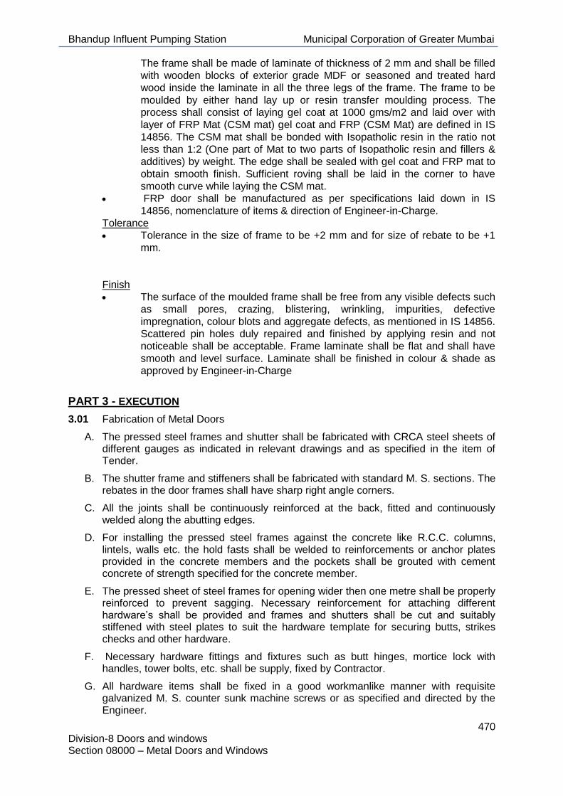
Bhandup Influent Pumping Station Municipal Corporation of Greater Mumbai
470 Division-8 Doors and windows Section 08000 – Metal Doors and Windows
The frame shall be made of laminate of thickness of 2 mm and shall be filled
with wooden blocks of exterior grade MDF or seasoned and treated hard
wood inside the laminate in all the three legs of the frame. The frame to be
moulded by either hand lay up or resin transfer moulding process. The
process shall consist of laying gel coat at 1000 gms/m2 and laid over with
layer of FRP Mat (CSM mat) gel coat and FRP (CSM Mat) are defined in IS
14856. The CSM mat shall be bonded with Isopatholic resin in the ratio not
less than 1:2 (One part of Mat to two parts of Isopatholic resin and fillers &
additives) by weight. The edge shall be sealed with gel coat and FRP mat to
obtain smooth finish. Sufficient roving shall be laid in the corner to have
smooth curve while laying the CSM mat.
• FRP door shall be manufactured as per specifications laid down in IS
14856, nomenclature of items & direction of Engineer-in-Charge.
Tolerance
• Tolerance in the size of frame to be +2 mm and for size of rebate to be +1
mm.
Finish
• The surface of the moulded frame shall be free from any visible defects such
as small pores, crazing, blistering, wrinkling, impurities, defective
impregnation, colour blots and aggregate defects, as mentioned in IS 14856.
Scattered pin holes duly repaired and finished by applying resin and not
noticeable shall be acceptable. Frame laminate shall be flat and shall have
smooth and level surface. Laminate shall be finished in colour & shade as
approved by Engineer-in-Charge
PART 3 - EXECUTION
3.01 Fabrication of Metal Doors
A. The pressed steel frames and shutter shall be fabricated with CRCA steel sheets of different gauges as indicated in relevant drawings and as specified in the item of Tender.
B. The shutter frame and stiffeners shall be fabricated with standard M. S. sections. The rebates in the door frames shall have sharp right angle corners.
C. All the joints shall be continuously reinforced at the back, fitted and continuously welded along the abutting edges.
D. For installing the pressed steel frames against the concrete like R.C.C. columns, lintels, walls etc. the hold fasts shall be welded to reinforcements or anchor plates provided in the concrete members and the pockets shall be grouted with cement concrete of strength specified for the concrete member.
E. The pressed sheet of steel frames for opening wider then one metre shall be properly reinforced to prevent sagging. Necessary reinforcement for attaching different hardware’s shall be provided and frames and shutters shall be cut and suitably stiffened with steel plates to suit the hardware template for securing butts, strikes checks and other hardware.
F. Necessary hardware fittings and fixtures such as butt hinges, mortice lock with handles, tower bolts, etc. shall be supply, fixed by Contractor.
G. All hardware items shall be fixed in a good workmanlike manner with requisite galvanized M. S. counter sunk machine screws or as specified and directed by the Engineer.

Bhandup Influent Pumping Station Municipal Corporation of Greater Mumbai
471 Division-8 Doors and windows Section 08000 – Metal Doors and Windows
H. The Contractor shall also see properly that the stains, grease, rust etc. is thoroughly removed before application of one coat of steel primer.
I. All the steel doors shall be approved by the Engineer before shop painting work is undertaken.
J. Suitable neoprene linings shall be provided around the frames as well as on intermediate hinge lines and meeting styles to make the doors perfectly airtight.
3.02 Fabrication of Aluminium Doors
A. Extruded sections shall have a minimum 3mm wall thickness. All sections shall be approved by the Engineer before fabrication is taken up. Doors, frames mullions, transomes etc. shall be anodized in bath of sulphuric acid to provide a clear coating. The anodized materials shall then be sealed by immersing in boiling water for 15 minutes. A protective transparent coating shall be applied to the sections before shipment from the factory.
B. All work shall be fitted and shop assembled to a first class job, and ready for erection. Shop joints shall be made to hair lines and then welded or braced by such method as will produce a uniform colour throughout the work. Work on the above, other than described, shall be carefully fitted and assembled with neat joints with concealed fasteners. Whenever possible, joints shall be made in concealed locations and on edges of doors. Field connections of all work may be made with concealed screws or other approved type of fasteners. Glazing beads shall be snap fit type without visible screws and shall be of sizes to accommodate 6mm thick glazing. All work shall be adequately braced and reinforced as necessary for strength and rigidity.
3.03 Fabrication Tolerance
A. The Working Drawings shall provide for sufficient tolerance in manufacture of the works in order to accommodate manufacturing tolerances of interfacing elements.
B. Full details shall be submitted to the Engineer for review of the proposed methods for achieving and constantly monitoring the tolerances during all stages of the work. Detailed records of the constant control and tolerances achieved shall be submitted to the Engineer.
3.04 Tolerances for Manufacture
A. Assembly: The physical fitting together of any assembly of sub-elements shall be properly allowed for in the Detailed Design of the corresponding sub-elements.
B. The following tolerances apply to each individual component:
1. Length/ Width: Maximum allowed deviation is the lesser of 1.5mm up to 2000mm and 2.0mm above 2000mm of design dimension.
2. Thickness/ Depth (extrusion tolerances nominally): Maximum allowed deviation is ±0.5mm.
3.05 Workmanship
A. During construction, exposed components shall be protected after fitting and care taken to avoid fitting any components whilst 'wet' trades are still in progress. Protect from abrasives, acids and other corrosive materials.
B. Installation of Fire Check Door sets shall be carried out by sub-contractors who are members of a nationally recognised quality assurance scheme, and ideally the same scheme to which the door manufacturer subscribes.

Bhandup Influent Pumping Station Municipal Corporation of Greater Mumbai
472 Division-8 Doors and windows Section 08000 – Metal Doors and Windows
C. Installation of Fire Check Door sets shall be in accordance with the recommendations of the Architectural and Specialist Door Manufacturer's Association Installation Guide.
1. Protection of Components
• Do not deliver to site components, which cannot be put immediately
into suitable dry, covered storage with a dry floor. Stack on bearers,
separated with spacers to prevent damage by and to projecting
ironmongery, beads, etc.
• Protection of Components after Installation
• Ensure that all exposed components have protective coverings during
storage and after installation to protect factory applied finishes. Door
leaves shall also be protected during on-site operations.
2. Moisture Content
• All timber shall be subjected to controlled drying to ensure that the moisture
content, if not otherwise specified, is suitable for the situation of the finished
joinery. When fixed it shall remain stable and free from expansion, contraction
or other movements detracting from the required performance or appearance.
• During delivery, storage, fixing and thereafter till handing over, maintain
conditions of temperature and humidity to suit the specified moisture
content(s) of timber components. When instructed by the Engineer, test
components with accepted electrical moisture meter used in accordance with
the manufacturer's recommendations.
3.06 Ironmongery
A. Assemble and fix carefully and accurately using fastenings with a matching finish supplied by the ironmongery manufacturer. Prevent damage to ironmongery and adjacent surfaces. At completion check, adjust and lubricate as necessary to ensure correct functioning.
B. Doors and Windows shall be mortised, reinforced, drilled and tapped in shop for hinges, hooks and bolts. They shall also be reinforced for closers, push plates and other surface hardware where necessary. Any drilling and tapping required for surface hardware shall be done at site. Where shown in drawing, provision shall be made for fixing glazing, vision panels, louvers etc.
3.07 On-Site Dimensions
A. Implantation Contractor to take responsibility for all dimensions and for checking dimensions on site prior to manufacture.
B. Ensure that the Detailed Design accommodates any given tolerances and differences between actual site dimensions and dimensions shown on the Design Drawings.
3.08 Tolerances
A. Tolerances shall be measured against the relevant Base Reference Datum; Location Reference Point; Location Reference Plane; Location Reference Surface or Reference Element.
1. All elements shall be set out to their correct position as indicated on the Design Drawings and/ or Working Drawings, within ±2mm or 0.1% of the length, whichever is the lesser.
2. Vertical elements shall be plumb, within ±2mm or 0.1% of the height, whichever is the lesser.
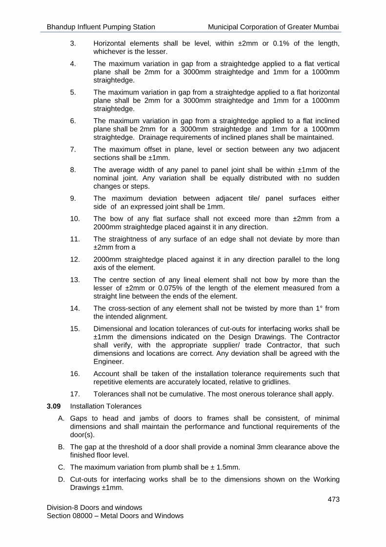
Bhandup Influent Pumping Station Municipal Corporation of Greater Mumbai
473 Division-8 Doors and windows Section 08000 – Metal Doors and Windows
3. Horizontal elements shall be level, within ±2mm or 0.1% of the length, whichever is the lesser.
4. The maximum variation in gap from a straightedge applied to a flat vertical plane shall be 2mm for a 3000mm straightedge and 1mm for a 1000mm straightedge.
5. The maximum variation in gap from a straightedge applied to a flat horizontal plane shall be 2mm for a 3000mm straightedge and 1mm for a 1000mm straightedge.
6. The maximum variation in gap from a straightedge applied to a flat inclined plane shall be 2mm for a 3000mm straightedge and 1mm for a 1000mm straightedge. Drainage requirements of inclined planes shall be maintained.
7. The maximum offset in plane, level or section between any two adjacent sections shall be ±1mm.
8. The average width of any panel to panel joint shall be within ±1mm of the nominal joint. Any variation shall be equally distributed with no sudden changes or steps.
9. The maximum deviation between adjacent tile/ panel surfaces either side of an expressed joint shall be 1mm.
10. The bow of any flat surface shall not exceed more than ±2mm from a 2000mm straightedge placed against it in any direction.
11. The straightness of any surface of an edge shall not deviate by more than ±2mm from a
12. 2000mm straightedge placed against it in any direction parallel to the long axis of the element.
13. The centre section of any lineal element shall not bow by more than the lesser of ±2mm or 0.075% of the length of the element measured from a straight line between the ends of the element.
14. The cross-section of any element shall not be twisted by more than 1° from the intended alignment.
15. Dimensional and location tolerances of cut-outs for interfacing works shall be ±1mm the dimensions indicated on the Design Drawings. The Contractor shall verify, with the appropriate supplier/ trade Contractor, that such dimensions and locations are correct. Any deviation shall be agreed with the Engineer.
16. Account shall be taken of the installation tolerance requirements such that repetitive elements are accurately located, relative to gridlines.
17. Tolerances shall not be cumulative. The most onerous tolerance shall apply.
3.09 Installation Tolerances
A. Gaps to head and jambs of doors to frames shall be consistent, of minimal dimensions and shall maintain the performance and functional requirements of the door(s).
B. The gap at the threshold of a door shall provide a nominal 3mm clearance above the finished floor level.
C. The maximum variation from plumb shall be ± 1.5mm.
D. Cut-outs for interfacing works shall be to the dimensions shown on the Working Drawings ±1mm.

Bhandup Influent Pumping Station Municipal Corporation of Greater Mumbai
474 Division-8 Doors and windows Section 08000 – Metal Doors and Windows
E. Horizontal Plan Position: For any element at any level whose position is defined in relation to a primary reference grid, the maximum allowed deviation from the Design Dimension to that reference grid is ±2mm.
F. Where a series of doors is arranged in an array of two or more, the maximum allowed deviation of the horizontal distance between any two adjacent elements is ±2mm from the corresponding Design Dimension.
G. Planarity: Any door whose position is defined from a reference plane shall not deviate from the Design Dimension of the reference plane by more than ±2mm measuring perpendicular to the defined plane.
H. The width of any joint shall not deviate from the nominal width by more than ±1mm of the joint width. Any variation shall be equally distributed with no sudden changes. The misalignment between joints shall not exceed 1mm.
I. Line and level shall be within ±2mm of the specified level.
J. The works shall be erected such that no point on any part is more than 1mm from its theoretical plane.
K. The dimensional and detailed provisions intended to accommodate the construction tolerances of surrounding elements in order to ensure that all aspects of the works relate satisfactorily to the works as a whole shall be stated and shown on the Working Drawings.
L. All tolerances stated shall be measured and monitored at a mean temperature to be agreed with the Engineer.
M. Before work begins on site the proposed method of dimensional setting-out and cross-checking with adjacent trades and elements, to satisfy the accuracy requirements, shall be submitted to the Engineer. The checking of any setting-out or of any line or level by the Engineer, or his representative, shall not in any way relieve the Contractor of his responsibility for the correctness thereof.
N. Alternative tolerances to those specified may be permitted at the Engineer's discretion, provided they are agreed in advance of the manufacture of components.
O. Tolerances shall not be cumulative.
3.10 Shop Coat of Paint
A. The shop paint for rolling shutter, steel doors / windows etc. shall be best red oxide or zinc chromate primer paint from approved manufacturer. All surfaces shall be thoroughly cleaned of rust, grease, loose mill scales etc. and given one coat of shop paint. Portions like mullions, transoms etc. which will be inaccessible after assembly of units shall be given an extra coat of paint before assembly.
B. Where called for in the Schedule of Items, all steel doors, Windows etc. shall be hot dip galvanized to give a coating weight of 1.5 to 2 oz. per sq. feet. One coat zinc chromate primer coat shall then be applied as shop paint.
C. Portions of aluminium frame which come in contact with masonry construction, shall, before shipment from workshop, be protected with a heavy coat of alkali resistant paint. Aluminium coming in contact with other incompatible metals shall be coated with zinc chromate primer.
3.11 Steel Windows, Aluminium Windows, Ventilators, Louvers
A. These shall conform in all respects to IS:1038 and IS:1361 latest editions. The details as called for in the above codes shall be applicable for coupling mullions, transoms, weather bars, pivot arrangements for ventilators, etc. or called for in the Schedule of Items.

Bhandup Influent Pumping Station Municipal Corporation of Greater Mumbai
475 Division-8 Doors and windows Section 08000 – Metal Doors and Windows
B. All welds shall be dressed flush on all exposed and contact surfaces. Where composite unit openings are shown on drawings, the individual window units shall be joined together with requisite transoms and mullions. All windows shall be outside glazed, fixed with putty or metal glazing beads and/or specified under Schedule of Items.
C. Mouldings shall be of 18g steel or extruded aluminium sections with profiles shown in drawing and suitable for fixing glass. Louvers blades shall be V or Z shaped and made out of 16g sheets.
D. Where aluminium beads are specified, they shall be extruded aluminium channel 9.5 mm x 9.5 mm x1.6 mm unless otherwise shown on drawings. Aluminium beads shall be given one coat of zinc chromate primer before fixing to windows. Both edges of doors / windows shall be jointed and reinforced full height by steel channels placed immediately inside and welded to the doors / window faces. Top and Bottom of doors / windows shall be reinforced horizontally by steel channels running full width of window. Doors / windows shall not have more than 2.5 mm clearance at jambs and heads shall have proper bevel on lock stiles and rails to operate without binding, and shall be reinforced at corners to prevent sagging or twisting. Pairs or double doors / windows shall have meeting stile edges bevelled or rebated. Where shown or drawing, or called for in the schedule of items, the doors / windows shall be sound insulated by filling the inside voids with mineral wool or other suitable approved materials.
END OF SECTION -08000.

Bhandup Influent Pumping Station Municipal Corporation of Greater Mumbai
476 Division 8 Doors and Windows Section 08360 GI Rolling Shutters
SECTION 08360 GI ROLLING SHUTTERS
PART 1 -GENERAL
1.01 Reference:
A. Section 08000 applies to and govern the work of this Section.
1.02 Work Included:
A. Design, supply and installation of rolling shutter doors complete with fitting accessories and motorized automation system.
B. Supply and installation of all appurtenances associated with the above for complete working systems.
C. The Drawings, Datasheets and Specifications are intended to set the acceptable minimum standard. Ensure that the installed equipment is trouble-free and meets performance requirements.
1.03 Related Work:
A. The following related work is covered elsewhere in the Contract Documents:
1. Division 4 - Masonry
2. Division 9 - Finishes - Painting
3. Division 16 - Electrical
1.04 Alternatives
A. Not applicable for this Section.
1.05 Submittals:
A. Submit shop drawings and Product Data, documents as specified in Section 08000 in accordance with Section 01007 and As-Built drawings as per Section 01016.
1.06 Code and Standards:
A. The following applicable standards established by the Bureau of Indian Standards govern the materials and workmanship for the work under this Section.
1 National Building Code of India, 2005
2 IS 6248: 1979 Metal Rolling Shutters and Grilles.
B. Where provisions of the pertinent codes and standards conflict with these Specifications, Drawings and Datasheets or with each other, comply with the more stringent provisions.
C. Use the latest issue of Standards.
PART 2 - PRODUCTS
2.01 General:
A. Design Requirements:
1. Wind Loading: Supply doors to withstand up to 6 kg/m2 wind load.
2. Cycle Life: Design doors of standard construction for normal use of up to 20 cycles per day.
B. Where door opening areas are 5 m2 or greater, provide an electrical actuated door system.

Bhandup Influent Pumping Station Municipal Corporation of Greater Mumbai
477 Division 8 Doors and Windows Section 08360 GI Rolling Shutters
2.02 Materials:
A. General:
1. Rolling shutter shall be of the size to suit the openings and shall be positioned at the entrance of the dry well to carry out maintenance activity and/or as directed by the Engineer.
2. The rolling shutter shall be fabricated from 0.9 mm thick steel for shutters up to 3.5m width and 1.2mm thick sheet for shutters over 3.5m width. The shutter shall be rolled with lath sections of effective bridge depth 12mm at 75mm rolling centres, interlocked with each other and ends locked with malleable cast iron or mild clips. The guide shall either be rolled or pressed deep channel sections, fitted with necessary fittings and fixtures. The width of the channel shall be 25 mm and the depth 75mm up to 8 M wide shutter. The depth shall be 100 mm for shutters above 8 M width.
3. The hood covers shall be made of 18 gauge G.I sheets with necessary stiffeners and frame work to prevent sag. The bottom lock plate shall be made of 3mm thick M.S. plate and 95 mm wide reinforced with angle iron of suitable section with 6mm dia. M.S rivets interlocked with stride of curtain. Where grills are specified in the drawings , shall be fabricated from 8 mm dia round / square bars with supporting frames , clips etc to allow free vertical movement of the shutter .
4. Unless otherwise specified for overall area of rolling shutters up to 8m2 pull and push type hand operated shutters shall be used. For area between 8 and 10m2, push and pull type shutters shall be provided with ball bearings.
5. For area larger than 10m2 mechanical gear type or electrically operated shutters shall be used. Operation of shutters shall be by means of worm and worm wheel and shaft arrangement and it shall be possible to operate the door either from inside or from outside. The shutter shall be capable of withstanding horizontal forces up to 100 kg/m² without any appreciable deflection.
B. Handling & Storage of Fabricated Materials
1. All doors windows, etc. shall be packed and crated properly before despatch, to ensure that there will be no damage to the fabricated materials. Loading into wagons and trucks shall be done with all care to ensure safe arrival of materials at site in undamaged condition.
2. When taking delivery of items supplied by Employer, the Contractor shall satisfy himself that the items supplied are up to the specified standard. Any defect detected shall promptly be brought to the notice of the Engineer. All doors, widows etc. shall be stored under cover in a way to prevent damage or distortion. Special care shall be taken to prevent staining of aluminium products by rust, mortar etc.
2.03 Approved supplier / Manufacturer
A. Supplier /Manufacturer meeting required specification.

Bhandup Influent Pumping Station Municipal Corporation of Greater Mumbai
478 Division 8 Doors and Windows Section 08360 GI Rolling Shutters
PART 3 - EXECUTION
3.01 General:
A. Inspect all parts as soon as they arrive on site and report any damage to the Engineer.
B. Have the door supplier carefully inspect and verify that substrate details and location are acceptable before installation of the doors commences.
C. Install all door components as per manufacturer’s instructions.
D. Upon completion of installation, operate all doors to ensure smooth operation and no jamming occurs during raising or lowering operations. Make all adjustments necessary for the door’s smooth operation. Ensure door operates as required under electrically actuated and manual operation.
E. Clean soiled surfaces as recommended by manufacturer.
F. Remove surplus materials and debris from the site.
G. Instruct the operators in the complete operation of the doors.
H. Instruct the operators regarding maintenance procedures.
PART 4 -SPECIFICATIONS FOR ROLLING SHUTTERS
4.01 `General
A. Rolling shutters complete with accessories shall be of approved quality and as specified. These shall be suitable for fixing in position as specified i.e. outside or inside; on or below lintel or between jambs of the opening. Rolling shutter shall be hand/gear operated as specified in the item of schedule of quantities. For hand operated shutters, it shall be push and pull type. For gear operated shutters, it shall be provided with reduction gear operated by mechanical device with chain, crank, shaft and handle. The shutter shall consist of 80 mm. wide m.s. laths 1.25 mm. thick or gauge as specified of best quality mild steel sheet machine rolled. Laths shall be inter locked together throughout their entire length and jointed together at the end with end locks. These shall be mounted on specially designed pipe shaft. The spring shall be of best quality and shall be manufactured from the tested tensile spring steel wire or strip of adequate strength to balance the shutter in all positions. The spring, pipe shaft etc. shall be supported on strong mild steel or malleable cast iron brackets. Both the side guides and bottom rails shall be joint less and of single piece of pressed steel of minimum 16 gauge thickness. The top cover of shaft, spring etc. shall be of the same materials as that of lath. No extra payment shall be made for the hood, brackets etc. to cover the shaft etc. The reduction gear arrangement operated by the mechanical device shall be of the best quality and shall be easy in operation.

Bhandup Influent Pumping Station Municipal Corporation of Greater Mumbai
479 Division 8 Doors and Windows Section 08360 GI Rolling Shutters
4.02 Fixing
A. Brackets shall be fixed on the lintel/beam or under the lintel/beam as specified in item with rawl plugs and screws, bolts, washers etc. The shaft along with the spring shall then be fixed on the brackets. The lath portion (shutters) shall be laid on ground and the side guide channels shall be bound with it. The shutter shall then be placed in position. The side guide channels shall be fixed to the wall through the plates welded to the guides. These plates and brackets shall be fixed by means of steel screws, bolts and rawl plugs drilled into the wall. The plates and screws, bolts shall be concealed in plaster to make their locations invisible. Fixing shall be done accurately in a workman like manner that the operation of the shutter is easy and smooth. All grout holes and damages on the wall while fixing of shutters shall be made good by the contractor at no extra cost to the Department. The contractor shall ensure smooth and easy working of shutters. All the members of the rolling shutter shall be thoroughly cleaned off dust, scales, rust etc. and shall be given approved priming coat of red oxide paint before fixing the shutter in position and then shall be painted with two coats of flat/synthetic enamel paint of approved quality and shade.
4.03 Mode Of Measurement
A. The area of rolling shutters shall be measured in square metre correct up to two places of decimal. Width and height shall be taken for net opening correct to a centimeter. The rate shall include the cost of materials, labour involved in all the operations described above
END OF SECTION 08360.

Bhandup Influent Pumping Station Municipal Corporation of Greater Mumbai
480 Division 8 Doors and Windows 08410 Aluminium Windows
08410 ALUMINUM WINDOWS
PART 1 -GENERAL
1.01 Reference:
A. Section 08000 applies to and governs the work of this Section.
1.02 Work Included:
A. Supply and installation of aluminium windows and windows with vents.
B. Glazing for all aluminium windows specified herein and in Section 08800.
C. Caulking and sealing of joints between framing members and at the perimeter of all aluminium members and adjacent materials as specified in Section 08000.
1.03 Related Work:
A. The following related work is covered elsewhere in the Contract Documents:
1. Division 3 - Concrete
2. Division 4 - Masonry
3. Division 9 - Finishes
1.04 Alternatives:
A. Not applicable for this Section.
1.05 Submittals:
A. Submit shop drawings, product data and other documents in accordance with Section 01007 and As-Built drawings as per section 1016.
B. Show details of construction, blocking, glazing, anchorage and other related work.
1.06 Codes and Standards:
A. The following applicable standards established by the Bureau of Indian Standards govern the materials and workmanship for the work under this Section:
1 IS:1948 Specification for aluminium door /windows and ventilators
2 IS:1081 Code of Practice for fixing and glazing of metal (steel and aluminium) doors, windows and ventilators.
B. Where provisions of the pertinent codes and standards conflict with these Specifications and Drawings or with each other comply with the more stringent provisions.
C. Use the latest issue of Standards.
PART 2 - PRODUCTS
2.01 General:
A. Specification is based on the following:
1. Aluminium frames: Series 516 for fixed sealed units and open-in vents with sealed units, 102 mm as approved by the Engineer.
B. Materials:

Bhandup Influent Pumping Station Municipal Corporation of Greater Mumbai
481 Division 8 Doors and Windows 08410 Aluminium Windows
1. Aluminium members and panels: fabricated of 6063-T5 extrusion alloy.
2. Screws: stainless steel in exposed locations of same finish as aluminium frames.
a) Clips and Anchor Straps: aluminium or stainless steel back-painted.
b) Anchors: stainless steel.
c) Setting Blocks and Shims: black neoprene rubber, conforming to IS 1081, Shore hardness: 80-90 for blocks, 40-60 for shims.
d) Compression Gaskets: extruded neoprene, as approved by the Engineer
e) Sealant:
i. For glazing: one part acrylic tempolymer or other approved.
ii. For caulking between framing members and other materials mastic or polysulphide compound.
f) Glazing material: As per Section 08800.
C. Fabrication:
1. Fabricate units from extrusions of general size and shapes as per approved shop drawings and formed with clean, sharply defined profiles. Joints shall be accurately machined, assembled and sealed to provide neat weathertight joinery. Frame joints drawn and secured on assembly with corner joint brackets and stainless steel screws or welded or concealed surfaces.
2. Fit and assemble work in the workshop, where possible. Execute work in accordance with details and approved shop drawings. Assembled units shall be square, true and correct in size and free of all defects or damage.
3. Seal joints before assembly.
4. Use and handle caulking compounds in accordance with the manufacturer’s instructions.
5. Aluminium coming in contact with masonry, concrete or dissimilar metals shall be given a heavy coat of bitumastic paint to prevent electrolytic action.
6. Finish to all exposed aluminium: Colour: submit sample to Engineer for approval before fabrication. Colour to match windows on existing buildings if any. See Section 09900 for colour selection.
2.02 Approved Suppliers / Manufacturer of Aluminium Sections for Windows:
A. Hindalco Industries Ltd
B. Jindal Aluminium Ltd
PART 3 -EXECUTION
3.01 General:
A. Materials shall be delivered, handled and stored such that cracking, warping, deformation, discoloration and deterioration are prevented.
B. Mark the glass immediately after glazing to show its presence.
C. Remove temporary protection upon completion.
D. Frames and insulated sealed glazing units shall be free from moisture, dirt, cement, plaster, oil and grease.
E. Windows:

Bhandup Influent Pumping Station Municipal Corporation of Greater Mumbai
482 Division 8 Doors and Windows 08410 Aluminium Windows
1. Centre glazing units using spacer shims and setting blocks, set at quarter points and at not more than 450 mm c/c.
2. Apply glazing tape to fixed leg of frame followed by needle bead of sealant. Set glazing units on setting blocks and press firmly into place against tape and sealant. Snap in glazing beads and press in compression gaskets. Mitre corners of vision strips.
3. Provide heel bead around perimeter of glazing units to give complete vapour seal.
3.02 Examination:
A. Examine job conditions before commencement of work.
B. Commencement of work will denote acceptance of existing conditions.
C. Rectify faults in the installed work to the satisfaction of the Engineer.
3.03 Erection:
A. Install, glaze and adjust windows using experienced workmen in accordance with the manufacturer’s instructions and reviewed shop drawings. Set items in their correct locations, level, square, plumb and at proper elevations and alignment with other work.
B. Securely anchor members to structure.
C. Seal joints tightly to provide watertight installation.
D. Use concealed fastenings throughout.
3.04 Sealing:
A. Seal all joints between the work of this Section and adjoining work, to make the installation weather tight.
END OF SECTION 08410.

Bhandup Influent Pumping Station Municipal Corporation of Greater Mumbai
483 Division 8 Doors and windows Section 08710 Ironmongery
SECTION 08710 IRONMONGERY
PART 1 -GENERAL
1.01 Reference:
A. Section 08000 applies to and governs the work of this Section.
1.02 Work Included:
A. Supply and installation of all ironmongery and accessories and as specified herein or as required.
1.03 Related Work:
A. The following related work is covered elsewhere in the Contract Documents:
1. Division 2 - Site Work
2. Division 3 - Concrete
3. Division 4 - Masonry
4. Section 08110 - Hollow Metal Doors and Frames
5. Section 08410 - Aluminium Windows
1.04 Alternatives:
A. Not applicable for this Section.
1.05 Submittals:
A. Submit a comprehensive itemized schedule of ironmongery for each door and window for review in accordance with Section 01007 and As-Built drawings as per Section – 01016.
B. Include a complete list of ironmongery illustrations and manufacturers’ data sheets literature, catalogues and samples.
1.06 Codes and Standards:
A. The applicable standards established by the Bureau of Indian Standards govern the materials and workmanship for the work of this Section.
B. Where provisions of the pertinent codes and standards conflict with these Specifications, Drawings and Datasheets or with each other, comply with the more stringent provisions.
C. Use the latest issue of Standards.
PART 2 -PRODUCTS
2.01 General:
A. Use stainless steel ironmongery, unless otherwise specified.
2.02 Keying:
A. Master key of all locks. Check with the Engineer with regard to master keying to the existing master key system.
2.03 Templates:
A. Deliver sufficient templates to enable door and frame manufacturers to fabricate and reinforce their materials to accommodate the respective ironmongery.
2.04 Hinges:

Bhandup Influent Pumping Station Municipal Corporation of Greater Mumbai
484 Division 8 Doors and windows Section 08710 Ironmongery
A. Supply 40 mm pairs, full mortised hinges for each door up to 2100 mm and two pairs of hinges for each door up to 4600 mm in height and three pairs of hinges for each door exceeding 4600 mm in height.
B. Hinges shall be as approved by the Engineer.
2.05 Locksets:
A. Locksets shall be heavy duty with satin, chrome finish. Lock cores - Multi-lock cores for master key system.
2.06 Latchsets:
A. Interior latchsets shall be Godrej or equivalent with standard duty series, Sat design, complete with strike. Latchsets shall have a satin, chrome finish.
2.07 Panic Device:
A. Panic devices for doors and fire doors shall be stainless steel rim type or equivalent subject to the approval of the Engineer.
2.08 Door Pulls:
A. Unless specified otherwise door pulls shall be stainless steel and subject to the approval of the Engineer.
2.09 Push Plates:
A. Unless specified otherwise push plates - stainless steel 125 mm x 500 mm.
2.10 Flush Door Bolts:
A. Unless specified otherwise for all double door systems, provide inactive leaf with a locking bolt, flush mounted in the door edge top and bottom, complete with strike plates. Mount bolts in the door edge flush so not visible when closed.
B. Unless specified otherwise, flush door bolts shall be stainless steel and subject to the approval of the Engineer..
2.11 Door Closers and Holders:
A. Supply brackets where necessary or recommended by the manufacturer.
B. Exterior doors: hold open arm as recommended by manufacturer .
2.12 Security Plates:
A. Stainless steel plates on exterior door locksets/padlocks.
2.13 Kickplates:
A. 3 mm x 200 mm height x door width less 40 mm stainless steel.
2.14 Door Jamb Strikes:
A. Stainless steel with extended lip.
2.15 Door Frame:
A. Weather-stripping integral with aluminium frame, as approved by Engineer.
2.16 Adjustable Door Sweeps:
A. Surface mounted CT-52: 23 x 48 mm x solid 3.1 mm neoprene- as approved by Engineer.
2.17 Padlocks:
A. Standard padlocks of approved make to suit the Engineer’s Master Key system.
2.18 Approved Suppliers/Manufacturers:
A. Godrej, Mumbai

Bhandup Influent Pumping Station Municipal Corporation of Greater Mumbai
485 Division 8 Doors and windows Section 08710 Ironmongery
B. or equivalent as approved.
PART 3 - EXECUTION
3.01 Mounting Height for Ironmongery:
A. In general set at the following heights or as recommended by the manufacturer:
1 Panic Device mount 1040 mm from finished floor to centreline of strike
2 Locksets, Latchsets mount 990 mm from finished floor to centreline of strike
3 Padlocks: mount 1040 mm from finished floor to centreline of strike
4 Door Pulls: mount 1070 mm from finished door to centreline of pull
5 Push Plates: mount 1220 mm from finished floor to centerline of plate
6 Hinges mount upper edge of top hinge 130 mm below head of frame; locate lower edge of bottom hinge 250 mm above finished floor; space centre hinge equal distance between top and bottom hinges.
3.02 Mounting Hardware:
A. Hinges, Closers and Holders:
1. Install hinges, closers and holders on doors using stainless steel machine screws.
B. Kick-plates:
1. Fix kick-plates opposite hinge side with stainless steel screws, half domed heads. Set screws at close centres.
C. Thresholds:
1. Set aluminium door thresholds in a bed of sealant compound and bolt into lead shields in the flooring.
D. Door Closers:
1. Install door closers in such a manner that door opening is not obstructed.
2. Arrange door closers to suit the conditions with parallel arm application. Corner brackets are not acceptable.
E. Weather-stripping/Door Seals:
1. Install effectively to seal entire perimeter of doors, secure in place with stainless steel screws, in accurate alignment.
2. Maintain integrity of seals at head of doors fitted with closers. Adapt weather-stripping as required to achieve proper performance and provide necessary accessories.
F. Keys:
1. Cylinder faces and keys to have visual identification stamping.
2. Provide three keys per lock.
3.03 Adjustment:
A. Verify that installed ironmongery functions properly and ensure that it is adjusted accordingly to ensure satisfactory operation.

Bhandup Influent Pumping Station Municipal Corporation of Greater Mumbai
486 Division 8 Doors and windows Section 08710 Ironmongery
B. After installation, ensure finished ironmongery operates smoothly and without binding. Lubricate ironmongery in accordance with the manufacturer's recommendations.
3.04 Cleaning:
A. Clean ironmongery so that it is free of scale and surface blemishes.
END OF SECTION 08710.

Bhandup Influent Pumping Station Municipal Corporation of Greater Mumbai
487 Division 8 Doors and Windows Section 08800 Glazing
SECTION 08800 GLAZING
PART 1 - GENERAL
1.01 Reference:
A. Section 08000 applies to and governs the work of this Section.
1.02 Work Included:
A. Supply and installation of glazing in doors and window walls.
B. Supply of all glazing products required for proper installation of the work of this Section.
1.03 Related Work:
A. Section 08110 - Metal Doors and Frames
B. Section 08410 - Aluminium Windows
1.04 Alternatives:
A. Refer to Section 01002 for requirements pertaining to acceptance of alternatives.
1.05 Submittals:
A. Submit samples of all products under this Section, if requested by the Engineer, prior to ordering of any item.
1.06 Codes and standards:
A. The following applicable standards established by the Bureau of Indian Standards govern the materials and workmanship for the work under this Section:
1 IS – 1081 Code of practice for fixing and glazing of metal (steel and aluminium) doors, windows and ventilation.
B. Where provisions of the pertinent codes and standards conflict with these Specifications, Drawings and Datasheets or with each other, comply with the more stringent provisions.
C. Use the latest issue of Standards.
PART 2 - PRODUCTS
2.01 General:
A. Comply with product requirements as specified and/or as indicated on the Drawings.
2.02 Materials:
A. Plate glass shall be float or plain glass conforming to the requirements of quality at least 5.50 mm thick.
B. Glazing compound, if required, shall be as approved by the Engineer.
2.03 Approved Suppliers/Manufacturers:
A. Saint Gobain
B. Asalin Glass Co.
C. Modi, Mumbai
PART 3 -EXECUTION
3.01 General:
A. Comply with the execution requirements as specified.
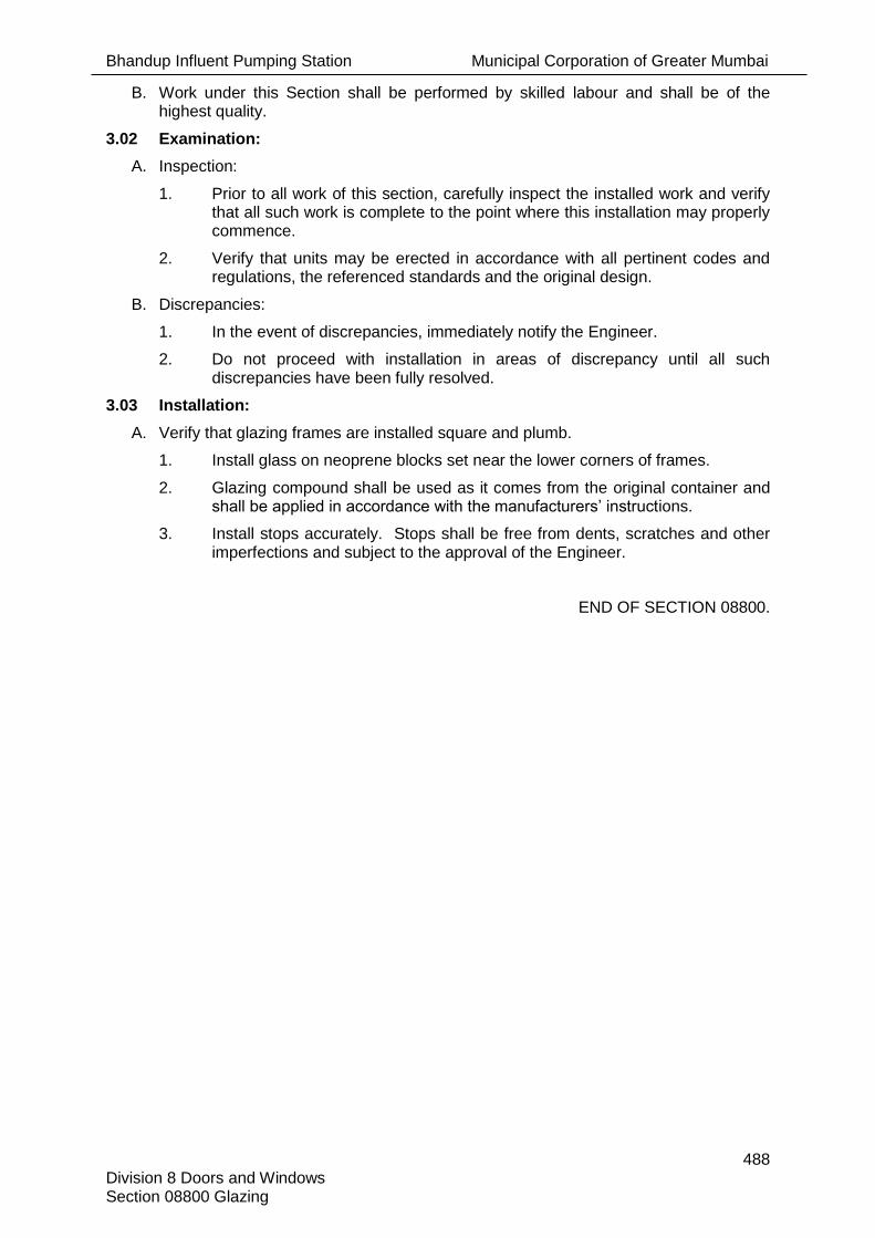
Bhandup Influent Pumping Station Municipal Corporation of Greater Mumbai
488 Division 8 Doors and Windows Section 08800 Glazing
B. Work under this Section shall be performed by skilled labour and shall be of the highest quality.
3.02 Examination:
A. Inspection:
1. Prior to all work of this section, carefully inspect the installed work and verify that all such work is complete to the point where this installation may properly commence.
2. Verify that units may be erected in accordance with all pertinent codes and regulations, the referenced standards and the original design.
B. Discrepancies:
1. In the event of discrepancies, immediately notify the Engineer.
2. Do not proceed with installation in areas of discrepancy until all such discrepancies have been fully resolved.
3.03 Installation:
A. Verify that glazing frames are installed square and plumb.
1. Install glass on neoprene blocks set near the lower corners of frames.
2. Glazing compound shall be used as it comes from the original container and shall be applied in accordance with the manufacturers’ instructions.
3. Install stops accurately. Stops shall be free from dents, scratches and other imperfections and subject to the approval of the Engineer.
END OF SECTION 08800.

Bhandup Influent Pumping Station Municipal Corporation of Greater Mumbai
489 Division- 9 Finishes Section 09000- Finishes
INDEX
SECTIONS NO.OF PAGES Section 09000 – Finishes ............................................................................................................ 2 Section 09100 – Plaster .............................................................................................................. 4 Section 09320 – Ceramic Tile ..................................................................................................... 4 Section 09500 – Color Coated Galvanized Roofing Sheet .......................................................... 2 Section 09510 – Suspended False Ceilings ................................................................................ 2 Section 09520 – Gypsum Board False Ceilings .......................................................................... 3 Section 09740 – Kotah Stone ...................................................................................................... 3 Section 09790 – Epoxy Floor Treatment ..................................................................................... 3 Section 09791 – Epoxy Lining ..................................................................................................... 2 Section 09800 – Acid Alkali Resistant Tile .................................................................................. 4 Section 09900 – Painting .......................................................................................................... 10 Section 09950 – Waterproofing on Terrace ................................................................................. 5 Section 09960 – Interior and Exterior Acrylic Emulsion Paint ...................................................... 5 Total Pages In This Division ................................................................................................... 49

Bhandup Influent Pumping Station Municipal Corporation of Greater Mumbai
490 Division- 9 Finishes Section 09000- Finishes
SECTION 09000- FINISHES
PART 1 -GENERAL
1.01 Reference:
A. The General Conditions, Particular Conditions, Contract Forms, Instruction to Bidder, and the requirements of Division 1 specified before, in addition to any and all Addenda, apply to and govern each Section of this Division.
B. This Section covers the general requirements for the work of this Division and shall be read in conjunction with other Sections in this Division.
C. This Section governs the work of other Sections in this Division.
1.02 Work Included:
A. The work of this Section includes, but is not necessarily limited to, the supply of labour, materials and equipment for:
1. Supply and application of cement plaster to RCC and brick work including finishing smooth with neeru.
2. Supply and application of paints and finish products, as specified for walls, ceilings, doors, rolling shutters, bollards, structural steel, valves, piping and equipment touch-up.
3. Repair or replace finished surfaces damaged during construction.
4. Finishing materials and products as hereinafter specified and as shown on the Drawings.
1.03 Co-ordination:
A. Co-ordinate with the work of other Divisions before installing work included in this Division. If work is installed without co-ordination with other works, the Engineer may direct that such work be removed, relocated and/or modified as necessary. Comply promptly with any Engineer's requests. Complete any correction and/or additional work, as directed by the Engineer.
B. For coordination requirements refer to Section 01002
1.04 Submittals:
A. Submit shop drawings, product data, documents and samples with necessary details for items in accordance with Section 01007 and As-Built drawings as per Section 01016.
1.05 Codes and Standard:
A. The following applicable standards established by the Bureau of Indian Standards govern the materials and workmanship for the work under this Division.
1. National Building Code of India: 2005
B. Where provisions of the pertinent codes and standards conflict with these Specifications, Drawings and Datasheets or with each other, comply with the more stringent provisions.
C. Use the latest issue of Standards.
PART 2 - PRODUCTS
2.01 General:
A. Comply with product requirements outlined in the individual Sections and/or as specified on the Drawings. Select all other materials, not specifically described but

Bhandup Influent Pumping Station Municipal Corporation of Greater Mumbai
491 Division- 9 Finishes Section 09000- Finishes
required for the proper completion of this Division, subject to the approval of the Engineer.
2.02 Fire Protection for materials and equipments:
A. All materials and equipments specified under this division shall be provided in accordance with NFPA 820 and the NEC-Area Electrical Classification details provided on the drawings.
B. Zones indicated in the drawings refers to divisions specified in NFPA 820
PART 3 -EXECUTION
3.01 General:
A. Comply with execution requirements as specified, and/or as shown on the Drawings.
3.02 Delivery, Storage and Handling:
A. Deliver, store and handle equipment, finishing materials and paints carefully to prevent damage. Do not remove materials from crates or other protective covering until ready for installation.
B. Store materials in a weather-tight building, raised clear of the ground so that the materials are protected from weather, dampness and deterioration.
C. Remove material from site for which shelf life has expired.
END OF SECTION 09000.

Bhandup Influent Pumping Station Municipal Corporation of Greater Mumbai
492
Division- 9 Finishes Section 09100-Plaster
SECTION 09100-PLASTER
PART 1 -GENERAL
1.01 Reference:
A. Section 09000 applies to and governs the work of this Section.
1.02 Work Included:
A. Provide labour, materials and equipment necessary to do the plastering work indicated on the Drawings and as specified.
B. The drawings, data sheets and specifications are intended to set the acceptable minimum standard.
1.03 Related Work:
A. The following related work is covered elsewhere in the contract documents:
1. Division 2 - Site work
2. Division 3 - Concrete
3. Division 4 - Masonry
4. Division 8 - Doors and Windows
1.04 Alternatives:
A. Not applicable.
1.05 Submittals
A. Submit product data and samples in accordance with Section 01007 and As-Built drawings as per Section 01016.
B. Certification:
1. Submit laboratory test certificates for the materials such as cement, sand and neeru to the Engineer before delivery to site.
1.06 Codes & Standards:
A. The following applicable standards established by the Bureau of Indian Standards govern the materials and workmanship for the work under this section.
1 IS: 1542 Specification for sand face plaster
2 IS: 1661 Code of practice for application of cement and cement
3 IS 2395 Part 1: Line finishes Painting of concrete, masonry and plaster surfaces – operations and workmanship
4 IS 2395: Part 2 Code of practice for painting concrete, masonry and plaster surfaces – Schedule
5 IS 712:1984 Specification for building limes.
B. Where provisions of the pertinent codes and standards conflict with these Specifications and Drawings or with each other comply with the more stringent provisions.
C. Use the latest issue of Standards.
PART 2 - PRODUCTS

Bhandup Influent Pumping Station Municipal Corporation of Greater Mumbai
493
Division- 9 Finishes Section 09100-Plaster
2.01 Materials:
A. Water
1. Water shall be free from deleterious materials, potable from the municipal main or other source approved by the Engineer.
2. Storage for the water shall be of sufficient size to ensure that there is a sufficient supply of water required for the work.
B. Sand
1. Sand shall be sharp, coarse and of approved quality and free from salt, earth, dust, silt or other impurities.
2. Sand may be washed and or/screened to meet required quality.
C. Cement
1. Cement shall be ordinary Portland cement or pozzolana cement of approved Indian manufacture and shall comply with relevant Indian standards in force. Compression and tensile tests on cement-sand cubes shall be made.
2. Cement shall be fresh when delivered. Cement shall be delivered in sound and properly secured bags, barrels or other packages ready for immediate use and shall be used directly from the bags or barrels.
3. Cement shall be stored in a watertight, well-ventilated and otherwise suitable shed or godown. The floor shall be raised not less than 450 mm from above ground level.
4. Maintain a sufficient stock of cement to ensure continuity of the work and each consignment shall be stacked separately to permit easy access for inspection and identification.
5. Cement stored for more than 90 days shall not be used.
D. Neeru
1. Neeru shall be from a reputable manufacturer as per IS 712-1984.
E. Ready-mix plaster shall be used with the approval of Engineer.
2.02 Approved Manufacturers/ Products for Water proofing compound
A. Dr. Fixit Pidiproof LW+,
B. Sika
PART 3 - EXECUTION
3.01 General:
A. Carry out the plastering work as shown on the Drawings and as specified.
B. The joints of masonry work shall be raked out to 20mm. The surface of concrete and reinforced concrete work shall be dented in the manner specified for reinforced concrete work before plaster is applied. All the surfaces shall be thoroughly washed and well-watered before plaster is applied.
C. Joints on the external side of walls under beams shall be filled with mortar and cured properly for seven days before the commencement of plastering.
D. A long straight edge shall be used to ensure an even surface. Corners and angles shall be plumb and true and soffits of arches shall be true arcs of circles. Exposed angles with door and window frames shall be carefully finished. Internal angles shall be rounded and arises shall be rounded, splayed as appropriate.
3.02 Cement Plaster

Bhandup Influent Pumping Station Municipal Corporation of Greater Mumbai
494
Division- 9 Finishes Section 09100-Plaster
A. The plaster on internal walls shall consist of single coat. The undercoat shall be minimum 12 mm thick and shall be of one part cement and 3 parts coarse sand and shall be dashed against the wall. It shall be uniformly applied and shall be floated and the surface shall be made even. The finishing shall be a smooth and even surface to the satisfaction of the Engineer.
B. Plaster to ceiling and other internal concrete surfaces shall be as for walls.
C. Adequate time interval shall be allowed between the applications of successive coats of plaster for hardening. The coats shall be kept moist by watering and shall not be allowed to dry out.
D. Waterproof compound shall be added for plastering to water-retaining structures.
E. In bathrooms, cement plaster shall be broom finished for tiling work.
3.03 Sand Faced Plaster
A. Sand face plaster shall be applied to external faces of building in two coats. Cement mortar shall consist of 1 part of cement to 3 parts sand. The undercoat shall be approximately 12mm thick and second coat shall be 8mm thick. The surface of the undercoat shall be scratched by wire brush to form a key for the finishing coat, before cement has set or hardened.
B. Water proofing compound of approved make shall be added in the first and second coat of cement mortar as per manufacturer’s guideline.
C. The surface of the undercoat shall be scratched for forming the key for the finishing coat before the mortar has set and hardened.
D. The finishing coat shall be 1 part of white cement, 3 parts sand to give a grained texture. The finishing coat shall be 6 mm thick, uniformly applied and surface finished with special cork sponges recommended for textured/cement plaster work. When finished the surface shall be even and shall have a grained texture.
E. Adequate time interval shall be allowed between the applications of successive coats for hardening. The coats shall be kept moist by watering for seven.
F. Joints between masonry and concrete members to be sealed properly. Provide chicken wire mesh along the joints of masonry and concrete members to prevent separation cracks.
3.04 Cornices & Enrichment
A. All plaster cornices, string courses, beading and mouldings around door and window openings, consoles, key stones, base mouldings, inserts, moulded panels, foliated caps and enrichments etc. to the exterior and interior walls (if of greater projection than 20 mm to be laid with projecting masonry and/or concrete work) shall be rough-cast in mortar, clear cut, rubbed smooth until a high polish is obtained and finished with clean sharp arises in strict accordance with the details supplied. Lines of mouldings shall be parallel.
B. Plaster cornices shall be laid with projecting masonry and /or concrete work as the case may be. Nailed cornices shall not be allowed.
3.05 Ceiling Fibrous Plaster of Paris
A. The work shall be carried out by an approved person/agency specializing in plaster of Paris work.
B. The fibrous plaster of Paris boards shall be made from the best quality plaster of Paris reinforced with jute fibres. The board shall be 12mm thick and shall be cast on plate glass to obtain an acceptable smooth surface on one side.

Bhandup Influent Pumping Station Municipal Corporation of Greater Mumbai
495
Division- 9 Finishes Section 09100-Plaster
C. The board shall be fixed to ceiling joists and battens with brass screws. The joints in the boards shall be flush and filled with a paste of plaster of Paris and the whole surface shall be smooth, uniform and even.
D. Cornices and other enrichments shall be provided wherever required. They shall be cast to the exact profile with clean and sharp edges, arises, moulds and shall be made of plaster of Paris reinforced with jute fibers. They shall be filled with plaster of Paris paste and on completion shall give a neat and clean appearance.
END OF SECTION 09100

Bhandup Influent Pumping Station Municipal Corporation of Greater Mumbai
496 Division- 9 Finishes Section 09320-Ceramic Tiles
SECTION 09320-CERAMIC TILES
PART 1 -GENERAL
1.01 Reference:
A. Section 09000 applies to and governs the work of this Section.
1.02 Work Included:
A. Supply and installation of ceramic-type floor tiles Grouting of floors to receive tile, to bring surfaces to the required elevation and slope.
B. The Drawings, Datasheets and Specifications are intended to set the acceptable minimum standard.
1.03 Related Work:
A. The following related work is covered elsewhere in the Contract Documents:
1. Division 2 - Site Work
2. Division 3 - Concrete
3. Division 11 - Equipment
4. Division 15 - Mechanical
1.04 Alternatives:
A. Not applicable to this Section
1.05 Submittals:
A. Submit shop drawing product data and samples of ceramic tiles in accordance with Section 01007 and As-Built drawings as per Section 01016.
B. Provide shop drawings showing tile setting pattern, location of all plumbing fixtures and locations of all expansion joints.
C. Submit duplicate 600 mm square sample panels of each colour, texture, size and pattern of the proposed tiles, mounted on 12 mm thick plywood and grout joints to represent project installation. Obtain approval of each tile sample prior to supplying material to project.
1.06 Codes and Standards:
A. The following applicable standards established by the Bureau of Indian Standards govern the materials and workmanship for the work under this section:
IS 13630:1994 (16 Parts) Ceramic tiles - methods of test.
IS 13712: 1993 Ceramic tiles - definitions, classifications, characteristics and making.
B. Where provisions of the pertinent codes and standards conflict with these Specifications and Drawings or with each other comply with the more stringent provisions.
C. Use the latest issue of Standards.
PART 2 - PRODUCTS
2.01 General:
A. Comply with the product requirements as specified.
2.02 Materials:

Bhandup Influent Pumping Station Municipal Corporation of Greater Mumbai
497 Division- 9 Finishes Section 09320-Ceramic Tiles
A. Providing and fixing approved sizes of ceramic flooring tiles of approved make or equivalent and of first quality to floors and dado including backing and bedding of cement mortar, cement floating and joints filled with white or coloured cement, washing and acid cleaning etc.
B. Before using the tiles, provide to the Engineer laboratory test reports as specified in IS codes.
C. Refer to Section 09900 for colour selection.
D. The sizes of ceramic flooring tiles except for washrooms shall be 450 mm x 450 mm or as approved by the Engineer.
E. All the flooring tiles in washrooms shall be anti skid with the sizes of 300 mm x 300 mm or as approved by the Engineer.
F. White or coloured glazed tiles shall be used for cladding in washrooms with sizes of 200 mm x 300 mm or as approved by the Engineer.
G. Joint grout shall be cement grout as specified or approved equivalent. Grout colour shall be selected to match tile or as selected by the Engineer from the supplier’s standard range.
H. Cement : Standard Portland cement in accordance with relevant IS Code.
I. Sand : For floor setting bed – passing No 8 sieve, with not more than 5% passing No 100.
J. Lime : as per relevant IS Code.
K. Water : Potable.
2.03 Mortar Mixes:
A. Mortar bed : 1 part cement, not more than 5% hydrated lime by volume of cement, 3 parts sand, 1 part water.
B. Slurry Coat : Cement and water mixed to creamy paste.
2.04 Approved Manufacturers/Suppliers:
A. Johnson Tiles,
B. Bell Ceramic Ltd,
C. Kajaria Ceramics ltd,
PART 3 -EXECUTION
3.01 General:
A. Comply with the execution requirements as specified.
B. The tiling work shall be done as per the pattern shown on the Drawings or as otherwise approved by the Engineer. As a general practice, laying of tiles shall be commenced from the centre of the room and advanced towards the walls. Cut tiles, if any, shall be laid along walls. Tiling work shall be completed by pressing firmly into place along the wall / floor.
3.02 Installation:
A. Ceramic Tile Flooring:
1. Ceramic tiles shall be of specified size, best quality and of approved make and colour.
2. Obtain tiles from one source only.
3. All the tiles which shall be used in the work shall strictly conform to the approved samples.

Bhandup Influent Pumping Station Municipal Corporation of Greater Mumbai
498 Division- 9 Finishes Section 09320-Ceramic Tiles
4. The surfaces where the tiles are to be laid shall be thoroughly hacked, cleaned of all mortar scales, concrete lumps, loose materials, etc. and washed to remove mud, dirt etc. from the surfaces.
5. Have the surface approved by the Engineer prior to laying of tiles in flooring.
6. The prepared surface shall be thoroughly drenched with water. The glazed tiles and all specials shall be soaked in water for a minimum period of 6 hours before use.
7. A bedding of 1:3cement mortar 30 mm or more thick for flooring shall be laid evenly to level or slopes as required.
8. The glazed tiles shall be laid on the bedding with a backing of thin cement paste. Tiles shall be truly and evenly set and pressed in position to obtain a uniform plane surface. The tiles shall be close-jointed and all joints shall be uniform and run in straight lines.
9. The entire finished surface shall be thoroughly cleaned to remove all cement stains etc.
10. The joints shall be pointed with a neat cement of matching colour after initial setting.
11. The flooring shall be kept wet for seven days.
12. The flooring shall be thoroughly cleaned with suitable hydrochloric acid before handing over.
B. Dado:
1. Joints of brick work shall be raked and cleaned properly.
2. The prepared surface shall be watered and plastered with 1:3 cement mortar to get a backing of 30mm thick. The plastered surfaces shall be even, uniform and true to plumb.
3. The glazed / ceramic tiles shall be fixed in position with a backing of cement paste.
4. The specifications for workmanship regarding joints, specials, cleanings, curing etc shall be the same as for ceramic tile flooring.
5. The surface shall be acid washed to provide a clean surface.
3.03 Precautions:
A. Protect tiled flooring from all traffic for a minimum of 36 hours. Protect at this time by using kneeling boards. General traffic not permitted for 72 hours.
B. Protect tiled and adjacent surfaces against stains or other damage. Where such damage occurs it shall be rectified without delay. Tile floors shall be left clean after grouting and protected with a suitable covering of paper before others have access. Board walkways shall be laid where continuous passage is required.
3.04 Expansion Joints:
A. Provide 6 mm wide expansion joints extending through tile surfaces and mortar setting bed to surface of structural concrete sub-floor along all walls and at intervals of 4800 mm in both directions in open floor areas. For joint back-up strips, use flexible and compressible type of close-celled polyethylene foam or butyl rubber rounded at the top to contact surface sealant. Use strips 6 mm wide and as high as required. Provide two-component sealant of 3.18 mm height at the surface, colour to match. Carefully clean all tile edges to which sealant will bond.
3.05 Extra Tiles:
A. Provide supplementary tiles in the amount of 5% of the total quantity of tiles to be installed on the job for each colour and type of tile supplied. Tiles to be boxed for storage.
3.06 Quality Assurance:

Bhandup Influent Pumping Station Municipal Corporation of Greater Mumbai
499 Division- 9 Finishes Section 09320-Ceramic Tiles
A. Tile setting shall be performed by skilled workers and work shall be performed to the highest standard of workmanship.
B. Perform tile work conforming to Installation Manual 200 – 1979 Ceramic Tile, produced by Terrazzo Tile and Marble Association of India, except where specified otherwise.
END OF SECTION 09320.

Bhandup Influent Pumping Station Municipal Corporation of Greater Mumbai
500 Division-9 Finishes Section 09500- Colour Coated Galvalume Roofing Sheets
SECTION 09500- COLOUR COATED GALVALUME ROOFING SHEETS
PART 1 -GENERAL
1.01 Reference:
A. Section 09000 applies to and governs the work of this Section.
1.02 Work Included:
A. The Contractor shall furnish all labour, materials, tools and services necessary to complete all work in roof sheeting, louvers, side cladding etc. in accordance with the drawings and as specified therein.
B. The Drawings, Datasheets and Specifications are intended to set the acceptable minimum standard.
1.03 Related Work:
A. The following related work is covered elsewhere in the Contract Documents:
1. Division 13 - Control and Instrumentation
2. Division 15 - Mechanical
3. Division 16 - Electrical
1.04 Alternatives:
A. Refer to Section 01002 for requirements pertaining to acceptance of alternatives.
1.05 Submittals:
A. Submit shop drawings, product data and samples of ceiling tile and suspension members in accordance with Section 01007 and As-Built drawings as per Section 01016.
B. Shop drawings shall include exact location for the start of fixing work, location of openings and all necessary detailed drawings for execution with brochures and catalogues for approval.
1.06 Codes and Standards:
A. The following applicable standards established by the Bureau of Indian Standards govern the materials and workmanship of the work under this Section.
1. IS:2527 : Code of Practice for fixing rain water gutters and down pipes for roof drainage.
2. IS:277 : Specification for galvanised steel sheets (plain and corrugated).
B. Where provisions of the pertinent codes and standards conflict with these Specifications and the Drawings or with each other comply with the more stringent provisions.
C. Use the latest issue of Standards.

Bhandup Influent Pumping Station Municipal Corporation of Greater Mumbai
501 Division-9 Finishes Section 09500- Colour Coated Galvalume Roofing Sheets
PART 2 - PRODUCTS
2.01 General:
A. Comply with product requirements.
B. Select other materials not specifically described but required for proper completion of the work of this Section, subject to the approval of the Engineer.
2.02 Materials:
A. These sheets shall be manufactured by roller coating process using polyester based paints and galvalume / zinc aluminium sheets as base substrate.
B. Colour quoted roofing sheet comprising of Hi -Rib profiled manufactured out of 0.5 mm TCT (Total coated thickness) high tensile zinc aluminium alloy coated with an alloy in the ratio of 55% aluminium, 43.4% zinc & 1.5% silicon plain galvalume high tensile cold rolled steel as per AS 1397, coating class AZ 150 ( min. 150gm/ m2 zinc aluminium alloy coating mass, total both side, 550 Mpa Yield strength) conforming to AS 1397. The minimum thickness of primer and polyester coating on topside shall be follows|:
1. Epoxy primer 5 to 7 Microns 2. Alkyd Back Coat 5 to 7 Microns 3. Polyester Top Coat 12 to 16 Micron
(silicon modified polyester paint, better resistance against detergents and acid fumes)
4. Nominal minimum coating 22 to 30 Microns
C. Colour Coated Galvanised Sheets shall be supplied by approved vendors.
PART 3 -EXECUTION
3.01 General:
A. Comply with the execution requirements as specified and or as shown on the Drawings.
3.02 Installation:
A. The sheet shall be laid from left to right and from bottom to upwards on the slopes with rib up and with overlapping (female) facing towards starting edge to commence fixing, place the first sheet in position with the female rib in line with other building elements and fasten the sheets. Lap the female rib (with turned down free edge) of the second sheet over the male rib (with turned out bottom edge ) of the first sheet and insert side lap fasteners to hold lap firmly in place before fastening second sheet to support.
B. The side laps are with special male / female side laps and anti-siphoning feature to prevent leakages. Sheets shall be fixed with self-drilling & self-tapping hot dip zinc coated Buildex / corroshield polymer coated hexed fastener of 12G-14TPIx55-58mm or required length (suitable for above item ) with EPDM washer as per AS-3566 Class 3 approved screws on upto 12mm thick purlins.
C. The over hang at the ends should not exceed 250mm. The expanded polythene foam filler block of appropriate Shape to be used at joint of ridge and roofing sheet and where there is vertical sheet cladding as Wall.`
END OF SECTION 09500.

Bhandup Influent Pumping Station Municipal Corporation of Greater Mumbai
502 Division-9 Finishes Section 09510-Suspended False Ceilings
SECTION 09510-SUSPENDED FALSE CEILINGS
PART 1 -GENERAL
1.01 Reference:
A. Section 09000 applies to and governs the work of this Section.
1.02 Work Included:
A. Supply and installation of ceiling suspension system and ceiling tile .
B. The Drawings, Datasheets and Specifications are intended to set the acceptable minimum standard.
1.03 Related Work:
A. The following related work is covered elsewhere in the Contract Documents:
1. Division 13 - Control and Instrumentation
2. Division 15 - Mechanical
3. Division 16 - Electrical
1.04 Alternatives:
A. Refer to Section 01002 for requirements pertaining to acceptance of alternatives.
1.05 Submittals:
A. Submit shop drawings, product data and samples of ceiling tile and suspension members in accordance with Section 01007 and As-Built drawings as per Section 01016.
B. Shop drawings shall include exact location for the start of fixing work, location of openings and all necessary detailed drawings for execution with brochures and catalogues for approval.
1.06 Codes and Standards:
A. The applicable standards established by the Bureau of Indian Standards govern the materials and workmanship of the work under this Section.
B. Where provisions of the pertinent codes and standards conflict with these Specifications and the Drawings or with each other comply with the more stringent provisions.
C. Use the latest issue of Standards.
PART 2 - PRODUCTS
2.01 General:
A. Comply with product requirements..
B. Select other materials not specifically described but required for proper completion of the work of this Section, subject to the approval of the Engineer.
2.02 Materials:
A. The grid suspension system shall be the exposed tee type, 600 x 600 mm grid supplied by approved supplier. Exposed areas of tees shall receive a white baked-on polyester paint.
B. Ceiling panels shall be lightweight gypsum, 600mm x 600mm x 19 mm from an approved supplier and with a vinyl-latex paint finish to match the wall finish. They shall be square, fine textured and shall be Class A.
C. Acoustic ceiling panels shall be of a corrugated pattern and perforated.

Bhandup Influent Pumping Station Municipal Corporation of Greater Mumbai
503 Division-9 Finishes Section 09510-Suspended False Ceilings
D. Concealed type false ceiling also can be used for required work. The sections shall be heavy gauge and Ceiling panels of 1220mm x 2440mm shall be used for paneling and covering works.
E. Also the ceiling shall be provided with moulding and other units for better aesthetic purpose.
2.03 Approved Manufactures/Suppliers:
A. Standard manufacturer providing material specified as per standard.
PART 3 - EXECUTION
3.01 General:
A. Comply with the execution requirements
3.02 Installation:
A. The hanger grid system and panels shall be installed by an operator approved by the grid manufacturer.
B. Ceiling work to be coordinated with electrical, mechanical and HVAC works for lights, grilles, pipes, ducts etc.
C. Ensure that panels are neatly fitted around pipes, ducts etc. Splices, if necessary, shall be staggered and tightly butted. Hold-down clips shall be used where necessary and thermal movement shall be allowed for.
D. Upon completion, remove smudges and dirt and replace any damaged sections to the satisfaction of the Engineer.
END OF SECTION 09510.

Bhandup Influent Pumping Station Municipal Corporation of Greater Mumbai
504 Division-9 Finishes Section 09520-Gypsum Board False Ceiling
SECTION 09520-GYPSUM BOARD FALSE CEILING
PART 1 - GENERAL
1.01 Reference:
A. Section 09000 applies to and governs the work of this Section.
1.02 Work Included:
A. Supply and installation of Gypsum or equivalent approved False Ceiling System for horizontal, inclined or vertical surfaces comprising of Indian gypsum or equivalent fire, termite, moisture resistant quality boards/tiles supported on all necessary G.I. suspenders of 3 mm dia. including all other accessories such as clips, hooks etc. Cutouts, supports for air diffusers, light fittings etc. wherever required shall be provided with appropriate additional framing.
B. The Drawings, Datasheets and Specifications are intended to set the acceptable minimum standard.
1.03 Related Work:
A. The following related work is covered elsewhere in the Contract Documents:
1. Division 13 - Control and Instrumentation
2. Division 15 - Mechanical
3. Division 16 - Electrical
1.04 Alternatives:
A. Refer to Section 01030 for requirements pertaining to acceptance of alternatives.
1.05 Submittals:
A. Submit shop drawings, product data and samples of panels, suspension system and other component member in accordance with Section 01007 and As-Built drawings as per Section 01016.
B. Shop drawings shall include exact location for the start of fixing work, location of openings, trimming for light fittings, grills, suspension and fixing details and all necessary detailed drawings for execution with brochures and catalogues for approval.
1.06 Codes and Standards:
A. The following applicable standards established by the Bureau of Indian Standards govern the materials and workmanship of the work under this Section:
1. IS:2095 Specification for gypsum plaster boards
2. IS:1200 Part 10 - 1973 Method of measurement of building and civil engineering works
B. Where provisions of the pertinent codes and standards conflict with these Specifications and the Drawings or with each other comply with the more stringent provisions.
C. Use the latest issue of Standards.
PART 2 - PRODUCTS
2.01 General:
A. Comply with product requirements.

Bhandup Influent Pumping Station Municipal Corporation of Greater Mumbai
505 Division-9 Finishes Section 09520-Gypsum Board False Ceiling
B. Select other materials not specifically described but required for proper completion of the work of this Section, subject to the approval of the Engineer.
2.02 Materials:
A. Gypsum Board False Ceiling
12.5 mm. thick Gypsum Board conforming to IS-2095 fixed to suitable suspension
system.
- Upon finishing, it shall be free of any visible joints.
- It shall be smooth finished.
- Panel shall not sag, wrap or shrink.
- Panel shall be air tight.
- Panel shall not shred any fibrous or dust.
- Exposed surface shall be finished with Polyurethane Paint.
- All joints between vertical wall surface and ceiling shall be sealed with coved
finish.
B. Suspension System
The suspension system shall be designed in such a way that it can provide substantial and
rigid support for (the movement of personal) ceiling panels and other light and grill fittings in
order that the soffit of the ceiling remains permanently true and level within specified
tolerance.
The system shall make allowance for the thermal movement of the ceiling material due to the
temperature variations deriving from heat emitted by light fittings or other cause.
The suspension system shall be designed to withstand a differential pressure equal to 20 cm
of water column (0.2 kg./cm2).
2.03 Approved Manufactures/Suppliers:
A. Armstrong India Ltd.,
B. or equivalent as approved.
PART 3 - EXECUTION
3.01 General:
A. Comply with the execution requirements.
3.02 Installation:
A. Setting out
The Contractor shall allow for all secondary systems of suspension as may be
necessary to bridge duct or other services. Before starting work ensure that light
fittings system, fire barriers, sprinklers etc. are in correct positions relative to ceiling
grid. Ensure that all trades use common setting out points. Ensure that the ceiling is
properly related to each grid line of the building and that there is no accumulative
creep over the length or width of any ceiling. The ceilings are part of a modular co-
ordination system of internal elements and the ceiling joint lines will dictate locations
for pre-manufactured partitions, panels, screens etc. which will be fixed later. No
cutting or making up will be allowed.
Method of erection and workmanship shall be in accordance with the standard code
of practice
B. Finishing

Bhandup Influent Pumping Station Municipal Corporation of Greater Mumbai
506 Division-9 Finishes Section 09520-Gypsum Board False Ceiling
All the joints between adjacent boards and internal angle joints including joints
between vertical surface and ceiling shall be filled with joint filler.
Nails and screw head indentation and minor damage shall be made good with joint
filler and/or joint finished as required by the size and depth of the defect.
Joint sealer shall be applied to the whole surface of the portion of dry lining to make
the system air tight.
3.03 Method of Measurement:
The mode of measurement shall be on m2 basis less the area for cut-outs. The rate shall include materials, labour, wastage, supervision, taxes and duties, transport and all other incidental charges, preparation of detailed drawings and by works, taxes, duties etc. to complete the work in all respects. No additional payment shall be made to complete the work. Rates to be all inclusive of above and also shall include all necessary taxes, duties and any other incidental expenses required to complete the entire work in scope.
3.04 Guarantee :
Minimum guarantee shall be for 24 months
3.05 Safety:
Adequate Safety Precautions and Safety measures shall be taken by the Contractor
for installation of the system
END OF SECTION 09520.

Bhandup Influent Pumping Station Municipal Corporation of Greater Mumbai
507 Division-9 Finishes Section 09740-Kotah Stone
SECTION 09740-KOTAH STONE
PART 1 -GENERAL
1.01 Reference:
A. Section 09000 - Finishes, applies to and governs the work of this Section.
1.02 Work Included:
A. Supply and installation of all Kota stone type floor tiles indicated on the Drawings and as specified.
B. Grouting of floors to receive tile, to bring surfaces to the required elevation and slope.
1.03 Related Work by Other Divisions:
A. The following related work is covered elsewhere in the contract documents:
1. Site Work - Division 2
2. Concrete - Division 3
3. Equipment - Division 11
4. Mechanical - Division 15
5. Finishes - Division 9
1.04 Alternatives:
A. Refer to Section 01002 for requirements pertaining to acceptance of alternative materials.
1.05 Submittals:
A. Submit shop drawings, product data and samples as specified in section 09000, in accordance with Section 01007 and “AS BUILT” as per Section 01016
B. Submit shop drawings showing tile setting pattern, location of all plumbing fixtures and locations of all expansion joints.
C. Submit duplicate 600 mm square sample pieces of hand and machine cut polished light green colour kota stone to obtain approval from Engineer, prior to supplying material to project.
1.06 Codes and standards:
A. The applicable standards established by the Bureau of Indian Standards govern the materials and workmanship employed in the manufacture of all equipment.
1. IS 3462-1986 - Flexible PVC flooring.
2. IS 5318-1969 - Code of practice for laying flexible PVC tiles flooring
3. IS 1121 -Method for determination of Compressive, Transverse, and shear strength of natural Building Stones
4. National Building Code -1985
B. Where provisions of the pertinent codes and standards conflict with these Specifications and Drawings or with each other comply with the more stringent provision
C. Use the latest issue of Standards.
PART 2 - PRODUCTS
2.01 General:

Bhandup Influent Pumping Station Municipal Corporation of Greater Mumbai
508 Division-9 Finishes Section 09740-Kotah Stone
A. Comply with the product requirements as specified as indicated on the drawings.
2.02 Materials:
A. Providing and fixing Kota Stone 30mm to 40mm thick.
B. Provide all coves, curbs and other tile accessories required.
C. Joint grout shall be Johnson grout or approved equal manufacture. Grout colour shall be selected to match tile, wall finish or as selected by the Engineer from the supplier’s standard range.
D. Cement: Normal Portland
E. Sand: For floor setting bed – pass No. 8 sieve, with not over 5% passing No. 100.
F. Lime: As per relevant IS code
G. Water: Potable.
2.03 Mortar Mixes:
A. Mortar bed 50mm thick: 1 part cement, 6 parts sand and water with proportionate to get dry form.
2.04 Approved Suppliers:
A. M/s. Virat Stone, Kota, Rajasthan
B. M/s. Agarwal Stone Mart, Bazar No.2 Ramganjmandi, Kota, Rajasthan
C. M/s. Kartik Overseas Incorporation, Kota, Rajasthan
PART 3 - EXECUTION
3.01 General:
A. Comply with the execution requirements as specified as indicated on the drawings.
B. Hand or machine cut with machine polished Kota stone 600x600 with 25 mm thick to floor as per approved pattern on bedding of cement, floated and jointed including machine polishing curing and cleaning.
C. Providing edge chamfering, polishing, grooves in treads etc as per the detailed drawings.
D. Providing and laying PVC flooring above the Kota stone flooring in Control Panel room with PVC skirting with height 150 mm.
3.02 Installation:
A. Floor:
1. Kota stone shall be installed on 50 mm thick dry mortar with leveling,
cleaning, curing etc.
2. Install tiles on floor substrata in accordance with relevant IS Code except as specified otherwise.
3. Clean concrete subsurface of all dust, paint, form release agents, laitance and other foreign matter.
4. Moisten concrete subsurface and then sprinkle with dry cement. The slurry created shall be thoroughly broomed into the rough slabs.
5. Spread the bedding mortar over the concrete tamped and screed to smooth, level bed and sloped to drains. Apply bedding mortar to raise subsurface to the proper elevation, nominal slope this bedding mortar to drains as indicated on the Drawings or with a minimum slope of 1: 100.
B. PVC Flooring:

Bhandup Influent Pumping Station Municipal Corporation of Greater Mumbai
509 Division-9 Finishes Section 09740-Kotah Stone
1. The surface shall be level and free from undulation and any loose material etc.
2. PVC sheet flooring shall be laid with proper cutting edge, free from bubbles and insure to apply the good quality adhesive.
3.03 Precautions:
A. Protect floor from all traffic a minimum of 36 hours. Protect at this time by using kneeling boards. General traffic not permitted for 72 hours.
B. Protect tiled and adjacent surfaces against stains or other damage. Where such damage occurs it shall be rectified without delay. Tile floors shall be left clean after grouting and protected with a suitable covering of paper. Board walkways shall be laid where continuous passage is required.
3.04 Expansion Joints:
A. Provide 6mm wide expansion joint extending through tiles surfaces and mortar setting bed to surface of structural concrete sub-floor along all walls, and at intervals for 4800 mm in both directions in open floor areas. For joint back-up strips use a flexible and compressible type of close celled polyethylene foam or butyl rubber rounded at the top to contact surface sealant. Use strips 6mm wide and high as required. Provide two-component sealant of 3.18 mm height at the surface, colour to match. Carefully clean all tile edges to which sealant will bond.
3.05 Extra Tile:
A. Provide supplementary tiles in the amount of 5% of the total quantity of tiles to be installed on the job for each colour and type of tile specified. Tile to be boxed for storage.
3.06 Quality Assurance:
A. Tile setting shall be performed by skilled worker and all work shall be performed to the highest standard or workmanship.
B. Do work confirming to Installation Manual 200 – 1979 “Ceramic Tile”, produced by Terrazzo Tile and Marble Association of India, except where specified elsewhere.
END OF SECTION 09740.

Bhandup Influent Pumping Station Municipal Corporation of Greater Mumbai
510 Division-9 Finishes Section 09790-Epoxy Floor Treatment
SECTION 09790-EPOXY FLOOR TREATMENT
PART 1 -GENERAL
1.01 Reference:
A. Section 09000 applies to and governs the work of this Section
1.02 Work Included:
A. Supply and application of the non-metallic, dry shake floor hardener, premixed powder containing selective hard aggregates having hardness 9 on Moh’s scale, as per ASTM C501, H22 wheel on all exposed concrete floors unless otherwise specified and as shown on the Drawings.
B. The product shall enhance surface abrasion resistance and shall not exceed wear of 0.25 mg/cycle when tested to ASTM C501, H22 wheel.
C. The Drawings, Datasheets and Specifications are intended to set the acceptable minimum standard.
1.03 Related Work:
A. The following related work is covered elsewhere in the Contract Documents:
1. Division 3 - Concrete
2. Division 4 - Masonry
1.04 Alternatives:
A. Refer to Section 01002 for requirements pertaining to acceptance of alternatives.
1.05 Submittals:
A. Submit shop drawings, product data and samples as specified in section 09000, in accordance with Section 01007 and As-Built drawings as per Section 01016.
B. Shop drawings shall include exact location for the start of the work, location of openings and all necessary detailed drawings for execution with brochures and catalogues for approval.
1.06 Codes and Standards:
A. The following applicable standards established by the Bureau of Indian Standard govern the materials and workmanship for the work under this section.
1 IS 9197-1979 Specification for epoxy resin, hardeners and epoxy resin compositions for floor topping
2 ASTM – C -501 Abrasion Resistance, H22 wheel, floor hardeners
B. Where provisions of the pertinent codes and standards conflict with these Specifications, Drawings and Datasheets or with each other, comply with the more stringent provisions.
C. Use the latest issue of Standards
PART 2 - PRODUCTS
2.01 General:
A. Comply with product requirements as specified and/or as shown on the Drawings.
2.02 Materials:

Bhandup Influent Pumping Station Municipal Corporation of Greater Mumbai
511 Division-9 Finishes Section 09790-Epoxy Floor Treatment
A. Non-slip additive is required and shall be clean, dry, No 25 mesh silica sand.
B. Chemical resistant floors shall have a two-component epoxy primer and modified polymer floor coating. Refer to Section 09900 for colour selection.
2.03 Approved Manufacturers/ Suppliers
A. BASF India
B. or equivalent as approved.
PART 3 - EXECUTION
3.01 General:
A. Comply with the execution requirements as specified and/or as shown on the Drawings.
B. Comply with the application instructions provided by the manufacturer.
3.02 Examination:
A. Inspection:
1. Before starting work under this Section, carefully inspect the installed work and verify that all such work is complete to the point where this installation may properly commence.
B. Discrepancies:
1. In the event of discrepancies, notify the Engineer immediately.
2. Do not proceed with installation in areas of discrepancy until all such discrepancies have been fully resolved.
3.03 Surface Preparation:
A. The concrete shall have cured for at least 28 days before installation begins.
B. New concrete shall be finished with a fine broom or wooden float. Care shall be taken not to raise any unnecessary laitance to the surface. Concrete shall be properly cured without the use of chemical curing agents. Any methods or materials that would prevent the proper bonding of an epoxy material shall not be used.
C. Any hard trowelled or contaminated concrete areas shall be abrasive cleaned as necessary to ensure that the concrete is free of all paint, sealers, curing agents, paint, oil, grease, moisture, dirt and other contaminants.
D. Placing: The epoxy floor finish shall be applied strictly in accordance with the manufacturer’s instructions.
E. Coverage:
1. The rate of application of the epoxy compound depends on the service conditions, which the floor will be exposed to. The rates of application are as below:
a. For heavy-duty traffic : 6-8 kg/m2 b. For medium duty traffic : 5-6 kg/m2 c. For light duty traffic : 3-5 kg/m2
3.04 Quality Assurance:

Bhandup Influent Pumping Station Municipal Corporation of Greater Mumbai
512 Division-9 Finishes Section 09790-Epoxy Floor Treatment
A. Floor treatment shall be applied on exposed concrete floor surfaces, unless otherwise specified, by skilled applicators with previous experience with the materials specified.
3.05 Precautions:
A. During hot, dry or windy conditions trowelling shall be kept to the minimum to obtain the required finish.
B. All moisture used to incorporate dry-shake material must come from within the slab. Under no circumstances shall water be applied to aid in the incorporation of dry shake.
END OF SECTION 09790.

Bhandup Influent Pumping Station Municipal Corporation of Greater Mumbai
513 Division-9 Finishes Section 09791-Epoxy Lining
SECTION 09791-EPOXY LINING
PART 1 -GENERAL
1.01 Reference:
A. Section 09000 applies to and governs the work of this Section.
1.02 Work Included:
A. Supply and application of the epoxy lining to wet well walls & floors as specified herein and as shown on the Drawings.
B. For schedule refer to Section 09900.
C. The Drawings, Datasheets and Specifications are intended to set the acceptable minimum standard.
1.03 Related Work:
A. The following related work is covered elsewhere in the contract documents:
1. Division 3 - Concrete
2. Division 4 - Masonry
1.04 Alternatives:
A. Refer to Section 01002 for requirements pertaining to acceptance of alternatives.
1.05 Submittals:
A. Submit shop drawings, product data and samples as specified in Section 09000, in accordance with Section 01007 and As-Built drawings as per Section 01016.
B. Shop drawings shall include marking of start up, location of openings and all necessary detailed drawings for execution with brochures/catalogues for the approval of the Engineer.
1.06 Codes and Standards:
A. The applicable standards established by the Bureau of Indian Standards govern the materials and workmanship of the work under this Section.
B. Where provisions of the pertinent codes and standards conflict with these Specifications and Drawings or with each other, comply with the more stringent provisions.
C. Use the latest issue of Standards.
PART 2 - PRODUCTS
2.01 General:
A. Comply with product requirements as specified and or as shown on the Drawings.
2.02 Materials:
A. Floor coating shall be a two component, solvent free, self-priming epoxy floor coating, as manufactured by approved manufacturer or equivalent. See Section 09900 for colour selection.
B. Chemical resistant floor and wall coating, lining in the wet well area shall be a two component epoxy primer and modified novolac vinyl ester polymer floor coating, as approved by the Engineer. See Section 09900 for colour selection.
C. Non-slip additive is required and shall be clean, dry No. 25 mesh silica sand.

Bhandup Influent Pumping Station Municipal Corporation of Greater Mumbai
514 Division-9 Finishes Section 09791-Epoxy Lining
PART 3 -EXECUTION
3.01 General:
A. Comply with the execution requirements as specified.
3.02 Examination:
A. Inspection:
1. Before starting work under this Section, carefully inspect the installed work of all other trades and verify that all such work is complete to the point where this installation may properly commence.
B. Discrepancies:
1. In the event of discrepancies, notify the Engineer immediately.
2. Do not proceed with installation in areas of discrepancy until all such discrepancies have been fully resolved.
3.03 Application:
A. Thoroughly mix components and allow for a 15-20 minute induction period immediately before application. Mix only enough for immediate use.
B. Apply material surface application using rollers in accordance with manufacturer’s recommendations. Finished coating shall be minimum 2 mm thick.
3.04 Quality Assurance:
A. Floor treatment shall be applied on all exposed interior concrete floor surfaces, where shown on the Drawings, by skilled applicators with previous experience with the materials specified.
END OF SECTION 09791.

Bhandup Influent Pumping Station Municipal Corporation of Greater Mumbai
515 Division-9 Finishes Section 09800- Acid Alkali Resistant Tiles
SECTION 09800- ACID ALKALI RESISTANT TILES
PART 1 -GENERAL
1.01 Reference:
A. Section 09000 applies to and governs the work of this Section.
1.02 Work Included:
A. Supply and installation of all acid/ alkali resistant floor and wall tiles as specified herein and as shown on the Drawings.
B. Grouting of floors to receive tile, to bring surfaces to the required elevation and slope.
C. The Drawings, Datasheets and Specifications are intended to set the acceptable minimum standard.
1.03 Related Work:
A. The following related work is covered elsewhere in the Contract Documents.
1. Division 2 - Site Work
2. Division 3 - Concrete
3. Division 4 - Masonry
1.04 Alternatives:
A. Not applicable for this Section.
1.05 Submittals:
A. Submit drawings and product data with all necessary details for execution, as specified in Section 09000 in accordance with Section 01007 and As-Built drawings as per Section – 01016.
B. Shop drawings showing tile setting pattern, location of all plumbing fixtures and locations of all expansion joints.
C. Submit duplicate sample tiles of each colour, texture, required size and pattern, mounted on 12 mm thick plywood and grout joints to represent project installation. Obtain approval of each tile sample prior to supplying material to project.
1.06 Codes and Standards:
A. The applicable standards established by the Bureau of Indian Standards govern the materials and workmanship of the work under this Section.
B. Where provisions of the pertinent codes and standards conflict with these Specifications and Drawings or with each other comply with the more stringent provisions.
C. Use the latest issue of Standards.
PART 2 - PRODUCTS
2.01 General:
A. Comply with product requirements as specified and as shown on the Drawings.
2.02 Materials:

Bhandup Influent Pumping Station Municipal Corporation of Greater Mumbai
516 Division-9 Finishes Section 09800- Acid Alkali Resistant Tiles
A. Providing and fixing approved sizes of acid alkali resistant tiles of Johnson or equivalent first quality to floors and dado including backing and bedding of silicon based cement mortar and joints filled with approved chemical, washing with acid cleaning etc. See Section 09900 for colour selection.
B. The sizes of flooring tiles shall be 300 mm x 300 mm or as approved by the Engineer.
C. The size of dado tiles shall be 200 mm x 300 mm or as approved by the Engineer.
D. Provide all coves, curbs and other tile accessories as required.
E. Joint grout shall be coloured epoxy grouts to fill up the joints. Grout colour shall be selected to match tile or as approved by the Engineer from the supplier’s standard range.
F. Cement: Ordinary Portland
G. Sand: For floor setting bed – pass No. 8 sieve, with not more than 5% passing No. 100 Sieve.
H. Lime:
I. Water: Potable.
2.03 Mortar Mixes:
A. Silicon based cement slurry with 5% sodium silicate liquid and polymer or as per the manufacturer’s instructions.
2.04 Approved Suppliers/Manufacturers:
A. Johnson Tiles
B. or equivalent as approved.

Bhandup Influent Pumping Station Municipal Corporation of Greater Mumbai
517 Division-9 Finishes Section 09800- Acid Alkali Resistant Tiles
PART 3 - EXECUTION
3.01 General:
A. Comply with the execution requirements as specified and or as shown on the Drawings.
3.02 Installation:
A. Floor Tiles:
1. Install tiles on floor substrate in accordance with relevant IS Code unless specified otherwise.
2. Clean concrete subsurface of all dust, paint, form release agents, laitance and other foreign matter.
3. Moisten concrete subsurface and then sprinkle with dry cement. The slurry created shall be thoroughly brushed into the rough slabs.
4. Spread the bedding mortar over the concrete, tamp and screed to smooth, level bed and slope to drains.
5. Apply bedding mortar to raise subsurface to the proper elevation, slope this bedding mortar to drains with a minimum slope of 1: 100.
B. Wall Tile:
1. Install tiles on walls in accordance with the respective IS Code /Installation Manual 200 – 1979 “Ceramic Tile”, produced by Terrazzo Tile and Marble Association of India, except where otherwise specified.
2. Surface to receive wall mix shall be plumb, straight and true.
C. Application:
1. Apply a thin pressured-on skim coat of setting bed grout to substrate in the area to be tiled. Do not spread more mortar than can be covered before skinning occurs.
2. Follow skim coat immediately with a doubling coat to form a mortar layer approximately 6.0 mm thick. Do not notch this layer until just before placing tile.
3. Prior to setting tile, notch the thin-set with a suitably notched trowel, combing an area that can be covered in 5 minutes in hot dry surroundings.
4. Place individual tile against freshly combed mortar with moderately firm pressure, followed by a thorough beat-in. The beat-in should be sufficient to cause mortar bed to flow into continuous layer. Make any necessary adjustment in alignment promptly following beat-in.
5. Tiles shall be bedded to required lines by straight edges with joints 6.00 mm wide.
6. Clean out joints where required of any mortar smudges with clean water.
7. Grouting shall be performed after initial set has occurred, using the specified joint grout or approved equal. Mix and apply grout in accordance with the manufacturers’ recommendations.
8. Seal grouted joints with sealer, applied in accordance with manufacturers’ instructions.

Bhandup Influent Pumping Station Municipal Corporation of Greater Mumbai
518 Division-9 Finishes Section 09800- Acid Alkali Resistant Tiles
9. Cove tile base and coving of all equipment bases shall match the floor tile, colour and pattern. Tiles shall be extended over fitments and accessories, except under floor fastened and full-skirted equipment.
3.03 Precautions:
A. Protect tiled floor from all traffic for a minimum of 36 hours. During this time protect using kneeling boards as necessary. General traffic not permitted for 72 hours.
B. Protect tiled and adjacent surfaces against stains or other damage. Where such damage occurs it shall be rectified without delay. Tile floors shall be left clean after grouting and protected with a suitable covering of paper before other trades have access. Board walkways shall be laid where continuous passage is required.
3.04 Expansion Joints:
A. Provide 6 mm wide expansion joints extending through tile surfaces and mortar setting bed to surface of structural concrete sub-floor along all walls and at intervals of 4800 mm in both directions in open floor areas. For joint back-up strips use a flexible and compressible type of close-celled polyethylene foam or butyl rubber rounded at the top to contact surface sealant. Use strips 6 mm wide and high as required. Provide two-component sealant of 3.18 mm height at the surface, colour to match. Carefully clean all tile edges to which sealant will bond.
3.05 Extra Tile:
A. Provide supplementary tiles in the amount of 5% of the total quantity of tiles to be installed on the job for each colour and type of tile specified. Tile to be boxed for storage.
3.06 Quality Assurance:
A. Tile setting shall be performed by skilled tradesmen to the highest standard of workmanship.
B. Do tile work to Installation Manual 200 – 1979 “Ceramic Tile”, produced by Terrazzo Tile and Marble Association of India, except where specified elsewhere.
END OF SECTION 09800.

Bhandup Influent Pumping Station Municipal Corporation of Greater Mumbai
519 Division-9 Finishes Section 09900-Painting
SECTION 09900-PAINTING
PART 1 -GENERAL
1.01 Reference:
A. Section 09000 applies to and governs the work of this Section.
1.02 Work Included:
A. The work of this Section includes painting of exterior and interior structure and site element surfaces, materials, equipment, machinery, piping, and ducting including but not limited to:
1. Concrete & masonry surfaces
2. Poured or precast concrete surfaces.
3. Ferrous metals.
4. Non ferrous metal.
5. Galvanized metal including ducts and pipes.
6. Piping and duct work.
7. Machinery and equipment,
8. Shop and field application of primers and finish coat.
9. Touch-up work on pre-finished machinery, equipment and appurtenances.
10. Interconnecting piping, rising main, bypass, hydrants and fittings etc
11. Conduits and fittings.
12. Metal flashings:
13. Buried, built into, fixed to and/or adjoining dissimilar materials.
14. All internal and external surfaces
B. Paint all piping and appurtenances except stainless steel, plastic and chrome-plated piping in accordance with these Specifications.
C. Provide piping identification by legend and arrows, as described in these Specifications.
D. Touch-up and repaint all painted surfaces damaged during construction and operation and maintenance period.
E. Unless otherwise specified, do not apply paint or protective coating to the following:
1. Copper, stainless steel, chrome plate, plastic, aluminum, bronze or brass surfaces.
2. Finishing hardware;
a) Equipment nameplates and other such identification;
b) Switches and other electrical device faceplates except if constructed of prime coat painted or galvanized steel, in which case they are to be painted;
c) Lighting fixtures;
d) Surfaces factory coated, including epoxy or enamel finishes, unless specified otherwise;

Bhandup Influent Pumping Station Municipal Corporation of Greater Mumbai
520 Division-9 Finishes Section 09900-Painting
e) Plastic laminate surfaces;
f) Glass;
g) Tile products, glazed or unglazed, including quarry tile;
h) Manhole and catchbasin covers;
i) Covers or strainers associated with floor drains, cleanout terminations and similar equipment;
j) Recessed electrical boxes and similar recessed equipment;
k) Control panels/unless specified otherwise - see Coating Schedule this section.
l) Circuit breakers, switches and similar electrical devices, unless specified otherwise;
m) Galvanized or plastic coated wire fencing; posts and accessories;
n) Pre-finished metal and flashings - trim;
o) Pre-finished louvres.
p) Hardware
1.03 Related Work by Other Divisions:
A. The following related work is covered elsewhere in the Contract Documents:
1. Site Work - Division 2
2. Masonry - Division 4
3. Metals - Division 5
4. Doors and Windows - Division 8
5. Specials - Division 10
6. Equipment - Division 11
7. Mechanical - Division 15
8. Electrical - Division 16
1.04 Alternatives:
A. Refer to Section 01002 for requirements pertaining to acceptance of alternative equipment.
1.05 Submittals:
A. Submit shop drawings, product data and samples in accordance with Section 01007 and As-Built drawings as per Section – 01016.
B. Submit for review complete list of materials listing proposed manufacturer, material designation and relevant identification data prior to ordering.
C. Submit standard colour chips of all types of paint to be used. The Engineer will approve all colours for use on this project
D. Supply only approved material.

Bhandup Influent Pumping Station Municipal Corporation of Greater Mumbai
521 Division-9 Finishes Section 09900-Painting
1.06 Codes and Standards
A. The following applicable standards established by the Bureau of Indian Standards govern the materials and workmanship of the work of this Section.
1. IS 5410-1992 - External painting
2. IS 6278-1971 - White wash and colour wash.
B. Where provisions of the pertinent codes and standards conflict with these Specifications and Drawings or with each other comply with the more stringent provisions.
C. Use the latest issue of Standards:
PART 2 - PRODUCTS
2.01 General:
A. Coatings manufactured by Asian Paints Industries are listed in the schedules in these Specifications. Equivalent products supplied by Asian Paints, Nerolac, Berger paints or equivalent companies are considered as approved alternates. The Engineer will determine the specific equivalence of any proposed alternate product.
B. Provide pure painting materials of the highest quality.
C. All painting materials and the minimum number of coats or applications of each type of material are specified in the schedules or referenced in other Sections.
D. The schedules in this Section are intended to be all-inclusive. Supply all necessary substitute or additional materials. Substitutions or additions are subject to the approval of the Engineer.
E. Provide thinners and cleaners for proper surface preparation recommended by the paint manufacturer for that particular finish paint.
F. Non-standard colours may be approved by the Engineer. Provide non-standard colours at no additional cost to the MCGM.
G. Unless otherwise noted, paint or protective coatings are to be ready-mixed. Where site mixing is required for certain products, mix in strict accordance with the manufacturer's recommendations to produce smooth flowing materials with an ease of application consistency.
H. Use internal paint coatings, finishes, polishes and adhesives and sealants, which have low or zero VOC(Volatile Organic Compounds).
2.02 Paint Systems:
A. Exterior and Interior Surfaces: Coating systems/materials and colours as specified in the schedules in this Section.
2.03 Pipe and Duct Identification Markers:
A. Provide markers having legend wording and arrows printed on pressure-sensitive PVC tape, type Perma-Seal (10 mil PVC pipe/duct sleeve) manufactured by Asian Paints or approved equal.
B. Pipe/duct contents description lettering size, material flow direction arrows and colours; conform to current Standard for pipe identification in water and wastewater treatment plants,
C. Colour Code:
1. See the schedules this Section.

Bhandup Influent Pumping Station Municipal Corporation of Greater Mumbai
522 Division-9 Finishes Section 09900-Painting
PART 3 - EXECUTION
3.01 General:
A. Carry out the work as shown on the Drawings and as specified.
3.02 Examination:
A. Examine surfaces to be finished before commencing work and advise the Engineer of any defective surfaces.
B. Correct defective surfaces before commencing work. Commencement of work implies the acceptance of the existing conditions.
3.03 Preparation:
A. Prior to beginning the coating work, clean all surfaces free of rust, corrosion, dirt, dust, grease or any extraneous matter.
B. Vacuum clean areas immediately prior to commencing finishing work.
C. Do not apply finishes on damp, wet or dirty surfaces.
D. Be responsible for taking all precautions or protective measures that may be necessary to suit the prevailing environmental conditions (excessive heat, humidity, spray, etc) as they may affect the work of this Section. Failure to comply with the foregoing will not be grounds for extra cost claims and will not void the specified maintenance guarantee.
E. Deliver all paint materials to the site in unopened, clearly labelled original containers.
F. Acid etch smooth concrete surfaces to achieve better paint or protective coating adhesion. Comply with paint manufacturer recommendations.
G. Prepare metal surfaces in accordance with surface preparation specification by The Steel Structures Painting Council SSPC Manual - "Systems and Specifications" and as indicated in the schedules provided in this Section.
H. Prepare galvanized metal surfaces in accordance with latest IS Code standard.
I. Abrasive blast clean shop and field welds in accordance with IS Code surface preparation indicated in the coating system provided at the end of this Section.
J. Test all surfaces for moisture content with an electronic moisture meter and test concrete, masonry and gypsum surfaces for acid-alkali balance.
K. Maintain at the site at all times until the work is completed, a moisture meter, hygrometer and thermometer to verify surface and environmental conditions.
L. Finish glazing rebates before glazing work commences.
M. Apply finishing materials at proper consistency, free from brush marks, sags, crawls, streaks, runs, laps, skips, voids, pinholes, missed areas and other perceptible defects, and with even colour, sheen, and texture.
N. Apply finishing and coating materials to provide full coverage and at a rate to provide the dry film thicknesses specified, but not to exceed that recommended by the manufacturer for the applicable surface.
O. Make clean, true junctions with no overlap between adjoining applications of finish coatings.
P. Leave all parts of mouldings and ornaments clean and true to details with no undue amount of coating in corners and depressions.

Bhandup Influent Pumping Station Municipal Corporation of Greater Mumbai
523 Division-9 Finishes Section 09900-Painting
Q. Use materials of a single manufacturer in coating system.
R. Apply each coat only after the preceding coat is dry and hard, or as otherwise directed by the material manufacturer.
S. Sand surfaces lightly with appropriate sandpaper between coats on wood and metal.
T. Prior to the application of special finishes and coatings, arrange for a meeting at the site with the Engineer, the painting sub-contractor and a representative of the special finish(es) manufacturer(s) to discuss the condition of surfaces to receive special finish, and application procedures.
U. Scrub and treat mildewed surfaces with a solution of trisodium phosphate bleach with a solution of one part sodium hydrochloride (Javex) to three parts water and rinse with clear water.
V. Arrange for the removal of finishing hardware, electrical plates, accessories and similar removable fittings on surfaces to be finished. Mask any other work that is not removable.
W. Prepare surfaces to be painted or coated such that the surfaces are thoroughly dry and free of chemicals, mortar splatters, organic matter, oil, grease, rust, scale, loose paint, and any other material and such that the surfaces are in a proper condition to receive paint, stain or other specified coating.
3.04 Application:
A. Apply all material and protective coating finish in strict accordance with latest IS Code and the manufacturer's recommendations and as specified herein. In the event of any conflict in specifications, the more stringent specifications apply.
B. Do not field blend colours unless approved by the Engineer.
3.05 Protection during Sandblasting:
A. Comply with current Environmental Protection Act: Refer to Section 01011.
1. Provide complete vacuum recovery system during any sandblasting operations.
B. Provide a shroud during sandblasting operations. The shroud to be designed so that contaminants do not leave the site during sandblasting. Alternative protection measures will be permitted provided that they meet the requirements of the Ministry of the Environment & Forest. It will be the responsibility of the Contractor to Obtain MOEF approval of the alternative measures.
3.06 Protection:
A. Cover or mask surfaces adjacent to those receiving treatment and finishing to protect the work of others from damage. Mask instruction and specification plates and controls attached to equipment being painted.
B. Take particular care in storage and mixing areas to ensure that floors are protected.
C. Co-ordinate with the appropriate trades for the removal from finished surfaces, storage and reinstallation after finishing work is completed, switch and receptacle plates, escutcheons, luminaire frames and similar items.
D. Post No Smoking signs and ensure that spark-proof electrical equipment is used in areas where flammable painting materials are being applied or stored.
E. Post Wet Paint signs throughout freshly finished areas to be removed when finishes are dry.

Bhandup Influent Pumping Station Municipal Corporation of Greater Mumbai
524 Division-9 Finishes Section 09900-Painting
F. Provide portable ULC 10: BC rated, 8 kg carbon dioxide fire extinguisher in work areas and where paint is stored.
3.07 Touch-up Surfaces:
A. Clean areas that are to receive touch-up paint as specified.
B. Sand lightly to clean areas for spot painting and apply two finish coats to match original coating specification.
C. Provide touch-up paint of all types and colours used on this work, suitably identified, for future use by the plant operating personnel.
D. Provide at least 1.5 litres of each type and colour of paint and stain.
3.08 Pipe and Duct Identification Markers:
A. Identify exposed piping and ductwork in accordance with latest IS Code and the conditions as follows:
1. at each end of piping or duct runs;
2. at each piece of connecting equipment;
3. on both sides of every pipe and duct passing through a floor, wall or partition, unless otherwise specified;
4. at 6 m intervals on pipe and duct runs exceeding 6 m in length;
5. on each side of special valves, special fittings and branch connections;
6. at least once in each room, and at least once on pipe and duct runs less than 6 m in length.
B. Apply arrows and markers in a uniform manner truly parallel to piping and ducting.
3.09 Clean-up:
A. Upon completion, remove all materials and debris from the buildings.
B. Carefully clean all work and remove paint from all adjoining surfaces, glass, hardware, etc. The whole shall be left in a condition satisfactory to the Engineer.
3.10 Paint/Protective Coating Schedule:
DIV.
MATERIAL/ SERVICE AREA
SURFACE PREP.**
PRIME** NO. OF COATS
FINISH** NO. OF COATS*
COLOUR ***
REMARKS
3 Building Above Grade Dry Structure - ceilings
Dry & clean See Part 03300
PPG 6-3 Speedhide Alkali Resistant
1 (1.5 mils)
PPG 54 LIne Alkyd Enamel Flat
2 (2.0 mils each)
White
3/
4
Building Above Grade Dry Structure Masonry/ Concrete: - Interior Walls
Clean & dry See Part 03300/ 04200
PPG 16-90 Pittglaze Block Filler.
See also section 09800
3 See section 09800
TBC Waterproof-
ing - See Section 07121
5 Galvanized Steel: (Non-immersion)
SP-1 PPG 6-209 Galv. Primer
1 (2.0 mils)
PPG 54 Line Alkyd Enamel Gloss
2 (2.0 mils each)
TBC

Bhandup Influent Pumping Station Municipal Corporation of Greater Mumbai
525 Division-9 Finishes Section 09900-Painting
DIV.
MATERIAL/ SERVICE AREA
SURFACE PREP.**
PRIME** NO. OF COATS
FINISH** NO. OF COATS*
COLOUR ***
REMARKS
5 Exposed structural, miscellaneous and cast iron steel
SP-2 PPG 97-682 Multiprime
1 (2.0 mils)
PPG 54 Line Alkyd Enamel Gloss
2 (2.0 mils each)
TBC
5 Exposed unfinished misc. metal trim
SP-2 PPG 97-682 Multiprime
1 (2.0 mils)
PPG 54 Line Alkyd Enamel Gloss
2 (2.0 mils each)
TBC
5 Ductile Iron: Exposed
SP-3 (SP-6 Rust)
PPG 97-682 Multiprime
1 (2.0 mils)
PPG 54 Line Alkyd Enamel Gloss
2 (2.5 mils each)
TBC
5 Ductile Iron (Bitumen -Tar Coated)
SP-3 17-21 "Sealgrip" Latex
1 (2.0 mils)
PPG 54 Line Alkyd Enamel Gloss
2 (2.5 mils each)
TBC
5 Galvanized Steel: (Immersion) Non-Potable Water
SP-5 SP-1 4:1 Trisodium Phosphate
PPG 97-46/98 Epoxy Primer
1 (3.0 mils)
PPG 97-130/139 Hi-build Epoxy
2 (5.0 mils each)
TBC
5/ 11
Steel/Cast Iron/Ductile Iron "In-ground"
SP-2/3 2 PPG 97-640/641 Coal Tar Epoxy
2 (7.0 mils each)
TBC
6 Wood/Plywood See 009900 Part 3
PPG Speedhide 606 Enamel Undercoater
1 (1.5 mils)
PPG 54 Line Alkyd Enamel Gloss
2 (2.0 mils each)
other than stained or oiled
8 Hollow metal doors/ steel frames
SP-2 97-682 Multiprime
1 (1.5-2 mils)
PPG 54 Line Speedhide Enamel
2
TBC
10 Alum, Louvre (shop primed)
SP-2
See Div. 10210
See Div. 10210
TBC See Div. 10
10 Steel Louvres (shop primed)
SP-2 PPG 97-682 Multiprime
1 (2.0 mils)
PPG 54 Line Speedhide Enamel
2 (2.0 mils each)
TBC
11 Exposed gate stands, supports
SP-2 PPG 97-682 Multiprime
1 (2.0 mils)
PPG 97-51/98 Aquapon
2 (2-3 mils each)
TBC
11 Steel operators, gear boxes, motors, and appurtenances
SP-2 PPG 97-682 Multiprime
1 (2.0 mils)
PPG 97-51/98 Aquapon
2 (2-3 mils each)
TBC
11 Shop primed and/or factory finished equipment (including preselected items)
SP-2 PPG 97-682 Multiprime
1 (2.0 mils)
PPG 97-51/98 Aquapon
2 (2-3 mils each)
TBC
11/ 15/ 16
Steel drains, vents, pipe duct supports, cable trays, conduits, process piping
SP-2 PPG 97-682 Multiprime
1 (2.0 mils)
PPG 97-51/98 Aquapon
2 (2-3 mils each)
TBC

Bhandup Influent Pumping Station Municipal Corporation of Greater Mumbai
526 Division-9 Finishes Section 09900-Painting
DIV.
MATERIAL/ SERVICE AREA
SURFACE PREP.**
PRIME** NO. OF COATS
FINISH** NO. OF COATS*
COLOUR ***
REMARKS
15 Exposed surfaces of fans and shutters
SP-2 PPG 97-682 Multiprime
1 (2.0 mils)
PPG 97-51/98 Aquapon
2 (2-3 mils each)
match colour of adjacent wall and/or ceiling
15 Fabric jacketed (steel/cast iron galvanized) surfaces including appurtenances
clean PPG 6-2 Speedhide Sealer
1 (2.0 mils)
PPG 6-510 Speedhide S/G Enamel
2 (2-3 mils each)
TBC
15 Fabric Jacket/Insulation on Pipes and Ducts
clean PPG Speedhide 6-6 Enamel Undercoater
1 (1.5 mils)
PPG 54 Line Alkyd Enamel Gloss
2 (2.0 mils each)
TBC
15 16
Mech. Machinery & Equip. Convectors, Heating Unit Enclosure
SP-2 PPG 97-682/684 Multiprime
1 (2.0 mils)
PPG 54 Line Alkyd Enamel Gloss
2 (2.0 mils each)
TBC
16 Steel electrical conduit
SP-2 PPG 97-682 Multiprime
1 (2.0 mils)
PPG 54 Line Alkyd Enamel Gloss
2 (2.0 mils each)
TBC
16 PVC electrical conduit
SP-2 PPG 6-3 Alkali Resistant Primer
1 (2.0 mils)
PPG 54 Line Alkyd Enamel Gloss
2 (2.0 mils each)
TBC
16 Electrical switchgear and Control Panels
SP-2 PPG 97-682 Multiprime
1 (2.0 mils)
PPG 54 Line Alkyd Enamel Gloss
2 (2.0 mils each)
TBC Unless shop finished
NOTE: * Min. Dry Film Thickness - mils per coat
** See preselected requirements for paint systems/colours (this Section). *** PPG colour references quoted **** The prime coat and two finish coats shop applied. For field touch-up, prepare surface as
per Part 3. Hand or power-tool clean in accordance with relevant IS Code or manufacturers directions to remove loose or damaged coating. Dry abrasive blast all weld areas to be coated as per Part 3.
# Also applies to steel flanges on stainless steel pipe. ***** Except as noted for specific machinery/equipment and appurtenances. TBC To be chosen by the Engineer.
3.11 Colour Schedule - Items to be Chosen
ITEM COLOUR
General
1. Exposed structural steel - To be chosen later by Engineer
2. Exposed miscellaneous steel - To be chosen later by Engineer

Bhandup Influent Pumping Station Municipal Corporation of Greater Mumbai
527 Division-9 Finishes Section 09900-Painting
3. Exposed stands, operators, - To be chosen later by Engineer
4. Gear boxes, motors, etc - To be chosen later by Engineer
5. Exposed unfinished misc. metal and trim - To be chosen later by Engineer
6. Drains, vents, metal pipe and duct
supports, cable trays, electrical
conduits, etc. - To be chosen later by Engineer
7. Exposed surfaces of fans and shutters - Match colour of adjacent wall and/or
Ceiling.
8. Items totally or partially submerged - To be chosen later by Engineer
Building Items
9. Floors, walls and ceilings - To be chosen later by Architect
(where colours not preselected)
Processing Piping, Equipment and Ducting
10. Shop primed and/or factory finished - To be chosen later by Engineer
equipment (including preselected items)
11. Steel/Cast Iron galvanized and - To be chosen later by Engineer
Fabric jacketed surfaces including appurtenances
12. Exposed ducting-galvanized/fabric- - To be chosen later by Engineer
jacketed surfaces
3.12 Colour Schedule - For Preselected Colours
ITEM SPEC. SECTION
SUPPLIER/ MANUFACTURER
COLOUR REMARKS
Exterior block and brick – plastered surface
04200 Conform to 04200 To match existing immediate adjacent buildings
Blocks to match existing Administration Bldg; of the Pumping Station.

Bhandup Influent Pumping Station Municipal Corporation of Greater Mumbai
528 Division-9 Finishes Section 09900-Painting
ITEM SPEC. SECTION
SUPPLIER/ MANUFACTURER
COLOUR REMARKS
Aluminium Louvres
08400 & 08110 Division 10 Division 15
Conform to 09900
Subject to Architect selection
Louvres
3.13 Quality Assurance:
A. Perform surface preparation and painting using skilled technicians/painters using the materials and methods specified.
B. Workmanship and equipment used to be of the highest quality and subject to the approval of the Engineer.
3.14 Safety:
A. Comply with precaution measures outlined in Safety Act and Regulations for Construction Projects for the safety of workers.
3.15 Manufacturer's Inspection and Approval:
A. Submit written certification to the Engineer stating that the manufacturer's representative has examined the various surfaces prior to application and that the surfaces and the environmental conditions are suitable to receive the specified finishes. Provide this certification to this Engineer before starting work.
B. Submit to the Engineer, on completion of painting, written certification, signed by the respective manufacturers of products, stating the manufacturer's representative has inspected (at intervals) the application of paint products and that paint products have been applied satisfactorily and to the required coverage.
3.16 Product Delivery, Storage and Handling:
A. Deliver products to the site in original sealed containers, each labelled with the manufacturer's name, product name and catalogue number, colour and colour number, formula type, reducing instructions, and, where applicable, reference standard specifications number. Products delivered to the site must conform to products on the approved manufacturer's list of products.
B. Store materials at the site only in safe, secure, ventilated areas specifically set aside for paint product storage and protected from direct sunlight.
C. Provide a fully charged, ULC 10:BC rated, 20 kg carbon dioxide fire extinguisher in the storage area for the entire time materials are stored in the area.
END OF SECTION 09900.

Bhandup Influent Pumping Station Municipal Corporation of Greater Mumbai
529 Division-9 Finishes Section 09950-Water Proofing on Terrace
SECTION 09950-WATER PROOFING ON TERRACE
PART 1 - GENERAL
1.01 Reference:
A. Section 09000 applies to and governs the work of this Section.
1.02 Work Included:
A. Supply and application of integral crystalline waterproofing for water retaining structures.
B. Supply and installation of three-layered waterproofing to terraces, layers consist of integral crystalline type waterproof base coat, second coarse of Brick bat Coba including grouting and third coarse of finishing with China Mosaic.
C. For schedule refer to Section 09900.
D. The Drawings, Datasheets and Specifications are intended to set the acceptable minimum standard.
1.03 Related Work:
A. The following related work is covered elsewhere in the Contract Documents:
1. Division 3 - Concrete
2. Division 4 - Masonry
1.04 Alternatives:
A. There are no alternatives applicable for this Section.
1.05 Submittals:
A. Submit product details of manufacturer’s catalogues and data sheets for integral waterproofing compounds to be used for the work.
B. Waterproofing sub-contractor to submit his credentials and procedure of works to be executed.
1.06 Codes and Standards:
A. The following applicable standards established by the Bureau of Indian Standards govern the materials and workmanship of the work under this Section.
IS 2645 – 2005 Integral Water Proofing compounds for cement mortar and concrete specification.
B. Where provisions of the pertinent codes and standards conflict with these Specifications and Drawings or with each other comply with the more stringent provisions.
C. Use the latest issue of Standards.
PART 2 - PRODUCTS
2.01 General:
A. Comply with product requirements as specified by the manufacturer.
2.02 Materials:
A. Integral crystalline waterproofing compound from approved manufacturer.
B. Broken brick bats of size 20 mm to 10mm from good and thoroughly well burnt bricks.

Bhandup Influent Pumping Station Municipal Corporation of Greater Mumbai
530 Division-9 Finishes Section 09950-Water Proofing on Terrace
C. China mosaic tiles of broken pieces of 6mm thick selected white / colour glazed tile pieces.
D. Cement, sand as per specification in Section 03300.
2.03 Storage:
A. Store crystalline waterproofing compound as per manufacturer’s instructions and check expiry date before using the same.
2.04 Approved Suppliers / products for waterproofing compound:
A. Penetron
B. BASF
PART 3 -EXECUTION
3.01 General:
A. Comply with the execution requirements as specified by the manufacturer.
B. Apply:
1. Consumption: Water retaining structures, internal concrete wall surfaces: Two coats of Crystalline Waterproofing Compound at 0.70 – 0.80 kg/m2 and one coat at 1.40 – 1.70 kg/m2 applied with brush or spray or as recommended by manufacturer.
2. Construction slabs: Waterproofing compound at 1.00 kg/m2 applied in one slurry coat to hardened concrete or dry sprinkled and trowel applied to fresh concrete when this has reached initial set.
3. Construction joints: Crystalline waterproof compound at 1.7 kg/m2 applied in slurry or dry powder consistency immediately prior to placing the next lift / bay of concrete.
4. Blinding concrete: Waterproof compound at 1.40 kg/m2 applied in slurry or dry powder consistency immediately prior to placing the overlying concrete slab.
3.02 Surface Preparation:
A. All surfaces on which crystalline waterproofing compound is to be applied shall be thoroughly cleaned. Remove all loose concrete or mortar, brush clean the surface, expose visible cracks and make V groves. Remove oil and grease stains by brushing or sand blasting.
B. All concrete to be treated with integral crystalline waterproofing must be clean and have an open capillary system. Remove laitance, dirt, grease etc by means of high pressure water jetting, wet sandblasting or wire brushing. Faulty concrete in the form of cracks, honeycombing etc must be chased out, treated with water proofing compound and filled flush with cement mortar. Surfaces must be carefully pre-watered prior to the water proofing compound application. The concrete surface must be damp but not wet. Waterproofing treatment shall be taken up the parapet walls to a height of 300 mm.
C. Mixing:
1. Mechanically mix waterproofing compound with clean water to a creamy consistency or that resembling thick oil. Approximate mixing ratio is 2 parts water to 5 parts water proof powder (by volume). Mix only as much material as can be used within 20 minutes and stir mixture frequently. If the mixture starts to set do not add more water. Re-stir to restore workability.
D. Application:

Bhandup Influent Pumping Station Municipal Corporation of Greater Mumbai
531 Division-9 Finishes Section 09950-Water Proofing on Terrace
1. Slurry consistency: Apply waterproofing compound in three coats according to specification by masonry brush or appropriate power spray equipment. When three coats are specified, apply the second coat while the first coat is still green.
E. Dry powder consistency (for horizontal surface only). The specified amount of waterproofing compound is distributed in powder form though a sieve and trowelled into the freshly placed concrete once this has reached initial set.
F. Post treatment: The treated areas should be kept damp for curing a period of five days and must be protected against direct sun and wind by covering with polyethylene sheeting, damp burlap or similar.
G. Waterproofing compound cannot be used as an additive to concrete or plasters.
H. Technical Data:
Aggregate state - Powder
Colour - Cement Grey
Bulk density - Approx. 1.25kg/l
*All data are averages of several tests under laboratory conditions. In practice, climatic variations such as temperature, humidity and porosity of substrate may affect these values.
I. Water Retaining Structure: Prepare putty by mixing crystalline powder with water. Apply putty in v grove. After wetting the surface hard press putty in the groove. Cure for 3 to 7 days. Fix nozzles on construction joints and honeycomb areas and pressure grout it with water mixed with crystalline powder. Apply slurry made of crystalline powder and water in two coats perpendicular to each other, on all surfaces to be waterproofed from positive side. Cure the surface properly. The procedure is given for guidelines. The work shall be carried out under manufacturer’s instruction and guidance.
J. Sunken Floor Slab:
1. Brickbat aggregate shall be from well-burnt bricks. The proprietary waterproofing compound and the quantity to be used shall be as specified above.
2. The surface shall be thoroughly cleaned with wire brushes. All loose scales, laitance shall be removed and dusted off. The surface bottom as well sides shall be applied with a coat of cement slurry admixed with proprietary water proofing compound to penetrate into crevices and fill up all the pores in the surface.
3. After the slurry coat is laid, a 20 mm thick layer of cement mortar not leaner than 1:5 (1 cement: 5 coarse sand) admixed with proprietary water proofing compound conforming to IS: 2645 shall be laid. Then a layer of well burnt brick bats of about 40mm size shall be laid in cement mortar of mix as specified by the specialist firm but not leaner than 1:5 (1cement: 5 coarse sand) admixed with proprietary water proofing compound, the mortar being filled to half the depth of the brick bat layer. The brickbat layer shall be rounded off at junction with the beam / wall etc., and tapered towards top to a height of 150 mm along beam / walls etc. Curing of this layer shall be done for two days.
4. After curing, the surface shall be applied with a coat of neat cement slurry admixed with proprietary water proofing compound.
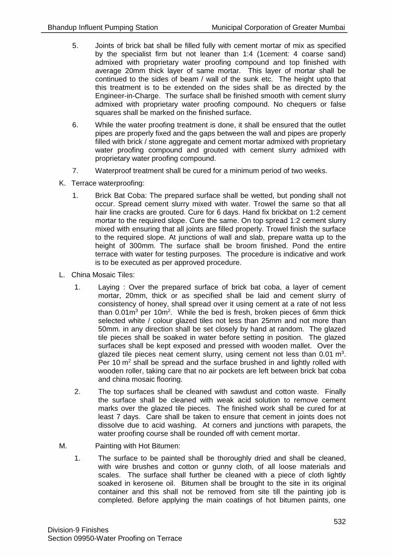
Bhandup Influent Pumping Station Municipal Corporation of Greater Mumbai
532 Division-9 Finishes Section 09950-Water Proofing on Terrace
5. Joints of brick bat shall be filled fully with cement mortar of mix as specified by the specialist firm but not leaner than 1:4 (1cement: 4 coarse sand) admixed with proprietary water proofing compound and top finished with average 20mm thick layer of same mortar. This layer of mortar shall be continued to the sides of beam / wall of the sunk etc. The height upto that this treatment is to be extended on the sides shall be as directed by the Engineer-in-Charge. The surface shall be finished smooth with cement slurry admixed with proprietary water proofing compound. No chequers or false squares shall be marked on the finished surface.
6. While the water proofing treatment is done, it shall be ensured that the outlet pipes are properly fixed and the gaps between the wall and pipes are properly filled with brick / stone aggregate and cement mortar admixed with proprietary water proofing compound and grouted with cement slurry admixed with proprietary water proofing compound.
7. Waterproof treatment shall be cured for a minimum period of two weeks.
K. Terrace waterproofing:
1. Brick Bat Coba: The prepared surface shall be wetted, but ponding shall not occur. Spread cement slurry mixed with water. Trowel the same so that all hair line cracks are grouted. Cure for 6 days. Hand fix brickbat on 1:2 cement mortar to the required slope. Cure the same. On top spread 1:2 cement slurry mixed with ensuring that all joints are filled properly. Trowel finish the surface to the required slope. At junctions of wall and slab, prepare watta up to the height of 300mm. The surface shall be broom finished. Pond the entire terrace with water for testing purposes. The procedure is indicative and work is to be executed as per approved procedure.
L. China Mosaic Tiles:
1. Laying : Over the prepared surface of brick bat coba, a layer of cement mortar, 20mm, thick or as specified shall be laid and cement slurry of consistency of honey, shall spread over it using cement at a rate of not less than 0.01m3 per 10m2. While the bed is fresh, broken pieces of 6mm thick selected white / colour glazed tiles not less than 25mm and not more than 50mm. in any direction shall be set closely by hand at random. The glazed tile pieces shall be soaked in water before setting in position. The glazed surfaces shall be kept exposed and pressed with wooden mallet. Over the glazed tile pieces neat cement slurry, using cement not less than 0.01 m3. Per 10 m2 shall be spread and the surface brushed in and lightly rolled with wooden roller, taking care that no air pockets are left between brick bat coba and china mosaic flooring.
2. The top surfaces shall be cleaned with sawdust and cotton waste. Finally the surface shall be cleaned with weak acid solution to remove cement marks over the glazed tile pieces. The finished work shall be cured for at least 7 days. Care shall be taken to ensure that cement in joints does not dissolve due to acid washing. At corners and junctions with parapets, the water proofing course shall be rounded off with cement mortar.
M. Painting with Hot Bitumen:
1. The surface to be painted shall be thoroughly dried and shall be cleaned, with wire brushes and cotton or gunny cloth, of all loose materials and scales. The surface shall further be cleaned with a piece of cloth lightly soaked in kerosene oil. Bitumen shall be brought to the site in its original container and this shall not be removed from site till the painting job is completed. Before applying the main coatings of hot bitumen paints, one

Bhandup Influent Pumping Station Municipal Corporation of Greater Mumbai
533 Division-9 Finishes Section 09950-Water Proofing on Terrace
coat of bituminous primer shall be applied. The number of coats of hot bitumen shall be either two coats or as specified in the Schedule of Quantities. The bitumen of approved quality (either of grade 80/100 or 30/40) shall be applied to the surface after heating it to the manufacturer’s specifications. Care shall be taken to see that no blank patches are left and the quality of bitumen to be spread shall be as specified and shall be to the satisfaction of the Engineer.
3.03 Quality Assurance:
A. Structures waterproofed shall be tested for water tightness as directed by Engineer. If any leakages are observed, rectify immediately.
END OF SECTION 09950.

Bhandup Influent Pumping Station Municipal Corporation of Greater Mumbai
534 Division-9 Finishes Section 09960-Interior and Exterior Acrylic Emulsion Paint
SECTION 09960-INTERIOR AND EXTERIOR ACRYLIC EMULSION PAINT
PART 1 -GENERAL
1.01 Reference:
A. Refer Section 09000 applies to and governs the work of this Section.
1.02 Work Included:
A. The work of this Section includes painting of exterior faces of the structure and site element surfaces, including but not limited to:
1. Concrete masonry block.
2. Poured or pre-cast concrete surfaces.
3. Shop and field application of primers and finish coats
B. Touch-up and repaint all painted surfaces damaged during construction.
C. Unless specified or otherwise noted, do not apply paint or protective coating to the following:
1. Copper stainless steel, chrome plate, plastic, aluminum, bronze, or brass surfaces.
2. Finishing hardware;
a) Equipment nameplates and other such identification;
b) Switches and other electrical device faceplates except if constructed of prime coat painted or galvanized steel, in which case they are to be painted;
c) Lighting fixtures;
d) Surfaces factory coated including epoxy or enamel finishes, unless specified otherwise;
e) Plastic laminate surfaces;
f) Glass;
g) Tile products, glazed or unglazed, including quarry tile;
h) Manhole covers;
i) Covers or strainers associated with floor drains, cleanout terminations, and similar equipment;
j) Recessed electrical boxes and similar recessed equipment;
k) Control panels/unless specified otherwise.
l) Circuit breakers, switches, receptacles and similar electrical devices, unless specified otherwise;
m) Galvanized or plastic coated wire fencing; posts and accessories;
n) Pre-finished metal and flashings - trim;
o) Pre-finished louvres.
1.03 Related Work:
A. The following related work is covered elsewhere in the contract documents:

Bhandup Influent Pumping Station Municipal Corporation of Greater Mumbai
535 Division-9 Finishes Section 09960-Interior and Exterior Acrylic Emulsion Paint
1. Division 4 - Masonry
2. Division 5 - Metals
3. Division 8 - Doors and Windows
4. Section 09900 - Painting
1.04 Alternatives:
A. Refer to Section 01002 for requirements pertaining to acceptance of alternatives.
1.05 Submittals:
A. Submit to the Engineer for review a complete list of materials listing proposed manufacturer, material designation and relevant identification data prior to ordering.
B. Provide only reviewed and approved material.
C. Submit standard colour chips of all types of paint to be used. The Engineer will approve all colours for use on this project.
1.06 Codes and Standards
A. The following applicable standards established by the Bureau of Indian Standards govern the materials and workmanship of the work under this Section.
IS : 2395 Indian Standard Code of practice for painting concrete, masonry and plaster surfaces.
B. Where provisions of the pertinent codes and standards conflict with these Specifications and Drawings or with each other comply with the more stringent provisions.
C. Use the latest issue of Standards:
Bhandup Influent Pumping Station Municipal Corporation of Greater Mumbai
536 Division-9 Finishes Section 09960-Interior and Exterior Acrylic Emulsion Paint
PART 2 - PRODUCTS
2.01 General:
A. Coatings manufactured by approved manufacturers/suppliers, Premium acrylic emulsion interior and exterior lead free paint with anti algal and anti fungal properties shall be considered. For exterior paints the paint shall withstand extreme tropical condition of heavy rainfall, humidity and heat. The paint shall also withstand UV degradation and shall not fade. The Engineer will determine the specific equivalence of any proposed alternative product.
B. The paint shall exhibit excellent adhesion to plaster and cement surface and shall resist deterioration by alkali salts. The paint film shall allow the moisture in wall to escape without peeling or blistering. The dried paint surface shall be able to withstand washing with mild soap and water without any deterioration a colour, or without showing flaking, blistering or peeling.
C. Provide painting materials of the highest quality.
D. All painting materials and the minimum number of coats or applications of each type of material as manufacturer guidelines.
E. Provide thinners and cleaners for proper surface preparation recommended by the paint manufacturer for that particular finish paint.
F. Non-standard colours may be selected by the Engineer. Provide non-standard colours at no additional cost to the MCGM.
G. Unless otherwise noted, paint or protective coatings are to be ready-mixed. Where site mixing is required for certain products, mix in strict accordance with the manufacturer's recommendations to produce smooth-flowing materials with an ease of application consistency.
2.02 Approved Manufacturers/Suppliers:
A. Asian Paints Ltd, Mumbai
B. Kansai Nerolac Paints Ltd
PART 3 -EXECUTION
3.01 Examination:
A. Examine surfaces to be finished before commencing work and advise the Engineer of any defective surfaces.
B. Correct defective surfaces before commencing work. Commencement of work implies the acceptance of the existing conditions.
3.02 Preparation:
A. Prior to beginning the coating work, clean all surfaces free of rust, corrosion, dirt, dust, grease or any extraneous matter.
B. Vacuum clean areas inside the building immediately prior to commencing finishing work.
C. Do not apply finishes on damp, wet or dirty surfaces.
D. Be responsible for taking all precautions or protective measures that may be necessary to suit the prevailing environmental conditions (excessive heat, humidity, spray etc) as they may affect the work of this Section.
E. Deliver all paint materials to the site in unbroken, sealed, clearly labelled original containers.

Bhandup Influent Pumping Station Municipal Corporation of Greater Mumbai
537 Division-9 Finishes Section 09960-Interior and Exterior Acrylic Emulsion Paint
F. Acid etch smooth concrete surfaces to achieve better paint or protective coating adhesion. Comply with paint manufacturer recommendations.
G. Prepare plaster surfaces as specified by manufacturer.
H. Test surfaces for moisture content with an electronic moisture meter and test concrete, masonry and gypsum surfaces for acid-alkali balance.
I. Maintain at the site at all times until the work is completed, a moisture meter, hygrometer and thermometer to verify surface and environmental conditions.
J. Apply finishing materials at proper consistency, free from brush marks, sags, crawls, streaks, runs, laps, skips, voids, pinholes, missed areas and other perceptible defects, and with even colour, sheen and texture.
K. Apply finishing and coating materials to provide full coverage and at a rate to provide the dry film thicknesses specified, but not to exceed that recommended by the manufacturer for the applicable surface.
L. Make clean, true junctions with no overlap between adjoining applications of finish coatings.
M. Leave all parts of mouldings and ornaments clean and true to details with no undue amount of coating in corners and depressions.
N. Use materials of a single manufacturer in coating system.
O. Apply each coat only after the preceding coat is dry and hard or as otherwise directed by the material manufacturer.
P. Prior to the application of special finishes and coatings, arrange for a meeting at the site with the Engineer, the painting sub-contractor and a representative of the special finish(es) manufacturer(s) to discuss the condition of surfaces to receive special finish, and application procedures.
Q. Scrub and treat mildewed surfaces with a solution of trisodium phosphate bleach with a solution of one part sodium hydrochloride (Javex) to three parts water and rinse with clean water.
R. Prepare surfaces to be painted or coated such that the surfaces are thoroughly dry and free of chemicals, mortar splatters, organic matter, oil, grease, rush, scale, loose paint or any other material and such that the surfaces are in a proper condition to receive the coating.
3.03 Application:
A. External Wall
1. Paint shall be applied on properly primed surface.
2. Subsequent coats shall not be applied till the previous coat is dry.
3. Apply no. of coats as per manufacturer's recommendations.
B. Internal Wall
1. Apply putty to rectify unevenness in surface
2. Paint shall be applied on properly primed surface.
3. Subsequent coats shall not be applied till the previous coat is dry.
4. Apply no. of coats as per manufacturer's recommendations.

Bhandup Influent Pumping Station Municipal Corporation of Greater Mumbai
538 Division-9 Finishes Section 09960-Interior and Exterior Acrylic Emulsion Paint
C. Apply all paint/stain material and protective coating finish in strict accordance with latest IS Code and the manufacturer's recommendations and as specified herein. In the event of any conflict in specifications, the more stringent specifications apply.
D. Do not field blend colours unless approved in writing by the Engineer.
3.04 Protection:
A. Cover or mask surfaces adjacent to those receiving treatment and finishing to protect the work of others from damage and soil. Mask instruction and specification plates and controls attached to equipment being painted.
B. Take particular care in storage and mixing areas to ensure that surfaces are protected.
C. Co-ordinate with the appropriate sub-contractors for the removal from finished surfaces, storage and reinstallation after finish work is completed of finish hardware, switches, plates, escutcheons, luminaire frames and similar items.
D. Post No Smoking signs and ensure that spark-proof electrical equipment is used in areas where flammable painting materials are being applied or stored.
E. Post Wet Paint signs throughout freshly finished areas and removed when finishes are dry.
F. Provide portable ULC 10: BC rated, 8 kg carbon dioxide fire extinguisher at work areas and where paint is stored.
3.05 Touch-up Surfaces:
A. Clean areas are to receive touch-up paint as specified.
B. Sand lightly to clean area for spot painting and apply two finish coats to match original coating specification.
C. Provide touch-up paint of all types and colours used on this work, suitably identified, for future use by the plant operating personnel.
3.06 Clean-up:
A. Upon completion, remove all materials and debris from the buildings.
B. Carefully clean work and remove paint from adjoining surfaces, glass, hardware etc. The whole shall be left in a condition satisfactory to the Engineer.
3.07 Quality Assurance:
A. Perform surface preparation and painting using skilled technicians/painters using the materials and methods specified.
B. Workmanship and equipment used to be of the highest quality and subject to the approval of the Engineer.
3.08 Safety:
A. Comply with precautionary measures specified in Section 01011 and 01005, for the safety of workers.
END OF SECTION 09960.

Bhandup Influent Pumping Station Municipal Corporation of Greater Mumbai
539 Division -10 Specials Section 10000-Specials
INDEX
SECTIONS NO. OF PAGES
Section 10000 - Specialties ......................................................................................................... 1
Section 10210 - Aluminum Louvers ............................................................................................. 2
Section 10430 - Signage ............................................................................................................. 2
Section 10500 - Lockers ............................................................................................................. 4
Section 10802 - Washroom Accessories ..................................................................................... 2
Total Pages in this Division .................................................................................................... 11

Bhandup Influent Pumping Station Municipal Corporation of Greater Mumbai
540 Division -10 Specials Section 10000-Specials
SECTION 10000-SPECIALS
PART 1 - GENERAL
1.01 Governing Conditions:
A. The General Conditions, Particular Conditions, Contract Forms, Instruction to Bidder, and the requirements of Division 1 herein before specified, in addition to any and all Addenda, apply to and govern each Section of this Division.
B. This Section of this Division shall be read in conjunction with other Sections in this Division.
C. This Section governs the work of all other Sections in this Division.
1.02 Work Included:
A. Supply and installation of Special Items such as soil pans, urinals, louvres, plastic water storage tanks, PVC pipes, marble partitions etc and other works as specified.
B. Provide labour, materials and equipment necessary to complete installation of special items.
C. The Drawings, Datasheets and Specifications are intended to set the acceptable minimum standard.
1.03 Co-ordination:
A. Co-ordinate before installing work included in this Division. If work is installed without co-ordination with other works, the Engineer may direct that such work be removed, relocated and/or modified as necessary. Comply promptly with any Engineer's requests. Complete any correction and/or additional work, as directed by the Engineer.
B. For coordination requirements refer to Section 01003.
1.04 Submittals:
A. Submit shop drawings/sample for Special items in this Division in accordance with Section 01007, and As-Built Drawings as per Section 01016.
1. Deviations to technical specification
2. Suppliers catalogues/samples
1.05 Codes and Standards:
A. The applicable standards established by the Bureau of Indian Standards govern the materials and workmanship of the work under this division.
B. Where provisions of the pertinent codes and standards conflict with these Specifications, Drawings and Datasheets or with each other, comply with the more stringent provisions.
C. Use the latest issue of Standards.
PART 2 -PRODUCTS
2.01 General:
A. Comply with product requirements outlined in the individual Sections. Select all other materials, not specifically described but required for the proper completion of this Division, subject to the approval of the Engineer.
Bhandup Influent Pumping Station Municipal Corporation of Greater Mumbai
541 Division -10 Specials Section 10000-Specials
PART 3 - EXECUTION
3.01 General:
A. Comply with execution requirements outlined in the individual Sections.
END OF SECTION 10000

Bhandup Influent Pumping Station Municipal Corporation of Greater Mumbai
`542 Division-10 Specials Section 10210- Aluminium Louvers
SECTION 10210- ALUMINIUM LOUVERS
PART 1 -GENERAL
1.01 Reference:
A. Section 10000 –applies to and governs the work of this Section.
1.02 Work Included:
A. Supply and installation of all exterior aluminum louvers including structural supports or frames, as specified and as shown on the drawings.
B. The Drawings, Datasheets and Specifications are intended to set the acceptable minimum standard.
1.03 Related Work:
A. The following related work is covered elsewhere in the contract documents:
1. Division 4 - Masonry
2. Division 5 - Metals
1.04 Alternatives:
A. Refer to Section 01002 for requirements pertaining to acceptance of alternatives.
1.05 Submittals:
A. Submit drawings and product data in accordance with Section 01007, and As-Built drawings as per Section 01016.
B. Submit to the Engineer, samples of storm-proof louvers, drainable louvers and aluminum heavy-duty bird screens.
1.06 Codes and Standards
A. The following applicable standards established by the Bureau of Indian Standards govern the materials and workmanship of the work under this section.
1 IS: 1038 Specifications for Steel, Doors, Windows and Ventilators.
2 IS: 4021 Specifications for Timber, Door, Window and Ventilator Frames.
3 IS: 1948 Specification for aluminium door windows and ventilators
B. Where provisions of the pertinent codes and standards conflict with these Specifications and Drawings or with each other comply with the more stringent provisions.
C. Use the latest issue of Standards.
PART 2 - PRODUCTS
2.01 Materials:
A. Louvre frames and blades shall be extruded aluminium alloy 6063 - T52 sections, minimum 8-gauge material; louvre depth shall be 150 mm unless otherwise specified.
B. Louvres up to 600 mm high shall have fixed horizontal storm proof blades and shall be 35 degrees from horizontal, complete with water baffle.

Bhandup Influent Pumping Station Municipal Corporation of Greater Mumbai
`543 Division-10 Specials Section 10210- Aluminium Louvers
C. Louvres over 600 mm high shall have fixed horizontal drainable blades with gutters designed to catch and direct water to jamb and mullion drains.
D. Frames shall be of all-welded construction and shall be provided with a caulking recess all around.
E. Provide 13 mm x 13 mm intercrimped aluminium heavy-duty bird screens (2.3 mm gauge) folded in extruded aluminum frames on all louvers, mounted on the interior.
F. Storm proof louvers shall be approved by the Engineer. Continuous blade louvers to be used with continuous blade mullions where required.
G. Colours: to match the Pumping Station.
H. Drainable louvers shall be approved by the Engineer. Continuous blade louvers to be used with continuous blade mullions where required.
I. Refer to Section 09900 for colour selection.
2.02 Approved supplier / manufacturer
A. Srinathji Aluminum Louvers, Chennai
B. Rathod Industries, Mumbai
C. Yogeshwar Enterprises, Thane
PART 3 - EXECUTION
3.01 Examination:
A. Prior to ordering, carefully verify that building openings have the required dimensions.
B. In the event of a discrepancy, immediately notify the Engineer.
3.02 Installation:
A. Install louvers plumb and true, flush with the outside of building surfaces or as detailed on the Drawings.
B. The structural support or frame shall be designed by the louver manufacturer to support the louver against a wind load of not less than 1.0 kPa with the maximum deflection not exceeding 1/180 of the span.
C. Upon completion of installation, all louvers shall be left clean and free from dirt. All debris shall be removed from the site.
D. Replace or repair any scratches, dents or other damage to the louvers using manufacturer’s recommended methods and to the satisfaction of the Engineer.
END OF SECTION 10210.

Bhandup Influent Pumping Station Municipal Corporation of Greater Mumbai
544 Division-10 Specials Section 10430-Signage
SECTION 10430-SIGNAGE
PART 1 - GENERAL
1.01 Reference:
A. Section 10000 applies to and governs the work of this Section.
1.02 Work Included:
A. Provide all labour, material and equipment necessary to supply and install bronze identification signage - “New (Name of pumping station)” - including concealed anchors and all other work specified herein.
B. Supply and install lettering on building face at the location as per Engineer’s instructions.
1.03 Related Work by Other Divisions:
A. The following related work is covered elsewhere in the Contract Documents:
1. Division 4 - Masonry
2. Division 5 - Metals
1.04 Alternatives:
A. Refer to Section 01002 for requirements pertaining to acceptance of alternatives.
1.05 Submittals:
A. Submit drawings of all products specified in accordance with Section 01007.
B. Shop drawings shall clearly indicate all component parts and fixings, the materials being supplied, the thickness of the materials and shall show all connections, attachments and anchorage.
C. Shop drawings shall incorporate exact graphic layout and final accurate art work for the signage.
D. Submit two samples of 250 mm high letters in the material finish and font specified.
E. Submit maintenance instructions for the bronze signage in accordance with Section 01016.
1.06 Codes and Standards:
A. The applicable standards established by the Bureau of Indian Standards govern the materials and workmanship of the work under this Sections.
B. Where provisions of the pertinent codes and standards conflict with these Specifications and Drawings or with each other comply with the more stringent provisions.
C. Use the latest issue of Standards.

Bhandup Influent Pumping Station Municipal Corporation of Greater Mumbai
545 Division-10 Specials Section 10430-Signage
PART 2 - PRODUCTS
2.01 Materials:
A. Cast bronze letters, 250 mm high and with a 13 mm deep return. Lettering shall be in upper case and font style to be approved by Engineer. Letters shall have a 13 mm offset from the wall with spacers. Texture to face and sides of letters shall be sandblasted. Finish remaining uncoated natural bronze. Manufacturer to be reputable approved by Engineer.
B. Letters shall be mounted onto face of exterior concrete / masonry wall as approved by the Engineer. Horizontal bands of letters shall be centred within the 190mm high block courses. Mounting shall be by way of studs into tapped bosses on backs of letters. Fill holes with quick-sealing cement.

Bhandup Influent Pumping Station Municipal Corporation of Greater Mumbai
546 Division-10 Specials Section 10430-Signage
2.02 Approved Manufacturer / Supplier for Bronze sheets
A. R. Mahveerchandra and Company, Mumbai
B. P.B. Corporation, Ahemdabad
C. Prolite Autoglow Mumbai
D. Delux Metal Industries, Ahmedabad
PART 3 -EXECUTION
3.01 Fabrication:
A. The outline of exterior exposed surfaces shall be exactly as indicated on the approved shop drawings.
B. Nuts, bolts, crews, clips and other means of fastening shall be concealed in the finished exposed work.
C. The finishes of the various materials shall be exactly as specified.
D. The dimensional tolerances shall be maintained with the closest accuracy for the various parts.
3.02 Installation:
A. Install sign at the location as per Engineer’s instruction.
B. Install as per these Specifications and manufacturer’s recommendations and guidelines.
C. Erect signs securely, plumb and square.
D. Fabricate and install signage in such a manner as to provide a permanently rigid and true installation.
E. Individual letters to be true, tight, flat and in alignment to the satisfaction of the Engineer.
3.03 Cleaning:
A. Clean and buff signs and leave in a neat appearance.
3.04 Maintenance Instructions:
A. Provide instruction on proper care and maintenance of the bronze signage.
3.05 Guarantee/Warranty:
A. The Guarantee/Warranty shall be for a period of five years from the date of Completion of Work.
B. The Guarantee/Warranty shall cover the repair of the bronze signage as a result of faulty materials or workmanship due to:
1. Loosening of units
2. Deforming failure in sign letters
C. Upon written notification that the signage is defective, promptly repair or replace the defective work.
END OF SECTION 10430

Bhandup Influent Pumping Station Municipal Corporation of Greater Mumbai
547 Division-10 Specials Section 10500-Lockers
SECTION 10500-LOCKERS
PART 1 -GENERAL
1.01 Reference:
A. Section 10000 – applies to and governs the work of this Section.
1.02 Work Included:
A. Supply and install new steel lockers, accessories and finish metal trim for each Pumping Station.
1.03 Related Work:
A. The following related work is covered elsewhere in the Contract Documents:
1. Division 5 - Metals
1.04 Alternatives:
A. Not applicable for this Section.
1.05 Submittals:
A. Submit shop drawings, fabrication drawings, installation drawings and product data in accordance with Section 01007.
B. Submit drawings showing locker types, size and quantities, including all necessary details relating to anchoring, trim installation and relationship to adjacent surfaces.
1.06 Codes and Standards:
A. The following applicable standards established by the Bureau of Indian Standards govern the materials and workmanship of the work under this section.
IS: 800 - 1984 Code of practice for use of structural steel in general building construction
IS: 226 Structural Steel (Standard quality)
IS: 961 Structural steel (High Tensile)
IS: 1977 Structural Steel (ordinary) - Fe 410-0
IS: 2062 Structural steel (Fusion Welding quality)
IS: 1079 Specifications for light gauge structural quality hot rolled carbon steel sheet and strip.
B. Where provisions of the pertinent codes and standards conflict with these Specifications and Drawings or with each other comply with the more stringent provisions.
C. Use the latest issue of Standards.
Bhandup Influent Pumping Station Municipal Corporation of Greater Mumbai
548 Division-10 Specials Section 10500-Lockers
PART 2 - PRODUCTS
2.01 Materials:
A. Products supplied by manufacturers shall be approved provided they meet the detailed specifications written below.
2.02 Lockers:
A. Style: Four Tier.
B. Type: Single Door.
C. Size: 380 mm (w) x 450 mm (d) x 1830 mm (h)
D. No of Locker frames: 3
E. No. of Locker Openings: 12 nos
2.03 Fabrication:
A. Specified locker components shall be manufactured from galvanised steel and finished by manufacturer’s standard process.
2.04 Finish:
A. Surfaces of the steel shall be thoroughly cleaned and phosphatized in a seven-stage process.
B. All parts shall then be finished with a heavy coat of Epoxy Polyester Powder to thickness of 50 microns (± 10).
C. Provide to the Engineer colour charts showing manufacturer’s available colours.
2.05 Construction:
A. Lockers shall be built on the unit principle - each locker shall have an individual door and frame, an individual top, bottom, back and shelves with common intermediate uprights separating units.
B. Provide rigid knock-down construction for locker.
2.06 Door Frames:
A. Door frames shall be 16 gauge formed into 25mm wide face channel shapes with a continuous vertical door strike, integral with the frame on both sides of the door opening.
Four tier locker cross frame members shall be 16 gauge channel shaped securely welded to vertical framing members to ensure a square and rigid assembly. Intermediate cross frame members are not required on box lockers.
2.07 Doors:
A. Provide door with 16 gauge or 18 gauge steel as required by manufacturer’s design, formed with a full channel shape on the lock side to fully conceal the lock bar, channel formation on the hinge side and right angle formation across the top and bottom.

Bhandup Influent Pumping Station Municipal Corporation of Greater Mumbai
549 Division-10 Specials Section 10500-Lockers
B. Locker doors shall be ventilated by louvres on the face of each door, top and bottom.
2.08 Pre-Locking Device:
A. All lockers shall be equipped with a positive automatic pre-locking device, whereby the locker may be locked while door is open and then closed without unlocking and without damaging locking mechanism.
B. Provide 10 lever cam lock with lock lever built in and three keys for each locker.
2.09 Handles:
A. A non-protruding 14 gauge lifting trigger and slide plate shall transfer the lifting force for actuating the lock bar when opening the door.
B. The exposed portion of the lifting trigger shall be encased in a moulded ABS thermoplastic cover that provides isolation from metal-to-metal contact and be contained in a formed 20 gauge stainless steel recessed pocket. This stainless steel pocket shall contain a recessed area for the various lock types available and a mounting area for the number plate.
2.10 Hinges:
A. Hinges shall be 50 mm high, 5-knuckle, full loop, tight pin style, securely welded frame and double riveted to the inside of the flange. Locker doors 1050 mm high and less shall have two hinges. Doors over 1050 mm high shall have three hinges.
2.11 Body:
A. The body of the locker to consist of 24 gauge upright sheets, backs, tops, bottoms and shelves. Tops, bottoms and shelves to be flanged on all four sides; backs to be flanged on two sides. Uprights shall be offset at the front and flanged at the rear to provide a double-lapped rear corner. All bolts and nuts shall be stainless steel.
2.12 Interior Equipment:
A. Single tier lockers over 1060 mm high shall have one hat/ book shelf. Other tiered lockers do not require shelves. All single, double and triple tier lockers shall have one double prong rear hook (single prong in 230 mm width) and two single prong wall hooks in each compartment. All hooks shall be made of steel, formed with ball points, zinc-plated and attached with two bolts or rivets. Lockers under 510 mm high shall not be equipped with hooks.
2.13 Number Plates:
A. Each locker shall have a polished aluminium number plate with black numerals not less than 38mm high. Plates shall be attached with rivets to the lower surface within the recessed handle pocket.
B. Provide number system in English and Marathi as per approved shop drawings.
2.14 Colour:
A. Doors and exposed body parts to be finished in selected colours, approved by the Engineer.

Bhandup Influent Pumping Station Municipal Corporation of Greater Mumbai
550 Division-10 Specials Section 10500-Lockers
2.15 Hanging Rod
A. One hanging rod in each component.
2.16 Accessories:
A. Stand for lockers – 125 mm high inclusive of leveller.
Approved supplier / manufacturer
A. Godrej & Boyce, Mumbai
B. Or equivalent approved.

Bhandup Influent Pumping Station Municipal Corporation of Greater Mumbai
551 Division-10 Specials Section 10500-Lockers
PART 3 -EXECUTION:
3.01 Installation:
A. Lockers shall be installed in accordance with the manufacturer’s approved shop drawings and assembly instructions.
B. Installation shall be level and plumb with flush surfaces and rigid attachment to anchoring surfaces on the stand.
3.02 Adjustment:
A. Upon completion of installation, inspect lockers and adjust as necessary for proper door and locking mechanism operation.
B. Touch up scratches and abrasions with factory-supplied paint to match original finish.
C. For user safety, all lockers must be secured to the wall and/or floor prior to use.
3.03 Inspection:
A. Lockers will be inspected at site for gauge thickness of door and body and proper closing of lockers.
END OF SECTION 10500.

Bhandup Influent Pumping Station Municipal Corporation of Greater Mumbai
552 Division-10 Specials Section 10802- Washroom Accessories
SECTION 10802- WASHROOM ACCESSORIES
PART 1 -GENERAL
1.01 Reference:
A. Section 10000 - applies to and governs the work of this Section.
1.02 Work Included:
A. Provide washroom accessories as specified hereinafter and as shown on the Drawings.
B. The Drawings, Datasheets and Specifications are intended to set the acceptable minimum standard.
1.03 Related Work by Other Divisions:
A. The following related work is covered elsewhere in the contract documents:
1. Division 4 - Masonry
2. Division 5 - Metals
3. Division 9 - Finishes
4. Division 15 - Mechanical
5. Section 15400 - Plumbing and Drainage.
1.04 Alternatives
A. Refer to Section 01002 for requirements pertaining to acceptance of alternatives.
1.05 Submittals:
A. Submit catalogues, product data documents as specified in section 10000 in accordance with Section 01007, and As-Built drawings as per Section 01016.
1.06 Codes and Standards:
A. The applicable standards established by the Bureau of Indian Standards govern the materials and workmanship of the work under this section.
B. Where provisions of the pertinent codes and standards conflict with these Specifications and Drawings or with each other comply with the more stringent provisions.
C. Use the latest issue of Standards.
PART 2 - PRODUCTS
2.01 Materials:
A. All materials as manufactured by approved manufacturers unless otherwise specified shall be provided in each wash room.
B. European pattern coloured white porcelain floor mounted soil pan 630 mm long of an approved make and pattern with trap and antisyphonage opening for vent pipe, 32mm dia. PVC seat cover with brass hinges. PVC cistern double-flush type with anti-microbial 3/6litres flushing capacity. Including CP stop cock, brass unions, jam nuts, GI/PVC flush pipes with plug bends with cleaning cap from soil pan to soil pipe, including fitting.
C. Flat base urinal in white glazed earthenware fixed with screw, P trap and 32mm PVC drain pipe, fitted with CP spreader with CP stop cock.
D. Polyethylene water storage tank of the required capacity, having ISI mark, approved make such as Sintex, Ashish Plast or equivalent with mosquito-proof brass jali frame

Bhandup Influent Pumping Station Municipal Corporation of Greater Mumbai
553 Division-10 Specials Section 10802- Washroom Accessories
and cover, 450mm with locking arrangement including required copper ball lock with brass arm including washout plug and overflow GI pipe with mosquito-proof jali.
E. Marble partitions of approved quality and grain 15mm thick highly polished on both sides with round edges and holes cut in the same to receive flushing pipe etc. as directed.
F. 100mm dia, 4mm thick (wt. approx.10 kg/m) centrifugally cast CI pipes, socket/spigot soil waste and ventilation purpose including specials such as cut pipes, bends, offsets and shoes.
G. White / coloured porcelain 550 mm wash basin with wall products of an approved make with overflow, sensor tap with touch-free operation, wastewater pipe, required P trap complete in all respects. Size 530 mm x 345 mm with 140 mm depth.
H. Automatic Hand Dryer
1. Stainless steel hand dryer, of grade SS-316, non-magnetic RPM-9000, Drying time less than 10 sec, time protection – 1 minute auto cut, Size 240 x 270 x 142 mm.
I. Liquid Soap Dispenser
1. Stainless steel AISI-316 soap dispenser and fitted to give classy appearance to wash room-capacity – 100ml.
J. Hand Towel Dispenser
1. Stainless steel paper dispenser, capacity – 450 – 500 tissues wall-mounted.
K. Double Roll Tissue Dispenser with Shelf
1. Manufactured using quality toilet tissue grade, serrated edges for smooth, single hand dispensing various length, pin-to-pin embossing pattern.
L. Glass Mirror
1. 600 X 450 mm, 6 mm thick bevel edged float glass mirror manufactured by Mode or equivalent mounted on 10 mm thick waterproof plywood with SS screws.
2.02 Approved suppliers / manufacturer
A. Euronics Industries
B. Parryware
C. Neelkamal, Mumbai
PART 3 - EXECUTION
3.01 Installation:
A. Install all items to the satisfaction of the Engineer.
END OF SECTION 10802.

Bhandup Influent Pumping Station Municipal Corporation of Greater Mumbai
554 Division-11 Repair Works Section 17001- Repair Works
SECTION 17001- REPAIR WORKS
PART 1 -POLYMER MODIFIED CEMENT MORTAR
1.01 General
The cement based polymer modified mortar shall be prepared at the site by adding blended cement, polymer and aggregate or using ready to use components supplied by manufacturer’s in pre-packed containers/ bags subject to approval of engineer. The polymer must be brought at the site in sealed packed containers directly from the manufacturer/source as specified and directed by the consultants.
1.02 QUALITY ASSURANCE LABELING
Contractor shall clearly mark all containers with following information
a. Name of manufacturer
b. Manufacturer’s product identification
c. Manufacturer’s instruction for mixing
d. Warning for handling and toxicity
1.03 APPLICATION CONTROL
The contractor shall submit mixing application procedure for approval prior to use.
1.04 DELIVERY OF MATERIAL
Contractor shall deliver all materials in sealed containers with labels legible and intact.
1.05 STORAGE OF MATERIAL
Contractor shall arrange to store all materials a t the temperature recommended by the manufacturer and as directed by the consultants.
1.06 MATERIALS
The CEMENT used shall be blended cement conforming to IS:8112. IT must be free from any lumps and must be from fresh stock. The sand shall be sharp washed, well graded and free from excessive fines. Quartz sand 1630 mesh size shall be used for all polymer modified work. Water used for cementitious polymer modified mortar shall conform to the requirement of IS:456. Polymer used shall be Acrylic base.
1.07 EXECUTION
A. PREPARATION OF CONCRETE SURFACE
A good base or foundation shall be prepared for successful application of polymer concrete. Proper support must be provided to members under repair before exposing the same for repair. It is mandatory for the contractor to seek consultant’s approval for the support system. The ultimate responsibility of the support system lies with the contractor. The gist of the point being the paramount importance of the safety of the building under repair. The props must be tight against any jerks or jolts. The system should ensure that all loads of slab, beams and overhangs are properly redistributed by by-passing the column to be repaired. Necessary length of the wall, if required can be dismantled. All unsound/ weak concrete material shall be first removed upto the required depth including undercut upto 6 mm behind the reinforcement bars, wherever required as directed by the Engineer. Chipping shall continue until there are no offsets in the cavity will cause an abrupt change in the thickness of the repaired surface.

Bhandup Influent Pumping Station Municipal Corporation of Greater Mumbai
555 Division-11 Repair Works Section 17001- Repair Works
While removal of cover, care is to be taken that the sound core of the column is not disturbed. Exposed corroded steel is to be cleaned thoroughly by chipping hammer and wire brush. The steel surface is to be evenly coated twice by any rust converter in 4 hours interval and must be cleaned with running water after 12 hours. Subsequently, two coats of Rust pasivator of Polymer: Cement should be applied on cleaned reinforcement in 4 hours interval. After it has been ensured that surface to which polymer modified cement mortar is to be bonded is sound, it shall be cleaned off all loose and foreign materials by means of wire brushing as directed by engineer.
B. METHODOLOGY
i. BOND COAT
The contractor shall wet the surface ensuring that they are saturated but free of surface water. Prepare a bonding slurry of 1.5 to 2 part of cement to 1 part of polymer mixed to a lump free creamy consistency. Alternatively, the primer (bonding slurry) shall be made as per manufacturer’s recommendations. The bonding slurry shall be worked well into the surface of the parent body using stiff brush ensuring that no pinhole are visible. Bonding slurry shall not be applied at a thickness in excess of 2 mm. If in the opinion of engineer a second coat is necessary, the same shall be applied after the first coat is touch dry. The second coat shall be applied at right angle to the first to ensure complete coverage. The bonding slurry shall be applied to prepare a concrete and reinforcement substrate after tying in new reinforcement wherever specified in the form of bars or welded wire fabric. Cement base polymer modified mortar shall be applied as soon as possible after application of bonding slurry but always during the open time of adhesive.
C. APPLICATION OF POLYMER MORTAR
Mixing of polymer with cement shall be done in proportion as recommended by manufacturer. Normally, 10 kg of polymer is to be mixed with 50 kg of cement. The mixing shall be carried out in efficient concrete mixer. However, the Engineer may allow hand mixing in case total weight of mix per batch is less than 25 kg. Polymer must be prepared in a water tight G.I. tray. The mixer shall be charged with required quantity of sand and cement and pre-mixing shall be carried for approximately one minute. Rendering of cement based Polymer modified mortar shall be done immediately after applying the bonding slurry to the prepared surface preferably in coats of approximately 12-15 mm thickness, as greater thickness may lead to slumping. Further coats shall be applied fairly in rapid succession immediately after the previous layer gets set hard enough to receive the subsequent layer. After application of mortar the surface shall be either finished by impregnating 20 mm down graded metal pieces or closed using a wooden float or steel trowel and furrowed subsequently, while the mortar is still green. In case the thickness of damaged concrete is more than 12-15 mm, the first layer must be applied using quartz sand and subsequently layers can be built using thoroughly cleaned river sand and 10 mm down metal. A proper bond coat must be applied prior to application of each layer of polymer modified cement mortar.
D. INSPECTION AND QUALITY CONTROL
The mortar application work shall be continuously inspected by a qualified supervisor, who shall check materials, application of mortar, curing, etc. Each completed work shall be systematically sounded with a hammer to check for drummy areas after hardening. In suspected areas or whenever directed by Engineer, contractor shall drill the cores from the finished work after 7 days and 28 days of mortar application. The cores shall be examined for evidence of poor

Bhandup Influent Pumping Station Municipal Corporation of Greater Mumbai
556 Division-11 Repair Works Section 17001- Repair Works
workmanship by the engineer and if he feels that either bonding work or the subsequent layer of mortar are not required workmanship, the contractor at the instruction of the engineer shall dismantle such areas of work as required by the Engineer and redo the same after re-preparing the surface by chipping of mortar work and abrading the bonding slurry interface. Fogging to be carried out for atleast 4-5 days.
E. PAYMENT
Measurement shall be in sqm/swft basis of the actual exposed surface for repairs. All the measurement shall be taken before starting application work of polymer modified cement mortar. The corner of the P.C.M. work to be measured once, with one side only. The rate shall include the cost of treatment given to old and new reinforcement and application of bond coat to exposed concrete surface and every successive layers. Quartz sand shall be supplied by the contractor. The rate is exclusive of providing and fixing of steel reinforcement. The rate shall include the cost of scaffolding and working platform at all height and level. The polymer consumption shall be strictly reconciled @ 200 gm/ per sft or 2.20 kg/ sq.m for all kind of repair work. Incase of polymer consumption is exceeding more than 20% i.e. specified dose the same should be brought to the notice of consultants maximum within 3 days in writing, failing which it will be considered as a wastage of polymer and the extra consumption of polymer shall be borne by contractor only. Similarly, in case polymer consumption is less than that specified i.e. more than 20% shall be considered as a manipulation of measurement or poor grade or work due to less consumption of polymer.
PART 2 -JACKETING
2.01 PREPARATION OF SURFACE
A good base or foundation shall be prepared for successful application of jacketing. Proper support must be provided to members under repair before exposing the same for repair. IT s mandatory for the contractor to seek consultant’s approval for the support system. The ultimate responsibility of the support system lies with the contractor. The gist of the point being the paramount importance of the safety of the building under repair. The props must be tight against any jerks and jolts. The system should ensure that all load of slab, beams and overhangs are properly redistributed by bypassing the column to be jacketed. Necessary length of wall etc. can be dismantled. All sound/ weak concrete material shall first be removed up to the required depth as directed by Engineer. Chipping shall continue until there are no offsets in the cavity, which will cause an abrupt change in thickness of repaired surface. Exposed corroded steel is to be cleaned thoroughly by chipping hammer and wire brush. The steel surface is to be evenly coated twice by any rust converter in 4 hours interval and must be cleaned with running water for 12 hours. Subsequently, two coats of Rust Passivator of Polymer: Cement should be applied on cleaned reinforcement in 4 hours interval. After it has been insured that the surface to which jacket concrete is to be bonded is sound, holes of required depth and diameter shall be drilled using heavy dity “BOSCH” hammer dirll as per the spacing stated. The drilled holes shall be thoroughly cleaned off loose particles by oil free air blast. The treated steel bars of required length, shape and diameter shall then be driven inside the hole, packed with polymer mortar. A polymer dash coat must be applied at least one day prior to casting of Jacket, impregnating 20 mm down metal pieces.
Bhandup Influent Pumping Station Municipal Corporation of Greater Mumbai
557 Division-11 Repair Works Section 17001- Repair Works
2.02 CASTING OF JACKET
Steel reinforcement is to be provided after proper binding, bending, etc. as specified by the Engineer. Hole to be drilled in the slab to pass the reinforcement to maintain the continuity of R.C.C. jacket. Proper form work/ shuttering is to be provided all around the column so as to provide a R.C.C. jacket. The jacket so provided will be min of 75 mm thickness over the R.C.C. Column/ beam and the same to be filled with M25 grade of concrete using super plasticizer to avoid honeycombing effect. Any kind of honey comb, if appeared after opening of shuttering next day, must be repaired as per the instruction of Engineer in charge at no cost to society. All form work/ shuttering is to be removed min after 24 hours. The jacketed portion is to be cured properly for 7 days using gunny bags to cover new concrete surface. All steel props to be removed and load re-transformed as per the instruction of the Engineer all complete including any incidental work if required.
2.03 PAYMENT
Payment of jacketing shall be made on the basis of unit rate quoted in the schedule of quantities. Measurement of jacketing shall be based on SqM of actual work done. The comer of jacket to be measured once, with one side only. The rate shall include providing and fixing shuttering with all necessary support, platform, surface preparation, treatment to reinforcement, curing, using of super plasticizer and any other incidental work as required. Nothing extra shall be paid for additional thickness of concrete if any, required to fill the excessive damaged cover/ core concrete. Relieving of load from R.C.C. column and beam shall be paid separately under relevant item. The rate shall exclude providing and fixing of reinforcement, which shall be paid under relevant item. Rate is inclusive of applying polymer dash coat and impregnating metal pieces if required, but exclusive of cost of polymer, which shall be paid separately. The rate should be inclusive of breaking of floor, P.C.C, removing of stone boulder, excavation in soil and backfilling the same after completion of jacketing work.
PART 3 -REPAIRS TO PLASTER
The work includes cutting the patch and preparing the wall surface. Patches of 2.50 square metres and less in area shall be measured under item of ‘Repairs to Plaster’ under this sub-head. Plastering in patches over 2.5 square metres in area shall be paid for at the rate as applicable to new work under sub head Finishing’.
3.01 SCAFFOLDING
Scaffolding as required for the proper execution of the work shall be erected. If work can be done safely with the ladder or jhoola these will be permitted in place of scaffolding. CUTTING The mortar of the patch, where the existing plaster has cracked, crumbled or sounds hollow when gently tapped on the surface, shall be removed. The patch shall be cut out to a square or rectangular shape at position marked on the wall as directed by the Engineer-in-Charge or his authorized representative. The edges shall be slightly under cut to provide a neat joint.
3.02 PREPARATION OF SURFACE
The masonry joints which become exposed after removal of old plaster shall be raked out to a minimum depth of 10 mm in the case of brick work and 20 mm in the case of stone work. The raking shall be carried out uniformly with a raking tool and

Bhandup Influent Pumping Station Municipal Corporation of Greater Mumbai
558 Division-11 Repair Works Section 17001- Repair Works
not with a basuli, and loose mortar dusted off. The surface shall then be thoroughly washed with water, and kept wet till plastering is commenced. In case of concrete surfaces, the same shall be thoroughly scrubbed with wire brushes after the plaster had been cut out . The joints shall be raked out properly. Dust and loose mortar shall be brushed out. Efflorescence if any shall be removed by brushing and scrapping. The surface shall then be thoroughly washed with water, cleaned and kept wet before plastering is commenced. In case of concrete surface if a chemical retarder has been applied to the form work, the surface shall be roughened by wire brushing and all the resulting dust and loose particles cleaned off and care shall be taken that none of the retarders is left on the surface. APPLICATION OF PLASTER Mortar of specified mix with the specified sand shall be used. The method of application shall be as described for single coat plaster work of the specified mix and under SP-CS-PL-05. The surface shall be finished even and flush and matching with the old surrounding plaster. All roundings necessary at junctions of walls, ceilings etc. shall be carried out in a tidy manner as specified in sub-head SP-CS-PL-05. All dismantled mortar & rubbish etc. shall be disposed off within 24 hours from its dismantling promptly as directed by the Engineer-in-Charge. PROTECTIVE MEASURE Doors, windows, floors, articles of furniture etc. and such other parts of the building shall be protected from being splashed upon. Splashing and droppings, if any, shall be removed by the contractor at his own cost and the surface cleaned. Damages, if any, to furniture or fittings and fixtures shall be recoverable from the contractor. CURING Curing shall be done as per plaster work with special reference to the particular type of plaster mix as described under sub-head finishing’. FINISHING After the plaster is thoroughly cured and dried the surface shall be white washed or colour washed to suit the existing finishing as required unless specified. MEASUREMENTS Length and breadth shall be measured correct to a cm. The area shall be calculated in square metre correct to two places of decimal. Patches below 0.05 square metre in area shall not be measured for payment. Pre-measurements of the patches to be plastered shall be recorded after the old plaster has been cut and wall surface prepared.
3.03 RATE
The rate includes the cost of all the materials and labour involved in all the operations described above including lead as described in the item for disposal of old dismantled plaster /material.
END OF SECTION 11001.

Bhandup Influent Pumping Station Municipal Corporation of Greater Mumbai
559 Section – Water supply, sanitary and drainage works
SECTION - WATER SUPPLY, SANITARY AND DRAINAGE WORKS
1.0 SCOPE
1.1 This specification covers the general requirements of providing and laying water mains and water supply piping and providing and laying drainage lines.
1.2 For specifications, mode of measurements and scope of work covered under the respective items for the work included under this contract, following documents shall be referred to in the order of precedence as given below:
(a) Description of the items and notes if any given in the Schedule of Quantities.
(b) Drawings
(c) Specifications.
(d) Additional/ Special Conditions of Contract.
(e) General Conditions of Contract.
(f) Applicable Codes and Standards as specified herein with amendments/ revisions issued till date.
In the event of any discrepancy among the documents referred above, the document in the higher order of precedence shall prevail.
1.3 In the event of any element of specification not being available in any of the documents mentioned above, the instructions of the Engineer in writing shall be followed by the Contractor.
1.4 The Work shall be carried out in accordance with the drawings and designs as would be issued to the Contractor by the Engineer duly signed and stamped by him. The Contractor shall not take cognisance of any drawings, designs, specifications, etc. not bearing Engineer's signature and stamp. Similarly the Contractor shall not take cognisance of instructions given by any other Authority except the instructions given by the Engineer in writing.
1.5 The Work shall be executed and measured as per metric dimensions given in the Schedule of Quantities, drawings, etc.
1.6 The Contractor shall acquaint himself fully with the partial provisions for supports that may be available in the structure and utilise them to the extent possible. In any case the Contractor shall provide all the supports regardless of provisions that have been already made. Nothing extra shall be payable for situations where bed plates (for supports) are not available or are not useful.
1.7 The Contractor shall incorporate seismic considerations of anchoring and isolation in the design of the systems as per the requirements of the different equipment.
1.8 Shop coats of paint that may be damaged during shipment or erection shall be cleaned off with mineral spirits, wire brushed and spot primed over the affected areas, then coated with paint to match the finish over the adjoining shop painted surface.
1.9 In addition to the sectional testing carried out during the construction, the Contractor shall test the entire installation after connections to the overhead tanks or pumping system or mains. He shall rectify all leakage and shall replace all defective materials in the system. Any consequential damage done to the building, furniture and fixtures on account of Contractor’s carelessness, like open or burst pipes or failure of fittings during testing and commissioning shall be made good by the Contractor at no additional cost.
2.0 SCAFFOLDING
2.1 Only steel tube scaffolding of approved design shall be used for all works. The scaffold structure shall comply with the requirements of IS: 4014 and IS: 3696. An independent tied scaffold (single and double scaffold), which has two lines of

Bhandup Influent Pumping Station Municipal Corporation of Greater Mumbai
560 Section – Water supply, sanitary and drainage works
standards, shall be provided with the inner line kept at least one board clear of the finished face with extended transoms, or hop up baskets to carry an inside board. Diagonal braces shall not prevent the material being moved along the scaffold run. The scaffolding shall be suitably packed at the ends to prevent damage to the finished work.
3.0 PROTECTION
3.1 Protection against damage: Care shall be taken to avoid damage from any cause at all stages. Packing pieces used for protection shall not disfigure or otherwise permanently mark the Works.
3.2 Surface protection shall be afforded by careful handling and the avoidance of the use of hooks, crowbars, or other implements that are likely to damage the works.
3.3 During installation of piping, open end of pipe shall be protected with temporary cover to prevent dust or other materials entering it.
3.4 Protection during construction: Decorative surfaces shall be carefully protected during construction by providing a temporary cover.
3.5 Protection of finished work: At all stages of the Contract it is essential that all works are properly protected.
3.6 Suitable packing shall be used to ensure that scaffolding does not damage erected stone, marble, granite or other finished works.
3.7 Any disfigurement, discolouration or imperfection whatsoever due to any reason shall not be accepted and the Contractor shall either remedy the same or redo the work at no extra cost. The decision of the Engineer as to whether any work either in whole or in part is acceptable or not shall be final and binding on the Contractor.
4.0 GUARANTEE
4.1 The Contractor shall guarantee and undertake to maintain and rectify the various components of the Plumbing work installed by him for successful performance for a period as indicated elsewhere in the tender/ contract document. The Contractor shall indemnify the Engineer for a similar period against any damage to property and injury to persons on account of any defective work or maintenance carried out by the Contractor. The format and text of the Guarantee and the Indemnity Bond shall be given by the Engineer.
5.0 APPLICABLE CODES, STANDARDS AND PUBLICATIONS
5.1 All equipment, supply, erection, testing and commissioning shall comply with the requirements of Indian Standards and code of practices given below as amended till date. All equipment and material being supplied by the Contractor shall meet the requirements of IS and other Codes/ Publications as given below.
SP: 6 (1) Structural steel sections.
IS: 325 Three phase induction motors.
IS: 554 Dimensions for pipe threads where pressure tight joints are required on the threads
IS:694 PVC insulated cables for working voltages up to and including 1100 V.
IS: 779 Specification for water meters (domestic type).
IS: 800 Code of Practice for general construction in steel.
IS: 1068 Electroplated coatings of nickel plus chromium and copper plus nickel plus chromium.
IS: 1172 Code of Basic requirements for water supply drainage and

Bhandup Influent Pumping Station Municipal Corporation of Greater Mumbai
561 Section – Water supply, sanitary and drainage works
sanitation.
IS: 1367 (Part 1) Technical supply conditions for threaded steel fasteners: General Requirements.
IS: 1367 (Part 2) Technical supply conditions for threaded steel fasteners: Tolerances for fasteners – Bolts, screws, studs and nuts – Product Grades A, B and C.
IS: 1554 (Part 1) PVC insulated (heavy duty) electric cables: For working voltages up to and including 1100 V.
IS: 1554 (Part 2) PVC insulated (heavy duty) electric cables: For working voltages from 3.3 kV up to and including 11 kV.
IS: 1726 Specification for cast iron man hole covers and frames.
IS: 1742 Code of practice for building drainage.
IS: 2065 Code of practice for water supply in buildings.
IS: 2104 Specification for water meter boxes (domestic type).
IS: 2373 Specification for water meters (bulk type).
IS: 2379 Colour code for identification of pipelines.
IS: 2527 Code of practice for fixing rain water gutters and down pipes for roof drainage.
IS: 2629 Recommended practice for hot dip galvanizing on iron and steel.
IS: 3114 Code of practice for laying of cast iron pipes.
IS: 4111 (Part 1) Code of practice for ancillary structures in sewerage system: Manholes.
IS: 4127 Code of practice for laying glazed stoneware pipes.
IS: 4853 Recommended practice for radiographic inspection of fusion welded butt joints in steel pipes.
IS: 4985 Unplasticised PVC pipes for potable water supplies - specification.
IS: 5329 Code of practice for sanitary pipe work above ground for buildings.
IS: 5455 Cast iron steps for manholes.
IS: 6159 Recommended practice for design and fabrication of material prior to galvanising.
IS: 7558 Code of practice for domestic hot water installations.
IS: 8321 Glossary of terms applicable to plumbing work.
IS: 9668 Maintenance of water supplies and fire fighting.
IS: 9842 Preformed fibrous pipe insulation.
IS: 9912 Coal tar based coating materials and suitable primers for protecting iron and steel pipe lines.
IS: 10221 Code of practice for coating and wrapping of underground mild steel pipelines.

Bhandup Influent Pumping Station Municipal Corporation of Greater Mumbai
562 Section – Water supply, sanitary and drainage works
IS: 10234 Recommendations for general pipeline welding.
IS: 10446 Glossary of terms relating to water supply and sanitation.
IS: 11149 Rubber Gaskets.
IS: 11790 Code of practice for preparation of butt welding ends for pipes, valves, flanges and fittings.
IS: 12183 (Part 1) Code of practice for plumbing in multi-storeyed buildings: Water Supply.
IS: 12251 Code of practice for drainage of building basements.
BS: 5572 Code of practice for sanitary pipe work.
BS: 6700 Specification for design, installation, testing and maintenance of services supplying water for domestic use within buildings and their curtilages.
BS: 8301 Code of practice for building drainage.
BSEN274 Sanitary tap ware, waste fittings for basins, bidets and baths. General technical specifications.
IS: 458 Specification for precast concrete pipes(with and without reinforcement).
IS:651 Salt glazed stoneware pipes and fittings.
IS: 1239 (Part 1) Steel tubes, tubulars and other wrought steel fittings: Steel tubes.
IS: 1536 Centrifugally cast (spun) iron pressure pipes for water, gas and sewage.
IS: 1538 Cast iron fittings for pressure pipes for water, gas and sewage.
IS: 1729 Sand cast iron spigot and socket soil, waste and ventilating pipes, fitting sand accessories.
IS: 1879 Malleable cast iron pipe fittings.
IS: 1978 Line pipe.
IS: 1979 High test line pipe.
IS: 2501 Copper tubes for general engineering purposes.
IS: 2643 (Part 1) Dimensions for pipe threads for fastening purposes: Basic profile and dimensions.
IS: 2643 (Part 2) Dimensions for pipe threads for fastening purposes: Tolerances.
IS: 2643 (Part 3) Dimensions for pipe threads for fastening purposes: Limits of sizes.
IS: 3468 Pipe nuts.
IS: 3589 Seamless or electrically welded steel pipes for water, gas and sewage (168.3 mm to 2032 mm outside diameter).
IS:3989 Centrifugally cast (spun) iron spigot and socket soil, waste and ventilating pipes, fittings and accessories.

Bhandup Influent Pumping Station Municipal Corporation of Greater Mumbai
563 Section – Water supply, sanitary and drainage works
IS: 4346 Specifications for washers for use with fittings for water services.
IS: 4711 Methods for sampling steel pipes, tube sand fittings.
IS: 6392 Steel pipe flanges.
IS: 6418 Cast iron and malleable cast iron flanges for general engineering purposes.
IS: 7181 Specification for horizontally cast iron double flanged pipes for water, gas and sewage.
IS: 778 Specification for copper alloy gate, globe and check valves for water works purposes.
IS: 780 Specification for sluice valves for water works purposes (50 mm to 300 mm size).
IS: 1703 Specification copper alloy float valves (horizontal plunger type) for water supply fittings.
IS: 2906 Specification for sluice valves for water works purposes (350 mm to 1200 mm size).
IS: 3950 Specification for surface boxes for sluice valves.
IS: 5312 (Part 1) Specification for swing check type reflux (non return) valves: Single door pattern.
IS: 5312 (Part 2) Specification for swing check type reflux (non return) valves: Multidoor pattern.
IS:12992 (Part 1) Safety relief valves, spring loaded: Design.
IS: 13095 Butterfly valves for general purposes.
IS: 1700 Specification for drinking fountains.
IS: 2692 Specification for ferrule for water services.
IS: 5961 Specification for cast iron gratings for drainage purposes.
6.0 QUALITY ASSURANCE AND QUALITY CONTROL
6.1 The Work shall conform to high standards of design and workmanship, shall be structurally sound and aesthetically pleasing. Quality standards prescribed shall form the backbone for the Quality Assurance and Quality Control system.
6.2 At the site level the Contractor shall arrange the materials, their stacking/ storage in an appropriate manner to ensure quality. Contractor shall provide equipment and manpower to test continuously the quality of materials, assemblies, etc. as directed by the Engineer. The test shall be conducted continuously and the result of tests maintained. In addition the Contractor shall keep appropriate tools and equipment for checking alignments, levels, slopes and evenness of surface.
6.3 The Engineer shall be free to carry out tests as may be considered necessary by him at his sole discretion, from time to time, in addition to those specified in this document. The Contractor shall provide the samples and labour for collecting the samples. Nothing extra shall be payable to the Contractor for samples or for the collection of the samples.
6.4 The test shall be conducted at the site laboratory that may be established by Engineer or at any other Standard Laboratory selected by Engineer.

Bhandup Influent Pumping Station Municipal Corporation of Greater Mumbai
564 Section – Water supply, sanitary and drainage works
6.5 The Contractor shall transport the samples to the laboratory for which nothing extra shall be payable. In the event of Contractor failing to arrange transportation of the samples in proper time Engineer shall have them transported and recover at two times the actual cost from the Contractor's bills.
6.6 Testing charges shall be borne by the Contractor.
6.7 Testing may be witnessed by the Contractor or his authorised representative. Whether witnessed by the Contractor or not, the test results shall be binding on the Contractor.
7.0 SANITARY AND OTHER APPLIANCES
7.1 SCOPE OF WORK
Without restricting to the generality of the foregoing, sanitary and other appliances shall inter-alia include the following:
(a) Sanitary appliances and fixtures for toilets.
(b) Chromium plated brass fittings.
(c) Stainless steel sinks.
(d) Accessories e.g. towel rods, toilet paper holders, soap dish, liquid soap dispensers, towel rails, coat hooks, etc.
(e) Mirrors, hand driers, drinking water fountains, etc.
Whether specifically indicated or not the Contractor shall provide for all appliances and fixtures, all fixing devices, nuts, washers, teflon tape, sealant, cement, brackets, supports, paints, connectors, Chromium Plated (CP) riser pipes, adopters, bolts, screws, hangers, etc., as required.
All exposed pipes within toilets and near appliances/ fixtures shall be of CP brass or copper unless otherwise specified.
7.2 GENERAL REQUIREMENTS
7.2.1 All materials shall be new and of quality conforming to specifications and subject to the approval of the Engineer. Wherever particular makes are mentioned, the choice of selection shall remain with the Engineer.
7.2.2 All appliances, fixtures and fittings shall be provided with all such accessories as are required to complete the item in working condition whether specifically mentioned or not in the Schedule of Quantities, specifications, and drawings. Accessories shall include proper fixing arrangement, brackets, nuts, bolts, washers, screws and required connection pieces.
7.2.3 Fixing screws shall be half round head CP brass screws, with CP brass washers unless otherwise specified.
7.2.4 Porcelain sanitary ware shall be glazed vitreous china of first quality free from warps, cracks and glazing defects conforming to IS: 2556. The choice of the colour of the Sanitary ware shall be that of the Engineer and nothing extra shall be payable to the Contractor for fixing of Sanitary ware of any colour.
7.2.5 CP fittings shall be cast brass CP of the best quality approved by the Engineer.
7.2.6 If Supply of sanitary appliances, fixtures are fittings are in Owner’s scope, Contractor shall ensure that no damages occur to the same during shifting, transportation, installation and successful handing over. If any damage occurs, the same shall be replaced by the Contractor at his own cost.
7.2.7 All appliances, fittings and fixtures shall be fixed in a neat workmanlike manner true to level and to heights shown on the drawings and in accordance with the manufacturer’s recommendations. Care shall be taken to fix all inlet and outlet pipes at correct positions. Faulty locations shall be made good and any damage to the

Bhandup Influent Pumping Station Municipal Corporation of Greater Mumbai
565 Section – Water supply, sanitary and drainage works
finished floor, tiling, plaster, paint, insulation or terrace shall be made good by the Contractor at his own cost.
7.2.8 All materials shall be rust proofed; materials in direct or indirect contact shall be compatible to prevent electrolytic or chemical (bimetallic) corrosion.
7.2.9 Sanitary appliances, subject to the type of appliance and specific requirements, shall be fixed in accordance with the relevant standards and the following:
(a) Contractor shall, during the entire period of installation and afterwards protect the appliances by providing suitable cover or any other protection in order to absolutely prevent any damage to the appliances until satisfactory handing over. (The original protective wrapping shall be left in position for as long as possible).
(b) The appliance shall be placed in correct position or marked out in order that pipe work can be fixed or partially fixed first.
(c) The appliance shall be fixed in a manner such that it will facilitate subsequent removal, if necessary.
(d) All appliances shall be securely fixed. Manufacturers' brackets and fixing methods shall be used wherever possible. Compatible rust proofed fixings shall be used. Fixing shall be done in a manner that minimises noise transmission.
(e) Appliances shall not be bedded (e.g. WC pans and pedestal units) in thick strong mortar that could crack the unit (e.g. a ceramic unit).
(f) Pipe connections shall be made with de-mountable unions. Pipe work shall not be fixed in a manner that it supports or partially supports an appliance.
(g) Appliances shall be fixed so that water falls to the outlet (e.g. baths).
(h) All appliances shall be secured as per the recommendations of manufacturer.
(i) Appliances shall be fixed true to level firmly fixed to anchor or supports provided by the manufacturer and additional anchors or supports where necessary.
7.2.10 Sizes of Sanitary fixtures given in the Specifications or in the Schedule of Quantities are for identification with reference to the catalogues of makes considered. Dimensions of similar models of other makes may vary within +10% and the same shall be provided and no claim for extra payment shall be entertained nor shall any payment be deducted on this account.
7.3 WASH DOWN WATER CLOSET
7.3.1 WC shall be wash down or siphonic wash down type floor or wall mounted set, as shown in the drawings, designed for low volume flushing from 3-6 litres of water, flushed by means of a flushing cistern or an exposed or concealed type (as detailed in the drawings or as directed by the Engineer) 32 mm size CP brass flush valve with regulator valve. Flush pipe/ bend shall be connected to the WC by means of a suitable rubber adaptor. Wall hung WC shall be supported by CI floor mounted chair, which shall be fixed in a manner as approved by the Engineer.
7.3.2 Each WC set shall be provided with a solid plastic seat, rubber buffers and CP brass hinges. Plastic seat shall be so fixed that it remains absolutely stationary in vertical position without falling down on the WC.
7.3.3 Each WC set shall be provided with a fixed type CP brass ablution jet, if called for in Schedule of Quantities, complete with CP/ plastic piping, concealed type CP brass angle cock, etc. all of approved make and brand. The nozzle of the ablution jet and its holding down plate shall have smooth and rounded edges and shall not be capable of causing any injury to a user or cleaner.

Bhandup Influent Pumping Station Municipal Corporation of Greater Mumbai
566 Section – Water supply, sanitary and drainage works
7.4 UNIVERSAL TYPE WATER CLOSET
7.4.1 Universal type water closet shall be wash down or siphonic type floor mounted porcelain ware flushed by means of a porcelain flushing cistern or an exposed or concealed type (as detailed in the drawings or as directed by the Engineer) 32 mm size CP brass flush valve with regulator valve. Flush pipe/ bend shall be connected to the WC by means of a suitable rubber adaptor.
7.4.2 Each WC set shall be provided with a solid plastic seat, rubber buffers and chromium plated brass hinges. Plastic seat shall be so fixed that it remains absolutely stationary in vertical position without falling down on the WC.
7.4.3 Provisions of clause7.3.3 above shall be applicable.
7.5 URINALS
7.5.1 Urinals shall be lipped type half stall white glazed vitreous china of size as called for in the Schedule of Quantities.
7.5.2 Half stall urinals shall be provided with 15 mm dia. CP spreader, 32 mm dia. CP domical waste and CP cast brass bottle/ ”P” trap with pipe and wall flange and shall be fixed to wall by CI brackets, CI wall clips and CP brass screws as recommended by manufacturer complete as directed by the Engineer.
7.5.3 Flushing for urinals shall be by means of no hand operation, PVC or ceramic flushing cistern/ electronic auto flush valve with all internal fittings, mounted on a CI brackets, and painted with two coats of approved paint of approved shade and confirming to IS: 2326.
7.5.4 Flush pipes shall be PVC pipes concealed in wall chase but with chromium plated bends at inlet and outlet or as given in Schedule of Quantities. These shall be measured and paid for separately.
7.5.5 PVC waste pipes shall be provided for urinals. Waste pipes may be exposed on wall or concealed in chase as directed by the Engineer. These shall be measured and paid for separately.
7.6 URINAL PARTITIONS
7.6.1 Urinal partitions shall be white glazed vitreous china of size specified in the Schedule of Quantities.
7.6.2 Porcelain partitions shall be fixed at proper heights with CP brass bolts, anchor fasteners and MS clips as recommended by the manufacturer and directed by the Engineer.
7.7 WASH BASIN
7.7.1 Wash basins shall be white glazed vitreous china of size, shape and type specified in the Schedule of Quantities.
7.7.2 Each basin shall be provided with painted MS angle or CI brackets and clips and the basin securely fixed to wall. Placing of basins over the brackets without secure fixing shall not be accepted. The MS angle shall be provided with two coats of red oxide primer and two coats of synthetic enamel paint of make, brand and colour as approved by the Engineer.
7.7.3 Each basin shall be provided with 32 mm dia. CP waste with overflow, pop-up waste or rubber plug, CP angle valve, CP riser pipe with connectors/ adaptors and CP brass chain as specified in the Schedule of Quantities, 32 mm dia. CP brass bottle trap with CP pipe to wall flange.
7.7.4 Wash basin shall be provided with hot and cold water mixing fitting or as specified in the Schedule of Quantities.
7.7.5 Basins shall be fixed at proper heights as shown on drawings. If height is not specified, the rim level shall be 790 mm from finished floor level or as directed by the Engineer or architect.

Bhandup Influent Pumping Station Municipal Corporation of Greater Mumbai
567 Section – Water supply, sanitary and drainage works
7.8 MIRRORS
7.10.1 Mirrors shall be electro coated, 6.0 mm thick glass of approved make, plane or beveled edge. The size shall be as specified in the Schedule of Quantities or as shown on the drawings. The image shall be clear and without waviness at all angles of vision.
7.10.2 Mirrors shall be provided with backing of 12 mm thick marine plywood, fixed with CP brass semi-round headed screws and cup washers or CP brass clamps as specified or instructed by Engineer.
7.9 TOWEL RAIL
7.13.1 Towel rail shall be chromium plated brass or of stainless steel or powder coated brass of size, shape and type specified in the Schedule of Quantities.
7.13.2 Towel rail shall be fixed with screws/capping having finish similar to the towel rail in wall with rawl plugs or nylon sleeves and shall include cutting and making good as required or directed by the Engineer.
7.10 LIQUID SOAP DISPENSER
7.14.1 Liquid Soap dispenser shall be wall/ counter mounted suitable for dispensing liquid soaps, lotions, detergents as specified in Schedule of Quantities.
7.14.2 Liquid soap dispenser shall be with CP brass bracket, caps, etc. fixed to wall with CP brass screws, and screwed onto wooden rawl plug. The container shall be of CP brass.
7.11 HAND DRIER
7.16.1 The hand drier shall be no touch operating type with solid state time delay to allow user to keep hand in any position.
7.16.2 The hand drier shall be fully hygienic, rated for continuous repeat use.
7.16.3 The rating of hand drier shall be such that time required to dry a pair of hands up to wrists is approximately 30 seconds.
7.16.4 The hand drier shall be of wall mounting type suitable for 230 V, single phase, 50 Hz, ac power supply.
7.16.5 The material of construction, size and finishing shall be as specified in Schedule of Quantities.
7.12 PILLAR COCK
A. Pillar cock shall of CP brass material table mounted type for cold water inlet of approved quality as specified in the Schedule of Quantities. Make & model shall be as per client section. Pillar Cock shall be provided with Suitable Approved type of Angle Cock.
7.13 ROBE HOOK
B. Robe hook shall be chromium plated brass or of stainless steel or powder coated brass of size, shape and type specified in the Schedule of Quantities.
C. Robe hook shall be fixed with screws/capping having golden finish in wall/doors with rawl plugs or nylon sleeves and shall include screwing and making good as required or directed by the Engineer-in-Charge.
7.14 MEASUREMENT AND RATES
D. Sanitary fixtures (Porcelain ware and CP fittings) shall be measured by numbers. Rate for providing and fixing of sanitary fixtures, accessories, shall include all items, and operations stated in the respective specifications and Schedule of Quantities and nothing extra is payable. Rates for all items under specification Clauses above shall be inclusive of cutting holes and chases and making good the same, CP brass

Bhandup Influent Pumping Station Municipal Corporation of Greater Mumbai
568 Section – Water supply, sanitary and drainage works
screws, nuts, bolts and any other fixing arrangements required and recommended by manufacturers, testing and commissioning etc. complete
8.0 SOIL, WASTE, VENT & RAIN WATER PIPES
8.1 SCOPE OF WORK
Soil, waste, vent and rain water disposal scope shall include Supply, Installation, testing, commissioning and successful handing over to Owner as per the drawings, specifications and Schedule of Quantities.
All soil, waste and storm water disposal for the portion above ground level to the public sewers/STP shall be by gravity, whereas from the basement it shall be by pumping. Without restricting to the generality of the foregoing, the soil, waste, vent and rain water pipes system shall inter-alia include the following:
(a) Vertical and horizontal soil, waste, vent and rainwater pipes and fittings, joints, supports, paints and connections to fixtures.
(b) Connection of all pipes to sewer lines as shown on the drawings at ground level.
(c) Floor and urinal traps, clean out plugs, inlet fittings and rainwater (roof) outlets.
(d) Testing of all pipes and fittings in the workshop.
(e) Testing, commissioning and handing over of all pipes lines after installation.
8.2 GENERAL REQUIREMENTS
8.2.1 Pipes and fittings shall be fixed truly vertical, horizontal or in slopes as required in a neat workmanlike manner.
8.2.2 Pipes shall be fixed in a manner so as to provide easy accessibility for repair and maintenance and shall not cause obstruction in shafts, passages etc.
8.2.3 Pipes shall be securely fixed to walls and ceilings by suitable clamps at intervals specified. Only approved type of anchor fasteners shall be used for fixing pipes on RCC ceilings and RCC/ masonry walls.
8.2.4 Access doors for fittings and clean outs shall be so located that they are easily accessible for repair and maintenance.
8.2.5 Long bends shall be used on all main pipelines as far as possible. Use of elbows shall be restricted for short connections.
8.2.6 Wherever piping is going across the separation/ expansion joints of buildings, piping shall be provided with flexible connectors on both sides of such joints or on single side depending on whether any wall is to be crossed or not.
8.5.1 UPVC PIPE WORK
UPVC SWR pipe work shall be provided for above ground soil, waste, vent and rain water pipe work as shown in drawings. UPVC SWR pipes and fittings shall confirm to IS: 13592 and IS: 14735 respectively. Pipes shall be of Type - B, pressure rating 6 kg/cm2. The pipes shall be supplied in nominal lengths of 2, 3, 4 or 6 metres, tolerance on specified lengths shall be +10 mm and -0 mm. Any physical test requirements shall be as per IS: 13592 - 1992.
8.7.1 Handling
Because of their light weight, there may be a tendency for the UPVC pipes to be thrown often during installation. Reasonable care should be taken in handling and storage to prevent damage to the pipes. The pipes shall be stored as per

Bhandup Influent Pumping Station Municipal Corporation of Greater Mumbai
569 Section – Water supply, sanitary and drainage works
manufacturer’s recommendation. The Contractor shall be fully responsible in this case. In no case, pipes should be dragged on the ground. Pipes should be given adequate supports at all times.
8.7.2 Pipe Work Installation
UPVC pipes shall be laid under the flooring or hanging below slab or fixed on walls either buried or exposed as the case may be, as shown in the drawings. The minimum thickness of fittings shall be of 3.2 mm. the fittings shall be of injection mould type with solvent cement joint (for exposed piping) or rubber ring joint (for concealed piping). The pipes and fittings shall be capable of withstanding sun’s rays. UPVC pipes laid below slab or suspended from ceiling shall be supported by GI angle brackets/ supports as detailed in the drawings.
(a) All vertical pipes shall be fixed by GI clamps truly horizontal. Branch pipes shall be connected to the stack at the same angle as that of the fittings. No collars shall be used on vertical stacks. Each stack shall be terminated at top with a vent cowl (terminal guard).
(b) Horizontal pipes running along ceiling shall be fixed on structural members by adjustable clamps of special design shown on the drawings or as directed. Horizontal pipes shall be laid to uniform slope and the clamps adjusted to the proper levels so that the pipes fully rest on them.
(c) Contractor shall provide all sleeves, openings, hangers and anchor fasteners during the construction. Sleeves shall be one size higher then pipe or there should be at least 12 mm gap all around between pipes and sleeves. Wherever pipe passes through fire rated wall, the gap shall be filled with fire rated sealant as directed by Engineer. For non-fire rated wall, gap shall be filled with wool and silicon sealant (20 mm depth). Contractor shall provide all necessary information to the building work Contractor for making such provisions in the structure as necessary. All damages shall be made good by the Contractor at his own cost to restore the surface.
(d) Door type fittings shall be used in vertical piping installations. Door position of fittings shall be on top of fitting. Easy removal of access door should be possible. The access door shall be air and water tight. Single - wye shall be used for horizontal branch connection. Double - wye fittings shall be used in vertical piping branch connection only.
8.7.3 Jointing
UPVC pipes and fittings shall be joined as per the manufacturer’s instructions/ recommendations. UPVC pipes and fittings shall be joined with Solvent Cement and jointing shall be carried out as follows:
(a) Cut the spigot end of the pipe square.
(b) All burrs from the internal and external surfaces should be removed.
(c) The spigot should be marked with a pencil line at a distance equivalent to the socket depth. Clean the surface within the marked area.
(d) Apply uniform coat of approved solvent cement on the external surface to the pipe and a lighter coat on the internal surface of the fitting.
(e) Insert the pipe end into the socket of the fitting and push it in upto the mark.
(f) The pipe work should be assembled in a manner such that it does not entail making of joints in restricted area.
E. 8.7.4 Cutting and Making Good Holes/ Chases
Pipes shall be fixed and tested as the building work proceeds. Contractor shall provide all necessary holes, cut outs and chases in structural members as the building work proceeds. Wherever holes are cut or left originally, they shall be made

Bhandup Influent Pumping Station Municipal Corporation of Greater Mumbai
570 Section – Water supply, sanitary and drainage works
good with cement concrete 1:1:2 (1 cement: 1coarse sand :2 stone aggregate 20 mm nominal size) or cement mortar 1:2 (1 cement :2 coarse sand) as directed by the Engineer-in-Charge and the surface restored as in original condition to the entire satisfaction of the Engineer-in-Charge at no extra cost.
8.7.5 UPVC Pipe Work Testing
UPVC pipes and fittings assembled shall be tested in accordance with IS13592 - 1992. The openings of the pipes shall be sealed for the section to be tested. The water column of 2 m shall be maintained for a maximum of 15 minutes. Contractor with his team shall examine carefully all the joints for leakage.
The Contractor shall test all vent pipes by a smoke testing machine. Smoke shall be pumped into the stack after plugging all inlets and connections and filling water in all trap seals. The test shall be conducted under a pressure of 25 mm of water and shall be maintained for 15 minutes. The stack shall then be observed for leakages and all defective pipes and fittings removed or repaired as directed by the Engineer.
A test register shall be maintained and all entries signed and dated by Contractor and Engineer. A proforma of the proposed test register shall be submitted to the Engineer for approval.
All pipes in wall chase or meant to be encased or buried shall be hydro tested before the chase is plastered or the pipe encased or buried.
All systems shall be tested in sections as required to expedite the work for other trades and meet construction schedules and final test on completion.
8.6 WASTE PIPE FROM APPLIANCES
8.7.1 Waste pipe from appliances e.g. washbasins, baths, sinks and urinals, etc. shall be of UPVC confirming IS: 4985 as given in the Schedule of Quantities.
8.7.2 The internal diameter sizes of outlet branch waste pipes for different fittings shall be as follows:
Wash Basin 32/40 dia.
Urinals 40/50 dia.
Nahani Trap 75 dia., 50 mm seal.
Multi Floor Trap 75 or 100 dia. as required, with 50 mm or 75 mm seal.
8.7.3 All pipes shall be fixed in gradient towards the outfalls of drains. Pipes inside a toilet room shall be in chase unless otherwise shown on drawings. Where required pipes may be run at ceiling level in suitable gradient and supported on structural clamps as directed by the Engineer. Spacing for the clamps shall be 3,000 mm for vertical runs and 2,400 mm for horizontal runs.
8.7.4 Pipes shall be UPVC tubes conforming to IS: 4985 and quality certificates shall be furnished. Pipes shall be provided with all required fittings conforming to IS: 4985 e.g. tees, couplings, bends, elbows, unions, reducers, nipples, plugs, etc. All UPVC waste pipes shall be terminated at the point of connection with the appliance with an outlet of suitable diameter. Pipes shall be painted as specified under Clause Error! Reference source not found..
8.7 DRAINAGE ACCESSORIES
(a) Floor Trap/ Urinal Trap Grating
Floor/ urinal traps grating shall be of stainless steel square/ round of size 125 mm x 125 mm square/ round as approved by Owner and shown in the drawing. Floor trap assembly shall be provided with round stainless steel

Bhandup Influent Pumping Station Municipal Corporation of Greater Mumbai
571 Section – Water supply, sanitary and drainage works
strainer basket as a cockroach trap. Entire assembly shall be complete with ring, frame, outer cup, inner cup, grating, screws, etc. of an approved make.
(b) Floor Cleanout
Floor cleanout cover shall be of stainless steel square/ round of size 125 mm x 125 mm square/ round as approved by Owner and shown in the drawing. Floor cleanout assembly shall be complete with ring, outer frame, cover, screws, etc. of an approved make.
(c) Cockroach Traps
Floor/ urinal traps shall sealed cover provided with 100-150mm square or round stainless steel cockroach trap assembly complete with ring, outer cup, inner cup, jali etc. of an approved make.
8.8 RAIN WATER OUTLET/SCUPPER DRAIN
(a) Rain water outlet shall be preferably parapet outlets. Suitable adapter/ connector shall be used to match the pipe.
(b) Rain water outlet shall be tested for water leaking, prior to waterproofing treatment. Extreme care shall be taken, while sealing gap between rain water outlet and wall/ slab.
8.9 MEASUREMENT AND RATES
8.16.1 General
(a) Rates for all items shall be inclusive of all work and items called for in the specifications given above and the Schedule of Quantities as applicable for the work under floors, in shafts or at ceiling level at all heights and depths.
(b) All rates are inclusive of cutting holes and chases in RCC and masonry work and making good the same.
(c) All rates are inclusive of shop testing, pre-testing at site and final testing of the installations, materials and commissioning.
8.16.2 Pipes
(a) The unit of measurement shall be linear metre to the nearest centimetre.
(b) All UPVC/PVC soil, waste, vent, anti-siphon age and rain water pipes shall be measured net, correct to a centimetre, including all fittings along their length after fixing. The length shall be taken along centre line of the pipes and fittings. No allowance shall be made for the portions of pipe lengths entering the sockets of the adjacent pipes or fittings. The above shall apply to all cases i.e. whether pipes are fixed on wall face or pillars or embedded in masonry or pipes running at ceiling level. The quoted rate shall include lead jointing.
(c) All UPVC/PVC pipes shall be measured in running metre correct to a centimetre for the finished work which shall include fittings e.g. bends, tees, elbows, reducers, crosses, sockets, nipples, nuts, unions, etc. The length shall be taken along centre line of the pipes and fittings. All pipes and fittings shall be classified according to their diameter, method of jointing and fixing substance, quality and finish. The diameters shall be nominal diameter of internal bore. In case of fittings of unequal bore, the largest bore shall be considered.
8.16.3 Pipe Encasing/ supports
(a) Cement concrete around pipes shall be measured along the centre of the pipe line measured per linear metre and include any masonry supports, shuttering and centering, curing, cutting, etc. complete as described in the relevant specifications.

Bhandup Influent Pumping Station Municipal Corporation of Greater Mumbai
572 Section – Water supply, sanitary and drainage works
8.16.4 GI Supports
(a) GI Supports rate for pipe work shall be included in the quoted BOQ/ SOQ rate and shall include GI channels/ angles (structural steel members), GI bolts, GI nuts, GI washers, brass screws, SS fasteners, GI threaded rod, GI clamps, GI hangers, primer coating, painting, etc. Length of supports embedded in the cement concrete blocks of 1:2:4 (1 cement : 2 coarse sand : 4 stone aggregate 20 mm nominal size) formed in the masonry walls shall not be paid extra. Also nothing shall be paid extra for the cement concrete block and making good the masonry wall, anchor fasteners, etc. complete.
8.16.5 Traps
(a) Unit of measurement shall be the number of pieces. All urinal traps, trap gratings, hoppers, clean out plugs shall be measured by number and shall include all items described in the relevant specifications and Schedule of Quantities. Cockroach traps shall not be measured separately and are deemed to be included in the rate for Traps.
8.16.6 Painting
(a) Painting of pipes shall be measured per running metre for each diameter of pipe and shall be inclusive of all fittings and clamps. No deduction shall be made for fittings.
8.16.7 Excavation for Soil Pipes
(a) No extra payment shall be admissible for excavation, dewatering, back filling, consolidation and disposal of surplus earth for soil and waste pipes.
8.16.8 Rain Water Outlet/Scupper Drain/CI KHURRA
(a) Rain water outlet shall be measured by numbers for different sizes.
(b) Leaf and gravel grates along with the perforated ring shall be measured in kilograms.
9.0 WATER SUPPLY SYSTEM
9.1 SCOPE OF WORK
The scope shall include supply, installation, testing, commissioning and satisfactory handing over of the complete water supply system to Owner as per drawings, specifications and Schedule of Quantities. The water supply system shall inter-alia include the following:
(a) Distribution system from main supply or overhead tank to all fixtures and appliances for cold and hot water.
(b) Insulation for hot water pipes.
(c) Pipe protection and painting.
(d) Control valves, masonry chambers and other appurtenances.
(e) Connections to all plumbing fixtures, tanks, appliances and municipal mains.
(f) Inserts, nozzles for Reinforced Concrete tanks.
The term water supply is used as indicative of all water supply work required and necessary for the building including such external work as may be necessary to make the system functional.
9.2 GENERAL REQUIREMENTS
9.2.1 If necessary and if approved by the Engineer, where unavoidable, bends may be formed by means of a hydraulic pipe bending machine for pipes up to 20 mm dia. No bending shall be done for pipes of 25 mm dia. and above. After bending zinc rich paint shall be applied wherever the zinc coating is damaged.

Bhandup Influent Pumping Station Municipal Corporation of Greater Mumbai
573 Section – Water supply, sanitary and drainage works
9.2.2 Valves and other appurtenances shall be so located as to provide easy accessibility for operations, maintenance and repairs. Valves shall be located at a height not exceeding 1.6 m above their operating floor/ platform level. Where such a provision is not possible and the valve is to be frequently operated a MS chain shall be provided for its operation.
9.3 CHLORINATED POLY VINYL CHLORIDE (CPVC) PIPES AND FITTINGS
CPVC pipes and fittings solvent welded type shall be used for internal cold and hot water supply piping work. CPVC pipes from 15 mm to 50 mm shall be Class - 1, SDR-11 confirming to the requirements of IS: 15778. CPVC pipes from 65 mm to 300 mm shall be Schedule 40/ Schedule 80 class confirming to the requirements of ASTM-F441 and as described in the Schedule of Quantities.
CPVC fittings i.e sockets, tees, bends, reducers, brass threaded male/ female connectors, brass threaded male/female adopters unions, bushings, etc. shall comply to the requirements of ASTM F438 and ASTM F439 for Schedule 40 and Schedule 80 class respectively. Solvent cement for CPVC pipe shall comply as per ASTM F493.
CPVC pipe work shall be installed strictly as per the recommendation of manufacturer. CPVC pipe work shall be adequately supported by GI split clamps with GI structural supports and GI threaded rods. CPVC pipe work shall be secured tightly with GI nuts, bolts and washers. Pipe work spacing shall be as per guidance of manufacturers.
After completion of piping work, piping shall be hydraulically tested in parts with test pumps at 10 bar for 24 hours or 1.5 times working pressure, whichever is higher. CPVC test plugs shall be used to seal the dead end of piping. Upon completion of entire installations, the complete system shall be tested as described above.
Upon successful testing of entire piping system, it shall be painted with one coat of approved primer and two coats of approved synthetic enamel paint, as per direction of Engineer/ Owner.
9.3.1 CPVC Piping Installation Procedure
(a) Pipe shall be cut truly straight to the required length.
(b) Remove burr (shavings) and clean the cut portion with dry cloth. Ensure that jointing portion is free from any dirt, grease or any other foreign material.
(c) Install dry fit out, by inserting pipe inside the sockets upto 1/3rd to 2/3rd penetration depth. Ensure that pipe can be inserted to the bottom of the sockets, without any resistance. If not then the process shall be repeated with another fitting.
(d) Apply a thin coat of solvent cement to the inner side of socket upto its bottom and full coat to the outer side of pipe.
(e) Insert pipe in to the socket, till the solvent is in fluid state. Twist the pipe turn to cover any dry spots.
(f) Hold the pipe for atleast 30 seconds, to ensure proper jointing. Wipe out excess solvent cement with clean dry cloth.
(g) Allow joint to cure for at least 24 hours.
(h) For pipe greater than 50 mm diameter, pipe work shall be jointed with primer and heavy duty solvent cement.
(i) Teflon tape shall be used for threaded portion of fittings.
(j) Manufacturer's recommendation shall be followed during pipe work installations.
9.3.2 Supports Spacing
CPVC pipe work supports shall be provided as per Table below:

Bhandup Influent Pumping Station Municipal Corporation of Greater Mumbai
574 Section – Water supply, sanitary and drainage works
Nominal Size (mm)
Pipe Size Support Spacing (Metres) Respectively with Pipe
Size
230C 380C 600C 800C
15 mm SDR 11/ SDR 13.5
1.22/ 1.22 1.22/ 1.22 1.07/ 1.07 0.92/ 0.92
20 mm SDR 11/ SDR 13.5
1.53/ 1.53 1.37/ 1.37 1.22/ 1.22 0.92/ 0.92
25 mm SDR 11/ SDR 13.5
1.68/ 1.68 1.53/ 1.53 1.37/ 1.37 0.92/ 0.92
32 mm SDR 11/
SDR 13.5 1.83/ 1.83 1.68/ 1.68 1.53/ 1.53 1.22/ 1.22
40 mm SDR 11/ SDR 13.5
1.98/ 1.98 1.83/ 1.83 1.68/ 1.68 1.22/ 1.22
50 mm SDR 11/
SDR 13.5 2.29/ 2.29 2.14/ 2.14 1.98/ 1.98 1.22/ 1.22
65 mm SCH 40/ SCH 80
2.13/ 2.86 2.13/ 2.86 1.82/ 1.98 1.06/ 1.22
80 mm SCH 40/ SCH 80
2.13/ 2.59 2.13/ 2.59 1.82/ 2.13 1.06/ 1.22
100 mm SCH 40/ SCH 80
2.86/ 2.74 2.86/ 2.74 1.98/ 2.86 1.22/ 1.37
150 mm SCH 40/ SCH 80
2.59/ 3.04 2.59/ 2.89 2.13/ 2.59 1.37/ 1.52
10 VALVES & FITTINGS
All valves (gate, globe, check, safety) shall be of gun metal suitable for the particular service as specified. All valves shall be of the particular duty and design as specified. Valves shall either be of screwed type or flanged type, as specified, with suitable flanges and non-corrosive bolts and gaskets. Tail pieces as required shall be supplied along with valves. Gate, globe and check valves shall conform to Indian Standard IS: 776 and non-return valves and swing check type reflux to IS: 5312.
Sluice valves, where specified shall be flanged sluice valves of cast iron body. The spindle, valve seat and wedge nuts shall be gunmetal. They shall generally have non-rising spindle and shall be of the particular duty and design as specified. The valves shall be supplied with suitable flanges, non-corrosive bolts and asbestos fibre gaskets. Sluice valves shall conform to Indian standard IS: 780 and IS: 2906.
Ball valves with floats to be fixed in storage tanks shall consist of cast brass lever arm having copper balls (26 SWG) screwed to the arm integrally. The copper ball shall have bronze welded seams. The closing/opening mechanism incorporating the piston and cylinder shall be non-corrosive metal and include washers. The

Bhandup Influent Pumping Station Municipal Corporation of Greater Mumbai
575 Section – Water supply, sanitary and drainage works
size and construction of ball valves and float shall be suitable for desired working pressure operating the supply system. Where called for forged brass valves shall be supplied with brass hexagonal back nuts to secure them to the tanks and a socket to connect to supply pipe.
Sl.no Type of Valve
Size Construction Ends
a. Isolating Valve.
15 mm to 50 mm 65 mm and above
Gun Metal Screwed
Flanged
b. Sluice Valve & Butterfly Valve
65 mm and above
Cast Iron Flanged
c. GM non return valve
15 mm to 50 mm 65 mm above
Gun Metal Screwed
Flanged
d. Flap Type – Non return valve
65 mm and above
Cast Iron Flanged
10.1 Gunmetal Valves
A. Valves 65 mm dia. and below shall be heavy gunmetal full way valves or globe valves conforming to Class I of IS: 778. Valves shall be tested at manufacturer's works and the same stamped on it.
B. All valves shall be approved by the Engineer-in-Charge before they are allowed to be used in the Work.
10.2 Sluice Valves
A. Unless otherwise specified all valves 80 mm dia. and above shall be CI double flanged sluice valves with non rising spindle. Sluice valves shall be provided with wheel when they are in exposed positions and with a cap top when they are located underground. Contractor shall provide suitable operating keys for sluice valves with cap tops.
B. Sluice valves shall be of approved makes conforming to IS: 780 of Class as specified.
10.3 Butterfly Valves
A. Where specified, Valves 80 mm dia. and above shall be cast iron butterfly valve to be used for isolation and/ or flow regulation as directed by the Engineer. The valves shall be tight shutoff/ regulatory type with resilient seat suitable for flow in either direction and seal in both directions.
B. Butterfly valve shall conform to IS: 13095.
10.4 Non Return Valve
Where specified non return valve (swing check type) shall be provided through which flow can occur in one direction only. It shall be single door swing check type of best quality conforming to IS: 5312.
10.5 Forged Brass Ball Valve
Valves of size 50 mm dia. and below shall be full bore quarter turn lever operated female threaded forged brass hard chrome plated ball valves conforming to IS: 554. Valve shall have PTFE body seat rings and gland packing, forged brass ball, stem and bonnet, carbon steel nut washer and lever and finished in chrome. Valves shall have minimum

Bhandup Influent Pumping Station Municipal Corporation of Greater Mumbai
576 Section – Water supply, sanitary and drainage works
working pressure of 20 bar. Valves shall be tested at manufacturer's works and the same stamped on it.
10.6 Ball Type Non Return Valve (NRV)
Ball type NRV shall be used in water treatment plants and sewage sump pump piping. NRV shall be constructed in cast iron body with epoxy coating, phenolic resin and NBR (Nitrile) seal. NRV shall have flanged ends and can be installed in horizontal as well as vertical position. NRV shall have minimum working pressure of 20 bar or as per system requirements. Valves shall be tested at manufacturer's works and the same stamped on it.
10.7 Air Release Valve (ARV)
A. Pressurized water supply lines shall be provided with air release valve at highest point to release accumulated air for piping system. Air release valve shall be automatic float operated, the diameter shall be as specified in the Schedule of Quantities. Air release valve shall be provided with ball valve for ease in Operation and Maintenance. Valve body shall be in cast iron stainless steel, brass and EPDM internal components. Valves shall have minimum working pressure of 20Kgs.
B. Air release valve shall be installed as per specifications provided in BOQ.
C. Table Commonly Adopted Size of Air Valves
D. Air release valves shall be single acting type air valves with cast iron body and bronze/gunmetal internal parts and plastic float.
E. Each air release valve shall be provided with a cast iron isolating sluice valve of specification given above.
11.0 TESTING
(a) All pipes, fittings and valves shall be tested in accordance with IS: 2065 except as may be modified herein under. All pipes, fittings and valves, after fixing at site, shall be tested to a hydrostatic pressure of 20 kg/cm2 or 1.5 times the shut off head of the pump whichever is greater.
(b) The test pressure shall be maintained for a period of at least thirty minutes without any drop in pressure.
(c) A test register shall be maintained and all entries shall be signed and dated by Contractor(s) and the Engineer-in-Charge.
(d) After commissioning of the water supply system, the Contractor shall test each valve by closing and opening it a number of times to observe if it is working efficiently and effectively. Valves which do not operate efficiently and effectively shall be replaced by new ones at no extra cost and the same shall be tested as above.
(e) All pipes in wall chase or meant to be encased or buried shall be hydro tested before the chase is plastered or the pipe encased or buried.
12.0 DISINFECTION OF INSTALLATION
The water supply installation shall be disinfected as per standards and as follows:
a) Tanks and pipes shall be filled and flushed out.
b) All bib cocks (taps) shall be closed.
c) Tanks and pipes shall be re-filled while adding sterilizing admixture containing 50 parts chlorine to one million parts water.

Bhandup Influent Pumping Station Municipal Corporation of Greater Mumbai
577 Section – Water supply, sanitary and drainage works
d) When the installation is filled all bib cocks (taps) shall be opened progressively and each allowed running until the water smells of chlorine.
e) The installation shall be topped up and more sterilizer added.
f) The installation shall then be left for three hours and shall then be tested for residual chlorine; if none is found, the installation shall be drained and the process repeated.
g) The installation shall be finally drained and flushed with potable water before use.
13.0 DISINFECTION OF PIPING SYSTEM AND STORAGE TANKS
Before commissioning the water supply system, the contractor shall arrange to disinfect the entire system as described in the succeeding paragraph.
The water storage tanks and pipes shall first be filled with water and thoroughly flushed out. The storage tanks shall then be filled with water again and disinfecting chemical containing chlorine added gradually while tanks are being filled to ensure thorough mixing. Sufficient chemical shall be used to give water a dose of 50 parts of chlorine to one million parts of water.
If ordinary bleaching powder is used, the proportions will be 150 gm of power to 1000 litres of water. The power shall be mixed with water in the storage tank. If a proprietary brand of chemical is used, the proportions shall be specified by the manufacturer. When the storage tanks are full, the supply shall be stopped and all the taps on the distributing pipes are opened successively working progressively away from the storage tank. Each tap shall be closed when the water discharged begins to smell of chlorine. The storage tank shall then be filled up with water from supply pipe and added with more disinfecting chemical in the recommended proportions. The storage tank and pipe shall then remain charged at least for three hours. Finally the tank and pipes shall be thoroughly flushed out before any water is used for domestic purpose.
The pipe work shall be thoroughly flushed before supply is restored.
14.0 COMMISSIONING
(a) Release water in the lines by opening Valves in the circuit. Drain out water in the system through scour valves in lower regions. Ensure clean water is now coming out of the system.
(b) Check all outlet points for proper operation by opening each valve and allowing water to flow for a few minutes. Also check for effective closure of valve.
(c) The entire water supply system should be disinfected with bleaching powder and system flush cleaned.
15.0 MEASUREMENT AND RATES
15.1 CPVC Pipes
(a) CPVC pipes above ground shall be measured per linear metre (to the nearest cm) along the centre line of the pipe and shall be inclusive of all fittings e.g. couplings, tees, bends, elbows, unions, flanges, etc. Deduction for valves shall be made. Rates quoted shall be inclusive of all fittings, clamps, cutting holes chases and making good the same and all other items mentioned in the specifications and Schedule of Quantities.
15.2 Valves
Valves shall be measured by numbers.

Bhandup Influent Pumping Station Municipal Corporation of Greater Mumbai
578 Section – Water supply, sanitary and drainage works
15.3 Flanges for Nozzles
(a) Flanges for nozzles shall be measured by numbers and the quoted rate shall include welding of the flanges to the pipe nozzles.
(b) Painting/ Pipe Protection/ Insulation
Unless otherwise specified painting/ pipe protection/ insulation for pipes shall be measured and paid for separately. These shall be measured per linear metre along the centre line of the pipe, over the finished surface and shall include all valves and fittings for which no deduction shall be made.
16.0 PROVIDING ACCESSORIES
Contractor shall provide following accessories. The cost related with these items shall be included in relevant plumbing works
a) 4 nos. (2 each in IPS building and Sub-office) of ABS Rinsing spray with regulator of approved quality with plastic flexible pipe 1.5 m long, wall hook complete as required.
b) 4 nos. (2 each in IPS building and Sub-office) of C.P. brass eurometic self closing pillar tap for Wash basin with all accessories complete.
c) 4 nos. (2 each in IPS building and Sub-office) of Auto Air vent for cold water supply risers – 15 mm
d) 2 nos. (1 each in IPS building and Sub-office) of uPVC Multi Floor Trap with 50 mm water seal conforming to IS:14735-90
END OF SECTION.