Marital Strategies and Elder Care Arrangements ... - CiteSeerX
612 IEEE TRANSACTIONS ON INDUSTRY APPLICATIONS, VOL. 48, NO. 2, MARCH/APRIL 2012
Different Arrangements for Dual-Rotor Dual-OutputRadial-Flux Motors
Yu-Han Yeh, Min-Fu Hsieh, Senior Member, IEEE, and David G. Dorrell, Senior Member, IEEE
Abstract—This paper describes different arrangements for adual-rotor, radial-flux, and permanent-magnet brushless dc motorfor application to variable-speed air conditioners. In conventionalair conditioners, two motors of appropriate ratings are usuallyused to drive the condenser and evaporator separately. Alterna-tively, a motor with two output shafts may be employed, and thisis studied here. The motor has inner and outer rotors with a statorin between which is toroidally wound or axially wound with innerand outer slotted stator surfaces. The power sharing on the tworotors is designed to meet the requirement of the condenser andevaporator. Finite element analysis (FEA) is employed to verifythe designs. A prototype is made and tested to evaluate the perfor-mance. Alternative windings are investigated to assess the possi-bilities of decoupling the rotors so that they run independently.In the final section, a new and novel arrangement is proposed,where one three-phase winding set and one two-phase winding set(both toroidal) are wound on the same stator to control two rotorsof different pole numbers. The two winding sets can be bifilaror share the same set of phase windings. This design simplifiesthe winding (because it is toroidal) and reduces the copper lossor amount of copper required. The design is tested using FEAsolutions, and the initial results indicate that this machine couldoperate successfully.
Index Terms—Air conditioning, dual rotor, permanent-magnetmotor, toroidal winding.
I. INTRODUCTION
MODERN air conditioner units often use PM motors [1].The condenser and evaporator drives in an air condi-
tioner require two electric motors of different speeds and powerratings for high-efficiency operation. The evaporator is used todeliver cool air to the room. In the condenser, hot high-pressuregas is condensed by cooling the gas and by transferring the heatto either air or water. The power rating of the evaporator motoris less than that of the condenser. The two independent motorsmay result in an increase in cost and space.
Manuscript received March 27, 2011; revised August 22, 2011 andOctober 30, 2011; accepted November 2, 2011. Date of publicationDecember 26, 2011; date of current version March 21, 2012. Paper 2011-EMC-072.R2, presented at the 2010 IEEE Energy Conversion Congress andExposition, Atlanta, GA, September 12–16, and approved for publication inthe IEEE TRANSACTIONS ON INDUSTRY APPLICATIONS by the ElectricMachines Committee of the IEEE Industry Applications Society. This workwas supported in part by the National Science Council, Taiwan, under ContractNSC 100-3113-E-006-005.
Y.-H. Yeh and M.-F. Hsieh are with the Department of Systems andNaval Mechatronic Engineering, National Cheng Kung University, Tainan 701,Taiwan (e-mail: [email protected]; [email protected]).
D. G. Dorrell is with the University of Technology Sydney, Sydney, N.S.W.2007, Australia (e-mail: [email protected]).
Color versions of one or more of the figures in this paper are available onlineat http://ieeexplore.ieee.org.
Digital Object Identifier 10.1109/TIA.2011.2180495
Fig. 1. Exploded view of (a) toroidally and (b) radially wound dual-rotormachines with 12 rotor poles and 18 stator slots.
This paper develops a radial-flux PM brushless dc motorwith dual rotors, dual air-gaps, and two output shafts to fitthe demand of the application, as shown in Fig. 1. Dual-rotorinduction machines were first reported by Kelly [2]. The design,optimization, and cogging torque reduction techniques for dual-rotor, radial-flux, and toroidally wound PM machines have beendiscussed in [3]–[5]. However, these machines combined thetwo rotors to form a joint shaft output rather than two separateoutputs. Some comparative analyses for dual-air-gap radial-fluxmachines and axial-flux machines were described in [5]–[8],where both types of machines were designed to produce onlyone joint shaft output. Xu [9] proposed the “dual mechanicalport” (DMP) machine which aimed to conceptually cover var-ious possible topologies with two rotors outputting mechanicalpower. One particular topology was used for exemplary study,i.e., an outer stator, a permanent-magnet rotor in the middlerunning at the synchronous speed, and an inner wound rotoroperated via slip rings with some degree of slip so that sub- andsupersynchronous operation was possible. This was a radial-flux machine. Using the same topology, a series of work hasbeen carried out [10]–[14], with applications to electric vehicles[12], [13] or wind turbines [14]. However, so far, only thisparticular topology (i.e., wound outer stator, PM center rotor,and wound inner rotor with slip rings) has been the subject ofstudy by others.
In this paper, the individual specifications of the inner andouter PM rotors are first determined from the load requirementof the condenser and evaporator. With the toroidally wound
0093-9994/$26.00 © 2011 IEEE
YEH et al.: DIFFERENT ARRANGEMENTS FOR DUAL-ROTOR DUAL-OUTPUT RADIAL-FLUX MOTORS 613
stator shown in Fig. 1(a), the two rotors are designed to satisfythe two output power ratings. It has one control and allows thetwo rotors to only run at the same synchronous speed. Thismachine design is investigated using finite element analysis(FEA) and is experimentally validated.
To explore the feasibility of operating the two rotors asyn-chronously to fit the application, the stator is radially wound(i.e., wound to link radial flux), as shown in Fig. 1(b). This issimulated using FEA to assess the machine operation, whichillustrates that the arrangement could be successfully imple-mented; the FEA results show little coupling between theinner winding/rotor arrangement and the outer winding/rotorarrangement.
The encouraging results from the asynchronous double ra-dial winding arrangement lead to the development of a newtopology where two windings are combined into one toroidalwinding. The rotors now have different pole numbers. In thetoroidally wound arrangement, the windings can be bifilarwound, or individual coils can be supplied by phase currentcombinations via an inverter. Two different phase sets (three-phase and two-phase) and pole numbers (16 pole and 12 pole)allow independent operation. This is fully explained in thispaper. The arrangement is again simulated using FEA. Theadvantages of this arrangement are an increase in the effectivecopper fill, with the possible lowering of copper loss, and useof a simple toroidal winding on a shared core. The simulationwork uses a commercial analysis package (JMAG).
It should be noted that, unlike the DMP machines developedin [9]–[14], the proposed machines possess dual PM rotorsthat will both operate at an appropriate synchronous speed.To achieve synchronous operation at two different speeds, theshared stator accommodates two sets of windings or a setof windings designed to control two rotors of different polenumbers. This is different from the machines in [9]–[14],where the stator has one set of windings with one control,and the wound inner rotor has a separate control via slip ringsfor nonsynchronous operation. In particular, the final machinearrangement described here is a novel design. This has three-phase and two-phase windings sharing the same stator slots ina toroidal configuration to achieve independent operation.
II. FEA OF SYNCHRONOUS AND ASYNCHRONOUS
MACHINE ARRANGEMENTS
A. Toroidally Wound Synchronous-Rotor Arrangement
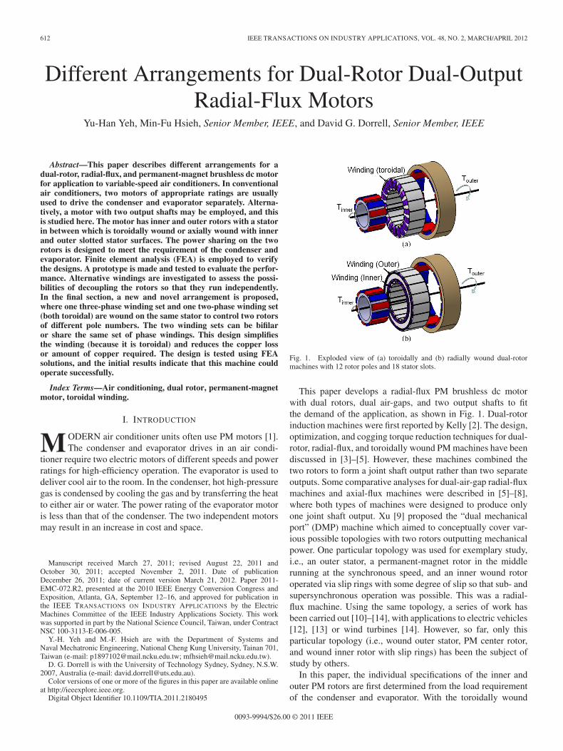
In this section, the dual-shaft (dual-rotor), radial-flux, andpermanent-magnet machine is first designed for a condenserand evaporator application in an air conditioner; the powersharing for the two devices is 62.5% and 37.5%, respectively.This is obtained from a total power rating of 80 W, as indicatedin the design specification given in Table I. This specificationcame from the test data of an air conditioner manufacturer. At aspeed of 1150 r/min, the two rotors should be able to separatelyoffer 50 and 30 W at a rated voltage of 35 V. An axial sectionof the proposed machine is shown in Fig. 2(a), while the actualprototype is shown in Fig. 2(b). The derived geometry is putforward in Table II. The sizing procedures described in [4] and
TABLE IMOTOR SPECIFICATION
Fig. 2. Prototype. (a) Axial section through machine. (b) Prototype toroidallywound machine.
[15] were employed to do this. A similar configuration waspresented in [4], although the machine had just one joint shaftoutput.
FEA is used to simulate the toroidally wound synchronous-rotor arrangement. A half cross section of the machine withinner and outer poles is shown in Fig. 3. The slots on theinner side of the stator are slightly larger simply because it wasenvisaged that more MMF (i.e., Amp-turns) is required for a setpower rating since the air-gap radius is much less.
When the machine is toroidally wound, then the slots onthe inner and outer surfaces contain the same coil sides, andthe rotors are synchronized (locked together) in the arrange-ment shown in Fig. 3; whereas in the radially wound machine

614 IEEE TRANSACTIONS ON INDUSTRY APPLICATIONS, VOL. 48, NO. 2, MARCH/APRIL 2012
TABLE IIDESIGN DIMENSION FOR THE MOTOR
Fig. 3. North–north magnet arrangement for synchronous rotor.
Fig. 4. Synchronous-rotor toroidally wound simulations at 1150 r/min—fluxdistribution.
simulations, the rotors rotate independently, and there are twoseparate three-phase winding sets—one in the outside slots ofthe stator and one set in the inner slots. These windings canbe of different coil turns and wire thickness in order to matchthe requirements of the drive. Fig. 4 shows a flux plot withthe toroidal arrangement with the two rotors fixed together asshown in Fig. 3. In Fig. 4, it can be observed that both inner andouter stator surfaces have their own flux linkages and the fluxdoes not cross from one side to the other despite the shared sta-tor. The instantaneous torque for each rotor is shown in Fig. 5,and the sum of the two torques is also illustrated (the averagetorques for the evaporator, the condenser, and their summationare 0.249, 0.417, and 0.665 N · m, respectively). These matchthe design requirements well. Experimental validation of thismachine is given in a later section. The locking of these tworotors together is a restriction, and it would be advantageous torun the rotor independently at different speeds within the sameframe. This is investigated in the following.
It should be noted that an 18-slot 12-pole topology wouldbe expected to have significant cogging torque that causeshigh torque ripple. Fig. 5 shows some torque ripple, but thisis acceptable for the application; hence, no cogging torque
Fig. 5. Synchronous-rotor toroidally wound simulations at 1150 r/min—torque from FEA.
reduction procedure was applied at this stage (using the usualtechniques such as skew, magnet pitch optimization, etc).
By combining two machines into one, the resultant highpower density should reduce the space required. This can beverified by comparing to two individually designed machineswith the same specifications. To do so, the torque-per-unit-rotor-volume (TRV) [16] of the inner rotor of the presentedmachine is used as the base. The TRV is defined as
TRV =T
Vrotor(1)
where T is the torque and Vrotor is the rotor volume. The TRVfor the inner rotor is 5678.5 N · m/m3, which is reasonablefor a small industrial machine (from [16]; this is substantiallyhigher than the fractional-horsepower totally enclosed fan-cooled motor range, in which this machine is a small exampleof, since 30 W is substantially less than 1 hp).
It is more complex to analyze the outer rotor in terms ofTRV. However, this TRV (5.68 KN · m/m3) can be used todesign two internal rotor machines (one being rated at 50 Wand the other at 30 W at 1120 r/min) with the same axiallength as the dual rotor machine. The sizing procedures arevery standard and can be referred to [15]. After calculations, thetwo machines (a total of 80 W) have an average power densityof 365 kW/m3 compared to the presented machine, which is419 kW/m3 using the outer rotor outside diameter in thevolumetric calculation (without considering the housing andbearing). For commercial production machines, it is difficultto obtain similar speed and power machine specifications fordirect comparison (since this is a niche application within aproduct and not a standard industrial power drive which is soldseparately). From two small electric machine manufacturers[17], [18], similar machines can be found, and they all have lesspower density than the presented machine. Therefore, the highpower density of the dual rotor machine appears to be validated.
B. Radially Wound Asynchronous-Rotor Arrangement
Some air conditioners may require the evaporator to operateat various speeds. For the present study, the evaporator isset to run at 1150, 950, and 850 r/min, while the condenserremains at 1150 r/min. To achieve this, the radially woundversion of the motor [Fig. 1(b)] is evaluated using FEA. Theradially wound machine FEA results are shown in Figs. 6–8.

YEH et al.: DIFFERENT ARRANGEMENTS FOR DUAL-ROTOR DUAL-OUTPUT RADIAL-FLUX MOTORS 615
Fig. 6. FEA flux plots for radially wound asynchronous-rotor machine withdifferent rotor alignments. (a) North–0.5 south alignment. (b) North–southalignment.
Fig. 7. FEA back-EMF waves for radially wound asynchronous-rotor ma-chine with different rotor alignments. Normalized back-EMFs for (a) outerevaporator and (b) inner condenser rotors.
The flux distributions are shown in Fig. 6, where Fig. 6(a)shows the alignment of the north pole of the outer rotor to aboutthe half south-pole point of the inner rotor, as indicated by thestraight line. This shows that some flux travels between the twosides. Fig. 6(b) shows the alignment of the north poles of theouter rotor to the south poles of the inner rotor. Again, more fluxtravels across the stator. Since the rotors are asynchronous, thentheir relative positions with respect to each other will be con-tinuously changing unless they are running at the same speed.Therefore, it is important to see if this flux interaction wouldaffect the performance. The condenser (outer) rotor speed ismaintained at 1150 r/min, and the speed of the evaporator(inner) rotor was varied. The back-EMFs were normalized andcompared (Fig. 7). There is little difference in the back-EMF
Fig. 8. FEA torque waves for radially wound asynchronous-rotor machinewith different rotor speeds. (a) For 1150–950 r/min. (b) For 1150–850 r/min.The condenser is at constant speed and is the outer rotor.
waveforms obtained from the FEA. This confirms that theconcept is valid.
The next step is to simulate the machine under load. Thecalculated instantaneous torque waveforms are shown in Fig. 8.These are shown at two asynchronous-speed ratios—the outerrotor (condenser) speed was kept constant at 1150 r/min, whilethe inner rotor (evaporator) speed was run at 950 and 850 r/min.There is some torque ripple (as with the previous synchronousconfiguration), but there is little cross coupling, and successfuloperation was simulated. Therefore, this configuration appearsto meet the requirements, and the common stator core betweenthe “inner motor” and “outer motor” does not appear to impedethe performances.
Both the synchronous and asynchronous configurations werefound to operate successfully. The synchronous machine wasconstructed and tested to validate the simulations, and this isdescribed in a later section. However, in the next section, anovel bifilar or phase sharing dual rotor machine is proposed,which is an original and new design.
C. Bifilar or Shared Phase Winding Arrangement—ANovel Design
This configuration is shown in Fig. 9, which is considered asa novel design and is named the “dual-pole dual-rotor machine”in this paper. The stator either combines one set of three-phasewindings and one set of two-phase windings (toroidal, bifilar)or utilizes only one set of toroidal windings which is sharedby two controls—the three- and two-phase controls. Theseindependently control the dual rotors (outer and inner) so thatindependent speed operation can be achieved. With a shared

616 IEEE TRANSACTIONS ON INDUSTRY APPLICATIONS, VOL. 48, NO. 2, MARCH/APRIL 2012
Fig. 9. Winding arrangement with bifilar or shared windings.
core, the flux generated by the two controls is assumed to belinearly superposed if there is no heavy saturation.
1) Pole–Slot Counts and Geometry: With two phases andthree phases sharing a stator, the number of slots needs to be amultiple of six. Therefore, the relationships between the innerand outer rotor pole numbers and the stator slots are be givenby
Nm,inner : Ns : Nm,outer = 2p : 6q : 2r (2)
where p, q, and r are all integers and Nm,inner, Ns, andNm,outer are the pole number of the inner rotor, the slotnumber of the stator, and the pole number of the outer rotor,respectively. For comparison to the previous configurations, the12-pole rotor is assigned to the two-phase side, and a 24-slotstator is employed to fit the two- and three-phase windings. Thepole–slot ratio (1 : 2) for the two-phase side is to simplify thecontrol (90◦ elec phase shift between the two phase currents).To maintain the same pole–slot ratio (2 : 3) as that for theprevious configuration on the three-phase side, 16 poles areemployed.
The sizing procedure is the same as that for the previouscases, and care was taken to avoid saturation by the superposedflux. It is found that the previous design met the performancerequirements, and hence, the only changes were to the slot pitchand pole pitches. The magnet pole span for the outer rotor is168◦ elec, while that for the inner is 144◦ elec. All the otherparameters are as given in Tables I and II.
It should be noted that there would be considerable coggingwith this arrangement when there are 24 slots with 16 and 12magnet poles on the rotors. With the major objective to investi-gate this novel design and to prove the concept, the cogging isnot a focus here; this can be reduced using conventional magnetshaping and skewing, as detailed later.
2) Winding Arrangements and Controls: Fig. 9 shows thediagram of coils in a toroidal configuration for the 24-slot statorwith 16 rotor poles on the outer rotor (with the three-phase coilwinding sequence A–B–C linking this) and 12 pole of innerrotor (with the two-phase coil winding sequence 1 − 2 − 1′ −2′ linking this). A three-phase winding can have coils with allthe same polarity in a toroidal configuration because the fluxsum when balanced is zero. A two-phase machine requires coilsof opposite polarity because the flux sum is not zero, so acirculating flux around the toroid will be generated, driving thecore into saturation.
Fig. 10. One of 12 modules for shared winding arrangement.
Fig. 11. Open-circuit back-EMFs at 1150–1150 r/min; the three-phase voltageset is for the 16-pole outer rotor, and the two-phase voltage set is for the 12-poleinner rotor. The peak phase voltage for phases A, B, and C is 16.8 V, while thatfor phases 1 and 2 is 9.52 V.
The dual toroidal winding can be realized by the use of bifilarwindings. However, if the same amount of copper is used, thenthe copper losses can be greatly reduced by feeding both slotphase currents into the same coil (obviously equal turns numberis required). This means that separate standard three-phase andtwo-phase inverters cannot be used, and for the configurationunder consideration here, 12 semi-H-bridges (Fig 10) are re-quired so that there are 12 independent coil currents, each fedwith an algebraic instantaneous sum of two currents. Whilethis seems complex, the modules will be lower in rating, andalso, there may be a reduction in copper requirement or copperloss; this will be discussed later. Control of these currents is outof the scope of this paper, and it will be the focus of furtherwork. However, some simulation results using shared phasewindings by feeding the algebraic instantaneous sum of twophase currents will be presented later.
3) General Open-Circuit Simulations: The simulations putforward here use the same slotted structure as the previoussynchronous and asynchronous machine simulations. The useof stator slots allows comparison to the synchronous and asyn-chronous machine arrangements already studied.
An FEA analysis in JMAG was carried out at 1150/1150,1150/950, and 1150/850 r/min, and the results are put forwardhere. In Figs. 11 and 12, the open-circuit back-EMFs areshown for two different speed relationships (1150/1150 and1150/850 r/min). The waveform for the 16-pole 3-phase voltageset is only slightly affected when the inner rotor speed isdecreased, indicating little cross coupling. It still gives voltagesof similar magnitude. In Fig. 12, the inner rotor moves through121.7◦ mech as the outer rotor moves through 180◦, and the

YEH et al.: DIFFERENT ARRANGEMENTS FOR DUAL-ROTOR DUAL-OUTPUT RADIAL-FLUX MOTORS 617
Fig. 12. Open-circuit back-EMFs at 1150–850 r/min; the two-phase voltageset has a lower frequency. The mechanical movement is for the outer rotoronly—the inner rotor moves through 121.7◦ mech.
Fig. 13. Cogging torque reduction. (a) Magnet shaping and (b) step skew withtwo axial rotor sections. lm and lyoke are the magnet length and rotor yokethickness, respectively. r is the radius of the rotor, and θ is the step skew angle.
x-axis is calibrated in outer-rotor movement only in order toillustrate the voltage phase and frequencies.
4) Cogging Torque Reduction: The concept of this arrange-ment is aimed at air-gap winding arrangements; however, forparity to the previous synchronous and asynchronous machines,the stator was maintained as a slotted arrangement with an in-crease in slot number (24 slots with 12 and 16 poles). Therefore,the cogging torque has to be investigated. From the simulationresults, it is found that the peak cogging torques for the innerand outer rotors are, respectively, 0.119 and 0.237 N · m; theseare without applying any cogging torque reduction methods.The cogging torque for the inner rotor has a cycle of 15◦ mech,and the outer rotor has a cycle of 7.5◦ mech. The cogging canbe reduced with careful design of the magnet shape and pitch,and use of skew. Fig. 13 shows how the magnet can be shapedto a bread-loaf and skewed in the axial direction.
For the magnet shaping, the magnets for the inner and outerrotors have different shapes in order to obtain a reduction incogging torque. In Fig. 13(a), R is 2.5 mm for the inner rotormagnet and 1.5 mm for the outer magnet. After magnet shaping,the cogging torque is reduced, as shown in Fig. 14, where thepeak values for the inner and outer rotor cogging torques are0.017 and 0.225 N · m, respectively. This method is, however,not very effective for the outer rotor. The rotational movementon the x-axis in Fig. 14 is for the inner and outer rotors; thewaveforms are constant with speed and are not affected by thespeed of the other rotor. Hence, this shows no cross couplingof the cogging torque when open circuit. There is a greateralignment pitch between the slots and inner rotor (two slots permagnet) which causes a longer cogging period compared to theouter rotor (which has three slots for every two poles). However,the outer rotor has a much higher cogging torque than the inner.
Fig. 14. Cogging torque characteristics for the inner and outer rotors. Coggingtorque is independent of speed.
Fig. 15. Cogging torque with skew for (a) outer rotor (a peak value of0.225 N · m for skew = 0◦ mech, which has virtually the same curve to thatof skew = 7.5◦ mech) and (b) inner rotor (a peak value of 0.017 N · m forskew = 0◦ mech). Bread-loaf magnets are used for both rotors.
The amplitude of the cogging in outer rotor is about 54% of therated torque, and this needs to be further reduced using skew.
Various step skew angles (θ) are tested (while the magnetshapes remain the same). Step skew uses two axial rotor sec-tions with an angular offset as shown in Fig. 13(b)[19]. Theradius r depends on the rotors. For each case, the two rotors areset at an identical skew angle (θ) between the axial sections;the arc length shift (rθ) will be different for the inner and outerrotors. The simulation results are shown in Fig. 15(a) for theouter rotor and Fig. 15(b) for the inner rotor. In Fig. 15(a),the curve for skew = 0◦ mech is virtually the same as that forskew = 7.5◦ mech. The peak cogging torque for each skewangle and for each rotor is shown in Fig. 16, where it is foundthat, at 3.75◦ mech, the outer rotor has the least cogging witha peak value of 0.009 N · m, which is only 2.17% of the ratedtorque. At this skew, the inner rotor has a peak cogging torqueof 0.01 N · m. Therefore, the skew angle of 3.75◦ mech is usedfor all the further simulations.

618 IEEE TRANSACTIONS ON INDUSTRY APPLICATIONS, VOL. 48, NO. 2, MARCH/APRIL 2012
Fig. 16. Peak cogging torque with skew for the inner/outer rotor. At skew =3.75◦ mech, the cogging for the inner rotor is 0.01 N · m, and that for the outeris 0.009 N · m.
Fig. 17. Total and cogging torque at 1150–1150 r/min, calibrated in outer-rotor movement (skew 3.75◦ mech).
Fig. 18. Total and cogging torque at 1150–950 r/min, calibrated in outer-rotormovement (skew 3.75◦mech).
5) Performance Simulations on Bifilar Windings: The loadsimulations were carried out to test the machine performancewith bifilar windings first. The 1150/950-r/min simulations arenow included for completeness. The total torques are shownin Figs. 17–19 at 1150/1150, 1150/950, and 1150/850 r/minwhen the machine is excited with current on the q-axis. Thewindings had 11 turns per coil, and the three-phase outercondenser current was maintained at 2.35 A (average torque of0.415 N · m), while the two-phase inner evaporator current wasvaried with 2.53 A (0.253 N·m, 1150 r/min), 3.06 A (0.308 N·m,950 r/min), and 3.42 A (0.339 N · m, 850 r/min). This loadingis similar to the previous two examples; this enables directcomparison. The cogging torque is also included, and it canbe seen that that there is almost no effect on the overall torqueripple. Instead, the two-phase control gives some minor level oftorque ripple.
Fig. 19. Total and cogging torque at 1150–850 r/min, calibrated in outer-rotormovement (skew 3.75◦ mech).
Fig. 20. Excitation torques (cogging removed from total) at 1150–1150,1150–950, and 1150–850 r/min.
Fig. 21. Flux plot at load showing 16–12 pole arrangement and 24 slots.
In order to assess the excitation torque, the cogging torqueis subtracted from the total torque, as shown in Fig. 20, forall of the three speed variations. It can be seen that there issome torque oscillation, but there is a steady torque value.The condenser torque appears to remain the same under thethree evaporator speeds. The evaporator torque increases asthe speed decreases; to do this, the current has to increase,and this maintains the output power. These initial results arevery promising. A flux plot for this arrangement from JMAG isshown in Fig. 21, where the stator is found not to be saturated.Also, most of the yoke (but excluding the teeth) has a low levelof flux density, and this is possibly due to flux cancellationbetween the two sets of windings. Some parts of the yoke have

YEH et al.: DIFFERENT ARRANGEMENTS FOR DUAL-ROTOR DUAL-OUTPUT RADIAL-FLUX MOTORS 619
TABLE IIICURRENT FOR EACH ROTOR AND RESULTANT CURRENTS IN SLOTS
high flux density, but this does not saturate the machine asa whole. Therefore, it was possible to independently controlthe speeds of the individual rotors using this design. However,these are initial results, and further work is needed to assess themachine with air-gap windings. In addition, iron losses need tobe further investigated. However, for the synchronous machine(first arrangement), then it was tested experimentally, and thiswas not found to be an issue. Soft magnet composite materialmay also be an alternative in the fabrication of this machine.
6) Performance Simulations on Shared Windings: If thewinding is shared using the multiple half-bridge arrangementshown in Fig. 10, then the winding area can be compacted. Fora given area and slot fill, the losses can be significantly reducedwhen sharing the same coils. This is an important issue whendealing with air-gap winding and can also be used to improvethe performance or the slotted machine.
Table III shows the excitation currents for each rotor side andthe resultant currents in each slot when both rotors aligningnorth–north with a tooth (as the black straight line shown inFig. 6(b) but with a north–north alignment). This is also theposition at 0◦ elec shown in Fig. 22(a) and (b) (as explainedlater). The “coils in slots” in Table III can be defined usingFig. 10, where the combination “A-1” is the coil in the firstslot of the three-phase side. It should be noted that the sharedwindings are used, so the current in each slot is the “resultantcurrent” (see Table III) at that instant/position. Table III onlygives the currents at one position at various operating points.As can be observed, some of the resultant currents (absolutevalues) in the slots are smaller than individual currents requiredfor driving the two rotors. In Section II-C5, bifilar windingsare used, and each coil possesses 11 turns so that a total of 22turns were in one slot. For the shared winding machine, only11 turns are needed in the slot so that the turn cross sectioncan be increased by two (possibly by simply putting the twobifilar winding in parallel) which gives lower current densityand halves the effective resistance for each of the two harmoniccurrent components. It can be shown by harmonic currentsynthesis that, unless two harmonic phase currents are of thesame frequency, then the total copper loss is reduced by twowhen moving to a shared winding rather than a bifilar winding.This is an interesting result. If the two phase harmonics havethe same frequency, then the copper loss will vary from zero(when in antiphase; i.e., zero current) to double loss (i.e., thesame loss as in a bifilar winding, as is to be expected).
Fig. 22(a) and (b) shows the driving currents for the outer andinner rotors and the resultant current distributions at two speed
Fig. 22. Driving currents for outer and inner rotors and the resultant currentdistributions at two speed ratios. (a) 1150–1150 r/min. (b) 1150–850 r/min.
ratios (1150–1150 and 1150–850 r/min). The vertical axes arethe phases to be excited, while the horizontal axis representsthe rotor position. It should be noted that the two sides havedifferent pole numbers, so their rotor positions in electricdegrees are different. The lower current wave in Fig. 22(a) and
620 IEEE TRANSACTIONS ON INDUSTRY APPLICATIONS, VOL. 48, NO. 2, MARCH/APRIL 2012
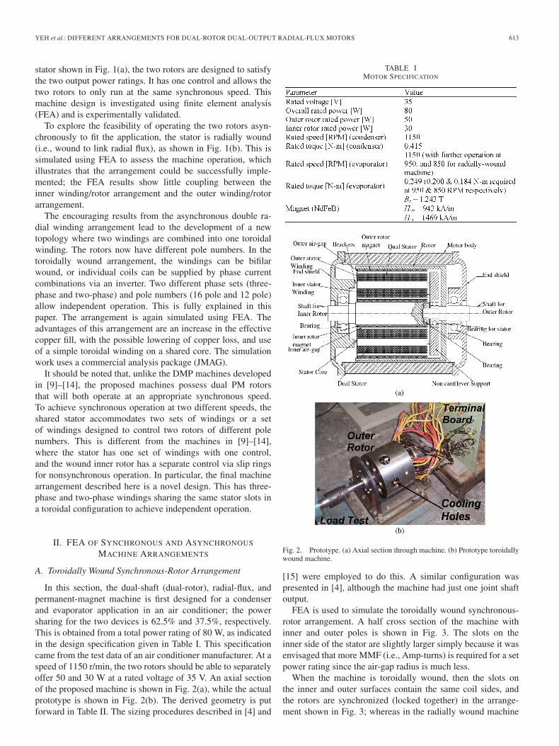
Fig. 23. Total at 1150–850 r/min for shared winding machine, calibrated inouter-rotor movement.
Fig. 24. Flux plot at load for shared winding machine.
(b) is the resultant current, with only A-1 being displayed as anexample. It would be easy to obtain the current distribution forany phase combinations from Fig. 22. At 850 r/min, the innerrotor is slower, so a higher angular current pitch can be observedin Fig. 22(b). The resultant currents in all of the slots are usedto simulate the performance of the shared winding machine.
Some sample simulation results with comparison are shownin Figs. 23 and 24. As can be seen, the torque performance ofthe shared winding machine is simply identical to that of thebifilar windings. The flux plot at load shown in Fig. 24 is thesame as the bifilar winding case (Fig. 21) when the rotors areat the same positions. Therefore, the concept of the proposeddual-pole dual-rotor machine has been proved. As stated earlier,the control of this machine is not discussed here, but it will bediscussed in a future work.
III. EXPERIMENTAL STUDY
In this section, the operation of the first arrangement, withtoroidal windings and synchronous rotors, is experimentallyvalidated. This is used to verify the original design and the FEAso that the simulations for the second and third arrangements(see Sections II-B and C) can be treated as reliable. As pre-viously mentioned, the inner rotor is for the evaporator drive,while the outer rotor is for the condenser. The complexity inassembly of the two rotors is a challenge; both air-gaps haveto be uniform and stable. Appropriate bearings were chosenfor the motor assembly. An axial slice diagram of the motorconfiguration and a photograph of the prototype are shown in
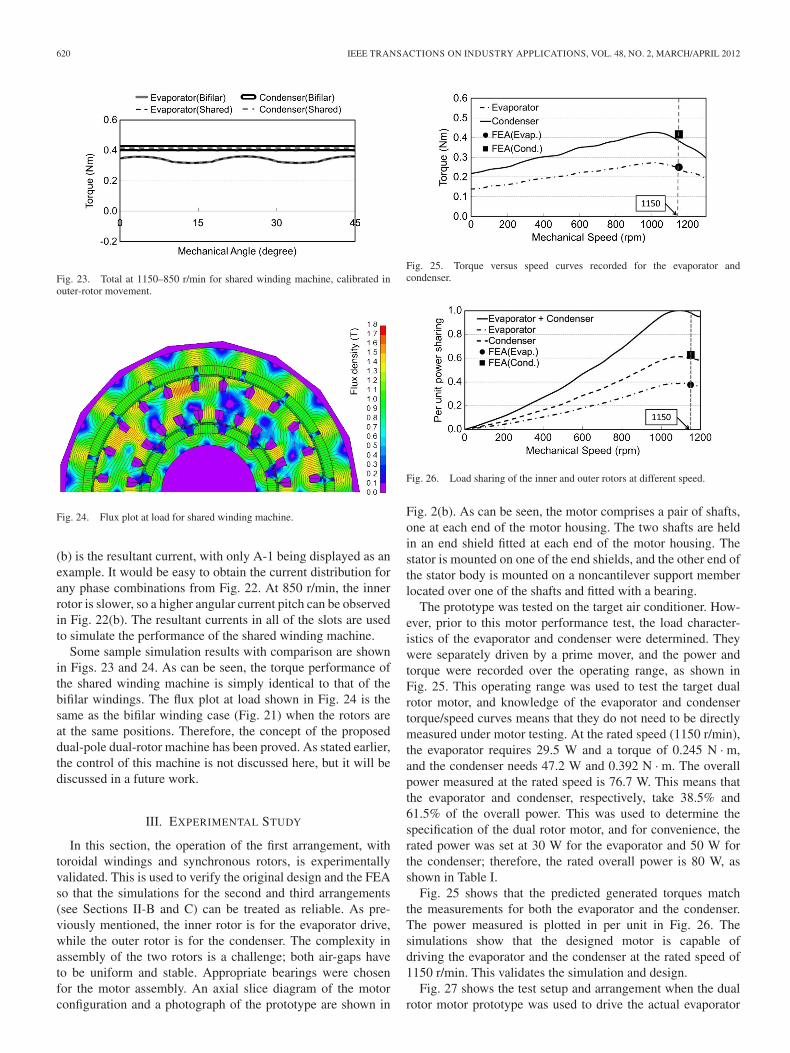
Fig. 25. Torque versus speed curves recorded for the evaporator andcondenser.
Fig. 26. Load sharing of the inner and outer rotors at different speed.
Fig. 2(b). As can be seen, the motor comprises a pair of shafts,one at each end of the motor housing. The two shafts are heldin an end shield fitted at each end of the motor housing. Thestator is mounted on one of the end shields, and the other end ofthe stator body is mounted on a noncantilever support memberlocated over one of the shafts and fitted with a bearing.
The prototype was tested on the target air conditioner. How-ever, prior to this motor performance test, the load character-istics of the evaporator and condenser were determined. Theywere separately driven by a prime mover, and the power andtorque were recorded over the operating range, as shown inFig. 25. This operating range was used to test the target dualrotor motor, and knowledge of the evaporator and condensertorque/speed curves means that they do not need to be directlymeasured under motor testing. At the rated speed (1150 r/min),the evaporator requires 29.5 W and a torque of 0.245 N · m,and the condenser needs 47.2 W and 0.392 N · m. The overallpower measured at the rated speed is 76.7 W. This means thatthe evaporator and condenser, respectively, take 38.5% and61.5% of the overall power. This was used to determine thespecification of the dual rotor motor, and for convenience, therated power was set at 30 W for the evaporator and 50 W forthe condenser; therefore, the rated overall power is 80 W, asshown in Table I.
Fig. 25 shows that the predicted generated torques matchthe measurements for both the evaporator and the condenser.The power measured is plotted in per unit in Fig. 26. Thesimulations show that the designed motor is capable ofdriving the evaporator and the condenser at the rated speed of1150 r/min. This validates the simulation and design.
Fig. 27 shows the test setup and arrangement when the dualrotor motor prototype was used to drive the actual evaporator
YEH et al.: DIFFERENT ARRANGEMENTS FOR DUAL-ROTOR DUAL-OUTPUT RADIAL-FLUX MOTORS 621
Fig. 27. Test arrangement.
and condenser. The motor was driven by a six-step square-waveinverter. The torque curves shown in Fig. 25 are for the separateinner and outer rotors. While the rotors were synchronous andrunning at the same speeds, the torques could be assessedseparately using the load measurements. A power meter wasused to record the electrical power input to the motor so thatthe efficiency can be calculated. However, by the nature ofthe single toroidal winding, it was not possible to measure theindividual electric power used to drive each of the two rotors(only the total electric input). Therefore, they were determinedby their prescribed power sharing, as given by
Pin_inner =Pin_elec × Prated_inner
Prated_motor(3)
Pin_outer =Pin_elec × Prated_outer
Prated_motor(4)
where Pin_inner and Pin_outer are the individual input electricpowers to the inner and outer rotors, Pin_elec is the measuredoverall input electric power at any speed, Prated_inner andPrated_out are the rated output powers for the inner and outerrotors (30 and 50 W), and Prated_motor is the overall ratedmotor output power (80 W). Using the rated power sharing todefine the input power ratio should be reasonable. Therefore,the efficiency for the two rotors can be calculated from
ηinner =Pm_inner
Pin_inner× 100% (5)
ηouter =Pm_outer
Pin_outer× 100% (6)
where Pm_inner and Pm_outer are the measured output pow-ers for the inner and outer rotors. It should be noted thatthere was no torque measurement devices here, and thetorque and mechanical power were simply determined fromFigs. 25 and 26.
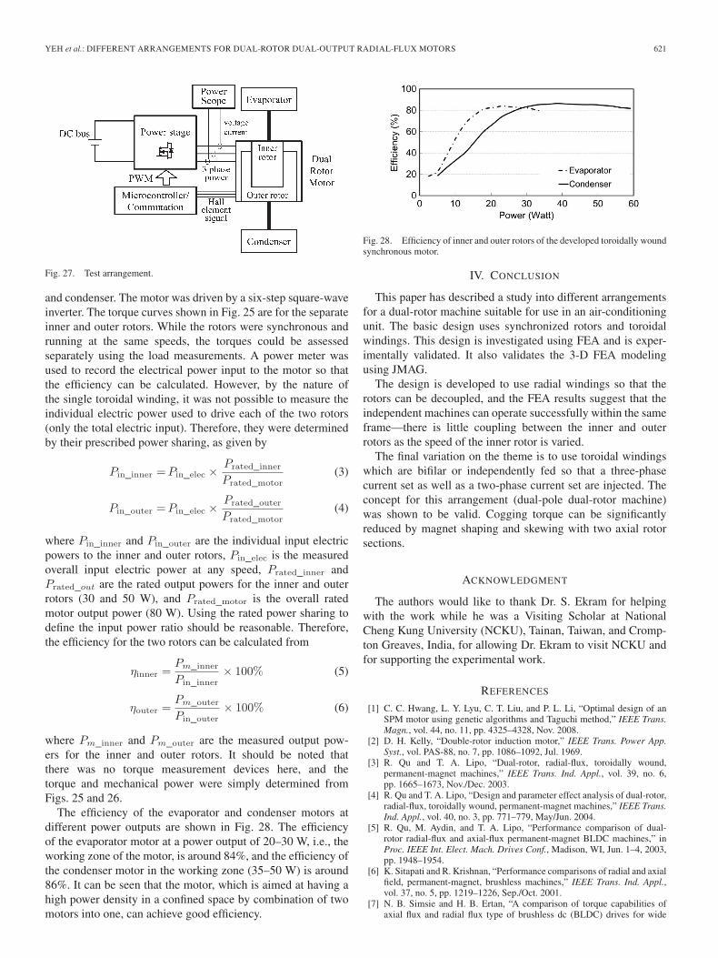
The efficiency of the evaporator and condenser motors atdifferent power outputs are shown in Fig. 28. The efficiencyof the evaporator motor at a power output of 20–30 W, i.e., theworking zone of the motor, is around 84%, and the efficiency ofthe condenser motor in the working zone (35–50 W) is around86%. It can be seen that the motor, which is aimed at having ahigh power density in a confined space by combination of twomotors into one, can achieve good efficiency.
Fig. 28. Efficiency of inner and outer rotors of the developed toroidally woundsynchronous motor.
IV. CONCLUSION
This paper has described a study into different arrangementsfor a dual-rotor machine suitable for use in an air-conditioningunit. The basic design uses synchronized rotors and toroidalwindings. This design is investigated using FEA and is exper-imentally validated. It also validates the 3-D FEA modelingusing JMAG.
The design is developed to use radial windings so that therotors can be decoupled, and the FEA results suggest that theindependent machines can operate successfully within the sameframe—there is little coupling between the inner and outerrotors as the speed of the inner rotor is varied.
The final variation on the theme is to use toroidal windingswhich are bifilar or independently fed so that a three-phasecurrent set as well as a two-phase current set are injected. Theconcept for this arrangement (dual-pole dual-rotor machine)was shown to be valid. Cogging torque can be significantlyreduced by magnet shaping and skewing with two axial rotorsections.
ACKNOWLEDGMENT
The authors would like to thank Dr. S. Ekram for helpingwith the work while he was a Visiting Scholar at NationalCheng Kung University (NCKU), Tainan, Taiwan, and Cromp-ton Greaves, India, for allowing Dr. Ekram to visit NCKU andfor supporting the experimental work.
REFERENCES
[1] C. C. Hwang, L. Y. Lyu, C. T. Liu, and P. L. Li, “Optimal design of anSPM motor using genetic algorithms and Taguchi method,” IEEE Trans.Magn., vol. 44, no. 11, pp. 4325–4328, Nov. 2008.
[2] D. H. Kelly, “Double-rotor induction motor,” IEEE Trans. Power App.Syst., vol. PAS-88, no. 7, pp. 1086–1092, Jul. 1969.
[3] R. Qu and T. A. Lipo, “Dual-rotor, radial-flux, toroidally wound,permanent-magnet machines,” IEEE Trans. Ind. Appl., vol. 39, no. 6,pp. 1665–1673, Nov./Dec. 2003.
[4] R. Qu and T. A. Lipo, “Design and parameter effect analysis of dual-rotor,radial-flux, toroidally wound, permanent-magnet machines,” IEEE Trans.Ind. Appl., vol. 40, no. 3, pp. 771–779, May/Jun. 2004.
[5] R. Qu, M. Aydin, and T. A. Lipo, “Performance comparison of dual-rotor radial-flux and axial-flux permanent-magnet BLDC machines,” inProc. IEEE Int. Elect. Mach. Drives Conf., Madison, WI, Jun. 1–4, 2003,pp. 1948–1954.
[6] K. Sitapati and R. Krishnan, “Performance comparisons of radial and axialfield, permanent-magnet, brushless machines,” IEEE Trans. Ind. Appl.,vol. 37, no. 5, pp. 1219–1226, Sep./Oct. 2001.
[7] N. B. Simsie and H. B. Ertan, “A comparison of torque capabilities ofaxial flux and radial flux type of brushless dc (BLDC) drives for wide

622 IEEE TRANSACTIONS ON INDUSTRY APPLICATIONS, VOL. 48, NO. 2, MARCH/APRIL 2012
speed range applications,” in Proc. IEEE PEDS, Hong Kong, Jul. 1999,pp. 719–724.
[8] A. Cavagnino, M. Lazzari, F. Profumo, and A. Tenconi, “A comparisonbetween the axial flux and the radial flux structures for PM synchronousmotors,” in Conf. Rec. IEEE IAS Annu. Meeting, Chicago, IL, Oct. 2001,vol. 3, pp. 1611–1618.
[9] L. Xu, “Dual-mechanical-port electric machines—A new concept in de-sign and analysis of electric machines,” in Conf. Rec. 40th IEEE IAS Annu.Meeting, 2005, vol. 4, pp. 2828–2834.
[10] F. Zhao, X. Wen, X. Guo, L. Han, and X. Guo, “Study of field coupling indual mechanical port electrical machines,” in Proc. Int. Conf. Elect. Mach.Syst., 2007, pp. 1591–1595.
[11] L. Xu and Y. Zhang, “Design and evaluation of a dual mechanical portmachine and system,” in Proc. IEEE Power Electron. Motion ControlConf., 2006, pp. 1–5.
[12] L. Xu, Y. Zhang, and X. Wen, “Multioperational modes and controlstrategies of dual-mechanical-port machine for hybrid electrical vehicles,”IEEE Trans. Ind. Appl., vol. 45, no. 2, pp. 747–755, Mar./Apr. 2009.
[13] L. Xu, “Dual-mechanical-port electric machines—Concept and applica-tion of a new electric machine to hybrid electrical vehicles,” IEEE Ind.Appl. Mag., vol. 15, no. 4, pp. 44–51, Jul./Aug. 2009.
[14] X. Sun, M. Cheng, W. Hua, and L. Xu, “Optimal design of double-layer permanent magnet dual mechanical port machine for wind powerapplication,” IEEE Trans. Magn., vol. 45, no. 10, pp. 4613–4616,Oct. 2009.
[15] D. C. Hanselman, Brushless Permanent Magnet Motor Design, 2nd ed.Winnipeg, MB, Canada: Writers’ Collective, 2003.
[16] J. R. Hendershot and T. J. E. Miller, Design of Brushless Permanent-Magnet Motors. Oxford, U.K.: Clarendon, 1999.
[17] Teco Electro Devices Co., Ltd, Specifications of BLDC 56Series. [Online]. Available: http://www.tedmotors.com/rimages/552/PDF/BLDC56.pdf
[18] Lan Chang Electric Co., Ltd, in Chinese DC Brushless Motor Introduc-tion. [Online]. Available: http://www.lan-cheng.com/dc_c.html
[19] H. S. Chen, D. G. Dorrell, and M. C. Tsai, “Design and operation ofinterior permanent magnet motors with two axial segments and high rotorsaliency,” IEEE Trans. Magn., vol. 46, no. 9, pp. 3664–3675, Sep. 2010.
Yu-Han Yeh received the B.Eng. and M.Sc. degreesfrom the Department of Systems and Naval Mecha-tronic Engineering, National Cheng Kung Univer-sity, Tainan, Taiwan, in 2007 and 2008, respectively,where she is currently working toward the Ph.D.degree.
Her research interests include electric machinedesign analysis for wind turbines.
Min-Fu Hsieh (M’02–SM’11) was born in Tainan,Taiwan. He received the B.Eng. degree in mechanicalengineering from National Cheng Kung University(NCKU), Tainan, in 1991, and the M.Sc. and Ph.D.degrees in mechanical engineering from the Univer-sity of Liverpool, Liverpool, U.K., in 1996 and 2000,respectively.
From 2000 to 2003, he served as a Researcherin the Electric Motor Technology Research Center,NCKU. In 2003, he joined the Department of Sys-tems and Naval Mechatronic Engineering, NCKU, as
an Assistant Professor, where he became an Associate Professor in 2007. Hisarea of interests includes renewable energy generation (wave, tidal current, andwind), electric machine design, and servo control.
Dr. Hsieh is a member of the IEEE Industry Applications, IEEE Magnetics,IEEE Industrial Electronics, and IEEE Oceanic Engineering Societies.
David G. Dorrell (M’95–SM’08) was born inSt Helens, U.K. He received the B.Eng. (Hons.) de-gree in electrical and electronic engineering from theUniversity of Leeds, Leeds, U.K., in 1988, the M.Sc.degree in power electronics engineering from theUniversity of Bradford, Bradford, U.K., in 1989, andthe Ph.D. degree in engineering from the Universityof Cambridge, Cambridge, U.K., in 1993.
He has held lecturing positions at The RobertGordon University, Aberdeen, U.K., and The Uni-versity of Reading, Reading, U.K. He was a Senior
Lecturer at The University of Glasgow, Glasgow, U.K., for several years. In2008, he took up a post at The University of Technology Sydney, Sydney,Australia, where he was promoted to Associate Professor in 2009. He isalso an Adjunct Associate Professor at The National Cheng Kung University,Tainan, Taiwan. His research interests cover the design and analysis of variouselectrical machines and also renewable energy systems, with over 150 technicalpublications to his name.
Dr. Dorrell is a Chartered Engineer in the U.K. and a Fellow of the Institutionof Engineering and Technology, U.K.
Copyright © 2022 FDOKUMEN