Schedule FIXED SERVICES PLANNING ARRANGEMENTS
43
1
-
Upload
khangminh22 -
Category
Documents
-
view
0 -
download
0
Transcript of Schedule FIXED SERVICES PLANNING ARRANGEMENTS

1

2
Schedule
FIXED SERVICES PLANNING ARRANGEMENTS
I. INTRODUCTION
This document sets out planning guidelines for the frequency assignment and coordination of terrestrial microwave fixed services in Vanuatu. It provides band planning arrangements for the 1.5 GHz, 5 GHz, 6 GHz, 6.7 GHz, 7.2 GHz, 7.5 GHz, 8 GHz, 10 GHz, 11GHz, 13 GHz, 15 GHz, 18 GHz and 22 GHz bands. It specifies key technical requirements for the use of these bands including channeling arrangements, assignment guidelines, antenna requirements and protection ratios.
Licensees deploying microwave fixed services in Vanuatu must follow these planning arrangements unless the Telecommunications and Radiocommunications Regulator agrees in writing to vary the requirements set out in this document.
II. FIXED POINT TO POINT MICROWAVE SYSTEMS; SOME BACKGROUND
The fixed microwave radio service (the fixed service) provides medium to high capacity connectivity between two points or between a central point and stations within a given area where access to cable or fibre is not available or economically viable.
The fixed service also provides connectivity over long distances where the inherent time delay associated with satellite connections makes these less attractive.
The fixed service is used in a number of ways. For example, it may transmit data over long distances (referred to as trunk services) between two towns or cities. It may also serve to interconnect numerous base stations within a cellular network. The fixed service is also used in a number of non-telecommunications networks. Some examples are the connection of a civil or military radar installation to an aircraft control tower, the transmission of supervisory control and data signals (SCADA) associated with the operation of an electricity transmission network and the interconnection of a private data network between two buildings.

3
Generally speaking, certain bands are suited to certain applications. For example, the 1.5 GHz microwave band is considered to be ‘low frequency’ in terms of fixed systems while still having the capacity to transmit large amounts of data. Other advantages of the 1.5 GHz band are low attenuation over distance, very little susceptibility to fade during heavy rain and the ability to use light ‘grid-pak’ type antennas on relatively light tower structures or supports. This means the 1.5 GHz band provides an economically viable method of transmitting data over relatively long distances (up to around 80 km) and is thus viable on many over water paths typical of Vanuatu geography.
Higher bands are suited to different purposes. For example the 10 GHz band still retains good rain fade characteristics and can provide high data rates over distances of up to 40km. This means it is useful for the interconnection of electricity substations, telephone exchanges or radar systems using solid antennas of about 1 metre diameter.
Higher bands, such as 15 GHz can carry high data rates and use much smaller solid antennas which allow integrated radio and antenna systems to be deployed. While these and higher bands are more susceptible to rain fade they are useful when interconnecting mobile base stations or for short hop length systems within cities.
III. PROPAGATION AND SYSTEMS DESIGN AT MICROWAVE FREQUENCIES
This section of this document is not intended to serve as a fixed service design guide. However, some background may be useful to those not involved in fixed service design.
Microwave antennas
Antennas used at microwave frequencies are usually parabolic reflectors. The gain of an antenna is frequency dependant; for example a 1.2 metre Grid-Pak at 1.5 GHz has a gain of around 23 dBi while a 1.2 metre parabolic antenna at 15 GHz has a gain of around 42 dBi. While the 1.5 GHz Grid-Pak design offers lighter weight and lower wind loading the higher gain at 15 GHz means much smaller antennas can be used making the higher bands viable for short hop deployment.
Microwave antennas also have very narrow beam widths, around 10 degrees for the 1.5 GHz Grid-Pak and around 1.5 degrees for the 1.2m 15 GHz parabolic. This means sharing the same frequencies within the same area is possible provided careful coordination is undertaken.
Sharing with other systems is also possible, again provided careful coordination is undertaken. Where systems are ‘ubiquitous’, a term used to mean deployed without the need for licensing and registration into a common database, coordination is not possible. In these cases it is prudent spectrum management to avoid conflict by restricting the band to a certain service type.
Propagation at microwave frequencies
Radiowave propagation through the atmosphere is a complex science, but some basic rules of thumb are provided to aid the reader not familiar with fixed service design.

4
The power loss of a system over a line of sight path between two points can be calculated from:
FSL = 32.5 + 20 Log(D x F)
where:
FSL is Free Space Loss F is frequency in MHz D is distance between the two points in kilometres.
For example, the free space loss at 1.5 GHz over a 50 km path is 130 dB.
Over very long paths the surface of the earth (or Earth bulge) can block a straight line path. This is overcome by using high towers, but the atmosphere also assists by bending (refracting) the radio waves around the earth thus increasing the horizon visible to the system (the radio horizon).
Attenuation by rain is also a problem for designers of systems in tropical areas. For example a rain event of 40 mm per hour can reduce a usable 20 km path length by a factor of two to 10 km. This means rain fade in tropical regions must be taken into account by the system designer and when coordinating interference between systems. It is important to note that rain fade may not be the same on both the wanted and unwanted path.
A final and important consideration, especially on overwater paths, is atmospheric multipath or ducting. This happens when a signal is refracted when passing through a change in the atmosphere, returning to the receive antenna out of phase with the wanted signal causing a fade. Another mechanism occurs when an interfering signal is trapped within a duct and arrives at a much higher power than line of sight calculations suggest causing interference and a systems failure.
All of these mechanisms are taken into account when deciding which bands to plan for the fixed service and which to preserve for other services. If the reader would like more information on digital fixed service design the International Telecommunications Union (ITU) produces an excellent manual called the ‘Handbook on Digital Radio-Relay Systems’.
Fixed service availability
Fixed services are designed for a specific error performance or availability depending on the service they provide. Examples of a high grade of service are a trunk network servicing a large town or a link between a radar and an airport control tower. Cellular systems are able to tolerate a lower grade of performance depending on how many cells the actual link services.
Fixed service availability is also a complex topic covered by a number of ITU publications. For more information the reader is directed to ITU Recommendations ITU-R F.634, ITU-R F.557, ITU-R F.697, ITU-T G.821 and ITU-T G.826. Reference antenna patters are found in R F 699. These can be found by searching the ITU site at www.itu.int.
As an example, the unavailability over time of a fixed, two-way link over 40 km should not exceed 0.0048% (ITU-R F.557) and that of a short hop system, such as that servicing a cellular

5
mobile network should not exceed between 0.001% and 0.01% depending on the system parameters (ITU-R F.697).
Cross Polarization.
Cross polarization enables coordination between two systems operating on the same channel. The actual level of cross polar discrimination can be found from manufacturer’s data or an amount of -20 dB can be used when ITU Rec F.699 is used. Cross polar discrimination cannot be applied over the whole antenna pattern as it varies considerably in the side lobes. Thus a discrimination of -20 dB can be applied in the main lobe until that level (Max gain – 20 dB) is reached and from there follow the R.F.699 pattern. An example of this is shown in Figure 1.
Figure 1.
Cross Polar Discrimination.
IV. BANDS PROPOSED FOR THE MICROWAVE FIXED SERVICE
Bands available to the Fixed Service (FS)
TRR has planned bands between 1500 MHz and 22 GHz for the fixed service because these encompass a range that is able to support the requirements of a range of services. Should plans for bands in higher frequency ranges be needed, these will be planned when the Fixed services Plan is reviewed.
Individual Fixed Service Band Plans are attached as Annex A.
Channel aggregation
Often the services supported by the fixed service evolve to provide or require more data. An example is the 4th Generation Mobile Service known as LTE. In order to provide flexibility for such services, spectrum managers have allowed channel aggregation in most bands (with some restrictions depending on the band). Channel aggregation may only be feasible where channels are unencumbered and coordination with other services is possible.
6
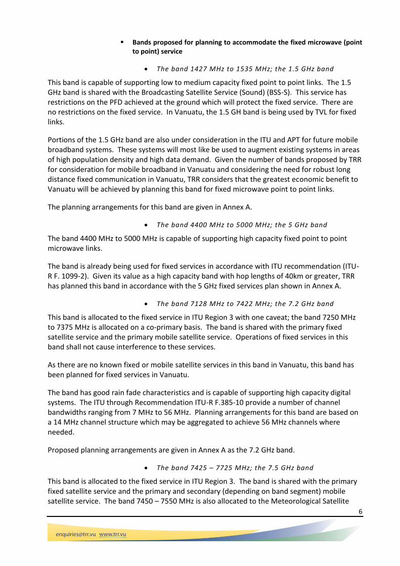
Bands proposed for planning to accommodate the fixed microwave (point to point) service
The band 1427 MHz to 1535 MHz; the 1.5 GHz band
This band is capable of supporting low to medium capacity fixed point to point links. The 1.5 GHz band is shared with the Broadcasting Satellite Service (Sound) (BSS-S). This service has restrictions on the PFD achieved at the ground which will protect the fixed service. There are no restrictions on the fixed service. In Vanuatu, the 1.5 GH band is being used by TVL for fixed links.
Portions of the 1.5 GHz band are also under consideration in the ITU and APT for future mobile broadband systems. These systems will most like be used to augment existing systems in areas of high population density and high data demand. Given the number of bands proposed by TRR for consideration for mobile broadband in Vanuatu and considering the need for robust long distance fixed communication in Vanuatu, TRR considers that the greatest economic benefit to Vanuatu will be achieved by planning this band for fixed microwave point to point links.
The planning arrangements for this band are given in Annex A.
The band 4400 MHz to 5000 MHz; the 5 GHz band
The band 4400 MHz to 5000 MHz is capable of supporting high capacity fixed point to point microwave links.
The band is already being used for fixed services in accordance with ITU recommendation (ITU-R F. 1099-2). Given its value as a high capacity band with hop lengths of 40km or greater, TRR has planned this band in accordance with the 5 GHz fixed services plan shown in Annex A.
The band 7128 MHz to 7422 MHz; the 7.2 GHz band
This band is allocated to the fixed service in ITU Region 3 with one caveat; the band 7250 MHz to 7375 MHz is allocated on a co-primary basis. The band is shared with the primary fixed satellite service and the primary mobile satellite service. Operations of fixed services in this band shall not cause interference to these services.
As there are no known fixed or mobile satellite services in this band in Vanuatu, this band has been planned for fixed services in Vanuatu.
The band has good rain fade characteristics and is capable of supporting high capacity digital systems. The ITU through Recommendation ITU-R F.385-10 provide a number of channel bandwidths ranging from 7 MHz to 56 MHz. Planning arrangements for this band are based on a 14 MHz channel structure which may be aggregated to achieve 56 MHz channels where needed.
Proposed planning arrangements are given in Annex A as the 7.2 GHz band.
The band 7425 – 7725 MHz; the 7.5 GHz band
This band is allocated to the fixed service in ITU Region 3. The band is shared with the primary fixed satellite service and the primary and secondary (depending on band segment) mobile satellite service. The band 7450 – 7550 MHz is also allocated to the Meteorological Satellite
7
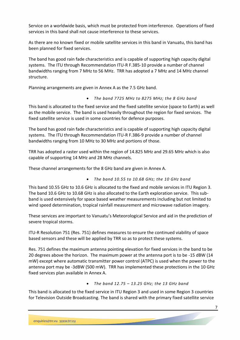
Service on a worldwide basis, which must be protected from interference. Operations of fixed services in this band shall not cause interference to these services.
As there are no known fixed or mobile satellite services in this band in Vanuatu, this band has been planned for fixed services.
The band has good rain fade characteristics and is capable of supporting high capacity digital systems. The ITU through Recommendation ITU-R F.385-10 provide a number of channel bandwidths ranging from 7 MHz to 56 MHz. TRR has adopted a 7 MHz and 14 MHz channel structure.
Planning arrangements are given in Annex A as the 7.5 GHz band.
The band 7725 MHz to 8275 MHz; the 8 GHz band
This band is allocated to the fixed service and the fixed satellite service (space to Earth) as well as the mobile service. The band is used heavily throughout the region for fixed services. The fixed satellite service is used in some countries for defence purposes.
The band has good rain fade characteristics and is capable of supporting high capacity digital systems. The ITU through Recommendation ITU-R F.386-9 provide a number of channel bandwidths ranging from 10 MHz to 30 MHz and portions of those.
TRR has adopted a raster used within the region of 14.825 MHz and 29.65 MHz which is also capable of supporting 14 MHz and 28 MHz channels.
These channel arrangements for the 8 GHz band are given in Annex A.
The band 10.55 to 10.68 GHz; the 10 GHz band
This band 10.55 GHz to 10.6 GHz is allocated to the fixed and mobile services in ITU Region 3. The band 10.6 GHz to 10.68 GHz is also allocated to the Earth exploration service. This sub-band is used extensively for space based weather measurements including but not limited to wind speed determination, tropical rainfall measurement and microwave radiation imagery.
These services are important to Vanuatu’s Meteorological Service and aid in the prediction of severe tropical storms.
ITU-R Resolution 751 (Res. 751) defines measures to ensure the continued viability of space based sensors and these will be applied by TRR so as to protect these systems.
Res. 751 defines the maximum antenna pointing elevation for fixed services in the band to be 20 degrees above the horizon. The maximum power at the antenna port is to be -15 dBW (14 mW) except where automatic transmitter power control (ATPC) is used when the power to the antenna port may be -3dBW (500 mW). TRR has implemented these protections in the 10 GHz fixed services plan available in Annex A.
The band 12.75 – 13.25 GHz; the 13 GHz band
This band is allocated to the fixed service in ITU Region 3 and used in some Region 3 countries for Television Outside Broadcasting. The band is shared with the primary fixed satellite service

8
and the primary mobile service. Operations of fixed services in this band shall not cause interference to these services.
As there are no known fixed satellite or mobile services in this band in Vanuatu, this band has been planned for fixed services.
The band has good rain fade characteristics and is capable of supporting high capacity digital systems. The ITU through Recommendation ITU-R F.497-7 provide a number of channel arrangements. TRR has specified a 28 MHz channel capable of supporting 34 Mbit systems.
Planning arrangements are given in Annex A as the 13 GHz band.
The band 14.5 - 15.35 MHz; the 15 GHz band
This band is allocated to the fixed service in ITU Region 3. The band is shared with the primary fixed satellite service and the primary mobile service. Operations of fixed services in this band shall not cause interference to these services.
As there are no known fixed or mobile satellite services in this band in Vanuatu, this band has been planned for fixed services.
The band has good rain fade characteristics and is capable of supporting high capacity digital systems. The ITU through Recommendation ITU-R F.636-4 provide a number of channel arrangements. TRR has specified a 7, 14 and 28 MHz channel structure all of which may be divided or aggregated in 7 MHz lots.
Planning arrangements are given in Annex A as the 15 GHz band.
The band 17.7 – 19.7 MHz; the 18 GHz band
This band is allocated to the fixed service in ITU Region 3. The band is shared with the primary fixed satellite service and the primary mobile service. The band 18.6 – 18.8 GHz is also allocated to the earth Exploration Satellite Service (passive). Operations of fixed services in this band shall not cause interference to these services.
As there are no known fixed or mobile satellite services in this band in Vanuatu, this band has been planned for fixed services.
The band has good rain fade characteristics and is capable of supporting high capacity digital systems. The ITU through Recommendation ITU-R F.595-10 provide a number of channel arrangements. TRR has specified a 7.5, 13.75, 27.5 and 55 MHz channel structure.
Planning arrangements are given in Annex A as the 18 GHz band.
The band 21.2 GHz to 23.6 GHz; the 22 GHz band
This band is allocated to the fixed service in ITU Region 3. While susceptible to severe rain fade the band supports a number of options for short range high capacity fixed links. Other services using the band include the radio Astronomy Service, but no restrictions have been placed on the deployment of fixed links. This band has been planned for fixed services in Vanuatu.

9
Planned channel arrangements are available in Annex A.
ANNEX A. FIXED SERVICES PLANS.
1.1 The 1.5 GHz band
THE 1.5 GHz BAND (1427-1535 MHz)
RF CHANNEL ARRANGEMENTS
ASSIGNMENT INSTRUCTIONS
This band is designated for use by low to medium capacity fixed point-to-point links.
Typical Use : >2 Mbit/s data
Minimum Path Length : 20 km
Antenna Requirements : Minimum 1.2 m grid-pak style antenna or minimum 21 dBi gain.
Channel Aggregation : Channel aggregation up to 20 MHz (5 channels) is permitted providing coordination can be achieved and only for paths exceeding 20 km. In order to preserve the band for longer hops channel aggregation is not permitted for any path below 20 km.
1
1430
.5
2
1434
.5
3
1438
.5
4
1442
.5
5
1446
.5
6
1450
.5
2'
1495
3'
1499
4'
1503
5'
1507
6'
1511
7'
1515
8'
1519
9'
1523
1
1432
.5
2
1436
.5
3
1440
.5
4
1444
.5
5
1448
.5
1' 2'
1497
3'
1501
4'
1505
5'
1509
6'
1513
7'
1517
8'
1521
4 MHz
fo
fo
4 MHz
60.5 MHzINTERLEAVED
MAIN
1427
1427
1452 1492
DSB Allocation
No new assignmentsMSS Allocation
No new assignments
1525
1535
15351481
1481
1525
1529
1533
1527
1531
1454
.514
58.5
1462
.514
66.5
1470
.5
1491
1452
.514
56.5
1460
.514
64.5
1468
.514
72.5
1493
9' 10' 11'
10' 11'
11109876
1110987
60.5 MHz
1'
1535

10
Notes:
1. The use the minimum antenna type preserves the band for future users.
2. Due to evaporation ducting coordination for an over water path shall use the actual path length or 20 km whichever is the lesser.
PROTECTION RATIOS
1. Protection ratios required between digital systems operating on 2, 4 and 8 MHz and greater aggregated bandwidth channels.
Frequency Offset
PROTECTION RATIO (dB) Aggregated Channels
Greater
(MHz) Digital Interferer Tx Digital Victim Rx
2 MHz
2 MHz
2 MHz
4 MHz
4 MHz
2 MHz
4 MHz
4 MHz
8 MHz
Any width
> 8 MHz into any
other channel
0 60 60 60 60 60 60
2 30 55 50 55 55 60
4 25 20 30 40 50
6 8 20 30
2. Protection ratios required by digital systems operating on 2 and 4 MHz channels against interference from analogue systems operating on 2 and 4 MHz channels. No aggregation of legacy analogue systems is permitted.
Frequency Offset PROTECTION RATIO (dB)
(MHz) Analogue Interferer Tx Digital Victim Rx
2 MHz
2 MHz
2 MHz
4 MHz
4 MHz
2 MHz
4 MHz
>=4 MHz
0 60 60 60 60
2 30 30 60

11
4 40
3. Protection ratios required by analogue systems operating on 2 and 4 MHz channels against interference from digital systems operating on 2 and 4 MHz channels. No aggregation of legacy analogue systems is permitted. Analogue systems receive maximum protections specified below from any digital system whether greater than 4 MHz bandwidth or otherwise.
Frequency Offset PROTECTION RATIO (dB)
(MHz) Digital Interferer Tx Analogue Victim Rx
2 MHz
2 MHz
2 MHz
4 MHz
4 MHz
2 MHz
4 MHz
4 MHz
0 60 60 60 60
2 10 10 10 30
Notes:
1. Protection ratio for digital systems are based on a 60 km path length and PL (Percentage
of time that the average refractivity gradient in the lowest 100 m of the atmosphere is less than or equal to -100 N units/km) of 20. Currently path length correction is not deemed necessary.

12
The 5 GHz band
This plan provides radio-frequency channel arrangements for fixed services operating in the 5 GHz band
(4 400-5 000 MHz), which may be used for high- and medium-capacity fixed systems, based on a 10
MHz common pattern.
THE 5 GHz BAND (4400 - 5000 MHz)
RF CHANNEL ARRANGEMENTS
ASSIGNMENT INSTRUCTIONS
Typical Use : 155 Mbit/s (STM-1) or equivalent.
Assignment Priority : Assign from Channel 1.
Minimum Path Length : 20 km
Antenna Requirements : 1.2 m parabolic dish minimum.
Protection Requirements : Protection ratios required between digital systems operating on the same channel raster.
Co Channel: 60 dB
1st Adjacent Channel 30 dB
2nd Adjacent Channel 0 dB
Orthogonal polarization may be used to achieve coordination; allow 20dB.
Channel aggregation
Channels may be aggregated to form 80 MHz channels or split to form 20 MHz channels in line with ITU-R F1099. Where aggregation is used the term ’2nd adjacent channel’ refers to a channel separated by the bandwidth of the aggregated channel.
References:
1. Rec. ITU-R F.1099-3, "Radio-frequency channel arrangements for high-capacity digital radio-relay systems in the 5 GHz (4400-5000 MHz) band", 2013.

13
The 6 GHz band
This plan provides radio-frequency channel arrangements for fixed services operating in the 6 GHz band
(5925 - 6425 MHz), which may be used for high- and medium-capacity fixed systems, based on a 29.65
MHz common pattern.
THE 6 GHz BAND (5925 - 6425 MHz)
RF CHANNEL ARRANGEMENTS
ASSIGNMENT INSTRUCTIONS
This band is designated for use by medium and high capacity fixed point-to-point links.
Typical Use : 34 Mbit/s data, FM Video
Assignment Priority : not specified
Minimum Path Length : 20 km
Antenna Requirements : 1.2 m parabolic.
Note:
1. Proposed links need to be coordinated with licensed earth stations operating in this band.
1
5945
.20
2
5974
.85
3
6004
.50
4
6034
.15
5
6063
.80
6
6093
.45
7
6123
.10
8
6152
.75
1'
6197
.24
2'
6226
.89
3'
6256
.54
4'
6286
.19
5'
6315
.84
6'
6345
.49
7'
6375
.14
8'
6404
.79
2
5960
.025
3
5989
.675
4
6019
.325
5
6048
.975
6
6078
.625
7
6108
.275
8
6137
.925
1'
6182
.415
2'
6212
.065
3'
6241
.715
4'
6271
.365
5'
6301
.015
6'
6330
.665
7'
6360
.315
8'
6389
.965
5925 6425
5925 6425
252.04 MHz29.65 MHz
6175
fo
29.65 MHz252.04 MHz
6175
MAIN
INTERLEAVED
fo
1
5930
.375

14
2. All terrestrial fixed services in this band operate on a no protection basis from interference from uplinks in the Fixed satellite Service (FSS) except where those services are aboard visiting ships or aircraft.
Reference
1. Rec. ITU-R F.383-5, “Radio-frequency channel arrangements for high capacity radio-relay systems operating in the lower 6 GHz band”.
THE 6 GHz BAND (5925 - 6425 MHz)
PROTECTION RATIOS
1. Protection ratios required between digital systems.
Frequency Offset
(MHz)
PROTECTION RATIO (dB)
Digital Interferer Tx Digital Victim Rx
14.825 MHz
14.825 MHz
14.825 MHz
29.65 MHz
29.65 MHz
14.825 MHz
29.65 MHz
29.65 MHz
0 60 60 60 60
14.825 30 45 55 57
29.65 23 20 30
2. Protection ratios required between digital and analogue systems.
Frequency Offset (MHz)
PROTECTION RATIO (dB)
Analogue Interferer Tx
Digital Victim Rx
Digital Interferer Tx
Analogue Victim Rx
29.65 MHz
14.825 MHz
29.65 MHz
29.65 MHz
14.825 MHz
29.65 MHz
29.65 MHz
29.65 MHz
15
0 60 60 60 60
14.825 42 55 40 58
29.65 21 0 30
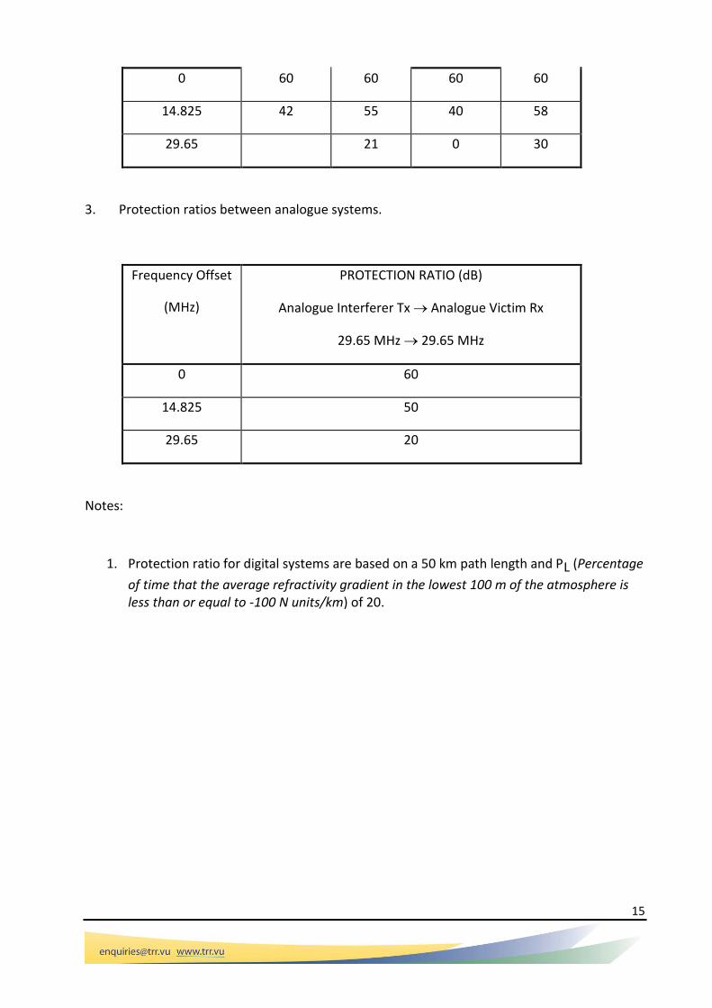
3. Protection ratios between analogue systems.
Frequency Offset
(MHz)
PROTECTION RATIO (dB)
Analogue Interferer Tx Analogue Victim Rx
29.65 MHz 29.65 MHz
0 60
14.825 50
29.65 20
Notes:
1. Protection ratio for digital systems are based on a 50 km path length and PL (Percentage
of time that the average refractivity gradient in the lowest 100 m of the atmosphere is less than or equal to -100 N units/km) of 20.

16
The 6.7 GHz band
The 6.7 GHz band is designed to offer high capacity channels capable of supporting 140 Mbit throughput.
THE 6.7 GHz BAND (6425 - 7110 MHz)
RF CHANNEL ARRANGEMENTS
ASSIGNMENT INSTRUCTIONS
This band is designated for use by digital high capacity fixed point-to-point links.
Typical Use : 140 Mbit/s data
Assignment Priority : not specified
Minimum Path Length : 20 km
Antenna Requirements : 1.2 m parabolic
Note:
1. Proposed links need to be coordinated with licensed earth stations operating in this band.
1
6460
2
6500
3
6540
4
6580
5
6620
6
6660
7
6700
8
6740
1'
6800
2'
6840
3'
6880
4'
6920
5'
6960
6'
7000
7'
7040
8'
7080
1
6440
2
6480
3
6520
4
6560
5
6600
6
6640
7
6680
8
6720
1'
6780
2'
6820
3'
6860
4'
6900
5'
6940
6'
6980
7'
7020
8'
7060
7110
7110
340 MHz40 MHz
6770
fo
40 MHz340 MHz
6770
fo
6425
6425
MAIN
INTERLEAVED

17
2. All terrestrial fixed services in this band operate on a no protection basis from interference from uplinks in the Fixed satellite Service (FSS) except where those services are aboard visiting ships or aircraft.
Reference
1. Rec. ITU-R F.384-10, “Radio-frequency channel arrangements for medium and high capacity analogue or high capacity digital radio-relay systems operating in the upper 6 GHz band”.
THE 6.7 GHz BAND (6425 - 7110 MHz)
PROTECTION RATIOS
Protection Ratios are:
Co-channel: 60 dB
1st adjacent channel: 30 dB
2nd adjacent channel: 0 dB
Note:
1. Protection ratios for digital systems are based on a 50 km path length and PL (Percentage of time that the average refractivity gradient in the lowest 100 m of the atmosphere is less than or equal to -100 N units/km) of 20.

18
The 7.2 GHz Band (7125 – 7425 MHz).
The 7.2 GHz band is designed to offer flexible arrangements capable of supporting channel bands widths of 14MHz, 28MHz and 56 MHz through aggregation of 14 MHz channels.
Preferred Arrangements from F.385 (10) (154 MHz Duplex)
Alternate Arrangements (161 MHz Duplex)
The alternate arrangements should only be used in extenuating circumstances. There are included to allow flexibility.
ASSIGNMENT INSTRUCTIONS
Typical Use : flexible high capacity data links.
Assignment Priority : Assign from Channel 1.
Minimum Path Length : 20 km
Minimum Antenna Requirements : 1.2 m parabolic dish minimum.
Protection Requirements : Protection ratios required between digital systems operating on the same channel raster.
Co Channel: 60 dB

19
1st Adjacent Channel 30 dB 2nd Adjacent Channel 0 dB
Some systems in Vanuatu may not be compliant with Rec F.385-10 and instead use an older Recommendation or an Annex to F.385. In this case any overlap means the system is co-channel. 1st adjacent must not overlap at all and 2nd adjacent must be one equivalent channel width away.
Orthogonal polarization may be used to achieve coordination; allow 20dB cross polar discrimination in the main beam but take care where reflections may be possible. Note that cross polar discrimination reduces beyond the main beam of an antenna.
Example: An antenna has a gain of 40 dBi. If another system uses orthogonal polarization then this may be reduced to 20 dBi. The cross polar discrimination of 20 dB may be subtracted from the gain of the antenna and the highest of this or the antenna gain used. If actual antenna patterns and discriminations are available these may be used.
Channel aggregation
Channels may be aggregated or split to form from 7 MHz up to 56 MHz channels in line with ITU-R F.385-10. Where aggregation is used the term ‘2nd adjacent channel’ refers to a channel separated by the bandwidth of the aggregated channel.
Note: Protection ratio for digital systems are based on a 50 km path length and PL (Percentage
of time that the average refractivity gradient in the lowest 100 m of the atmosphere is less than or equal to -100 N units/km) of 20.
References:
1. Rec. ITU-R F.385-10, " Radio-frequency channel arrangements for fixed wireless systems operating in the 7 110-7 900 MHz band ", 2012.
20
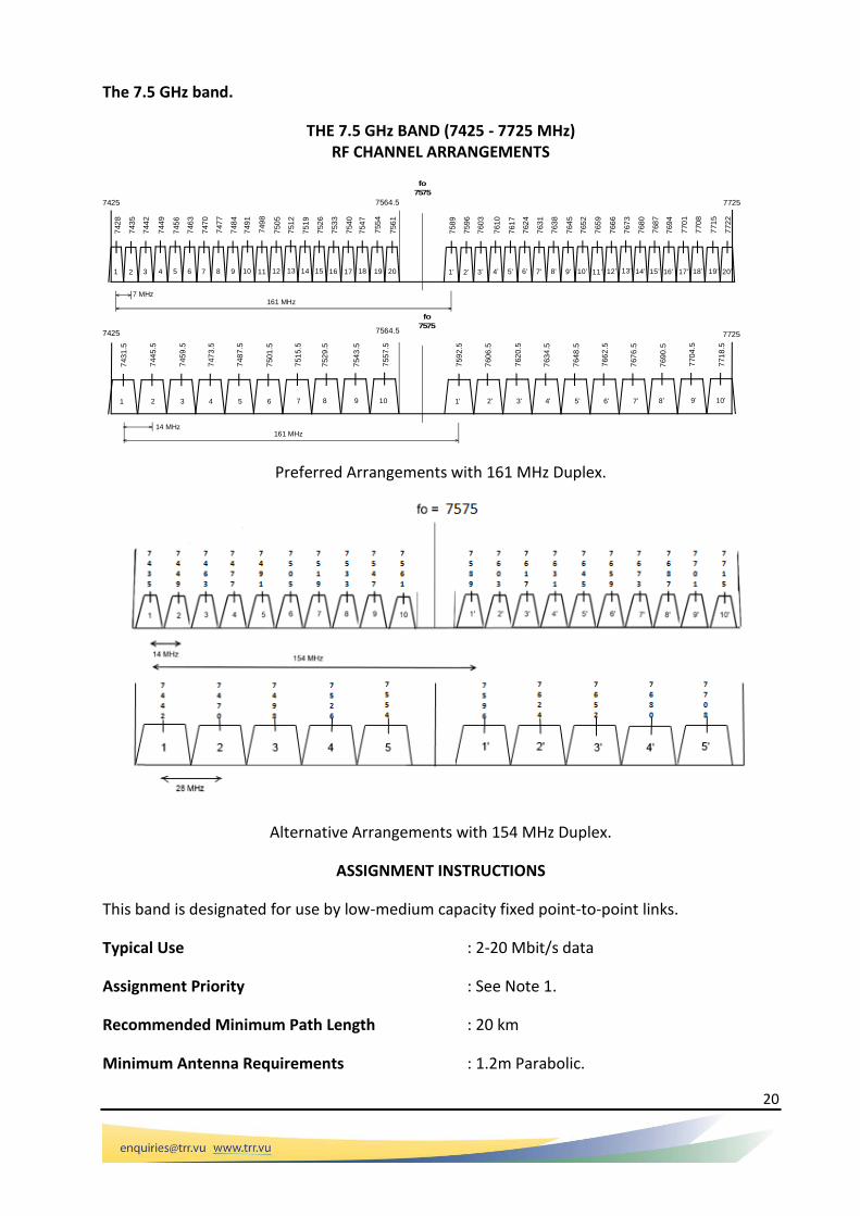
The 7.5 GHz band.
THE 7.5 GHz BAND (7425 - 7725 MHz) RF CHANNEL ARRANGEMENTS
Preferred Arrangements with 161 MHz Duplex.
Alternative Arrangements with 154 MHz Duplex.
ASSIGNMENT INSTRUCTIONS
This band is designated for use by low-medium capacity fixed point-to-point links.
Typical Use : 2-20 Mbit/s data
Assignment Priority : See Note 1.
Recommended Minimum Path Length : 20 km
Minimum Antenna Requirements : 1.2m Parabolic.
161 MHz7 MHz
7575
fo
7575
fo
7725
14 MHz161 MHz
2 3 4 5 6 7
2 3 4 85 6 7 9 10 11 12 13 14
742
8
743
5
744
2
744
9
745
6
746
3
747
0
747
7
748
4
749
1
749
8
750
5
751
2
751
9
768
0
767
3
766
6
765
9
765
2
764
5
763
8
763
1
762
4
761
7
761
0
760
3
759
6
758
9
743
1.5
744
5.5
745
9.5
747
3.5
748
7.5
750
1.5
751
5.5
767
6.5
766
2.5
764
8.5
763
4.5
762
0.5
760
6.5
759
2.5
7564.5
1
1
7425 7564.5
15 16 17 18 19 20 2' 3' 4' 8'5' 6' 7' 9' 10 ' 11 ' 12' 13' 14'1' 15' 16' 17' 18' 19' 20'
9 108 2' 3' 4' 5' 6' 7'1' 9' 10'8'
769
0.5
770
4.5
771
8.5
752
9.5
754
3.5
755
7.5
768
7
769
4
770
1
770
8
771
5
772
2
752
6
753
3
754
0
754
7
755
4
756
1
7725
7425

21
Notes:
1. Assignment priorities are defined as follows: 14 MHz channels - from the highest channel downward;
7 MHz channels - from the lowest channel upward.
2. Assignments on the 7 MHz Ch1 must coordinate with services in the 7.2 GHz band using the same protection ratios defined below.
3. Channel aggregation is permitted. Where aggregation is used the term ’2nd adjacent channel’ refers to a channel separated by the bandwidth of the aggregated channel.
References
1. Rec. ITU-R F.385-10, “Radio-frequency channel arrangements for radio-relay systems operating in the 7 GHz band”.
PROTECTION RATIOS
1. Protection ratios required between digital systems operating on the same channel raster.
Co Channel: 60 dB 1st Adjacent Channel 30 dB 2nd Adjacent Channel 0 dB Some systems in Vanuatu may not be compliant with Rec F.385-10 and instead use an older Recommendation or an Annex to F.385. In this case any overlap means the system is co-channel. 1st adjacent must not overlap at all and 2nd adjacent must be one equivalent channel width away.
Orthogonal polarization may be used to achieve coordination; allow 20dB cross polar discrimination in the main beam but take care where reflections may be possible. Note that cross polar discrimination reduces beyond the main beam of an antenna.
Example: An antenna has a gain of 40 dBi. If another system uses orthogonal polarization then this may be reduced to 20 dBi. The cross polar discrimination of 20 dB may be subtracted from the gain of the antenna and the highest of this or the antenna gain used. If actual antenna patterns and discriminations are available these may be used.
Notes:
1. Protection ratio for digital systems are based on a 50 km path length and PL (Percentage of
time that the average refractivity gradient in the lowest 100 m of the atmosphere is less than or equal to -100 N units/km) of 20.
The 8 GHz Band
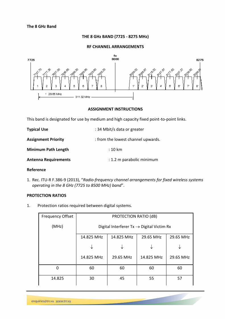
THE 8 GHz BAND (7725 - 8275 MHz)
RF CHANNEL ARRANGEMENTS
ASSIGNMENT INSTRUCTIONS
This band is designated for use by medium and high capacity fixed point-to-point links.
Typical Use : 34 Mbit/s data or greater
Assignment Priority : from the lowest channel upwards.
Minimum Path Length : 10 km
Antenna Requirements : 1.2 m parabolic minimum
Reference
1. Rec. ITU-R F.386-9 (2013), “Radio-frequency channel arrangements for fixed wireless systems operating in the 8 GHz (7725 to 8500 MHz) band”.
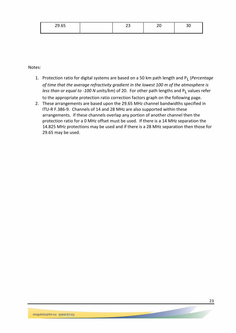
PROTECTION RATIOS
1. Protection ratios required between digital systems.
Frequency Offset
(MHz)
PROTECTION RATIO (dB)
Digital Interferer Tx Digital Victim Rx
14.825 MHz
14.825 MHz
14.825 MHz
29.65 MHz
29.65 MHz
14.825 MHz
29.65 MHz
29.65 MHz
0 60 60 60 60
14.825 30 45 55 57
23
29.65 23 20 30
Notes:
1. Protection ratio for digital systems are based on a 50 km path length and PL (Percentage
of time that the average refractivity gradient in the lowest 100 m of the atmosphere is less than or equal to -100 N units/km) of 20. For other path lengths and PL values refer
to the appropriate protection ratio correction factors graph on the following page. 2. These arrangements are based upon the 29.65 MHz channel bandwidths specified in
ITU-R F.386-9. Channels of 14 and 28 MHz are also supported within these arrangements. If these channels overlap any portion of another channel then the protection ratio for a 0 MHz offset must be used. If there is a 14 MHz separation the 14.825 MHz protections may be used and if there is a 28 MHz separation then those for 29.65 may be used.

24
The 10 GHz band
THE 10 GHz BAND (10.55 - 10.68 GHz)
RF CHANNEL ARRANGEMENTS
ASSIGNMENT INSTRUCTIONS
This band is designated for use by low and medium capacity fixed point-to-point links.
Typical Use : 2 Mbit/s data or greater
Assignment Priority : See Note 1.
Minimum Path Length : 1 km
Antenna Requirements : 0.8 m parabolic minimum
Maximum Antenna Elevation : < 20 degrees above the horizon. See Note 2.
Maximum power to the antenna port : -15 dBW. See Note 3.
Notes:
1. Assignment priorities are defined as follows: 7 MHz channels - from the lowest channel upward;
14 MHz channels - from the highest channel downward; and
for one-way links using the 7 MHz channels - channel 9 should be utilised first.
65 MHz7 MHz
10.68
3 4 5 6 7 8 91 2
10.56510.572
10.57910.586
10.59310.600
10.60710.614
10.55810.623
10.63010.637
10.64410.651
10.65810.665
10.672
1' 2' 3' 4' 5' 6' 7' 8'
10.68
14 MHz65 MHz
1 2 3 4
10.5615 10.5755 10.5895 10.6035
1' 2' 3' 4'
10.6265 10.6405 10.6545 10.6685
10.55
10.55

25
2. When feeding towers from low structures such as buildings designers must ensure a maximum elevation of 20 degrees is not exceeded.
3. Where automatic transmitter power control is used to overcome rain fade the power to the antenna port may be increased to -3 dBW.
References Rec. ITU-R F.747, “Radio-frequency channel arrangements for radio-relay systems operating in the 10 GHz band”.
PROTECTION RATIOS
1. Protection ratios required between systems operating on 7 and 14 MHz channels.
Frequency Offset
(MHz)
PROTECTION RATIO (dB)
Digital Interferer Tx Digital Victim Rx
7 MHz
7 MHz
7 MHz
14 MHz
14 MHz
7 MHz
14 MHz
14 MHz
0 60 60 60 60
3.5 60 60
7 35 60 55 60
10.5 55 45
14 20 30 20 55
17.5 10 10
Notes:
1. Protection ratio for digital systems are based on a 30 km path length and PL (Percentage of
time that the average refractivity gradient in the lowest 100 m of the atmosphere is less than or equal to -100 N units/km) of 20. The protections above take into account a fade into the victim receiver of 5dB. Designers are advised to properly design systems for rain depending on system availability requirements.

26
The band 10.7 – 11.7 GHz; the 11 GHz band.
11 GHz BAND (10.7 - 11.7 GHz)
RF CHANNEL ARRANGEMENTS
MAIN
INTERLEAVED
ASSIGNMENT INSTRUCTIONS
This band is designated for use by digital high capacity fixed point-to-point links.
Typical Use : 140/155 Mbit/s data
Assignment Priority : not specified
Minimum Path Length : 1 km
Antenna Requirements : 1.2 m parabolic
Note:
1. Assignments made on interleaf channel 1 must coordinate with systems using the 10 GHz plan due to adjacent band considerations.
2. Proposed fixed links need to be coordinated with earth stations operating in this band.
3. All terrestrial fixed services in this band operate on a no protection basis from interference from uplinks in the Fixed satellite Service (FSS) except where those services are aboard visiting ships or aircraft.
Reference
1. Rec. ITU-R F.387-6, “Radio-frequency channel arrangements for radio relay systems operating in the 11 GHz band”.
1
10.735
2
10.775
3
10.815
4
10.855
5
10.895
6
10.935
7
10.975
8
11.015
9
11.055
10
11.095
11
11.135
12
11.175
1'
11.225
2'
11.265
3'
11.305
4'
11.345
5'
11.385
6'
11.425
7'
11.465
8'
11.505
9'
11.545
10'
11.585
11'
11.625
12'
11.665
11.7
490 MHz40 MHz
11.210.7
fo
1
10.715
2
10.755
3
10.795
4
10.835
5
10.875
6
10.915
7
10.955
8
10.995
9
11.035
10
11.075
11
11.115
12
11.155
1'
11.205
2'
11.245
3'
11.285
4'
11.325
5'
11.365
6'
11.405
7'
11.445
8'
11.485
9'
11.525
10'
11.565
11'
11.605
12'
11.645
11.7
490 MHz40 MHz
11.210.7

27
11 GHz BAND (10.7 - 11.7 GHz)
PROTECTION RATIOS
Protection ratios for systems operating in the 11 GHz band are:
Co-channel or overlapping channels: 60 dB
1st adjacent channel: 30 dB
2nd adjacent channel: 0 dB
Notes:
1. The “co-channel” protection ratio shall apply in cases where any portion of the interfering and victim channels overlap.
2. The “1st adjacent channel” protection ratio shall apply in cases where the interfering and victim channels do not actually overlap but are immediately adjacent to each other.
3. Protection ratios for digital systems are based on a 30 km path length and PL (Percentage of time that the average refractivity gradient in the lowest 100 m of the atmosphere is less than or equal to -100 N units/km) of 20.

28
The 13 GHz band
The 13 GHz band provides channels capable of supporting data rates of up to 34 Mbits over short paths.
THE 13 GHz BAND (12.75 - 13.25 GHz)
RF CHANNEL ARRANGEMENTS
ASSIGNMENT INSTRUCTIONS
This band is designated for use by medium capacity fixed point-to-point links.
Typical Use : FIXED - 34 Mbit/s data
Assignment Priority : not specified
Minimum Path Length : not specified
Antenna Requirements : 0.6 m standard parabolic dish
Notes:
1. Each channel may be subdivided into 14 MHz or 7 MHz channels within a 28 MHz channel maintaining the duplex spacing of 266 MHz.
2. Proposed fixed links need to be coordinated with earth stations operating in this band.
3. All terrestrial fixed services in this band operate on a no protection basis from interference from uplinks in the Fixed satellite Service (FSS) except where those services are aboard visiting ships or aircraft.
References
1. Rec. ITU-R F.497-7, “Radio-frequency channel arrangements for fixed wireless systems operating in the 13 GHz frequency band”.

29
THE 13 GHz BAND (12.75 - 13.25 GHz)
PROTECTION RATIOS
1. Protection ratios required between digital systems.
Frequency Offset
(MHz)
PROTECTION RATIO (dB)
Digital Interferer Tx Digital Victim Rx
14 MHz
14 MHz
14 MHz
28 MHz
28 MHz
14 MHz
28 MHz
28 MHz
0 50 50 50 50
14 20 35 45 47
2. Protection ratios required between digital and analogue systems.
Frequency Offset
(MHz)
PROTECTION RATIO (dB)
Analogue Interferer Tx
Digital Victim Rx
Digital Interferer Tx
Analogue Victim Rx
28 MHz
14 MHz
28 MHz
28 MHz
14 MHz
28 MHz
28 MHz
28 MHz
0 50 50 60 60
14 35 45 40 55
3. Protection ratios between analogue systems

30
Frequency Offset
(MHz)
PROTECTION RATIO (dB)
Analogue Interferer Tx Analogue Victim Rx
28 MHz 28 MHz
0 60
14 50
Notes:
1. Protection ratios for digital systems are based on a 20 km path length and R (Rainfall rate in mm/hr for 0.01% of the worst month) of 80 mm/hr.

31
1.11 The 15 GHz Band
The 15 GHz band (14.5 – 15.35 GHz) is designed to provide channels for low and medium capacity fixed links over short path lengths.
THE 15 GHz BAND (14.5 - 15.35 GHz) RF CHANNEL ARRANGEMENTS
ASSIGNMENT INSTRUCTIONS
This band is designated for use by low and medium capacity fixed point-to-point links.
Typical Use : low capacity - 2/8 Mbit/s
: medium capacity - 34 Mbit/s
Assignment Priority : See Note 1.
Minimum Path Length : Not specified.
Antenna Requirements : Not specified.
Note:
1. Assignment priorities are defined as follows:
28 MHz channels - from highest channel downward;
14 MHz channels - from lowest channel upward; and
7 MHz channels - from lowest channel upward.
References
1. Rec. ITU-R F.636-4, “Radio-frequency channel arrangements for fixed wireless systems operating in the 15 GHz band”.
7 MHz
14.925
fo
14 MHz 28 MHz
1
14.5
045
14.5
115
2
14.5
185
3
14.5
255
4
14.5
325
5
14.5
395
6 1
14.5
50
2
14.5
64
3
14.5
78
4
14.5
92
5
14.6
06
1 2 3
14.6
27
14.6
55
14.6
83
15.3
27
15.2
99
15.2
71
3'2'1'
15.2
50
5'
15.2
36
4'
15.2
22
3'
15.2
08
2'
15.1
94
1'6'
15.1
835
5'
15.1
765
4'
15.1
695
3'
15.1
625
2'
15.1
555
15.1
485
1'
28 MHz14 MHz
14.925
7 MHz
15.35
fo
644 MHz
14.5

32
THE 15 GHz BAND (14.5 - 15.35 GHz)
PROTECTION RATIOS
1. Protection ratios between digital systems operating on the same channel arrangements.
Co Channel 60 dB
1st Adjacent Channel 30 dB
2nd Adjacent Channel 0 dB
2. Protection ratios between digital systems requiring 7 and 14 MHz channels.
Frequency Offset
(MHz)
PROTECTION RATIO (dB)
Digital Interferer Tx Digital Victim Rx
7 MHz 14 MHz 14 MHz 7 MHz
7 60 59
10.5 58 49
14 44 37
17.5 32 26
21 23 13
24.5 15

33
3. Protection ratios between digital and analogue systems requiring 14 and 28 MHz channels.
Frequency Offset
PROTECTION RATIO (dB)
(MHz) Digital Tx
Digital Rx
Analogue Tx
Digital Rx
Digital Tx
Analogue Rx
14 MHz
28 MHz
28 MHz
14 MHz
28 MHz
14 MHz
14 MHz
28 MHz
0 60 60 60 60
7 60 58 60 60
21 35 33 30 30
4. Protection ratios between digital and analogue systems requiring 28 MHz channels.
Frequency Offset
(MHz)
PROTECTION RATIO (dB)
Analogue Tx
Analogue Rx
Analogue Tx
Digital Rx
Digital Tx
Analogue Rx
0 60 60 60
28 20 21 30
Notes:
1. Protection ratio for digital systems are based on a 20 km path length and R (Rainfall rate in mm/hr for 0.01% of the worst month) of 80 mm/hr.
The 18 GHz Band
The 18 GHz band (17.7 – 19.7 GHz) provides highly flexible arrangements for data systems operating over short paths.

THE 18 GHz BAND (17.7 - 19.7 GHz) RF CHANNEL ARRANGEMENTS
2 3 4
1 2 3 4 5 6 7 8 9 10
1' 2' 3' 4' 5' 6' 7' 8' 9' 10'
2' 3' 4'
7.5 MHzChannels
18.688
75
1'
1
1 2 3 4 5 6 7 8 9 10 11 12 13 14 15 16 17 18 19 20
1' 2' 3' 4' 5' 6' 7' 8' 9' 10' 11' 12' 13' 14' 15' 16' 17' 18' 19' 20'
19.315
19.328
7519
.342
519
.356
2519
.370
19.383
7519
.397
519
.411
2519
.425
19.438
7519
.452
519
.466
2519
.480
19.493
7519
.507
519
.521
2519
.535
19.548
7519
.562
519
.576
25
18.566
25
18.552
5
18.538
75
18.525
18.511
25
18.497
5
18.483
75
18.470
18.456
25
18.442
5
18.428
75
18.415
18.401
25
18.387
5
18.373
75
18.360
18.346
25
18.332
5
18.318
75
18.305
18.3
60
18.4
15
18.4
70
18.5
25
19.6
2375
18.613
75
19.7
18.7fo17.7
18.7
fo
5
18.5
80
5'
7.5 MHzChannels
19.3
1519
.342
519
.370
19.3
975
19.4
2519
.452
519
.480
19.5
075
19.5
3519
.562
5
19.3
70
19.4
25
19.4
80
19.5
35
19.5
90
18.3
05
18.3
325
18.3
60
18.3
875
18.4
15
18.4
425
18.4
70
18.4
975
18.5
25
18.5
525
See page 2
See page 2
1010 MHz
13.75 MHz
13.75 MHz
27.5 MHz
27.5 MHz
55 MHz
55 MHz
19.6
9875

RF CHANNEL ARRANGEMENTS Sub-Bands 18.61375 - 18.68875 GHz and 19.62375 - 19.69875 GHz
(7.5 MHz Channeling)
ASSIGNMENT INSTRUCTIONS
This band is designated for use by small, medium and high capacity fixed links.
Typical Use : 8/16/34/155 Mbit/s data
Assignment Priority : 55 MHz channels - from highest channel downward;
:27.5 MHz channels - from lowest channel upward;
:13.75 MHz channels - from channel 10/10’ downward then from channel 11/11’upward;
:7.5 MHz channels - from highest channel downward.
Minimum Path Length : Not specified.
Antenna Requirements : Not specified.
Notes:
1. Assignments made which would overlap the frequency range 18.8 -19.3 GHz may be required to cease operation in the future.
2. The output power of transmitters (measured at the antenna connection) operating in the band 18.6-18.8 GHz is not to exceed +27 dBm (0.5 Watts). It should be noted that multiple transmitters operating on different RF carrier frequencies individually respecting the above output power limit can be connected to a single antenna. See Reference 4.
References
1. Rec. ITU-R F.595-10, “Radio-frequency channel arrangements for radio-relay systems operating in the 18 GHz frequency band”.
2. Article 21.5A, ITU Radio Regulations, Edition of 2001.
18.6175 18.6250 18.6325 18.6400 18.6475 18.6550 18.6625 18.6700 18.6775 18.6850
18.61375 18.68875
19.62375 19.69875
19.6275 19.6350 19.6425 19.6500 19.6575 19.6650 19.6725 19.6800 19.6875 19.6950
1 2 3 4 5 6 7 8 9 10
1' 2' 3' 4' 5' 6' 7' 8' 9' 10'
1010 MHz
18.7fo
19.77.5 MHz
3. Resolution 802 (WRC-03) Agenda of the 2007 World Radiocommunication Conference, Agenda item 1.2.
4. Resolution 746 (WRC-03) Issues dealing with allocations to science services.
THE 18 GHz BAND (17.7 - 19.7 GHz)
PROTECTION RATIOS
Protection ratios required between systems operating in the 18 GHz band:
Co-channel or overlapping channels 60dB 1st Adjacent Channel 30dB 2nd Adjacent Channel 0 dB
Notes:
1. The “Co-channel” protection ratio shall apply in cases where any portion of the interfering and victim channels overlap.
2. The “1st Adjacent Channel” protection ratio shall apply in cases where the interfering and victim channels do not actually overlap but are immediately adjacent to each other.
3. Protection ratios for digital systems are based on a 10 km path length and R (Rainfall rate in mm/hr for 0.01% of the worst month) of 80 mm/hr.

38
The 22 GHz band
THE 22 GHz BAND (21.2 - 23.6 GHz) RF CHANNEL ARRANGEMENTS
1.2 GHz50 MHz
22.4
fo
21.2 23.6
1 2 3 4 5 6 7
21.
675
21.
725
21.
775
21.
825
21.
875
21.
925
21.
975
1' 2' 3' 4' 5' 6' 7'
22.
875
22.
925
22.
975
23.
025
23.
075
23.
125
23.
175
22.008 22.211 23.240 23.443
28, 14, 7
& 3.5 MHz
channels
(see page 2) (see page 2)
channels
& 3.5 MHz
28, 14, 7

39
THE 22 GHz BAND (21.2 - 23.6 GHz)
CHANNEL CENTRE FREQUENCIES (GHz)
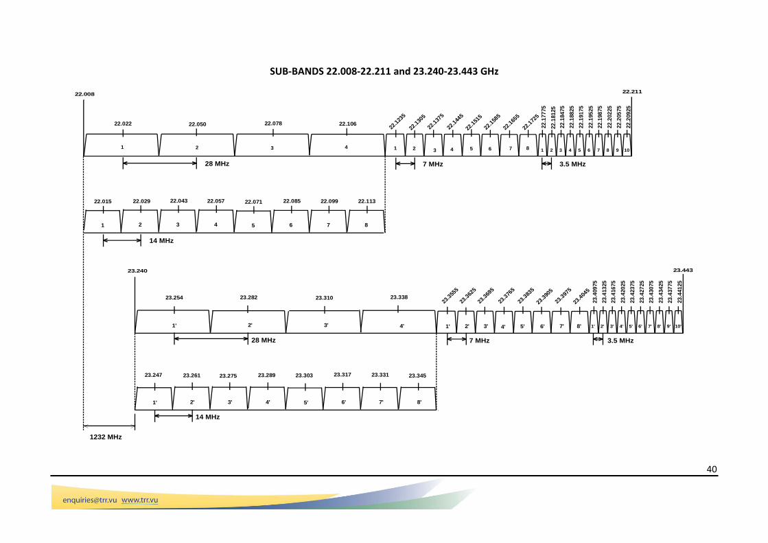
Channels 50 MHz Channels 28 MHz Channels 14 MHz Channels 7 MHz Channels 3.5 MHz Channels
1 1’ 21.675 22.875 22.022 23.254 22.015 23.247 22.1235. 23.3555 22.17775 23.40975
2 2’ 21.725 22.925 22.050 23.282 22.029 23.261 22.1305 23.3625 22.18125 23.41325
3 3’ 21.775 22.975 22.078 23.310 22.043 23.275 22.1375 23.3695 22.18475 23.41675
4 4’ 21.825 23.025 22.106 23.338 22.057 23.289 22.1445 23.3765 22.18825 23.42025
5 5’ 21.875 23.075 22.071 23.303 22.1515 23.3835 22.19175. 23.42375
6 6’ 21.925 23.125 22.085 23.317 22.1585 23.3905 22.19525 23.42725
7 7’ 21.975 23.175 22.099 23.331 22.1655 23.3975 22.19875 23.43075
8 8’ 22.113 23.345 22.1725 23.4045 22.20225 23.43425
9 9’ 22.20575 23.43775
10 10’ 22.20925 23.44125
40
SUB-BANDS 22.008-22.211 and 23.240-23.443 GHz
22
.184
75
3
22
.188
25
4
22
.191
75
5
22
.195
25
6
22
.198
75
7
22
.202
25
8
22
.205
75
9
22
.209
25
10
22.1
235
22.1
305
22.1
375
22.1
515
22.1
445
22.1
585
22.1
655
22.1
725
2 3 4 5 6 7 8
1 2 43
2
22.022 22.050
22.015 22.029 22.043 22.057
3' 4'2'1'
1
28 MHz
5' 6' 8'7'
3
22.10622.078
4
22.11322.09922.08522.071
7 865
22.008
2
22
.181
25
1
22
.177
75
23.240
23
.409
75
23
.413
25
23.443
23.303 23.317 23.331 23.345
23.310 23.338
23.28923.27523.26123.247
23.28223.25423
.404
5
23.3
975
23.3
905
23.3
765
23.3
835
23.3
695
23.3
625
23.3
555
23
.441
25
23
.437
75
23
.434
25
23
.430
75
23
.427
25
23
.423
75
23
.420
25
23
.416
75
1' 2' 3' 4' 1' 2' 3' 4' 5' 6' 7' 8' 1' 2' 3' 4' 5' 6' 7' 8' 9' 10'
14 MHz
7 MHz 3.5 MHz
28 MHz 3.5 MHz7 MHz
14 MHz
1232 MHz
22.211
1

41
THE 22 GHz BAND (21.2 - 23.6 GHz)
ASSIGNMENT INSTRUCTIONS
This band is designated for use by fixed point-to-point links and offers a wide variety of channel bandwidths to support a number of requirements.
Typical Use : 2/8 Mbit/s data or greater.
Assignment Priority : none
Minimum Path Length : none
Antenna Requirements : Parabolic. No requirements on diameter. See Note 2.
Notes:
1. Assignment priorities for point-to-point services are defined as follows: 50 MHz channels (4/4’..7/7’) - from the lowest channel upward;
28 MHz channels - from the lowest channel upward;
14 MHz channels - from the highest channel downward;
7 MHz channels - from the lowest channel upward;
3.5 MHz channels - from the highest channel downward. 2. This band is highly susceptible to rain fade. While no antenna size is specified to enable
the use of compact equipment designers are advised to ensure there is sufficient margin to ensure availability targets are met.
References
1. Rec. ITU-R F.637-4, “Radio-frequency channel arrangements for radio-relay systems operating in the 23 GHz band”.
PROTECTION RATIOS
1. Protection ratios required between digital systems operating on the same channel
arrangements.
Co channel 60 dB
1st Adjacent Channel 30 dB
2nd Adjacent Channel 0 dB

42
2. Protection ratios required between digital systems operating on 3.5 and 7 MHz channels.
Frequency Offset
(MHz)
PROTECTION RATIO (dB)
Digital Interferer Tx Digital Victim Rx
3.5 MHz 7 MHz 7 MHz 3.5 MHz
5.25 55 48
8.75 18 20
12.25 0
3. Protection ratios required between digital systems operating on 7 MHz channels and digital systems operating on 14 and 28 MHz channels.
Frequency Offset
PROTECTION RATIO (dB)
Digital Interferer Tx Digital Victim Rx
(MHz) 7 MHz14 MHz 14 MHz7 MHz 7 MHz28 MHz 28 MHz7 MHz
10.5 58 49
17.5 32 26 45 35
24.5 15 10 20
4. Protection ratios required between digital systems operating on 14 and 28 MHz channels.
Frequency Offset
(MHz)
PROTECTION RATIO (dB)
Digital Interferer Tx Digital Victim Rx
28 MHz 14 MHz 14 MHz 28 MHz
7 58 60

43
21 33 35
Notes:
1. Protection ratio for digital systems are based on a 5 km path length and R (Rainfall rate in mm/hr for 0.01% of the worst month) of 80 mm/hr.