
Dual-Band Dual-Mode Textile Antenna/Rectenna for ...
11
IEEE TRANSACTIONS ON ANTENNAS AND PROPAGATION, VOL. X, NO. X 1 Dual-Band Dual-Mode Textile Antenna/Rectenna for Simultaneous Wireless Information and Power Transfer (SWIPT) Mahmoud Wagih, Graduate Student Member, IEEE, Geoffrey S. Hilton, Alex S. Weddell, Member, IEEE, and Steve Beeby, Senior Member, IEEE Abstract—This paper presents a textile antenna for dual- band Simultaneous Wireless Information and Power Transfer (SWIPT). The antenna operates as a 2.4 GHz off-body com- munications antenna and a sub-1 GHz (785-875 MHz) broad- beam rectenna. Incorporated within the broadside microstrip antenna is a high-impedance rectenna for sub-1 GHz power harvesting. Utilizing antenna-rectifier co-design, the rectenna eliminates the rectifier matching network. The textile antenna is fabricated on a felt substrate and utilizes conductive fabrics for the antenna. At 2.4 GHz, the antenna achieves a realized gain of 7.2 dBi on a body phantom and a minimum radiation efficiency of 63%, with and without the rectifier. The rectenna achieves a best-in-class RF to DC efficiency of 62% from 0.8 μW/cm 2 , representing over 25% improvement over state- of-the-art textile rectennas and demonstrating that SWIPT does not detrimentally affect the energy harvesting or communications performance. The antenna/rectenna occupies an electrically-small area of 0.213×0.19λ 2 0 . This antenna is the first dual-band, dual- mode antenna demonstrated on textiles for SWIPT applications and the first dual-band matching network-free SWIPT rectenna. Index Terms—Antennas, Microstrip Antennas, Rectennas, RF Energy Harvesting, SWIPT, Wearable Antenna, Wireless Power Transfer I. I NTRODUCTION W IRELESS communication in Body Area Networks (BANs) enables a variety of applications in healthcare monitoring, fitness tracking and localization. Wireless Power Transmission (WPT) [1], Radio Frequency Energy Harvest- ing (RFEH) [2], and Simultaneous Wireless Information and Power Transfer (SWIPT) [3] are methods of enabling battery- free sustainable low-power Internet of Things (IoT) devices. In SWIPT, a single wave can be used to transmit information and power to the IoT device. SWIPT is often implemented using a single-band antenna, combined with time-based splitting or power-dividing mechanisms, to split the incident power This paragraph of the first footnote will contain the date on which you submitted your paper for review. This work was supported by the European Commission through the EnABLES Project, funded under H2020-EU.1.4.1.2 grant number: 730957 and the UK Engineering and Physical Sciences Research Council (EPSRC) under Grant EP/P010164/1. Datasets used in ths work will be available at DOI: 10.5258/SOTON/D1777 (Corresponding author: M. Wagih) M. Wagih, A. S. Weddell, and S. Beeby are with the School of Electronics and Computer Science, University of Southampton, Southampton, SO17 1BJ, U.K. (email: [email protected]) G. S. Hilton is in the Communication Systems & Networks Group, Univer- sity of Bristol, Bristol BS8 1UB, U.K. (email: [email protected]) between rectifier and the information receiver [3]. Despite ex- tensive research showing the performance benefits of SWIPT in networking, very limited antenna implementations have been specifically designed for simultaneous operation as com- munication and RFEH antennas. A variety of antenna designs, from conventional and novel 50 Ω antennas to high-impedance antennas designed in con- junction with the rectifier have been proposed for RF-powering [4]. Textile rectennas are mostly based on off-body antennas [5]–[9], due to their improved isolation. More recently, wide- beam omnidirectional “wire-type” antennas such as monopoles were investigated for wearable applications [10]–[12]. While textile-based rectifiers have been used in [5] and [8], their Power Conversion Efficiency (PCE) has been lower than a rigid low-loss rectifier coupled to a textile patch antenna [7]. Furthermore, while a high-PCE sub-μW/cm 2 all-textile rectenna was presented in [10], its PCE plateaues below 55% for higher power densities. The reported wearable rectennas have been exclusively focused on power reception and have not considered a SWIPT scenario. In existing SWIPT rectenna and antenna designs, the com- mon approach is to use two antennas in the same space [13] or a dual band antenna [14]. It is common to use a lower frequency band for down-link power transmission to the wireless-powered device, and a higher frequency for up- link information transmission to the base-station. This was proposed at 2.4/0.915 GHz [15], 40/24 GHz [14], and 60/24 GHz [13]. A two-port 2.4 GHz antenna was used in [16] to enable simultaneous communications and energy harvesting. Recently, a SWIPT rectenna has been proposed in [17] based on a high-isolation hybrid coupler. However, the size of the coupler is large compared to the antenna and a rectifier matching network is required at the antenna’s input port. Furthermore, such a coupler on a lossy textile substrate would incur significant insertion losses reducing the harvested DC power. To design a hybrid antenna/rectenna for wearable SWIPT, propagation in BANs needs to be reviewed. Antennas for body-centric communications are categorized into different modes of operation. First of all, off-body, where the wearable antenna communicates with a device or a base-station off the body [18]–[22]. Off-body antennas typically have broadside radiation patterns to minimize interaction with the body. The second mode is on-body communications, where two antennas mounted on the same user communicate across the body [23]–
-
Upload
khangminh22 -
Category
Documents
-
view
0 -
download
0
Transcript of Dual-Band Dual-Mode Textile Antenna/Rectenna for ...
IEEE TRANSACTIONS ON ANTENNAS AND PROPAGATION, VOL. X, NO. X 1
Dual-Band Dual-Mode Textile Antenna/Rectennafor Simultaneous Wireless Information
and Power Transfer (SWIPT)Mahmoud Wagih, Graduate Student Member, IEEE, Geoffrey S. Hilton,
Alex S. Weddell, Member, IEEE, and Steve Beeby, Senior Member, IEEE
Abstract—This paper presents a textile antenna for dual-band Simultaneous Wireless Information and Power Transfer(SWIPT). The antenna operates as a 2.4 GHz off-body com-munications antenna and a sub-1 GHz (785-875 MHz) broad-beam rectenna. Incorporated within the broadside microstripantenna is a high-impedance rectenna for sub-1 GHz powerharvesting. Utilizing antenna-rectifier co-design, the rectennaeliminates the rectifier matching network. The textile antennais fabricated on a felt substrate and utilizes conductive fabricsfor the antenna. At 2.4 GHz, the antenna achieves a realizedgain of 7.2 dBi on a body phantom and a minimum radiationefficiency of 63%, with and without the rectifier. The rectennaachieves a best-in-class RF to DC efficiency of 62% from0.8 µW/cm2, representing over 25% improvement over state-of-the-art textile rectennas and demonstrating that SWIPT doesnot detrimentally affect the energy harvesting or communicationsperformance. The antenna/rectenna occupies an electrically-smallarea of 0.213×0.19λ2
0. This antenna is the first dual-band, dual-mode antenna demonstrated on textiles for SWIPT applicationsand the first dual-band matching network-free SWIPT rectenna.
Index Terms—Antennas, Microstrip Antennas, Rectennas, RFEnergy Harvesting, SWIPT, Wearable Antenna, Wireless PowerTransfer
I. INTRODUCTION
W IRELESS communication in Body Area Networks(BANs) enables a variety of applications in healthcare
monitoring, fitness tracking and localization. Wireless PowerTransmission (WPT) [1], Radio Frequency Energy Harvest-ing (RFEH) [2], and Simultaneous Wireless Information andPower Transfer (SWIPT) [3] are methods of enabling battery-free sustainable low-power Internet of Things (IoT) devices. InSWIPT, a single wave can be used to transmit information andpower to the IoT device. SWIPT is often implemented usinga single-band antenna, combined with time-based splittingor power-dividing mechanisms, to split the incident power
This paragraph of the first footnote will contain the date on which yousubmitted your paper for review. This work was supported by the EuropeanCommission through the EnABLES Project, funded under H2020-EU.1.4.1.2grant number: 730957 and the UK Engineering and Physical SciencesResearch Council (EPSRC) under Grant EP/P010164/1. Datasets used inths work will be available at DOI: 10.5258/SOTON/D1777 (Correspondingauthor: M. Wagih)
M. Wagih, A. S. Weddell, and S. Beeby are with the School of Electronicsand Computer Science, University of Southampton, Southampton, SO17 1BJ,U.K. (email: [email protected])
G. S. Hilton is in the Communication Systems & Networks Group, Univer-sity of Bristol, Bristol BS8 1UB, U.K. (email: [email protected])
between rectifier and the information receiver [3]. Despite ex-tensive research showing the performance benefits of SWIPTin networking, very limited antenna implementations havebeen specifically designed for simultaneous operation as com-munication and RFEH antennas.
A variety of antenna designs, from conventional and novel50 Ω antennas to high-impedance antennas designed in con-junction with the rectifier have been proposed for RF-powering[4]. Textile rectennas are mostly based on off-body antennas[5]–[9], due to their improved isolation. More recently, wide-beam omnidirectional “wire-type” antennas such as monopoleswere investigated for wearable applications [10]–[12]. Whiletextile-based rectifiers have been used in [5] and [8], theirPower Conversion Efficiency (PCE) has been lower than arigid low-loss rectifier coupled to a textile patch antenna[7]. Furthermore, while a high-PCE sub-µW/cm2 all-textilerectenna was presented in [10], its PCE plateaues below 55%for higher power densities. The reported wearable rectennashave been exclusively focused on power reception and havenot considered a SWIPT scenario.
In existing SWIPT rectenna and antenna designs, the com-mon approach is to use two antennas in the same space[13] or a dual band antenna [14]. It is common to use alower frequency band for down-link power transmission tothe wireless-powered device, and a higher frequency for up-link information transmission to the base-station. This wasproposed at 2.4/0.915 GHz [15], 40/24 GHz [14], and 60/24GHz [13]. A two-port 2.4 GHz antenna was used in [16] toenable simultaneous communications and energy harvesting.Recently, a SWIPT rectenna has been proposed in [17] basedon a high-isolation hybrid coupler. However, the size of thecoupler is large compared to the antenna and a rectifiermatching network is required at the antenna’s input port.Furthermore, such a coupler on a lossy textile substrate wouldincur significant insertion losses reducing the harvested DCpower.
To design a hybrid antenna/rectenna for wearable SWIPT,propagation in BANs needs to be reviewed. Antennas forbody-centric communications are categorized into differentmodes of operation. First of all, off-body, where the wearableantenna communicates with a device or a base-station off thebody [18]–[22]. Off-body antennas typically have broadsideradiation patterns to minimize interaction with the body. Thesecond mode is on-body communications, where two antennasmounted on the same user communicate across the body [23]–
2 IEEE TRANSACTIONS ON ANTENNAS AND PROPAGATION, VOL. X, NO. X
[25], these antennas typically have omnidirectional radiationpatterns with vertical polarization, or end-fire radiation pat-terns for point-to-point applications [24]. The final mode isin-body, where the wearable antenna communicates with animplant or is used for medical imaging [26].
Multiple wearable antenna designs, based on textile andnon-textile materials, such as buttons and accessories, havebeen proposed for off-, on- and in-body applications. Aground plane or reflector-backing is often implemented todirect the antenna’s main beam away from the body for off-body applications. On the other hand, on-body/omnidirectionalantennas often resemble monopoles and have omnidirectionalradiation patterns [10]. As for in-body antennas, either omni-directional radiation patterns or high gain beams directed intothe body are used. For example, in [27] an off-/in-body antennacombines two patch elements, one facing off the body and theother facing into the body, with a ground plane in between.Textile-based rectennas have been developed with broadside(off-body) radiation [5], [7]–[9], as well as omnidirectionalradiation with no shielding from the body [10]–[12].
To improve the versatility of the wearable antennas, makingthem suitable for different off-, on-, and in-body applicationssimultaneously, multi-mode antennas have been proposed.Multiple antennas have been developed using textile dualand multi-mode antennas [27]–[36]. This has been achievedusing multi-port antennas [32], [34], single-port antennas withmultiple radiating elements [27], [28] as well as antennaswith multiple resonant modes for multi-band and multi-modeoperation with reconfigurable elements [37].
Nevertheless, all the reported wearable antennas were de-veloped solely for communications or energy harvesting, andrequire a separate impedance matching network. In addition,the dual-radiation modes generated from the antennas arefrom standard 50 Ω ports, even in the case of dual-portantennas [34]. Furthermore, complex impedance antennas,such as RFID antennas [38] or rectennas [4], have not beenintegrated in any dual-mode BANs antennas.
This paper presents the first dual-band dual-mode antennacombining a microstrip patch with a high-impedance co-designed rectenna for SWIPT applications, unlike our previouswork in [39] where a single-band/mode SWIPT antenna wasfirst demonstrated. The proposed antenna uses its broadsideradiation pattern for 2.4 GHz off-body communications andan omnidirectional radiation pattern for power reception inthe sub-1 GHz Industrial Scientific Medical (ISM)-band. Bychoosing a lower ISM-band for power transmission, the higherpath-loss can be avoided. Moreover, integrating a sub-1 GHzrectenna within a 2.4 GHz microstrip patch overcomes thesize limitation of a standalone sub-1 GHz WPT antenna.At 2.4 GHz, the antenna achieves a minimum measuredradiation efficiency of 63%, with and without the rectifierconnected, and a gain of 7.2 dBi. The sub-1 GHz rectennais electrically very compact (0.03λ2) with over 25% peak-PCE-improvement over state-of-the-art (SoA) textile rectennasfor sub-µW/cm2 RFEH. The textile implementation of theantenna, the high radiation efficiency and gain at 2.4 GHz,and the high energy harvesting efficiency and sensitivity showthat a single antenna could be used to simultaneously power a
MCU,
Wireless TX
2.4 GHz Patch
DC
Power
2.4 GHz TX
(Bluetooth, IEEE 802.15)
Sub-1 GHz
Dipole
Off-Body
Broadside
2.4 GHz
Gain
Broad-beam
Sub-1 GHz Gain
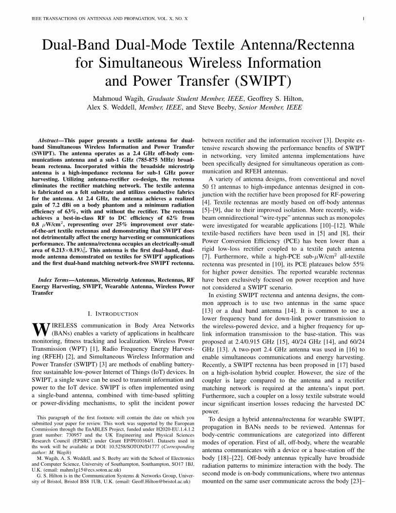
Fig. 1. The architecture of the proposed SWIPT antenna for sub-1 GHz WPTand 2.4 GHz communications, with broadside and omnidirectional radiationpatterns for the communication antenna and the rectenna, respectively.
sensor node while transmitting and receiving information froman off-body source.
II. SWIPT ANTENNA DESIGN AND SIMULATION
A. Dual-Band Dual-Mode Antenna
The antenna design process is divided into two parts: thedesign of a 50Ω 2.4 GHz antenna with broadside off-bodyradiation patterns, and the design of a broad-beam sub-1GHz rectenna, due to the improved harvesting probability anomnidirectional antenna in sub-1 GHz bands [40]. Further-more, sub-1 GHz rectifiers typically achieve a higher PCE [1].For SWIPT to be efficient, the mutual coupling between therectenna and the communication antenna needs to minimized.To illustrate, high mutual coupling would result in the 2.4GHz transmitted power leaking to the rectifier, reducing thecommunication’s range. Moreover, the rectenna’s DC outputmay degrade if the sub-1 GHz incident power is absorbed bythe 2.4 GHz transceiver instead of the rectifier.
Fig. 1 shows the application of a the proposed antennaat a system level. The same dual-port fully-textile antennacan be utilized as a rectenna, without a matching network, topower wearable a microcontroller unit (MCU), sensors and atransceiver. The same antenna can then be used by the wirelesstransceiver to communicate with an off-body base-station. Thescope of this work covers the antenna and rectenna design asopposed to the complete system implementation.
B. Antenna/Rectenna Stepped Design and Simulations
The first step in designing the antenna is the design ofa standard 2.4 GHz patch with a microstrip feed. The firstiteration of the patch is based on the standard geometry toresonate at 2.4 GHz. A proximity-coupled microstrip feed isselected due to the high thickness of the felt fabric (h=3.2 mm)which will result in a probe-feed having high inductance [7].The felt fabric falls within the h > 0.03λ margin to achievehigh radiation efficiency [41]. Furthermore, felt has a relativelylow dissipation factor (tanδ=0.02) compared to other woventextiles due to the larger air gaps in its composition [10]. Theantenna was simulated in CST Microwave Studio to tune thelength of the inset microstrip feed. Fig. 2 shows the designsteps of the antenna, with step 1 being a common geometry
WAGIH et al.: DUAL-BAND DUAL-MODE TEXTILE ANTENNA/RECTENNA FOR SWIPT 3
Felt substrateFabric
GND
Radiating
patch
Proximity
feed
Fabric
GND
Inductive
feed
50Ω (2.4
GHz)50Ω (2.4 GHz)
High-ImZ
Miniaturized
Fabric GND
Step 1: Common patch
High Re/ImZ
50Ω (2.4
GHz)Tuning
stub
ZAnt. = Z*Rect. (Sub-1 GHz)
Step 5: Dipole meandering
High Re/ImZ
Bent on hand
Bent in space
Flat on hand
Step 4: 2-port patch +
dipole arms
Step 6: Z-tuning
Step 2: Common patch
+ inductive portStep 3: Miniaturized GND
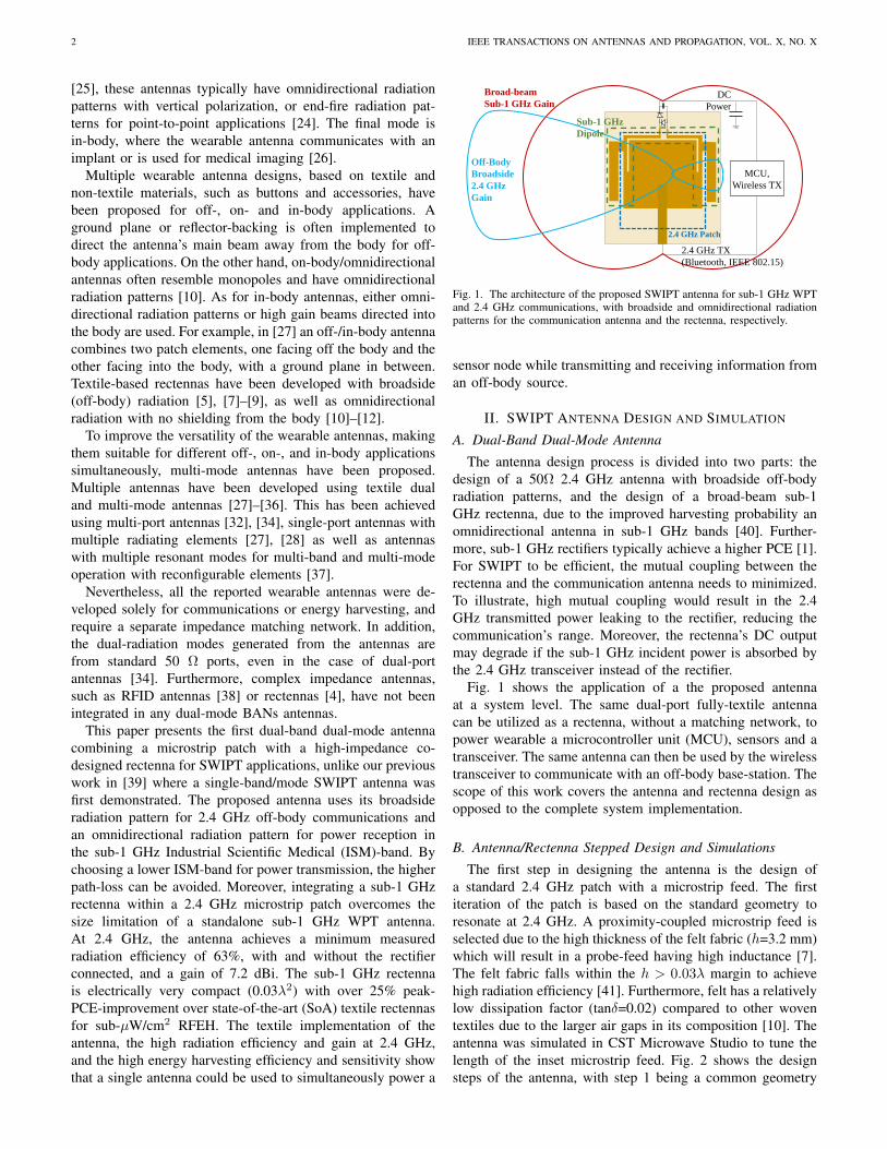
Fig. 2. Design steps of the proposed dual-band SWIPT antenna.
patch with the proximity-coupled feed, whose performanceparameters are quote in Table I.
Step 2 is to introduce a second port for connecting the rec-tifier. While port-2 could be directly connected to a microstripline and a rectifier impedance matching network, antenna-rectifier co-design could be utilized to improve the impedancematching and subsequently the PCE [39]. For a single-seriesrectifier, the input impedance can be calculated analyticallyusing
Zdiode =VFIdc
=V0 sinωt− 0.5VDC
IS
[B0
(V0
mVT
)exp
(−0.5VDCmVT
)− 1] , (1)
where VF and VT are the diode’s forward voltage drop andthe thermal voltage, IS is the diode’s saturation current, ω isthe angular frequency, m is the diode’s ideality factor and B0
denotes the DC harmonic of the Bessel function describing thediode’s current [42]. A high-accuracy estimate of the rectifierinput impedance can be estimated for the low power regionusing Harmonic Balance (HB) simulation [43]. In [42], itwas shown that for varying RF power levels and frequencies,the rectifier maintains a predominantly capacitive imaginaryimpedance.
As a result, an inductive feed is required, so a 1 mm-wideslot is added at 1 mm from the top of the patch to introducean inductive matching loop. The clearance of the slot formthe top of the patch has been minimized to keep the antenna’sfoot-print small, and not to increase the resonant frequencyof the 2.4 GHz patch. A balanced port was used to simulatethe antenna’s input impedance looking into the inductive loop.The simulated input impedance at port-2 shows a high compleximpedance as shown in Table I.
Due to the size of the patch and the ground backing, almostall the accepted power at 868 MHz at port-2 will dissipatein the dielectric substrate resulting in the very low radiationefficiency in step 2. To explain, the simulated dielectric lossesin step 2 were over 95% of the accepted power. Therefore,the ground plane is miniaturized as in step 3 in Fig. 2. Thisreduces the capacitance of the loop and allows a reduced input
TABLE ISUMMARY OF THE ANTENNA’S PARAMETERS FOR EACH DESIGN STAGE.
2.4 GHzS11
2.4 GHzηRad.
868 MHzZ (Ω)
868 MHzηRad.
(%)Step 1:common patch
< −20dB
69% single-port
single-port
Step 2: Port-2added + loop
−1.7 dB 58% 1.4+j183 <0.01%
Step 3: GNDminiaturization
−0.2 dB 54% 0.92+j182 10.1%
Step 4: dipolearms added
−3.6 dB 72% 11+j307 82%
Step 5: dipolemeandering
−3.9 dB 71% 5+j337 43%
Step 6: patch stubmatching
−19 dB 71% 16+j396 53%
SMS7630-079lf
100 pF100 pF +
Zs=Rs+jXs
ZL
8.5 mm
3.5
mm
3.5 mm
1.2 mm
(a)
(b)
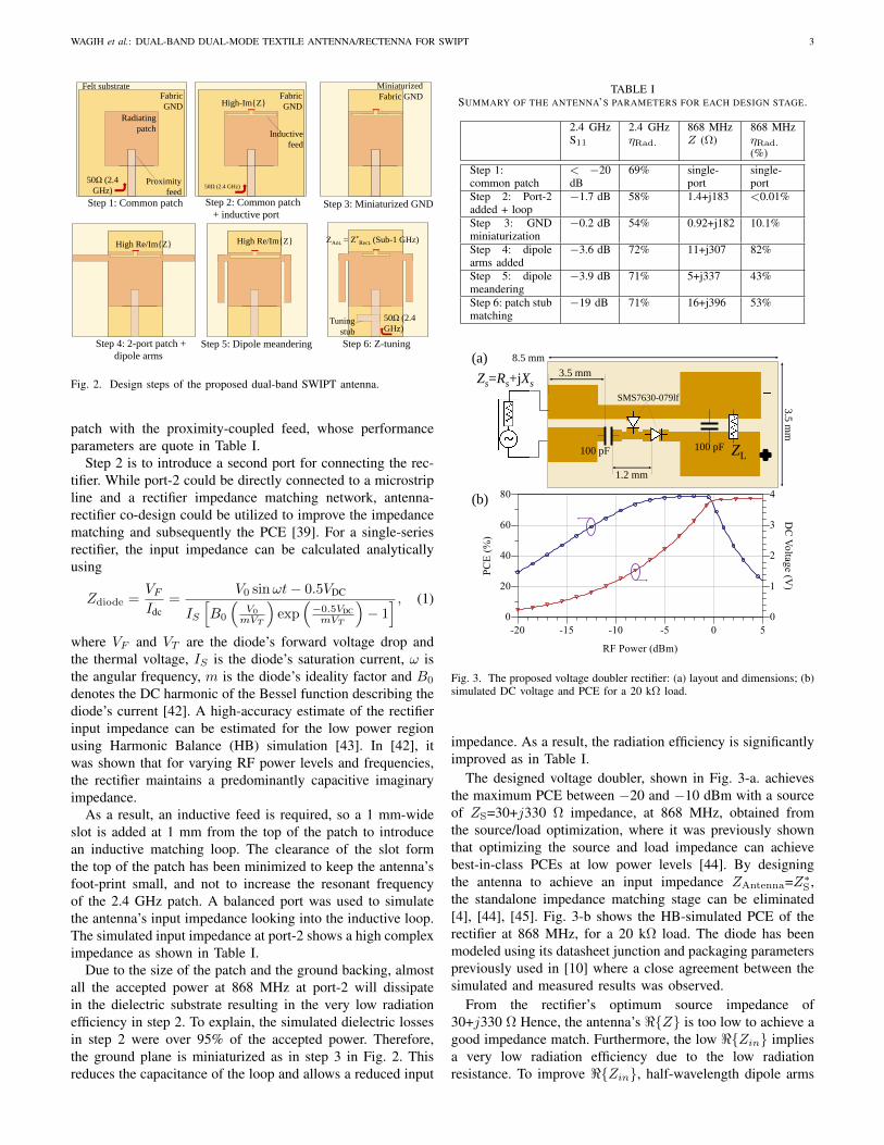
Fig. 3. The proposed voltage doubler rectifier: (a) layout and dimensions; (b)simulated DC voltage and PCE for a 20 kΩ load.
impedance. As a result, the radiation efficiency is significantlyimproved as in Table I.
The designed voltage doubler, shown in Fig. 3-a. achievesthe maximum PCE between −20 and −10 dBm with a sourceof ZS=30+j330 Ω impedance, at 868 MHz, obtained fromthe source/load optimization, where it was previously shownthat optimizing the source and load impedance can achievebest-in-class PCEs at low power levels [44]. By designingthe antenna to achieve an input impedance ZAntenna=Z∗
S ,the standalone impedance matching stage can be eliminated[4], [44], [45]. Fig. 3-b shows the HB-simulated PCE of therectifier at 868 MHz, for a 20 kΩ load. The diode has beenmodeled using its datasheet junction and packaging parameterspreviously used in [10] where a close agreement between thesimulated and measured results was observed.
From the rectifier’s optimum source impedance of30+j330 Ω Hence, the antenna’s <Z is too low to achieve agood impedance match. Furthermore, the low <Zin impliesa very low radiation efficiency due to the low radiationresistance. To improve <Zin, half-wavelength dipole arms
4 IEEE TRANSACTIONS ON ANTENNAS AND PROPAGATION, VOL. X, NO. X
400
500
600
700
800
900
0
40
80
120
160
200
10 20 30 40 50
ImZ
(Ω
)
Re
Z (Ω)
LArm (mm)
100
200
300
400
500
600
0
5
10
15
20
25
0 5 10 15 20
ImZ
(Ω
)
Re
Z (Ω)
LGap (mm)
(a) (b)
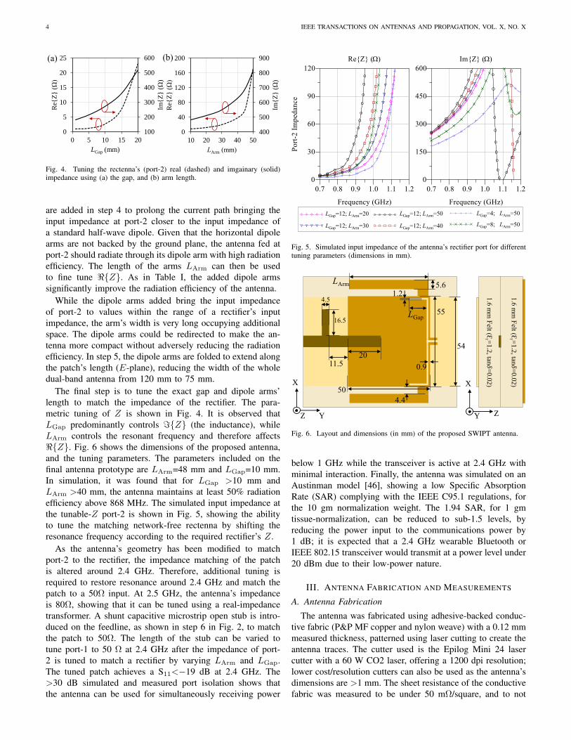
Fig. 4. Tuning the rectenna’s (port-2) real (dashed) and imgainary (solid)impedance using (a) the gap, and (b) arm length.
are added in step 4 to prolong the current path bringing theinput impedance at port-2 closer to the input impedance ofa standard half-wave dipole. Given that the horizontal dipolearms are not backed by the ground plane, the antenna fed atport-2 should radiate through its dipole arm with high radiationefficiency. The length of the arms LArm can then be usedto fine tune <Z. As in Table I, the added dipole armssignificantly improve the radiation efficiency of the antenna.
While the dipole arms added bring the input impedanceof port-2 to values within the range of a rectifier’s inputimpedance, the arm’s width is very long occupying additionalspace. The dipole arms could be redirected to make the an-tenna more compact without adversely reducing the radiationefficiency. In step 5, the dipole arms are folded to extend alongthe patch’s length (E-plane), reducing the width of the wholedual-band antenna from 120 mm to 75 mm.
The final step is to tune the exact gap and dipole arms’length to match the impedance of the rectifier. The para-metric tuning of Z is shown in Fig. 4. It is observed thatLGap predominantly controls =Z (the inductance), whileLArm controls the resonant frequency and therefore affects<Z. Fig. 6 shows the dimensions of the proposed antenna,and the tuning parameters. The parameters included on thefinal antenna prototype are LArm=48 mm and LGap=10 mm.In simulation, it was found that for LGap >10 mm andLArm >40 mm, the antenna maintains at least 50% radiationefficiency above 868 MHz. The simulated input impedance atthe tunable-Z port-2 is shown in Fig. 5, showing the abilityto tune the matching network-free rectenna by shifting theresonance frequency according to the required rectifier’s Z.
As the antenna’s geometry has been modified to matchport-2 to the rectifier, the impedance matching of the patchis altered around 2.4 GHz. Therefore, additional tuning isrequired to restore resonance around 2.4 GHz and match thepatch to a 50Ω input. At 2.5 GHz, the antenna’s impedanceis 80Ω, showing that it can be tuned using a real-impedancetransformer. A shunt capacitive microstrip open stub is intro-duced on the feedline, as shown in step 6 in Fig. 2, to matchthe patch to 50Ω. The length of the stub can be varied totune port-1 to 50 Ω at 2.4 GHz after the impedance of port-2 is tuned to match a rectifier by varying LArm and LGap.The tuned patch achieves a S11<−19 dB at 2.4 GHz. The>30 dB simulated and measured port isolation shows thatthe antenna can be used for simultaneously receiving power
400
500
600
700
800
900
0
40
80
120
160
200
10 20 30 40 50
ImZ
(Ω
)
Re
Z (Ω)
LArm (mm)
100
200
300
400
500
600
0
5
10
15
20
25
0 5 10 15 20
ImZ
(Ω
)
Re
Z (Ω)
LGap (mm)
(a) (b)
RF Transceiver
RF Energy Harvester
Microcontroller and peripherals
IoT SoC
0
30
6090
120
150
180
210
240270
300
330
-10 -5 00
30
6090
120
150
180
210
240270
300
330
-30 -20 -10 0
(a
LGap=12; LArm=20
LGap=12; LArm=30 LGap=12; LArm=40
LGap=12; LArm=50 LGap=4; LArm=50
LGap=8; LArm=50
Fig. 5. Simulated input impedance of the antenna’s rectifier port for differenttuning parameters (dimensions in mm).
-40
-35
-30
-25
-20
-15
-10
-5
0
-180 -120 -60 0 60 120 180
No
rmal
ized
Gai
n (
dB
)
YZ E-Plane: Angle θ (º)
x-pol.
co-pol.
-40
-35
-30
-25
-20
-15
-10
-5
0
-180 -120 -60 0 60 120 180
No
rmal
ized
Gai
n (
dB
)
E-Plane: Angle θ (º)
Arm: w/o rectifier
Body: w/ rectifier
Body: w/o rectifier
θ
-40
-35
-30
-25
-20
-15
-10
-5
0
-180 -120 -60 0 60 120 180
XZ H-Plane: Angle θ (º)
x-pol.
co-pol.
53
LArm
5516.5
54
50
1.24.5
20
1.6
mm
Felt (Ɛ
r =1.2
, tan𝛿=
0.0
2)
1.6
mm
Felt (Ɛ
r =1.2
, tan𝛿=
0.0
2)
Fabric
GND
7.0
52.0
Y
X
Z
X
Y Z
11.5
5.6
4.4
LGap
Unloaded
On-chest
Wrist (x-bending)
Wrist (y-bending)
ISM-Band
0.9
Fig. 6. Layout and dimensions (in mm) of the proposed SWIPT antenna.
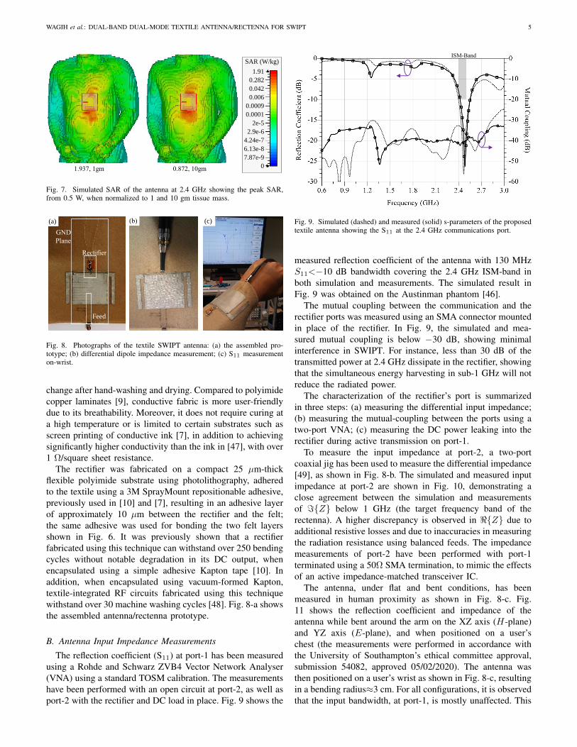
below 1 GHz while the transceiver is active at 2.4 GHz withminimal interaction. Finally, the antenna was simulated on anAustinman model [46], showing a low Specific AbsorptionRate (SAR) complying with the IEEE C95.1 regulations, forthe 10 gm normalization weight. The 1.94 SAR, for 1 gmtissue-normalization, can be reduced to sub-1.5 levels, byreducing the power input to the communications power by1 dB; it is expected that a 2.4 GHz wearable Bluetooth orIEEE 802.15 transceiver would transmit at a power level under20 dBm due to their low-power nature.
III. ANTENNA FABRICATION AND MEASUREMENTS
A. Antenna Fabrication
The antenna was fabricated using adhesive-backed conduc-tive fabric (P&P MF copper and nylon weave) with a 0.12 mmmeasured thickness, patterned using laser cutting to create theantenna traces. The cutter used is the Epilog Mini 24 lasercutter with a 60 W CO2 laser, offering a 1200 dpi resolution;lower cost/resolution cutters can also be used as the antenna’sdimensions are >1 mm. The sheet resistance of the conductivefabric was measured to be under 50 mΩ/square, and to not
WAGIH et al.: DUAL-BAND DUAL-MODE TEXTILE ANTENNA/RECTENNA FOR SWIPT 5
1.937, 1gm 0.872, 10gm
SAR (W/kg)
1.91
0.282
0.042
0.006
0.0009
0.0001
2e-5
2.9e-6
4.24e-7
6.13e-8
7.87e-9
0
Fig. 7. Simulated SAR of the antenna at 2.4 GHz showing the peak SAR,from 0.5 W, when normalized to 1 and 10 gm tissue mass.
(a) (b)
θ
X
Y
Z
Co-pol. vector
Rectifier
GND
Plane
Feed
(a) (b) (c)
Fig. 8. Photographs of the textile SWIPT antenna: (a) the assembled pro-totype; (b) differential dipole impedance measurement; (c) S11 measurementon-wrist.
change after hand-washing and drying. Compared to polyimidecopper laminates [9], conductive fabric is more user-friendlydue to its breathability. Moreover, it does not require curing ata high temperature or is limited to certain substrates such asscreen printing of conductive ink [7], in addition to achievingsignificantly higher conductivity than the ink in [47], with over1 Ω/square sheet resistance.
The rectifier was fabricated on a compact 25 µm-thickflexible polyimide substrate using photolithography, adheredto the textile using a 3M SprayMount repositionable adhesive,previously used in [10] and [7], resulting in an adhesive layerof approximately 10 µm between the rectifier and the felt;the same adhesive was used for bonding the two felt layersshown in Fig. 6. It was previously shown that a rectifierfabricated using this technique can withstand over 250 bendingcycles without notable degradation in its DC output, whenencapsulated using a simple adhesive Kapton tape [10]. Inaddition, when encapsulated using vacuum-formed Kapton,textile-integrated RF circuits fabricated using this techniquewithstand over 30 machine washing cycles [48]. Fig. 8-a showsthe assembled antenna/rectenna prototype.
B. Antenna Input Impedance Measurements
The reflection coefficient (S11) at port-1 has been measuredusing a Rohde and Schwarz ZVB4 Vector Network Analyser(VNA) using a standard TOSM calibration. The measurementshave been performed with an open circuit at port-2, as well asport-2 with the rectifier and DC load in place. Fig. 9 shows the
-40
-35
-30
-25
-20
-15
-10
-5
0
-180 -120 -60 0 60 120 180
Norm
aliz
ed G
ain (
dB
)
YZ E-Plane: Angle θ (º)
x-pol.
co-pol.
-40
-35
-30
-25
-20
-15
-10
-5
0
-180 -120 -60 0 60 120 180
Norm
aliz
ed G
ain (
dB
)
Angle (º)
Arm: w/o rectifier
Body: w/ rectifier
Body: w/o rectifier
θ
-40
-35
-30
-25
-20
-15
-10
-5
0
-180 -120 -60 0 60 120 180
Norm
aliz
ed G
ain (
dB
)
XZ H-Plane: Angle (º)
x-pol.
co-pol.
53
LArm
5516.5
54
50
14.5
20
1.6
mm
Fel
t (Ɛ
r=1.2
, ta
n𝛿
=0.0
2)
1.6
mm
Fel
t (Ɛ
r=1.2
, ta
n𝛿
=0.0
2)
Fabric
GND
7.0
52.0
Y
X
Z
X
Y Z
11.5
5.6
4.4
LGap
Unloaded
On-chest
Wrist (x-bending)
Wrist (y-bending)
ISM-Band
Fig. 9. Simulated (dashed) and measured (solid) s-parameters of the proposedtextile antenna showing the S11 at the 2.4 GHz communications port.
measured reflection coefficient of the antenna with 130 MHzS11<−10 dB bandwidth covering the 2.4 GHz ISM-band inboth simulation and measurements. The simulated result inFig. 9 was obtained on the Austinman phantom [46].
The mutual coupling between the communication and therectifier ports was measured using an SMA connector mountedin place of the rectifier. In Fig. 9, the simulated and mea-sured mutual coupling is below −30 dB, showing minimalinterference in SWIPT. For instance, less than 30 dB of thetransmitted power at 2.4 GHz dissipate in the rectifier, showingthat the simultaneous energy harvesting in sub-1 GHz will notreduce the radiated power.
The characterization of the rectifier’s port is summarizedin three steps: (a) measuring the differential input impedance;(b) measuring the mutual-coupling between the ports using atwo-port VNA; (c) measuring the DC power leaking into therectifier during active transmission on port-1.
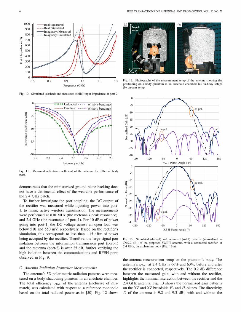
To measure the input impedance at port-2, a two-portcoaxial jig has been used to measure the differential impedance[49], as shown in Fig. 8-b. The simulated and measured inputimpedance at port-2 are shown in Fig. 10, demonstrating aclose agreement between the simulation and measurementsof =Z below 1 GHz (the target frequency band of therectenna). A higher discrepancy is observed in <Z due toadditional resistive losses and due to inaccuracies in measuringthe radiation resistance using balanced feeds. The impedancemeasurements of port-2 have been performed with port-1terminated using a 50Ω SMA termination, to mimic the effectsof an active impedance-matched transceiver IC.
The antenna, under flat and bent conditions, has beenmeasured in human proximity as shown in Fig. 8-c. Fig.11 shows the reflection coefficient and impedance of theantenna while bent around the arm on the XZ axis (H-plane)and YZ axis (E-plane), and when positioned on a user’schest (the measurements were performed in accordance withthe University of Southampton’s ethical committee approval,submission 54082, approved 05/02/2020). The antenna wasthen positioned on a user’s wrist as shown in Fig. 8-c, resultingin a bending radius≈3 cm. For all configurations, it is observedthat the input bandwidth, at port-1, is mostly unaffected. This
6 IEEE TRANSACTIONS ON ANTENNAS AND PROPAGATION, VOL. X, NO. X
0
0.25
0.5
0.75
1
1.25
1.5
1.75
0
10
20
30
40
50
60
70
0 0.5 1 1.5 2
DC
Vo
ltag
e (V
)
PC
E (
%)
S (μW/cm2)
DC Voltage: 20 kOhm PCE: 8 kOhm
PCE: 20 kOhm DC Voltage: 8 kOhm
0
0.25
0.5
0.75
1
1.25
1.5
1.75
0
10
20
30
40
50
60
70
0.01 0.1 1
DC
Vo
ltag
e (V
)
PC
E (
%)
S (μW/cm2)
DC Voltage: 20 kOhm PCE: 8 kOhm
PCE: 20 kOhm DC Voltage: 8 kOhm
(b)
(a)
0.15
1.5
15
150
700 750 800 850 900 950 1000
DC
Po
wer
(µ
W)
Frequency (MHz)
2.1 uW/cm^2
0.52 uW/cm^2
0.07 uW/cm^2
0
0.2
0.4
0.6
0.8
1
1.2
1.4
0
10
20
30
40
50
60
70
1 10 100
DC
Vo
ltag
e (V
)
PC
E (
%)
Load Impedance (kΩ)
0.8 uW/cm^2
0.3 uW/cm^2
V: 0.8 uW/cm^2
V:0.3 uW/cm^2
Rectifier
GND
Plane
Feed
(a) (b)
(c) (d)
0
100
200
300
400
500
600
700
800
900
1000
0.5 0.7 0.9 1.1 1.3 1.5
Port
2 I
mped
ance
(Ω
)
Frequency (GHz)
Real: MeasuredReal: SimulatedImaginary: MeasuredImaginary: Simulated
Fig. 10. Simulated (dashed) and measured (solid) input impedance at port-2.
-40
-35
-30
-25
-20
-15
-10
-5
0
-180 -120 -60 0 60 120 180
No
rmal
ized
Gai
n (
dB
)
YZ E-Plane: Angle θ (º)
x-pol.
co-pol.
-40
-35
-30
-25
-20
-15
-10
-5
0
-180 -120 -60 0 60 120 180
No
rmal
ized
Gai
n (
dB
)
Angle (º)
Arm: w/o rectifier
Body: w/ rectifier
Body: w/o rectifier
θ
-40
-35
-30
-25
-20
-15
-10
-5
0
-180 -120 -60 0 60 120 180
No
rmal
ized
Gai
n (
dB
)
XZ H-Plane: Angle (º)
x-pol.
co-pol.
53
LArm
5516.5
54
50
14.5
20
1.6
mm
Fel
t (Ɛ
r=1.2
, ta
n𝛿
=0.0
2)
1.6
mm
Fel
t (Ɛ
r=1.2
, ta
n𝛿
=0.0
2)
Fabric
GND
7.0
52.0
Y
X
Z
X
Y Z
11.5
5.6
4.4
LGap
Unloaded
On-chest
Wrist (x-bending)
Wrist (y-bending)
Fig. 11. Measured reflection coefficient of the antenna for different bodyparts.
demonstrates that the miniaturized ground plane-backing doesnot have a detrimental effect of the wearable performance ofthe 2.4 GHz patch.
To further investigate the port coupling, the DC output ofthe rectifier was measured while injecting power into port-1, to mimic active wireless transmission. The measurementswere performed at 830 MHz (the rectenna’s peak resonance),and 2.4 GHz (the resonance of port-1). For 10 dBm of powergoing into port-1, the DC voltage across an open load wasbelow 510 and 550 mV, respectively. Based on the rectifier’ssimulation, this corresponds to less than −15 dBm of powerbeing accepted by the rectifier. Therefore, the large-signal portisolation between the information transmission port (port-1)and the rectenna (port-2) is over 25 dB, further verifying thehigh isolation between the communications and RFEH portsobserved in Fig. 9.
C. Antenna Radiation Properties Measurements
The antenna’s 3D polarimetric radiation patterns were mea-sured on a body shadowing phantom in an anechoic chamber.The total efficiency ηTot. of the antenna (inclusive of mis-match) was calculated with respect to a reference monopolebased on the total radiated power as in [50]. Fig. 12 shows
(a) (b)
θ
X
Y
Z
Co-pol. vector
Fig. 12. Photographs of the measurement setup of the antenna showing thepositioning on a body phantom in an anechoic chamber: (a) on-body setup;(b) on-arm setup.
-40
-35
-30
-25
-20
-15
-10
-5
0
-180 -120 -60 0 60 120 180
No
rmal
ized
Gai
n (
dB
)
YZ E-Plane: Angle θ (º)
x-pol.
co-pol.
-40
-35
-30
-25
-20
-15
-10
-5
0
-180 -120 -60 0 60 120 180
No
rmal
ized
Gai
n (
dB
)
Angle (º)
Arm: w/o rectifier
Body: w/ rectifier
Body: w/o rectifier
θ
-40
-35
-30
-25
-20
-15
-10
-5
0
-180 -120 -60 0 60 120 180
No
rmal
ized
Gai
n (
dB
)
XZ H-Plane: Angle (º)
x-pol.
co-pol.
Fig. 13. Simulated (dashed) and measured (solid) patterns (normalized toD=9.2 dBi) of the proposed SWIPT antenna, with a connected rectifier, at2.4 GHz, on a phantom body (Fig. 12-a).
the antenna measurement setup on the phantom’s body. Theantenna’s ηTot. at 2.4 GHz is 66% and 63%, before and afterthe rectifier is connected, respectively. The 0.2 dB differencebetween the measured gain, with and without the rectifier,highlights the minimal interaction between the rectifier and the2.4 GHz antenna. Fig. 13 shows the normalized gain patternson the YZ and XZ broadside E- and H-planes. The directivityD of the antenna is 9.2 and 9.3 dBi, with and without the
WAGIH et al.: DUAL-BAND DUAL-MODE TEXTILE ANTENNA/RECTENNA FOR SWIPT 7
-40
-35
-30
-25
-20
-15
-10
-5
0
-180 -120 -60 0 60 120 180
No
rmal
ized
Gai
n (
dB
)
YZ E-Plane: Angle θ (º)
x-pol.
co-pol.
-40
-35
-30
-25
-20
-15
-10
-5
0
-180 -120 -60 0 60 120 180
Norm
aliz
ed G
ain (
dB
)
Angle (º)
Arm: w/o rectifier
Body: w/ rectifier
Body: w/o rectifier
θ
-40
-35
-30
-25
-20
-15
-10
-5
0
-180 -120 -60 0 60 120 180
Norm
aliz
ed G
ain (
dB
)
XZ H-Plane: Angle (º)
x-pol.
co-pol.
Fig. 14. Measured co-polarized normalized E-plane patterns of the antennawith (w/) and without (w/o) the rectifier on the phantom’s body (Fig. 12-a)and arm (Fig. 12-b).
rectifier, respectively. This confirms that the rectifier does notaffect the antenna’s radiation properties. From the measuredefficiency and directivity, the measured realized gain of theantenna is 7.2 and 7.5 dBi, with and without the rectifier,respectively.
From the measured patterns, it can be observed that theantenna is predominantly vertically-polarized, with 25 dBmeasured co-/cross-polarization isolation on the E-plane. Onthe H-plane, despite an increase in the cross polarization overthe simulated values, the antenna still maintains over 15 dBpolarization purity in the main broadside beam. However, thisincrease in the cross-polarized component has previously beenreported for textile antennas measured on a body phantom[7], [35], and is not regarded as a disadvantage in off-bodywearable communications [35].
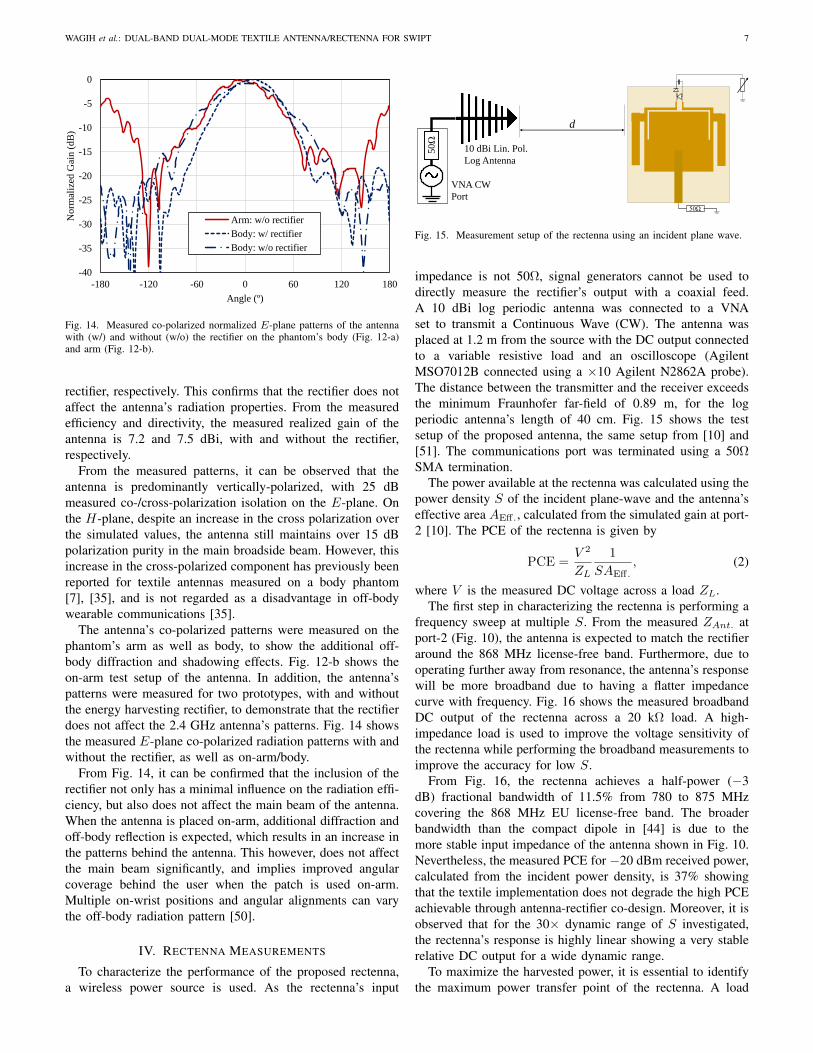
The antenna’s co-polarized patterns were measured on thephantom’s arm as well as body, to show the additional off-body diffraction and shadowing effects. Fig. 12-b shows theon-arm test setup of the antenna. In addition, the antenna’spatterns were measured for two prototypes, with and withoutthe energy harvesting rectifier, to demonstrate that the rectifierdoes not affect the 2.4 GHz antenna’s patterns. Fig. 14 showsthe measured E-plane co-polarized radiation patterns with andwithout the rectifier, as well as on-arm/body.
From Fig. 14, it can be confirmed that the inclusion of therectifier not only has a minimal influence on the radiation effi-ciency, but also does not affect the main beam of the antenna.When the antenna is placed on-arm, additional diffraction andoff-body reflection is expected, which results in an increase inthe patterns behind the antenna. This however, does not affectthe main beam significantly, and implies improved angularcoverage behind the user when the patch is used on-arm.Multiple on-wrist positions and angular alignments can varythe off-body radiation pattern [50].
IV. RECTENNA MEASUREMENTS
To characterize the performance of the proposed rectenna,a wireless power source is used. As the rectenna’s input
(a) (b)
θ
X
Y
Z
Co-pol. vector
Rectifier
GND
Plane
Feed
(a) (b) (c)
VNA CW
Port
50Ω
d
10 dBi Lin. Pol.
Log Antenna
50Ω
Fig. 15. Measurement setup of the rectenna using an incident plane wave.
impedance is not 50Ω, signal generators cannot be used todirectly measure the rectifier’s output with a coaxial feed.A 10 dBi log periodic antenna was connected to a VNAset to transmit a Continuous Wave (CW). The antenna wasplaced at 1.2 m from the source with the DC output connectedto a variable resistive load and an oscilloscope (AgilentMSO7012B connected using a ×10 Agilent N2862A probe).The distance between the transmitter and the receiver exceedsthe minimum Fraunhofer far-field of 0.89 m, for the logperiodic antenna’s length of 40 cm. Fig. 15 shows the testsetup of the proposed antenna, the same setup from [10] and[51]. The communications port was terminated using a 50ΩSMA termination.
The power available at the rectenna was calculated using thepower density S of the incident plane-wave and the antenna’seffective area AEff., calculated from the simulated gain at port-2 [10]. The PCE of the rectenna is given by
PCE =V 2
ZL
1
SAEff., (2)
where V is the measured DC voltage across a load ZL.The first step in characterizing the rectenna is performing a
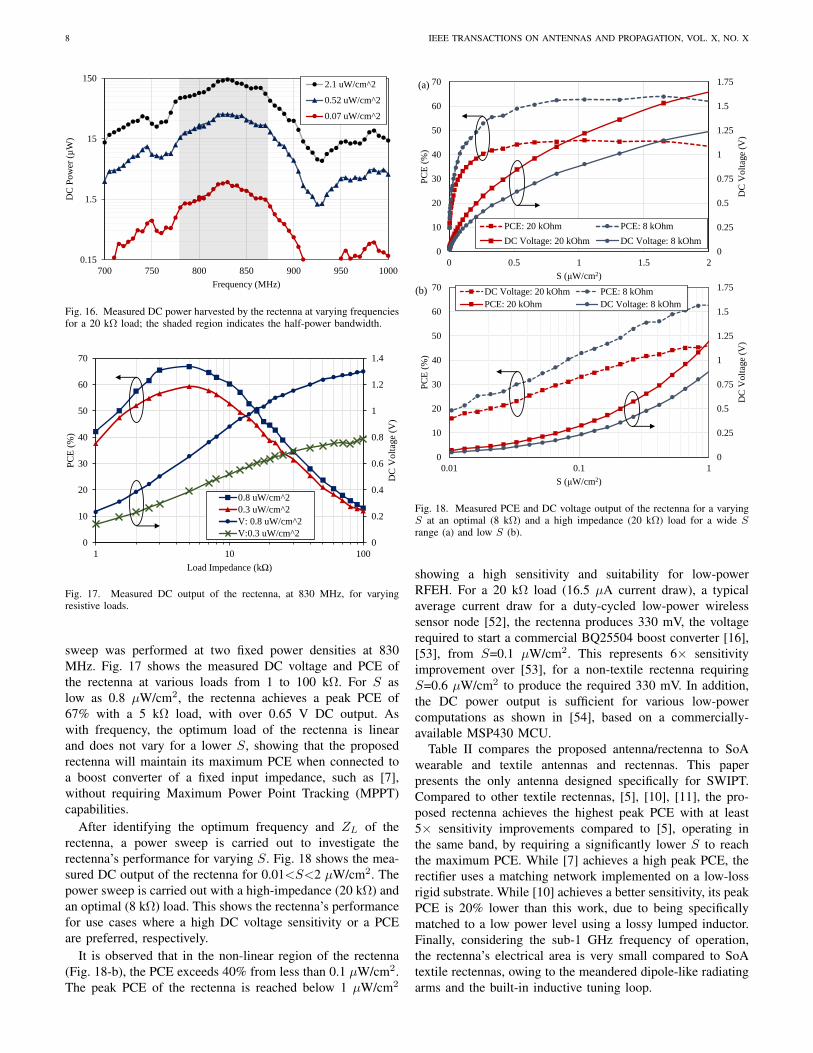
frequency sweep at multiple S. From the measured ZAnt. atport-2 (Fig. 10), the antenna is expected to match the rectifieraround the 868 MHz license-free band. Furthermore, due tooperating further away from resonance, the antenna’s responsewill be more broadband due to having a flatter impedancecurve with frequency. Fig. 16 shows the measured broadbandDC output of the rectenna across a 20 kΩ load. A high-impedance load is used to improve the voltage sensitivity ofthe rectenna while performing the broadband measurements toimprove the accuracy for low S.
From Fig. 16, the rectenna achieves a half-power (−3dB) fractional bandwidth of 11.5% from 780 to 875 MHzcovering the 868 MHz EU license-free band. The broaderbandwidth than the compact dipole in [44] is due to themore stable input impedance of the antenna shown in Fig. 10.Nevertheless, the measured PCE for −20 dBm received power,calculated from the incident power density, is 37% showingthat the textile implementation does not degrade the high PCEachievable through antenna-rectifier co-design. Moreover, it isobserved that for the 30× dynamic range of S investigated,the rectenna’s response is highly linear showing a very stablerelative DC output for a wide dynamic range.
To maximize the harvested power, it is essential to identifythe maximum power transfer point of the rectenna. A load
8 IEEE TRANSACTIONS ON ANTENNAS AND PROPAGATION, VOL. X, NO. X
0
0.25
0.5
0.75
1
1.25
1.5
1.75
0
10
20
30
40
50
60
70
0 0.5 1 1.5 2
DC
Vo
ltag
e (V
)
PC
E (
%)
S (μW/cm2)
PCE: 20 kOhm PCE: 8 kOhm
DC Voltage: 20 kOhm DC Voltage: 8 kOhm
0
0.25
0.5
0.75
1
1.25
1.5
1.75
0
10
20
30
40
50
60
70
0.01 0.1 1
DC
Vo
ltag
e (V
)
PC
E (
%)
S (μW/cm2)
DC Voltage: 20 kOhm PCE: 8 kOhm
PCE: 20 kOhm DC Voltage: 8 kOhm
(b)
(a)
0.15
1.5
15
150
700 750 800 850 900 950 1000
DC
Po
wer
(µ
W)
Frequency (MHz)
2.1 uW/cm^2
0.52 uW/cm^2
0.07 uW/cm^2
0
0.2
0.4
0.6
0.8
1
1.2
1.4
0
10
20
30
40
50
60
70
1 10 100
DC
Vo
ltag
e (V
)
PC
E (
%)
Load Impedance (kΩ)
0.8 uW/cm^2
0.3 uW/cm^2
V: 0.8 uW/cm^2
V:0.3 uW/cm^20
100
200
300
400
500
600
700
800
900
1000
0.5 0.7 0.9 1.1 1.3 1.5
Port
2 I
mped
ance
(Ω
)
Frequency (GHz)
Real: MeasuredReal: SimulatedImaginary: MeasuredImaginary: Simulated
Fig. 16. Measured DC power harvested by the rectenna at varying frequenciesfor a 20 kΩ load; the shaded region indicates the half-power bandwidth.
0
0.25
0.5
0.75
1
1.25
1.5
1.75
0
10
20
30
40
50
60
70
0 0.5 1 1.5 2
DC
Volt
age
(V)
PC
E (
%)
S (μW/cm2)
PCE: 20 kOhm PCE: 8 kOhm
DC Voltage: 20 kOhm DC Voltage: 8 kOhm
0
0.25
0.5
0.75
1
1.25
1.5
1.75
0
10
20
30
40
50
60
70
0.01 0.1 1
DC
Volt
age
(V)
PC
E (
%)
S (μW/cm2)
DC Voltage: 20 kOhm PCE: 8 kOhm
PCE: 20 kOhm DC Voltage: 8 kOhm
(b)
(a)
0.15
1.5
15
150
700 750 800 850 900 950 1000
DC
Pow
er (
µW
)
Frequency (MHz)
2.1 uW/cm^2
0.52 uW/cm^2
0.07 uW/cm^2
0
0.2
0.4
0.6
0.8
1
1.2
1.4
0
10
20
30
40
50
60
70
1 10 100
DC
Volt
age
(V)
PC
E (
%)
Load Impedance (kΩ)
0.8 uW/cm^2
0.3 uW/cm^2
V: 0.8 uW/cm^2
V:0.3 uW/cm^20
100
200
300
400
500
600
700
800
900
1000
0.5 0.7 0.9 1.1 1.3 1.5
Port
2 I
mped
ance
(Ω
)
Frequency (GHz)
Real: MeasuredReal: SimulatedImaginary: MeasuredImaginary: Simulated
Fig. 17. Measured DC output of the rectenna, at 830 MHz, for varyingresistive loads.
sweep was performed at two fixed power densities at 830MHz. Fig. 17 shows the measured DC voltage and PCE ofthe rectenna at various loads from 1 to 100 kΩ. For S aslow as 0.8 µW/cm2, the rectenna achieves a peak PCE of67% with a 5 kΩ load, with over 0.65 V DC output. Aswith frequency, the optimum load of the rectenna is linearand does not vary for a lower S, showing that the proposedrectenna will maintain its maximum PCE when connected toa boost converter of a fixed input impedance, such as [7],without requiring Maximum Power Point Tracking (MPPT)capabilities.
After identifying the optimum frequency and ZL of therectenna, a power sweep is carried out to investigate therectenna’s performance for varying S. Fig. 18 shows the mea-sured DC output of the rectenna for 0.01<S<2 µW/cm2. Thepower sweep is carried out with a high-impedance (20 kΩ) andan optimal (8 kΩ) load. This shows the rectenna’s performancefor use cases where a high DC voltage sensitivity or a PCEare preferred, respectively.
It is observed that in the non-linear region of the rectenna(Fig. 18-b), the PCE exceeds 40% from less than 0.1 µW/cm2.The peak PCE of the rectenna is reached below 1 µW/cm2
0
0.25
0.5
0.75
1
1.25
1.5
1.75
0
10
20
30
40
50
60
70
0 0.5 1 1.5 2
DC
Volt
age
(V)
PC
E (
%)
S (μW/cm2)
PCE: 20 kOhm PCE: 8 kOhm
DC Voltage: 20 kOhm DC Voltage: 8 kOhm
0
0.25
0.5
0.75
1
1.25
1.5
1.75
0
10
20
30
40
50
60
70
0.01 0.1 1
DC
Volt
age
(V)
PC
E (
%)
S (μW/cm2)
DC Voltage: 20 kOhm PCE: 8 kOhm
PCE: 20 kOhm DC Voltage: 8 kOhm
(b)
(a)
0.15
1.5
15
150
700 750 800 850 900 950 1000
DC
Pow
er (
µW
)
Frequency (MHz)
2.1 uW/cm^2
0.52 uW/cm^2
0.07 uW/cm^2
0
0.2
0.4
0.6
0.8
1
1.2
1.4
0
10
20
30
40
50
60
70
1 10 100
DC
Volt
age
(V)
PC
E (
%)
Load Impedance (kΩ)
0.8 uW/cm^2
0.3 uW/cm^2
V: 0.8 uW/cm^2
V:0.3 uW/cm^20
100
200
300
400
500
600
700
800
900
1000
0.5 0.7 0.9 1.1 1.3 1.5
Po
rt 2
Im
ped
ance
(Ω
)
Frequency (GHz)
Real: MeasuredReal: SimulatedImaginary: MeasuredImaginary: Simulated
Fig. 18. Measured PCE and DC voltage output of the rectenna for a varyingS at an optimal (8 kΩ) and a high impedance (20 kΩ) load for a wide Srange (a) and low S (b).
showing a high sensitivity and suitability for low-powerRFEH. For a 20 kΩ load (16.5 µA current draw), a typicalaverage current draw for a duty-cycled low-power wirelesssensor node [52], the rectenna produces 330 mV, the voltagerequired to start a commercial BQ25504 boost converter [16],[53], from S=0.1 µW/cm2. This represents 6× sensitivityimprovement over [53], for a non-textile rectenna requiringS=0.6 µW/cm2 to produce the required 330 mV. In addition,the DC power output is sufficient for various low-powercomputations as shown in [54], based on a commercially-available MSP430 MCU.
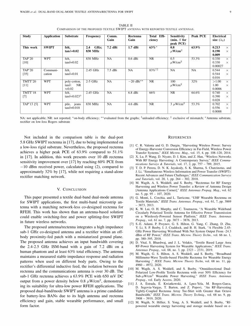
Table II compares the proposed antenna/rectenna to SoAwearable and textile antennas and rectennas. This paperpresents the only antenna designed specifically for SWIPT.Compared to other textile rectennas, [5], [10], [11], the pro-posed rectenna achieves the highest peak PCE with at least5× sensitivity improvements compared to [5], operating inthe same band, by requiring a significantly lower S to reachthe maximum PCE. While [7] achieves a high peak PCE, therectifier uses a matching network implemented on a low-lossrigid substrate. While [10] achieves a better sensitivity, its peakPCE is 20% lower than this work, due to being specificallymatched to a low power level using a lossy lumped inductor.Finally, considering the sub-1 GHz frequency of operation,the rectenna’s electrical area is very small compared to SoAtextile rectennas, owing to the meandered dipole-like radiatingarms and the built-in inductive tuning loop.
WAGIH et al.: DUAL-BAND DUAL-MODE TEXTILE ANTENNA/RECTENNA FOR SWIPT 9
TABLE IICOMPARISON OF THE PROPOSED TEXTILE SWIPT ANTENNA WITH REPORTED TEXTILE ANTENNAS.
Study Application Substrate Frequency Comm.Gain
RectennaGain
Total Effi-ciency
Sensitivity(min. S forpeak PCE)
Peak PCE Electricalsize (λ0)
This work SWIPT felt,tanδ=0.02
2.4 GHz;830 MHz
7.2 dBi 1.7 dBi 63%∗ 0.8µW/cm2
63.9% 0.213 ×0.190 ×0.009
TAP’20[10]
WPT felt,tanδ=0.02
830 MHz NA 0.6 dBi NR 0.5µW/cm2
53.3% 0.330 ×0.330 ×0.00027
TAP’20[35]
Communi-cation
felt,tanδ=0.01
2.45 GHz 7.5 dBi NA 83%†‡ NA NA 0.544 ×0.544 ×0.016
TMTT’20[11]
WPT poly-cotton,tanδ: NR≈0.02
2-5 GHz NA −20 dBi∗∗ NR 100µW/cm2
32% >1.00 ×1.00 ×0.0006
TMTT’18[7]
WPT felt,tanδ=0.023
2.45 GHz NA 6.8 dBi 66% NR 64.6% 0.740 ×0.390 ×0.028
TAP’13 [5] WPT pile, jeanstanδ=0.018
830 MHz NA 4.6 dBi NR 3 µW/cm2 53.3% 0.702 ×0.556 ×0.0088
NA: not applicable; NR: not reported; ∗on-body efficiency; ∗∗evaluated from the graphs; †unloaded efficiency; ‡ exclusive of mismatch; Antenna substrate,rectifier on low-loss Rogers substrate
Not included in the comparison table is the dual-port5.8 GHz SWIPT rectenna in [17], due to being implemented ona low-loss rigid substrate. Nevertheless, the proposed rectennaachieves a higher peak PCE of 63.9% compared to 51.1%in [17]. In addition, this work presents over 10 dB rectennasensitivity improvement over [17] by reaching 60% PCE from−10 dBm received power, calculated using (2), compared toapproximately 32% by [17], while not requiring a stand-alonerectifier matching network.
V. CONCLUSION
This paper presented a textile dual-band dual-mode antennafor SWIPT applications, the first multi-band microstrip an-tenna with a matching network-less co-designed rectenna forRFEH. This work has shown than an antenna-based solutioncould enable switching-free and power splitting-free SWIPTin future wireless networks.
The proposed antenna/rectenna integrates a high impedancesub-1 GHz co-designed antenna and a rectifier within an off-body proximity-fed patch with a miniaturized ground plane.The proposed antenna achieves an input bandwidth coveringthe 2.4-2.5 GHz ISM-band with a gain of 7.2 dBi on ahuman phantom and at least 63% total efficiency. The antennamaintains a measured stable impedance response and radiationpatterns when used on different body parts. Owing to therectifier’s differential inductive feed, the isolation between therectenna and the communications antenna is over 30 dB. Thesub-1 GHz rectenna achieves a 63.9% PCE with 650 mV DCoutput from a power density below 0.8 µW/cm2, demonstrat-ing its suitability for ultra-low power RFEH applications. Theproposed dual-band/mode SWIPT antenna is a prime candidatefor battery-less BANs due to its high antenna and rectennaefficiency and gain, stable wearable performance, and smallform factor.
REFERENCES
[1] C. R. Valenta and G. D. Durgin, “Harvesting Wireless Power: Surveyof Energy-Harvester Conversion Efficiency in Far-Field, Wireless PowerTransfer Systems,” IEEE Microw. Mag., vol. 15, 4, pp. 108–120, 2014.
[2] X. Lu, P. Wang, D. Niyato, D. I. Kim, and Z. Han, “Wireless NetworksWith RF Energy Harvesting: A Contemporary Survey,” IEEE Commu-nications Surveys & Tutorials, vol. 17, 2, pp. 757 – 789, 2015.
[3] T. D. P. Perera, D. N. K. Jayakody, S. K. Sharma, S. Chatzinotas, andJ. Li, “Simultaneous Wireless Information and Power Transfer (SWIPT):Recent Advances and Future Challenges,” IEEE Communication Surveysand Tutorials, vol. 20, 1, pp. 264 – 302, 2018.
[4] M. Wagih, A. S. Weddell, and S. Beeby, “Rectennas for RF EnergyHarvesting and Wireless Power Transfer: a Review of Antenna Design[Antenna Applications Corner],” IEEE Antennas Propag. Mag., vol. 62no. 5, pp. 95 – 107, 2020.
[5] G. Monti, L. Corchia, and L. Tarricone, “UHF Wearable Rectenna onTextile Materials,” IEEE Trans. Antennas. Propag., vol. 61, 7, pp. 3869– 3873, 2013.
[6] K. W. Lui, O. H. Murphy, and C. Toumazou, “A Wearable WidebandCircularly Polarized Textile Antenna for Effective Power Transmissionon a Wirelessly-Powered Sensor Platform,” IEEE Trans. AntennasPropag., vol. 61 no. 7, pp. 3873 – 3876, 2013.
[7] S.-E. Adami, P. Proynov, G. S. Hilton, G. Yang, C. Zhang, D. Zhu,Y. Li, S. P. Beeby, I. J. Craddock, and B. H. Stark, “A Flexible 2.45-GHz Power Harvesting Wristband With Net System Output From -24.3dBm of RF Power,” IEEE Trans. Microw. Theory Techn., vol. 66 no. 1,pp. 380–395, 2018.
[8] D. Vital, S. Bhardwaj, and J. L. Volakis, “Textile Based Large AreaRF-Power Harvesting System for Wearable Applications,” IEEE Trans.Antennas Propag., vol. 68, no. 3, pp. 2323 – 2331, 2019.
[9] M. Wagih, G. S. Hilton, A. S. Weddell, and S. Beeby, “BroadbandMillimetre-Wave Textile-based Flexible Rectenna for Wearable EnergyHarvesting ,” IEEE Trans. Microw Theory Techn, vol. 68 no. 11, pp.4960 – 4972, 2020.
[10] M. Wagih, A. S. Weddell, and S. Beeby, “Omnidirectional Dual-Polarized Low-Profile Textile Rectenna with over 50% Efficiency forSub-µW/cm2 Wearable Power Harvesting,” IEEE Trans. AntennasPropag., vol. Early Access, 2020.
[11] J. A. Estrada, E. Kwiatkowski, A. Lpez-Yela, M. Borgos-Garca,D. Segovia-Vargas, T. Barton, and Z. Popovi, “An RF-HarvestingTightly-Coupled Rectenna Array Tee-Shirt with Greater than OctaveBandwidth,” IEEE Trans. Microw. Theory Techniq., vol. 68 no. 9, pp.3908 – 3919, 2020.
[12] M. Wagih, N. Hillier, S. Yong, A. S. Weddell, and S. Beeby, “Rf-powered wearable energy harvesting and storage module based on e-
10 IEEE TRANSACTIONS ON ANTENNAS AND PROPAGATION, VOL. X, NO. X
textile coplanar waveguide rectenna and supercapacitor,” IEEE OpenJournal of Antennas and Propagation, vol. 2, pp. 302 – 314, 2021.
[13] M. Tabesh, N. Dolatsha, A. Arbabian, and A. M. Niknejad, “A Power-Harvesting Pad-Less Millimeter-Sized Radio,” IEEE Journal of Solid-State Circuits, vol. 50, 4, pp. 962 – 977, 2015.
[14] P. Burasa, T. Djerafi, N. G. Constantin, and K. Wu, “On-Chip Dual-Band Rectangular Slot Antenna for Single-Chip Millimeter-Wave Iden-tification Tag in Standard CMOS Technology,” IEEE Trans. AntennasPropag., vol. 65 no. 8, pp. 3858 – 3868, 2017.
[15] G. Papotto, F. Carrara, A. Finocchiaro, and G. Palmisano, “A 90-nm CMOS 5-Mbps Crystal-Less RF-Powered Transceiver for WirelessSensor Network Nodes,” IEEE Journal of Solid-State Circuits, vol. 49,2, pp. 335 – 346, 2014.
[16] J. Bito, R. Bahr, J. G. Hester, S. A. Nauroze, A. Georgiadis, andM. M. Tentzeris, “A Novel Solar and Electromagnetic Energy HarvestingSystem With a 3-D Printed Package for Energy Efficient Internet-of-Things Wireless Sensors,” IEEE Trans. Microw. Theory Techn., vol. 65no. 5, pp. 1831 – 1842, 2017.
[17] P. Lu, C. Song, and K. M. Huang, “A Two-Port Multi-PolarizationRectenna with Orthogonal Hybrid Coupler for Simultaneous WirelessInformation and Power Transfer (SWIPT),” IEEE Trans. AntennasPropag., vol. 68 no. 10, pp. 6893 – 6905, 2020.
[18] K. Turbic, L. M. Correia, and M. Beko, “A Channel Model for Po-larized Off-Body Communications With Dynamic Users,” IEEE Trans.Antennas Propag., vol. 67 no. 11, pp. 7001 – 7013, 2019.
[19] N. Chahat, M. Zhadobov, S. A. Muhammad, L. L. Coq, and R. Sauleau,“60-GHz Textile Antenna Array for Body-Centric Communications,”IEEE Trans. Antennas Propag., vol. 61 no. 4, pp. 1816 – 1824, 2013.
[20] P. Sambandam, M. Kanagasabai, R. Natarajan, M. G. N. Alsath, andS. Palaniswamy, “Miniaturized Button like WBAN Antenna for Off bodyCommunication,” IEEE Trans. Antennas Propag., vol. 68 no. 7, pp. 5228– 5235, 2020.
[21] P. B. Samal, P. J. Soh, and G. A. E. Vandenbosch, “UWB All-TextileAntenna With Full Ground Plane for Off-Body WBAN Communica-tions,” IEEE Trans. Antennas Propag., vol. 62 no. 1, pp. 102 – 108,2014.
[22] G.-P. Gao, C. Yang, B. Hu, R.-F. Zhang, and S.-F. Wang, “A WearablePIFA With an All-Textile Metasurface for 5 GHz WBAN Applications,”IEEE Antennas Wireless Propag. Lett., vol. 18, no. 2, pp. 288 – 292,2019.
[23] C. Mendes and C. Peixeiro, “On-Body Transmission Performance of aNovel Dual-Mode Wearable Microstrip Antenna,” IEEE Trans. AntennasPropag., vol. 66 no. 9, pp. 4872 – 4877, 2018.
[24] N. Chahat, M. Zhadobov, L. L. Coq, and R. Sauleau, “Wearable EndfireTextile Antenna for On-Body Communications at 60 GHz,” IEEEAntennas Wireless Propag. Lett., vol. 11, pp. 799 – 802, 2012.
[25] A. Alemaryeen and S. Noghanian, “On-Body Low-Profile TextileAntenna With Artificial Magnetic Conductor,” IEEE Trans. AntennasPropag., vol. 67 no. 6, pp. 3649 – 3656, 2019.
[26] M. Srestniemi, C. Pomalaza-Rez, T. Kumpuniemi, M. Hmlinen, R. Ko-vacs, and J. Iinatti, “Measurement Data-Based Study on the IntrabodyPropagation in the Presence of the Sternotomy Wires and Aortic ValveImplant,” IEEE Trans. Antennas Propag., vol. 67 no. 8, pp. 4989 – 5001,2019.
[27] M. K. Magill, G. A. Conway, and W. G. Scanlon, “Circularly PolarizedDual-Mode Wearable Implant Repeater Antenna With Enhanced Into-Body Gain,” IEEE Trans. Antennas Propag., vol. 68 no. 5, pp. 3515 –3524, 2020.
[28] K. Zhang, Z. H. Jiang, W. Hong, and D. H. Werner, “A Low-Profileand Wideband Triple-Mode Antenna for Wireless Body Area NetworkConcurrent On-/Off-Body Communications,” IEEE Trans. AntennasPropag., vol. 68 no. 3, pp. 1982 – 1994, 2020.
[29] H. Xiaomu, S. Yan, and G. A. E. Vandenbosch, “Wearable ButtonAntenna for Dual-Band WLAN Applications With Combined on andoff-Body Radiation Patterns,” IEEE Trans. Antennas Propag., vol. 65no. 3, pp. 1384 – 1387, 2017.
[30] J. Tak, S. Woo, J. Kwon, and J. Choi, “Dual-Band Dual-Mode PatchAntenna for On-/Off-Body WBAN Communications,” IEEE AntennasWireless Propag. Lett., vol. 15, pp. 1384 – 1387, 2015.
[31] X. Y. Zhang, H. Wong, T. Mo, and Y. F. Cao, “Dual-Band Dual-ModeButton Antenna for On-Body and Off-Body Communications,” IEEETrans. Biomed. Circuits Sys., vol. 11 no. 4, pp. 933 – 941, 2017.
[32] R. Masood, C. Person, and R. Sauleau, “A Dual-Mode, Dual-Port PatternDiversity Antenna for 2.45-GHz WBAN,” IEEE Antennas WirelessPropag. Lett., vol. 16, pp. 1064 – 1067, 2016.
[33] R. B. V. B. Simorangkir, Y. Yang, L. Matekovits, and K. P. Es-selle, “Dual-Band Dual-Mode Textile Antenna on PDMS Substrate for
Body-Centric Communications,” IEEE Antennas Wireless Propag. Lett.,vol. 16, pp. 677 – 680, 2016.
[34] C. Mendes and C. Peixeiro, “A Dual-Mode Single-Band WearableMicrostrip Antenna for Body Area Networks,” IEEE Antennas WirelessPropag. Lett., vol. 16, pp. 3055 – 3058, 2017.
[35] C.-X. Mao, D. Vital, D. H. Werner, Y. Wu, and S. Bhardwaj, “Dual-Polarized Embroidered Textile Armband Antenna Array With Omni-directional Radiation for On-/Off-Body Wearable Applications,” IEEETrans. Antennas Propag., vol. 68 no. 4, pp. 2575 – 2584, 2020.
[36] X. Tong, C. Liu, X. Liu, H. Guo, and X. Yang, “Switchable ON-/OFF-Body Antenna for 2.45 GHz WBAN Applications,” IEEE Trans.Antennas Propag., vol. 66 no. 2, pp. 967 – 971, 2018.
[37] S. J. Chen, D. C. Ranasinghe, and C. Fumeaux, “A Robust Snap-OnButton Solution for Reconfigurable Wearable Textile Antennas,” IEEETrans. Antennas Propag., vol. 66 no. 9, pp. 4541 – 4551, 2018.
[38] G. Marrocco, “The art of UHF RFID antenna design: impedance-matching and size-reduction techniques,” IEEE Antennas Propag. Mag-azine, vol. 50, 1, pp. 66 – 79, 2008.
[39] M. Wagih, G. S. Hilton, A. S. Weddell, and S. Beeby, “2.4 GHzWearable Textile Antenna/Rectenna for Simultaneous Information andPower Transfer,” in 2021 15th European Conference on Antennas andPropagation, 2021.
[40] M. Wagih, O. Cetinkaya, B. Zaghari, A. S. Weddell, and S. Beeby,“Real-World Performance of Sub-1 GHz and 2.4 GHz Textile Antennasfor RF-Powered Body Area Networks,” IEEE Access, vol. 8, pp. 133 746– 133 756, 2020.
[41] C. A. Balanis, “Antenna Theory: Analysis and Design. Third Edition,”Wiley Interscience, pp. 830 – 833, 2005.
[42] C. Song, Y. Huang, P. Carter, J. Zhou, S. Yuan, Q. Xu, and M. Kod,“A Novel Six-Band Dual CP Rectenna Using Improved ImpedanceMatching Technique for Ambient RF Energy Harvesting,” IEEE Trans.Antennas Propag., vol. 64, 7, pp. 3160 –3171, 2016.
[43] C. R. Valenta, M. M. Morys, and G. D. Durgin, “Theoretical Energy-Conversion Efficiency for Energy-Harvesting Circuits Under Power-Optimized Waveform Excitation,” IEEE Trans. Microw. Theory Techn.,vol. 63 no. 5, pp. 1758 – 1767, 2015.
[44] M. Wagih, A. S. Weddell, and S. Beeby, “High-Efficiency Sub-1 GHzFlexible Compact Rectenna based on Parametric Antenna-Rectifier Co-Design,” in 2020 IEEE/MTT-S International Microwave Symposium(IMS), 2020.
[45] C. Song, Y. Huang, P. Carter, J. Zhou, S. D. Joseph, and G. Li,“Novel Compact and Broadband Frequency-Selectable Rectennas for aWide Input-Power and Load Impedance Range,” IEEE Trans. AntennasPropag., vol. 66, 7, pp. 3306 – 3316, 2018.
[46] J. W. Massey and A. E. Yilmaz, “Austinman and austinwoman: High-fidelity, anatomical voxel models developed from the vhp color images,”in 2016 38th Annual International Conference of the IEEE Engineeringin Medicine and Biology Society (EMBC), 2016.
[47] W. G. Whittow, A. Chauraya, J. C. Vardaxoglou, Y. Li, R. Torah,K. Yang, S. Beeby, and J. Tudor, “Inkjet-Printed Microstrip Patch An-tennas Realized on Textile for Wearable Applications,” IEEE AntennasWireless Propag. Lett., vol. 13, pp. 71–74, 2014.
[48] M. Wagih, Y. Wei, A. Komolafe, R. Torah, and S. Beeby, “Reliable UHFLong-Range Textile-Integrated RFID Tag Based on a Compact FlexibleAntenna Filament,” Sensors, vol. 20 (12), p. 3435, 2020.
[49] K. Palmer and M. van Rooyen, “Simple broadband measurementsof balanced loads using a network analyzer,” IEE Transactions onInstrumentation and Measurements, vol. 55, no. 1, pp. 266 – 272, 2006.
[50] D. L. Paul, H. Giddens, M. G. Paterson, G. S. Hilton, and J. P.McGeehan, “Impact of Body and Clothing on a Wearable TextileDual Band Antenna at Digital Television and Wireless CommunicationsBands,” IEEE Trans. Antennas Propag., vol. 61 no. 4, pp. 2188 – 2194,2013.
[51] M. Wagih, A. S. Weddell, and S. Beeby, “Meshed High-ImpedanceMatching Network-Free Rectenna Optimized for Additive Manufactur-ing,” IEEE Open Journal of Antennas and Propagation, vol. 1, pp. 615– 626, 2020.
[52] S. N. Daskalakis, G. Goussetis, S. D. Assimonis, M. M. Tentzeris, andA. Georgiadis, “A uW Backscatter-Morse-Leaf Sensor for Low-PowerAgricultural Wireless Sensor Networks,” IEEE Sensors J., vol. 18 no.1, pp. 7889 – 7898, 18.
[53] A. Okba, A. Takacs, and H. Aubert, “Compact rectennas for ultra-low-power wireless transmission applications,” IEEE Trans. Microw. TheoryTechn., vol. 67, 5, pp. 1697 – 1707, 2019.
[54] D. Balsamo, O. Cetinkaya, A. R. Arreola, S. C. B. Wong, G. V. Merrett,and A. S. Weddell, “A Control Flow for Transiently Powered Energy

WAGIH et al.: DUAL-BAND DUAL-MODE TEXTILE ANTENNA/RECTENNA FOR SWIPT 11
Harvesting Sensor Systems,” IEEE J. Sensors, vol. 20 no. 18, pp. 10 687– 10 695, 2020.
Mahmoud Wagih (GS’18) received his B.Eng.(Hons.) from the University of Southampton in 2018,where he is currently pursuing his Ph.D.
In 2017 he worked as a Research Assistant atthe University of Southampton, investigating noveldifferential transmission lines. In 2018, he was aHardware Engineering Intern at Arm, and, in 2020,a Research Intern at Arm, Cambridge, U.K. He iscurrently a Senior Research Assistant at the Uni-versity of Southampton. His research interests lie inRF energy harvesting, wireless power transmission,
RFID sensing, and wearable antennas. He has over 30 journal and conferencepublications and has delivered an invited webinar on these topics.
Mr. Wagih was the recipient of the Best Undergraduate Project Prize atthe University of Southampton, in 2018, and was selected for the IEEEInternational Microwave Symposium Project Connect, 2019. He received theBest Student Paper Award at the IEEE Wireless Power Transfer Conference,2019, and the Best Oral Paper at PowerMEMS, 2019. He received the Best3MT Presentation Prize (second place) at the IEEE Microwave Week, 2020.He has acted as a reviewer for 7 journals including IEEE TRANSACTIONSON ANTENNAS AND PROPAGATION.
Geoffrey S. Hilton received the B.Sc. degree fromthe University of Leeds, Leeds, U.K., in 1984, andthe Ph.D. degree from the University of Bristol,Bristol, U.K., in 1993, for research on the design andfinite-difference time-domain modeling of printedantenna elements.
He is a Senior Lecturer with the Universityof Bristol. His current research interests includepractical antenna and system design for a varietyof communications and radar applications such asground penetrating radar, performance evaluation of
antennas in mobile radio, electrically small elements, active/tuneable elements,and vehicle-mounted conformal antennas.
Alex S. Weddell (GS’06-M’10) received the M.Eng.degree (1st class honors) and Ph.D. in electronicengineering from the University of Southampton,U.K., in 2005 and 2010.
His main research focus is in the areas of en-ergy harvesting and energy management for futureInternet of Things devices. He has over 14 yearsexperience in design and deployment of energyharvesting systems, and has published around 55peer-reviewed papers in the area. He is currently aLecturer in the Center for Internet of Things and
Pervasive Systems at the University of Southampton, and is involved withthree projects funded by EPSRC, EU Horizon 2020 and Clean Sky 2.
Steve Beeby received the B.Eng. (Hons.) degreein mechanical engineering from the University ofPortsmouth, Portsmouth, U.K., in 1992, and thePh.D. degree in MEMS resonant sensors from theUniversity of Southampton, Southampton, U.K., in1998.
He is currently the Head of the Smart ElectronicMaterials and Systems Research Group and leads theU.K.’s E-Textiles Network. He is currently leadingthree U.K. funded research projects and has receivedover 16 million research funding. He is a Co-
Founder of Perpetuum Ltd., a University spin-out based upon vibration energyharvesting formed in 2004, Smart Fabric Inks Ltd., and D4 TechnologyLtd. He has co-authored/edited four books including Energy Harvesting forAutonomous Systems (Artech House, 2010). He has given 25 invited talksand has over 300 publications and 10 patents. He has an h-Index of 52. Hiscurrent research interests focus on energy harvesting, e-textiles and the useof energy harvesting in wearable applications.
Prof. Beeby was the recipient of two prestigious EPSRC Research Fel-lowships to investigate the combination of screen-printed active materialswith micromachined structures and textiles for energy harvesting and wasalso awarded a Personal Chair in 2011. He is currently the Chair of theInternational Steering Committee for the PowerMEMS Conference series.


![Patch Antenna[1]](https://static.fdokumen.com/doc/165x107/63158e4cc32ab5e46f0d5c89/patch-antenna1.jpg)