Dual 48V and 24V DC Power System – Guardian Dual
7
www.unipowerco.com North America & CALA: +1 954-346-2442 • EMEA: +1 561-990-3830 • [email protected] P O W E R I N G T E C H N O L O G Y Telecom Utilities Cable Government Industrial INDUSTRIES & APPLICATIONS -48 VDC Loads AC Source Guardian Rectifier Batteries FMD15.24 CONVERTER +24 VDC Loads Site Management KEY FEATURES >96% Efficiency Rectifiers Dual -48V | +24V Output 360A | 250A Total Capacity Remote Monitoring & Control Field Replaceable Controller Ethernet Comm. with SNMPv3 3 LED Alarm/Status Indicators Up to 10 Form-C Relay Alarms Up to 26 Load Breakers Up to 6 Battery Breakers LCD Display with Keypad Floor Standing or Wall Mounting GUARDIAN DUAL CABINET MODEL GDN.C.48.M24 Integrated DC Power System & Battery -48VDC / +24V | 360A / 250A | 19.2kW / 6kW SAFETY COMPLIANCE UL60950-1 2nd Ed. CSA22.2 No. 60950-1 2nd Ed. EN60950-1 2nd Ed. THREE-YEAR WARRANTY DESCRIPTION Guardian Dual Cabinet is an integrated DC power system providing outputs of -48VDC and +24VDC. The system can accommodate up to five or ten Guardian family high efficiency hot-swap rectifiers and dc-dc converters in 1.4m, 1.8m or 2m floor standing cabinets or an 18U high wall-mounted cabinet which also accommodate up to 3 battery strings. A load current of 300A at -48V is available with battery charge current software controlled subject to an overall 360A while the secondary load is up to 250A at +24V. The rectifiers and dc-dc converters are internally fan cooled with speed control which is a function of load and temperature, keeping acoustic noise to a minimum. The DC output circuits can provide up to 26 loads which utilize circuit breakers rated from 2A to 63A plus up to six 100A or 125A breakers that provide battery protection. An optional extension PDU module provides a further 24 load circuits. A programmable 400A low voltage battery disconnect (LVBD) is standard while one or two partial load disconnects (PLD), rated at 125A, 200A or 400A and also programmable, can provide non-critical load shedding when operating on batteries. The ACX Advanced remote access controller monitors system parameters, controls rectifier output, and provides alarms for system failures. The Controller Module is also pluggable for easy field replacement in case of failure. There are 2 LED alarm indicators which indicate failures, (RED) Alarm and (YELLOW) Message. A third green LED indicates the controller is working properly. As standard four form-C relay outputs provide the alarms for remote use. An additional 6 can be included as an option. Two digital inputs and outputs are also provided as well as a microSD card slot that accepts an up to 4GB card which is sufficient for more than 20 years data logging. The system can be programmed by means of a remote PC web page display. Communication is by Ethernet LAN with SNMPv3 including alarm trapping. It also has provision for temperature compensated charging of an external battery using a supplied TC probe. An LCD Display/Touchpad is included for local metering, status, and setup. The Guardian Access is compatible with UNIPOWER’s free PowCom™ software which offers local and remote management through an advanced Windows GUI. LVD2006/95/EC EMC2004/108/EC ROHS2011/65/EU
-
Upload
khangminh22 -
Category
Documents
-
view
2 -
download
0
Transcript of Dual 48V and 24V DC Power System – Guardian Dual
www.unipowerco.comNorth America & CALA: +1 954-346-2442 • EMEA: +1 561-990-3830 • [email protected]
P O W E R I N G T E C H N O L O G Y
TelecomTelecomWireless
TelecomWireline
Utilities Energy GovernmentCableMedical Datacom IndustrialTelecomTelecomWireless
TelecomWireline
Utilities Energy GovernmentCableMedical Datacom IndustrialTelecomTelecomWireless
TelecomWireline
Utilities Energy GovernmentCableMedical Datacom Industrial
INDUSTRIES & APPLICATIONS
-48 VDC Loads AC Source Guardian Rectifier
Batteries
FMD15.24CONVERTER
+24 VDC Loads Site Management
KEY FEATURES >96% Efficiency Rectifiers
Dual -48V | +24V Output
360A | 250A Total Capacity
Remote Monitoring & Control
Field Replaceable Controller
Ethernet Comm. with SNMPv3
3 LED Alarm/Status Indicators
Up to 10 Form-C Relay Alarms
Up to 26 Load Breakers
Up to 6 Battery Breakers
LCD Display with Keypad
Floor Standing or Wall Mounting
GUARDIAN DUAL CABINETMODEL GDN.C.48.M24
Integrated DC Power System & Battery-48VDC / +24V | 360A / 250A | 19.2kW / 6kW
SAFETY COMPLIANCE
UL60950-1 2nd Ed.CSA22.2 No. 60950-1 2nd Ed.EN60950-1 2nd Ed.
THREE-YEAR WARRANTY
DESCRIPTION
Guardian Dual Cabinet is an integrated DC power system providing outputs of -48VDC and +24VDC. The system can accommodate up to five or ten Guardian family high efficiency hot-swap rectifiers and dc-dc converters in 1.4m, 1.8m or 2m floor standing cabinets or an 18U high wall-mounted cabinet which also accommodate up to 3 battery strings. A load current of 300A at -48V is available with battery charge current software controlled subject to an overall 360A while the secondary load is up to 250A at +24V. The rectifiers and dc-dc converters are internally fan cooled with speed control which is a function of load and temperature, keeping acoustic noise to a minimum.
The DC output circuits can provide up to 26 loads which utilize circuit breakers rated from 2A to 63A plus up to six 100A or 125A breakers that provide battery protection. An optional extension PDU module provides a further 24 load circuits. A programmable 400A low voltage battery disconnect (LVBD) is standard while one or two partial load disconnects (PLD), rated at 125A, 200A or 400A and also programmable, can provide non-critical load shedding when operating on batteries.
The ACX Advanced remote access controller monitors system parameters, controls rectifier output, and provides alarms for system failures. The Controller Module is also pluggable for easy f ield replacement in case of failure. There are 2 LED alarm indicators which indicate failures, (RED) Alarm and (YELLOW) Message. A third green LED indicates the controller is working properly. As standard four form-C relay outputs provide the alarms for remote use. An additional 6 can be included as an option. Two digital inputs and outputs are also provided as well as a microSD card slot that accepts an up to 4GB card which is sufficient for more than 20 years data logging.
The system can be programmed by means of a remote PC web page display. Communication is by Ethernet LAN with SNMPv3 including alarm trapping. It also has provision for temperature compensated charging of an external battery using a supplied TC probe. An LCD Display/Touchpad is included for local metering, status, and setup.
The Guardian Access is compatible with UNIPOWER’s free PowCom™ software which offers local and remote management through an advanced Windows GUI.
LVD2006/95/ECEMC2004/108/ECROHS2011/65/EU
North America & CALA: +1 954-346-2442 • EMEA: +1 561-990-3830 • [email protected]
P O W E R I N G T E C H N O L O G Y
Guardian Dual Cabinet GDN.C.48.M24 - 2
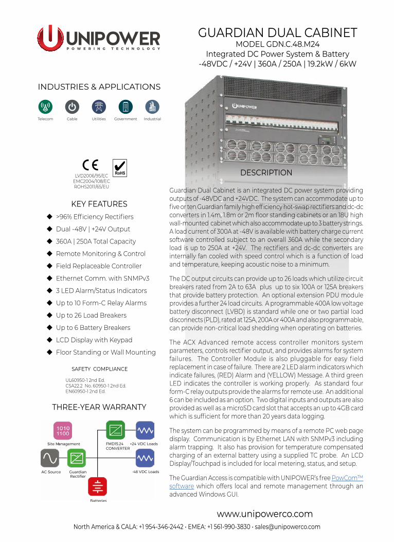
RECTIFIER & DC-DC CONVERER MODULES vs. SYSTEM CAPACITIESRECTIFIER MODULES (float voltage 53.5V) / DC-DC CONVERTER MODULE (24V) SYSTEM CAPACITY (400A LVD)
MODELNUMBER EFFICIENCY INPUT
VOLTAGEINPUT
CURRENTOUTPUT POWER
OUTPUT CURRENT
MAX. LOADCURRENT 5RU 7
MAX. LOADCURRENT 6RU 7
-48VDC +24VDC -48VDC +24VDC
RECTIFIERS
FMPe20.48G 2 >96.0% 185-180VAC 9.6A 3 1100W 4 20.6A 4 61.8A 5 123.6A 5
112.2A 5 224.4A 5180-275VAC 11.6A 3 2000W 37.4A
FMP25.48G 2, 6 >92.5% 185-180VAC 14.4A 3 1400W 4 26.2A 4 78.6A 5 157.2A 5
180-275VAC 16.8A 3 2500W 46.7A 140.1A 5 280.2A 5
FMPe30.48G 2 >95.0% 185-180VAC 15.7A 3 1700W 4 31.8A 4 95.4A 5 190.8A 5
180-275VAC 17.0A 3 2900W 54.2A 150.0A 5 300.0A 5
CONVERTER FMD15.24 90.5% typical 36-72VDC 53.8A 1500W 62.5A 125A 250A
Notes:1. When operating at 230VAC.2. Will operate over the full range, automatically limiting output current/power according to the actual input voltage range applied.3. Input currents shown are expected maximums at 85VAC/180VAC as appropriate4. Figures quoted are at 110VAC input. Derating is linear from 180VAC to 85VAC. See separate rectifier datasheets for details.5. May required reduction in maximum charge current when batteries not fully charged.6. Rectifier model FMP25.48G is not a preferred model for new requirements. It remains available for existing programmes.7. Assumes 3 rectifiers and 2 DC-DC converters in 5U configuration, 6 rectifiers and 4 DC-DC converters in 6U configuration. Other
configurations are available, see configuration guide. Each DC-DC converter consumes up to 53.8A from the -48V total capacity.
SYSTEM SPECIFICATION & CAPABILITY GUIDESYSTEM DESIGNATION GUARDIAN DUAL CABINET - M00024G
OUTPUT
System Voltage -48VDC nominal (53.5VDC float) / +24VDC
Maximum Capacity @ 120VAC nominal Load 190A | 250A
Battery 190A / 250A discharge | s/w controlled charge
Maximum Capacity @ 230/400VAC nominal Load 300A / 250A
Battery 300A / 250A discharge | s/w controlled charge
No. Rectifier / DC-DC Converter Slots 5 or 10 (see configuration guide on page 5)
DC DISTRIBUTION (see configuration guide on page 5)
Loads Circuits +24V-48V
up to 8 x 2A to 63Aup to 18 x 2A to 63A + up to 24 x 2A to 25A with extension PDU
Battery Circuits 1 to 6 x (80A, 100A or 125A)
INPUT
Voltage (nominal) 1-phase 100-120/200-240VAC (L + N + PE)3-phase 230/400VAC (L1 L2 L3 + N + PE)
Frequency 47-63Hz
Maximum Input Current 200A @ 100-120VAC | 169A @ 200-240VAC | 56A per phase @ 400/230VAC
Rectifier Power Factor >0.98 (typical)
Surge Protection Optional (see configuration guide on page 5)
MONITORING & CONTROL (ACX Advanced Controller)
Alarm Relays 4 standard, option for 10
Local Interface 4 x 20 LCD, 4-key menu, USB / RS232, microSD card slot (4GB max,) for data logging
Remote Interface Ethernet / Modem using PowCom™ software packageEthernet port allows monitoring and control over a TCP/IP network.
Web browser support + SNMPv3
LED Indications Green - System ON; Yellow - Message(s); Red LED - Alarm(s)
External Digital I/O 2 x Inputs, 2 x Outputs (Open Collector)
BATTERY MANAGEMENT
Symmetry Inputs 6 or 12 (can be redefined as analog inputs up to 100VDC)
Low Voltage Battery Disconnect (LVBD) 1 x 400A Programmable
Partial Load Disconnect (PLD) 1 or 2 x 125A, 200A or 400A Programmable (Optional)
Temperature Compensated Charging Programmable
COMPLIANCE
EMC EN 300 386 ; EN61000-6-3 (Emission) ; EN61000-6-2 (Immunity)
Safety IEC60950-1:2005 2 Ed. +A1:2009
ENVIRONMENTAL
Operating Temperature -40ºC to +55ºC
Storage Temperature -40ºC to +85ºC
North America & CALA: +1 954-346-2442 • EMEA: +1 561-990-3830 • [email protected]
P O W E R I N G T E C H N O L O G Y
Guardian Dual Cabinet GDN.C.48.M24 - 3
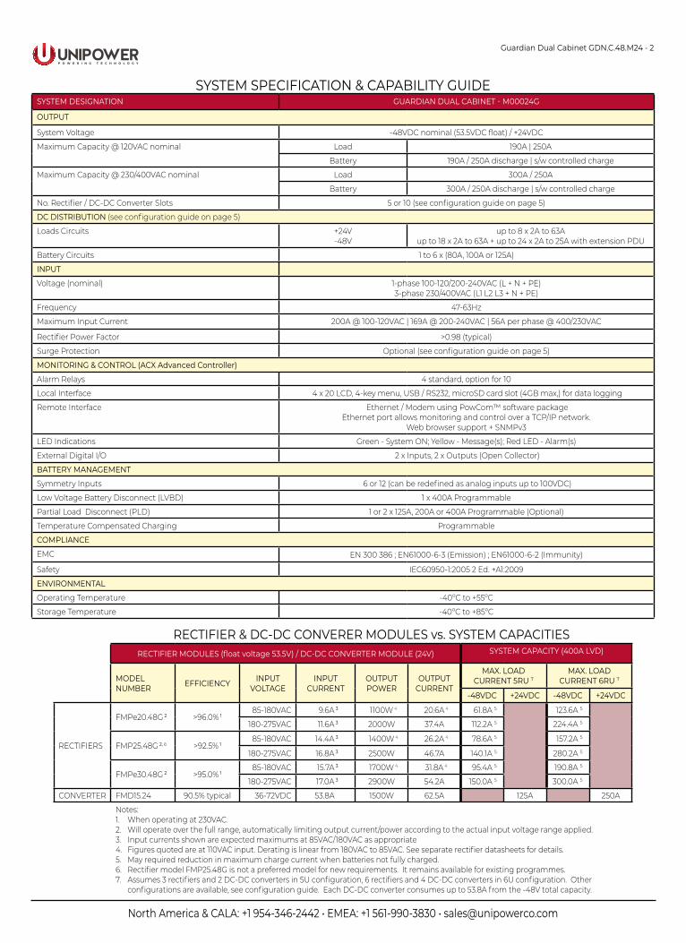
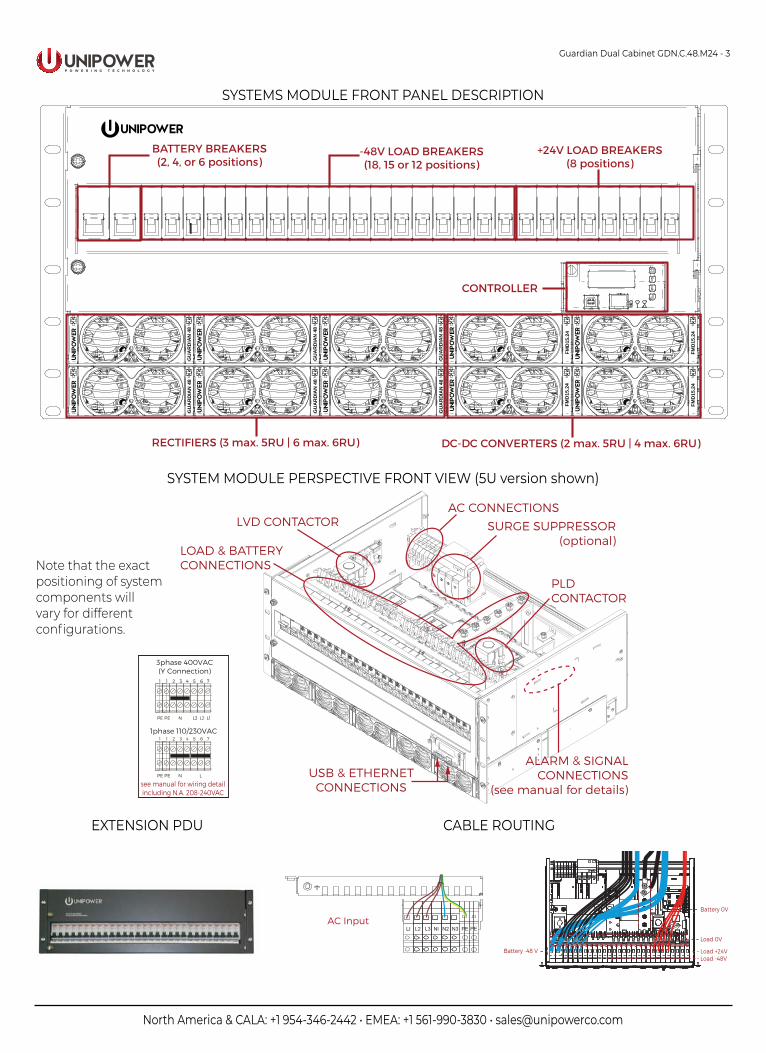
SYSTEMS MODULE FRONT PANEL DESCRIPTION
GU
AR
DIA
N 4
8G
UA
RD
IAN
48
GU
AR
DIA
N 4
8G
UA
RD
IAN
48
FMD
15.2
4FM
D15
.24
FMD
15.2
4FM
D15
.24
GU
AR
DIA
N 4
8G
UA
RD
IAN
48
RECTIFIERS (3 max. 5RU | 6 max. 6RU)
BATTERY BREAKERS(2, 4, or 6 positions)
CONTROLLER
-48V LOAD BREAKERS(18, 15 or 12 positions)
DC-DC CONVERTERS (2 max. 5RU | 4 max. 6RU)
+24V LOAD BREAKERS(8 positions)
SYSTEM MODULE PERSPECTIVE FRONT VIEW (5U version shown)
LVD CONTACTORAC CONNECTIONS
ALARM & SIGNALCONNECTIONS
(see manual for details)
LOAD & BATTERYCONNECTIONS
USB & ETHERNETCONNECTIONS
SURGE SUPPRESSOR(optional)
1 2 3 4 5 6 7
N LPE
1
PE
1phase 110/230VAC
1 2 3 4 5 6 7
N L1L2L3PE
1
PE
3phase 400VAC(Y Connection)
see manual for wiring detailincluding N.A. 208-240VAC
PLDCONTACTOR
AC Input
CABLE ROUTING
Battery -48 V
Battery 0V
Load 0V
Load +24VLoad -48V
Note that the exactpositioning of systemcomponents willvary for different configurations.
EXTENSION PDU
North America & CALA: +1 954-346-2442 • EMEA: +1 561-990-3830 • [email protected]
P O W E R I N G T E C H N O L O G Y
Guardian Dual Cabinet GDN.C.48.M24 - 4
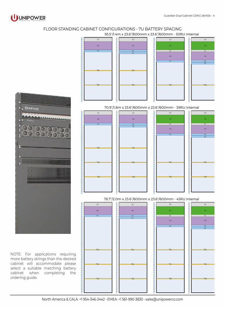
FLOOR STANDING CABINET CONFIGURATIONS - 7U BATTERY SPACING
RectifierShelf
Key:
System Unit BatteryShelf
BlankingPanel
Extension PDU
55.5”/1.4m x 23.6”/600mm x 23.6”/600mm - 30RU internal
70.9”/1.8m x 23.6”/600mm x 23.6”/600mm - 39RU internal
78.7”/2.0m x 23.6”/600mm x 23.6”/600mm - 43RU internal
1U
2U
4U
1U
7U
7U
2U
4U
1U
7U
7U
1U
7U 7U
2U
4U
1U
7U
7U
2U
4U
1U
7U
7U
1U
7U 7U
2U
4U
1U
7U
7U
2U
4U
1U
7U
7U
1U
2U
4U
1U
7U
1U
4U
2U
4U
7U
1U
4U
1U
2U
4U
1U
7U
2U
4U
1U
7U
1U
7U 7U
1U
4U
1U
4U
2U
4U
1U
7U
7U
2U
4U
1U
7U
7U
7U 7U
1U1U
4U
1U
4U
NOTE: For applications requiring more battery strings than the desired cabinet will accommodate please select a suitable matching battery cabinet when completing the ordering guide.
North America & CALA: +1 954-346-2442 • EMEA: +1 561-990-3830 • [email protected]
P O W E R I N G T E C H N O L O G Y
Guardian Dual Cabinet GDN.C.48.M24 - 5
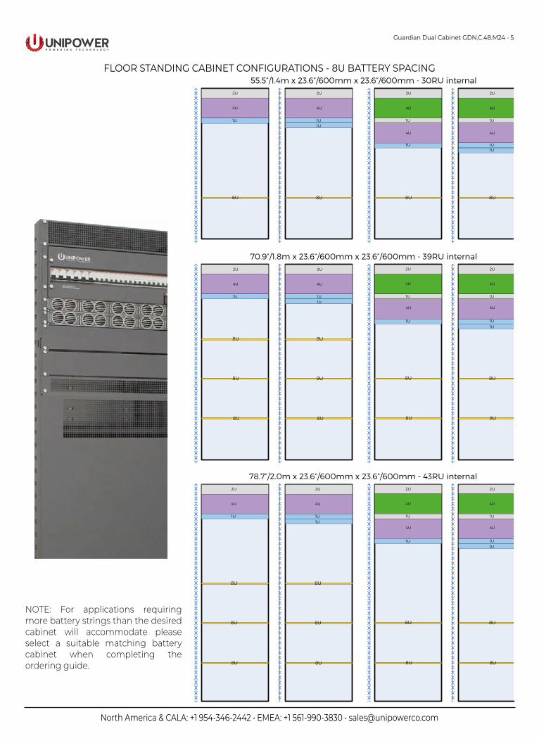
FLOOR STANDING CABINET CONFIGURATIONS - 8U BATTERY SPACING
Key:
55.5”/1.4m x 23.6”/600mm x 23.6”/600mm - 30RU internal
70.9”/1.8m x 23.6”/600mm x 23.6”/600mm - 39RU internal
78.7”/2.0m x 23.6”/600mm x 23.6”/600mm - 43RU internal
1U
RectifierShelf
System Unit BatteryShelf
BlankingPanel
Extension PDU
2U
4U
1U
8U
8U
2U
4U
1U
8U
8U
1U
8U 8U
2U
4U
1U
8U
8U
2U
4U
1U
8U
8U
1U
8U 8U
2U
4U
1U
8U
2U
4U
1U
8U
1U
2U
4U
1U
8U
1U
4U
2U
4U
8U
1U
4U
1U
2U
4U
1U
8U
2U
4U
1U
8U
1U
8U 8U
1U
4U
1U
4U
2U
4U
1U
8U
2U
4U
1U
8U
8U 8U
1U1U
4U
1U
4U
NOTE: For applications requiring more battery strings than the desired cabinet will accommodate please select a suitable matching battery cabinet when completing the ordering guide.

North America & CALA: +1 954-346-2442 • EMEA: +1 561-990-3830 • [email protected]
P O W E R I N G T E C H N O L O G Y
Guardian Dual Cabinet GDN.C.48.M24 - 6
CONFIGURATION GUIDEPLEASE COMPLETE THE BELOW TABLE AND SUBMIT TO UNIPOWER FOR VERIFICATION AND CONF. NO. ALLOCATION
(This form is fully interactive and may be completed electronically OR it can be printed and complete by hand)
STEP 1 - CUSTOMER DETAILS
Company: _______________________________Address: _______________________________ _______________________________Zip Code: _________ Country: ____________
Contact Name: ________________________________Email Address: ________________________________ Telephone: ________________________________Quantity for quotation: __________
STEP 2 - CHASSIS TYPE - Choose one version
5RU - 3 Rectifier and 2 Converter PositionsOR 6RU - 6 Rectifier and 4 Converter Positions
5RU chassisOR 6RU chassis
STEP 3a - RECTIFIER MODULES - Choose one type of rectifier module and enter quantity up to 3 for 5U chassis or 6 for 6U.STEP 3b - CONVERTER MODULES - Enter quantity of FMD15.24 converter modules - dummies will be inserted into unused slots
FMP20.48 - 2000W - >92.5% Efficiency (APAC region only)FMPe20.48G - 2000W - >96% EfficiencyFMP25.48G - 2500W - >92% Efficiency FMPe30.48G - 2900W - >95% Efficiency
FMP20.48OR FMPe20.48GOR FMP25.48G Quantity _____OR FMPe30.48G
FMD15.24 Quantity _____
STEP 4 - ALARM INTERFACE - Select desired alarm interface
Alarm Interface - 4 Relays or 10 Relays or 10 Relays + PLD2 4 Relays OR 10 Relays OR 10 Relays + PLD2
STEP 5 - LOW VOLTAGE BATTERY DISCONNECT (LVBD) Select with 2 battery breakers, 4 battery breakers or 6 battery breakers
2 battery breaker positions (21 load breaker positions)4 battery breaker positions (18 load breaker positions)6 battery breaker positions (12 load breaker positions)
2 positions OR 4 positions OR 6 positions
Note that the 6 position option is not available when PLDs are included.
STEP 6 - BATTERY BREAKERS - Choose rating and quantity based on step 5 choice or NONE (Breakers MUST be identical rating)
OR 80A 1 pole x 1 or x 2 or x 3 or x 4 or x 5 or x 6 (APAC only)OR 100A 1 pole x 1 or x 2 or x 3 or x 4 or x 5 or x 6OR 125A 1 pole x 1 or x 2 or x 3 or x 4 or x 5 or x 6OR 80A 2 pole x 1 or x 2 or x 3 (APAC only)OR 100A 2 pole x 1 or x 2 or x 3 (APAC only)OR 125A 2 pole x 1 or x 2 or x 3OR 100A 3 pole x 1 or x 2 (APAC only)
OR Qty 1 OR Qty 2 OR Qty 3 OR Qty 4 OR Qty 5 OR Qty 6OR Qty 1 OR Qty 2 OR Qty 3 OR Qty 4 OR Qty 5 OR Qty 6OR Qty 1 OR Qty 2 OR Qty 3 OR Qty 4 OR Qty 5 OR Qty 6OR Qty 1 OR Qty 2 OR Qty 3OR Qty 1 OR Qty 2 OR Qty 3OR Qty 1 OR Qty 2 OR Qty 3OR Qty 1 OR Qty 2
STEP 7 - PARTIAL LOAD DISCONNECT (PLD) - Select 125A or 200A or NO (default) - PLD2 may only be selected with correct Alarm Interface
125A or 200A PLD1 (non-critical -48V load / load shed disconnect)125A or 200A PLD2 (non-critical -48V load / load shed disconnect)
125A OR 200A OR NO125A OR 200A OR NO
CONTINUE ON NEXT PAGE
WALL-MOUNT CABINET CONFIGURATIONS
BlankingPanel
RectifierShelf
System Unit
Key:
Extension PDU
33.6”/854mm x 23.6”/600mm x 15.4”/390mm - 18RU internal
2U
4U
1U
2U
4U
1U1U
2U
4U
1U
1U
4U
2U
4U
1U
4U
1U
1U 1U 1U 1U
NOTE: Due to the overall depth of 15.4”/390mm, this cabinet will not accommodate large capacity (>60Ah typical) front terminal batteries. If larger batteries are going to be used please select a suitable battery cabinet when completing the ordering guide.
GU
AR
DIA
N 4
8G
UA
RD
IAN
48
GU
AR
DIA
N 4
8G
UA
RD
IAN
48
GU
AR
DIA
N 4
8G
UA
RD
IAN
48
GU
AR
DIA
N 4
8G
UA
RD
IAN
48
GU
AR
DIA
N 4
8G
UA
RD
IAN
48
North America & CALA: +1 954-346-2442 • EMEA: +1 561-990-3830 • [email protected]
gua
rdia
n_du
al_c
ab-d
s-re
vD-0
819.
indd
© 2019 UNIPOWER LLCThis document is believed to be correct at time of publication and UNIPOWER LLC accepts no responsibility for consequences from printing errors or inaccuracies. All specifications subject to change without notice.
P O W E R I N G T E C H N O L O G Y
Guardian Dual Cabinet GDN.C.48.M24 - 7
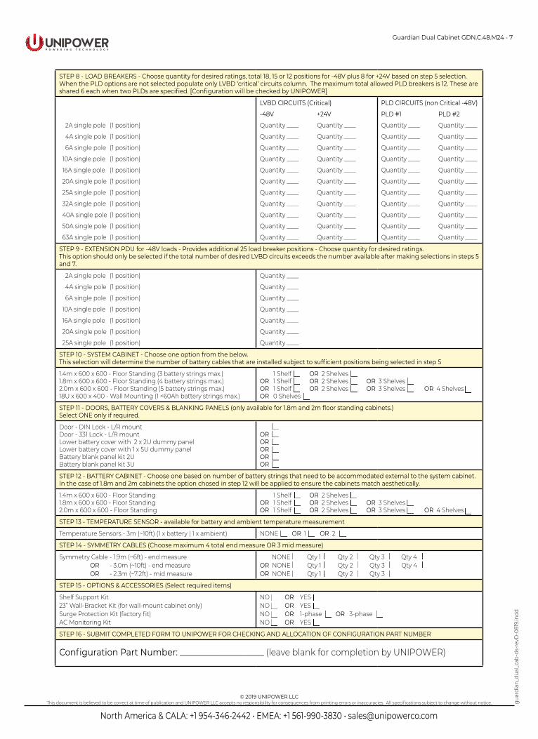
STEP 8 - LOAD BREAKERS - Choose quantity for desired ratings, total 18, 15 or 12 positions for -48V plus 8 for +24V based on step 5 selection.When the PLD options are not selected populate only LVBD ‘critical’ circuits column. The maximum total allowed PLD breakers is 12. These are shared 6 each when two PLDs are specified. [Configuration will be checked by UNIPOWER]
2A single pole (1 position)
4A single pole (1 position)
6A single pole (1 position)
10A single pole (1 position)
16A single pole (1 position)
20A single pole (1 position)
25A single pole (1 position)
32A single pole (1 position)
40A single pole (1 position)
50A single pole (1 position)
63A single pole (1 position)
LVBD CIRCUITS (Critical)
-48V +24V
Quantity ____ Quantity ____
Quantity ____ Quantity ____
Quantity ____ Quantity ____
Quantity ____ Quantity ____
Quantity ____ Quantity ____
Quantity ____ Quantity ____
Quantity ____ Quantity ____
Quantity ____ Quantity ____
Quantity ____ Quantity ____
Quantity ____ Quantity ____
Quantity ____ Quantity ____
PLD CIRCUITS (non Critical -48V)
PLD #1 PLD #2
Quantity ____ Quantity ____
Quantity ____ Quantity ____
Quantity ____ Quantity ____
Quantity ____ Quantity ____
Quantity ____ Quantity ____
Quantity ____ Quantity ____
Quantity ____ Quantity ____
Quantity ____ Quantity ____
Quantity ____ Quantity ____
Quantity ____ Quantity ____
Quantity ____ Quantity ____
STEP 9 - EXTENSION PDU for -48V loads - Provides additional 25 load breaker positions - Choose quantity for desired ratings.This option should only be selected if the total number of desired LVBD circuits exceeds the number available after making selections in steps 5 and 7.
2A single pole (1 position)
4A single pole (1 position)
6A single pole (1 position)
10A single pole (1 position)
16A single pole (1 position)
20A single pole (1 position)
25A single pole (1 position)
Quantity ____
Quantity ____
Quantity ____
Quantity ____
Quantity ____
Quantity ____
Quantity ____
STEP 10 - SYSTEM CABINET - Choose one option from the below.This selection will determine the number of battery cables that are installed subject to sufficient positions being selected in step 5
1.4m x 600 x 600 - Floor Standing (3 battery strings max.)1.8m x 600 x 600 - Floor Standing (4 battery strings max.)2.0m x 600 x 600 - Floor Standing (5 battery strings max.)18U x 600 x 400 - Wall Mounting (1 <60Ah battery strings max.)
1 Shelf OR 2 ShelvesOR 1 Shelf OR 2 Shelves OR 3 ShelvesOR 1 Shelf OR 2 Shelves OR 3 Shelves OR 4 ShelvesOR 0 Shelves
STEP 11 - DOORS, BATTERY COVERS & BLANKING PANELS (only available for 1.8m and 2m floor standing cabinets.)Select ONE only if required.
Door - DIN Lock - L/R mountDoor - 331 Lock - L/R mountLower battery cover with 2 x 2U dummy panelLower battery cover with 1 x 5U dummy panelBattery blank panel kit 2UBattery blank panel kit 3U
OR OR OR OR OR
STEP 12 - BATTERY CABINET - Choose one based on number of battery strings that need to be accommodated external to the system cabinet. In the case of 1.8m and 2m cabinets the option chosed in step 12 will be applied to ensure the cabinets match aesthetically.
1.4m x 600 x 600 - Floor Standing1.8m x 600 x 600 - Floor Standing2.0m x 600 x 600 - Floor Standing
1 Shelf OR 2 ShelvesOR 1 Shelf OR 2 Shelves OR 3 ShelvesOR 1 Shelf OR 2 Shelves OR 3 Shelves OR 4 Shelves
STEP 13 - TEMPERATURE SENSOR - available for battery and ambient temperature measurement
Temperature Sensors - 3m (~10ft) (1 x battery | 1 x ambient) NONE OR 1 OR 2
STEP 14 - SYMMETRY CABLES (Choose maximum 4 total end measure OR 3 mid measure)
Symmetry Cable - 1.9m (~6ft) - end measure OR - 3.0m (~10ft) - end measure OR - 2.3m (~7.2ft) - mid measure
NONE Qty 1 Qty 2 Qty 3 Qty 4OR NONE Qty 1 Qty 2 Qty 3 Qty 4OR NONE Qty 1 Qty 2 Qty 3
STEP 15 - OPTIONS & ACCESSORIES (Select required items)
Shelf Support Kit23” Wall-Bracket Kit (for wall-mount cabinet only)Surge Protection Kit (factory fit)AC Monitoring Kit
NO OR YESNO OR YESNO OR 1-phase OR 3-phaseNO OR YES
STEP 16 - SUBMIT COMPLETED FORM TO UNIPOWER FOR CHECKING AND ALLOCATION OF CONFIGURATION PART NUMBER
Configuration Part Number: ____________________ (leave blank for completion by UNIPOWER)