
Guardian GlassTime
256
Guardian GlassTime Technical Manual
-
Upload
khangminh22 -
Category
Documents
-
view
1 -
download
0
Transcript of Guardian GlassTime

Guardian GlassTimeTechnical Manual

Guardian GlassTime
GlassTimeTechnical Manual
Publisher: Guardian Europe S.à r.l.
Bertrange / Luxembourg
Edition: 2022

Guardian GlassTime
Preface ................................................................................3
Milestones ...........................................................................5
1. Base glass ....................................................................81.1 History .................................................................................8
1.2 Float glass ...........................................................................81.2.1 Colouring .............................................................................101.2.2 Properties ............................................................................11
Density | Modulus of elasticity (Young’s modulus) | Emissivity | Compressive strength | Tensile bending strength | Thermo-shock resistance | Transformation temperature range | Softening temper-ature | Linear coefficient of thermal expansion (thermal dilatation) | Specific heat capacity | Heat transmission coefficient (U-value) | Acid resistance| Alkali resistance | Water resistance | Fresh, aggressive alkaline substances
1.3 Coatings on float glass ......................................................131.3.1 Pyrolytic process ..................................................................131.3.2 Magnetron sputtering process ................................................14
Typical assembly of a magnetron-sputter-coating
2. Insulating glass ....................................................... 18
2.1 General ..............................................................................18
2.2 Production .........................................................................18
2.3 Edge seal ...........................................................................192.3.1 Sealant systems ...................................................................19
Primary seal | Secondary seal
2.3.2 Spacer .................................................................................20Stainless steel | Metal / plastic combinations | Thermoplastic systems (TPS)
2.4 Dew point and condensation .............................................212.4.1 Condensation in the interspace of the unit ...............................212.4.2 Condensation on the interior surface of the unit ........................212.4.3 Condensation on the exterior surface of the unit .......................22
2.5 Colour rendering index ......................................................24
2.6 Interference phenomena ...................................................24
2.7 Insulating glass effect – climatic loads .............................25

Guardian GlassTime
3. Light, energy and heat ........................................ 30
3.1 Solar energy ..................................................................... 30
3.2 Visible light ........................................................................32
3.3 Heat ...................................................................................32
3.4 UV radiation .......................................................................32
4. Thermal insulation ................................................. 36
4.1 Economy ........................................................................... 36
4.2 Ecology ..............................................................................37
4.3 Comfort ..............................................................................37
4.4 Heat loss ........................................................................... 38
4.5 Emissivity ............................................................................. 40
4.6 U value .................................................................................. 404.6.1 Ug value ...............................................................................40
Ug value for inclined glass surfaces
4.6.2 Uf value ................................................................................414.6.3 Y value ................................................................................424.6.4 UW value ..............................................................................42
4.7 Guardian product range for thermal insulation .................42
5. Solar control ................................ ................................46
5.1 Economy ................................ .............................................46
5.2 Ecology ................................ ...............................................46
5.3 Comfort ................................ ...............................................46
5.4 Solar energy flow through glass ................................ .........47
5.5 Solar factor (g value) ................................ ..........................47
5.6 Shading coefficient (b factor) ................................ .............48
5.7 Spectral selectivity ................................ .............................48
5.8 Heat gain control in summer ................................ ..............49
5.9 Sun protection using glass ................................ .................50
5.10 Solar control glass as design component ......................... 51
5.11 SunGuard® solar control glass ................................ ...........52

Guardian GlassTime
6. Sound control ........................................................... 56
6.1 Human aspects ................................................................ 56
6.2 Sound wave characteristics ............................................. 566.2.1 Limits ................................................................................. 566.2.2 Sound perception – Sound rating ............................................57
6.3 Sound ratings for buildings . ............................................. 586.3.1 Average noise reduction factor .......................................... ...... 586.3.2 Correction factors .................................................................59
6.4 Acoustic performance of glazing ....................................... 606.4.1 Weight of the pane ............................................................... 606.4.2 Insulating glass build up ........................................................616.4.3 Gas filling .............................................................................616.4.4 Stiffness of the glazing (decoupling of single glass
elements) .............................................................................62
6.5 Guardian sound control glass ...........................................63
7. Safety and security ............................................... 66
7.1 Fully tempered (toughened) glass ................................... 667.1.1 Production .......................................................................... 667.1.2 Building physical characteristics ............................................ 687.1.3 Resistance to impact and shock ............................................ 687.1.4 Tensile bending strength ....................................................... 687.1.5 Resistance to ball impact ...................................................... 687.1.6 Heat influence and thermo-shock resistance ........................... 697.1.7 Anisotropies (strain pattern) .................................................. 697.1.8 Optical quality ..................................................................... 697.1.9 Moisture film on tempered glass .............................................707.1.10 Identification .........................................................................70
7.2 Heat-soaked tempered glass ............................................70
7.3 Heat strengthened glass (partially tempered) ..................727.3.1 Production ...........................................................................727.3.2 Breakage pattern ..................................................................727.3.3 Residual load capacity as component
of laminated glass .................................................................727.3.4 Tensile bending strength (EN 1863-1) ......................................737.3.5 Thermo-shock resistance (EN 1863-1) ....................................73
7.4 Laminated safety glass .....................................................737.4.1 Production ...........................................................................747.4.2 Building physical characteristics .............................................757.4.3 Nomenclature of laminated glass ............................................75

Guardian GlassTime
7.4.4 Safety features of laminated glass ..........................................76Protection against injury/pendulum impact test (EN 12600) – passive safety | Impact resistance against manual attack (EN 356) – active safety | Hard body drop test (Ball drop) | Axe test | Bullet resistance (EN 1063) – active safety | Explosion resistance (EN 13541) – active safety
7.5 Safety with and through glass ...........................................797.5.1 Barrier glazing (glazing for protecting people from
falling out) ............................................................................79Floor-to-floor barrier glazing without supporting beam (category A) | At base line clamped glass parapets / ballustrades (category B) | Barrier glazing in combination with load transferring beam (category C) | Linear supported glazing with proven impact resistance
7.5.2 Overhead glazing ..................................................................827.5.3 Walk-on glazing ....................................................................827.5.4 Step-on glazing for cleaning
and maintenance purposes ....................................................837.5.5 Post-glass breakage performance / residual strength ...............87
7.6 Recommendations for particular applications ..................857.6.1 Vertical glazing without protection
against falling through ...........................................................857.6.2 Horizontal / overhead glazing .................................................877.6.3 Glazing for protecting people against falling out ...................... 887.6.4 Glazing in buildings used for special purposes ........................ 907.6.5 Glazing for interior works without fall protection ........................927.6.6 Special safety glasses ...........................................................937.6.7 Structural glass construction ................................................. 95
8. Building with glass ................................................. 98
8.1 Façades ............................................................................ 988.1.1 Façade functions ................................................................. 98
Warm façade | Cold façade | Double skin façade – ventilated systems | Types of ventilated façades | Interactive (passive) systems | Solar control glass in the outer pane | Condensation
8.1.2 Façade constructions ..........................................................104Stick-System-Façade (Mullion-Transom-System) | Structural glazing | Definitions | Types of structural glazing | Relevant European standards for structural glazing | Coated glass in structural glazing applications | Point supported façade | Membrane façade

Guardian GlassTime
8.2 Ceramic printing on glass ...............................................1128.2.1 Ceramic printing methods ....................................................113
Roller coating | Screen-printing | Digital printing
8.2.2 Spandrel glass ....................................................................1148.2.3 Edge enamelling – Guardian System TEA .............................1158.2.4 Decorative print ..................................................................116
8.3 Design glass ....................................................................1188.3.1 Transfer colour print on glass ...............................................1188.3.2 Design laminated safety glass ..............................................1198.3.3 Coloured films in laminated glas ...........................................1198.3.4 Decorative laminated glass ..................................................120
8.4 Curved architectural glass ..............................................1208.4.1 Gravity bending ..................................................................1218.4.2 Bending toughened glass ....................................................1228.4.3 Bending shapes ..................................................................1228.4.4 Requirements .....................................................................1238.4.5 Suitable glass types ............................................................1238.4.6 Determination of shape ........................................................1248.4.7 Specifics ............................................................................124
Local optical distortions | Outline precision | Torsion (twist deviation) | Edge displacement | Tangential junctions
8.4.8 Static specifics ...................................................................1278.4.9 Cold-bending .....................................................................127
8.5 Glass elevators ................................................................128
8. Interaction with long-wave radiation ...............................1298.6.1 Radar reflection damping glazing ..........................................130
Radar reflection attenuation with SunGuard® RD coated glass
8.6.2 Damping of electro-magnetic high frequency radiation / electrical smog ...................................................................132
8.7 Anti-reflective glazing ......................................................134
8.8 Bird-friendly glazing ........................................................1368.8.1 What’s the problem? ...........................................................1368.8.2 Evaluation of „bird-friendly“ solutions ....................................1368.8.3 Glass solutions providing better visibility for birds ...................137
9. Standards and guidelines .................................142
9.1 Glass relevant norms ......................................................142
9.2 Tolerances for standardised requirements .....................1449.2.1 Base glass .........................................................................144

Guardian GlassTime
9.2.2 Cutting ...............................................................................144General | Possible break-off for float glass | Acute angle of tempered glass, laminated safety glass, IGU-cutback (zone not to be assessed) | Length, width and perpendicularity
9.2.3 Processing .........................................................................146Edge processing qualities | Standard tolerances | Special tolerances | Special shapes | Edge processing | Processing (cut-outs, notches) | Corner cut-off, seamed < 100 mm x 100 mm | Corner cut-out, seamed | Edge cut-out, seamed | Standard deviation for manual processing – cut-out dimensions | Standard deviation for CNC processing – cut-out dimensions | Corner cut-off, smooth ground | Corner cut-off, polished - CNC processing centre | Standard | Special deviation | Standard | Special deviation | Corner cut-out, polished - CNC processing centre | Standard | Special deviation | Edge cut-out, smooth ground or polished - CNC processing centre | Standard deviation | Special deviation | Drillings | Diameters of drilled holes | Limitation and po-sition of the drilled hole | Deviations in drilling positions | Drilled hole positions | Drilled countersunk hole diameters | Drilled countersunk holes in laminated safety glass
9.2.4 Tempered glass, tempered heat-soaked glass and heat-strengthened glass ......................................................153General distortion – uncoated float glass | Local distortion (roller waves) – uncoated float glass | Recommended minimum glass thickness depending on the glass dimensions
9.2.5 Insulating glass units (IGU) ..................................................154Edge seal | Thickness tolerances in the edge area of the insulating glass unit | Dimension tolerance / offset
9.2.6 Laminated safety glass ........................................................155Dimensional tolerances | Displacement tolerance (offset) | Thickness tolerance
9.3 Glass edges ....................................................................1579.3.1 Edge types .........................................................................1579.3.2 Edge processing .................................................................1589.3.3 Edge geometries and typical applications ..............................158
9.4 Glass corners and joint ...................................................159 9.4.1 Glass joint with sealant joint and weather stripping
for double insulating glass ....................................................1599.4.2 Glass joint with sealant joint and weather stripping for triple insulating glass ......................................................1609.4.3 Glass joint with sealant joint and preformed seal for double insulating glass ....................................................1609.4.4 Glass joint with sealant joint and preformed seal for triple insulating glass ......................................................160

Guardian GlassTime
9.4.5 All-glass corner with double-stepped glazing unit ...................1609.4.6 All-glass corner with triple-stepped glazing unit ......................1619.4.7 All-glass corner with preformed seal for double- insulated glass with stepped edges .......................................1619.4.8 All-glass corner with preformed seal for triple-
insulated glass with stepped edges .......................................161
9.5 Glass thickness dimensioning ........................................162
9.6 Surface damage to glass ................................................162
9.7 Guidelines for assessing the visual quality of glass in buildings .........................................................163
9.7.1 Visual quality of coated glass ...............................................163Detection of defects | Conditions of examination | General | Uniformity defects and stains | Punctual defects | Acceptance criteria for coated glass defects
9.7.2 Visual quality of insulating glass units (IGU) ...........................165Observation conditions | IGU made of two panes of monolithic glass | Spot faults | Residues | Linear / extended defects | IGU other than those made of two panes of monolithic glass panes | IGU containing a heat-treated glass | Edge defects | Tolerance on spacer straightness | Curved IGU | Other visual aspects of insulating glass units | Inherent colour | Difference in insulating glass unit colour | Interference effect | Specific effect due to barometric conditions | Multiple reflections | Anisotropy (iridescence) | Condensation on the external surface of the IGU | Wetting of glass surfaces | Assessment of the visible section of the edge seal of the insulating glass unit | IGU with internal muntins
9.8 Glass breakage ...............................................................1719.8.1 Thermal breakage / thermal stress ........................................171
General | Thermal cracks | Factors influencing thermal breakage | Factors influencing glass strength and thermal breakage risk | Calculation and evaluation of the risk of thermal breakages
9.8.2 Typical glass fracture pattern ...............................................174
9.9 CE qualification ...............................................................178
9.10 Material compatibility ......................................................1799.10.1 Sealant compatibility of coated glass .....................................179
Standard insulating glass | Guardian SunGuard coatings in structural glazing
9.10.2 Ceramic printing on coated glass ...........................................181Requirements on enamelling of SunGuard for monolithic spandrel applications | Ceramic print with Ferro System 140 | SunGuard HD in combination with ceramic print on surface #1
9.10.3 Architectural coatings in laminated glass ................................184

Guardian GlassTime
9.11 Cleaning of glass ..............................................................1869.11.1 Introduction .........................................................................1869.11.2 Types of cleaning .................................................................186
During the construction phase | During use
9.11.3 Glass cleaning instructions ...................................................187General | Specially finished and externally coated glass | Further notes
9.12 Transportation and storage ..............................................189
10. Product selector ............................................... ........192
10.1 Float glass ............................................... ..........................192
10.2 Thermal insulating glass ............................................... ....194
10.3 Solar control glass ...........................................................196
10.4 Anti-reflective glazing ......................................................213
10.5 Sound control glass .........................................................214
10.6 Safety glass .....................................................................219
11. Search and find ..................................................... 226
11.1 Service offer ................................................................... 22611.1.1 Guardian Glass Analytics online tool .................................... 226
Guardian Performance Calculator | Guardian Glass Visualizer | Guardian Acoustic Assistant
11.1.2 Guardian Possibilities website ............................................. 22711.1.3 Glass- and application-relevant calculations ......................... 22711.1.4 Technical customer service ................................................. 22811.1.5 Competence transfer .......................................................... 228
11.2 Subject index .................................................................. 230
11.3 Common abbreviations .................................................. 236
11.4 Greek symbols ................................................................241

Guardian GlassTime
Base glass
Insulating glass
Light, energy and heat
Thermal insulation
Solar control
Sound control
Safety and security
Building with glass
Standards and guidelines
Product selector
Search and find11
10
9
8
7
6
5
4
3
2
1

Guardian GlassTime
History | Float glass | Colouring | Properties | Coatings on float glass | Pyrolytic process | Magnetron sputtering process
General | Production | Edge seal | Sealant systems | Spacer | Dew point and con-densation | Condensation in the interspace of the unit | Condensation on the interi-or surface of the unit | Condensation on the exterior surface of the unit | Colour ren-dering index | Interference phenomena | Insulating glass effect – climatic loads
Solar energy | Visible light | Heat | UV radiation
Economy | Ecology | Comfort | Heat loss | Emissivity | U value | Ug value | Uf value | Y value | UW value | Guardian product range for thermal insulation
Economy | Ecology | Comfort | Solar energy flow through glass | Solar factor (g value) | Shading coefficient (b factor) | Spectral selectivity | Heat gain control in summer | Sun protection using glass | Solar control glass as design compo-nent | SunGuard® solar control glass
Human aspects | Sound wave characteristics | Limits | Sound perception – Sound rating | Sound ratings for buildings | Average noise reduction factor | Correction factors | Acoustic performance of glazing | Weight of the pane | Insulating glass build up | Gas filling | Stiff-ness of the glazing (decoupling of single glass elements) | Guardian sound control glass
Fully tempered (toughened) glass | Heat-soaked tempered glass | Heat strength- ened glass (partially tempered) | Laminated safety glass | Safety with and through glass | Recommendations for particular applications
Façades | Ceramic printing on glass | Design glass | Curved architectural glass | Glass elevators | Interaction with long-wave radiation | Anti-reflective glazing | Bird-friendly glazing
Glass relevant norms | Tolerances for standardised requirements | Glass edges | Glass corners and joint | Glass thickness dimensioning | Surface damage to glass | Guidelines for assessing the visual quality of glass in buildings | Glass breakage | CE qualification | Material compatibility | Cleaning of glass | Transportation and storage
Float glass | Thermal insulating glass | Solar control glass | Anti-reflective glaz-ing | Sound control glass | Safety glass
Service offer | Guardian Glass Analytics online tool | Guardian Possibilities web-site | Glass- and application-relevant calculations | Technical customer service | Competence transfer | Subject index | Common abbreviations | Greek symbols

Elbphilharmonie Hamburg, Hamburg, Germany SunGuard® HD Light Blue 52 | 3-dimensional gravity curved, ceramically printed, laminated insulating glassArchitect: Herzog & De Meuron, Basel | Photo: © Cordelia Ewerth


the world ends at the wall.Without glass,
La Casa del Desierto, Gorafe, Spain | SunGuard® SNX 60Architect: OFIS architects | Photo: © Gonzalo Botet

Preface
Guardian GlassTime
It is impossible to imagine our world without glass. The invention of the float glass process in the middle of the last century ushered in the use of glass in every conceivable area. Today’s modern architecture takes special advantage of this building material, using it to create residential and commercial oases that provide protection with transparency, open-ness and access to the outdoors. Glass really is a product that improves people’s lives.
The increasing need for daylight, safety and security and the importance of energy savings translate to an increased use of glass in homes and the building envelopes. Interior designers are also taking more and more advantage of this material to pull light deeper into a project and reflecting our modern lifestyle.
Glass doors, furniture, partitions and accessories are an accepted and everyday part of this generation’s living and working environment. Inter- active elements such as display screens, glass surfaces for modern con-trol and communication and solar, thermal and photovoltaic elements make up a broad spectrum of components that shape our world today and will for the future. There is no end in sight for the innovative uses of this dynamic product.
The basic material is typically industrially manufactured float glass which is then coated or processed into innovative buildings and other functional so-lutions. We are living in the “Age of Glass” - or “Glass Time” - and this is a journey that started over 7 000 years ago to which there is no end in sight.
To continue this journey, we are very happy to share our knowledge of glass, glass products and glass possibilities through this handbook. We do not restrict ourselves to core business issues in this respect, but rather highlight the essential aspects of this versatile material in its many pro-cessed forms. This edition will certainly not be able to cover all glass issues in depth, but it provides answers to many questions relating to glass – true to the title “GlassTime”.
Preface / Guus Boekhoudt Vice President Flat Glass Europe& Managing Director Guardian Europe S.à r.l.
Reproduction, including extracts, is only permitted on approval. This manual has been compiled to current technological standards and to the best of our knowledge. Subject to change. No legal claims may be derived from the contents of this manual.
35
12
8
67
4
9
10Bern
Madrid
Chisinau
Kiev
Warsaw
Czestochowa
Berlin
CopenhagenRiga
StockholmOslo
Helsinki
Minsk
Moscow
Paris
BrusselsLuxembourg
AmsterdamLondon
Dublin
Rome
Belgrade
Athens
Nicosia
Ankara
Vienna
Prague
Bucharest
11
Guardian GlassTime
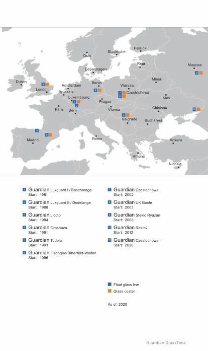
1 Guardian Luxguard I / Bascharage Start: 1981
2 Guardian Luxguard II / Dudelange Start: 1988
3 Guardian Llodio Start: 1984
4 Guardian Orosháza Start: 1991
5 Guardian Tudela Start: 1993
6 Guardian Flachglas Bitterfeld-Wolfen Start: 1996
7 Guardian Czestochowa Start: 2002
8 Guardian UK Goole Start: 2003
9 Guardian Steklo Ryazan Start: 2008
10 Guardian Rostov Start: 2012
11 Guardian Czestochowa II Start: 2020
Float glass line
Glass coater
As of: 2020
Moscow
Guardian GlassTime
Guardian Industries began as the Guardian Glass Company in 1932. Back then, we made windshields for the automotive industry. Today, Guardian Industries is a global company headquartered in Auburn Hills, Michigan. It employs 18 000 people and operates facilities throughout North America, Europe, South America, Africa, the Middle East and Asia. Guardian com-panies manufacture high-performance float, coated and fabricated glass products for architectural, residential, interior, transportation and techni-cal glass applications, and high-quality chrome-plated and painted plastic components for the automotive and commercial truck industries. Guardian’s vision is to create value for its customers and society through constant innovation using fewer resources. Guardian is a wholly owned subsidiary of Koch Industries, Inc.
In 1970, we opened our first glass plant in Carleton, Michigan, and began manufacturing float glass, a product achieved by floating molten glass on a bath of liquid tin. At the time, we were the first company to enter the US primary glass industry in nearly 50 years. Today, we have 25 float glass lines and 13 glass fabrication plants around the world.
The focus at the turn of the century was on value-added product inno-vation. Guardian opened its Science and Technology Center in Carleton, Michigan in the year 2000 to address this need. It has expanded and enhanced our product spectrum in the commercial, residential, interior, electronics and automotive segments.
With hundreds of new patents, scores of fresh products, state-of-the-art facilities and a team of dedicated professionals around the world, Guardian is poised to meet the challenges of the coming decades. Our products and systems grace homes, buildings and automobiles all over the world. Having accomplished so much in such a short time, identifying and mastering the latest demands and requirements is a constant chal-lenge and opportunity.
Guardian’s extensive European network of glass and automotive manu-facturing facilities and sales and distribution operations means we are always close at hand to address customer needs. Since entering Europe in 1981 with our first float glass plant in Bascharage, Luxembourg, Guardian has expanded its operations into seven countries throughout Europe to better serve the commercial and residential glass segments and the automotive industry.
Today, Guardian operates 11 float glass lines in Europe and produces high-quality coated glass products with state-of-the-art glass coaters in nine locations across Europe.
Milestones / From humble beginnings to global presence
Milestones

Tour Incity, Lyon, France | SunGuard® HD Silver 70 Architect: Valode & Pistre | Photo: © Stanislas Ledoux

7Guardian GlassTime
1. Base glass ......................................................................8
1.1 History .................................................................................8
1.2 Float glass ............................................................................81.2.1 Colouring ..............................................................................101.2.2 Properties .............................................................................11
Density | Modulus of elasticity (Young’s modulus) | Emissivity | Compressive strength | Tensile bending strength | Thermo-shock resistance | Transformation temperature range | Softening temperature | Linear coefficient of thermal expansion (thermal dilatation) | Specific heat capacity | Heat transmission coefficient (U-value) | Acid resistance| Alkali resistance | Water resistance | Fresh, aggressive alkaline substances
1.3 Coatings on float glass .......................................................131.3.1 Pyrolytic process ...................................................................131.3.2 Magnetron sputtering process .................................................14
Typical assembly of a magnetron-sputter-coating
1
Bas
e gl
ass

8 Guardian GlassTime
1.1 History The history of glass production dates back to around 5 000 BC. Glass beads discovered in ancient Egypt and early Roman sites bear witness to a long tradition of drawing and moulding techniques used in glass production. For centuries, however, individual craftsmanship dominated manufacturing processes that ranged from using blowpipes and cylinder blow moulding techniques to the crown glass method. These manual production methods resulted in small quantities and small window panes, which were almost exclusively used in stained glass windows in churches.
Demand for glass during the seventeenth century rose because in addi-tion to master church builders using glass in church windows, builders of castles and stately townhouses were also now discovering how to use glass to enclose spaces. French glassmakers first developed a glass roll-ing process that produced 1.20 x 2 m glass panels, a size that until then had seemed impossible. Glass production did not become industrialised until the twentieth century when 12 x 2.50 m sheets of glass later began to be mass produced on a large scale using the Lubbers and Fourcault methods of glass production, advancing to the more recent technologies developed by Libbey-Owens and Pittsburgh.
All of these methods had one distinct disadvantage: manufactured glass panels had to be ground and polished on both sides to obtain distortion-free and optically perfect mirror glass - a process that was extremely time consuming and expensive.
1.2 Float glassIndustrial glass – which today would be glass used in the automotive and construction industries – was originally manufactured using a system known as float glass. This floating process, which reached its peak in 1959, revolutionised glass production methods. Until this float process was developed, glass panes were produced by drawing or moulding molten glass, and then polishing it.
This new method allows the glass to “float”, with the molten glass spreading out evenly over the surface of a bath with liquid tin. Due to the inherent surface tension of the liquid tin, and the fact that glass is only half as dense as tin, the molten glass does not sink into the tin bath, but rather floats on the surface, thereby moulding itself evenly to the surface shape of the liquid tin. This method creates absolute plane parallelism, which guaran-tees freedom from distortion and crystal-clear transparency. Reducing the temperature in the tin bath from approx. 1 000 °C to approx. 600 °C turns a viscous mass of molten glass into a solid glass sheet that can be lifted right off the surface of the tin bath at the end of the floating process.

Tin bath
Base glass
9Guardian GlassTime
Batch Melting, refi ning Floating CoolingControlling, cutting, stacking
app. 1600 °C
app. 1200 °C app. 600 °C
app. 1100 °C app. 50 °C
Floating process (schematic representation)
Tin is ideal for shape forming because it remains liquid throughout the entire shape forming process and does not evaporate due to its low vapour pres-sure. In order to prevent the tin from oxidising, the fl oating process takes place in a protective gas atmosphere of nitrogen with a hydrogen additive.The molten process precedes form shaping by fl oating glass in a tin bath. This process begins with an exact proportion of the raw materials based on around 60 % quartz, 20 % soda and sulphate and 20 % limestone and dolomite. These materials are crushed in huge agitators and processed into a mixture. A blend comprising approx. 80 % of this mixture and 20 % recycled scrap glass is fed into the furnace and melted at around 1,600 °C. The result is a soda-lime-silica glass that conforms to EN 572-2.
After gassing the molten mixture, which is referred to as refi ning, the molten glass is fed into the condition-ing basin and left to cool to approx. 1,200 °C before fl owing over a re-fractory spout into the fl oat bath. This mixture is constantly fed, or “fl oated”, onto the tin surface, a method that can be likened to a tub that over-fl ows due to constant water intake. An infi nite glass ribbon of approx. 3.50 m width is lifted off the surface at the end of the fl oat bath.
At this point, the glass ribbon is approx. 600 °C and is cooled down to room temperature using a very precise procedure in the roller cooling channel to ensure that no permanent stress remains in the glass. This operation is extremely important for problem-free processing. The glass ribbon is still approx. 50 °C at the end of the 250 m long cooling line and a laser inspects the glass to detect faults such as inclusions, bubbles and cords. Faults are automatically registered and scrapped when blanks are later pre-cut.
Pre-cuts are normally realised at intervals of 6 metres or less, with the glass being cut perpendicular to the endless ribbon. Both edges of the ribbon are also trimmed, generally producing fl oat glass panes of 3.21 m x 6 m, which are then immediately processed or stored on frames for further processing.
1
Bas
e gl
ass

10 Guardian GlassTime
Longer plates of 7 m or more are also produced. An average float glass line is about 600 m long and has a daily capacity of approx. 70 000 m² flat glass with a thickness of 4 mm.
1.2.1 Colouring
Normal float glass has a slightly greenish tint. This colouring is primarly seen along the edge of the glass and is caused by naturally existing ferric oxide in the raw materials. By selecting extremely low ferric oxide-containing raw materials, or by undergoing a chemical bleaching process, the melt can be turned into an colour-neutral, extra-white glass.
Guardian produces this type of glass under the name Guardian UltraClear™. Interiors and special solar products are the widest areas of application. With the standard product Guardian ExtraClear®, Guardian offers a base glass to the market with reduced iron content. In terms of colour (green tint) and spectral properties, this glass falls between the UltraClear white float and the standard Clear float. Due to its interesting combination of properties, Float ExtraClear is ideal as the base material for ClimaGuard® thermal insulating and SunGuard® solar control coatings. This improves the selectivity and colour neutrality, irrespective of the particular coatings, particularly for glass used in facades.
70
300 500 700 900 1100 1300 1500 1700 1900 2100 2300 2500
75
80
85
90
95
Tran
smis
sion
[%]
Wavelength [nm] Clear float glass ExtraClear UltraClear
Types of clear float glass
In addition to these three versions of float glass, tinted glass can be produced using coloured mass. Chemical additives in the mixture allow green, grey, blue, reddish and bronze-coloured glass to be produced during certain production floating line periods. Changing glass colour in the vat naturally entails a considerable degree of effort and increased cost due to scrap and loss in productivity. It is therefore only produced for special campaigns.
Base glass
11Guardian GlassTime
1.2.2 Properties
Most of today’s glass production is float glass, with thicknesses typically ranging from 2 mm – 25 mm and a standard size of 3.21 x 6 m that is used for further processing. The glass has the following physical properties:
1.2.2.1 Density
The density of the material is determined by the proportion of mass-to-volume and is indicated using the notation “ρ”. Float glass has a factor of ρ = 2,500 kg/m³. This means that the weight of a square metre of float glass with a thickness of 1 mm is 2.5 kg.
1.2.2.2 Modulus of elasticity (Young’s modulus)
The modulus of elasticity is a material characteristic that describes the correlation between the tension and expansion when deforming a solid compound with linear elastic properties. It is designated with the formula symbol “E”. The more a material resists deformation, the higher the value of the E-module. Float glass has a value of E = 7 x 10¹⁰ Pa according to EN 572-1.
1.2.2.3 Emissivity
Emissivity (ε) measures the ability of a surface to release absorbed heat as radiation. A precisely defined “black body” is used as the basis for this ratio. The normal emissivity of float glass is ε = 0.89, which means 89 % of the absorbed heat is re-radiated (→ chapter 4.5).
1.2.2.4 Compressive strength
As the term implies, this indicator demonstrates the resistance of a material to compressive stress. Glass is extremely resilient to pressure, as demonstrated by its 700 - 900 MPa value. Flat glass can withstand a compressive load 10 times greater than the tensile load.
1.2.2.5 Tensile bending strength
The tensile bending strength of glass is not a specific material parameter, but rather an indicated value which like all brittle materials is influenced by the composition of the surface being subjected to tensile stress. Sur-face infractions reduce this indicated value, which is why the value of the flexural strength can only be defined using a statistically reliable value for the probability of fracture. This definition states that the fracture probability of a bending stress of 45 MPa for float glass (EN 572-1) as per the Ger-man building regulations list, may be a maximum 5 % on average, based on a likelihood of 95 % as determined by statistical calculation methods. σ = 45 MPa as measured with the double ring method in EN 1288-2.
1
Bas
e gl
ass

12 Guardian GlassTime
1.2.2.6 Thermo-shock resistance
The resistance of float glass to temperature differences (ΔT) over the glass pane surface is 40 K (Kelvin) according to the EN 572 standard. This means that a temperature difference of up to 40 K over the glass pane has no effect. Greater differences can cause dangerous stress in the glass cross-section, and this may result in glass breakage. Heating devices should therefore be kept at least 30 cm away from glazing. If this distance cannot be maintained, the installation of tempered glass is rec-ommended (→ chapter 9.8.1). The same applies to solid, permanent and partial shading of glazing, due, for example, to static building elements or to nearby plants.
1.2.2.7 Transformation temperature range
The mechanical properties of float glass vary within a defined temperature range. This range is between 520 - 550°C and should not be compared with the pre-tempering and form shaping temperature, which is around 100°C higher.
1.2.2.8 Softening temperature
The glass transition or softening temperature of float glass is at approx. 600°C.
1.2.2.9 Linearcoefficientofthermalexpansion (thermal dilatation)
This value indicates the minimum length change of float glass when the temperature is increased. This is extremely important for joining to other materials: 9 x 10⁻⁶ K-1 pursuant to ISO 7991 at 20 - 300°C. This value gives the expansion of a glass edge of 1 m when the tempera-ture increases by 1 K.
1.2.2.10 Specificheatcapacity
This value determines the heat increase required to heat 1kg of float glass by 1K: C = 800 J · kg-1 · K-1
1.2.2.11 Heattransmissioncoefficient(U-value)
This value is calculated in accordance with EN 673. The value for float glass with a thickness of 4 mm is 5.8 W/m²K (→ chapter 4.6).
1.2.2.12 Acid resistance
Chart: Class 1 acc. to DIN 12116
1.2.2.13 Alkali resistance
Chart: Class 1-2 acc. to ISO 695

Floating
Glass substrateapprox. 800 °C
Metal oxides
Metal oxide layer
Coating Cooling
Pyrolytic process (online)
Base glass
13Guardian GlassTime
1.2.2.14 Water resistance
Chart: Hydrolytic class 3-5 acc. to ISO 719
1.2.2.15 Fresh, aggressive alkaline substances
These include substances washed out of cement, which have not com-pletely hardened and when they come into contact with the glass, attack the silica acid structure that is part of the glass structure. This changes the surface as contact points become rougher. This effect occurs when the liquid alkaline substances dry and is completed after the cement has fully solidifi ed. For this reason, alkaline leaching substances should never come into contact with glass or any points of contact should be removed immediately by rinsing them off with clean water (→ chapter 9.11).
1.3 Coatings on float glassIndustrial coatings for fl oat glass are produced in huge quantities, primarily using two techniques. One is the chemical pyrolysis process, also known “hard coating”. The second is a physical process called vacuum deposition or magnetron sputtering.
Depending on the coating used, materials in both methods result in a neutral or coloured appearance, whereby the coloured effects are less obvious when viewing the glass head-on and are easier to note when looking at refl ections on the surface of the glass. These two technologies are base glass oriented and are not to be confused with surface coating applied through spraying, rolling or imprinting processes (→ chapter 8.2).
1.3.1 Pyrolytic process
This type of fl oat glass coating pro-cess occurs online during glass production on the float line. At this point, the glass surface is still several hundred degrees Celsius when metal oxides are sprayed onto it. These oxides are perma-nently baked onto the surface and extremely hard (“hard-coatings”) and resistant, but their properties are very limited due to their simple structure. Multi-layer glass systems are used to meet the higher requirements that are generally demanded today. They are produced offl ine under vacuum in the magnetron sputter process. Guardian therefore focuses solely on the coating technology described below.
1
Bas
e gl
ass

14 Guardian GlassTime
1.3.2 Magnetron sputtering process
The magnetron process has many appellations, one of which dates back to the beginning of this technology when this process was known as “soft-coating”, rather than “hard-coating”. Today, this definition is misleading, as extremely resistant magnetron sputter films now exist that are, in all cases, composed of individual ultra-thin layers of film. No other technology is capable of coating glass so smoothly and with such outstanding optical and thermal properties.
The material (i.e. the target, which is a metal plate) to be deposited on the glass surface is mounted on an electrode with a high electrical potential. Electrode and target are electrically isolated from the wall of the vacuum chamber. The strong electrical field (fast electrons) ionises the sputter gas argon. The accelerated argon ions are capable of breaking off material from the target by colliding with it, and this then comes into contact with the glass, where it is deposited onto the surface.
Metals and alloys are sputtered with or without additional reactive gases (O2 or N2). It is now possible to deposit metals, metal oxides and metal nitrides.
Entrancechamber
Bufferchamber
Bufferchamber
Exitchamber
Sputteringchamber
Lock valve Turbomolecular pump
Glass substrate Sputter cathode
Cross-section of a magnetron sputter coating line

Bottom layer
Glass substrate
Protection layer
Functional layer
Protection layer
Top layer
ca. 1
00 n
m
Base glass
15Guardian GlassTime
1.3.2.1 Typical assembly of a magnetron-sputter-coating
Bottom and top layer:
• Dielectric materials infl uence the refl ectance, transmittance and colour of the coating
• Ensure high mechanical durability
Functional layer:
• E.g. silver or other metals/alloys• Responsible for the refl ection of
long-wave and/or short-wave radiation• Strong infl uence on heat transmission (U-value), energy transmission
(g-value) and light transmission
Protection layer:
• Protection of the functional layer (silver) against mechanical and chemical infl uences
In order to enhance the spectral selectivity of solar control coatings, the silver functional layer can be split (double and triple silver coatings) by sputtering dielectric layers in between. This improves the ratio of visible light and solar energy transmission by increasing the transparency.
Spectral selectivity
3 x silver2 x silver1 x silverNo silver
1
Bas
e gl
ass

W Hotel La Vela, Barcelona, Spain | SunGuard® HP Silver 43/31Architect: Ricardo Bofi ll Taller de Arquitectura | Photo: © courtesy of Ricardo Bofi ll
17Guardian GlassTime
2. Insulating glass ............................................................18
2.1 General ...................................................................................18
2.2 Production ..............................................................................18
2.3 Edge seal ................................................................................192.3.1 Sealant systems ........................................................................19
Primary seal | Secondary seal
2.3.2 Spacer ......................................................................................20Stainless steel | Metal / plastic combinations | Thermoplastic systems (TPS)
2.4 Dew point and condensation ................................................212.4.1 Condensation in the interspace of the unit .................................212.4.2 Condensation on the interior surface of the unit .........................212.4.3 Condensation on the exterior surface of the unit ........................22
2.5 Colour rendering index .........................................................24
2.6 Interference phenomena ......................................................24
2.7 Insulating glass effect – climatic loads ...............................25
2
Insu
lati
ng
glas
s

18 Guardian GlassTime
A series of factors and physical rules defi ne the characteristics of insulating glass as it is used in thermal insulation and solar protection applications
2.1 GeneralTo achieve thermal insulation properties, several fl oat glass panes should be combined with at least one low E coating to create an insulating glass unit.
Two or more panes of the same size are aligned with each other at a defi ned distance and glued together. The resulting hermetically sealed interspace is fi lled with especially effective thermal insulating inert gas. No vacuum is generated, as laypersons often mistakenly assume.
The width of the pane interspace depends on the inert gas that is used. Argon is most frequently used, krypton more rarely. To reach its optimum thermal insulation effi ciency, argon needs an interspace of 15 - 18 mm; krypton needs only 10 - 12 mm for better insulating results. The gas fi lling rate is typically about 90 %. Krypton is many times more expensive than argon since it is more rare.
The spacer that permanently separates the panes has some infl uence on the insulating performance and consequently on the dew point at the edge of the glazing (→ chapter 2.4). For the past few decades, aluminium spacers have been the industry standard. These are being replaced today by systems with lower heat conductivity (warm-edge technology).
2.2 ProductionThe insulating glass panes are glued together using the dual-barrier system, in which a spacer is used to keep the two panes sepa-rated, and a continuous string of butyl adhesive is applied around the edges of the spacer to keep both panes of glass glued together. The space that is created is fi lled with a desiccant that keeps the interspace permanently dry. During the gluing process, it is important that the coated side of the pane of fl oat glass faces the interspace and that the adhesive is applied to this side. Some types of coatings need to be removed mechanically before the adhesive can be applied properly. Removing the coating before the adhesive is applied increases the bonding strength and protec-tion against corrosion (→ chapter 9.10.1).
Insulating glass
19Guardian GlassTime
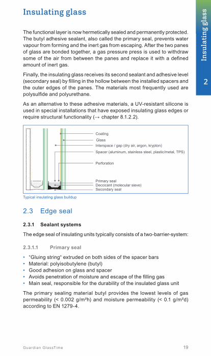
The functional layer is now hermetically sealed and permanently protected. The butyl adhesive sealant, also called the primary seal, prevents water vapour from forming and the inert gas from escaping. After the two panes of glass are bonded together, a gas pressure press is used to withdraw some of the air from between the panes and replace it with a defi ned amount of inert gas.
Finally, the insulating glass receives its second sealant and adhesive level (secondary seal) by fi lling in the hollow between the installed spacers and the outer edges of the panes. The materials most frequently used are polysulfi de and polyurethane.
As an alternative to these adhesive materials, a UV-resistant silicone is used in special installations that have exposed insulating glass edges or require structural functionality (→ chapter 8.1.2.2).
Coating
GlassInterspace / gap (dry air, argon, krypton)
Perforation
Primary sealDeccicant (molecular sieve)Secondary seal
Spacer (aluminum, stainless steel, plastic/metal, TPS)
Typical insulating glass buildup
2.3 Edge seal
2.3.1 Sealant systems
The edge seal of insulating units typically consists of a two-barrier-system:
2.3.1.1 Primary seal
• “Gluing string“ extruded on both sides of the spacer bars• Material: polyisobutylene (butyl)• Good adhesion on glass and spacer• Avoids penetration of moisture and escape of the fi lling gas• Main seal, responsible for the durability of the insulated glass unit
The primary sealing material butyl provides the lowest levels of gas permeability (< 0.002 g/m²h) and moisture permeability (< 0.1 g/m²d)according to EN 1279-4.
2
Insu
lati
ng
glas
s

20 Guardian GlassTime
2.3.1.2 Secondary seal
• Glued connection between glass and spacer• Mechanical strength of the edge seal• Protection of the primary seal• Additional diffusion barrier
The following materials are most commonly used as secondary sealants:
• Polysulfi de (2-component organic polymer)• Polyurethane (2-component organic polymer)• Hotmelt (1-component organic polymer)• Silicone (1- or 2-component)
The gas and moisture permeability of the organic polymers are much lower compared to silicone.
Secondary sealants based on organic polymers do not resist UV-A radia-tion and must be protected. Any insulating unit with edges exposed to UV should be equipped with silicone as secondary sealant. Due to higher strength, silicones resist UV impact.
2.3.2 Spacer
The thermal properties of insulating glass refer to the centre area of the panes without any infl uences from the insulating glass edges.
Until very recently, the majority of insulating glass was produced using aluminium spacers. More demanding requirements have created thermally improved alternatives that are gaining ground in insulating glass production. In the meantime, the aluminium spacer bars were increasingly replaced by other materials using the so-called “warm-edge-technology“.
With the linear heat transfer coeffi cient (Ψ value), the spacer material directly infl uences the heat transmission coeffi cient of the window Uw
(→ chapter 4.6.3 and 4.6.4).
2.3.2.1 Stainless steel
Extremely thin stainless-steel profi les with considerably reduced heat conductivity when compared to aluminium are the most common alterna-tive. They are similar to aluminium, however, in terms of their mechanical stability and diffusion capability.
2.3.2.2 Metal / plastic combinations
Another option are plastic spacers, which offer excellent thermal insulation but do not have a suffi cient gas diffusion density to ensure the life-cycle of an insulating glass. Consequently, combinations of plastic with gas-impermeable stainless steel or aluminium fi lms are available.

Insulating glass
21Guardian GlassTime
2.3.2.3 Thermoplastic systems (TPS)
A hot extruded, special plastic substance, which is placed between two panes of glass during insulating glass production and which guarantees the required mechanical strength, as well as gas diffusion density after cooling down, replaces the conventional metal. The desiccant is incorpo-rated. There is a wide range of disposable alternatives today that provide important reductions of the Ψ value, the linear heat transfer coefficient in the perimeter zone, when they are directly compared with each other (→ chapter 4.6.3).
2.4 Dew point and condensation
2.4.1 Condensation in the interspace of the unit
This rarely occurs with today’s insulating glasses, since they are her-metically sealed and filled with dried gases. Condensation in the space of insulating glass units indicates a defect edge seal, missing desiccant or incorrect manufacturing.
2.4.2 Condensation on the interior surface of the unit
This occurs on poorly thermally insulated windows or those with single glazing. Warm air cools suddenly near windows and transfers humidity to the cold interior surface – the temperature in winter is often below the dew point of the ambient air. Today, the inner pane of insulating glass stays warm longer so that condensation rarely occurs.
If the relative air humidity is very high, for example due to cooking, wash-ing or proximity to a swimming pool, panes may condensate more often. One way to correct this is to exchange the air by means of short and direct ventilation.
The outside temperature at which the glazing on the inner side conden-sates (= formation of condensation water = dew point), can be determined using the dew point graph.
2
Insu
lati
ng
glas
s

22 Guardian GlassTime
Ug [
W/m
2 K]
Rel
ativ
e hu
mid
ity [%
]
Roo
m te
mpe
ratu
re [°
C]
Outdoor temperature [°C]
Out
door
tem
pera
ture
[°C
]
1.11.41.61.8
3.0
5.8
30
20
10
0
-10
30
20
109
0
100
80
60
50
40
20
-50 -48 -40 -30 -20 -10
Dew point graph
Recorded examples (see dew point graph):
• Room temperature 20 °C• Room humidity 50 %• Outdoor temperature 9 °C
2.4.3 Condensationontheexteriorsurfaceoftheunit
This effect has appeared with the advent of modern insulated glass, and is particularly noticeable during the early morning hours, when the moisture content in the outside air has sharply increased during the night.
The excellent insulating quality of these glass surfaces prohibits heat transfer to the outside, so the outer pane remains extremely cold. When the sun’s rays start to heat the outside air faster than the temperature of the pane, it may lead to condensation, depending on the orientation of the building and the environment. This is not a defect, but proof of the excellent thermal insulation of the insulating glass.
Dew points at*:
• Ug = 5.8 W/m²K → 9 °C• Ug = 3.0 W/m²K → -8 °C• Ug = 1.4 W/m²K → -40 °C• Ug = 1.1 W/m²K → -48 °C* condensation formed at the displayed
temperature
-8

Insulating glass
23Guardian GlassTime
Triple glazings and roof windows typically show a much higher tendency for condensation on the outer surface in cold areas with higher humidity.
The graph shows a typical situation. In the critical zone is the environmental temperature close to the dew point (red zone).
Temperature [°C] 100
90
80
70
60
50
40
30
20
10
0
50
45
40
35
30
25
20
15
10
5
0
Dew point Relative humidity of the air [%]
Relative humidity of the air
Temperature
Dew temperature
6.00 pm 8.00 pm 10.00 pm 0.00 am 2.00 am 4.00 am 6.00 am 8.00 am
With ClimaGuard Dry, Guardian offers a special coating (anti-fog) that ensures a clear view through glazing even during the morning hours (→ chapter 4.7).
The refl ected heat radiation on surface #1 (ClimaGuard Dry coating) back into the IGU leads to a temperature increase of the outer pane and a signifi cant reduction of the tendency for condensation.
ClimaGuard Dry
Heat radiation
ClimaGuard Low-e
InteriorExterior
Sur
face
1
Sur
face
3S
urfa
ce 2
Sur
face
4
Sur
face
6
Sur
face
5
With ClimaGuard Dry coating
Without ClimaGuard Dry coating
2
Insu
lati
ng
glas
s
24 Guardian GlassTime
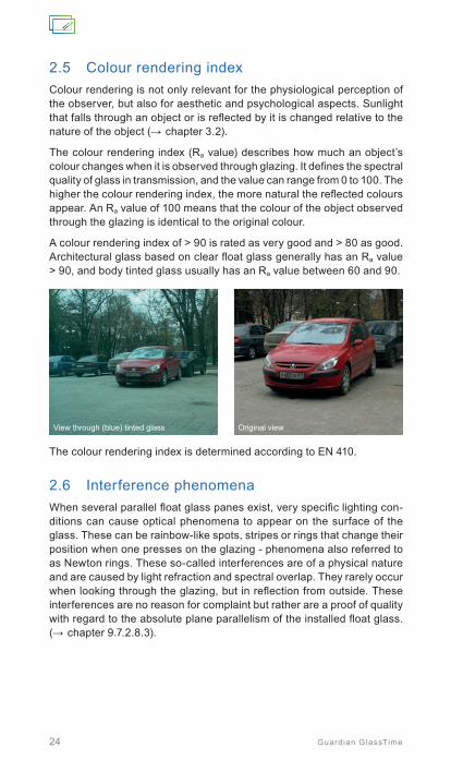
2.5 Colour rendering indexColour rendering is not only relevant for the physiological perception of the observer, but also for aesthetic and psychological aspects. Sunlight that falls through an object or is refl ected by it is changed relative to the nature of the object (→ chapter 3.2).
The colour rendering index (Ra value) describes how much an object’s colour changes when it is observed through glazing. It defi nes the spectral quality of glass in transmission, and the value can range from 0 to 100. The higher the colour rendering index, the more natural the refl ected colours appear. An Ra value of 100 means that the colour of the object observed through the glazing is identical to the original colour.
A colour rendering index of > 90 is rated as very good and > 80 as good. Architectural glass based on clear fl oat glass generally has an Ra value > 90, and body tinted glass usually has an Ra value between 60 and 90.
View through (blue) tinted glass Original view
The colour rendering index is determined according to EN 410.
2.6 Interference phenomenaWhen several parallel fl oat glass panes exist, very specifi c lighting con-ditions can cause optical phenomena to appear on the surface of the glass. These can be rainbow-like spots, stripes or rings that change their position when one presses on the glazing - phenomena also referred to as Newton rings. These so-called interferences are of a physical nature and are caused by light refraction and spectral overlap. They rarely occur when looking through the glazing, but in refl ection from outside. These interferences are no reason for complaint but rather are a proof of quality with regard to the absolute plane parallelism of the installed fl oat glass. (→ chapter 9.7.2.8.3).

Insulating glass
25Guardian GlassTime
2.7 Insulating glass effect – climatic loadsA component of every insulating glass is at least one hermetically enclosed space: the interspace. Since this space is filled with air or gas, the panes react like membranes that bulge in and out in reaction to varying air pres-sure in the surrounding air.
Under extreme weather conditions, unavoidable distortions may appear, despite the plane-parallel glazing. This can also occur due to extreme changes in air pressure, and influencing factors include the size and geo-metry of the pane of glass, the width of the interspace, and the structure of the pane of glass itself. With triple insulating glazing, the middle pane remains nearly flat, which is why the impact on both outer panes is stronger than on double insulating glazing. The two gaps of the triple glazing have the same effect as one large gap of the same overall thickness. These deformations disappear without effect once the air pressure normalises and, far from representing a defect, are an indication of the edge seal density (→ chapter 9.7.2.8.4).
Windforce /pressure
Excess pressure
Deformation
Outside Inside
Deformation
Lowpressure
Insulating glass effect
2
Insu
lati
ng
glas
s

Le Cristallin, Boulogne-Billancourt, FranceSunGuard® HD Silver 70 | Ventilated system, coating on impact paneArchitect: AZC – Atelier Zündel Cristea | Photo: © Sergio Grazia

Insulating glass
27Guardian GlassTime
The deflections caused by high pressure differences (climatic loads) can lead to high mechanical loads on the glass panes of the insulating glass unit but also in the spacer area. Particularly critical are asymmetrical build ups where the thinner glass deflects more than thick or laminated glass and small units where the glass can’t follow the volume change of the filling gas.
.Normal gap Large gap Two gaps
Guardian recommends a climatic load analysis for triple glazing with wide gaps, unfavourable dimensions and asymmetrical build-ups.
In case of critical load scenarios, the glass should be heat-treated. It is also advisable to check the sealant depth in order to ensure the necessary mechanical strength of the secondary edge seal of the insulating glass unit.
Asymmetrical glazings
2
Insu
lati
ng
glas
s

Oliphant, Amsterdam, Netherlands | SunGuard® SNX 50Architect: OZ Architect | Photo: © Georges De Kinder

29Guardian GlassTime
3. Light, energy and heat .........................................30
3.1 Solar energy ......................................................................30
3.2 Visible light ........................................................................32
3.3 Heat ...................................................................................32
3.4 UV radiation .......................................................................32
3
Ligh
t, e
ner
gy a
nd
hea
t

30 Guardian GlassTime
The physical definitions of light, energy and heat describe defined areas of the electromagnetic spectrum.
The area relevant to architectural glass in connection with light and solar energy falls within a 300 - 2 500 nm (0.0003 mm - 0.0025 mm) wave-length range and is considered as short-wave radiation. Heat is long wave radiation and related to a wave length range between 5 000 and 50 000 nm (0.005 – 0.05 mm).
Longer wavelengths are referred to as radar, micro and radio waves, while shorter wavelengths are known as high energy X-ray and gamma radiation.
Wavelength◄Longer
◄Lower
RADIO WAVES
AMradio
Footballfield
House Tennis ball
A Period Cell Bacteria Virus Protein Water molecule
FMradio
Microwaveoven
Radar People Light bulb
Advanced lightsource
X-Ray machines
Radioactiveelements
MICROWAVES
INFRARED
ULTRAVIOLETT
HARD X-RAYS
GAMMA RAYS
SOFT X-RAYS
103
10-9
106
101
10-7
108
10-1
10-5
1010
10-3
10-3
1012
10-5
10-1
1014
102
10-8
107
1
10-6
109
10-2
10-4
1011
10-4
10-2
1013
10-6
1
1015
10-7
101
1016
10-9
103
1018
10-11
105
1020
10-8
102
1017
10-10
104
1019
10-12
106
Shorter►
Higher►
Relevant for buildings
VISIBLE
Sources
Frequency(waves
per second)Energy of
one photon(electron
volts)
Size of a wavelength
Common name of
wavelength
Heat Solar energy
VIS
The electromagnetic spectrum
3.1 Solar energyThe radiation emitted by the sun that strikes the Earth is called solar energy. This wavelength range has been defined through international standardisation (EN 410) as ranging from 300 to 2 500 nm and includes:
• Ultra violet (UV) radiation 300 … 380 nm
• Visible light (VIS) radiation 380 … 780 nm
• Near infrared (IR) radiation 780 … 2 500 nm
Solar energy is considered to be in the short-wave range.

Light, energy and heat
31Guardian GlassTime
The worldwide-accredited global radiation distribution curve (acc. to C.I.E., Publication No. 20) shows the intensity of total solar radiation in its respective wave ranges. 52 per cent of these wavelengths are visible and 48 per cent are invisible.
The shorter the wave length, the more energy is transported. This means that there is a considerable quantity of energy in the visible portion of the radiation. Therefore, light and energy cannot be separated from each other. This is a critical aspect in using and improving architectural glass.
Important properties that are critical for characterising the nature of archi-tectural glass such as solar energy transmission, reflection and absorption, and total energy transmittance, can be derived from the solar energy in the global radiation wavelength range (300 - 2 500 nm) and its interactions with glass (→ chapter 5).
Total radiation100 %
Rel
ativ
e ra
diat
ion
inte
nsity
[%]
Rel
ativ
e se
nsiti
vity
of t
he n
aked
eye
[%]
Visible55 %
300 500 700
Thermal insulating glass Sensitivity of the human eye
Conventional insulating glass Solar spectrum
900 1100 1300 1500 1700 1900 2100 2300 2500
Heat41 %
UV4 %
100
90
80
70
60
50
40
30
20
10
0
100
90
80
70
60
50
40
30
20
10
0
Thermal insulating glass
Conventional insulating glass
Visible radiation 75 % 79 %
Heat radiation 30 % 66 %
Total radiation 54 % 73 %
Permeability of thermal insulating glass and conv. insulating glass, based on the intensity distribution of the solar spectrum. Energy distribution acc. to DIN EN 410 (Air Mass 1.0)
Global radiation distribution curve (C.I.E., Publication No.20)
3
Ligh
t, e
ner
gy a
nd
hea
t

32 Guardian GlassTime
3.2 Visible lightThe small area of the solar spectrum that can be seen by the human eye is called (visible) light. The spectral range is defined by the European standard EN 410 as between 380 nm and 780 nm.
Unbroken (visible) light hitting the human eye is perceived as white light. It is, however, composed of a light spectrum where the various wavelengths – each representing a defined energy – flow into each other:
When light hits an object, the object absorbs part of the energy spectrum. Glass, however, transmits light, reflecting the rest of the energy. Depending on the nature of the object, certain wavelengths are reflected and others absorbed. The human eye perceives the reflected colour as being the colour of the object.
Artificial lighting can result in colour misinterpretation due to missing wavelength ranges. A well-known example is low-pressure sodium vapour lamps. Since they lack blue, green and red wavelengths, everything ap-pears in monochromatic yellow tones.
3.3 HeatHeat or heat radiation are a wavelength range that is not part of the solar spectrum. Heat radiation has far longer wavelengths and is to be found in the far infrared range. The spectral range is defined in the European standard EN 673 as between 5 000 and 50 000 nm.
Its interaction with heat defines the insulation characteristics of architectural glass and is influenced by heat radiation, heat conduction and convection. The Ug value – heat transmission coefficient – is the fundamental char-acteristic for evaluating the glass construction material’s heat insulation capability (→ chapter 4).
3.4 UV radiationUV is high-energy radiation and is separated into three ranges:
UV-C: 100 … 280 nm (blocked by the ozone layer of the atmosphere.UV-B: 280 … 315 nm (blocked by float glass products).UV-A: 315 … 380 nm (transmitted through glazing to a certain degree).
Colour Wavelength [nm]
Violet 380-420
Blue 420-490
Green 490-575
Yellow 575-585
Orange 585-650
Red 650-780

Light, energy and heat
33Guardian GlassTime
Stratosphere with ozone layerUV-AUV-B
UV-CTroposphere
If the UV impact is too strong, this radiation has not only a harmful impact on the skin but also on many other organic materials (paintings, furniture, sealants, etc.). Normal insulating glass with two glass panes reduces the UV transmission by more than 50 %, and when combined with laminated safety glass (→ chapter 7.4), the radiation is almost completely fi ltered out.
Glazing UV transmission ISO 9050 [%]
2 x 4 mm glass 43
2 x 4 mm glass + 0.38 mm PVB 2.4
2 x 4 mm glass + 0.76 mm PVB 0.5
2 x 4 mm glass + 1.14 mm PVB 0.07
2 x 4 mm glass + 1.52 mm PVB 0.02
Laminated glass with PVB interlayer is able to block UV radiation
Wave length [nm]
Tran
smis
sion
[%]
UV-B UV-A100
90
80
70
60
50
40
30
20
10
0
280 290 300 330 370310 350 380320 360 390 400
2 x 4 mm glass2 x 4 mm glass + 0.38 mm PVB2 x 4 mm glass + 0.76 mm PVB
2 x 4 mm glass + 1.14 mm PVB2 x 4 mm glass + 1.52 mm PVB
3
Ligh
t, e
ner
gy a
nd
hea
t

Alpine Shelter, Skuta, Slovenia | SunGuard® SN 70/37Architect: OFIS architects | Photo: © Anže Cokl

35Guardian GlassTime
4. Thermal insulation ................................................. 36
4.1 Economy ........................................................................... 36
4.2 Ecology ..............................................................................37
4.3 Comfort ..............................................................................37
4.4 Heat loss ........................................................................... 38
4.5 Emissivity ............................................................................. 40
4.6 U value .................................................................................. 404.6.1 Ug value ...............................................................................40
Ug value for inclined glass surfaces
4.6.2 Uf value ................................................................................414.6.3 Ψ value ................................................................................424.6.4 UW value ..............................................................................42
4.7 Guardian product range for thermal insulation .................42 4
Ther
mal
insu
lati
on

36 Guardian GlassTime
Saving energy remains a hot topic worldwide and the thermal insulation of building envelopes is an important part of contemporary architecture. Yet advances in glass transparency, an architectural achievement during the last three decades, should not be held back in favour of energy saving. “Transparent insulation” was specifically developed and designed to offer not only unique economic and environmental benefits, but also to guarantee both comfort and convenience for building’s occupants.
4.1 EconomyTechnological advances during the last 30 years have produced systems and equipment that can coat glass with razor-thin, neutral high-tech coat-ings. This made “ɛ” emissivity values of thermal insulating glass possible to as low as 0.02 and even lower, whereas for uncoated float glass, ɛ is 0.89.
However, from an economic perspective, this development and its ap-plication in new buildings is just the first step. The next step should be to integrate this new glass technology into the millions of square metres of glazed areas of new and existing windows and façades. This process is almost an automatic one for new buildings today. But existing buildings represent a much greater challenge, and a lot of work must be done in terms of education, explanation and persuasion so that ecological, eco-nomic and climate goals can be achieved.
In times of steadily increasing heating energy costs this economic benefit represents a persuasive argument. Just making a simple change, such as glazing involves a fairly short amortisation period and also offers the occupants remarkable improvements in convenience and comfort (→ chapter 4.3).
The following formula offers one possibility for estimating the energy savings potential provided when replacing outdated glass with modern thermal insulated glazing:
E = (Ua - Un) · F · G · 1.19 · 24
H · W=
l
HP
E SavingsUa U value of your existing glazingUn U value of your future glazingF (Glazing area in m²)G Heating degree day number pursuant to VDI 47101.19 Conversion of kilogrammes to litres: 1 kg = 1.19 litre fuel oilH Heat value of fuel: light fuel oil at approx. 11.8 kWh/kgW Heating system efficiency: oil heater at a 0.85 I LitreHP Heating season

37
Thermal insulation
Guardian GlassTime
4.2 EcologyEvery litre of fuel oil or cubic metre of natural gas that can be saved through using advanced glazing reduces CO2 emissions and benefits the environ-ment. Fossil fuel resources are also saved by reducing their consumption and in addition, almost all glass types are one hundred percent recyclable because it is made from natural raw materials. Due to its natural ingredients and superior energy balancing properties, glass should not be overlooked or dismissed as a viable material in globally recognised certification pro-grams for sustainable and environmentally friendly building.
Leadership in Energy and Environmental Design (LEED) is a leading system in this field. Other systems, include DGNB or BREEAM. Buildings realised in compliance with these systems use resources more efficiently than conventional techniques because they take every phase in the life cycle of a building into account – starting with design and construction to renovation and eventually, demolition and disposal.
4.3 ComfortAside from its economic and ecological aspects, another important goal of building with glass is the tangible improvements in the living and working environments. Coated float glass installed in insulated glass (→ chapter 5.3) increases the glazing’s room-side surface temperature, thus minimis-ing unpleasant air flows considerably in areas where glazing is present.
Outside air temperature [°C]
Glass type 0 -5 -11 -14
Single-pane glass, Ug = 5,8 W/m2K +6 +2 -2 -4
2-pane insulated glass, Ug = 3,0 W/m2K +12 +11 +8 +7
2-pane coated insulating glass, Ug = 1,1 W/m2K +17 +16 +15 +15
3-pane coated insulating glass, Ug = 0,7 W/m2K +18 +18 +17 +17
Surface temperature at 20 °C room temperature [°C]
State-of-the-art thermal insulating glass increases this temperature to a near-room temperature levels and significantly improves the comfort level of a home. The decisive factor in comfort is the temperature difference between ambient air and the adjacent wall and window surfaces. Most people find a room to be particularly comfortable when the temperature differences between wall (glass) and room air is no higher than 5 °C and between foot and head height not higher than 3 °C.
4
Ther
mal
insu
lati
on
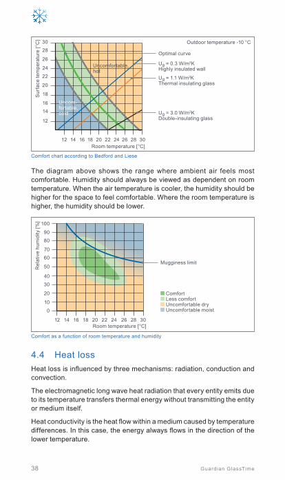
38 Guardian GlassTime
12
1416
18
20
2224
26
2830
12 14 16 18 20 22 24 26 28 30
Sur
face
tem
pera
ture
[°C
]
Room temperature [°C]
Uncomfortable, hot
Uncom-fortable, cold
Ug = 0.3 W/m2K Highly insulated wall
Outdoor temperature -10 °C
Ug = 1.1 W/m2K Thermal insulating glass
Ug = 3.0 W/m2K Double-insulating glass
Optimal curve
Comfort chart according to Bedford and Liese
The diagram above shows the range where ambient air feels most comfortable. Humidity should always be viewed as dependent on room temperature. When the air temperature is cooler, the humidity should be higher for the space to feel comfortable. Where the room temperature is higher, the humidity should be lower.
10
0
20
3040
50
6070
8090
100
12 14 16 18 20 22 24 26 28 30
Rel
ativ
e hu
mid
ity [%
]
Room temperature [°C]
Mugginess limit
Comfort Less comfort Uncomfortable dry Uncomfortable moist
Comfort as a function of room temperature and humidity
4.4 Heat lossHeat loss is influenced by three mechanisms: radiation, conduction and convection.
The electromagnetic long wave heat radiation that every entity emits due to its temperature transfers thermal energy without transmitting the entity or medium itself.
Heat conductivity is the heat flow within a medium caused by temperature differences. In this case, the energy always flows in the direction of the lower temperature.

39
Thermal insulation
Guardian GlassTime
Convection is a fl ow of gas particles in the interspace due to the difference in temperature between the inner and outer panes of insulating glass. The particles drop onto the colder surface and rise again on the warmer side. Consequently, the gas circulates, creating a heat fl ow from warm to cold.
Insulating glass consisting of just two uncoated panes of fl oat glass and with air fi lling the interspace loses around two-thirds of the heat that the room would otherwise have due to the radiation loss between the two panes, and a third due to heat conductivity and heat convection to the outside air.
Invisible thermal insulating coatingHeat radiation(2/3 of heat transmission in conventional double insulating glass)
Heat conduction(together 1/3 of heat transmission inconventional double insulating glass)
Convection1. Heat transmission based on radiation can be almost eliminated by a coating (up to 98 %)2. Filling insulation glass with argon reduces conduction3. Convention can be reduced by optimisation of the gas space
Heat loss in a double insulating glass
In the case of older insulating glass units without coatings, this results in an extreme difference in temperature between the inner pane and the warmer room air in the cooler seasons of the year, resulting in a signifi cant loss of heat due to the heat transfer from the inner pane to the outer pane. Most of today’s insulating glass consists of a minimum of one fl oat glass pane equipped with a low-E coating. These coatings can have emissivity values of less than 0.02 (2 %) and refl ect more than 98 % of incident long wave heat radiation, so that radiation loss is almost completely eliminated. This represents an improvement of approx. 66 % compared to insulating glass units without coatings. Heat conductivity and convection are not affected by coatings. However, the heat conductivity can be reduced by using an inert gas such as argon. Inert gases have signifi cantly lower heat conductivity than air, thereby reducing the heat fl owing through the insulating glass system. The convection is minimised at a certain gas space, depending on the fi lling gas. For example, this is approx. 16 mm in the case of air, 15 - 18 mm for argon and 10 - 12 mm for krypton.
4
Ther
mal
insu
lati
on

40 Guardian GlassTime
4.5 EmissivityAccording to EN 12898, emissivity is the ratio of the energy emitted by a given surface at a given temperature to that of a perfect emitter (i.e. a black body with normal and corrected emissivity of 1.0) at the same temperature.
In practice, the corrected emissivity is used for describing the radiation exchange between glass surfaces facing each other in multiple glazing and glass surfaces facing a room.
The normal emissivity εn is determined by measuring the normal spectral reflectance Rn with photospectrometers in 30 steps within the range of long wave infra-red (IR) radiation of λ = 5 and 50 μm according to the following equation:
Rn = Rn (λi)1
30∑i = 30
i = 1
The normal emissivity is given by:
εn = 1 - Rn
In order to determine the corrected emissivity ε for float glass and coated float glass – used for calculating the Ug value of glazing – the normal emissivity εn is multiplied with a ratio given in the EN 12898 standard. The corrected emissivity of float glass is 0.837 (EN 673).
4.6 U value – heat transmission coefficient This value characterises the heat loss through a component. It indicates how much heat passes through 1 m² of a component when there is a tem-perature difference of 1 K between the two adjacent sides – for example, between a room and an outside wall. The smaller this value, the better the heat insulation.
The U value is given in Watts per square metre Kelvin [W/(m²K)].
According to EN 673, the spectral range of the concerned heat radiation is long wave infrared between 5 000 and 50 000 nm (5 ... 50 μm).
Please note that the European U values are different from American values. This must be taken into account when making international comparisons.
4.6.1 Ug value
The Ug value is the heat transmission coefficient for glazing. According to the European standard EN 673, this characterises the heat transfer through the central part of the glazing, i.e. without edge effects, and states the steady-state density of heat transfer rate per temperature difference between the environmental temperatures on each side.

45° I U
g = 1
.5 W/m
2 K90
° I U
g = 1.
1 W
/m2 K
0° I Ug = 1.7 W/m2K
Mounting position
Mounting angle
Ug
[W/m2K]
Vertical 90 ° 1.1
Inclined 45 ° 1.5
Overhead 0 ° 1.7
Effect of the mounting position of the glazing Ug value
41
Thermal insulation
Guardian GlassTime
It can be calculated according to EN 673 or determined by measurement according to EN 674 (guarded hot plate method) under standardised boundary conditions. Four factors determine this value: the emissivity of the coating, which is determined and published by the producer of the coated glass; the distance of the gas space between the panes; the fi lling gas and the fi lling rate when using inert gases.
(To fi nd the rated value for real life usage, national aggregates need to be considered – DIN 41408-4 applies in Germany).
4.6.1.1 Ug value for inclined glass surfaces
The Ug value that is most often de-fi ned and published refers to glazing that is vertically (90°) installed. Glaz-ing installed at an angle changes the convection in the interspace and deteriorates the Ug value. The smaller the angle of the glazing, the more rapid the circulation in the interspace and the higher the heat transmission from the inner to the outer pane. This can worsen the Ug
value by up to 0.6 W/m²K for double insulating glass.
4.6.2 Uf value
The Uf value is the heat transmission coeffi cient of the frame, the nominal value of which can be determined in three different ways:
• Measuring according to EN ISO 12412-2• Calculating according to EN ISO 10077-2• Using the EN ISO 10077-1 defi nition, appendix D
The nominal value, as well as additions due to national regulations deter-mine the rated value for real-life usage.
4
Ther
mal
insu
lati
on

42 Guardian GlassTime
4.6.3 Ψ value
The Ψ value (Psi value) is the linear thermal bridge loss coefficient for a component. With regard to windows, it describes the interaction of insulating glass, dimensions, spacer and frame material and defines the component’s thermal bridges. The Ψ value can be influenced by the spacer bar material. So-called warm edge technologies using stainless steel, metal-plastic combinations or thermoplastic systems can reduce Ψ significantly. Insulating glass itself has no Ψ value, as this only applies to the construction element into which it is integrated.
4.6.4 UW value
Insulating glass is normally used in windows. The Uw value describes the heat conductivity of the construction element window. Based on the Ug
value, it can be determined using three different methods:
• Using a given value in EN ISO 10077-1, Tab. F1• By measuring in accordance with EN ISO 12567-1• By calculating in accordance with EN ISO 10077-1
as per the following formula:
Uw: Thermal transmittance of the windowUf: Thermal transmittance of the frame (assessment value)Ug: Thermal transmittance of the glazing (nominal value)Af: Frame surfaceAg: Glass surfacelg: Periphery of the glazingΨ: Linear thermal transmittance of the glass edge
Uw = Af . Uf + Ag . Ug + ∑(lg . Ψ)
Af + Ag
The heat loss in the edge zone is more important than the middle of the glazing, which is why thermally improved spacers are becoming increas-ingly important.
4.7 Guardian product range for thermal insulationGuardian provides a broad range of state-of-the-art thermal insulation layers normally applied to ExtraClear® float glass, which enable the reali-sation of a range of modern thermal insulation glasses by our customers.
The following are available in terms of thermal insulating glass:
• ClimaGuard® Premium2 Today’s Guardian’s standard thermal insulating glass product in
modern double and triple glazing. This insulating glass offers excellent thermal insulation and the best light and solar efficiency. In a standard double insulating glass unit filled with argon, ClimaGuard Premium2 provides a Ug value of 1.1 W/m²K, up to 0.5 W/m²K in triple glazing, combined with high transparency for maximising natural daylight and high solar heat gain for passive solar energy. With ClimaGuard Premium2 T, Guardian offers a heat treatable and bendable version.

43
Thermal insulation
Guardian GlassTime
• ClimaGuard® 1.0+ With a Ug value of 1.0 W/m²K for an argon-filled double insulated
glazing ClimaGuard 1.0+ offers the physical maximum in terms of thermal insulation, but without using the expensive krypton gas filling. With ClimaGuard 1.0+ T a heat treatable and bendable version is available.
• Guardian Sun®
(where appropriate based on climate) A product optimised for the change of seasons. Possesses excellent
thermal insulation during cold weather and excellent solar protection for the summer months. Guardian Sun T is a heat treatable version.
• ClimaGuard® Neutral 70 (where appropriate based on climate and / or construction norms) This durable product has low processing requirements and was
developed primarily for regions where not only ease of handling is important, but also where heat and solar protection are critical. ClimaGuard Neutral 70 can be heat treated and bent.
• ClimaGuard® Dry ClimaGuard Dry is a coating specially designed for surface #1
(outside) which permanently minimises condensation (anti-fog coating) on the outer surface of highly insulated (triple) glazing (→ chapter 2.4.3), or on the inside of the monolithic outer pane of ventilated systems → chapter 8.1.1.3.4). The photo-spectrometric values are hardly affected.
The coating has to be heat treated in order to become activated.
Please see chapter 10 for details on all products and their relevant values.
4
Ther
mal
insu
lati
on

Novartis Gehry Building, Basel, Switzerland | SunGuard® HP Neutral 60/40Architect: Gehry Partners LLP | Photo: © Hans Ege

45Guardian GlassTime
5. Solar control ................................ ................................46
5.1 Economy ................................ .............................................46
5.2 Ecology ................................ ...............................................46
5.3 Comfort ................................ ...............................................46
5.4 Solar energy flow through glass ................................ .........47
5.5 Solar factor (g value) ................................ ..........................47
5.6 Shading coefficient (b factor) ................................ .............48
5.7 Spectral selectivity ................................ .............................48
5.8 Heat gain control in summer ................................ ..............49
5.9 Sun protection using glass ................................ .................50
5.10 Solar control glass as design component ......................... 51
5.11 SunGuard® solar control glass ................................ ...........52
5
Sola
r co
ntr
olSo
lar
con
trol

46 Guardian GlassTime
Modern architecture today is characterised by spaciousness and transpar-ency. Ever larger glass elements for the outer building envelope appear to merge the exterior with the interior. This is reflected worldwide in office and administration buildings of the last two decades, but also in private housing that includes atriums, gables and winter garden glazing using increasingly large glass components. This style of construction only became feasible with the advent of solar protection glass. These types of glass reduce the greenhouse effect that occurs primarily in the summer months due to the rooms heating up to the point at which they become unpleasant to be in.
5.1 EconomyLarge window and façade surfaces allow plenty of light to penetrate deep into a building’s interior, thereby avoiding excessive use of artificial lighting. Despite this light penetration, one decisive benefit of using sun protec-tion glass is the huge number of options now available for minimising the amount of heat energy that penetrates a building, limiting the significant costs associated with air conditioning, as it costs much more to cool the interior of a building than to heat it.
5.2 EcologyWherever energy is saved – whether by reducing the amount of cooling power used or artificial lighting - the environment also benefits as a result. ln this context, it is a logical consequence that these types of sun protection glass products help certifying buildings according to, for example, LEED, BREEAM, DGNB or other worldwide-approved certification systems for sustainable construction. (→ chapter 4.2).
5.3 ComfortSuper-cooled interiors and over-heated rooms are both uncomfortable environments to be in. When rooms become overheated, it can be due to too much incoming solar energy (→ chapter 4.3). The floor, walls and furniture absorb solar energy and reflect it as long-wave heat radiation. For this reason, every effort should be made to keep this energy outside interior rooms to achieve an acceptable room climate – without air con-ditioning. This was previously achieved by constructing buildings using opaque building components that only had small openings in the walls.
Today‘s architecture, which strives to create living and working environ-ments that are closer to nature with an open and spacious feel, has shifted away from this opaque manner of construction towards transparency. Therefore, it is essential to understand the significant parameters involved in sun protection using glass in order to create a functional and comfortable interior, while also meeting other requirements such as building physical specifications and achieving energy efficiency.

47
Solar control
Guardian GlassTime
5.4 Solar energy flow through glassAn interaction occurs whenever solar radiation strikes a window: one part of the radiation is refl ected back into the environment; another part is al-lowed to pass through unhindered, and the rest is absorbed. The sum of all three parts is always 100 %:
transmission + refl ection + absorption = 100 %
re
τe
qin
qout
Secondary heat coeffi cient inside (re-radiated)
Secondary heat coeffi cient outside (re-radiated)
Transmission AbsorptionRefl ection
Solar factor (g value)
Direct energy transmission
Direct energy refl ection outside
Solar energy = τe + re + qout + qin
Solar performance of glass
5.5 Solar factor (g value)The total energy transmittance degree (solar factor or g value) defi nes the permeability of insulating glass to solar radiation. Solar protection glass minimises the g value through the appropriate selection of glass and coat-ings. The g value of transparent thermal insulating glass is preferably high in order to use the passive solar energy gains for reducing heating costs during the cold seasons.
The solar factor (g) is calculated by adding the direct solar energy transmis-sion (short wave radiation) τe and the re-radiated long wave radiation to the interior (caused by solar energy absorption) qin according to EN 410 (2011).
g = τe + qin
5
Sola
r co
ntr
ol
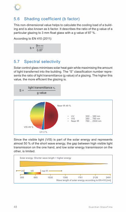
48 Guardian GlassTime
5.6 Shading coefficient (b factor)This non-dimensional value helps to calculate the cooling load of a build-ing and is also known as b factor. It describes the ratio of the g value of a particular glazing to 3 mm float glass with a g value of 87 %.
According to EN 410 (2011):
b =0.87
gEN 410
5.7 Spectral selectivitySolar control glass minimises solar heat gain while maximising the amount of light transferred into the building. The “S” classification number repre-sents the ratio of light transmittance (g value) of a glazing. The higher this value, the more efficient the glazing is.
S =g value
light transmittance τv
VIS 49 %
Near IR 49 %
UV 2 %
• UV 300 ... 380 nm• VIS 380 ... 780 nm• Near IR 780 ... 2500 nm
Since the visible light (VIS) is part of the solar energy and represents almost 50 % of the short wave energy, the gap between high visible light transmission on the one hand, and low solar energy transmission on the other, is limited.
UV VIS near IR
Solar energy: Shorter wave length = higher energy
Wave length of solar energy according to EN 410 [nm]300 665 1030 1395 1761 2126 2491

49
Solar control
Guardian GlassTime
The latest generation of solar control glass from Guardian, SunGuard SNX, already exceeds a ratio of 2:1, which has long been considered the maximum possible value.
UV VIS near IR
Spectral selectivity of various solar control glass types (light transmission approx. 60 %)
Tran
smis
sion
[%]
Wavelength [nm]
Visible light windowSunGuard HD Neutral 67SunGuard HP Neutral 60/40SunGuard SN 63SunGuard SNX 60
HD: no AgHP: 1 Ag layerSN: 2 Ag layerSNX: 3 Ag layer
300
1009080706050403020100
665 1030 1395 1761 2126 2491
5.8 Heat gain control in summerModern insulated glass allows short-wave solar radiation to pass through without hindrance, but the majority of long-wave heat radiation is refl ected back to the interior. This results in solar heat gain in the cold seasons. ln summer, however, this solar radiation can result in overheating.
In addition to other energy sources (see fi gure below), the position and size of the glazing are critical. In general, windows or façades with large glazed areas that face East, West and particularly the South, should be equipped with suitable sun protection glazing.
HT
HV
Qs
Qs QsQw
Qc Qi
Qh
HT
HT
HT Transmission heat lossHV Ventilation heat lossQw Energy demand for hot waterQh Heating demandQc Cooling demand
Qs Solar heat gainsQi Internal heat gains (e.g. people, electrical equipment)
Heat losses and energy gains
Specifi c requirements need to be met to prevent overheating that can result from large glass surfaces, starting with the solar input factor S.
In general, the following rule applies according to DIN 4108:
Sexisting ≤ Sadmissable
5
Sola
r co
ntr
ol

50 Guardian GlassTime
The admissible solar input factor results from the proportional input factors.
Sadmissable = S1 + S2 + S3 + S4 + S5 + S6
The proportional input factors depend on:
• S1: Utilisation of the building (residential/commercial, climate zone, type of construction, night cooling) – see DIN 4108-2, table 8
• S2: Percentage of window area• S3: Solar control glass• S4: Glazing slope• S5: Glazing orientation• S6: Passive building cooling
The existing solar input factor results from the following equation:
AW,j: Glazed area in m²AG: Ground area of the room in m²gtot,j: (Total) solar factor including mechanical shading: - EN ISO 52022-1 - EN ISO 52022-2 - Based on EN 410 - Manufacturer statements
Sexisting = AG
∑ Aw,j . gtot,jj
Determination of gtot is carried out using the following equation:
g: Solar factor of the glazingFC: Reduction ratio for shading devicesgtot = g . Fc
The generalised reduction ratio FC for fixed installed shading systems can be taken from DIN 4108-2, table 7.
A detailed method for the determination of gtot is available according to EN ISO 52022-2. This method considers the specific physical properties and the interactions of a defined shading and a defined glazing. The calcula-tions are to be carried out using special software tools.
The Guardian Technical Advisory Centre can support with related calcula-tions on request.
5.9 Sun protection using glassEarly production of solar protection glass was based on coloured glass compounds. Compared to clear glass, coloured glass increases solar radiation absorption, but it also has a significant effect on the transmitted visible light. As monolithic glass, it reduces the transfer of energy to ap-prox. 60 %, and in an insulating glass unit, combined with a normal pane of clear float glass, it reduces the solar energy transmission to approx. 50 % when the coloured glass thickness is 6 mm. The thicker the glass, the higher the energy absorption and the lower the transmission. Green, grey and bronze-coloured glass is most frequently used.

51
Solar control
Guardian GlassTime
Due to their own inherent colouring, they can significantly change the way interior colours are perceived. Advances in glass coating technology have produced a much broader range of colours that are also much more neutral in terms of the effect they have on interior colours.
Today’s sun protection glazing is based on coated glass rather than on coloured glass and is produced using the magnetron-sputter process (→ chapter 1.3.2). The multitude of coating varieties available can be used to meet the requirements of every application. Guardian is focused on this coating technology and developing new glass for a wide variety of project requirements.
In addition to actual solar protection, which is constantly being refined, a great deal of research and development effort is invested in optimising storage life, processing and resistance to mechanical influences. Another typical requirement with regard to coatings is to supply versions that can be laminated, tempered and bent. Only through providing these options and parameters can the broad spectrum of modern architectural require-ments be properly addressed.
Sun protection coatings are normally used on the outer pane and oriented towards the interspace (insulating glass position #2). A 6 mm-thick outer pane is standard. A thinner counter pane prevents optical distortion caused by climatic pressure changes (→ chapter 2.7). lf the interspace is wider than 16 mm due to fixtures in the interspace or for sound damping purposes, this effect should be considered during planning. Static requirements often demand thicker glass.
5.10 Solar control glass as design element The trend today is towards design-oriented façades, which require new designs in solar control glass.
Glass with low outside reflection can be manufactured, depending on the coating used. Glass façades can be built to neutralise the visible borders between inside and outside, yet remain energy efficient. On the other hand, there are mirroring or colour-reflecting coatings that allow for some architectural freedom, including the realisation of unconventional design concepts. Colour matching balustrades, for example, enlarge the range of solar control glass (→ chapter 8.2.2).
Such creative and additive glass design is generally project-related and feasible once the physical construction rules have been taken into account. Digital or screen print techniques are available, along with laminated safety glass. Please refer to chapter 8.3 for more information.
5
Sola
r co
ntr
ol

5.11 SunGuard solar control glass Regardless of what the building’s architectural or building physical require-ments are, the broad SunGuard® glass range can provide an optimum transparent solution.
• SunGuard® eXtra Selective (SNX) SunGuard® SNX offers an outstanding symbiosis of transparency,
thermal insulation and solar protection. The focus is on extremely high selectivity – the ratio of light to solar energy transmission. The term “SNX” stands for the latest generation of solar control coatings with a spectral selectivity greater than 2. All technical values are close to physical feasibility. With “SNX-HT”, heat treatable and bendable versions are also available.
Elbphilharmonie Hamburg, Hamburg, Germany SunGuard® HD Light Blue 52 | 3-dimensional gravity curved, ceramically printed, laminated insulating glassArchitect: Herzog & De Meuron, Basel | Photo: © Cordelia Ewerth

53
Solar control
Guardian GlassTime
• SunGuard® SuperNeutral® (SN) In addition to high spectral selectivity, the most important feature
of this product line based on ExtraClear® float glass, is its neutral appearance combined with minimal reflection. In double insulating glass, Ug values as low as 1.0 W/(m2K) are achieved with different light transmission values.
All SunGuard® SuperNeutral® types are available as “SN-HT”, a heat treatable and bendable version.
• SunGuard® High Performance (HP) SunGuard® HP is a product line of selective multi-functional coatings
with a broad variety of colours and reflection grades. All of this glass can be tempered, bent and printed using a ceramic process.
Due to the durability of the coatings, many SunGuard® HP variants are compatible with a broad range of sealants for standard insulating glass applications. In a double-glazed insulating glass unit, Ug values lie between 1.5 and 1.1 W/(m²K) without additional thermal insulation as a counterpane, τL values are between 60 and 30 % and g values between approx. 50 - 20 %, depending on the colour intensity and reflection grade.
• SunGuard® High Durable (HD) Providing the highest flexibility for use and processing, SunGuard®
HD is the series of pure solar control coatings. The whole spectrum of every conceivable process, including laminating, tempering or bending, can be realised using SunGuard® HD glass. It withstands almost all glazing materials and sealants. In double insulating glass and with a counter pane of ClimaGuard® Premium2, the SunGuard® HD series provides a Ug value of 1.1 W/(m2K) with τL values of ap-prox. 10 to 64 % and g values of < 10 up to approx. 50 %.
The high durability allows the SunGuard® HD range for monolithic applications (facing the interior side of the construction).
• SunGuard® Solar With SunGuard® Solar, Guardian provides pure solar protection glass
with a range of special colours. These coatings can be heat treated, bent or printed with ceramic paint.
Please see chapter 10 for details on all products and their relevant values.
5
Sola
r co
ntr
ol

InterContinental Ljubljana, Ljubljana, Slovenia | SunGuard® SN 70/35Architect: OFIS architects | Photo: © OFIS Arhitekti d.o.o

55Guardian GlassTime
6. Sound control ........................................................... 56
6.1 Human aspects ................................................................ 56
6.2 Sound wave characteristics ............................................. 566.2.1 Limits ................................................................................. 566.2.2 Sound perception – Sound rating ............................................57
6.3 Sound ratings for buildings .............................................. 586.3.1 Average noise reduction factor .............................................. 586.3.2 Correction factors .................................................................59
6.4 Acoustic performance of glazing ..................................... 606.4.1 Weight of the pane ............................................................... 606.4.2 Insulating glass build up ........................................................616.4.3 Gas filling .............................................................................616.4.4 Stiffness of the glazing (decoupling of single glass
elements) .............................................................................62
6.5 Guardian sound control glass ...........................................63
6So
und
con
trol

56 Guardian GlassTime
6.1 Human aspectsIn the past few decades, our environment has become much louder as a result of mobility and industrialisation. This development has since become a severe problem for many people.
In 2011 the WHO (World Health Organization) published a study with the title “Burden of disease from environmental noise” with data based on various long-term (10-year period) large-scale investigations of envi-ronmental noise in Western Europe. The study reports about evidences on the relation between health effects and noise. These effects may include cardiovascular disease, cognitive impairment, sleep disturbances, tinnitus, annoyance…
6.2 Sound wave characteristicsNoise is a mixture of different sound waves that arise in solid compounds, liquids or gases (air). Depending on the way they are transmitted, these waves are known as airborne or structure-borne noise.
Airborne sound Structure-borne sound
6.2.1 Limits
Sound is normally transported through both air and solid objects. The intensity of pressure fl uctuations is called sound pressure, measured in Decibels (dB), and can vary signifi cantly from the ticking of a clock to the crack of a gunshot.
0 20 40 60 80 100 120 140 160 180Sound level dB(A)
Auditory threshold
Soft music Car
Hammer outSpeech Truck
Hearing impairment (long-term ex.) Pain threshold
Jet
Firecrackers
Gunshot
Decibel meter

57
Sound control
Guardian GlassTime
Sound source Distance app. [m] Sound level dB(A)
Rustling leaf 1 10
Clock ticking 1 20
Soft music 1 40
Normal speech 1 50 - 60
Car 7 80
Heavy truck 7 90
Jackhammer 7 90 - 100
Police siren 10 110
Jet 20 120 - 130
Hammer out 5 150
Firecrackers 0 170
Gunshot 0 180
Noise source and sound level
Frequency is the number of waves or vibrations per second and is meas-ured in Hertz (Hz). Sound or noise is composed of many waves of different frequencies. Deep tones represent low frequencies and high tones high frequencies.
Sou
nd p
ress
ure
[dB
]
Time [s]
Sou
nd p
ress
ure
[dB
]
Time [s]
Bass (low-pitched) tones Treble (high-pitched) tones
6.2.2 Sound perception – Sound rating
The mix of these frequencies in a sound can be represented as a frequency spectrum. The frequency spectrum of sounds that the human ear can hear falls between 20 and 20 000 Hz. Only the highest range, which lies at around 4 kHz and then dissipates rapidly in both directions, is relevant when it comes to protecting against structural noise. Sound insulation ratings, therefore, primarily take the range between 100 and 5 000 Hz into account. Moreover, as the human ear registers high frequencies more readily than low frequencies, appropriate consideration is taken of this auditory sensation, a capacity which is expressed in terms of dB(A), where “A” stands for adjusted in this respect. Defining sound reduction does not follow a linear path, but is a logarithmic function. For example, two sources of sound that are each 80 dB do not add up to 160 dB, but only to 83 dB. Therefore, the human ear registers a difference of ± 10 dB as a doubling or halving of the volume.
6So
und
con
trol

58 Guardian GlassTime
Generally, the following ratings apply based on a logarithmic correlation:
Rw = 10 log P1 / P2
P1: Incoming soundP2: Outgoing sound
Insulation Noise reduction [%]
10 dB 50
20 dB 75
30 dB 87.5
40 dB 93.75
Since a large percentage of sound insulating glass installed today is rated for 40 dB, this type of glass only permits around 6 % of external noise to penetrate to the inside of a building.
6.3 Sound ratings for buildingsA building component (e.g. glass) with a noise reduction capacity rating of 40 dB will reduce 70 dB of outside noise to 30 dB on the inside of the building - a noticeable reduction that is approximately 5 % of the outdoor noise level. When working with buildings, it is not possible to consider the individual building in terms of noise level. The entire periphery around the building must be taken into account in order to calculate the total dB possible for sound reduction.
6.3.1 Average noise reduction factor (Rw)
The noise for solid objects is defined according to EN 20140, EN ISO 717 and EN ISO 140 and indicated as Rw in dB. This is carried out by measur-ing and comparing a reference curve. Rw represents an average sound insulation over the relevant frequencies.
125 2500
10
20
30
40
50
60
500 1000 2000 4000
Road noise Noise level outdoors = 69 dB (A)
Standard insulation (4/16/4) Rw,P = 30 dB
Noise level indoors = 39 dB (A)
Acoustic insulating glass (44.1/14/6) Rw,P = 43 dB
Noise level indoors = 26 dB (A)
Gain in sound insulation between the standard insulating and acoustic insulating glass.
Frequency [Hz]
One
-third
oct
ave
nois
e le
vel [
dB]
Comparison soundproofing between standard insulating and sound insulating glass
Here, the reference curve is moved vertically, providing that the lower deviation does not exceed 2 dB. An overshooting is not taken into account. The value of the ordinates of the moved reference curve at 500 Hz then complies with the average evaluated noise reduction value of Rw. In addi-tion, particularly in Germany, DIN 4109 must be considered.

59
Sound control
Guardian GlassTime
This defines the following nomenclature:
Rw = Evaluated noise reduction extent in dB with no noise transfer over the adjacent components (just the net glass value, for example)
R’w = Weighted sound reduction index in dB with sound transmission via adjacent structural components (for example windows)
R’w, res = Resulting sound reduction index in dB of the entire structural component (e.g. entire wall incl. windows consisting of frames with glass and structural connections)
Rw,P = Weighted sound reduction index in dB, determined on the test station
Rw,R = Weighted sound reduction index in dB, calculation value
Rw,B = Weighted sound reduction index in dB, values measured on the construction
6.3.2 Correction factors (C, Ctr)
This correlation can be used to compare and calculate individual acoustic components in order to arrive at the total sound level. However, real-life applications have shown that, depending on the noise source for these Rw mean values, there are certain correction factors that should be taken into account, which are also defined in the standard EN 717-1.
Source of the noise Spectrum adaptation value
Normal frequency noise levels such as talking, listening to music, radio and TV
CChildren playing
Railcars moving at an average and high speeds*
Highway traffic travelling at over 80 km/h*
Airplanes using jet propulsion from a short distance
Production plants, which emit predominantly medium to high-frequency noise Spectrum 1
Inner city street noise
Ctr
The sound made by railcars moving at a slow speed
Prop planes
Airplanes using jet propulsion from a great distance
Disco music
Manufacturing companies with predominantly low-frequency noise radiation Spectrum 2
Spectrum adaptation value* In several EU countries, there are computational methods for the fixation of octave band
sound levels for road and rail traffic noise. These can be used for comparison with the spectra of 1 and 2.
These correction factors, i.e. spectrum adaptation values C and Ctr, reduce the sound reduction index Rw of the component if the noise sources conforming to the EN list are causative.
6So
und
con
trol

60 Guardian GlassTime
This means for a typical glazing of Rw (C, Ctr) = 42 (-1; -5)
Rw = 42 dB
Rw+C = 42 - 1 = 41 dB
Rw+Ctr = 42 - 5 = 37 dB
The corrections are based on the A-weighted sound spectra (→ chapter 6.2.2).
6.4 Acoustic performance of glazingMany parameters infl uence the acoustic performance of glazing.
Glass thickness IGU gap LamiGlass®LamiGlass®
Acoustic
Standard IGU Asymmetricalbuild up +
thicker glass
Larger distance of glass panes
Laminated glass
(standard PVB)
Laminated glass
(acoustic PVB)
Optimisation of sound insulation
6.4.1 Weight of the glass panes
It generally follows that the thicker the pane per surface unit, the greater the noise reduction. Therefore, insulation effi ciency increases as glass thickness increases.
20
25
2 4 6 8 10 12
30
35
40
45
50
Sou
nd in
sula
tion
valu
e R
w [d
B]
Gla
ss th
ickn
ess
Glass thickness [mm]
Insulating performance as a function of the glass thickness

Insulating glass as mass-spring-mass system (glass – gas interspace – glass)
Infl uence of insulating glass interspace on Rw
20
30
40
241612
50
60
4 5 6 7 8 910 15 20 30
Rw
[dB
]
Inte
rspa
ce [m
m]
Total glass thickness [mm]
61
Sound control
Guardian GlassTime
6.4.2 Insulating glass build-up
Double or triple glazed units are a mass-spring-mass system. Both outer panes (masses) are separated from each other by the air or gas that fi lls the interspace. The sound is almost completely transmitted by resonance from pane 1 to pane 2 if both have the same thickness. Therefore, the improvement from a single glass to an insulating glass consisting of glass panes of the same thickness is marginal.
The interspace muffl es the vibra-tions from the outer pane before they reach the inner second pane, with the rule being the greater the interspace, the more effective the noise reduction. But this is only possible to a limited degree, as a large interspace reduces the ther-mal insulation (→ chapter 4.4) and increases the climatic load.
In order to optimise the acoustic performance of glazing, the insulating glass composition should be as asymmetrical as possible. This minimises resonance effects due to the thickness differences of the glass components.
Interspace
Variation of the insulating glass interspace
Asymmetrical insulating glass construction
Insulating glass constructions
6.4.3 Gasfilling
In the past, the fi lling gas was also considered as a method of improving the acoustic performance of insulating glass units. Special heavy gas mixtures using SF6 were used for high sound insulation requirements. However, as these gases were recognised as detrimental to the environment, since 2007 they are forbidden for use in windows in the EU.
6So
und
con
trol

62 Guardian GlassTime
According to the EN 12758, measured acoustic performance data based on argon or air gas fillings can be used for the same glass build ups filled with both argon or air. From 2018, the preliminary version of this standard also takes krypton as a filling gas into these considerations.
The differences regarding thermal insulation of these mentioned filling gases need to be considered.
6.4.4 Stiffness of the glazing (decoupling of single glass elements)
The noise reducing effect of thicker, heavier glass can be further optimised by laminated glass using a flexible interlayer (PVB) to connect two single panes of glass. With this solution, the thickness and weight per unit area remain the same. The pane, however, becomes “softer”, therefore increas-ing its sound insulation by decoupling and damping the vibrations of the glass panes generated by the sound waves.
Special acoustic PVB interlayers are available for further improving the capabilities of sound insulating glass. It consists of a multi-layer build up using standard PVB with a special soft acoustic core.
AccousticPVB
Glass
Time [s]
Reduced vibration
LamiGlass® Acoustic
Standard PVB foilAm
plitu
de [V
] Soft accoustic layer
Standard PVB layer
Decoupling of single panes
This composition enables safety and security performance to be maintained, while significantly improving the acoustic insulation.
125 2500
10
20
30
40
50
60
500 1000 2000 4000
Guardian LamiGlass® Acoustic 44.2 Rw = 38 dB
Standard Guardian LamiGlass® 44.2 Rw = 34 dB
Frequency [Hz]
Sou
nd in
sula
ting
valu
e R
w [d
B]
Comparison between standard Guardian LamiGlass® and Guardian LamiGlass® Acoustic

63
Sound control
Guardian GlassTime
The acoustic performance of laminated glass (particularly with soft acoustic interlayers) depends strongly on the environmental temperatures. The PVB interlayer becomes very stiff at low temperatures and soft at higher temperatures. The stiffer the PVB, the worse the sound damping and decoupling behaviour. Laboratory measurements for Rw according to the EN 10140-2 standard require a sample temperature of 20 °C ± 3 °C. Measurements on the building site according to EN 140-5 (R‘w) are not regulated in terms of temperatures and glass dimensions. Obviously, this can lead to significant differences in results compared to certified acoustic performance values based on standardised lab measurements.
T < Tstandard → worse sound insulationT > Tstandard → better sound insulation
Dimensions [mm] 44 dB 50 dB
5 °C 20 °C* 40 °C 5 °C 20 °C* 40 °C
1230 x 1480* 42 44 46 44 50 52
640 x 1600 39 44 45 42 47 51
1620 x 1620 40 41 43 43 45 49
Influence of temperature and dimensions on acoustic performance of laminated sound reduction glass* Standard temperature and standard dimensions Data: gbd, A-6850 Dornbirn
6.5 Guardian sound control glassGuardian has certified the acoustic performance of a variety of single and insulating glass build ups consisting of Guardian float glass, LamiGlass or LamiGlass Acoustic (→ chapter 10.5).
In addition, Guardian provides the „Acoustic Assistant“ estimation software tool, which enables the acoustic performance of glazing to be estimated based on existing certified data and special modelling. The software is available online at https://glassanalytics.guardian.com
6So
und
con
trol

64 Guardian GlassTime
7. Safety and security ............................................... 66
7.1 Fully tempered (toughened) glass ................................... 667.1.1 Production .......................................................................... 667.1.2 Building physical characteristics ............................................ 687.1.3 Resistance to impact and shock ............................................ 687.1.4 Tensile bending strength ....................................................... 687.1.5 Resistance to ball impact ...................................................... 687.1.6 Heat infl uence and thermo-shock resistance ........................... 697.1.7 Anisotropies (strain pattern) .................................................. 697.1.8 Optical quality ..................................................................... 697.1.9 Moisture fi lm on tempered glass .............................................707.1.10 Identifi cation .........................................................................70
SAP Frankfurt, Frankfurt, Germany | SunGuard® HD Diamond 66 | Double skin facadeArchitect: KSP/Frankfurt | Photo: © pierer.net

65Guardian GlassTime
7.2 Heat-soaked tempered glass ............................................70
7.3 Heat strengthened glass (partially tempered) ..................727.3.1 Production ...........................................................................727.3.2 Breakage pattern ..................................................................727.3.3 Residual load capacity as component
of laminated glass .................................................................727.3.4 Tensile bending strength (EN 1863-1) ......................................737.3.5 Thermo-shock resistance (EN 1863-1) ....................................73
7.4 Laminated safety glass .....................................................737.4.1 Production ...........................................................................747.4.2 Building physical characteristics .............................................757.4.3 Nomenclature of laminated glass ............................................757.4.4 Safety features of laminated glass ..........................................76
Protection against injury/pendulum impact test (EN 12600) – passive safety | Impact resistance against manual attack (EN 356) – active safety | Hard body drop test (Ball drop) | Axe test | Bullet resistance (EN 1063) – active safety | Explosion resistance (EN 13541) – active safety
7.5 Safety with and through glass ...........................................797.5.1 Barrier glazing (glazing for protecting people from
falling out) ............................................................................79Floor-to-floor barrier glazing without supporting beam (category A) | At base line clamped glass parapets / ballustrades (category B) | Barrier glazing in combination with load transferring beam (category C) | Linear supported glazing with proven impact resistance
7.5.2 Overhead glazing ..................................................................827.5.3 Walk-on glazing ....................................................................827.5.4 Step-on glazing for cleaning
and maintenance purposes ....................................................837.5.5 Post-glass breakage performance / residual strength ...............87
7.6 Recommendations for particular applications ..................857.6.1 Vertical glazing without protection
against falling through ...........................................................857.6.2 Horizontal / overhead glazing .................................................877.6.3 Glazing for protecting people against falling out ...................... 887.6.4 Glazing in buildings used for special purposes ........................ 907.6.5 Glazing for interior works without fall protection ........................927.6.6 Special safety glasses ...........................................................937.6.7 Structural glass construction ................................................. 95
7
Safe
ty a
nd
secu
rity

Fragmentation of tempered glass
66 Guardian GlassTime
A component should be reliable if it‘s going to be safe to use. Glass manufacturers recognised this fact more than 100 years ago and applied this principle to automotive glazing first. A wide range of safety glass is available that is used either individually or in combination with other types of glass in building construction.
In each application, whether they involve fully glazed doors, showers, parts of furniture or large-scale glazing in public areas, glass should not be applied in such a way that it results in sharp-edged shards, which could cause serious injuries in the case of glass breakage or shattering. This is why heat treated or laminated safety types of glass are supplied in very different assemblies, depending on their intended use.
7.1 Fully tempered (toughened) glassThis glass type can be manufactured from float glass or practically every known flat structured ornamental and cast glass. In this process,the basic glass is thermally treated (tempered), providing it with three outstanding characteristics. The tensile strength is four to five times greater than annealed glass of the same thickness, allowing it to handle much higher suction or blunt impact forces. Tempering also makes glass more resistant to severe, short-term fluctuations in hot and cold tempera-tures, as well as enhancing its capability to handle large temperature dif-ferences within the pane of glass itself. However, should failure occur due to overloading, the glass will fracture into a blunt-edged mass of loosely connected pieces that pose less of an injury risk than the sharp-edged shards produced by shattered annealed glass.
7.1.1 Production
The only glass panes that reach the tempering unit are those cut from basic glass. These glasses are precisely measured, the edges have already been worked, and drilled holes and boundary cuts have already been made. These panes are heated to approx. 600 °C using controlled and uniform heating, then quenched using cold air to rapidly cool the surfaces, followed by further cooling with cold air back to room temperature.

Cold surface -generates
compression
Hot core - generates tension
Thermal strenghening of glass
Safety and security
67Guardian GlassTime
> 600 °C
Loading Heating Quench Cooling Unloading
Manufacturing process of tempered glass (schematic representation)
This “quenching” or, in professional terms, blow off causes the glass surface to cool down faster than the centre of the glass, creating a permanent stress profi le in the glass. The compressive stress of glass surfaces subject to tensile force increases relative to the core of the glass cross-section.
This stress profi le gives the glass its outstanding features and also explains why all machining should be carried out on the glass in advance. If drill-ing, for example, is carried out on the glass after it has been tempered, the entire glass will shatter as drilling breaks up, or interrupts, the tension structure, causing the glass to break apart. The zones under tension and compression are visible under polarised light and can be viewed at certain angles as coloured, optical effects.
Tension Tension Tension
Compression Compression Compression
No load appliedCompression
Slight bending pressure applied tension
Increased bending pressure applied
Tensile strength distribution
Tension dynamic - visible
7
Safe
ty a
nd
secu
rity

68 Guardian GlassTime
7.1.2 Buildingphysicalcharacteristics
Thermal conductivity, light and energy transmittance, thermal expansion, compressive strength and elastic modulus remain identical to the base glass, as do the weight, sound insulation characteristics and the chemical properties. Other parameters, however, will vary considerably.
7.1.3 Resistance to impact and shock
Fully tempered glass is resistant to shock from soft, deformable objects such as the human body and conforms to EN 12600 (pendulum impact test for glass in buildings). The respective field of application determines the required glass thickness.
7.1.4 Tensile bending strength
Fully tempered glass can be made from various basic types of glass and is also frequently coated with ceramic colours. The tensile bend-ing strength should therefore be classified according to the design:
• Tempered glass made from float glass σ = 120 MPa
• Tempered glass made from patterned glass σ = 90 Mpa
• Tempered glass made from enamelled glass, whereby the enamelled side is under tensile stress σ = 75 Mpa
7.1.5 Resistance to ball impact
At 6 mm thick, fully tempered glass is particularly suitable for use in large surface glass applications in gyms and sports halls, as is typi-cal in countries such as Germa-ny (in acc. with DIN 18032 “Test of safety against throwing balls”) (→ chapter 10.6).
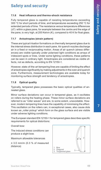
1 Bow2 Diagonal3 Toughened glass 3
1 2
Safety and security
69Guardian GlassTime
7.1.6 Heatinfluenceandthermo-shockresistance
Fully tempered glass is capable of resisting temperatures exceeding 300 °C for short periods of time, and temperatures exceeding 250 °C for extended periods of time. The resistance versus temperature differences (ΔT) within a glass pane, for example between the centre and the edge of the pane, is very high, at 200 Kelvin (K), compared to 40 K for float glass.
7.1.7 Anisotropies (strain pattern)
These are typical irisation formations on thermally tempered glass due to the internal stress distribution in each pane. Air quench nozzles discharge air in a fixed or reciprocating motion. Areas of air quench (stress differ-ences) are visible typically under polarised light conditions as arrays of iridescent spots or lines. Under some lighting conditions, these patterns can be seen in ordinary light. Anisotropies are considered as visible ef-fects, not as defects, according to EN 12150-1.
However, state-of-the-art tempering lines are capable of limiting the effect of anisotropies significantly by making adjustments in the oven and quench zone. Furthermore, measurement technologies are available today for monitoring surface strength and tendency of anisotropies.
7.1.8 Optical quality
Typically, tempered glass possesses the basic optical qualities of an-nealed glass.
Minor surface deviations can occur in tempered glass, as it oscillates on rollers during the heating phase. These minor surface deviations are referred to as “roller waves” and are, to some extent, unavoidable. How-ever, modern tempering lines have the capability of minimising the effect. This oscillation on the rollers can, in exceptional cases, also cause dots known as „roller pickup“ which form on the glass surface and are visible under adverse lighting conditions.
The European standard EN 12150-1 for tempered glass describes specific requirements for optical distortions:
Overall bow:
The induced stress conditions can produce a slight bow.
Maximum allowable tolerances
≤ 3.0 mm/m (0.3 % of measured distance)
7
Safe
ty a
nd
secu
rity

Manufacturerapp. Manufacturing plant
Certificate Authority
EN 12150
Trad
em
ark or product na me
Identification of tempered glass
1 Ruler2 Wave deformation3 Toughened glass
≥ 1503 2
1
Nickel sulphide – particle in float glass with mechanical stress
100 μm
70 Guardian GlassTime
Roller waves:
Glass that is passed horizontally through an oven may contain a very slight surface wave caused by con-tact with the rollers. The reason for this is the softening of the glass at the end of the heating time.
Maximum alloable tolerances ≤ 0.3 mm over a distance of 300 mm
7.1.9 Moisturefilmontemperedglass
The wettability of the surface can differ due to pressure from rollers, suction cups, trowelling compounds or lubricants. During subsequent formation of a moisture film on the glass surface, this varying wettability within a glass surface is visible but does not indicate any deficiency.
7.1.10 Identification
Each piece of tempered glass must be clearly and permanently marked in accordance with EN 12150.
7.2 Heat-soaked tempered glassEach basic glass contains extremely low quantities of nickel sulphide (NiS) crystals, which are inevitably introduced into the glass via the raw materials. In normal annealed float or patterned glass, these crystals do not have any relevance.
The extremely rapid cooling-off pe-riod during the tempering process “freezes” the NiS particles in a high temperature crystal modification. When heat is later applied, for example, through solar energy absorption, this crystal structure may change because the volume of the crystals change, i.e. increases, and this may cause the glass to suddenly burst apart as soon as the particles exceed a critical size.

Heat-soak oven
Trademark or product name
Identification of tempered heat-soaked glass
EN 14179-1
Manufacturerapp. Manufacturing plant
Certificate Authority
Tempered heat-soaked glass
Safety and security
71Guardian GlassTime
Any safey-relevant glazing and panes, such as façade glass, which are exposed to high temperature fluctuations, should therefore be subjected to an additional heat-soak test.
This test is carried out in accord-ance with EN 14179 and should be documented. This test forces the NiS crystals that may be present to react quickly. Those panes of glass that do have these invisible crystals are intentionally destroyed during this test.
For this purpose, the tempered glass panes are heated to a defined 290 °C ± 10 % for at least 2 hours.
KeyT Glass temperature at any point, °Ct Time, h1 First glass to reach 280 °C2 Last glass to reach 280 °C
T [°C]
d
1
2
a b c t
320300280
d Ambient temperaturea Heating phaseb Holding phasec Cooling phase
Holding phase duration: 2 h T: 290 °C (± 10%)
This process is typically monitored by internal and external controllers and should be permanently docu-mented for each pane supplied (man-datory in Germany). Moreover, these panes should be visibly marked with the tempered heat-soaked glass label.
7
Safe
ty a
nd
secu
rity

Fragmentation of heat strengthened glass
72 Guardian GlassTime
7.3 Heat strengthened glass (partially tempered)
7.3.1 Production
Production is the same as for fully tempered glass, but the cooling process is slower, which means that the stress differences in the glass are lower. You could even rank heat strengthened glass between float and fully tempered glass. The values for thermo-shock resistance and the flexural tensile strength are proof of this.
Slower cooling down during the production process vastly reduces the potential risk of a spontaneous breakage by NiS inclusions.
7.3.2 Breakagepattern
The structure after a fracture occurs is similar to that of a float glass pane. The fracture radiates outward from the point where the impact/fracture occurred, to the edges of the pane. Typically, “islands“ (larger fragments) and “particles“ (small fragments) should be avoided by adjusting the pro-cess parameters in order to ensure that the glass remains in the frame after breakage.
The test procedures and limitations on “islands“ and “fragments“ are defined in EN 1863-1.
Important note: monolithic heat strengthened glass is not a safety glass!
7.3.3 Residual load capacity as component of laminated glass
Due to the fracture characteristics of heat strengthened glass, which are different from tempered glass, a single unit of laminated safety glass made from heat strengthened glass has excellent residual load-bearing properties.
In the event of failure even both heat strengthened panes in laminated safety glass, only minor deflection occurs, contrary to the sagging of laminated safety glass made from tempered glass. This is why heat strengthened glass is increasingly replacing tempered glass in laminated glass when increased flexural tensile strength and alternating temperature loading are required.

Safety and security
73Guardian GlassTime
Laminated safety glass made of 2 x tempered glass – top pane broken
Laminated safety glass made of 2 x heat strengthened glass – top pane broken
Laminated safety glass made of 2 x tempered glass – both panes broken
Laminated safety glass made of 2 x heat strengthened glass – both panes broken
7.3.4 Tensile bending strength (EN 1863-1)
• Heat strengthened glass made from float glass σ = 70 MPa
• Heat strengthened glass made from patterned glass σ = 55 Mpa
• Heat strengthened glass made from enamelled glass. whereby the enamelled side is under tensile stress σ = 45 Mpa
7.3.5 Thermo-shock resistance (EN 1863-1)
The failure strength of a heat strengthened glass against temperature differences (ΔT) within one glass pane is 100 K (annealed float glass: 40 K). This makes heat strengthened glass suitable for any application where there is increased risk of thermally induced breakage (→ chapter 9.8.1).
7.4 Laminated safety glassSince its invention in 1909, and after more than a century of continuous improvement, laminated safety glass is a key component in the realisation of modern architecture. The permanent connection of two or more single pane glasses with sticky, elastic, highly tear-resistant interlayers make a multi-functional element from the glass, which can handle high static forces and constructive tasks in addition to its given transparency. Any conceivable type of plate glass can be laminated to laminated safety glass, regardless of whether it is float or flat structural patterned glass, coated or printed. The safety effect of laminated safety glass is based on the extremely high tensile strength of the interlayer and its excellent adhesion to the adjacent glass surface. In terms of mechanical stress such as shock, impact or influence from other forces breaking the glass, the fragments adhere to the interlayer, so that the laminated safety glass will usually retain its stability under load.
7
Safe
ty a
nd
secu
rity

Laminated safety glass build up
Float / tempered / heat strengthened
PVB interlayer
Float / tempered /heat strengthened
Optional additional fi lms / panes
74 Guardian GlassTime
This leaves the glazed opening closed, which greatly reduces the risk of injury due to chips adhering. Depending on the use of laminated safety glass, multiple interlayers can be placed between two glass surfaces in order to meet more stringent requirements.
The most common interlayer type used is PVB (Polyvinyl butyral). It is manufactured using a 3-step chemical reaction where all intermediate reaction products are present in the fi nal PVB interlayer. In particular, the OH- groups of Polyvinyl alcohol are essential to enable the bonding to the fl oat glass surface by H+ bridges. With the amount of PV-alcohol the PVB manufacturer can adjust the bonding between PVB interlayer and glass. This is crucial for the breakage behaviour of the fi nal laminated glass product. Additional plasticizers infl uence the stiffness and therefore the mechanical and acoustic performance.
Other interlayer types are Ionoplast and EVA (Ethylene vinyl acetate).
7.4.1 Production
Laminated safety glass is produced according to the stipulations of EN 14449. Two or more thoroughly cleaned panes, each with one or more PVB interlayers are mounted on each other in a clean room. This sandwich is then pre-strengthened in a rolling process at approx. 200 °C heat. This is referred to as a mechanical pre-bonding unit.
The resulting opaque glass-fi lm unit is now transported with many others on a glass rack to the autoclave, a high pressure aggregate, where the transparent pre-bonded unit is subjected to approx. 10 bar of pressure and heated to 130 °C, producing an absolutely transparent laminated safety glass.
App. 200 °C App. 130 °C / 10 bar
Loading CleaningLaminate (clean room)
Mechanical pre-bonding Autoclave Unloading
Production process for laminated safety glass (schematic representation)

44.2
Thickness pane 2 [mm]
PVB interlayer thickness:1 0.38 mm (0.50 mm SR Acoustic PVB)2 0.76 mm3 1.14 mm4 1.52 mm5 2.28 mm
Thickness interlayer [number]
Thickness pane 1 [mm]
Safety and security
75Guardian GlassTime
Production of laminated safety glass – clean room
7.4.2 Buildingphysicalcharacteristics
Compressive strength, thermal conductivity, thermal expansion, modulus of elasticity and mass per unit area and chemical characteristics are similar to monolithic basic glass properties. The light transmission is also a result of the values of the processed basic glass and the PVB films.
Depending on the thickness of the assembly, the light transmission is between 90 - 70 %. The light transmission and the colour rendering in-dex – especially when the assemblies are thicker with several panes and multiple films – can be improved by using Float Guardian ExtraClear® and primarily Float Guardian UltraClear™.
7.4.3 Nomenclature of laminated glass
The nomenclature of laminated glass describes the build-up considering the number and thickness of the glass panes used and the thickness of the interlayers.
Example:
Guardian LamiGlass 44.2
Additions such as “SR“ for acoustic interlayer (e.g. 44.2 SR) describe further properties.
7
Safe
ty a
nd
secu
rity

76 Guardian GlassTime
7.4.4 Safety features of laminated glass
7.4.4.1 Protection against injury/pendulum impact test (EN 12600) – passive safety
To simulate the impact of a human body, the European standard stipulates a pendulum test for glass for buildings. Fulfilling these requirements is a condition for laminated safety glass.
Drop height
Twin tyreα: Highest drop height – no breakage or breakage according to clause 4a or 4b “Test requirements”β: Breakage behavior (A = typical of annealed glass, B = typical of laminated glass, C = typical of toughened glass)
Classification of breakage: α (β) ϕ
Highest classification: 1(B)1 → for laminated 33.2 or 55.1 or thicker
ϕ: Highest drop height – no breakage or breakage according to clause 4a “Test requirements”
Classification Drop height [mm]
3 190
2 450
1 1200
Tested glazings according to EN 12600 are listed in chapter 10.6, table 22.
7.4.4.2 Impact resistance against manual attack (EN 356) – active safety
7.4.4.2.1 Hard body drop test (Ball drop)
Impact resistant glass is tested with a steel ball weighing 4 kg with a diameter of 10 cm. To distinguish be-tween different resistance classes. this ball is dropped in freefall from different heights and several times onto the same point. The following specifications result from this test:
Resistance class acc. to EN 356
Drop height (hits) [mm]
Suitable laminated glass
P1 A 1500 (3) 44.1. 44.1 SR. 55.1. ...
P2 A 3000 (3) 33.2. 33.2 SR. 44.2. 44.2 SR. 66.2. 66.2 SR. ...
P3 A 6000 (3) 44.3. ...
P4 A 9000 (3) 33.4. 44.4. 44.4 SR. 66.4. 66.4 SR. ...
P5 A 9000 (9) 44.6. 44.6 SR. 55.6. 66.6. ...
The list of suitable laminated glass build ups shows that the interlayer thickness alone defines the safety level of the glazing.
Tested glazings according to EN 356 (ball drop) are listed in chapter 10.6, table 23.
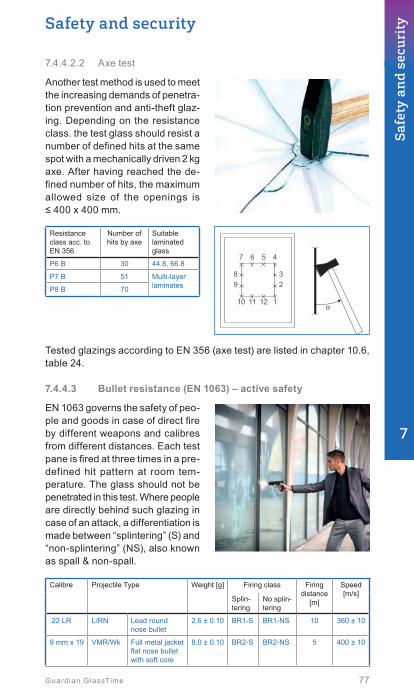
Safety and security
77Guardian GlassTime
7.4.4.2.2 Axe test
Another test method is used to meet the increasing demands of penetra-tion prevention and anti-theft glaz-ing. Depending on the resistance class. the test glass should resist a number of defined hits at the same spot with a mechanically driven 2 kg axe. After having reached the de-fined number of hits, the maximum allowed size of the openings is ≤ 400 x 400 mm.
Resistance class acc. to EN 356
Number of hits by axe
Suitable laminated glass
P6 B 30 44.8, 66.8
P7 B 51 Multi-layer laminatesP8 B 70
1
4
12
5
11α
6
10
7
2938
Tested glazings according to EN 356 (axe test) are listed in chapter 10.6, table 24.
7.4.4.3 Bulletresistance(EN1063)–activesafety
EN 1063 governs the safety of peo-ple and goods in case of direct fire by different weapons and calibres from different distances. Each test pane is fired at three times in a pre-defined hit pattern at room tem-perature. The glass should not be penetrated in this test. Where people are directly behind such glazing in case of an attack, a differentiation is made between “splintering” (S) and “non-splintering” (NS), also known as spall & non-spall.
Calibre Projectile Type Weight [g] Firing class Firing distance
[m]
Speed[m/s]
Splin-tering
No splin-tering
.22 LR L/RN Lead round nose bullet
2.6 ± 0.10 BR1-S BR1-NS 10 360 ± 10
9 mm x 19 VMR/Wk Full metal jacket flat nose bullet with soft core
8.0 ± 0.10 BR2-S BR2-NS 5 400 ± 10
7
Safe
ty a
nd
secu
rity

78 Guardian GlassTime
Calibre Projectile Type Weight [g] Firing class Firing distance
[m]
Speed[m/s]
Splin-tering
No splin-tering
.357 Magn.
VMKS/Wk
Full metal jacket cone pointed nose bullet with soft core
10.25 ± 0.10 BR3-S BR3-NS 5 430 ± 10
.44 Magn. VMF/Wk Full metal jacket flat nose bullet with soft core
15.55 ± 0.10 BR4-S BR4-NS 5 440 ± 10
5.56 x 45 FJ/PB/SCP 1
Full jacket pointed bullet with lead core with steel insert
4.0 ± 0.10 BR5-S BR5-NS 10 950 ± 10
7.62 x 51 VMS/Wk Full jacket pointed bullet with soft core
9.45 ± 0.10 BR6-S BR6-NS 10 830 ± 10
7.62 x 51 VMS/Hk Full jacket pointed bullet with a hard core
9.75 ± 0.10 BR7-S BR7-NS 10 820 ± 10
Shotgun 12/70*
Brenneke 31.0 ± 0.50 SG1-S * SG1-NS *
10 420 ± 20
Shotgun 12/70
Brenneke 31.0 ± 0.50 SG2-S SG2-NS 10 420 ± 20
* The test is performed using a single shot
All laminated safety glass types used in this application have laminated, asymmetric assemblies. and automatically have outstanding penetration prevention.
Tested glazings according to EN 1063 (bullet proof) are listed in chapter 10.6, table 25.
7.4.4.4 Explosionresistance(EN13541)–activesafety
This European requirement specifies the qualifications and the methods for blast- resistant security glazing products for building applications. The classification applies only to the dimension of a specimen of around 1 m². The aim here is also to automatically achieve excellent penetration resistance parallel to the types of glass supplied.
Type classification number
Characteristics of a flat compression waveMinimum values for the
Pos. max. compression of the reflected shock wave (Pr)
[kPa]
Pos. specific impulse (i+)[kPa x ms]
Pos. pressure phase period (t+) [ms]
ER 1 50 ≤ Pr < 100 370 ≤ i+ < 900 ≥ 20
ER 2 100 ≤ Pr < 150 900 ≤ i+ < 1500 ≥ 20
ER 3 150 ≤ Pr < 200 1500 ≤ i+ < 1500 ≥ 20
ER 4 200 ≤ Pr < 250 2200 ≤ i+ < 3200 ≥ 20
In accordance with EN 13 541
Tested glazings according to EN 13541 (explosion resitant) are listed in chapter 10.6, table 26.

Safety and security
79Guardian GlassTime
7.5 Safety with and through glass
7.5.1 Barrierglazing(glazingforprotectingpeoplefromfallingout)
Clear regulation parameters govern the installation of glass elements in areas where there is a risk of falling. These areas range from simple rail-ings and barriers to room-high glazing installed more than approx. one metre above solid ground. In Germany, the DIN 18008, part 4 applies. This DIN is based on unified European standards which all EU countries will have to implement in the short- to medium-term. This legal specifica-tion regulates in detail the kind of glass and assembly, depending on its area of application. Glazing that deviates from this legal specification is of course allowed, but should be inspected and tested in each single case and approved by the authorities (→ chapter 7.6).
Barrier glazing according to DIN 18008-4 is classified in several categories (A, B and C), depending on the kind of construction.
The main requirements on the design are:
• The construction depends on the category of the barrier glazing.• Glazing with different build-ups and dimensions requires tests in
order to verify the shock resistance (glass build-ups with proven shock resistance are listed in table B.1 in the DIN 18008) – see chapter 7.5.1.4.
• General rule for laminated glass: the thickness of the individual panes must not differ from each other by a factor greater than 1.7 (e.g.: 4 mm + 6 mm, 5 mm + 8 mm, 6 mm + 10 mm, etc. ...)
7.5.1.1 Floor-to-floorbarrierglazingwithoutsupportingbeam (category A)
• Single glass must consist of laminated safety glass.• Impact side of IG must consist of laminated safety glass, tem-
pered glass or laminated glass consisting of tempered glass.• Minimum one pane of an IGU must be laminated safety glass.• Triple glazed units: float can be used behind tempered glass on the
impact side if the tempered glass does not break in a pendulum impact test.
7
Safe
ty a
nd
secu
rity

80 Guardian GlassTime
7.5.1.2 At base line clamped glass parapets / ballustrades (categoryB)
• Individual glass panes are connected by a handrail.• Handrail can be placed on the upper edge or fixed by plate holder
(point support) according to DIN 18008-3.• In the event of failure, the beam load gets transferred to neighbouring
glasses.• Only laminated safety glass must be used.
7.5.1.3 Barrierglazingincombinationwithloadtransferringbeam (category C)
• Filling below or behind the beam.• All sides of linearly supported glazings of the categories C1 and
C2 may consist of monolithic tempered glass – in all other cases laminated safety glass is mandatory.
• IGU of the categories C1 and C2: Zame rules for impact side as for category A, other panes according to DIN 18008 part 2 (rules for linear supported) and 3 (point supported glazing).
• Category C3 needs to be treated like category A with regard to the permitted glass types.
C1 C2 C3

Safety and security
81Guardian GlassTime
7.5.1.4 Linear supported glazing with proven impact resistance
The glass build-ups listed below may be used without additional tests. For triple glazing considerations, additional tempered or tempered heat-soaked glass lites may be used for the combinations shown in the rows 1, 2, 3, 4, 7, 8, 20 and 28.
Cate-gory
Type Linear sup-port
Width [mm]
min. max.
Hight [mm]
min. max.
Glass build up from impact to fall side
Row
A Insu-latingglass
All sides
500 1300 1000 2500 8 tempered + 4 float/0.76 PVB/4 float 1
1000 2000 500 1300 8 tempered + 4 float/0.76 PVB/4 float 2
900 2000 1000 3000 8 tempered + 5 float/0.76 PVB/5 float 3
1000 2500 900 2000 8 tempered + 5 float/0.76 PVB/5 float 4
1100 1500 2100 2500 5 float/0.76 PVB/5 float+ 8 tempered 5
2100 2500 1100 1500 5 float/0.76 PVB/5 float+ 8 tempered 6
900 2500 1000 4000 8 tempered + 6 float/0.76 PVB/6 float 7
1000 4000 900 2500 8 tempered + 6 float/0.76 PVB/6 float 8
300 500 1000 4000 4 tempered + 4 float/0.76 PVB/4 float 9
300 500 1000 4000 4 float/0.76PVB/4 float+ 4 tempered 10
Mono-lithicgla-zing
All sides
500 1200 1000 2000 6 float/0.76 PVB/6 float 11
500 2000 1000 1200 6 float/0.76 PVB/6 float 12
500 1500 1000 2500 8 float/0.76 PVB/8 float 13
500 2500 1000 1500 8 float/0.76 PVB/8 float 14
1000 2100 1000 3000 10 float/0.76 PVB/10 float 15
1000 3000 1000 2100 10 float/0.76 PVB/10 float 16
300 500 500 3000 6 float/0.76 PVB/6 float 17
C1and C2
Insu-latingglass
All sides
500 2000 500 1100 6 tempered+ 4 float/0.76 PVB/4 float 18
500 1500 500 1100 4 tempered + 4 float/0.76 PVB/4 float 19
2 sides upper and lower side
1000 bel. 500 1100 6 tempered + 5 float/0.76 PVB/5 float 20
Mono-lithicgla-zing
All sides
500 2000 500 1100 5 float/0.76 PVB/5 float 21
2 sides upper and lower side
1000 bel. 500 800 6 float/0.76 PVB/6 float 22
800 bel. 500 1100 5 tempered /0.76 PVB/5 tempered 23
800 bel. 500 1100 8 float/1.52 PVB/8 float 24
2 sides left and right side
500 800 1100 1100 6 float/0.76 PVB/6 float 25
500 1100 800 1100 6 tempered /0.76 PVB/6 tempered 26
500 1100 800 1100 8 float/1.52 PVB/8 float 27
7
Safe
ty a
nd
secu
rity

82 Guardian GlassTime
Cate-gory
Type Linear sup-port
Width [mm]
min. max.
Hight [mm]
min. max.
Glass build up from impact to fall side
Row
C3 Insu-latingglass
All sides
500 1500 1000 3000 6 tempered + 4 float/0.76 PVB/4 float 28
500 1300 1000 3000 4 float/0.76 PVB/4 float+12tempered
29
Mono-lithicgla-zing
All sides
500 1500 1000 3000 5 float/0.76 PVB/5 float 30
Table B1 (DIN 18008-4): glass build-ups with provenshock resistance
7.5.2 Overhead glazing
Any glazing installed at an inclination of ± 10° relative to the vertical is referred to as overhead glazing. In addition to having to withstand the usual types of forces such as wind, varying weather conditions and snow, the glass must be able to hold up under its own construction load. Therefore, these types of glass should be treated differently from those installed vertically. It is critical that in case of failure, this type of overhead glazing is guaranteed not to shower down glass splinters, shards or jagged pieces. DIN 18008, part 2 currently covers these types of installations in Germany. This DIN is a national norm but is based on designated European standards which should be implemented in the medium term by all EU countries.
It is a general rule that today’s overhead glazing should consist exclusively of laminated safety glass, with a minimum of 0.76 mm PVB for the lower pane. Static requirements may even demand higher standards.
7.5.3 Walk-on glazing
These are glazings suitable for permanent access of people for walking on. The typical admissible loads are personal loads. Requirements are defined in DIN 18008 part 5.
Typical applications are: stairs, platforms, glass bridges or light well covers.
Permitted glass types with proven shock resistance are shown in table B.1 (DIN 18008 part 5).
Length max. [mm]
Width max. [mm]
Laminated glass build up a Bearing depth min.
[mm]
1500 400 8 HSGC / 1.52 PVB / 10 FGb / 1.52 PVB / 10 FGb 30
1500 750 8 HSGC / 1.52 PVB / 12 FGb / 1.52 PVB / 10 FGb 30
1250 1250 8 HSGC / 1.52 PVB / 10 HSGC / 1.52 PVB / 10 HSGC 35
1500 1500 8 HSGC / 1.52 PVB / 12 HSGC / 1.52 PVB / 12 HSGC 35
2000 1400 8 HSGC / 1.52 PVB / 15 FGb / 1.52 PVB / 10 FGb 35
a From topb Float glass c Heat strengthened glass
Table B1 (DIN 18008-5): all-side linear supported. regular acessible glazing with proven shock resistance and residual load capacity

Safety and security
83Guardian GlassTime
Main requirements on the design are:
• Glass surface must have anti-slip characteristics.• Position must be fi xed (against shifting or lifting).• Glass build up: minimum triple laminated glass.• Load limitation for passenger traffi c at typical use and vertical load:
max. 5 kN/m².• Bending rigid substructure.• Elastomer bearing material with 60 - 80 shore A-hardness.• Minimum support depth of 30 mm.
SealingGlazing tape
Distance block
Supporting material
≥ 30 mm
Framing all sides
Glass structure from top to bottom:Protective pane protects the supporting glass composite against damage. Min. thickness 6 mm, tempered or heat strengthened with / without print. Supporting glass composite of two or three glass panes which are connected together with PVB fi lms. Hardness of the elastomer support material: 60 ° to 80 ° Shore A
7.5.4 Step-on glazing for cleaning and maintenance purposes
These are glazings suitable for short term access of specially trained personnel for cleaning and maintenance purposes. Requirements are defi ned in DIN 18008 part 6 and typically apply for linear and point sup-ported constructions.
The construction needs:
• to prevent people from falling through intact glazing.• to prevent people from falling through damaged glazing.• to prevent danger to persons below damaged glazing.
The requirements differentiate between walk-on for stay and not for walk-on, but because of slope fall-through protection is necessary.
Vertical or sloped glazing on the same level as work platform or traffi c way must have fall-though protection. The following scenarios must be considered:
7
Safe
ty a
nd
secu
rity

< 2.0 m
< 0.
9 m
< 0.
3 m
< 2.0 m0°< α ≤ 90°
84 Guardian GlassTime
• Distance to glass < 2 m
• Elevated glazing: < 0.9 m above and up to 0.3 m below
• Sloped glazing:
The approved glass types (conform to horizontal glazing according to DIN 18008 part 2) are:
• Laminated safety glass only consisting of glass types breaking into large pieces (float glass or heat strengthened glass)
• Wired glass is not considered as fall-through safe!• Upper glass of insulating glass (impact side) must be safe in case
of breakage (laminated safety glass or fully tempered glass only)
For structural design calculations a point load of 150 kg impacting on an area of 10 cm x 10 cm (= 1.5 kN/m²) in the middle of the pane must be considered.
7.5.5 Post-glass breakage performance / residual strength
Residual stability refers to the characteristic of an installed glass element to remain standing for a defined, limited period of time without exerting any load. This applies only to vertical glazing. Overhead glazing’s residual capacity refers to the fact that in case of failure, the glass should bear its own weight over a defined period of time. The requirements and installation situations always determine the respective type of glazing that should be used. The following charts (→ chapter 7.6) give a broad overview of this type of implementation.

Safety and security
85Guardian GlassTime
7.6 Recommendations for particular applicationsDetailed specifications for glass construction and the dimensioning of glass are based on the respective rules and are not stated here in detail. If, for example, additional specifications, fire protection or project-specific requirements exist, they must also be observed.
The following recommendations may partially exceed the legal require-ments, based on practical experience.
Key for the tables below
Colour Explanation
Minimum required type of glass
Recommended type of glass
Alternative type of glass
Inadmissible type of glass
Colours
Abbreviation Explanation
EG Single-pane glass
MIG MIG Multi-pane insulated glass
abZ General approval by a construction supervising body
ZiE Approval on individual case basis
TG Tempered glass
TG-H Tempered – heat-soaked glass
HSG Heat strengthened glass
LSG Laminated safety glass
Abbreviations used
7.6.1 Verticalglazingwithoutprotectionagainstfallingthrough
Application Floa
t
TG 1
TG-H
LSG made of
NoteFloa
t
TG 2
HS
G
Window above railing height
Shop / display window A minimum glass thickness of 12 mm laminated safety glass is recommended due to lack of corresponding regulations.Amendment to DIN 18008-1: free accessible vertical glazing up to 0.8 m must contain glass with save breakage behaviour on the impact side.
7
Safe
ty a
nd
secu
rity

86 Guardian GlassTime
Application Floa
t
TG 1
TG-H
LSG made of
NoteFloa
t
TG 2
HS
G
Level glazing3 e.g. French doors, entrance doors (for burglar-resistant glazing see sec. “Specific safety glass”).Amendment to DIN 18008-1: free accessible vertical glazing up to 0,8 m must contain glass with save breakage behaviour on the impact side.
Noise protection wall DIN 18008-2, ZTV-Lsw 06Monolithic heat strengthened glass must be supported on 4 sides.
All-glass door system “Points of sale” govern of the Occupational Health and Safety Executive (BGR 202), and/or Workplace Directive (ArbStättV) with ASR 10/5, ASR 1.6.
Cladding for external walls DIN 18516-4Application of laminated safety glass only with a general approval (abZ) or approval in specific case (ZiE)
Structural glazing3
Inte
rnal ETAG 002 “Structural sealant
glazing systems (SSGS)”
Ext
erna
l
Point-supported facade
EG
According to abZ or ZiEImportant: DIN 18008-3 only laminated safety glass made of tempered or heat strengthened glass!
MIG
1 Important! According to DIN 18008-2: non heat-soaked tempered safety glass should only be used for an installation height above public area < 4 m and where no persons are standing directly under the glazing, otherwise tempered – heat-soaked glass must be used!
2 Important! Laminated safety glass made of 2 x tempered glass does not have a residual load-bearing capacity. In particular, the installation requirements should be considered.
3 Glass used pursuant to chapter “Glazing in buildings used for special purposes” takes priority.

Safety and security
87Guardian GlassTime
7.6.2 Horizontal / overhead glazing
Application Floa
t
TG1
TG-H
LSG made of
NoteFloa
t
TG2
HS
G
Skylights Only for flats and rooms of similar type of use (e.g. hotel and office rooms) with a light surface (inter-nal frame dimension) < 1,6 m2, otherwise see horizontal glazing
Horizontal glazing
Upp
er DIN 18008
Low
er
Other glasses possible provided that the falling of larger glass parts on public areas is prevented by suitable measures (e. g. nets with mesh width ≤ 40 mm)
Projecting glass roof DIN 18008-2DIN 18008-3: only laminated safety glass made of tempered glass or heat strengthened glass.DIN 18008-5: Clamps not allowed.
Glass slats DIN 18008-2DIN 18008-3: only laminated safety glass made of tempered glass or heat strengthened glass!DIN 18008-5: Clamps not allowed.
Walk-on glass DIN 18008-5Top pane of the 3 panes made of Tempered glass or Heat strength-ened glass;sufficient skid resistance should be ensured; deviating design: single case approval (ZiE)
Tread-on glass ZiE generally required,lower requirements compared to walk-on glass
1 Important! According to DIN 18008-2: non heat-soaked tempered safety glass should only be used for an installation height above public area < 4 m and where no persons are standing directly under the glazing, otherwise tempered – heat-soaked glass must be used!
2 Important! Laminated safety glass made of 2 x tempered glass does not have a residual load-bearing capacity. In particular, the installation requirements should be considered.
7
Safe
ty a
nd
secu
rity

88 Guardian GlassTime
7.6.3 Glazing for protecting people against falling out
Application Floa
t
TG1
TG-H
LSG made of
NoteFloa
t
TG2
HS
G
Room-height glazing
(category A according to DIN 18008-4)
EG DIN 18008-4
MIG
Applies to pane of glass on the attack, or side most likely to absorb the impact; pane on non-attack side variable; If laminated safety glass on non-attack side, then tempered glass or laminated safety glass on attack side
All-glass balustrade with fitted rail
(category B according to DIN 18008-4)
DIN 18008-4Laminated safety glass made of Float glass only with abZ or ZiE
Balustrade with glass bracing linear supported
(category C1 according to DIN 18008-4)
DIN 18008-4If not linear supported on all sides, laminated safety glass must be used.Free edges must be protected by the balustrade structure or adjacent panes from unintended shocks.
Balustrade with glass bracing supported with clamp
(category C1 according to DIN 18008-4)
DIN 18008-4Edge protection is not necessary.
Balustrade with glass bracing supported with clamp
(not regulated according to DIN 18008-4)
Pursuant to abZ or ZiEFree edges must be protected by the balustrade structure or adjacent panes from unintended shocks;Tempered glass can be used if approved by abZ.

Safety and security
89Guardian GlassTime
Application Floa
t
TG1
TG-H
LSG made of
NoteFloa
t
TG2
HS
G
Glazing under cross bars
(category C2 according to DIN 18008-4)
EG
DIN 18008-4; If not linear sup-ported on all sides, laminated safety glass must be used.
MIG
Applies to glass pane on the impact side, or side most likely to absorb the impact; pane on non-impact side variable; If laminated safety glass on non-impact side then tempered glass or laminated safety glass on impact side
Floor-to-floor glazing with beam
(category C3 according to DIN 18008-4)
EG
Beam at required height accor-ding to building requirements
MIG
Applies to glass pane on the impact side or side most likely to absorb the impact; pane on non-impact side variable; If laminated safety glass on non-impact side then tempered glass or laminated safety glass on impact side
Double skin facade
Inte
rnal
3 Internal facade without fall protection, consultation with the local building control authority and principal recommended
Ext
erna
l External facade as fall protec-tion, DIN 18008-4 according to category A or C
Lift shaft DIN 18008-4 and EN 81
French balcony3 Building component on impact op- posite side of the glazing fully acts as fall protection
1 Important! According to DIN 18008-2: non heat-soaked tempered safety glass should only be used for an installation height above public area < 4 m and where no persons are standing directly under the glazing, otherwise tempered – heat-soaked glass must be used!
2 Important! Laminated safety glass made of 2 x tempered glass does not have a residual load-bearing capacity. In particular, the installation requirements should be considered.
3 Glass used pursuant to chapter “Glazing in buildings used for special purposes” takes priority.
7
Safe
ty a
nd
secu
rity

90 Guardian GlassTime
7.6.4 Glazing in buildings used for special purposes
Application Floa
t
TG 1
TG-H
LSG made of
NoteFloa
t
TG 2
HS
G
Office, walls or doors made of glass
Workplace Directive (ArbStättV) GUV-I 8713 Administration.ASR 1.6
Entrance halls/foyers Rule of the Occupational Health and Safety Executive (BGR 202) and / or Workplace Directive (ArbStättV) with ASR 10/5ASR 1.6
School GUV-SR 2002; up to a height of 2.00 m safety glass or sufficient railing
Kindergarden, nursery school GUV-SR 2002; up to a height of 1.50 m safety glass or sufficient railing
Hospital / care facility According to the Ordinance governing Hospital Buildings (KhBauVO) for particular areas (e.g. in stairwells) and for special pur- poses (e.g. children’s ward) BGI/GUV-I 8681
Shopping centre “Points of sale” rule of the Occupational Health and Safety Executive (BGR 202)
Retail Workplace Directive (ArbStättV) “Points of sale” rule of the Oc-cupational Health and Safety Executive (BGR 202) or sufficient railing

Safety and security
91Guardian GlassTime
Application Floa
t
TG 1
TG-H
LSG made of
NoteFloa
t
TG 2
HS
G
Car park Workplace Directive (ArbStättV) annex 1.7 (4); ASR 8/4 and ASR 10/5
Bus stop Workplace Directive (ArbStättV) annex 1.7 (4); ASR 8/4 and ASR 10/5
Swimming pool GUV-R 1/111, DIN 18361; up to a height of 2 m safety glass or sufficient railing.In the case of a sports pool, additional safety against ball throwing (water polo) according to DIN 18032-3
Gymnasium DIN 18032-1; up to a height of 2 m planar, closed and shatterproof;safety against ball throwing according to DIN 18032-3
Squash hall Glass parts of the rear wall must be made of min. 12 mm tempered glass
1 Important! According to DIN 18008-2: non heat-soaked tempered safety glass should only be used for an installation height above public area < 4 m and where no persons are standing directly under the glazing, otherwise tempered – heat-soaked glass must be used!
2 Important! Laminated safety glass made of 2 x tempered glass does not have a residual load-bearing capacity. In particular, the installation requirements should be considered.
7
Safe
ty a
nd
secu
rity
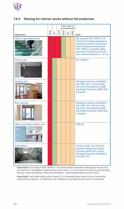
92 Guardian GlassTime
7.6.5 Glazing for interior works without fall protection
Application Floa
t
TG 1
TG-H
LSG made of
NoteFloa
t
TG 2
HS
G
Walk-on glass/glass stairs ZiE required. DIN 18008-2, list of technical building regulations; admissible tensions according to horizontal glazing according to DIN 18008-2; laminated safety glass with PVB films of the mini-mum nominal thickness = 1.5 mm
Shower wall EN 14428/A1
All-glass door Workplace Directive (ArbStättV) with ASR 10/5, „Points of sale” rule of the Occupational Health and Safety Executive (BGR 202), if required
Door opening Workplace Directive (ArbStättV) with ASR 10/5, „Points of sale“ rule of the Occupational Health and Safety Executive (BGR 202), if required
Office separating / partition wall ASR 8/4
Draft lobbies „Points of sale“ rule of the Oc-cupational Health and Safety Executive (BGR 202), and/or Workplace Directive (ArbStättV) with ASR 10/5
1 Important! According to DIN 18008-2: non heat-soaked tempered safety glass should only be used for an installation height above public area < 4 m and where no persons are standing directly under the glazing, otherwise tempered – heat-soaked glass must be used!
2 Important! Laminated safety glass made of 2 x tempered glass does not have a residual load-bearing capacity. In particular, the installation requirements should be considered.

Safety and security
93Guardian GlassTime
7.6.6 Special safety glasses
Application Floa
t
TG1
TG-H
LSG made of
NoteFloa
t
TG2
HS
G
Burglar resistance EN 1627
Fling / trough resistance EN 356 VdS regulation 2163
Break resistance EN 356 and/or EH VdS regulation
Shot / bullet resistance EN 1063, EN 1522
Explosion resistance EN 13541, EN 13123
1 Important! According to DIN 18008-2: non heat-soaked tempered safety glass should only be used for an installation height above public area < 4 m and where no persons are standing directly under the glazing, otherwise tempered – heat-soaked glass must be used!
2 Important! Laminated safety glass made of 2 x tempered glass does not have a residual load-bearing capacity. In particular, the installation requirements should be considered.
7
Safe
ty a
nd
secu
rity

Hounslow Civic Centre, London, United Kingdom | SunGuard® SNX 60Architect: Sheppard Robson Architects | Photo: © Rubin & Sampford Photography

Safety and security
95Guardian GlassTime
7.6.7 Structural glass construction
Application Floa
t
TG1
TG-H
LSG made of
NoteFloa
t
TG 2
HS
G
Glass sword, supporting glass ZiE required
All-glass structures ZiE required
Special glass structures ZiE required
1 Important! According to DIN 18008-2: non heat-soaked tempered safety glass should only be used for an installation height above public area < 4 m and where no persons are standing directly under the glazing, otherwise tempered – heat-soaked glass must be used!
2 Important! Laminated safety glass made of 2 x tempered glass does not have a residual load-bearing capacity. In particular, the installation requirements should be considered.
Appropriate Guardian glasses and glass combinations for these applica-tion areas can be found in chapter 10.
7
Safe
ty a
nd
secu
rity

96 Guardian GlassTime
8. Building with glass ................................................. 98
8.1 Façades ............................................................................ 988.1.1 Façade functions ................................................................. 98
Warm façade | Cold façade | Double skin façade – ventilated systems |Types of ventilated façades | Interactive (passive) systems | Solar control glass in the outer pane | Condensation
8.1.2 Façade constructions ..........................................................104Stick-System-Façade (Mullion-Transom-System) | Structural glazing | Defi nitions | Types of structural glazing | Relevant European standards for structural glazing | Coated glass in structural glazing applications | Point supported façade | Membrane façade
8.2 Ceramic printing on glass ...............................................1128.2.1 Ceramic printing methods ....................................................113
Roller coating | Screen-printing | Digital printing
8.2.2 Spandrel glass ....................................................................1148.2.3 Edge enamelling – Guardian System TEA .............................1158.2.4 Decorative print ..................................................................116
Innsbruck University - Architecture Faculty, Innsbruck, Austria SunGuard® HD Light Blue 52 | Ventilated system, coating on impact paneArchitect: ATP Architects and Engineers | Photo: © pierer.net

97Guardian GlassTime
8.3 Design glass ....................................................................1188.3.1 Transfer colour print on glass ...............................................1188.3.2 Design laminated safety glass ..............................................1198.3.3 Coloured films in laminated glas ...........................................1198.3.4 Decorative laminated glass ..................................................120
8.4 Curved architectural glass ..............................................1208.4.1 Gravity bending ..................................................................1218.4.2 Bending toughened glass ....................................................1228.4.3 Bending shapes ..................................................................1228.4.4 Requirements .....................................................................1238.4.5 Suitable glass types ............................................................1238.4.6 Determination of shape ........................................................1248.4.7 Specifics ............................................................................124
Local optical distortions | Outline precision | Torsion (twist deviation) | Edge displacement | Tangential junctions
8.4.8 Static specifics ...................................................................1278.4.9 Cold-bending .....................................................................127
8.5 Glass elevators ................................................................128
8. Interaction with long-wave radiation ...............................1298.6.1 Radar reflection damping glazing ..........................................130
Radar reflection attenuation with SunGuard® RD coated glass
8.6.2 Damping of electro-magnetic high frequency radiation / electrical smog ...................................................................132
8.7 Anti-reflective glazing ......................................................134
8.8 Bird-friendly glazing ........................................................1368.8.1 What’s the problem? ...........................................................1368.8.2 Evaluation of „bird-friendly“ solutions ....................................1368.8.3 Glass solutions providing better visibility for birds ...................137
8
Bui
ldin
g w
ith
glas
s

98 Guardian GlassTime
For centuries, people have used glass for filling “light holes” in solid outer walls. This has drastically changed in the last three decades. Today, glass itself forms and shapes space and creates room enclosures, thus creating transparent architecture that allows people to feel close to nature. Experts use the generic term “façade” to describe any external architectural con-struction that serves as protection against weather and dangers of any kind.
In addition to science, research and technology, art and architecture in particular have given rise to a host of possibilities when it comes to façades made from glass. Aesthetics, functionality and construction are the most important aspects of using glass as an architectural element, and all of these factors must be precisely defined at the start of planning. A glass’s finish on a façade always influences its reflective properties, which can range from being produced so that the glass is very reflective, reflects an overall colour, or has weak reflection. The change of daylight due to weather, the sun’s changing position in the sky, the colour of the sky and the seasonal change of vegetation influence reflection, and inte-rior light conditions also impact on glass’s appearance from the outside. Glass façades are generally composed of transparent and opaque areas that can be produced so that interior spaces are visible, or are “optically neutralised” and rendered “invisible” by using a specific type of glass. Reflections during the daytime also influence whether a person on the street can see into the interior.
The colour matching between a translucent window and an opaque bal-ustrade is only approximately possible as the colour impression of the translucent pane is always affected by the room behind the pane and its light conditions. In addition to the original function of a façade to provide protection, further decisive criteria relating to functionality are also in focus, especially for glass façades. Not only is there a possibility of obtaining energy from the façade, but one must also consider protection from heat during the summer (→ chapter 5). With regard to the constructive periphery of concrete, steel or aluminium, it should always be assured that, in ad-dition to static loads caused by wind, suction and snow, the glass weight is also considered.
8.1 FaçadesGenerally, glass façades must be looked at from two perspectives, namely function and construction.
8.1.1 Façade functions
The façade function describes the mode of operation of the building shell. There are generally three different possibilities:

Insulating glass
Sandwich panel
Glass
Thermal insulation
Steam barrier
Insulating glass
Ventilatedpane
GlassThermal insulationSteam barrier
99
Building with glass
Guardian GlassTime
8.1.1.1 Warm façade
The warm façade describes a single-shell system in which thermal insula-tion with an interior steam barrier is connected to a glass pane (sandwich panel). This single-shell system is located behind an opaque pane of glass that protects it from the weather.
This sandwich panel is installed in the façade construction as a whole below the transparent insulating glass and attached using clamping strips. The sill’s vapour diffusion resistance is achieved by applying a sealer and edge lipping. Thus, the opaque and transparent elements serve not only to enclose the room and protect it against weather, but also to protect the room from exces-sive heat, noise and, if necessary, to keep fire from penetrating into the room. These opaque panels need a four-sided frame in the form of post-and-beam construction.
Suitable glass types are enamelled float glass or single glazed SunGuard HD (→ chapter 10, table 17).
8.1.1.2 Cold façade
The physical construction and technical functions are performed in the sill area of a two-shell con-struction. The outer shell is used for weather protection as well as the visual design. It is designed with a ventilated glazing so that trapped heat and moisture can be removed. This pane is usually made of solar control or clear glass and most often enamelled - colour matching with the transparent window. Installation op-tions range from all-sided, two-sided to supporting systems attached at various points, which allows for a broad spectrum of individual design. Underneath the transparent insulating glass windows, the thermal insulation of the wall area is achieved by insulating opaque wall areas behind these parapet planes.
A typical glass type is enamelled float glass (→ chapter 10, table 17).
8
Bui
ldin
g w
ith
glas
s

100 Guardian GlassTime
8.1.1.3 Double skin façade – ventilated systems
Ventilated façades are highly innovative. Their benefits in conjunction with numerous other features are manifold. They include in particular, optimisation with regard to energy management, thermal insulation and above all the dynamic selectivity regarding the inclusion of mechanical sun protection located in the inter space, sound insulation and, last but not least, the possibility of providing ventilation and enhanced comfort.
Südddeutscher Verlag, Munich, Germany SunGuard® HD Neutral 67 | Double skin facade, coating inside laminated Architect: GKK | Photo: © GKK+Architekten, Oliver Kuhn, Photo Claus Graubner

101
Building with glass
Guardian GlassTime
8.1.1.3.1 Types of ventilated façades
Active system Interactive system
There are two systems - active and interactive (passive). The active sys-tems have an outer skin of airtight insulation glass in front of the ventilated inter space. Air exchange is artificially induced and takes place inside the building via heat exchangers. In winter this has the advantage that energy required for heating can be saved via heat recovery. The customary types of glass can be employed for the external insulating glass skin.
A special type of ventilated system is the so-called “Closed Cavity Façade” (CCF). It provides an encapsulated air space between inner and outer skin but is not hermetically sealed. Dry and clean air is constantly fed into the cavity to prevent condensation forming. The advantage of this system is the significantly reduced effort required for cleaning and maintenance.
8.1.1.3.2 Interactive (passive) systems
In the case of ventilated façade systems, the interactive systems are by far the most common. The air exchange takes place between the inter space and the environment. A natural convection is created via defined openings usually located above and below the outer glass. Suspended glass walls in front of a conventional construction are also possible, as are punctuated façades with box-type windows that have a fixed or hinged outer glass.
The aim is to reflect a part of the short-wave solar energy directly at the outer glass so that the heat build-up in the inter space is reduced and in turn the thermal load. The use of coatings is particularly beneficial in combination with additional sun and anti-glare protection in the inter space.
Acceptable g-values are also achieved when the blinds are operated in a fully retracted or intermediate state. The dynamic selectivity that can be achieved in this manner renders the ventilated system particularly attractive.
8
Bui
ldin
g w
ith
glas
s

102 Guardian GlassTime
While the inner glazing of a passive system is a normal double or triple insulated glass, for the outer single glazing typically a laminated safety glass (often consisting of heat strengthened glass) is used. Its residual load capacity ensures maximum safety in case of breakage.
Air outlet for natural ventilation in the cavity
Air intlet for natural ventilation in the cavity
Outside glazing
Inside glazing
Air flow
Mechanical shading
Interactive (passive) construction
8.1.1.3.3 Solar control glass in the outer pane
The application of a transparent solar control coating on the ventilated outer pane can significantly reduce the overall solar factor of the system by reflecting a proportion of the short-wave solar radiation already on the most external component before entering the system. The use of mechani-cal shading can be reduced or the blinds can be even be fully retracted compared to alternative solutions without a sun protection coating. The user therefore has the opportunity to operate the mechanical solar protection more effectively (either open or in intermediate states) without having to fear overheating. As a result, more daylight can enter the room and the user can enjoy the unhindered view from inside to outside for longer. This can contribute significantly to an enhanced comfort factor.
When using the coating facing the ventilated air space it must be durable and suitable for monolithic applications – such as the SunGuard HD (High Durable) series. This offers many possibilities with various types of inter-layers such as SentryGlas or EVA without limitations regarding structural performance, compatibility or safety classification.
In the case of facing to the interlayer of laminated glass, the coatings must be compatible with the interlayer material and must be certified according to the relevant standards when safety glass is required.
Reasons for using SunGuard HD against interlayer can be the reduced outdoor reflection and higher light transmission which leads to an increased spectral selectivity. The combination of SunGuard HD with solar absorbing PVB interlayers can further improve the solar control performance and particularly the spectral selectivity of the ventilated outer pane.
For suitable combinations of laminated glass for ventilated systems considering the SunGuard HD range and PVB interlayer, see the product selector (→ chapter 10).

Left side: With anti-fog coating, ClimaGuard Dry. Right side: Typical condensation on the inner side of the outer pane of a ventilated system.
103
Building with glass
Guardian GlassTime
8.1.1.3.4 Condensation
Depending on the position of the building, as well as adverse climatic conditions, condensation may occur on the inner side of the outer glass pane of passive ventilated construc-tions. Of particular concern are the morning hours in spring and autumn. This can significantly disrupt the clear view from inside.
BGL BNP Paribas, Luxembourg, Luxembourg ClimaGuard® Dry | Double skin facade, anti-condensation coating on exterior surface Architect: M3 Architectes | Photo: © Frank Weber
Solutions against this natural phenomenon are anti-fog-coatings such as Guardian “ClimaGuard Dry”. A specially designed, extra-durable coating is applied onto the outer glass pane, which prevents condensation. It is essential to consider the use of this glass in the planning stage because the application of such coating after installation is not possible.
The anti-fog-coating must be installed on surface #1 (facing outside) of the secondary glazing in order to ensure the best possible functionality.
8
Bui
ldin
g w
ith
glas
s

104 Guardian GlassTime
Tests under real building conditions have shown that this solution provides slightly higher surface temperatures compared to an uncoated outer sur-face. This temperature difference significantly reduces the appearance of condensation. While the uncoated secondary glazing shows condensation during many hours, under the same conditions the coated glass remains clear and free of water droplets throughout.
#4 facing inside• Solar control (SunGuard HD)
#2 facing interlayer• Solar control (SunGuard HD*)#1 facing outside• Anti-fog (ClimaGuard Dry)* Refer to Guardian application information and local regulations
Use of functional coatings on the outer pane of interactive (passive) constructions
8.1.2 Façade constructions
Joining the glass to the building and the shell is as important as the function.
8.1.2.1 Stick-system-façade (mullion-transom-system)
The majority of today’s glass façades still consist of post and beam. Here, the load-bearing posts extend from the foundation to the roof of the building in a fixed, aesthetically pleasing manner and at a statically determined and technically feasible distance from each other. These posts are anchored to the building design and transfer all applied loads into it. The “long fields” that therefore react to the top are then intersected by a defined number of horizontal beams that bear the weight of the glass and convey it into the posts. After installing the glass and precisely placing the glazing blocks, pressure pads are fixed with screws, both on the posts and on the beams. The pressure pads fasten the glass elements and seal them. In order to derive the built up humidity caused by condensation water in the rebate area, an inner drainage is installed with an opening to the outside. The optical closing is generally made by cover strips, which have to be fixed by clips and are available in almost all anodised colours. These strips primarily influence the outer colour scheme. Stick façades are typically equipped with a dry gasket (rubber profiles).

105
Building with glass
Guardian GlassTime
StickTransom
Mullion
Stick-system-façade A stick façade consists of a mullion or post (vertical bar between glass panes) and a transom or beam (horizontal bar between glass panes)
A large number of systems are available on the market. These range from extremely small to very large, depending on the desired visual façade’s appearance and function of the façade. Generally, the extremely small profi les don‘t have an obvious window function and are installed in venti-lated or air conditioned buildings so as not to interrupt the sophisticated grid design. Post and beam constructions are approved systems and can in most cases be used without any legal restrictions.
8.1.2.2 Structural glazing
8.1.2.2.1 Defi nitions
A structural glazing façade is designed as an aluminium-adapter-framework glued together with a special insulating glass unit using structural glazing silicones. This aluminium-glass-system is suspended into a conventional curtain wall construction. From the exterior side only, glass and – depend-ing on the system – weather sealant, are visible.
Main features:
• Joining technique appropriate for the material involved• No microstructural change of parts (e.g. welding)• Load transferring function• No local stress peaks by planar transfer of forces trough planar
adhesive area• Ageing stability of silicone (adhesion, UV resistance, temperature
resistance)• Safety at extreme mechanical loads (earthquakes, tropical cyclones,
explosions, etc.)
8
Bui
ldin
g w
ith
glas
s
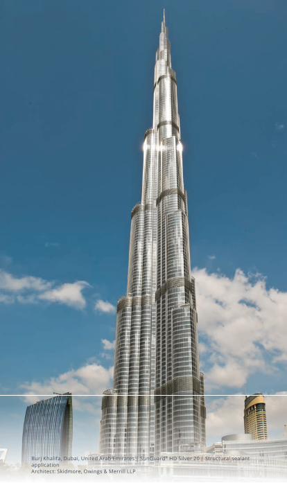
Burj Khalifa, Dubai, United Arab Emirates | SunGuard® HD Silver 20 | Structural sealant applicationArchitect: Skidmore, Owings & Merrill LLP

Glass
Spacer
Gap
IGU edge seal
Structural bonding
Frame
Gasket
Structural bonding
Insulating glass edge seal
Weather seal
107
Building with glass
Guardian GlassTime
A typical structural glazing junction consists of:
• Structural bonding providing a static effective connection
• Insulating glass edge seal adapted on wind and dead loads and with density function
• Weather seal
The structural silicones provide a high sheer and Young’s modulus for compensation or for transferring
• Dynamic loads (wind suction, wind pressure, traffi c loads)• Static loads (dead and snow loads)• Differences in the thermal dilatations of involved materials such as
glass and aluminium
As structural glazing systems are typically in front of the curtain wall sub-constructions, no profi les cover and protect the sealant materials from UV radiation. For this reason, requirements on UV resistance are very high. Normal insulating glass sealants based on organic polymers such as polysulfi de or polyurethane consisting of carbon-carbon and carbon-oxygen bondings do not resist radiation in the range of UV-A. The bond-ings are destroyed and the sealants lose their mechanical and chemical performance. The Silicon-Oxygen bondings of Silicones have a much higher bonding energy corresponding to the energy of UV-C radiation. This radiation does not reach the surface of our planet under normal conditions.
Compared to organic polymer sealants silicones are also hydrophobic and provide increased fl exibility.
8.1.2.2.2 Types of structural glazing
Structural step (insulating) glass
• Structural bonding between glass and sub-construction: metal (e.g. aluminium, stainless steel) or other panel materials
• High modulus silicones• Structural functionality and load
transfer on the outer pane
8
Bui
ldin
g w
ith
glas
s

GlassGap
Spacer
Structural edge seal
Frame
Structural bonding
GlassGap
Spacer
Toggle
Structural edge seal
Screw connection
Frame
Gasket
108 Guardian GlassTime
Structural insulating glass
• Structural bonding between glass and sub-construction
• Structural insulating glass sealants
• High modulus silicones• Structural IG silicones should
never be used as structural glazing adhesives!
• Structural functionality and load transfer on the outer and inner pane
Toggle system
• Structural insulating glass sealants
• screw connection between edge seal (U-profile) and sub-construction
• High modulus silicones• Structural functionality and load
transfer through edge seal
8.1.2.2.3 Relevant European standards for structural glazing
• ETAG 002 Guideline for European Technical Approval for Structural Sealant Glazing Kits
• EN 13 022 Glass in building – Structural sealant glazing• Part 1: Glass products for structural sealant glazing systems
for supported and unsupported monolithic and multiple glazing
• Part 2: Assembly rules
• EN 15 434 Glass in building – Product standard for structural and/or ultra-violet resistant sealant (for use with structural sealant glazing and/or insulating glass units with exposed seals.
• EN 1279 Insulating glass
• DIN 18 008 Glass in building - Design and construction rules

109
Building with glass
Guardian GlassTime
Mech. self-weight support Retaining device to reduce danger in case of bond failure Support frame Glass
Type I
Mechanical transfer of the self-weight of the infill to the sealant support frame and from there to the structure.The struc- tural seal transfers all other actions.Devices are used to reduce danger in the event of a bond failure.
Mechanical transfer of the self-weight of the infill to the sealant support frame and from there to the structure. The struc- tural seal transfers all other actions.No devices are used to reduce danger in the event of a bond failure.
The structural seal transfers all actions including the self- weight of the infill to the sealant support frame, and from there to the structure. Devices are used to reduce danger in the event of a bond failure.
The structural seal transfers all actions, including the self- weight of the infill, to the sealant support frame and from there to the structure. No devices are used to reduce danger in the event of a bond failure.
Type II Type III Type IV
Structural glazing categories according to ETAG 002
8.1.2.2.4 Coated glass in structural glazing applications
According to ETAG 002-1, multifunctional glass (without the approval of a notified body institute for monolithic applications such as SunGuard HP, SunGuard SN and SunGuard SNX or thermal insulating low-E glass such as ClimaGuard) is not suitable for structural glazing. In this case the coat-ing needs to be removed in the concerned areas accordingly. Selected coatings from the SunGuard HD range of products which are suitable for monolithic applications can be used in structural glazing.
Typically, applications with structural bonding need to be tested and ap-proved. If a European certification for structural glazing according to ETAG 002-1 is required, please contact Guardian for detailed information about suitable glass types and tested coating-sealant combinations that comply with ETAG 002-1 requirements.
Another option when using high performance coated architectural glass (SunGuard SN, SNX, HP) in structural applications is “Guardian System TEA”. This is a special enamel system that can be applied directly onto the coated surface. After firing, the coating is completely dissolved and only glass and enamel are left. This system is tested and approved for most Guardian heat treatable SunGuard coatings. The enamel is mechanically and chemically very stable and the optically homogeneous surface pro-vides reliable adhesion for structural applications. Guardian System TEA is tested and certified for various structural sealants according to ETAG 002-1. For detailed information please contact Guardian. (→ chapter 8.2.3)
8
Bui
ldin
g w
ith
glas
s

Insulating glass
Insulating glass
Silicone seam
Plastic liners
Profi le seal
Crosshead
Point fi xing
Point supported façade
Point supported façadeIntersection – visual impression
110 Guardian GlassTime
8.1.2.3 Point supported façade
This façade technique is based on point-fi xed bearing connections as single holders. In this system, the active strengths of the glazing are transmitted to a mostly moveable mounted point supporting button, which transports the active strengths via a metallic conjunction into the massive substructure.
In the conventional method, anchor bolts are mounted through the glaz-ing, covered with an elastic core to avoid glass/metal contact and fi xed with counter panes. These covering and fi xing panes project from the surface. An alternative is conical perforations that gain stability with special conical fi ttings by the clamp-ing power on the edges of the bore-holes. This form allows even façade surfaces without any outstanding elements. Another development is holding points, which are placed on the level of PVB fi lms and thus form a laminated safety glass, of which the outer pane is plain and the backside pane has outstanding connecting threads for mounting. The dimensions of the glazing for such construction account for the allowable deformation of the panes and the fl exibility of the fi ttings. The stresses arising from loads are induced through the holding buttons without any restraint into the load bearing construction.
The joints between the individual glass façade elements are sealed with UV-resistant closing systems. In this way, attached façades out of monolithic glasses can be built, as well as insulating glazed façades. In the latter, the glass rebate is ven-tilated through appropriate systems and enables the condensation water to be diverted. Point-supported fa-çades in countries such as Germany are not regulated construction prod-ucts (in terms of legal construction regulations) and therefore need approval for construction in each particular case.

Membrane façadeIntersection – visual impression
111
Building with glass
Guardian GlassTime
8.1.2.4 Membrane façade
In the last few years, a variation of the point-supported façade with drill holes in the glazing has been developed. Like a tennis racket, the whole façade is strung with a network of steel cables in a grid dimension of the glass panes.
Membrane façade from construction side
The joints of the horizontal and verti-cal cables are fi xed using fasteners, which also serve at the same time as fi ttings for the façade glass in the relevant four corners. Loads affecting the façade are transported through these fi ttings into the cables from where they are conducted into the bearing frame construction. Due to the sealing of the joints, similar to a point supported design, the network of cables disappears opti-cally behind the glass edges, offer-ing a construction-free perspective through the façade.
The corner positioning of the glass elements without boreholes avoids increased stress concentrations and enables greater dimensional freedom.
8
Bui
ldin
g w
ith
glas
s

112 Guardian GlassTime
Insulating glass
Compression spring element
Atrium
Glass holder
Steel cable
Membrane façade
Pre-stressing of the ropes is achieved by ensuring that the whole area can be deformed under load and all functions are maintained before the load peaks are conveyed via the vertical ropes into the grounding and the roof frame. This construction requires approval in each individual case.
8.2 Ceramic printing on glassEnamels have been carefully developed for printing and fi ring on normal soda-lime based fl oat glass. During the tempering process of the glass, these enamels melt and fuse permanently to the glass surface to form a coloured ceramic layer.
A typical enamel consists of a mix of fi ne ground glass fl ux and colour pigments together with oil- or water-based solvents and thinner. Depend-ing on the application method the composition can differ signifi cantly. A ceramic paint (enamel) can be applied using various techniques: screen printing, roller coating, digital printing, spraying, curtain coating or by brush.
After a special drying process, the enamel melts during fi ring at 500 … 650 °C and fuses to the substrate. The result is a UV-durable, mechani-cally- and chemically-stable, ceramic coating.

113
Building with glass
Guardian GlassTime
8.2.1 Ceramic printing methods
8.2.1.1 Roller coating
Enamelling using the roll technique allows a precisely adjustable and uni-form paint application. Due to the increased enamel thickness it ensures a high visual density and homogeneous appearance. This technology is adopted for covering large areas (such as spandrels) or edge enamelling and is ideal for large quantities.
8.2.1.2 Screen-printing
One colour screen print printed directly onto glass has a long tradition. The enamel is pressed using a scraper through the open parts of the mesh onto the glass. First, the mesh is technically prepared in open sections to be printed and closed sections (not to be printed). The open sections form the motif to be printed in this respect with the aid of the colour. Printing using the silk-screen technique allows the application of special design patterns on a glass surface but also the possibility of covering larger ar-eas too. The enamel thickness is precisely adjustable depending on the screen parameters and enamel consumption is less compared to other techniques. This technology is ideal for high volumes and is suitable for design and edge printing. A disadvantage is the comparably high manu-facturing cost of the screens.
8
Bui
ldin
g w
ith
glas
s

114 Guardian GlassTime
8.2.1.3 Digital printing
Digital printing is a relatively new technology for applying images or design pattern to the glass surface. The technology includes a digital glass printer, digital ceramic ink and, typically, image processing software too.
The printer is equipped with print heads with nozzles and ink fixation (immediate drying of the droplets) allowing a single pass process even for multi-colour designs. A piezo-electric pulser releases single ink droplets very precisely. The digital printing ink is adapted to the printer hardware using very fine nozzles.
Advantages are its high design flexibility and there are no silk-screen costs.
8.2.2 Spandrel glass
Spandrel glass is the glass that conceals structural building components such as columns, floors, air conditioning systems, electrical wiring, plumb-ing, etc. Spandrel glass is typically located between vision glasses on each floor of a building.
Curtain wall and structurally glazed designs often require the use of spandrel glass to achieve a designer’s vision of the finished project. Spandrel glass applications can be complementary or contrasting in colour when compared to the vision glass appearance. Typically, spandrel glass must be heat treated to avoid thermal stress breakage due to high energy absorption (→ chapter 9). Guardian has experience in spandrel glass applications and can help architects and building owners achieve the desired appearance whilst minimising the risk of thermal stress breakage.
When vision glass is specified with a high light transmission or low external reflection, an exact colour match between spandrel and vision glass is chal-lenging. Daylight conditions can have a dramatic effect on the perception of vision to spandrel appearance. For example, a clear, bright sunny day provides a higher reflective appearance, which will improve the vision-to-spandrel match. A grey, overcast day may allow more visual transmission from the exterior and produce a greater contrast between the vision and spandrel glass. Guardian recommends that a full-size outdoor mock-up be prepared and approved in order to confirm the most desirable spandrel option for a specific project.
Spandrel glass can consist of an opacified clear or coated* float glass (picture left), a reflectively coated glass (picture middle) or can be an insulating glass unit comprising of a solar control glass as the exterior pane and an opacified uncoated interior pane (picture right).

115
Building with glass
Guardian GlassTime
Monolithic
1 1 32 2 4
Clear or coated* float glass
Exterior Exterior ExteriorCoating
InteriorInteriorCeramic frit Ceramic frit
Shadow box(black background)
SunGuard HD
Insulating glass unit
All SunGuard types(simulation of shadow box)
Spandrel glass build-up‘s
SunGuard® HD reflective coated glass allows for the application as monolithic spandrel. This provides an economical solution that is suitable for many applications. If the desired match cannot be achieved with the monolithic spandrel solution, an insulation glazing spandrel can be considered.* see chapter 10.3 for suitable types
For larger projects, it is recommended that a real-size mock-up is con-structed to verify the colour matching between vision (window) and spandrel.
→ chapter 10.3 provides spandrel recommendations for SunGuard architectural glass.
8.2.3 Edge enamelling – Guardian System TEA
Many situations in modern construction designs require partial or peri-metrical ceramic edge print. Such as:
• Structural glazing• All-glass cornersRoof glazing with glass overlap
• Glass louvre windows• Glass fins• Top and side hung windows in fully-glazed façades
Typically, edge enamelling in combination with architectural coated glass is performed by cut-to size technology with the disadvantage of additional handling steps, possible quality issues and long lead times.
With ceramic paint, compatible coatings can be printed but often show an undesirable colour shift.
A new technology – developed with the company Ferro – for ceramic printing of architectural coatings is „Guardian System TEA“ (TEA = True Edge Application).
8
Bui
ldin
g w
ith
glas
s

La Casa del Desierto, Gorafe, Spain SunGuard® SNX 60 I with System TEA edge enamelling I Architect: OFIS architects Photo: © Gonzalo Botet
116 Guardian GlassTime
This special enamel is applied directly on the coating. During the heat treatment (firing) process, the coating is completely dissolved. The System TEA enamel fuses with the glass and creates a strong bond (comparable to standard enamel on float glass). After cooling, the coating material is fully embedded in the enamel (similar to colour pigments). This patented system provides edge-deletion and enamelling in one step.
Application of enamel
Glass substrateSputter coatingGuardian System TEA enamelGuardian System TEA enamel with embedded coating
Wet
Drying
Cured
Heat treatment
Fired
Guardian System TEA – process
System TEA enamel can be applied by roller coating or screen-printing. Most of Guardian’s heat treatable SunGuard and ClimaGuard coat-ings, as well as Clarity anti-reflective glass, are compatible and proven by notified body testing institutes.
The System TEA enamel surface is also suitable and certified for struc-tual sealant applications. Please ask Guardian’s Technical Services for more information regarding tested combinations.
8.2.4 Decorative print
Not only are the design of parapet panes (spandrels) further refined in functional terms in modern architecture but transparent elements are also receiving more and more visual and functional decorative facets. Glass offers a variety unlike any other construction material. The design can be a decorative ornament, symbol or even an all over illustration or matting. The areas that can be designed with decoration glass are multifaceted. In modern apartments, offices, restaurants and hotels, for example, design glasses as partitions and coverings maintain a balance between separating and joining with individual emphasis. Glasses with such design components achieve a high aesthetic appeal and additional solar protection. In addition, they guarantee at the same time consistency and colour fastness. In combination with solar control glass, they offer extensive, individual impulses for modern façades design.

117
Building with glass
Guardian GlassTime
Typically, techniques used are silk-screen printing and digital printing (→ chapter 8.2.1)
In combination with architectural coatings, different scenarios and con-sequences must be considered:
1. Print between glass surface and coating (#2)• For non-heat treatable coatings• Requires cut-to-size technology• No colour shift in exterior appearance• Influence on thermal and solar energy performance of the coating• Additional production steps• Quality risks• Logistical and lead-time issues
2. Print on top of the coating (#2)• Use of heat treatable coatings only• Coatings must be compatible with enamel• High flexibility• Colour shift in outside appearance possible• Loss of thermal performance (low emissivity) at enamelled areas
8
Bui
ldin
g w
ith
glas
s

118 Guardian GlassTime
3. Print (#1) and coating (#2) are on opposite surfaces of the glass (→ chapter 9.10.2.3)• Special enamel suitable for #1 (outdoors) applications• Use of mechanically stable, highly durable coatings (such as
SunGuard HD) only• Feasibility tests regarding processing recommended• High flexibility• No colour shift
8.3 Design glassIn addition to enamelling, other processes are currently available for the production of design glasses.
8.3.1 Transfer colour print on glass
The transfer print offers an alternative to achieve a multi-coloured print rather than single colour screen printing. In addition, enamel and ceramic colours can also be transferred through digital printing onto transfer films, thus reproducing multi-coloured motifs. These printed films are then fixed on glasses to be tempered. During the tempering process, these transfer films burn residue-free and the painted colours bond as previously de-scribed. Besides all kinds of ornaments, this method can also generate illustrations which similar quality to coloured photos.

119
Building with glass
Guardian GlassTime
8.3.2 Design laminated safety glass
Large sized illustrations such as photographic slides technology of the past, are produced using the same digital print method but with other paint components and films. The illustrations are inserted be-tween the PVB films of the laminated safety glass and then compressed. Colours and films are lightfast and UV- resistant and create a decorative pane that retains its individuality. Despite this additional laminate, the laminated glass retains its out-standing characteristics (→ chapter 7.4), supplemented by the individual design component.
8.3.3 Colouredfilmsinlaminatedglass
The same lamination process can today offer of a large range of different colour films, which can be combined to achieve every conceivable col-our in laminated glass. This method enables the creation of completely transparent coloured glass. In addition, with supplementary dispersion films to further define translucency, products such as colourful blinds can be produced. These films are also UV-resistant for outdoor use, thus preserving their radiant colour effect without affecting the characteristics of the laminated glass.
8
Bui
ldin
g w
ith
glas
s
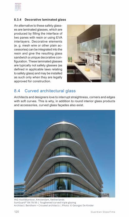
120 Guardian GlassTime
8.3.4 Decorative laminated glass
An alternative to these safety glass-es are laminated glasses, which are produced by filling the interface of two panes with resin or using EVA interlayers. Decorative elements (e. g. mesh wire or other plain ac-cessories) can be integrated into the resin and give the resulting glass sandwich a unique decorative con-figuration. These laminated glasses are typically not safety glasses (as defined in applicable laws relating to safety glass) and may be installed as such only when they are legally approved for construction.
8.4 Curved architectural glassArchitects and designers love to interrupt straightness, corners and edges with soft curves. This is why, in addition to round interior glass products and accessories, curved glass façades also exist.
ING Hoofdkantoor, Amsterdam, Netherlands SunGuard® SN 70/35 | Toughened curved triple glazing Architect: Benthem + Crouwel architects | Photo: © Georges De Kinder

[4] Slow cooling of float glass (several hours)
[1] Construction of a bending mould and placement of the flat glass substrate
[2] Heating of the glass substrate
[3] The glass sinks into the bending mould
550 to 620 °C
Gravity bending process
121
Building with glass
Guardian GlassTime
8.4.1 Gravity bending
In building envelope applications, glass is generally bent through a thermal gravity process.
By the middle of the 19th century, architects were bending glass, a technique developed in England, and this exists today in a slightly modified form.
The procedure is as follows: a glass pane is laid over a bending form and heated to 550 - 620 °C in the bend-ing oven. Having reached the sof-tening temperature, the plain pane descends (through gravity) slowly into the bending mould and adopts its shape. The subsequent cooling down phase defines the shape of the glass. Slow cooling, free from residual stress, produces a glass which can be further processed, whereas fast cooling creates a par-tially or fully tempered glass, which is not suitable for further processing (→ chapters 7.1 and 7.3).
Advantages of gravity bending are:
• Good optical quality (no roller wave distortions)• No anisotropies• All shapes (cylindrical and 2-axis) are possible• Concave and convex shapes with coatings are possible
A challenge is typically the long production time (heating up the box furnace + holding time + annealing time). This must be taken into account when discussing production capacities and lead times.
Gravity curved glass is not safety glass (no tempering or heat strengthening process). If safety requirements are to be considered, the curved glass panes can be laminated after the bending process. A pre-condition here is that all lites to be laminated are placed at the same time onto the mold in order to ensure the identical shape. This avoids stress in the laminate and delamination.
8
Bui
ldin
g w
ith
glas
s

122 Guardian GlassTime
8.4.2 Bendingtoughenedglass
During the process, the glass be-comes curved and either fully tem-pered or heat strengthened at the same time. The treatment takes place in similar production facilities as those used for flat tempered or heat strengthened glass.
After the heating process in the furnace, the soft glass is mechanically curved (pushed) in the flexible quench zone while strengthening and cooling.
The cycle times for bending the glass are comparable to flat tempered or heat strengthened glass. The main problems can often be anisotropies and optical distortions caused by the production process. Another characteristic of this process is the limitation to cylindrical shapes and concave shapes when coatings are involved.
8.4.3 Bendingshapes
A distinction is generally made between bent glass, slightly bent glazing with a bending radius of more than two metres and severely bent glass with small radii. Moreover there is a difference between glass which is bent cylindrically and spherically. Cylindrically bent glass is bent along one axis, and spherically over two axes.
Cylindrical Spherical Conical
Bending shapes (selection)
Float glass is, in principle, suitable for all these bending shapes. Due to the production technology involved, fully tempered and heat strengthened glass are used primarily for cylindrical bending.
The smallest possible bending radius is approx. 100 mm for glass with a thickness < 10 mm and about 300 mm for glass > 10 mm thick. These possibilities depend on the experience and technical capabilities of the glass bending company and should be discussed in advance.
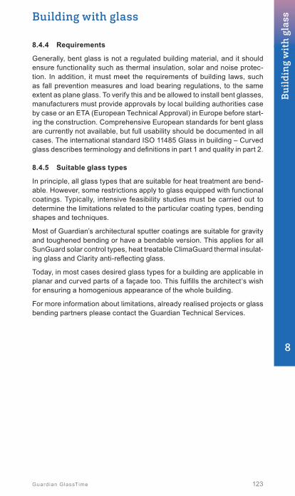
123
Building with glass
Guardian GlassTime
8.4.4 Requirements
Generally, bent glass is not a regulated building material, and it should ensure functionality such as thermal insulation, solar and noise protec-tion. In addition, it must meet the requirements of building laws, such as fall prevention measures and load bearing regulations, to the same extent as plane glass. To verify this and be allowed to install bent glasses, manufacturers must provide approvals by local building authorities case by case or an ETA (European Technical Approval) in Europe before start-ing the construction. Comprehensive European standards for bent glass are currently not available, but full usability should be documented in all cases. The international standard ISO 11485 Glass in building – Curved glass describes terminology and definitions in part 1 and quality in part 2.
8.4.5 Suitable glass types
In principle, all glass types that are suitable for heat treatment are bend-able. However, some restrictions apply to glass equipped with functional coatings. Typically, intensive feasibility studies must be carried out to determine the limitations related to the particular coating types, bending shapes and techniques.
Most of Guardian’s architectural sputter coatings are suitable for gravity and toughened bending or have a bendable version. This applies for all SunGuard solar control types, heat treatable ClimaGuard thermal insulat-ing glass and Clarity anti-reflecting glass.
Today, in most cases desired glass types for a building are applicable in planar and curved parts of a façade too. This fulfills the architect‘s wish for ensuring a homogenious appearance of the whole building.
For more information about limitations, already realised projects or glass bending partners please contact the Guardian Technical Services.
8
Bui
ldin
g w
ith
glas
s
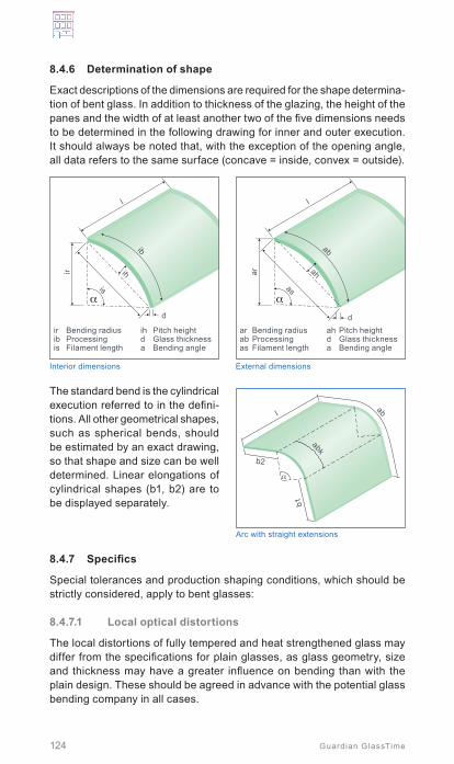
abk
l
b2
b1
α
ab
Arc with straight extensions
124 Guardian GlassTime
8.4.6 Determination of shape
Exact descriptions of the dimensions are required for the shape determina-tion of bent glass. In addition to thickness of the glazing, the height of the panes and the width of at least another two of the five dimensions needs to be determined in the following drawing for inner and outer execution. It should always be noted that, with the exception of the opening angle, all data refers to the same surface (concave = inside, convex = outside).
ar
d
α
ah
l
as
ab
ar Bending radiusab Processing as Filament length
ah Pitch heightd Glass thicknessa Bending angle
ir
d
α
ih
l
is
ib
ir Bending radiusib Processing is Filament length
ih Pitch heightd Glass thicknessa Bending angle
Interior dimensions External dimensions
The standard bend is the cylindrical execution referred to in the defini-tions. All other geometrical shapes, such as spherical bends, should be estimated by an exact drawing, so that shape and size can be well determined. Linear elongations of cylindrical shapes (b1, b2) are to be displayed separately.
8.4.7 Specifics
Special tolerances and production shaping conditions, which should be strictly considered, apply to bent glasses:
8.4.7.1 Local optical distortions
The local distortions of fully tempered and heat strengthened glass may differ from the specifications for plain glasses, as glass geometry, size and thickness may have a greater influence on bending than with the plain design. These should be agreed in advance with the potential glass bending company in all cases.

125
Building with glass
Guardian GlassTime
8.4.7.2 Outline precision
Outline precision means the accuracy of bending. This should be within a tolerance range of ± 3 mm in relation to the target contour so that the glass can be processed further without any diffi culties (Guideline on thermally curved glass for building applications – BF-Bulletin 009).
PC
PC
dd Glass thickness
RB
1000 mm
Contour accuracy (PC) Straightness of the edge height (RB)
8.4.7.3 Torsion (twist deviation)
Torsion describes the exactness to the plane parallelism of the edges or unbent edges. In this case, the largest irregularity after bending should also not exceed ± 3 mm per metre of glass edge (Guideline on thermally curved glass for building applications – BF-Bulletin 009).
V
1000 mm
Twist (V)
8.4.7.4 Edge displacement
Diverging from the specifi cations of plain laminated and insulating glass, the displacement at the edges may increase after bending. It is absolutely necessary to fi nd common conformity in advance.
d
d
dd
A, H
A, H
A, H
Displacement in laminated glass (d height) Displacement in insulating glass (d height)
8
Bui
ldin
g w
ith
glas
s

Evolution Tower, Moscow, Russian FederationSunGuard® HP Neutral 60/40 | “Twisted” facade with cold bent insulating glassArchitect: Tony Kettle | Photo: © Olga Alexeyenko

127
Building with glass
Guardian GlassTime
8.4.7.5 Tangential junctions
The tangent is the straight line which has its origin in a particular point of the curve. Thereby the line is perpendicular compared with the bent radius of the curve. Without this tangential transition there would be a sharp angle at this spot, which can be achieved with glass, but is not advisable. There are normally larger tolerances at the sharp angle than with tangential transitions.
R R
R R
90° < 90°
Tangent
Arc center Arc center
With tangential transition No tangential transition
8.4.8 Staticspecifics
The deformation and mechanical stress of a bent glass can be defined through finite element models with the aid of the shell theory. The curva-ture, depending on installation conditions in the case of monolithic glass, can have a positive effect due to the shell bearing impact, namely in the direction of thinner glasses. Insulating glass, however, does not achieve this effect as readily. The curvature of the glass means that the bending strength is increased and, consequently, extremely high climatic loads can arise. This must be considered, particularly when units have tangential attachment pieces at a curvature. This can result in broader edge seals that affect later glass installation.
8.4.9 Cold-bending
This technique allows designers to create continuously smooth glass sur-faces (as opposed to segmented structures) and can be a cost-effective method of cladding a shaped glass façade.
Often, cold-bending refers to a practice of fabricating pre-shaped unitised curtain-wall panels and industrial cladding at the production site or the flat glass units are installed at the building site on a curved sub-construction.
A necessary pre-condition is the toughening process of all applied glasses, as the resulting high bending strength of toughened glass allows for applying permanent deflections to the glazing without issue. The radius limitations of the glass units depend on the degree of surface compression. The minimum achievable radii are much larger compared to thermally curved glass and are typically several metres. The typical parameter describing the deflection of cold-bent glass is the displacement „dZ“ (see drawings below).
8
Bui
ldin
g w
ith
glas
s

128 Guardian GlassTime
The shaping of the glass can be achieved by:
• Pushing by cover bars.• Structural sealant between glass and sub-construction.• Hardened resin of thin laminated glass (laminate-bending).
The applied permanent tensions of the cold-bent units must be considered for dimensioning the insulating glass sealant depth, together with the bite and area of the used structural silicone if applied on a pre-shaped sub-construction.
dZ
Cold-bent rectangular glass panes with displacement dZ
Displacement dZ: IGU before pushing onto the curved sub-construction
8.5 Glass elevatorsOne highlight of today’s architecture are transparent elevators, which gives users the feeling of fl oating. In these applications, the shafts, lifts and cars are made from glass. These types of constructions must meet a number of safety and mechanical requirements that are regulated in European elevators by directives 95/16 EC 7/99 and EN 81 02/99.
Additional national requirements may exist, such as building regulations of the respective federal state in Germany. For a glass shaft, proof of stability for an applied force of 300 N on an area of 5 cm2 is required. Depend-ing on the size of the cars, the walls, which are fi xed and mounted on all sides, create different demands on the characteristics of the laminated glass to be used. If the glazing stretches from the fl oor to the ceiling, a beam should be installed in the vicinity of a height of 0.90 - 1.10 m which should not be supported by glass.
Doors, on the other hand, need to meet special requirements which should be assessed according to the fi xture, mechanism and dimensions. Lifts made from glass are always custom-made products which can only be realised together with everybody involved. All lift glass components should have a permanent and visible identifi cation marking.
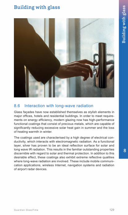
129
Building with glass
Guardian GlassTime
8.6 Interaction with long-wave radiationGlass façades have now established themselves as stylish elements in major offices, hotels and residential buildings. In order to meet require-ments on energy efficiency, modern glazing now has high-performance functional coatings that consist of precious metals, which are capable of significantly reducing excessive solar heat gain in summer and the loss of heating warmth in winter.
The coatings used are characterised by a high degree of electrical con-ductivity, which interacts with electromagnetic radiation. As a functional layer, silver has proven to be an ideal reflection surface for solar and long wave IR radiation. This results in the familiar outstanding properties discernible with regard to solar and thermal protection. In addition to this desirable effect, these coatings also exhibit extreme reflective qualities where long-wave radiation are involved. These include mobile communi-cation applications, wireless Internet, navigation systems and radiation of airport radar devices.
8
Bui
ldin
g w
ith
glas
s

Radar
Multipath propagation Glass
facade
130 Guardian GlassTime
8.6.1 Radarreflectiondampingglazing
Other interference phenomena arise as a result of major reflection on the exterior of glass building envelopes. The so-called multi-path propaga-tion of radio waves that occurs here can cause major interference in many communication systems. This includes air traffic control ra-dar waves. For example, the authority responsible for German air traffic control, Deutsche Flugsicherung (DFS), uses secondary surveillance radar systems (SSR) in the microwave range (ca. 1,1 GHz) at airports and selected locations to ensure the broadest possible monitoring of the airspace. An interrogation signal from the radar determines the direction of the aircraft here according to its identity, altitude, speed, etc. The reply from the aircraft can be reflected on large surfaces (e.g. tall buildings), resulting in its duplication from another direction. These phantom targets can lead to the erroneous position determination of aircraft or, in the case of multiplication, even result in transponder overloading.
Henninger Turm, Frankfurt/M, Germany SunGuard® RD 60 | Radar reflection damping and solar control glass Architect: Meixner Schlüter Wendt (Frankfurt/M.) | Photo: © Frank Weber
Air traffic control therefore requires that buildings of a specific size, distance and alignment relative to the radar system are planned and realised with radar reflection attenuation characteristics.

131
Building with glass
Guardian GlassTime
Specifi c project-related requirements are determined by qualifi ed experts. This generally involves a requirement for refl ection attenuation with regards to building components in [dB] relative to the incidence angle of radar waves.
The attenuation or damping properties of glass types depends greatly on their structure. Single glass panes with a normal thickness have only a very minimal damping effect. The improvement is also barely discernible in the case of normal insulating glass. The most problematic situation is, as mentioned above, evident in relation to solar and thermal protection glass with precious metal damping. An undesirable and practically complete refl ection of radar waves occurs here.
Consequently, the most common contemporary solar and thermal protec-tion glass types cannot be used where radar attenuation is demanded without taking further measures!
8.6.1.1 RadarreflectionattenuationwithSunGuard® RD coated glass
SunGuard® RD is specially developed for radar beam attenuation to exploit the phase displacement effect. The coating, which is “semi-permeable” for radar waves, is on the outer pane of the insulating glass. The residual beam is refl ected completely on the inner pane on a (typically low-E) coat-ing containing silver. Wave superposition occurs as they are refl ected on both coatings. As the wavelength of the radar beam is approximately within the range of the insulating glass thicknesses, the degree of superposition and, consequently, the phase displacement can be optimised relative to the incidence angle with exactly corresponding pane interspaces and thicknesses of the individual glass panes.
The following applies:
d = f (λRadar and Radar)
SunGuard® anti radar coatingPartial refl ection
Outside
Incident radar waves
Refl ected radar waves
ClimaGuard®
Full-refl ection
Insided
Obliteration through phase displacement
The front coating should be calibrated in its electrical properties so that an exactly measured beam volume is allowed to penetrate and, in conjunc-tion with the back refl ection of the second coating, the maximum possible obliteration occurs.
8
Bui
ldin
g w
ith
glas
s

132 Guardian GlassTime
Based on the topographic conditions and requirements stipulated in the expert radar appraisal, a special insulating glass structure is deter-mined for each specific case with uniquely determined attenuation properties derived from this. These reflect a logarithmic function (table).
In cooperation with engineering firms and consultants, Guardian provides assistance during preliminary dimensioning of radar reflection attenuation glazing. This involves the mathematical determination of insulating glass structures, which meets the requirements for radar beam attenuation (secondary radar).
A typical glazing build-up is shown in chapter 10.3, table 16.
This preliminary dimensioning does not replace the final confirmation of glass structures through measurement and appropriate expert radar ap-praisals which must be compiled for each specific project.
For more information please contact Guardian’s Technical Services.
8.6.2 Damping of electro-magnetic high frequency radiation / electrical smog
Only the use of high-frequency pulsed radiation makes the performance of today’s mobile service applications possible. Ultimately, this has led to its widespread use. Many people are now worried about excessive exposure to radiation, particularly near mobile service transmission installations.
The term “electrical smog” originates from the 1970s and refers to the pollution of the environment by electromagnetic radiation.
Electromagnetic radiation is reflected by conductive surfaces or boundary layers. Absorption plays a decisive part where poor electrical conductors are concerned (e.g. thickness of concrete structural elements).
Electromagnetic screening is always relative and depends on the incident signal and its strength (radiation density in μW/m²).
As the electromagnetic screening is mathematically difficult to determine, the damping properties of a whole series of building materials, including double and triple glazing, were examined at the Bundeswehr University in Munich, together with the consultant Dr. Moldan many years ago.
High-frequency radiation is dampened very effectively by thermal insu-lating coated glass (such as ClimaGuard Premium2 or ClimaGuard 1.0+ and solar protection glass of the types SunGuard HP, SN and SNX) with a surface resistance of the coating of < 5 Ohm.
Damping [dB] Reduction [%]
5 app. 38
10 app. 90
15 app. 97
20 app. 99

133
Building with glass
Guardian GlassTime
For triple glazing with 2 ClimaGuard/SunGuard coatings, HF transmission damping of approx. 34 dB was achieved for 900 MHz (GSM 900 mobile service) and approx. 34 - 38 dB in the 1 900 MHz band (GSM 1800 mobile service, DECT, UMTS).
Aside from that, double glazing with a single ClimaGuard coating achieves an HF transmission damping of approx. 25 dB at 900 MHz and approx. 28 dB at 1 900 MHz. Recent investigations with the high-energy 5G technology on modern triple glazing have tended to result in even higher damping rates. 60 to 70 dB were determined for the frequency range of approx. 60 GHz.
The damping is specified as the so-called “damping ratio”. It describes the amount by which the incident electromagnetic signal is reduced on passing through a structural element and is specified in the unit dB (Decibel). Since the function is logarithmic, the following relationship results:
Damping ratio [dB] Reduction [%]
10 90.00
20 99.00
30 99.90
40 99.99
Damping ratios vs. reduction of transmission
Frequency [MHz] Application Damping with double glazing (1 x low-e)
[dB]
Damping with triple glazing (2 x low-e)
[dB]
900 GSM 900 (D-network) app. 25 app. 34
1900 DECT, UMTS app. 28 app. 34 - 38
2500 WLAN, LTE app. 30 app. 35 - 40
The data are based on measurements performed according to the IEEE 299-1997 standard on specific glass samples (source: Bundeswehr University, Dr. Pauli, Dr. Moldan) and can deviate in special installation situations. The Insulating glass gap as well as the used coatings can lead to slightly different results too.
The damping ratio and the related transmission reduction of the electro-magnetic radiation in the considered range, demonstrate that a very low signal level can be received behind energy efficient glazing.
In order to improve the permeability for high-frequency radiation the coatings can be segmented by special treatments (laser, specific ceramic enamels). This segmentation influences the generation of circular currents in the highly-conductive coatings which are responsible for the reflection properties.
In any case, however, it must be noted that only comprehensive consid-erations can offer solutions. In the specific case, therefore, the complete window and façade elements must be considered along with their cor-responding profiles and wall connections.
8
Bui
ldin
g w
ith
glas
s

134 Guardian GlassTime
8.7 Anti-reflective glazingDespite the excellent transparency of modern glazing, the view from the bright exterior to the darker interior may be hindered by reflections, depend-ing on the viewing angle and incidence of light. Shop window glazing in particular can diminish the view of items behind the glass due to reflections.
CFL Control Tower, Dudelange, Luxembourg | Guardian Clarity™ | Anti-reflective coated glass Photo: © Frank Weber
430 480 530 580 630 680 730 780380
Refl
ectiv
ity [%
]
Wavelength [nm]
30
25
20
15
10
5
0
Double sided AR glass Single sided AR glass Standard clear float glass

135
Building with glass
Guardian GlassTime
A standard float glass surface reflects approximately 4 % of visible light. This means a float pane with two surfaces reflects 8 % and a double glazing close to 16 %.
Special anti-reflective coatings, such as Guardian Clarity™, are able to decrease the reflectivity significantly. The coating on both glass surfaces reduces the degree of reflection on glazing with one pane to significantly less than 1 %.
Product Visible light transmission [%] Visible light reflection [%]
Guardian Clarity double sided on UltraClear 4 mm
98 <1
Guardian UltraClear float glass 4 mm
91 8
For highest requirements on reducing reflections, all surfaces of a desired glass build up should be anti-reflective coated. Any uncoated float glass surface would increase the visible light reflection by 4 %.
Clarity™ anti-reflective coating is applied on UltraClear low-iron glass as a standard and is available as single and double side coated. It is heat treatable to fully tempered or heat strengthened glass and can be bent using the gravity or tempering technique (→ chapter 8.4).
The performance data for typical single and double glazing build-up’s and combinations with further functional coatings are shown in chapter 10.4.
Guardian Clarity is particularly suitable for:
• Retail storefronts• Display cases in shops and
museums• Protection of paintings and
other artwork in art galleries• Control rooms• Architectural entrances• Airports / control towers• Stadia / arenasPetrol stations• Car showrooms• Hotel lobbies• Restaurants• Rooftop bars
8
Bui
ldin
g w
ith
glas
s

136 Guardian GlassTime
8.8 Bird-friendly glazing
8.8.1 What’s the problem?
The use of glass in architecture with its transparency and refl ectivity can infl uence the perception of the environment.
Unlike humans, birds are not able to perceive images refl ected on glass surfaces as a refl ection and hit the glass, which appears like a cloudy sky, a tree or other natural environment.
Transparent glazings are also dangerous, as birds do not perceive it as a solid object and strike the glass to try to enter the environment visible behind it. In particular, glazed corridors, windows behind each other, glass walls, glass balconies and all-glass corners are critical.
The impact in full fl ight often results in death. The problem is getting worse as cities are growing and the use of glass in architecture is expanding. Authorities and investors in Central Europe and North America have recognised the problem and many glass manufacturers have developed products and technologies to address the problem.
Refl ections Transparency
8.8.2 Evaluation of „bird-friendly“ solutions
When the awareness of bird collisions on glass became established by planners and users, the glass industry started to develop glazings ac-cordingly to minimise the effect, but no standards or regulations were availabe to verify so-called bird friendly or bird protection glass solutions.
The fi rst step was the introduction of the Austrian standard ONR 191040. This standard describes the effectiveness of solutions and „bird-protection glass“ was fi rst time established in assessments and regulations. It evaluates the glass solutions through special tests using a “fl ight tunnel“. Two glazings are placed next to each other at the end of the tunnel: one standard reference glass and one glass with bird protective measure to be tested. A defi ned number of birds are set free and fl y in the direction of the glass. In order to prevent the birds hitting the glass, a net is placed in front of the glazings.

137
Building with glass
Guardian GlassTime
To consider a glazing as bird-friendly, less that 10 % of the test birds must decide to fly into the sample glass with the protective measure. This 10 % limit was agreed with Swiss, Austrian, German and American ornitholo-gists. Based on experiments with thousands of birds, 4 categories of ef-fectiveness were defined:
A Highly effective < 10 % approachB Limited 10 % to 20 % approachC Poor 20 to 45 % approachD Not effective > 45 %
The topic of bird-protection is currently under discussion and the knowledge of the behaviour of the birds and suitable glass products are continiously developing.
8.8.3 Glass solutions providing better visibility for birds
In general, the following rule applies: the higher the visible contrast the better. On large glass areas without grids, lower reflections are favourable, as landscapes are less visible. Very high reflections can even interfere with non-transparent markings. Right now, the common meaning is ac-cepted that light reflection values < 15 % (applies for triple glazing too!) do not require an opaque marking. Organisations such as the BUND (D), the Ornithological station Sempach (CH) or the Minergie Certification (CH) recommend exterior reflections of < 15 % as “low-priced and reasonable solution“ without obstructed views. The Minergie organisation states for windows generally “maximum of 15 % (better 12 %), particularly if trees/bushes are in front of the glass“. Façades should have markings or a limitation of the exterior reflection < 15 %, corner glazings of 2 m or larger should be performed always with markings.
For higher requirements, an additional marking should be applied at least on surface #2 of the glazing. An ideal solution, if architectural SunGuard solar control or ClimaGuard thermal insulating coatings are involved, is the enamel “System TEA“ for ceramic printing of black marks directly onto the coating (→ chapter 8.2.3). As this enamel dissolves the coating (and it’s reflection) a maximum contrast can be achieved when looking from outside on the glass.
Suitable coatings with the mentioned limitation on outdoor reflection can be found in chapters 10.2 + 10.3.
For any markings, the maximum distance should not exceed 10 cm and the diameter of the single marks (e.g. dots) should not be less than 8 mm. It’s not the degree of coverage that is crucial, but the maximum contrast when looking from the exterior!
Critical constructions (e.g. corners, glass walls, balconies or glass walk-ways) require the marking outside on #1. According to current knowledge in Europe, UV marking is considered as „poorly suitable“ or even „not effective“.
8
Bui
ldin
g w
ith
glas
s

Conarg Offi ces, Bucharest, Romania | SunGuard® SN 63Architect: Colbax | Photo: © Arthur Tintu

139Guardian GlassTime
9. Standards and guidelines .................................142
9.1 Glass relevant norms ......................................................142
9.2 Tolerances for standardised requirements .....................1449.2.1 Base glass .........................................................................1449.2.2 Cutting ...............................................................................144
General | Possible break-off for float glass | Acute angle of tempered glass, laminated safety glass, IGU-cutback (zone not to be assessed) | Length, width and perpendicularity
9.2.3 Processing .........................................................................146Edge processing qualities | Standard tolerances | Special tolerances | Special shapes | Edge processing | Processing (cut-outs, notches) | Corner cut-off, seamed < 100 mm x 100 mm | Corner cut-out, seamed | Edge cut-out, seamed | Standard deviation for manual processing – cut-out dimensions | Standard deviation for CNC processing – cut-out dimensions | Corner cut-off, smooth ground | Corner cut-off, polished - CNC processing centre | Standard | Special deviation | Standard | Special deviation | Corner cut-out, polished - CNC processing centre | Standard | Special deviation | Edge cut-out, smooth ground or polished - CNC processing centre | Standard deviation | Special deviation | Drillings | Diameters of drilled holes | Limitation and position of the drilled hole | Deviations in drilling positions | Drilled hole positions | Drilled countersunk hole diameters | Drilled countersunk holes in laminated safety glass
9.2.4 Tempered glass, tempered heat-soaked glass and heat-strengthened glass ......................................................153General distortion – uncoated float glass | Local distortion (roller waves) – uncoated float glass | Recommended minimum glass thickness depending on the glass dimensions
9.2.5 Insulating glass units (IGU) ..................................................154Edge seal | Thickness tolerances in the edge area of the insulating glass unit | Dimension tolerance / offset
9.2.6 Laminated safety glass ........................................................155Dimensional tolerances | Displacement tolerance (offset) | Thickness tolerance
9.3 Glass edges ....................................................................1579.3.1 Edge types .........................................................................1579.3.2 Edge processing .................................................................1589.3.3 Edge geometries and typical applications ..............................158
9.4 Glass corners and joint ...................................................159 9.4.1 Glass joint with sealant joint and weather stripping
for double insulating glass ....................................................1599.4.2 Glass joint with sealant joint and weather stripping for triple insulating glass ......................................................160
9
Stan
dard
s an
d gu
idel
ines

140 Guardian GlassTime
9.4.3 Glass joint with sealant joint and preformed seal for double insulating glass ....................................................1609.4.4 Glass joint with sealant joint and preformed seal for triple insulating glass ......................................................1609.4.5 All-glass corner with double-stepped glazing unit ...................1609.4.6 All-glass corner with triple-stepped glazing unit ......................1619.4.7 All-glass corner with preformed seal for double- insulated glass with stepped edges .......................................1619.4.8 All-glass corner with preformed seal for triple-
insulated glass with stepped edges .......................................161
9.5 Glass thickness dimensioning ........................................162
9.6 Surface damage to glass ................................................162
9.7 Guidelines for assessing the visual quality of glass in buildings .........................................................163
9.7.1 Visual quality of coated glass ...............................................163Detection of defects | Conditions of examination | General | Uniformity defects and stains | Punctual defects | Acceptance criteria for coated glass defects
9.7.2 Visual quality of insulating glass units (IGU) ...........................165Observation conditions | IGU made of two panes of monolithic glass | Spot faults | Residues | Linear / extended defects | IGU other than those made of two panes of monolithic glass panes | IGU containing a heat-treated glass | Edge defects | Tolerance on spacer straightness | Curved IGU | Other visual aspects of insulating glass units | Inherent colour | Difference in insulating glass unit colour | Interference effect | Specific effect due to barometric conditions | Multiple reflections | Anisotropy (iridescence) | Condensation on the external surface of the IGU | Wetting of glass surfaces | Assessment of the visible section of the edge seal of the insulating glass unit | IGU with internal muntins
9.8 Glass breakage ...............................................................1719.8.1 Thermal breakage / thermal stress ........................................171
General | Thermal cracks | Factors influencing thermal breakage | Factors influencing glass strength and thermal breakage risk | Calculation and evaluation of the risk of thermal breakages
9.8.2 Typical glass fracture pattern ...............................................174
9.9 CE qualification ...............................................................178
9.10 Material compatibility ......................................................1799.10.1 Sealant compatibility of coated glass .....................................179
Guardian SunGuard coatings in structural glazing
9.10.2 Ceramic printing on coated glass ..........................................181Requirements on enamelling of SunGuard for monolithic spandrel applications | Ceramic print with Ferro System 140 | SunGuard HD in combination with ceramic print on surface #1

141Guardian GlassTime
9.10.3 Architectural coatings in laminated glass ...............................184
9.11 Cleaning of glass .............................................................1869.11.1 Introduction ........................................................................1869.11.2 Types of cleaning ................................................................186
During the construction phase | During use
9.11.3 Glass cleaning instructions ..................................................187General | Specially finished and externally coated glass | Further notes
9.12 Transportation and storage .............................................189
9
Stan
dard
s an
d gu
idel
ines

142 Guardian GlassTime
Naturally enough, the rapid development of glass as a building material means that the rules governing its use are becoming more stringent and comprehensive. European standards now cover most aspects of the application and testing of various types of glass in the construction industry. But beyond this, a host of national and country-specific regula-tions and guidelines also exist which should be consulted, depending on the application. Regardless of the testing and usage regulations, purely glass-specific parameters must also be observed, and these can have a major influence on the function and longevity of glass products, as has been illustrated in previous chapters.
9.1 Glass relevant normsThe most important norms for the assessment and the use of glass in connection with buildings are:
EN 81 Safety rules for the construction and installation of lifts
EN 101 Ceramic tiles; Determination of surface scratch hardness according to the Mohs scale
EN 356 Glass in building – Security glazing – Testing and classification of resist-ance against manual attack
EN 410 Glass in building – Determination of luminous and solar characteristics of glazing
EN 572 Glass in building – Basic soda lime silicate glass products
EN 673 Glass in building – Determination of thermal transmittance (U value) - Calculation method
EN 674 Glass in building – Determination of the thermal transmittance (U value) - Guarded hot plate method
EN 1063 Glass in building – Security glazing – Testing and classification of resist-ance against bullet attack
EN 1096 Glass in building – Coated glass
EN 1279 Glass in building – Insulated glass units
EN 1363 Fire resistance tests
EN 1364 Fire resistance tests on non-load bearing elements
EN 1522/1523 Windows, doors, shutters and blinds – Bullet resistance
EN 1627 - 1630 Burglar resistant construction products – Requirements and classifica-tion, test methods for the determination of resistance under static and dynamic loading and to manual burglary attempts
EN 1748 Glass in building – Special basic products
EN 1863 Glass in building – Heat strengthened soda lime silicate glass
EN 10204 Metallic products – Types of inspection documents
EN 12150 Glass in building – Thermally-tempered soda lime silicate safety glass
EN 12207 Windows and doors – Air permeability – Classification
EN 12208 Windows and doors – Watertightness – Classification
EN 12412 Thermal performance of windows, doors and shutters
EN 12488 Glass in building – Glazing requirements – Assembly rules
EN 12600 Glass in building – Pendulum tests
EN 12758 Glass in building – Glazing and air- borne sound insulation
EN 12898 Glass in building – Determination of the emissivity
EN 13022 Glass in building – Structural sealant glazing

Standards and guidelines
143143Guardian GlassTime
EN 13123, (p. 1+2) Windows, doors and shutters – Explosion resistance
EN 13501 Fire classification of construction products and building elements
EN 13541 Glass in building – Security glazing – Testing and classification of resist-ance against explosion pressure
EN 14179 Glass in building – Heat-soaked thermally tempered soda lime silicate safety glass
EN 14449 Glass in building – Laminated glass and laminated safety glass
EN 15434 Glass in building – Product standard for structural and/or ultra-violet resistant sealant
EN 15651 Joint sealants for non-load bearing applications in buildings and on pedestrian paths
prEN 16612 Glass in building – Determination of the load resistance of glass panes by calculation and testing
DIN 18008-1 Glass in building – Design and construction rulesTerms and general bases
DIN 18008-2 Glass in building – Design and construction rulesLinearly supported glazing
DIN 18008-3 Glass in building – Design and construction rulesPoint fixed glazing
DIN 18008-4 Glass in building – Design and construction rulesAdditional requirements on barrier glazing
DIN 18008-5 Glass in building – Design and construction rulesAdditional requirements for walk-on glazing
DIN 18008-6 Glass in building – Design and construction rulesAdditional requirements for walk-on glazing in case of maintenance procedures and for fall-through glazing
EN 20 140 Acoustics – Measurement of sound insulation in buildings and of building elements
EN ISO 140- 3 Acoustics – Measurement of sound insulation in buildings and of building elements – Laboratory measurements of airborne sound insulation of building elements
EN ISO 717-1 Acoustics – Rating of sound insulation in building and of building ele-ments – Airborne sound insulation
EN ISO 1288, 1 - 5 Glass in building – Bending strength of glass
EN ISO 9050 Glass in building – Determination of light transmittance, solar direct transmittance, total solar energy transmittance, ultraviolet transmittance and related glazing factors
EN ISO 10077 Thermal performance of windows, doors and shutters
EN ISO 12543 Glass in building – Laminated glass and laminated safety glass
EN ISO 13788 Hygrothermal performance of building components and building elements
9
Stan
dard
s an
d gu
idel
ines

Nominal thickness [mm] Deviation limit [mm]
2 ± 0.2
3 ± 0.2
4 ± 0.2
5 ± 0.2
6 ± 0.2
8 ± 0.3
10 ± 0.3
12 ± 0.3
15 ± 0.5
19 ± 1.0
Tab. 1: Deviation limits for glass thicknesses
Specifi eddimension
Specifi eddimension
Fig. 1: Overbreak Fig. 2: Underbreak
144 Guardian GlassTime
9.2 Tolerances for standardised requirementsThe basic principles for tolerances are specifi ed in the applicable stand-ards. However, these standards are not always suffi cient in actual practice. This chapter therefore describes those applications that are listed in the standards where they are not clearly defi ned or are not specifi ed at all, and breaks them down into two categories:
• Standard tolerancesStandard tolerances are tolerances that can be ensured during the normal course of production.
• Special tolerances Special tolerances can be realised during production with additional
precautionary measures and must be agreed upon on a case-by-case basis.
9.2.1 Baseglass
EN 572 is a normative standard for base glass.
The standard specifi es the deviation limits for nominal thicknesses for various glass products. Further-more, requirements for quality as well as optical and visible fl aws in basic glass products are defi ned in this standard.
The following tolerances of the nom-inal thickness apply:
No differentiations are made be-tween standard and special tolerances when considering the deviation limits.
9.2.2 Cutting
EN 572 and general length dimensions also apply, in all cases ± 0.2 mm/m edge length.
9.2.2.1 General
The angular break must be taken into consideration! This type of break depends on glass thickness and the quality of the base glass.

Glass thickness [mm] Maximum value [mm]
2, 3, 4, 5, 6 ± 1.0
8, 10 ± 1.5
12 ± 2.0
15 ± 2.0
19 + 5.0 / - 3.0
Tab. 2: Angular break values
W +
5
W -
5
H - 5
H + 5
Fig. 4: Angularity
α x [mm]
≤ 12.5° -65
≤ 20° -33
Tab. 2b: Cutback
Standards and guidelines
145145Guardian GlassTime
These factors must be taken into consideration when providing in-formation on tolerances, i. e. glass dimensions may change with a raised edge by twice the value of the angular break.
As for non-rectangular elements, the following tolerances shown in table 2a can apply to the given angles (similar to cutback). The geometry of the elements remains the same.
9.2.2.1.1 Possible break-off for fl oat glass
α x [mm]
≤ 12.5° -30
≤ 20° -18
≤ 35° -12
≤ 45° -8
Tab. 2a: Cutbackx
α
Fig. 3: Cutback
9.2.2.1.2 Acute angle of tempered glass, laminated safety glass, IGU-cutback (zone not to be assessed)
Due to manufacturing reasons, the glass manufacturer reserves the right to cut back, according to Table 2b. If such a cutback is not performed, the measurements listed in Table 2b are considered zones that are not to be assessed. In this case, unevenness at the edges (e.g. upper breaks) and on the surface may occur and are not a reason for complaint.
If the angle is > 25°, the cutback equals the break-off. The tolerances listed in chapter 9.2.3.1.4, Table 6 should not be added to the toler-ances mentioned above in Tables 2a and 2b.
9.2.2.2 Length, width and perpendicularity
Based on the nominal dimensions of the length H and width W, the glass pane should fi t into a rectangle that has been enlarged in size by the upper deviation limit and reduced in size by the lower deviation limit.
The sides of this rectangle should be parallel to each other and share a common middle point (see fi g. 4). The rectangles also describe the limits of perpendicularity. The deviation limits for the nominal dimensions of length (H) and width (W) are ± 5 mm.
9
Stan
dard
s an
d gu
idel
ines

146 Guardian GlassTime
9.2.3 Processing
The tolerances depend on the respective type of edge processing. In addition, EN 14179 and national requirements, such as DIN 1249, Part 11 in Germany, also apply.
9.2.3.1 Edge processing qualities
(→ chapter 9.3.2)
9.2.3.1.1 Standard tolerances
Edge processing is divided into bordered, ground, smooth ground and polished. Therefore, there are two tolerance categories:
• The tolerance with angular break indicated in “cutting“ (→ chapter 9.2.2) applies to bordered edges.
• The following table applies to smooth ground / polished edges.
Edge length [mm] Thickness ≤ 12 mm [mm] Thickness = 19 mm [mm]
≤ 1000 ± 1.5 ± 2.0
≤ 2000 ± 2.0 ± 2.5
≤ 3000 + 2.0 / - 2.5 ± 3.0
≤ 4000 + 2.0 / - 3.0 + 3.0 / - 4.0
≤ 5000 + 2.0 / - 4.0 + 3.0 / - 5.0
≤ 6000 + 2.0 / - 5.0 + 3.0 / - 5.0
Tab. 3: Standard rectangle deviations
± 1 mm/ ± 5°
1,5 → 45°
1.5
→ 4
5°
Fig. 5: Edge processing
The diagonal deviation is derived from w2 + h2 Example:
Glass pane w · h = 1 000 x 3 000 mm
Therefore: Plus dimension: 1.52 + 2.02 = +2.5 mm Minus dimension: 1.52 + 2.52 = -2.9 mm;Therefore: Diagonal deviation: + 2.5 / - 3.0 mm

Standards and guidelines
147147Guardian GlassTime
9.2.3.1.2 Special tolerances
The tolerances listed in Table 4 can be realised with an increased effort. This special effort is necessary because the first glass pane must be measured exactly. Unground glass panes should be recut in this respect.
Edge length [mm] Thickness ≤ 12 mm [mm] Thickness = 15 and 19 mm [mm]
≤ 1000 + 0.5 / - 1.5 + 0.5 / - 1.5
≤ 2000 + 0.5 / - 1.5 + 0.5 / - 2.0
≤ 3000 + 0.5 / - 1.5 + 0.5 / - 2.0
≤ 4000 + 0.5 / - 2.0 + 0.5 / - 2.5
≤ 5000 + 0.5 / - 2.5 + 0.5 / - 3.0
≤ 6000 + 1.0 / - 3.0 + 1.0 / - 3.5
Tab. 4: Special rectangle deviations
9.2.3.1.3 Special shapes
The following table applies to 15 and 19 mm glass:
Edge length
Standard [mm] Special (CNC) [mm]
≤ 1000 ± 2.0 + 1.0 / - 1.0
≤ 2000 ± 3.0 + 1.0 / - 1.5
≤ 3000 ± 4.0 + 1.0 / - 2.0
≤ 4000 ± 5.0 ≤ 3900 + 1.0 / - 2.5
≤ 5000 + 5.0 / - 8.0 ≤ 5000 + 2.0 / - 4.0
≤ 6000 + 5.0 / - 10.0 ≤ 6000 + 2.0 / - 5.0
Tab. 5: Special shapes
9.2.3.1.4 Edge processing
α x [mm]
≤ 12.5° - 15
≤ 20° - 9
≤ 35° - 6
≤ 45° - 4
Tab. 6 (Legend figure 3, chapter 9.2.2.1.1)
9.2.3.2 Processing (cut-outs, notches)
Processing can involve corner cut-outs, surface cut-outs and edge cut-outs in a glass pane. Positions and dimensions of processing should, where not standardised, be agreed to suit each production situation. As for corner and edge cut-outs, the minimum radius of the processing tool should be considered. The hole position and/or position tolerances of different kinds of processing are the same as the edge processing tolerances.
9.2.3.2.1 Corner cut-off, seamed < 100 mm x 100 mm
Standard deviation ± 4 mm
9
Stan
dard
s an
d gu
idel
ines

Cut-out length [mm] Deviation [mm]
≤ 2000 ± 4.0
≤ 3400 ± 4.0
≤ 6000 ± 5.0
Tab. 8: Edge cut-out deviation CNC processing centre, seamed
Fig. 6: Special shape
148 Guardian GlassTime
9.2.3.2.2 Corner cut-out, seamed
Standard deviation ± 4 mm to position/deviations
9.2.3.2.3 Edge cut-out, seamed
9.2.3.2.3.1 Standard deviation for manual processing – cut-out dimensions
Cut-out length [mm] Deviation [mm]
≤ 1000 ± 6.0
Tab. 7: Edge cut-out deviation HB, seamed
9.2.3.2.3.2 Standard deviation for CNC processing – cut-out dimensions
Important: Minimum dimension with internal radii: 15 mm
9.2.3.2.4 Corner cut-off, smooth ground
Standard deviation ± 2 mm (Edge cut-off < 100 mm x 100 mm otherwise special shape)
Special deviation ± 1.5 mm Production performed in CNC processing centre
9.2.3.2.5 Corner cut-off, polished - CNC processing centre
9.2.3.2.5.1 Standard
Standard deviation ± 2 mm(Edge cut-off < 100 mm x 100 mm, otherwise special shape)
9.2.3.2.5.2 Special deviation
Deviation ± 1.5 mm

Cut-out length [mm] Deviation [mm]
< 500 ± 2.0
≤ 1000 ± 3.0
≤ 2000 ± 3.0
≤ 3400 ± 4.0
Tab. 9: Edge cut-out deviation CNC pro-cessing centre, smooth ground or polished
Standards and guidelines
149149Guardian GlassTime
9.2.3.2.6 Corner cut-out, smooth ground
9.2.3.2.6.1 Standard
Depending on the glass thickness, minimum distance with internal radii:
≤ 10 mm: R 10 ≤ 12 mm: R 15 Deviation of size ± 2 mm Deviation of position ± 3 mm
9.2.3.2.6.2 Special deviation
Minimum dimension with internal radii: 17.5 mm, deviation 1.5 mm.
Special processing is performed in the CNC processing centre.
9.2.3.2.7 Corner cut-out, polished - CNC processing centre
Minimum dimension with internal radii: 17.5 mm
9.2.3.2.7.1 Standard
Deviation ± 2 mm
9.2.3.2.7.2 Special deviation
Deviation ± 1.5 mm
9.2.3.2.8 Edge cut-out, smooth ground or polished - CNC processing centre
9.2.3.2.8.1 Standard deviation
Minimum dimension with internal radii: 17.5 mm
9.2.3.2.8.2 Special deviation
Minimum dimension with internal radii: 17.5 mm
Deviation ± 1.5 mm
9
Stan
dard
s an
d gu
idel
ines

a ≥ 2tThe distance of the well shall not be less than 2 x t
a
Fig. 7: Position of hole relative to edge
150 Guardian GlassTime
9.2.3.3 Drillings
The drilling positions and/or position tolerances correspond to the edge processing tolerances.
9.2.3.3.1 Diameters of drilled holes
The diameters Ø of drilled holes should not be smaller than the glass thickness. Please enquire separately from the manufacturer regarding small diameters of drilled holes.
9.2.3.3.2 Limitation and position of the drilled hole
The position of the drilling (edge of the hole) relative to the glass edge, glass corner and next drilling depends on:
• Glass thickness (t)• Diameter of the drilling• Shape of the glass pane• Number of drillings
Fig. 9: Position of hole relative to corner
c ≥ 6tThe distance of the borehole edge to the corner of the glass should not be less than 6 x t
c 2t
2t
b ≥ 2tThe distance of the holes to each other should not be less than 2 x t
b
Fig. 8: Position of adjacent holes
Nominal diameter Ø [mm]
Deviation [mm]
4 < Ø < 20 ± 1.0
20 < Ø < 100 ± 2.0
Ø > 100 Request from manufacturer
Tab. 10: Drill hole deviations

Standards and guidelines
151151Guardian GlassTime
9.2.3.3.3 Deviations in drilling positions
Deviations in the position of individual drillings equal those of width (W) and length (H) from table 11.
Nominal dimensions of side W or H [mm]
Deviation [mm]
Nominal thickness ≤ 12 Nominal thickness > 12
≤ 2000 ± 2.5 (horizontal manufacturing processes)
± 3.0
± 3.0 (vertical manufacturing processes)
2000 < W or H ≤ 3000 ± 3.0 ± 4.0
> 3000 ± 4.0 ± 5.0
Tab. 11
The position of the holes is measured in perpendicular coordinates (X & Y-axis) from the reference point to the centre of the hole. The reference point is generally an existing corner or an assumed fi xed point. The po-sition of the holes (X, Y) is (x ± deviation, y ± deviation), where x & y are the required distances.
x
x
x
yy
y
y
x
Fig. 10: Hole position
9
Stan
dard
s an
d gu
idel
ines

Fig. 12: Countersunk hole deviation
90° ± 2°+ 1,5- 1,0Ø
Outer 90°
X X
X min
. 2 m
m
Core Ø2 mm 2 mm
Fig. 13: Drilled countersunk holes in laminated safety glass
152 Guardian GlassTime
9.2.3.3.4 Drilled hole positions
> 4500 ± 4
≤ 4500 ± 3
≤ 3000 ± 2
> 10
00 ±
2
All
mea
sure
men
ts in
mm
≤ 1000 ± 1
≤ 10
00 ±
1
Fig. 11: Drilled hole positions
9.2.3.3.5 Drilled countersunk hole diameters
Diameter:≤ 30 mm: ± 1 mm> 30 mm: ± 2 mm
9.2.3.3.6 Drilled countersunk holes in laminated safety glass
The cylindrical drilled hole of the opposite glass pane must have a 4 mm larger diameter compared to the core diameter of the drilled countersunk hole.
X =countersunk hole Ø - core Ø
2
Min. glass thickness = X + 2 mm

1: Bow2: Diagonal3: Toughened glass
1 2
3
Standards and guidelines
153153Guardian GlassTime
9.2.4 Tempered glass, tempered heat-soaked glass and heat-strengthened glass
Following standards apply:
EN 12150-1/-2 for tempered glass EN 14179 for heat-soaked tempered glass EN 1863 for heat-strengthened glass
9.2.4.1 Generaldistortion–uncoatedfloatglass
The induced stress conditions can produce an overall bow.
Standard 0.3 % of the measured length. To be measured at the edges and diagonal, where none of the measured values may exceed 0.3 % of the measured length. With square formats with side ratios between 1:1 and 1:1.3 and with glass thick-nesses ≤ 6 mm, the deviation from the straightness is larger compared to narrow rectangular formats due to the toughening process.
9.2.4.2 Localdistortion(rollerwaves)–uncoatedfloatglass
Glass that is passed horizontal-ly through an oven may contain a very slight surface distortion (wave) caused by contact with the rollers. The reason for this is softening of the glass at the end of the heating cycle.
1: Ruler2: Wave deformation3: Toughened glass
1 2
3≥ 150
Standard 0.3 mm over a distance of 300 mm of the measured length. The measurement must be performed in a min. distance of 25 mm to the edge.
9
Stan
dard
s an
d gu
idel
ines

154 Guardian GlassTime
9.2.4.2.1 Recommended minimum glass thickness depending on the glass dimensions
Due to the thermal tempering process, we recommend the following size-dependent minimum glass thicknesses. In this context, application requirements are not considered.
Min. glass thickness [mm] Max. pane dimension [mm]
4 1000 x 2000
5 1500 x 3000
6 2100 x 3500
8 2500 x 4500
10 2800 x 5000
12 2800 x 5900
Tab. 12: Minimum glass thicknesses
9.2.5 Insulatingglassunits(IGU)
Following standards apply: EN 1279-1 ... -6 (insulating glass) EN 1096-1 (coated glass) supplemented by national requirements.
9.2.5.1 Edge seal
The structure of the edge seal corresponds to the system specifications of the manufacturer. The maximum deviation of the edge seal width is ± 2.5 mm.
9.2.5.2 Thickness tolerances in the edge area of the insulating glass unit
The actual thickness should be measured at each corner and near the midpoints of the edges between the outer glass surfaces. The measured values should be determined to an accuracy of 0.1 mm. The measured thickness values may not deviate from the nominal thickness specified by the manufacturer of the insulating glass units by more than the deviations specified in table 13. The thickness tolerances of insulating glass units with multiple pane cavities are ensured by adhering to the following rules:
a) Determine the tolerances of every single glass/cavity/glass formation according to table 13
b) Calculate the squares of these valuesc) Sum the square valuesd) Take the square root of this sum
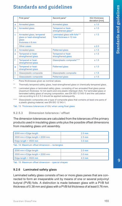
Standards and guidelines
155155Guardian GlassTime
First pane* Second pane* IGU thickness deviation [mm]
a Annealed glass Annealed glass ± 1.0
b Annealed glass Tempered or heat- strengthened glass**
± 1.5
c Annealed glass, tempered glass or heat-strengthened glass thickness ≤ 6 mm
Laminated glass with foils***Total thickness ≤ 12 mm
± 1.5
Other cases ± 2.0
d Annealed glass Patterned glass ± 1.5
e Tempered or heat- strengthened glass
Tempered or heat- strengthened glass
± 1.5
f Tempered or heat- strengthened glass
Glass/plastic composite**** ± 1.5
g Tempered or heat- strengthened glass
Patterned glass ± 1.5
h Glass/plastic composite Glass/plastic composite ± 1.5
i Glass/plastic composite Patterned glass ± 1.5
* Pane thicknesses given as nominal values.
** Thermally tempered safety glass, heat-strengthened glass or chemically-tempered glass.
*** Laminated glass or laminated safety glass, consisting of two annealed float glass panes (maximum thickness 12 mm each) and one plastic interlayer (foil). For laminated glass or laminated safety glass of varying composition, see EN ISO 12 543-5 and the calculation rule according to 9.2.5.2 should be applied subsequently.
**** Glass/plastic composites are a type of composite glass that contains at least one pane of a plastic glazing material; see EN ISO 12 543-1.
Tab. 13: Thickness tolerances of IGU when using float glass
9.2.5.3 Dimension tolerance / offset
The dimension tolerances are calculated from the tolerances of the primary products used in insulating glass units plus the possible offset dimensions from insulating glass unit assembly.
2000 mm ≥ Edge length 2.0 mm
3500 mm ≥ Edge length > 2000 mm 2.5 mm
Edge length > 3500 mm 3.0 mm
Tab. 14: Maximum offset dimension – rectangles
2000 mm ≥ Edge length 2.0 mm
3500 mm ≥ Edge length > 2000 mm 3.0 mm
Edge length > 3500 mm 4.0 mm
Tab. 15: Maximum offset dimension – special shapes
9.2.6 Laminated safety glass
Laminated safety glass consists of two or more glass panes that are con-nected to form an inseparable unit by means of one or several polyvinyl butyral (PVB) foils. A distinction is made between glass with a PVB foil thickness of 0.38 mm and glass with a PVB foil thickness of at least 0.76 mm.
9
Stan
dard
s an
d gu
idel
ines

d d
B, H ± t
Fig. 15: Offset
B +
t B -t
H + t
H - t
Fig. 14: Limit sizes for dimensions of rectangular panes
156 Guardian GlassTime
9.2.6.1 Dimensional tolerances
The tolerances generally comply with EN ISO 12 543.
Laminated safety glass is distin-guished according to its structure: laminated safety glass 0.38 PVB, laminated safety glass from 0.76 PVB, laminated safety glass with sound protection foil (sound control laminated safety glass) and lam-inated safety glass with coloured foil (PVB).
The respective dimensional toler-ances of the semi-fi nished products used in the laminated safety glass element apply, and additionally the permissible displacement tolerances as shown in Tables 16 and 17.
Example:
Laminated safety glass made of 6 mm tempered glass / 0.76 PVB / 6 mm heat-strengthened glass; polished edges. Deviation of the single pane: ± 1.5 mm, additional offset tolerance: ± 2.0 mm.
The permissible offset tolerance adds up to ± 3.5 mm
9.2.6.2 Displacement tolerance (offset)
The individual panes might be dis-placed during the laminating process for manufacturing reasons.
The cutting tolerances are added to the displacement tolerances. The longest edge of the element is used in tables 16 and 17.
Edge length l [mm] Permissible maximum dimensions for displacement perlaminated safety glass nominal thickness
≤ 8 mm ≤ 20 mm > 20 mm
l ≤ 2000 1.0 2.0 3.0
2000 < l ≤ 4000 2.0 2.5 3.5
l > 4000 3.0 3.0 4.0
Tab. 16: Permissible maximum dimensions for displacement: rectangles
Edge length l [mm] Permissible maximum dimensions for displacement perlaminated safety glass nominal thickness
≤ 8 mm ≤ 20 mm > 20 mm
l ≤ 2000 1.5 3.0 4.5
2000 < l ≤ 4000 3.0 4.0 5.5
l > 4000 4.5 5.0 6.0
Tab. 17: Permissible maximum dimensions for offset: special shapes

< 90°
≤ 2
Standards and guidelines
157157Guardian GlassTime
9.2.6.3 Thickness tolerance
The thickness deviation of laminated safety glass should not exceed the sum of the individual glass panes, which is specifi ed in the standards for basic glass (EN 572). The tolerance limit of the intermediate layer must not be taken into account if the thickness of the intermediate layer is < 2 mm. For intermediate layers ≥ 2 mm a deviation of ≤ 0.2 mm is taken into account.
9.3 Glass edgesThe quality of glass edges of single panes that are built into a glass system has an enormous infl uence on the longevity of the product. Glass edges without further processing may show micro-cracks, which have negative effects and can lead, in extreme cases, to breakages. The quality depends on the status of the cutting tools as well as on further edge processing. Defi nitions can be found in EN 12150.
9.3.1 Edge types
• Round edges (RK) This edge surface grinding is
somewhat rounded. The most popular type by far is the “C edge”.
• Straight edge (K) The straight edge forms an
angle of 90° to the glass surface.
• Mitre edge (GK) The mitre edge forms an angle
between < 90° and ≥ 45° to the glass surface. There is no sharp edge but always a bevel of 90° to the glass surface.
• Facet edge (FK) In this case, there will be an op-
tional angle deviating from 90° to the glass surface. Depending on the facet width, differentiations are made between fl at and steep facets. In addition, the faceted edge runs towards a remaining 90° edge, thus a bevel that may also be rounded.
9
Stan
dard
s an
d gu
idel
ines
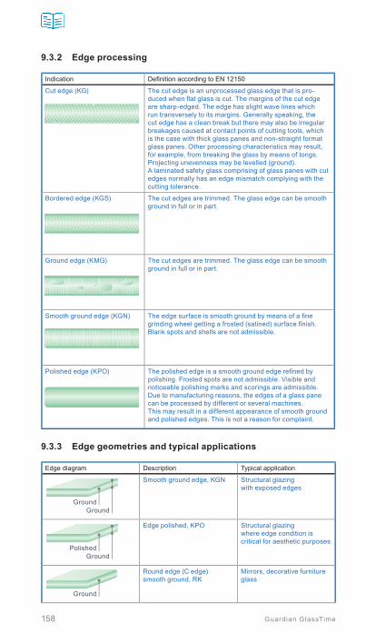
158 Guardian GlassTime
9.3.2 Edge processing
Indication Defi nition according to EN 12150
Cut edge (KG) The cut edge is an unprocessed glass edge that is pro-duced when fl at glass is cut. The margins of the cut edge are sharp-edged. The edge has slight wave lines which run transversely to its margins. Generally speaking, the cut edge has a clean break but there may also be irregular breakages caused at contact points of cutting tools, which is the case with thick glass panes and non-straight format glass panes. Other processing characteristics may result, for example, from breaking the glass by means of tongs. Projecting unevenness may be levelled (ground). A laminated safety glass comprising of glass panes with cut edges normally has an edge mismatch complying with the cutting tolerance.
Bordered edge (KGS) The cut edges are trimmed. The glass edge can be smooth ground in full or in part.
Ground edge (KMG) The cut edges are trimmed. The glass edge can be smooth ground in full or in part.
Smooth ground edge (KGN) The edge surface is smooth ground by means of a fi ne grinding wheel getting a frosted (satined) surface fi nish. Blank spots and shells are not admissible.
Polished edge (KPO) The polished edge is a smooth ground edge refi ned by polishing. Frosted spots are not admissible. Visible and noticeable polishing marks and scorings are admissible. Due to manufacturing reasons, the edges of a glass pane can be processed by different or several machines. This may result in a different appearance of smooth ground and polished edges. This is not a reason for complaint.
9.3.3 Edge geometries and typical applications
Edge diagram Description Typical application
GroundGround
Smooth ground edge, KGN Structural glazingwith exposed edges
PolishedGround
Edge polished, KPO Structural glazingwhere edge condition is critical for aesthetic purposes
Ground
Round edge (C edge)smooth ground, RK
Mirrors, decorative furniture glass

Standards and guidelines
159159Guardian GlassTime
Edge diagram Description Typical application
Polished
Round edge (C edge)polished, RK
Mirrors, decorative furniture glass
α = 22°, 45°, 67°Ground
Facet edge, steep smooth ground
Structural glazing
Polishedα = 5°
Facet edge, fl at polished Mirrors, decorative furniture glass
Natural cutSeamed
Bordered edge, KGS Normal edge treatment for heat-treated glass
9.4 Glass corners and jointsThis form of modern architecture is characterised by the fact that there is no vertical post, header or load-bearing beam behind the corner or the joint to hide them, nor is there a front cover. Therefore, the glass that is used should generally have UV-resistant edge seals (→ chapter 3.4) and all materials utilised should be compatible with each other. The conditions for forming the rebates between the adjoining glass elements for sealing are identical with glazing held in frames. The same applies to structural analysis verifi cation and specifi cations relating to heat and noise reduction where appropriate.
The design possibilities are multifaceted and should be defi ned clearly when planning commences. Here are some examples of possible implementations.
9.4.1 Glass joint with sealant joint and weather stripping for double insulating glass
Suitable for vertical use, not for roof glazing as there is no ventilation or drainage in the rebate area.
9
Stan
dard
s an
d gu
idel
ines

160 Guardian GlassTime
9.4.2 Glass joint with sealant joint and weather stripping for triple insulating glass
Suitable for vertical use, not for roof glazing as there is no ventilation nor drainage in the rebate area.
9.4.3 Glass joint with sealant joint and preformed seal for double insulating glass
Ventilation and drainage of the re-bate fold is possible, and designed so that it is conveyed to the outside, especially in the joint intersections.
9.4.4 Glass joint with sealant joint and preformed seal for triple insulating glass
Ventilation and drainage of the re-bate fold are available and follow-ing the construction to the outside, especially in the joint intersections.
9.4.5 All-glass corner with double-stepped glazing unit
Ventilation and drainage of the re-bate area is not possible, therefore not suitable for angular glazing.

Standards and guidelines
161161Guardian GlassTime
9.4.6 All-glass corner with triple-stepped glazing unit
Ventilation and drainage of the re-bate area is not possible, therefore not suitable for angular glazing.
9.4.7 All-glass corner with preformed seal for double-insulated glass with stepped edges
Moisture removal and ventilation of the rebate area is possible if de-signed so that it is conveyed to the outside; therefore, suitable for ver-tical as well as for angular glazing.
9.4.8 All-glass corner with preformed seal for triple-insulated glass with stepped edges
Humidity removal and ventilation of the rebate area is possible and constructed so that it is conveyed to the outside; therefore, suitable for vertical as well as for angular glazing.
Detailed explanations of this sub-ject matter regarding national rules (e.g. in Germany) are contained in the V.07 leafl et from the window + façade association or can be defi ned together with Guardian during the planning stage. 9
Stan
dard
s an
d gu
idel
ines

162 Guardian GlassTime
9.5 Glass thickness dimensioningThe installed glass is subject to different loads and should therefore be dimensioned according to the conditions. In addition to positive/negative wind and snow loads, its own weight and when using insulating glass, the climatic loads in the cavity should also be considered. The following variants should in general be considered when calculating dimensions:
• Geographical location and installation position of the glazing• Load distribution• IGU cavity contraction and expansion due to fluctuating weather
conditions (climatic load)• Glass bearing on all sides or partially• Thermally induced glass stress
National guidelines and rules governing the precise dimensioning of glass should be introduced and adapted gradually in the medium term in all EU countries.
Examples of currently valid norms in Europe:
• Germany: DIN 18008• Austria: ÖNORM B 3716 / OIB Richtlinie 4• UK: BS 6180• Netherlands: NEN 2608• Switzerland: SIGAB 002
9.6 Surface damage to glassLike all other high quality surfaces, float glass can be exposed to mechan-ical, thermal or chemical stress. Past experience has shown that this type of damage generally occurs during the construction period and seldom once the building has been completed. Mechanical surface damage is generally due to inappropriate transport to the construction site, storage or installation or by the sliding of one glass surface over another when there is dust from the construction site on the panes.
Using unsuitable tools such as glass planers or blades to remove persistent dirt on glass can cause mechanical damage to the surface.
The most frequent cause of damage on construction sites is that the glass comes into contact with fresh cement, mortar or chalk. Corrosion is left behind after these types of materials have dried on the glass surface and are then removed.
Thermal damage, however, can occur when welding work or metal cutting is carried out near glass that is not protected against flying sparks.
Unsuitable sealing material may cause irreparable streaking, as can aggressive cleaning agents that may possibly contain hydrofluoric acid, an agent that is often used for cleaning brick façades.

Standards and guidelines
163163Guardian GlassTime
To prevent these possible scenarios, the glass should be protected with films if it is installed at an early stage of the building phase, cleaned later using only suitable cleaning agents and an appropriate amount of clean water (→ chapter 9.11).
9.7 Guidelines for assessing the visual quality of glass in buildings
9.7.1 Visualqualityofcoatedglass
The appearance of coated glass and defect detection is described in the EN 1096-1 standard. The defects affecting appearance are specific to the glass substrate (e.g. float glass acc. to EN 572-2) or specific to the coating. If a defect specific to the glass substrate is more visible because of the coating, it will be treated as a coating defect.
9.7.1.1 Detection of defects
The defects are detected visually by an observation of the coated glass in transmission and/or reflection. An artificial sky or daylight may be used as the source of illumination.
The artificial sky is a plane emitting diffuse light with a uniform brightness and a general colouring index Ra higher than 70 (see CIE 013.3-1995).
It is obtained by using a light source whose correlated colour temperature is in the range between 4 000 K and 6 000 K. In front of the arrangement of light sources is a light scattering panel, without spectral selectivity. The illuminance level on the glass surface shall be between 400 lx and 20 000 lx.
Daylight illumination is a uniform overcast sky, without direct sunlight.
9.7.1.2 Conditionsofexamination
9.7.1.2.1 General
Coated glass may be examined in stock size plates or in finished sizes ready for installation. The examination may be undertaken in the factory or on site when glazed.
The pane of coated glass being examined is viewed from a minimum distance of 3 m. The actual distance will depend on the defect being considered and the illumination source being used. The examination of the coated glass in reflection is performed by the observer looking at the side that will be the outside of the glazing. The examination of the coated glass in transmission is performed by the observer looking at the side that will be the inside of the glazing. During the examination, the angle between the normal to the surface of the coated glass and the light beam proceeding to the eyes of the observer after reflection or transmission by the coated glass, shall not exceed 30° (see Figures below).
9
Stan
dard
s an
d gu
idel
ines

164 Guardian GlassTime
a) Reflection
1: Illumination source2: Observer3: Coated glass sample
2 2
2 11 33 2
Min. 3 m
30°
30°30°
30°Min. 3 m
b) Transmission
Examination procedures for coated glass
For panes of coated glass in finished sizes ready to be installed, both the main area and an edge area of the pane shall be examined (see figure below).
1
2
4 H
3
L
1: Edge area height (5 % of H dimension)2: Edge area length (5 % of L dimension)3: Central area length (90 % of L dimension)4: Central area height (90 % of H dimension)
Areas to be examined on finished sizes
Each examination shall take no more than 20 s.
9.7.1.2.2 Uniformity defects and stains
Under the conditions of examination, given in 9.7.1.1, note any coating variations either within one pane or between neighbouring panes that are visually disturbing.
9.7.1.2.3 Punctual defects
Under the conditions of examination, given in 9.7.1.1, note any spots, pinholes and/or scratches that are visually disturbing.
For spots/pinholes, measure the size and note the number relative to the size of the pane. If there are any clusters found their position relative to the through vision area shall be determined.
For scratches, determine whether or not they are in the main or edge area. Measure the length of any scratches noted. For scratches > 75 mm long, determine the distance between adjacent scratches. For scratches ≤ 75 mm long, note any areas where their density produces visual disturbance.

Standards and guidelines
165165Guardian GlassTime
9.7.1.3 Acceptance criteria for coated glass defects
Defect TypesAcceptance Criteria
Pane/Pane Individual Pane
Uniformity/Stain Allowed as long as not visually disturbing
Allowed as long as not visually disturbing
Main Area Edge Area
Punctual Not applicable
Spots/Pinholes;>3 mm
Not allowed Not allowed
>2 mm and ≤ 3 mm Allowed if not more than 1/m2
Allowed if not more than 1/m2
Cluster; Not allowed Allowed as long as not in area of through vision
Scratches;>75 mm
Not allowed Allowed as long as they are separated by > 50 mm
≤75 mm Allowed as long as local density is not visually disturbing
Allowed as long as local density is not visually disturbing
9.7.2 Visualqualityofinsulatingglassunits(IGU)
The criteria of the visual glass quality of IGU made of base glass com-ponents are described in the EN 1279-1 standard (normative Annex F).
The optical and visual quality requirements for glass components shall be taken from the appropriate European standards.
The information provided by the tables below give the maximum allowable fault per insulating glass unit, as well as the faults that are specific to the assembly. This information shall not be used for insulating glass units with at least one component made of patterned glass, wired glass, wired patterned glass, drawn sheet glass, or fire-resistant laminated glass.
9.7.2.1 Observation conditions
The panes shall be examined in transmission and not in reflection.
The discrepancies shall not be marked on the pane.
The insulating glass units shall be observed from a distance of not less than 3 m from the inside to the outside and at a viewing angle as perpen-dicular as possible to the glass surface for up to one minute per m2. The assessment is carried out under diffuse daylight conditions (e.g. overcast sky), without direct sunlight or artificial lighting.
Insulating glass units assessed from the outside shall be examined in installed condition, taking into consideration the usual viewing distance with a minimum of 3 m. The viewing angle shall be as perpendicular as possible to the glass surface.
9
Stan
dard
s an
d gu
idel
ines

166 Guardian GlassTime
R: Zone of 15 mm usually covered by the frame, or corresponding to the edge seal in case of unframed edgeE: Zone at the edge of the visible area, with a width of 50 mmM: Main zone
50
REM
5015
15
Observation zones
9.7.2.2 IGUmadeoftwopanesofmonolithicglass
9.7.2.2.1 Spot faults
Zone Dimensions and type [ø in mm] Pane area S (m2)
S ≤ 1 1 < S
R All No limitation
E
Spots ø ≤ 1 No limitation
Spots 1 mm < ø ≤ 3 4 1 per m of pe-rimeter
Stain ø ≤ 17 1
Spots ø > 3 and stain ø > 17 Maximum 1
M
Spots ≤ 1 Maximum 3 in each area of ø ≤ 20 cm
Spots 1 < ø ≤ 3 Maximum 2 in each area of ø ≤ 20 cm
Spots ø > 3 and stain ø > 17 Not accepted
Maximum number of spot faults
9.7.2.2.2 Residues
Zone Size of fault (excluding halo) [ø in mm]
Sizes of the pane S (m2)
S ≤ 1 1 < S ≤ 2 2 < S ≤ 3 3 < S
R All sizes No limitation
E
ø ≤ 1 Accepted if less than 3 in each area of ≤ 20 cm
1 < ø ≤ 3 4 1 per metre of perimeter
ø > 3 Not allowed
M ø ≤ 1 Accepted if less than 3 in each area of ≤ 20 cm
1 < ø ≤ 2 2 3 5 5 + 2/m2
ø > 2 Not allowed
Maximum allowable number of residue spots and stains

Standards and guidelines
167167Guardian GlassTime
9.7.2.2.3 Linear / extended defects
Hairlines scratches are allowed, provided that they do not form a cluster.
Zone Individual lengths [mm] Total of individual lengths [mm]
R No limitation
E ≤ 30 ≤ 90
M ≤ 15 ≤ 45
The maximum number of linear / extended fault
9.7.2.3 IGUotherthanthosemadeoftwopanesofmonolithicglass panes
The allowable number of discrepancies defined in chapter 9.7.2.2 is increased by 25 % per additional glass component (in multiple glazing or in a laminated glass component). The number of allowable defects is always rounded up.
Examples:
• Triple glazed unit made of 3 monolithic glass panes: the number of allowable faults of F.3 is multiplied by 1.25.
• Double glazed unit made of two laminated glass panes with 2 glass components each: the number of allowable faults of chapter 9.7.2.2 is multiplied by 1.5.
9.7.2.4 IGUcontainingaheat-treatedglass
The visual quality of thermally toughened safety glass, with or without heat-soaking and of heat strengthened glass, when assembled in an insulating glass unit or in a laminated glass which is a component of an insulating glass unit, shall fulfill the requirements of their respective product standard.
In addition to these requirements, for heat treated float glass, the overall bow relative to the total glass edge length may not be greater than 3 mm per 1 000 mm glass edge length. Greater overall bow may occur for square or near-square formats (up to 1:1.5) and for single panes with a nominal thickness < 6 mm.
9.7.2.5 Edge defects
Allowable edge defects are given in the relevant standard for each glass pane component.
External shallow damage to the edge or conchoidal fractures that do not affect the glass strength, and which do not project beyond the width of the edge seal, are acceptable.
Internal conchoidal fractures without loose shards, which are filled by the sealant, are acceptable.
9
Stan
dard
s an
d gu
idel
ines
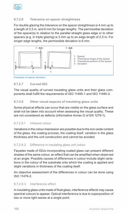
168 Guardian GlassTime
9.7.2.6 Tolerance on spacer straightness
For double glazing the tolerance on the spacer straightness is 4 mm up to a length of 3.5 m, and 6 mm for longer lengths. The permissible deviation of the spacer(s) in relation to the parallel straight glass edge or to other spacers (e.g. in triple glazing) is 3 mm up to an edge length of 2.5 m. For longer edge lengths, the permissible deviation is 6 mm.
1: Spacer2: Theoretical shape of the spacer3: Theoretical position of the spacer4: Deviation
4
1 1
2 3
44
4
Examples of spacer deviation
9.7.2.7 CurvedIGU
The visual quality of curved insulating glass units and their glass com-ponents shall fulfill the requirements of ISO 11485-1 and ISO 11485-2.
9.7.2.8 Other visual aspects of insulating glass units
Some physical effects can occur that are visible on the glass surface and shall not be taken into account when assessing the visual quality. These are not considered as defects (informative Annex G of EN 1279-1).
9.7.2.8.1 Inherent colour
Variations in the colour impression are possible due to the iron oxide content of the glass, the coating process, the coating itself, variation in the glass thickness and the unit construction and cannot be avoided.
9.7.2.8.2 Difference in insulating glass unit colour
Façades made of IGUs incorporating coated glass can present different shades of the same colour, an effect that can be amplified when observed at an angle. Possible causes of differences in colour include slight varia-tions in the colour of the substrate onto which the coating is applied and slight variations in thickness of the coating itself.
An objective assessment of the differences in colour can be done using ISO 11479-2.
9.7.2.8.3 Interference effect
In insulating glass units made of float glass, interference effects may cause spectral colours to appear. Optical interference is due to superposition of two or more light waves at a single point.

Standards and guidelines
169169Guardian GlassTime
The effects are seen as variation in intensity of the coloured zones, which change when pressure is applied to the glass. This physical effect is rein-forced by the parallelism of the surfaces of the glass. Interference effects occur at random and cannot be avoided.
9.7.2.8.4 Specific effect due to barometric conditions
An insulating glass unit includes a volume of air or other gas, hermetically sealed by the edge seal. The state of the gas is essentially determined by the altitude, the barometric pressure and the air temperature, at the time and place of manufacture. If the insulating glass unit is installed at another altitude, or when the temperature or barometric pressure changes (higher or lower pressure), the panes will deflect inwards or outwards, resulting in optical distortion (→ chapter 2.7).
9.7.2.8.5 Multiple reflections
Multiple reflections can occur in varying intensity at the surfaces of glass units. These reflections can be seen particularly clearly if the background viewed through the glazing is dark. This effect is a physical property of all insulating glass units.
9.7.2.8.6 Anisotropy (iridescence)
Insulating glass units that contain a heat-treated glass component may show visual phenomena known as anisotropy, see EN 12150-1, EN 1863-1 (→ chapter 7.1.7).
9.7.2.8.7 Condensation on the external surface of the IGU
Condensation can occur on the external glass surfaces when the glass surface is colder than the adjacent air.
The extent of condensation on the external surfaces of a glass pane is determined by the U-value, the air humidity, air movement and the indoor and outdoor temperatures.
When the ambient relative humidity is high and when the surface tem-perature of the pane falls below the ambient temperature, condensation at the glass surface occurs.
(→ chapter 2.4.3 for information on how to minimise condensation on external surfaces.)
9.7.2.8.8 Wetting of glass surfaces
The appearance of the glass surfaces can differ due to the effect of rollers, finger-prints, labels, vacuum suction holders, sealant residues, silicone compounds, smoothing agents, lubricants, environmental influences, etc. This can become evident when the glass surfaces are wet by condensation, rain or cleaning water.
9
Stan
dard
s an
d gu
idel
ines

170 Guardian GlassTime
9.7.2.8.9 Assessment of the visible section of the edge seal of the insulating glass unit
Features on the glass and spacer resulting from production processes can be recognised in insulating glass units in the visible section of the edge seal. By definition, this section is not included in the area between the sight lines that is subject to assessment. If the edge seal of the insulating glass unit is exposed on one or more sides due to design requirements, features resulting from production processes may be visible in the area of the edge seal.
If the edge seal on the insulating glass unit is exposed due to design requirements, typical features of the edge seal may become visible that are not covered by this guideline. In such cases, individual arrangements should be agreed.
9.7.2.8.10 IGU with internal muntins
Due to climatic influences (e.g. insulated glass effect) shocks or manu-ally generated vibration, clapping noise may occur in the muntins. The production process results in visible saw cuts and the slight removal of paint near the saw cuts.
In assessing deviations from right angles and misalignment within the glazing zones, the manufacturing and installation tolerances and the overall impression must be taken into account.
Effects due to temperature-related changes in the lengths of muntins in the gas-filled cavity are basically unavoidable. Misalignment of muntins caused by production cannot be ruled out.

Standards and guidelines
171171Guardian GlassTime
9.8 Glass breakageGlass is a brittle construction material and therefore does not allow for excessive deformations. Exceeding the elasticity border due to mechan-ical or thermal influences immediately leads to breakage. The defined guidelines referring to this must be followed precisely. For thermal load, the normal float glass used for facades that are partially in the shade, may be exposed to a maximum temperature difference of 40 K (EN 572) to 42 K. If the glass is exposed to temperature changes exceeding this range, then this float glass should be replaced with tempered or heat strengthened glass in order to increase this delta. This is particularly essential in the case of absorbing solar protection glasses.
Another danger that may lead to glass breakage is on the construction site when modern, coated insulating glass packages on racks are unprotected from the sun. The sun heats the glass packs and, due to the coatings, the heat is unable to dissipate. This inevitably results in glass breakage. Therefore, glass packs standing in the open must be covered with opaque material. Also, smallsized insulating glass panes with unfavourably pro-portioned sides and asymmetric structures need a thinner tempered glass pane to prevent breakage.
Glass breakage formerly caused by residual stress is practically ruled out, due to today’s glass production methods. But both unqualified finishing of edges with nearly invisible micro-cracks and mechanical surface damage may lead to medium-term pane failure. The same applies to incorrect trans-port and edge damage. In such cases, the failure may not become obvious immediately, but only at a later point in time. Breakage by the material itself can only occur with tempered glass, so-called “spontaneous” breakage occurs where nickel sulphide inclusions are present (→ chapter 7.2).
Generally, it can be said that glass breakage is almost 100 % preventable if glass is handled appropriately with advance planning, correct dimen-sioning, proper use and maintenance.
9.8.1 Thermal breakage / thermal stress
9.8.1.1 General
Thermal stress is caused when one area of glass is heated, while another part remains cold at the same time. It is not an issue if the temperature increase is uniform across the entire glass pane. Heated areas are under expansion – cold areas are under compression due to the temperature difference (ΔT) aspect.
9
Stan
dard
s an
d gu
idel
ines

172 Guardian GlassTime
Warm
Cold
Cold Edges
Heatedcentral areas(glass tendsto expand)
(Glass tendsto contract)
Area ofhigh stress
9.8.1.2 Thermal cracks
Thermal breakage always starts at the edge and is perpendicular (90°) to the glass edge.
• Different areas expand and contract differently; when they collide, energy seeks its way out towards the nearest edge and breakage starts
• Breakage can be single or multiple depending on thermal stress build up
• It starts straight for 2 to 5 cm and then branches out into one or more directions
• The number of branches or secondary cracks depends on the amount of stress
Wallner change of orientationStarts perpendicular from edge, no conchoidal fracture
Perpendicular aspect on edge,no conchoidal fracture
Shortest way to crack triggering zone
First orientation change in warm/
cold zone
Multiple change of orientation
9.8.1.3 Factorsinfluencingthermalbreakage
Thermal stress caused by temperature differences (ΔT) is the only ultimate factor.
ΔT depends on:
• Environmental factors - Façade orientation• Solar intensity (W/m²)• Temperature difference between inside and outside
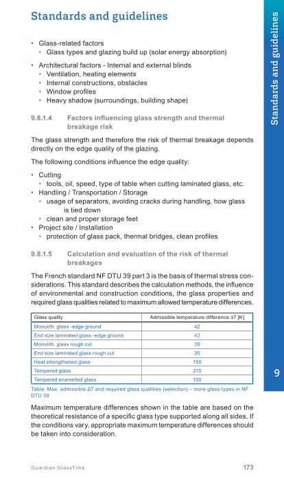
Standards and guidelines
173173Guardian GlassTime
• Glass-related factors • Glass types and glazing build up (solar energy absorption)
• Architectural factors - Internal and external blinds• Ventilation, heating elements• Internal constructions, obstacles• Window profiles• Heavy shadow (surroundings, building shape)
9.8.1.4 Factorsinfluencingglassstrengthandthermal breakage risk
The glass strength and therefore the risk of thermal breakage depends directly on the edge quality of the glazing.
The following conditions influence the edge quality:
• Cutting• tools, oil, speed, type of table when cutting laminated glass, etc.
• Handling / Transportation / Storage• usage of separators, avoiding cracks during handling, how glass
is tied down• clean and proper storage feet
• Project site / Installation• protection of glass pack, thermal bridges, clean profiles
9.8.1.5 Calculation and evaluation of the risk of thermal breakages
The French standard NF DTU 39 part 3 is the basis of thermal stress con-siderations. This standard describes the calculation methods, the influence of environmental and construction conditions, the glass properties and required glass qualities related to maximum allowed temperature differences.
Glass quality Admissible temperature difference ΔT [K]
Monolith. glass -edge ground 42
End size laminated glass -edge ground 42
Monolith. glass rough cut 35
End size laminated glass rough cut 35
Heat strengthened glass 150
Tempered glass 215
Tempered enamelled glass 150
Table: Max. admissible ΔT and required glass qualities (selection) – more glass types in NF DTU 39
Maximum temperature differences shown in the table are based on the theoretical resistance of a specific glass type supported along all sides. If the conditions vary, appropriate maximum temperature differences should be taken into consideration.
9
Stan
dard
s an
d gu
idel
ines

174 Guardian GlassTime
Glass resistance under thermal stress is signifi cantly infl uenced by the quality of the edge fi nishing. The maximum allowable values are only valid when edge fi nishing has no defects (→ chapter 9.8.1.4).
The Guardian Technical Services provides a comprehensive service for the assessment of thermal breakage risk using customer and project-related data.
IGU producers and glaziers are responsible for the quality and the in-stallation of glazed units. In case of doubt, Guardian recommends the consideration of a lower maximum allowable temperature difference. The fi nal decision regarding the glazing to be installed is the responsibility of the insulating glass unit manufacturer.
Guardian does not provide any warranty regarding thermal breakage.
9.8.2 Typical glass fracture pattern
Kind of glass breakage Representation
Example: EdgebreakagefloatglassMechanical point load• Short term• Weak to medium intensity
Happens with fl oat glass, laminated safety glass,laminated glass, cast resin panes and ornamental glass
Reason: Little stones between glass panes, hammer blow on glazing bead, other blow and collision effects
Characteristics: Feeding angle all directions, out of square,continuous angle out of square,origin to be seen in the edge area, shells possible in the breakage centre
Pane view
Fracture cross section
Example: Edge breakage heat strengthened glassMechanical point load• Short term• Weak to medium intensity
Happens only with heat strengthened glass per DIN EN 1863
Reason: Little stones between glass panes, hammer blow on glazing bead, other blow and collision effects
Characteristics: Feeding angle all directions, out of square, contin-uous angle out of square, origin to be seen in the edge area, shells to be found often in the breakage centre
Pane view
Fracture cross section

Standards and guidelines
175175Guardian GlassTime
Kind of glass breakage Representation
Example: Clamping crackMechanical point or line load• Short term dynamic• Long lasting static
Happens with fl oat glass, laminated safety glass,laminated glass, cast resin panes and patterned glass
Reason: Too small or wrong setting blocks and very high glass weight, wrong handling of the block lever,length change (thermal dilatation) of glass/frame not considered
Characteristics: Feeding angle all directions, out of square, continuous angle out of square, origin to be seen in the edge area, shells possible in the breakage center
Pane view
Fracture cross section
Example: Torsion breakageMechanical line load• Short term• Dynamic
To be found at fl oat glass, laminated safety glass,laminated glass, cast resin panes and ornamental glass
Reason: Glass thickness not suffi cient, specially when mounted on two sides, twisted and jamming case-ment frames, movements in the structure with load transfer to the pane
Characteristics: Feeding angle all directions, out of square, con-tinuous angle out of square, generally not clearly allocated
Pane view
Fracture cross section
Example: Area pressure breakageMechanical distributed load• Long lasting• Dynamic/statical
To be found at fl oat glass, laminated safety glass,laminated glass, cast resin panes and ornamental glass
Reason: Too high load of the insulating glass by temperature, air pressure and/or altitude differences between production and installation location, undersized aquarium pane supported on four sides
Characteristics: Feeding angle all directions, out of square, no breakage center to be seen, continuous angle rectangular, no shells at glass edge
Pane view
Fracture cross section
9
Stan
dard
s an
d gu
idel
ines

176 Guardian GlassTime
Kind of glass breakage Representation
Example: Hybrid crackThermal/mechanical loads• Overlapping
To be found at fl oat glass, laminated safety glass,laminated glass, cast resin panes and ornamental glass
Reason: Several effects by area load (squall) on undersized and already thermally loaded pane
Characteristics: Feeding pane rectangular, continuous angle out of square, no edge shells, no breakage center to be seen
Pane view
Fracture cross section
Example: Thermal normal crackThermal line load• Weak to medium intensity
To be found at fl oat glass, laminated safety glass,laminated glass, cast resin panes and ornamental glass, wired glass may differ due to the network
Reason: Partial covering of the pane in the interior during solar irradiation, glazing depth too low, as package stored sound-, heat- and solar protection glazing (especially insulating glass) without protection against direct solar irradiation.
Characteristics: Feeding angle rectangular, continuous angle rectan-gular, edge shells not to be found at incoming
Pane view
Fracture cross section
Example: Delta breakageMechanical line load• Long lasting• Static/dynamic• Two sides bearing
Happens with fl oat glass, laminated safety glass, laminated glass, ornamental and wired glass
Reason: Long-lasting, high snow load on overhead glazing being mounted on two or three sides
Characteristics: Feeding angle out of square, continuous angle out of square, no shells on glass edge, breakage center on non mounted edge
Pane view
Fracture cross section

Standards and guidelines
177177Guardian GlassTime
Kind of glass breakage Representation
Example: Thermal line crackThermal line load• Weak to strong intensity
To be found at fl oat glass, laminated safety glass, laminated glass, cast resin panes and ornamental glass, wired glass differs possibly due to wire net work
Reason: Partial covering of the glass pane with interior decoration, dark spots (stickers, advertisements) on the glass pane, a large plant leaf or likewise inside directly on the glass pane
Characteristics: Feeding angle rectangular, continuous angle rectan-gular, edge shells not to be found at incoming
Pane view
Fracture cross section
Example: Edge joint breakageMechanic point load• Short term• Weak to strong intensity
To be found at fl oat glass, laminated safety glass, laminated glass, cast resin panes and ornamental glass
Reason: Placing panes on stone or metal parts, edges hit by metal part, mishandling of tensioning strips of transport racks
Characteristics: Feeding angles all directions, out of square, contin-uous angle out of square, edge shells to be seen at crack in different sizes depending on the power of force effect, very obvious centre seen at the edge
Pane view
Fracture cross section
Example: Edge pressure breakageMechanical point load• Short term or long term aggressive• Weak to medium intensity
To be seen at fl oat glass, laminated safety glass, laminated glass, cast resin panes and ornamental glass
Reason: Undersized blocks for high glass weight, too high clamping pressure by screw connection, too high clamping pressure by using nails for wood strips without preformed tape
Characteristics: Feeding angle out of square, continuous angle out of square, shells of edge not or seldom present, origin at edge to be seen
Pane view
Fracture cross section
9
Stan
dard
s an
d gu
idel
ines

178 Guardian GlassTime
9.9 CE qualificationCE is the abbreviation for Conformité Européenne (European Conformity). Products are identified with CE when they correspond with the coordinat-ed European product standards. It is neither an emblem of origin nor a quality symbol but rather declares that a particular product complies with the „Regulation (EU) No 305/2011 of the European Parliament and of the Council of 9 March 2011 laying down harmonised conditions for the mar-keting of construction products and repealing Council Directive 89/106/EEC”. This regulation confirms that the product can be marketed in all EU countries without any reservations. National special requests, however, may define additional specifications for use of these products. With the CE identification, the manufacturer declares that the product complies with the underlying product standards.
Proof of this compliance is made on very different levels, two of which are relevant for glass:
• Level 1: Type test by a notified body institute with internal production control
and external monitoring
• Level 3: Declaration of performance (DoP) of the manufacturer after type test
by a notified body institute with internal production control
The requirements are defined in the following product standards:
Product standard
Titel Level
EN 572 Basic soda lime silicate glass products(e.g. float glass)
3
EN 1096 Coated glass 3
EN 1279 Multi-pane insulated glass 3
EN 1863 Heat strengthened soda lime silicate glass 3
EN 12150 Thermally tempered single-pane safety glass 3
EN 14179 Heat-soaked thermally tempered soda lime silicate safety glass 3
EN 14449 Laminated glass and laminated safety glass 3 or 1
The introduction of these rules has replaced the national standards. These EN standards have common characteristics such as:
• Quality management system• Definition of quality characteristics• Definition of quality checks

Decomposition of the butyl sealing by migration
Setting block after harmful interactions
Standards and guidelines
179179Guardian GlassTime
9.10 Material compatibilityAs a building material, glass comes into direct or indirect contact with a number of other materials such as PVB films, insulating glass edge seal, setting blocks, press sealing of pressure glazing or sealing mass and elements at joint gaps and glass corners. Preconditions should be checked as to whether the individual materials have any harmful interac-tions between them.
Interactions are all physical, physi-cal-chemical or chemical processes that, in the short, medium or long term, may lead to changes in the structure, colour or consistency. Even materials that are not in direct contact, but merely in the vicinity, can generate interactions through migration. Especially those products that contain softeners may, in the case of incompatibility, result in other adjacent materials absorbing these softeners as solvents and changing their consistency completely.
As the components used during the construction phase rarely come from the same producer, these compati-bilities should be checked – by test-ing if necessary. Generally speaking, it is imperative to plan carefully and carry out work with the assistance of all participants and their product specifications. The more complex the installed glass systems, the more essential this requirement is in order to guarantee longevity and lasting functionality.
A broad range of tested products (including specifications of their mutual compatibility) is available.
9.10.1 Sealant compatibility of coated glass
9.10.1.1 Standard insulating glass
Edge deletion is necessary to ensure that chemicals in certain sealants do not attack the silver layer in the coating. Extensive testing has shown that for some of the coating types, edge deletion is not necessary. Note: when a sealant is put behind an existing coating, a colour change may be visible.
Different sealant types use different mechanisms for sealant cure and some of the chemicals used in the curing process may attack the coating. For this reason, only approved sealants should be used.
9
Stan
dard
s an
d gu
idel
ines

Glass
Coating Spacer
Desiccant
Overlap
Secondary sealant
Primary sealant
180 Guardian GlassTime
The use of untested coated glass or unapproved sealants requires edge deletion in any case!
Important note:
• Guardian SunGuard® SuperNeutral (SN), SuperNeutral HT (SN-HT) eXtraSelective (SNX) and eXtraSelective HT (SNX-HT): edge deletion required
• SunGuard® Solar and High Durable (HD): no edge deletion required• SunGuard® High Performance (HP): no edge deletion required if
applied sealants and related applications are tested and approved (list of compatible sealant types available at the Guardian Technical Services).
Where edge deletion is required, remove the coating by using grinding appliances and grinding wheels developed specifically for this purpose. More information ont the appropriate types may be directly requested from Guardian.
The overlapping of coatings and primary sealant should be limited to minimise the risk of transferring shear stress into the coating under extreme conditions. The figure illus-trates this requirement as an exam-ple in an insulated glass unit. The ground-off margin should generally not be wider than 10 mm, otherwise it may enter the visible area. If for any reason the sealing depth of the insulated glass has to be increased, then the width of edge deletion of the coating must be increased accordingly. A coating detector can be used to check whether all coating has been removed.
Important note:
Where the edge deleted part is visible from the outside of the building, a colour difference will be visible with the coated part of the glass. In the case of structural glazing, please contact the sealant manufacturer for further information. Guardian recommends a mock-up to secure the static requirements. For special applications such as step glazing with exposed coated surfaces (e.g. roofs, corners of structural glazing, etc.), please consult the local Technical Services at Guardian.
9.10.1.2 Guardian SunGuard coatings in structural glazing
According to ETAG 002-1, multifunctional glass without approval from a notified body institute for monolithic applications (such as SunGuard HP, SunGuard SN and SunGuard SNX) or thermal insulating low-E glass (such as ClimaGuard) is not suitable for structural glazing.
In this case, the coating needs to be removed accordingly.

Standards and guidelines
181181Guardian GlassTime
Typically, applications with structural bonding need to be tested and ap-proved. If a European certification for structural glazing according to ETAG 002-1 is required, please contact Guardian for detailed information on suitable glass types and tested coating-sealant combinations that comply with the ETAG 002-1 requirements (→ chapter 8.1.2.2).
For more information, please also consult the Product Application Informa-tion „Sealant Compatibility and Structural Glazing“ available at Guardian.
9.10.2 Ceramic printing on coated glass
Enamels have been carefully developed for printing and firing on normal soda-lime based float glass. During the tempering process of the glass, these enamels melt and fuse permanently to the glass surface to form a coloured ceramic layer.
Various Guardian SunGuard® coatings can be printed with ceramic paints (please contact the Guardian Technical Services for a list of SunGuard coated glass that can be printed and the recommended enamel types).
Glass enamels may react during firing with coatings, causing some hazy appearance or even complete destruction of the coating. Therefore, it is necessary to test the compatibility of enamels with coated glass, under production firing conditions in order to achieve optimum results. It is rec-ommended to run preliminary tests with the selected ceramic paint/glass combination, using the intended production furnace, glass geometries and ceramic covered areas. Unfavourable temper conditions could be the reason for poor results (low gloss, colour, homogeneity, durability, density, adhesion).
Compatibility and suitability tests are essential for each project. Any printing on a coated glass surface can create colour deviations after firing. Full size project mock-ups are advisable. The processor is responsible for quality control and quality of the final product.
SunGuard® products can be printed with ceramic paint for various purposes:
• Decorative print• Patterns (dots or lines) which are applied to the coating by
silk-screen printing.• Must be used facing inside the cavity of insulating glass only
(except SunGuard HD coated glass). (→ chapter 8.2.4)
• Parapet wall glazings / spandrels (ceramic paint covering the whole coated surface)• With SunGuard® Solar and High Durable coatings only
(please contact Guardian for information regarding approved coating-enamel combinations).
• Can be used as a single glazing.• Ceramic paint needs to cover the SunGuard® coating in order to
ensure effective protection from any environmental influences. (→ chapter 8.2.2)
9
Stan
dard
s an
d gu
idel
ines

182 Guardian GlassTime
• Edge enamelling• Covers up construction elements in the edge area.• Protects IG sealants against UV radiation.• No common approval in combination with SunGuard® HP. Please
contact Guardian!• Edge enamelling of SunGuard® HP with a width of more than 5 cm
can be critical due to the different heating behaviour of the coated and uncoated surfaces.
• Stepped insulating glass units with enamelled SunGuard® HP on the outer pane are not permitted unless the enamelled surface is additionally protected by suitable sealing material.
• Another possibility for edge-enamelling of coated glass is “Guar-dian System TEA”. Detailed information regarding compatible coatings and application methods are available at the Guardian Technical Services.
(→ chapter 8.2.3)
9.10.2.1 Requirements on enamelling of SunGuard for monolithic spandrel applications
After performing extensive internal tests, Guardian recommends the following procedures:
• All enamels must not contain the following ingredients: lead, cadmium, graphite, lithium, carbonate.
• Minimum thickness of the wet coating after printing with correct adjusted processing viscosity:• 70 μm by silk-screen printing
(e.g. silk-screen type PET 1500/32-100)• 90 μm by enamelling with roller coating
• Complete drying through the entire thickness of the enamel must be ensured before firing.
• The final thickness of the enamel coating after firing should not be less than 30 μm.
• The ceramic frit must melt without bubbling, under normal temper conditions for flat glass, in order to ensure a dense and uniform cover with a minimised porosity.
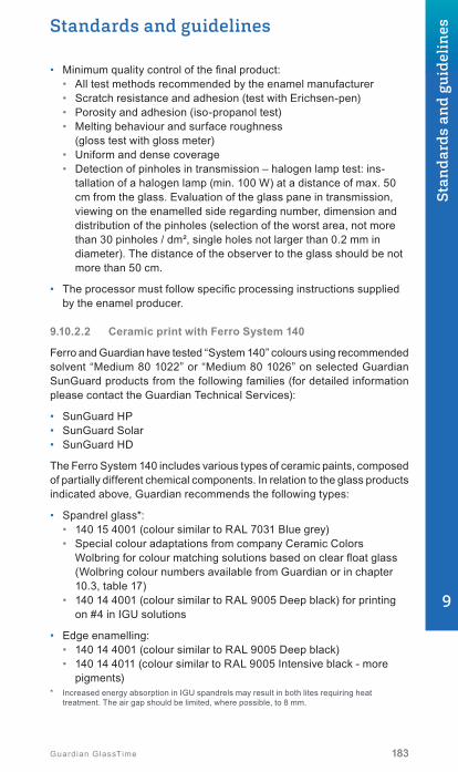
Standards and guidelines
183183Guardian GlassTime
• Minimum quality control of the final product:• All test methods recommended by the enamel manufacturer• Scratch resistance and adhesion (test with Erichsen-pen)• Porosity and adhesion (iso-propanol test)• Melting behaviour and surface roughness
(gloss test with gloss meter)• Uniform and dense coverage• Detection of pinholes in transmission – halogen lamp test: ins-
tallation of a halogen lamp (min. 100 W) at a distance of max. 50 cm from the glass. Evaluation of the glass pane in transmission, viewing on the enamelled side regarding number, dimension and distribution of the pinholes (selection of the worst area, not more than 30 pinholes / dm², single holes not larger than 0.2 mm in diameter). The distance of the observer to the glass should be not more than 50 cm.
• The processor must follow specific processing instructions supplied by the enamel producer.
9.10.2.2 Ceramic print with Ferro System 140
Ferro and Guardian have tested “System 140” colours using recommended solvent “Medium 80 1022” or “Medium 80 1026” on selected Guardian SunGuard products from the following families (for detailed information please contact the Guardian Technical Services):
• SunGuard HP• SunGuard Solar• SunGuard HD
The Ferro System 140 includes various types of ceramic paints, composed of partially different chemical components. In relation to the glass products indicated above, Guardian recommends the following types:
• Spandrel glass*: • 140 15 4001 (colour similar to RAL 7031 Blue grey)• Special colour adaptations from company Ceramic Colors
Wolbring for colour matching solutions based on clear float glass (Wolbring colour numbers available from Guardian or in chapter 10.3, table 17)
• 140 14 4001 (colour similar to RAL 9005 Deep black) for printing on #4 in IGU solutions
• Edge enamelling: • 140 14 4001 (colour similar to RAL 9005 Deep black)• 140 14 4011 (colour similar to RAL 9005 Intensive black - more
pigments)* Increased energy absorption in IGU spandrels may result in both lites requiring heat
treatment. The air gap should be limited, where possible, to 8 mm.
9
Stan
dard
s an
d gu
idel
ines

1 1
Ext
erio
r
Inte
rior
Inte
rior
Glass PVB interlayer Coating
Ext
erio
r
2 23 34 4
184 Guardian GlassTime
It must be ensured that monolithic SunGuard® spandrels are not exposed to any aggressive media before, during and after installation.
Spandrel recommendations for SunGuard architectural glass → chapter 10.3, table 17.
9.10.2.3 SunGuard HD in combination with ceramic print on surface #1
Special applications, such as ceramic frit on surface #1, may require the tempering of the glass with the coating facing down.
Such a particular application requires sufficient processing equipment. In particular, the ceramic rollers of the furnace must be clean of dirt and the glass should not be slid over stationary machine parts (rollers, castors, etc.).
Production set-up as well as a mock-up are mandatory. However, Guardian takes no responsibility whatsoever and will not be held liable for any dam-ages whatsoever such as, but not limited to, surface damages resulting from this type of processing.
Provided that the tempering is performed properly, the overall glass performance, such as light transmission or shading coefficient should not deteriorate.
For special applications, please consult the Guardian Technical Services.
9.10.3 Architectural coatings in laminated glass
Guardian SunGuard® products can be produced as laminated glass for safety and sound control requirements. To maintain aesthetics and ensure superior performance, special care must be taken during the fabrication.
The coating can be applied on surface 4 (laminated with coating outside) or on surface 2 (laminated with coating against PVB).
If the glass is laminated with coating outside (surface 4) special atten-tion must be paid if the coating is exposed to mechanical contact - especially if nip rolls are used for the pre-lamination process. The coated surface requires quality control after each fabrication step under suitable light conditions.
Regarding any further handling (e.g. transportation, cutting, edge working, washing) specific instructions for handling of SunGuard products shall be followed. If you require more information, please contact Guardian.

Standards and guidelines
185185Guardian GlassTime
If the glass is laminated with the coating against PVB (surface 2), SunGuard products are able to enhance the overall aesthetics and performance of laminated glass. However, thermal performance (SunGuard® HP and SN) may diminish. Guardian can assist its customers in estimating thermal performance based on the application. In addition, a colour shift may be noted when projects involve laminated and monolithic products side by side. Guardian recommends a mock-up.
Please contact the Guardian Technical Services for information on coatings compatible with PVB interlayers.
Conditions that affect non-coated laminated glass can also have an adverse effect on coated laminated glass products.
Without compatibility tests, the direct contact between PVB and any sealant materials should be avoided. Generally, laminated glass must not be stood in water or be exposed to high moisture. In order to avoid delamination or corrosion of the SunGuard High Performance coating, the glazing must be designed accordingly, and the processor is responsible for the correct application. As for edge deletion, in case of any doubts, Guardian recommends suitable edge deletion of the SunGuard HP coating in order to avoid edge corrosion. Guardian gives no general approval for SunGuard SN and SNX.
The following issues require special attention when using laminated glass with coating against PVB:
• Colour shift compared to non-laminated glasses of the same type• Loss of thermal insulation performance of the coating (U-value)• Inside laminated coated glass products generally comply with EN
12543-3 laminated glass. Only a few inside laminated coated glass products comply with EN 12543-2 laminated safety glass. For further information, please contact your Guardian representative
• In combination with selective coatings (e.g. SunGuard HP or SN) only one production run of the coated base glass should be used due to stronger requirements on colour tolerances (please contact Guardian regarding your particular project or further information)
• For durability tests of laminated glass, please refer to EN 12543-4
Guardian does not recommend use of resins, structural PVB, SentryGlas or EVA foil unless compatibility tests have been successfully performed. If these materials are intended to be used in direct contact with SunGuard, a suitable compatibility test performed by the processor is mandatory. The increased shear and Young’s modulus of interlayers with structural properties must not be used for structural design considerations and glass thickness calculations without special approval.
Please refer to the latest version of our product application information “SunGuard in Laminated Glass Applications”.
9
Stan
dard
s an
d gu
idel
ines

186 Guardian GlassTime
9.11 Cleaning of glassThis bulletin was produced by: The ‘Safety Glass’ working group at Bun-desverband Flachglas e. V., Mülheimer Straße 1 • D-53840 Troisdorf in cooperation of: Bundesinnungsverband des Glaserhandwerks, Hadamar • Gütegemeinschaft Mehrscheiben-Isolierglas e. V., Troisdorf • Verband Fenster und Fassade, Frankfurt
© Bundesverband Flachglas e. V.
9.11.1 Introduction
Glass can cope with a lot – but not everything!
As part of the facade, glass is subject to natural and building-related soiling. Normal dirt, professionally cleaned at reasonable intervals, pre-sents no problem to glass. However, depending on time, location, climate and building situation, significant chemical and physical accretions of dirt can accumulate on the glass surface, making professional cleaning particularly important.
This technical guide is intended to provide information on how to prevent and minimise soiling during the lifetime of different glass surfaces, and how to clean them properly and in time.
9.11.2 Types of cleaning
9.11.2.1 During the construction phase
As a general principle, all aggressive soiling must be prevented during the construction phase. Nevertheless, if this occurs, the dirt must be washed off without trace by the person responsible, immediately after it appears, using non-aggressive cleaning agents.
Concrete and cement slurries, plasters and mortars in particular, are highly alkaline and cause etching and hence damage to the glass (dulling) if they are not immediately rinsed off with plenty of water. Dusty and granular deposits must be removed professionally, but under no circumstances removed when dry. As a result of his obligations to intervene and protect, the building contractor is responsible for controlling the interaction of the different trades, and in particular for informing subsequent trades of the necessary protective measures.
Soiling can be minimised by optimising the construction process and by separately arranging for protective measures, for example the application of protective films in front of windows and façade surfaces. The object of so-called initial cleaning is to clean the components after the building work is complete. It cannot be used to remove all the dirt accumulated during the entire construction period.

Standards and guidelines
187187Guardian GlassTime
9.11.2.2 During use
Professional cleaning, matched to the particular glass and carried out at appropriate intervals, is essential to maintain the characteristics of the glass over its entire period of use.
9.11.3 Glass cleaning instructions
9.11.3.1 General
The following cleaning information applies to all glass products used in the building. Plenty of clean water must be used when cleaning glass to avoid any scouring effect from dirt particles. Soft and clean sponges, leathers, cloths and rubber scrapers are suitable hand tools. Careful use of glass cleaning tools is a further prerequisite for avoiding damage to the glass. Separate cleaning tools must be used for glass, seals and frames. Cleaning tools can be backed up by the use of largely pH-neutral cleaning agents or commercially available domestic glass cleaners. If the dirt consists of grease or sealant residue, commercially available solvents such as ethyl alcohol or isopropanol can be used for cleaning. Alkaline solutions, acids and agents containing fluoride are all chemical cleaning agents that must never be used.
The use of pointed, sharp metallic objects, e.g. blades or knives, can damage the surface (scratches). A cleaning agent must not visibly attack the surface. Do not use a bladed scraper to clean whole areas of glass. If damage to glass products or surfaces caused by cleaning is noticed while cleaning is in progress, then work must be stopped immediately, and the right information on how to prevent further damage must be obtained without delay.
9
Stan
dard
s an
d gu
idel
ines

188 Guardian GlassTime
9.11.3.2 Speciallyfinishedandexternallycoatedglass
The specially finished and externally coated glass types described below are high quality products. They require particular care and attention when cleaning. Damage to this glass can be more conspicuous or may impair its function. If necessary, separate recommendations from the individual manufacturers with regard to cleaning must also be observed, particularly with externally coated products. Do not use a „glass scraper“ for cleaning the glass surface.
• Some solar control glass types are designed as external coatings (position 1 = weather side). These can often be recognised by very high reflection, even in the spectral range of the visible radiation. At the same time, solar control glasses are often thermally tempered, particularly in the case of facade plates and sun skirts.
• Furthermore, reflection-reducing coatings (anti-reflection coatings), which by their very nature are difficult to detect, can be applied to the outside or inside of the glazing.
• External or internal heat insulation coatings are a special case here. In special window designs (box windows or composite windows), these coatings may, exceptionally, not face the cavity of the insulating glass unit. Mechanical damage to these coatings usually manifests itself in the form of streaks of surface abrasion due to the slightly rougher surface.
• Dirt-repellant/self-cleaning surfaces are visually difficult to identify. Because of the way they are used, these coatings are normally to be found on that side of the glazing unit exposed to the weather. Mechanical damage to self-cleaning coatings (scratches) not only constitutes visually discernible damage to the glass, but can also lead to a loss of functionality in the damaged area. Silicone and grease deposits on these surfaces should also be avoided. Rubber scrapers in particular must therefore be free from silicone, grease and foreign bodies.
• Toughened safety glass (TG) and heat strengthened glass (HS) is permanently marked in accordance with statutory regulations and may be combined with the above-mentioned coatings. The surface of ESG is modified by thermal tempering compared with normal float glass. Under certain circumstances, the surface tension that has been introduced makes damage more visible than with non-tempered glass (sometimes after a time delay).

Standards and guidelines
189189Guardian GlassTime
9.11.3.3 Further notes
The use of portable polishing machines for removing surface damage can cause considerable abrasion of the glass body. This can cause optical distortion, which is perceived as a „lens effect“ and leads to a reduction in strength. Do not use polishing machines, particularly on the specially finished and externally coated glasses mentioned above.
And by the way:
It may be that glass surfaces might not be evenly wettable due to marks left by such things as stickers, roll-ers, fingers, sealant residues and also environmental influences. This phenomenon can only be seen when the pane is wet, i.e. when it is being cleaned.
BF Bulletin 012 / 2012
9.12 Transportation and storageGlass should generally be transported standing on its edge. This edge generally stands parallel on two cushioned supports. Every contact the glass panes make with metal or with each other is damaging. Panes in glass packets should therefore be separated using suitable spacers.
If insulating glass is transported over altitude differences of more than 500 metres, a special insulating glass production unit should be made. The distances between the stacked panes should also be enlarged.
Panes should be stored on the edge, just as they are during transport. Warehousing should be dry and, if possible, not exposed to direct solar radiation. If stored outdoors, it is recommended that the glass packet be covered with an opaque awning. If stacked glass is exposed to humidity, there is a risk that sodium hydroxide could be generated, which irreparably damages the panes during prolonged exposure. The stacks should there-fore be opened and the individual panes of glass dried out and restacked. Moreover, Guardian storage instructions for individual glass products should always be taken into consideration. 9
Stan
dard
s an
d gu
idel
ines

Hotel Jakarta, Amsterdam, Netherlands | SunGuard® SN 70/37Architect: Search Architecture and Urban planning | Photo: © Georges De Kinder

191Guardian GlassTime
10. Product selector .....................................................192
10.1 Float glass ............................................... ..........................192
10.2 Thermal insulating glass .................................................194
10.3 Solar control glass ...........................................................196
10.4 Anti-reflective glazing ......................................................213
10.5 Sound control glass .........................................................214
10.6 Safety glass .....................................................................219
10
Pro
duct
sel
ecto
r
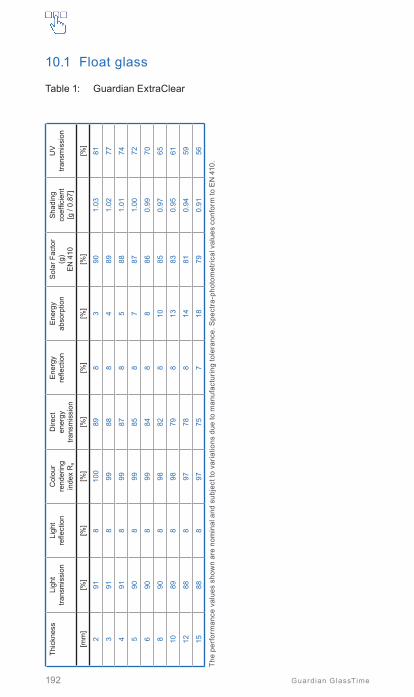
192 Guardian GlassTime
10.1 Float glass
Table 1: Guardian ExtraClear
Thic
knes
sLi
ght
trans
mis
sion
Ligh
t re
flect
ion
Col
our
rend
erin
g in
dex
Ra
Dire
ct
ener
gy
trans
mis
sion
Ene
rgy
re
flect
ion
Ene
rgy
abso
rptio
nS
olar
Fac
tor
(g)
EN
410
Sha
ding
coef
ficie
nt[g
/ 0.
87]
UV
tra
nsm
issi
on
[mm
][%
][%
][%
][%
][%
][%
][%
][%
]
291
810
089
83
901.
0381
391
899
888
489
1.02
77
491
899
878
588
1.01
74
590
899
858
787
1.00
72
690
899
848
886
0.99
70
890
898
828
1085
0.97
65
1089
898
798
1383
0.95
61
1288
897
788
1481
0.94
59
1588
897
757
1879
0.91
56
The
perf
orm
ance
val
ues
show
n ar
e no
min
al a
nd s
ubje
ct to
var
iatio
ns d
ue to
man
ufac
turin
g to
lera
nce.
Spe
ctra
-pho
tom
etric
al v
alue
s co
nfor
m to
EN
410
.
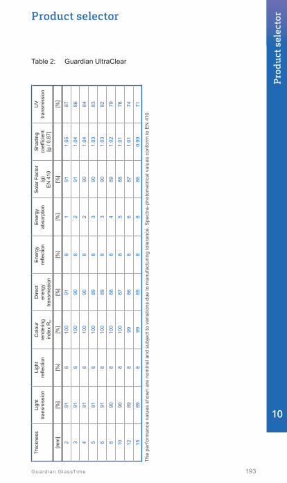
193
Product selector
Guardian GlassTime
Table 2: Guardian UltraClear
Thic
knes
sLi
ght
trans
mis
sion
Ligh
t re
flect
ion
Col
our
rend
erin
g in
dex
Ra
Dire
ct
ener
gy
trans
mis
sion
Ene
rgy
re
flect
ion
Ene
rgy
abso
rptio
nS
olar
Fac
tor
(g)
EN
410
Sha
ding
coef
ficie
nt[g
/ 0.
87]
UV
tra
nsm
issi
on
[mm
][%
][%
][%
][%
][%
][%
][%
][%
]
291
810
091
81
911.
0587
391
810
090
82
911.
0486
491
810
090
82
901.
0484
591
810
089
83
901.
0383
691
810
089
83
901.
0382
890
810
088
84
891.
0279
1090
810
087
85
881.
0176
1289
899
868
687
1.01
74
1589
899
858
886
0.99
71
The
perf
orm
ance
val
ues
show
n ar
e no
min
al a
nd s
ubje
ct to
var
iatio
ns d
ue to
man
ufac
turin
g to
lera
nce.
Spe
ctra
-pho
tom
etric
al v
alue
s co
nfor
m to
EN
410
.
10
Pro
duct
sel
ecto
r
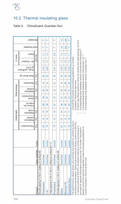
194 Guardian GlassTime
10.2 Thermal insulating glass
Table 3: ClimaGuard, Guardian Sun
Pro
duct
Gla
ss s
ubst
rate
Col
our
Visi
ble
light
Sol
ar e
nerg
y
Solar factor (g)
Shad. coefficient(g / 0.87)
U v
alue
Heat treatable1
Bendable1
Transmission
Reflection outside
Reflection inside
Colour ren. index Ra
Direct transmission
Refelction outside
Absorption
Air / Krypton2
Argon
[%]
[%]
[%]
[%]
[%]
[%]
[%]
[W/m
2 K]
Dou
ble
glaz
ing
4 (1
6) 4
, coa
ting
on s
urfa
ce #
3
Pre
miu
m2
Ext
raC
lear
neut
ral
8212
1398
5828
1464
0.73
1.4
1.1
T3T3
1.0+
Ext
raC
lear
neut
ral
7618
1896
4739
1553
0.60
1.3
1.0
T4T4
Trip
le g
lazi
ng 4
(14)
4 (1
4) 4
, coa
ting
on s
urfa
ce #
2 +
5
Pre
miu
m2
Ext
raC
lear
neut
ral
7416
1697
4733
2153
0.61
0.52
0.6
T3T3
Dou
ble
glaz
ing
4 (1
6) 4
, coa
ting
on s
urfa
ce #
2
Sol
arE
xtra
Cle
arne
utra
l67
2724
9641
4316
420.
491.
31.
0no
no
Neu
tral
70
Ext
raC
lear
neut
ral
7112
1196
5220
2855
0.63
1.6
1.4
yes
yes
Gu
ard
ian
Su
nE
xtra
Cle
arne
utra
l70
1917
9441
4120
430.
491.
31.
1T5
T5
The
perf
orm
ance
val
ues
show
n ar
e no
min
al a
nd s
ubje
ct to
var
iatio
ns d
ue to
m
anuf
actu
ring
tole
ranc
e. S
pect
ra-p
hoto
met
rical
val
ues
conf
orm
to E
N 4
10,
U v
alue
s co
nfor
m to
EN
673
. All
deta
ils re
latin
g to
furt
her p
roce
ssin
g is
pr
ovid
ed fo
r gen
eral
info
rmat
ion
purp
ose
only
. For
furt
her i
nfor
mat
ion,
pl
ease
con
sult
the
rele
vant
Gua
rdia
n pr
oduc
t pro
cess
ing
guid
elin
es o
r co
nsul
t Gua
rdia
n’s
Tech
nica
l Ser
vice
s.
1 C
onsu
lt th
e G
uard
ian
proc
essi
ng g
uide
lines
or c
onta
ct
Gua
rdia
n’s
Tech
nica
l Ser
vice
s2
Kry
pton
gas
filli
ng (o
ptim
um c
avity
for d
oubl
e an
d tr
iple
gla
zing
: 12
mm
)3
Cor
resp
ondi
ng h
eat t
reat
able
ver
sion
Clim
aGua
rd P
rem
ium
2 T
4 C
orre
spon
ding
hea
t tre
atab
le v
ersi
on C
limaG
uard
1.0
+ T
5 C
orre
spon
ding
hea
t tre
atab
le v
ersi
on G
uard
ian
Sun
T

195
Product selector
Guardian GlassTime
Table 4: ClimaGuard – anti condensation
Pro
duct
Gla
ss s
ubst
rate
Col
our
Visi
ble
light
Sol
ar e
nerg
y
Solar factor (g)
Shad. coefficient(g / 0.87)
U v
alue
Heat treatable2
Bendable2
Transmission
Reflection outside
Reflection inside
Colour ren. index Ra
Direct transmission
Refelction outside
Absorption
Krypton
Argon
[%]
[%]
[%]
[%]
[%]
[%]
[%]
[W/m
2 K]
Trip
le g
lazi
ng 4
(14)
4 (1
4) 4
, Clim
aGua
rd D
RY
1 on
surfa
ce #
1
Pre
miu
m2
on #
3+5
Ext
raC
lear
neut
ral
7217
1797
4529
2653
0.61
0.5
0.6
T3T3
The
perf
orm
ance
val
ues
show
n ar
e no
min
al a
nd s
ubje
ct to
var
iatio
ns d
ue to
m
anuf
actu
ring
tole
ranc
e. S
pect
ra-p
hoto
met
rical
val
ues
conf
orm
to E
N 4
10,
U v
alue
s co
nfor
m to
EN
673
. All
deta
ils re
latin
g to
furt
her p
roce
ssin
g is
pr
ovid
ed fo
r gen
eral
info
rmat
ion
purp
ose
only
. For
furt
her i
nfor
mat
ion,
pl
ease
con
sult
the
rele
vant
Gua
rdia
n pr
oduc
t pro
cess
ing
guid
elin
es o
r co
nsul
t Gua
rdia
n’s
Tech
nica
l Ser
vice
s.
1 C
oatin
g m
ust b
e he
at tr
eate
d to
be
activ
ated
2 C
onsu
lt th
e G
uard
ian
proc
essi
ng g
uide
lines
or c
onta
ct G
uard
ian’
s
Tech
nica
l Ser
vice
s3
Cor
resp
ondi
ng h
eat t
reat
able
ver
sion
Clim
aGua
rd P
rem
ium
2 T
10
Pro
duct
sel
ecto
r

196 Guardian GlassTime
10.3 Solar control glass
Table 5: SunGuard eXtra Selective (SNX) – double glazing
Pro
duct
Gla
ss s
ubst
rate
Col
our
Visi
ble
light
Sol
ar e
nerg
y
Solar factor (g)
Shad. coefficient(g / 0.87)
U v
alue
Heat treatable1
Bendable1
Transmission
Reflection outside
Reflection inside
Colour ren. index Ra
Direct transmission
Refelction outside
Absorption
Air
Argon
[%]
[%]
[%]
[%]
[%]
[%]
[%]
[W/m
2 K]
Dou
ble
glaz
ing 6
(16)
4, c
oatin
g on
sur
face
#2
SN
X 7
0 H
TE
xtra
Cle
arne
utra
l68
1314
9330
4426
320.
361.
31.
0ye
sye
s
SN
X 7
0 H
T U
ltra
Ultr
aCle
ar3
neut
ral
6813
1495
3150
1932
0.37
1.3
1.0
yes
yes
SN
X 7
0E
xtra
Cle
arne
utra
l67
1112
9531
3732
330.
381.
31.
0no
no
SN
X 7
0 U
ltra
Ultr
aCle
ar3
neut
ral
6711
1296
3242
2633
0.39
1.3
1.0
nono
SN
X 6
0E
xtra
Cle
arne
utra
l60
1313
9327
3835
290.
341.
31.
0H
T2H
T2
SN
X 6
0 U
ltra
Ultr
aCle
ar3
neut
ral
6013
1395
2844
2829
0.34
1.3
1.0
HT2
HT2
SN
X 5
0E
xtra
Cle
arne
utra
l50
1013
9022
3642
240.
281.
31.
0H
T2H
T2
SN
X 5
0 U
ltra
Ultr
aCle
ar3
neut
ral
5010
1291
2242
3624
0.28
1.3
1.0
HT2
HT2
The
perf
orm
ance
val
ues
show
n ar
e no
min
al a
nd s
ubje
ct to
var
iatio
ns d
ue to
m
anuf
actu
ring
tole
ranc
e. S
pect
ra-p
hoto
met
rical
val
ues
conf
orm
to E
N 4
10,
U v
alue
s co
nfor
m to
EN
673
. All
deta
ils re
latin
g to
furt
her p
roce
ssin
g is
pr
ovid
ed fo
r gen
eral
info
rmat
ion
purp
ose
only
. For
furt
her i
nfor
mat
ion,
pl
ease
con
sult
the
rele
vant
Gua
rdia
n pr
oduc
t pro
cess
ing
guid
elin
es o
r co
nsul
t Gua
rdia
n’s
Tech
nica
l Ser
vice
s.
1 C
onsu
lt th
e G
uard
ian
proc
essi
ng g
uide
lines
or c
onta
ct G
uard
ian’
s
Tech
nica
l Ser
vice
s2
C
orre
spon
ding
hea
t tre
atab
le v
ersi
on S
unG
uard
SN
X H
T3
In
boar
d an
d ou
tboa
rd s
ubst
rate
Gua
rdia
n U
ltraC
lear

197
Product selector
Guardian GlassTime
Table 6: SunGuard eXtra Selective (SNX) – triple glazing
Pro
duct
Gla
ss s
ubst
rate
Col
our
Visi
ble
light
Sol
ar e
nerg
y
Solar factor (g)
Shad. coefficient(g / 0.87)
U v
alue
Heat treatable1
Bendable1
Transmission
Reflection outside
Reflection inside
Colour ren. index Ra
Direct transmission
Refelction outside
Absorption
Krypton
Argon
[%]
[%]
[%]
[%]
[%]
[%]
[%]
[W/m
2 K]
Trip
le g
lazi
ng 6
(14)
4 (1
4) 4
, coa
ting
on s
urfa
ce #
2, C
limaG
uard
Pre
miu
m2
on #
5
SN
X 7
0 H
TE
xtra
Cle
arne
utra
l61
1518
9227
4528
290.
340.
50.
6ye
sye
s
SN
X 7
0 H
T U
ltra
Ultr
aCle
ar3
neut
ral
6215
1794
2851
2130
0.34
0.5
0.6
yes
yes
SN
X 7
0E
xtra
Cle
arne
utra
l60
1316
9428
3834
310.
350.
50.
6no
no
SN
X 7
0 U
ltra
Ultr
aCle
ar3
neut
ral
6113
1596
2944
2731
0.36
0.5
0.6
nono
SN
X 6
0E
xtra
Cle
arne
utra
l54
1516
9224
3937
270.
310.
50.
6H
T2H
T2
SN
X 6
0 U
ltra
Ultr
aCle
ar3
neut
ral
5415
1694
2545
3027
0.31
0.5
0.6
HT2
HT2
SN
X 5
0E
xtra
Cle
arne
utra
l45
1116
8920
3744
220.
250.
50.
6H
T2H
T2
SN
X 5
0 U
ltra
Ultr
aCle
ar3
neut
ral
4511
1691
2043
3822
0.26
0.5
0.6
HT2
HT2
The
perf
orm
ance
val
ues
show
n ar
e no
min
al a
nd s
ubje
ct to
var
iatio
ns d
ue to
m
anuf
actu
ring
tole
ranc
e. S
pect
ra-p
hoto
met
rical
val
ues
conf
orm
to E
N 4
10,
U v
alue
s co
nfor
m to
EN
673
. All
deta
ils re
latin
g to
furt
her p
roce
ssin
g is
pr
ovid
ed fo
r gen
eral
info
rmat
ion
purp
ose
only
. For
furt
her i
nfor
mat
ion,
pl
ease
con
sult
the
rele
vant
Gua
rdia
n pr
oduc
t pro
cess
ing
guid
elin
es o
r co
nsul
t Gua
rdia
n’s
Tech
nica
l Ser
vice
s.
1 C
onsu
lt th
e G
uard
ian
proc
essi
ng g
uide
lines
or c
onta
ct G
uard
ian’
s
Tech
nica
l Ser
vice
s2
C
orre
spon
ding
hea
t tre
atab
le v
ersi
on S
unG
uard
SN
X H
T3
In
boar
d, m
iddl
e an
d ou
tboa
rd s
ubst
rate
Gua
rdia
n U
ltraC
lear
10
Pro
duct
sel
ecto
r

198 Guardian GlassTime
Table 7: SunGuard SuperNeutral (SN) – double glazing
Pro
duct
Gla
ss s
ubst
rate
Col
our
Visi
ble
light
Sol
ar e
nerg
y
Solar factor (g)
Shad. coefficient(g / 0.87)
U v
alue
Heat treatable1
Bendable1
Transmission
Reflection outside
Reflection inside
Colour ren. index Ra
Direct transmission
Refelction outside
Absorption
Air
Argon
[%]
[%]
[%]
[%]
[%]
[%]
[%]
[W/m
2 K]
Dou
ble
glaz
ing
6 (1
6) 4
, coa
ting
on s
urfa
ce #
2
SN
75
HT
Ext
raC
lear
neut
ral
7013
1495
3839
2340
0.46
1.3
1.0
yes
yes
SN
75
HT
Ult
raU
ltraC
lear
3ne
utra
l76
1314
9540
4416
410.
471.
31.
0ye
sye
s
SN
75E
xtra
Cle
arne
utra
l73
1213
9638
3725
400.
461.
31.
0no
no
SN
75
Ult
raU
ltraC
lear
3ne
utra
l73
1213
9739
4318
410.
471.
31.
0no
no
SN
70S
Ext
raC
lear
neut
ral
7011
1395
3738
2539
0.45
1.3
1.0
HT2
HT2
SN
70/
37E
xtra
Cle
arne
utra
l70
1112
9335
3926
370.
421.
31.
0H
T2H
T2
SN
70/
35E
xtra
Cle
arne
utra
l blu
e70
1415
9433
4225
350.
401.
31.
0H
T2H
T2
SN
63
Ext
raC
lear
neut
ral
6312
1692
3137
3133
0.38
1.3
1.0
HT2
HT2
SN
51
Ext
raC
lear
neut
ral
5114
1391
2538
3727
0.31
1.3
1.0
HT2
HT2
SN
40/
23E
xtra
Cle
arne
utra
l blu
e40
1632
9121
3643
230.
271.
31.
0H
T2H
T2
SN
29/
18E
xtra
Cle
arne
utra
l blu
e29
1727
9016
3352
180.
211.
31.
0H
T2H
T2
The
perf
orm
ance
val
ues
show
n ar
e no
min
al a
nd s
ubje
ct to
var
iatio
ns d
ue to
m
anuf
actu
ring
tole
ranc
e. S
pect
ra-p
hoto
met
rical
val
ues
conf
orm
to E
N 4
10,
U v
alue
s co
nfor
m to
EN
673
. All
deta
ils re
latin
g to
furt
her p
roce
ssin
g is
pr
ovid
ed fo
r gen
eral
info
rmat
ion
purp
ose
only
. For
furt
her i
nfor
mat
ion,
pl
ease
con
sult
the
rele
vant
Gua
rdia
n pr
oduc
t pro
cess
ing
guid
elin
es o
r co
nsul
t Gua
rdia
n’s
Tech
nica
l Ser
vice
s.
1 C
onsu
lt th
e G
uard
ian
proc
essi
ng g
uide
lines
or c
onta
ct G
uard
ian’
s
Tech
nica
l Ser
vice
s2
C
orre
spon
ding
hea
t tre
atab
le v
ersi
on S
unG
uard
SN
HT
3
Inbo
ard
and
outb
oard
sub
stra
te G
uard
ian
Ultr
aCle
ar

199
Product selector
Guardian GlassTime
Table 8: SunGuard SuperNeutral (SN) – triple glazing
Pro
duct
Gla
ss s
ubst
rate
Col
our
Visi
ble
light
Sol
ar e
nerg
y
Solar factor (g)
Shad. coefficient(g / 0.87)
U v
alue
Heat treatable1
Bendable1
Transmission
Reflection outside
Reflection inside
Colour ren. index Ra
Direct transmission
Refelction outside
Absorption
Krypton
Argon
[%]
[%]
[%]
[%]
[%]
[%]
[%]
[W/m
2 K]
Trip
le g
lazi
ng 6
(14)
4 (1
4) 4
, coa
ting
on s
urfa
ce #
2, C
limaG
uard
Pre
miu
m2
on #
5
SN
75
HT
Ext
raC
lear
neut
ral
6816
1794
3340
2737
0.42
0.5
0.6
yes
yes
SN
75
HT
Ult
raU
ltraC
lear
3ne
utra
l69
1617
9535
4619
380.
440.
50.
6ye
sye
s
SN
75E
xtra
Cle
arne
utra
l66
1416
9533
3829
370.
420.
50.
6no
no
SN
75
Ult
raU
ltraC
lear
3ne
utra
l67
1416
9735
4421
380.
430.
50.
6no
no
SN
70S
Ext
raC
lear
neut
ral
6414
1794
3240
2836
0.41
0.5
0.6
HT2
HT2
SN
70/
37E
xtra
Cle
arne
utra
l64
1416
9231
4029
340.
390.
50.
6H
T2H
T2
SN
70/
35E
xtra
Cle
arne
utra
l blu
e64
1618
9429
4328
320.
370.
50.
6H
T2H
T2
SN
63
Ext
raC
lear
neut
ral
5714
1991
2838
3431
0.32
0.5
0.6
HT2
HT2
SN
51
Ext
raC
lear
neut
ral
4615
1791
2238
4025
0.29
0.5
0.6
HT2
HT2
SN
40/
23E
xtra
Cle
arne
utra
l blu
e37
1632
9019
3645
210.
240.
50.
6H
T2H
T2
SN
29/
18E
xtra
Cle
arne
utra
l blu
e26
1828
8913
3354
160.
180.
50.
6H
T2H
T2
The
perf
orm
ance
val
ues
show
n ar
e no
min
al a
nd s
ubje
ct to
var
iatio
ns d
ue to
m
anuf
actu
ring
tole
ranc
e. S
pect
ra-p
hoto
met
rical
val
ues
conf
orm
to E
N 4
10,
U v
alue
s co
nfor
m to
EN
673
. All
deta
ils re
latin
g to
furt
her p
roce
ssin
g is
pr
ovid
ed fo
r gen
eral
info
rmat
ion
purp
ose
only
. For
furt
her i
nfor
mat
ion,
pl
ease
con
sult
the
rele
vant
Gua
rdia
n pr
oduc
t pro
cess
ing
guid
elin
es o
r co
nsul
t Gua
rdia
n’s
Tech
nica
l Ser
vice
s.
1 C
onsu
lt th
e G
uard
ian
proc
essi
ng g
uide
lines
or c
onta
ct G
uard
ian’
s
Tech
nica
l Ser
vice
s2
C
orre
spon
ding
hea
t tre
atab
le v
ersi
on S
unG
uard
SN
HT
3
Inbo
ard,
mid
dle
and
outb
oard
sub
stra
te G
uard
ian
Ultr
aCle
ar
10
Pro
duct
sel
ecto
r

200 Guardian GlassTime
Table 9: SunGuard High Performance (HP) – double glazing
Pro
duct
Gla
ss s
ubst
rate
Col
our
Visi
ble
light
Sol
ar e
nerg
y
Solar factor (g)
Shad. coefficient(g / 0.87)
U v
alue
Heat treatable1
Bendable1
Transmission
Reflection outside
Reflection inside
Colour ren. index Ra
Direct transmission
Refelction outside
Absorption
Air
Argon
[%]
[%]
[%]
[%]
[%]
[%]
[%]
[W/m
2 K]
Dou
ble
glaz
ing
6 (1
6) 4
, coa
ting
on s
urfa
ce #
2
HP
Lig
ht B
lue
62/5
2E
xtra
Cle
arne
utra
l blu
e62
1612
9648
1735
520.
591.
71.
5ye
sye
s
HP
Neu
tral
60/
402
Ext
raC
lear
neut
ral
6025
2093
3835
2740
0.46
1.4
1.1
yes
yes
HP
Neu
tral
50/
32E
xtra
Cle
arne
utra
l50
2623
9430
4030
320.
371.
41.
1ye
sye
s
HP
Sil
ver
43/3
1E
xtra
Cle
arsi
lver
4332
1631
2937
3431
0.36
1.4
1.2
yes
yes
HP
Am
ber
41/2
9E
xtra
Cle
arlig
ht b
ronz
e41
2517
8727
3736
290.
341.
41.
1ye
sye
s
HP
Neu
tral
41/
33E
xtra
Cle
arne
utra
l41
2212
9129
2546
330.
381.
61.
4ye
sye
s
HP
Roy
al B
lue
41/2
9E
xtra
Cle
arde
ep b
lue
4027
2795
2631
4329
0.33
1.4
1.1
yes
yes
HP
Bri
ght G
reen
40/
292
Ext
raC
lear
light
gre
en40
3724
9526
2460
290.
331.
41.
1ye
sye
s
HP
Bro
nze
40/
27E
xtra
Cle
arbr
onze
4015
2690
2427
4927
0.31
1.4
1.1
yes
yes
HP
Sil
ver
35/2
6E
xtra
Cle
arsi
lver
3544
2398
2443
3327
0.30
1.4
1.2
yes
yes
The
perf
orm
ance
val
ues
show
n ar
e no
min
al a
nd s
ubje
ct to
var
iatio
ns d
ue to
m
anuf
actu
ring
tole
ranc
e. S
pect
ra-p
hoto
met
rical
val
ues
conf
orm
to E
N 4
10,
U v
alue
s co
nfor
m to
EN
673
. All
deta
ils re
latin
g to
furt
her p
roce
ssin
g is
pr
ovid
ed fo
r gen
eral
info
rmat
ion
purp
ose
only
. For
furt
her i
nfor
mat
ion,
pl
ease
con
sult
the
rele
vant
Gua
rdia
n pr
oduc
t pro
cess
ing
guid
elin
es o
r co
nsul
t Gua
rdia
n’s
Tech
nica
l Ser
vice
s.
1 C
onsu
lt th
e G
uard
ian
proc
essi
ng g
uide
lines
or c
onta
ct G
uard
ian’
s
Tech
nica
l Ser
vice
s2
D
ata
afte
r hea
t tre
atm
ent

201
Product selector
Guardian GlassTime
Table 10: SunGuard High Performance (HP) – triple glazing
Pro
duct
Gla
ss s
ubst
rate
Col
our
Visi
ble
light
Sol
ar e
nerg
y
Solar factor (g)
Shad. coefficient(g / 0.87)
U v
alue
Heat treatable1
Bendable1
Transmission
Reflection outside
Reflection inside
Colour ren. index Ra
Direct transmission
Refelction outside
Absorption
Krypton
Argon
[%]
[%]
[%]
[%]
[%]
[%]
[%]
[W/m
2 K]
Trip
le g
lazi
ng 6
(14)
4 (1
4) 4
, coa
ting
on s
urfa
ce #
2, C
limaG
uard
Pre
miu
m2
on #
5
HP
Lig
ht B
lue
62/5
2E
xtra
Cle
arne
utra
l blu
e56
1815
9536
2143
420.
480.
60.
7ye
sye
s
HP
Neu
tral
60/
402
Ext
raC
lear
neut
ral
5526
2293
3137
3136
0.41
0.5
0.6
yes
yes
HP
Neu
tral
50/
32E
xtra
Cle
arne
utra
l46
2725
9325
4134
290.
330.
50.
6ye
sye
s
HP
Sil
ver
43/3
1E
xtra
Cle
arsi
lver
3933
1994
2338
3927
0.31
0.5
0.6
yes
yes
HP
Am
ber
41/2
9E
xtra
Cle
arlig
ht b
ronz
e37
2620
8722
3840
260.
290.
50.
6ye
sye
s
HP
Neu
tral
41/
33E
xtra
Cle
arne
utra
l37
2316
9023
2651
270.
310.
60.
7ye
sye
s
HP
Roy
al B
lue
41/2
9E
xtra
Cle
arde
ep b
lue
3628
2894
2132
4725
0.29
0.5
0.6
yes
yes
HP
Bri
ght G
reen
40/
292
Ext
raC
lear
light
gre
en36
3826
9421
2554
250.
290.
50.
6ye
sye
s
HP
Bro
nze
40/
27E
xtra
Cle
arbr
onze
3616
2789
2027
5324
0.28
0.5
0.6
yes
yes
HP
Sil
ver
35/2
6E
xtra
Cle
arsi
lver
3244
2597
1944
3723
0.26
0.5
0.6
yes
yes
The
perf
orm
ance
val
ues
show
n ar
e no
min
al a
nd s
ubje
ct to
var
iatio
ns d
ue to
m
anuf
actu
ring
tole
ranc
e. S
pect
ra-p
hoto
met
rical
val
ues
conf
orm
to E
N 4
10,
U v
alue
s co
nfor
m to
EN
673
. All
deta
ils re
latin
g to
furt
her p
roce
ssin
g is
pr
ovid
ed fo
r gen
eral
info
rmat
ion
purp
ose
only
. For
furt
her i
nfor
mat
ion,
pl
ease
con
sult
the
rele
vant
Gua
rdia
n pr
oduc
t pro
cess
ing
guid
elin
es o
r co
nsul
t Gua
rdia
n’s
Tech
nica
l Ser
vice
s.
1 C
onsu
lt th
e G
uard
ian
proc
essi
ng g
uide
lines
or c
onta
ct G
uard
ian’
s
Tech
nica
l Ser
vice
s2
D
ata
afte
r hea
t tre
atm
ent
10
Pro
duct
sel
ecto
r
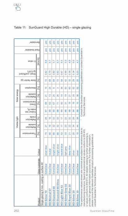
202 Guardian GlassTime
Table 11: SunGuard High Durable (HD) – single glazing
Pro
duct
Gla
ss s
ubst
rate
Col
our
Visi
ble
light
Sol
ar e
nerg
y
Solar factor (g)
Shad. coefficient(g / 0.87)
U value
Heat treatable1
Bendable1
Transmission
Reflection outside
Reflection inside
Colour ren. index Ra
Direct transmission
Refelction outside
Absorption
[%]
[%]
[%]
[%]
[%]
[%]
[%]
[W/m
2 K]
Sin
gle
glaz
ing
6 m
m, c
oatin
g on
sur
face
#2
HD
Sil
ver
70E
xtra
Cle
arsi
lver
blu
e70
2728
9769
2110
720.
825.
6ye
sye
s
HD
Neu
tral
67
Ext
raC
lear
neut
ral
6616
1899
6313
2468
0.79
5.7
yes
yes
HD
Dia
mon
d 66
Ext
raC
lear
brig
ht s
ilver
6632
3399
6724
969
0.80
5.7
yes
yes
HD
Dia
mon
d 66
Ult
raU
ltraC
lear
brig
ht s
ilver
6632
3398
7126
372
0.83
5.7
yes
yes
HD
Lig
ht B
lue
52E
xtra
Cle
arne
utra
l blu
e52
1717
9950
1436
580.
675.
5ye
sye
s
HD
Sil
ver
Gre
y 32
Ext
raC
lear
light
gre
y33
2322
9631
1950
420.
485.
3ye
sye
s
HD
Roy
al B
lue
20E
xtra
Cle
arde
ep b
lue
2122
3298
1921
6032
0.36
4.9
yes
yes
HD
Sil
ver
20E
xtra
Cle
arsi
lver
2034
2894
1929
5229
0.34
5.0
yes
yes
HD
Sil
ver
10E
xtra
Cle
arsi
lver
1044
3898
1038
5220
0.23
4.7
yes
yes
The
perf
orm
ance
val
ues
show
n ar
e no
min
al a
nd s
ubje
ct to
var
iatio
ns d
ue to
m
anuf
actu
ring
tole
ranc
e. S
pect
ra-p
hoto
met
rical
val
ues
conf
orm
to E
N 4
10,
U v
alue
s co
nfor
m to
EN
673
. All
deta
ils re
latin
g to
furt
her p
roce
ssin
g is
pr
ovid
ed fo
r gen
eral
info
rmat
ion
purp
ose
only
. For
furt
her i
nfor
mat
ion,
pl
ease
con
sult
the
rele
vant
Gua
rdia
n pr
oduc
t pro
cess
ing
guid
elin
es o
r co
nsul
t Gua
rdia
n’s
Tech
nica
l Ser
vice
s.
1 C
onsu
lt th
e G
uard
ian
proc
essi
ng g
uide
lines
or c
onta
ct G
uard
ian’
s
Tech
nica
l Ser
vice
s

203
Product selector
Guardian GlassTime
Table 12: SunGuard High Durable (HD) – single glazing laminated glass
Pro
duct
Gla
ss
subs
trate
Col
our
Visi
ble
light
Sol
ar e
nerg
y
Solar factor (g)
Shad. coefficient(g / 0.87)
U value
Heat treatable1
Bendable1
Ball drop test EN 356
Pendulum impact EN 12600
Transmission
Reflection outside
Reflection inside
Colour ren. index Ra
Direct transmission
Refelction outside
Absorption
[%]
[%]
[%]
[%]
[%]
[%]
[%]
[W/m
2 K]
Sin
gle
lam
inat
ed g
lass
66.
2, c
lear
PV
B in
terla
yer,
coat
ing
on s
urfa
ce #
4
HD
Sil
ver
70E
xtra
Cle
arsi
lver
blu
e68
2628
6097
1822
650.
755.
3ye
sye
sP
2A1(
B)1
HD
Neu
tral
67
Ext
raC
lear
neut
ral
6416
1899
5412
3462
0.71
5.4
yes
yes
P2A
1(B
)1
HD
Dia
mon
d 66
Ext
raC
lear
brig
ht s
ilver
6531
3399
5821
2163
0.72
5.4
yes
yes
P2A
1(B
)1
HD
Lig
ht B
lue
52E
xtra
Cle
arne
utra
l blu
e51
1717
9843
1245
530.
615.
2ye
sye
sP
2A1(
B)1
HD
Sil
ver
Gre
y 32
Ext
raC
lear
light
gre
y32
2322
9626
1658
390.
455.
0ye
sye
sP
2A1(
B)1
HD
Roy
al B
lue
20E
xtra
Cle
arde
ep b
lue
2121
3298
1717
6630
0.35
4.7
yes
yes
P2A
1(B
)1
HD
Sil
ver
20E
xtra
Cle
arsi
lver
2033
2893
1624
6028
0.32
4.7
yes
yes
P2A
1(B
)1
HD
Sil
ver
10E
xtra
Cle
arsi
lver
1042
3897
831
5920
0.23
4.5
yes
yes
P2A
1(B
)1
The
perf
orm
ance
val
ues
show
n ar
e no
min
al a
nd s
ubje
ct to
var
iatio
ns d
ue to
m
anuf
actu
ring
tole
ranc
e. S
pect
ra-p
hoto
met
rical
val
ues
conf
orm
to E
N 4
10,
U v
alue
s co
nfor
m to
EN
673
. All
deta
ils re
latin
g to
furt
her p
roce
ssin
g is
pr
ovid
ed fo
r gen
eral
info
rmat
ion
purp
ose
only
. For
furt
her i
nfor
mat
ion,
pl
ease
con
sult
the
rele
vant
Gua
rdia
n pr
oduc
t pro
cess
ing
guid
elin
es o
r co
nsul
t Gua
rdia
n’s
Tech
nica
l Ser
vice
s.
1 C
onsu
lt th
e G
uard
ian
proc
essi
ng g
uide
lines
or c
onta
ct G
uard
ian’
s
Tech
nica
l Ser
vice
s
10
Pro
duct
sel
ecto
r

204 Guardian GlassTime
Pro
duct
Gla
ss
subs
trate
Col
our
Visi
ble
light
Sol
ar e
nerg
y
Solar factor (g)
Shad. coefficient(g / 0.87)
U value
Heat treatable1
Bendable1
Ball drop test EN 356
Pendulum impact EN 12600
Transmission
Reflection outside
Reflection inside
Colour ren. index Ra
Direct transmission
Refelction outside
Absorption
[%]
[%]
[%]
[%]
[%]
[%]
[%]
[W/m
2 K]
Sin
gle
lam
inat
ed g
lass
66.
2, li
ght s
olar
PV
B in
terla
yer2 ,
coat
ing
on s
urfa
ce #
4
HD
Sil
ver
70E
xtra
Cle
arsi
lver
blu
e64
2328
9841
1445
520.
595.
3ye
sye
sP
2A1(
B)1
HD
Neu
tral
67
Ext
raC
lear
neut
ral
6015
1896
389
5350
0.58
5.4
yes
yes
P2A
1(B
)1
HD
Dia
mon
d 66
Ext
raC
lear
brig
ht s
ilver
6028
3397
3915
4550
0.57
5.4
yes
yes
P2A
1(B
)1
HD
Lig
ht B
lue
52E
xtra
Cle
arne
utra
l blu
e48
1517
9530
1060
440.
505.
2ye
sye
sP
2A1(
B)1
Sin
gle
lam
inat
ed g
lass
66.
2, m
ediu
m s
olar
PV
B in
terla
yer3 ,
coat
ing
on s
urfa
ce #
4
HD
Sil
ver
70E
xtra
Cle
arsi
lver
blu
e58
2028
9530
1159
440.
515.
3ye
sye
sP
2A1(
B)1
HD
Neu
tral
67
Ext
raC
lear
neut
ral
5513
1793
288
6443
0.50
5.4
yes
yes
P2A
1(B
)1
HD
Dia
mon
d 66
Ext
raC
lear
brig
ht s
ilver
5524
3394
2913
5843
0.49
5.4
yes
yes
P2A
1(B
)1
HD
Lig
ht B
lue
52E
xtra
Cle
arne
utra
l blu
e44
1417
9223
869
390.
445.
2ye
sye
sP
2A1(
B)1
The
perf
orm
ance
val
ues
show
n ar
e no
min
al a
nd s
ubje
ct to
var
iatio
ns d
ue to
m
anuf
actu
ring
tole
ranc
e. S
pect
ra-p
hoto
met
rical
val
ues
conf
orm
to E
N 4
10,
U v
alue
s co
nfor
m to
EN
673
. All
deta
ils re
latin
g to
furt
her p
roce
ssin
g is
pr
ovid
ed fo
r gen
eral
info
rmat
ion
purp
ose
only
. For
furt
her i
nfor
mat
ion,
pl
ease
con
sult
the
rele
vant
Gua
rdia
n pr
oduc
t pro
cess
ing
guid
elin
es o
r co
nsul
t Gua
rdia
n’s
Tech
nica
l Ser
vice
s.
1 C
onsu
lt th
e G
uard
ian
proc
essi
ng g
uide
lines
or c
onta
ct G
uard
ian’
s
Tech
nica
l Ser
vice
s2
Safl
ex S
H-4
13
Safl
ex S
G-4
1
Table 12: SunGuard High Durable (HD) – single glazing laminated glassContinued
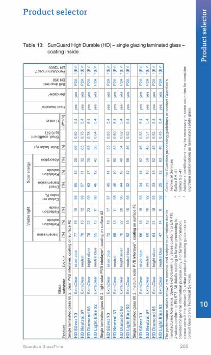
205
Product selector
Guardian GlassTime
Table 13: SunGuard High Durable (HD) – single glazing laminated glass – coating inside
Pro
duct
Gla
ss
subs
trate
Col
our
Visi
ble
light
Sol
ar e
nerg
y
Solar factor (g)
Shad. coefficient(g / 0.87)
U value
Heat treatable1
Bendable1
Ball drop test EN 356
Pendulum impact4 EN 12600
Transmission
Reflection outside
Reflection inside
Colour ren. index Ra
Direct transmission
Refelction outside
Absorption
[%]
[%]
[%]
[%]
[%]
[%]
[%]
[W/m
2 K]
Sin
gle
lam
inat
ed g
lass
66.
2, c
lear
PV
B in
terla
yer,
coat
ing
on s
urfa
ce #
2
HD
Sil
ver
70E
xtra
Cle
arsi
lver
blu
e77
1919
9865
1520
690.
805.
4ye
sye
sP
2A1(
B)1
HD
Neu
tral
67
Ext
raC
lear
neut
ral
7013
1298
5711
3265
0.75
5.4
yes
yes
P2A
1(B
)1
HD
Dia
mon
d 66
Ext
raC
lear
brig
ht s
ilver
7522
2399
6317
2068
0.78
5.4
yes
yes
P2A
1(B
)1
HD
Lig
ht B
lue
52E
xtra
Cle
arne
utra
l blu
e55
1511
9846
1242
560.
645.
4ye
sye
sP
2A1(
B)1
Sin
gle
lam
inat
ed g
lass
66.
2, li
ght s
olar
PV
B in
terla
yer2 ,
coat
ing
on s
urfa
ce #
2
HD
Sil
ver
70E
xtra
Cle
arsi
lver
blu
e72
1817
9745
1441
550.
635.
4ye
sye
sP
2A1(
B)1
HD
Neu
tral
67
Ext
raC
lear
neut
ral
6513
1195
4010
5052
0.60
5.4
yes
yes
P2A
1(B
)1
HD
Dia
mon
d 66
Ext
raC
lear
brig
ht s
ilver
7022
2096
4416
4054
0.62
5.4
yes
yes
P2A
1(B
)1
HD
Lig
ht B
lue
52E
xtra
Cle
arne
utra
l blu
e52
1510
9532
1256
460.
525.
4ye
sye
sP
2A1(
B)1
Sin
gle
lam
inat
ed g
lass
66.
2, m
ediu
m s
olar
PV
B in
terla
yer3 ,
coat
ing
on s
urfa
ce #
2
HD
Sil
ver
70E
xtra
Cle
arsi
lver
blu
e66
1815
9334
1452
460.
535.
4ye
sye
sP
2A1(
B)1
HD
Neu
tral
67
Ext
raC
lear
neut
ral
6012
1092
3110
5945
0.51
5.4
yes
yes
P2A
1(B
)1
HD
Dia
mon
d 66
Ext
raC
lear
brig
ht s
ilver
6421
1893
3315
5245
0.52
5.4
yes
yes
P2A
1(B
)1
HD
Lig
ht B
lue
52E
xtra
Cle
arne
utra
l blu
e47
149
9225
1263
400.
455.
4ye
sye
sP
2A1(
B)1
The
perf
orm
ance
val
ues
show
n ar
e no
min
al a
nd s
ubje
ct to
var
iatio
ns d
ue to
m
anuf
actu
ring
tole
ranc
e. S
pect
ra-p
hoto
met
rical
val
ues
conf
orm
to E
N 4
10,
U v
alue
s co
nfor
m to
EN
673
. All
deta
ils re
latin
g to
furt
her p
roce
ssin
g is
pr
ovid
ed fo
r gen
eral
info
rmat
ion
purp
ose
only
. For
furt
her i
nfor
mat
ion,
pl
ease
con
sult
the
rele
vant
Gua
rdia
n pr
oduc
t pro
cess
ing
guid
elin
es o
r co
nsul
t Gua
rdia
n’s
Tech
nica
l Ser
vice
s.
1 C
onsu
lt th
e G
uard
ian
proc
essi
ng g
uide
lines
or c
onta
ct G
uard
ian’
s
Tech
nica
l Ser
vice
s2
Safl
ex S
H-4
13
Safl
ex S
G-4
14
Add
ition
al c
ertifi
catio
ns m
ay b
e ne
cess
ary
in s
ome
coun
trie
s fo
r con
side
r-in
g th
ese
com
bina
tions
as
lam
inat
ed s
afet
y gl
ass
10
Pro
duct
sel
ecto
r

206 Guardian GlassTime
Table 14: SunGuard High Durable (HD) – double glazing
Pro
duct
Gla
ss s
ubst
rate
Col
our
Visi
ble
light
Sol
ar e
nerg
y
Solar factor (g)
Shad. coefficient(g / 0.87)
U v
alue
Heat treatable1
Bendable1
Transmission
Reflection outside
Reflection inside
Colour ren. index Ra
Direct transmission
Refelction outside
Absorption
Air
Argon
[%]
[%]
[%]
[%]
[%]
[%]
[%]
[W/m
2 K]
Dou
ble
glaz
ing
6 (1
6) 4
, coa
ting
on s
urfa
ce #
2, C
limaG
uard
Pre
miu
m2
on s
urfa
ce #
3
HD
Sil
ver
70E
xtra
Cle
arsi
lver
blu
e64
2929
9746
3717
510.
591.
41.
1ye
sye
s
HD
Neu
tral
67
Ext
raC
lear
neut
ral
5918
2098
4225
3348
0.55
1.4
1.1
yes
yes
HD
Dia
mon
d 66
Ext
raC
lear
brig
ht s
ilver
6034
3399
4540
1550
0.57
1.4
1.1
yes
yes
HD
Dia
mon
d 66
Ult
raU
ltraC
lear
2br
ight
silv
er61
3433
9848
448
520.
601.
41.
1ye
sye
s
HD
Lig
ht B
lue
52E
xtra
Cle
arne
utra
l blu
e47
1920
9834
2145
390.
451.
41.
1ye
sye
s
HD
Sil
ver
Gre
y 32
Ext
raC
lear
light
gre
y30
2424
9621
2257
260.
301.
41.
1ye
sye
s
HD
Roy
al B
lue
20E
xtra
Cle
arde
ep b
lue
2022
3298
1422
6418
0.21
1.4
1.1
yes
yes
HD
Sil
ver
20E
xtra
Cle
arsi
lver
1934
2893
1330
5717
0.20
1.4
1.1
yes
yes
HD
Sil
ver
10E
xtra
Cle
arsi
lver
944
3797
739
5410
0.12
1.4
1.1
yes
yes
The
perf
orm
ance
val
ues
show
n ar
e no
min
al a
nd s
ubje
ct to
var
iatio
ns d
ue to
m
anuf
actu
ring
tole
ranc
e. S
pect
ra-p
hoto
met
rical
val
ues
conf
orm
to E
N 4
10,
U v
alue
s co
nfor
m to
EN
673
. All
deta
ils re
latin
g to
furt
her p
roce
ssin
g is
pr
ovid
ed fo
r gen
eral
info
rmat
ion
purp
ose
only
. For
furt
her i
nfor
mat
ion,
pl
ease
con
sult
the
rele
vant
Gua
rdia
n pr
oduc
t pro
cess
ing
guid
elin
es o
r co
nsul
t Gua
rdia
n’s
Tech
nica
l Ser
vice
s.
1 C
onsu
lt th
e G
uard
ian
proc
essi
ng g
uide
lines
or c
onta
ct G
uard
ian’
s
Tech
nica
l Ser
vice
s2
In
boar
d an
d ou
tboa
rd s
ubst
rate
Gua
rdia
n U
ltraC
lear

207
Product selector
Guardian GlassTime
Table 14: SunGuard High Durable (HD) – double glazingContinued
The
perf
orm
ance
val
ues
show
n ar
e no
min
al a
nd s
ubje
ct to
var
iatio
ns d
ue to
m
anuf
actu
ring
tole
ranc
e. S
pect
ra-p
hoto
met
rical
val
ues
conf
orm
to E
N 4
10,
U v
alue
s co
nfor
m to
EN
673
. All
deta
ils re
latin
g to
furt
her p
roce
ssin
g is
pr
ovid
ed fo
r gen
eral
info
rmat
ion
purp
ose
only
. For
furt
her i
nfor
mat
ion,
pl
ease
con
sult
the
rele
vant
Gua
rdia
n pr
oduc
t pro
cess
ing
guid
elin
es o
r co
nsul
t Gua
rdia
n’s
Tech
nica
l Ser
vice
s.
1 C
onsu
lt th
e G
uard
ian
proc
essi
ng g
uide
lines
or c
onta
ct G
uard
ian’
s
Tech
nica
l Ser
vice
s2
In
boar
d an
d ou
tboa
rd s
ubst
rate
Gua
rdia
n U
ltraC
lear
Pro
duct
Gla
ss s
ubst
rate
Col
our
Visi
ble
light
Sol
ar e
nerg
y
Solar factor (g)
Shad. coefficient(g / 0.87)
U v
alue
Heat treatable1
Bendable1
Transmission
Reflection outside
Reflection inside
Colour ren. index Ra
Direct transmission
Refelction outside
Absorption
Air
Argon
[%]
[%]
[%]
[%]
[%]
[%]
[%]
[W/m
2 K]
Dou
ble
glaz
ing
6 (1
6) 4
, coa
ting
on s
urfa
ce #
2, C
limaG
uard
1.0
+ on
sur
face
#3
HD
Sil
ver
70E
xtra
Cle
arsi
lver
blu
e59
3232
9638
4517
430.
491.
31.
0ye
sye
s
HD
Neu
tral
67
Ext
raC
lear
neut
ral
5521
2596
3431
3540
0.45
1.3
1.0
yes
yes
HD
Dia
mon
d 66
Ext
raC
lear
brig
ht s
ilver
5637
3697
3737
3642
0.48
1.3
1.0
yes
yes
HD
Dia
mon
d 66
Ult
raU
ltraC
lear
2br
ight
silv
er57
3736
9739
538
430.
491.
31.
0ye
sye
s
HD
Lig
ht B
lue
52E
xtra
Cle
arne
utra
l blu
e44
2024
9627
2548
320.
371.
31.
0ye
sye
s
HD
Sil
ver
Gre
y 32
Ext
raC
lear
light
gre
y28
2528
9517
2759
220.
251.
31.
0ye
sye
s
HD
Roy
al B
lue
20E
xtra
Cle
arde
ep b
lue
1822
3596
1222
6616
0.18
1.3
1.0
yes
yes
HD
Sil
ver
20E
xtra
Cle
arsi
lver
1735
3293
1131
5815
0.17
1.3
1.0
yes
yes
HD
Sil
ver
10E
xtra
Cle
arsi
lver
944
4096
639
559
0.10
1.3
1.0
yes
yes
10
Pro
duct
sel
ecto
r

208 Guardian GlassTime
Table 15: SunGuard Solar – double glazing
Pro
duct
Gla
ss s
ubst
rate
Col
our
Visi
ble
light
Sol
ar e
nerg
y
Solar factor (g)
Shad. coefficient(g / 0.87)
U v
alue
Heat treatable1
Bendable1
Transmission
Reflection outside
Reflection inside
Colour ren. index Ra
Direct transmission
Refelction outside
Absorption
Air
Argon
[%]
[%]
[%]
[%]
[%]
[%]
[%]
[W/m
2 K]
Dou
ble
glaz
ing
6 (1
6) 4
, coa
ting
on s
urfa
ce #
2, C
limaG
uard
Pre
miu
m2
on s
urfa
ce #
3
Sol
ar B
righ
t Gre
en 2
0E
xtra
Cle
arlig
ht g
reen
1935
1196
1220
6816
0.18
1.4
1.1
yes
yes
Sol
ar B
ron
ze 2
0E
xtra
Cle
arbr
onze
1917
1493
1220
6816
0.18
1.4
1.1
yes
yes
Sol
ar G
old
20E
xtra
Cle
argo
ld21
2613
9513
1770
170.
191.
41.
1ye
sye
s
Sol
ar G
rey
20E
xtra
Cle
ada
rk g
rey
1910
796
1312
7518
0.20
1.4
1.1
yes
yes
Dou
ble
glaz
ing
6 (1
6) 4
, coa
ting
on s
urfa
ce #
2, C
limaG
uard
1.0
+ on
sur
face
#3
Sol
ar B
righ
t Gre
en 2
0E
xtra
Cle
arlig
ht g
reen
1735
1794
1020
7014
0.16
1.3
1.0
yes
yes
Sol
ar B
ron
ze 2
0E
xtra
Cle
arbr
onze
1817
1992
1020
7014
0.16
1.3
1.0
yes
yes
Sol
ar G
old
20E
xtra
Cle
argo
ld19
2719
9711
1871
150.
171.
31.
0ye
sye
s
Sol
ar G
rey
20E
xtra
Cle
ada
rk g
rey
1711
1395
1112
7715
0.17
1.3
1.0
yes
yes
The
perf
orm
ance
val
ues
show
n ar
e no
min
al a
nd s
ubje
ct to
var
iatio
ns d
ue to
m
anuf
actu
ring
tole
ranc
e. S
pect
ra-p
hoto
met
rical
val
ues
conf
orm
to E
N 4
10,
U v
alue
s co
nfor
m to
EN
673
. All
deta
ils re
latin
g to
furt
her p
roce
ssin
g is
pr
ovid
ed fo
r gen
eral
info
rmat
ion
purp
ose
only
. For
furt
her i
nfor
mat
ion,
pl
ease
con
sult
the
rele
vant
Gua
rdia
n pr
oduc
t pro
cess
ing
guid
elin
es o
r co
nsul
t Gua
rdia
n’s
Tech
nica
l Ser
vice
s.
1 C
onsu
lt th
e G
uard
ian
proc
essi
ng g
uide
lines
or c
onta
ct G
uard
ian’
s
Tech
nica
l Ser
vice
s

209
Product selector
Guardian GlassTime
Table 16: SunGuard RD – Radar reflection damping glazing
Pro
duct
Gla
ss s
ubst
rate
Col
our
Visi
ble
light
Sol
ar e
nerg
y
Solar factor (g)
Shad. coefficient(g / 0.87)
U v
alue
Heat treatable1
Bendable1
Transmission
Reflection outside
Reflection inside
Colour ren. index Ra
Direct transmission
Refelction outside
Absorption
Air
Argon
[%]
[%]
[%]
[%]
[%]
[%]
[%]
[W/m
2 K]
Dou
ble
glaz
ing
88.2
(16)
6, c
oatin
g in
side
lam
inat
ed2 o
n su
rface
#2,
Clim
aGua
rd P
rem
ium
2 on
sur
face
#5
RD
60
HT
Ext
raC
lear
neut
ral
5918
1495
3618
4642
0.48
1.4
1.1
yes
yes
Typi
cal g
lass
bui
ld-u
p fo
r rad
ar re
flect
ion
dam
ping
of a
irpor
t SS
R ra
dar
syst
ems.
The
coa
ting
RD
60
need
s to
be
heat
trea
ted
to e
nsur
e th
e co
rrec
t el
ectr
ical
pro
pert
ies.
The
perf
orm
ance
val
ues
show
n ar
e no
min
al a
nd s
ubje
ct to
var
iatio
ns d
ue to
m
anuf
actu
ring
tole
ranc
e. S
pect
ra-p
hoto
met
rical
val
ues
conf
orm
to E
N 4
10,
U v
alue
s co
nfor
m to
EN
673
. All
deta
ils re
latin
g to
furt
her p
roce
ssin
g is
pr
ovid
ed fo
r gen
eral
info
rmat
ion
purp
ose
only
. For
furt
her i
nfor
mat
ion,
pl
ease
con
sult
the
rele
vant
Gua
rdia
n pr
oduc
t pro
cess
ing
guid
elin
es o
r co
nsul
t Gua
rdia
n’s
Tech
nica
l Ser
vice
s.
1 C
onsu
lt th
e G
uard
ian
proc
essi
ng g
uide
lines
or c
onta
ct G
uard
ian’
s
Tech
nica
l Ser
vice
s2
Com
mon
type
app
rova
l for
saf
ety
glas
s by
DIB
t for
Ger
man
y
10
Pro
duct
sel
ecto
r

210 Guardian GlassTime
Table 17: Colour adapted spandrel solutions for SunGuard glazing
The
info
rmat
ion
prov
ided
abo
ve is
a g
ener
al re
com
men
datio
n on
ly b
ased
on
vis
ual m
ock-
ups
and
com
patib
ility
test
s pe
rfor
med
with
the
indi
cate
d Fe
rro
cera
mic
frit
syst
em. O
ther
cer
amic
frit
syst
ems/
pain
ts c
an c
onsi
st o
f di
ffere
nt c
ompo
nent
s; th
is c
an le
ad to
com
patib
ility
issu
es w
ith th
e G
uard
ian
Sun
Gua
rd® c
oatin
gs a
nd/o
r can
mod
ify th
e fin
al e
sthe
tic a
ppea
ranc
e of
the
rele
vant
pai
nt-c
oatin
g co
mbi
natio
n. It
is th
e re
spon
sibi
lity
of th
e us
ers
of th
is
info
rmat
ion
to a
ssur
e th
at a
ppro
pria
te c
ompa
tibili
ty te
sts
in a
real
siz
e m
ock-
up
are
per
form
ed to
ver
ify th
e co
lour
mat
chin
g be
twee
n vi
sion
and
spa
ndre
l.
1 Th
e in
dica
ted
enam
els
(num
bers
) fro
m F
erro
and
Wol
brin
g (W
O) a
re b
ased
on
the
enam
el ty
pe F
ER
RO
Sys
tem
140
and
spe
cial
col
our m
ixtu
res
to
adap
t bes
t to
the
rela
ted
visi
on.
Ple
ase
cont
act t
he G
uard
ian
Tech
nica
l Ser
vice
s fo
r mor
e in
form
atio
n.
2 In
sula
ting
glas
s sp
andr
els
sim
ulat
e th
e de
pth
of a
room
. Bas
ed o
n ou
r ex
perie
nce,
bla
ck (e
.g. R
AL
9005
) or d
ark
grey
(e.g
. RA
L 70
21) a
re th
e en
amel
col
ours
that
bet
ter m
atch
the
visi
on a
reas
. The
cav
ity s
houl
d be
lim
ited
to 8
mm
in o
rder
to m
inim
ize
pote
ntia
l clim
atic
load
s. D
ue to
in
crea
sed
ener
gy a
bsor
ptio
n of
the
glas
s, h
eat t
reat
men
t sho
uld
be
cons
ider
ed.
Gua
rdia
n S
unG
uard
®
glaz
ing
Mon
olith
ic s
pand
rel
Insu
latin
g gl
ass
span
drel
2
(coa
ting
on #
2 +
enam
el o
n #4
)en
amel
led1
Sha
dow
box
(ven
tilat
ed w
ith b
lack
ba
ckgr
ound
)
Gua
rdia
n S
unG
uard
® e
Xtra
Sel
ectiv
e
SN
X 7
0-
-S
G S
NX
70
SN
X 7
0 H
TC
lear
floa
t gla
ss +
WO
-E-1
4-70
65 (g
reyi
sh)
Cle
ar fl
oat g
lass
+ W
O-B
-14-
7066
(blu
eish
)S
G H
D L
ight
Blu
e 52
SG
SN
X 7
0 H
T
SN
X 6
0C
lear
floa
t gla
ss +
WO
-B-1
4-70
67S
G S
olar
Roy
al B
lue
20 +
Fer
ro 1
40 1
5 40
01 o
n #2
SG
HD
Roy
al B
lue
20S
G S
NX
60
SN
X 5
0C
lear
floa
t gla
ss +
WO
-B-1
4-70
67S
G S
olar
Roy
al B
lue
20 +
Fer
ro 1
40 1
5 40
01 o
n #2
SG
HD
Roy
al B
lue
20S
G S
NX
50
Gua
rdia
n S
unG
uard
® S
uper
Neu
tral™
SN
75
Cle
ar fl
oat g
lass
+ W
O-E
-14-
7065
(gre
yish
)C
lear
floa
t gla
ss +
WO
-B-1
4-70
66 (b
luei
sh)
-S
G S
N 7
5
SN
70S
Cle
ar fl
oat g
lass
+ W
O-E
-14-
7063
-S
G S
N 7
0S
SN
70
/ 37
Cle
ar fl
oat g
lass
+ W
O-E
-14-
7063
-S
G S
N 7
0/37
SN
70
/ 35
Cle
ar fl
oat g
lass
+ W
O-B
-14-
7067
-S
G S
N 7
0/35
SN
63
Cle
ar fl
oat g
lass
+ W
O-B
-14-
7064
SG
HD
Lig
ht B
lue
52S
G S
N 6
3
SN
51
Cle
ar fl
oat g
lass
+ W
O-E
-14-
7063
(gre
yish
)C
lear
floa
t gla
ss +
WO
-B-1
4-70
64 (b
luei
sh)
SG
HD
Lig
ht B
lue
52S
G S
N 5
1
SN
40
/ 23
Cle
ar fl
oat g
lass
+ W
O-B
-14-
7067
SG
Sol
ar R
oyal
Blu
e 20
+ F
erro
140
15
4001
on
#2S
G H
D R
oyal
Blu
e 20
SG
SN
40/
23

211
Product selector
Guardian GlassTime
Table 17: Colour adapted spandrel solutions for SunGuard glazing
Continued
Gua
rdia
n S
unG
uard
®
glaz
ing
Mon
olith
ic s
pand
rel
Insu
latin
g gl
ass
span
drel
2
(coa
ting
on #
2 +
enam
el o
n #4
)en
amel
led1
Sha
dow
box
(ven
tilat
ed w
ith b
lack
ba
ckgr
ound
)
SN
29
/ 18
Cle
ar fl
oat g
lass
+ W
O-B
-14-
7067
SG
Sol
ar R
oyal
Blu
e 20
+ F
erro
140
15
4001
on
#2S
G H
D R
oyal
Blu
e 20
SG
SN
29/
18
Gua
rdia
n S
unG
uard
® H
igh
Per
form
ance
HP
Lig
ht B
lue
62 /
52C
lear
floa
t gla
ss +
WO
-B-1
4-70
67S
G H
P Li
ght B
lue
62/5
2
HP
Neu
tral
60
/ 40
Cle
ar fl
oat g
lass
+ W
O-B
-14-
7064
SG
HD
Silv
er G
rey
32 +
Fer
ro 1
40 1
5 40
01 o
n #2
SG
HD
Silv
er G
rey
32
SG
HP
Neu
tral 6
0/40
HP
Neu
tral
50
/ 32
Cle
ar fl
oat g
lass
+ W
O-B
-14-
7064
SG
HD
Silv
er G
rey
32 +
Fer
ro 1
40 1
5 40
01 o
n #2
SG
HD
Silv
er G
rey
32S
G H
P N
eutra
l 50/
32
HP
Sil
ver
43 /
31-
SG
HD
Silv
er 7
0S
G H
P S
ilver
43/
31
HP
Neu
tral
41
/ 33
Cle
ar fl
oat g
lass
+ W
O-B
-14-
7064
SG
HD
Silv
er G
rey
32 +
Fer
ro 1
40 1
5 40
01 o
n #2
SG
HD
Silv
er G
rey
32S
G H
P N
eutra
l 41/
33
HP
Am
ber
41 /
29-
-S
G H
P A
mbe
r 41/
29
HP
Roy
al B
lue
41 /
29S
G S
olar
Roy
al B
lue
20 +
Fer
ro 1
40 1
5 40
01 o
n #2
SG
HD
Roy
al B
lue
20S
G H
P R
oyal
Blu
e 41
/29
HP
Bro
nze
40
/ 27
SG
Sol
ar B
ronz
e 20
+ F
erro
140
15
4001
on
#2-
SG
HP
Bro
nze
40/2
7
HP
Bri
ght G
reen
40
/ 29
SG
Sol
ar B
right
Gre
en 2
0 +
Ferr
o 14
0 15
400
1 on
#2
-S
G H
P B
right
Gre
en 4
0/29
HP
Sil
ver
35 /
26S
G H
D S
ilver
10
+ Fe
rro
140
15 4
001
on #
2S
G H
D S
ilver
10
SG
HP
Silv
er 3
5/26
The
info
rmat
ion
prov
ided
abo
ve is
a g
ener
al re
com
men
datio
n on
ly b
ased
on
vis
ual m
ock-
ups
and
com
patib
ility
test
s pe
rfor
med
with
the
indi
cate
d Fe
rro
cera
mic
frit
syst
em. O
ther
cer
amic
frit
syst
ems/
pain
ts c
an c
onsi
st o
f di
ffere
nt c
ompo
nent
s; th
is c
an le
ad to
com
patib
ility
issu
es w
ith th
e G
uard
ian
Sun
Gua
rd® c
oatin
gs a
nd/o
r can
mod
ify th
e fin
al e
sthe
tic a
ppea
ranc
e of
the
rele
vant
pai
nt-c
oatin
g co
mbi
natio
n. It
is th
e re
spon
sibi
lity
of th
e us
ers
of th
is
info
rmat
ion
to a
ssur
e th
at a
ppro
pria
te c
ompa
tibili
ty te
sts
in a
real
siz
e m
ock-
up
are
per
form
ed to
ver
ify th
e co
lour
mat
chin
g be
twee
n vi
sion
and
spa
ndre
l.
1 Th
e in
dica
ted
enam
els
(num
bers
) fro
m F
erro
and
Wol
brin
g (W
O) a
re b
ased
on
the
enam
el ty
pe F
ER
RO
Sys
tem
140
and
spe
cial
col
our m
ixtu
res
to
adap
t bes
t to
the
rela
ted
visi
on.
Ple
ase
cont
act t
he G
uard
ian
Tech
nica
l Ser
vice
s fo
r mor
e in
form
atio
n.
2 In
sula
ting
glas
s sp
andr
els
sim
ulat
e th
e de
pth
of a
room
. Bas
ed o
n ou
r ex
perie
nce,
bla
ck (e
.g. R
AL
9005
) or d
ark
grey
(e.g
. RA
L 70
21) a
re th
e en
amel
col
ours
that
bet
ter m
atch
the
visi
on a
reas
. The
cav
ity s
houl
d be
lim
ited
to 8
mm
in o
rder
to m
inim
ize
pote
ntia
l clim
atic
load
s. D
ue to
in
crea
sed
ener
gy a
bsor
ptio
n of
the
glas
s, h
eat t
reat
men
t sho
uld
be
cons
ider
ed.
10
Pro
duct
sel
ecto
r

212 Guardian GlassTime
Table 17: Colour adapted spandrel solutions for SunGuard glazing
Continued
Gua
rdia
n S
unG
uard
®
glaz
ing
Mon
olith
ic s
pand
rel
Insu
latin
g gl
ass
span
drel
2
(coa
ting
on #
2 +
enam
el o
n #4
)en
amel
led1
Sha
dow
box
(ven
tilat
ed w
ith b
lack
ba
ckgr
ound
)
Gua
rdia
n S
unG
uard
® H
igh
Dur
able
HD
Sil
ver
70-
SG
HD
Silv
er 7
0S
G H
D S
ilver
70
HD
Neu
tral
67
Cle
ar fl
oat g
lass
+ W
O-E
-14-
7063
(gre
yish
)C
lear
floa
t gla
ss +
WO
-B-1
4-70
64 (b
luei
sh)
SG
HD
Neu
tral 6
7S
G H
D N
eutra
l 67
HD
Dia
mon
d 66
-S
G H
D D
iam
ond
66S
G H
D D
iam
ond
66
HD
Lig
ht B
lue
52C
lear
floa
t gla
ss +
WO
-E-1
4-70
63 (g
reyi
sh)
Cle
ar fl
oat g
lass
+ W
O-B
-14-
7064
(blu
eish
)S
G H
D L
ight
Blu
e 52
SG
HD
Lig
ht B
lue
52
HD
Sil
ver
Gre
y 32
Cle
ar fl
oat g
lass
+ W
O-B
-14-
7064
SG
HD
Silv
er G
rey
32 +
Fer
ro 1
40 1
5 40
01 o
n #2
SG
HD
Silv
er G
rey
32S
G H
D S
ilver
Gre
y 32
HD
Roy
al B
lue
20S
G S
olar
Roy
al B
lue
20 +
Fer
ro 1
40 1
5 40
01 o
n #2
SG
HD
Roy
al B
lue
20S
G H
D R
oyal
Blu
e 20
HD
Sil
ver
20S
G H
D S
ilver
20
+ Fe
rro
140
15 4
001
on #
2S
G H
D S
ilver
20
SG
HD
Silv
er 2
0
HD
Sil
ver
10S
G H
D S
ilver
10
+ Fe
rro
140
15 4
001
on #
2S
G H
D S
ilver
10
SG
HD
Silv
er 1
0
Gua
rdia
n S
unG
uard
® S
olar
Sol
ar B
ron
ze 2
0S
G S
olar
Bro
nze
20 +
Fer
ro 1
40 1
5 40
01 o
n #2
-S
G S
olar
Bro
nze
20
Sol
ar G
old
20-
-S
G S
olar
Gol
d 20
Sol
ar G
rey
20-
-S
G S
olar
Gre
y 20
Sol
ar B
righ
t Gre
en 2
0S
G S
olar
Brig
ht G
reen
20
+ Fe
rro
140
15 4
001
on #
2-
SG
Sol
ar B
right
Gre
en 2
0
The
info
rmat
ion
prov
ided
abo
ve is
a g
ener
al re
com
men
datio
n on
ly b
ased
on
vis
ual m
ock-
ups
and
com
patib
ility
test
s pe
rfor
med
with
the
indi
cate
d Fe
rro
cera
mic
frit
syst
em. O
ther
cer
amic
frit
syst
ems/
pain
ts c
an c
onsi
st o
f di
ffere
nt c
ompo
nent
s; th
is c
an le
ad to
com
patib
ility
issu
es w
ith th
e G
uard
ian
Sun
Gua
rd® c
oatin
gs a
nd/o
r can
mod
ify th
e fin
al e
sthe
tic a
ppea
ranc
e of
the
rele
vant
pai
nt-c
oatin
g co
mbi
natio
n. It
is th
e re
spon
sibi
lity
of th
e us
ers
of th
is
info
rmat
ion
to a
ssur
e th
at a
ppro
pria
te c
ompa
tibili
ty te
sts
in a
real
siz
e m
ock-
up
are
per
form
ed to
ver
ify th
e co
lour
mat
chin
g be
twee
n vi
sion
and
spa
ndre
l.
1 Th
e in
dica
ted
enam
els
(num
bers
) fro
m F
erro
and
Wol
brin
g (W
O) a
re b
ased
on
the
enam
el ty
pe F
ER
RO
Sys
tem
140
and
spe
cial
col
our m
ixtu
res
to
adap
t bes
t to
the
rela
ted
visi
on.
Ple
ase
cont
act t
he G
uard
ian
Tech
nica
l Ser
vice
s fo
r mor
e in
form
atio
n.
2 In
sula
ting
glas
s sp
andr
els
sim
ulat
e th
e de
pth
of a
room
. Bas
ed o
n ou
r ex
perie
nce,
bla
ck (e
.g. R
AL
9005
) or d
ark
grey
(e.g
. RA
L 70
21) a
re th
e en
amel
col
ours
that
bet
ter m
atch
the
visi
on a
reas
. The
cav
ity s
houl
d be
lim
ited
to 8
mm
in o
rder
to m
inim
ize
pote
ntia
l clim
atic
load
s. D
ue to
in
crea
sed
ener
gy a
bsor
ptio
n of
the
glas
s, h
eat t
reat
men
t sho
uld
be
cons
ider
ed.

213
Product selector
Guardian GlassTime
10.4 Anti-reflective glazing
Table 18: Guardian Clarity™
Pro
duct
Gla
ss s
ubst
rate
Col
our
Visi
ble
light
Sol
ar e
nerg
y
Solar factor (g)
Shad. coefficient(g / 0.87)
U v
alue
Heat treatable1
Bendable1
Transmission
Reflection outside
Reflection inside
Colour ren. index Ra
Direct transmission
Refelction outside
Absorption
Air
Argon
[%]
[%]
[%]
[%]
[%]
[%]
[%]
[W/m
2 K]
Sin
gle
glaz
ing
lam
inat
ed 6
6.2,
coa
ting
on s
urfa
ce #
1 +
#4
Cla
rity
Ultr
aCle
arne
utra
l96
0.5
0.5
9975
1114
780.
905.
4-
yes
yes
Dou
ble
glaz
ing
8 (1
6) 8
, coa
ting
on s
urfa
ce #
1, #
2, #
3 +
#4
Cla
rity
Ultr
aCle
arne
utra
l94
0.9
0.9
9969
1714
730.
842.
72.
6ye
sye
s
Dou
ble
glaz
ing
66.2
(16)
44.
2, c
oatin
g on
sur
face
#1,
#4
+ #8
, Clim
aGua
rd P
rem
ium
2 on
#5
Cla
rity
Ultr
aCle
arne
utra
l89
1.5
2.1
9755
2223
610.
701.
31.
1ye
sye
s
Dou
ble
glaz
ing
66.2
(16)
44.
2, c
oatin
g on
sur
face
#1,
#5
+ #8
, Sun
Gua
rd S
N 7
0/37
on
#2
Cla
rity
Ultr
aCle
arne
utra
l77
2.4
2.2
9336
3430
380.
441.
31.
0ye
sye
s
The
perf
orm
ance
val
ues
show
n ar
e no
min
al a
nd s
ubje
ct to
var
iatio
ns d
ue to
m
anuf
actu
ring
tole
ranc
e. S
pect
ra-p
hoto
met
rical
val
ues
conf
orm
to E
N 4
10,
U v
alue
s co
nfor
m to
EN
673
. All
deta
ils re
latin
g to
furt
her p
roce
ssin
g is
pr
ovid
ed fo
r gen
eral
info
rmat
ion
purp
ose
only
. For
furt
her i
nfor
mat
ion,
pl
ease
con
sult
the
rele
vant
Gua
rdia
n pr
oduc
t pro
cess
ing
guid
elin
es o
r co
nsul
t Gua
rdia
n’s
Tech
nica
l Ser
vice
s.G
lazi
ng’s
con
sist
of G
uard
ian
U
ltraC
lear
onl
y.
1 C
onsu
lt th
e G
uard
ian
proc
essi
ng g
uide
lines
or c
onta
ct G
uard
ian’
s
Tech
nica
l Ser
vice
s
10
Pro
duct
sel
ecto
r

214 Guardian GlassTime
10.5 Sound control glass• acoustic performance valid for argon and air gas filling (according to
EN 12758)
• Krypton filled units are marked with Kr
• PVB: standard PVB interlayer (Guardian LamiGlass)
• SR: sound reduction PVB interlayer (Guardian LamiGlass Acoustic)
• Ug values and spectra-photometrical values are to be determined depending on the used performance coatings
• EN 12758:2019: Values for IGU with a cavity of 12 mm can be applied for wider cavities too.
• The orientation of the build-up has no influence on the sound insulation performance (glazing can be flipped).
Table 19: Sound control single glazing
Build up
Acoustic performance acc. to EN ISO 717-1 Safety/security
Weighted sound
reduction factor
RW [dB]
Correction factor
high freq.
C [dB]
Correction factor
low freq.
Ctr [dB]
Ball drop
EN 356
Pendulum impact
EN 12600
33.1 SR 36 -1 -4 P1A 1(B)1
33.2 SR 35 -1 -4 P2A 1(B)1
44.1 SR 38 -1 -4 P1A 1(B)1
44.2 SR 38 -1 -4 P1A 1(B)1
44.4 SR 37 -1 -3 P4A 1(B)1
55.1 SR 39 -1 -4 P1A 1(B)1
55.2 SR 39 -1 -3 P2A 1(B)1
66.1 SR 40 -1 -3 P1A 1(B)1
66.2 SR 39 0 -2 P2A 1(B)1
88.1 SR 41 -1 -3 npd 1(B)1
88.2 SR 41 0 -2 npd 1(B)1
1010.1 SR 43 -1 -3 npd npd
1010.2 SR 43 -1 -3 npd npd
1212.4 SR 44 0 -3 npd npd

215
Product selector
Guardian GlassTime
Table 20: Sound control double glazing
Build up
Acoustic performance acc. to EN ISO 717-1 Safety/security
Weighted sound
reduction factor
RW [dB]
Correction factor
high freq.
C [dB]
Correction factor
low freq.
Ctr [dB]
Ball drop
EN 356
Pendulum impact
EN 12600
4 (12) 4 29 -1 -3 - -
4 (16) 4 30 -1 -4 - -
5 (12) 5 31 -1 -4 - -
5 (12) 4 32 -1 -3 - -
6 (12) 4 33 -1 -3 - -
6 (12) 5 34 -1 -3 - -
8 (12) 4 34 -1 -4 - -
6 (16) 4 34 -1 -5 - -
33.1 SR (12) 4 34 -1 -4 P1A 1(B)1
6 (16) 6 35 -2 -4 - -
8 (12) 5 35 -1 -4 - -
8 (12) 6 35 -1 -3 - -
8 (16) 4 35 -2 -5 - -
8 (16) 8 35 -1 -4 - -
33.1 PVB (12) 6 35 -1 -5 - 2(B)2
44.1 PVB (12) 4 36 -1 -5 - 2(B)2
55.1 PVB (12) 4 36 -1 -4 - 1(B)1
33.1 PVB (12) 5 36 -1 -5 - 2(B)2
33.1 PVB (12) 33.1 PVB 36 -1 -5 - 2(B)2
44.1 PVB (12) 5 36 -1 -4 - 2(B)2
10 (16) 4 37 -2 -6 - -
44.1 PVB (12) 6 37 -1 -5 - 2(B)2
55.1 PVB (12) 6 37 -1 -4 - 1(B)1
33.1 PVB (12) 8 37 -1 -4 - 2(B)2
44.1 PVB (12) 44.1 PVB 37 -1 -4 - 2(B)2
44.2 PVB (16) 8 37 -1 -5 P2A 1(B)1
33.1 SR (16) 4 37 -1 -5 P1A 1(B)1
44.2 PVB (16) 6 38 -1 -5 P2A 1(B)1
44.4 PVB (16) 8 38 -1 -5 P4A 1(B)1
44.1 PVB (12) 33.1 PVB 38 -1 -4 - 2(B)2
33.1 SR (16) 4 38 -3 -7 P1A 1(B)1
33.1 SR (20) 4 38 -2 -7 P1A 1(B)1
33.1 SR (16) 5 38 -2 -7 P1A 1(B)1
10 (16) 6 39 -1 -4 - -
66.1 PVB (12) 6 39 -1 -4 P1A 1(B)1
66.1 PVB (12) 10 39 -1 -3 P1A 1(B)1
44.1 SR (16) 4 39 -2 -6 P1A 1(B)1
44.1 SR (16) 5 39 -2 -6 P1A 1(B)1
44.1 PVB (16) 10 40 -2 -5 - 2(B)2
55.1 PVB (16) 8 40 -1 -4 - 1(B)1
10
Pro
duct
sel
ecto
r

216 Guardian GlassTime
Build up
Acoustic performance acc. to EN ISO 717-1 Safety/security
Weighted sound
reduction factor
RW [dB]
Correction factor
high freq.
C [dB]
Correction factor
low freq.
Ctr [dB]
Ball drop
EN 356
Pendulum impact
EN 12600
44.2 PVB (16) 6 40 -3 -7 P2A 1(B)1
55.1 PVB (16) 44.1 PVB 40 -2 -5 - 1(B)1
55.1 PVB (16) 55.1 PVB 40 -2 -6 - 1(B)1
55.2 PVB (20) 6 40 -1 -5 P2A 1(B)1
66.1 PVB (12) 33.1 PVB 40 -1 -4 P1A 1(B)1
33.1 SR (16) 6 40 -2 -7 P1A 1(B)1
33.1 SR (16) 33.1 SR 40 -2 -7 P1A 1(B)1
44.1 SR (12) 33.1 PVB 40 -3 -7 P1A 1(B)1
55.1 SR (12) 6 40 -1 -5 P1A 1(B)1
55.1 SR (16) 8 40 -1 -4 P1A 1(B)1
55.2 PVB (16) 8 41 -1 -4 P2A 1(B)1
66.1 PVB (12) 44.1 PVB 41 -1 -3 P1A 1(B)1
44.1 PVB (16) 33.1 SR 41 -2 -6 P1A 1(B)1
66.1 PVB (16) 8 42 -2 -4 P1A 1(B)1
66.1 PVB (16) 55.1 PVB 42 -1 -4 P1A 1(B)1
66.1 PVB (16) 66.1 PVB 42 -1 -4 P1A 1(B)1
44.1 SR (16) 6 42 -2 -6 P1A 1(B)1
44.1 SR (16) 33.1 SR 42 -2 -6 P1A 1(B)1
44.1 SR (20) 33.1 SR 42 -2 -7 P1A 1(B)1
44.2 SR (16) 6 42 -2 -6 P2A 1(B)1
44.2 SR (16) 8 42 -1 -5 P2A 1(B)1
55.2 SR (16) 6 42 -2 -6 P2A 1(B)1
44.1 SR (16) 33.1 PVB 42 -2 -6 P1A 1(B)1
66.2 PVB (16) 10 43 -2 -5 P2A 1(B)1
44.1 SR (16) 44.1 PVB 43 -2 -6 P1A 1(B)1
44.1 SR (14) 6 - Kr 43 -3 -8 P1A 1(B)1
55.2 SR (16) 8 43 -1 -5 P2A 1(B)1
55.2 SR (18) 8 43 -1 -6 P2A 1(B)1
44.1 SR (20) 6 43 -2 -7 P1A 1(B)1
66.1 SR (16) 6 43 -2 -5 P1A 1(B)1
66.2 SR (16) 8 43 -2 -5 P2A 1(B)1
55.1 PVB (16) 44.1 PVB 44 -2 -7 - 1(B)1
44.1 SR (20) 8 44 -3 -7 P1A 1(B)1
66.1 PVB (16) 44.1 SR 44 -1 -5 P1A 1(B)1
44.1 SR (16) 10 44 -2 -6 P1A 1(B)1
44.1 SR (16) 44.1 SR 44 -2 -7 P1A 1(B)1
66.1 SR (16) 44.1 SR 44 -1 -5 P1A 1(B)1
55.2 SR (16) 10 44 -1 -4 P2A 1(B)1
88.4 PVB (18) 10 45 -1 -4 P4A 1(B)1
55.2 SR (16) 10 45 -2 -6 P1A 1(B)1
44.1 SR (18) 10 45 -2 -6 P1A 1(B)1
66.1 SR (16) 10 45 -2 -6 P1A 1(B)1

217
Product selector
Guardian GlassTime
Build up
Acoustic performance acc. to EN ISO 717-1 Safety/security
Weighted sound
reduction factor
RW [dB]
Correction factor
high freq.
C [dB]
Correction factor
low freq.
Ctr [dB]
Ball drop
EN 356
Pendulum impact
EN 12600
1212.4 SR (16) 12 45 -1 -4 P4A 1(B)1
55.1 SR (16) 44.1 SR 46 -2 -7 P1A 1(B)1
66.2 SR (20) 10 46 -2 -6 P2A 1(B)1
66.1 SR (16) 55.1 SR 48 -2 -6 P1A 1(B)1
66.1 SR (16) 66.1 SR 49 -2 -6 P1A 1(B)1
66.2 SR (16) 44.2 SR 49 -2 -7 P2A 1(B)1
66.2 SR (20) 55.2 SR 49 -2 -6 P2A 1(B)1
88.2 SR (16) 66.2 SR 51 -1 -4 P2A 1(B)1
66.4 SR (20) 44.4 SR 51 -2 -6 P4A 1(B)1
88.4 SR (20) 55.2 SR 51 -2 -6 P4A 1(B)1
88.2 SR (24) 46.2 SR 52 -2 -6 P2A 1(B)1
Table 21: Sound control triple glazing
Build up
Acoustic performance acc. to EN ISO 717-1 Safety/security
Weighted sound
reduction factor
RW [dB]
Correction factor
high freq.
C [dB]
Correction factor
low freq.
Ctr [dB]
Ball drop
EN 356
Pendulum impact
EN 12600
4 (8) 4 (8) 4 - Kr 31 -1 -4 - -
4 (12) 4 (12) 4 31 -1 -5 - -
4 (14) 4 (14) 4 31 -1 -5 - -
4 (16) 4 (16) 4 32 -1 -5 - -
4 (12) 4 (12) 4 - Kr 33 -1 -5 - -
6 (10) 4 (10) 4 - Kr 34 -1 -5 - -
4 (20) 4 (20) 4 35 -2 -7 - -
6 (12) 4 (12) 4 35 -1 -5 - -
6 (12) 4 (12) 4 - Kr 36 -2 -6 - -
6 (16) 4 (16) 6 36 -1 -6 - -
8 (12) 4 (12) 4 36 -2 -6 - -
6 (16) 4 (16) 4 37 -1 -6 - -
4 (14) 44.1 SR (14) 6 37 -2 -5 P1A 1(B)1
33.1 PVB (16) 4 (16) 4 37 -1 -6 - 2(B)2
6 (16) 4 (16) 5 38 -2 -8 - -
8 (12) 4 (12) 6 38 -1 -5
8 (12) 4 (12) 6 - Kr 38 -2 -5
33.1 SR (16) 4 (16) 4 38 -1 -7 P1A 1(B)1
6 (20) 4 (20) 4 39 -2 -6 - -
33.1 PVB (16) 4 (16) 6 39 -2 -6 - 2(B)2
33.1 PVB (16) 4 (16) 33.1 PVB 39 -2 -7 - 2(B)2
44.1 PVB (16) 4 (16) 4 39 -2 -6 - 2(B)2
8 (16) 4 (16) 6 40 -1 -5 - -
10
Pro
duct
sel
ecto
r

218 Guardian GlassTime
Build up
Acoustic performance acc. to EN ISO 717-1 Safety/security
Weighted sound
reduction factor
RW [dB]
Correction factor
high freq.
C [dB]
Correction factor
low freq.
Ctr [dB]
Ball drop
EN 356
Pendulum impact
EN 12600
33.1 SR (16) 4 (16) 6 40 -2 -6 P1A 1(B)1
44.1 PVB (16) 4 (16) 44.1 PVB 41 -1 -5 - 2(B)2
44.2 PVB (12) 6 (12) 6 41 -2 -6 P2A 1(B)1
44.1 PVB (16) 4 (16) 33.1 PVB 42 -2 -7 - 2(B)2
44.1 PVB (16) 6 (16) 44.1 PVB 42 -2 -5 - 2(B)2
44.2 PVB (18) 4 (16) 6 42 -1 -5 P2A 1(B)1
44.2 PVB (18) 4 (16) 44.1 PVB 42 -2 -5 P2A 1(B)1
44.1 PVB (16) 4 (16) 6 42 -2 -6 - 2(B)2
44.2 SR (16) 4 (16) 4 42 -2 -7 P2A 1(B)1
33.1 SR (16) 4 (16) 33.1 SR 42 -2 -8 P1A 1(B)1
44.2 PVB (16) 4 (16) 6 43 -1 -5 P2A 1(B)1
44.2 PVB (16) 6 (16) 6 43 -2 -6 P2A 1(B)1
66.1 PVB (16) 6 (16) 66.1 PVB 43 -1 -3 P1A 1(B)1
55.2 PVB (12) 6 (12) 8 43 -1 -5 P2A 1(B)1
44.1 SR (14) 4 (14) 6 43 -1 -7 P1A 1(B)1
55.1 PVB (16) 6 (16) 44.1 PVB 44 -1 -4 - 1(B)1
44.1 PVB (18) 4 (18) 6 44 -1 -5 - 2(B)2
55.2 PVB (16) 6 (16) 8 44 -1 -4 P2A 1(B)1
55.1 PVB (16) 6 (16) 44.1 PVB 44 -1 -4 - 1(B)1
44.1 SR (12) 6 (12) 8 44 -2 -7 P1A 1(B)1
44.2 SR (14) 4 (14) 8 44 -2 -6 P2A 1(B)1
44.2 SR (16) 6 (16) 6 44 -3 -8 P2A 1(B)1
44.1 SR (18) 4 (18) 6 44 -1 -5 P1A 1(B)1
44.1 SR (16) 4 (16) 33.1 SR 44 -2 -9 P1A 1(B)1
44.2 PVB (27) 4 (12) 6 45 -2 -6 P2A 1(B)1
55.2 PVB (18) 6 (16) 8 45 -2 -4 P2A 1(B)1
55.2 PVB (12) 6 (12) 44.2 PVB 45 -1 -5 P2A 1(B)1
66.2 PVB (16) 6 (16) 8 45 -2 -4 P2A 1(B)1
66.2 PVB (16) 6 (16) 10 45 -2 -4 P2A 1(B)1
66.1 PVB (16) 6 (16) 44.1 PVB 46 -1 -3 P1A 1(B)1
44.1 SR (16) 6 (16) 8 46 -2 -6 P1A 1(B)1
44.1 SR (16) 6 (16) 10 46 -1 -5 P1A 1(B)1
44.1 SR (16) 4 (16) 44.1 SR 46 -2 -9 P1A 1(B)1
44.1 SR (16) 6 (16) 44.1 SR 46 -2 -9 P1A 1(B)1
44.2 SR (12) 4 (12) 44.2 SR 46 -2 -7 P2A 1(B)1
44.1 SR (12) 6 (12) 10 46 -2 -7 P1A 1(B)1
44.1 SR (16) 6 (16) 10 46 -1 -5 P1A 1(B)1
55.2 SR (16) 6 (16) 8 46 -2 -6 P2A 1(B)1
66.2 SR (16) 6 (16) 8 46 -2 -6 P2A 1(B)1
44.1 SR (12) 6 (12) 10 - Kr 47 -2 -7 P1A 1(B)1
55.2 SR (16) 6 (14) 10 48 -1 -5 P2A 1(B)1
66.2 SR (16) 6 (16) 10 48 -2 -5 P2A 1(B)1

219
Product selector
Guardian GlassTime
Build up
Acoustic performance acc. to EN ISO 717-1 Safety/security
Weighted sound
reduction factor
RW [dB]
Correction factor
high freq.
C [dB]
Correction factor
low freq.
Ctr [dB]
Ball drop
EN 356
Pendulum impact
EN 12600
66.2 SR (16) 6 (16) 12 48 0 -3 P2A 1(B)1
55.2 SR (16) 6 (16) 10 49 -1 -4 P2A 1(B)1
55.1 SR (14) 4 (14) 44.1 SR 51 -2 -7 P1A 1(B)1
66.2 SR (14) 6 (14) 44.2 SR 52 -3 -7 P2A 1(B)1
88.1 SR (16) 6 (16) 66.1 SR 53 -1 -3 P1A 1(B)1
88.2 SR (16) 6 (16) 55.2 SR 53 -2 -6 P2A 1(B)1
88.2 SR (12) 6 (12) 66.2 SR 54 -1 -5 P2A 1(B)1
10.6 Safety glass
Table 22: Passive safety – protection against injury, barrier glazing Pendulum impact test according to EN 12600
Type Build up Safety level EN 12600
LamiGlass 22.1 float 2 (0.38 mm PVB) float 2 3(B)3
LamiGlass 22.2 float 2 (0.76 mm PVB) float 2 2(B)2
LamiGlass 22.4 float 2 (1.52 mm PVB) float 2 1(B)1
LamiGlass 33.1 float 3 (0.38 mm PVB) float 3 2(B)2
LamiGlass 33.2 float 3 (0.76 mm PVB) float 3 1(B)1
LamiGlass 33.4 float 3 (1.52 mm PVB) float 3 1(B)1
LamiGlass 43.1 1 float 4 (0.38 mm PVB) float 3 2(B)2
LamiGlass 43.2 1 float 4 (0.76 mm PVB) float 3 1(B)1
LamiGlass 44.1 float 4 (0.38 mm PVB) float 4 2(B)2
LamiGlass 44.2 float 4 (0.76 mm PVB) float 4 1(B)1
LamiGlass 44.3 float 4 (1.14 mm PVB) float 4 1(B)1
LamiGlass 44.4 float 4 (1.52 mm PVB) float 4 1(B)1
LamiGlass 44.6 float 4 (2.28 mm PVB) float 4 1(B)1
LamiGlass 44.8 float 4 (3.04 mm PVB) float 4 1(B)1
LamiGlass 54.1 float 5 (0.38 mm PVB) float 4 2(B)2
LamiGlass 55.1 float 5 (0.38 mm PVB) float 5 1(B)1
LamiGlass 55.2 float 5 (0.76 mm PVB) float 5 1(B)1
LamiGlass 55.4 float 5 (1.52 mm PVB) float 5 1(B)1
LamiGlass 55.6 float 5 (2.28 mm PVB) float 5 1(B)1
LamiGlass 64.2 1 float 6 (0.76 mm PVB) float 4 1(B)1
LamiGlass 64.4 1 float 6 (1.52 mm PVB) float 4 1(B)1
LamiGlass 65.1 1 float 6 (0.38 mm PVB) float 5 2(B)2
LamiGlass 66.1 float 6 (0.38 mm PVB) float 6 1(B)1
LamiGlass 66.2 float 6 (0.76 mm PVB) float 6 1(B)1
LamiGlass 66.4 float 6 (1.52 mm PVB) float 6 1(B)1
LamiGlass 66.6 float 6 (2.28 mm PVB) float 6 1(B)1
LamiGlass 66.8 float 6 (3.04 mm PVB) float 6 1(B)1
LamiGlass 86.2 1 float 8 (0.76 mm PVB) float 6 1(B)1
10
Pro
duct
sel
ecto
r

220 Guardian GlassTime
Type Build up Safety level EN 12600
LamiGlass 88.1 float 8 (0.38 mm PVB) float 8 1(B)1
LamiGlass 88.2 float 8 (0.76 mm PVB) float 8 1(B)1
LamiGlass 88.4 float 8 (1.52 mm PVB) float 8 1(B)1
LamiGlass 1010.1 float 10 (0.38 mm PVB) float 10 1(B)1
LamiGlass 1010.2 float 10 (0.76 mm PVB) float 10 1(B)1
LamiGlass 1010.3 float 10 (1.14 mm PVB) float 10 1(B)1
LamiGlass 1212.2 float 12 (0.76 mm PVB) float 12 1(B)1
LamiGlass 1515.4 float 15 (1.52 mm PVB) float 15 1(B)1
LamiGlass Acoustic 33.1 float 3 (0.50 mm PVB-SR) float 3 1(B)1
LamiGlass Acoustic 33.2 float 3 (0.76 mm PVB-SR) float 3 1(B)1
LamiGlass Acoustic 44.1 float 4 (0.50 mm PVB-SR) float 4 1(B)1
LamiGlass Acoustic 44.2 float 4 (0.76 mm PVB-SR) float 4 1(B)1
LamiGlass Acoustic 44.4 float 4 (1.52 mm PVB-SR) float 4 1(B)1
LamiGlass Acoustic 44.6 float 4 (2.28 mm PVB-SR) float 4 1(B)1
LamiGlass Acoustic 55.1 float 5 (0.50 mm PVB-SR) float 5 1(B)1
LamiGlass Acoustic 55.2 float 5 (0.76 mm PVB-SR) float 5 1(B)1
LamiGlass Acoustic 55.4 float 5 (1.52 mm PVB-SR) float 5 1(B)1
LamiGlass Acoustic 55.6 float 5 (2.28 mm PVB-SR) float 5 1(B)1
LamiGlass Acoustic 64.2 float 6 (0.76 mm PVB-SR) float 4 1(B)1
LamiGlass Acoustic 66.1 float 6 (0.50 mm PVB-SR) float 6 1(B)1
LamiGlass Acoustic 66.2 float 6 (0.76 mm PVB-SR) float 6 1(B)1
LamiGlass Acoustic 66.4 float 6 (1.52 mm PVB-SR) float 6 1(B)1
LamiGlass Acoustic 66.6 float 6 (2.28 mm PVB-SR) float 6 1(B)1
LamiGlass Acoustic 86.2 1 float 8 (0.76 mm PVB-SR) float 6 1(B)1
LamiGlass Acoustic 88.1 float 8 (0.50 mm PVB-SR) float 8 1(B)1
LamiGlass Acoustic 88.2 float 8 (0.76 mm PVB-SR) float 8 1(B)1
LamiGlass Acoustic 88.4 float 8 (1.52 mm PVB-SR) float 8 1(B)1
LamiGlass Transwhite 33.1 float 3 (0.38 mm PVB-WT) float 3 2(B)2
LamiGlass Transwhite 33.2 float 3 (0.76 mm PVB-WT) float 3 1(B)1
LamiGlass Transwhite 43.1 float 4 (0.76 mm PVB-WT) float 3 2(B)2
LamiGlass Transwhite 44.1 float 4 (0.38 mm PVB-WT) float 4 2(B)2
LamiGlass Transwhite 44.2 float 4 (0.76 mm PVB-WT) float 4 1(B)1
LamiGlass Transwhite 44.4 float 4 (1.52 mm PVB-WT) float 4 1(B)1
LamiGlass Transwhite 55.1 float 5 (0.38 mm PVB-WT) float 5 1(B)1
LamiGlass Transwhite 55.2 float 5 (0.76 mm PVB-WT) float 5 1(B)1
LamiGlass Transwhite 66.1 float 6 (0.38 mm PVB-WT) float 6 1(B)1
LamiGlass Transwhite 66.2 float 6 (0.76 mm PVB-WT) float 6 1(B)1
LamiGlass Transwhite 88.1 float 8 (0.38 mm PVB-WT) float 8 1(B)1
LamiGlass Structural 33.2 float 3 (0.76 mm PVB-XT) float 3 1(B)1
LamiGlass Structural 44.2 float 4 (0.76 mm PVB-XT) float 4 1(B)1
LamiGlass Structural 55.2 float 5 (0.76 mm PVB-XT) float 5 1(B)1
LamiGlass Structural 66.2 float 6 (0.76 mm PVB-XT) float 6 1(B)1
LamiGlass Structural 88.2 float 8 (0.76 mm PVB-XT) float 8 1(B)1
LamiGlass Structural 1010.2 float 10 (0.76 mm PVB-XT) float 10 1(B)1
LamiGlass Structural 1010.4 float 10 (1.52 mm PVB-XT) float 10 1(B)1
Guardian audited designs as of 05.20191 Asymmetrical designs are examined on both sides

221
Product selector
Guardian GlassTime
Table 23: Active safety – impact resistance Ball drop test according to EN 356
Type Build up Safety level EN 356
LamiGlass 22.4 float 2 (1.52 mm PVB) float 2 P4A
LamiGlass 33.2 float 3 (0.76 mm PVB) float 3 P2A
LamiGlass 33.4 float 3 (1.52 mm PVB) float 3 P4A
LamiGlass 44.2 float 4 (0.76 mm PVB) float 4 P2A
LamiGlass 44.3 float 4 (1.14 mm PVB) float 4 P3A
LamiGlass 44.4 float 4 (1.52 mm PVB) float 4 P4A
LamiGlass 44.6 float 4 (2.28 mm PVB) float 4 P5A
LamiGlass 55.2 float 5 (0.76 mm PVB) float 5 P2A
LamiGlass 55.4 float 5 (1.52 mm PVB) float 5 P4A
LamiGlass 55.6 float 5 (2.28 mm PVB) float 5 P5A
LamiGlass 64.2 1 float 6 (1.52 mm PVB) float 4 P2A
LamiGlass 66.1 float 6 (0.38 mm PVB) float 6 P1A
LamiGlass 66.2 float 6 (0.76 mm PVB) float 6 P2A
LamiGlass 66.4 float 6 (1.52 mm PVB) float 6 P4A
LamiGlass 66.6 float 6 (2.28 mm PVB) float 6 P5A
LamiGlass 86.2 1 float 8 (0.76 mm PVB) float 6 P2A
LamiGlass 88.1 float 8 (0.38 mm PVB) float 8 P1A
LamiGlass 88.2 float 8 (0.76 mm PVB) float 8 P2A
LamiGlass 88.4 float 8 (1.52 mm PVB) float 8 P4A
LamiGlass Acoustic 33.1 float 3 (0.50 mm PVB-SR) float 3 P1A
LamiGlass Acoustic 33.2 float 3 (0.76 mm PVB-SR) float 3 P2A
LamiGlass Acoustic 44.1 float 4 (0.50 mm PVB-SR) float 4 P1A
LamiGlass Acoustic 44.2 float 4 (0.76 mm PVB-SR) float 4 P2A
LamiGlass Acoustic 44.4 float 4 (1.52 mm PVB-SR) float 4 P4A
LamiGlass Acoustic 44.6 float 4 (2.28 mm PVB-SR) float 4 P5A
LamiGlass Acoustic 55.1 float 5 (0.50 mm PVB-SR) float 5 P1A
LamiGlass Acoustic 55.2 float 5 (0.76 mm PVB-SR) float 5 P2A
LamiGlass Acoustic 55.4 float 5 (1.52 mm PVB-SR) float 5 P4A
LamiGlass Acoustic 55.6 float 5 (2.28 mm PVB-SR) float 5 P5A
LamiGlass Acoustic 66.1 float 6 (0.50 mm PVB-SR) float 6 P1A
LamiGlass Acoustic 66.2 float 6 (0.76 mm PVB-SR) float 6 P2A
LamiGlass Acoustic 66.4 float 6 (1.52 mm PVB-SR) float 6 P4A
LamiGlass Acoustic 66.6 float 6 (2.28 mm PVB-SR) float 6 P5A
LamiGlass Acoustic 86.2 1 float 8 (0.76 mm PVB-SR) float 6 P2A
LamiGlass Transwhite 33.2 float 3 (0.76 mm PVB-WT) float 3 P2A
LamiGlass Transwhite 44.2 float 4 (0.76 mm PVB-WT) float 4 P2A
LamiGlass Transwhite 55.2 float 5 (0.76 mm PVB-WT) float 5 P2A
LamiGlass Transwhite 66.1 float 6 (0.38 mm PVB-WT) float 6 P1A
LamiGlass Transwhite 66.2 float 6 (0.76 mm PVB-WT) float 6 P2A
LamiGlass Transwhite 88.1 float 8 (0.38 mm PVB-WT) float 8 P1A
LamiGlass Structural 33.2 float 3 (0.76 mm PVB-XT) float 3 P2A
LamiGlass Structural 44.2 float 4 (0.76 mm PVB-XT) float 4 P2A
LamiGlass Structural 55.2 float 5 (0.76 mm PVB-XT) float 5 P2A
LamiGlass Structural 66.2 float 6 (0.76 mm PVB-XT) float 6 P2A
10
Pro
duct
sel
ecto
r

BudaPart Gate, Budapest, Hungary | SunGuard® SNX 50Architect: Stúdió 100 Építésziroda Kft. | Photo: © Bálint Hirling

223
Product selector
Guardian GlassTime
Type Build up Safety level EN 356
LamiGlass Structural 88.2 float 8 (0.76 mm PVB-XT) float 8 P2A
LamiGlass Structural 1010.2 float 10 (0.76 mm PVB-XT) float 10 P2A
LamiGlass Structural 1010.4 float 10 (1.52 mm PVB-XT) float 10 P4A
Guardian audited designs as of 05.20191 Asymmetrical designs are examined on both sides
Table 24: Active safety – impact resistance Axe test according to EN 356
Type Build up Safety level EN 356
LamiGlass 44.8 float 4 (3.04 mm PVB) float 4 P6B
LamiGlass 66.8 float 6 (3.04 mm PVB) float 6 P6B
Guardian audited designs as of 05.2019
Table 25: Active safety - resistant against bullet attack Bullet proof glazing according to EN 1063 (2001)
Type Classification according to EN 1063
LamiGlass BR1 (24) NS BR1-NS
LamiGlass BR2 (25) S BR2-S
LamiGlass BR2 (30) NS BR2-NS
LamiGlass BR3 (29) S BR3-S
LamiGlass BR4 (41) S BR4-S
Guardian audited designs as of 05.2019. Bullet proof glazing consists of multi-layer build-ups. For more information about the compositions contact the Guardian Technical Services.NS: Shatterproof (non-splintering)S: Non-shatterproof (splintering)
Table 26: Active safety - resistant against explosion pressure Explosion resistant glazing according to 13541 (2012)
Type Classification according to EN 13541
LamiGlass ER1 (18) NS ER1-NS
Guardian audited designs as of 05.2019. Explosion proof glazing consists of multi-layer build-ups. For more information about the compositions contact the Guardian Technical Services.NS: Shatterproof (non-splintering)
Table 27: Ball impact resistant glazing for sports facility use according to DIN 18032-3
Type Build up Safety level EN 356
LamiGlass 44.2 float 4 (0.76 mm PVB) float 4 Ball resistant
LamiGlass Transwhite 44.2 float 4 (0.76 mm PVB-WT) float 4 Ball resistant
Guardian audited designs as of 05.2019
10
Pro
duct
sel
ecto
r

PEMA II, Innsbruck, Austria | SunGuard® HD Light Blue 52Architect: LAAC | Photo: © Marc Lins

225Guardian GlassTime
11. Search and find ..................................................... 226
11.1 Service offer ................................................................... 22611.1.1 Guardian Glass Analytics online tool .................................... 226
Guardian Performance Calculator | Guardian Glass Visualizer | Guardian Acoustic Assistant
11.1.2 Guardian Possibilities website ............................................. 22711.1.3 Glass- and application-relevant calculations ......................... 22711.1.4 Technical customer service ................................................. 22811.1.5 Competence transfer .......................................................... 228
11.2 Subject index .................................................................. 230
11.3 Common abbreviations .................................................. 236
11.4 Greek symbols ................................................................241
11
Sear
ch a
nd
fin
d
226 Guardian GlassTime
Various elements are summarised in this chapter, ranging from searching for particular service offers to finding special technical terms or abbreviations.
We do not claim completeness, but merely wish to provide an insight into the different options and conditions available.
11.1 Service offerGuardian supplements its high-quality products, practical glass solutions and functional distribution with a wide range of services. Highly qualified and motivated Guardian employees are available to answer your questions and assist you in the different categories. Guardian is just as focused on rapid response times and providing support in the areas of marketing, technology, construction and logistics.
11.1.1 Guardian Glass Analytics online tool
Guardian Glass Analytics is a comprehensive suite of glazing analysis resources, presenting facade solutions that allow architects, designers, glaziers and fabricators to explore the aesthetic and functional possibili-ties of building with light while meeting complex energy, daylighting and sustainability requirements. Each tool works to aid in the down selection process, guiding the user to the appropriate product to specify as the basis of design for their project. Getting started is easy, go to the Project Centre and start with a few details or jump straight into the tools and add the project details later.
The Guardian Glass Analytics software suite is available online at:
→ https://glassanalytics.guardian.com
The user creates his own account and has access to all tools at any time.
11.1.1.1 Guardian Performance Calculator
The Guardian Performance Calculator simplifies the calculation of glass make-ups through a simple point-and-click, web-based interface. In ad-dition, you can use the calculator to archive project data and generate client-ready reports. It is, quite simply, extremely useful yet easy-to-use glass performance calculator. Custom BIM content is now available for download.

Search and find
227Guardian GlassTime
11.1.1.2 GuardianGlassVisualizer
The Guardian Glass Visualizer allows users to evaluate the aesthetic properties of virtually any glass make-up using Guardian products. Just choose the glass you want to visualize, select the building and perspective that suits you, and watch how various sky conditions affect the appear-ance of the glass.
The Glass Visualizer dynamically generates photorealistic images of glass by combining spectral data exported from the Performance Calculator, with typical indoor and outdoor illuminants and sky conditions to depict reflected-in, reflected-out and transmitted glass appearance.
11.1.1.3 Guardian Acoustic Assistant
The Guardian Acoustic Assistant is a tool to estimate acoustic performance of different types of glazing.
Due to the large number of potential glazing combinations, certification testing of all glass make-ups is not practical. The information included in the Acoustic Assistant has been compiled according to test protocols and an estimation method developed by Guardian in order to provide the performance assessment herein.
11.1.2 Guardian Possibilities website
With Guardian Possibilities, Guardian Glass shares its glass expertise with architects and specifiers and supports them in making their project come to life. From inspiring designs to tools to specify glass, Guardian Possibilities helps See what’s possible™, with glass.
→ https://inspire.guardian-possibilities.com
11.1.3 Glass- and application-relevant calculations
In many cases, various calculations are required as early as the planning and/or quotation phases before a precise further course of action can be determined. These may be static loads which need to be determined for deciding the proper glass dimensions, or isothermal lines defined for façades and windows have to be defined, or solar-relevant values which need to be determined for certain complicated assemblies that the Performance Calculator is no longer able to generate. State-of-the-art software that is continually updated and handled by top-notch specialists produces the required values quickly and reliably, providing efficient and effective as-sistance in working in the every-day commercial glass business.
It must, however, be categorically stated that these value indicators are given without any kind of guarantee, and are only recommendations that should still be confirmed by designated and authorised experts before placing an order.
11
Sear
ch a
nd
fin
d

228 Guardian GlassTime
Guardian provides the following project related calculations and analysis:
• Thermal, light and energy performance data of glazings• Glass thickness, climatic loads• Risk for thermal breakage• Estimation of the acoustic performance of glazing• Performance data for ventilated glazings• Glazing performance data in combination with mechanical shading
devices• Estimation of radar reflection properties of glazing
For more information please contact your local Guardian Technical Services.
11.1.4 Technical customer service
In addition to a multitude of varied documents, available to customers to view items such as test certificates, manufacturer statements and other technical documents, we also have employees on our staff who can pro-vide on-site support, if necessary, regardless of whether you are a new customer who needs a professional assessment made on your storage and production facilities, or you would like a personal introduction to new Guardian products with test runs.
Guardian actively promotes high-quality and efficient production processes and operations at the customer’s site as this also enhances its own image and professional reputation.
For more information please contact your local Guardian Technical Services.
11.1.5 Competence transfer
The more differentiated the knowledge, the more efficient the consult-ing service and sales. Guardian experts remain true to this motto when providing their customers with all the information they need with regard to our complete product range and its use. Whether inquiries involve new developments, products or application areas, changes to boundary parameters or sales and support, appropriate assistance and advice is always available. Training seminars held regularly throughout Europe cover all the aspects contributing to mutual success, as only highly quali-fied customer support personnel are capable of producing the variety of glass applications in and on buildings and positioning them effectively and profitably on the market.

Search and find
229Guardian GlassTime
With our architectural glass workshops, we offer architects, processors and other interested parties insights on glass production and processing, as well as a general overview of glass products and their applications.
Our workshops consist of 3 “modules”, each of which builds on the other:
• Module 1: Products and properties• Module2:Usesofarchitecturalglass• Module 3: Constructional aspects
Typically, our workshops are the opportunity to clear up any outstanding questions on glass or to make suggestions too.
11
Sear
ch a
nd
fin
d

230 Guardian GlassTime
11.2 Subject index
A Absorption............................. 31, 47, 50, 70, 114, 173, 183, 192 ffAcid resistance ..........................................................................12Acoustic assistant ..............................................................63, 227Active safety ..........................................................76 ff, 221, 223Alkali resistance.........................................................................12Alkaline substances ...................................................................13Altitude difference............................................................175, 189Angularity .................................................................................145Anisotropies .......................................................69, 121, 122, 169Anti-fog coating ...........................................................103, 23, 43Anti-reflective glazing ......................................................134, 213Average noise reduction factor .................................................58Axe test ..............................................................................77, 223
B Basic types of glass ...................................................................68 B factor .......................................................................................48 Ball drop .......................................................76, 203 ff, 214 ff, 221 Barrier glazing ........................................................79 ff, 143, 219 Bent architectural glass .......................................→ Curved glass Bird collisions ...........................................................................136 Bird-friendly glazing .................................................................136 Bullet resistance ..................................................77, 93, 142, 223 Butyle .........................................................................................19C CE qualification ........................................................................178
Ceramic printing ....................................................112 ff, 137, 181 Certification .................................37, 46, 109, 137, 181, 205, 227, Cleaning of glass .....................................................................186 Climatic load .......................................... 25, 27, 61, 127, 162, 228 Closed cavity façade ...............................................................101 Coated glass ................................13, 41, 51, 102, 104, 109, 114 f, ......................................132, 142, 154, 163 ff, 179 ff, 184 f, 188 f Cold bending ............................................................................127 Cold façade ................................................................................99 Colour rendering index .............................................24, 75, 192 ff Coloured film ............................................................................ 119 Coloured glass ....................................................... 10, 50, 51, 119 Colouring ..................................................................... 10, 51, 163 Comfort ....................................................36, 37, 38, 46, 100, 102 Compatibility ......................................................102, 179 ff, 210 ff Condensation ........................21 ff, 43, 101, 103 ff, 110, 169, 195 Convection .......................................................32, 38, 39, 41, 101 Corner cut ................................................................ 147, 148, 149 Correction factors ......................................................................59 Curved glass .........................................................................120 ff Cut back ...................................................................................145

Search and find
231Guardian GlassTime
D Decibel ....................................................................56, 133, 214 ff Decorative print ............................................................... 116, 181 Decoupling of single glass elements .........................................62 Density ........................................11, 40, 107, 113, 132, 164 f, 181 Design glass ............................................................................ 118 Detection ..........................................................................163, 183 Dew point .................................................................18, 21, 22, 23 Dielectric materials ....................................................................15 Digital printing ................................................... 112, 114, 117, 118 Dimension tolerances ..............................................................155 Displacement ............................................125, 127, 128, 131, 156 Distortions ....................................................25, 69, 121, 122, 124 Double silver coating .................................................................15 Double skin façade ............................................................89, 100 Double-stepped glazing ..........................................................160 Drilled countersunk hole ..........................................................152 Drilled holes .......................................................................66, 150E Ecology ................................................................................ 37, 46
Edge cut-out .........................................................................147 ff Edge deletion ......................................................... 116, 179 f, 185 Edge displacement ..................................................................125 Edge enamelling .............................................. 113, 115, 182, 183 Edge processing ............................................ 146, 147, 150, 157 f Elasticity module ....... → Modulus of elasticity, Young’s modulus Electrical smog ........................................................................132 Electromagnetic damping ........................................................132 Emissivity ............................................11, 36, 39, 40, 41, 117, 142 EN standards ................................................................... 142, 178 Enamel ............................................ 109, 112 ff, 137, 181 ff, 210 ff Enamelling ................................................................. 112 ff, 181 ff Energy flow ................................................................................47 Explosion resistance .......................................... 78, 93, 143, 223F Façades .............. 49, 51, 98 ff, 120, 129, 137, 162, 168, 171, 227
Fall protection ......................................................................89, 92 Float glass.................... 8 ff, 36 f, 40, 48, 66, 68 f, 72 f, 99, 114 ff, ...................................122, 134, 135, 162, 171, 178, 192 ff, 210 ff Fragmentation ......................................................................66, 72 Frequencies ...........................................................30, 57, 58, 132 Fully tempered glass.......................................................66 ff, 122G Glass analytics ........................................................................226
Glass breakage................................................. 66, 84, 171, 174 ff Glass cleaning .........................................................................187 Glass edges ..........................................................19, 20, 111, 157 Glass elevators ........................................................................128 Glass fracture pattern ................................174, → Fragmentation
11
Sear
ch a
nd
fin
d

232 Guardian GlassTime
Glass joint .............................................................................159 ff Glass visualizer .......................................................................227 Global radiation distribution ......................................................31 Gravity bending .......................................................................121 Greenhouse effect .....................................................................46 Guardian Acoustic Assistant ...................................................227 Guardian Glass Analytics ........................................................226 Guardian Glass Visualizer .......................................................227 Guardian Performance Calculator ..........................................226H Hard body drop test ...................................................................76
Hard coating ..............................................................................13 Heat capacity .............................................................................12 Heat conduction ...................................................................32, 39 Heat gain ................................................................42, 48, 49, 129 Heat influence ............................................................................69 Heat insulation ........................32, 40, 188, → Thermal insulation Heat loss ...........................................................................38 ff, 49 Heat radiation ................................................ 23, 32, 38 ff, 46, 49 Heat strengthened glass ................ 72 ff,82, 84 ff, 102, 122, 124, .............................................. 135, 153, 155, 156, 167, 171 ff, 188 Heat-soak test.........................................................................70 ff Heat-soaked tempered glass ............................................70, 153 Heat transmission coefficient ........................................12, 32, 40 Horizontal glazing ..........................................................84, 87, 92 Hotmelt .......................................................................................20 Human aspects ..........................................................................56
I Inclination ...................................................................................82 Identification .................................................................... 70 f, 178 Impact resistance ................................................76, 81, 221, 223 Infra-red ............................................................ 30, 32, 40, 48, 49 Insulating glass .................18 ff, 36 ff, 58, 61ff, 99, 101, 107, 108, ..........................................114, 125, 127, 131, 154 f 159 ff, 165 ff, .................................................................. 174 ff, 179, 181 f, 188 f Insulating glass effect .................................... 25, → Climatic load Interactive systems ..................................................................101 Interference ...............................................................24, 130, 168 Inherent colour .........................................................................168L Laminated glass............................. 27, 33, 62, 63, 72, 73 ff, 79 ff,
.........................................102, 119, 121, 125, 128, 143, 155, 167, .....................................................173, 174 ff, 184 ff, 203 ff, 219 ff Linear coefficient of thermal expansion ....................................12 Light ............................................. 15, 30 ff, 46, 48 ff, 75, 98, 102, .................................................... 114, 134 f, 137, 163, 168, 192 ff Local distortions ......................................................................124 Long wave radiation ..................................................... 30, 47, 129 Low-E ...................................................23, 39, 109, 131, 133, 180

Search and find
233Guardian GlassTime
M Magnetron process ....................................................................14 Magnetron sputtering ..........................................................13, 14 Magnetron sputter coating ..................................................14, 15 Mass-spring-mass system ........................................................61 Material compatibility ...............................................................179 Membrane façade .............................................................111, 112 Modulus of elasticity ............................................................ 11, 75 Moisture film ..............................................................................70 Mullion-transom system ..........................................................104N Nickel Sulphide – NiS .....................................................70 ff, 171
Noise level ...........................................................................58, 59 Noise protection .................................................................86, 123O Optical quality ........................................69, 121, → Visual quality
Outline precision ......................................................................125 Outside condensation........................................................22, 169 Overhead glazing ..................................................82, 84, 87, 176P Parapet glass ....................................................→ Spandrel glass
Partially tempered glass ................... → Heat strengthened glass Passive safety ....................................................................76, 219 Passive solar energy gain .........................................................47 Passive (ventilated) system .....................................................101 Pendulum impact test ............................................68, 76, 79, 219 Performance calculator ...................................................226, 227 Plastic spacers ..........................................................................20 Point supported façade ............................................. 86, 110, 111 Polarised light .....................................................................67, 69, Polyisobutylene .........................................................................19 Polysulfide ...................................................................19, 20, 107 Polyurethane ................................................................19, 20, 107 Primary seal .........................................................................19, 20 Printing ...............................................................112 ff, 137, 181 ff, Psi value ....................................................................................42 PVB ...............................33, 62, 63, 74 ff, 102, 184, 185, 214, 219 Pyrolytic process .......................................................................13Q Quality ............................ 22, 24, 69, 115, 117, 118, 121, 144, 157,
...................................... 162 ff, 173, 174, 178, 181, 183, 184, 188R Radar reflection damping ........................................................130
Rated values ..............................................................................57 Reflection ..................................... 31, 51, 53, 98, 102, 114, 129 ff, ....................................................... 134 ff, 136 ff, 163 ff, 169, 188 Residual load capacity ................................................72, 82, 102 Residual strength .......................................................................84 Resistance classes ..............................................................76, 77 Resistance to impact and shock ...............................................68 Resonance .................................................................................61 11
Sear
ch a
nd
fin
d

234 Guardian GlassTime
Resulting sound reduction index ...............................................59 Risk of injury ........................................................................66, 74 Roller coating ..........................................................112 f, 116, 182 Roller waves ....................................................................69 f, 153S Screen printing ..................................................112 f, 116 ff, 181 f
Sealant ...........................19, 20, 27, 33, 53, 105, 107 ff, 116, 128, ................................... 142, 143, 159 ff, 167, 169, 179 ff, 185, 187 Sealant joint .....................................................................159, 160 Secondary seal ............................................ 19, 20, 107, 108, 180 Shading coefficient ................................................ 48, 184, 192 ff Shape determination ...............................................................124 Short wave radiation ...................................................15, 30, 47 ff Silicone ................................................19 ff, 105 ff, 128, 169, 188 Silver .................................................................. 15, 129, 131, 179 Softening temperature ....................................................... 12, 121 Solar control............................................................................46 ff Solar energy .............15, 30, 31, 42, 46 ff, 70, 101, 117, 143, 173 Solar factor (g value) ...................................................... 47, 192 ff Solar gains .................................................................................47 Solar input factor S ....................................................................49 Solar protection glass .......................46 f, 50, 53, 132, 171, 196 ff Sound control...............................................................55 ff, 214 ff Sound insulation .......................................57 ff, 68, 100, 142, 143 Sound level ....................................................................56, 57, 59 Sound perception ......................................................................57 Sound rating ........................................................................57, 58 Spacer ......................... 18 ff, 27, 42, 107, 108, 168, 170, 180, 189 Spandrel glass .............................................. 114, 115, 183, 210 ff Special safety glasses ...............................................................93 Special tolerances ................................................... 124, 144, 147 Specific heat capacity ...............................................................12 Spectral selectivity ................................. 48, 49, 52, 53, 102, 163 Stainless steel ...............................................................19, 20, 42 Standard tolerances ........................................................144, 146 Standards ................................................................................142 Static specifics .........................................................................127 Stick-system-façade ........................................................104, 105 Structural glass construction .....................................................95 Structural glazing ........................86, 105, 107 ff, 115, 158 f, 180 f Sputtering ...............................................................................13 ff Step-on glazing .........................................................................83 Storage ............................................................162, 173, 189, 228 Heat Gain control in summer .....................................................49 Surface damage .............................................. 162, 171, 184, 189 Surface temperature ................................................37 f, 104, 169 System TEA ....................................................109, 115 f, 137, 182

Search and find
235Guardian GlassTime
T Tangential transitions ..............................................................127 Tempered ........................12, 53, 66 ff, 79 ff, 118, 121 f, 124, 135, ............................................... 142 f, 145, 153, 155, 171, 173, 188 Tempering ........... 12, 53, 66 ff, 112, 118, 121, 135, 154, 184, 188 Thermal breakage ........................................................171 ff, 228 Thermal insulation ........................ 18, 20, 22, 36 , 42, 43, 52, 53, ...............................................................61, 62, 99, 100, 123, 185 Thermal stress .............................................................. 114, 171 ff Thermal dilatation ...................................................... 12, 107, 175 Thermoplastic systems (TPS) ...................................................21 Thermo-shock resistance ........................................12, 69, 72, 73 Thickness tolerances.......................................................154, 155 Toggle system ..........................................................................108 Tolerances .............................................69, 70, 124 ff, 144 ff, 185 Toughened bending .........................................................122, 123 Transfer colour print................................................................. 118 Transformation temperature range ...........................................12 Transportation ..................................................................173, 189 Triple silver coating ....................................................................15U U value ......................................... 12, 15, 36, 40, 169, 185, 194 ff
UV .................. 19, 20, 30 ff, 48, 105, 107, 110, 112, 119, 137, 159V Ventilated system........................................................... 43, 100 ff
Ventilated façade ...................................................................100 f Vertical glazing ........................................................................84 f Visible light ................................................ 15, 30, 32, 48, 50, 135 Visual quality..........................................................163, 165, 167 fW Walk-on glazing .................................................................82, 143
Warm-edge ....................................................................18, 20, 42 Warm façade..............................................................................99 Water resistance ........................................................................13 Weighted sound .......................................................................59 fY Young‘s modulus ............................................................... 11, 107
11
Sear
ch a
nd
fin
d

236 Guardian GlassTime
11.3 Common abbreviationsa......................Year
A .....................Ampere
abP .................German National test certificate
AbZ .................General approval by a construction supervising body
ATV .................General technical specifications
AufzV .............. Lift ordinance
b......................Factor of mean transition
BM ..................Ribbon dimension
BPR ................Construction Products Directive
BRL ................Building Regulations List
BW ..................Rated value
c ......................Specific heat capacity
C .....................Spectrum adjustment value
CE ..................Conformité Européenne
CEN ................Comité Européen de Normalisation
CENELEC ......Commité Européen de Normalisation Électrotechnique
CiO .................Degree of gas filling
cm ...................Centimetre
CO2 .................Carbon dioxide
Ctr ...................Spectrum adjustment value
dB ...................Decibel
dB(A) ..............Weighted sound reduction index
DIBt ................German Institute for Civil Engineering
DIN .................German Institute for Standardization
E .....................Emissivity
E .....................Young module (Modulus of elasticity)
EN...................European standards
EnEV ..............Energy Conservation Regulation
EOTA ..............European Organisation for Technical Approvals
EPBD ..............Energy Performance of Buildings Directive
ETA .................European Technical Approval

Search and find
237Guardian GlassTime
ETAG ..............European Technical Approval Guideline
EU ...................European Union
Fc ....................Reducing coefficient for solar protection equipment
FEM ................Finite-Element Method
Fg ....................Coincidence frequencies
fg,h ...................Characteristic tensile bending strength
fR .....................Resonance frequency
g......................Total energy transmittance degree
G .....................Heating degree days
GBM ...............Split ribbon dimensions
GHz ................Gigahertz (109 Hertz)
GPa ................Giga pascals
GWp ...............Maximum reachable power (from photovoltaic mo dules) in Gigawatt (peak)
h......................Hour
H .....................Caloric value of oil
hEN ................European harmonised standards
HK ..................Knoop hardness test
HSG ................Heat strengthened glass
HVBG .............Federation of the legal professional associations
Hz ...................Hertz
Ift .................... Institute for Window Technology, Rosenheim
ISO ................. International Organization for Standardization
J ......................Joule
k ......................Kilo
K .....................Kelvin
K .....................Correction value (at sound insulation)
kF ....................Heat conductivity coefficient window (old)
kg ....................Kilogram
kHz .................Kilohertz (103 Hertz)
kPa .................Kilopascals
LG ................... Laminated glass 11
Sear
ch a
nd
fin
d
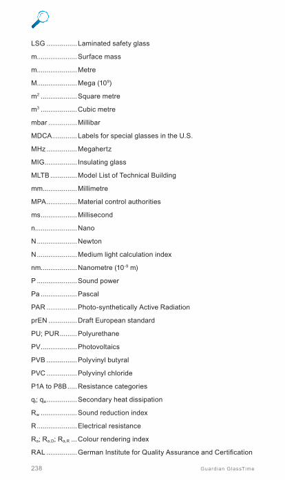
238 Guardian GlassTime
LSG ................ Laminated safety glass
m .....................Surface mass
m .....................Metre
M .....................Mega (109)
m2 ...................Square metre
m3 ...................Cubic metre
mbar ...............Millibar
MDCA ............. Labels for special glasses in the U.S.
MHz ................Megahertz
MIG ................. Insulating glass
MLTB ..............Model List of Technical Building
mm..................Millimetre
MPA ................Material control authorities
ms ...................Millisecond
n......................Nano
N .....................Newton
N .....................Medium light calculation index
nm...................Nanometre (10-9 m)
P .....................Sound power
Pa ...................Pascal
PAR ................Photo-synthetically Active Radiation
prEN ...............Draft European standard
PU; PUR .........Polyurethane
PV ...................Photovoltaics
PVB ................Polyvinyl butyral
PVC ................Polyvinyl chloride
P1A to P8B .....Resistance categories
qi; qa ................Secondary heat dissipation
Rw ...................Sound reduction index
R .....................Electrical resistance
Ra; Ra,D; Ra,R ...Colour rendering index
RAL ................German Institute for Quality Assurance and Certification
Search and find
239Guardian GlassTime
Re ....................Solar energy reflection
RL ....................Degree of light reflection
RLT .................Ventilation and air conditioning systems for indoor climate
Rw,B .................Weighted sound reduction, values measured on the construction
Rw,P .................Weighted sound reduction, determined on the test station
Rw,R .................Weighted sound reduction, calculation value
R’w,res ...............Resulting sound reduction index of the entire structural component
Rw; R’w ............Weighted sound reduction
s ......................Second
S .....................Selectivity factor
S .....................Solar input factor
SC...................Shading coefficient
SZR ................ Insulating glass interspace
TG ...................Tempered glass
TG-H ..............Heat-soaked tempered glass
TUV ..................UV radiation transmission
U .....................Heat transmittance coefficient
UCW .................Heat transmittance coefficient (U value), facade
Uf; Um; Ut.........Heat transmittance coefficient of frames, post-and-beam profiles
Ug, BW ...............Heat transmittance coefficient, glass, measured value
Ug; Up ..............Heat transmittance coefficient of gas and filling
ÜH ..................Declaration of conformity of the manufacturer
ÜHP ................Declaration of conformity of the manufacturer after test
ÜHZ ................Certificate of conformity
UV ..................Ultraviolet
UW ...................Heat transmittance coefficient, window
VDI .................Association of German Engineers
VdS .................Association of Property Insurers, damage prevention
VOB ................Procurement and construction contract procedures 11
Sear
ch a
nd
fin
d

240 Guardian GlassTime
W ....................Watt
W ....................Window
WPK ...............Factory production control
ZiE ..................Approval on a case-by-case basis

Search and find
241Guardian GlassTime
11.4 Greek symbolsα Drop height of the pendulum impact
α Average linear thermal expansion coefficient
α Angle
αe Energy absorption
β Fracture behaviour in pendulum impact
g Global safety factor
Δ Difference
ΔT Temperature difference
ε Emissivity
λ Wavelength of sound and light
λ Thermal conductivity
μ Poisson number
μm Micrometre (= 10–6 m)
r Density
re Solar energy reflection
S Sum
σ Tensile bending strength
τe Solar energy transmission
τL Degree of light transmittance
τV Degree of light transmittance
τV,BW Degree of light transmittance, measured value
ϕ Drop height in pendulum impact
y Heat transfer coefficient, related to length
W Ohm
11
Sear
ch a
nd
fin
d

Guardian Glass - United Kingdom
Phone: 0044 (0) 800 032 6322
e-mail: [email protected]
Guardian Glass - Russia (Rostov)
Phone: 007 (8) 86367 50900
e-mail: [email protected]
Guardian Glass - Poland
Phone: 0048 (0) 34 323 9300
e-mail: tac_poland@
guardian.com
Guardian Glass - Luxembourg
Phone: 00 352 50301
e-mail: [email protected]
Guardian Glass - Hungary
Phone: 0036 (0) 68 887 200
e-mail: [email protected]
Guardian Glass - Germany
Phone: 0049 (0) 3494 361 800
e-mail: anwendungstechnik@
guardian.com
Guardian Glass - Russia (Ryazan)
Phone: 007 (8) 4912 956600
e-mail: [email protected]
Guardian Glass - Spain
Phone: 00 34 948 817255
e-mail: [email protected]
Disclaimer:The present version of this document replaces and cancels all previous versions, please be sure to use the latest one.This document is only valid for the processing of the products mentioned in there. For more technical information, latest version of this document and other Guardian guidelines please refer to www.guardianglass.com or contact Guardian Technical Services. The guidelines contained herein are for information purposes only and are not intended to be a comprehensive set of instructions but assume the processor has professional knowledge of glass processing. Guardian does not provide any warranty with respect to the content of this document, as well Guardian does not assume any liability for the accuracy or completeness hereof, unless otherwise stipulated by applicable law. It is the responsibility of the purchaser to confirm that the products are suitable for their intended application in compliance with the applicable laws and regulations. Guardian does not provide any warranty regarding the intended further processing or end product, which remains the full responsibility of the processor.The products in this publication are sold subject to Guardian‘s standard terms and conditions of sale and any applicable written warranties. Nothing in this document provides any express or implied warranty, or serves to change or supplement Guardian‘s written warranties, which warranties are provided in Guardian’s Conditions of Sale, or any additional written limited warranties for certain fabricated, coated or safety glazing products located on our website at www.guardianglass.com.

Photo: © jens kirchner
Guardian EuropeReference code: Handbook / EN / 0222 ©2022 Guardian Glass, LLC.
www.guardianglass.com