dual dc regulated power supply 0-+30v
17
DUAL DC REGULATED POWER SUPPLY 0-+ 30V Digital Power Supplies has been designed and manufactured as per exact engineering standards using best quality components, offering overload/short circuit protection. Different controls for voltage and current controls Fine and coarse controls for variation Line Regulation is 0 .01%. +10% Line variation & load regulation is 0.05% from no load to full load Our 3½ digit Digital Panel Meters are Compact panel meters for digital display of electrical quantities. The output is short circuit protected with crossbar electronics fold back current limiting circuit. Applications: These power supplies are very useful for R&D laboratories, control panel manufacturers, defense Establishment’s school & college laboratories. Technical specifications: Output Voltage Output Current Meters 0-30V, 3A, 0-(-30V), 3A 4 DPM (3½ digit) Output voltage: 0-30V AND 0-(-30V)+ 1% continuously adjustable Output current: 0-3A AND 0-3A+ 1% continuously adjustable Features 1. Trainer operated on 230V, 50 Hz + 10% 2. Supplied with instruction manual 3. Highly Short Circuit Proof. 4. With Digital Readout. DIMMER STAT 3A Features 1. Trainer operated on 230V, 50 Hz + 10% 2. ON/OFF Controlled 3. Highly Short Circuit Protection with fuse. 4. Load Current 3A. 5. Output brought out to 6A Terminal and Home Appliances Sockets. DC REGULATED POWER SUPPLY 0-24V/1A Digital Power Supplies has been designed and manufactured as per exact engineering standards using best quality components, offering overload/short circuit protection.
-
Upload
khangminh22 -
Category
Documents
-
view
0 -
download
0
Transcript of dual dc regulated power supply 0-+30v

DUAL DC REGULATED POWER SUPPLY 0-+30VDigital Power Supplies has been designed and manufactured as per exact engineering standards using best qualitycomponents, offering overload/short circuit protection. Different controls for voltage and current controls Fine and coarse controls for variation Line Regulation is 0 .01%. +10% Line variation & load regulation is 0.05% from no load to fullload Our 3½ digit Digital Panel Meters are Compact panel meters for digital display ofelectrical quantities. The output is short circuit protected withcrossbar electronics fold back current limitingcircuit.
Applications:These power supplies are very useful for R&Dlaboratories, control panel manufacturers, defenseEstablishment’s school & college laboratories.Technical specifications:Output Voltage Output Current Meters0-30V, 3A, 0-(-30V), 3A 4 DPM (3½ digit)Output voltage:0-30V AND 0-(-30V)+1% continuously adjustableOutput current:0-3A AND 0-3A+1% continuously adjustableFeatures
1. Trainer operated on 230V, 50 Hz + 10%2. Supplied with instruction manual3. Highly Short Circuit Proof.4. With Digital Readout.
DIMMER STAT 3A
Features1. Trainer operated on 230V, 50 Hz + 10%2. ON/OFF Controlled3. Highly Short Circuit Protection with fuse.4. Load Current 3A.5. Output brought out to 6A Terminal and Home Appliances
Sockets.
DC REGULATED POWER SUPPLY 0-24V/1A
Digital Power Supplies has been designed and manufactured as per exact engineering standards using best qualitycomponents, offering overload/short circuit protection.
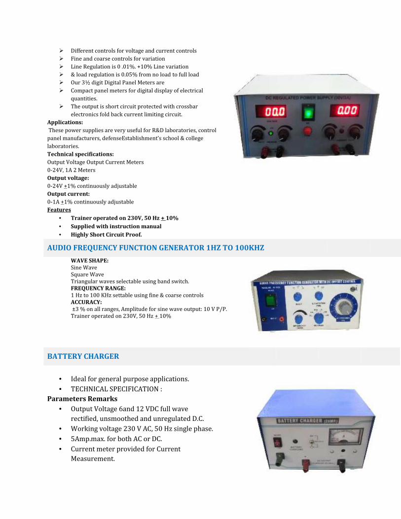
Different controls for voltage and current controls Fine and coarse controls for variation Line Regulation is 0 .01%. +10% Line variation & load regulation is 0.05% from no load to full load Our 3½ digit Digital Panel Meters are Compact panel meters for digital display of electricalquantities. The output is short circuit protected with crossbarelectronics fold back current limiting circuit.
Applications:These power supplies are very useful for R&D laboratories, controlpanel manufacturers, defenseEstablishment’s school & collegelaboratories.Technical specifications:Output Voltage Output Current Meters0-24V, 1A 2 MetersOutput voltage:0-24V +1% continuously adjustableOutput current:0-1A +1% continuously adjustableFeatures
Trainer operated on 230V, 50 Hz + 10% Supplied with instruction manual Highly Short Circuit Proof.
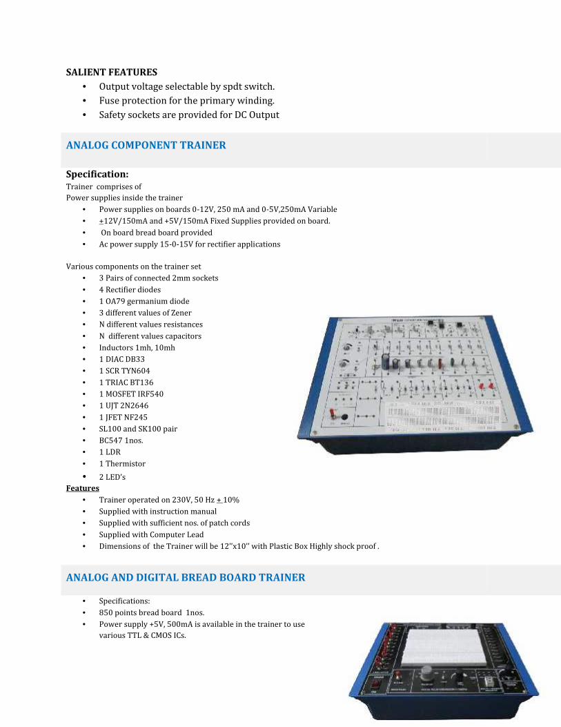
AUDIO FREQUENCY FUNCTION GENERATOR 1HZ TO 100KHZWAVE SHAPE:Sine WaveSquare WaveTriangular waves selectable using band switch.FREQUENCY RANGE:1 Hz to 100 KHz settable using fine & coarse controlsACCURACY:±3 % on all ranges, Amplitude for sine wave output: 10 V P/P.Trainer operated on 230V, 50 Hz + 10%
BATTERY CHARGER
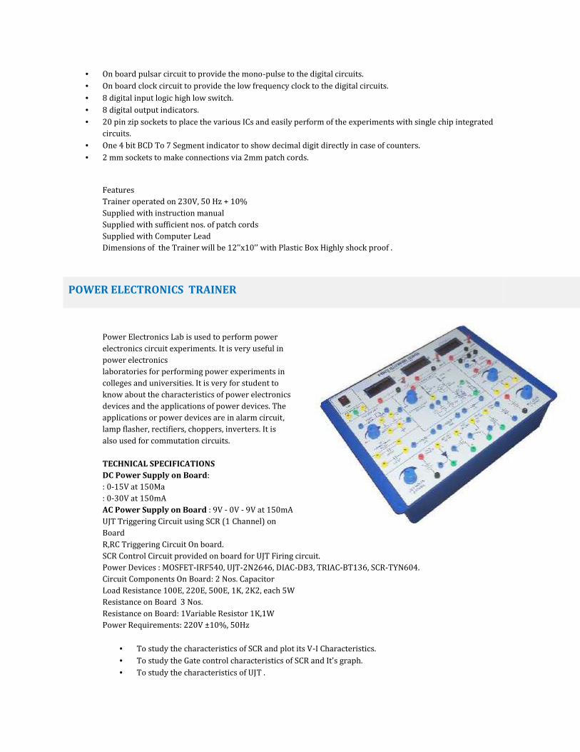
Ideal for general purpose applications. TECHNICAL SPECIFICATION :
Parameters Remarks Output Voltage 6and 12 VDC full waverectified, unsmoothed and unregulated D.C. Working voltage 230 V AC, 50 Hz single phase. 5Amp.max. for both AC or DC. Current meter provided for CurrentMeasurement.
SALIENT FEATURES Output voltage selectable by spdt switch. Fuse protection for the primary winding. Safety sockets are provided for DC Output
ANALOG COMPONENT TRAINER
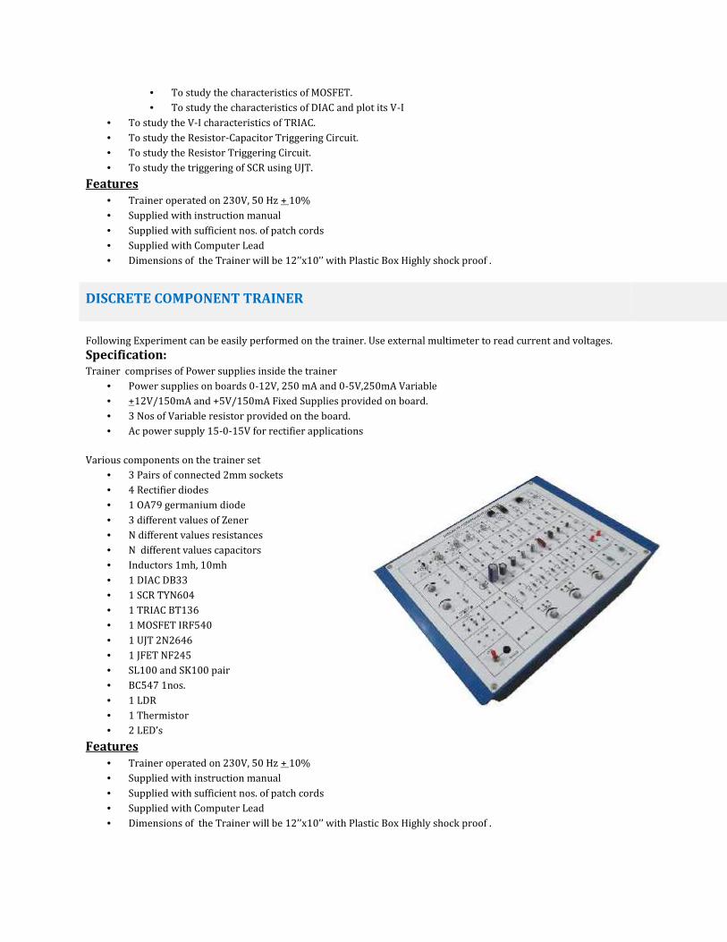
Specification:Trainer comprises ofPower supplies inside the trainer Power supplies on boards 0-12V, 250 mA and 0-5V,250mA Variable +12V/150mA and +5V/150mA Fixed Supplies provided on board. On board bread board provided Ac power supply 15-0-15V for rectifier applicationsVarious components on the trainer set 3 Pairs of connected 2mm sockets 4 Rectifier diodes 1 OA79 germanium diode 3 different values of Zener N different values resistances N different values capacitors Inductors 1mh, 10mh 1 DIAC DB33 1 SCR TYN604 1 TRIAC BT136 1 MOSFET IRF540 1 UJT 2N2646 1 JFET NF245 SL100 and SK100 pair BC547 1nos. 1 LDR 1 Thermistor 2 LED’s
Features Trainer operated on 230V, 50 Hz + 10% Supplied with instruction manual Supplied with sufficient nos. of patch cords Supplied with Computer Lead Dimensions of the Trainer will be 12’’x10’’ with Plastic Box Highly shock proof .
ANALOG AND DIGITAL BREAD BOARD TRAINER
Specifications: 850 points bread board 1nos. Power supply +5V, 500mA is available in the trainer to usevarious TTL & CMOS ICs.
On board pulsar circuit to provide the mono-pulse to the digital circuits. On board clock circuit to provide the low frequency clock to the digital circuits. 8 digital input logic high low switch. 8 digital output indicators. 20 pin zip sockets to place the various ICs and easily perform of the experiments with single chip integratedcircuits. One 4 bit BCD To 7 Segment indicator to show decimal digit directly in case of counters. 2 mm sockets to make connections via 2mm patch cords.
FeaturesTrainer operated on 230V, 50 Hz + 10%Supplied with instruction manualSupplied with sufficient nos. of patch cordsSupplied with Computer LeadDimensions of the Trainer will be 12’’x10’’ with Plastic Box Highly shock proof .POWER ELECTRONICS TRAINER
Power Electronics Lab is used to perform powerelectronics circuit experiments. It is very useful inpower electronicslaboratories for performing power experiments incolleges and universities. It is very for student toknow about the characteristics of power electronicsdevices and the applications of power devices. Theapplications or power devices are in alarm circuit,lamp flasher, rectifiers, choppers, inverters. It isalso used for commutation circuits.TECHNICAL SPECIFICATIONSDC Power Supply on Board:: 0-15V at 150Ma: 0-30V at 150mAAC Power Supply on Board : 9V - 0V - 9V at 150mAUJT Triggering Circuit using SCR (1 Channel) onBoardR,RC Triggering Circuit On board.SCR Control Circuit provided on board for UJT Firing circuit.Power Devices : MOSFET-IRF540, UJT-2N2646, DIAC-DB3, TRIAC-BT136, SCR-TYN604.Circuit Components On Board: 2 Nos. CapacitorLoad Resistance 100E, 220E, 500E, 1K, 2K2, each 5WResistance on Board 3 Nos.Resistance on Board: 1Variable Resistor 1K,1WPower Requirements: 220V ±10%, 50Hz
To study the characteristics of SCR and plot its V-I Characteristics. To study the Gate control characteristics of SCR and It's graph. To study the characteristics of UJT .
To study the characteristics of MOSFET. To study the characteristics of DIAC and plot its V-I
To study the V-I characteristics of TRIAC. To study the Resistor-Capacitor Triggering Circuit. To study the Resistor Triggering Circuit. To study the triggering of SCR using UJT.
Features Trainer operated on 230V, 50 Hz + 10% Supplied with instruction manual Supplied with sufficient nos. of patch cords Supplied with Computer Lead Dimensions of the Trainer will be 12’’x10’’ with Plastic Box Highly shock proof .
DISCRETE COMPONENT TRAINER
Following Experiment can be easily performed on the trainer. Use external multimeter to read current and voltages.Specification:Trainer comprises of Power supplies inside the trainer
Power supplies on boards 0-12V, 250 mA and 0-5V,250mA Variable +12V/150mA and +5V/150mA Fixed Supplies provided on board. 3 Nos of Variable resistor provided on the board. Ac power supply 15-0-15V for rectifier applicationsVarious components on the trainer set 3 Pairs of connected 2mm sockets 4 Rectifier diodes 1 OA79 germanium diode 3 different values of Zener N different values resistances N different values capacitors Inductors 1mh, 10mh 1 DIAC DB33 1 SCR TYN604 1 TRIAC BT136 1 MOSFET IRF540 1 UJT 2N2646 1 JFET NF245 SL100 and SK100 pair BC547 1nos. 1 LDR 1 Thermistor 2 LED’s
Features Trainer operated on 230V, 50 Hz + 10% Supplied with instruction manual Supplied with sufficient nos. of patch cords Supplied with Computer Lead Dimensions of the Trainer will be 12’’x10’’ with Plastic Box Highly shock proof .
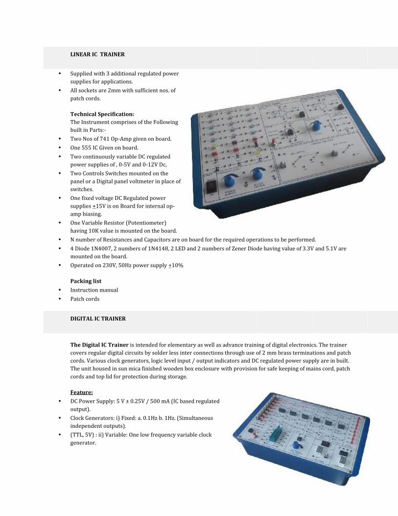
LINEAR IC TRAINER
Supplied with 3 additional regulated powersupplies for applications. All sockets are 2mm with sufficient nos. ofpatch cords.
Technical Specification:The Instrument comprises of the Followingbuilt in Parts:- Two Nos of 741 Op-Amp given on board. One 555 IC Given on board. Two continuously variable DC regulatedpower supplies of , 0-5V and 0-12V Dc, Two Controls Switches mounted on thepanel or a Digital panel voltmeter in place ofswitches. One fixed voltage DC Regulated powersupplies +15V is on Board for internal op-amp biasing. One Variable Resistor (Potentiometer)having 10K value is mounted on the board. N number of Resistances and Capacitors are on board for the required operations to be performed. 4 Diode 1N4007, 2 numbers of 1N4148, 2 LED and 2 numbers of Zener Diode having value of 3.3V and 5.1V aremounted on the board. Operated on 230V, 50Hz power supply +10%
Packing list Instruction manual Patch cords
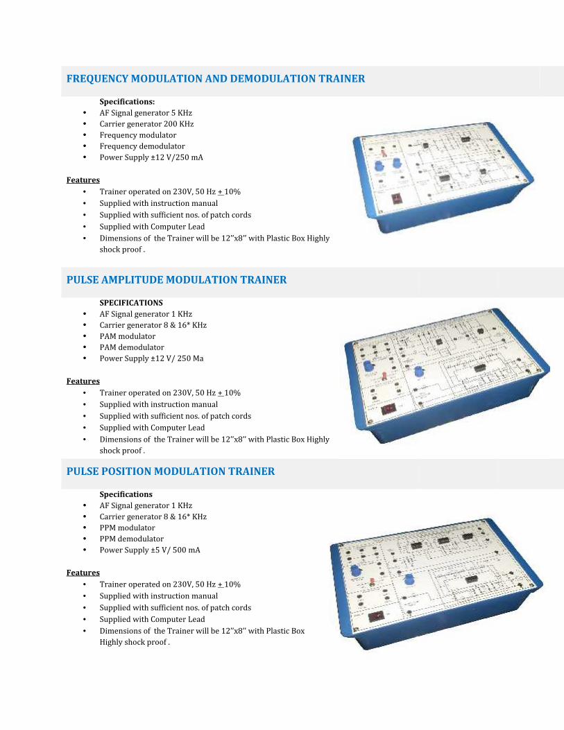
DIGITAL IC TRAINER
The Digital IC Trainer is intended for elementary as well as advance training of digital electronics. The trainercovers regular digital circuits by solder less inter connections through use of 2 mm brass terminations and patchcords. Various clock generators, logic level input / output indicators and DC regulated power supply are in built.The unit housed in sun mica finished wooden box enclosure with provision for safe keeping of mains cord, patchcords and top lid for protection during storage.Feature:
DC Power Supply: 5 V ± 0.25V / 500 mA (IC based regulatedoutput). Clock Generators: i) Fixed: a. 0.1Hz b. 1Hz. (Simultaneousindependent outputs). (TTL, 5V) : ii) Variable: One low frequency variable clockgenerator.

Manual Pulser : One independent bounce less manual Pulser ( useful for freezing the action of each stage of thecounter after every clock pulse ). Logic Level Inputs : Eight independent logic level inputs to select High / Low TTL levels, each with a LED toindicate high / low status and termination. Logic Level : Eight independent buffered logic level indicators for High / Low status Indicators : indication of digital outputs. Seven segment decoder : One BCD to Seven Segment Decoder/ Driver IC with terminations. Logic Probe given on board. All logic gate operation given onboard with multi operations. ZIF socket : IC’s up to 20 pin Universal ZIF Socket ( without soldering) Power On : Power ON switch with indicator for mains on indication and fuse for protection. Patch Cords : Adequate no of assorted colored multi-stand wires with 2mm stackable plug termination at bothends.( Stackable ) Power Requirement : 230V + 10% single phase AC. Instruction manual : One detailed instruction manual with well thought out experiments covering the abovetopics
OPERATIONAL AMPLIFIER TRAINER
Supplied with 3 additional regulated powersupplies for applications. All sockets are 2mm with sufficient nos. ofpatch cords.
Technical Specification:The Instrument comprises of the Followingbuilt in Parts:- Two Nos of 741 Op-Amp given on board. One 555 IC Given on board. Two continuously variable DC regulatedpower supplies of , 0-5V and 0-12V Dc, Two Controls Switches mounted on thepanel or a Digital panel voltmeter in place ofswitches. One fixed voltage DC Regulated powersupplies +15V is on Board for internal op-amp biasing. One Variable Resistor (Potentiometer)having 10K value is mounted on the board. N number of Resistances and Capacitors are on board for the required operations to be performed. 4 Diode 1N4007, 2 numbers of 1N4148, 2 LED and 2 numbers of Zener Diode having value of 3.3V and 5.1V aremounted on the board. Operated on 230V, 50Hz power supply +10%
Packing list Instruction manual Patch cords
FREQUENCY MODULATION AND DEMODULATION TRAINER
Specifications: AF Signal generator 5 KHz Carrier generator 200 KHz Frequency modulator Frequency demodulator Power Supply ±12 V/250 mA
Features Trainer operated on 230V, 50 Hz + 10% Supplied with instruction manual Supplied with sufficient nos. of patch cords Supplied with Computer Lead Dimensions of the Trainer will be 12’’x8’’ with Plastic Box Highlyshock proof .
PULSE AMPLITUDE MODULATION TRAINER
SPECIFICATIONS AF Signal generator 1 KHz Carrier generator 8 & 16* KHz PAM modulator PAM demodulator Power Supply ±12 V/ 250 Ma
Features Trainer operated on 230V, 50 Hz + 10% Supplied with instruction manual Supplied with sufficient nos. of patch cords Supplied with Computer Lead Dimensions of the Trainer will be 12’’x8’’ with Plastic Box Highlyshock proof .
PULSE POSITION MODULATION TRAINER
Specifications AF Signal generator 1 KHz Carrier generator 8 & 16* KHz PPM modulator PPM demodulator Power Supply ±5 V/ 500 mA
Features Trainer operated on 230V, 50 Hz + 10% Supplied with instruction manual Supplied with sufficient nos. of patch cords Supplied with Computer Lead Dimensions of the Trainer will be 12’’x8’’ with Plastic BoxHighly shock proof .
PULSE WIDTH MODULATION TRAINER
Specifications
AF Signal generator 1 KHz Carrier generator 8 & 16* KHz PWM modulator PWM demodulator Power Supply ±12 V/250 mA
Features Trainer operated on 230V, 50 Hz + 10% Supplied with instruction manual Supplied with sufficient nos. of patch cords Supplied with Computer Lead Dimensions of the Trainer will be 12’’x8’’ withPlastic Box Highly shock proof .
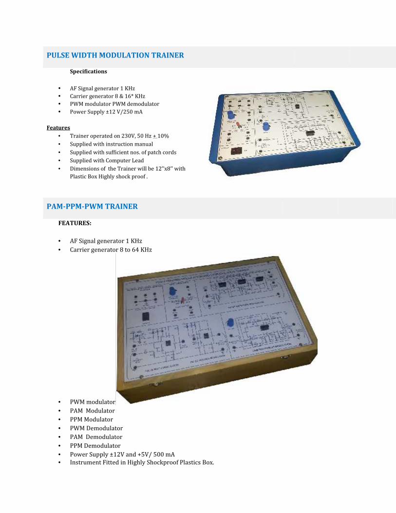
PAM-PPM-PWM TRAINER
FEATURES:
AF Signal generator 1 KHz Carrier generator 8 to 64 KHz
PWM modulator PAM Modulator PPM Modulator PWM Demodulator PAM Demodulator PPM Demodulator Power Supply ±12V and +5V/ 500 mA Instrument Fitted in Highly Shockproof Plastics Box.
Instrument Dimensions: 16’’X10’’ACCESSORIES:Sufficient no of 4mm Patch Cords for InterconnectionInstruction Manual for Student Workbook.Power Cords 230v, 50Hz
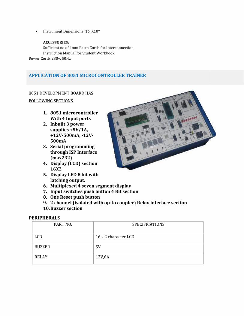
APPLICATION OF 8051 MICROCONTROLLER TRAINER
8051 DEVELOPMENT BOARD HASFOLLOWING SECTIONS1. 8051 microcontroller
With 4 Input ports2. Inbuilt 3 power
supplies +5V/1A,+12V-500mA, -12V-500mA
3. Serial programmingthrough ISP Interface(max232)
4. Display (LCD) section16X2
5. Display LED 8 bit withlatching output.
6. Multiplexed 4 seven segment display7. Input switches push button 4 Bit section8. One Reset push button9. 2 channel (isolated with op-to coupler) Relay interface section10.Buzzer section
PERIPHERALSPART NO. SPECIFICATIONSLCD 16 x 2 character LCDBUZZER 5VRELAY 12V,6A

POWER SUPPLIES PROVIDED INTERNALLYVoltage Rating Current Rating+ 5 V 1A+/- 12V 500mA
8051 MICROCONTROLLER TRAINING KIT WITH INBUILT POWER SUPPLY
Based on 8031/8051/8751 operating at 10/12 MHz.On board 8K RAM.Battery backup for RAM area.8/16K bytes of EPROM with powerful monitor program.Total memory expandable upto 128K Bytes using four 28 pin sockets.48 I/O lines using 2 nos. of 8255.Two External interrupts INT0 & INT1.28 keys Hexadecimal Keyboard and six Seven Segment displays.RS-232C interface using 8251.Auxiliary RS-232C using serial pins of 80C31.All data, address and control signals (TTL compatible) available at FRC connector.Powerful software commands like INSERT, DELETE, BLOCK MOVE, SET/CLEAR BREAK POINT, SINGLESTEP, EXAMINE THROUGH REGISTER, EXECUTE, EXAMINE, MODIFY, PROGRAM/DATA/INTERNALMEMORY etc.Uploading/Downloading facility from PC in Intel Hex format.In-built Power Supply User's Manual.User's Manual
ANALOG OPTICAL FIBER COMMUNICATION
Objective:1. Voice transmission through optical fiber cable.2. To study transmitter circuit & calculate its output power3. To study receiver circuit & calculate its input power4. To study the attenuation of signal betweentransmitter & receiver end.5. Measurement of numerical apertureSpecifications:
In built IC based Fixed DC Regulated PowerSupply + 6VDC/100mA. Pre amplifier stage consists of MIC(Microphone).

Photo detectors, transistors,& biasing network of resistance & capacitors. Power Amplifier stages consist of impedance matching transformers, transistors & biasing network of resistance& capacitors. Output section having LED & speaker, fiber optic cable for transmission of signal. Circuit diagram is printed on glass epoxy PCB & different combination of resistance. Test point are brought out on front panel .
Accessories:1. Adequate no of 4mm Patch Cords required for the Experiments.2. Microphone for Voice Transmission.3. Speaker for Voice Receiver End.4. Optical Fiber Cable 1 Meter Length.SOLAR STREET LIGHT SYSTEM TRAINER
SENSOR TRAINER
Objective:1.Strain Gauge Measurement2 Load cell Measurement.3. LVDT Measurement4. Smoke Sensor5. RTD Sensor6. Thermocouple Sensor.7. Speed Measurement of Motor By Proximity Sensor.SPPED SENSOR SPECIFICATIONS
1. Power supply : 230V Ac, 50 Hz.2. Transducer Type : Magnetic pickup.3. Motor : 12V DC motor with 3000 RMP speed4. Arrangement : Motor mounted with wheel and magnetic
pickup

5. Motor Speed controller : provided to change the speed of motor.6. Measurement Range : 10000 RPM Max.7. Output Display : 4 digits Digital frequency Counter calibrated in R.P.M.
2.STRAIN GAUGE/LOAD CELL SENSOR SPECIFICATIONSParameter Measured: Strain in terms of Kilograms on a cantilever beam.Measurement System: a) Weights b) Transducer with electronic instrumentation.Transducer: Temperature compensated strain gauge.Type : Cu-Ni foil with polyamide carrier base.Gauge Resistance: 350 Ohms (Nominal).Gauge Length: 6mm.Gauge Width : 2.4 mm.Gauge Base : 12.5 mm x 4.3 mm.Gauge Factor : 2:1 (approx.)Transducer : Strain gauges mounted on a stainless steel Measurement cantilever beam.Configuration: Bridge with two arms as strain gauges (Wheatstone Bridge principle).Range: 10 Kilograms.Actual Strain: By various weights to be placed in a pan fixed with the beam.Excitation Source: DC Regulated source.Tare Adjustment: Zero adjustment by a ten turn potentiometer.Readout: 3.5 digit digital display to indicate strain in kilograms.Test Points: Multi colored test points are provided at various stages in the circuit to observewaveforms and voltages.3. THERMOCOUPLE SPECIFICATION :Study of THERMOCOUPLE as temperature measuring transducerTHERMOCOUPLE probe with protection cover3.5 digit DPM as temperature indicatorBridge circuit for transducerDifferential amplifier with feedbackLead compensation systemO/P provided on test points for monitoring & controlling.4. RTD SPECIFICATION :Study of RTD as temperature measuring transducerRTD ( PT - 100 ) probe with protection cover3.5 digit DPM as temperature indicatorBridge circuit for transducerDifferential amplifier with feedbackLead compensation systemO/P provided on test points for monitoring & controlling.
5. LVDT SENSOR SPECIFICATIONSFeatures:

The instrumentation trainer consists of the following1. One board having the following built in parts.
± 12V D.C. at 50mA I.C.regulated Power Supply for Sine wave Oscillator. 4KHz fixed Sine wave Oscillator having variable amplitude 0–10V (P–P). Digital Panel meter 3½ digits range 200mV. Detector circuit with output adjustment pot. 9 pin male connector.
2. Transducer: Linear variable differential transducer (L.V.D.T.).3. Range : ± 20 mm. (Accuracy ± 1 mm, ± 1 Digit)4. Moving action : 6 wires,spring loaded type axial.6. SMOKE SENSOR SPECIFICATIONS
12V D.C. at 50Ma connected internally.
WHEATSTONE BRIDGE:Experimental Training Board has been designed specifically for the study of Wheatstone Bridge.Using this bridge the value of unknown resistor can be found. The board is absolutely selfcontained and requires no other apparatus.Practical experience on this board carries great educative value for science and engineeringstudents.
Object:01. To study Wheatstone Bridge02. To measure value of unknownresistance.Features:The board consists of the followingbuilt in parts:01. +5V D.C. At 100mA IC regulatedpower supply internally connected.02. Galvanometer, ANALOG to read30-0-30.03. Six decade resistance ofdifferent range.04. Adequate. no. of otherelectronic components.05. Mains ON/OFF switch, Fuse and
Jewel Light.* The unit is operative on 230V ±10% at 50Hz A.C. Mains.* Adequate no. of patch cords stackable from rear both ends 4mm spring loaded plug length ½metre.* Good Quality, reliable terminal/sockets are provided at appropriate places on panel forconnections/ observation of waveforms.

WHEATSTONE BRIDGE TRAINER
Specifications:1. On board dacade resistance box given.2. On board fractional resistance box given.3. Connection for external battery given.4. On board galvanometer given.5. Unknown resistance given.6. All connectional given internally.7. 2 Press key given.8. Intrument comprises 12x8 size box.9. Supplied with instruction manual.10.
Electronics workbenchElectrical electronics Work Bench is specially designed keeping in mind the actual need for Training & use with properInstrument panel and sufficient working area. The Work Bench is made of M.S. Powder coated mild steel with LaminatedWood based top on the working area.
Dimensions:
The basic frame work is made of 30 x 30 x 2 mm tubular mild steel The MS sheet used is over 1.5 mm in thickness for sturdiness The complete Work Bench is made of M.S. (except the Top) and Powder Coated in two colors for better aesthetic looks The overall dimensions of Work Bench / Test Bench are W = 4ft ; D = 2.5ft ; H = 2.5ft mm Top : 25 mm thick work top made from laminated wood based plain particle board with one side post forming (round
profile). Remaining three sides of the work top is lipped with PVC edge band. Size not less than : 1500mm x 750 mmand is fitted at a height of not less 750 mm
Three lockable drawers in line as shown in the figureFeatures:
Ergonomically designed instrument panel above the working area Various Instruments & 6 separate Electrical Outlets on Front Panel Rugged & Sturdy Powder Coated Steel Construction with levelling base on all four legs Laminated Wood Based post-formed front Top 2 Lockable Drawers in line MCB is provided for AC supply input for safety purpose
Electrical Fittings:
Wiring panel at the back above the table top height with 6 separate Modular sets of 5 Amp Switch & 5 pin Child proofprotective Socket are provided on the panel
1 set of 4 Pole MCB (32A) for 3 Φ ON / OFF for the whole table and Hi Bright R,Y,B phase indicators & 15A fuse for each phase are provided on the panel
[ Note : Photo for Illustration Purpose Only Actual Bench may be different but as per the Specifications ]
Supplied instruments
30MHz Digital controller oscilloscope 1MHz function generator dual tracking DC power supply 4.5digit true RMSDMM handheld Soldering and D-soldering station, ESD wrist strip. 2 digital meters with one variable single phase supply 4A, 0-250V Short circuited proof with MCB protection in both single phase and
3 phase
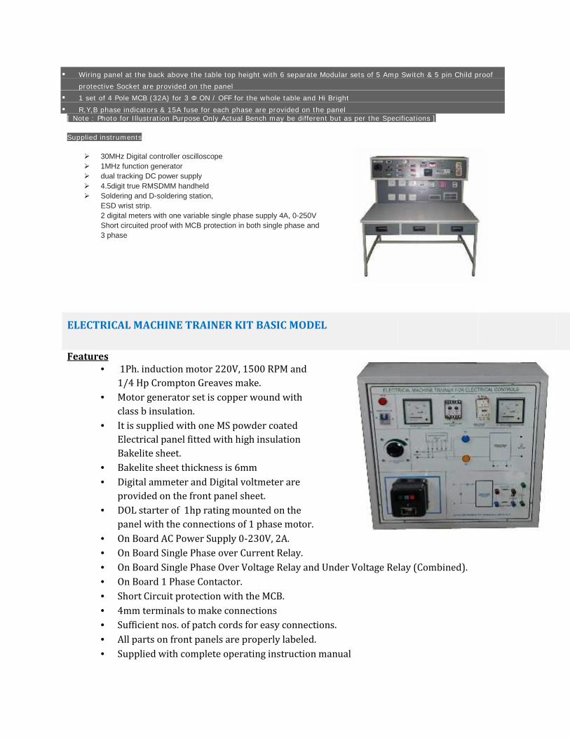
ELECTRICAL MACHINE TRAINER KIT BASIC MODEL
Features 1Ph. induction motor 220V, 1500 RPM and1/4 Hp Crompton Greaves make. Motor generator set is copper wound withclass b insulation. It is supplied with one MS powder coatedElectrical panel fitted with high insulationBakelite sheet. Bakelite sheet thickness is 6mm Digital ammeter and Digital voltmeter areprovided on the front panel sheet. DOL starter of 1hp rating mounted on thepanel with the connections of 1 phase motor. On Board AC Power Supply 0-230V, 2A. On Board Single Phase over Current Relay. On Board Single Phase Over Voltage Relay and Under Voltage Relay (Combined). On Board 1 Phase Contactor. Short Circuit protection with the MCB. 4mm terminals to make connections Sufficient nos. of patch cords for easy connections. All parts on front panels are properly labeled. Supplied with complete operating instruction manual

All connections and circuits are properly labels for easily understanding.Experiment consist of
Electrical panel size24”X24” SIZE 4 mm Connection leads required nos. Operating voltage 230V, 50HZ line. Laboratory experimental manual