
NICKEL ALLOY CONNECTING ROD BY ANSYS APPROACH
12
ISSN: 2455-2631 © September 2019 IJSDR | Volume 4, Issue 9 IJSDR1909006 International Journal of Scientific Development and Research (IJSDR) www.ijsdr.org 29 CHARACTERIZATION AND ANALYSIS OF STEEL- NICKEL ALLOY CONNECTING ROD BY ANSYS APPROACH 1 K. Naveen Kumar, 2 Mr. K. Veeranjaneyulu 1 Student, 2 Associate Professor Department of Mechanical Engineering, Anurag Engineering College, Kodad-508206, T.S. Abstract: Connecting rod is a vital link between piston and crank pin. Together with the crank, it forms a simple mechanism that converts reciprocating motion into rotating motion. With the advent technological improvements in metallurgical processes the present research focus shifted to metal alloys. In this thesis, the mechanical properties of Steel and nickel (9.06%) alloy were calculated and subjected to simulation in ANSYS. The addition of nickel, as an alloying element enhances tensile strength, imparts hardness, toughness and reduces rust formation. These properties are essential for a connecting rod and the stress strain analysis was carried out for total deformation, equivalent stress, and equivalent strain and the corresponding results were plotted. Keywords: Connecting rod, Steel-Nickel, Big end and Small end, Tensile Strength, Impact Strength, Yield Strength, CATIA V5, ANSYS. 1. INTRODUCTION Steel is the generic term for a large family of Iron-Carbon alloys, which are malleable, within some temperature range, immediately after solidification from the molten state. The principle raw materials used in steel making are iron ore, coal, and limestone. These materials are converted in a blast furnace into a product known as ‘pig iron,’ which contains considerable amounts of carbon (above 15%), manganese, sulfur, phosphorous, and silicon. Pig iron is hard, brittle, and unsuitable for direct processing into wrought forms. Pig iron was named long ago when molten iron was poured through a trench in the ground to flow into shallow earthen holes. The arrangement looked like new born pigs suckling. The central channel became known as the “sow,” and the molds were “pigs.” Steel making is the process of refining pig iron as well as iron and steel scrap by removing undesirable elements from the melt and then adding desirable elements in predetermined amounts. A primary reaction in most steel making is the combination of carbon with oxygen to form a gas. If dissolved oxygen is not removed from the melt prior to or during pouring, the gaseous products continue to evolve during solidification. If, the steel is strongly deoxidized elements, no gas is evolved, and the steel is called “killed” because it lays quality in the molds. Increasing degree of gas evolution (decreased de -oxidation) characterize steels called “semi killed,” “capped,” or “rimmed.” The degree of de-oxidation effects some of the properties of the steel. In addition to oxygen, liquid steel contains measurable amounts of dissolved hydrogen and nitrogen. For some critical steel applications, special de- oxidation practices as well as vacuum treatments may be used to reduce and control dissolved gases. 2. LITERATURE SURVEY 2.1 EFFECTS OF CHIEF ALLOYING ELEMENTS: Carbon – is generally considered to be the most important alloying element in steel and can be present up to 2% (although most welded steels have less than 0.5%). Increased amounts of carbon increases hardness and tensile strength, as well as response to heat treatment (hardenability). Increased amounts of carbon will reduce weldability. Sulfur – is usually an undesirable impurity in steel rather an alloying element. In amounts exceeding 0.05% it tends to cause brittleness and reduce weldability. Alloying additions of sulfur in amounts from 0.10% to 0.30% will tend to improve the machinability of steel. Such types may be referred to as “re-sulfurized” or “free-machining”. Free-machining alloys are not intended for use where welding is required. Phosphorus – is generally considered to be an undesirable impurity in steels. It is normally found in amounts up to 0.04% in most carbon steels. In hardened steels, it may tend to cause embrittlement. In low-alloy high –strength steels, phosphorus may be added in amounts up to 0.10% to improve strength and corrosion resistance. Silicon – Usually only small amounts (0.20%) are present in rolled steel when it is used as a deoxidizer. However, in steel castings, 0.35 to 1.00 % is usually present. Silicon dissolves in iron and tends to strength it. Weld metal usually contains approximately 0.50% silicon as a deoxidizer. Some filler metals may contain up to 1% to provide enhanced cleaning deoxidization for welding on contaminated surfaces. When these filler metals are used for welding on clean surfaces, the resulting weld metal strength will be markedly increased. The resulting decrease in ductility could resent cracking problems.
-
Upload
khangminh22 -
Category
Documents
-
view
0 -
download
0
Transcript of NICKEL ALLOY CONNECTING ROD BY ANSYS APPROACH

ISSN: 2455-2631 © September 2019 IJSDR | Volume 4, Issue 9
IJSDR1909006 International Journal of Scientific Development and Research (IJSDR) www.ijsdr.org 29
CHARACTERIZATION AND ANALYSIS OF STEEL-
NICKEL ALLOY CONNECTING ROD BY ANSYS
APPROACH
1K. Naveen Kumar, 2Mr. K. Veeranjaneyulu
1Student, 2Associate Professor
Department of Mechanical Engineering,
Anurag Engineering College, Kodad-508206, T.S.
Abstract: Connecting rod is a vital link between piston and crank pin. Together with the crank, it forms a simple mechanism
that converts reciprocating motion into rotating motion. With the advent technological improvements in metallurgical
processes the present research focus shifted to metal alloys. In this thesis, the mechanical properties of Steel and nickel
(9.06%) alloy were calculated and subjected to simulation in ANSYS. The addition of nickel, as an alloying element enhances
tensile strength, imparts hardness, toughness and reduces rust formation. These properties are essential for a connecting
rod and the stress strain analysis was carried out for total deformation, equivalent stress, and equivalent strain and the
corresponding results were plotted.
Keywords: Connecting rod, Steel-Nickel, Big end and Small end, Tensile Strength, Impact Strength, Yield Strength, CATIA
V5, ANSYS.
1. INTRODUCTION
Steel is the generic term for a large family of Iron-Carbon alloys, which are malleable, within some temperature range, immediately
after solidification from the molten state. The principle raw materials used in steel making are iron ore, coal, and limestone. These
materials are converted in a blast furnace into a product known as ‘pig iron,’ which contains considerable amounts of carbon (above
15%), manganese, sulfur, phosphorous, and silicon. Pig iron is hard, brittle, and unsuitable for direct processing into wrought forms.
Pig iron was named long ago when molten iron was poured through a trench in the ground to flow into shallow earthen holes. The
arrangement looked like new born pigs suckling. The central channel became known as the “sow,” and the molds were “pigs.”
Steel making is the process of refining pig iron as well as iron and steel scrap by removing undesirable elements from the melt and
then adding desirable elements in predetermined amounts. A primary reaction in most steel making is the combination of carbon
with oxygen to form a gas. If dissolved oxygen is not removed from the melt prior to or during pouring, the gaseous products
continue to evolve during solidification. If, the steel is strongly deoxidized elements, no gas is evolved, and the steel is called
“killed” because it lays quality in the molds. Increasing degree of gas evolution (decreased de-oxidation) characterize steels called
“semi killed,” “capped,” or “rimmed.” The degree of de-oxidation effects some of the properties of the steel. In addition to oxygen,
liquid steel contains measurable amounts of dissolved hydrogen and nitrogen. For some critical steel applications, special de-
oxidation practices as well as vacuum treatments may be used to reduce and control dissolved gases.
2. LITERATURE SURVEY
2.1 EFFECTS OF CHIEF ALLOYING ELEMENTS:
Carbon – is generally considered to be the most important alloying element in steel and can be present up to 2% (although most
welded steels have less than 0.5%). Increased amounts of carbon increases hardness and tensile strength, as well as response to heat
treatment (hardenability). Increased amounts of carbon will reduce weldability.
Sulfur – is usually an undesirable impurity in steel rather an alloying element. In amounts exceeding 0.05% it tends to cause
brittleness and reduce weldability. Alloying additions of sulfur in amounts from 0.10% to 0.30% will tend to improve the
machinability of steel. Such types may be referred to as “re-sulfurized” or “free-machining”. Free-machining alloys are not intended
for use where welding is required.
Phosphorus – is generally considered to be an undesirable impurity in steels. It is normally found in amounts up to 0.04% in most
carbon steels. In hardened steels, it may tend to cause embrittlement. In low-alloy high –strength steels, phosphorus may be added
in amounts up to 0.10% to improve strength and corrosion resistance.
Silicon – Usually only small amounts (0.20%) are present in rolled steel when it is used as a deoxidizer. However, in steel castings,
0.35 to 1.00 % is usually present. Silicon dissolves in iron and tends to strength it. Weld metal usually contains approximately
0.50% silicon as a deoxidizer. Some filler metals may contain up to 1% to provide enhanced cleaning deoxidization for welding on
contaminated surfaces. When these filler metals are used for welding on clean surfaces, the resulting weld metal strength will be
markedly increased. The resulting decrease in ductility could resent cracking problems.

ISSN: 2455-2631 © September 2019 IJSDR | Volume 4, Issue 9
IJSDR1909006 International Journal of Scientific Development and Research (IJSDR) www.ijsdr.org 30
Manganese – steels usually contain at least 0.30% manganese because it assists in the de-oxidation greater strength by increasing
the hardenability of the steel. Amounts of up to 1.5% can be found in some carbon steels.
Chromium – is a powerful alloying element in steel. In strongly increases the hardenability of steel, and markedly improves the
corrosion resistance of alloys in oxidizing media. Its presence in some steels could cause excessive hardness and cracking in and
adjacent to welds. Stainless steels may contain in excess of 12% chromium.
Molybdenum – this element is a strong carbide former and is usually present in alloy steels in amounts less than 1%. It increases
hardenability. It often improves the toughness and ductility of the steel, even with the increased strength and hardness it brings. It
is frequently used to improve toughness at low temperature.
Aluminum – is added to steel in very small amounts as a deoxidizer. It also is a grain refiner for improved toughness; steels with
moderate aluminum additions have been made to a “fine grain practice”.
Vanadium – the addition vanadium results in an increase in the hardenability of steel. It is very effective, so it is added in minute
amounts. At greater than 0.05%, there may be a tendency for the steel to become embrittled during thermal stress relief treatments.
2.2 A GLIMPSE OF CONNECTING ROD:
A connecting rod is a rigid member which connects a piston to a crank or crankshaft in a reciprocating engine. Together with the
crank, it forms a simple mechanism that converts reciprocating motion into rotating motion.
A connecting rod may also convert rotating motion into reciprocating motion, its original use. Earlier mechanisms, such as the
chain, could only impart pulling motion. Being rigid, a connecting rod may transmit either push or pull, allowing the rod to rotate
the crank through both halves of a revolution. In a few two-stroke engines the connecting rod is only required to push.
Today, the connecting rod is best known through its use in internal combustion piston engines, such as automobile engines. These
are of a distinctly different design from earlier forms of connecting rod used in steam engines and steam locomotives.
2.2.1 SMALL END AND BIG END:
The small end attaches to the piston pin, gudgeon pin or wrist pin, which is currently most often press fit into the connecting rod
but can swivel in the piston, a "floating wrist pin" design. The big end connects to the crankpin (bearing journal) on the crank
throw, in most engines running on replaceable bearing shells accessible via the ‘connecting rod bolts’ which hold the bearing "cap"
onto the big end. Typically there is a pinhole bored through the bearing on the big end of the connecting rod so that
pressurized lubricating motor oil squirts out onto the thrust side of the cylinder wall to lubricate the travel of the pistons and piston
rings. Most small two-stroke engines and some single cylinder four-stroke engines avoid the need for a pumped lubrication system
by using a rolling-element bearing instead, however this requires the crankshaft to be pressed apart and then back together in order
to replace a connecting rod.
2.2.2 STRESS AND FAILURE :
The connecting rod is under tremendous stress from the reciprocating load represented by the piston, actually stretching and being
compressed with every rotation, and the load increases as the square of the engine speed increase. Failure of a connecting rod,
usually called throwing a rod, is one of the most common causes of catastrophic engine failure in cars, frequently putting the
broken rod through the side of the crankcase and thereby rendering the engine irreparable; it can result from fatigue near a physical
defect in the rod, lubrication failure in a bearing due to faulty maintenance, or from failure of the rod bolts from a defect, improper
tightening or over-revving of the engine. In an unmaintained, dirty environment, a water or chemical emulsifies with the oil that
lubricates the bearing and causes the bearing to fail. Re-use of rod bolts is a common practice as long as the bolts meet manufacturer
specifications. Despite their frequent occurrence on televised competitive automobile events, such failures are quite rare on
production cars during normal daily driving. This is because production auto parts have a much larger factor of safety, and often
more systematic quality control.

ISSN: 2455-2631 © September 2019 IJSDR | Volume 4, Issue 9
IJSDR1909006 International Journal of Scientific Development and Research (IJSDR) www.ijsdr.org 31
Aluminum connecting rod for 4-stroke engine, fatigue breakage and subsequent impact with the crankshaft
3. FABRICATION OF STEEL-NICKEL ALLOY
The primary base metal selected for the casting is AISI 1141 carbon steel. This steel is a medium carbon steel and possesses all the
required characteristics which are essential, if used as a material alloy for the connecting rod. Carbon steels contain carbon as the
primary alloying element. Small quantities of molybdenum, chromium, nickel, aluminum, and copper are also present in these
steels. They contain 0.4% silicon and 1.2% manganese. They are designated by AISI four-digit numbers.
3.1 PRACTICAL WORKING:
The working spot has been captured and given below. Both the metals were melted at temperatures ranging from 1560o C to 1640o
C, in the Induction furnace.
Molten metal in the crucible
The molten metal has been poured into a square shaped mould and then allowed to solidify to the open air. Later, when the metal
is solidified, it has been drawn out. The metal obtained metal has given in the below picture. This metal, which is the alloy of Steel-
Nickel, now has been tested mechanically and found the desired properties which are essential for the analysis by ANSYS approach.

ISSN: 2455-2631 © September 2019 IJSDR | Volume 4, Issue 9
IJSDR1909006 International Journal of Scientific Development and Research (IJSDR) www.ijsdr.org 32
Steel-Nickel metal alloy after solidification
The obtained specimen has a weight of approximately 12.2 kilograms. And the corresponding dimensions of the specimen are 160
mm length, 160 mm breadth and 60 mm thickness. The standards of the specimen were calculated appropriately before the metal
alloy subjected to the mechanical characterization.
Though the metal has been selected and worked preciously; it is impossible to avoid the practical impossibilities and as a result few
unavoidable alloying elements has been a part of the alloy and were present in a minute and negligible amounts. As a result of this,
the characterization of the practical alloy has been subjected to few alterations compared to the theoretical characterization.
4. EXPERIMENTAL ANALYSIS
4.1 CHEMICAL CHARACTERIZATION OF THE STEEL-NICKEL ALLOY :
Equipment used: Optical emission Spectrometer BAIRD DV6
S.No. CONTENT PERCENTAGE
%
1. HEAT NO. 451
2. CARBON © 0.48%
3. NICKEL (Ni) 9.06%
4. MANGANESE
(Mn)
0.22%
5. PHOSPHORUS(
P)
0.16%
6. IRON (Fe) Remainder
Chemical characterization of the Steel-Nickel Alloy
Hence as expected the Nickel content ranges around 9% in the steel; this imparts high impact strength and good hardenability to
the steel. The addition few alloying elements like Phosphorus might impact few characteristics of the Steel but they can’t be avoided
due to the few practical imperfections and difficulties.
4.2 TENSILE CHARACTERISTICS OF THE STEEL-NICKEL ALLOY:
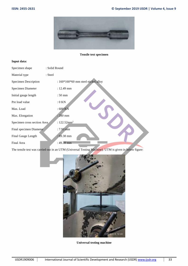
The casted metal after solidification has been subjected to various cutting and machining operations. For the tensile test, the metal
has been cut into to the shape of a Dog bone, which is given below.
ISSN: 2455-2631 © September 2019 IJSDR | Volume 4, Issue 9
IJSDR1909006 International Journal of Scientific Development and Research (IJSDR) www.ijsdr.org 33
Tensile test specimen
Input data:
Specimen shape : Solid Round
Material type : Steel
Specimen Description : 160*160*60 mm steel-nickel alloy
Specimen Diameter : 12.49 mm
Initial gauge length : 50 mm
Pre load value : 0 KN
Max. Load : 600 KN
Max. Elongation : 280 mm
Specimen cross section Area : 122.52mm2
Final specimen Diameter : 7.93 mm
Final Gauge Length : 69.38 mm
Final Area : 49.39 mm
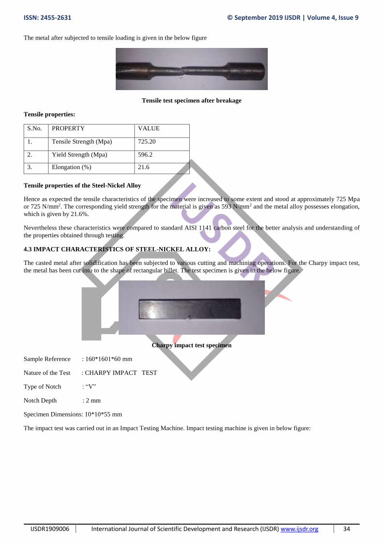
The tensile test was carried out in an UTM (Universal Testing Machine). UTM is given in below figure:
Universal testing machine
ISSN: 2455-2631 © September 2019 IJSDR | Volume 4, Issue 9
IJSDR1909006 International Journal of Scientific Development and Research (IJSDR) www.ijsdr.org 34
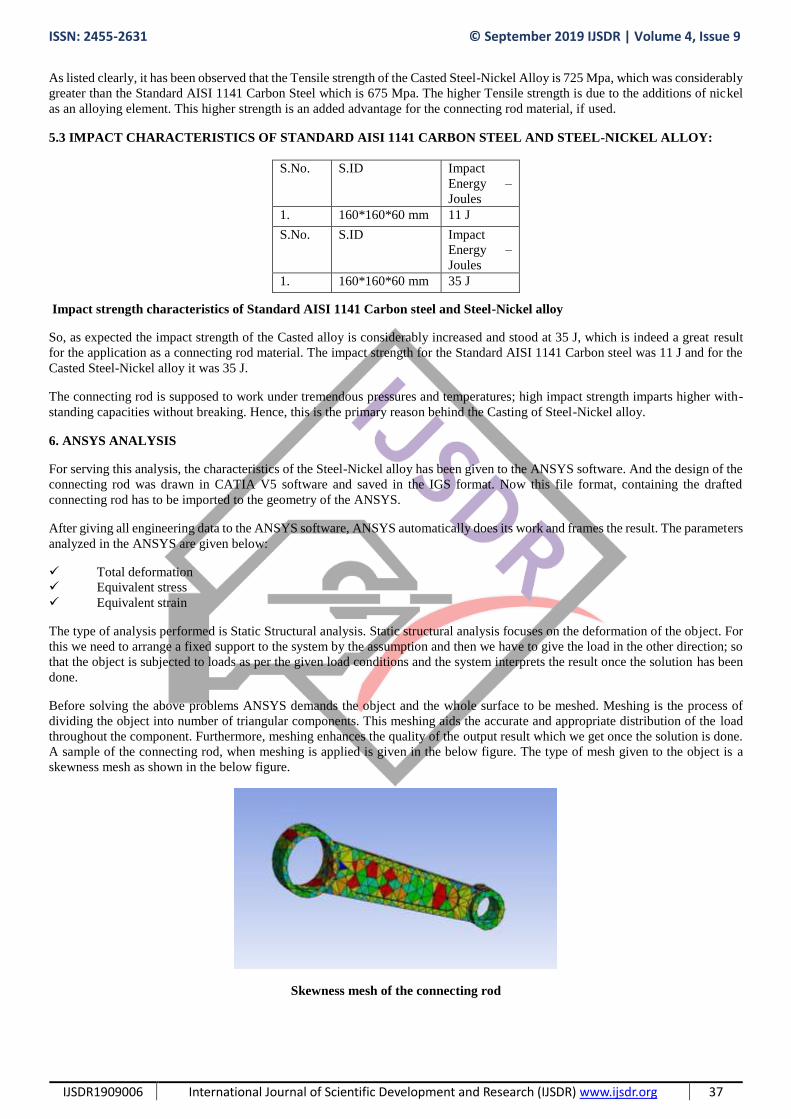
The metal after subjected to tensile loading is given in the below figure
Tensile test specimen after breakage
Tensile properties:
S.No. PROPERTY VALUE
1. Tensile Strength (Mpa) 725.20
2. Yield Strength (Mpa) 596.2
3. Elongation (%) 21.6
Tensile properties of the Steel-Nickel Alloy
Hence as expected the tensile characteristics of the specimen were increased to some extent and stood at approximately 725 Mpa
or 725 N/mm2. The corresponding yield strength for the material is given as 593 N/mm2 and the metal alloy possesses elongation,
which is given by 21.6%.
Nevertheless these characteristics were compared to standard AISI 1141 carbon steel for the better analysis and understanding of
the properties obtained through testing.
4.3 IMPACT CHARACTERISTICS OF STEEL-NICKEL ALLOY:
The casted metal after solidification has been subjected to various cutting and machining operations. For the Charpy impact test,
the metal has been cut into to the shape of rectangular billet. The test specimen is given in the below figure.
Charpy impact test specimen
Sample Reference : 160*1601*60 mm
Nature of the Test : CHARPY IMPACT TEST
Type of Notch : “V”
Notch Depth : 2 mm
Specimen Dimensions: 10*10*55 mm
The impact test was carried out in an Impact Testing Machine. Impact testing machine is given in below figure:

ISSN: 2455-2631 © September 2019 IJSDR | Volume 4, Issue 9
IJSDR1909006 International Journal of Scientific Development and Research (IJSDR) www.ijsdr.org 35
Impact test equipment
The test specimen has been subjected to impact test and the respective specimen is given in the below figure:
Impact test specimen after breakage
Impact strength of the specimen
S.No. S.ID Impact Energy
– Joules
1. 160*160*60
mm
35 J
Impact properties of the Steel-Nickel Alloy
The impact strength of the specimen is 35J and by far this is a great feat in the project. Impact strength has been principle feature
required in the connecting rods. So if this material has been applied to the connecting rod, then the con rod might have better
operating characteristics and that could even resist high fatigue loads and operating temperature and pressures.
4.4 HARDNESS CHARACTERISTICS OF STEEL-NICKEL ALLOY:
The casted metal after solidification has been subjected to various cutting and machining operations. For the hardness test, the metal
has been cut into to square shape. The test specimen is given in the below figure.
AISI 1141 CARBON STEEL STEEL-NICKEL ALLOY
S.No. CONTENT PERCENTAGE % CONTENT PERCENTAGE %
1. HEAT NO. 451 HEAT NO. 451
2. CARBON C 0.370% - 0.45% CARBON C 0.48%
3. SULFUR S 0.080% - 0.13% NICKEL Ni 9.06%
4. MANGANESE Mn 1.35-1.65% MANGANESE Mn 0.22%
5. PHOSPHORUS P 0.040% PHOSPHORUS P 0.16%
6. IRON Fe 97.73-98.2% IRON Fe Remainder

ISSN: 2455-2631 © September 2019 IJSDR | Volume 4, Issue 9
IJSDR1909006 International Journal of Scientific Development and Research (IJSDR) www.ijsdr.org 36
Brinell hardness test specimen
Sample Reference : 160*1601*60 mm
Nature of the Test : Brinell Hardness Test
Specimen Dimensions : 30*28*26 mm
Brinell Hardness Number
S.No HB
1. 173
Hardness characteristics of the Steel-Nickel Alloy
The Brinell hardness number for the casted alloy has reduced to a bit. It might be due to the inclusion of few impurities like sulfur
and phosphorus. Though the reduced value is minute, yet it should be taken care off while working in the industry and while
applying this material to any kind of practical working purposes such as manufacturing of bearings for the engines or fabrication of
connecting rods.
5. COMPARISON OF STEEL-NICKEL ALLOY WITH A STANDARD AISI 1141 CARBON STEEL
5.1 CHEMICAL CHARACTERIZATION OF THE AISI 1141 CARBON STEEL AND STEEL-NICKEL ALLOY :
Equipment used: Optical emission spectroscope BAIRD DV6
Carbon steels contain carbon as the primary alloying element. Small quantities of molybdenum, chromium, nickel, aluminum, and
copper are also present in these steels. They contain 0.4% silicon and 1.2% manganese. They are designated by AISI four-digit
numbers.
Upon comparison of Steel-Nickel Alloy Chemical composition with a standard AISI 1141 Carbon steel composition; it is found
that small alloying elements were present in both the metals. But the additions of Nickel in the casted alloy enhanced Impact strength
of the Steel, which is indeed a desirable and indispensable feature for the connecting rod material, if used.
5.2 TENSILE CHARACTERISTICS OF STANDARD AISI 1141 CARBON STEEL AND STEEL-NICKEL ALLOY:
Tensile properties:
PROPERTY AISI 1141 STEEL STEEL& NICKEL
S.
No
.
PROPERTY METRIC IMPERIAL VALUE
1. Tensile Strength (Mpa) 675.00 97900 PSI 725.20
2. Yield Strength (Mpa) 360.00 52200 PSI 596.2
3. Elongation (%) 22 22 21.6
Tensile characteristics of Standard AISI 1141 Carbon Steel and Steel-Nickel alloy
ISSN: 2455-2631 © September 2019 IJSDR | Volume 4, Issue 9
IJSDR1909006 International Journal of Scientific Development and Research (IJSDR) www.ijsdr.org 37
As listed clearly, it has been observed that the Tensile strength of the Casted Steel-Nickel Alloy is 725 Mpa, which was considerably
greater than the Standard AISI 1141 Carbon Steel which is 675 Mpa. The higher Tensile strength is due to the additions of nickel
as an alloying element. This higher strength is an added advantage for the connecting rod material, if used.
5.3 IMPACT CHARACTERISTICS OF STANDARD AISI 1141 CARBON STEEL AND STEEL-NICKEL ALLOY:
Impact strength characteristics of Standard AISI 1141 Carbon steel and Steel-Nickel alloy
So, as expected the impact strength of the Casted alloy is considerably increased and stood at 35 J, which is indeed a great result
for the application as a connecting rod material. The impact strength for the Standard AISI 1141 Carbon steel was 11 J and for the
Casted Steel-Nickel alloy it was 35 J.
The connecting rod is supposed to work under tremendous pressures and temperatures; high impact strength imparts higher with-
standing capacities without breaking. Hence, this is the primary reason behind the Casting of Steel-Nickel alloy.
6. ANSYS ANALYSIS
For serving this analysis, the characteristics of the Steel-Nickel alloy has been given to the ANSYS software. And the design of the
connecting rod was drawn in CATIA V5 software and saved in the IGS format. Now this file format, containing the drafted
connecting rod has to be imported to the geometry of the ANSYS.
After giving all engineering data to the ANSYS software, ANSYS automatically does its work and frames the result. The parameters
analyzed in the ANSYS are given below:
Total deformation
Equivalent stress
Equivalent strain
The type of analysis performed is Static Structural analysis. Static structural analysis focuses on the deformation of the object. For
this we need to arrange a fixed support to the system by the assumption and then we have to give the load in the other direction; so
that the object is subjected to loads as per the given load conditions and the system interprets the result once the solution has been
done.
Before solving the above problems ANSYS demands the object and the whole surface to be meshed. Meshing is the process of
dividing the object into number of triangular components. This meshing aids the accurate and appropriate distribution of the load
throughout the component. Furthermore, meshing enhances the quality of the output result which we get once the solution is done.
A sample of the connecting rod, when meshing is applied is given in the below figure. The type of mesh given to the object is a
skewness mesh as shown in the below figure.
Skewness mesh of the connecting rod
S.No. S.ID Impact
Energy –
Joules
1. 160*160*60 mm 11 J
S.No. S.ID Impact
Energy –
Joules
1. 160*160*60 mm 35 J

ISSN: 2455-2631 © September 2019 IJSDR | Volume 4, Issue 9
IJSDR1909006 International Journal of Scientific Development and Research (IJSDR) www.ijsdr.org 38
6.1 TOTAL DEFORMATION:
There are two types of deformations in the ANSYS. Deformation results generally can be in ANSYS Work Bench as total
deformation or directional deformation. Both of them are used to obtain displacements from stresses. The main difference is the
directional deformation calculates for the deformations in X, Y, and Z planes for a given system. In total deformation, it gives a
square root of the summation of the square of x-direction, y-direction and z-direction.
The corresponding load given to the connecting rod for the results of total deformation is 7000 N. This may be an exaggeration, if
I explain that this load is nothing in front of the material which we made. To be clearer, the connecting rod absolutely sustained this
7000 N load without any considerable deformations. Hence, once again proved that the Steel-Nickel alloy absolutely sustains the
impact loads and deformations in working conditions, if used in the Automobile components.
The corresponding result and the drafting model of the connecting rod are presented in the below table and figures respectively.
Object Name Equivalent Stress Equivalent Elastic Strain Total Deformation
State Solved
Scope
Scoping Method Geometry Selection
Geometry All Bodies
Definition
Type Equivalent (von-Mises) Stress Equivalent Elastic Strain Total Deformation
By Time
Display Time Last
Calculate Time History Yes
Identifier
Suppressed No
Integration Point Results
Display Option Averaged
Average Across Bodies No
Results
Minimum 166.32 Pa 1.0991e-009 m/m 0. m
Maximum 3.4038e+007 Pa 1.7089e-004 m/m 2.2814e-005 m
Average 1.4115e+007 Pa 7.3044e-005 m/m 7.6068e-006 m
Minimum Occurs On connecting rod-Free Parts
Maximum Occurs On connecting rod-Free Parts
Information
Time 1. s
Load Step 1
Substep 1
Iteration Number 1
Solution for static structural analysis of the connecting rod
The tabular data, which we got after the solution has been done in the ANSYS, clearly demystifies that maximum deformation that
occurred for a load of 7000N is 166.32 Pa and the corresponding minimum deformation occurred is 3.4038e+007 Pa.
The drafting image for the same is given in the below figure. The figure shows the Total deformation of the object under loading
conditions. There are different color coding’s for the amount of load with respect to the time, which shows that what amount of
load has been applied at that particular zone and at a particular time period.

ISSN: 2455-2631 © September 2019 IJSDR | Volume 4, Issue 9
IJSDR1909006 International Journal of Scientific Development and Research (IJSDR) www.ijsdr.org 39
Total deformation of the connecting rod
6.2 EQUIVALENT STRESS DISTRIBUTION:
Equivalent stress (also called von Mises stress) is often used in design work because it allows any arbitrary three-dimensional stress
state to be represented as a single positive stress value. Equivalent stress is part of the maximum equivalent stress failure theory
used to predict yielding in a ductile material.
The corresponding figure for the equivalent stress is given in the below figure.
Equivalent stress distribution in the connecting rod
Unlike total deformation, the stress induced in the connecting rod was a bit recognizable as depicted in the above figure. However,
it is not a considerable issue, if the material (Steel-Nickel alloy) used for the connecting rod.
6.3 EQUIVALENT STRAIN DISTRIBUTION:
The von Mises equivalent strain increment is derived for the case of large strain simple shear (torsion testing). This is used, in
conjunction with the von Mises yield surface, to define the von Mises equivalent stress as well as the incremental work per unit
volume. Integration of the equivalent strain increment leads to the definition of the von Mises equivalent strain for torsion.
The equivalent plastic strain gives a measure of the amount of permanent strain in an engineering body. The equivalent plastic strain
is calculated from the component plastic strain as defined in the Equivalent stress/strain section.
ISSN: 2455-2631 © September 2019 IJSDR | Volume 4, Issue 9
IJSDR1909006 International Journal of Scientific Development and Research (IJSDR) www.ijsdr.org 40
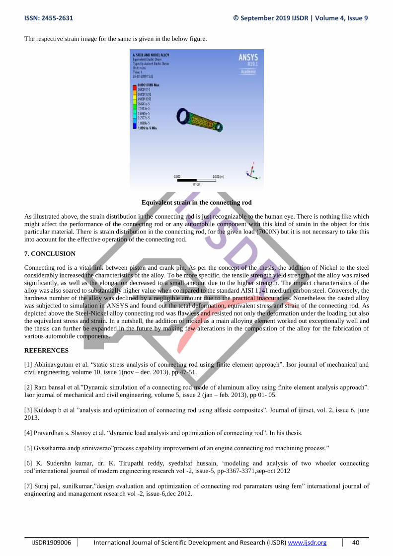
The respective strain image for the same is given in the below figure.
Equivalent strain in the connecting rod
As illustrated above, the strain distribution in the connecting rod is just recognizable to the human eye. There is nothing like which
might affect the performance of the connecting rod or any automobile component with this kind of strain in the object for this
particular material. There is strain distribution in the connecting rod, for the given load (7000N) but it is not necessary to take this
into account for the effective operation of the connecting rod.
7. CONCLUSION
Connecting rod is a vital link between piston and crank pin. As per the concept of the thesis, the addition of Nickel to the steel
considerably increased the characteristics of the alloy. To be more specific, the tensile strength yield strength of the alloy was raised
significantly, as well as the elongation decreased to a small amount due to the higher strength. The impact characteristics of the
alloy was also soared to substantially higher value when compared to the standard AISI 1141 medium carbon steel. Conversely, the
hardness number of the alloy was declined by a negligible amount due to the practical inaccuracies. Nonetheless the casted alloy
was subjected to simulation in ANSYS and found out the total deformation, equivalent stress and strain of the connecting rod. As
depicted above the Steel-Nickel alloy connecting rod was flawless and resisted not only the deformation under the loading but also
the equivalent stress and strain. In a nutshell, the addition of nickel as a main alloying element worked out exceptionally well and
the thesis can further be expanded in the future by making few alterations in the composition of the alloy for the fabrication of
various automobile components.
REFERENCES
[1] Abhinavgutam et al. “static stress analysis of connecting rod using finite element approach”. Isor journal of mechanical and
civil engineering, volume 10, issue 1(nov – dec. 2013), pp 47-51.
[2] Ram bansal et al.”Dynamic simulation of a connecting rod made of aluminum alloy using finite element analysis approach”.
Isor journal of mechanical and civil engineering, volume 5, issue 2 (jan – feb. 2013), pp 01- 05.
[3] Kuldeep b et al ”analysis and optimization of connecting rod using alfasic composites”. Journal of ijirset, vol. 2, issue 6, june
2013.
[4] Pravardhan s. Shenoy et al. “dynamic load analysis and optimization of connecting rod”. In his thesis.
[5] Gvsssharma andp.srinivasrao”process capability improvement of an engine connecting rod machining process.”
[6] K. Sudershn kumar, dr. K. Tirupathi reddy, syedaltaf hussain, ‘modeling and analysis of two wheeler connecting
rod’international journal of modern engineering research vol -2, issue-5, pp-3367-3371,sep-oct 2012
[7] Suraj pal, sunilkumar,”design evaluation and optimization of connecting rod paramaters using fem” international journal of
engineering and management research vol -2, issue-6,dec 2012.